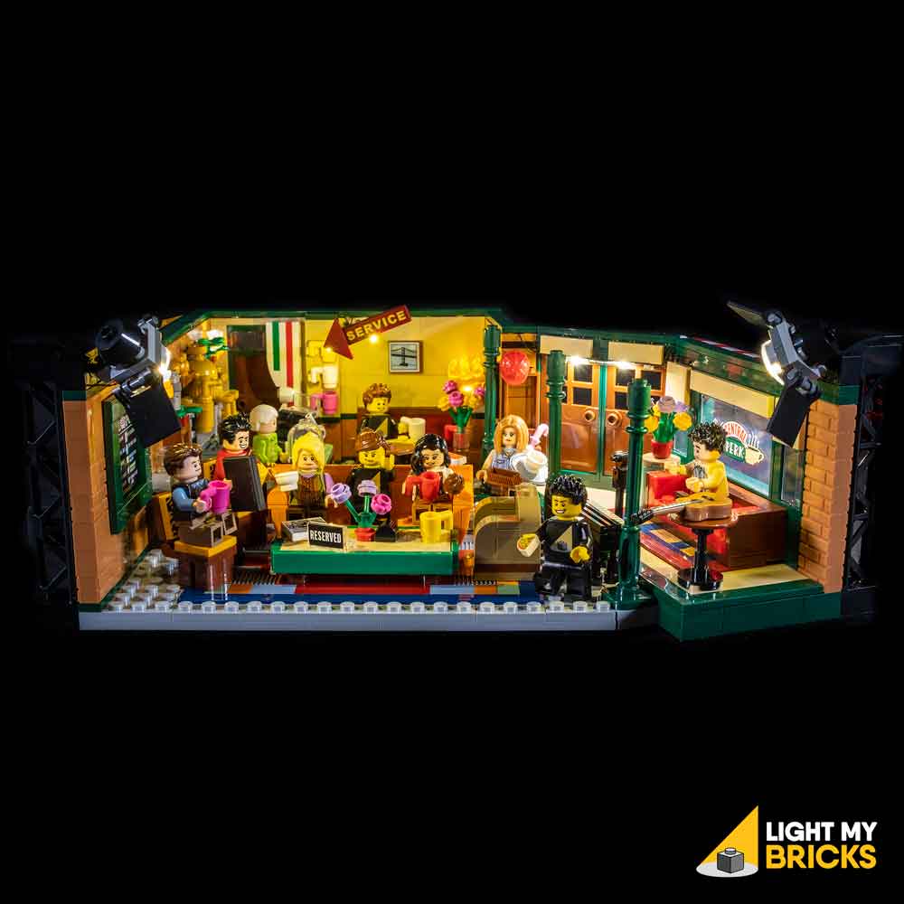
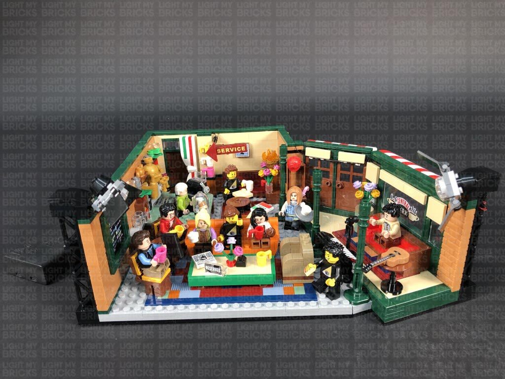
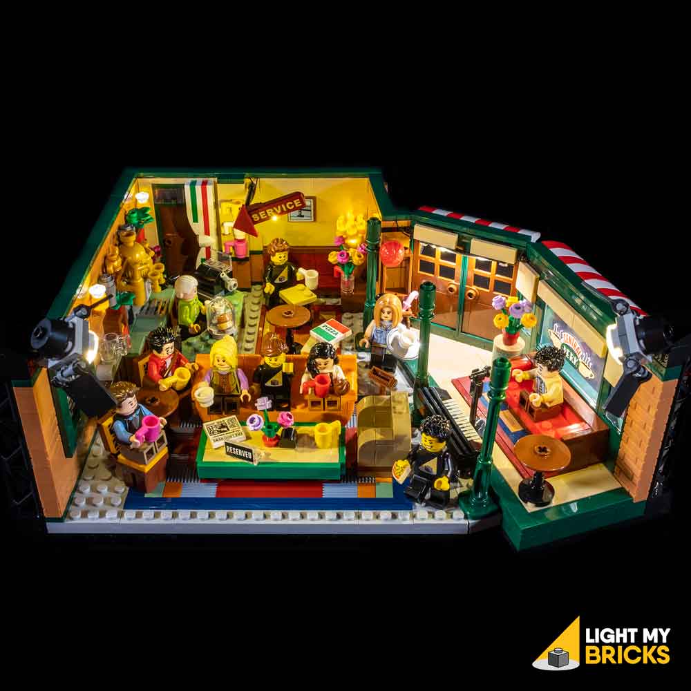
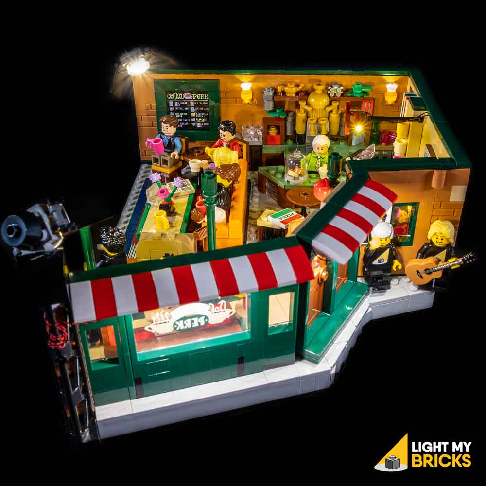
The following page is the instructions for the Light My Bricks LEGO Friends Central Perk (21319) LED light kit.
If you run into any issues, please refer to the online troubleshooting guide.
To ensure a trouble-free installation of your light kit, please read and follow each step carefully. These instructions can be downloaded in PDF format here
Please note: This page lists instructions for the LED light kit only. If you are wishing to purchase the Light My Bricks LEGO Friends Central Perk (21319) LED light kit , please click here to view the product page
Package Contents:
- 6x White 15cm Micro Bit Lights
- 2x White 30cm Bit Lights
- 2x Warm White 30cm Large Bit Lights
- 3x Warm White Strip Lights
- 2x Micro 4-Port Expansion Boards
- 1x 6-Port Expansion Board
- 1x Flicker Effects Board
- 4x 5cm Connecting Cables
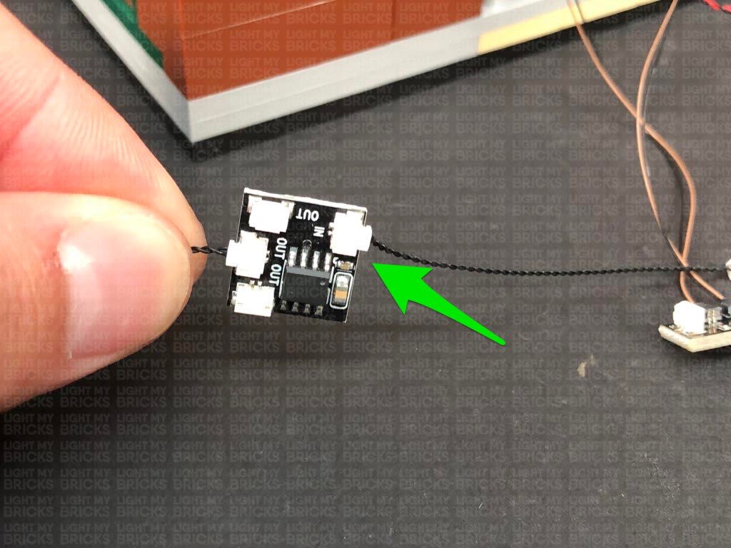
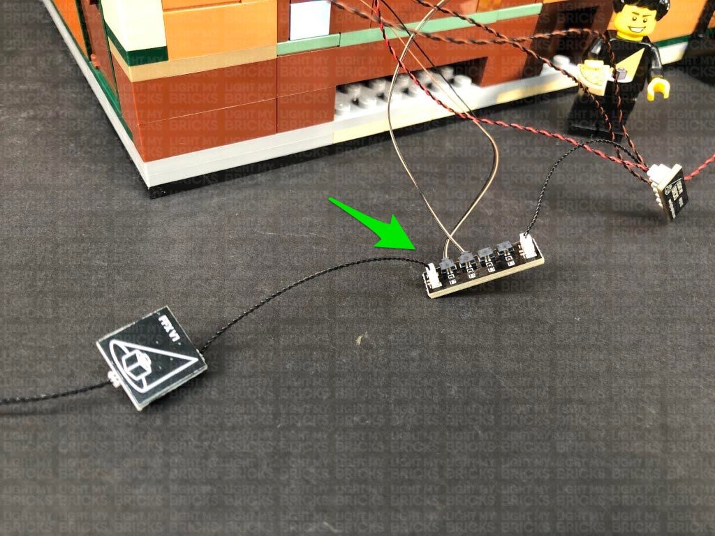
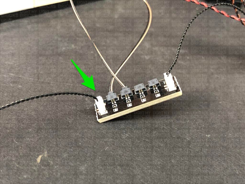
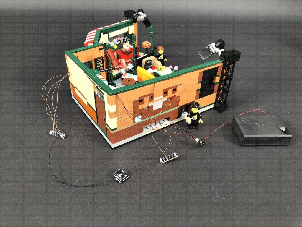
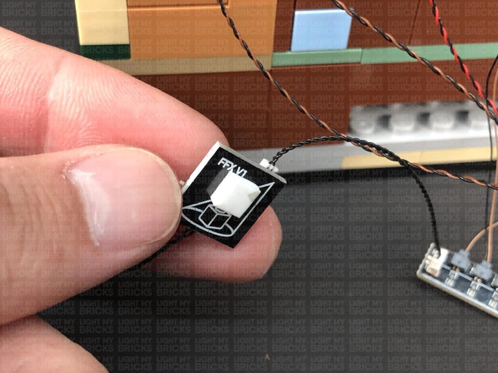
- 1x 15cm Connecting Cables
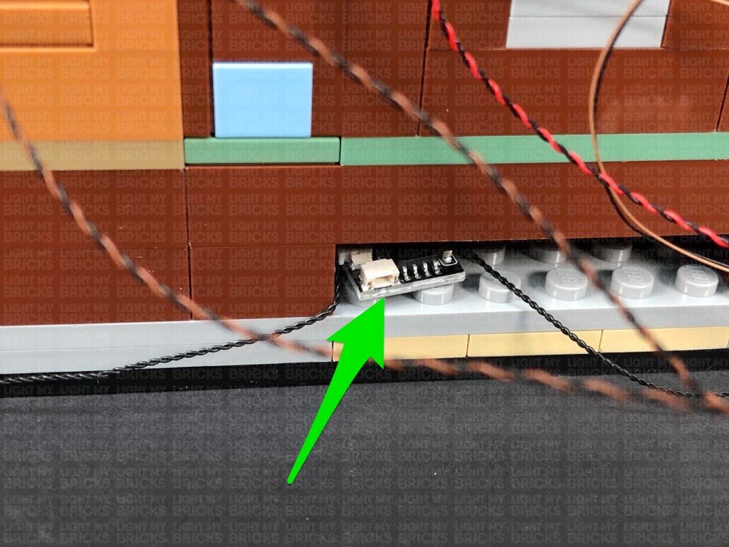
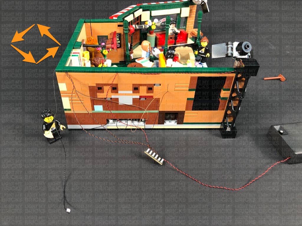
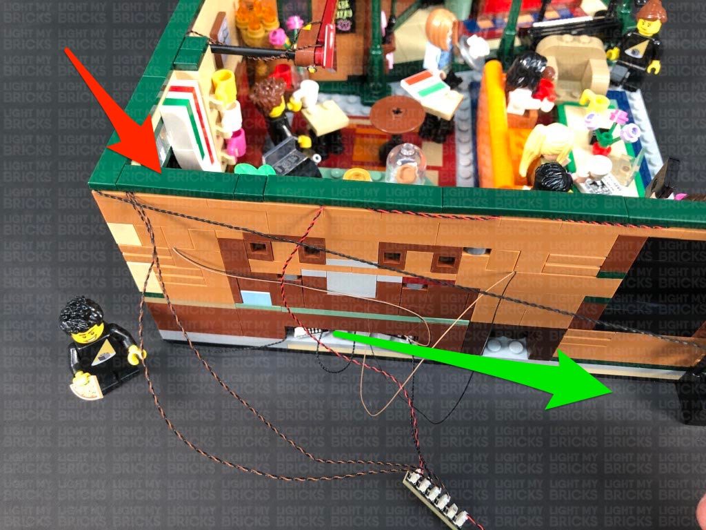
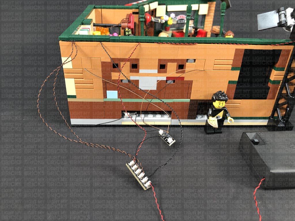
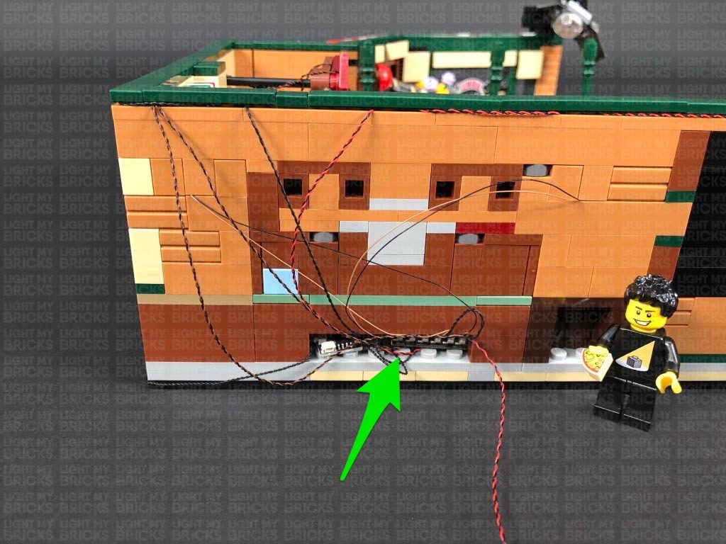
- 1x 50cm Connecting Cable
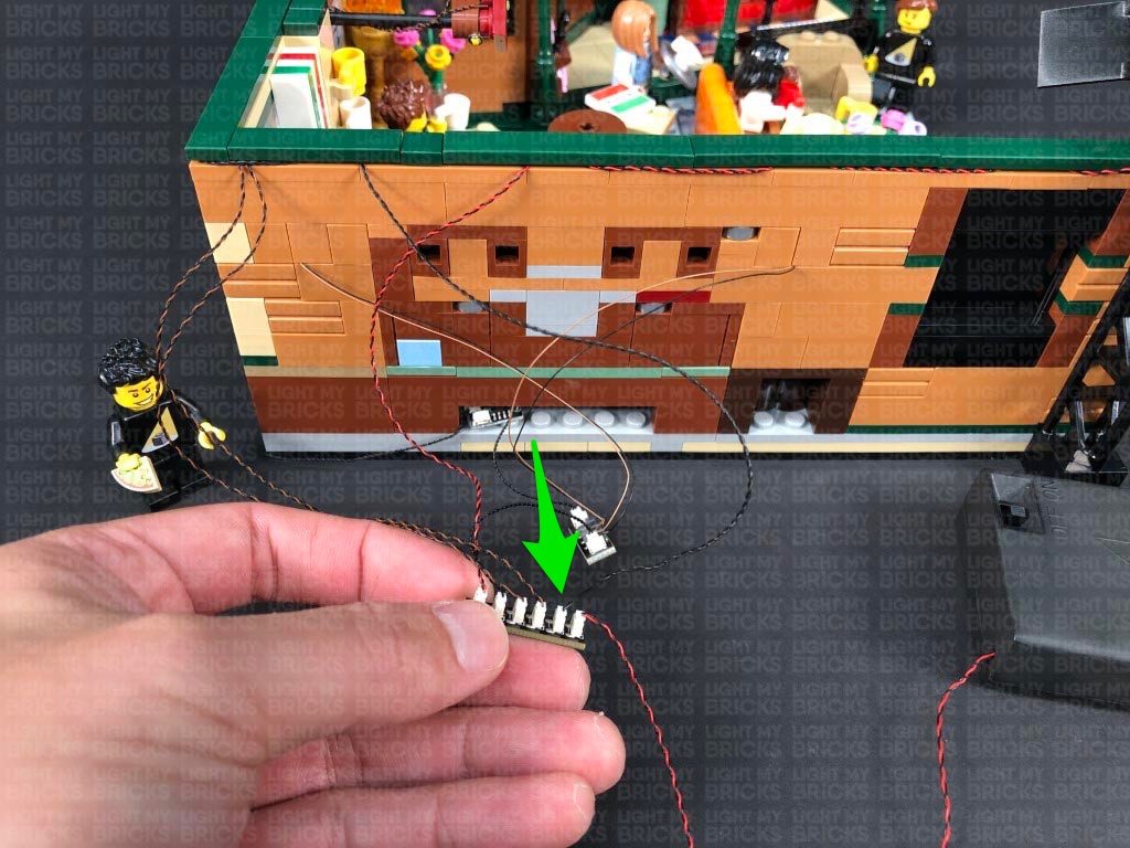
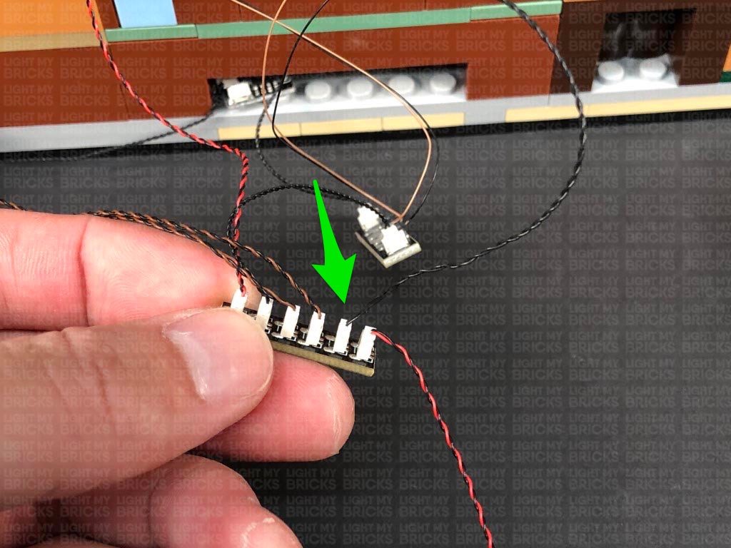
- 1x AA Battery Pack (requires 3x AA Batteries)
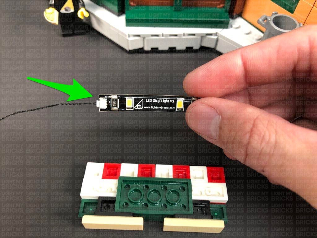
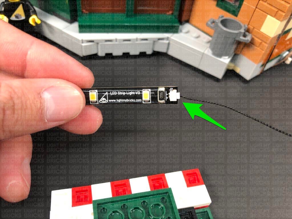
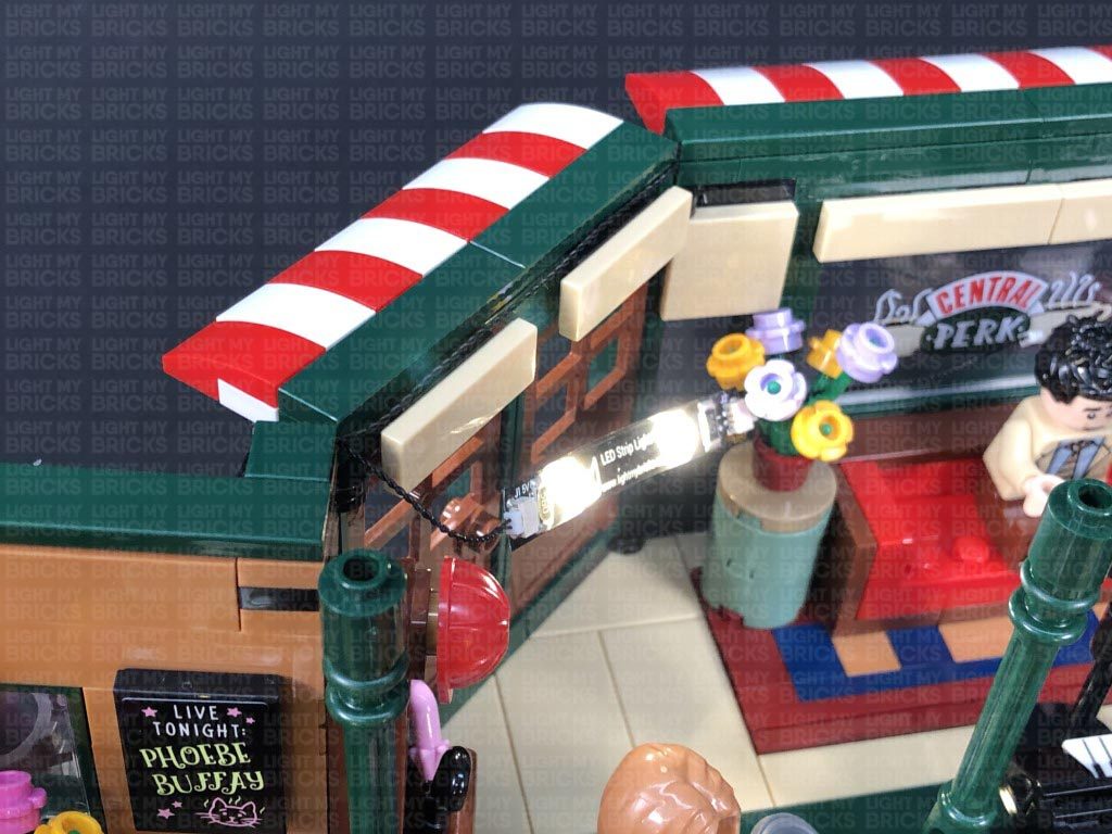
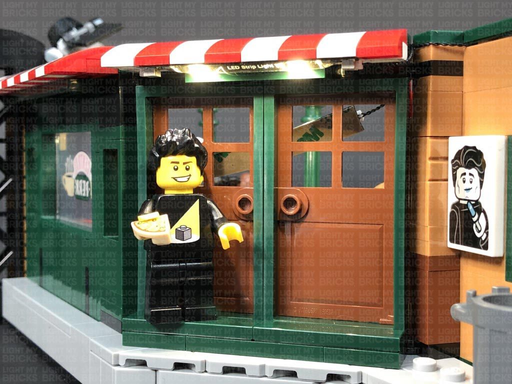
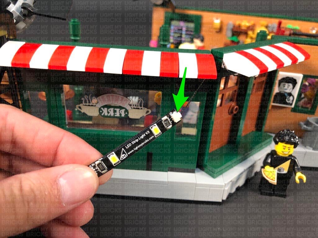
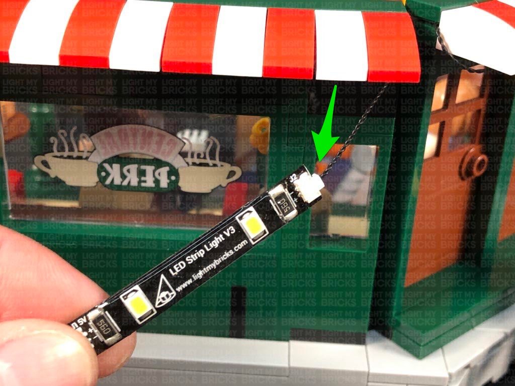
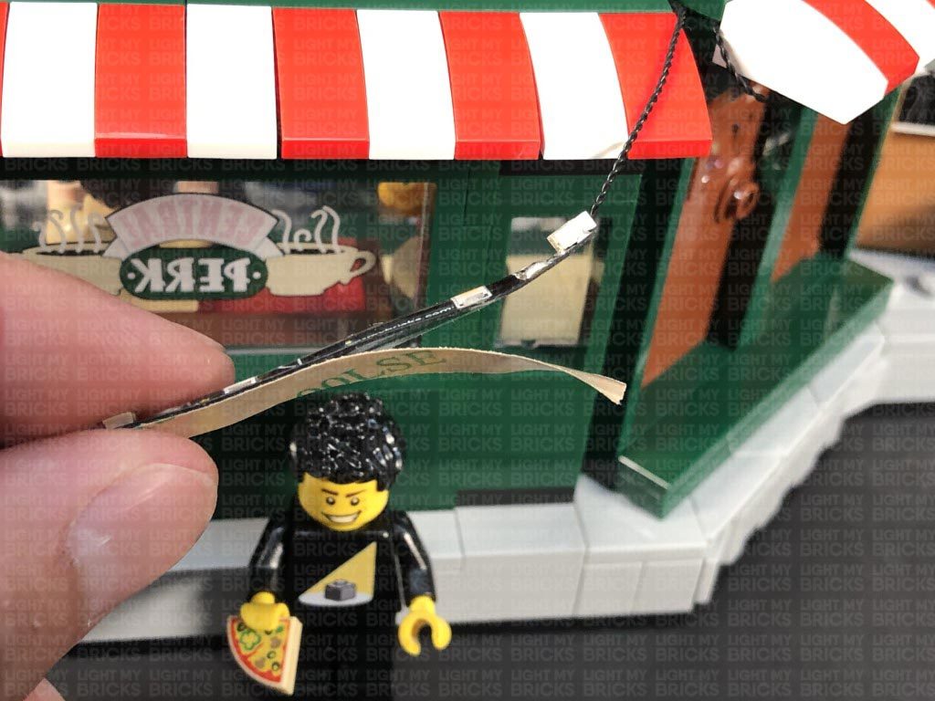
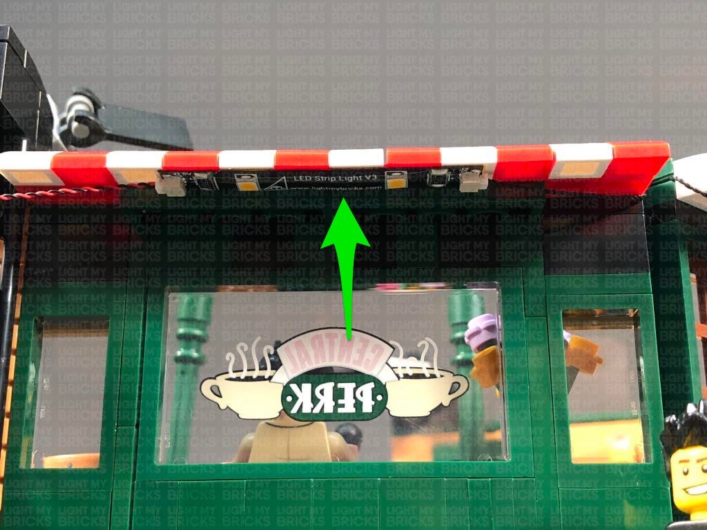
- 6x Adhesive Squares
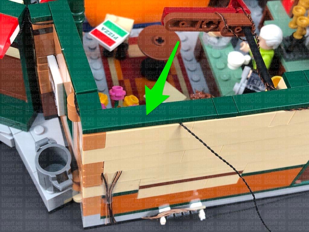
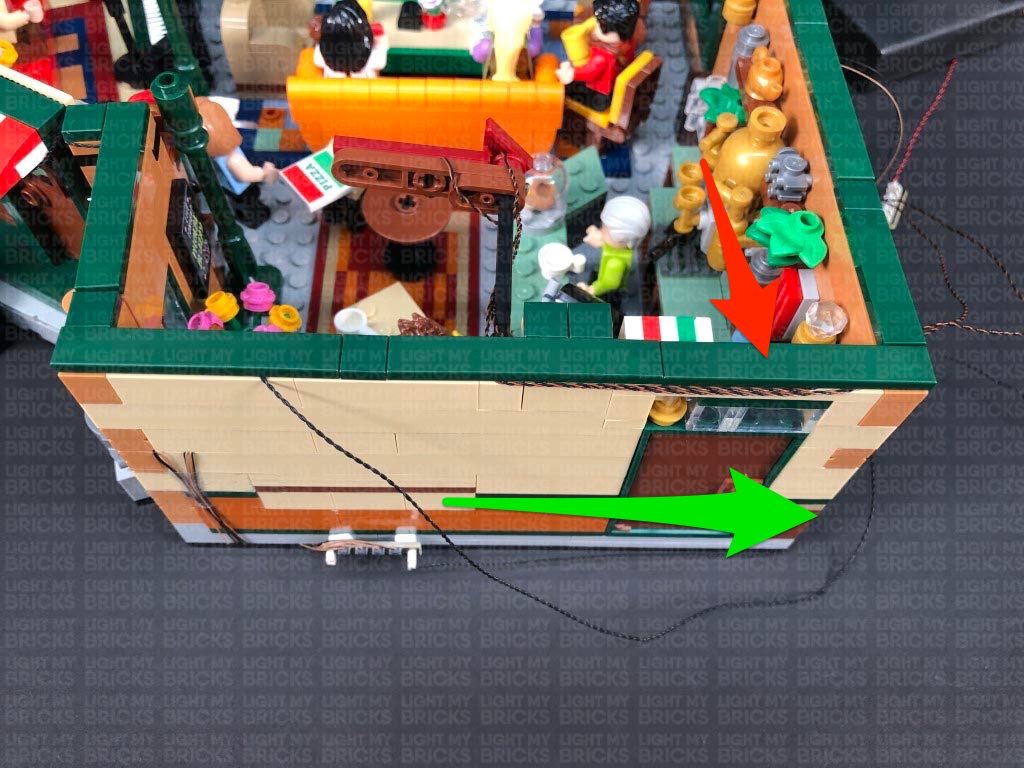
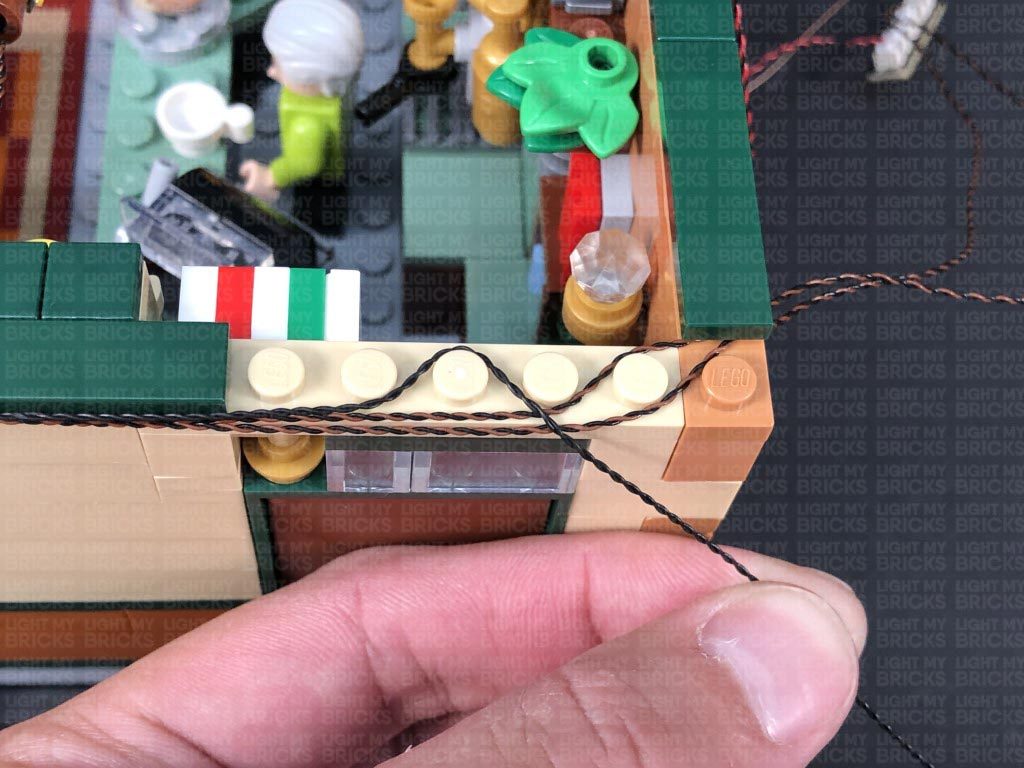
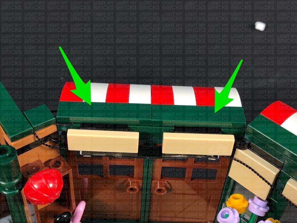
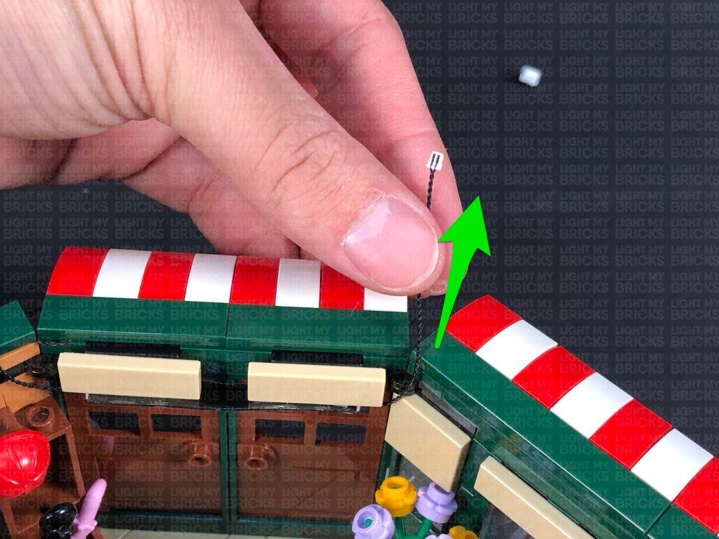
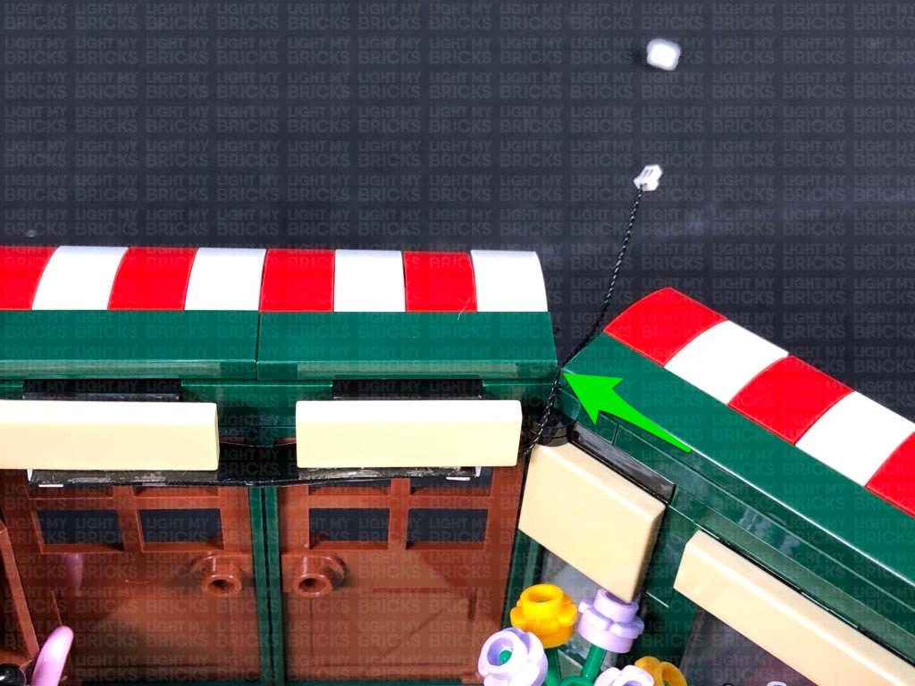
Important things to note:
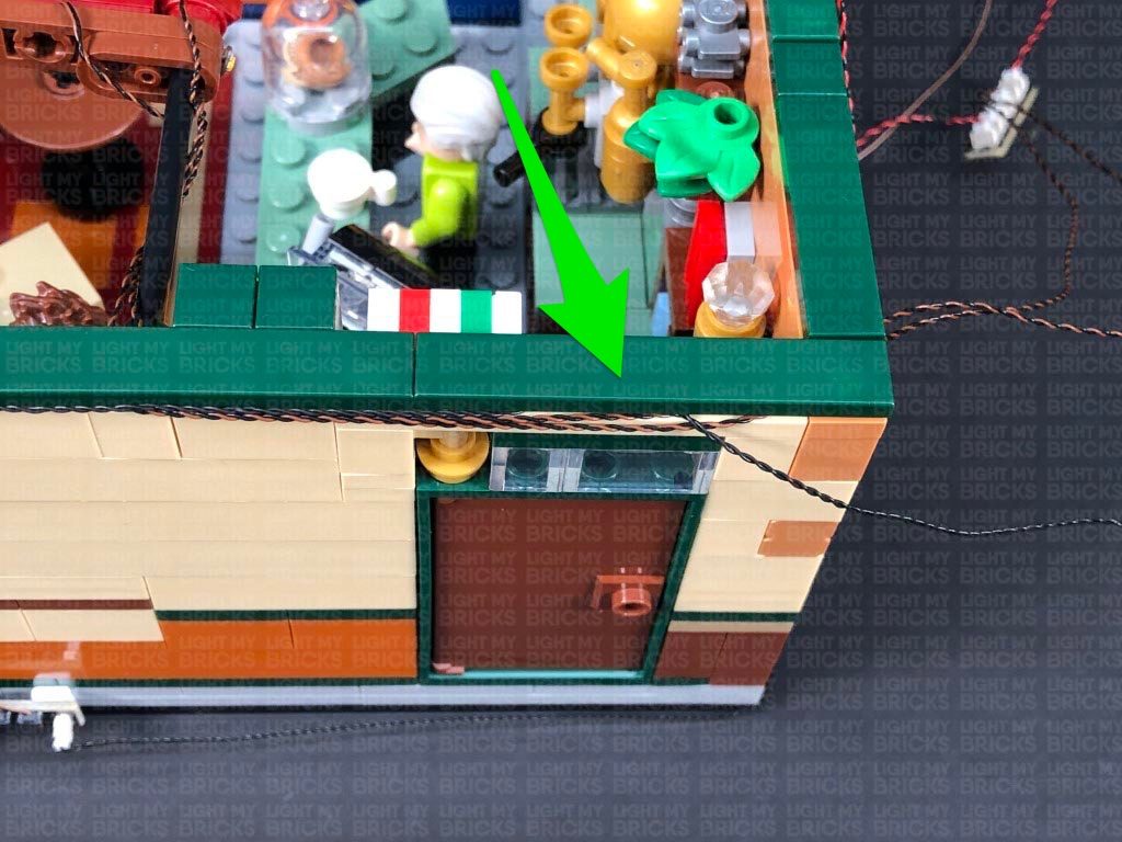
Laying cables in between and underneath bricks
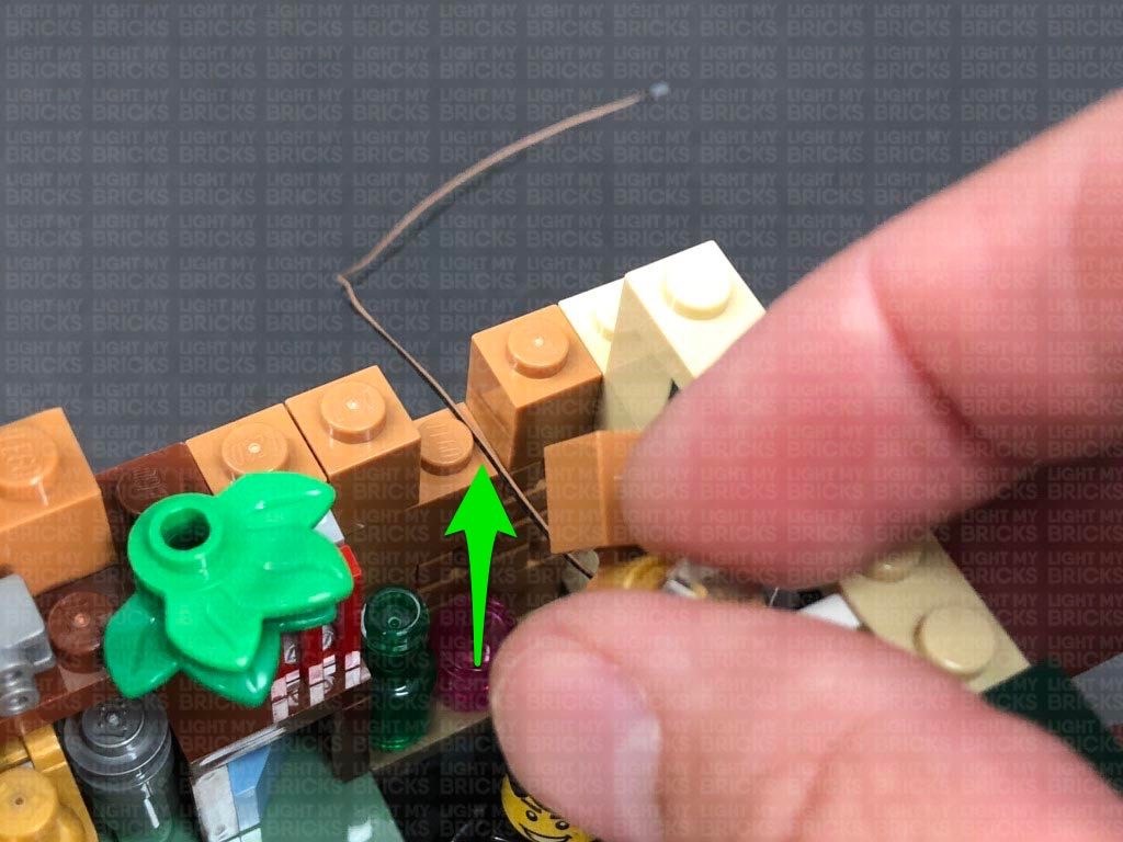
Cables can fit in between and underneath LEGO® bricks, plates, and tiles providing they are laid correctly between the LEGO® studs. Do NOT forcefully join LEGO® together around cables; instead ensure they are laying comfortably in between each stud.
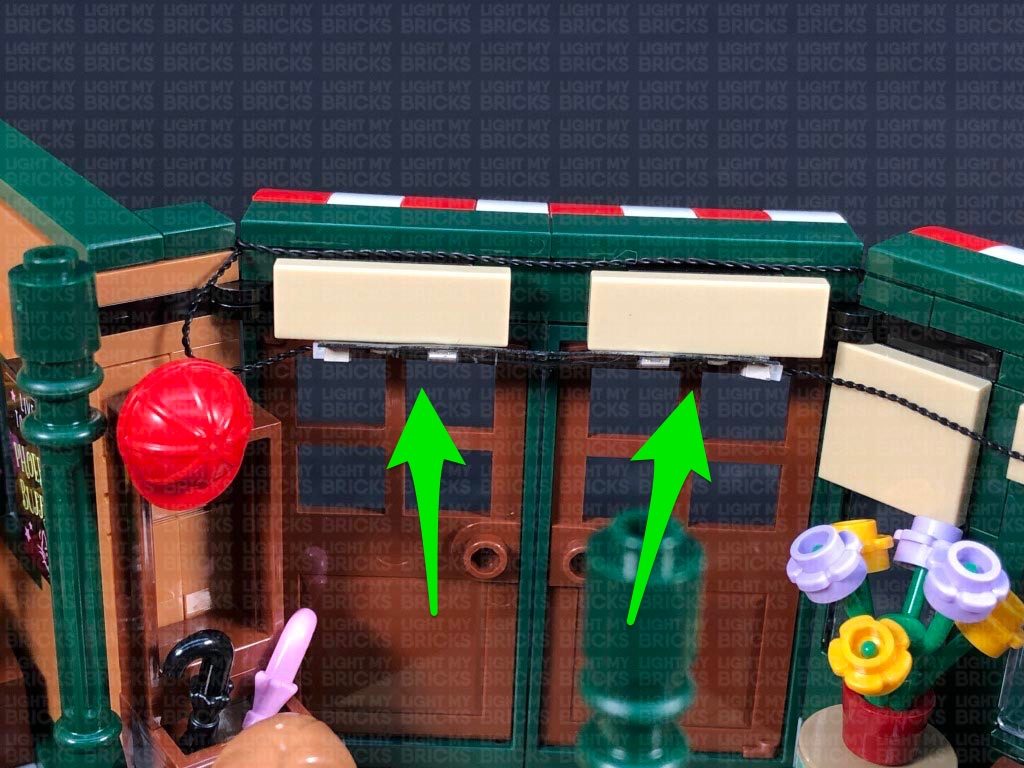
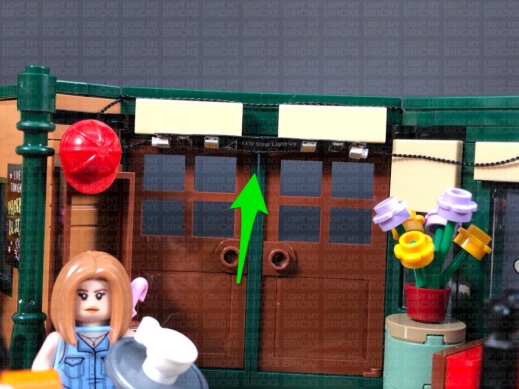
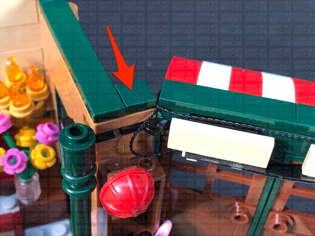
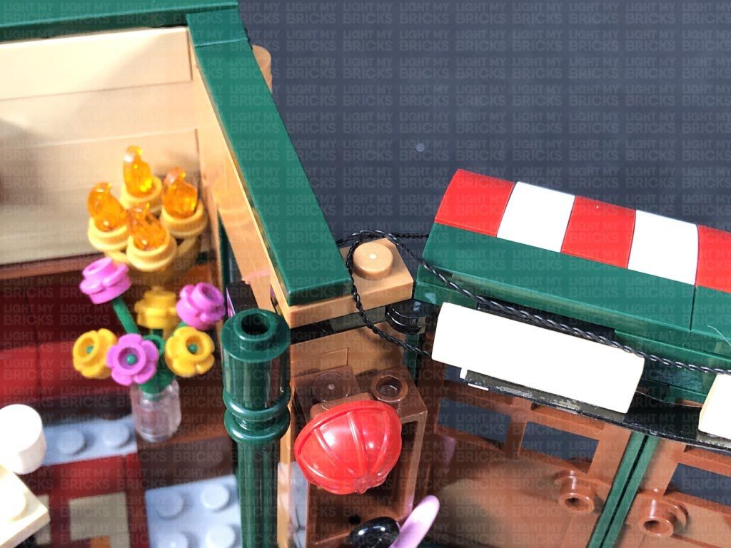
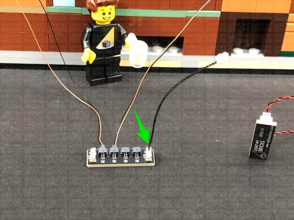
Connecting cable connectors to Expansion Boards
Take extra care when inserting connectors to ports of Expansion Boards. Connectors can be inserted only one way. With the expansion board facing up, look for the soldered “=” symbol on the left side of the port. The connector side with the wires exposed should be facing toward the soldered “=” symbol as you insert into the port. If a plug won’t fit easily into a port connector, do not force it.
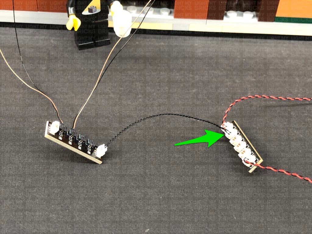
Connecting cable connectors to Strip Lights
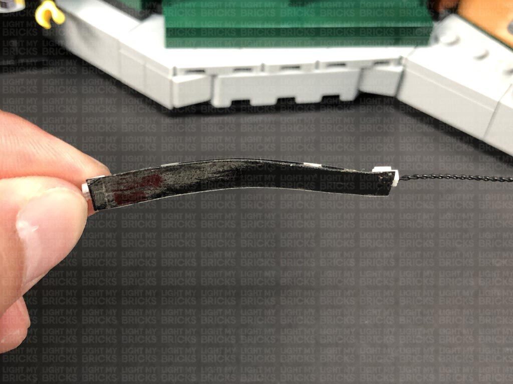
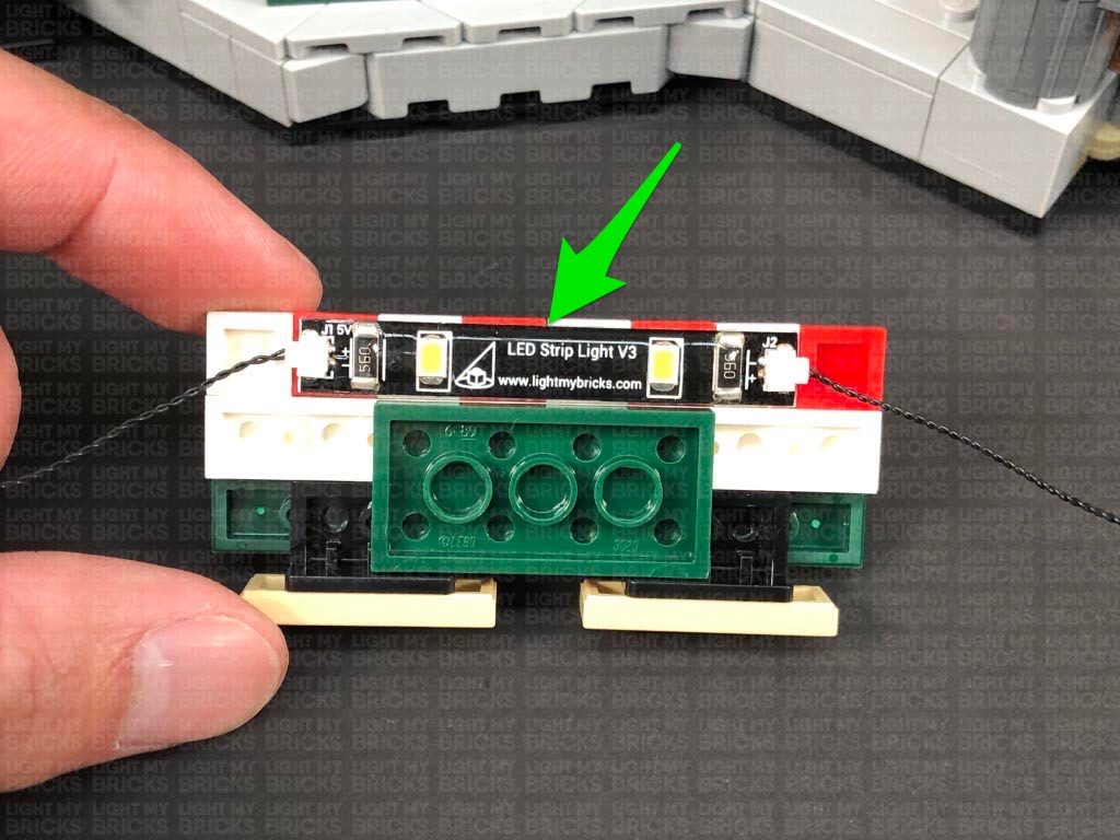
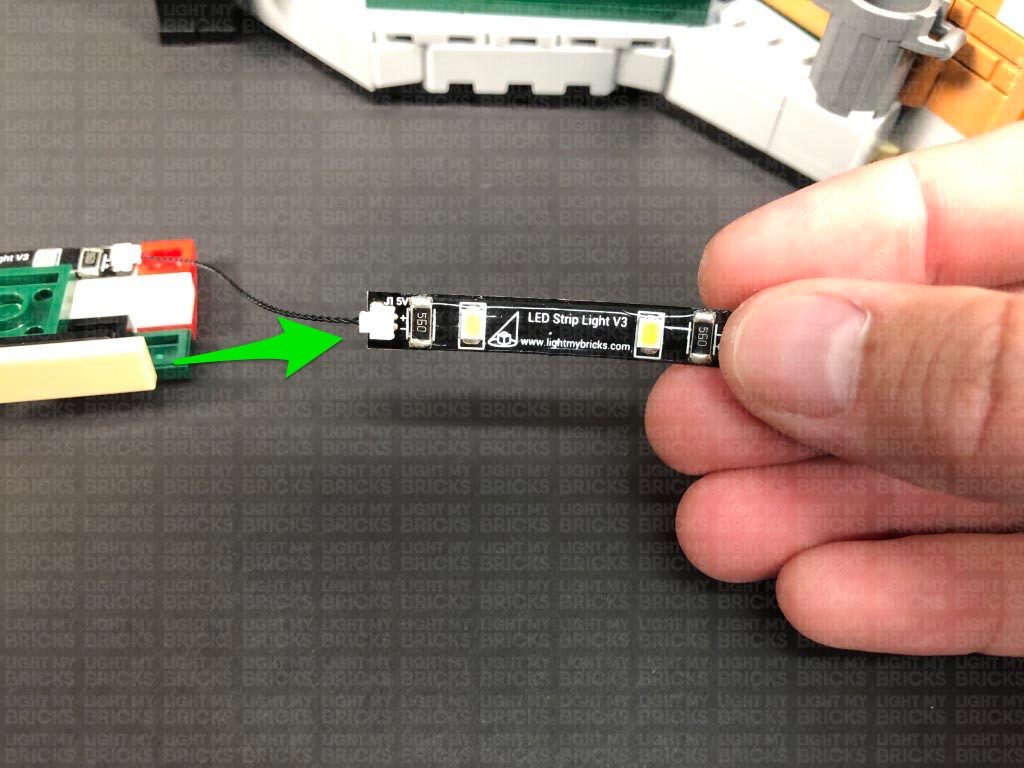
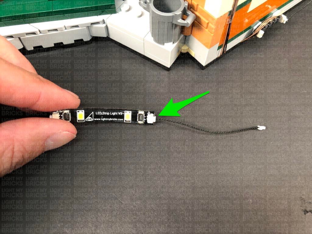
Take extra care when inserting connectors to ports on the Strip Lights. Connectors can be inserted only one way. With the Strip Light facing up, ensure the side of the connector with the wires exposed is facing down. If a plug won’t fit easily into a port connector, don’t force it. Doing so will damage the plug and the connector.
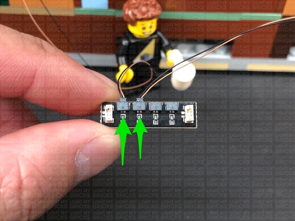
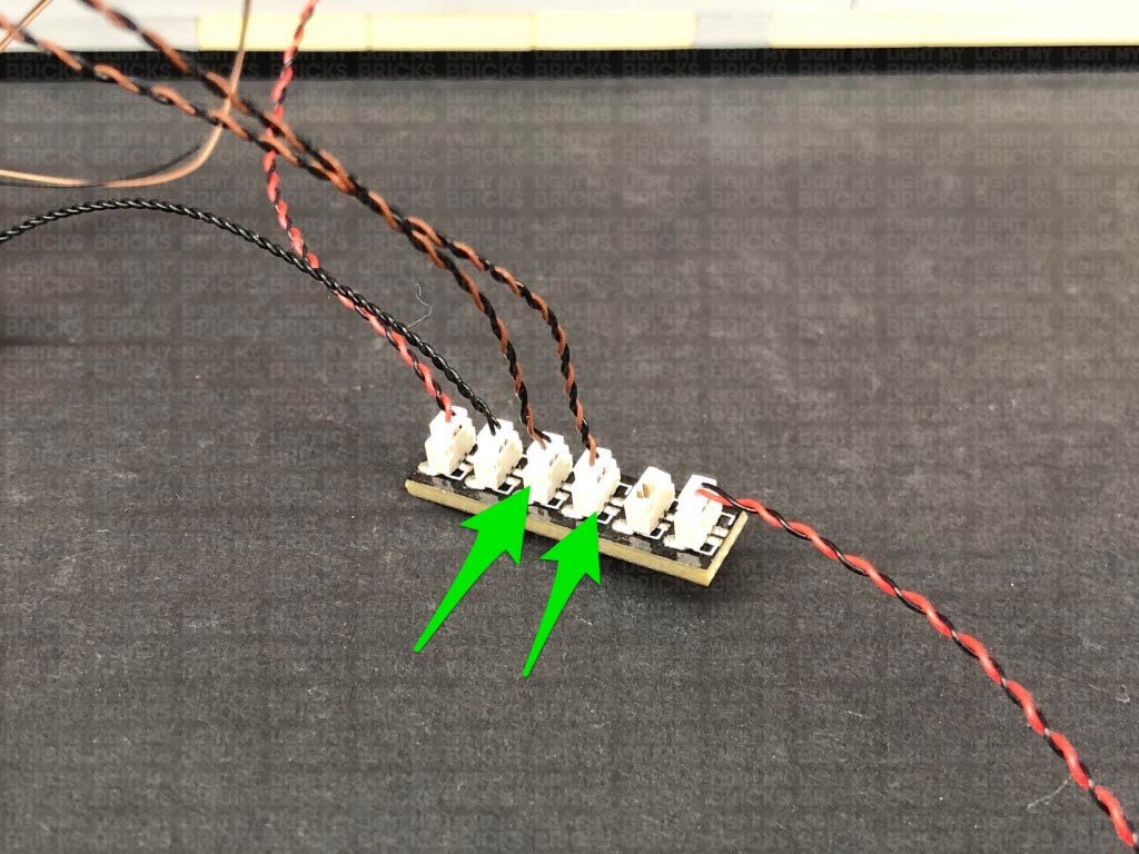
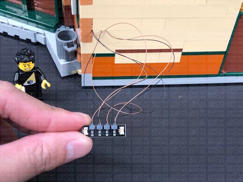
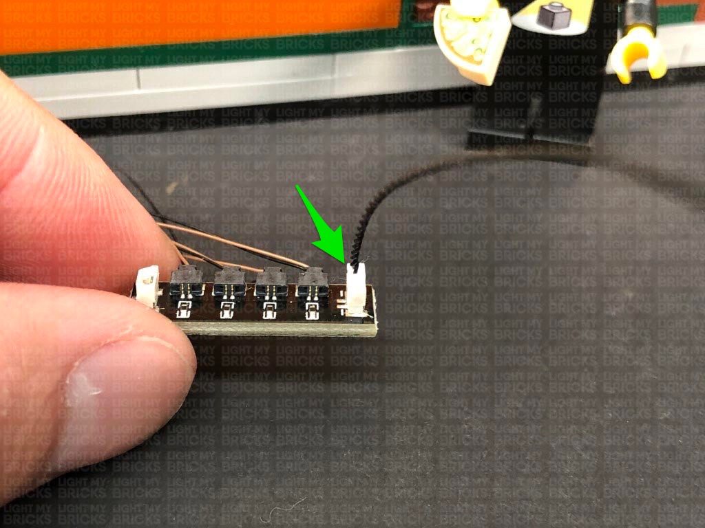
Connecting Micro Cable connectors to Micro Expansion Board Ports
Take extra care when inserting the micro connectors to micro ports of Micro Expansion Boards. Connecting Micro Bit Lights to Micro Expansion Boards is similar to connecting lights and cables to Strip Lights. With the expansion board facing up, ensure the side of the connector with the wires exposed is facing down. If a plug won’t fit easily into a port connector, do not force it. Use your fingernail to push the plastic part of the connector to the micro port.
Installing Bit Lights under LEGO® bricks and plates.
When installing Bit Lights under LEGO® pieces, ensure they are placed the correct way up (Yellow LED component exposed). You can either place them directly on top of LEGO® studs or in between.
OK, Let’s Begin!
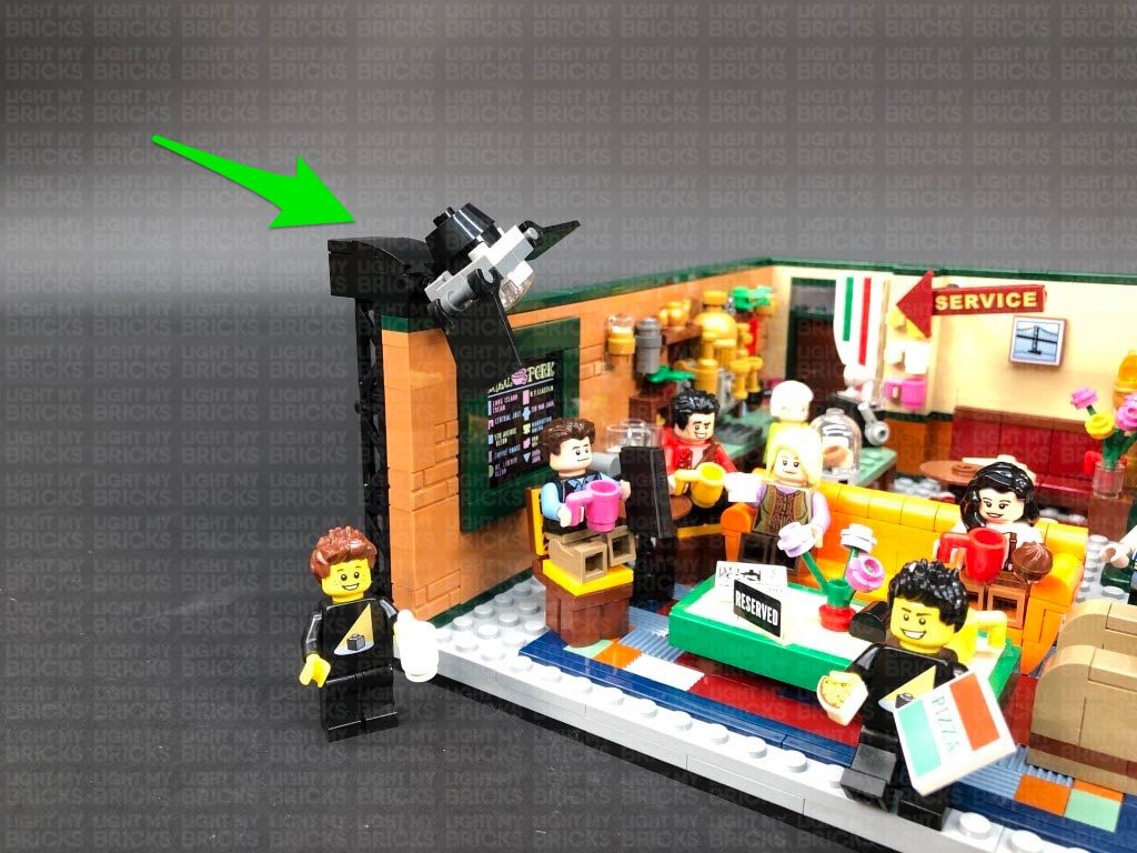
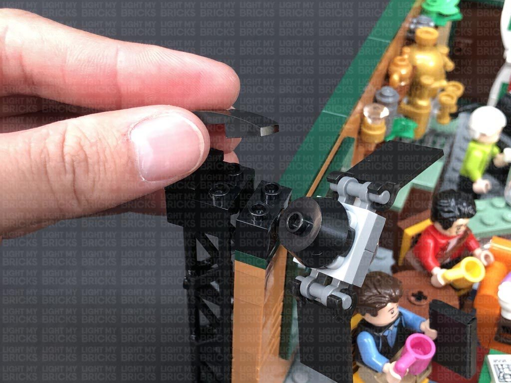
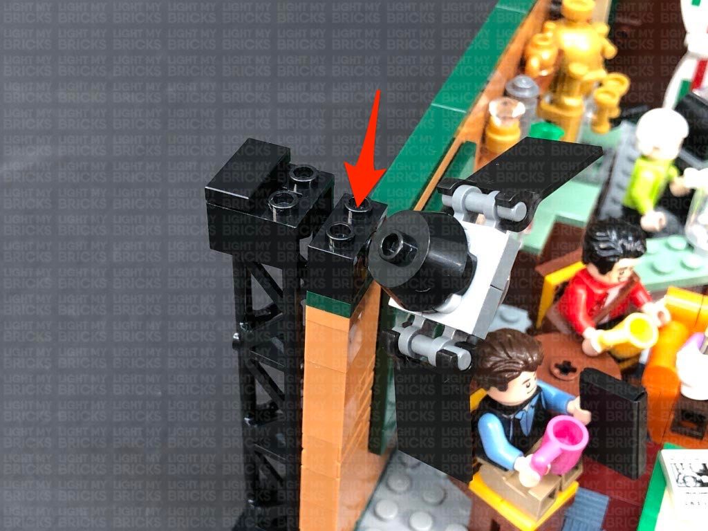
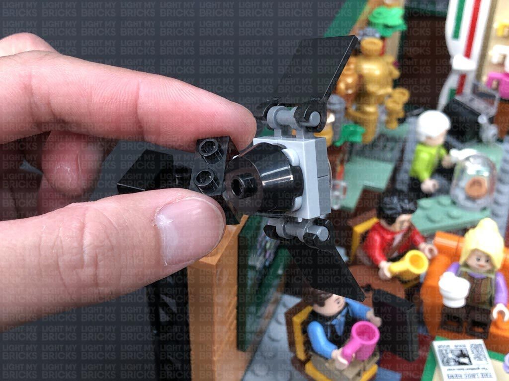
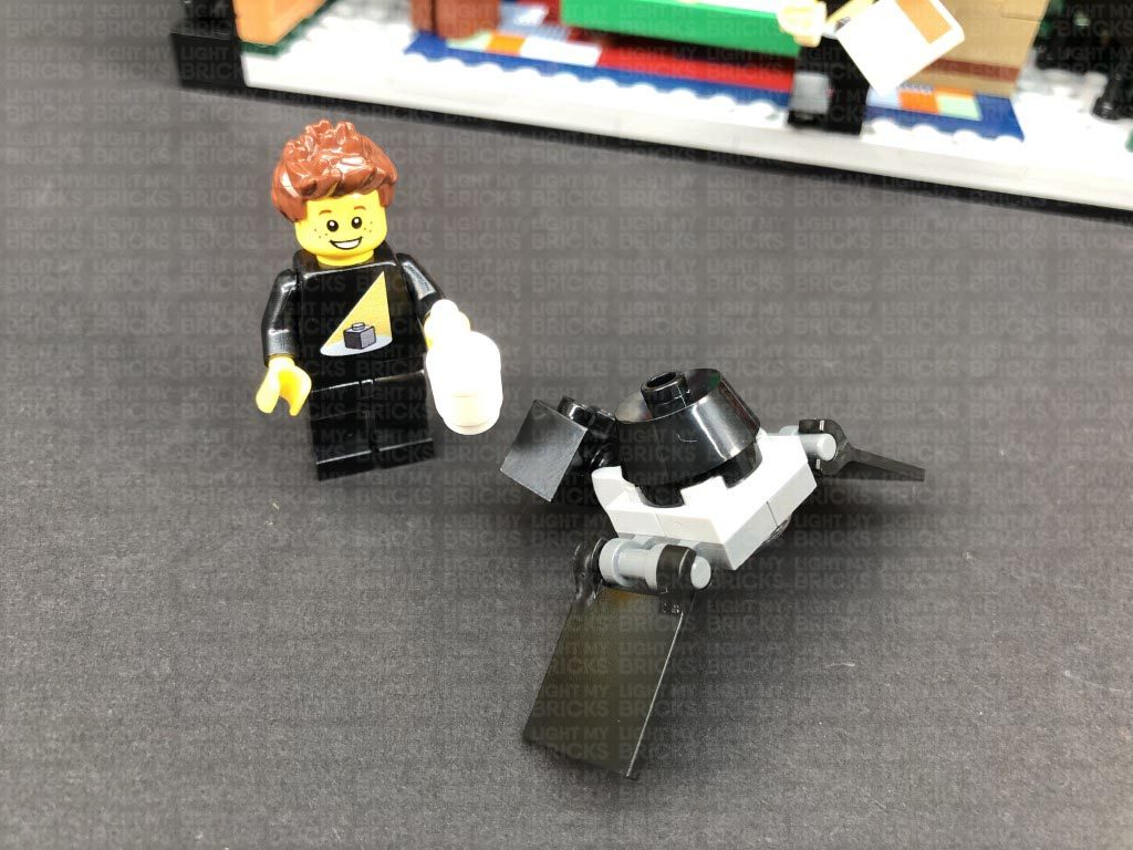
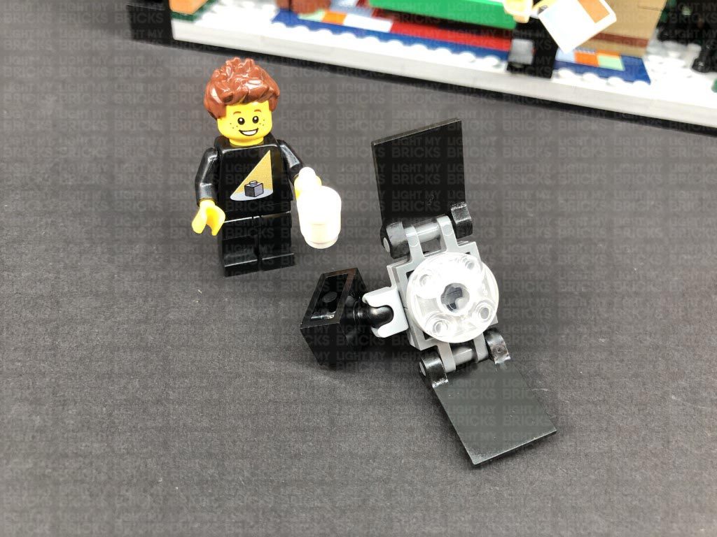
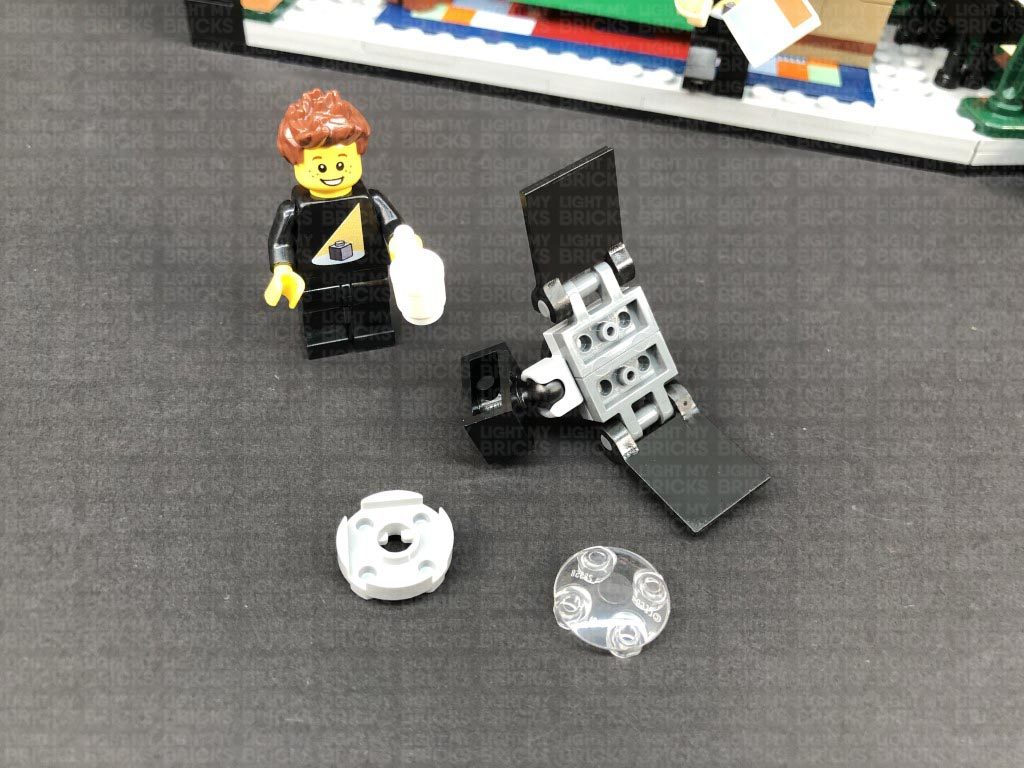
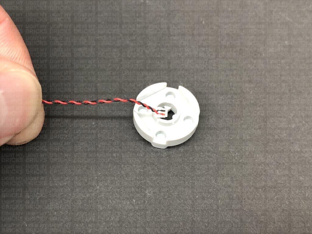
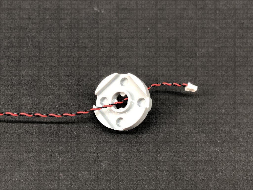
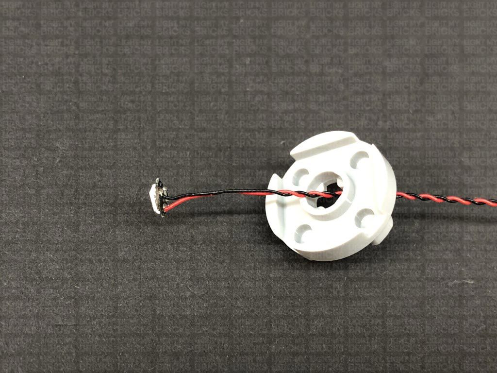
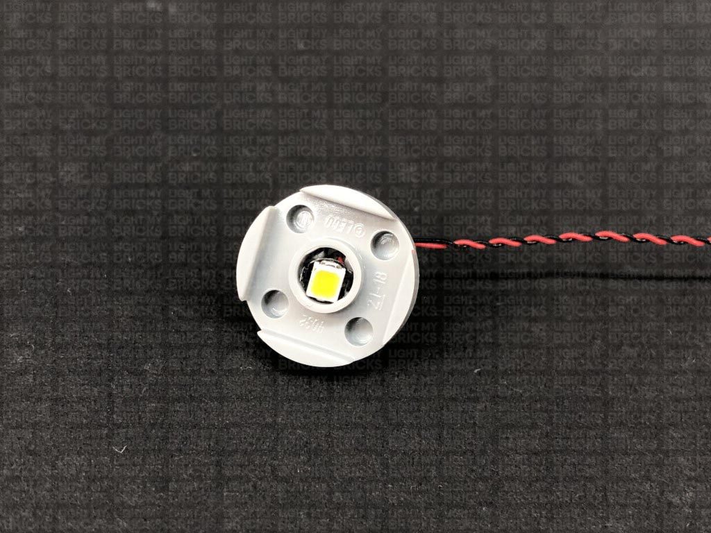
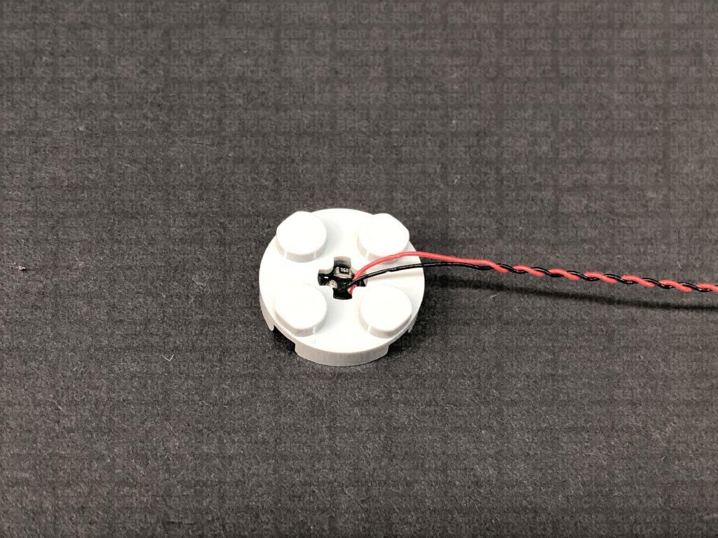
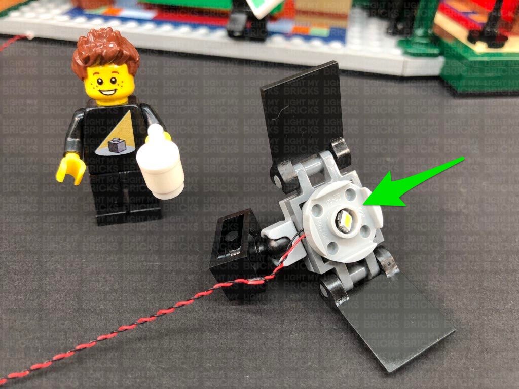
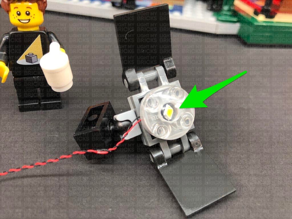
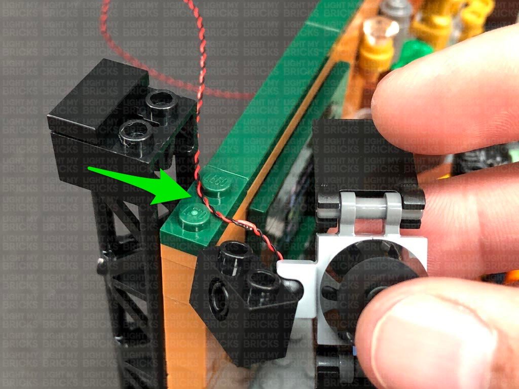
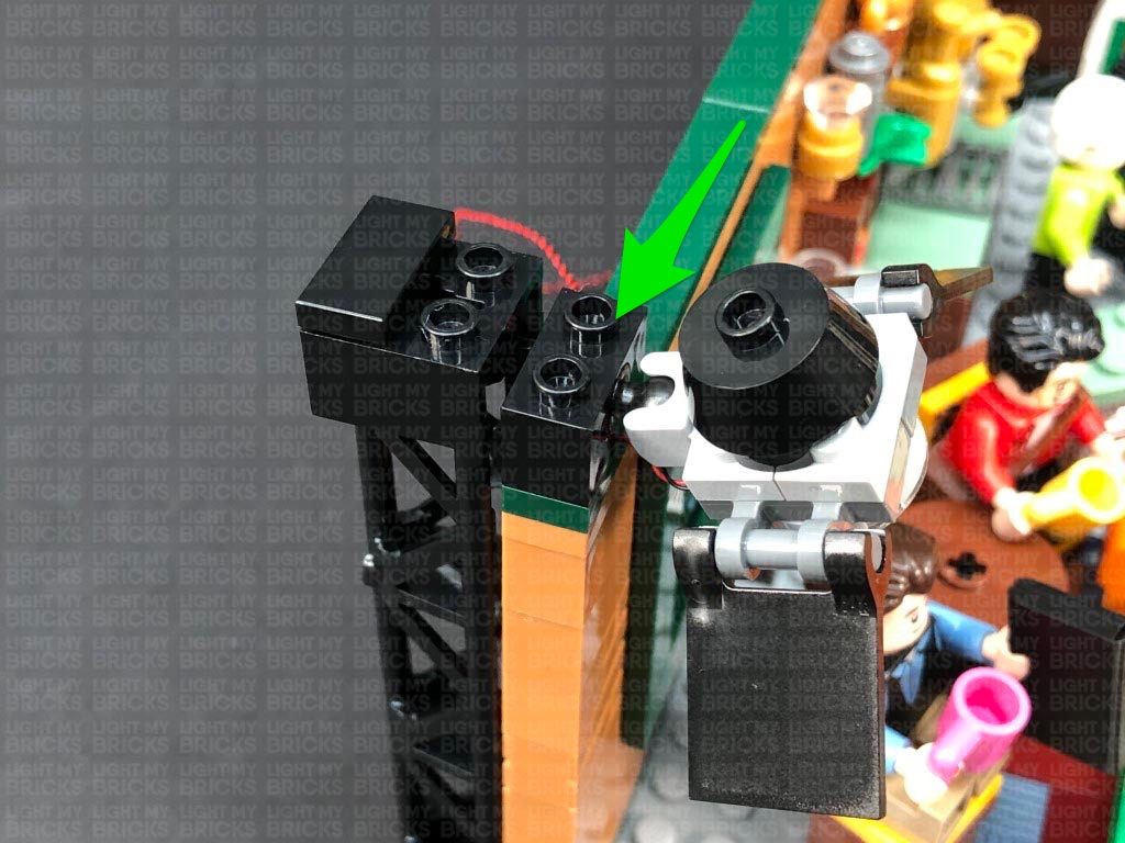
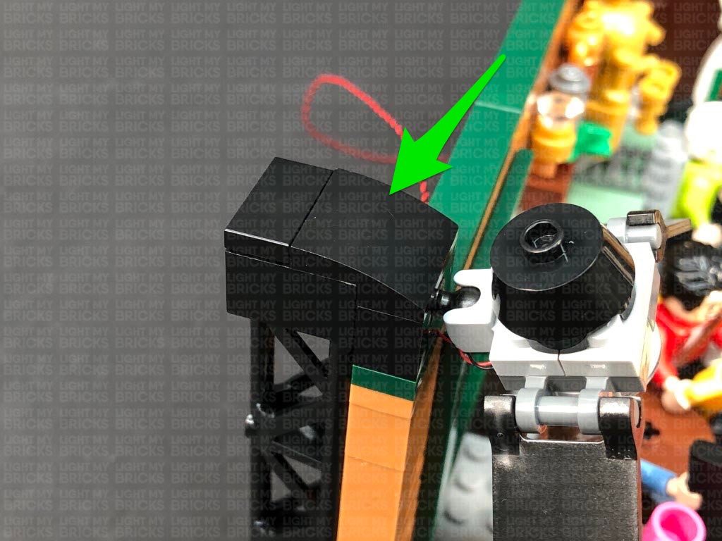
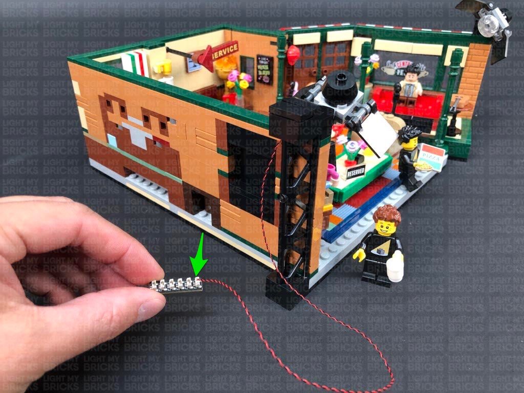
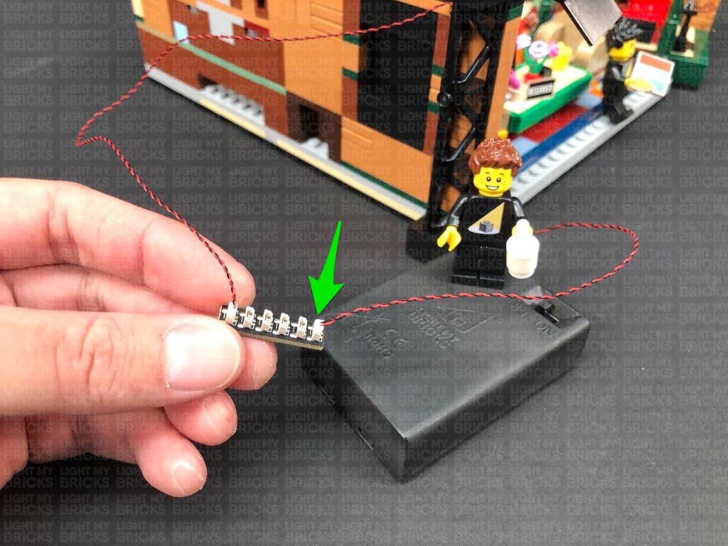
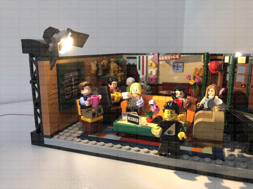
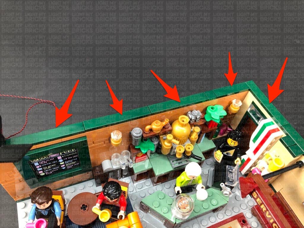
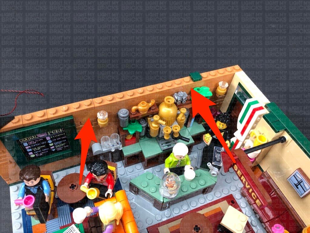
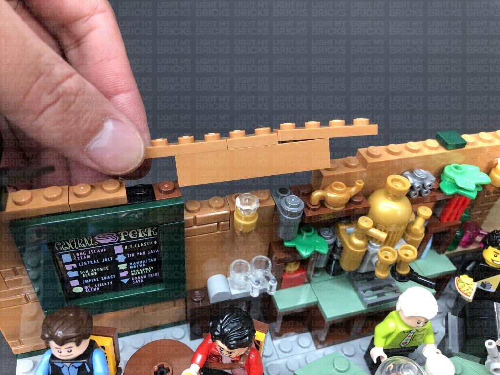
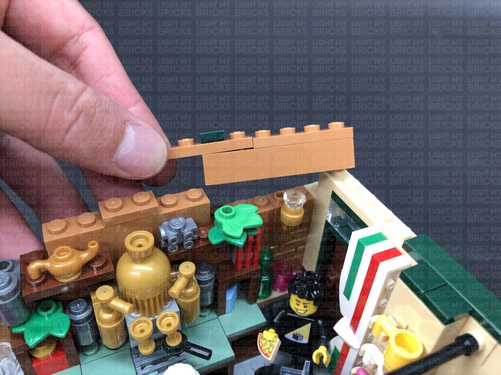
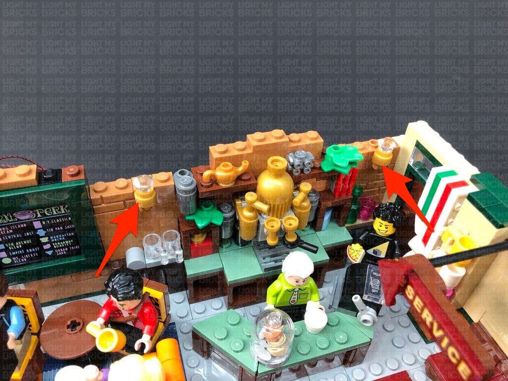
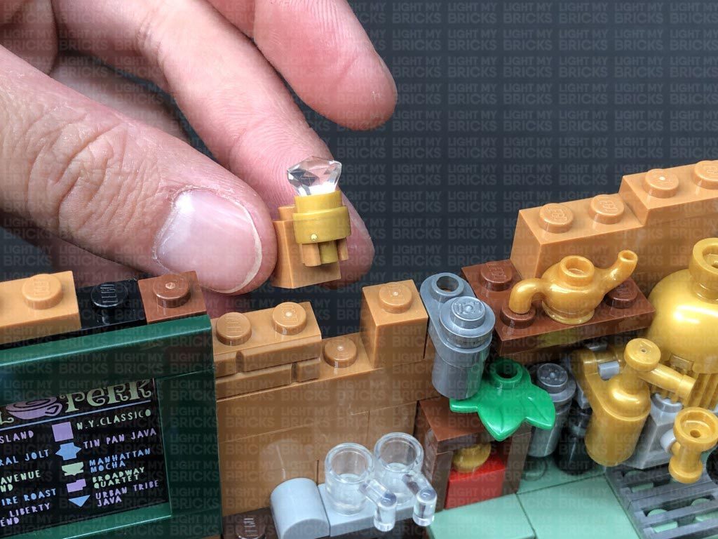
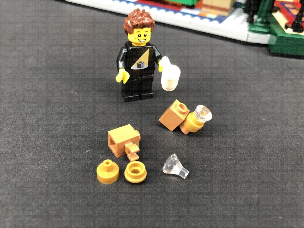
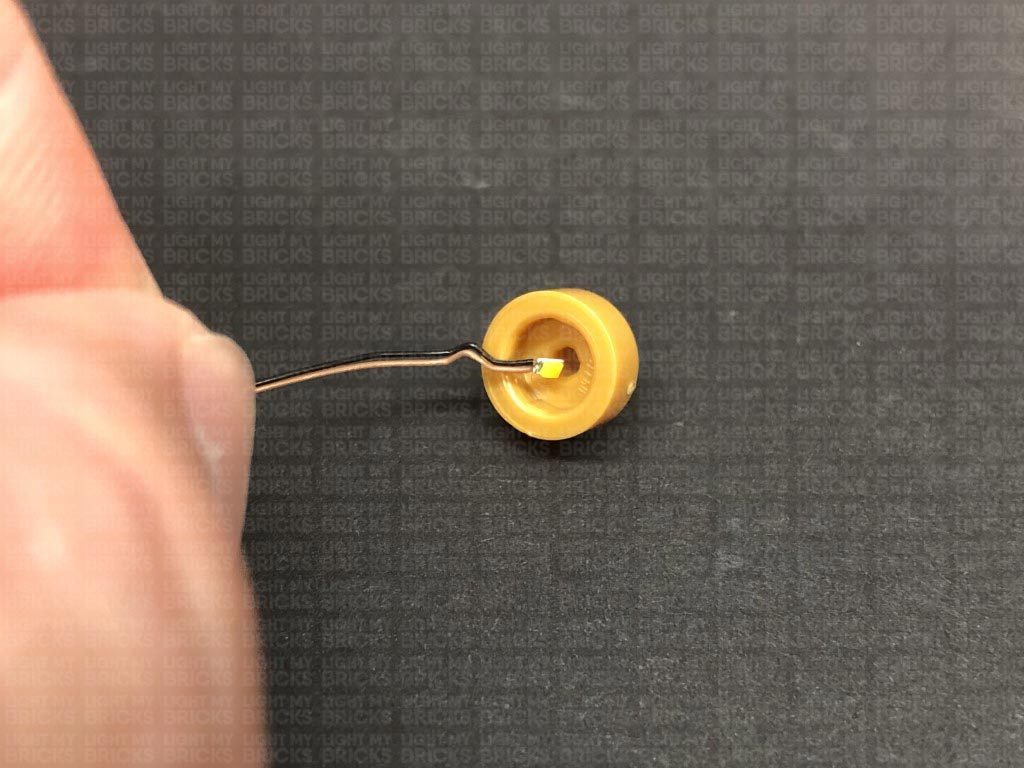
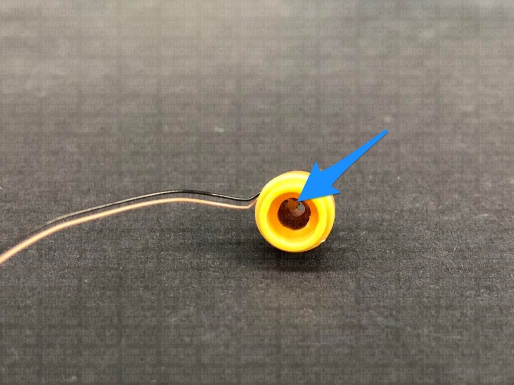
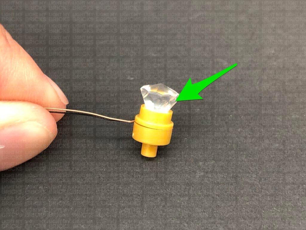
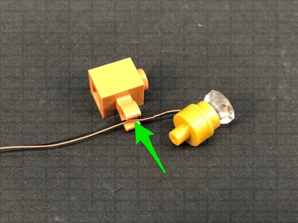
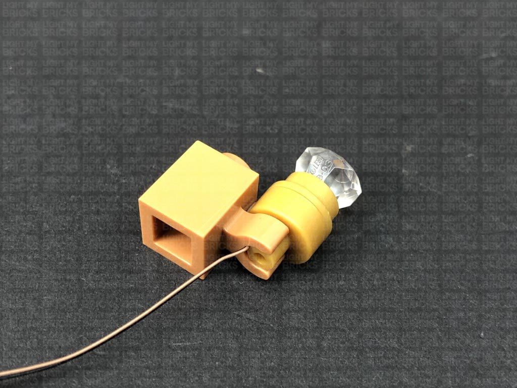
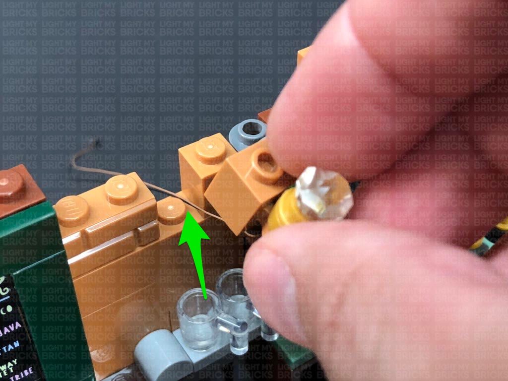
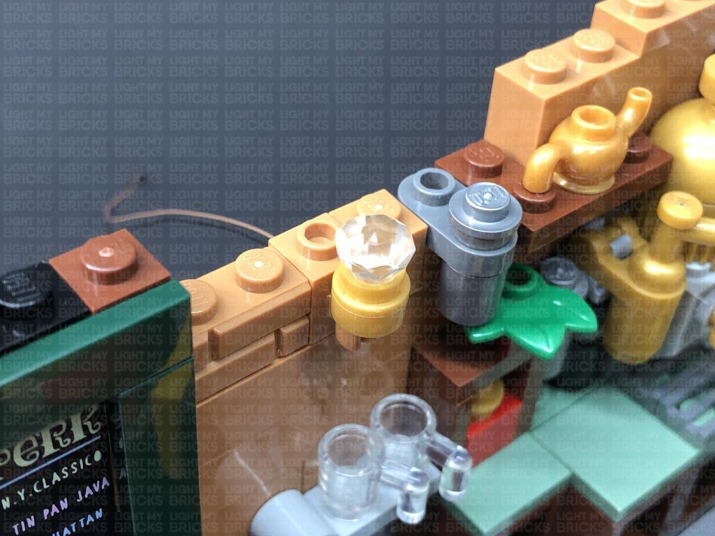
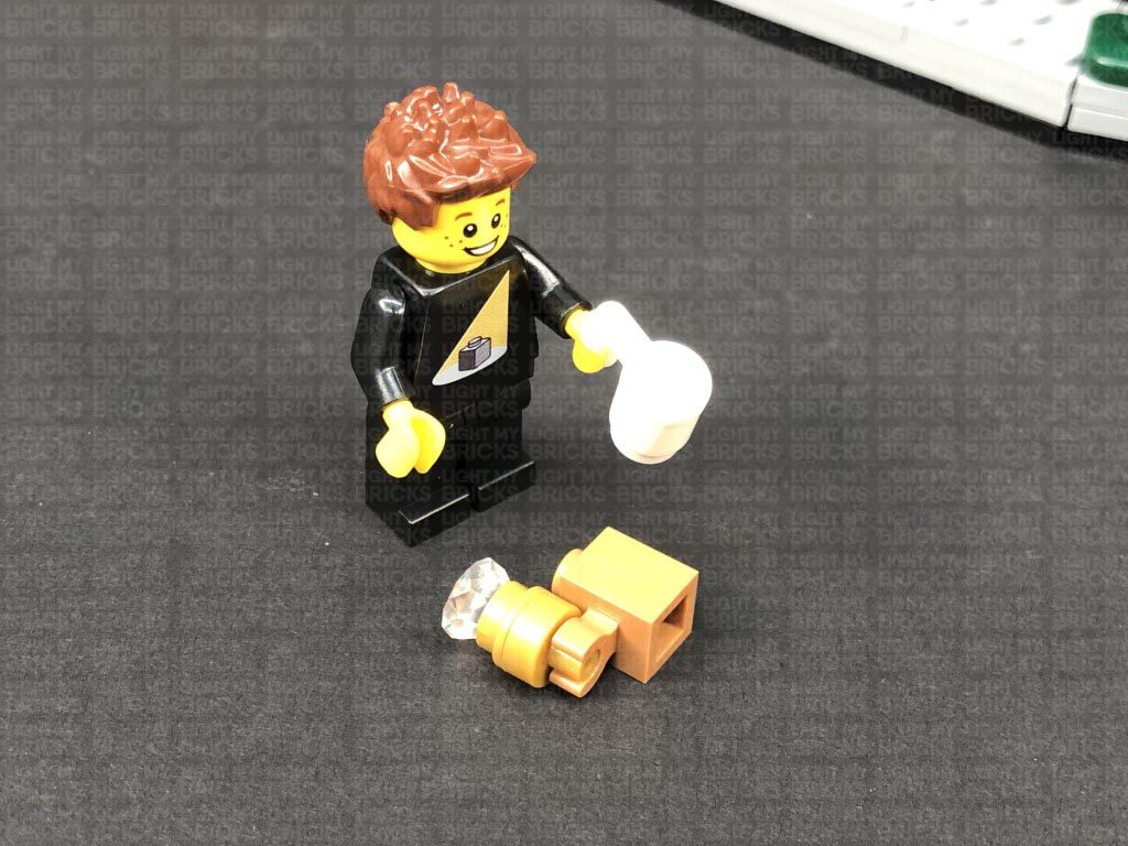
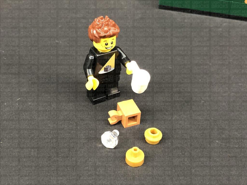
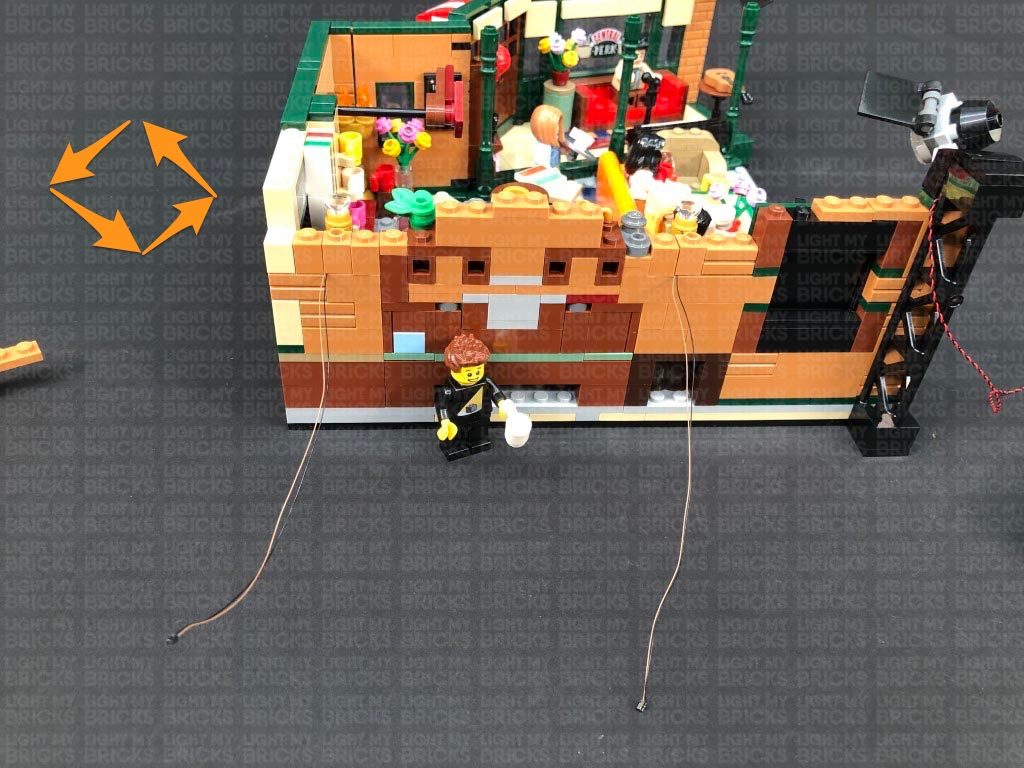
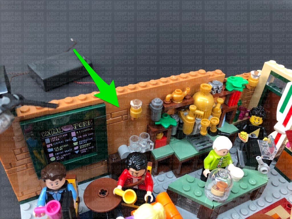
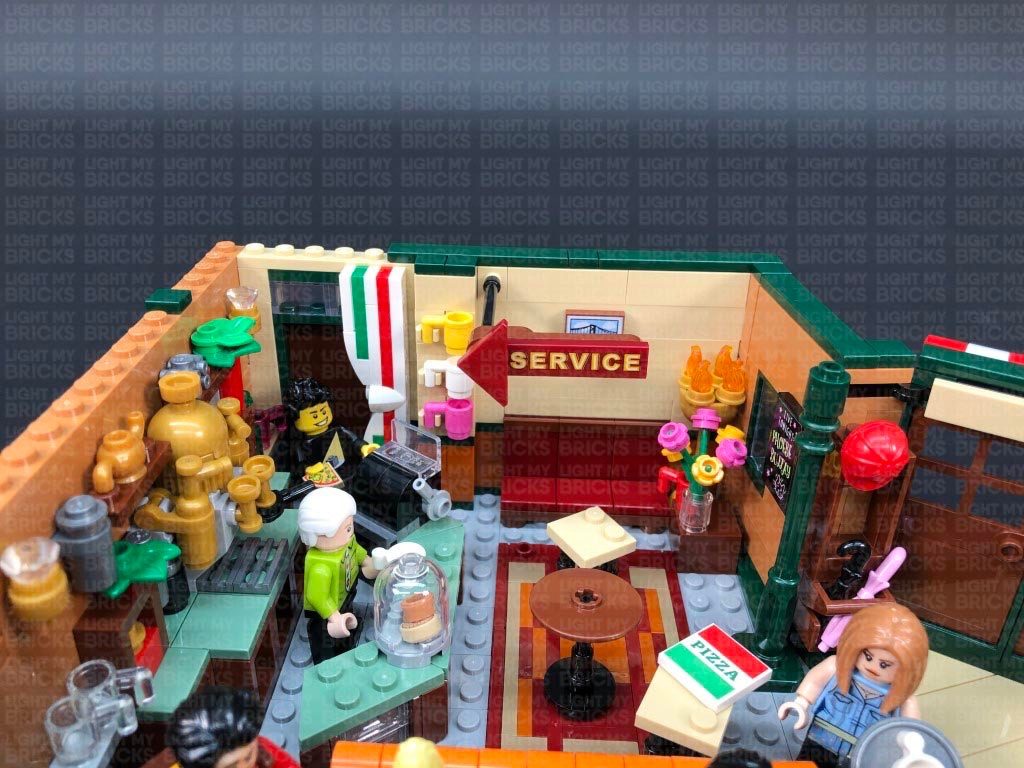
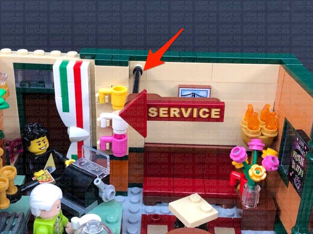
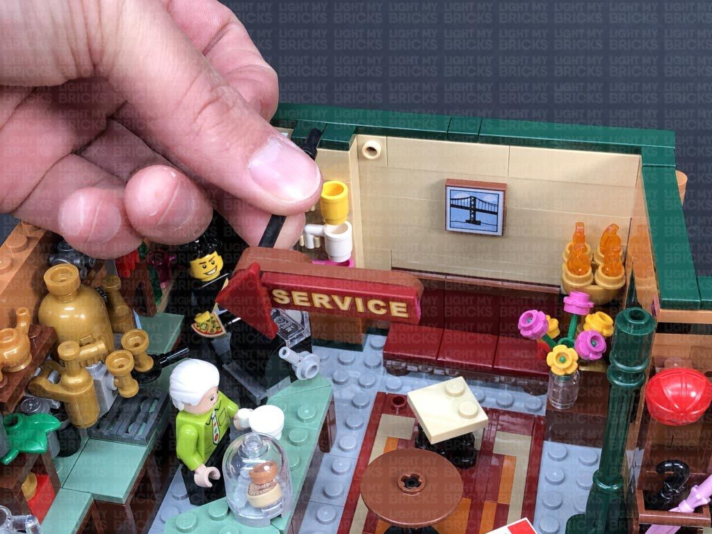
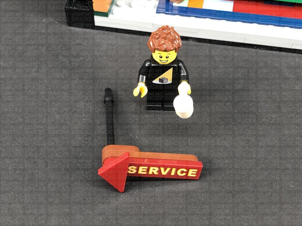
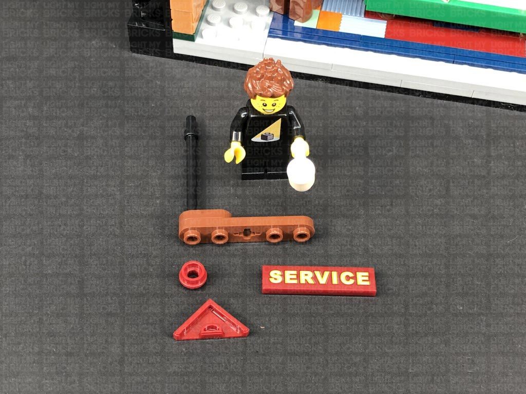
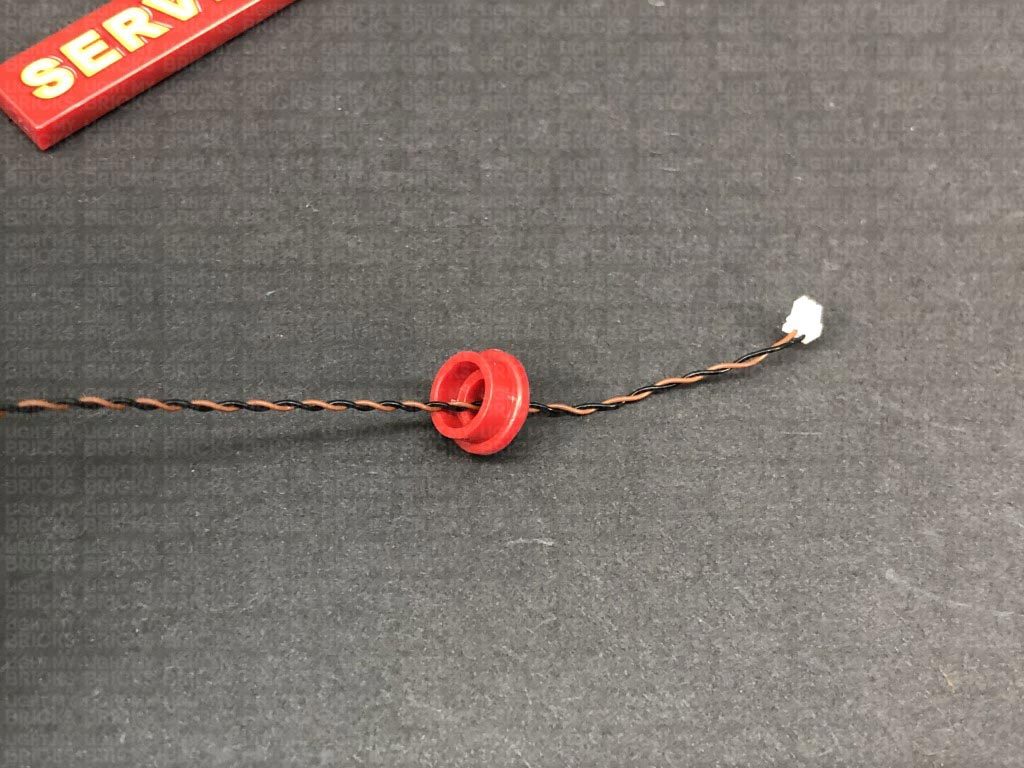
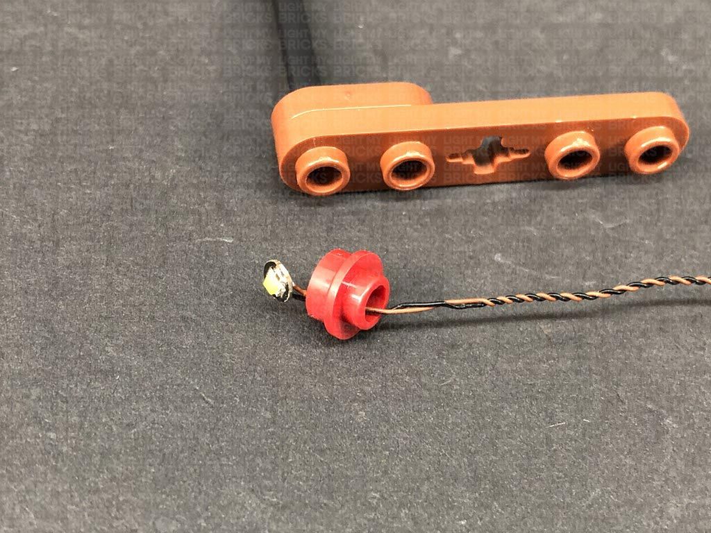
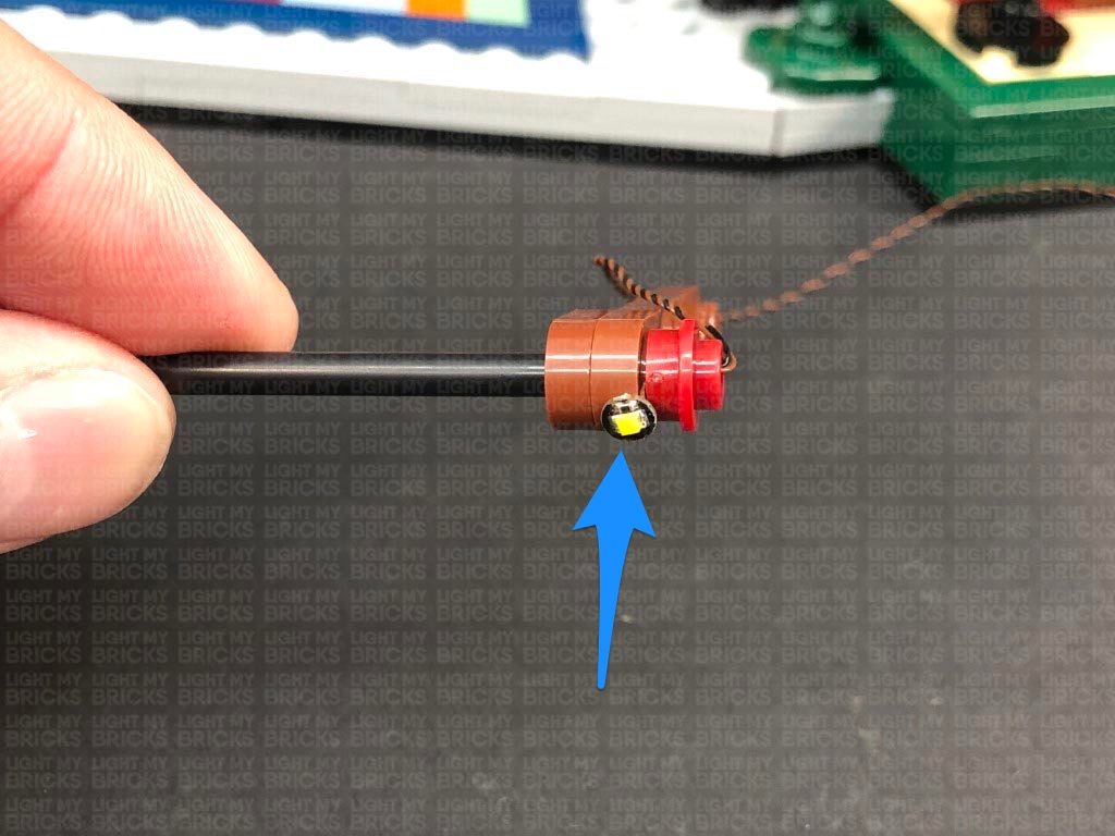
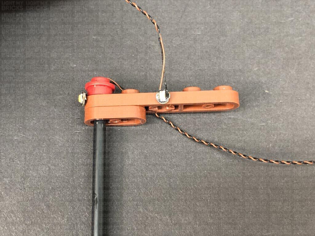
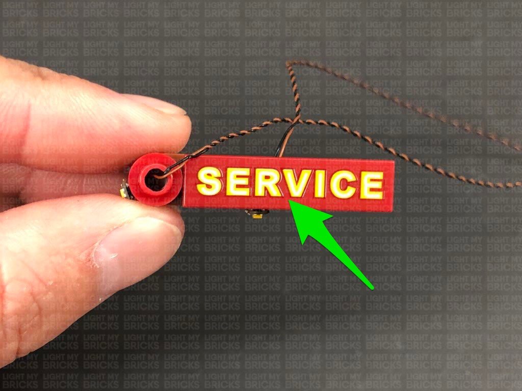
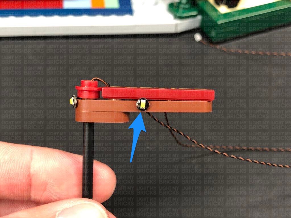
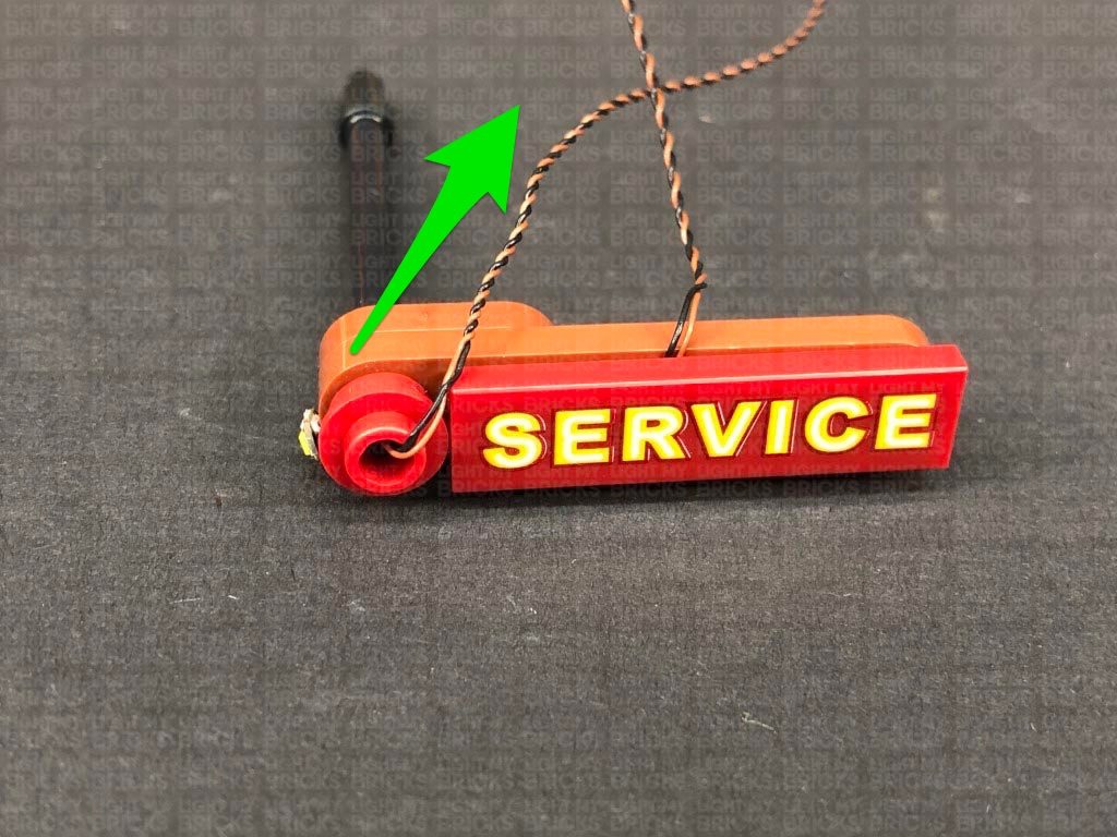
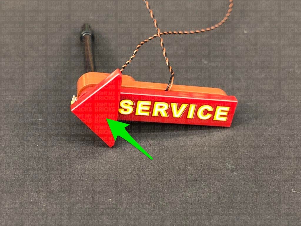
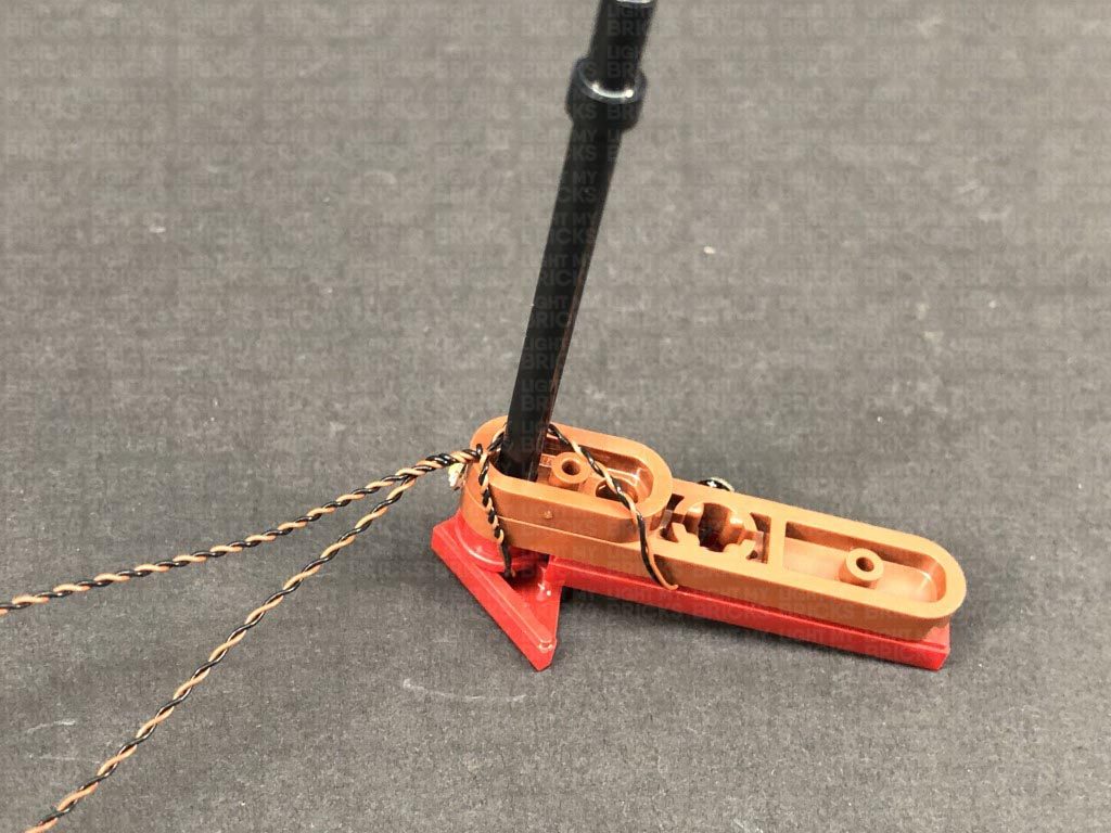
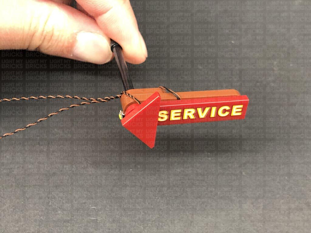
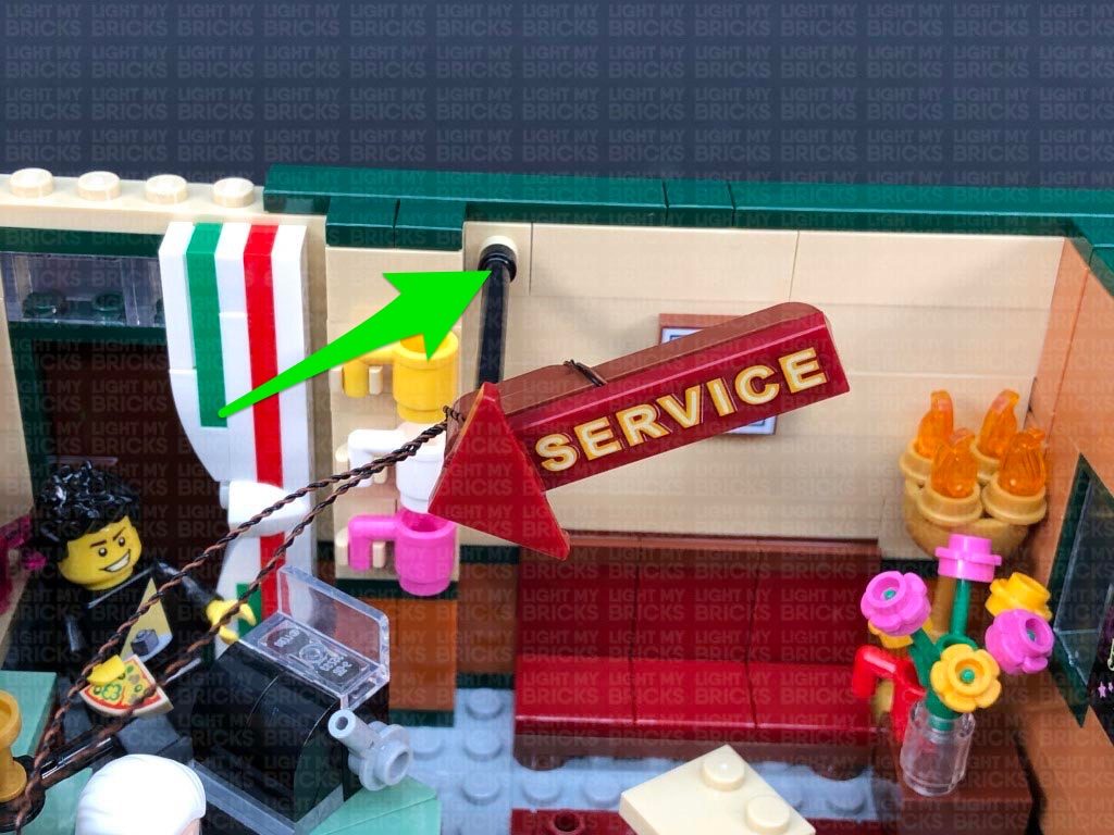
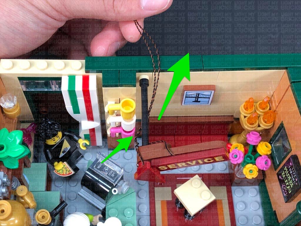
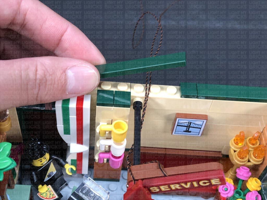
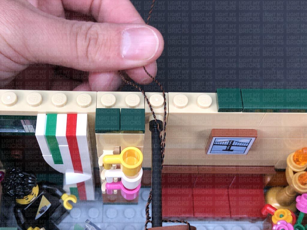
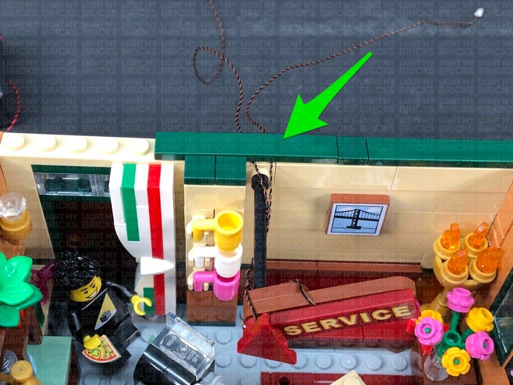
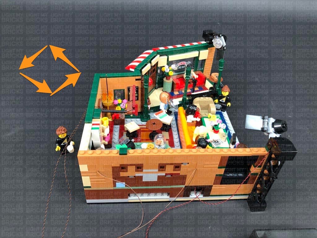
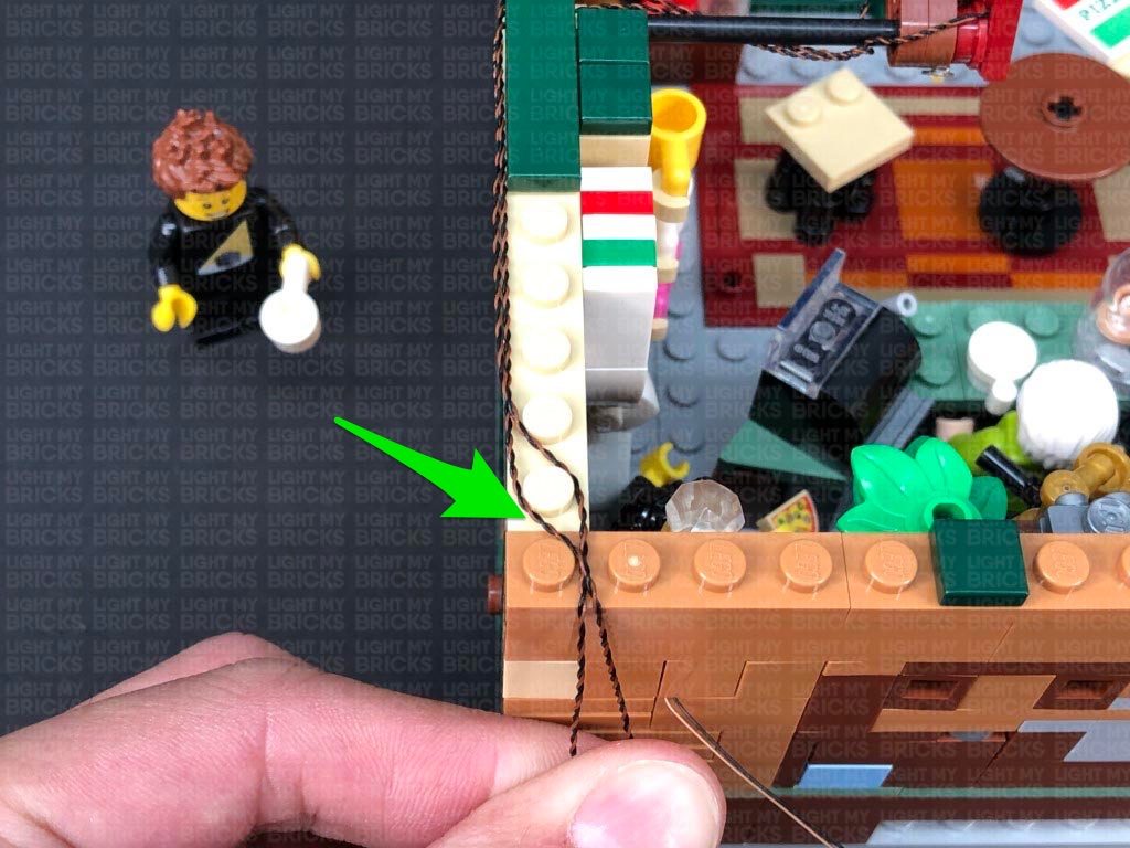
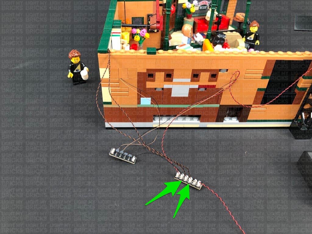
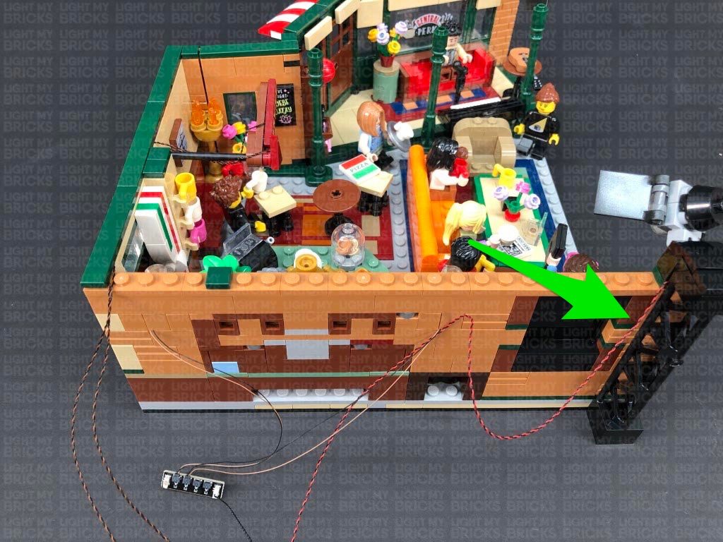
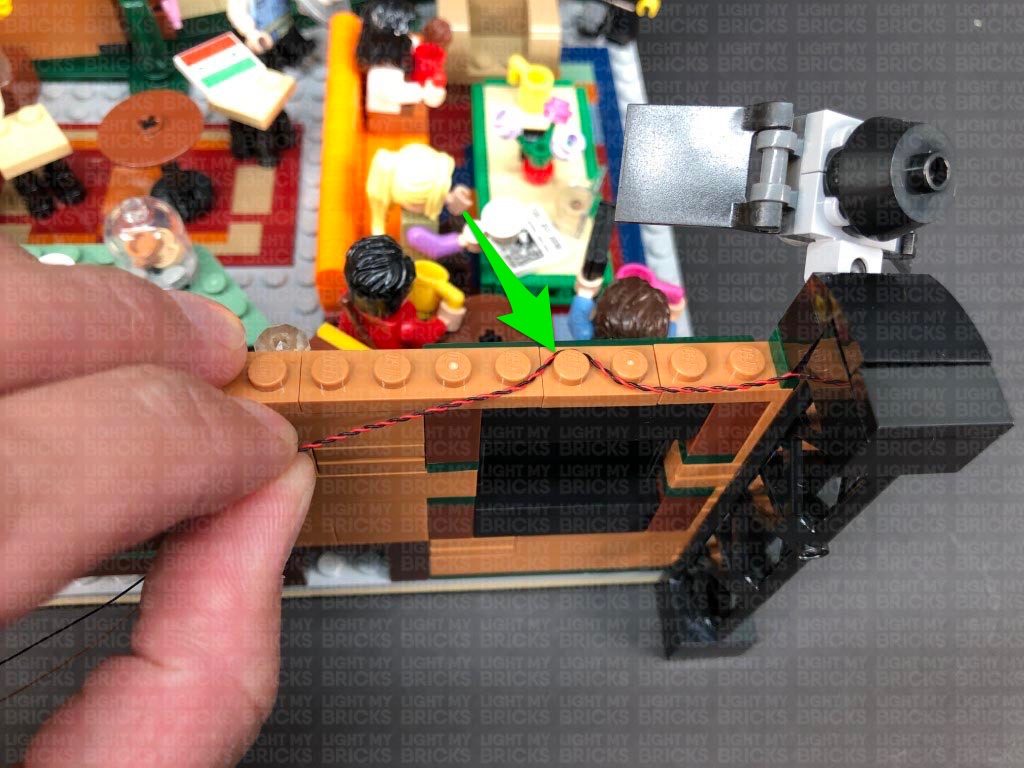
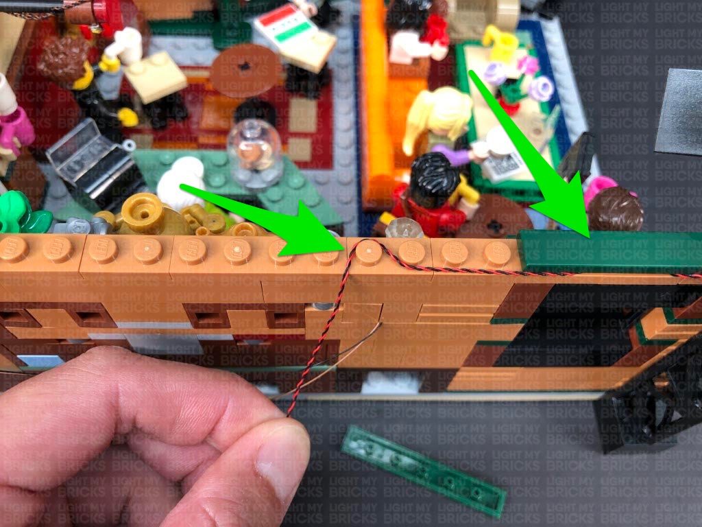
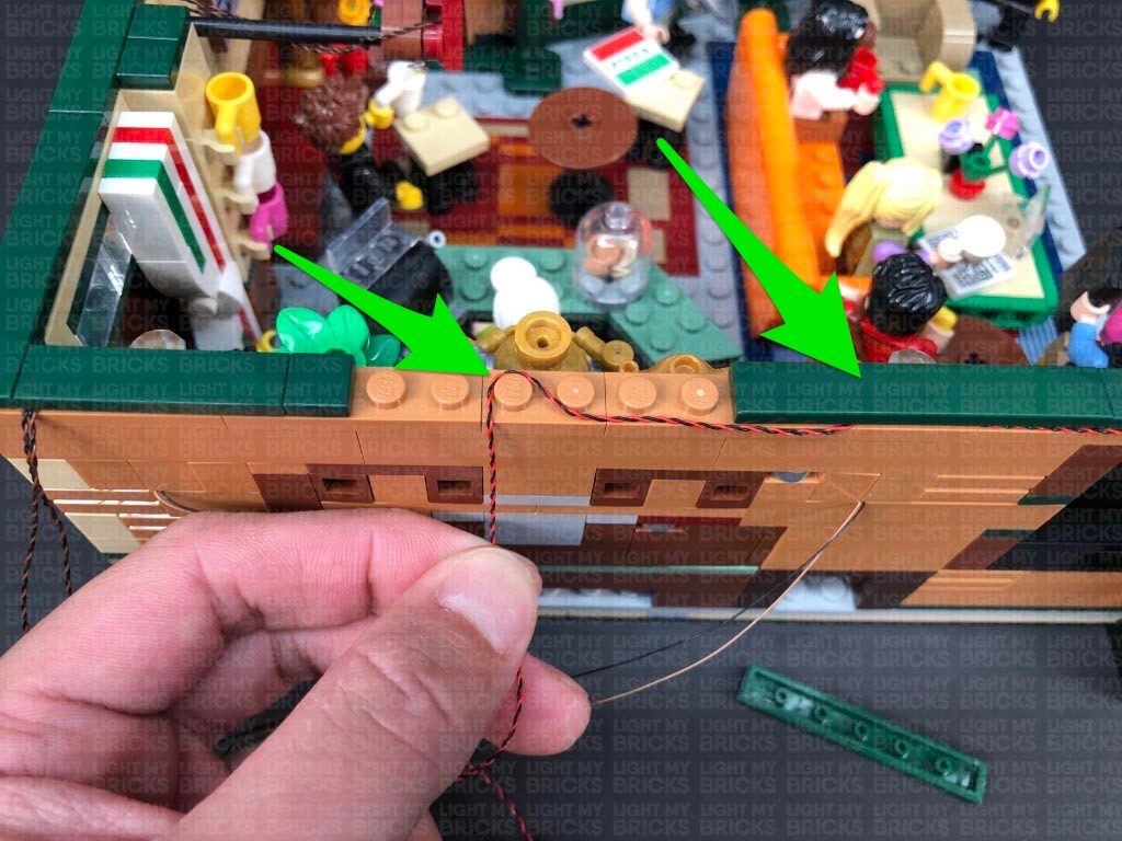
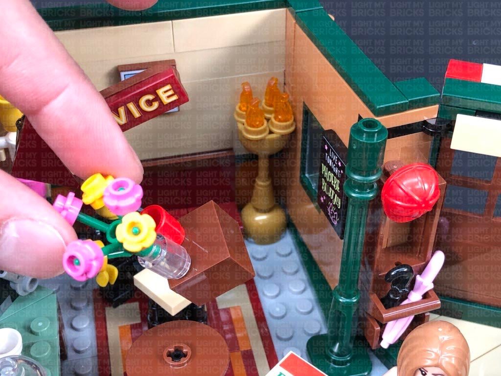
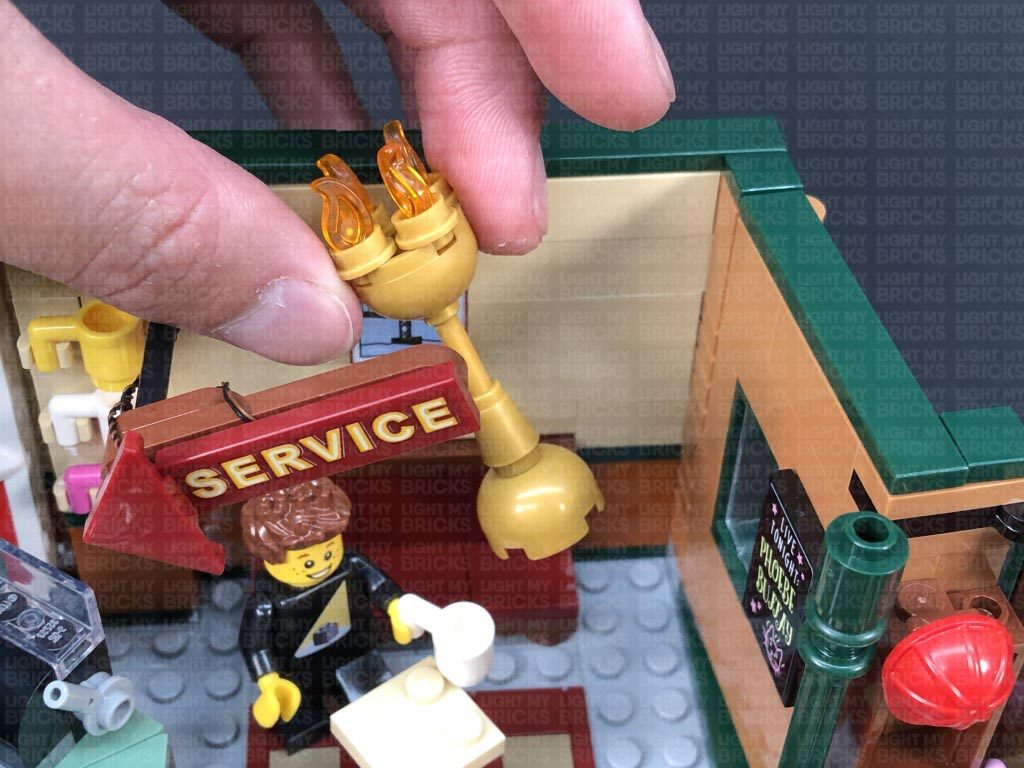
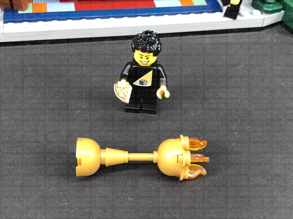
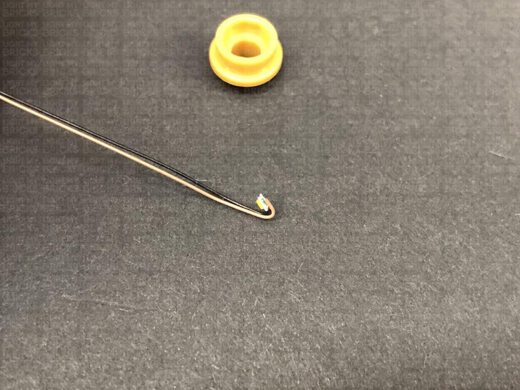
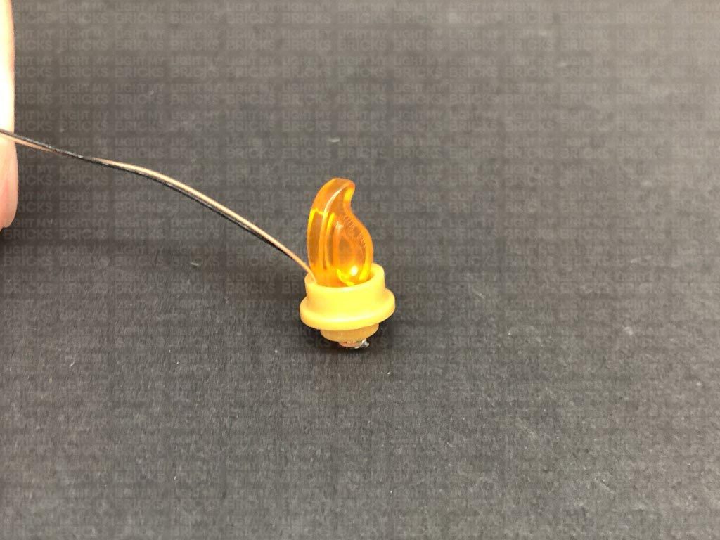
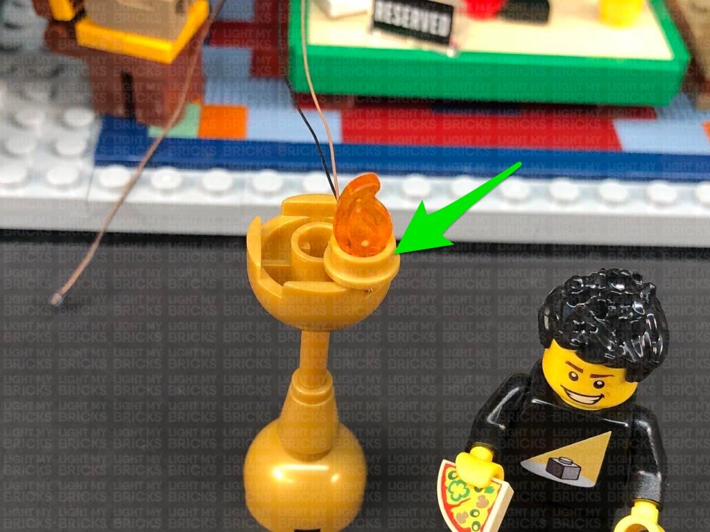
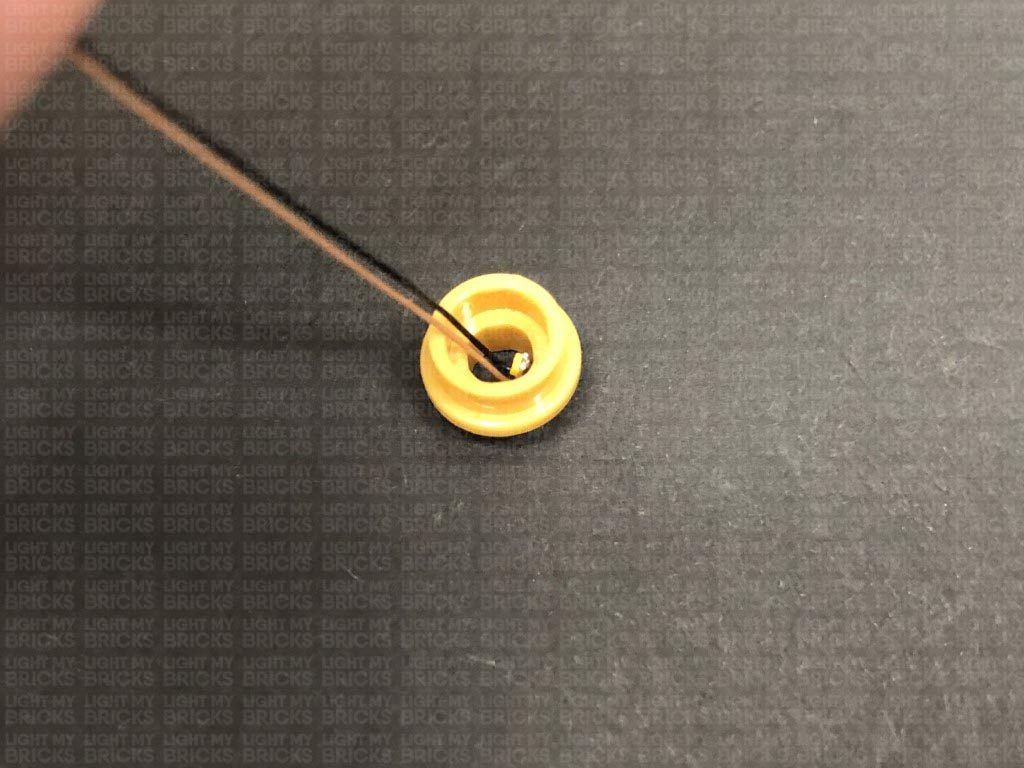
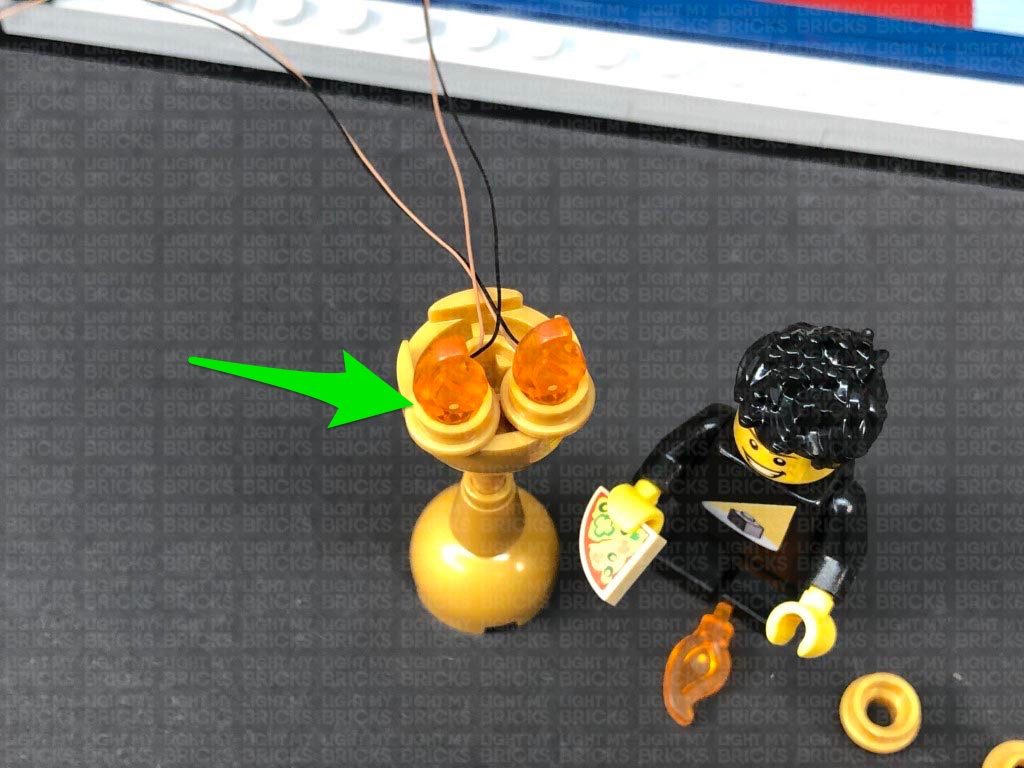
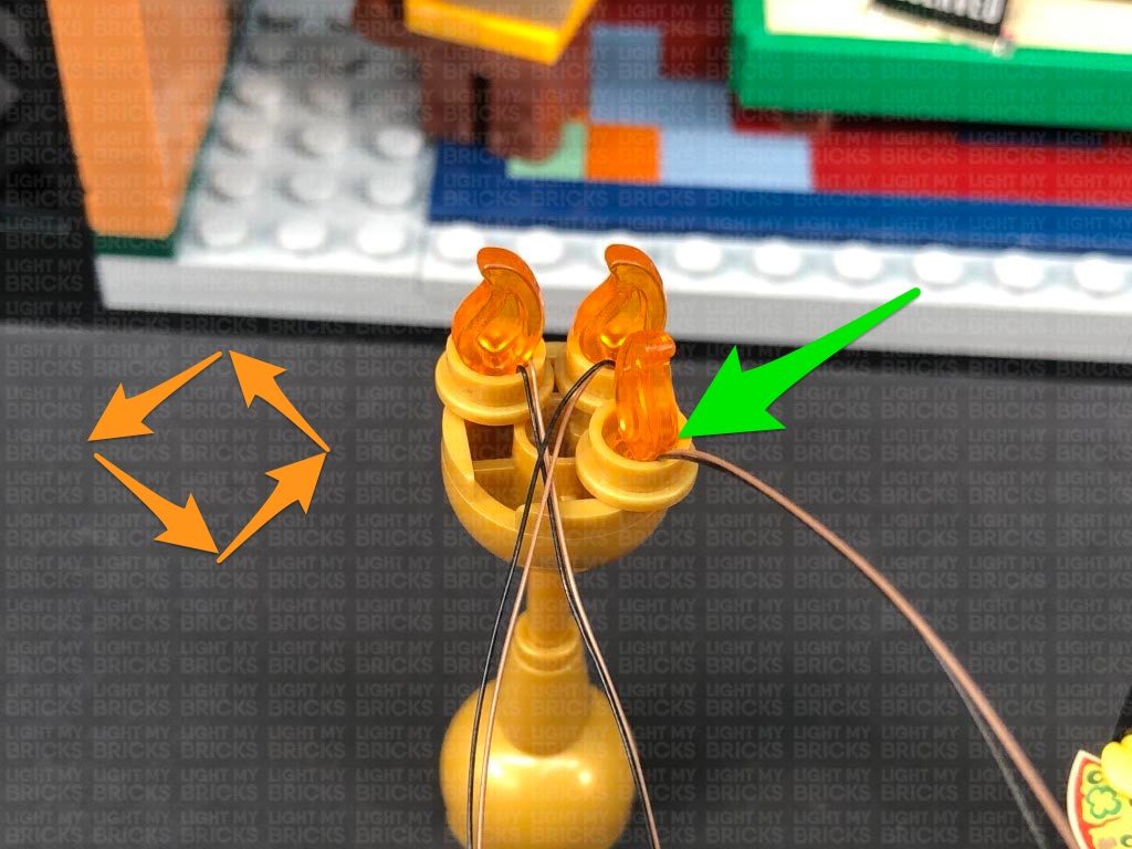
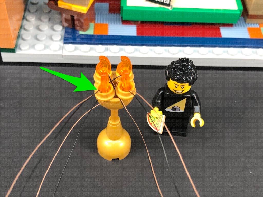
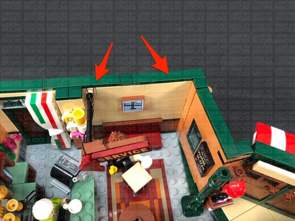
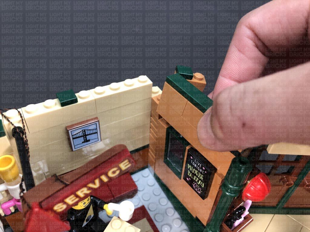
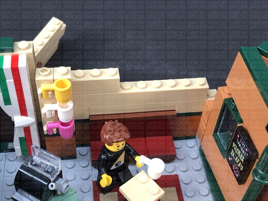
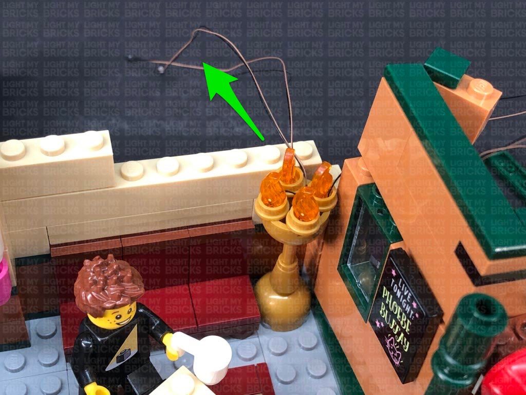
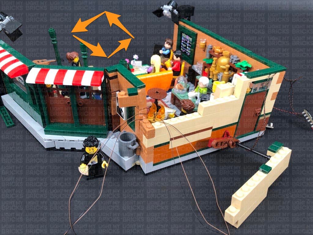
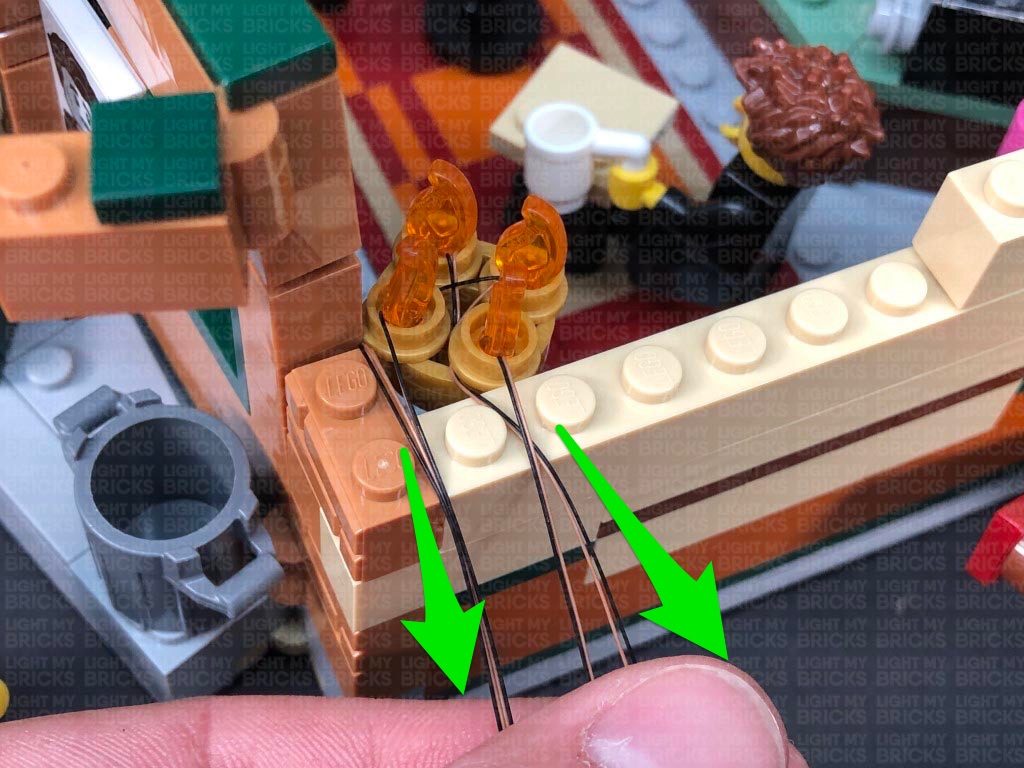
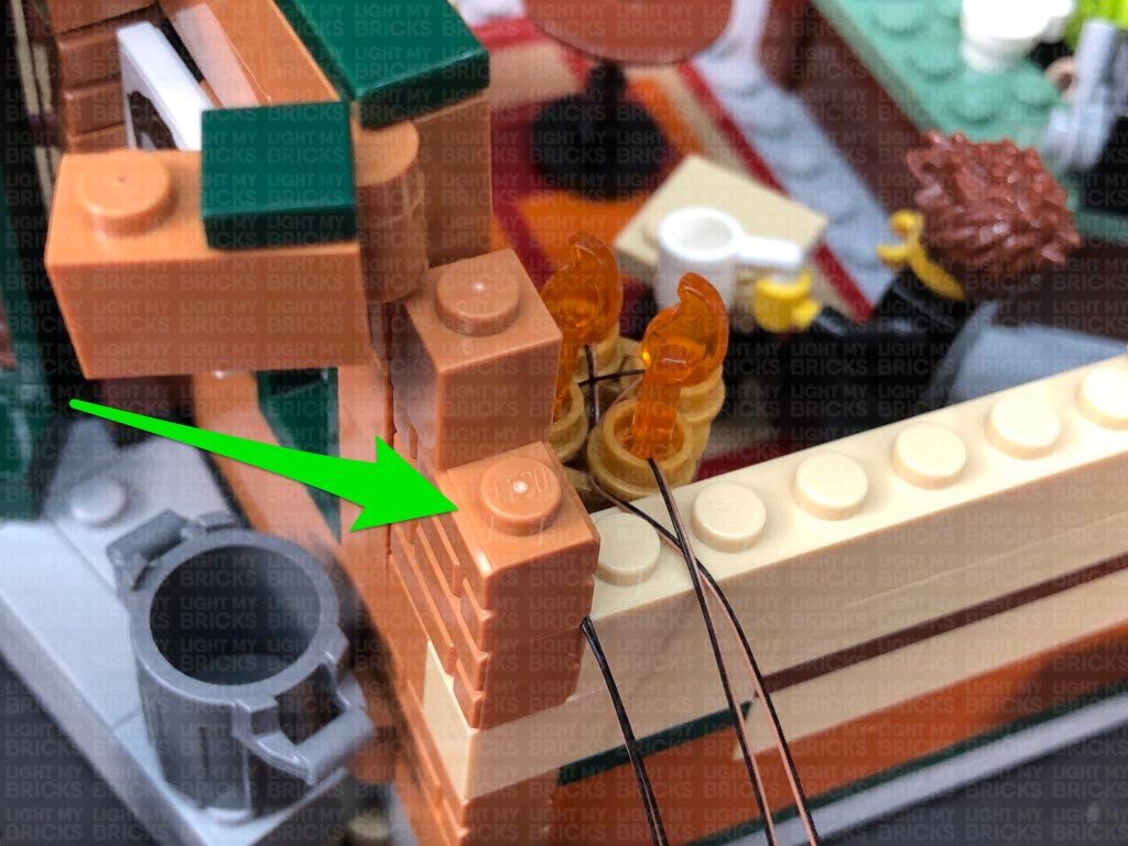
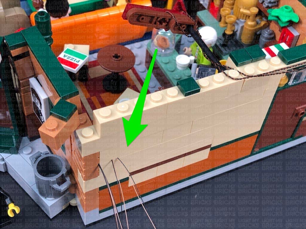
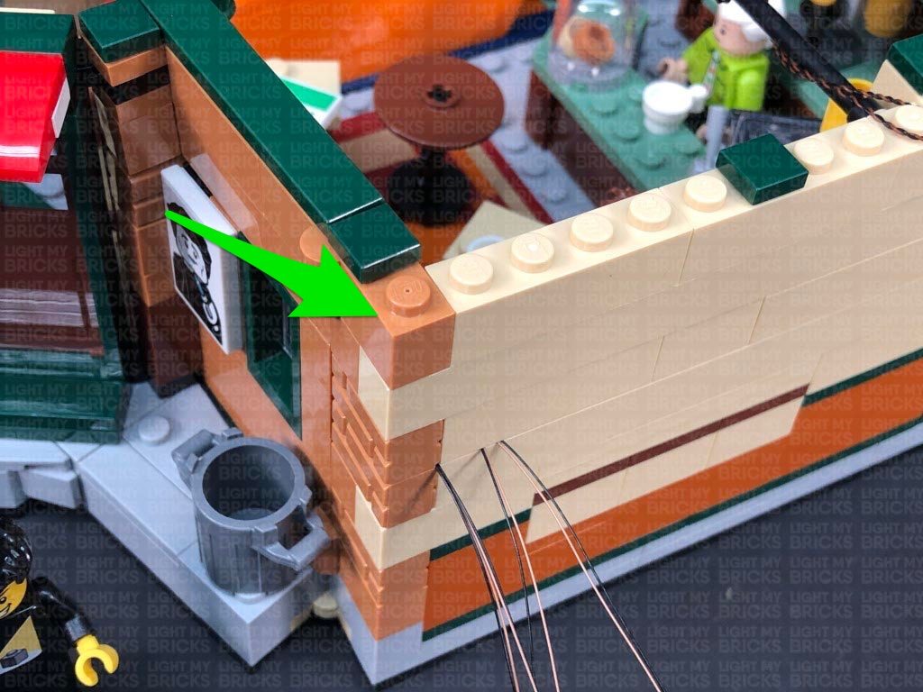
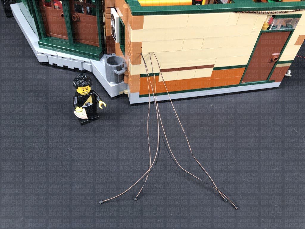
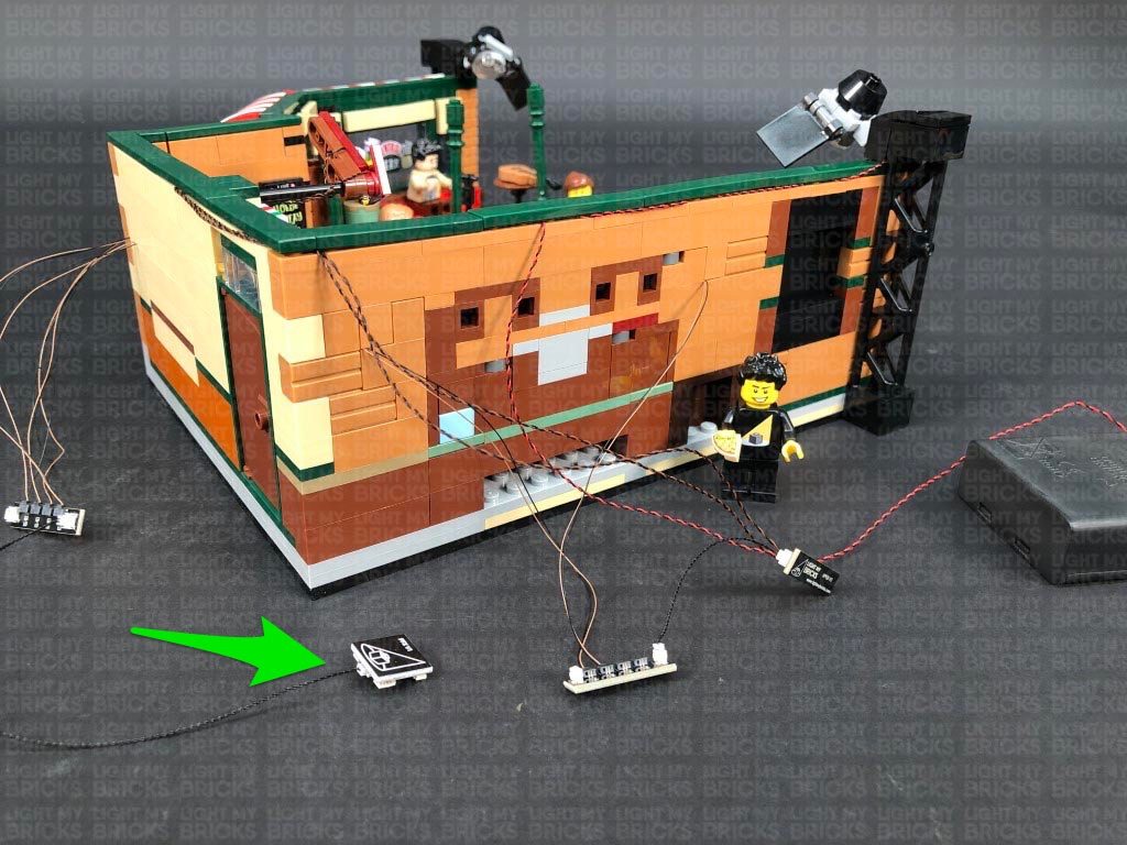
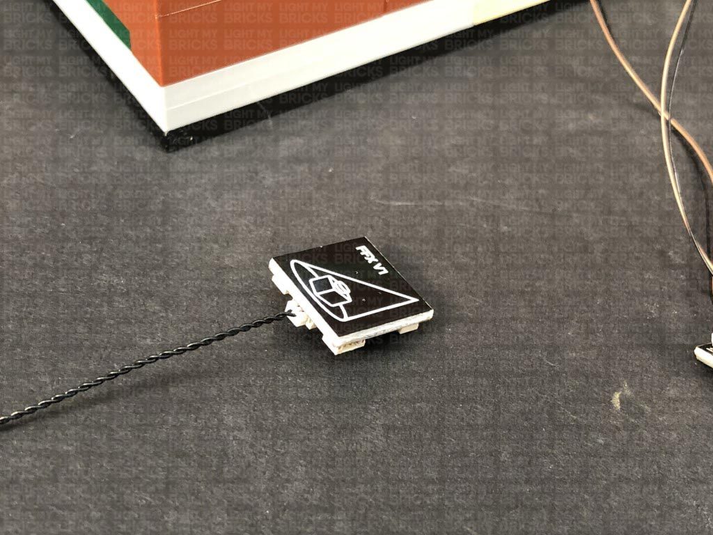
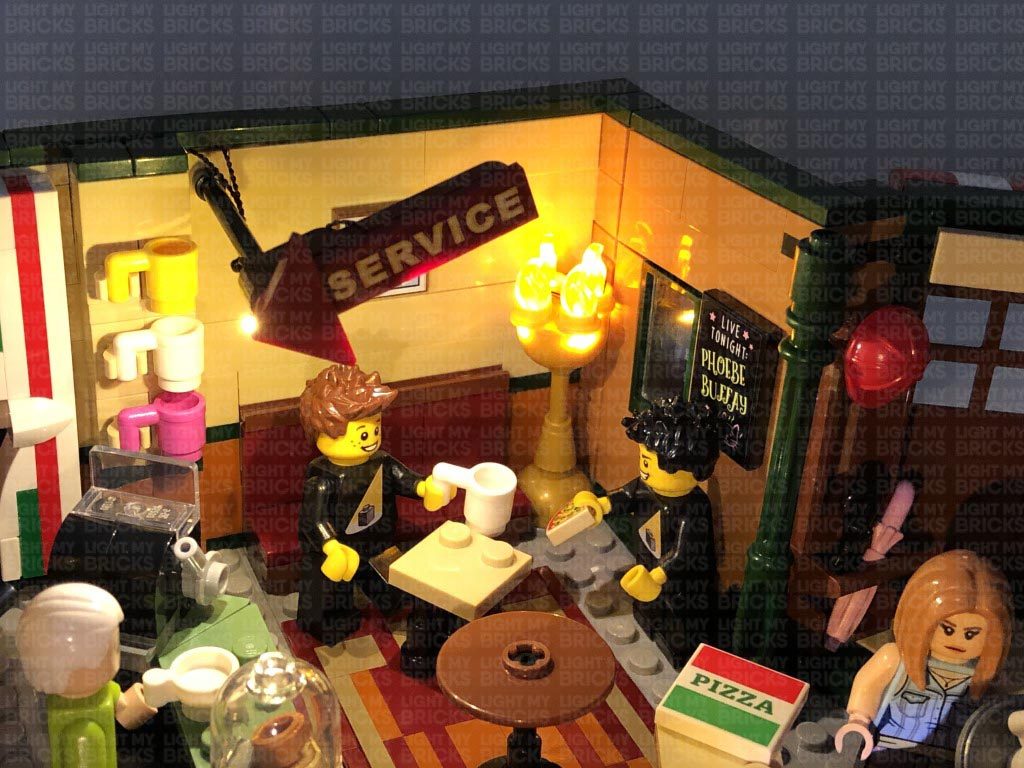
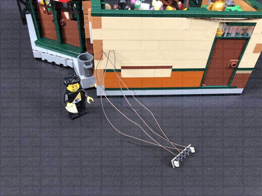
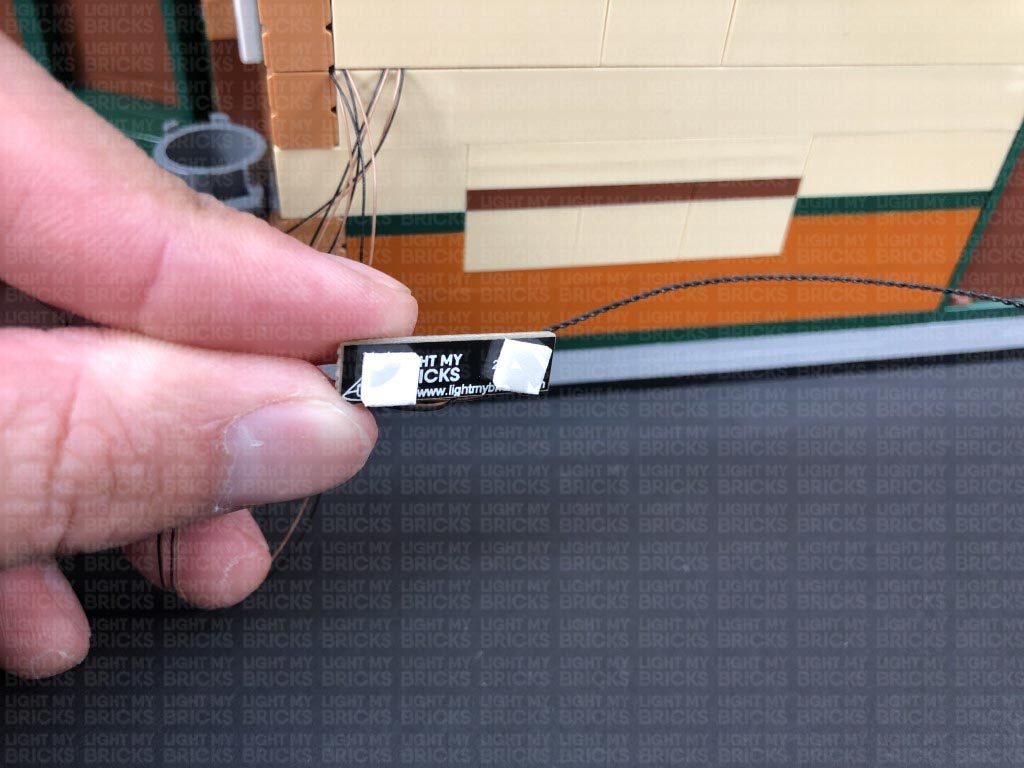
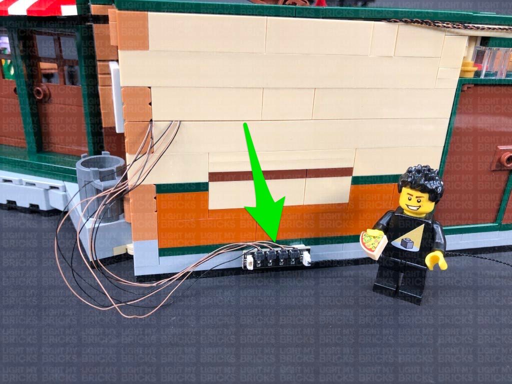
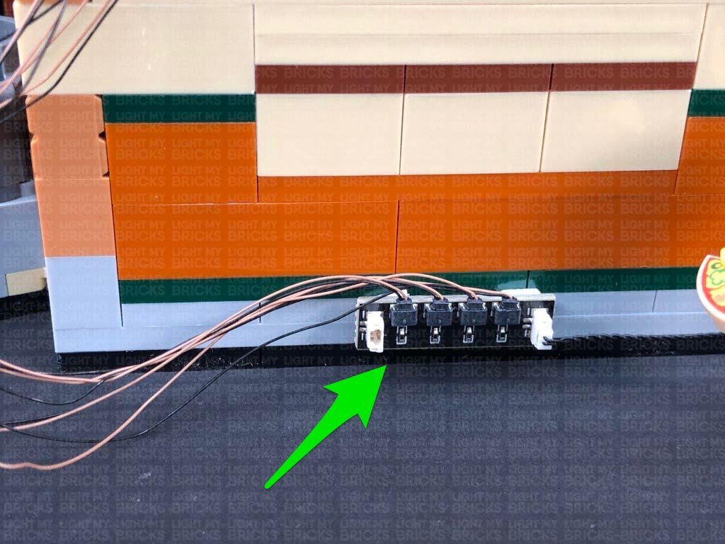
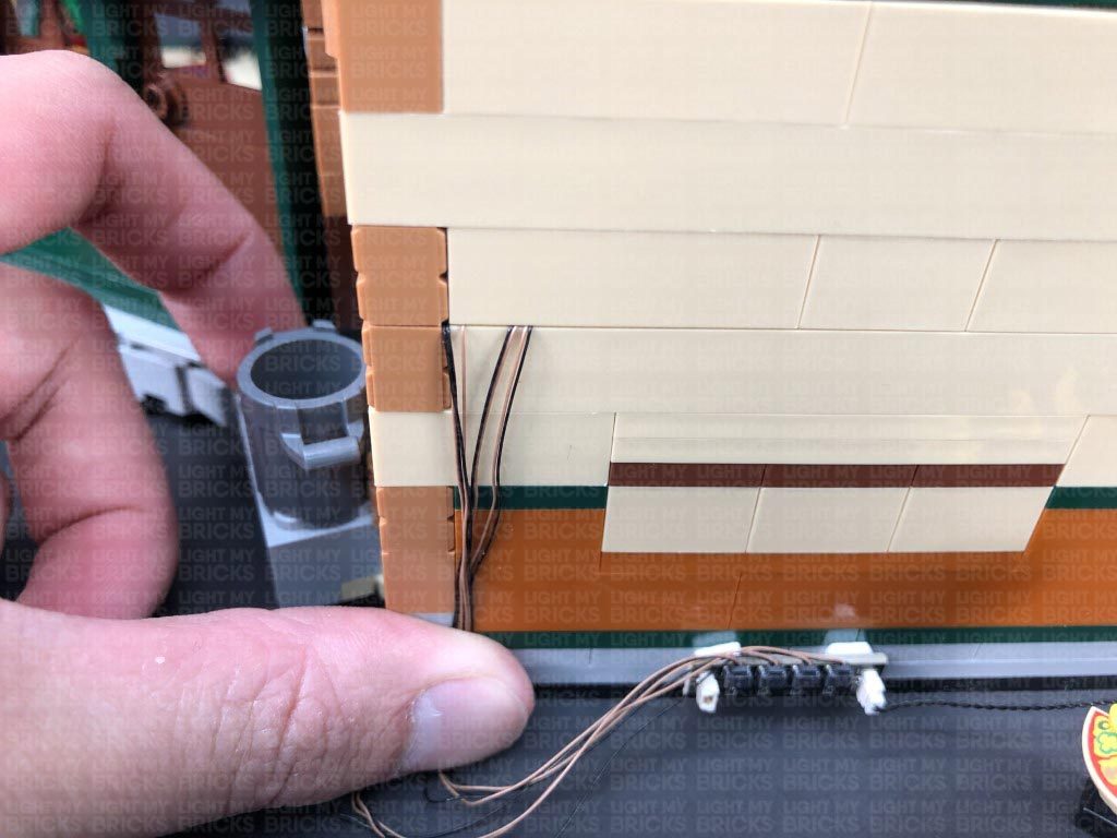
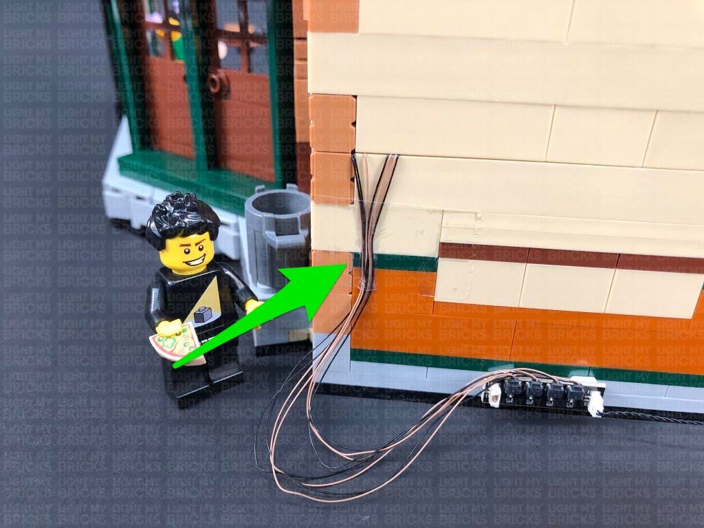
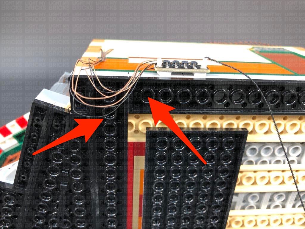
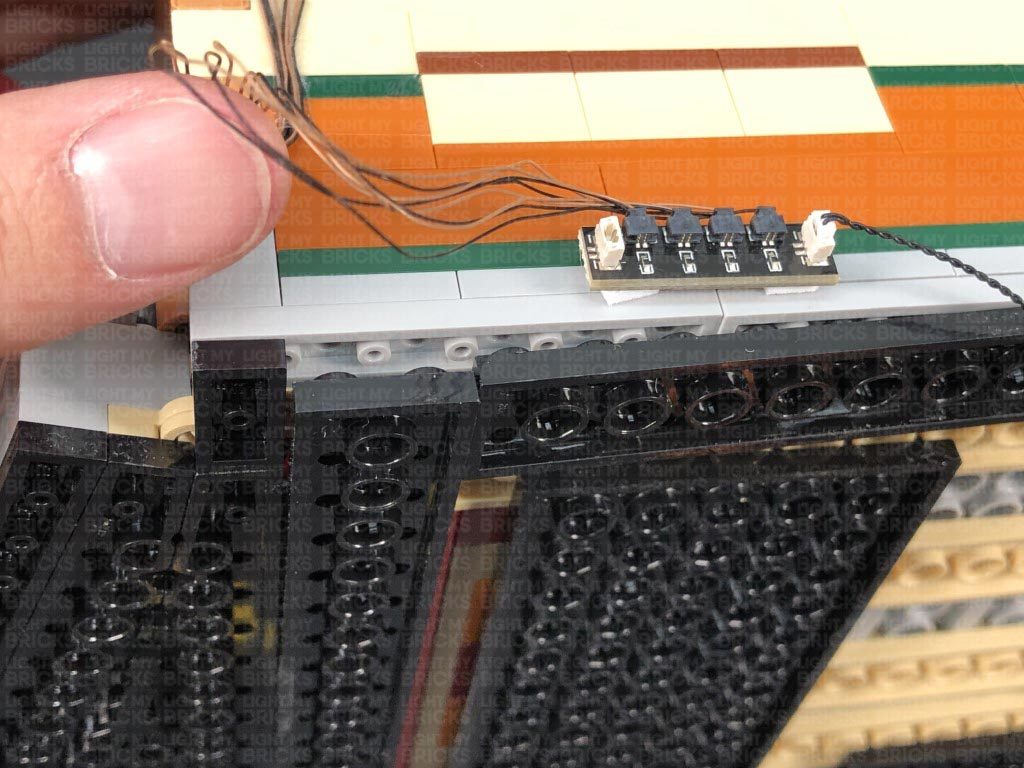
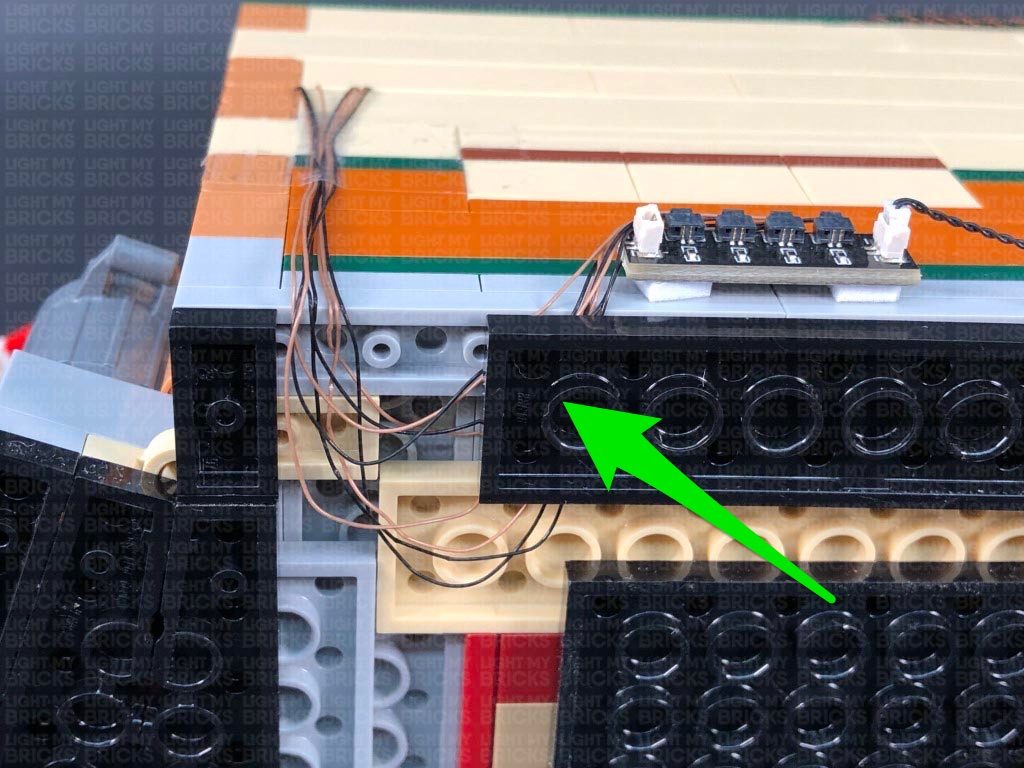
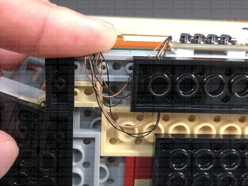
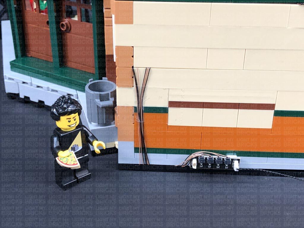
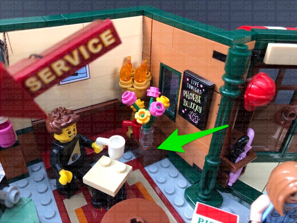
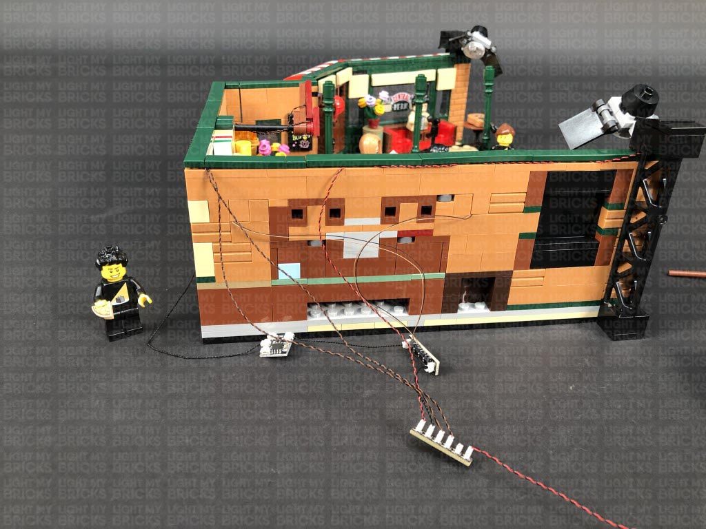
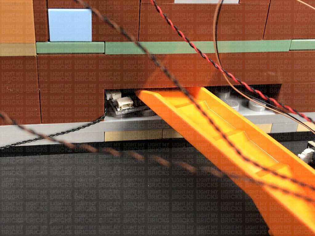
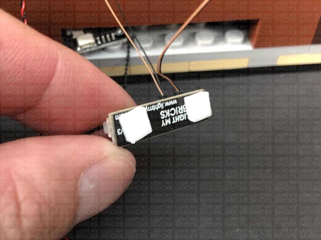
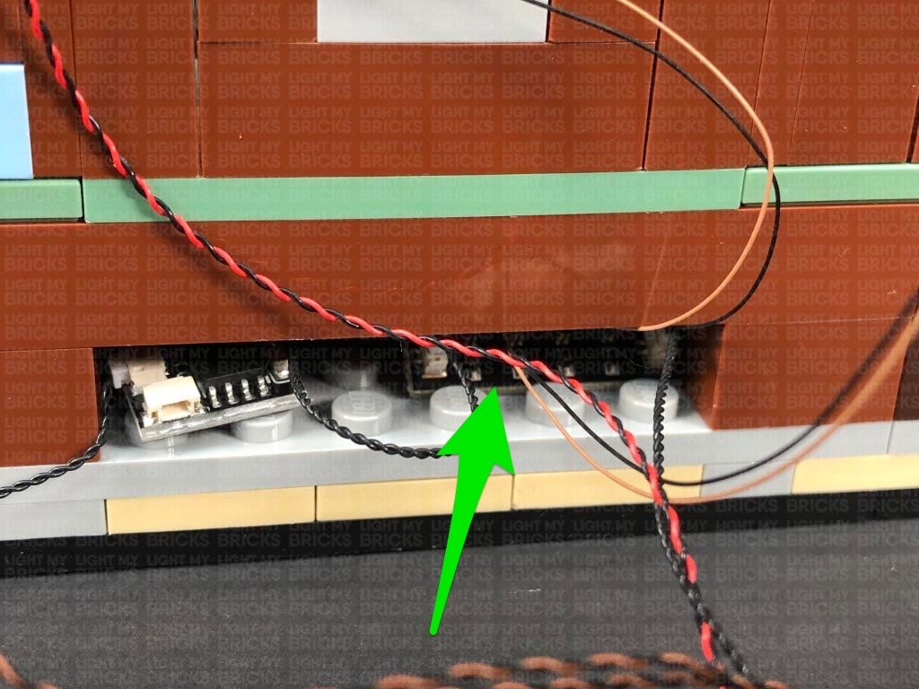
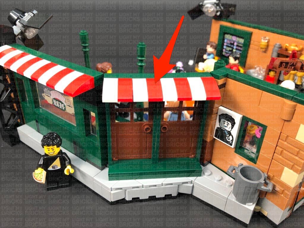
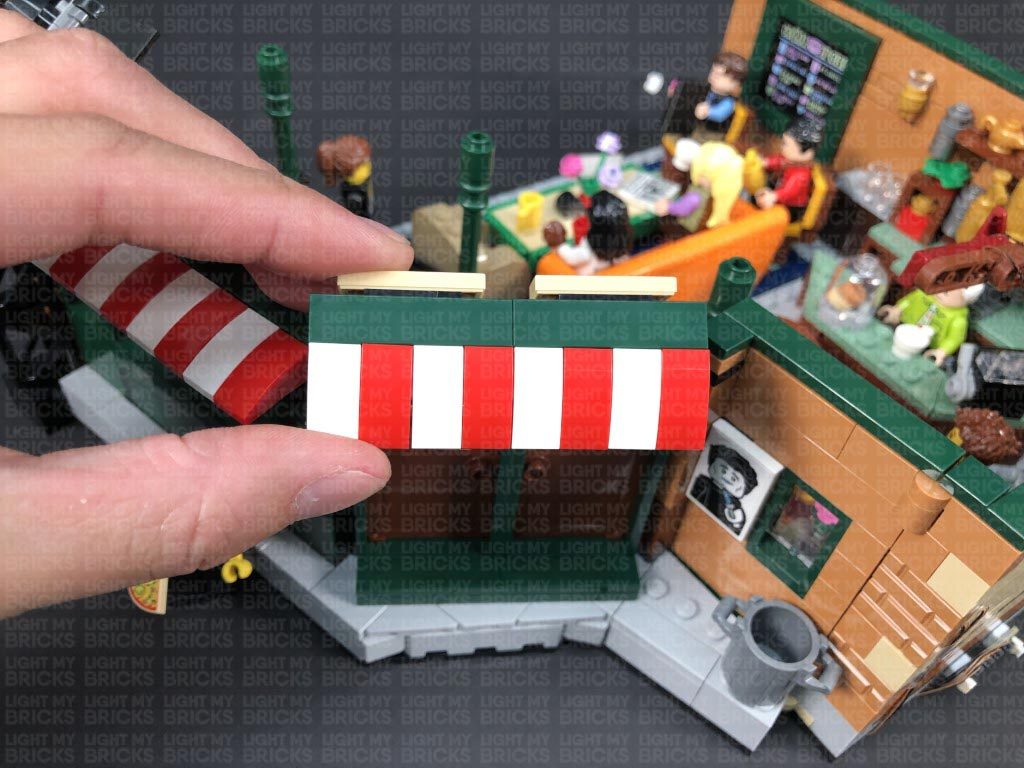
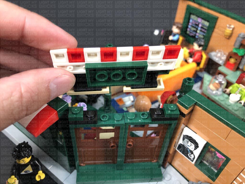
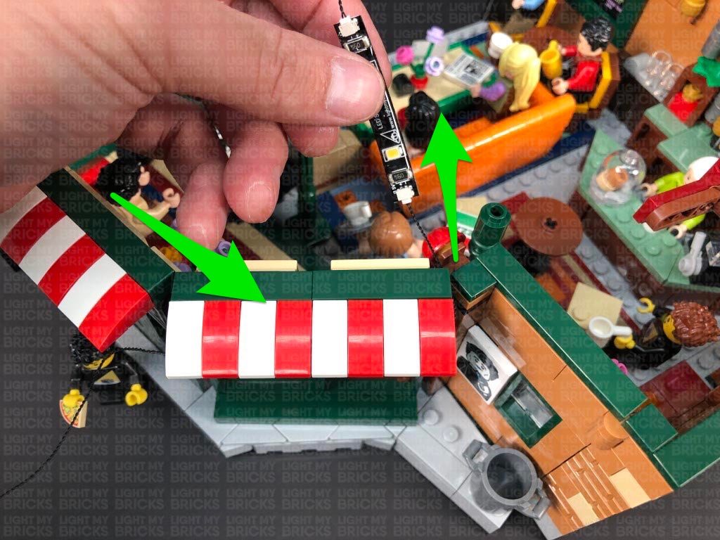
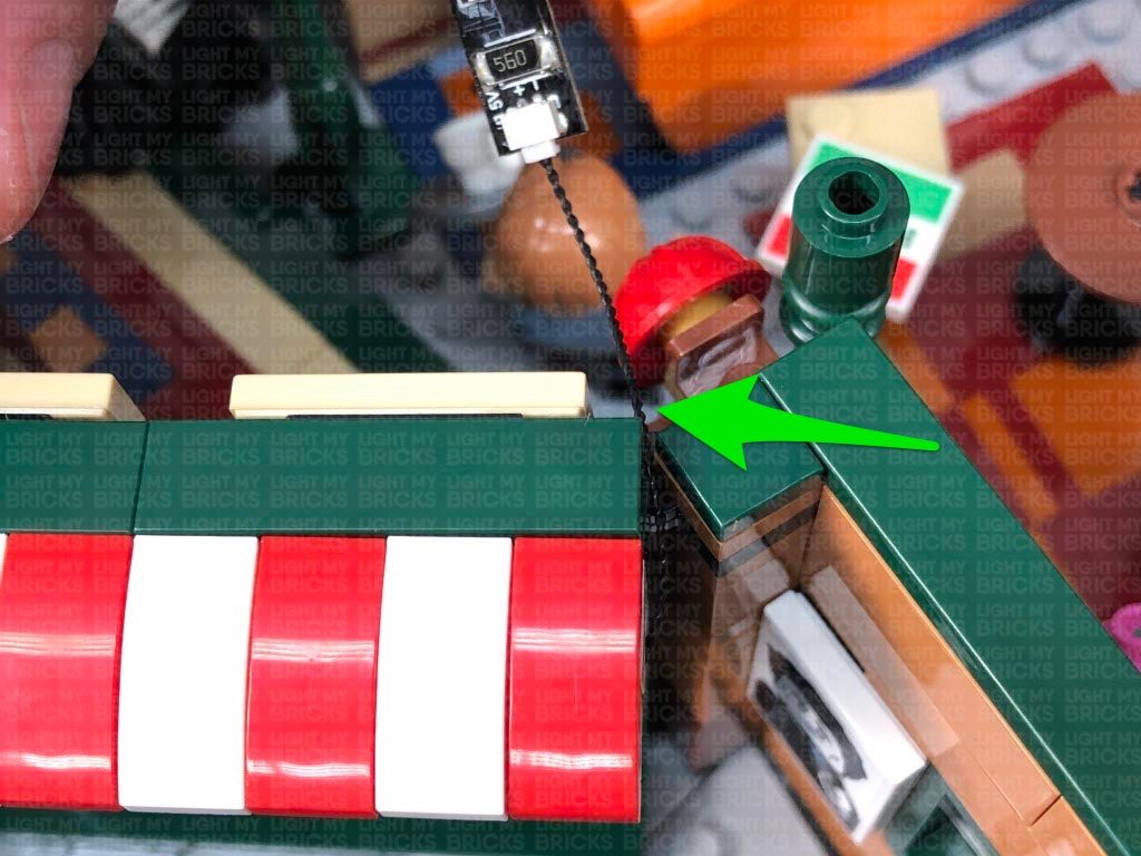
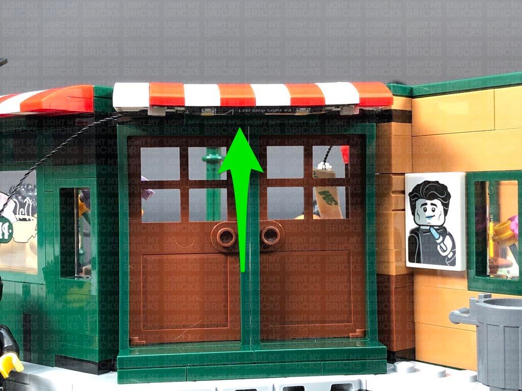
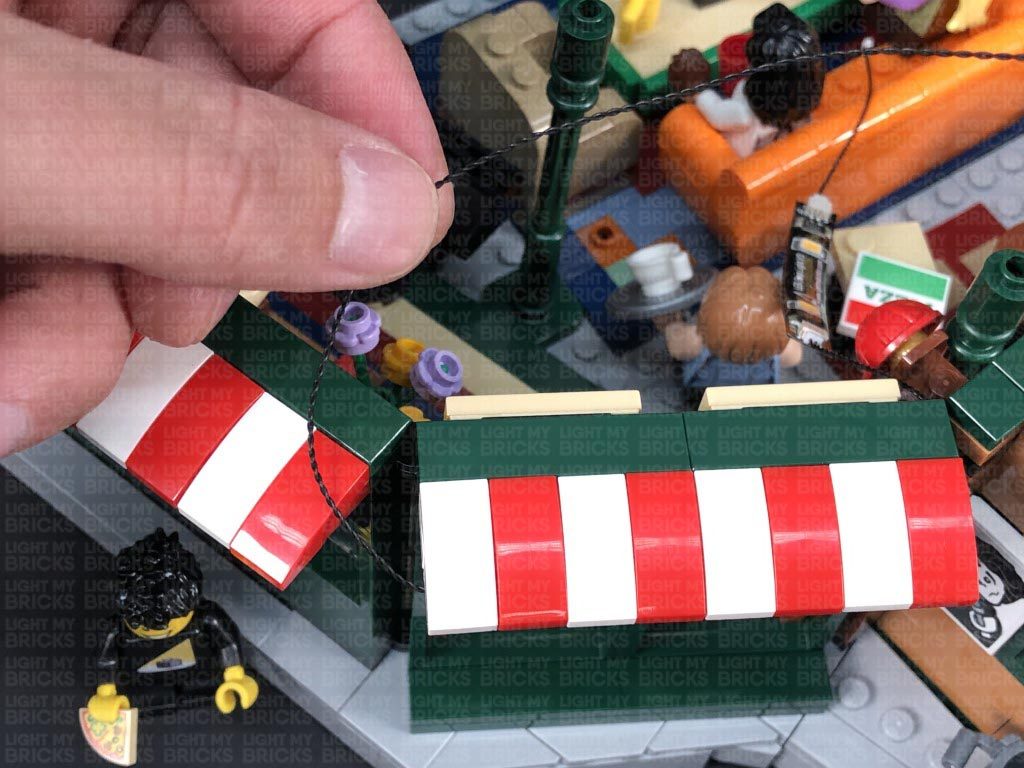
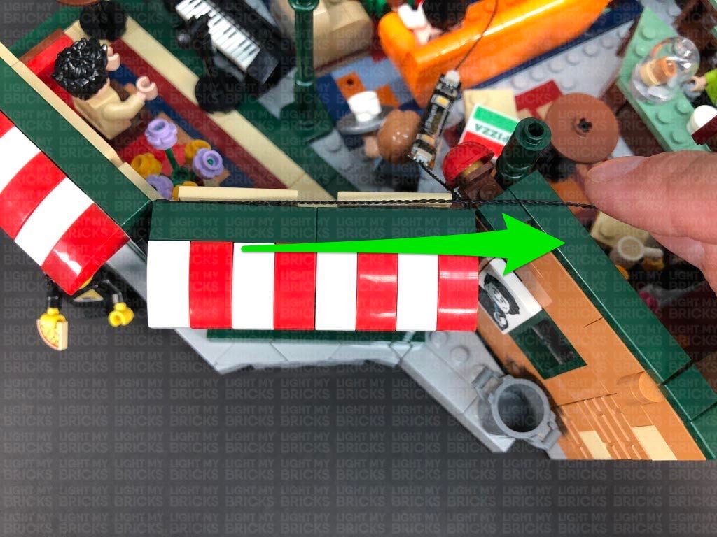
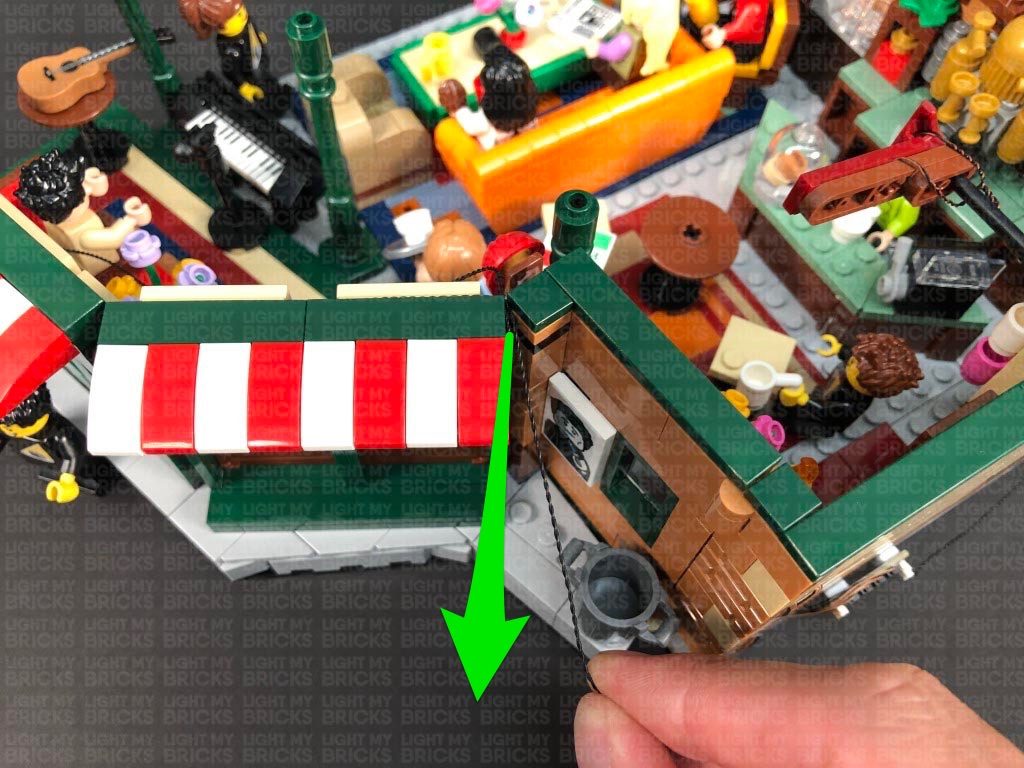
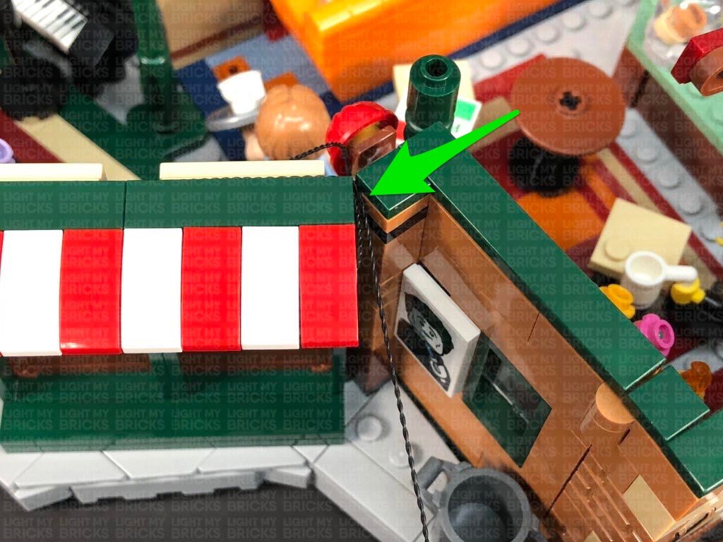
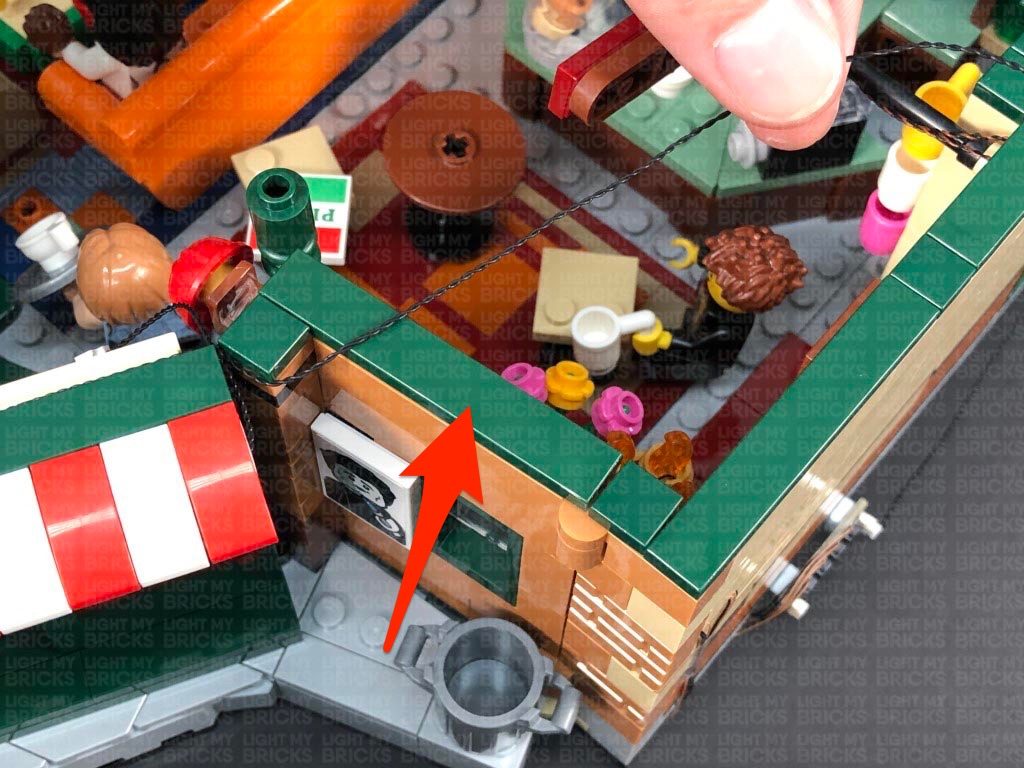
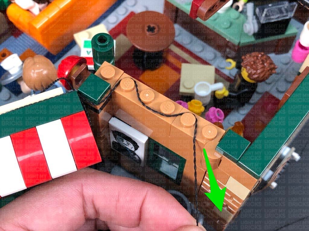
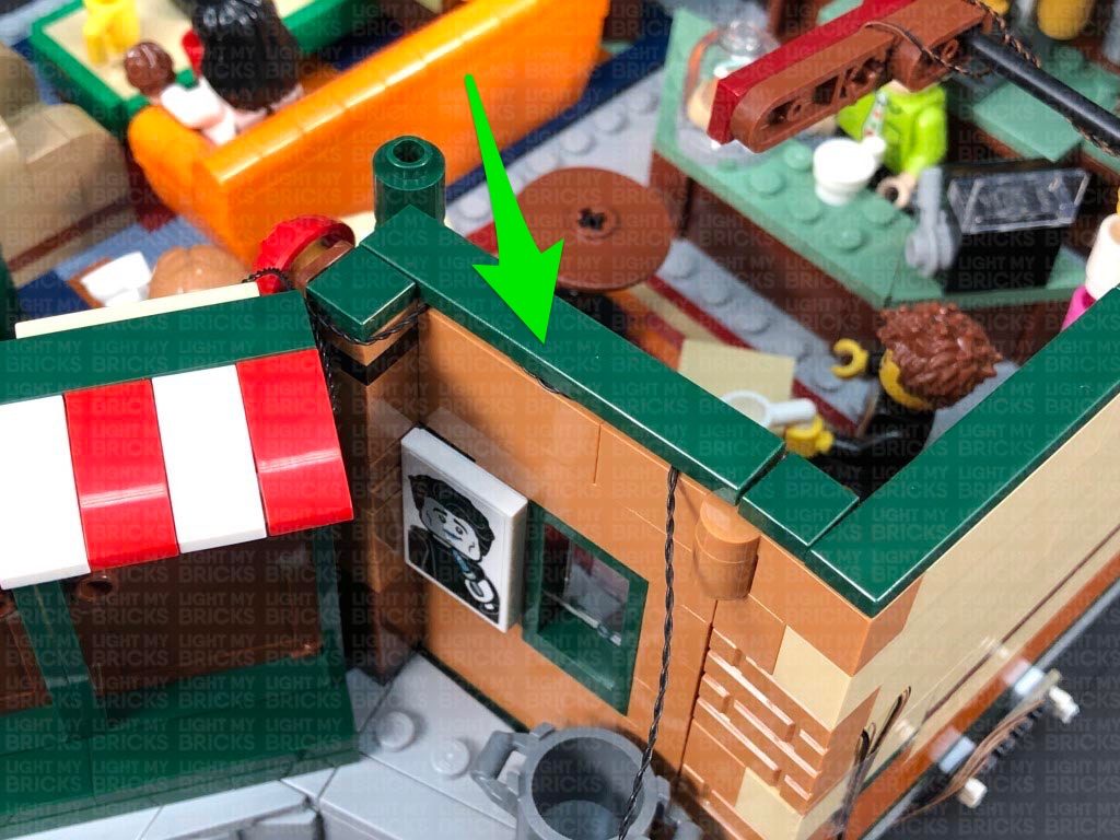
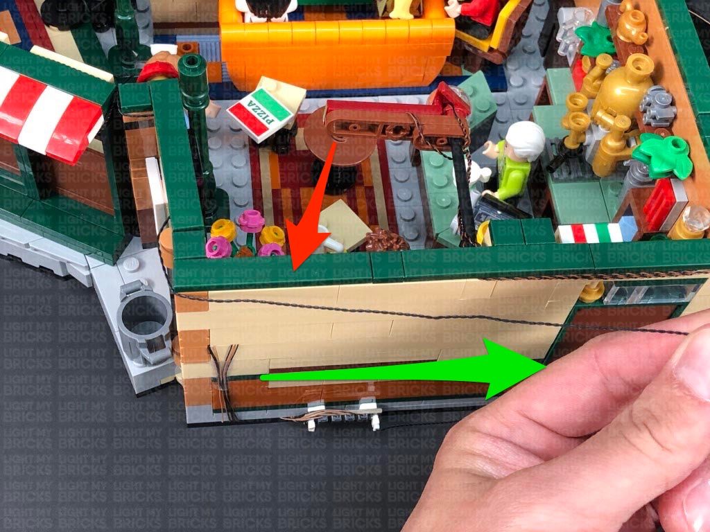
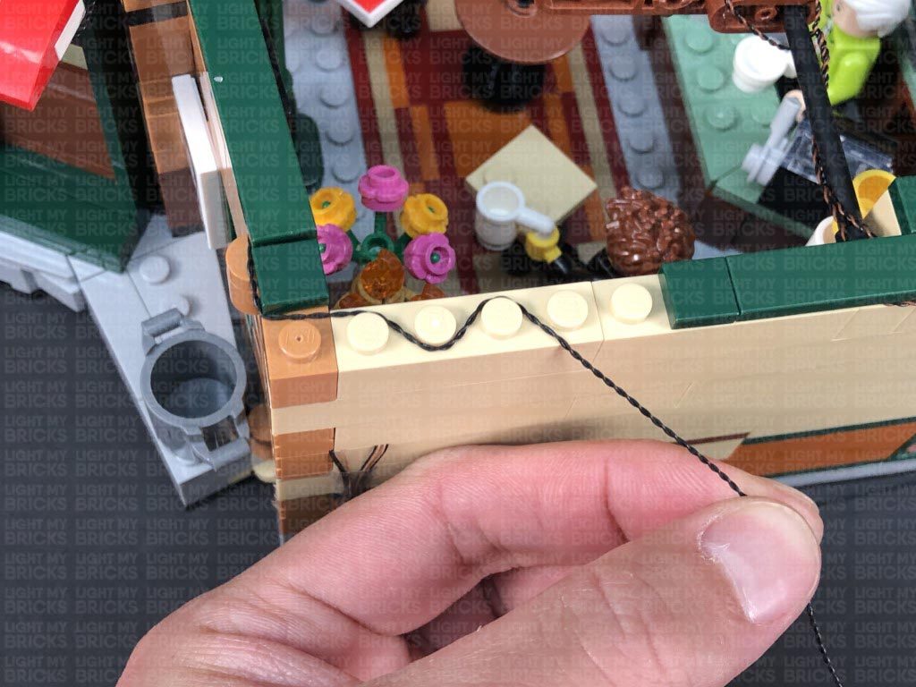
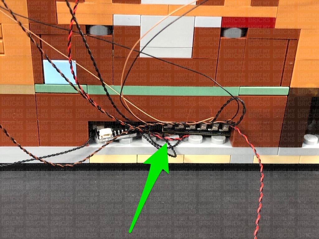
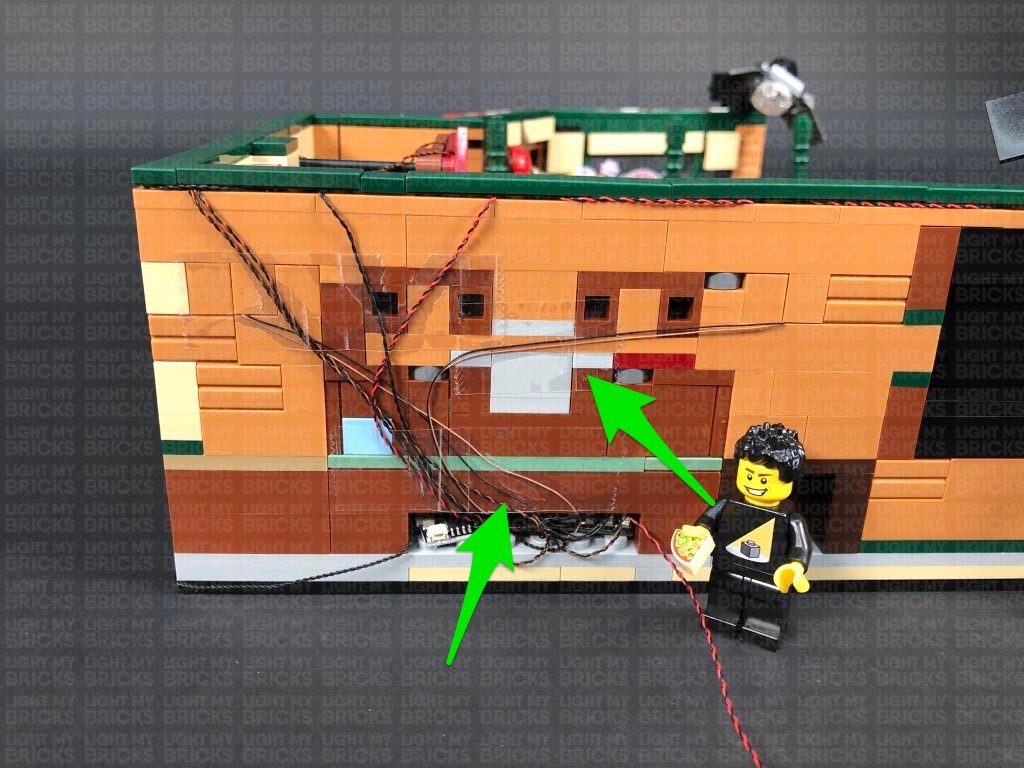
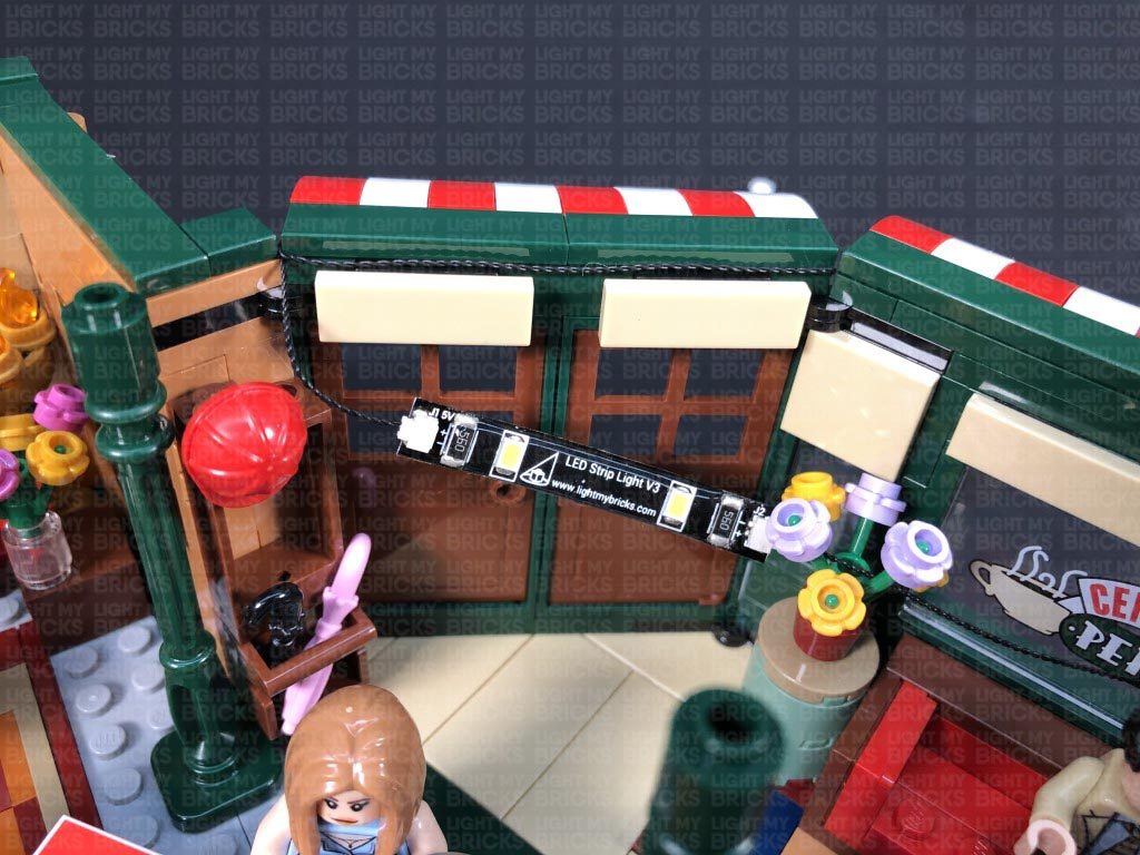
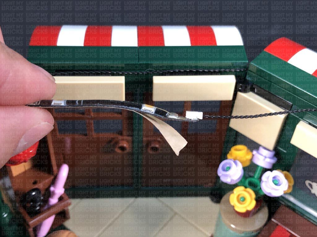
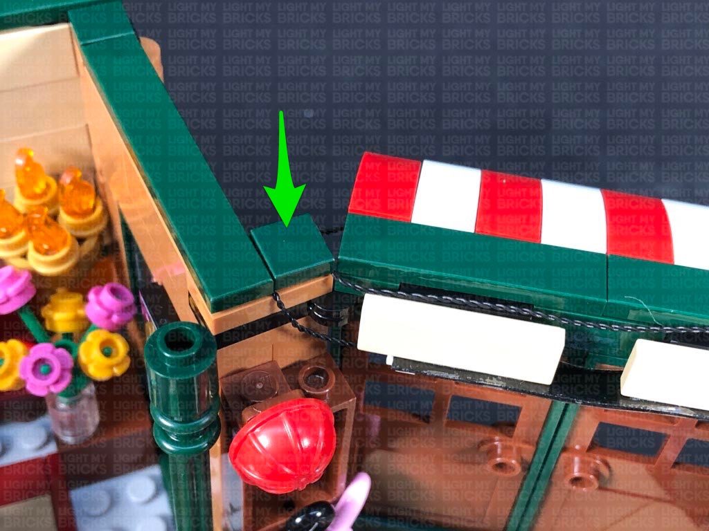
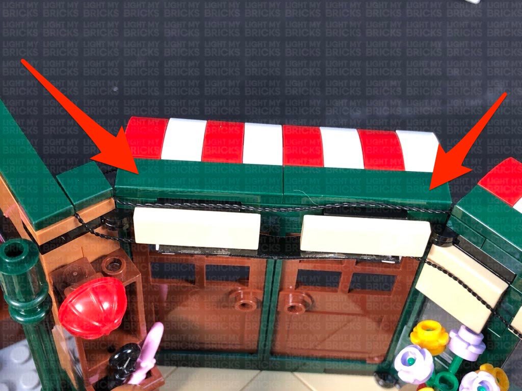
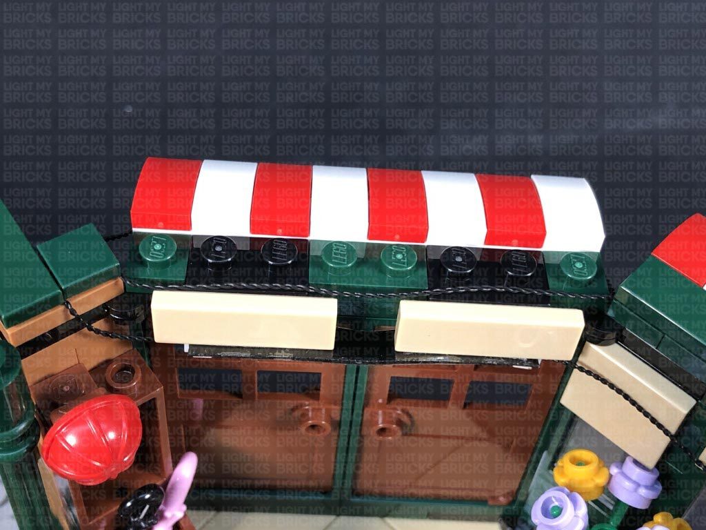
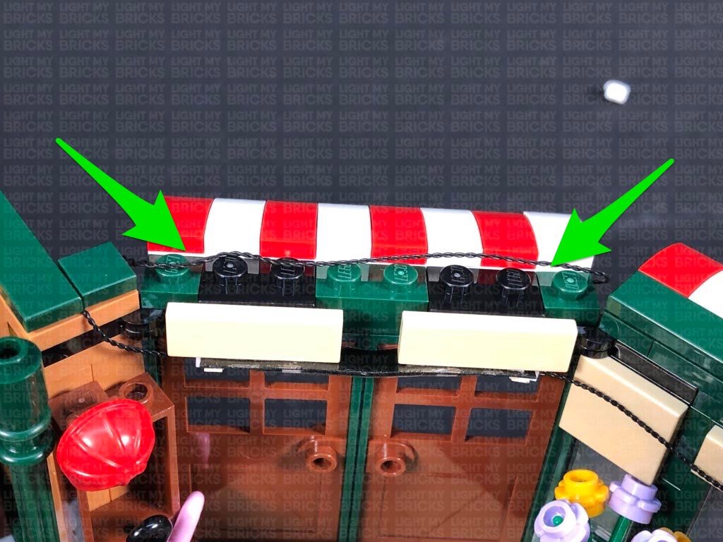
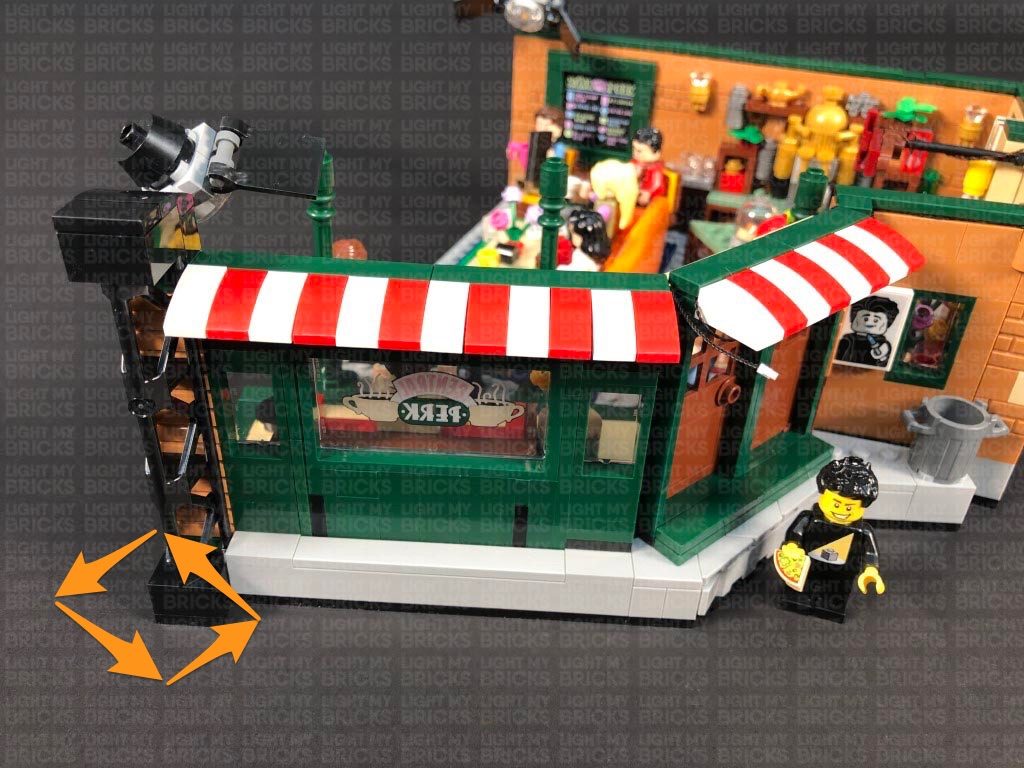
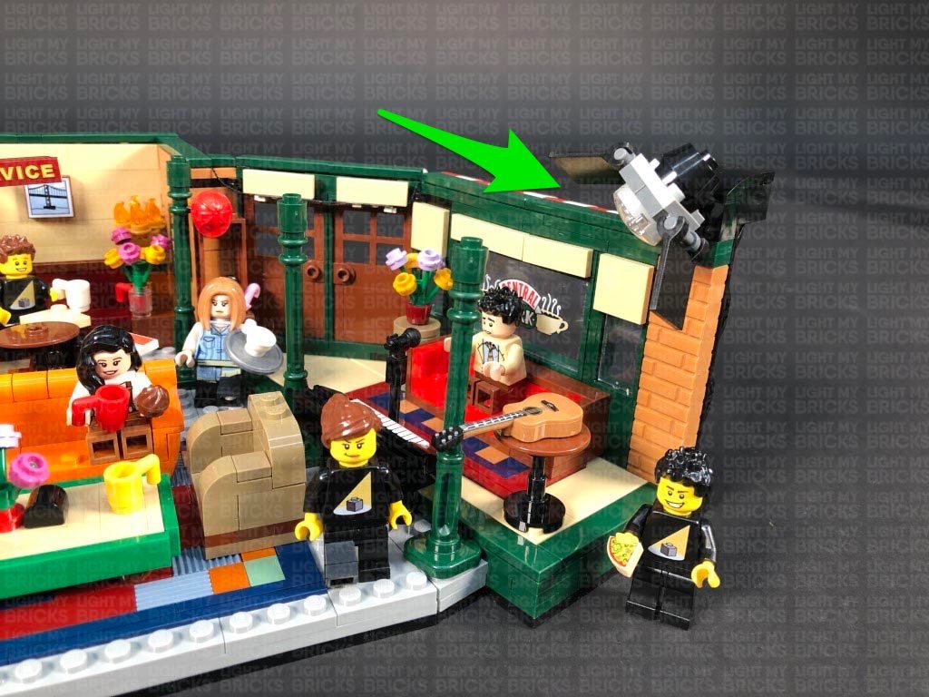
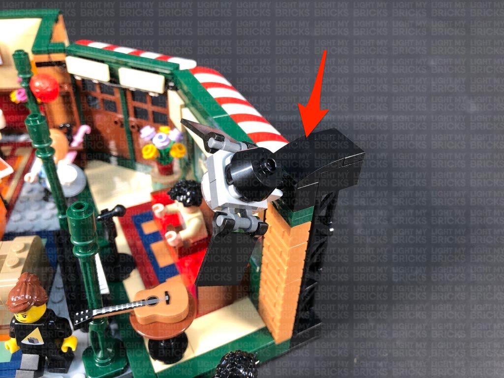
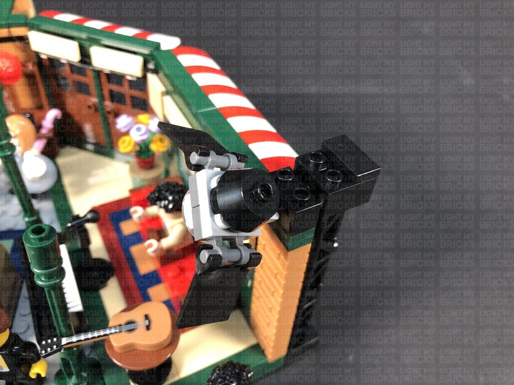
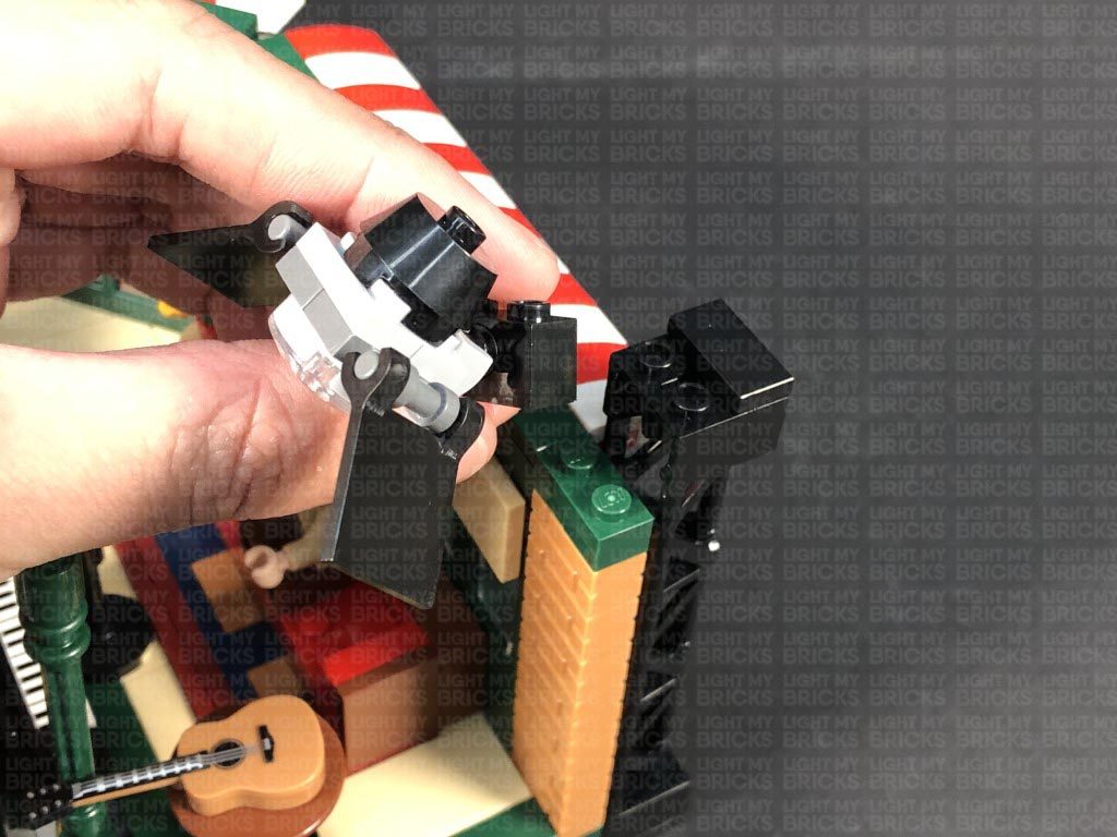
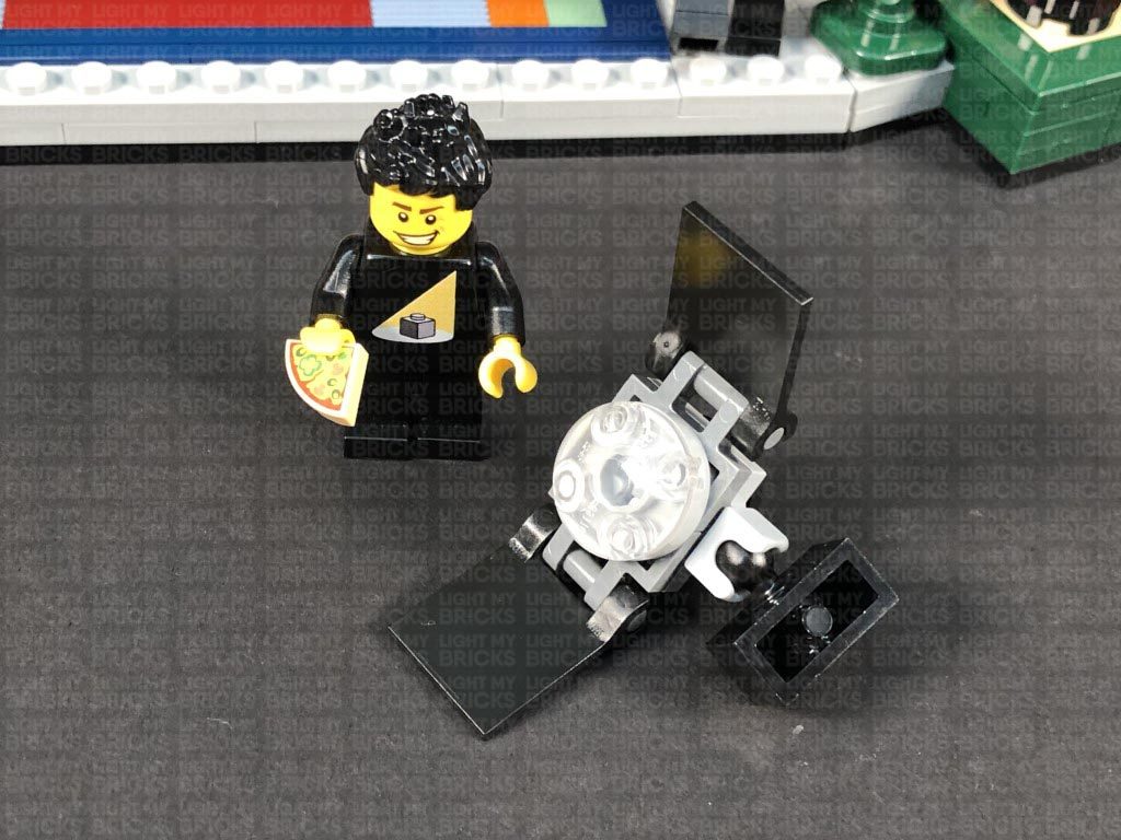
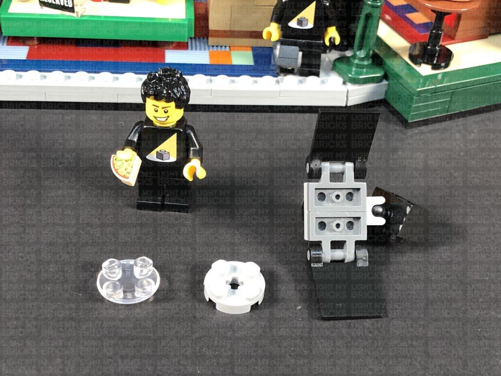
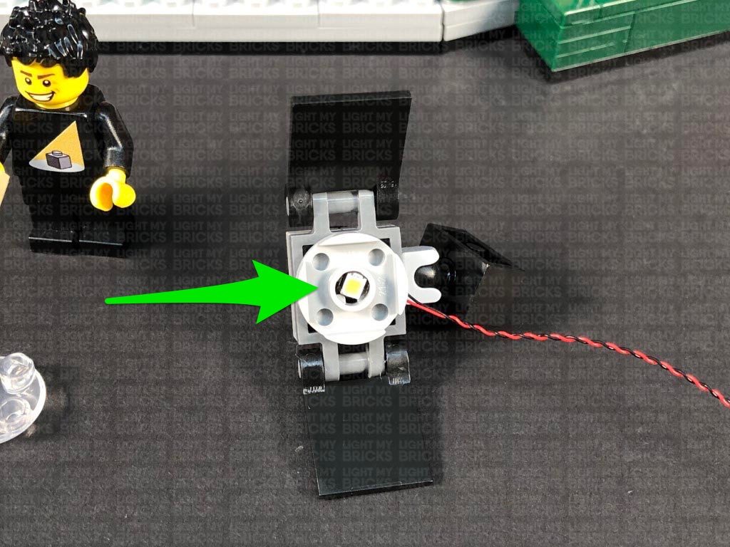
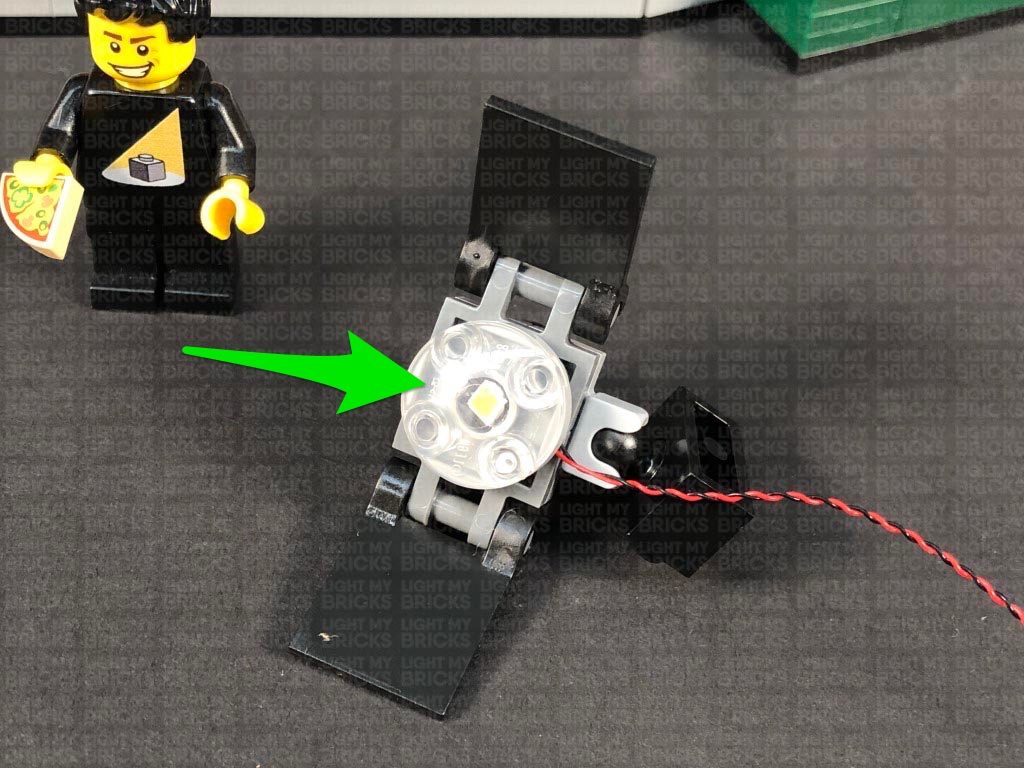
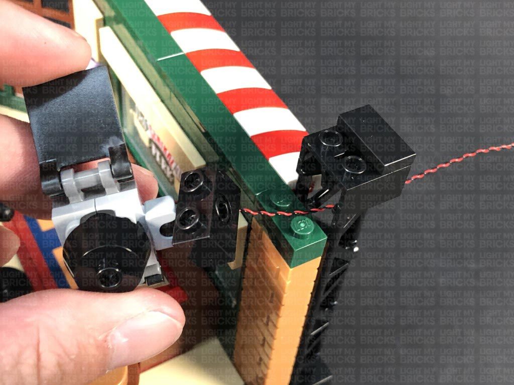
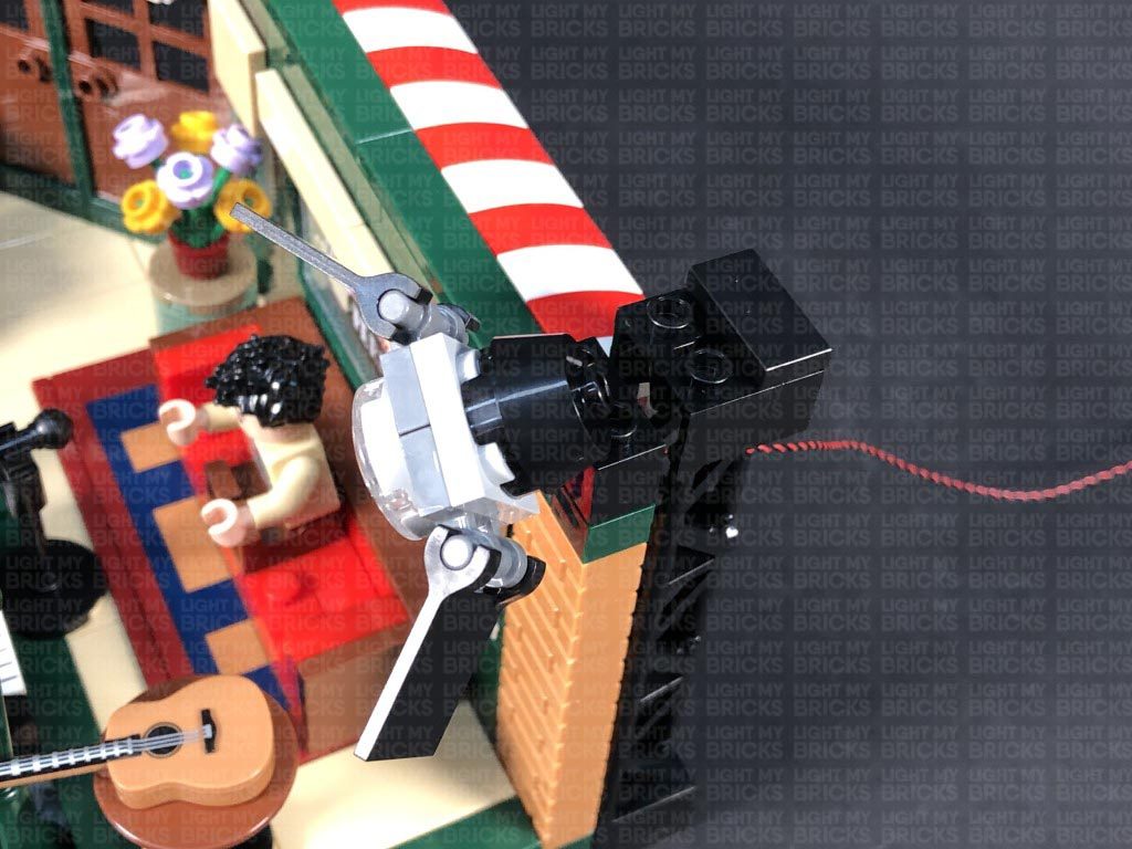
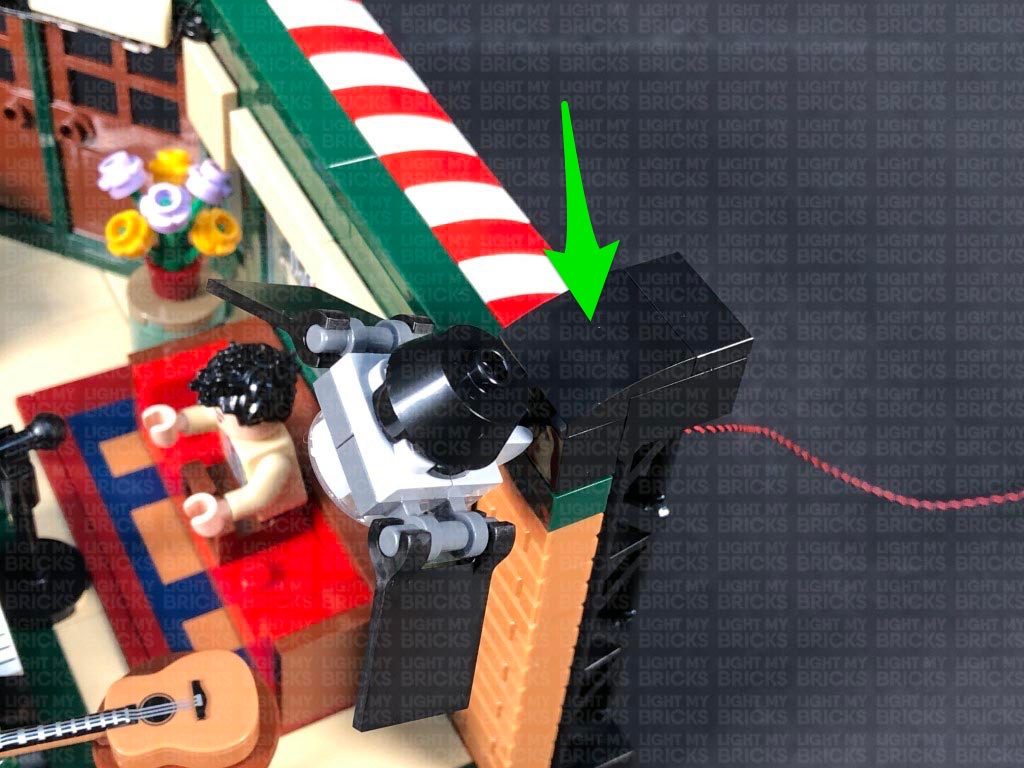
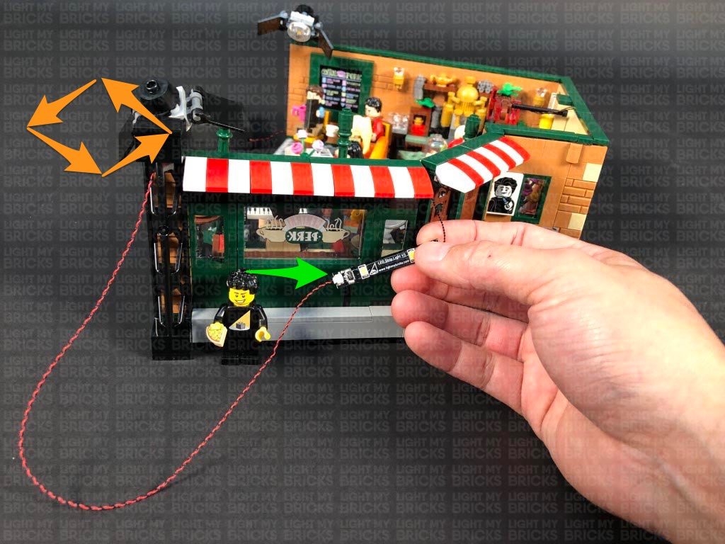
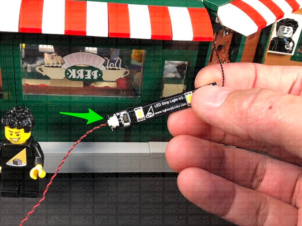
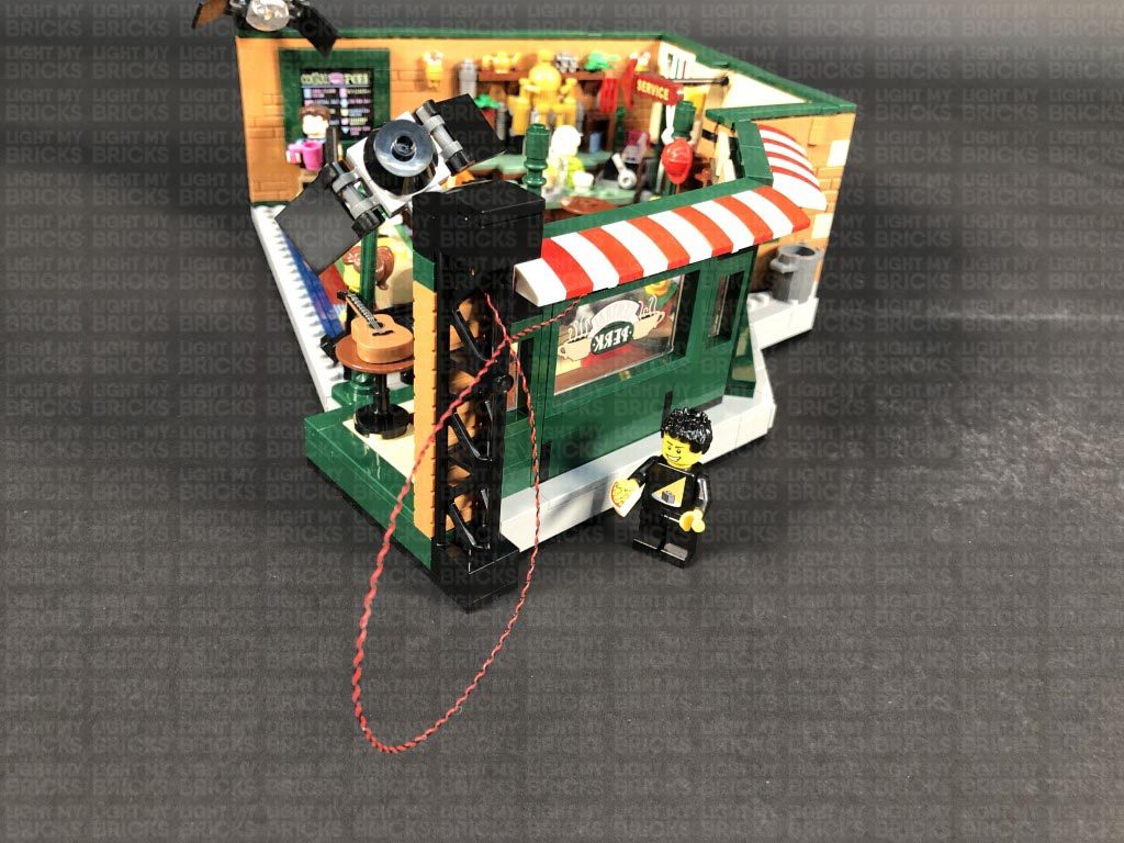
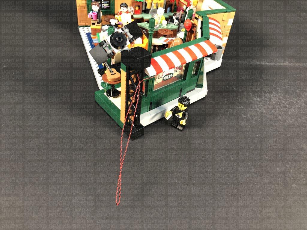
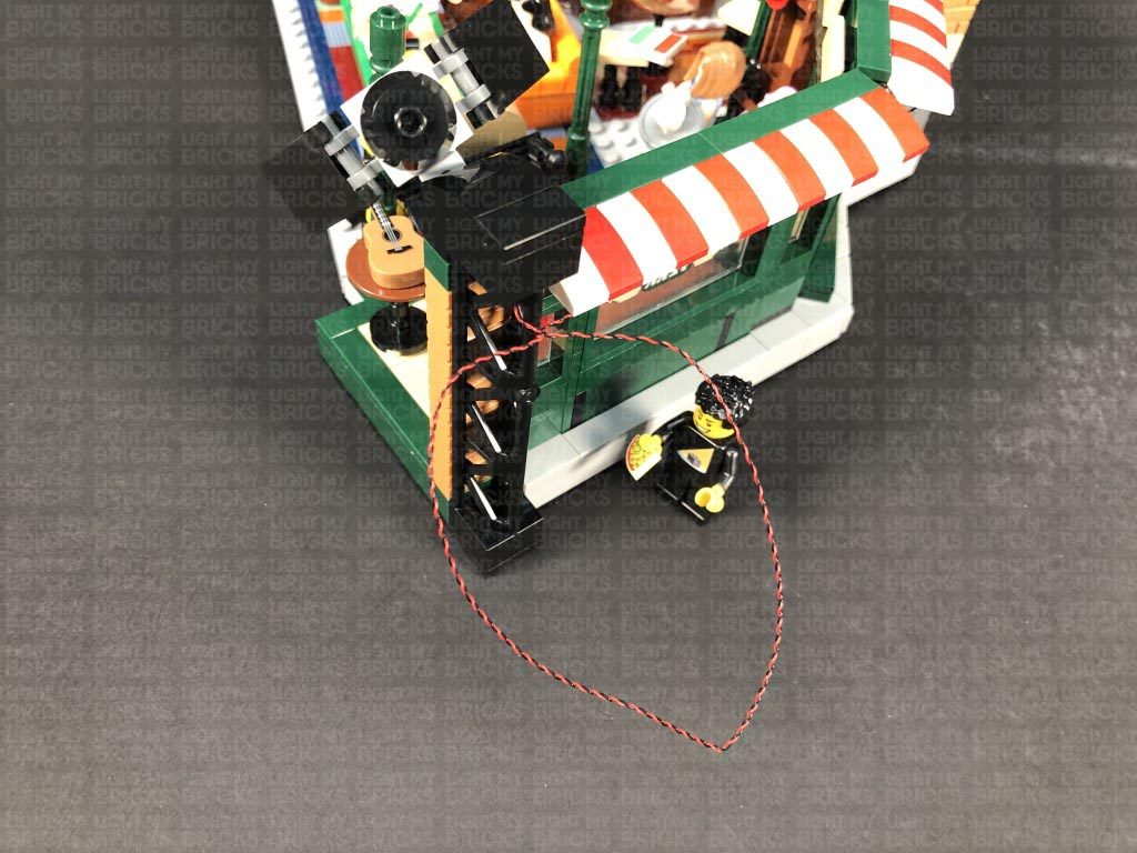
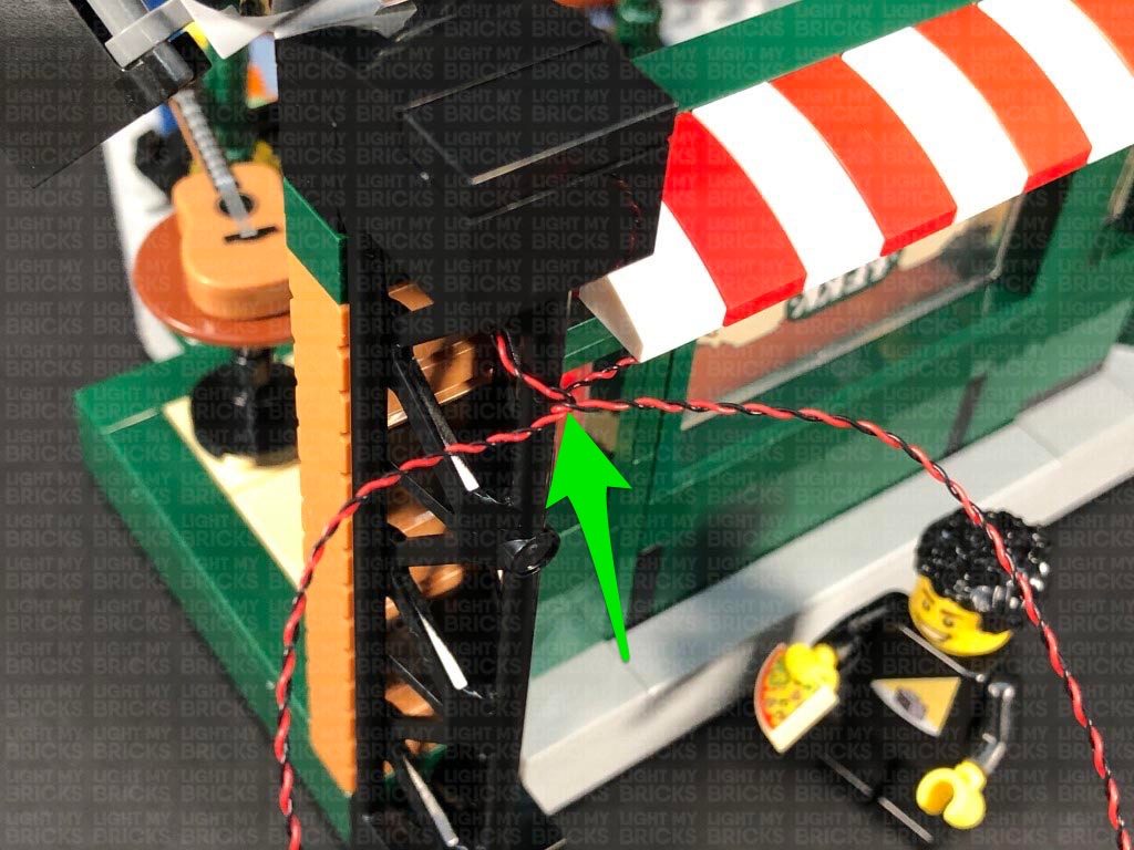
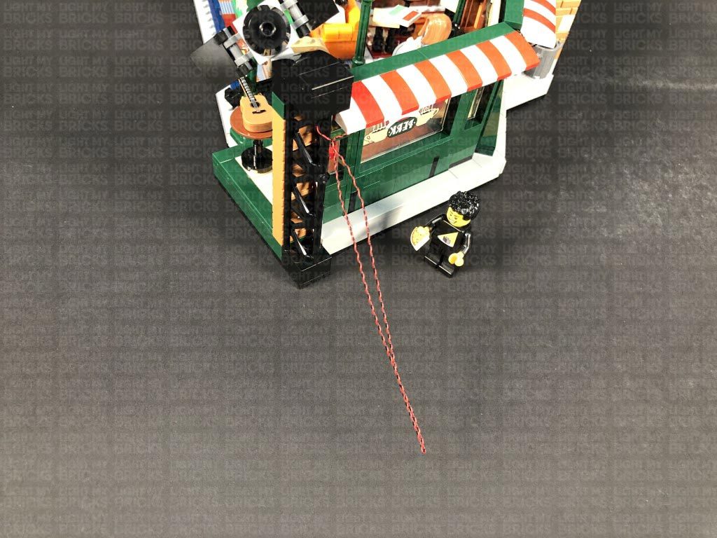
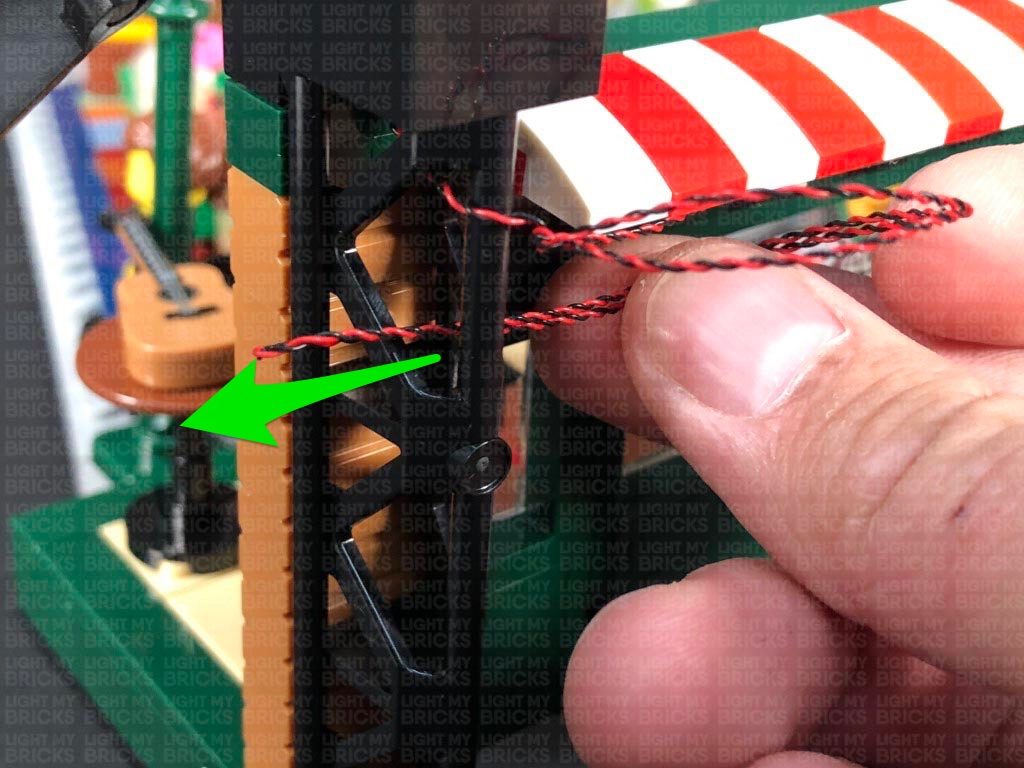
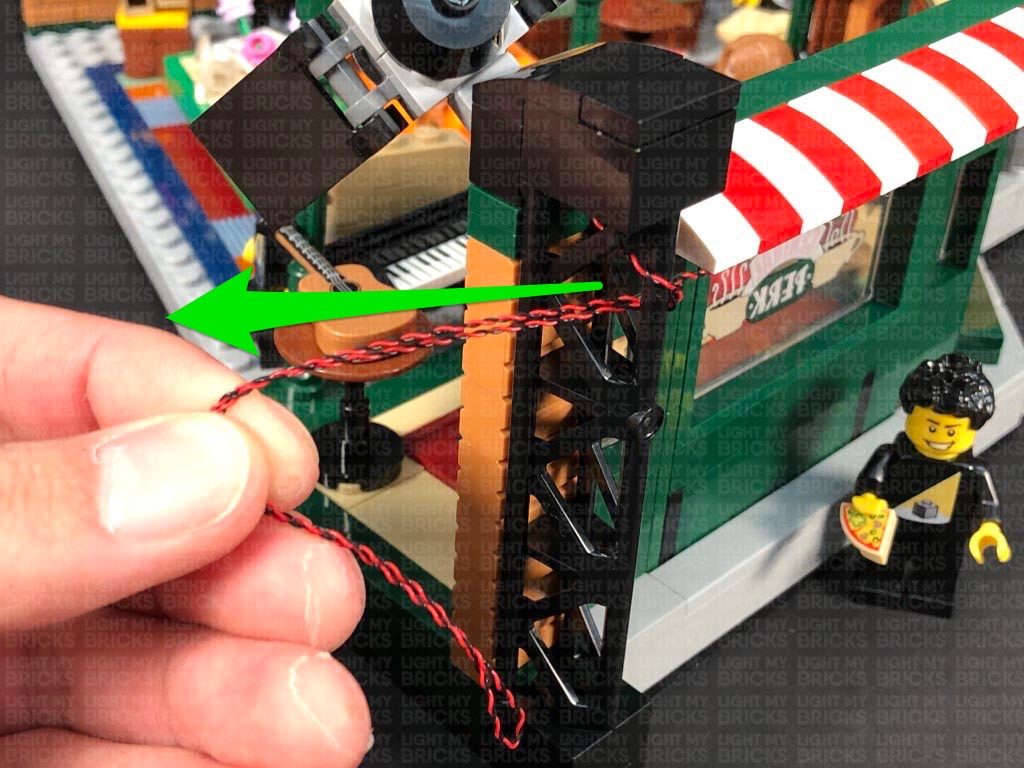
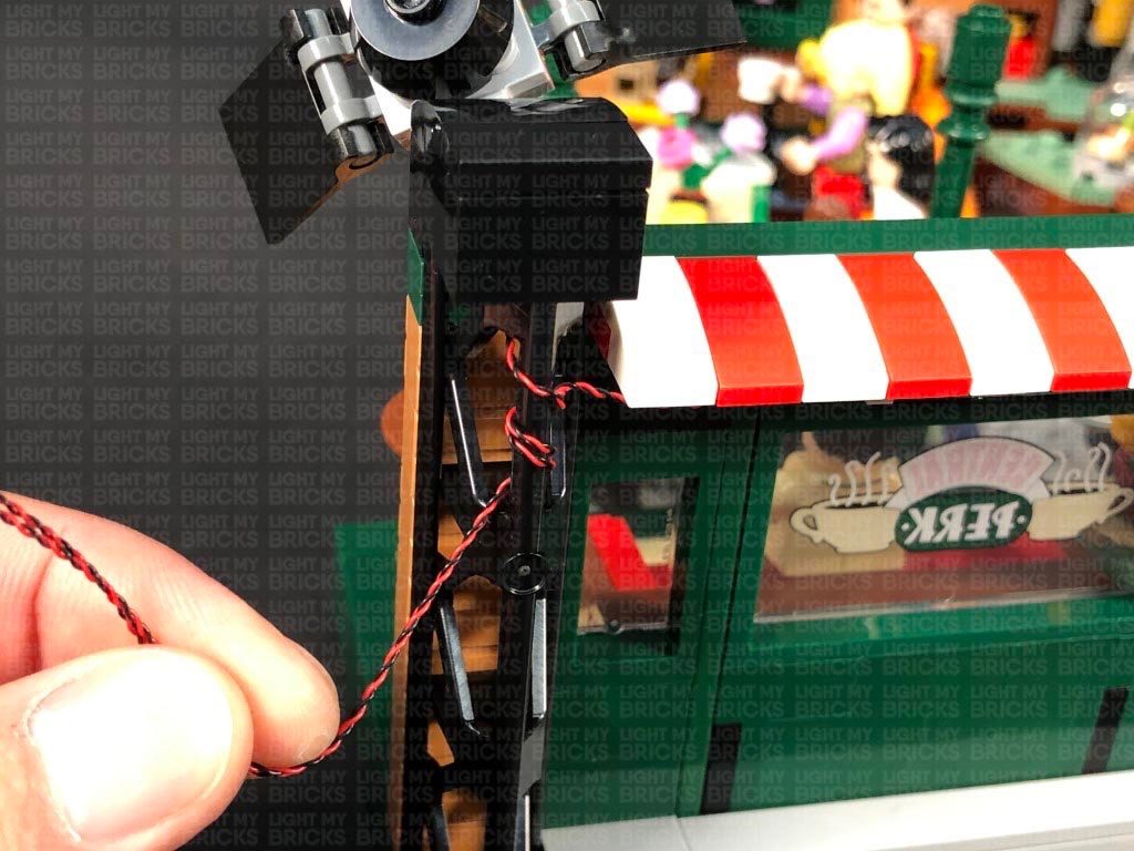
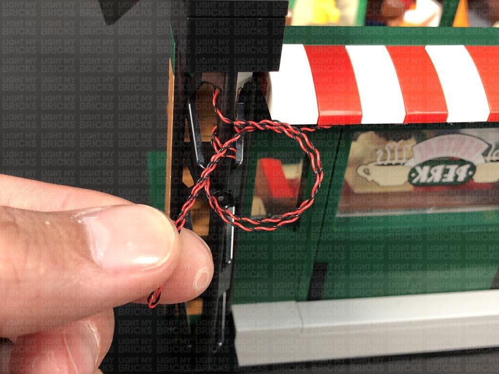
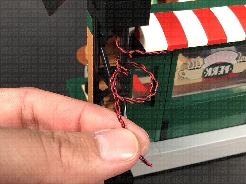
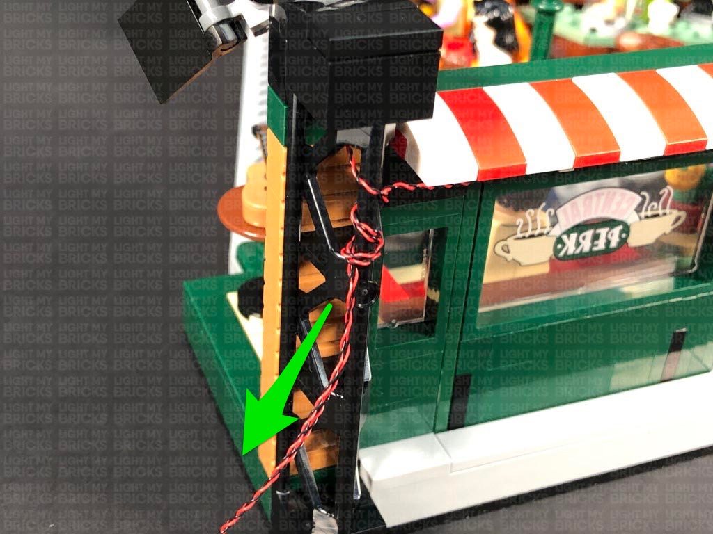
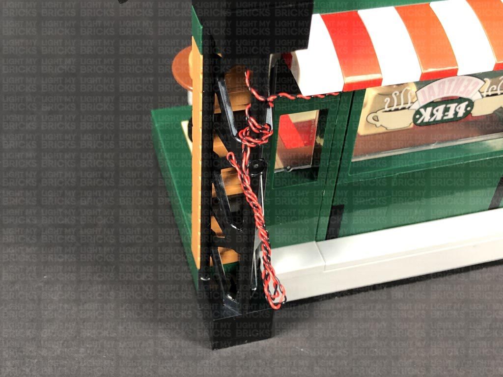
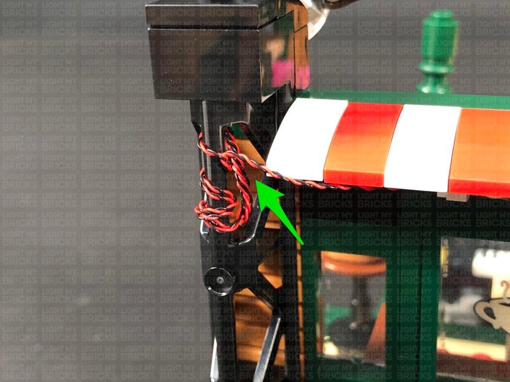
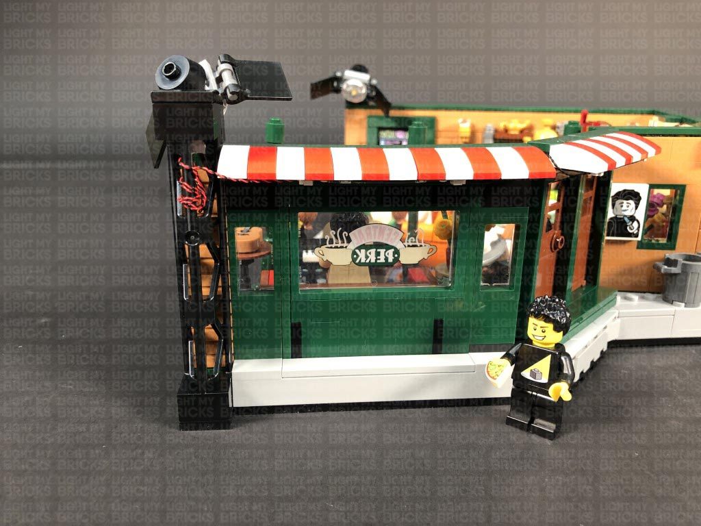
1.) We will first install the left stage light. Start by disconnecting the curved plate above it, then remove the stage light via the technic 1×2 brick. Disassemble the stage light as shown below: Take a Warm White 30cm Large Bit Light and thread the connector end of the cable through the bottom of the light grey round plate. Thread it all the way through, then carefully bend the LED so that it sits flat against the edge of the hole. Flip the light grey round plate around and lay the cable in between studs. Reconnect it to the stage light section, ensuring the cable is facing the black technic 1×2 brick, then reconnect the trans clear 2×2 plate with rounded bottom over the top. 2.) Reconnect the stage light to the set but first, lay the Bit Light cable in between the two studs underneath the black technic brick. Reconnect the black curved plate on top. Turn the set around to the left side and connect the Bit Light to a 6-Port Expansion Board. Take the AA Battery Pack and insert 3x NEW AA Batteries to it. Connect the battery pack cable to the 6-Port Expansion Board, then turn it ON to test the stage light is working OK. Note: If you experience any issues with the lights not working and suspect an issue with a component, please try a different port on the expansion board to verify where the fault lies (with the light or expansion board). To correct any issues with expansion board ports, please view the section addressing expansion board issues on our online troubleshooting guide. 3.) We will now install lights to the wall lamps. First, disconnect the following dark green tiles from the top of the walls, then disconnect the following wall sections to allow us to disconnect the bricks with clips that are holding the lamps. Disassemble one of the wall lamp sections as shown below, then take a White 15cm Micro Bit Light and place the led inside one of the gold plates with shafts. Ensuring the LED is facing up, secure the Bit Light in place by reconnecting the gold plate with open stud. If you look carefully inside, the LED should be visible and in the middle of the hole. Reconnect the trans clear piece, then lay the cable in between the clip of the 1×1 brick it connects to before reconnecting the lamp to it. Reconnect the lamp to the wall ensuring you first lay the cable to the side of the stud it connects on top of. 4.) Repeat the previous step to install another White 15cm Micro Bit Light to the other lamp section before reconnecting it to the wall. 5.) Turn the set around and connect the two Micro Bit Lights to a Micro 4-Port Expansion Board. Take a 5cm Connecting Cable and connect it to one of the larger ports on the micro expansion board. Connect the other end of the cable to the 6-Port Expansion Board to the right of it, then turn ON the AA Battery Pack to test the wall lamps are working OK. 6.) Reconnect the wall sections we removed, then disconnect the “service” sign section at the black pole. Disassemble this section as shown below: Take a White 30cm Bit Light and thread the connector end of the cable through the bottom of the red round plate with open stud. Thread the cable all the way through, then reconnect the round plate to the brown plates ensuring the LED is facing diagonally down on the left side of the round red plate. We are positioning the LED this way, so that it will shine down onto Gunther’s section behind the cash register. 7.) Turn the sign section over so we can access underneath, then take another White 30cm Bit Light and with the cable facing away from you, place it in the centre of the front brown plate. Fold the cable down over the front of the brown plate, before reconnecting the “service” tile over the top. The LED is positioned in the centre so that it will shine directly down onto the cafe area. Bring the cable from the first Bit Light over the top of the sign toward the back, then reconnect the arrow tile over the top. Flip the sign over onto it’s front, then take the two cables and twist them around each other 2-3 times at the left side to lock them in place. Reconnect the sign back to the set. 8.) Bring the cables underneath the black pole, then secure them both underneath the dark green tile behind ensuring they are both laid in between studs underneath. Turn the set around so that we are facing the outside of the left wall, then bring the two cables down the top of the back wall, laying them in between the following studs. Secure the cables down by reconnecting the dark green tile. 9.) Connect both Bit Light cables to spare ports on the 6-Port Expansion Board, then turn ON the battery pack to test the Service sign lights are working OK. Note: If you experience any issues with the lights not working and suspect an issue with a component, please try a different port on the expansion board to verify where the fault lies (with the light or expansion board). To correct any issues with expansion board ports, please view the section addressing expansion board issues on our online troubleshooting guide. Before we reconnect all the dark green tiles, take the cable from the stage light and lay them around studs on the top of the wall. Secure them by reconnecting the dark green tiles over the top of the cable, one at a time. 10.) We will now install lights to the lamp in the corner. First disconnect the table with flowers, then disconnect the lamp from the corner and disassemble it as per below: Take a White 15cm Micro Bit Light and carefully bend the LED slightly up, then place it inside the bottom of one of the gold round plates with open stud. Secure the LED in place by reconnecting one of the flame pieces. The LED should be secured in between the flame piece and gold plate as shown below. Ensuring the cable is facing the back, reconnect this section to the front of the lamp post. 11.) Repeat previous step to install another White 15cm Micro Bit Light to another fire section, then reconnect it to the lamp post ensuring the cable is laid behind. Turn the lamp post over and install another 2x White 15cm Micro Bit Lights, then reconnect them to the lamp post ensuring the cables from the front two lights are laid in between the gaps on the curved gold brick underneath. 12.) We will need to remove sections of the wall in order for us to bring the lamp post light cables behind. Follow the below images to disconnect the following sections of the wall. Reconnect the lamp post and lay the cables over the wall, then turn the set around to the back. Lay the two left cables in between studs, then lay the other two cables in between the next studs along. Reconnect all the wall sections we removed earlier. 13.) Connect the four Micro Bit Lights to a new Micro 4-Port Expansion Board. Take a 15cm Connecting Cable and connect it to one of the larger ports on the expansion board, then bring the cable around to the right side and connect it to one of the OUT ports on a Flicker Effects Board. Take a 5cm Connecting Cable and connect it to the IN port on the Flicker Effects Board. Connect the other end of the cable to one of the larger ports on the other Micro 4-Port Expansion Board to the right. Turn ON the battery pack to test the lamp lights are working and flickering OK. Note: If you experience any issues with the lights not working and suspect an issue with a component, please try a different port on the expansion board to verify where the fault lies (with the light or expansion board). To correct any issues with expansion board ports, please view the section addressing expansion board issues on our online troubleshooting guide. 14.) Take 2x Adhesive Squares and stick them on the back of the Micro 4-Port Expansion Board we connected the lamp post lights to. Stick the expansion board to the bottom of the wall in the following position, then bring the four cables together and secure them to the wall using tape. Lift the set up so we can access underneath, then secure the excess cables from the Micro Bit Lights underneath the following two black plates at the bottom of the set. Turn the set back around again and reconnect the table with flowers in front of the lamp post. 15.) Stick an Adhesive Square to the back of the Flicker Effects Board, and another 2x Adhesive Squares on the back of the other Micro 4-Port Expansion Board. Stick both boards inside the space at the bottom of the wall toward the right. Use your LEGO removal tool to push down the boards so they securely stick down to the studs. 16.) Turn the set around to the front entrance area and disconnect the roof section above the doors. Take a Warm White Strip Light and connect a 50cm Connecting Cable to the left port. Take a 5cm Connecting Cable and connect it to the Strip Light’s right port, then using it’s adhesive backing, stick the strip light underneath the roof section in the following position ensuring the 5cm cable is on the right side. 17.) Take another Warm White Strip Light and connect the other end of the 5cm Cable from previous step to it’s left port. Take a new 5cm Connecting Cable and connect it to the strip light’s right port. Flip the roof section over and reconnect it to the set. Bring the 5cm cable and strip light through to the inside of the building by slipping it in between the wall sections. Bring the other end of the 50cm Connecting Cable through to the inside by slipping it in between wall sections, then bring the cable across to the right, laying it in between the dark green and beige tiles. Bring the cable back outside, securing it in place by slipping it in between wall sections as shown below. 18.) Disconnect the following dark green tile to the right, then lay the cable in between studs before reconnecting the tile over the top. Continue to bring the cable around to the right side and lay it in between studs underneath the following dark green tiles. 19.) Turn the set around to the far right side and secure the 50cm connecting cable underneath the following dark green tile on the left, then connect the cable to the remaining port on the 6-Port Expansion Board. Turn ON the battery pack to test the two strip lights we have connected are working OK. Note: If you experience any issues with the lights not working and suspect an issue with a component, please try a different port on the expansion board to verify where the fault lies (with the light or expansion board). To correct any issues with expansion board ports, please view the section addressing expansion board issues on our online troubleshooting guide. Tuck the remaining two expansion boards inside the space at the bottom of the wall, then neaten up all the cables and secure them to the wall using tape. 20.) From the inside of the set, locate the Warm White Strip Light and using it’s adhesive backing, stick it underneath the two beige coloured tiles just above the front entrance. Because the tiles are thin, the strip light will only partially stick underneath them. Secure the 5cm Connecting cable from the left underneath the following square tile, then disconnect the two longer tiles above the entrance and hide the 50cm cable on the back side of the studs underneath. Reconnect the two tiles over the top. Bring the 5cm Connecting Cable on the right over to the front side of the wall, slipping it in between the wall sections. Turn the set around, then take the remaining Warm White Strip Light and connect the 5cm Connecting Cable we brought over to it’s right port. Leave the strip light as is for now as we will fix it underneath the roof section later. 21.) We will now install the remaining large bit light to the stage light on the right side of the set. First disconnect the black curved plate on top, then disconnect and disassemble the stage light section as per below Take a Warm White Large 30cm Bit Light and install it to this stage light following the same method we used to install the first stage light. Reconnect the stage light ensuring you first thread the cable through the stage light post and lay it in between studs underneath the technic brick. Reconnect the black curved plate on top. 22.) Turn the set around and connect the Large Bit Light to the Strip Light. Turn ON the battery pack to test all the lights are working OK. Using it’s adhesive backing, stick the strip light underneath the middle of the roof section as shown below. 23.) Wind up the large bit light cable 2-3 times at the stage light post so the cable locks and is prevented from dangling down, then fold the cable together and thread it through the back of the post. Pull the cable all the way out from the front side. Thread the cable back through the following space, pulling it all the way out from the back side of the post. Repeat this process again then tie a knot in the cable around the pole to secure everything in place. Fold and twist up the remaining excess cable, then tuck it inside the stage post. Finally, turn ON the Battery Pack to test all your lights are working OK. Note: If you experience any issues with the lights not working and suspect an issue with a component, please try a different port on the expansion board to verify where the fault lies (with the light or expansion board). To correct any issues with expansion board ports, please view the section addressing expansion board issues on our online troubleshooting guide.
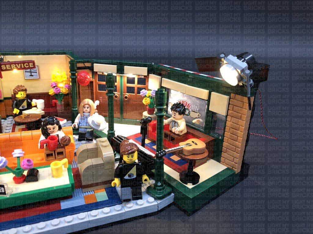
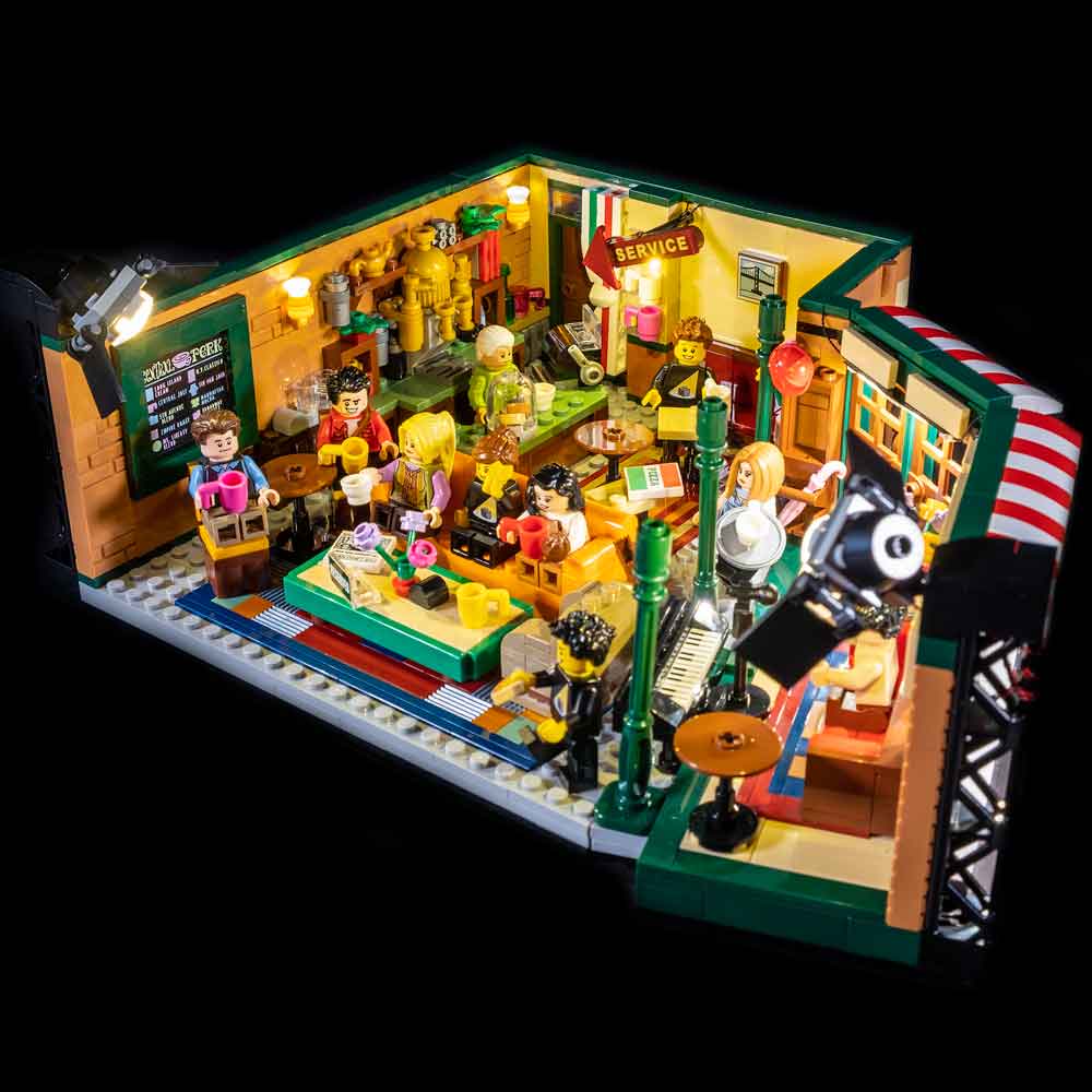
This finally completes installation of the Light My Bricks Friends Central Perk Light Kit.
We thank you for purchasing this product and hope you enjoy!