
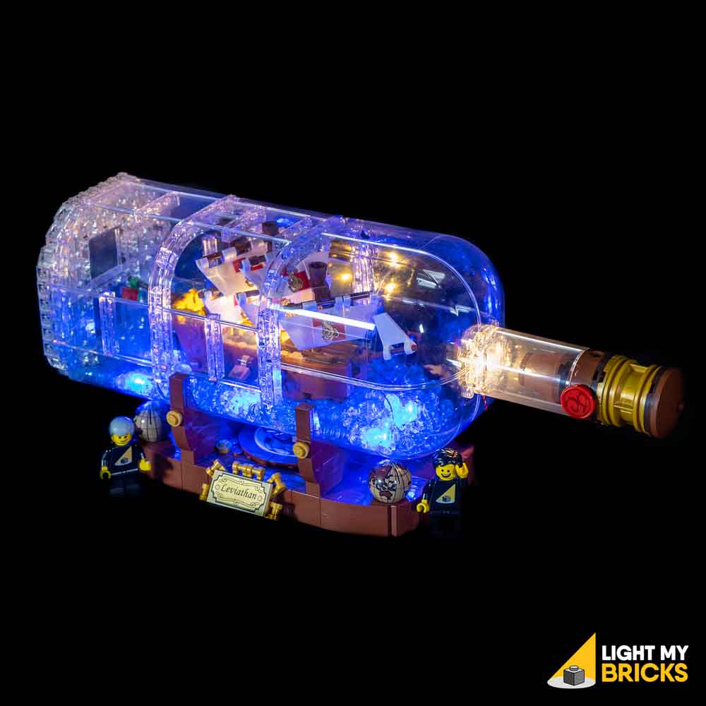
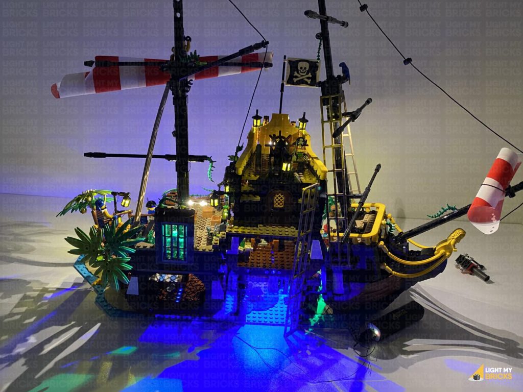
The following page is the instructions for the Light My Bricks Pirates of Barracuda Bay (21322) LED light kit.
If you run into any issues, please refer to the online troubleshooting guide.
To ensure a trouble-free installation of your light kit, please read and follow each step carefully. These instructions can be downloaded in PDF format here
Please note: This page lists instructions for the LED light kit only. If you are wishing to purchase the Light My Bricks LEGO Pirates of Barracuda Bay (21322) LED light kit , please click here to view the product page
Package Contents:
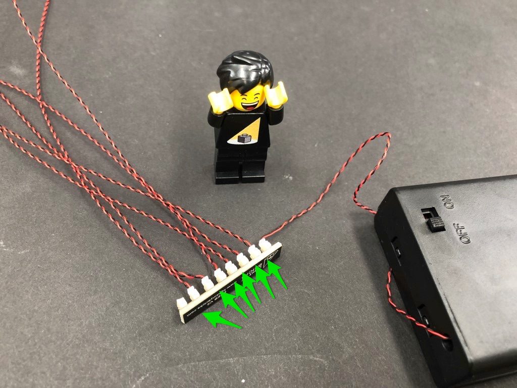
Bit Lights
- 6x White 30cm Bit Lights
- 6x White 15cm Bit Lights
- 2x White 30cm Micro Bit Lights
- 5x White 15cm Micro Bit Lights
- 1x Green 30cm Bit Lights
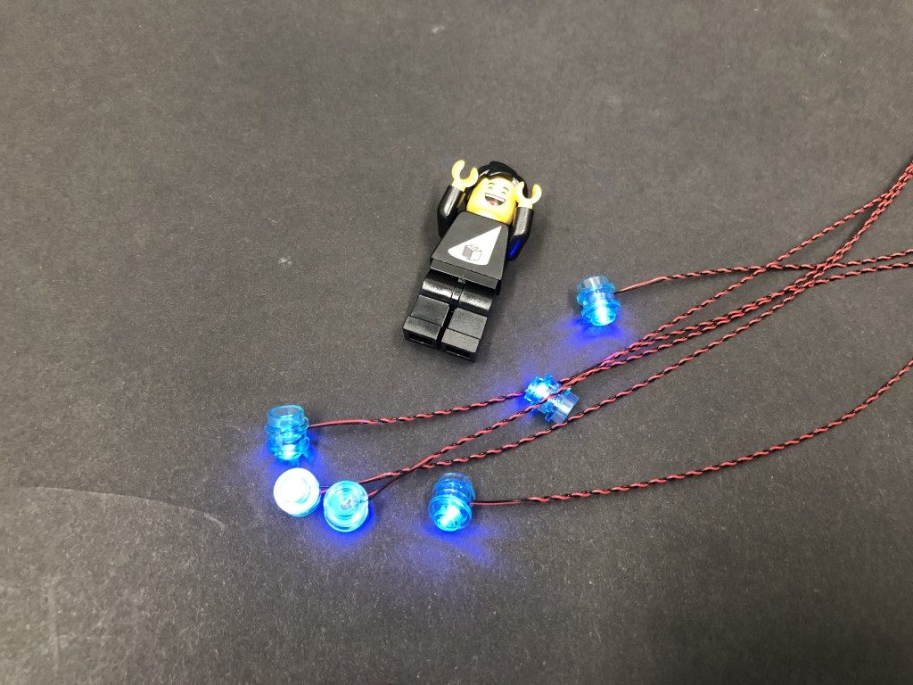
Strip Lights
- 4x Warm White Strip Lights
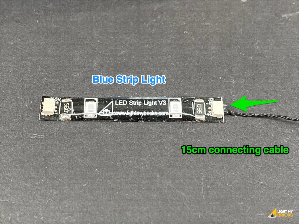
- 4x Blue Strip Lights
- 1x Green Strip Light
Expansion Boards
- 1x 2-Port Expansion Board
- 3x 6-Port Expansion Boards
- 1x 8-Port Expansion Board
- 2x Micro 2-4 Port Expansion Boards
- 2x Flicker Effects Boards
Connecting Cables
- 5x 5cm Connecting Cables
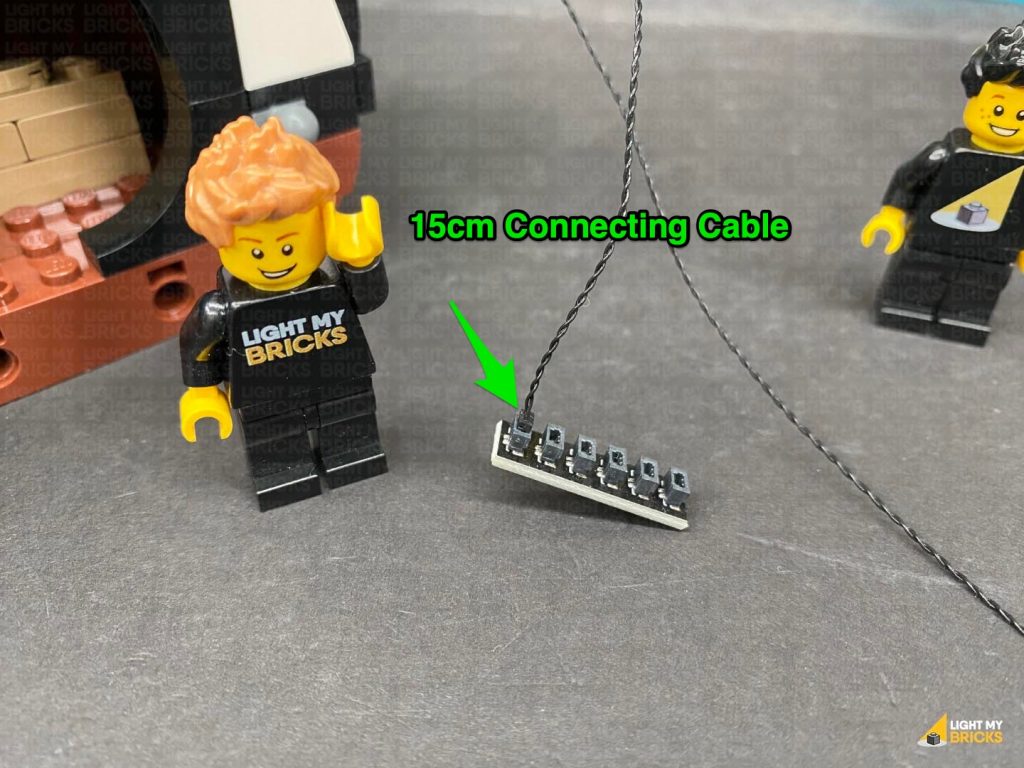
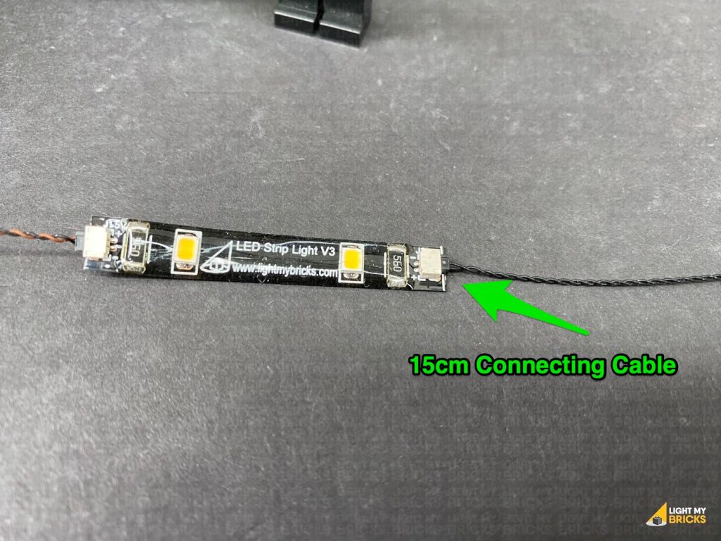
- 6x 15cm Connecting Cables
- 4x 30cm Connecting Cables
- 2x 50cm Connecting Cables
- 1x USB Power Cable
LEGO Pieces:
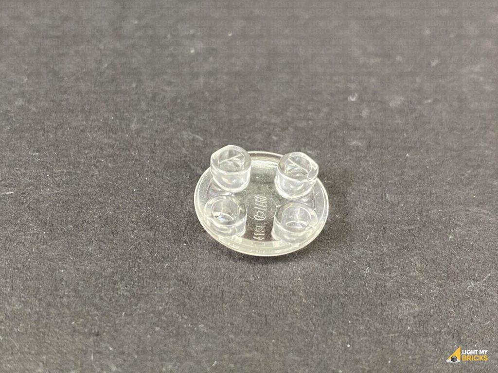
- 1x Trans Clear Plate w Rounded Bottom 2×2
- 2x Black Round Plate 1×1 with Open Stud
- 2x Black Tile 1×1 with Clip Rounded Edges
- 2x Black 1×1 Modified Plate Rounded with Handle
Important things to note:
Laying cables in between and underneath bricks
Cables can fit in between and underneath LEGO® bricks, plates, and tiles providing they are laid correctly between the LEGO® studs. Do NOT forcefully join LEGO® together around cables; instead ensure they are laying comfortably in between each stud.
Connecting cable connectors to Expansion Boards
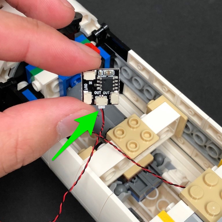
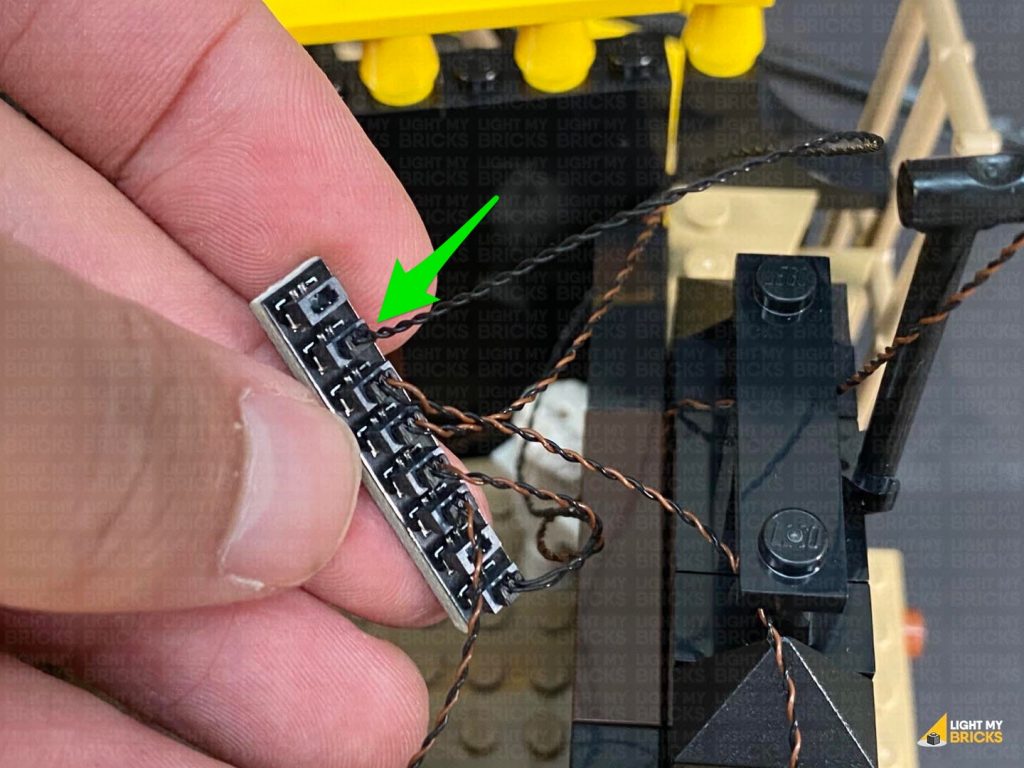
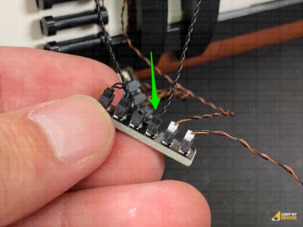
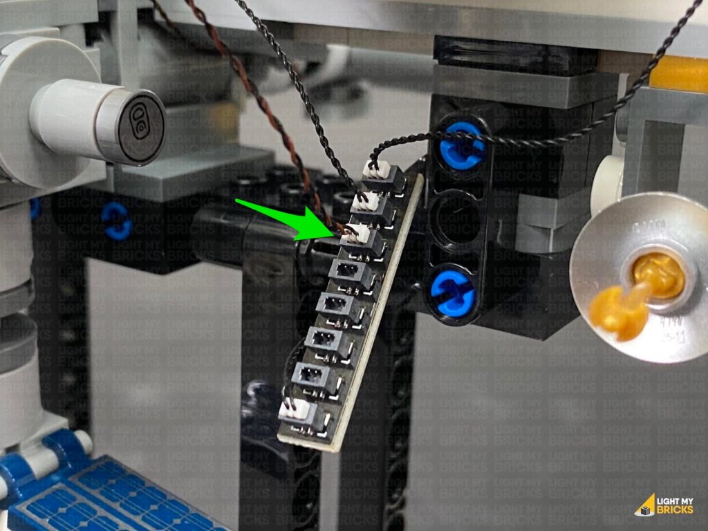
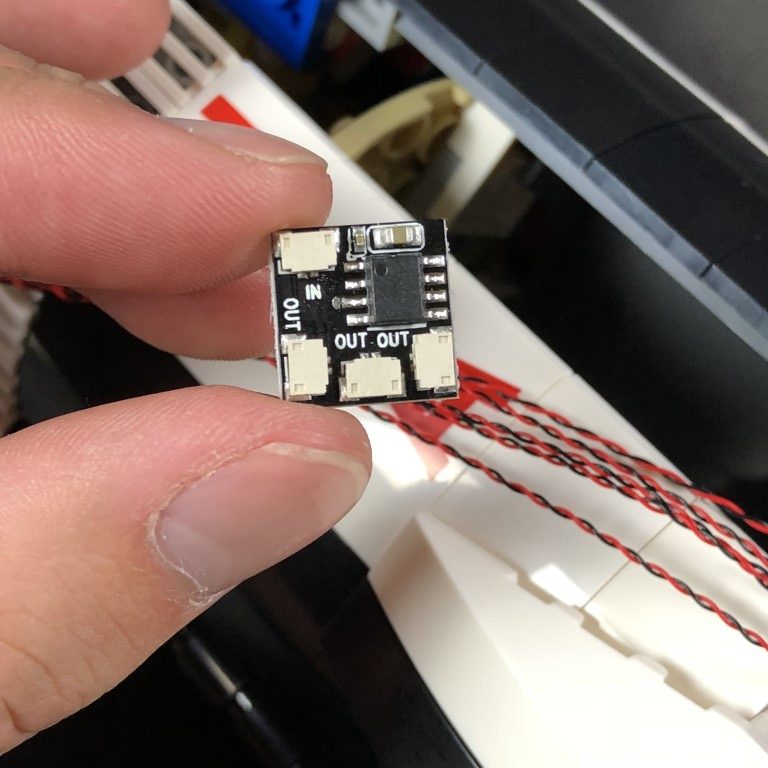
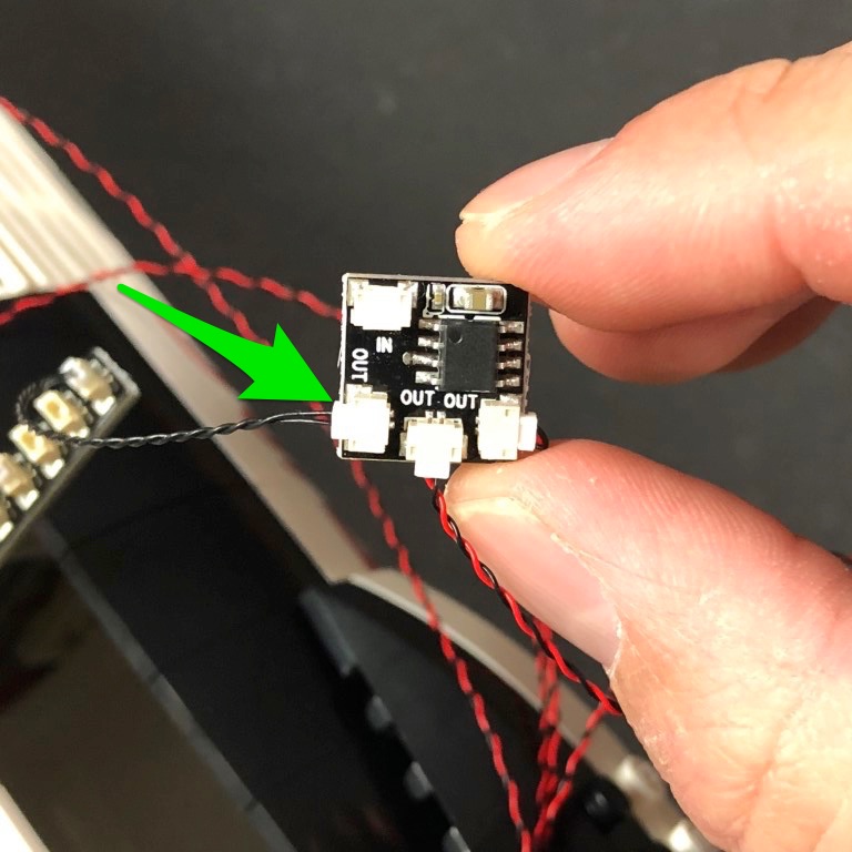
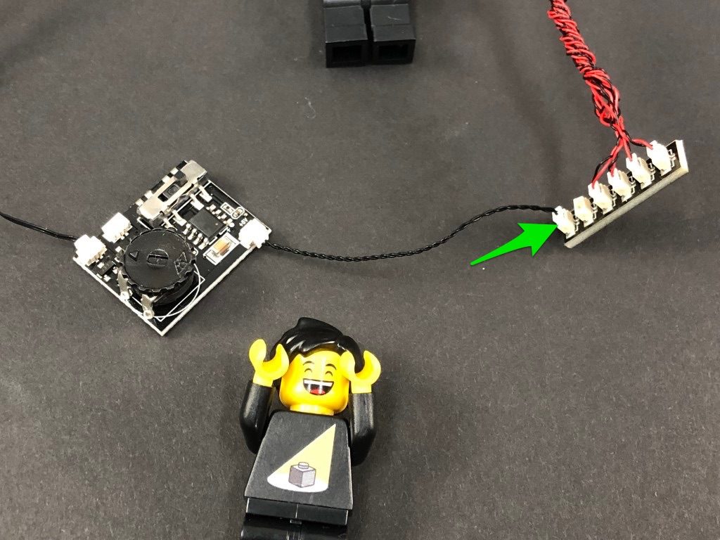
Take extra care when inserting connectors to ports of Expansion Boards. Connectors can be inserted only one way. With the expansion board facing up, look for the soldered “=” symbol on the left side of the port. The connector side with the wires exposed should be facing toward the soldered “=” symbol as you insert into the port. If a plug won’t fit easily into a port connector, do not force it.
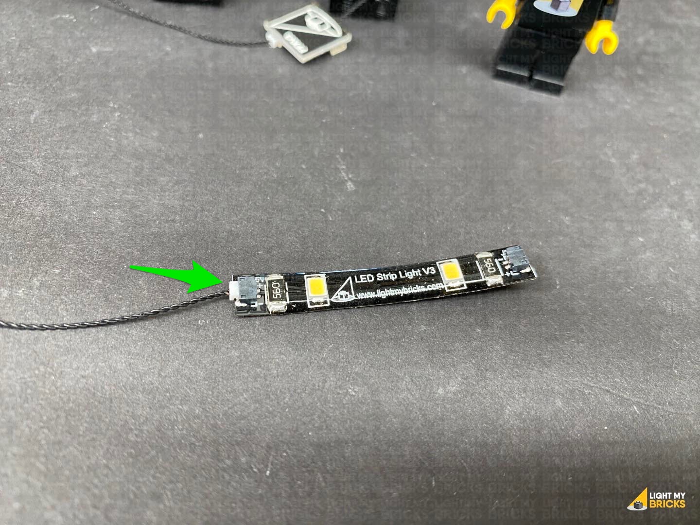
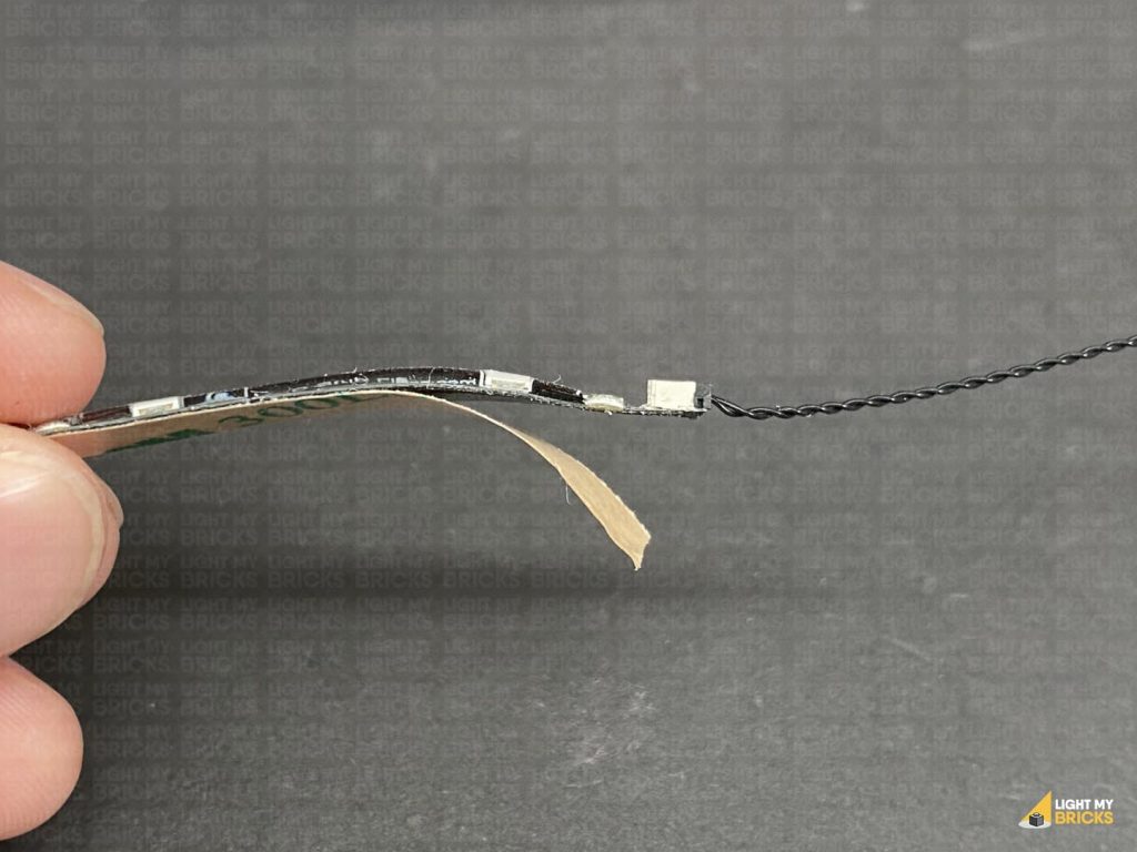
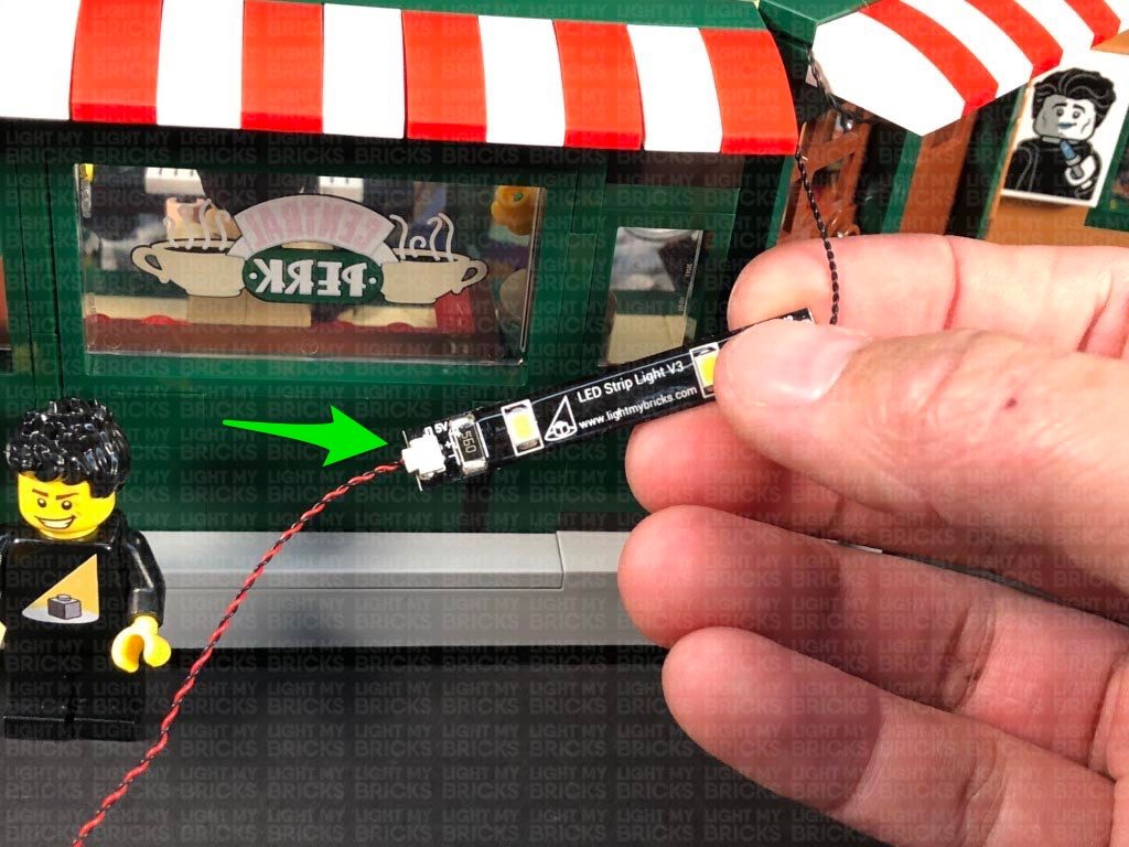
Connecting cable connectors to Strip Lights
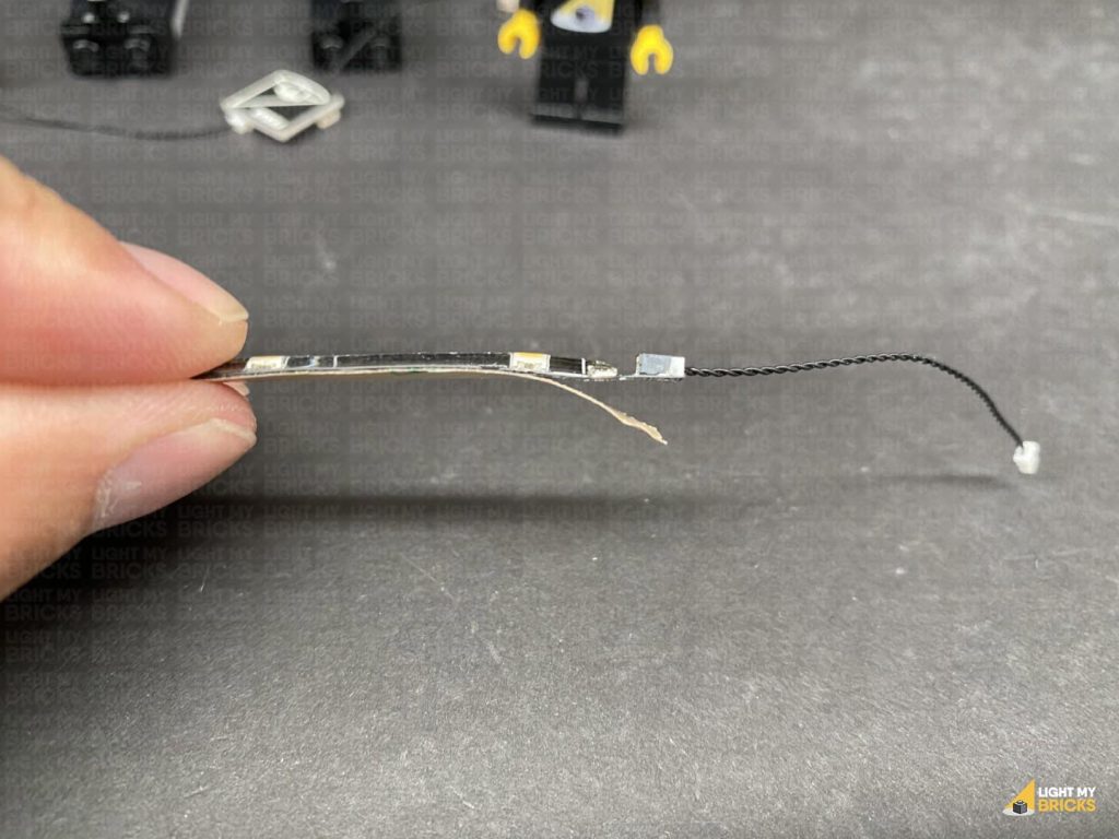
Take extra care when inserting connectors to ports on the Strip Lights. Connectors can be inserted only one way. With the Strip Light facing up, ensure the side of the connector with the wires exposed is facing down. If a plug won’t fit easily into a port connector, don’t force it. Doing so will damage the plug and the connector.
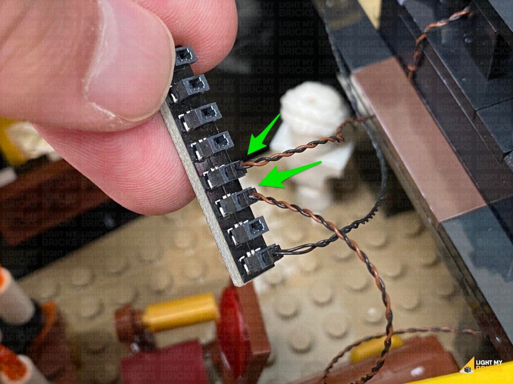
Connecting Micro Cable connectors to Micro Expansion Board Ports
Take extra care when inserting the micro connectors to micro ports of Micro Expansion Boards. Connecting Micro Bit Lights to Micro Expansion Boards is similar to connecting lights and cables to Strip Lights. With the expansion board facing up, ensure the side of the connector with the wires exposed is facing down. If a plug won’t fit easily into a port connector, do not force it. Use your fingernail to push the plastic part of the connector to the micro port.Installing Bit Lights under LEGO® bricks and plates.
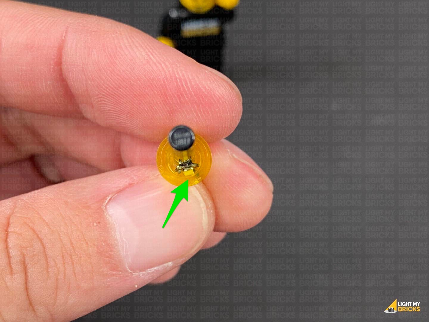
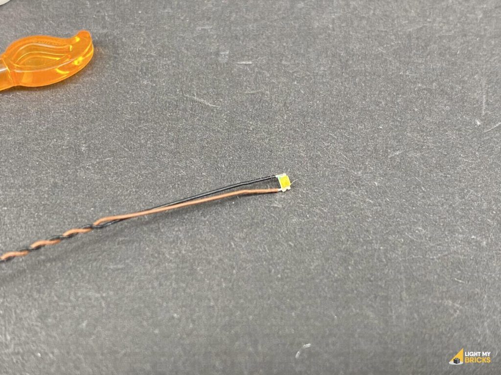
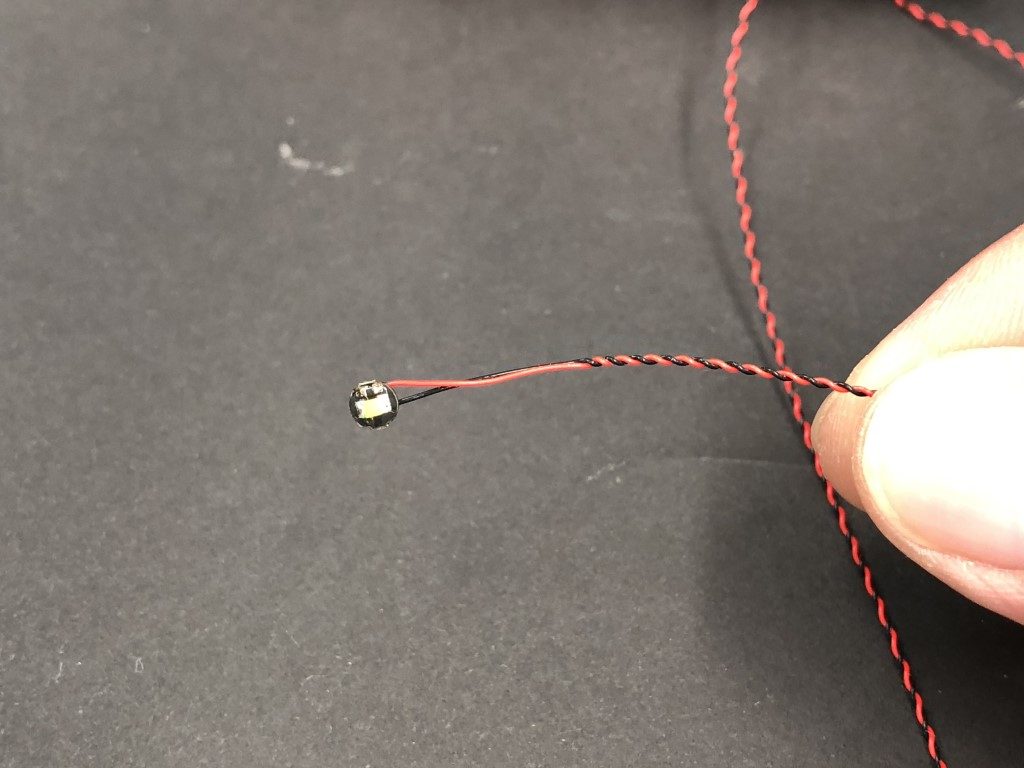
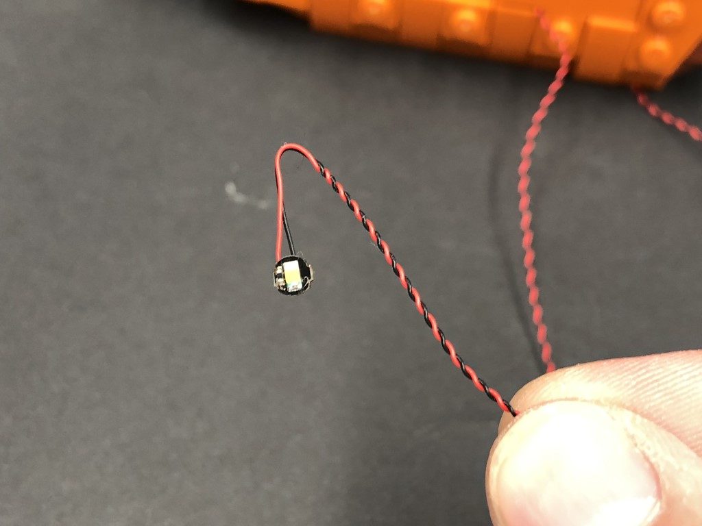
When installing Bit Lights under LEGO® pieces, ensure they are placed the correct way up (Yellow LED component exposed). You can either place them directly on top of LEGO® studs or in between.
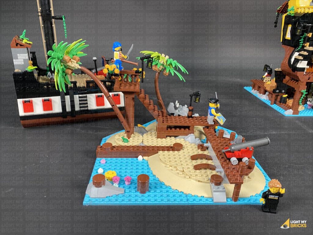
OK, Let’s Begin!
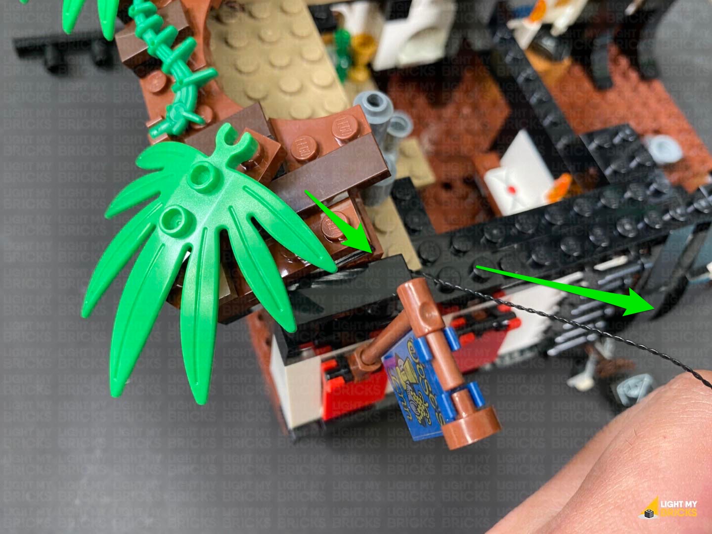
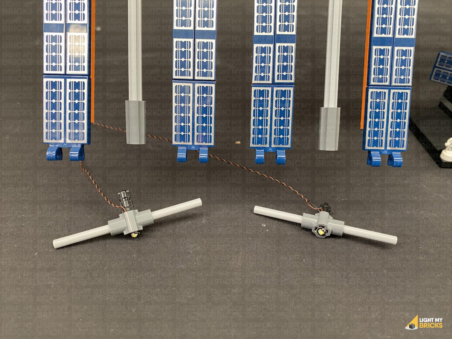
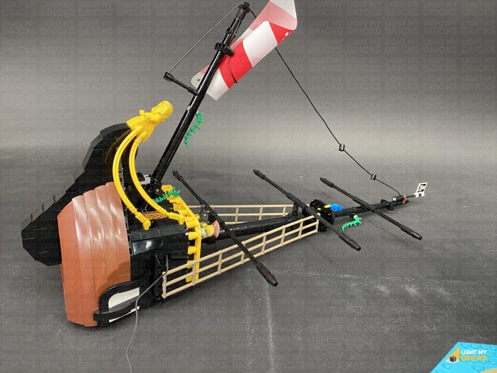
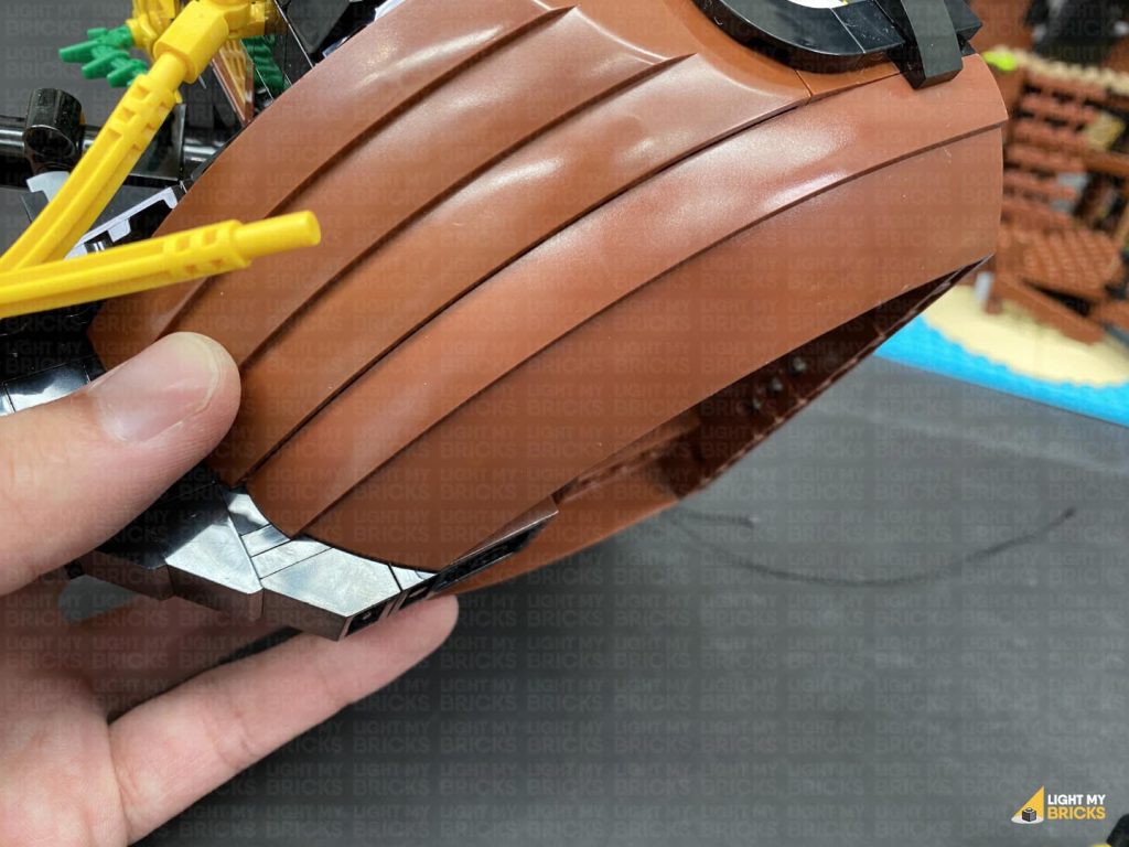
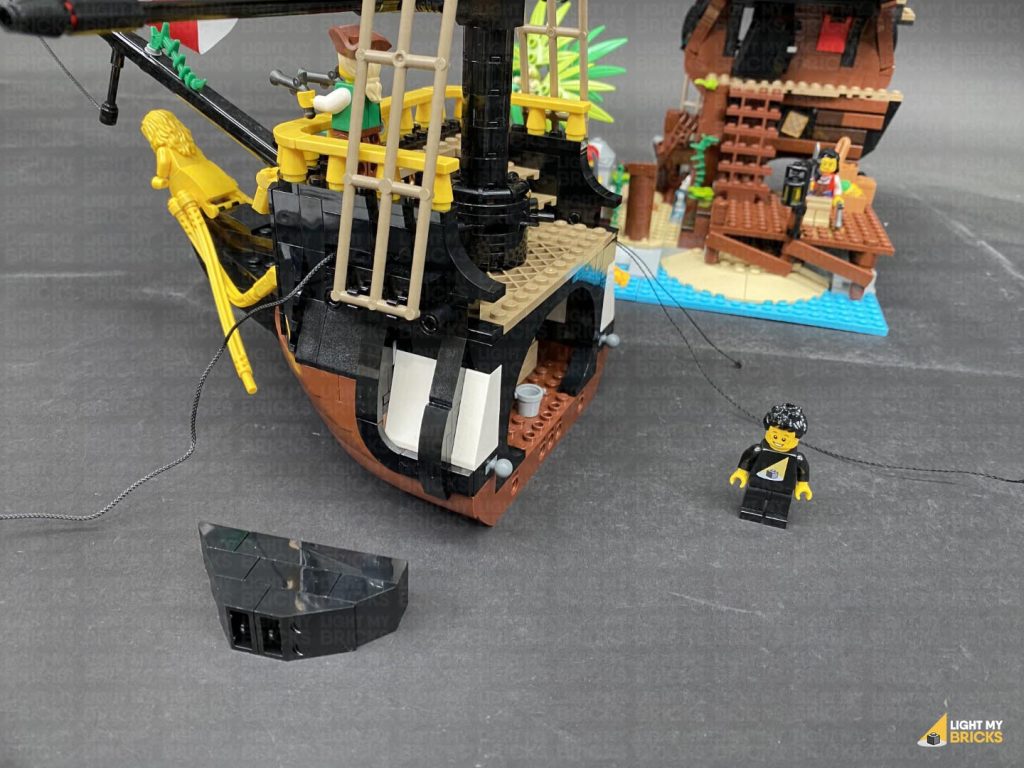
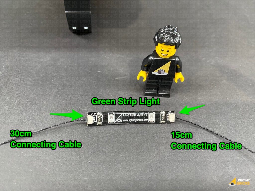
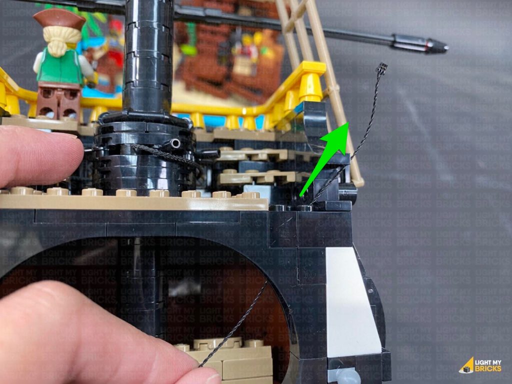
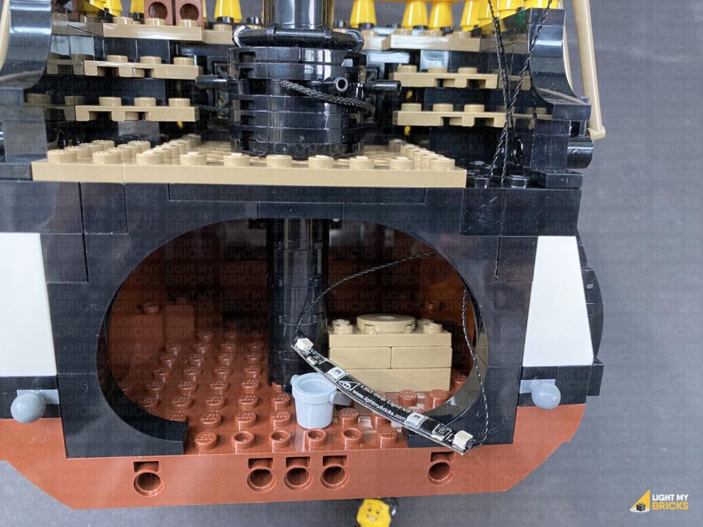
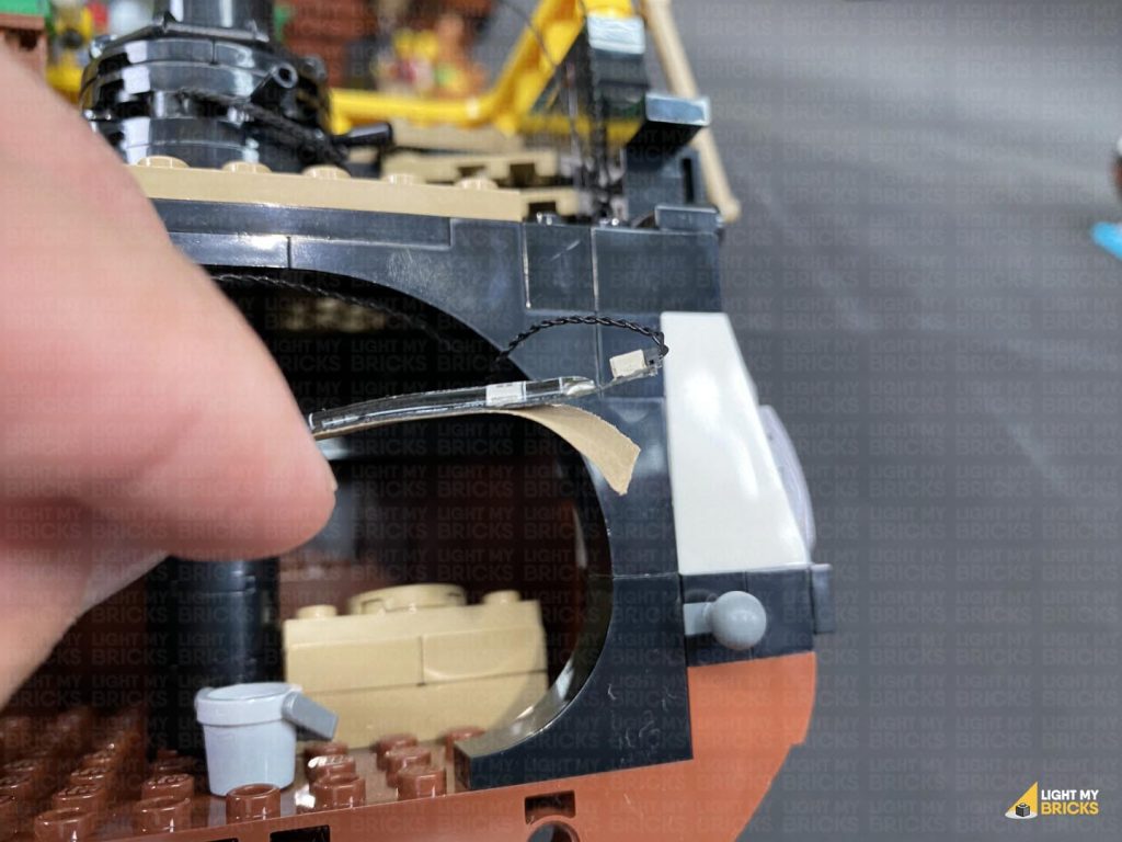
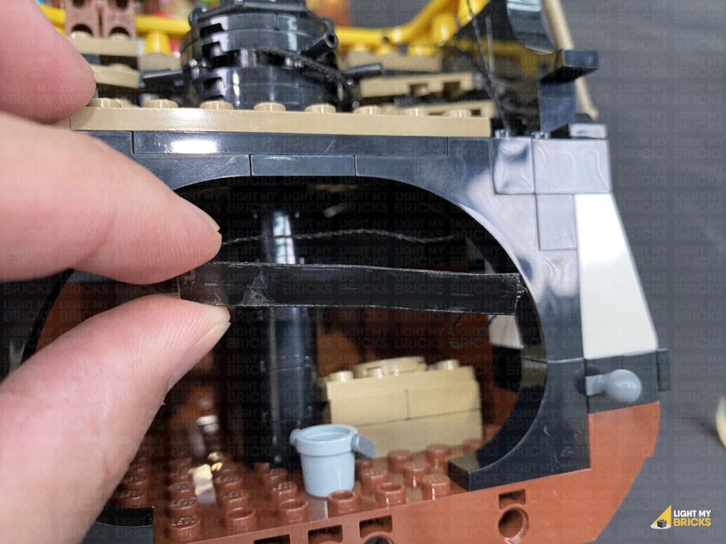
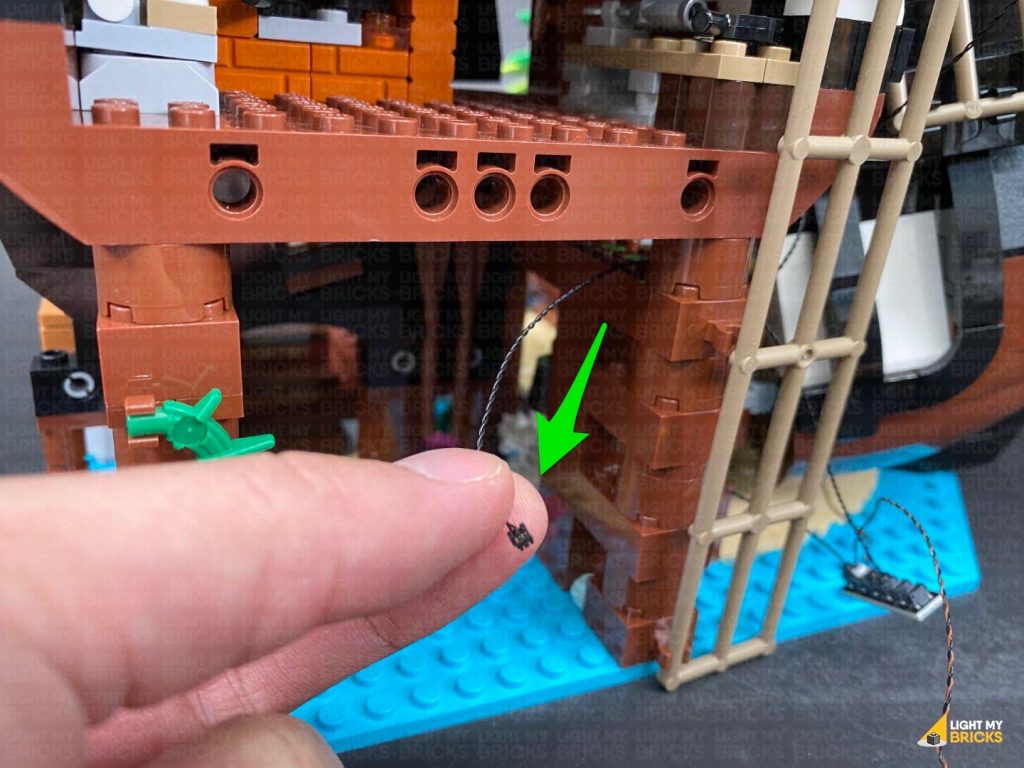
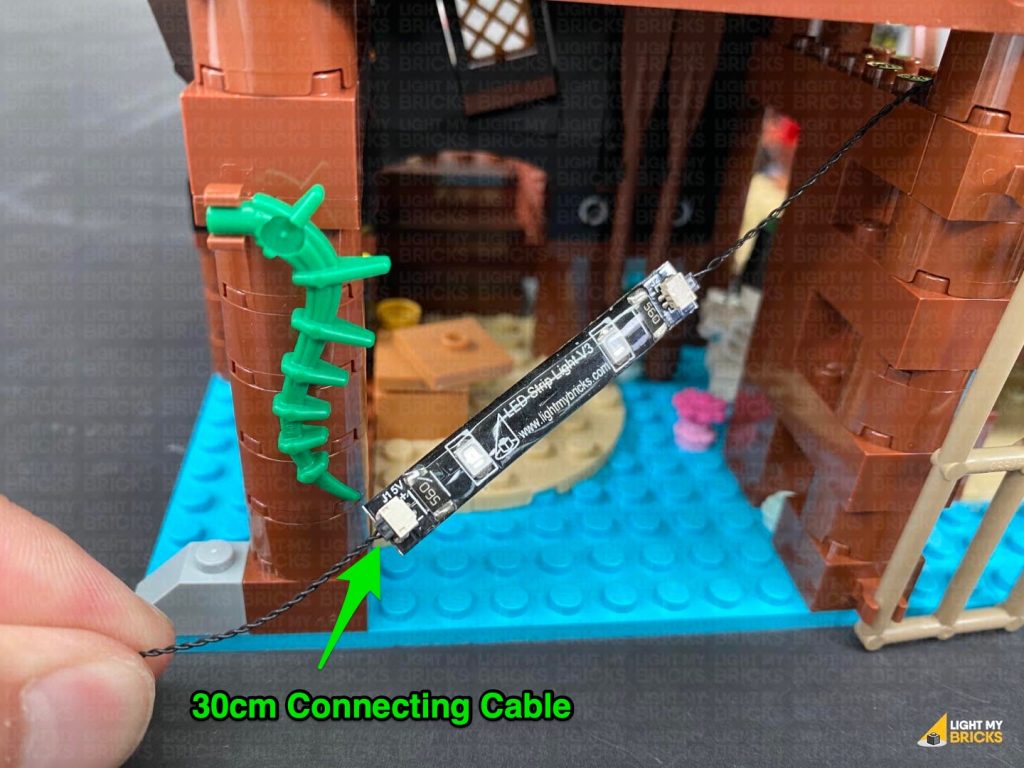
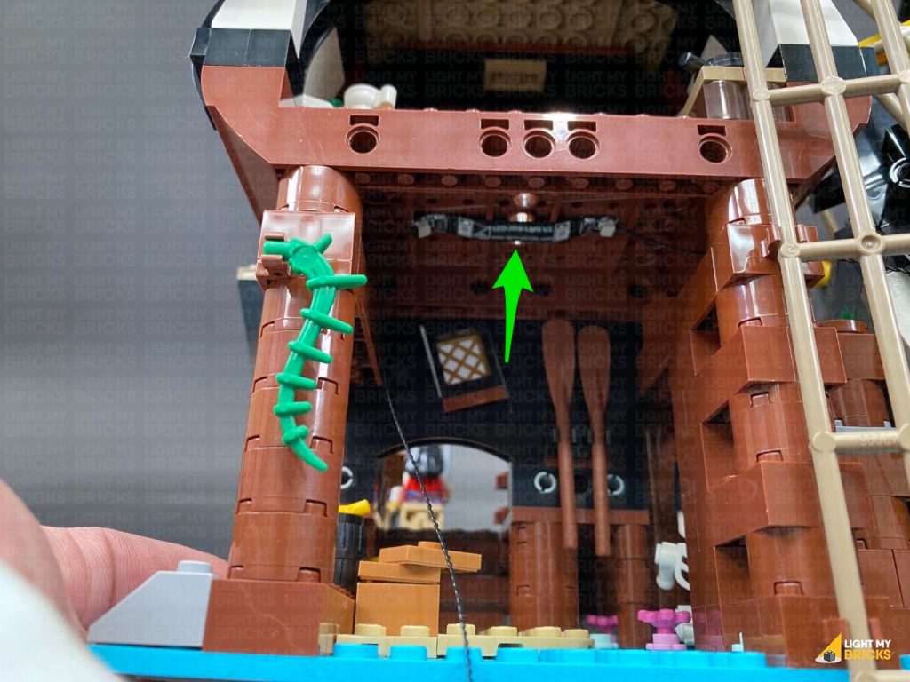
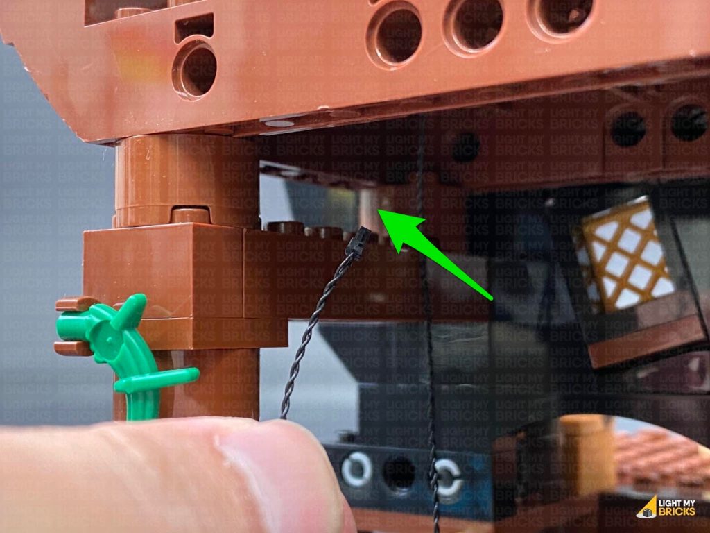
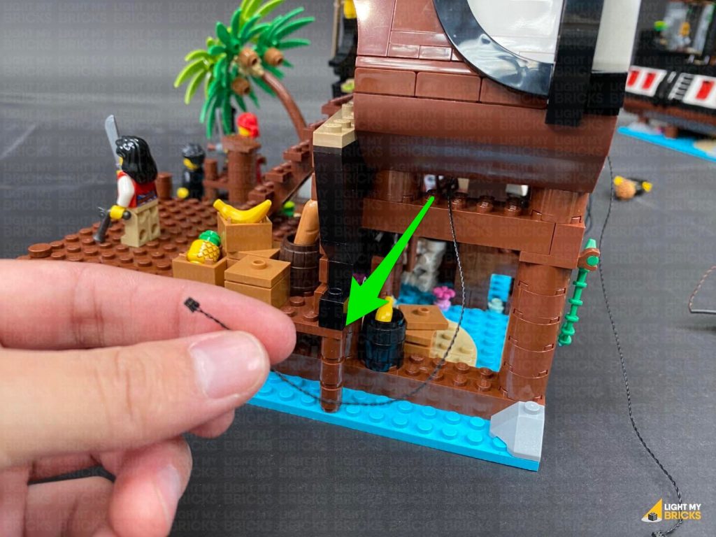
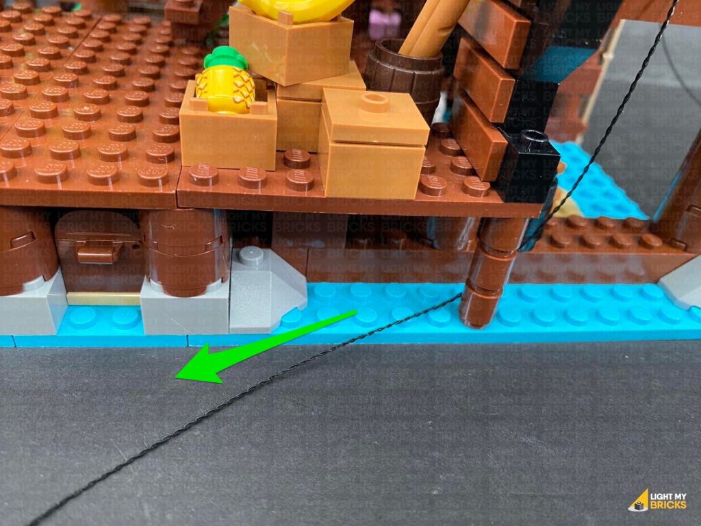
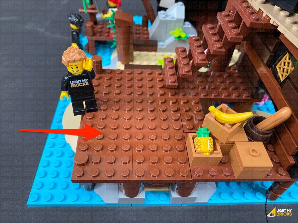
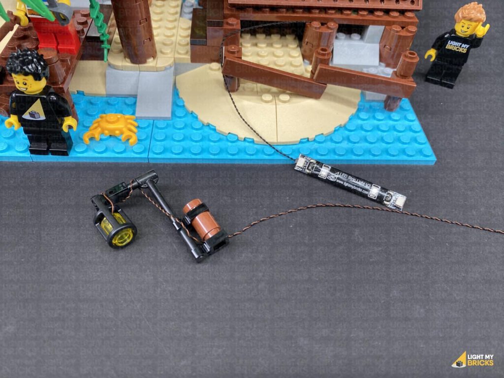
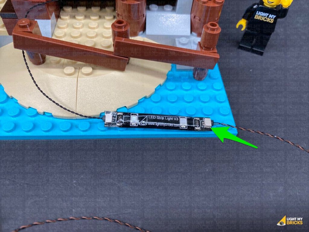
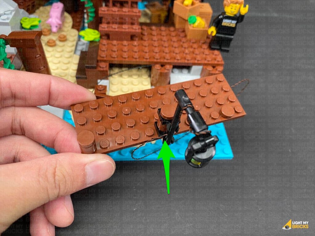
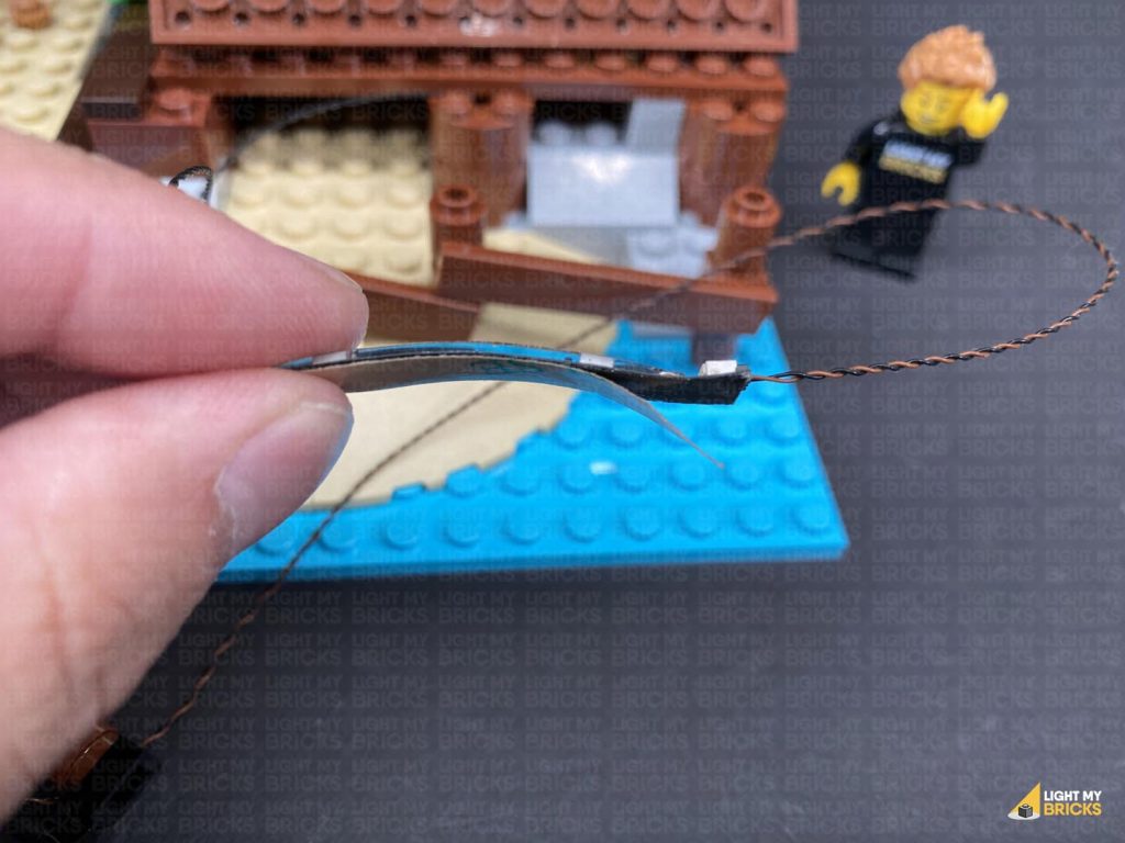
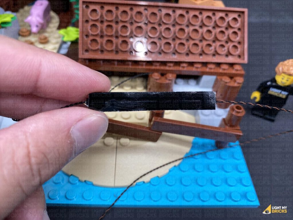
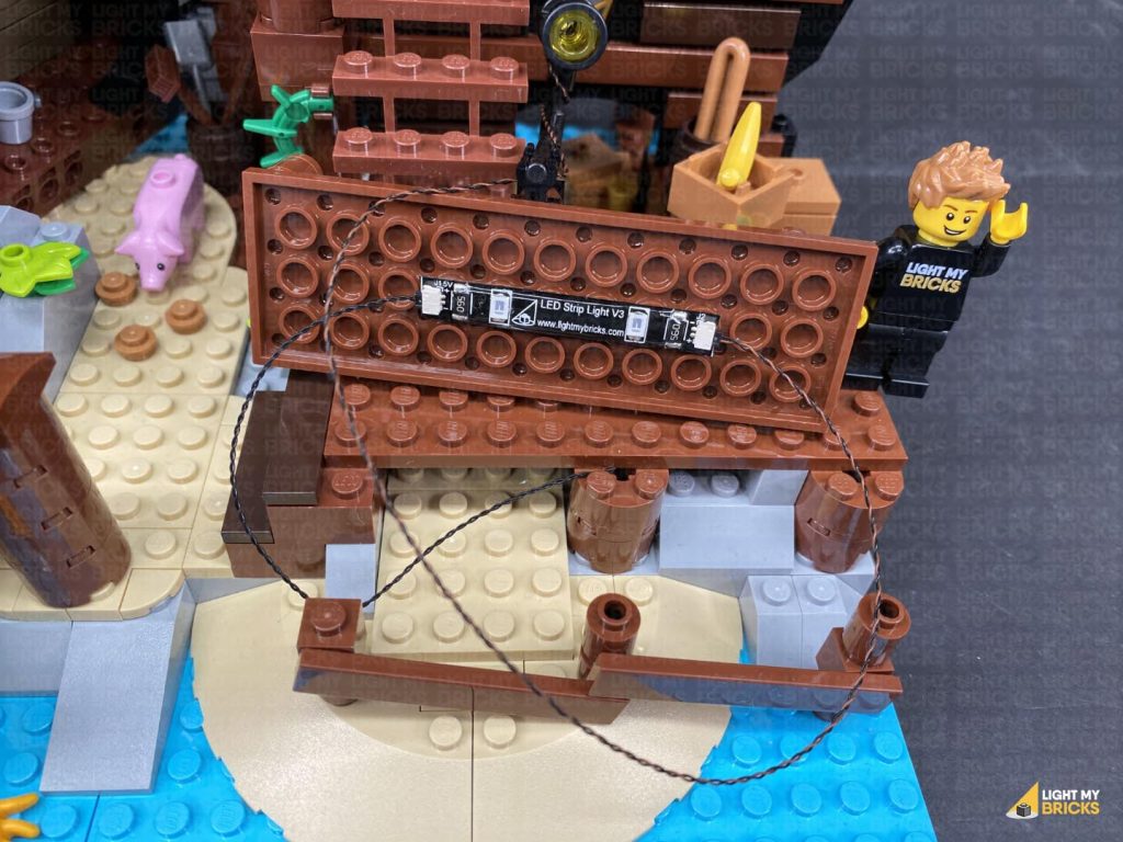
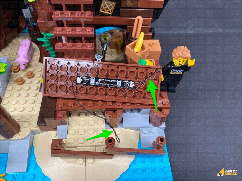
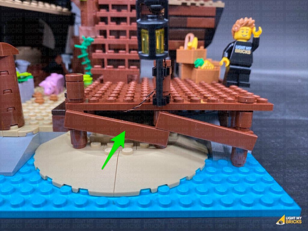
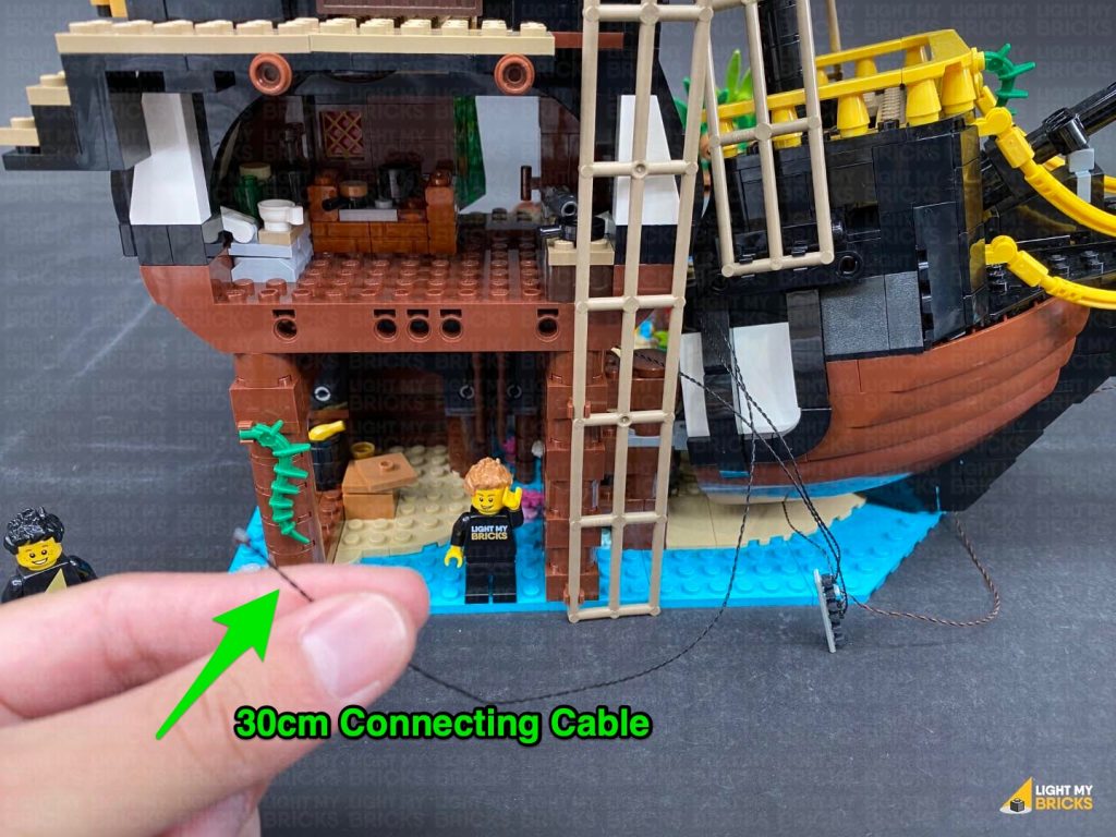
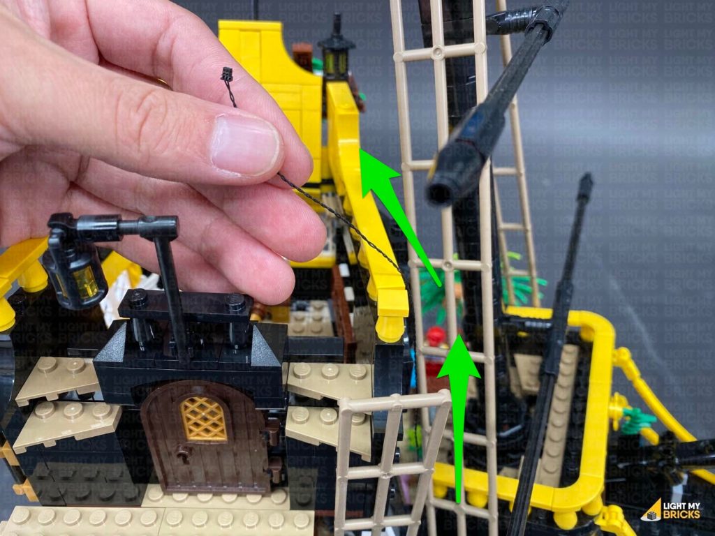
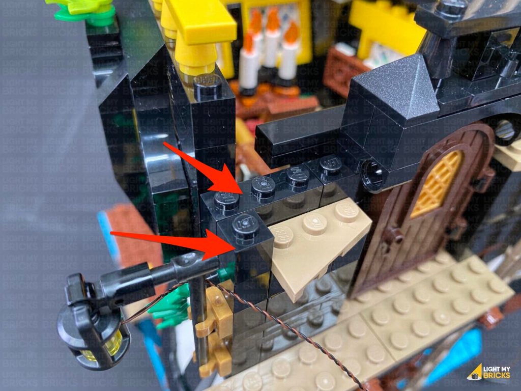
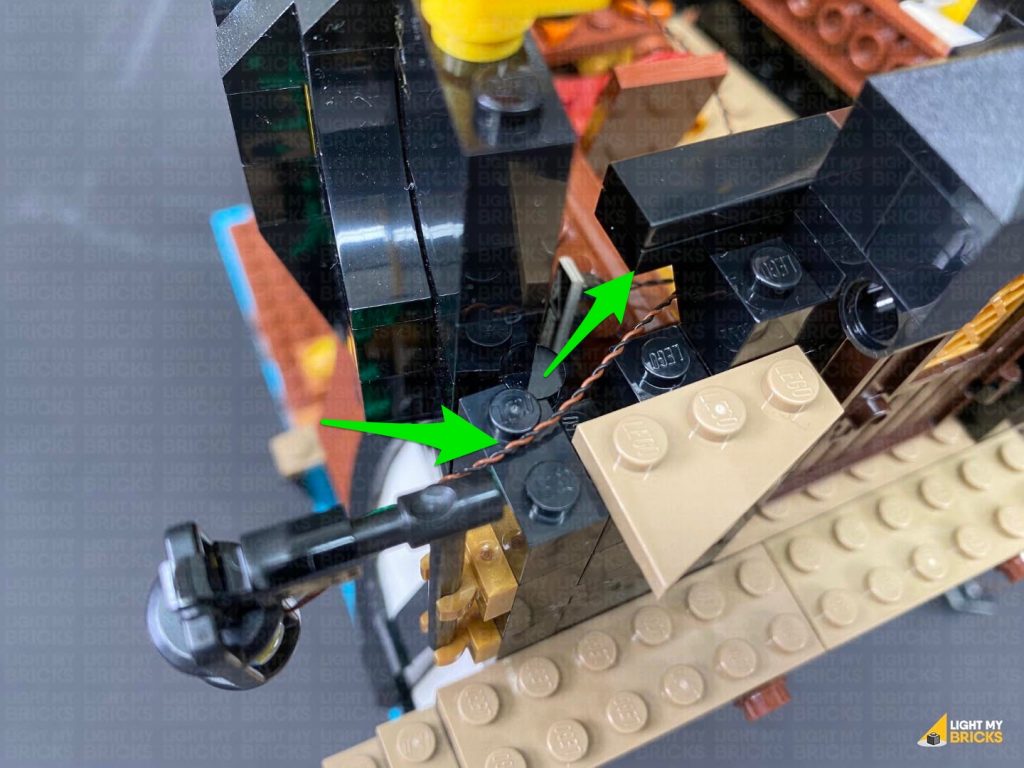
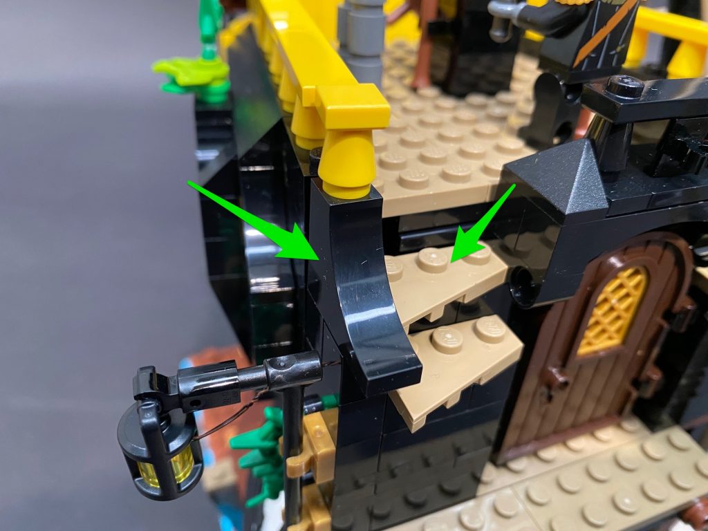
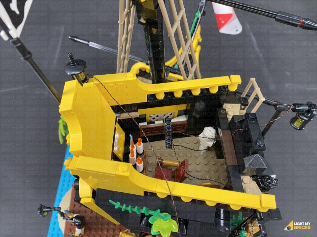
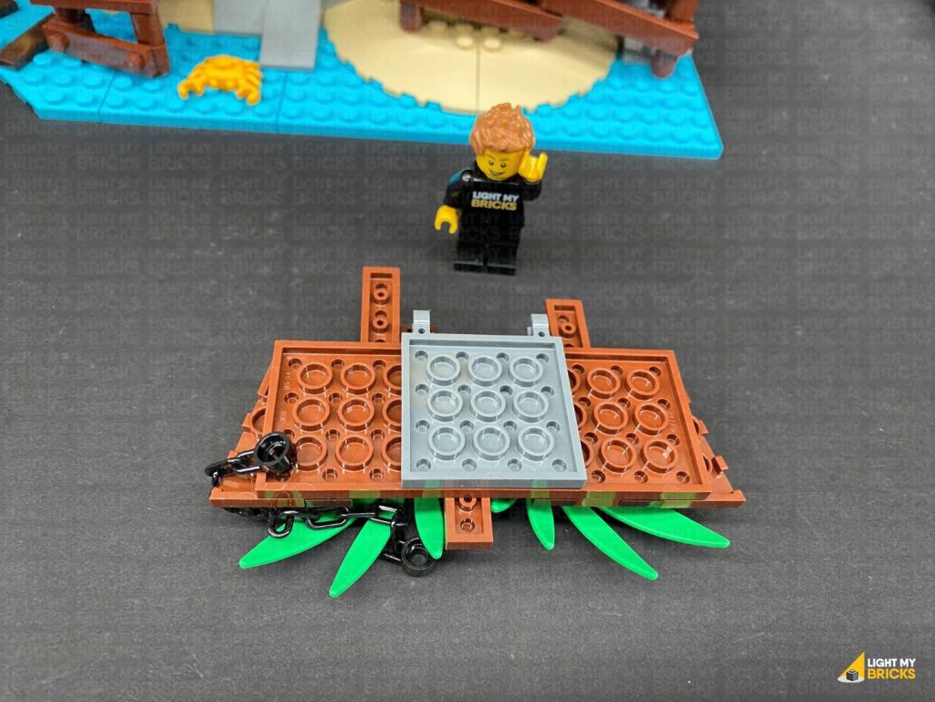
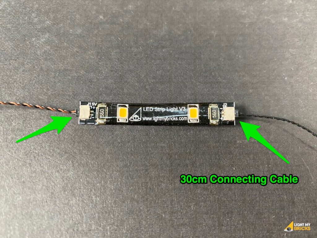
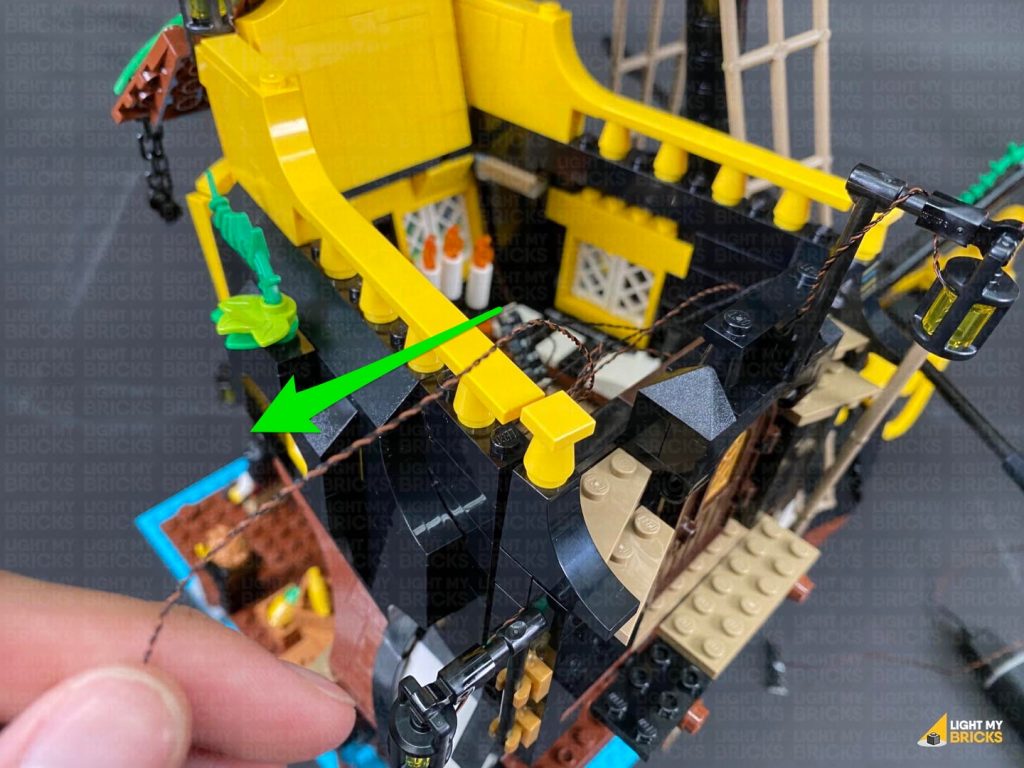
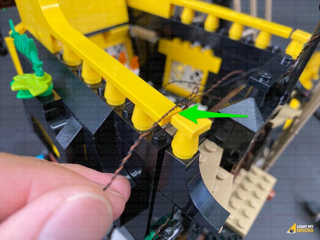
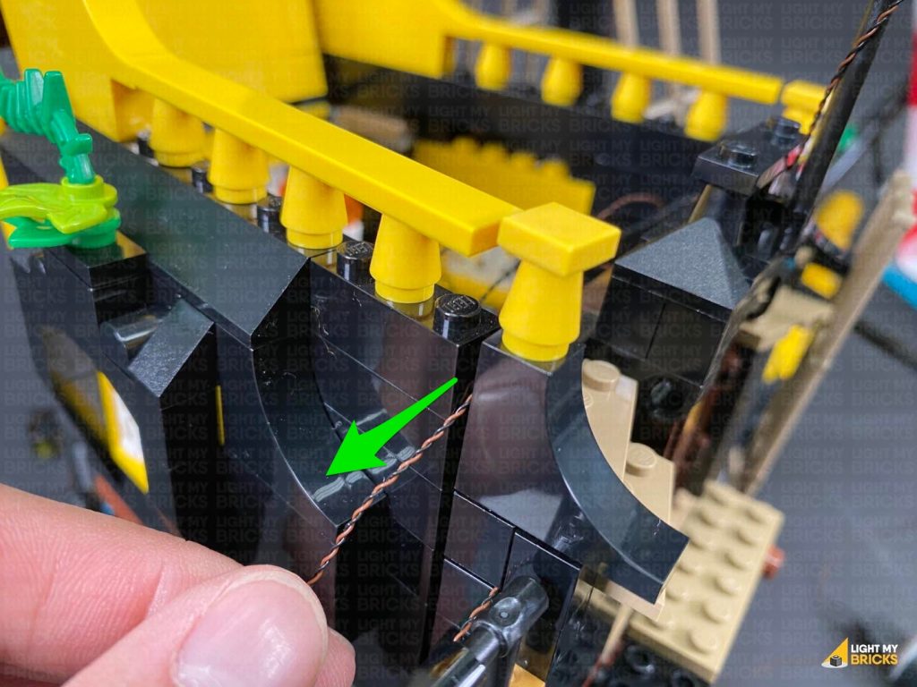
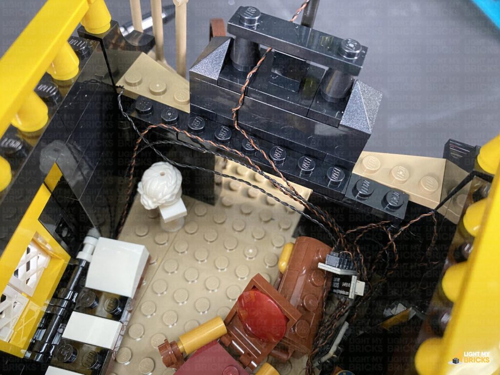
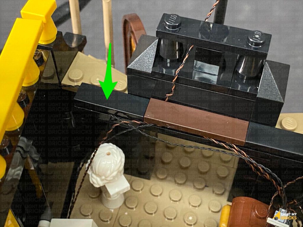
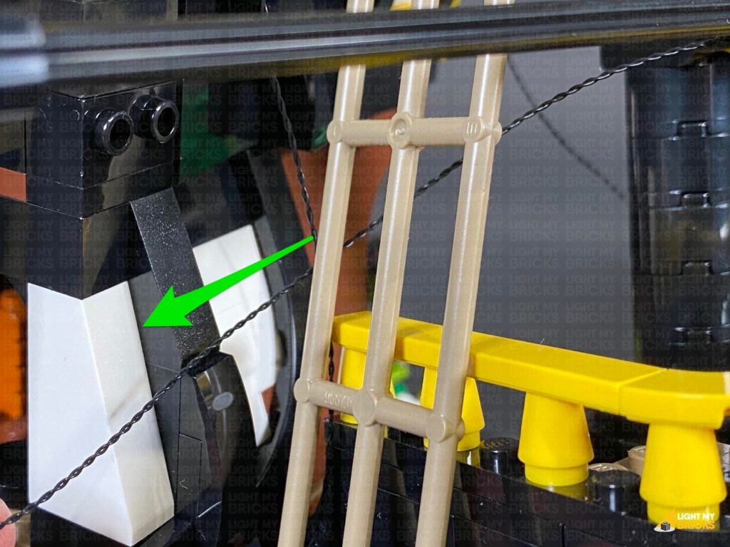
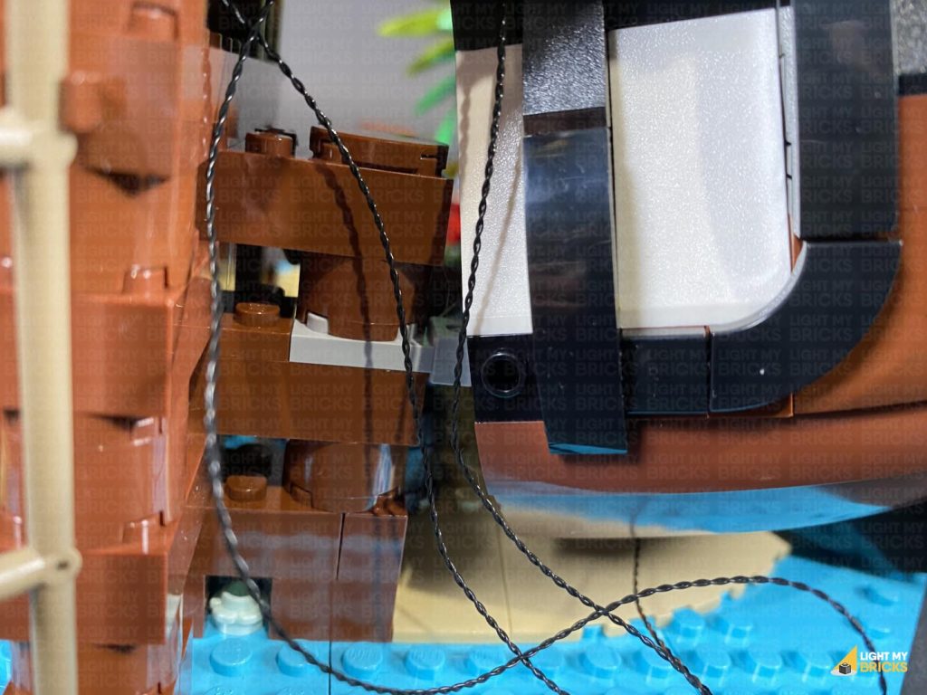
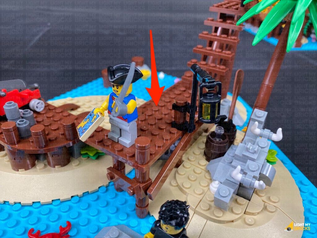
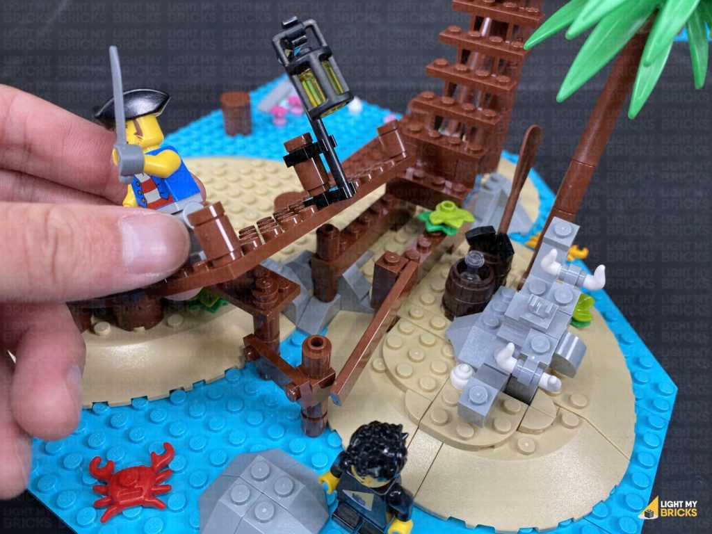
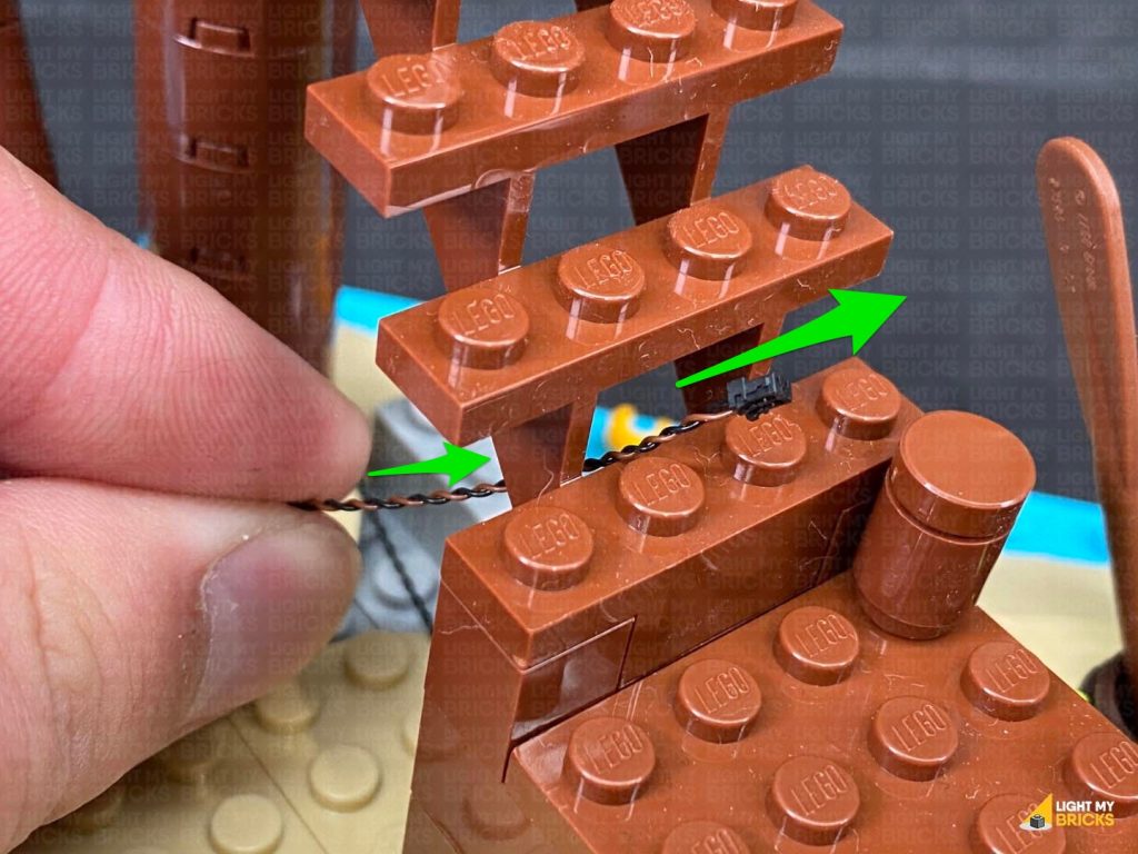
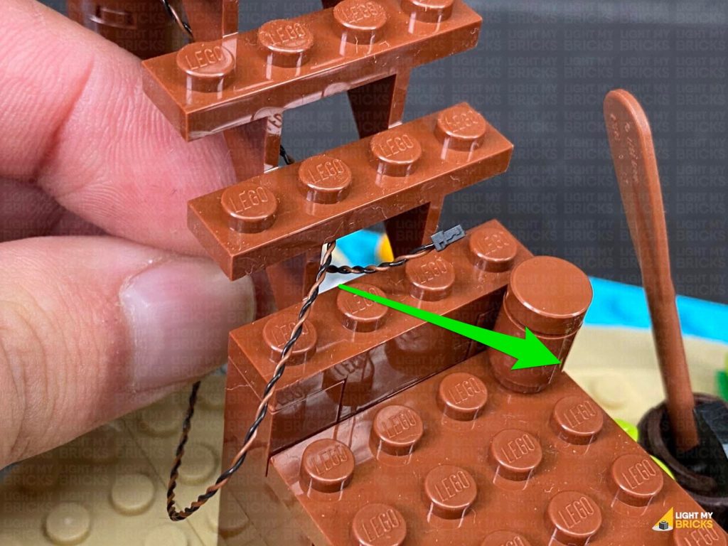
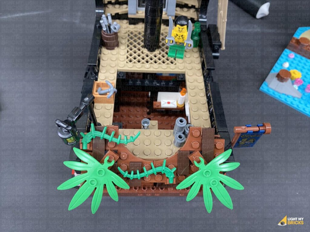
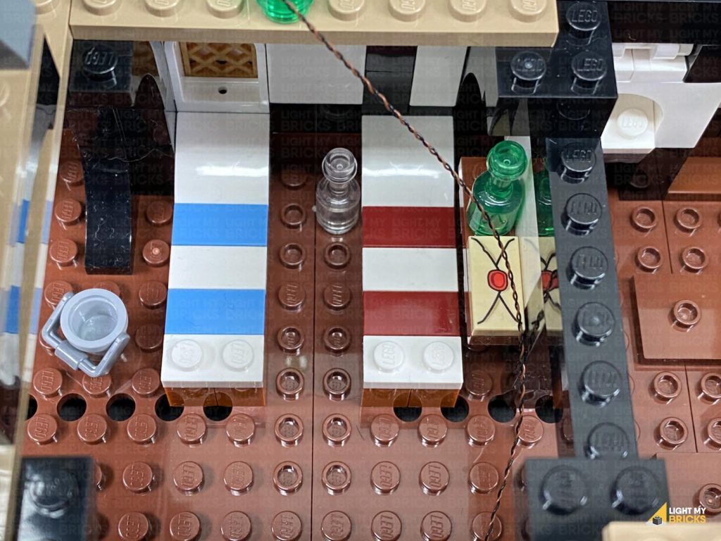
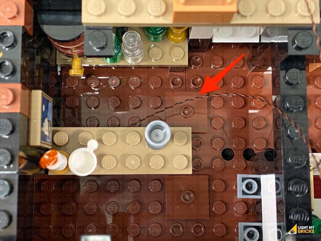
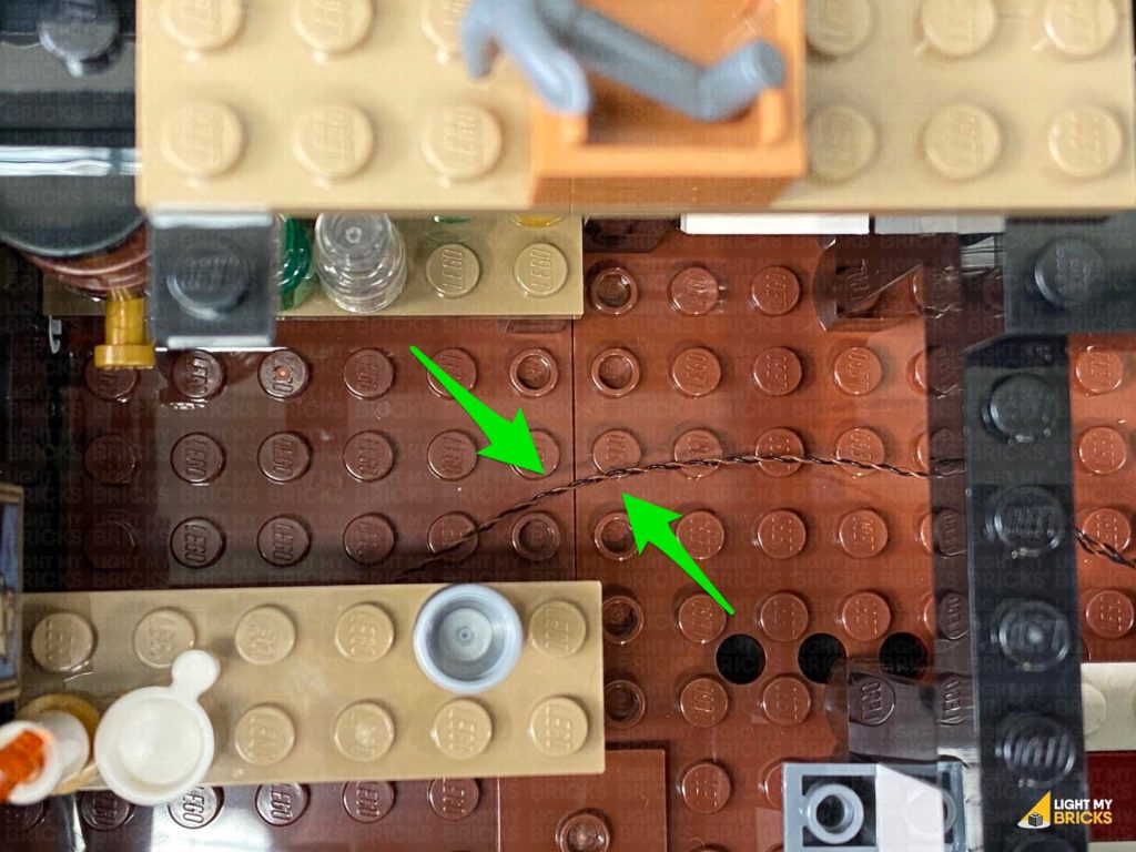
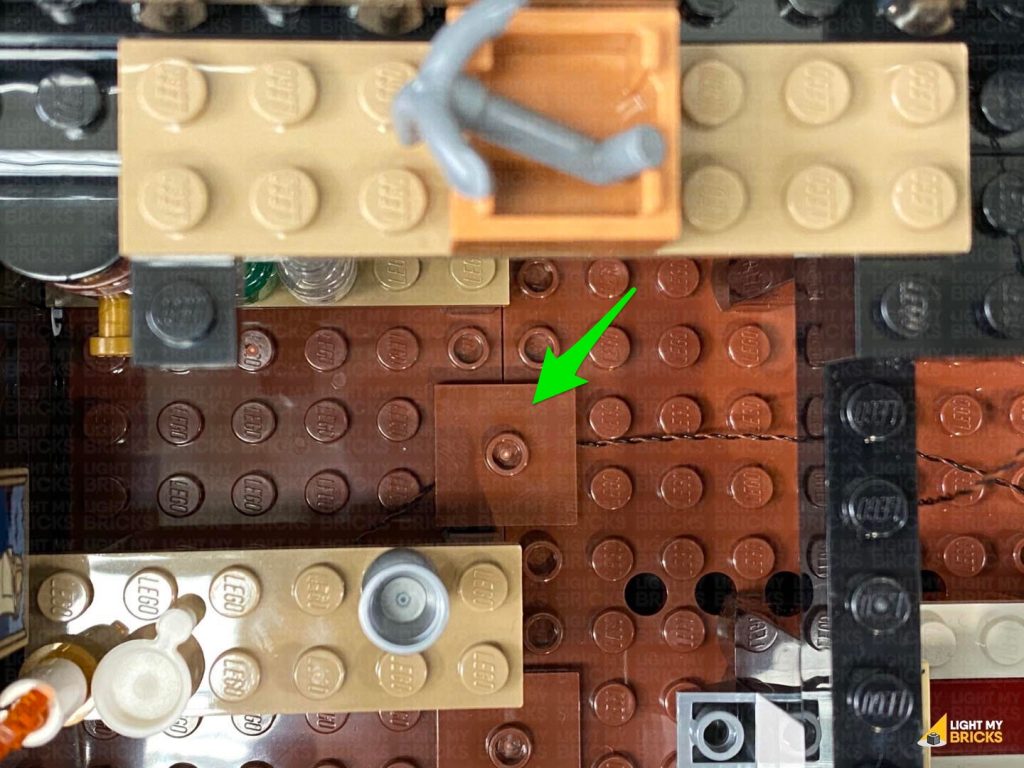
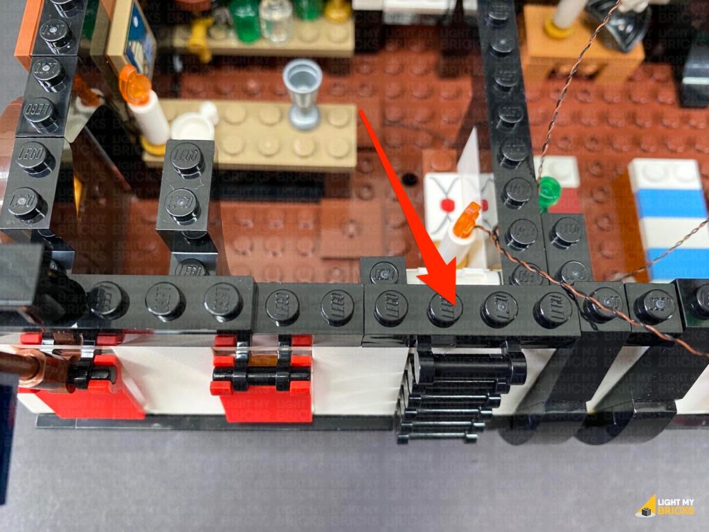
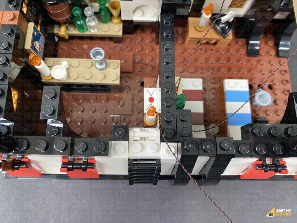
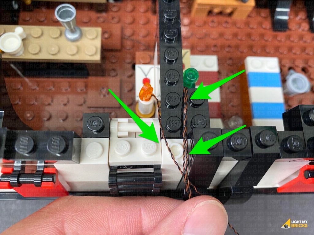
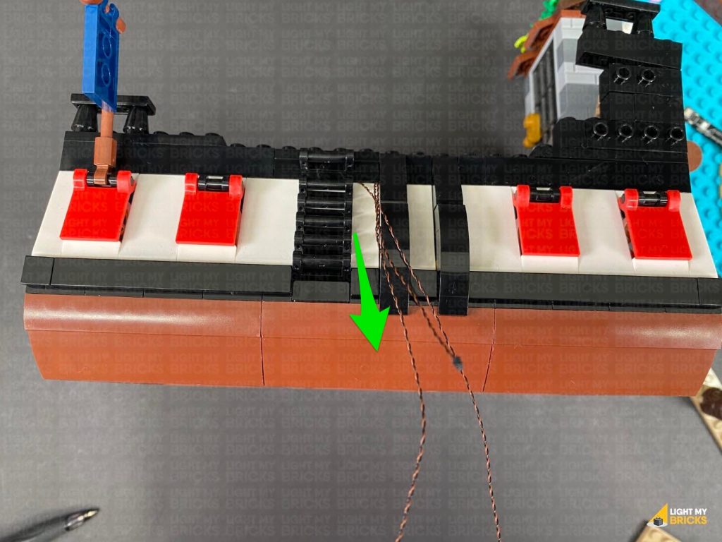
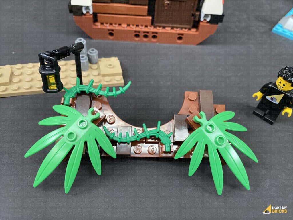
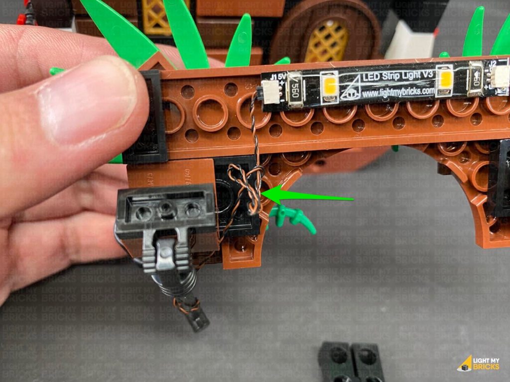
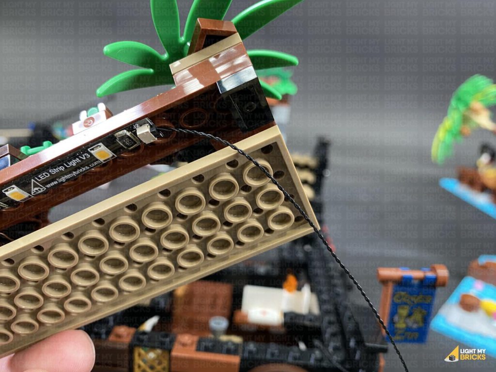
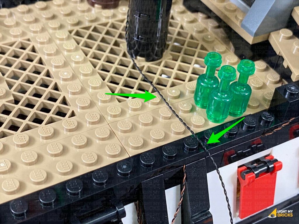
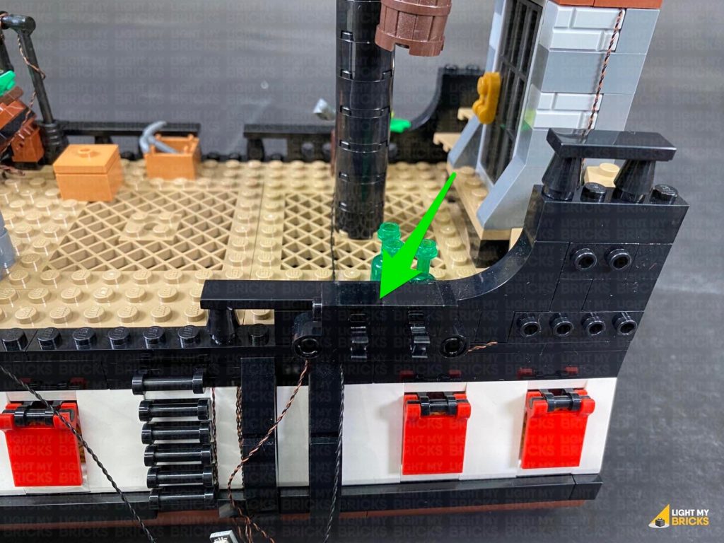
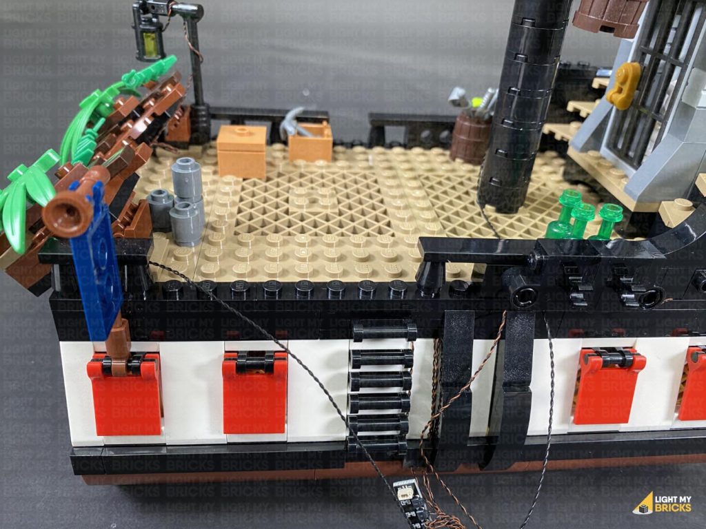
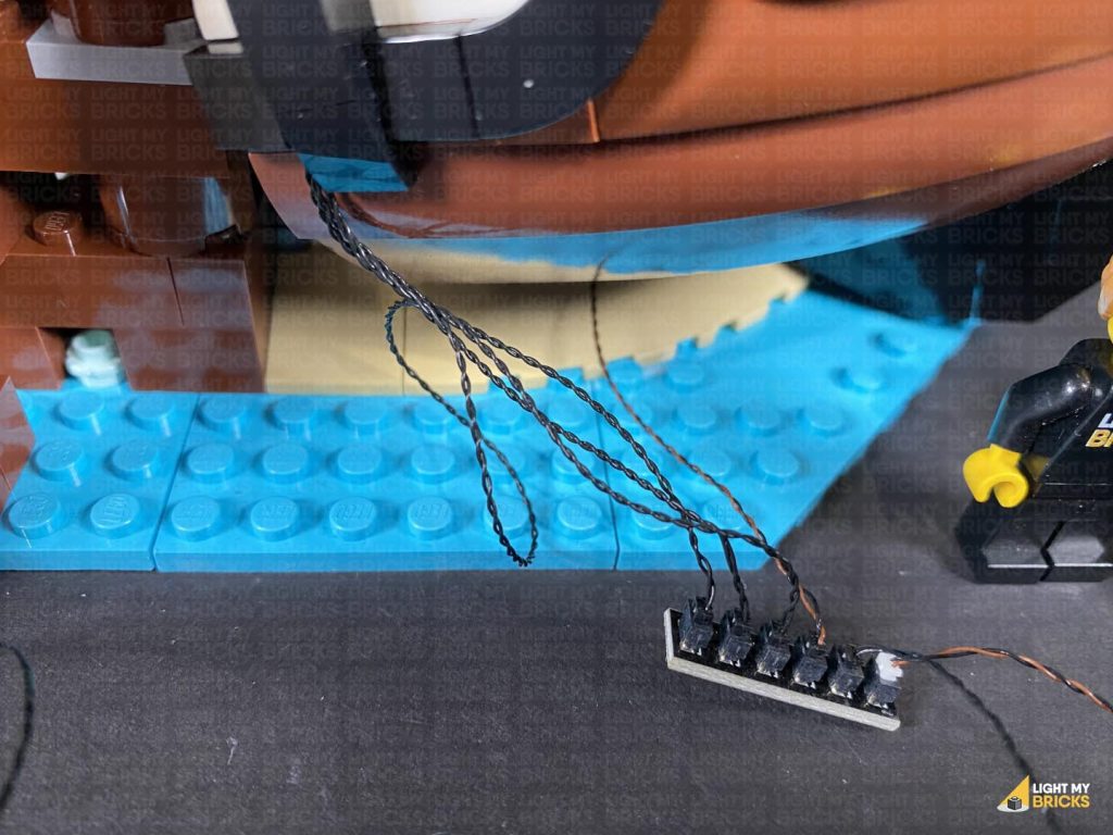
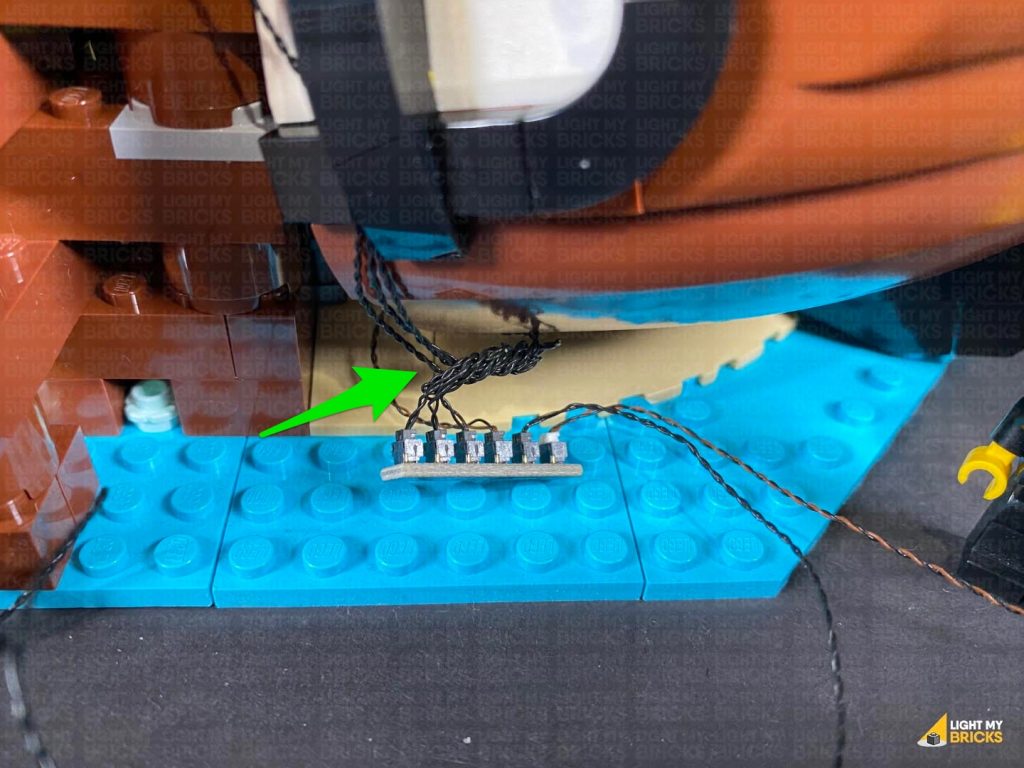
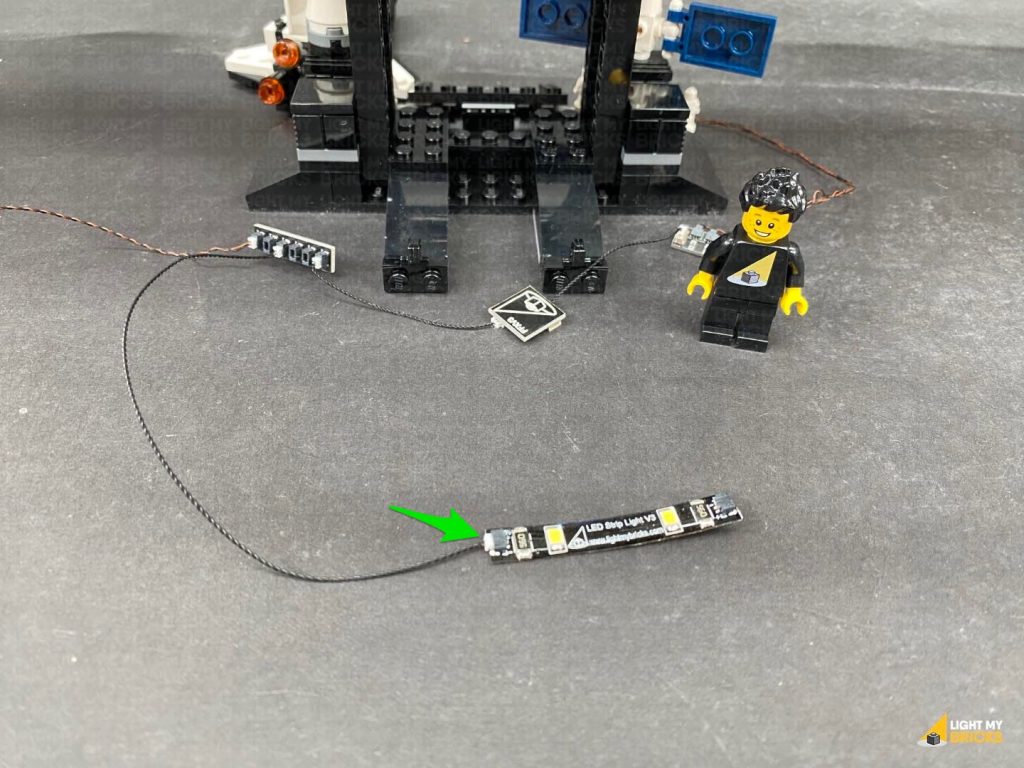
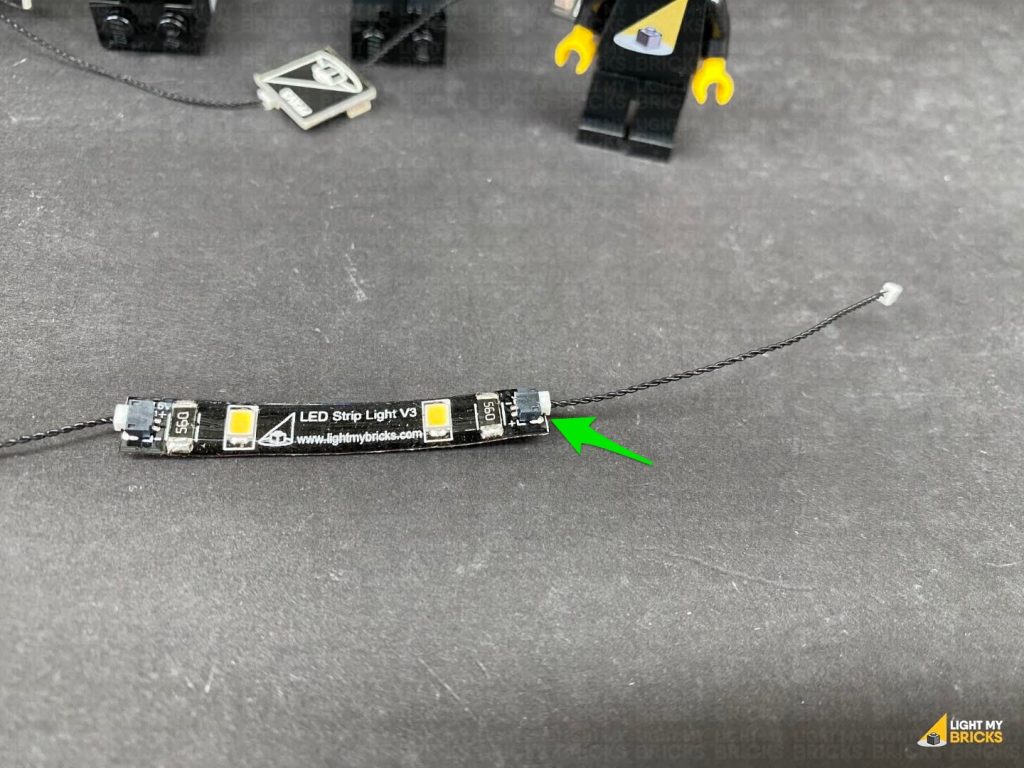
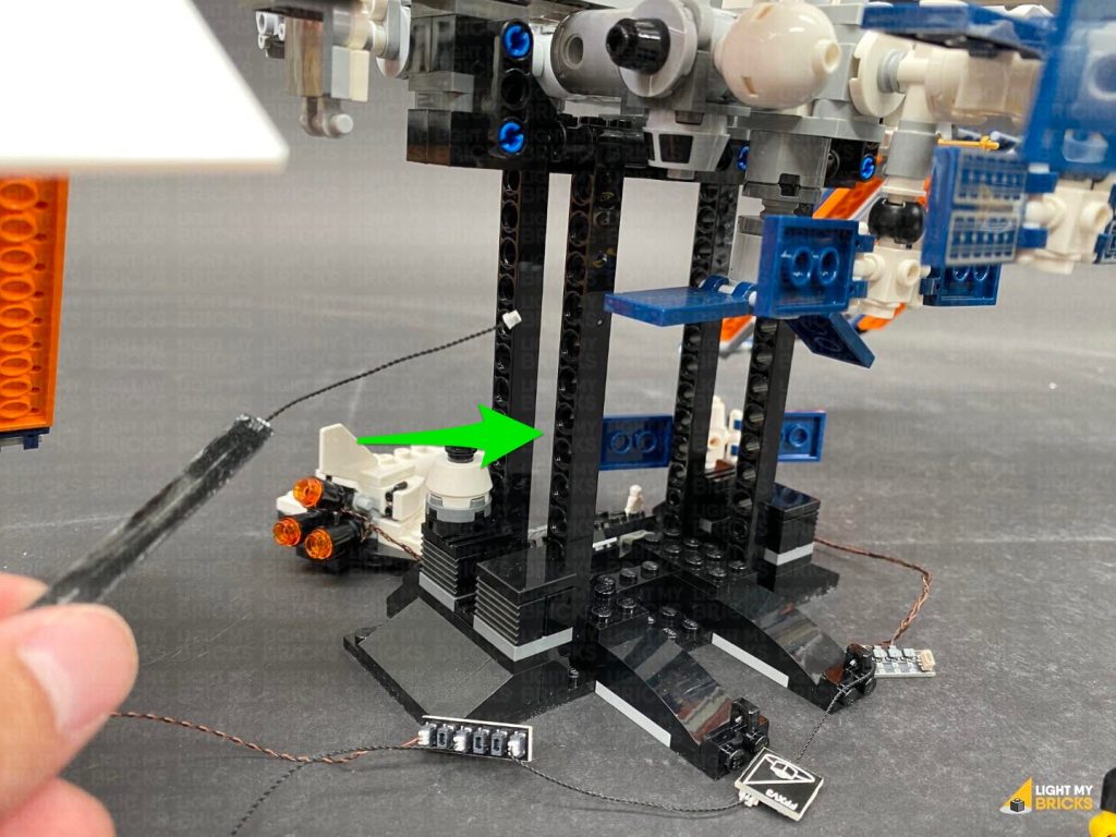
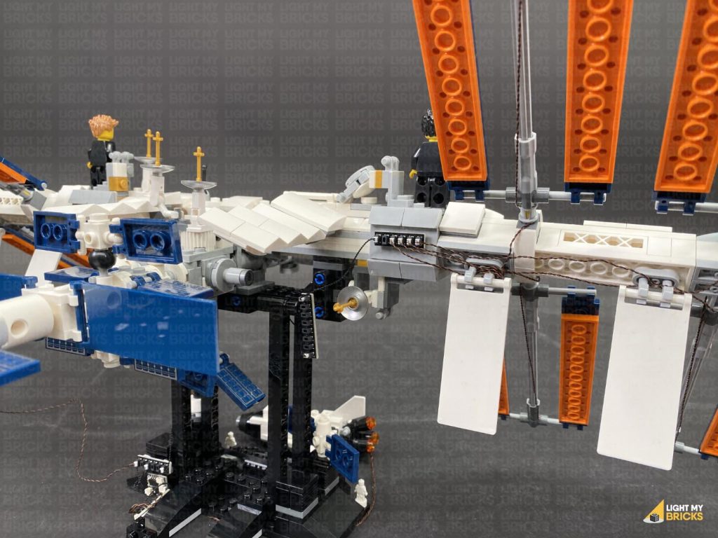
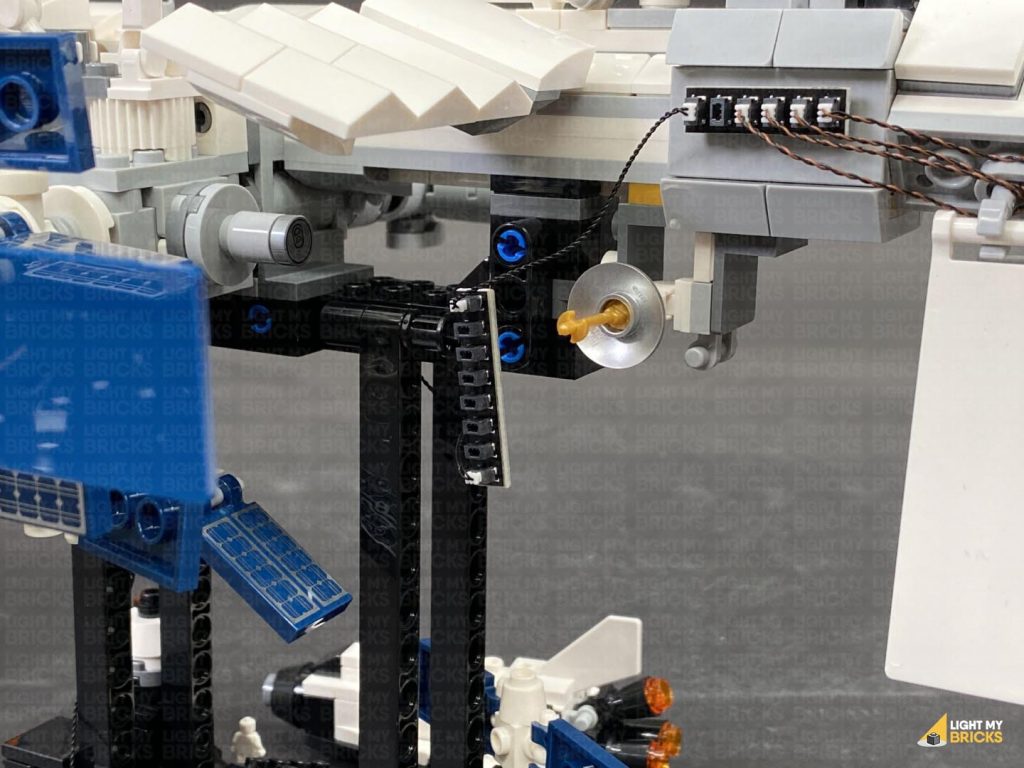
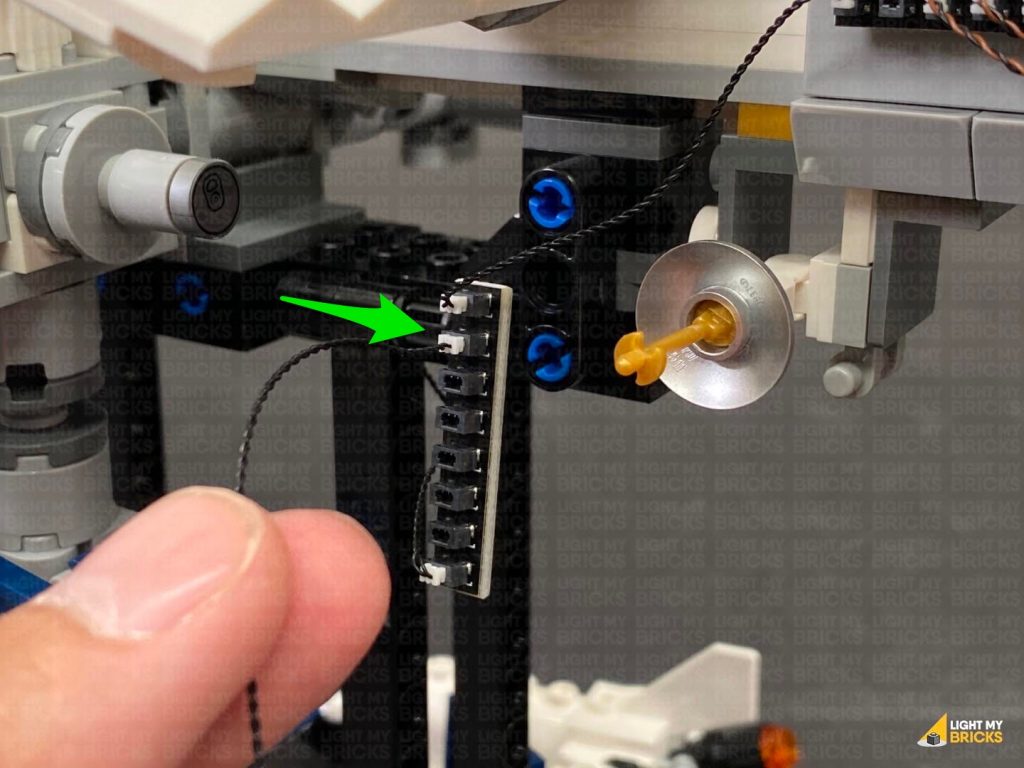
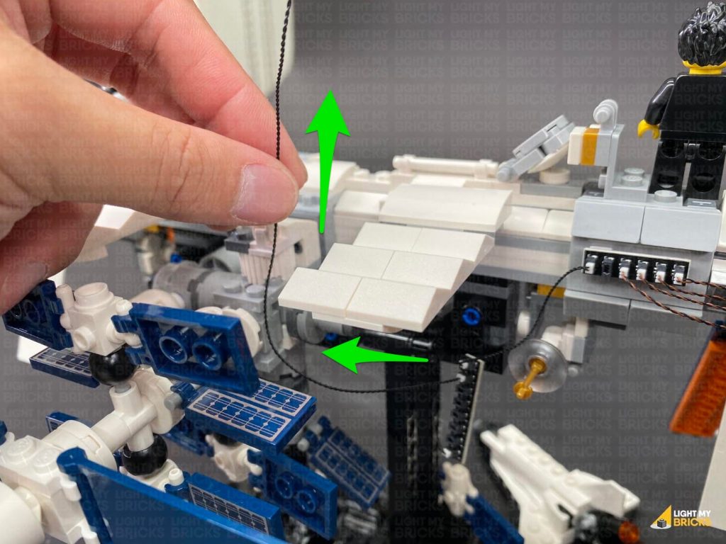
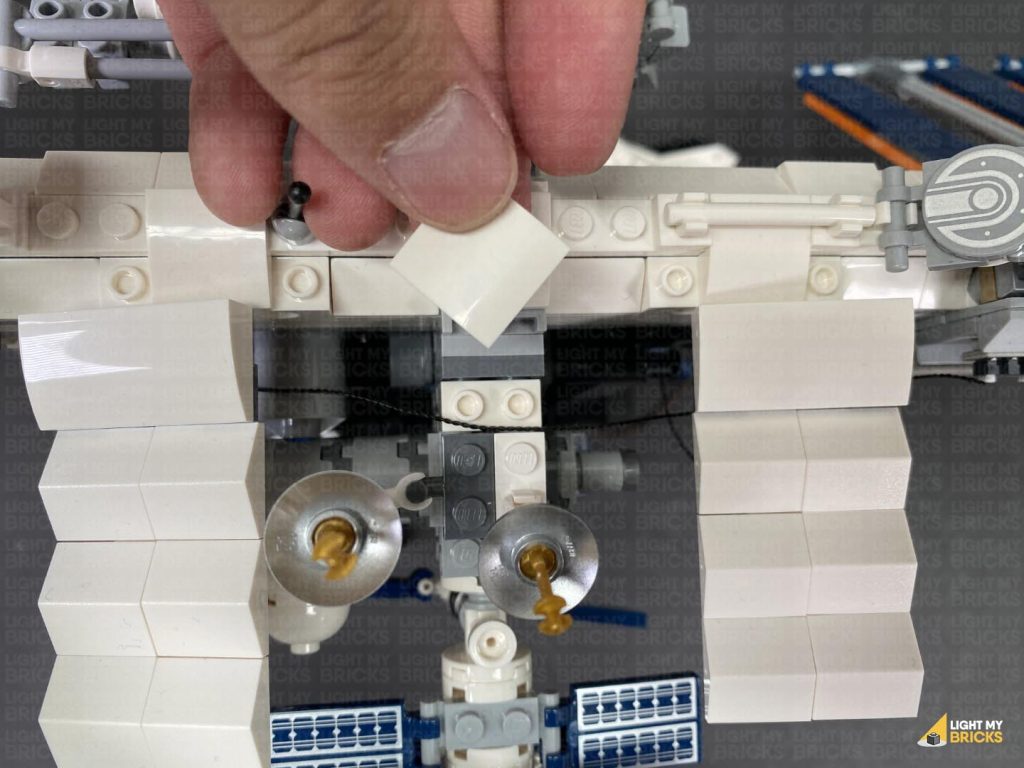
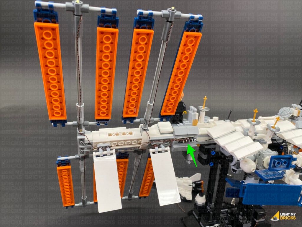
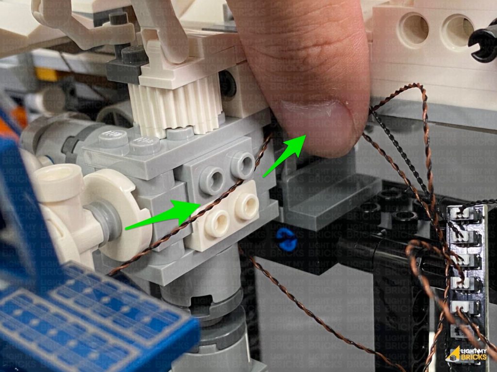
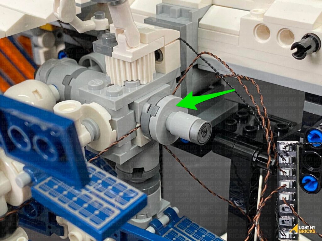
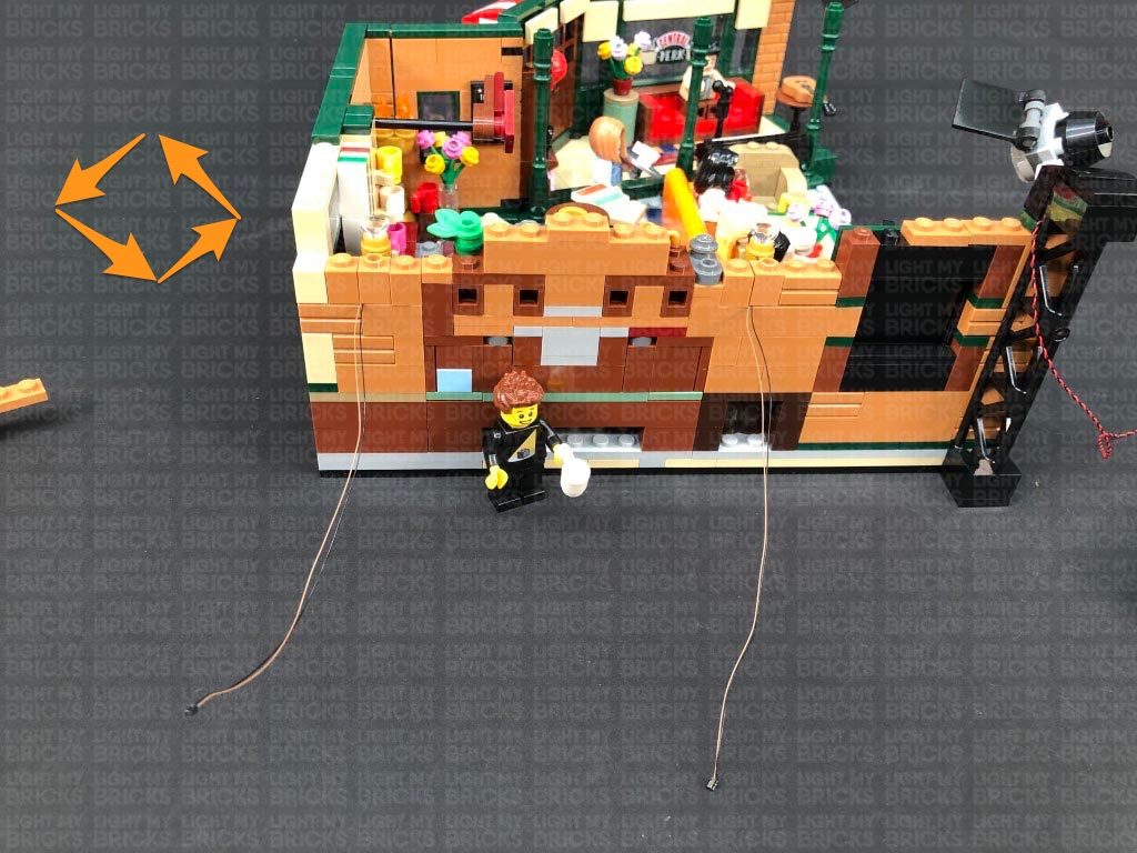
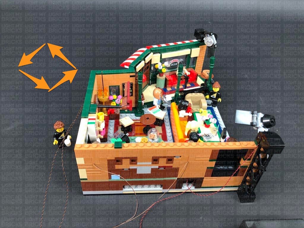
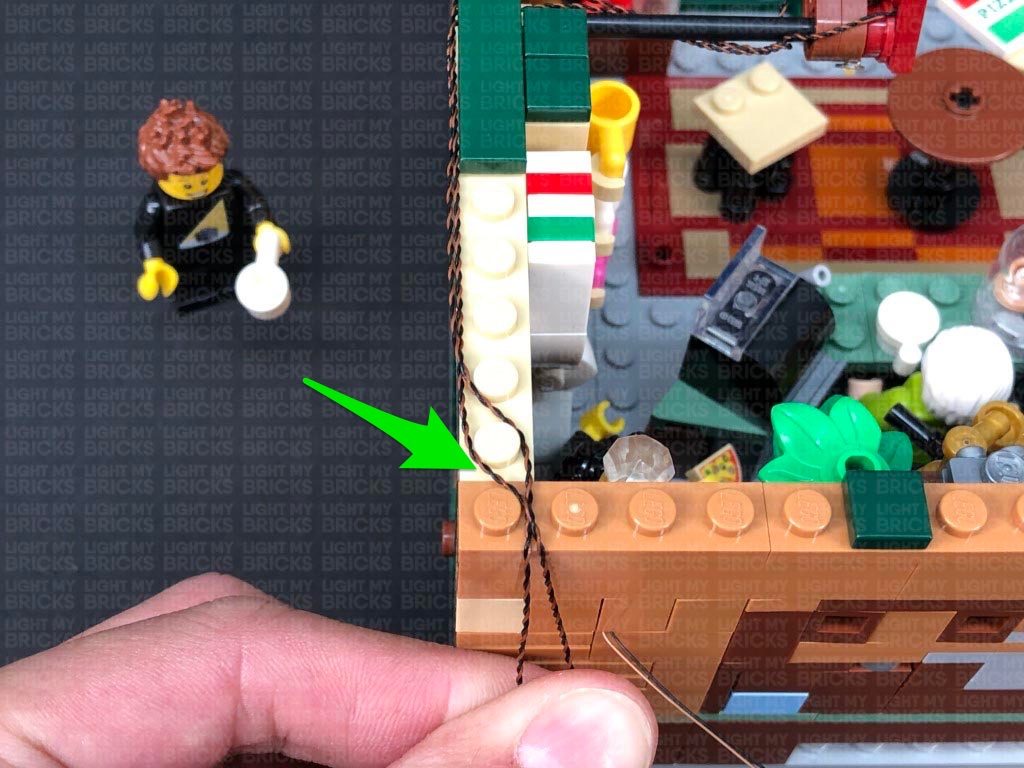
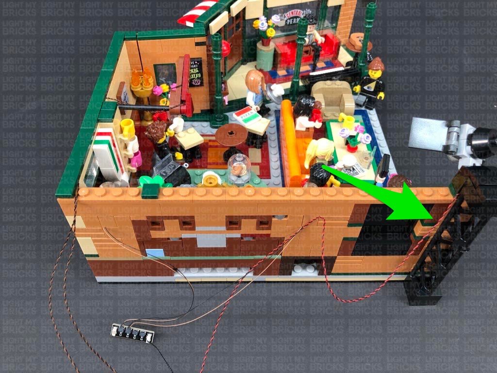
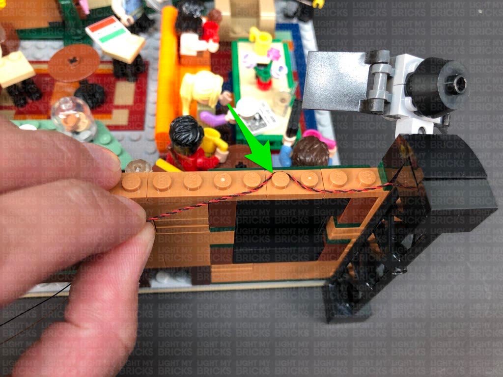
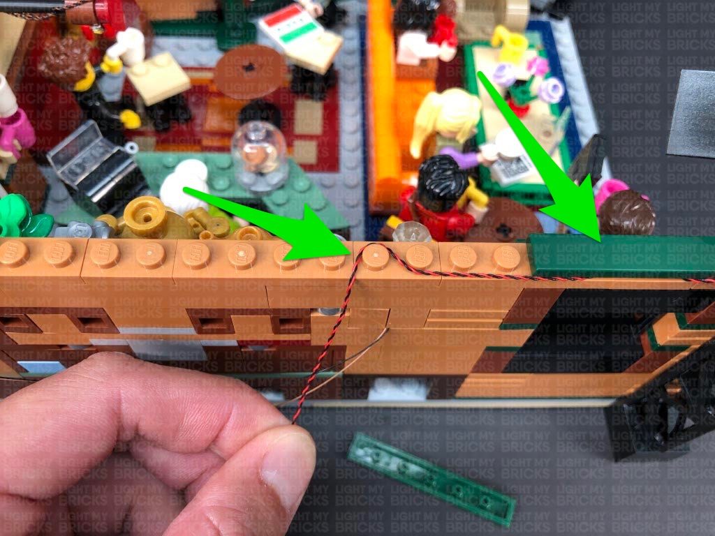
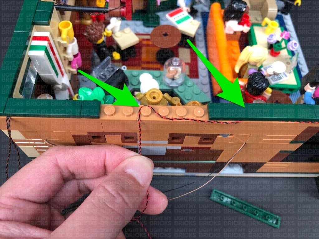
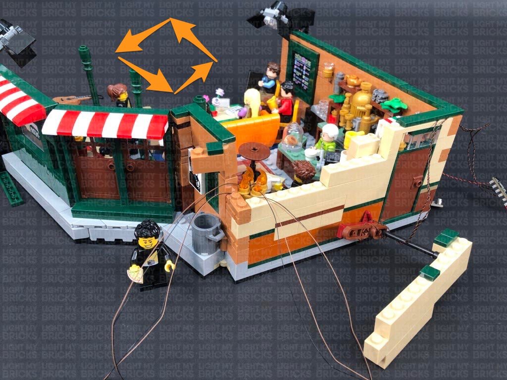
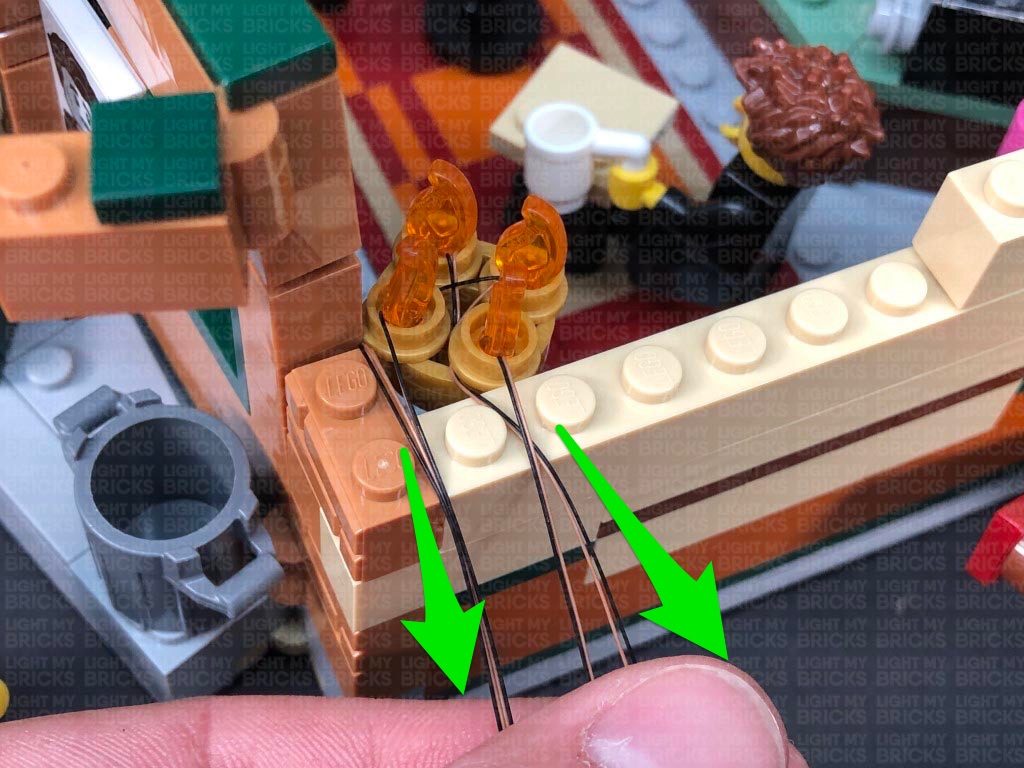
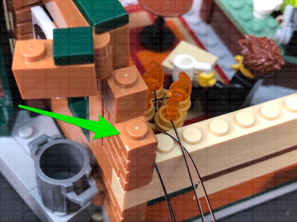
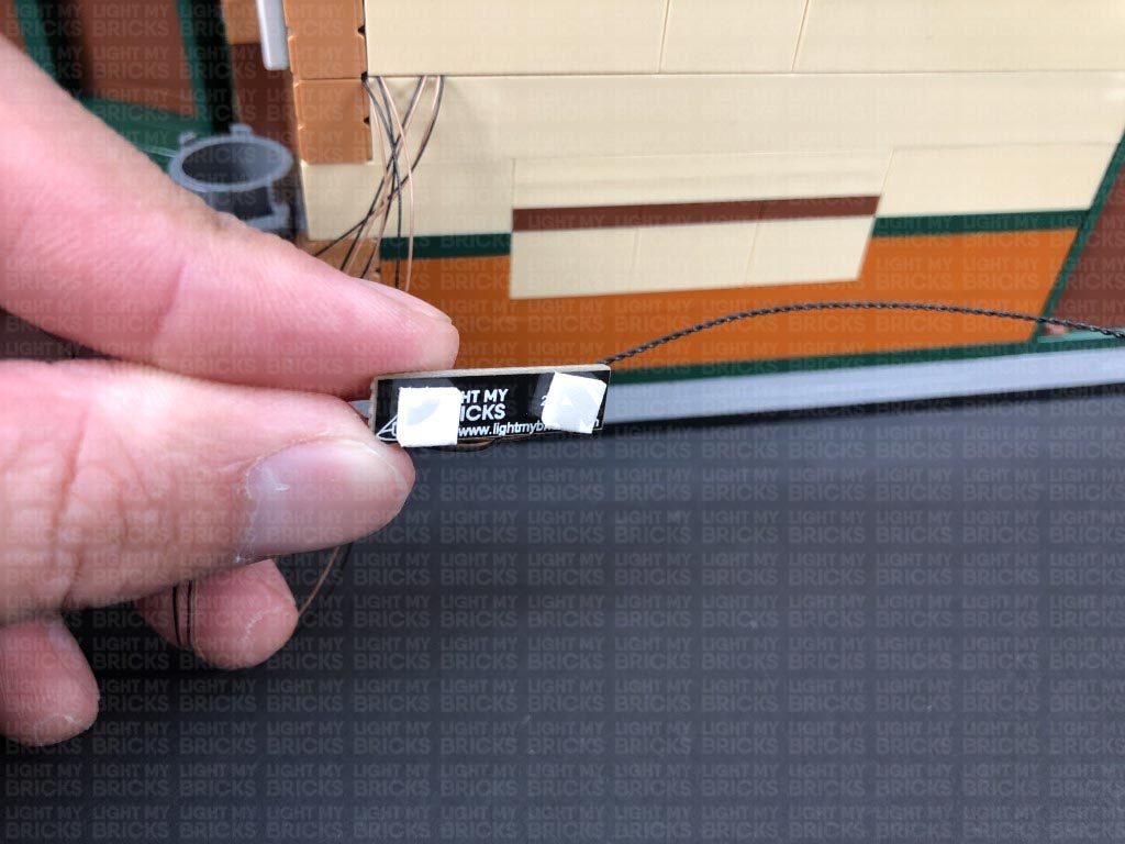
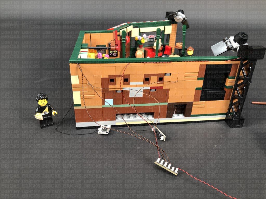
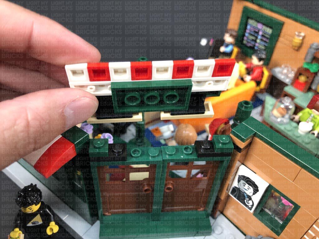
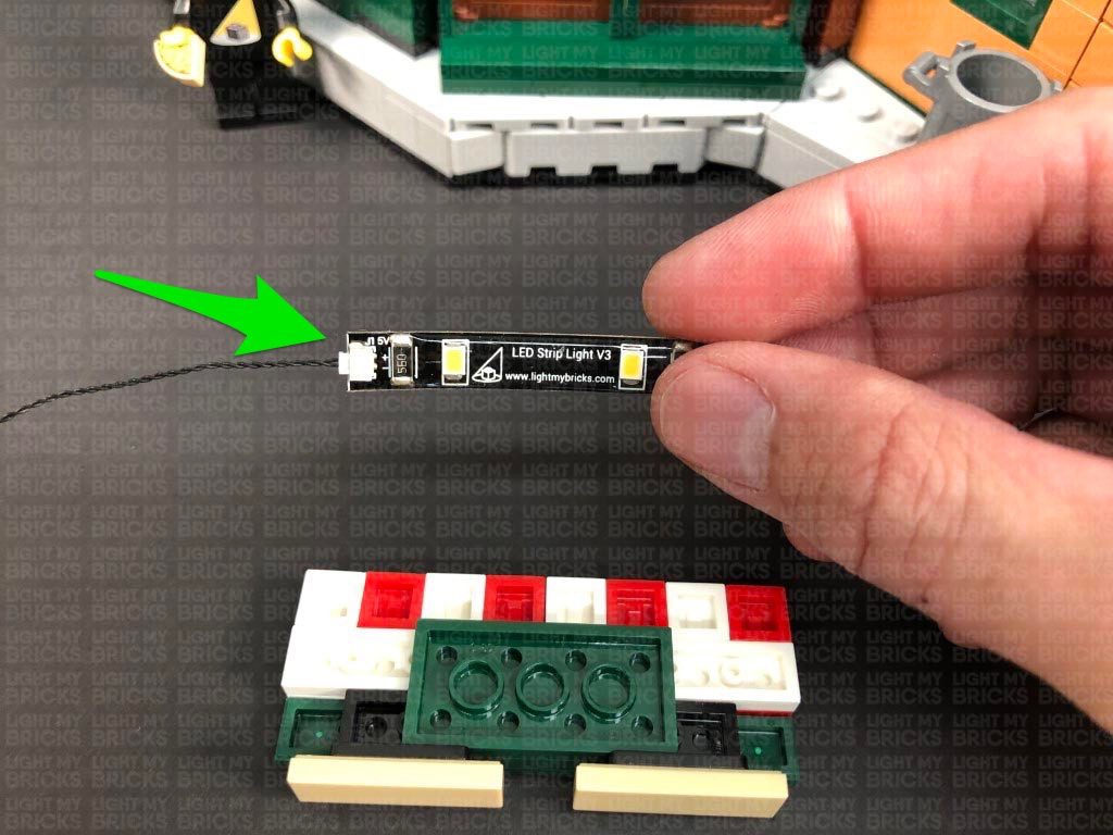
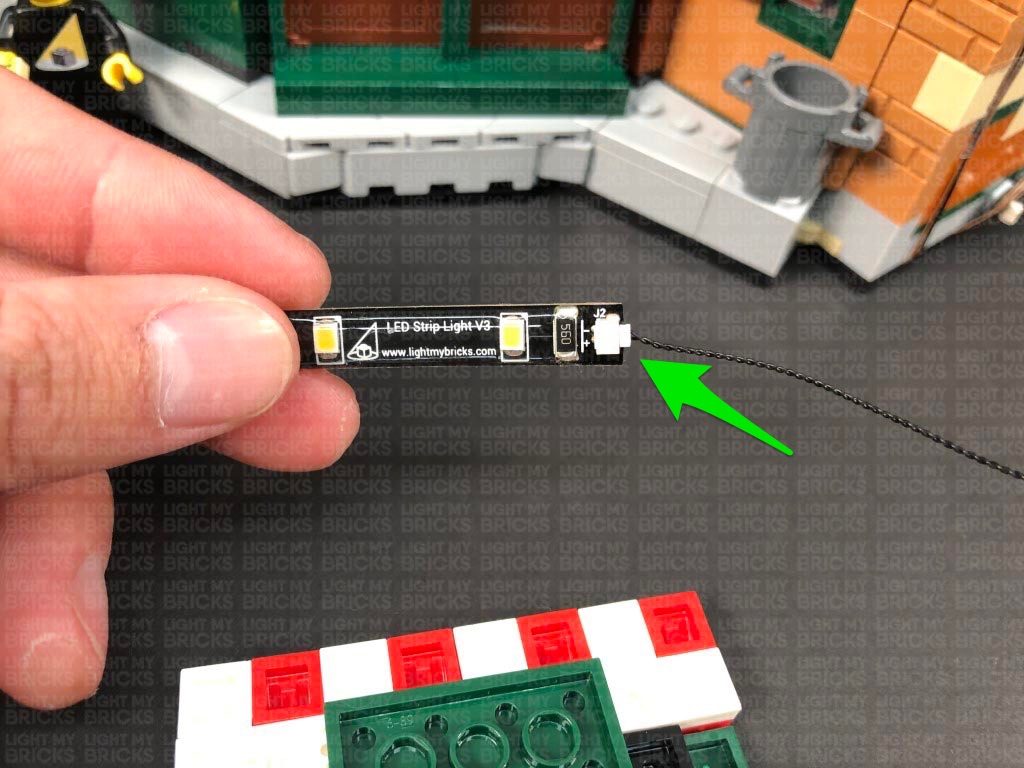
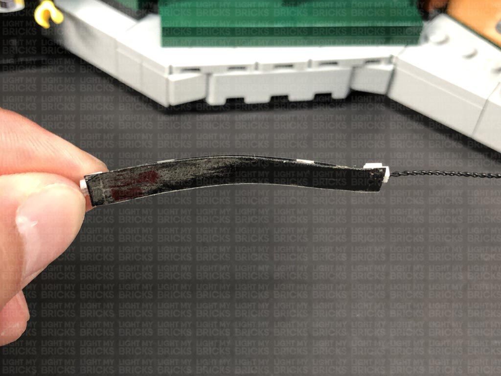
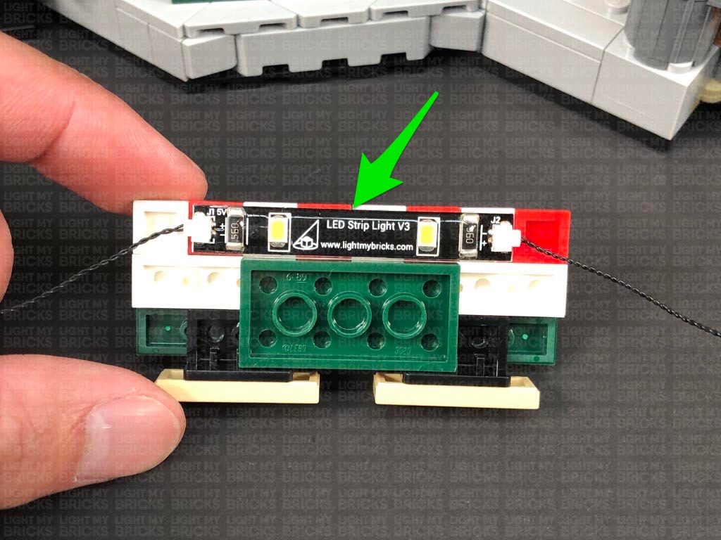
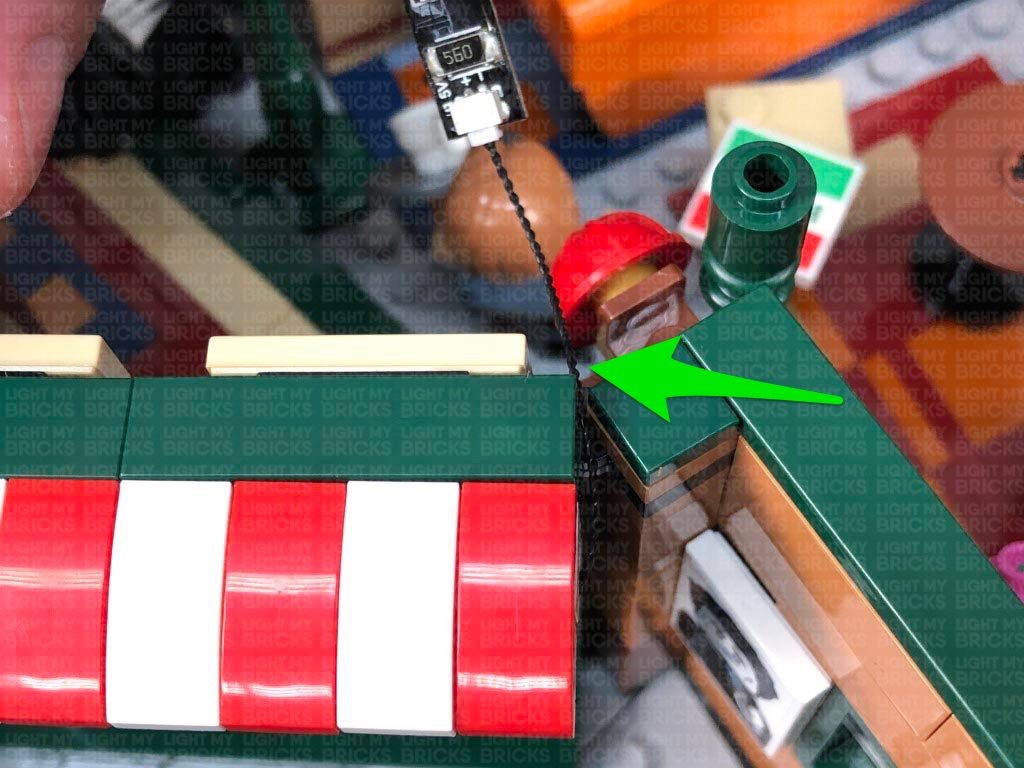
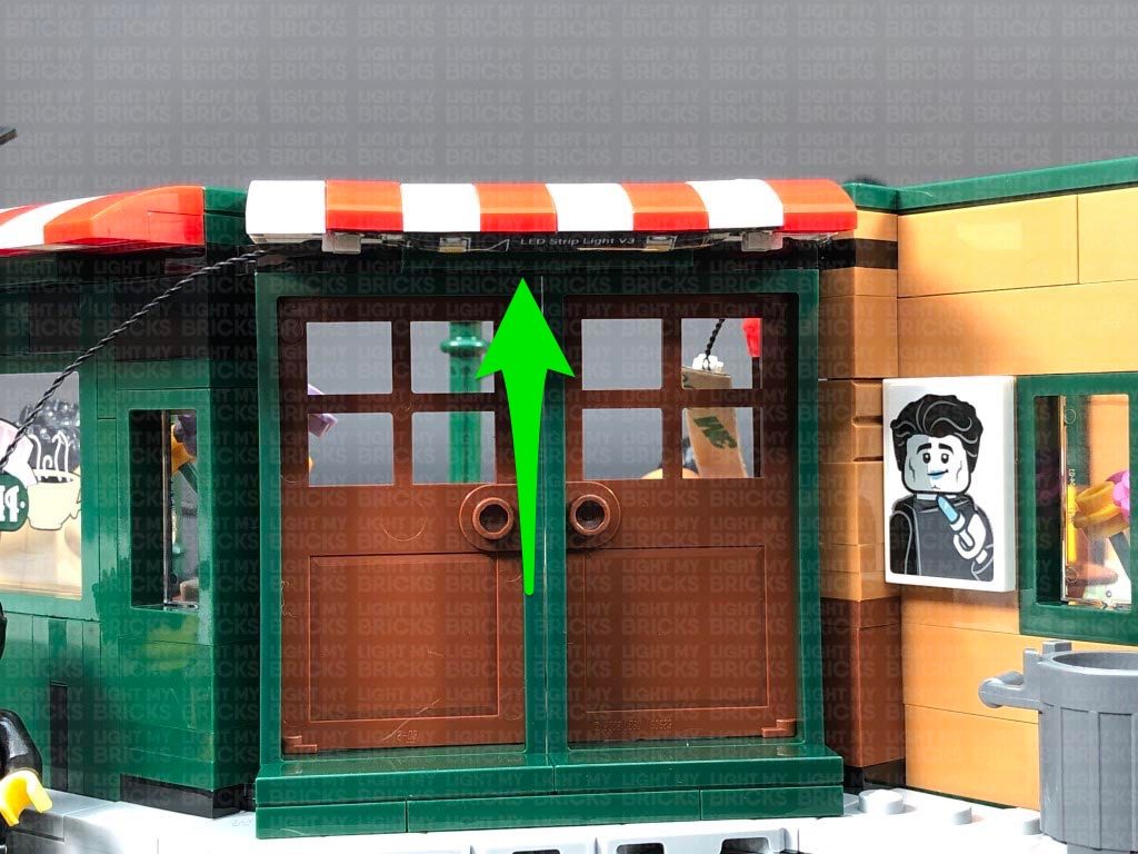
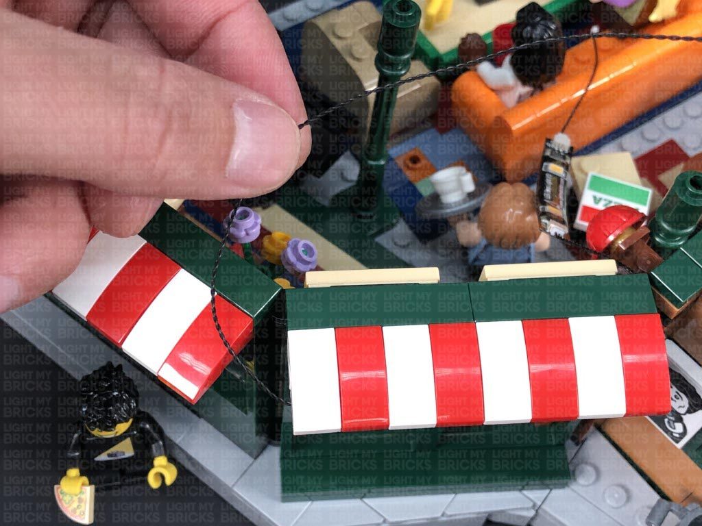
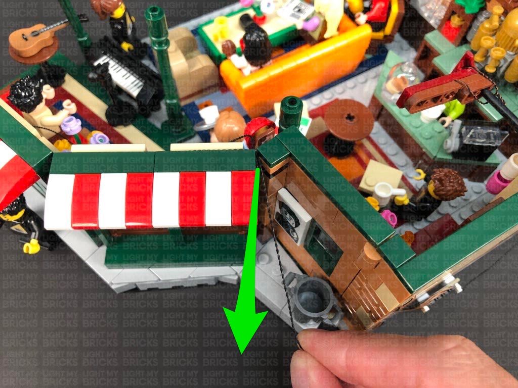
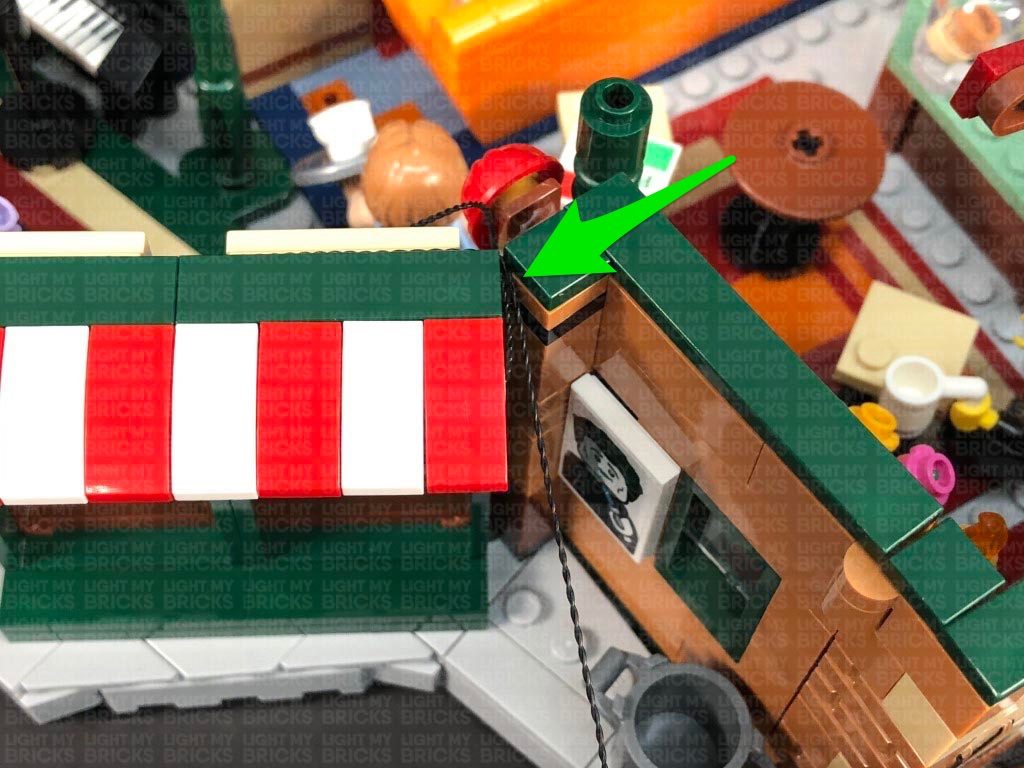
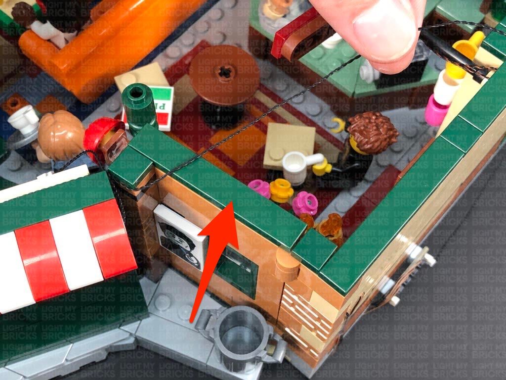
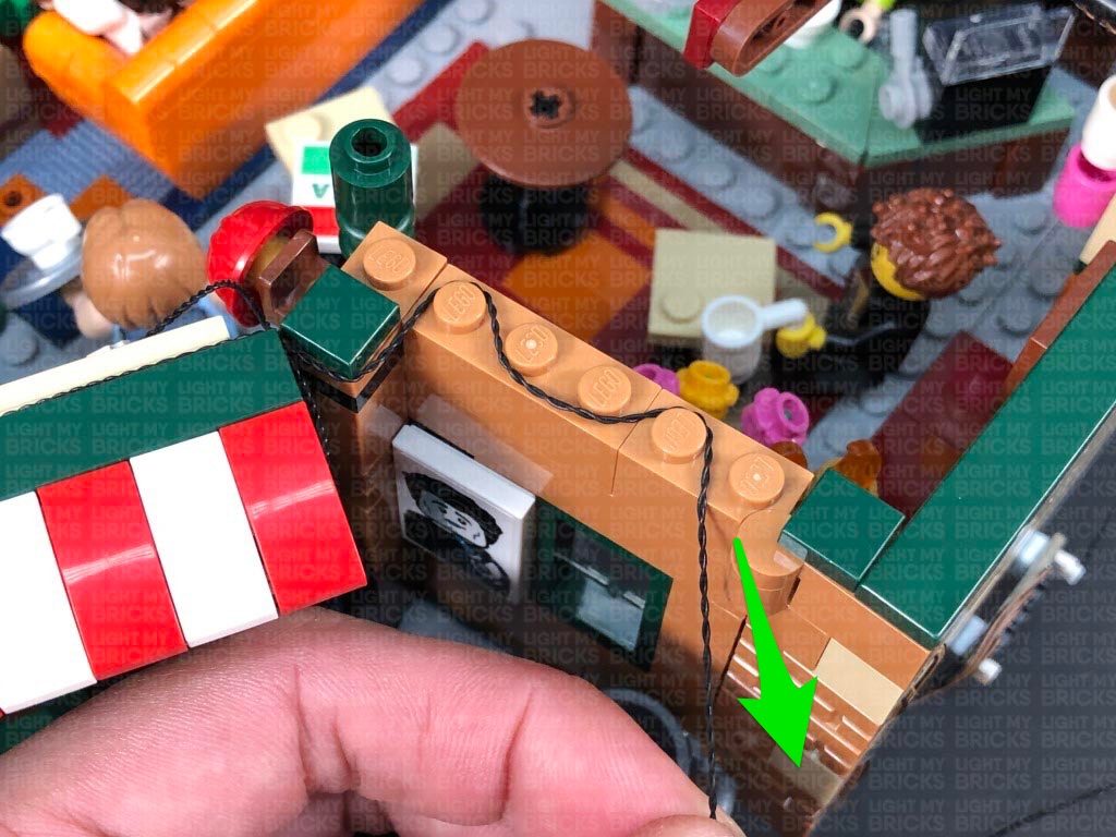
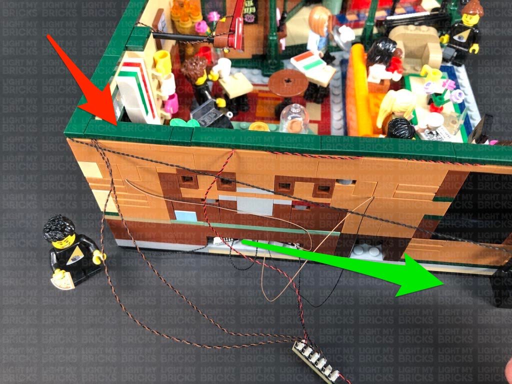
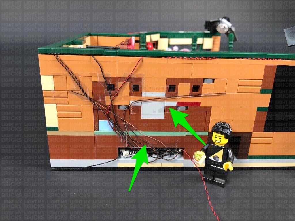
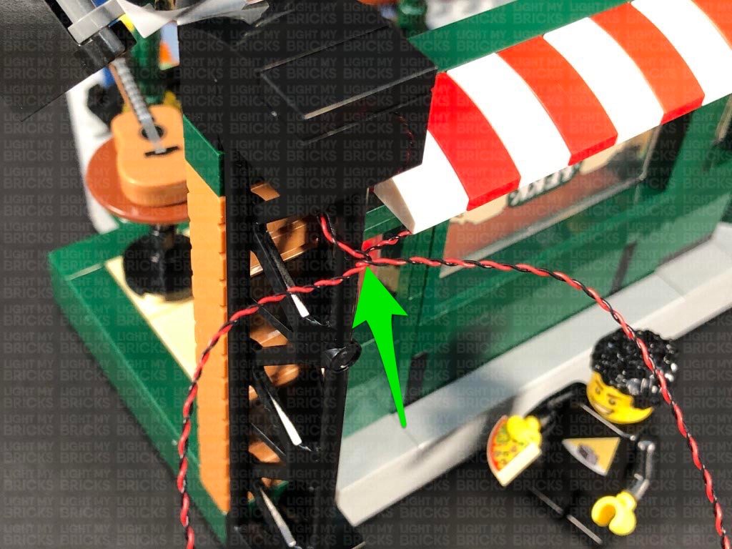
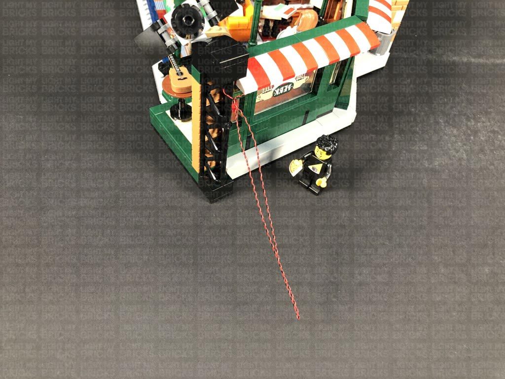
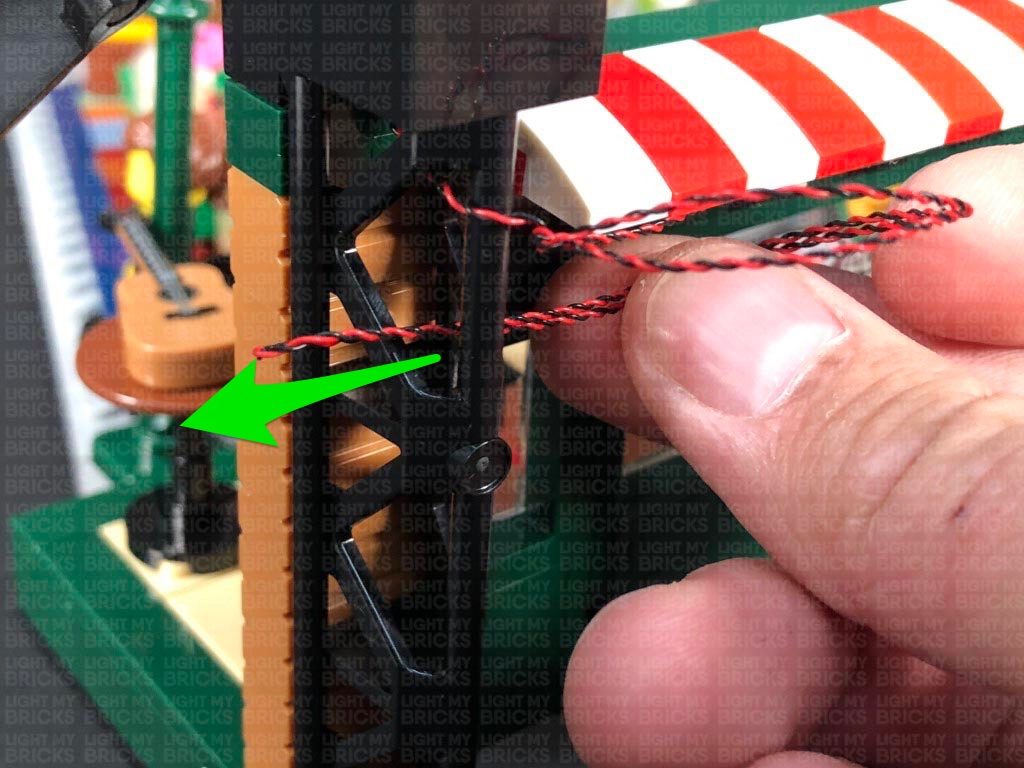
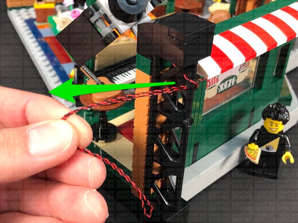
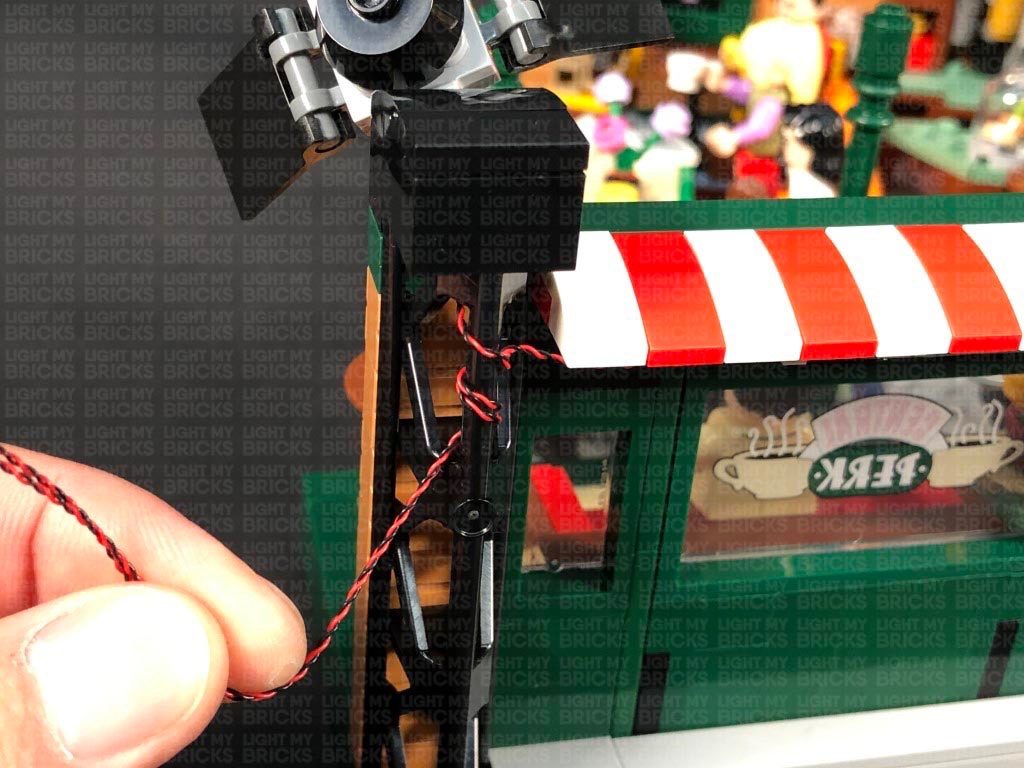
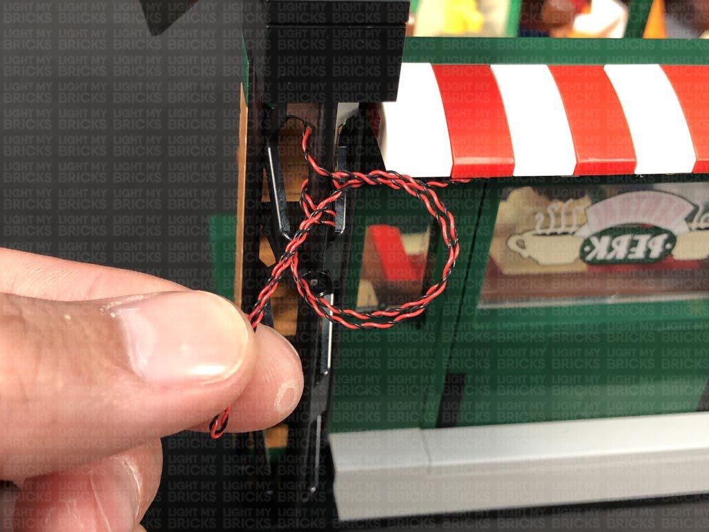
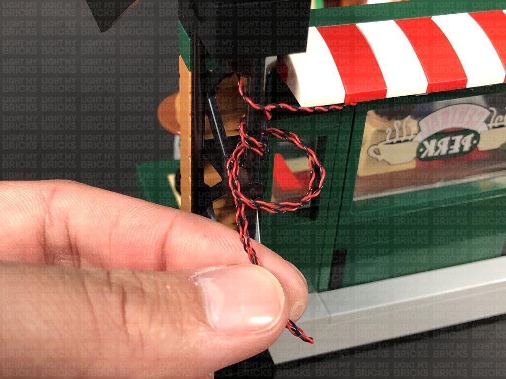
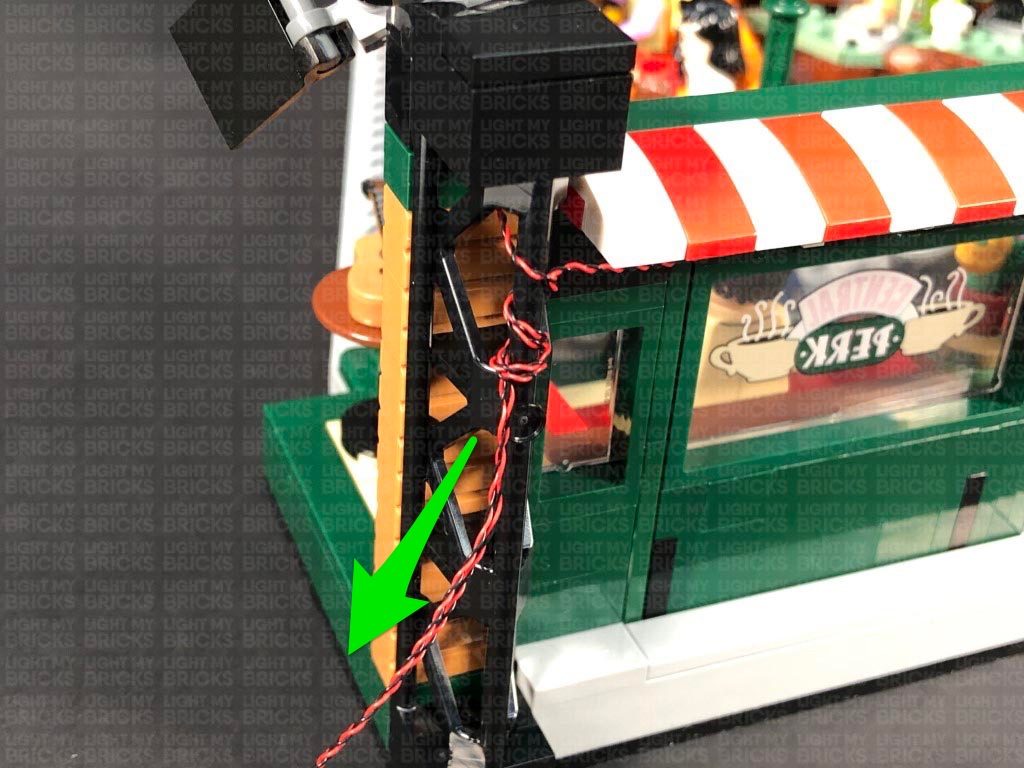
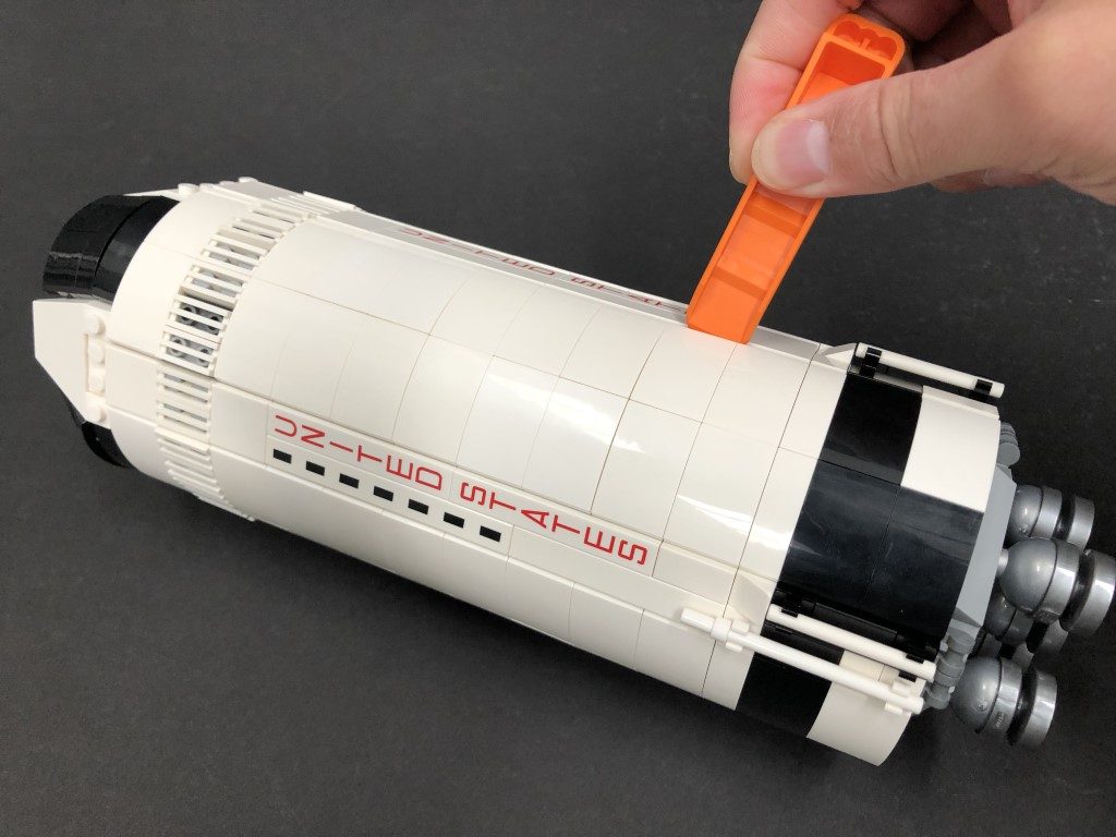
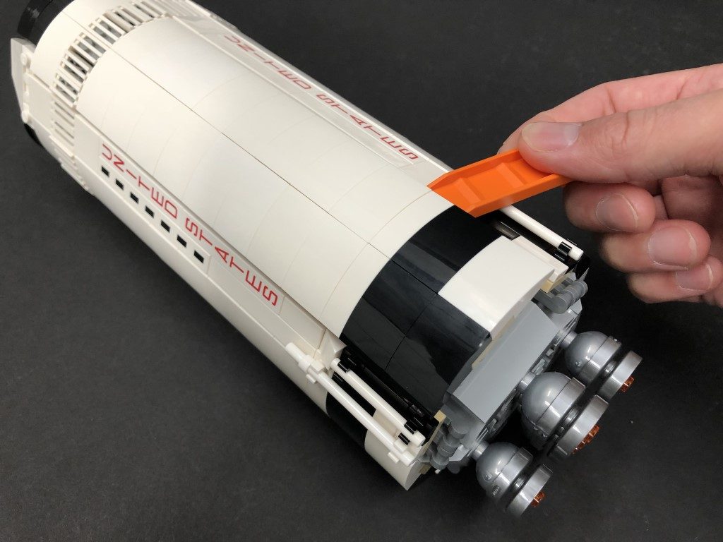
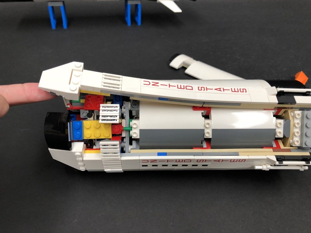
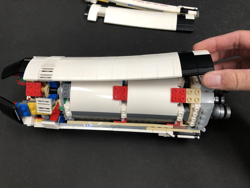
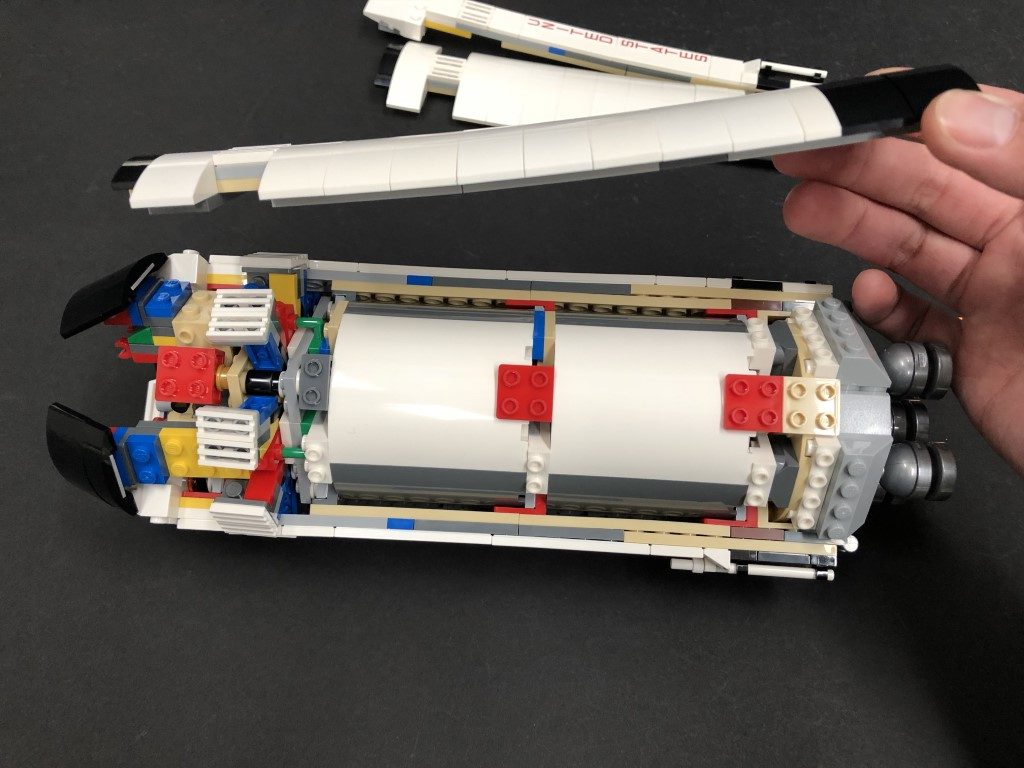
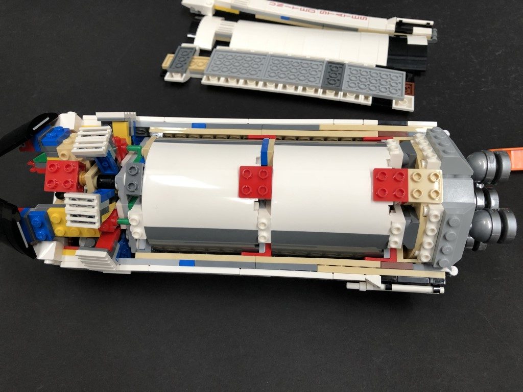
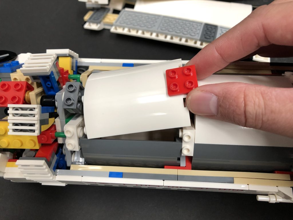
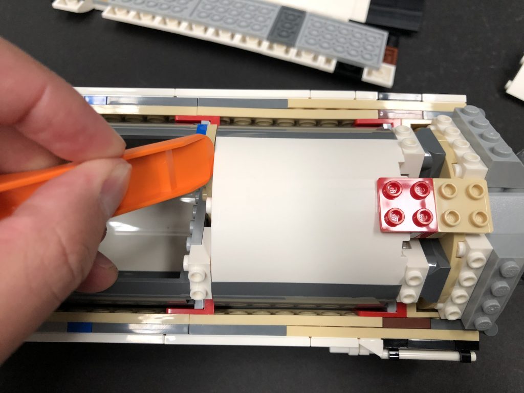
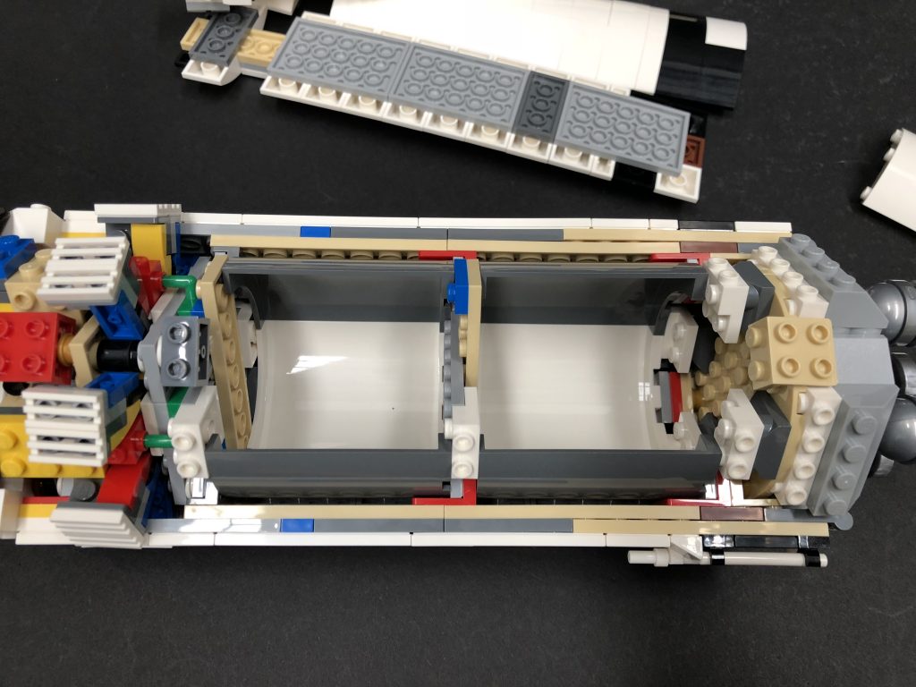
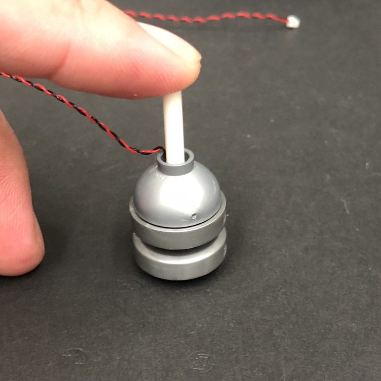
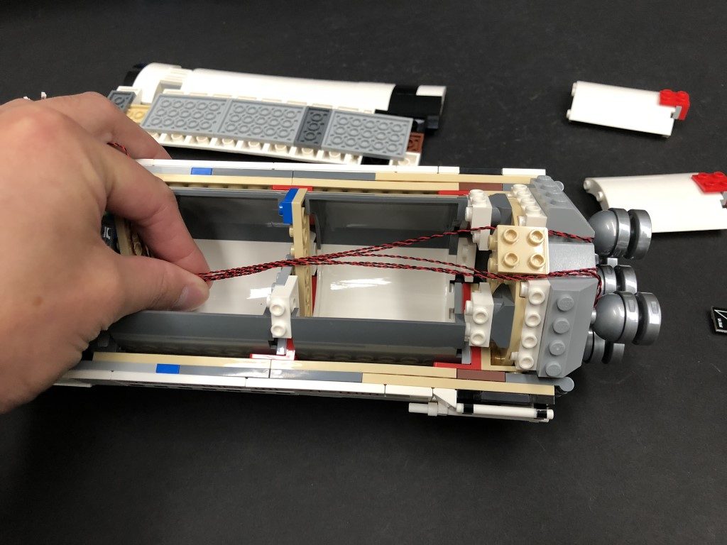
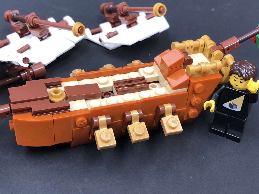
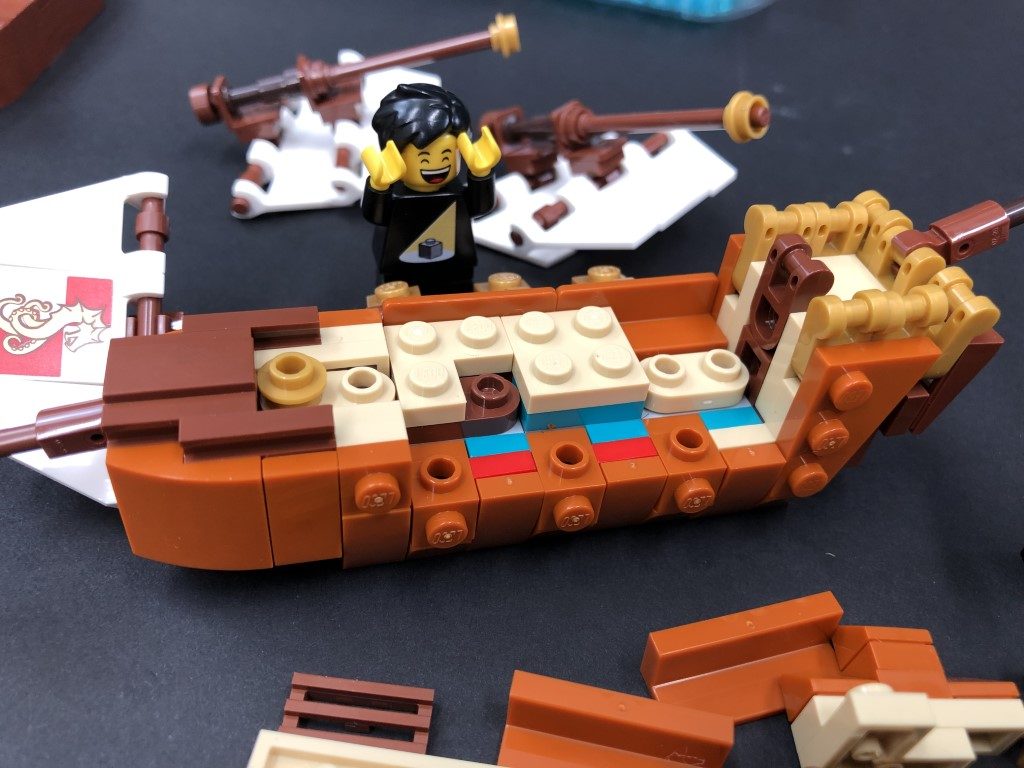
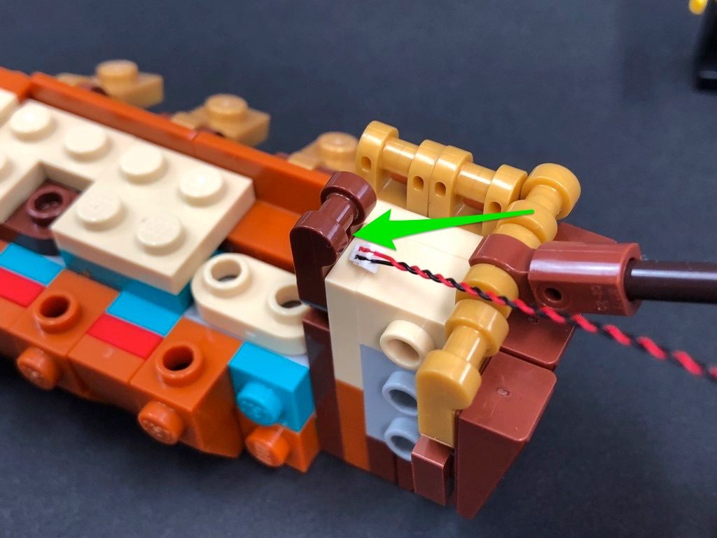
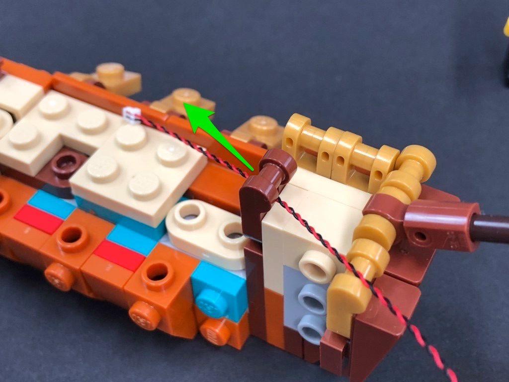
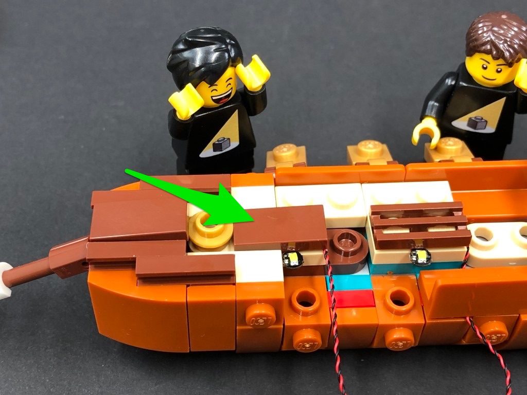
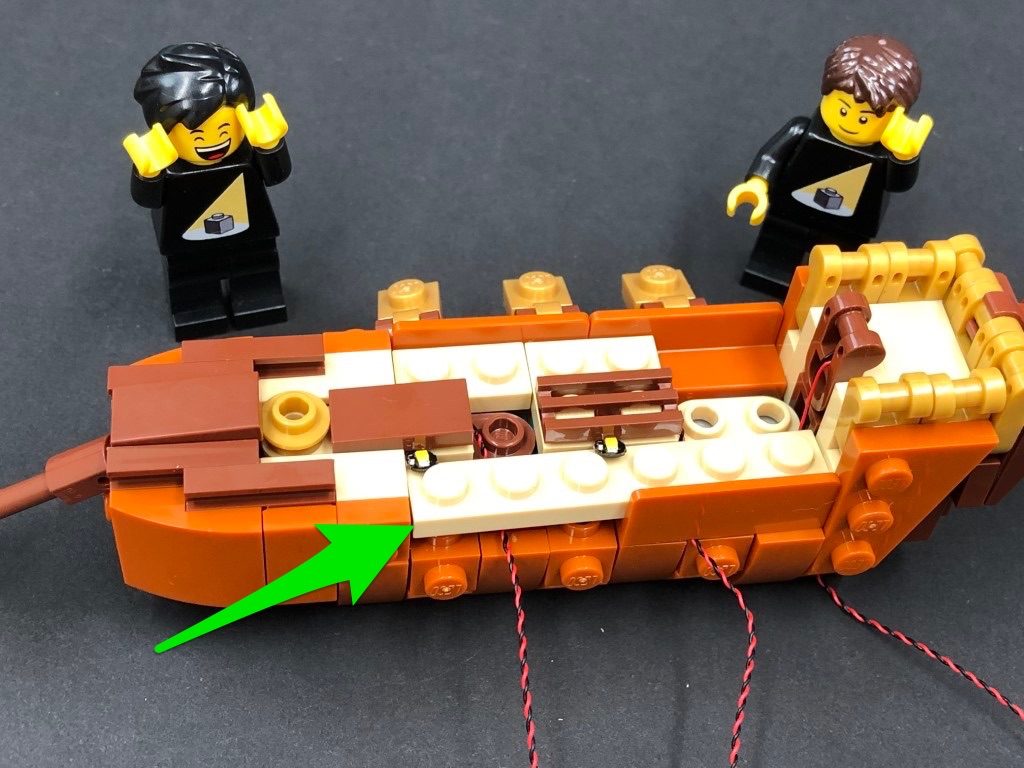
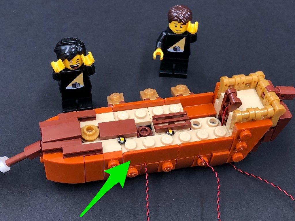
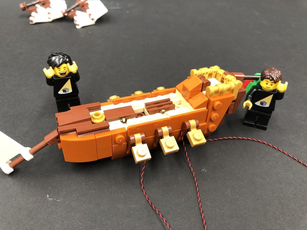
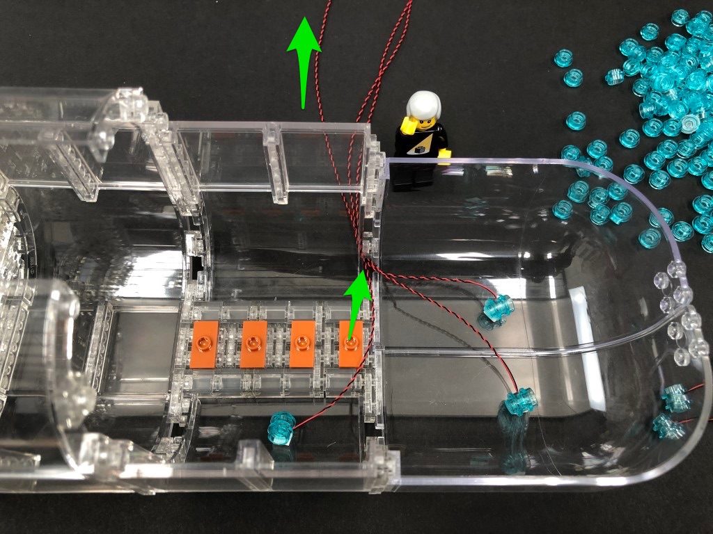
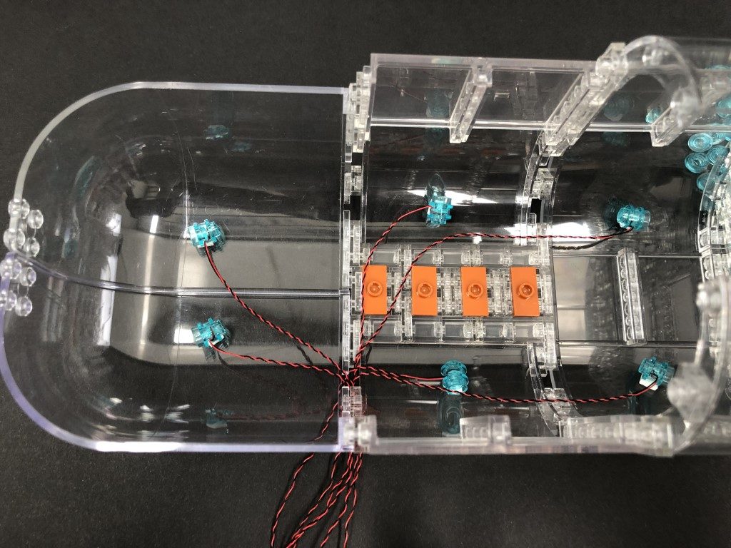
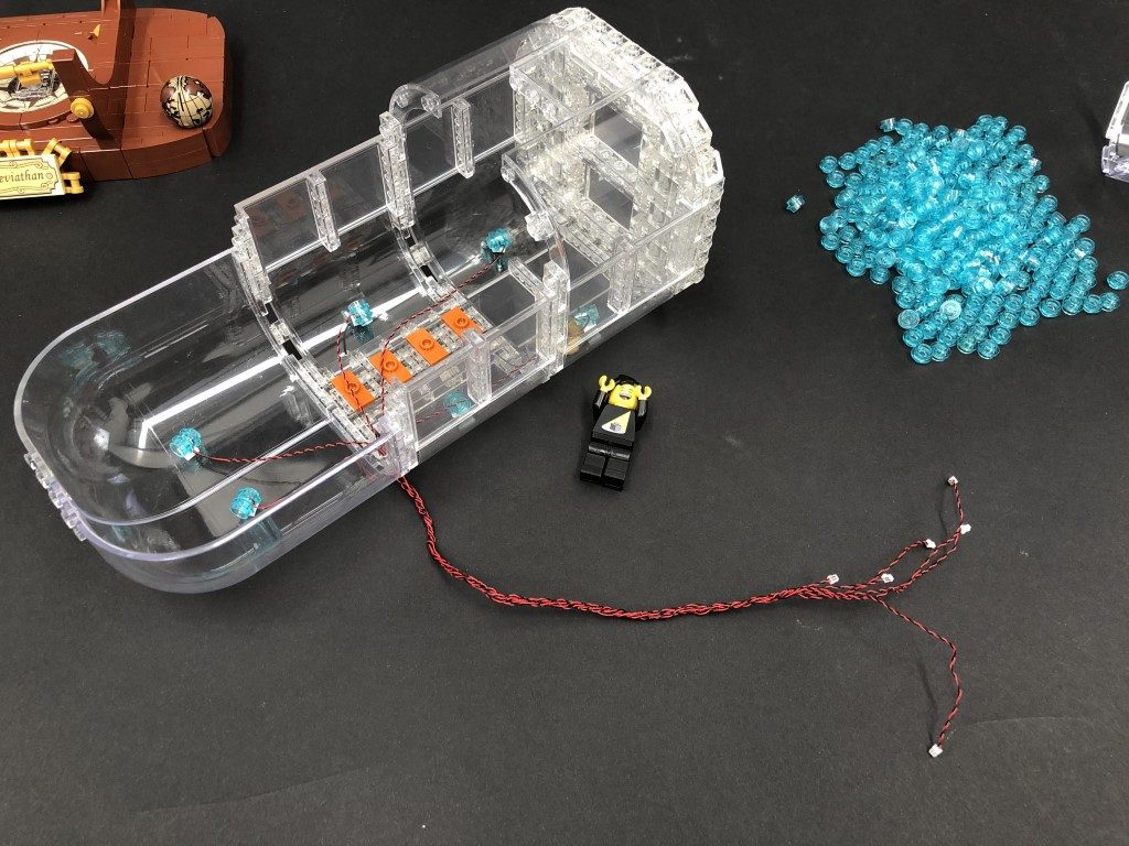
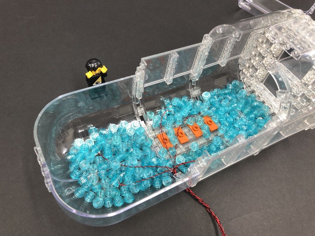
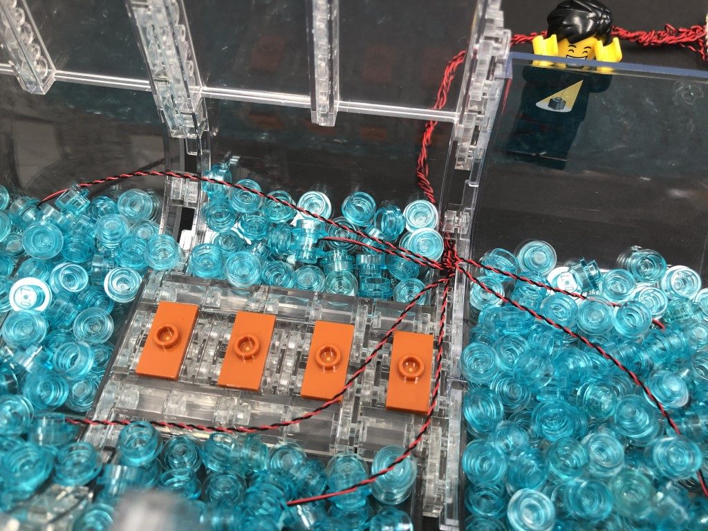
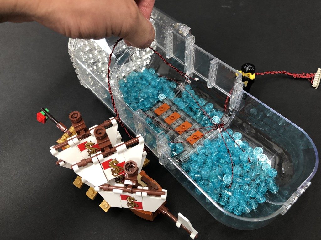
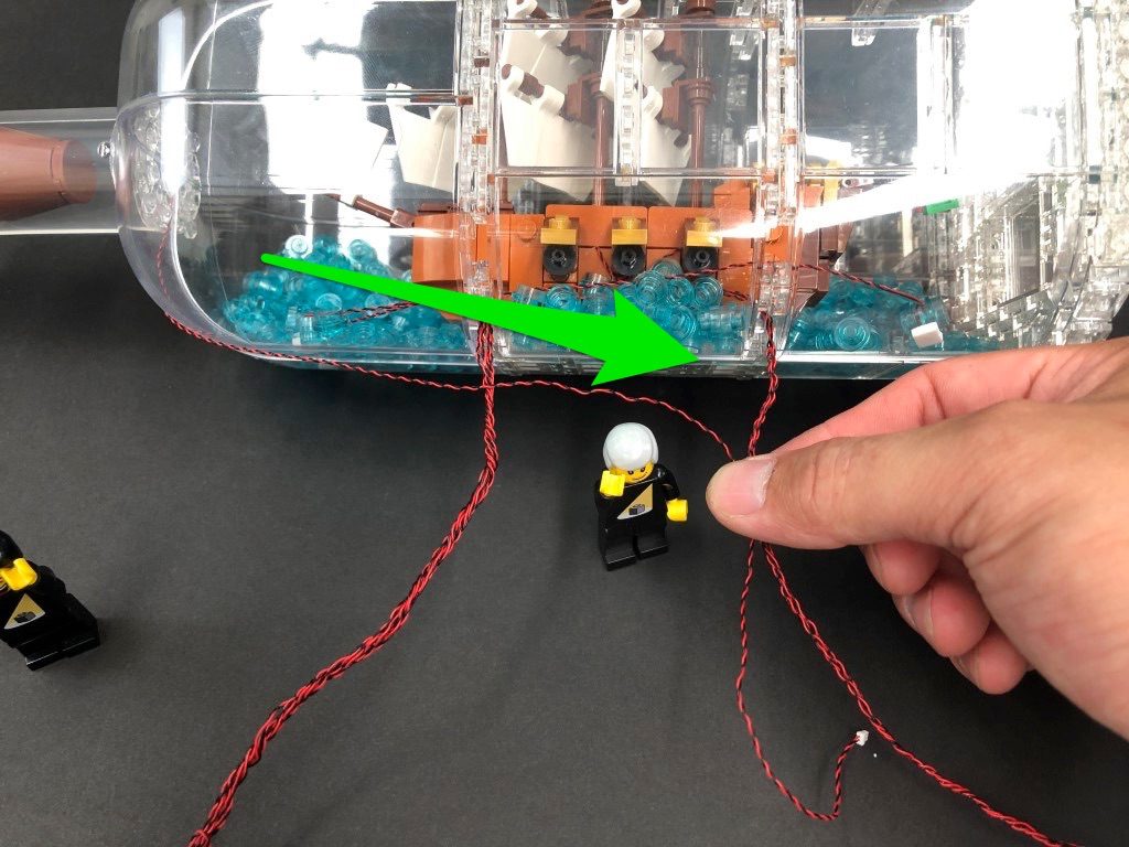
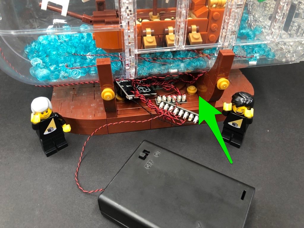
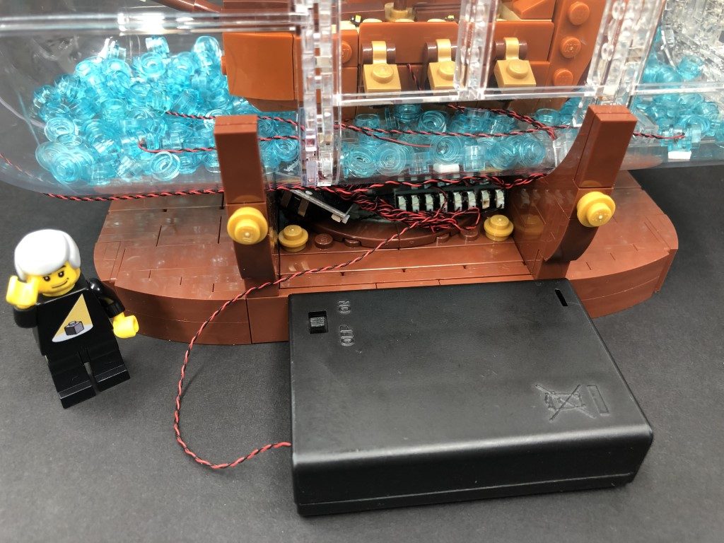
1.) We will begin with lighting the left section first. Seperate the two sections, then disconnect the front of the ship via the ball joints. Disconnect the following black bricks from underneath the ship, then disconnect the following 2×4 plate from the top. 2.) Take a Green Strip Light and connect a 30cm Connecting Cable to the left port, then connect a 15cm Connecting Cable to the right port. Thread both cables up underneath the first floor, then pull both cables out from the top. Peel off the adhesive backing from the green strip light and stick it underneath the first floor in the following position. Pull both cables all the way out from above, then disconnect the following black 1×1 tile on the side and lay the cables down across to the side of the ship in between studs as shown below. Reconnect both the tile and the 2×4 plate we removed earlier over the top. Ensure there are no dangling cables showing where the strip light is.
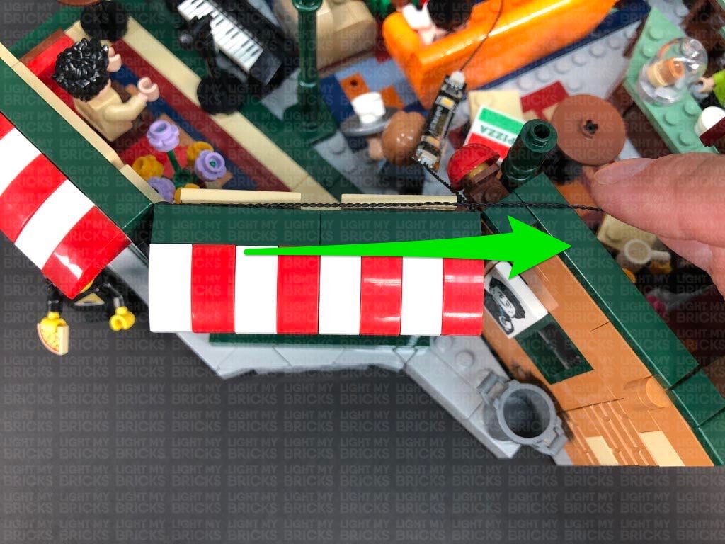
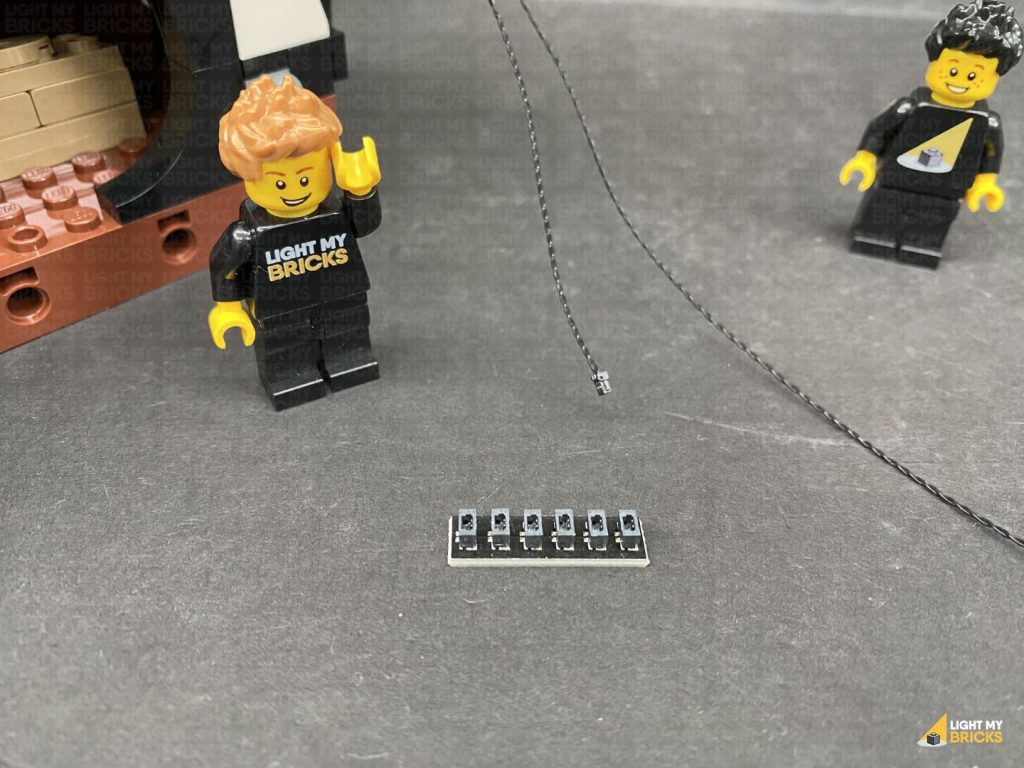
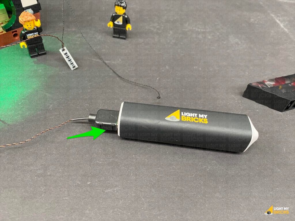
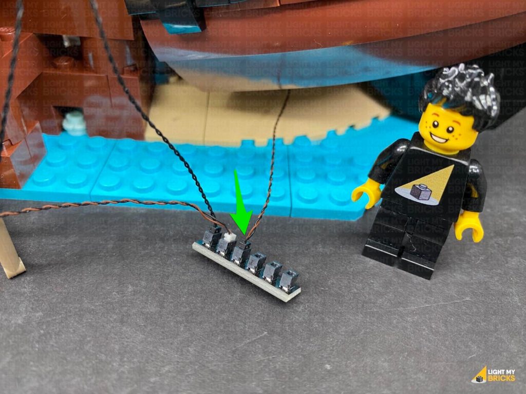
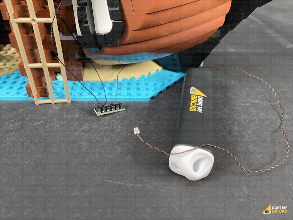
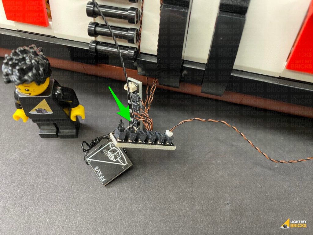
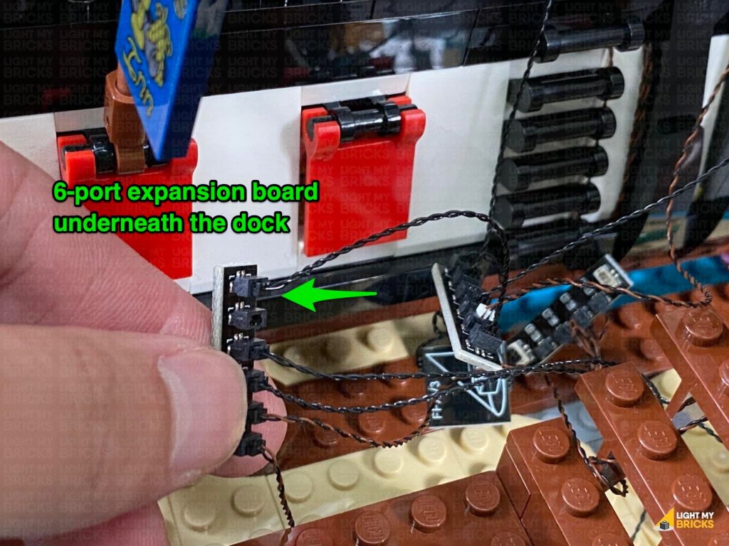
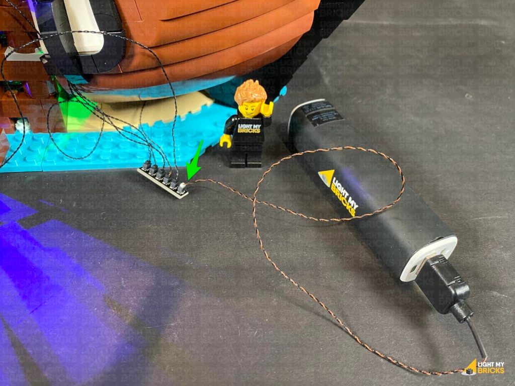
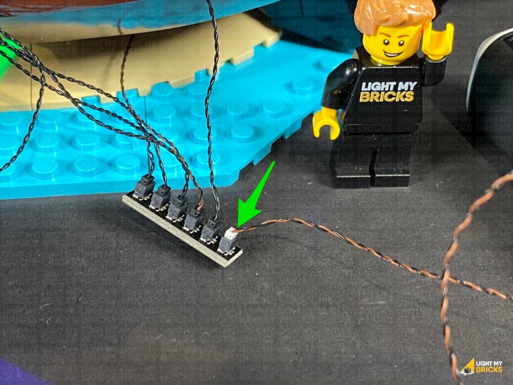
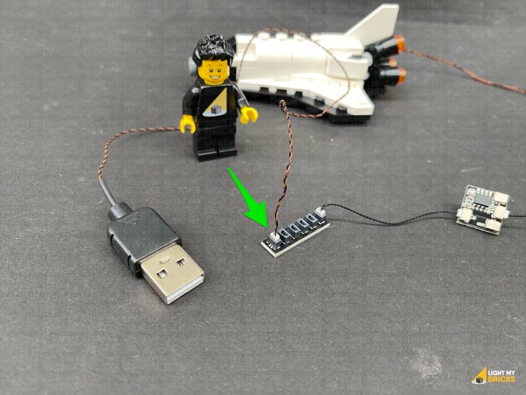
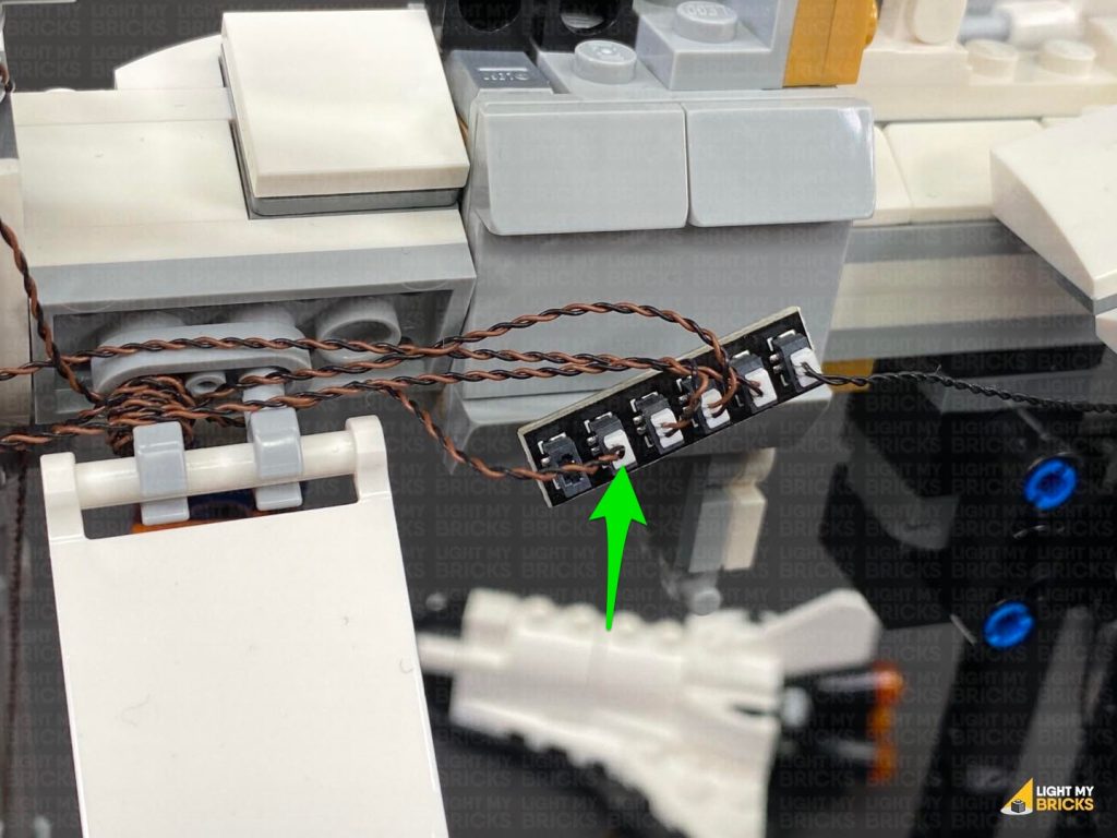
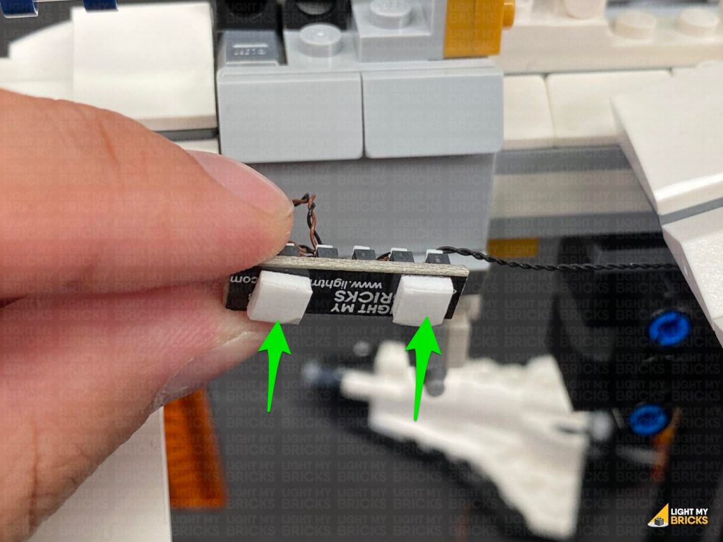
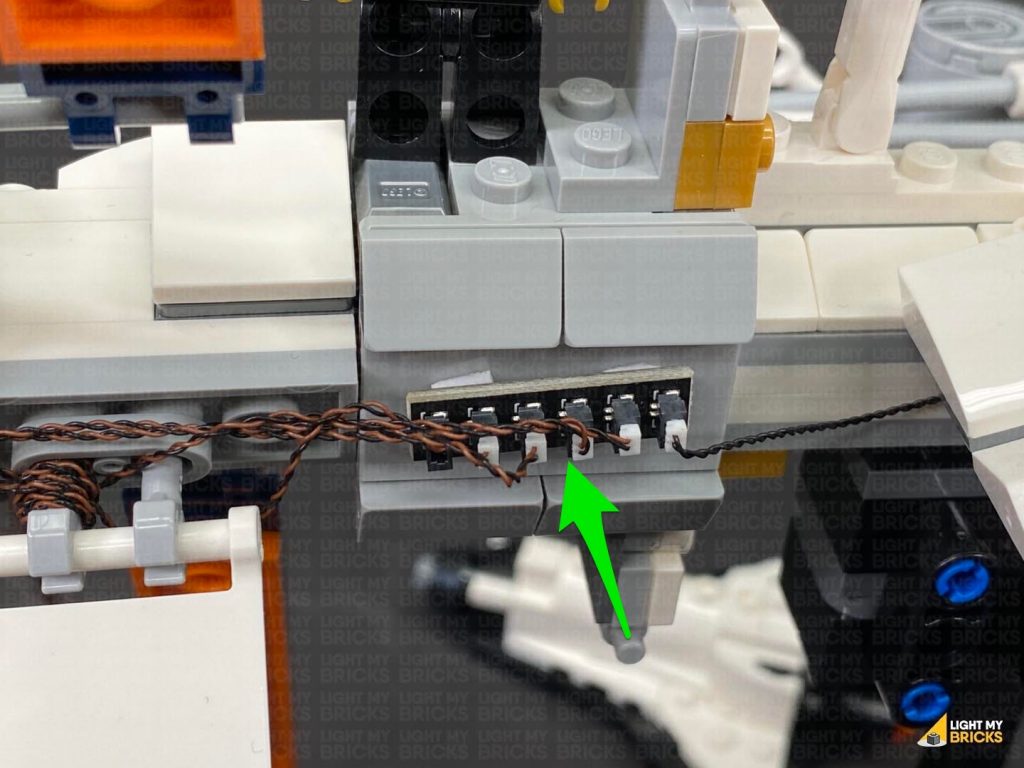
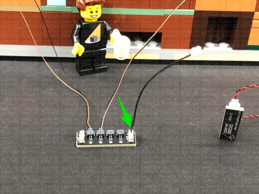
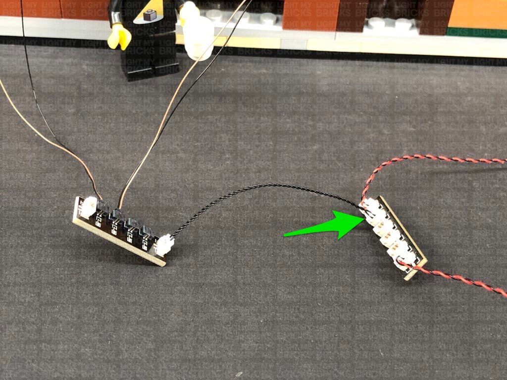
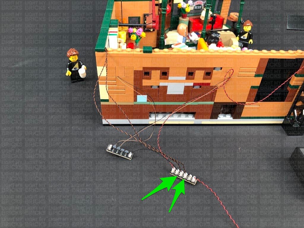
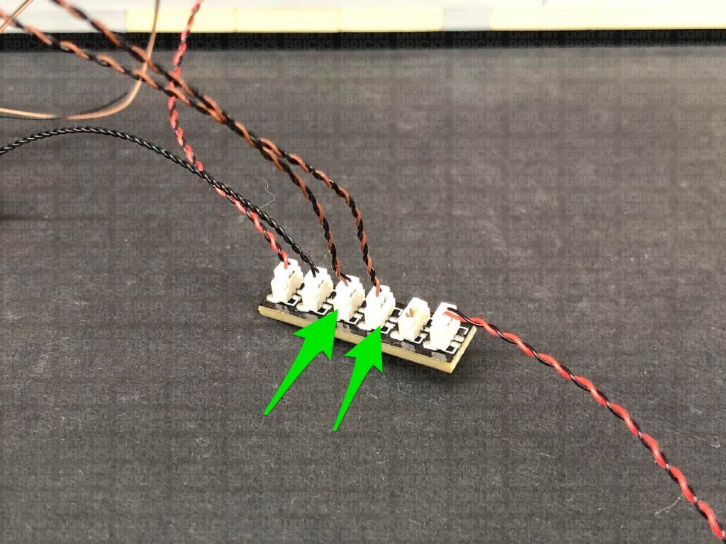
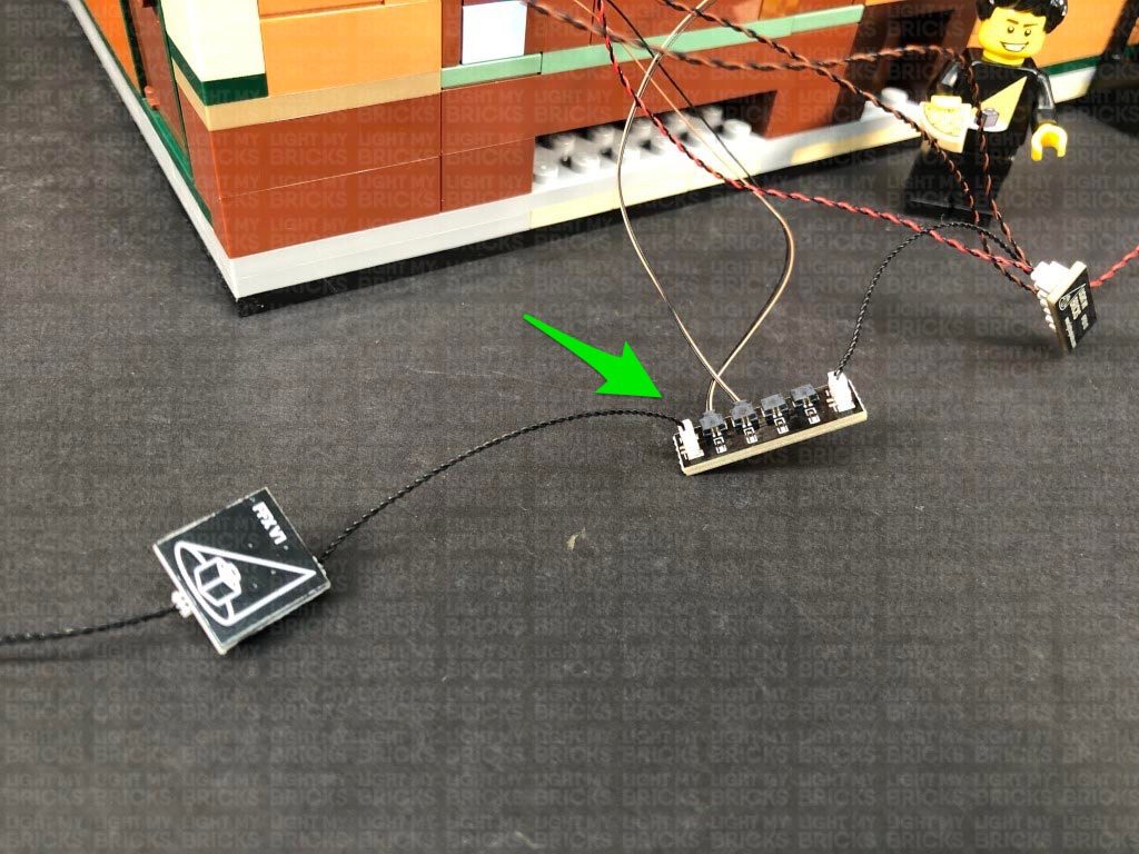
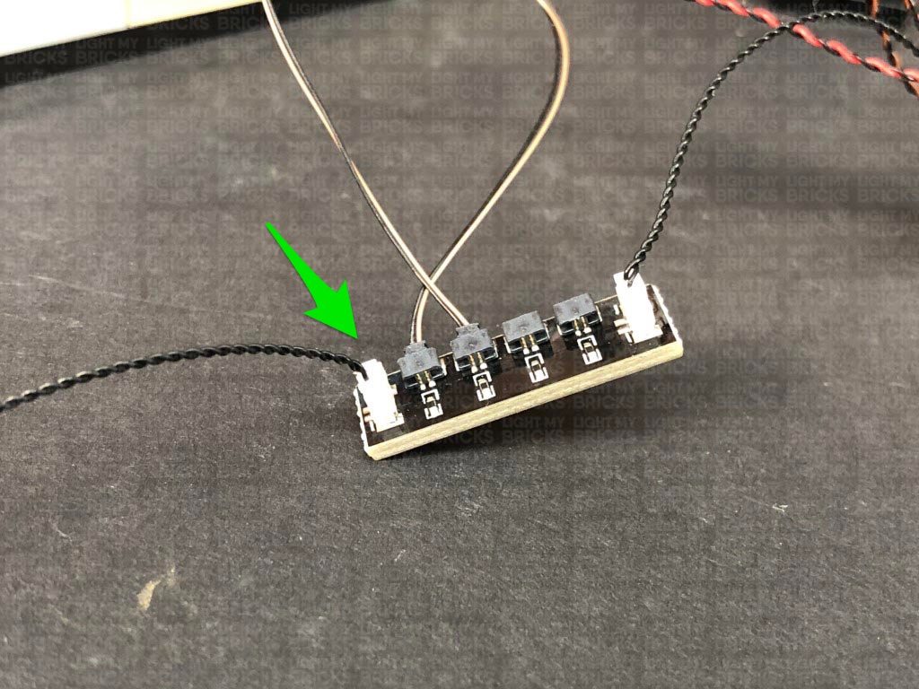
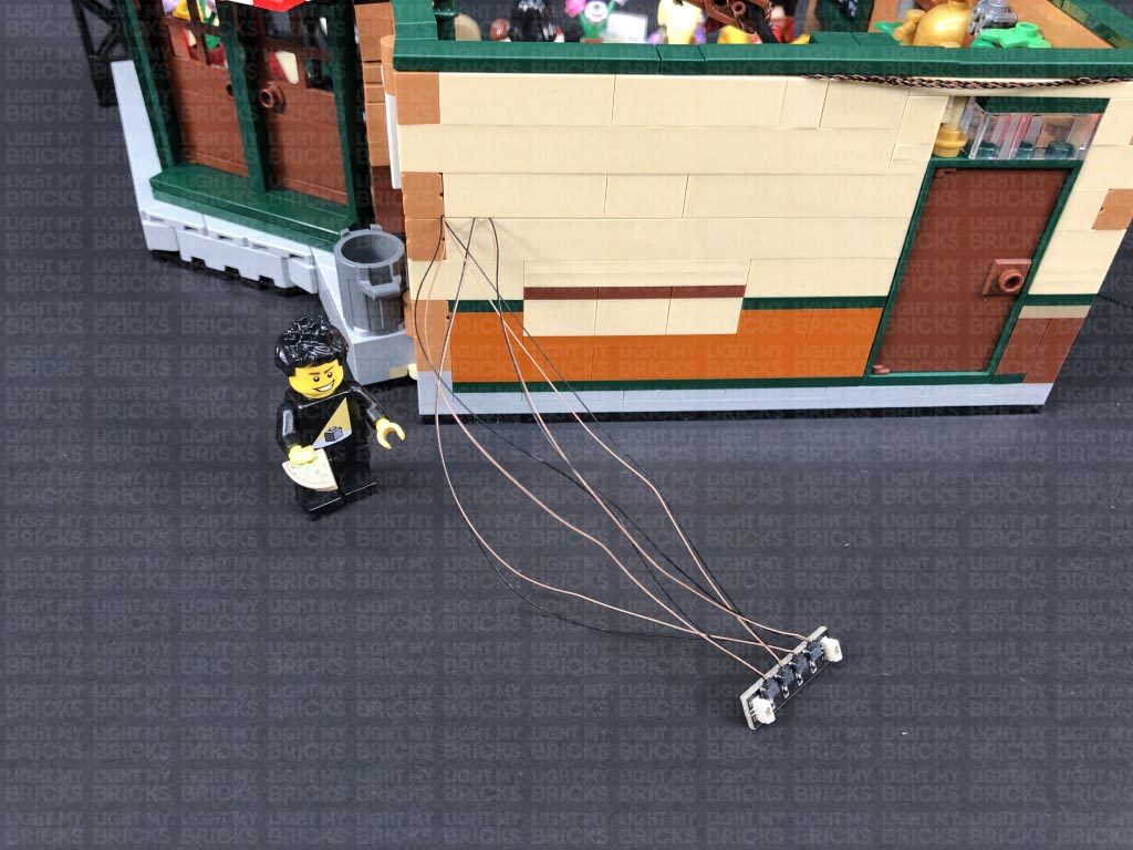
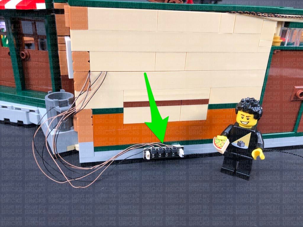
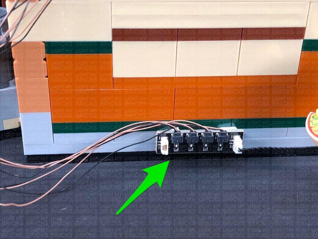
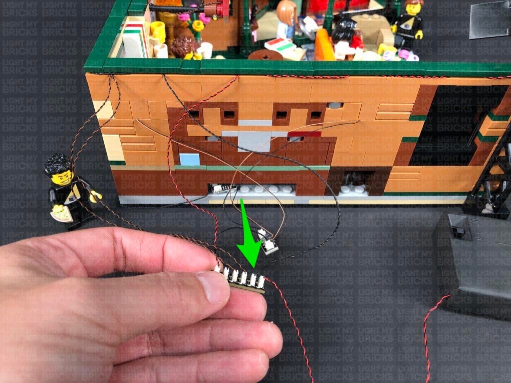
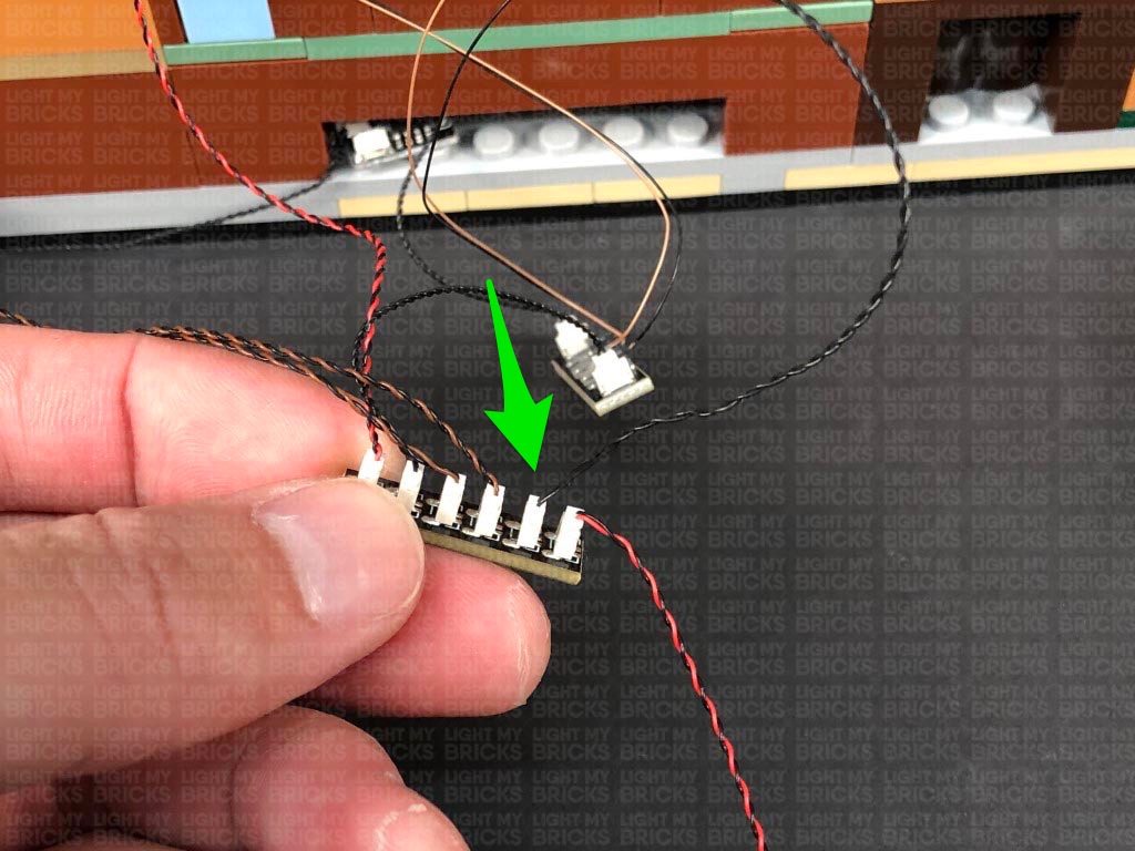
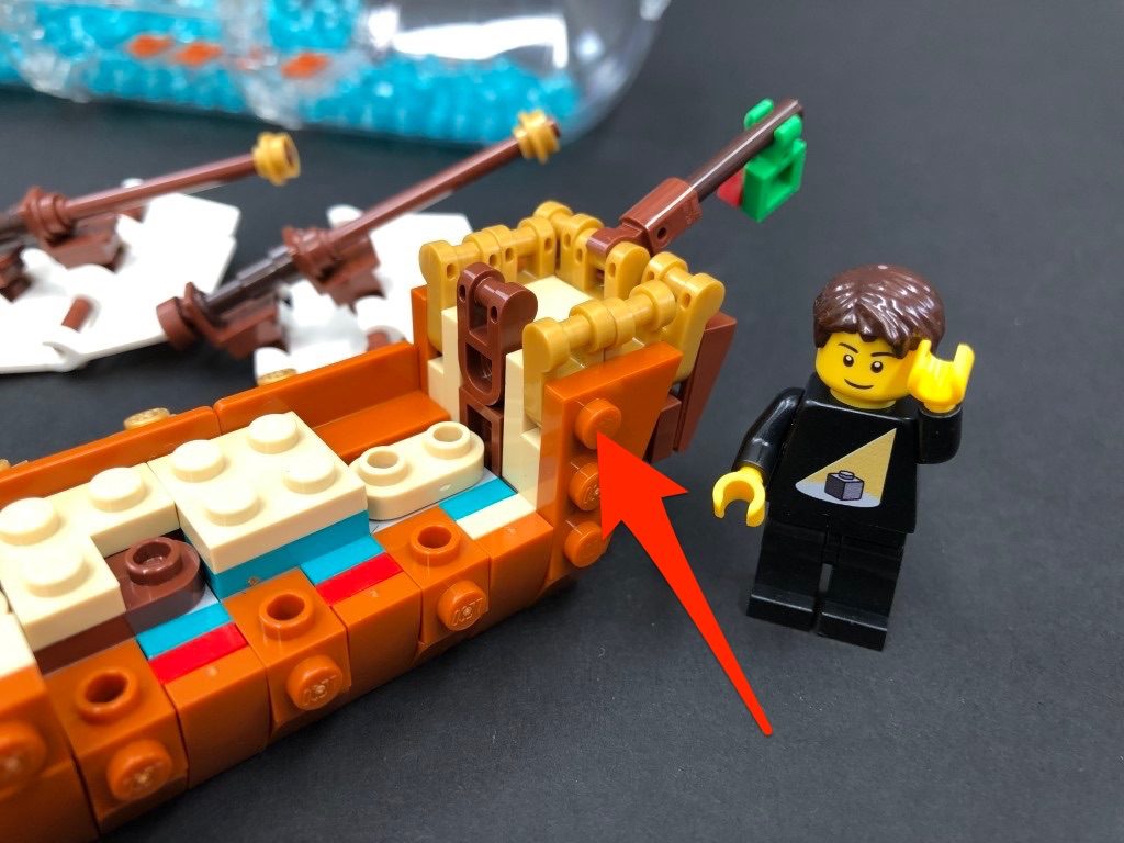
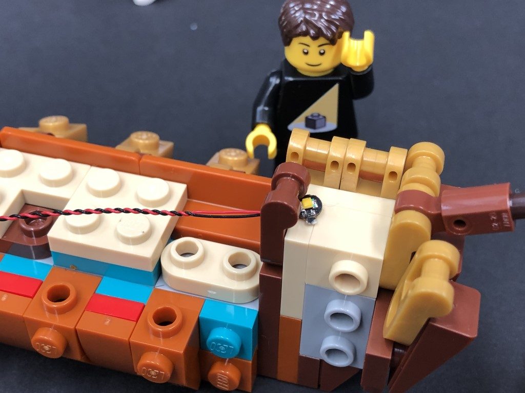
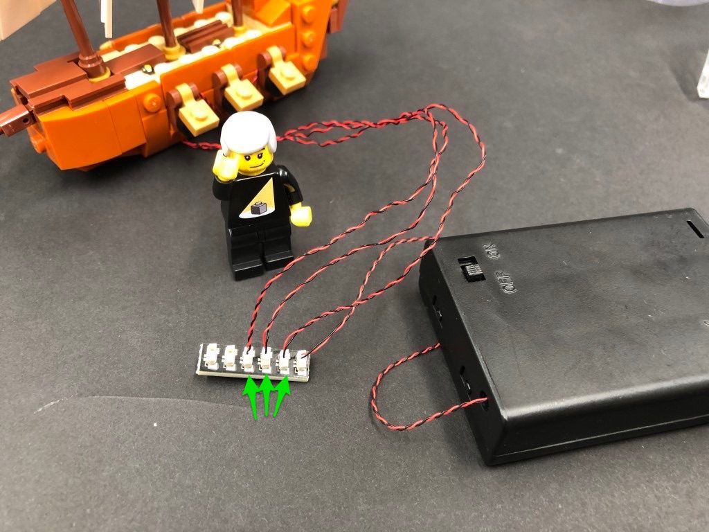
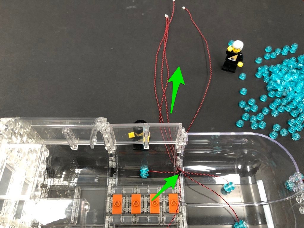
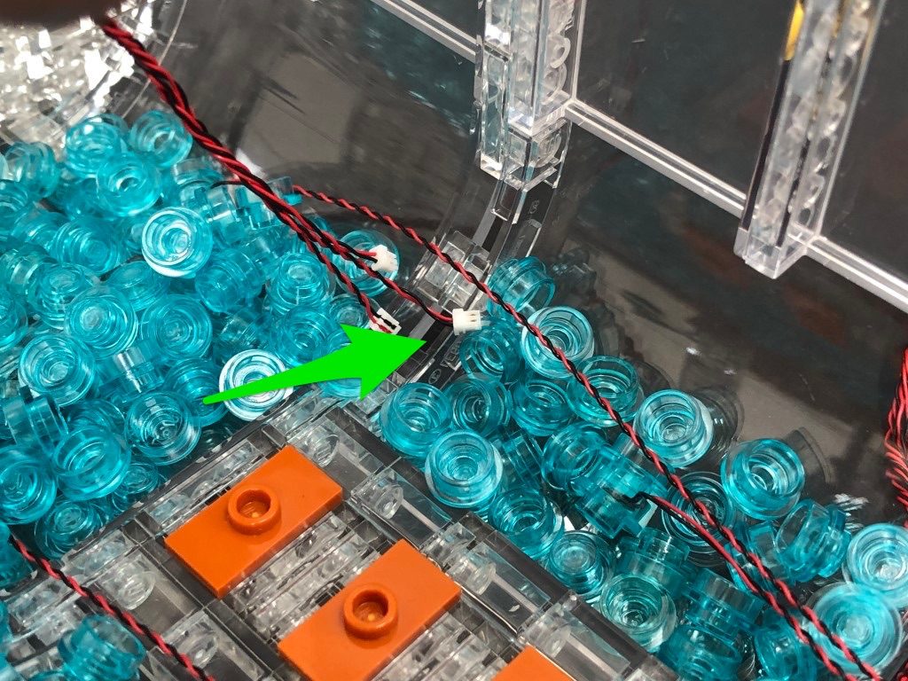
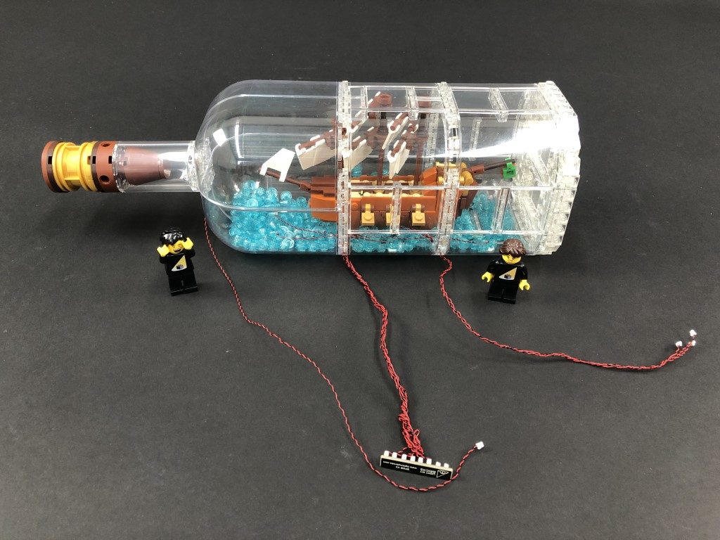
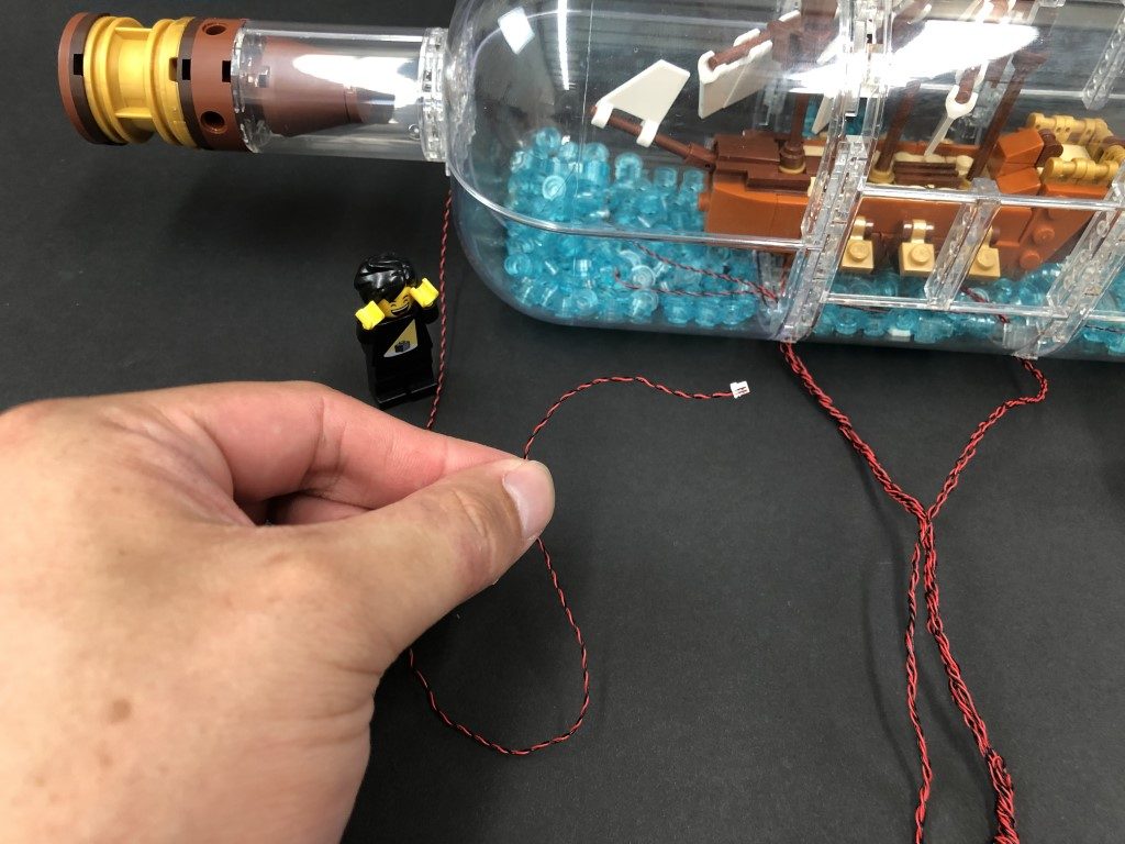
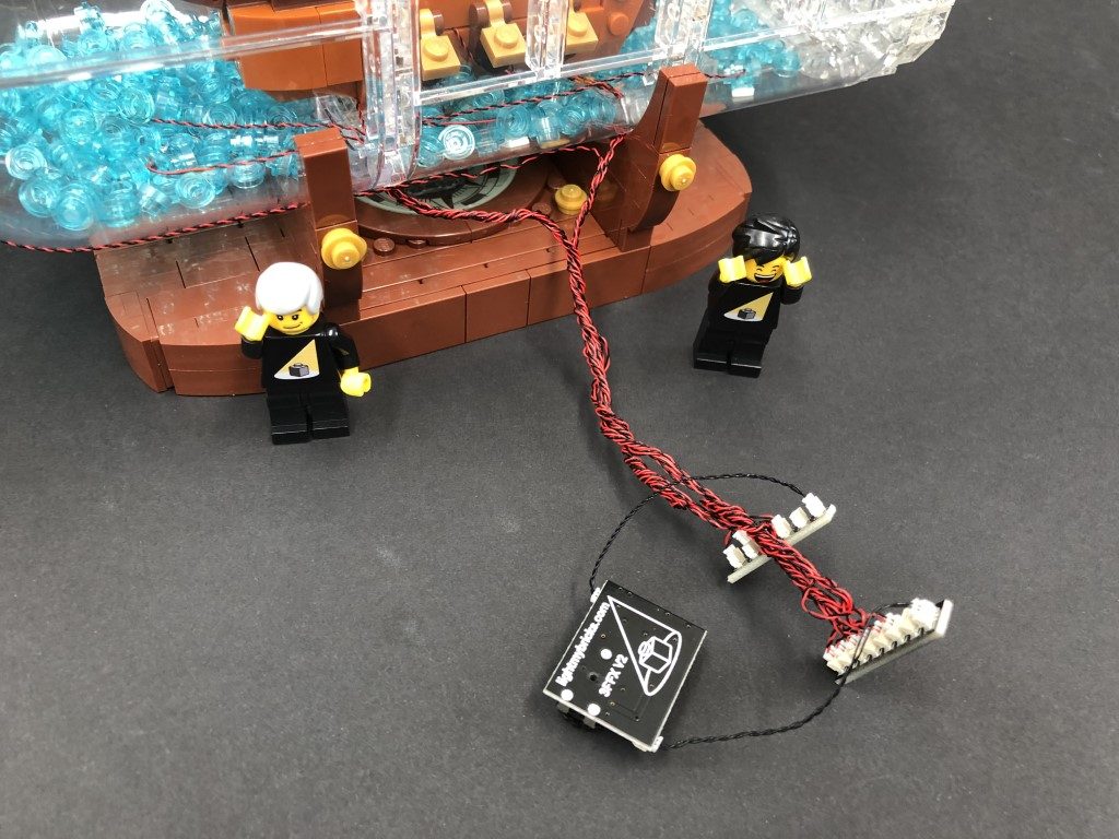
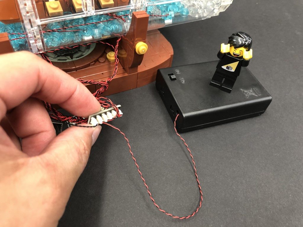
 3.) Take out a 6-Port Expansion Board and connect the end of the 15cm Connecting Cable to one of the far ports, then connect a USB power Cable to the next port on the board. Connect the other end of the USB cable to your USB Power Bank or wall adaptor (sold separately) to test the Green Strip Light is working OK.
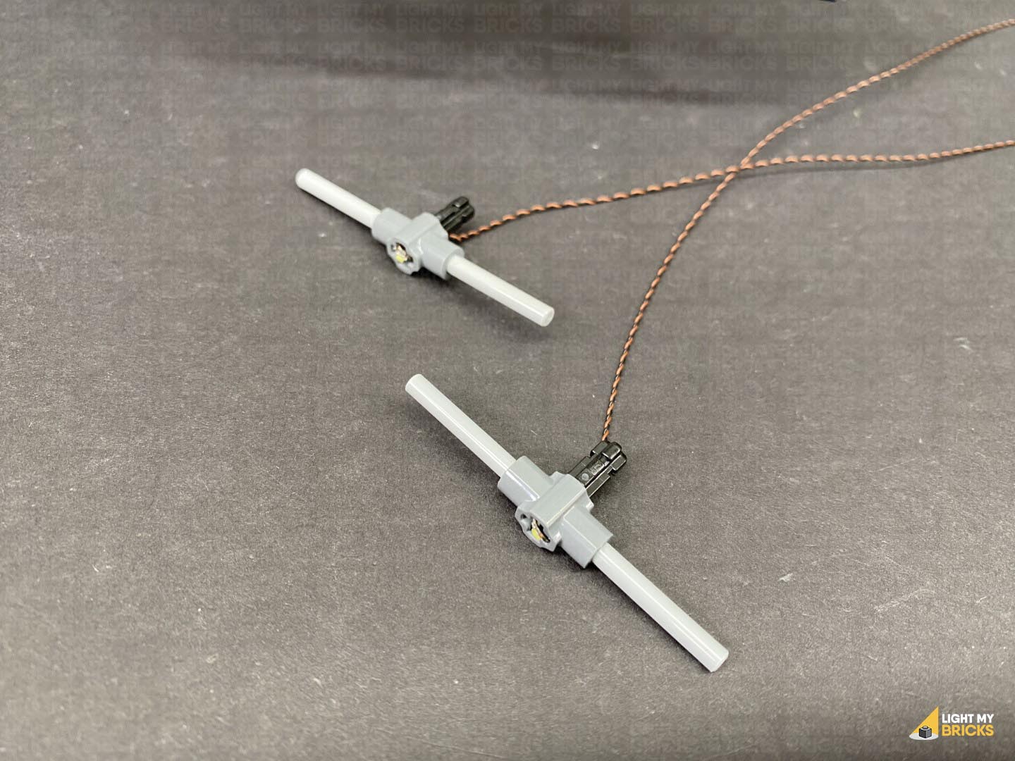
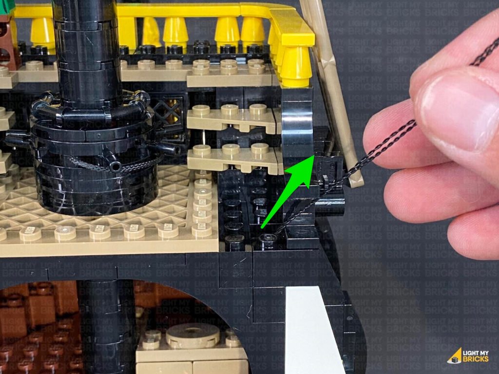
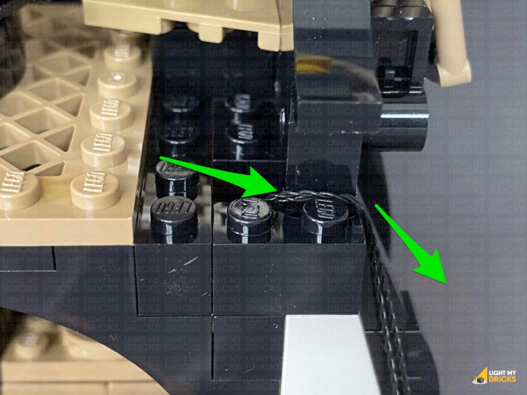
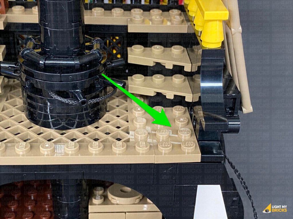
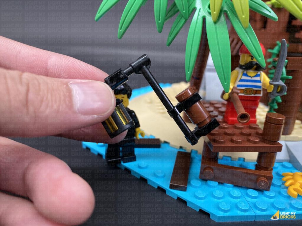
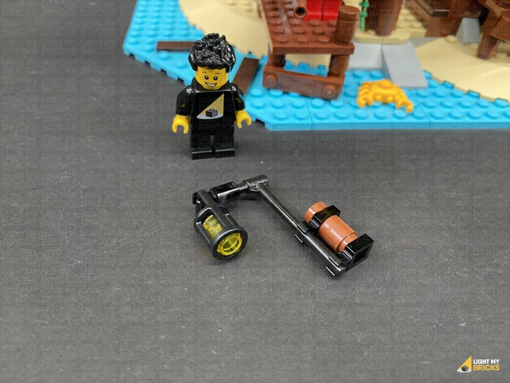
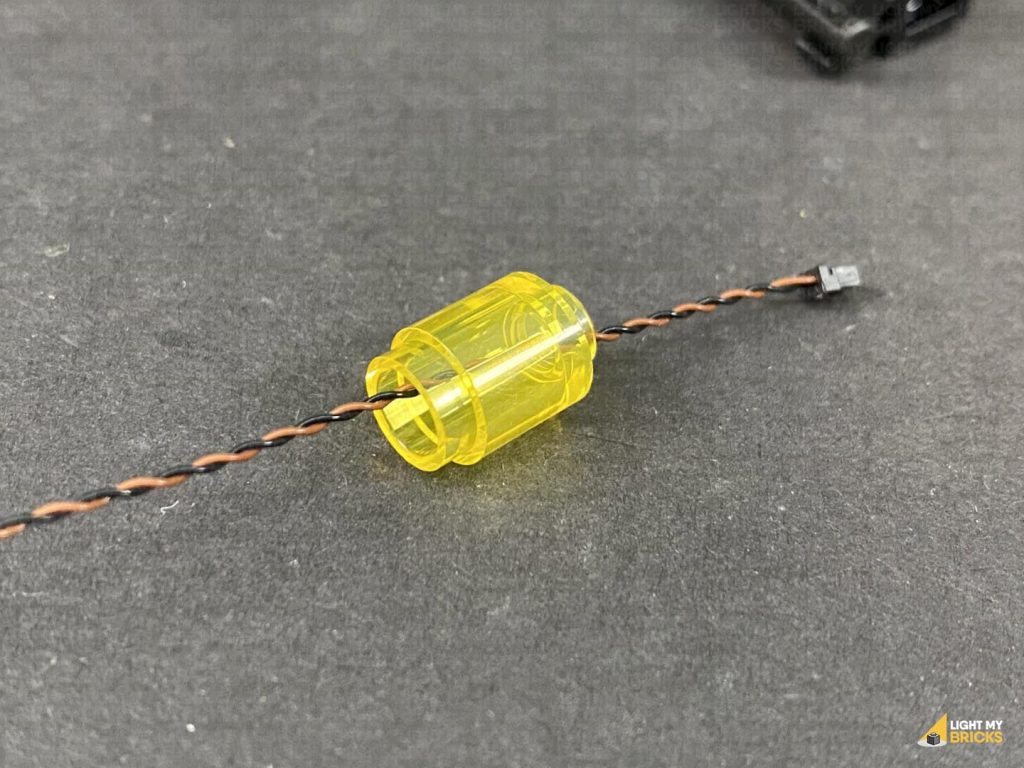
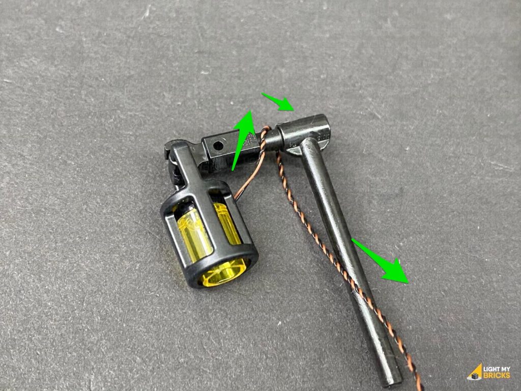
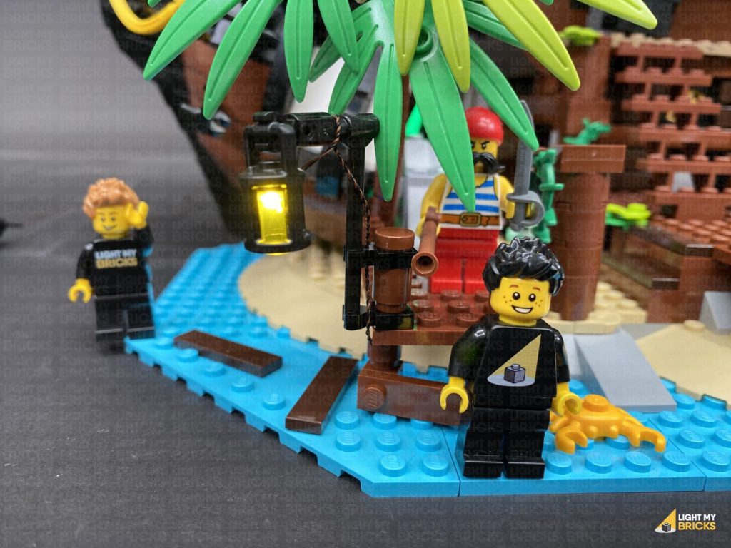
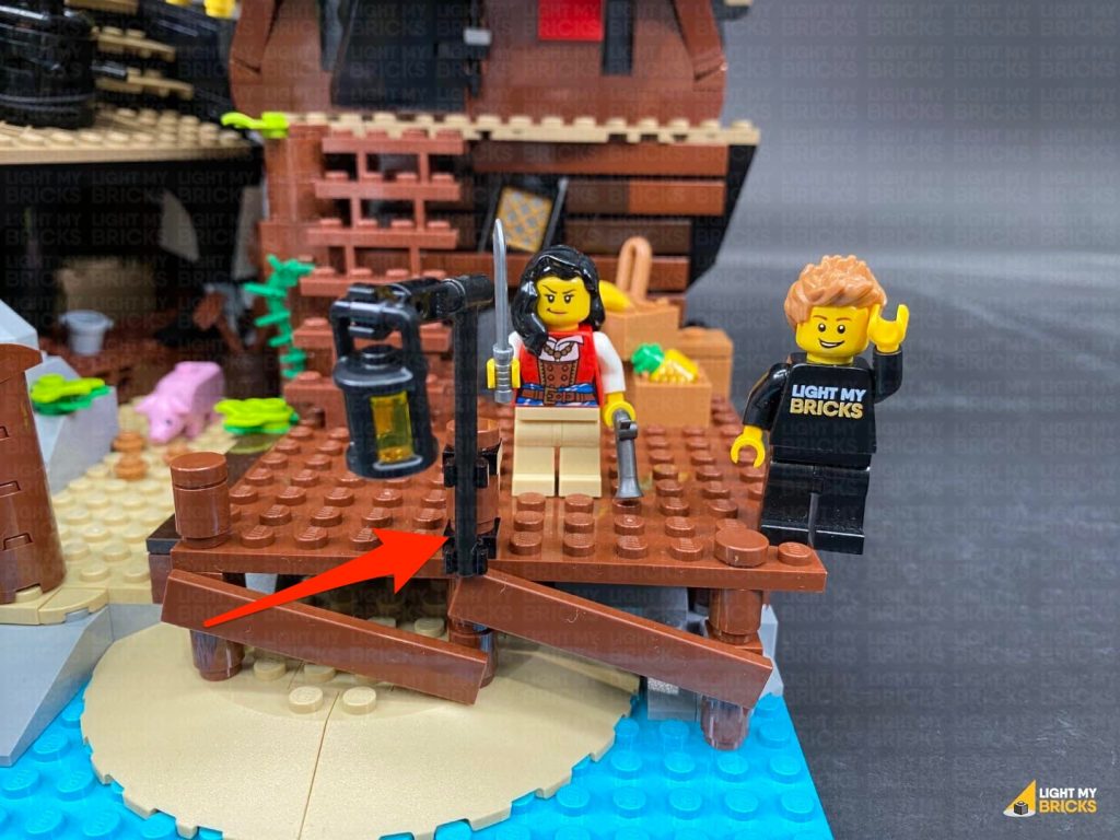
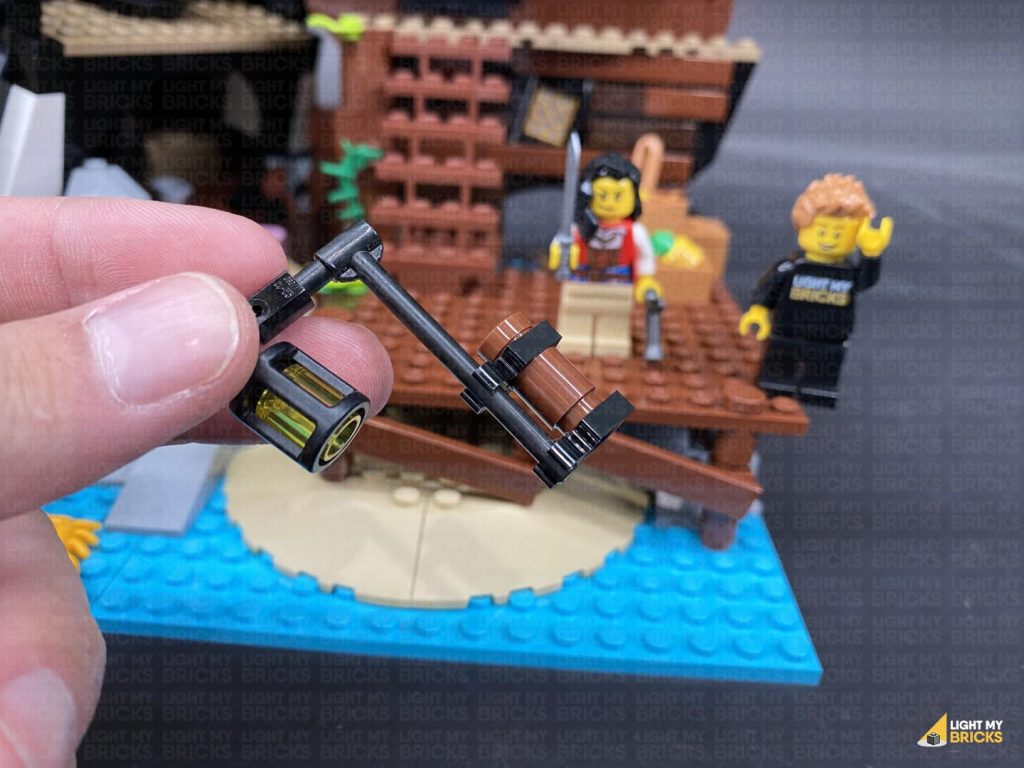
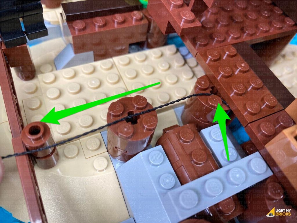
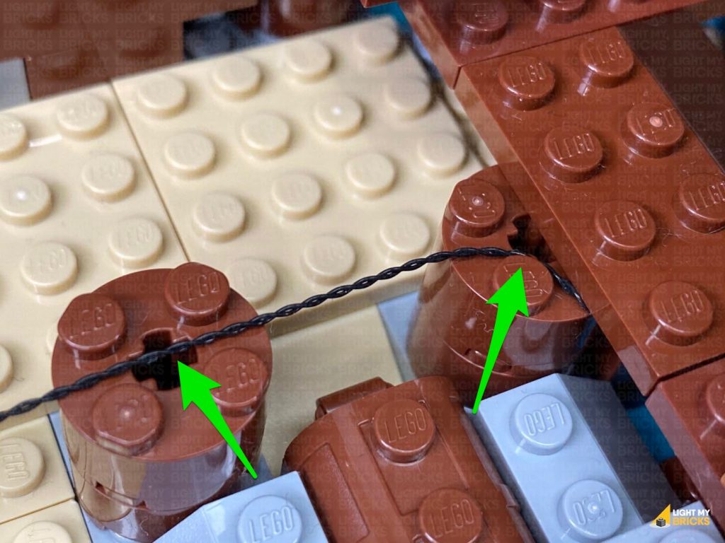
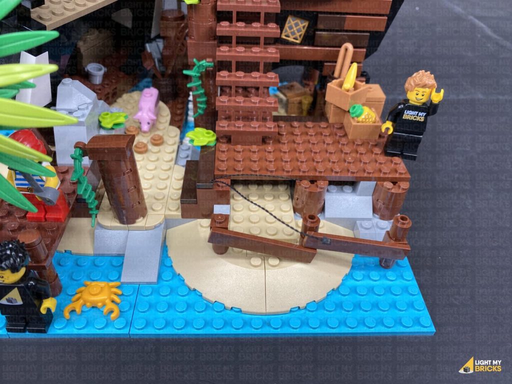
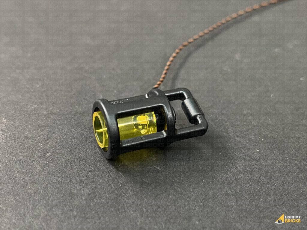
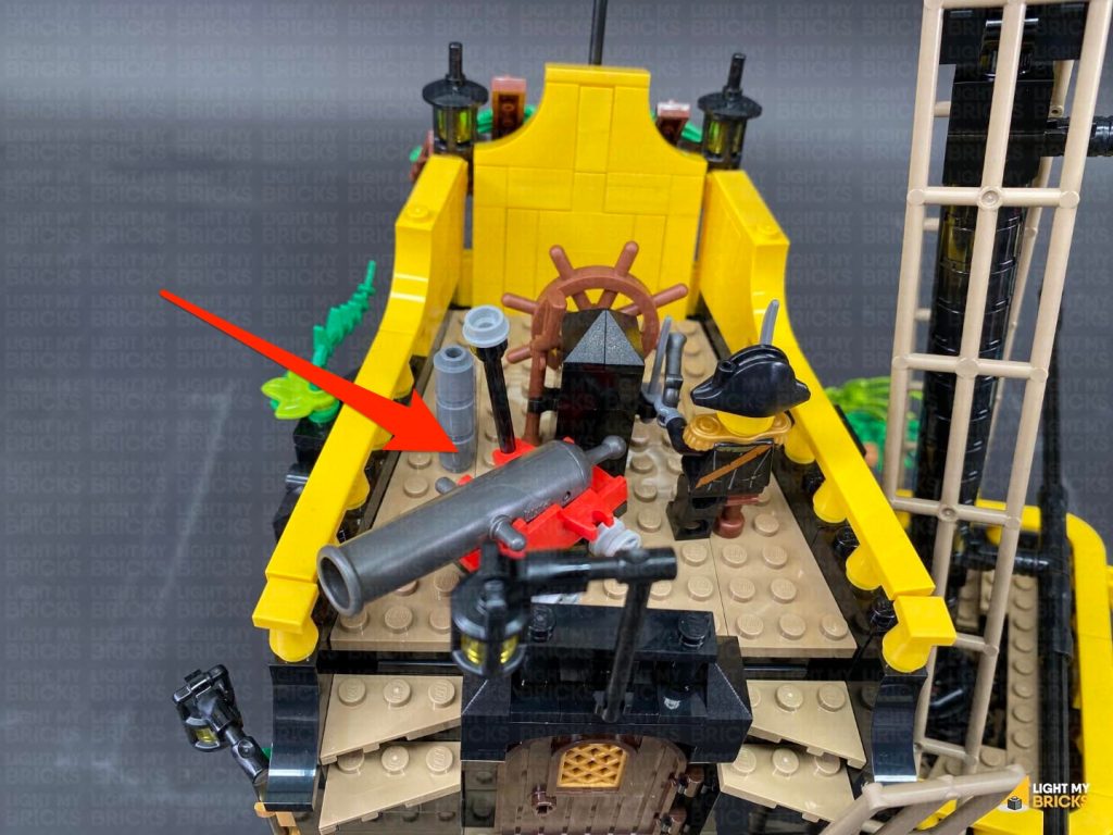
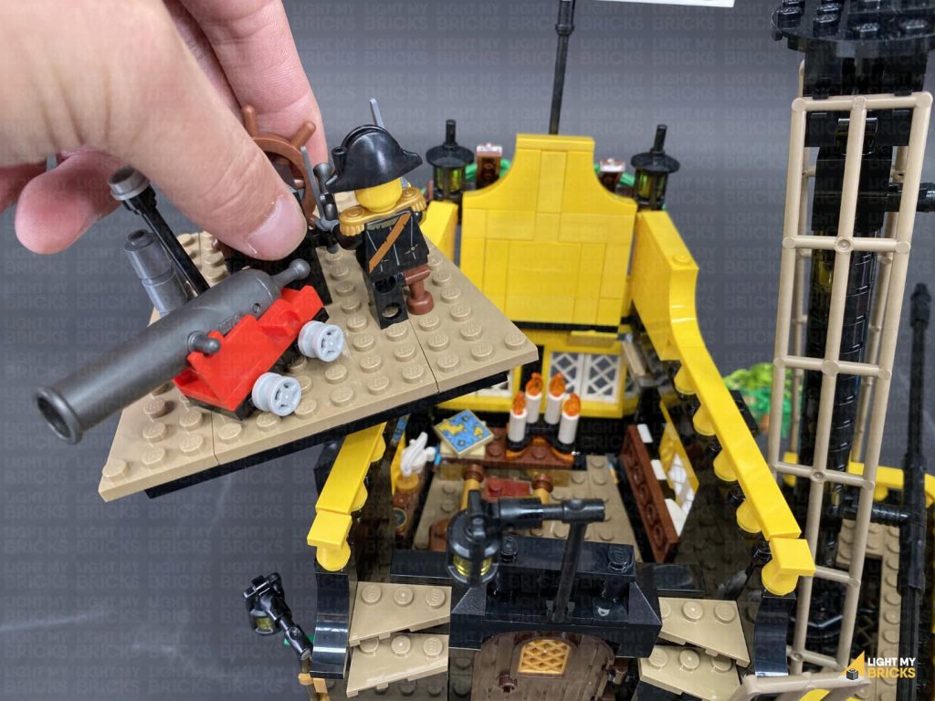
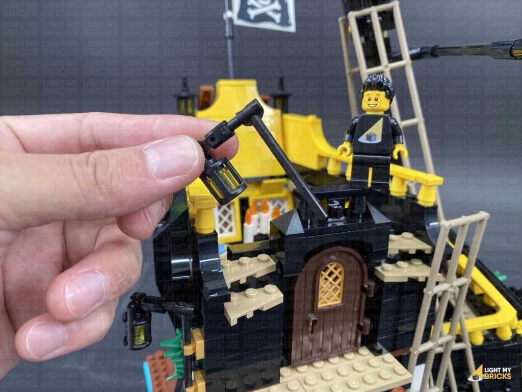
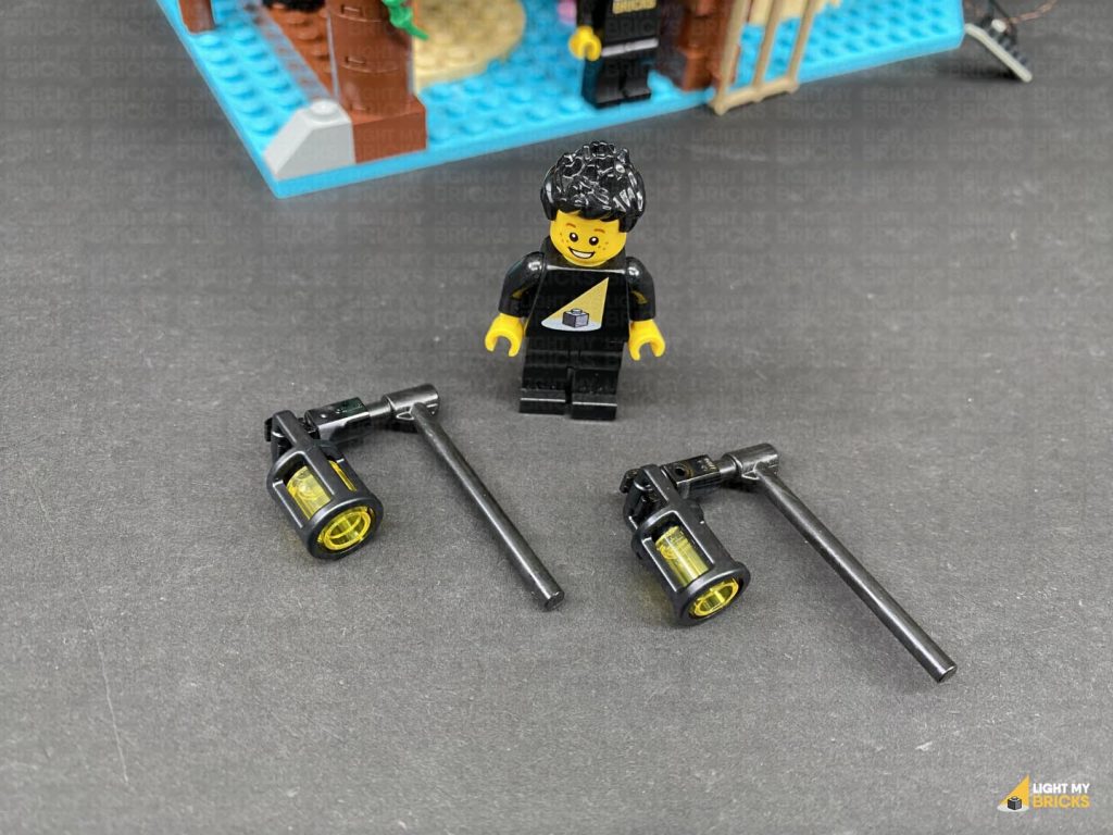
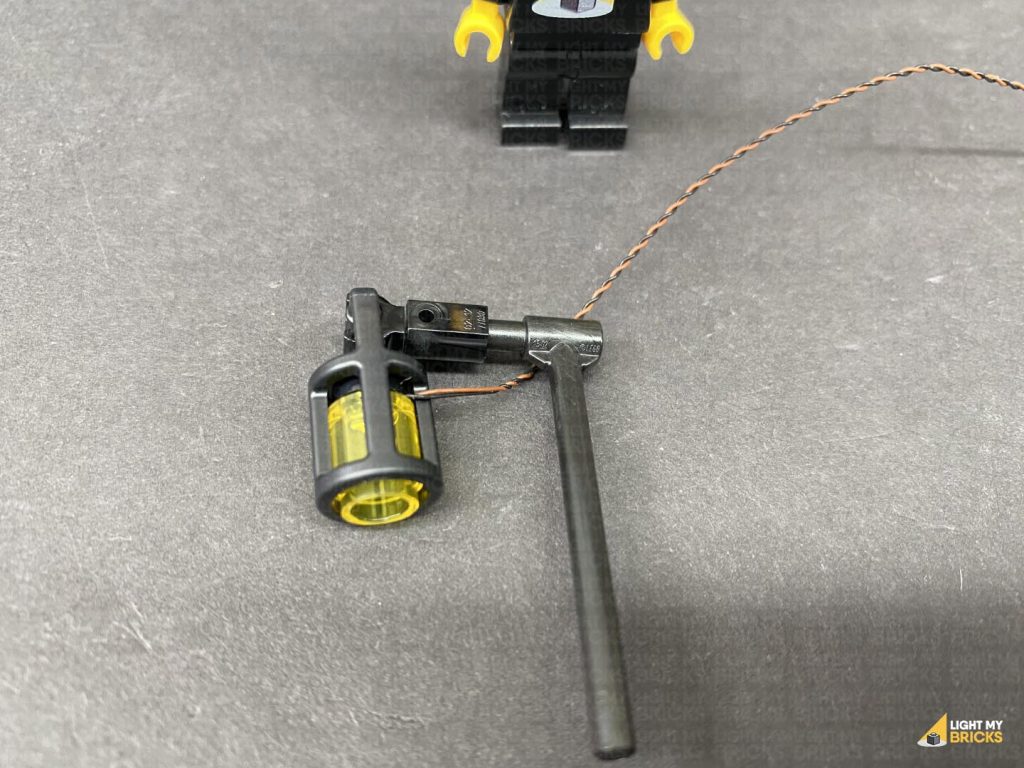
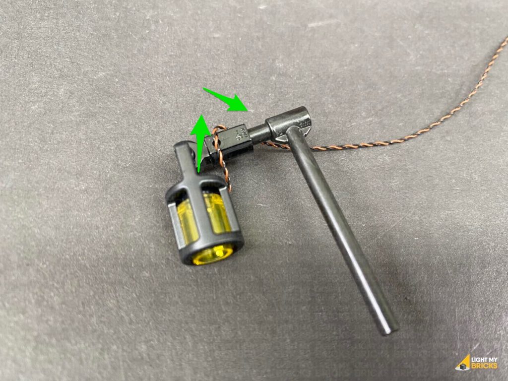
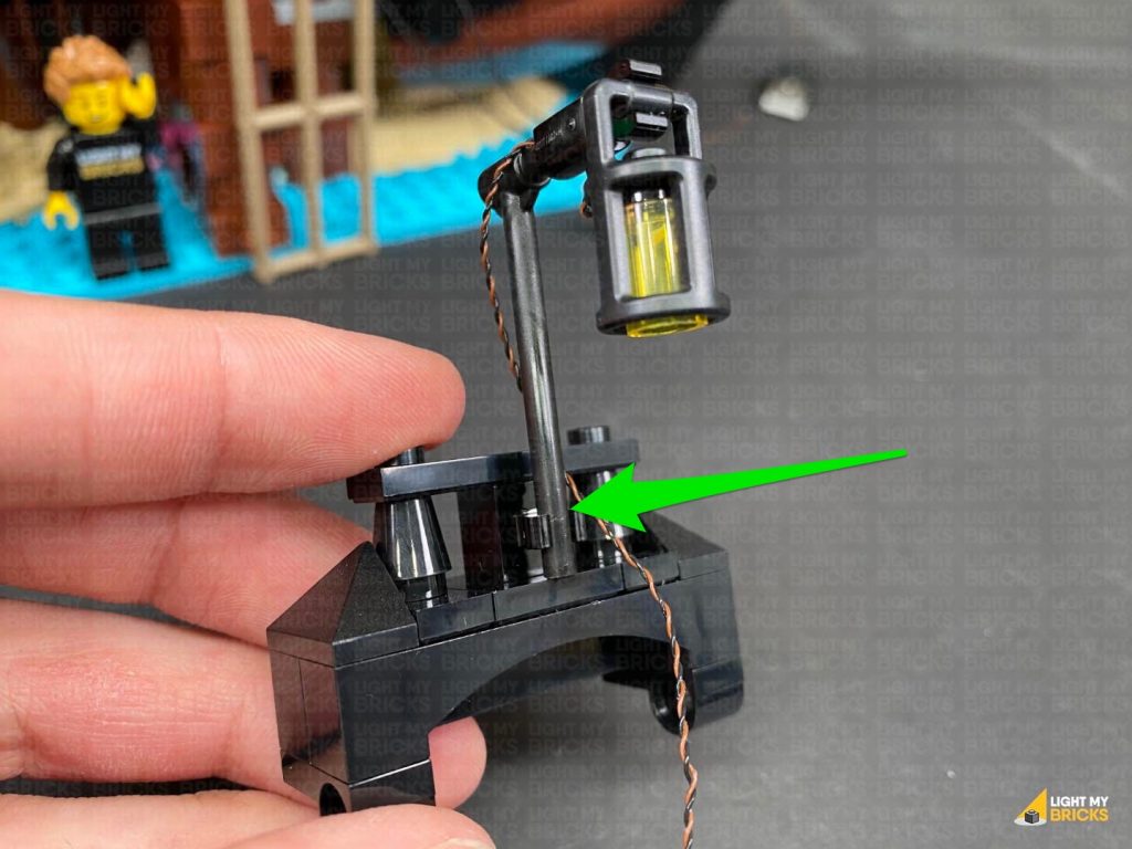
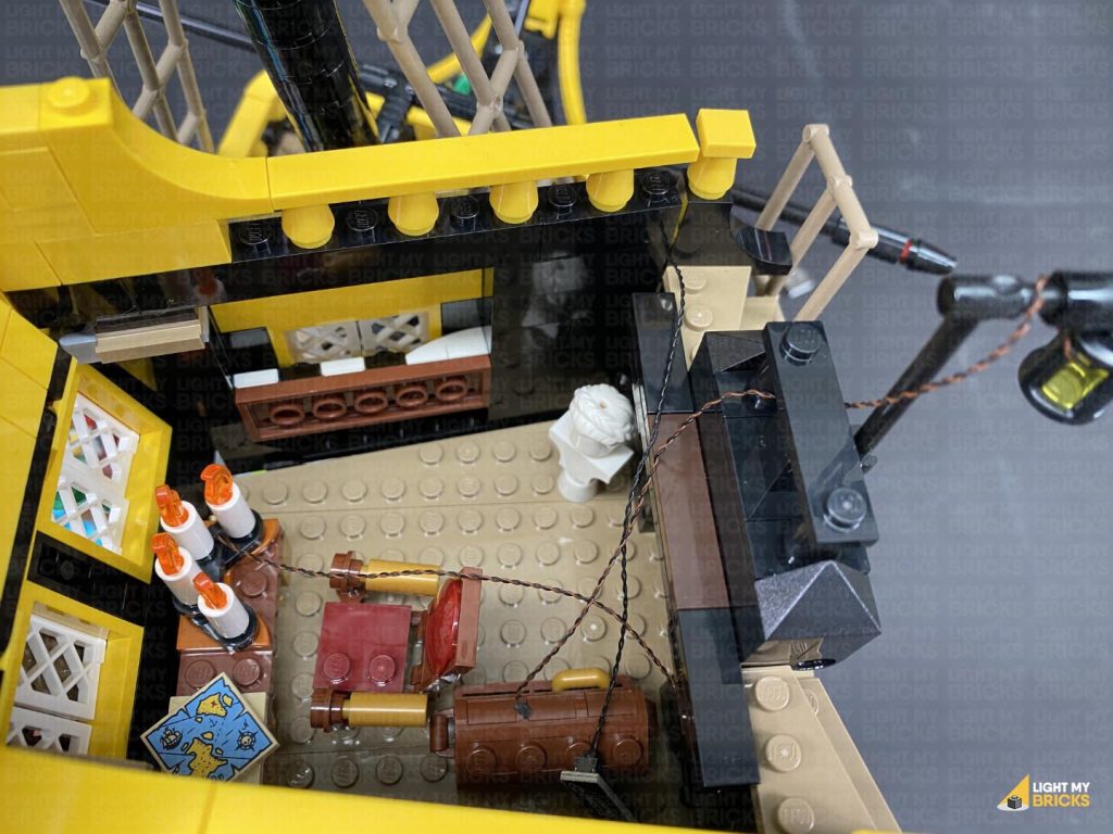
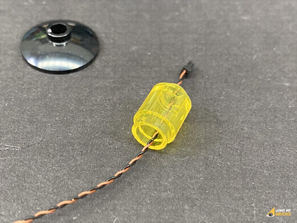
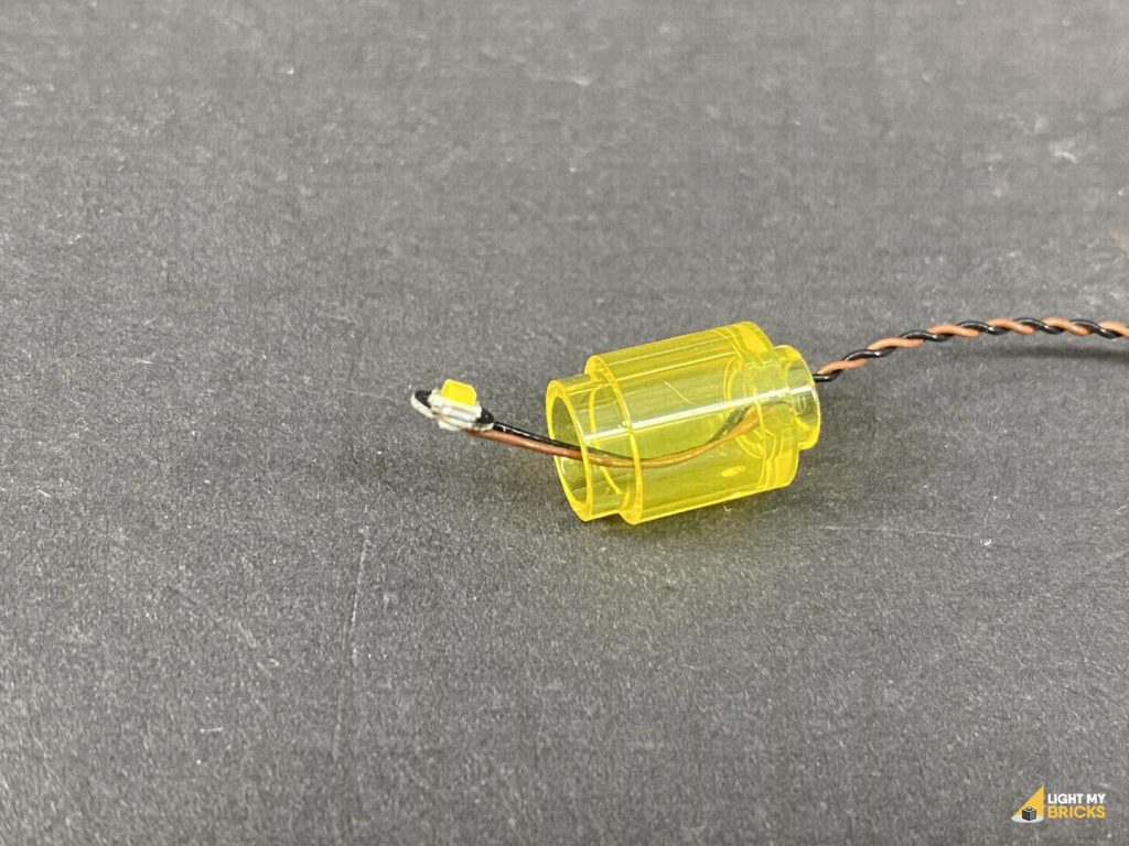
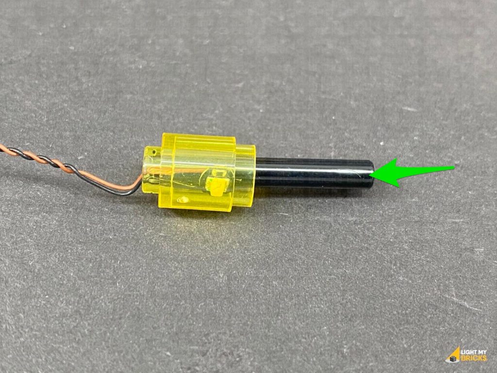
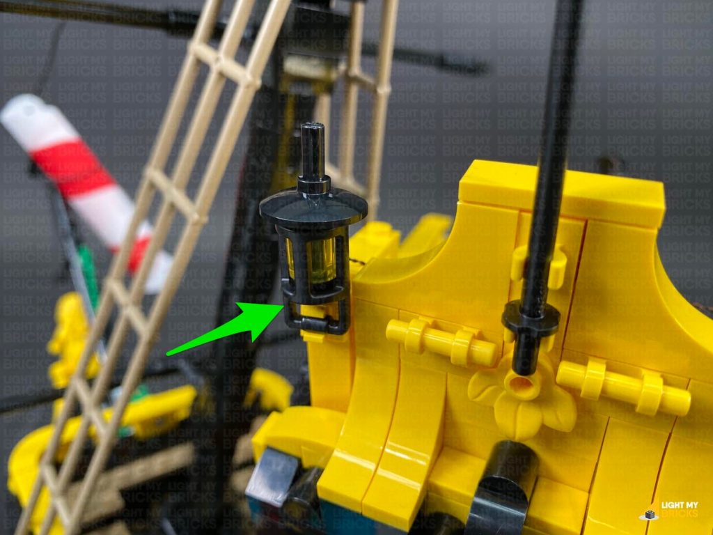
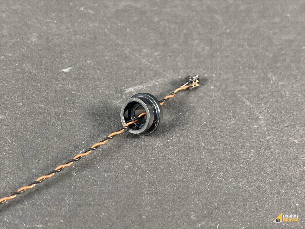
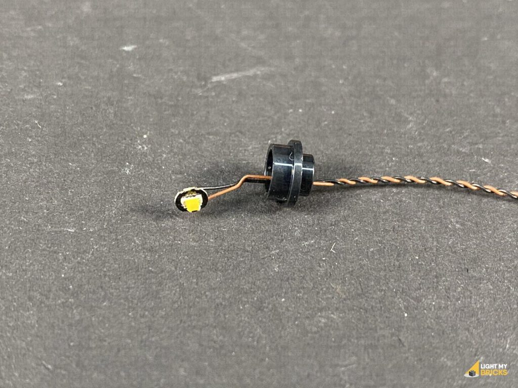
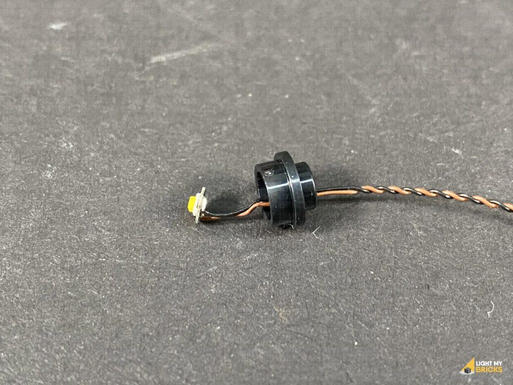
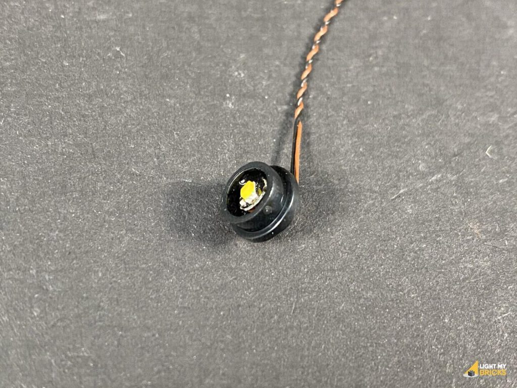
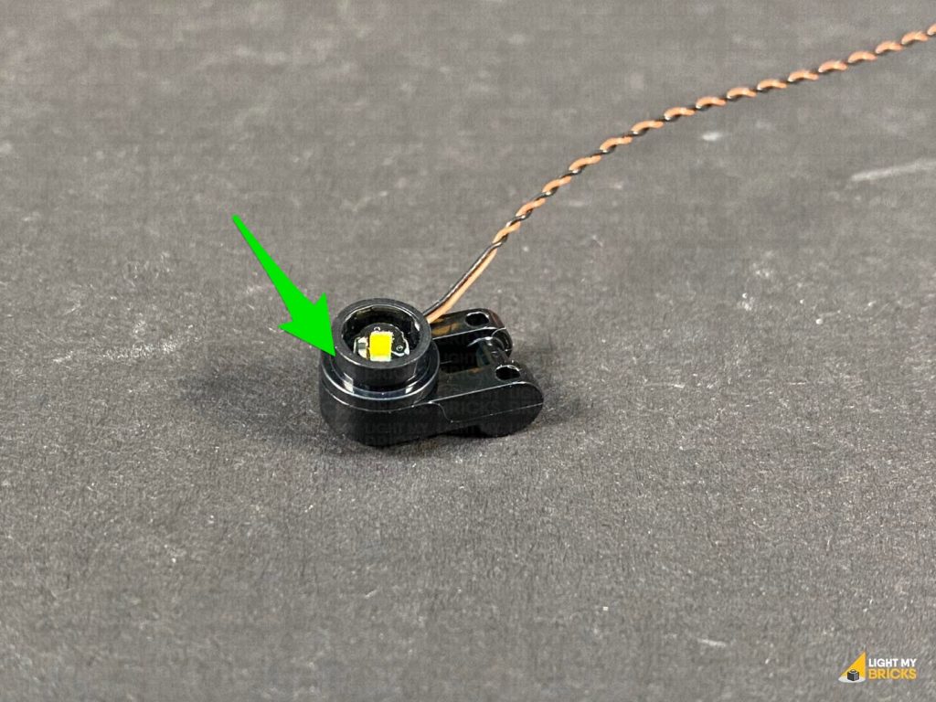
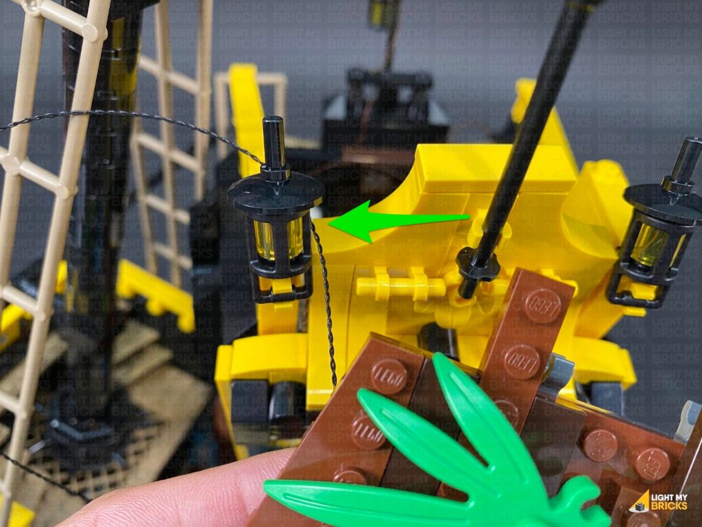
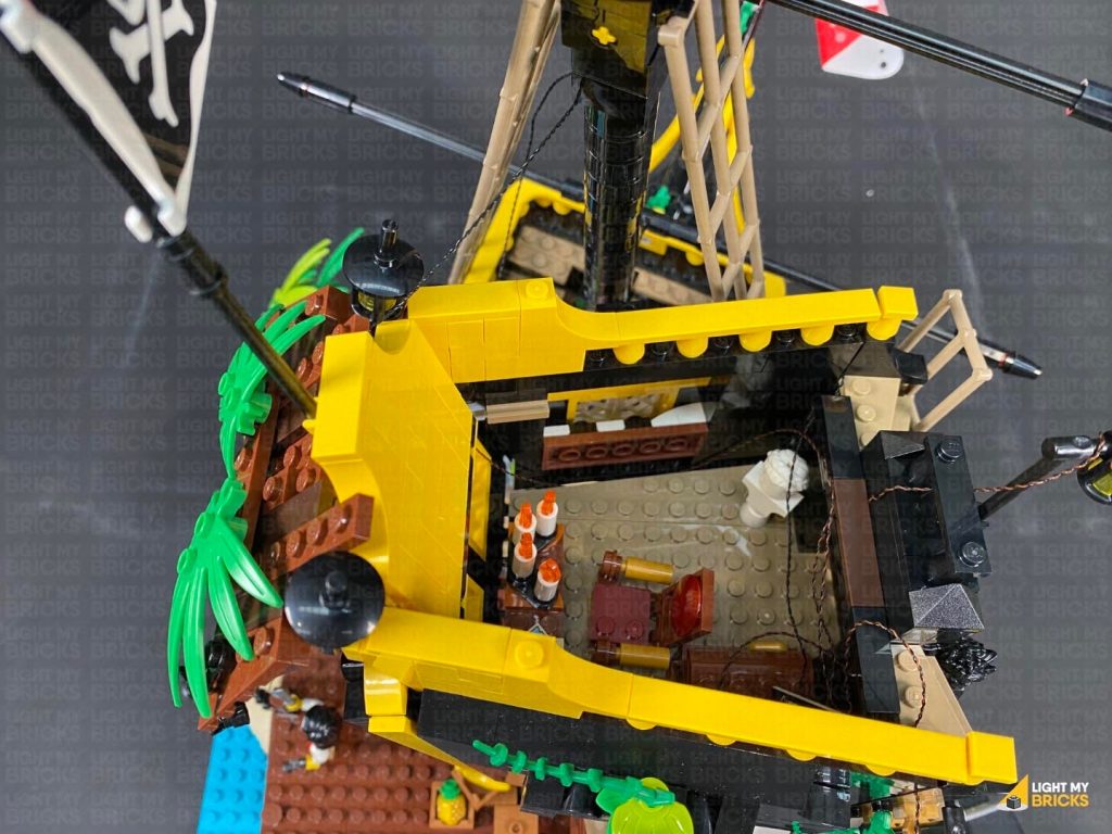
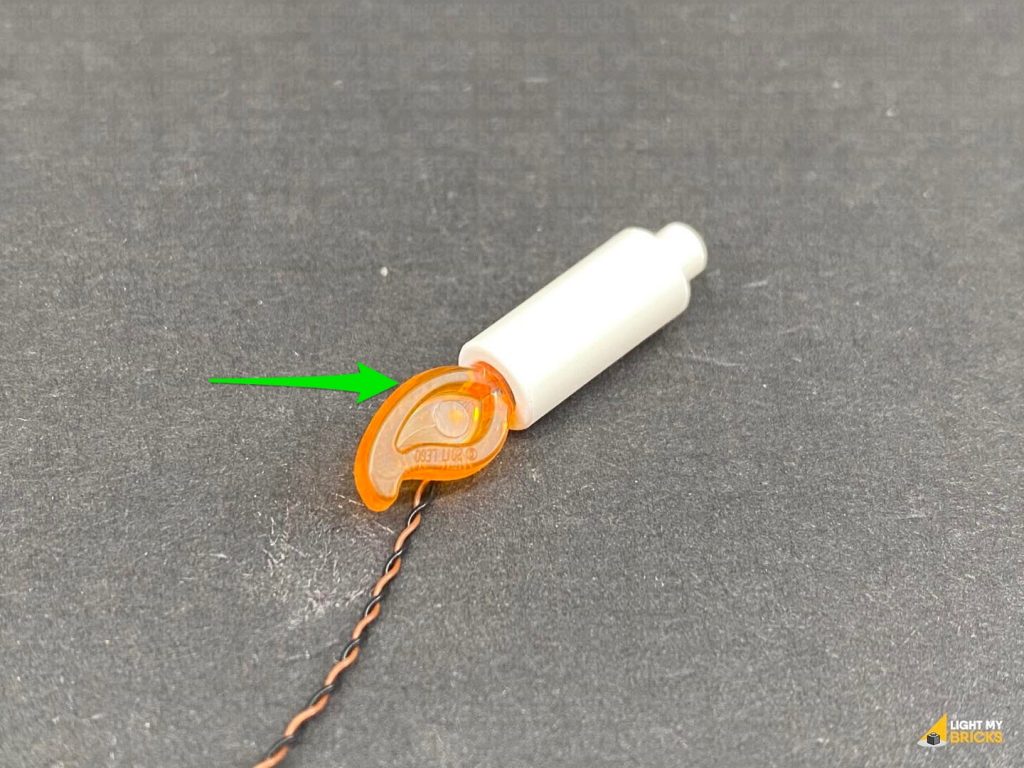
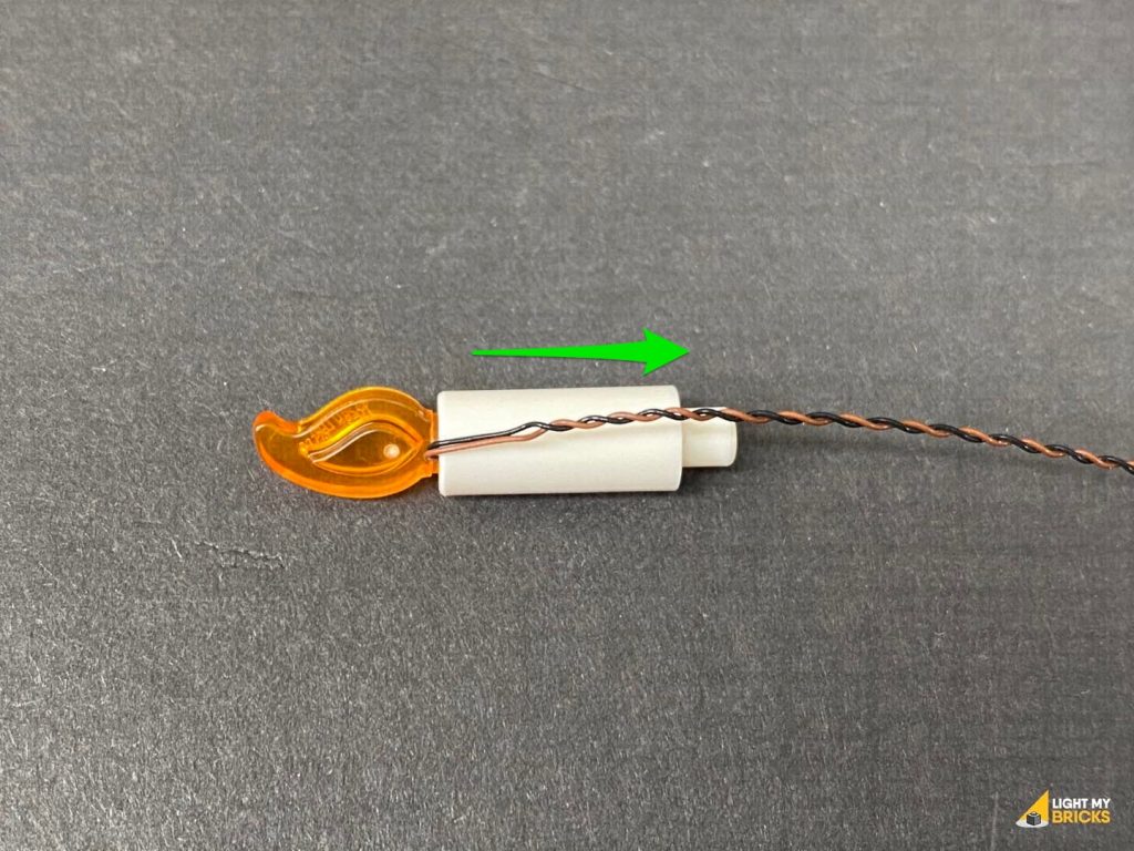
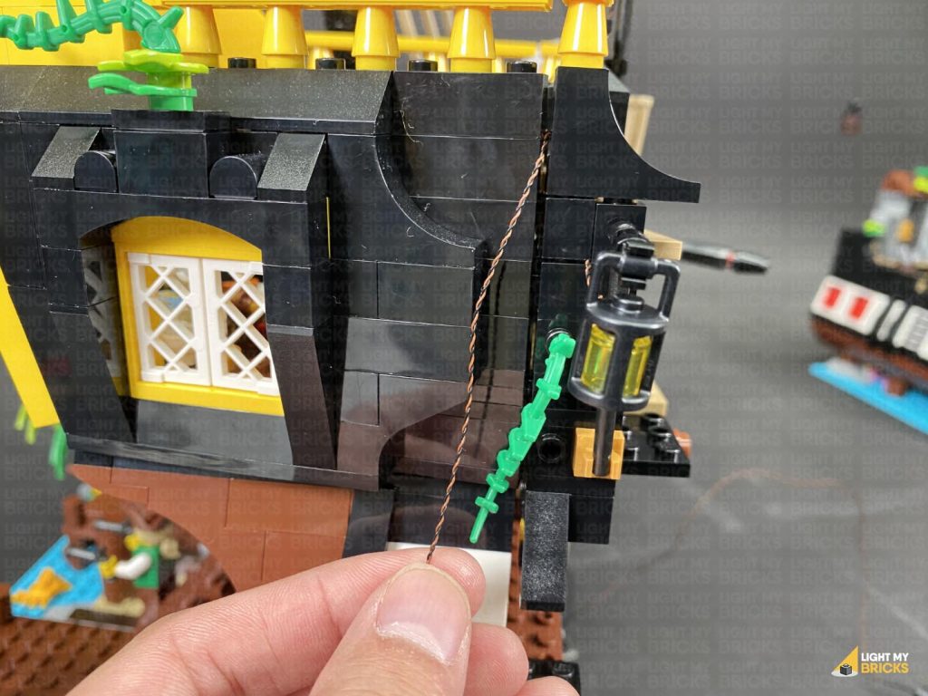
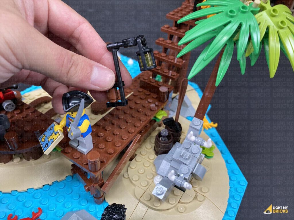
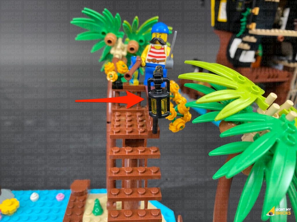
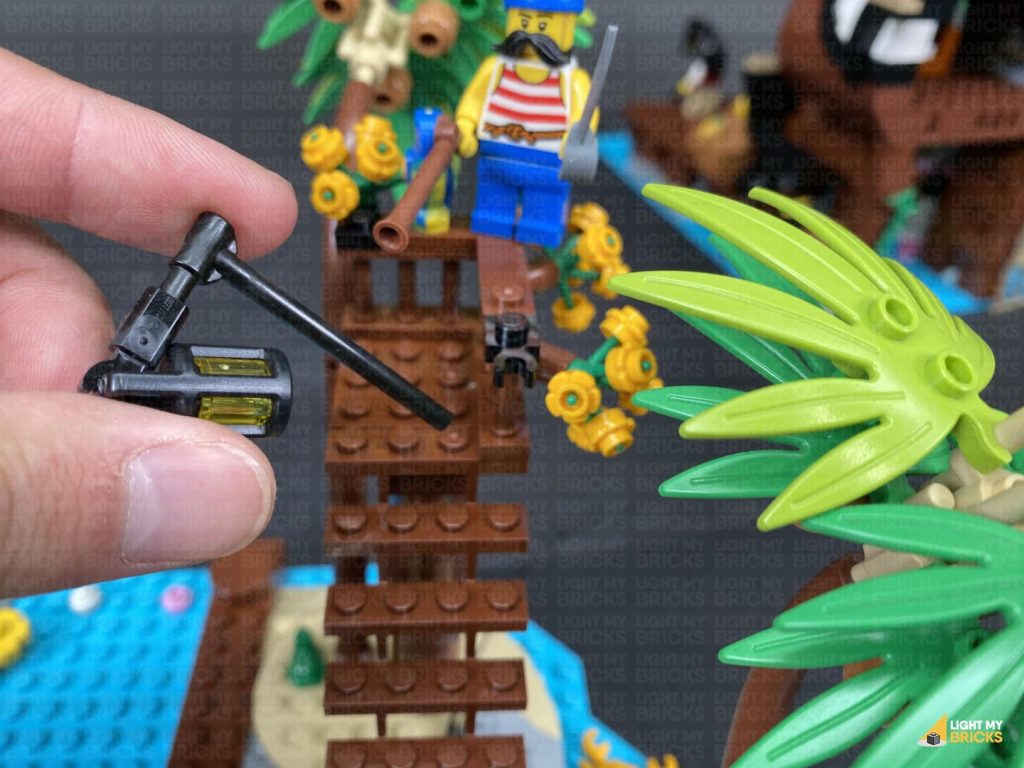
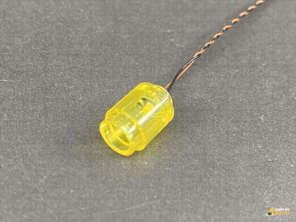
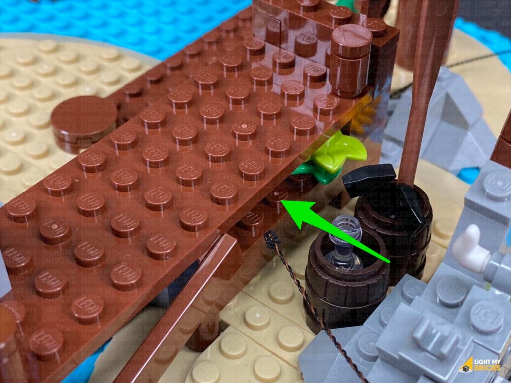
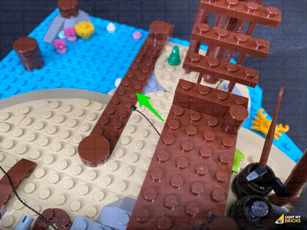
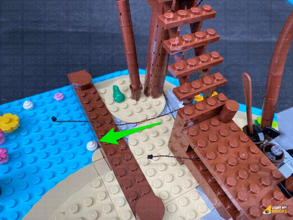
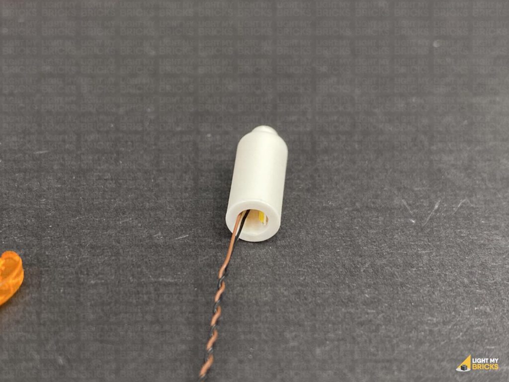
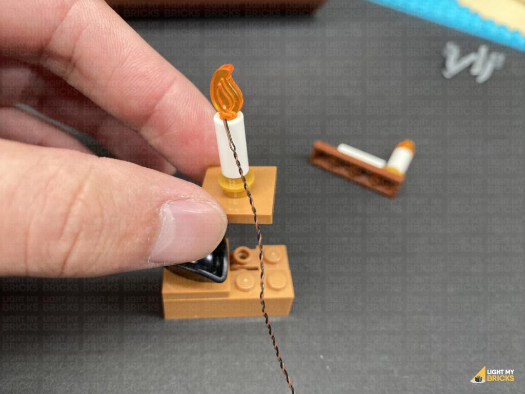
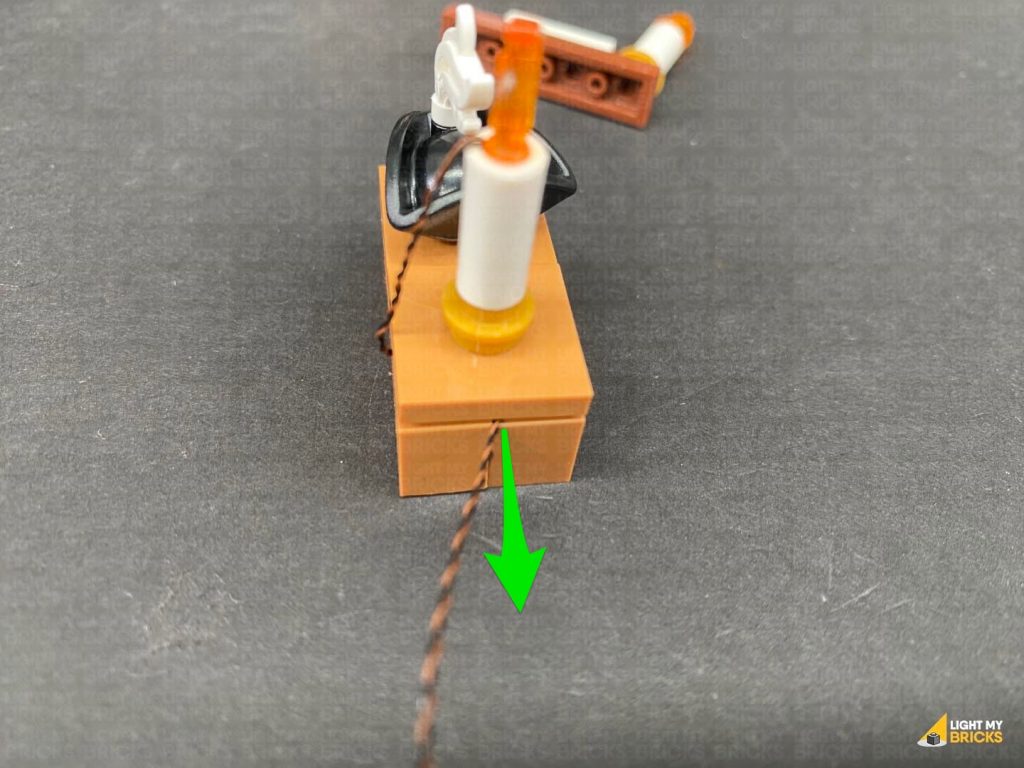
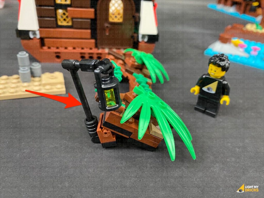
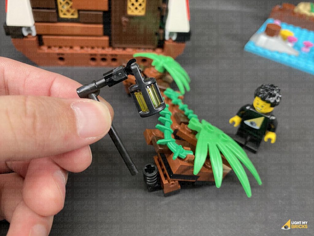
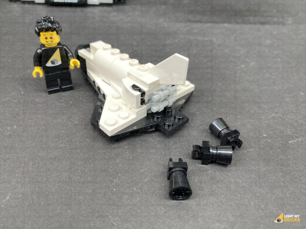
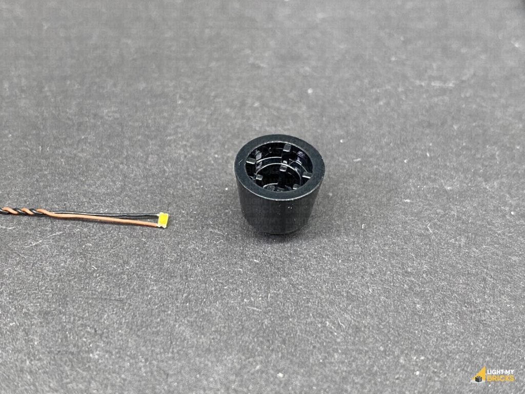
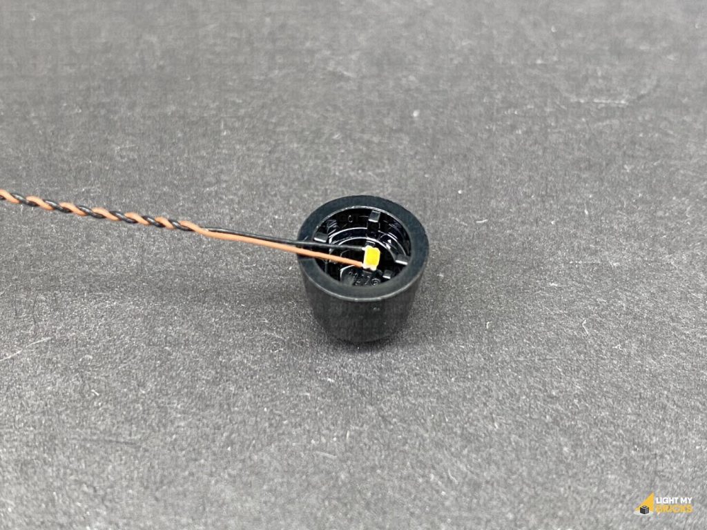
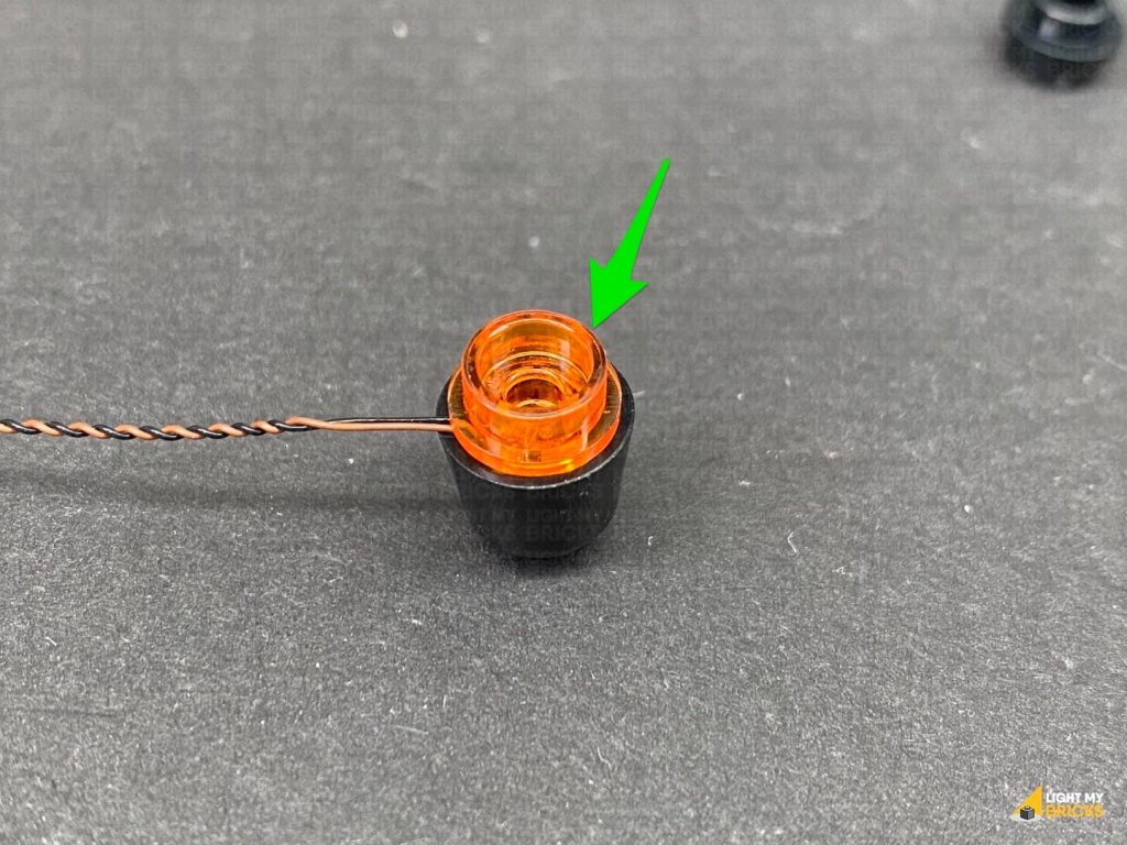
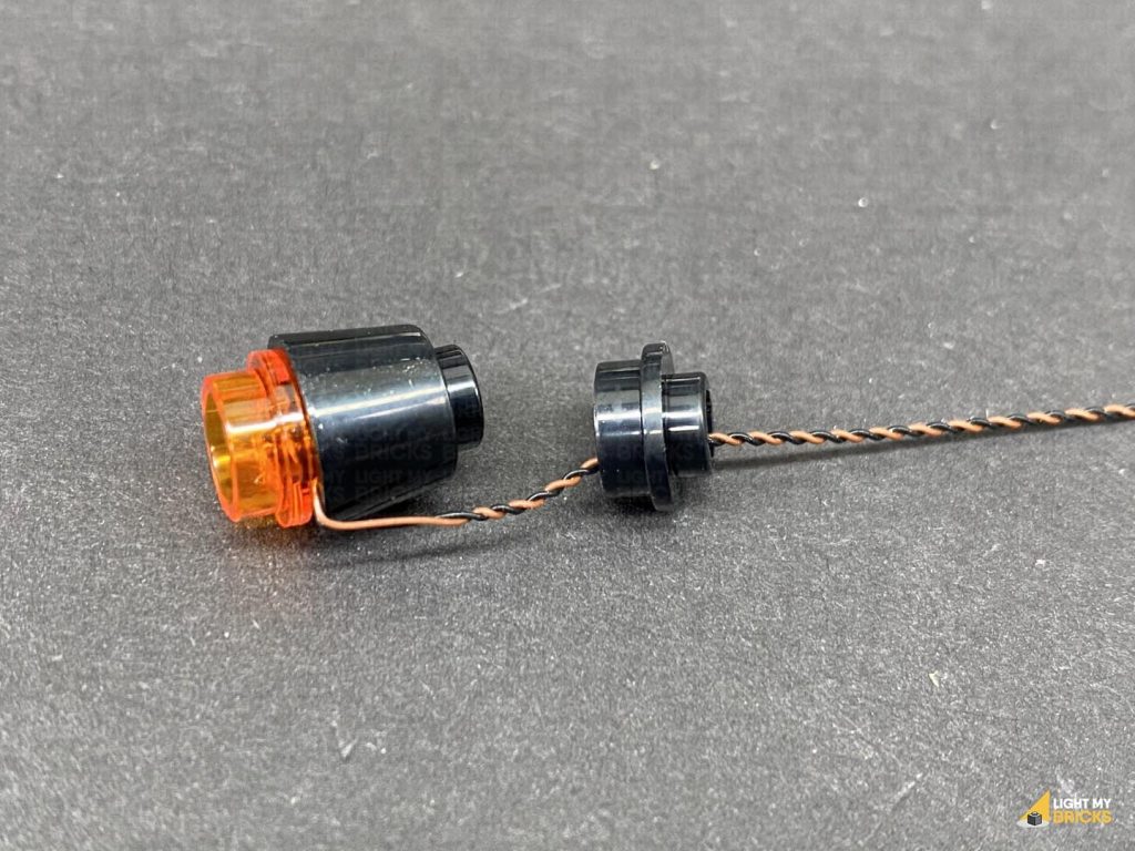
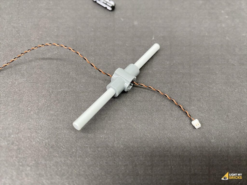
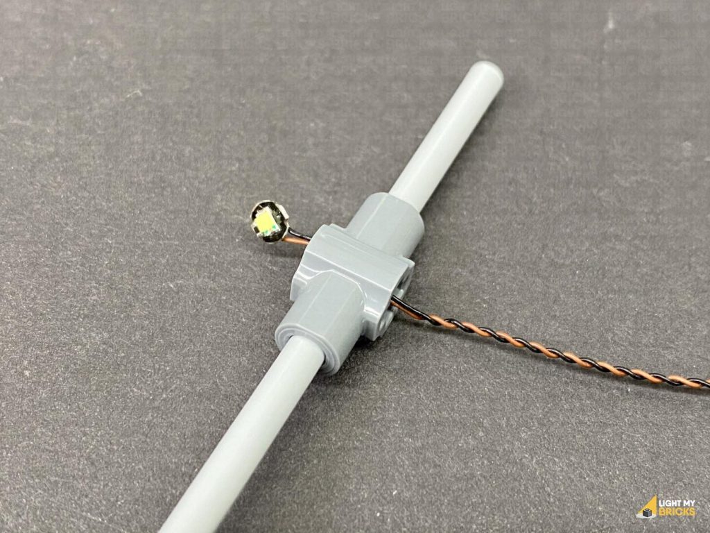
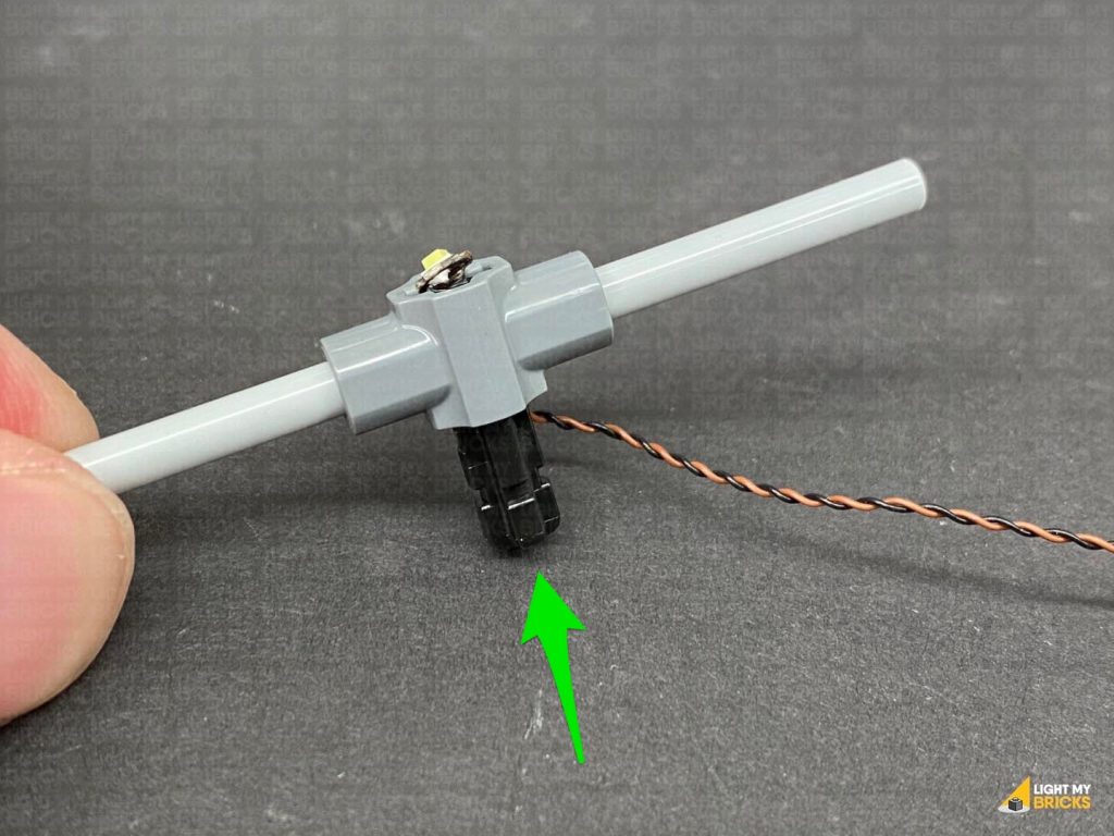
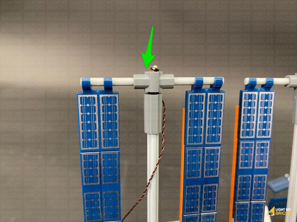
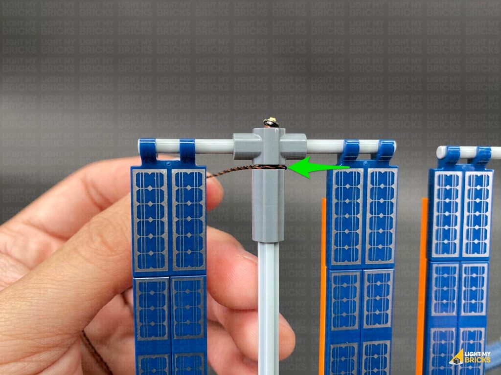
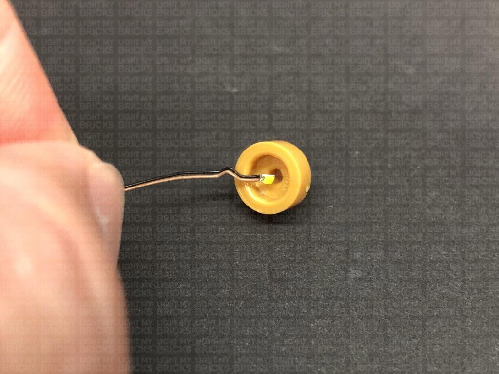
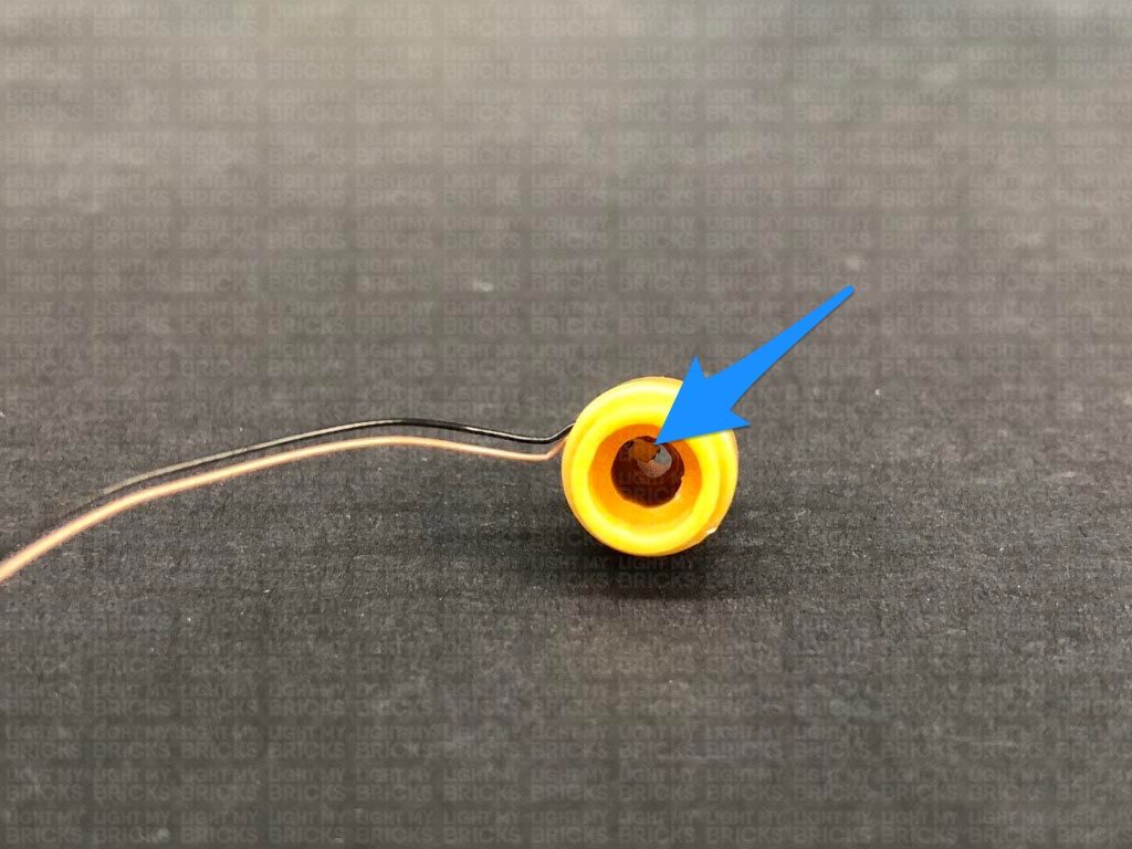
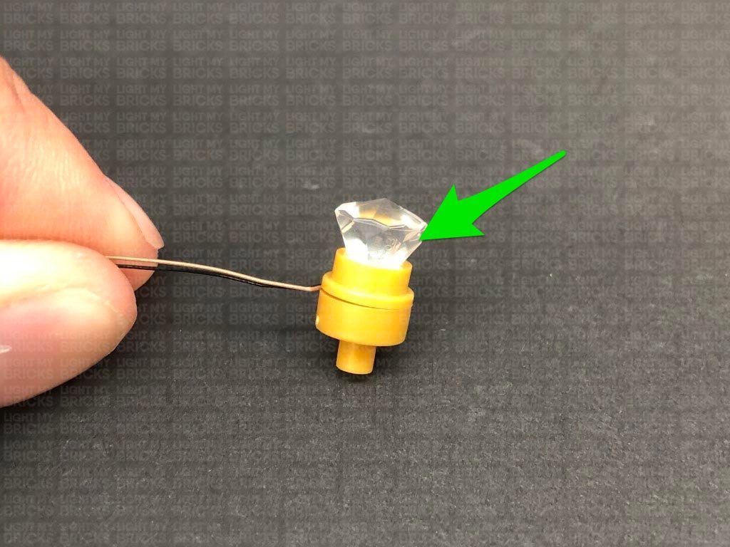
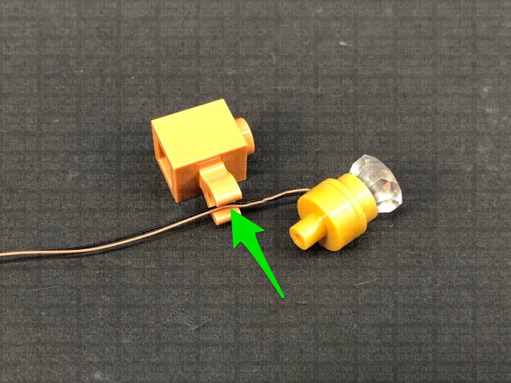
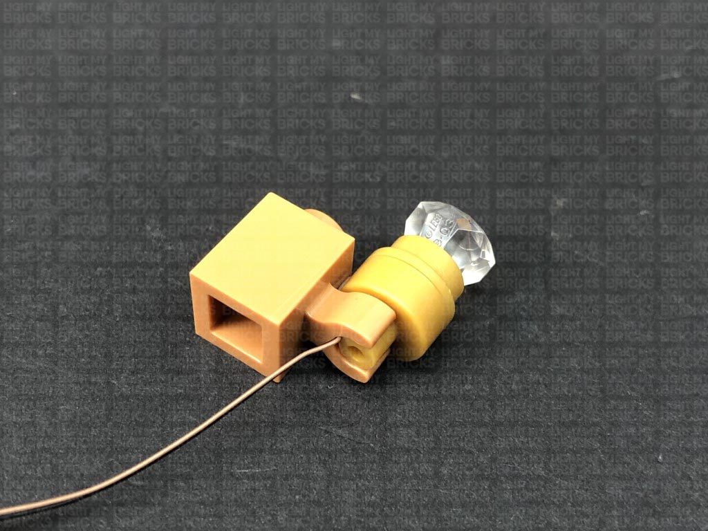
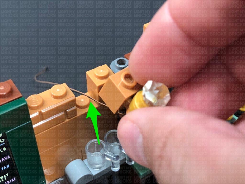
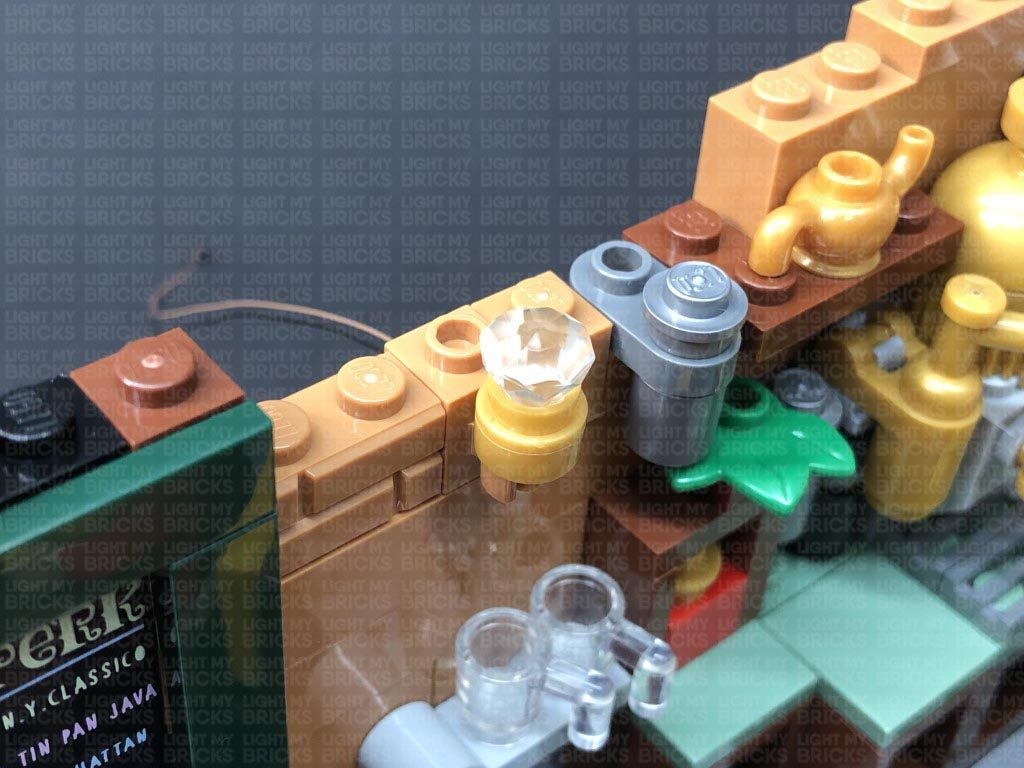
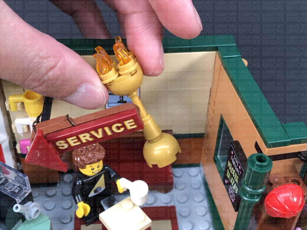
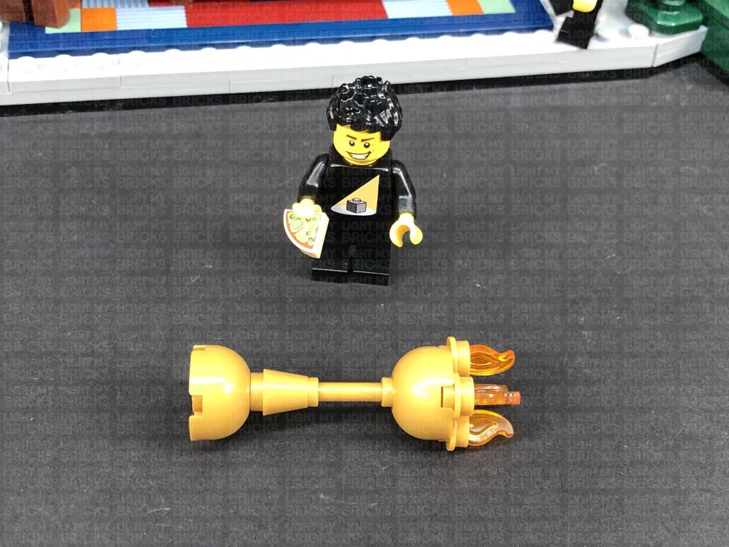
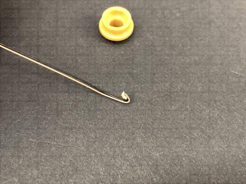
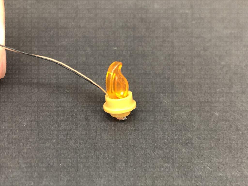
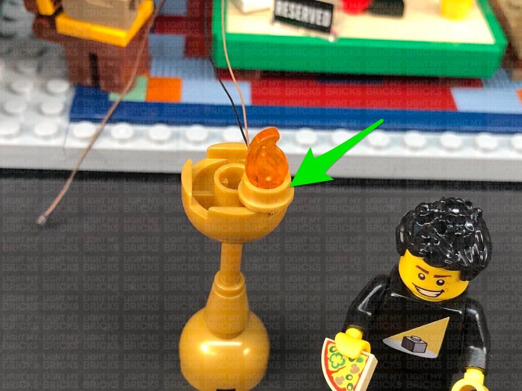
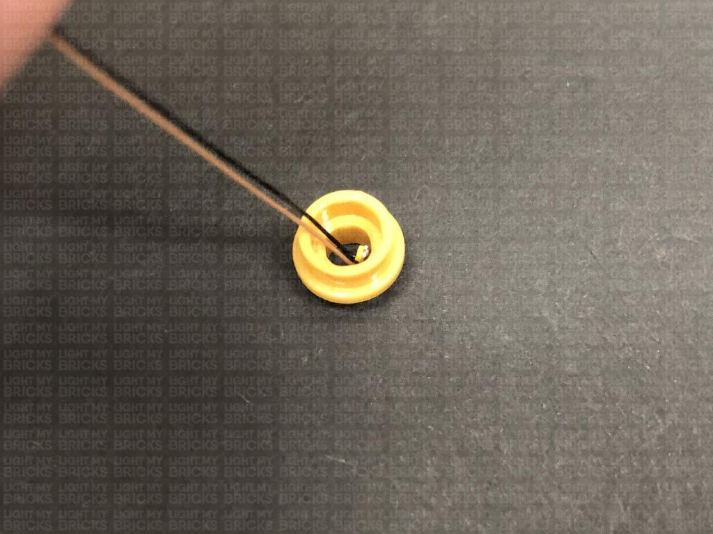
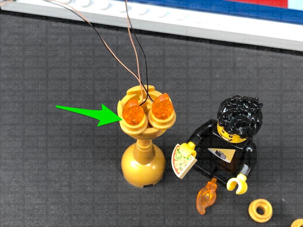
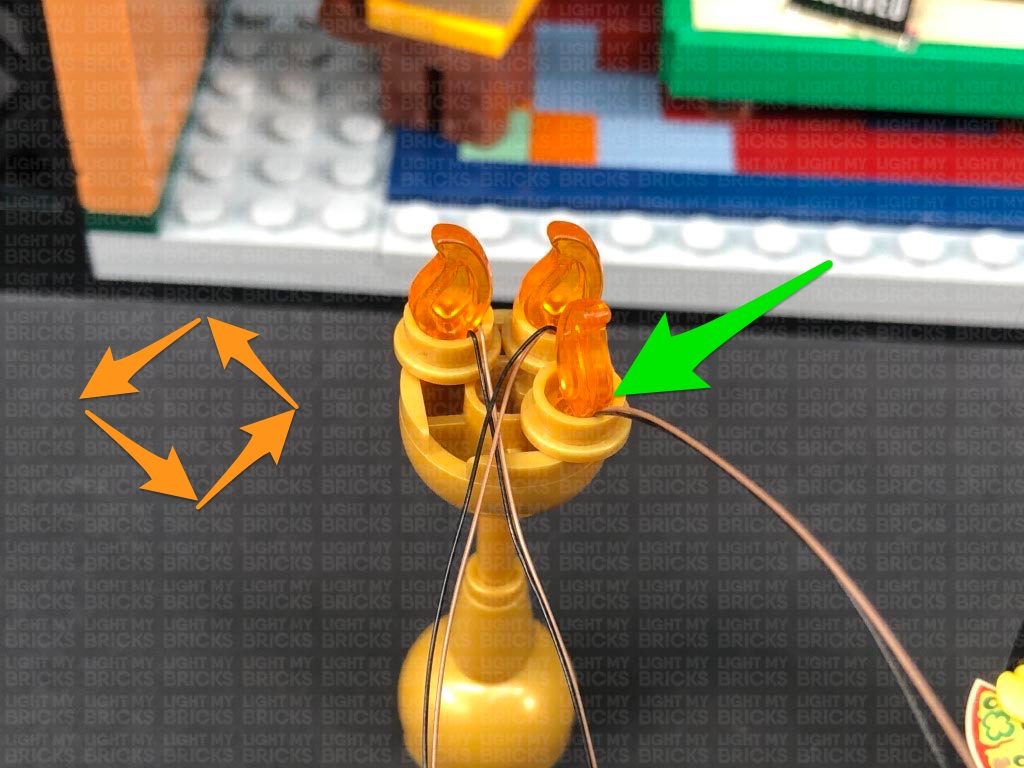
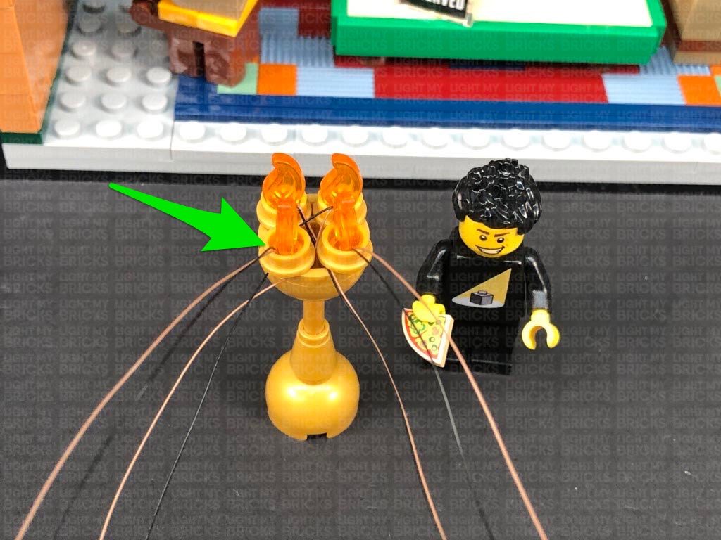
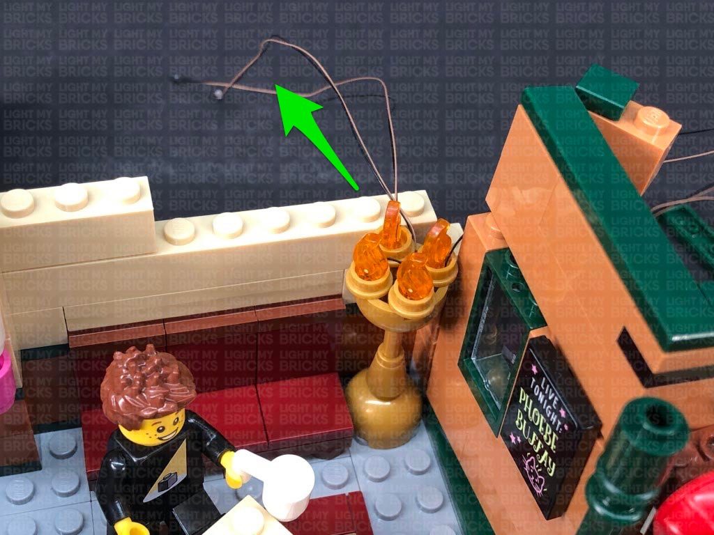
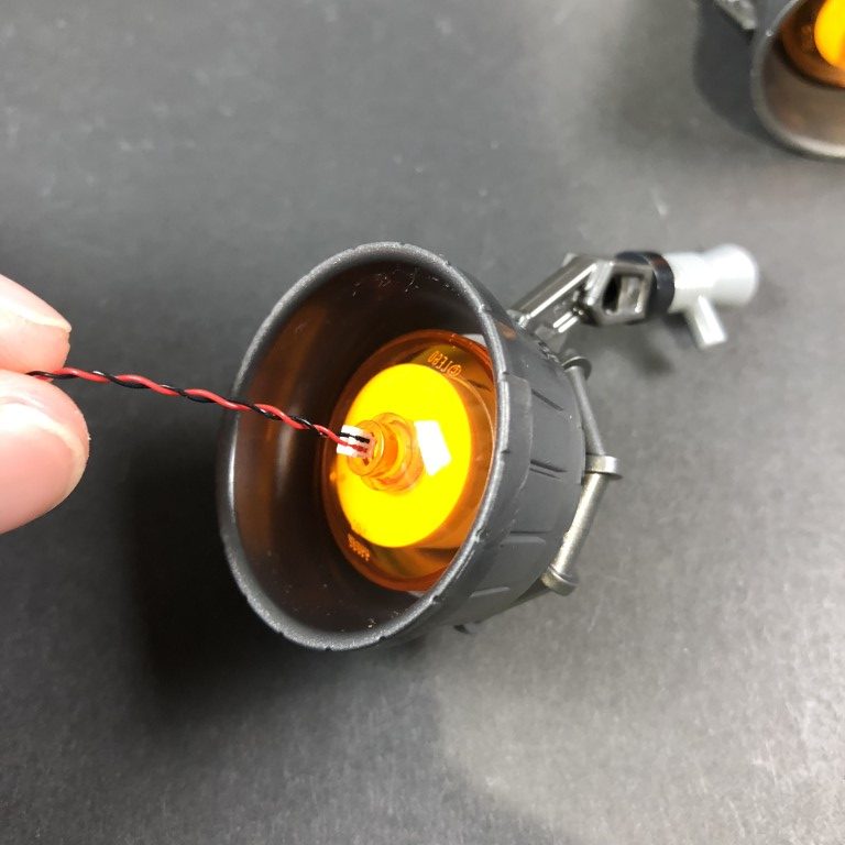
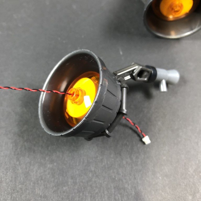
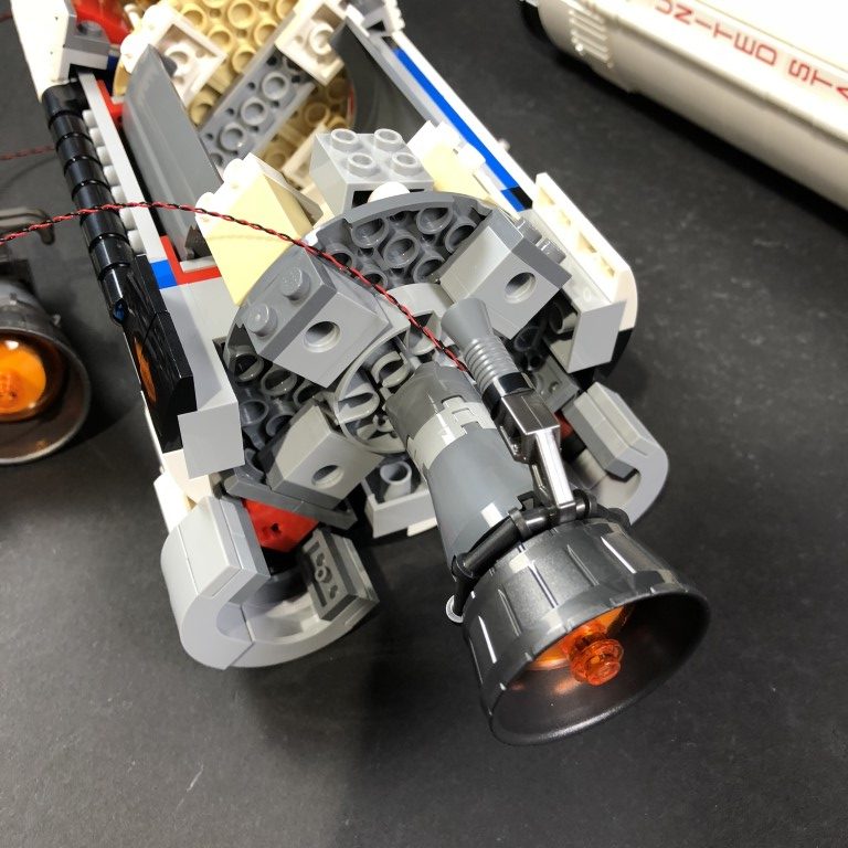
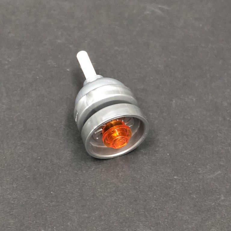
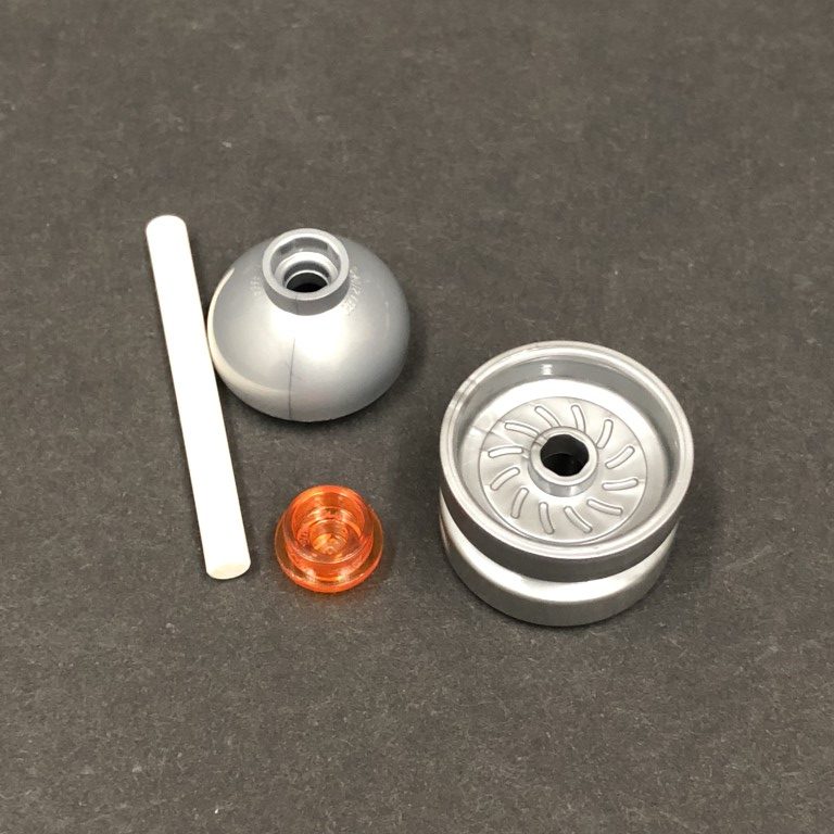
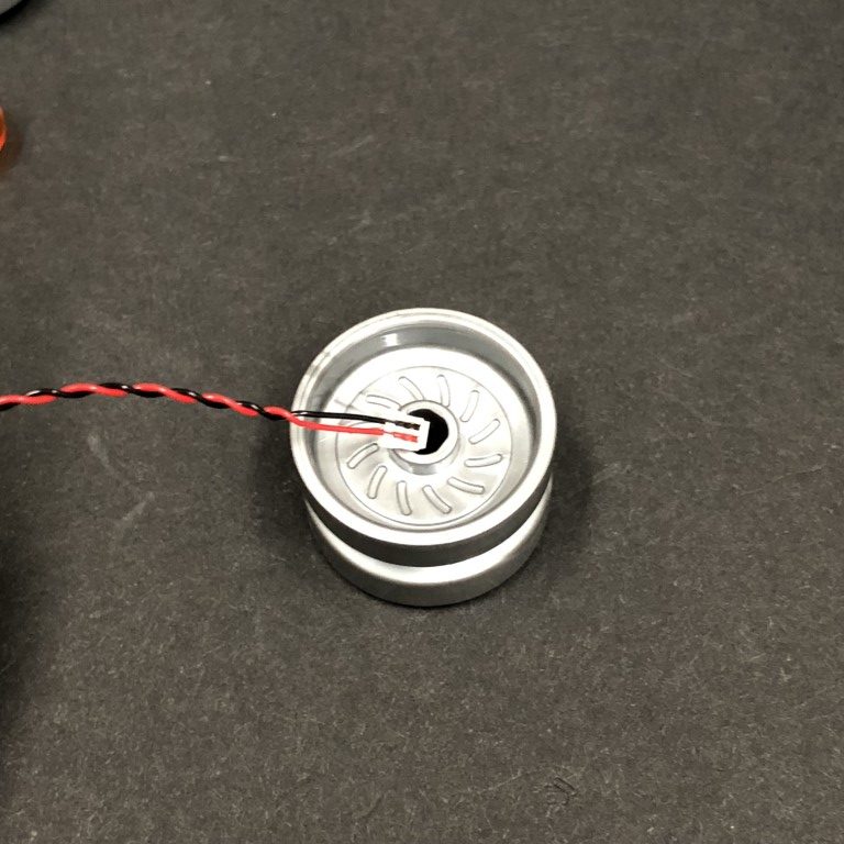
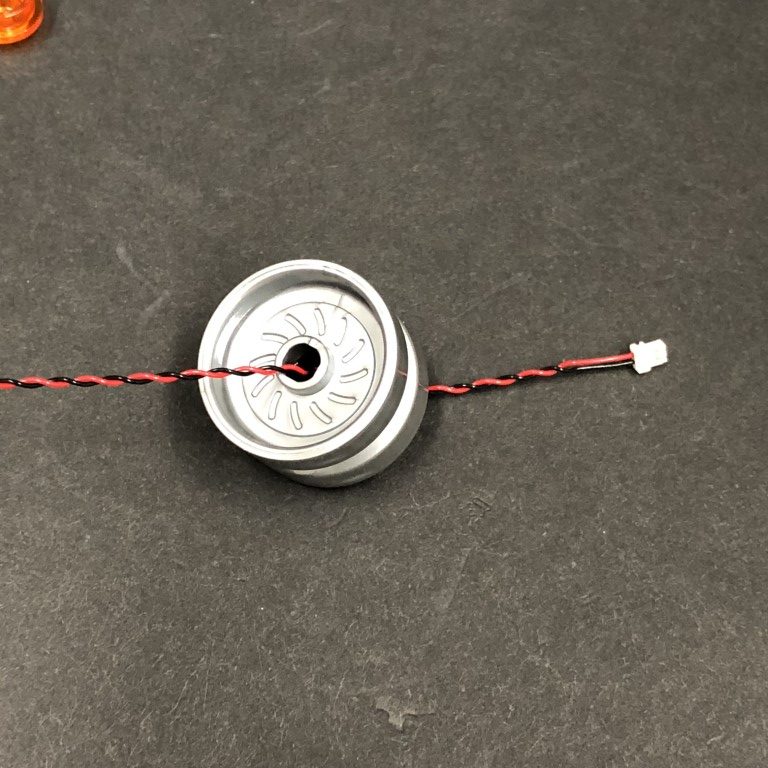
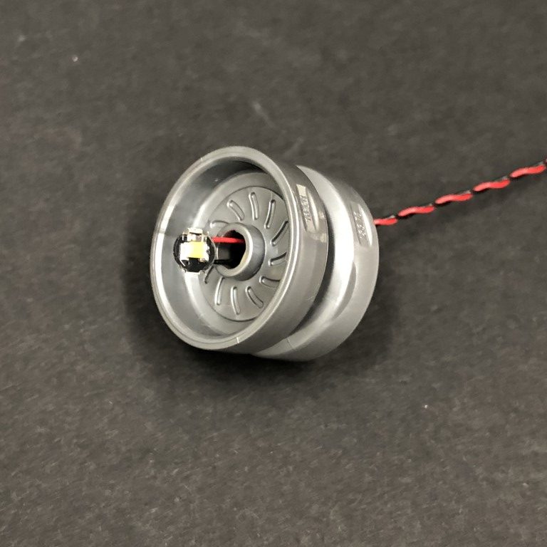
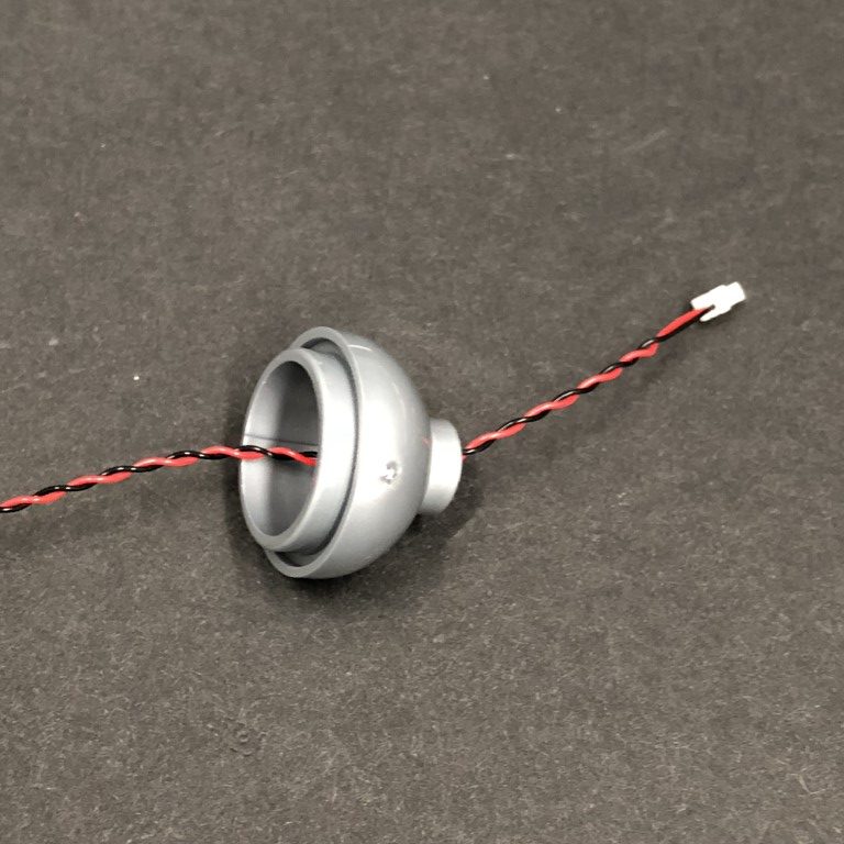
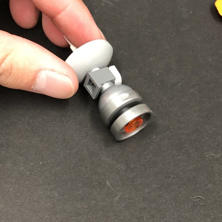
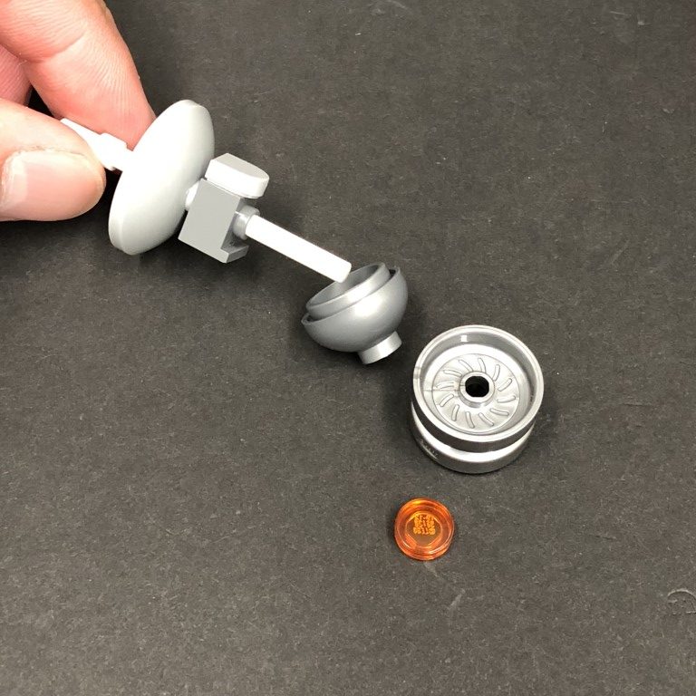
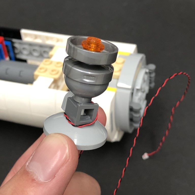
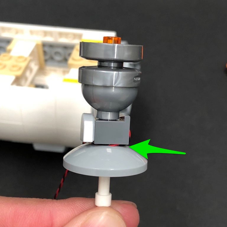
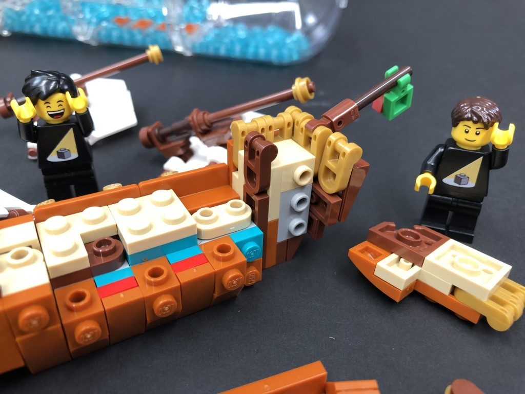
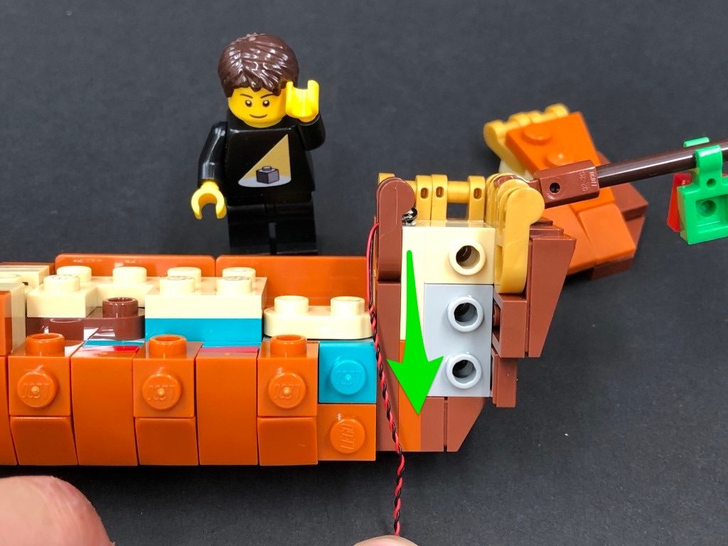
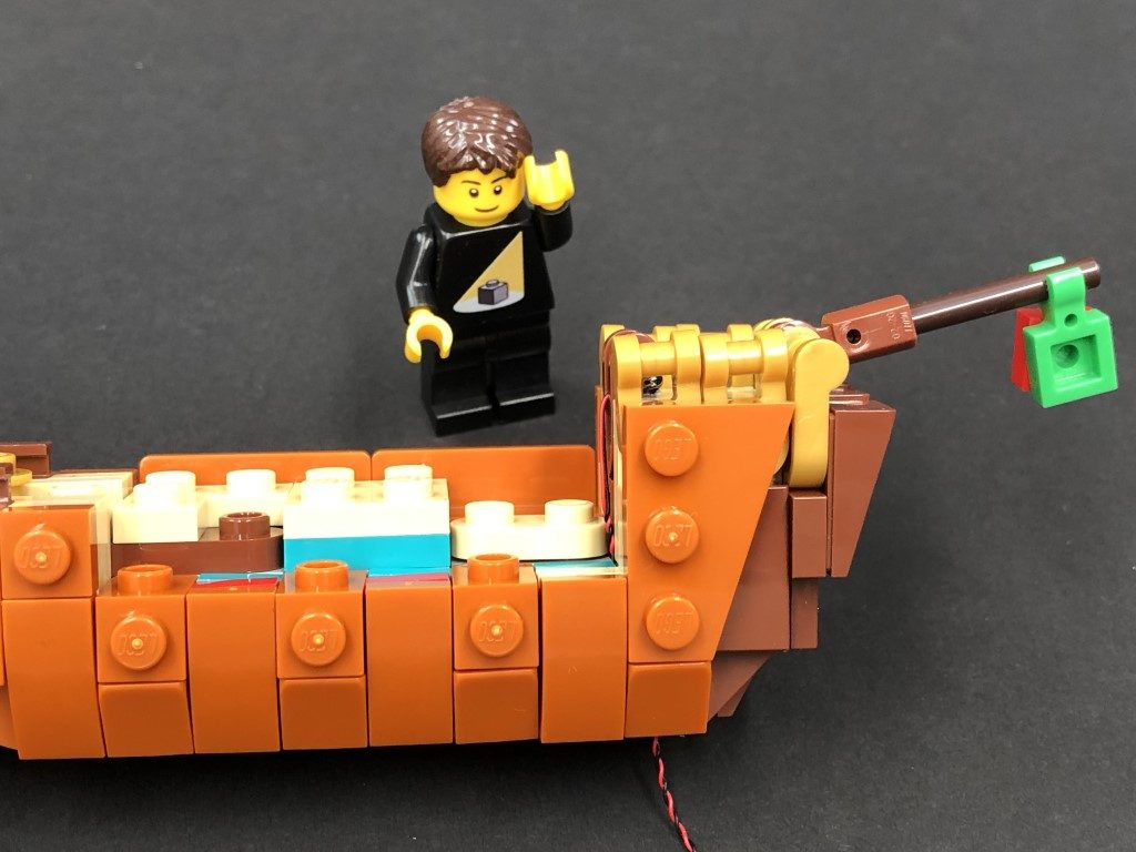
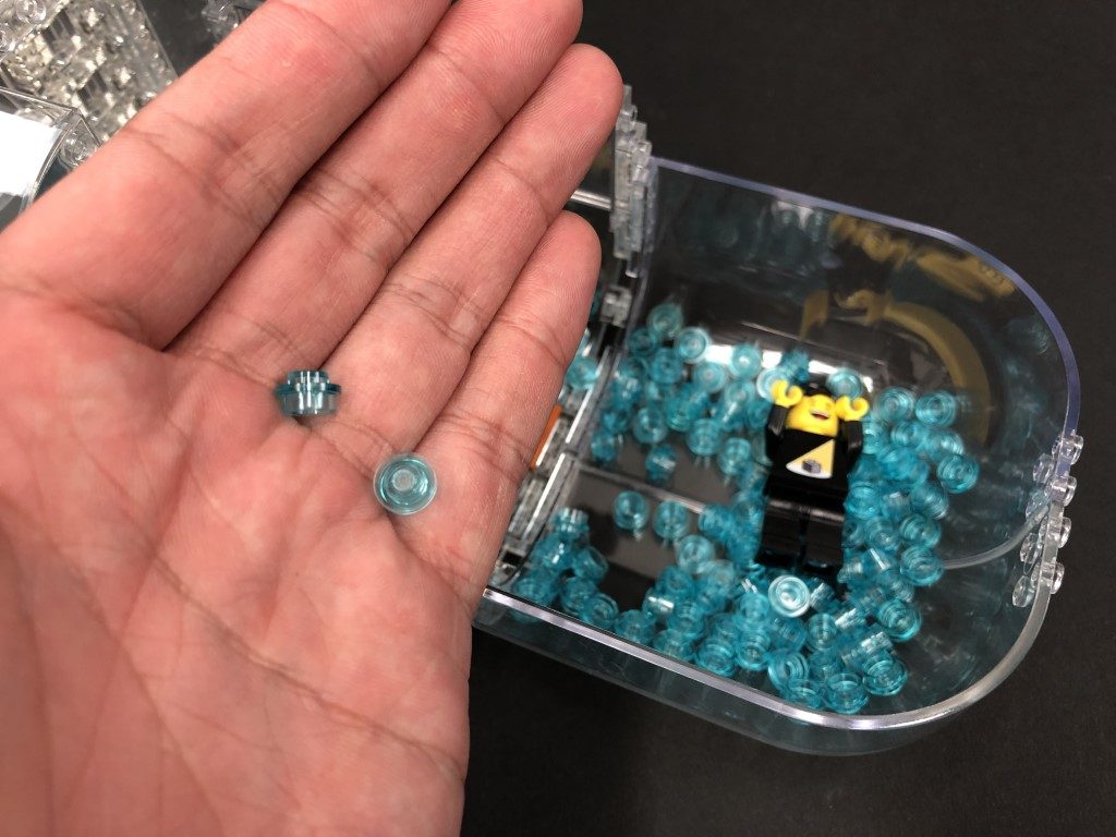
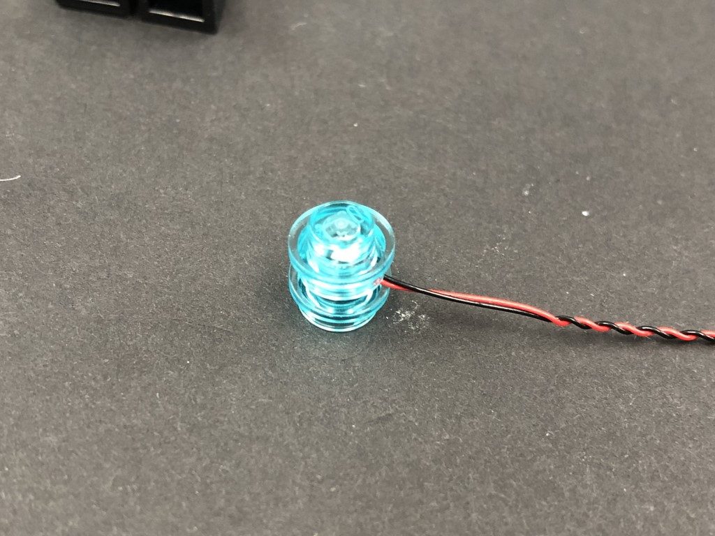
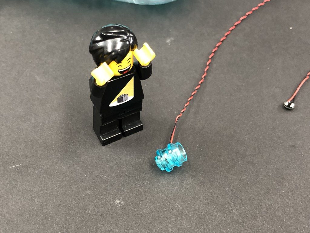
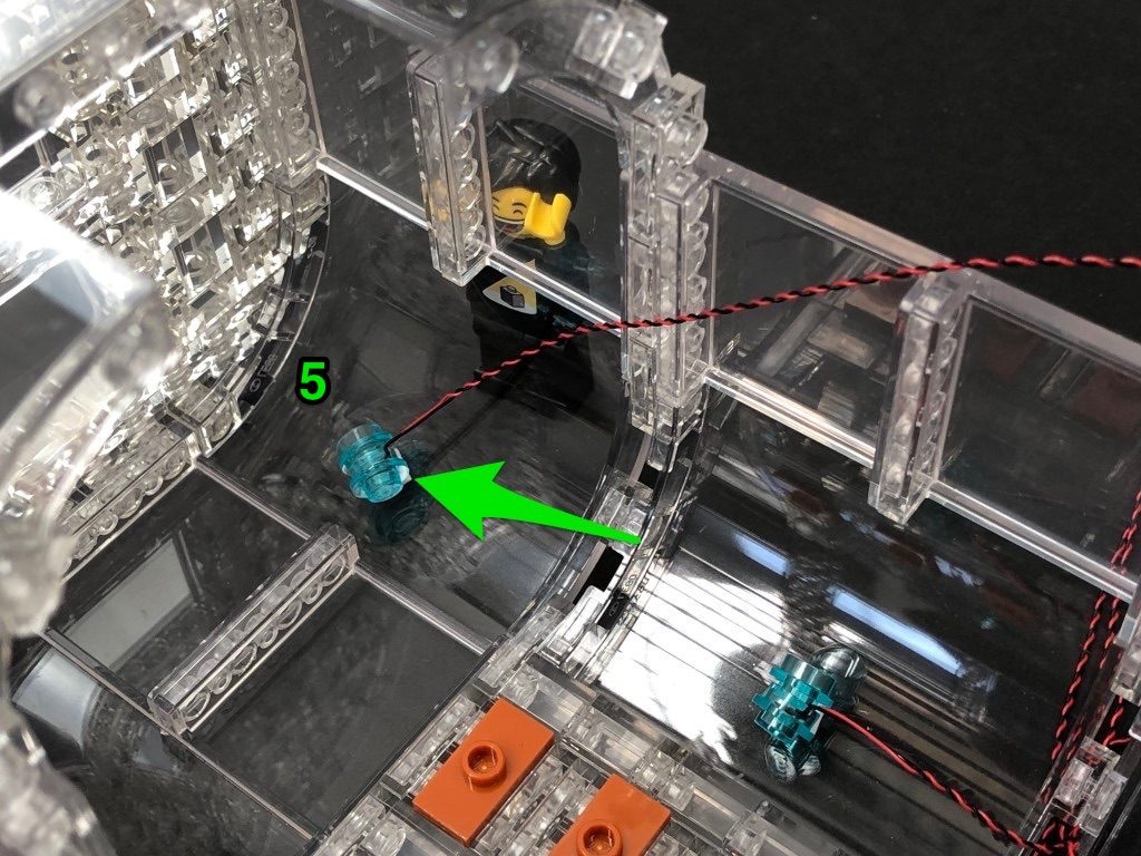
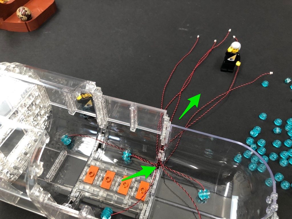
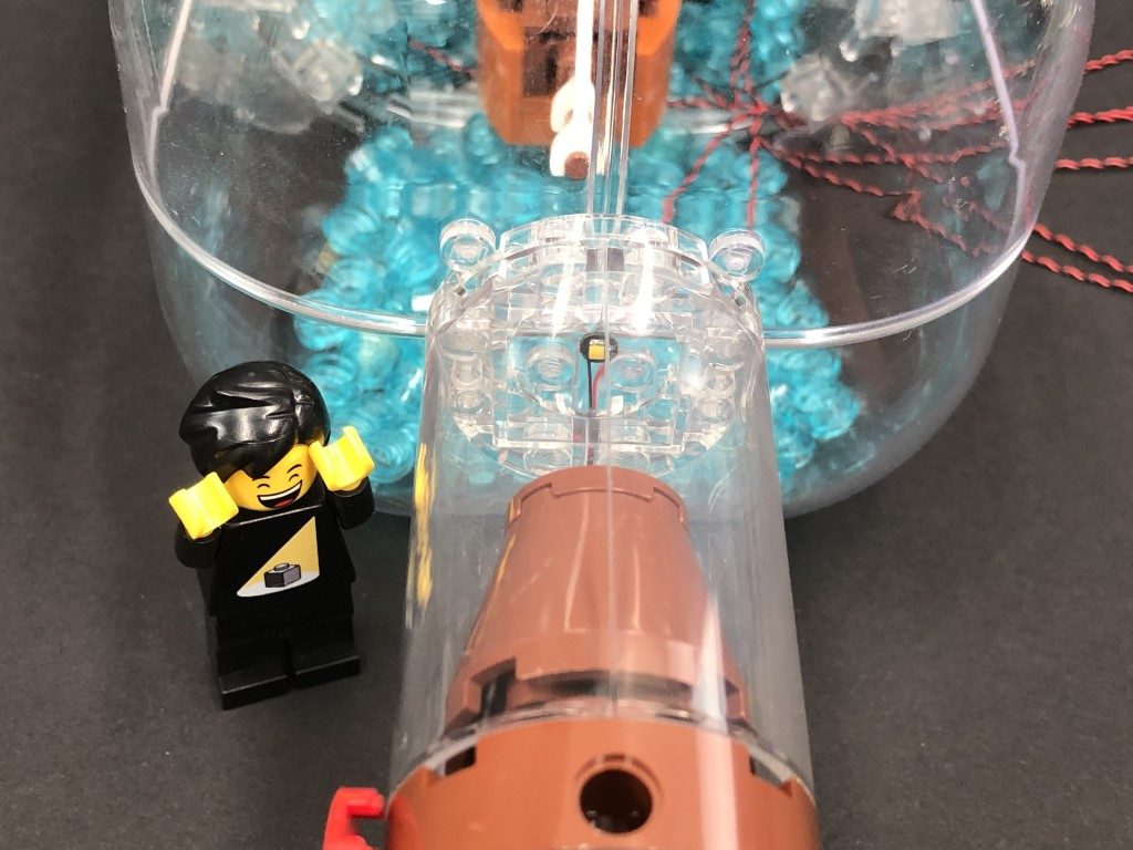
Note: If you experience any issues with the lights not working and suspect an issue with a component, please try a different port on the expansion board to verify where the fault lies (with the light or expansion board). To correct any issues with expansion board ports, please view the section addressing expansion board issues on our online troubleshooting guide.Power Bank Note – If your are using the Light My Bricks USB Power Bank, it is normal for the strip light to turn off automatically after a few minutes. This is due to very low power being consumed from the power bank. You won’t have this issue later on when you connect up more lights. 4.) Disconnect the lamp from the front side of this section, then disassemble it as per below. Take a White 30cm Bit Light and thread the connector side of the cable through the base (larger hole) of the trans yellow round brick. Thread the cable through, then slightly bend the LED onto a 90 degree angle so that it will eventually point directly down when the lamp is reconnected. Pull the cable all the way from the top of the trans brick so that the LED sits comfortably inside, then thread the connector end of the cable through the base of the lamp enclosure. Pull the cable out from the outside, then reconnect the trans yellow brick inside. 5.) Reconnect the lamp to the lamp post, then pull the cable over the top post and then bring the cable back down and thread the cable between the two black clips. Reconnect the lamp to the deck, then thread the cable underneath. Pull the cable all the way out from behind, then thread it through the back of the deck (in between the rock and the tree trunk) Disconnect the following pieces and lay the cable down in between studs before reconnecting these pieces over the top. Take the front section of the ship and reconnect the black bricks underneath. Connect the ship back to the set via the ball joints, then turn the set around and connect the Bit Light cable from the lamp to the 6-port expansion board. Turn the power ON to test the lamp LED is working OK. 6.) Take a 15cm Connecting Cable and connect one end of the cable to the 6-Port Expansion Board. Thread the other end of the cable through to the left (behind the post that is attached to the rigging). Bring the cable underneath the ships’s kitchen, then connect the cable to a Blue Strip Light. Take a 30cm Connecting Cable and connect it to the Blue Strip Light’s left port. Peel off the adhesive backing and mount the strip light underneath the ship in the following position. Thread the other end of the 30cm Cable through to the outside of the ship, then pull the cable down and thread it in between the deck post and deck base. Pull the cable all the way out as shown below. 7.) Disconnect the lamp post section from the front, then disconnect the following two larger brown plates. Take the 30cm Connecting cable from the side and thread it underneath the deck, then lay it around the following studs of the deck post. Reconnect one of the larger brown plates over the top as shown below. 8.) Disassemble the lamp section as per below, then repeat the same method used for the previous lamp to install another White 30cm Bit Light to it. 9.) Locate the 30cm Connecting Cable from underneath the deck and connect it to a Blue Strip Light. Connect the Bit Light cable from the lamp post to the other port on the blue strip light. Reconnect the lamp post to the front of the large brown plate that sits at the front of the deck, then turn it over so we can access underneath of it. Using the adhesive backing, stick the Blue Strip Light underneath this plate in the below position. Twist/Fold the excess cable from the Bit Light and Connecting Cable into neat bunches, then turn the plate over and tuck the cables neatly underneath the plate behind. Reconnect the large brown plate, then disconnect the brown tile at the front and further tuck in any excess cable before reconnecting the tile. Turn ON the power to test all the lights installed so far are working OK. Note: If you experience any issues with the lights not working and suspect an issue with a component, please try a different port on the expansion board to verify where the fault lies (with the light or expansion board). To correct any issues with expansion board ports, please view the section addressing expansion board issues on our online troubleshooting guide. 10.) From the back of this section, remove the top floor above the captain’s HQ, then locate the spare end of the 30cm Connecting Cable from the Green Strip Light below and bring it up above the top floor. Slip the cable in between the yellow plates on the right and connect it to an 8-Port Expansion Board. Disconnect the two lamps, then repeat the same method used for the previous lamps to install this time, a White 15cm Bit Light to each lamp (Total 2x White 15cm Bit Lights) 11.) Reconnect one of the lamps to the side of the ship, then follow the below images to disconnect the surrounding pieces. Bring the lamp cable through to the inside of the captain’s HQ and lay it down in between studs before reconnecting all the pieces we removed earlier. 12.) Take the other lamp post and loop the cable around the top of the lamp post. Disconnect the railing section above the door, then reconnect the lamp post to it. Thread the cable through the railing and pull it all the way out from the other side before reconnecting this section back to the top of the ship. Disconnect the following brown tile and lay down the cable from the lamp above in between studs, before reconnecting the tile over the top. Connect the two lamp cables to the 8-Port Expansion Board. Turn ON the power to test the lamp lights are working OK.

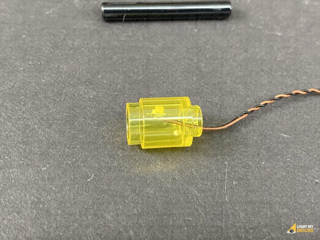
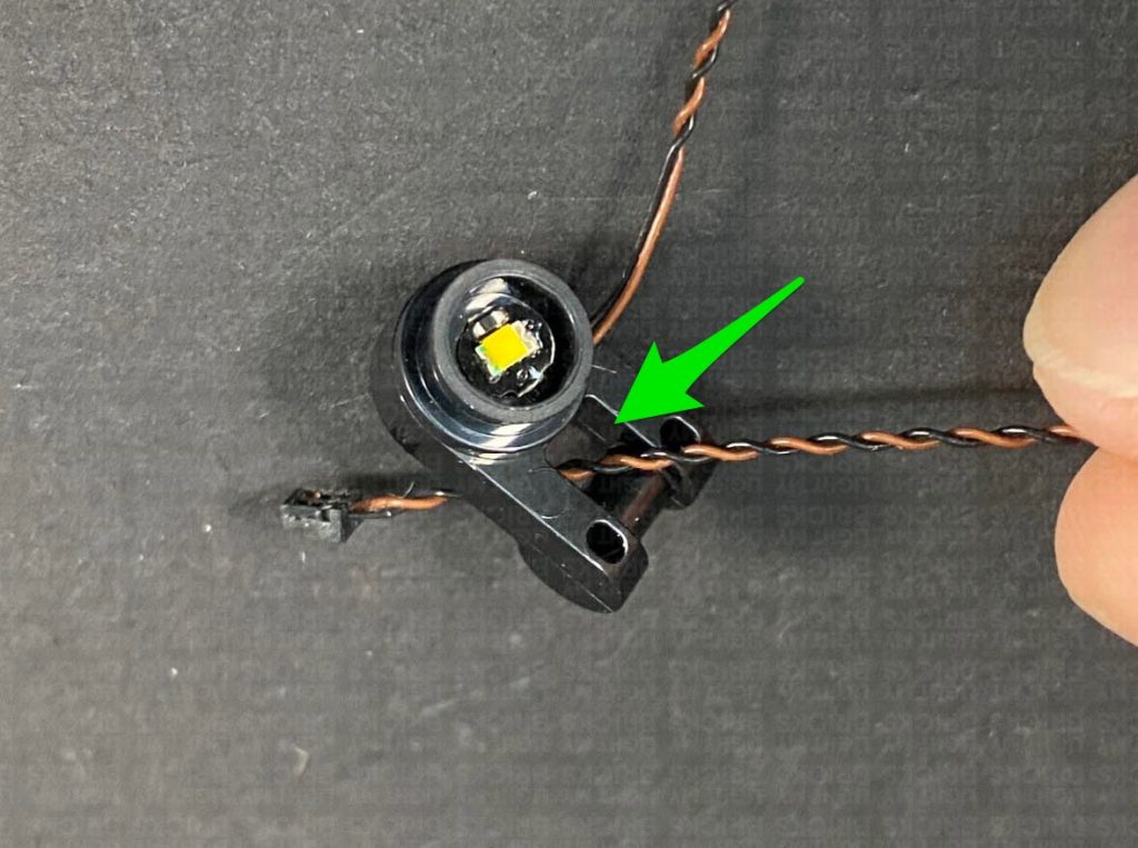
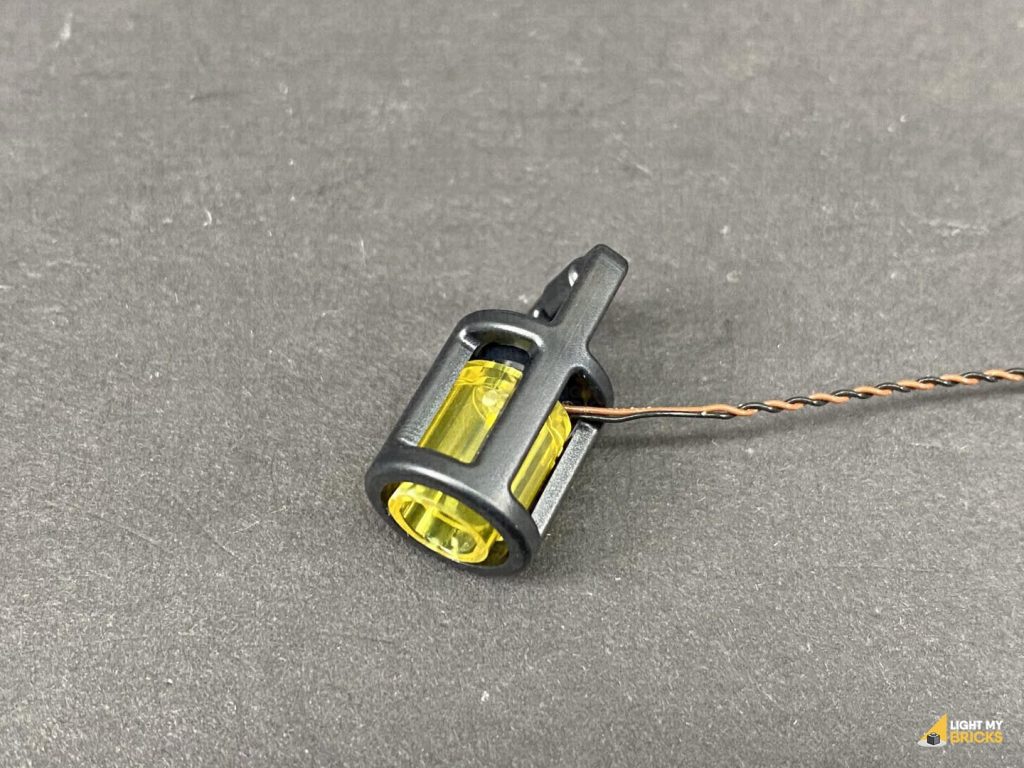
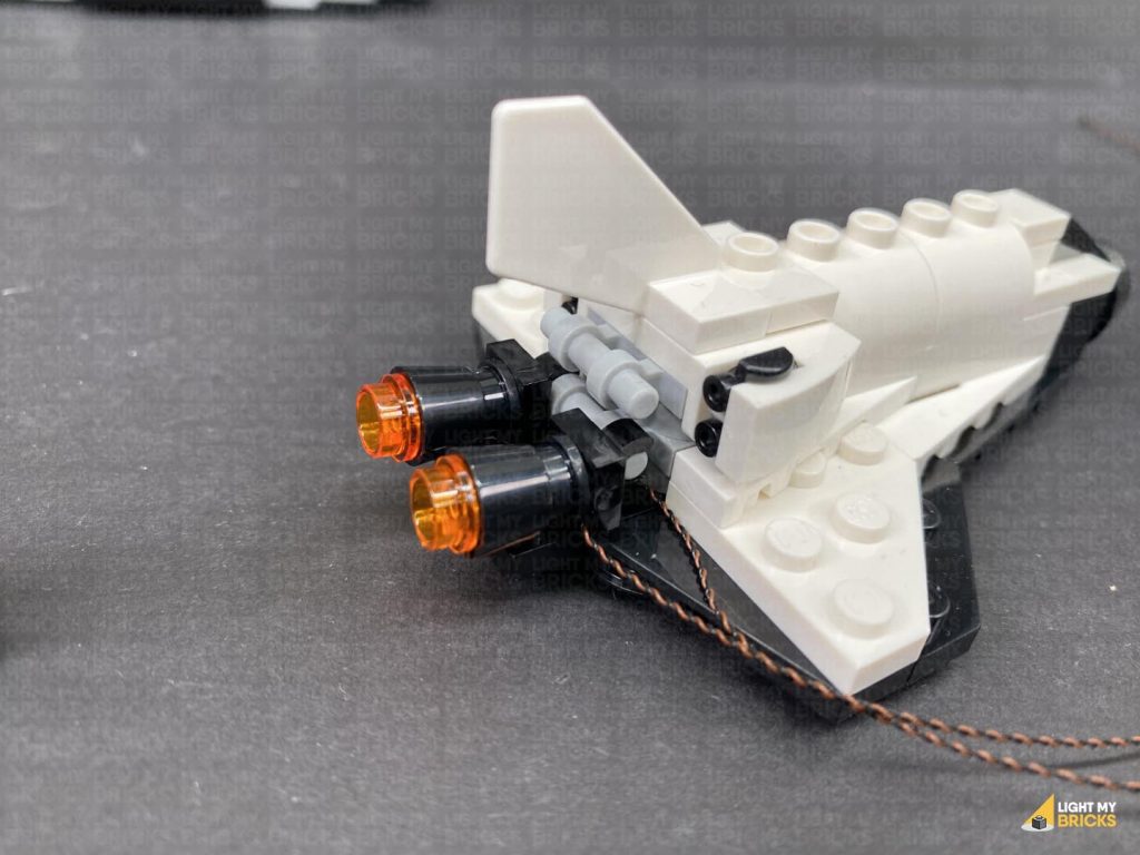
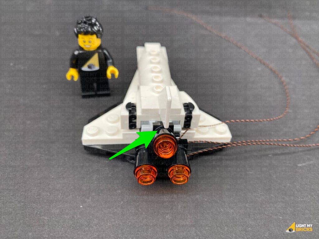
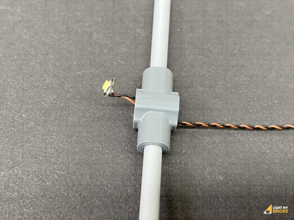
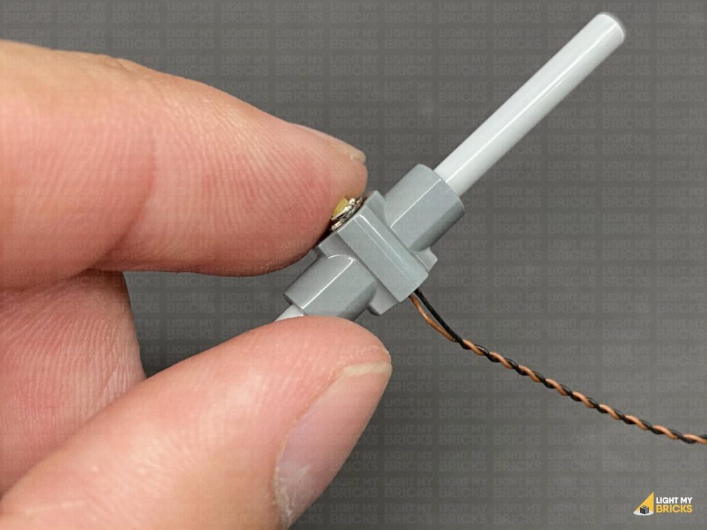
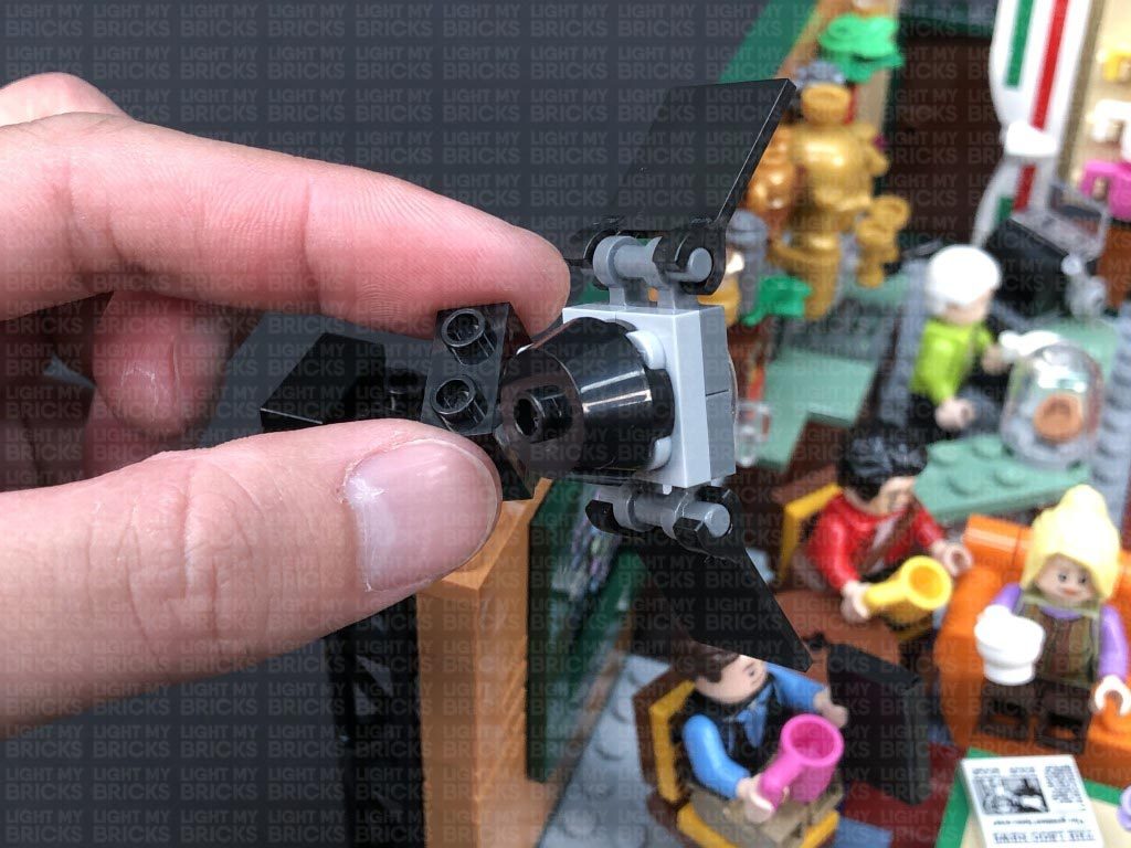
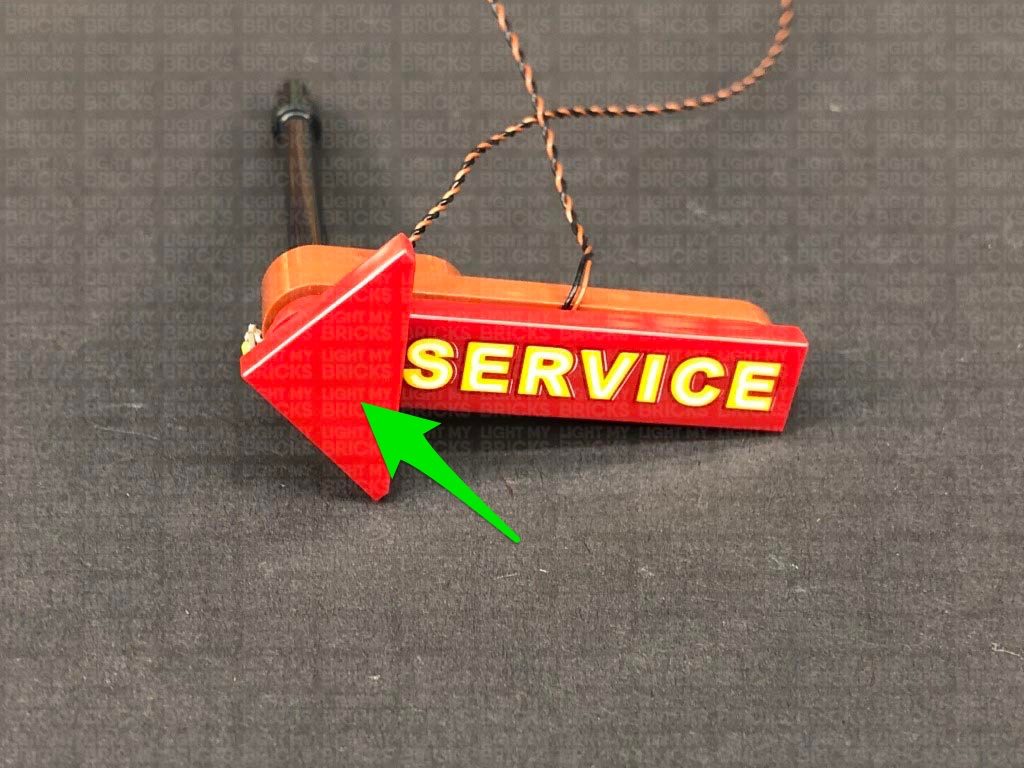
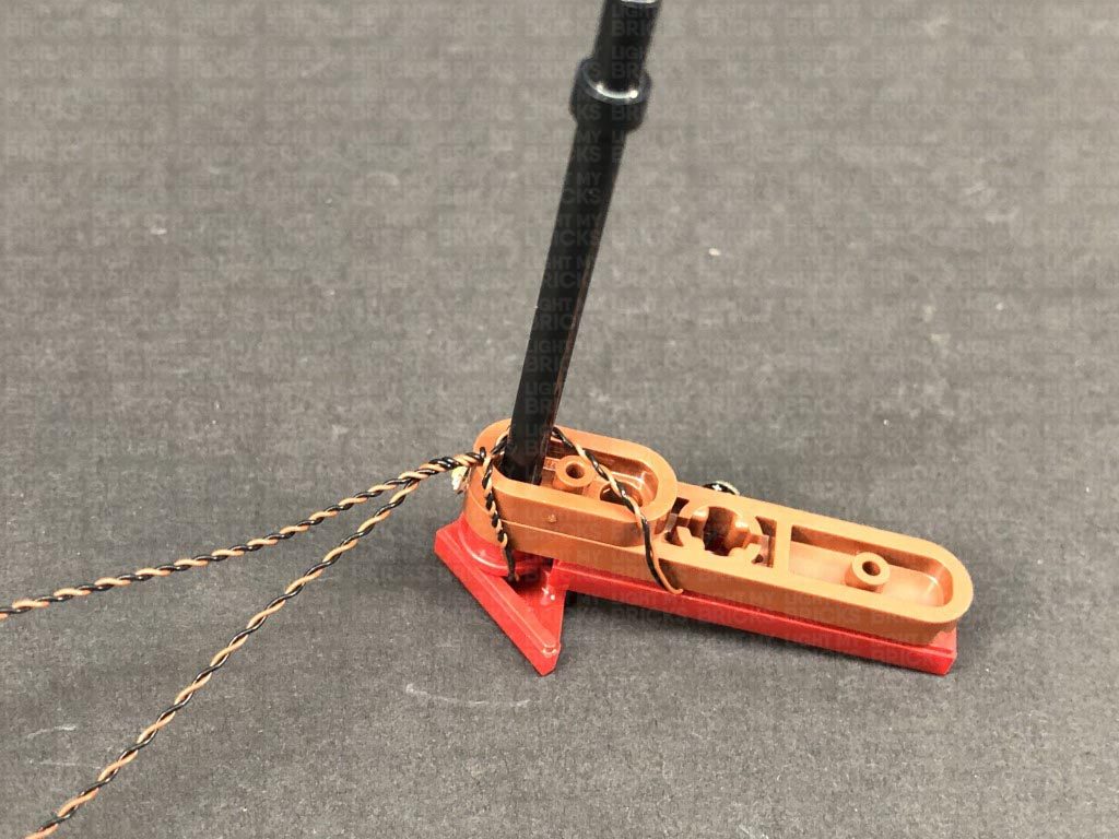
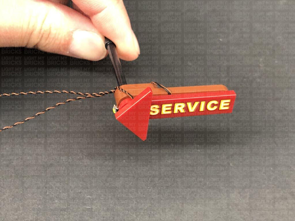
Note: If you experience any issues with the lights not working and suspect an issue with a component, please try a different port on the expansion board to verify where the fault lies (with the light or expansion board). To correct any issues with expansion board ports, please view the section addressing expansion board issues on our online troubleshooting guide.13.) From the front of the set, disconnect the front panel on the top floor as well as the two lamp sections. Disassemble one of the lamps, then take a White 30cm Bit Light and thread the connector side of the cable through the base of the trans yellow brick (larger hole). Place the LED all the way inside the brick (without bending it on a 90 degree angle like we did earlier). With the LED facing the inside wall of the trans yellow brick, carefully reconnect the black bar through the larger hole of the brick. You will notice the bar will be on a slight angle because of the LED pushing against it. This is normal. Do not forcefully push the black bar all the way through, we just need the bar to be pushed in enough to stay secure. Pushing the bar the whole way through may break the cable.
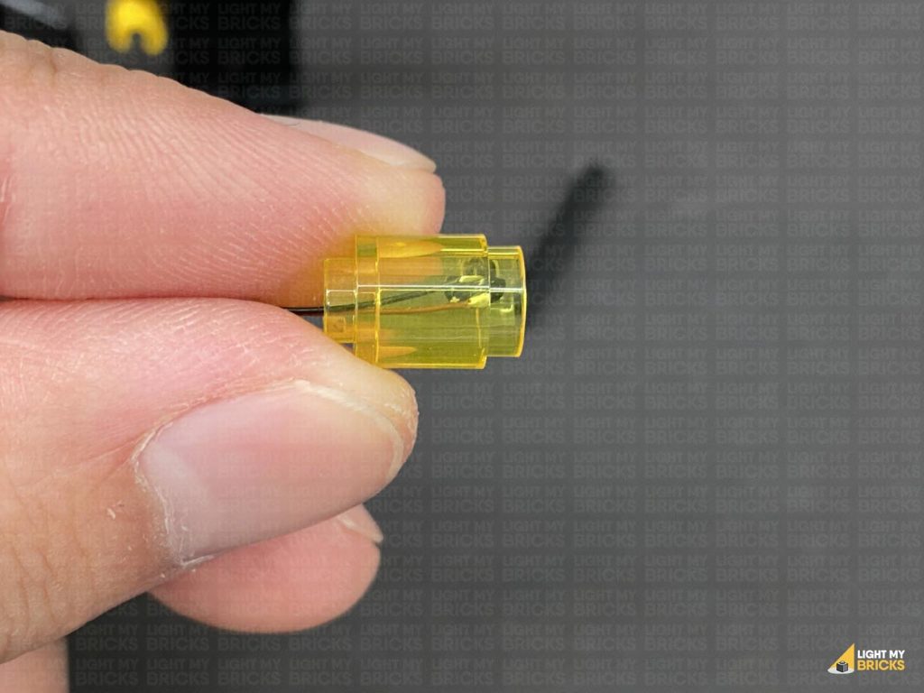
 Reconnect the black dish, then thread the cable through the inside of the lamp enclosure before reconnecting everything back together. Align the lamp enclosure so that the LED is facing directly forward.
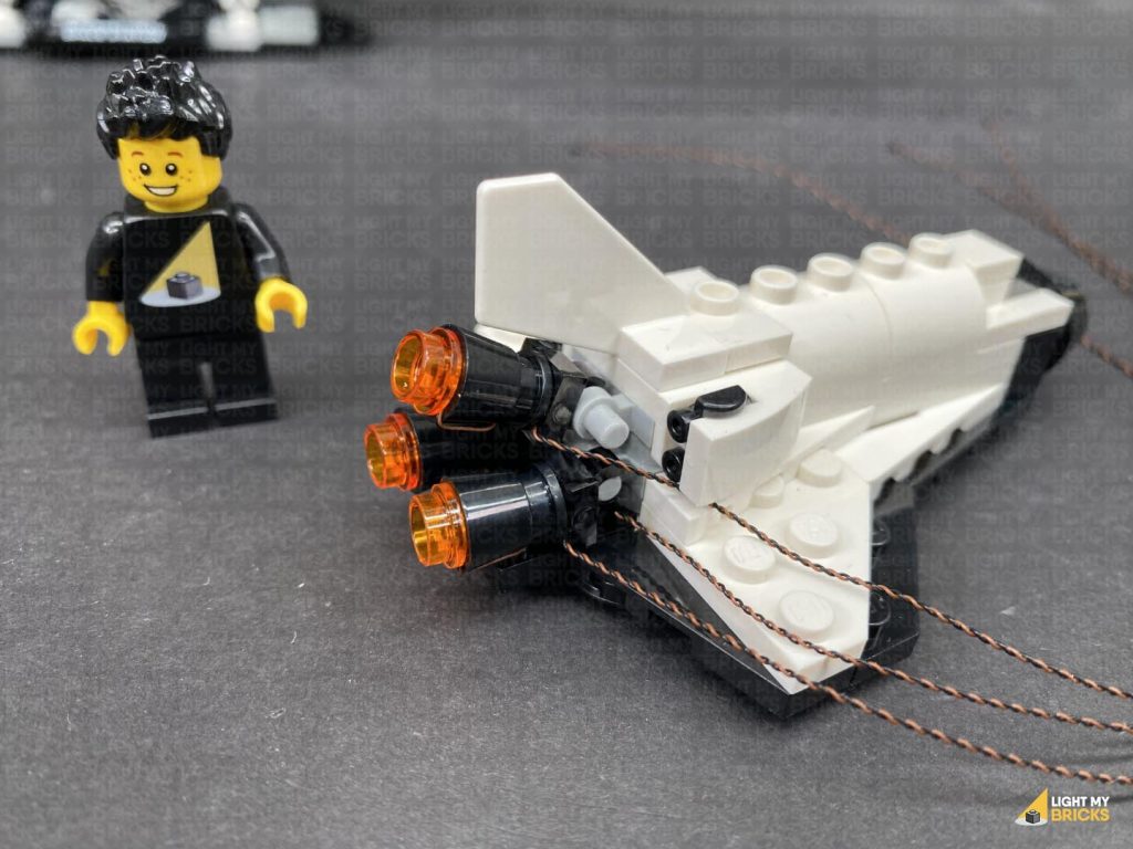
 Repeat this step to install another White 30cm Bit Light to the other lamp.
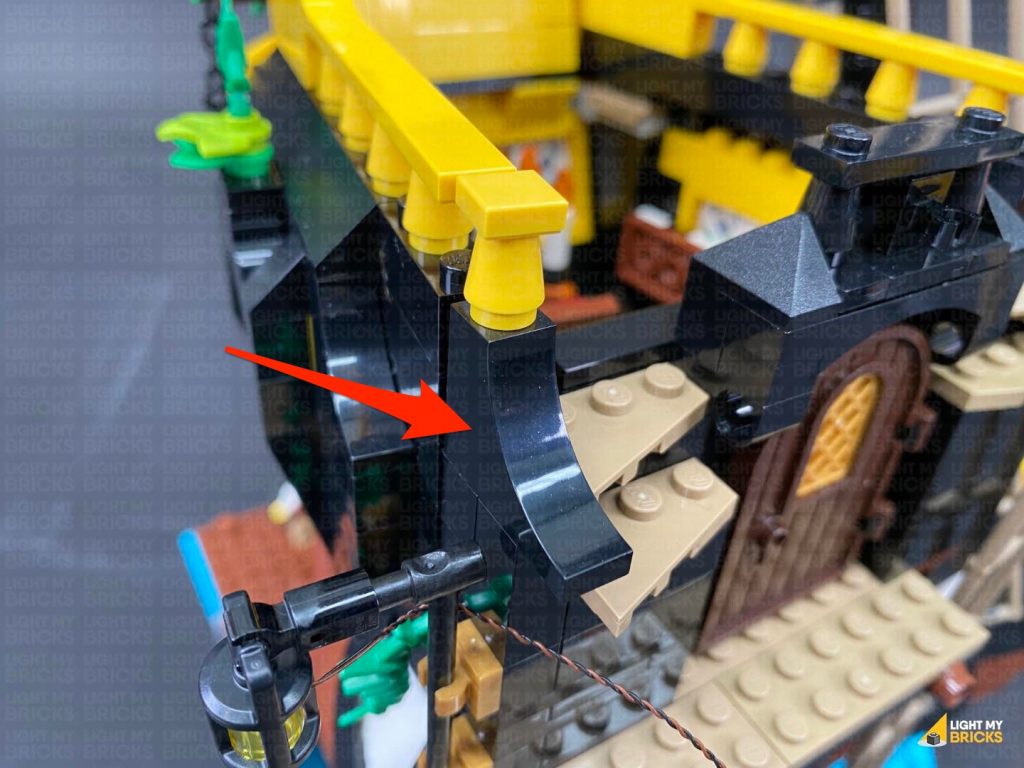
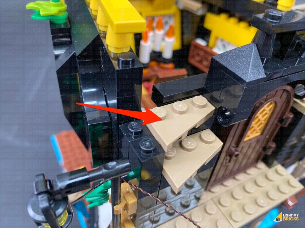
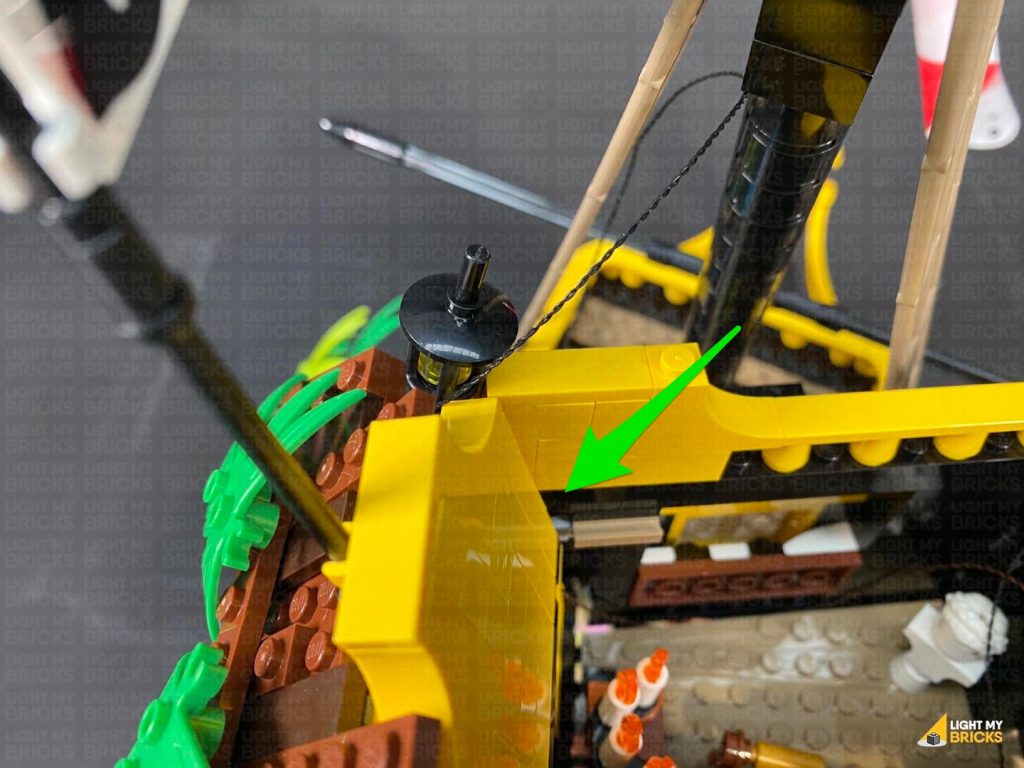
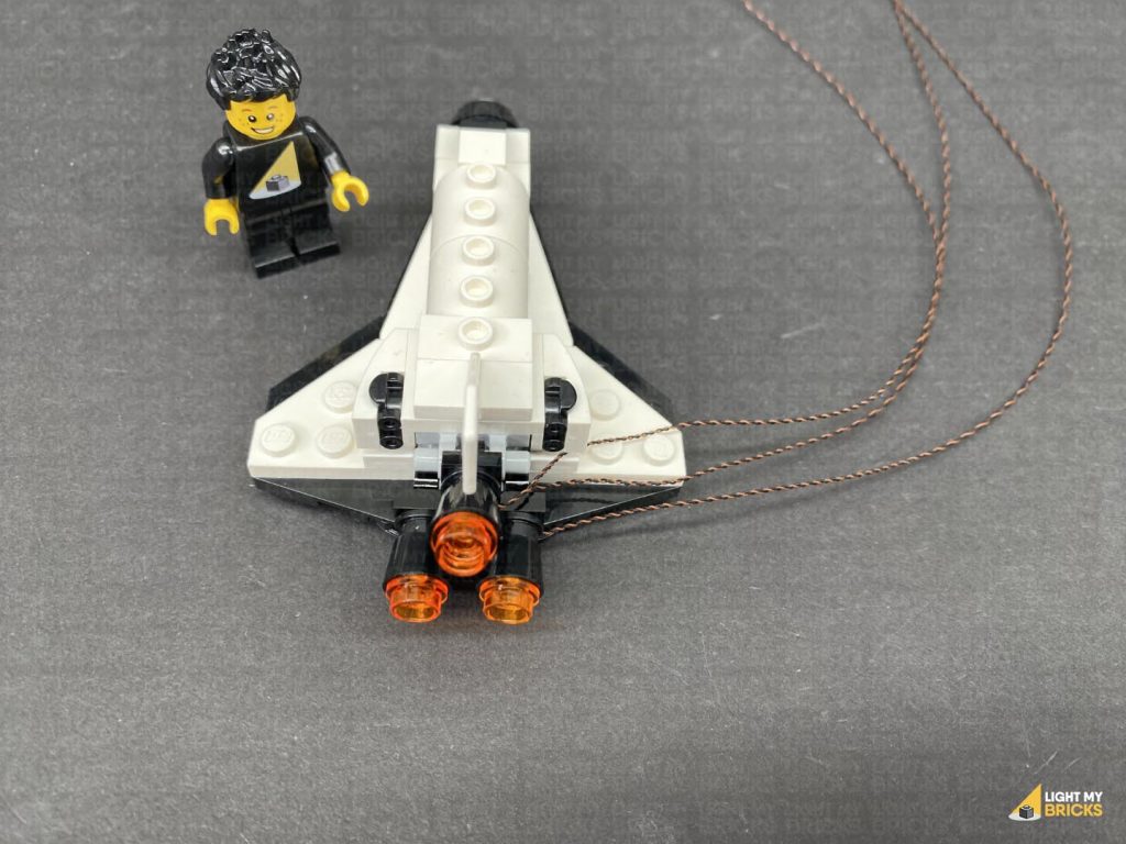
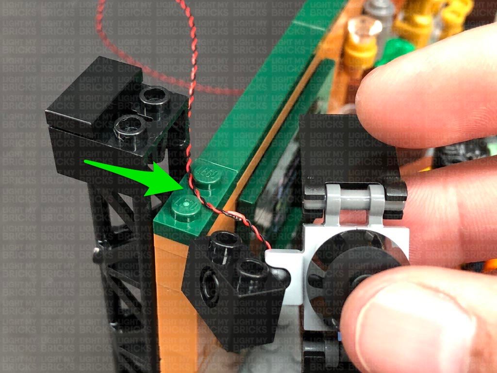
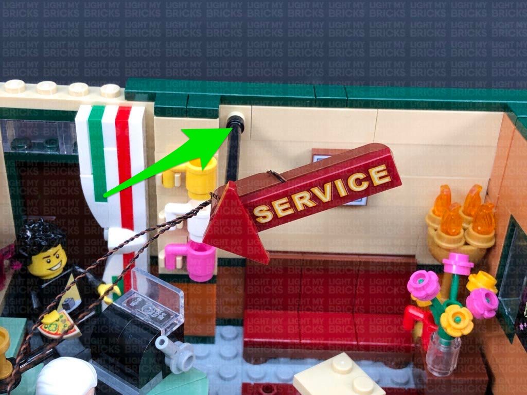
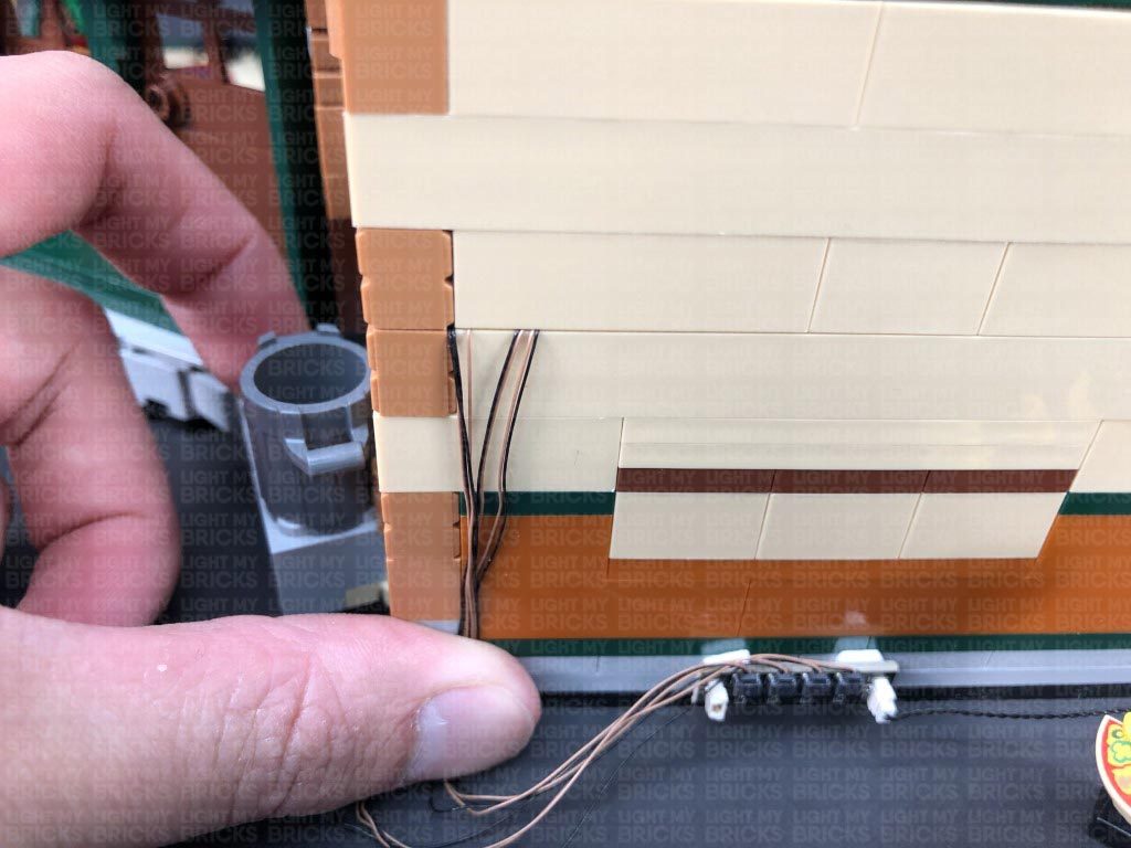
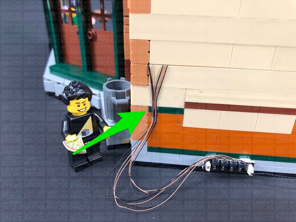
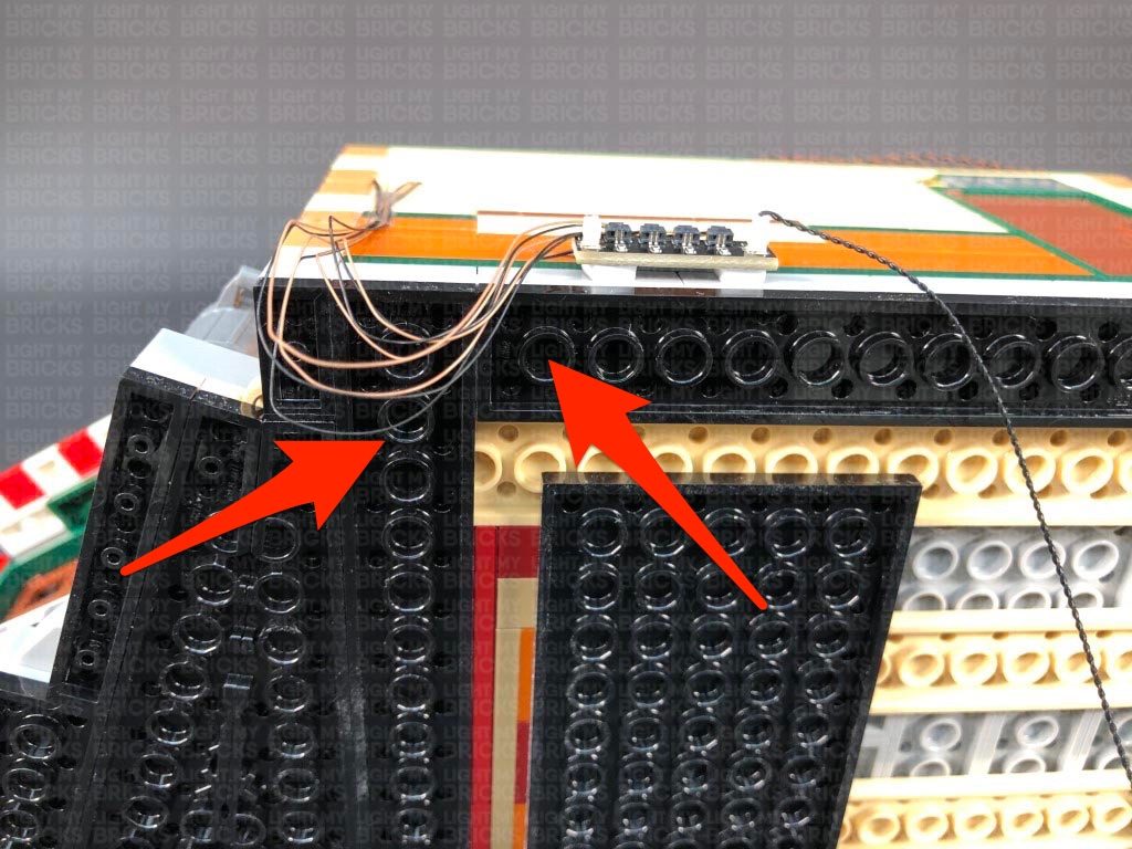
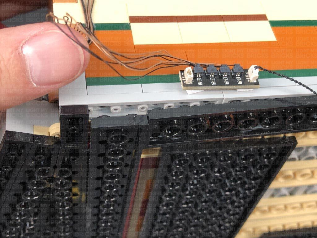
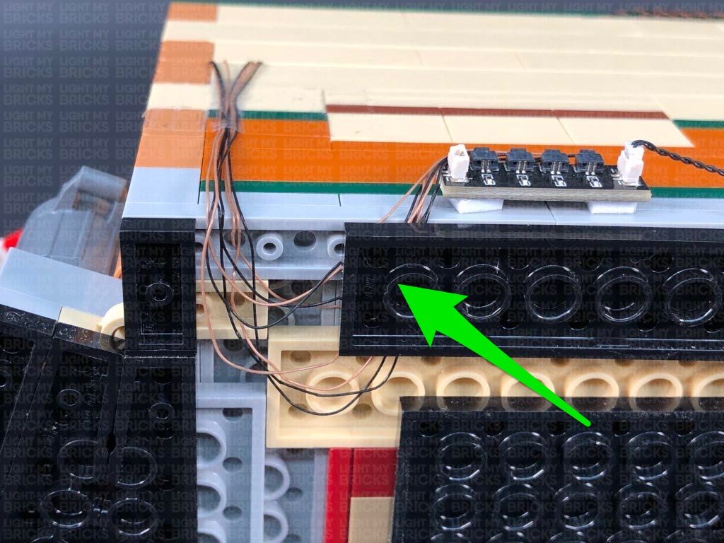
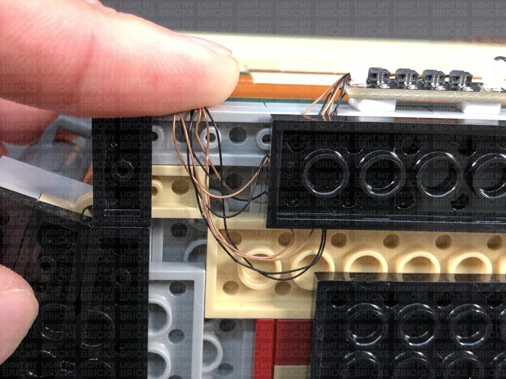
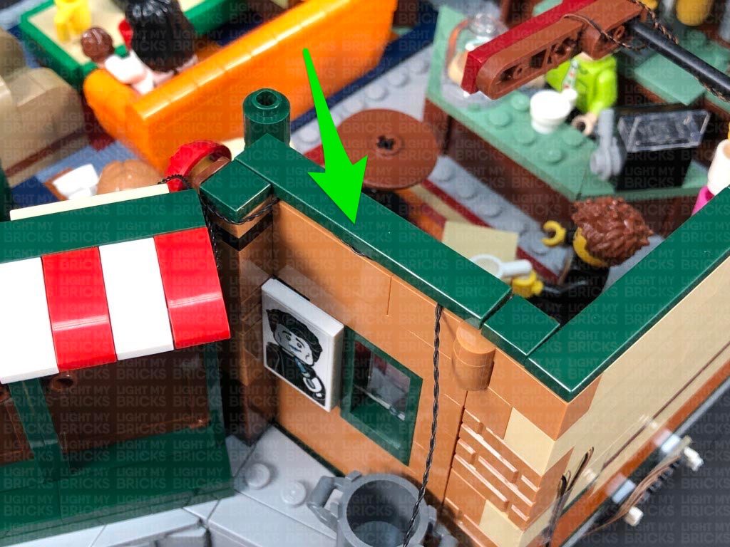
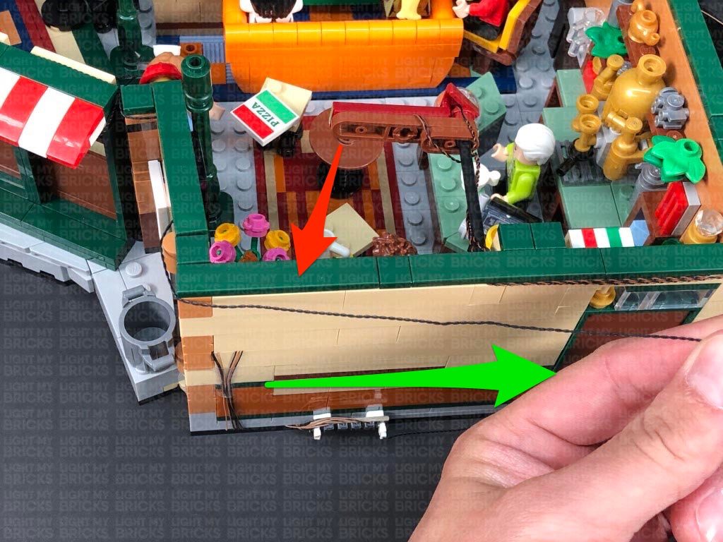
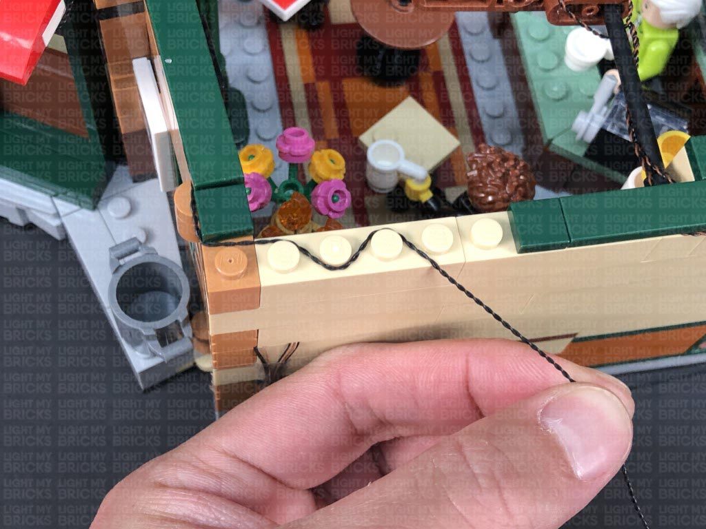
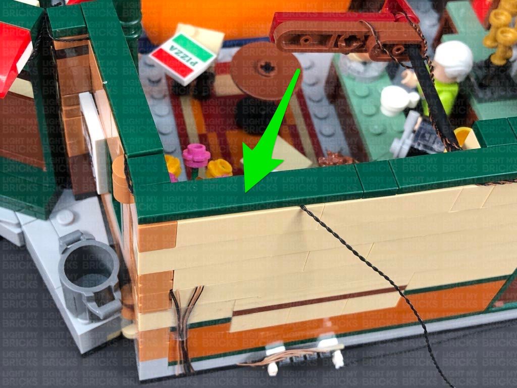
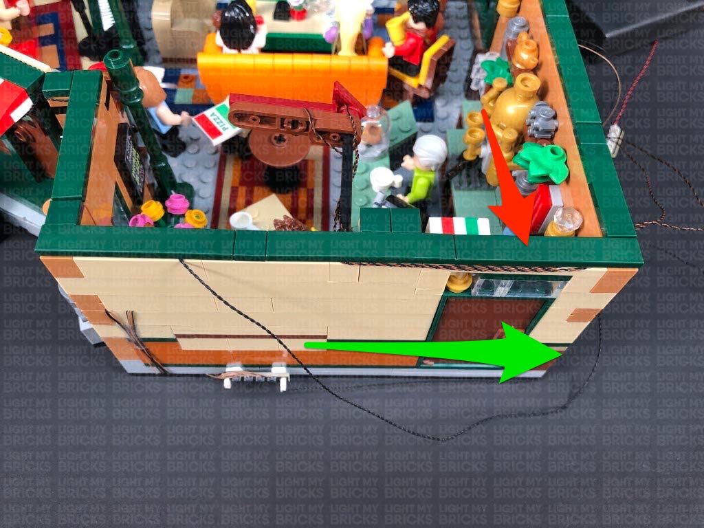
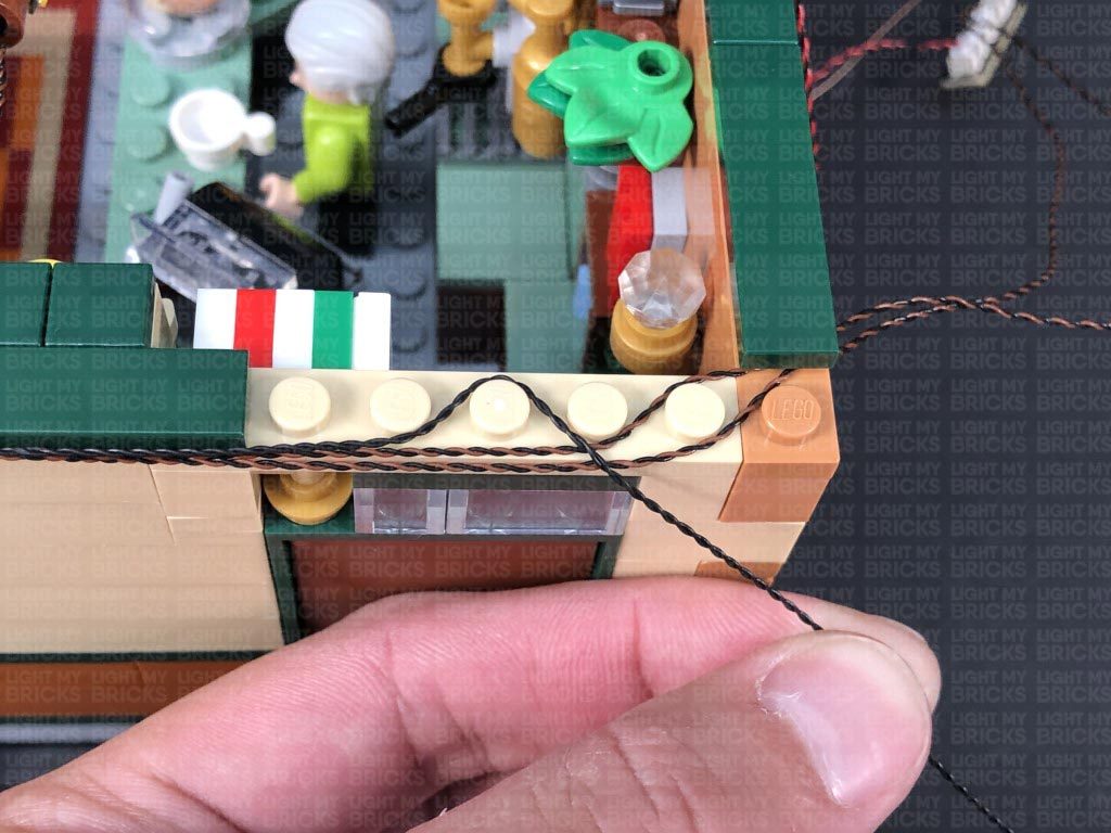
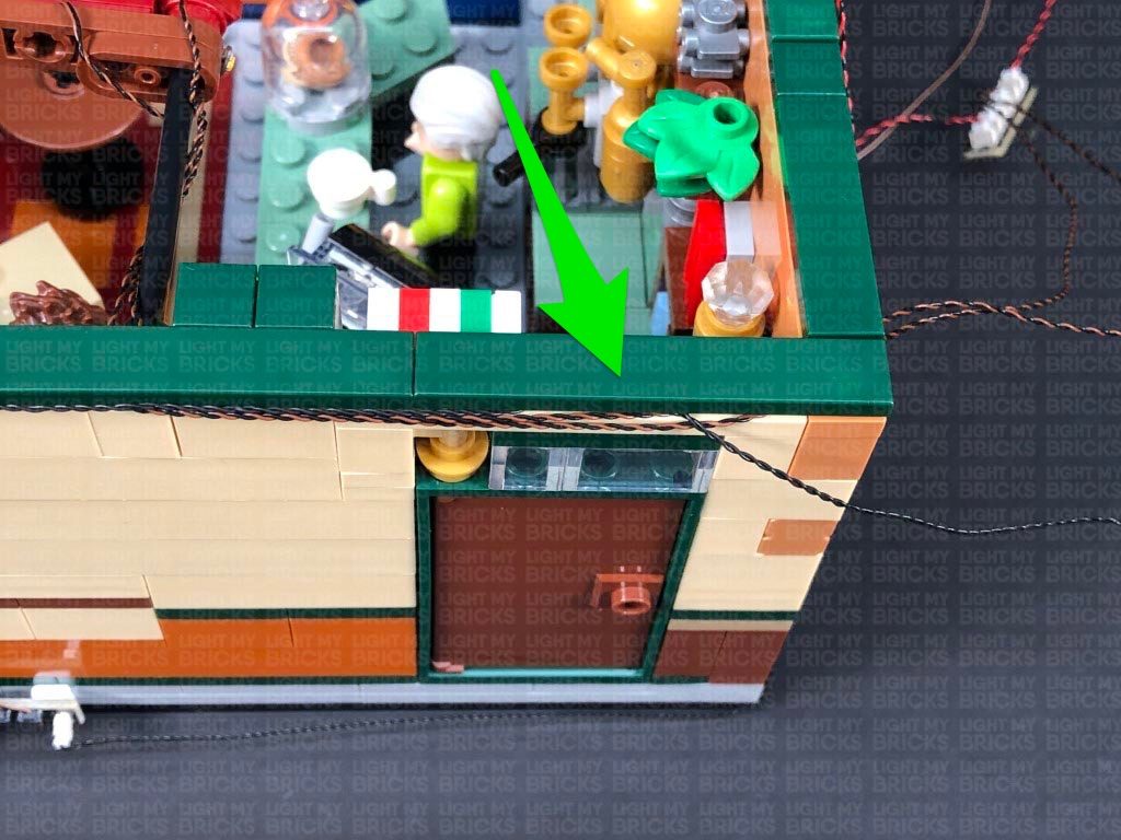
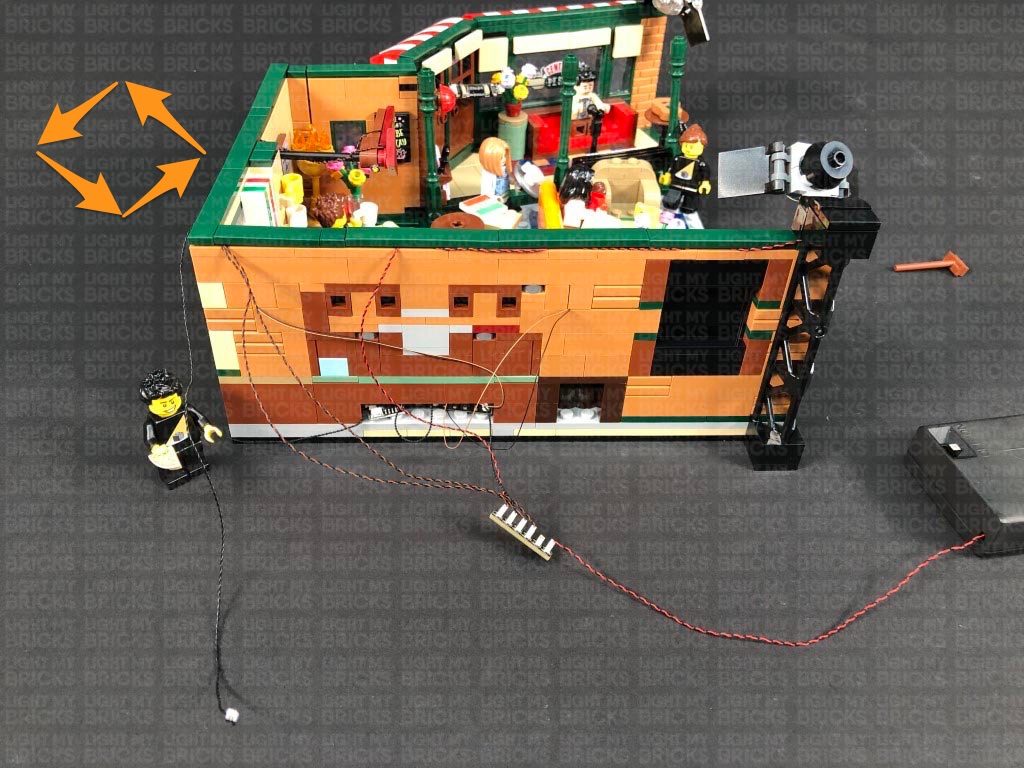
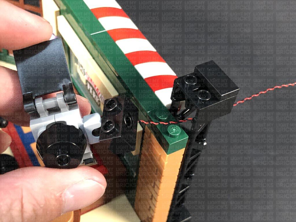
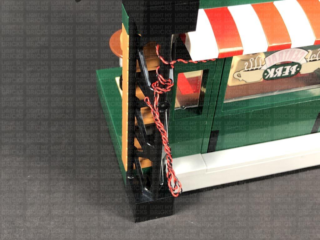
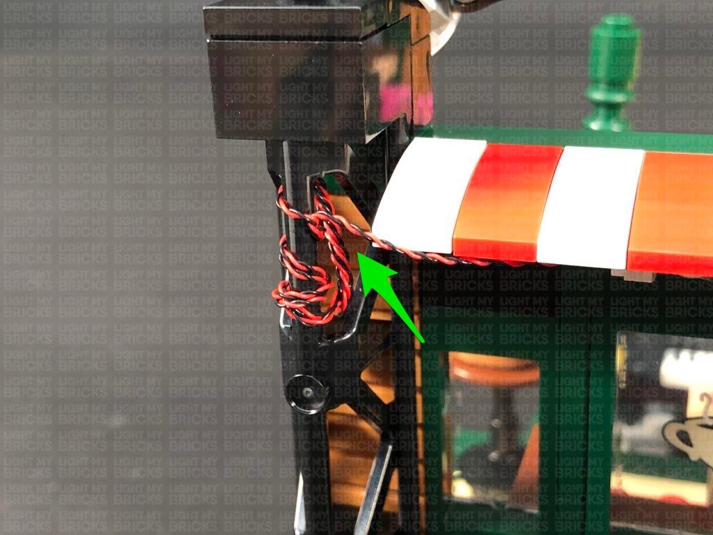
 14.) Reconnect one of the lamps to the left side, then slip the cable inside the corner behind as well as down on the side of the wall as shown below. Connect the cable to the 8-Port Expansion Board
Repeat this step for the other lamp to the right side.
Turn ON the power to test the lamp lights are working OK.
14.) Reconnect one of the lamps to the left side, then slip the cable inside the corner behind as well as down on the side of the wall as shown below. Connect the cable to the 8-Port Expansion Board
Repeat this step for the other lamp to the right side.
Turn ON the power to test the lamp lights are working OK.
 Note: If you experience any issues with the lights not working and suspect an issue with a component, please try a different port on the expansion board to verify where the fault lies (with the light or expansion board). To correct any issues with expansion board ports, please view the section addressing expansion board issues on our online troubleshooting guide.
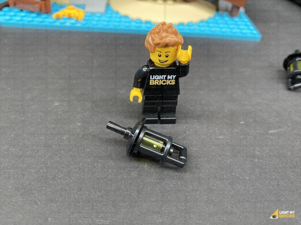
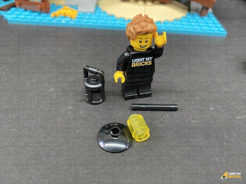
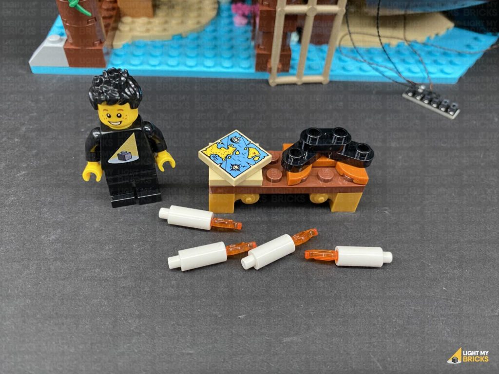
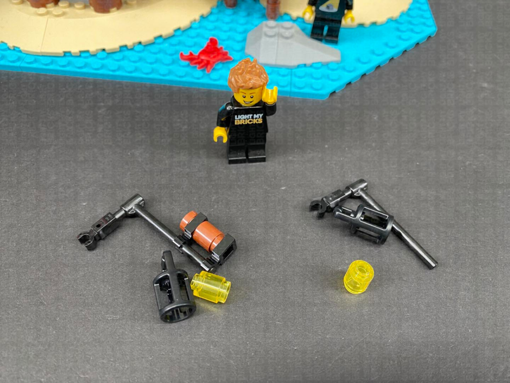
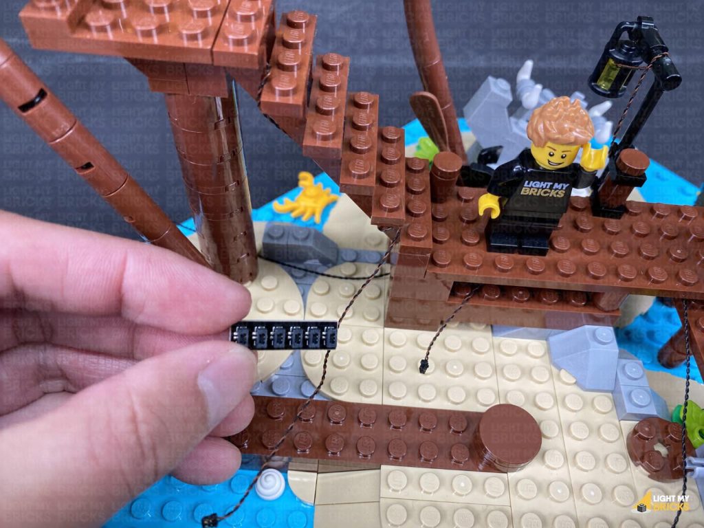
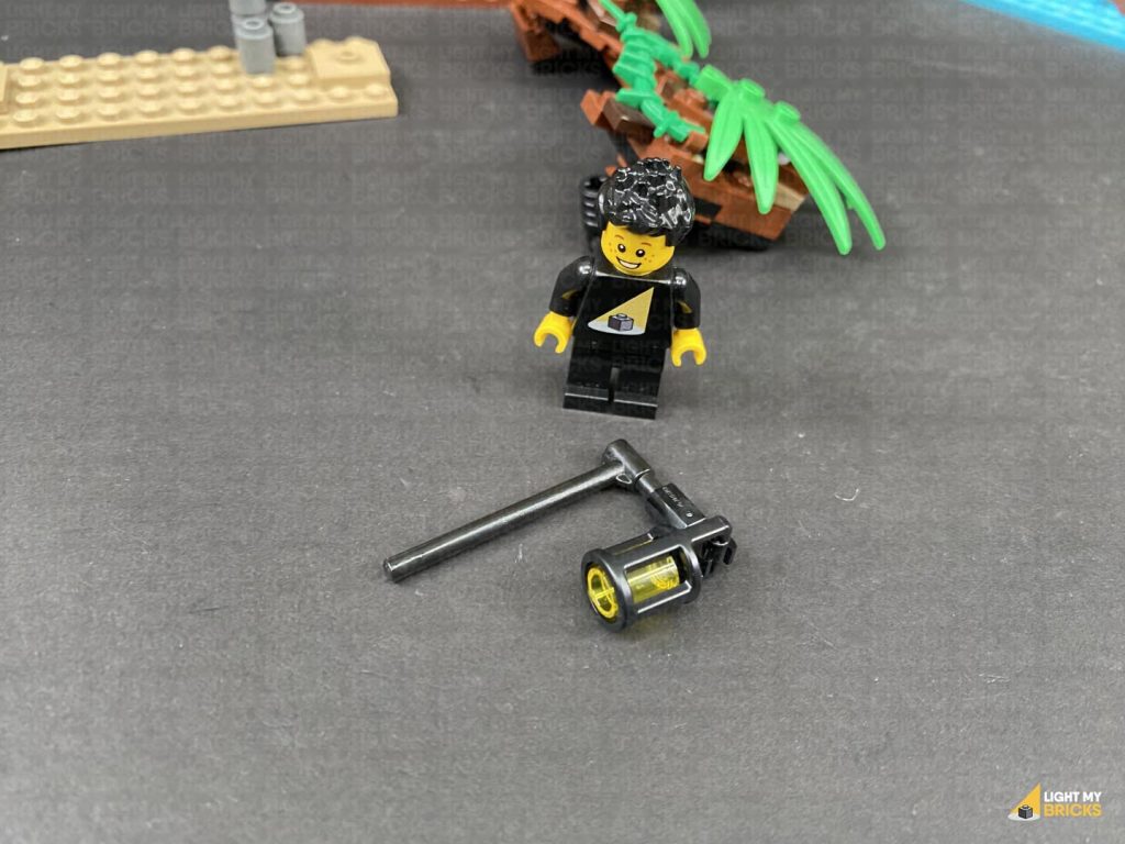
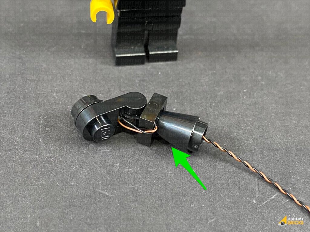
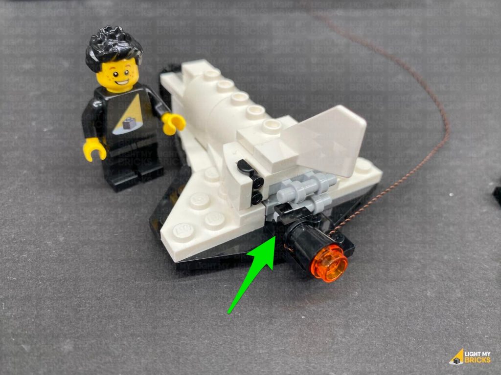
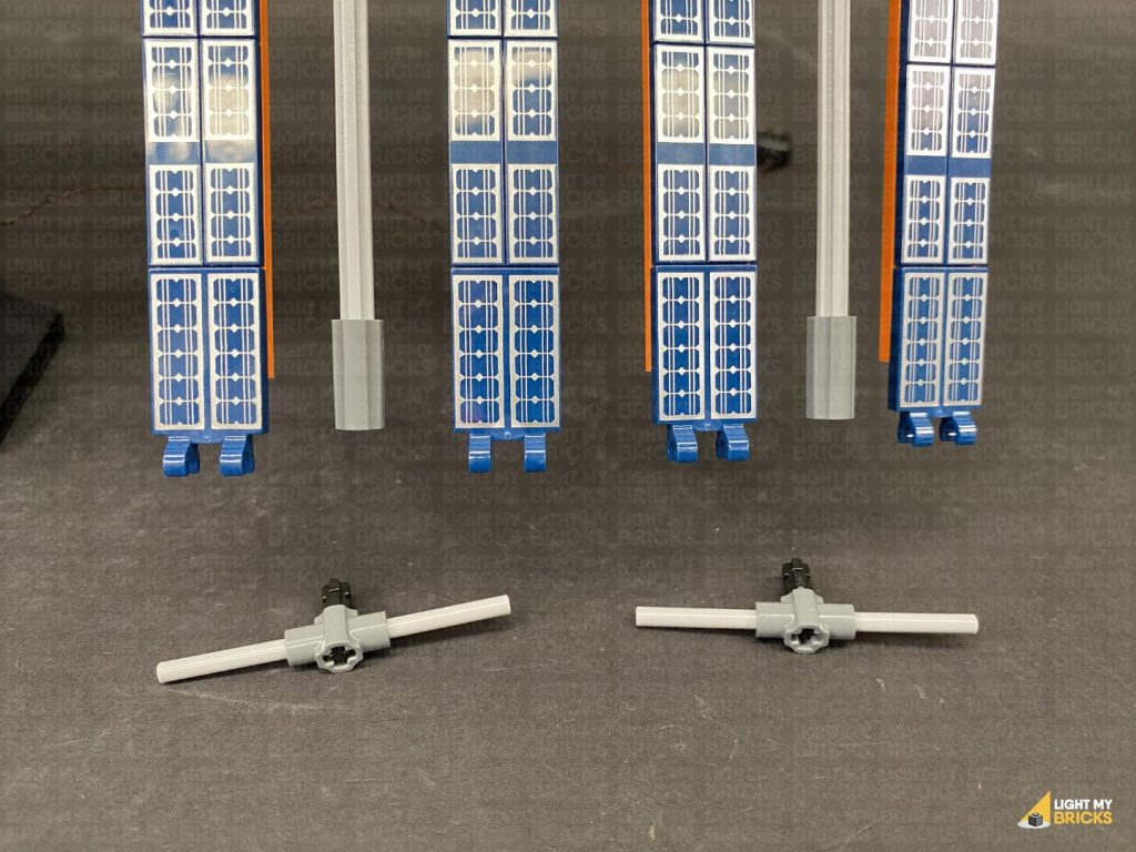
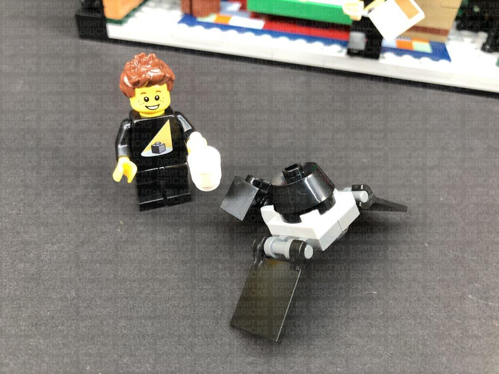
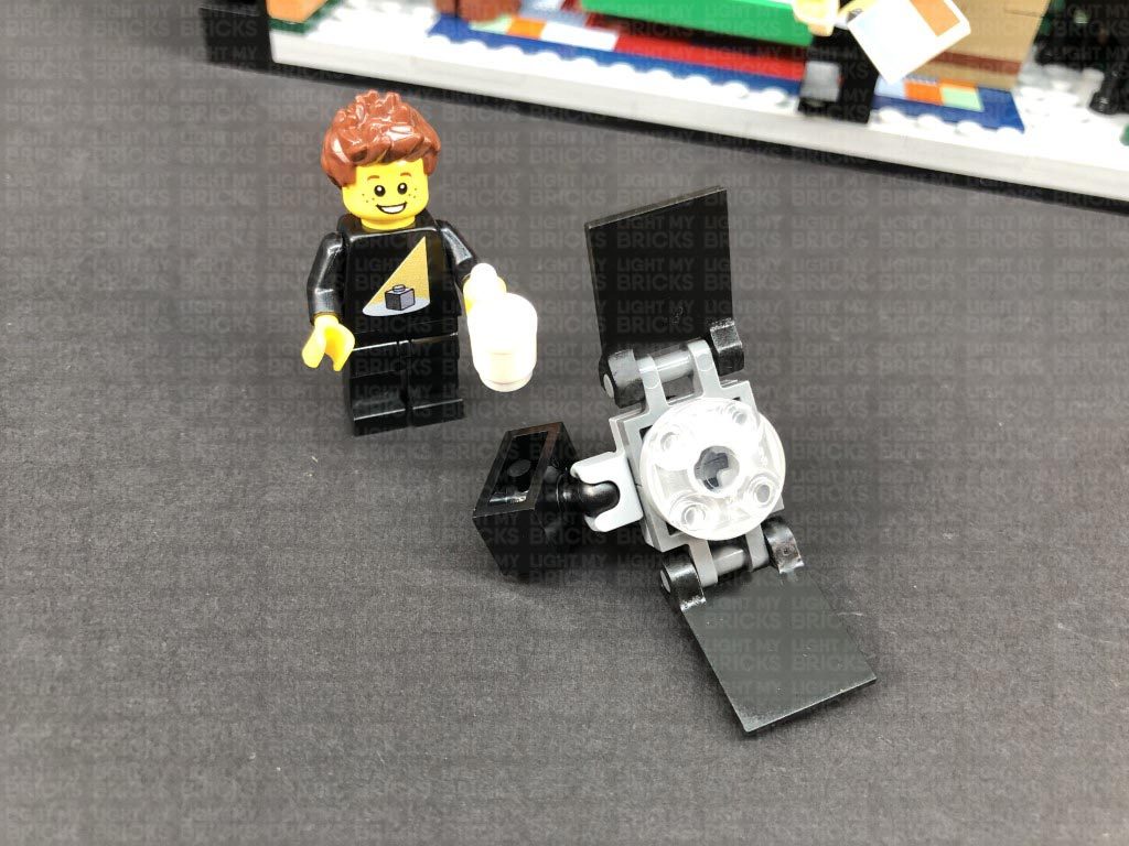
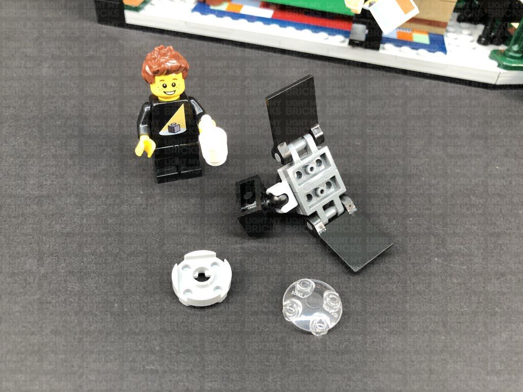
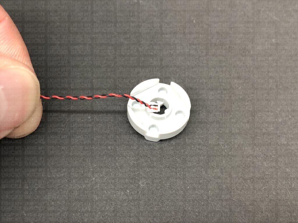
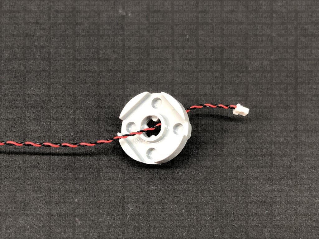
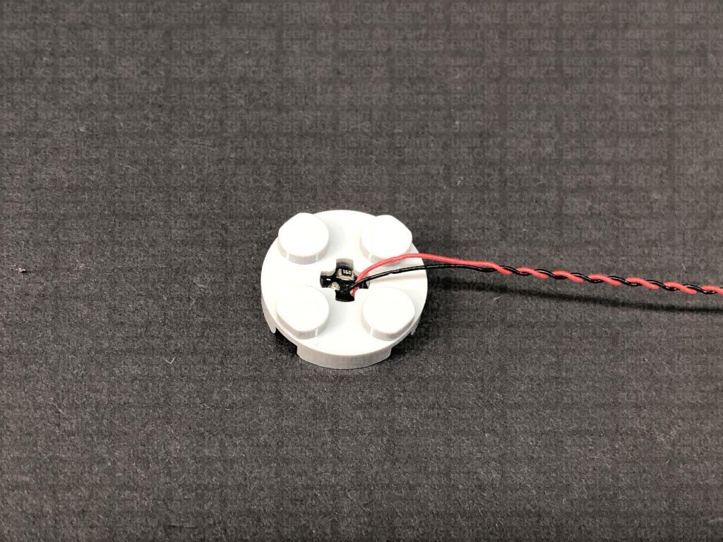
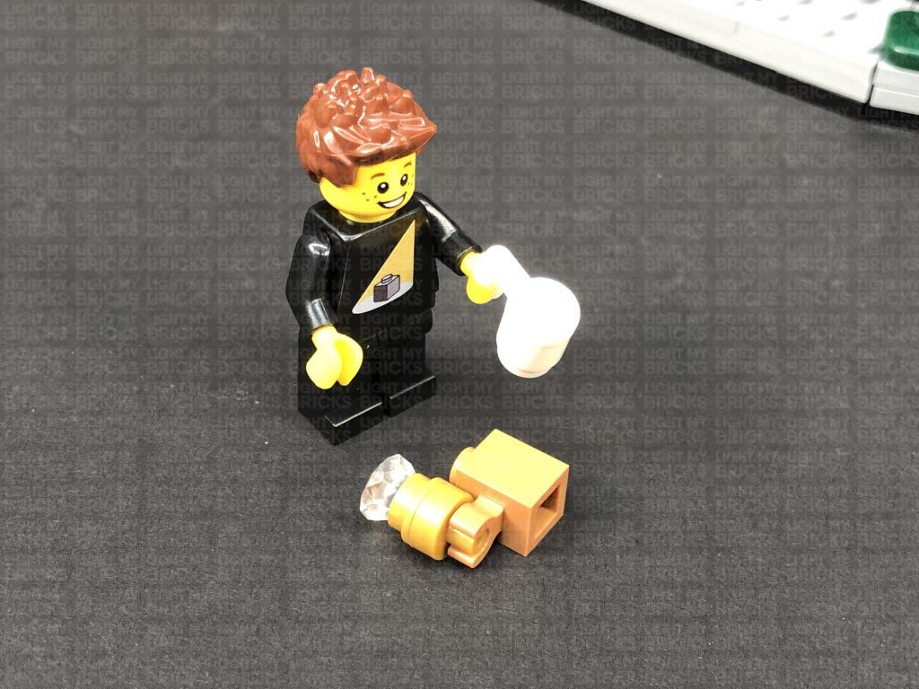
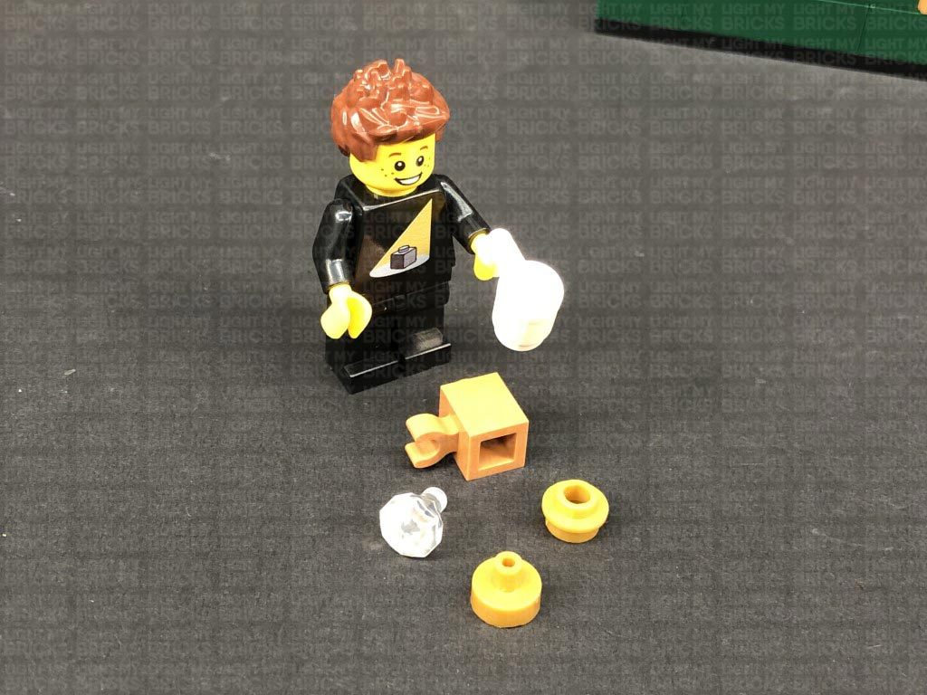
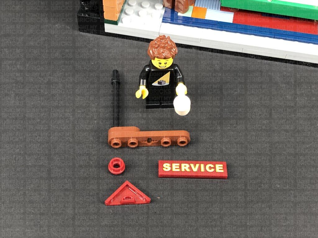
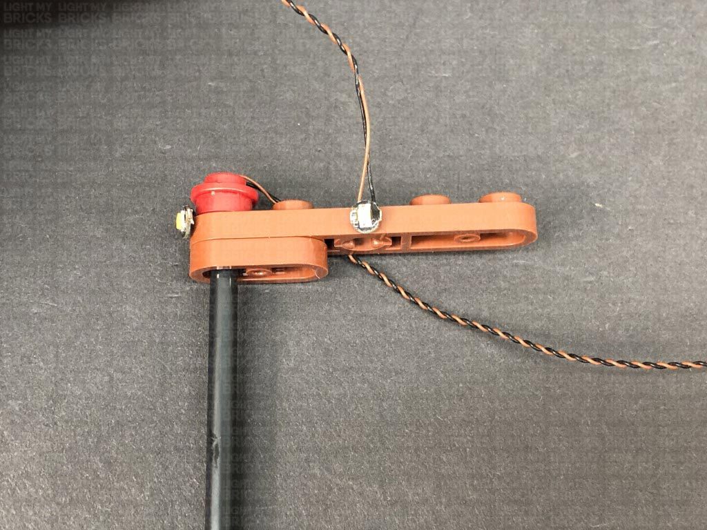
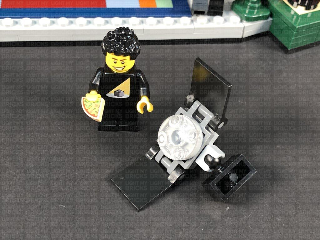
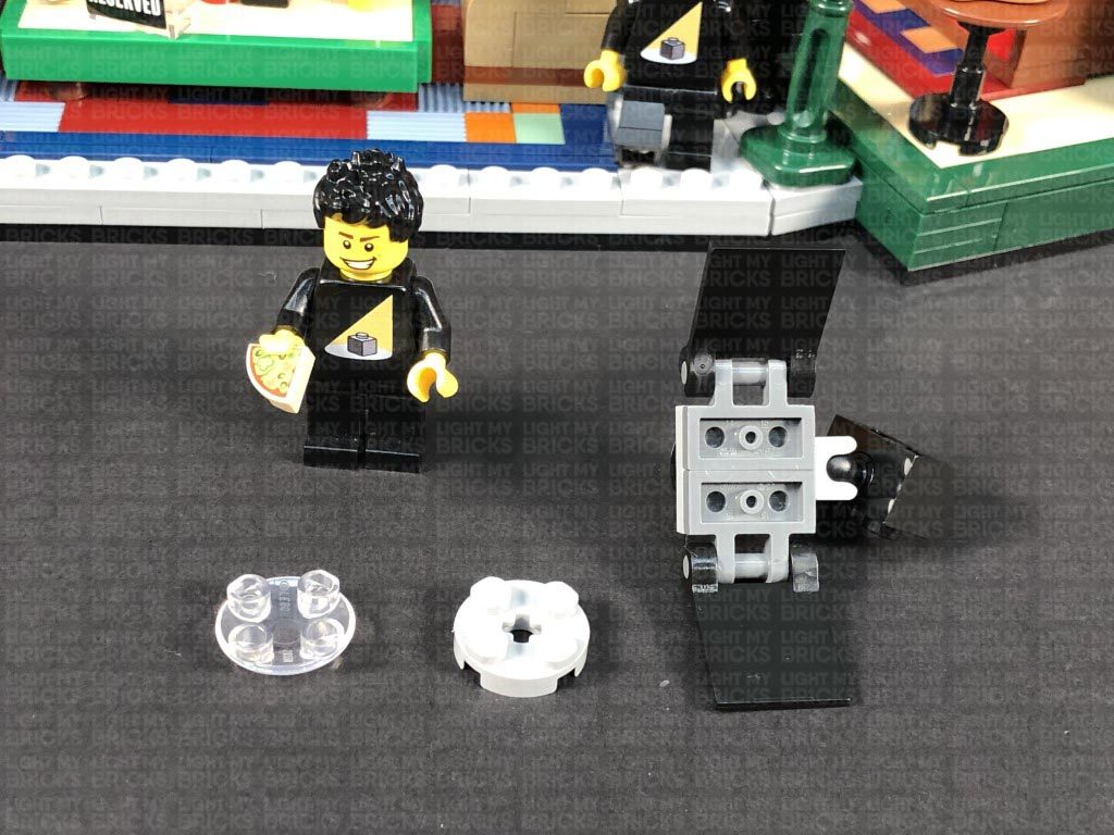
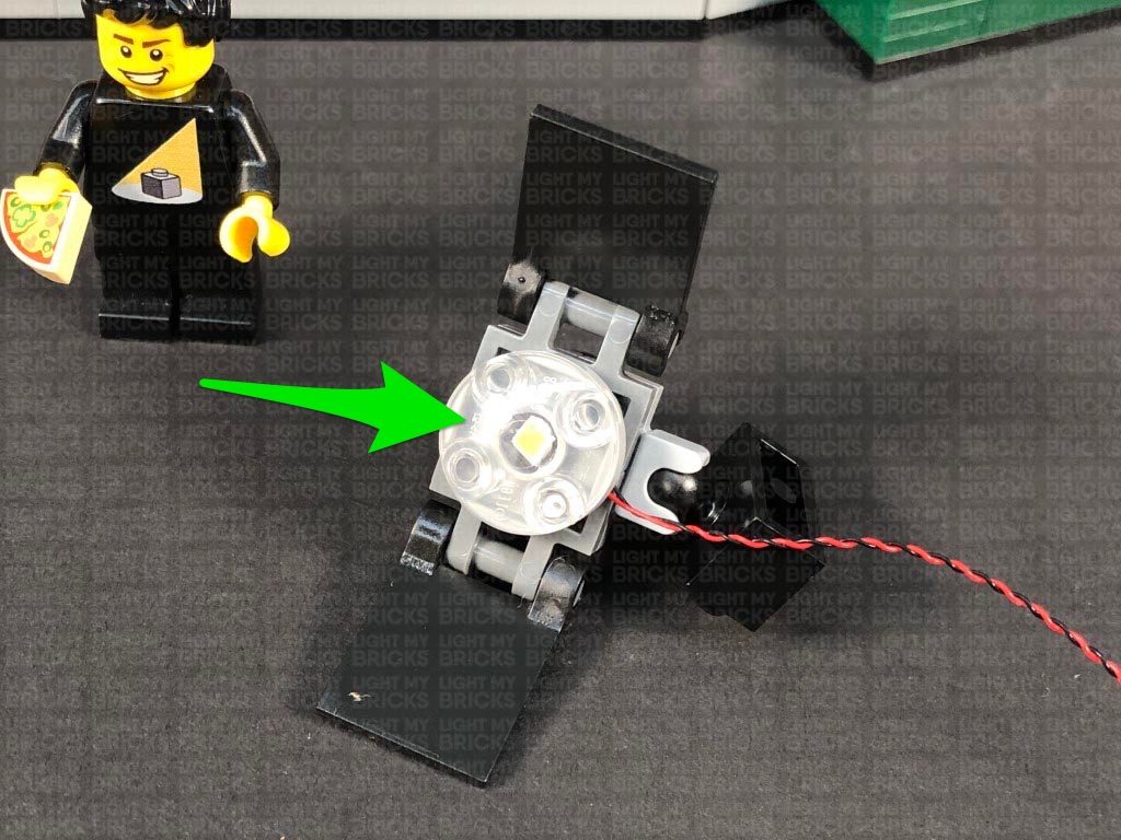
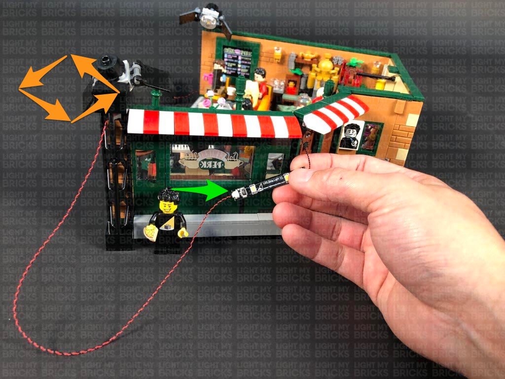
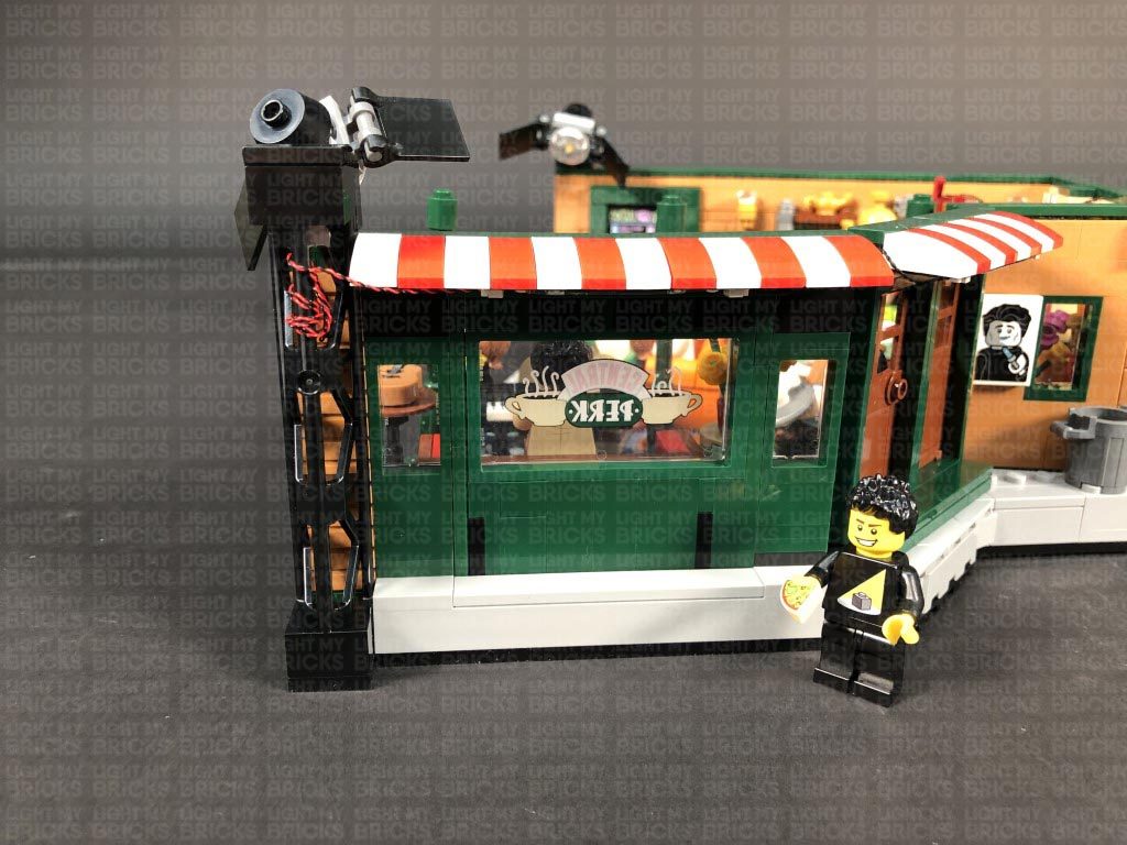
15.) Take out the following provided pieces included in this kit (to assemble a spot light) as well a White 15cm Bit Light
Note: If you experience any issues with the lights not working and suspect an issue with a component, please try a different port on the expansion board to verify where the fault lies (with the light or expansion board). To correct any issues with expansion board ports, please view the section addressing expansion board issues on our online troubleshooting guide.
15.) Take out the following provided pieces included in this kit (to assemble a spot light) as well a White 15cm Bit Light
- 1x Black Round Plate 1×1 with Open Stud
- 1x Black Tile 1×1 with Clip Rounded Edges
- 1x Black 1×1 Modified Plate Rounded with Handle
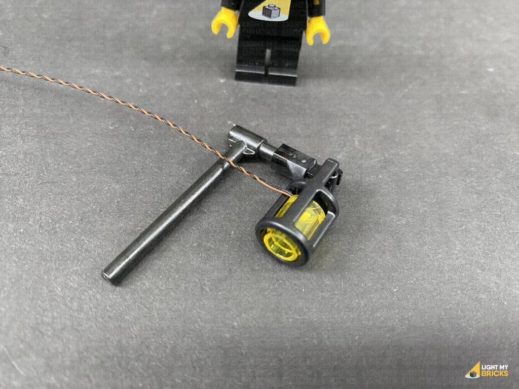
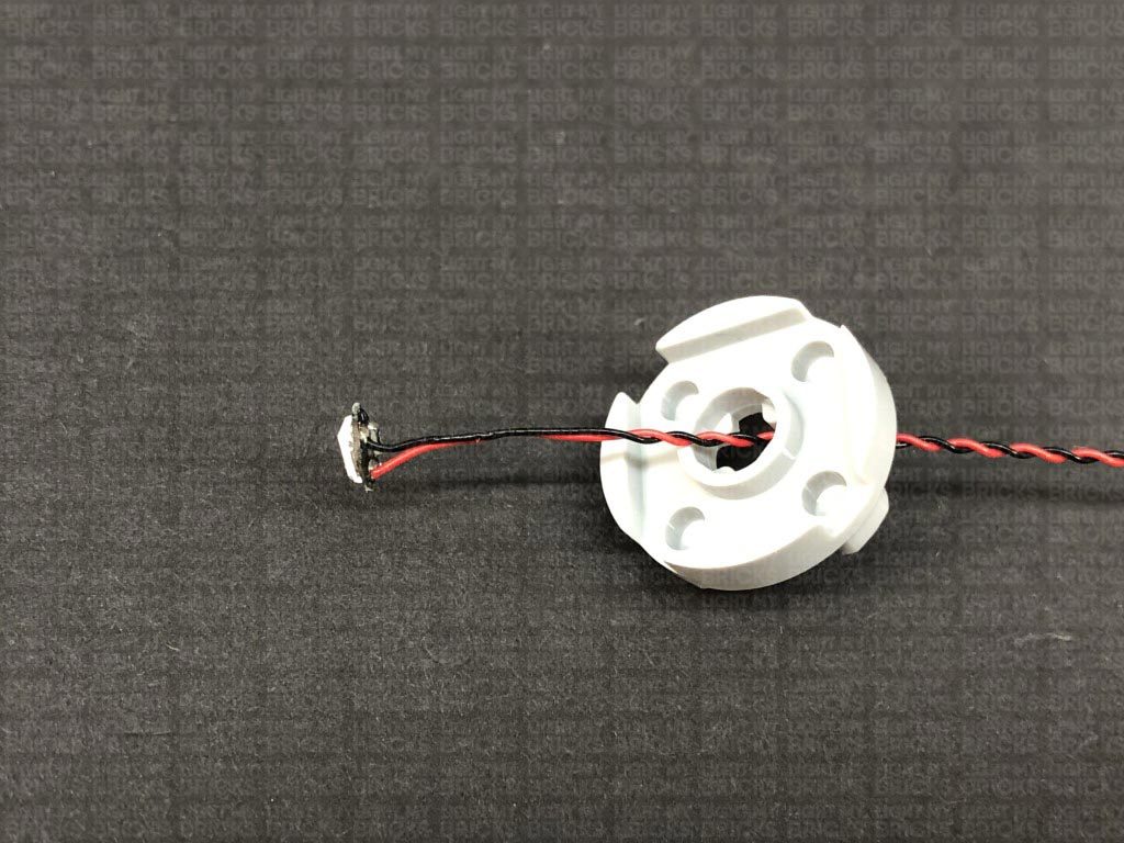
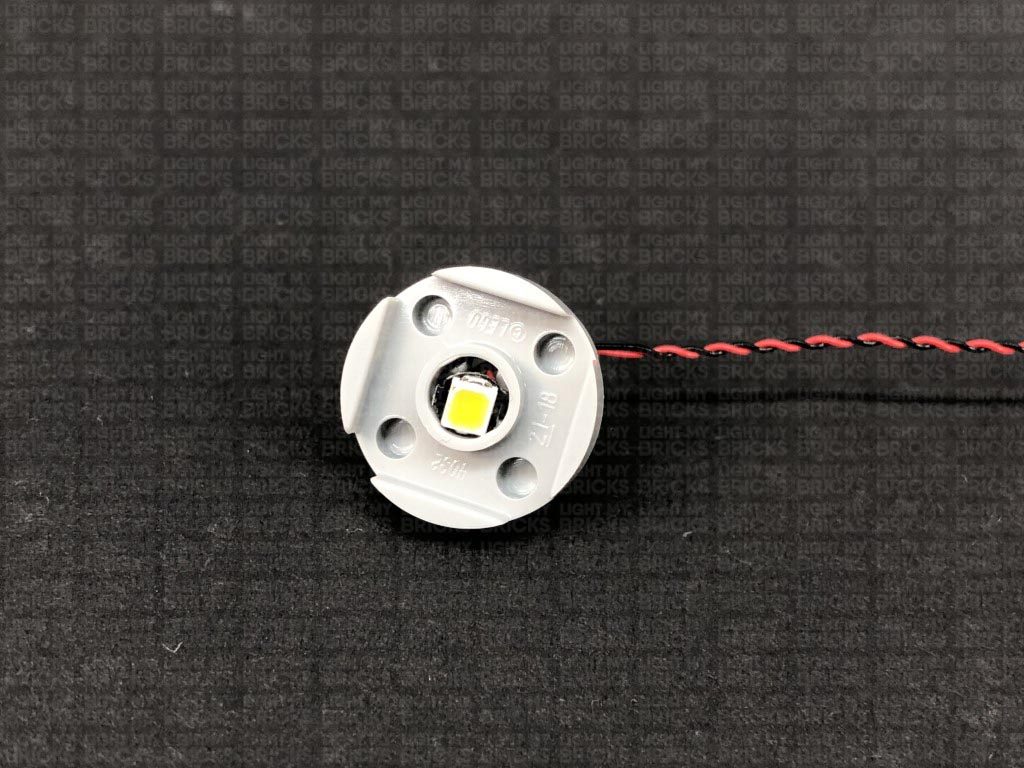
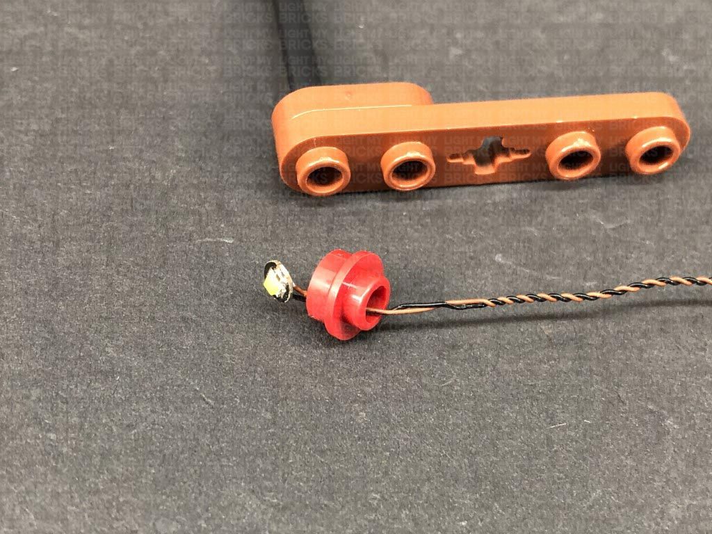
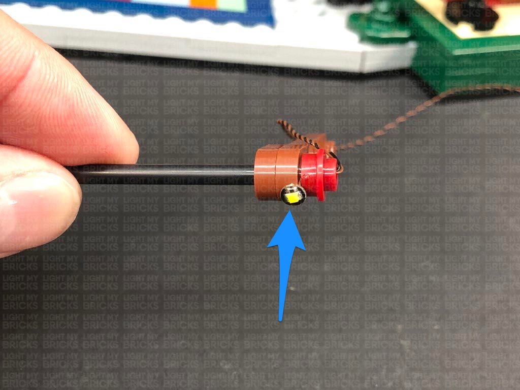
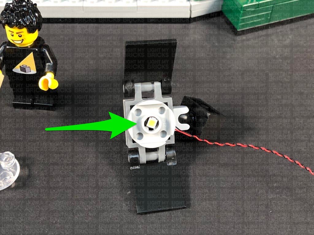
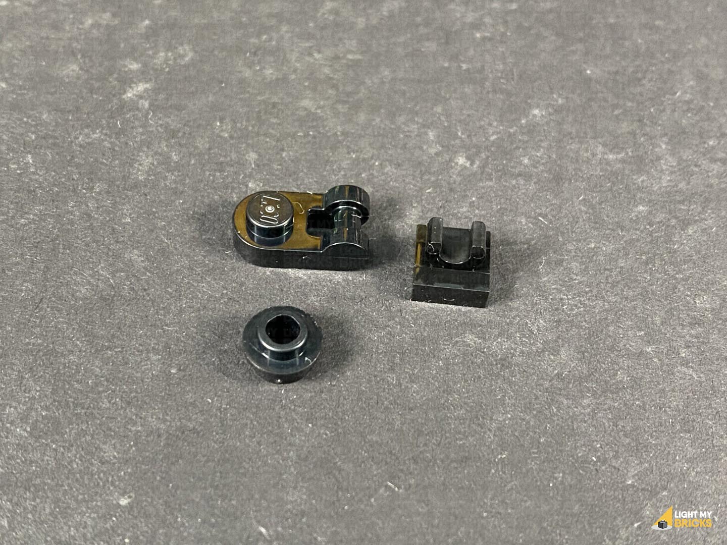 Thread the connector end of the Bit Light through the bottom of the round plate with open stud (larger hole). Slightly bend the LED so that it sits flat against the inside of the plate, then connect the plate to the bottom of the rounded plate with handle.
Thread the cable through the space of the handle, pulling it all the way out from the other side, then connect the handle to the tile with clip.
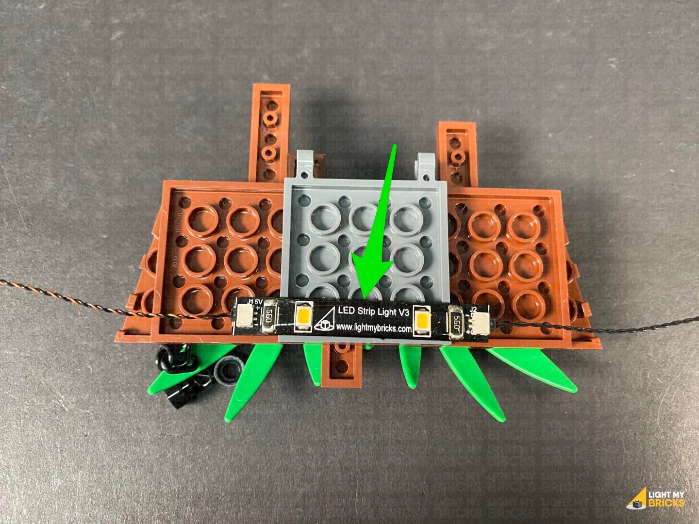
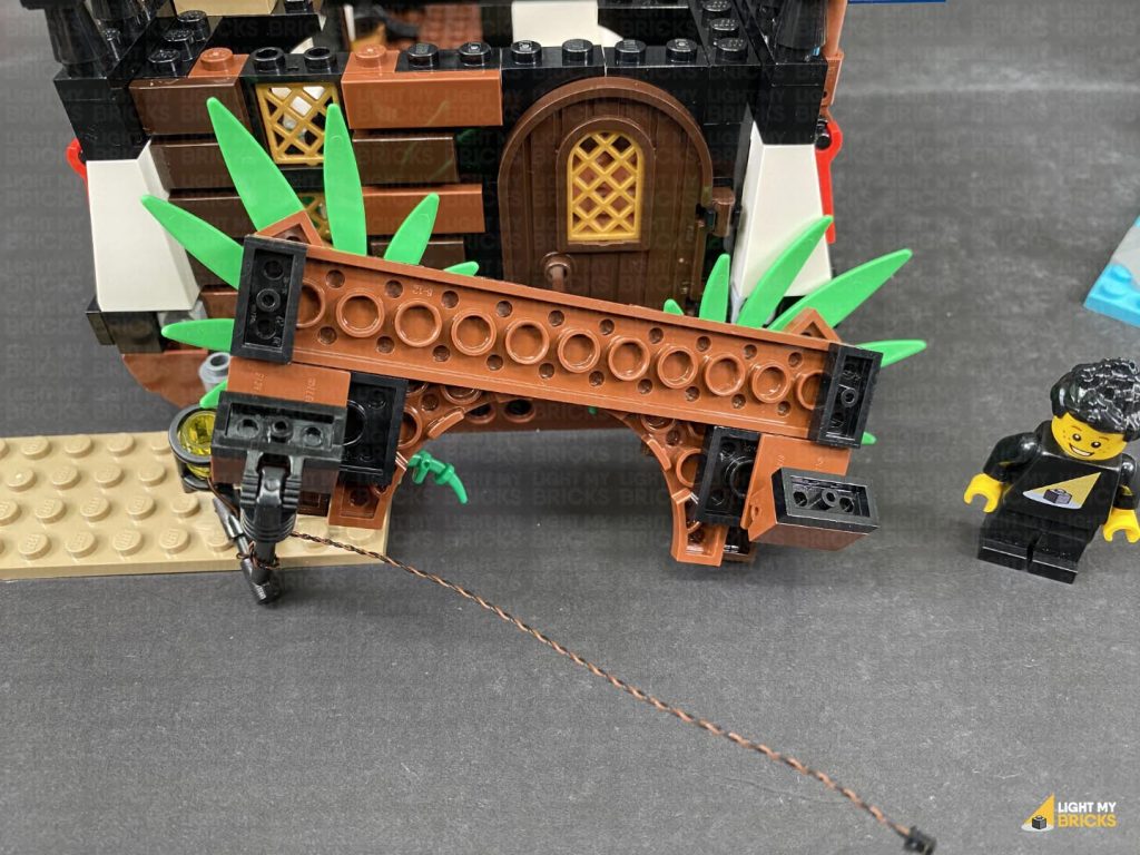
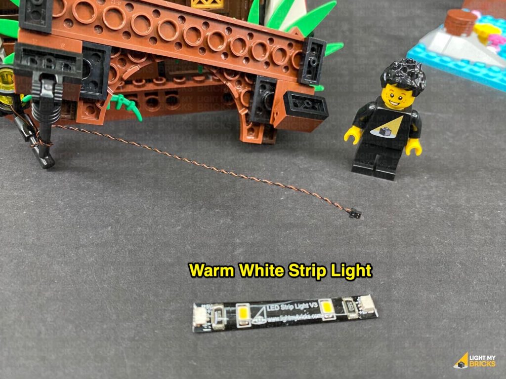
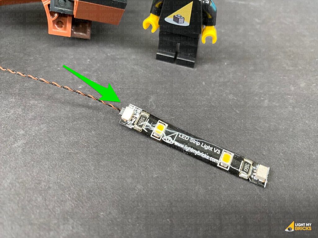
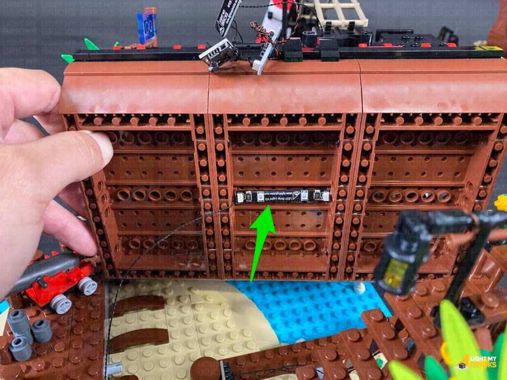
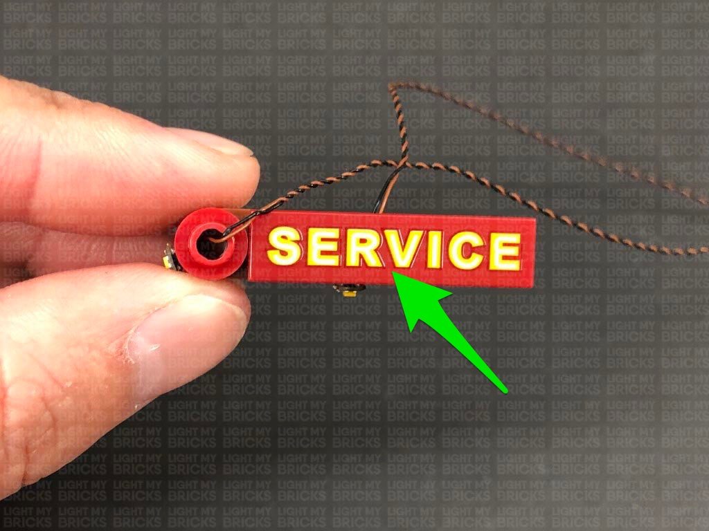
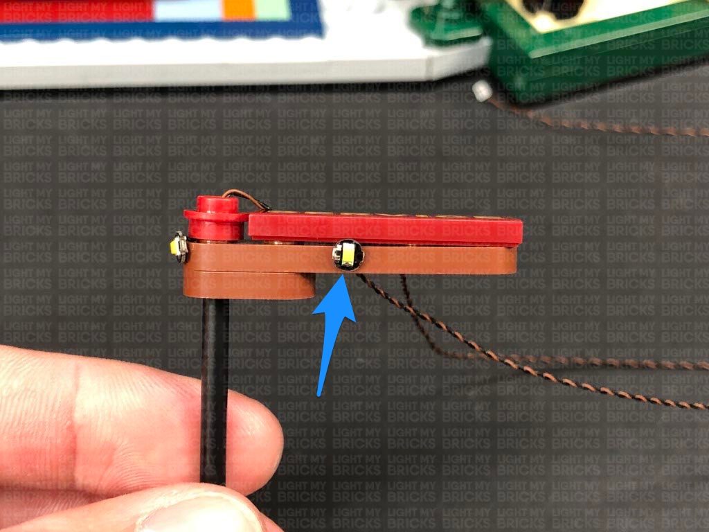
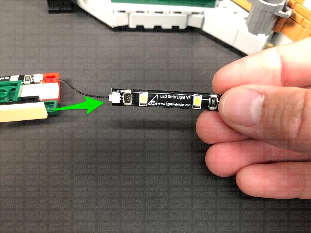
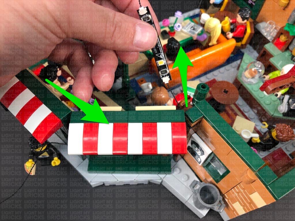
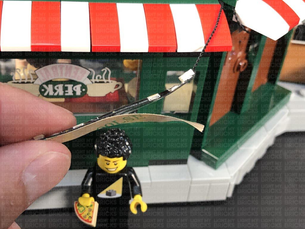
16.) Take the front panel we removed earlier and flip it over. Take a Warm White Strip Light and connect the Bit Light from previous step to the left port, and connect a new 30cm Connecting Cable to the right port. Using it’s adhesive backing, stick the Strip Light underneath the front panel as per below.
Thread the connector end of the Bit Light through the bottom of the round plate with open stud (larger hole). Slightly bend the LED so that it sits flat against the inside of the plate, then connect the plate to the bottom of the rounded plate with handle.
Thread the cable through the space of the handle, pulling it all the way out from the other side, then connect the handle to the tile with clip.
16.) Take the front panel we removed earlier and flip it over. Take a Warm White Strip Light and connect the Bit Light from previous step to the left port, and connect a new 30cm Connecting Cable to the right port. Using it’s adhesive backing, stick the Strip Light underneath the front panel as per below.
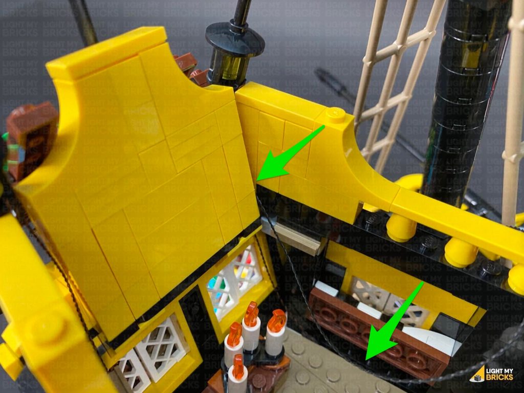
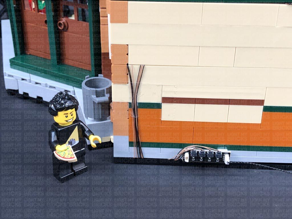
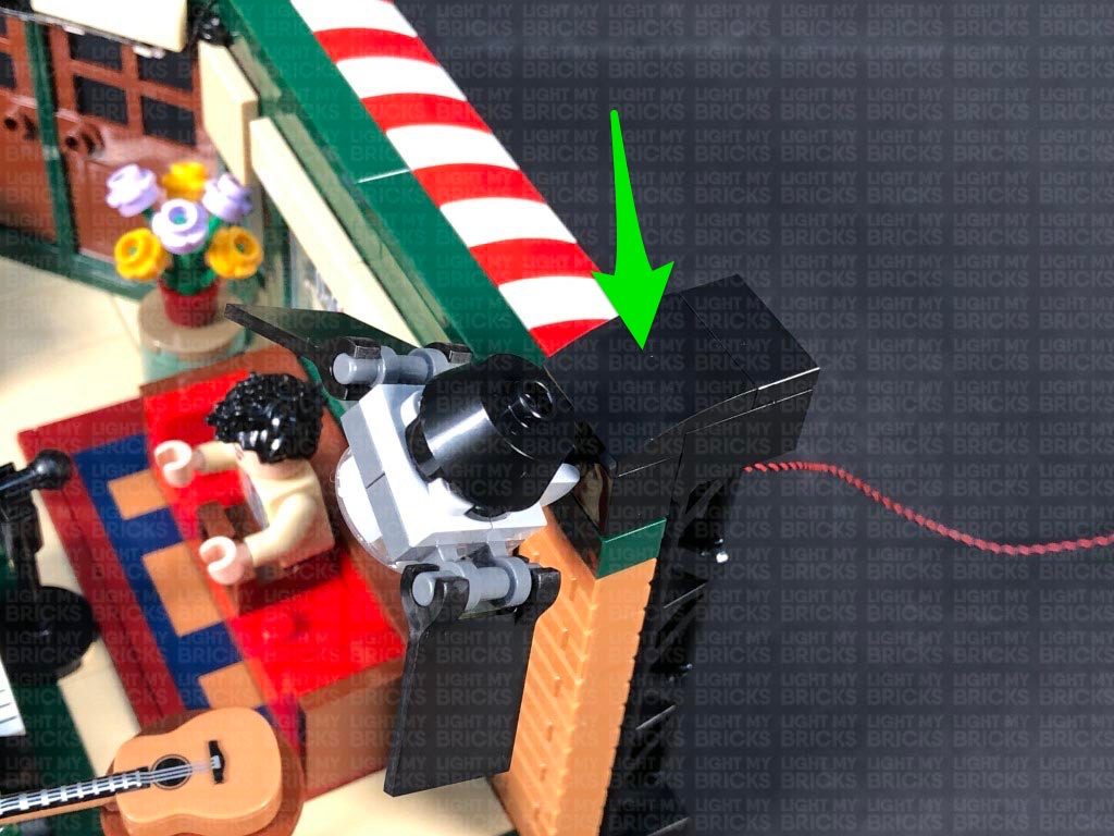
 Reconnect the panel to the front of the set, ensuring the 30cm connecting cable is placed through the left corner in between the two yellow walls. Hide the cable down in between sections on the floor, then connect it to the 8-port Expansion Board.
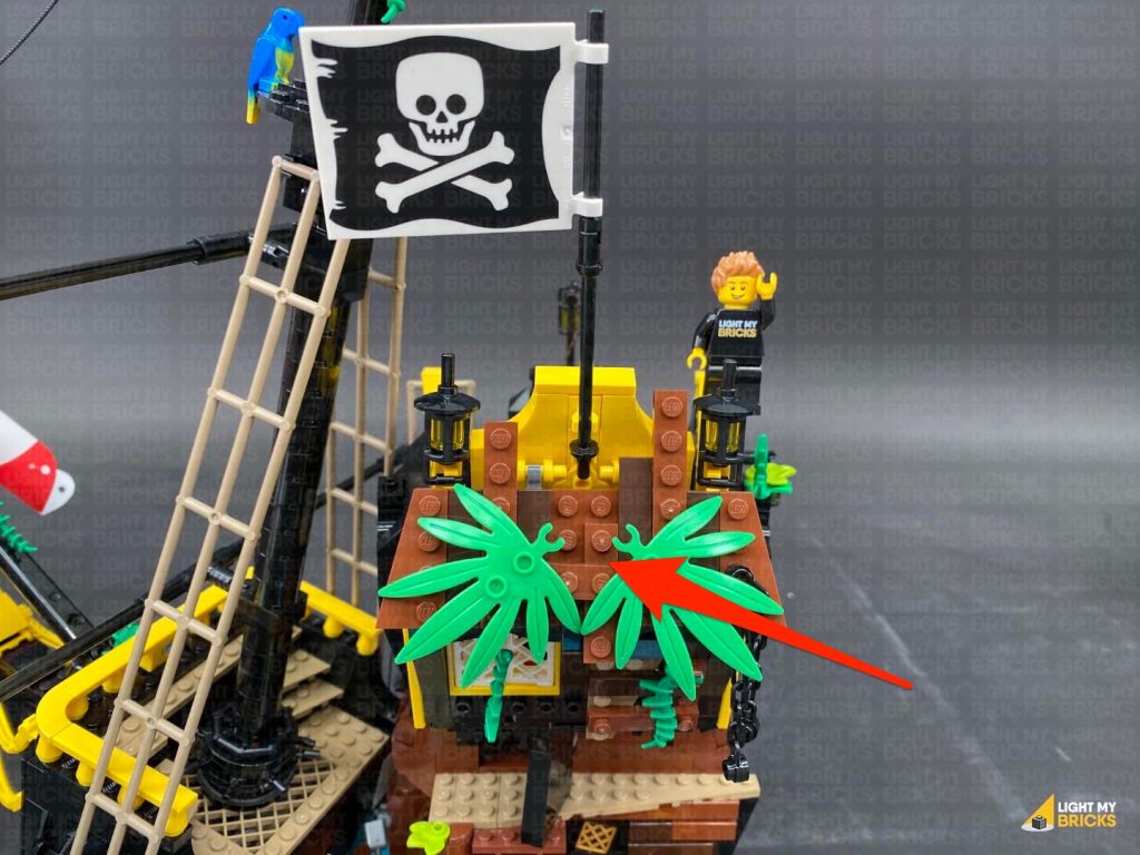
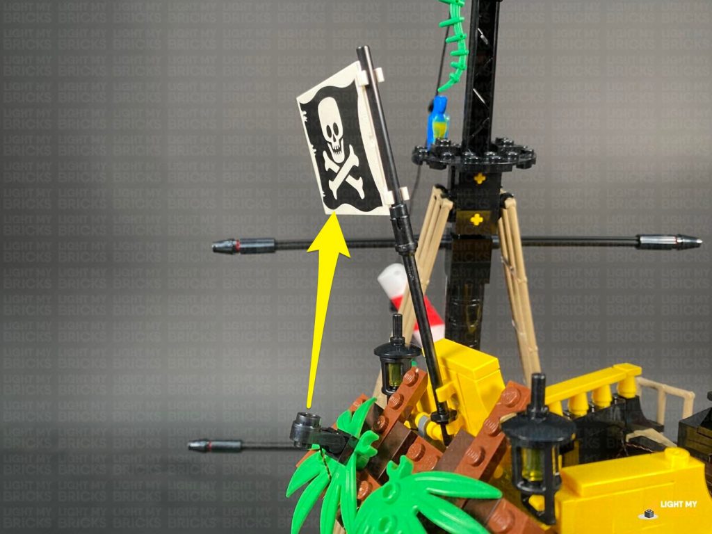
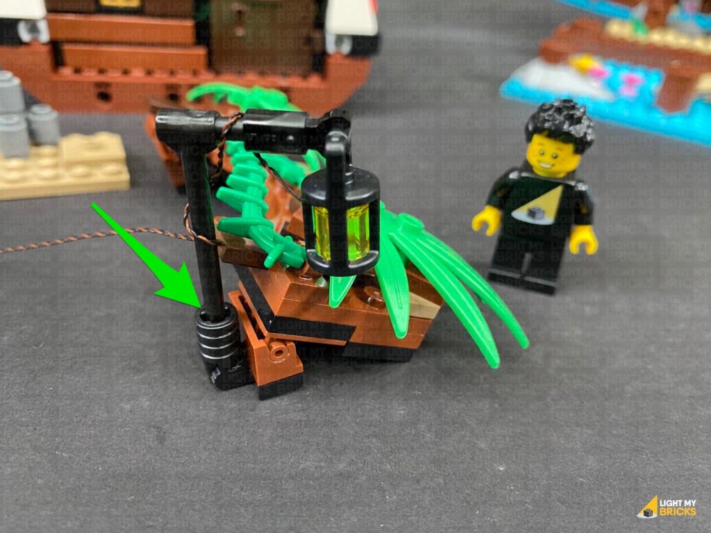
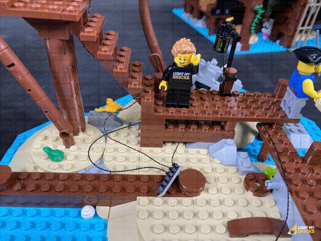
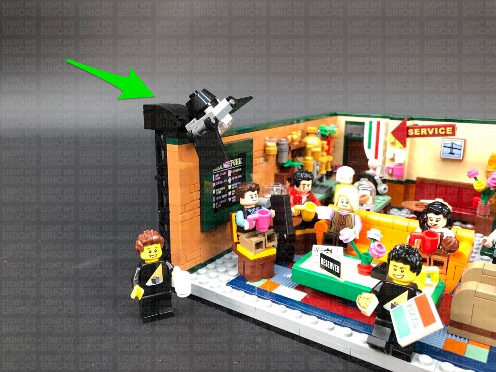
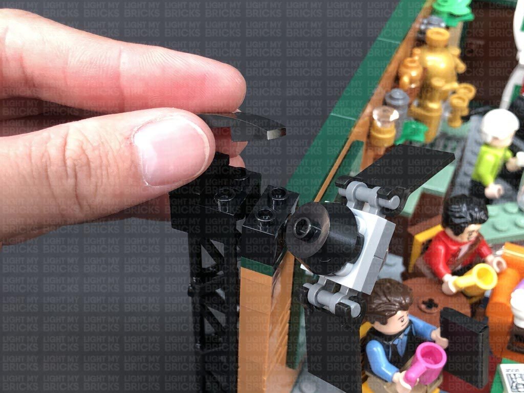
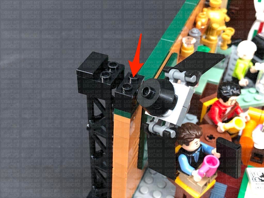
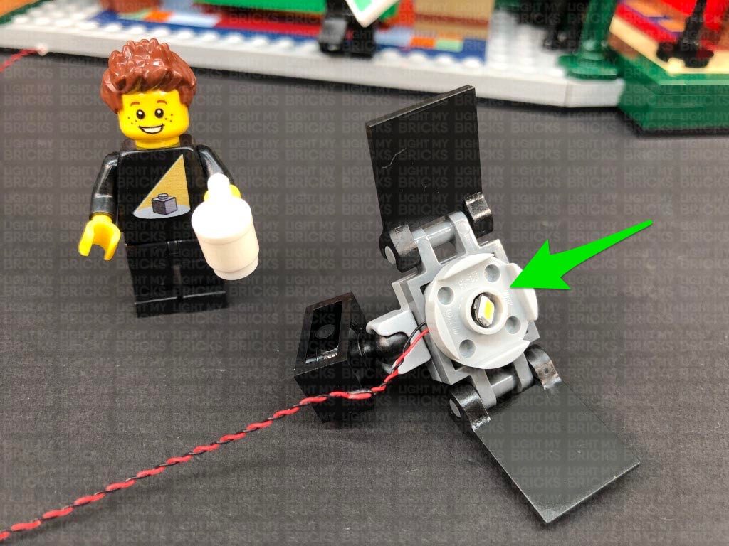
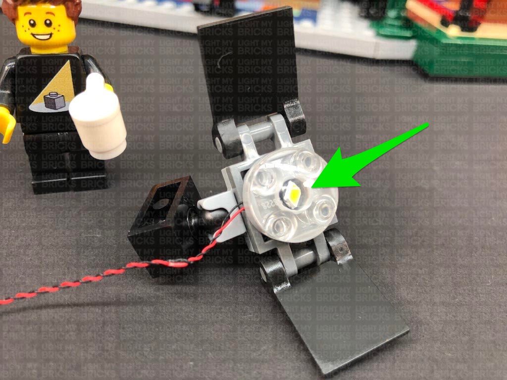
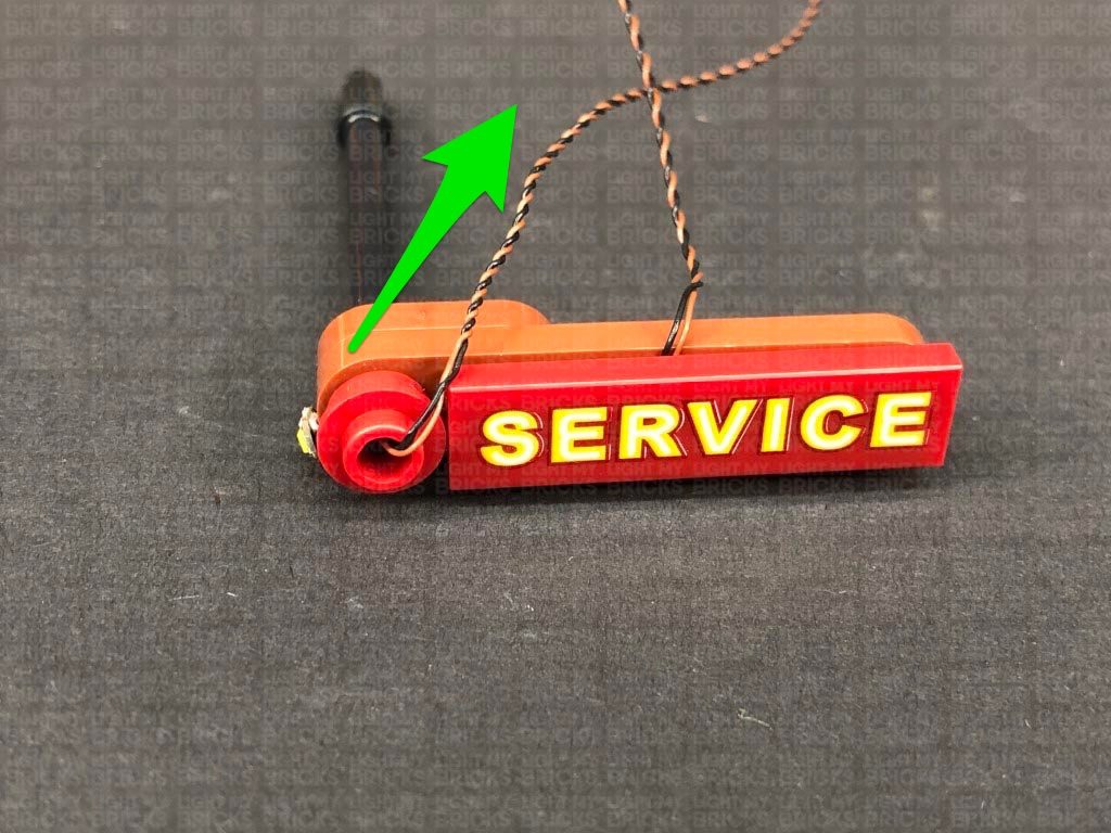
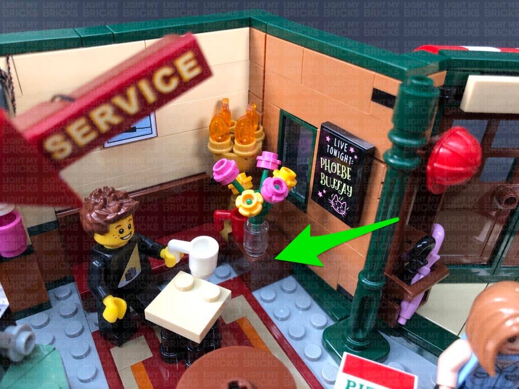
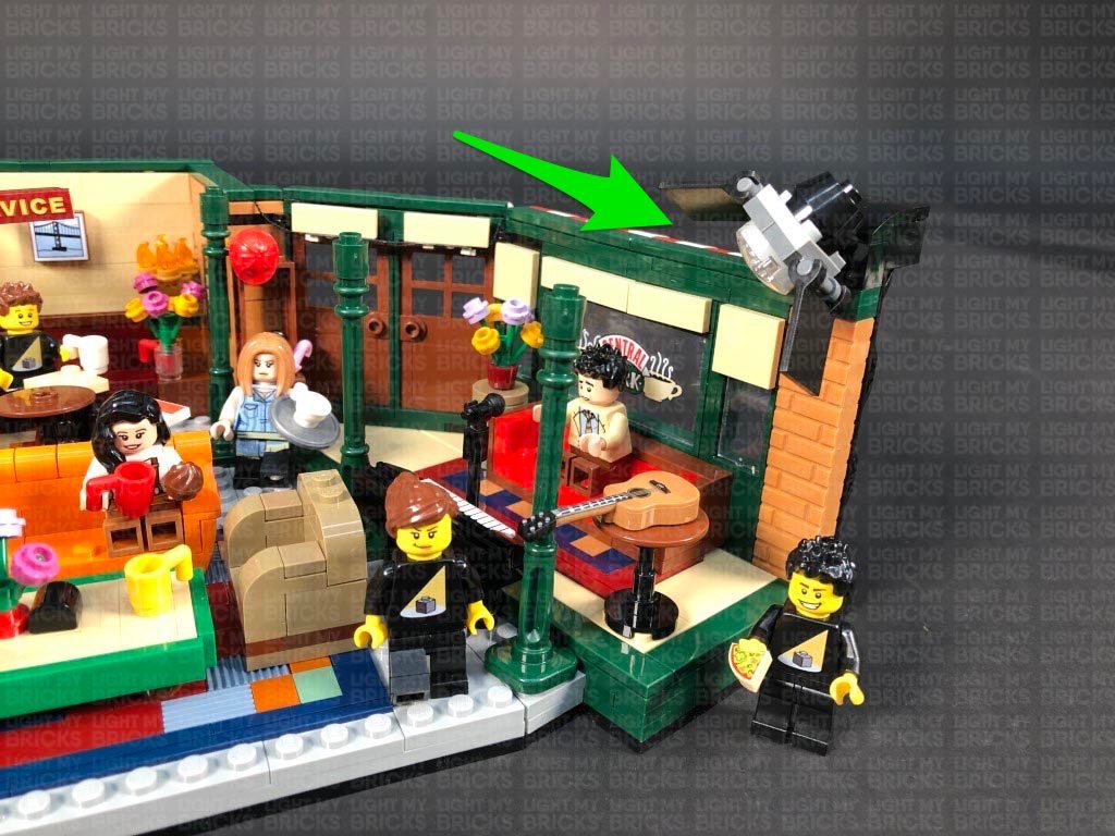
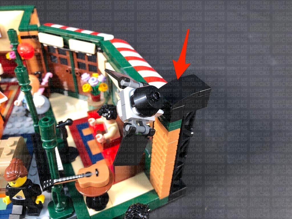
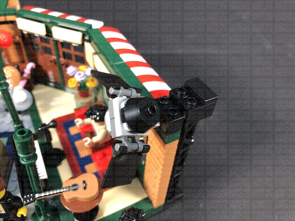
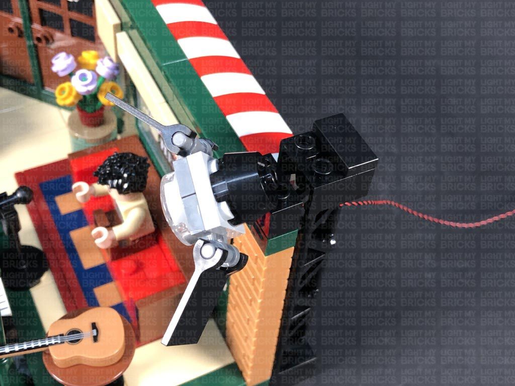
17.) Connect the spotlight section to the top of the tree branch piece to the following stud. Position the spot light so that the LED is shining up onto the Pirate flag.
Neaten up the cable by twisting it into a neat bunch, then tucking it in underneath the panel as shown below:
Turn ON the power to test the strip light and spot light is working OK.
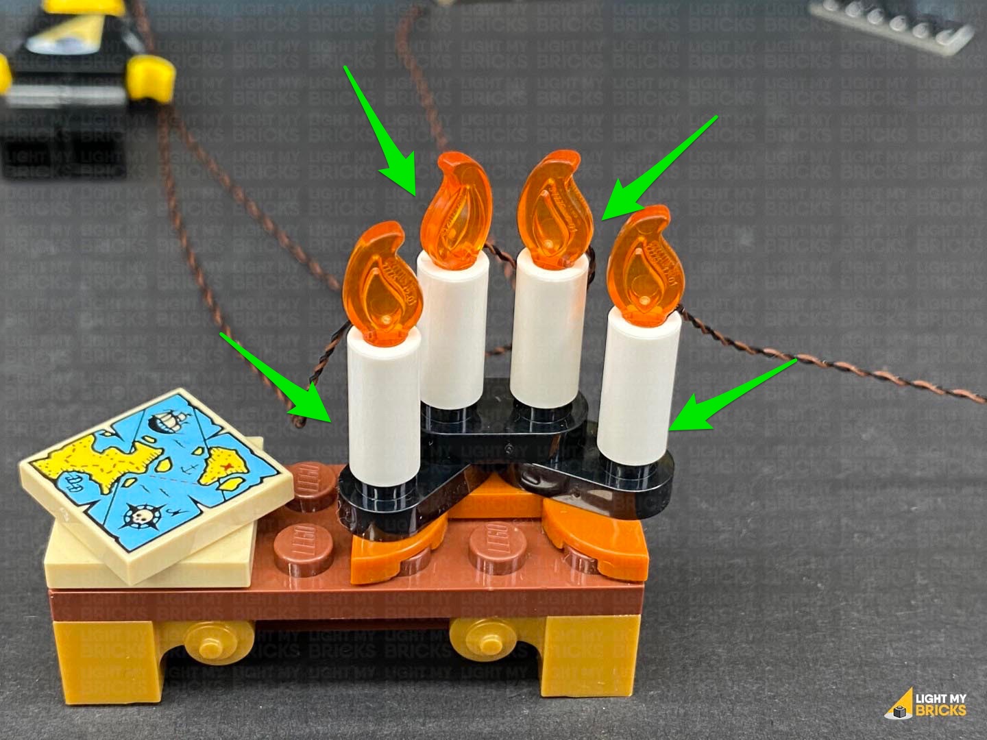
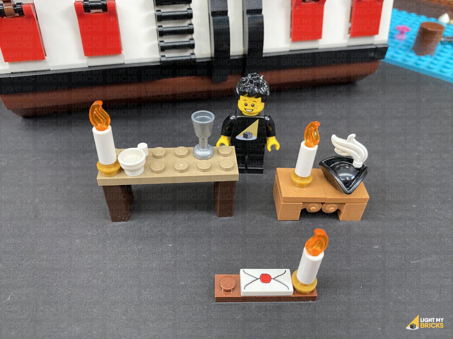
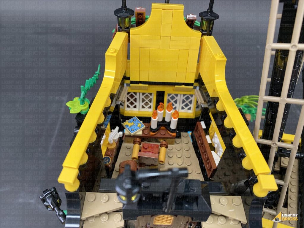
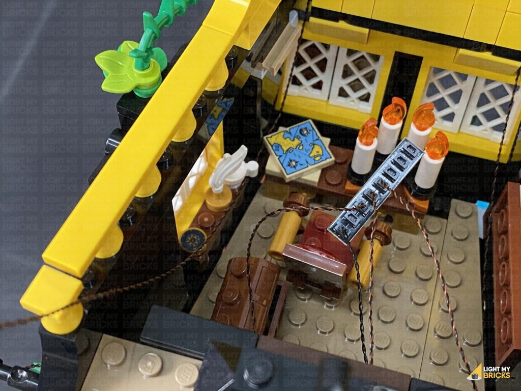
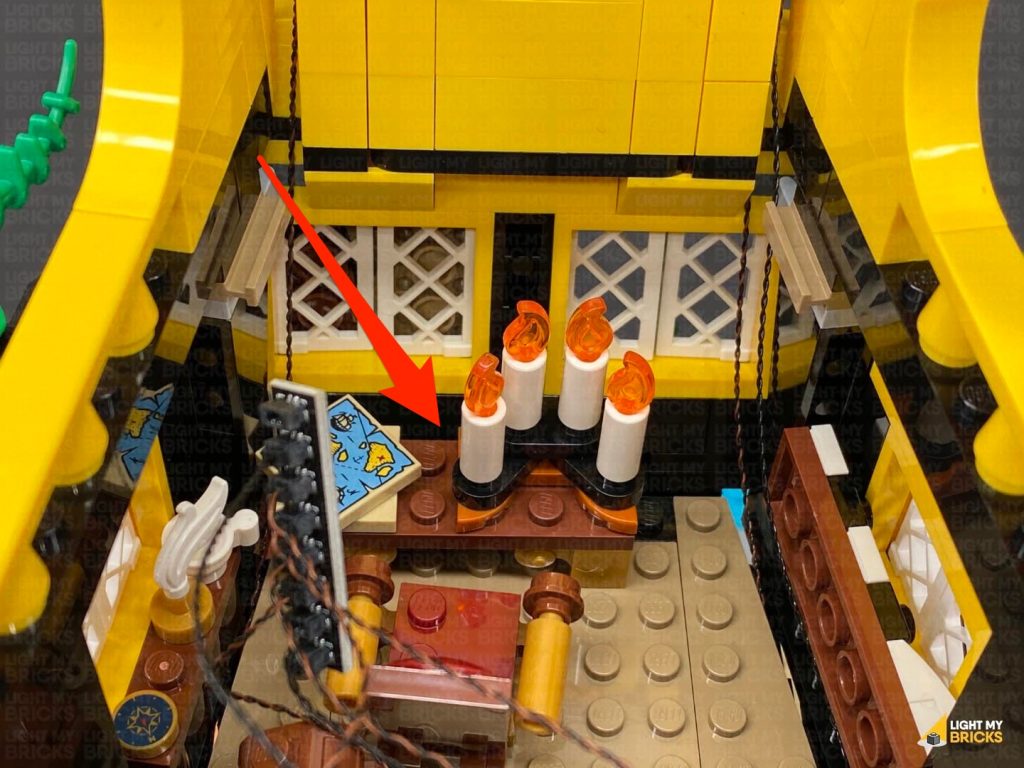
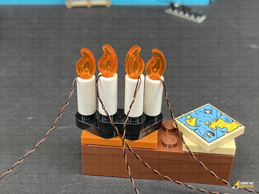
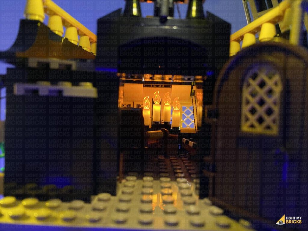
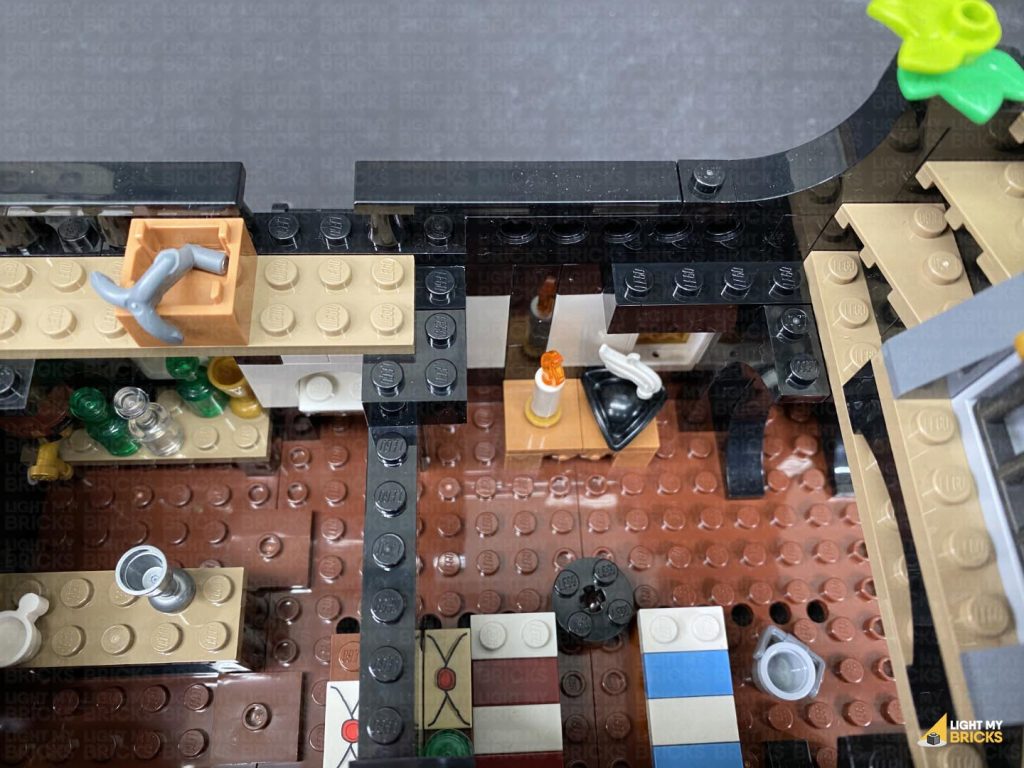
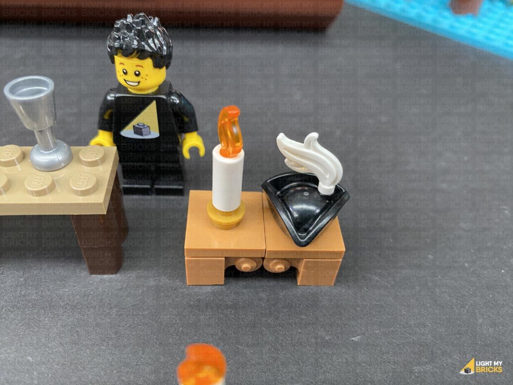
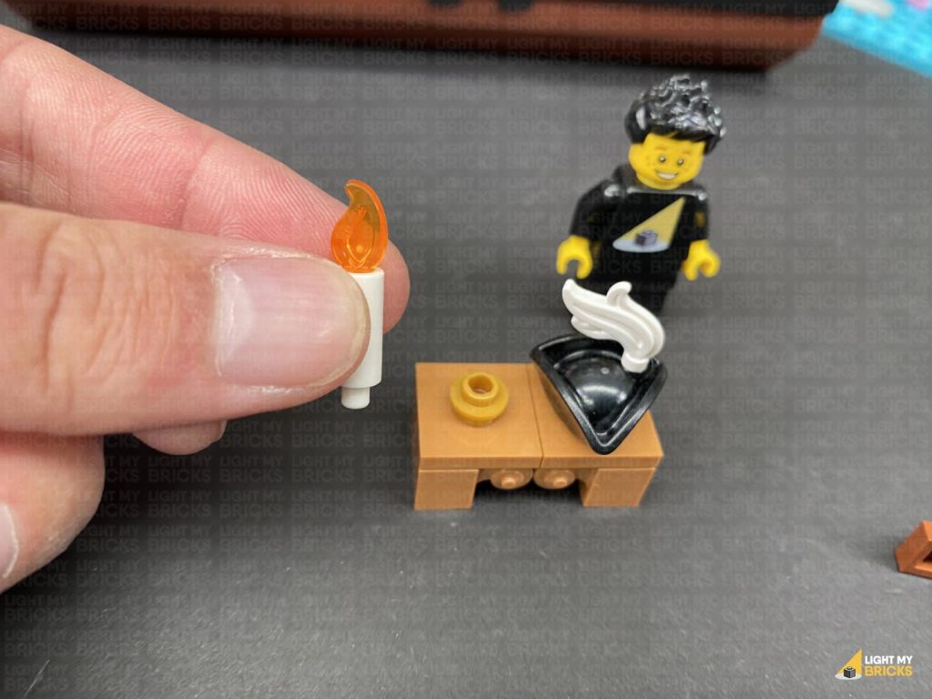
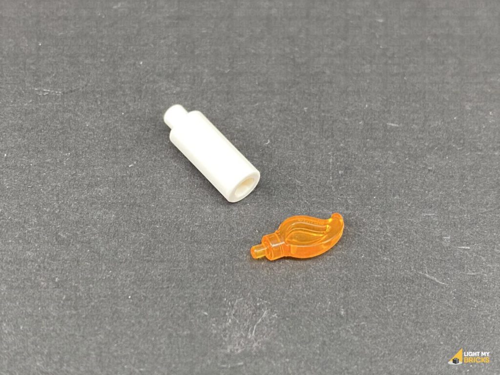
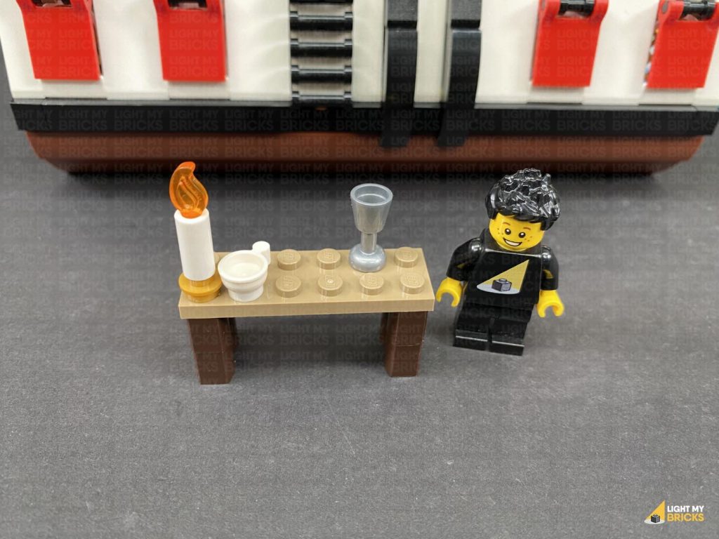
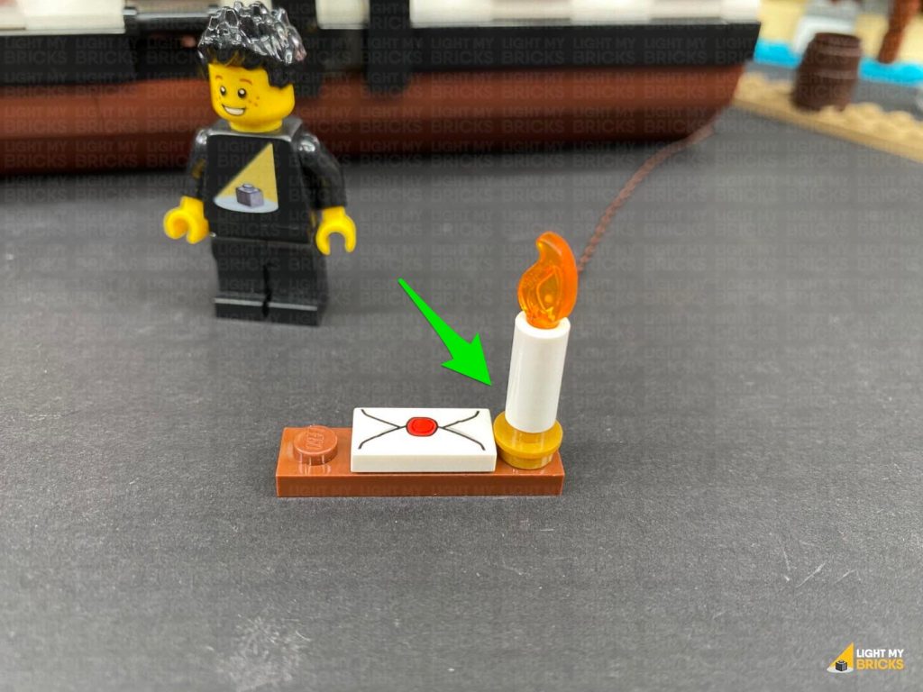
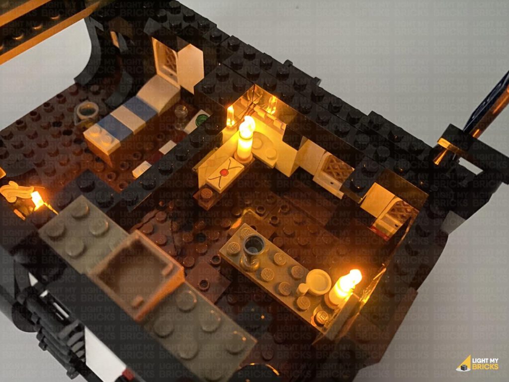
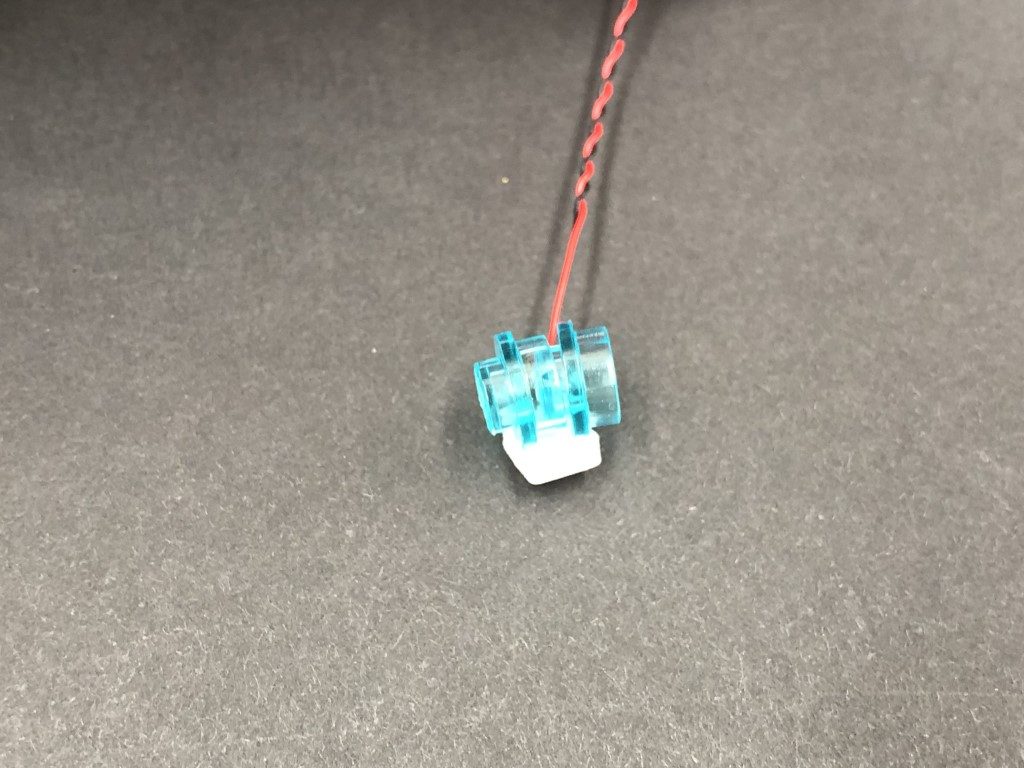
18.) Disconnect the captains desk with candles from inside of the headquarters. Disconnect the candles and remove the flame piece from each candle.
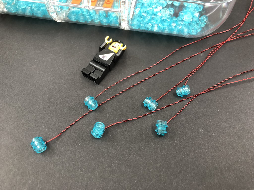
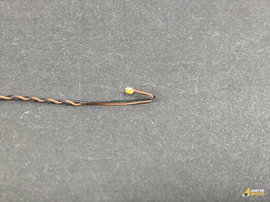
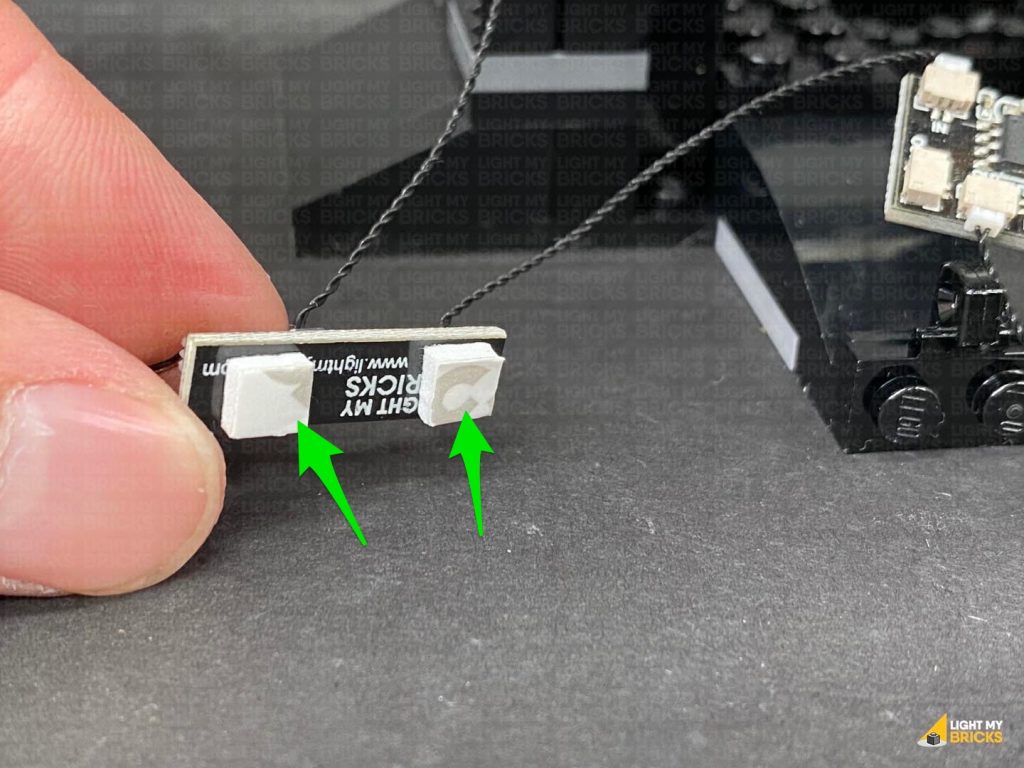
Take a White 15cm Micro Bit Light and carefully bend/fold the LED side of the cable about 5mm down. With the LED facing in, insert the folded part into the Candle piece, then secure it in place by reconnecting the flame piece. Fold the cable down the side of the candle.
Repeat this step to install another 3x White 15cm Micro Bit Lights to the remaining 3 candles, then reconnect all four candles to the desk.
Reconnect the panel to the front of the set, ensuring the 30cm connecting cable is placed through the left corner in between the two yellow walls. Hide the cable down in between sections on the floor, then connect it to the 8-port Expansion Board.
17.) Connect the spotlight section to the top of the tree branch piece to the following stud. Position the spot light so that the LED is shining up onto the Pirate flag.
Neaten up the cable by twisting it into a neat bunch, then tucking it in underneath the panel as shown below:
Turn ON the power to test the strip light and spot light is working OK.
18.) Disconnect the captains desk with candles from inside of the headquarters. Disconnect the candles and remove the flame piece from each candle.
Take a White 15cm Micro Bit Light and carefully bend/fold the LED side of the cable about 5mm down. With the LED facing in, insert the folded part into the Candle piece, then secure it in place by reconnecting the flame piece. Fold the cable down the side of the candle.
Repeat this step to install another 3x White 15cm Micro Bit Lights to the remaining 3 candles, then reconnect all four candles to the desk.
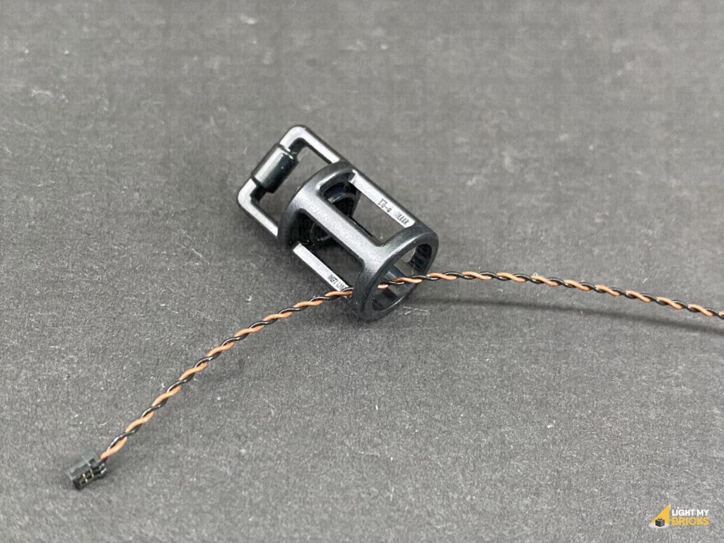
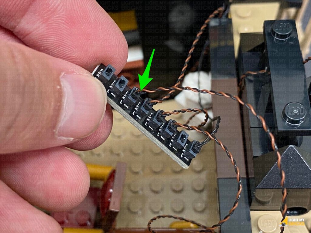
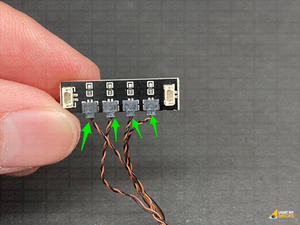
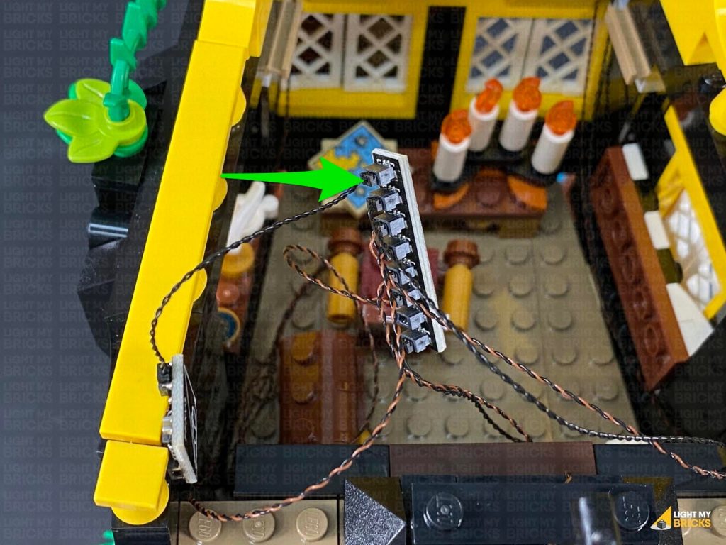
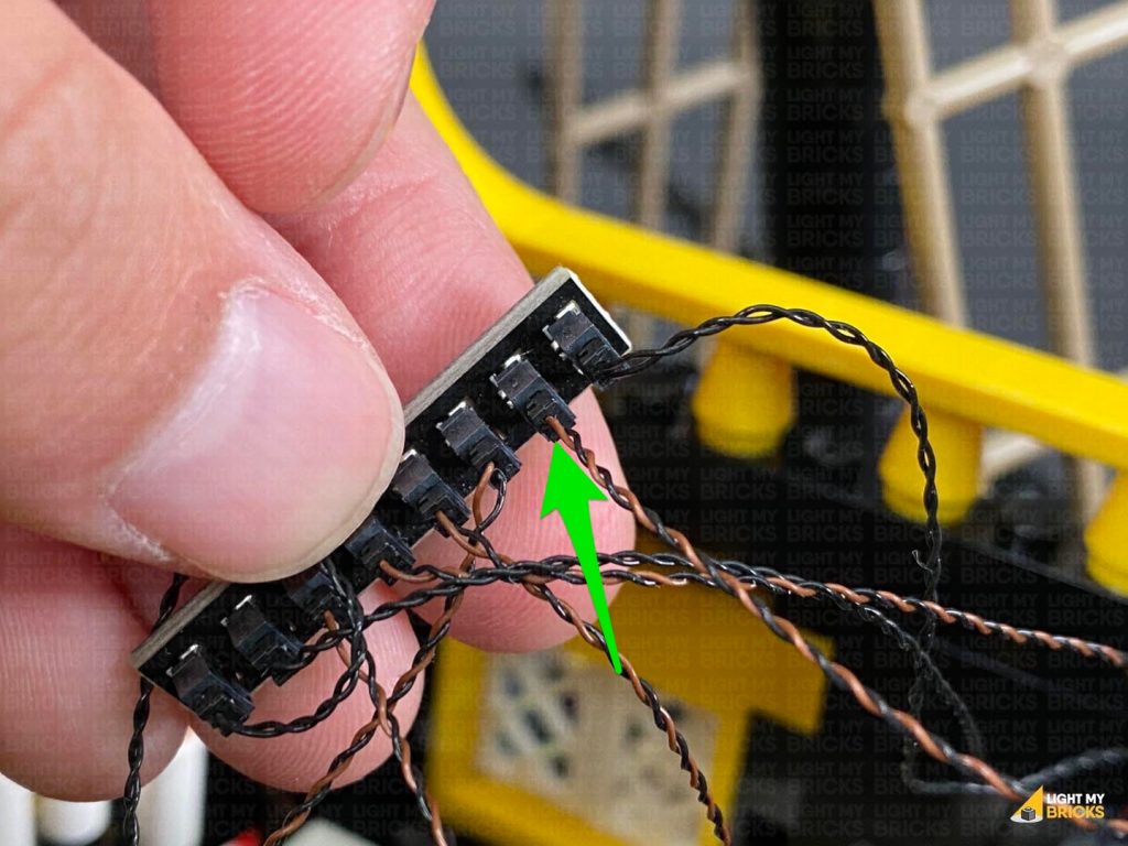
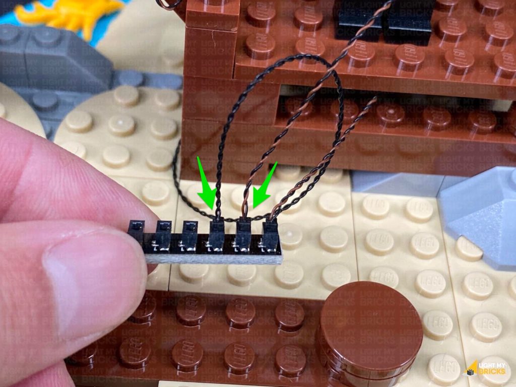
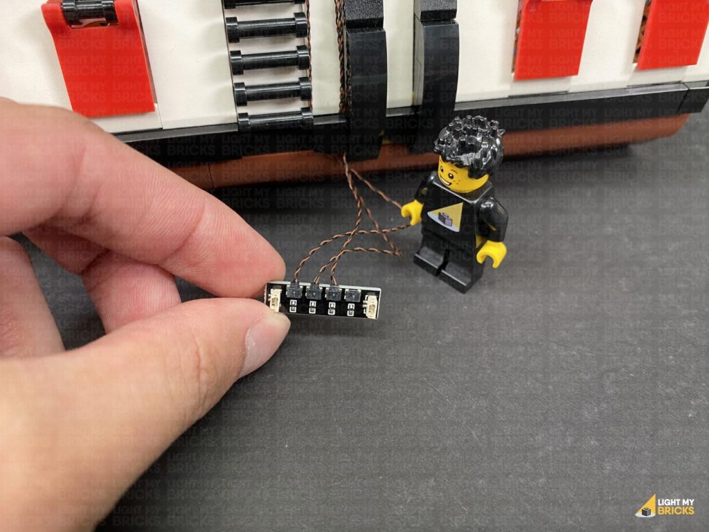
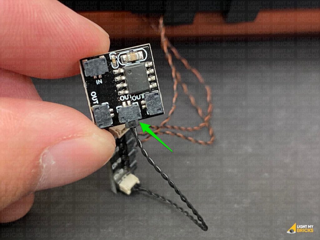
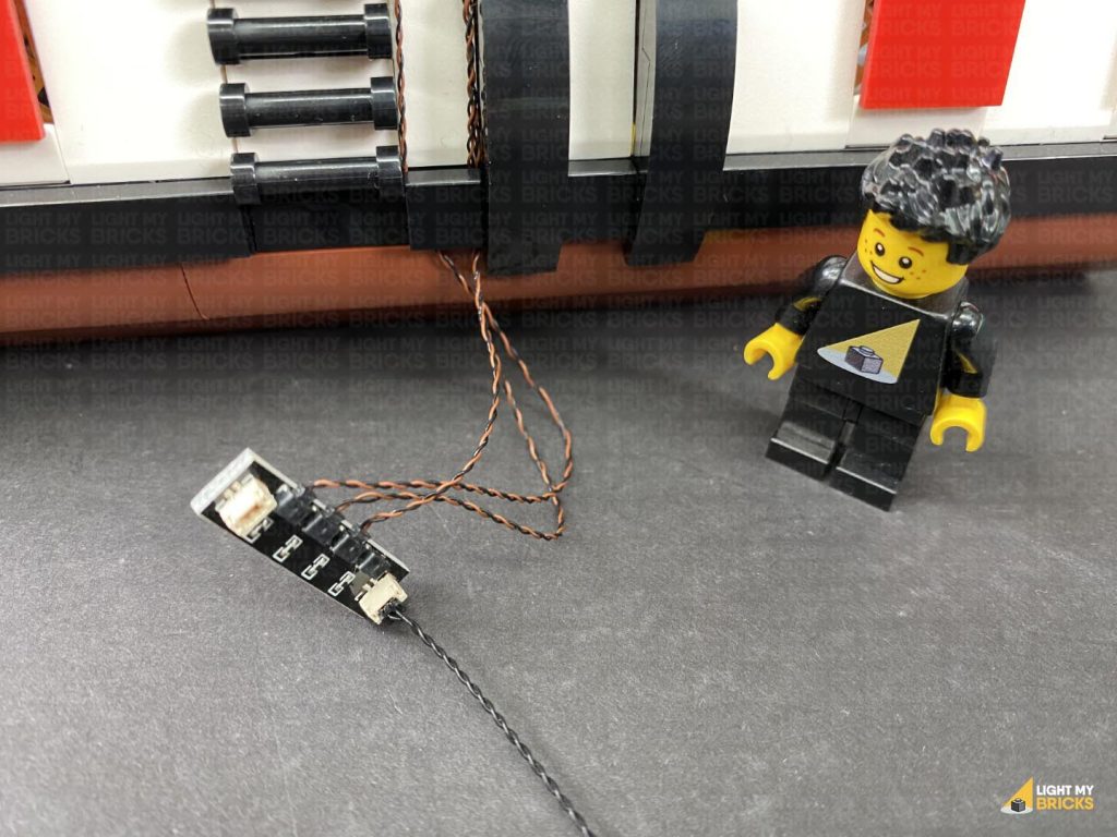
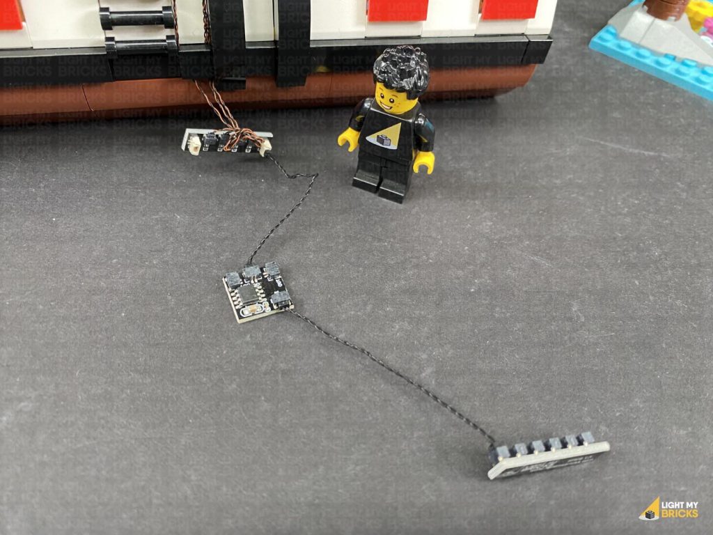
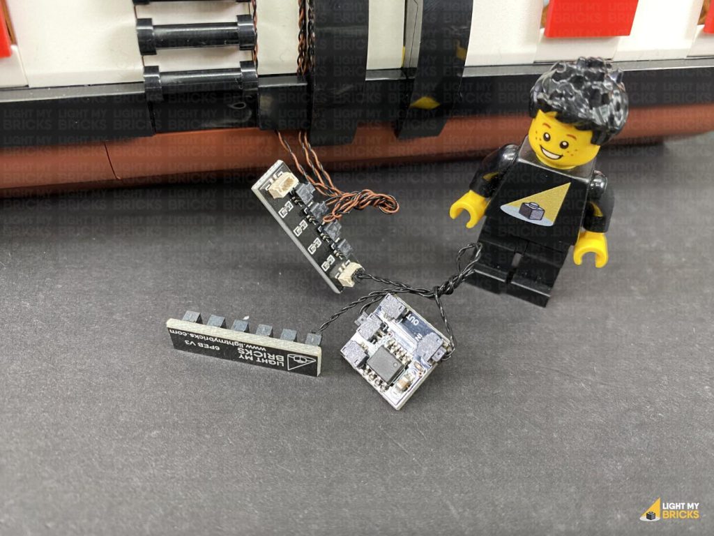
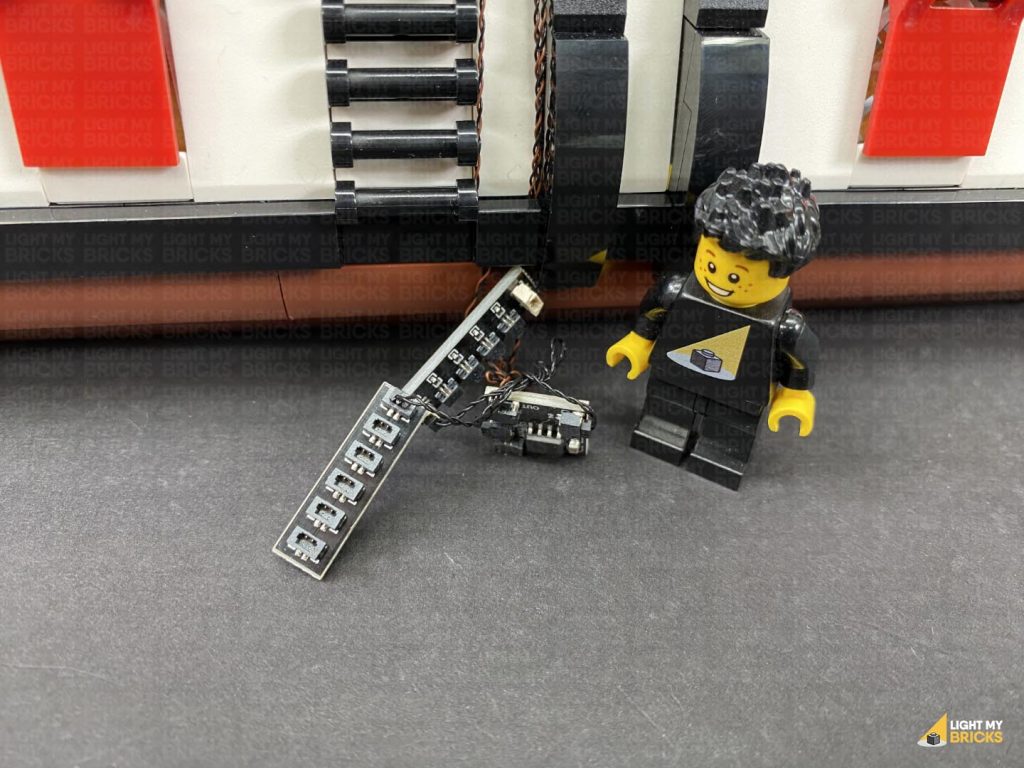
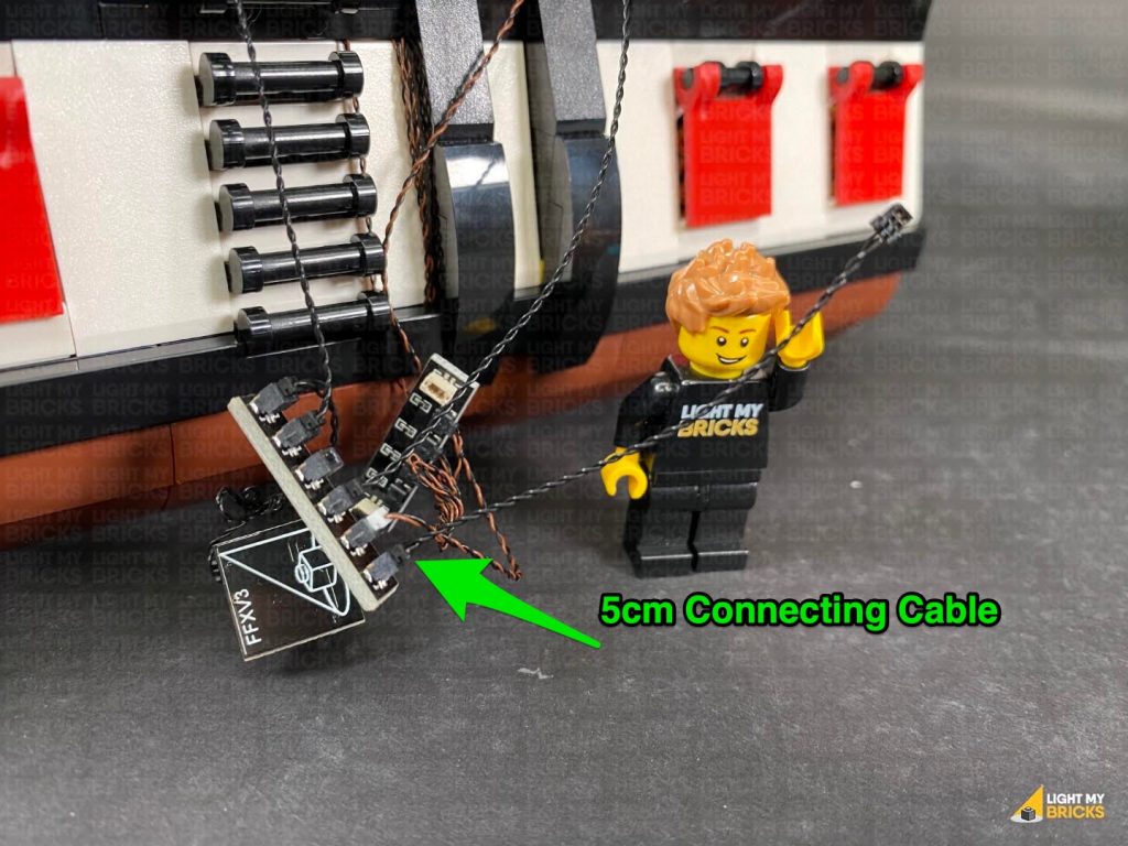
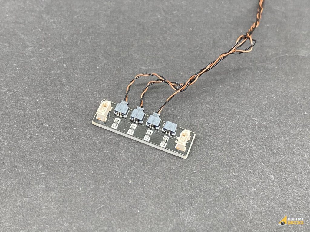
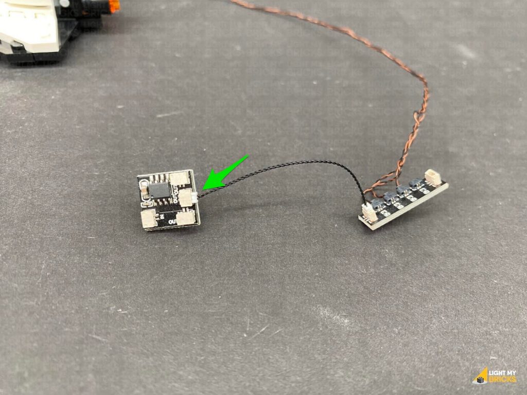
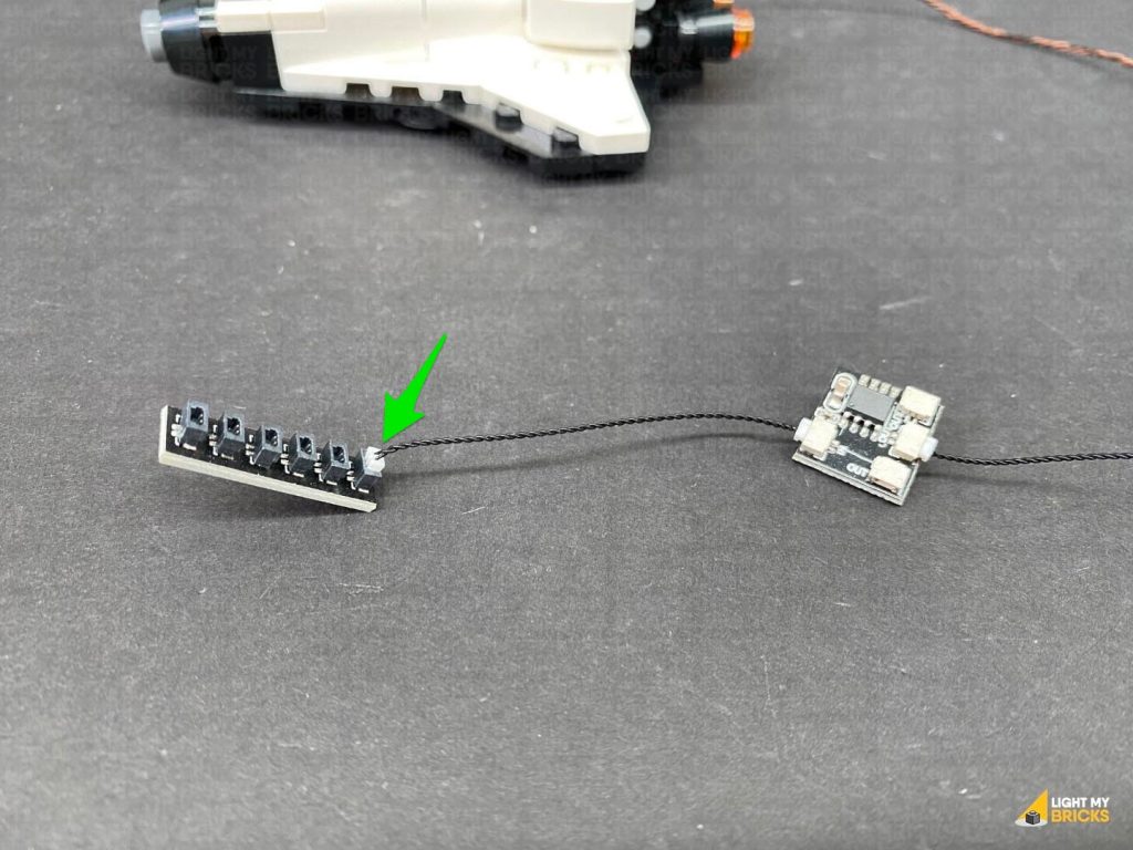
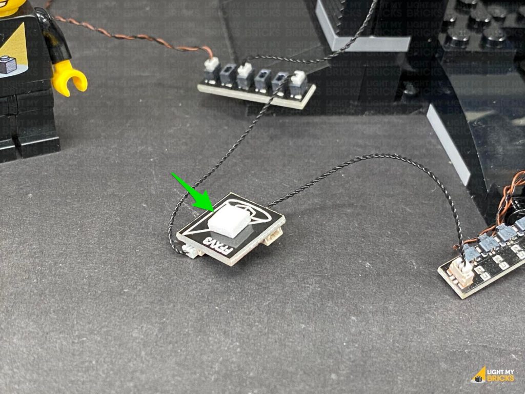
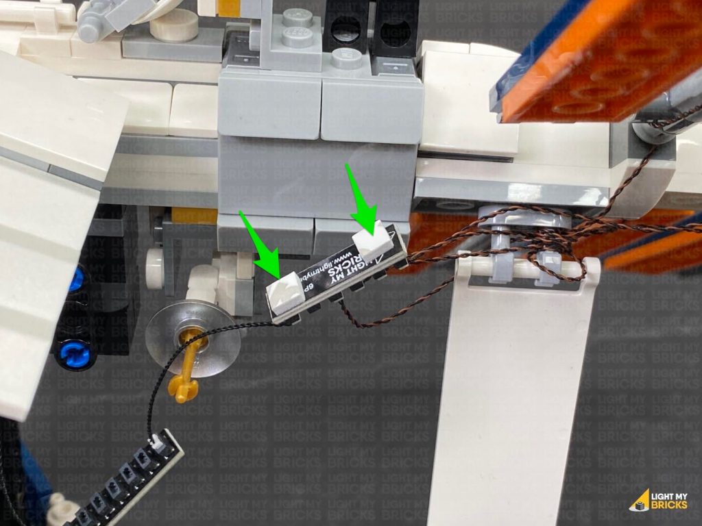
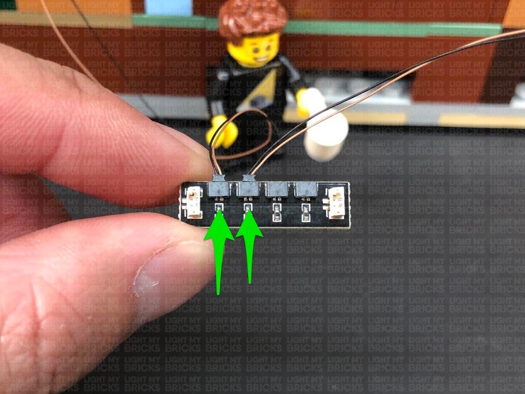
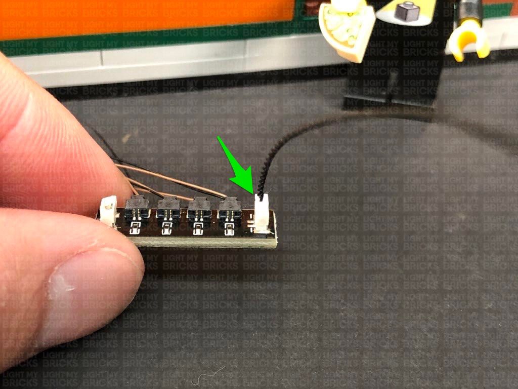
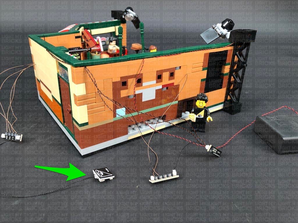
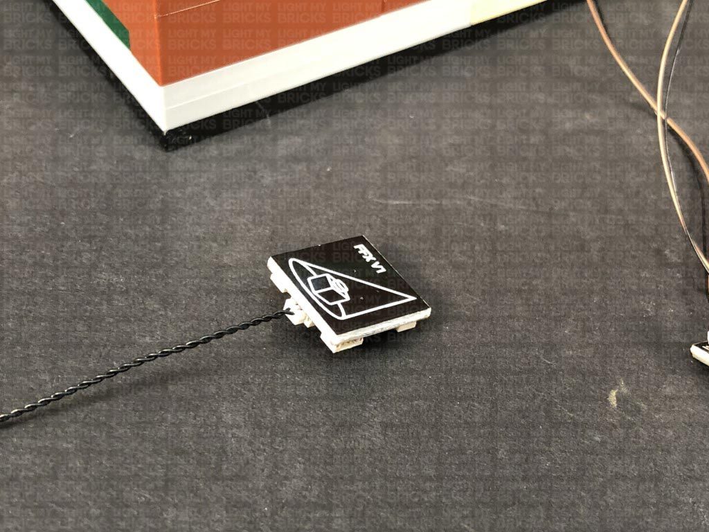
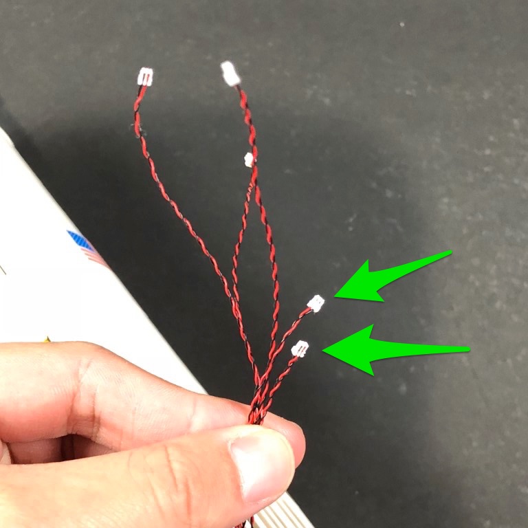
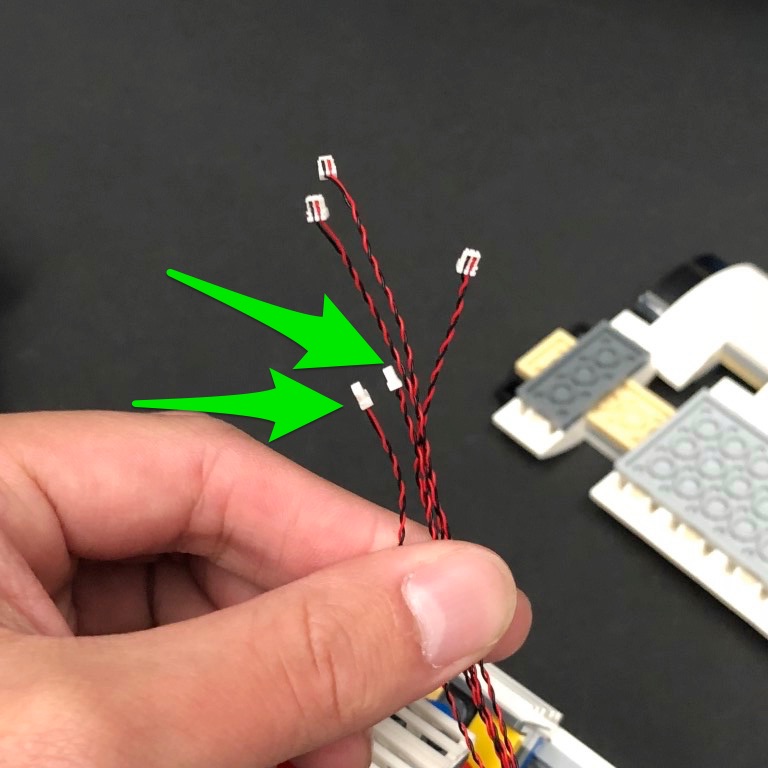
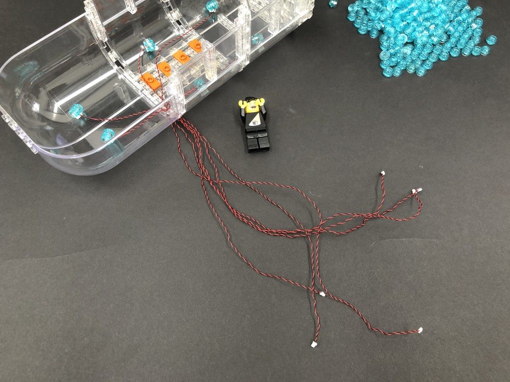
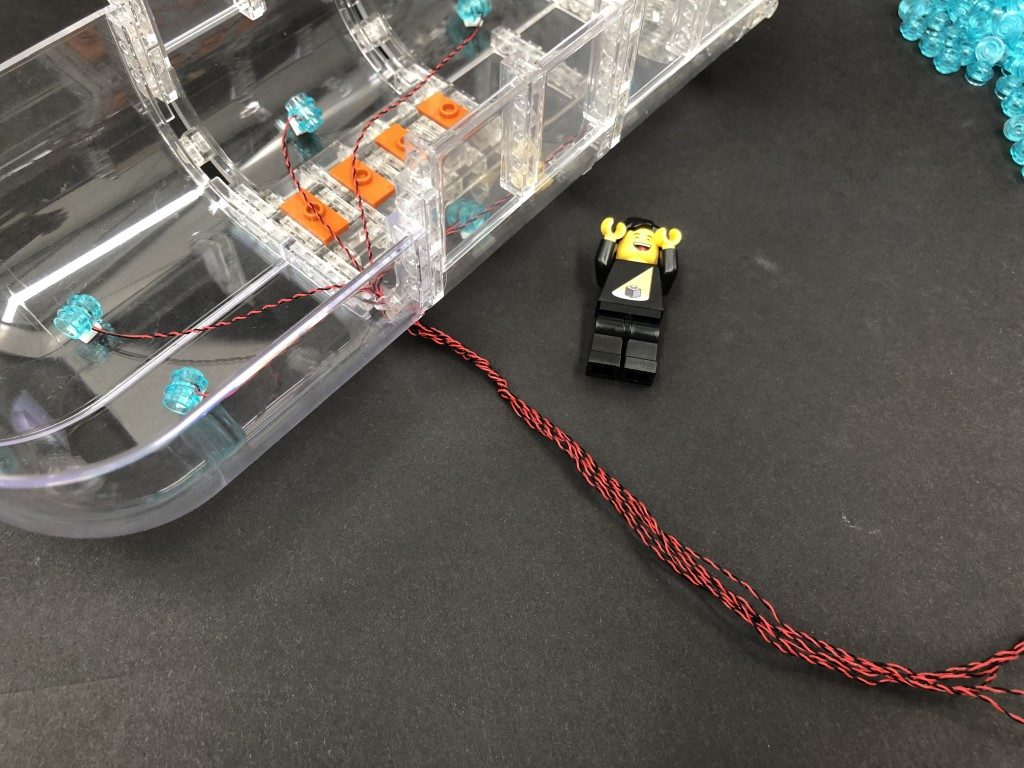
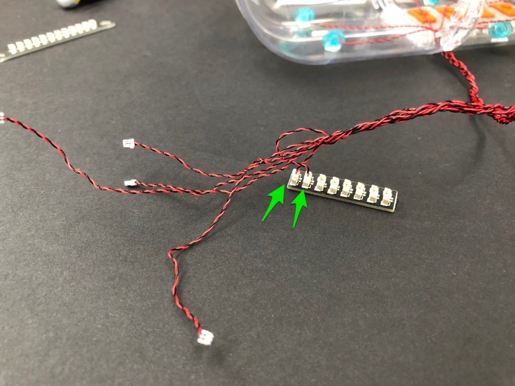
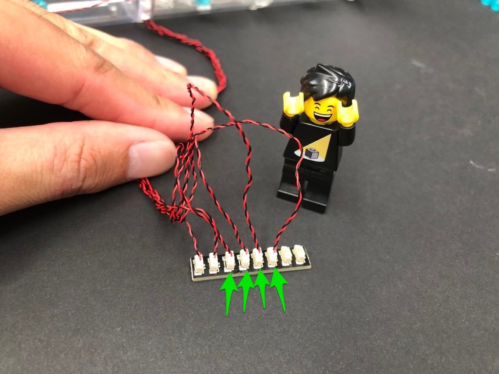
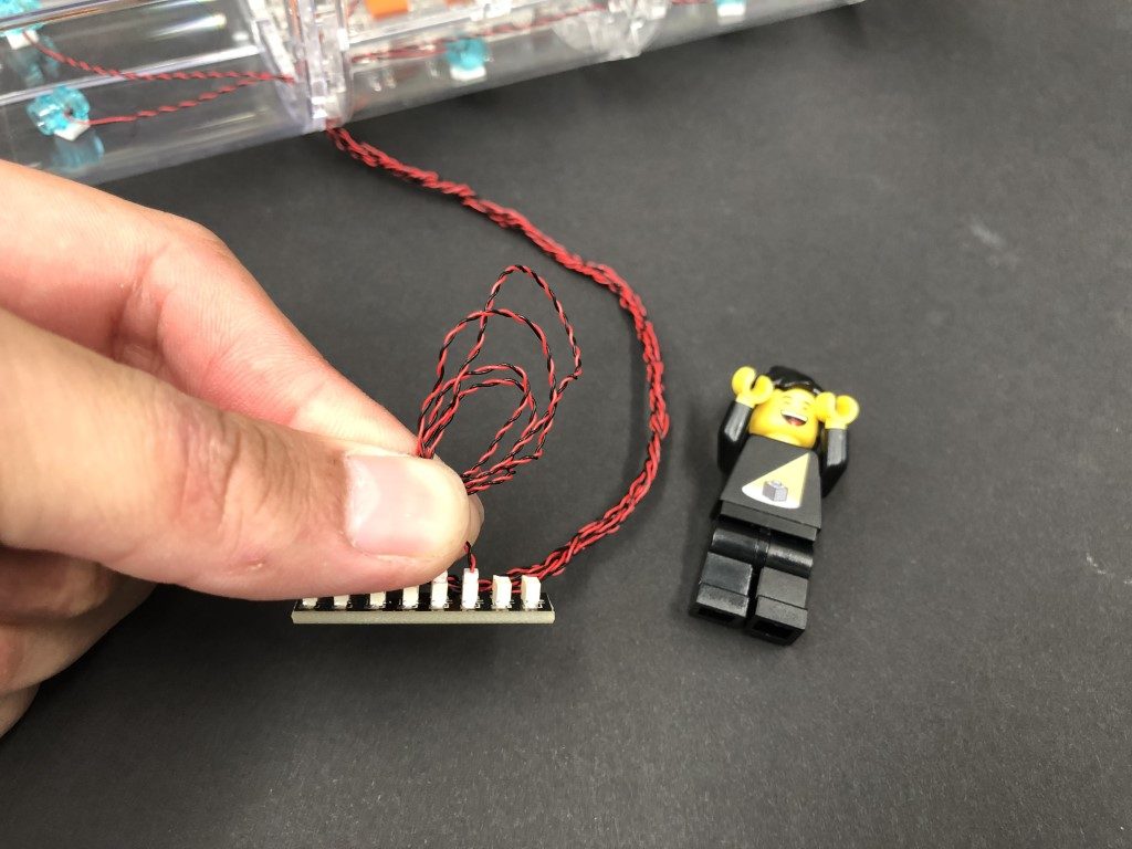
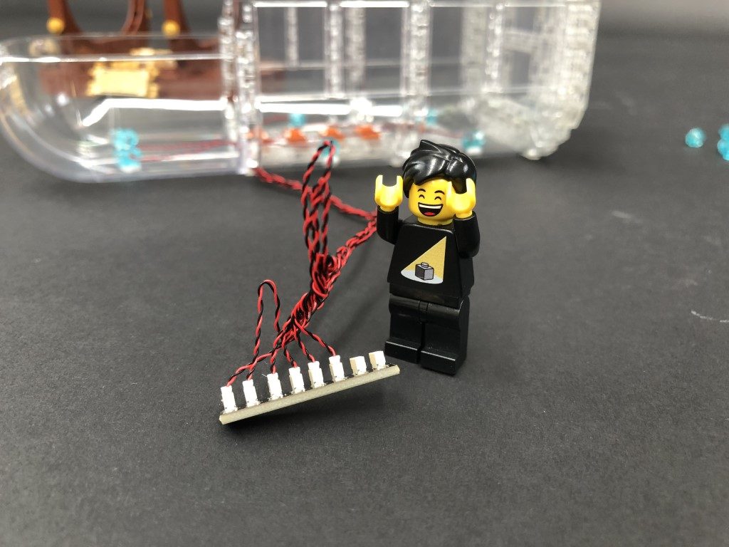
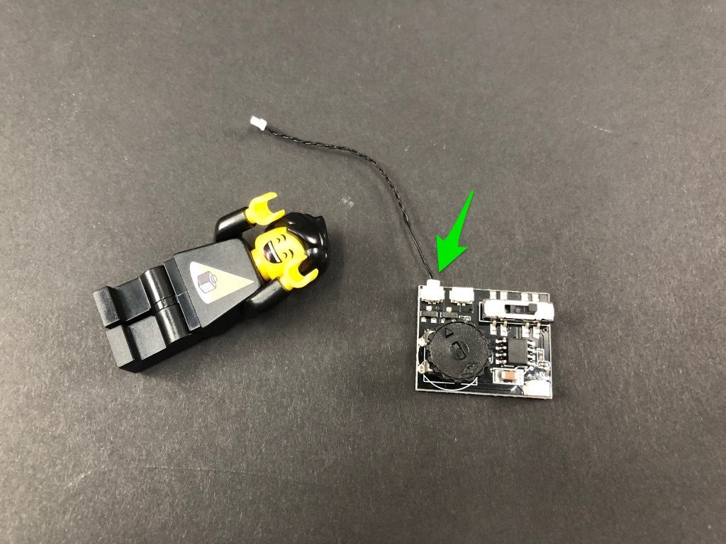
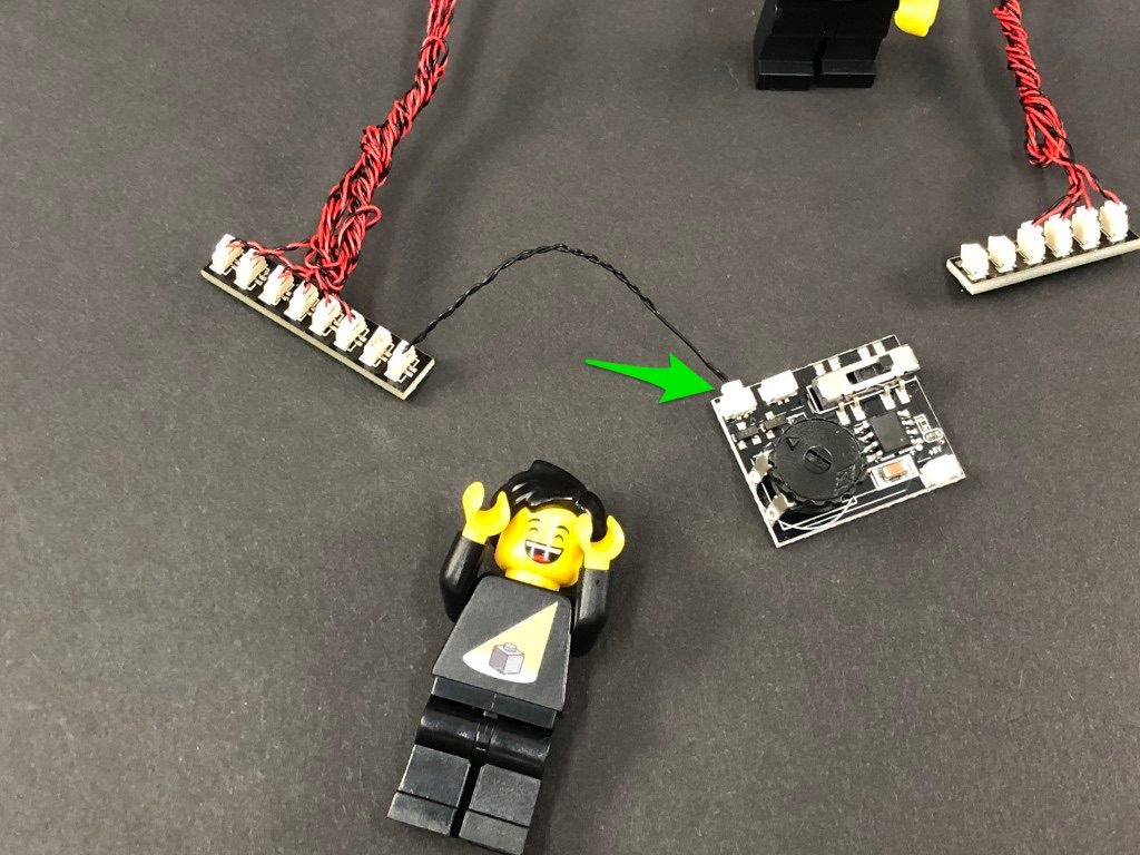
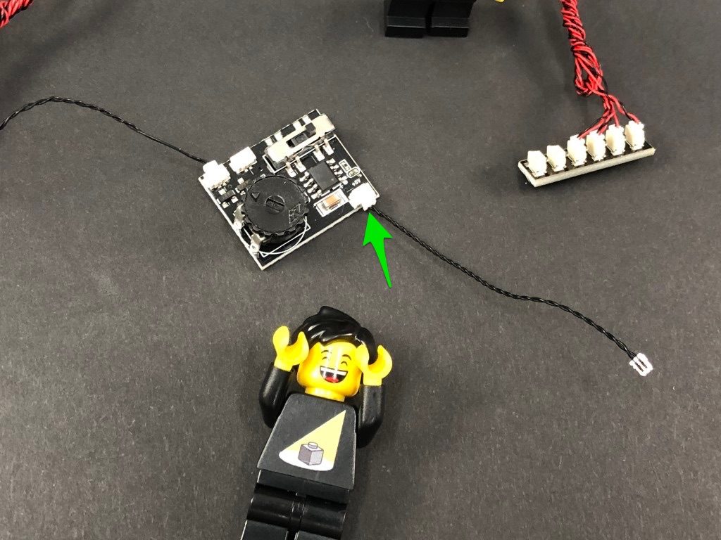
 19.) Turn the desk around, then group the four cables and twist them around each other a few times. Continue to twist/braid the cables around each other all the way to the ends, then connect them to the smaller ports on a Micro 2-4 Port Expansion Board
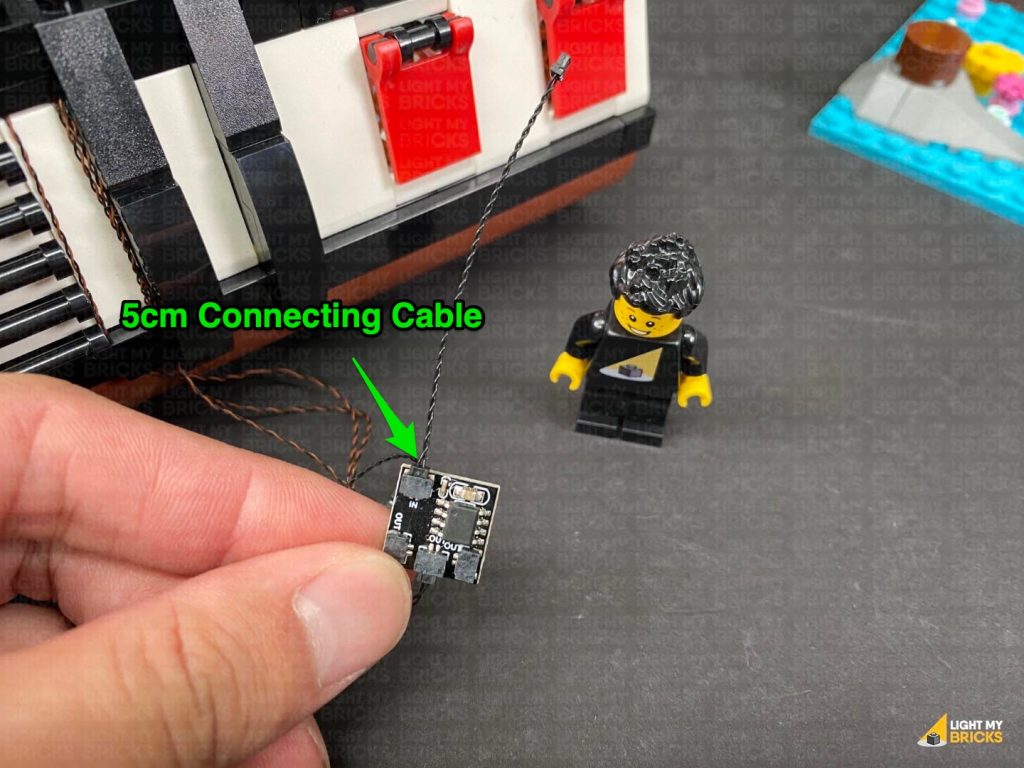
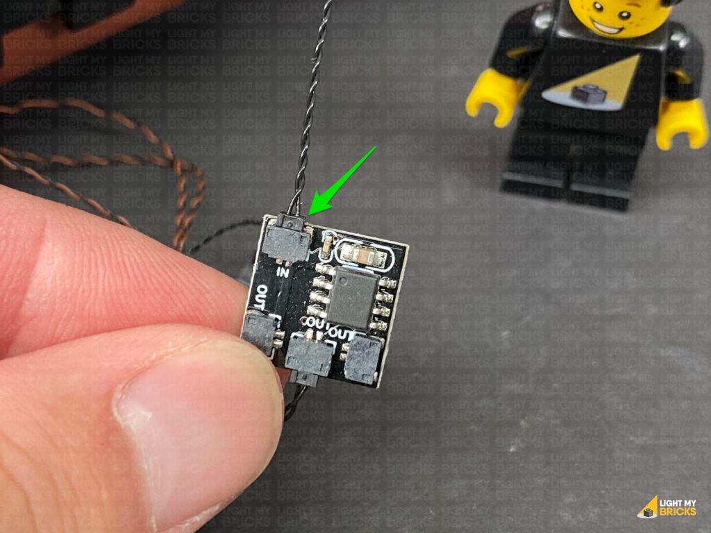
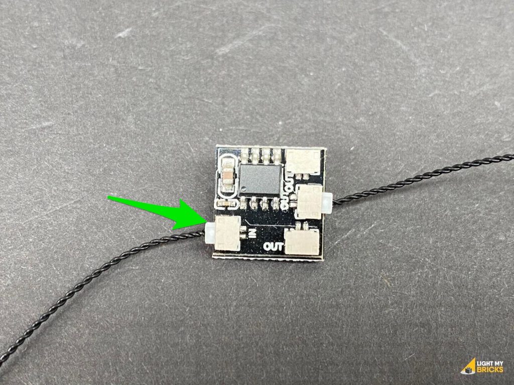
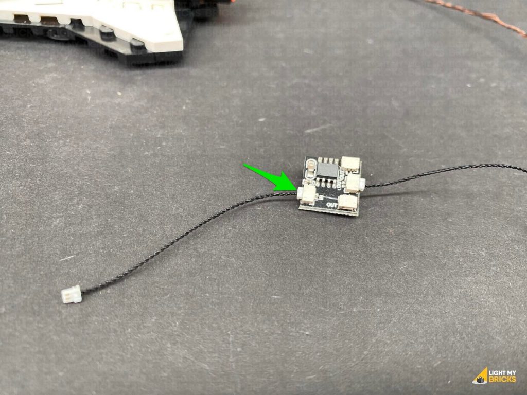
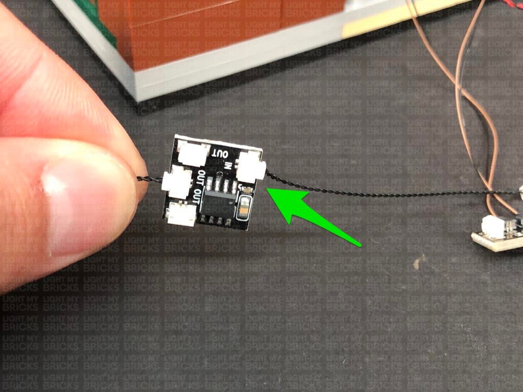
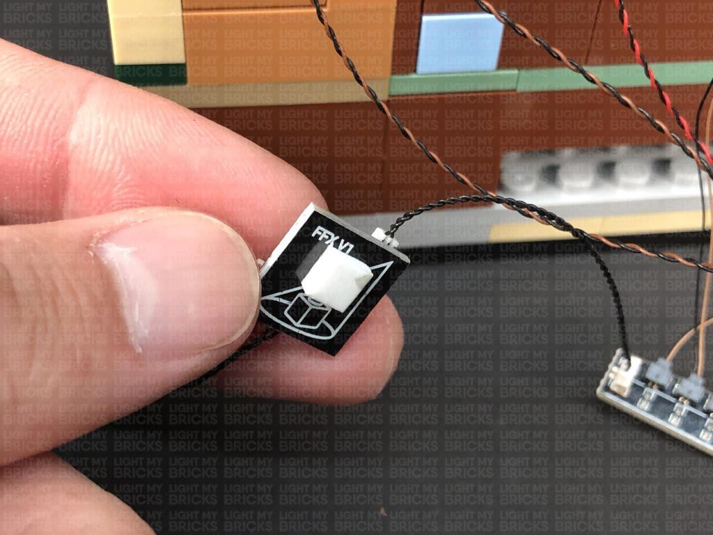
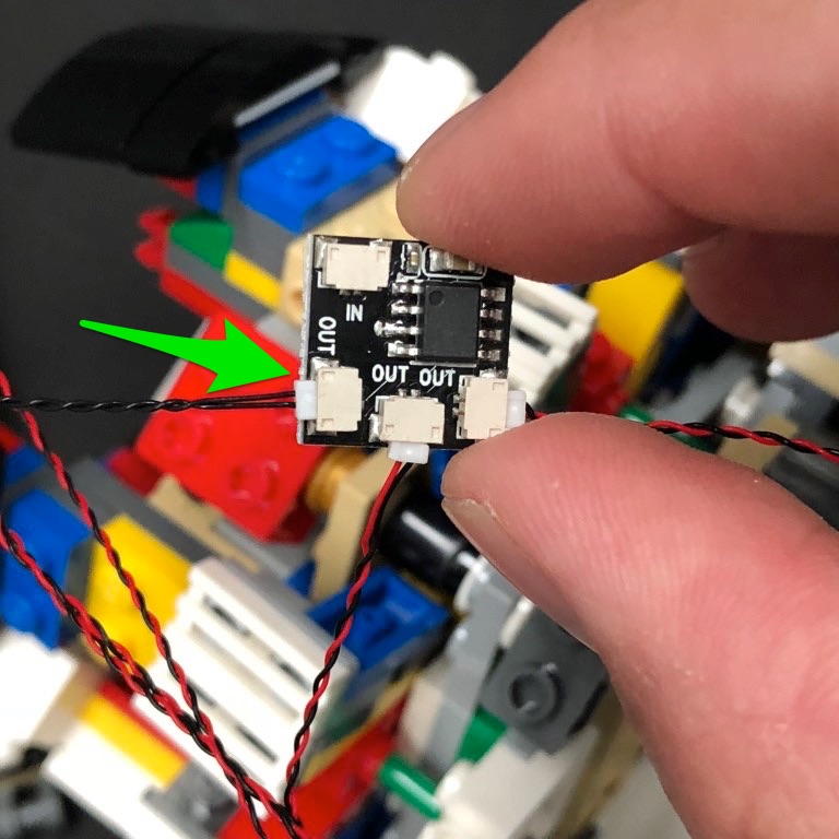
Connect a 5cm Connecting Cable to the larger port on the expansion board, then connect the other end of the cable to one of the OUT ports on a Flicker Effects Board. Connect a new 5cm Connecting Cable to the IN port on the Flicker effects board.
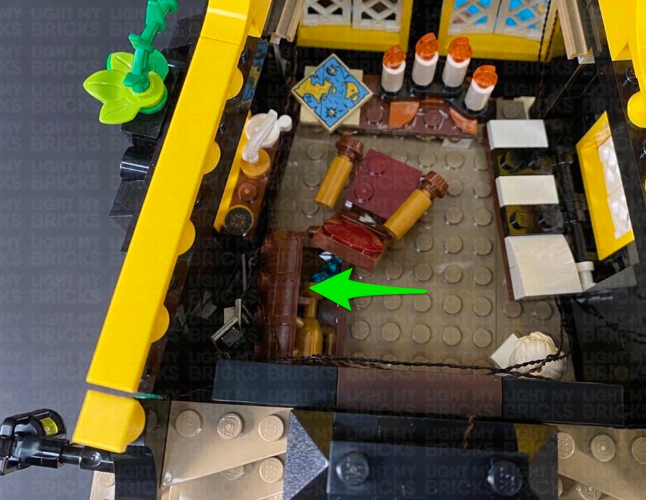
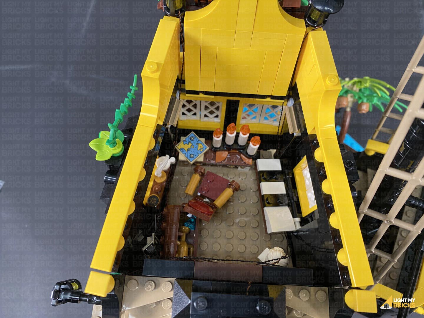
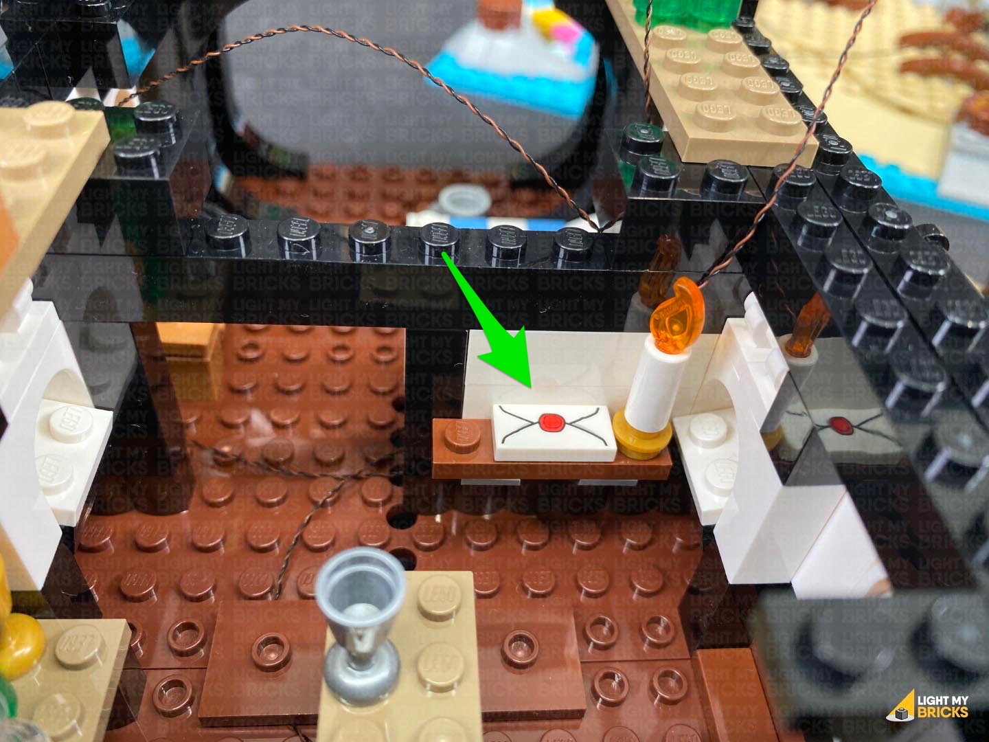
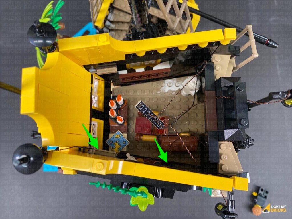
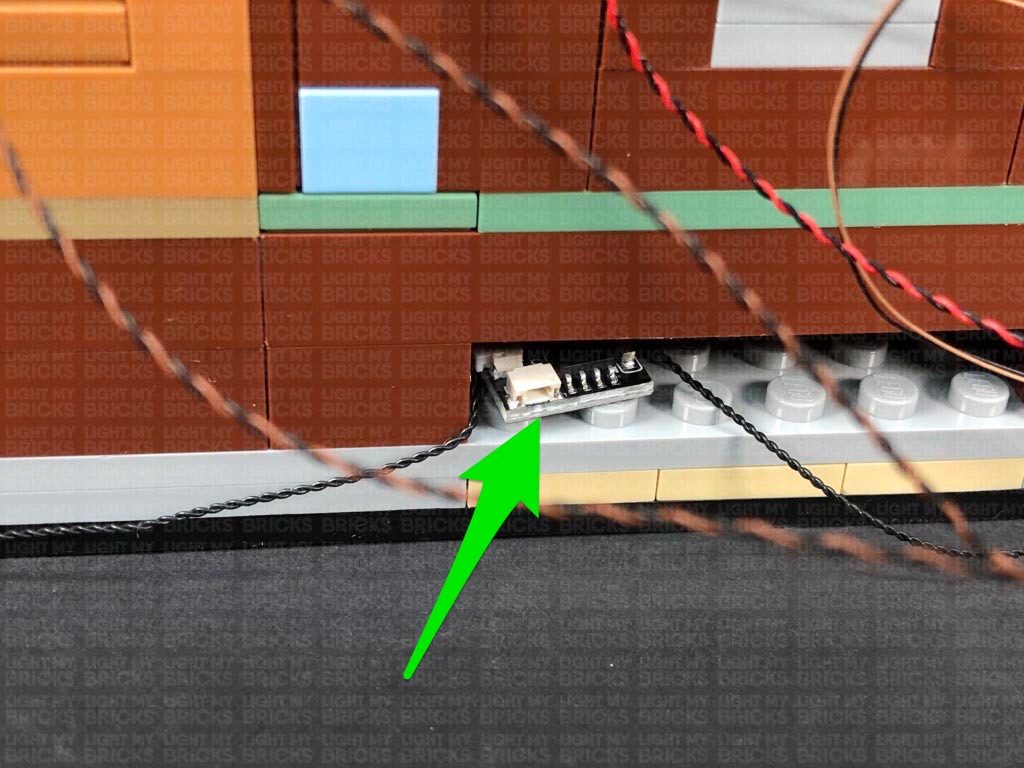
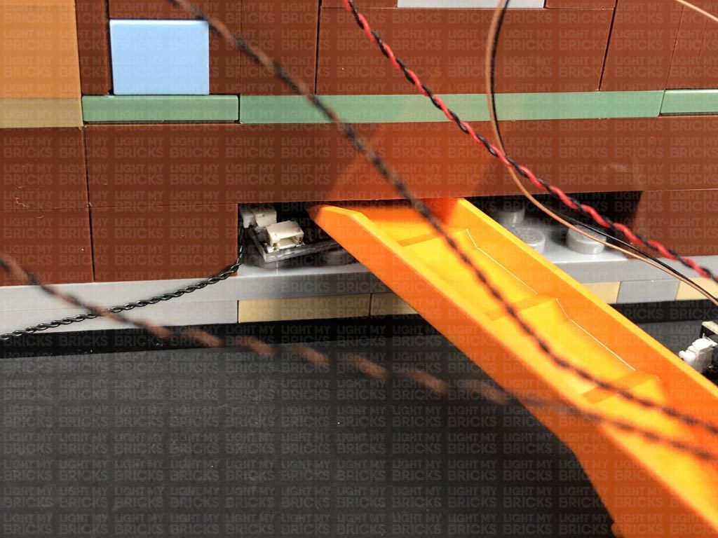
20.) Reconnect the desk inside the captain’s HQ, then lay the cables down the left side of the room. Connect the other end of the 5cm Connecting cable to the 8-port Expansion Board near the door.
Ensure the cables down the right side are well hidden into the corners, then fold down the captain’s bed to help further conceal the cables.
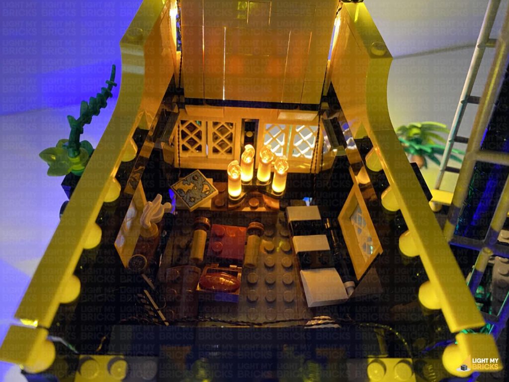
Turn ON the power to test the candle lights are working and flickering OK.
Note: If you experience any issues with the lights not working and suspect an issue with a component, please try a different port on the expansion board to verify where the fault lies (with the light, expansion board or effects board). To correct any issues with expansion board ports, please view the section addressing expansion board issues on our online troubleshooting guide.
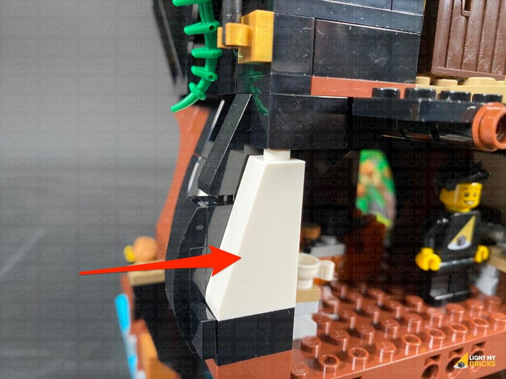
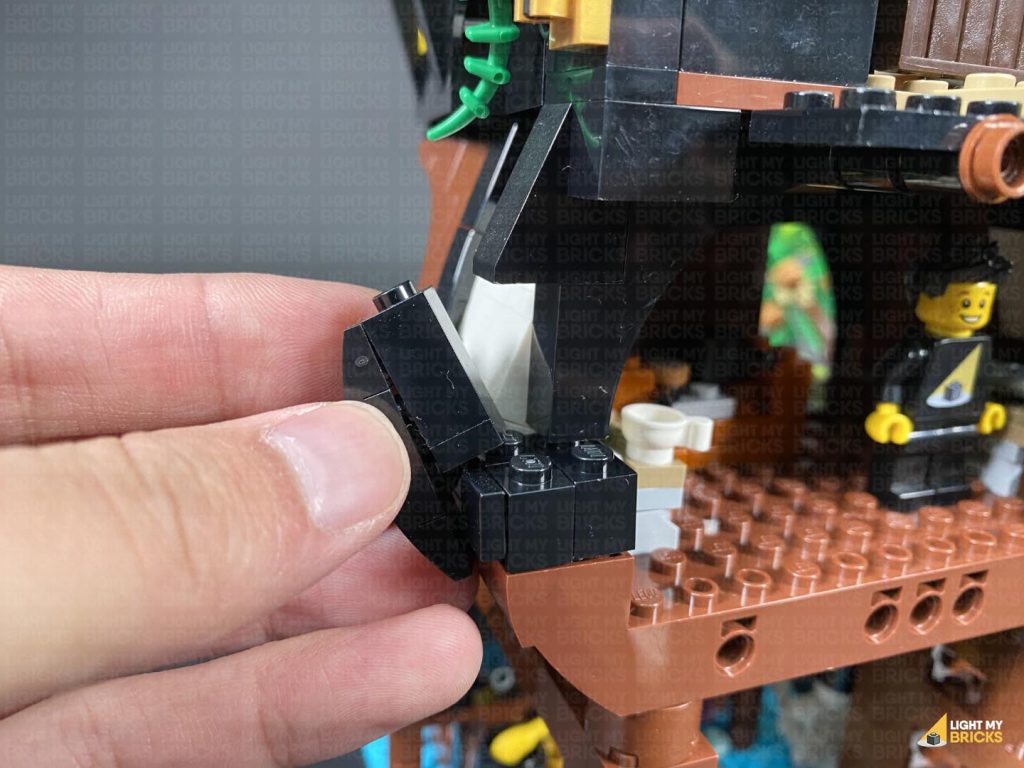
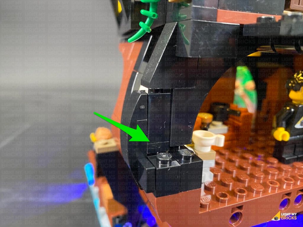
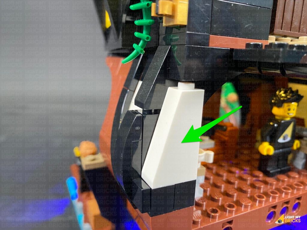
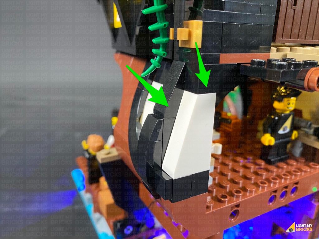
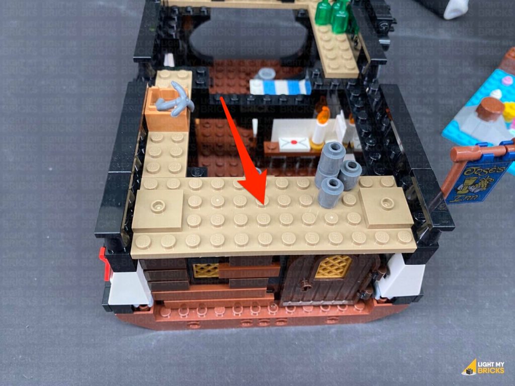
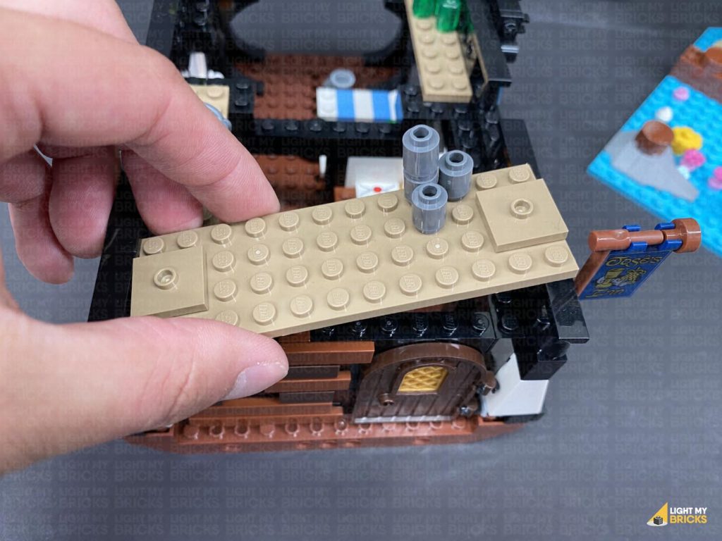
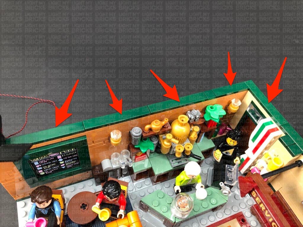
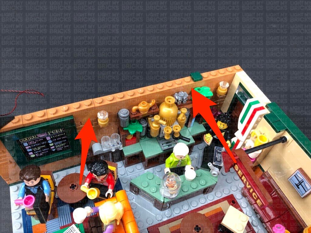
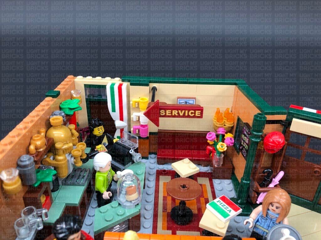
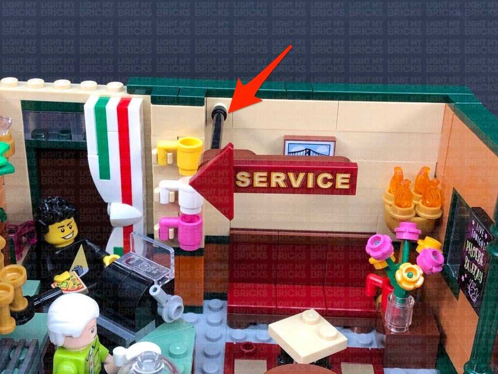
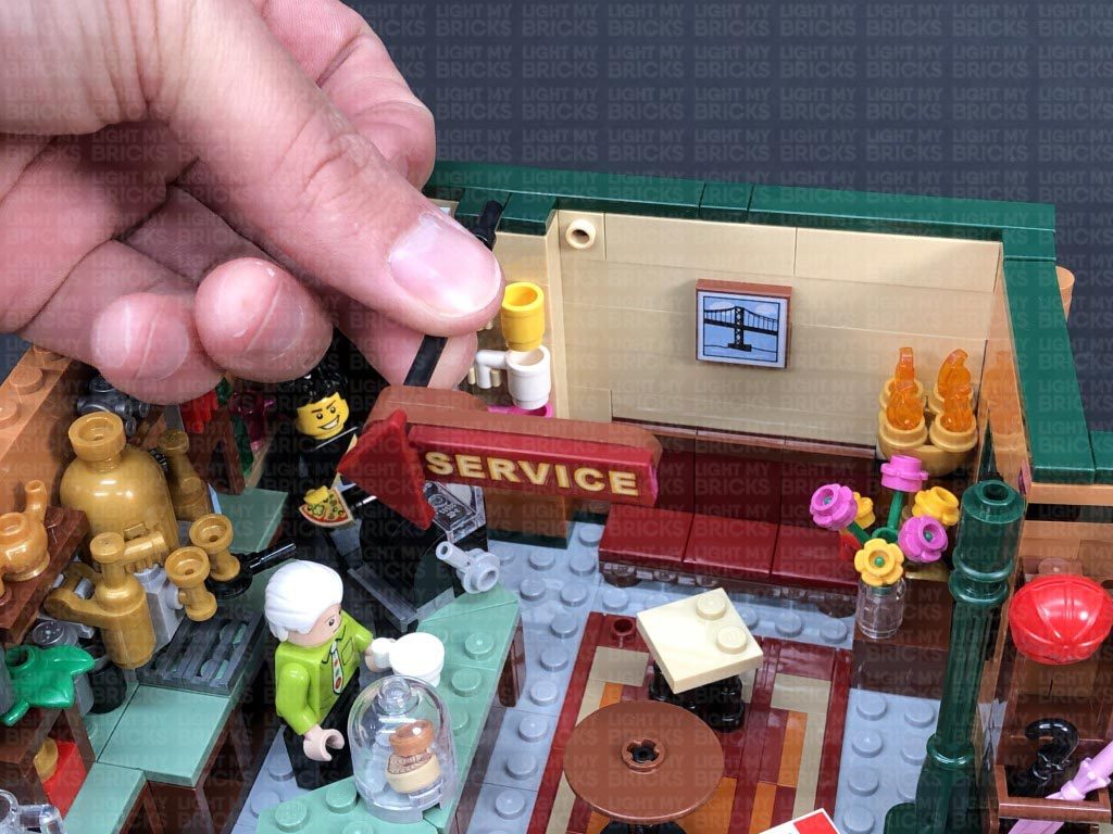
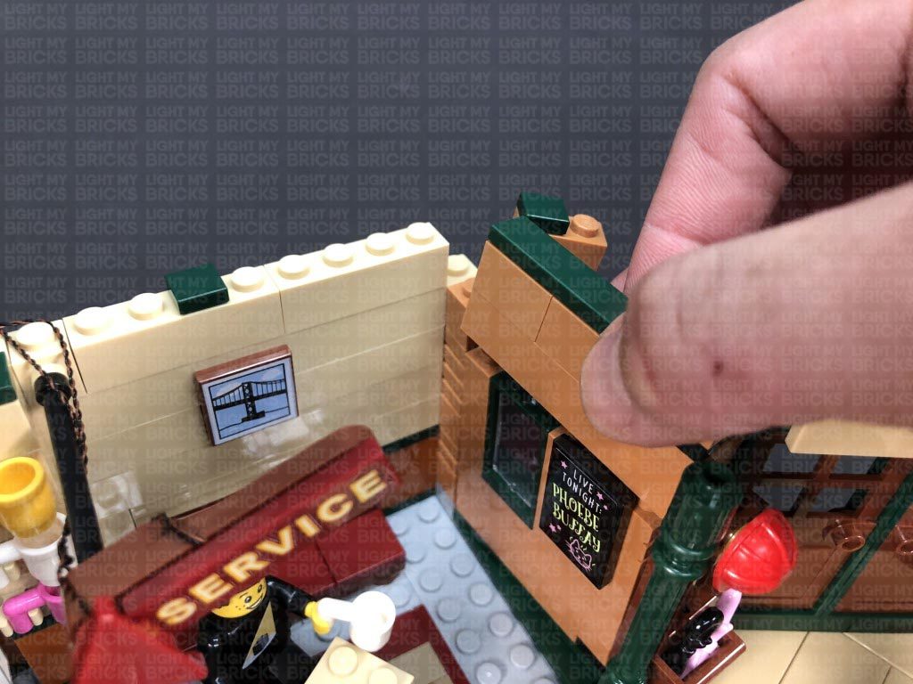
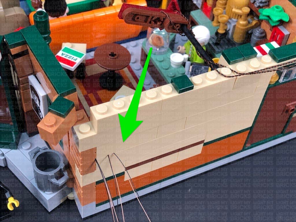
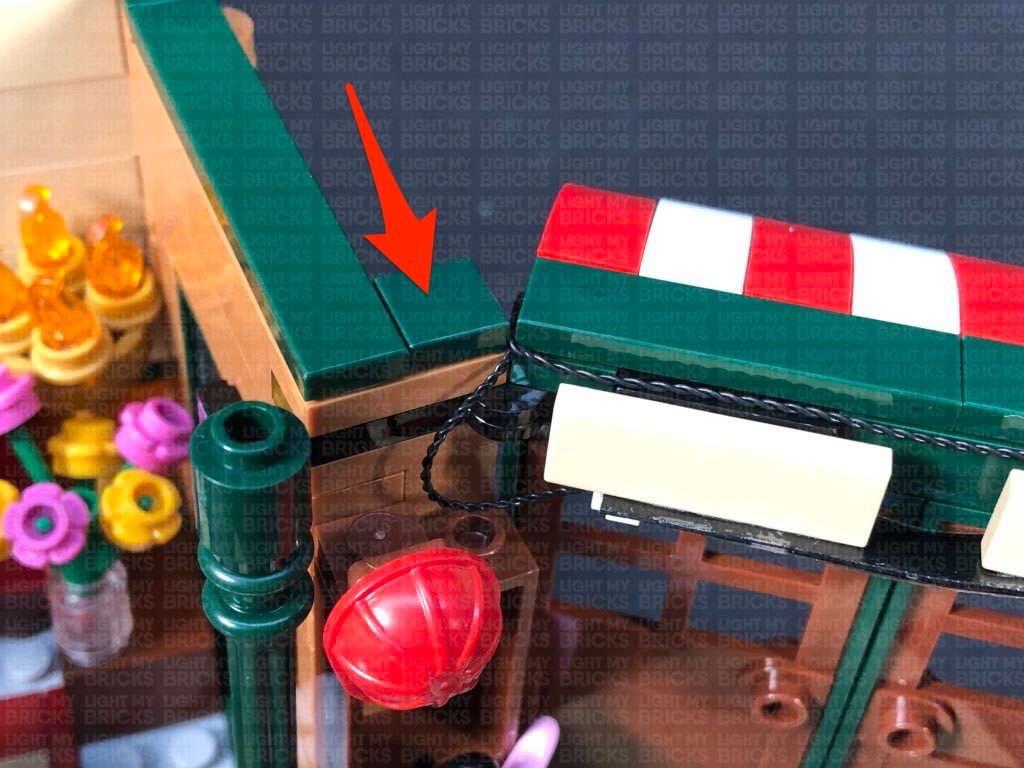
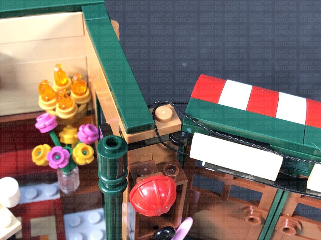
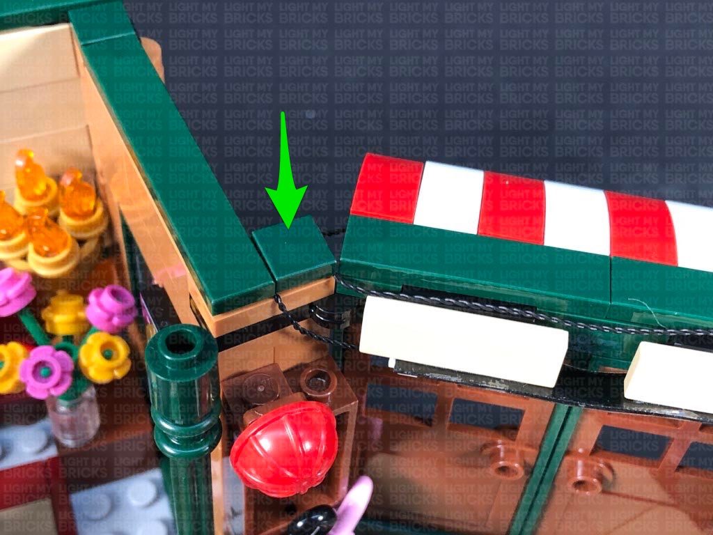
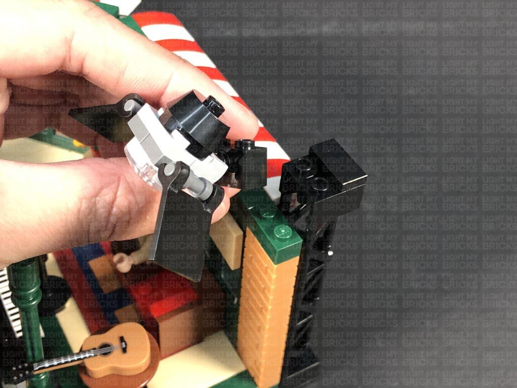
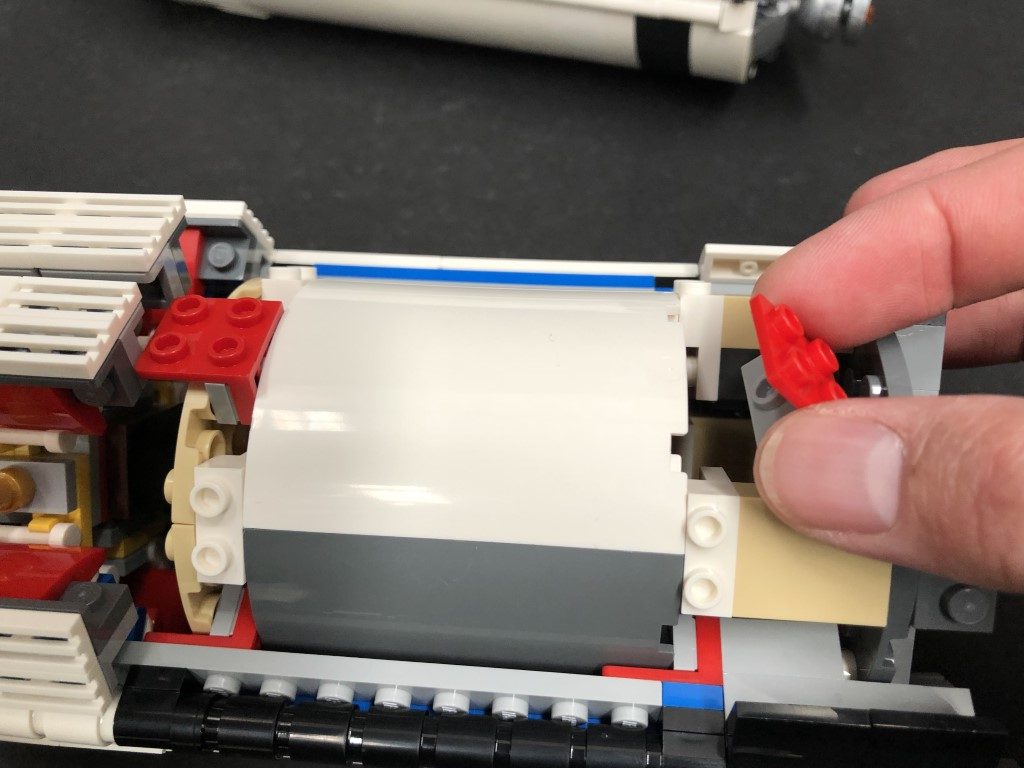
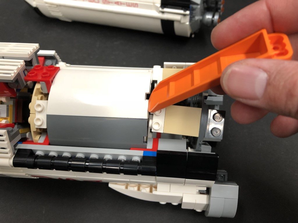
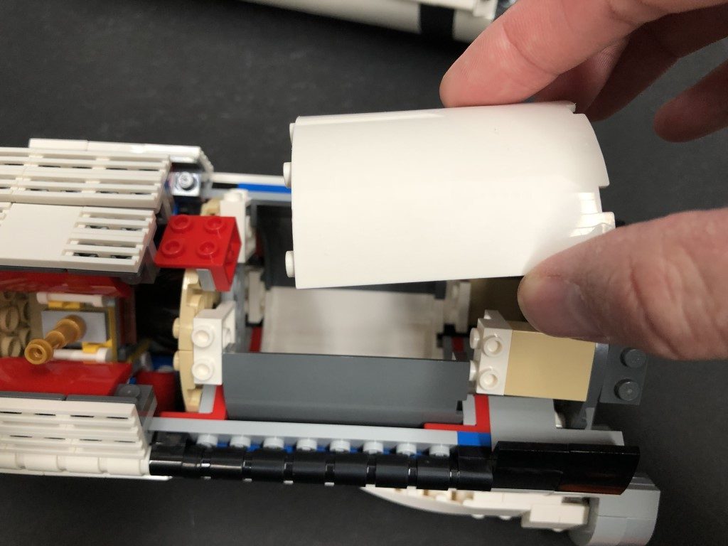
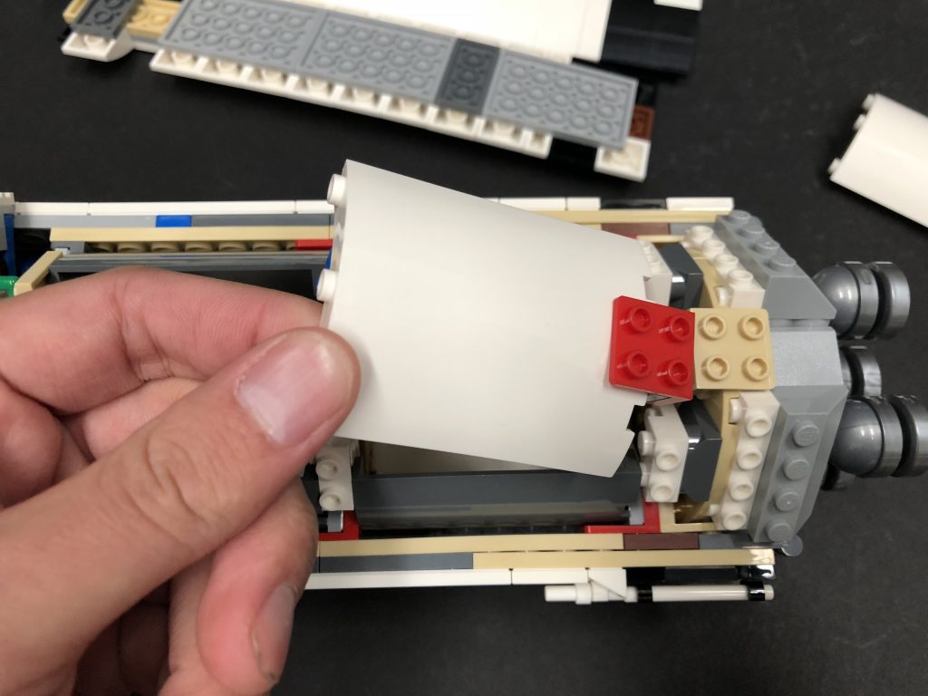
21.) We will now light up the kitchen area. First, disconnect the left section underneath the door, then carefully partially disconnect the top floor section to allow us to disconnect the white angled brick, followed by the pieces behind it.
19.) Turn the desk around, then group the four cables and twist them around each other a few times. Continue to twist/braid the cables around each other all the way to the ends, then connect them to the smaller ports on a Micro 2-4 Port Expansion Board
Connect a 5cm Connecting Cable to the larger port on the expansion board, then connect the other end of the cable to one of the OUT ports on a Flicker Effects Board. Connect a new 5cm Connecting Cable to the IN port on the Flicker effects board.
20.) Reconnect the desk inside the captain’s HQ, then lay the cables down the left side of the room. Connect the other end of the 5cm Connecting cable to the 8-port Expansion Board near the door.
Ensure the cables down the right side are well hidden into the corners, then fold down the captain’s bed to help further conceal the cables.
Turn ON the power to test the candle lights are working and flickering OK.
Note: If you experience any issues with the lights not working and suspect an issue with a component, please try a different port on the expansion board to verify where the fault lies (with the light, expansion board or effects board). To correct any issues with expansion board ports, please view the section addressing expansion board issues on our online troubleshooting guide.
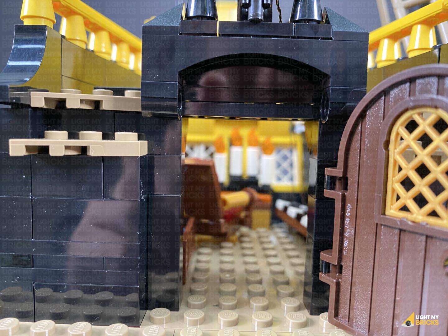
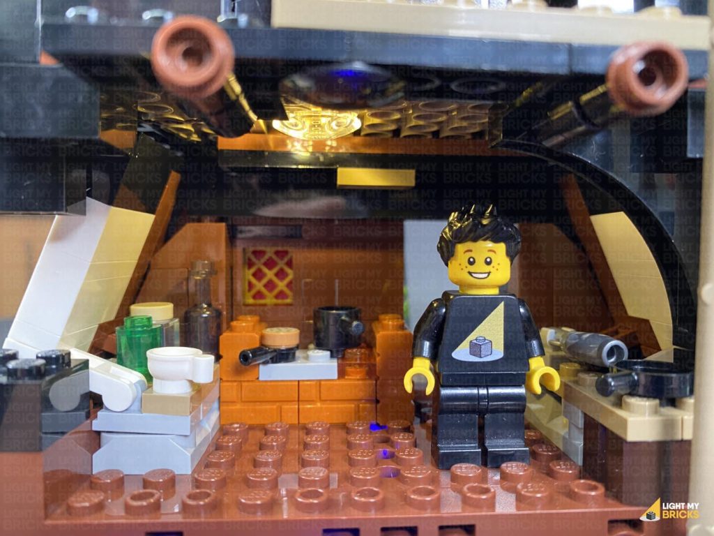
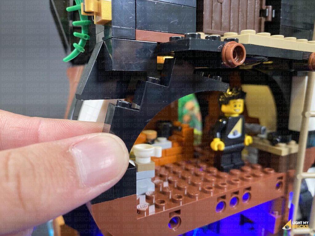
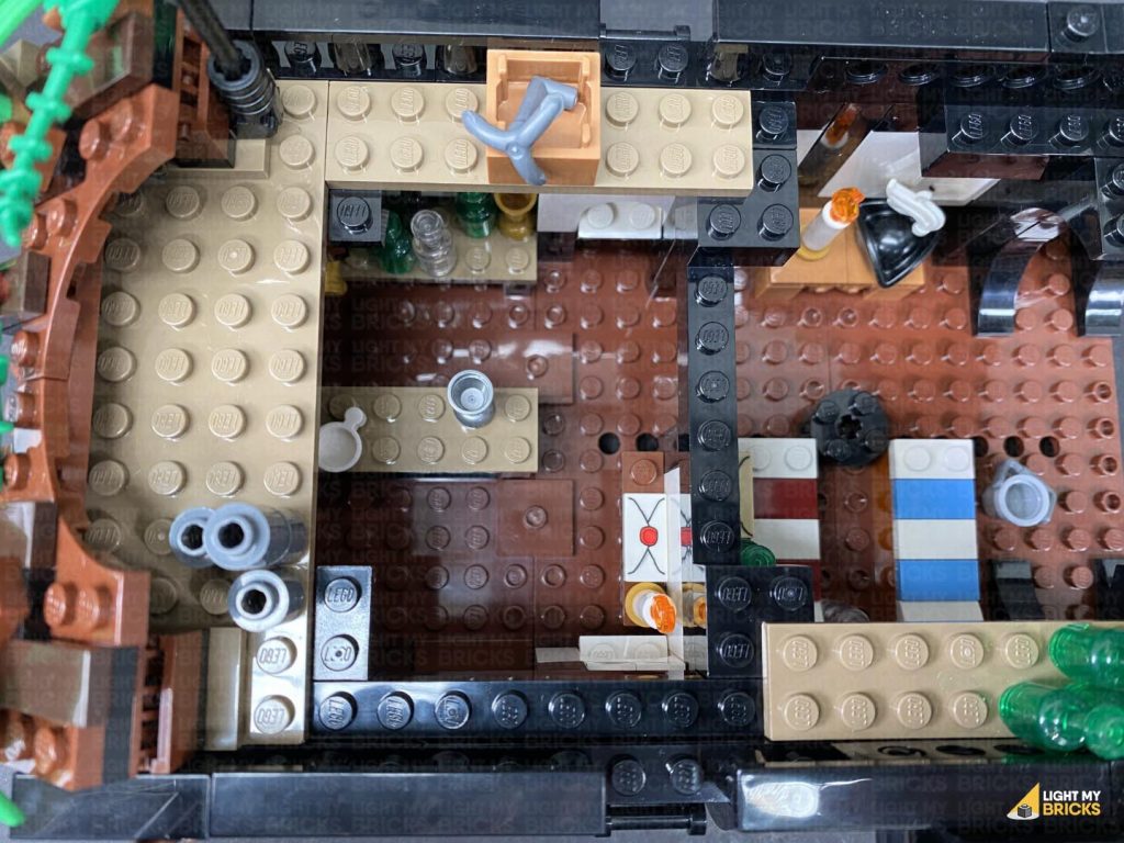
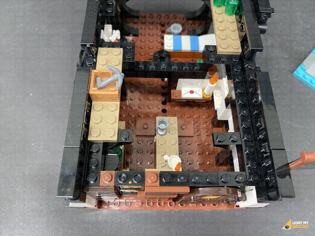
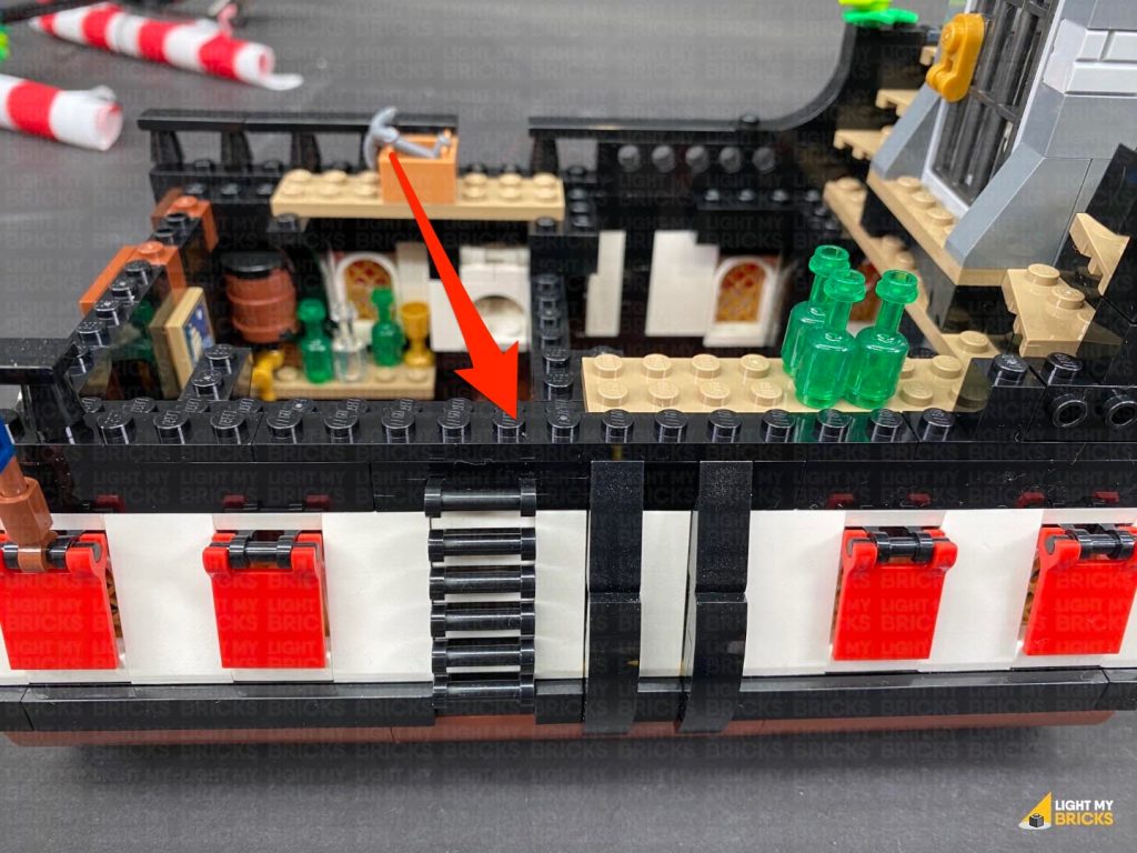
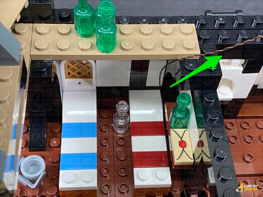
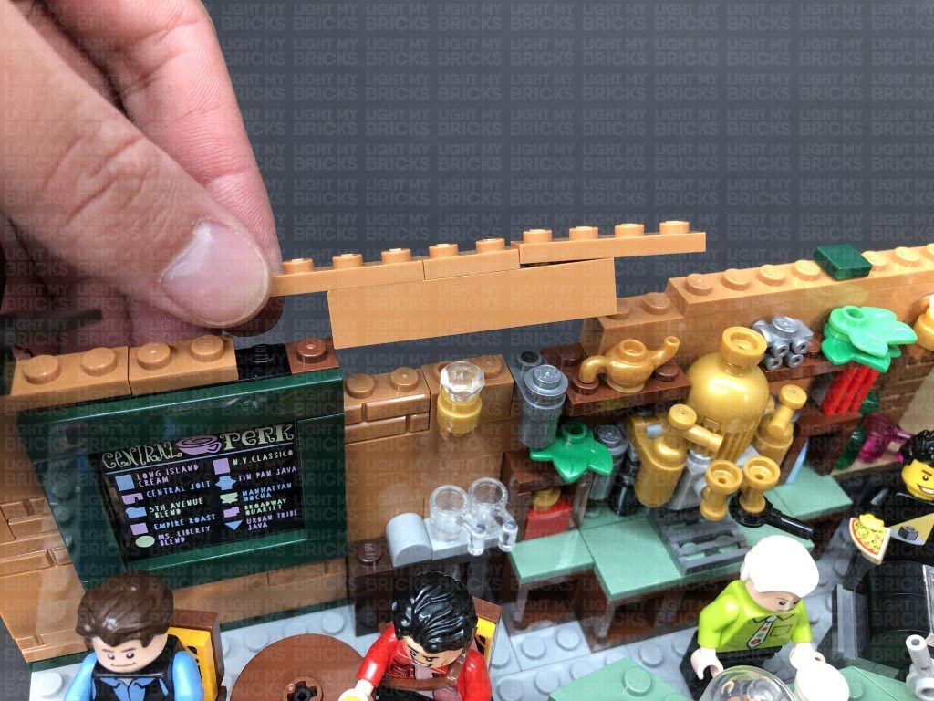
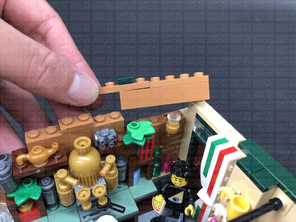
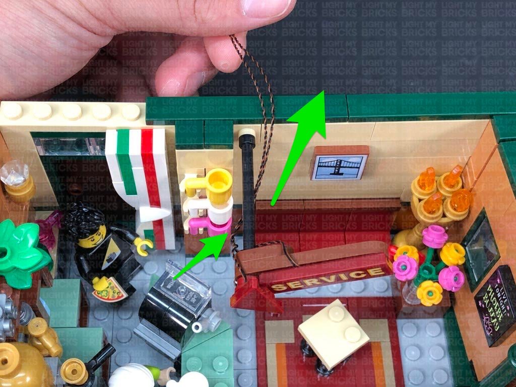
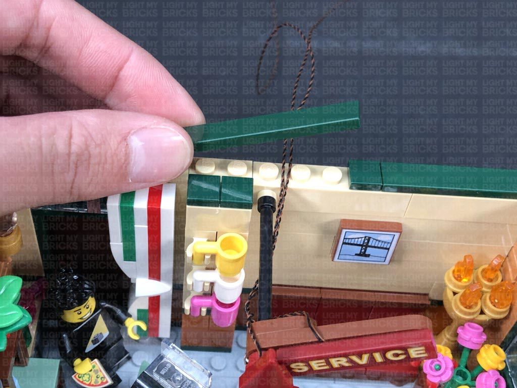
21.) We will now light up the kitchen area. First, disconnect the left section underneath the door, then carefully partially disconnect the top floor section to allow us to disconnect the white angled brick, followed by the pieces behind it.
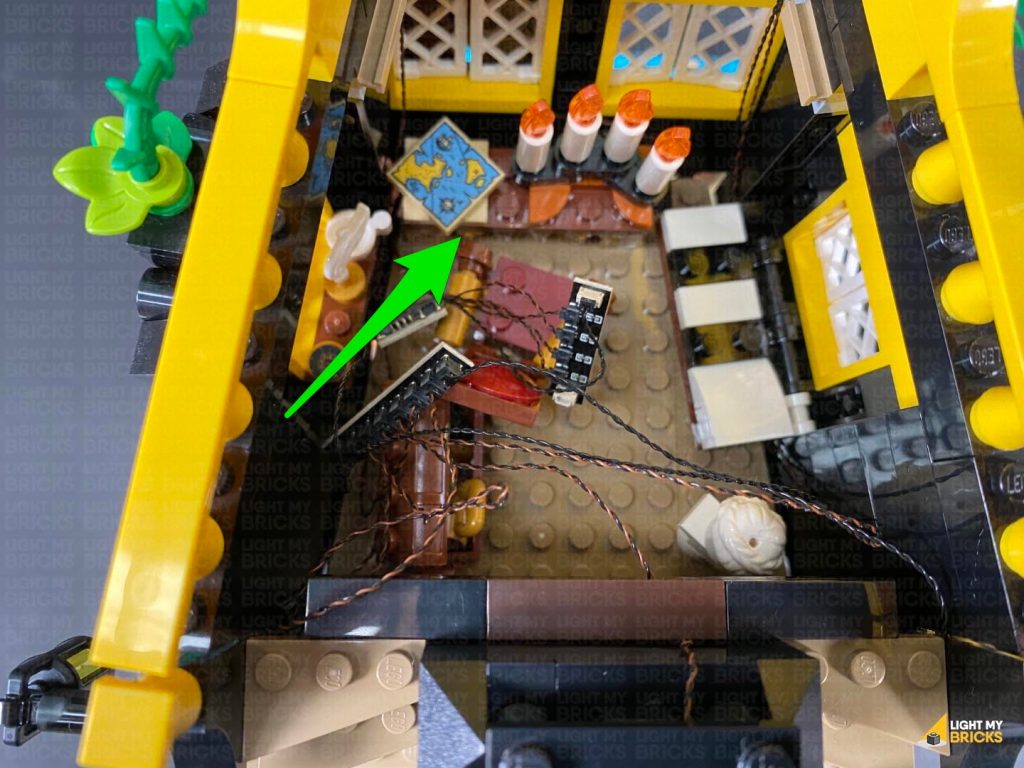
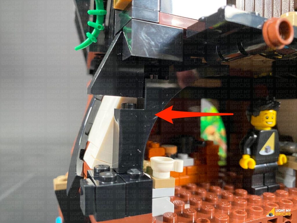
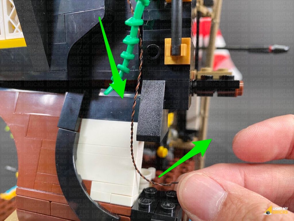
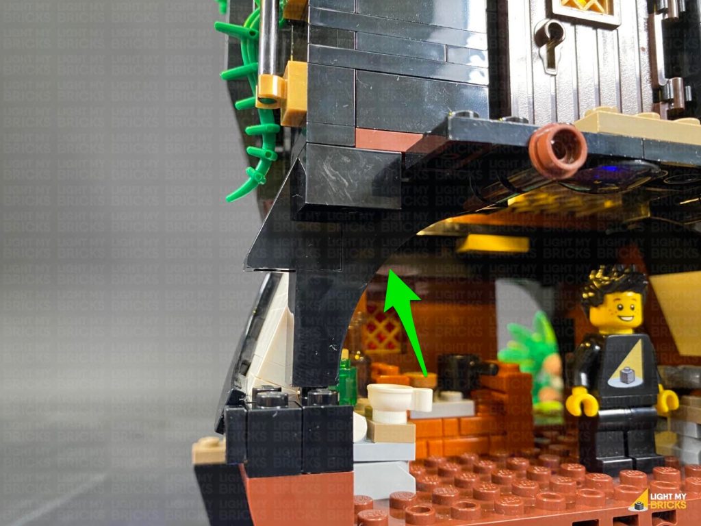
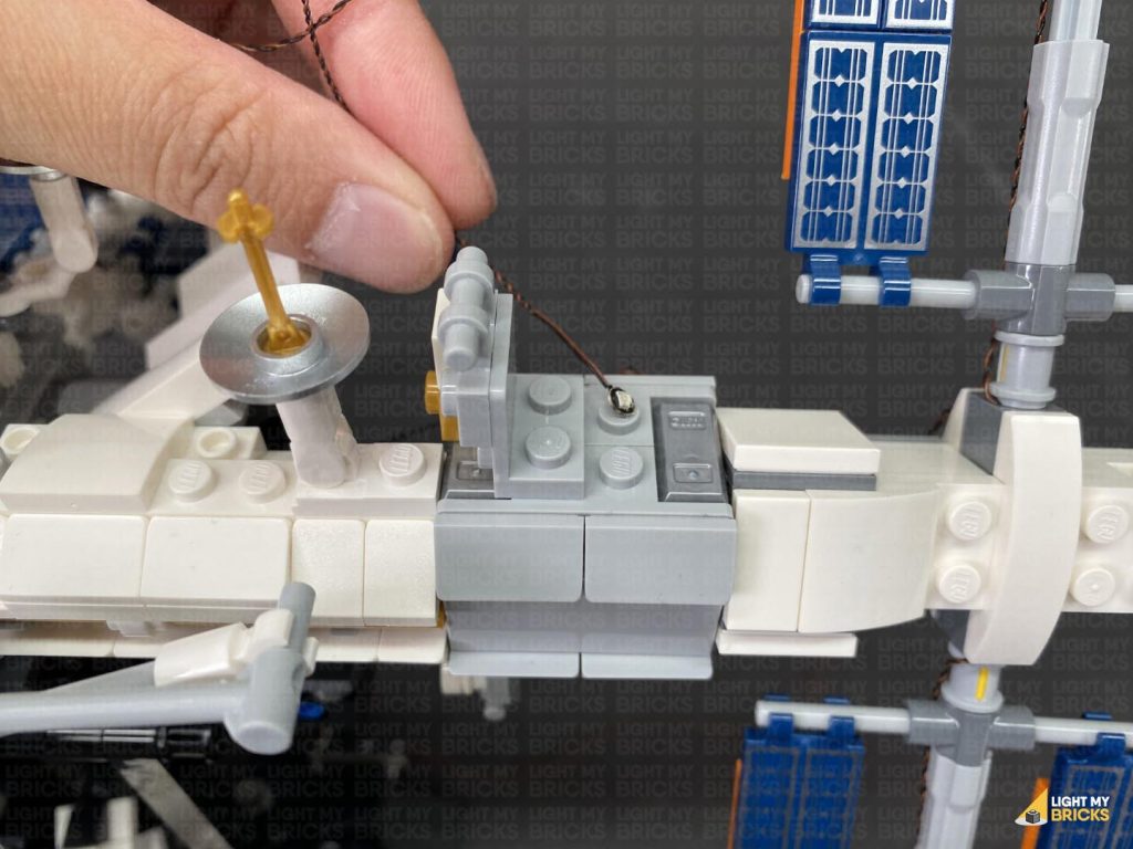
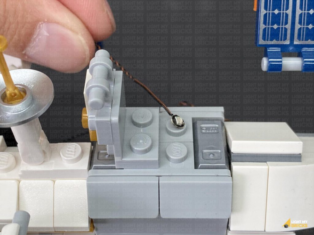
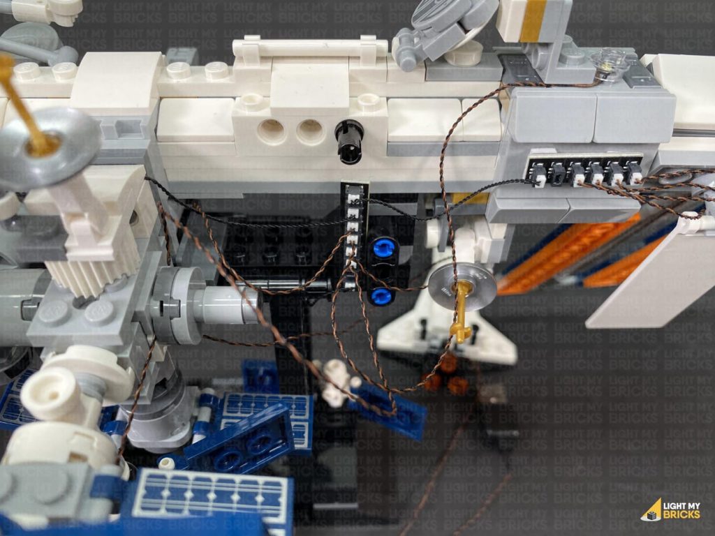
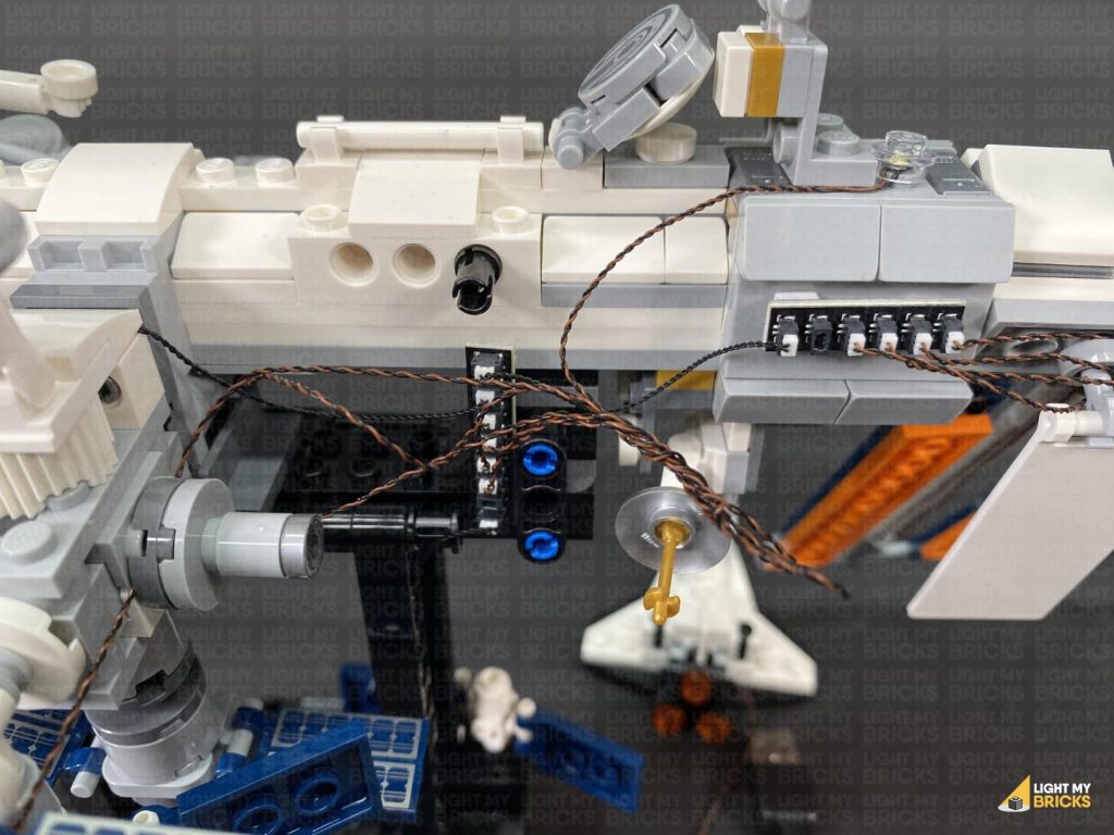
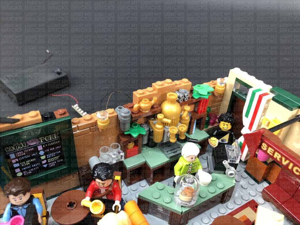
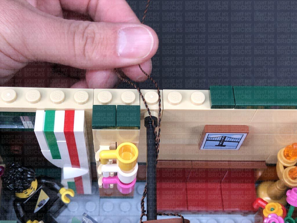
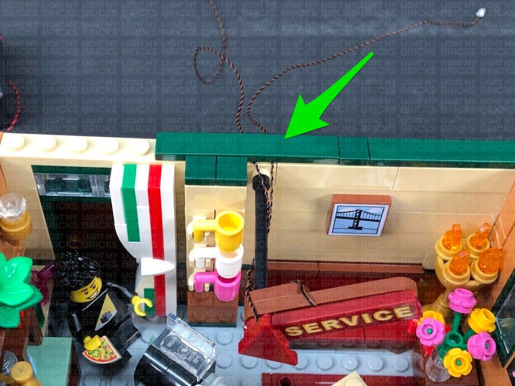
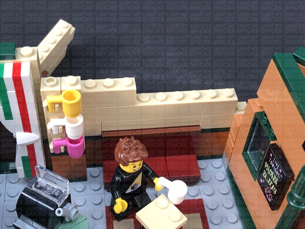
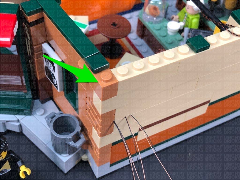
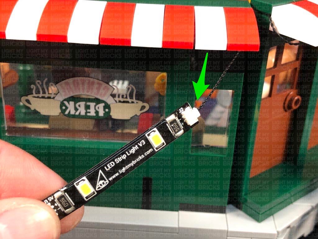
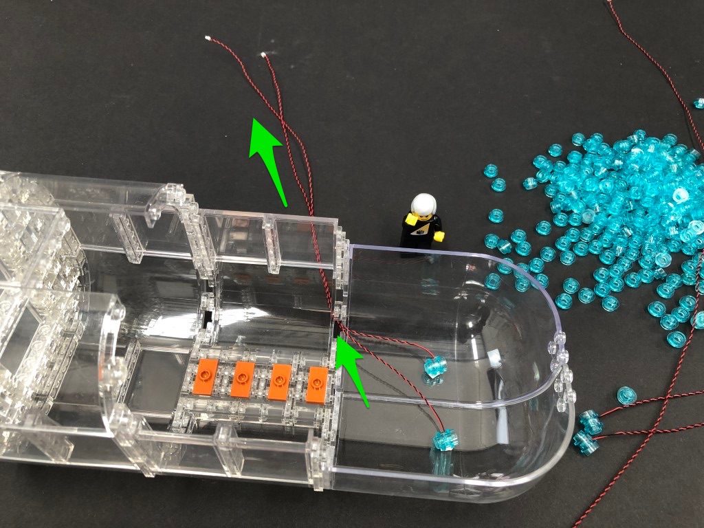
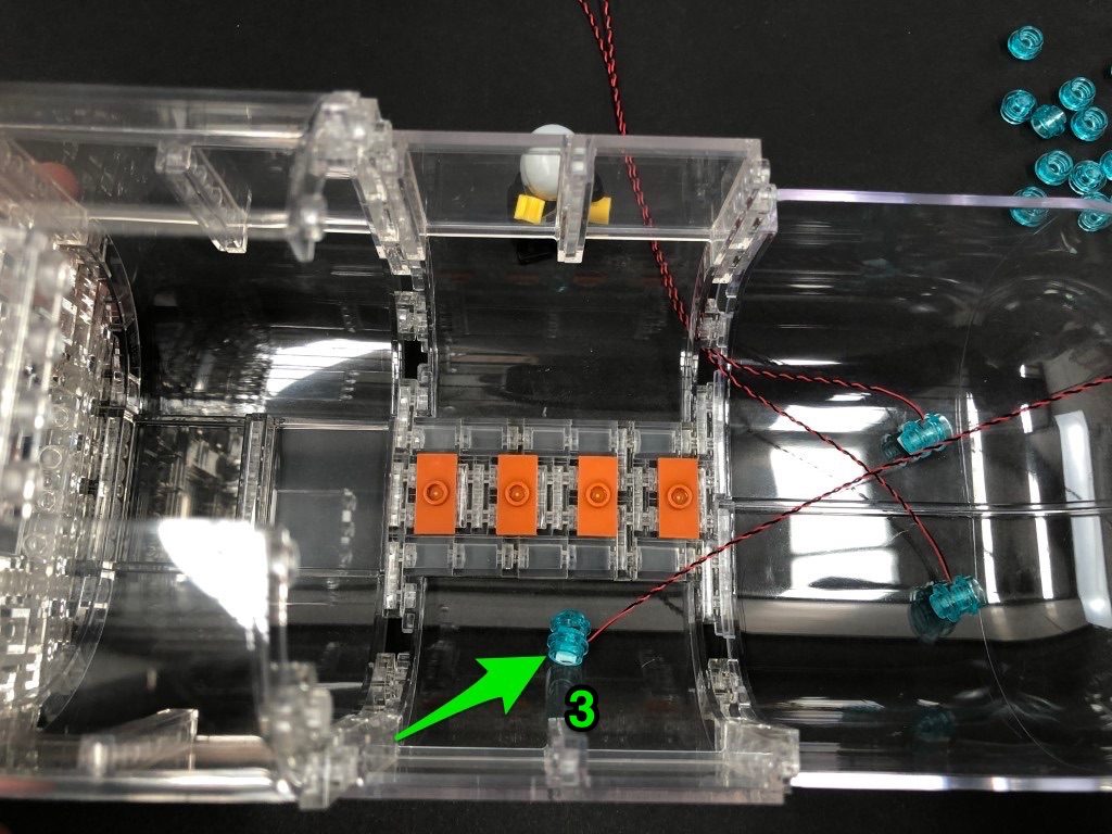
 22.) Take a White 15cm Bit Light and connect it to a spare port on the 8-Port Expansion Board inside the captain’s HQ. Bring the cable over the left wall, slipping it in between the black wall sections as shown below.
Bring the cable inside the kitchen area, threading the cable underneath the black angled bricks.
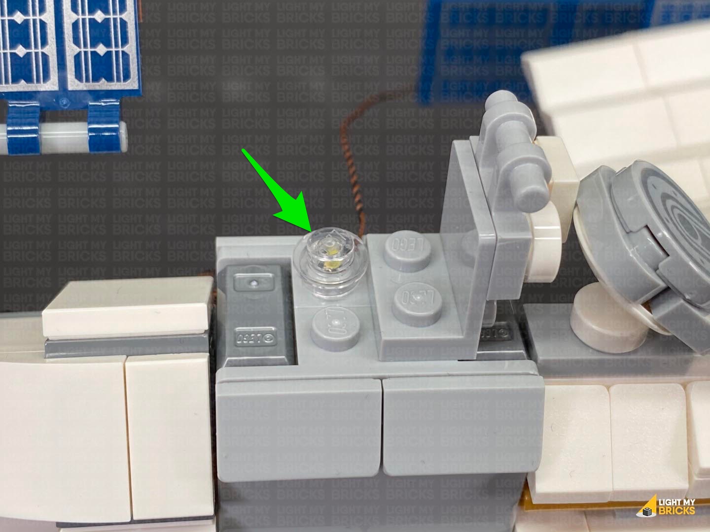
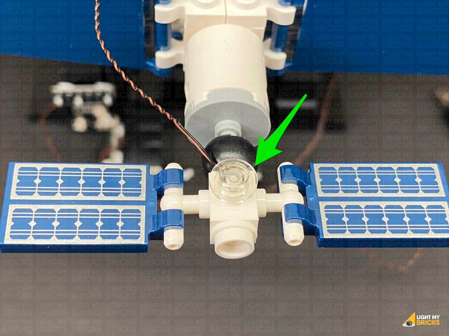
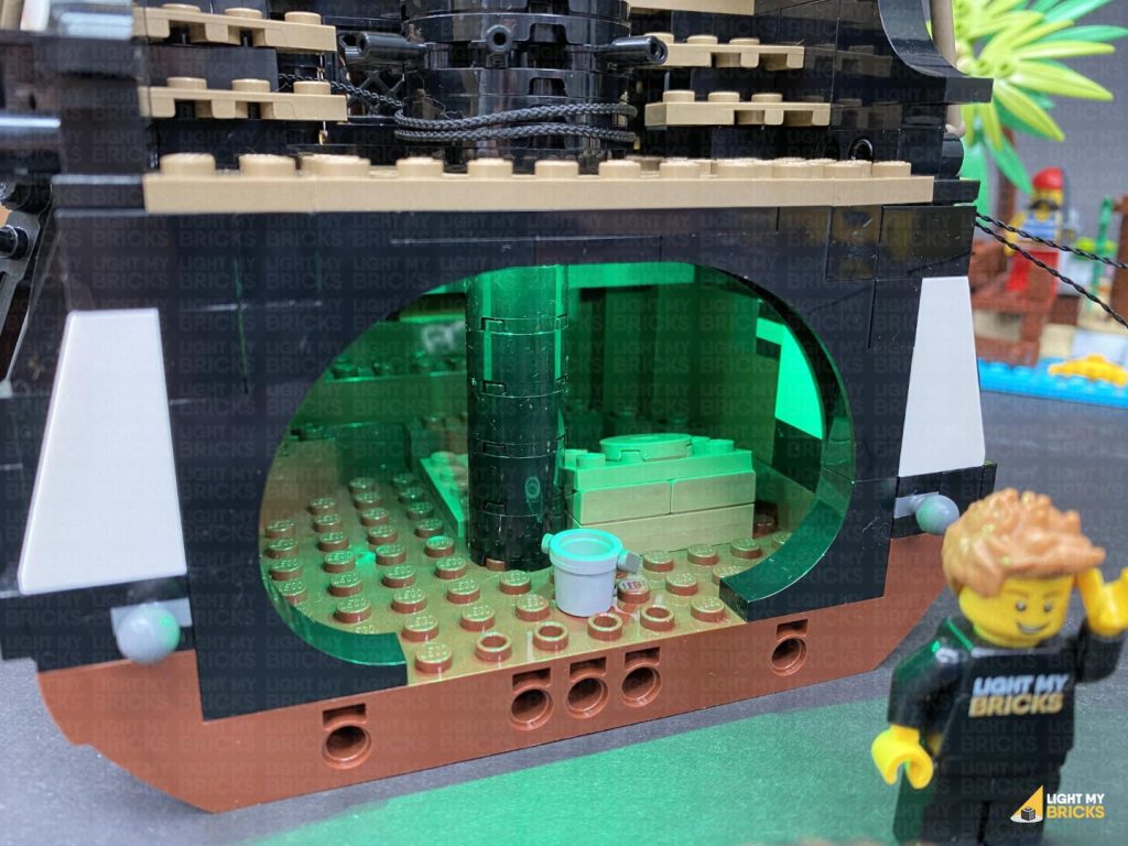
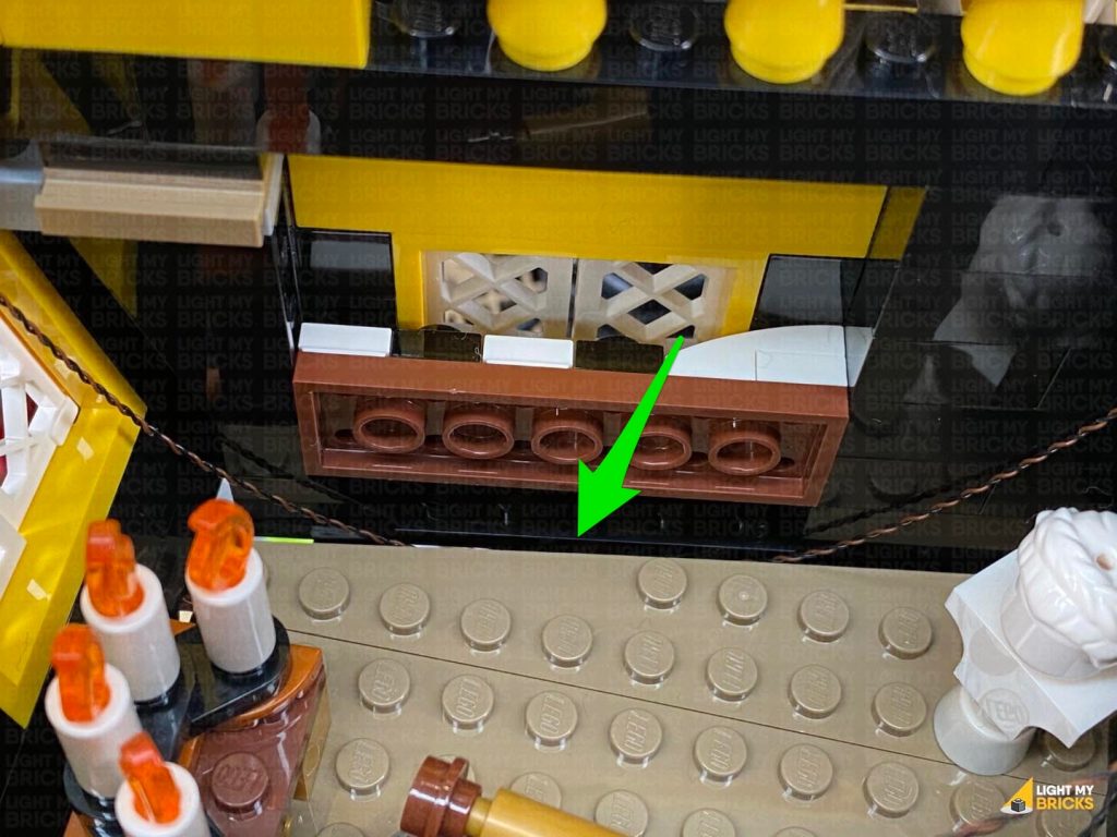
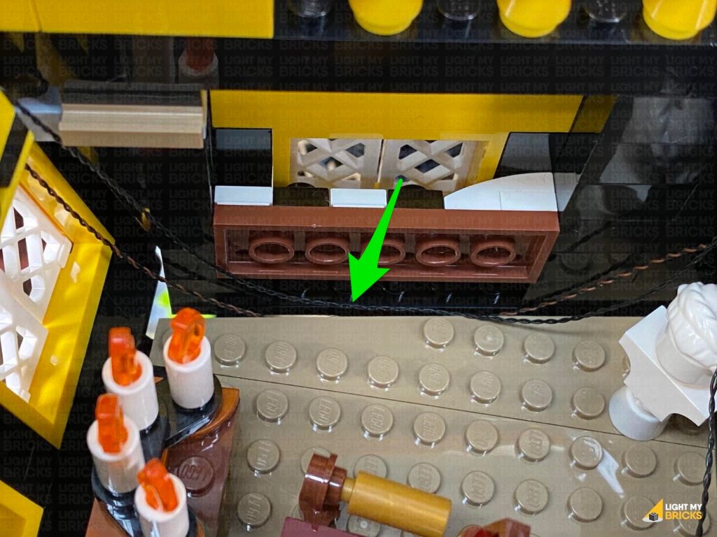
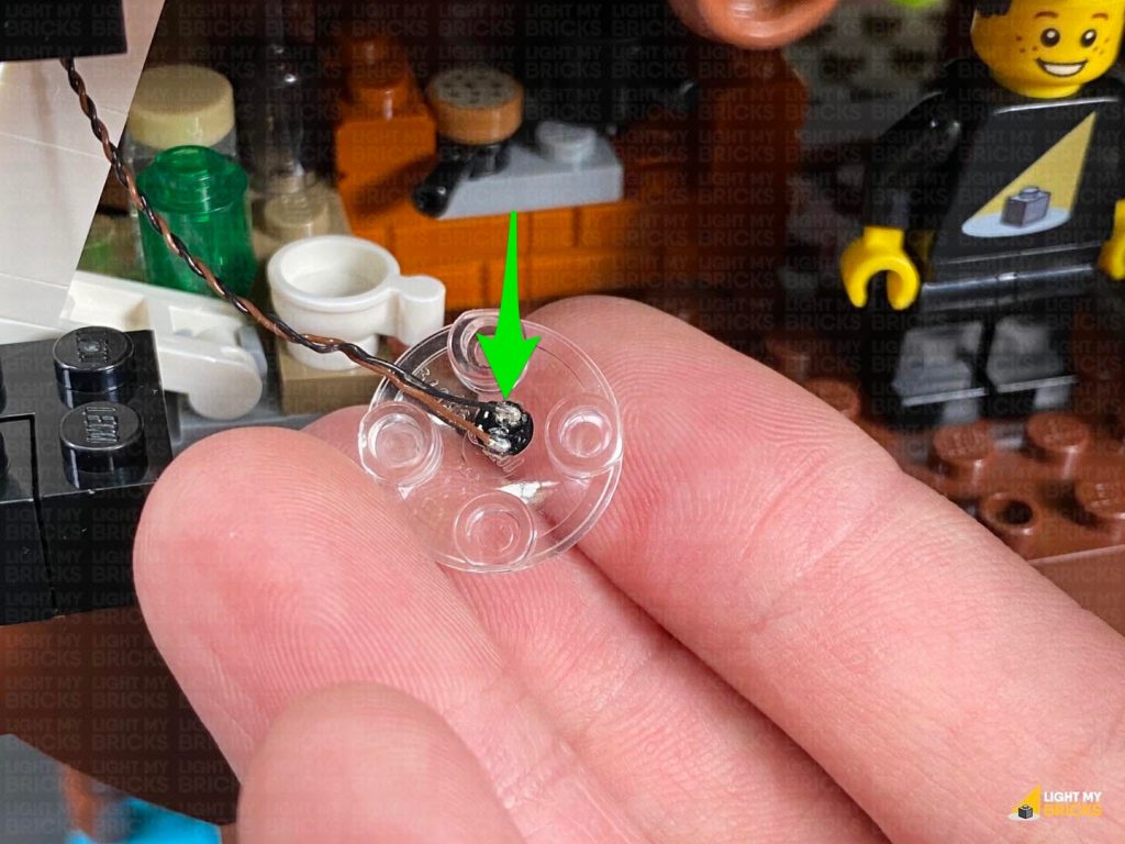
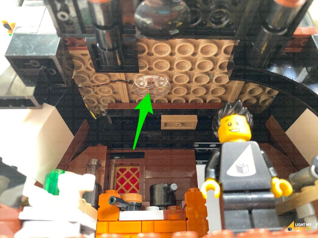
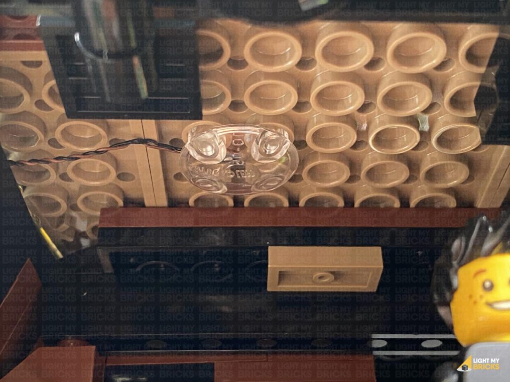
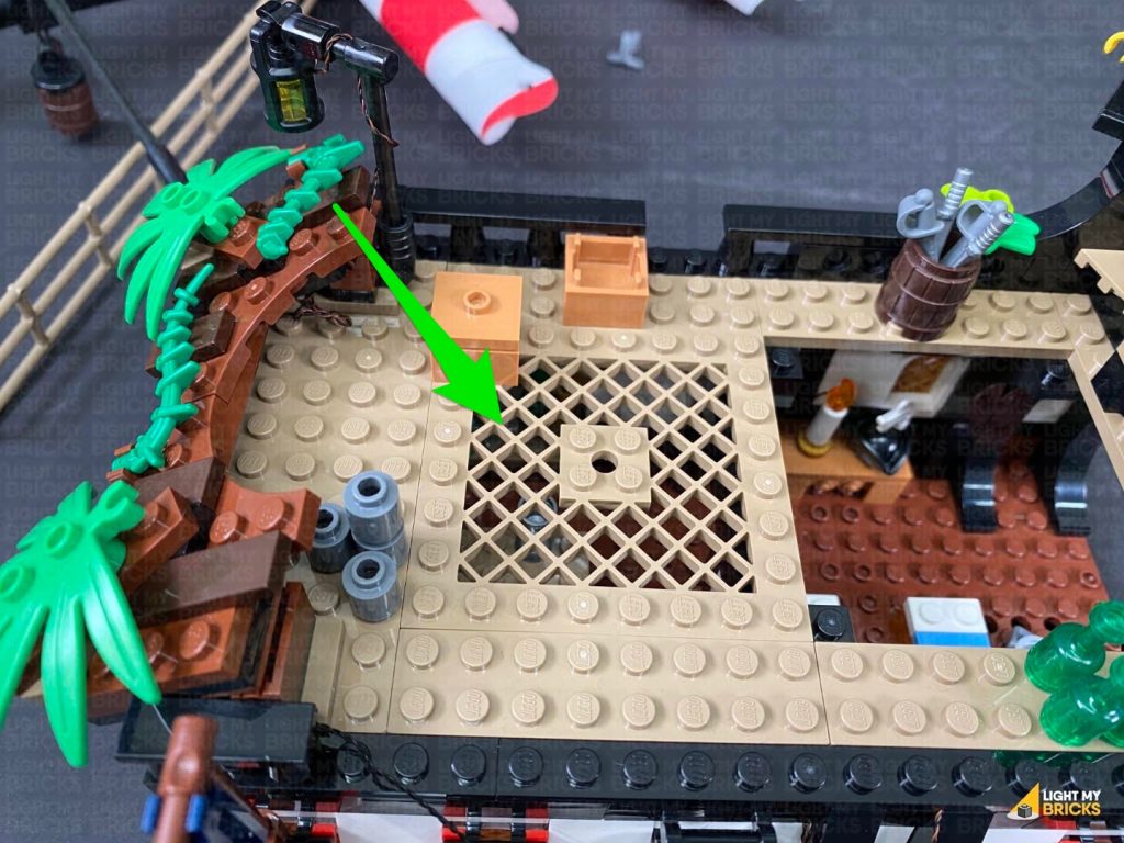
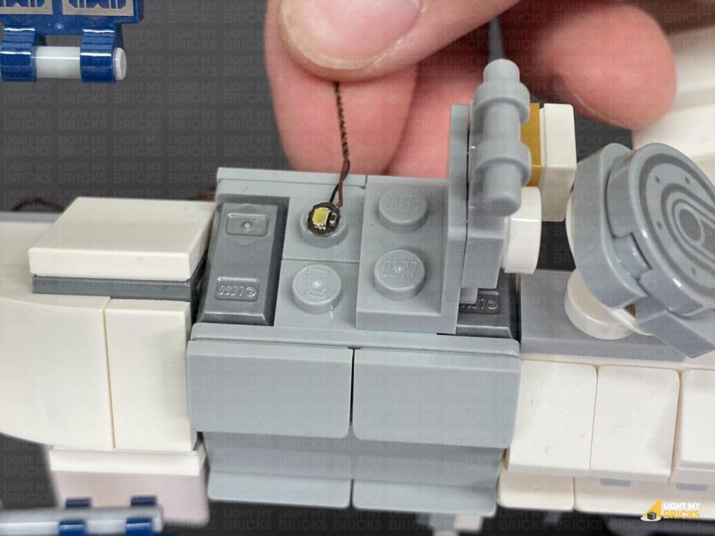
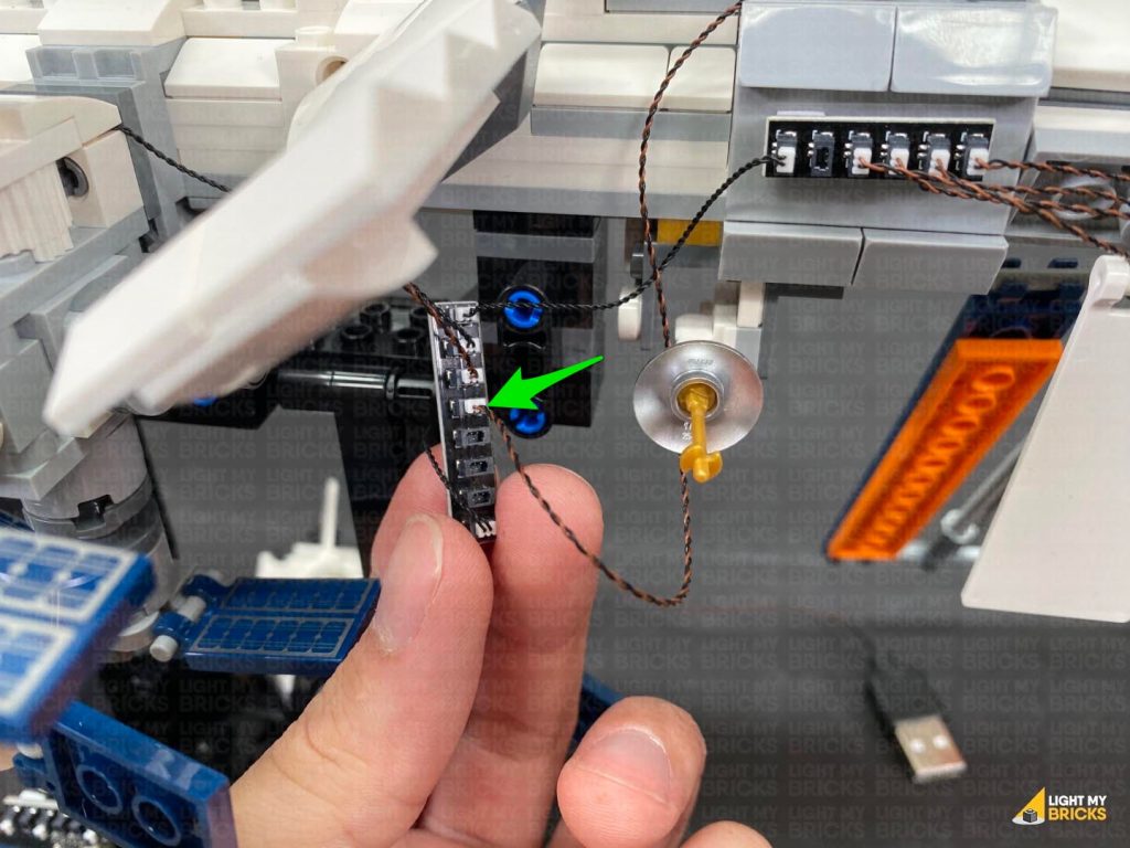
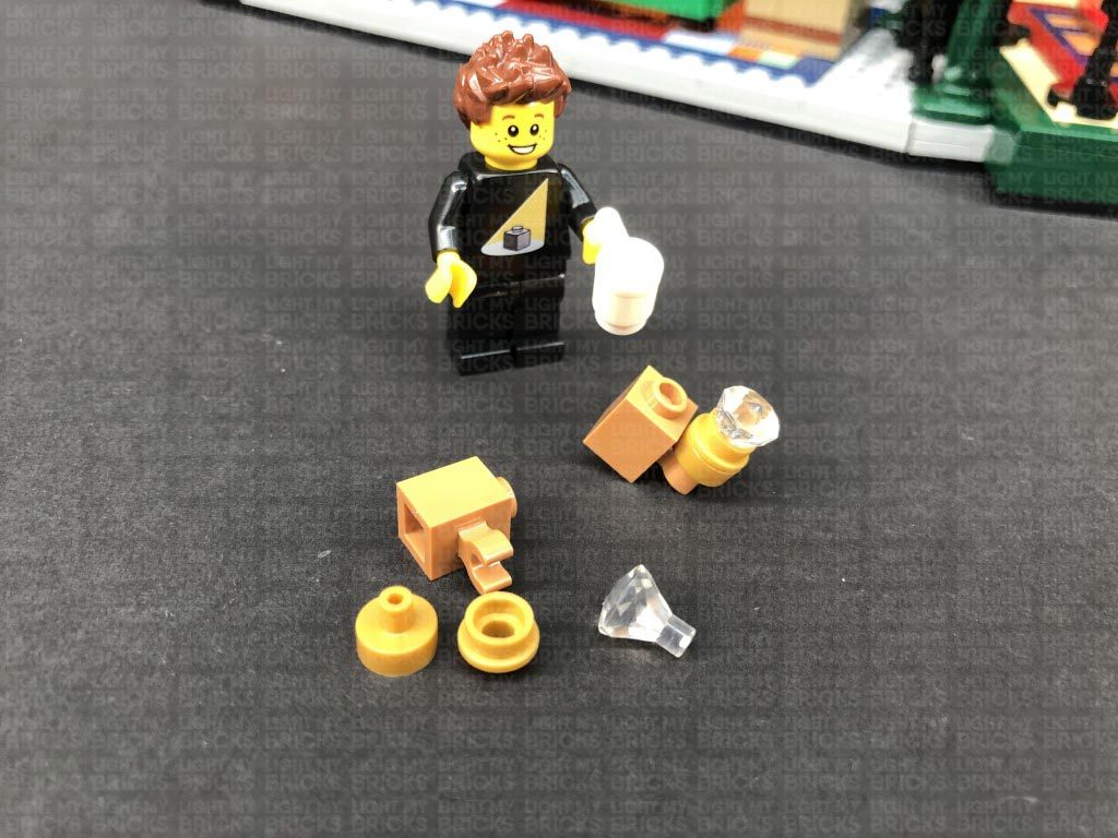
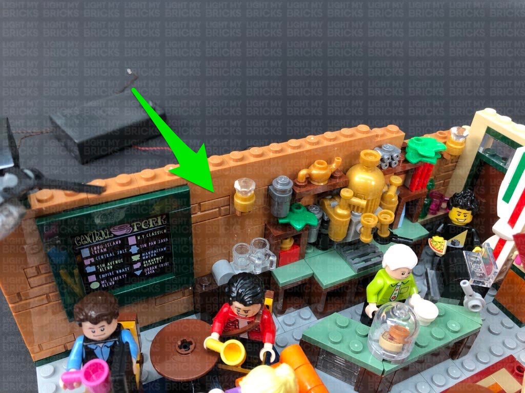
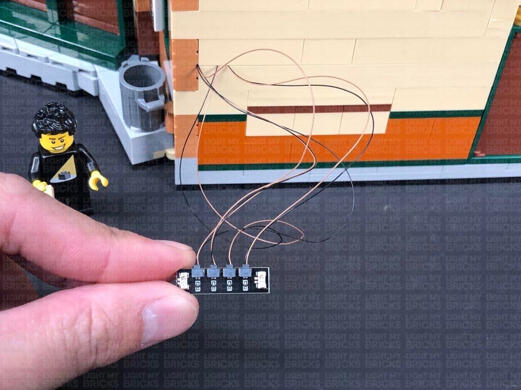
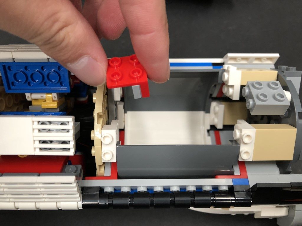
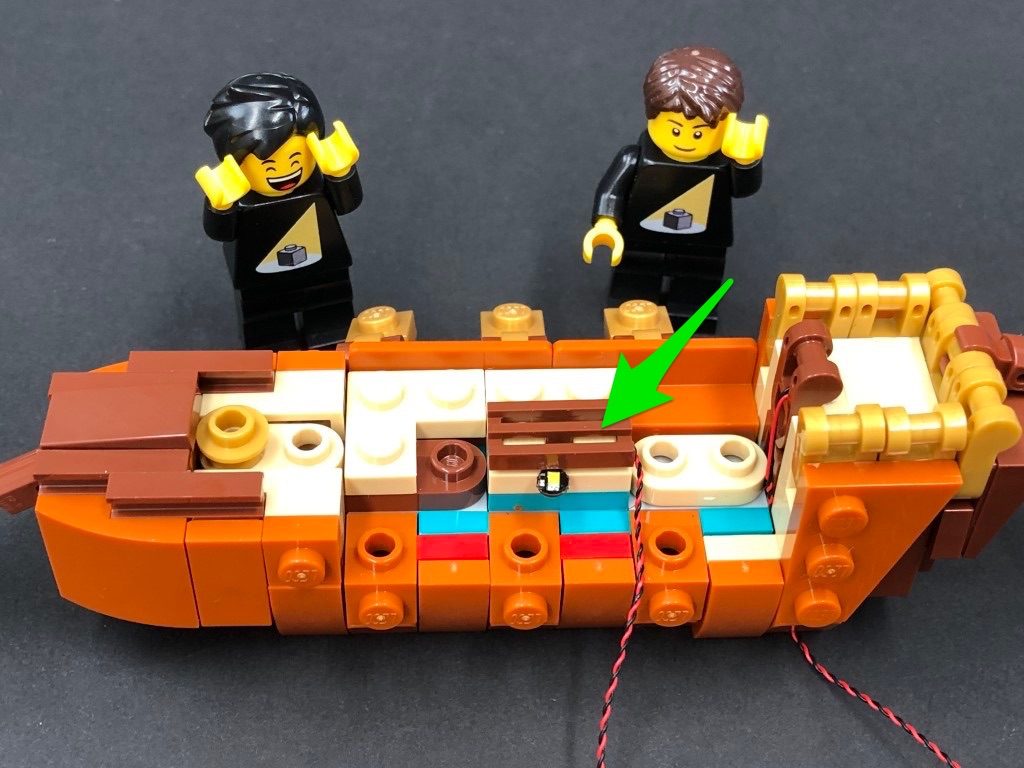
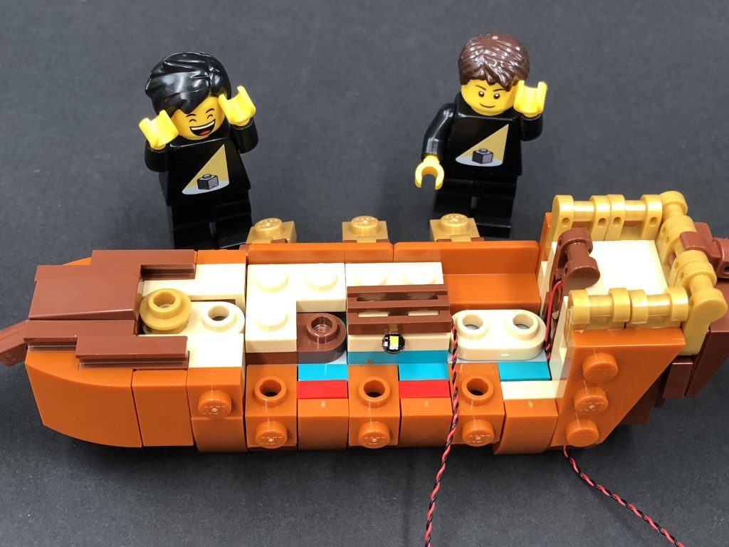
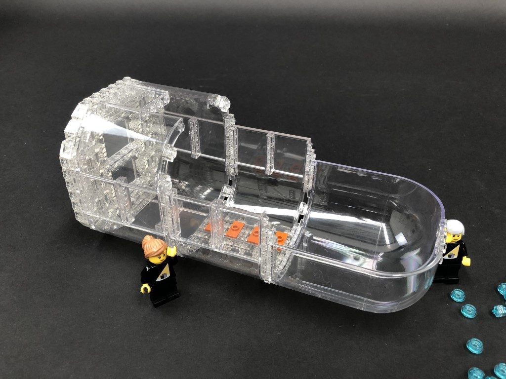
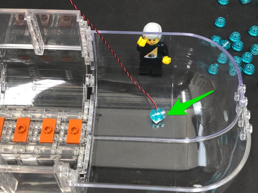
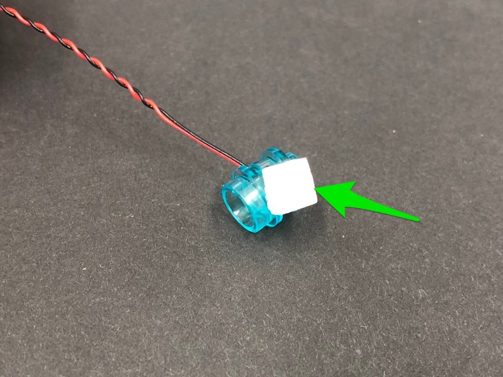
23.) Take the provided Trans Clear 2×2 Plate w Rounded Bottom and place the LED facing down in the middle of the inside of the plate (studded area). While ensuring the LED stays facing down inside the plate, connect the plate underneath the roof of this section as shown below. The Bit Light should be secured and facing down.
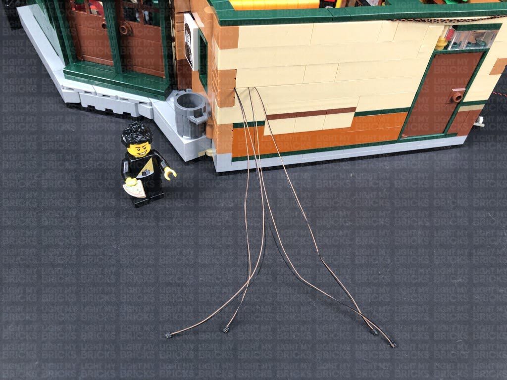
From the outside of the ship, pull the excess cable back inside the captain’s HQ ensuring the cable is slipped completely inside the gaps.
Turn the power ON to test the kitchen light is working OK.
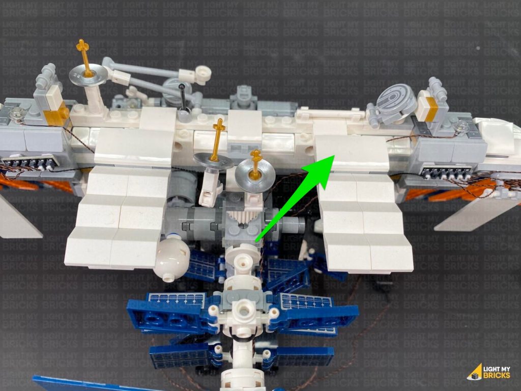
Reconnect all the pieces we removed earlier, then securely reconnect the top floor section as well as the outside floor section.
24.) Clean up messy cables inside the captain’s HQ by bunching up cables and components and placing them behind the treasure chest. Lift up the treasure chest lid to further conceal the cables.
22.) Take a White 15cm Bit Light and connect it to a spare port on the 8-Port Expansion Board inside the captain’s HQ. Bring the cable over the left wall, slipping it in between the black wall sections as shown below.
Bring the cable inside the kitchen area, threading the cable underneath the black angled bricks.
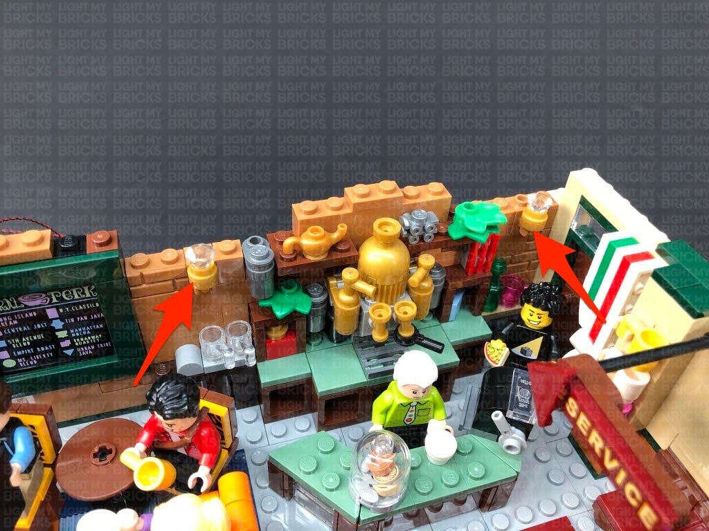
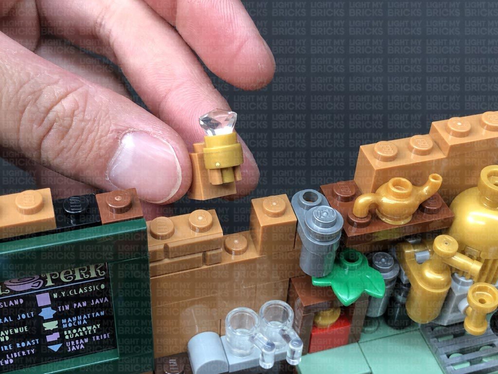
23.) Take the provided Trans Clear 2×2 Plate w Rounded Bottom and place the LED facing down in the middle of the inside of the plate (studded area). While ensuring the LED stays facing down inside the plate, connect the plate underneath the roof of this section as shown below. The Bit Light should be secured and facing down.
From the outside of the ship, pull the excess cable back inside the captain’s HQ ensuring the cable is slipped completely inside the gaps.
Turn the power ON to test the kitchen light is working OK.
Reconnect all the pieces we removed earlier, then securely reconnect the top floor section as well as the outside floor section.
24.) Clean up messy cables inside the captain’s HQ by bunching up cables and components and placing them behind the treasure chest. Lift up the treasure chest lid to further conceal the cables.
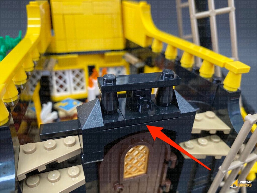
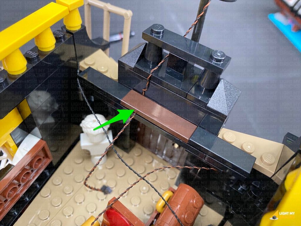
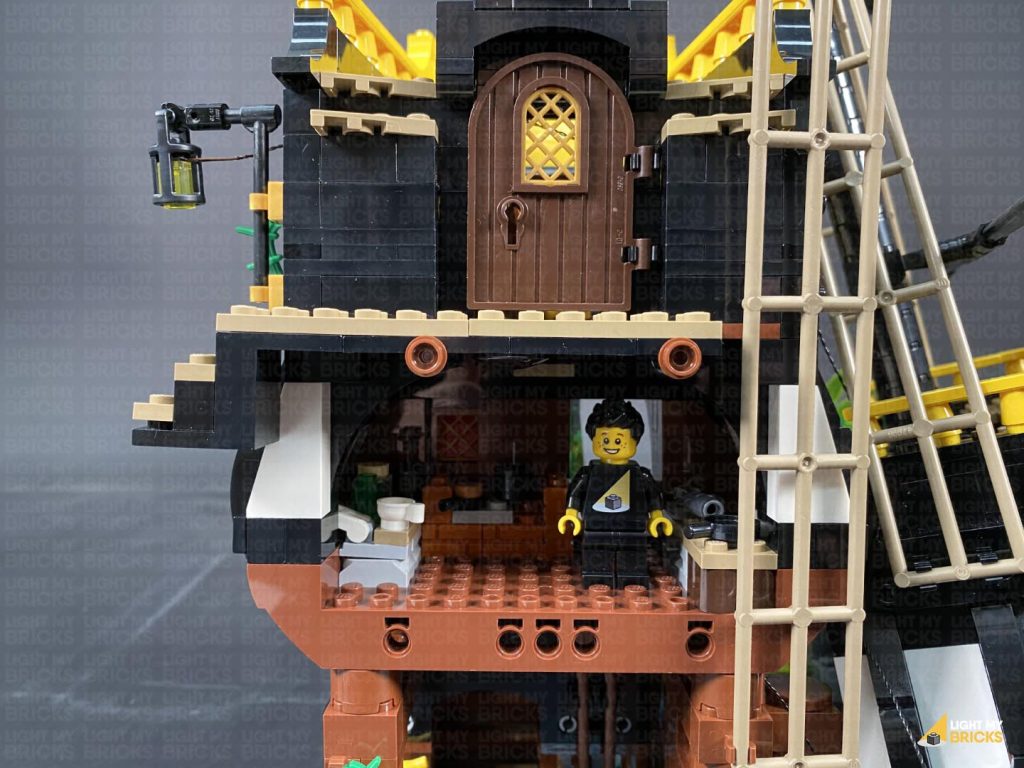
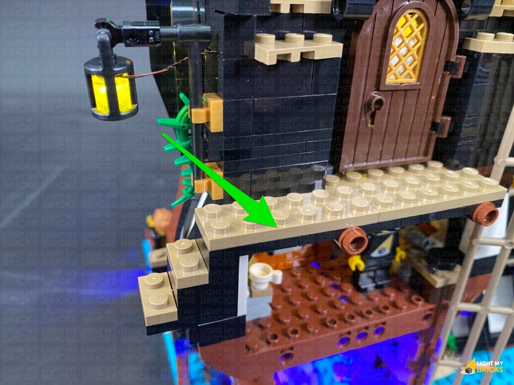
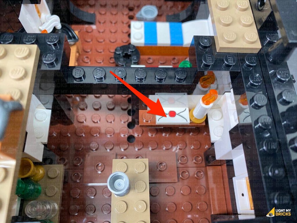
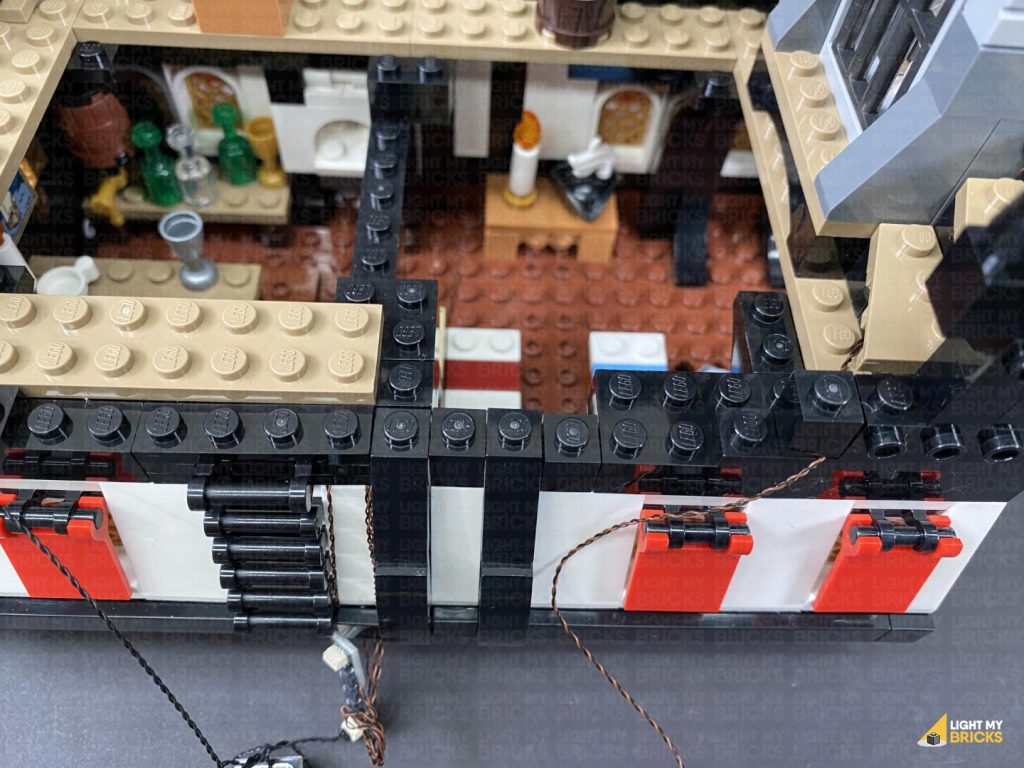
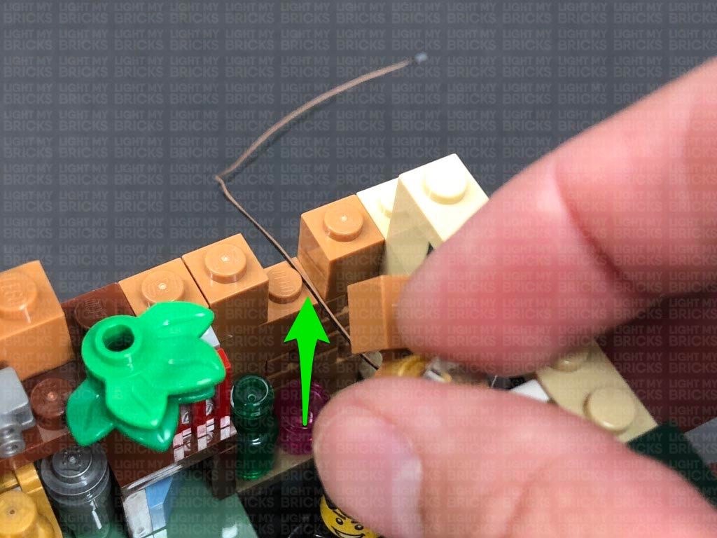
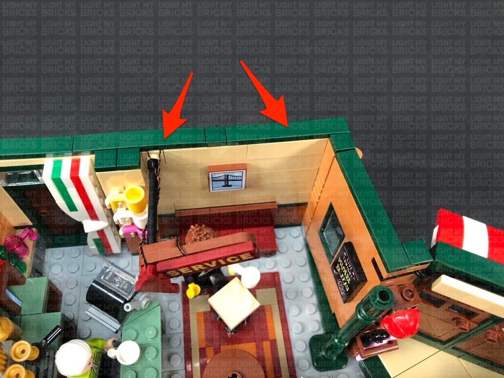
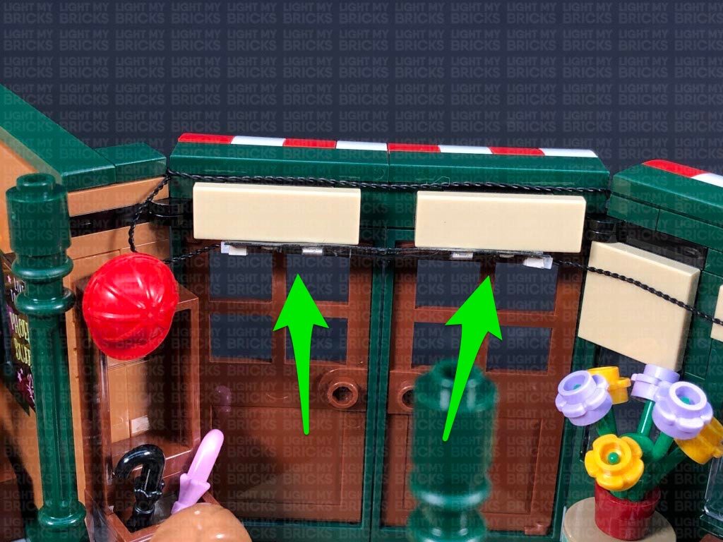
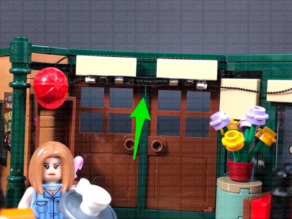
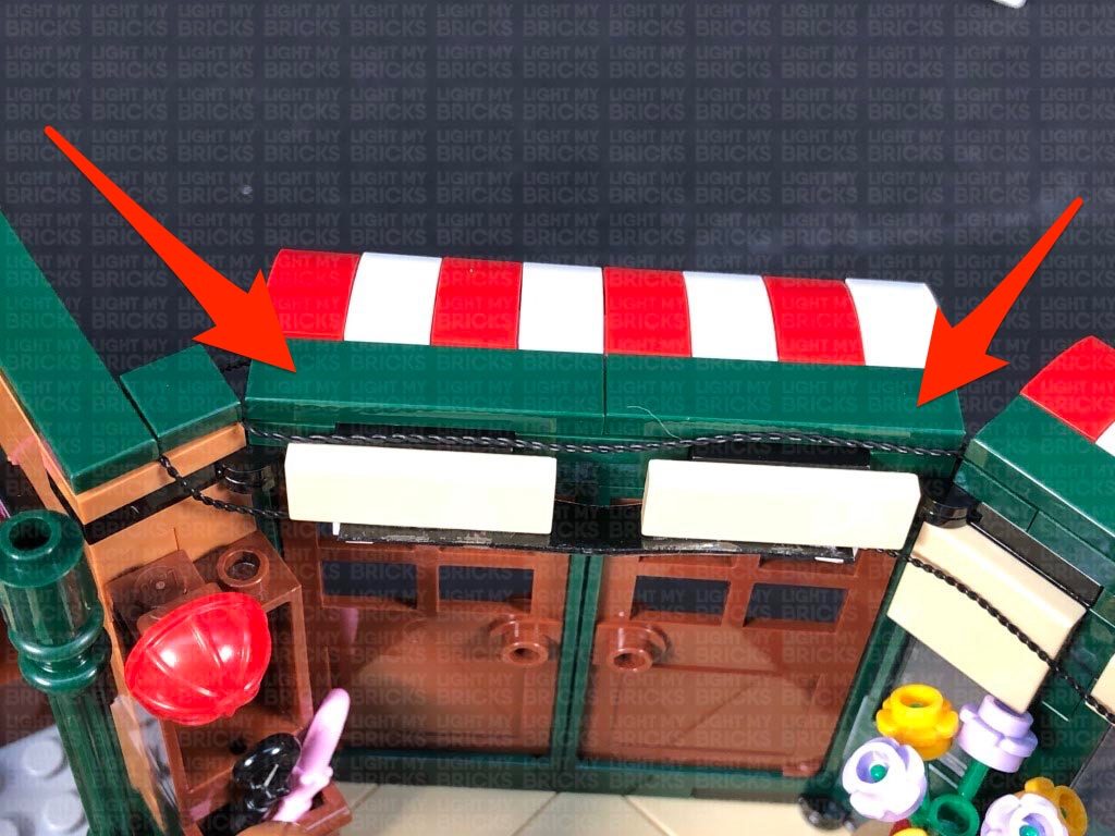
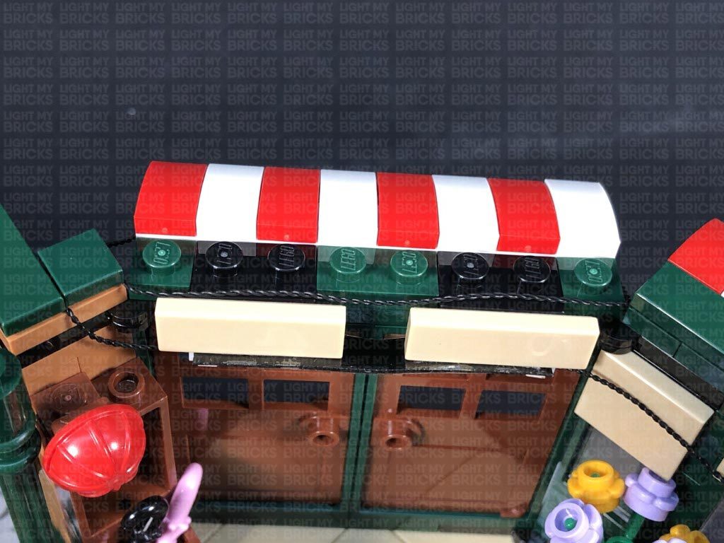
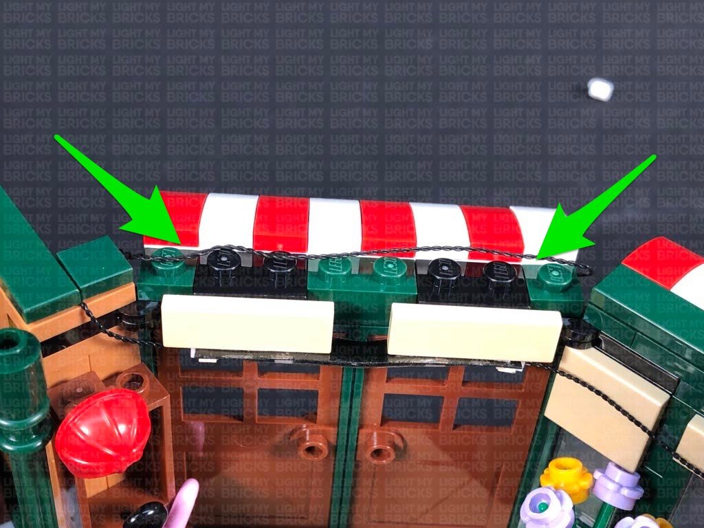
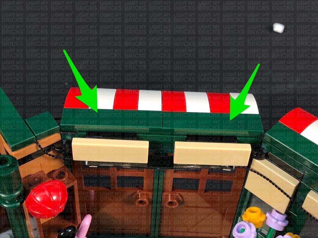
 Disconnect the following three tiles from above the door. Lay the cables across the top beam, in between studs, then one by one, reconnect the tiles over them to prevent the cables from dangling down.
Do your best to hide the wiring so that they aren’t seen dangling down when you open the door.
Disconnect the following three tiles from above the door. Lay the cables across the top beam, in between studs, then one by one, reconnect the tiles over them to prevent the cables from dangling down.
Do your best to hide the wiring so that they aren’t seen dangling down when you open the door.
 Turn all the lights on again to test everything is looks OK.
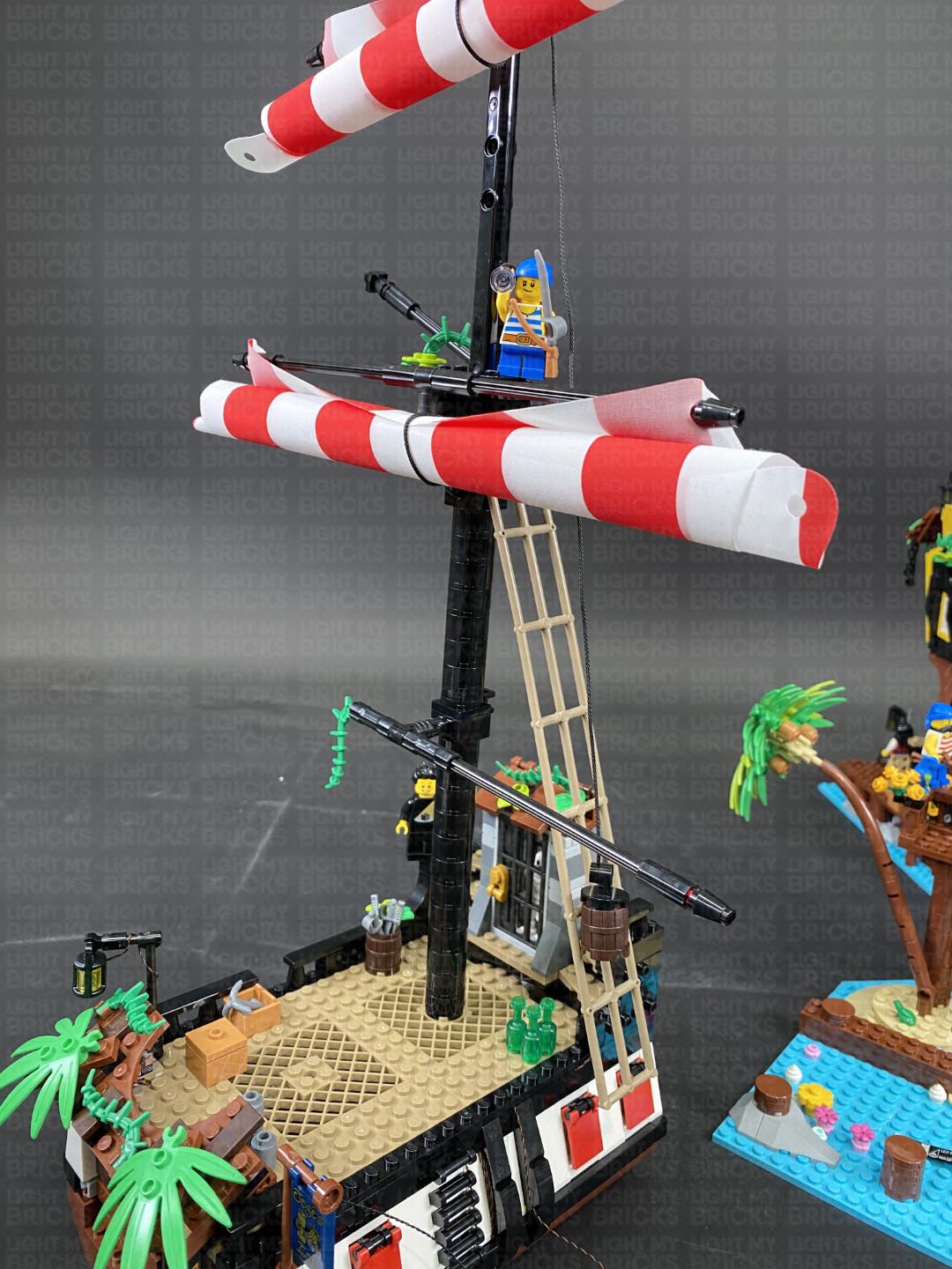
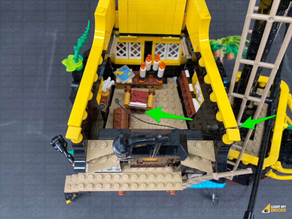
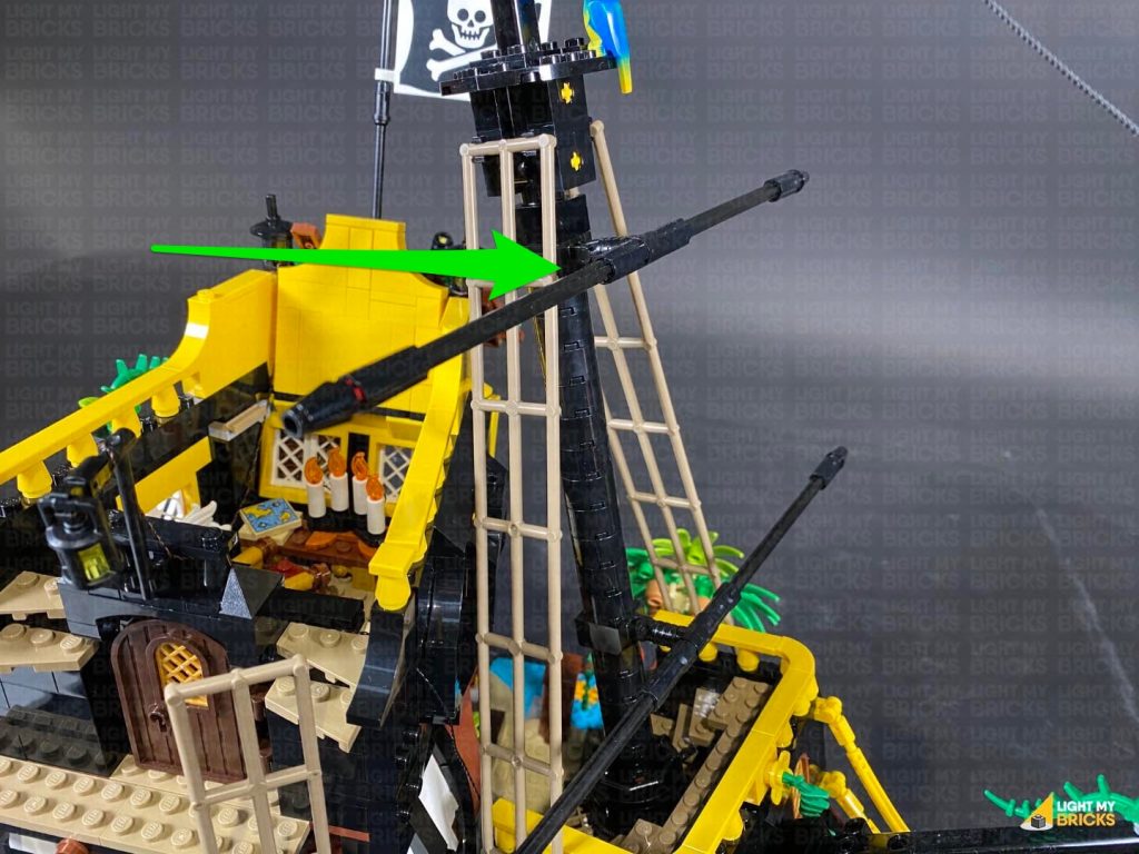
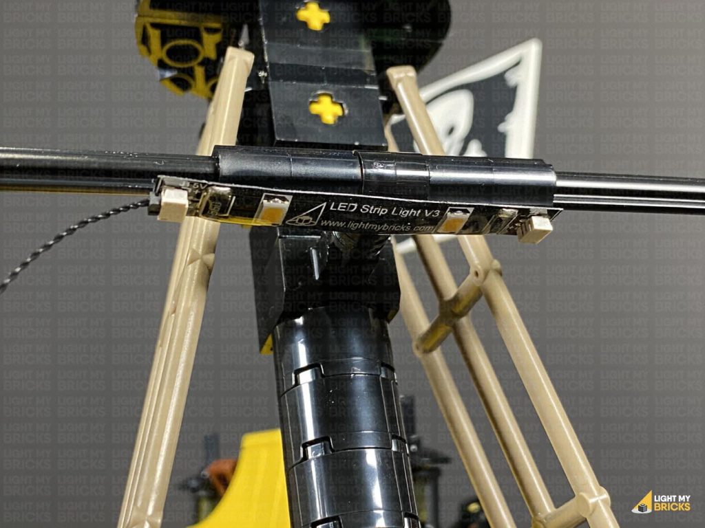
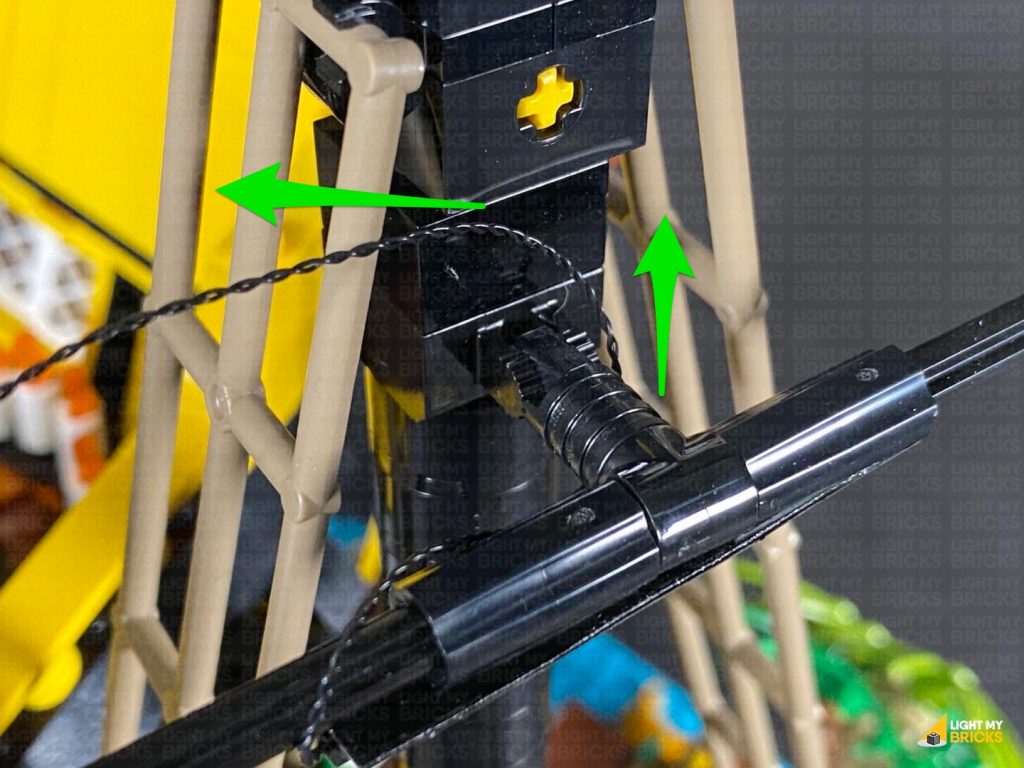
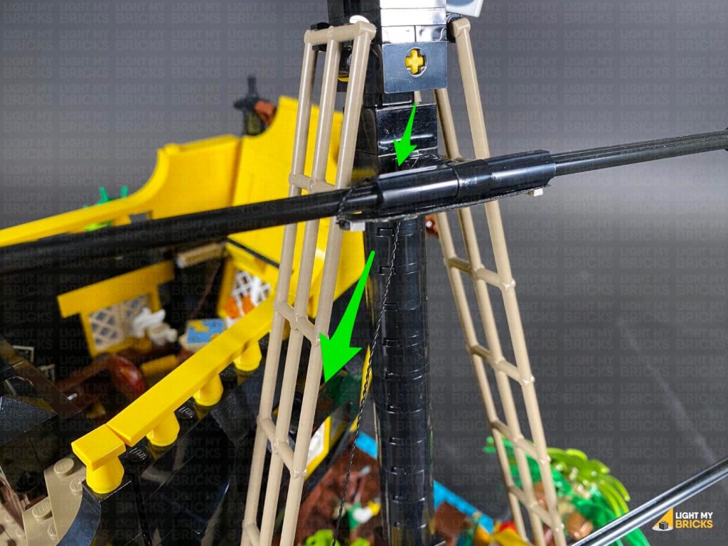
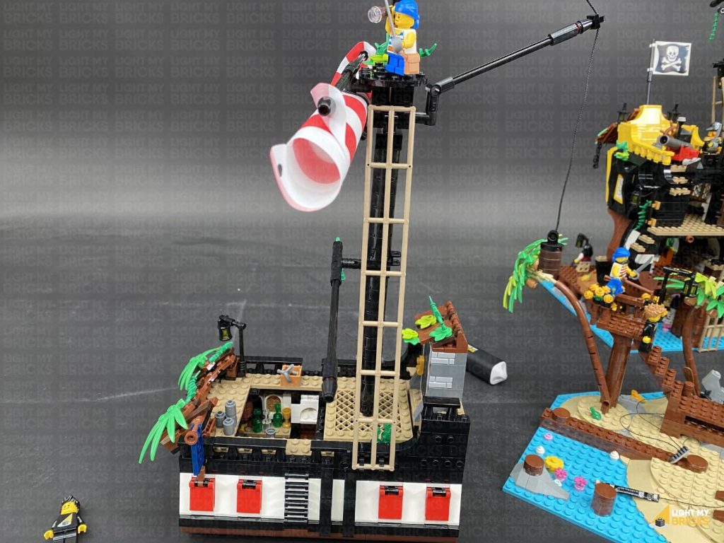
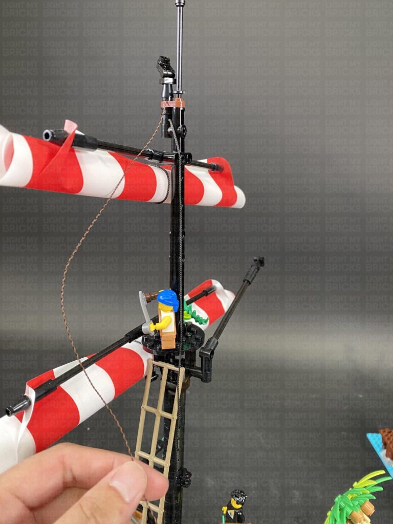
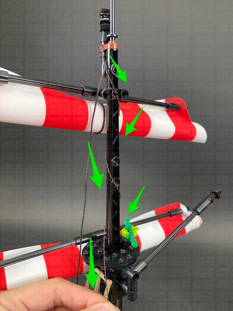
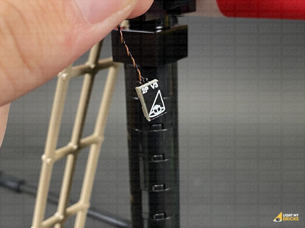
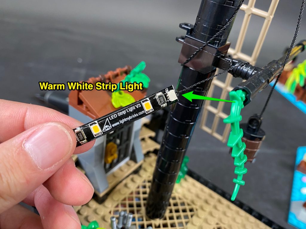
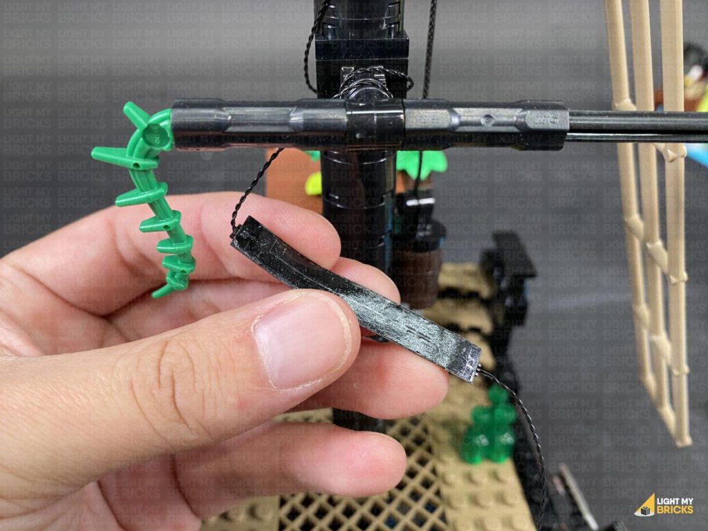
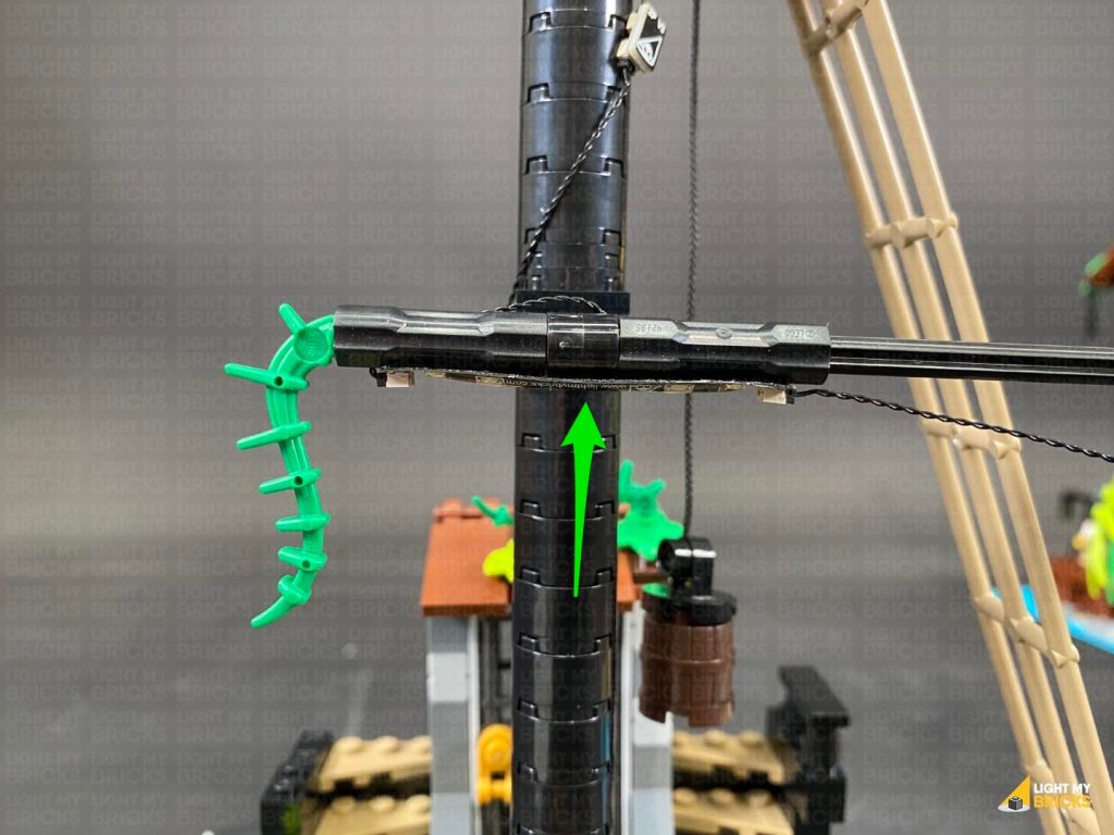
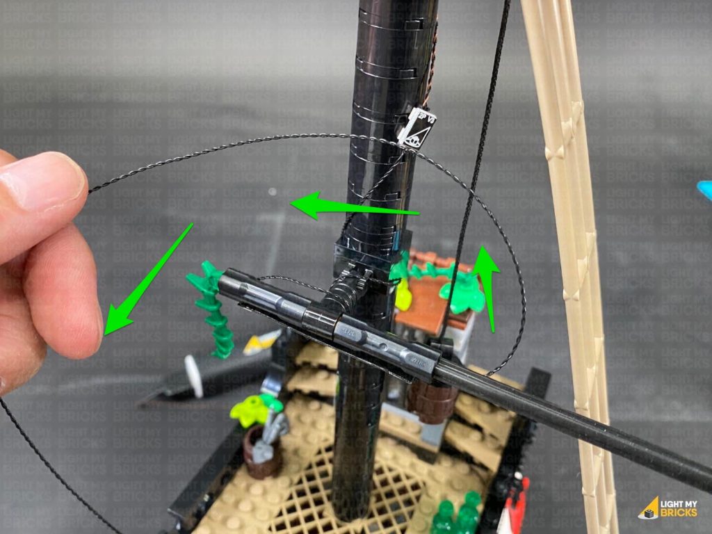
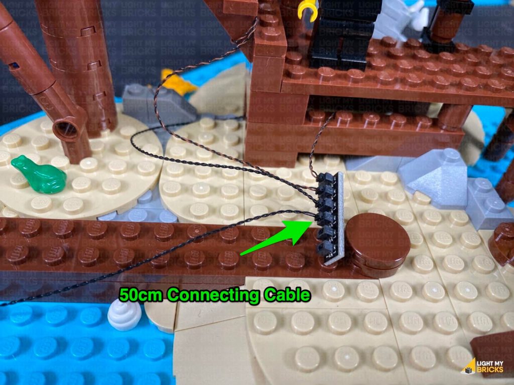
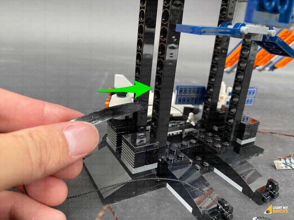
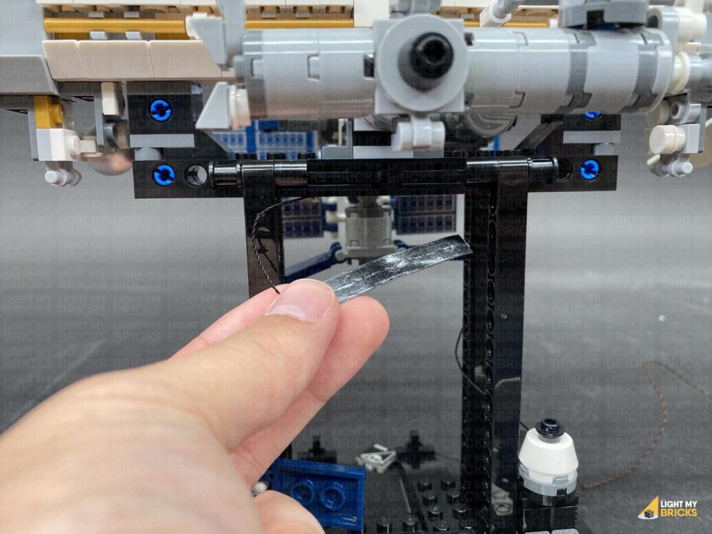
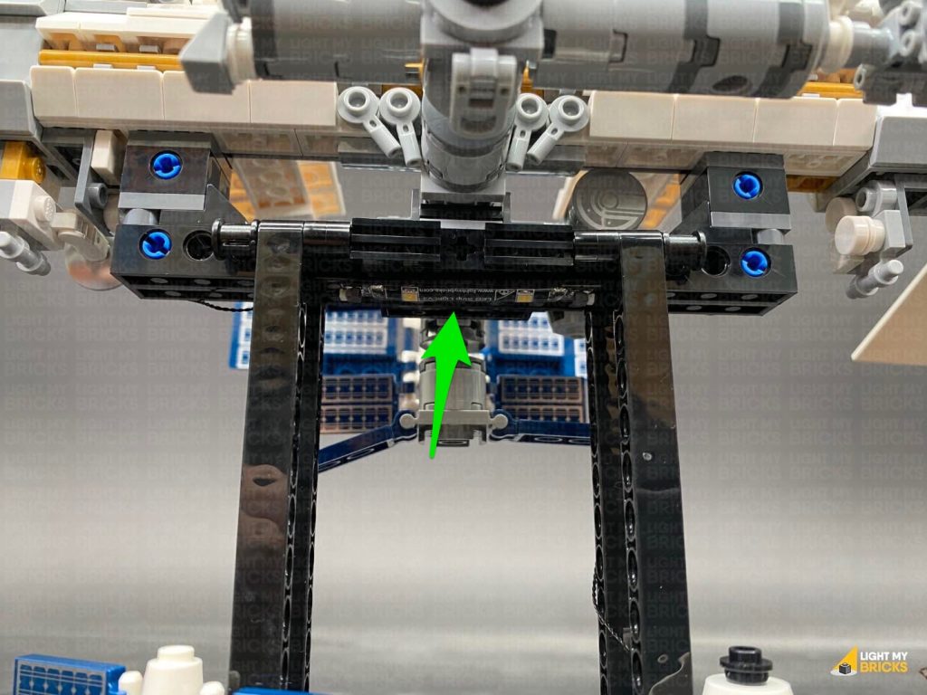
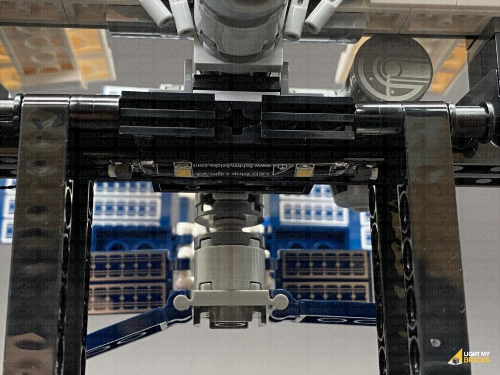
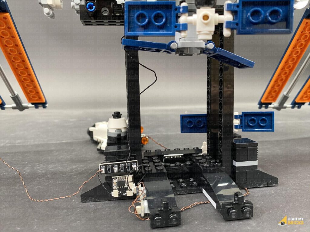
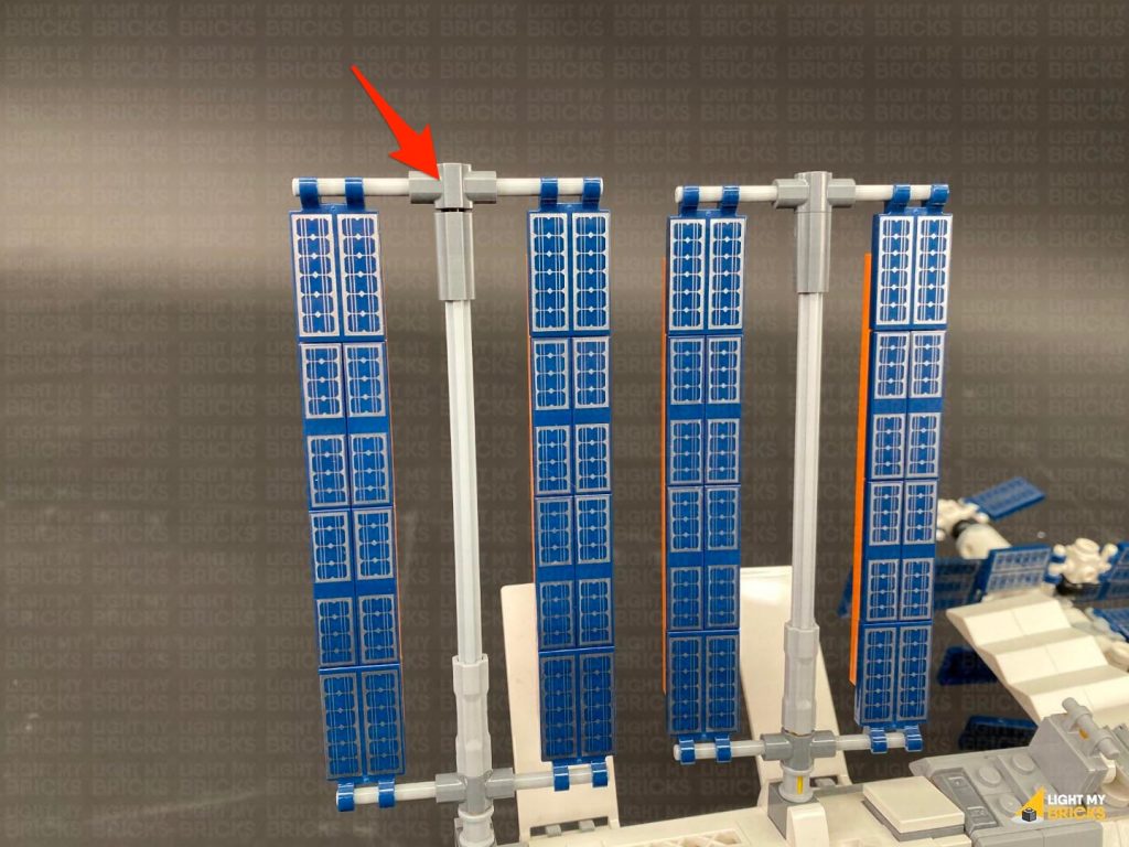
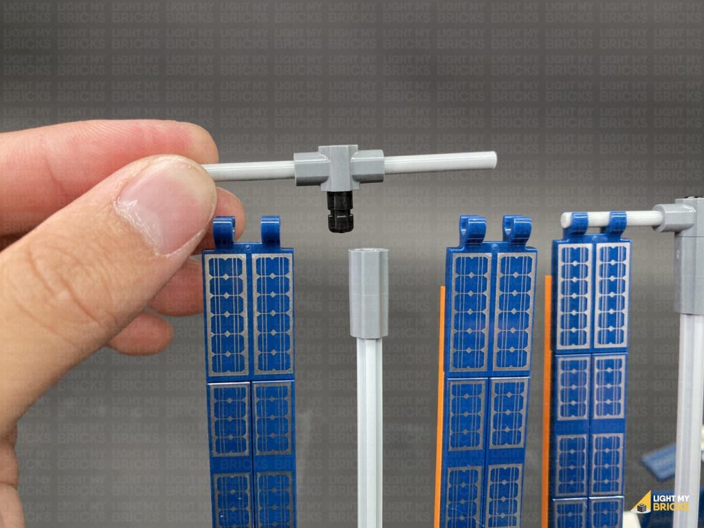
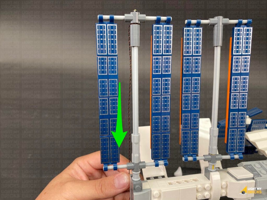
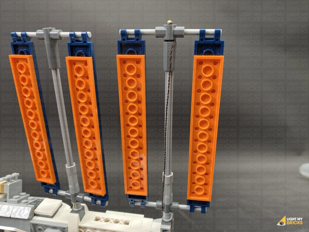
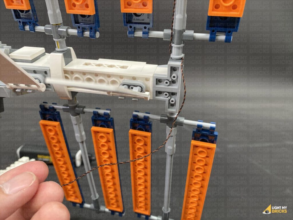
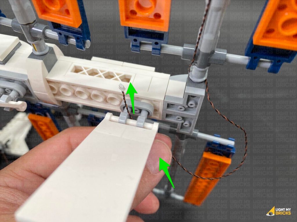
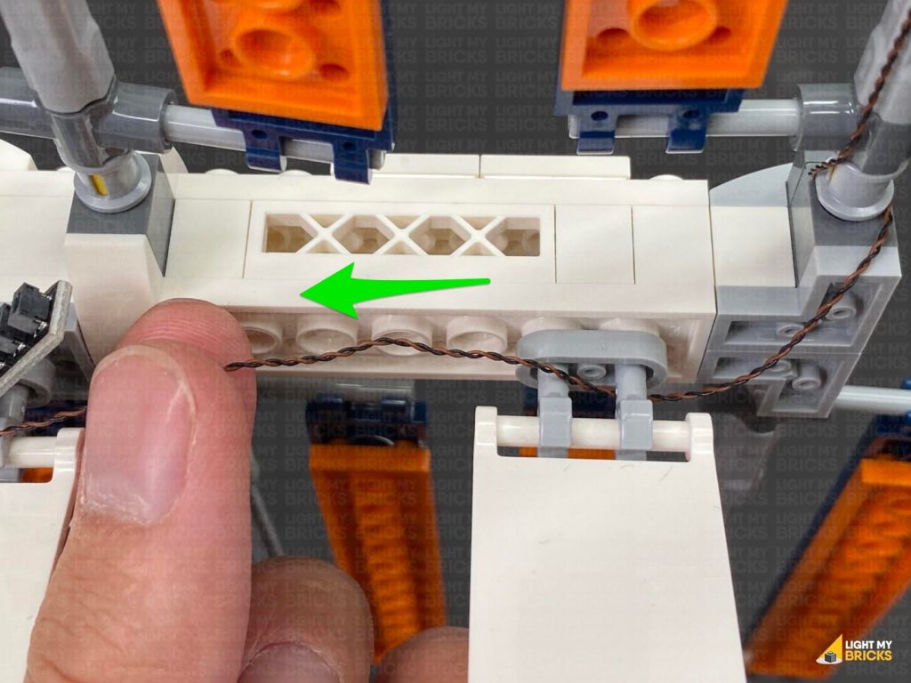
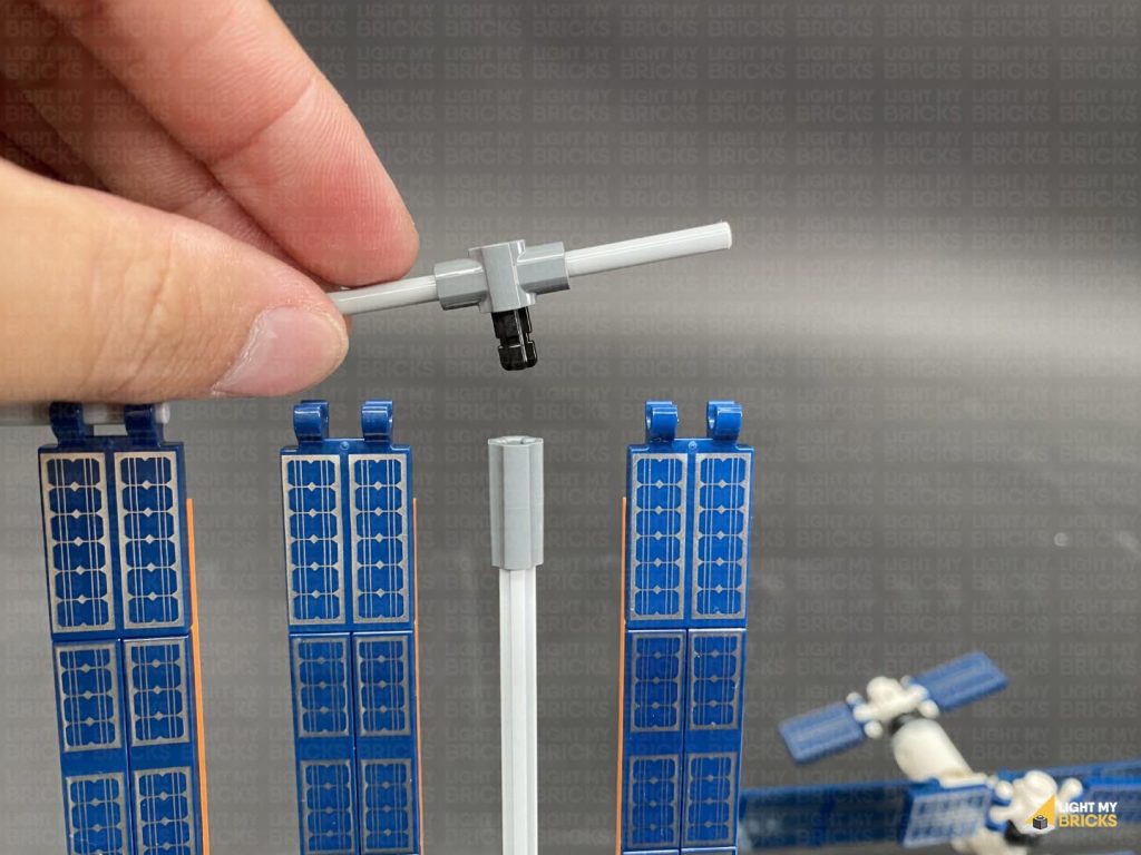
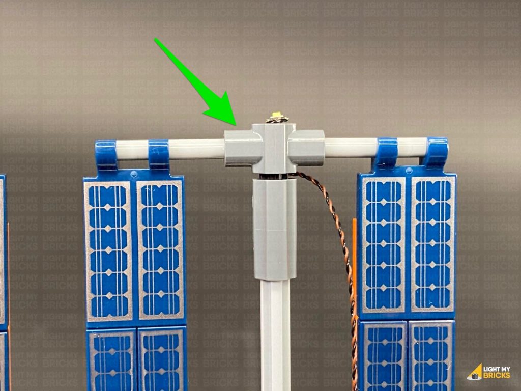
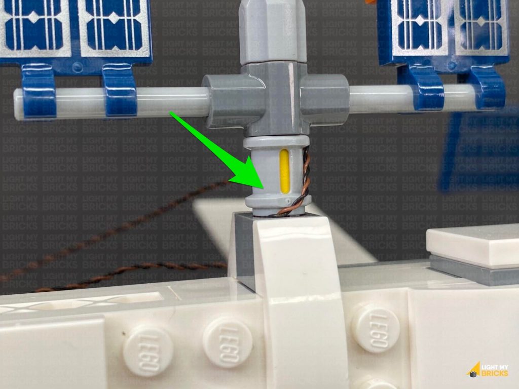
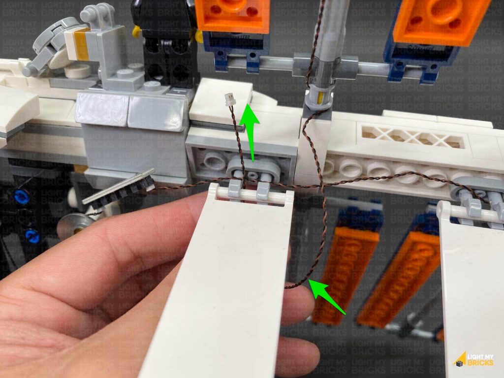
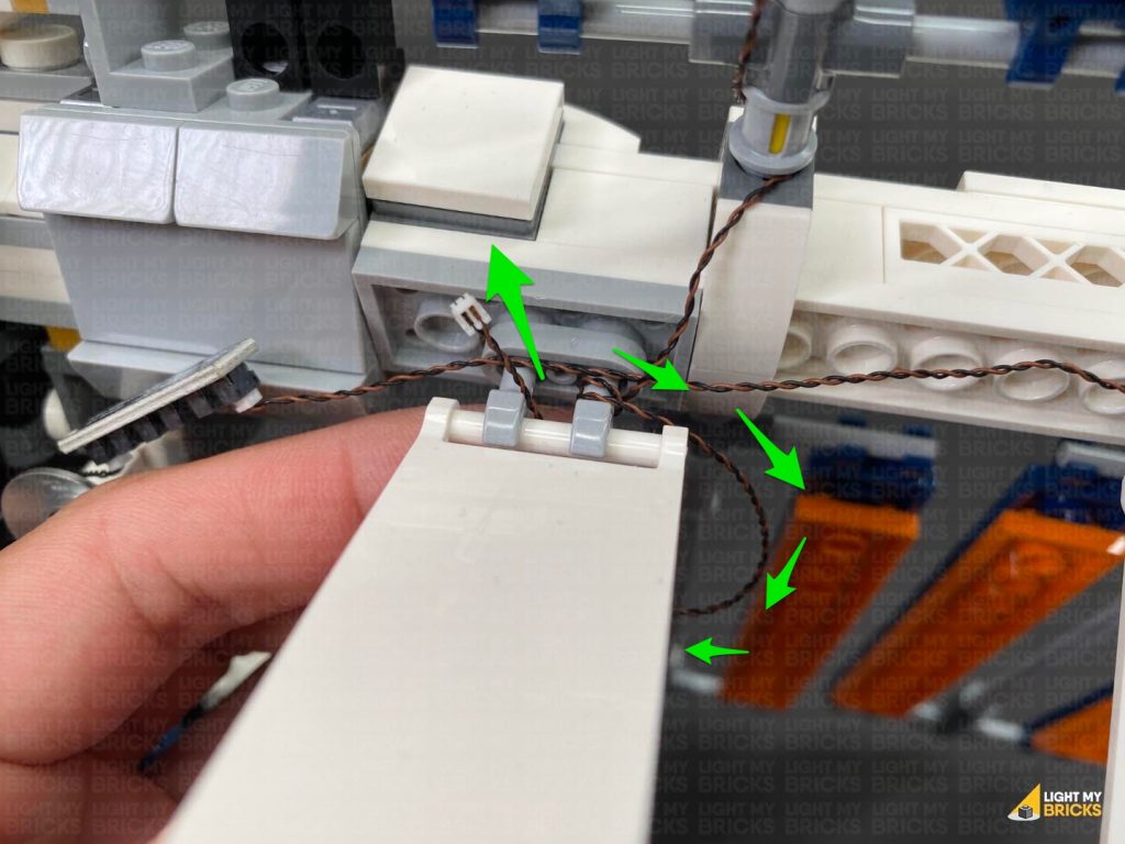
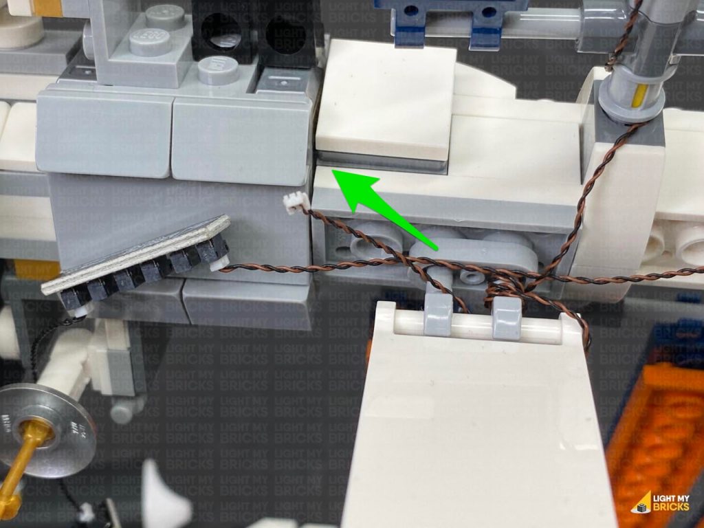
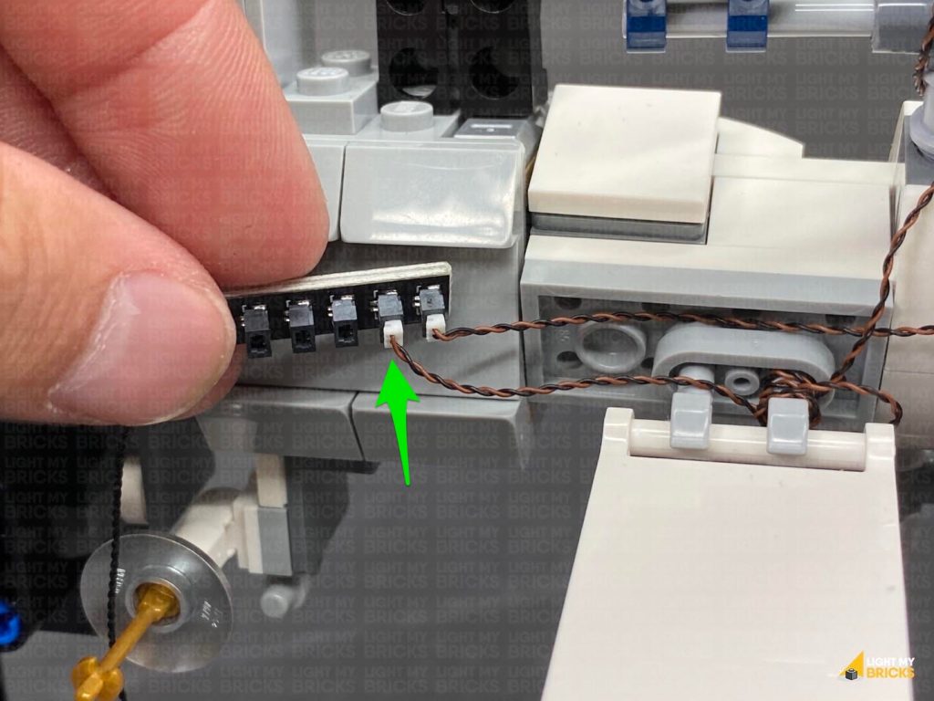
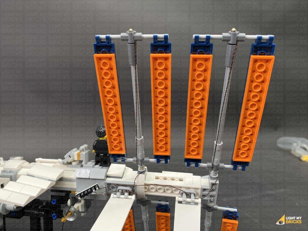
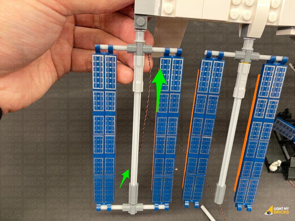
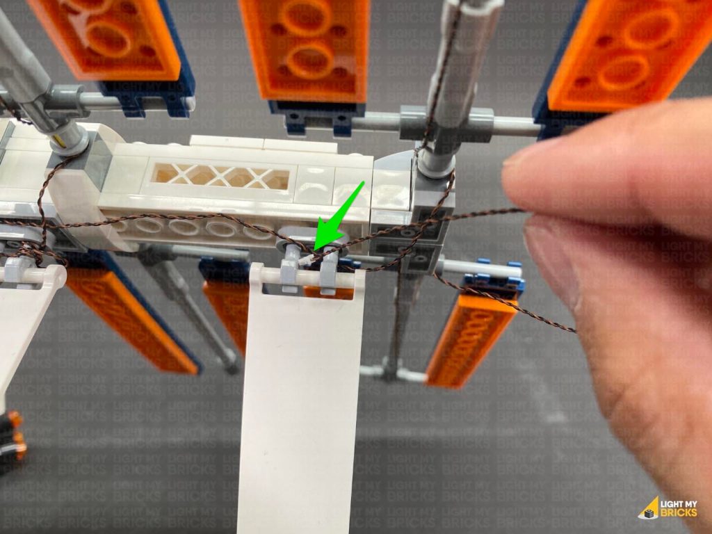
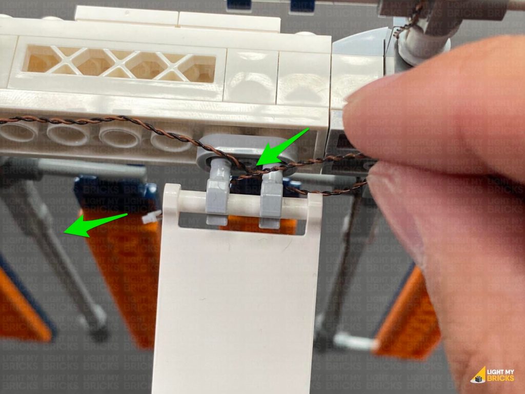
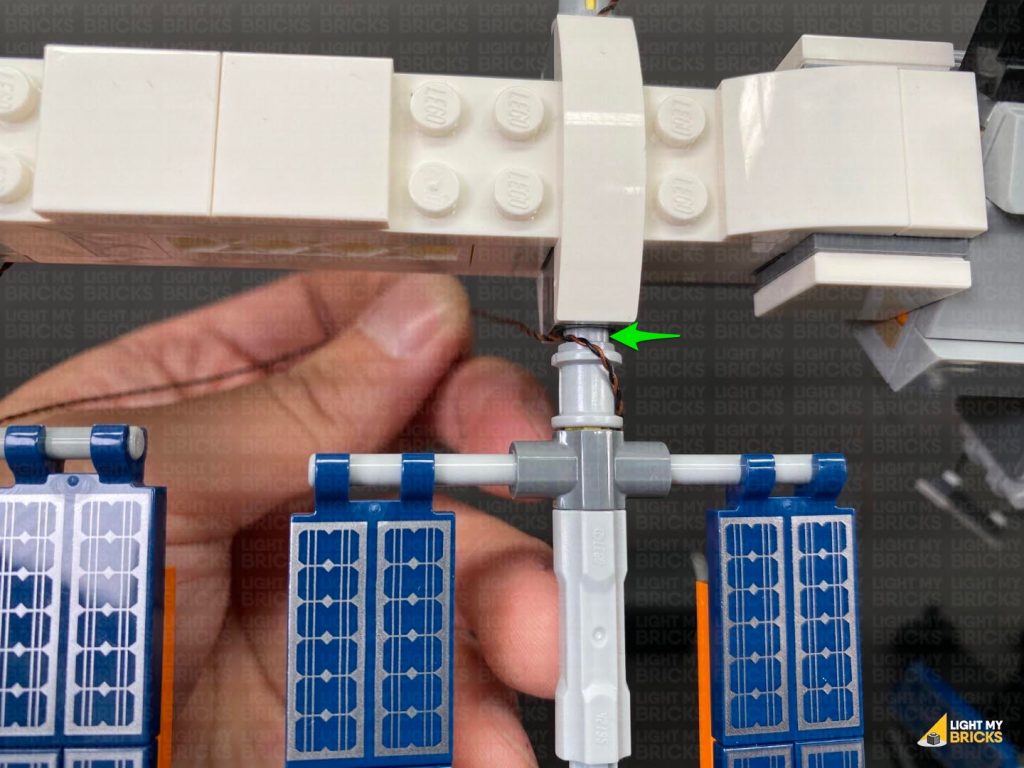
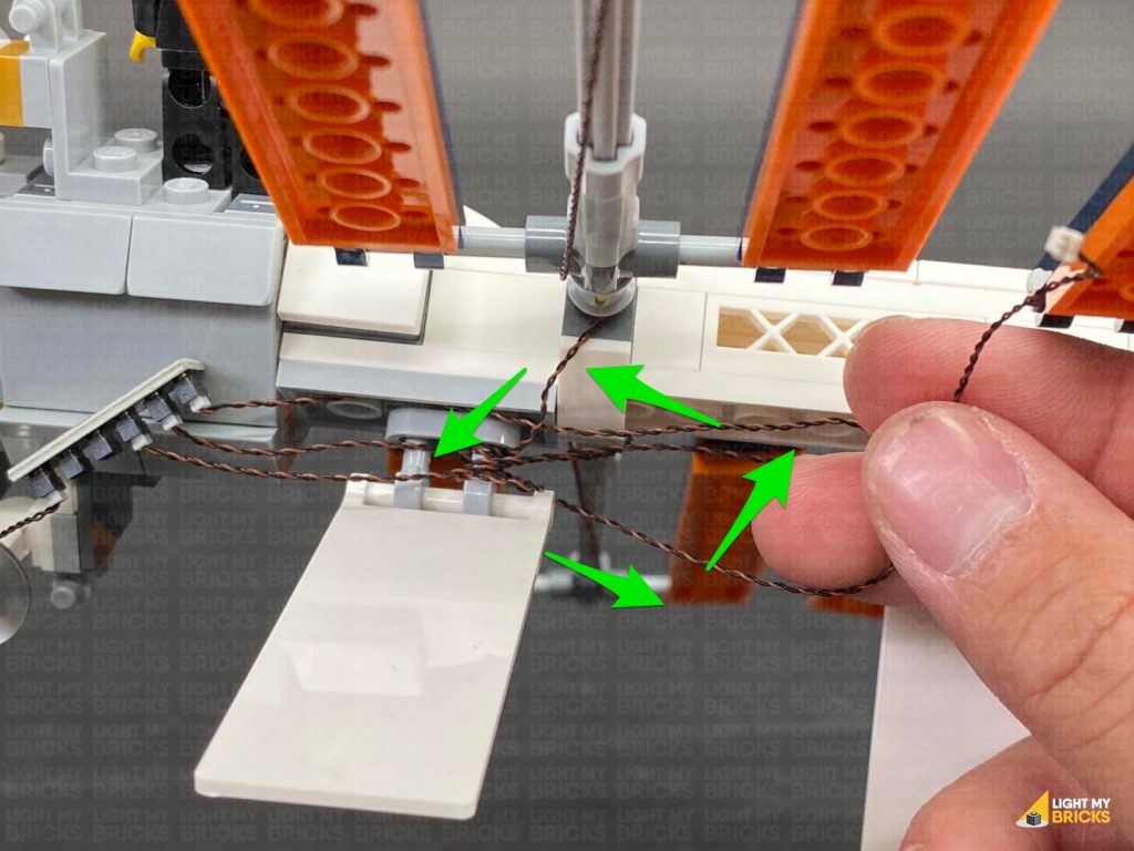
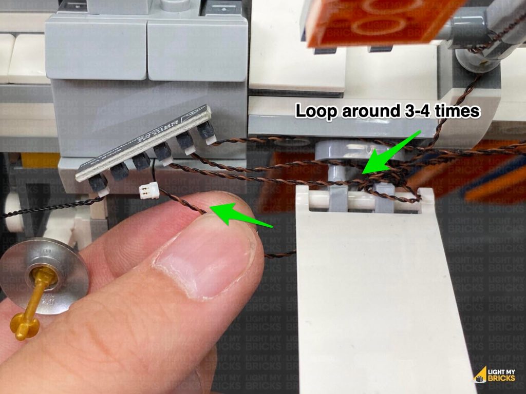
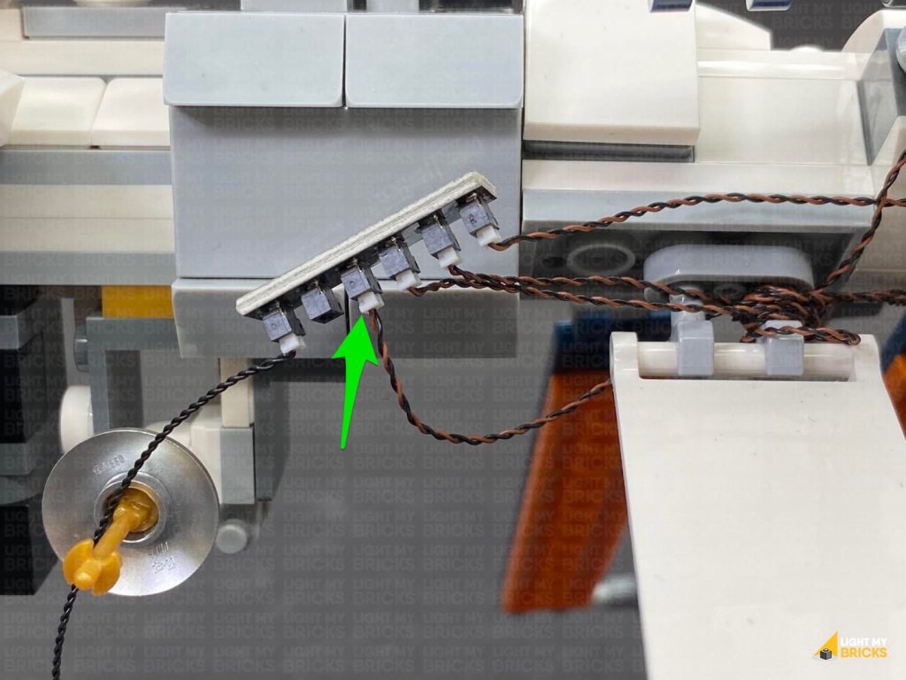
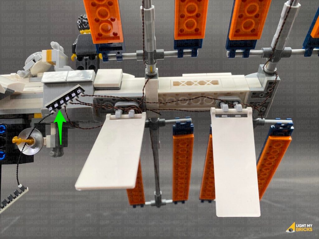
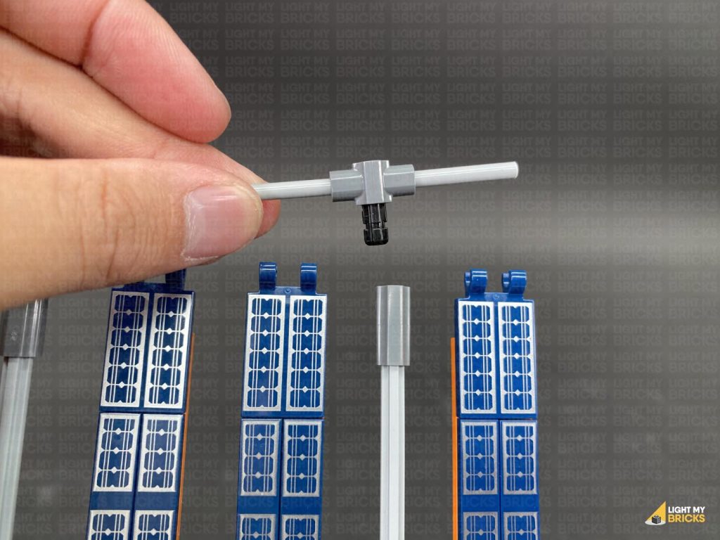
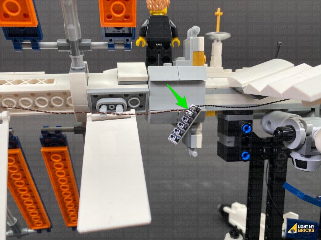
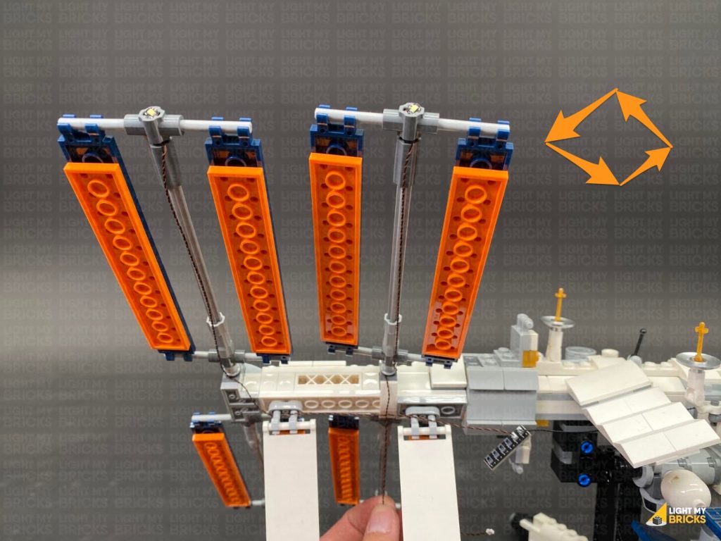
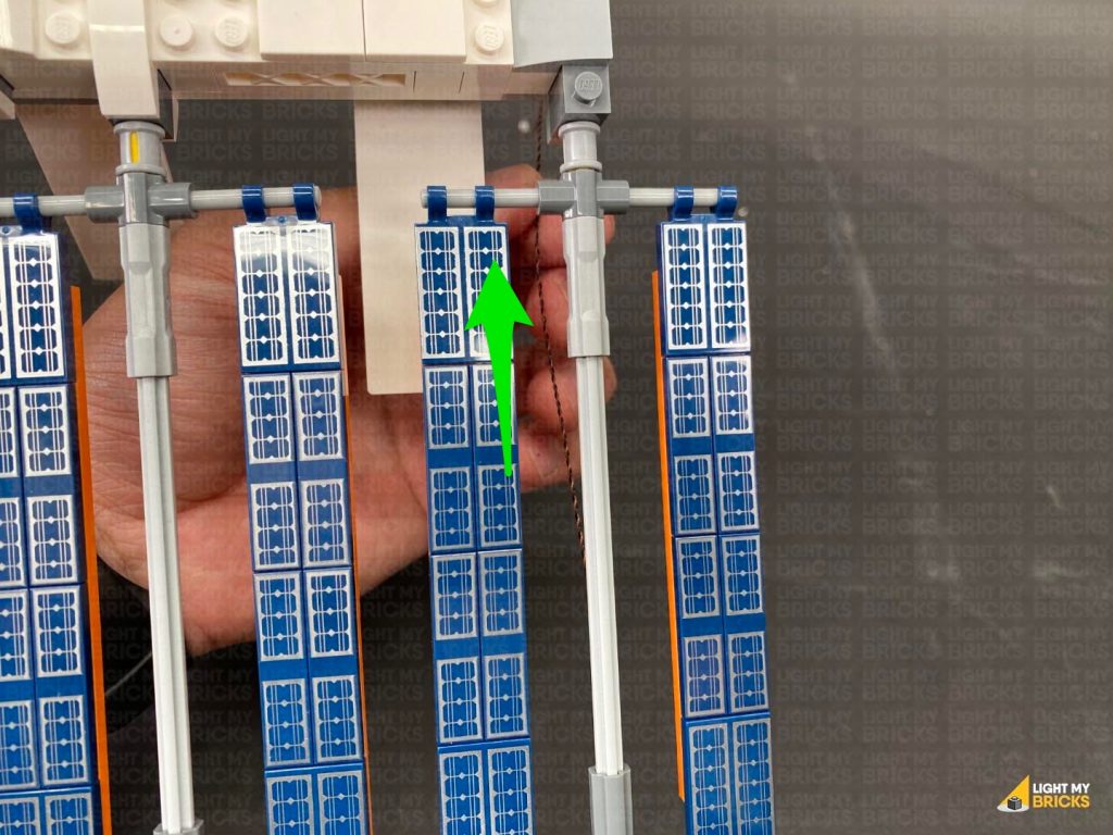
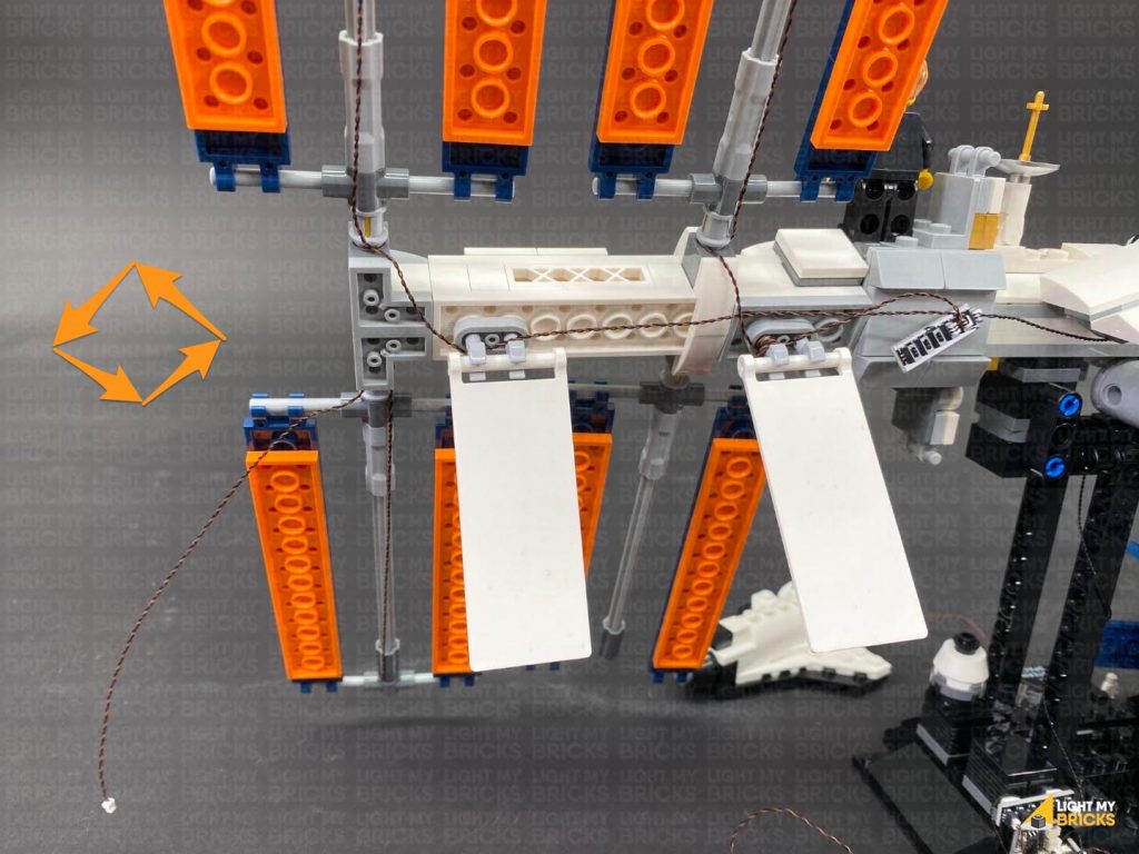
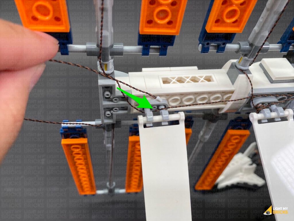
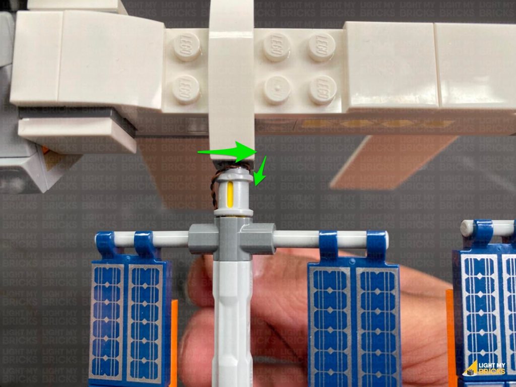
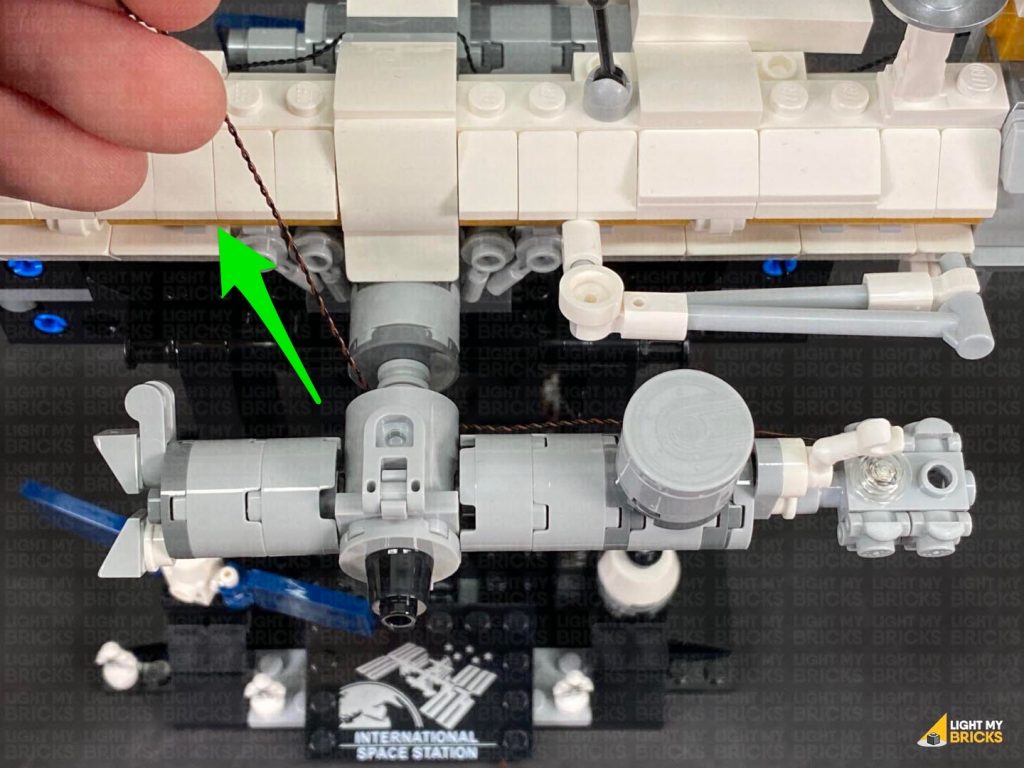
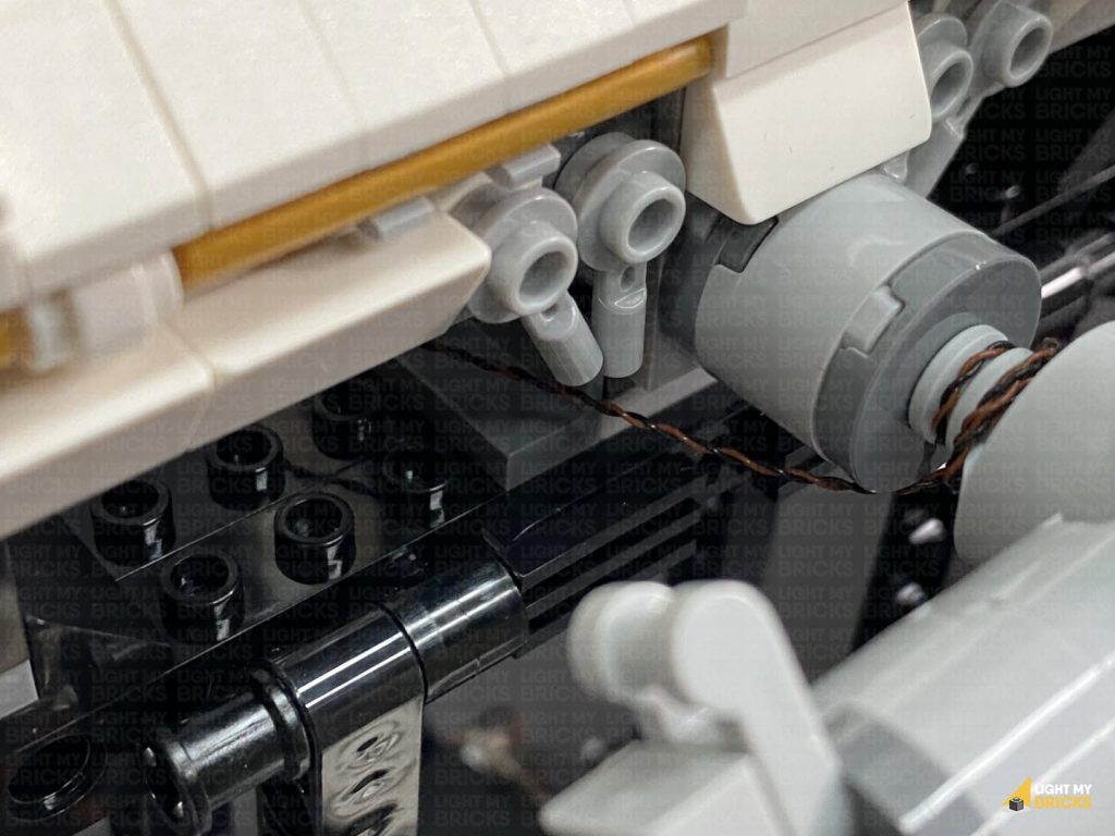
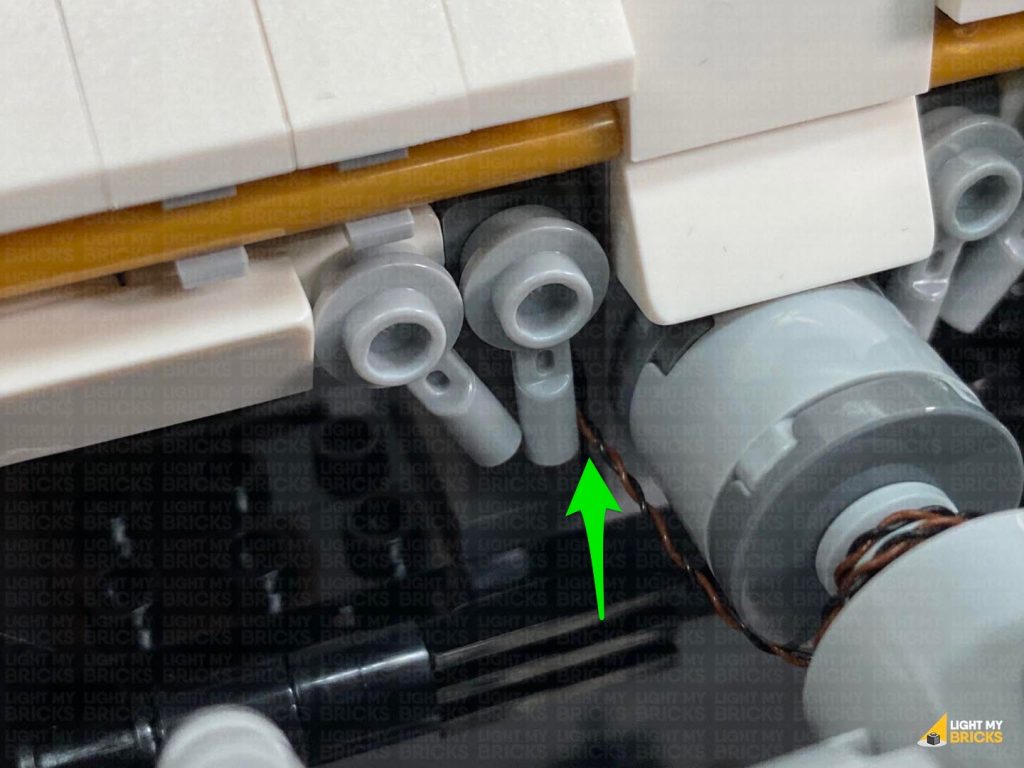
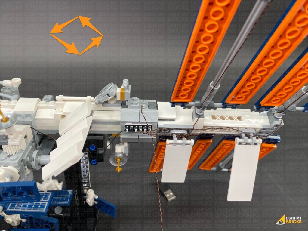
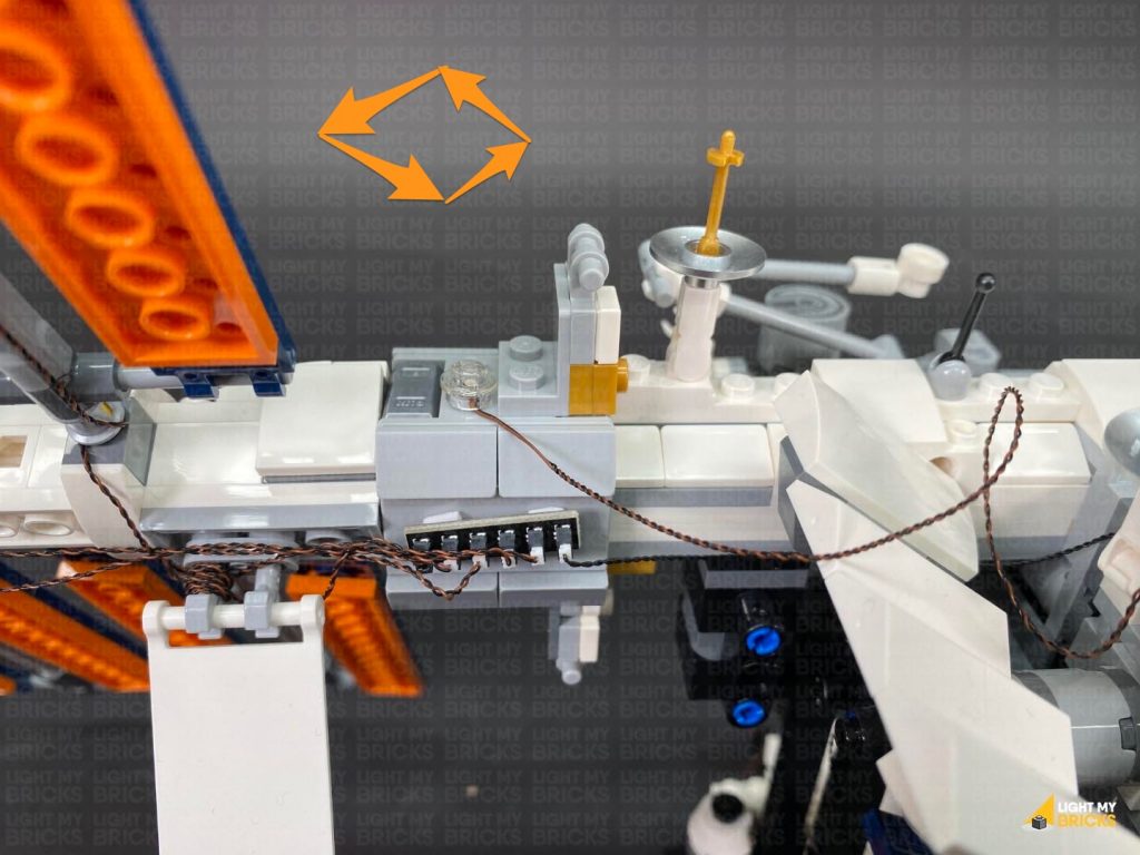
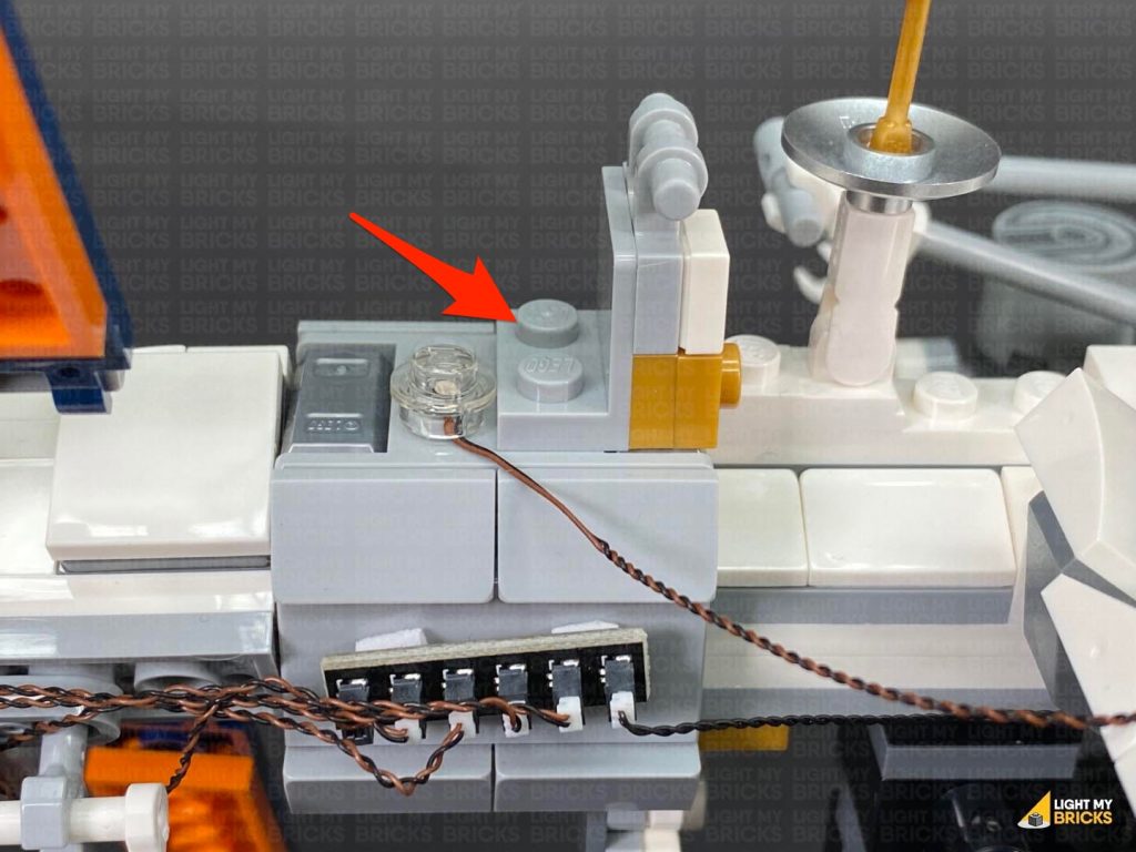
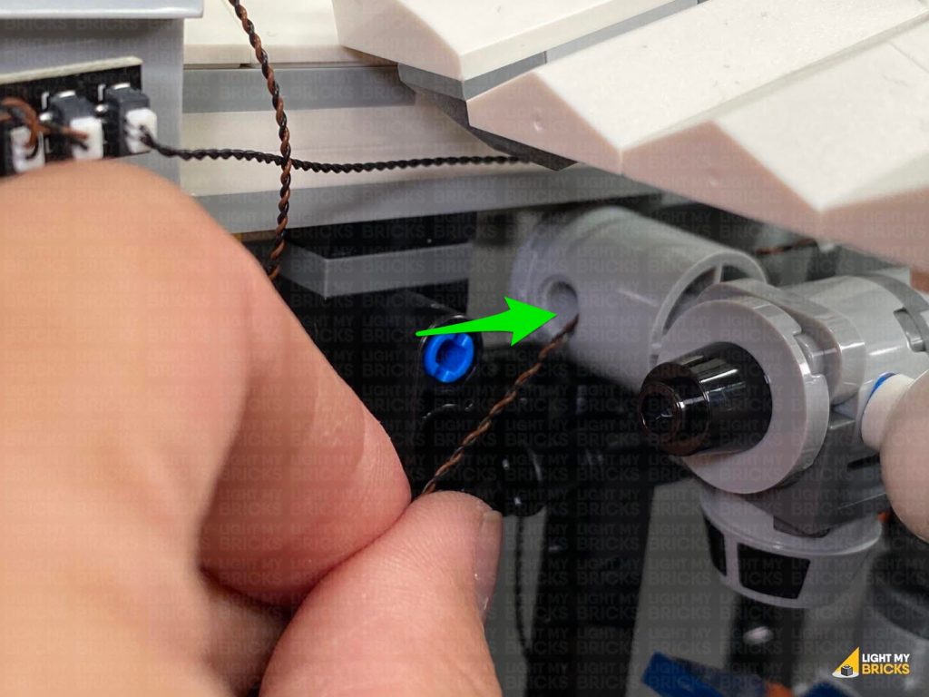
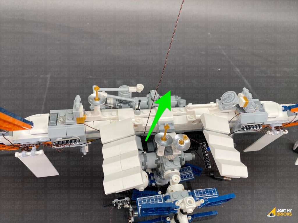
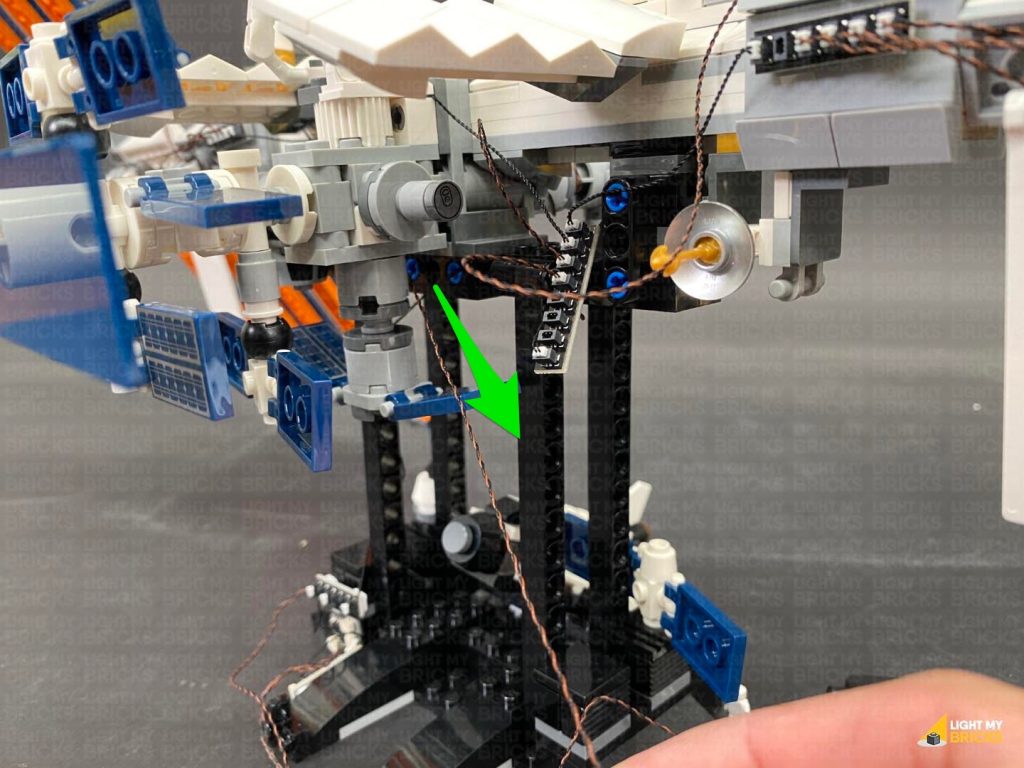
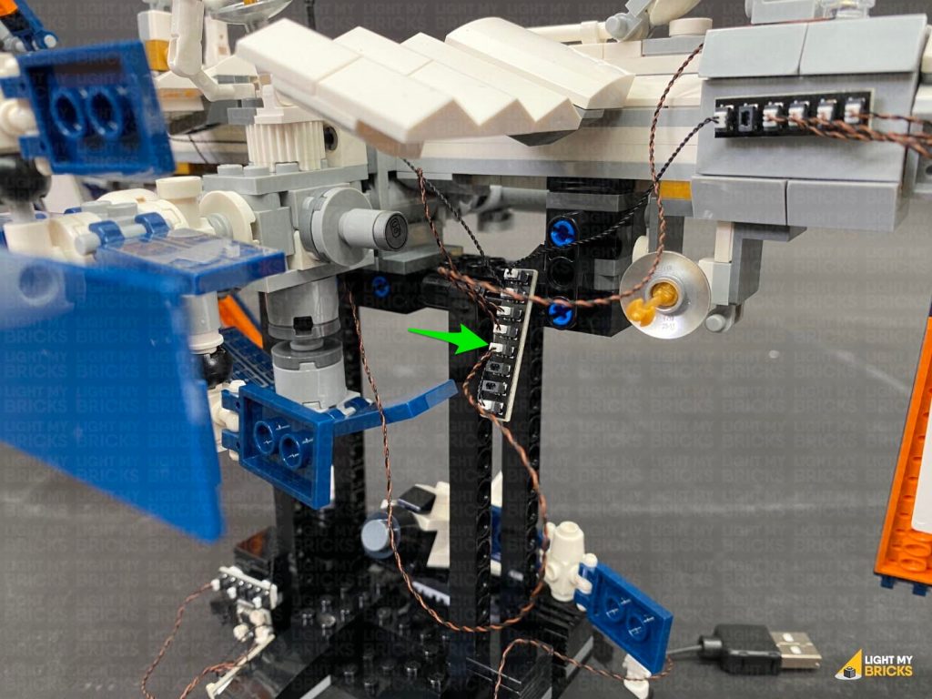
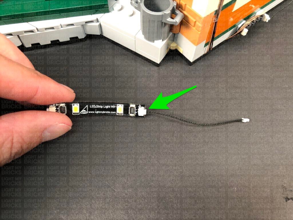
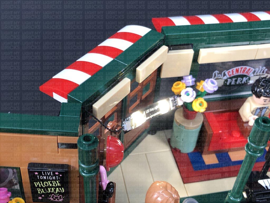
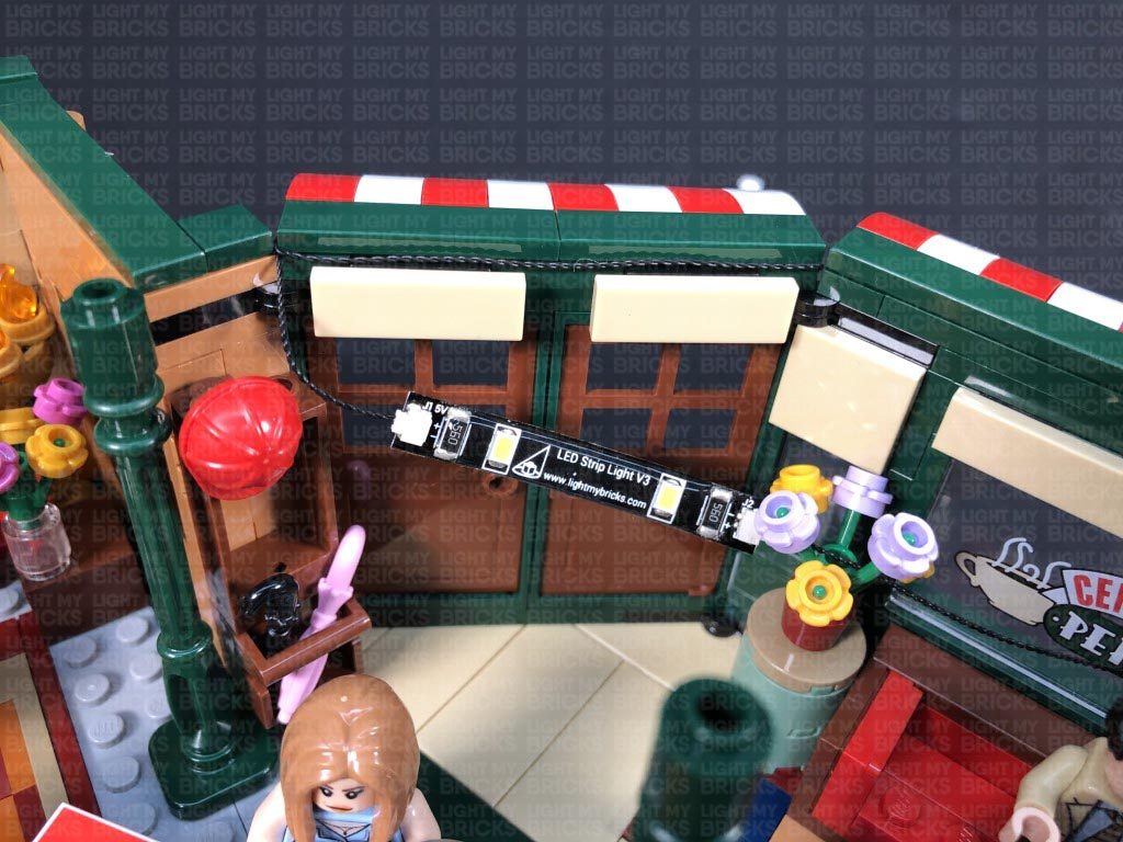
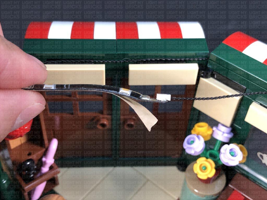
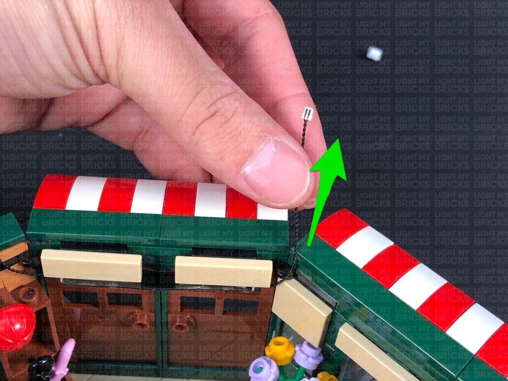
25.) Take a Warm White Strip Light and connect a 50cm Connecting Cable to it. Using it’d adhesive backing, stick the strip light underneath the second horizontal beam, ensuring the connecting cable is facing the back.
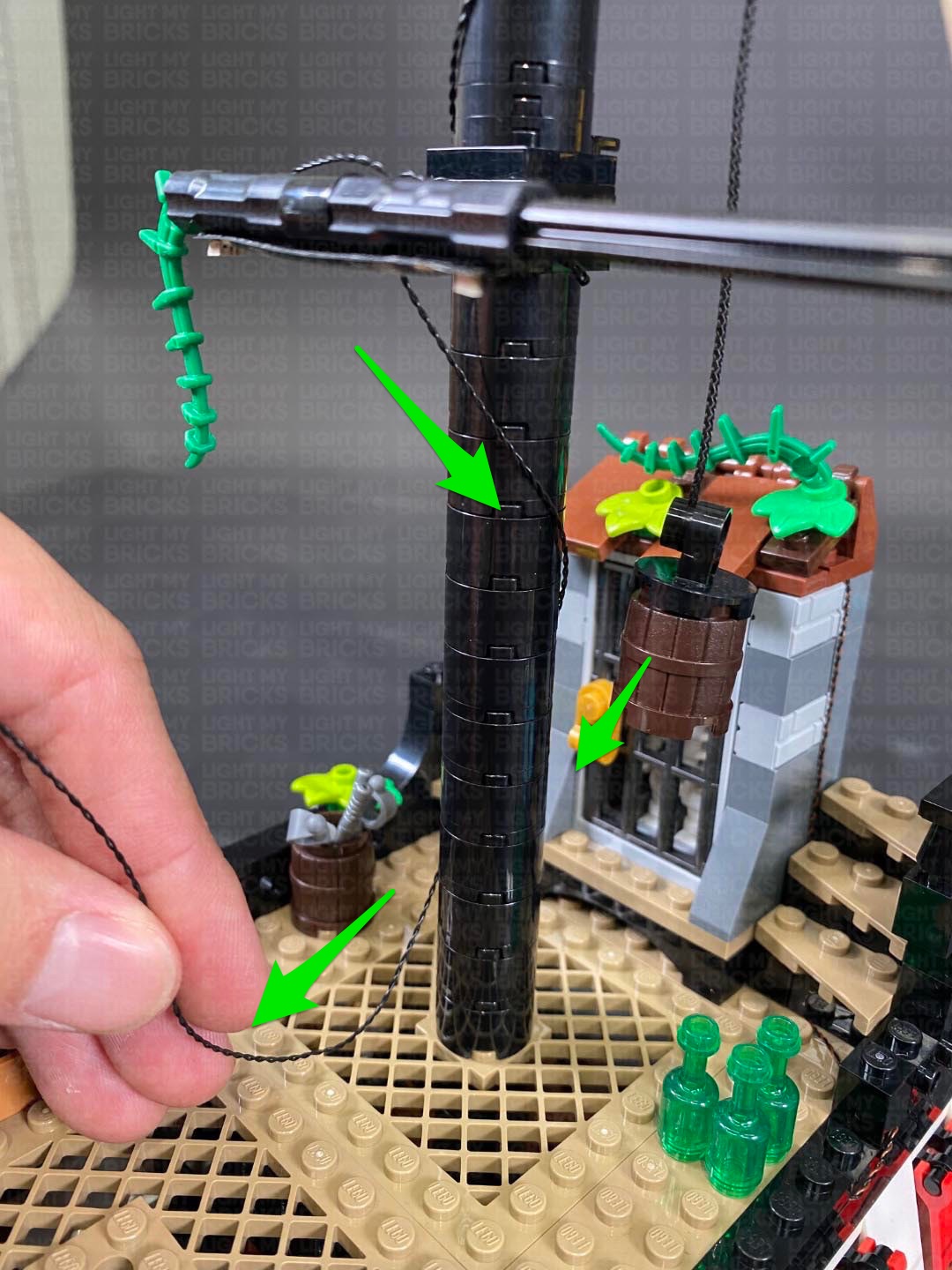
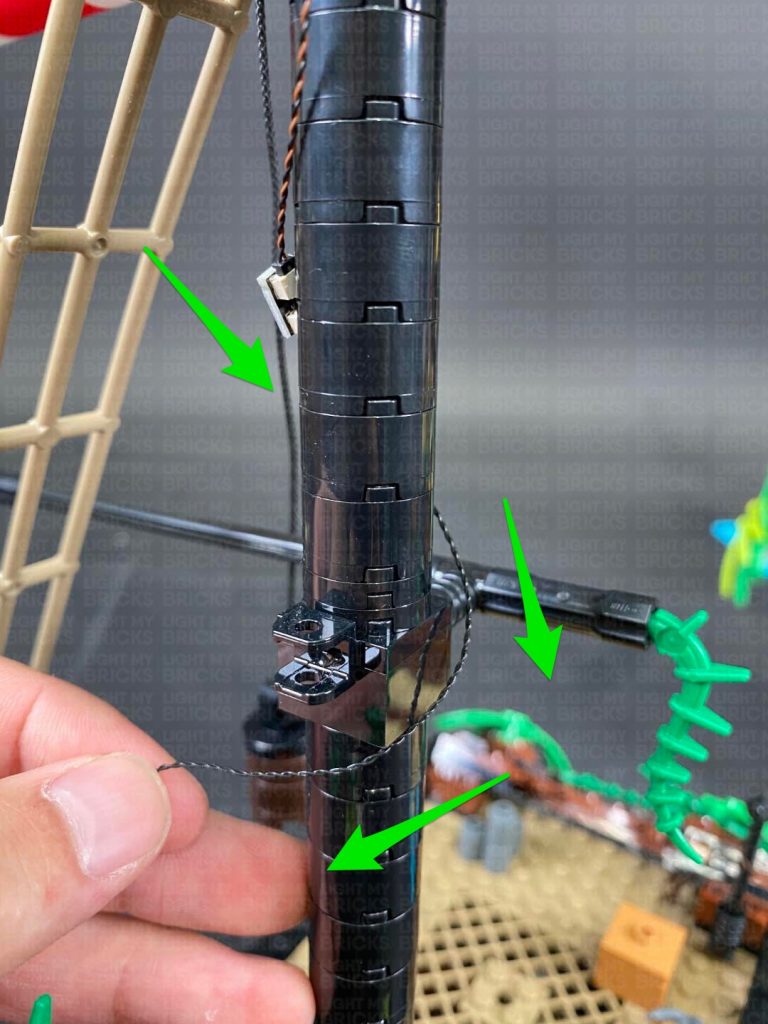
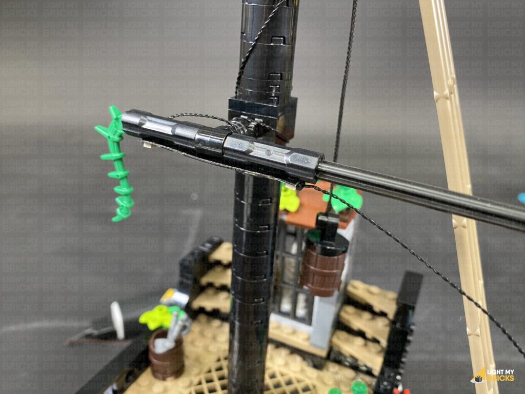
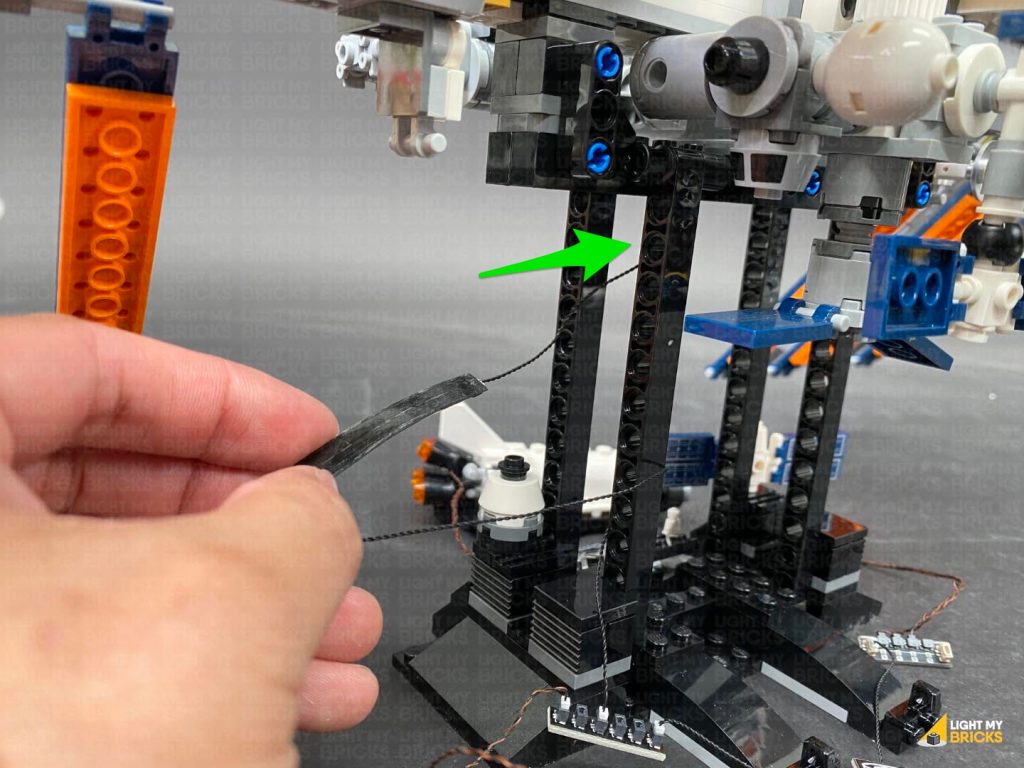
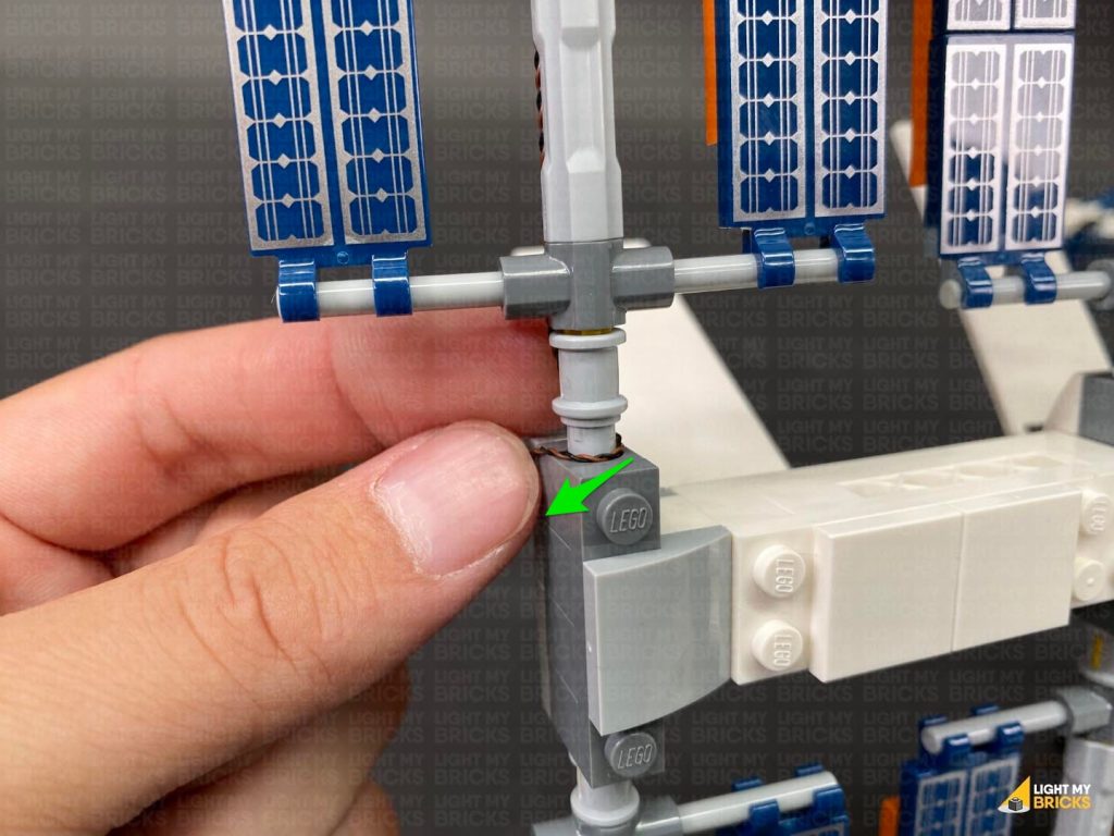
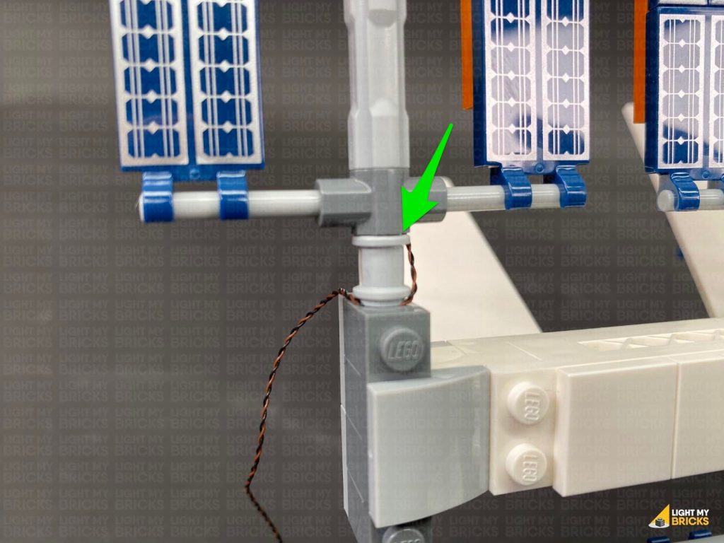
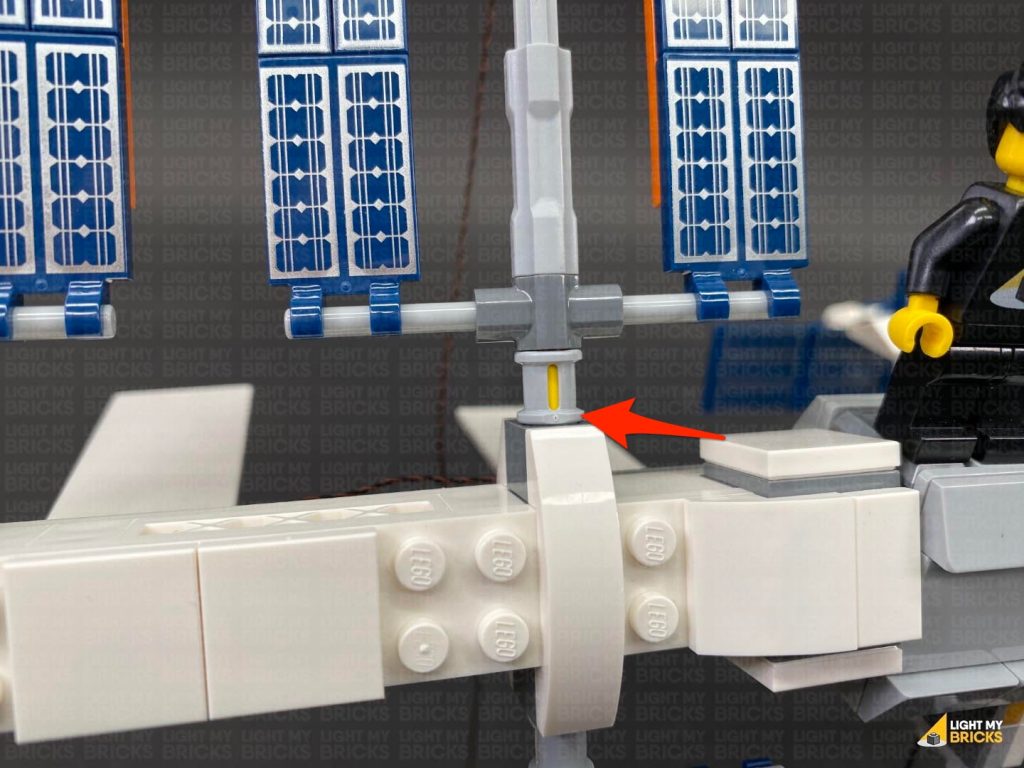
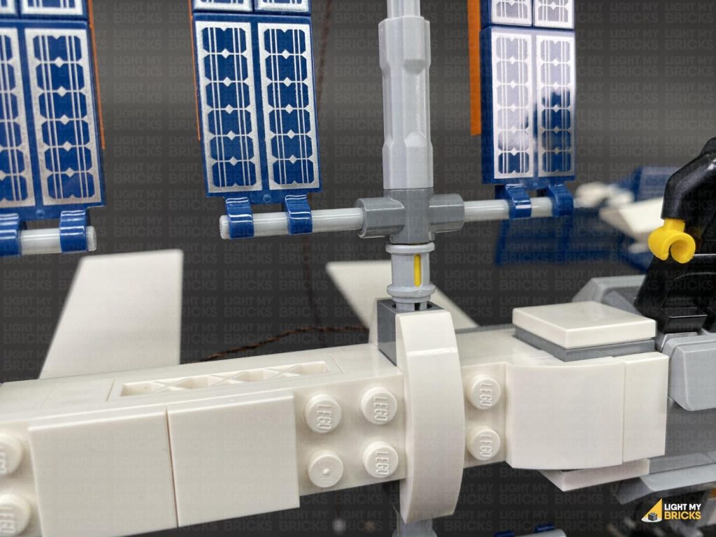
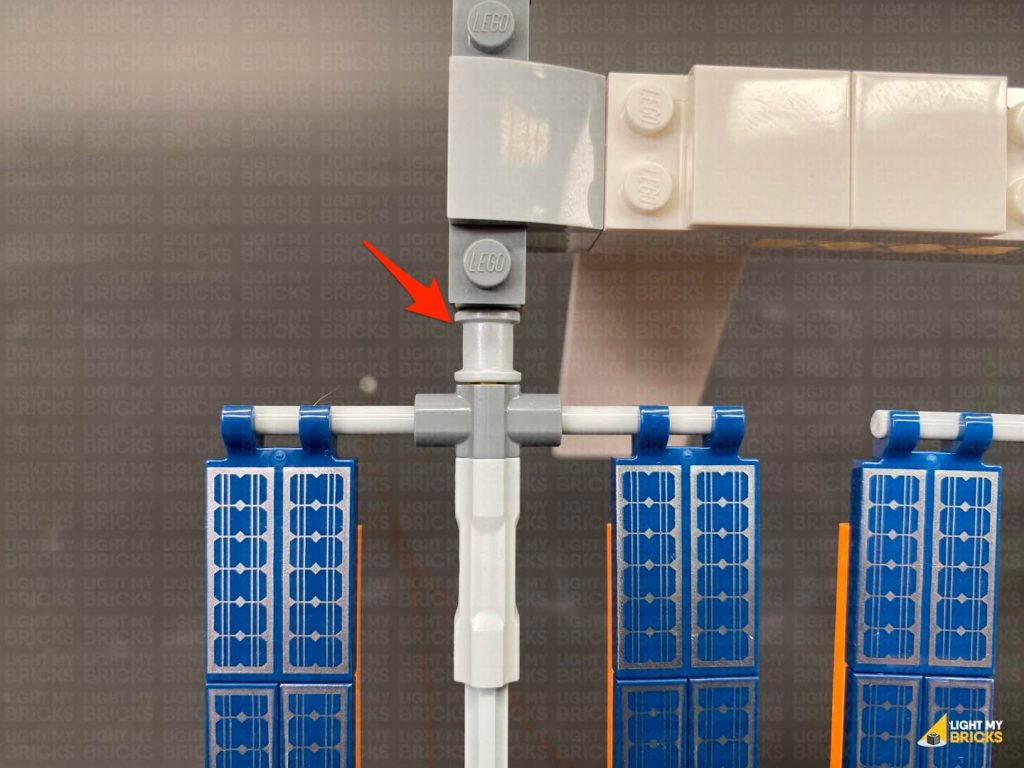
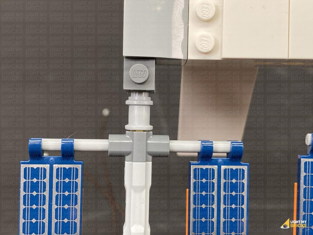
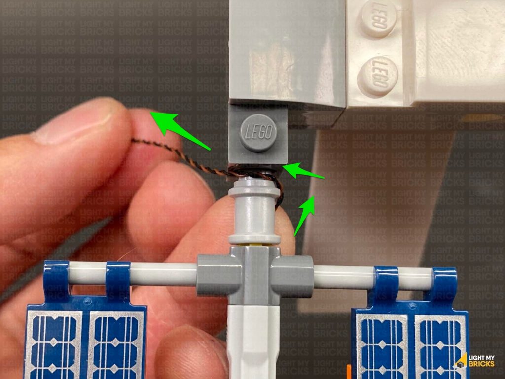
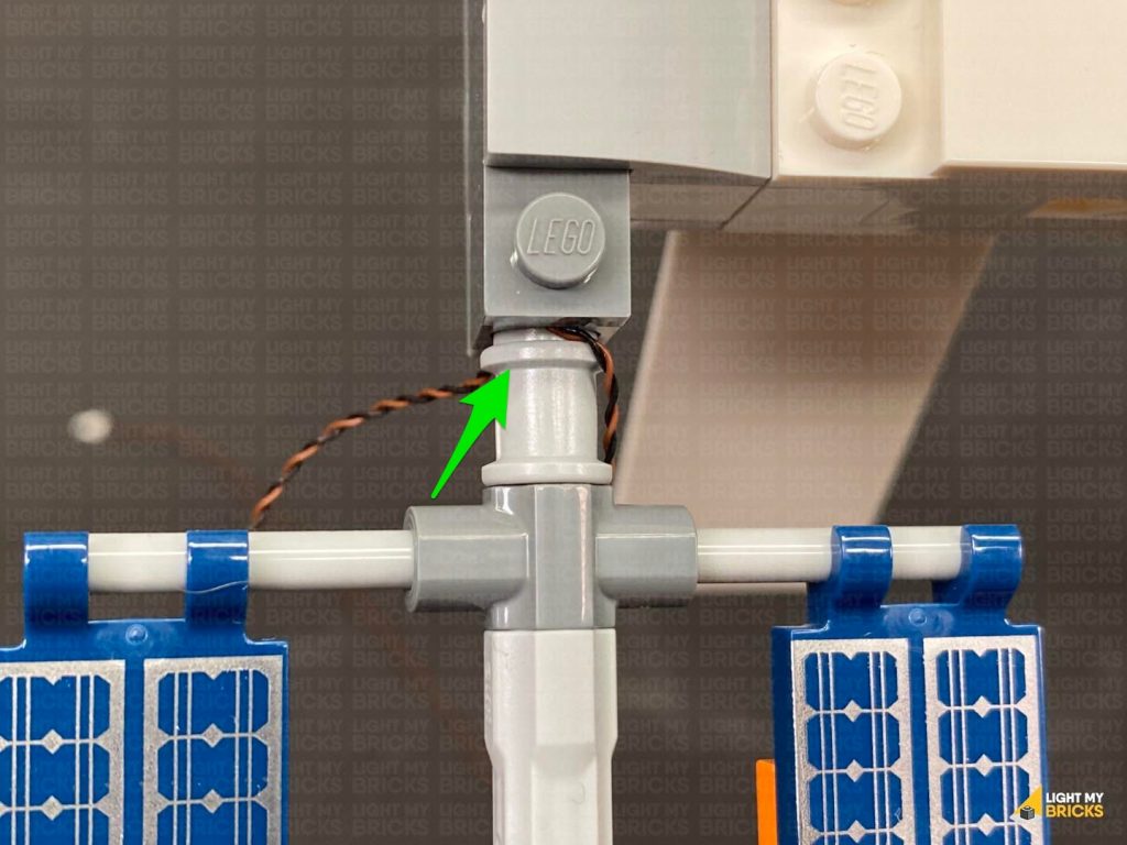
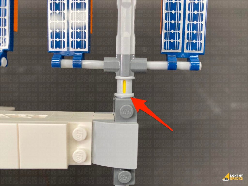
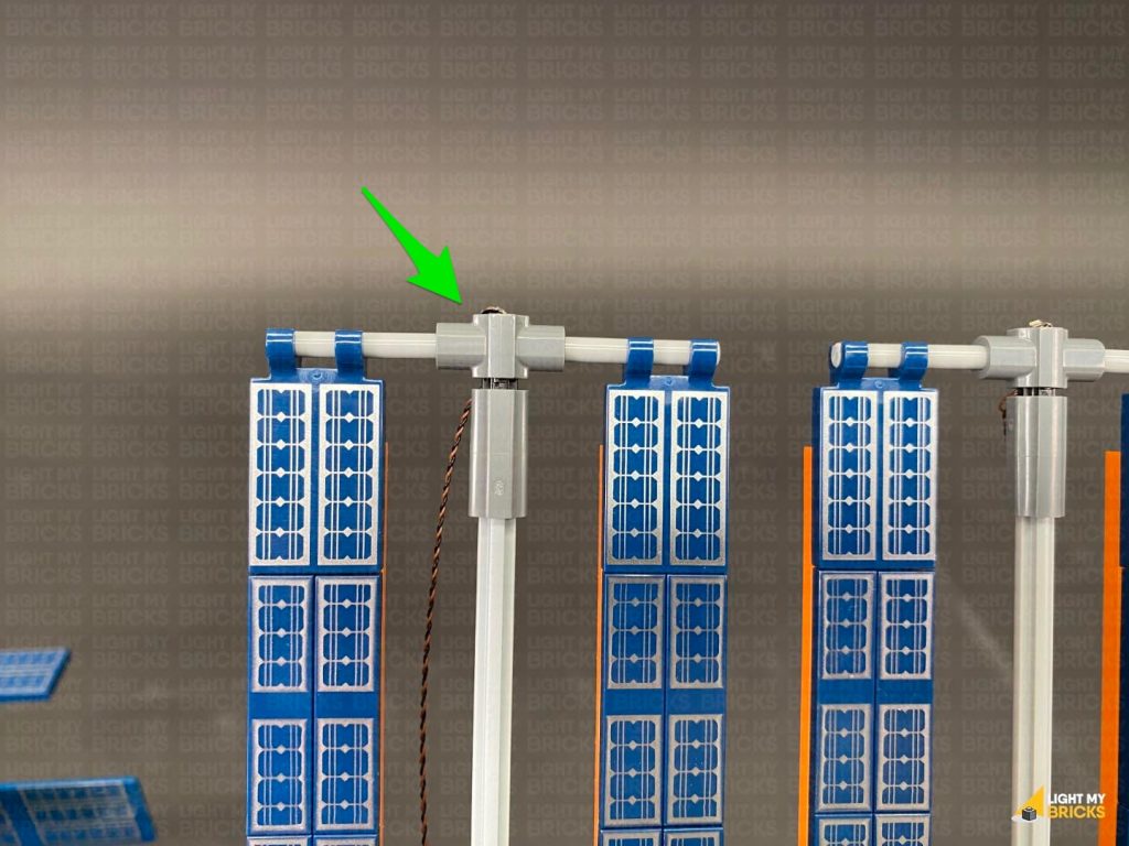
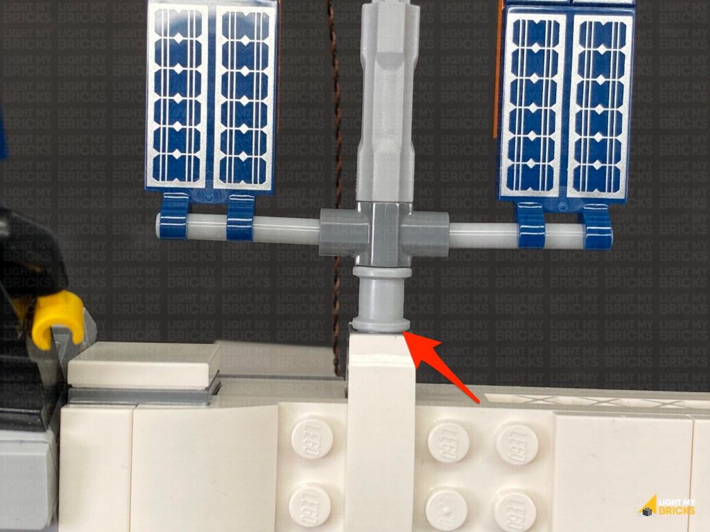
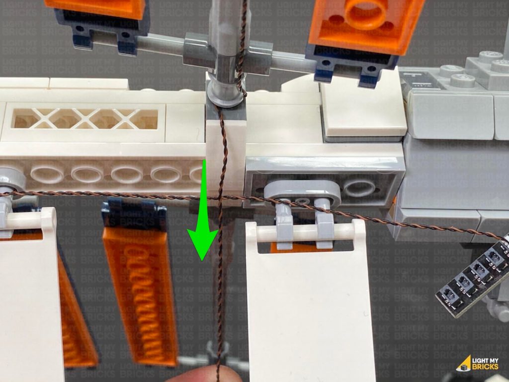
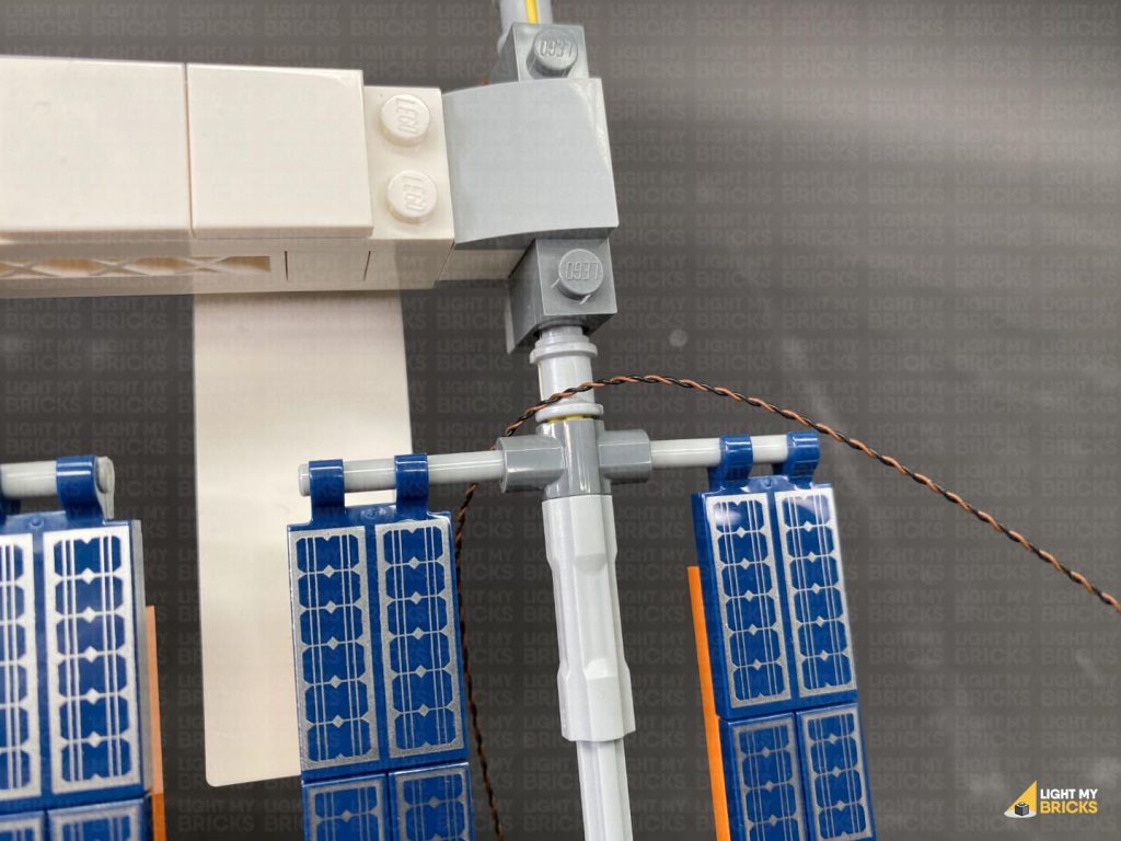
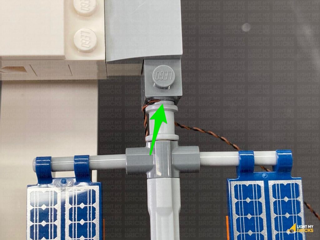
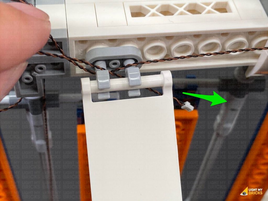
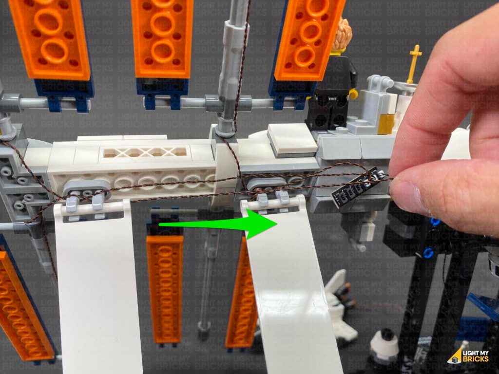
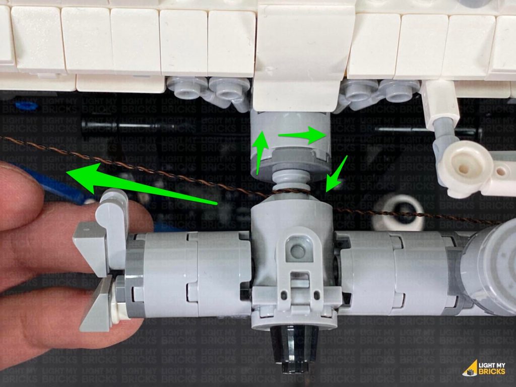
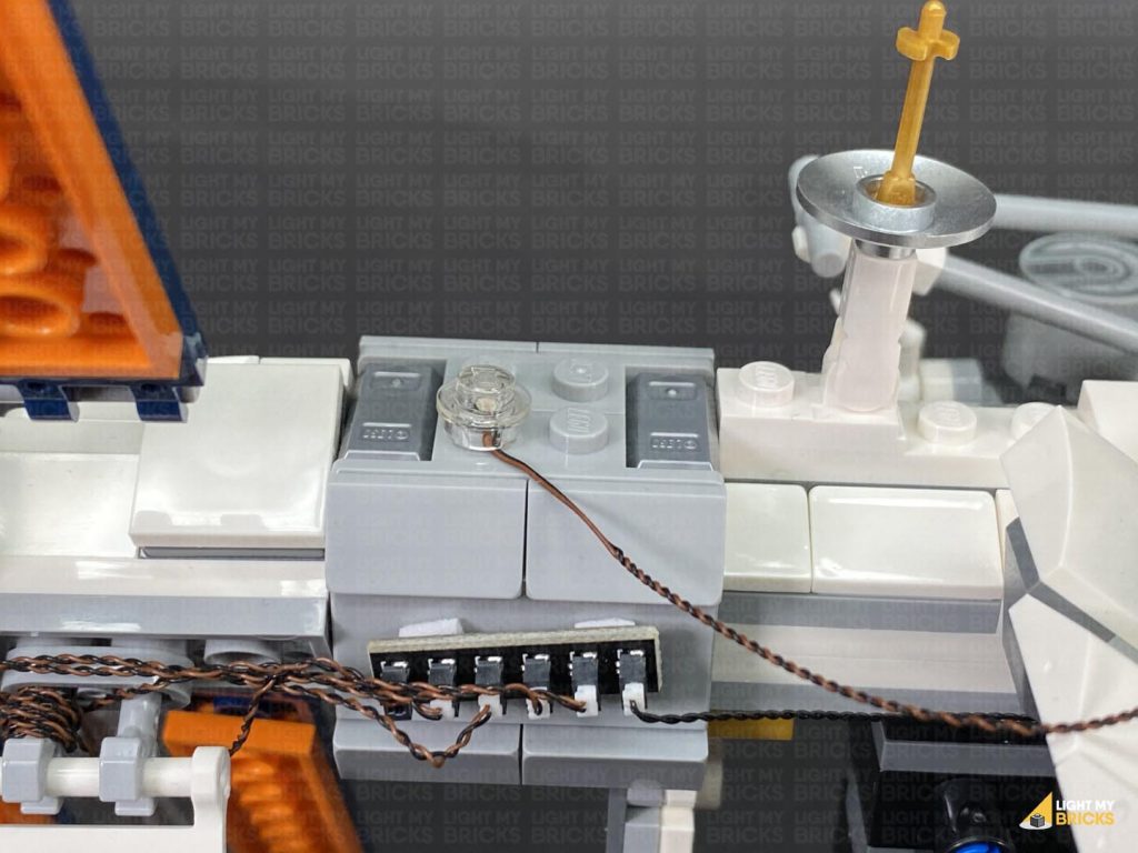
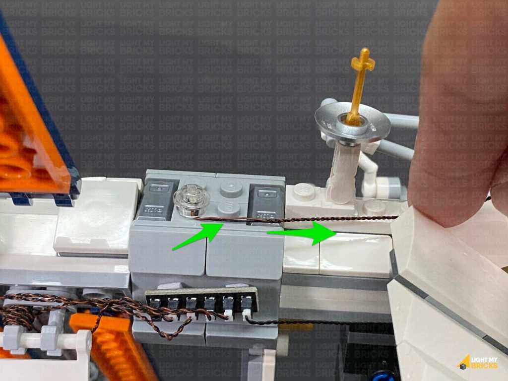
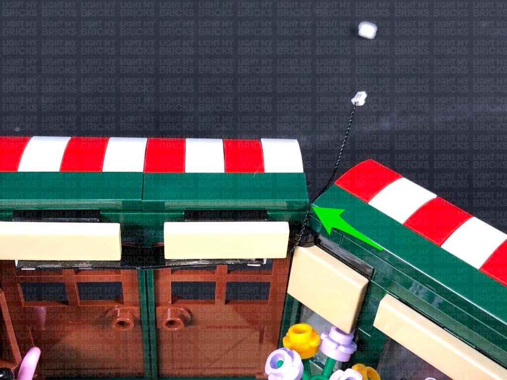
Bring the cable over the beam and towards the centre bracket, then tuck it underneath and loop it over the bracket as shown below, bringing the cable down the centre mast.
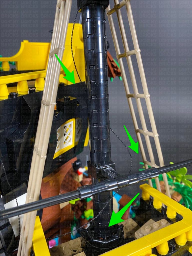
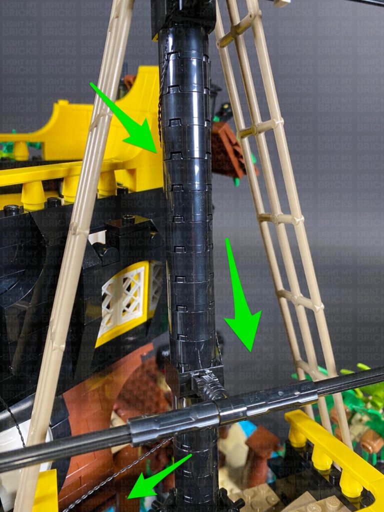
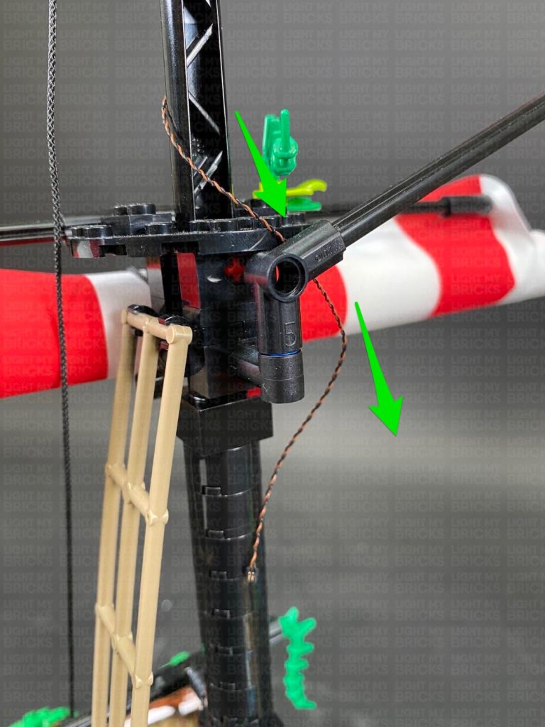
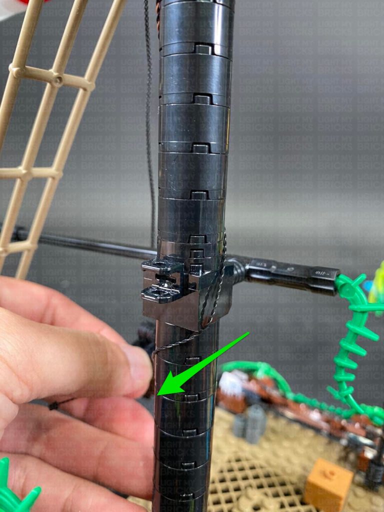
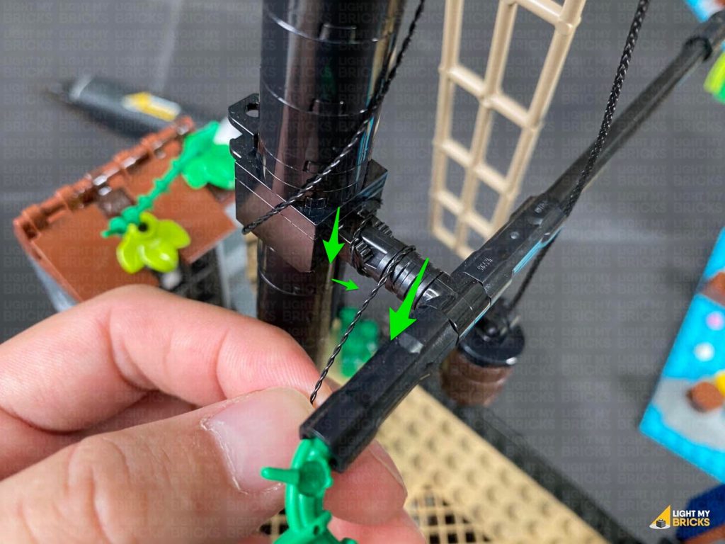
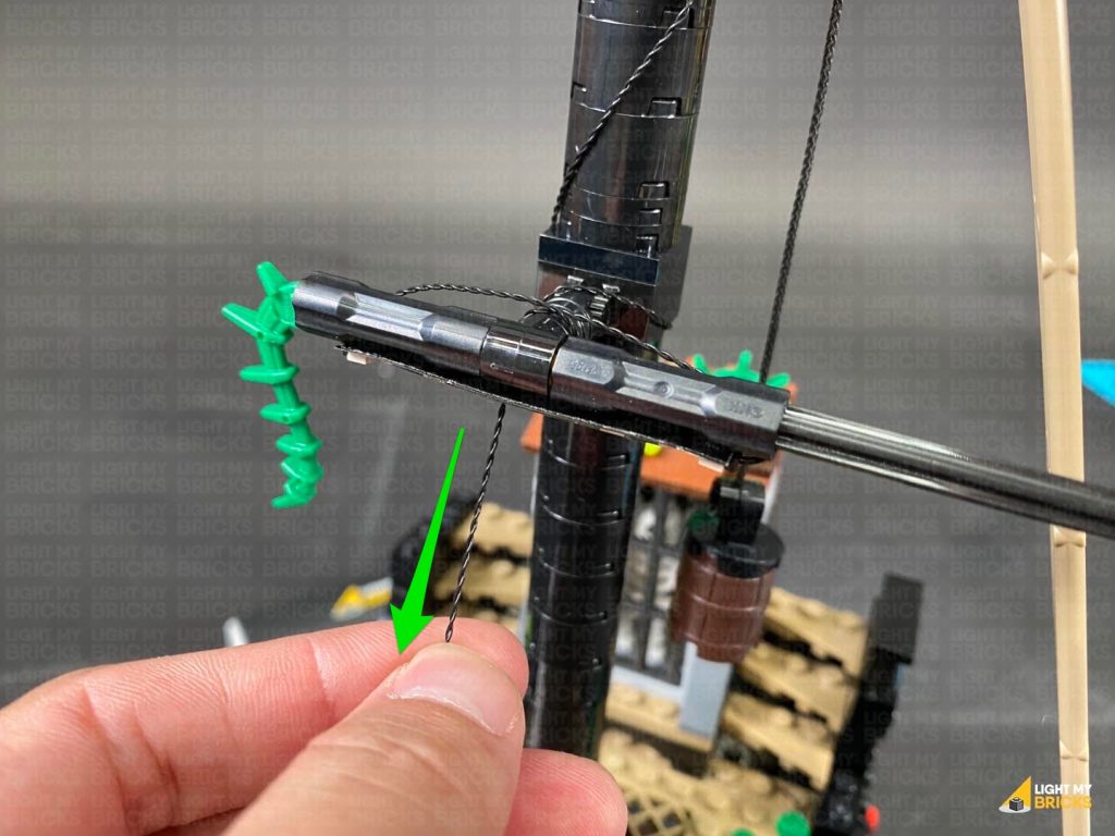
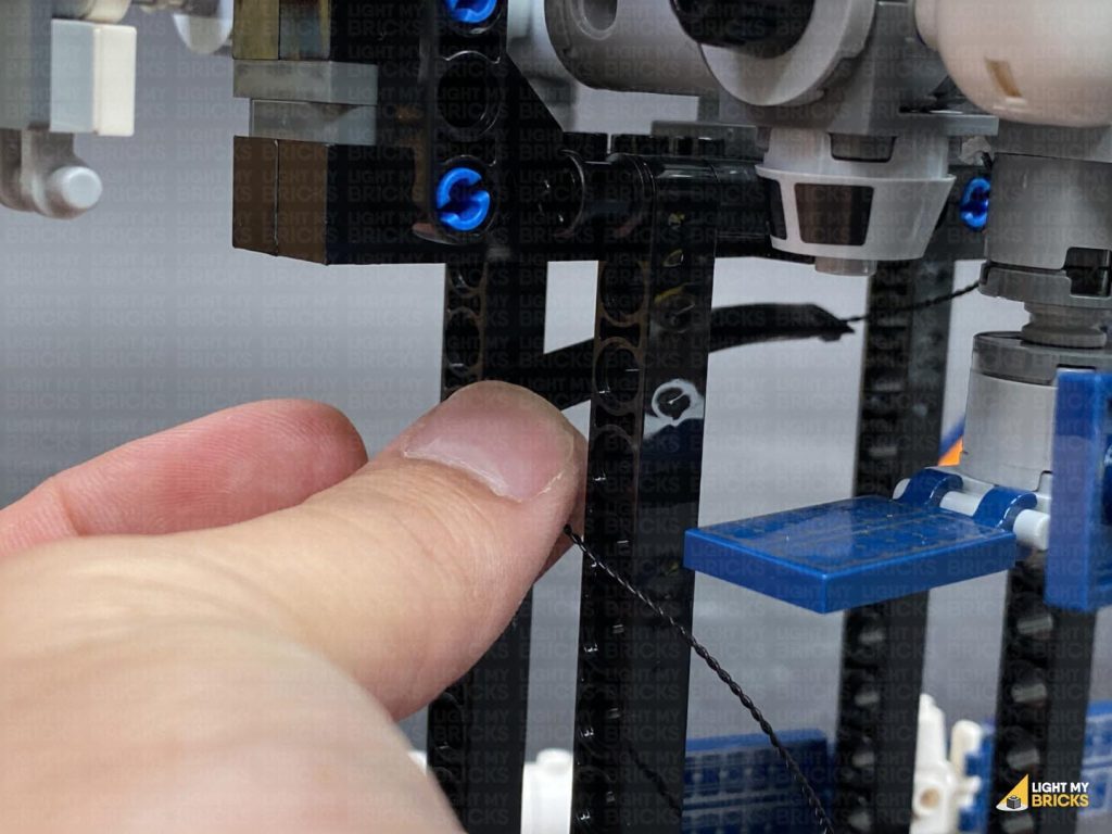
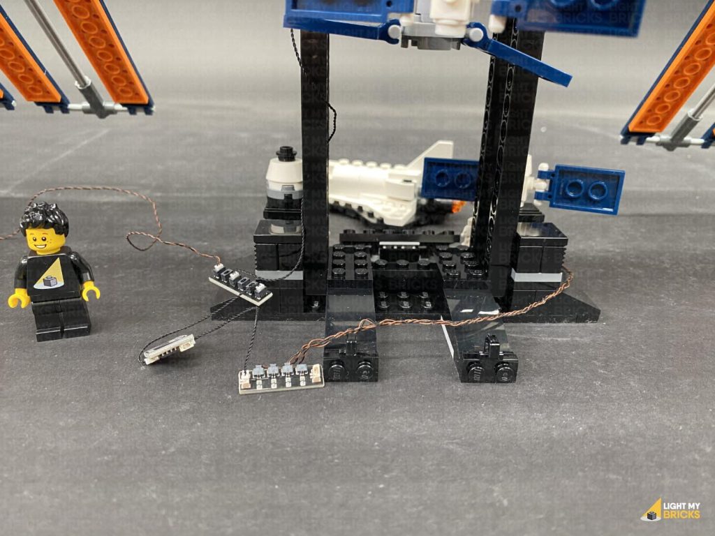
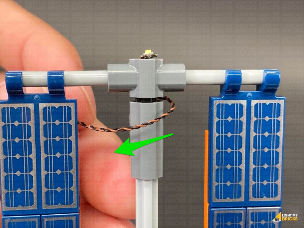
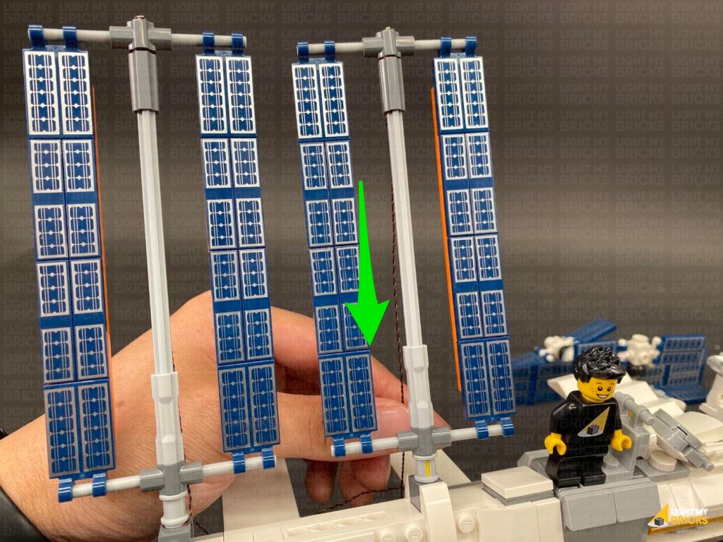
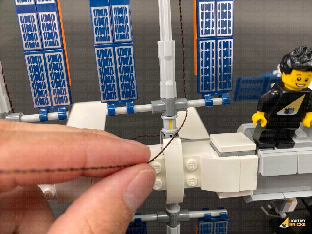
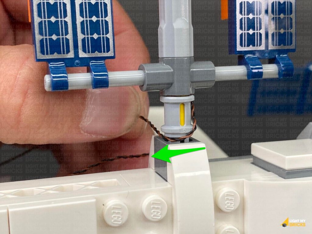
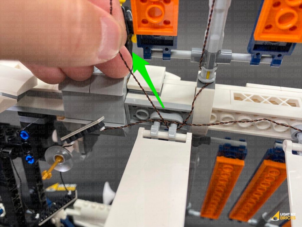
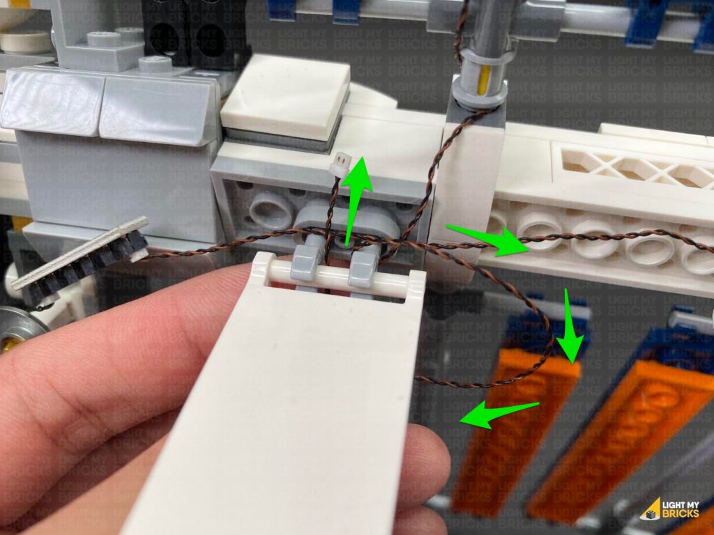
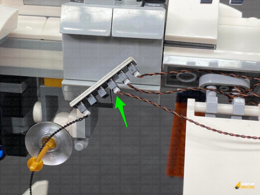
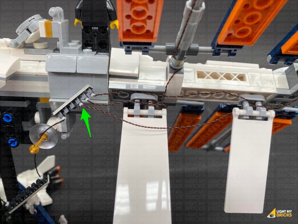
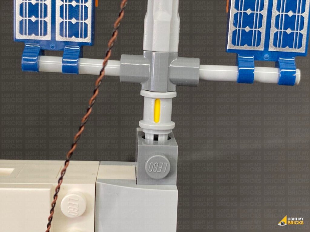
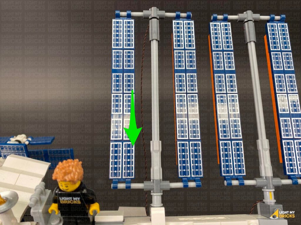
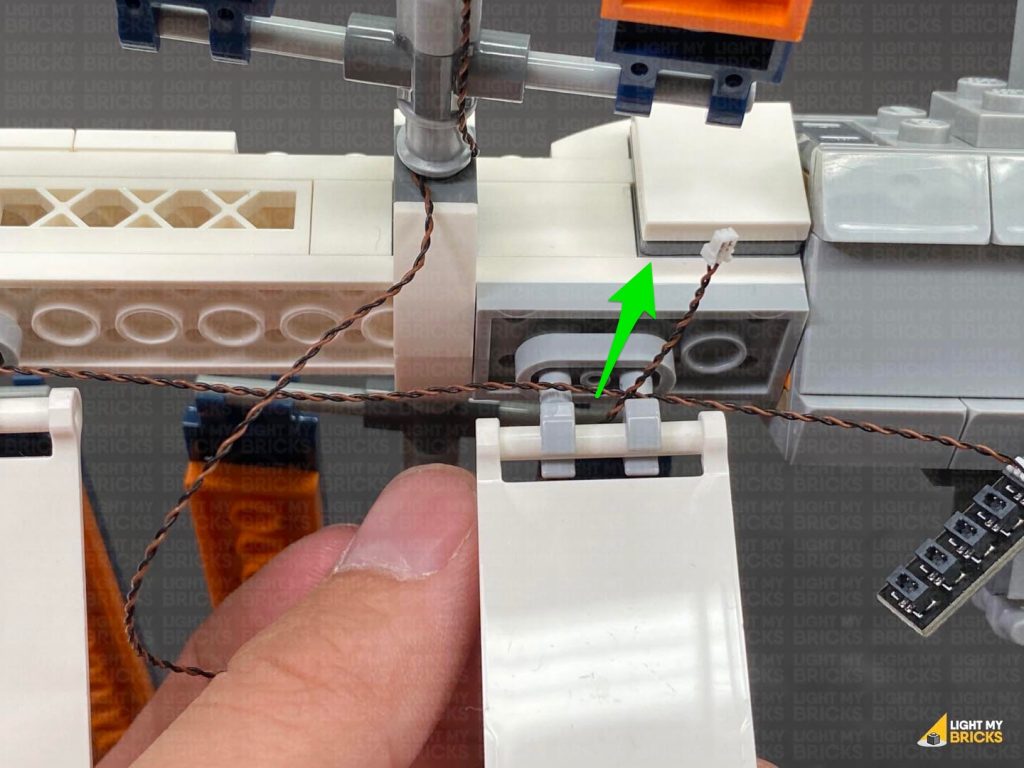
Wind the cable around the centre mast, then bring it under the bottom beam and bracket, toward the back.
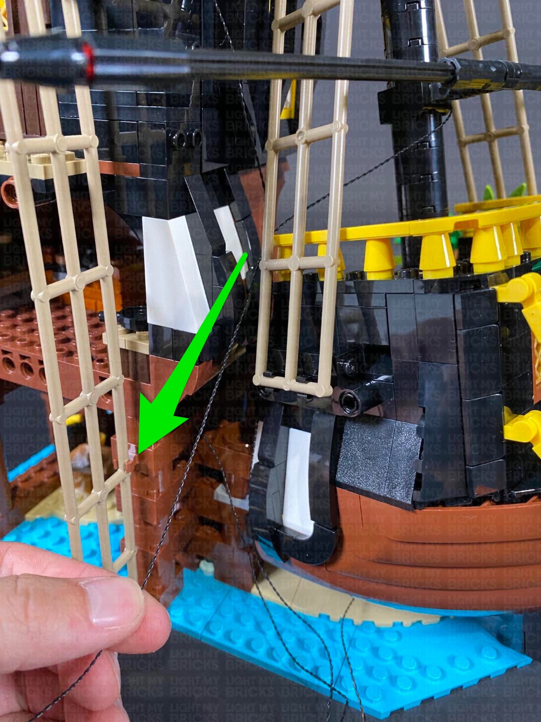
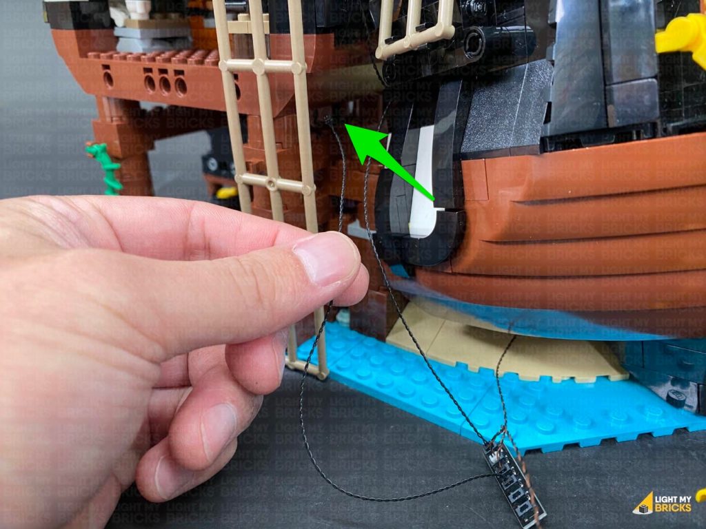
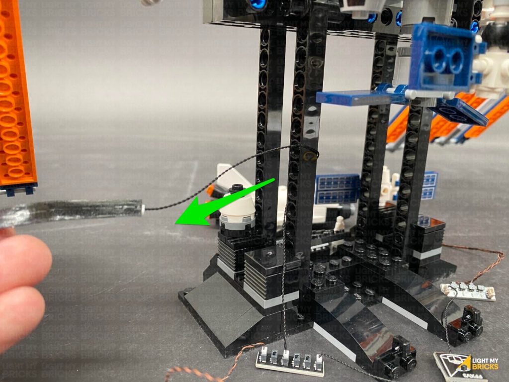
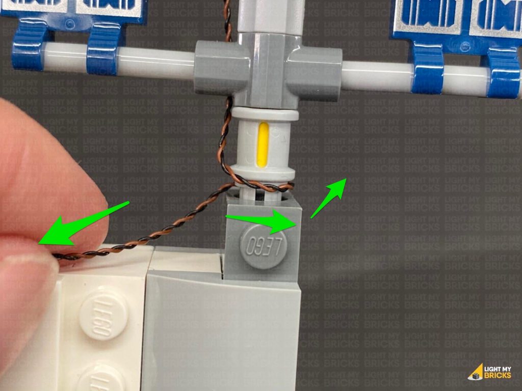
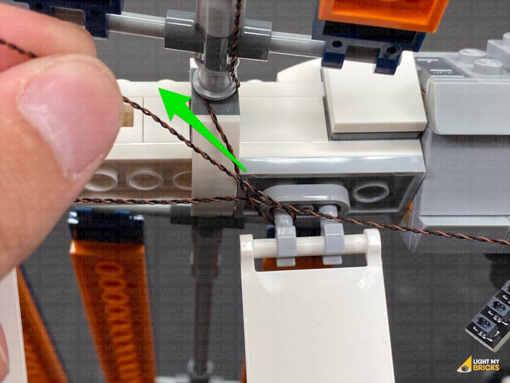
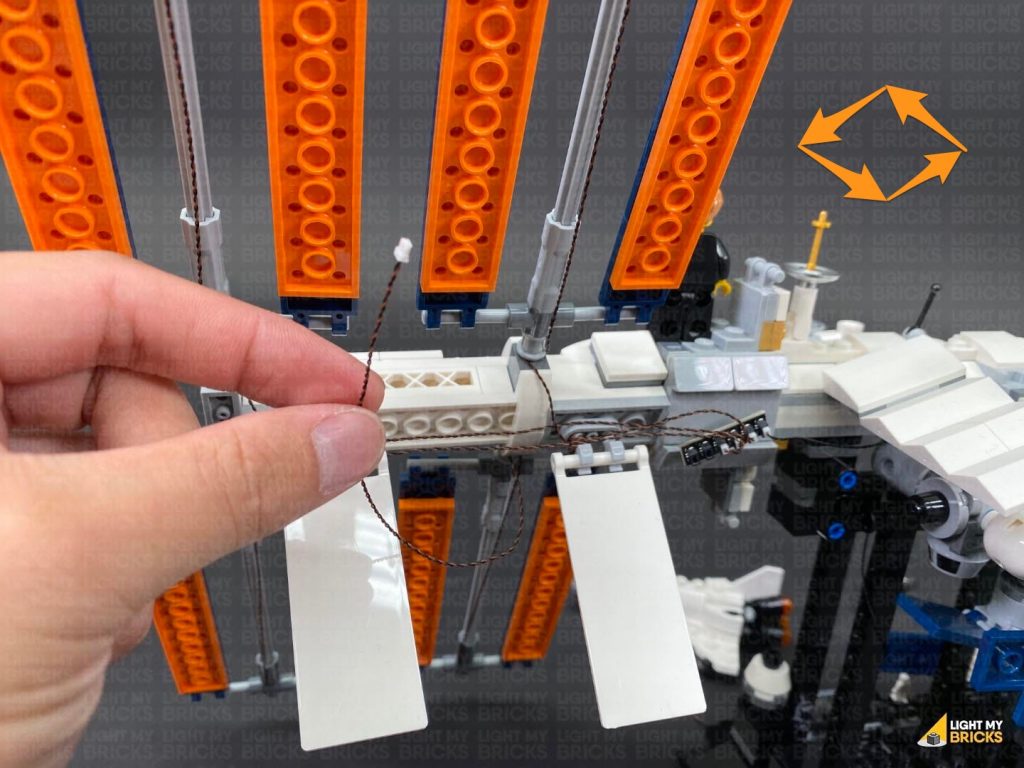
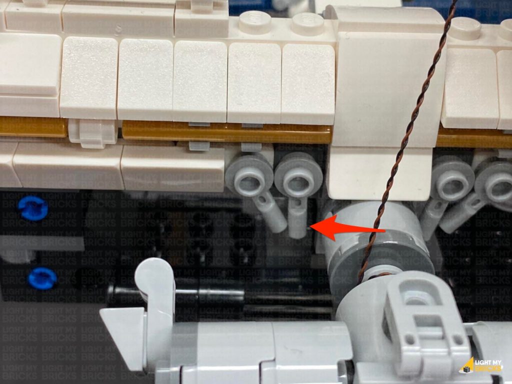
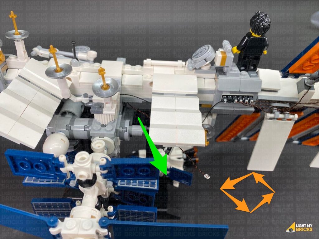
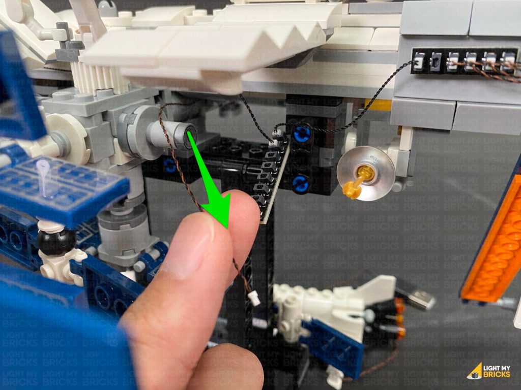
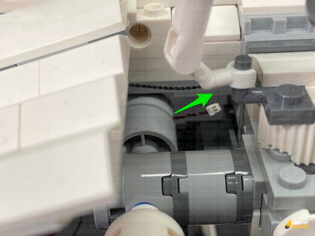
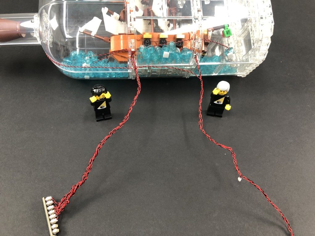
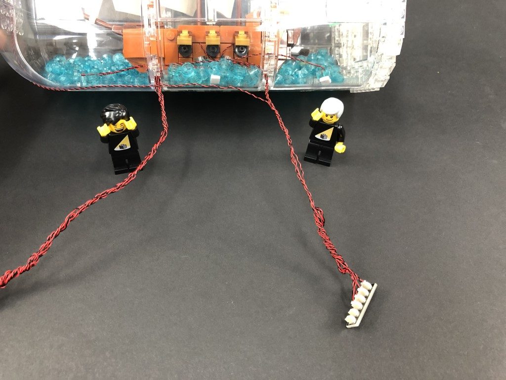
Bring the cable through in between the rope ladder and mast, then pull it out between the rope ladder and the ship.
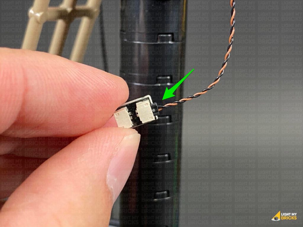
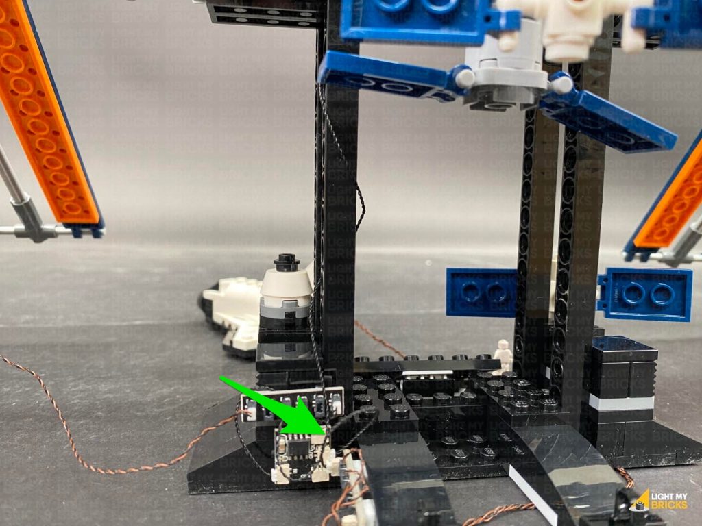
Pull the cable all the way out from the bottom and connect it to a spare port on the 6-Port Expansion Board.
Turn all the lights on again to test everything is looks OK.
25.) Take a Warm White Strip Light and connect a 50cm Connecting Cable to it. Using it’d adhesive backing, stick the strip light underneath the second horizontal beam, ensuring the connecting cable is facing the back.
Bring the cable over the beam and towards the centre bracket, then tuck it underneath and loop it over the bracket as shown below, bringing the cable down the centre mast.
Wind the cable around the centre mast, then bring it under the bottom beam and bracket, toward the back.
Bring the cable through in between the rope ladder and mast, then pull it out between the rope ladder and the ship.
Pull the cable all the way out from the bottom and connect it to a spare port on the 6-Port Expansion Board.
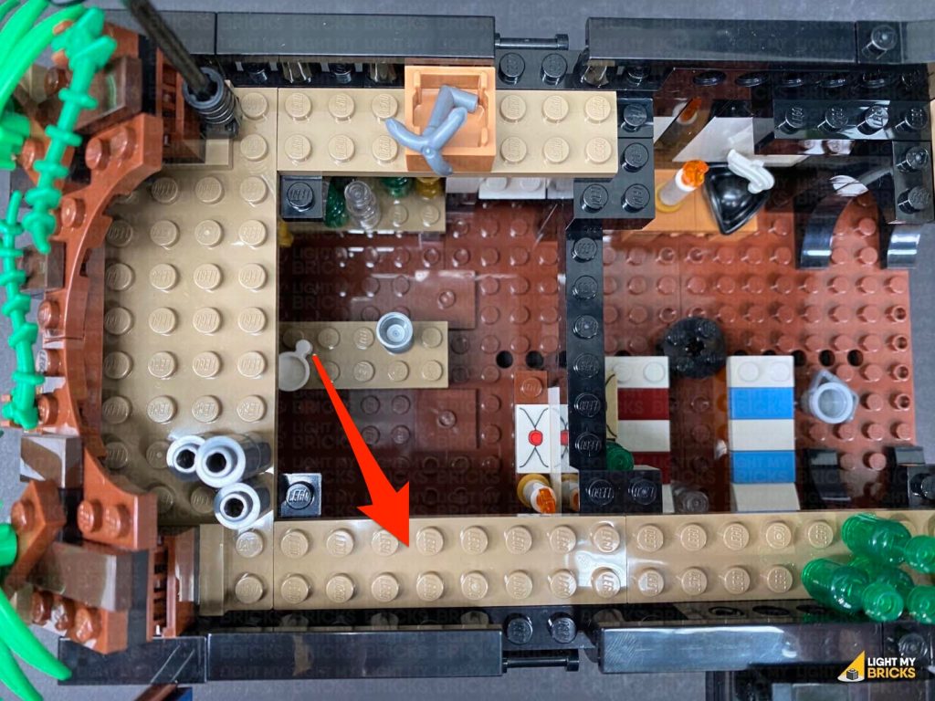
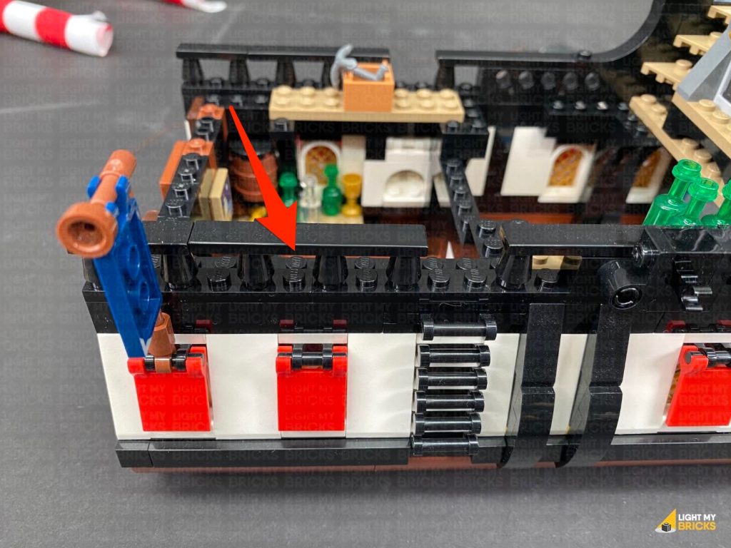
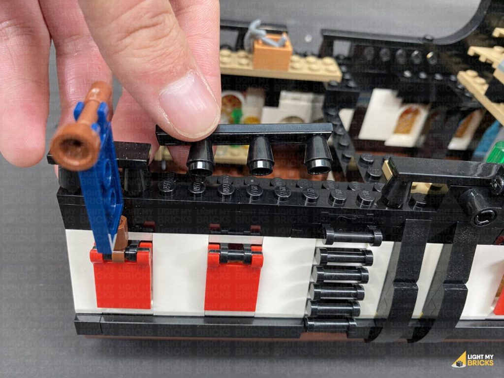
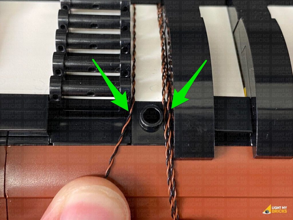
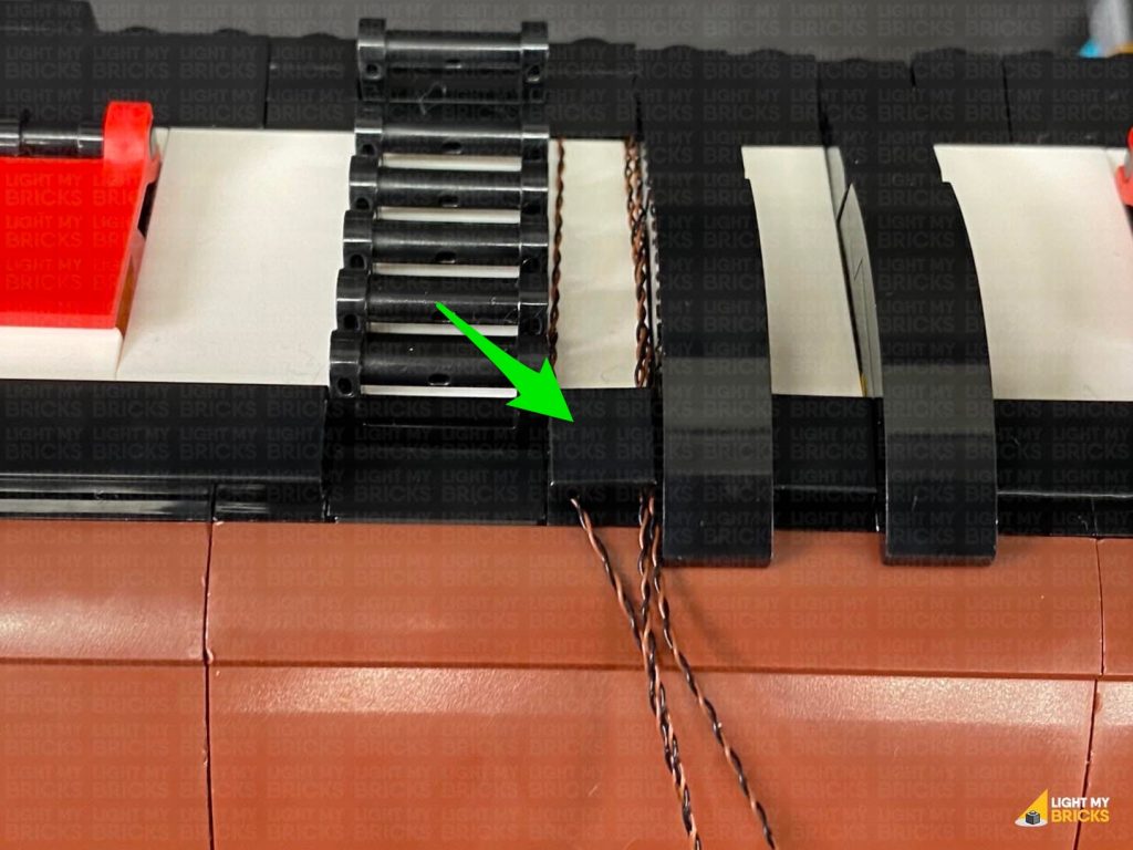
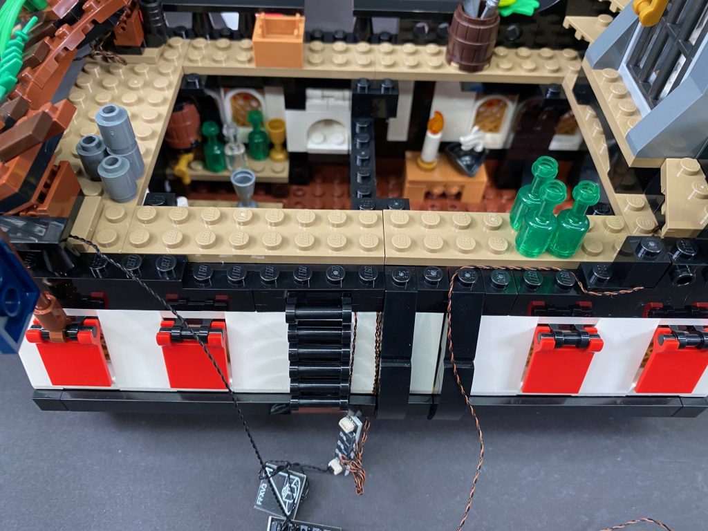
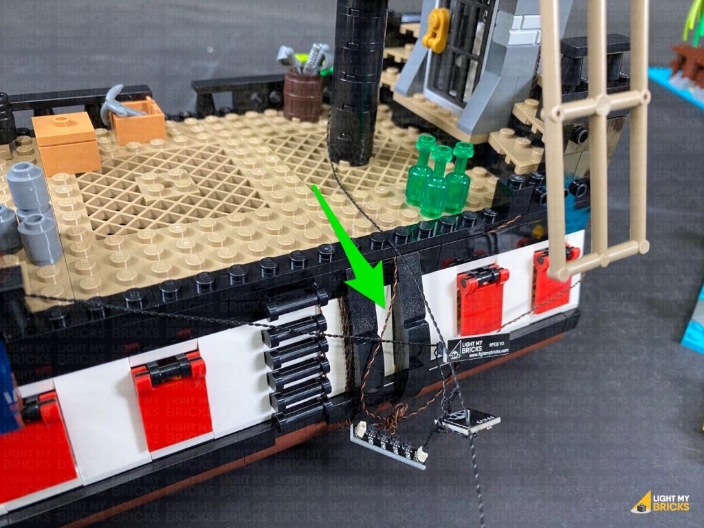
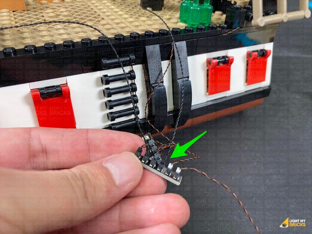
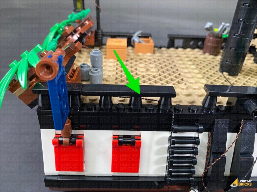
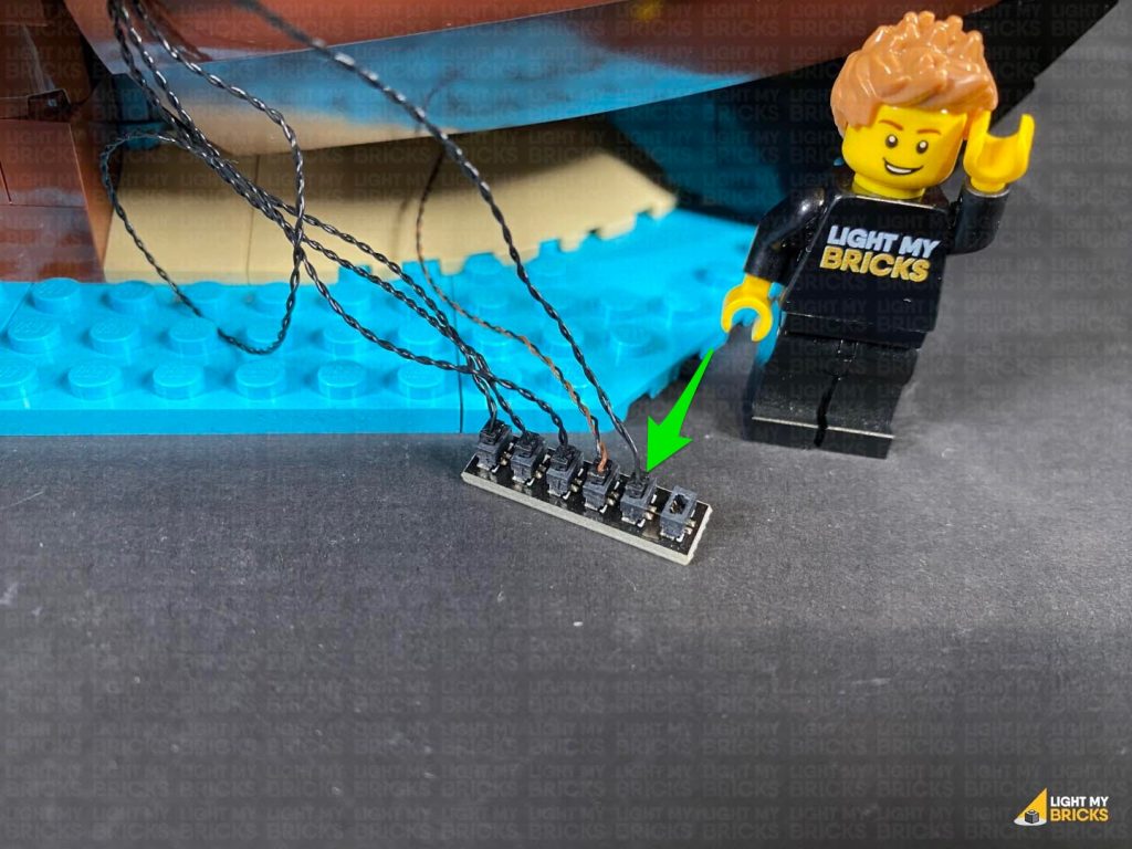
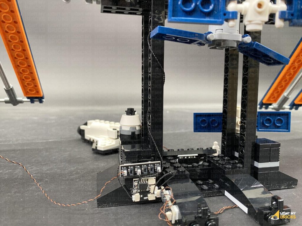
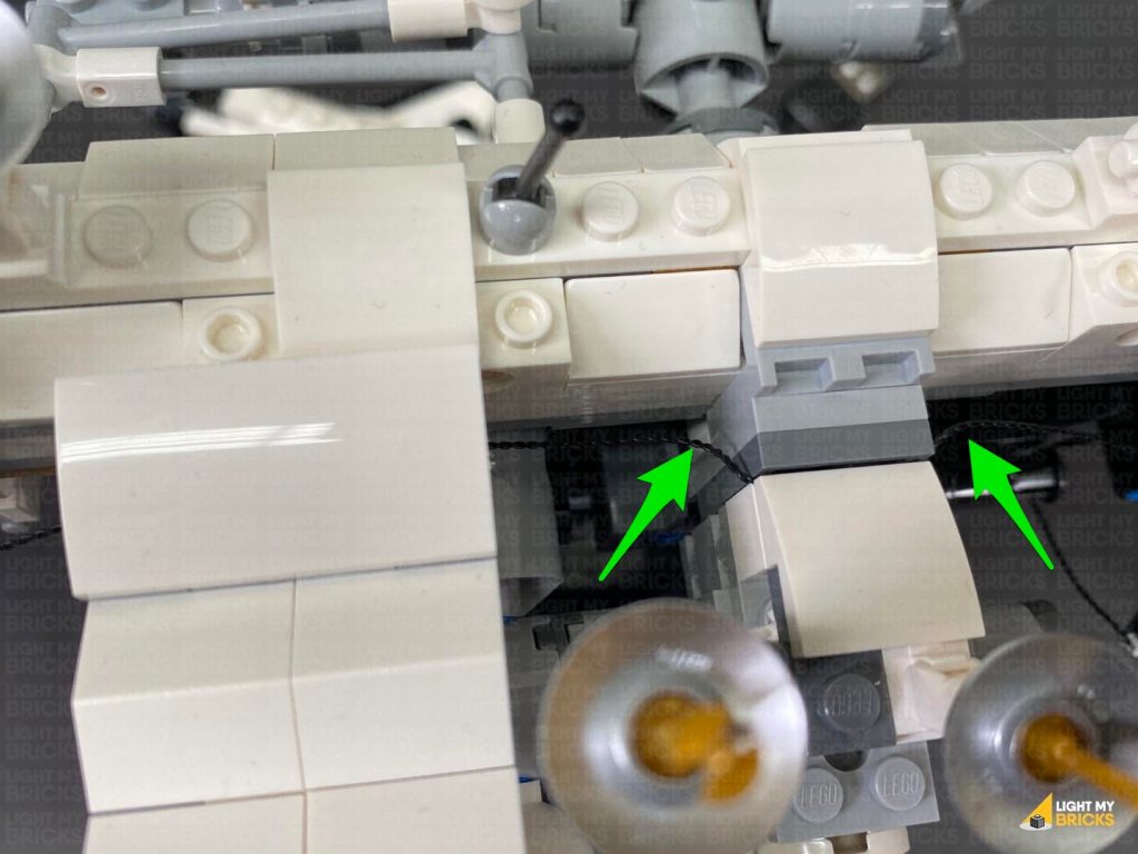
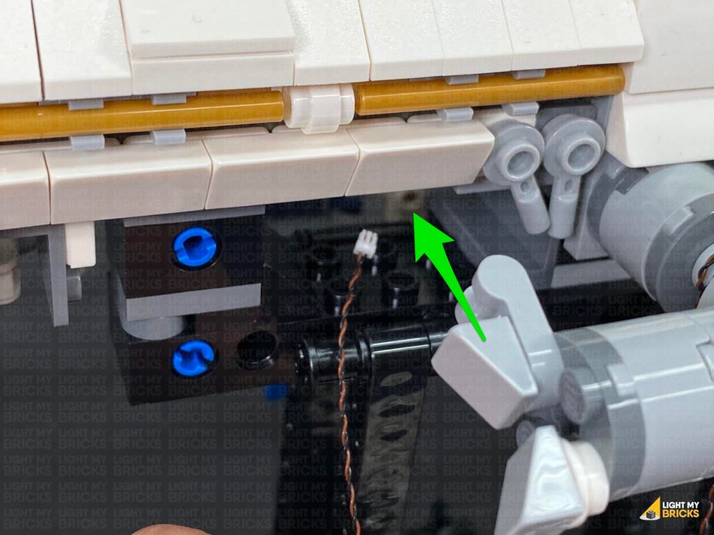
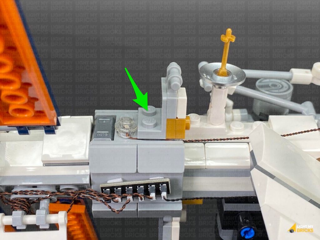
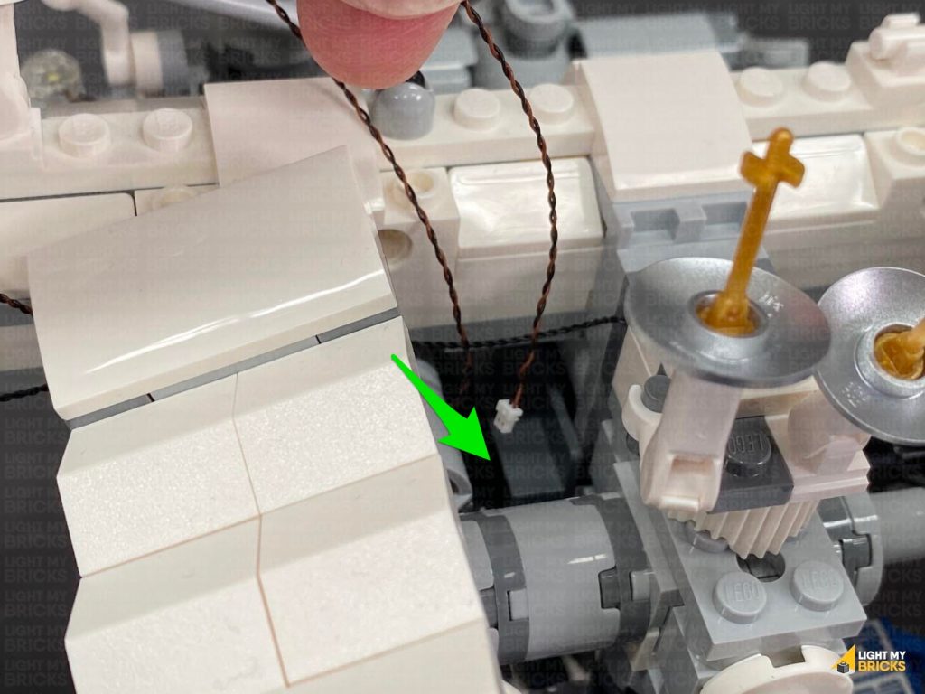
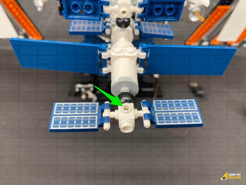
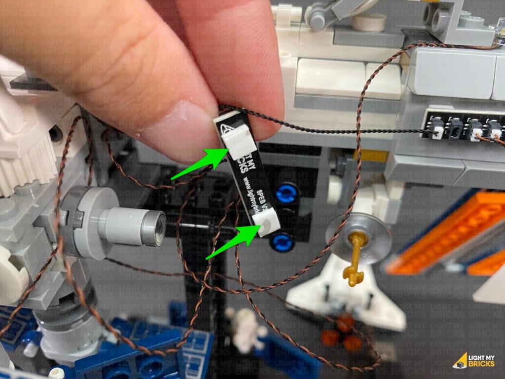
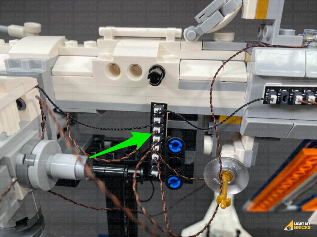
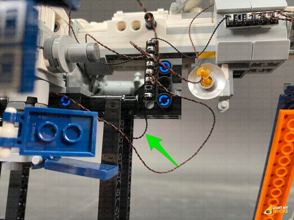
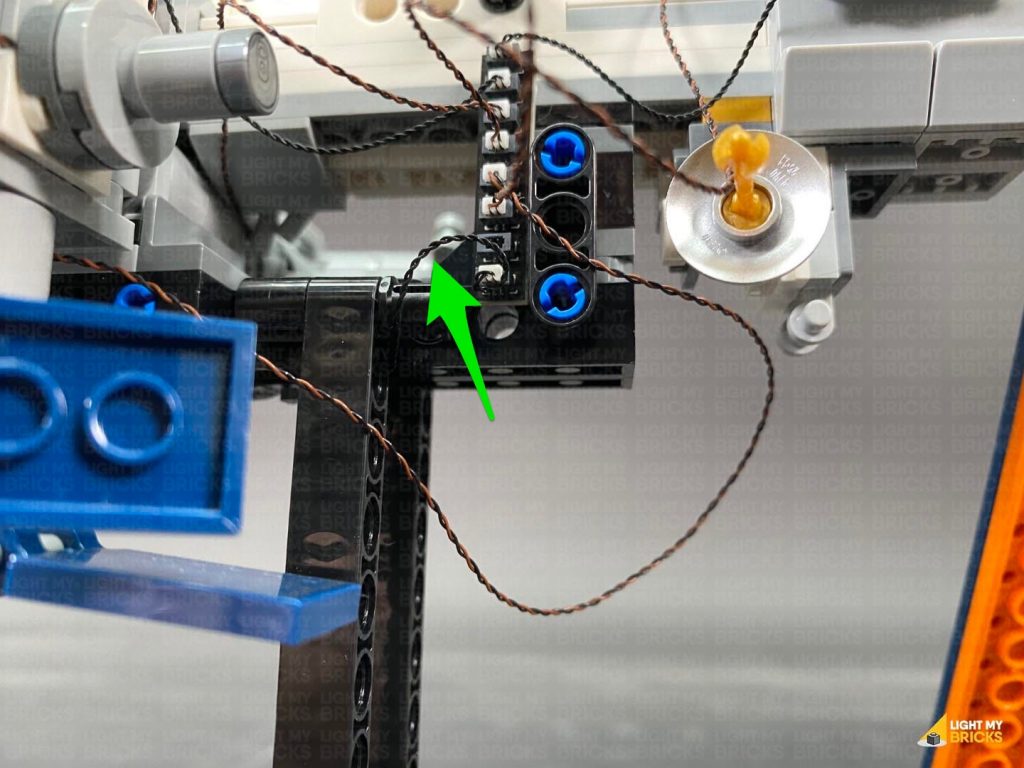
 26.) Disconnect the following black 1×1 tile on the bottom of the ship. Group together and lay the cables down on either side of the stud, then reconnect the tile over the top.
Turn the power ON to test the Strip Light is working OK along with all the lights on this entire section of the set.
26.) Disconnect the following black 1×1 tile on the bottom of the ship. Group together and lay the cables down on either side of the stud, then reconnect the tile over the top.
Turn the power ON to test the Strip Light is working OK along with all the lights on this entire section of the set.
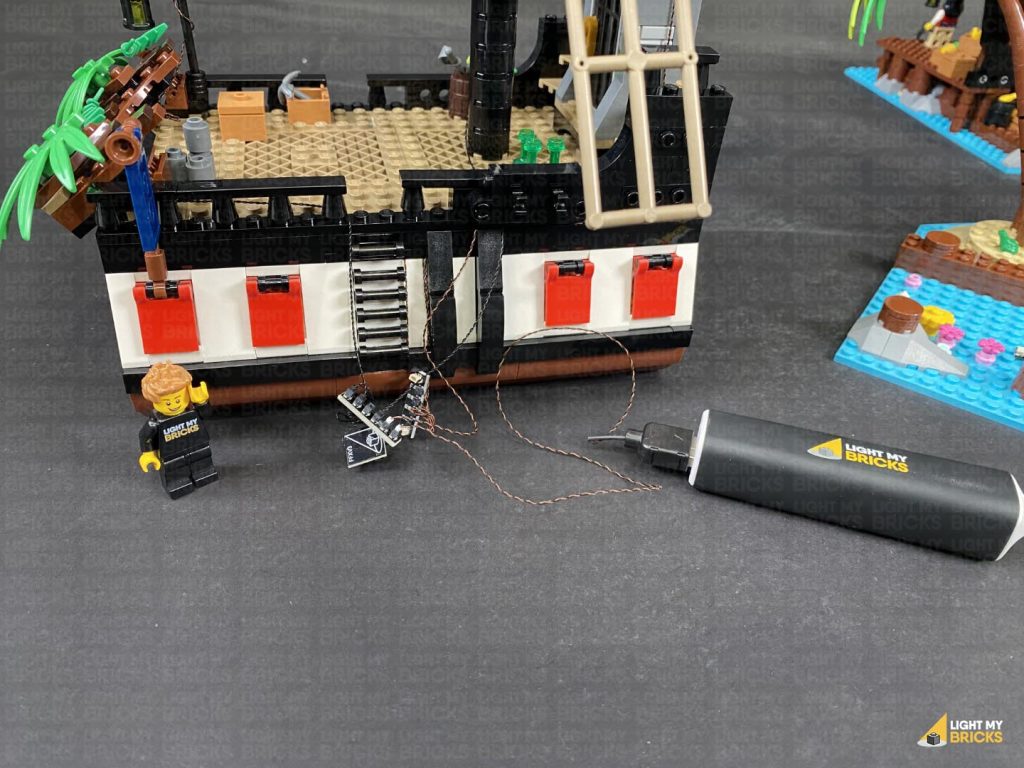
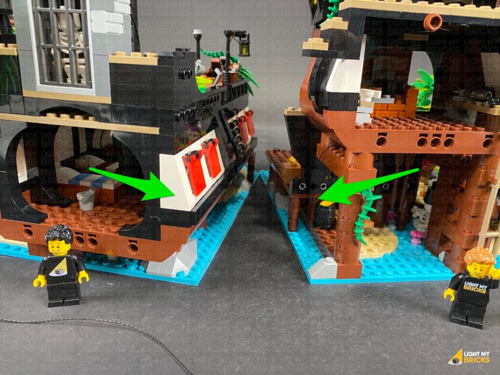
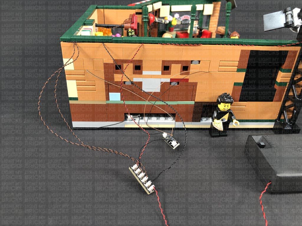
Note: If you experience any issues with the lights not working and suspect an issue with a component, please try a different port on the expansion board to verify where the fault lies (with the light, expansion board or effects board). To correct any issues with expansion board ports, please view the section addressing expansion board issues on our online troubleshooting guide.Disconnect the USB Power Cable from the 6-Port Expansion Board as we will use this to test the lights we install to the right section of this set. 27.) We will now move onto the right section. First remove the ship from the dock by disconnecting it from the technic pins on the dock and pulling it all the way out.
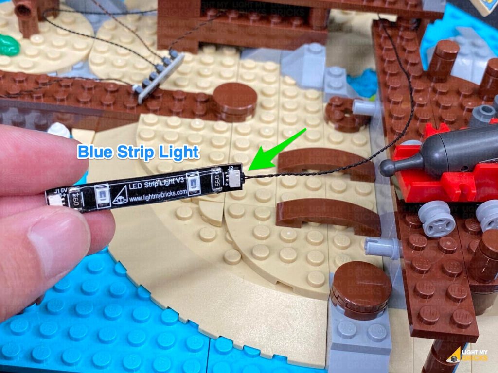
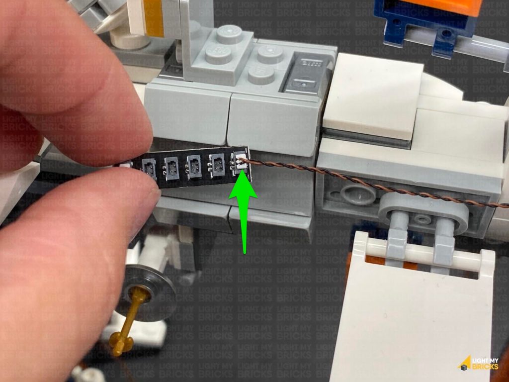
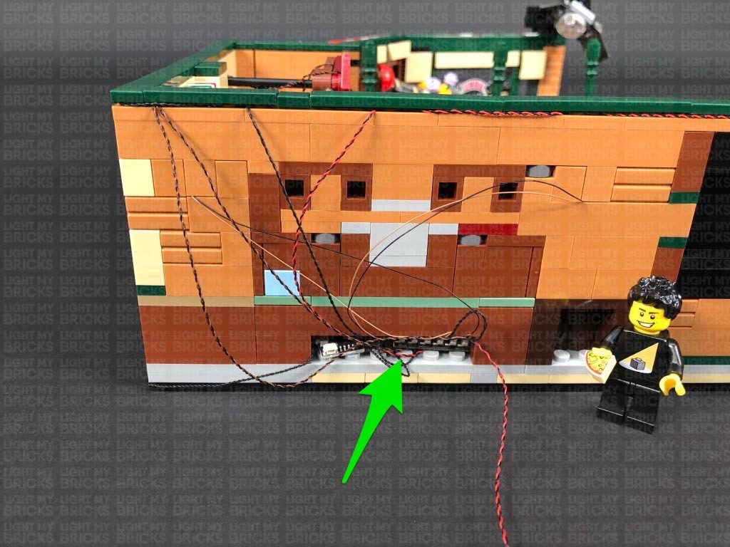
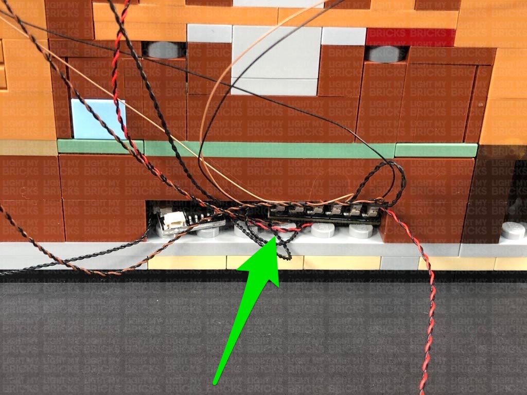
 Disconnect the brown plate from the front of the deck and flip it over so we can access underneath. Take a Blue Strip Light and connect a 15cm Connecting Cable to it. Take another 15cm Connecting Cable and connect it to the other port, then using it’s adhesive backing, stick the strip light underneath the brown plate in the following position:
Thread the 15cm Connecting cable facing the back underneath the steps before reconnecting the brown plate to the dock. Ensure the other 15cm connecting cable is laid out toward the left side.
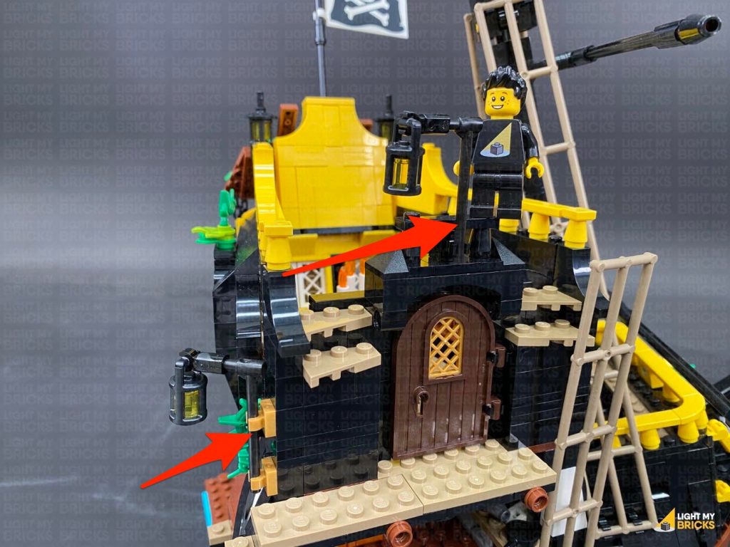
28.) Disconnect the lamp sections at the front and the top of the stairs, then using the same method used to install previous lamps, install a White 15cm Bit Light to the front lamp and a White 30cm Bit Light to the lamp from the top of the stairs.
Take the lamp from the front and thread the cable underneath the deck before reconnecting the lamp to the deck.
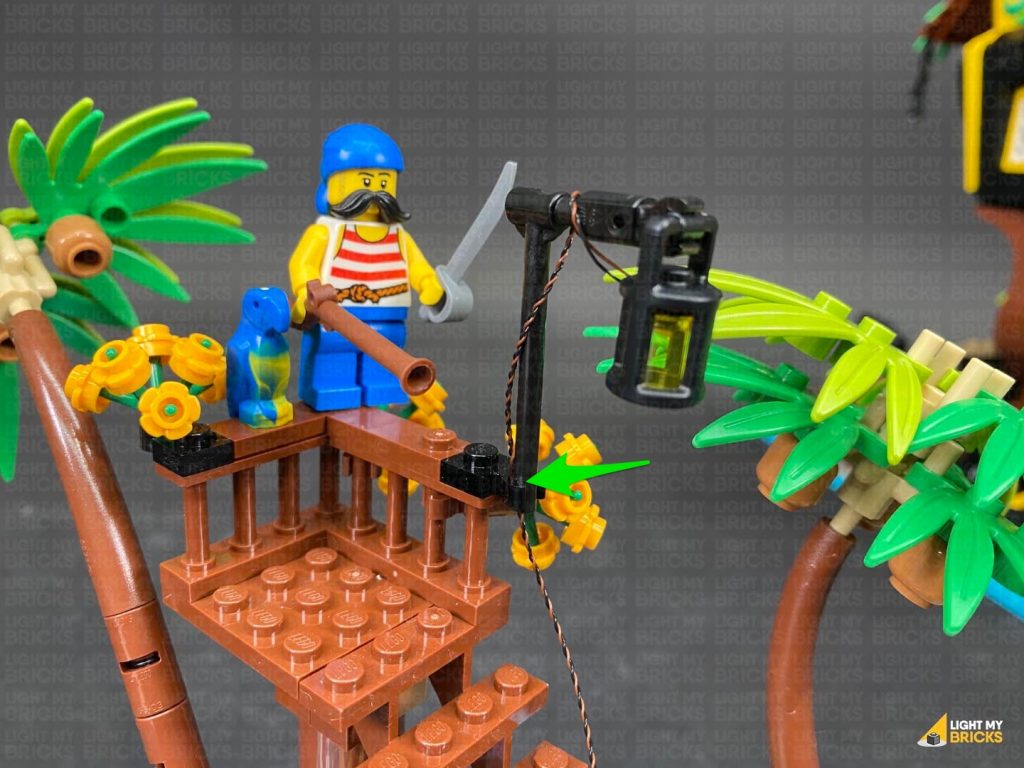
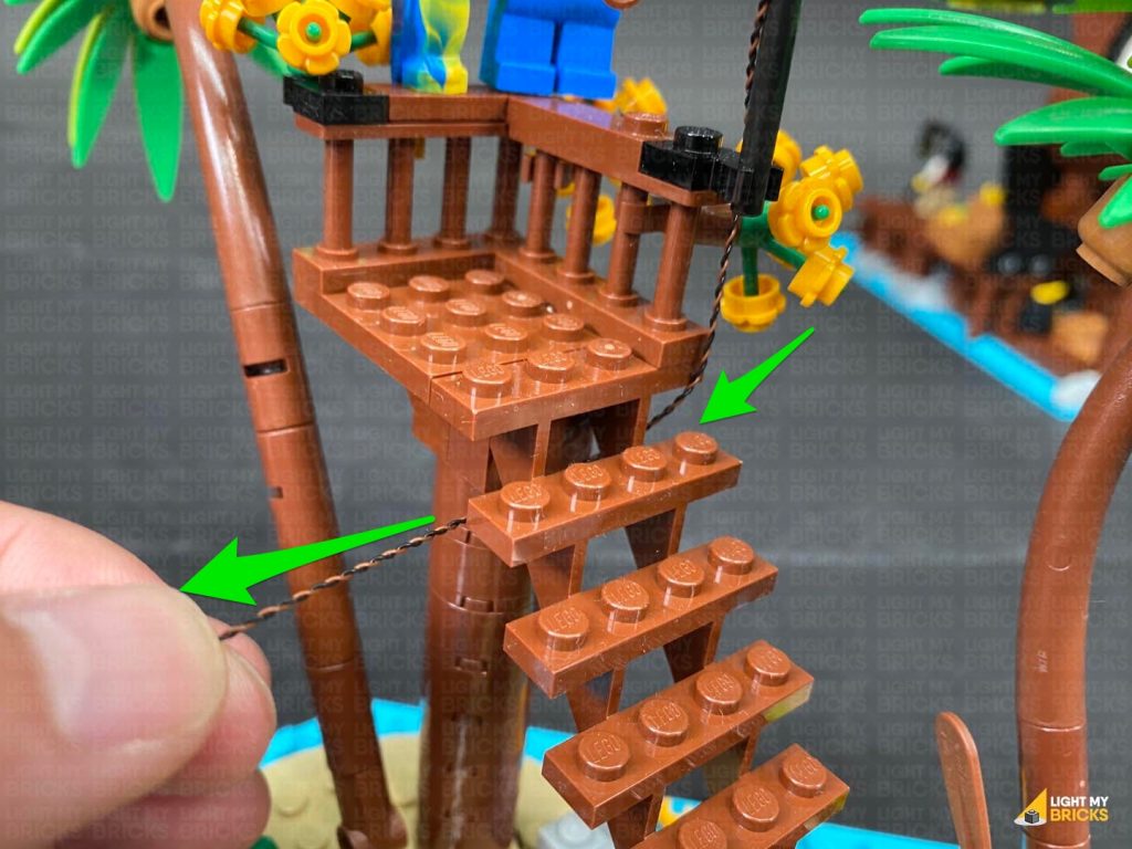
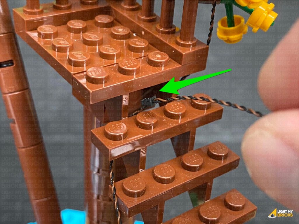
29.) Reconnect the other lamp to the top of the stairs, then bring the cable underneath the top of the stairs, toward the left side. Loop the cable by threading it through the middle space underneath the top step. Pull the cable all the way down from underneath ensuring there is no loose dangling cable around the stairs.
Disconnect the brown plate from the front of the deck and flip it over so we can access underneath. Take a Blue Strip Light and connect a 15cm Connecting Cable to it. Take another 15cm Connecting Cable and connect it to the other port, then using it’s adhesive backing, stick the strip light underneath the brown plate in the following position:
Thread the 15cm Connecting cable facing the back underneath the steps before reconnecting the brown plate to the dock. Ensure the other 15cm connecting cable is laid out toward the left side.
28.) Disconnect the lamp sections at the front and the top of the stairs, then using the same method used to install previous lamps, install a White 15cm Bit Light to the front lamp and a White 30cm Bit Light to the lamp from the top of the stairs.
Take the lamp from the front and thread the cable underneath the deck before reconnecting the lamp to the deck.
29.) Reconnect the other lamp to the top of the stairs, then bring the cable underneath the top of the stairs, toward the left side. Loop the cable by threading it through the middle space underneath the top step. Pull the cable all the way down from underneath ensuring there is no loose dangling cable around the stairs.
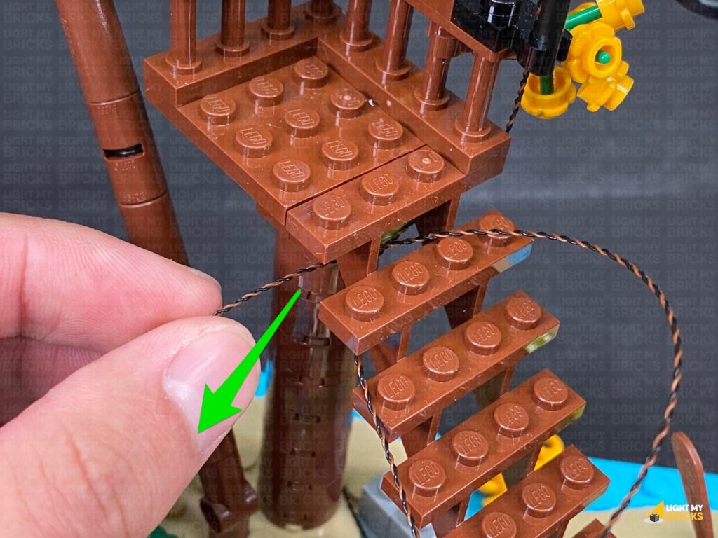
 Thread the cable through the bottom of the steps via the middle space, then loop it by threading it back through the middle space. Pull the cable out from the front, then lay it out towards the left side.
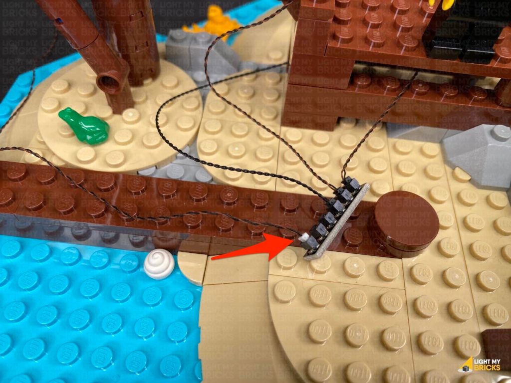
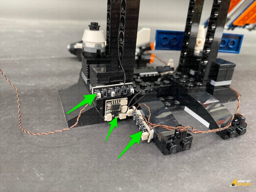
Connect both lamp Bit Light cables as well as the 15cm Connecting Cable from the Blue Strip Light (closest one facing the back) to a 6-Port Expansion Board. Take the USB Power Cable and connect it to a spare port on the expansion board, then turn the power ON to test the lights installed to this section are working OK.
Thread the cable through the bottom of the steps via the middle space, then loop it by threading it back through the middle space. Pull the cable out from the front, then lay it out towards the left side.
Connect both lamp Bit Light cables as well as the 15cm Connecting Cable from the Blue Strip Light (closest one facing the back) to a 6-Port Expansion Board. Take the USB Power Cable and connect it to a spare port on the expansion board, then turn the power ON to test the lights installed to this section are working OK.

Note: If you experience any issues with the lights not working and suspect an issue with a component, please try a different port on the expansion board to verify where the fault lies (with the light or expansion board). To correct any issues with expansion board ports, please view the section addressing expansion board issues on our online troubleshooting guide.
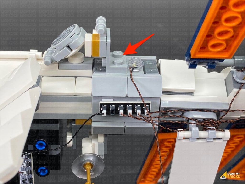
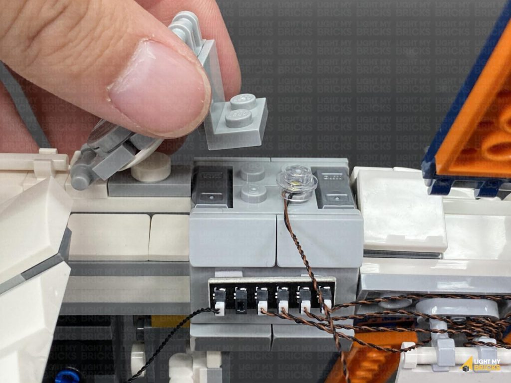
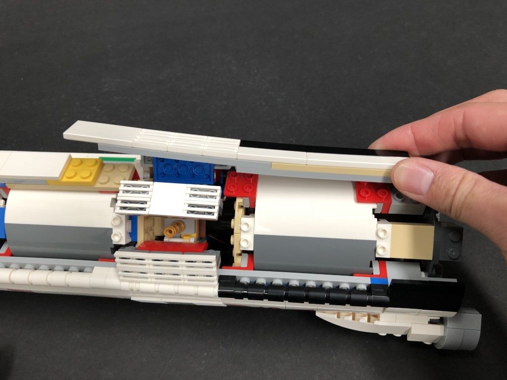
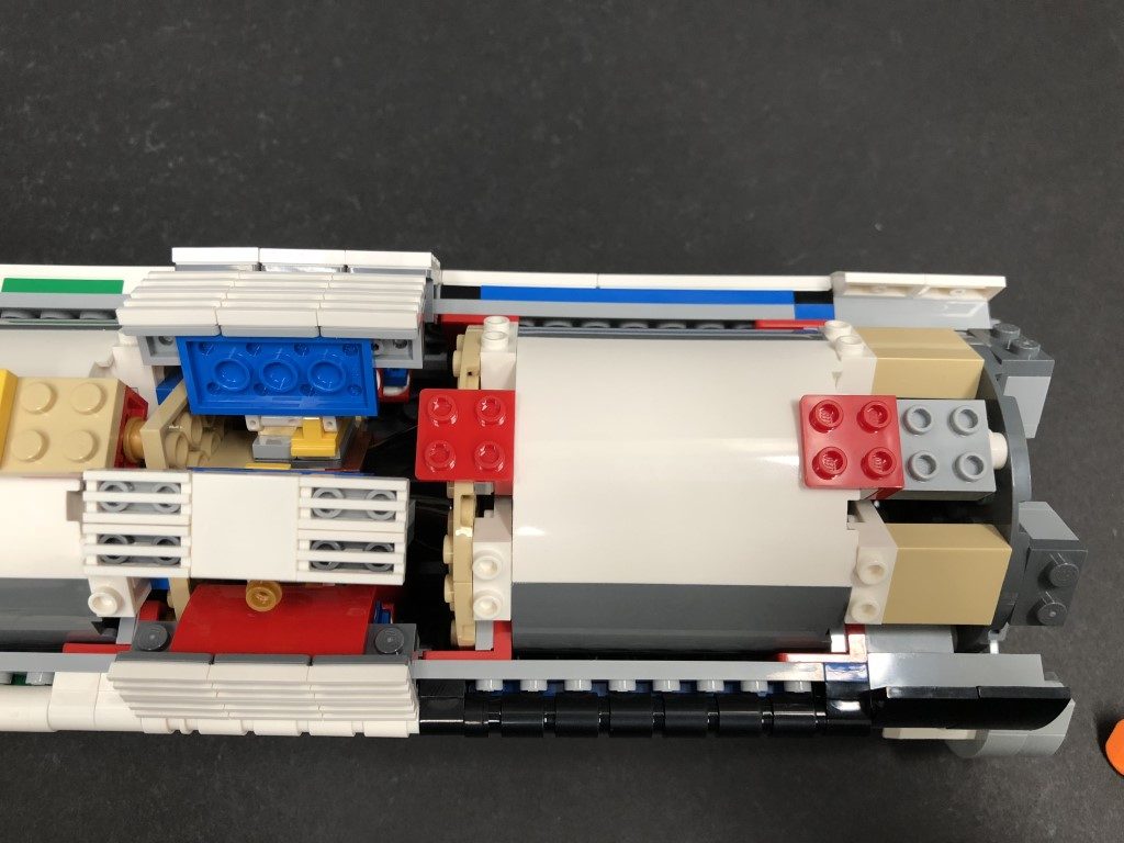
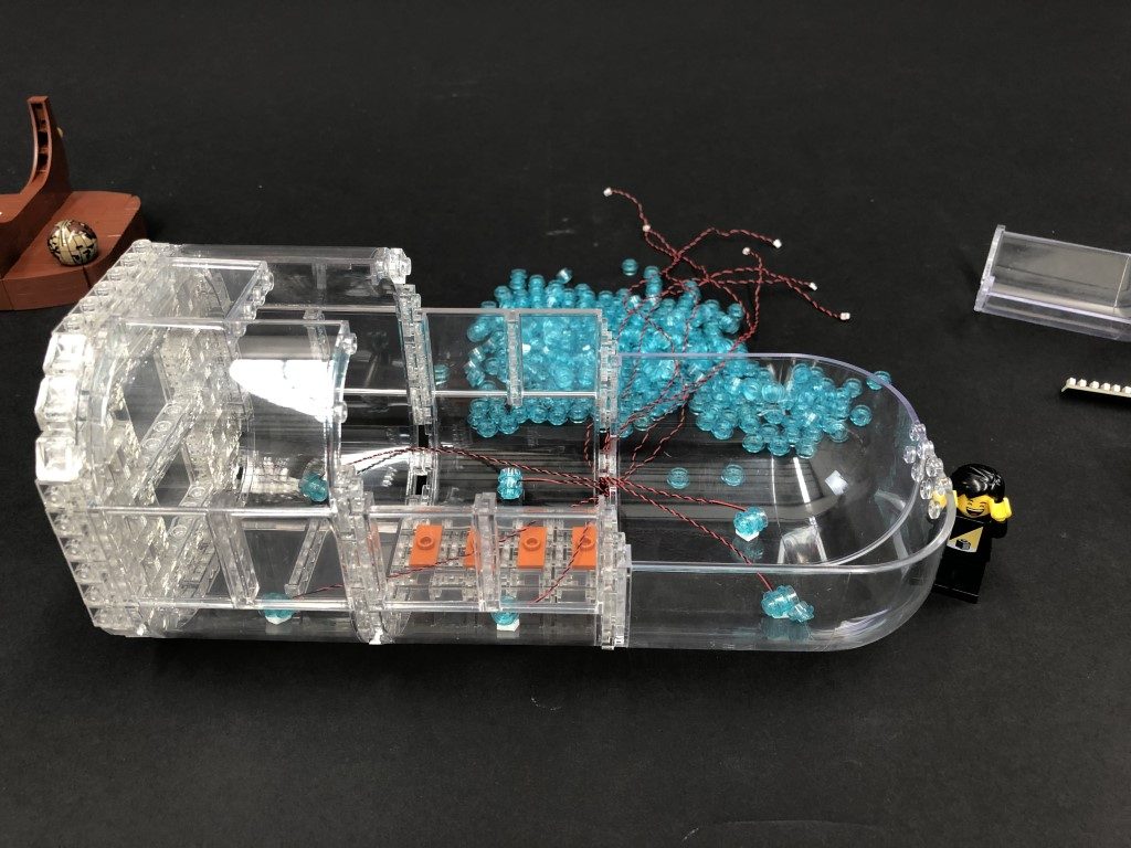
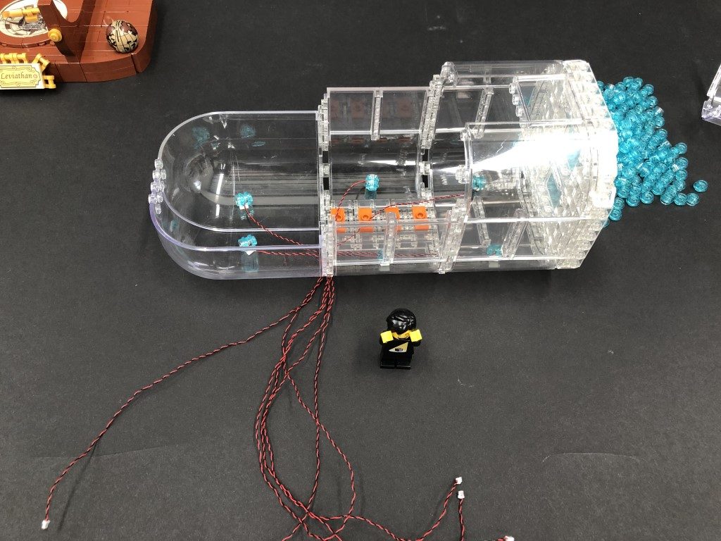
30.) Connect the spare end of the 15cm Connecting Cable from the Blue Strip Light to a new Blue Strip Light, then leave this aside for now as we will stick this strip light underneath the ship later on. Disconnect the USB Power Cable from the expansion board as we will use this to test lights we are about to install to the ship. 31.) Disconnect the following square plate from the ship’s deck, then un-clip the bottom of the rope ladder to allow us to completely remove the square plate along with the mast. Disconnect the following plates from the main floor, then remove the front panel as well as the plate underneath as shown below.
32.) Disconnect the following 3 sections from the lower deck that the candles are connected to.
Disconnect the following plates from the main floor, then remove the front panel as well as the plate underneath as shown below.
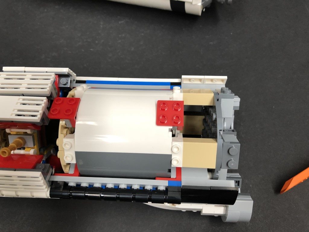
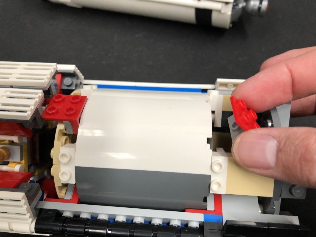
32.) Disconnect the following 3 sections from the lower deck that the candles are connected to.
 Disconnect the following plates and sections from the right side of the ship.
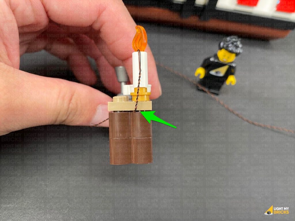
33.) Take the table with the pirate hat and following the same method used to install lights to the candles in the captain’s HQ, install a White 30cm Micro Bit Light to this candle.
Reconnect the candle to the table, then turn this section around and disconnect the gold square tile and lay the cable underneath before reconnecting the tile. Ensure the cable is laying out the side, then reconnect the table to the inside of the lower deck.
Disconnect the following plates and sections from the right side of the ship.
33.) Take the table with the pirate hat and following the same method used to install lights to the candles in the captain’s HQ, install a White 30cm Micro Bit Light to this candle.
Reconnect the candle to the table, then turn this section around and disconnect the gold square tile and lay the cable underneath before reconnecting the tile. Ensure the cable is laying out the side, then reconnect the table to the inside of the lower deck.
 Lay the cable from the candle down in between studs across the floor toward the opposite side. Turn the ship over to the left side and tuck the cable down underneath the shelf next to the bed.
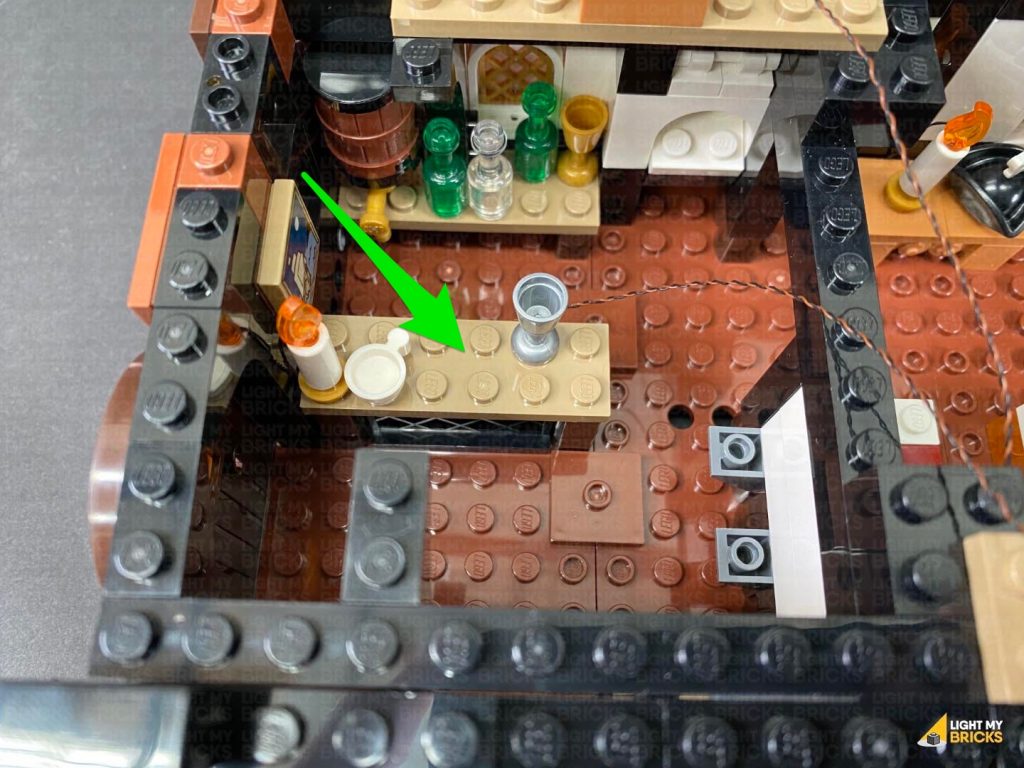
34.) Take the table with the cups, and following the same method used in the previous step, install another White 30cm Micro Bit Light to this candle.
Reconnect the candle to the table ensuring the cable is facing the left side, then disconnect the top plate and lay the cable underneath before reconnecting it (cable facing inside). Reconnect the table back inside the lower deck.
Using a LEGO Removal Tool, disconnect the following brown square tile with stud and lay the cable underneath it in between studs, before reconnecting the tile back over it. Lay the cable across the floor toward the back, then tuck it underneath the same shelf we tucked the other cable under.
35.) Install a White 15cm Micro Bit Light to the remaining candle on the shelf (this time, we don’t need to fold the cable down the side of the candle), then reconnect this section back inside the lower deck.
Lay the cable from the candle down in between studs across the floor toward the opposite side. Turn the ship over to the left side and tuck the cable down underneath the shelf next to the bed.
34.) Take the table with the cups, and following the same method used in the previous step, install another White 30cm Micro Bit Light to this candle.
Reconnect the candle to the table ensuring the cable is facing the left side, then disconnect the top plate and lay the cable underneath before reconnecting it (cable facing inside). Reconnect the table back inside the lower deck.
Using a LEGO Removal Tool, disconnect the following brown square tile with stud and lay the cable underneath it in between studs, before reconnecting the tile back over it. Lay the cable across the floor toward the back, then tuck it underneath the same shelf we tucked the other cable under.
35.) Install a White 15cm Micro Bit Light to the remaining candle on the shelf (this time, we don’t need to fold the cable down the side of the candle), then reconnect this section back inside the lower deck.
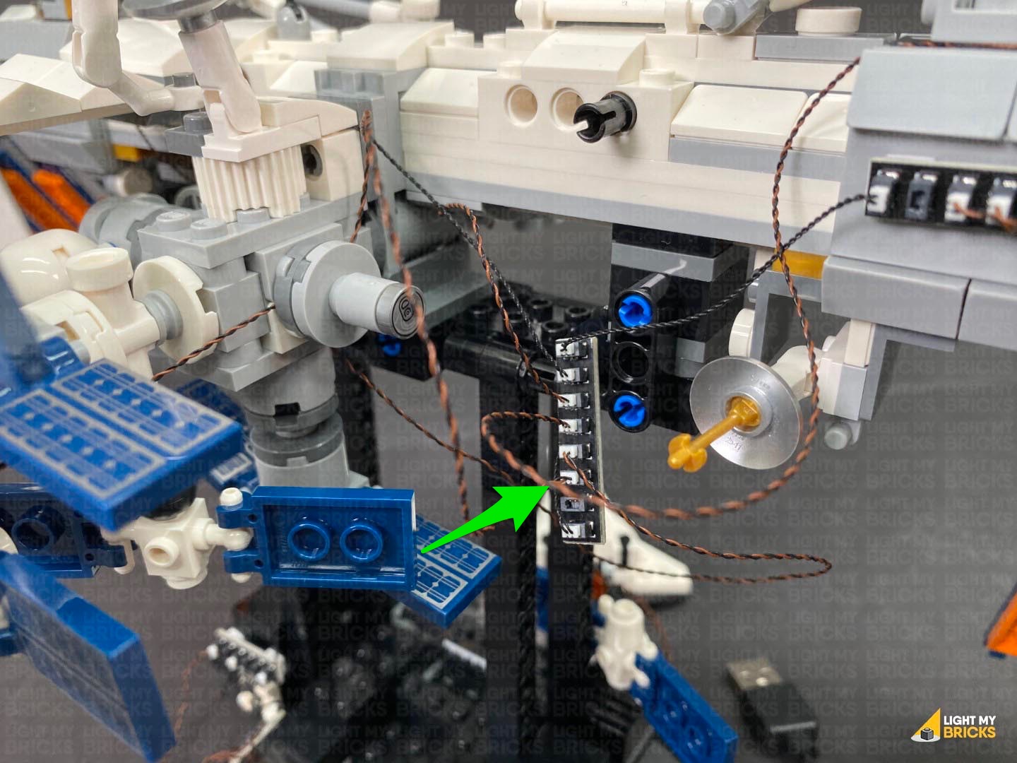
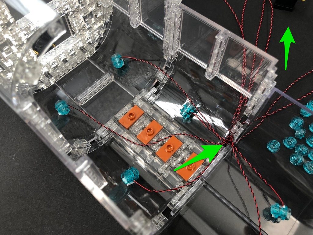
 36.) Disconnect the following pieces from the right side of the ship, then lay three Micro Bit Light cables over the side of the ship. Ensure they are all laid in between studs as demonstrated in the below images, then reconnect pieces over the top.
Lay the cables down the side of the ship, then disconnect the following black 1×1 tile. Lay the cables down each side of the stud before reconnecting the tile over the top.
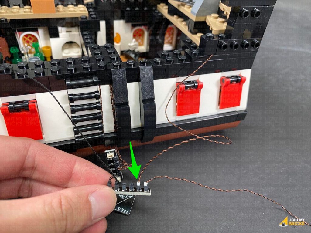
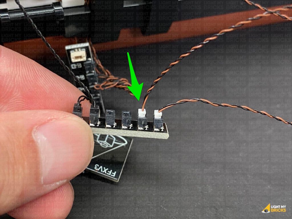
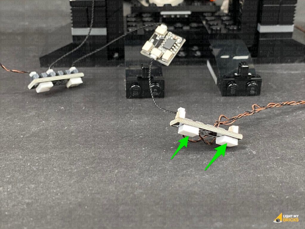
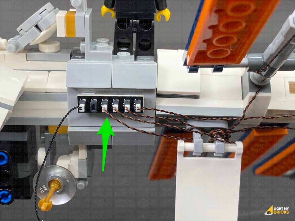
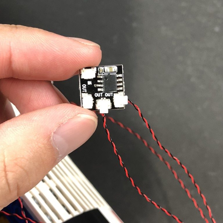
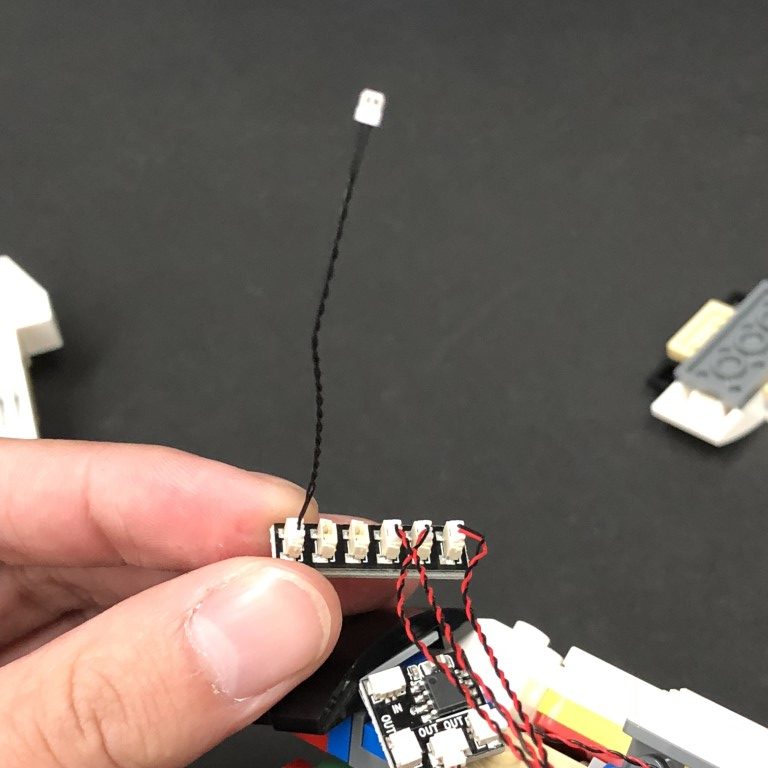
37.) Connect the three Micro Bit Lights to a Micro 2-4 Port Expansion Board. Connect a 5cm Connecting Cable to the larger port on the expansion board, then connect the other end of the cable to one of the OUT ports on a new Flicker Effects Board
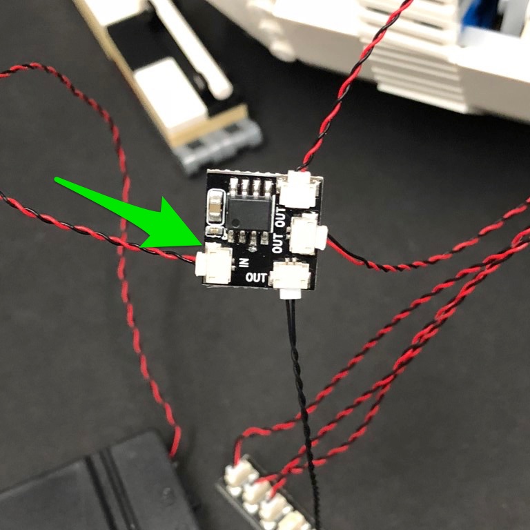
Connect a new 5cm Connecting Cable to the IN port on the Flicker Effects Board, then connect the other end of this cable to a 6-Port Expansion Board. Connect the USB Power Cable to any spare port on the expansion board, then turn the power ON to test the candle lights are working and flickering OK.
36.) Disconnect the following pieces from the right side of the ship, then lay three Micro Bit Light cables over the side of the ship. Ensure they are all laid in between studs as demonstrated in the below images, then reconnect pieces over the top.
Lay the cables down the side of the ship, then disconnect the following black 1×1 tile. Lay the cables down each side of the stud before reconnecting the tile over the top.
37.) Connect the three Micro Bit Lights to a Micro 2-4 Port Expansion Board. Connect a 5cm Connecting Cable to the larger port on the expansion board, then connect the other end of the cable to one of the OUT ports on a new Flicker Effects Board
Connect a new 5cm Connecting Cable to the IN port on the Flicker Effects Board, then connect the other end of this cable to a 6-Port Expansion Board. Connect the USB Power Cable to any spare port on the expansion board, then turn the power ON to test the candle lights are working and flickering OK.
38.) Disconnect the USB Power Cable from the 6-Port Expansion Board, then twist/fold the micro bit light cables into a neat bunch. Bring all the expansion boards together and twist the two 5cm connecting cables into a neat bunch. 39.) Take the front panel section and disconnect the lamp post. Using the same method used to install previous lamp lights, install a White 15cm Bit Light to it. Wind the cable around the lamp post as shown below, then reconnect it to this section. Turn this section onto it’s back so we can access underneath of it. Connect the Bit Light cable to the left port on a Warm White Strip Light, then connect a 15cm Connecting Cable to the right port. Using it’s adhesive backing, stick the strip light underneath this section in the following position, then neaten up the excess cable from the Bit Light by twisting/folding it into a neat bunch. 40.) Reconnect the panel to the plate underneath, then tuck the 15cm connecting cable underneath and in between the panel and the plate before reconnecting this section to the top of the ship.Note: If you experience any issues with the lights not working and suspect an issue with a component, please try a different port on the expansion board to verify where the fault lies (with the light, expansion board or effects board). To correct any issues with expansion board ports, please view the section addressing expansion board issues on our online troubleshooting guide.
 Bring the 15cm cable across to the right side of the ship and connect it to a spare port on the 6-Port Expansion board. Connect the USB Power Cable to the expansion board and turn the power ON to test the lights are working OK.
Note: If you experience any issues with the lights not working and suspect an issue with a component, please try a different port on the expansion board to verify where the fault lies (with the light, expansion board or effects board). To correct any issues with expansion board ports, please view the section addressing expansion board issues on our online troubleshooting guide.
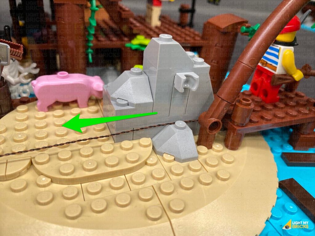
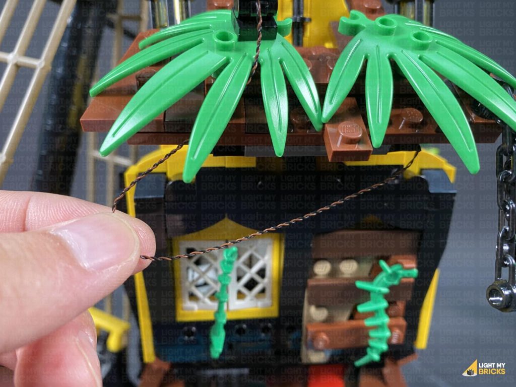
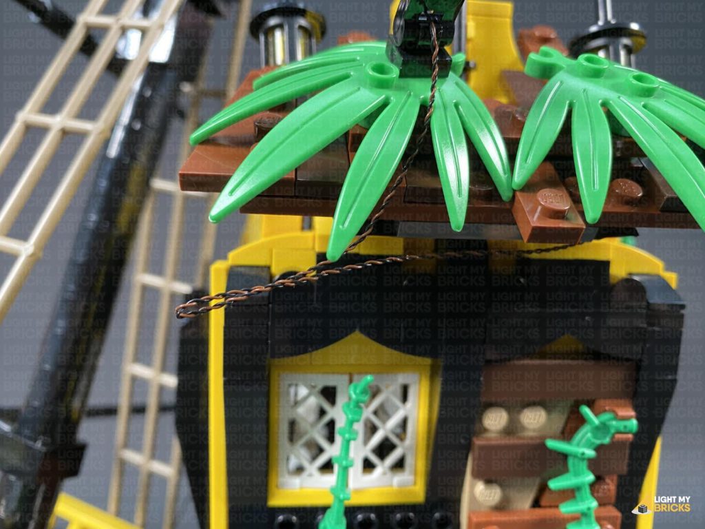
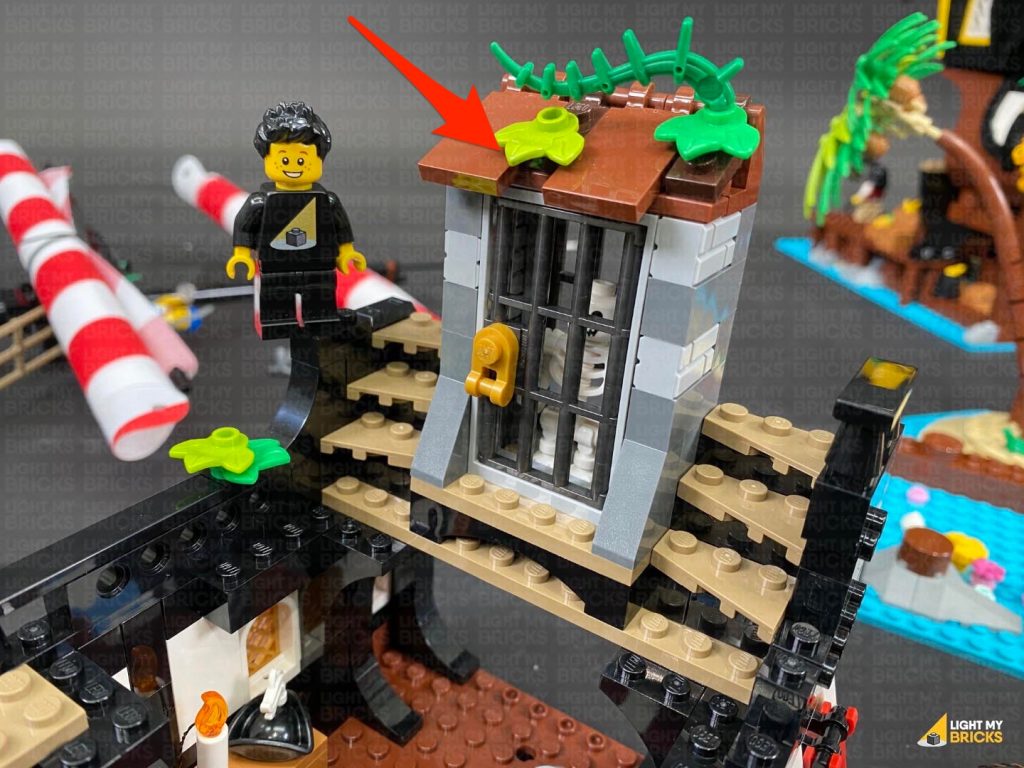
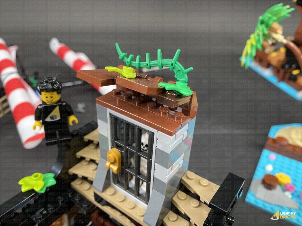
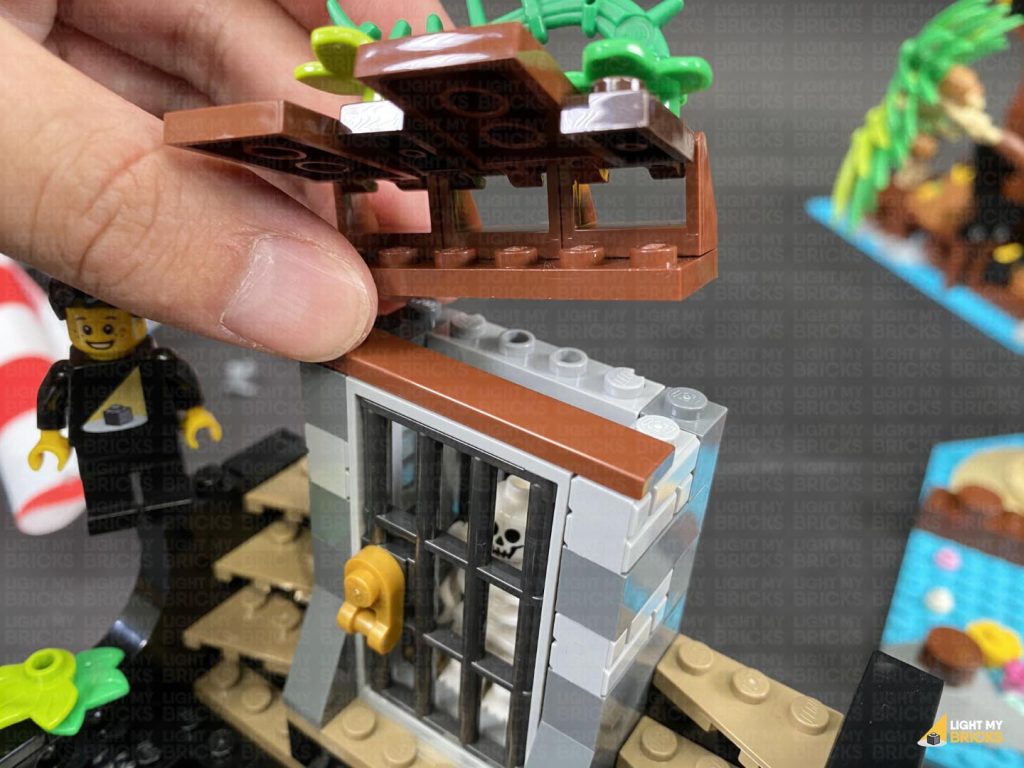
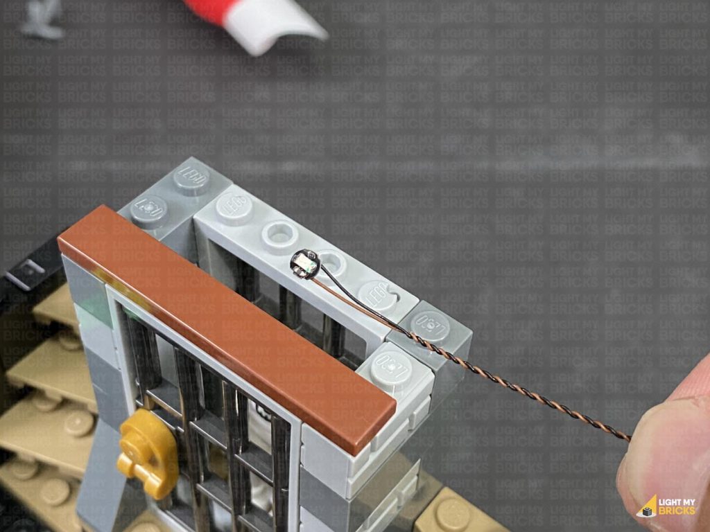
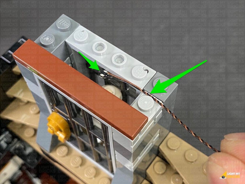
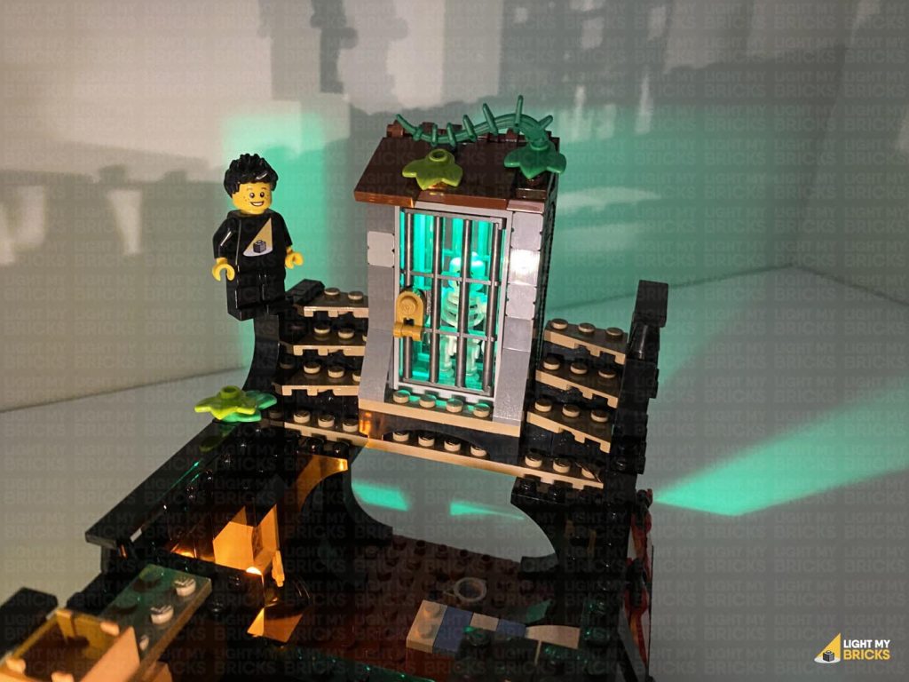
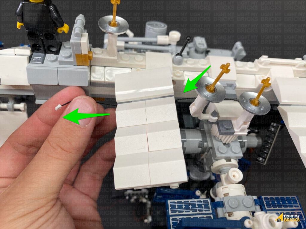
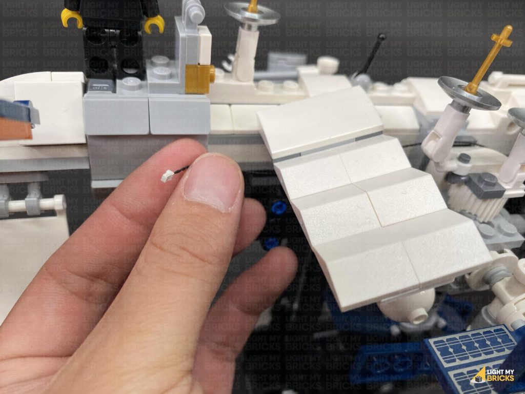
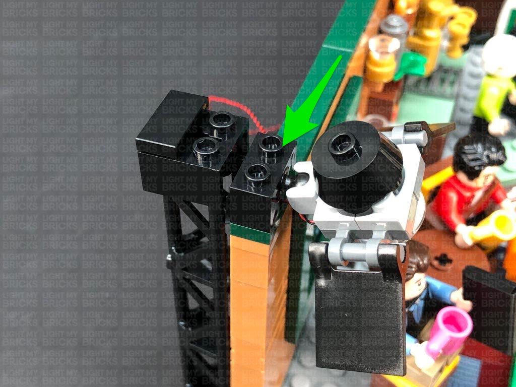
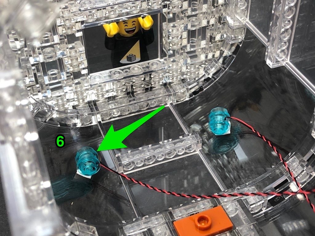
41.) Disconnect the roof section above the skeleton’s cell, then take a Green 30cm Bit Light and ensuring the LED is facing down, lay the cable down in between the following studs. Reconnect the roof.
Bring the 15cm cable across to the right side of the ship and connect it to a spare port on the 6-Port Expansion board. Connect the USB Power Cable to the expansion board and turn the power ON to test the lights are working OK.
Note: If you experience any issues with the lights not working and suspect an issue with a component, please try a different port on the expansion board to verify where the fault lies (with the light, expansion board or effects board). To correct any issues with expansion board ports, please view the section addressing expansion board issues on our online troubleshooting guide.
41.) Disconnect the roof section above the skeleton’s cell, then take a Green 30cm Bit Light and ensuring the LED is facing down, lay the cable down in between the following studs. Reconnect the roof.
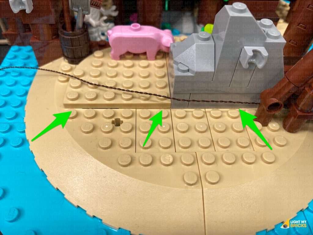
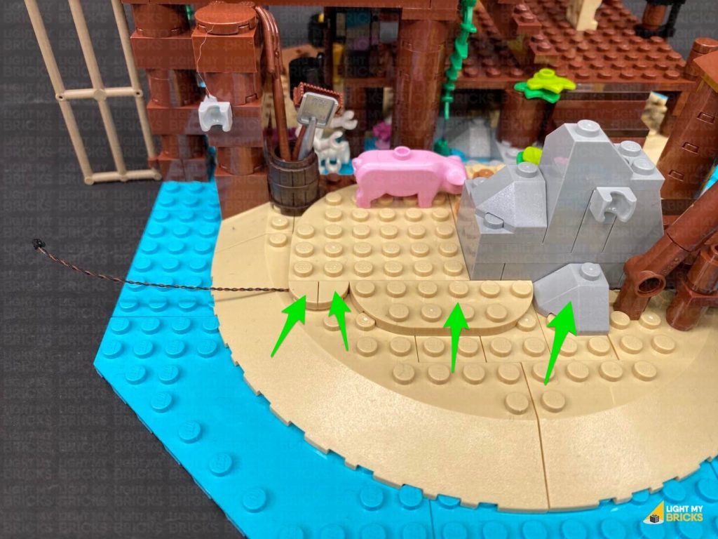
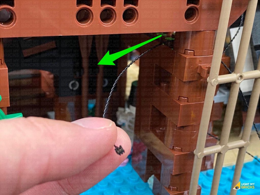
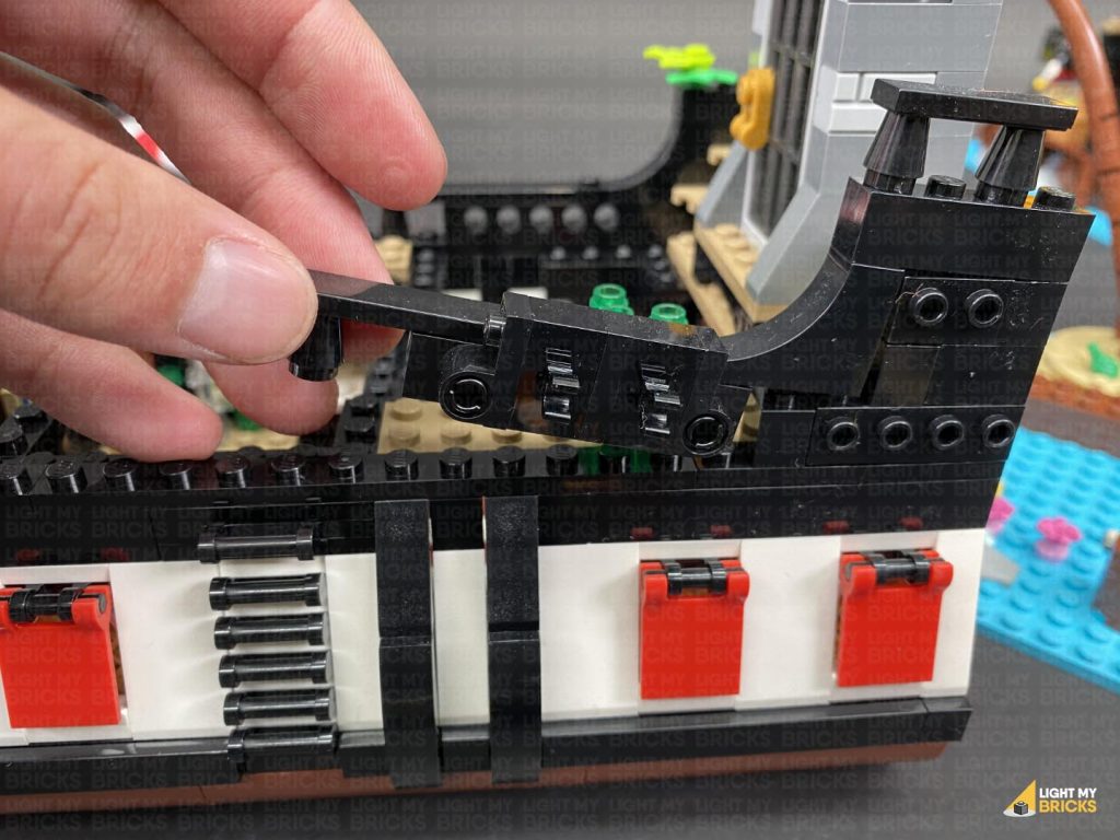
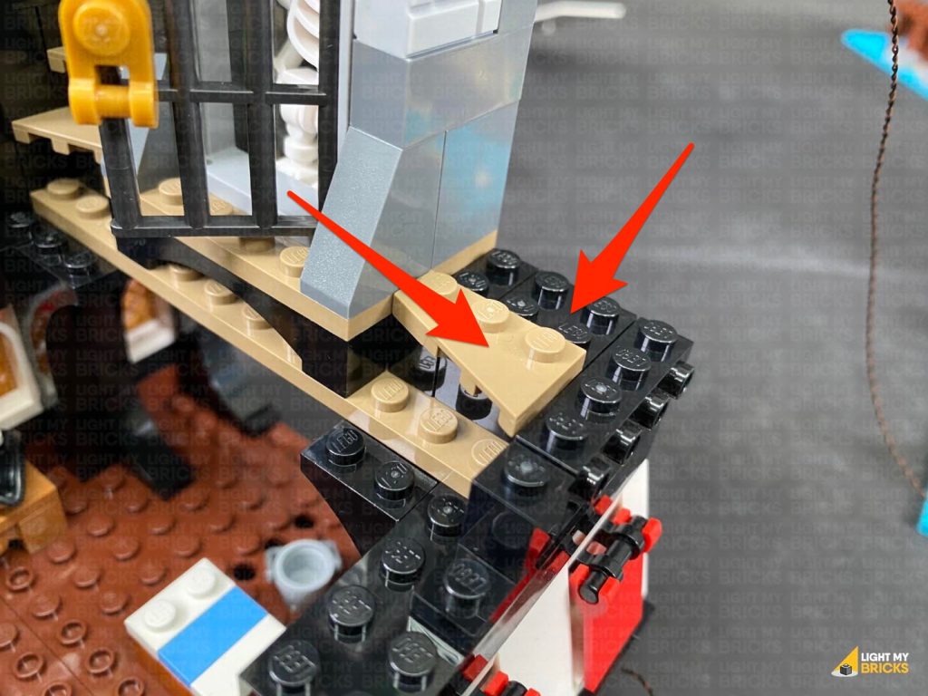
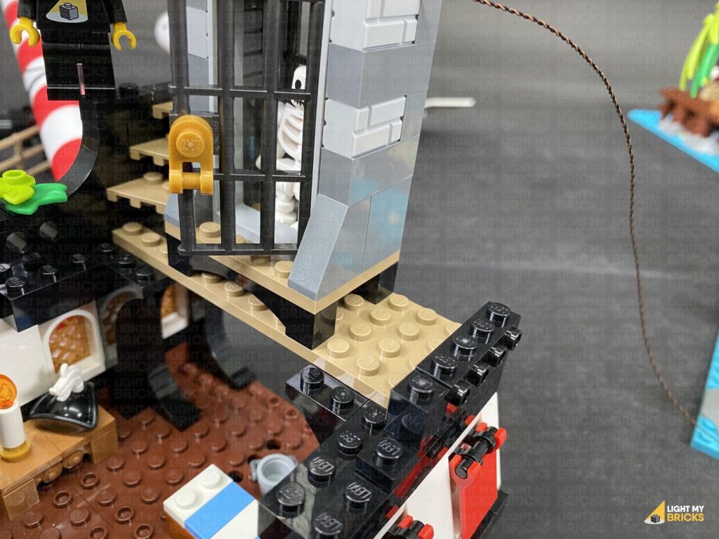
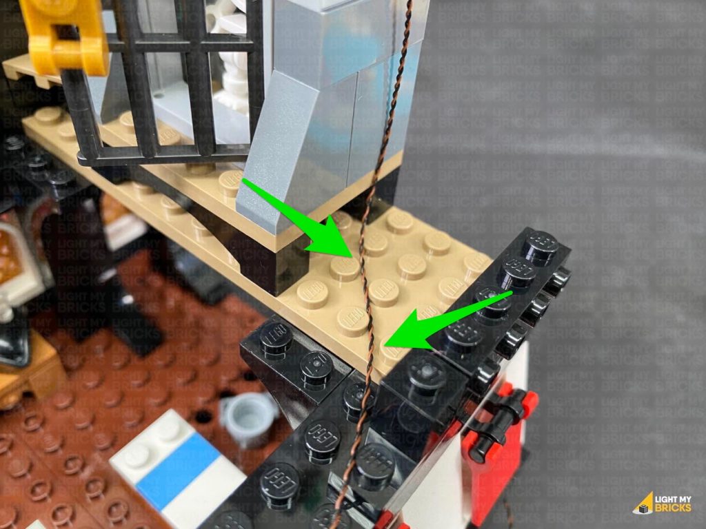
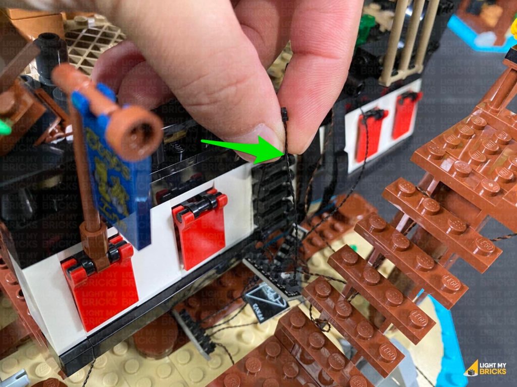
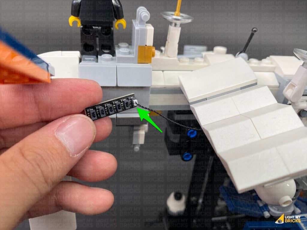
 Disconnect the following sections that make up the top of the stairs, then fold the Bit Light cable down the outside of the prison cell. Lay the cable down in between studs as shown below, then reconnect the stair sections.
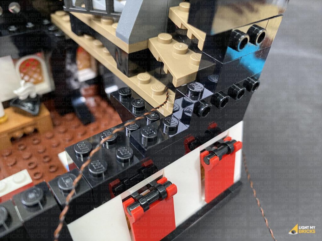
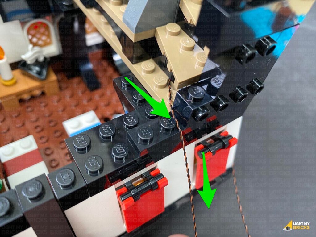
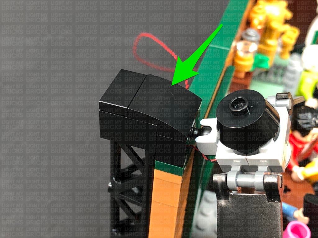
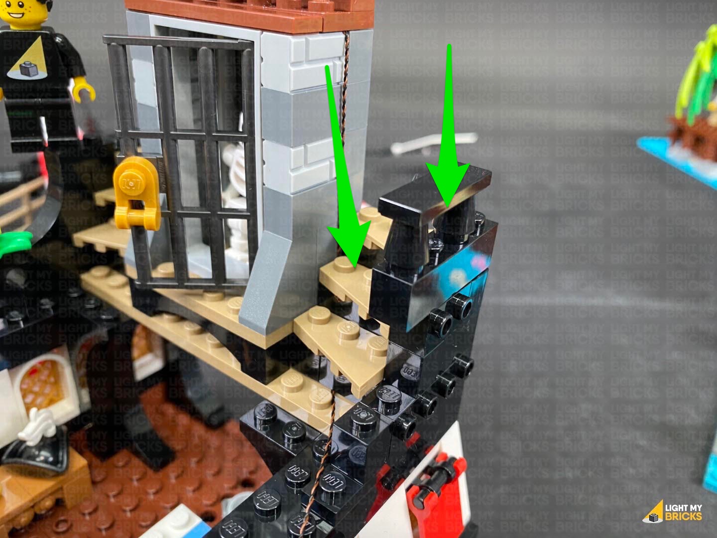 Disconnect the following black brick, then lay the cable down over the edge, in between studs. Reconnect the brick over the top, then connect the cable to the next available port on the 6-Port Expansion Board.
Turn the Power ON to test the green light is working OK.
Note: If you experience any issues with the lights not working and suspect an issue with a component, please try a different port on the expansion board to verify where the fault lies (with the light, expansion board or effects board). To correct any issues with expansion board ports, please view the section addressing expansion board issues on our online troubleshooting guide.
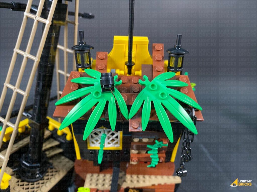
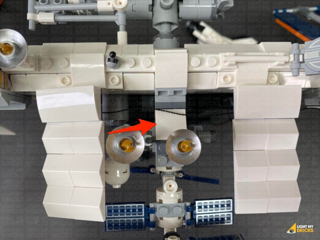
42.) Reconnect the following 2 plates to the top of the ship.
Lay the green bit light cable down in between studs as shown below, before reconnecting the remaining brown plate as well as the black 1×12 plate.
Reconnect the square plate to the middle of the deck as well as the other square plate with the mast and upper section.
Disconnect the following black brick, then lay the cable down over the edge, in between studs. Reconnect the brick over the top, then connect the cable to the next available port on the 6-Port Expansion Board.
Turn the Power ON to test the green light is working OK.
Note: If you experience any issues with the lights not working and suspect an issue with a component, please try a different port on the expansion board to verify where the fault lies (with the light, expansion board or effects board). To correct any issues with expansion board ports, please view the section addressing expansion board issues on our online troubleshooting guide.
42.) Reconnect the following 2 plates to the top of the ship.
Lay the green bit light cable down in between studs as shown below, before reconnecting the remaining brown plate as well as the black 1×12 plate.
Reconnect the square plate to the middle of the deck as well as the other square plate with the mast and upper section.
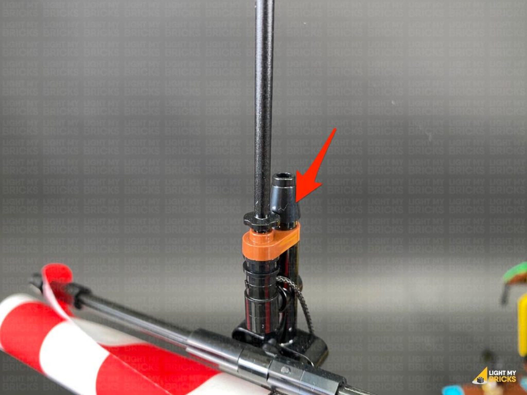
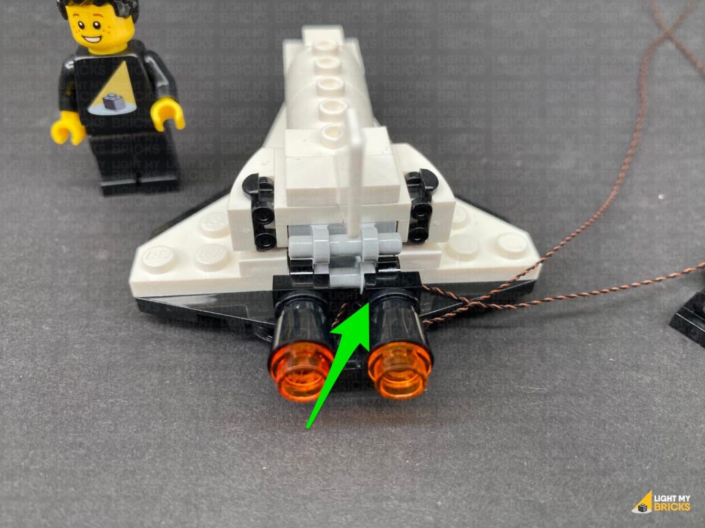
 43.) Disconnect the black cone piece from the bottom of the upper flag pole, then disconnect the flag pole and connect it to the hole behind.
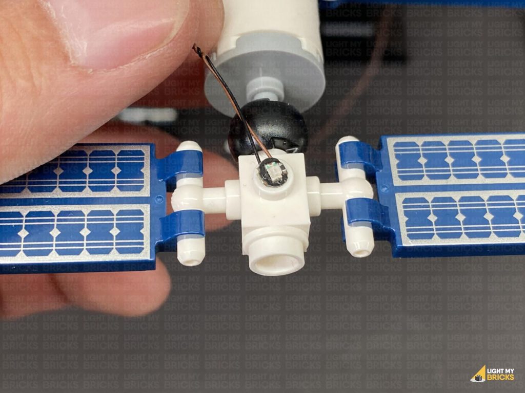
Take out the following provided LEGO pieces and using the same method used to install the spot light from the other flag (step 15), install a White 30cm Bit Light to it.
43.) Disconnect the black cone piece from the bottom of the upper flag pole, then disconnect the flag pole and connect it to the hole behind.
Take out the following provided LEGO pieces and using the same method used to install the spot light from the other flag (step 15), install a White 30cm Bit Light to it.
- 1x Black Round Plate 1×1 with Open Stud
- 1x Black Tile 1×1 with Clip Rounded Edges
- 1x Black 1×1 Modified Plate Rounded with Handle
Thread the Bit Light cable through the top of the black cone, then connect the cone to the bottom of the spot light.
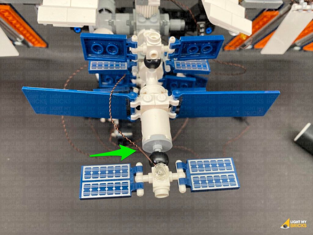
44.) Connect the cone and spot light to the bottom of the flag pole and position the spot light so that it is facing toward the Flag.
Bring the Bit Light cable down and wrap it around the mast as shown below, then tuck it in between the mast and the beam underneath the look-out platform.
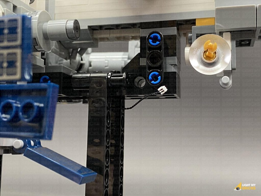
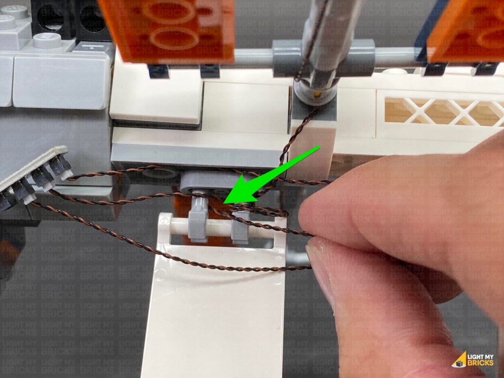
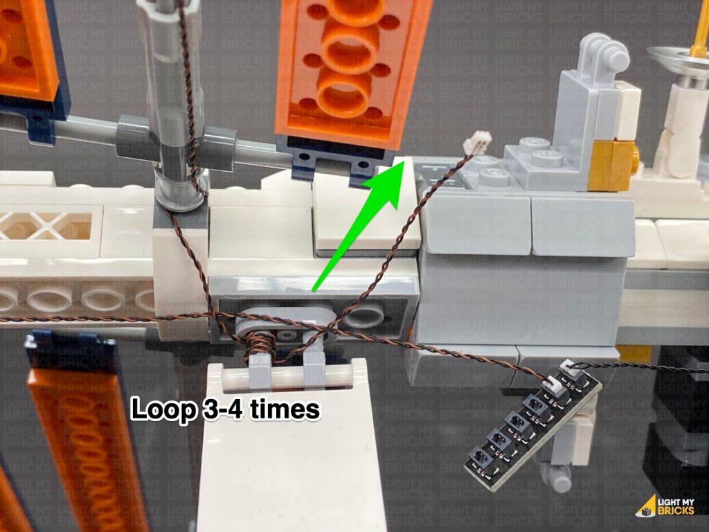
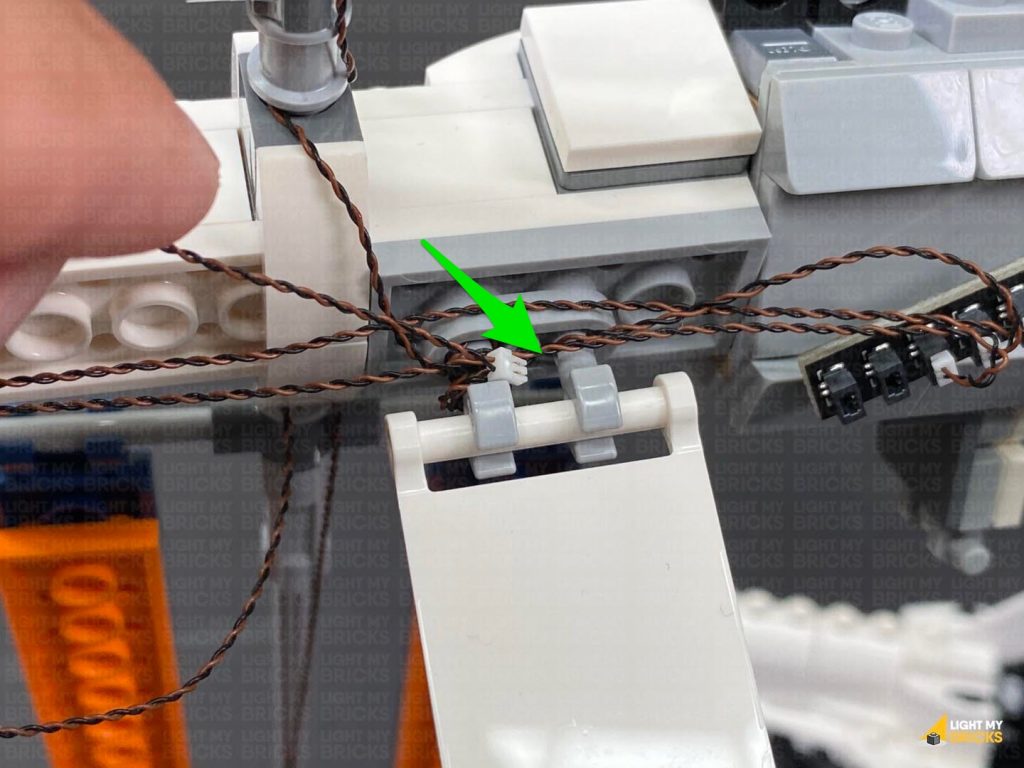
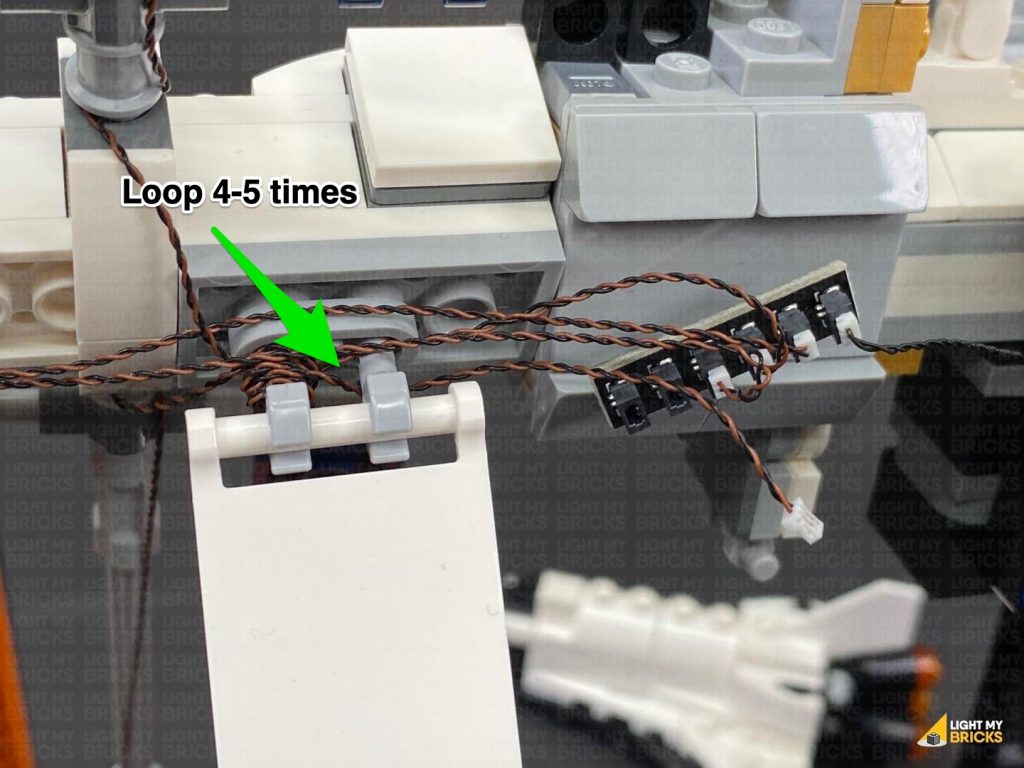
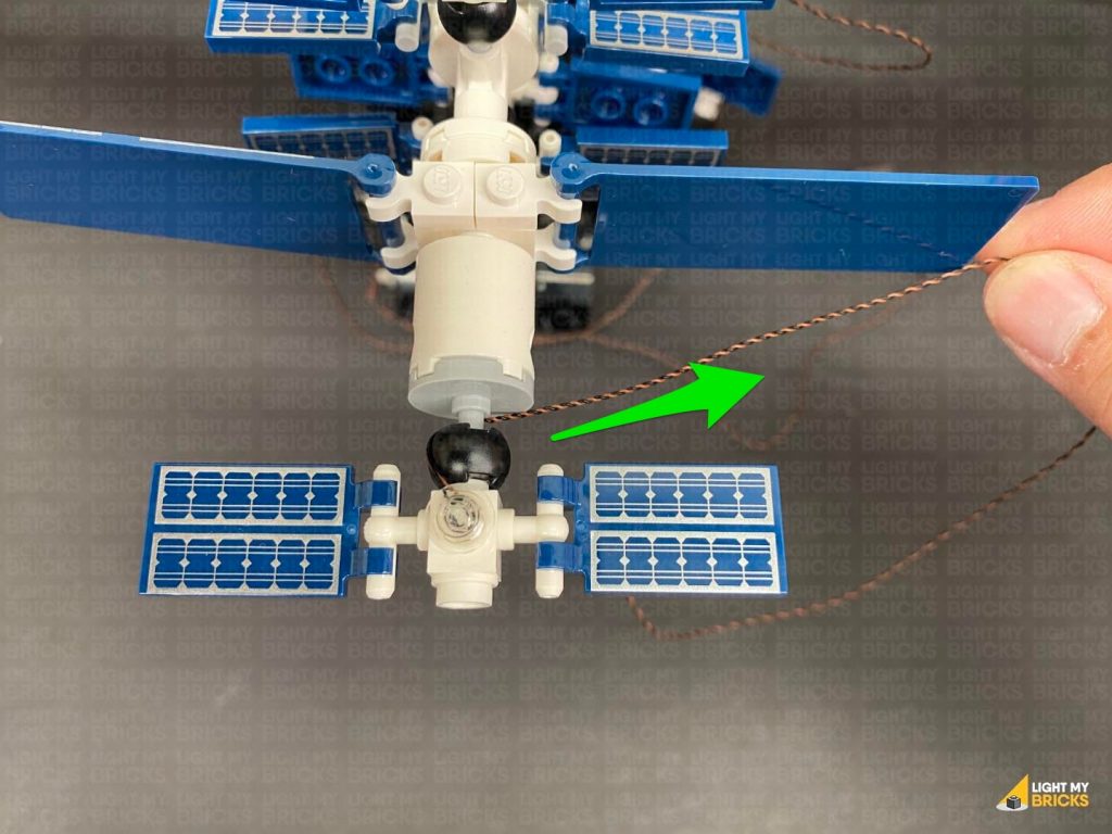
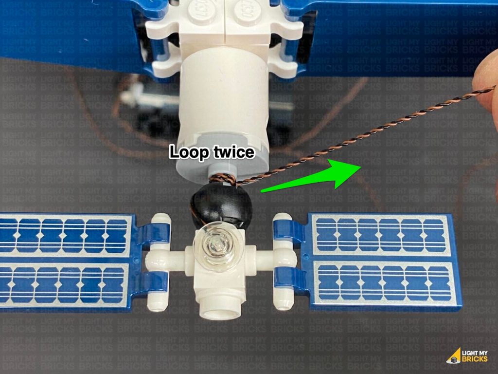
 Connect the Bit Light to a 2-Port Expansion Board. Connect the remaining 15cm Connecting Cable to the other port, then bring the cable down and loop it twice around the bracket connected to the horizontal beam underneath.
45.) Take the remaining Warm White Strip Light and connect the other end of the 15cm connecting cable to it. Take out the remaining 30cm Connecting Cable and connect the strip light’s other port. Using it’s adhesive backing, stick the strip light underneath the horizontal beam as shown below:
Bring the cable over the bracket and pull it down from the other side, then wind the cable around the bottom of the mast a few times as shown below.
Connect the Bit Light to a 2-Port Expansion Board. Connect the remaining 15cm Connecting Cable to the other port, then bring the cable down and loop it twice around the bracket connected to the horizontal beam underneath.
45.) Take the remaining Warm White Strip Light and connect the other end of the 15cm connecting cable to it. Take out the remaining 30cm Connecting Cable and connect the strip light’s other port. Using it’s adhesive backing, stick the strip light underneath the horizontal beam as shown below:
Bring the cable over the bracket and pull it down from the other side, then wind the cable around the bottom of the mast a few times as shown below.
 Bring the cable down the right side of the ship and connect it to a spare port on the 6-Port Expansion Board below.
Ensure the connecting cable is laid across the floor in between studs, then reconnect sections we removed earlier.
Turn ON the power to test the spot light and strip light is working OK.
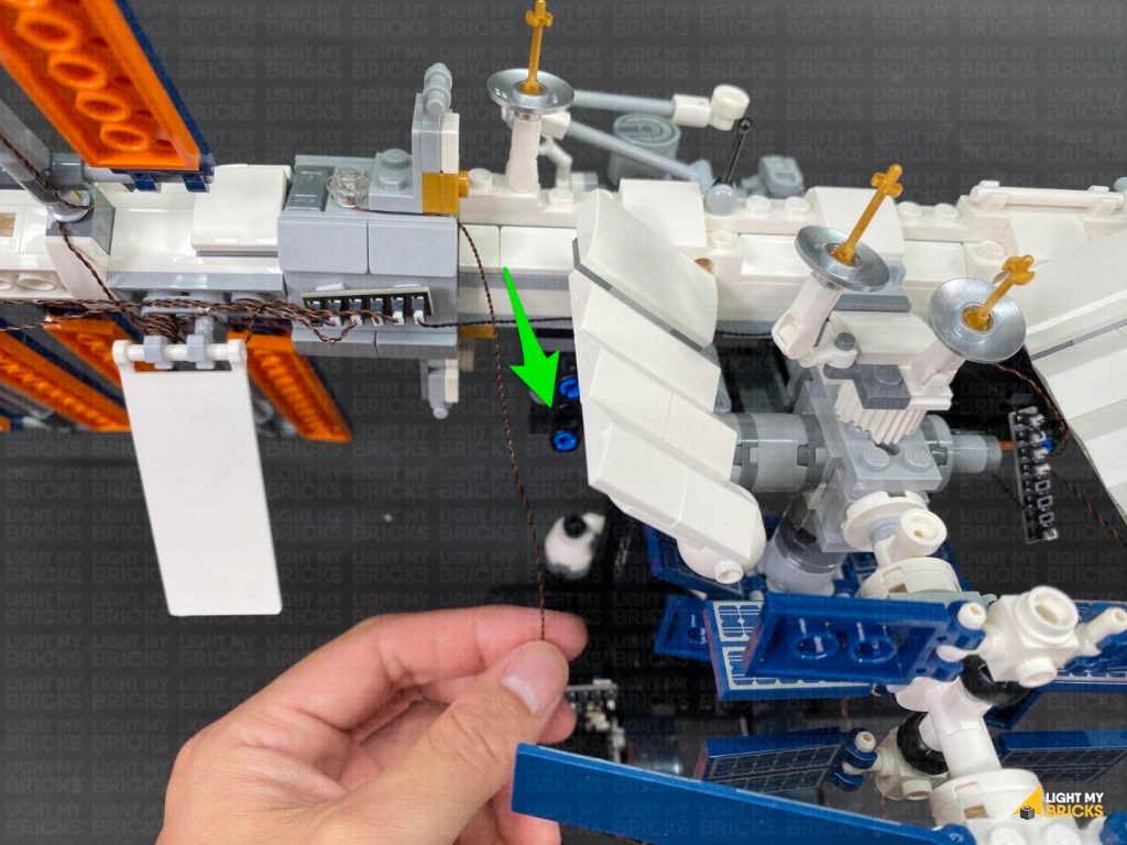
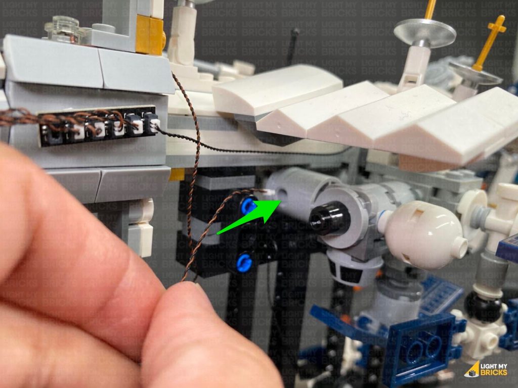
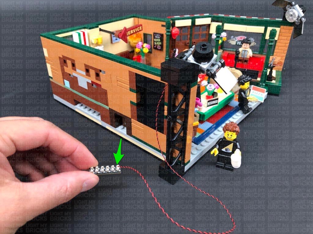
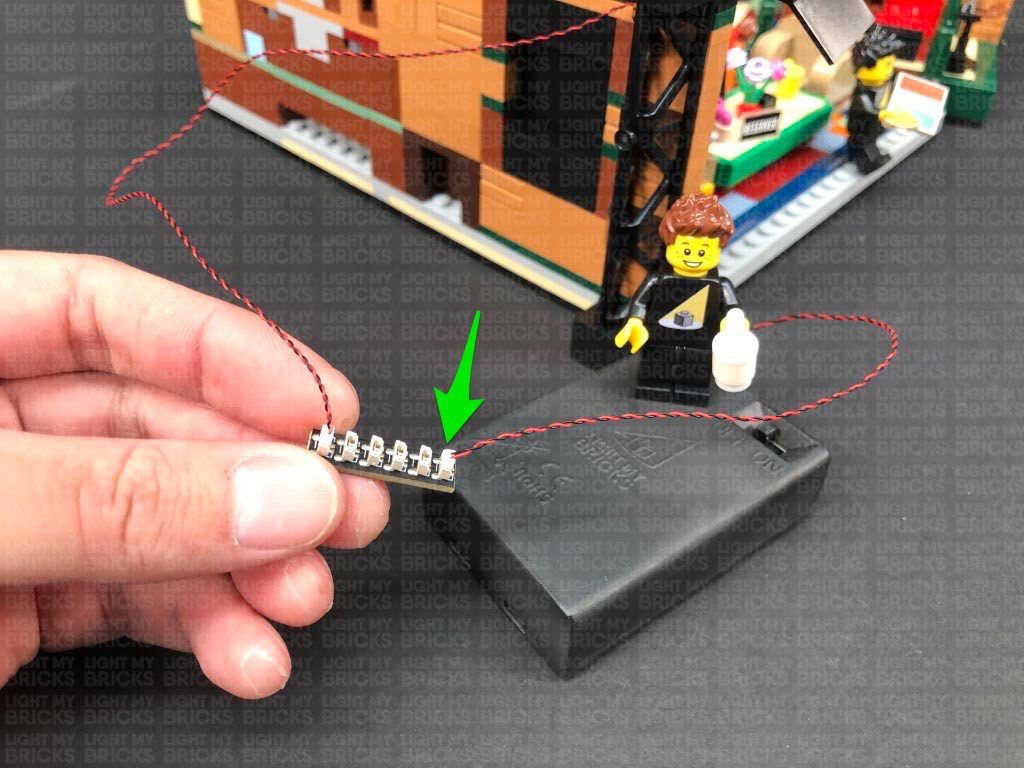
46.) Disconnect the USB Power Cable from the 6-Port Expansion Board, then connect a new 5cm Connecting Cable to the expansion board.
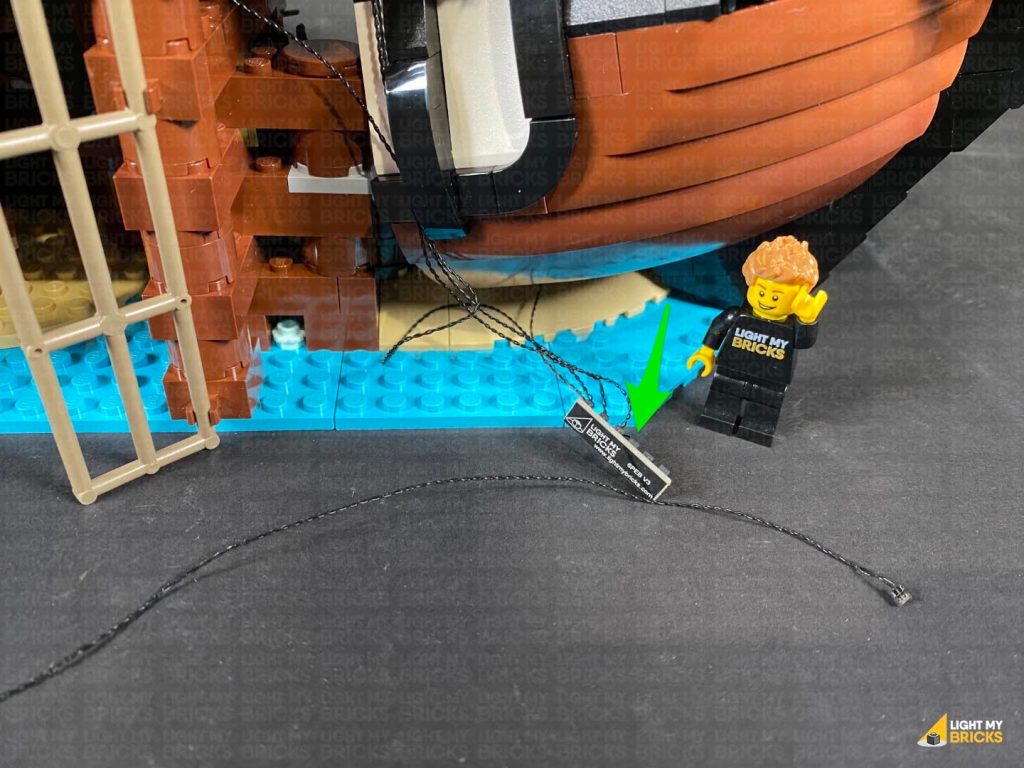
Go back to the docks section and connect a 50cm Connecting Cable to the 6-port Expansion board underneath the deck. Thread the other end underneath the stairs through to the right side of the set.
Bring the ship close to this section and place it onto it’s left side so we can access underneath of it. Take the spare Blue Strip Light we left aside earlier on and stick it underneath the ship in the below position using it’s adhesive backing.
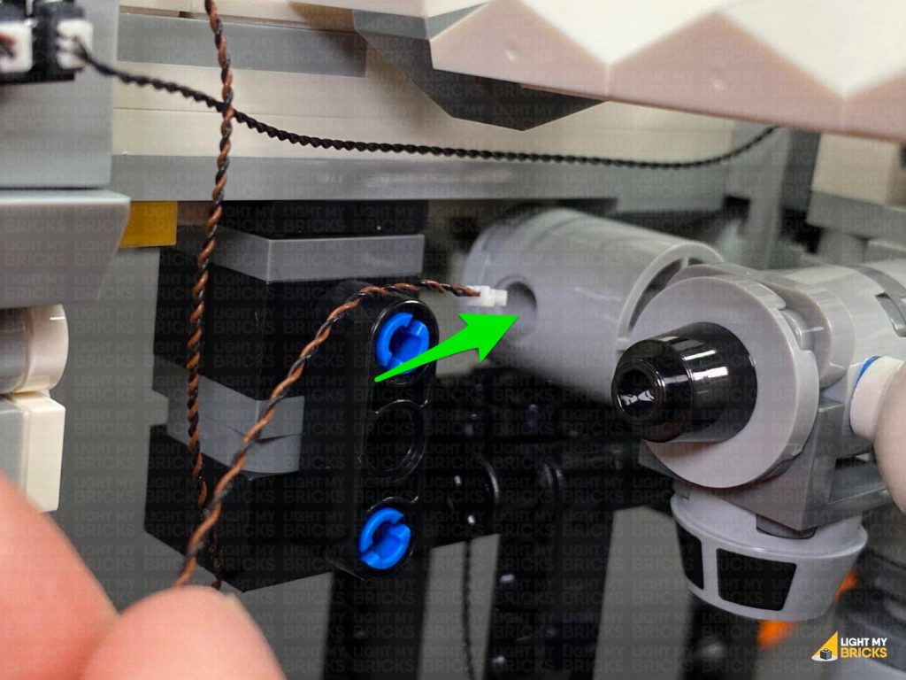
Flip the ship back over and take the other end of the 5cm Connecting cable from the bottom and connect the other end of the cable to a spare port on the 6-port expansion board from underneath the deck.
Reconnect it to the docks via the two technic pins ensuring all the expansion boards are well hidden underneath the stairs and the spare end of the 50cm Connecting Cable is laid out the right side.
Bring the cable down the right side of the ship and connect it to a spare port on the 6-Port Expansion Board below.
Ensure the connecting cable is laid across the floor in between studs, then reconnect sections we removed earlier.
Turn ON the power to test the spot light and strip light is working OK.
46.) Disconnect the USB Power Cable from the 6-Port Expansion Board, then connect a new 5cm Connecting Cable to the expansion board.
Go back to the docks section and connect a 50cm Connecting Cable to the 6-port Expansion board underneath the deck. Thread the other end underneath the stairs through to the right side of the set.
Bring the ship close to this section and place it onto it’s left side so we can access underneath of it. Take the spare Blue Strip Light we left aside earlier on and stick it underneath the ship in the below position using it’s adhesive backing.
Flip the ship back over and take the other end of the 5cm Connecting cable from the bottom and connect the other end of the cable to a spare port on the 6-port expansion board from underneath the deck.
Reconnect it to the docks via the two technic pins ensuring all the expansion boards are well hidden underneath the stairs and the spare end of the 50cm Connecting Cable is laid out the right side.
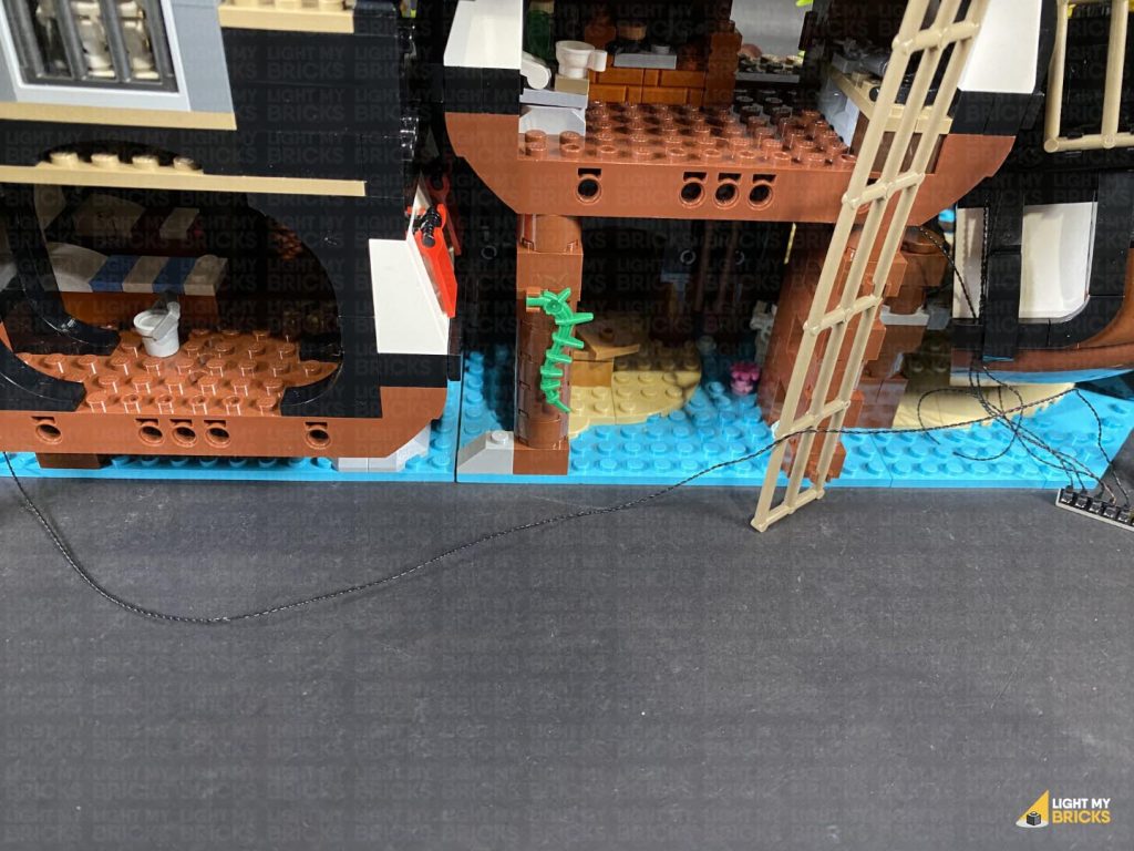
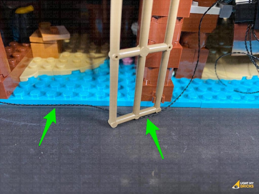
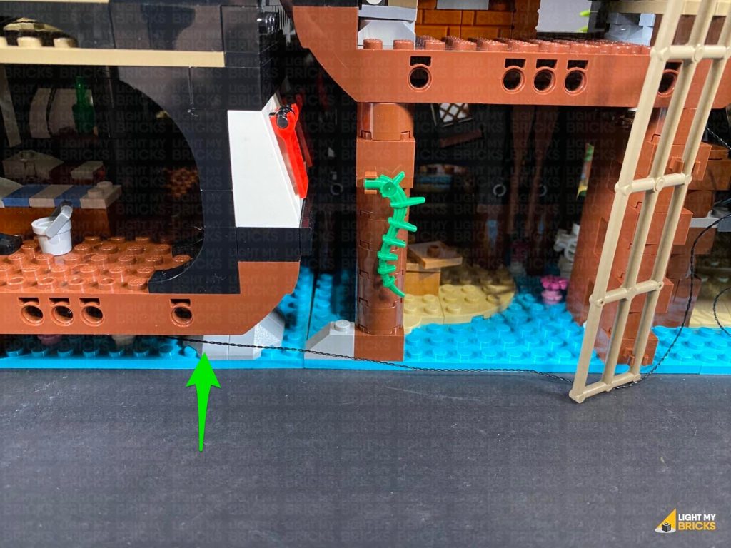
 47.) Bring the two main sections together and from the back of the set, bring the 50cm Connecting Cable over to the right side and connect it to a spare port on the 6-port expansion board on the far right side of the set.
Secure any loose excess cable underneath the ladder and underneath the base plates.
Connect the USB Power Cable to a spare port on the 6-port expansion board on the far right side, then neaten up the cables connected to it by twisting and folding them up into a neat bunch. Tuck the bunched up cables underneath the ship, then turn ON the power to test all the lights are working OK.
Note: If you experience any issues with the lights not working and suspect an issue with a component, please try a different port on the expansion board to verify where the fault lies (with the light, expansion board or effects board). To correct any issues with expansion board ports, please view the section addressing expansion board issues on our online troubleshooting guide.
47.) Bring the two main sections together and from the back of the set, bring the 50cm Connecting Cable over to the right side and connect it to a spare port on the 6-port expansion board on the far right side of the set.
Secure any loose excess cable underneath the ladder and underneath the base plates.
Connect the USB Power Cable to a spare port on the 6-port expansion board on the far right side, then neaten up the cables connected to it by twisting and folding them up into a neat bunch. Tuck the bunched up cables underneath the ship, then turn ON the power to test all the lights are working OK.
Note: If you experience any issues with the lights not working and suspect an issue with a component, please try a different port on the expansion board to verify where the fault lies (with the light, expansion board or effects board). To correct any issues with expansion board ports, please view the section addressing expansion board issues on our online troubleshooting guide.
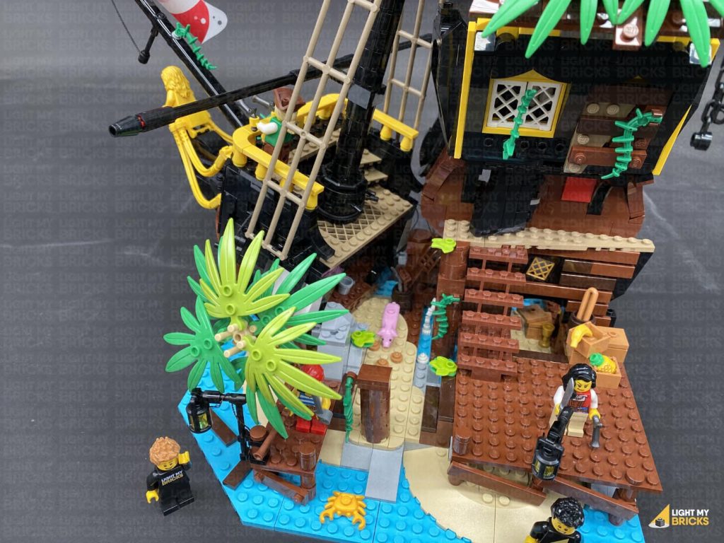
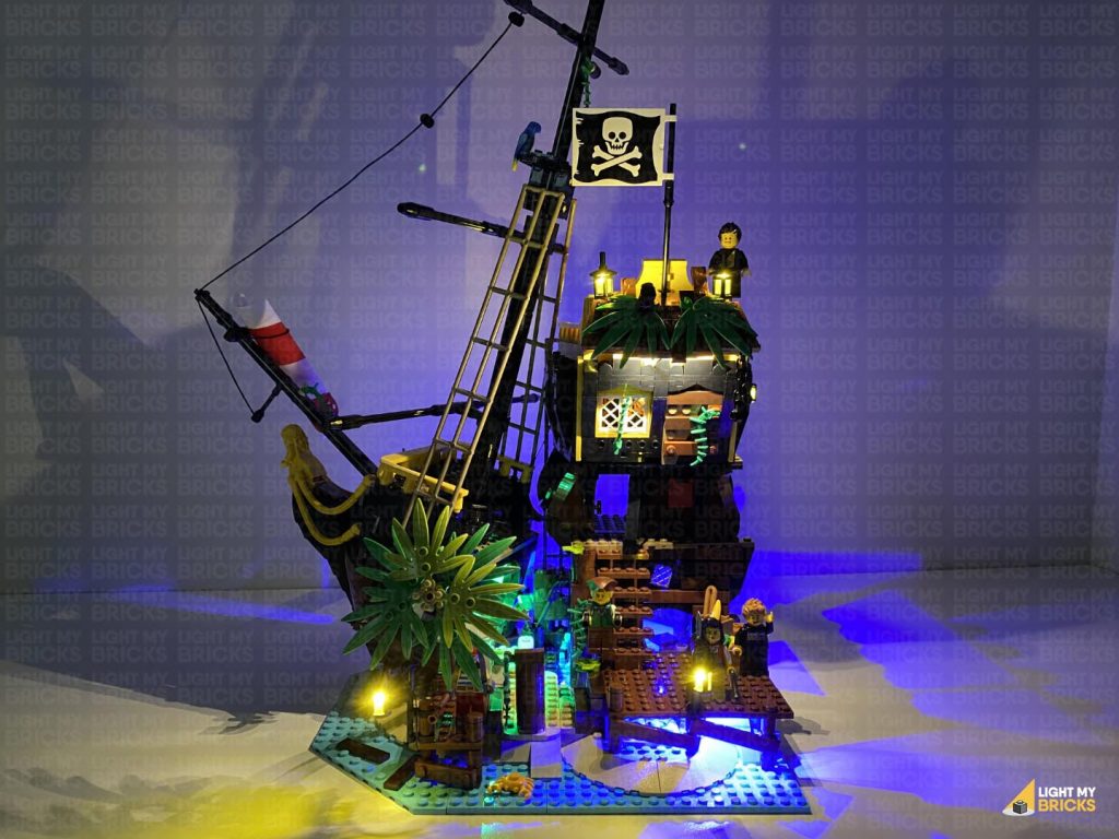
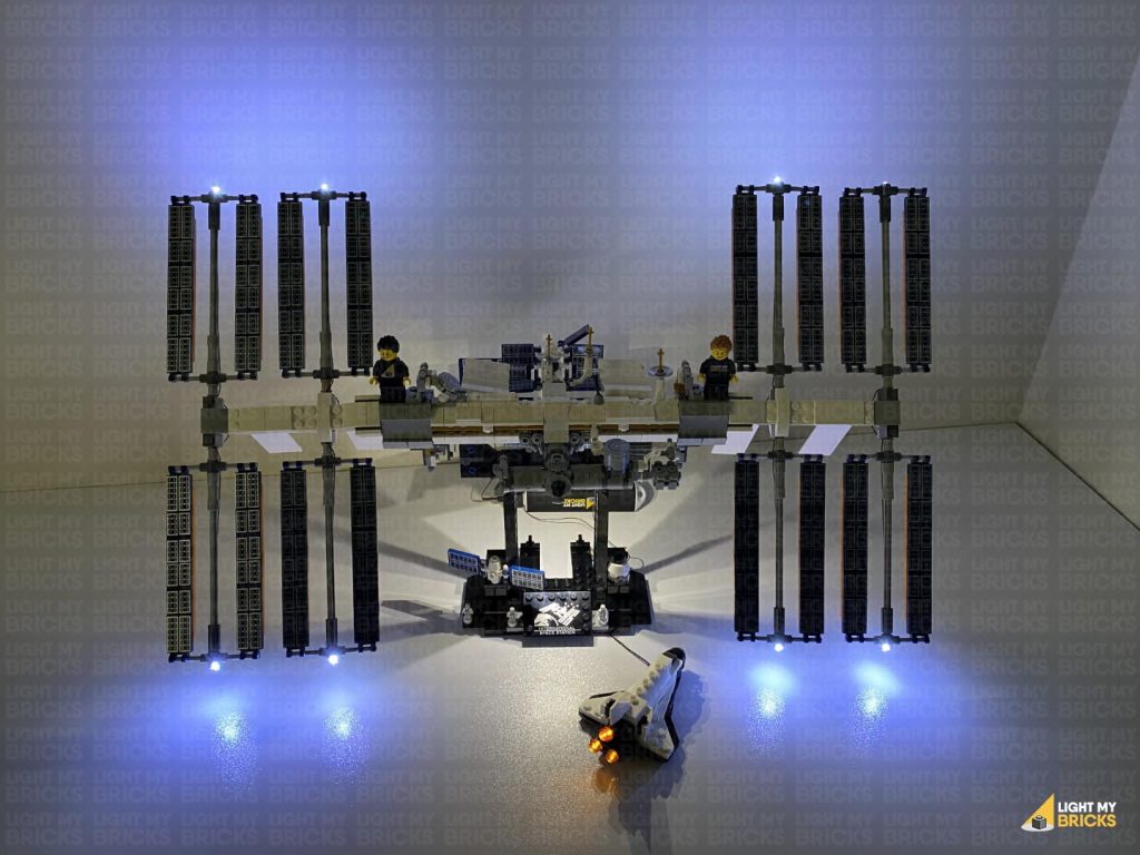
This finally completes installation of the Light My Bricks Pirates of Barracuda Bay Light Kit.
We thank you for purchasing this product and hope you ENJOY!


