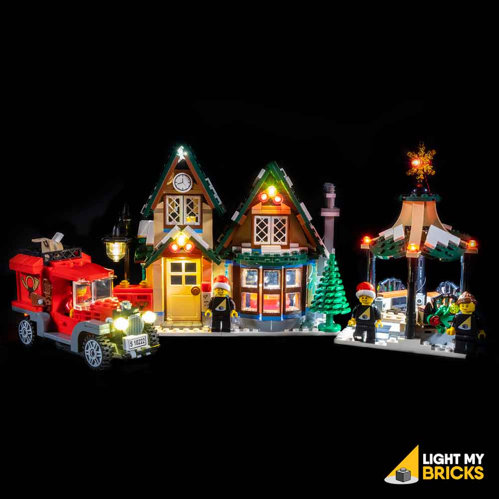
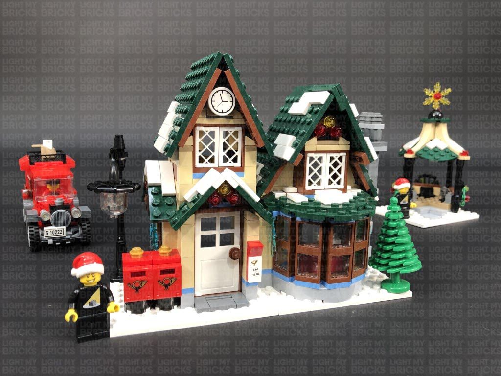
The following page is the instructions for the Light My Bricks LEGO Winter Village Post Office (10222) LED light kit.
If you run into any issues, please refer to the online troubleshooting guide.
To ensure a trouble-free installation of your light kit, please read and follow each step carefully.
Please note: This page lists instructions for the LED light kit only. If you are wishing to purchase the Light My Bricks LEGO Winter Village Post Office (10222) LED light kit , please click here to view the product page
Package Contents:
- 4x White 15cm Micro Bit Lights
- 5x White 15cm Bit Lights
- 11x Flashing White 15cm Bit Lights
- 3x White Strip Lights
- 1x Micro 2 to 4-Port Expansion Board
- 4x 6-Port Expansion Board
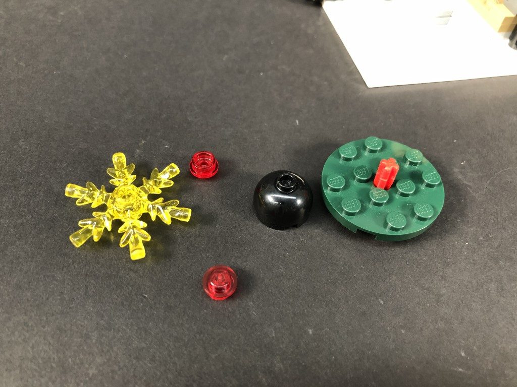
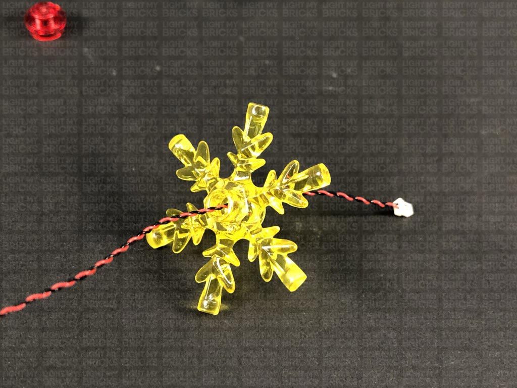
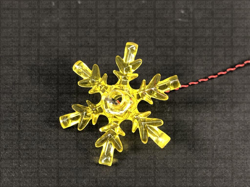
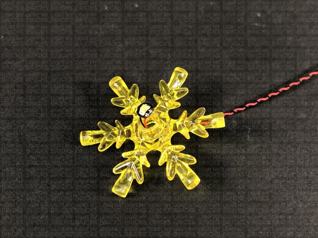
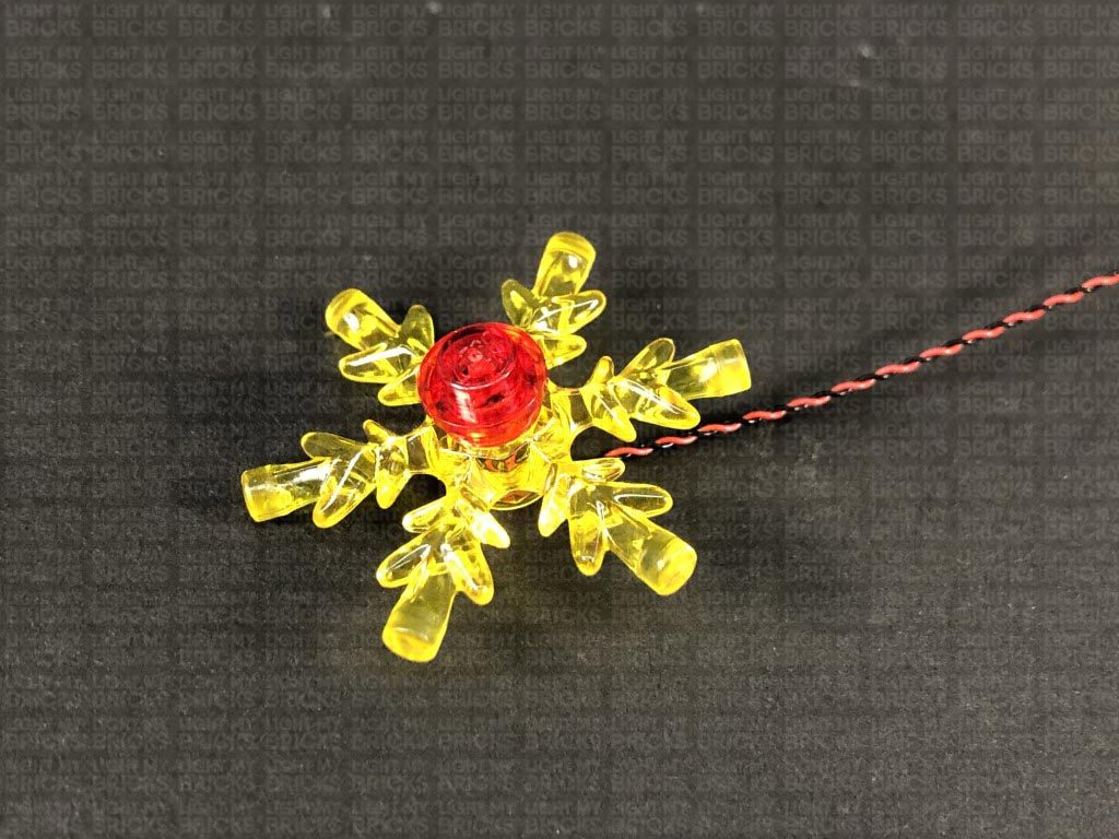
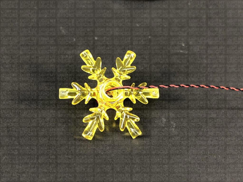
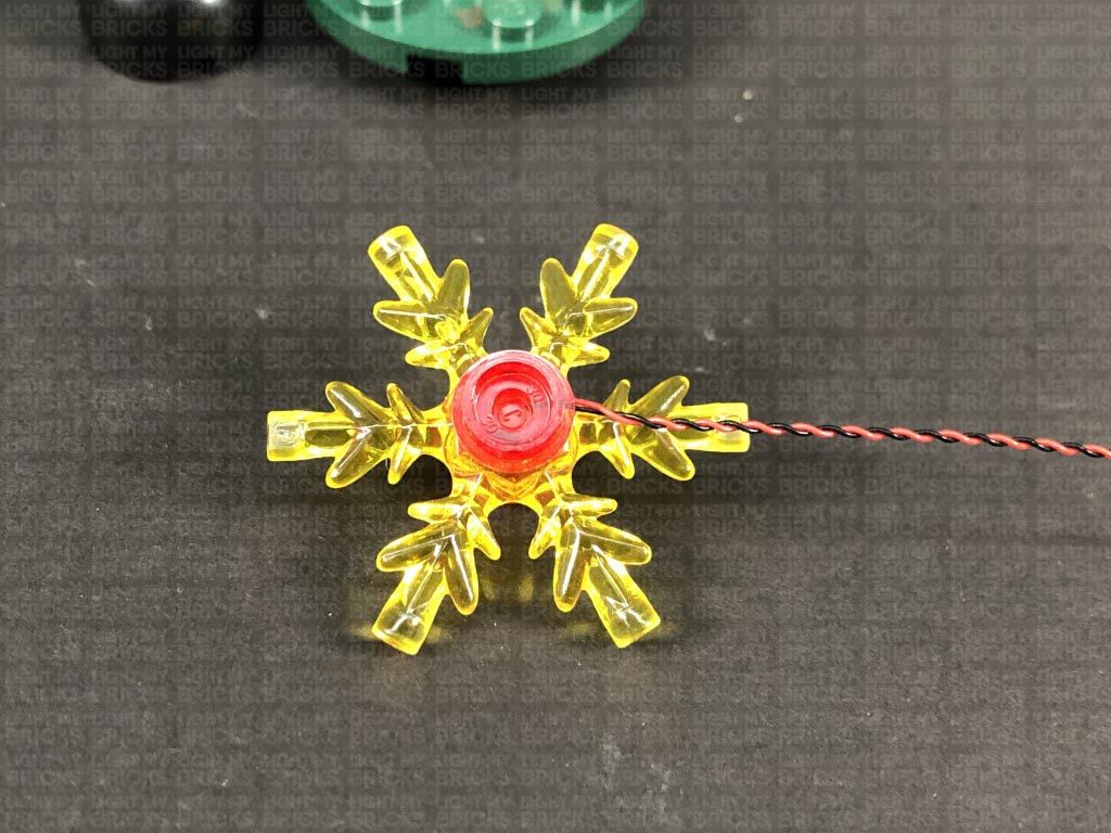
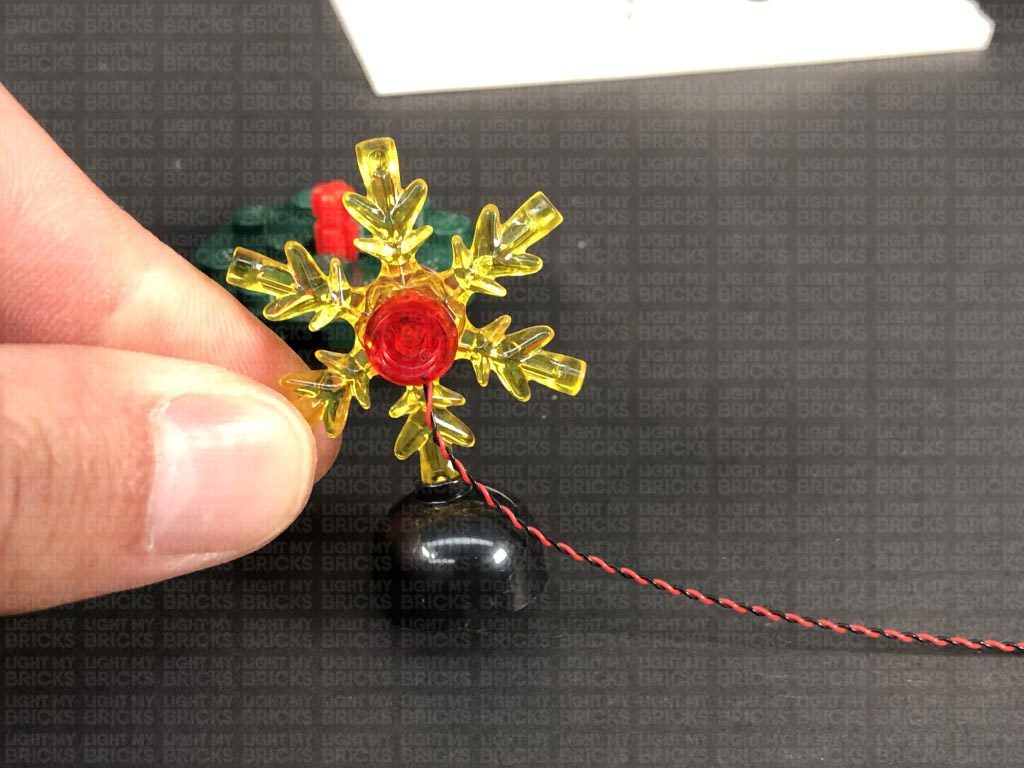
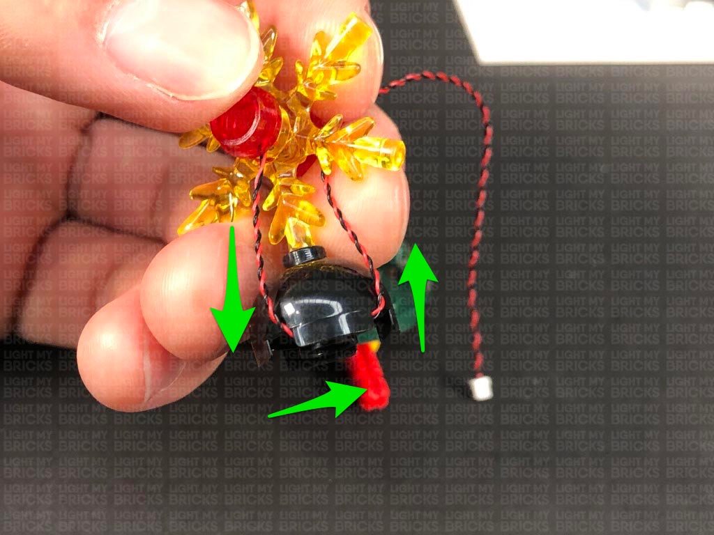
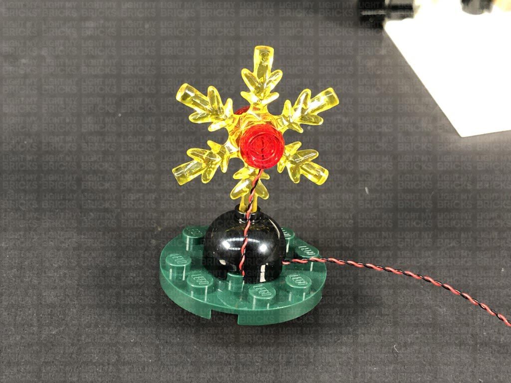
- 1x Flicker Effects Board
- 3x 5cm Connecting Cables
- 3x 15cm Connecting Cables
- 1x 30cm Connecting Cable
- 1x 50cm Connecting Cable
- 1x AA Battery Pack
- 8x 3M Adhesive Squares
- 1x Trans Clear Plate w Rounded Bottom 2×2
Important things to note:
Laying cables in between and underneath bricks
Cables can fit in between and underneath LEGO® bricks, plates, and tiles providing they are laid correctly between the LEGO® studs. Do NOT forcefully join LEGO® together around cables; instead ensure they are laying comfortably in between each stud.
Connecting cable connectors to Expansion Boards
Take extra care when inserting connectors to ports of Expansion Boards. Connectors can be inserted only one way. With the expansion board facing up, look for the soldered “=” symbol on the left side of the port. The connector side with the wires exposed should be facing toward the soldered “=” symbol as you insert into the port. If a plug won’t fit easily into a port connector, do not force it.
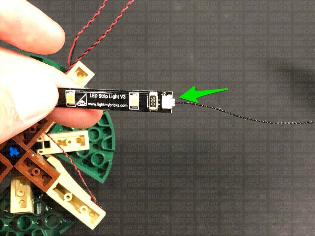
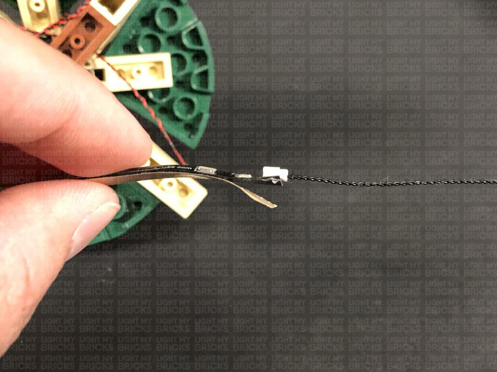
Connecting cable connectors to Strip Lights
Take extra care when inserting connectors to ports on the Strip Lights. Connectors can be inserted only one way. With the Strip Light facing up, ensure the side of the connector with the wires exposed is facing down. If a plug won’t fit easily into a port connector, don’t force it. Doing so will damage the plug and the connector.
Connecting Micro Cable connectors to Micro Expansion Board Ports
Take extra care when inserting the micro connectors to micro ports of Micro Expansion Boards. Connecting Micro Bit Lights to Micro Expansion Boards is similar to connecting lights and cables to Strip Lights. With the expansion board facing up, ensure the side of the connector with the wires exposed is facing down. If a plug won’t fit easily into a port connector, do not force it. Use your fingernail to push the plastic part of the connector to the micro port.
Installing Bit Lights under LEGO® bricks and plates.
When installing Bit Lights under LEGO® pieces, ensure they are placed the correct way up (Yellow LED component exposed). You can either place them directly on top of LEGO® studs or in between.
OK, Let’s Begin!
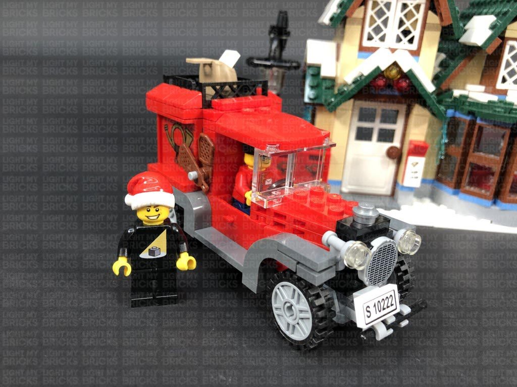
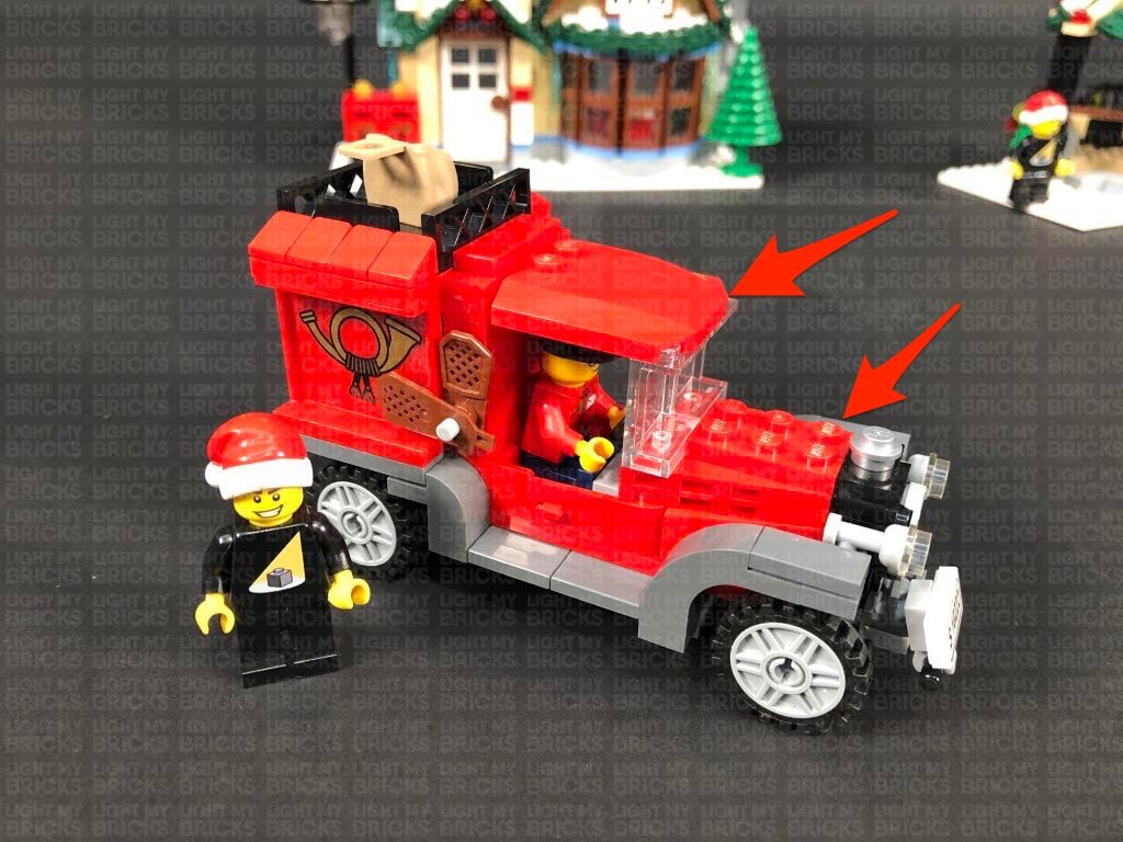
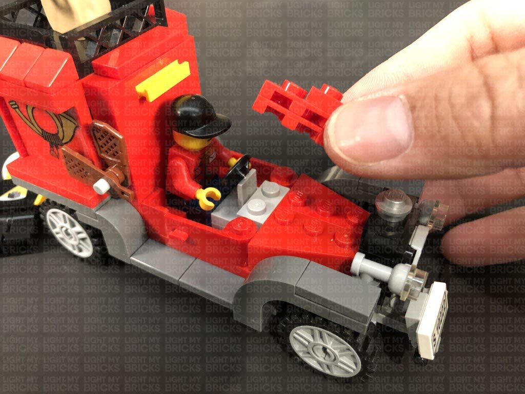
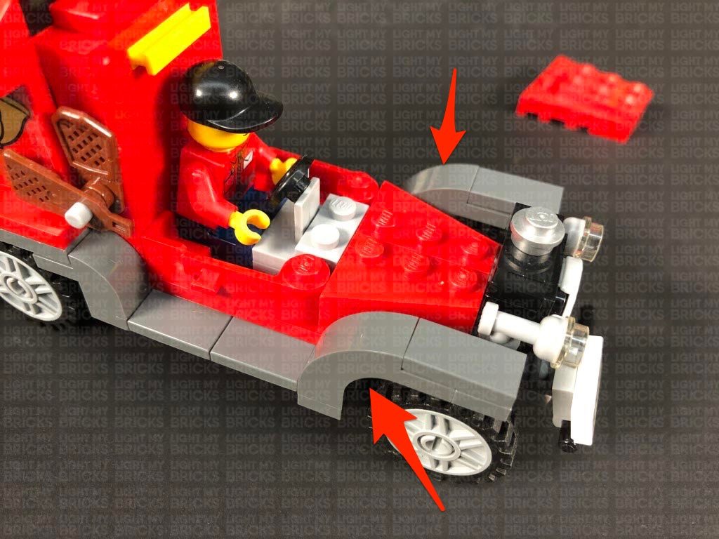
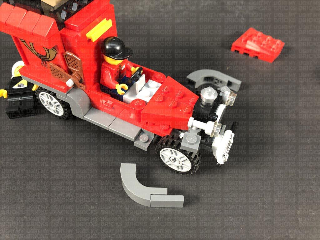
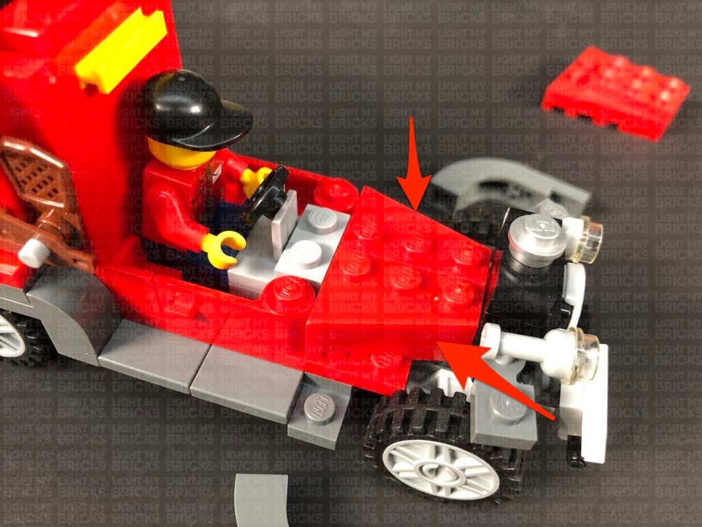
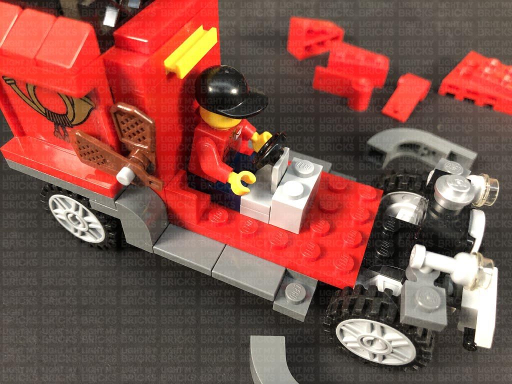
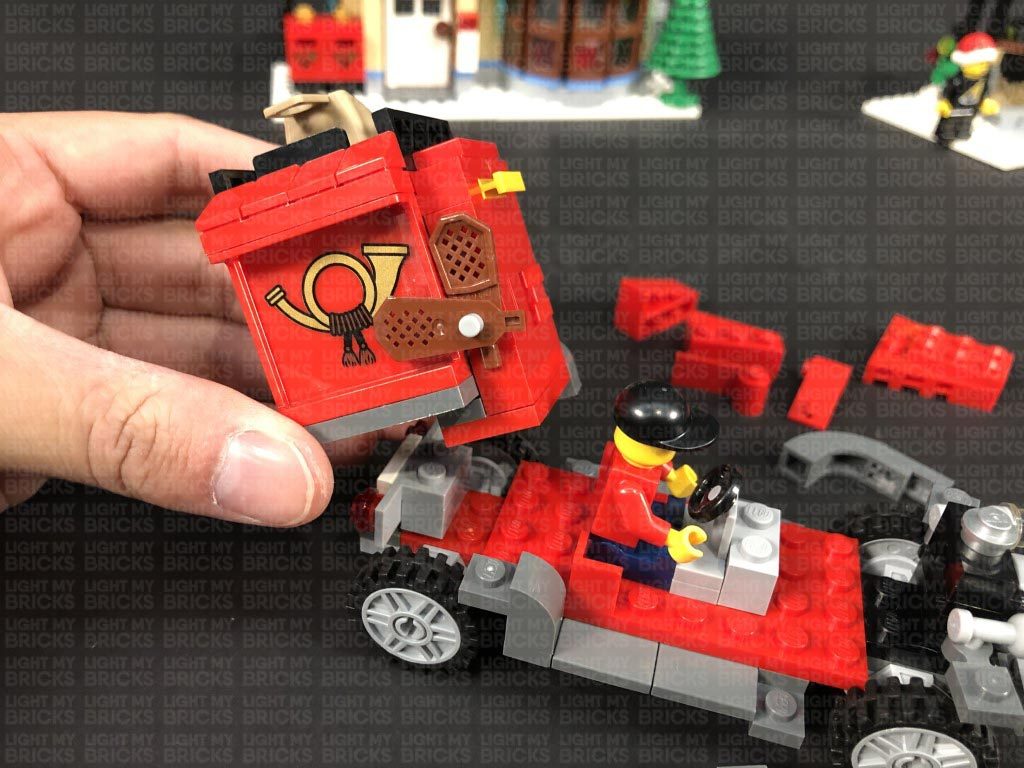
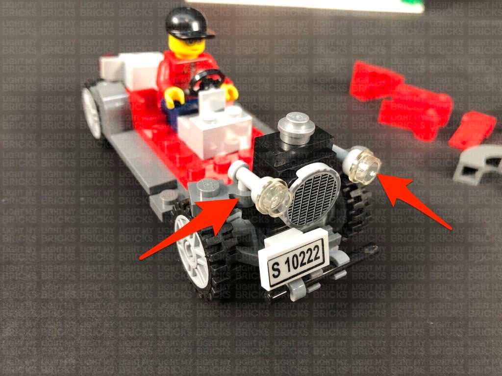
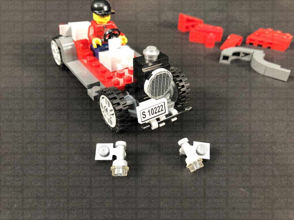
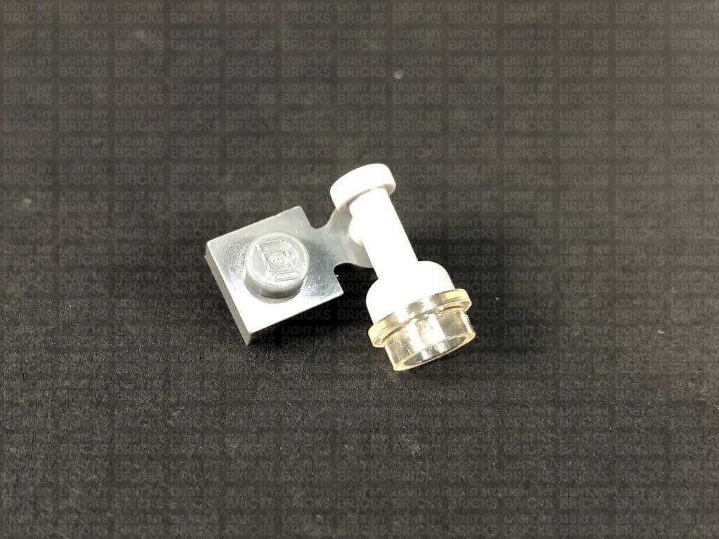
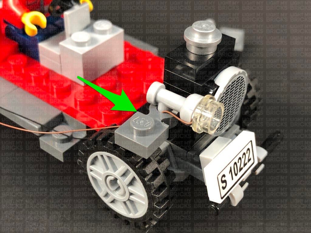
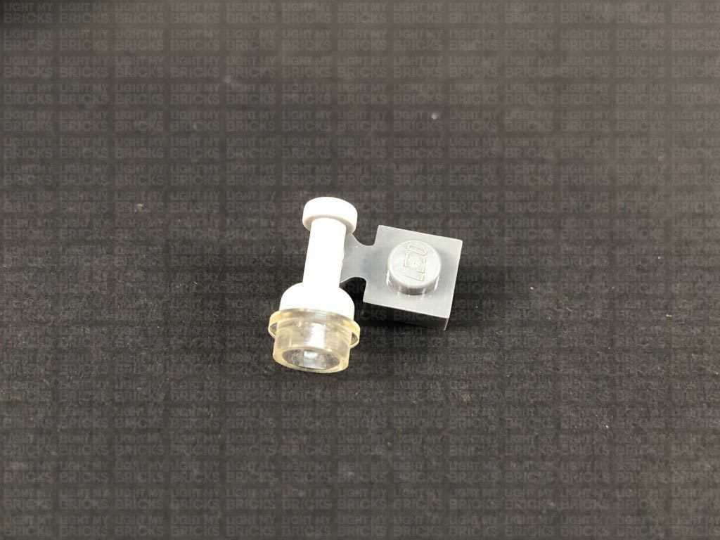
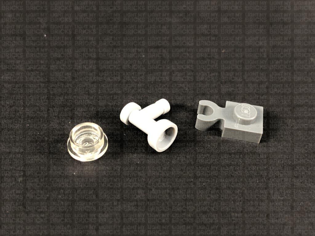
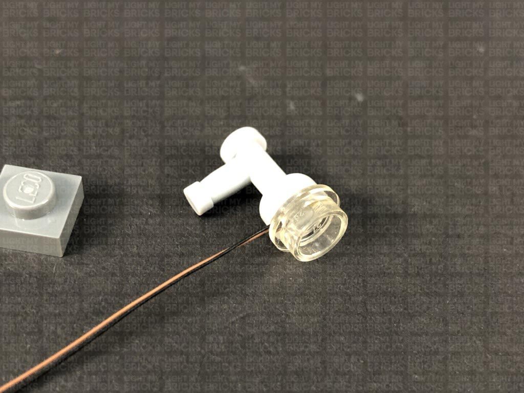
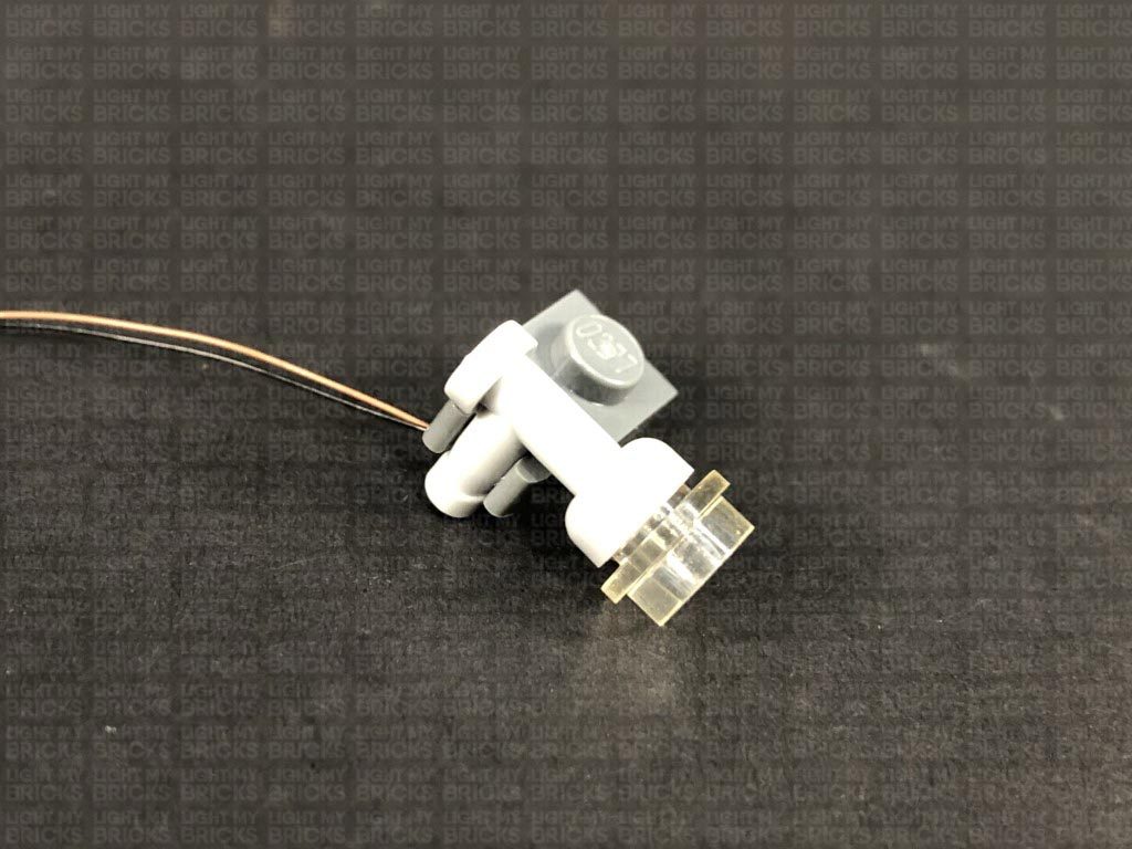
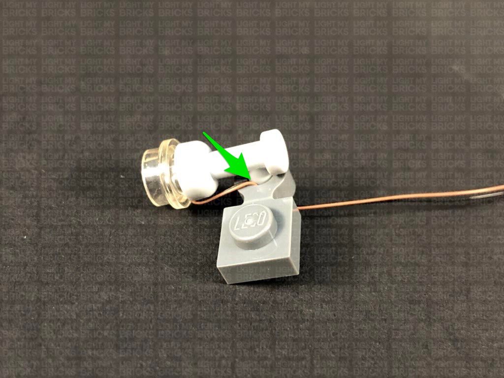
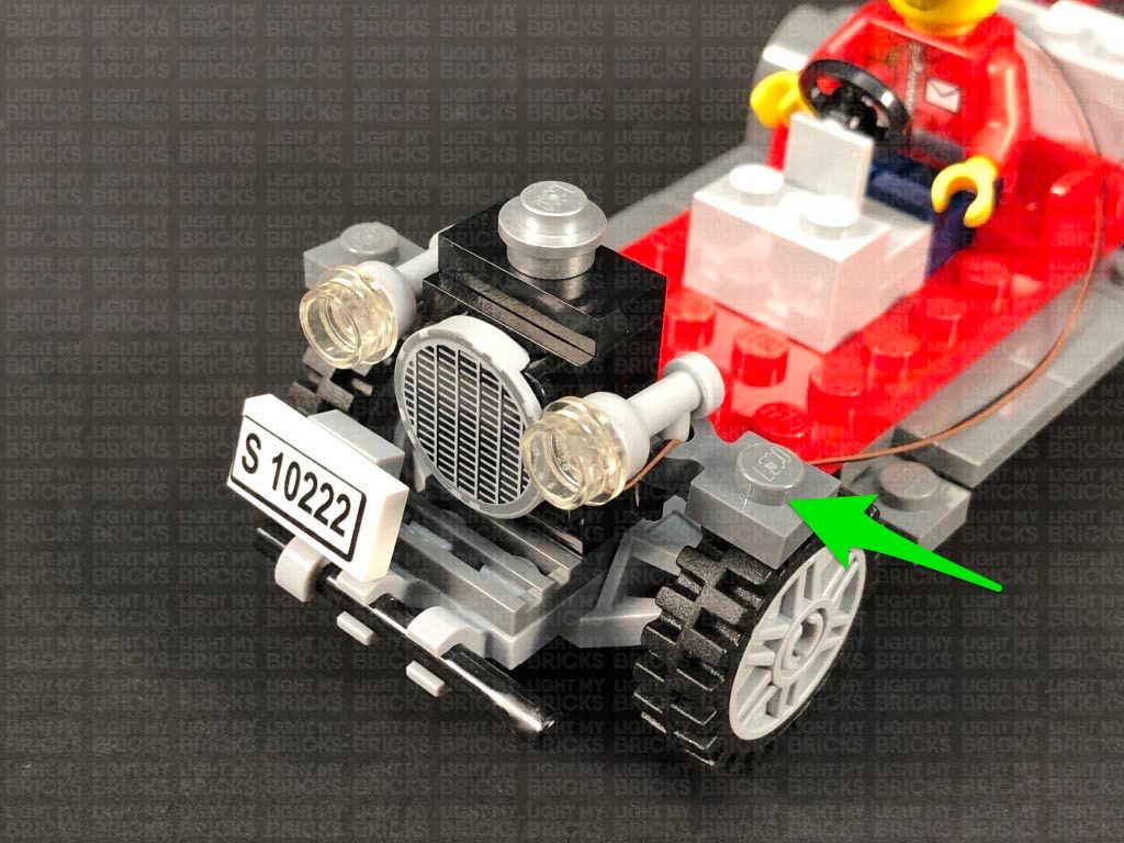
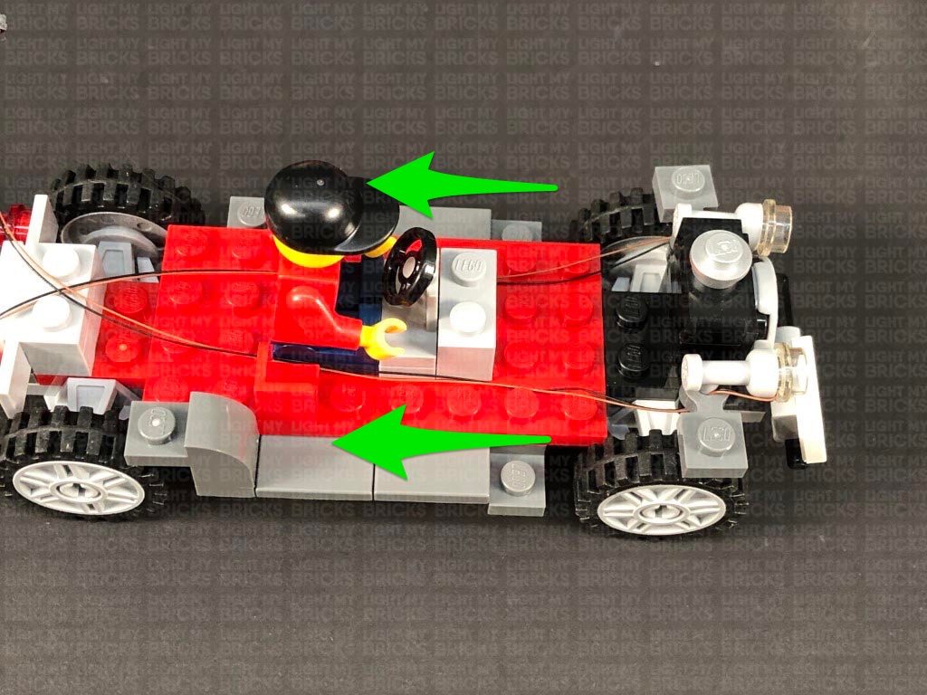
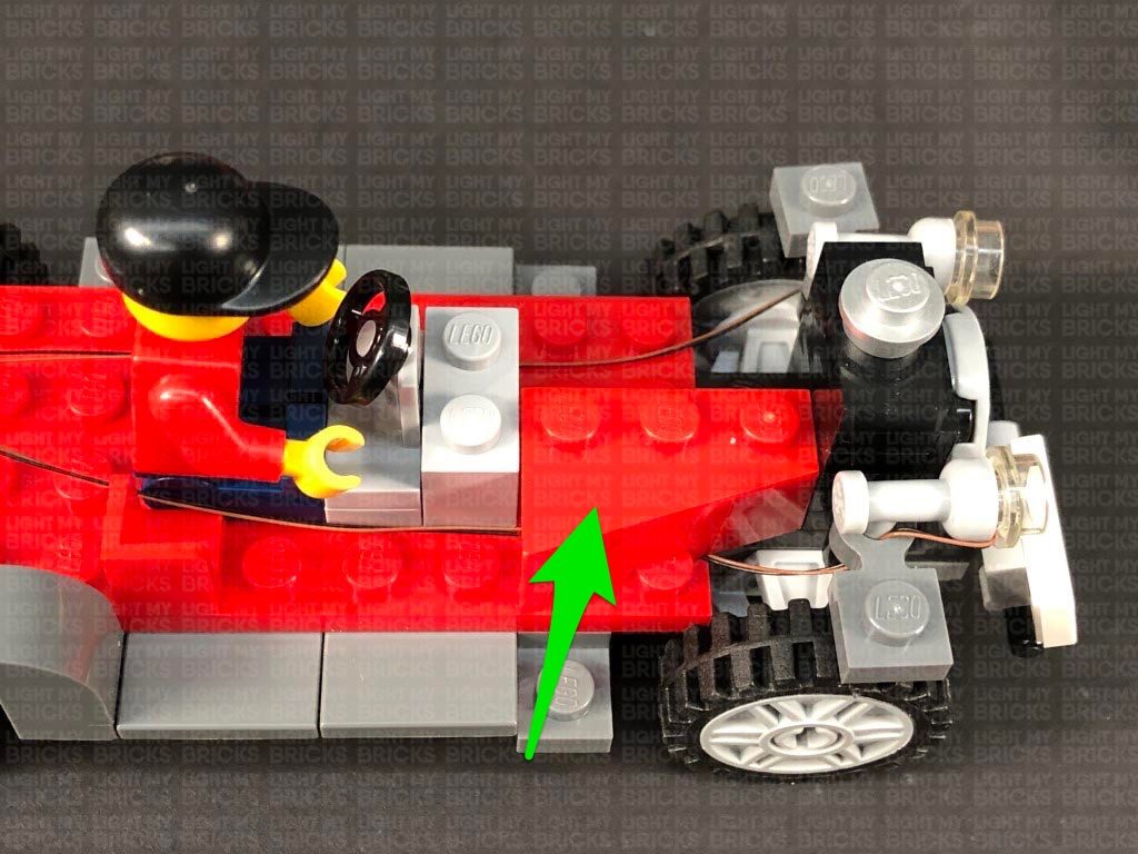
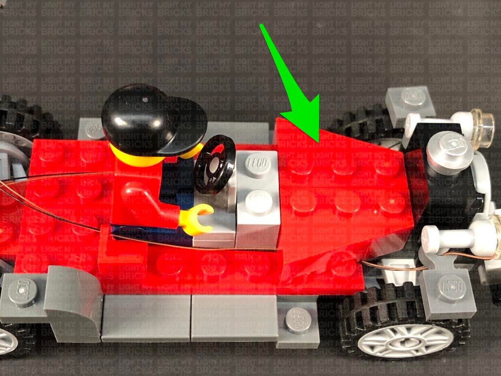
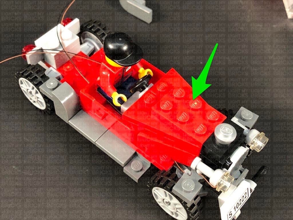
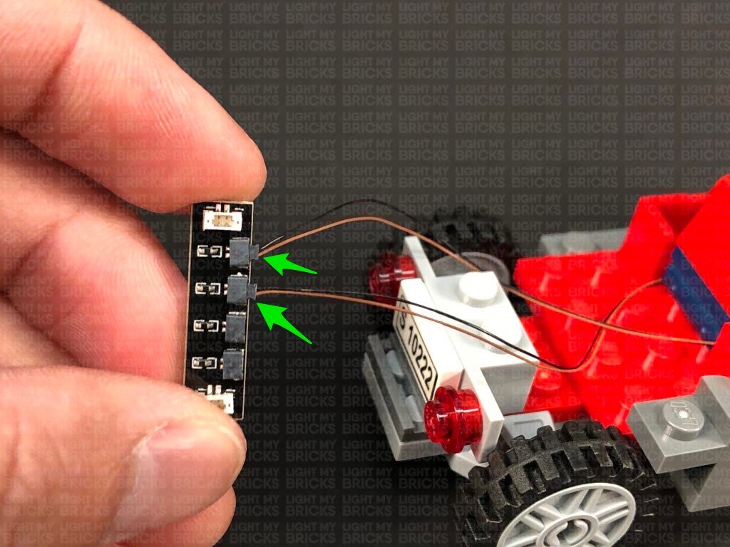
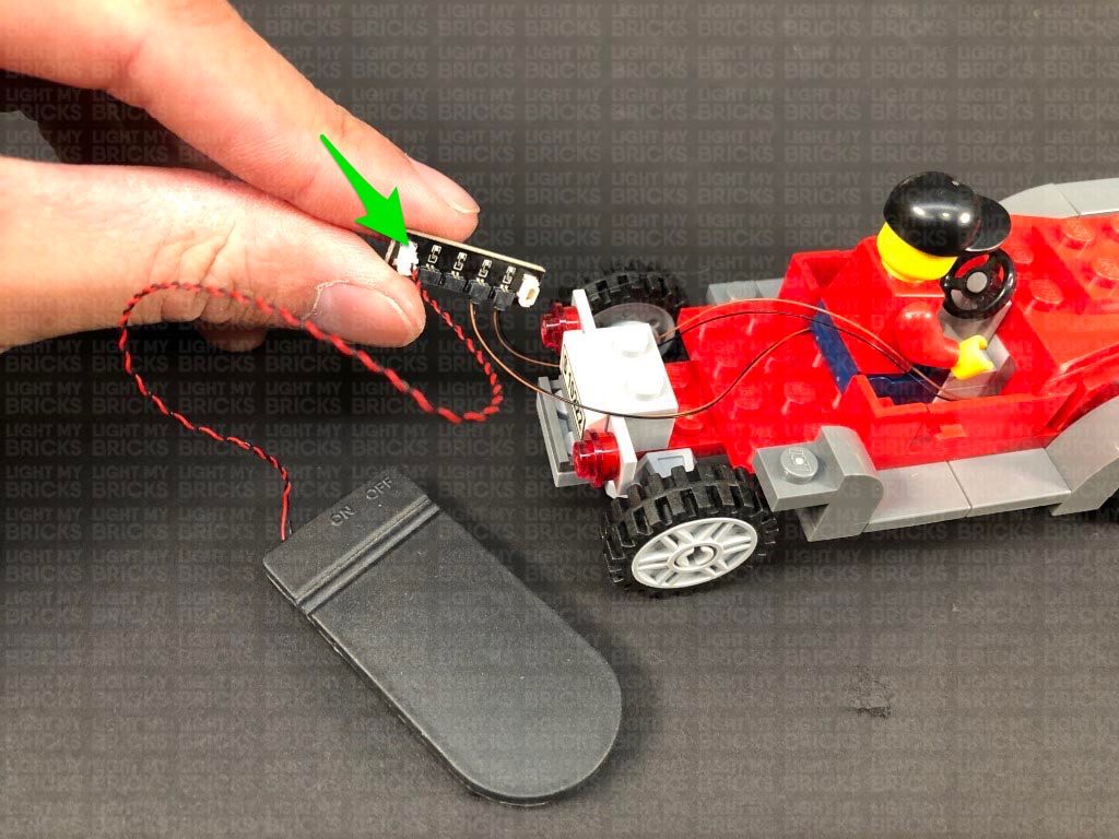
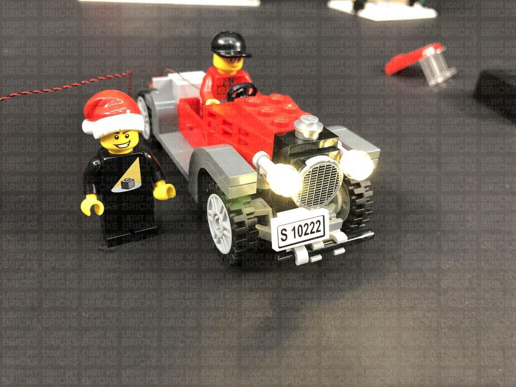
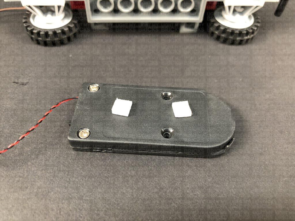
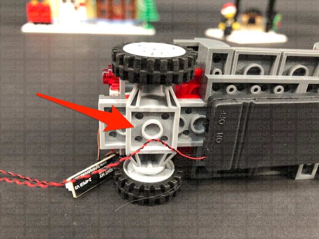
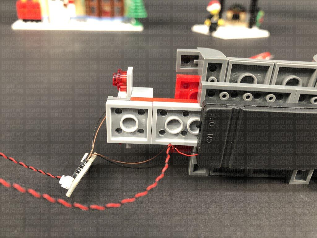
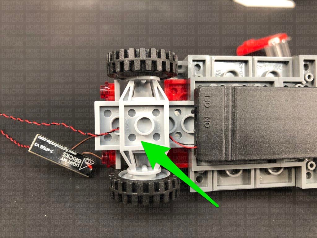
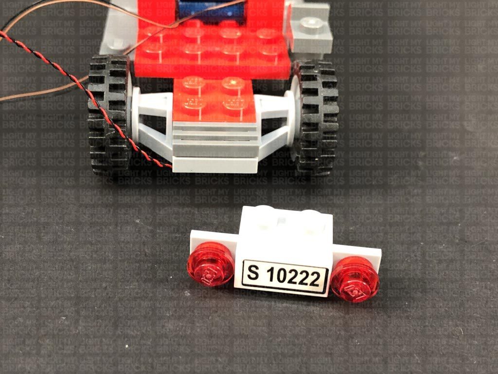
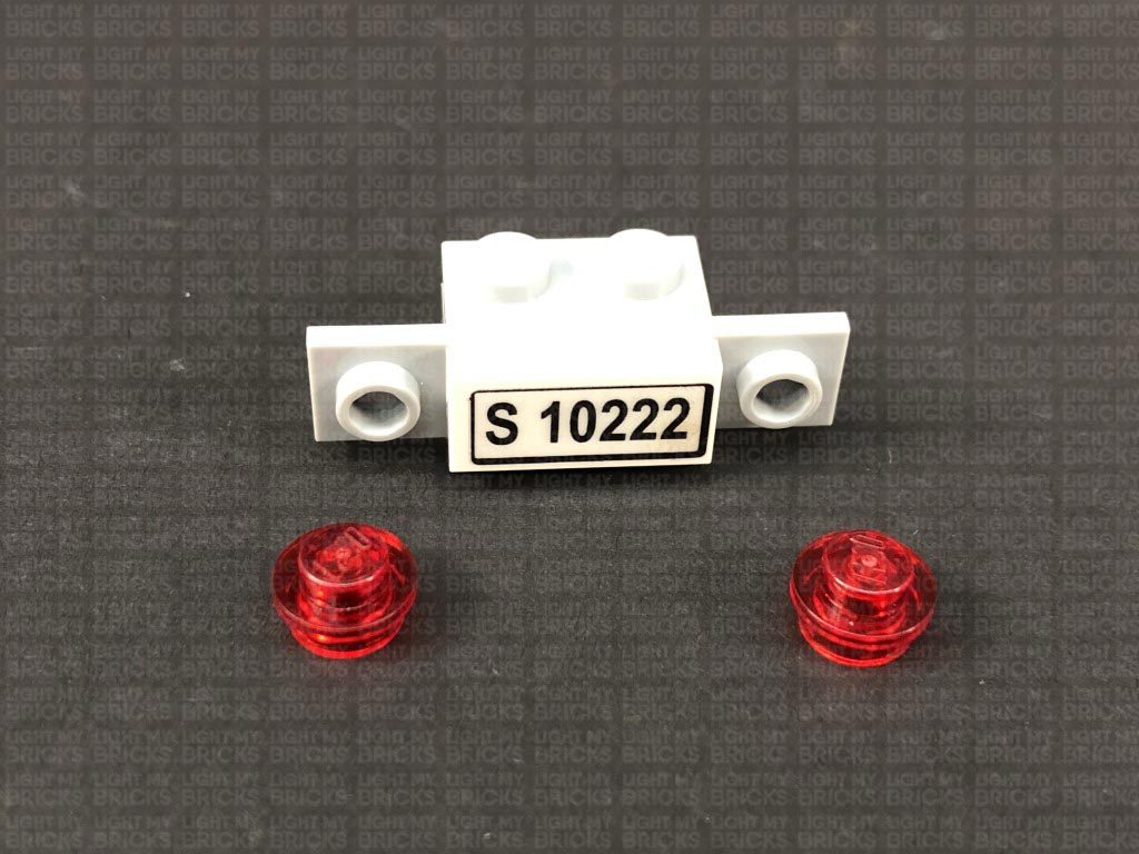
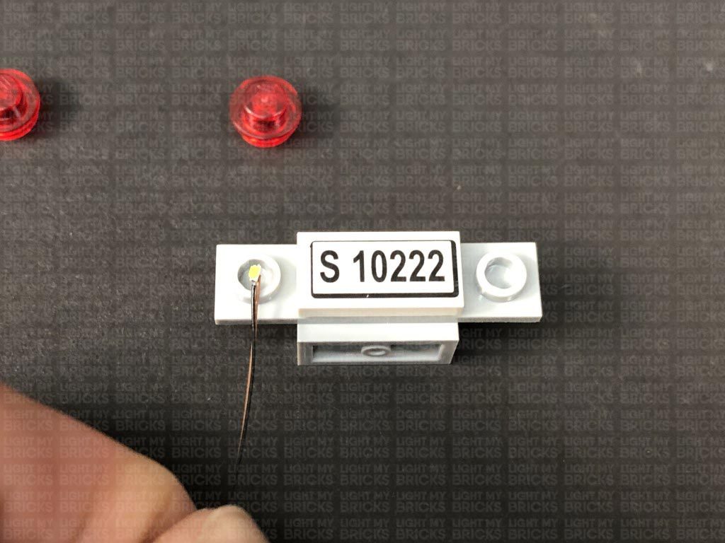
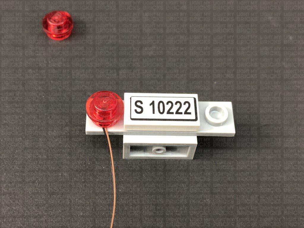
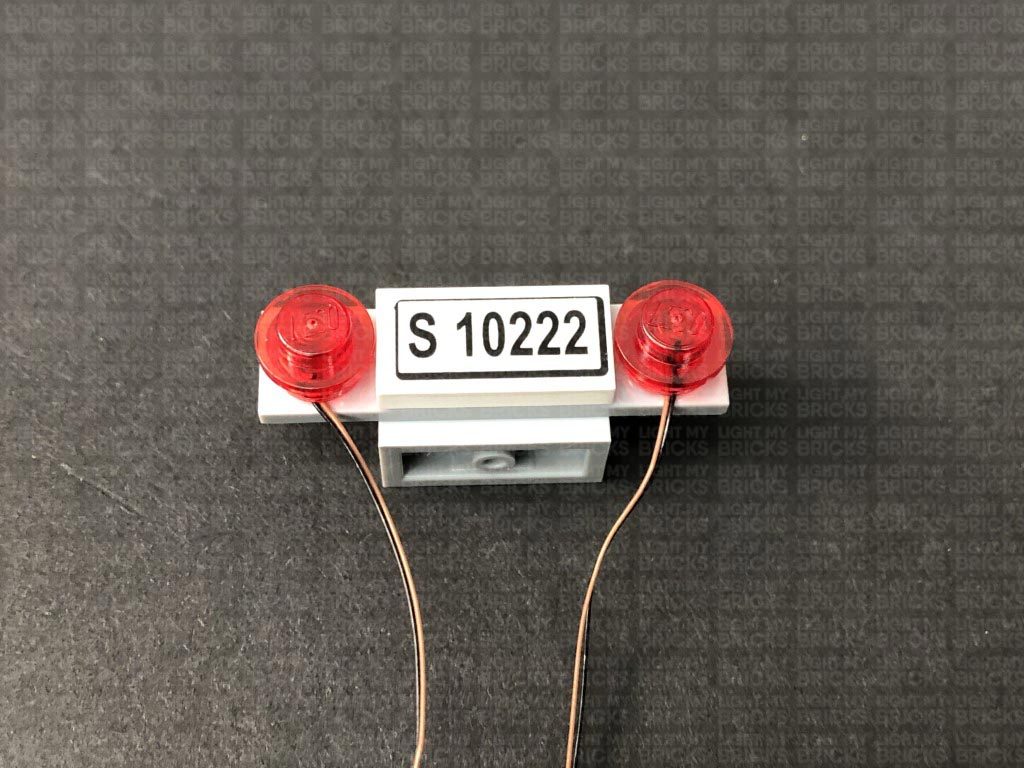
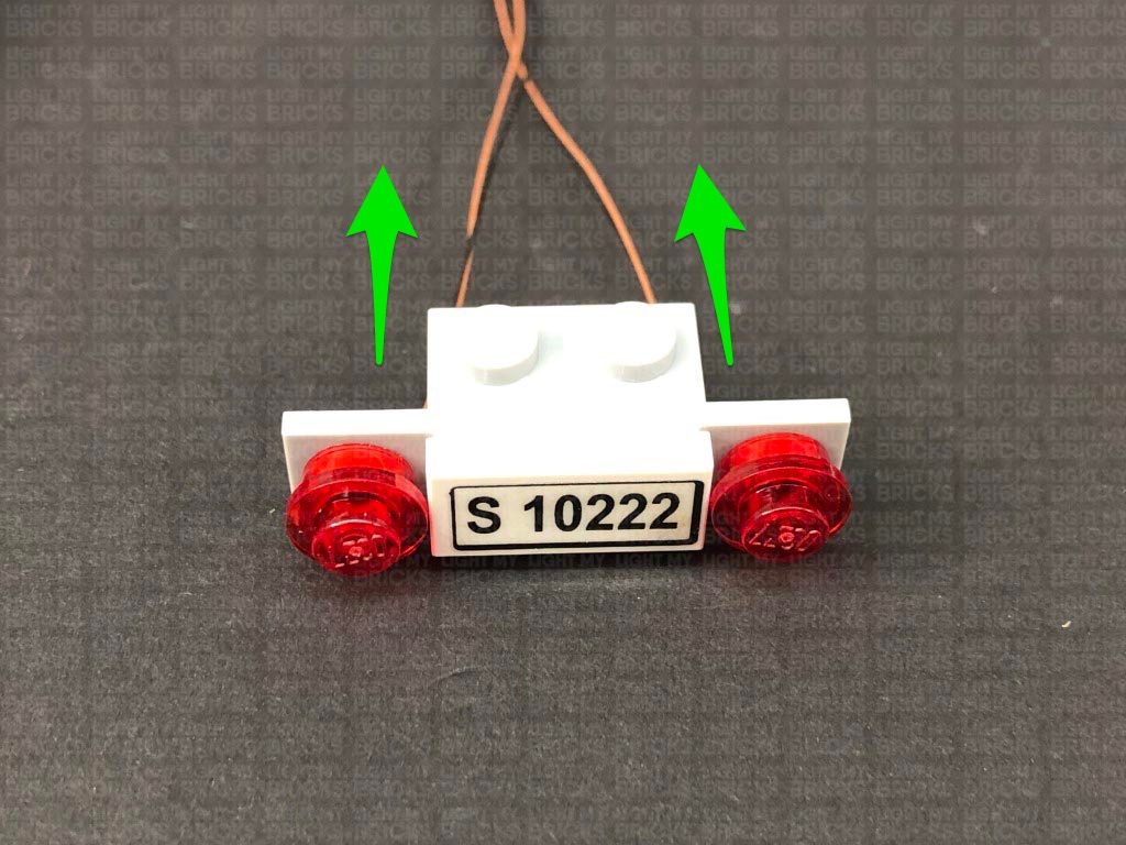
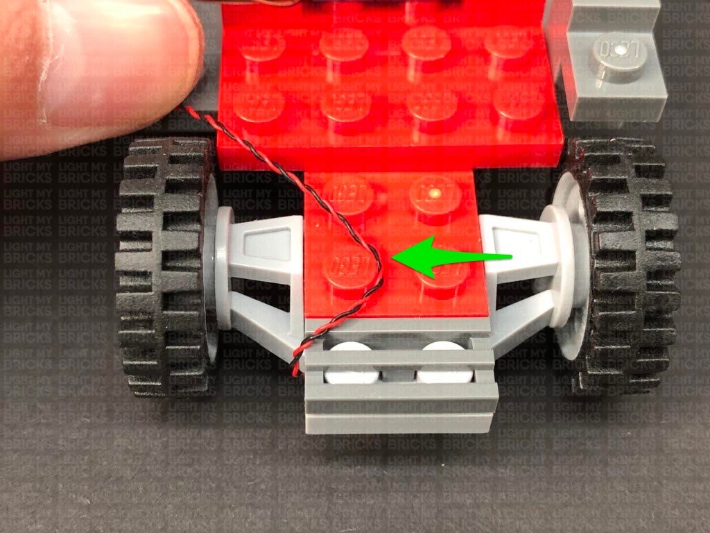
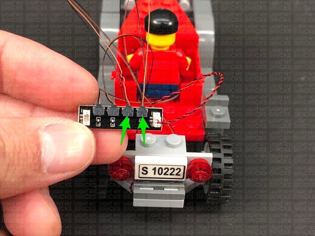
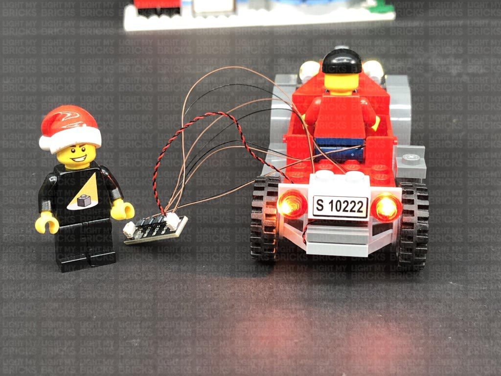
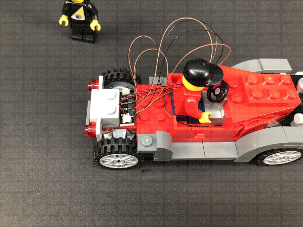
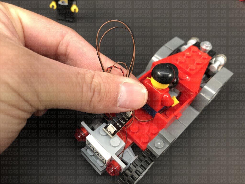
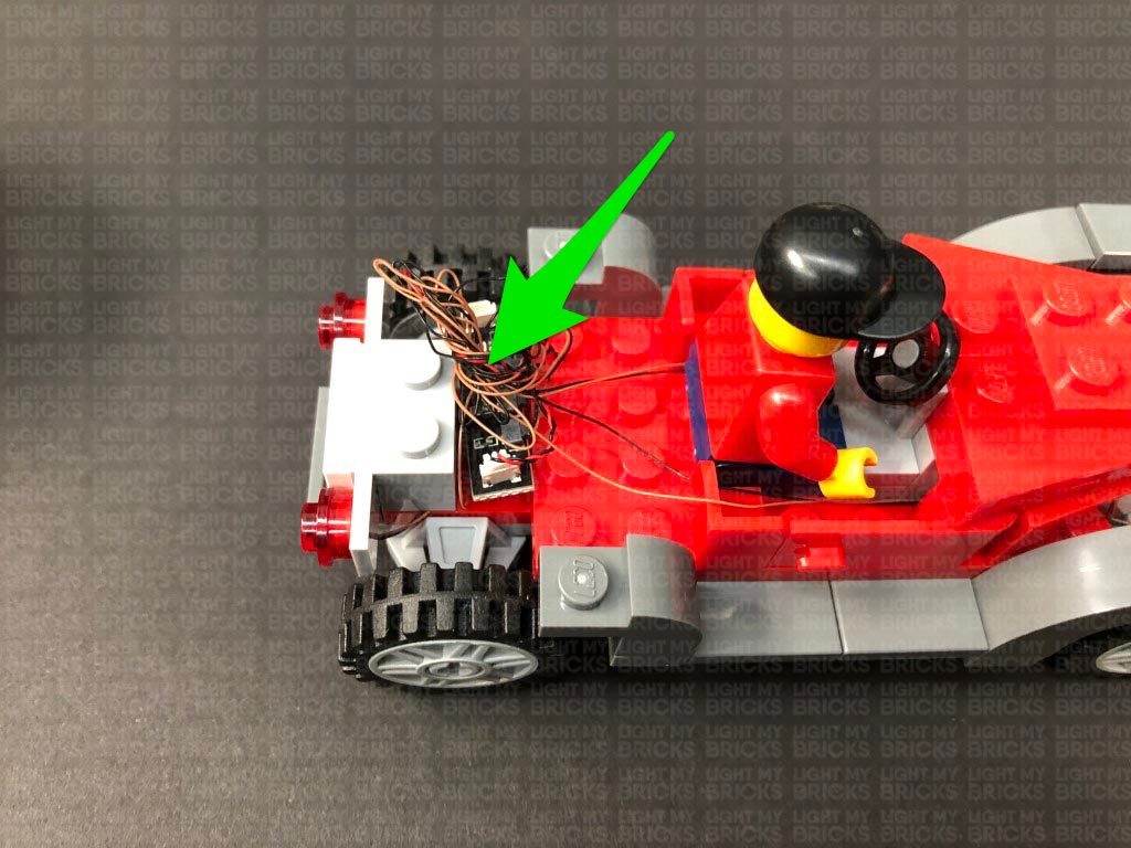
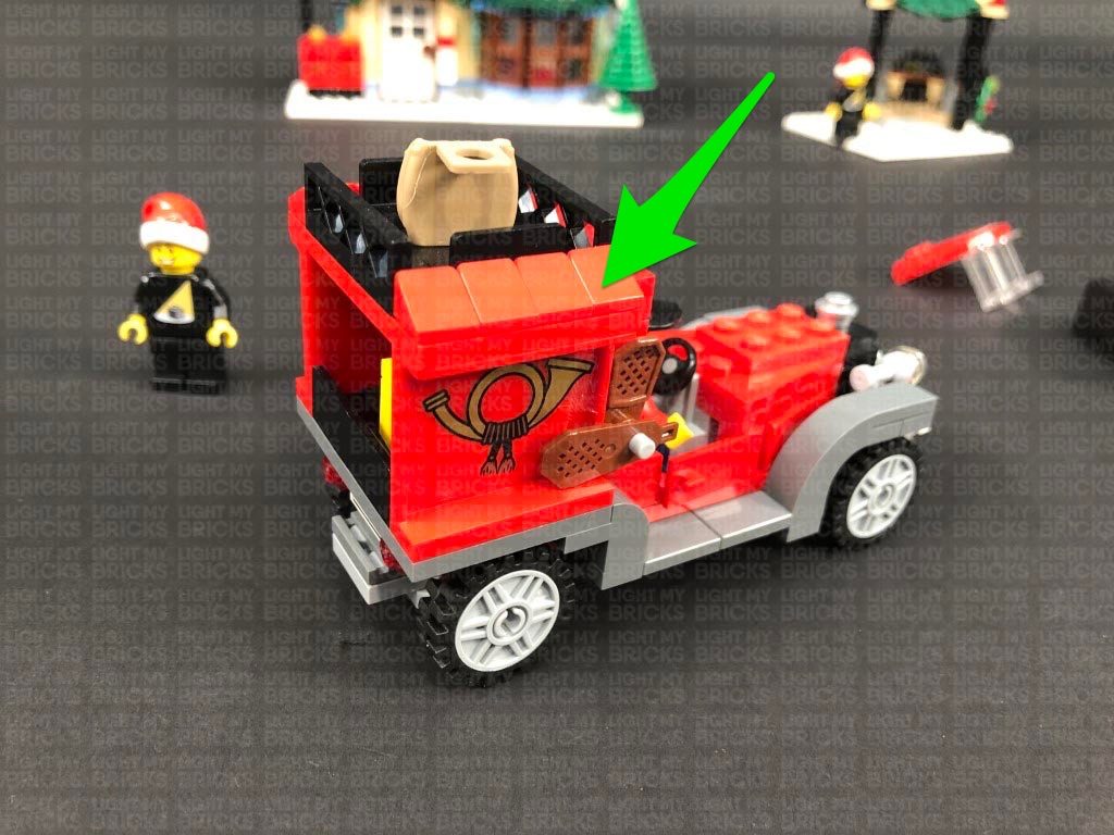
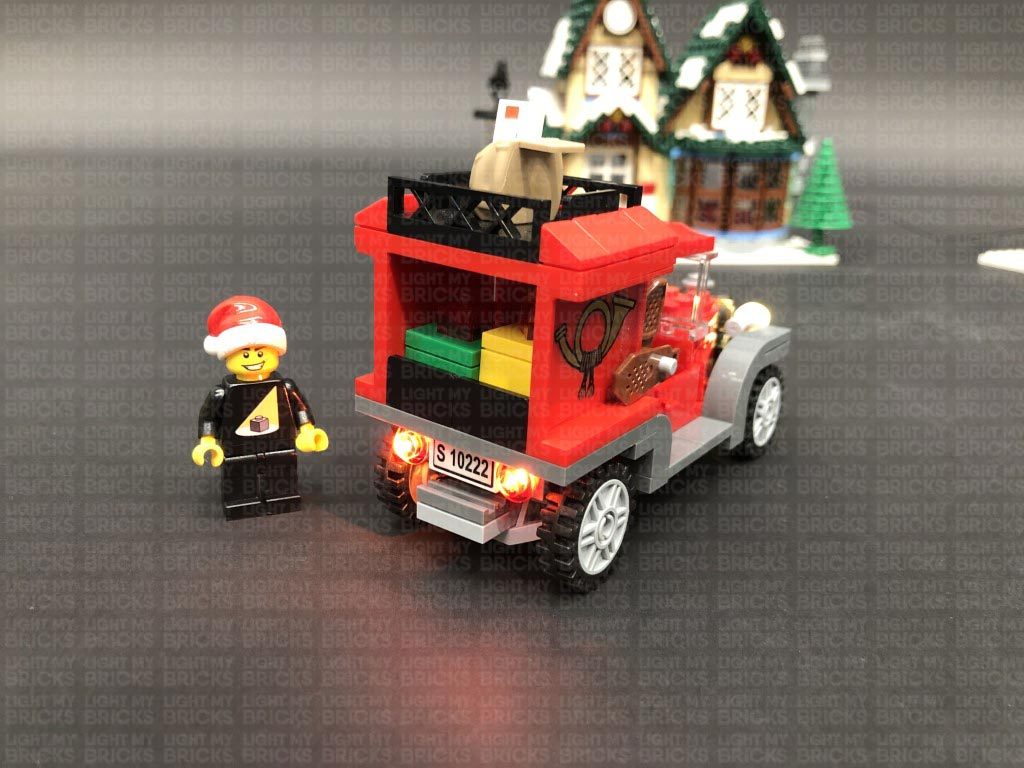
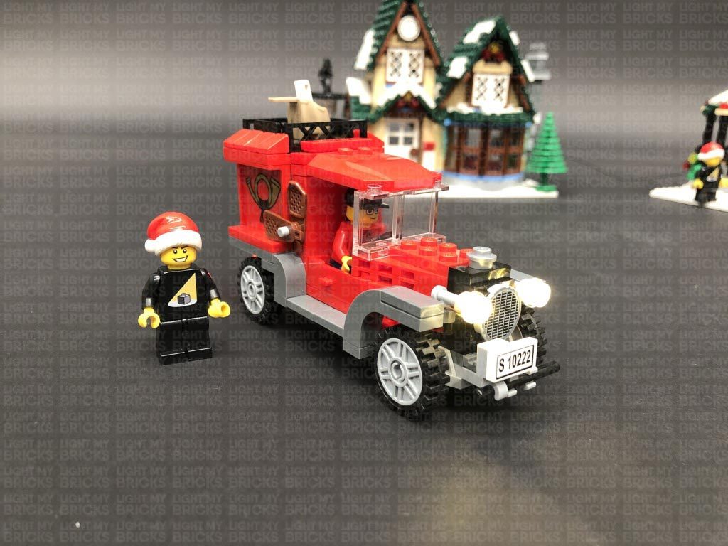
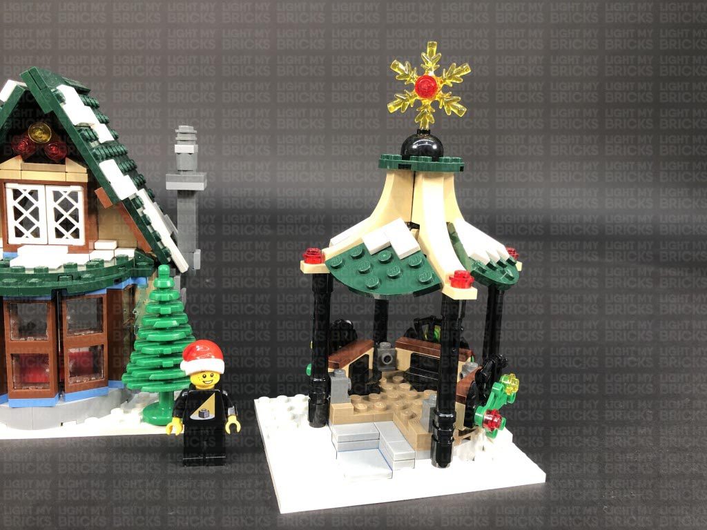
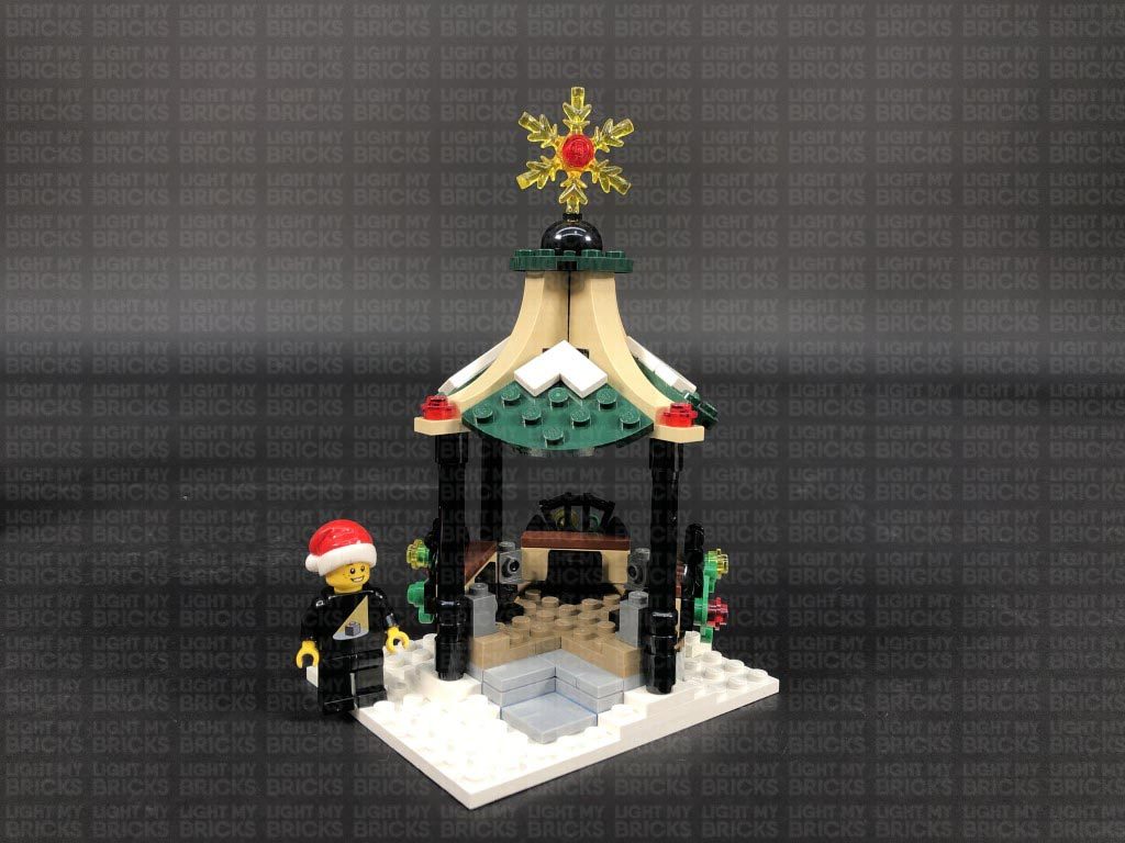
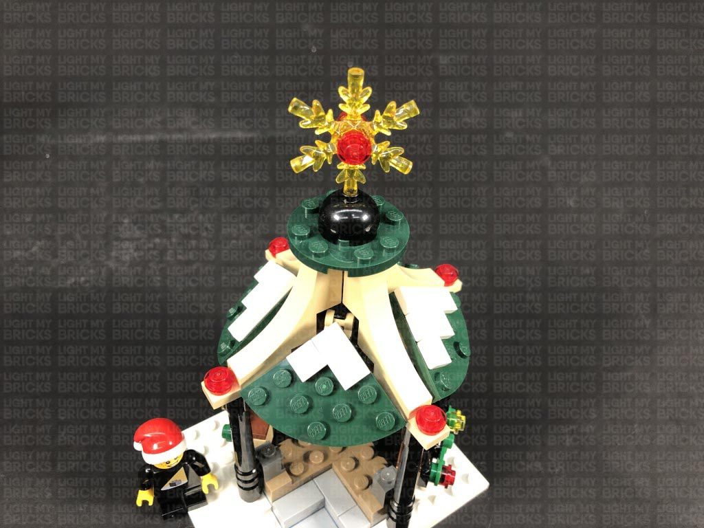
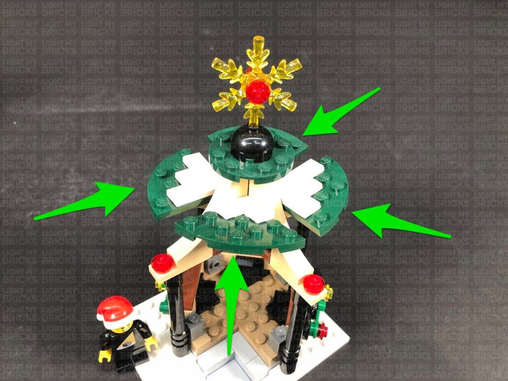
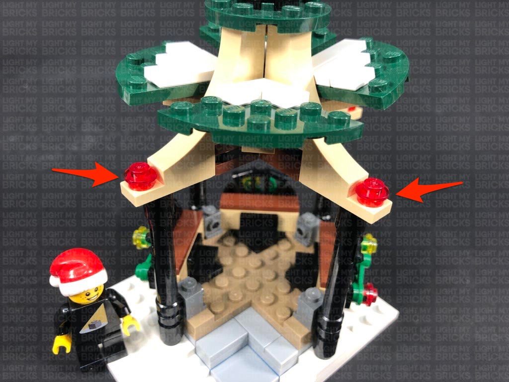
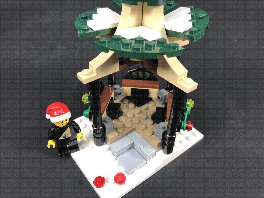
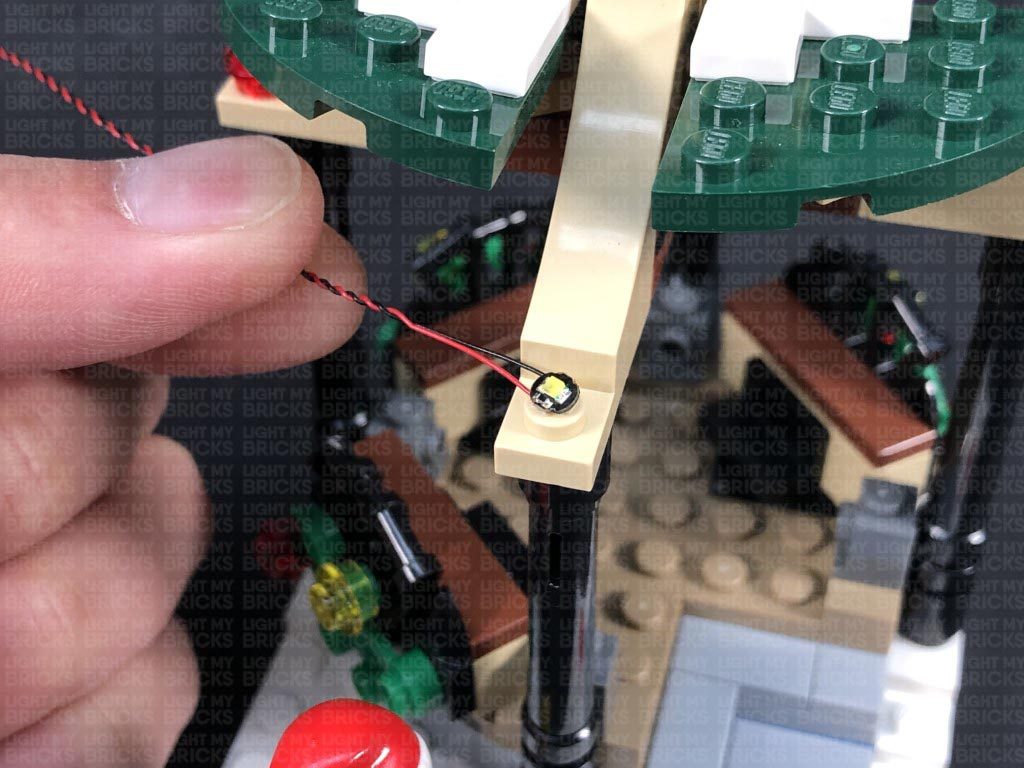
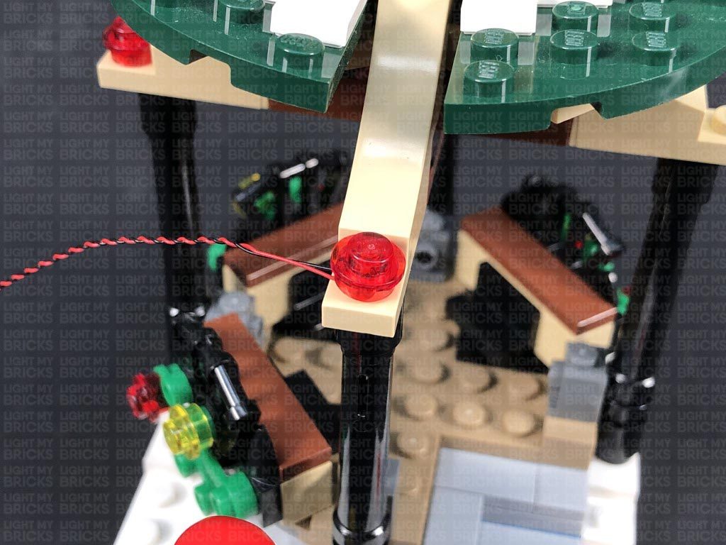
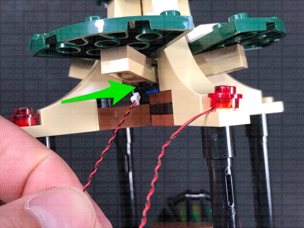
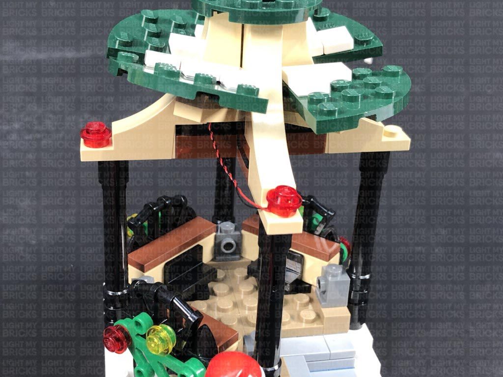
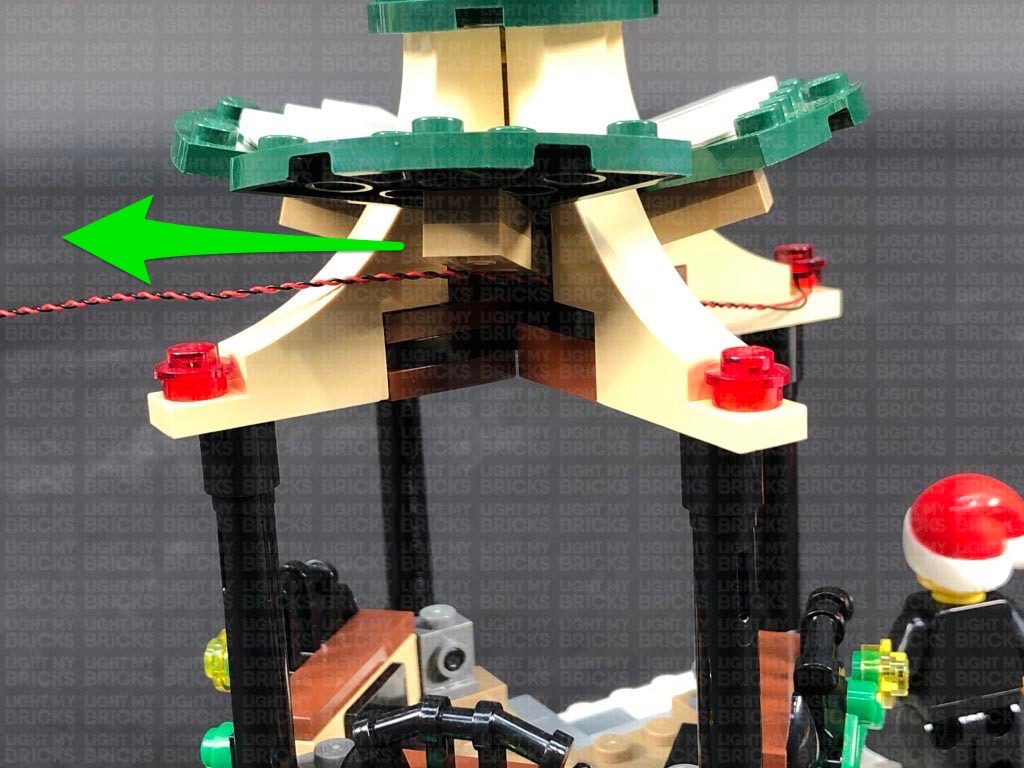
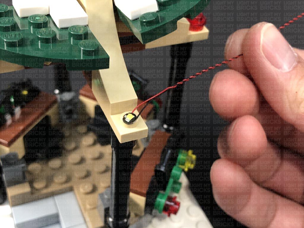
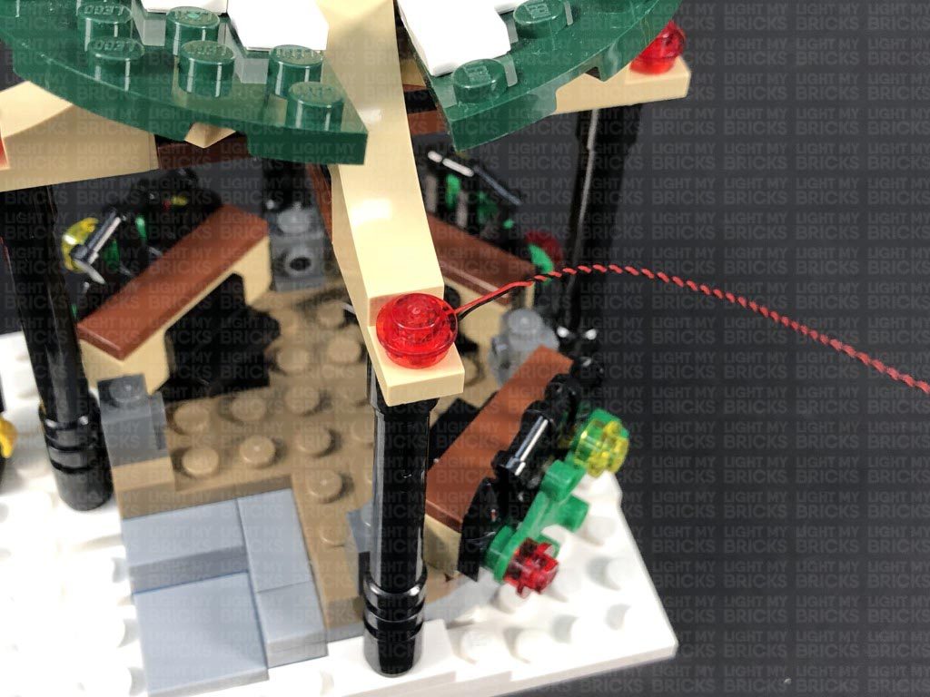
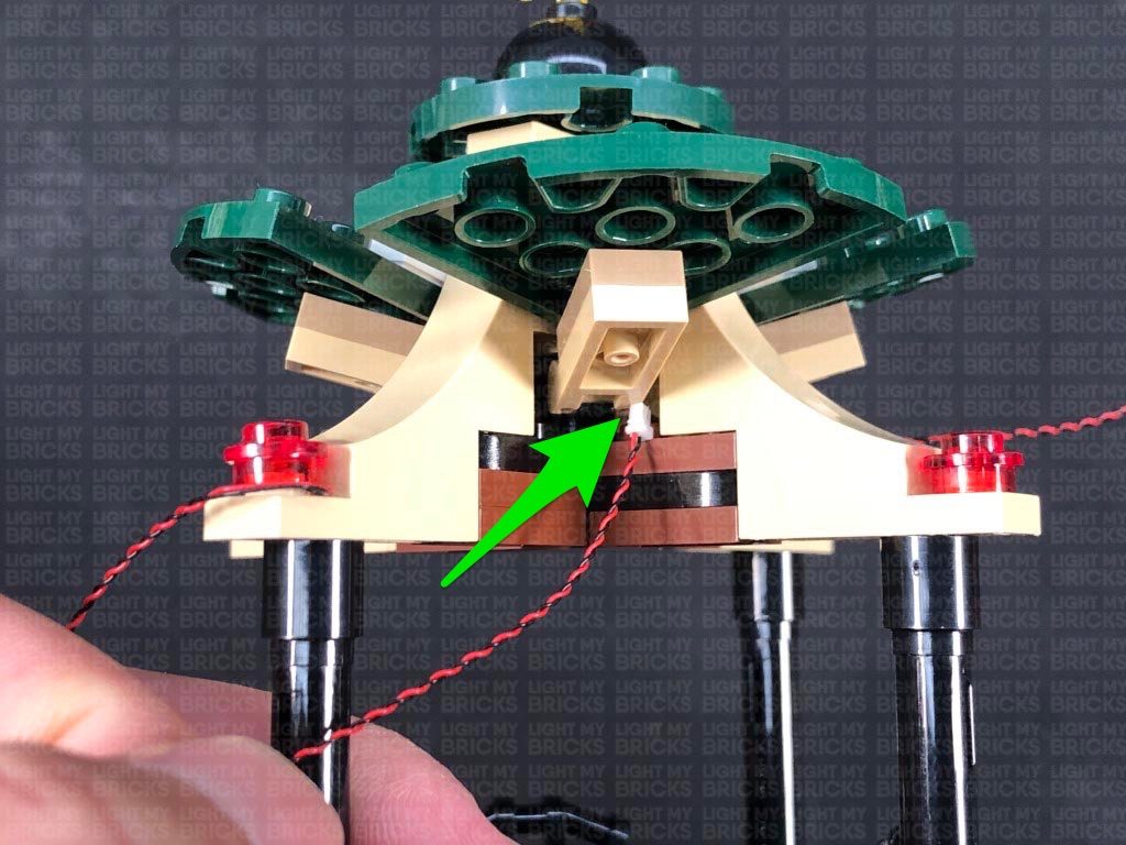
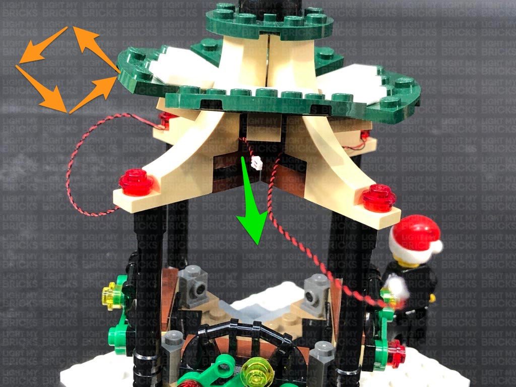
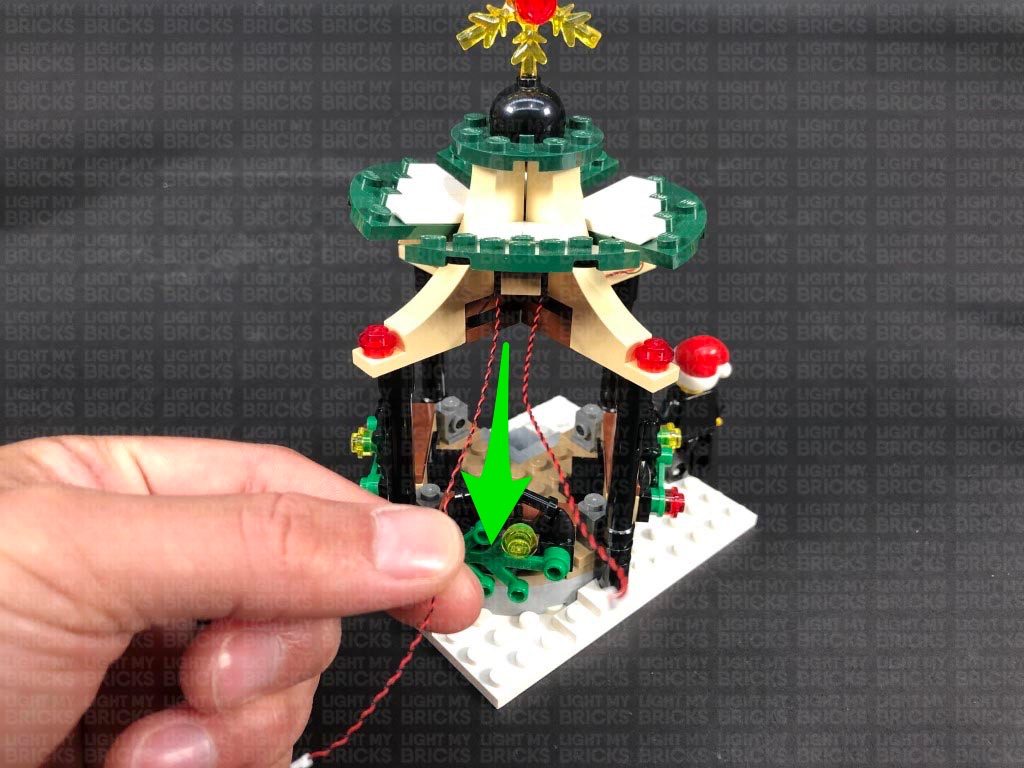
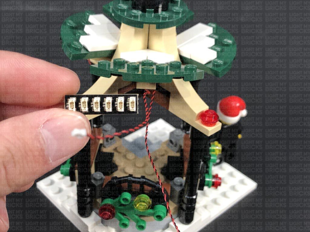
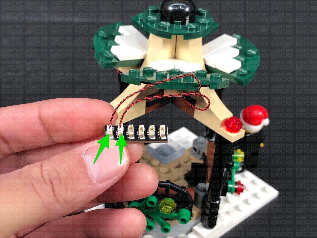
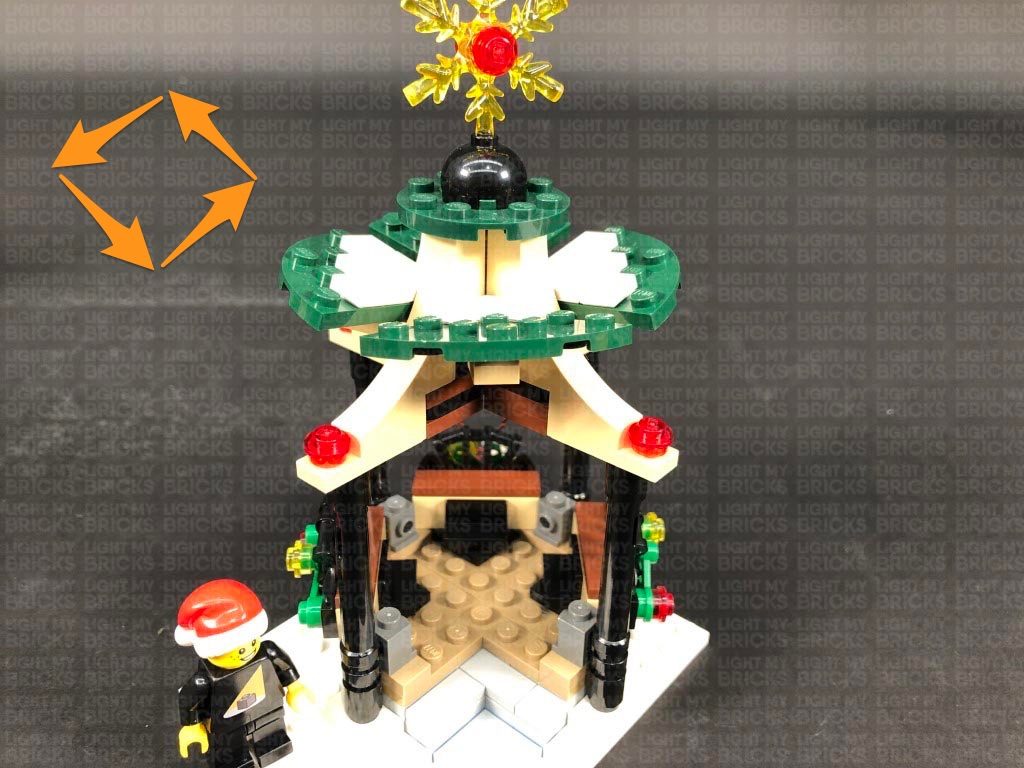
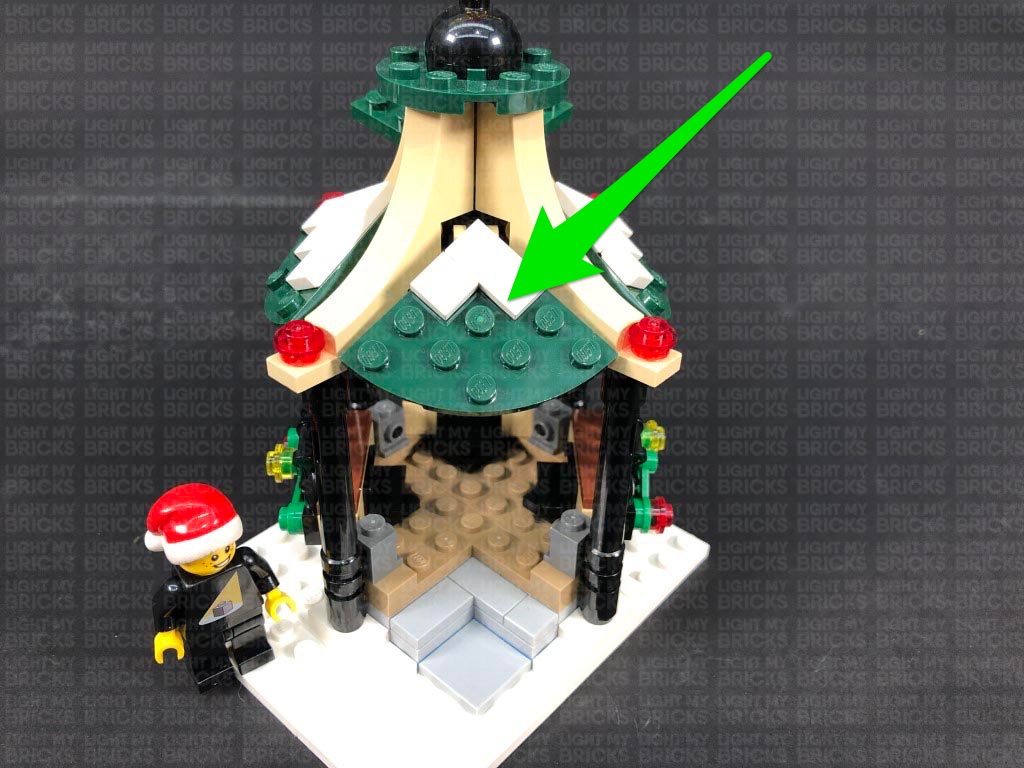
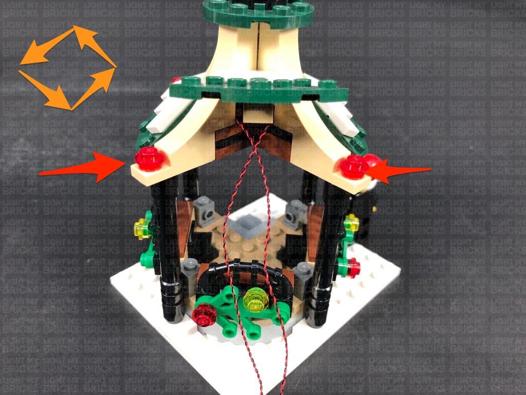
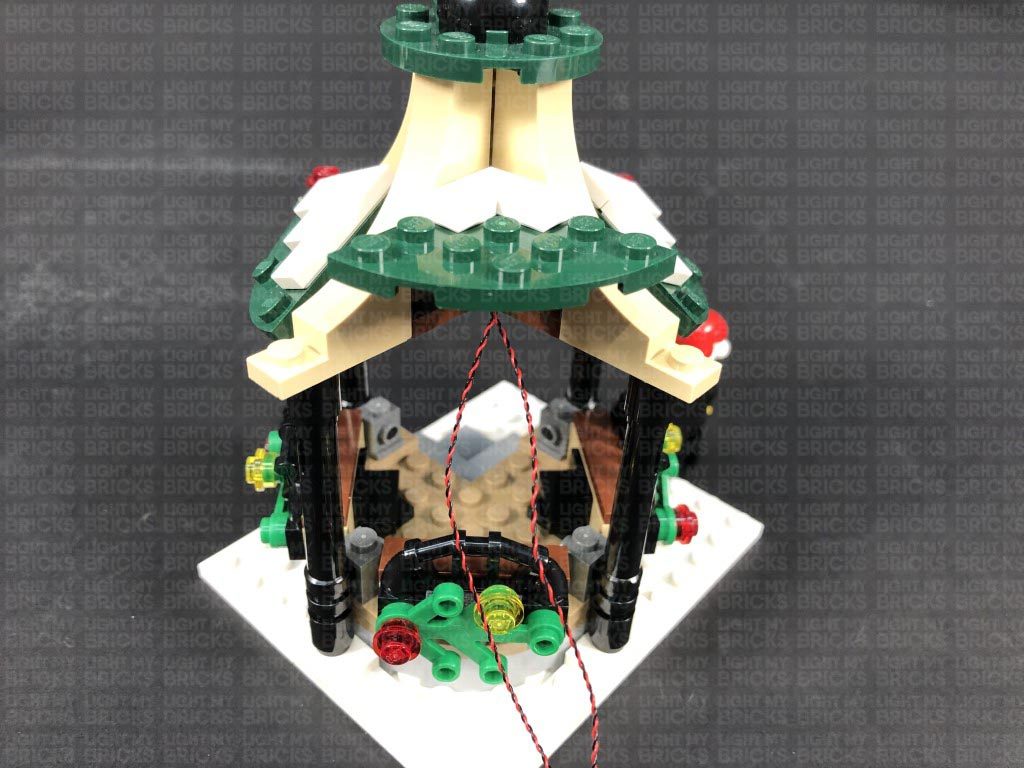
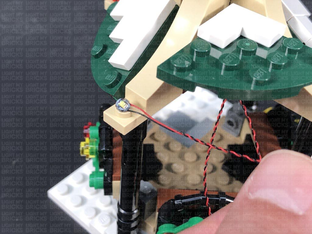
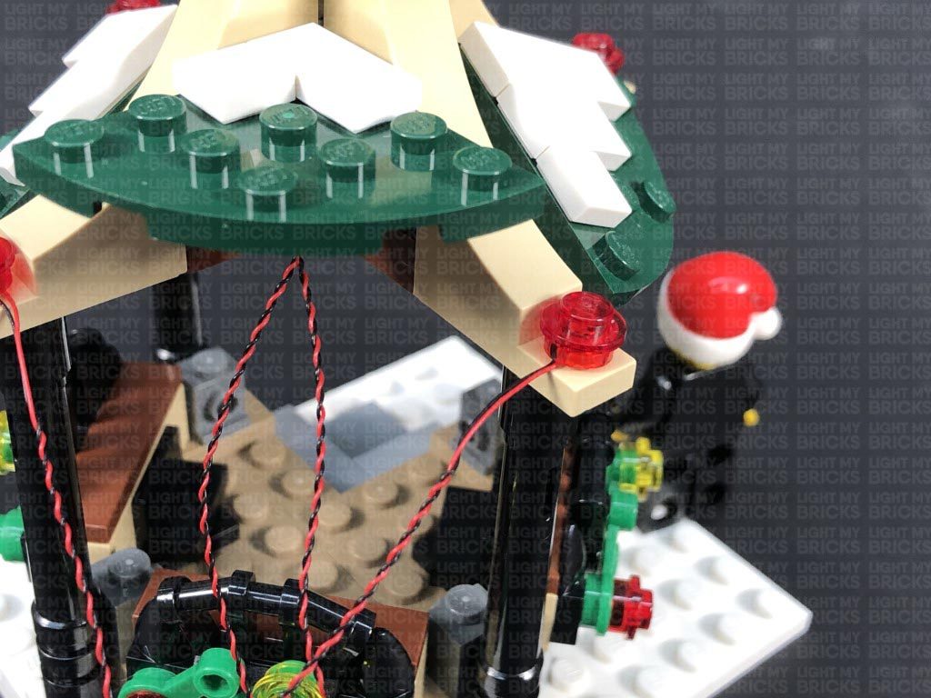
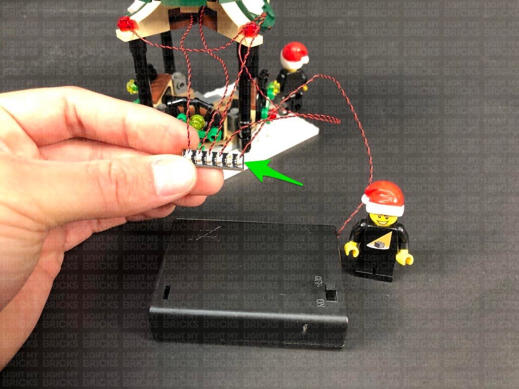
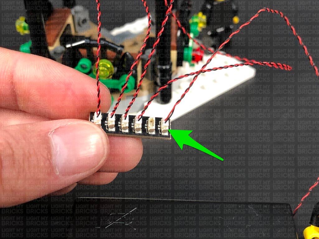
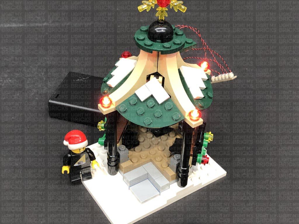
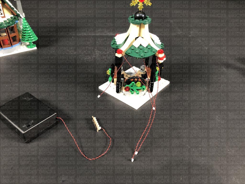
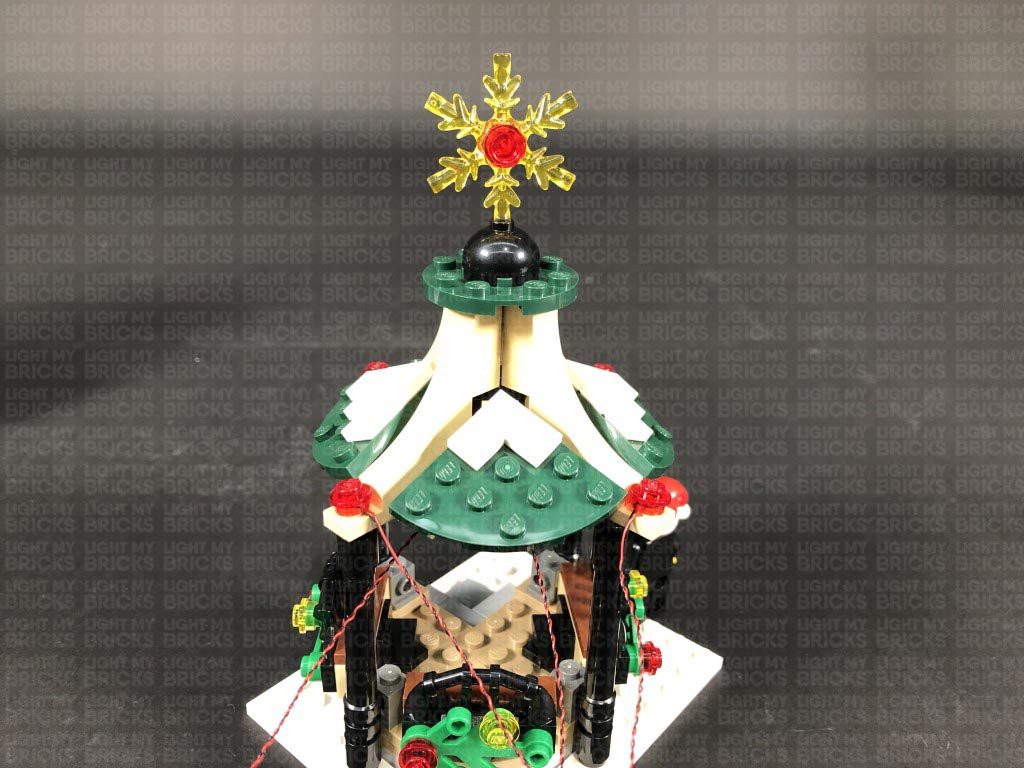
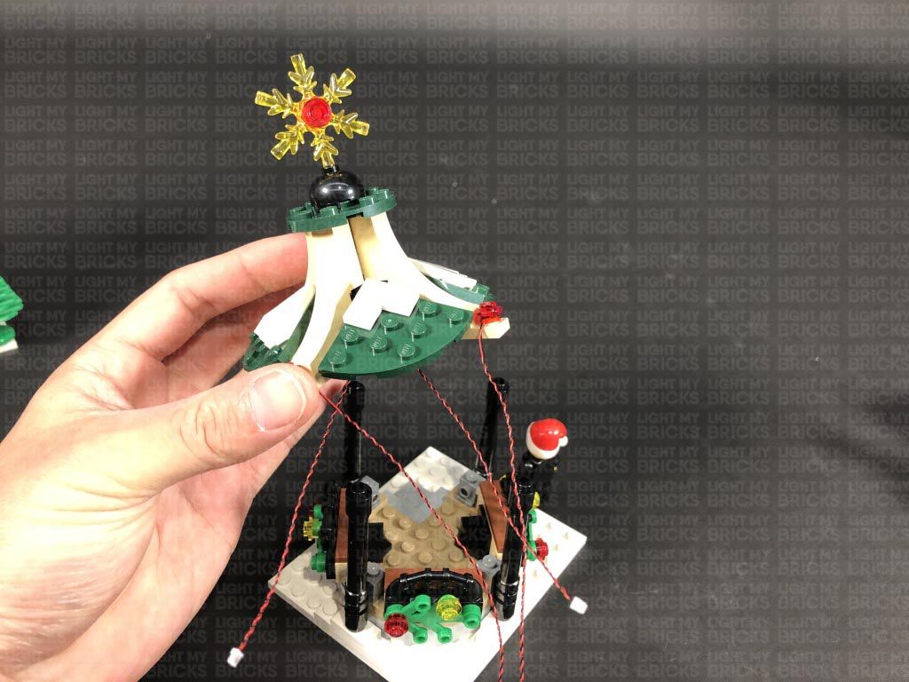
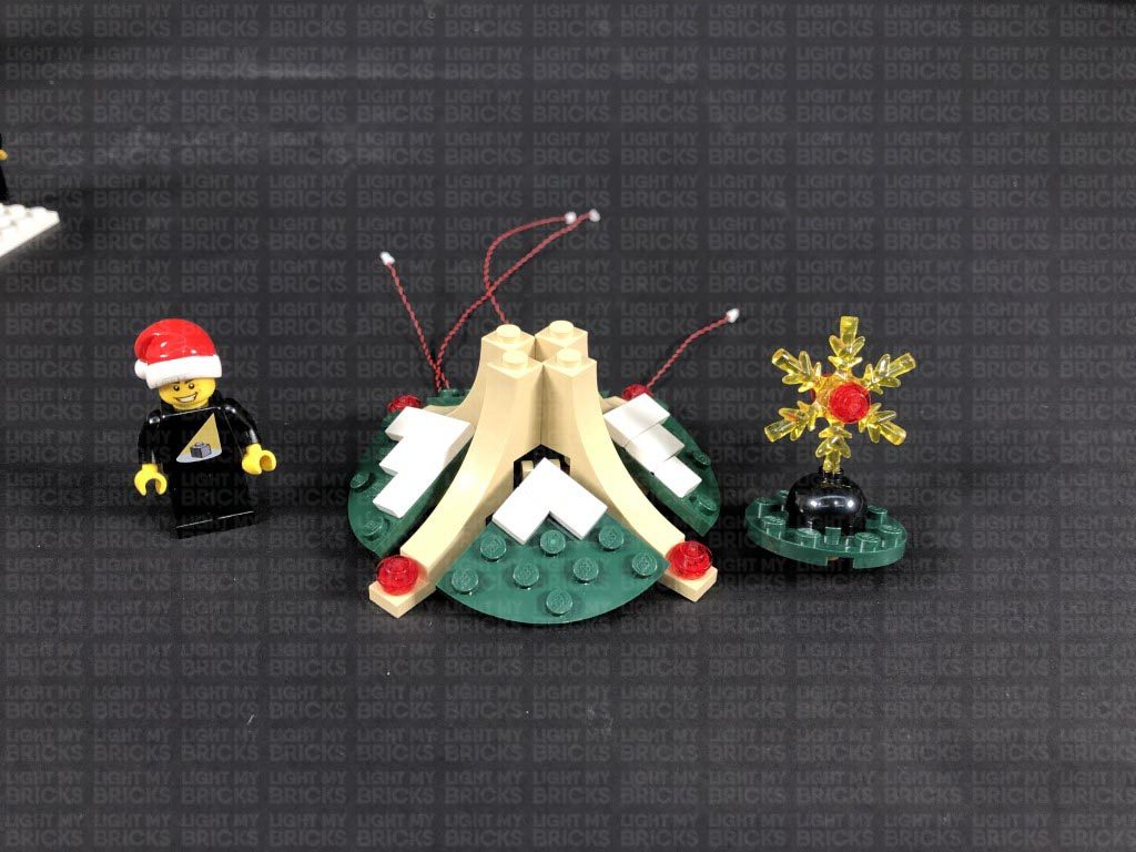
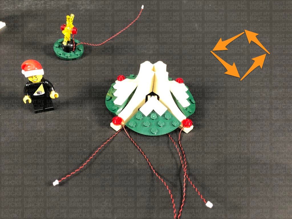
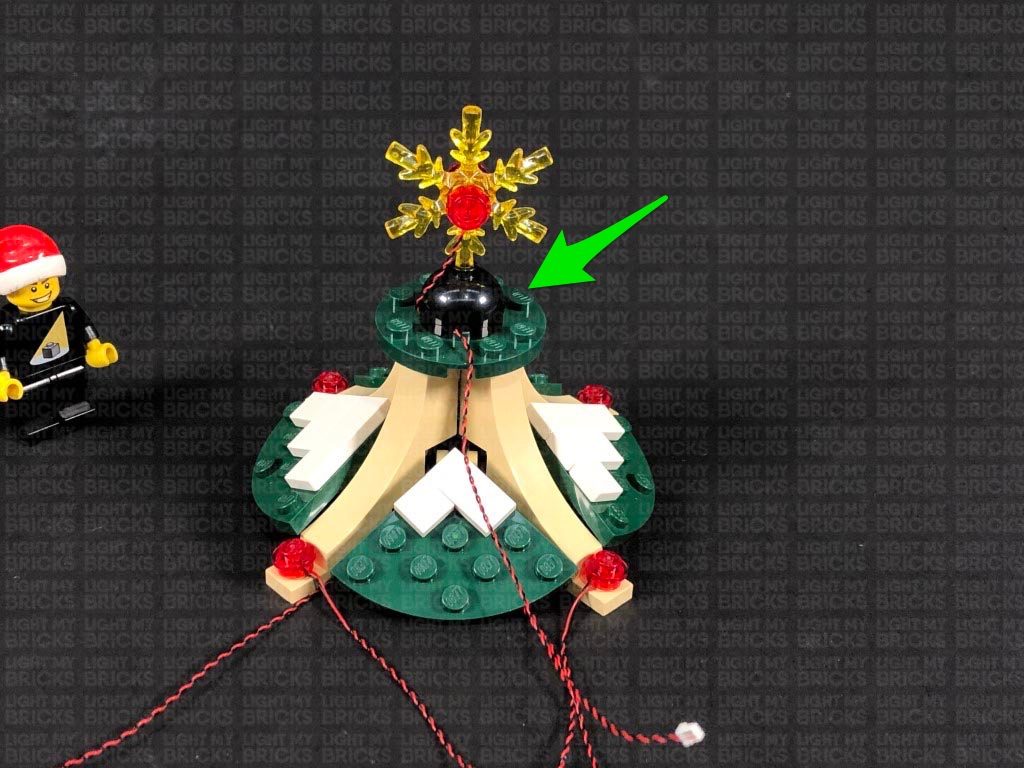
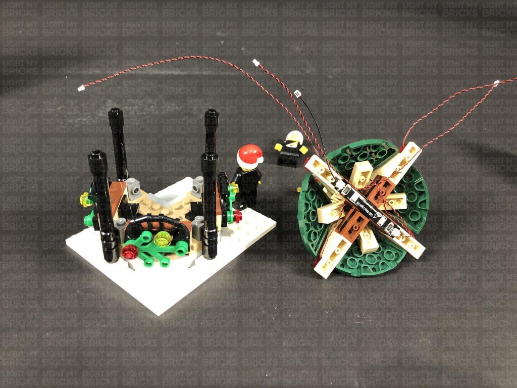
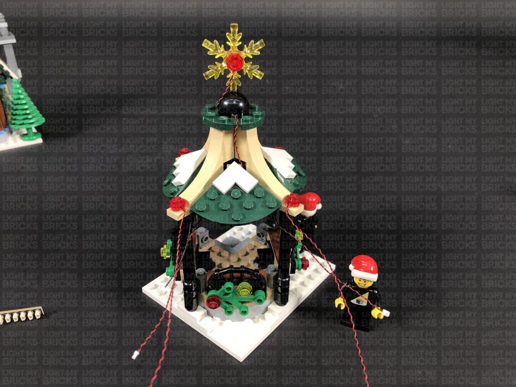
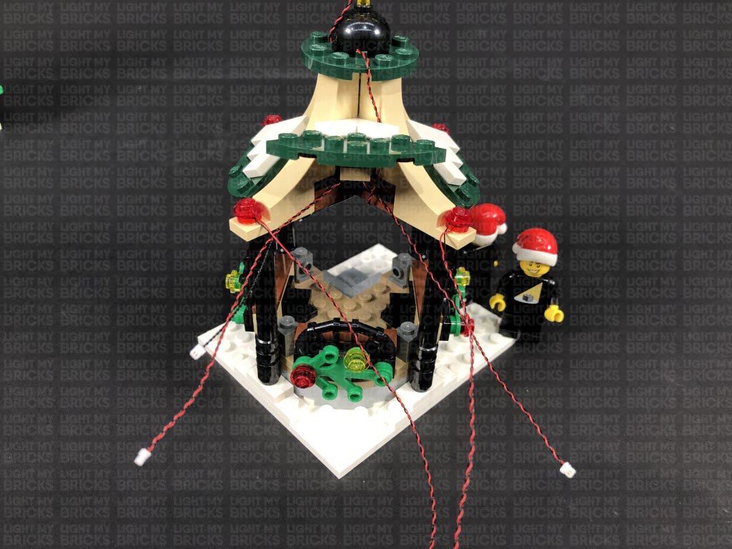
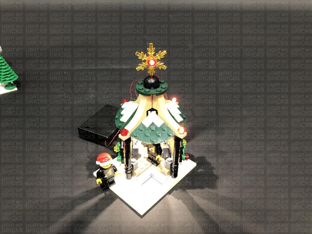
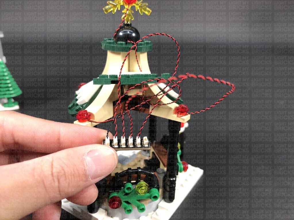
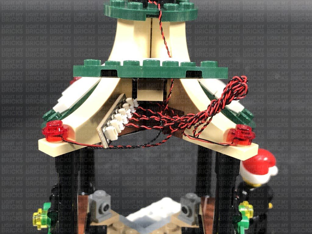
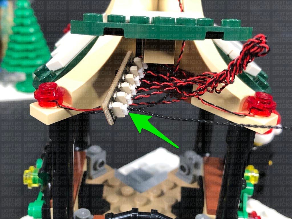
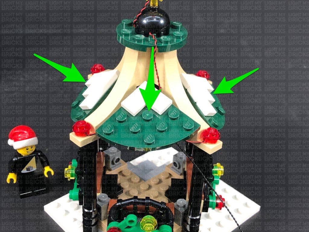
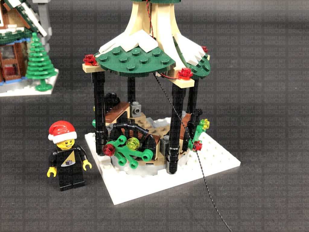
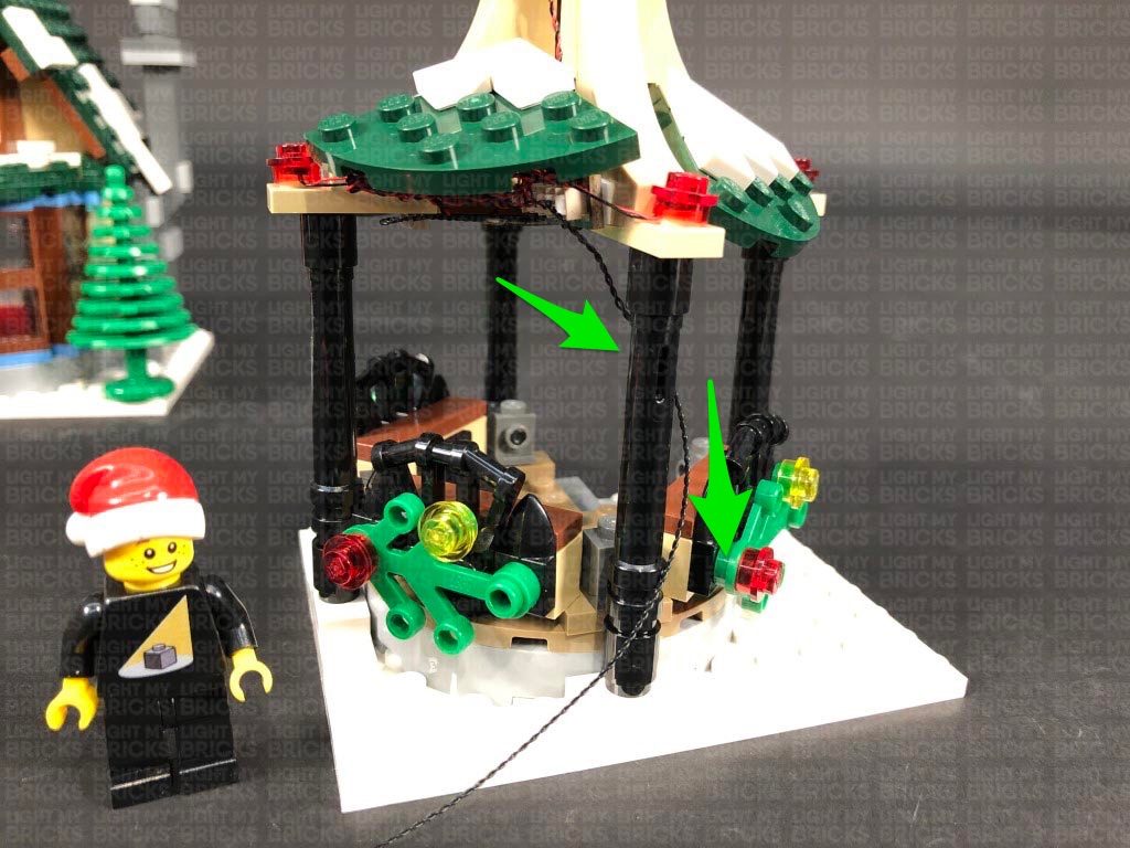
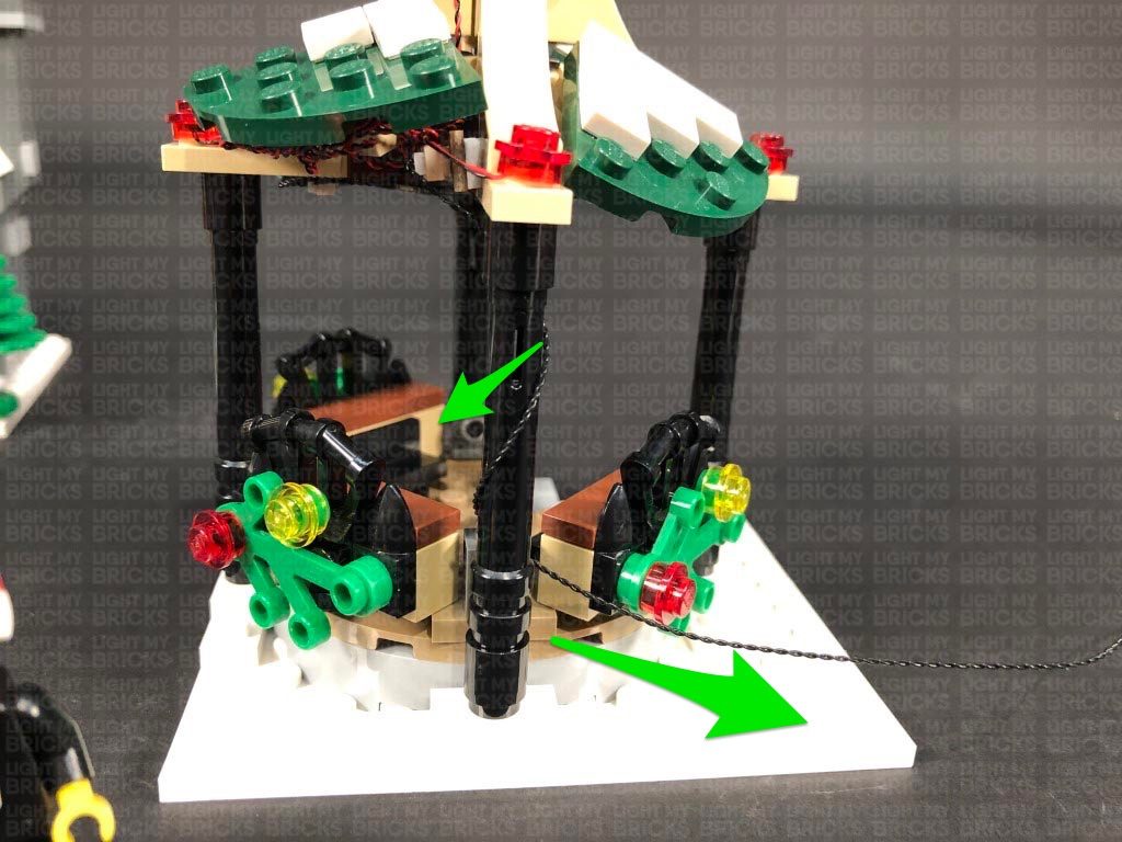
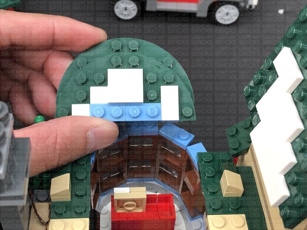
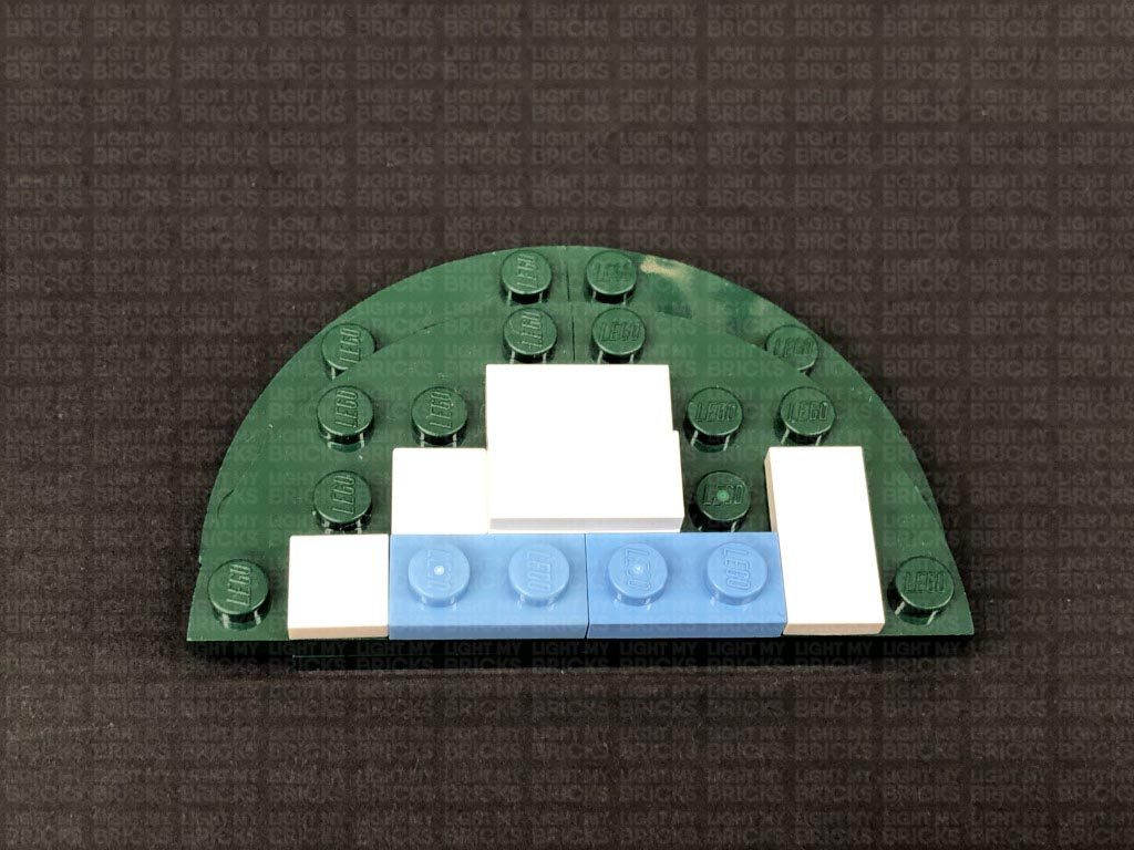
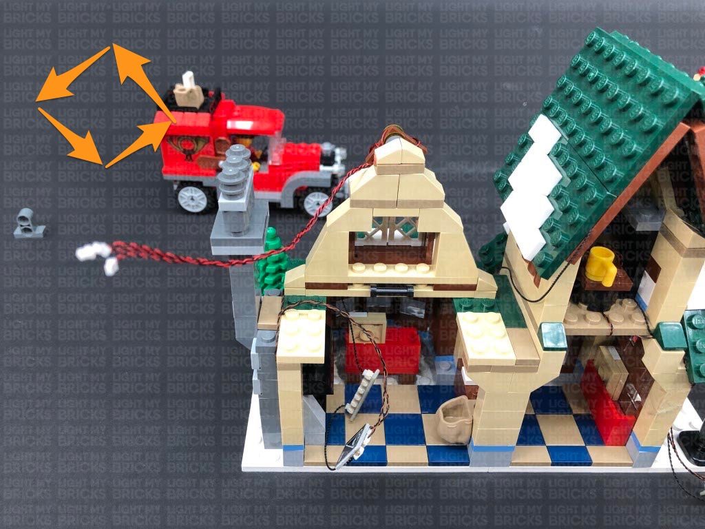
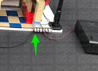
1.) We will first install lights to the post office truck. Disconnect the following sections surrounding the front and back of the truck as shown below: Disconnect the two headlight sections and disassemble one of them as shown below 2.) Take a White 15cm Micro Bit Light and with the cable facing the same way as the tap, place the LED inside the plate underneath. Ensuring the LED is facing the correct way up, secure the Bit Light in place by reconnecting the trans clear round plate. Reconnect the tap piece to the dark grey plate with clip ensuring you secure the cable underneath the clip as shown below, then reconnect this headlight to the front of the truck. Repeat this process to install another White 15cm Micro Bit Light to the other headlight, before reconnecting it to the front of the truck. 3.) Lay both cables in between studs leading to the back of the truck, then secure them in place by reconnecting all the pieces we removed earlier over the top. Connect the Bit Lights to the Micro 4-Port Expansion Board. Take the Flat Battery Pack and insert 2x NEW CR2032 Batteries inside. Connect the Battery Pack cable to the larger port on the expansion board, then turn it ON to test if the headlights are working OK. IMPORTANT NOTE: Flat and Round Battery Packs (CR2032) have been removed as of June 2022 due to child safety regulations. To test the lights, connect the 50cm Connecting Cable to a spare Expansion Board. Take the AA Battery Pack and with new batteries inserted, connect it to the expansion board. Turn the battery pack ON to test if all is working ok. Once tested, disconnect the Expansion Board and AA Battery Pack and set them aside. Note: If you experience any issues with the lights not working and suspect an issue with a component, please try a different port on the expansion board to verify where the fault lies (with the light or expansion board). To correct any issues with expansion board ports, please view the section addressing expansion board issues on our online troubleshooting guide. 4.) Turn the truck over so we can access underneath of it, then disconnect the 4×6 plate. Stick 2x Adhesive Squares onto the back of the Flat Battery Pack, then stick it it underneath the truck with the switch facing the back. Disconnect the rear wheel section and lay the battery pack cable underneath, before reconnecting it over the top, securing the cable. 5.) We will now install the rear lights to the truck. First disconnect this section and disconnect the trans red round plates. Take another White 15cm Micro Bit Light and place the LED facing up over the top of one of the grey studs. Secure the Bit Light in place by reconnecting one of the trans red round plates over the top, then repeat this step to install another White 15cm Micro Bit Light to the other rear light. 6.) Tuck the bit light cables underneath this section, then before we reconnect this to the back of the truck, lay the battery pack cable in between studs as shown below: Connect the two Bit Lights to the Micro 4-Port Expansion Board, then turn the battery pack ON to test the rear lights are working OK. 7.) Neaten up the cables by twisting and folding them together into a neat bunch. Place the components directly in front of the light grey back piece before reconnecting the main carriage section. Test all lights are working OK. 8.) We will now install lights to the gazebo. First lift up the four roof sections, then disconnect the 2x trans red round plates from the front. Take a Flashing White 15cm Bit Light and with the cable facing the outside, place it over the left stud. Secure it in place by reconnecting the trans red round plate over the top. Thread the bit light cable through the space in the centre of the roof. Turn the section around to the back and pull the cable all the way out. 9.) Repeat the previous step to install another Flashing White 15cm Bit Light to the right side and pulling it out from the back side. Connect both cables to a 6-Port Expansion Board, then turn the set back around to the front and push close the centre roof panel. 10.) Turn the set around to the back again and using the same method as we did for the front lights, install another 2x Flashing White 15cm Bit Lights to the back except this time, ensure the cables are facing the middle . Connect both lights to the 6-Port Expansion Board, then take the AA Battery Pack and insert 3x NEW AA Batteries to it. Connect the battery pack cable to the expansion board, then turn it ON to test the flashing lights are working OK. Note: If you experience any issues with the lights not working and suspect an issue with a component, please try a different port on the expansion board to verify where the fault lies (with the light or expansion board). To correct any issues with expansion board ports, please view the section addressing expansion board issues on our online troubleshooting guide. 11.) We will now install another flashing light to the star. First disconnect all the lights from the expansion board, then completely disconnect the gazebo roof. Disconnect the star and disassemble this section as shown below. Take a Flashing White 15cm Bit Light and thread the connector side of the cable through the hole at the front of the Star piece. Flatten the bit light so that it sits flat, then secure it in place by reconnecting the trans red round plate over the top. Turn the star over and reconnect the other trans red round plate to the back of it, then reconnect the star to the black round brick. Loop the cable underneath the black brick, ensuring you lay it in between the gaps, then reconnect it to the green plate. 12.) Turn the roof around to the back, then reconnect the star section ensuring the cable from this light is also facing the back. Slide the bit light cable from the star down behind the roof panel, then flip the roof over and connect the bit light cable (from the star) to a White Strip Light Take a 5cm Connecting Cable and connect it to the other port on the Strip Light, then using it’s adhesive backing, stick the strip light underneath the roof in the following position: Ensure the 5cm cable is facing the back along with the rest of the cables. 13.) Flip the roof back over, then reconnect it to the gazebo. Connect all 5 cables (4 from the roof and the 5cm cable) as well as the AA Battery Pack Cable to the 6-Port Expansion Board. Turn ON the battery pack to test all the lights installed to the gazebo are working OK. Disconnect the AA Battery Pack, then neaten up cables by twisting and folding them all together into a neat bunch Take the 30cm Connecting Cable and connect it to the remaining port on the expansion board, then using 2x Adhesive Squares, stick the expansion board to the roof on the right side as shown below. Bring the bunched up cables inside toward the centre, then close all the roof panels. 14.) Bring the other end of the 30cm Connecting Cable down the back right post and wind it around toward the bottom. Turn the gazebo back around to the front and reposition it back to the right of the post office.
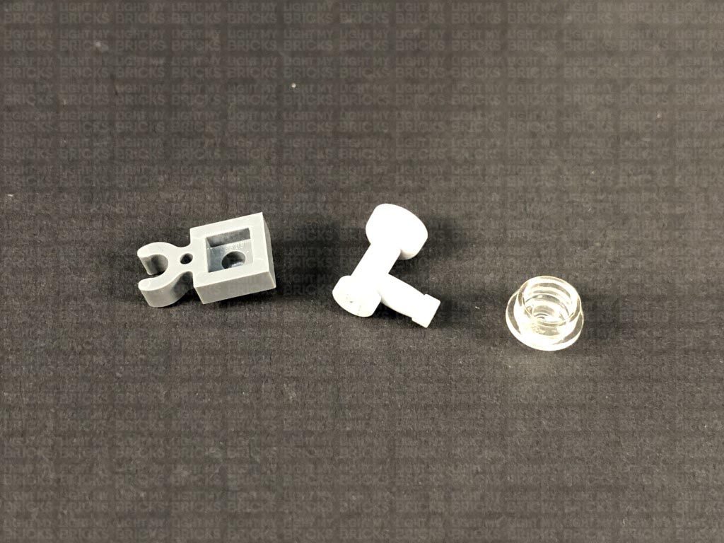
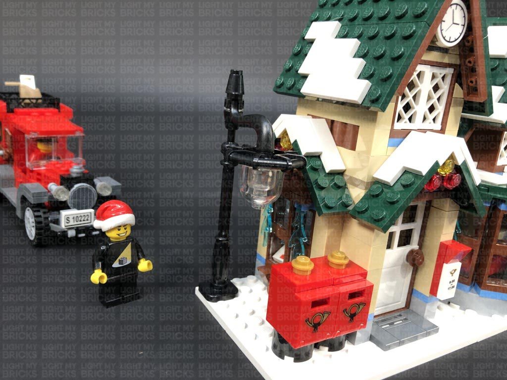
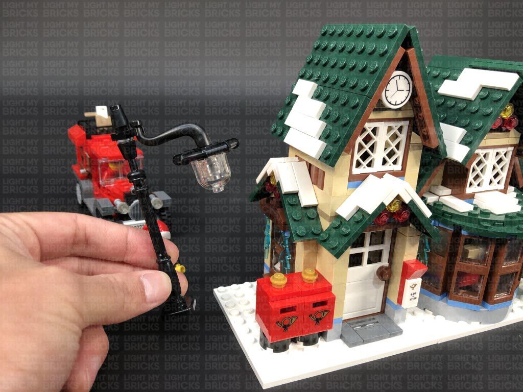
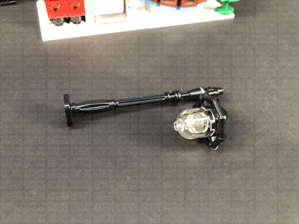
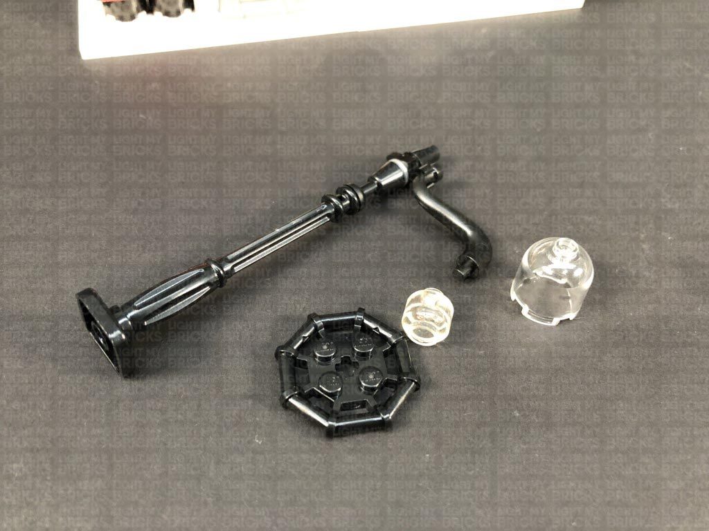
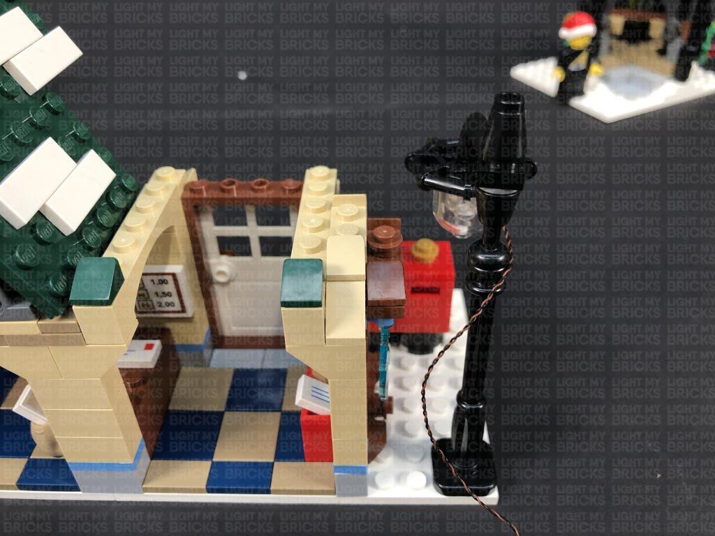
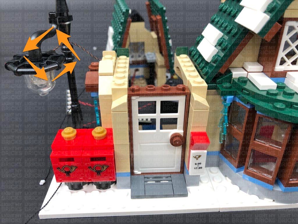
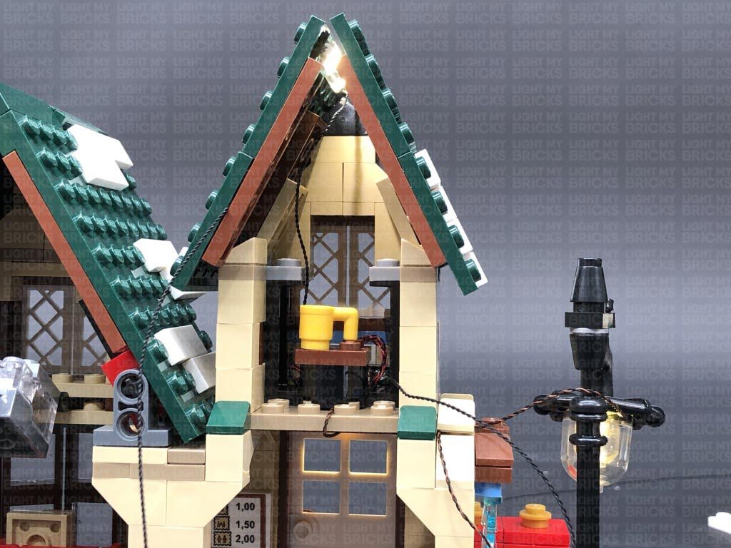
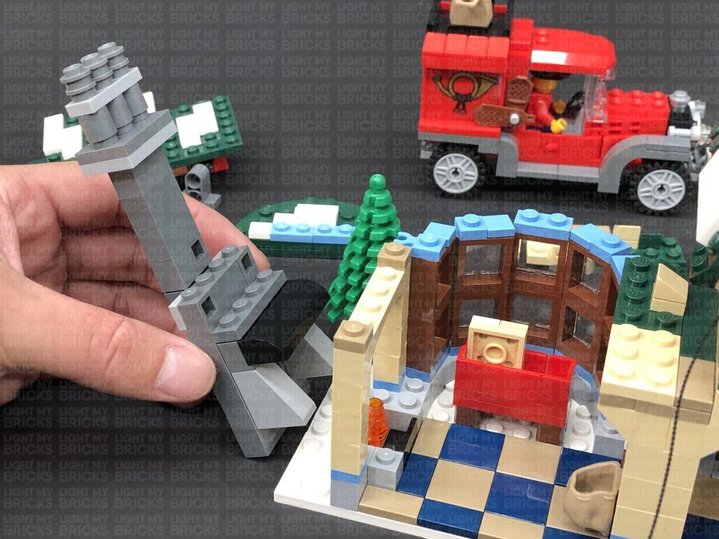
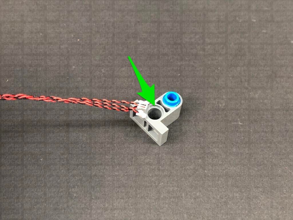
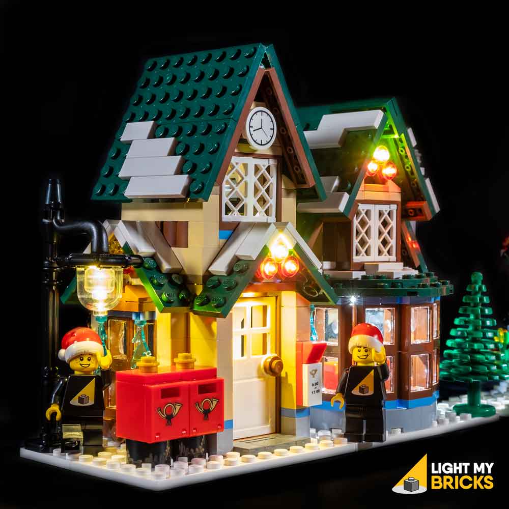
 15.) We will now install lights to the post office starting with the lamp post. First disconnect the lamp post and disassemble it as per below.
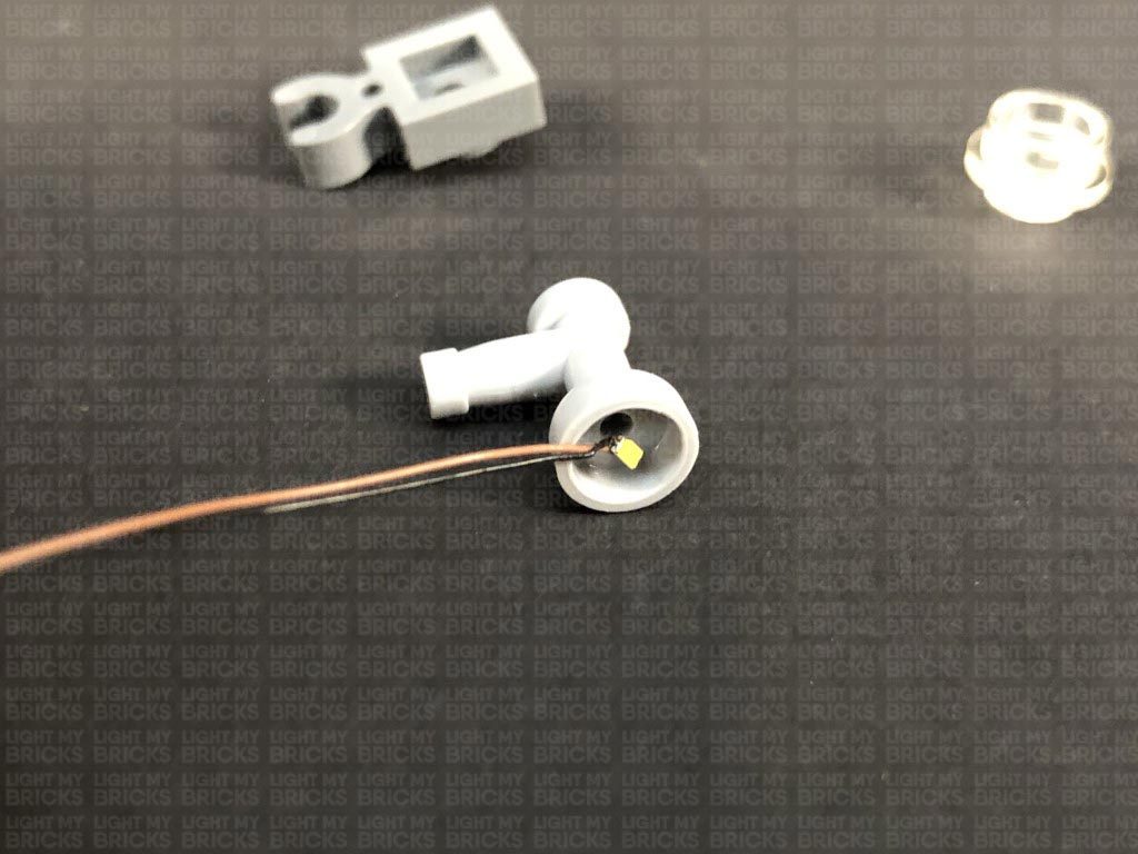
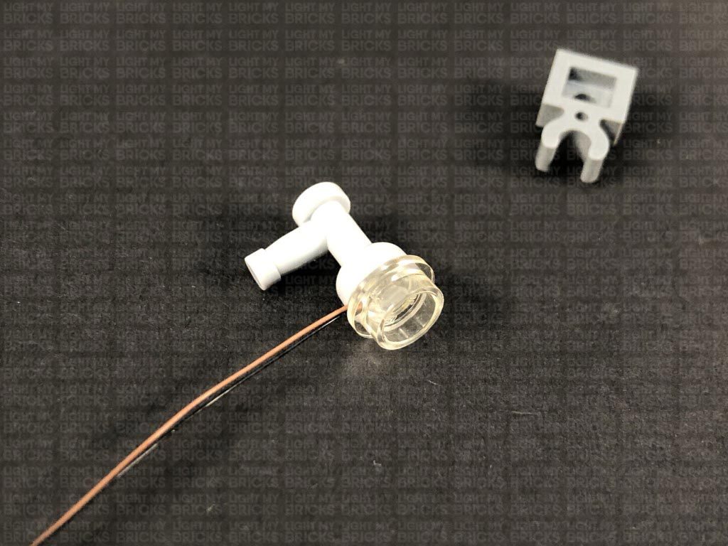
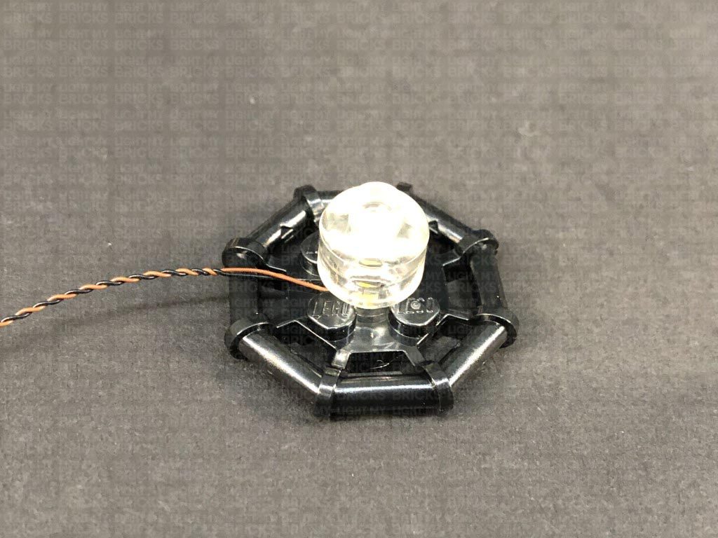
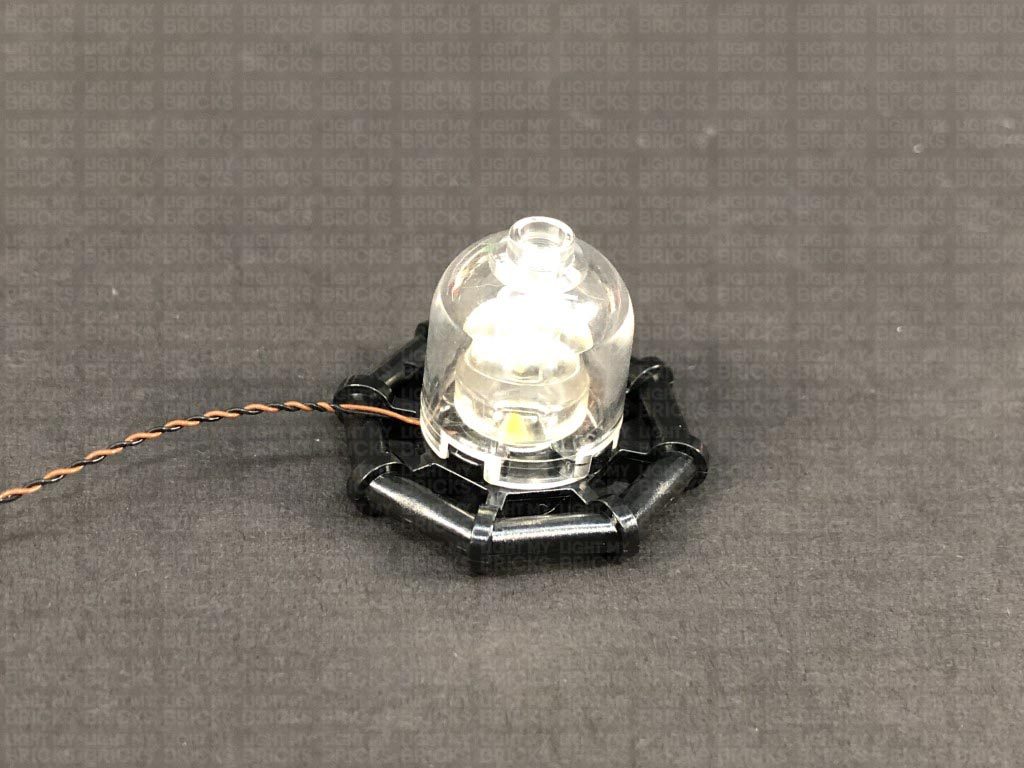
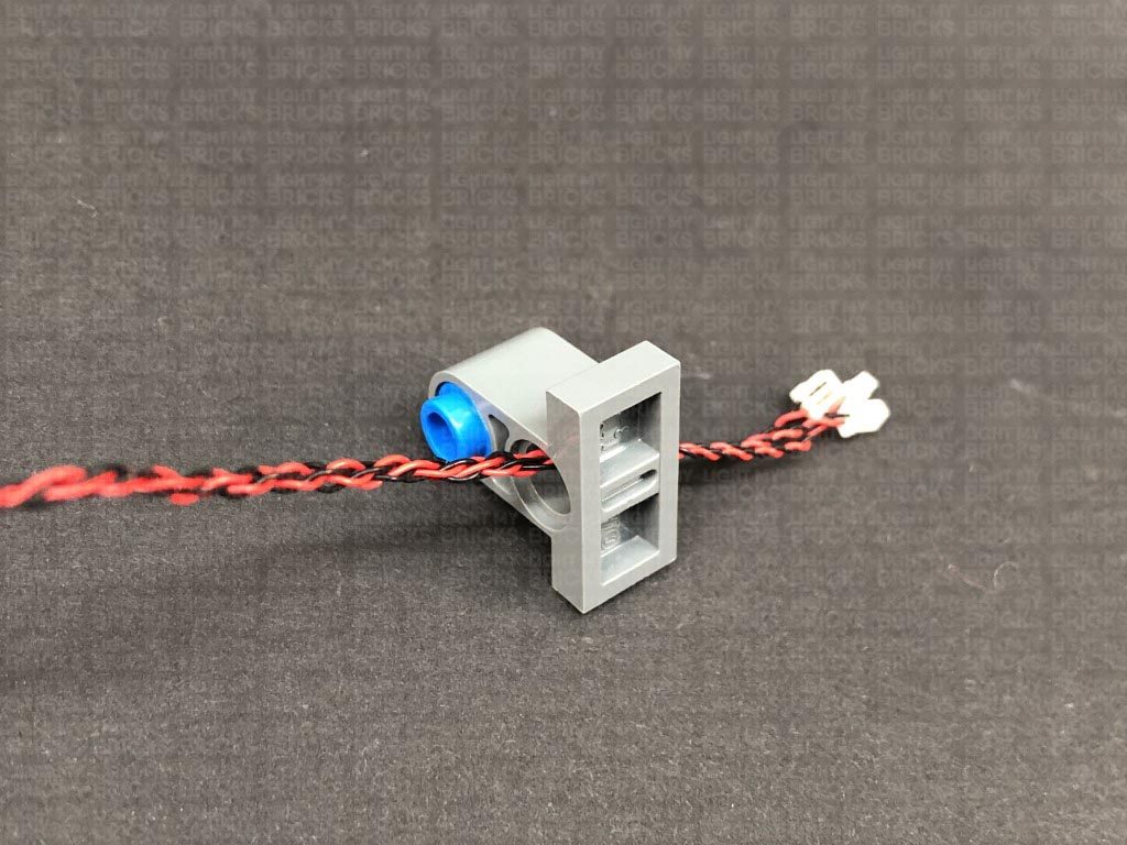
Take a White 15cm Bit Light and with the LED facing up, place it in the centre of the black plate. Secure the Bit Light in place by reconnecting the trans clear minifig head over it, followed by the larger trans clear cover.
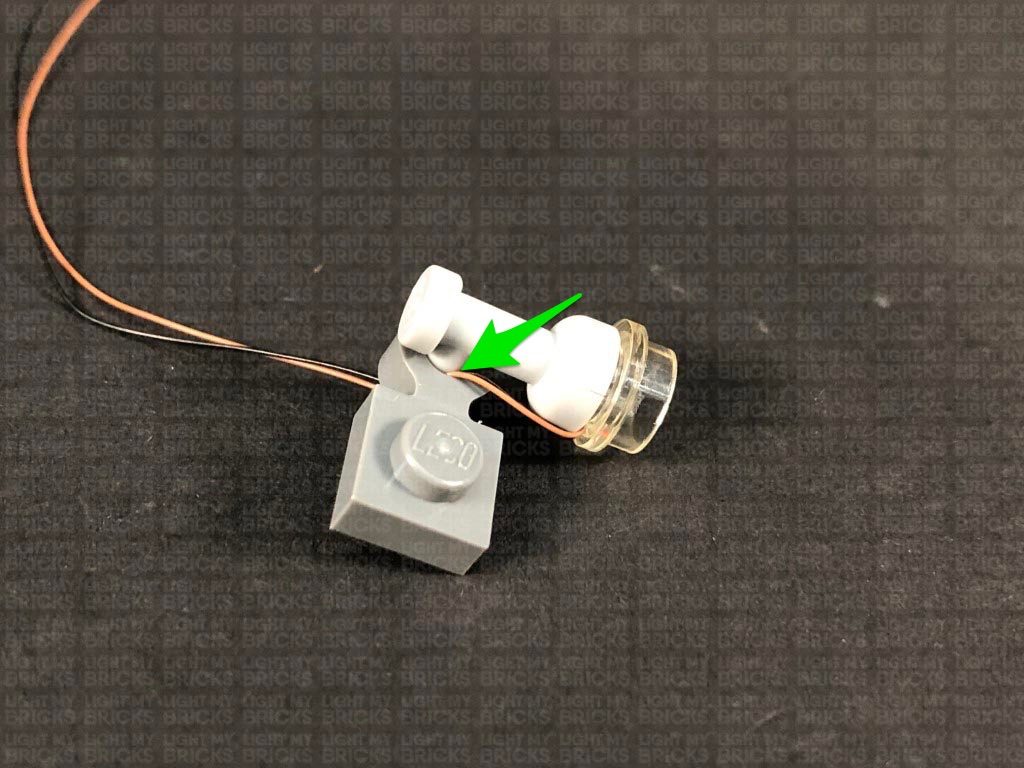
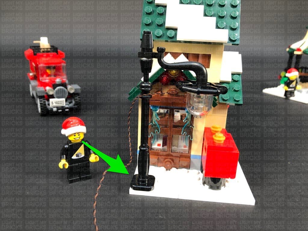
Reconnect this section the lamp post ensuring the cable is facing the same way as the back of the lamp post, then reconnect the lamp post to the set.
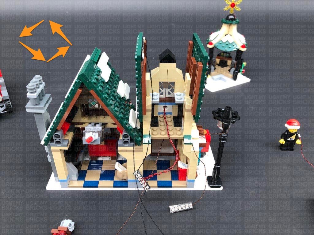
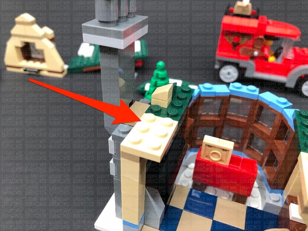
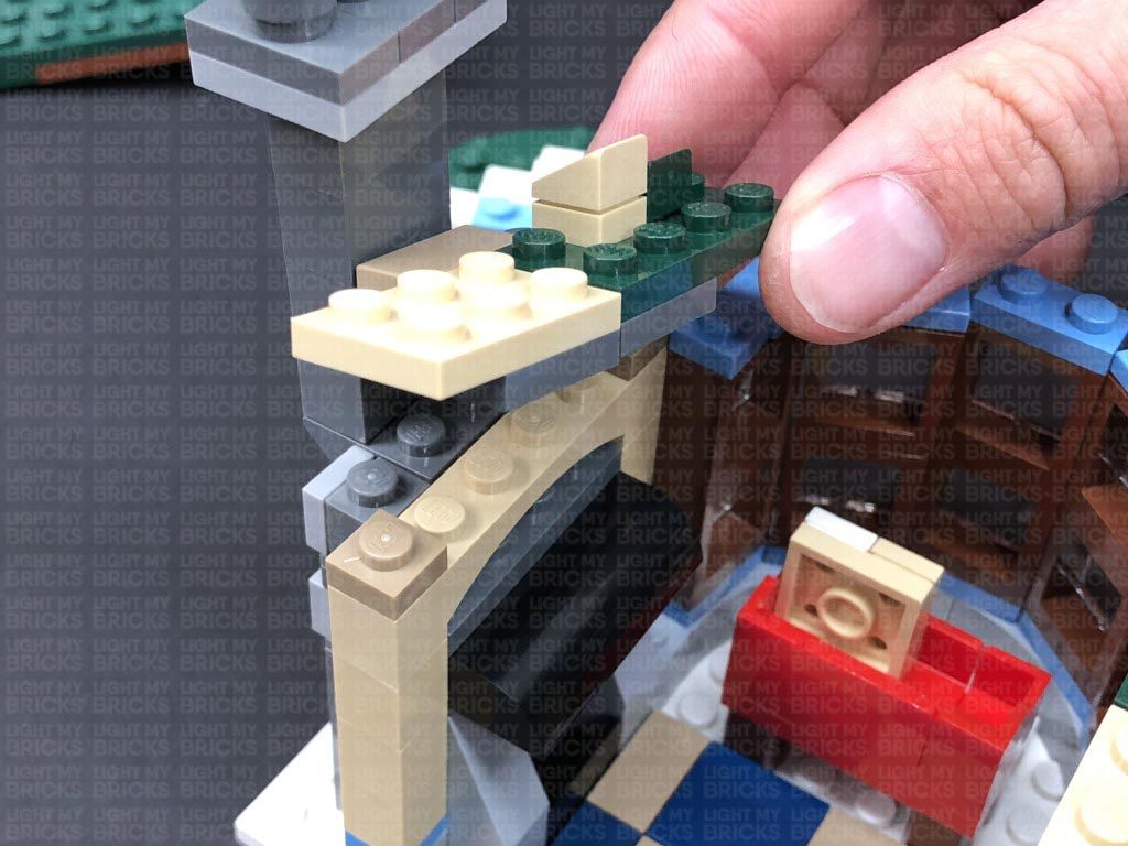
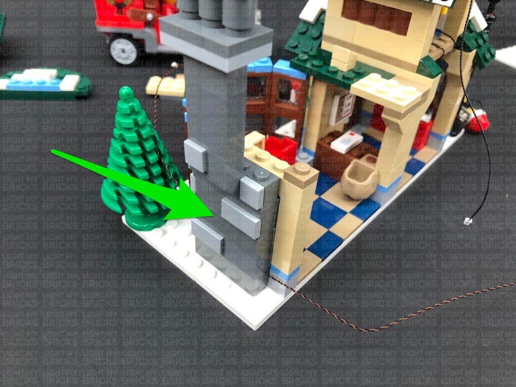
16.) Turn the set around, then carefully remove the second level on the right side by lifting it up at the dark tan base as shown below.
Disconnect the following angled tile, then bring the lamp post cable across to the left and lay it around the stud underneath, before reconnecting the angled tile over the top.
Connect the Bit Light to the end port on a new 6-Port Expansion Board. Take the AA Battery Pack and connect it to another spare port on the expansion board, then turn it ON to test the lamp post light is working OK.
15.) We will now install lights to the post office starting with the lamp post. First disconnect the lamp post and disassemble it as per below.
Take a White 15cm Bit Light and with the LED facing up, place it in the centre of the black plate. Secure the Bit Light in place by reconnecting the trans clear minifig head over it, followed by the larger trans clear cover.
Reconnect this section the lamp post ensuring the cable is facing the same way as the back of the lamp post, then reconnect the lamp post to the set.
16.) Turn the set around, then carefully remove the second level on the right side by lifting it up at the dark tan base as shown below.
Disconnect the following angled tile, then bring the lamp post cable across to the left and lay it around the stud underneath, before reconnecting the angled tile over the top.
Connect the Bit Light to the end port on a new 6-Port Expansion Board. Take the AA Battery Pack and connect it to another spare port on the expansion board, then turn it ON to test the lamp post light is working OK.
 Note: If you experience any issues with the lights not working and suspect an issue with a component, please try a different port on the expansion board to verify where the fault lies (with the light or expansion board). To correct any issues with expansion board ports, please view the section addressing expansion board issues on our online troubleshooting guide.
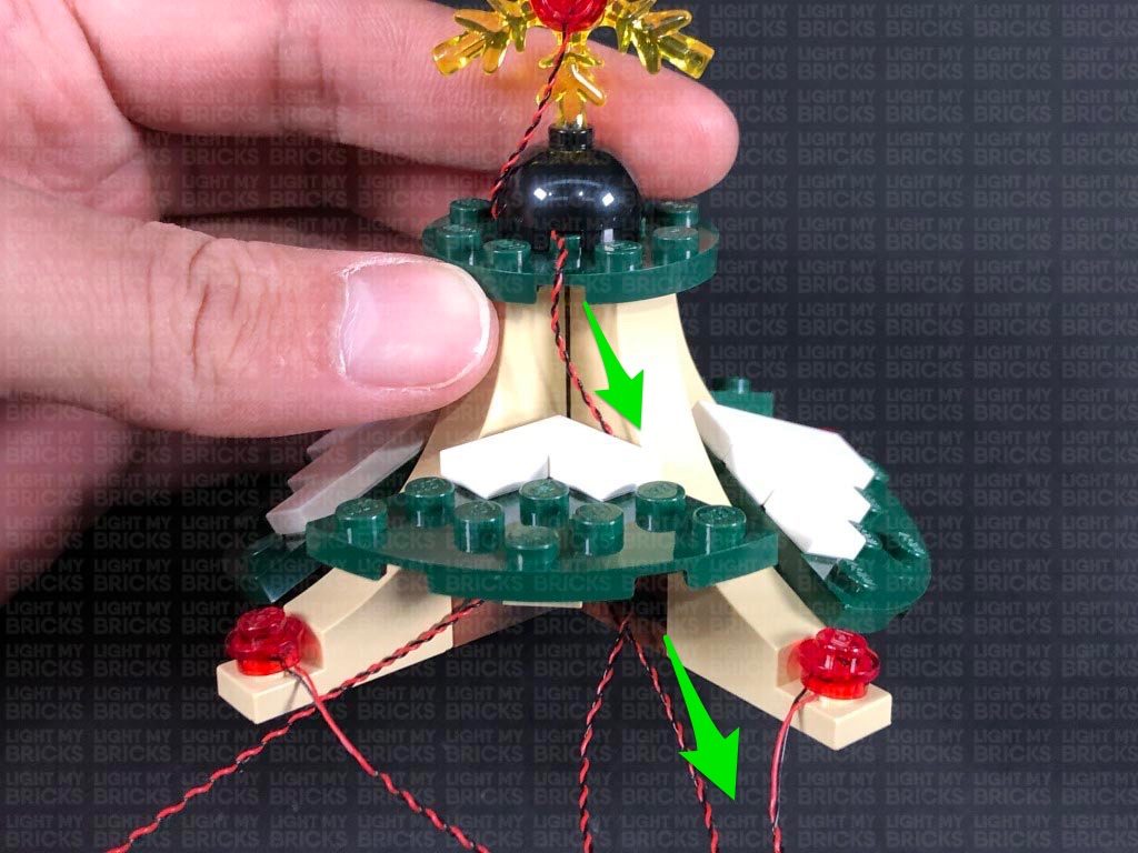
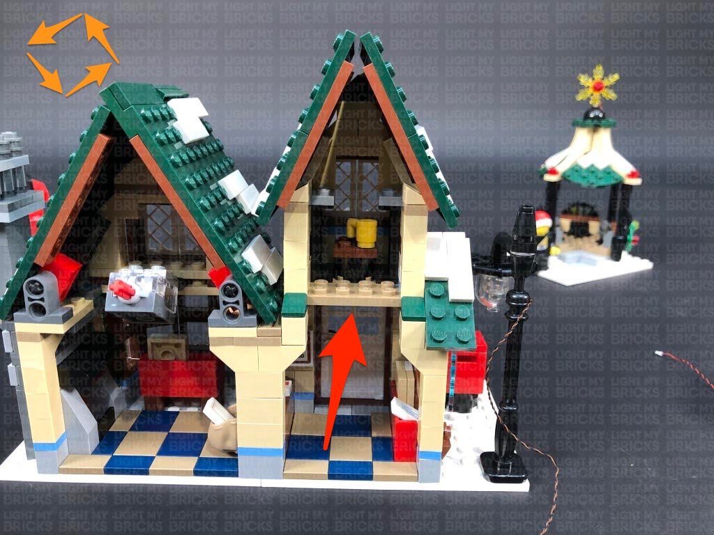
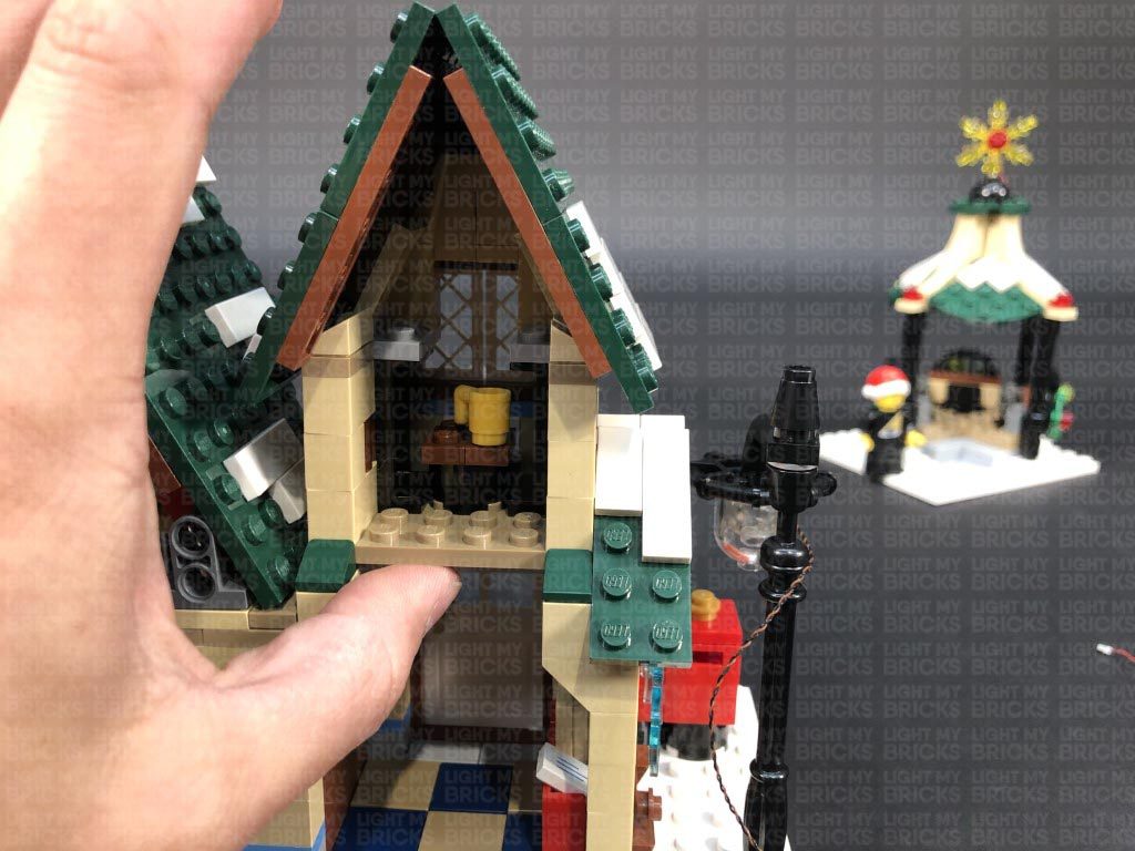
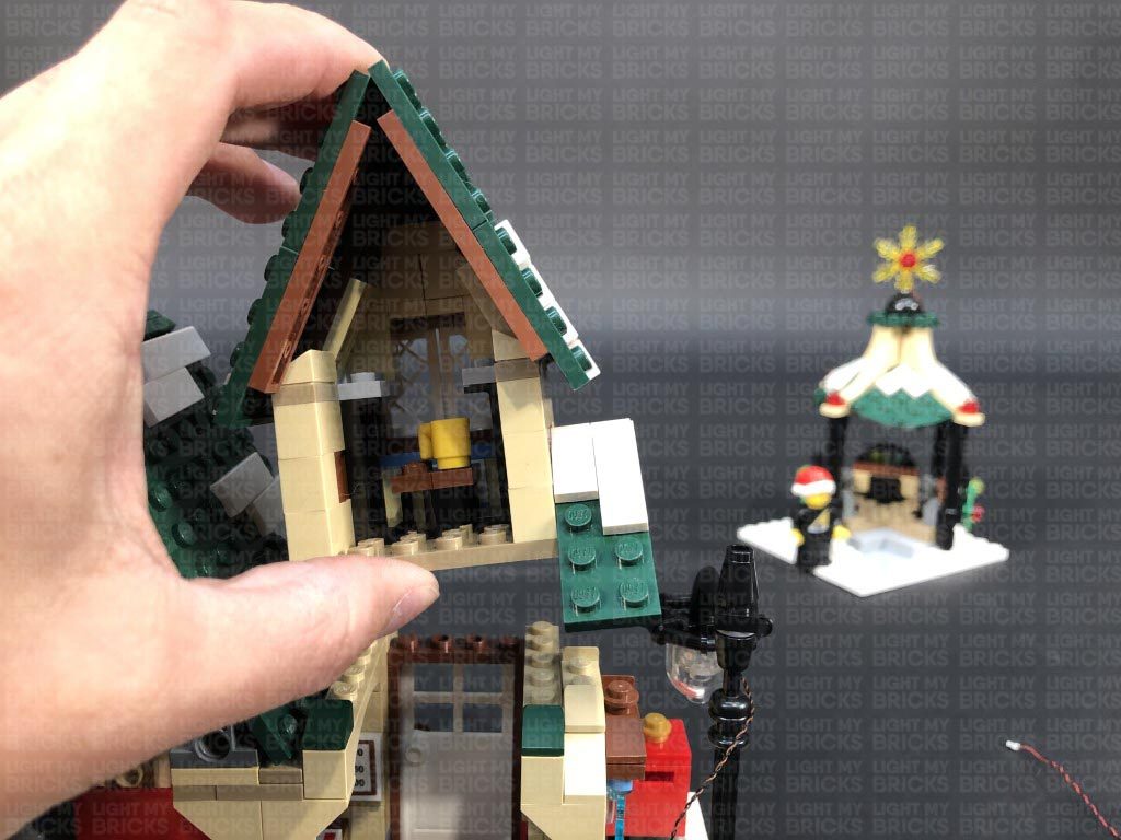
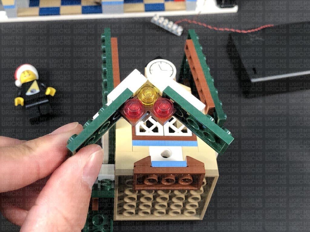
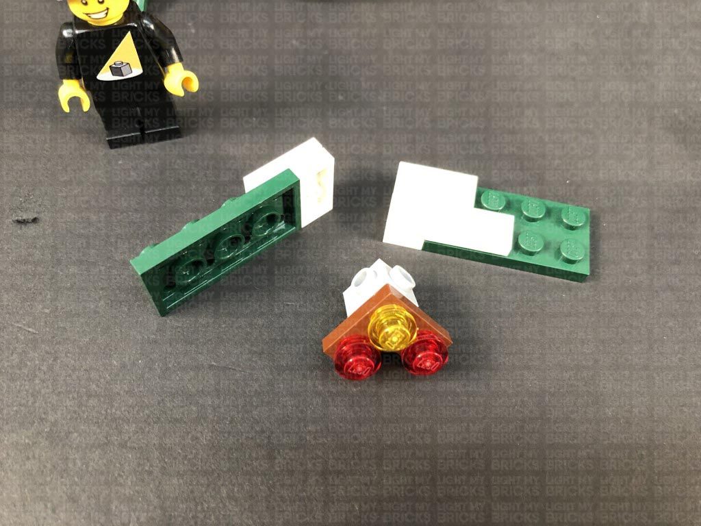
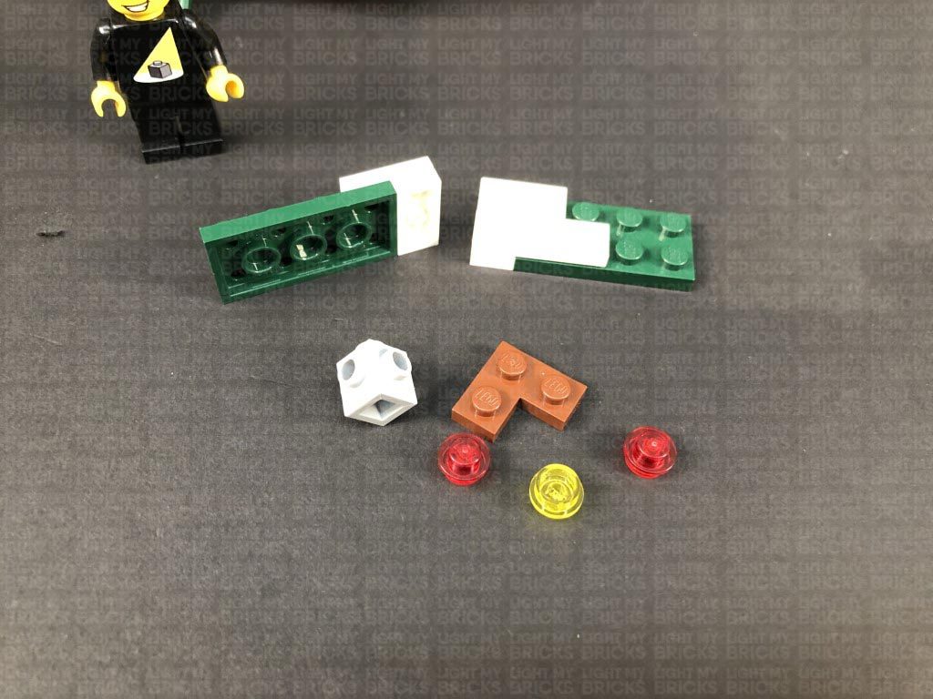
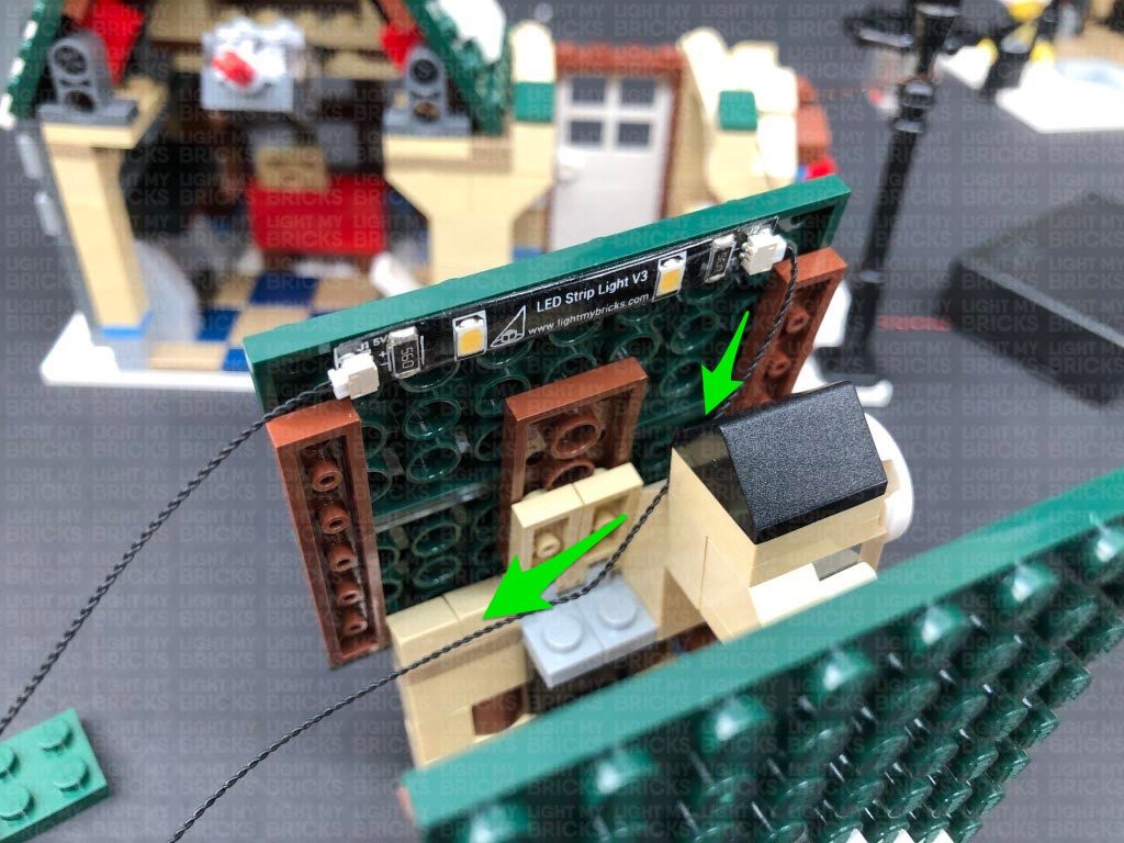
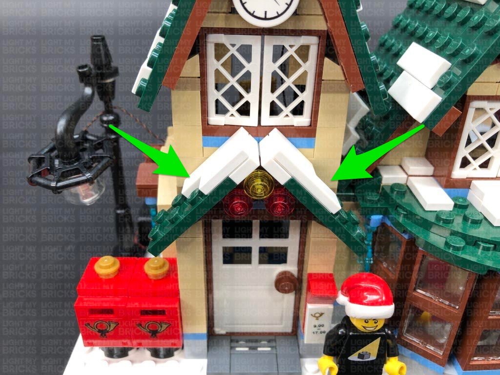
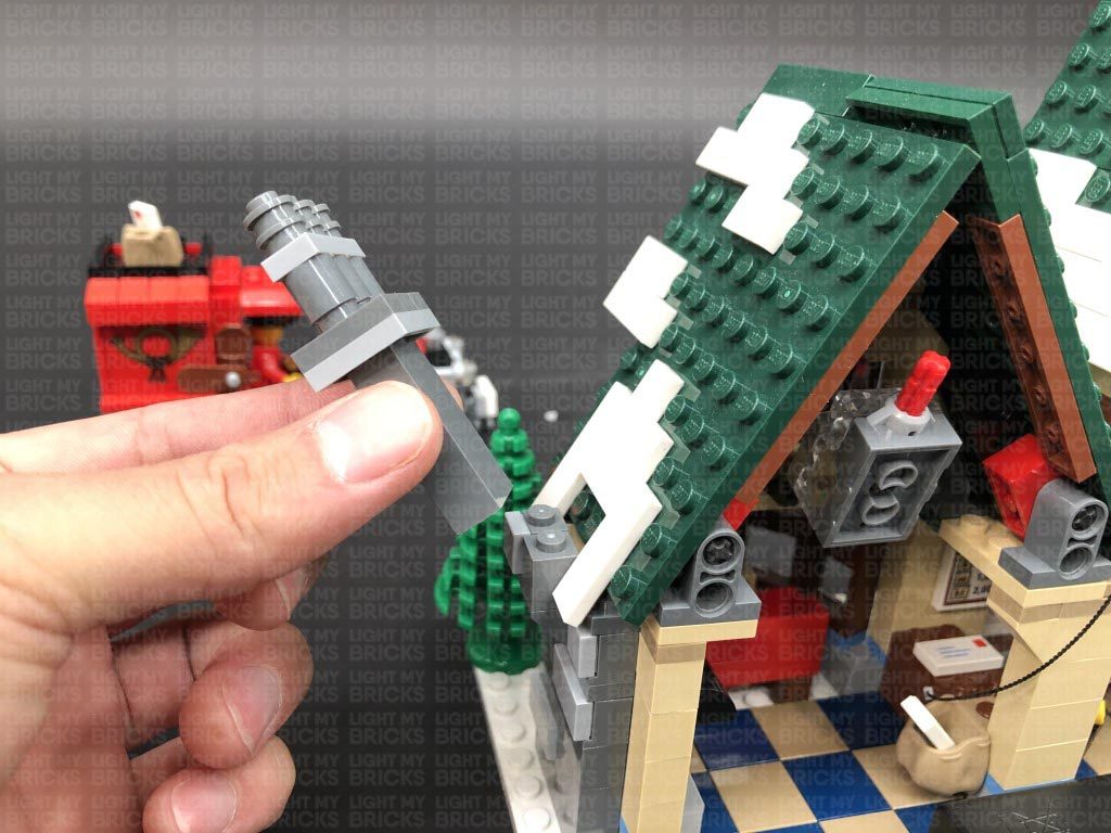
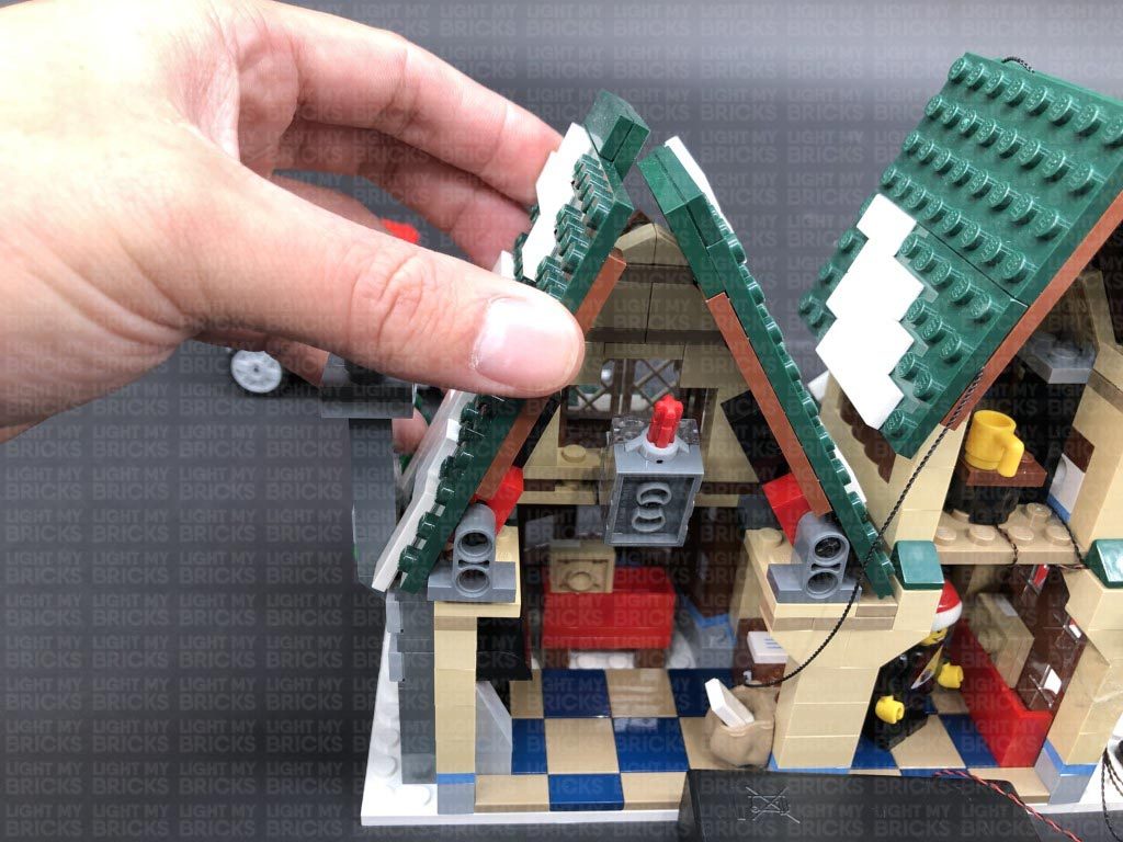
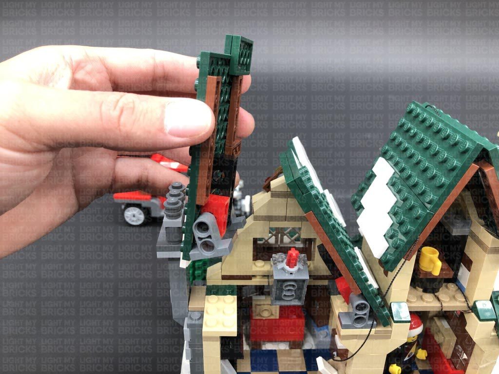
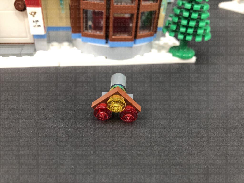
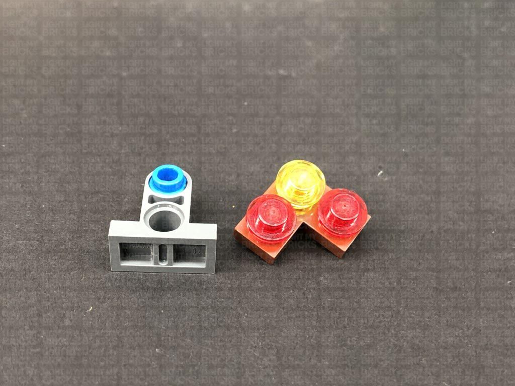
17.) Take the second level of the post office and lift up the two sides of the roof, then disconnect the table from the inside. Turn the level around to the front and disconnect the lower level roof section with lights as shown below:
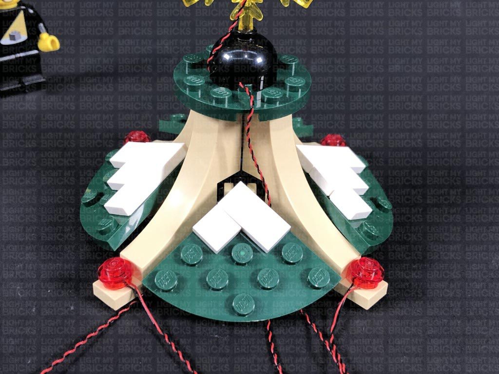
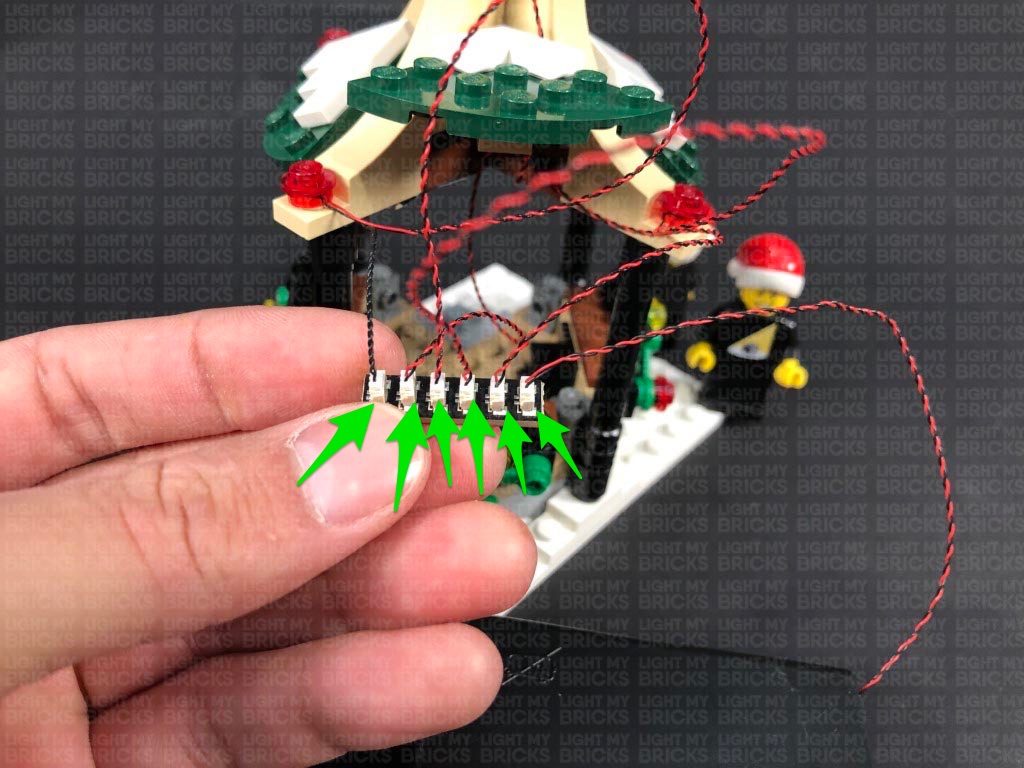
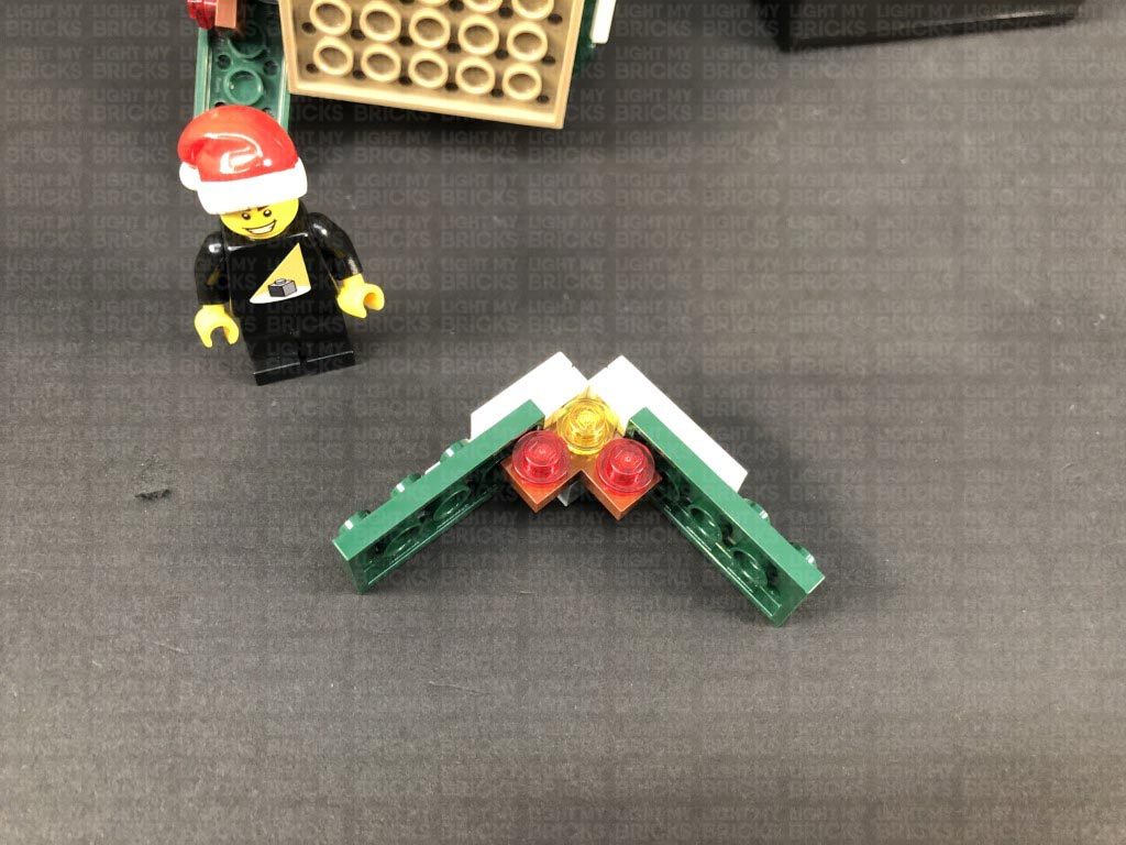
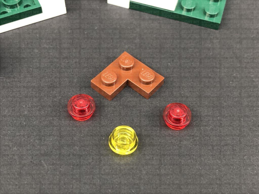
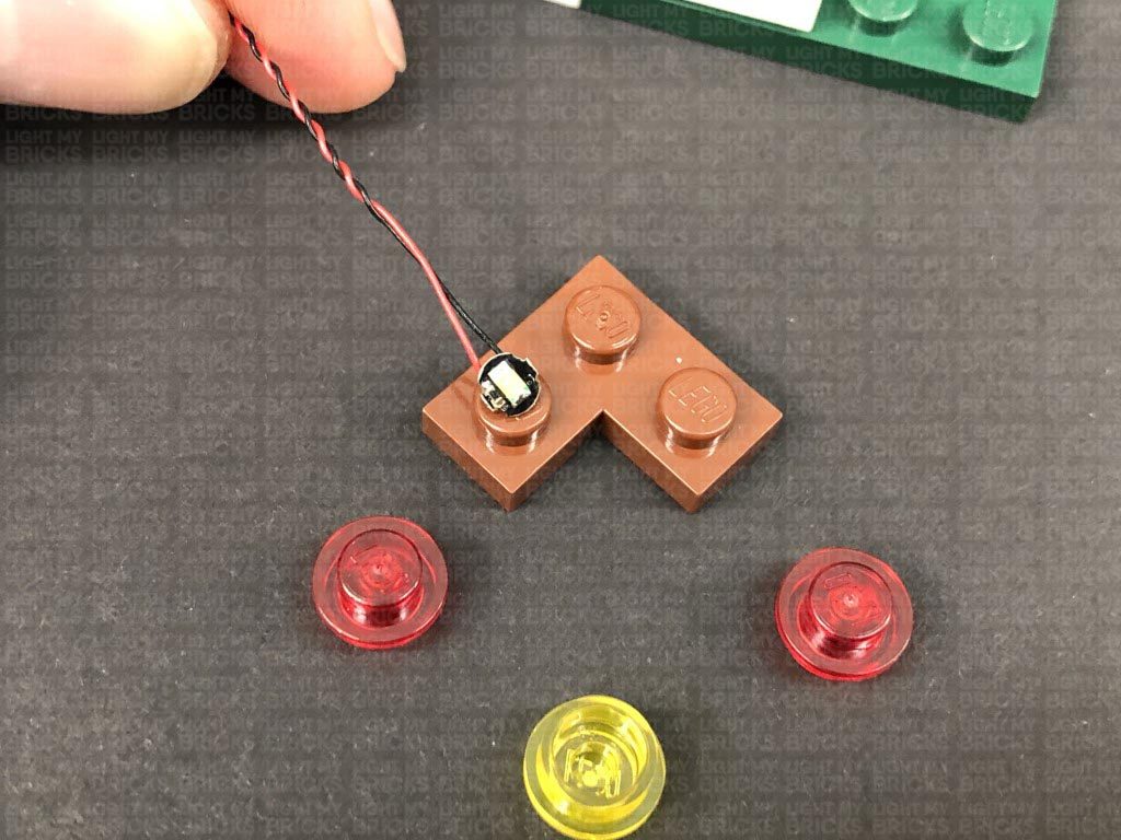
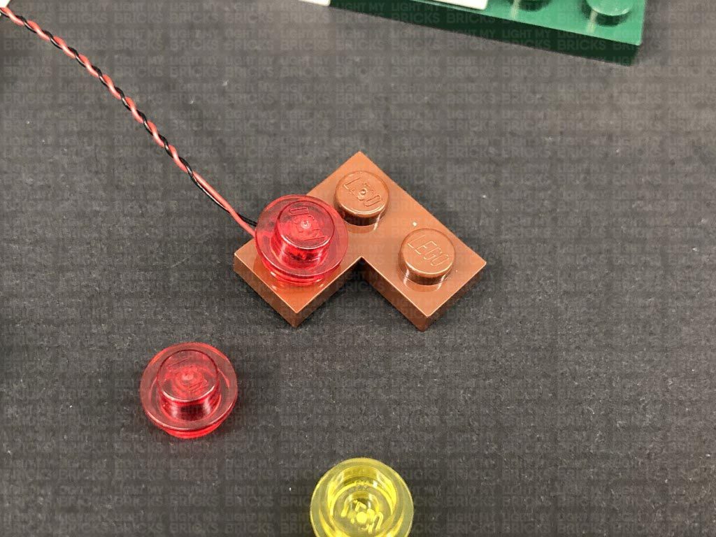
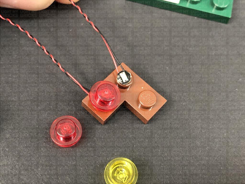
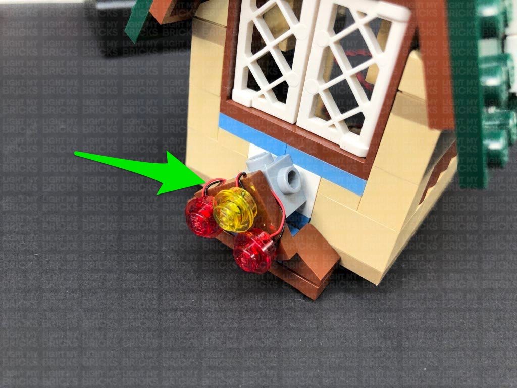
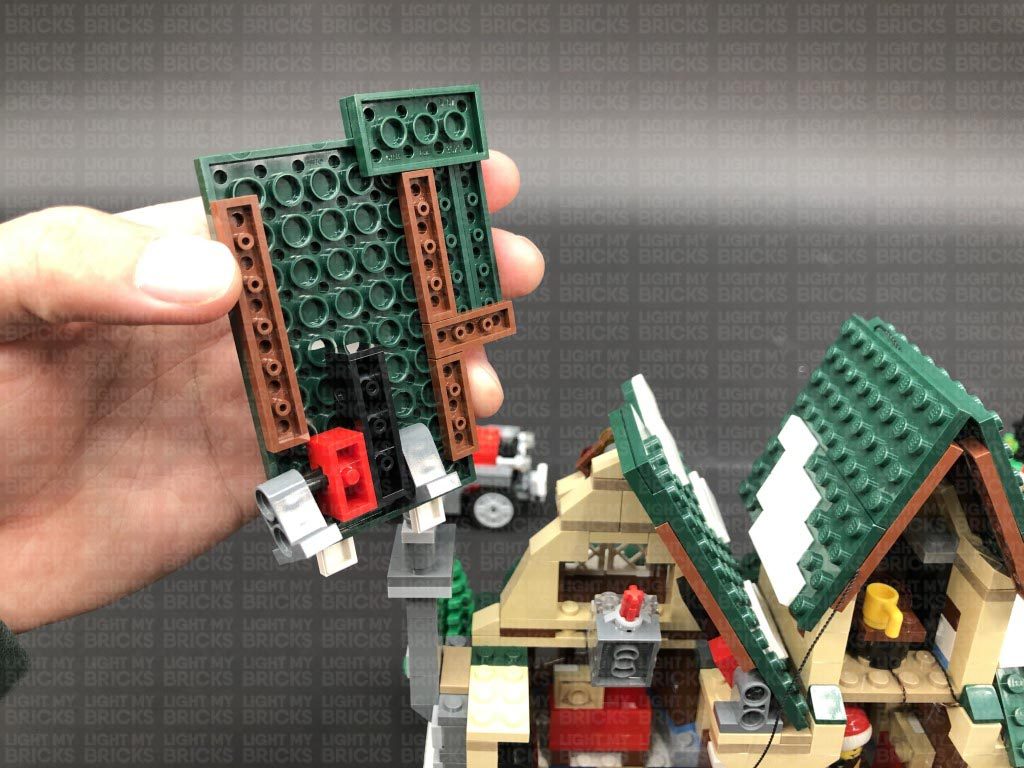
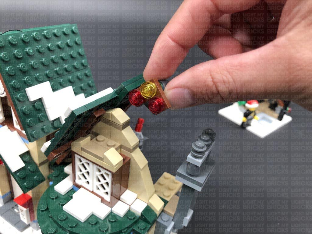
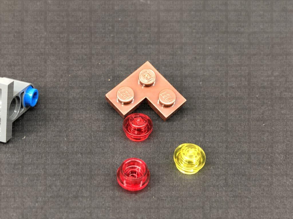
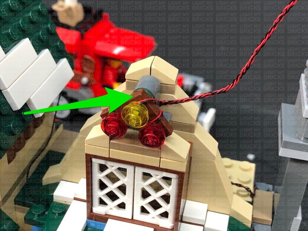
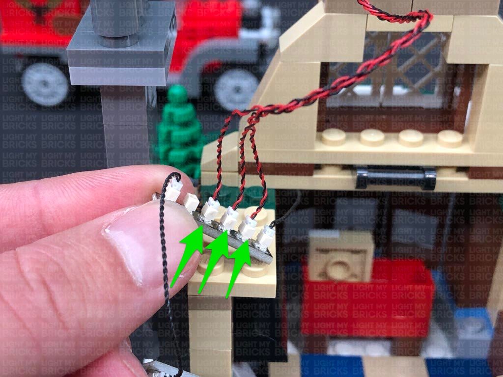
Disassemble the lower roof section as shown below, then take out a Flashing White 15cm Bit Light, and with the cable facing up, place it over the left stud on the brown ‘L’ plate. Secure the Bit Light in place by reconnecting one of the trans red round plates over the top.
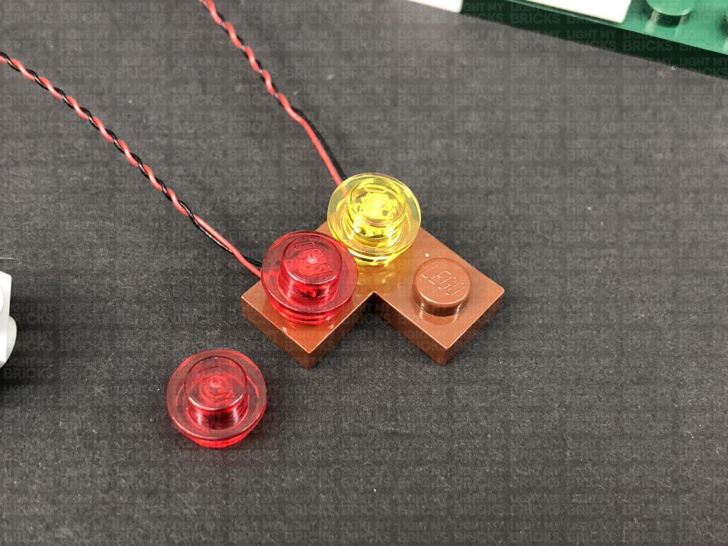
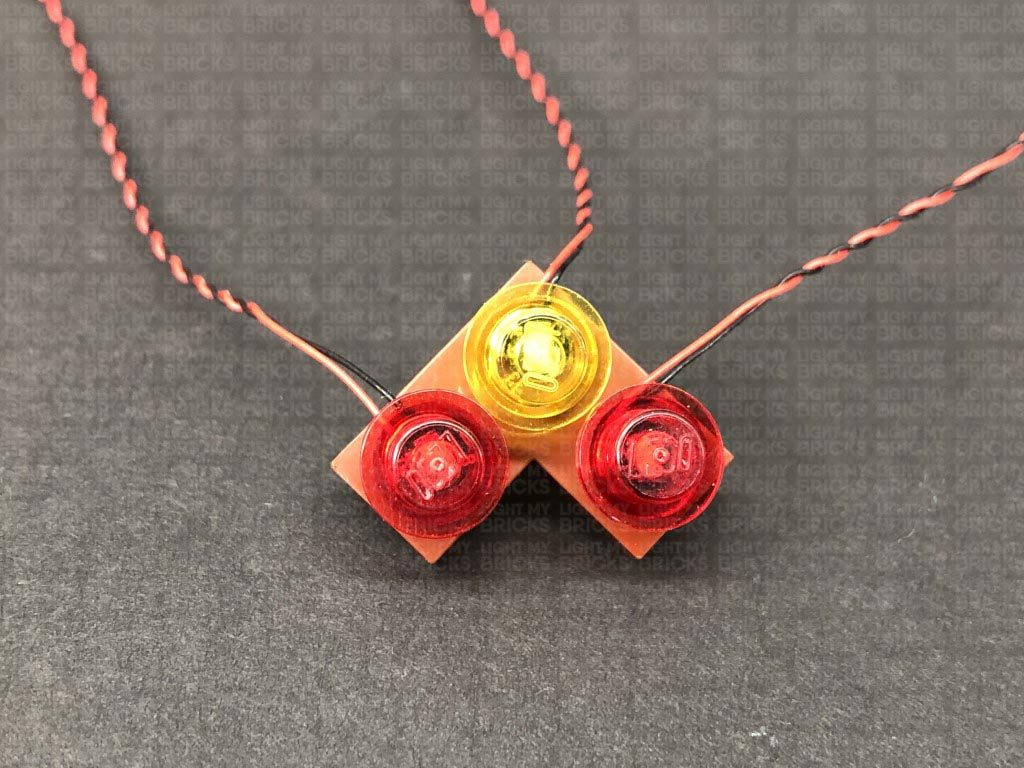
Install another 2x Flashing White 15cm Bit Lights to this section, securing them in place by reconnecting the other trans red and trans yellow round plates.
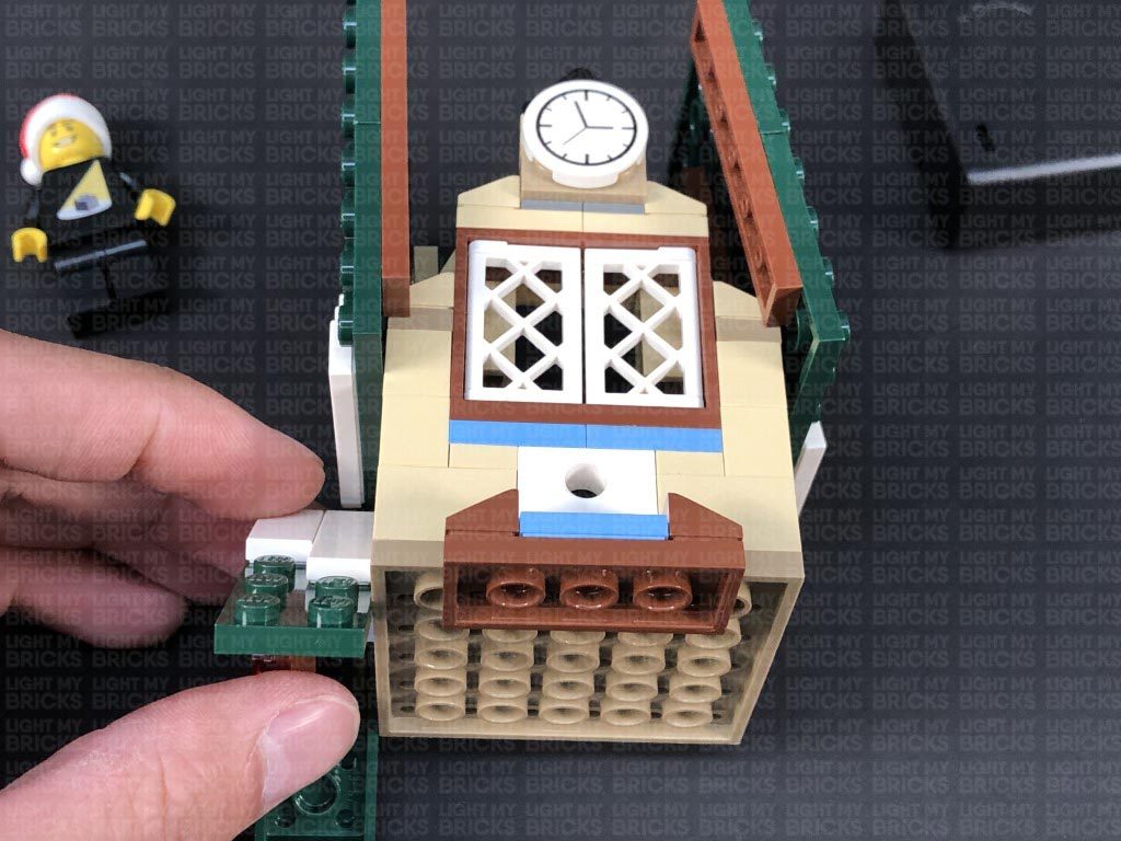
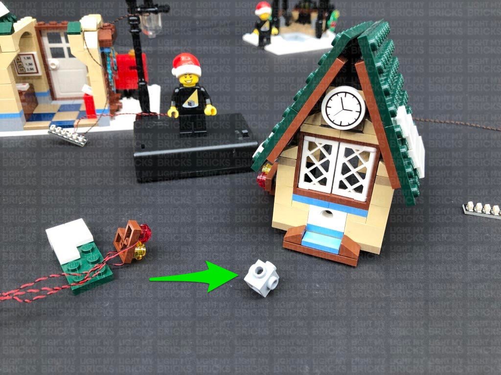
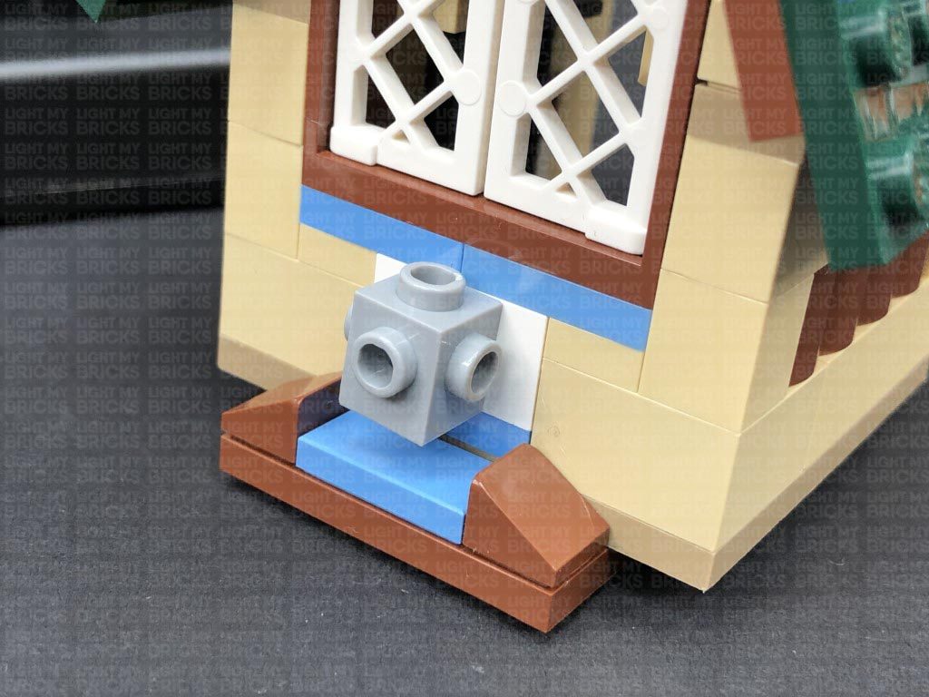
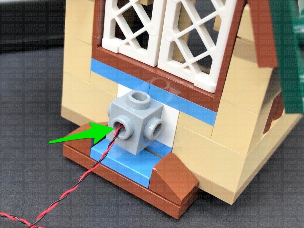
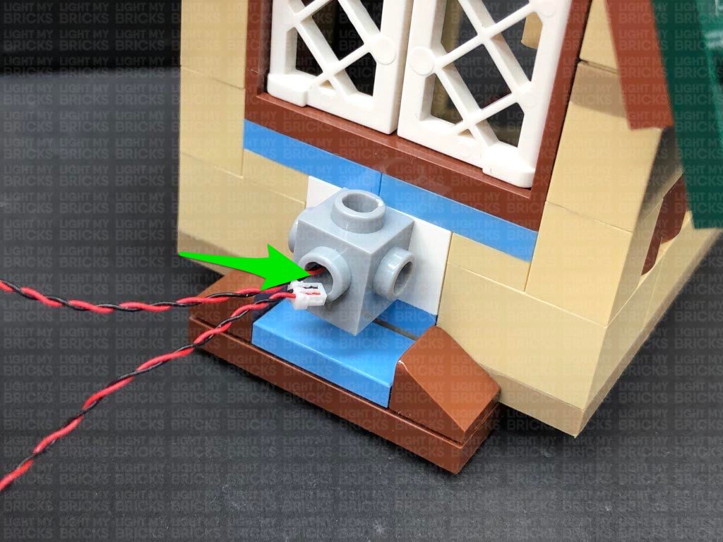
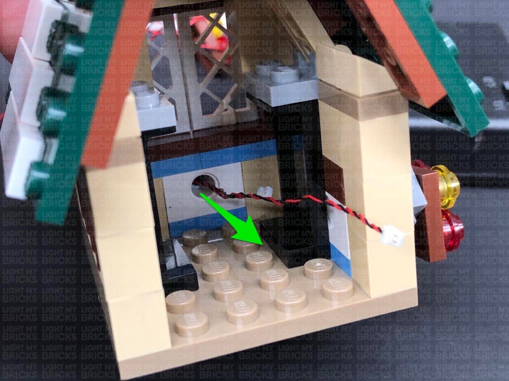
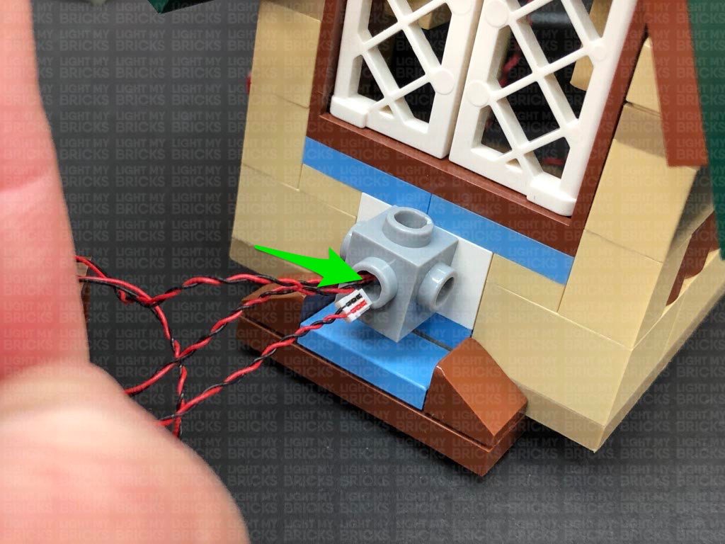
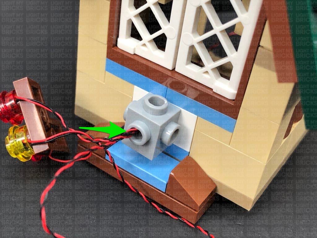
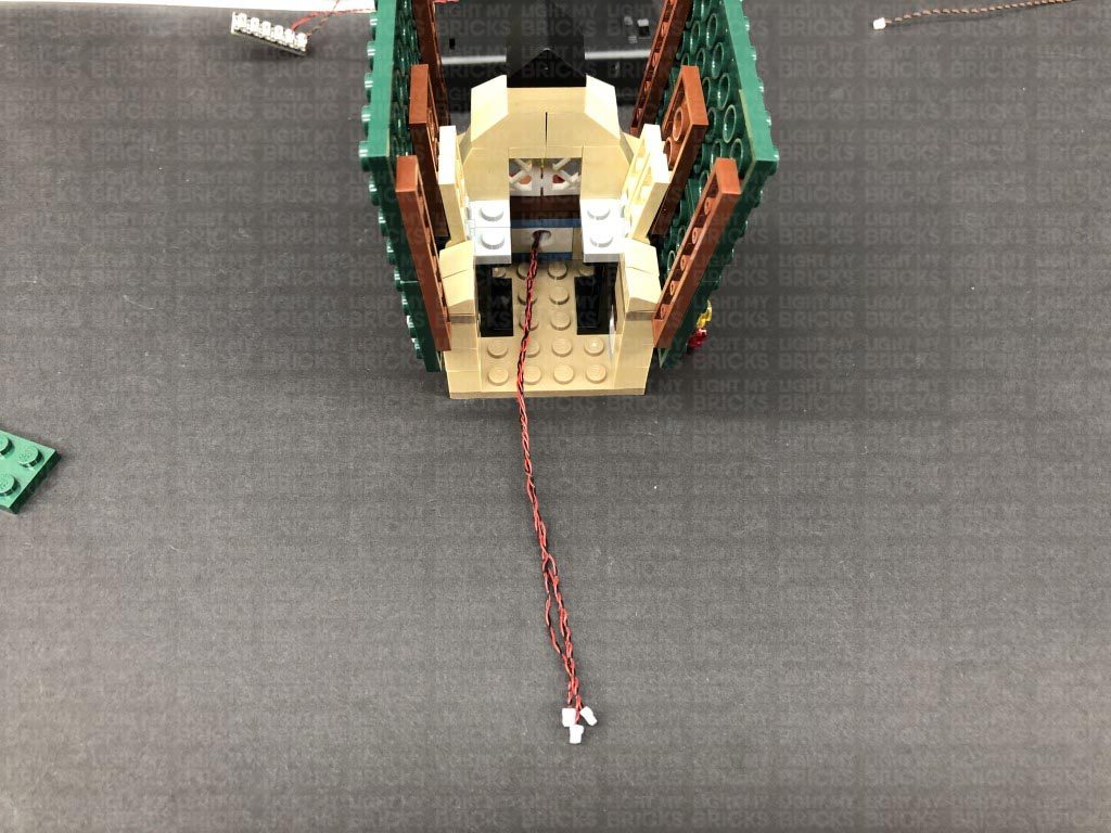
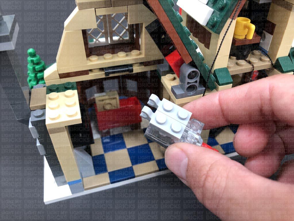
18.) Take the light grey brick and reconnect it to the front of the second level, then take one of the Bit Light cables and thread it through the front open stud on the grey brick. Pull the cable out from the inside of the building as shown below:
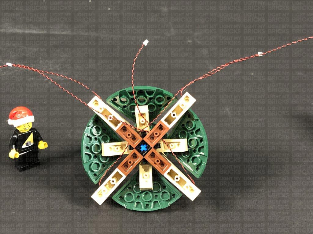
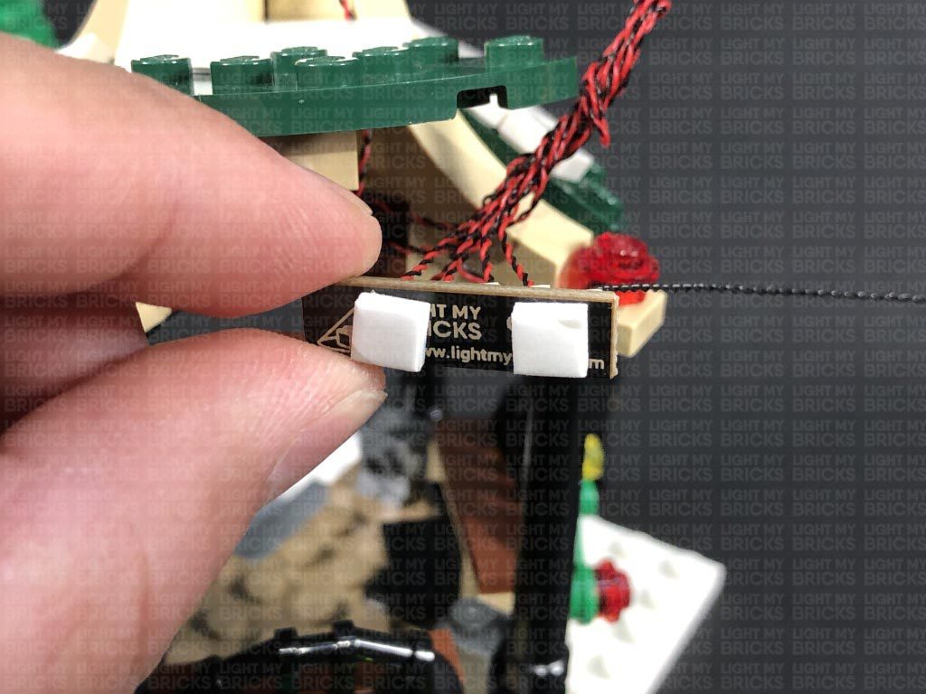
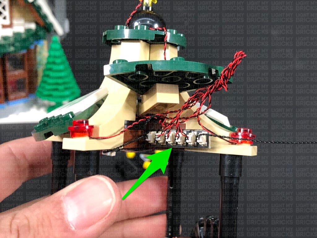
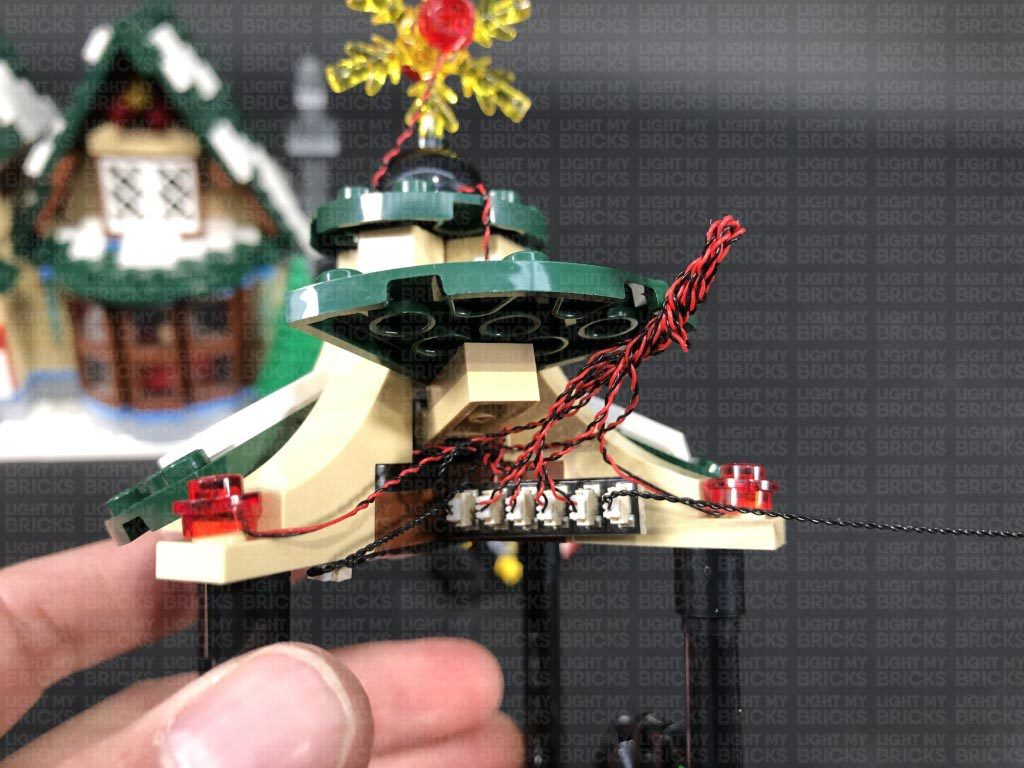
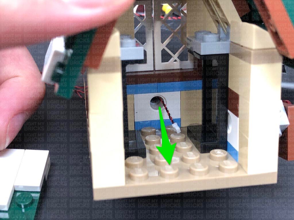
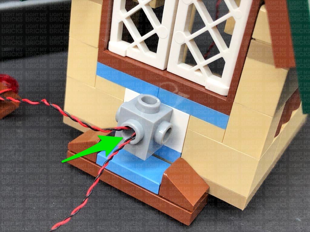
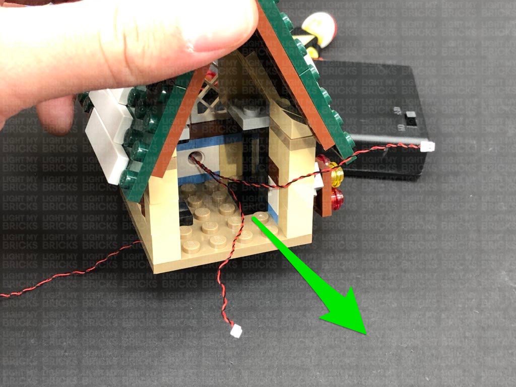
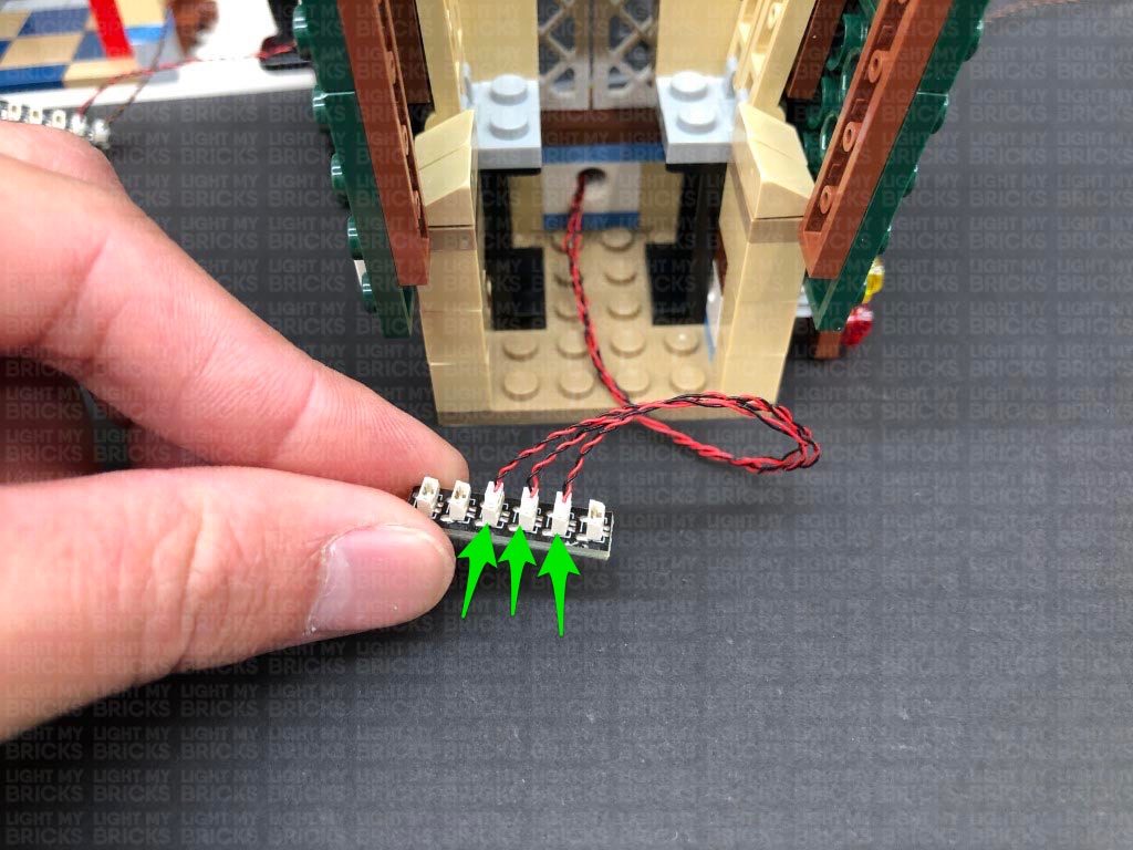
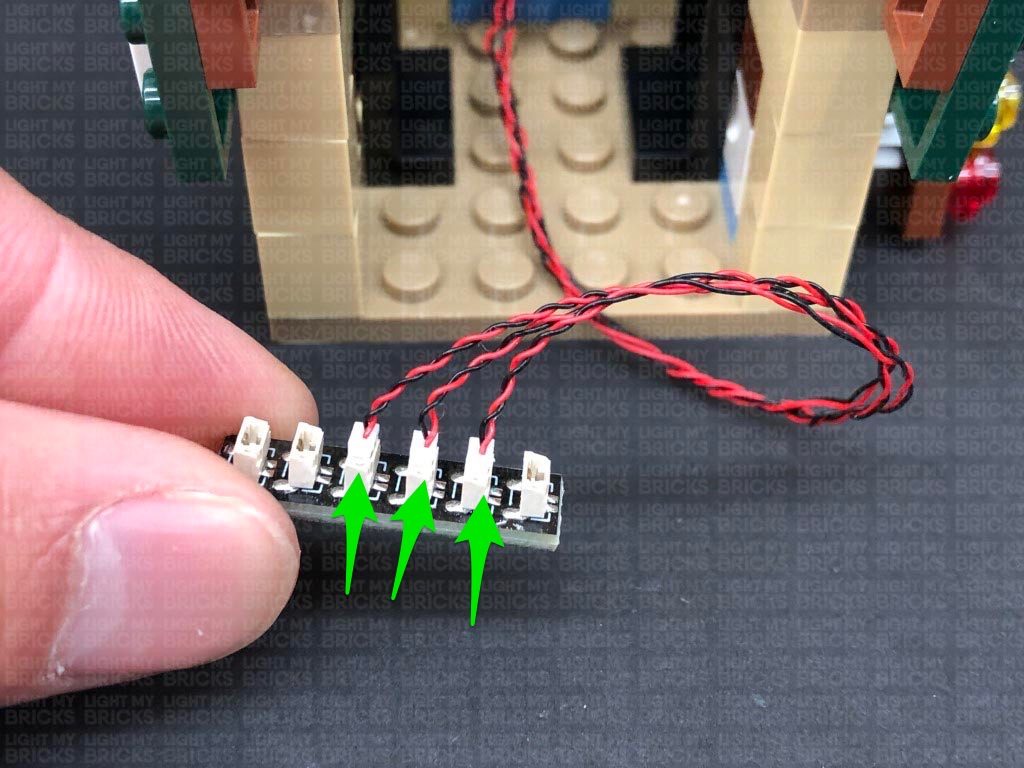
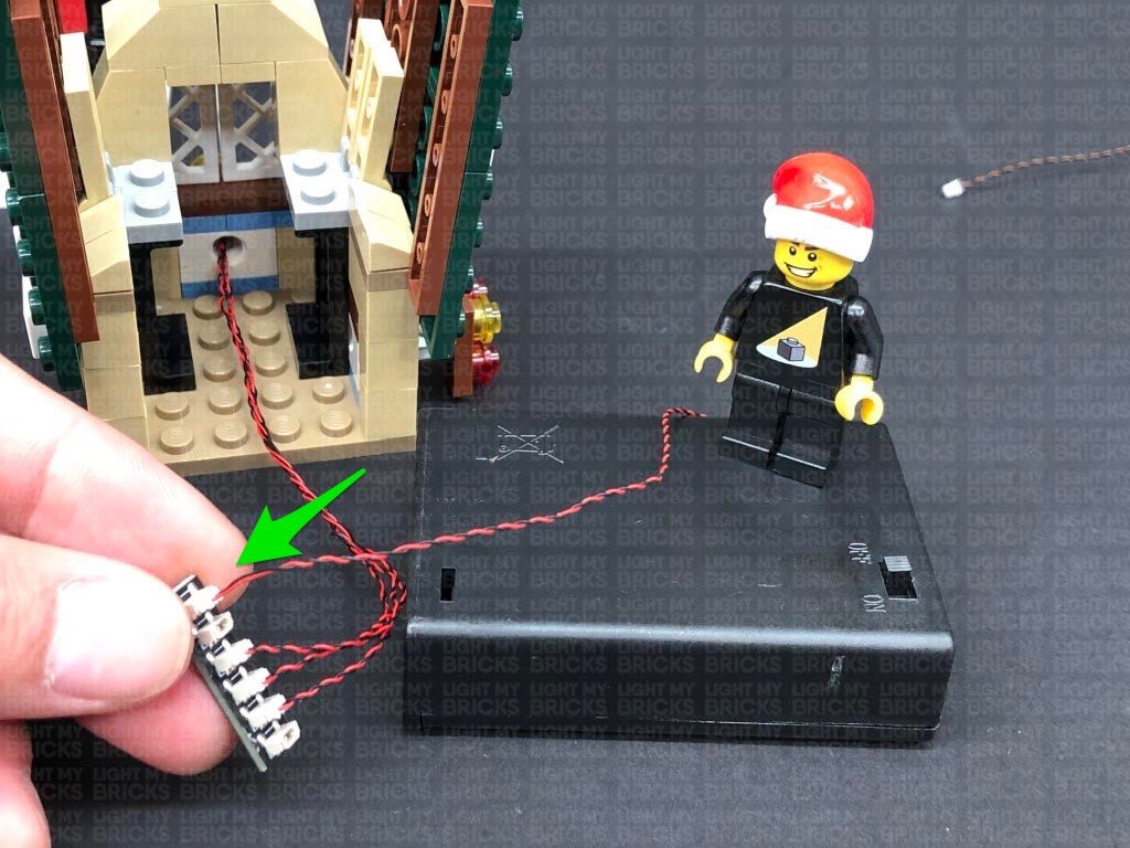
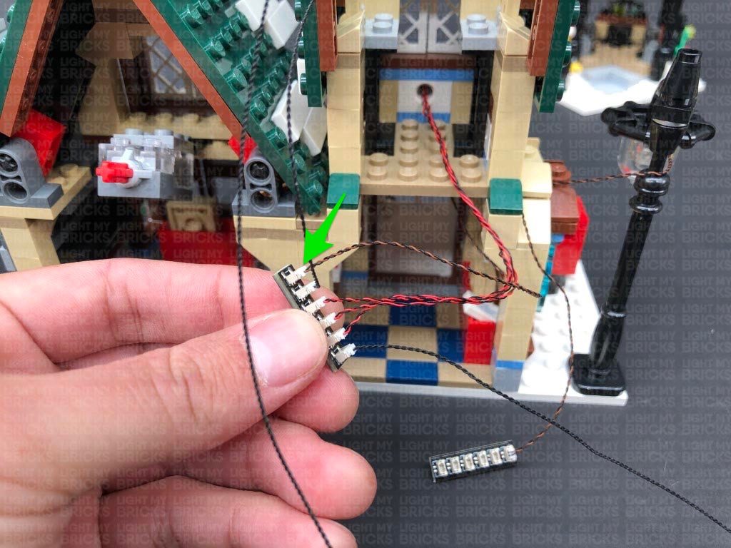
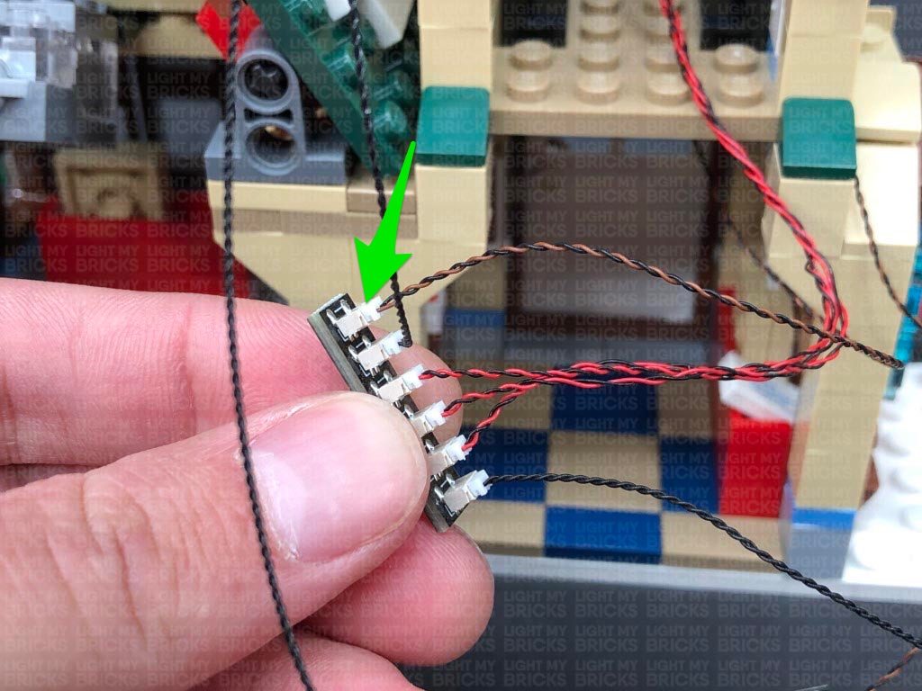
Thread the other two Bit Light cables through the same hole, one at a time, then pull all three cables all the way out from the inside of the room and reconnect the brown ‘L’ plate to the grey brick.
19.) From the back of the set, twist the three cables around each other all the way to the ends so they come together forming one larger cable, then connect them all to a new 6-Port Expansion Board. Disconnect the AA Battery Pack from the bottom floor and connect it to this expansion board. Turn it ON to test the three lights at the front of this level are working OK.
Note: If you experience any issues with the lights not working and suspect an issue with a component, please try a different port on the expansion board to verify where the fault lies (with the light or expansion board). To correct any issues with expansion board ports, please view the section addressing expansion board issues on our online troubleshooting guide.
17.) Take the second level of the post office and lift up the two sides of the roof, then disconnect the table from the inside. Turn the level around to the front and disconnect the lower level roof section with lights as shown below:
Disassemble the lower roof section as shown below, then take out a Flashing White 15cm Bit Light, and with the cable facing up, place it over the left stud on the brown ‘L’ plate. Secure the Bit Light in place by reconnecting one of the trans red round plates over the top.
Install another 2x Flashing White 15cm Bit Lights to this section, securing them in place by reconnecting the other trans red and trans yellow round plates.
18.) Take the light grey brick and reconnect it to the front of the second level, then take one of the Bit Light cables and thread it through the front open stud on the grey brick. Pull the cable out from the inside of the building as shown below:
Thread the other two Bit Light cables through the same hole, one at a time, then pull all three cables all the way out from the inside of the room and reconnect the brown ‘L’ plate to the grey brick.
19.) From the back of the set, twist the three cables around each other all the way to the ends so they come together forming one larger cable, then connect them all to a new 6-Port Expansion Board. Disconnect the AA Battery Pack from the bottom floor and connect it to this expansion board. Turn it ON to test the three lights at the front of this level are working OK.
 Note: If you experience any issues with the lights not working and suspect an issue with a component, please try a different port on the expansion board to verify where the fault lies (with the light or expansion board). To correct any issues with expansion board ports, please view the section addressing expansion board issues on our online troubleshooting guide.
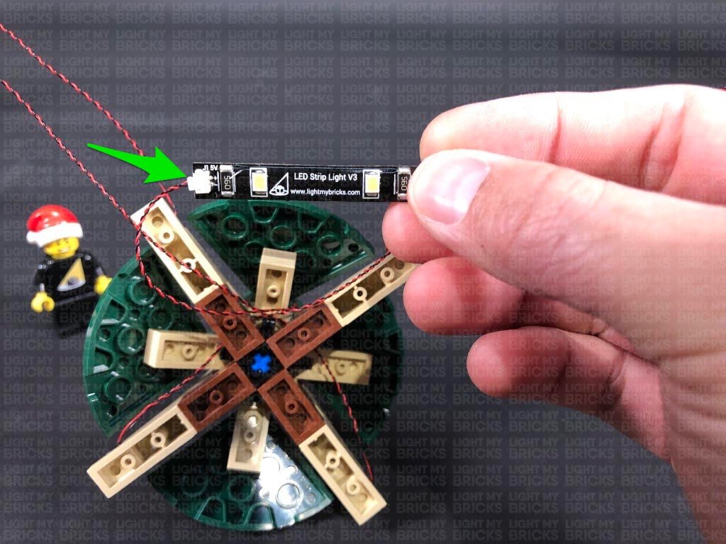
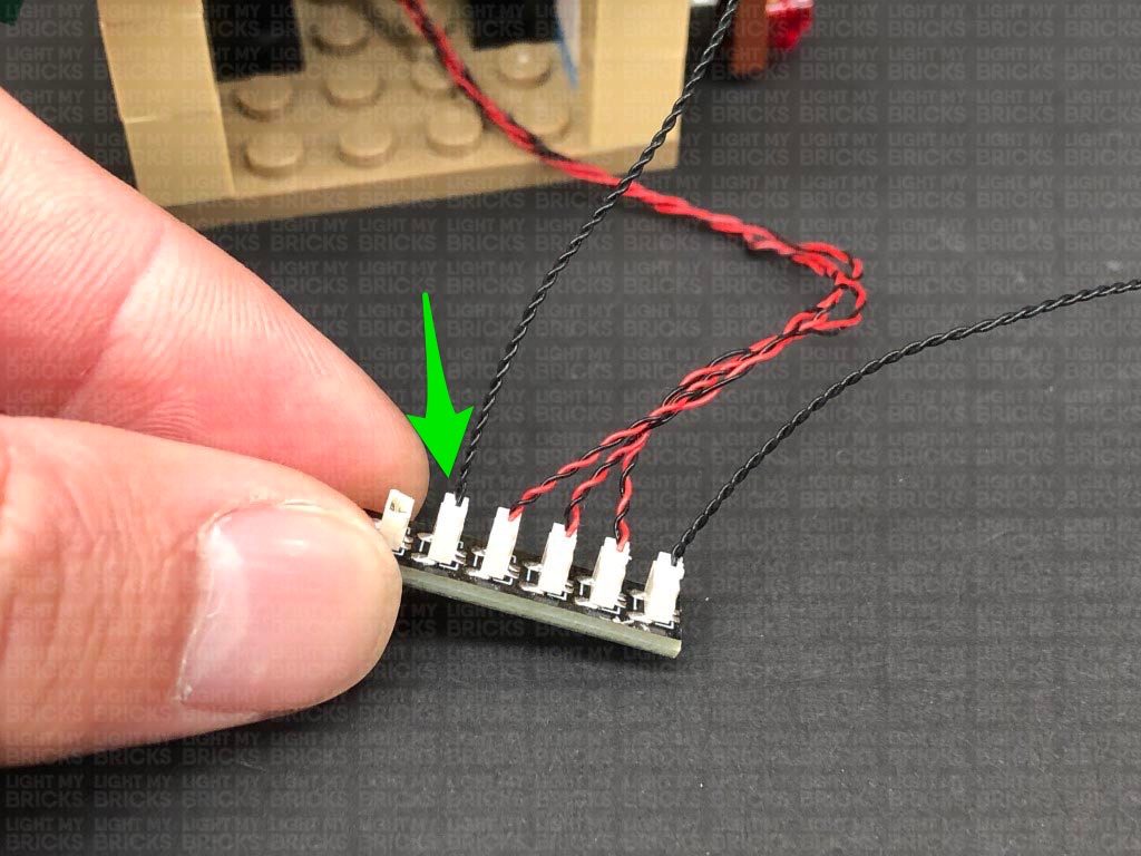
Disconnect the Battery Pack and connect 2x 15cm Connecting Cables to the 6-Port Expansion Board. Connect the other end of one of the 15cm Cables to a White Strip Light.
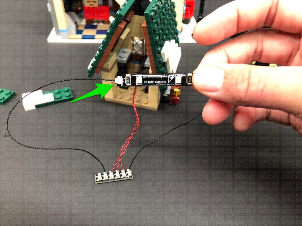
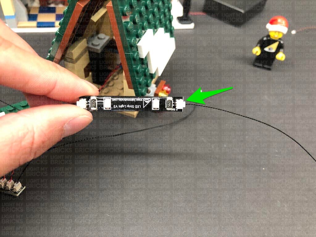
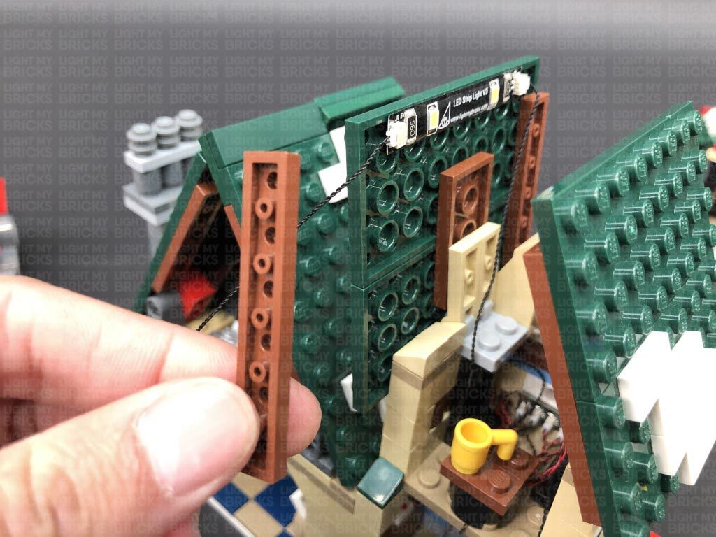
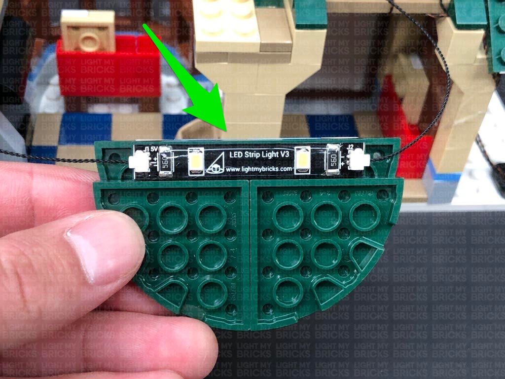
20.) Connect a new 15cm Connecting Cable to the other end of the White Strip Light from the previous step, then using it’s adhesive backing, stick the Strip Light to the top of the left roof panel ensuring the 15cm cable we just connected is facing the back (toward you).
Tuck the 15cm Connecting Cable facing the front, down behind the left side of the middle section..
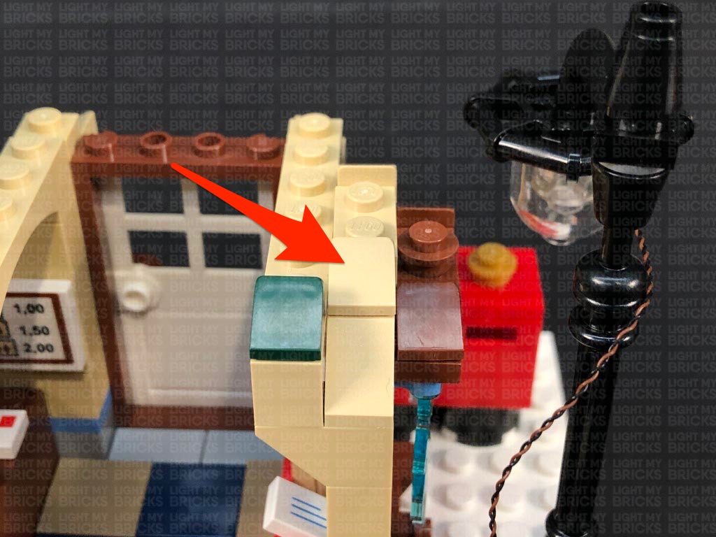
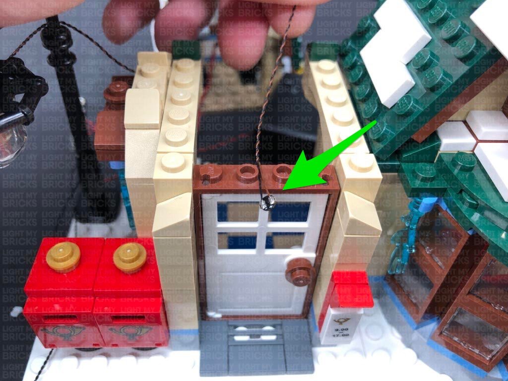
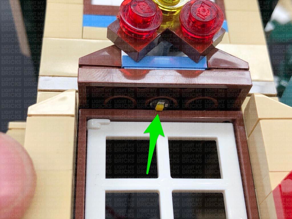
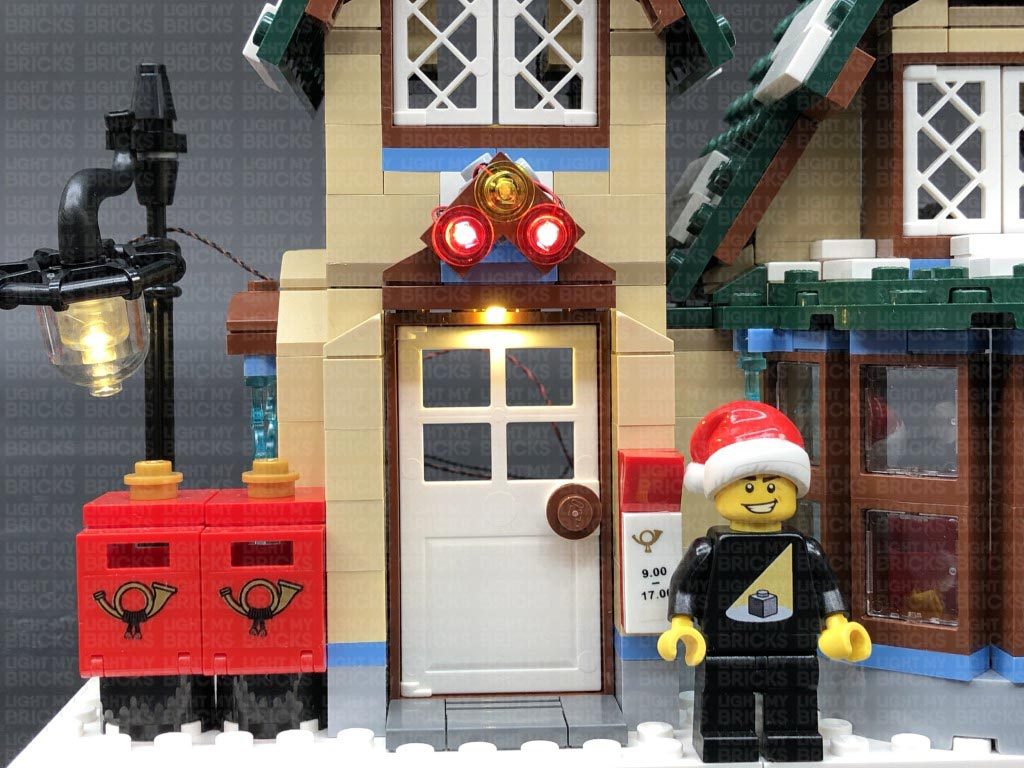
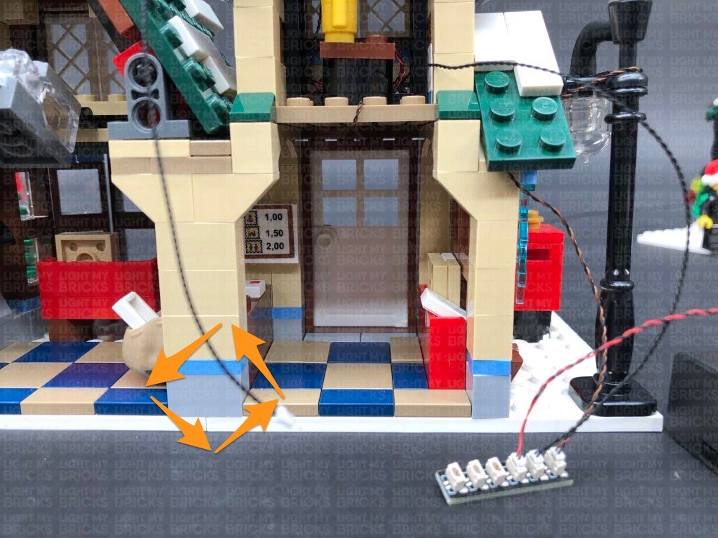
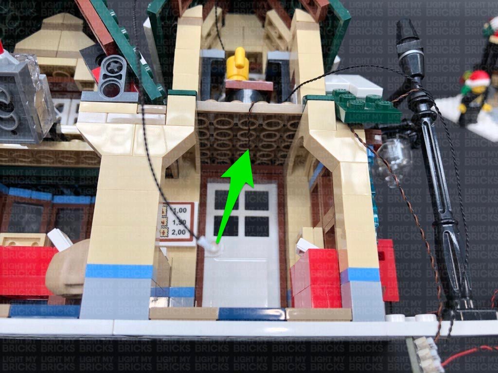
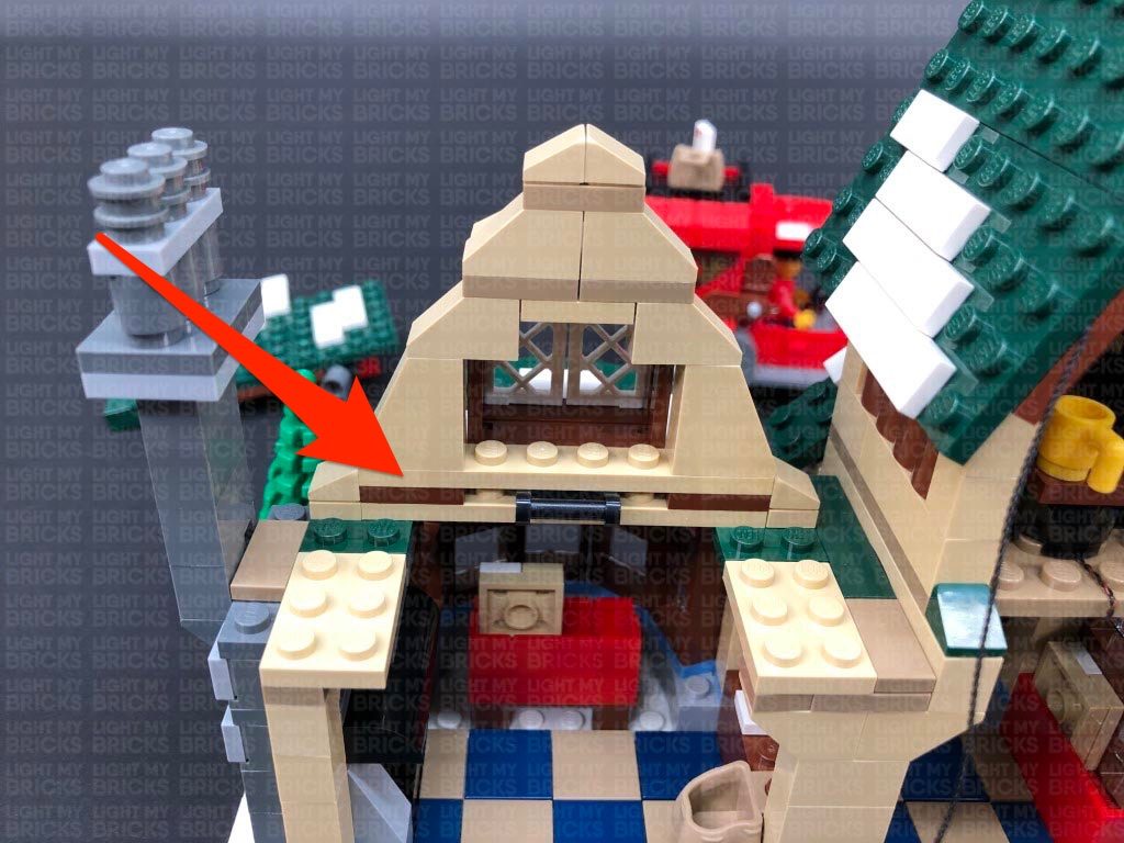
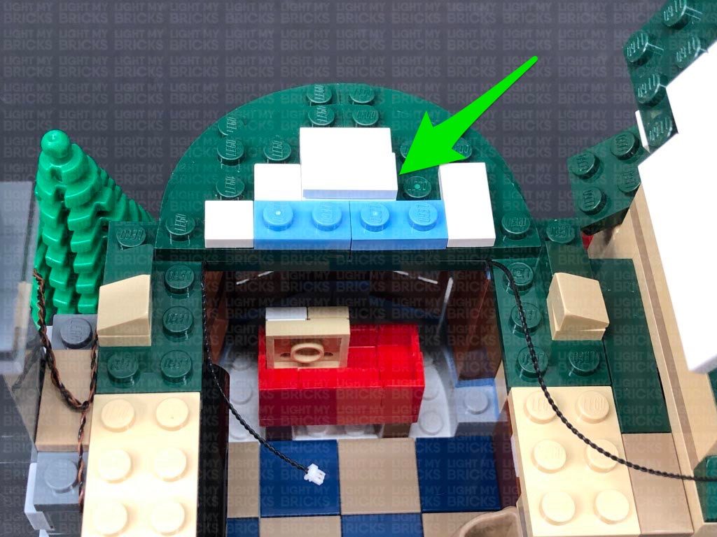
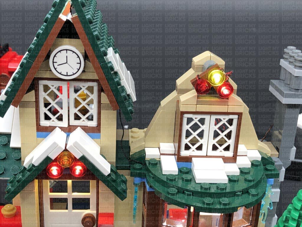
21.) Turn this section around to the front, then take a White 15cm Bit Light and with the LED facing down and cable facing the back, place it just over the top of the door frame as shown below:
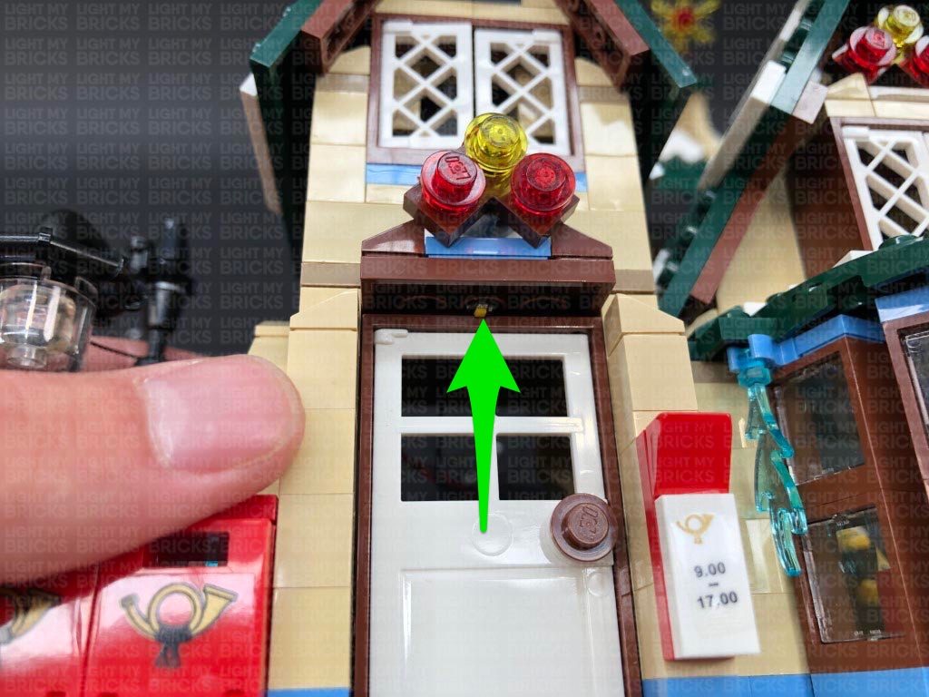
Take the second level and reconnect it to the building, over the bit light cable. Looking from underneath, push the bit light inside the brown stud hole in the middle. The LED should be just peaking out over the top of the front door frame as shown below.
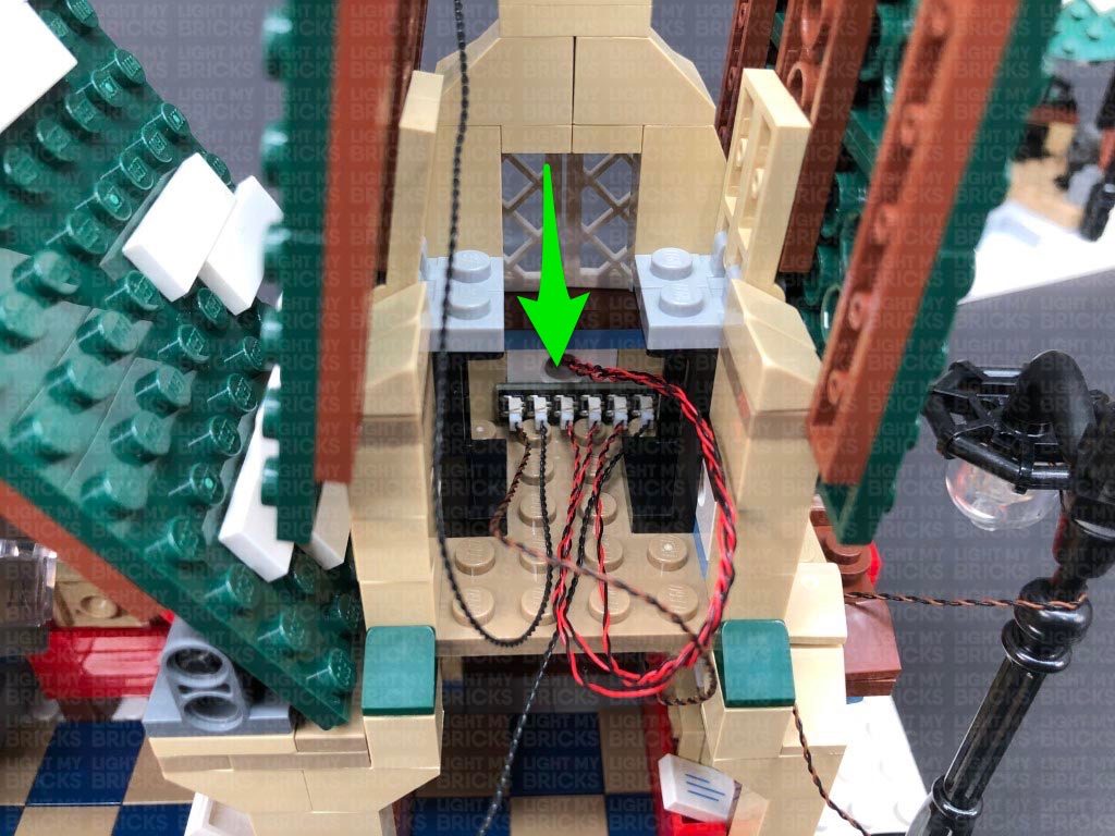
Turn the set around to the back and connect the Bit Light cable from the front door to the 6-Port Expansion Board on the second level.
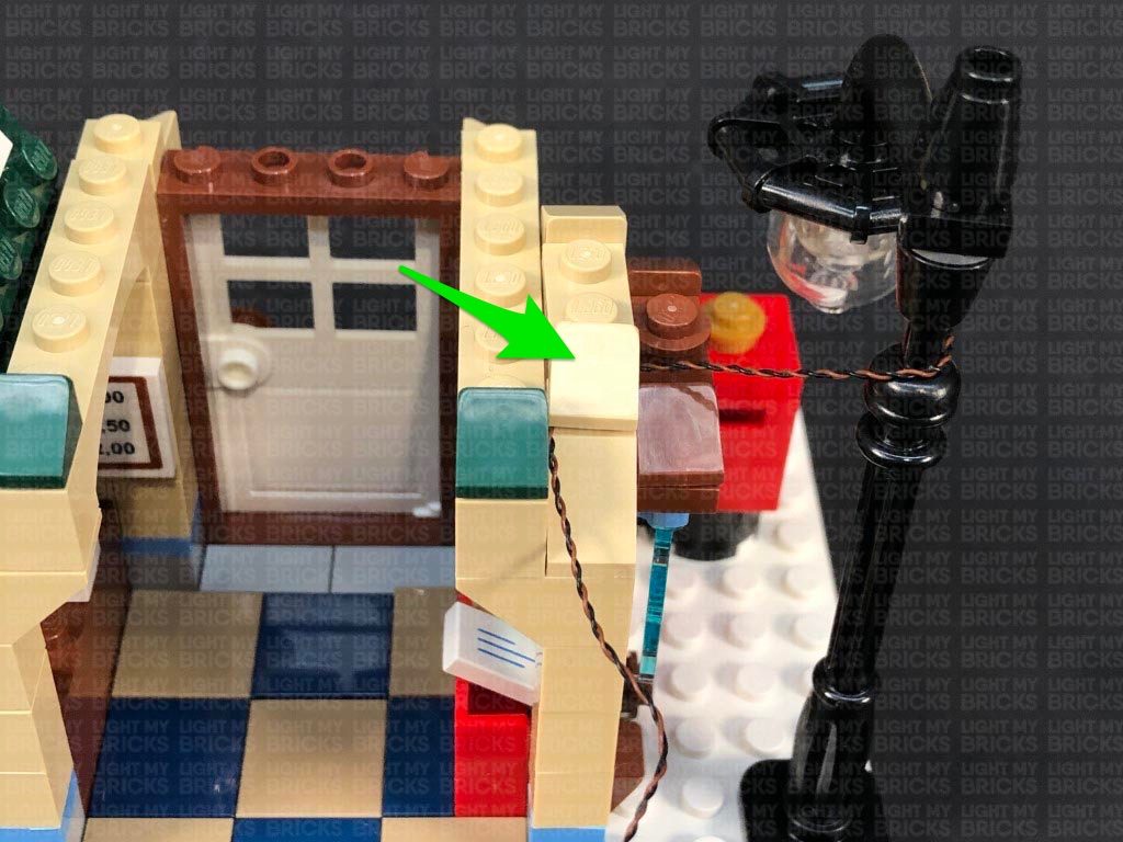
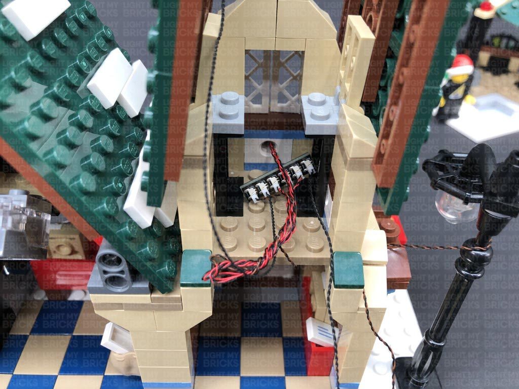
21.) Neatly place the 6-Port Expansion against the wall, then neaten up all the cables by folding and twisting them around each other into a neat bunch. Tuck the bunched up cables in against the wall before reconnecting the table ensuring the front door bit light is laid in between studs underneath.
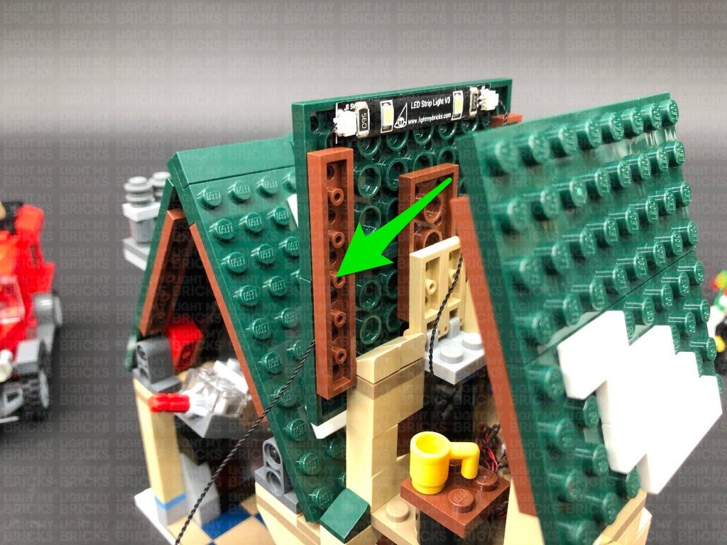
Secure the 15cm Connecting Cable from the Strip Light underneath the following brown 1×6 plate on the left. Ensure the cable is secured closer toward the bottom as shown below, then fold in the two roof panels.
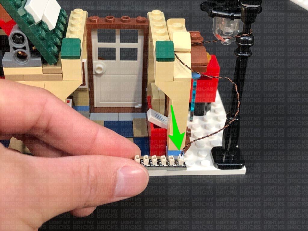
Bring the 15cm Connecting Cable from the 6-port expansion board on the second level down and connect it to the 6-Port Expansion Board on the ground floor. Connect the AA Battery Pack to the same expansion board, then turn it ON to test all the lights installed so far are working OK.
Note: If you experience any issues with the lights not working and suspect an issue with a component, please try a different port on the expansion board to verify where the fault lies (with the light or expansion board). To correct any issues with expansion board ports, please view the section addressing expansion board issues on our online troubleshooting guide.
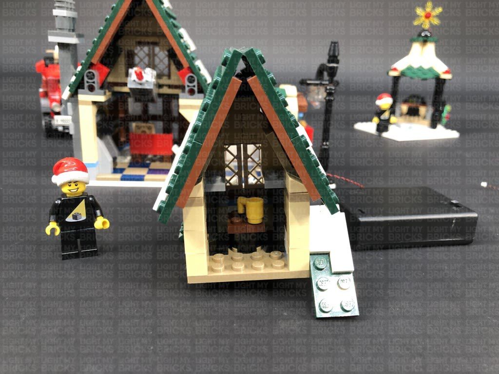
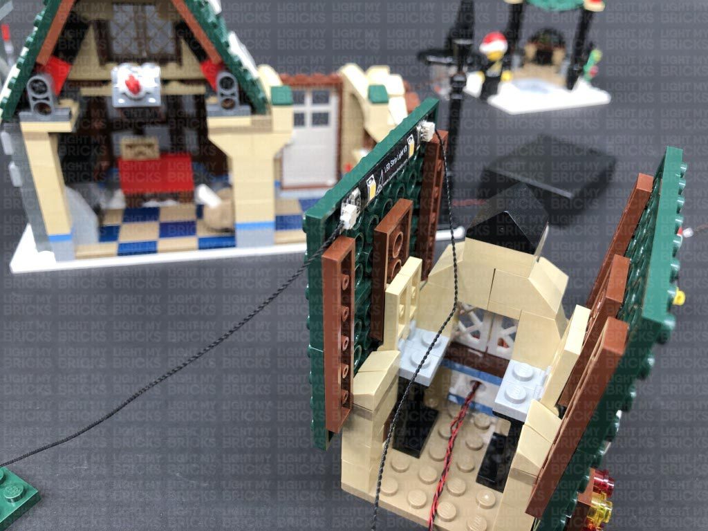
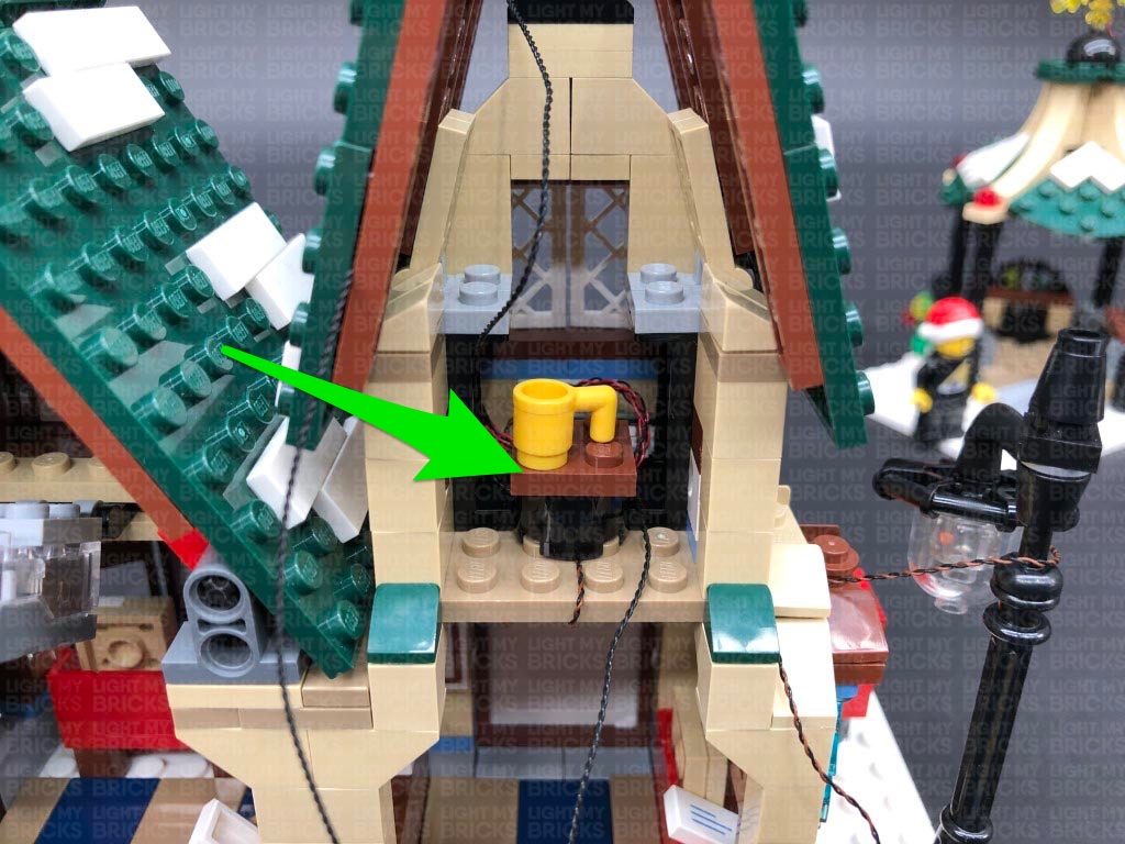
22.) Reconnect the two roof pieces above the front door lights, then turn the set around to the back again for us to install a light to inside of the ground floor.
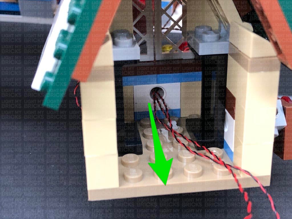
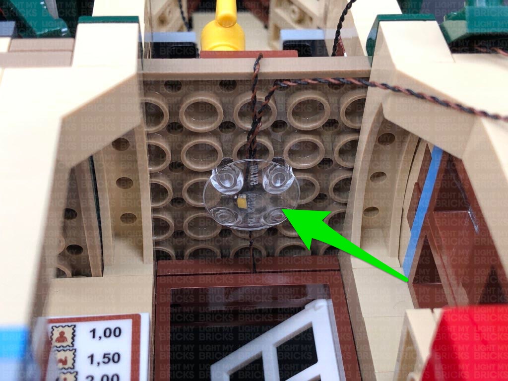
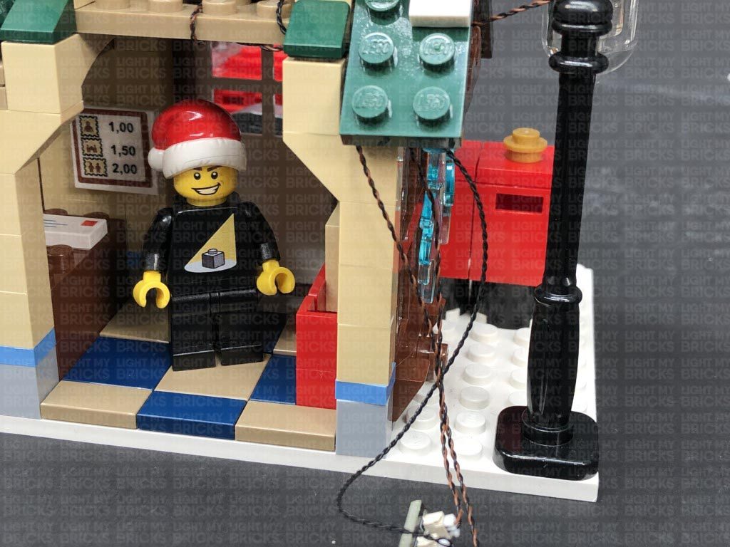
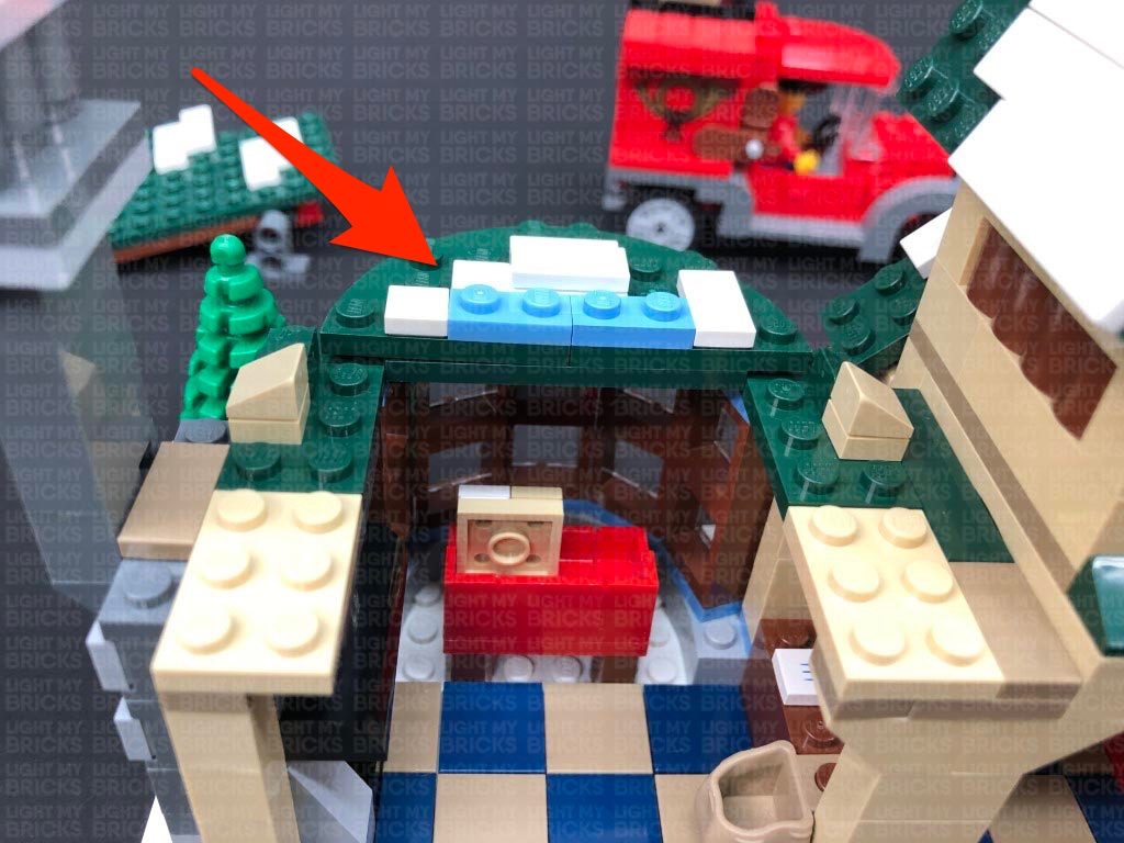
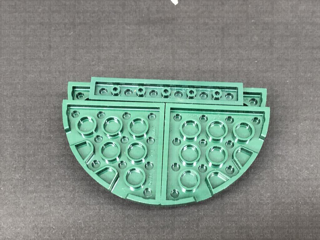
Take a White 15cm Bit Light and with the cable facing toward you and the LED facing down, place it in the centre, underneath the base plate of the second floor. Secure the Bit Light in place by connecting a provided LEGO Trans Clear Plate w Rounded Bottom 2×2 over the top as shown below:
Note: If you experience any issues with the lights not working and suspect an issue with a component, please try a different port on the expansion board to verify where the fault lies (with the light or expansion board). To correct any issues with expansion board ports, please view the section addressing expansion board issues on our online troubleshooting guide.
Disconnect the Battery Pack and connect 2x 15cm Connecting Cables to the 6-Port Expansion Board. Connect the other end of one of the 15cm Cables to a White Strip Light.
20.) Connect a new 15cm Connecting Cable to the other end of the White Strip Light from the previous step, then using it’s adhesive backing, stick the Strip Light to the top of the left roof panel ensuring the 15cm cable we just connected is facing the back (toward you).
Tuck the 15cm Connecting Cable facing the front, down behind the left side of the middle section..
21.) Turn this section around to the front, then take a White 15cm Bit Light and with the LED facing down and cable facing the back, place it just over the top of the door frame as shown below:
Take the second level and reconnect it to the building, over the bit light cable. Looking from underneath, push the bit light inside the brown stud hole in the middle. The LED should be just peaking out over the top of the front door frame as shown below.
Turn the set around to the back and connect the Bit Light cable from the front door to the 6-Port Expansion Board on the second level.
21.) Neatly place the 6-Port Expansion against the wall, then neaten up all the cables by folding and twisting them around each other into a neat bunch. Tuck the bunched up cables in against the wall before reconnecting the table ensuring the front door bit light is laid in between studs underneath.
Secure the 15cm Connecting Cable from the Strip Light underneath the following brown 1×6 plate on the left. Ensure the cable is secured closer toward the bottom as shown below, then fold in the two roof panels.
Bring the 15cm Connecting Cable from the 6-port expansion board on the second level down and connect it to the 6-Port Expansion Board on the ground floor. Connect the AA Battery Pack to the same expansion board, then turn it ON to test all the lights installed so far are working OK.
Note: If you experience any issues with the lights not working and suspect an issue with a component, please try a different port on the expansion board to verify where the fault lies (with the light or expansion board). To correct any issues with expansion board ports, please view the section addressing expansion board issues on our online troubleshooting guide.
22.) Reconnect the two roof pieces above the front door lights, then turn the set around to the back again for us to install a light to inside of the ground floor.
Take a White 15cm Bit Light and with the cable facing toward you and the LED facing down, place it in the centre, underneath the base plate of the second floor. Secure the Bit Light in place by connecting a provided LEGO Trans Clear Plate w Rounded Bottom 2×2 over the top as shown below:
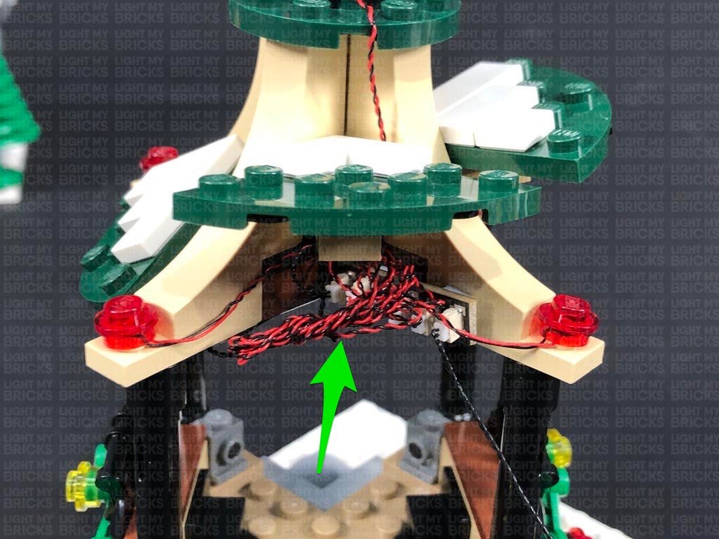
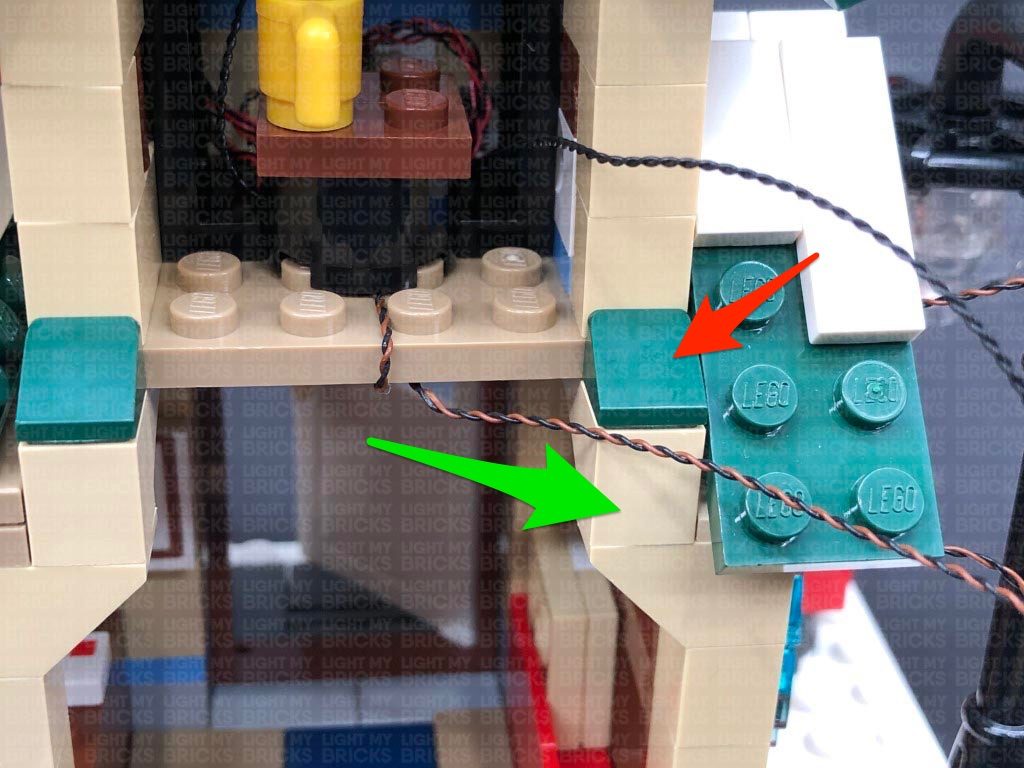
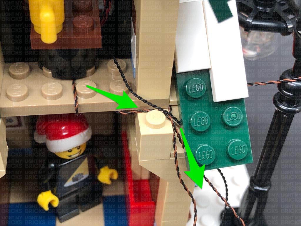
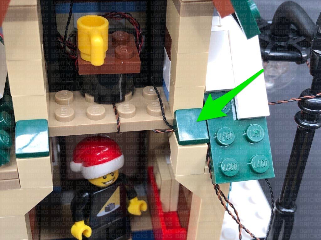
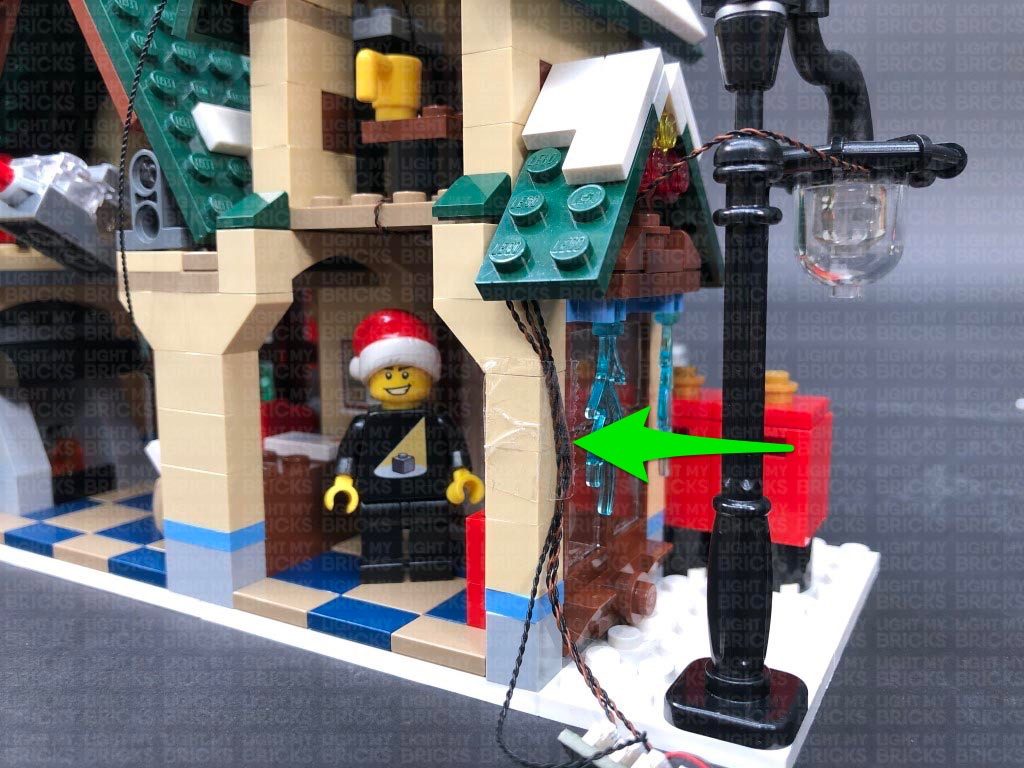
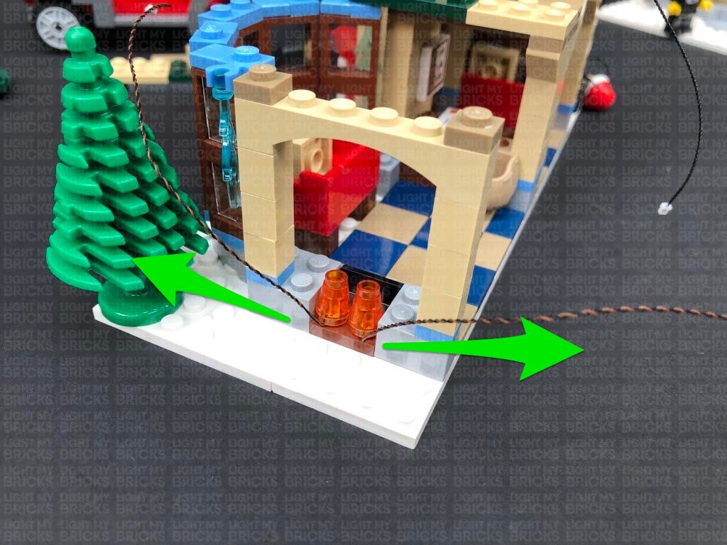
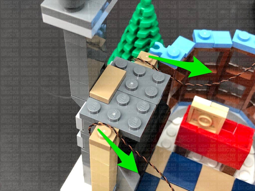
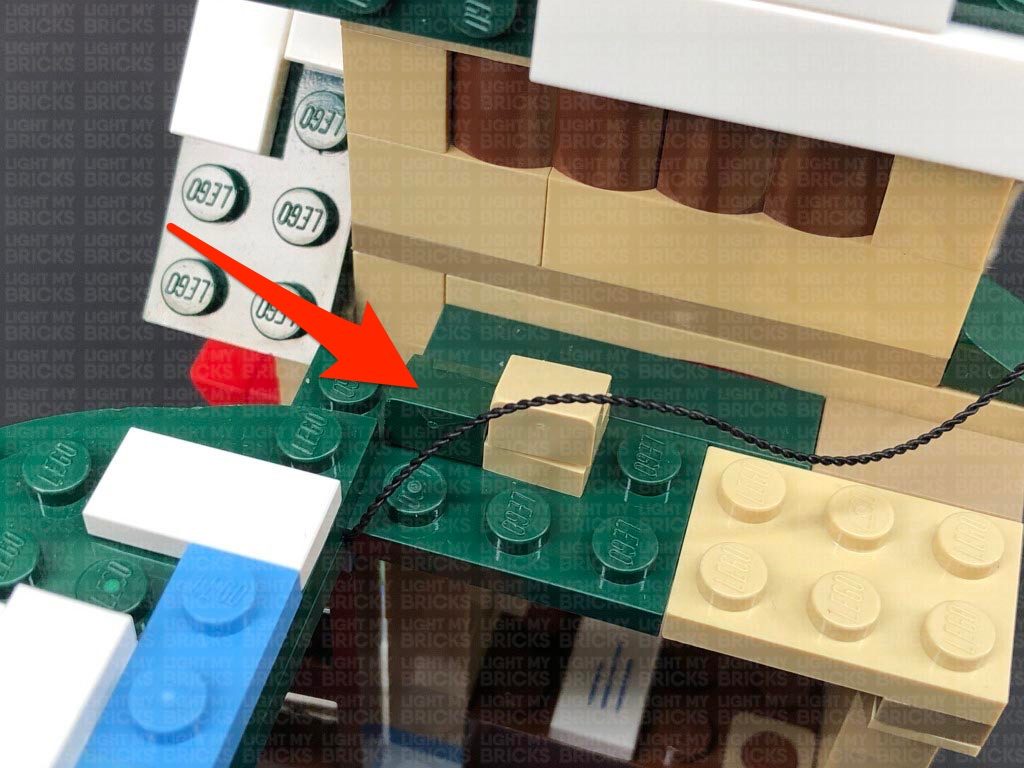
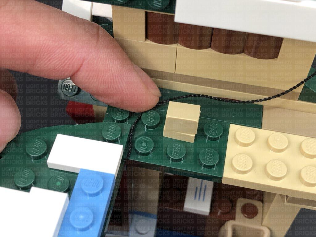
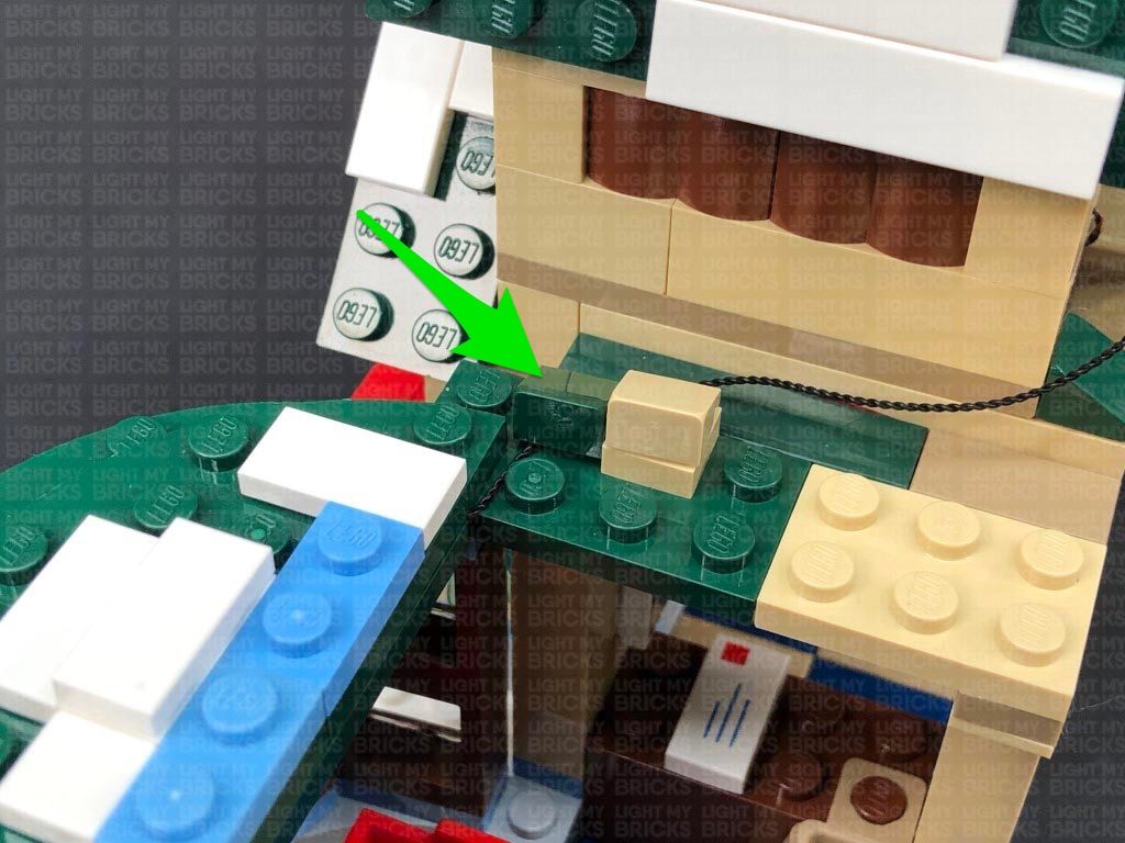
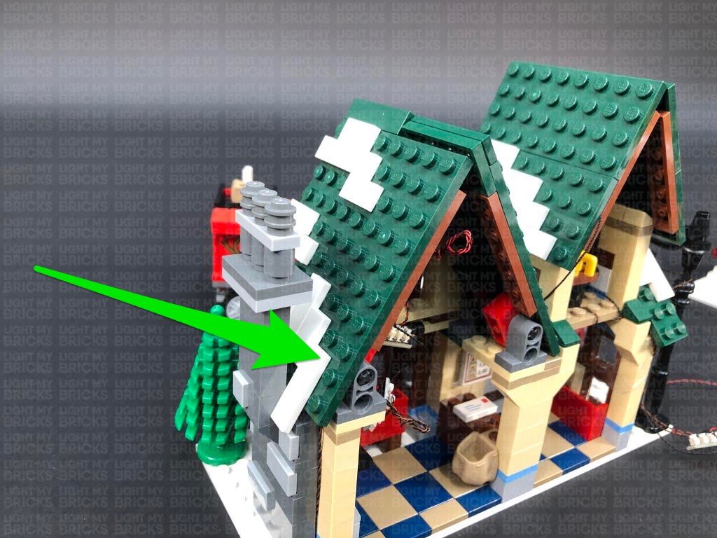
 23.) Bring the cable across to the right and secure it, as well as the 15m connecting cable, underneath the dark green angled tile, ensuring you first lay them around the stud.
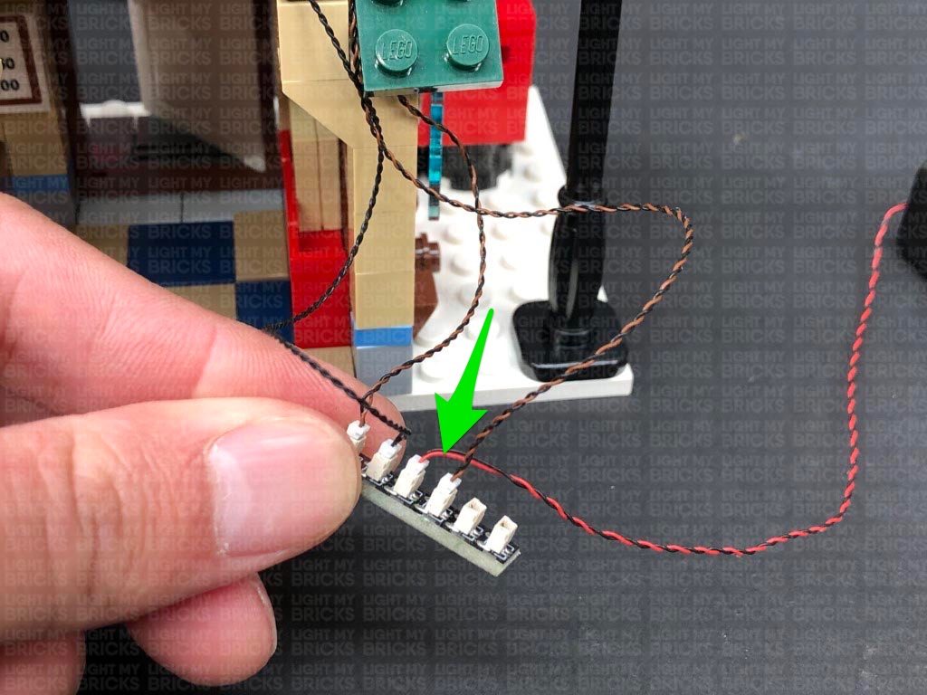
Connect the Bit Light to the 6-Port Expansion Board below, then turn the battery pack ON again to test the internal light is working OK.
Bring all the cables together and secure them to the outside of the wall using tape.
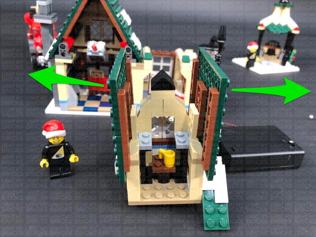
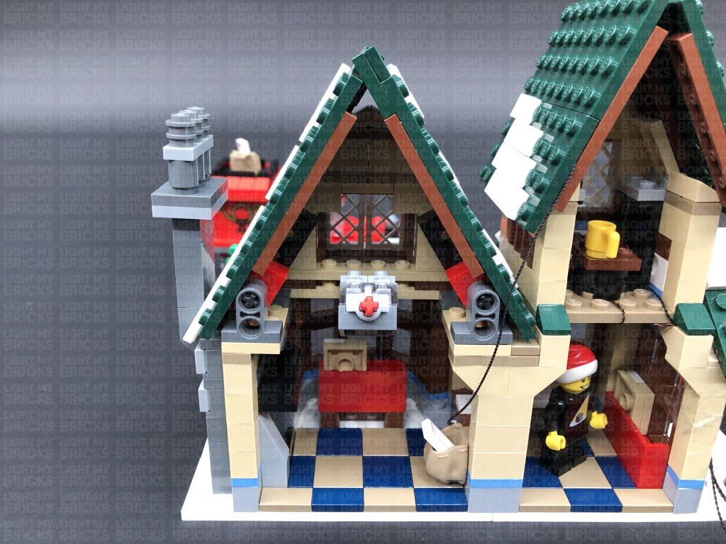
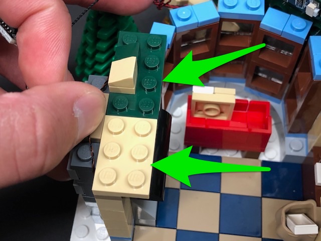
24.) We will now light up the left section of the post office. Follow the below images to remove all the sections surrounding the top of this floor.
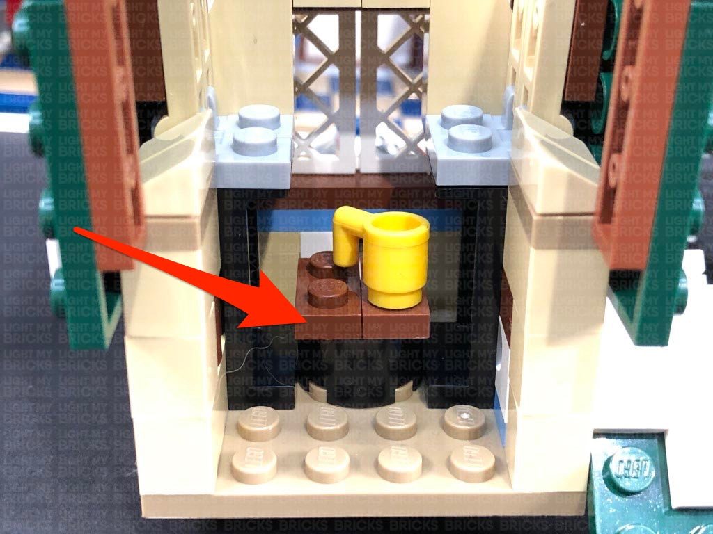
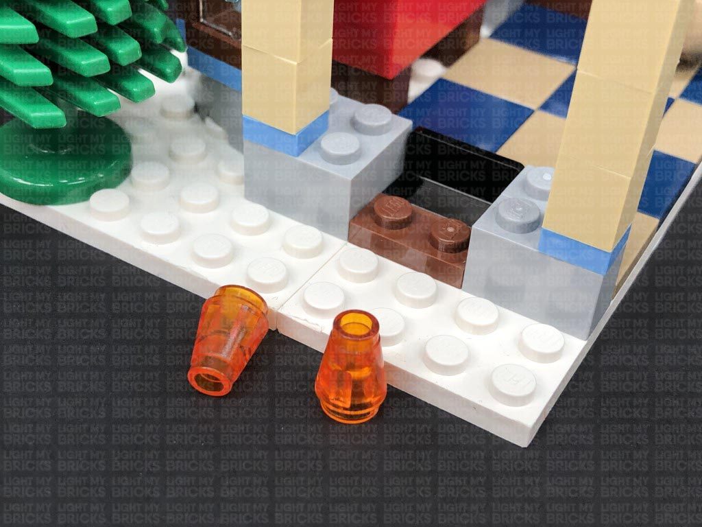
25.) Continue to remove the following sections in order for us to install lights to the fire place.
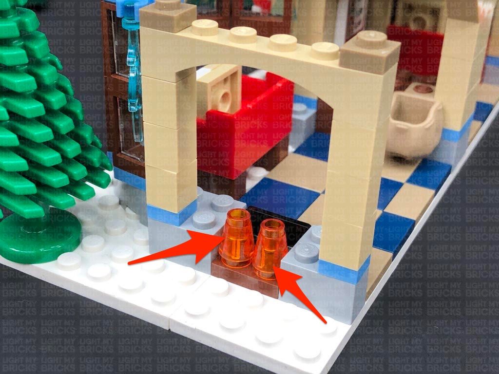
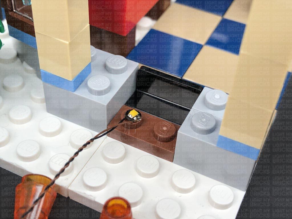
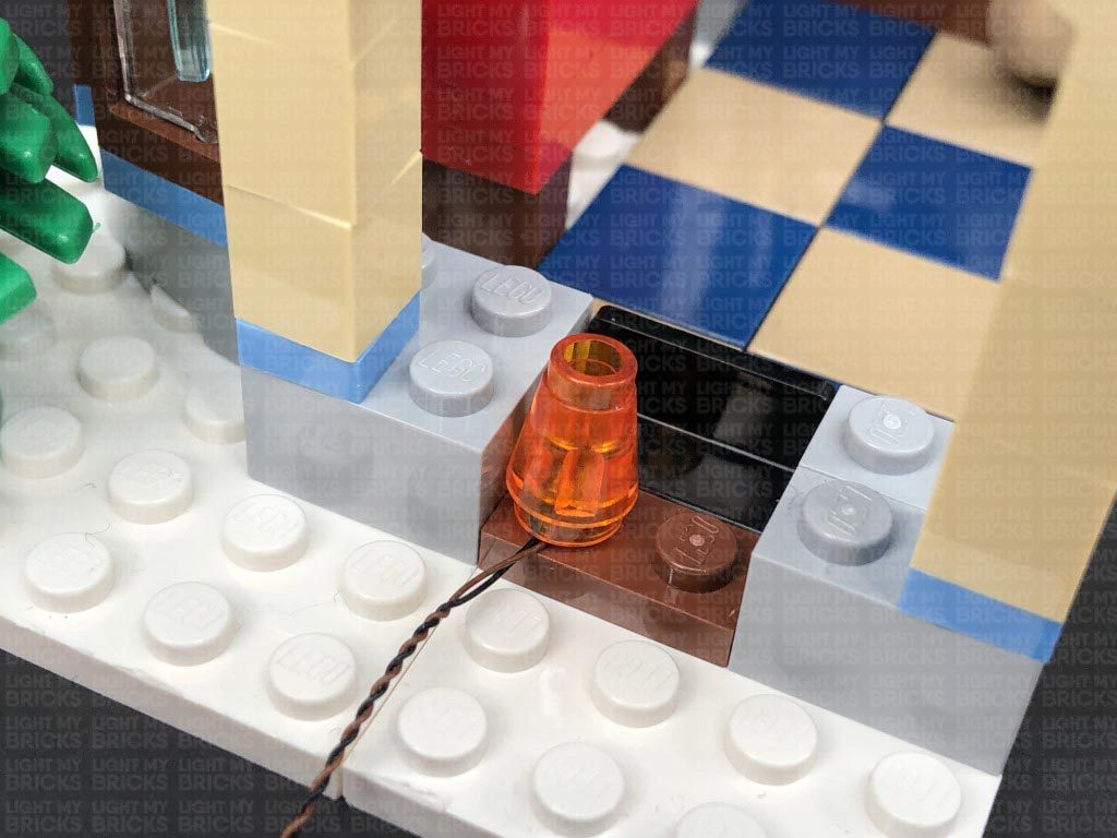
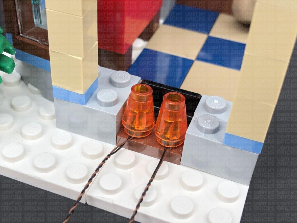
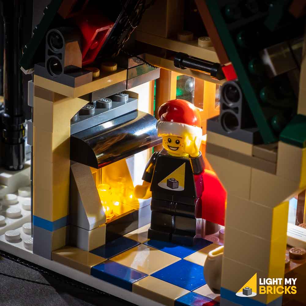
Take a White 15cm Bit Light and with the cable facing the outside, place it over the left brown stud. Secure the Bit Light in place by reconnecting one of the trans orange pieces over the top. Use the same method to install another White 15cm Bit Light to the other brown stud.
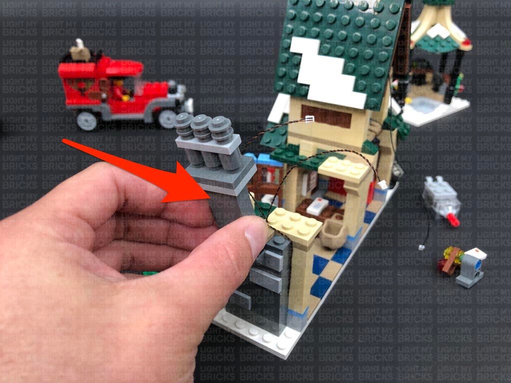
26.) Pull the Bit Light cables out to each side before reconnecting the chimney section.
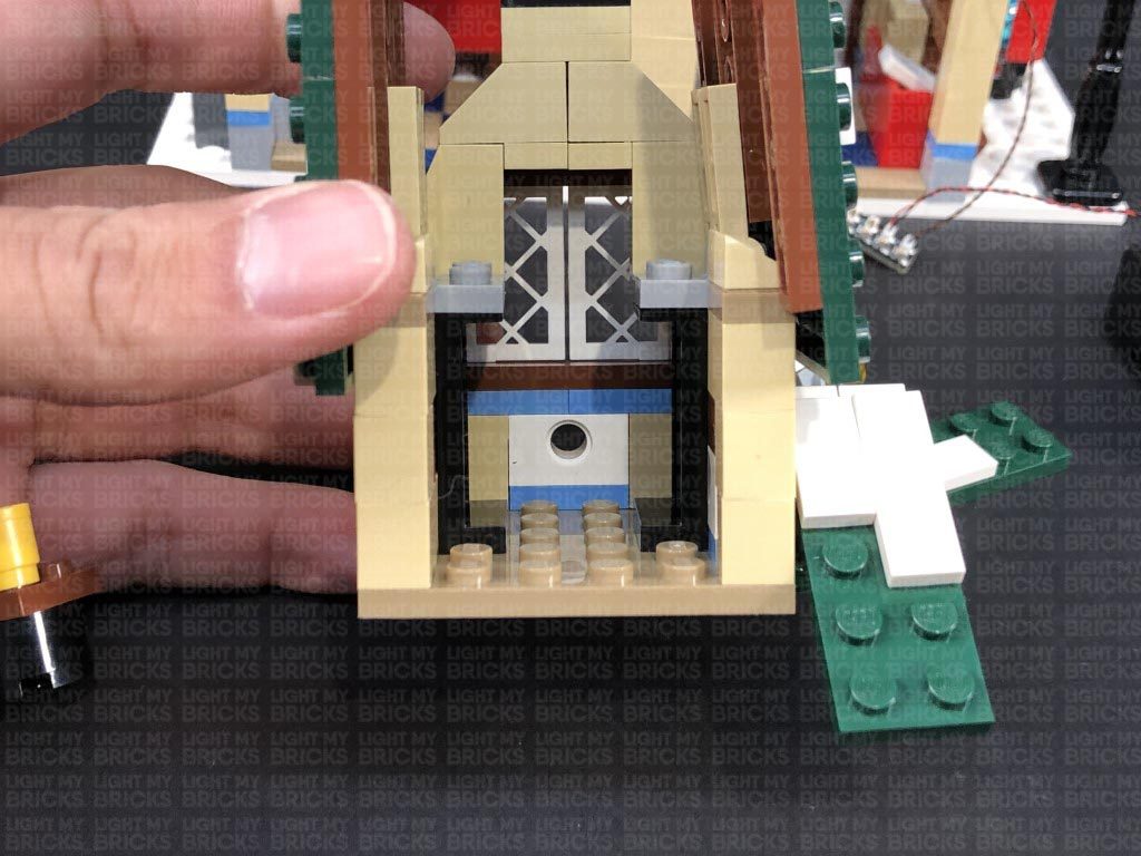
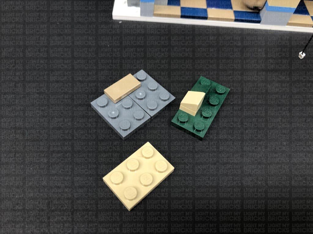
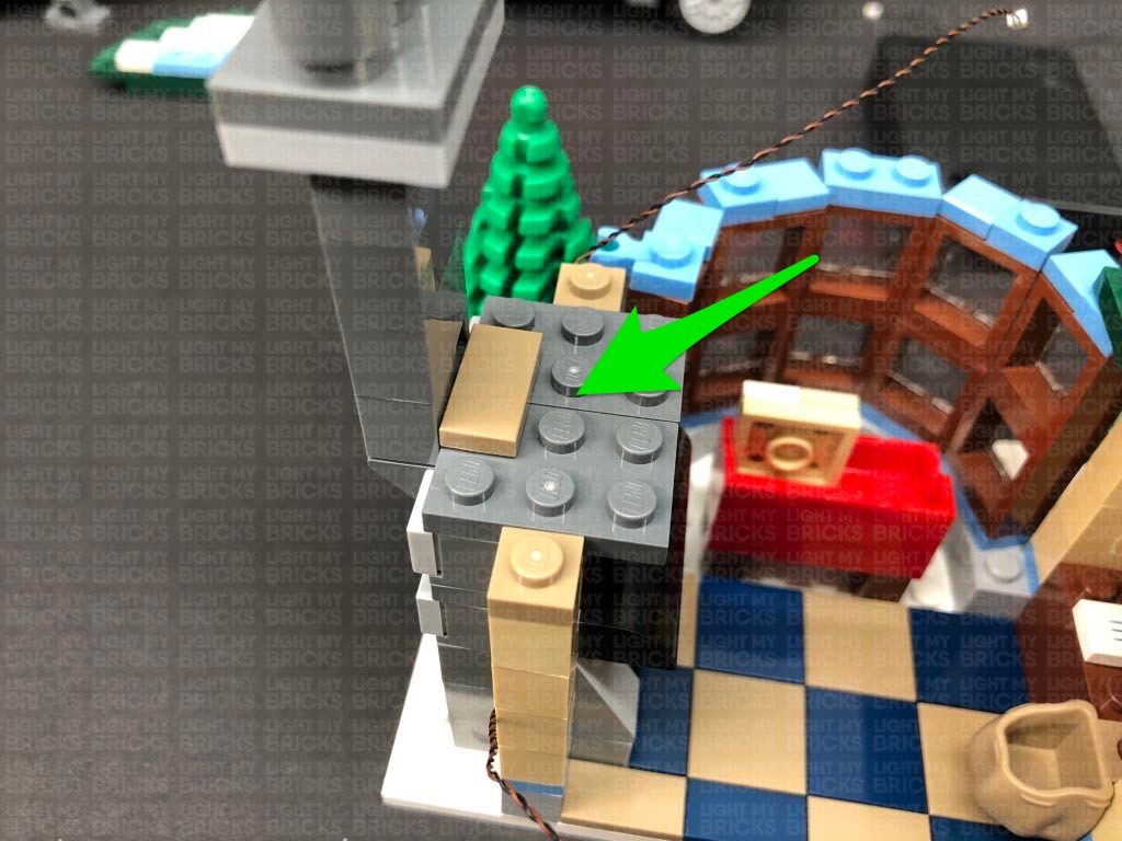
Take the following section we removed before and disassemble it as shown below, then take the grey plates and reconnect them over the fire place.
Bring both Bit Light cables over the wall, laying them between studs, then reconnect the green and beige plates.
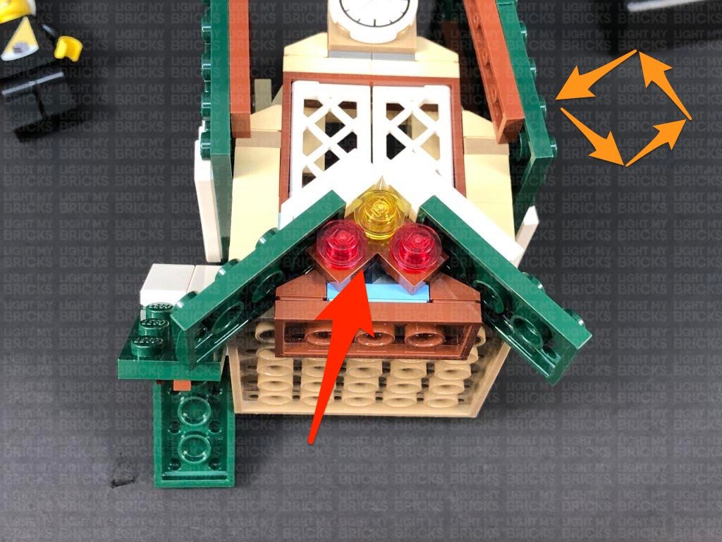
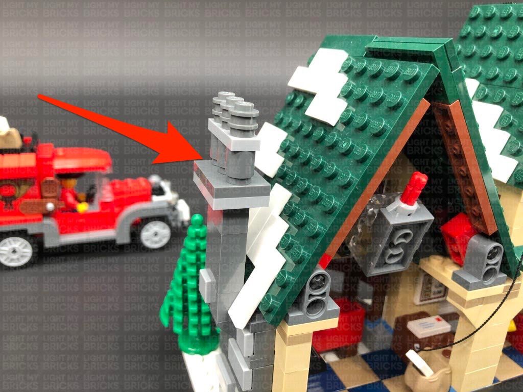
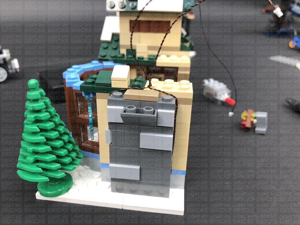
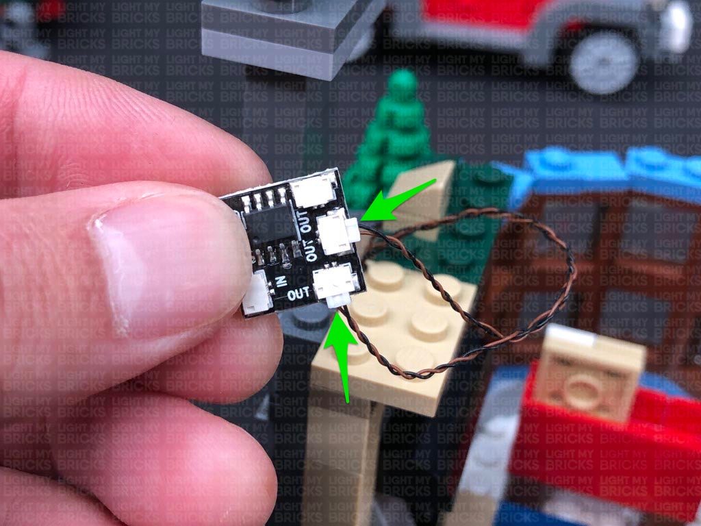
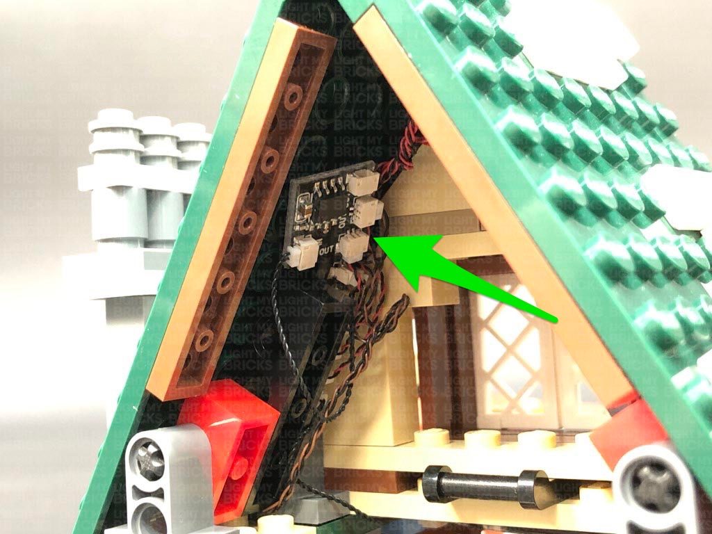
27.) Disconnect the upper section of the chimney in the below position, then bring the two Bit Light cables together in the centre of the green and beige plates. Twist them around each other all the way to the ends to form one larger cable.
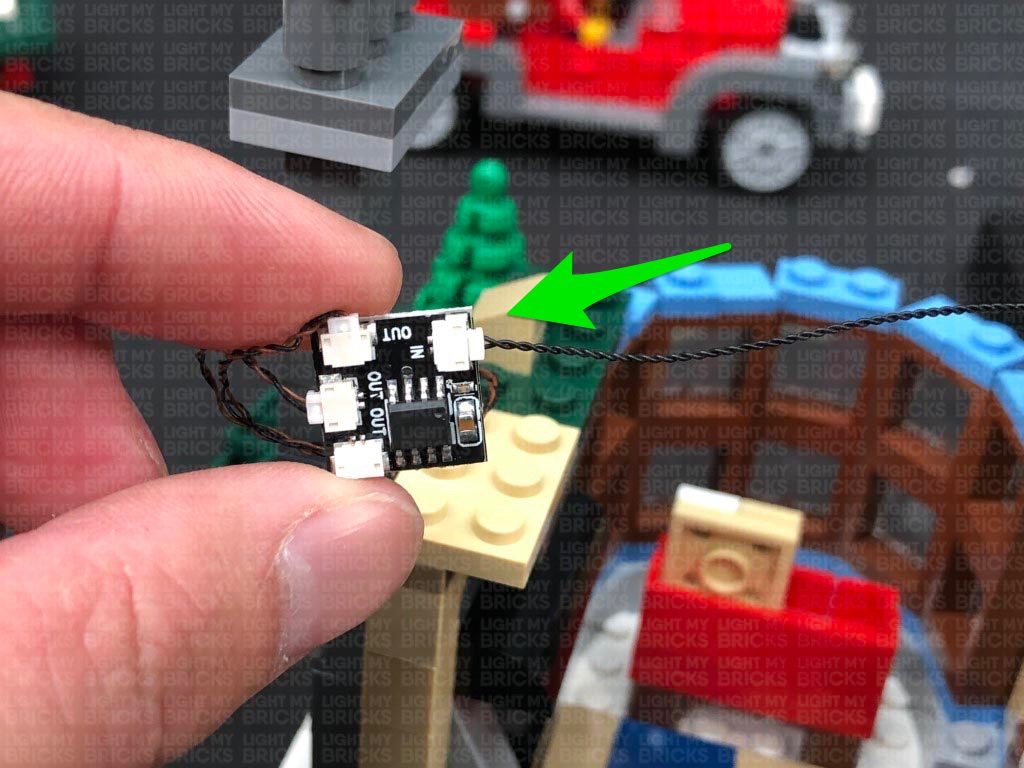
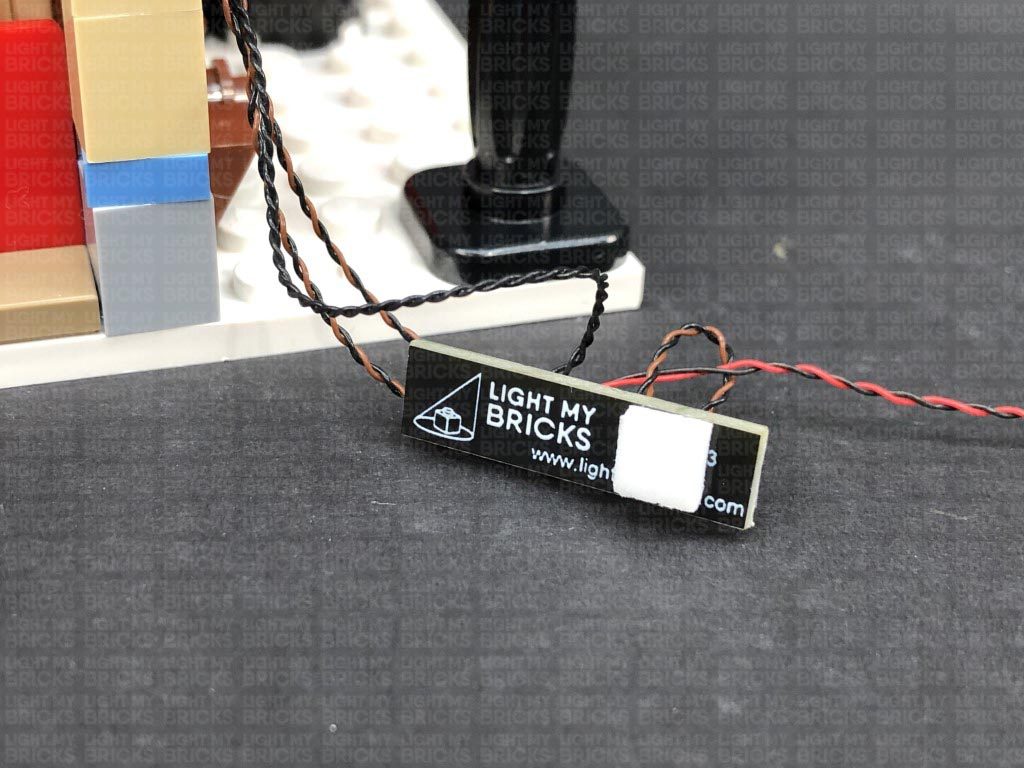
Reconnect the upper chimney section, then connect the two bit light cables to the two OUT ports on a Flicker Effects Board. Take a 5cm Connecting Cable and connect it to the IN port on the effects board. Connect the other end of the connecting cable to the remaining 6-Port Expansion Board.
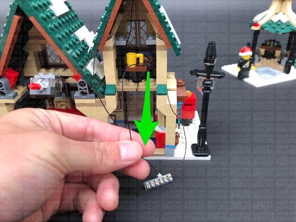
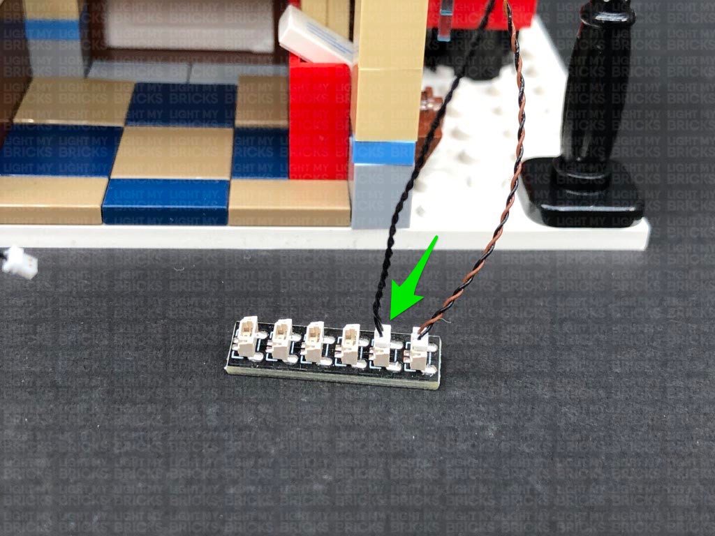
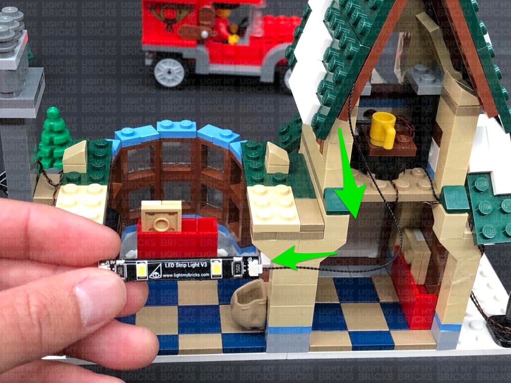
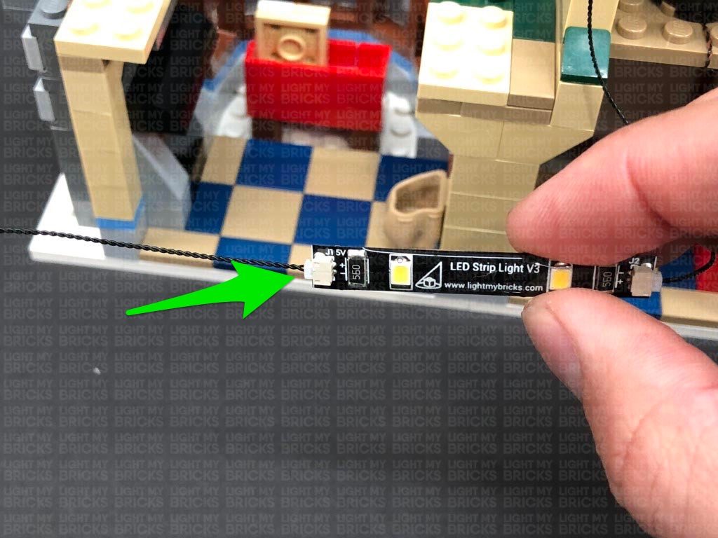
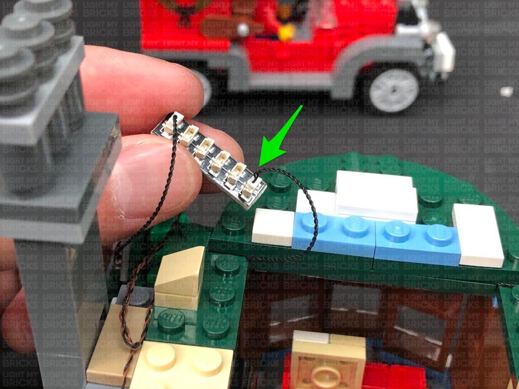
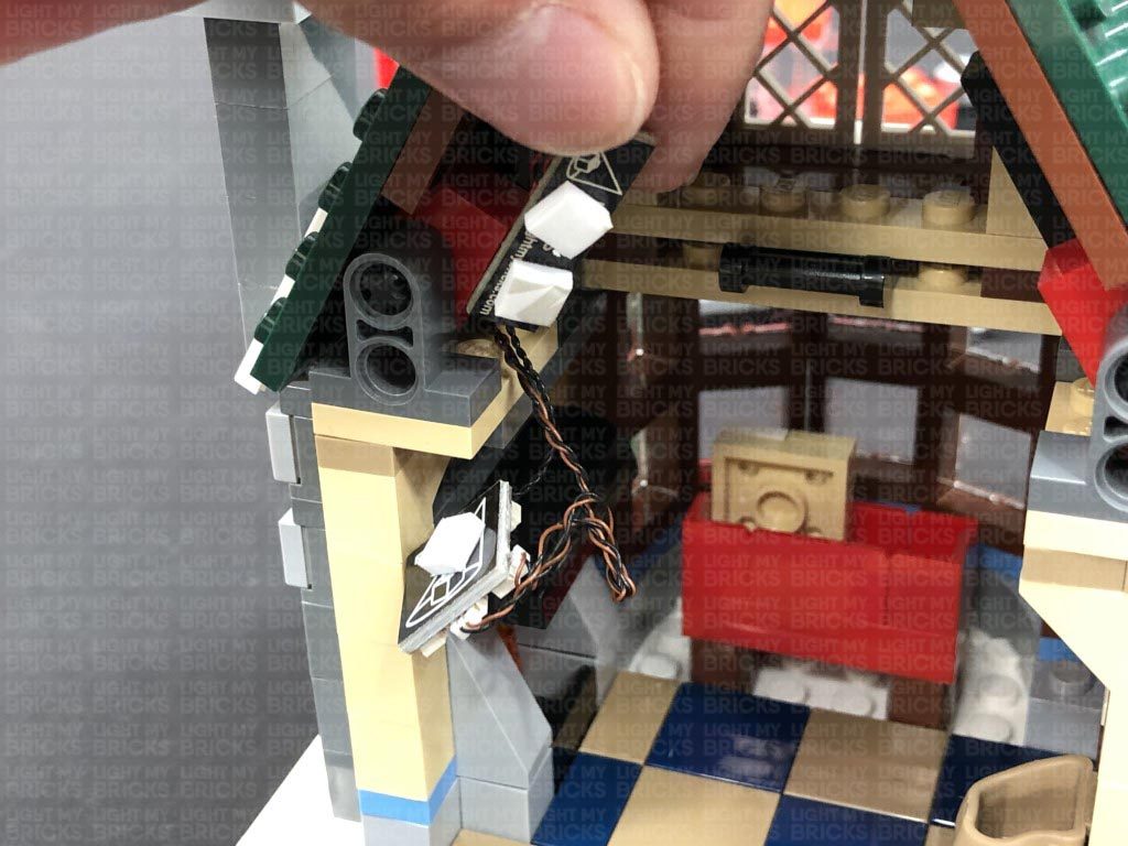
28.) Locate the other end of the 15cm Connecting Cable from the right side and connect it to a White Strip Light. Take a new 5cm Connecting Cable and connect it to the other port on the Strip Light.
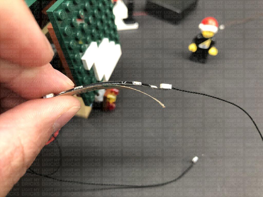
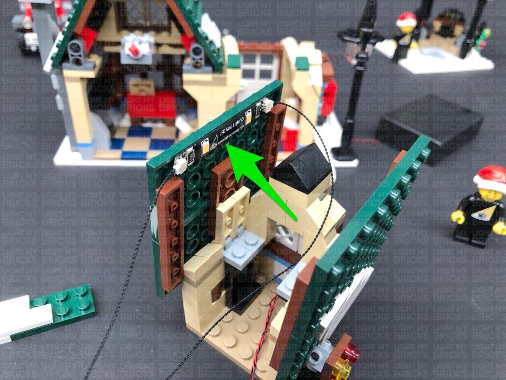
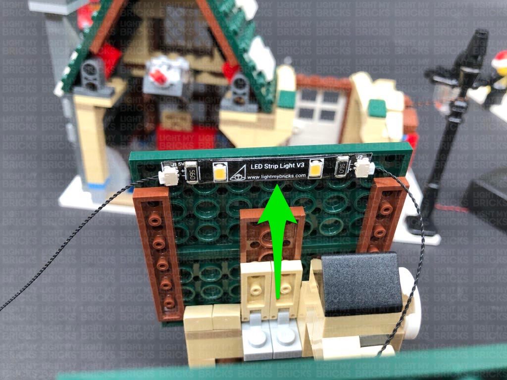
Take the following section we removed (just above the front windows) and flip it over so we can access underneath of it. Using it’s adhesive backing, stick the strip light in the following position ensuring the 5cm cable is facing the left side.
Reconnect this section back above the front windows, ensuring the cables are pulled out underneath, then secure the 15cm cable underneath the following green angled tile.
Connect the other end of the 5cm cable from the White Strip Light to the 6-Port Expansion Board nearby, then turn ON the battery pack to test the strip light and flickering lights are working OK.
Note: If you experience any issues with the lights not working and suspect an issue with a component, please try a different port on the expansion board to verify where the fault lies (with the light or expansion board). To correct any issues with expansion board ports, please view the section addressing expansion board issues on our online troubleshooting guide.
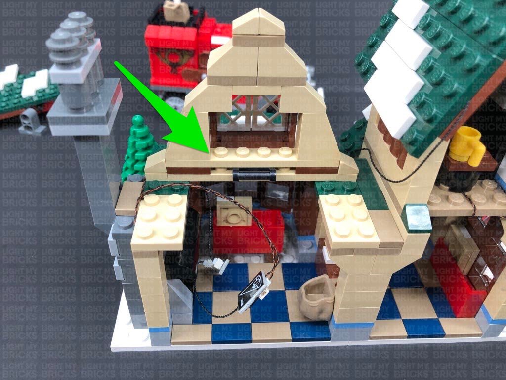
29.) Reconnect the large middle section above the front windows, then locate the front window light section and disassemble it as shown below.
Follow the same method used to install lights to the other window light section in step 17 to install another 3x Flashing White 15cm Bit Lights to this section.
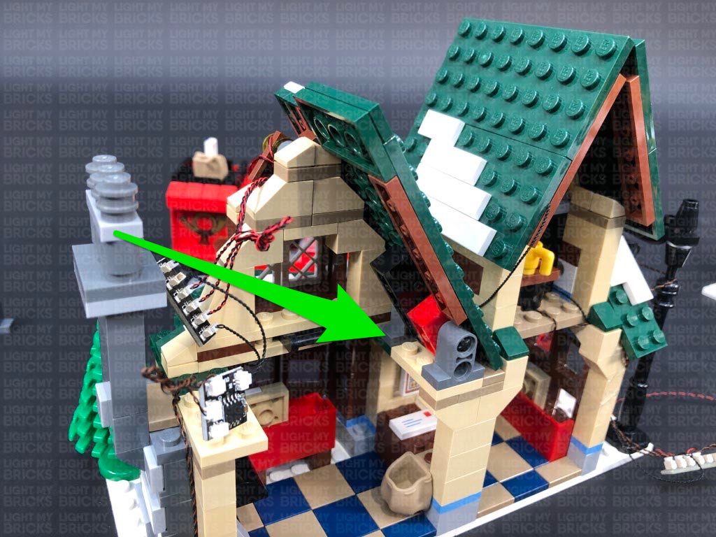
30.) Twist the three cables around each other all the way to the ends to form one larger cable, then thread all three of them through the hole on the dark grey technic piece until you can reconnect both of them together. Reconnect this section back to the front of the post office.
Turn the set around to the back, then connect the three flashing bit light cables to the 6-port expansion board. Turn ON the Battery Pack to test all the lights are working OK.
Note: If you experience any issues with the lights not working and suspect an issue with a component, please try a different port on the expansion board to verify where the fault lies (with the light or expansion board). To correct any issues with expansion board ports, please view the section addressing expansion board issues on our online troubleshooting guide.
31.) Twist and fold the flashing bit light cables together into a neat bunch, then do the same for the two bit light cables from the fire place. Reconnect the two roof panels.
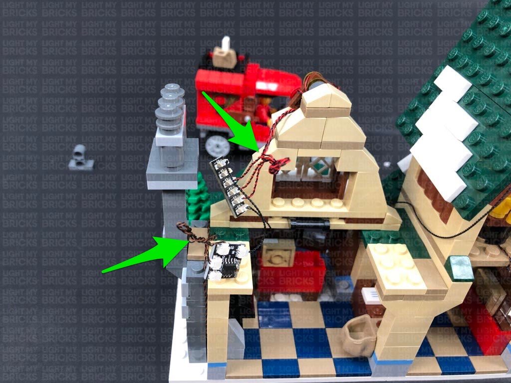
Stick 2x Adhesive Squares to the back of the 6-Port Expansion Board and another Adhesive Square to the back of the flicker effects board. Mount the 6-port expansion board vertically behind the black technic brick on the left roof panel, then mount the flicker effects board just above it.
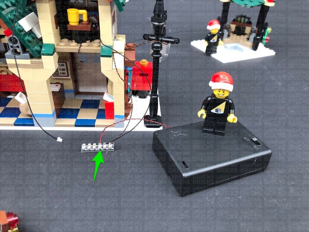
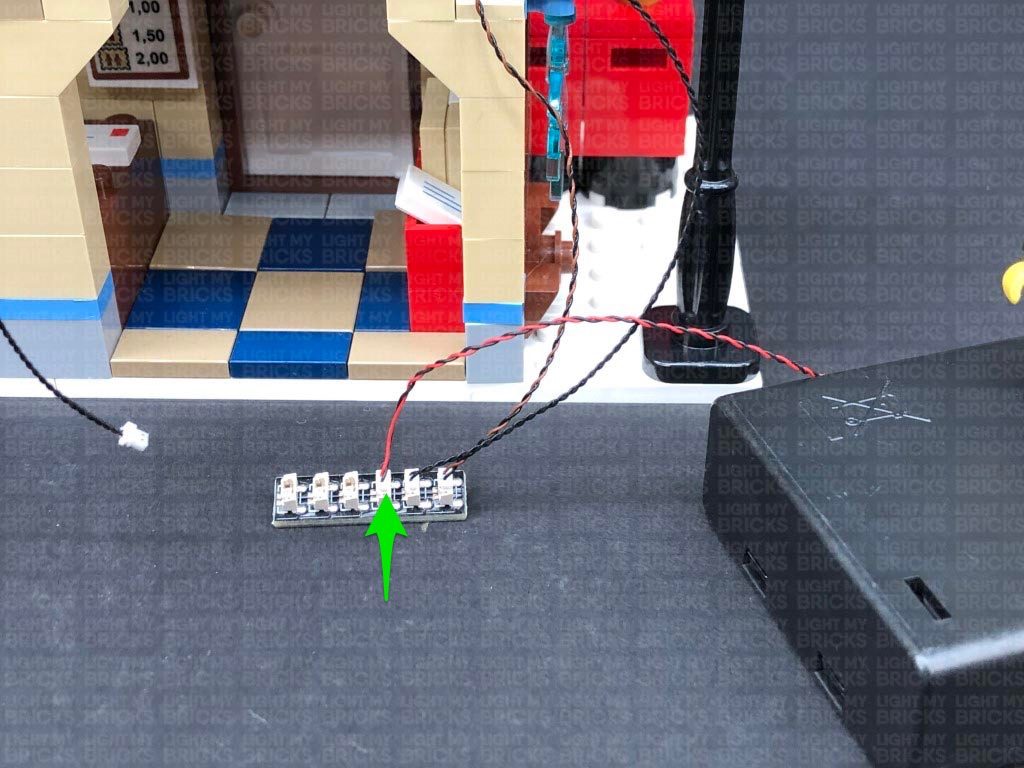
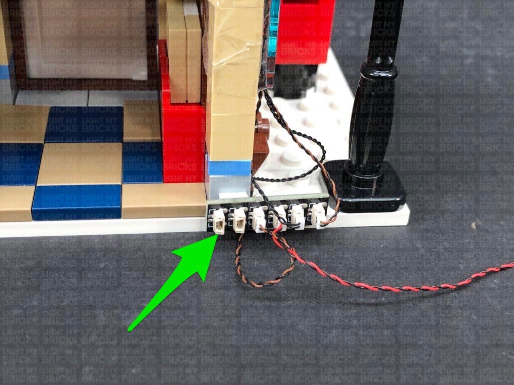
Stick the remaining Adhesive Square to the back of the 6-Port Expansion Board on the bottom of the set near the lamp post. Stick the expansion board to the following position, then test all the lights are working ok by turning on the battery pack.
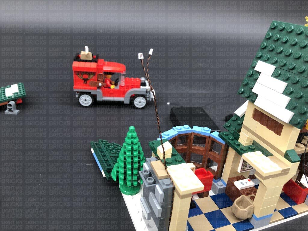
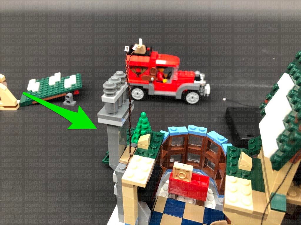
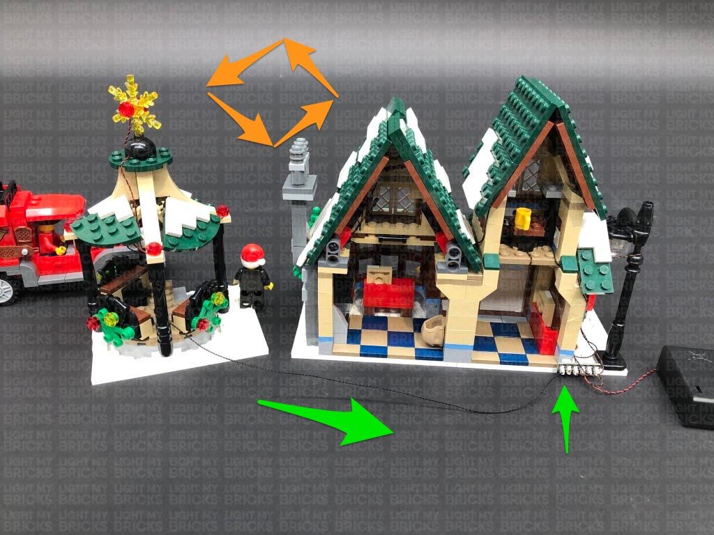
32.) Position the gazebo next to the post office, then connect the 30cm connecting cable from it to a spare port on the 6-port expansion board near the lamp post.
IMPORTANT NOTE:
If you tethered the vehicle with the 50cm Connecting Cable, connect it to the 6-Port Expansion Board.
23.) Bring the cable across to the right and secure it, as well as the 15m connecting cable, underneath the dark green angled tile, ensuring you first lay them around the stud.
Connect the Bit Light to the 6-Port Expansion Board below, then turn the battery pack ON again to test the internal light is working OK.
Bring all the cables together and secure them to the outside of the wall using tape.
24.) We will now light up the left section of the post office. Follow the below images to remove all the sections surrounding the top of this floor.
25.) Continue to remove the following sections in order for us to install lights to the fire place.
Take a White 15cm Bit Light and with the cable facing the outside, place it over the left brown stud. Secure the Bit Light in place by reconnecting one of the trans orange pieces over the top. Use the same method to install another White 15cm Bit Light to the other brown stud.
26.) Pull the Bit Light cables out to each side before reconnecting the chimney section.
Take the following section we removed before and disassemble it as shown below, then take the grey plates and reconnect them over the fire place.
Bring both Bit Light cables over the wall, laying them between studs, then reconnect the green and beige plates.
27.) Disconnect the upper section of the chimney in the below position, then bring the two Bit Light cables together in the centre of the green and beige plates. Twist them around each other all the way to the ends to form one larger cable.
Reconnect the upper chimney section, then connect the two bit light cables to the two OUT ports on a Flicker Effects Board. Take a 5cm Connecting Cable and connect it to the IN port on the effects board. Connect the other end of the connecting cable to the remaining 6-Port Expansion Board.
28.) Locate the other end of the 15cm Connecting Cable from the right side and connect it to a White Strip Light. Take a new 5cm Connecting Cable and connect it to the other port on the Strip Light.
Take the following section we removed (just above the front windows) and flip it over so we can access underneath of it. Using it’s adhesive backing, stick the strip light in the following position ensuring the 5cm cable is facing the left side.
Reconnect this section back above the front windows, ensuring the cables are pulled out underneath, then secure the 15cm cable underneath the following green angled tile.
Connect the other end of the 5cm cable from the White Strip Light to the 6-Port Expansion Board nearby, then turn ON the battery pack to test the strip light and flickering lights are working OK.
Note: If you experience any issues with the lights not working and suspect an issue with a component, please try a different port on the expansion board to verify where the fault lies (with the light or expansion board). To correct any issues with expansion board ports, please view the section addressing expansion board issues on our online troubleshooting guide.
29.) Reconnect the large middle section above the front windows, then locate the front window light section and disassemble it as shown below.
Follow the same method used to install lights to the other window light section in step 17 to install another 3x Flashing White 15cm Bit Lights to this section.
30.) Twist the three cables around each other all the way to the ends to form one larger cable, then thread all three of them through the hole on the dark grey technic piece until you can reconnect both of them together. Reconnect this section back to the front of the post office.
Turn the set around to the back, then connect the three flashing bit light cables to the 6-port expansion board. Turn ON the Battery Pack to test all the lights are working OK.
Note: If you experience any issues with the lights not working and suspect an issue with a component, please try a different port on the expansion board to verify where the fault lies (with the light or expansion board). To correct any issues with expansion board ports, please view the section addressing expansion board issues on our online troubleshooting guide.
31.) Twist and fold the flashing bit light cables together into a neat bunch, then do the same for the two bit light cables from the fire place. Reconnect the two roof panels.
Stick 2x Adhesive Squares to the back of the 6-Port Expansion Board and another Adhesive Square to the back of the flicker effects board. Mount the 6-port expansion board vertically behind the black technic brick on the left roof panel, then mount the flicker effects board just above it.
Stick the remaining Adhesive Square to the back of the 6-Port Expansion Board on the bottom of the set near the lamp post. Stick the expansion board to the following position, then test all the lights are working ok by turning on the battery pack.
32.) Position the gazebo next to the post office, then connect the 30cm connecting cable from it to a spare port on the 6-port expansion board near the lamp post.
IMPORTANT NOTE:
If you tethered the vehicle with the 50cm Connecting Cable, connect it to the 6-Port Expansion Board.
This finally completes installation of the Light My Bricks LEGO Winter Village Post Office Light Kit. We thank you for purchasing this product and hope you ENJOY!