
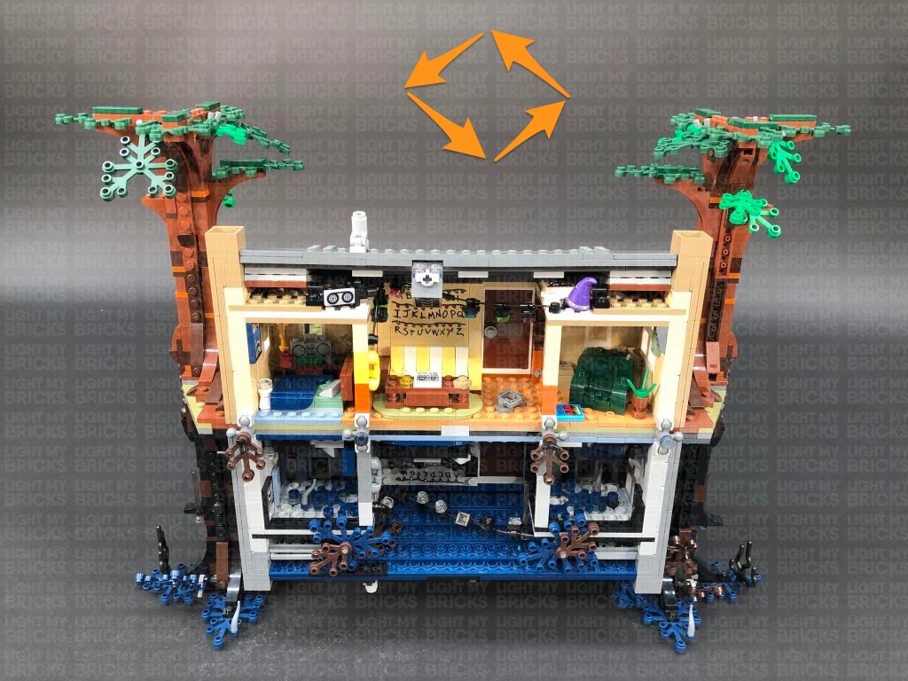
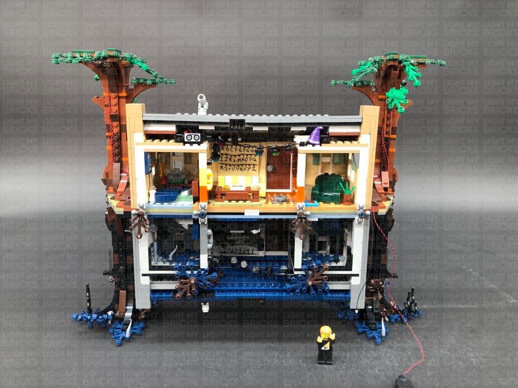
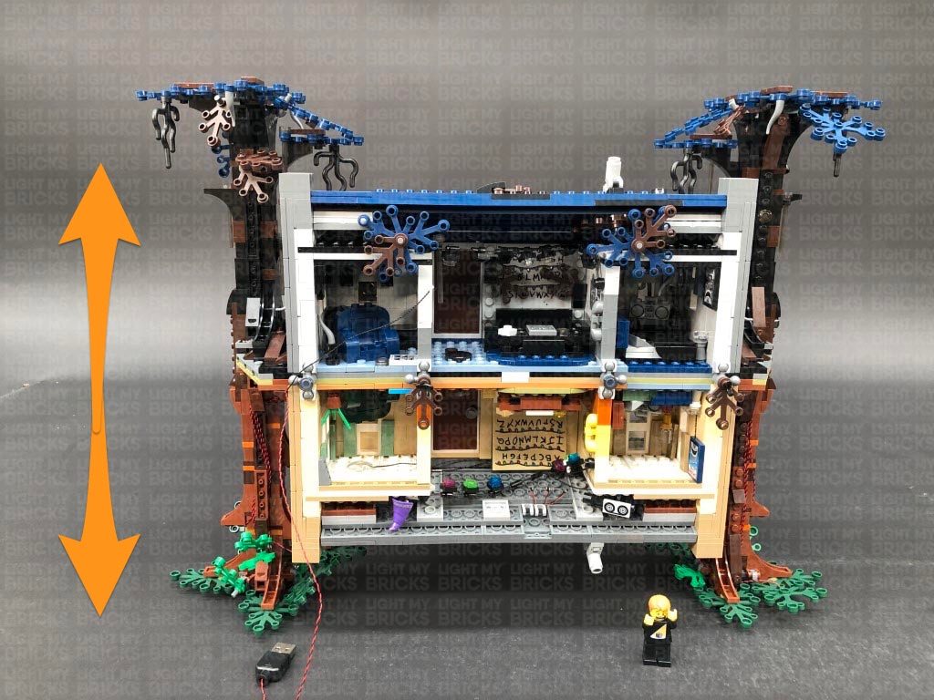
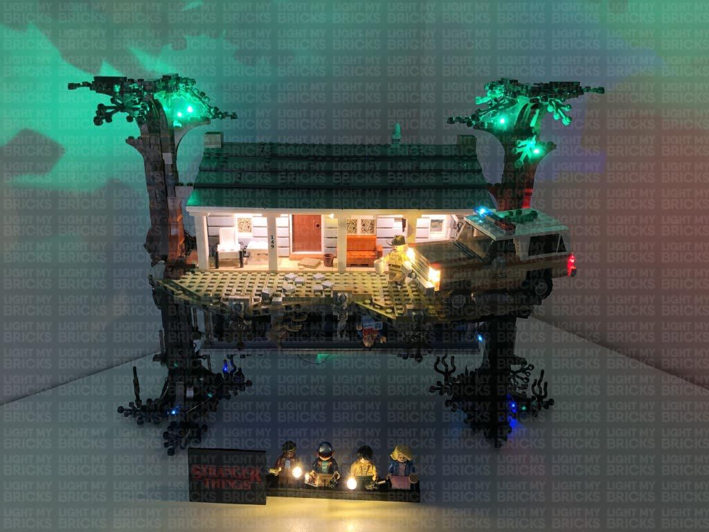
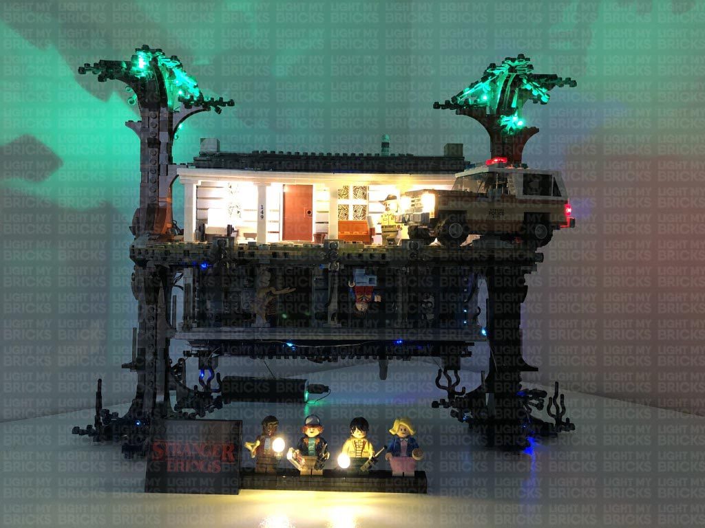
The following page is the instructions for the Light My Bricks LEGO Stranger Things: The Upside Down (75810) LED light kit.
If you run into any issues, please refer to the online troubleshooting guide.
To ensure a trouble-free installation of your light kit, please read and follow each step carefully.
Please note: This page lists instructions for the LED light kit only. If you are wishing to purchase the Light My Bricks LEGO Stranger Things – The Upside Down (75810) LED light kit , please click here to view the product page
Package Contents:
- 11x White 15cm Bit Lights
- 1x White 30cm Bit Light
- 9x Green 30cm Bit Lights
- 1x Blue 30cm Bit Light
- 1x Pink 30cm Bit Light
- 2x Warm White Strip Lights
- 2x Glitter Effects Light Strings
- 3x 6-Port Expansion Boards
- 2x 8-Port Expansion Boards
- 1x Multi Effects Board
- 1x Sequence Effects Board
- 1x Scary Flicker Effects Board
- 1x Glitter Effects Board
- 3x 5cm Connecting Cables
- 5x 15cm Connecting Cables
- 2x 50cm Connecting Cable
- 8x Adhesive Squares
- 1x USB Power Cable
LEGO Pieces:
- 2x Trans Clear Plate 1×1
- 2x Trans Red Plate 1×1
- 3x Trans Clear Round Plate 1×1
- 1x Trans Clear Plate w Rounded Bottom 2×2 Important Note: As of June 2022, Flat Battery Packs have been removed due to child safety regulations.
Important things to note:
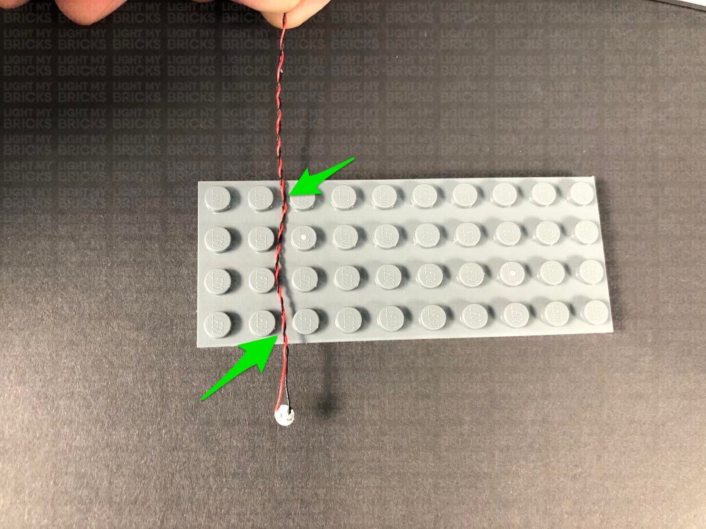
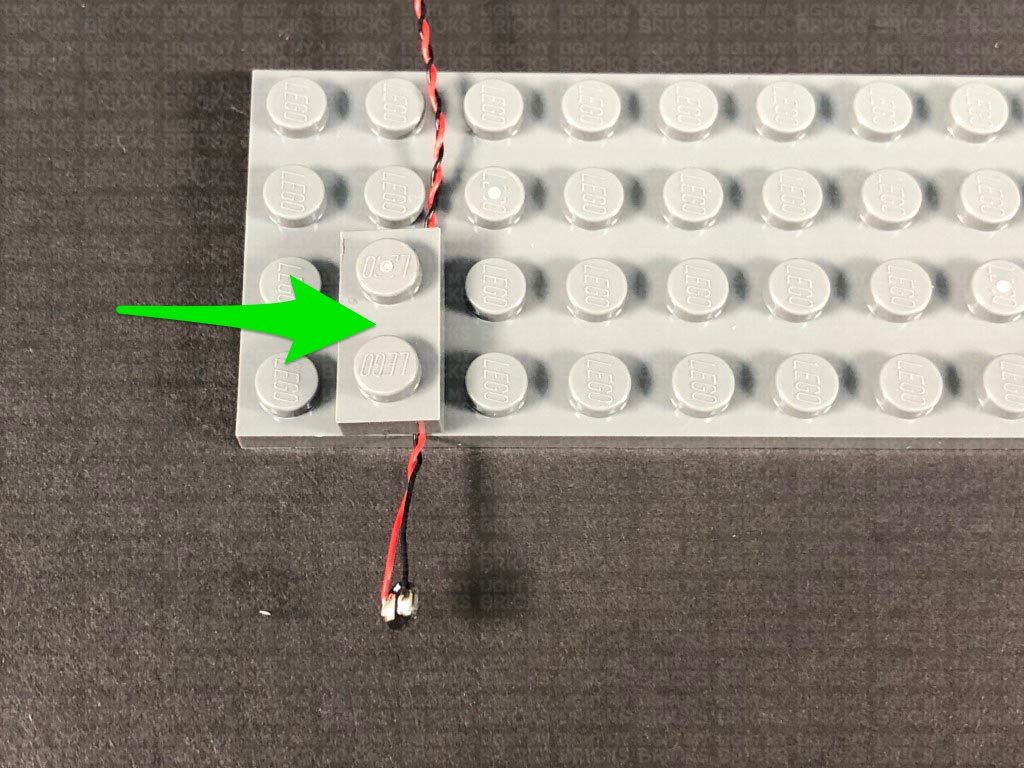
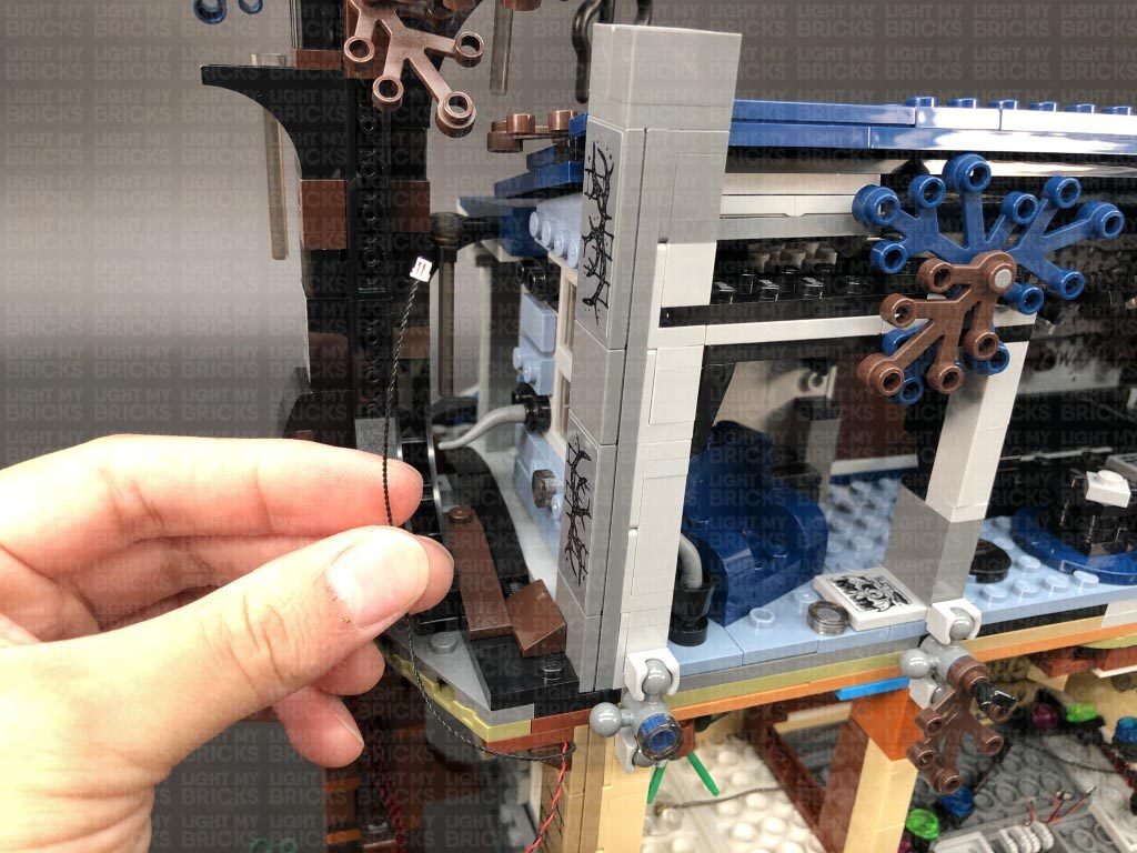
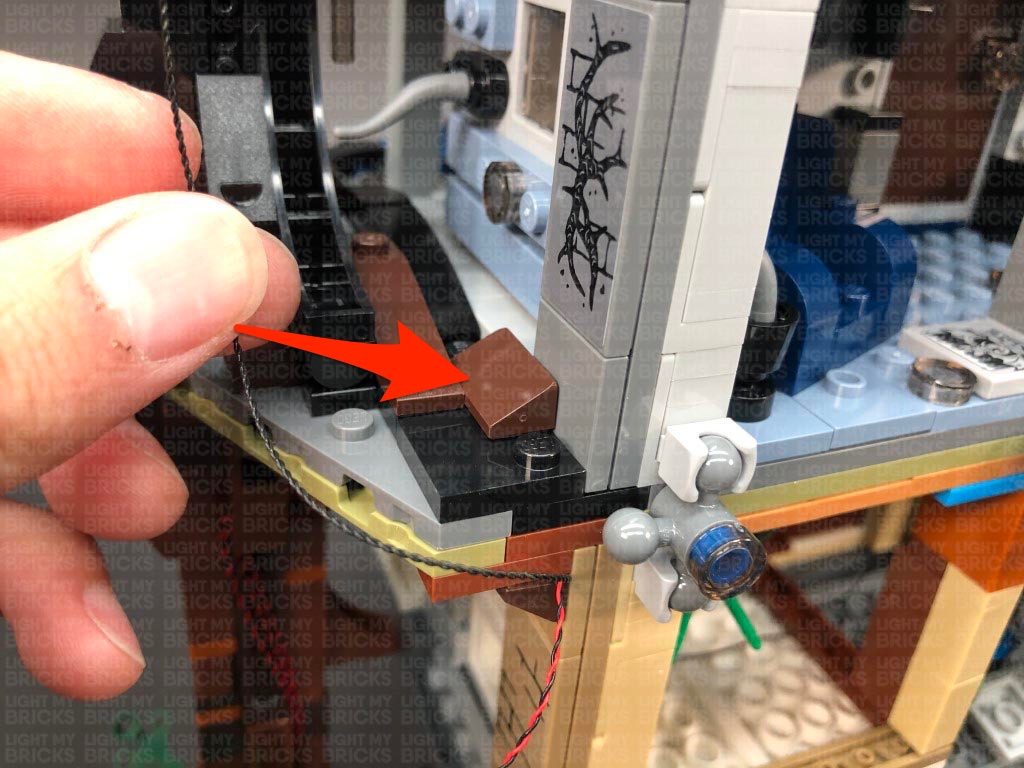
Laying cables in between and underneath bricks
Cables can fit in between and underneath LEGO® bricks, plates, and tiles providing they are laid correctly between the LEGO® studs. Do NOT forcefully join LEGO® together around cables; instead ensure they are laying comfortably in between each stud.
Connecting cable connectors to Expansion Boards
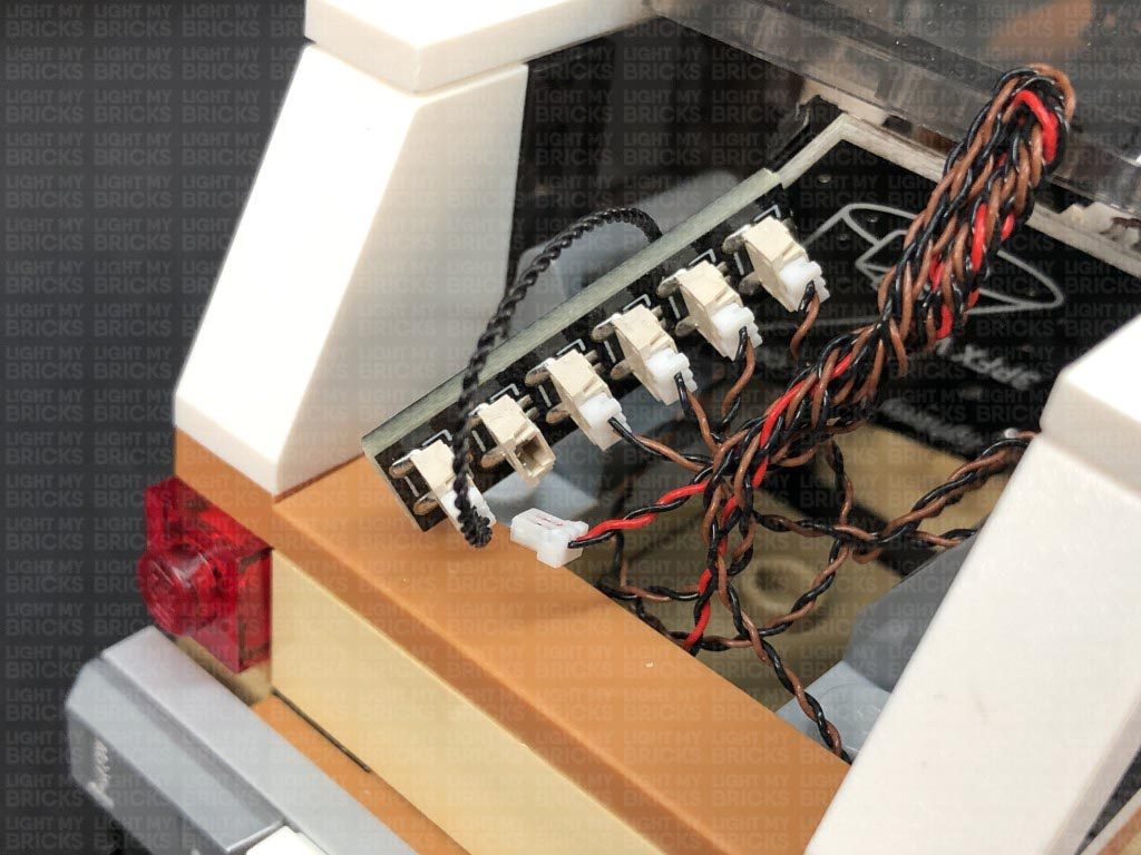
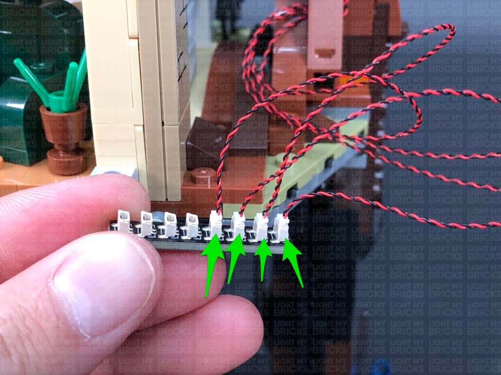
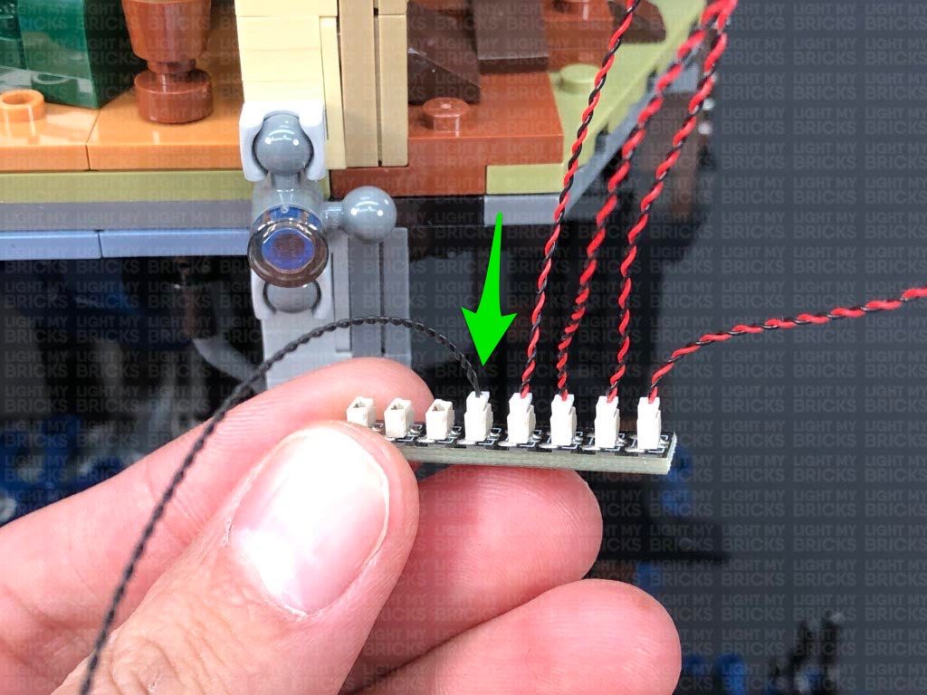
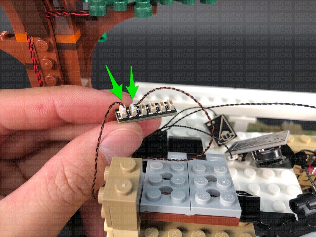
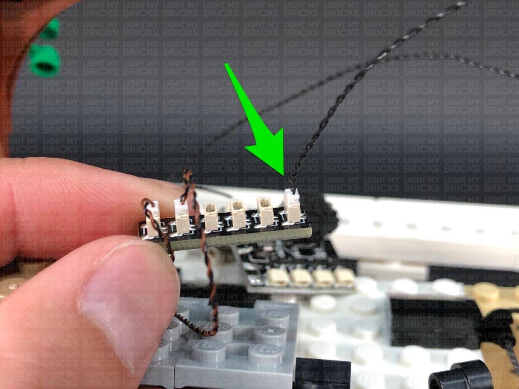
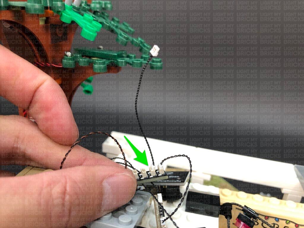
Take extra care when inserting connectors to ports of Expansion Boards. Connectors can be inserted only one way. With the expansion board facing up, look for the soldered “=” symbol on the left side of the port. The connector side with the wires exposed should be facing toward the soldered “=” symbol as you insert into the port. If a plug won’t fit easily into a port connector, do not force it.
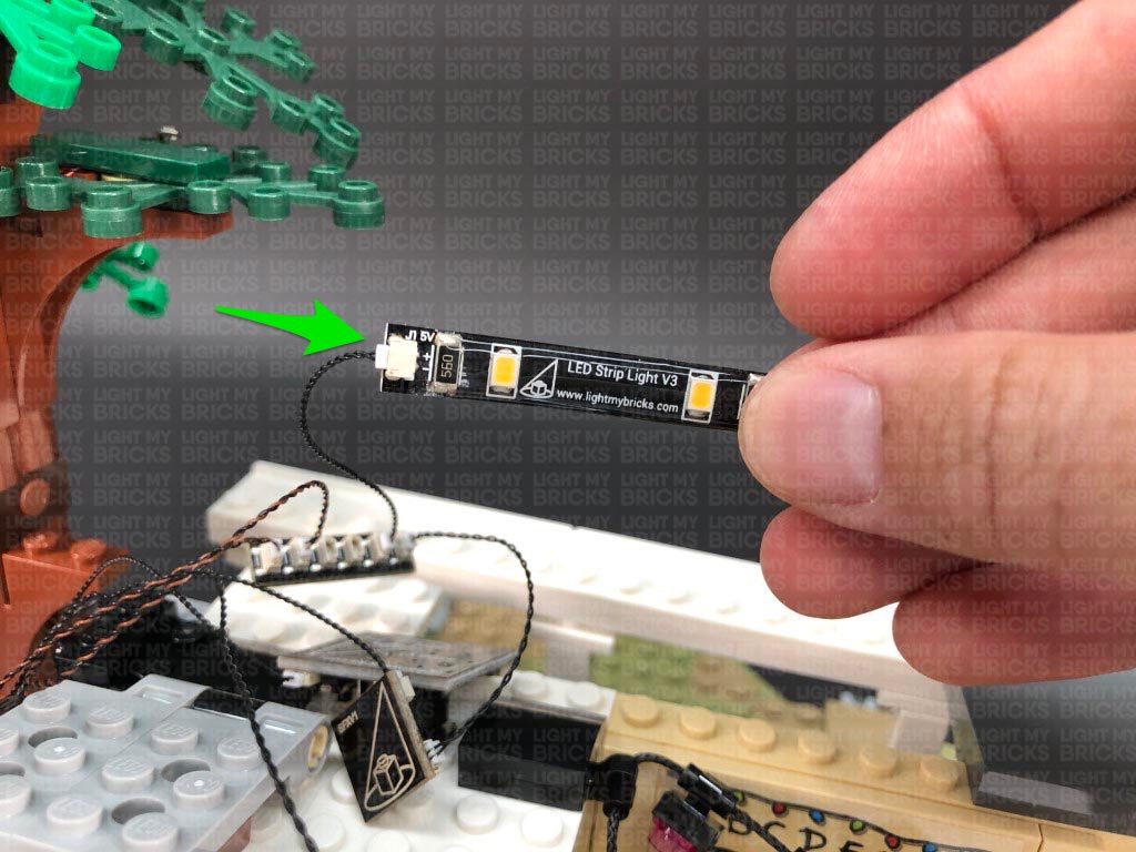
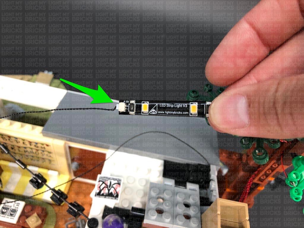
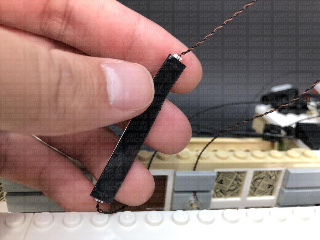
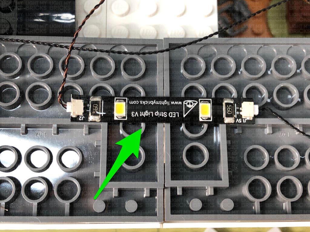
Connecting cable connectors to Strip Lights
Take extra care when inserting connectors to ports on the Strip Lights. Connectors can be inserted only one way. With the Strip Light facing up, ensure the side of the connector with the wires exposed is facing down. If a plug won’t fit easily into a port connector, don’t force it. Doing so will damage the plug and the connector.
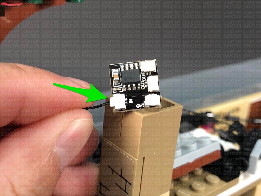
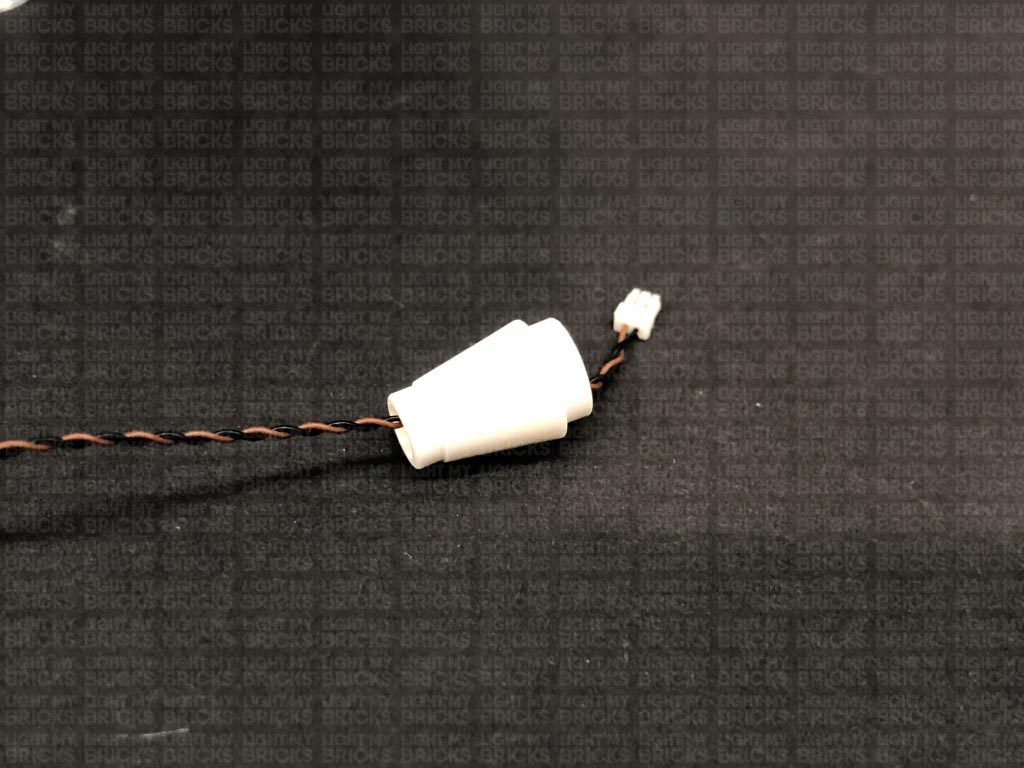
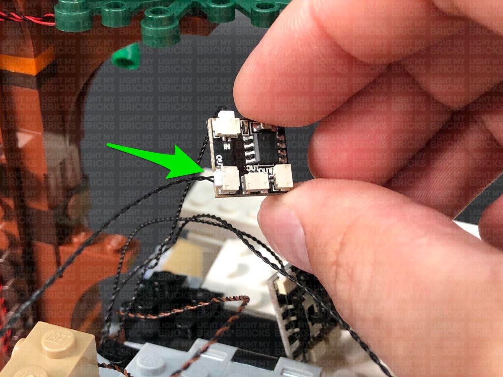
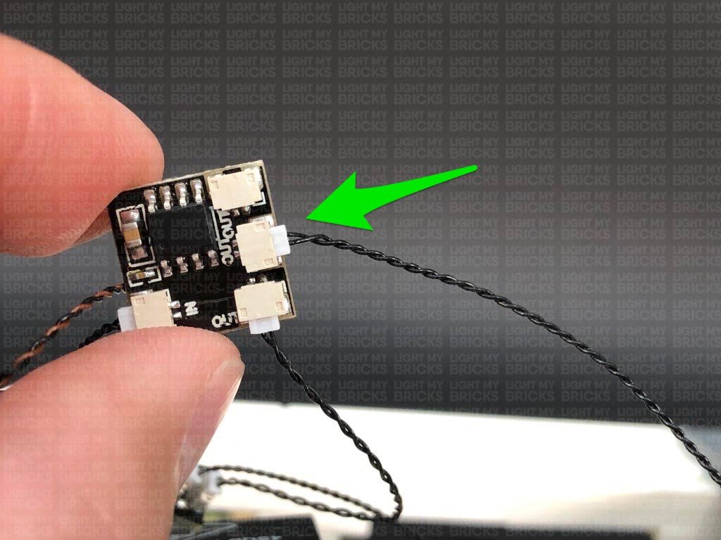
Connecting Micro Cable connectors to Micro Expansion Board Ports
Take extra care when inserting the micro connectors to micro ports of Micro Expansion Boards. Connecting Micro Bit Lights to Micro Expansion Boards is similar to connecting lights and cables to Strip Lights. With the expansion board facing up, ensure the side of the connector with the wires exposed is facing down. If a plug won’t fit easily into a port connector, do not force it. Use your fingernail to push the plastic part of the connector to the micro port.
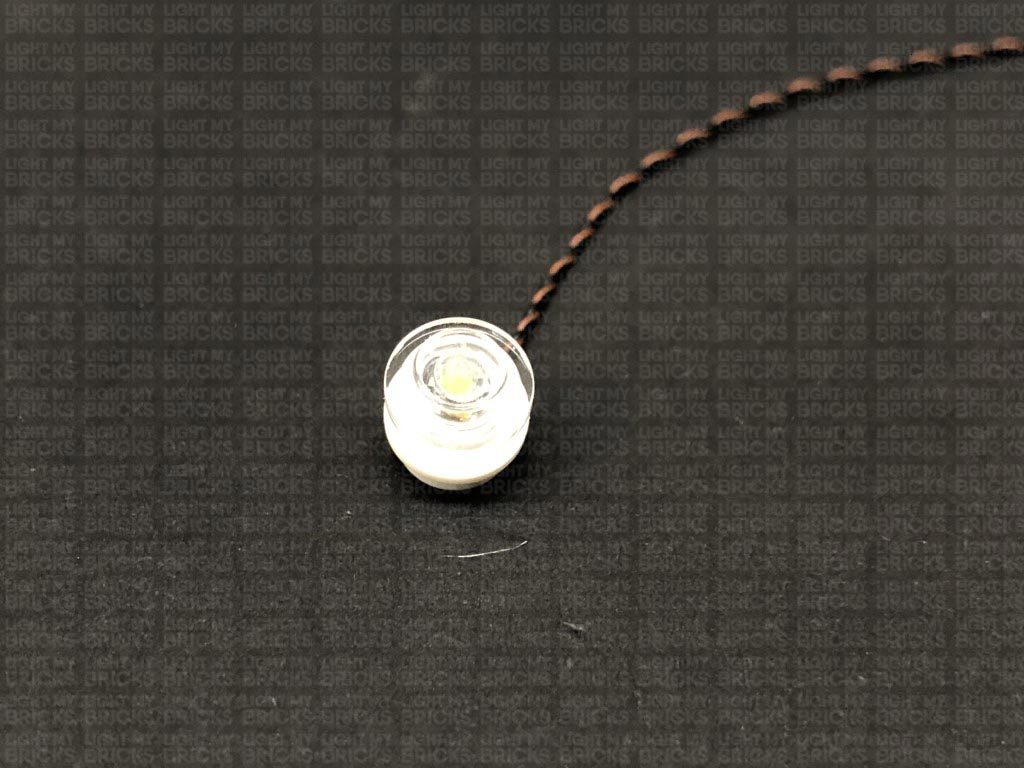
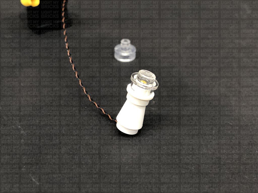
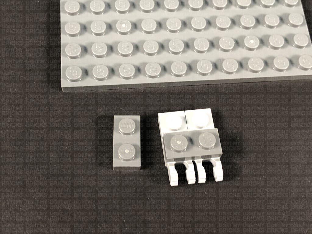
Installing Bit Lights under LEGO® bricks and plates.
When installing Bit Lights under LEGO® pieces, ensure they are placed the correct way up (Yellow LED component exposed). You can either place them directly on top of LEGO® studs or in between.
OK, Let’s Begin!
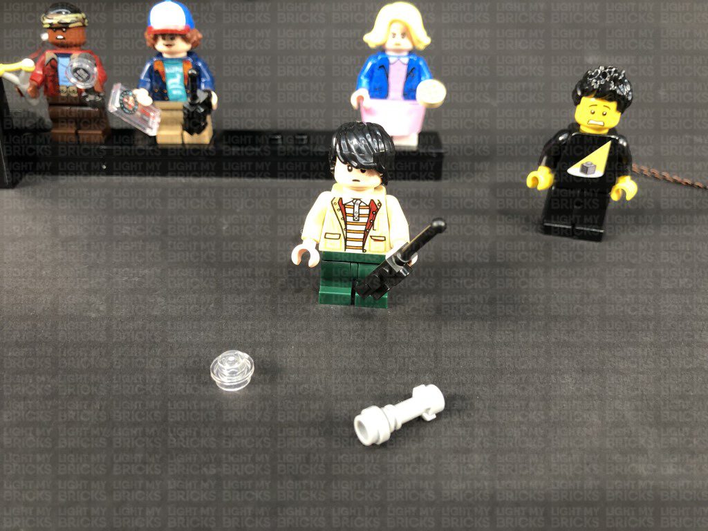
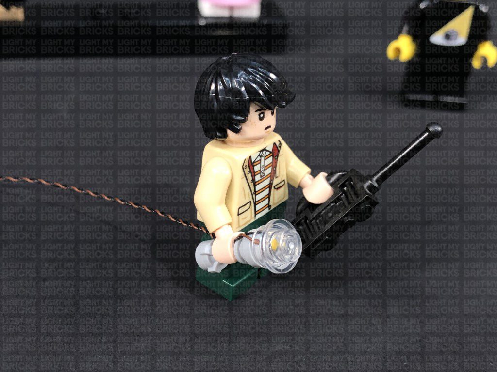
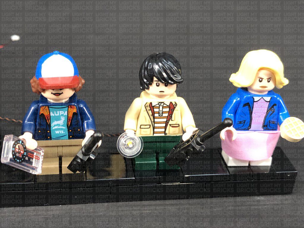
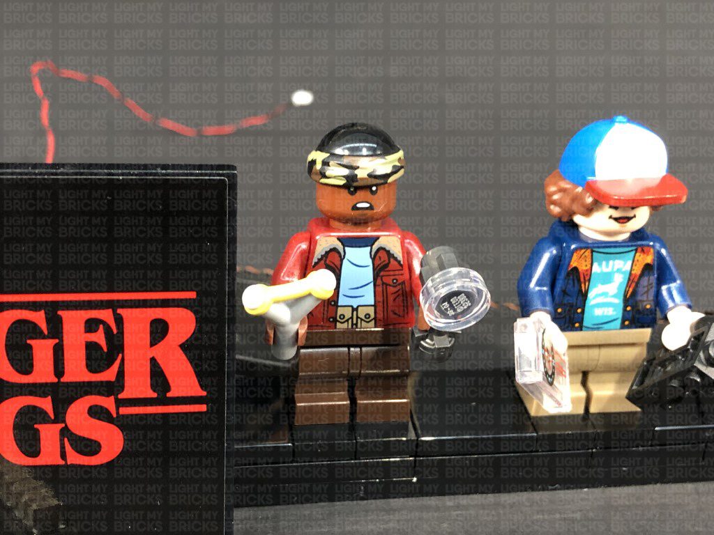
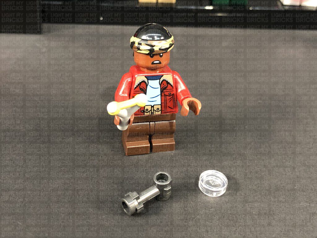
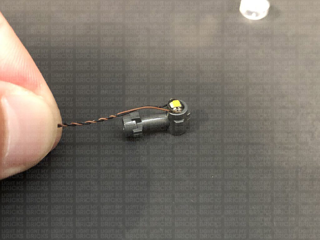
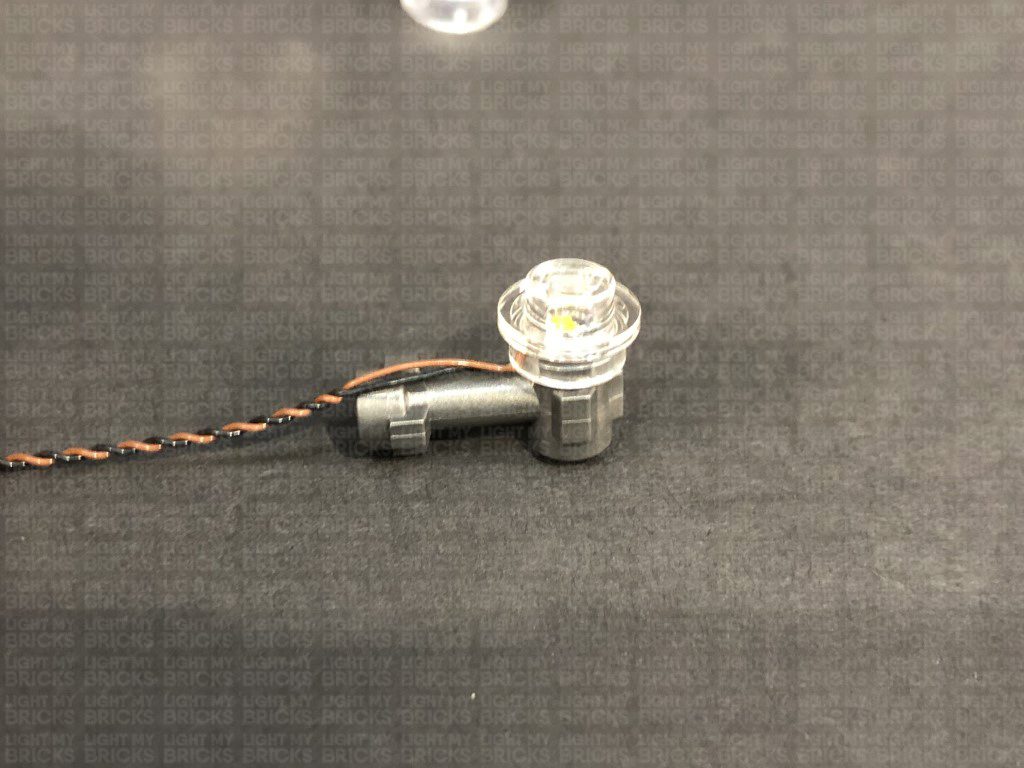
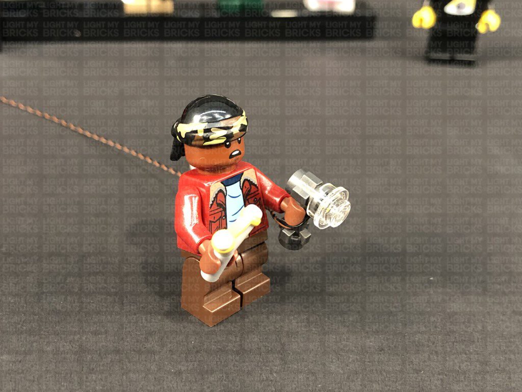
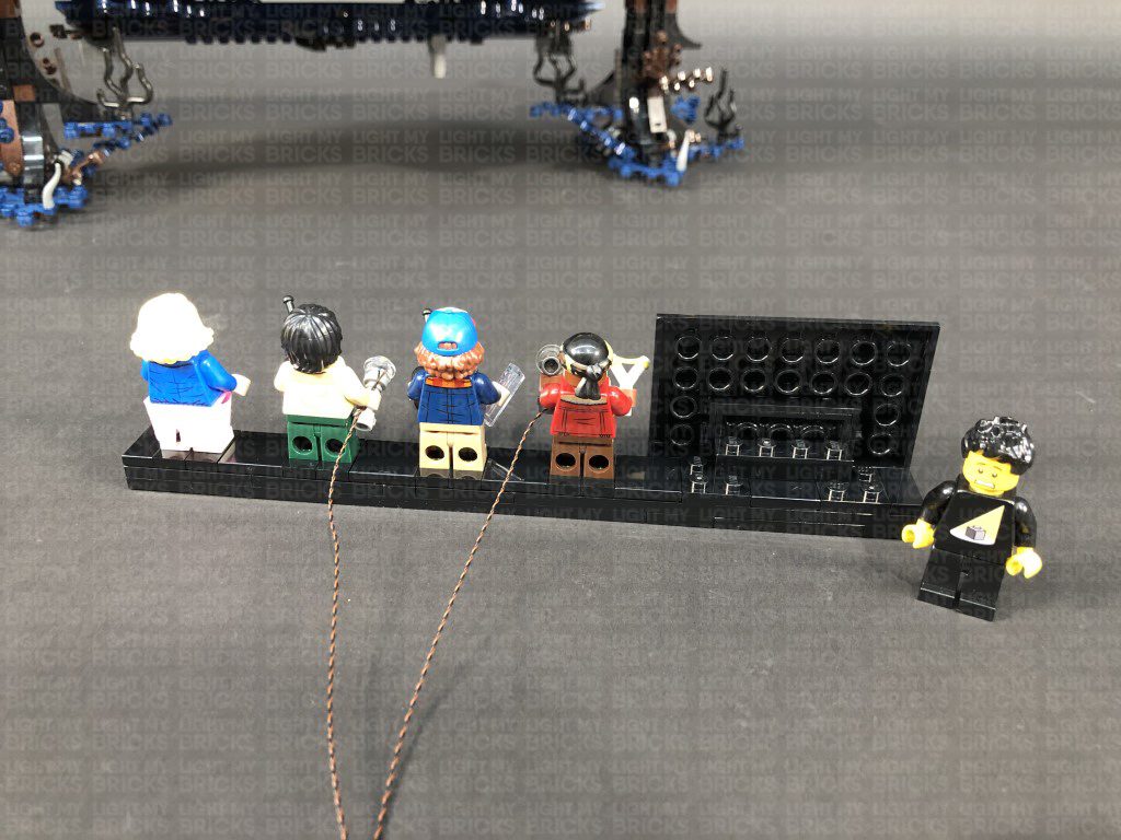
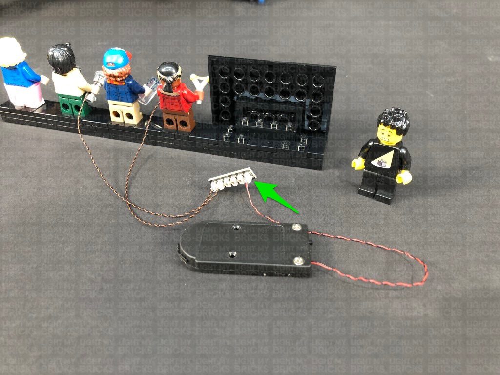
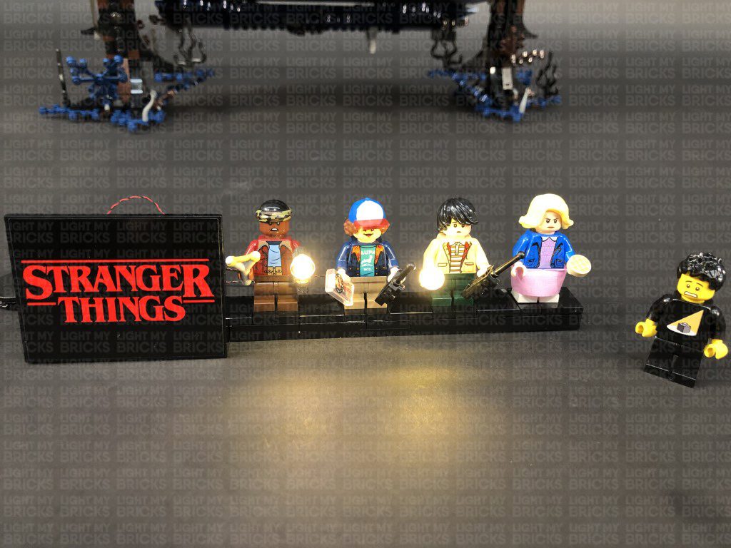
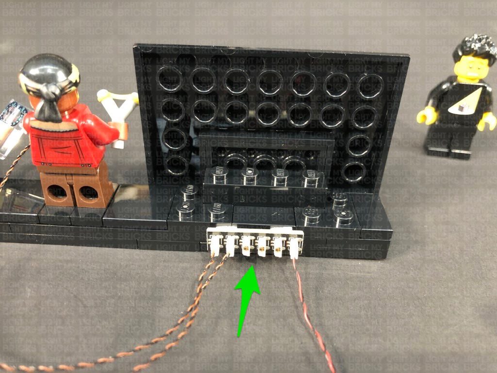
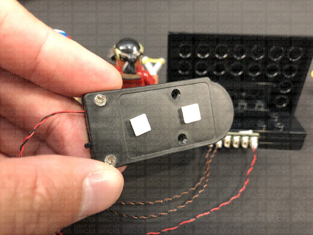
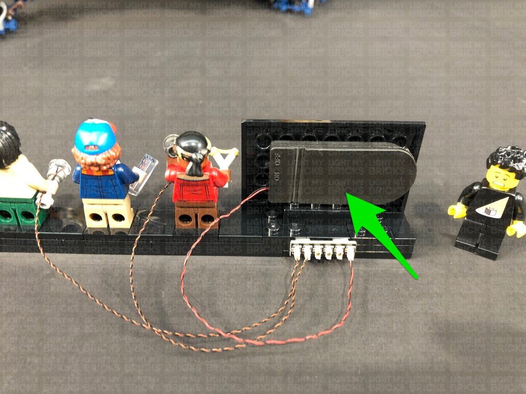
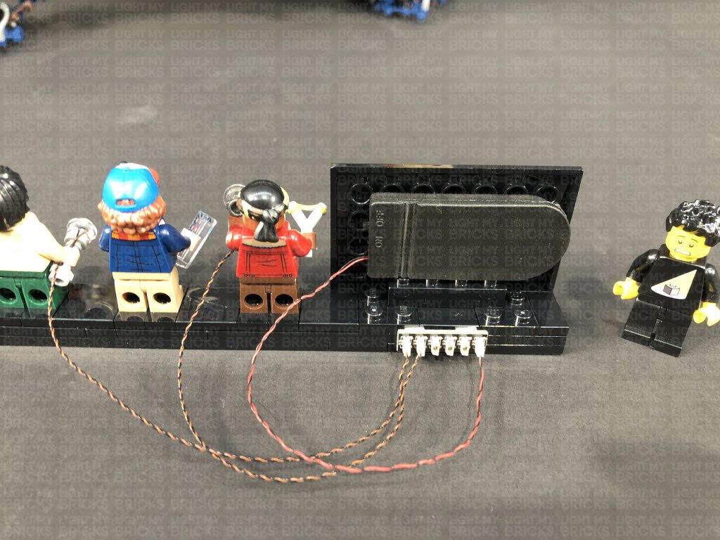
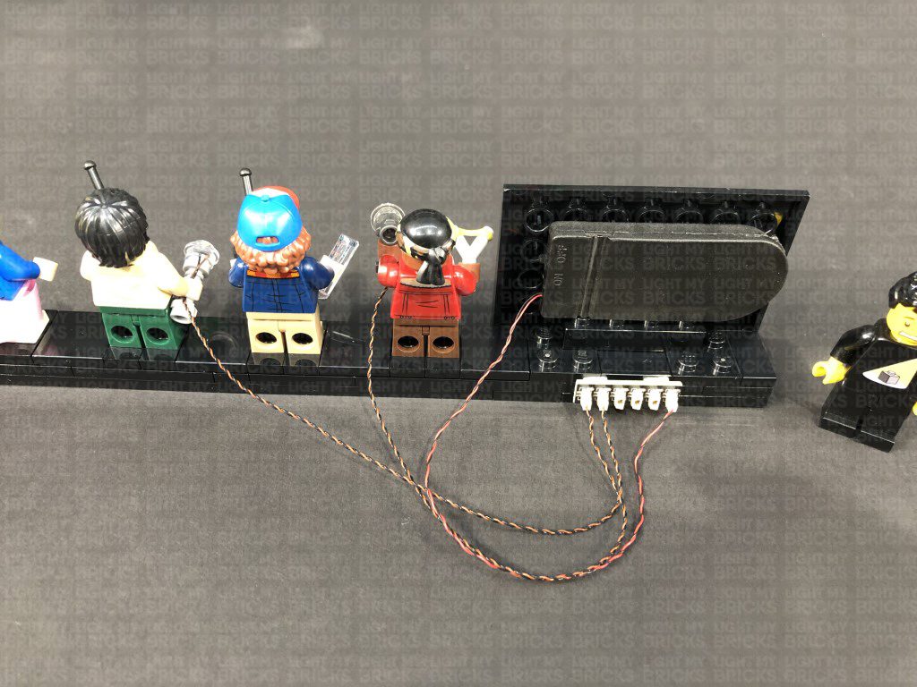
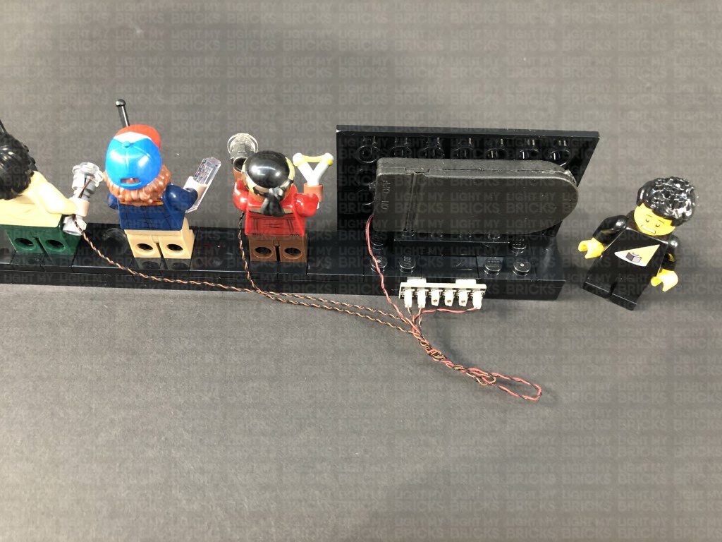
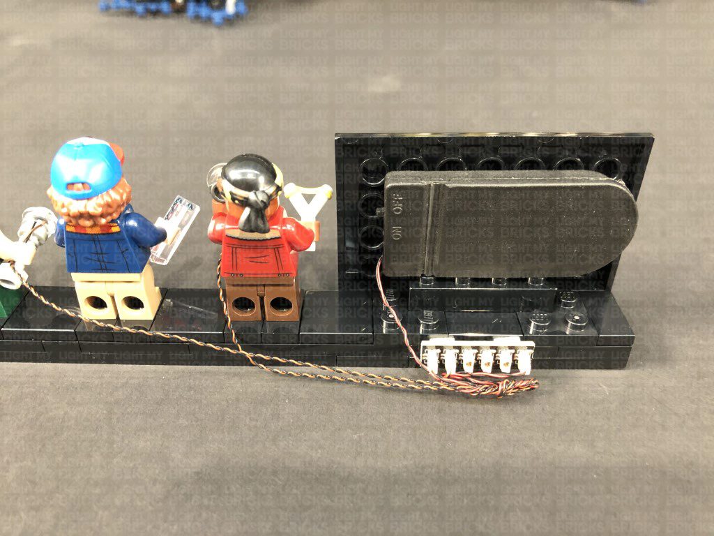
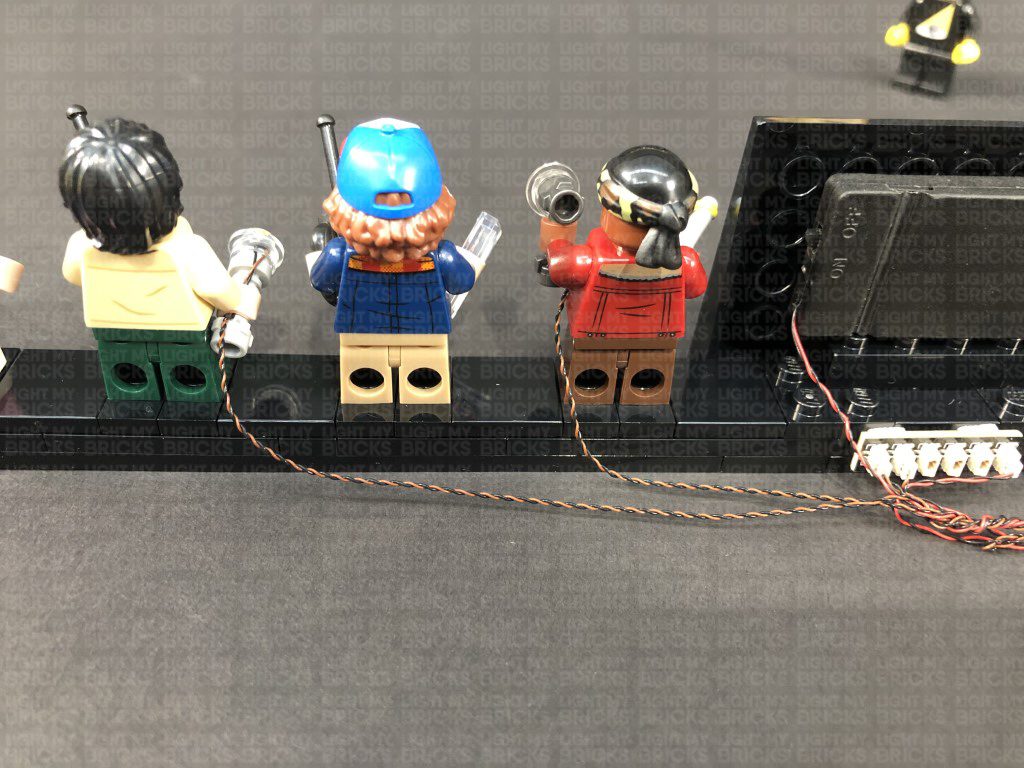
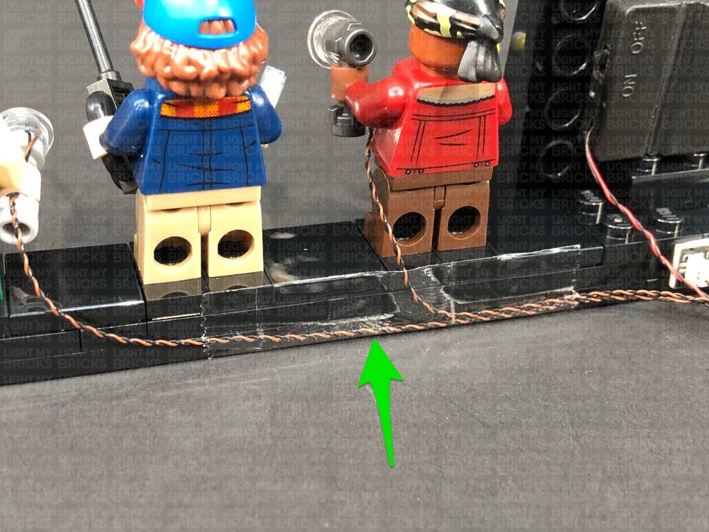
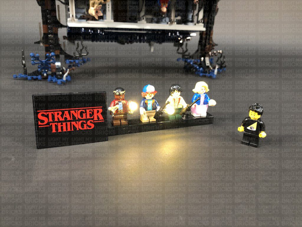
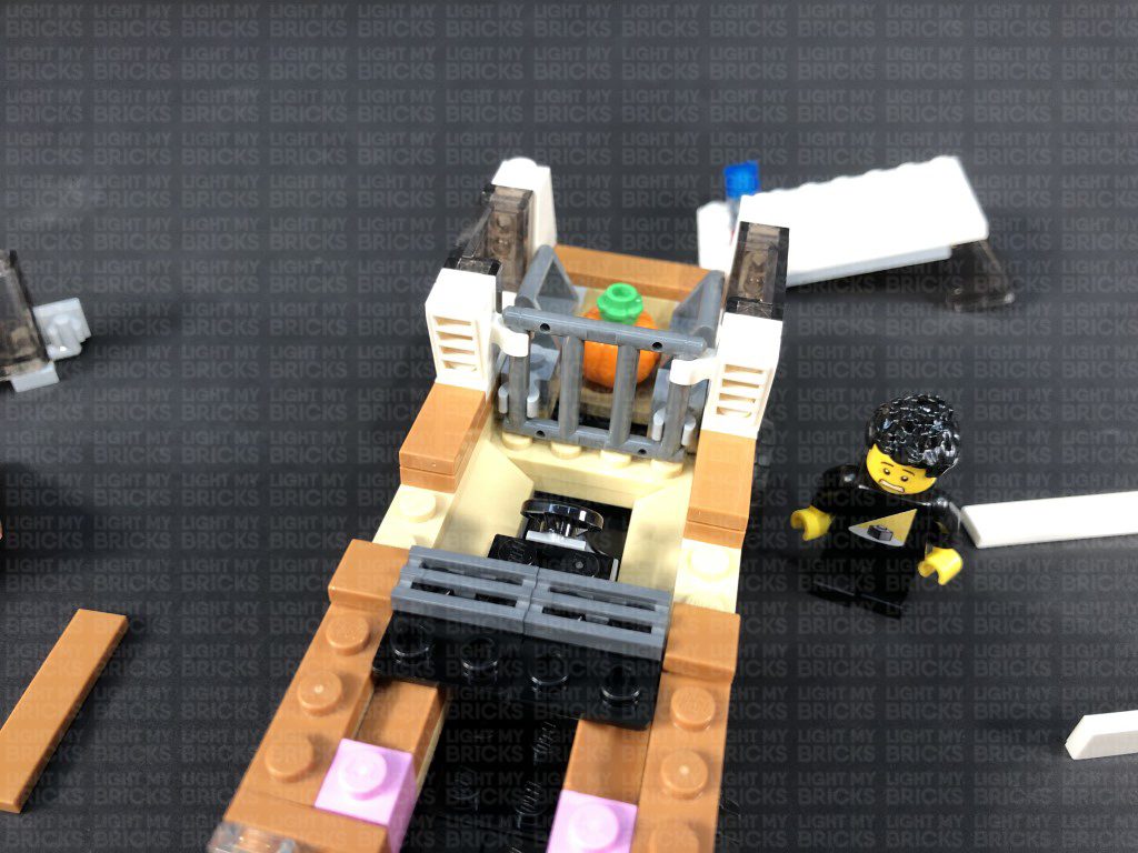
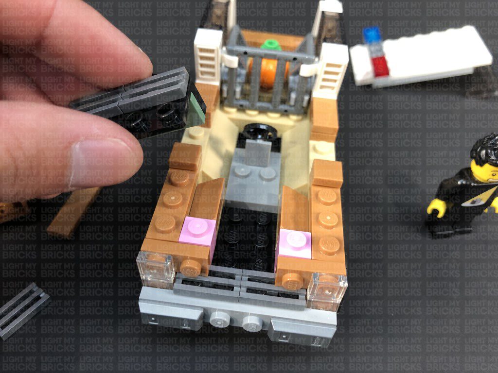
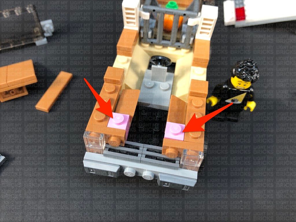
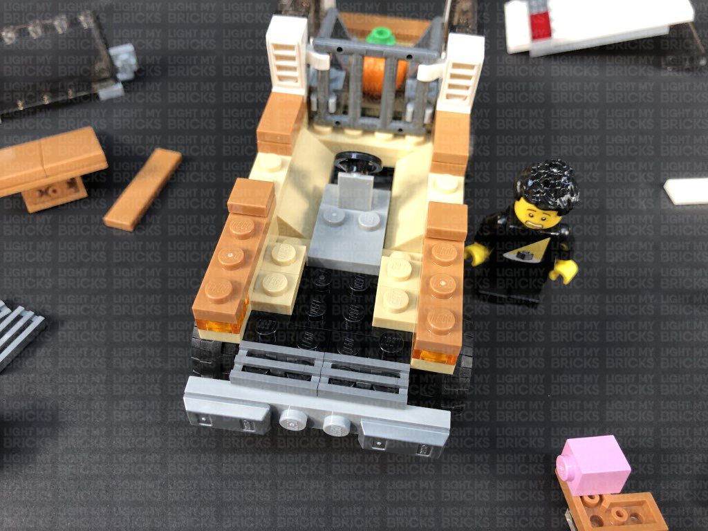
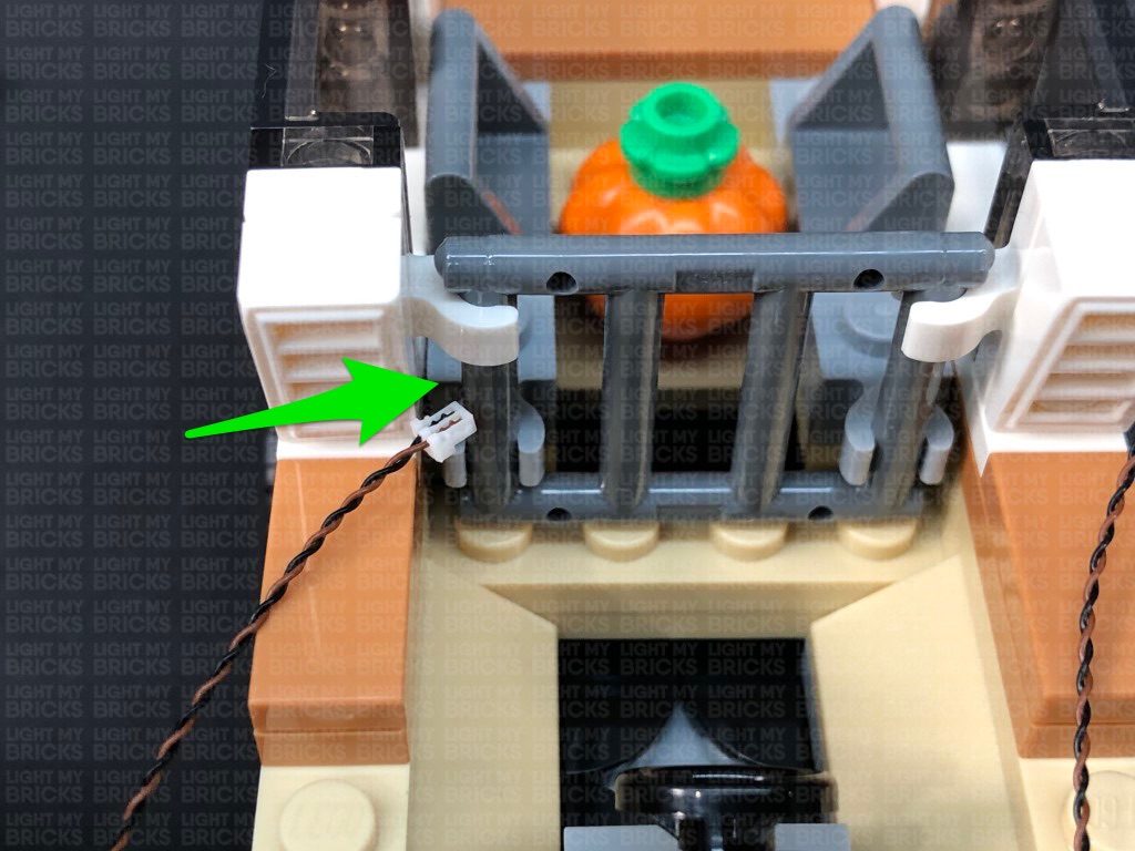
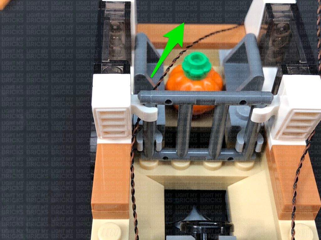
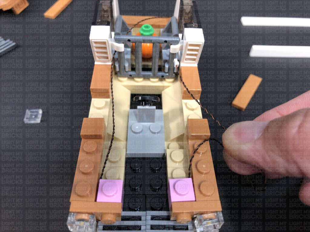
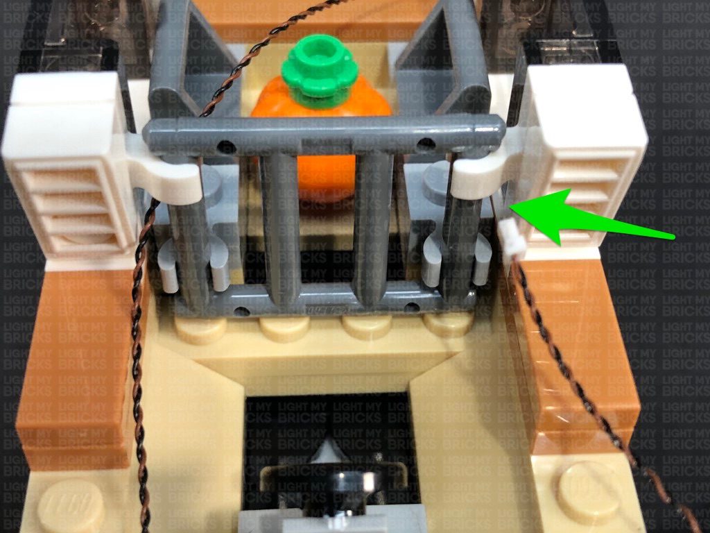
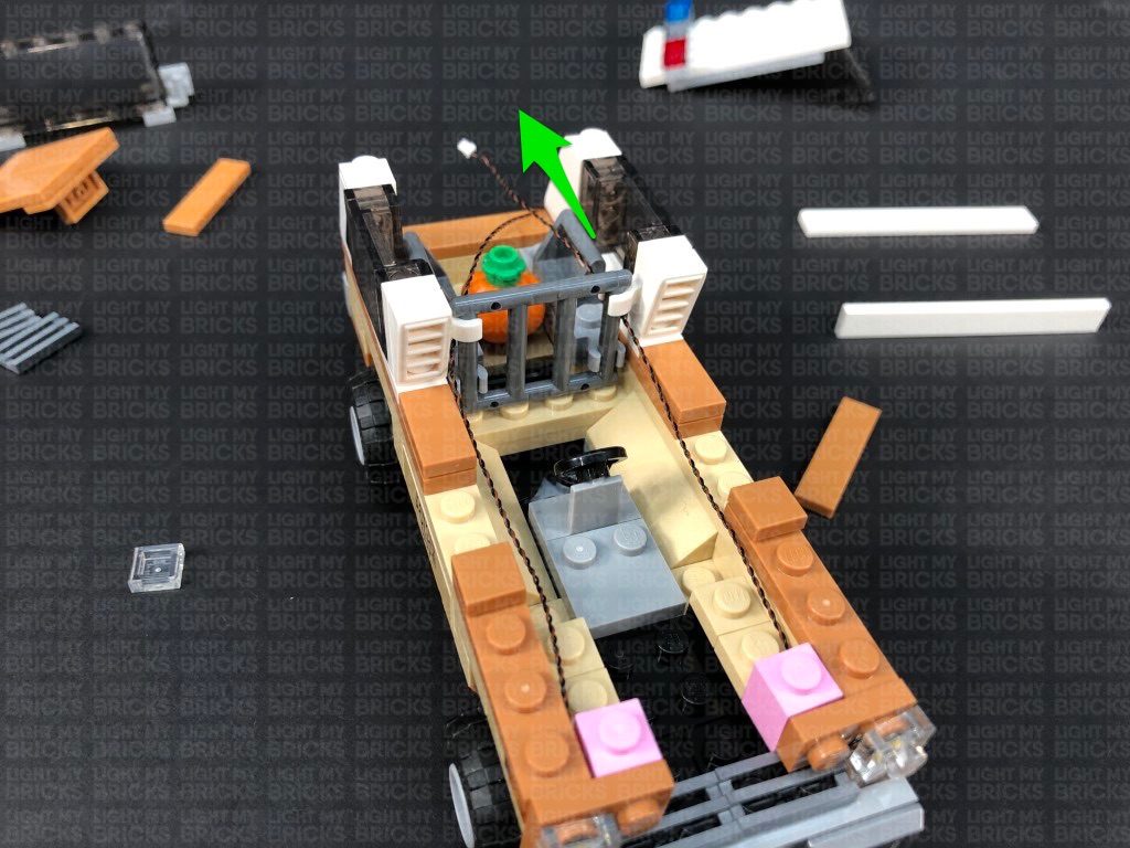
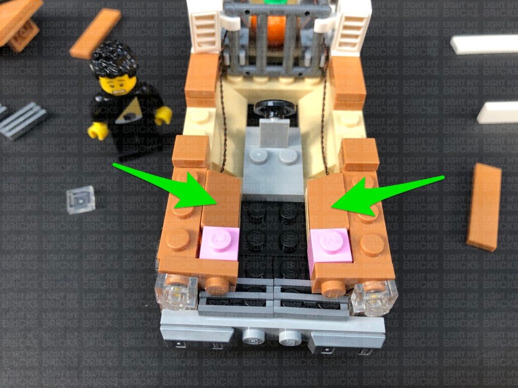
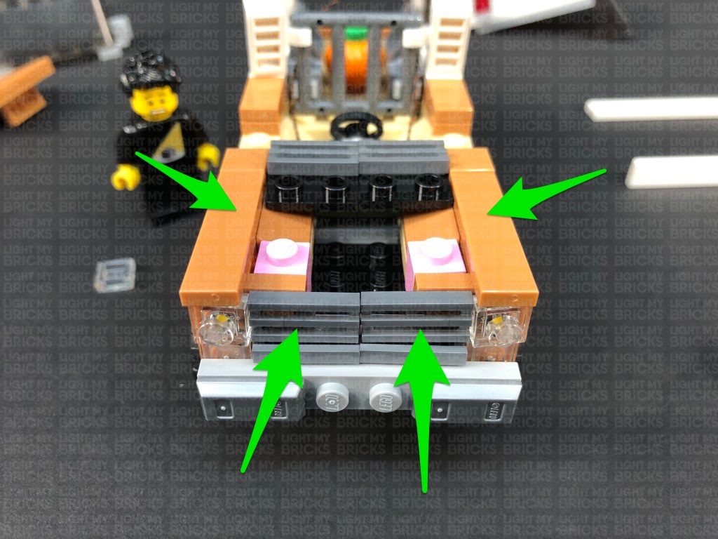
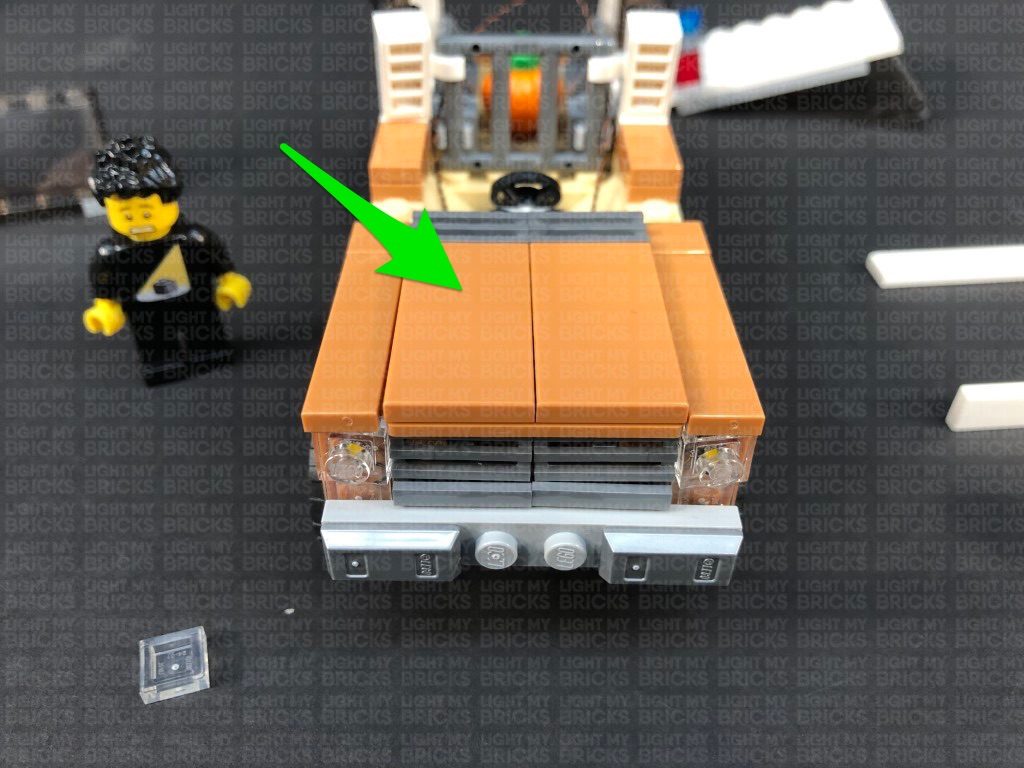
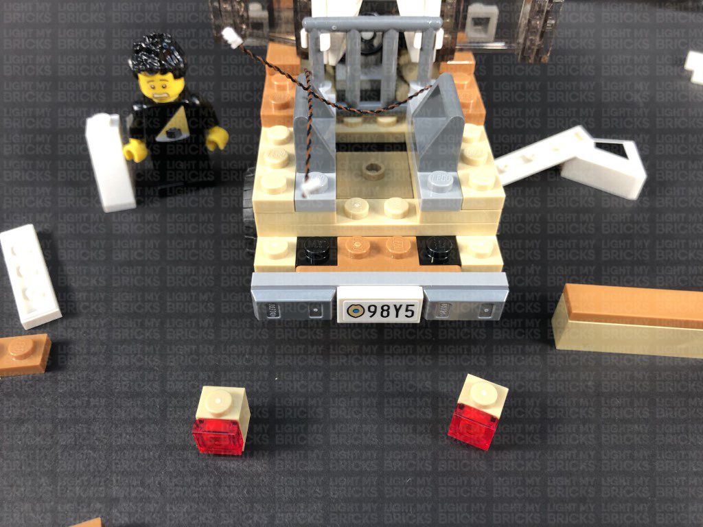
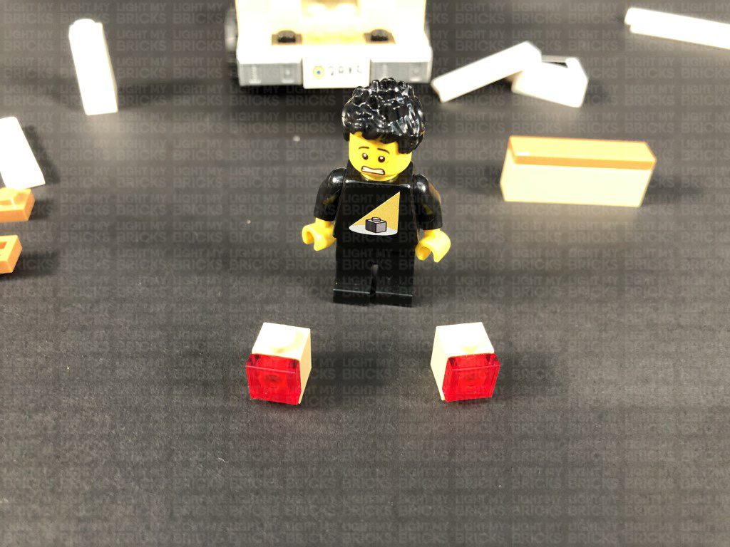
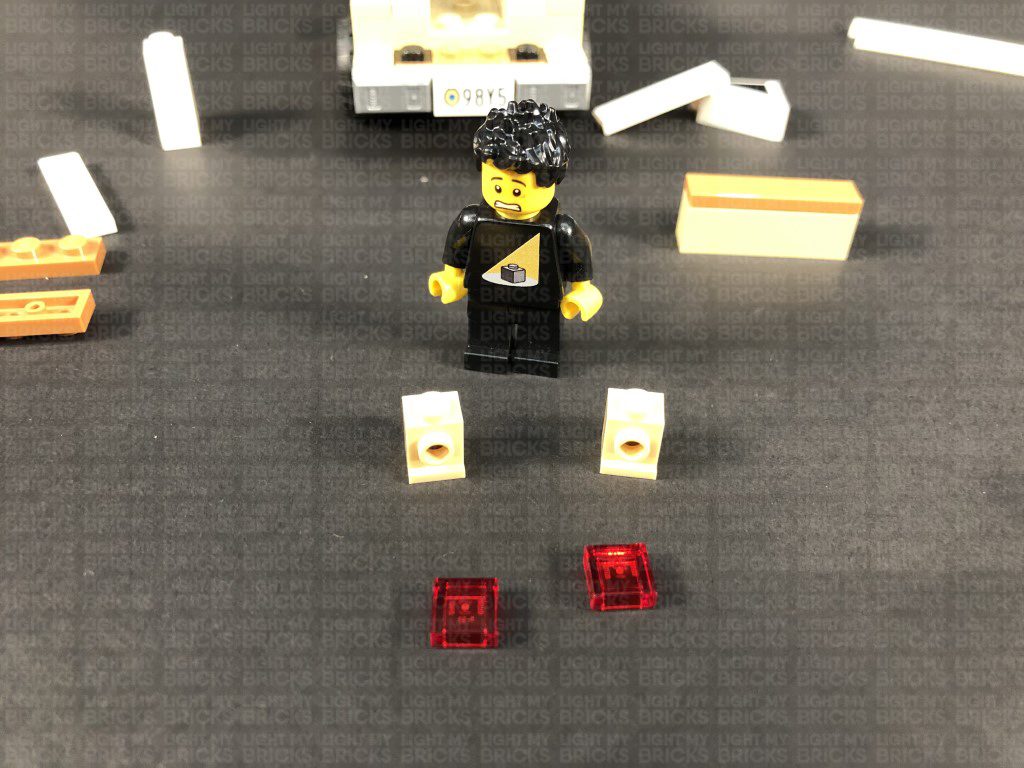
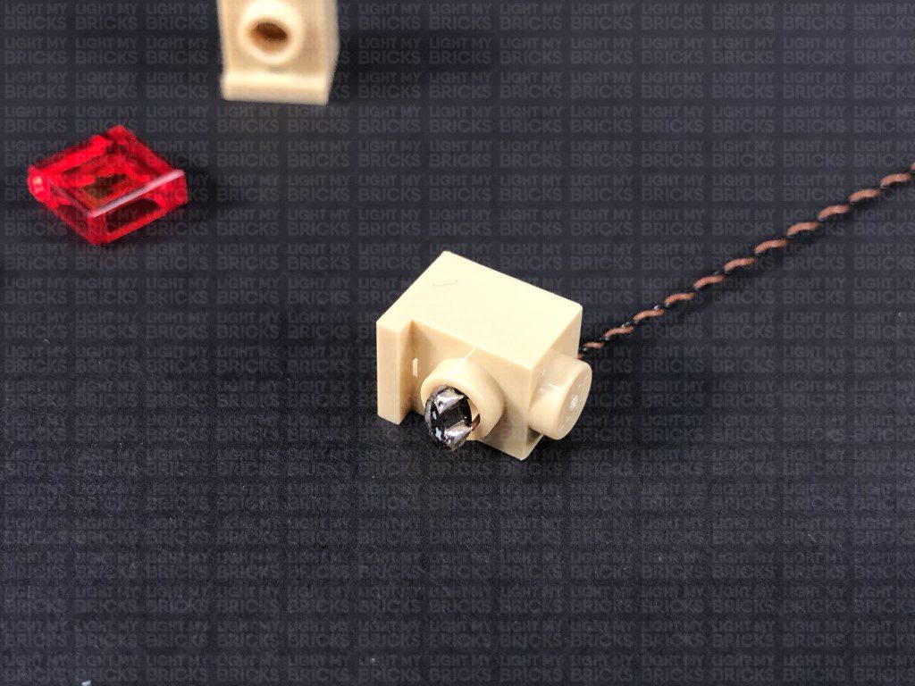
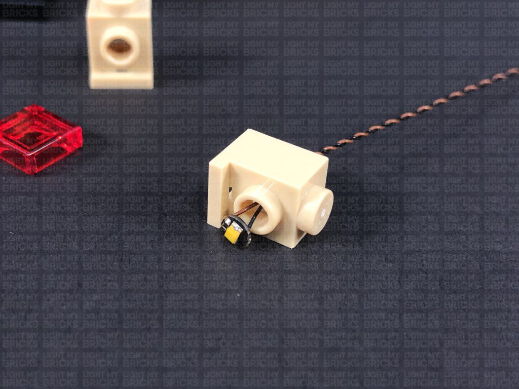
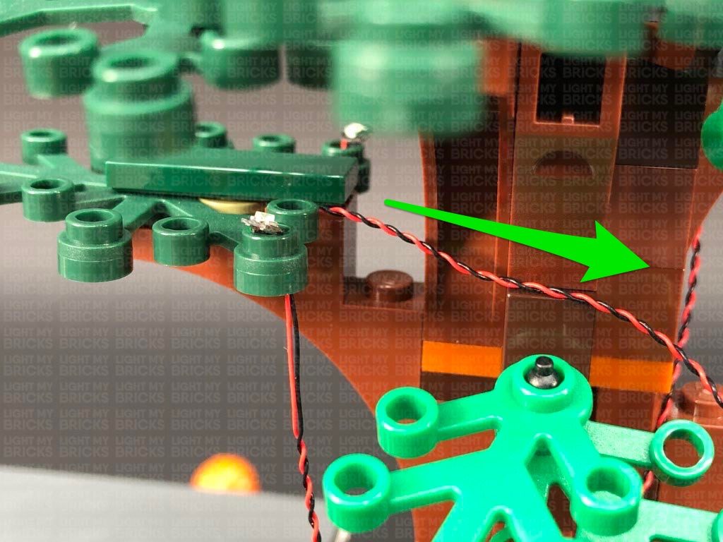
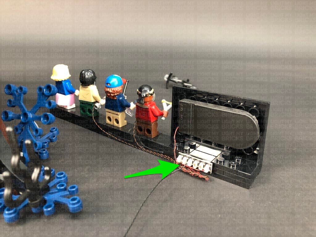
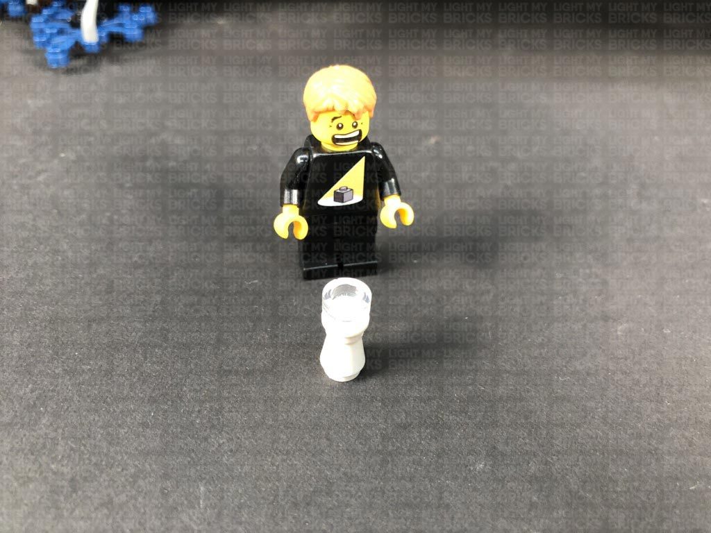
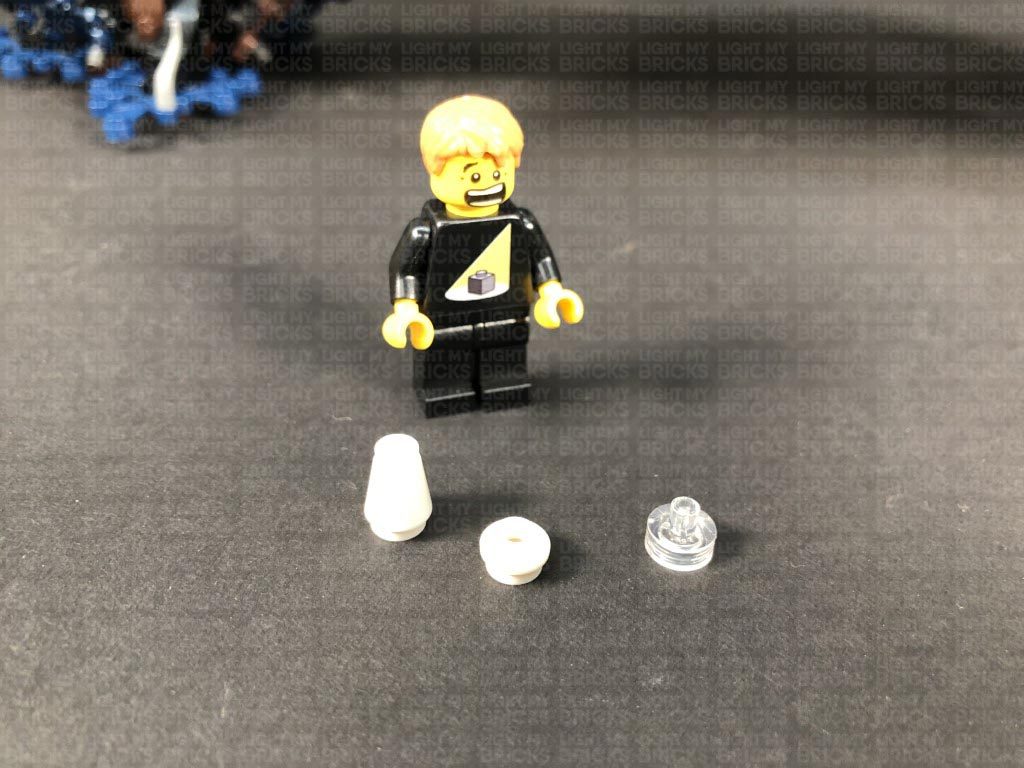
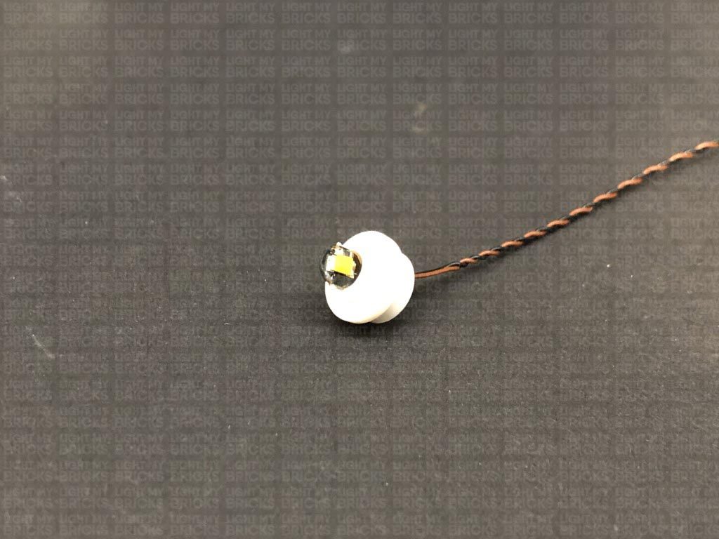
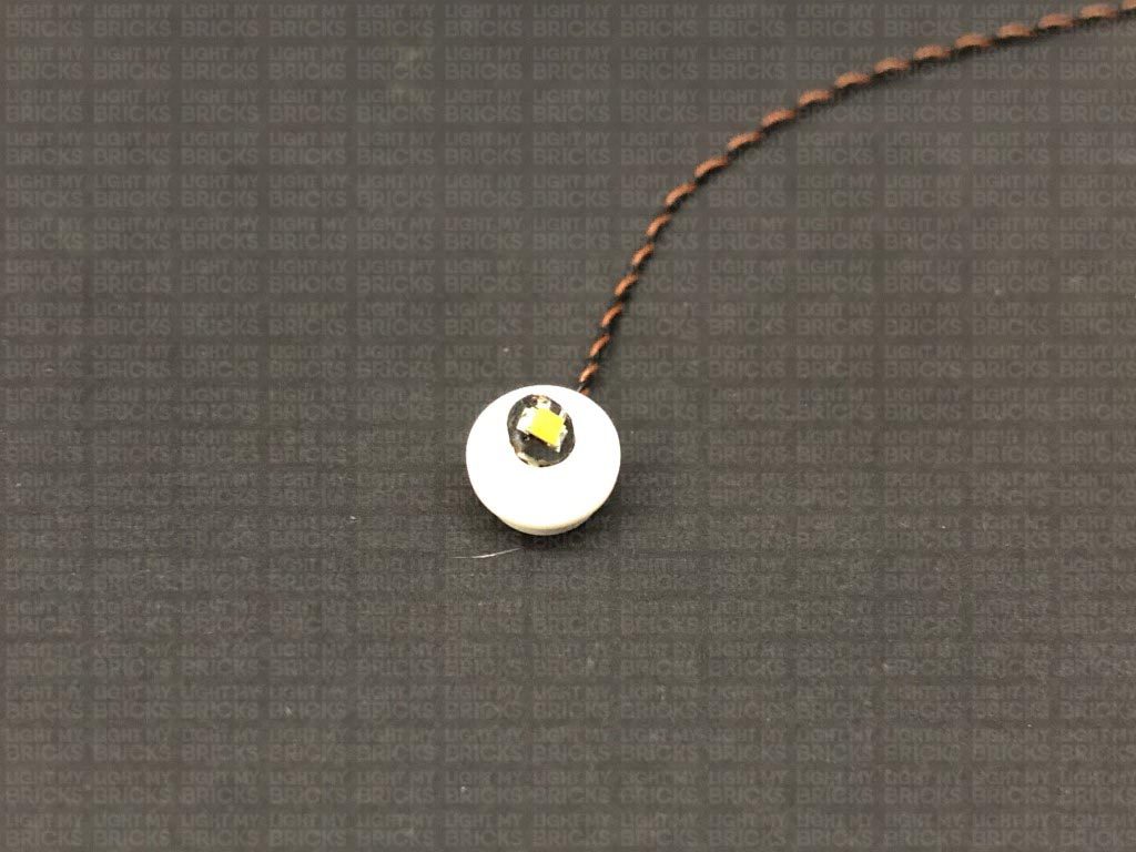
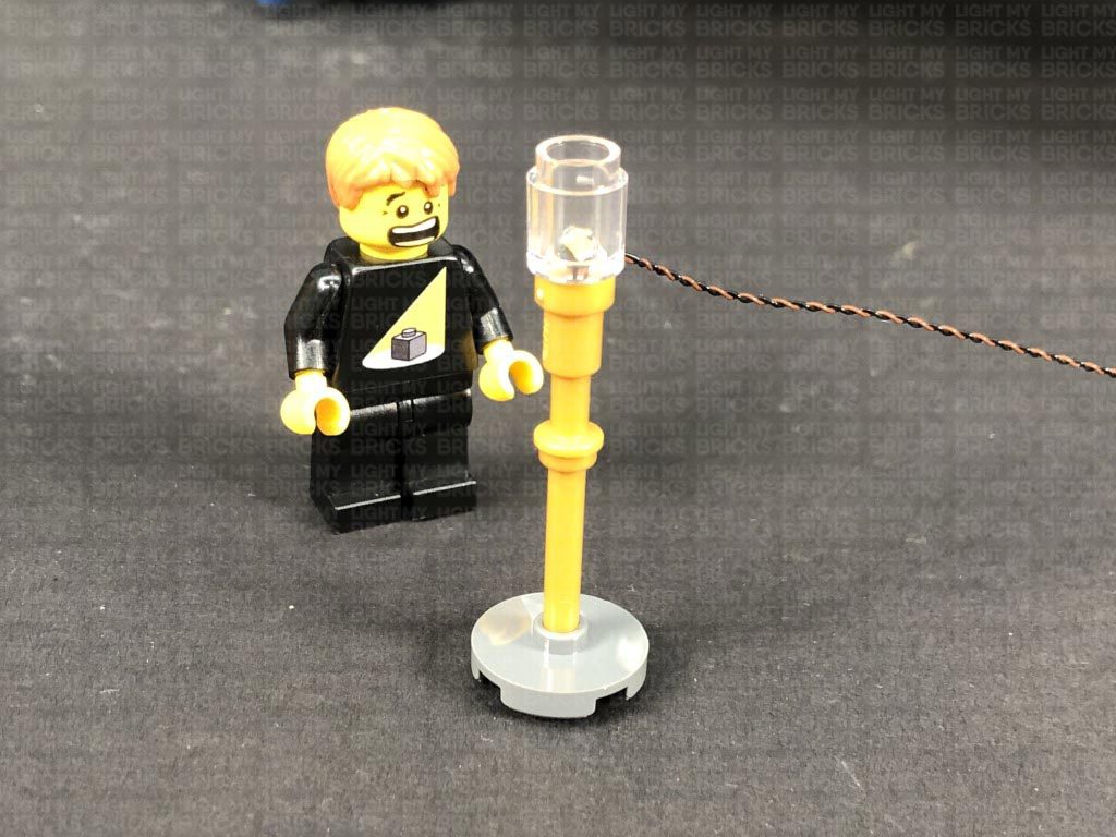
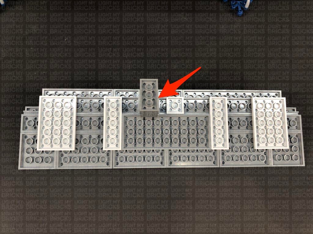
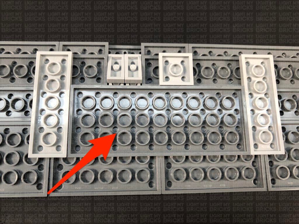
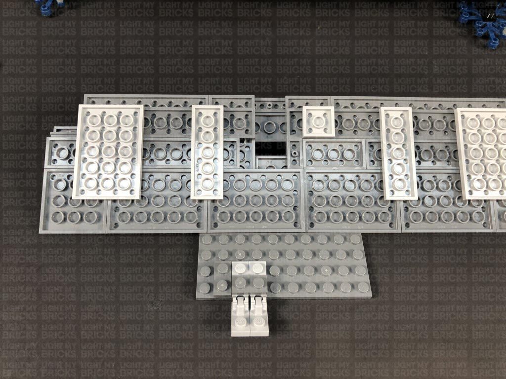
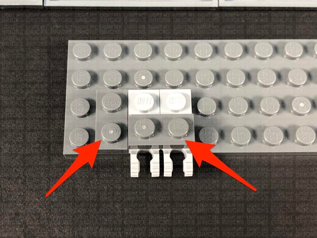
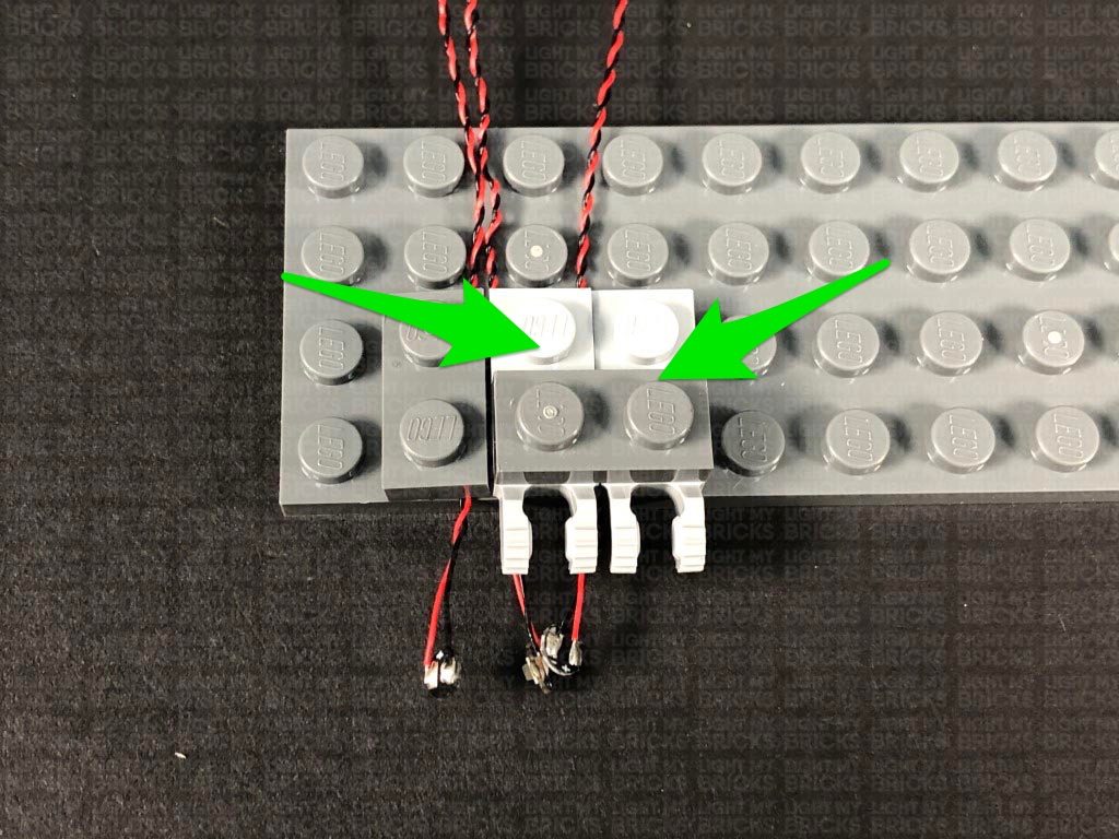
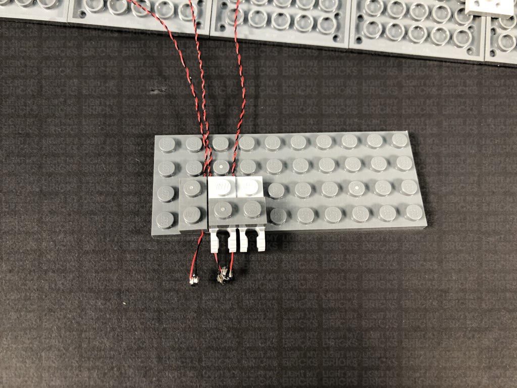
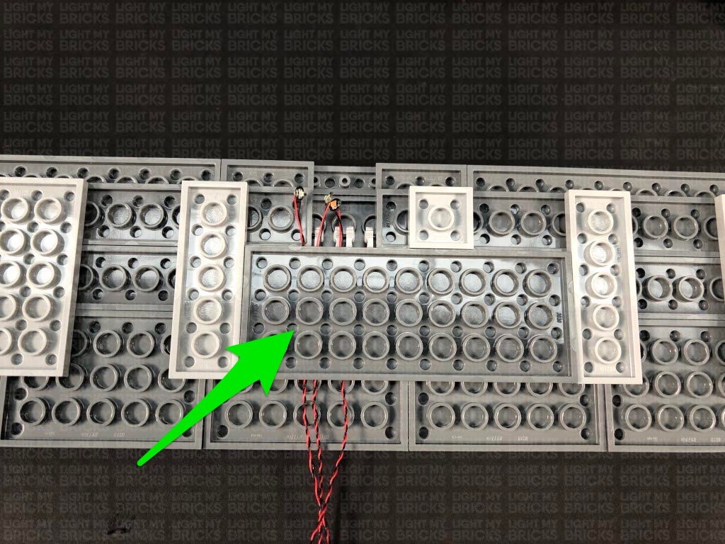
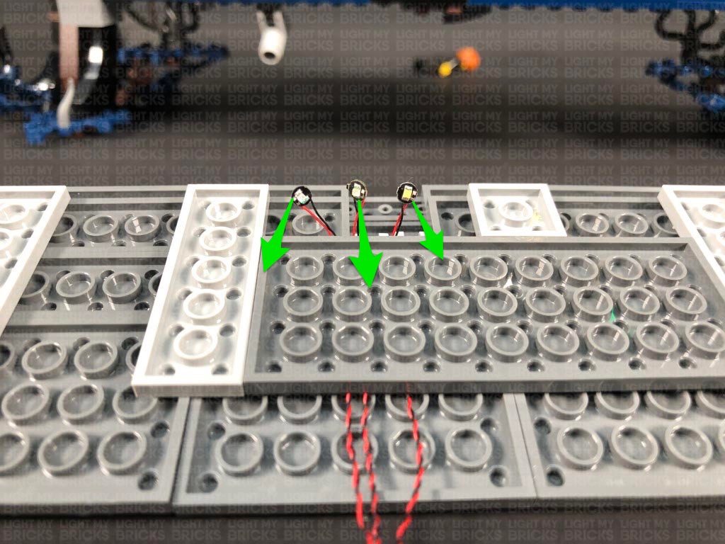
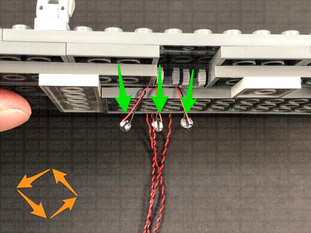
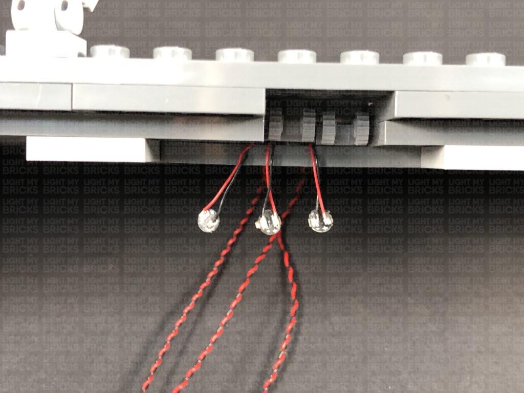
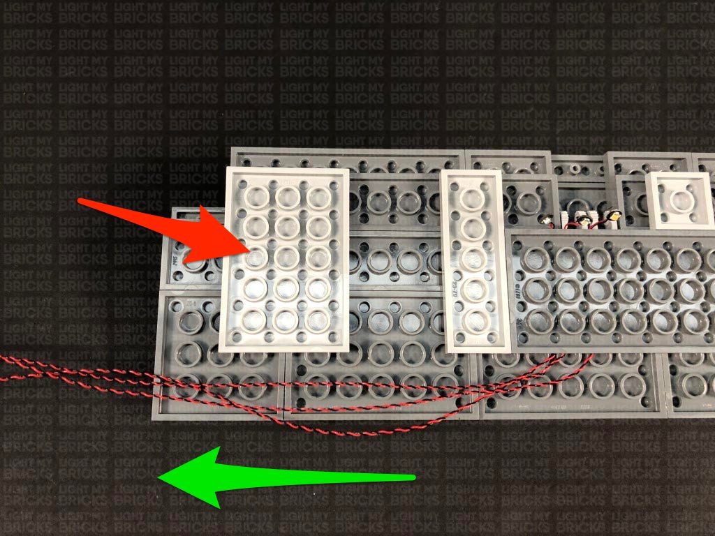
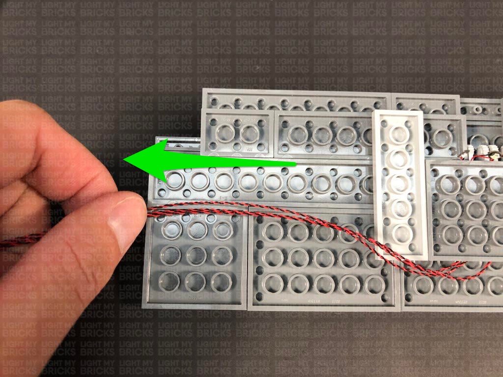
1.) The first section we will light up are the main characters on their “Stranger Things” platform. First, disconnect Mike, then disassemble his flash light. Take a White 15cm Bit Light and place it over the hilt’s stud. Secure it in place by reconnecting the trans clear round plate 1×1 over the top. Fold the Bit Light cable down toward the bottom of the hilt, then reconnect it to Mike’s hand ensuring the cable is also clipped inside. Reconnect Mike to the platform. 2.) Disconnect Lucas, then disassemble his flash light. Take a White 15cm Bit Light and with the cable facing the bottom of the flash light hilt, place it over the hilt’s stud. Since we can’t reconnect the trans clear tile over the bit light, discard this piece and connect a provided Trans clear Round Plate 1×1 over the top to secure the light in place. Wind the Bit Light cable behind the flash light, then reconnect it to Lucas’ hand ensuring the cable is also clipped inside. Reconnect Lucas to the platform. 3.) Turn the platform around, then connect the two Bit Light cables to a 6-Port Expansion Board. Take a Flat Battery Pack and insert 2x NEW CR2032 Batteries. Connect the battery pack cable to the expansion board and turn it ON to test the flashlights are working OK. Important Note: As of June 2022, Flat Battery Packs have been removed due to child safety regulations. Please read below to see an alternative power source (50cm Connecting Cable). Note: If you experience any issues with the lights not working and suspect an issue with a component, please try a different port on the expansion board to verify where the fault lies (with the light or expansion board). To correct any issues with expansion board ports, please view the section addressing expansion board issues on our online troubleshooting guide. 4.) Use 2x Adhesive Squares to mount the expansion board behind the bottom of the platform, then use another 2x Adhesive Squares to mount the flat battery pack (with cable facing the left) on the back of the Stranger Things board. Neaten up the excess cable by grouping them together and twisting/folding them around each other into a neat bunch. Secure the two cables down to the back of the platform, using sticky tape. This now completes installation for this section. If you wish to tether the power for the flash lights to the main light kit for the house rather than using batteries, connect the provided 50cm Connecting Cable to a spare port on the expansion board. You can connect the other end of the cable to the main circuit later on.
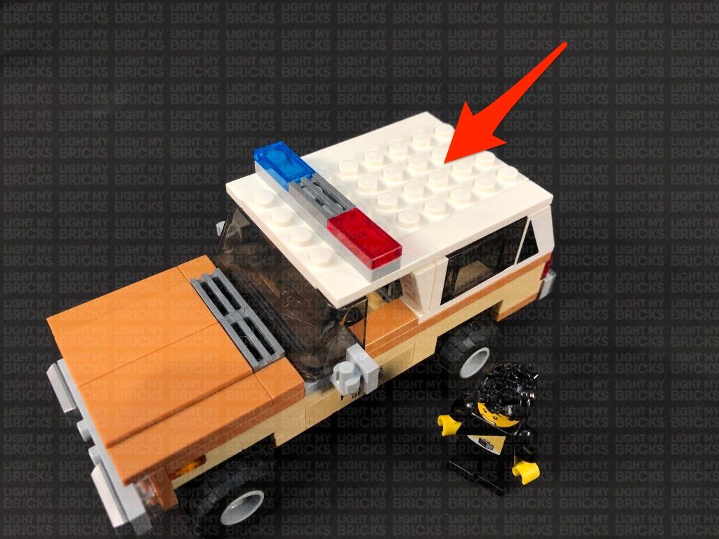
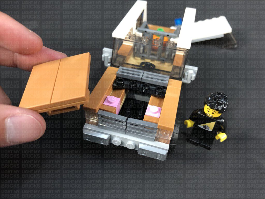
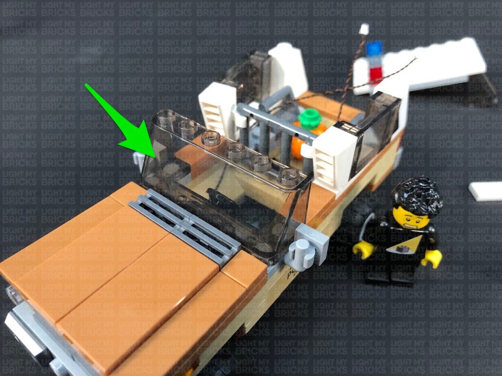
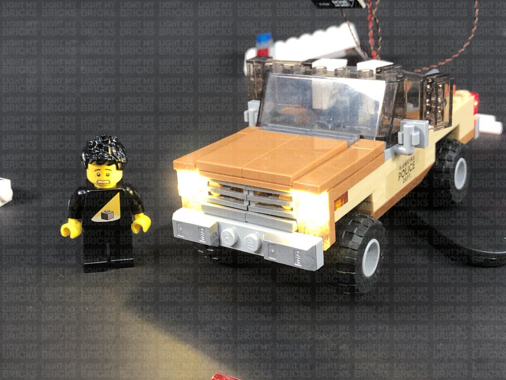
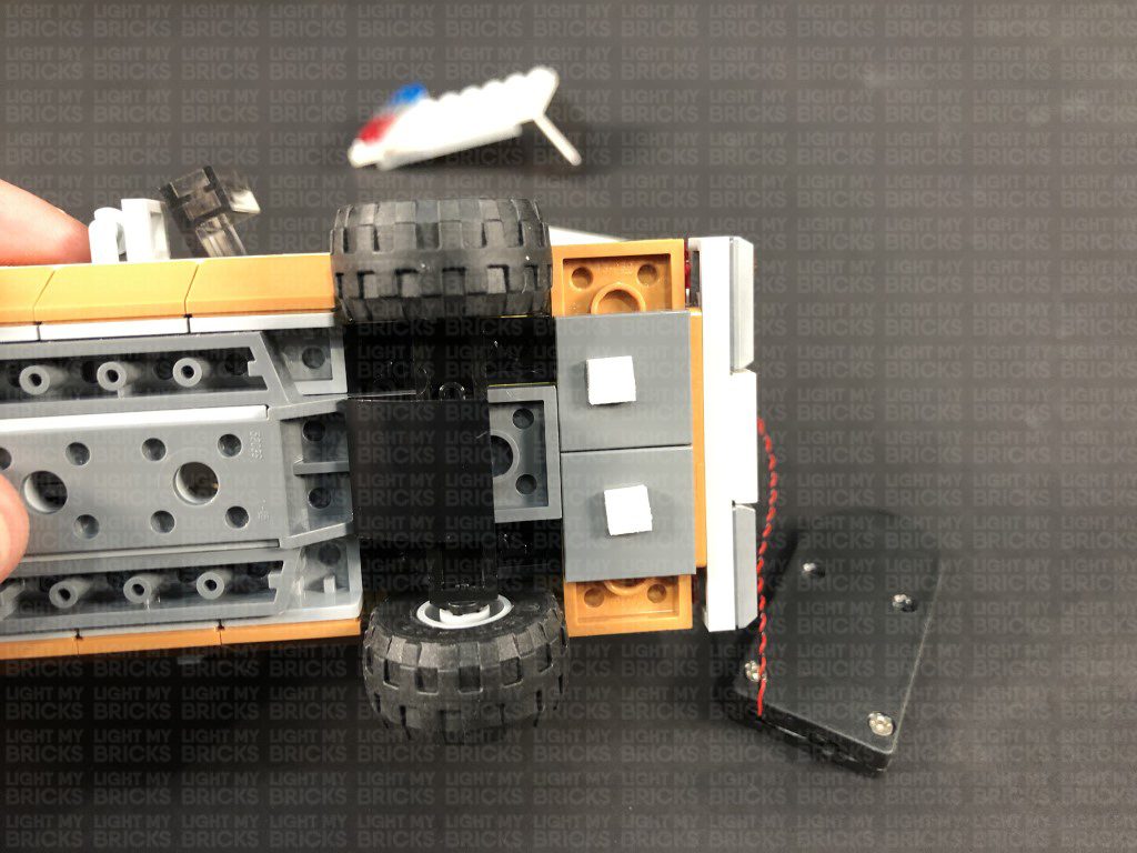
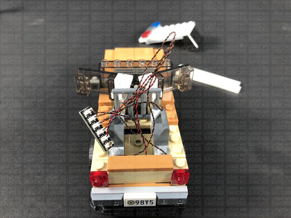
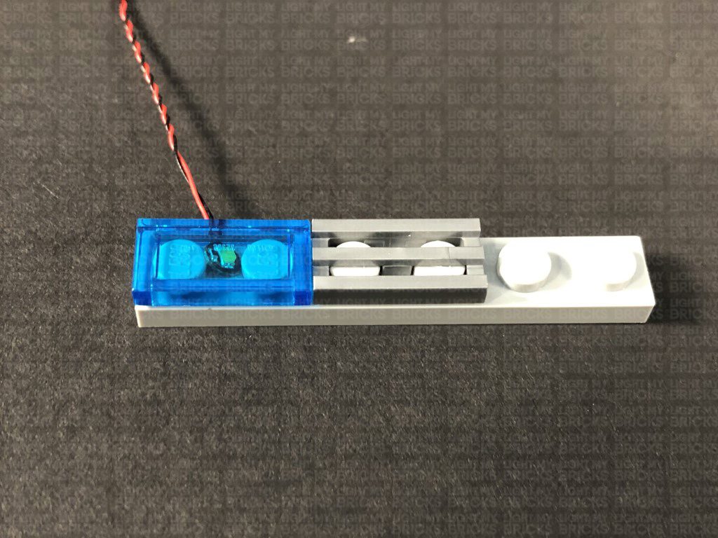
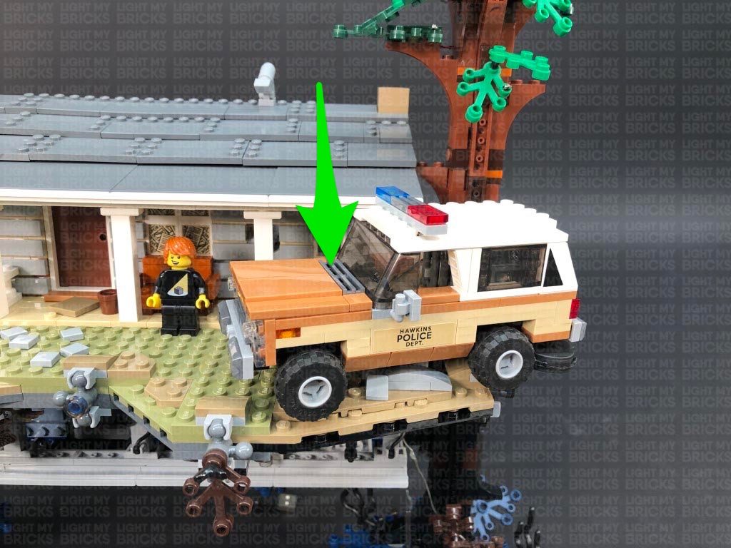
 5.) We will now light up Chief Hopper’s police car. First disconnect the car from the front of the set, then disconnect the roof and sections around the front to enable us to remove the head light sections.
*
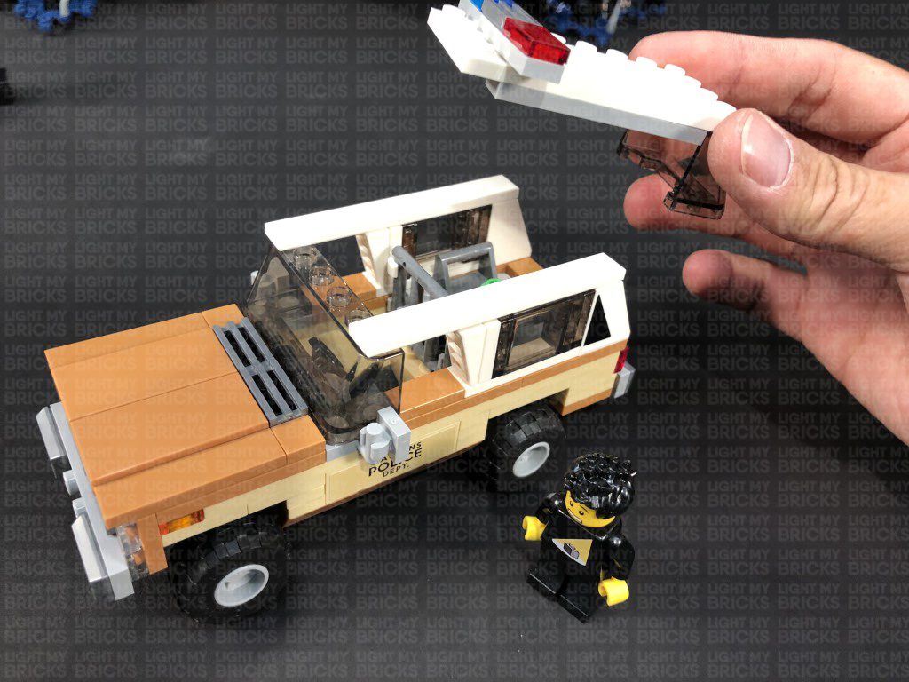
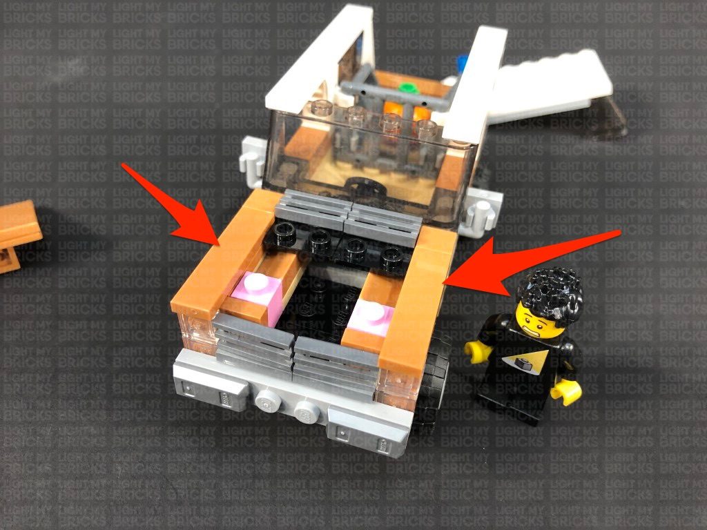
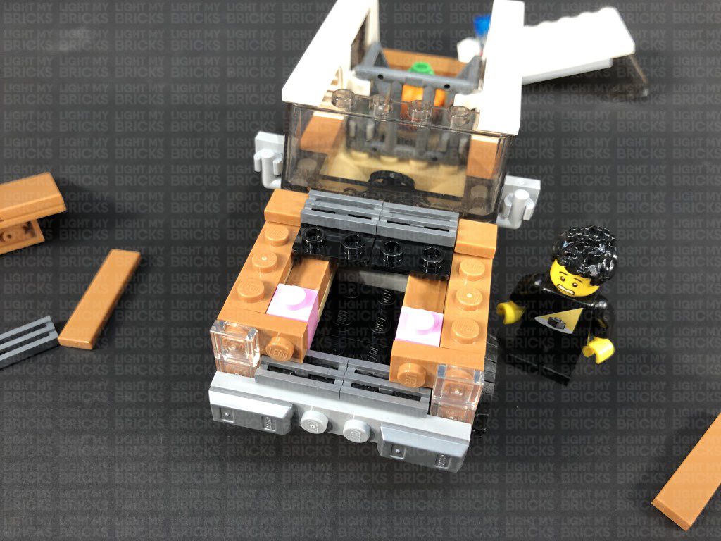
6.) Disconnect and discard the top trans clear tiles from the headlights as per below, then take a White 15cm Bit Light and with the cable facing the right, place it over the left head light section. Secure the Bit Light in place by connecting a provided Trans Clear Plate 1×1 over the top.
Fold the cable up underneath this section, then reconnect it to the front of the car ensuring the cable is pulled up behind and in between the pink and brown bricks as shown below.
7.) Repeat previous step to install another White 15cm Bit Light to the right headlight section.
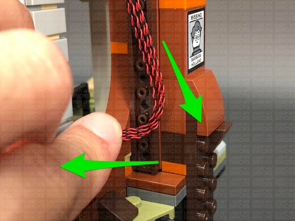
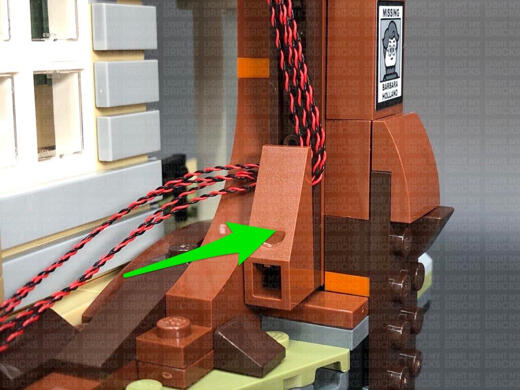
Thread both headlight cables through the following spaces which lead to the back of the vehicle.
.
Reconnect the pieces we removed earlier surrounding the front of the car.
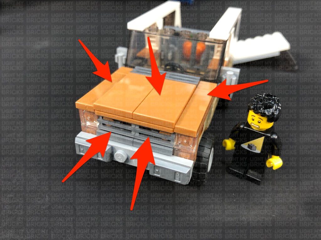
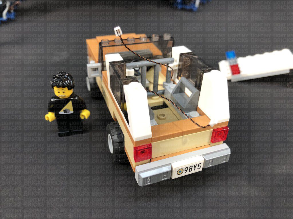
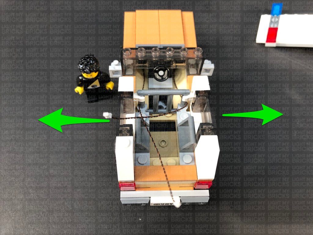
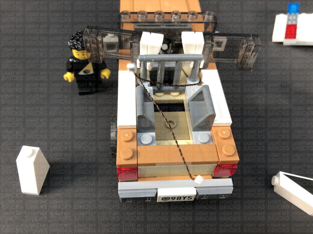
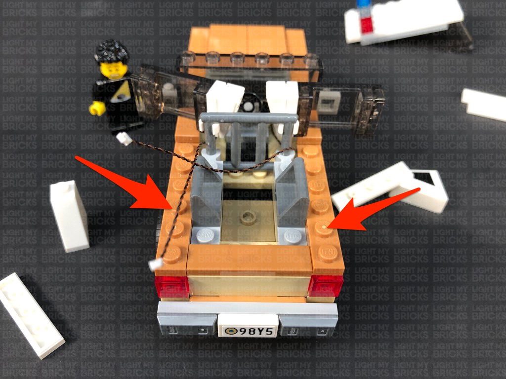
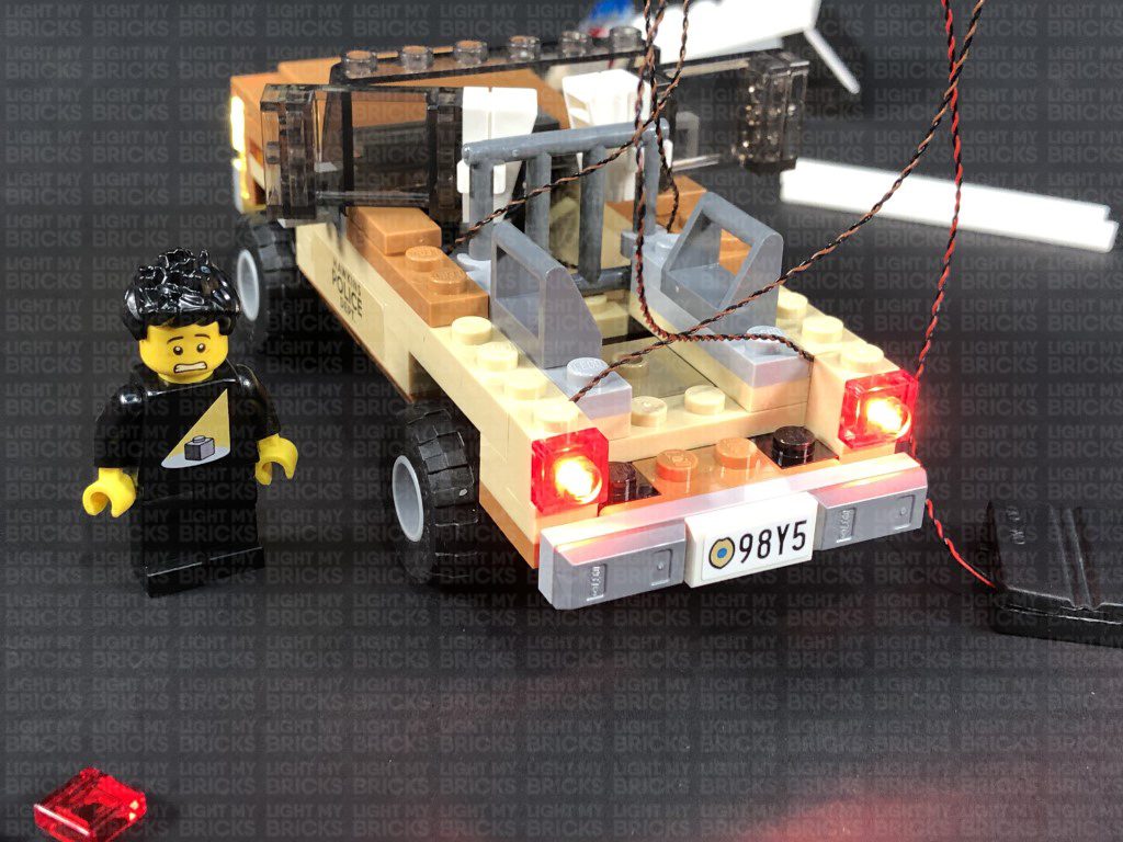
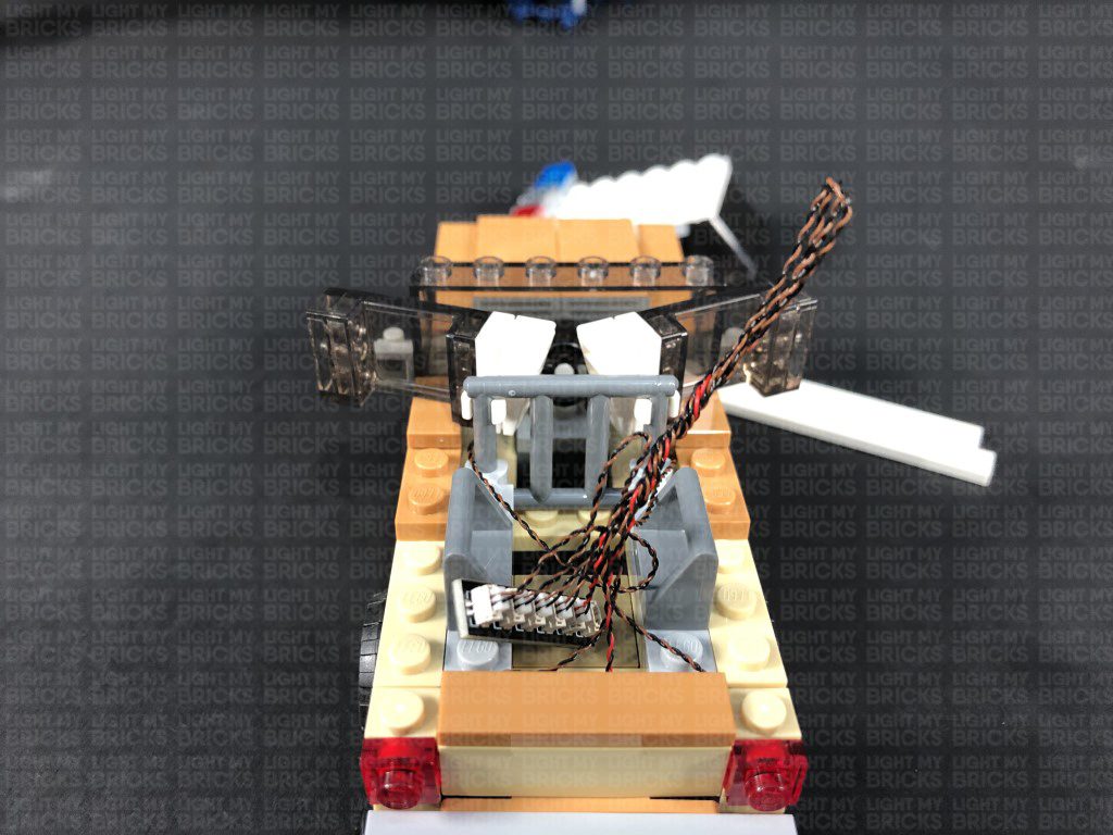
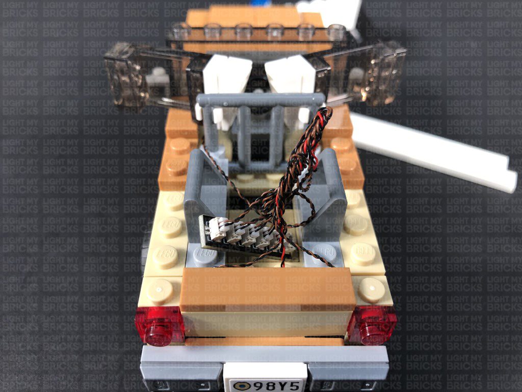
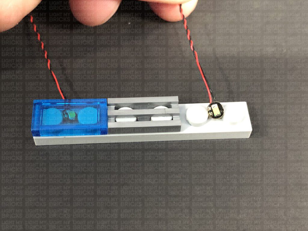
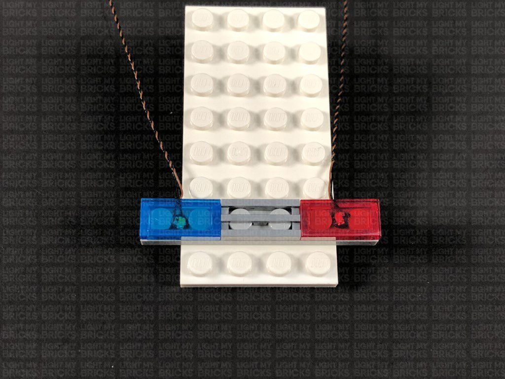
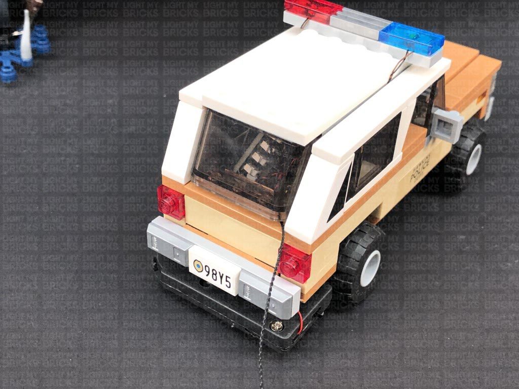
8.) Turn the car around to the rear side and pull the side windows out from each side, then disconnect the following pieces to enable us to disconnect the two tail light sections as shown below:
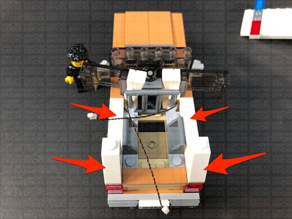
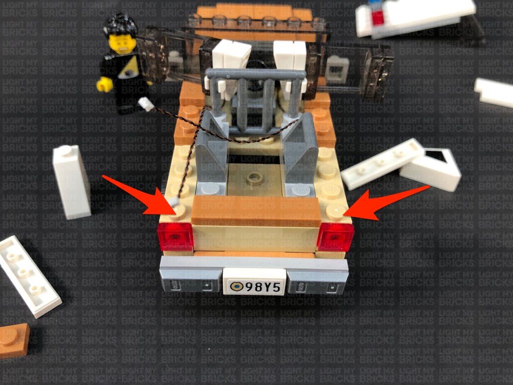
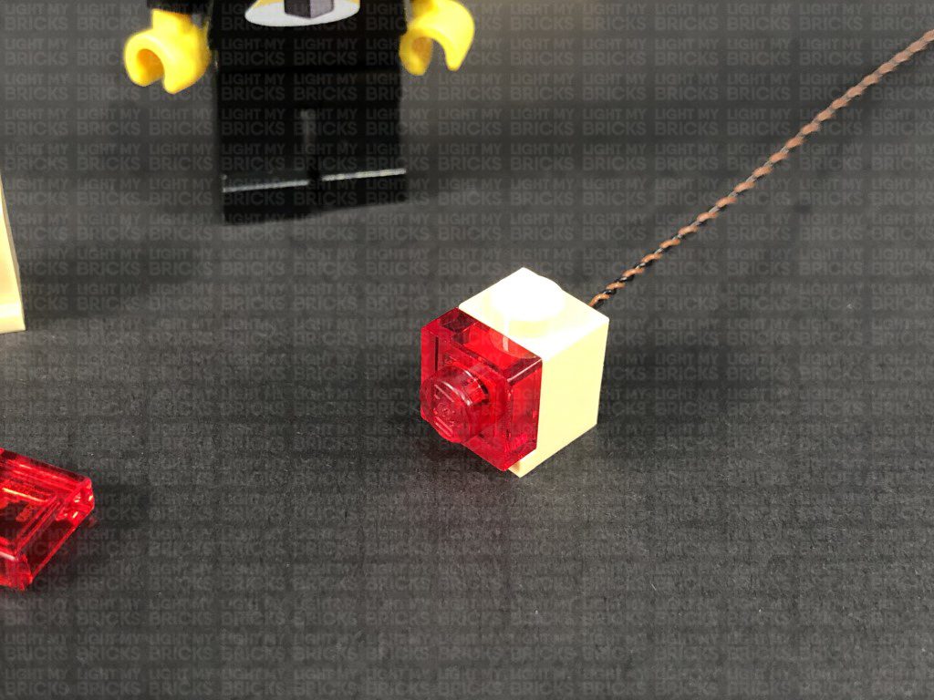
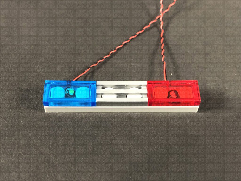
9.) Disconnect and discard the two trans red tiles from the tail lights, then take a White 15cm Bit Light and thread the connector end through the front of one of the tan coloured bricks. Pull the cable all the way out from the back of the brick, then slightly bend the Bit Light so that it sits flat against the edge of the front of the brick. Secure the light in place by connecting a provided Trans Red Plate 1×1 over the top.
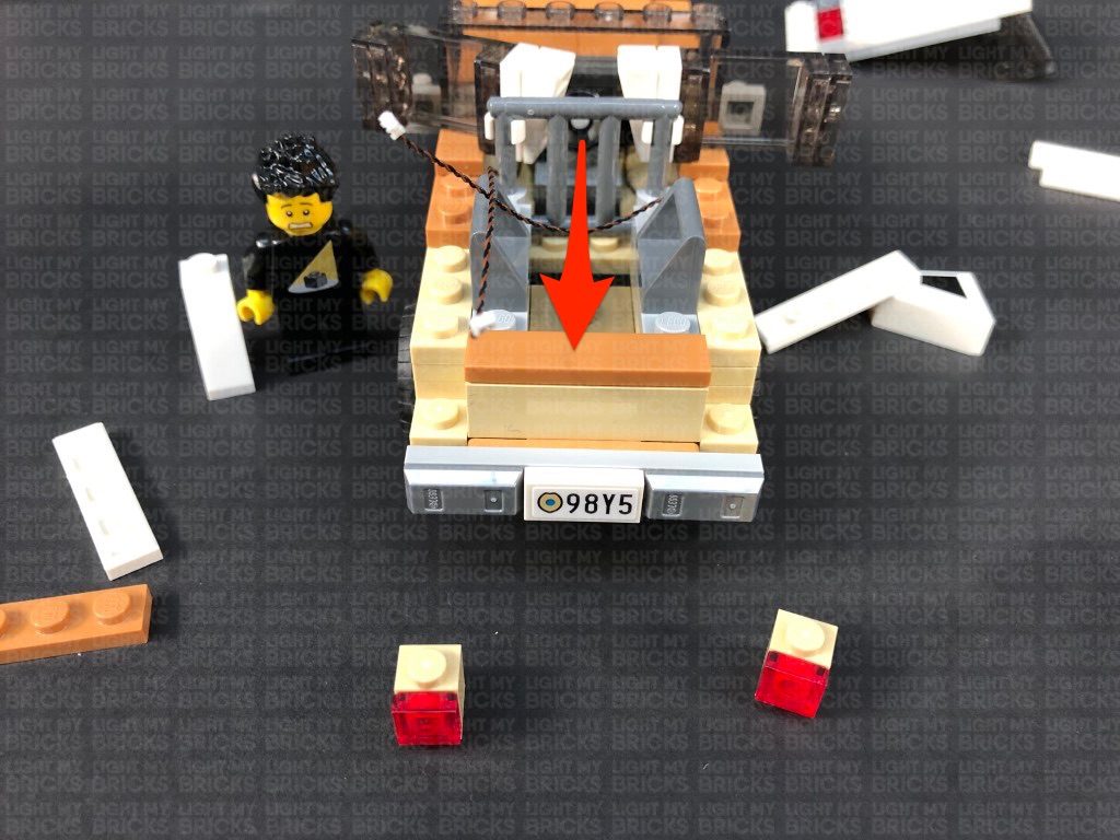
Reconnect the tail light section to the left side of the back of the car. Ensure you bring the cable to the right side, laying it behind the brick as shown below.
5.) We will now light up Chief Hopper’s police car. First disconnect the car from the front of the set, then disconnect the roof and sections around the front to enable us to remove the head light sections.
*
6.) Disconnect and discard the top trans clear tiles from the headlights as per below, then take a White 15cm Bit Light and with the cable facing the right, place it over the left head light section. Secure the Bit Light in place by connecting a provided Trans Clear Plate 1×1 over the top.
Fold the cable up underneath this section, then reconnect it to the front of the car ensuring the cable is pulled up behind and in between the pink and brown bricks as shown below.
7.) Repeat previous step to install another White 15cm Bit Light to the right headlight section.
Thread both headlight cables through the following spaces which lead to the back of the vehicle.
.
Reconnect the pieces we removed earlier surrounding the front of the car.
8.) Turn the car around to the rear side and pull the side windows out from each side, then disconnect the following pieces to enable us to disconnect the two tail light sections as shown below:
9.) Disconnect and discard the two trans red tiles from the tail lights, then take a White 15cm Bit Light and thread the connector end through the front of one of the tan coloured bricks. Pull the cable all the way out from the back of the brick, then slightly bend the Bit Light so that it sits flat against the edge of the front of the brick. Secure the light in place by connecting a provided Trans Red Plate 1×1 over the top.
Reconnect the tail light section to the left side of the back of the car. Ensure you bring the cable to the right side, laying it behind the brick as shown below.
 Repeat this step to install another White 15cm Bit Light to the right tail light, securing it in place with another provided Trans Red Plate 1×1. Ensure you bring the cable to the left side, behind the brick as you reconnect it to the right side of the back of the car.
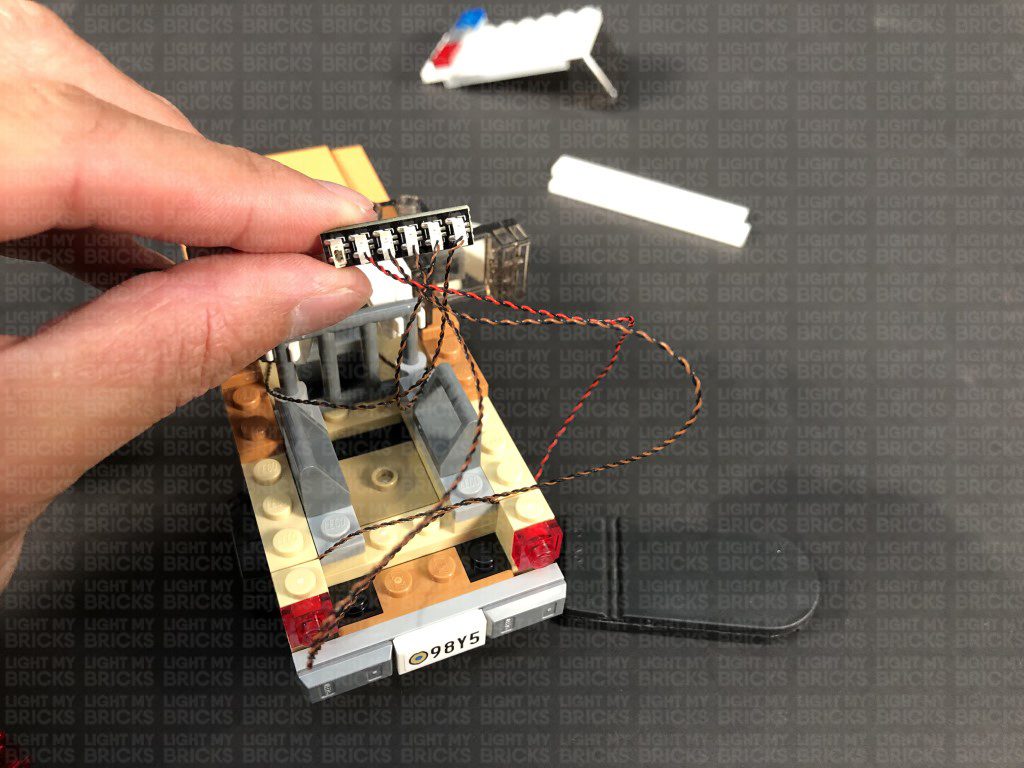
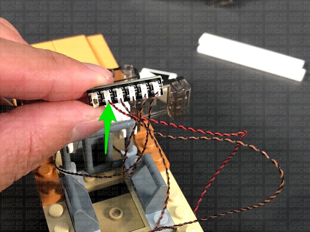
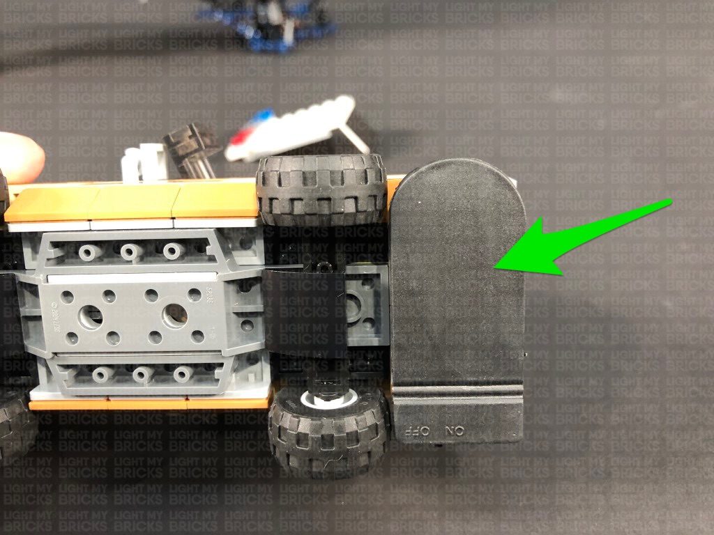
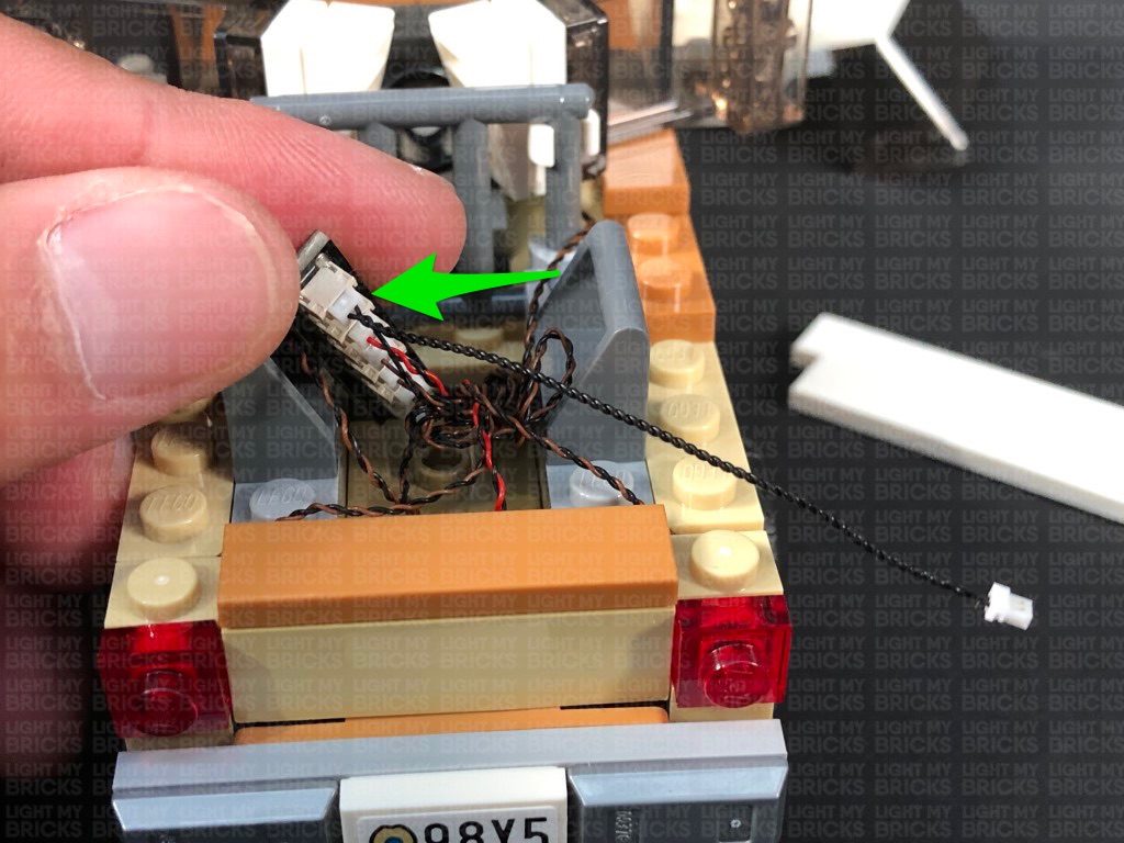
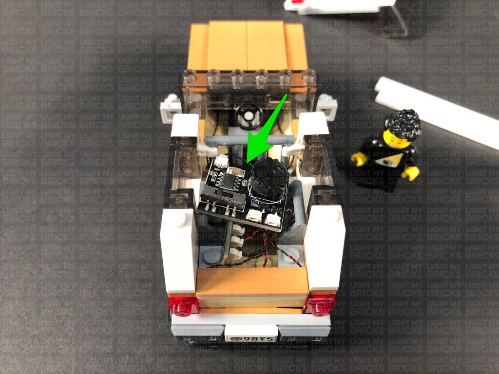
 10.) Take a 6-Port Expansion Board and connect the two head light cables as well as the two tail light cables to it. Take a Flat Battery Pack and insert 2x NEW CR2032 Batteries to it. Connect the battery pack cable to the 6-Port Expansion Board, then turn the battery pack ON to test the head and tail lights are working OK.
Important Note: As of June 2022, Flat Battery Packs have been removed due to child safety regulations. Please read below to see an alternative power source (15cm Connecting Cable).
Note: If you experience any issues with the lights not working and suspect an issue with a component, please try a different port on the expansion board to verify where the fault lies (with the light or expansion board). To correct any issues with expansion board ports, please view the section addressing expansion board issues on our online troubleshooting guide.
11.) Flip the car over and mount the Flat Battery Pack underneath the car towards the back using 2x Adhesive Squares. Ensure the battery pack switch is facing the right side of the car.
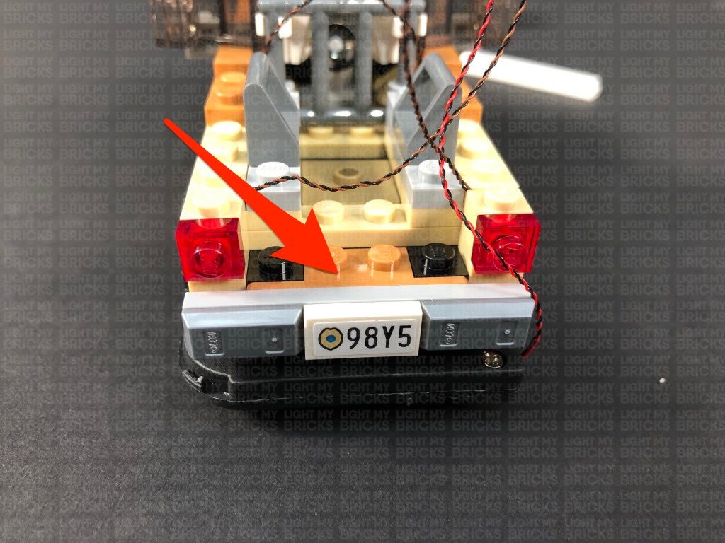
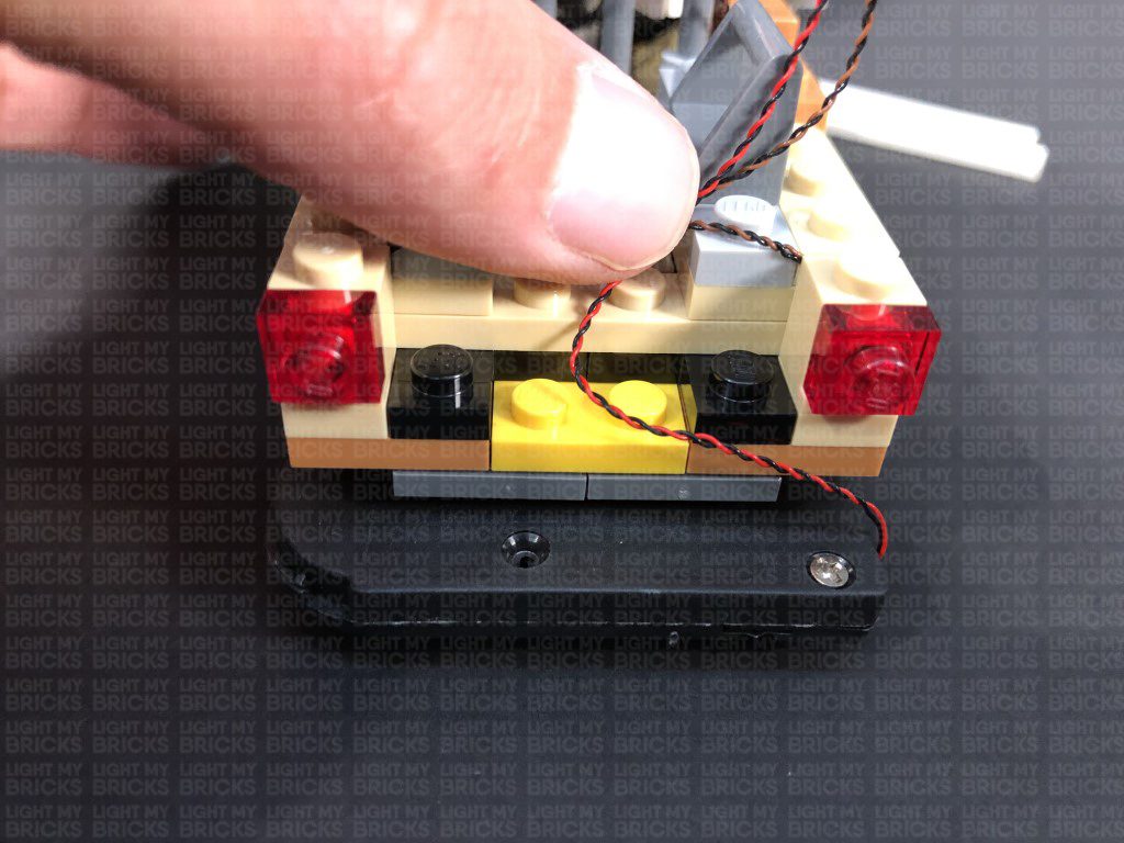
Turn the car back over and disconnect the following number plate section. Pull the battery pack all the way up inside the car and lay it down in between studs toward the middle before reconnecting the section over the top as shown below:
Reconnect the following piece, then neaten up the cabling by grouping all the cables and folding and twisting them around each other a few times, forming a neat bunch.
10.) Take a 6-Port Expansion Board and connect the two head light cables as well as the two tail light cables to it. Take a Flat Battery Pack and insert 2x NEW CR2032 Batteries to it. Connect the battery pack cable to the 6-Port Expansion Board, then turn the battery pack ON to test the head and tail lights are working OK.
Important Note: As of June 2022, Flat Battery Packs have been removed due to child safety regulations. Please read below to see an alternative power source (15cm Connecting Cable).
Note: If you experience any issues with the lights not working and suspect an issue with a component, please try a different port on the expansion board to verify where the fault lies (with the light or expansion board). To correct any issues with expansion board ports, please view the section addressing expansion board issues on our online troubleshooting guide.
11.) Flip the car over and mount the Flat Battery Pack underneath the car towards the back using 2x Adhesive Squares. Ensure the battery pack switch is facing the right side of the car.
Turn the car back over and disconnect the following number plate section. Pull the battery pack all the way up inside the car and lay it down in between studs toward the middle before reconnecting the section over the top as shown below:
Reconnect the following piece, then neaten up the cabling by grouping all the cables and folding and twisting them around each other a few times, forming a neat bunch.
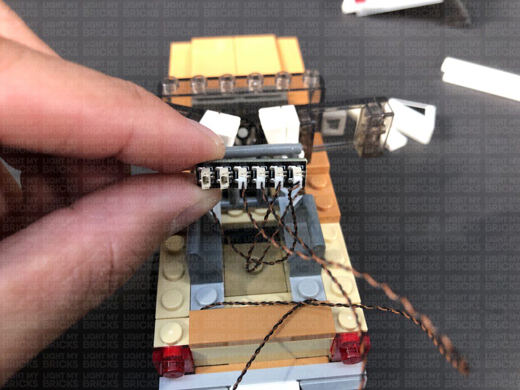
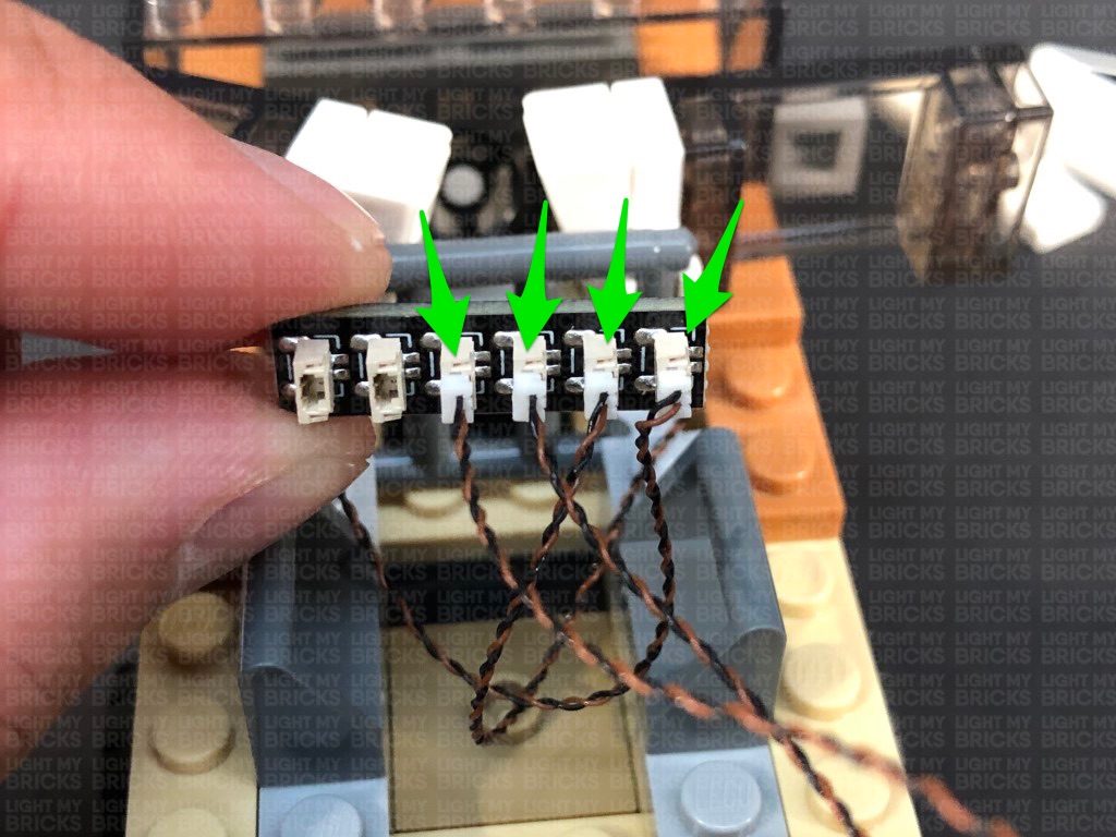
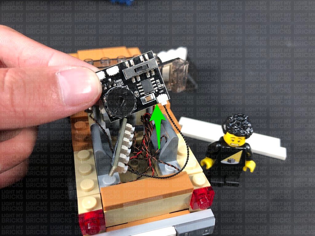
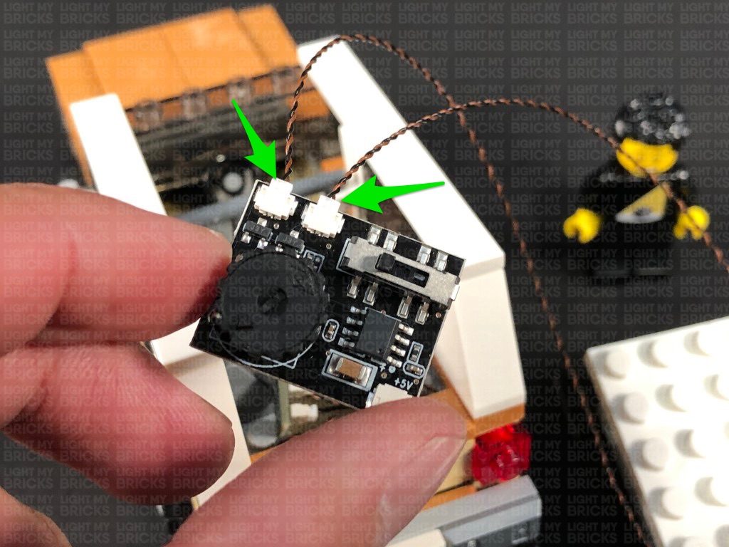
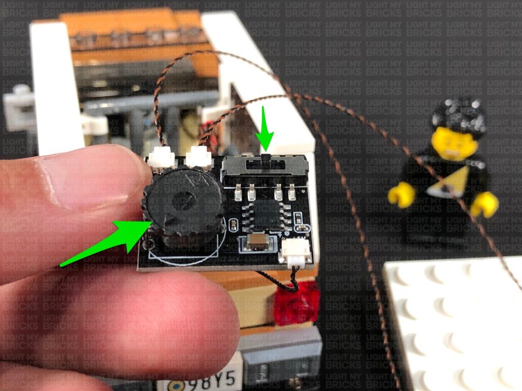
 12.) Take a 5cm Connecting Cable and connect it to the remaining port on the 6-Port Expansion Board. Connect the other end of the cable to the IN port (+5V) on the Multi Effects Board (side with 1 port)
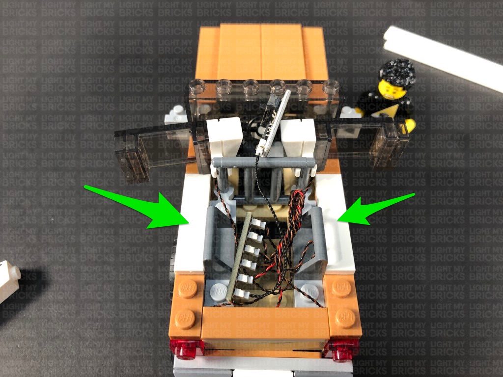
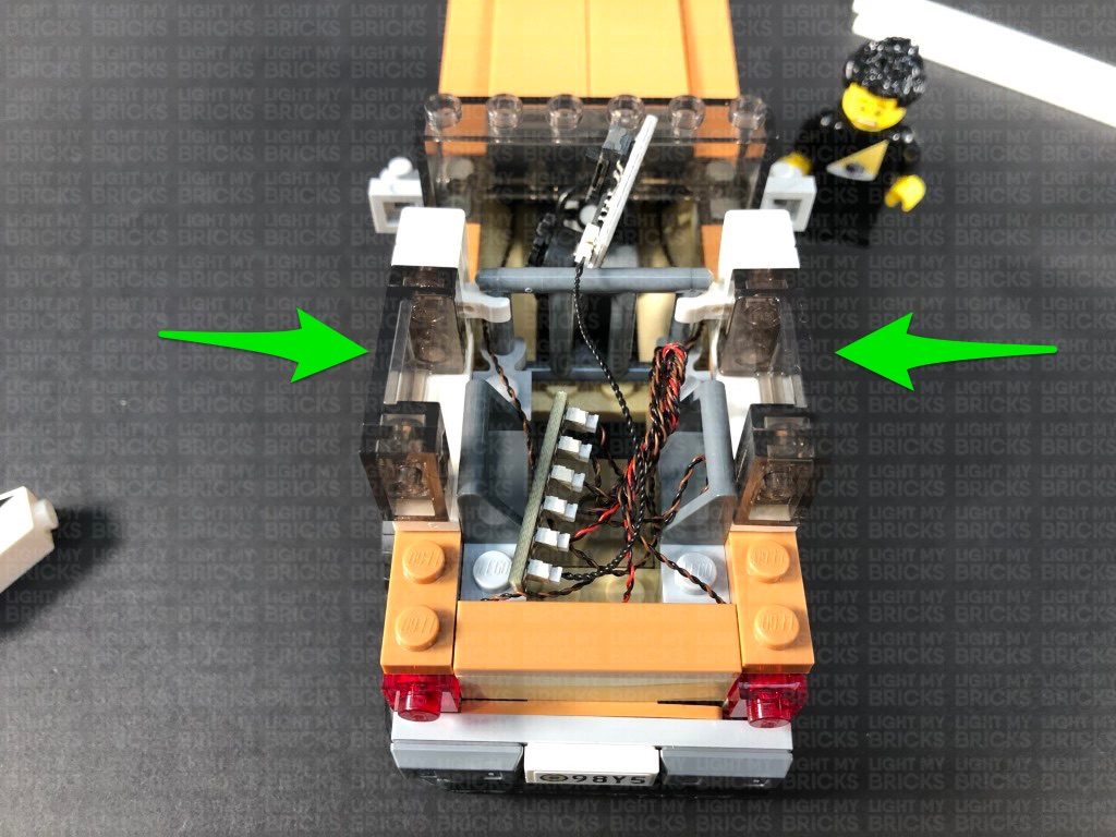
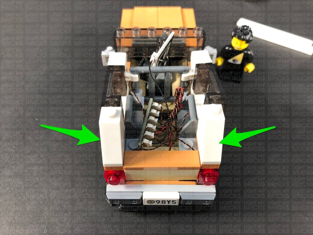
Reconnect (and fold in) the following pieces and sections we removed earlier, then place all the components in the back area as shown below:
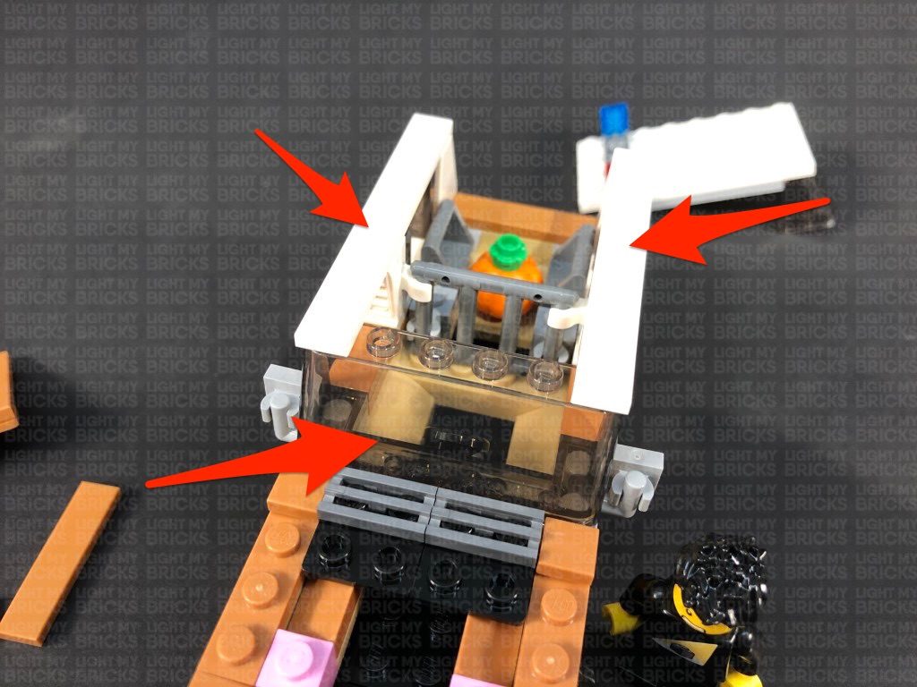
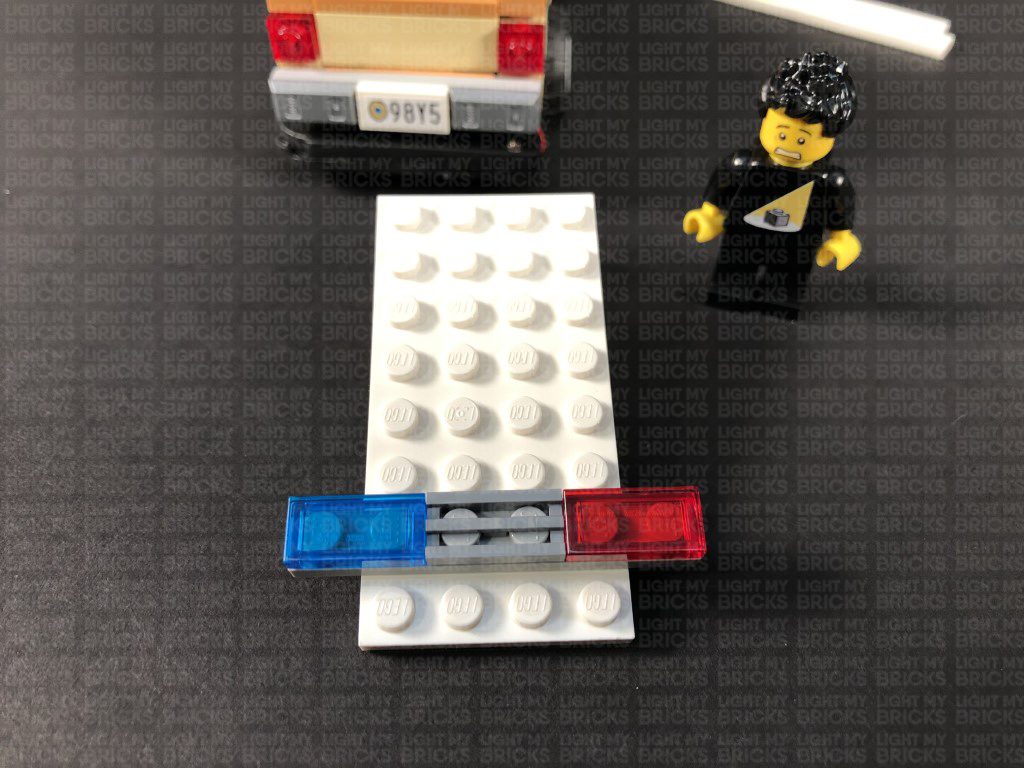
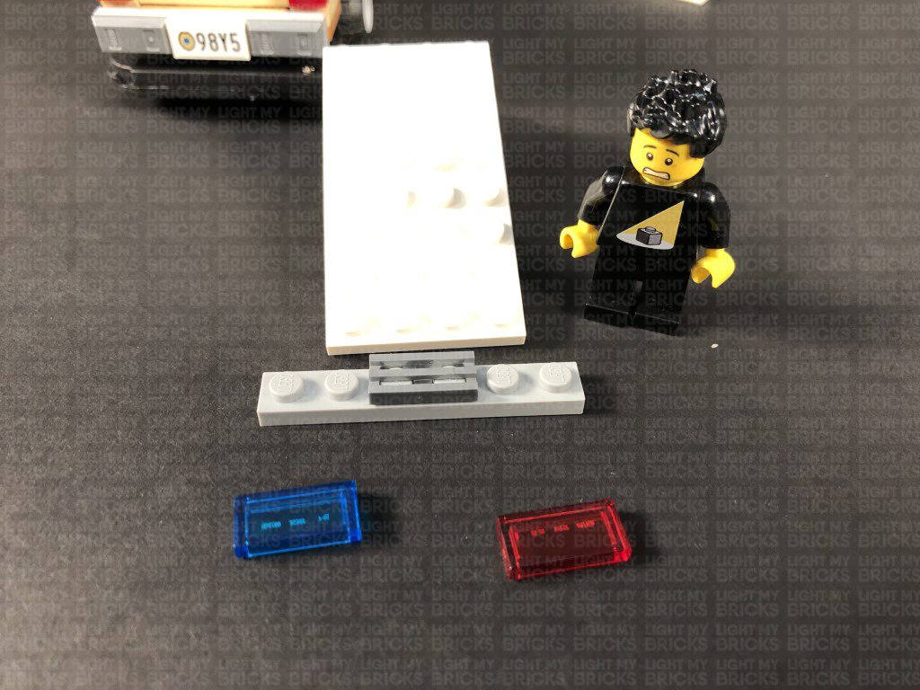
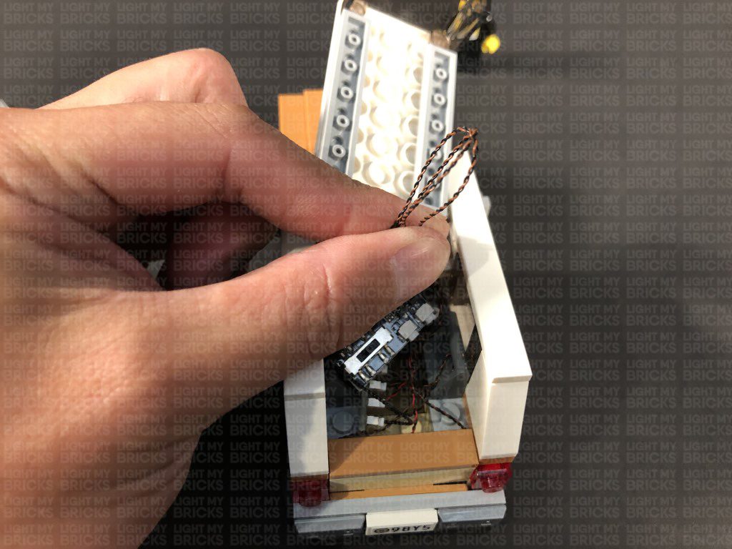
13.) Take the roof of the car and disconnect the 1×6 plate as well as the trans blue and trans red tiles from it.
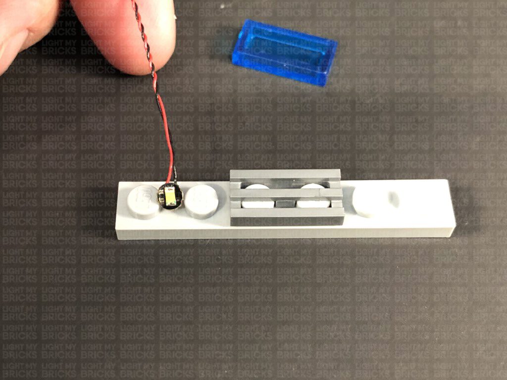
Take a White 15cm Bit Light and with the cable facing forward, place it in between the two left studs. Secure the light in place by reconnecting the trans blue tile over the top, then repeat this step to install another White 15cm Bit Light underneath the trans red tile.
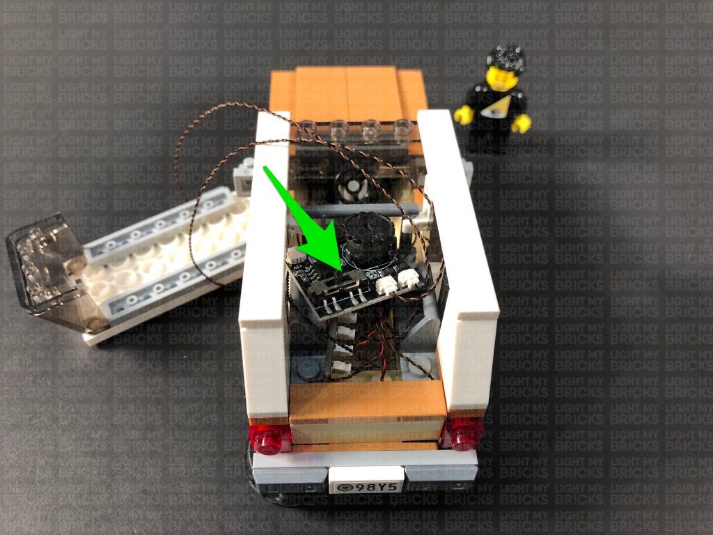
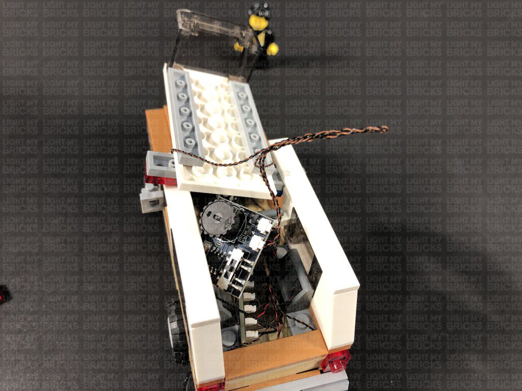
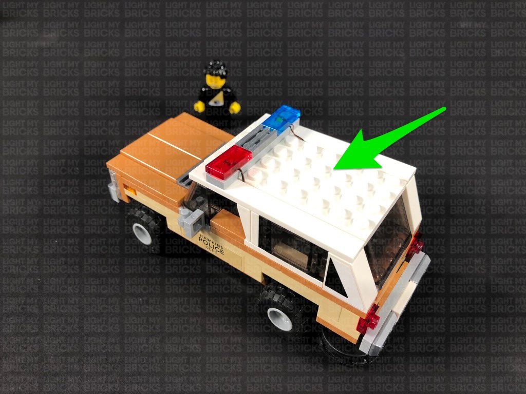
14.) Reconnect the plate to the roof plate, then connect the two roof lights to the Multi Effects Board.
Turn the Battery Pack ON and configure the Multi Effects Board to use the “emergency” effect by setting the switch on the effects board to the middle setting. You can adjust the speed of the effect by turning the wheel to the left or to the right (slower or faster).
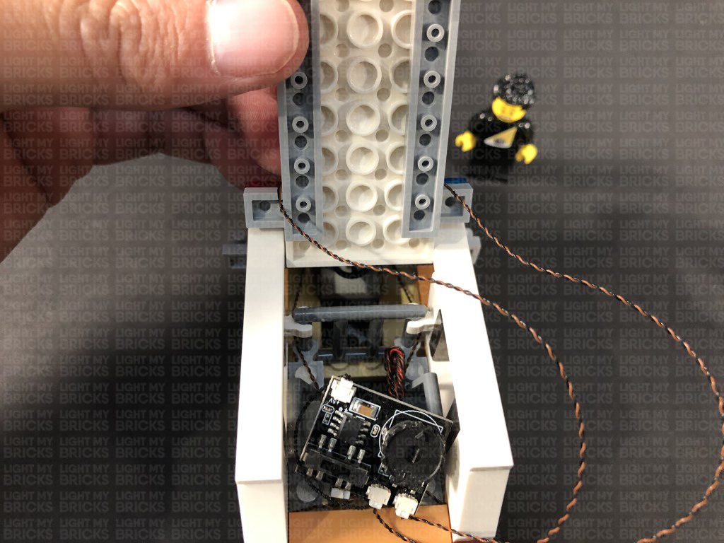
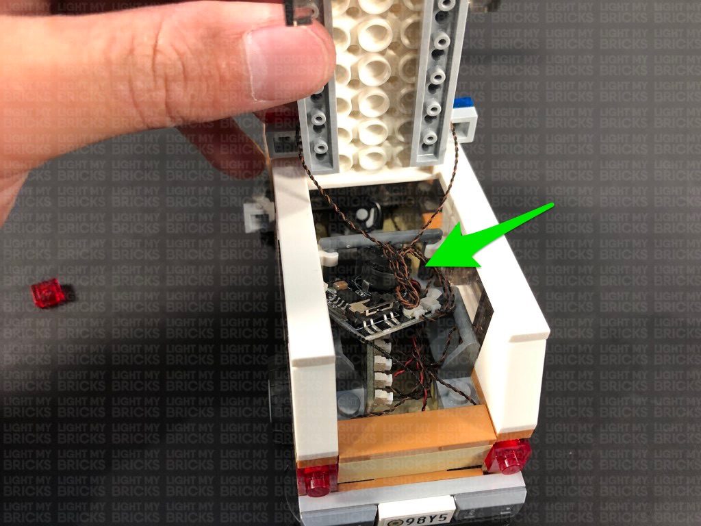
Place the Multi Effects Board back inside the back of the car, then place the roof on top of the car. Group the two cables from the roof together and fold/twist them around each other into a neat bunch to eliminate excess cable. Place the bunched up cables inside before securely reconnecting the roof.
This completes installation of the lights for Chief Hoppers car.
12.) Take a 5cm Connecting Cable and connect it to the remaining port on the 6-Port Expansion Board. Connect the other end of the cable to the IN port (+5V) on the Multi Effects Board (side with 1 port)
Reconnect (and fold in) the following pieces and sections we removed earlier, then place all the components in the back area as shown below:
13.) Take the roof of the car and disconnect the 1×6 plate as well as the trans blue and trans red tiles from it.
Take a White 15cm Bit Light and with the cable facing forward, place it in between the two left studs. Secure the light in place by reconnecting the trans blue tile over the top, then repeat this step to install another White 15cm Bit Light underneath the trans red tile.
14.) Reconnect the plate to the roof plate, then connect the two roof lights to the Multi Effects Board.
Turn the Battery Pack ON and configure the Multi Effects Board to use the “emergency” effect by setting the switch on the effects board to the middle setting. You can adjust the speed of the effect by turning the wheel to the left or to the right (slower or faster).
Place the Multi Effects Board back inside the back of the car, then place the roof on top of the car. Group the two cables from the roof together and fold/twist them around each other into a neat bunch to eliminate excess cable. Place the bunched up cables inside before securely reconnecting the roof.
This completes installation of the lights for Chief Hoppers car.
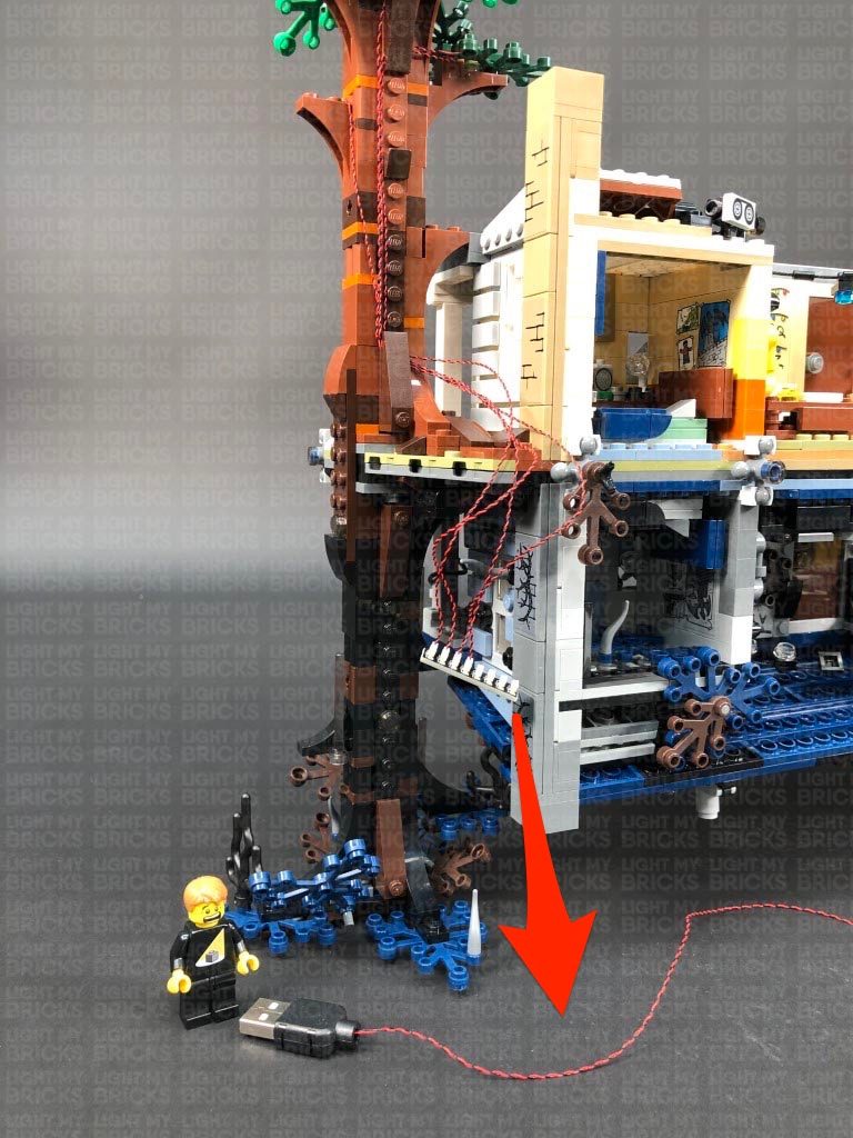
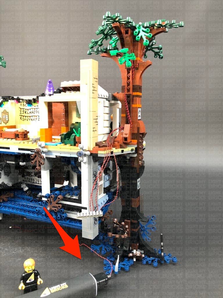
 The Police Car lights are currently powered independently via the Flat Battery Pack. If you wish to avoid the battery route, the car lights can be tethered to the house lights later on. Simply swap out the Flat Battery Pack with a provided 15cm Connecting Cable. Leave the other end of it disconnected as we will connect this to the right side of the house at a later stage.
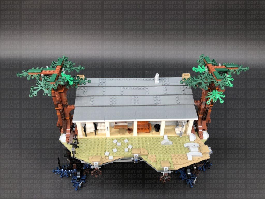
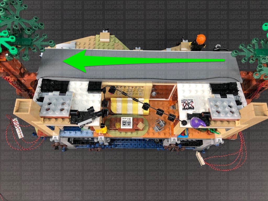
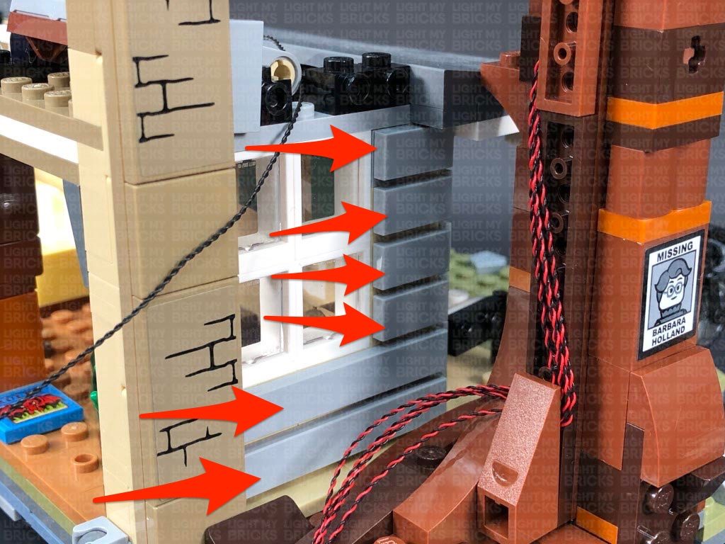
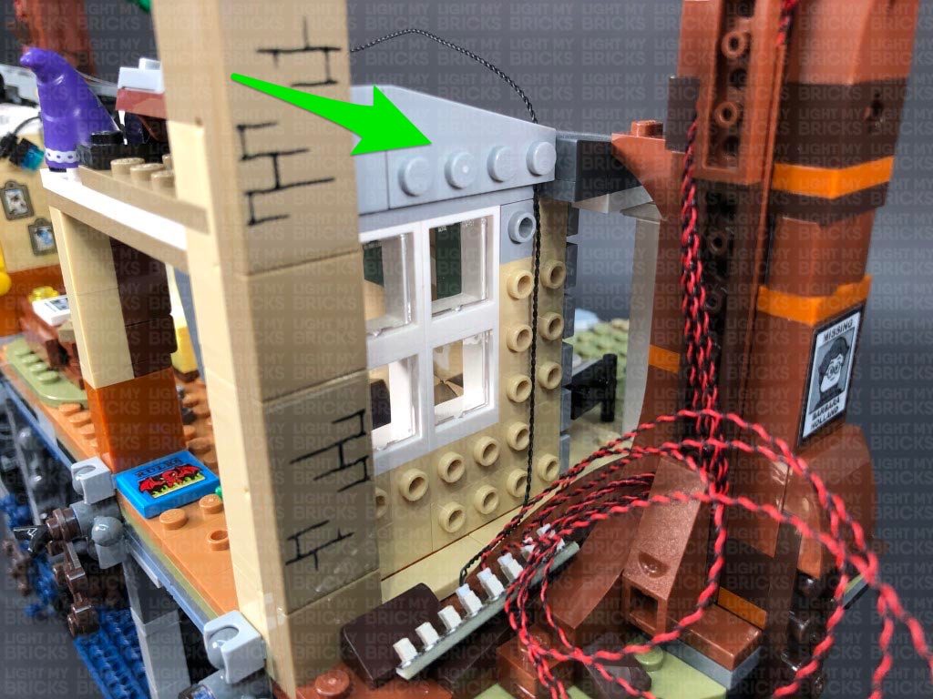
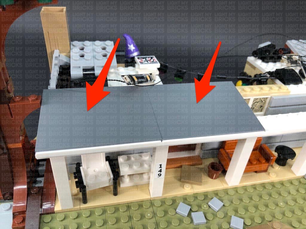
15.) We will now install lights to the house. First, turn the set around to the back side and using your LEGO removal tool, carefully disconnect the roof section at the following two positions as shown below.
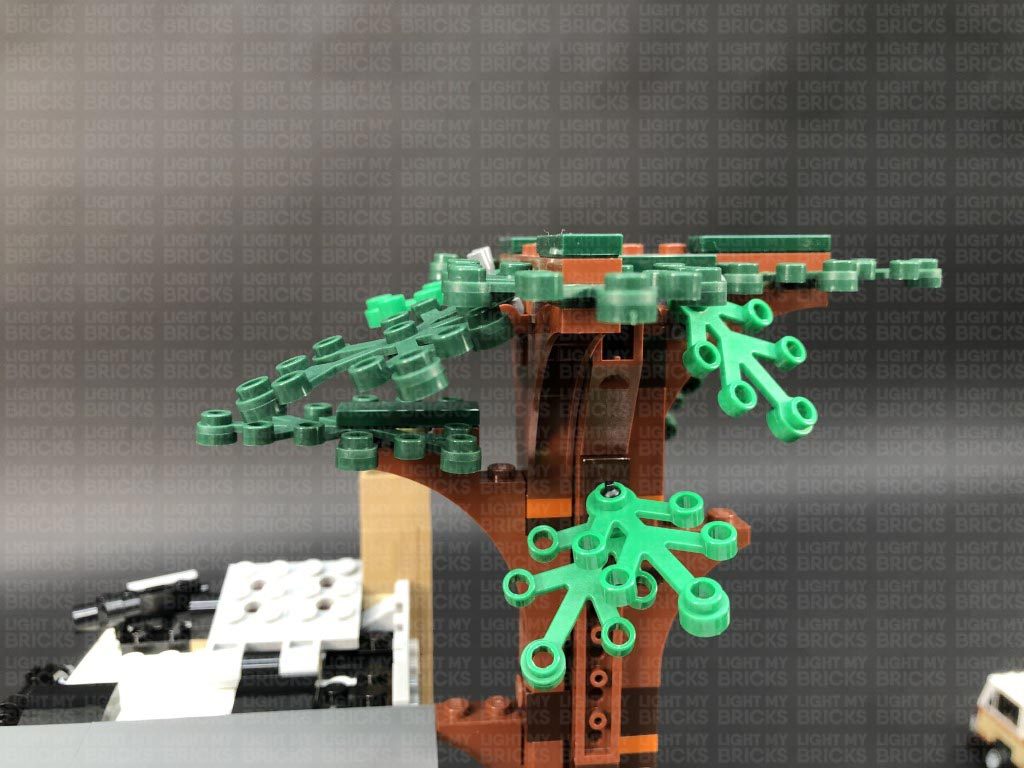
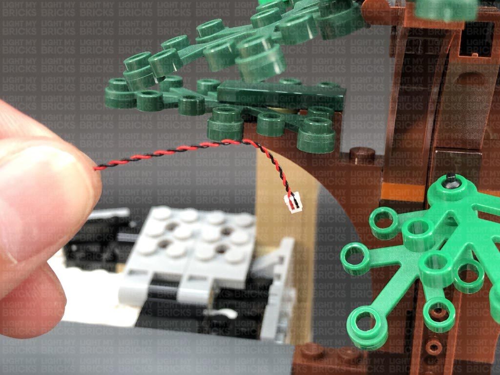
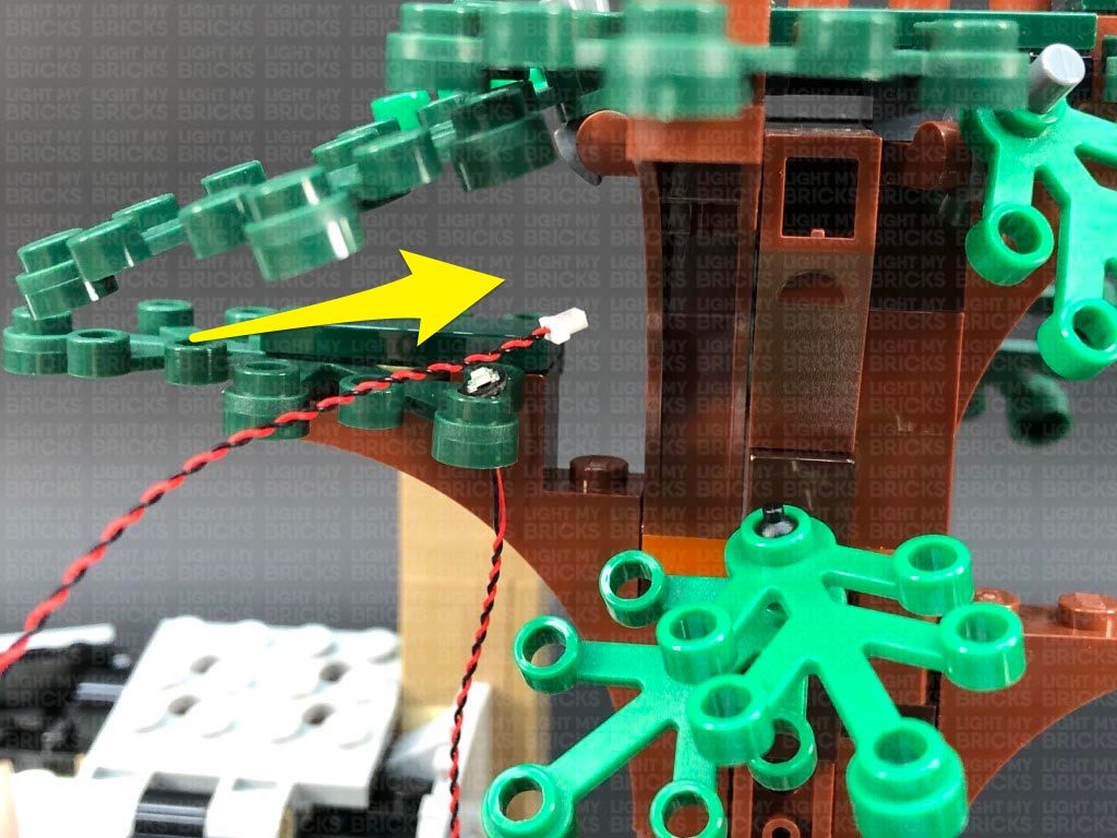
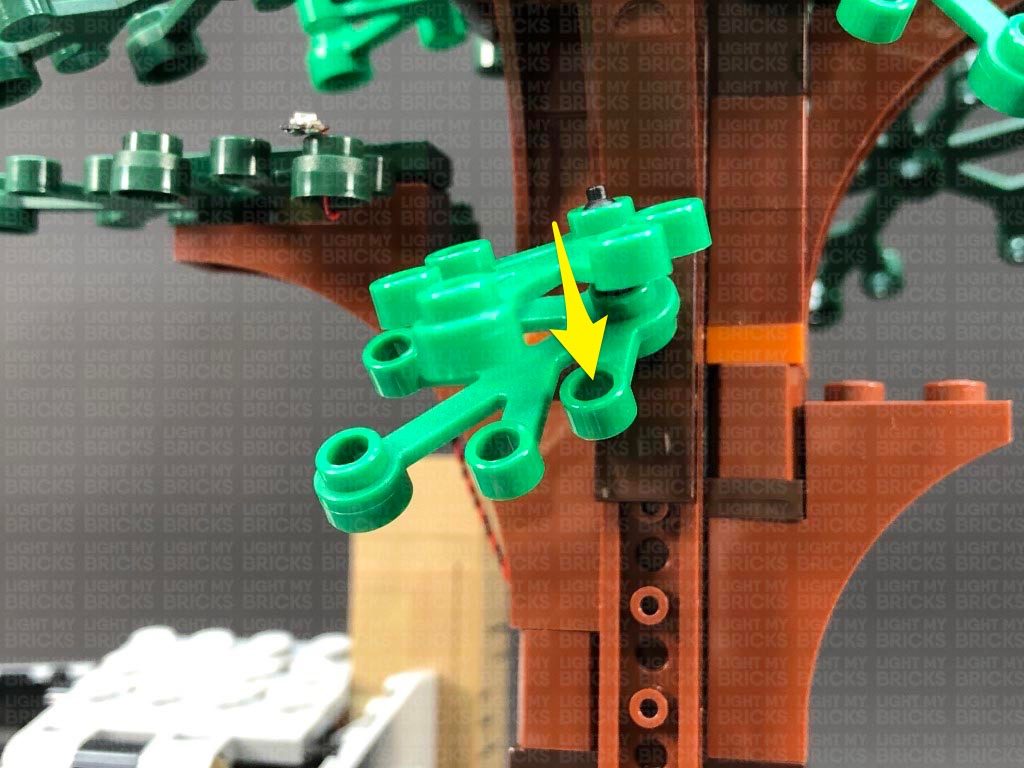
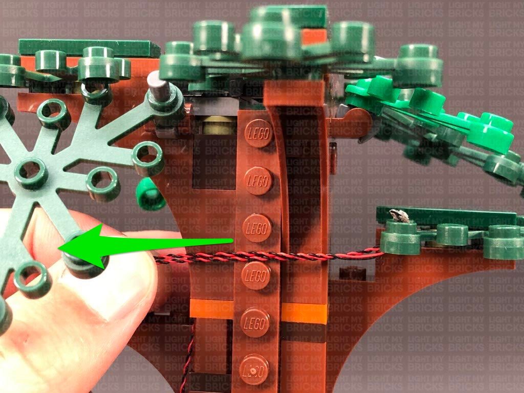
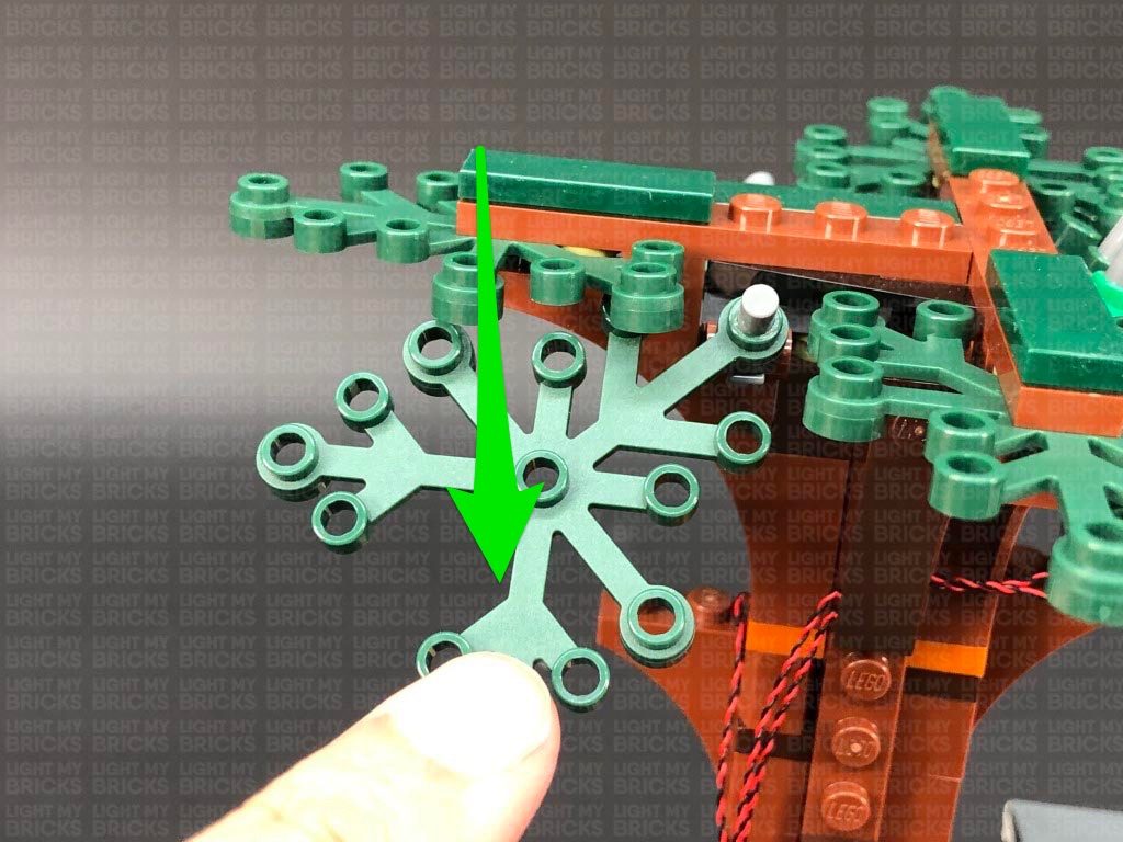
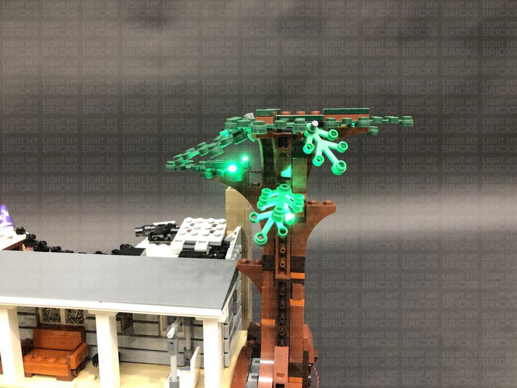
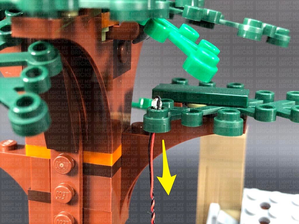
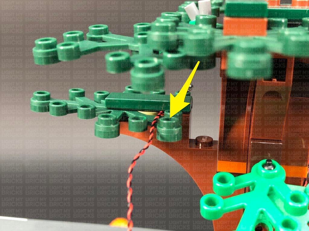
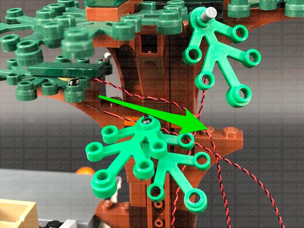
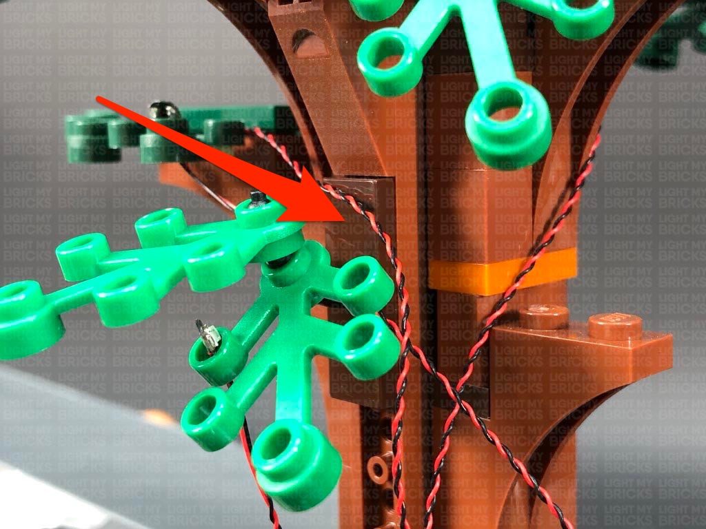
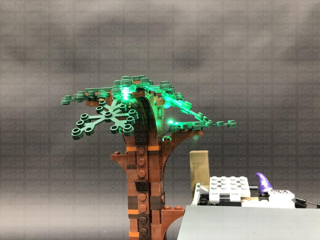
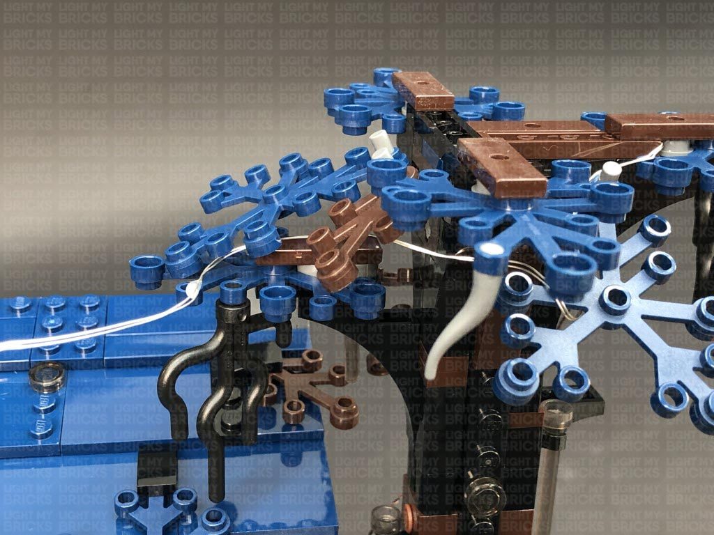
Turn the set back around to the front, as we will first install lights to the trees, starting with the tree on the right side. We will be threading each Bit Light through the holes in the tree leaf pieces. First, take a Green 30cm Bit Light and slightly bend the bit light into a U shape toward the connector end of the cable. Thread the connector end through the hole of the following leaf piece as shown below, then pull the cable all the way down from underneath.
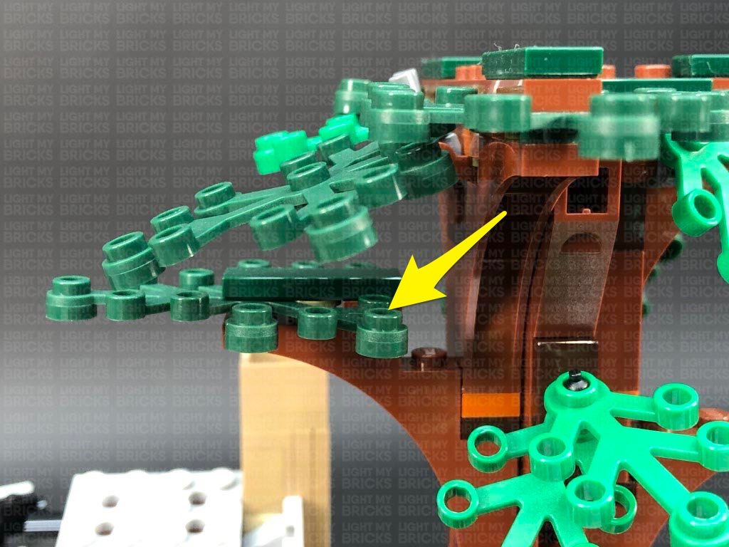
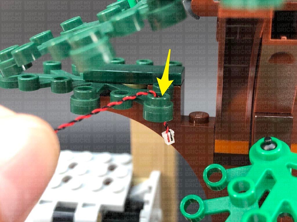
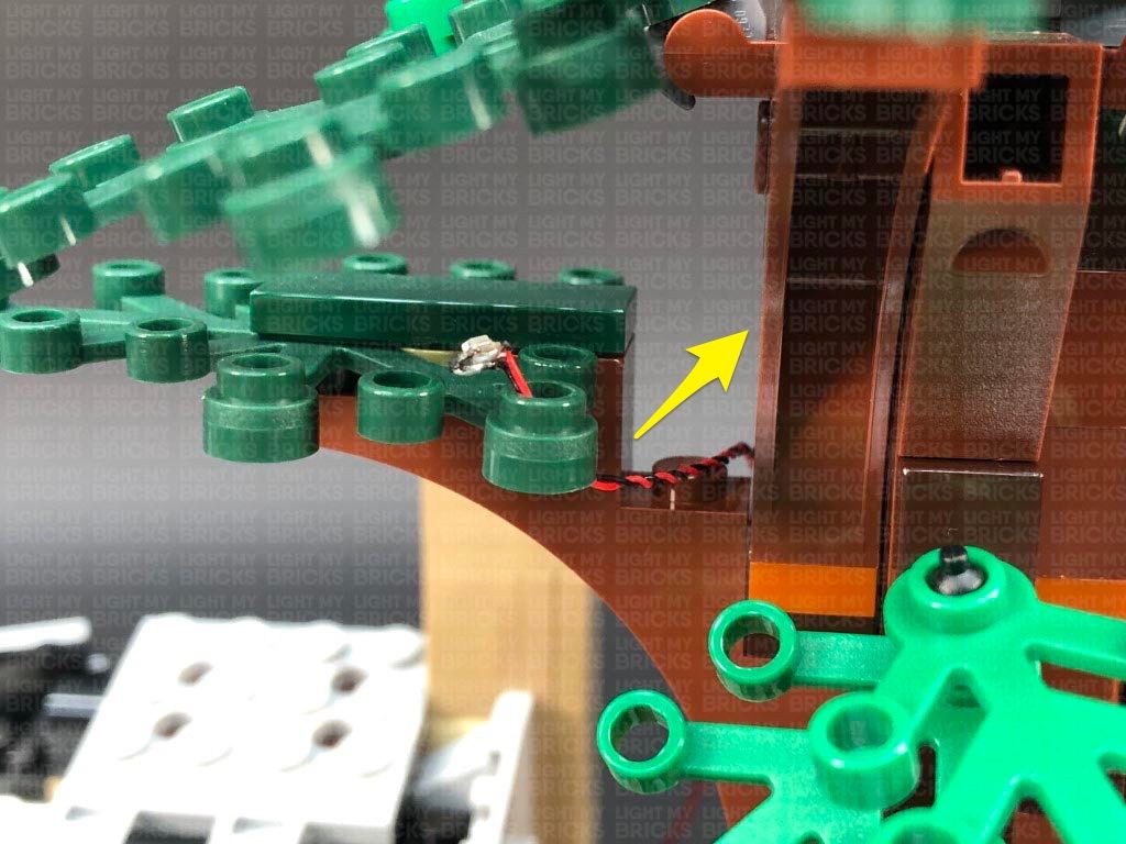
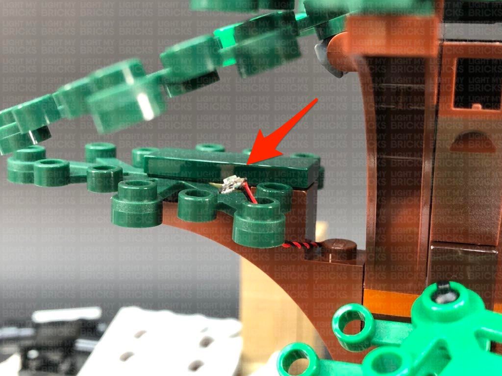
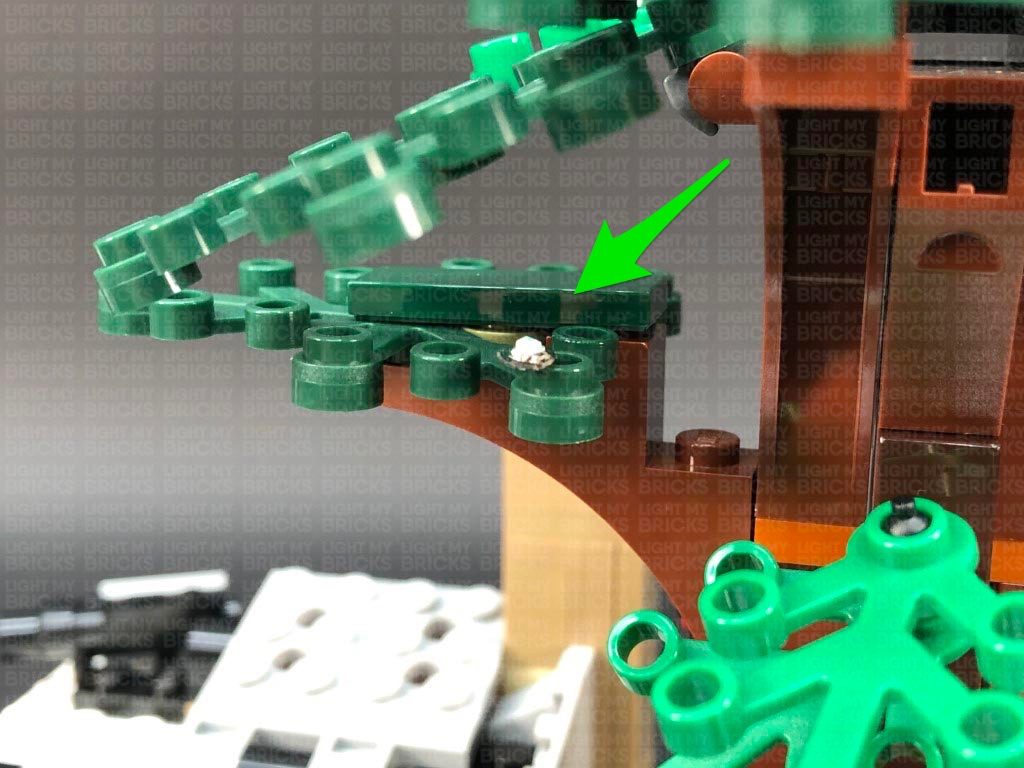
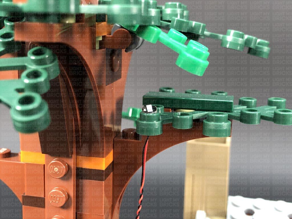
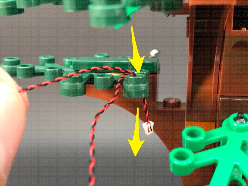
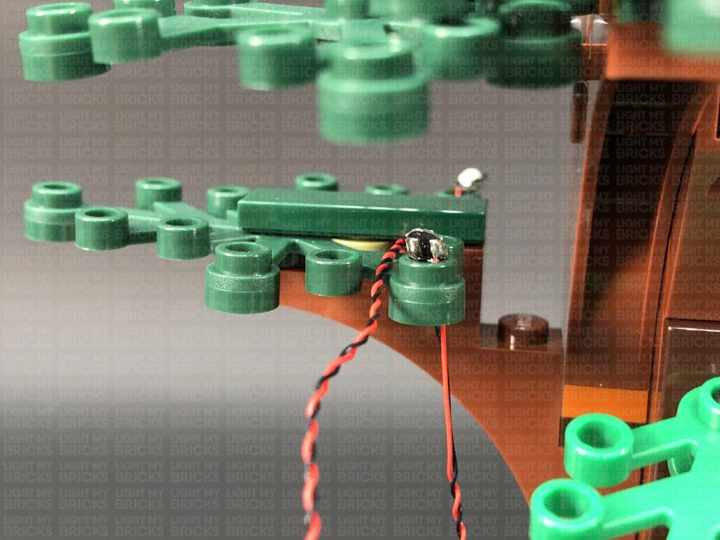
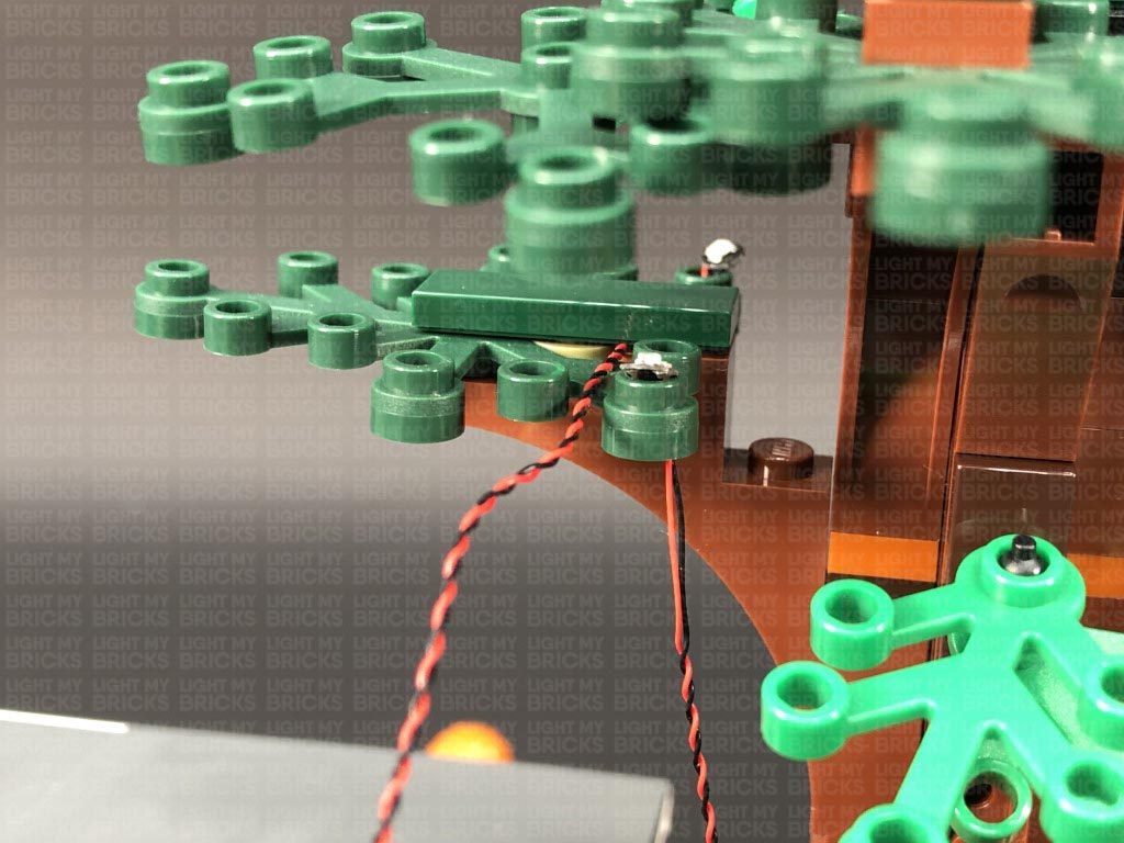
Flatten the Bit Light against the top of the leaf hole so that it sits flat and that the LED is facing directly up, then thread the cable through the space above, pulling it out from the other side. Secure the light in place by disconnecting the dark green tile and laying the cable down underneath it, before reconnecting the tile over the top.
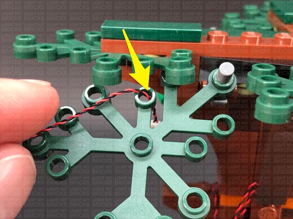
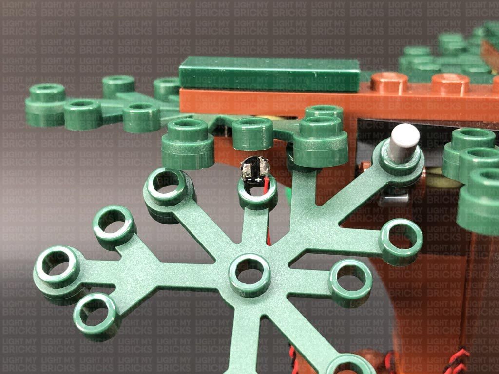
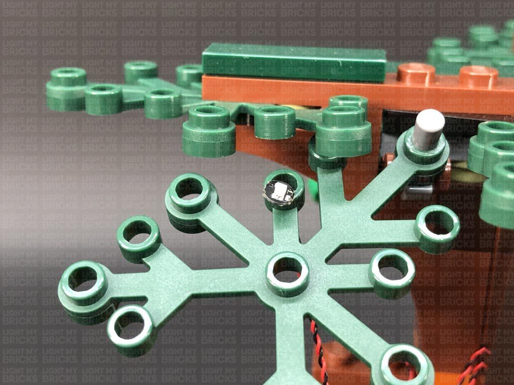
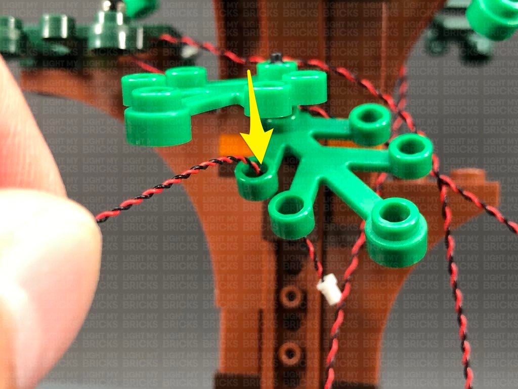
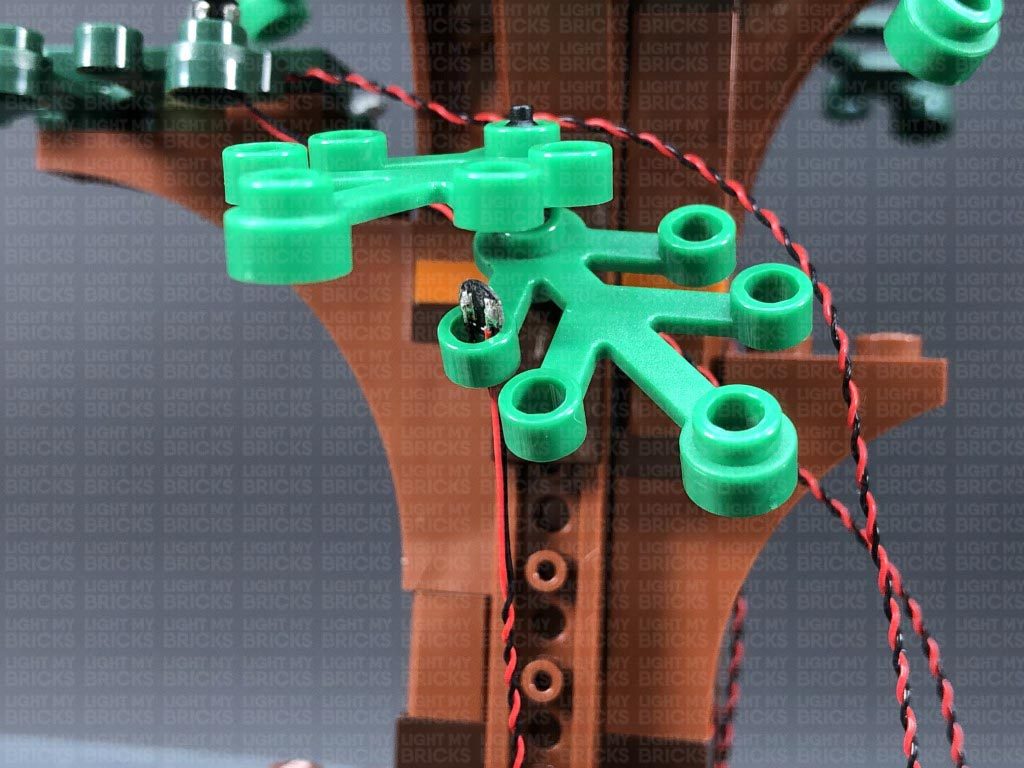
16.) Take another Green 30cm Bit Light and slightly bend the connector end of the cable into a U shape. Thread the cable through the hole of the light green leaf piece in the centre, pulling it all the way out from underneath. Ensure the Bit Light’s LED is facing forward as shown below.
Bring the cable behind and over the branch on the right side.
The Police Car lights are currently powered independently via the Flat Battery Pack. If you wish to avoid the battery route, the car lights can be tethered to the house lights later on. Simply swap out the Flat Battery Pack with a provided 15cm Connecting Cable. Leave the other end of it disconnected as we will connect this to the right side of the house at a later stage.
15.) We will now install lights to the house. First, turn the set around to the back side and using your LEGO removal tool, carefully disconnect the roof section at the following two positions as shown below.
Turn the set back around to the front, as we will first install lights to the trees, starting with the tree on the right side. We will be threading each Bit Light through the holes in the tree leaf pieces. First, take a Green 30cm Bit Light and slightly bend the bit light into a U shape toward the connector end of the cable. Thread the connector end through the hole of the following leaf piece as shown below, then pull the cable all the way down from underneath.
Flatten the Bit Light against the top of the leaf hole so that it sits flat and that the LED is facing directly up, then thread the cable through the space above, pulling it out from the other side. Secure the light in place by disconnecting the dark green tile and laying the cable down underneath it, before reconnecting the tile over the top.
16.) Take another Green 30cm Bit Light and slightly bend the connector end of the cable into a U shape. Thread the cable through the hole of the light green leaf piece in the centre, pulling it all the way out from underneath. Ensure the Bit Light’s LED is facing forward as shown below.
Bring the cable behind and over the branch on the right side.
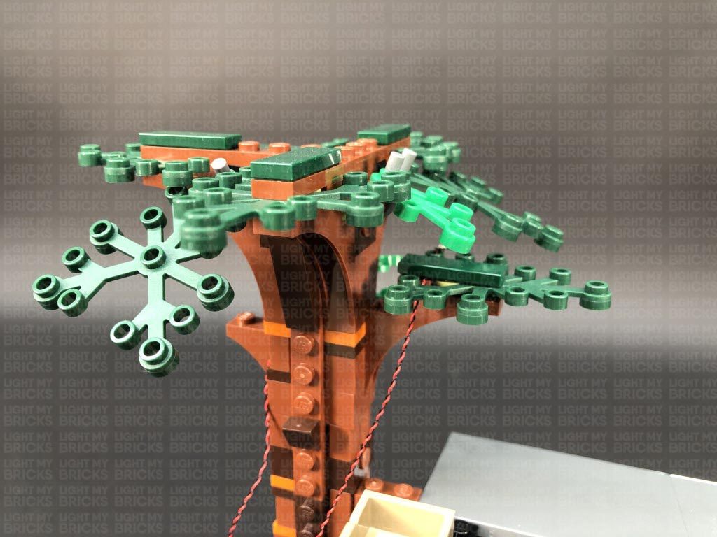
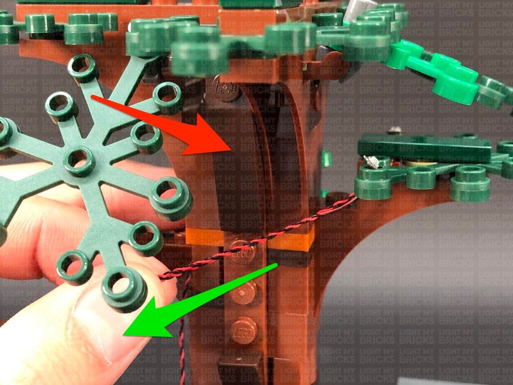
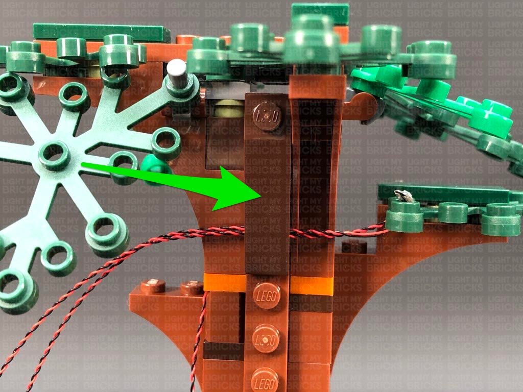
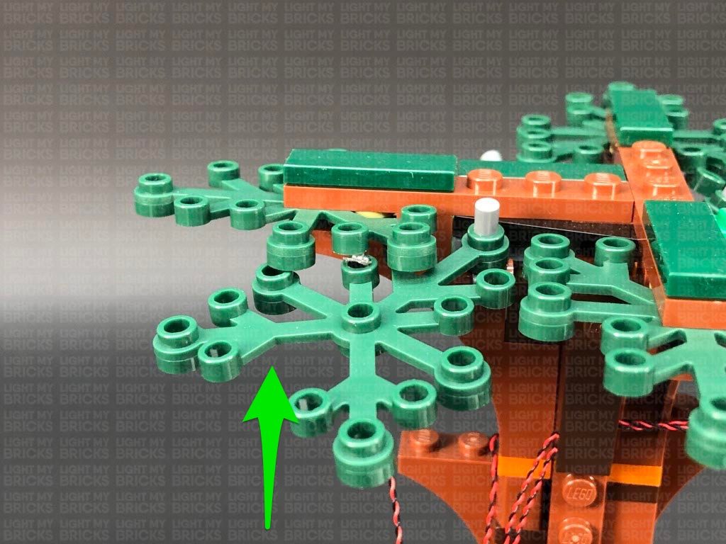
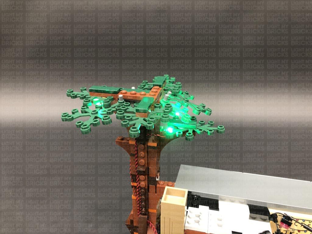
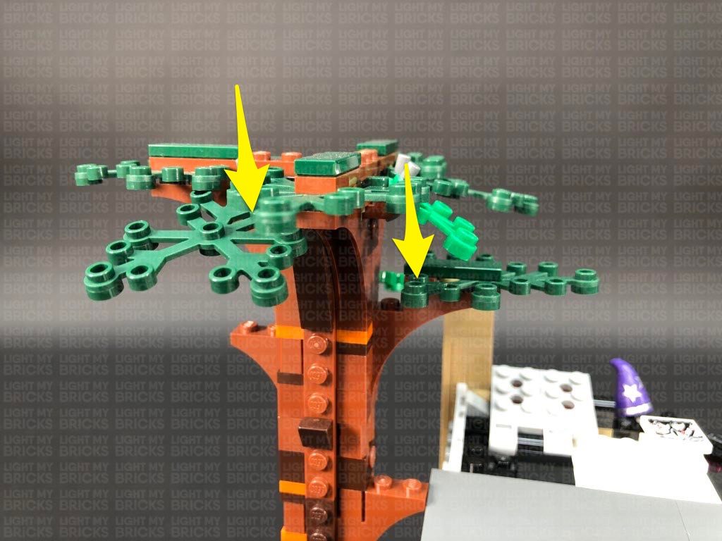
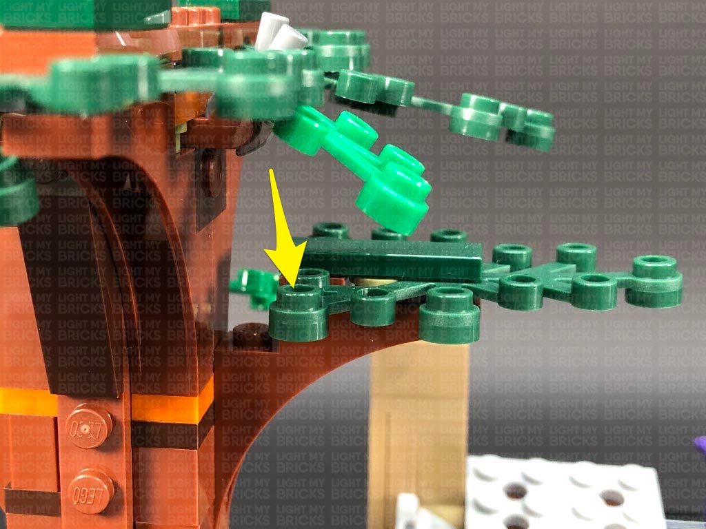
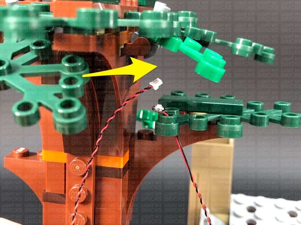
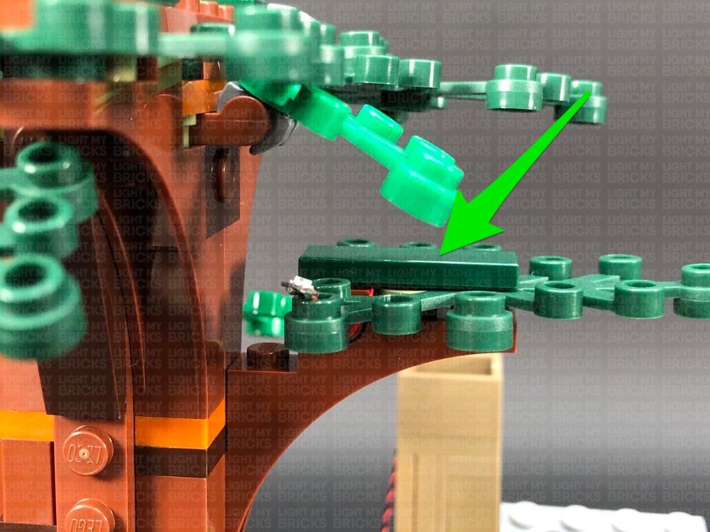
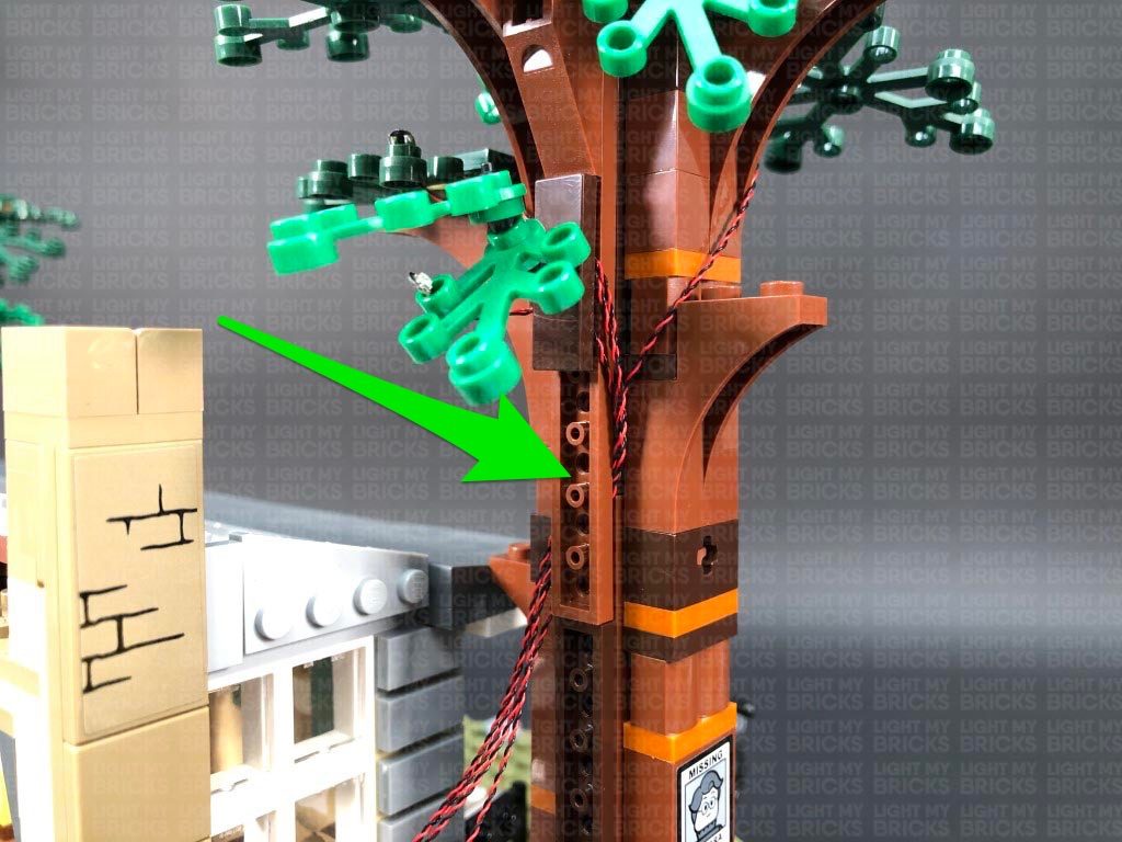
 17.) Turn the set around to the back so we can continue installing another two lights to the back side of the tree. Take another Green 30cm Bit Light and bend the connector end of the cable into a U shape. Thread the cable through the hole on the right leaf piece, pulling it all the way out from underneath.
Flatten the Bit Light so that it sits flat against the top of the hole and LED is facing directly up, then bring both front and back cables across to the left side and secure them underneath the following dark brown plate. Ensure the cables are laid across in between studs before reconnecting the dark brown plate over the top.
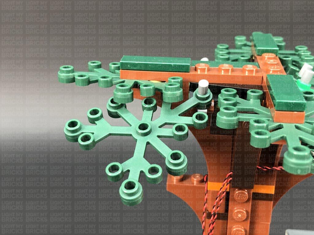
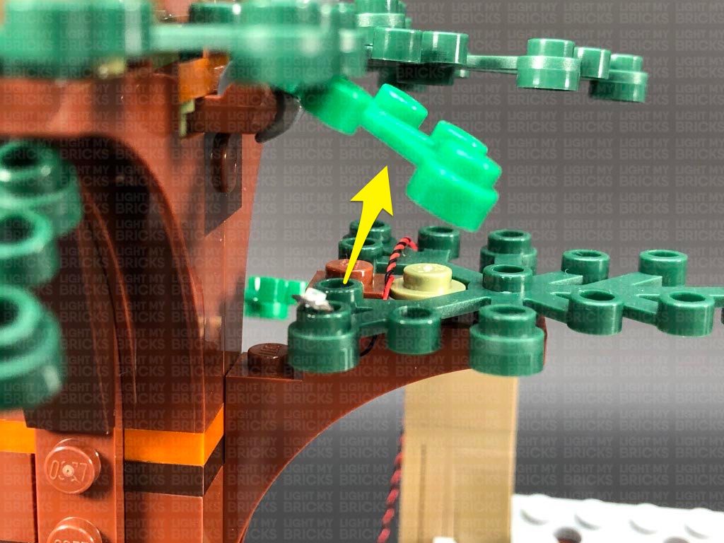
18.) Bend the dark green leaf piece on the left side down slightly so we can access the hole on the top. Take another Green 30cm Bit Light and slightly bend the connector end of the cable into a U shape. Thread the cable through the hole on the dark green leaf piece, pulling it all the way out from underneath as shown below:
Flatten the Bit Light so that it sits flat against the top of the hole and the LED is facing up, then push up the leaf piece back to it’s original position. Bring the cable across to the right and lay it in between studs underneath the dark brown plate as shown below (around the top stud):
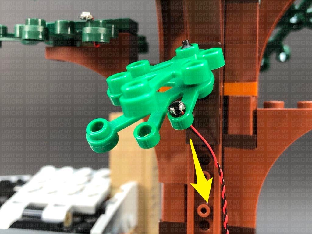
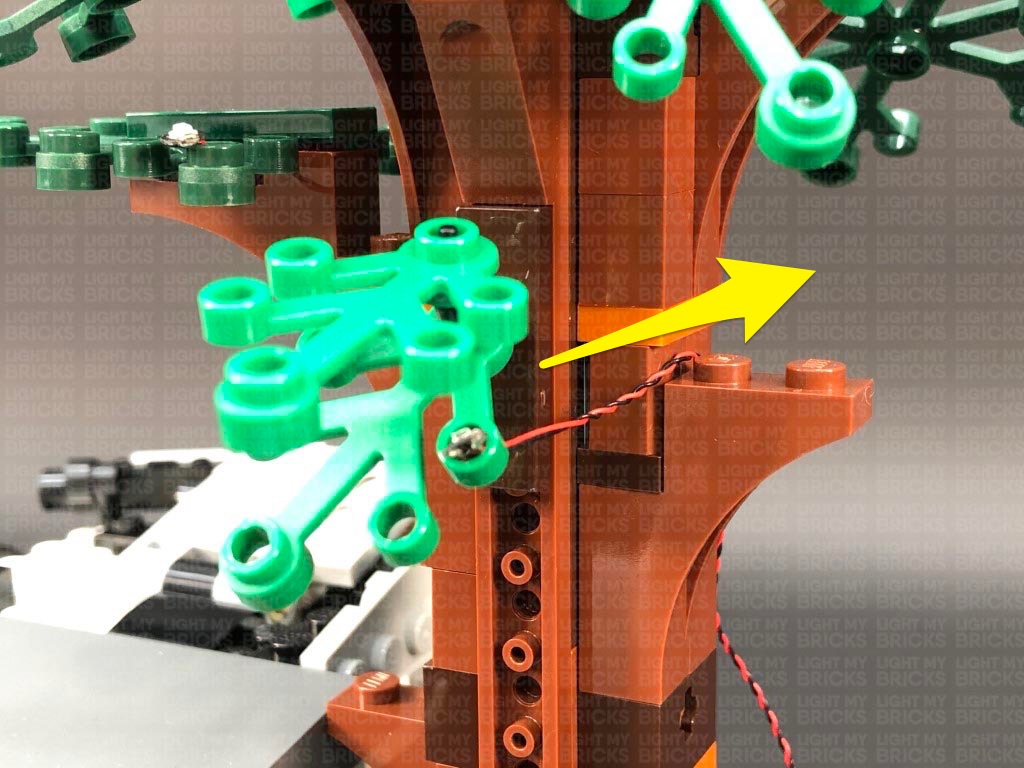
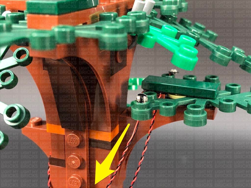
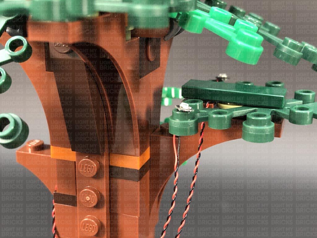
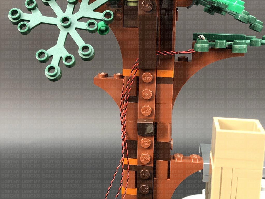
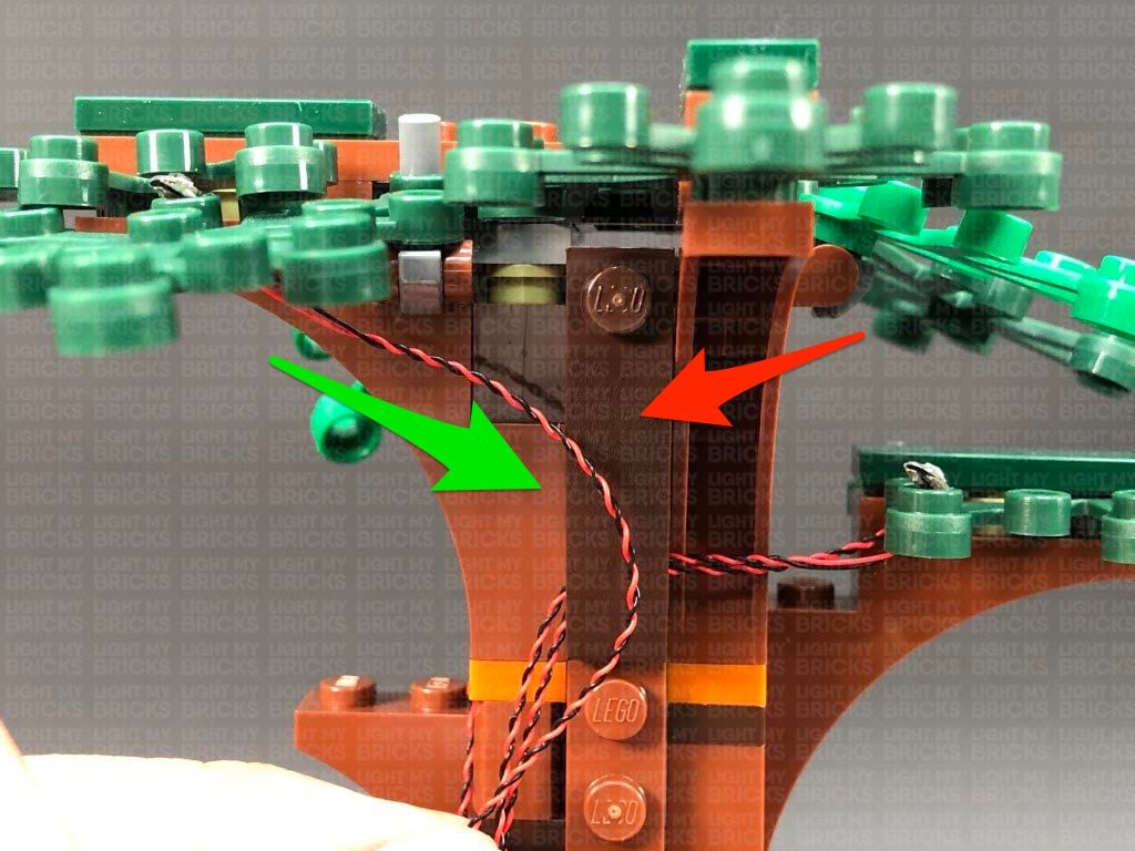
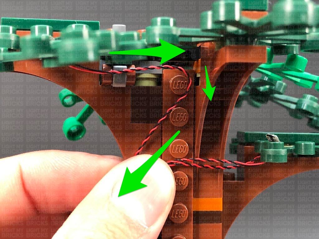
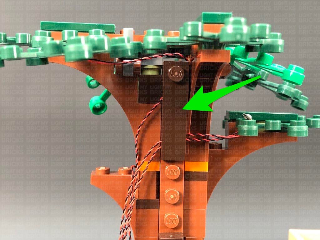
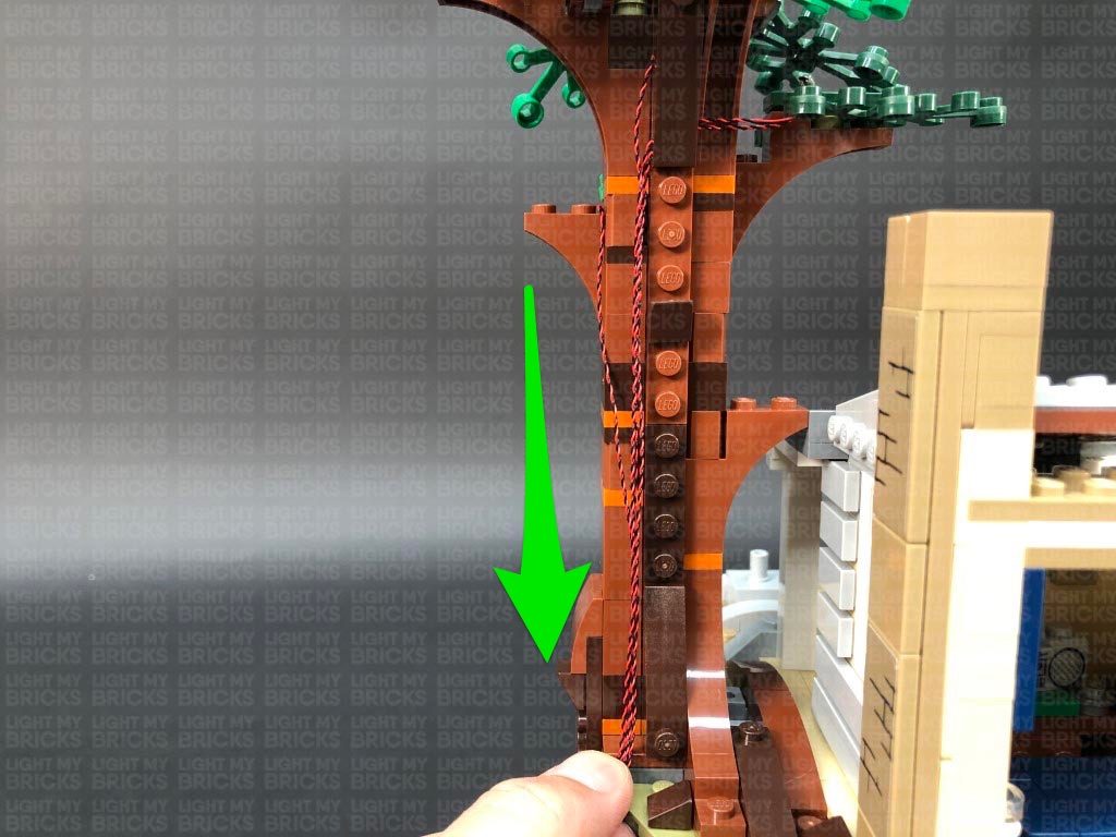
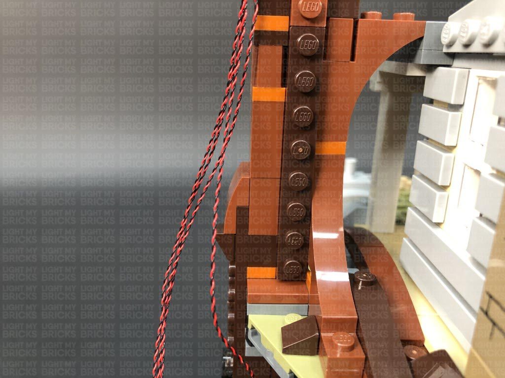
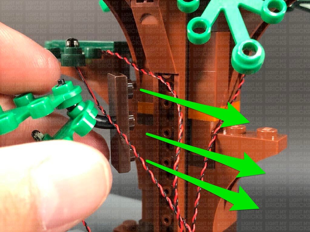
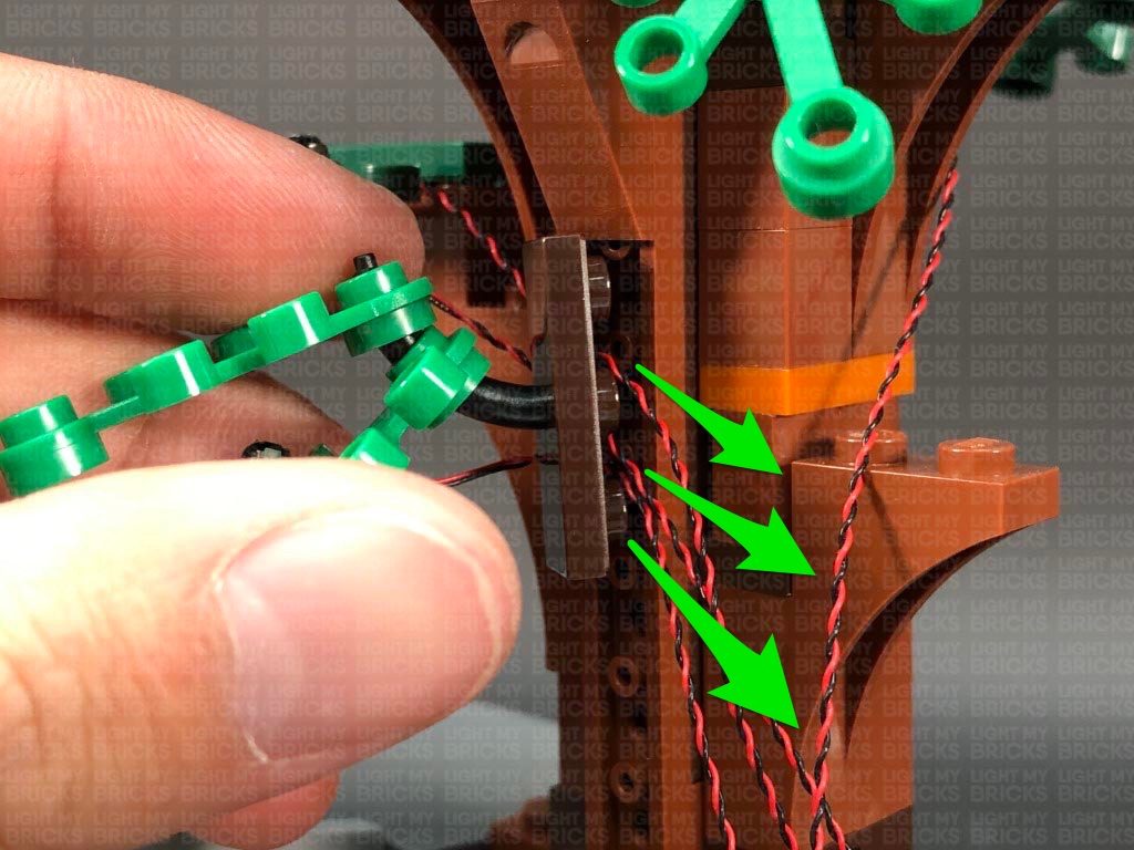
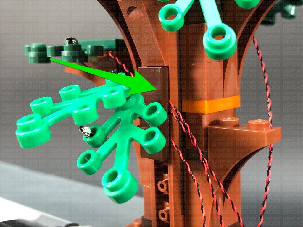
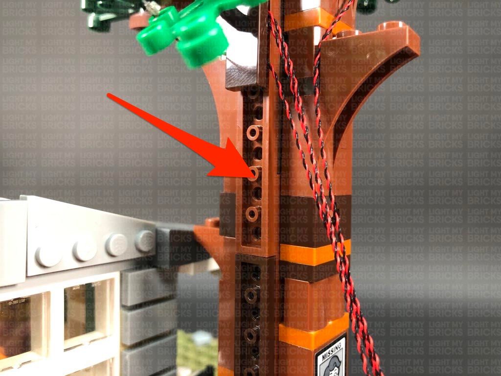
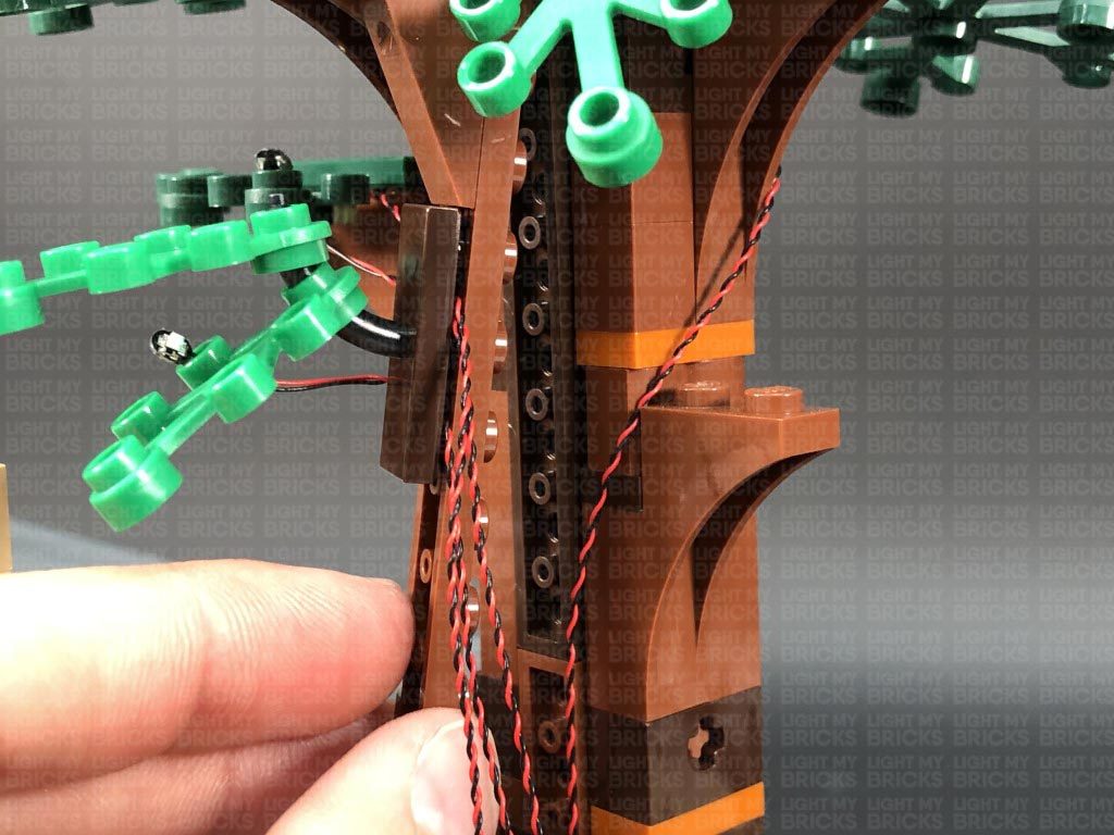
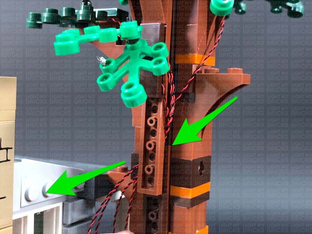
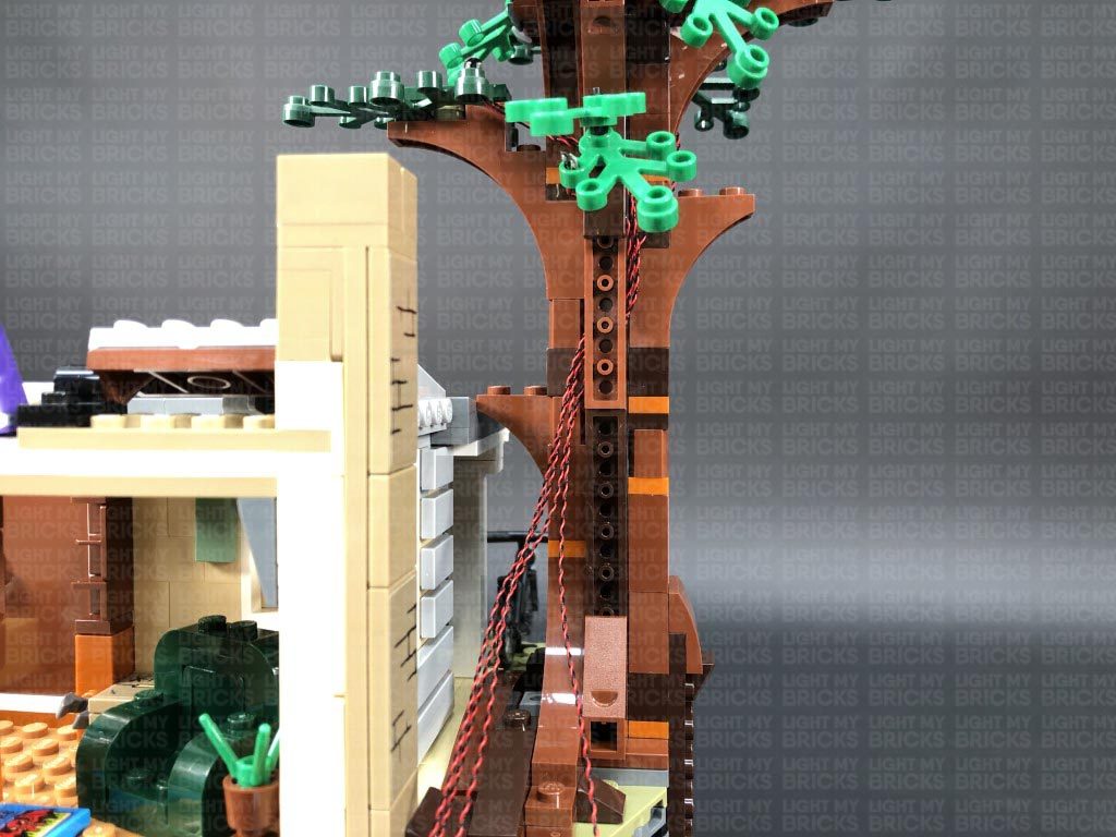
Bring the four cables down the left side of the tree trunk, then bring them across to the right side, laying them in between studs underneath the following dark brown angled plate.
17.) Turn the set around to the back so we can continue installing another two lights to the back side of the tree. Take another Green 30cm Bit Light and bend the connector end of the cable into a U shape. Thread the cable through the hole on the right leaf piece, pulling it all the way out from underneath.
Flatten the Bit Light so that it sits flat against the top of the hole and LED is facing directly up, then bring both front and back cables across to the left side and secure them underneath the following dark brown plate. Ensure the cables are laid across in between studs before reconnecting the dark brown plate over the top.
18.) Bend the dark green leaf piece on the left side down slightly so we can access the hole on the top. Take another Green 30cm Bit Light and slightly bend the connector end of the cable into a U shape. Thread the cable through the hole on the dark green leaf piece, pulling it all the way out from underneath as shown below:
Flatten the Bit Light so that it sits flat against the top of the hole and the LED is facing up, then push up the leaf piece back to it’s original position. Bring the cable across to the right and lay it in between studs underneath the dark brown plate as shown below (around the top stud):
Bring the four cables down the left side of the tree trunk, then bring them across to the right side, laying them in between studs underneath the following dark brown angled plate.
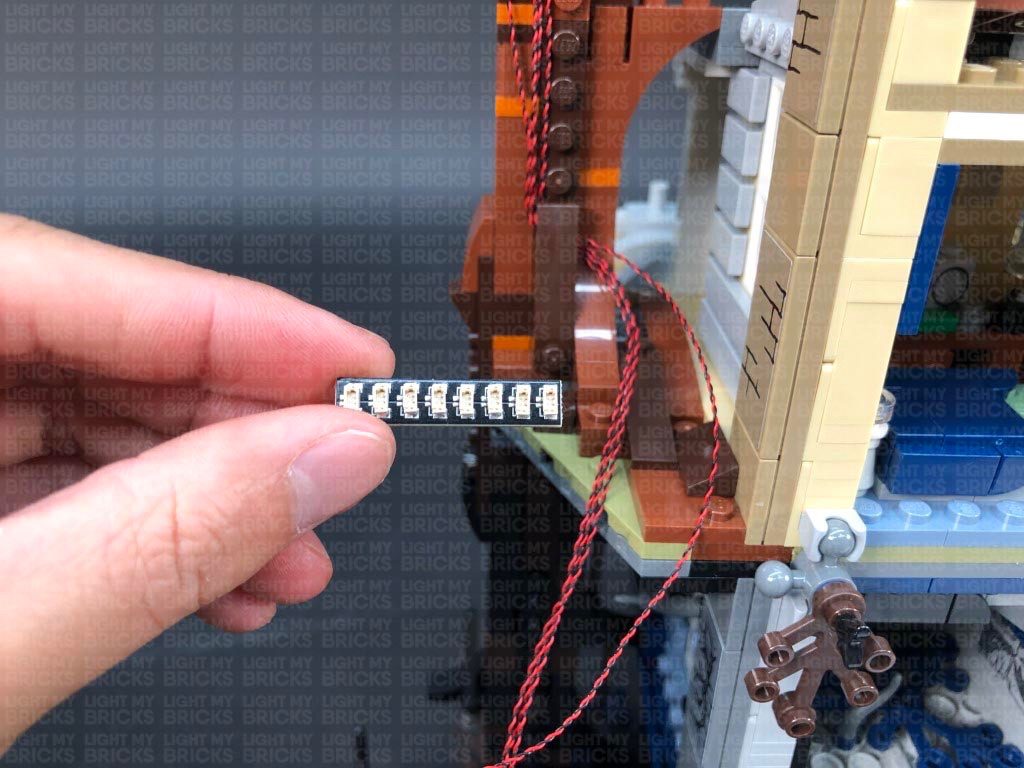
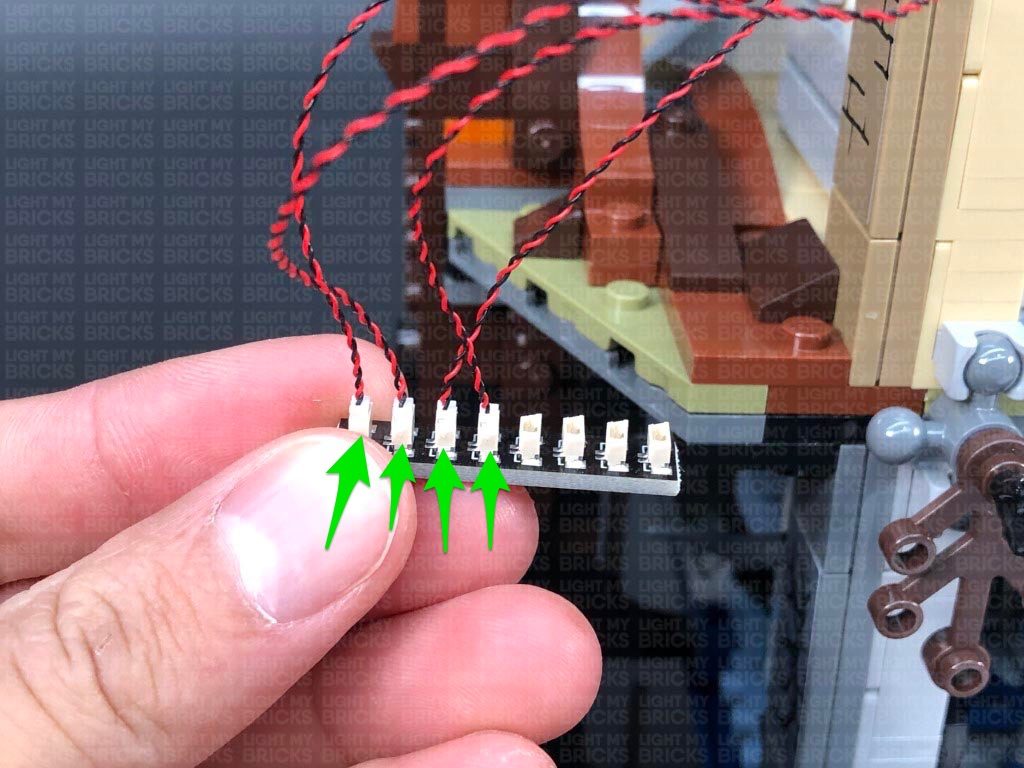
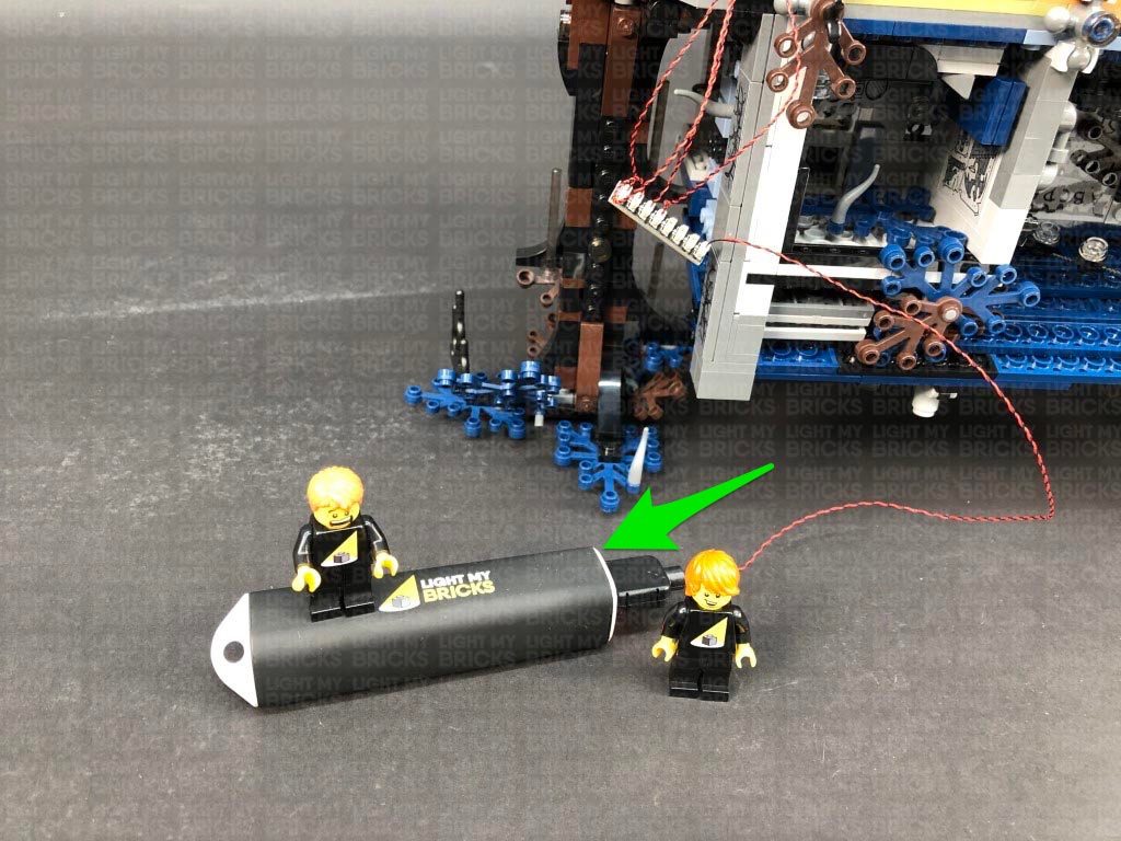
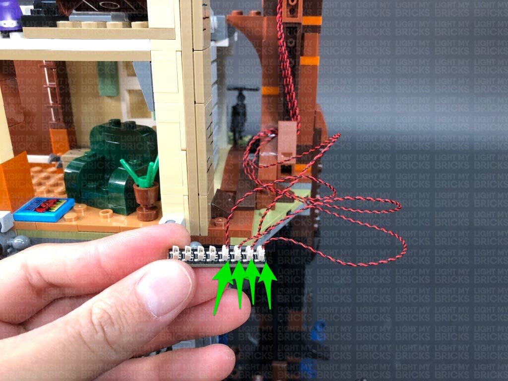
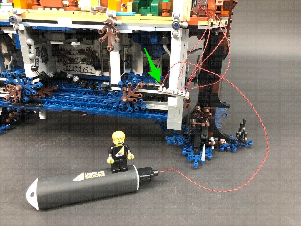
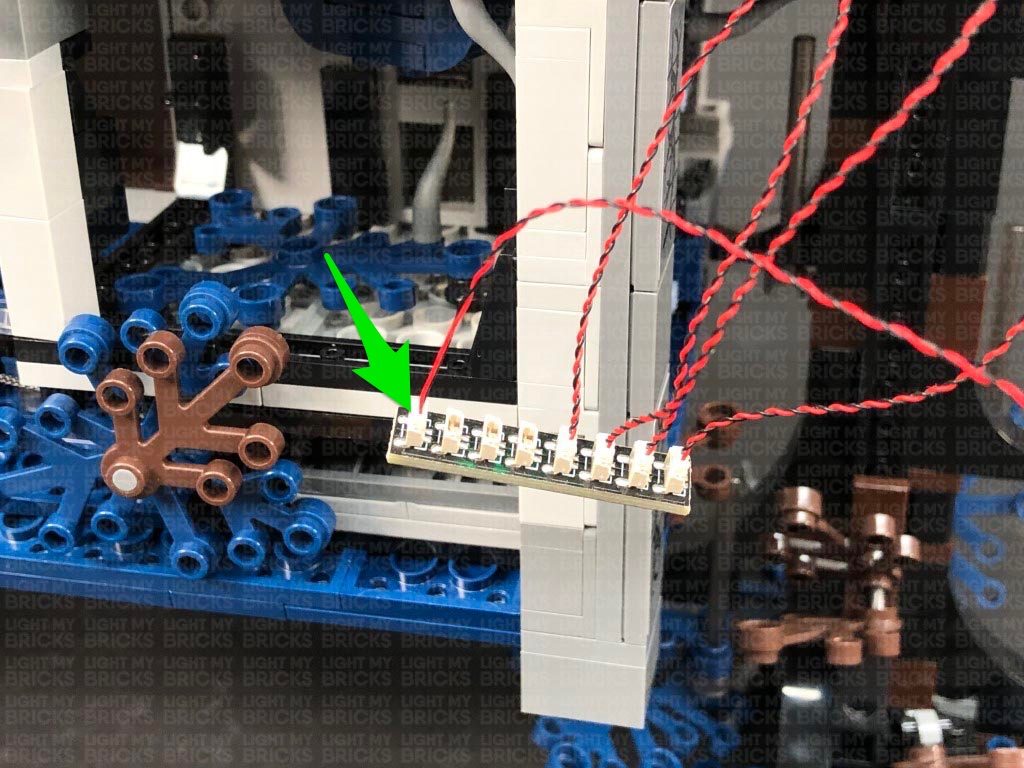
 19.) Connect the four bit light cables to an 8-Port Expansion Board. Take your USB Power Cable and connect it to the end port on the expansion board. Connect the USB Connector to a USB Power Bank or wall adaptor (sold separately) and turn it ON to test the green lights are working OK.
Note: If you experience any issues with the lights not working and suspect an issue with a component, please try a different port on the expansion board to verify where the fault lies (with the light or expansion board). To correct any issues with expansion board ports, please view the section addressing expansion board issues on our online troubleshooting guide.
20.) Facing the front of the house, we will now install lights to the tree on the left side. Using the same method used for the other tree lights, follow the below images to install another Green 30cm Bit Light to the front.
Push down the left leaf piece and install another Green 30cm Bit Light. Flatten the LED, then push the leaf section back up and bring the cable behind.
21.) Turn the set around and install another Green Bit 30cm Light to the left leaf piece, then bring both cables (this one and the first one we installed) over to the right side
Install the remaining Green 30cm Bit Light to the leaf on the right ensuring the LED is facing toward the front of the tree, then disconnect this section at the brown plate. Bring the three cables from the left over to the right and lay them underneath this brown plate in between studs, then securely reconnect this plate as shown below.
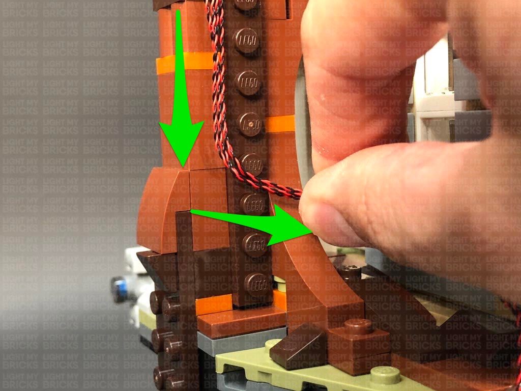
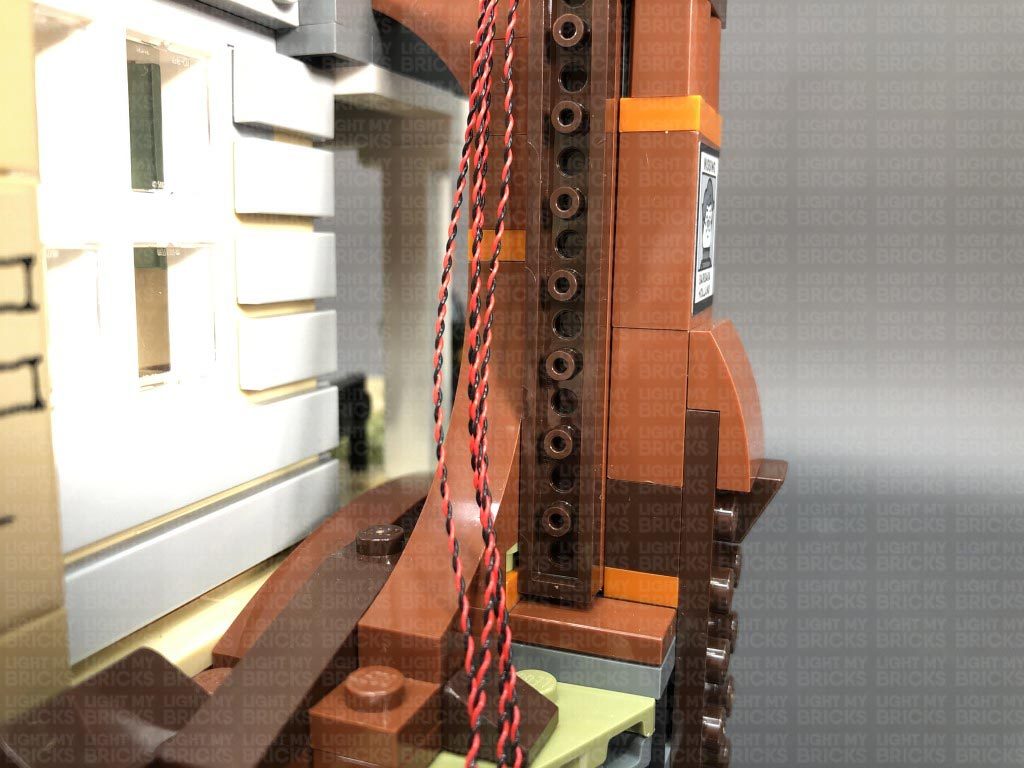
22.) Slightly disconnect the light brown plate from the bottom side, then slip the four cables underneath it toward the left side before reconnecting the plate over the cables. Ensure the cables are laid in between studs underneath.
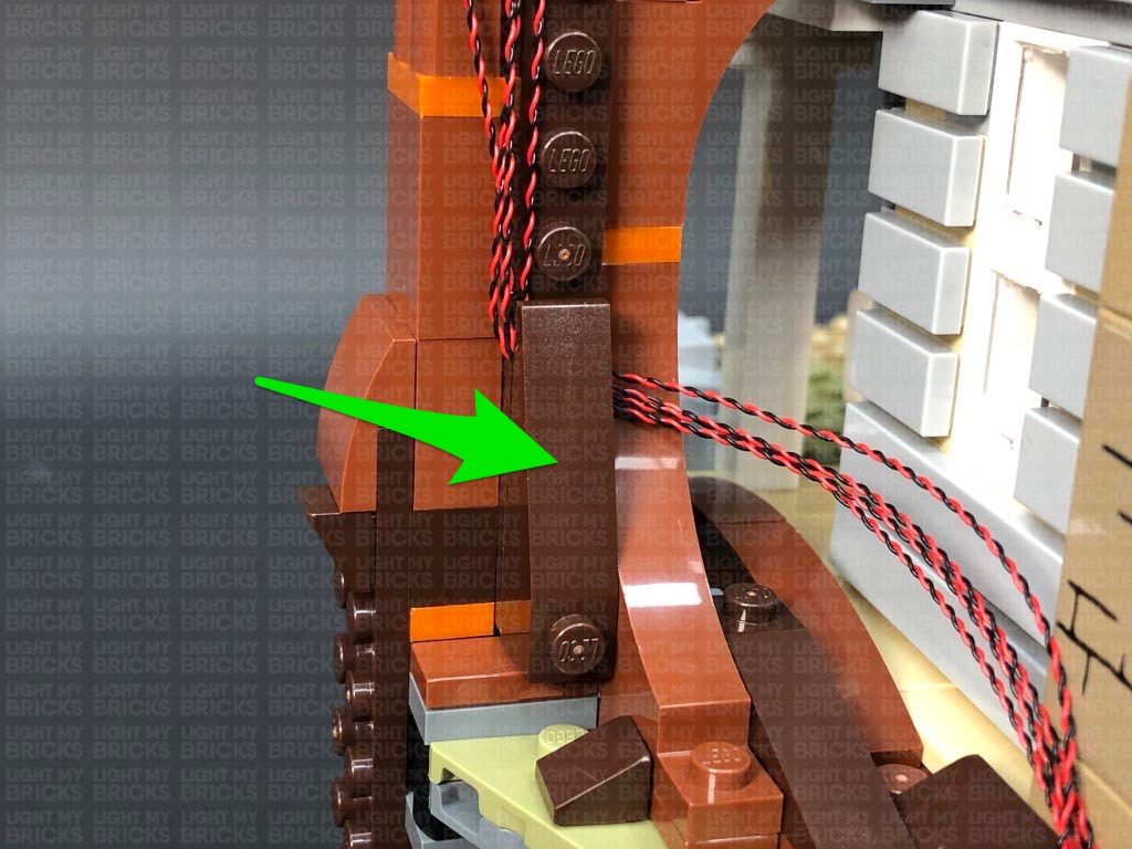
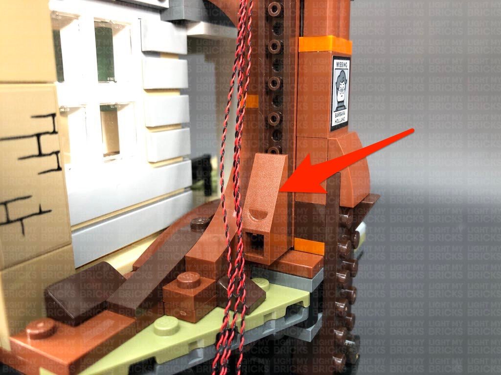
Disconnect the following angled brick at the bottom of the trunk, then group the four cables and lay them across to the left side before reconnecting the angled brick over the top. Ensure the cables are laid in between studs underneath.
Connect the four Bit Lights to a new 8-Port Expansion Board. Disconnect the USB Power Cable from the other tree lights and connect it to this expansion board, then turn ON the power to test the green lights installed to this tree are working OK.
Note: If you experience any issues with the lights not working and suspect an issue with a component, please try a different port on the expansion board to verify where the fault lies (with the light or expansion board). To correct any issues with expansion board ports, please view the section addressing expansion board issues on our online troubleshooting guide.
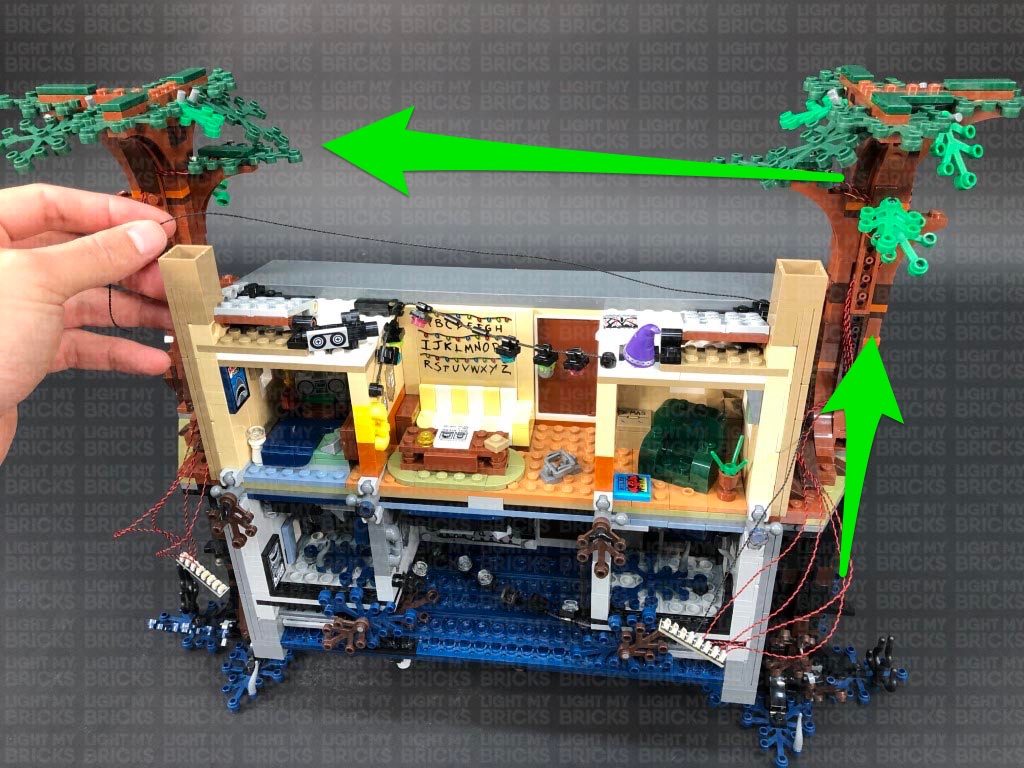
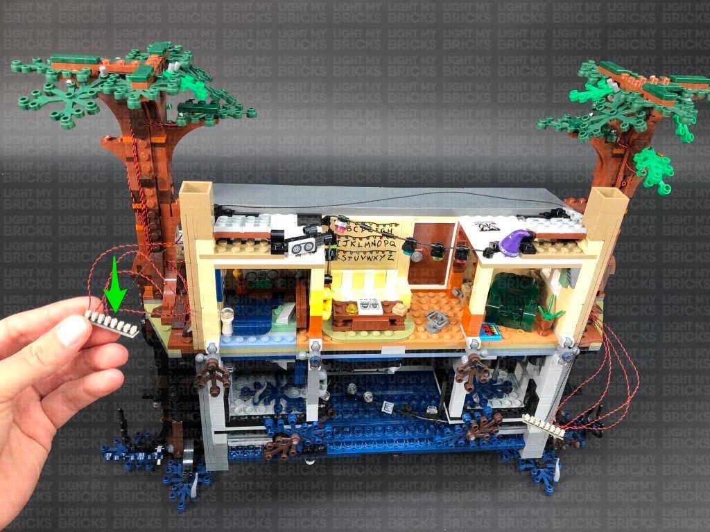
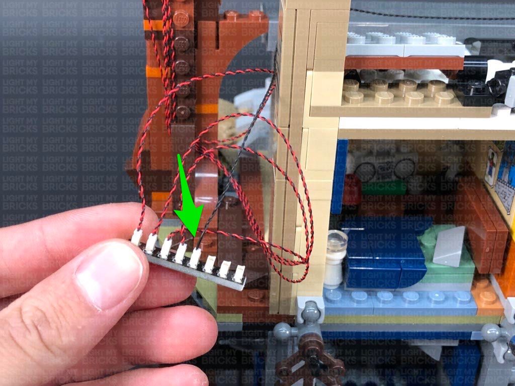
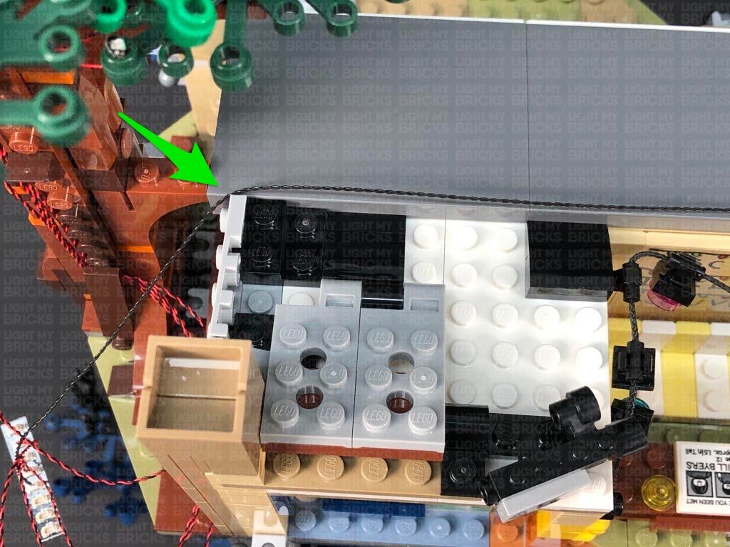
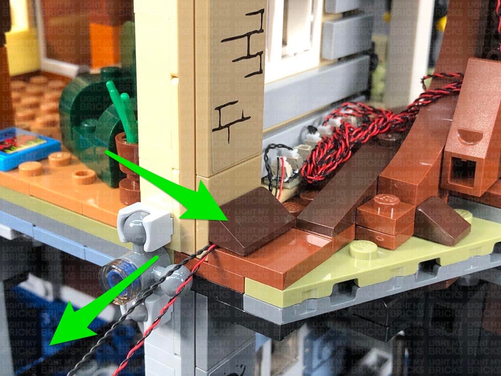
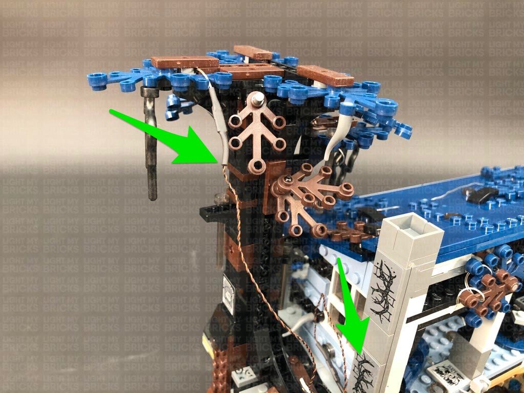
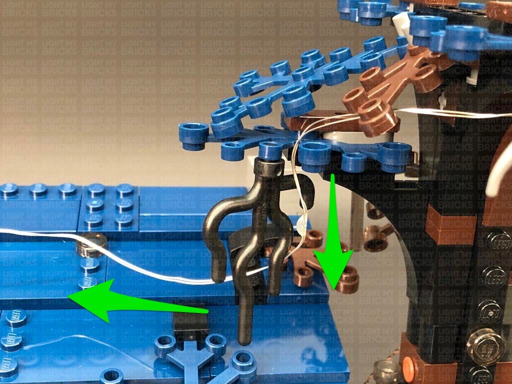
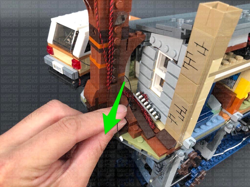
23.) Disconnect the USB Power Cable, then take out a 50cm Connecting Cable and connect it to the expansion board from previous step. Bring the other end of the cable up and over the house to the left side, then connect it to the 8-port expansion board underneath the left tree. Secure the cable in place by tucking it into the roof’s left and right side as shown below.
Disconnect the grey triangular plate as well as all the light grey tiles from the right side of the house. Lay the connecting cable down in between studs before reconnecting all of these pieces one by one starting with the triangular plate.
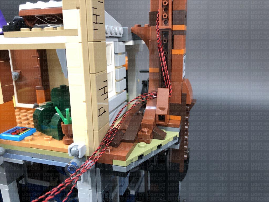
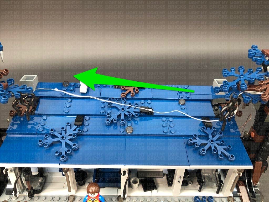
24.) Neaten up all the messy cables from this side by twisting and folding them together into one neat bunch, then tuck the bunched up cables underneath the expansion board and place everything at the side of the house as shown below.
Take your USB Power Cable and reconnect it to the expansion board, then secure it underneath the dark brown angled tile. Turn the power ON to test both tree lights are working OK
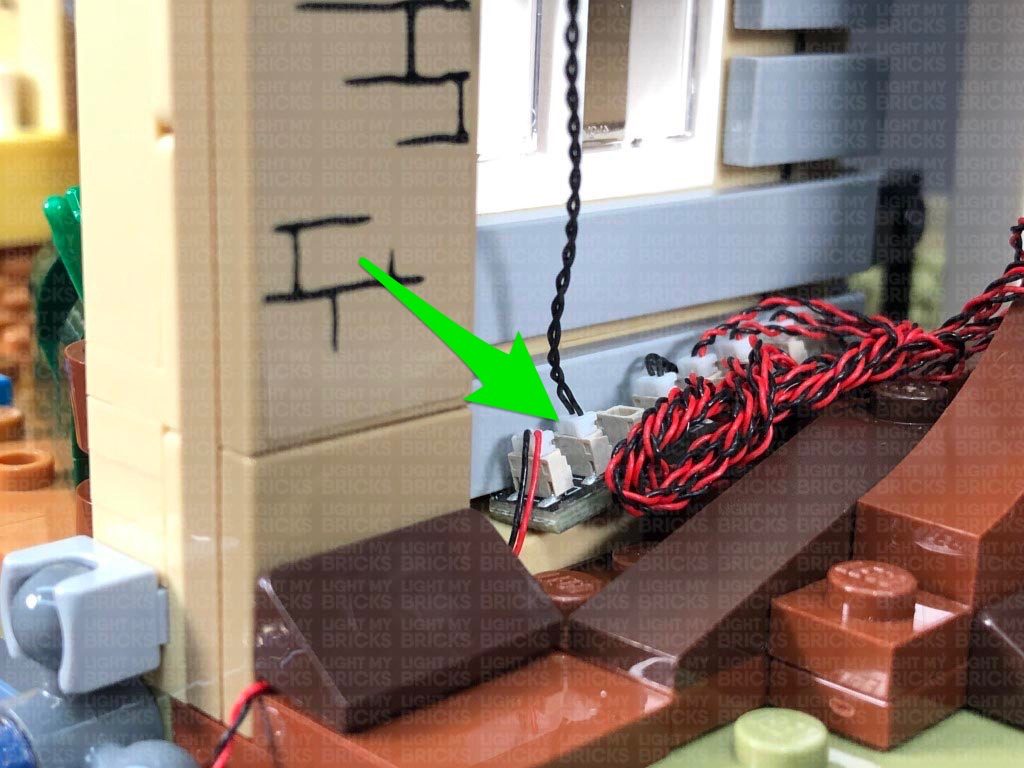
NOTE – If you wish to tether the lights from the Stranger Things minifig stand, you can connect the other end of the 50cm Connecting cable from this section (step 4.) to the expansion board. Secure the cable in place underneath the dark brown angled tile.
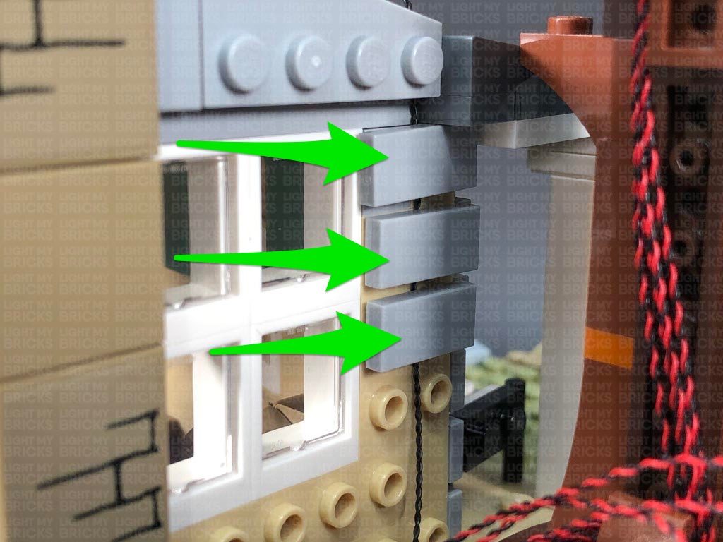
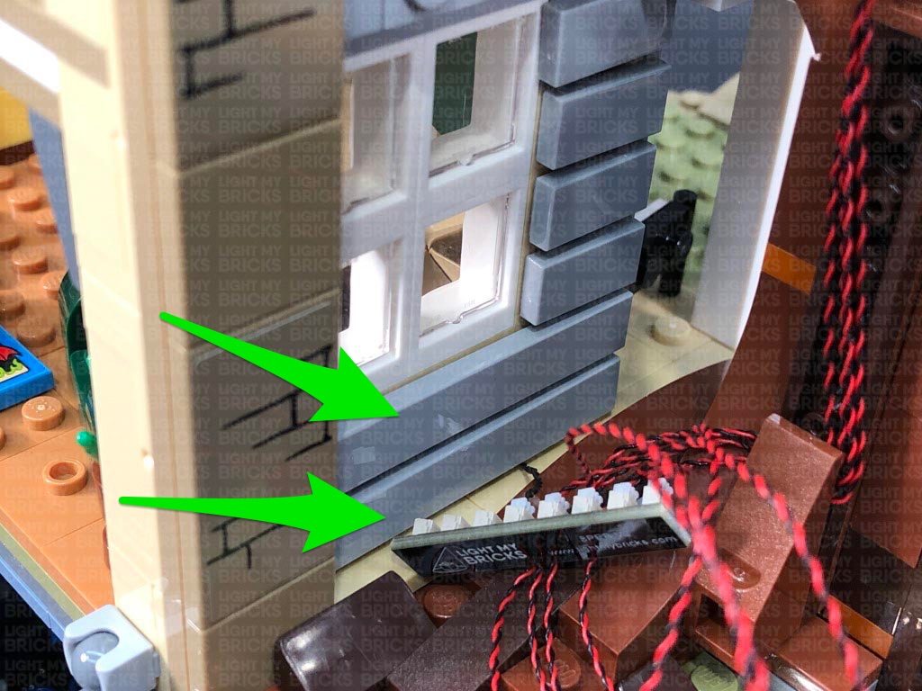
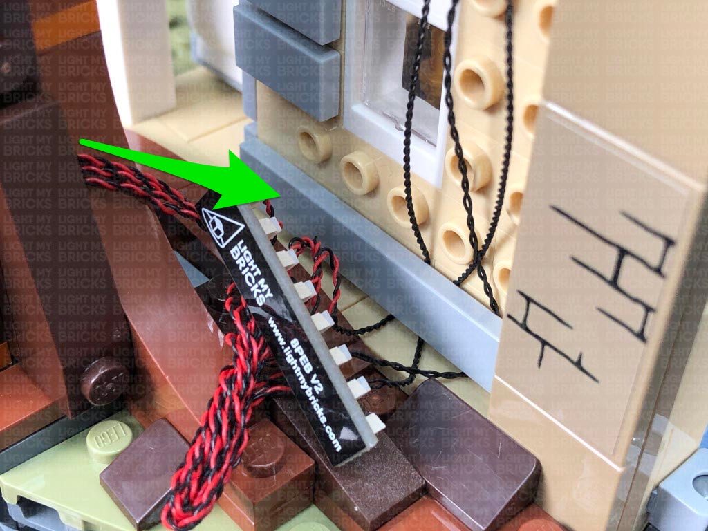
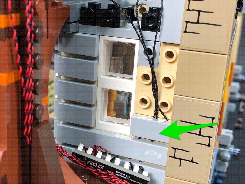
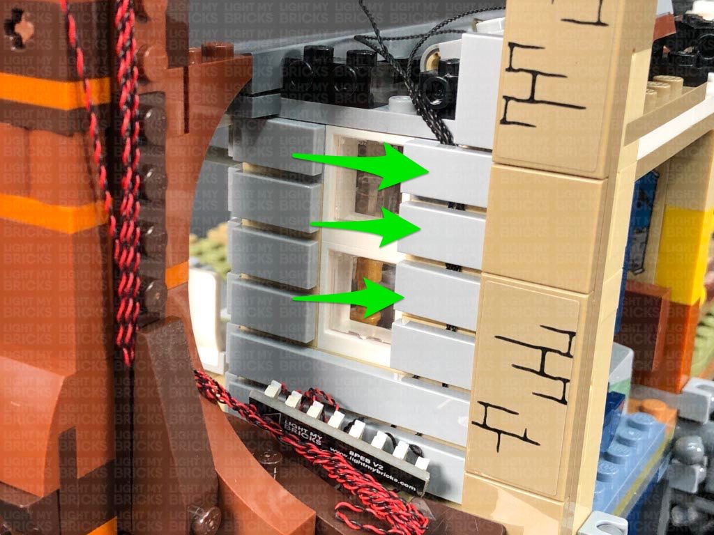
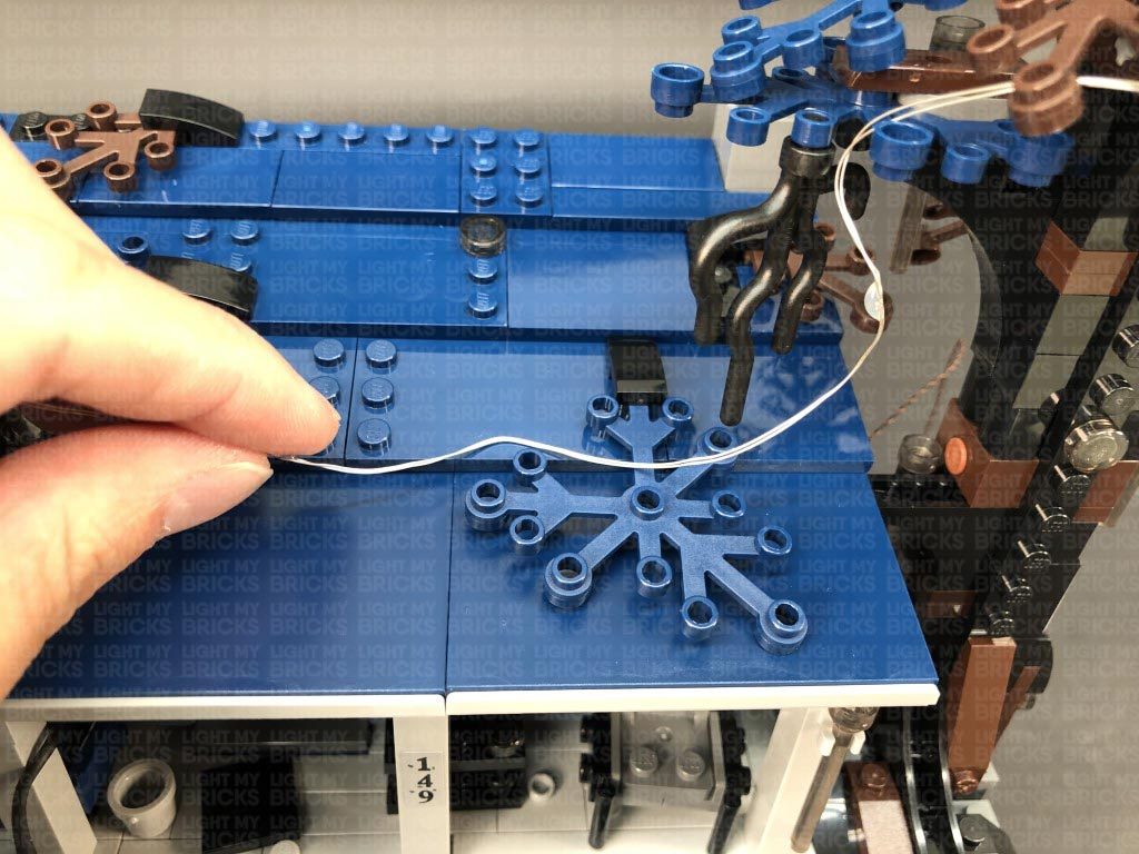
25.) Disconnect the light grey triangular plate from the left side of the house, as well as the following tiles from the wall.
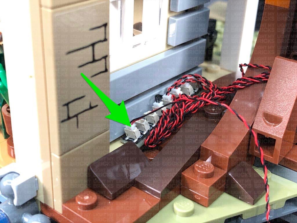
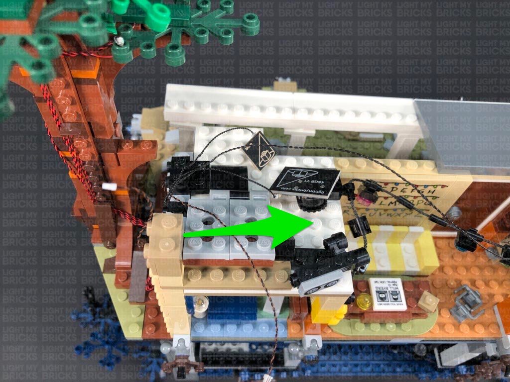
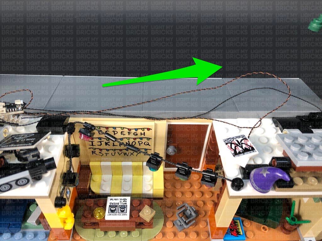
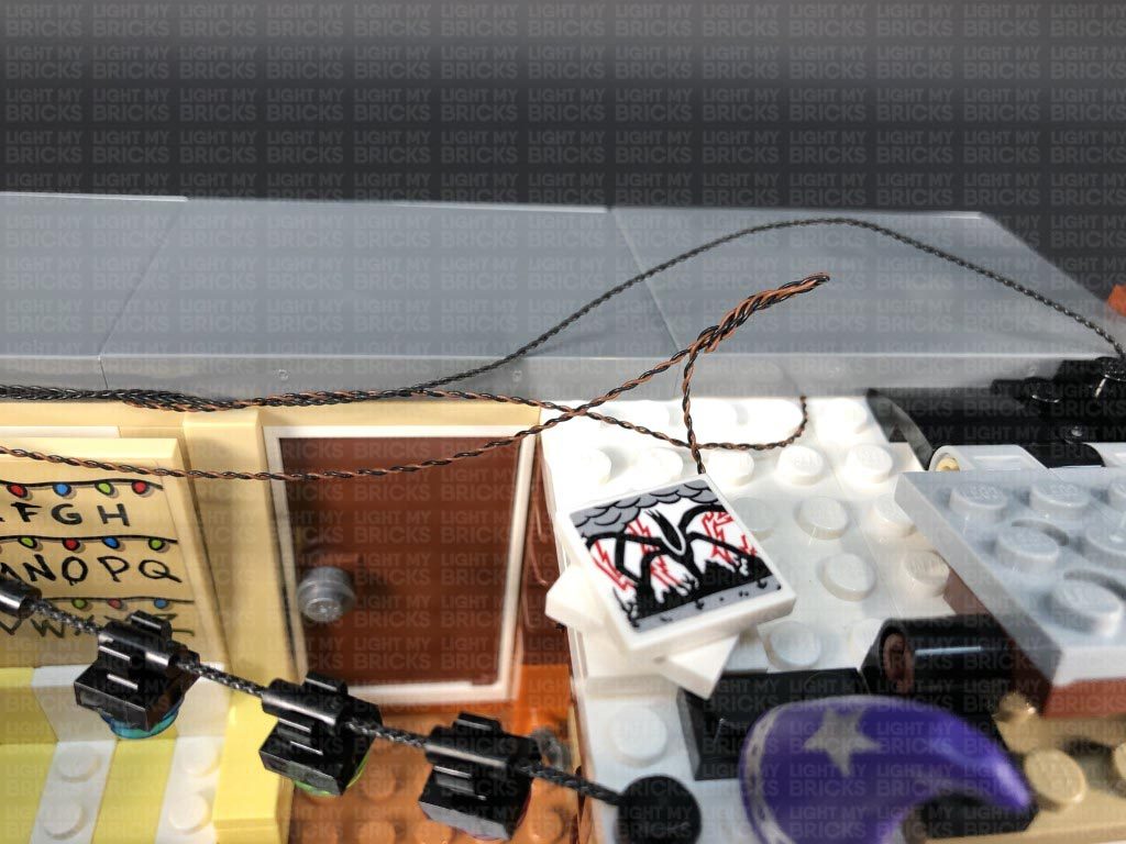
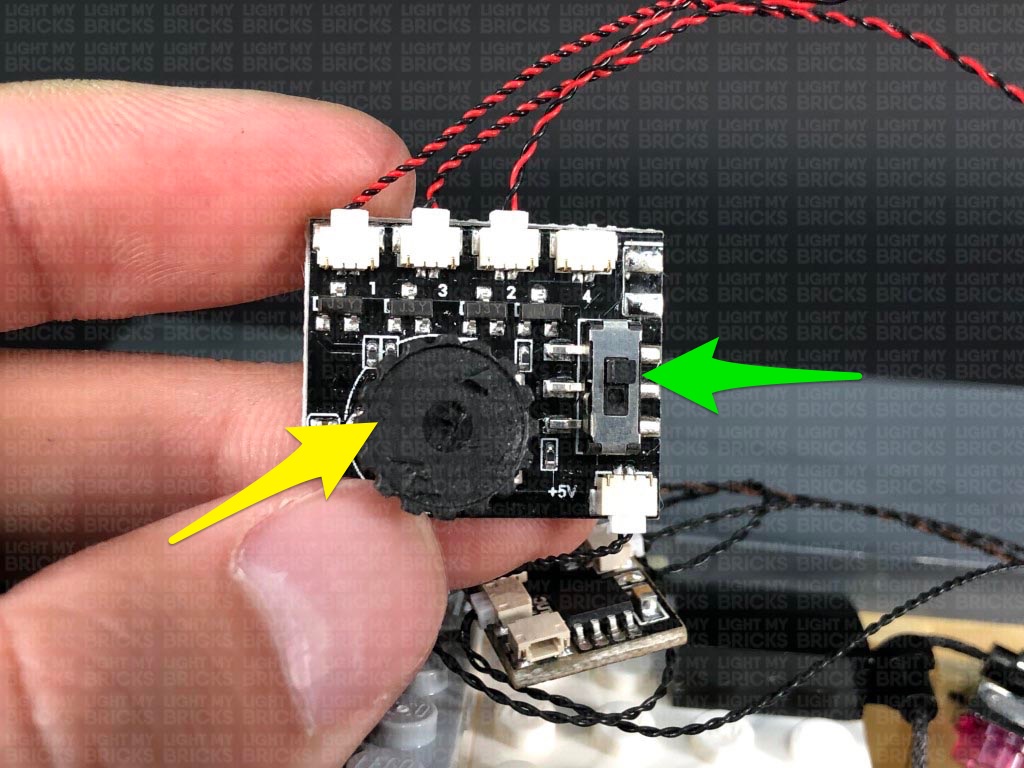
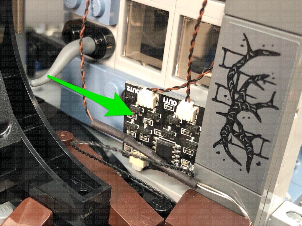
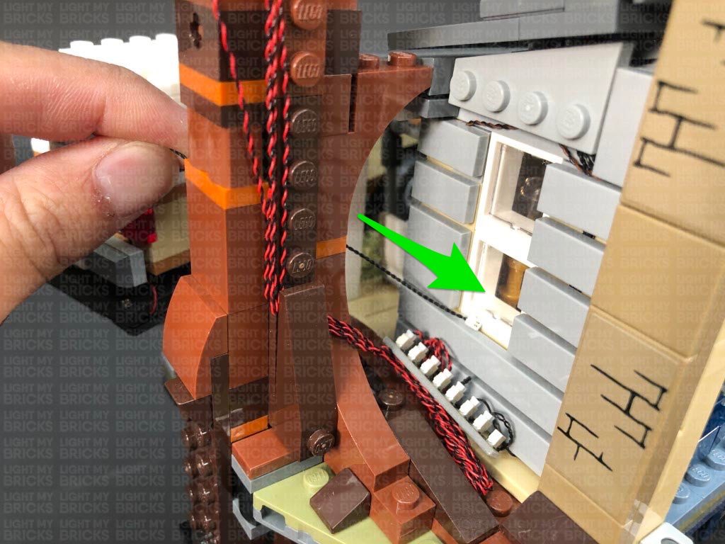
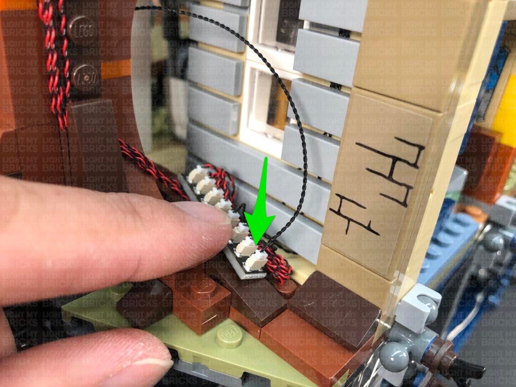
Take a 15cm Connecting Cable and connect it to the 8-port expansion board from the left side of the house, then bring the cable over the top of the house and connect it to the IN port on the Scary Flicker Effects Board (SFXV1). Place the effects board on the top of the house.
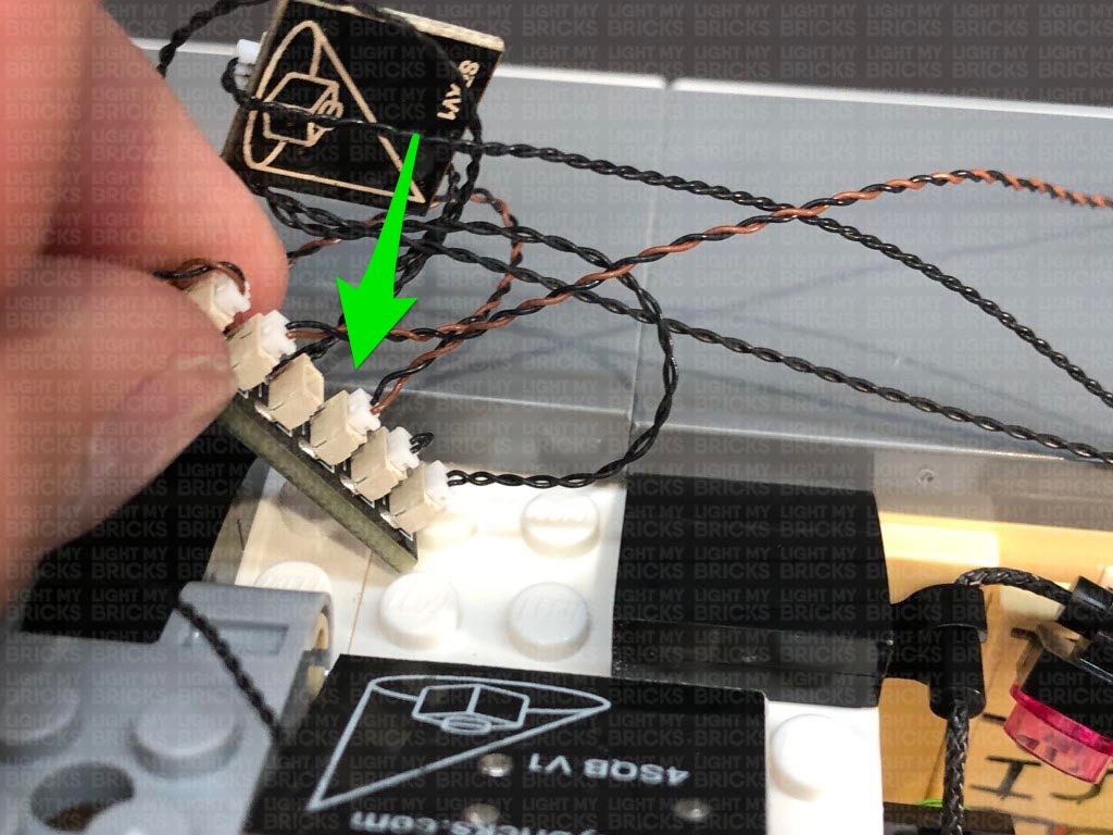
26.) Take another 15cm Connecting Cable and connect it to the 8-Port Expansion Board. Bring the cable up and over the wall and connect it to the IN port (+5V) on the Sequence Effects Board (4SQBV1). Place the sequence effects board on top of the house.
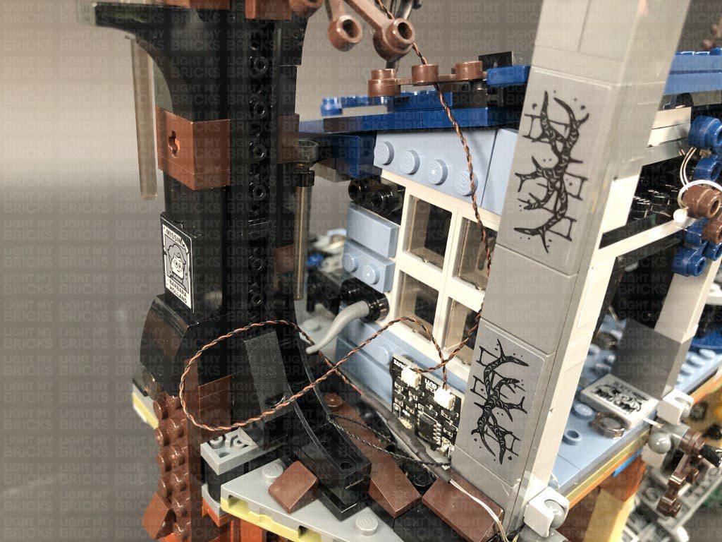
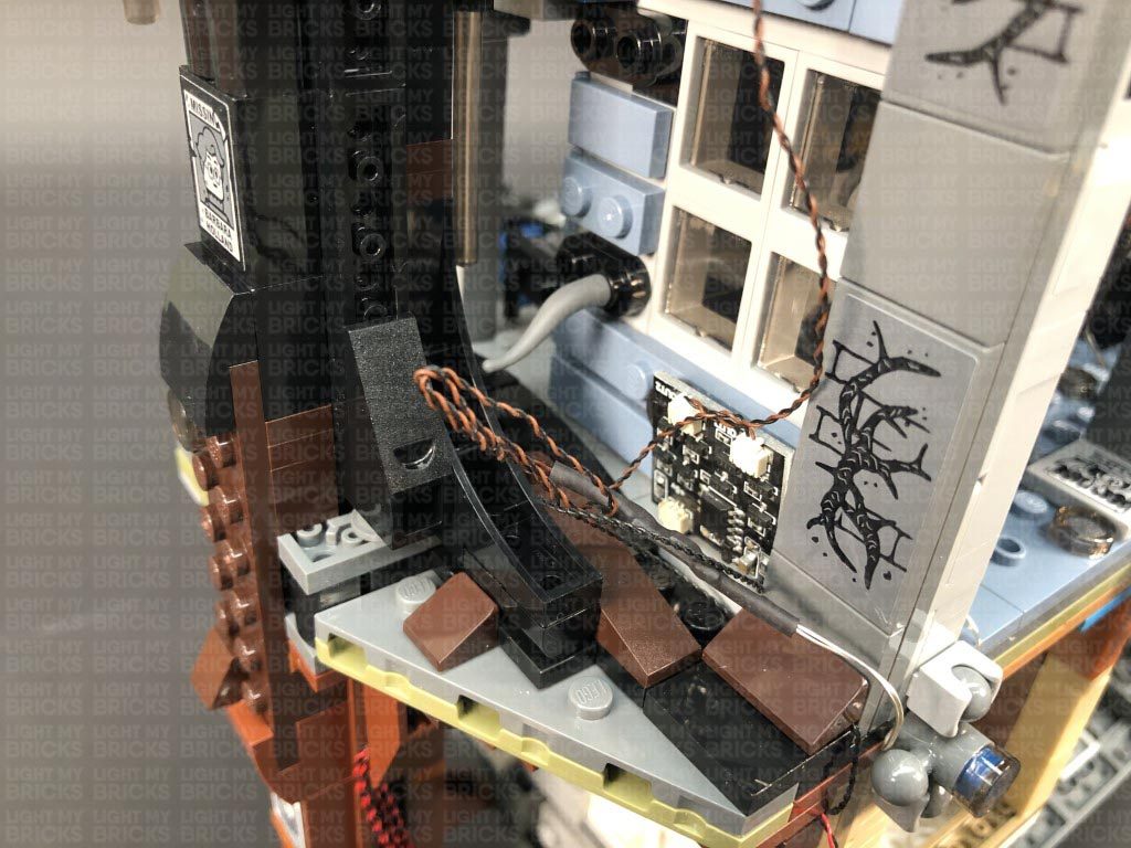
Group the four green bit light cables together and twist and fold them around each other into a neat bunch.
Place the bunched up cables underneath the expansion board, then lay the three connecting cables down in between studs along the wall. Secure the cables in place by reconnecting the bottom light grey tile.
Reconnect the remaining tiles to wall one at a time starting from the bottom up, ensuring the cables are laid in between studs.
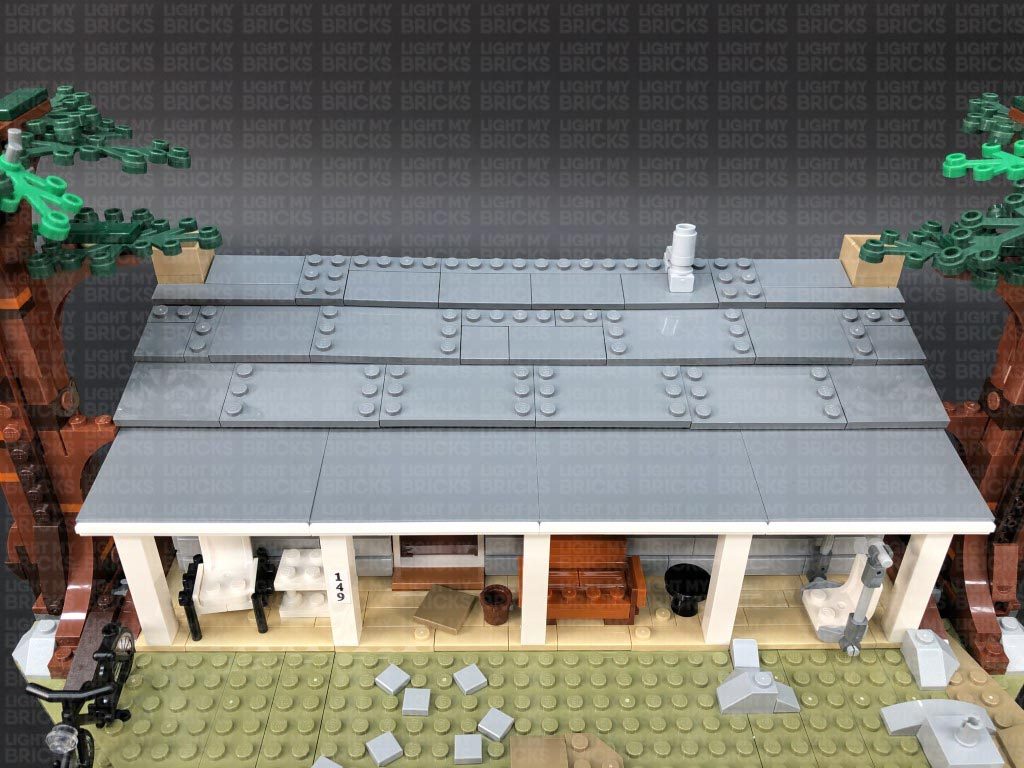
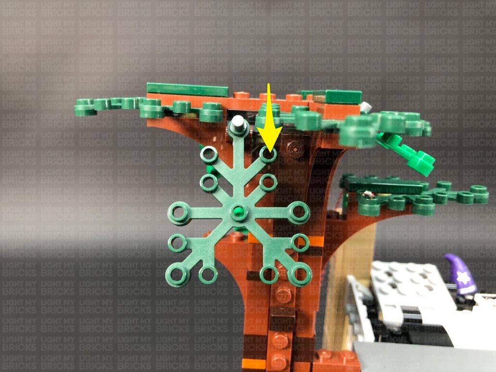
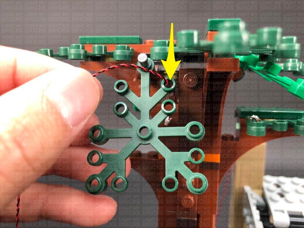
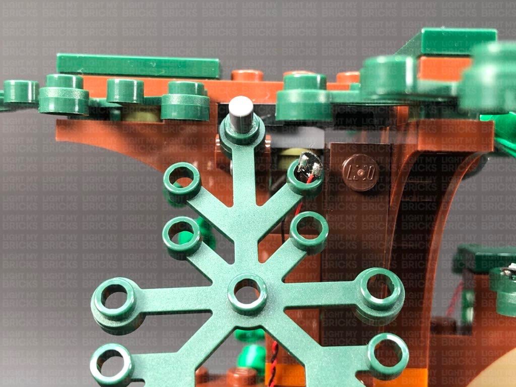
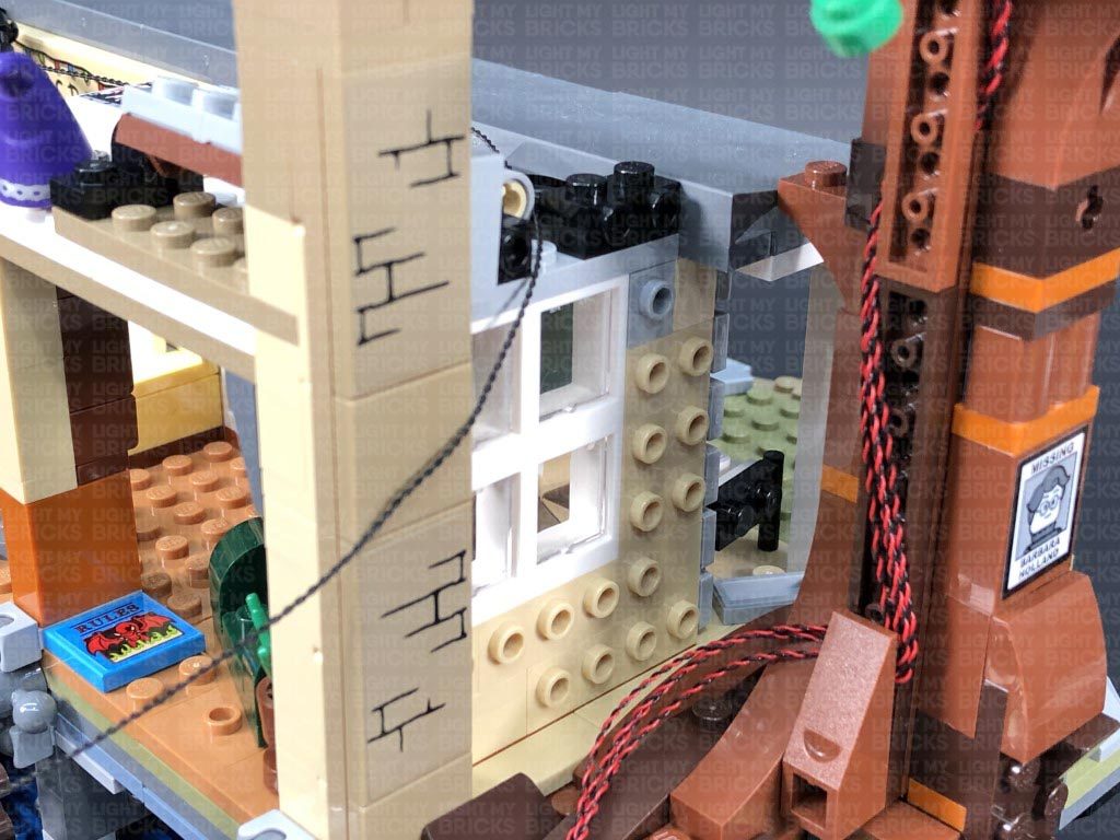
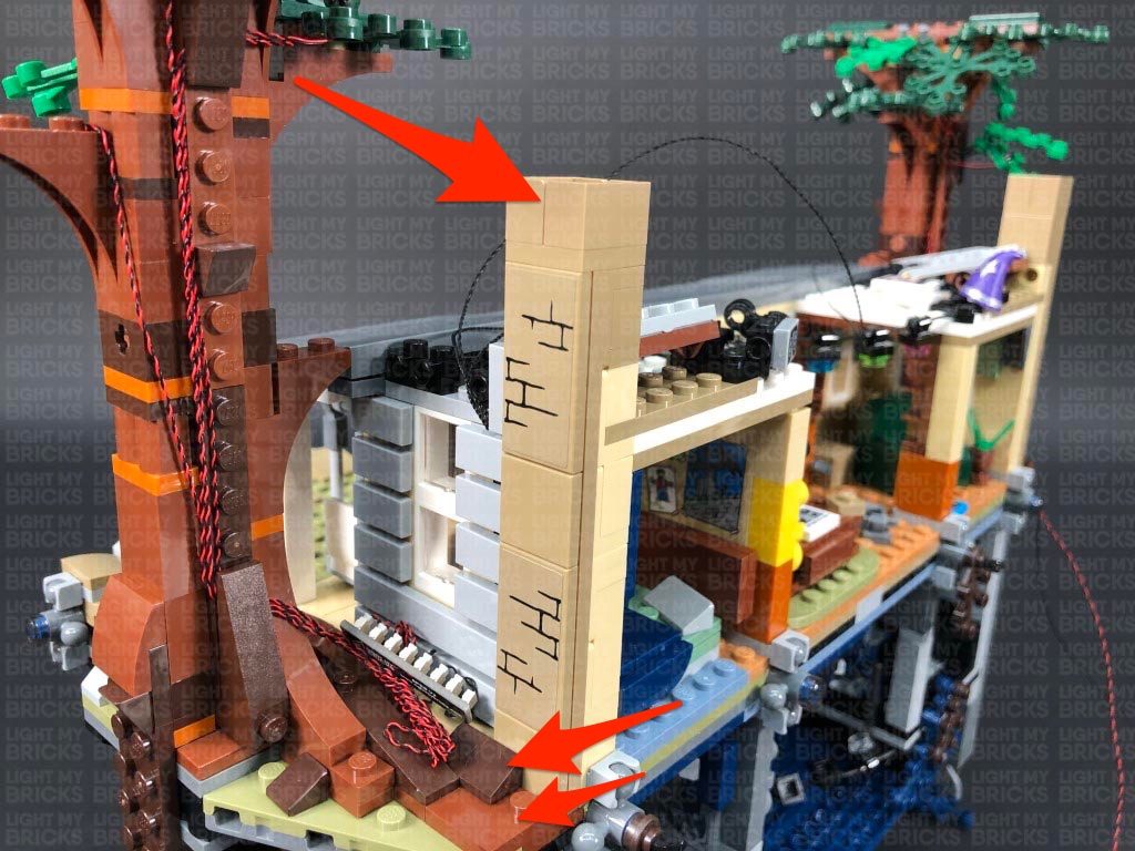
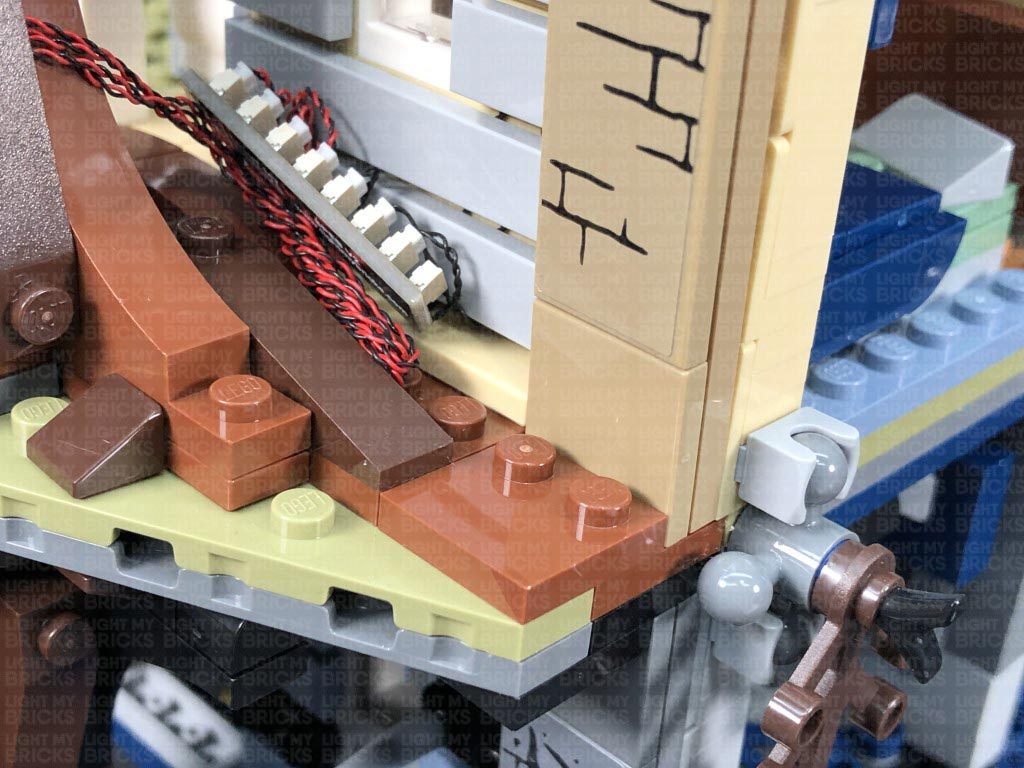
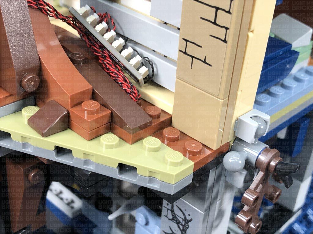
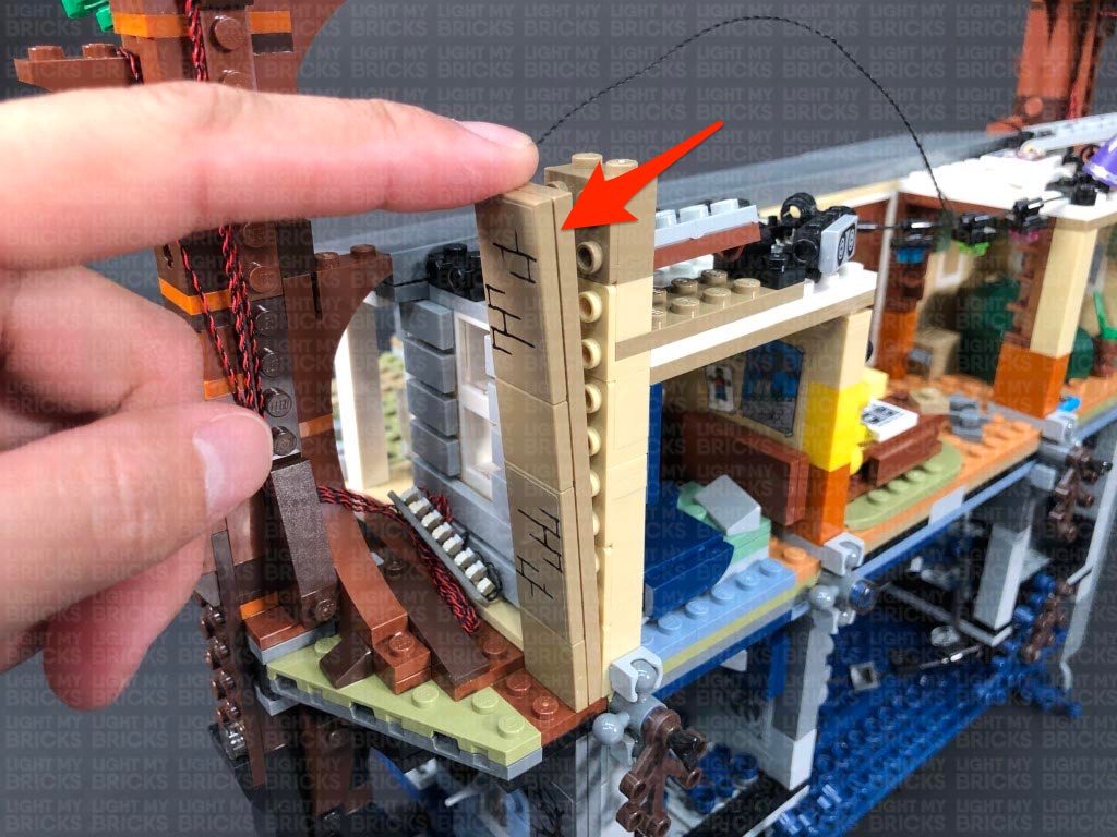
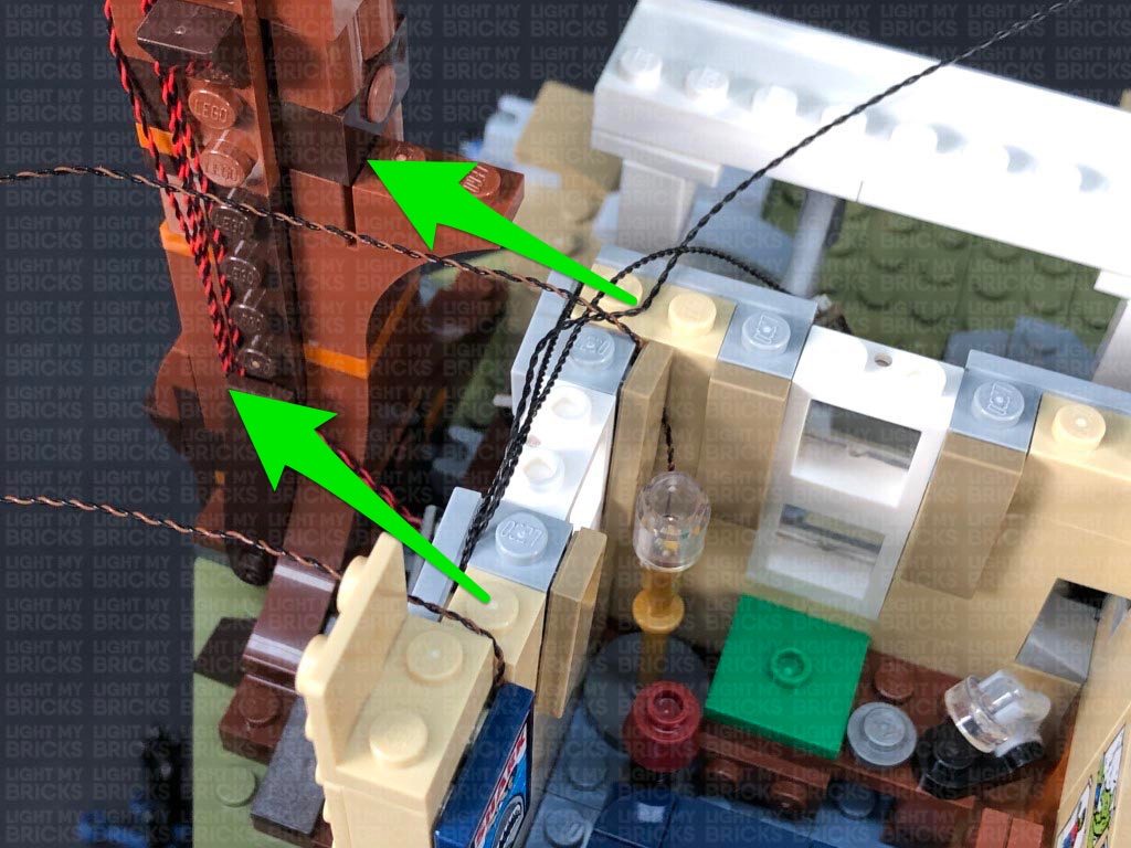
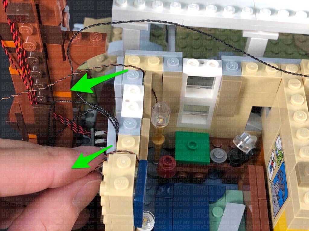
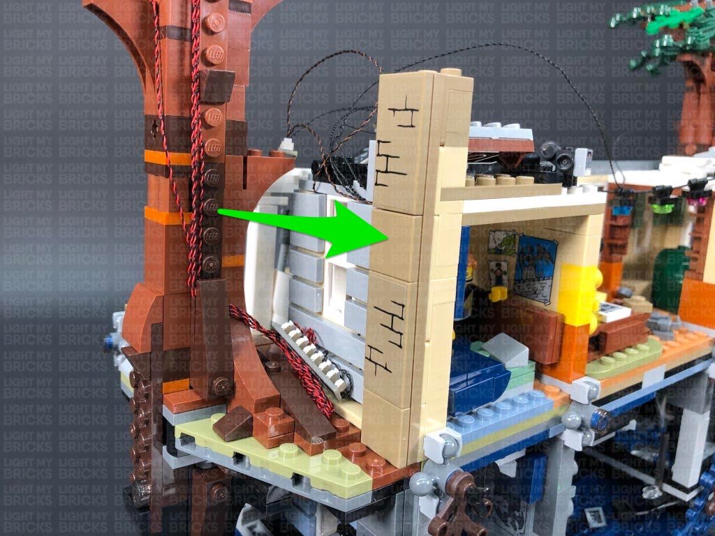
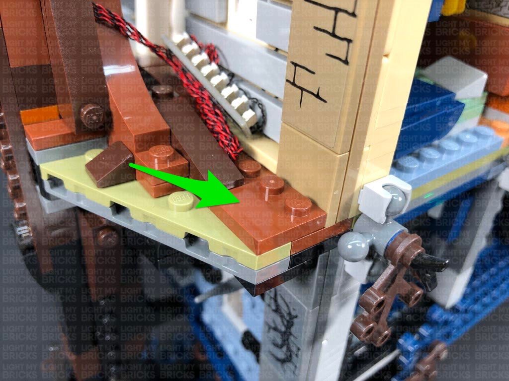
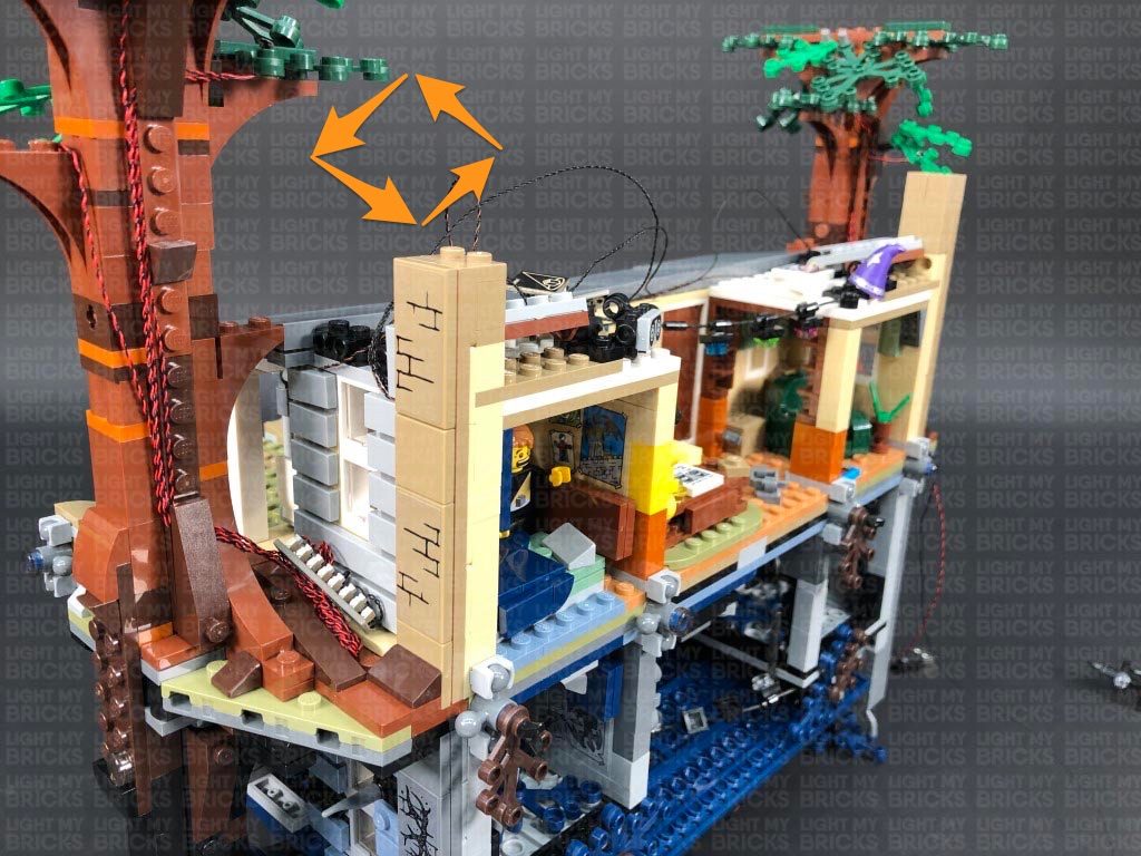
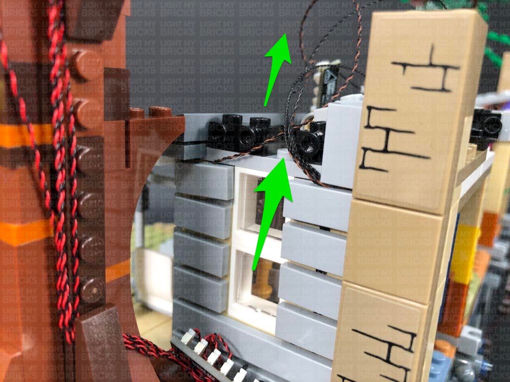
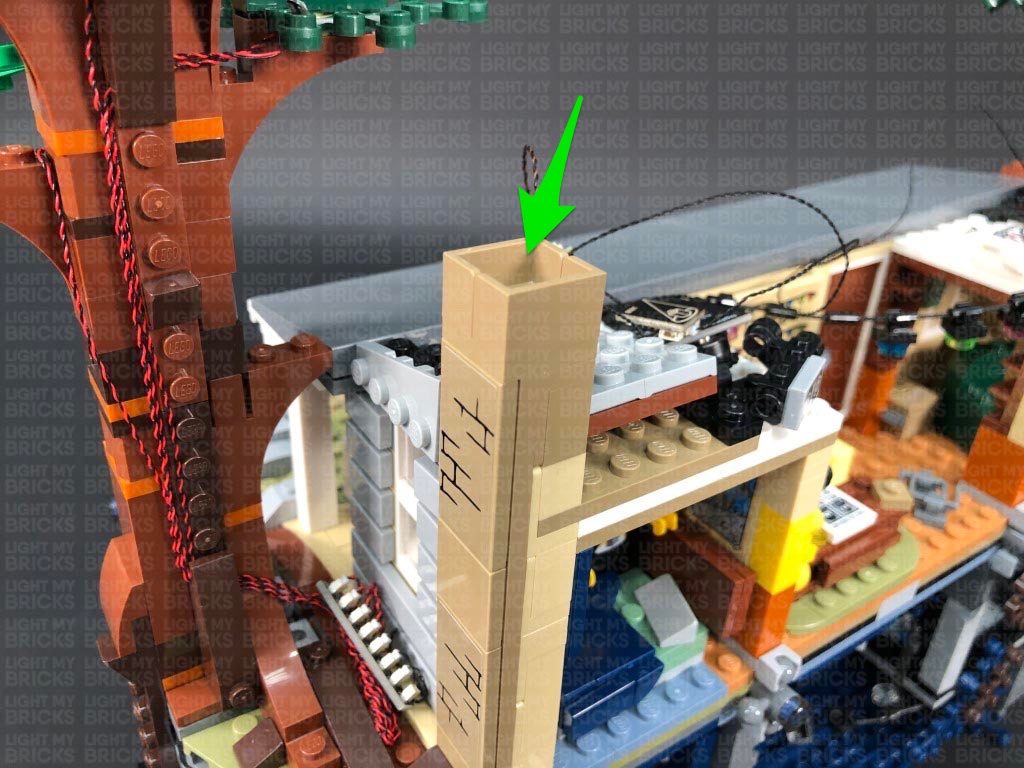
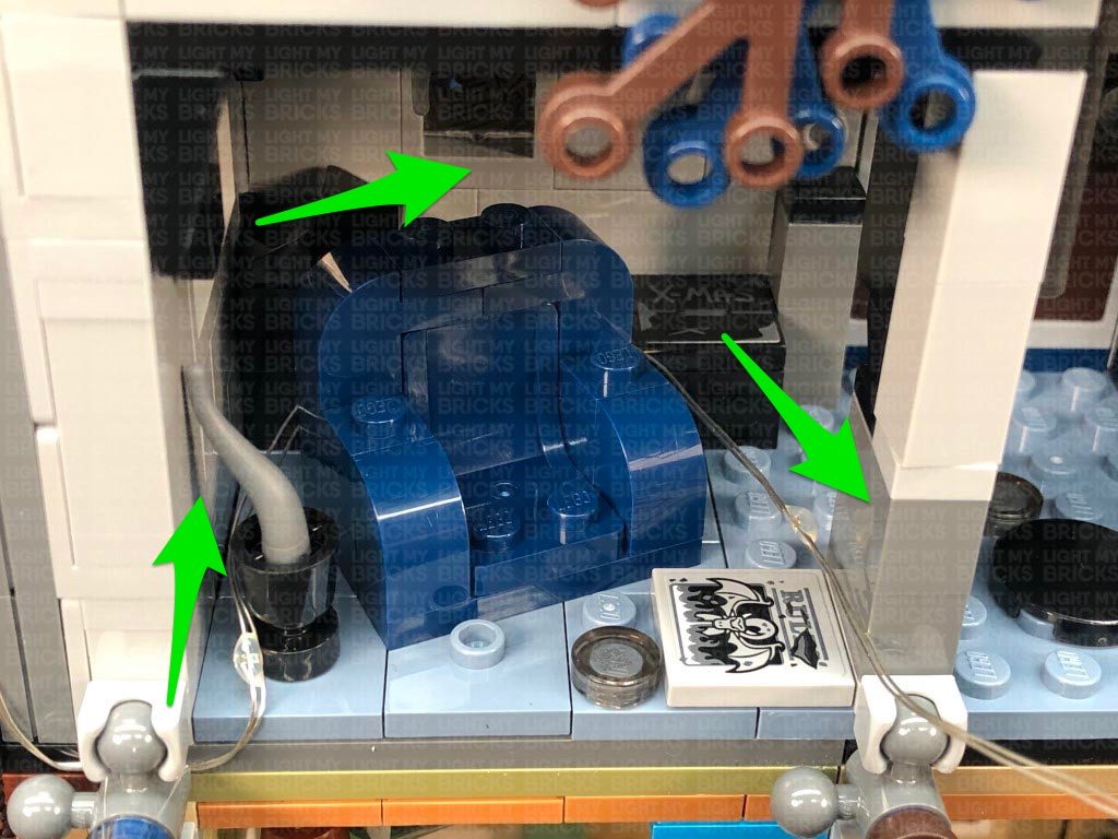
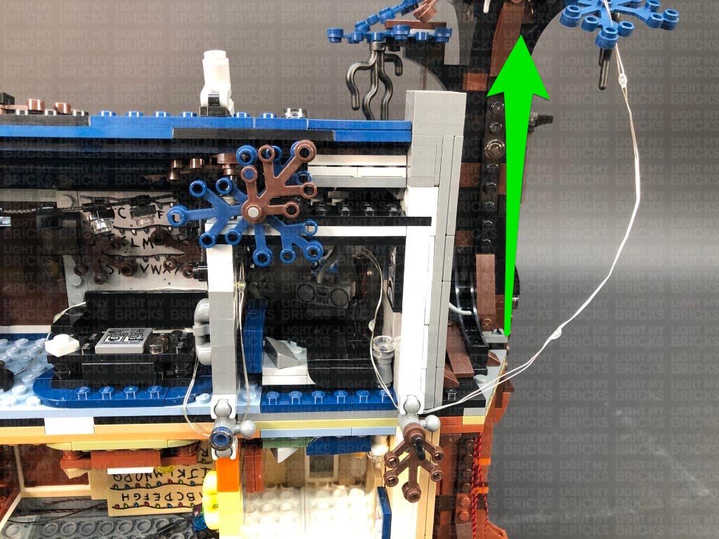
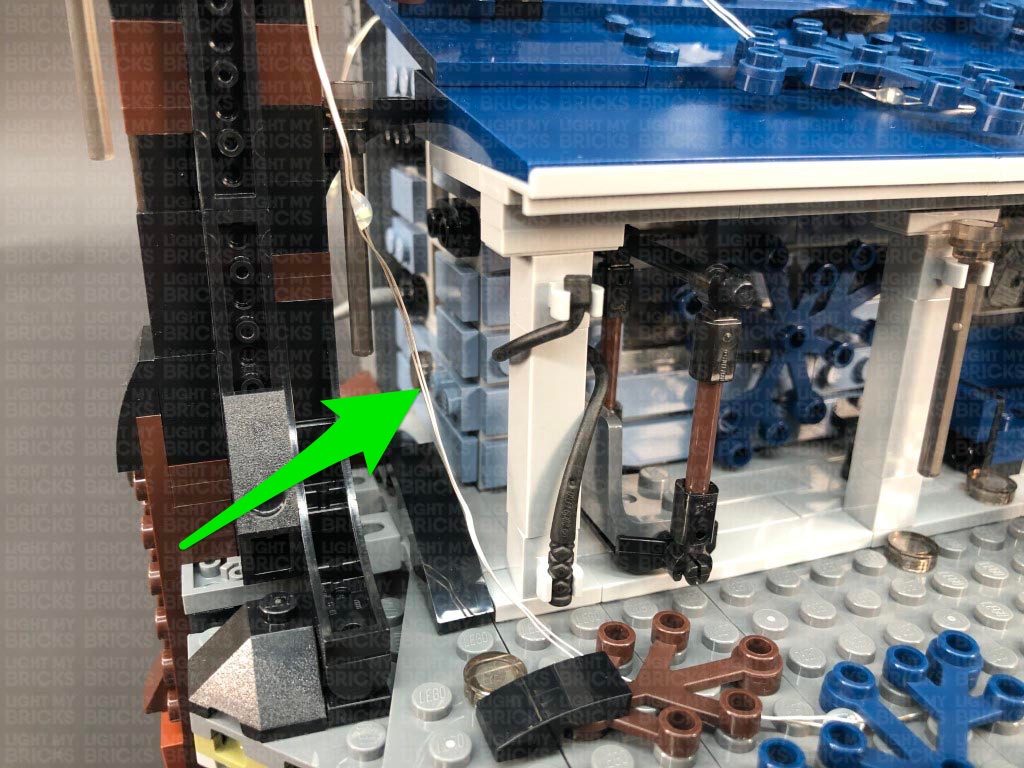
27.) Remove the following pieces from the top and bottom of the chimney to allow us to disconnect the exterior panel section.
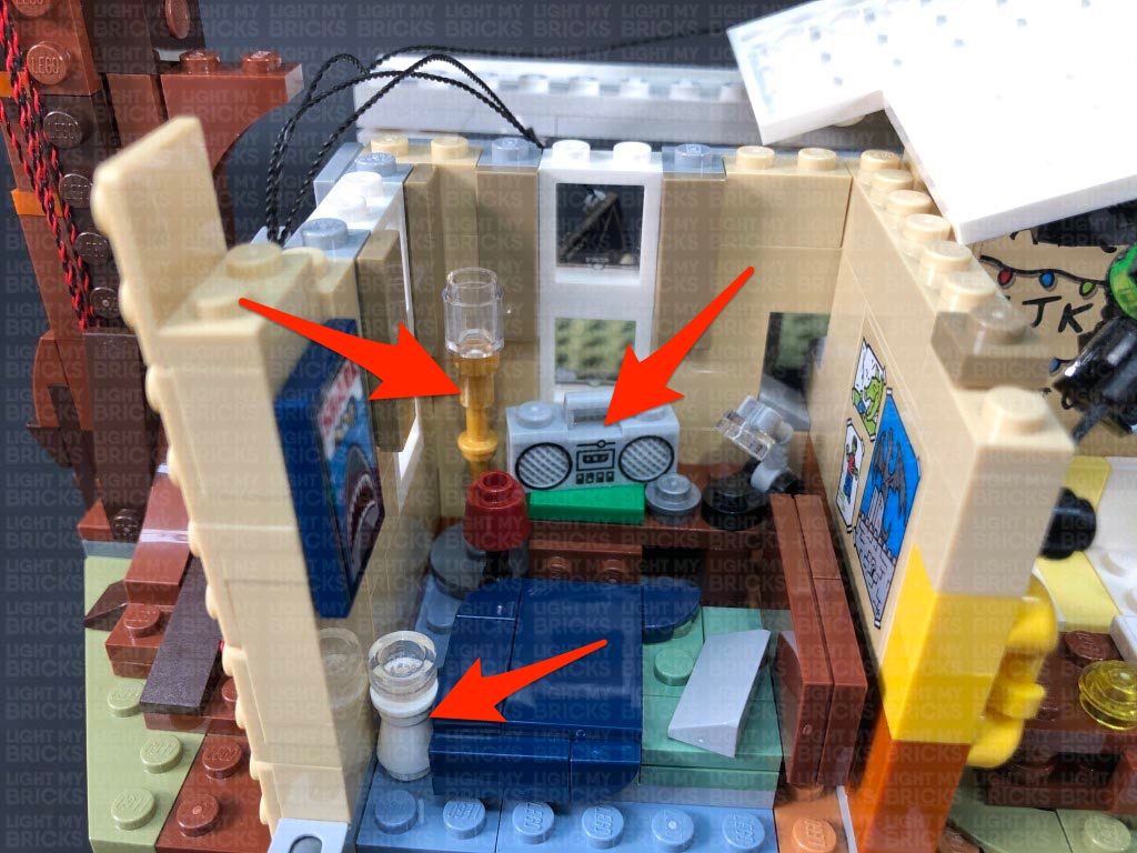
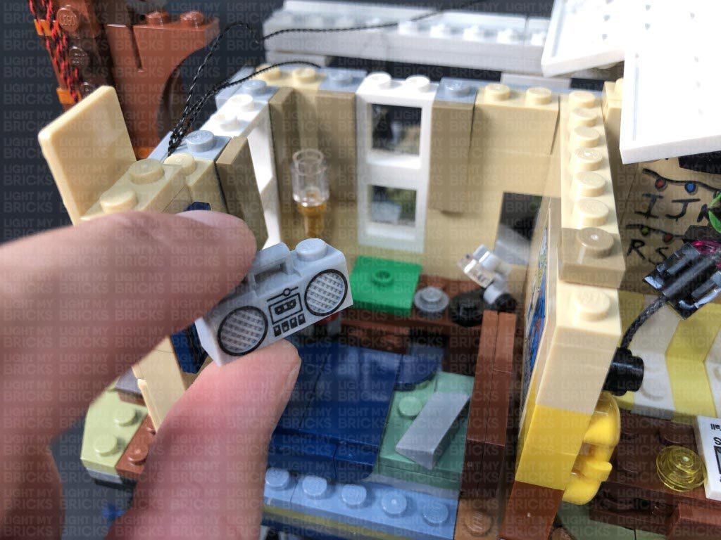
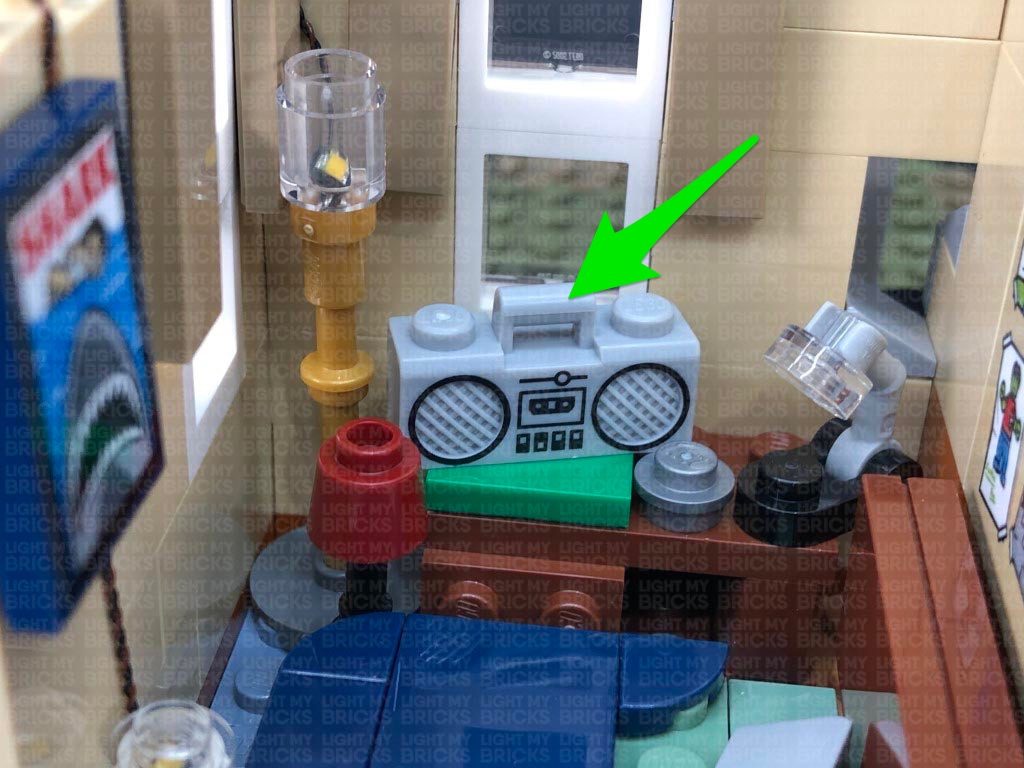
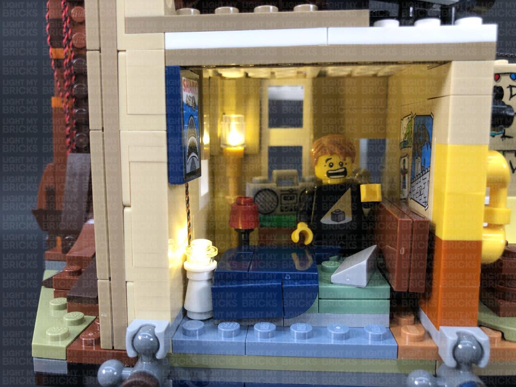
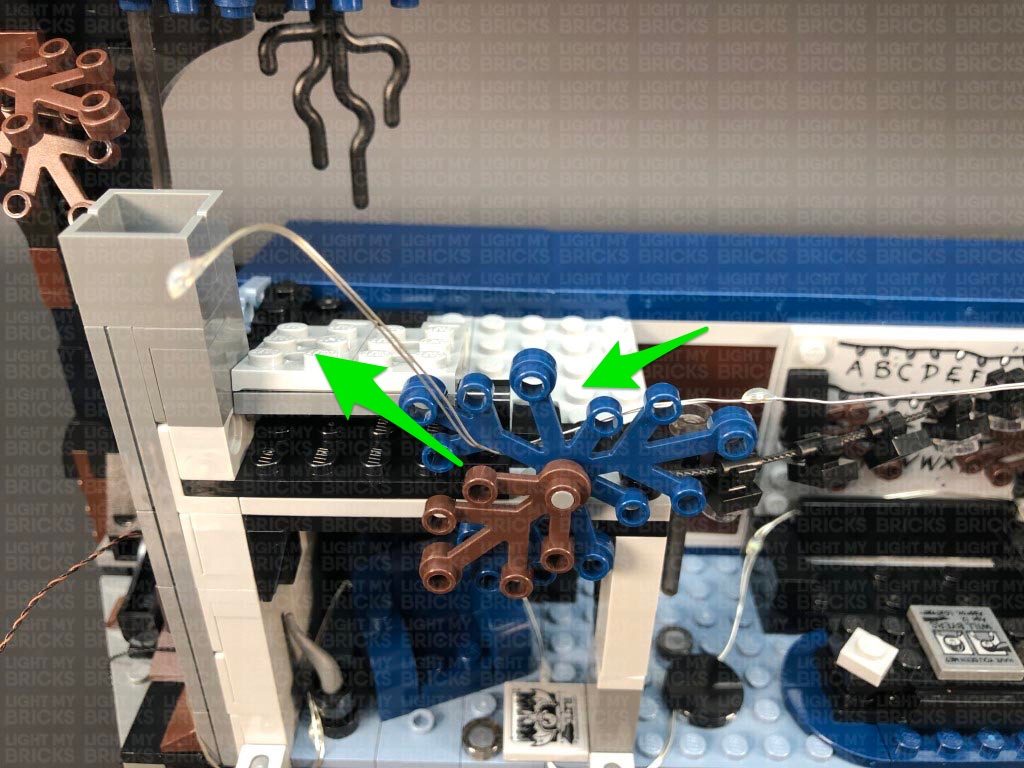
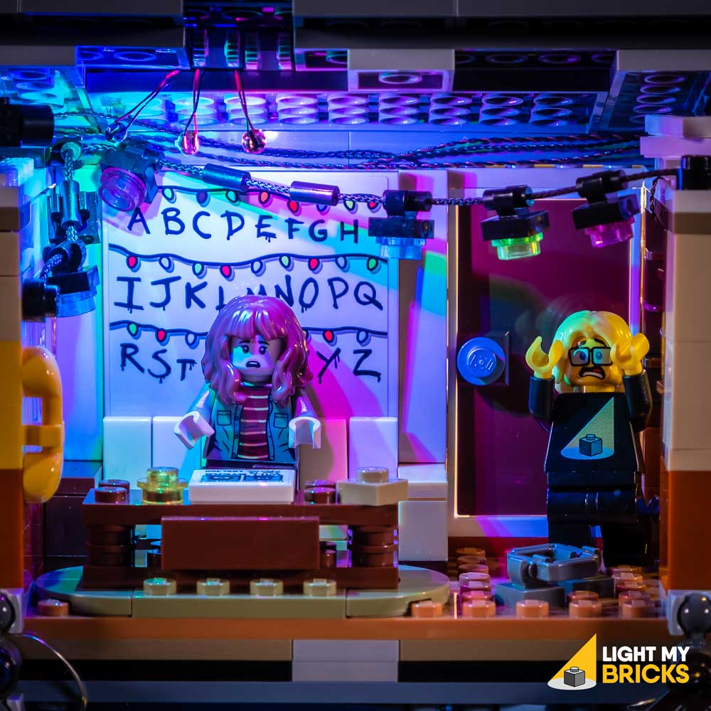
Remove the two left grey roof sections at the front, then remove the top section of the bedroom. Remove the radio to enable us to remove the following two lamps inside.
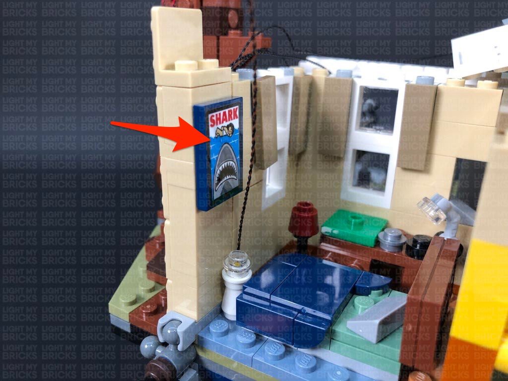
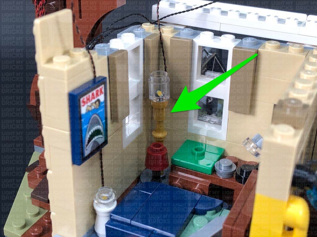
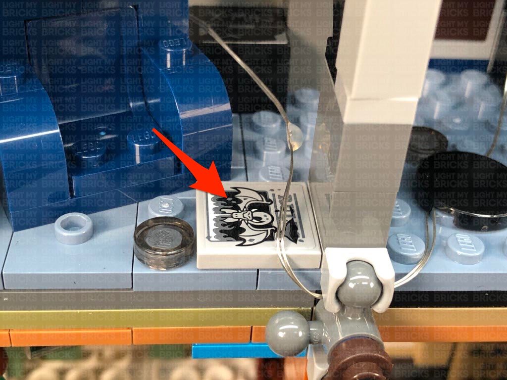
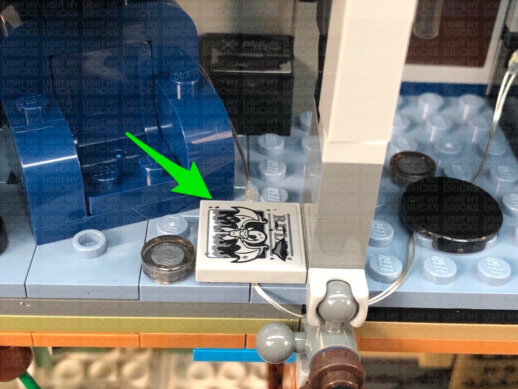
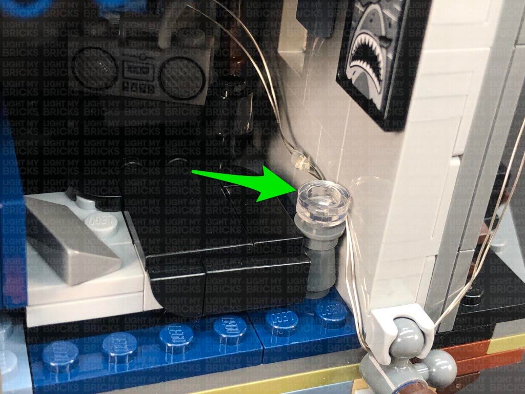
28.) Disassemble the following lamp, then take a White 15cm Bit Light and thread the connector end of the cable through the top of the white round plate with open stud. Pull the cable all the way out from the other side then flatten the LED so that it is directly facing up. Secure the Bit Light in place by connecting a provided LEGO Trans Clear Round Plate 1×1 over the top.
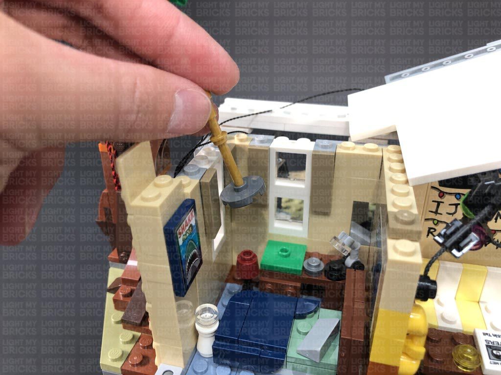
Thread the cable through the top of the white cone brick then reconnect the top section before reconnecting the lamp inside the room ensuring the cable is facing the wall.
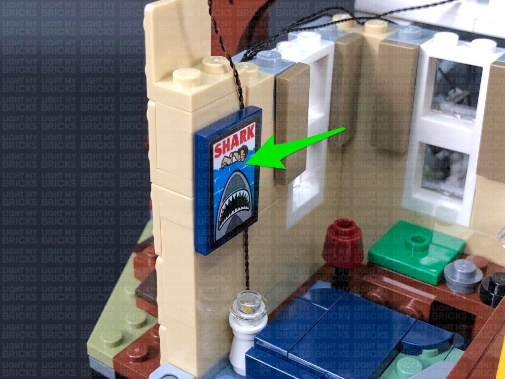
Disconnect the Shark poster and lay the cable up the wall before reconnecting the poster over the top.
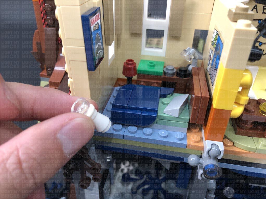
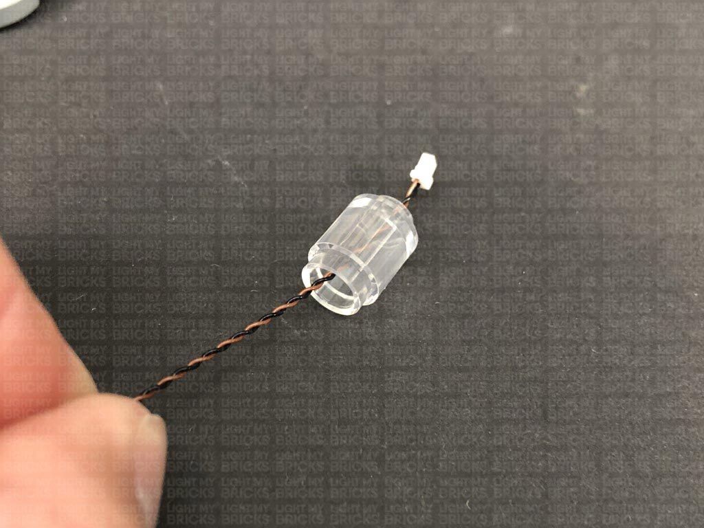
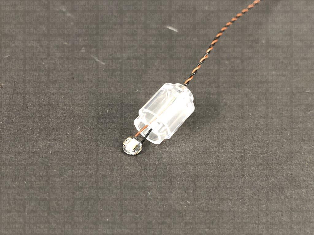
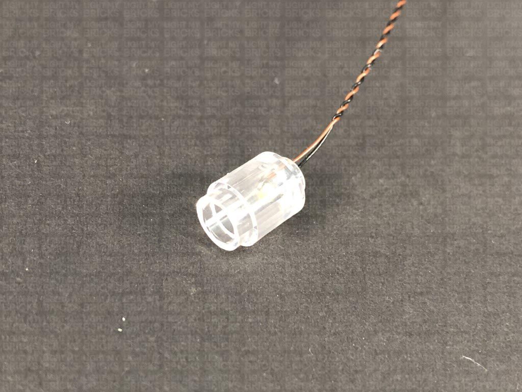
29.) Disconnect the trans clear round brick from the floor lamp, then take another White 15cm Bit Light and thread the connector end of the cable through the larger hole of the trans clear round brick. Pull the cable out from the top of the brick then carefully bend the LED so that it is facing directly down before pushing the LED all the way inside the brick.
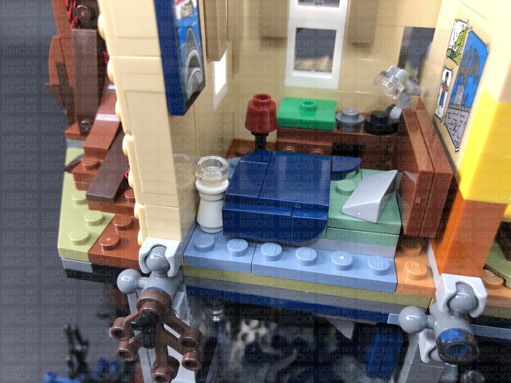
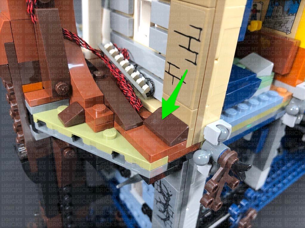
Reconnect this section to the lamp, then reconnect the floor lamp to the inside of the room ensuring the cable is facing the back corner.
Secure the cable behind the following dark tan tile, then reconnect the Radio.
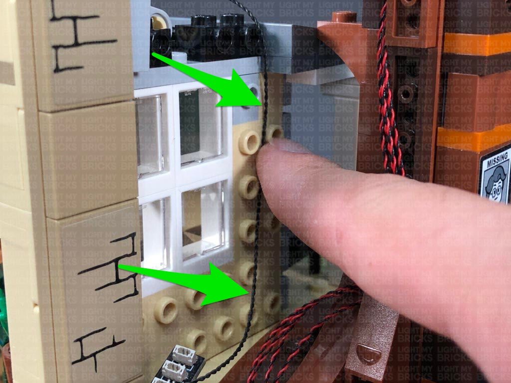
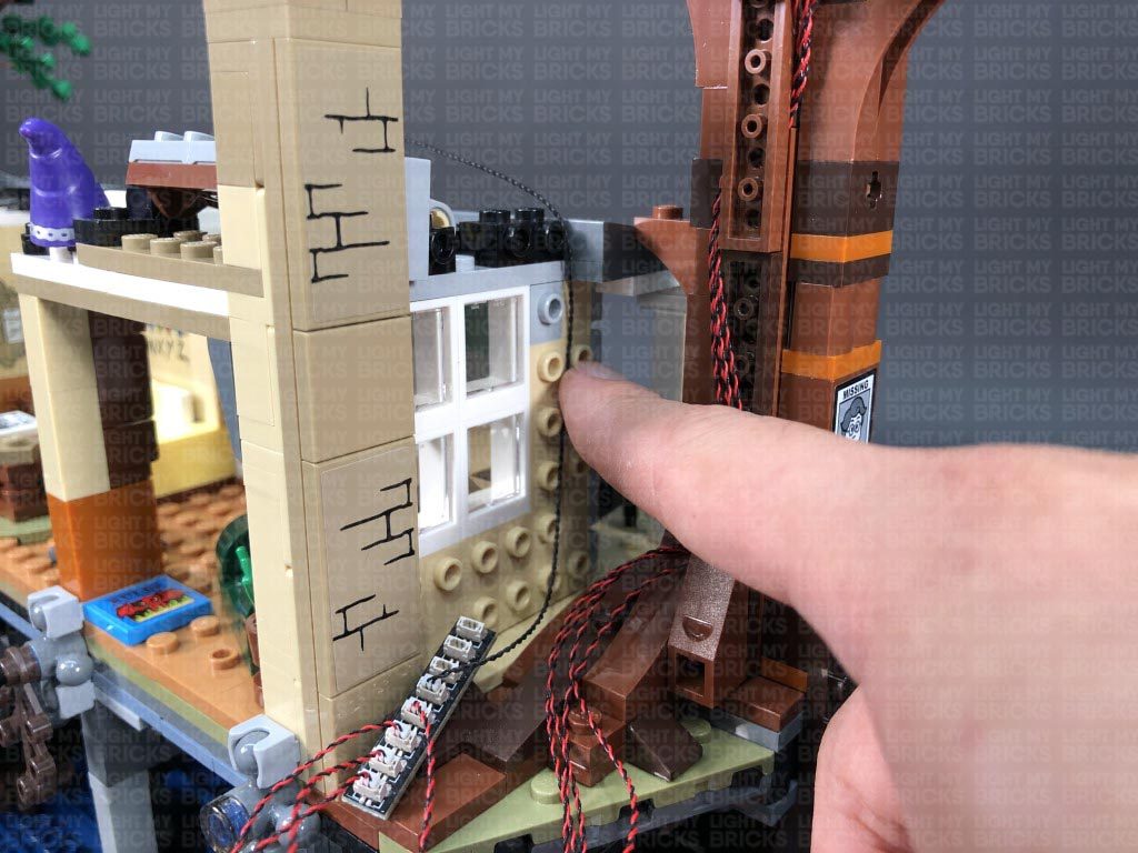
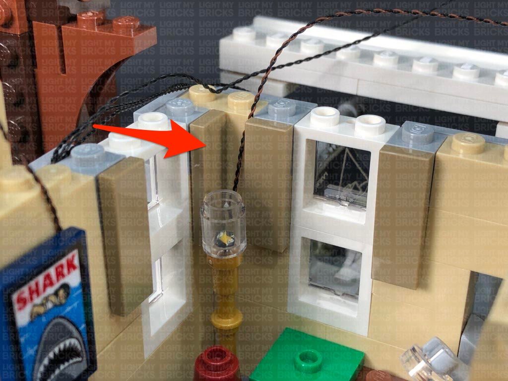
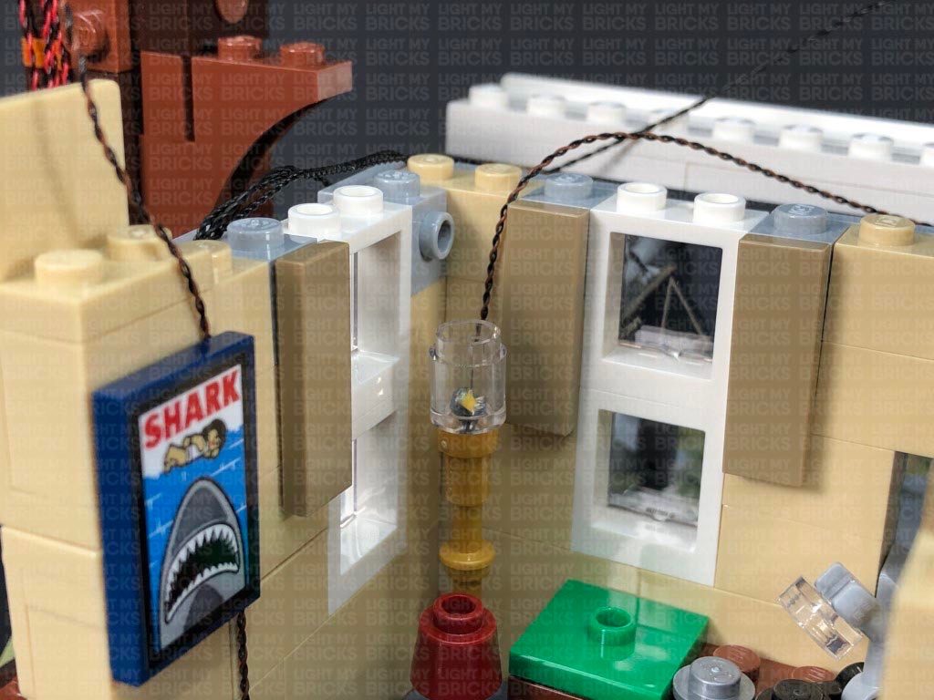
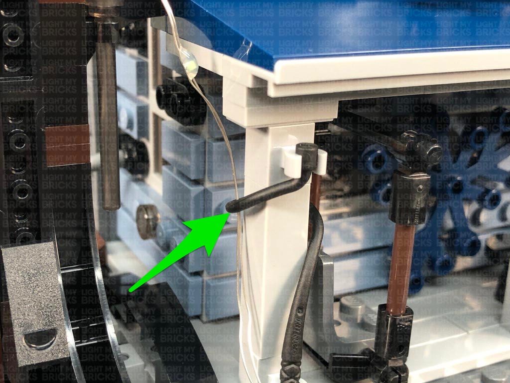
30.) Bring both Bit Light cables over the wall in the following positions. Reconnect the roof section of the bedroom, then bring all the components and cables back over onto the top.
Connect the two Bit Light cables form the bedroom lamps to a 6-Port Expansion Board. Take a 5cm Connecting Cable and connect one end to the 6-Port Expansion Board. Connect the other end of the connecting cable to one of the OUT ports on the Scary Flicker effects Board. Turn the power ON to test the bedroom lamps are working and flickering OK. The scary effects board should enable to lights on each channel to flicker approximately every 15 seconds.
19.) Connect the four bit light cables to an 8-Port Expansion Board. Take your USB Power Cable and connect it to the end port on the expansion board. Connect the USB Connector to a USB Power Bank or wall adaptor (sold separately) and turn it ON to test the green lights are working OK.
Note: If you experience any issues with the lights not working and suspect an issue with a component, please try a different port on the expansion board to verify where the fault lies (with the light or expansion board). To correct any issues with expansion board ports, please view the section addressing expansion board issues on our online troubleshooting guide.
20.) Facing the front of the house, we will now install lights to the tree on the left side. Using the same method used for the other tree lights, follow the below images to install another Green 30cm Bit Light to the front.
Push down the left leaf piece and install another Green 30cm Bit Light. Flatten the LED, then push the leaf section back up and bring the cable behind.
21.) Turn the set around and install another Green Bit 30cm Light to the left leaf piece, then bring both cables (this one and the first one we installed) over to the right side
Install the remaining Green 30cm Bit Light to the leaf on the right ensuring the LED is facing toward the front of the tree, then disconnect this section at the brown plate. Bring the three cables from the left over to the right and lay them underneath this brown plate in between studs, then securely reconnect this plate as shown below.
22.) Slightly disconnect the light brown plate from the bottom side, then slip the four cables underneath it toward the left side before reconnecting the plate over the cables. Ensure the cables are laid in between studs underneath.
Disconnect the following angled brick at the bottom of the trunk, then group the four cables and lay them across to the left side before reconnecting the angled brick over the top. Ensure the cables are laid in between studs underneath.
Connect the four Bit Lights to a new 8-Port Expansion Board. Disconnect the USB Power Cable from the other tree lights and connect it to this expansion board, then turn ON the power to test the green lights installed to this tree are working OK.
Note: If you experience any issues with the lights not working and suspect an issue with a component, please try a different port on the expansion board to verify where the fault lies (with the light or expansion board). To correct any issues with expansion board ports, please view the section addressing expansion board issues on our online troubleshooting guide.
23.) Disconnect the USB Power Cable, then take out a 50cm Connecting Cable and connect it to the expansion board from previous step. Bring the other end of the cable up and over the house to the left side, then connect it to the 8-port expansion board underneath the left tree. Secure the cable in place by tucking it into the roof’s left and right side as shown below.
Disconnect the grey triangular plate as well as all the light grey tiles from the right side of the house. Lay the connecting cable down in between studs before reconnecting all of these pieces one by one starting with the triangular plate.
24.) Neaten up all the messy cables from this side by twisting and folding them together into one neat bunch, then tuck the bunched up cables underneath the expansion board and place everything at the side of the house as shown below.
Take your USB Power Cable and reconnect it to the expansion board, then secure it underneath the dark brown angled tile. Turn the power ON to test both tree lights are working OK
NOTE – If you wish to tether the lights from the Stranger Things minifig stand, you can connect the other end of the 50cm Connecting cable from this section (step 4.) to the expansion board. Secure the cable in place underneath the dark brown angled tile.
25.) Disconnect the light grey triangular plate from the left side of the house, as well as the following tiles from the wall.
Take a 15cm Connecting Cable and connect it to the 8-port expansion board from the left side of the house, then bring the cable over the top of the house and connect it to the IN port on the Scary Flicker Effects Board (SFXV1). Place the effects board on the top of the house.
26.) Take another 15cm Connecting Cable and connect it to the 8-Port Expansion Board. Bring the cable up and over the wall and connect it to the IN port (+5V) on the Sequence Effects Board (4SQBV1). Place the sequence effects board on top of the house.
Group the four green bit light cables together and twist and fold them around each other into a neat bunch.
Place the bunched up cables underneath the expansion board, then lay the three connecting cables down in between studs along the wall. Secure the cables in place by reconnecting the bottom light grey tile.
Reconnect the remaining tiles to wall one at a time starting from the bottom up, ensuring the cables are laid in between studs.
27.) Remove the following pieces from the top and bottom of the chimney to allow us to disconnect the exterior panel section.
Remove the two left grey roof sections at the front, then remove the top section of the bedroom. Remove the radio to enable us to remove the following two lamps inside.
28.) Disassemble the following lamp, then take a White 15cm Bit Light and thread the connector end of the cable through the top of the white round plate with open stud. Pull the cable all the way out from the other side then flatten the LED so that it is directly facing up. Secure the Bit Light in place by connecting a provided LEGO Trans Clear Round Plate 1×1 over the top.
Thread the cable through the top of the white cone brick then reconnect the top section before reconnecting the lamp inside the room ensuring the cable is facing the wall.
Disconnect the Shark poster and lay the cable up the wall before reconnecting the poster over the top.
29.) Disconnect the trans clear round brick from the floor lamp, then take another White 15cm Bit Light and thread the connector end of the cable through the larger hole of the trans clear round brick. Pull the cable out from the top of the brick then carefully bend the LED so that it is facing directly down before pushing the LED all the way inside the brick.
Reconnect this section to the lamp, then reconnect the floor lamp to the inside of the room ensuring the cable is facing the back corner.
Secure the cable behind the following dark tan tile, then reconnect the Radio.
30.) Bring both Bit Light cables over the wall in the following positions. Reconnect the roof section of the bedroom, then bring all the components and cables back over onto the top.
Connect the two Bit Light cables form the bedroom lamps to a 6-Port Expansion Board. Take a 5cm Connecting Cable and connect one end to the 6-Port Expansion Board. Connect the other end of the connecting cable to one of the OUT ports on the Scary Flicker effects Board. Turn the power ON to test the bedroom lamps are working and flickering OK. The scary effects board should enable to lights on each channel to flicker approximately every 15 seconds.
 Note: If you experience any issues with the lights not working and suspect an issue with a component, please try a different port on the expansion board to verify where the fault lies (with the light or expansion board). To correct any issues with expansion board ports, please view the section addressing expansion board issues on our online troubleshooting guide.
31.) Reconnect the exterior panel section as well as the surrounding pieces to the bottom of the chimney.
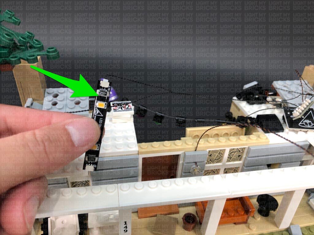
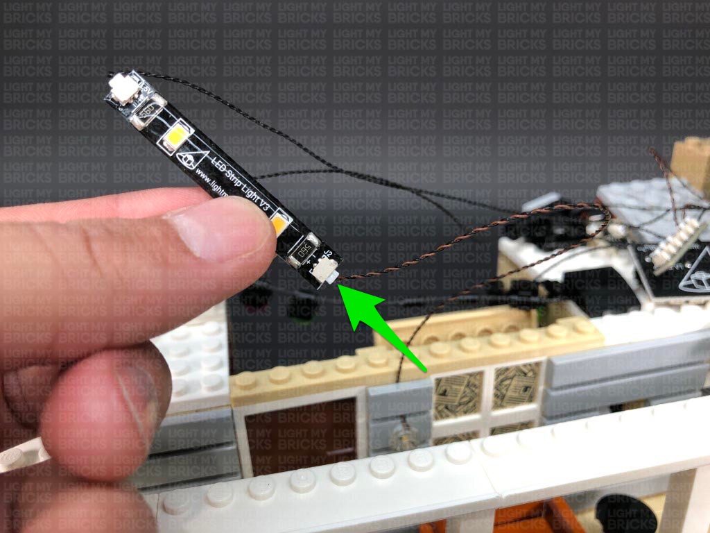
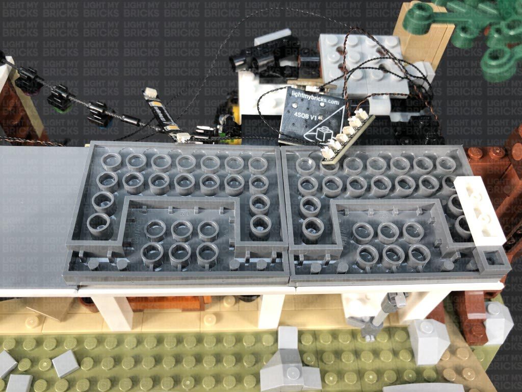
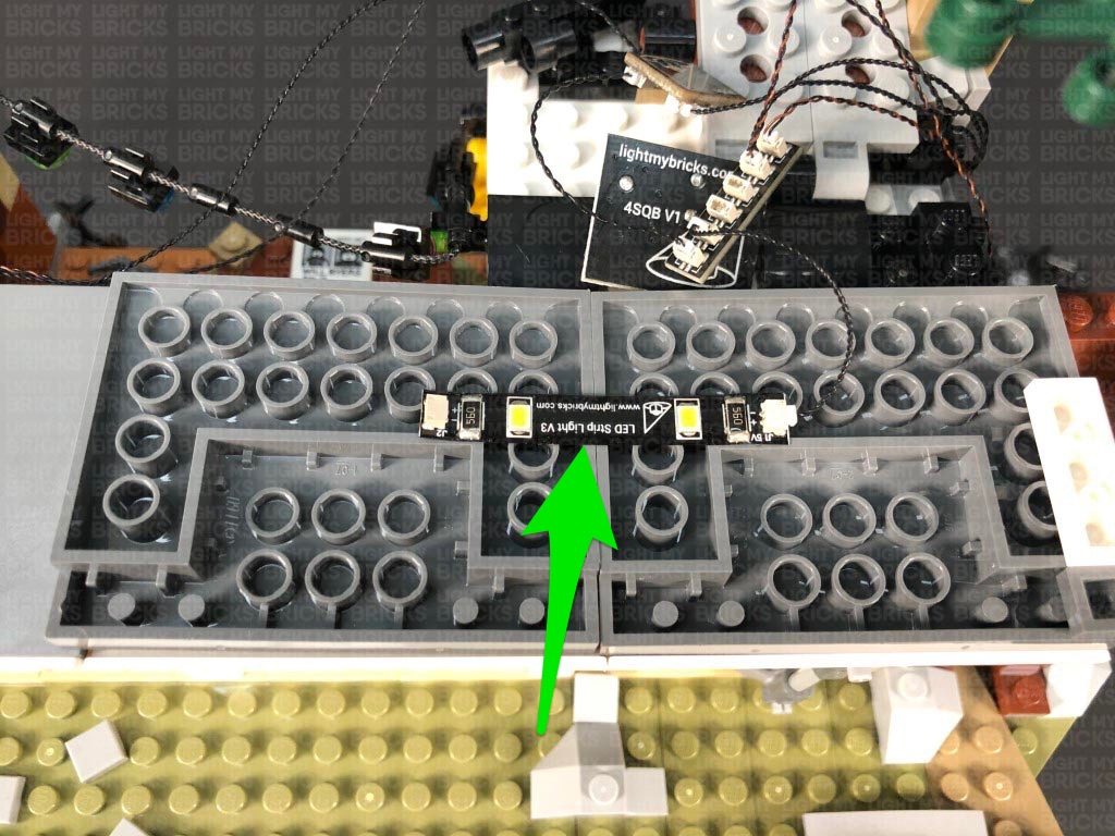
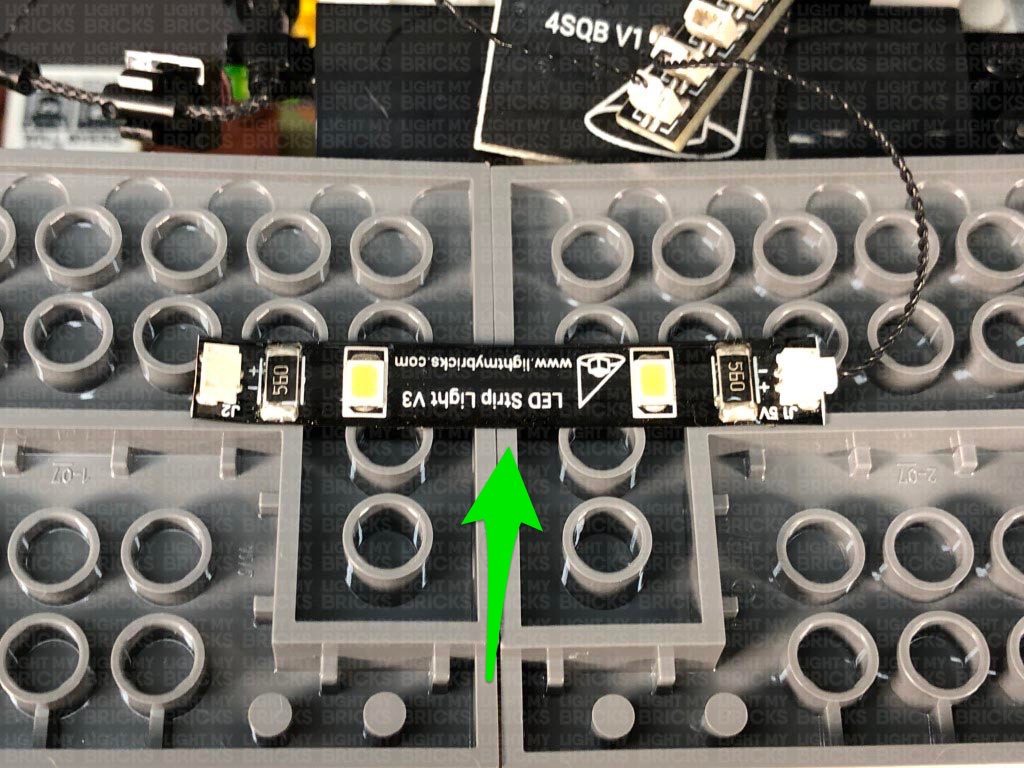
Take a 5cm Connecting Cable and connect one end to the 6-Port Expansion Board on top of the bedroom. Connect the other end of the cable to a Warm White Strip Light. Turn the power ON to test the strip light is working OK and flickering with the lamps in the bedroom. Leave the Strip Light as is for now as we will install it later.
32.) Take a new 15cm Connecting Cable and connect it to a different OUT port on the Scary Flicker Effects Board. Bring the other end of the cable across to the right and connect it to a new Warm White Strip Light.
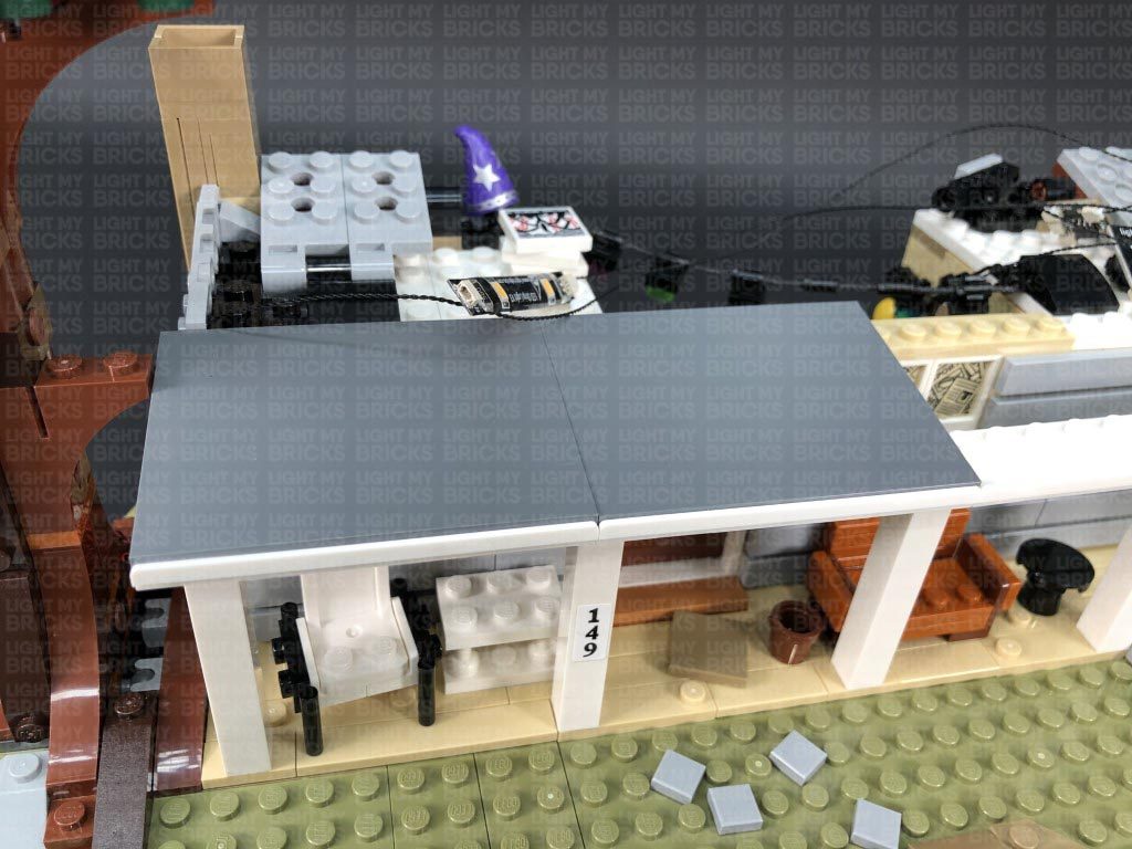
Turn the set around to the front and disconnect the two grey roof pieces as well as the two light grey tiles to the right of the front door.
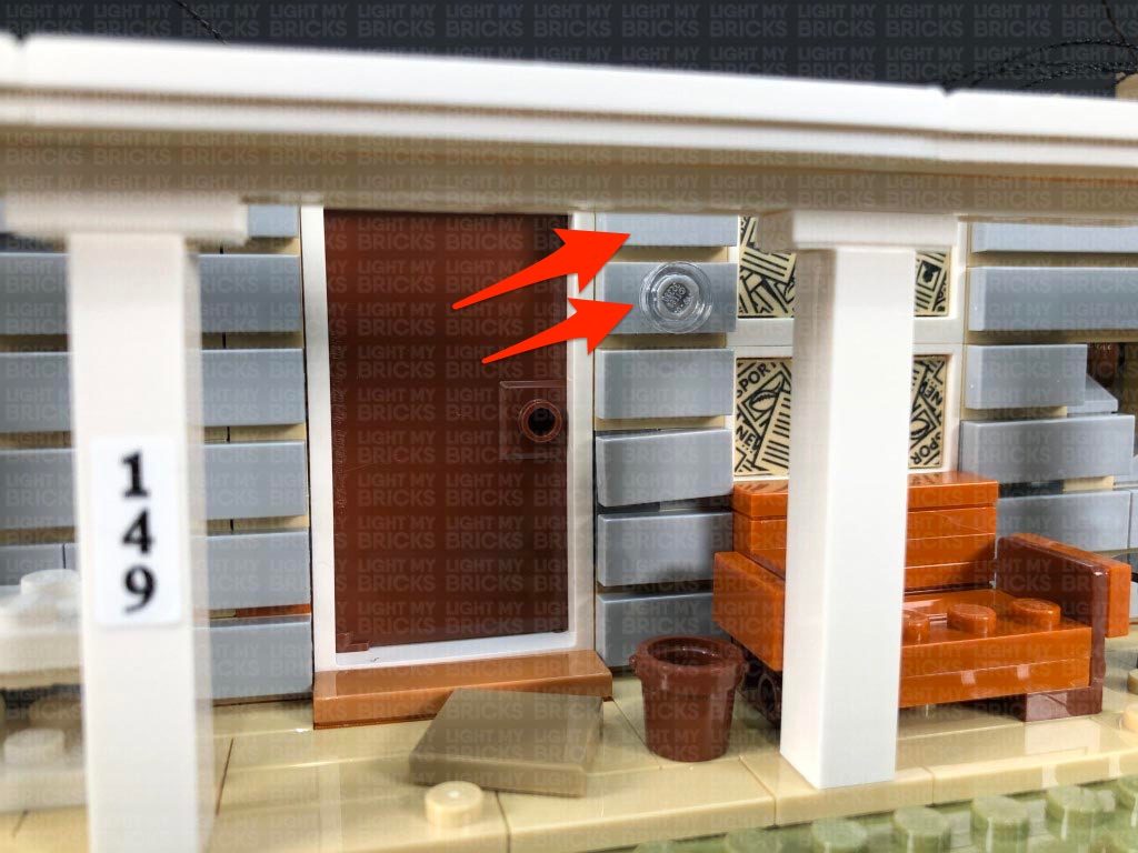
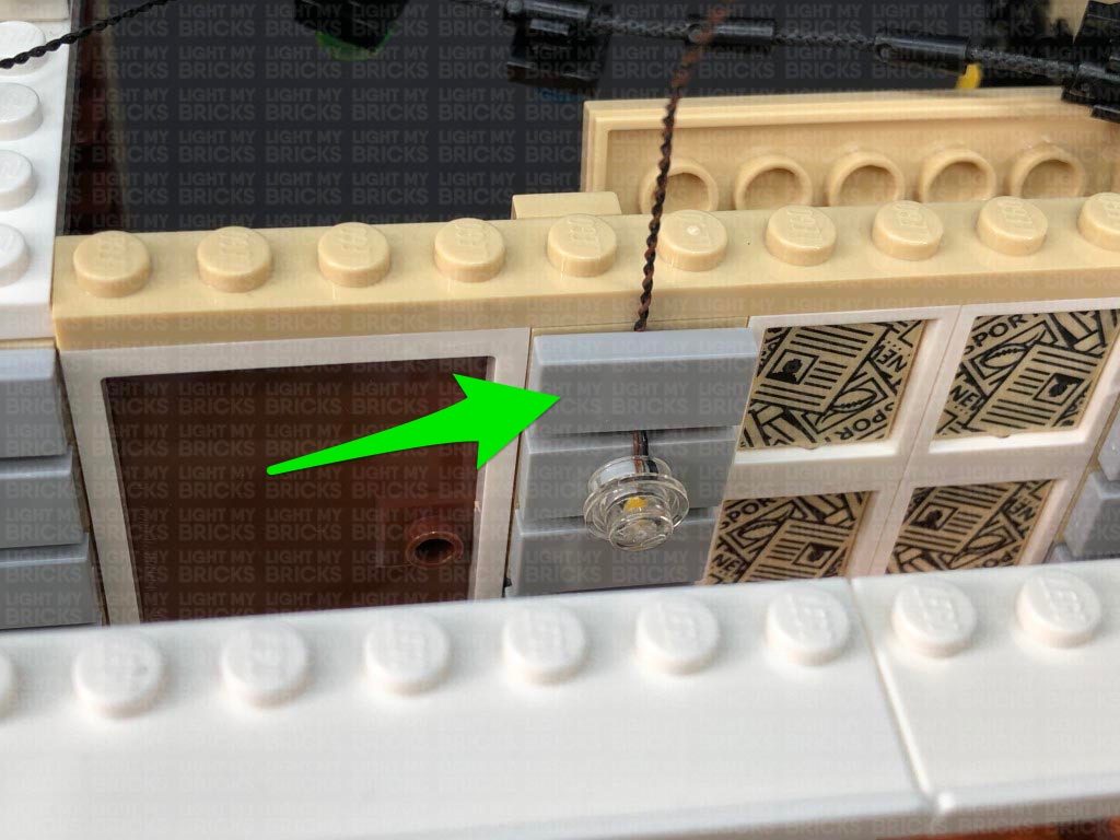
33.) Disconnect the trans clear tile from the trans clear round tile from the light grey tile, then take a White 15cm Bit Light and place the LED over the stud on the grey tile. Secure the Bit Light in place by connecting a provided LEGO Trans Clear Round Plate 1×1 over the top. Reconnect this tile to the front of the house ensuring the cable is facing up.
Lay the Bit Light cable in between studs above, then reconnect the other light grey tile. Bring the cable up and connect it to the White Strip Light we connected in the previous step.
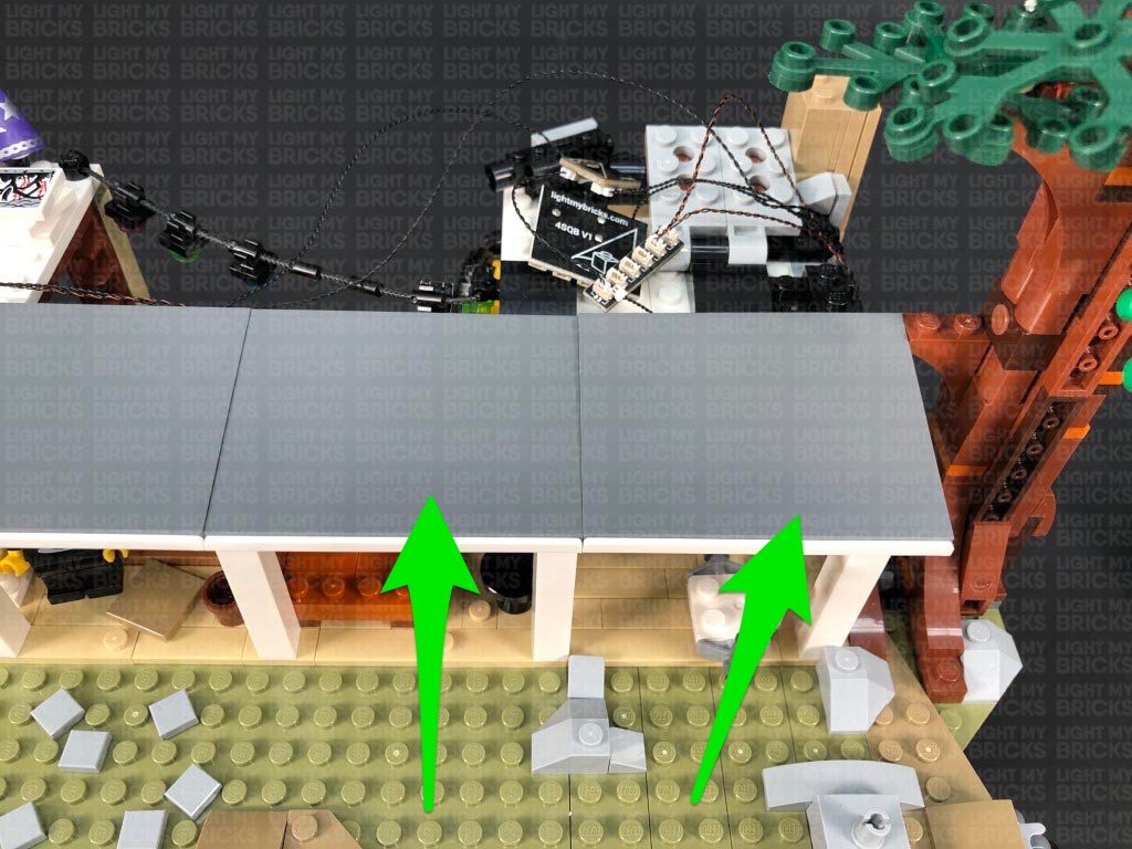
34.) Take the two roof pieces from the left side of the house and flip them over so we can access underneath of it. Using it’s adhesive backing, stick the Strip Light from previous step underneath the roof pieces in the following position. Ensure the Bit Light cable is on the left side.
Flip the roof pieces over and securely reconnect them to the front of the house. From the back side of the house, check to ensure that the bit light cable and 15cm cable are laid in between studs underneath. Turn ON the power to test the lights at the front are flickering OK. Because these lights are connected to a different channel on the Scary Flicker Effects Board, they should be flickering in a different sequence than the lights inside the house.
Note: If you experience any issues with the lights not working and suspect an issue with a component, please try a different port on the expansion board to verify where the fault lies (with the light or expansion board). To correct any issues with expansion board ports, please view the section addressing expansion board issues on our online troubleshooting guide.
35.) Turn the set back over to the front, then take the two roof pieces from the right side and flip them over so we can access underneath of it. Locate the White Strip Light we connected and left hanging from the 6-port expansion board (step 31.) and stick it underneath the two roof pieces in the following position.
Flip the two roof panels over and reconnect them to the right side of the house ensuring the 5cm connecting cable between the strip light and 6-port expansion board is carefully laid in between studs underneath. Turn ON the power to test all the lights at the front of the house are working OK. The Strip Light on the right should be flickering at the same rate as the inside lights.
From the back of the set, neaten and secure the cabling running over the left side of the house by ensuring they are laid in between studs before reconnecting the remaining triangular plate. Reconnect the top section of the chimney.
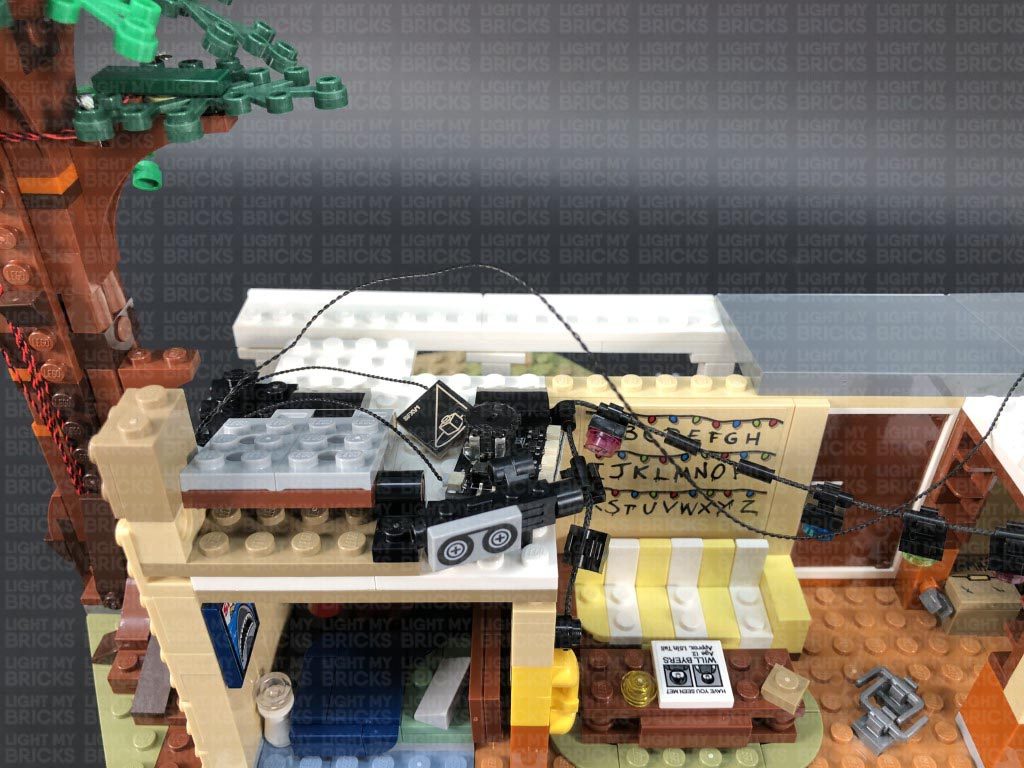
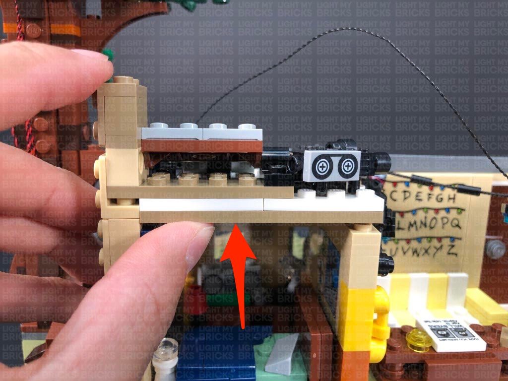
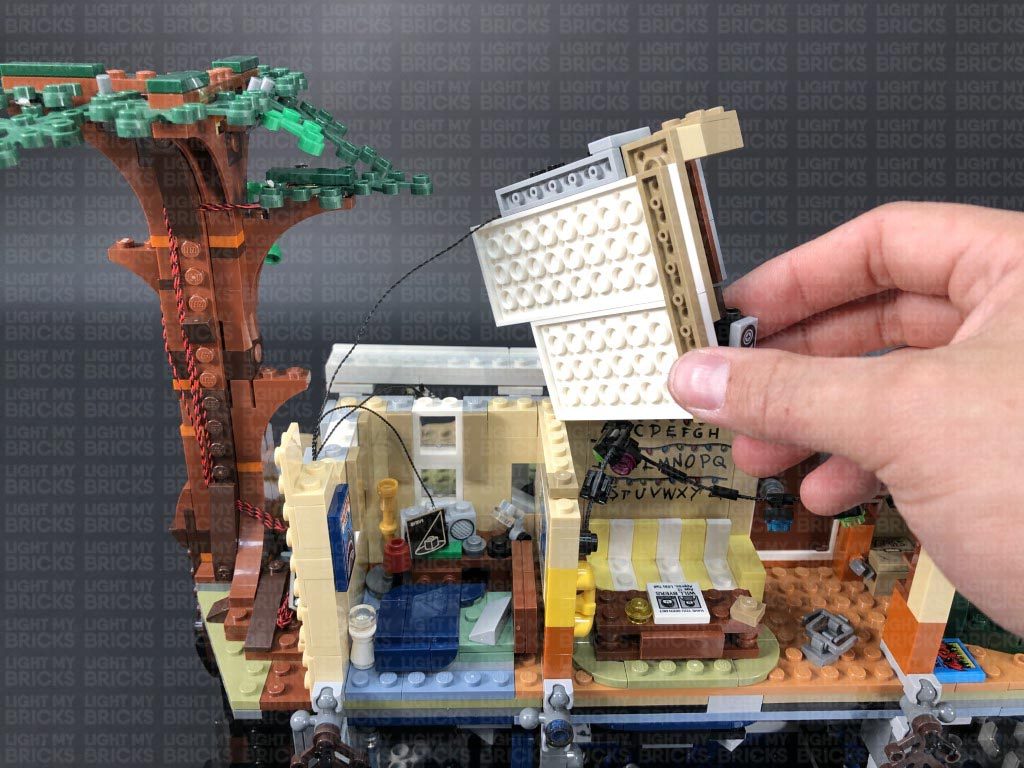
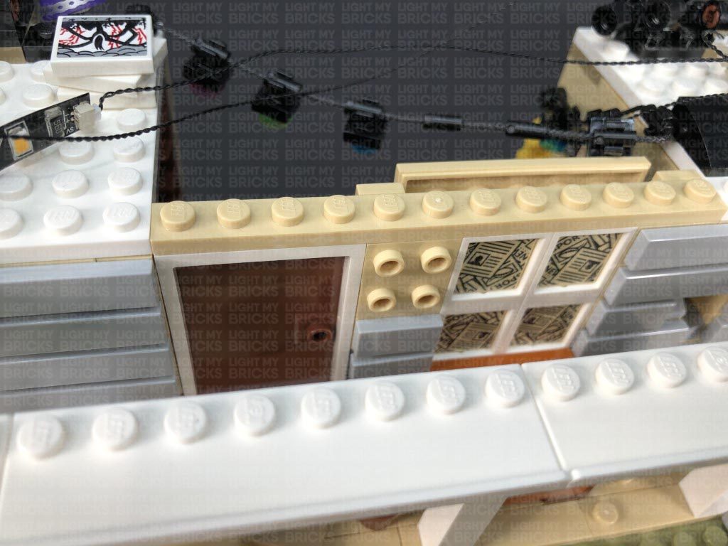
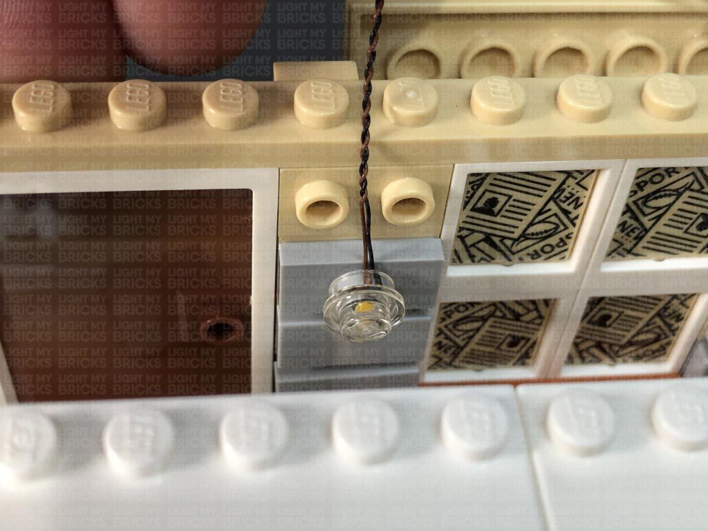
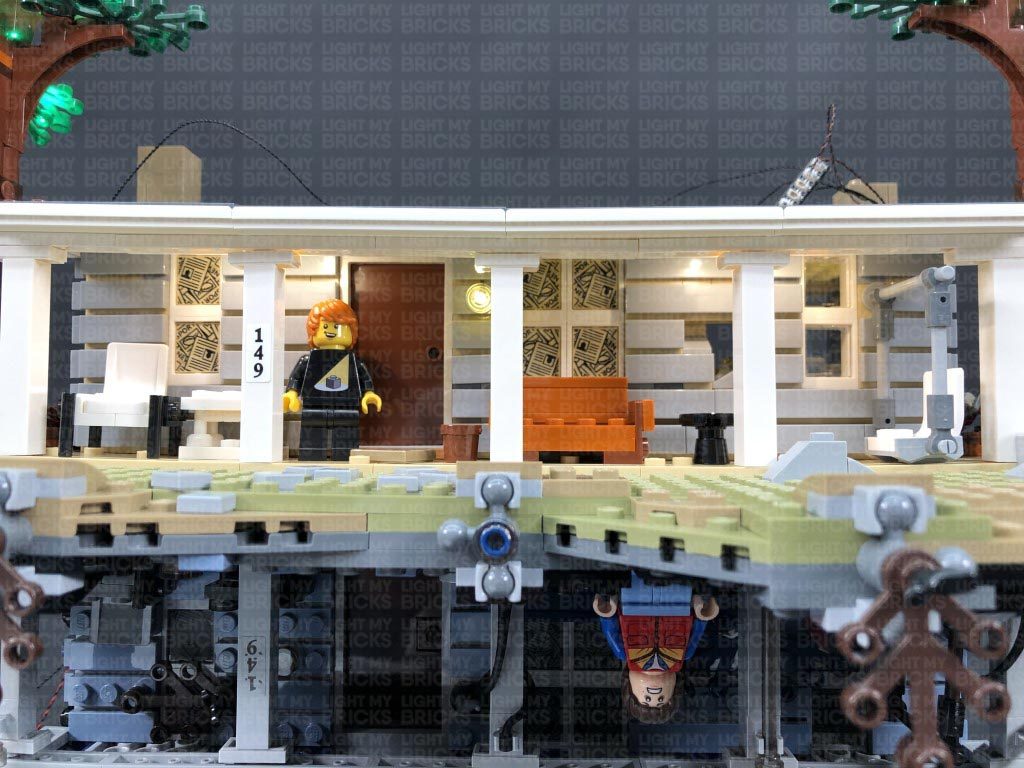
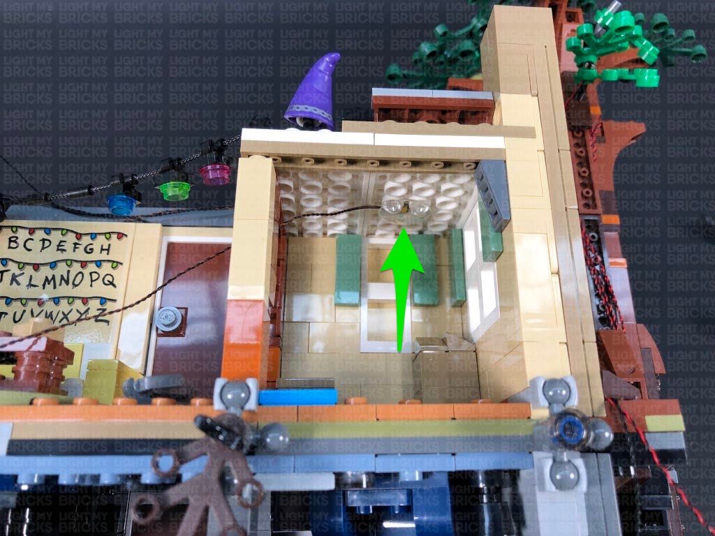
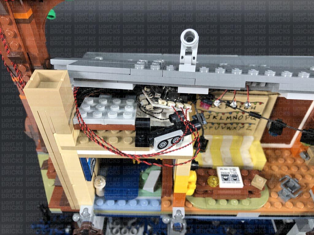
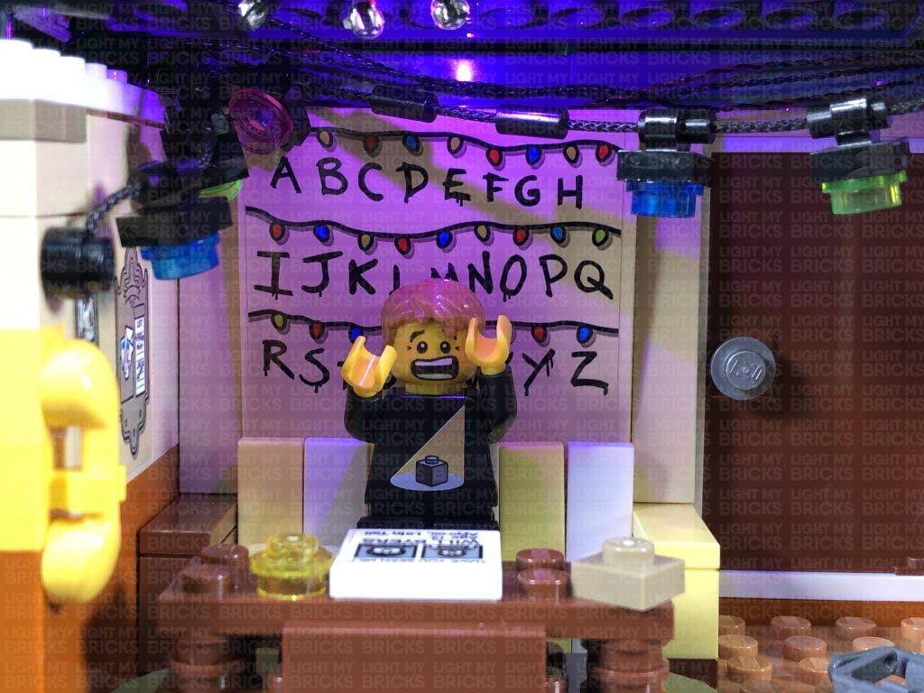
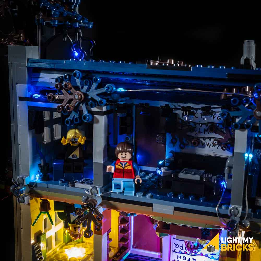
36.) We will now install the remaining light inside the house on the right side of the living room. Take a White 30cm Bit Light and with the cable facing the left, place the Bit Light against the centre of the roof with the LED shining down. Secure the Bit Light in place by connecting a provided LEGO Trans Clear Plate w Rounded Bottom 2×2 over the top ensuring the LED is positioned in the middle.
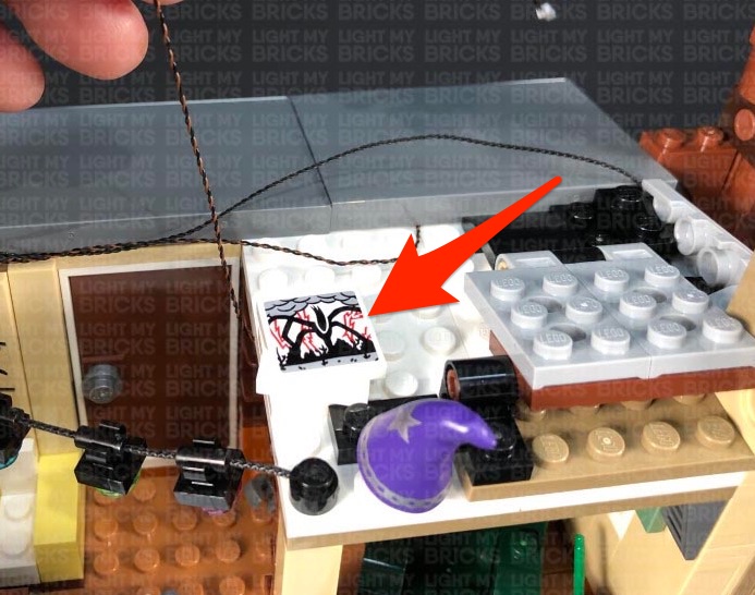
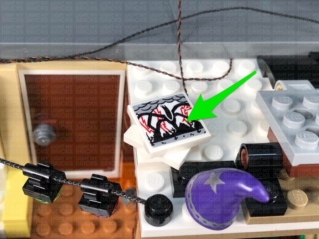
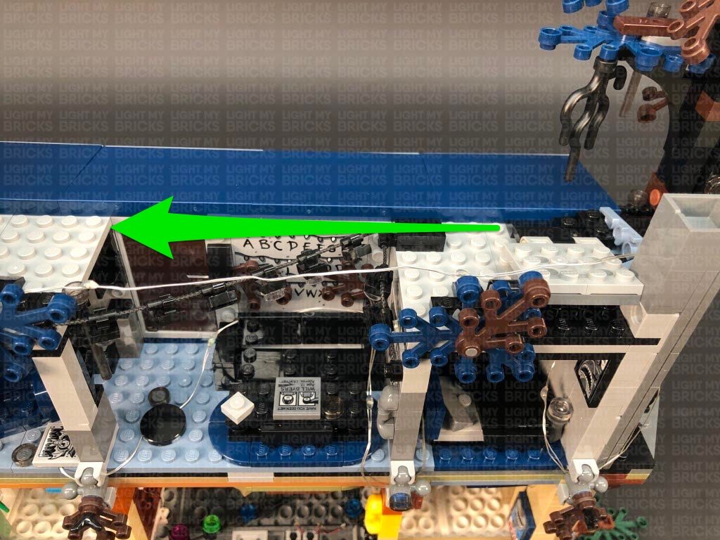
Pull the cable up over the left side of the roof of the room, then secure it underneath the following ‘artwork’ tile pieces on top. Ensure the cable is neatly laid in between stud underneath these pieces.
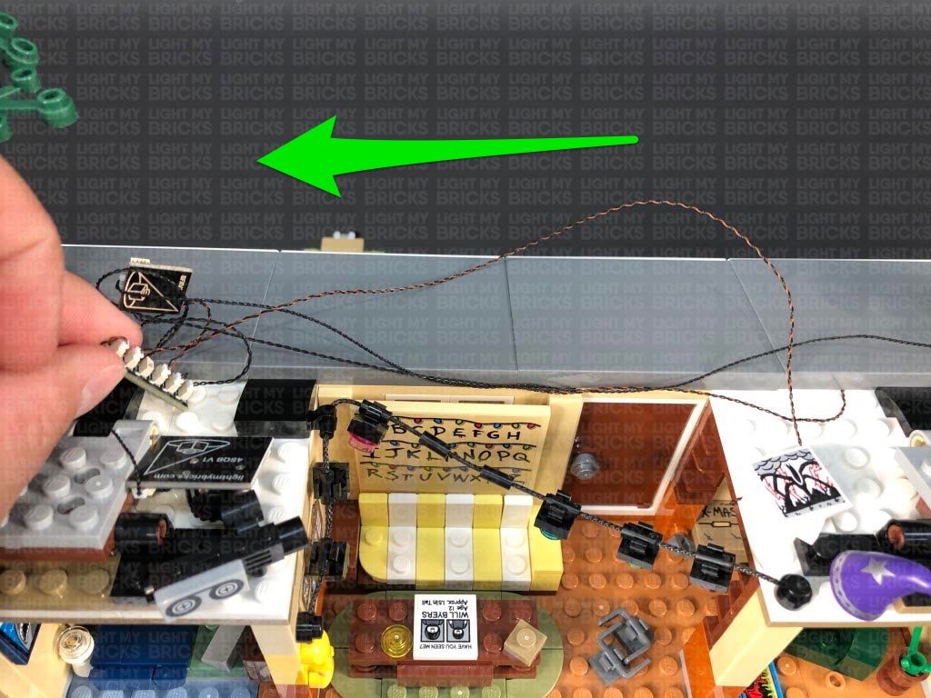
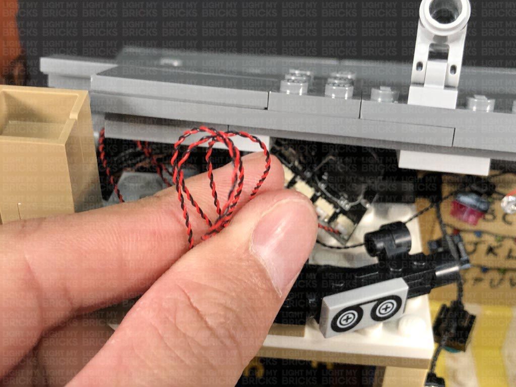
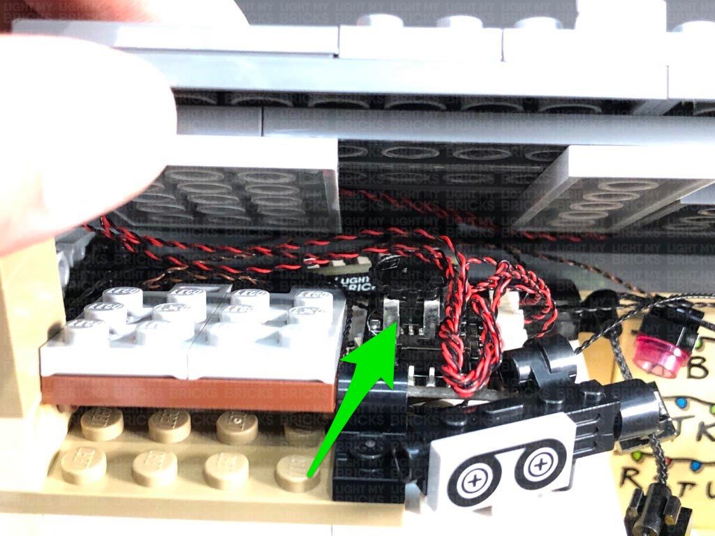
Bring the cable across to the left side to connect to the 6-Port Expansion Board, then turn ON the power to test the Bit Light is working OK and flickering at the same rate as the lights on the left side.
Neaten up and eliminate excess cabling from this Bit Light by pulling the cable to the right, then twisting it into a neat bunch. Neaten up the rest of the cables running across the top by grouping them all together.
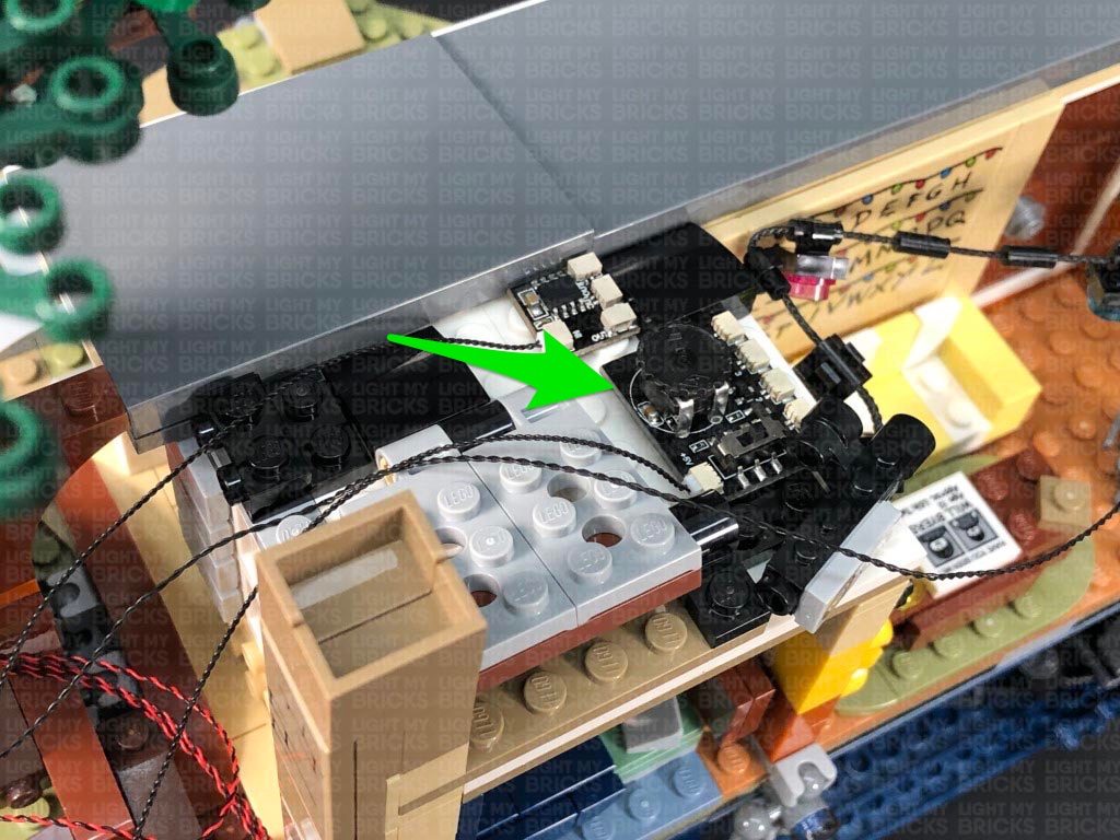
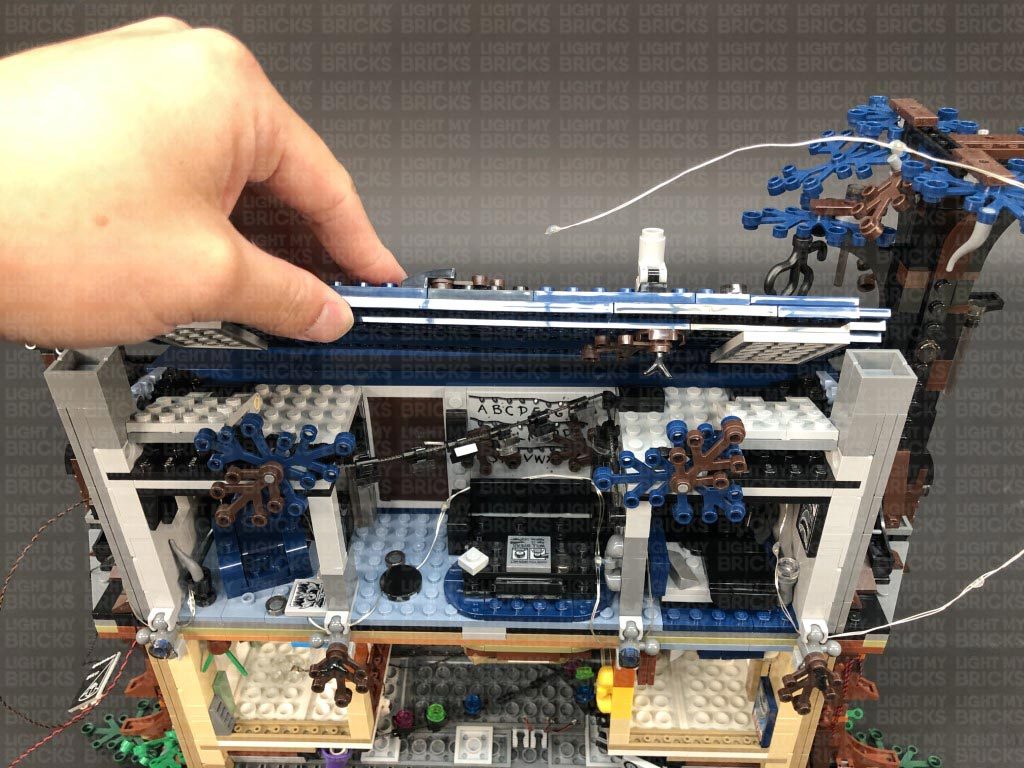
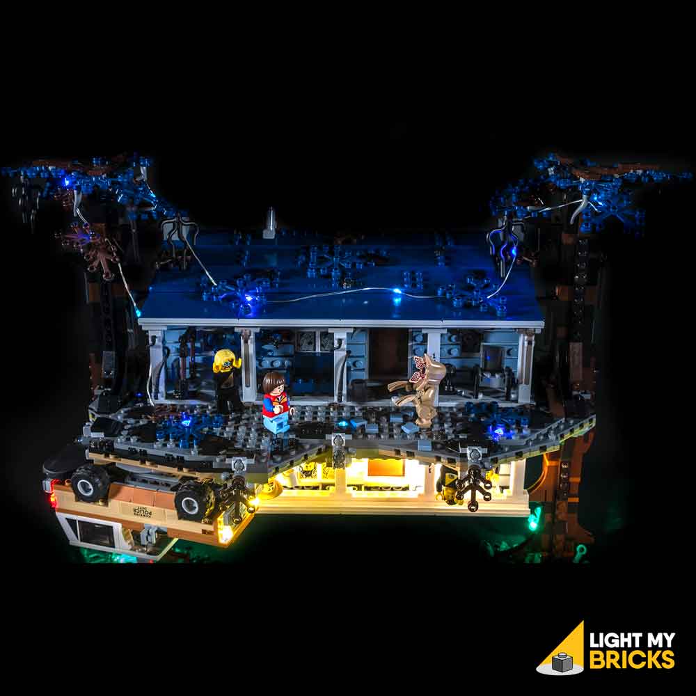
37.) Take the main roof section and flip it over so we can access underneath. Remove the LEGO light section as well as the large 4×10 plate section as shown below.
Disconnect the following pieces from the 4×10 plate, then take a Blue 30cm Bit Light and with the LED facing down, place it in between the following studs. Ensure the LED is hanging approximately 1cm over the bottom edge. Secure the Bit Light in place by reconnecting the 1×2 plate.
Take a Pink 30cm Bit Light and a Green 30cm Bit Light and place them in between the next few studs to the right with their LEDs facing down. (The order in which you place these Bit Lights does not matter). Secure the Bit Lights in place by reconnecting the two light grey clip pieces.
38.) Flip the 4×10 plate over and reconnect it to the main roof section, then carefully bend the Bit Lights down so that when you look at the back of the roof, they are shining away from you.
Place the roof section back down, then bring the three cables across to the left side. Disconnect the light grey 4x 6 plate and lay the cables underneath in between studs before reconnecting the plate over the top.
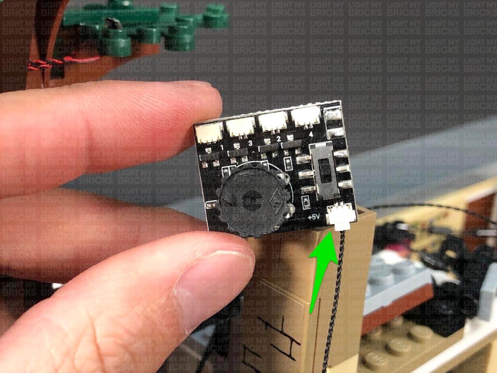
39.) Place the roof section near the house in the following position, then bring the three bit light cables from the roof panel up toward the house and connect them into the following OUT ports 1, 2, and 3 on the Sequence Effects Board we connected in step 26. (The numbers on the ports represent which order the ports activate in sequence. The port you connect each light to does not matter.)
Ensure the correct configuration is set on the sequence board. Turn ON the power to test the lights are working OK and configure the effect. Check the switch is in the top position and adjust the speed wheel as desired. The effect should mimic the R.U.N. scene where Joyce is attempting to communicate with Will. (1, 2, 3 repeat 6 times then flash all together 6 times).
Note: If you experience any issues with the lights not working and suspect an issue with a component, please try a different port on the expansion board to verify where the fault lies (with the light or expansion board). To correct any issues with expansion board ports, please view the section addressing expansion board issues on our online troubleshooting guide.
31.) Reconnect the exterior panel section as well as the surrounding pieces to the bottom of the chimney.
Take a 5cm Connecting Cable and connect one end to the 6-Port Expansion Board on top of the bedroom. Connect the other end of the cable to a Warm White Strip Light. Turn the power ON to test the strip light is working OK and flickering with the lamps in the bedroom. Leave the Strip Light as is for now as we will install it later.
32.) Take a new 15cm Connecting Cable and connect it to a different OUT port on the Scary Flicker Effects Board. Bring the other end of the cable across to the right and connect it to a new Warm White Strip Light.
Turn the set around to the front and disconnect the two grey roof pieces as well as the two light grey tiles to the right of the front door.
33.) Disconnect the trans clear tile from the trans clear round tile from the light grey tile, then take a White 15cm Bit Light and place the LED over the stud on the grey tile. Secure the Bit Light in place by connecting a provided LEGO Trans Clear Round Plate 1×1 over the top. Reconnect this tile to the front of the house ensuring the cable is facing up.
Lay the Bit Light cable in between studs above, then reconnect the other light grey tile. Bring the cable up and connect it to the White Strip Light we connected in the previous step.
34.) Take the two roof pieces from the left side of the house and flip them over so we can access underneath of it. Using it’s adhesive backing, stick the Strip Light from previous step underneath the roof pieces in the following position. Ensure the Bit Light cable is on the left side.
Flip the roof pieces over and securely reconnect them to the front of the house. From the back side of the house, check to ensure that the bit light cable and 15cm cable are laid in between studs underneath. Turn ON the power to test the lights at the front are flickering OK. Because these lights are connected to a different channel on the Scary Flicker Effects Board, they should be flickering in a different sequence than the lights inside the house.
Note: If you experience any issues with the lights not working and suspect an issue with a component, please try a different port on the expansion board to verify where the fault lies (with the light or expansion board). To correct any issues with expansion board ports, please view the section addressing expansion board issues on our online troubleshooting guide.
35.) Turn the set back over to the front, then take the two roof pieces from the right side and flip them over so we can access underneath of it. Locate the White Strip Light we connected and left hanging from the 6-port expansion board (step 31.) and stick it underneath the two roof pieces in the following position.
Flip the two roof panels over and reconnect them to the right side of the house ensuring the 5cm connecting cable between the strip light and 6-port expansion board is carefully laid in between studs underneath. Turn ON the power to test all the lights at the front of the house are working OK. The Strip Light on the right should be flickering at the same rate as the inside lights.
From the back of the set, neaten and secure the cabling running over the left side of the house by ensuring they are laid in between studs before reconnecting the remaining triangular plate. Reconnect the top section of the chimney.
36.) We will now install the remaining light inside the house on the right side of the living room. Take a White 30cm Bit Light and with the cable facing the left, place the Bit Light against the centre of the roof with the LED shining down. Secure the Bit Light in place by connecting a provided LEGO Trans Clear Plate w Rounded Bottom 2×2 over the top ensuring the LED is positioned in the middle.
Pull the cable up over the left side of the roof of the room, then secure it underneath the following ‘artwork’ tile pieces on top. Ensure the cable is neatly laid in between stud underneath these pieces.
Bring the cable across to the left side to connect to the 6-Port Expansion Board, then turn ON the power to test the Bit Light is working OK and flickering at the same rate as the lights on the left side.
Neaten up and eliminate excess cabling from this Bit Light by pulling the cable to the right, then twisting it into a neat bunch. Neaten up the rest of the cables running across the top by grouping them all together.
37.) Take the main roof section and flip it over so we can access underneath. Remove the LEGO light section as well as the large 4×10 plate section as shown below.
Disconnect the following pieces from the 4×10 plate, then take a Blue 30cm Bit Light and with the LED facing down, place it in between the following studs. Ensure the LED is hanging approximately 1cm over the bottom edge. Secure the Bit Light in place by reconnecting the 1×2 plate.
Take a Pink 30cm Bit Light and a Green 30cm Bit Light and place them in between the next few studs to the right with their LEDs facing down. (The order in which you place these Bit Lights does not matter). Secure the Bit Lights in place by reconnecting the two light grey clip pieces.
38.) Flip the 4×10 plate over and reconnect it to the main roof section, then carefully bend the Bit Lights down so that when you look at the back of the roof, they are shining away from you.
Place the roof section back down, then bring the three cables across to the left side. Disconnect the light grey 4x 6 plate and lay the cables underneath in between studs before reconnecting the plate over the top.
39.) Place the roof section near the house in the following position, then bring the three bit light cables from the roof panel up toward the house and connect them into the following OUT ports 1, 2, and 3 on the Sequence Effects Board we connected in step 26. (The numbers on the ports represent which order the ports activate in sequence. The port you connect each light to does not matter.)
Ensure the correct configuration is set on the sequence board. Turn ON the power to test the lights are working OK and configure the effect. Check the switch is in the top position and adjust the speed wheel as desired. The effect should mimic the R.U.N. scene where Joyce is attempting to communicate with Will. (1, 2, 3 repeat 6 times then flash all together 6 times).
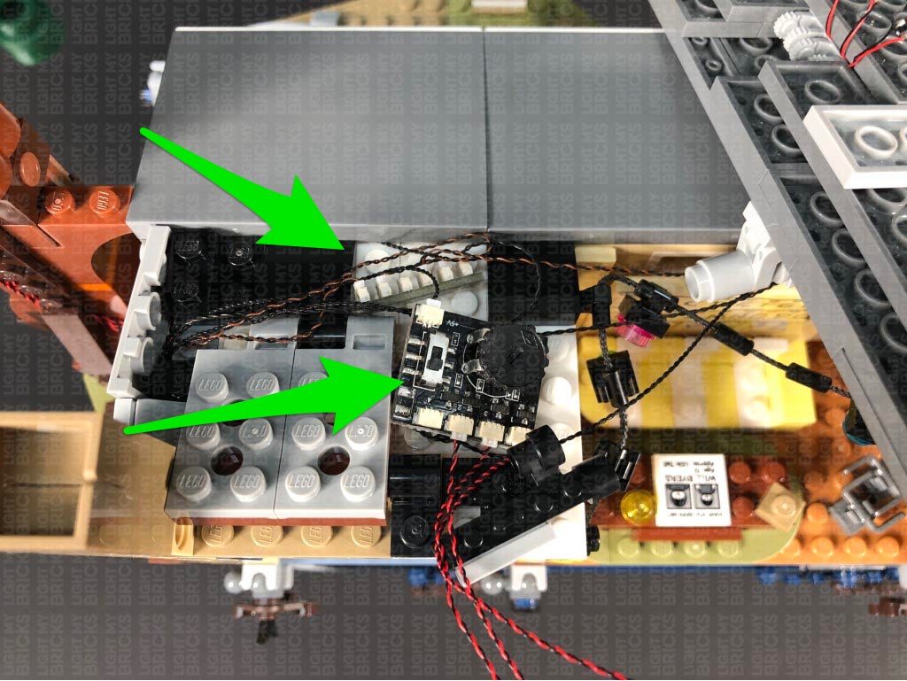
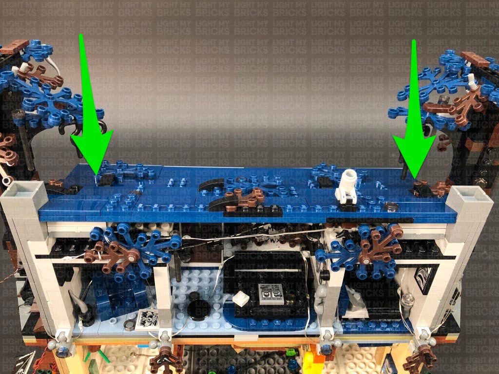
 40.) Bring the roof panel up on top of the house, then neatly place all the components in the following positions, with the scary flicker effects board underneath the sequence board. Ensure all cables are out of the way of the light grey technic plate on where the roof will reconnect to. Neaten up excess cables from the Blue, Pink and Green Bit Lights by twisting and folding them into a neat bunch. Neatly Tuck everything in before securely reconnecting the roof on both left and right sides.
Check that the Blue, Pink and Green lights are positioned correctly and shining onto the wall.
Note: If you experience any issues with the lights not working and suspect an issue with a component, please try a different port on the expansion board to verify where the fault lies (with the light or expansion board). To correct any issues with expansion board ports, please view the section addressing expansion board issues on our online troubleshooting guide.
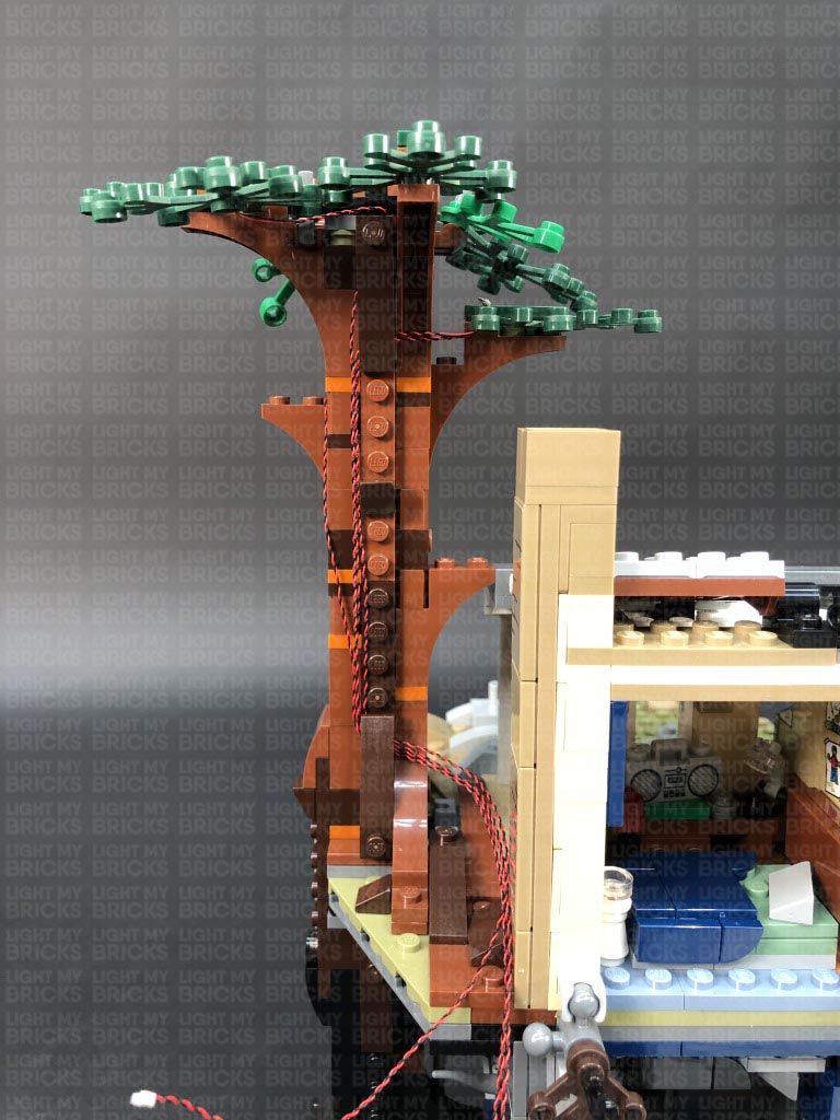
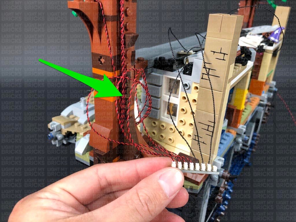
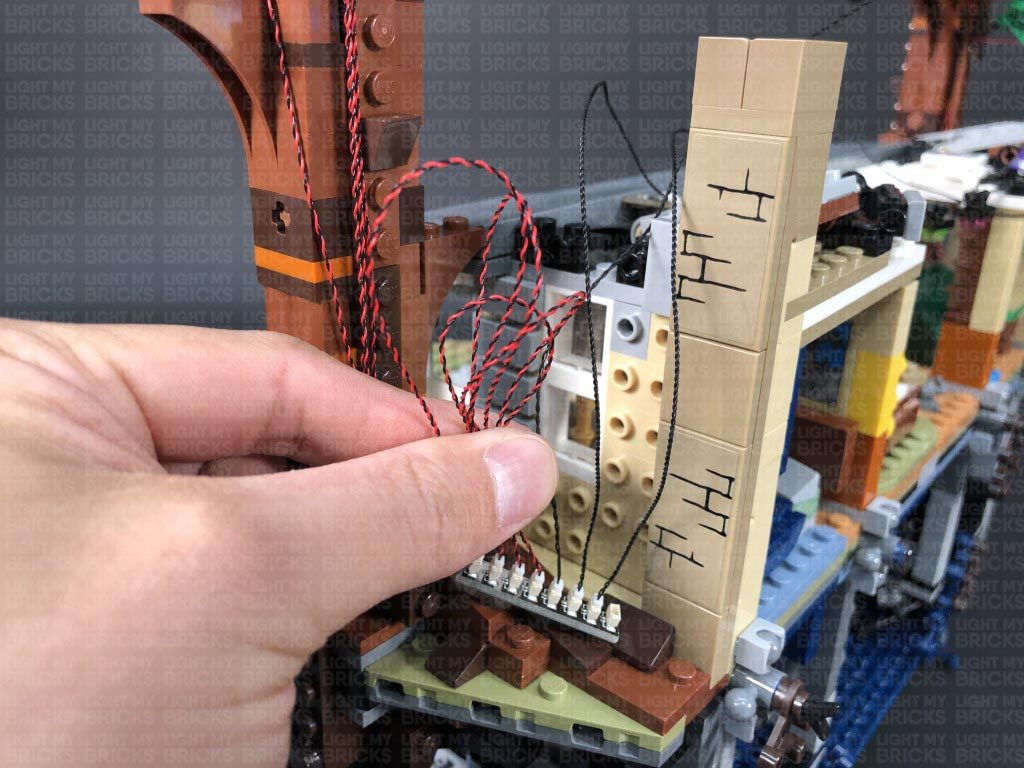
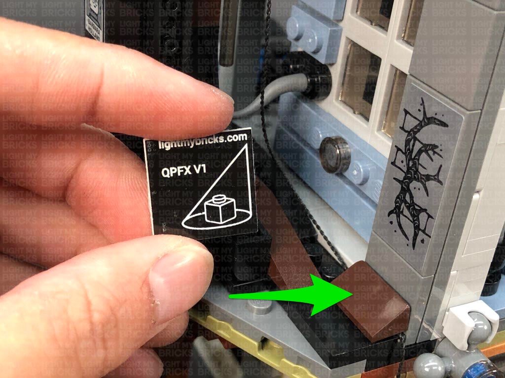
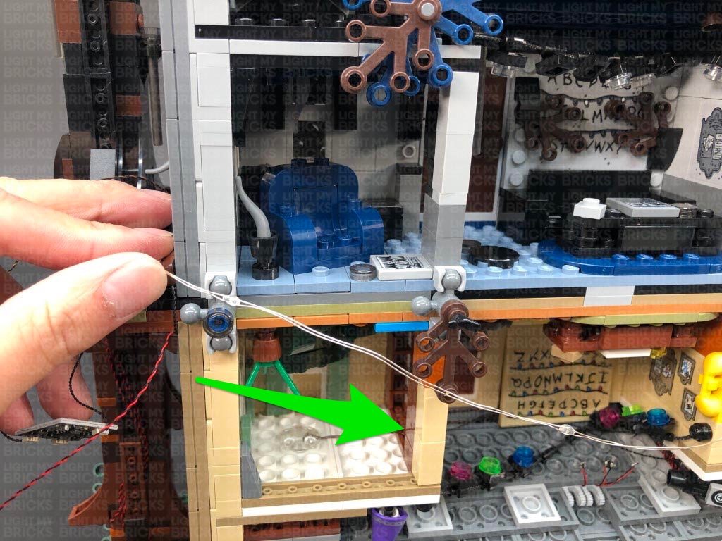
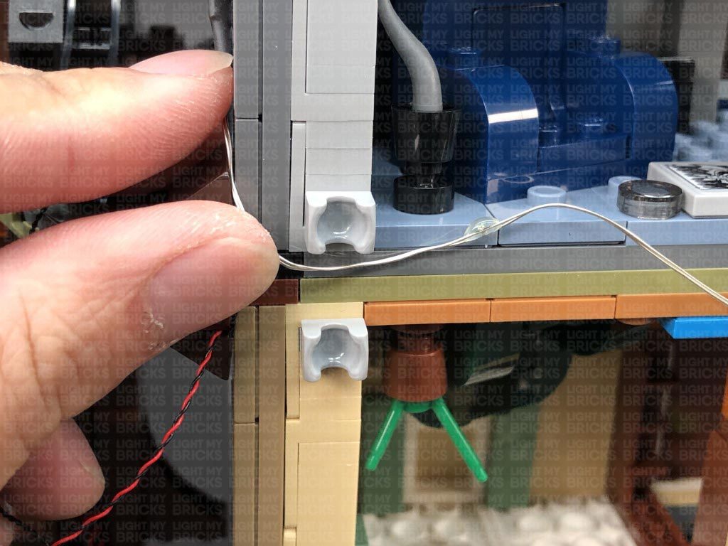
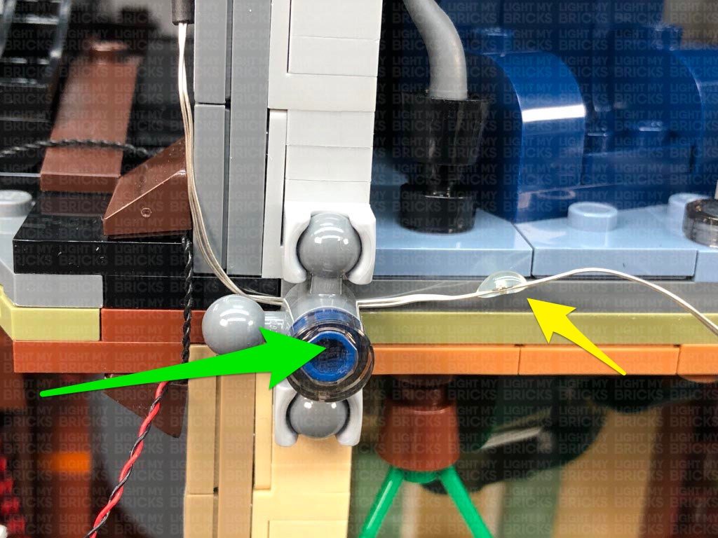
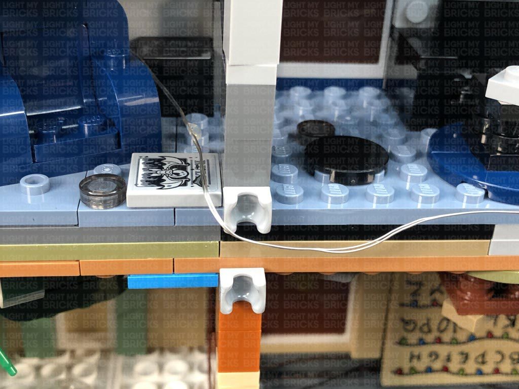
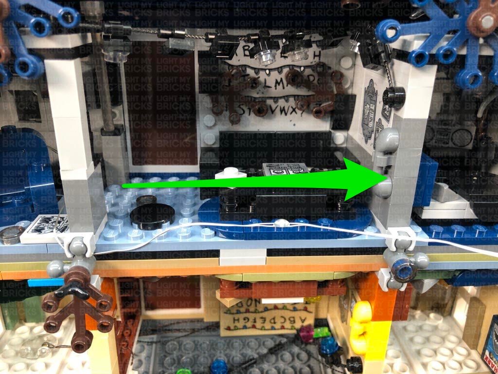
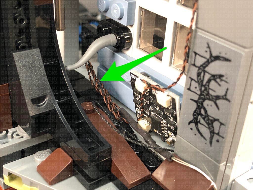
41.) We will now install lights to the Upside Down. Take a 15cm Connecting Cable and connect it to another spare port on the 8-port Expansion Board on the right side of the house. Secure the cable underneath the brown angled tile, then turn the set upside down.
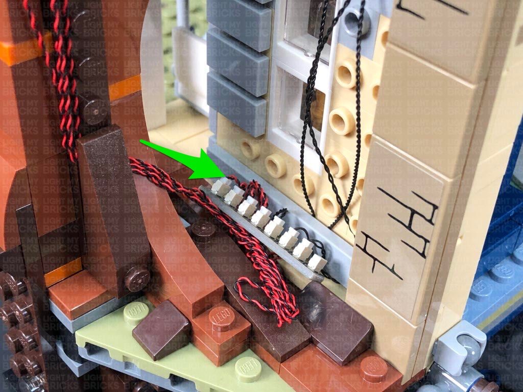
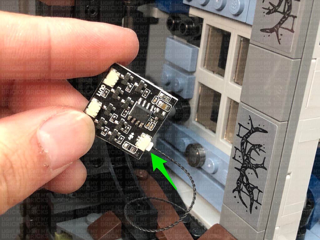
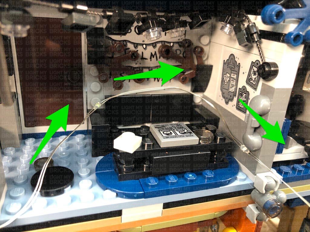
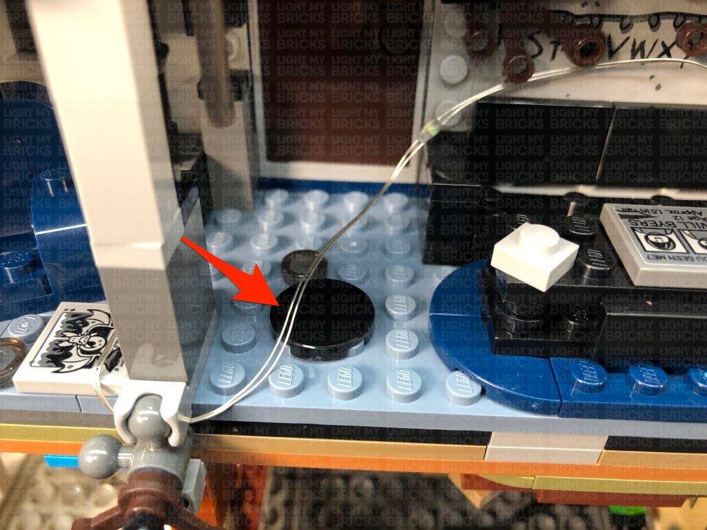
Lay the 15cm cable toward the front and secure it underneath the following brown angled tile at the bottom. Take the Glitter Effects Board (QPFX V1) and connect the other end of the 15cm cable to the IN port (+5V). Place the board down in the corner with the excess cable tucked underneath.
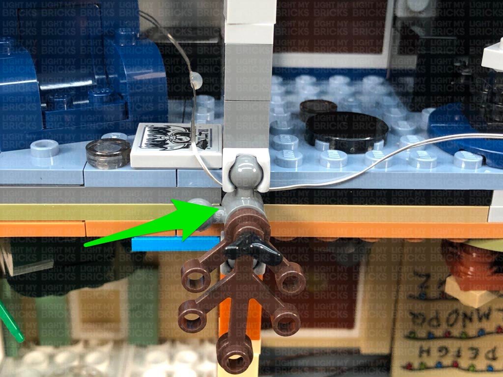
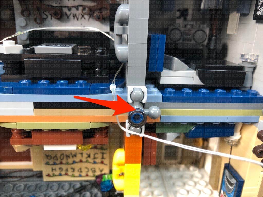
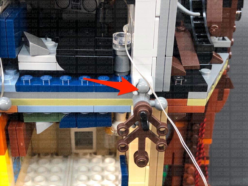
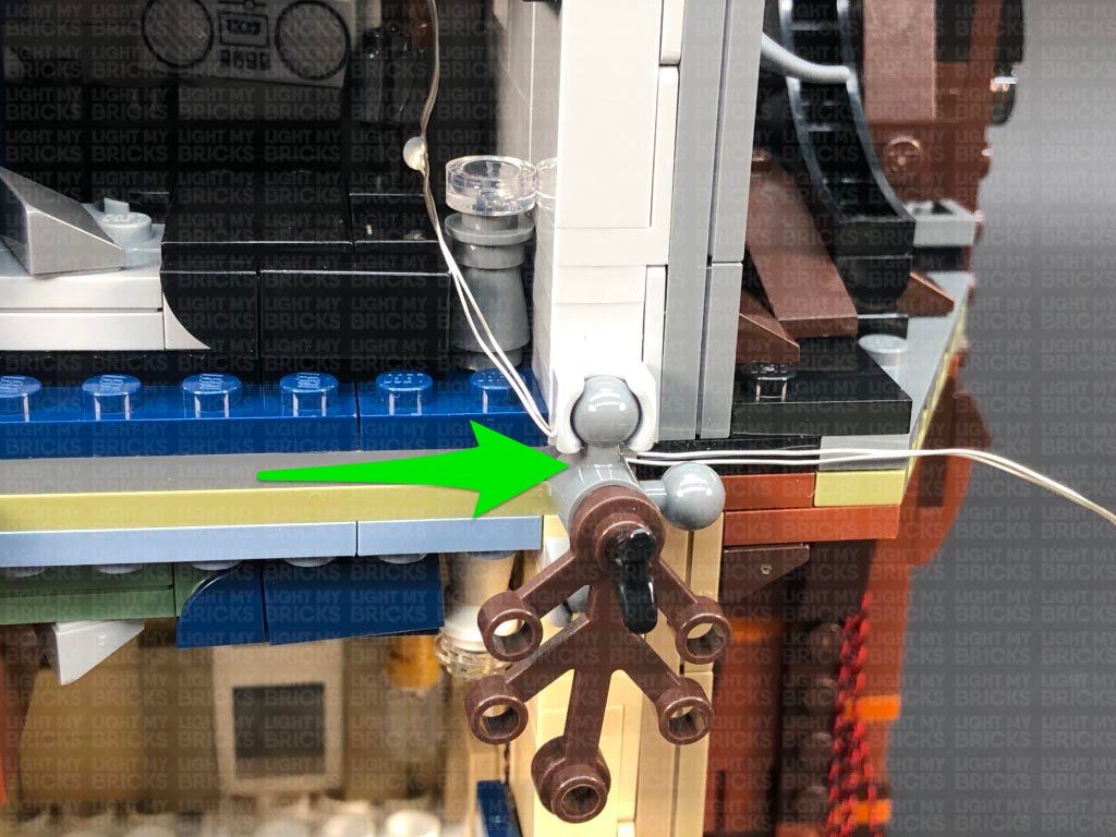
42.) Take one of the Glitter Effects Light Strings and connect it to one of the OUT ports on the Glitter Effects Board. Bring the light string across to the right and secure it underneath the following technic ball joint piece (disconnect and reconnect over the light string). Ensure the first LED on the glitter light string is laying toward the inside of the living room.
Bring the light string inside the living room and tuck it behind the dark blue couch. Bring the rest of the light string out toward the right side and secure it underneath the following technic ball joint piece (disconnect and reconnect over the light string).
Secure the light string underneath the white plate (Will’s drawing).
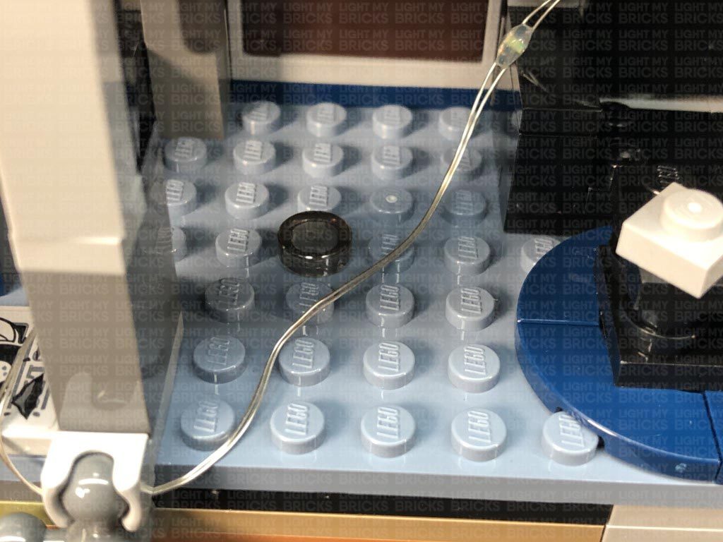
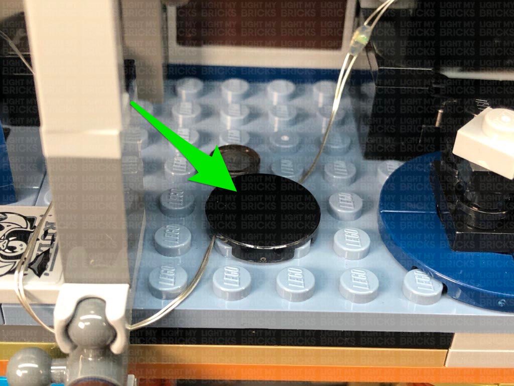
43.) Bring the light string across the living room and then bring it inside and tuck it in behind the black couch. Secure the light string underneath the following technic ball joint piece on the right(disconnect and reconnect over the light string). Secure the light string underneath the black round tile as well as behind the black plates of the couch.
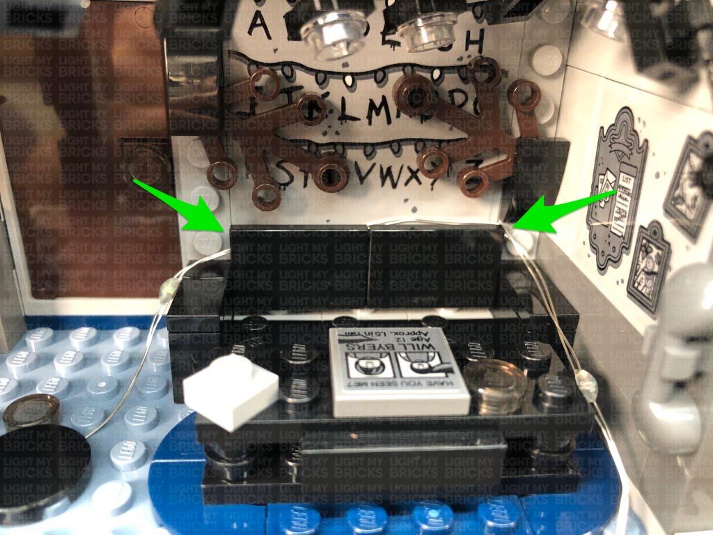
Lay the light string inside the bedroom, ensuring you tuck it in behind the radio. Secure the light string underneath the technic ball joint piece on the right side as well as behind the torch against the right wall.
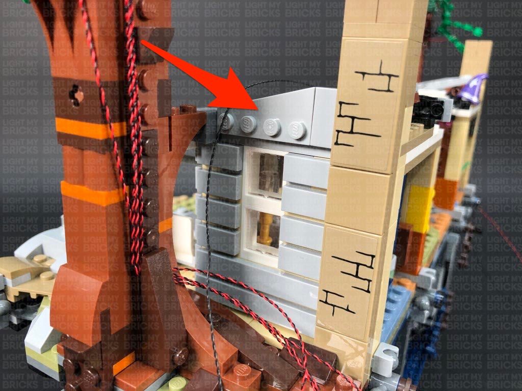
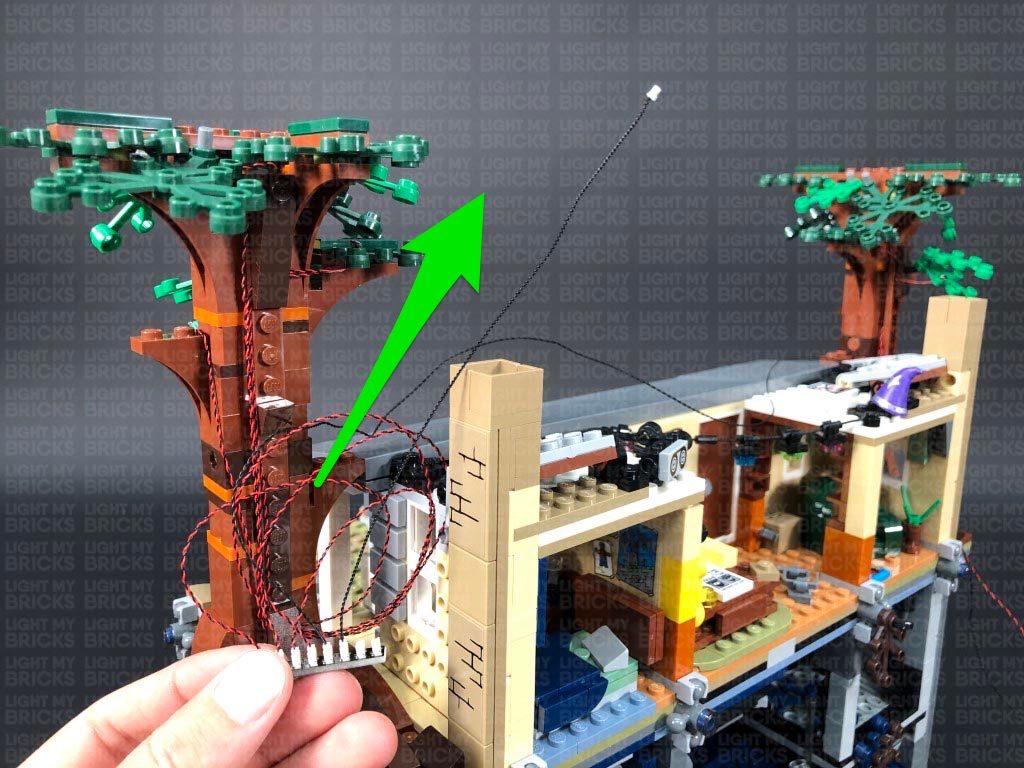
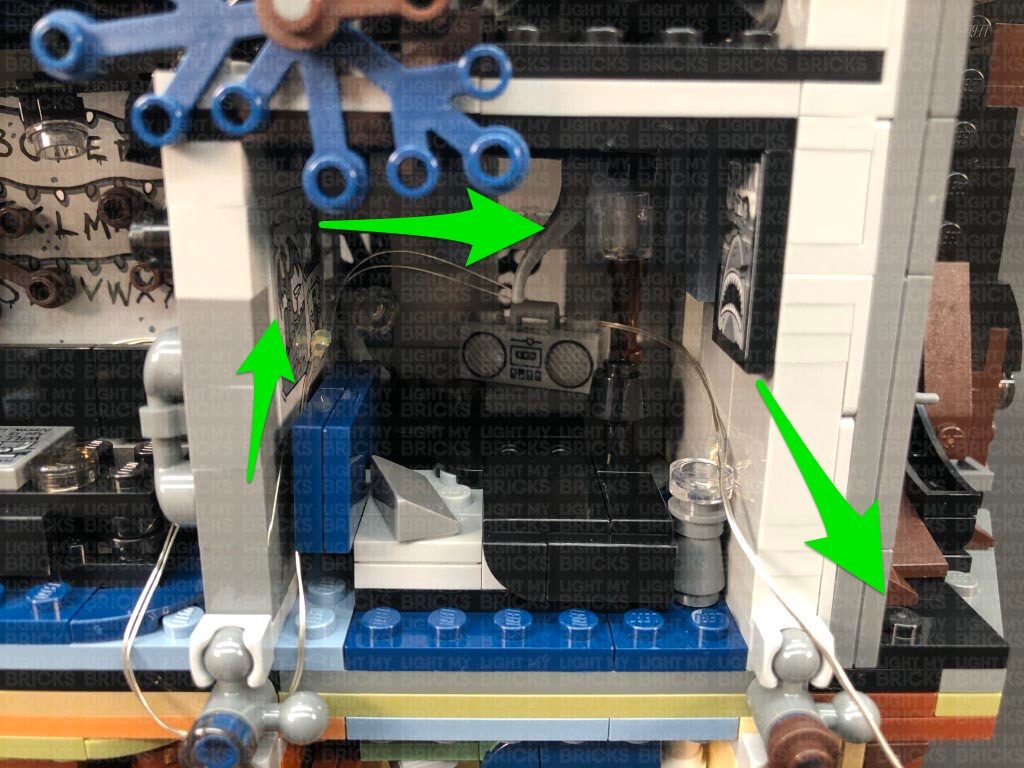
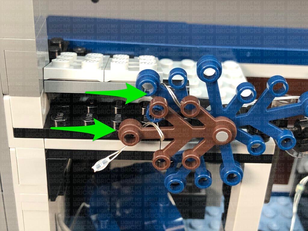
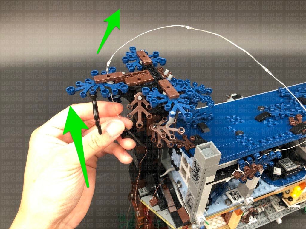
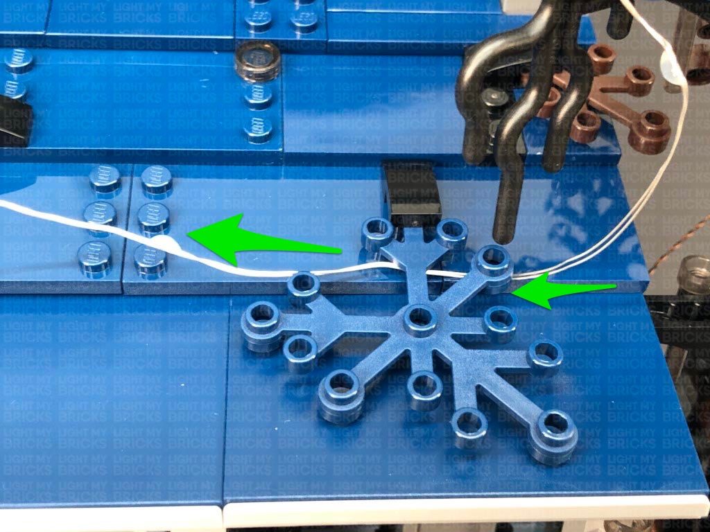
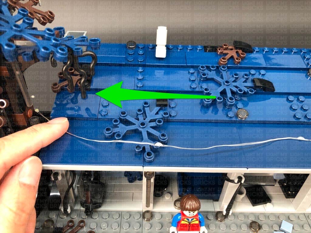
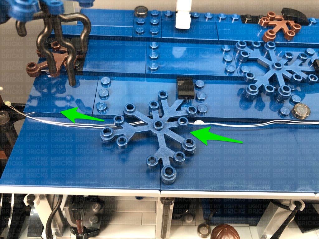
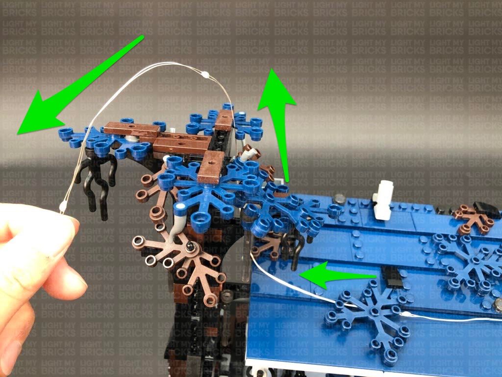
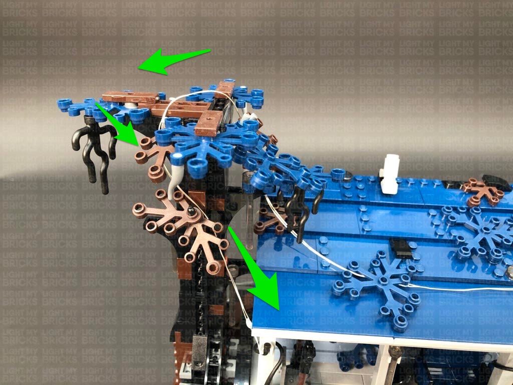
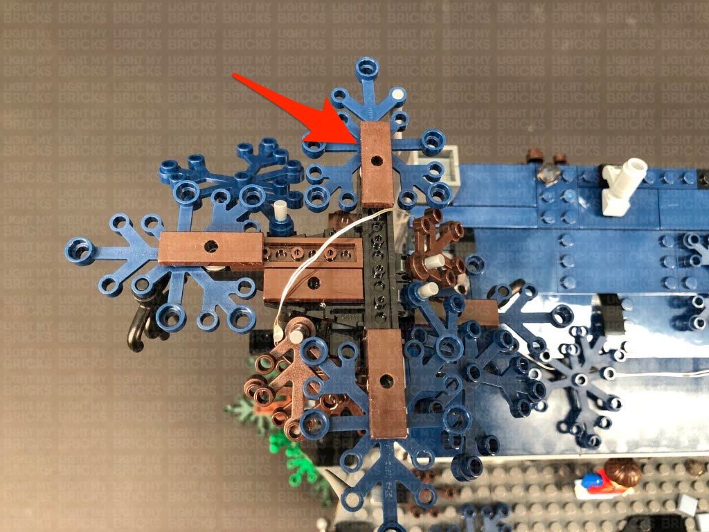
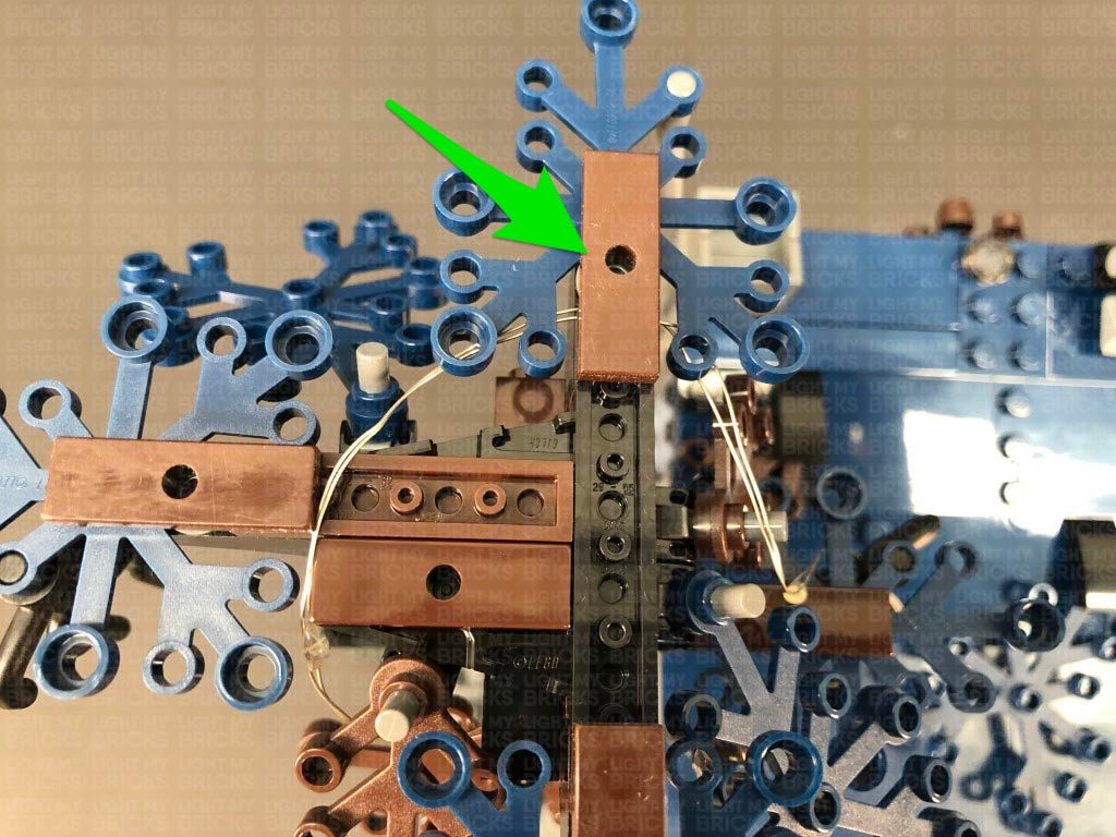
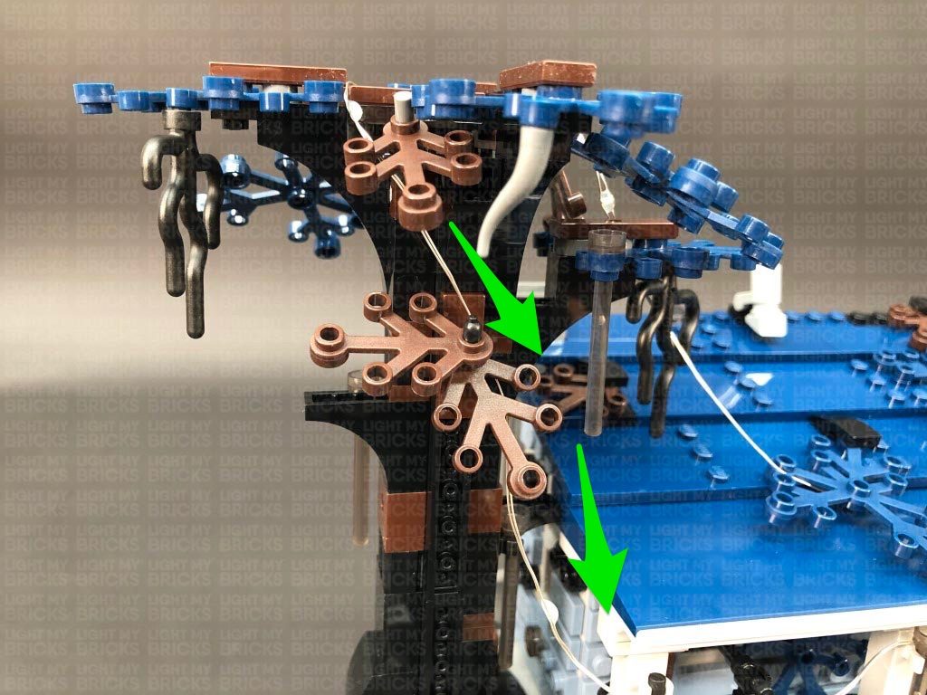
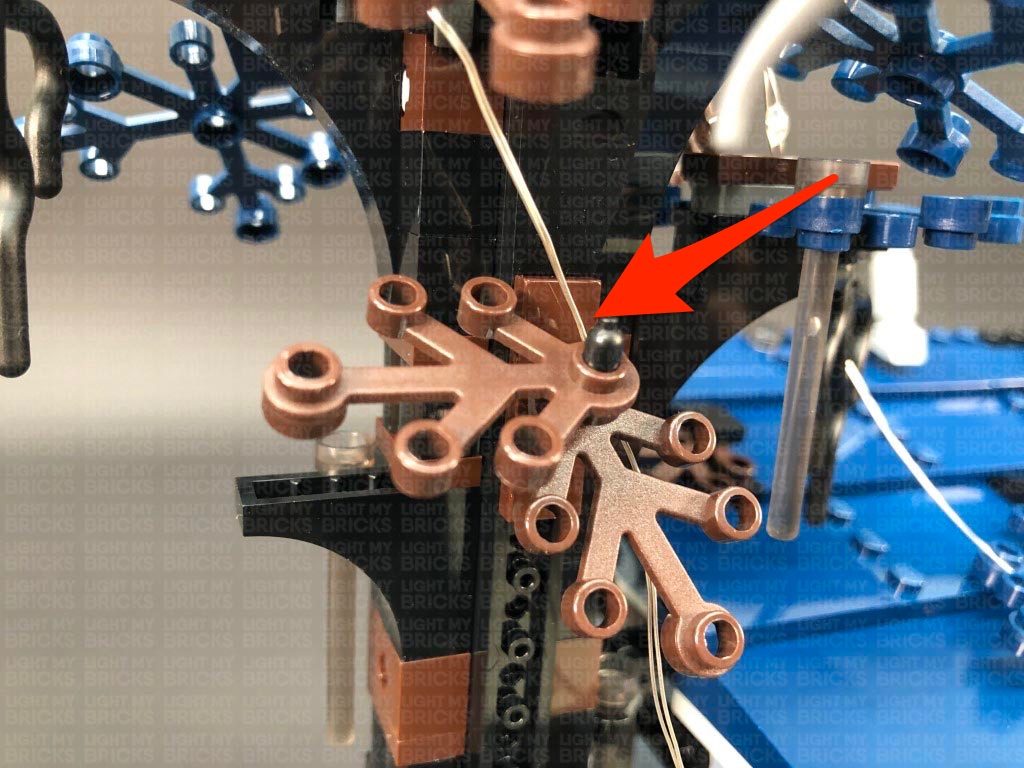
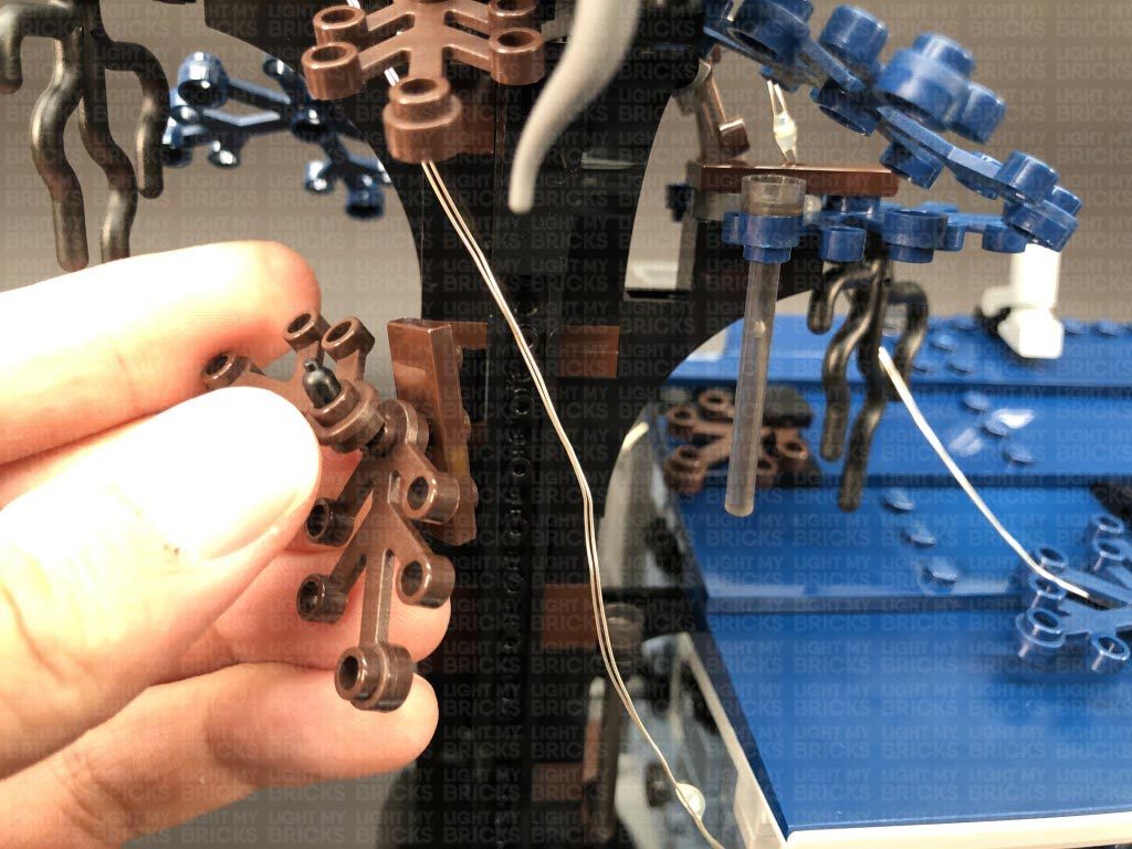
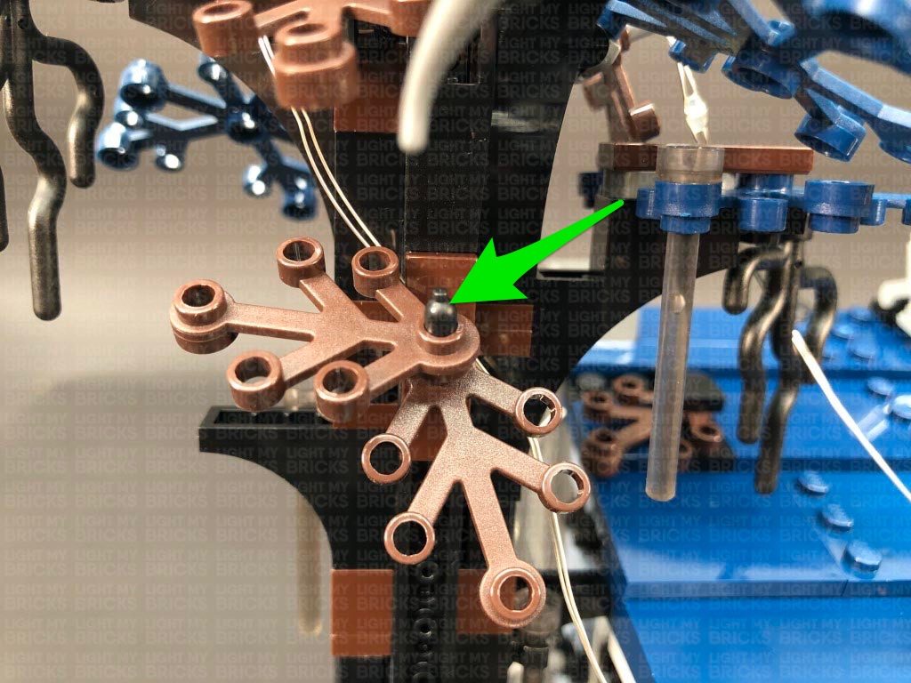
44.) Pull the Light string up the right side of the house, then using your LEGO removal tool, disconnect the roof section. Bring the light string over the top of the house, then secure it by winding the top of the light string around the brown and blue leaf pieces on the left side as shown below.
Ensuring the light string is laid in between LEGO studs, reconnect the roof section, then turn ON the power to test the glitter light string is working OK. The lights will slowly pulse on and off in sequence, to represent floating particles of the Upside Down. Note that the LEDS are designed to be a much dimmer than the rest of the LEDs in the light kit.
Note: If you experience any issues with the lights not working and suspect an issue with a component, please try a different port on the expansion board to verify where the fault lies (with the light or expansion board). To correct any issues with expansion board ports, please view the section addressing expansion board issues on our online troubleshooting guide.
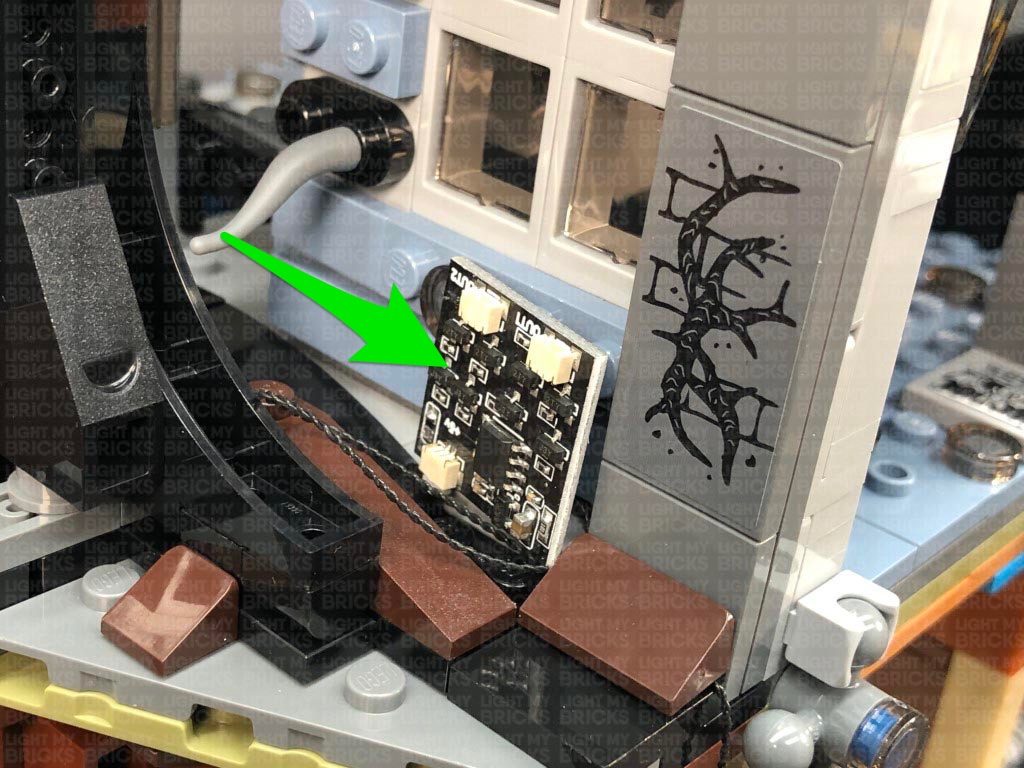
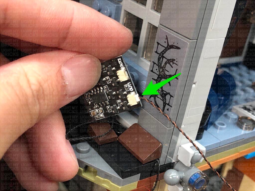
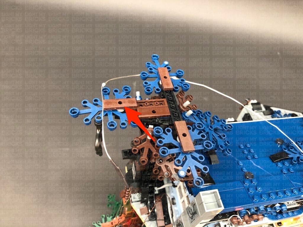
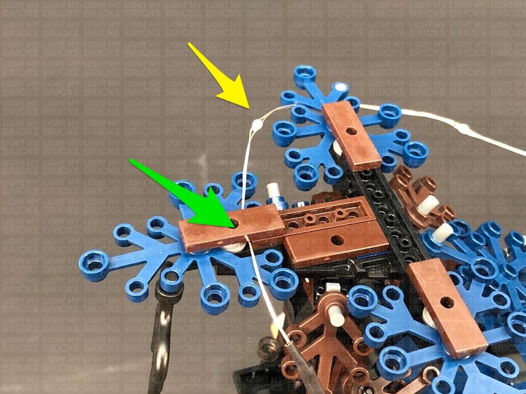
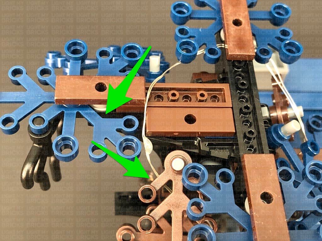
45.) Take the remaining Glitter Effects Light String and connect it to the other OUT port on the Glitter Effects Board. Bring the cable up and over the left side of the tree, then secure it underneath the following brown plate on top. Ensure the first LED is laid over toward the front of the plate as shown below.
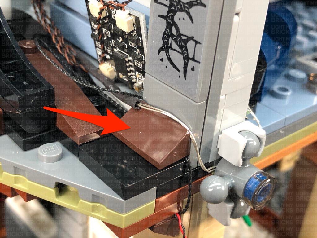
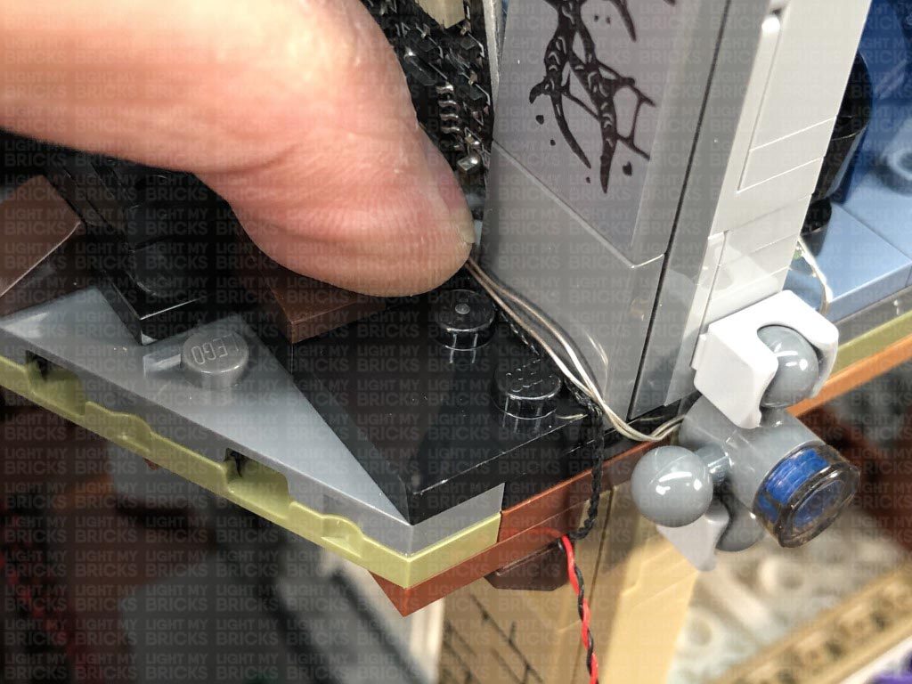
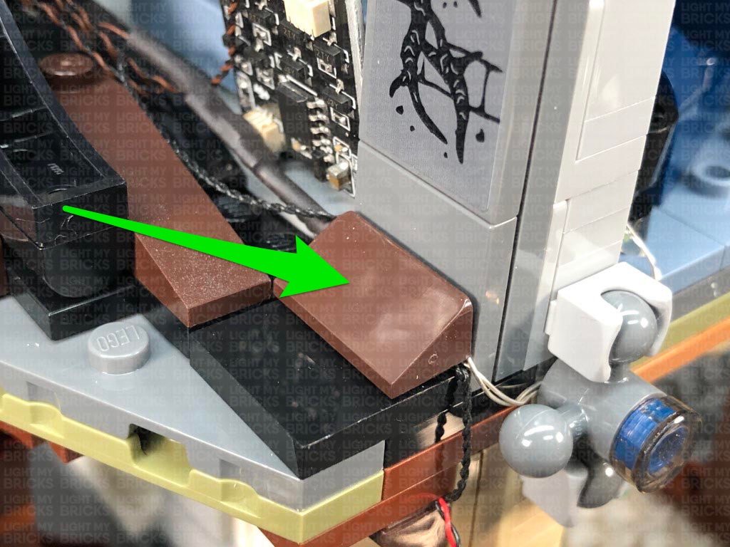
Bring the connector end of the light string down and over the brown leaf pieces. Take 2x Adhesive Squares and stick them to the back of the Glitter Effects Board, then stick the effects board to the bottom of the left wall.
Neaten up excess cable from the light string by twisting and folding it into a neat bunch, then tuck it down the side of the house. Secure the end of the first glitter light string underneath the brown angled tile.
40.) Bring the roof panel up on top of the house, then neatly place all the components in the following positions, with the scary flicker effects board underneath the sequence board. Ensure all cables are out of the way of the light grey technic plate on where the roof will reconnect to. Neaten up excess cables from the Blue, Pink and Green Bit Lights by twisting and folding them into a neat bunch. Neatly Tuck everything in before securely reconnecting the roof on both left and right sides.
Check that the Blue, Pink and Green lights are positioned correctly and shining onto the wall.
Note: If you experience any issues with the lights not working and suspect an issue with a component, please try a different port on the expansion board to verify where the fault lies (with the light or expansion board). To correct any issues with expansion board ports, please view the section addressing expansion board issues on our online troubleshooting guide.
41.) We will now install lights to the Upside Down. Take a 15cm Connecting Cable and connect it to another spare port on the 8-port Expansion Board on the right side of the house. Secure the cable underneath the brown angled tile, then turn the set upside down.
Lay the 15cm cable toward the front and secure it underneath the following brown angled tile at the bottom. Take the Glitter Effects Board (QPFX V1) and connect the other end of the 15cm cable to the IN port (+5V). Place the board down in the corner with the excess cable tucked underneath.
42.) Take one of the Glitter Effects Light Strings and connect it to one of the OUT ports on the Glitter Effects Board. Bring the light string across to the right and secure it underneath the following technic ball joint piece (disconnect and reconnect over the light string). Ensure the first LED on the glitter light string is laying toward the inside of the living room.
Bring the light string inside the living room and tuck it behind the dark blue couch. Bring the rest of the light string out toward the right side and secure it underneath the following technic ball joint piece (disconnect and reconnect over the light string).
Secure the light string underneath the white plate (Will’s drawing).
43.) Bring the light string across the living room and then bring it inside and tuck it in behind the black couch. Secure the light string underneath the following technic ball joint piece on the right(disconnect and reconnect over the light string). Secure the light string underneath the black round tile as well as behind the black plates of the couch.
Lay the light string inside the bedroom, ensuring you tuck it in behind the radio. Secure the light string underneath the technic ball joint piece on the right side as well as behind the torch against the right wall.
44.) Pull the Light string up the right side of the house, then using your LEGO removal tool, disconnect the roof section. Bring the light string over the top of the house, then secure it by winding the top of the light string around the brown and blue leaf pieces on the left side as shown below.
Ensuring the light string is laid in between LEGO studs, reconnect the roof section, then turn ON the power to test the glitter light string is working OK. The lights will slowly pulse on and off in sequence, to represent floating particles of the Upside Down. Note that the LEDS are designed to be a much dimmer than the rest of the LEDs in the light kit.
Note: If you experience any issues with the lights not working and suspect an issue with a component, please try a different port on the expansion board to verify where the fault lies (with the light or expansion board). To correct any issues with expansion board ports, please view the section addressing expansion board issues on our online troubleshooting guide.
45.) Take the remaining Glitter Effects Light String and connect it to the other OUT port on the Glitter Effects Board. Bring the cable up and over the left side of the tree, then secure it underneath the following brown plate on top. Ensure the first LED is laid over toward the front of the plate as shown below.
Bring the connector end of the light string down and over the brown leaf pieces. Take 2x Adhesive Squares and stick them to the back of the Glitter Effects Board, then stick the effects board to the bottom of the left wall.
Neaten up excess cable from the light string by twisting and folding it into a neat bunch, then tuck it down the side of the house. Secure the end of the first glitter light string underneath the brown angled tile.
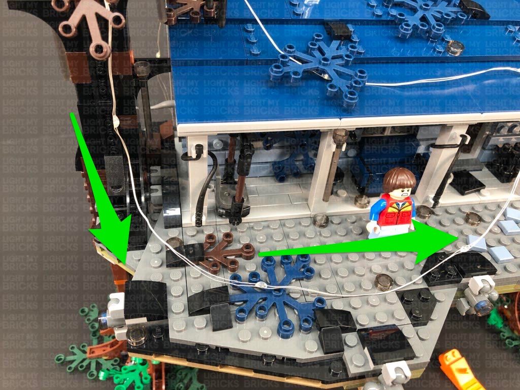
 46.) Turn the set around to the front, then bring the light string over and lay it around the following blue leaf piece.
Bring the cable across to the left side of the tree, then tuck it behind the black leaf piece.
With the light string now across the roof, secure it underneath the blue leaf piece on the right side, then bring the light string across to the other side and secure it underneath the blue leaf piece on the left side.
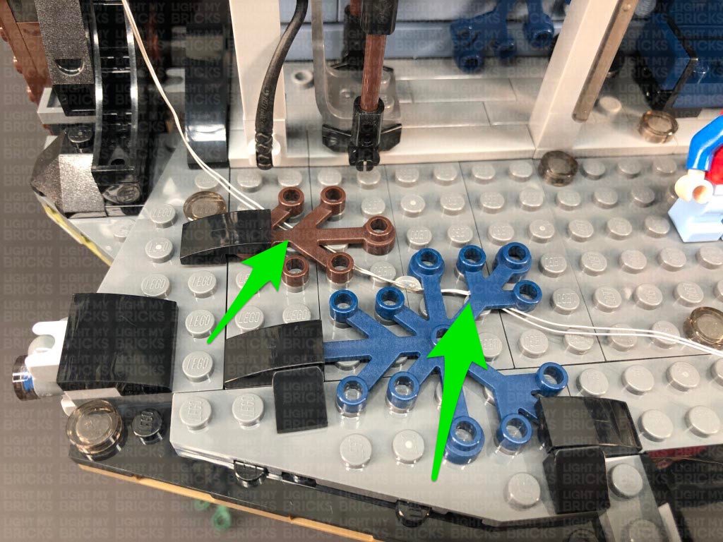
47.) Bring the light string up and over the top of the tree on the left side, then secure it underneath the following brown plate on the top. Bring the light string over toward the front , then tuck it down underneath the front of the leaf section, toward the front of tree.
Bring the light string down to the bottom right side of the tree, then secure it underneath the following brown plate where the brown leaf pieces are connect to. Ensure the light string is laid in between studs.
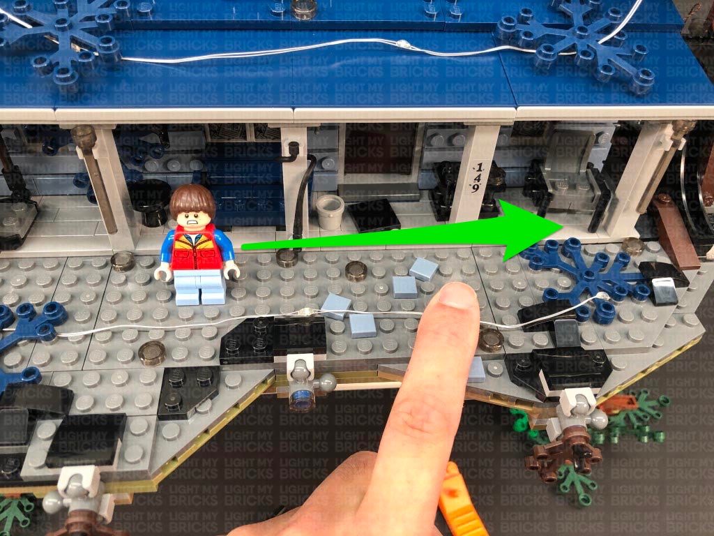
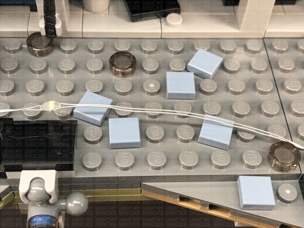
48.) Bring the light string down and then lay it across the base of the set. Secure the light string underneath the following brown and blue leaf pieces, then bring the cable across and secure the last LED underneath the black angled tile on the right side. Secure the middle of the light string underneath the light blue 1×1 tiles as shown below.
46.) Turn the set around to the front, then bring the light string over and lay it around the following blue leaf piece.
Bring the cable across to the left side of the tree, then tuck it behind the black leaf piece.
With the light string now across the roof, secure it underneath the blue leaf piece on the right side, then bring the light string across to the other side and secure it underneath the blue leaf piece on the left side.
47.) Bring the light string up and over the top of the tree on the left side, then secure it underneath the following brown plate on the top. Bring the light string over toward the front , then tuck it down underneath the front of the leaf section, toward the front of tree.
Bring the light string down to the bottom right side of the tree, then secure it underneath the following brown plate where the brown leaf pieces are connect to. Ensure the light string is laid in between studs.
48.) Bring the light string down and then lay it across the base of the set. Secure the light string underneath the following brown and blue leaf pieces, then bring the cable across and secure the last LED underneath the black angled tile on the right side. Secure the middle of the light string underneath the light blue 1×1 tiles as shown below.
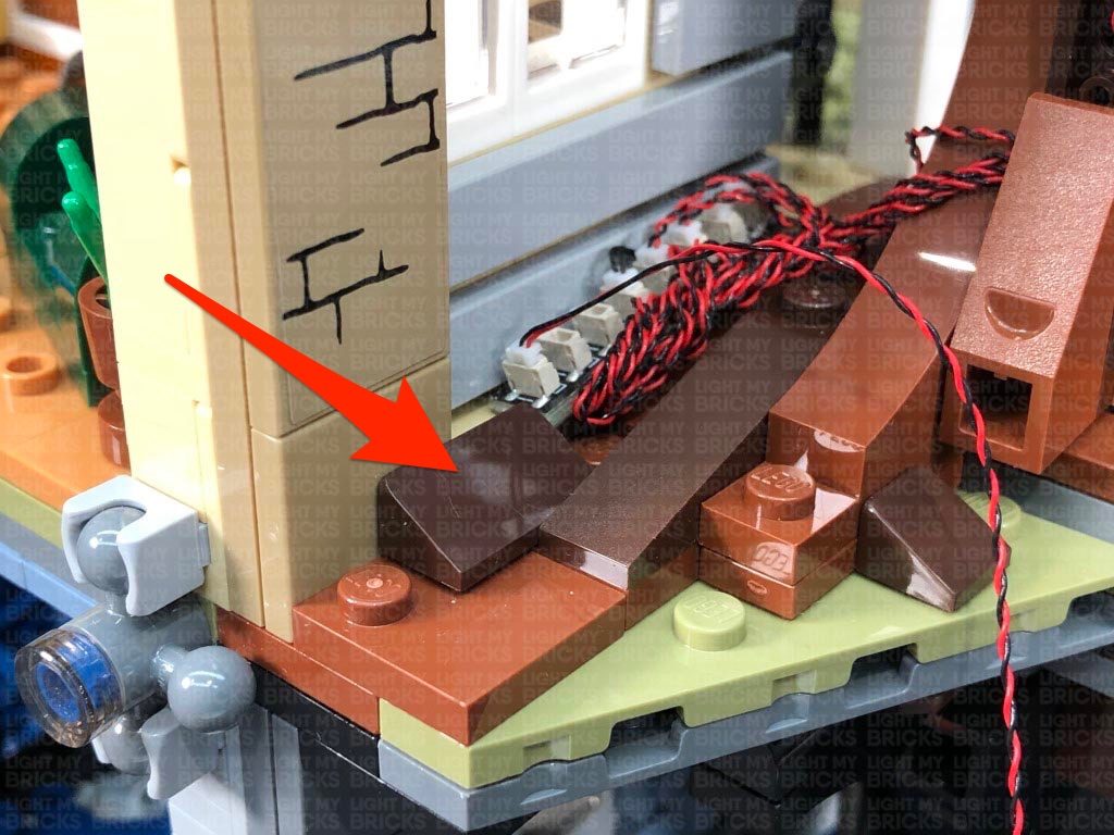
 Secure the light string on the left side of the house underneath the black whip piece on the left pillar. Turn the power ON to test the light string is working OK.
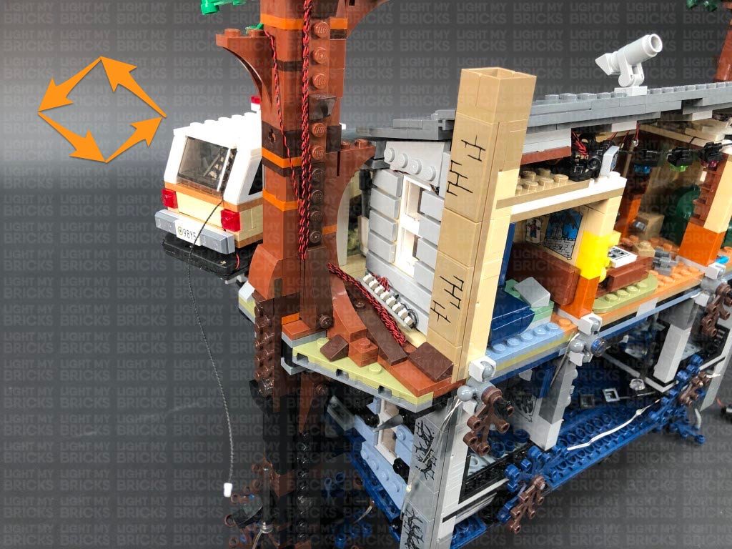
49.) Flip the set back over to the top side, then take Chief Hoppers Car and reconnect it to the front of the set. If you chose to tether the car lights to the house lights rather than the Flat Battery Pack, then bring the other end of the 15cm Connecting Cable from the vehicle around to the back of the set, and connect it to a spare port on the 8-Port Expansion Board on the left side of the house.
Turn the power ON to test all the lights are working together OK.
Note: If you experience any issues with the lights not working and suspect an issue with a component, please try a different port on the expansion board to verify where the fault lies (with the light or expansion board). To correct any issues with expansion board ports, please view the section addressing expansion board issues on our online troubleshooting guide.
Secure the light string on the left side of the house underneath the black whip piece on the left pillar. Turn the power ON to test the light string is working OK.
49.) Flip the set back over to the top side, then take Chief Hoppers Car and reconnect it to the front of the set. If you chose to tether the car lights to the house lights rather than the Flat Battery Pack, then bring the other end of the 15cm Connecting Cable from the vehicle around to the back of the set, and connect it to a spare port on the 8-Port Expansion Board on the left side of the house.
Turn the power ON to test all the lights are working together OK.
Note: If you experience any issues with the lights not working and suspect an issue with a component, please try a different port on the expansion board to verify where the fault lies (with the light or expansion board). To correct any issues with expansion board ports, please view the section addressing expansion board issues on our online troubleshooting guide.
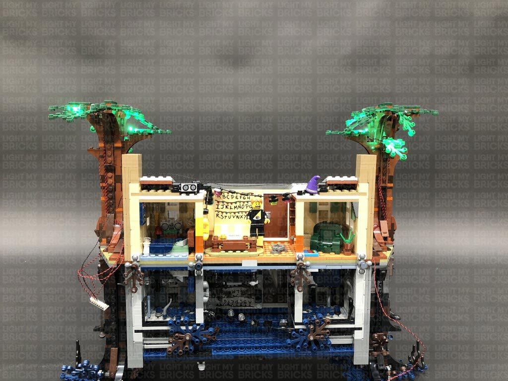
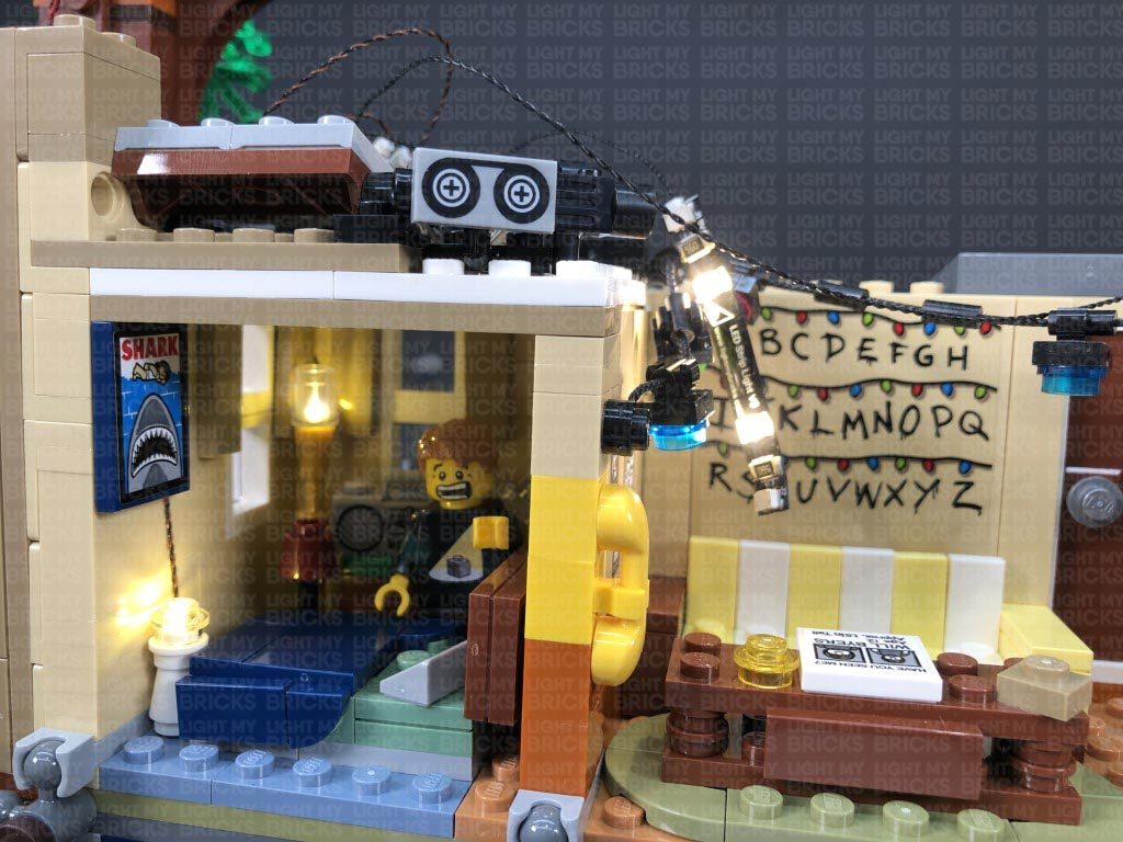
This finally complete’s installation of the Light My Bricks Stranger Things Upside Down Light Kit.
We thank you for purchasing this product and hope you ENJOY!