To ensure a trouble-free installation of your light kit, please read and follow each step carefully. These instructions can be downloaded in PDF format here
Please note: This page lists instructions for the LED light kit only. If you are wishing to purchase the Light My Bricks LEGO NASA Apollo Saturn V (21309) LED light kit , please click here to view the product page
Cables can fit in between and underneath LEGO® bricks, plates, and tiles providing they are laid correctly between the LEGO® studs. Do NOT forcefully join LEGO® together around cables; instead ensure they are laying comfortably in between each stud.
CAUTION: Forcing LEGO® to connect over a cable can result in damaging the cable and light.
Connecting cable connectors to Expansion Boards
Take extra care when inserting connectors to ports of Expansion Boards. Connectors can be inserted only one way. With the expansion board facing up, look for the soldered “=” symbol on the left side of the port. The connector side with the wires exposed should be facing toward the soldered “=” symbol as you insert into the port. If a plug won’t fit easily into a port connector, do not force it.
Incorrectly inserting the connector can can result in bent pins inside the port or possible overheating of the expansion board when connected.
Connecting cable connectors to Strip Lights
Take extra care when inserting connectors to ports on the Strip Lights. Connectors can be inserted only one way. With the Strip Light facing up, ensure the side of the connector with the wires exposed is facing down. If a plug won’t fit easily into a port connector, don’t force it. Doing so will damage the plug and the connector.
Installing Bit Lights under LEGO® bricks and plates.
When installing Bit Lights under LEGO® pieces, ensure they are placed the correct way up (Yellow LED component exposed). You can either place them directly on top of LEGO® studs or in between.
OK, Let’s Begin!
1.) We will install lights to the bottom rocket first. Start by disconnecting the bottom jet sections followed by the tail pieces as per below:
2.) Using the LEGO Removal tool, disconnect the following wall section from the bottom as shown below
Carefully press down at the following position to allow you to completely pull this section out.
3.) Repeat previous step to remove the wall section to the right
4.)Remove the section in the middle by lifting out sections using your finger as well as using the LEGO removal tool
5.) Use the LEGO Removal tool to disconnect the following sections to then allow us to remove the internal white wall section as well as the red pieces above and underneath
6.) Take the 5 jet sections and starting with one, disconnect the bottom half then take a White 30cm Bit Lightand thread the connector side of the cable down through the centre of the top of the jet (trans orange piece). Thread it all the way through until the Bit Light is right up against the edge of the trans orange piece.
Slightly bend the Bit Light on a 90 degree angle so that it sits flat, then secure it in place by connecting one of the provided Trans Orange Round Plate 1×1over the top
Reconnect the top half of the jet section back to the bottom half ensuring the cable from the Bit Light is tucked neatly underneath the dark grey bars.
Take caution when reconnecting to the bottom half and ensure there is enough cable slack between the jet section and bottom half for the technic bar to push against the cable as the two sections reconnect. If there is not enough cable slack, the technic bar will push the cable out and snap the cable.
7.)Repeat previous step to install White 30cm Bit Lights to the other four Jet sections using more of the provided Trans Orange Round Plate 1×1
8.) Reconnect the bottom three jet sections back to the base of the rocket starting with the one in the centre. Ensure the cable from each jet light is laid toward the top centre as shown below:
9.) Take the wall section closest to the bottom and then reconnect this to the ship starting with the top part.
10.) Reconnect the Jet section that connects to the bottom of the wall section we just reconnected ensuring all cables are neatly laid towards the centre.
Flip the rocket over and then reconnect the remaining wall section by first reconnecting the top part then reconnect the remaining Jet section.
11.) Take 1x Flicker Effects Board and connect the two shortest Bit Light Cables to the OUT ports (There are 3 OUT ports in total).
12.) Take remaining three Bit Light cables and connect them to a 6-Port Expansion Board
13.) Take a 5cm Connecting Cable and connect one end to the 6-port Expansion Board and connect the other end to the remaining OUT port on the Flicker Effects Board.
14.) Take a Flat Battery Pack and insert 2x CR2032 Batteries to it and then connect the battery pack cable to the IN Port on the Flicker Effects Board
Turn the Battery Pack on and confirm all lights and effects are working OK
Note: If you experience any issues with the lights not working and suspect an issue with a component, please try a different port on the expansion board to verify where the fault lies (with the light or expansion board). To correct any issues with expansion board ports, please view the section addressing expansion board issues on our online troubleshooting guide.
15.) Eliminate excess cabling by grouping all the cables and twisting them around each other. Tuck everything in to the open middle section.
Reconnect remaining sections of the Rocket.
To turn On and OFF the lights, simply detach the middle section to access the Battery Pack.
16.) We will now proceed to lighting the middle section of the Saturn V. Using the LEGO Removal Tool, disconnect the following sections (two main and one centre section).
17.) Remove the internal walls
18.) Disconnect the five Jet sections
19.)Disassemble one of the Jets and then take a White 30cm Bit Light and then thread the connector side through the top of outer section. Thread it all the way through until the component is right up against the edge.
Carefully bend the Bit Light 90 degrees so that it now sits flat against the hole then secure it in place by reconnecting theTrans Orange Round Plate
Thread the cable through the piece that connects behind and then carefully reconnect the white bar securing all pieces together.
Take caution when reconnecting to the white bar and ensure there is enough cable slack between the jet section and white bar for the bar to push against the cable as the two pieces reconnect. If there is not enough cable slack, the white bar will push the cable out and snap the cable.
20.) Repeat previous step to install White 30cm Bit Lights to the other four Jet sections.
21.)Reconnect the five Jet sections to the base starting with the bottom ones, ensuring the cables for each light is laid neatly up the centre as shown below
22.) Turn the section over on it’s side and then pull all the cables up to the top section. Reconnect the bottom inside wall section to secure the cables in place.
23.) Take the the shortest two cables and connect them to the OUT ports on Flicker Effects Board
24.)Connect the remaining three cables to a 6-Port Expansion Board
Connect one end of a 5cm Connecting Cable to the 6-port Expansion Board and connect the other end to the remaining OUT port on the Flicker Effects Board
25.) Take a Flat Battery Pack and insert 2x CR2032 Batteries to it then connect the battery pack cable to the IN Port on the Flicker Effects Board. Turn the Battery Pack on and confirm all lights and effects are working OK
Note: If you experience any issues with the lights not working and suspect an issue with a component, please try a different port on the expansion board to verify where the fault lies (with the light or expansion board). To correct any issues with expansion board ports, please view the section addressing expansion board issues on our online troubleshooting guide.
26.)Eliminate excess cabling by grouping all the cables and twisting them around each other. Tuck everything inside the open top section.
27.)Reconnect the outside sections starting with the two main sections followed by the middle section
To turn On and OFF the lights, simply detach the middle section (from the bottom where you the cables are visible) to access the Battery Pack.
This completes installation of the lights to the middle section of the Saturn V. Let’s move on to the top and final section.
28.) Take the top section and disconnect one of the outside wall sections using the LEGO Removal Tool
Remove the outside wall section underneath
29.) Disconnect the bottom section to allow us to then remove the following dark grey round bricks in the centre.
30.) Reconnect the bottom section as well as one of the outside wall sections
31.) Disconnect the Jet section and then disassemble pieces as shown below:
32.) Follow Step 19 to install the remaining White 30cm Bit Light to this Jet section using the provided Trans Orange Round Plate 1×1.
Take caution when reconnecting to the white bar and ensure there is enough cable slack between the jet section and white bar for the bar to push against the cable as the two pieces reconnect. If there is not enough cable slack, the white bar will push the cable out and snap the cable.
33.) Pull the cable around the bottom of the Jet and then secure it in between the light grey dish and dark grey modified brick.
34.) Reconnect the Jet section back to the bottom of this rocket section ensuring the cable is facing toward the centre of the open section above.
Lay the cable underneath the following LEGO pieces in between studs.
35.) Connect the other end of the Bit Light cable to any OUT port on the remaining Flicker Effects Board
Take the remaining Flat Battery Pack and insert 2x CR2032 Batteries to it. Connect the battery pack cable to the IN port on the Flicker Effects Board
36.) Eliminate excess cable by looping and twisting the cable around a few times. Tuck everything into the lower compartment. The Battery Pack should sit neatly sideways.
37.) Turn on the battery pack and then reconnect the outside wall section.
This finally completes installation of the Light My Bricks Apollo Saturn V Lighting Kit. Your light kit can be enjoyed either with all 3 sections connected or all apart.
To ensure a trouble-free installation of your light kit, please read and follow each step carefully. These instructions can be downloaded in PDF format here
Please note: This page lists instructions for the LED light kit only. If you are wishing to purchase the Light My Bricks LEGO Ship In A Bottle (21313) LED light kit , please click here to view the product page
Package Contents:
4x White 30cm Bit Lights
6x Blue 30cm Bit Lights
1x Multi Effects Board
1x 6-Port Expansion Board
1x 8-Port Expansion Board
2x 5cm Connecting Cables
1x AA Battery Pack
6x Adhesive Squares
Important things to note:
Laying cables in between and underneath bricks
Cables can fit in between and underneath LEGO® bricks, plates, and tiles providing they are laid correctly between the LEGO® studs. Do NOT forcefully join LEGO® together around cables; instead ensure they are laying comfortably in between each stud.
CAUTION: Forcing LEGO® to connect over a cable can result in damaging the cable and light.
Connecting cable connectors to Expansion Boards
Take extra care when inserting connectors to ports of Expansion Boards. Connectors can be inserted only one way. With the expansion board facing up, look for the soldered “=” symbol on the left side of the port. The connector side with the wires exposed should be facing toward the soldered “=” symbol as you insert into the port. If a plug won’t fit easily into a port connector, do not force it.
Incorrectly inserting the connector can can result in bent pins inside the port or possible overheating of the expansion board when connected.
Connecting cable connectors to Strip Lights
Take extra care when inserting connectors to ports on the Strip Lights. Connectors can be inserted only one way. With the Strip Light facing up, ensure the side of the connector with the wires exposed is facing down. If a plug won’t fit easily into a port connector, don’t force it. Doing so will damage the plug and the connector.
Installing Bit Lights under LEGO® bricks and plates.
When installing Bit Lights under LEGO® pieces, ensure they are placed the correct way up (Yellow LED component exposed). You can either place them directly on top of LEGO® studs or in between.
OK, Let’s Begin!
1.) First remove the bottle from the stand and disconnect the bottle top as well as top window sections to allow us to remove the ship.
2.) Remove the three masts from the ship, then disconnect the following sections around the front:
3.) Take a White 30cm Bit Light and thread the connector end of the cable through the gap of the brown clip on the back of the ship. Thread it all the way through until the Bit Light is up against the edge of the gap. Ensure the LED is facing up, then lay the cable down the side of the ship as shown below. Secure it in place by reconnecting the back section over the top. The Bit Light should be seen slightly peaking out from below the brown clip.
4.) Take another White 30cm Bit Light and slightly bend the wire down about 1cm from the top of the Bit Light as shown below. Hook the bit light over the following stud, then secure it in place by reconnecting the brown grill tile over the top.
Lay the cable down in between studs, then reconnect the side brown wall tile.
Repeat this process to install another White 30cm Bit Light to the left, securing it in place by reconnecting the brown tile over the top.
5.) Before reconnecting the brown wall tile, slide in the 1×6 plate as shown below. You may need to slightly lift up the two bit lights to reconnect the plate back in place. Reconnect the brown wall tile by sliding it in and connecting it underneath, then reconnect the last remaining section to the back of the ship.
Reconnect the three masts then group the three cables together and twist/wind them around each other a few times at the top to lock them in place.
6.) Take the AA Battery Pack and insert 3x AA Batteries to it. Connect the battery pack cable to the first port on the 6-Port Expansion Board. Connect the three cables from the ship to the spare ports on the expansion board, then turn ON the battery pack to test the lights connected are working OK.
Note: If you experience any issues with the lights not working and suspect an issue with a component, please try a different port on the expansion board to verify where the fault lies (with the light or expansion board). To correct any issues with expansion board ports, please view the section addressing expansion board issues on our online troubleshooting guide.
Disconnect the three bit lights and battery pack from the expansion board, then continue to twist/wind the cables around each other all the way to the end so they all come together to form one larger cable.
7.) Take two trans light blue round plates from inside the bottle then take out a Blue 30cm Bit Light and place it directly over one of studs. Secure the Bit Light in place by reconnecting the other trans light blue round plate over the top as shown below:
Repeat this step to install another 5x Blue 30cm Bit Lights using more of the trans light blue round plates from inside the bottle to secure them in place.
Take the 8-Port Expansion Board and connect the AA Battery Pack to it, then connect all six Blue Bit Light cables. Turn ON the battery pack to test all the blue lights are working OK.
Note: If you experience any issues with the lights not working and suspect an issue with a component, please try a different port on the expansion board to verify where the fault lies (with the light or expansion board). To correct any issues with expansion board ports, please view the section addressing expansion board issues on our online troubleshooting guide.8.) Tip all the trans light blue round plates out of the bottle then take an Adhesive Square and stick it to the side of the trans light blue plates where we have installed one of the Blue Bit Lights to. We will be installing 6 blue lights around the base of the bottle.
Mount the LEGO plates with Bit Light to the base of the bottle as shown below, then thread the connector end of the cable through the lower gap of the bottle. Pull the cable all the way out from behind.
We will now install the remaining five Blue Bit Lights around the base of the bottle. Using the same method as above, mount the other five trans light blue round plates with Bit Lights to the base of the bottle using extra Adhesive Squares. Continue to thread the other end of the cables through the same gap we did for the first Blue Bit Light.
9.) Turn the bottle around to the back, then ensure all cables inside the bottle are laid away from the brown plates except for the two cables shown below. Lay these two cables in between the brown plates.
Twist/wind the six cables around each other all the way to the ends so they come together to form one larger cable, then starting with the shorter two cables, connect all six cables to the 8-Port Expansion Board.
Group all the cables closest the expansion board and twist/wind them around the larger cable so they group together.
10.) Pour back in, all of the trans light blue round plates into the bottle. Spread the pieces out evenly to try and cover the cables inside, then turn the bottle back around to the front.
Take the ship and thread the group of three cables through the gap on the left of the blue bit light cables. Pull the cables all the way out from behind to then allow you to reconnect the ship back inside the bottle.
11.) Reconnect all the trans clear sections which make up main section of the bottle.
12.) Take a White 30cm Bit Light and with the cable facing down, place it over the centre of the studs on top of the main bottle section. Secure the Bit Light in place by reconnecting the bottle top section.
Bring the other end of the cable across to the right, then twist/wind it around the group of white 30cm bit lights (on the right side). Connect the bit light to the next port on the 6-Port Expansion Board.
Twist/wind any remaining excess cables around the larger group of cables as shown below:
13.) Take a Multi Effects Board and connect a 5cm Connecting Cable into one of the OUT ports (side with two ports). Connect the other end of the 5cm Connecting Cable to a spare port on the 8-Port Expansion Board.
Take another 5cm Connecting Cable and connect it to the IN port on the Multi Effects Board (side with one port). Connect the other end of the 5cm Connecting Cable to a spare port on the 6-Port Expansion Board, then connect the AA Battery Pack to the remaining Port.
14.) We can now set the effect we want. For a slow effect to represent ‘waves of the sea’, we chose to the ‘Pulse’ effect. Flick the switch to the far right for ‘Pulse’, then turn the speed wheel all the way to the left for the slowest speed. Alternatively, you can set whichever effect and speed you desire by simply changing the channel switch and adjusting the speed wheel. Once you are happy with your desired effect, place the bottle back on top of the bottle stand with the back facing toward you still.
Twist/wind the two larger cables together then fold up the cables so they can be neatly hidden underneath the bottle in between the stand and bottle. Neatly place the AA Battery Pack to cover up the gap then turn the bottle around to the front.
This finally completes installation of the Light My Bricks Ship in a Bottle Light Kit. We thank you for purchasing this product!
To ensure a trouble-free installation of your light kit, please read and follow each step carefully. These instructions can be downloaded in PDF format here
Please note: This page lists instructions for the LED light kit only. If you are wishing to purchase the Light My Bricks LEGO Welcome To Apocalypseburg! (70840) LED light kit , please click here to view the product page
Package Contents:
5x White 15cm Bit Lights
10x White 30cm Bit Lights
3x Flashing White 15cm Bit Lights
2x Blue 30cm Bit Lights
10x White Strip Lights
1x Blue Strip Light
1x Red Strip Light
2x Flicker Effects Boards
4x 6-Port Expansion Board
1x 8-Port Expansion Board
7x 5cm Connecting Cables
4x 15cm Connecting Cable
6x 30cm Connecting Cables
1x 50cm Conecting Cable
1x USB Power Cable
6x Adhesive Squares
LEGO Pieces:
1x Trans Clear Round Plate 1×1
7x Plate 1×6 (Any Colour)
2x Light Grey Round Plate 1×1 with Open Stud
2x Trans Clear Round Brick 2×2
Important things to note:
Laying cables in between and underneath bricks
Cables can fit in between and underneath LEGO® bricks, plates, and tiles providing they are laid correctly between the LEGO® studs. Do NOT forcefully join LEGO® together around cables; instead ensure they are laying comfortably in between each stud.
CAUTION: Forcing LEGO® to connect over a cable can result in damaging the cable and light.
Connecting cable connectors to Expansion Boards
Take extra care when inserting connectors to ports of Expansion Boards. Connectors can be inserted only one way. With the expansion board facing up, look for the soldered “=” symbol on the left side of the port. The connector side with the wires exposed should be facing toward the soldered “=” symbol as you insert into the port. If a plug won’t fit easily into a port connector, do not force it.
Incorrectly inserting the connector can can result in bent pins inside the port or possible overheating of the expansion board when connected.
Connecting cable connectors to Strip Lights
Take extra care when inserting connectors to ports on the Strip Lights. Connectors can be inserted only one way. With the Strip Light facing up, ensure the side of the connector with the wires exposed is facing down. If a plug won’t fit easily into a port connector, don’t force it. Doing so will damage the plug and the connector.
Installing Bit Lights under LEGO® bricks and plates.
When installing Bit Lights under LEGO® pieces, ensure they are placed the correct way up (Yellow LED component exposed). You can either place them directly on top of LEGO® studs or in between.
OK, Let’s Begin!
1.) First remove the second and third levels from the front, then turn the set around to the back and disconnect the water tank section.
2.) Disconnect the trans blue water piece from the pipe, then take a Blue 30cm Bit Light and carefully bend the led up on a 90 degree angle as shown below.
Insert the Bit Light with (led facing down) up inside the pipe, then secure it in place by reconnecting the water piece.
Wind the cable around the pipe as shown below, then secure it in place underneath the technic piece below:
3.) Remove the following sections around the water tank
Turn the water tank around and disconnect the water plate then take another Blue 30cm Bit Light and using an Adhesive Square, stick it at the bottom of the inside of the front wall ensuring the cable is facing down
Reconnect the water section plate ensuring the bit light cable is neatly laid in between studs, then reconnect the surround pieces we removed earlier.
4.) We now need to remove the black brick at the bottom of the wall behind the water tank. Carefully lift up the base, then using your index finger, push out the black brick from the inside.
5.) Take the two bit light cables from the water tank section and thread them through the space we just created, then pull them all the way out from underneath the base. Reconnect the water tank section.
6.) Connect both Bit Lights to the OUT ports on one of the Flicker Effects Boards. Take the USB Power Cable and connect it to the IN port on the flicker effects board. Connect the other side to your USB Power Bank (sold separately) and turn it on to test the blue lights are working and flickering OK.
Disconnect the USB Power Cable and connect a 5cm Connecting Cable to the IN port on the flicker effects board. Connect the other side to a 6-Port Expansion Board.7.) Move the water tank section out of the way, then take a 30cm Connecting Cable and thread one end of the cable through the space which leads underneath. Pull the cable out from underneath and connect it to the next port on the 6-Port Expansion Board.
Thread the USB Power Cable (connector side) through the same space, then pull it out from underneath and connect it to the next port on the 6-port Expansion Board.
Take another 30cm Connecting Cable and thread it through the same space, then pull it out from underneath and connect it to the next port on the 6-port Expansion Board.
Pull the first 30cm Connecting Cable and USB Power Cable all the way out toward the left side of the water tank, then pull the other 30cm Connecting Cable all the way out the right side before reconnecting the water tank to cover up the space.
8.) Move the set along towards the left side and disconnect the roof off by first disconnecting the pillars to allow you to completely pull the roof off.
Bring the other end of the 30cm Connecting Cable from the left side of the water tank around to this side, then thread it underneath the following section. Secure the cable in place underneath the light grey tile.
9.) Take a White Strip Light and using it’s adhesive backing, stick it onto the base of a provided LEGO Plate 1×6
Take the roof section we removed and turn it over so we can access underneath. Thread the 30cm Connecting Cable we have brought over through the following technic brick hole underneath the roof section. Thread the cable through so that it comes out through the top, then connect it to the Strip Light. Mount the Strip Light underneath this section in the following position as shown below.
10.) Remove the following rail section then disconnect and disassemble the lamp.
Take a White 15cm Bit Light and place the led face down over the hole on top of the brown dish. Secure the Bit Light in place by reconnecting the light grey plate with clip over the top.
Reconnect the lamp back to the rail, then reconnect the rail to the roof ensuring the cable is facing behind.
11.) Take the roof section and turn it onto it’s front side (with back side facing up). Thread the Bit Light cable through the following technic brick hole, then turn the roof over and connect the bit light cable to the strip light’s other port.
Reconnect the roof then connect the USB Cable to the power bank and test that the lights we have installed so far are working OK.
Note: If you experience any issues with the lights not working and suspect an issue with a component, please try a different port on the expansion board to verify where the fault lies (with the light or expansion board). To correct any issues with expansion board ports, please view the section addressing expansion board issues on our online troubleshooting guide.12.) Turn the set around to the front and disconnect the table/umbrella and plate where the fire pit sits on, then carefully lift up the base of the set and disconnect the darker tan plate as shown below:
Take the fire pit section and disassemble as per below, then take out the provided 2x Light Grey Round Plate 1×1 with open stud
13.) Take a White 30cm Bit Light and thread the connector side of the cable through the base (larger hole) of one of the Light Grey Round Plate 1×1 with open stud. Thread the cable all the way through, then carefully bend the Bit Light on a 90 degree angle so that the Bit Light is facing up and flat against the edge of the hole.
Reconnect the Light Grey Dish over the top of the Bit Light, then take the other provided Light Grey Round Plate 1×1 with open stud and connect it on top of the dish.
Reconnect the flame piece then reconnect the fire pit on top of the brown piece to connect back to the light tan plate ensuring the cable is behind.
14.) Take the connector end of the Bit Light and thread it through the following space behind where the fire pit goes. Carefully lift up the base of the set and pull the cable all the way out then reconnect the fire pit section.
Carefully lift the set up again and pull down the flicker effects board from the right side. Thread the Bit Light cable from the fire pit through the following technic brick hole and pull it all the way out from the other side as shown below:
Thread the cable through another technic brick hole as per below, and pull it all the way out from the other side. Once through, connect the cable to the remaining OUT port on the flicker effects board
Group all the excess cables and twist wind them around each other so they bunch up neatly together, then tuck them up inside the space above.
Place the set back down again and reconnect all sections surrounding the fire pit that we removed earlier. Test the fire pit light is working OK with the flicker effect by turning ON the USB Power Bank.
15.) Turn the set around to the back and disconnect the roof off the gym.
Take the end of the 30cm Connecting Cable we installed earlier and lay it down underneath the water pipe, then up along the left side of the gym. Secure it down by laying it underneath the 2×2 tile with stud.
16.) Take a White Strip Light and using it’s adhesive backing, stick it to the base of a provided LEGO Plate 1×6. Take a 15cm Connecting Cable and connect it to the right side of the Strip Light then connect the other end of the 30cm Connecting cable to the left port on the strip light.
Mount the Strip Light underneath the roof of the gym in the following position then securely reconnect the roof ensuring the other end of the 15cm connecting cable is laid out the right side.
17.) Swing the set around toward the right side, then disconnect all of the following sections as shown below:
18.) Take the other end of the 15cm Connecting Cable from the left side and lay it down in between studs as shown below. Secure the cable in place by reconnecting the green angled brick over the top.
Disconnect the roof section and turn it upside down so we can access underneath.
19.) Take a White Strip Light and connect the other side of the 15cm Connecting cable to the left port. Take a new 15cm Connecting Cable and connect it to the strip light’s right port, then using it’s adhesive backing, stick the strip light underneath the roof section directly onto the plate in the following position.
Reconnect the roof section ensuring both cables are secured behind the clips. Bring the cable on the right side up and lay both cables in between studs as shown below. Secure them down by reconnecting the 2×4 tile over the top.
Connect the other end of the 15cm Connecting cable from the strip light’s right port to a new 6-Port Expansion Board, then tuck the cable inside the following space.
20.) Refer to the below images to disconnect the following sections:
21.) We will now install flashing lights to the police station. First disconnect the trans blue tile, then take a Flashing White 15cm Bit Light and with the cable facing the inside of the building, place it down in between the following studs. Secure the light in place by reconnecting the trans blue tile over the top.
Repeat this process to install another Flashing White 15cm Bit Light underneath the trans red tile.
Reconnect the light grey tile, then connect both flashing bit lights to the 6-port expansion board on the left side.
Turn ON your usb power bank to test that all the lights are working OK.
Note: If you experience any issues with the lights not working and suspect an issue with a component, please try a different port on the expansion board to verify where the fault lies (with the light or expansion board). To correct any issues with expansion board ports, please view the section addressing expansion board issues on our online troubleshooting guide.22.) Take a new 15cm Connecting Cable and connect it to the 6-port expansion board. Lay the other end of the cable toward the right then group the two flashing bit light cables together and lay all three cables down in between studs as shown below. Secure all three cables down by reconnecting the green 1×6 brick over the top, then reconnect the large angled brick.
23.) Disconnect the following section and disassemble it as per below.
Take a White 30cm Bit Light and thread the connector side through the base (larger hole) of the Black 1×1 round brick. Thread it all the way through, then carefully bend the Bit Light on a 90 degree angle so that it is facing up and sitting flat against the edge of the base. Reconnect the black dish piece over the top.
Reconnect the brown clip, then secure the cable by threading it through the front hole of the brown clip and pulling it all the way out from behind. Reconnect this section back to the set ensuring the cable is pulled down the left side, then tucked under the base (in between studs) and out the right side as shown below.
24.) Thread the Bit Light cable down the following space and pull it out from underneath to connect the the 6-port expansion board below.
Take a 30cm Connecting Cable and connect it to the remaining port on the 6-Port Expansion Board. Take the other end of the cable and thread it up the following space above then pull it all the way out.
Reconnect all the following sections we removed earlier ensuring all cables are laid in between studs before connecting bricks over the top.
Once all the sections are reconnected, turn ON the usb power bank to test all the lights are working OK.
Note: If you experience any issues with the lights not working and suspect an issue with a component, please try a different port on the expansion board to verify where the fault lies (with the light or expansion board). To correct any issues with expansion board ports, please view the section addressing expansion board issues on our online troubleshooting guide.25.) Swing the set around to the front as we will now move onto lighting the second and third levels of the set. First, disconnect the third level as well as the roof off the second level. Turn the second level section over onto it’s back so we can access underneath it.
Take 3x White Strip Lights and stick 2 of 3 of them onto 2x provided LEGO Plate 1×6. Take a 15cm Connecting Cable and connect one end to one of the strip lights stuck to a lego plate. Connect the other end to the strip light without a lego plate. Take a 5cm Connecting Cable and connect one end to the strip light without the lego plate, then connect the other end to the the other strip light (stuck to a lego plate).
Mount the three strip lights underneath the second level section as shown below. Secure the 15cm connecting cable underneath the strip light with lego plate. This will prevent the cable from dangling down.
26.) Take a 30cm Connecting Cable and connect it to strip light on the right. Bring the cable down and secure it underneath the large black plate toward the bottom. Flip the second level back over and turn it to the back. Pull the cable all the way up then secure it underneath the light grey tile along the top.
27.) Turn the second level around to the front and disconnect the rail. Disassemble the lamp section from it as shown below:
Take a White 30cm Bit Light and place the led face down over the hole on top of the brown dish. Secure the Bit Light in place by reconnecting the light grey plate with clip over the top.
Reconnect the lamp back to the rail ensuring the cable is laid underneath the clip, then thread the cable around the rail as shown below then reconnect this section back to the second level ensuring the cable is laid toward the inside.
28.) Disconnect the light grey tile and black tile from the top of the level followed by the blue wall section. Bring the cable inside the room then reconnect the blue wall over the top (ensuring the cable is laid in between studs).
Bring the cable out toward the back of the room then lay it in between studs on the top before reconnecting the light grey tile. Reconnect the black tile.
Bring the 30cm Connecting Cable across toward the middle of the section and secure it underneath the following dark grey 1×4 tile.
29.) Take the roof of the second level and turn it onto it’s back so we can access underneath. Take a Blue Strip Light and using it’s adhesive backing, stick it to the base of a provided LEGO Plate 1×6. Take a 5cm Connecting cable and connect it to the strip light’s left port.
Take a Red Strip Light and using it’s adhesive backing, stick it to the base of a provided LEGO Plate 1×6. Connect the other end of the 5cm connecting cable to the red strip light’s right port then take a 30cm Connecting Cable and connect it to the left port.
Mount both strip lights underneath the roof in the following positions. Ensure you loop the 30cm Connecting Cable underneath the red strip light as shown below.
30.) Bring the roof over the second level and connect the other end of the 30cm Connecting Cable below to the Blue Strip Light, then securely reconnect the roof.
Take the entire second level and bring it over the ground level. Locate the other end of the 15cm Connecting Cable from below and connect it to the Red Strip Light, then securely reconnect the second level on top. Ensure the other end of the 30cm Connecting Cable and Bit Light are pulled out and accessible.
Turn your USB Power Bank ON to test all the lights we have installed so far are working OK.
31.) Take the roof off the top level, then disconnect the lamp section and disassemble it as shown below:
Take a White 15cm Bit Light and place the led face down over the hole on top of the brown dish. Secure the Bit Light in place by reconnecting the light grey plate with clip over the top.
Reconnect the lamp section back to the pole, then reconnect it back to the top level ensuring the cable is facing inside the building. Secure the cable underneath the dark grey tile on top ensuring the cable is laid in between studs, then connect it to a new 6-Port Expansion Board. Securely reconnect the top level on top of the second level.
32.) Locate the other end of the Bit Light cable and 30cm Connecting Cable from below and connect them to the next available ports on the 6-port expansion board. Using 2x Adhesive Squares, mount the expansion board to the inside of the top floor in the below position.
Secure all the excess cables underneath the tiles along the top of the level then turn ON the USB Power Bank to test the lights are working OK.
Note: If you experience any issues with the lights not working and suspect an issue with a component, please try a different port on the expansion board to verify where the fault lies (with the light or expansion board). To correct any issues with expansion board ports, please view the section addressing expansion board issues on our online troubleshooting guide.33.) Take the roof of the top floor and disconnect and disassemble the following section on the right.
Disconnect the trans clear round plate from the rail, then take a Flashing White 15cm Bit Light and with the cable facing the right, place it over the top left black stud. Secure the Bit Light in place by reconnecting the trans clear round plate over the top.
Bring the cable down, then reconnect the rail back to the clip ensuring the cable is laid behind. Reconnect everything back to the roof.
34.) Take a White Strip Light and using it’s adhesive backing, stick it to the base of the remaining provided LEGO Plate 1×6. Take a 5cm Connecting Cable and connect it to one side then connect the other side to the 6-port expansion board inside the top level.
Bring the roof over the top level and connect the other end of the flashing white 15cm bit light to the expansion board. Mount the strip light underneath the roof in the below position ensuring you connect the 1×6 plate over the flashing bit light cable.
Securely reconnect the roof then turn ON the USB Power Bank to test all the lights are working OK.
Note: If you experience any issues with the lights not working and suspect an issue with a component, please try a different port on the expansion board to verify where the fault lies (with the light or expansion board). To correct any issues with expansion board ports, please view the section addressing expansion board issues on our online troubleshooting guide.35.) Turn the set around to the back and locate the other end of the 30cm Connecting Cable from step 24. Thread the cable through the following space behind and pull it out from the other side. Disconnect the following section made up of the green angled brick, then connect the cable to a new 6-Port Expansion Board.
36.) We will now install a light to the top of the pipe nearby. Disconnect this section then disassemble as per below:
Replace the silver round plate 1×1 with a provided Trans Clear Round Plate 1×1 then take a White 15cm Bit Light and with the cable facing behind, place it over the top of the pipe. Secure it in place by reconnecting the dish and trans clear round plate over the top, then connect the bit light to the 6-port Expansion Board behind.
37.) Disconnect the chains connecting the torch and the liberty crown, then lift up the back section of the head to allow us to disconnect the head section.
Disconnect the two sections from each side of the face as well as the back section, then disconnect the face section as shown below:
38.) Disconnect the very top section of the crown then flip this section we removed over so we can access underneath it.
Take out 2x White Strip Lights, a 30cm Connecting Cable and a 5cm Connecting Cable. Connect the two strip lights together using the 5cm connecting cable then connect the 30cm connecting cable to one of the strip light’s other port.
Using it’s adhesive backing, stick the second strip light underneath the crown’s top section as shown below. Ensure the 30cm cable is facing the back.
Lift up the bottom section of the liberty crown and fold down the individual bars underneath. Take the top part of the crown above and thread the first strip light through to the front to allow us to stick it underneath the bottom section as shown below:
39.) Push back down the bottom crown section and fold up the bars underneath, then securely reconnect the top ensuring the other end of the 30cm Connecting Cable is laid out behind. Secure the 30cm Connecting Cable underneath the following brick that connects to the back.
Reconnect the back section.
40.) Disconnect the two eye sections from the face then remove and discard the green round 2×2 bricks. Replace them with the provided Trans Clear Round Brick 2×2 and connect the eyebrow sections over them.
Take a White 15cm Bit Light and with the cable facing behind, place it in the centre of the four studs underneath the left eye section. Secure the Bit Light in place by reconnecting the left eye section over the top, ensuring the Bit Light is fitted underneath the hole of the trans clear brick.
Repeat this process to install another White 15cm Bit Light to the right eye section
41.) Reconnect the face back to the head section, then reconnect the two pieces back to each side of the face.
Lift up the following piece, then bring the head section up and thread the two bit light cables as well as the 30cm cable through the front and out the back as per below, then securely reconnect the head section.
Take all three cables and connect them to the 6-port expansion board below. Turn ON the USB Power Bank to test all the lights are working OK.
Note: If you experience any issues with the lights not working and suspect an issue with a component, please try a different port on the expansion board to verify where the fault lies (with the light or expansion board). To correct any issues with expansion board ports, please view the section addressing expansion board issues on our online troubleshooting guide.42.) Take a 50cm Connecting Cable and connect it to the 6-Port Expansion Board. Tuck all the components in (except for the 50cm cable) then close the flap and reconnect the wall section we removed earlier. Ensure the cable from the pipe light is laid in between studs underneath.
43.) We will now light up the statue of liberty torch. First disconnect the torch by pulling it out from the front, then disconnect and dissemble the flame section as shown below:
44.) Take a White 30cm Bit Light and with the cable facing the right (facing back of the flame), place it over the stud as per below. Secure it in place by reconnecting the section over the top.
Take another White 30cm Bit Light and with the cable facing the right (facing back of the flame), place it over the top stud. Secure it in place by reconnecting the angled tile over the top.
Turn the flame section around and disconnect the following pieces. Lay the cable from the second bit light down in between studs, then reconnect the pieces over the top to hide the cable.
45.) Take another 2x White 30cm Bit Lights and install them to the next studs to the right. Secure them in place by reconnecting the angled tiles over the top.
46.) Take an Adhesive Square and stick it to the following position. Take another White 30cm Bit Light and stick it down onto the adhesive square as shown below, then reconnect the large piece over the top.
Flip the flame section over and using the same method as above, install another White 30cm Bit Light using another Adhesive Square.
Repeat this step again, to install the remaining White 30cm Bit Light to the middle using another Adhesive Square.
47.) Bring the cable from the front side of the flame down the base of the section before reconnecting the entire flame section back to the top of the torch. Ensure the cable we brought down the bottom is laid in between studs.
Disconnect the following rail section from the front right. Group all seven cables together and twist/wind them around each other 4-5 times so they lock in place together.
Connect all seven cables to the 8-Port Expansion Board then test all the flame lights are working OK by connecting the other end of the 50cm Connecting Cable from above to the expansion board and turning ON the USB Power Bank.
Note: If you experience any issues with the lights not working and suspect an issue with a component, please try a different port on the expansion board to verify where the fault lies (with the light or expansion board). To correct any issues with expansion board ports, please view the section addressing expansion board issues on our online troubleshooting guide.48.) Disconnect the 50cm Connecting Cable as well as the lights from the expansion board, then continue to twist/wind all the bit light cables around each other all the way to the end so they come together forming one larger cable.
Open up the statue’s fingers then thread the cables down through the space where we removed the rail piece earlier. Pull the cables all the way out from underneath then reconnect the rail piece above. Reconnect all seven cables to the 8-port expansion board.
Take a 5cm Connecting Cable and connect one end to the expansion boards remaining port, then connect the other end to a new Flicker Effects Board‘s OUT port.
49.) Reconnect the torch section back to the set then take the other end of the 50cm Connecting Cable from underneath and thread it through the following space in the centre of set. Pull the cable all the way out, then connect it to the remaining White Strip Light.
Take the remaining 5cm Connecting Cable and connect one end of the cable to the White Strip Light and the other end to the IN port on the Flicker Effects Board.
50.) Lift up the the ladder section so that it comes away from the set then using it’s adhesive backing, stick the Strip Light underneath the platform in the following position:
Reconnect the ladder section ensuring the 50cm cable is laid behind.
Fold/twist the excess bit light cables into a neat bunch then tuck them along with the expansion board and effects board underneath the statue’s fingers as shown below:
51.) Secure the excess cable from the 50cm Connecting Cable by neatly laying it underneath the following LEGO pieces. Push down any excess cable down the spaces behind the set.
Turn on the USB Power Bank to test all lights are working OK.
Note: If you experience any issues with the lights not working and suspect an issue with a component, please try a different port on the expansion board to verify where the fault lies (with the light or expansion board). To correct any issues with expansion board ports, please view the section addressing expansion board issues on our online troubleshooting guide.
This finally completes installation of the Light My Bricks Welcome to Apocalypseburg! Light Kit. We thank you for purchasing this product.
To ensure a trouble-free installation of your light kit, please read and follow each step carefully.
Package Contents:
1x Remote Control (Includes CR2025 battery)
1x Remote Control and Sound Board
1x 64MB Memory Card (pre inserted)
1x IR Receiver with 30cm Connecting Cable
1x Speaker with 15cm Connecting Cable
1x 5cm Connecting Cable
1x Micro USB Cable
Important things to note:
Laying cables in between and underneath bricks
Cables can fit in between and underneath LEGO® bricks, plates, and tiles providing they are laid correctly between the LEGO® studs. Do NOT forcefully join LEGO® together around cables; instead ensure they are laying comfortably in between each stud.
CAUTION: Forcing LEGO® to connect over a cable can result in damaging the cable and light.
Connecting cable connectors to Expansion Boards
Take extra care when inserting connectors to ports of Expansion Boards. Connectors can be inserted only one way. With the expansion board facing up, look for the soldered “=” symbol on the left side of the port. The connector side with the wires exposed should be facing toward the soldered “=” symbol as you insert into the port. If a plug won’t fit easily into a port connector, do not force it.
Incorrectly inserting the connector can can result in bent pins inside the port or possible overheating of the expansion board when connected.
Connecting cable connectors to Strip Lights
Take extra care when inserting connectors to ports on the Strip Lights. Connectors can be inserted only one way. With the Strip Light facing up, ensure the side of the connector with the wires exposed is facing down. If a plug won’t fit easily into a port connector, don’t force it. Doing so will damage the plug and the connector.
Installing Bit Lights under LEGO® bricks and plates.
When installing Bit Lights under LEGO® pieces, ensure they are placed the correct way up (Yellow LED component exposed). You can either place them directly on top of LEGO® studs or in between.
Setting up the Remote Control and Sound Kit
Important Note regarding Power: If your light kit contains multiple multi-effects boards, we recommend powering the remote control board via mains electricity (connecting usb power cable into a wall adaptor similar to a smartphone charger). This will eliminate any potential issues relating to powering of the device.
1.) Your Remote Control Board should be connected in between your light kit and power source. First disconnect the power source from your light circuit
2.) Assemble your Remote Control and Sound Kit as shown below ensuring all your components are connected to the correct ports:
Audio – Connect Speaker to this port
IR – Connect IR Receiver 30cm Connecting Cable to this port
Out – Connect 5cm Connecting Cable to this port
3.) Once your Remote Control and Sound Kit is assembled as per above, connect the other end of the 5cm Connecting Cable to your light kit (where your power source was previously connected). Then connect your power source to the remote control board’s 5V port.
Important Note regarding Power: If your light kit contains multiple multi-effects boards, we recommend powering the remote control board via mains electricity (connecting usb power cable into a wall adaptor similar to a smartphone charger). This will eliminate any potential issues relating to powering of the device.
4.) Take the IR Receiver and bring it over to the front of your light kit, so that we can mount it ‘in line of sight’ of the remote control. Using it’s adhesive backing, mount the IR Receiver somewhere suitable ensuring the sensor is facing forward.
5.) Take the speaker and secure it somewhere suitable ensuring speaker is facing the correct way up.
Your remote control and sound kit is now ready to use. To activate, follow the below procedure:
Operation
Refer to the below remote control button functions and ensure you first remove the plastic tag to activate the remote control battery. Also ensure your power source is turned on before you operate, and that the remote control sensor is pointing directly at the IR sensor.
Load Your Desired Audio Track(s)
The Light My Bricks Remote Control and Sound Kit’s included 64MB memory card comes with 9 pre-loaded audio tracks in MP3 format:
Everything is Awesome
Disneyland theme
Harry Potter Theme
Ninjago theme
Millennium Falcon take off and interior sounds
Ghostbusters Theme
City Police Siren
So Ruff So Tuff
Star Wars Main Theme
To load your desired audio tracks, simply disconnect the Remote Control and Sound Board and connect the Micro USB Cable to the micro usb port on the bottom side of the board. Connect the other side (USB plug) to your PC/MAC and wait for it to load. The Remote Control and Sound board does not require power in order for your PC to read it. It should load as a normal USB external drive.
Simply Drag and Drop your chosen audio tracks (MP3 format only) into the USB drive and then eject and reconnect back to your light circuit. Simple as that!
OSxPCRe-arrange the order of audio files played.
If you wish to re-arrange the order of the mp3 files that are played, follow the below steps:
Copy all the files to your local hard drive.
Delete all the files from the memory card (ensure you have copied the files off as per step 1)
Rename the files on your local hard drive with the number order of your choosing, e.g. Rename “Police Siren.mp3” to “01. Police Siren.mp3“, “Car Engine.mp3” to “02. Car Engine.mp3“, etc.
Copy the files back to the memory card.
You must completely remove and re-copy the files on the memory card in order to reset the order. Simply renaming the files already saved on the memory card will not re-arrange the order.
Troubleshooting
My lights do not power on using the remote control!
If your lights do not power on via the remote control, first check that all your connections are correct as per step 2.
If all the connections are correct and all you hear is a brief beep of static through the speaker, this is a powering issue where not enough power is being inputted to the remote board and light kit. If your light kit contains multiple multi-effects boards, we recommend powering the remote control board via mains electricity (connecting usb power cable into a wall adaptor similar to a smartphone charger). This will eliminate any potential issues relating to powering of the device.
Remote Control system is draining batteries very quickly
When you are powering the remote control system and lights with our battery packs, the remote board will still output a very small amount of power, even with the lights remotely turned off. This is because the remote board still requires just enough power so that it can detect when it is time to remotely “turn on”. This is the reason your AA Batteries are draining quickly. If you want to remotely turn ON the lights whenever you want, it is best to power using our USB Power Cable connected to mains power via a USB wall adaptor (like a smart phone wall adaptor).
I can remotely turn on Lights but when I press play to play audio, lights turn off and it makes a buzzing noise
This issue is relating to lower power or batteries are not fully charged. Replace batteries with fresh fully charged batteries and try again. Alternatively, use our recommended power source and power your remote control lighting circuit using our USB Power Cable to mains power wall adaptor.
Light My Bricks USB Power Bank green light turns off after I remotely turn off the remote control system. Once this happens I can’t remotely turn ON the lights.
Our USB Power Banks have a standby function which saves power when it detects no or very little power. When the lights are turned off remotely, it is only outputting a very tiny amount of power, so the USB power bank will detect inactivity and power off. If you want to remotely turn ON the lights whenever you want, it is best to power using our USB Cable connected to mains power via a USB wall adaptor (like a smart phone wall adaptor).
For all other questions or issues please contact our friendly customer service team by emailing info@lightmybricks.com
To ensure a trouble-free installation of your light kit, please read and follow each step carefully. These instructions can be downloaded in PDF format here
Please note: This page lists instructions for the LED light kit only. If you are wishing to purchase the Light My Bricks LEGO Corner Garage (10264) LED light kit , please click here to view the product page
6x Adhesive Squares
Important Note:Micro Battery Packs are no longer available as of June 2022 due to child safety regulations. Please use the 50cm Connecting Cable in place of the Battery Pack.
LEGO Pieces:
2x Trans Clear Round Plate 1×1
2x Trans Red Round Plate 1×1
6x Plate 1×6 (Any Colour)
2x Black Round Plate 1×1 with Open Stud
2x Black Tile 1×1 with Clip Rounded Edges
2x Black 1×1 Modified Plate Rounded with Handle
Wireless Power Connectors:
If you wish to use Light My Bricks Wireless Power Connectors in between floors (sold separately), please scroll to the bottom of the page to view the instructions.
You will require the following extra parts (available for purchase through our DIY range)
3x Wireless Power Connectors sets (available to purchase in a 2pk)
2x 2-Port Expansion Board (available to purchase in a 4pk)
3x 1×6 Plate (any colour)
Important things to note:
Laying cables in between and underneath bricks
Cables can fit in between and underneath LEGO® bricks, plates, and tiles providing they are laid correctly between the LEGO® studs. Do NOT forcefully join LEGO® together around cables; instead ensure they are laying comfortably in between each stud.
CAUTION: Forcing LEGO® to connect over a cable can result in damaging the cable and light.
Connecting cable connectors to Expansion Boards
Take extra care when inserting connectors to ports of Expansion Boards. Connectors can be inserted only one way. With the expansion board facing up, look for the soldered “=” symbol on the left side of the port. The connector side with the wires exposed should be facing toward the soldered “=” symbol as you insert into the port. If a plug won’t fit easily into a port connector, do not force it.
Incorrectly inserting the connector can can result in bent pins inside the port or possible overheating of the expansion board when connected.
Connecting cable connectors to Strip Lights
Take extra care when inserting connectors to ports on the Strip Lights. Connectors can be inserted only one way. With the Strip Light facing up, ensure the side of the connector with the wires exposed is facing down. If a plug won’t fit easily into a port connector, don’t force it. Doing so will damage the plug and the connector.
Installing Bit Lights under LEGO® bricks and plates.
When installing Bit Lights under LEGO® pieces, ensure they are placed the correct way up (Yellow LED component exposed). You can either place them directly on top of LEGO® studs or in between.
OK, Let’s Begin!
Lighting up the Truck
1.) The first thing we will do is light up the truck. First take this vehicle and remove the following pieces from the front, then disassemble as per below:
2.) Take a White 15cm Bit Light and thread the connector side of the cable through the front of the light grey technic pin. Thread it all the way through, then carefully bend the Bit Light on a 90 degree angle so that it is sitting flat against the edge of the pin. Take a provided Trans Clear Round Plate 1×1 and connect it over the top.
Repeat this step to install another White 15cm Bit Light to the other technic pin, securing it in place using another provided Trans Clear Round Plate 1×1.3.) Remove the following sections from the front of the truck,then thread one of the Bit Light cables through the front of the below piece allowing you to reconnect the left headlight.
Disconnect the wheel, then reconnect the left headlight section ensuring the cable is passed through over the wheel axis, before reconnecting the wheel over the top.
4.) Repeat previous step to reconnect the right headlight to the truck then reconnect the remaining sections we removed earlier.
5.) Turn the truck around and disconnect the back section as well as rear right wheel, then thread the cable from the right headlight up the space in front of the rear right wheel (which leads to the back of the truck). Ensure the cable is pulled up inside the black side rail as per below images.
Repeat this process to thread the cable from the left headlight up the space in front of the left rear wheel.
6.) Take out the Micro Battery Pack and pull out and discard the clear tag to activate the batteries. Connect the two cables to the bottom ports (ensuring the battery switch side is facing up), then turn the battery pack ON to verify the headlights are working OK.
Important Note:Micro Battery Packs are no longer available as of June 2022 due to child safety regulations. Please use the 50cm Connecting Cable in place of the Battery Pack. The Connecting Cable will then tether to the 12-Port Expansion Board in the Corner Garage later on.
7.) Disconnect the two trans red tiles from the back panel, then take a White 15cm Bit Light and with the cable facing toward the centre, place it over the right stud as shown below. Secure the Bit Light in place by connecting a provided Trans Red Round Plate 1×1 over the top.
Repeat this process to install another White 15cm Bit Light to the left side, securing it in place using another provided Trans Red Round Plate 1×1. Reconnect this panel back to the truck ensuring both cables are laid in between studs underneath.
8.) Remove the rear left wheel then thread the left tail light cable up the space in front of the left wheel axis and pull it up from the top on the inside of the black bars (same way we did for the headlight cables).
Reconnect the wheel, then connect the cable to the next port along the micro battery pack.
Repeat this process to thread the right tail light cable up to the top and connect it to the next port on the Micro Battery Pack.
9.) Neaten up excess cables by grouping them all together and twisting/folding them around each other a few times. Tuck the bunched up cables underneath the battery pack then lower the hook section so that it secures the battery pack in place.
This completes installation of the lights for the Corner Garage Truck. Turn ON the battery pack to test the tail lights are working OK.
Lighting up the Corner Garage
1.) The Corner Garage lights are installed from the bottom up. First remove the second and third floors, then disconnect the gas station roof, gas pump, followed by the lamp post.
2.) Use your LEGO removal tool to disconnect the following tiles as well as the trolley from the building leading to the gas pump.
Remove the upper section of the gas pump then take out a Blue 30cm Bit Light and with the cable facing the back of the pump, place it in the centre, in between the white studs. Reconnect the upper section of the gas pump on top, ensuring the Bit Light is neatly secured in the middle.
Turn the Gas Pump around to the back and secure the bit light cable underneath the following light grey tile.
3.) Reconnect the following tile before reconnecting the Gas Pump section over the top, back onto the base plate.
Bring the front corner of the base plate over the edge of your table and bend it down slightly so that the dark green wall comes apart at the following section:
Feed the wire from the Blue Bit Light through the following space, then pull it all the way out from the inside of the wall.
4.) Neatly lay the cable in between the following studs, then reconnect the following tiles and pieces we disconnected earlier, starting with the grey tile with stud on top.
5.) Take a 12-Port Expansion Board and connect the Blue Bit Light to the first port on the left. Take your USB Power Cable and connect it to the far right port. Connect the other side to your USB Power Bankor USB to AA Battery Pack (each sold separately) and turn it on to test the blue light is working OK.
Note: If you experience any issues with the lights not working and suspect an issue with a component, please try a different port on the expansion board to verify where the fault lies (with the light or expansion board). To correct any issues with expansion board ports, please view the section addressing expansion board issues on our online troubleshooting guide.6.) Disconnect the following pieces in front of the garage door, then take out the provided LEGO Lamp Post with Bit Light installed.
Bring this side of the base plate over the edge of the table and slightly bend it down to create a gap underneath the right side of the garage door.
7.) Thread the Lamp Post cable through this gap and then pull it out from the inside of the garage before connecting the lamp post to the base plate.
Ensure the cable is neatly laid in between the following studs and is pulled all the way out from the inside of the garage before closing up the gap in between base plate and wall.
Connect the lamp post cable to the next port on the left of the 12-port Expansion Board, then turn on your USB Power Bank to test the lamp post light is working OK. Reconnect the tiles and pieces we disconnected earlier (discard the black 2×2 plate).
Note: If you experience any issues with the lights not working and suspect an issue with a component, please try a different port on the expansion board to verify where the fault lies (with the light or expansion board). To correct any issues with expansion board ports, please view the section addressing expansion board issues on our online troubleshooting guide.8.) Take the roof section of the gas station and disconnect the following sections.
Take the following provided LEGO pieces and assemble two of the pieces to make two spot lights as per below:
2x Black Round Plate 1×1 with Open Stud
2x Black Tile 1×1 with Clip Rounded Edges
2x Black 1×1 Modified Plate Rounded with Handle
9.) Take a White 30cm Bit Light and thread the connector side of the cable through the base (large hole) of the round plate with open stud. Thread the cable all the way through and then carefully bend the Bit Light on a 90 degree angle so that it sits flat against the inside of the round plate.
Connect the round plate to the back of the Black 1×1 Modified Plate Rounded with Handle ensuring the cable is facing the bottom then repeat this process to install another White 30cm Bit Light to the other spot light section.
10.) Connect both spot lights to the front of the gas station roof section in the following positions. Ensure that both cables are neatly laid in between studs before securing the cables underneath the white 1×6 tile at the back.
Reconnect the roof top with the ‘Jo’s Garage’ sign followed by the dark grey corner sections.
11.) Take 2x White Strip Lights and connect them together using a 15cm Connecting Cable. Take another 15cm Connecting Cable and connect it to the other side of one of the Strip Lights.
Using it’s adhesive backing, stick the Strip Lights underneath the gas station roof section in the following positions. Ensure the Strip Light with the spare end of the 15cm connecting cable is toward the back of the roof as shown below:
Secure the excess cable from the 15cm Connecting Cable (in between the strip lights) underneath the green plates along the side. Bunch up any remaining excess and tuck it in to the inside of the roof, then secure the spare end of the 15cm connecting cable (towards the back), underneath the following green plate.
12.) Reconnect the pillars underneath the roof section before reconnecting this whole section back to the base plate and top of the first floor ensuring the 15cm connecting cable and 2x White 30cm Bit Lights are laid out toward the inside of the building.
Connect the 2x White 30cm Bit Lights and 15cm Connecting Cable to the next ports along the 12-port Expansion Board (next to the USB Power Cable). Turn ON the USB Power Bank to test the spot lights and strip lights are working OK.
Note: If you experience any issues with the lights not working and suspect an issue with a component, please try a different port on the expansion board to verify where the fault lies (with the light or expansion board). To correct any issues with expansion board ports, please view the section addressing expansion board issues on our online troubleshooting guide.13.) We will now install some lights to the lamps above the garage door. Using your LEGO Removal tool, disconnect the following sections, then disassemble the pieces from the lamps.
Take a White 15cm Bit Light and thread the connector side of the cable through the base of the black round plate with open stud (large hole). Thread the cable all the way through and then carefully bend the Bit Light on a 90 degree angle so that it sits flat against the inside of the round plate. Reconnect this section to the black dish with trans yellow round plate.
Carefully reconnect this section back to the black tap piece ensuring you do NOT Forcefully push it all the way in. *CAUTION – This section cannot be pushed all the way in as doing so may break the wire.14.) Repeat the previous step to install another White 15cm Bit Light to the other lamp, then reconnect this section back to the top of the garage.
Reconnect the top section above the garage door, then connect the two Bit Light Cables to the next ports along the 12-Port Expansion Board (next to the lamp post cable). Turn the USB Power Bank ON to confirm the lamp lights are working OK.
Note: If you experience any issues with the lights not working and suspect an issue with a component, please try a different port on the expansion board to verify where the fault lies (with the light or expansion board). To correct any issues with expansion board ports, please view the section addressing expansion board issues on our online troubleshooting guide.15.) We will now install a light to the door lamp on the other side of the building. First disconnect the following pieces to allow us to remove and disassemble the lamp section.
Take a White 15cm Bit Light and thread the connector side of the cable through the base of the black round plate with open stud (large hole). Thread the cable all the way through and then carefully bend the Bit Light on a 90 degree angle so that it sits flat against the inside of the round plate.
Reconnect this section to the trans yellow cone piece then with the cable facing the back, carefully reconnect this to the black bar ensuring you do NOT Forcefully push it all the way in.
*CAUTION – This section cannot be pushed all the way in as doing so may break the wire.16.) Reconnect this section back to the top of the building, then connect the Bit Light to the next port along the 12-Port Expansion Board (next to the 15cm connecting cable). Turn ON the USB Power Bank to confirm the light is working OK, then reconnect the pieces we removed surrounding the top of this section.
Note: If you experience any issues with the lights not working and suspect an issue with a component, please try a different port on the expansion board to verify where the fault lies (with the light or expansion board). To correct any issues with expansion board ports, please view the section addressing expansion board issues on our online troubleshooting guide.17.) We will now secure down the 12-port expansion board and neaten up cables. Take 3x Adhesive Squares and stick them to the back of the 12-Port Expansion, then turn the set around to the back and mount the expansion board to the inside of the building as shown below
Disconnect the 1×8 tile from the top of the back wall and secure the USB Power Cable in between studs underneath.
18.) Neaten up all the excess cable and prevent them from being too visible from the outside. Starting with the the cables on the left near the garage door (except for the lamp post cable), bring them together and twist/fold them around each other in a neat bunch.
For the lamp post cable, use some tape to secure it up the side of the wall.
Secure the two cables from the spot lights underneath the light grey 1×4 tile, then group the two cables as well as the connecting cable and twist/fold them around each other in a neat bunch.
Secure the door lamp cable underneath the dark grey 1×8 tile.
IMPORTANT NOTE:At this point, please connect the 50cm Connecting Cable from the truck to the 12-Port Expansion Board. The cable will run out from the side of the building.
All cables should be neatly hidden and tidied up looking similar to the below. Now Turn on the USB Power Bank again to test all lights are working OK.
19.) Take the entire second floor and turn it onto it’s back so we can access underneath. Take 2x White Strip Lights and using their adhesive backings, stick them to the provided 2x LEGO Plates 1×6.
Connect the two strip lights together using a 15cm Connecting Cable, then take another 15cm Connecting Cable and connect it to one of the strip light’s other port. Take a 30cm Connecting Cable and connect it to the other strip light’s port.
20.) Mount the two strip lights underneath the second floor in the below positions ensuring the other end of the 15cm Connecting cable is facing the right and the other end of the 30cm Connecting Cable is facing the space that leads up to the second level.
Take the end of the 30cm Connecting Cable and thread the cable up the space that leads to the second level. Flip the second level back over and pull the cable all the way up.
21.) Disconnect the following two pieces then secure the cable underneath in the left corner of the top of the staircase. Reconnect the brown brick over the top, then bring the cable over the top corner and secure it down by reconnecting the light grey plate over the top.
Bring the cable over toward the right and secure it underneath the light grey 1×4 tile.
Turn the set around to the back and bring the second level over the ground level. Connect the other side of the 15cm Connecting Cable (from the strip light) to a spare port on the 12-port Expansion Board underneath.
Secure the excess cable from the 15cm Connecting Cable by looping it around the stud underneath on top of the ground level. Securely reconnect the second level then turn ON the USB Power Bank to test all the strip lights on the ground floor are working OK.
22.) Take the entire third level and place it onto it’s back so we can access underneath. Take another 2x White Strip Lights and stick them onto the provided 2x LEGO Plates 1×6.
Connect the two strip lights together using another 15cm Connecting Cable. Take a 30cm Connecting Cable and connect it to one of the strip light’s spare ports.
Mount the two strip lights underneath the third floor in the below positions. Ensure the other end of the 30cm Connecting Cable is closest to the space which leads up to the third floor.
23.) Take the end of the 30cm Connecting Cable and thread the cable up the space that leads to the third level. Flip the third level back over and pull the cable all the way up.
Disconnect the light grey plate as well as the staircase. Lay the connecting cable down toward the front of the building, then secure it down by reconnecting the staircase over it (ensuring the cable neatly laid in between studs). Reconnect the brown brick as well as the light grey plate.
From the front of the level looking down, lay the cable across to the right in between studs and behind the TV. Connect the cable to the first port on the 8-Port Expansion Board.
24.) We will now install some lights underneath the flowers outside the windows. Disconnect the following pieces to allow us to remove the windows and window ledge section.
Create a gap underneath the flower section by lifting up the tan plate, then take a White 30cm Bit Light and thread the connector side through the gap.
25.) Take the window ledge section and with the back of it facing down, place the bit light (facing down) flat against the bottom of the ledge in the centre. While holding the wire with you finger/thumb, reconnect this section to the front of the building ensuring the Bit Light is secured in place (cable laid in between studs and led facing down). If you look from underneath you should be able to see the Bit Light peaking out underneath the window ledge.
Close up the gap underneath the flowers by reconnecting this section over the top of the wire (ensuring it’s laid in between studs).
26.) Disconnect the pink flower and leaf piece and disassemble as shown below:
Take a Pink 30cm Bit Light and thread the connector side through the top of the leaf piece. Thread it all the way through, then carefully bend the Bit Light so that it sits flat against the top of the hole. Secure it in place by reconnecting the pink flower over the top, then reconnect it back to the window (ensuring the cable is facing the inside of the building).
Reconnect the windows and surrounding pieces we removed earlier.
Group both Bit Light cables together and lay them along the front of the room behind the TV.
27.) We will now install a few more pink lights to the flowers on the front corner. First disconnect the following pieces to allow us to remove the centre windows as well as the purple and pink flowers in the middle.
Disassemble the two flowers, then using the same method as previous step, install another 2x Pink 30cm Bit Lights to them.
28.) Reconnect the two flowers ensuring the cables are facing inside and laid in between studs before reconnecting the windows and surrounding pieces we removed earlier.
Lay both cables along the front of the room behind the TV, then connect these along with the two cables from previous step to the 8-port expansion board.
29.) We will now install another light underneath the window ledge on the right side of this floor. First disconnect the following pieces to allow us to disconnect the windows and window ledge section.
Take the window ledge section and with the back of it facing down, take a White 15cm Bit Light and place it (facing down) flat against the bottom of the ledge in the centre. While holding the cable in place with your thumb/finger, reconnect this section to the front of the building ensuring the Bit Light cable is in between studs. If you look from underneath you should be able to see the Bit Light peaking out underneath the window ledge.
Reconnect the light tan plate over the top followed by the window section and surrounding pieces we disconnected earlier.
30.) We now need to clean up excess cables and prevent them from being too obvious from the outside looking in. First disconnect the TV and reconnect it over the top of the cables to secure them down then turn the third level around to the back for better access.
Group all the cables on the left (except for the White 15cm Bit Light cable) and fold/twist them around each other to form a neat bunch. Neatly tuck the bunched up cables and expansion board down next to the TV, then connect the White 15cm Bit Light to a spare port on the expansion board.
31.) Disconnect the bed, then take out a new 30cm Connecting Cable and connect it to a spare port on the 8-port Expansion Board.
Neatly lay the 30cm connecting cable down along the floor toward the left corner, then up the wall. Neatly bunch up the white 15cm bit light cable before reconnecting the bed over the two cables to secure them in place.
Pull the cable up along the right side of the wall then secure it underneath the light grey 1×4 tile on the top.
32.) Bring the entire third level above the building then take the spare end of the 30cm Connecting Cable from the second level underneath and connect it to the Strip Light underneath the 3rd level. Securely reconnect the third level on top, then turn ON the USB Power Bank to test all the lights we installed so far are working OK.
Note: If you experience any issues with the lights not working and suspect an issue with a component, please try a different port on the expansion board to verify where the fault lies (with the light or expansion board). To correct any issues with expansion board ports, please view the section addressing expansion board issues on our online troubleshooting guide.33.) Take the entire roof section and turn it onto it’s back so we can access underneath. Take out the remaining 2x White Strip Lights and stick them to the provided 2x LEGO Plates 1×6.
Connect the two strip lights together using a 15cm Connecting Cable, then take a new 15cm Connecting Cable and connect it to one of the strip light’s spare port.
34.) Mount the two strip lights underneath the roof section in the below positions, ensuring the spare end of the 15cm Connecting Cable is closest to the door way that leads to the rooftop.
Open the doors and thread the other end of the 15cm Connecting Cable up to the rooftop. Flip the roof section back over and pull the cable up. Secure the cable by closing the doors, then connect the cable to the 6-port Expansion Board
35.) Disconnect the following piece from the left corner of the roof, then take a White 15cm Bit Light and with the LED facing down, place it over the centre of the brown piece. Secure it in place by reconnecting the light grey piece over the top, then pull the bit light cable back so the LED is just peaking out the top of the roof piece.
Connect the Bit Light to the 6-port Expansion Board.
36.) Remove the following section from the front corner of the roof. Take out another White 15cm Bit Light and with the LED facing down, place it over the centre of the brown piece underneath. Secure it in place by reconnecting the light grey piece over the top, then pull the bit light cable back so the LED is just peaking out the top of the roof piece.
Connect the Bit Light to the 6-port Expansion Board.
37.) Remove the following section from the right corner of the roof. Take out the remaining White 30cm Bit Light and with the LED facing down, place it over the centre of the brown piece underneath. Secure it in place by reconnecting the light grey piece over the top, then pull the bit light cable back so the LED is just peaking out the top of the roof piece.
Connect the Bit Light to the 6-port Expansion Board.
38.) Group the three bit light cables together and twist/fold them around each other to form a neat bunch.
Take 2x Adhesive Squares and stick them on the back of the 6-Port Expansion Board. Mount the expansion board to the inside of the left corner of the roof, then secure the bunch of cables by tucking them in underneath it.
39.) Take the rooftop section over the rest of the building and locate the spare end of the 30cm Connecting Cable from underneath. Connect the cable to the strip light underneath the rooftop section.
Securely reconnect the rooftop, then turn ON the USB Power Bank to confirm that all the lights installed are working OK.
Note: If you experience any issues with the lights not working and suspect an issue with a component, please try a different port on the expansion board to verify where the fault lies (with the light or expansion board). To correct any issues with expansion board ports, please view the section addressing expansion board issues on our online troubleshooting guide.
This finally completes installation of the Light My Bricks Corner Garage Light Kit. We thank you for purchasing this product!
Wireless Power Connectors (sold separately)
Follow the below instructions if you wish to install the Light My Bricks Wireless Power Connectors in between floors. You will require the following extra parts: (sold separately)
3x Wireless Power Connectors sets (Available to purchase in a 2pk)
2x 2-Port Expansion Board
3x 1×6 Plate (any colour)
1.) Lift up the roof then disconnect the connecting cable from the 2nd floor to the strip light on the ceiling. Once disconnected, remove the roof.
2.) Lift up the 2nd floor then disconnect the connecting cable from the 1st floor to the strip light on the ceiling. Once disconnected, remove the 2nd floor.
3.) Lift up the 1st floor then disconnect the connecting cable from the ground floor to the strip light on the ceiling (for this connecting cable specifically, you want to completely disconnect it from the expansion board). Once disconnected, remove the 1st floor.
4.) Disconnect the following tile piece then connect the tile side of your wireless power connectors as shown. Ensure the cable is facing the inside of the building.
5.) Disconnect the following plate from underneath the 1st floor as shown. Connect the plate side of the Wireless Power Connector to the following position underneath, then connect it to the strip light on the ceiling ensuring the wire is secured under the larger plate. Connect a 1×6 plate (sold separately) as shown and re-connect the 1st floor back to the ground floor.
Ensure both wireless connector ends are correctly aligned directly on top of each other.
6.) Connect the connecting cable to the 2-Port Expansion Board. Remove the tile side of a wireless power connector in it’s place as shown. Pull and tighten the wires to one side then twist/braid to ensure a cleaner look.
7.) Take the 2nd floor and disconnect the following 1×10 plate from underneath. Connect the plate side of a wireless power connector in the following position, then connect the wire to the strip light of the ceiling as shown. Finally connect a 1×6 plate (any colour) next to the wireless power connector before connecting the entire 2nd level back to the set.
Ensure both wireless connector ends are correctly aligned directly on top of each other.
8.) Connect the connecting cable on the 2nd floor to a 2-Port Expansion Board. Remove the tile piece as shown below before connecting the tile side of another Wireless Power Connector set the following position. Connect the wire to the other end of the 2-Port Expansion Board.
Pull the wires together tightly before twisting/braiding to group them together into a neat bunch.
9.) Take the roof section and disconnect the LEGO plate from underneath. Connect the plate side of a wireless power connector to the following position, then connect the wire to the strip light. Lastly, connect the final 1×6 plate (any colour) as shown before finally reconnecting the roof.
Ensure both wireless connector ends are correctly aligned directly on top of each other.
Wireless Power Connectors Install Tip
If you’re having connectivity / contact issues with the Wireless Power Connectors, try the following tip to help resolve the issue:
Pull the terminal contacts further out. Use a pair of tweezers to gently pull out both terminal contacts from the plate.
This will ensure that both plate and tile connectors are can easily make contact.
To ensure a trouble-free installation of your light kit, please read and follow each step carefully. These instructions can be downloaded in PDF format here
Please note: This page lists instructions for the LED light kit only. If you are wishing to purchase the Light My Bricks LEGO Star Wars UCS Y-Wing Starfighter (75181) LED light kit , please click here to view the product page
Package Contents:
4x Cool White 30cm Bit Lights
2x Green 30cm Bit Lights
2x Pink 30cm Bit Lights
1x Multi Effects Board
1x Flicker Effects Board
1x 8-Port Expansion Board
1x 2-Port Expansion Board
1x 15cm Connecting Cable
2x 30cm Connecting Cables
6x Adhesive Squares
1x USB Power Cable
LEGO Pieces:
2x Trans Clear Round Plate 1×1
2x Trans Bright Green Lightsaber Bar
Important things to note:
Laying cables in between and underneath bricks
Cables can fit in between and underneath LEGO® bricks, plates, and tiles providing they are laid correctly between the LEGO® studs. Do NOT forcefully join LEGO® together around cables; instead ensure they are laying comfortably in between each stud.
CAUTION: Forcing LEGO® to connect over a cable can result in damaging the cable and light.
Connecting cable connectors to Expansion Boards
Take extra care when inserting connectors to ports of Expansion Boards. Connectors can be inserted only one way. With the expansion board facing up, look for the soldered “=” symbol on the left side of the port. The connector side with the wires exposed should be facing toward the soldered “=” symbol as you insert into the port. If a plug won’t fit easily into a port connector, do not force it.
Incorrectly inserting the connector can can result in bent pins inside the port or possible overheating of the expansion board when connected.
Connecting cable connectors to Strip Lights
Take extra care when inserting connectors to ports on the Strip Lights. Connectors can be inserted only one way. With the Strip Light facing up, ensure the side of the connector with the wires exposed is facing down. If a plug won’t fit easily into a port connector, don’t force it. Doing so will damage the plug and the connector.
Installing Bit Lights under LEGO® bricks and plates.
When installing Bit Lights under LEGO® pieces, ensure they are placed the correct way up (Yellow LED component exposed). You can either place them directly on top of LEGO® studs or in between.
OK, Let’s Begin!
1.) We will first install lights to the cannons on the front of the star fighter. First disconnect the following pieces surrounding the front, then disconnect the two cannon sections.
Continue to remove sections which make up the windows and roof cannons.
2.) Disassemble the two cannons as per below, then discard the two grey bars and replace them with the provided 2x Trans Bright Green Lightsaber bars that come in this kit.
Take a Green 30cm Bit Light and thread the connector end of the cable through the top of the technic piece on one of the cannon bases as shown below:
Thread the cable all the way through and before pulling the Bit Light inside the technic piece, slightly bend the LED so that it is facing up.
3.) Insert one of the Trans Bright Green Bars inside, then reconnect the other cannon pieces.
Repeat steps 2 and 3 to install another Green 30cm Bit Light to the other cannon section, then reconnect both to the front of the starfighter.
4.) Disconnect the following tiles along the top of the starfighter, then disconnect all the angled bricks along the left side as shown below.
Lift up the white top and bottom flap piece on the back of this cockpit section:
Take the cable from the left cannon and thread it toward the end of the cockpit, in between the gaps underneath the pieces we removed earlier, then slip it in between the light grey round 2×2 plate and side of the ship. Pull the cable underneath and then secure it in place by closing the top and bottom flap pieces.
5.) Repeat previous step to secure the cable along the right side of the starfighter.
6.) Take the Multi Effects Board and connect both bit light cables from the cannons to the OUT ports (side with 2 ports). Take the AA Battery Pack and insert 3x AA Batteries to it. Connect the battery pack cable to the IN port (side with 1 port). Turn ON the battery pack to test the cannon lights are working OK, then adjust the settings on the Multi Effects Board for the “firing” effect. Set the switch to the middle setting and turn the speed wheel all the way to the left for the slowest speed.
If you’re using the USB Power Cable, connect this to the board this instead of the battery pack, and connect the other end to a USB Power Bank or wall adaptor (sold separately) and turn it ON to test and configure the lights and effects
Your cannons should be firing away like the below example video:
7.) Once you are happy with the cannon effect, disconnect the AA Battery Pack / USB Cable and connect a 15cm Connecting Cable to the IN port. Take 4x Adhesive Squares and stick them to the back of the multi effects board, then flip the Y-Wing over and stick the effects board underneath in the following position.
8.) Flip the Y-Wing back over and place it back onto it’s stand, then eliminate excess cable from the right cannon bit light by tucking the cable in behind pieces along the side of the ship as shown below:
Pull any remaining excess cable toward the front of the starfighter as shown below:
9.) Turn the Y-Wing around to the left side and repeat the previous step to eliminate excess cable from the left cannon bit light by tucking the cable behind pieces along the left side of the Y-Wing.
10.) Turn the Y-Wing back around to the right side, then take the other end of the 15cm Connecting Cable from the multi effects board and pull it toward the front then up and secure it in place by opening and closing the dark grey technic piece (which pulls out and folds back in over the cable).
Take an 8-Port Expansion Board and connect the other end of the 15cm Connecting Cable to it, then set it aside for now.
11.) Turn the Y-Wing around to the left side, then disconnect the following pieces from the front of the cockpit.
Take the following section and disconnect the trans orange 1×2 plate from underneath.
Take 2x Cool White 30cm Bit Lights and hold them together as shown below. With both cables facing the front of the cockpit, place them over the two light grey studs then secure them down by reconnecting the trans orange 1×2 plate over the top.
12.) Lay each cable out the side in between studs as shown below, then run the cable down each side of the starfighter ensuring you tuck it under the white flap piece toward the back of the cockpit.
Reconnect the front sections of the cockpit we removed earlier.
13.) Take each cable from the cock pit and connect them to the 8-Port Expansion Board from step 10.
Place the expansion board inside the below space, then disconnect the following pieces so that we can lay and hide the excess cable from the cockpit lights underneath them.
14.) Lay both cables down in between studs as shown below, then reconnect pieces over the top. Continue to lay each cable in between studs and reconnect pieces over the top. Ensure you pull any excess cable out toward the front of the vehicle.
Disconnect the following pieces to secure the 15cm Connecting Cable underneath, then reconnect the pieces over the top, ensuring the cable is laid in between studs.
15.) Eliminate excess cables from both sides of the cockpit lights by pulling each cable toward the front, then twisting and folding them around each other before tucking them down each side of the star fighter.
Test the cockpit lights by connecting the AA Battery Pack / USB Cable to the expansion board and turning ON to verify all is working OK.
16.) Disconnect the AA Battery Pack / USB Cable and reconnect all the angled bricks and tiles we removed earlier which made up the front exterior of the Y-Wing
17.) We will now install some white lights on the back of the Y-Wing. Take a Cool White 30cm Bit Light and from the back of the plane, thread it through in between the light grey bars and place it over the top of the following stud above the left wing. Secure it in place by connecting a provided Trans Clear Round Plate 1×1 over the top.
Pull the other end of the cable down from the behind the left wing then thread the cable through the following space underneath the wing in between bars.
Lift the Starfighter off from the stand and flip it over so we can access underneath. Pull the cable all the way out from the back of the wing then thread it up along underneath the wing in between the brown bars.
Thread the cable up underneath the dark grey bar on the top left corner of the wing, then pull the cable diagonally up across the bottom of the plane (over the multi effects board). Flip the plane over so that we are facing the right side of the plane, then pull the cable all the way up from underneath and secure it underneath the dark grey technic piece (which pulls out and folds back in over the cable).
18.) Turn the Y-Wing over so we are facing the left side again. Disconnect the following two pieces on top of the right wing.
Take the remaining Cool White 30cm Bit Light and with the cable facing down, place it on top of the following stud above the right wing. Secure the Bit Light in place by connecting a provided Trans Clear Round Plate 1×1 over the top.
Lay the cable down toward the centre of the Y-Wing underneath the following pieces, then thread it down the following gap to lead to underneath. Turn the plane around so that we can access the right side. Thread the rest of the cable down underneath all the following bars and sections.
Pull the cable underneath and toward the front of the plane, then pull it up the following corner and tuck it in underneath the dark grey technic bar (which pulls out and folds in over the cable). Ensure the two cables are pulled up tight so there are no excess cables dangling down.
19.) Turn the Y-Wing back around to it’s left side, then take the two cables we pulled up and connect them to the next available ports on the 8-Port Expansion Board.
Hide the two cables underneath the following sections:
Test the wing lights are working OK by connecting up the AA Battery Pack /USB Cable to the expansion board and turning ON to verify all is working OK.
Disconnect the AA Battery Pack / USB Cable
20.) We will now install pink lights to the back jets. First disconnect the jet sections from each side and disassemble them as shown below:
21.) Take a Pink 30cm Bit Light and place the LED component over the centre of one of the jet section’s white bricks. Push the bit light inside the centre hole, then press the cable down the side of the brick . Reconnect the trans pink dish over the top to secure the bit light in place. The LED should be peaking out the hole of the trans pink dish.
Push the cable down the corner side the brick and then lay it in between studs before reconnecting the dark grey cone piece over the top. Tuck the cable in through the following gap below to prevent it from dangling down.
Repeat this step to install another Pink 30cm Bit Light to the other jet section.
22.) Reconnect each jet section ensuring the cables are facing down and not visible from above the Starfighter.
Flip the Starfighter over and disconnect the following pieces from underneath the right wing. Lay the cables up the starfighter in between studs accordingly, then thread the cable up underneath the brown bar. Reconnect the pieces over the top of the cable.
Repeat this process to thread and lay cables underneath pieces for the left jet’s cable.
23.) Take the Flicker Effects Board and connect a 30cm Connecting Cable to the IN port. Connect the cable from each jet light to one of the OUT ports on the effects board. Stick 2x Adhesive Squares to the back of the flicker effects board and mount it underneath the Y-Wing in the following position. Thread the other end of the 30cm Connecting Cable underneath the centre section.
Follow the below images to lay the cable from each jet light underneath the following pieces.
24.) Lay the other end of the 30cm Connecting Cable up the side of underneath of the Y-Wing then pull it down over the front side and tuck it in underneath the dark grey technic bar (which pulls out and folds back in over the top of the cable).
Flip the Y-Wing over so you are facing the left side of the Y-Wing, then pull the cable up and connect it to a spare port on the 8-port Expansion Board. Test the jet light effects by connecting the AA Battery Pack / USB Cable to the expansion board and turning it ON to verify all is working OK.
The Pink lights should be flickering like the below example video:
25.) Disconnect the AA Battery Pack / USB Cable and take the remaining 30cm Connecting Cable and connect it to a spare port on the Expansion Board then disconnect the following brown bar.
Pull the 30cm Connecting Cable from the flicker effects board up to eliminate any excess cable dangling down, then tuck the cable in between the following pieces. Take the other 30cm Connecting Cable we just connected up to the board, and tuck it in between the same pieces, then reconnect the brown bar over the top of the two cables.
Twist and fold the excess cable from the flicker effects board,, then tuck everything inside the space underneath. You can place the R2-BHD Droid inside this space to hide the components.
26.) Turn the Y-Wing to its right side then pull the spare end of the 30cm Connecting Cable down and tuck it in underneath the dark grey technic piece (that pulls out and folds back in over the top of the cable). Continue to tuck and thread the cable in behind pieces and spaces, then bring it all the way down and connect it to the 2-Port Expansion Board.
27.) Lastly, connect the AA Battery Pack /USB cable to the other end of the 2-port Expansion Board, then neatly place it behind the back stand.
This finally completes installation of the Light My Bricks Star Wars UCS Y-Wing Starfighter. We thank you and hope you enjoy this product!
To ensure a trouble-free installation of your light kit, please read and follow each step carefully.
Please note: This page lists instructions for the LED light kit only. If you are wishing to purchase the Light My Bricks LEGO Winter Village Cottage (10229) LED light kit , please click here to view the product page
Package Contents:
5x White 30cm Bit Lights
12x White 15cm Bit Lights
3x White Strip Lights
1x Multi Colour Light String
4x 6-Port Expansion Board
1x 8-Port Expansion Boards
1x Flicker Effects Board
2x 5cm Connecting Cable
2x 15cm Connecting Cables
3x 30cm Connecting Cables
1x 50cm Connecting Cable
1x AA Battery Pack
8x Adhesive Squares
IMPORTANT NOTE:Flat and Round Battery Packs (CR2032) have been removed as of June 2022 due to child safety regulations.
LEGO Pieces:
2x Trans Clear Round Plate 1×1
1x Trans Orange Round Plate 1×1
5x White Plate 1×4
2x Plate 1×6 (any colour)
Important things to note:
Laying cables in between and underneath bricks
Cables can fit in between and underneath LEGO® bricks, plates, and tiles providing they are laid correctly between the LEGO® studs. Do NOT forcefully join LEGO® together around cables; instead ensure they are laying comfortably in between each stud.
CAUTION: Forcing LEGO® to connect over a cable can result in damaging the cable and light.
Connecting cable connectors to Expansion Boards
Take extra care when inserting connectors to ports of Expansion Boards. Connectors can be inserted only one way. With the expansion board facing up, look for the soldered “=” symbol on the left side of the port. The connector side with the wires exposed should be facing toward the soldered “=” symbol as you insert into the port. If a plug won’t fit easily into a port connector, do not force it.
Incorrectly inserting the connector can can result in bent pins inside the port or possible overheating of the expansion board when connected.
Connecting cable connectors to Strip Lights
Take extra care when inserting connectors to ports on the Strip Lights. Connectors can be inserted only one way. With the Strip Light facing up, ensure the side of the connector with the wires exposed is facing down. If a plug won’t fit easily into a port connector, don’t force it. Doing so will damage the plug and the connector.
Installing Bit Lights under LEGO® bricks and plates.
When installing Bit Lights under LEGO® pieces, ensure they are placed the correct way up (Yellow LED component exposed). You can either place them directly on top of LEGO® studs or in between.
OK, Let’s Begin!
Installing lights to the Snow Truck
1.) We will first install head lights to the Snow Truck. First disconnect the headlight section from the front, then remove the trans clear round tiles.
Take a White 15cm Bit Light and with the cable facing down, place it over the top of the left black stud. Secure the Bit Light in place by connecting a provided Trans Clear Round Plate 1×1 over the top.
2.) Repeat previous step to install another White 15cm Bit Light to the other side using another Trans Clear Round Plate 1×1 to secure it in place, then reconnect this section back to the front of the truck.
3.) Turn the truck onto it’s side, then pull each cable behind the front wheel. Repeat this step to pull the cable on the other side over the wheel.
4.) Flip the truck over and bring each cable toward the back and secure them underneath the dark blue 1×4 plate on each side. Ensure the cables are laid in between studs underneath each dark blue plate.
5.) Take out a 6-Port Expansion Board and connect both Bit Light cables to it, then take the Flat Battery Pack and insert 2x CR2032 Batteries to it. Connect the Battery Pack cable to the expansion board and turn ON to verify the headlights are working OK.
IMPORTANT NOTE:Flat and Round Battery Packs (CR2032) have been removed as of June 2022 due to child safety regulations. Please use the 50cm Connecting Cable in place of the Battery Pack.
To test the lights, connect the 50cm Connecting Cable to a spare Expansion Board. Take the AA Battery Pack and with new batteries inserted, connect it to the expansion board. Turn the battery pack ON to test if all is working ok. Once tested, disconnect the Expansion Board and AA Battery Pack and set them aside.
6.) With the truck flipped onto it’s right side, disconnect the rear left wheel.
Stick 2x Adhesive Squares onto the back of the expansion board, then mount it on the side behind the wheel. Reconnect the wheel as shown below:
7.) Turn the truck back over and disconnect the two brown bricks on the trailer. Take 2x Adhesive Squares and stick them to the below positions, then disconnect the tan 1×6 tile just below.
Stick the Flat Battery Pack onto the back of the truck, ensuring the switch is at the back, then lay the battery pack cable in between studs before reconnecting the tan 1×6 tile over the top.
8.) Bring the Battery Pack cable down the side of the trailer, then disconnect the light grey brick and lay the cable underneath in between studs before reconnecting the brick over the top.
9.) Clean up any excess cables underneath the truck by laying them underneath the dark blue plates as shown below:
This completes installation of the lights for the winter village cottage truck.
Installing Lights to the Fire Station and external sections.
1.) We will first install a light to the igloo. First take this section and remove the roof, then disconnect the back left corner wall sections as shown below:
2.) Disconnect one of the light grey tiles from the stove then, take a White 30cm Bit Light and place if over the top of the black stud. Secure the Bit Light in place by connecting a provided Trans Orange Round Plate 1×1 over the top.
Ensure the cable is laid down in between studs before reconnecting wall sections over the top, then reconnect the roof and place aside as we will connect this to the cottage at a later stage.
3.) We will now install a strip light to the tool cabin. First take this section and lift up the roof sections. Take a White Strip Light and using it’s adhesive backing, stick it to the base of a provided Plate 1×6.
Take a 30cm Connecting Cable and connect it to the Strip Light’s left port, then with the cable facing the back, mount the strip light to the right roof section as shown below:
Secure the cable underneath the following brick then place the cabin on the left side of the cottage. We will connect up the cable at a later stage.
4.) We will now light up the cottage starting with the lamp post. First disconnect the lamp post, then disconnect and disassemble to the top section.
5.) Take a White 30cm Bit Light and thread the connector end of the cable through one of the side holes of the black brick, then out the bottom as shown below:
Thread the Bit Light all the way through, then carefully push the bit light so that it sits flat against the edge of the hole. Secure the Bit Light in place by reconnecting the trans clear triangular piece over the top.
6.) Take another White 30cm Bit Light and bend the cable in a ‘hook’ shape, then thread it through hole on the opposite side of the black brick and out the bottom. Flatten the bit light against the edge of the hole then reconnect the trans clear triangular piece over the top.
Repeat the same process to install one more White 30cm Bit Light to the middle hold of this section.
Turn this section to the back and reconnect the remaining trans clear piece (without light underneath). The reason we are not installing another light to the back of this lamp post is to reduce the amount of visible cables that will be wound around the lamp post later.
7.) Take all three cables and thread each end through the top of the black dish piece one at a time, then reconnect this dish to the bottom of the light section. Reconnect the top of the lamp post.
8.) Reconnect the lamp back on top of the lamp post ensuring the cables are facing the back, then twist/wind the cables around each other starting from the top, all the way to the end so they all come together forming one larger cable.
9.) Wind the cable around the left side of the lamp post, then down toward the bottom right. Tuck the cable underneath the lamp post and lay in between studs toward the back before reconnecting the lamp post over top.
Bring the cable towards the back of the cottage and lay underneath the white bricks to secure the cable in place.
10.) Turn the cottage around to the back and take a 6-Port Expansion Board and connect the three bit light cables from the lamp post to it. Take the AA Battery Pack and insert 3x AA Batteries to it. Connect the battery pack cable to the expansion board, then turn it ON to test the lamp post lights are working OK.
11.) We will now install lights to the cottage. First disconnect the christmas roof lights followed by the front left roof section.
Disconnect the window section from the left roof section, then disconnect the left side of the window.
12.) Turn this section over then take a White 30cm Bit Light and stick it onto an Adhesive Square. Stick the light underneath this section with cable facing back as shown below:
Reconnect this section back to the window, then reconnect the window back to the roof ensuring the cable is facing up.
13.) Flip the roof section over and then upside down. Pull the cable up from underneath and secure it underneath the white 2×8 plate as well as the dark grey plate (disconnect plate, lay cable underneath, then reconnect plate over the top).
Take a White Strip Light and connect 5cm Connecting Cable to the right port. Take a 15cm Connecting Cable and connect it to the left port.
Using it’s adhesive backing, stick the strip light to the back side of this roof section in the below position. Ensure the 5cm connecting cable is facing the right side then connect it along with the Bit Light cable from the window to a new 6-Port Expansion Board.
14.) From the back of the cottage, push your finger up underneath the second floor to disconnect the left plate with the bedside table on it.
Disconnect the trans clear round plates (bedside lamp) from the bedside table then take a White 15cm Bit Light and with the cable facing behind, place it over the top of the stud. Secure it in place by reconnecting the trans clear round plates over the top, then from the back of the bedside table, press the cable down the back as shown below:
15.) Reconnect the left roof section to the cottage ensuring you first thread the other end of the 15cm Connecting Cable from the Strip Light as well as the 6-port expansion board down through to the inside.
From the inside of the cottage, thread the 15cm connecting cable down through to the inside of the ground floor and then pull it all the way out from the bottom.
16.) Take a White Strip Light and using it’s adhesive backing, stick it to the base of a provided Plate 1×6. Connect the 15cm Connecting Cable from above the ground floor to the right port. Take a 30cm Connecting Cable and connect it to the strip light’s left port.
Mount the Strip Light to the ceiling above the ground floor in the below position ensuring the 30cm connecting cable is on the left side.
Ensuring the 30cm Cable is in between studs, reconnect the plate with the bedside table, then connect the Bit Light cable from the bedside lamp to the 6-port expansion board.
17.) Take a 30cm Connecting Cable and connect it to the 6-port Expansion Board then disconnect the right roof section. Bring the 30cm cable behind the bedside table and bed, then down the right side of the room and secure it down underneath the bed. Connect the cable to the 6-port expansion board at the bottom right side of the cottage.
Turn the AA Battery Pack ON to verify all lights installed so far to the cottage are working OK.
18.) Disconnect the following section above the side window then take a White 15cm Bit Light and split apart the red and black wires as shown below:
Turn the Bit Light upside down and then place it over the green stud directly above the window. Secure the Bit Light in place by reconnecting the section above. If you look from below the window, the Bit Light should be slightly peaking out above the window to shine down.
19.) Connect the White 15cm Bit Light to the 6-port Expansion board behind the bedside table then lay the cable up the right side and then across behind the bed as shown below:
IMPORTANT NOTE:If you have tethered the vehicle, please connect the cable from the vehicle to the remaining port on the 6-Port Expansion Board, while ensuring the cable is running out from the side (through the window) or behind the building.
Neaten up cables by grouping them altogether and winding/twisting/folding them around each other, then the tuck cables and expansion board down behind the bedside table.
Eliminate excess cable from the 30cm connecting cable on the right side by pulling some of it up, then twisting/folding it around each other. Tuck the bunched up cable in above the light grey clip before reconnecting the side roof section over the top.
Turn ON the battery pack to test the window light is working OK.
20.) From the front of the cottage, disconnect the left and right sections from the right roof, then from the inside, disconnect section with the four lights.
21.) Bring the 30cm Connecting Cable from the right side over towards the left section and thread it in between studs on top of the light blue plates on the right side, then reconnect the section with four lights over the top. Bring the cable further across to the left and secure in between studs underneath the light blue 1×6 plate as shown below.
22.) Disconnect the light section from the top of the floor, then disassemble it as per below:
Take a White 15cm Bit Light and thread the connector end of the cable through the bottom of one of the black dish pieces. Thread it all the way through and then reconnect the trans clear minifig head piece to the bottom of the dish. The Bit Light should be neatly secured inside the stud of the trans clear piece.
23.) Repeat previous step to install another 3x White 15cm Bit Lights to the remaining three light pieces.
24.) Reconnect the four lights back to the light bracket then group all four cables and twist and wind them around each other all the way to the ends so they all come together to form one larger cable.
Reconnect this section back to the horizontal bar then reconnect it back to the top of the cottage.
Connect the four bit light cables to an 8-Port Expansion Board then connect the other end of the 30cm Connecting Cable pulled over from the right side to it. Turn your AA Battery Pack ON to test the lights are working OK.
25.) Take a new 15cm Connecting Cable and connect one end to a spare port on the 8-port Expansion Board. Leave the other end of the cable unplugged for now, then from the front of the cottage, remove the dark brown 1×2 tile from the top.
Take a White 15cm Bit Light and with the cable facing behind, place it upside down in between brown studs. Secure it in place by reconnecting the dark brown 1×2 tile over the top. The Bit Light should be slightly peaking out above the window to shine down.
Connect the Bit Light to the 8-port expansion board then turn the Battery Pack ON to verify all lights are working OK.
26.) Take a Multi-Colour Light String and connect it to the remaining port on the 8-port expansion board. Leave this out for now as we will connect it to the roof towards the end.
27.) From the inside of the cottage disconnect the fire place front grill as well as the flame section from the fire place. Disconnect the trans orange pieces from the brown plates.
Take a White 15cm Bit Light and with the cable facing behind, place it over the top of the left brown stud. Secure the Bit Light in place by reconnecting one of the trans orange fire pieces over the top.
Repeat this process to install another 2x White 15cm Bit Lights to the right and middle flame sections.
28.) From the back of the fire section, twist/wind the cables around each other all the way to the ends so they come together to form one larger cable.
Thread the cable up underneath the top of the fire place and pull it out from above before reconnecting the fire section as well as the front grill.
29.) Take out a 6-Port Expansion Board, 5cm Connecting Cable, and a Flicker Effects Board. Connect one end of the 5cm Connecting Cable to the expansion board and connect the other end to one of the OUT ports on the Flicker Effects Board.
Take the other end of the 15cm Connecting Cable from step 25 and connect it to the IN port on the Flicker Effects Board.
Connect two out of the three Bit Light cables from the fireplace to the remaining two OUT ports on the Flicker Effects Board, then connect the third Bit Light cable to the 6-port expansion board.
30.) Bring the Igloo over to the right side of the cottage and connect it’s Bit Light cable to the 6-port Expansion Board (as this will also utilise the flicker effect).
Stick 2x Adhesive Squares to the back of the 6-port Expansion Board and another Adhesive Square to the back of the flicker effects board. Mount both boards to the side of the chimney in the below positions as shown below:
Neaten up cabling in between boards by twisting/folding the cables around each other, then tuck them down inside.
31.) Neaten up cabling from the 8-Port Expansion Board above by twisting and folding the cables around each other before reconnecting the left and right roof section. Neatly tuck the 8-port expansion board and cables inside in between gaps of the roof as shown below:
Turn the Battery Pack ON to test all lights are working including the flicker effect for the fire place and igloo fire stove.
32.) From the front of the cottage, bring the Multi Colour Light string behind in between roof and chimney, then wind it around the right side and lay it up the right roof as shown below. Secure this part of the light string down by connecting a provided White Plate 1×4 over the top ensuring the light string is in between studs.
Bring the cable up and over the roof to the left side then secure it down using another provided White Plate 1×4.
33.) Follow the below images to continue laying the Multi-Colour Light String across the roof, securing it in place using another 3x White Plates 1×4.34.) Place the tool cabin on the left of the cottage and connect the 30cm Connecting Cable from the strip light to the 6-Port Expansion Board on the left side of the cottage.
From the back of the cottage, neaten up all the components by tucking them underneath the Battery Pack as shown below:
This finally completes installation of the Light My Bricks Winter Village Cottage Light Kit.
We hope you enjoy and we thank you for purchasing this product.
Please note: This page lists instructions for the LED light kit only. If you are wishing to purchase the Light My Bricks LEGO Winter Village Fire Station (10263) LED light kit , please click here to view the product page
Package Contents:
2x White 30cm Bit Lights
9x White 15cm Bit Lights
10x Flashing White 15cm Bit Lights
3x White Strip Lights
1x Blue Strip Light
4x 6-Port Expansion Board
1x 8-Port Expansion Boards
1x 5cm Connecting Cable
3x 15cm Connecting Cables
1x 30cm Connecting Cables
3x 50cm Connecting Cables
1x AA Battery Pack
8x Adhesive Squares
LEGO Pieces:
4x Trans Red Round Plate 1×1
4x Trans Yellow Round Plate 1×1
2x Trans Blue Round Plate 1×1
2x Trans Green Round Plate 1×1
2x Plate 1×6 (any colour)
1x Plate 1×2 (any colour)
IMPORTANT NOTE:Flat and Round Battery Packs (CR2032) have been removed as of June 2022 due to child safety regulations. Please use the 50cm Connecting Cable in place of the Battery Packs.
Important things to note:
Laying cables in between and underneath bricks
Cables can fit in between and underneath LEGO® bricks, plates, and tiles providing they are laid correctly between the LEGO® studs. Do NOT forcefully join LEGO® together around cables; instead ensure they are laying comfortably in between each stud.
CAUTION: Forcing LEGO® to connect over a cable can result in damaging the cable and light.
Connecting cable connectors to Expansion Boards
Take extra care when inserting connectors to ports of Expansion Boards. Connectors can be inserted only one way. With the expansion board facing up, look for the soldered “=” symbol on the left side of the port. The connector side with the wires exposed should be facing toward the soldered “=” symbol as you insert into the port. If a plug won’t fit easily into a port connector, do not force it.
Incorrectly inserting the connector can can result in bent pins inside the port or possible overheating of the expansion board when connected.
Connecting cable connectors to Strip Lights
Take extra care when inserting connectors to ports on the Strip Lights. Connectors can be inserted only one way. With the Strip Light facing up, ensure the side of the connector with the wires exposed is facing down. If a plug won’t fit easily into a port connector, don’t force it. Doing so will damage the plug and the connector.
Installing Bit Lights under LEGO® bricks and plates.
When installing Bit Lights under LEGO® pieces, ensure they are placed the correct way up (Yellow LED component exposed). You can either place them directly on top of LEGO® studs or in between.
OK, Let’s Begin!
Installing lights to the Fire Truck
1.) We will first install head and tail lights to the fire truck. Take the truck and disconnect the front section from the vehicle, then disconnect the two trans yellow round tiles from it.
Take a White 15cm Bit Light and thread the connector end of the cable through the front of one of the side pieces. Thread the cable all the way through, then flatten the Bit Light against the edge of the round stud. Secure the Bit Light in place by connecting a provided Trans Yellow Round Plate 1×1 over the top.
Repeat this step to install another White 15cm Bit Light to the other side, securing it in place using another provided Trans Yellow Round Plate 1×1. 2.) Flip this front section over then take the cable from the right side and fold it over to the left side before reconnecting this section back to the front of the vehicle. Ensure that both cables are laid toward the left.
Flip the truck over and lay it on its left side. Take both cables and bring them behind the front right wheel
3.) Turn the truck around and disconnect the black 2×12 plate from underneath, then disconnect the back wheel section
Disconnect the tail light section from the back wheel then disconnect the two trans red round tiles.
4.) Take a White 15cm Bit Light and with the cable facing down, place it over the left stud as shown below. Secure the Bit Light in place by connecting a provided Trans Red Round Plate 1×1 over the top.
Repeat this step to install another White 15cm Bit Light to the right side using another Trans Red Round Plate 1×1 to secure the Bit Light in place.
5.) Fold both cables underneath the this section then reconnect it to the back wheel. Ensuring both cables are laid in between studs, reconnect it back underneath the truck.
Take both tail light cables and twist/wind them around each other 3-4 times at the edge of the plate.
Continue to wind the cables around each other all the way to the ends, then repeat this step to twist/wind the cables from the headlights.
6.) Lay the two thicker cables underneath the truck, then reconnect the black 2×12 plate over the top ensuring the cables are laid in between studs as shown below.
The headlight cables should be laid out toward the left side of the truck and the tail light cables should be laid out toward the right side.
From the left side of the truck, tuck the head light cables toward the inside of the front wheels, then flip the car around.
7.) Take a 6-Port Expansion Board and connect all four Bit Light cables to it. Take 2x Adhesive Squares and stick them to the flat side of the expansion board, then mount the expansion board underneath the truck in the following position
8.) Take the Flat Battery Pack and insert 2x CR2032 Batteries inside. Connect the battery pack cable to the expansion board and turn it ON to test that all four lights are working OK.
IMPORTANT NOTE:Flat and Round Battery Packs (CR2032) have been removed as of June 2022 due to child safety regulations. Please use the 50cm Connecting Cable in place of the Battery Packs.
To test the lights, connect the 50cm Connecting Cable to a spare Expansion Board. Take the AA Battery Pack and with new batteries inserted, connect it to the expansion board. Turn the battery pack ON to test if all is working ok. Once tested, disconnect the Expansion Board and AA Battery Pack and set them aside.
Stick another 2x Adhesive Squares underneath the Flat Battery Pack (side with screws) then twist/wind the battery pack cable before mounting the battery pack underneath the Truck as per below.
This completes installation of the Fire Truck lights.
Installing Lights to the Fire Station and external sections.
1.) We will first install lights to the lamp post beside the bench. Disconnect the lamp post then remove and disassemble the top section as per below.
Take a White 30cm Bit Light and thread the connector side of the cable through the bottom of one of the lamps. Thread the cable all the way through until the Bit Light is up inside of the trans yellow round brick.
Carefully and slowly reconnect the black tap piece to the top ensuring the bit light is facing the left side of the lamp (This is so the light is shining the correct way when reconnected to the lamp).
Important Note: Do not forcefully push the tap piece as this may break the cable. The bit light should push down slightly as the tap piece is reconnected.2.) Thread the Bit Light cable through the left side of the 1×1 brick with open studs and then out the bottom as shown below. Thread the cable all the way through before reconnecting the lamp section.
3.) Repeat previous steps to install another White 30cm Bit Light to the right lamp ensuring the bit light is facing the right side of the lamp when reconnecting the black tap piece.
4.) Reconnect this section (with lights installed) back to the lamp post then from the back, twist/wind the two cables around each other all the way to the end so that they both come together to form one larger cable.
Reconnect the lamp post back to the base (next to the bench) and while doing so, lay the cable underneath the lamp post base and then out toward the back (in between studs).
Place this section on the left side of the Fire Station. Leave this section for now as we will connect up the lights at a later stage.
5.) We will now move onto lighting the Ice Rink. First take a Blue Strip Light and connect a 50cm Connecting Cable to the right side.
Using its adhesive backing, stick the strip light behind the front feature as close to the bottom as you can. The strip light will project down and illuminate the trans light blue tiles. The cable should be facing the left side of the rink.
6.) Disconnect the following pieces on the front left of the rink, then lay the cable from the strip light down in between studs. Reconnect pieces over the top of the cable.
Bring cable up the side and toward the back of the rink. Disconnect the following pieces on the back left then lay the cable down in between studs. Reconnect pieces over the top.
Place the ice rink in the following position outside the front left of the Fire Station. Leave the cable disconnected for now as we will connect this up at a later stage.
7.) We will now install lights to the christmas tree. Take this section and disconnect the four sides as well as the star section from the top of the tree as shown below:
Disconnect the black 1×1 brick underneath the star section, then take a Flashing White 15cm Bit Light and thread the connector end of the cable through the top of the 1×1 brick. Thread the cable all the way through, then flatten the Bit Light so that it sits flat against the edge of the brick.
Reconnect this section back to the top of the tree, then reconnect the star section.
8.) Take one of the tree’s side sections and disconnect the following pieces.
Take a Flashing White 15cm Bit Light and with the cable facing the bottom of the tree, place it over the following stud. Secure the Bit Light in place by connecting a provided Trans Red Round Plate 1×1 over the top.
Lay the cable in between studs before reconnecting the green 1×4 plate.
9.) Take another Flashing White 15cm Bit Light and with the cable facing toward the inside, place it over the following stud. Secure the Bit Light in place by connecting a provided Trans Yellow Round Plate 1×1 over the top.
Lay the cable toward the bottom of the tree in between studs, then reconnect the following section over the top as shown below:
Reconnect this side section back to the tree, ensuring all cables are neatly laid down the side toward the bottom.
10.) Repeat the previous 2 steps to install another 2x Flashing White 15cm Bit Lights to another side section of the tree, securing them in place using another provided Trans Red Round Plate 1×1 and Trans Yellow Round Plate 1×1.
Reconnect this section to the opposite side of the tree where you reconnected the first side section.
11.) Take another side section of the tree and disconnect the following pieces:
Take a Flashing White 15cm Bit Light and with the cable facing toward the bottom of the tree, place it over the very top stud of this section. Secure the Bit Light in place by connecting a provided Trans Green Round Plate 1×1 over the top.
Lay the cable down toward the bottom of the tree in between studs, then reconnect the following pieces.
12.) Take another Flashing White 15cm Bit Light and place it over the following stud. Secure the Bit Light in place by connecting a provided Trans Blue Round Plate 1×1 over the top.
Lay the cable down toward the bottom of the tree, in between the following studs, then reconnect the following section over the top.
Reconnect this side section to the christmas tree.
13.) Repeat the previous two steps to install another 2x Flashing White 15cm Bit Lights to the remaining side section of the tree, securing them in place using another provided Trans Green Round Plate 1×1 and Trans Blue Round Plate 1×1.
Reconnect this section to the remaining open side of the tree
14.) Group all nine cables together behind the tree, then twist/wind the cables around each other so they all come together forming one larger cable.
Take 2x 6-Port Expansion Boards and connect the five shorter cables to one expansion board, then connect the other three to the other expansion board.
Connect the two expansion boards together using another 5cm Connecting Cable.
Take the AA Battery Pack and insert 3x AA Batteries to it. Connect the battery pack cable to a spare port on the 6-port expansion board, then turn the battery pack ON to test the christmas tree lights are working OK.
15.) Disconnect the Battery Pack cable from the expansion board and connect one end of a 50cm Connecting Cable to it instead. Take 2x Adhesive Squares and stick one to each side of the dark grey brick at the bottom of the christmas tree.
Stick both expansion boards down onto the adhesive squares then neaten up cabling by pushing them down. The components and cables should be neatly hidden behind and not too obvious from the front of the tree.
Place the tree on the right side of the Fire Station. Leave the other end of the 50cm Connecting Cable disconnected for now as we will connect it up at a later stage.
16.) We will now install lights to the Fire Station, starting with the alarm at the front right of the building. First disconnect the roof then disconnect the alarm section including the light grey 1×2 tile with stud behind.
Disassemble this section as shown below then take a Flashing White 15cm Bit Light and with the cable facing behind, place it over the red stud. Secure the Bit Light in place by reconnecting the trans blue round plate over the top.
Take the other end of the bit light cable and thread it through the back of this section and then out the bottom as shown below:
Reconnect this section back to the light grey 1×2 tile with stud then thread the cable through the left hole that leads into the inside of the Fire Station. Thread this cable all the way through then reconnect this section back to the wall ensuring the cable is laid underneath the light grey tile..
17.) We will now install a strip light just above the front entrance. Using your LEGO removal tool, create a gap above the light grey bricks as shown below:
From the inside of the building, take the other end of the flashing white bit light from the alarm and thread it through the gap we just created (in between studs). Pull the cable out from front of the building and connect it to the right port on a White Strip Light.18.) Take a 15cm Connecting Cable and connect it to the Strip Light’s left port then using it’s adhesive backing, stick the strip light underneath the roof just above the front door as shown below:
Take the other end of the 15cm connecting cable and thread it through the gap and pull it all the way out from the inside of the building.
Pull the excess cable from the flashing white bit light (connected to the strip light) back inside the building then with both cables in between studs, close up the gap we created (above the front entrance).
From the inside of the building tuck the excess cable from the flashing white bit light up into the top left to ensure the front doors can open without the cable getting caught.
19.) Take a White Strip Light and using it’s adhesive backing, stick it into the base of a provided Plate 1×6.
Take the other end of the 15cm Connecting Cable from the strip light out the front and connect it to this Strip Light. Take a new 15cm Connecting Cable and connect it to the other port on the strip light.
Mount the Strip Light underneath the roof inside the ground floor as shown below. Ensure the newer 15cm connecting cable is facing the right side. To eliminate excess cable in between the two strip lights, loop the cable and tuck in, underneath the strip light.
20.) Take the other end of the 15cm Connecting Cable and connect it into the end port on an 8-Port Expansion Board.
Connect up the AA Battery Pack, the 50cm Connecting Cable from the Ice Rink, and the two Bit Light cables from the lamp post to the 8-Port Expansion Board. Turn the Battery Pack On to test that all lights installed so far are working OK
Disconnect the Ice Rink Cable, the two bit light cables from the lamp post, as well as the AA Battery Pack to allow us to easily move the building around in order to install the remaining lights.
21.) We will now install a light to the lamp on the left side of the Fire Station. First disconnect the lamp along with the light grey 1×2 tile with stud behind it. Disconnect the trans yellow round brick and black dish.
Take a White 15cm Bit Light and thread the connector end of the cable through the bottom of the trans yellow brick. Thread it all the way through, then slightly bend the Bit Light so that it is directly facing down before pushing the it inside the trans yellow brick. Do NOT pull the cable all the way out from the other side, instead, leave Bit Light about half a centimetre from the top of the inside of the brick.
Carefully reconnect the lamp back to the bracket piece but do NOT forcefully push the bracket piece all the way down otherwise it may snap the bit light cable, instead, leave the bracket piece about half a centimetre out.
Use one of the LEGO tool pieces to push the Bit Light right up inside the trans yellow round brick.
22.) Thread the connector side of the Bit Light all the way through the left hole of the building before reconnecting the lamp ensuring the cable is laid underneath the light grey tile.
23.) Turn the building around to the back, then using your LEGO removal tool, create a gap in between floors as shown below:
Bring the cable from the lamp down the side of the building and slip it through the gap in between the far right stud. Pull the cable down from the inside to eliminate any excess cable, then connect the Bit Light to the 8-port Expansion Board underneath. Connect up the AA Battery Pack to the expansion board again and turn it ON to test the lamp is working OK.
24.) Take a 30cm Connecting Cable and connect one end to the 8-Port Expansion Board. Bring the other end of the cable out and slip it in between the gaps (where the lamp bit light cable is), secure both cables in place by reconnecting the floors to close up the gap.
Bring the 30cm Connecting Cable up the right side of the building then secure it in place by laying the cable in between studs underneath the red tile as shown below:
25.) We will now install a light to the lamp on the right side of the building. First disconnect the lamp along with the light grey 1×2 tile with stud behind it. Disconnect the trans yellow round brick and black dish. Follow steps 21 – 22 to install another White 15cm Bit Light to this lamp section, then reconnect it to the building. Remember to take extra caution when reconnecting the bracket piece back to the lamp. Do NOT forcefully push the bracket piece all the way down otherwise it may snap the bit light cable, instead, leave the bracket piece about half a centimetre out.
26.) Use the LEGO Removal Tool to disconnect the roof off the right section of the building.
Thread the Bit Light cable from the lamp up the tower through the corner gaps, then pull it all the way up to the top. Connect the cable to a new 6-Port Expansion Board.27.) Take the roof that we just disconnected and flip it over so we can access underneath. Take a White 15cm Bit Light and with the cable facing toward the left, place it inside the centre hole. Secure the Bit Light in place by connecting a provided Plate 1×2 over the cable. The Bit Light should be peaking out the right side of the plate as shown below.
Leave this section for now as we will reconnect it at a later stage.
28.) We will now install some lights above the front windows. First, turn the set around to the front and disconnect the following tiles and sections as per below, then disconnect pieces from the large main section.
29) Take a White 15cm Bit Light and with the bit light facing down and cable facing toward the inside of the building, place it over the edge of the left window in between white studs. Secure the Bit Light in place by reconnecting the two L shaped plates. If you look from underneath, you should be able to see the Bit Light peaking out just over the top of the window.
Repeat this step to install another White 15cm Bit Light to the window on the right then reconnect surrounding pieces, except for the tiles.
30.) Turn the building around and from the inside of the set, lay the cable from the right around the stud above, then secure it down by reconnecting one of the red tiles.
Repeat this step for the cable on the left.
31.) Use the LEGO Removal Tool to create a gap to the upper section of the left tower, then thread both cables from the windows through this gap.
32.) Take a 15cm Connecting Cable and connect one end to the 6-port expansion board inside the left tower. Thread the other side of the cable through the gap we created in previous step. Pull the cable through from the other side then reconnect the wall to close up the gap and secure the cables (ensuring cables are laid in between studs).
Connect both window light cables to the expansion board then take 2x Adhesive Squares and stick them to the back of the expansion board to mount it on the inside of the tower as shown below:
33.) Take the tower roof we installed a Bit Light to in step 27 and bring it over the tower. Connect the Bit Light cable to the expansion board then wind/twist/fold the excess cable to neaten everything up. Tuck the excess cable toward the sides of the tower as well as up inside underneath the roof before securely reconnecting the roof.
IMPORTANT NOTE:
If you used the 50cm Connecting Cable for the Fire Truck, connect it to the remaining port on the 6-Port Expansion Board.
Run the cable out the side of the building before reconnecting the roof.
34) Take the main roof section and flip it over. Take the remaining White Strip Light and using it’s adhesive backing, stick it to the base of the remaining LEGO Plate 1×6. Take the 15cm Connecting Cable from the left tower and connect it to the left port on the strip light. Take the 30cm Connecting Cable from the right side of the building and connect it to the right port on the Strip Light.
Take the main roof section above the building and mount the Strip Light underneath in the below position. Eliminate excess cable by looping them underneath the strip light’s LEGO plate as shown below then securely reconnect the roof back on top of the building.
Turn the Battery Pack ON to test that all lights we have installed to the building are working OK.
35.) We can now reposition the Christmas Tree on the right side of the building. Take the 50cm Connecting Cable from this section and bring it around the back to connect to the 8-Port Expansion Board on the inside right side.
Reposition the Ice Rink and Lamp Post sections on the left side of the building and then reconnect all cables to the 8-Port Expansion Board.
Lastly, neaten up all cables, then tuck in the 8-Port Expansion Board inside the building behind the tool box. Neatly Place the AA Battery Pack behind and you’re done!
This finally completes installation of the Light My Bricks Winter Village Fire Station Light Kit.
We hope you enjoy and we thank you for purchasing this product.
To ensure a trouble-free installation of your light kit, please read and follow each step carefully. These instructions can be downloaded in PDF format here
Please note: This page lists instructions for the LED light kit only. If you are wishing to purchase the Light My Bricks LEGO Mack Anthem (42078) LED light kit , please click here to view the product page
Package Contents:
9x White 30cm Bit Lights
13x White 15cm Bit Lights
8x Cool White 30cm Bit Lights
1x 6-Port Expansion Board
3x 8-Port Expansion Boards
1x 12-Port Expansion Board
1x 5cm Connecting Cable
2x 15cm Connecting Cables
1x 50cm Connecting Cables
1x AA Battery Pack (requires 3x AA Batteries)
12x Adhesive Squares
LEGO Pieces:
4x Trans Red Plate 1×1
3x Trans Clear Plate 1×1
2x Trans Orange Plate 1×1
4x Technic Pin 1/2
Important things to note:
Laying cables in between and underneath bricks
Cables can fit in between and underneath LEGO® bricks, plates, and tiles providing they are laid correctly between the LEGO® studs. Do NOT forcefully join LEGO® together around cables; instead ensure they are laying comfortably in between each stud.
CAUTION: Forcing LEGO® to connect over a cable can result in damaging the cable and light.
Connecting cable connectors to Expansion Boards
Take extra care when inserting connectors to ports of Expansion Boards. Connectors can be inserted only one way. With the expansion board facing up, look for the soldered “=” symbol on the left side of the port. The connector side with the wires exposed should be facing toward the soldered “=” symbol as you insert into the port. If a plug won’t fit easily into a port connector, do not force it.
Incorrectly inserting the connector can can result in bent pins inside the port or possible overheating of the expansion board when connected.
Connecting cable connectors to Strip Lights
Take extra care when inserting connectors to ports on the Strip Lights. Connectors can be inserted only one way. With the Strip Light facing up, ensure the side of the connector with the wires exposed is facing down. If a plug won’t fit easily into a port connector, don’t force it. Doing so will damage the plug and the connector.
Installing Bit Lights under LEGO® bricks and plates.
When installing Bit Lights under LEGO® pieces, ensure they are placed the correct way up (Yellow LED component exposed). You can either place them directly on top of LEGO® studs or in between.
OK, Let’s Begin!
1.) We will first install headlights to the Mack Anthem. Remove the cargo trailer and then disconnect the following headlight sections from each side.
Disassemble the right headlight section as shown below:
2.) Take 2x Cool White 30cm Bit Lights and position one approximately 1 cm above the other with both LEDs facing up. Place the Bit Lights over the right studs of the right headlight as shown below:
Secure the two lights in place by reconnecting the trans clear 1×2 plate over the top. Ensure both Bit Lights are comfortably siting in the inside of each trans clear stud.
Take another 2x Cool White 30cm Bit Lights and position them together the same way as we did the previous two bit lights. Place them over the top of the two left studs of the headlight section as shown below and then secure them in place by reconnecting the trans orange 1×2 plate over the top. Ensure both Bit Lights are comfortably siting in the inside of each trans orange stud.
3.) Turn the right headlight section over so the trans coloured plates are facing the back. Bring the two right cables over to the front and then secure them underneath the two curved pieces as shown below:
Bring the two left cables down and press them down along the edge of the curved pieces.
4.) Turn the headlight section over to the front side then take a White 30cm Bit Light and with the cable facing the back, place it over the right stud as shown below then secure the Bit Light in place by reconnecting the trans orange triangular piece over the top
Repeat this step to install another White 30cm Bit Light to the left stud.
Reconnect the two trans black 1×2 tiles to the front of the headlight section.
5.) Repeat previous steps to install another 4x Cool White 30cm Bit Lights to the front of the left headlight section and 2x White 30cm Bit Lights to the top.
6.) Test all the lights installed so far are working OK by connecting all six cables from each headlight to an 8-port Expansion Board. Take the AA Battery Pack and insert 3x AA batteries to it, then connect the battery pack cable to the expansion board. Turn the battery pack ON to verify all lights are working OK. Repeat this step to test the lights for the other headlight section are working OK.
From the back of one of the headlight section, take all six cables and twist/wind them around each other a few times. Continue to twist the cables around each other all the way to the end, so they all come together forming one larger cable. Repeat this step for the other headlight section.
7.) Take the right headlight section and feed the cable through the following gap, then reconnect the headlight back to the front of the truck.
Flip the truck onto it’s side left side, then bring the cable over behind the wheel.
Thread the cable through the following space, then pull it out from the other side as shown below:
Follow the below images to thread the cable through the holes of the technic piece, then pull it out from the other side.
Take an 8-Port Expansion Board and connect all six cables to it.
8.) Flip the truck back over and repeat previous steps to reconnect the left headlight section and thread the cable underneath the truck.
Take another 8-Port Expansion Board and connect all six cables from this headlight section to it.
9.) Take a 5cm Connecting Cable and connect one end to one of the expansion boards, then connect the other end to the other expansion board.
Connect the AA Battery Pack cable to one of the expansion boards and turn it ON to verify all lights are working OK.
Disconnect the Battery Pack, then take 4x Adhesive Squares and stick two on the back of each expansion board.
Mount both expansion boards in the following positions underneath the truck then neatly press up all the cables so they are not dangling down.
Test that the engine bonnet can open all the way, and close easily. The cables from the bit lights should move back and forth comfortably as the bonnet opens and closes.
10.) Flip the truck over again so we can access underneath. Take a 15cm Connecting Cable and connect one end of the cable to one of the expansion board’s spare ports. Thread the other end of the cable up the following space and through the hole of the technic plate. Pull the cable all the way up from the other side and connect it to the end port of a 12-port Expansion Board.
11.) We will now install lights above the front window. First disconnect this light section by using your finger to push it up each side so that it completely disconnects.
Disconnect the roof by pulling back the following sections so that each side disconnects, then lift the entire roof back as per below:
12.) Take the light section and disconnect the two sections, then disassemble the left side as shown below:
Take a White 30cm Bit Light and with the cable facing down, place it over the left stud. Secure the Bit Light in place by reconnecting one of the trans orange plates over the top.
Using this same method, install another 2x White 30cm Bit Lights to this section. Reconnect the 1×4 tile over the top then reconnect this section back ensuring the cables are laid underneath and out toward the back.
13.) Disassemble the right section and then repeat the previous step to install another 2x White 30cm Bit Lights.
14.) Flip this light section over and then twist/wind all five cables around each other at the edge of the section. Continue to twist/wind the cables all the way to the end so they all come together to form one larger cable.
15.) Reconnect this light section back above the front window, then thread the large cable through the window and then up above the following space.
From the top of the truck, pull the cable all the way out, then thread the cable down the back through the following space as per below. Continue to push the cable all the way down so that we can see if peeping out from the bottom of the back of the truck.
Pull the cable all the way out and then connect all five cables to the 12-port expansion board.
Reconnect the roof.
Connect the AA Battery Pack cable to one of the spare ports on the expansion board, then turn it ON to verify all lights we have installed so far are working OK.
Disconnect the Battery Pack and proceed to the next step.
16.) We will now install lights along the sides of the truck. Starting with the right side, disconnect the following sections and pieces:
Take 2x provided Technic Pins 1/2 and connect them to where we disconnect the trans orange plates from.
Take a White 15cm Bit Light and thread the connector end of the cable down the holes of one of the technic pins we just connected. Thread it all the way through (ensuring it does not go through the second hole on the back of this section) then secure it in place by reconnecting the trans orange plate over the top this time, with the stud facing up.
17.) Install another White 15cm Bit Light to the left side, the same way we did for the right light.
Bring both cables across toward the back and connect them to the 12-port Expansion Board ensuring both cables are tucked in underneath.
Reconnect the panel section then connect the battery pack cable again and test the side lights are working OK.
18.) Turn the truck over the the left side and repeat previous steps to install another 2x White 15cm Bit Lights to this side using another provided 2x Technic Pins 1/2
Reconnect the Battery Pack Cable to a spare port and verify the left side lights are working OK.
19.) Neaten up cabling at the back by grouping the cables together and then twisting/winding/folding them around each other.
Take a 15cm Connecting Cable and connect one end to a spare port on the expansion board. Bring the other end of the cable down the right side and thread it down the following hole. Pull the cable all the way out from underneath.
Connect the other end of the cable to a 6-Port Expansion Board.20.) Connect the Battery Pack cable to the expansion board and then flip the expansion board over so the cables are facing toward the inside. Tuck the expansion board into the gap (underneath light grey bars) then secure both battery pack cable and 15cm connecting cable underneath the bottom 2×8 technic plate (disconnect plate, lay cables down, reconnect plate over the top)
Take 4x Adhesive Squares and stick them to the following studs, then stick down the AA Battery Pack ensuring the switch is facing the correct way up.
21.) We will now install the tail lights to the truck. Disconnect the following two bottom sections as well as the trans coloured tiles.
Take a White 15cm Bit Light and with the cable facing down, place it over the left stud. Secure the bit light in place by connecting a provided Trans Red Plate 1×1 over the top.
Take another White 15cm Bit Light and place it over the next stud along. Secure the bit light in place by connecting a provided Trans Clear Plate 1×1 over the top.
Install another White 15cm Bit Light to the remaining stud, securing it in place with another provided Trans Red Plate 1×1.22.) Lay the cable from the right Bit Light down in between studs, then reconnect the black plate over the top. Thread the cables through the hole directly underneath each cable.
Ensure the first and second cable is neatly laid in between studs before reconnecting the registration plate over the top.
23.) Turn the truck over onto it’s side and then twist/wind the three cables around each other all the way to the end so they come together forming one larger cable.
Thread the cable through the space in between wheels and then pull it all the way out from the other side. Wedge the cable in between technic bricks as shown below (to lock the cable in place), then connect the three cables to the 6-port Expansion Board.
Turn ON the battery pack to test the tail lights are working OK.
24.) Take 2x Adhesive Squares and stick them to the back of the 6-port expansion board. Mount the expansion board underneath the truck in the following position. Ensure the expansion board is clear from the turning gears, then push the cable down and out of the way.
Flip the truck back over and turn ON the battery pack to ensure everything looks OK.
25.) We will now install tail lights to the cargo trailer. Turn the trailer around and disconnect the two tail light sections, then disassemble the left section as per below:
Take a White 15cm Bit Light and with the cable facing down, place it over the left stud of the black 1×3 plates. Secure the Bit Light in place by connecting a provided Trans Orange Plate 1×1 over the top.
Install another 2x White 15cm Bit Lights to this tail light section, securing them in place using a provided Trans Red Plate 1×1 and Trans Clear Plate 1×1.
26.) Flip this section over (lights facing down) and thread each cable through the holes of the three technic pins on the left side of the trailer. Thread the cables all the way through and then flip the tail light section around the correct way and reconnect the tail light section ensuring the cables are below.
Repeat previous steps to install another 3x White 15cm Bit Lights to the right tail light section securing them in place with another Trans Orange Plate 1×1, Trans Red Plate 1×1, and Trans Clear Plate 1×1. Reconnect the right tail light section back to the right side of the trailer, ensuring the cables are first threaded through the holes behind.
27.) Take the three cables from the left tail light and twist/wind them around each other all the way to the end so they come together forming one larger cable.
Thread the cable through the following hole underneath the trailer, then pull it all the way out from the other side and connect the three cables to a new 8-Port Expansion Board
28.) Turn the trailer over to the right side and repeat previous step to twist/wind the cables together and thread through the same hole underneath the truck (as we did for the left tail lights) to connect to the 8-port expansion board.
29.) Take a 50cm Connecting Cable and connect one end of the cable to the 8-port expansion board. Thread the other end of the cable through the following hole and pull it all the way out from the other side.
Thread the cable through the following space and then continue to thread the cable through the last space (where the red technic piece is) and pull it all the way out from the other side of the trailer.
30.) Eliminate excess cabling by bring the cable back down and re-threading it back through the last space we threaded the cable through. Repeat this another two times and then pull the cable down to lock it in place.
31.) Reconnect the trailer to the back of the truck and then carefully flip both onto their sides. Take the other end of the 50cm Connecting Cable and connect it to a spare port on the 6-port expansion board underneath the truck.
Carefully flip both sections over, then turn ON the battery pack to ensure the tail lights on the trailer are working OK.
The cargo trailer and lights can easily be removed by simply disconnecting the 50cm Connecting Cable from the 6-port expansion board.
This finally completes installation of the Light My Bricks Mack Anthem Light Kit.
We hope you enjoy and we thank you for purchasing this product.
To ensure a trouble-free installation of your light kit, please read and follow each step carefully. These instructions can be downloaded in PDF format here
Please note: This page lists instructions for the LED light kit only. If you are wishing to purchase the Light My Bricks LEGO Winter Village Station (10259) LED light kit , please click here to view the product page
Package Contents:
7x White 30cm Bit Lights
6x White 15cm Bit Lights
4x White Strip Lights
1x Multi Colour Light String
1x 8-Port Expansion Board
1x 12-Port Expansion Board
2x 5cm Connecting Cables
2x 15cm Connecting Cables
1x 50cm Connecting Cable
1x AA Battery Pack
LEGO Pieces:
4x Plate 1×6 (Any Colour)
2x White Plates 1×4
2x Trans Clear Round Plate 1×1
2x Trans Orange Round Plate 1×1
1x Trans Clear Plate w Rounded Bottom 2×2
IMPORTANT NOTE:Flat and Round Battery Packs (CR2032) have been removed as of June 2022 due to child safety regulations. Please use the 50cm Connecting Cable in place of the Battery Packs.
Important things to note:
Laying cables in between and underneath bricks
Cables can fit in between and underneath LEGO® bricks, plates, and tiles providing they are laid correctly between the LEGO® studs. Do NOT forcefully join LEGO® together around cables; instead ensure they are laying comfortably in between each stud.
CAUTION: Forcing LEGO® to connect over a cable can result in damaging the cable and light.
Connecting cable connectors to Expansion Boards
Take extra care when inserting connectors to ports of Expansion Boards. Connectors can be inserted only one way. With the expansion board facing up, look for the soldered “=” symbol on the left side of the port. The connector side with the wires exposed should be facing toward the soldered “=” symbol as you insert into the port. If a plug won’t fit easily into a port connector, do not force it.
Incorrectly inserting the connector can can result in bent pins inside the port or possible overheating of the expansion board when connected.
Connecting cable connectors to Strip Lights
Take extra care when inserting connectors to ports on the Strip Lights. Connectors can be inserted only one way. With the Strip Light facing up, ensure the side of the connector with the wires exposed is facing down. If a plug won’t fit easily into a port connector, don’t force it. Doing so will damage the plug and the connector.
Installing Bit Lights under LEGO® bricks and plates.
When installing Bit Lights under LEGO® pieces, ensure they are placed the correct way up (Yellow LED component exposed). You can either place them directly on top of LEGO® studs or in between.
OK, Let’s Begin!
Install lights to the Bus
1.) We will start by installing lights to the bus. First take the bus and disconnect the roof as well as the following pieces so we can access the headlights.
Remove the trans clear round tile from each headlight then take a White 15cm Bit Light and place it over the top of one of the headlight pieces. Secure the Bit Light in place by connecting a provided Trans Clear Round Plate 1×1 over the top then fold the cable down the side.
Repeat this process to install another White 15cm Bit Light to the other headlight, securing it in place using another provided Trans Clear Round Plate 1×1.2.) Reconnect both headlights to the front of the bus ensuring the cable is on the bottom and in between each clip then lay each cable toward the inside of the bus in between the following studs.
Reconnect surrounding pieces at the front of the bus.
3.) Disconnect the front chair then bring the cable from the left headlight across and lay it in between studs before reconnecting the chair over the top.
Take a 8-Port Expansion Board and connect both cables from the headlights to the far right ports.
4.) Test the headlights by taking the Flat Battery Pack and inserting 2x CR2032 Batteries to it. Connect the battery pack cable to the expansion board and turn ON the battery pack to verify the headlights are working OK.
IMPORTANT NOTE:Flat and Round Battery Packs (CR2032) have been removed as of June 2022 due to child safety regulations. Please use the 50cm Connecting Cable in place of the Battery Packs.
To test the lights, connect the 50cm Connecting Cable to a spare Expansion Board. Take the AA Battery Pack and with new batteries inserted, connect it to the expansion board. Turn the battery pack ON to test if all is working ok. Once tested, disconnect the Expansion Board and AA Battery Pack and set them aside.
Ensure the cable is running out from the side of the vehicle. This will then tether to 12-Port Expansion Board at the very end of this guide.
Reconnect the remaining pieces which make up the front of the Bus.
5.) Turn the Bus around and disconnect the following pieces from the back of the vehicle.
6.) Disconnect the following two tail light sections and then disconnect the trans red plates from each side.
Take a White 15cm Bit Light and thread the connector end of the cable through the front hole of one of the yellow bricks. Pull the cable all the way out from the back of the brick then press down the Bit Light so that it sits flat against the front side of the brick.
Secure the Bit Light in place by reconnecting the Trans Red Round Plate over the top.
Repeat this process to install another White 15cm Bit Light to the other tail light.
7.) Reconnect both tail lights to the back of the Bus and with both cables laid toward the inside of the bus and down in between studs, then reconnect the following side pieces.
Reconnect the remaining pieces which make up the back and side windows.
8.) Take the two tail light cables and connect them to the next spare ports on the Expansion Board, then turn ON the Flat Battery Pack to test the lights installed so far are working OK.
9.) Take the following top section and remove the trans orange round tiles.
With this top section flipped onto it’s back, place a White 15cm Bit Light over one of the black studs (with cable facing down). Secure the Bit Light in place by connecting a provided Trans Orange Round Plate 1×1 over the top.
Repeat this step the install another White 15cm Bit Light to the other upper rear light securing it in place using another provided Trans Orange Round Plate 1×1.10.) Reconnect the upper rear light section to the back of the bus ensuring the cables are laid inside, then connect both cables to the Expansion Board.
Turn ON the flat battery pack to test and ensure all lights are working OK.
11.) Disconnect the Flat Battery Pack and then from the inside of the bus, lay the two cables from the upper rear lights down and then along the floor of the bus in the below positions, then reconnect the two seats over the top.
12.) Take the roof of the bus and flip it over to disconnect the two round dark grey 2×2 plates from underneath.
Take a White Strip Light and provided Plate 1×6. Using it’s adhesive backing, stick the Strip Light onto the base of the Plate 1×6 then mount the Strip Light underneath the roof of the bus in the following position.
13.) Take a 15cm Connecting Cable and connect it to the expansion board then reconnect the flat battery pack to the expansion board.
Neatly tuck all cables and expansion board in to the left side of the bus as per below (leave the other end of the 15cm cable out)
14.) Neatly place the battery pack down the right side of the bus ensuring the switch is facing the front.
Tuck in any excess cables and then place your driver minifig in the front seat.
15.) Take the 15cm Connecting Cable and lay it down along the side, toward the back of the bus. Secure the end of the cable underneath the following tile on the back left of the bus.
Take the roof of the bus and connect the cable to the Strip Light before securely reconnecting on top.
Test all lights are working OK by turning ON the battery pack.
This completes installation of the lights for the Bus.
Install lights to the Winter Village Station
1.) We will first install lights to the lamp posts on each side. Disconnect both of these and then dissemble one of them as shown below.
2.) Take a White 30cm Bit Light and place it in the middle of the studs on the base side of the black round 2×2 plate (with rounded bottom). Secure the bit light in place by reconnecting the trans yellow cone piece over the top then reconnect the trans clear cover.
Thread the connector end of the cable through the top of the black brick and then pull it out from the back as shown below:
Pull the cable all the way through before reconnecting the lamp to the black brick ensuring the cable is facing the back.
3.) Reconnect the lamp post to the right side of the station then wind the cable around the pole twice. Secure the cable down by laying it underneath the lamp post base in between studs with the cable facing the right side then thread the cable through to the back of the station.
From the back of the station, secure the cable underneath the black base section and then bring it under and secure in between the platform and platform base as shown below:
4.) Repeat previous steps to install another White 30cm Bit Light to the other lamp post.
Reconnect the lamp post to the left side of the station then wind the cable around the pole twice. Secure the cable down by laying it underneath the lamp post base in between studs with the cable facing the back side.
Bring the cable toward the back of the station and then secure it in between bricks underneath the platform base as shown below.
5.) We will now install a light above the main entrance door to shine down. Take a White 30cm Bit Light and thread the connector end of the bit light through the space above the door as shown below:
Thread it all the way through and pull it out from the inside of the station.
With the LED facing down, push the bit light up the following hole then secure the Bit Light in place by taking a provided Trans Clear Plate w Rounded Bottom 2×2 and connecting it to the ceiling above the doorway as shown below. The Bit Light should be visible and in between the studs of the trans clear plate.
6.) From the back of the station, bring the cable from the bit light we just installed toward the right and then secure it underneath the Winter Village schedule plate ensuring the cable is laid in between studs.
7.) Take a 12-Port Expansion Board and connect this bit light cable, along with the two bit light cables from the lamp posts to the first few ports.
Take the AA Battery Pack and insert 3x AA Batteries. Connect the battery pack cable to the expansion board and then turn the battery pack ON to test all the lights we have installed so far are working OK.
8.) We will now install a light above the ticket window. Carefully disconnect the front of the roof section to create a gap just above the window.
Take a White 30cm Bit Light and thread the connector side of the cable through this space we have created. Pull the cable all the way out from the other side and then push the Bit Light up inside the hole of the ceiling as shown below (with LED facing down).
Close up the gap by reconnecting the roof section to secure the Bit Light in place.
9.) Disconnect the entrance door bit light from the expansion board then group together this Bit Light along with the ticket booth Bit Light and twist/wind them around each other so they come together to form one larger cable.
Bring the large cable down the side of the building, then bring it under the platform and secure it in between plates. Connect both cables to the 12-port expansion board
Turn the Battery Pack ON to verify the light above the ticket window is working OK
10.) We will now install lights above the clock on each side of the tower. Open up the three roof sections and then disconnect the following sections from the top.
11.) Take a White 30cm Bit Light and with the LED facing down, split/seperate the two wires to allow you to place it over the right side’s green stud as shown below.
Secure the Bit Light in place by reconnecting the light grey section on the right side. The LED should be peeking out just above the clock on the right side to shine down.
12.) Pull the cable toward the left then, slip it in between bricks to lead to the back side as shown below:
From the back of the set, take the Bit Light cable and thread it down through the following space just above the front door. Pull it all the way down from underneath.
13.) Take another White 30cm Bit Light and split/seperate the wire to place it over the green stud on the left side of the tower as shown below.
Secure the Bit Light in place by reconnecting the light grey section on the left side. The LED should be peeking out just above the clock on the left side to shine down.
From the back of the station, thread the cable down the same space we did for the other Bit Light, then slip the cable in between bricks as shown below:
14.) Take another White 30cm Bit Light and using the same method we used for the other clock lights, install it to the front stud on the tower. Pull the cable behind and then slip it in between bricks before reconnecting the middle section back on top to secure the Bit Light in place. The LED should be peeking out just above the clock on the front side to shine down.
From the back of the station, thread the cable down the same space we did for the other Bit Lights
15.) Take all three cables from the clock tower and twist/wind them around each other so they come together to form a larger cable.
Bring the cable down the right side of the door frame and then lay it down across the floor in between studs underneath the corner section as shown below:
Connect all three cables to the next available ports on the 12-Port Expansion Board then turn the Battery Pack ON to verify all the lights from the clock tower are working OK.
16.) Reconnect sections that make up the roof.
17.) We will now install some strip lights underneath the roof.
Take a White Strip Light and using it’s adhesive backing, stick it to the base of a provided Plate 1×6.
Take a 5cm Connecting Cable and connect it one side to one of the Strip Lights then take a new 5cm Connecting Cable and connect it to the other side of the Strip Light.
18.) Use the LEGO Removal tool to create a gap between the roof and the top of the wall as per below:
Thread the spare end of one of the 5cm Connecting Cables through this gap we just created, then mount the strip light to the ceiling as shown below. Ensure the cable we threaded through the gap is on the left side of the strip light then close up the gap by securely reconnecting the roof.
19.) Connect the other end of the 5cm Connecting Cable from the strip light we just mounted to a new White Strip Light. Take a 15cm Connecting Cable and connect it to the Strip Light’s other port.
Take a provided Plate 1×6 and connect it underneath the roof on the right side of the station as shown below.
Using it’s adhesive backing, stick the Strip Light directly underneath the roof on the right side ensuring the 15cm connecting cable is on the right side. Push the 5cm connecting cable in between the strip lights up so that it is not hanging down.
20.) Thread the other end of the 15cm Connecting Cable through to the back side of the station then wind it around the black post a few times before connecting it to the 12-Port Expansion Board.
21.) Take another White Strip Light and using it’s adhesive backing, stick it to the base of a provide Plate 1×6. From the inside of the train station, take the other end of the 5cm Connecting Cable we threaded through the gap and connect it to the White Strip Light.
Mount the Strip Light underneath the first floor as shown below then turn ON the Battery Pack to verify all the strip lights we installed are working OK.
22.) Take a Multi-Coloured Light String and place the top end of the cable upside down on the roof of the left side of the station in the below position. Secure the Light String by connecting a provided White Plate 1×4 over the top ensuring you are connecting it over in between the LEDs.
Pull the Light String over to the roof of the clock tower and then secure it in place by disconnecting then reconnecting the white tiles over the top ensuring you are connecting the plates over in between the LEDs.
23.) Bring the Light String across to the front side of the roof and secure it underneath the white 1×4 tile on this side.
Bring the Light String across to the right side of the roof and then secure it underneath the white 1×4 tile on this side.
Bring the Light String down the right roof section and underneath the winter village sign, then bring the cable up and across to the right. Secure the Light String underneath the 1×2 brick (underneath the Winter Village Sign).
24.) Bring the Light String over to the roof on the right side of the station and then secure it by connecting a provided White Plate 1×4 over the top. Loop and bend the Light String at the top of the roof to bring the cable over to the other side.
From the other side, bring the cable down and wind it around the black pole a few times before connecting it up to a spare port on the 12-Port Expansion Board.
Finally, if you used a 50cm Connecting Cable for the vehicle instead of a Battery Pack, connect it to the 12-Port Expansion Board.
Turn the Battery Pack ON to verify all the lights are working OK.
25.) Finally, neaten up any messy cables at the back of the station, then tuck the expansion board and Battery Pack in neatly.
26.) Lastly, if you intend to have the Winter Village Station setup with the Winter Holiday Train light kit, you will need to remove the following pieces along the railway crossing tracks. This is so the components on the bottom of the train are not caught against the track as it passes.
This finally completes installation of your Light My Bricks Winter Village Light Kit.
We hope you enjoy and we thank you for purchasing this product.

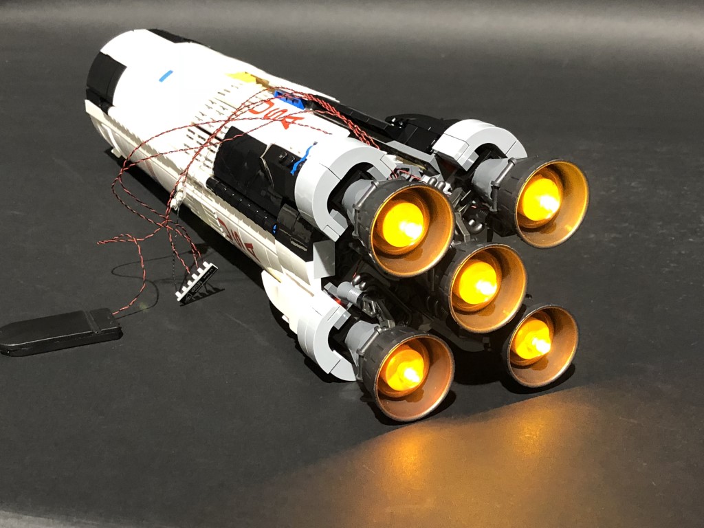
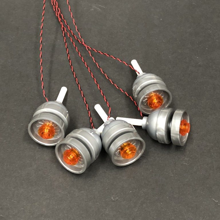
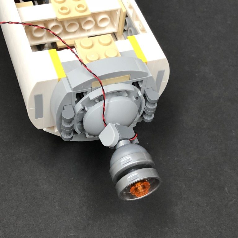
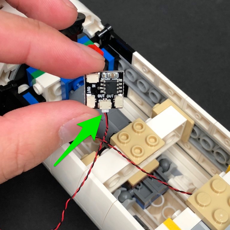


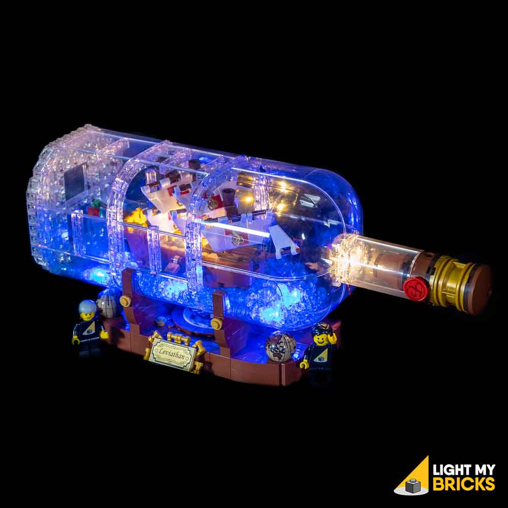
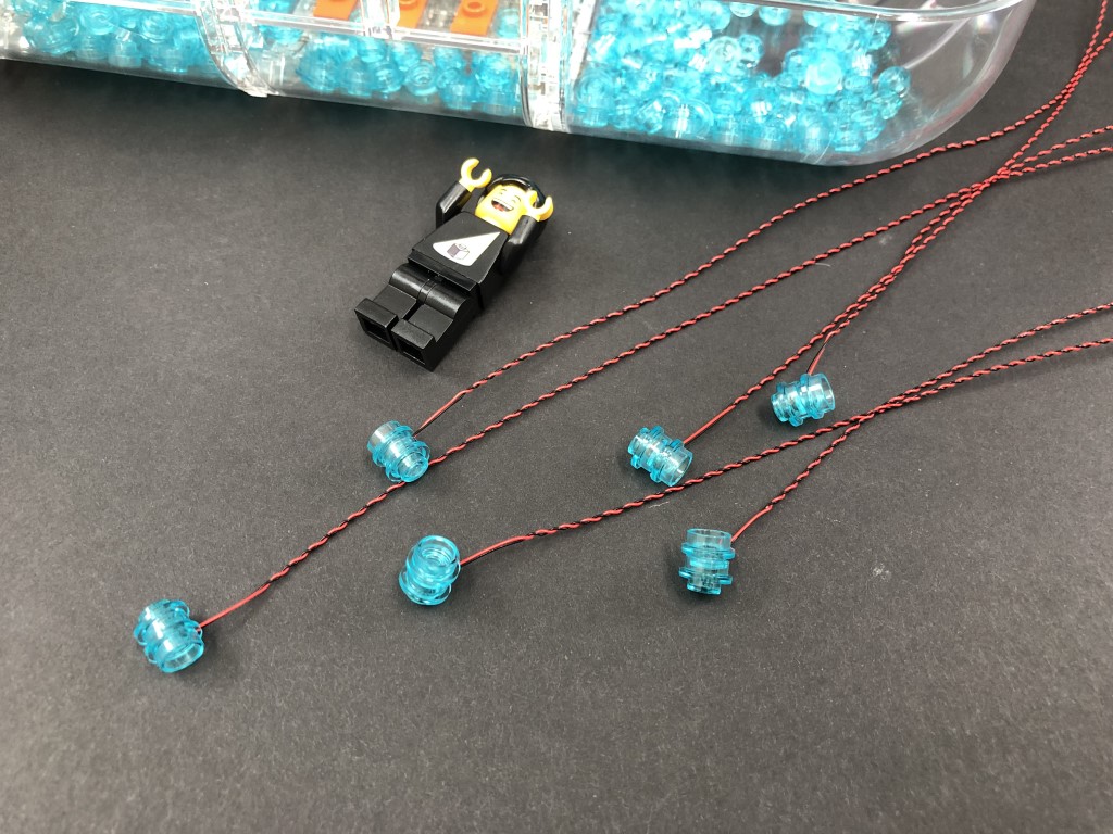
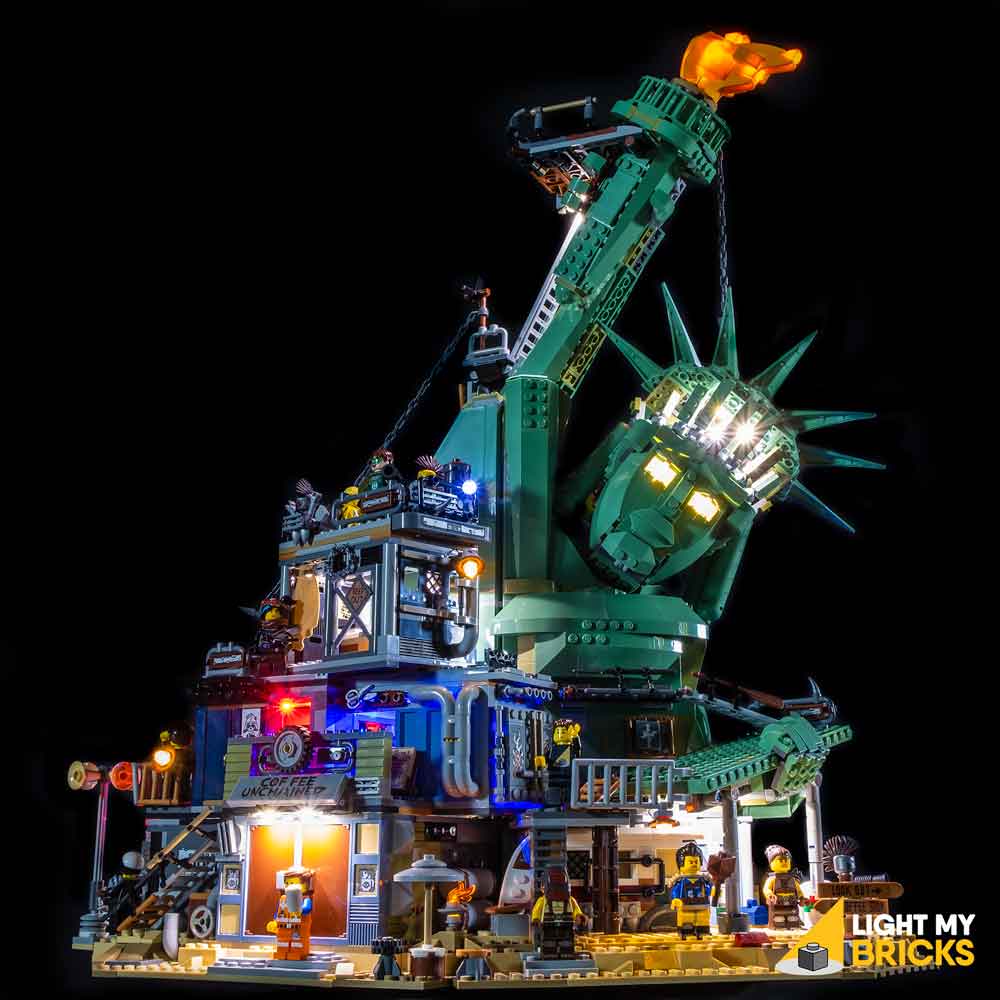
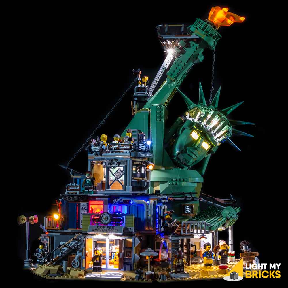
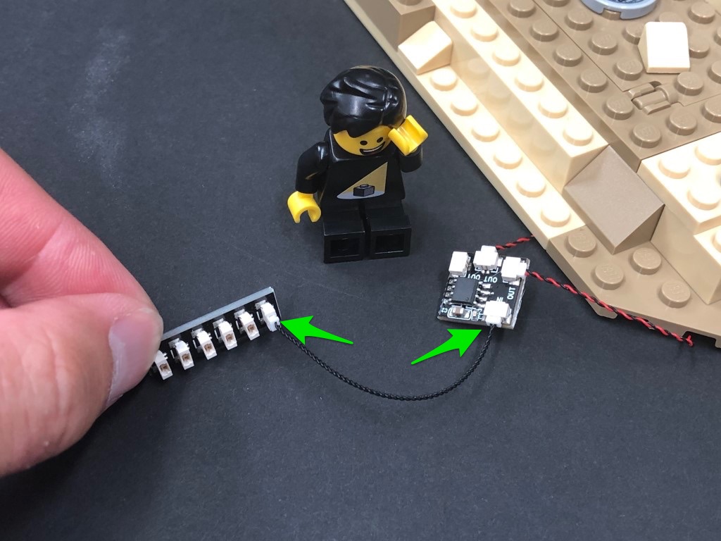
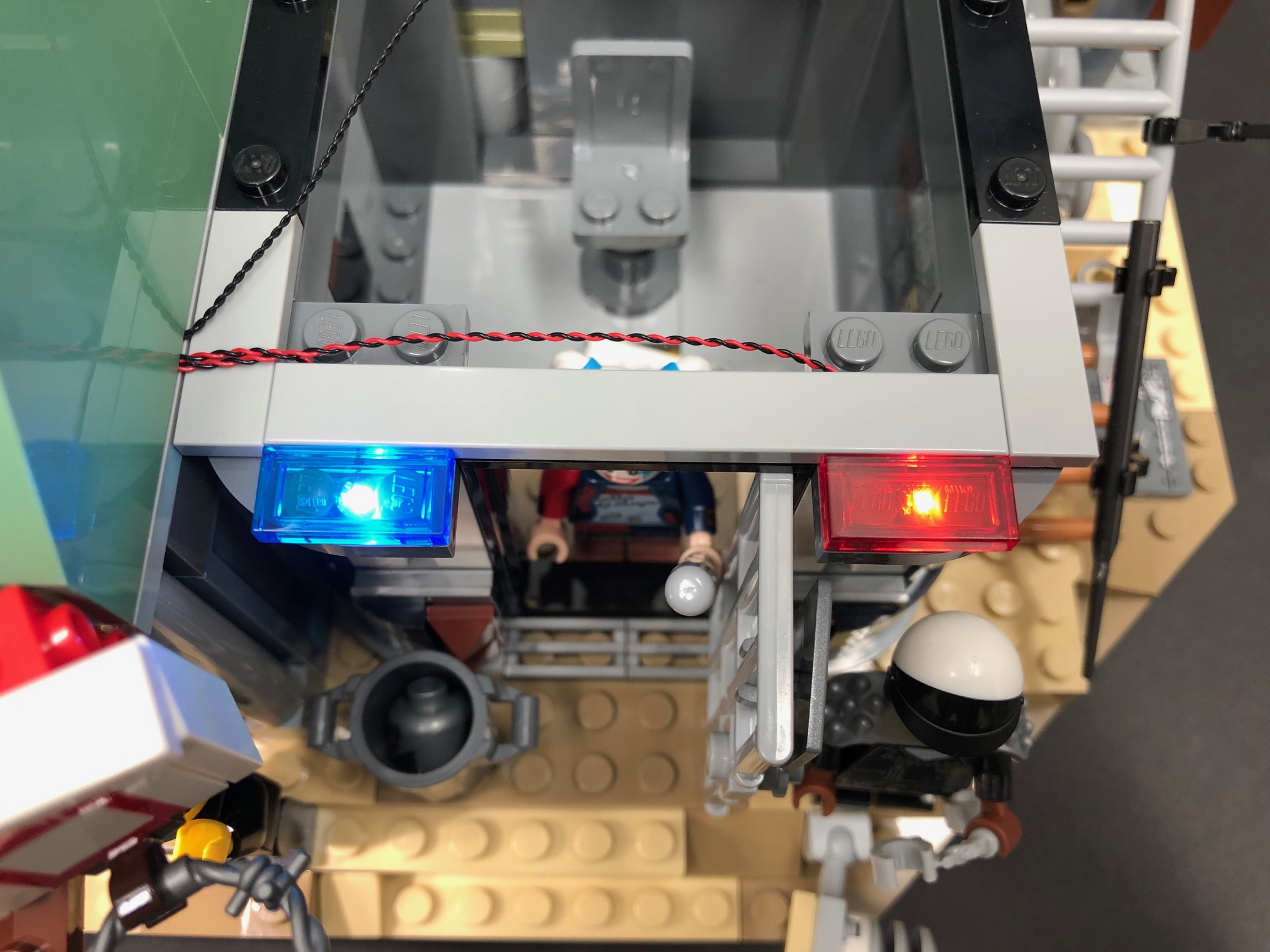
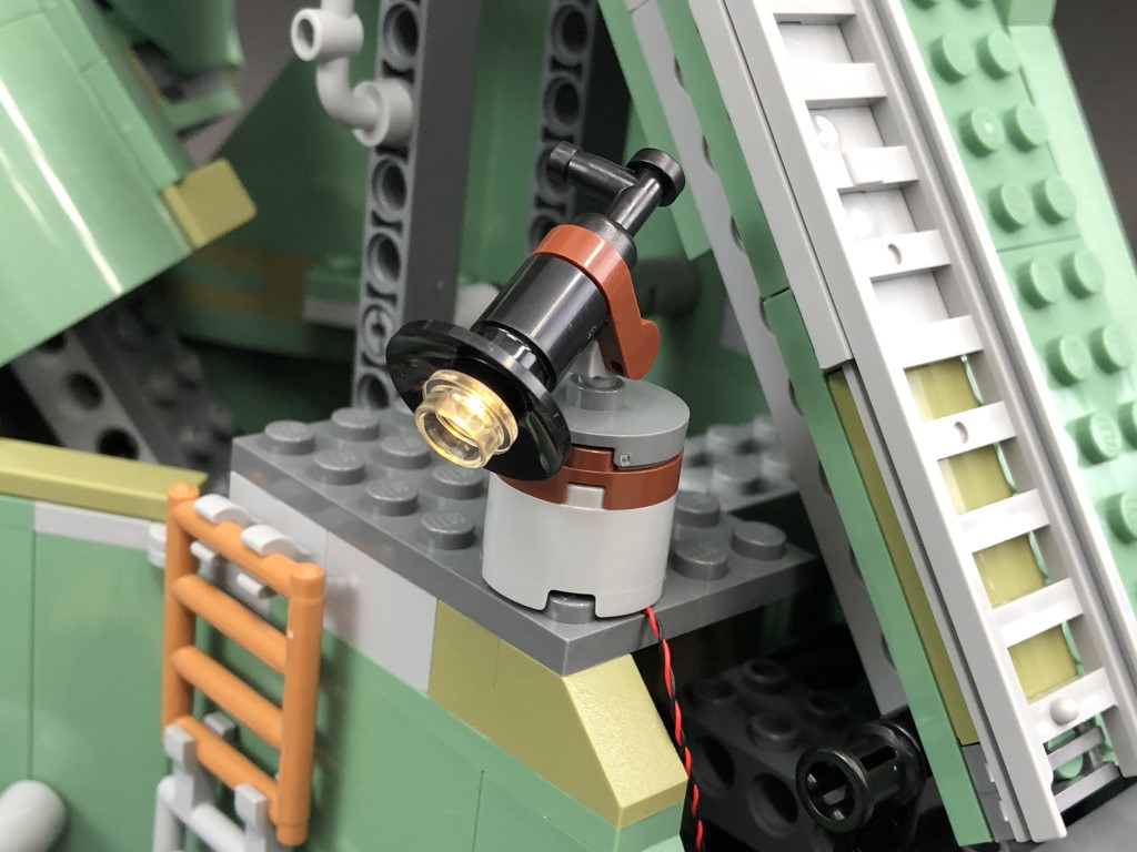
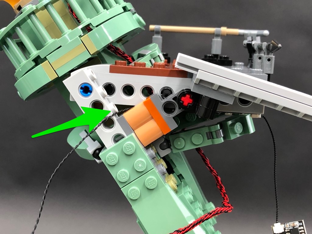
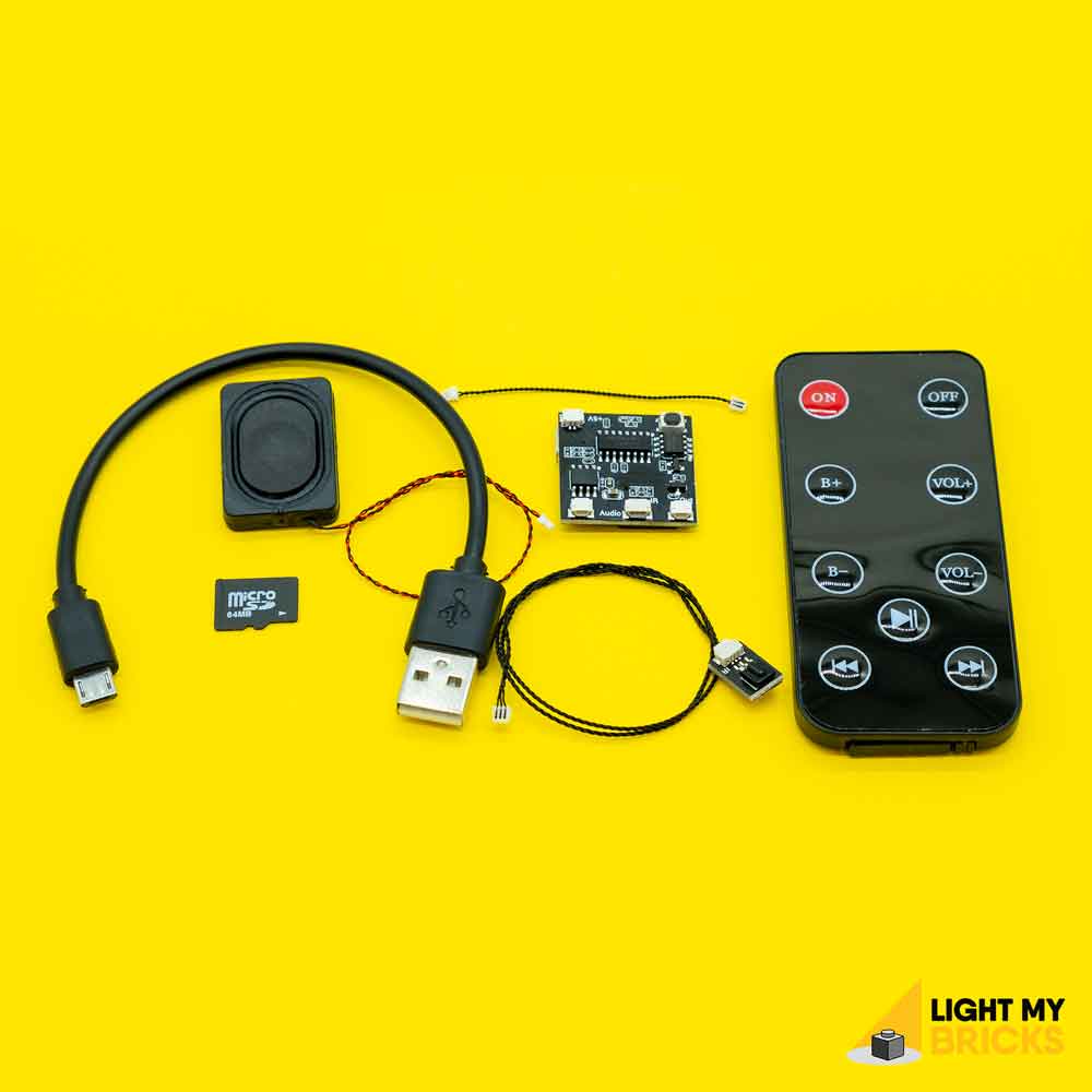

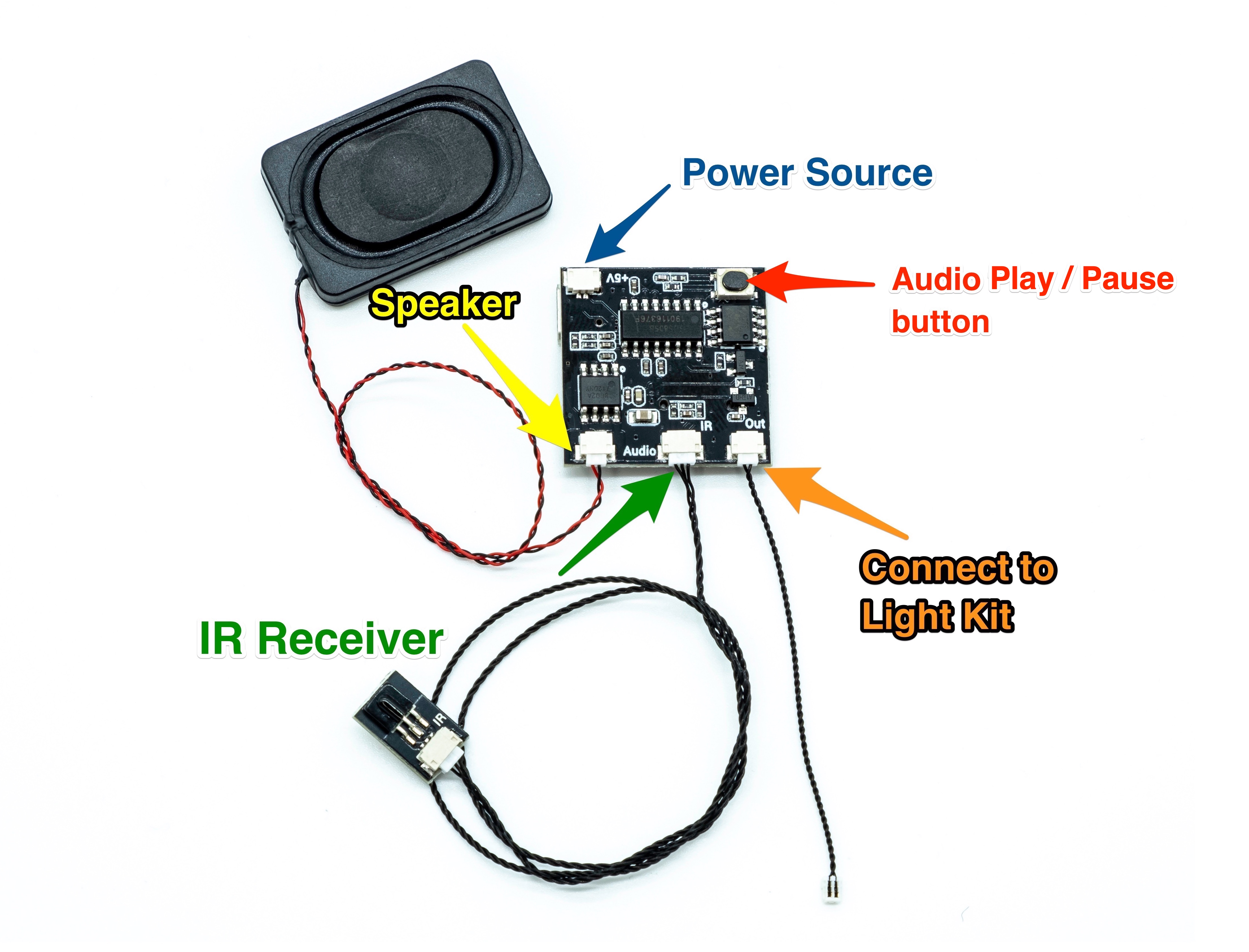
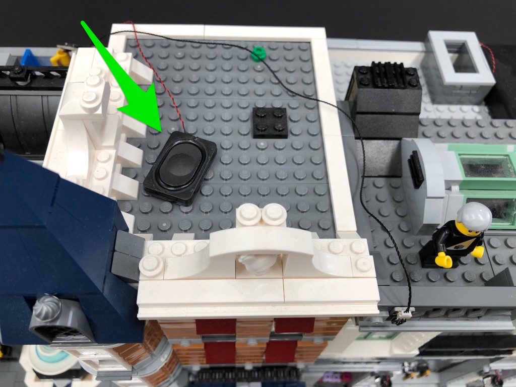


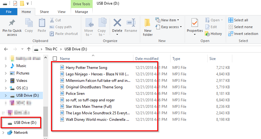

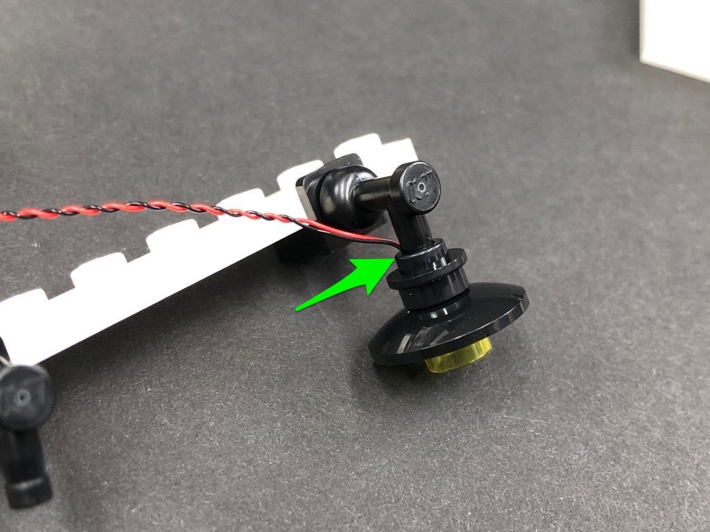 *CAUTION – This section cannot be pushed all the way in as doing so may break the wire.
14.) Repeat the previous step to install another White 15cm Bit Light to the other lamp, then reconnect this section back to the top of the garage.
*CAUTION – This section cannot be pushed all the way in as doing so may break the wire.
14.) Repeat the previous step to install another White 15cm Bit Light to the other lamp, then reconnect this section back to the top of the garage.

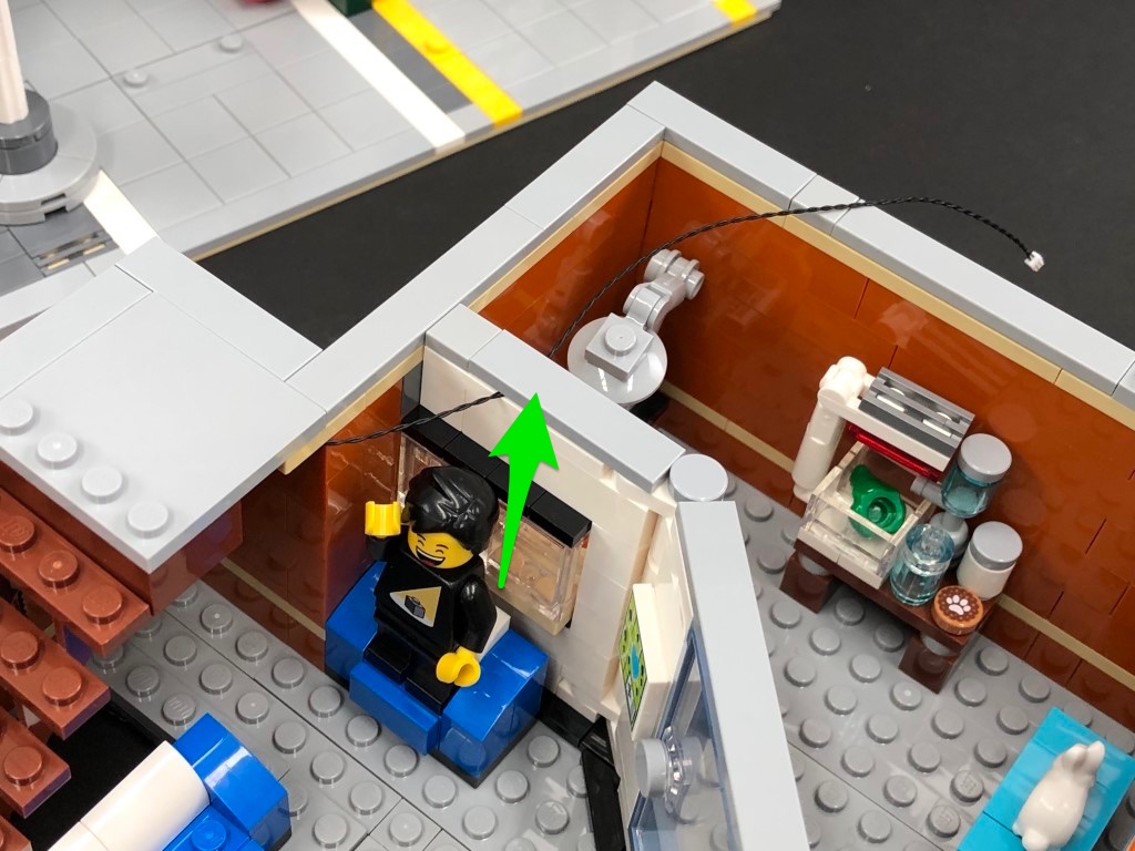

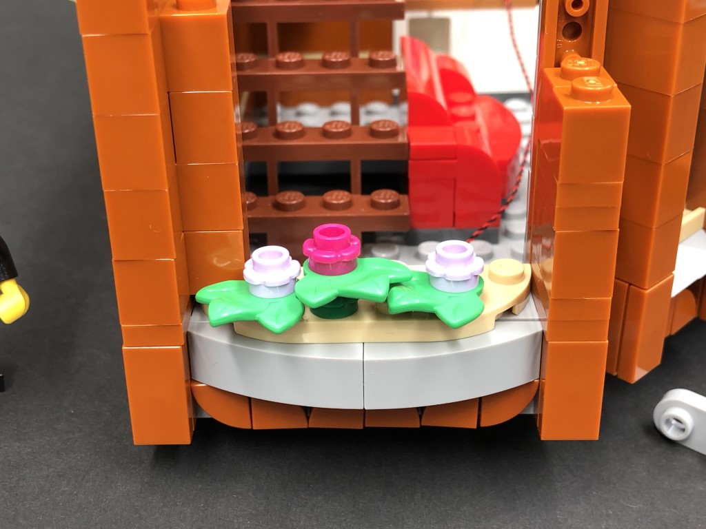


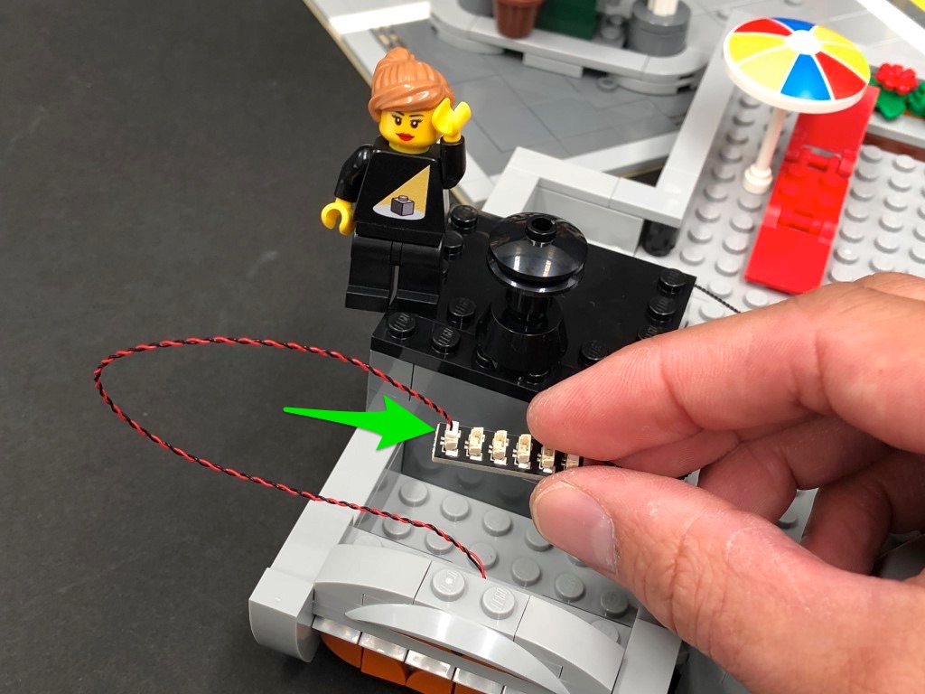

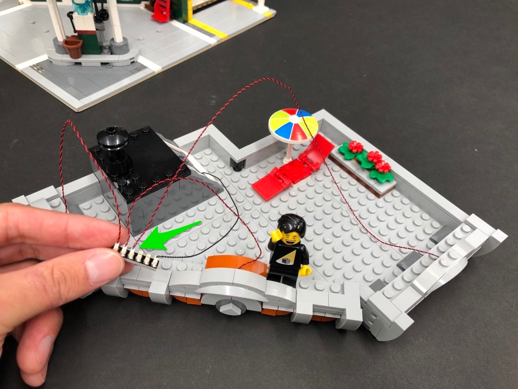

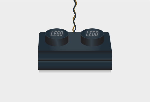
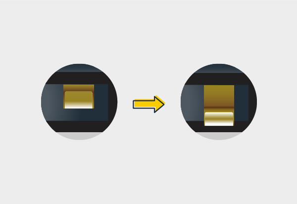

 7.) Once you are happy with the cannon effect, disconnect the AA Battery Pack / USB Cable and connect a 15cm Connecting Cable to the IN port. Take 4x Adhesive Squares and stick them to the back of the multi effects board, then flip the Y-Wing over and stick the effects board underneath in the following position.

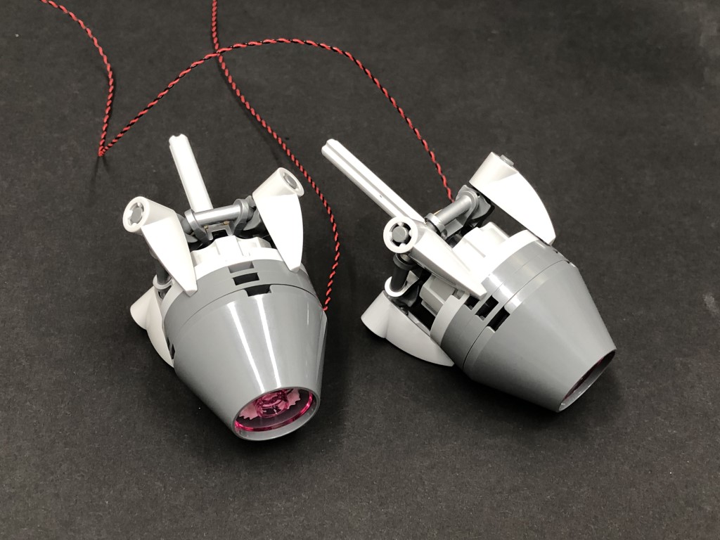
 25.) Disconnect the AA Battery Pack / USB Cable and take the remaining 30cm Connecting Cable and connect it to a spare port on the Expansion Board then disconnect the following brown bar.
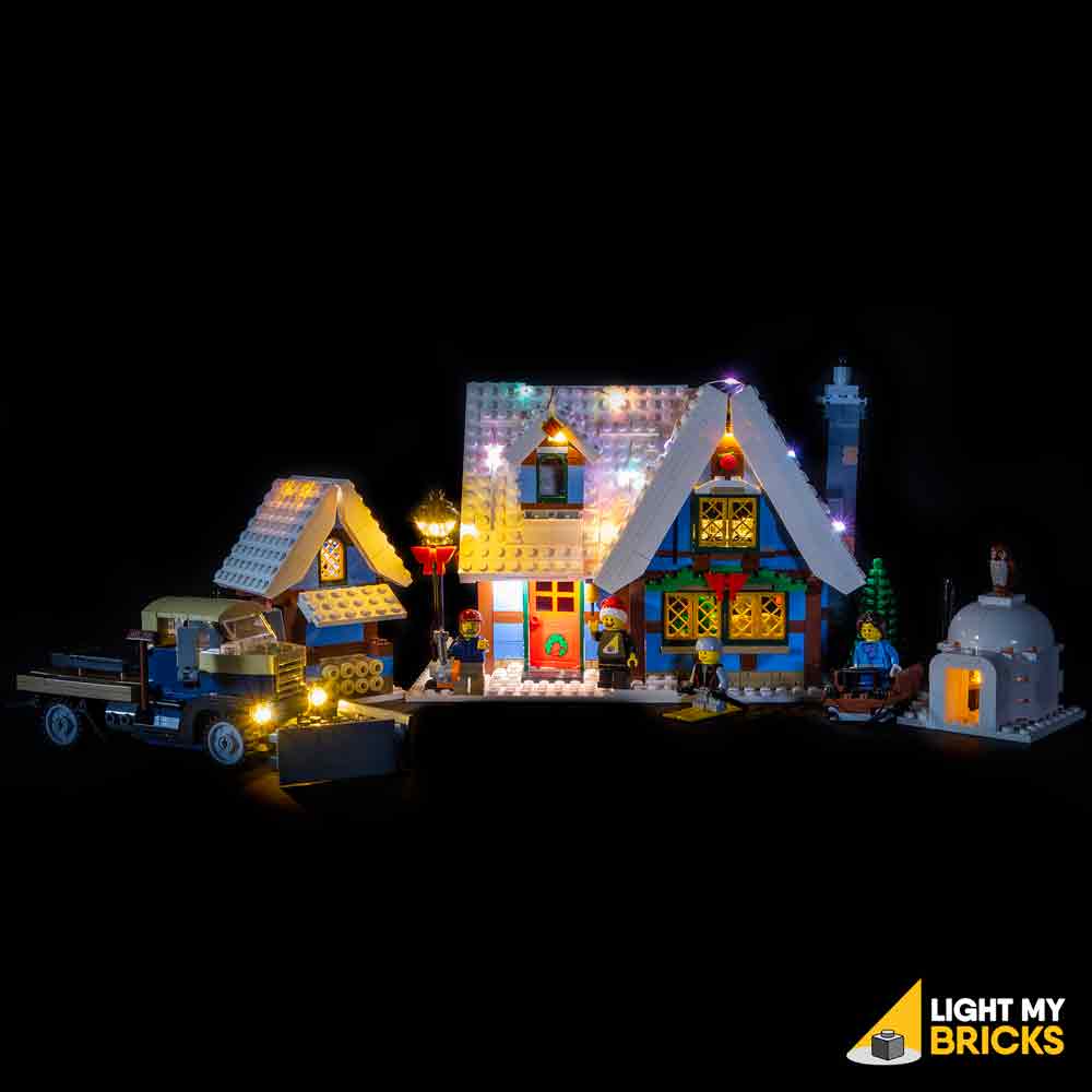
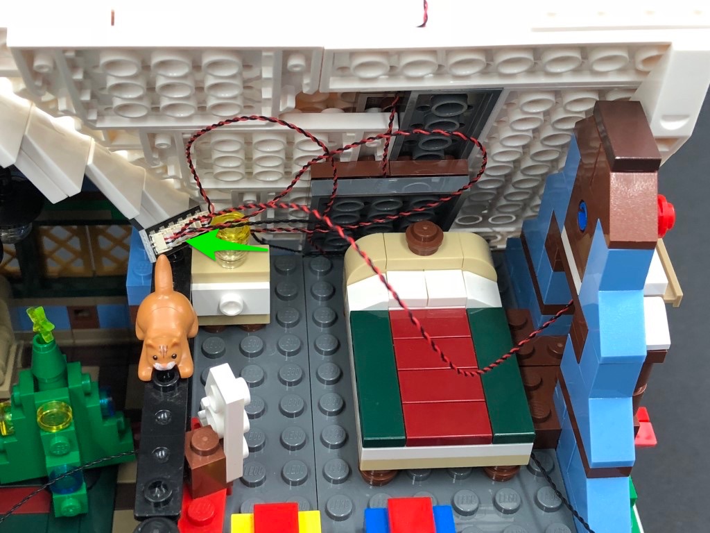


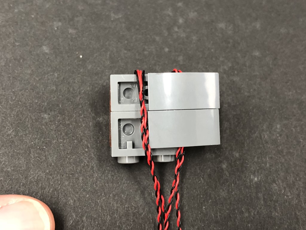
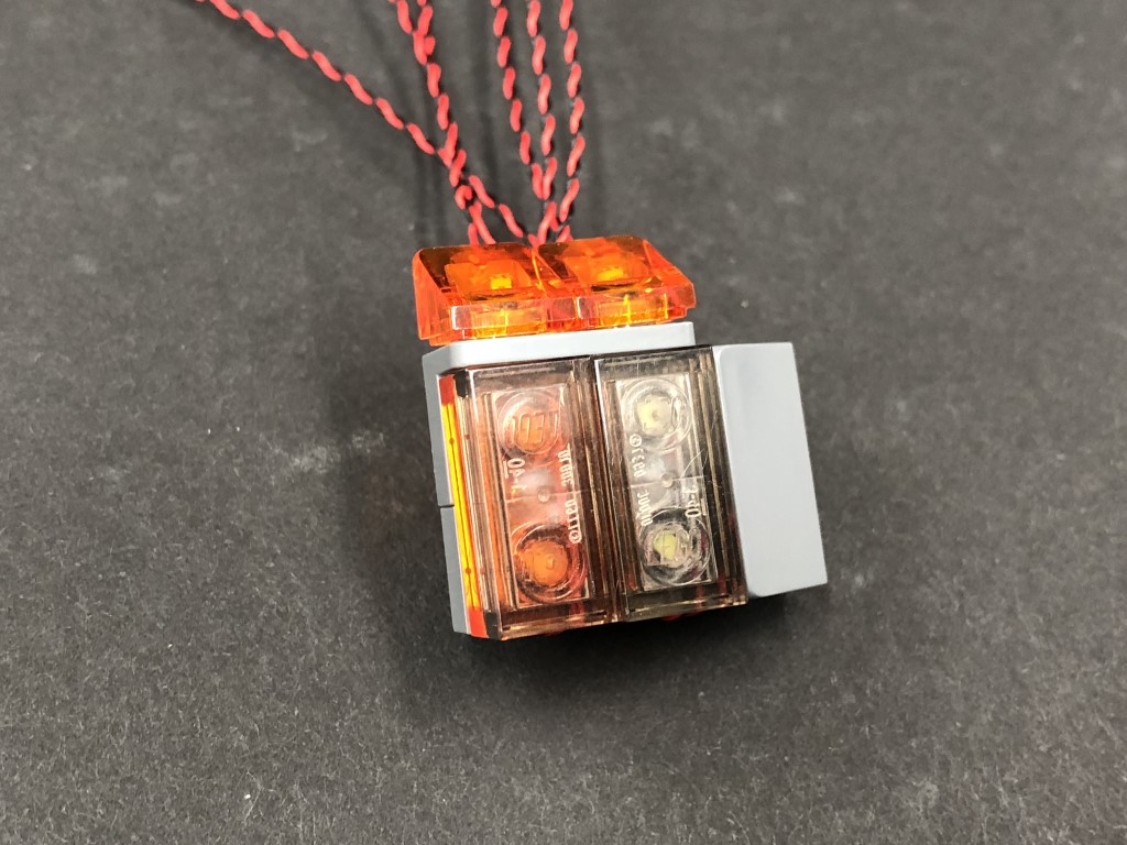


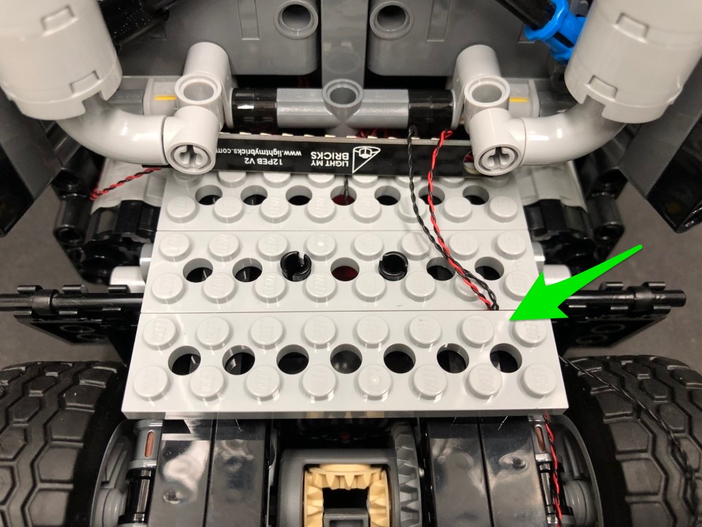

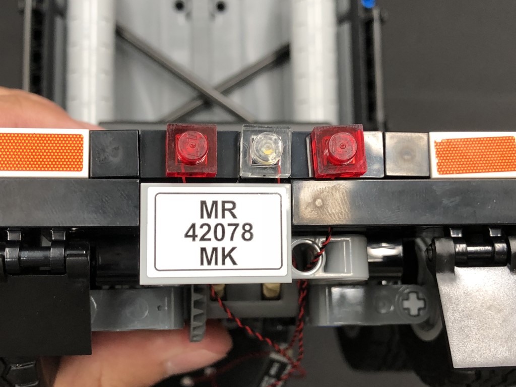
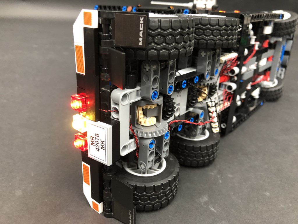


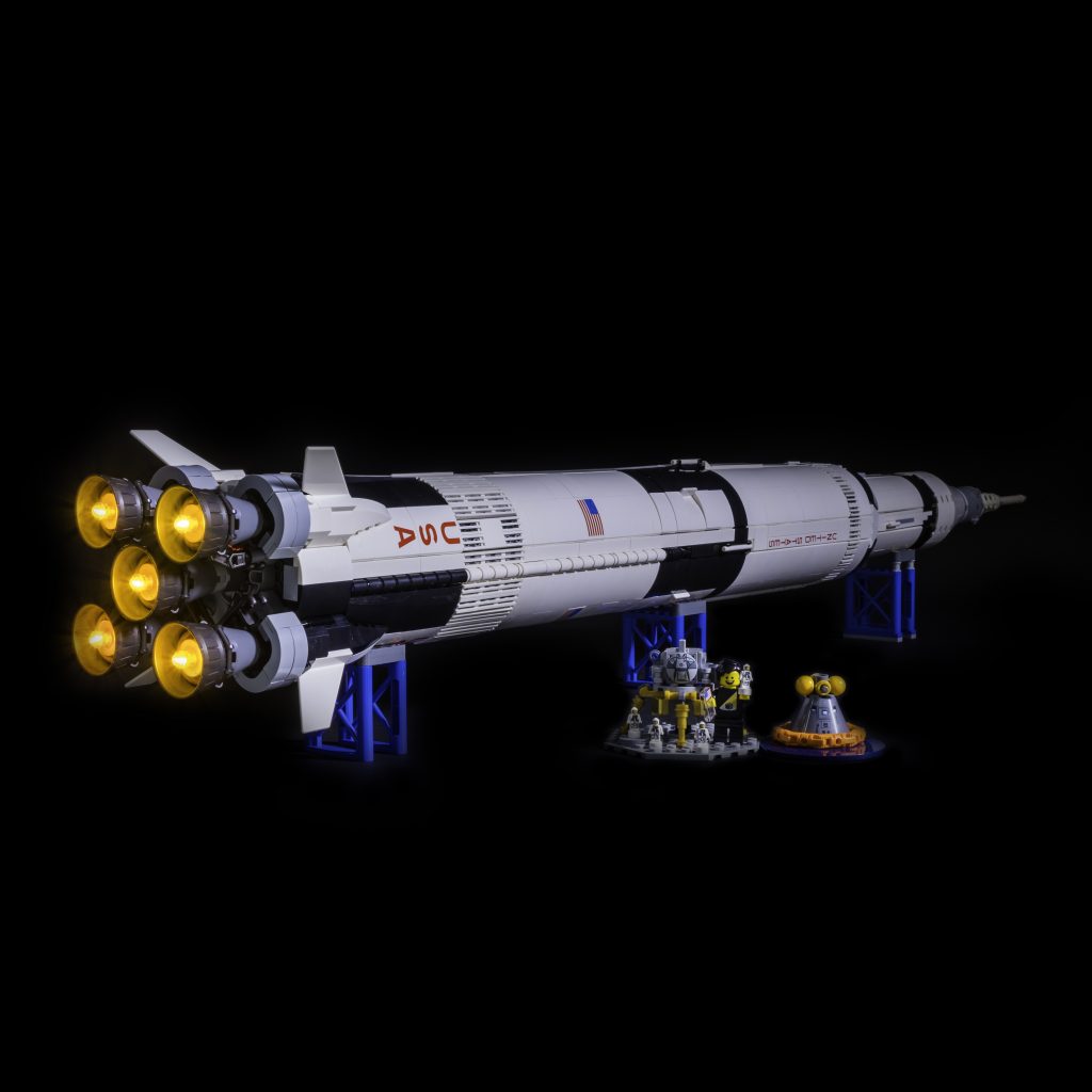
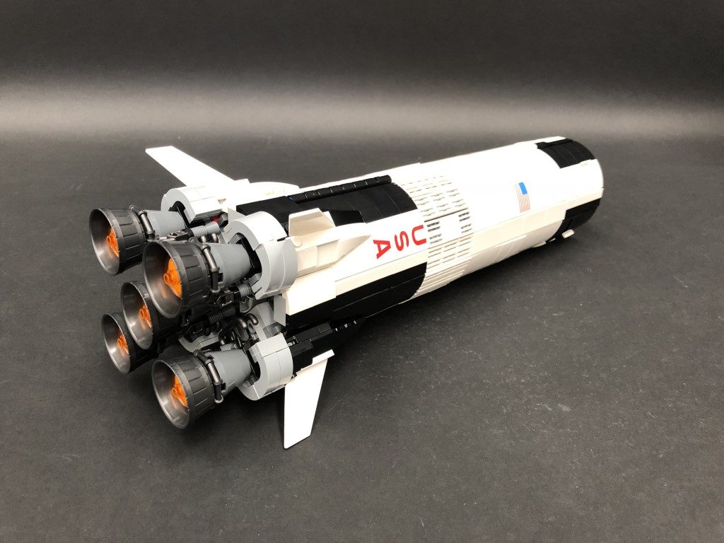
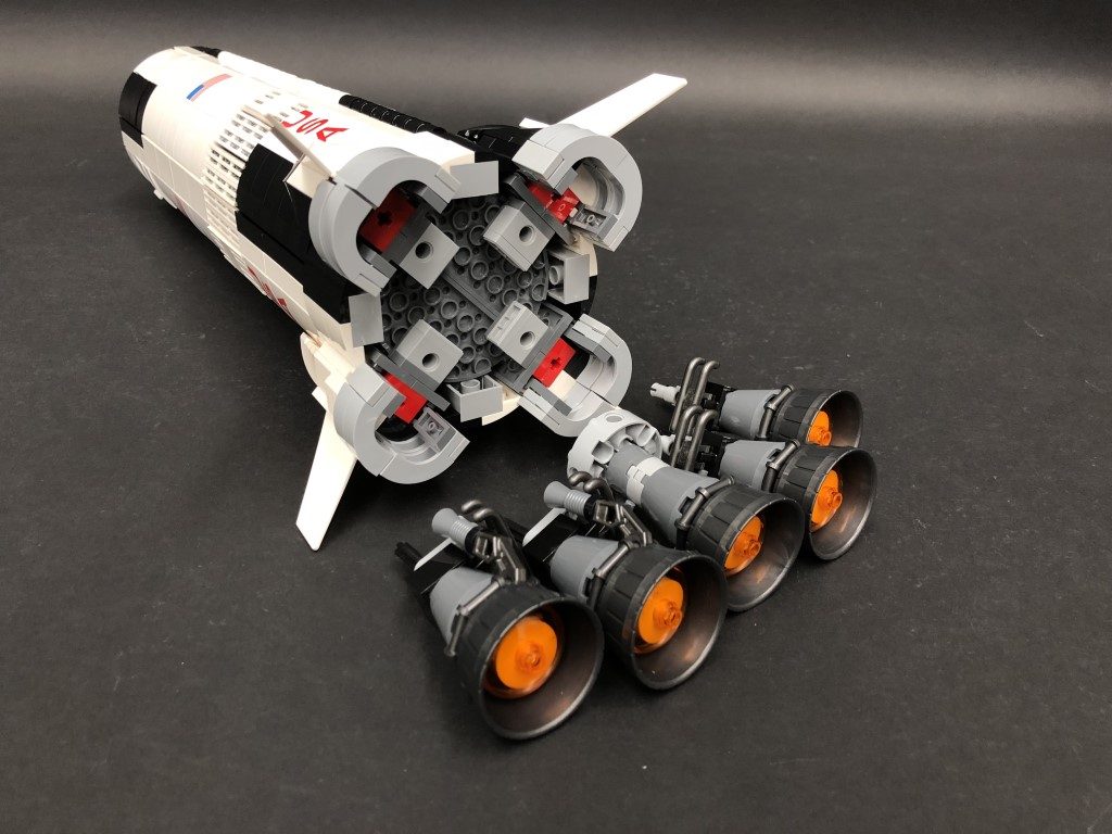
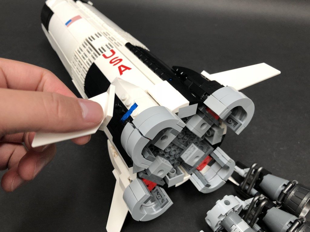
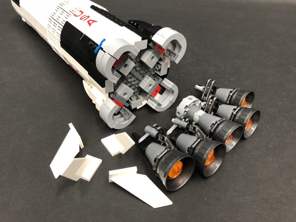
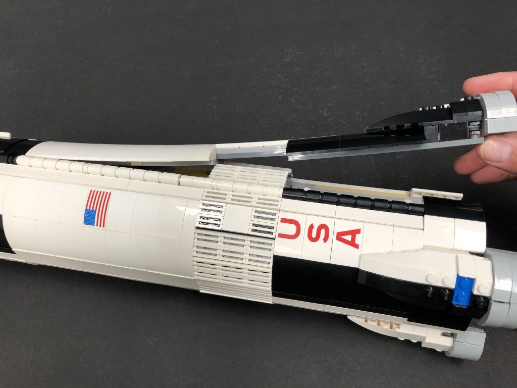
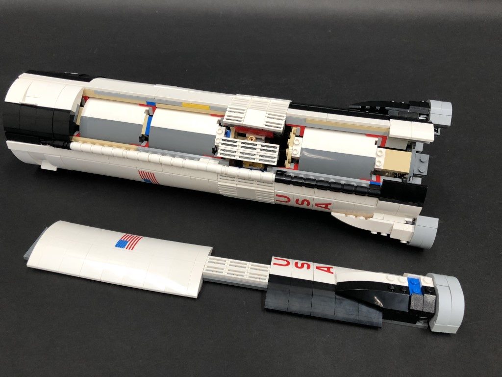
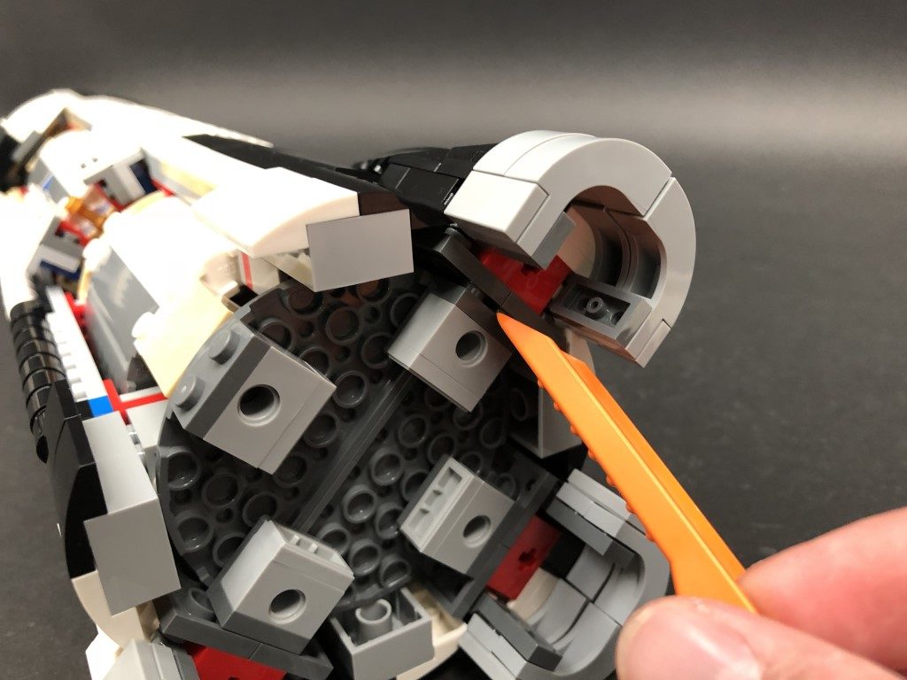
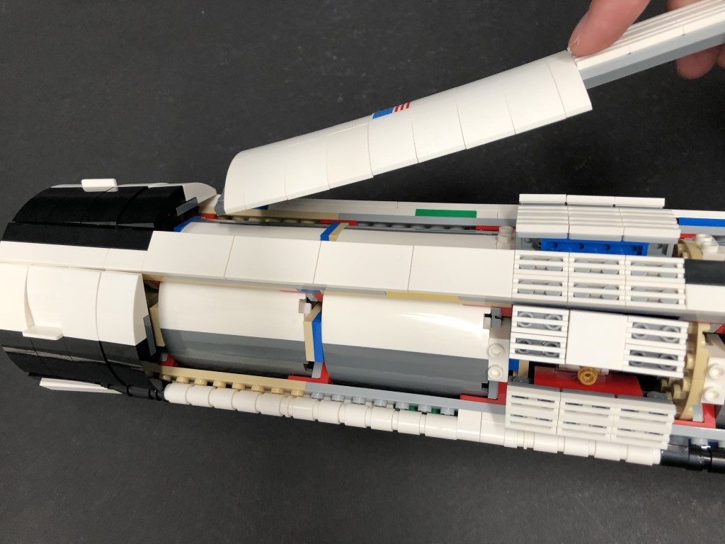
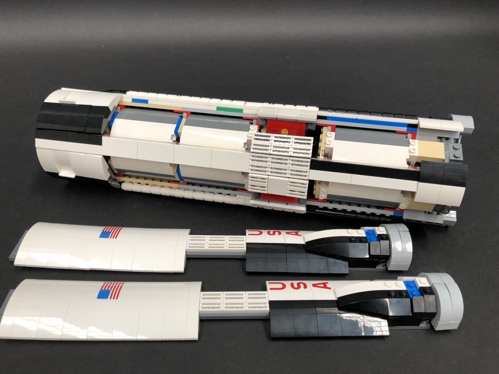
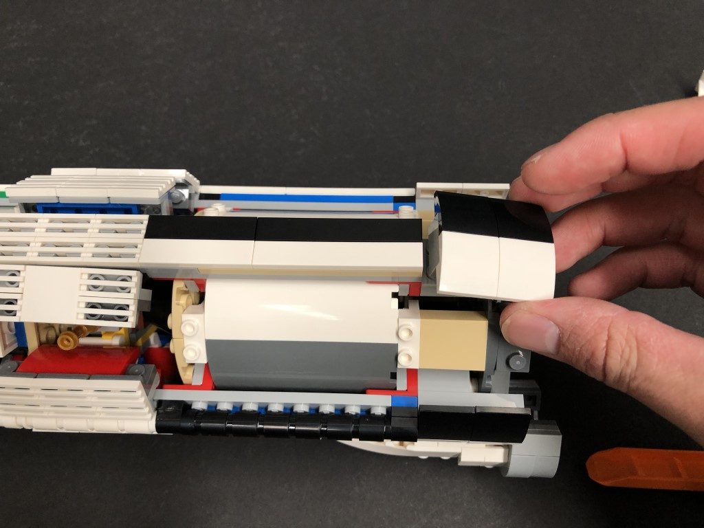
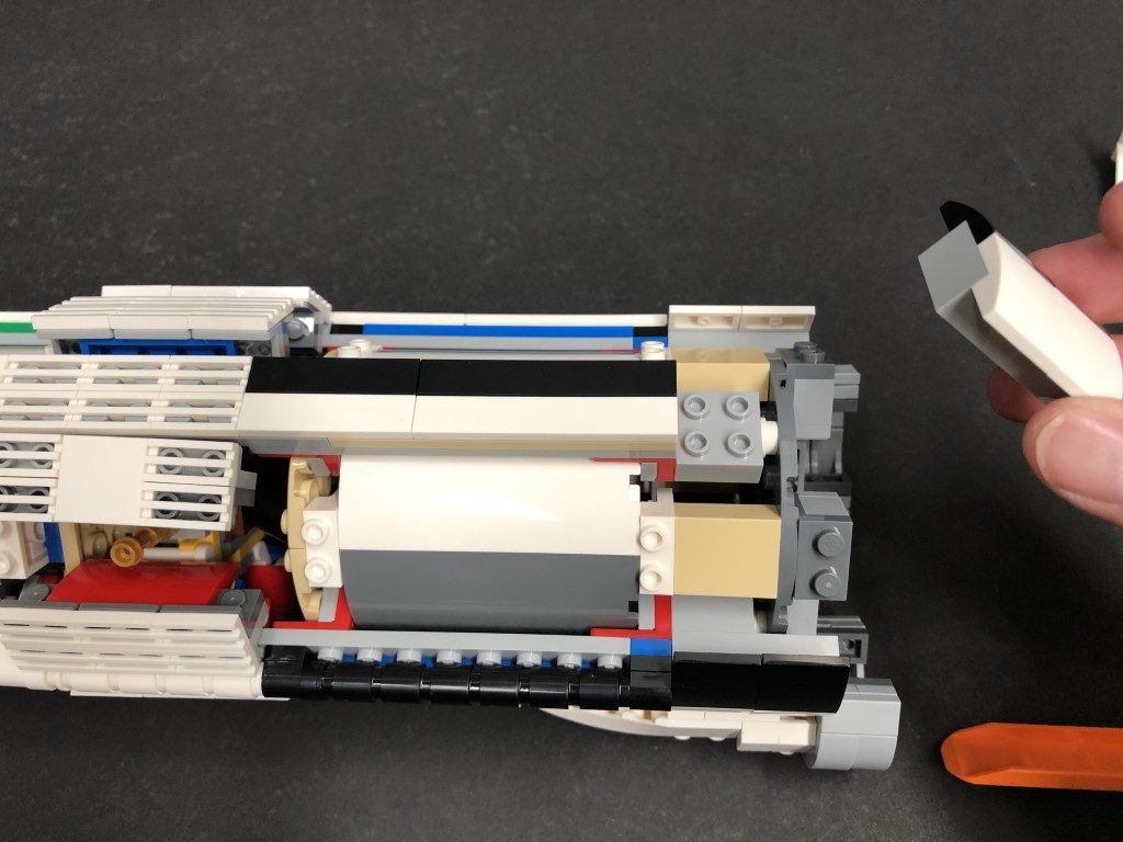
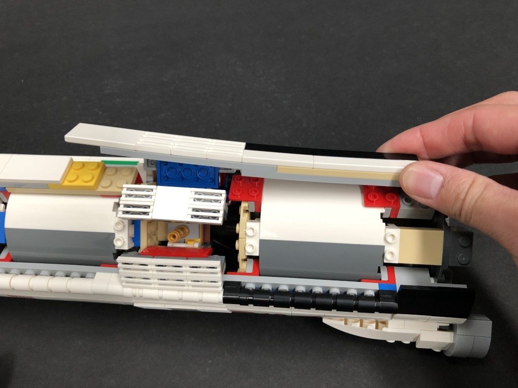
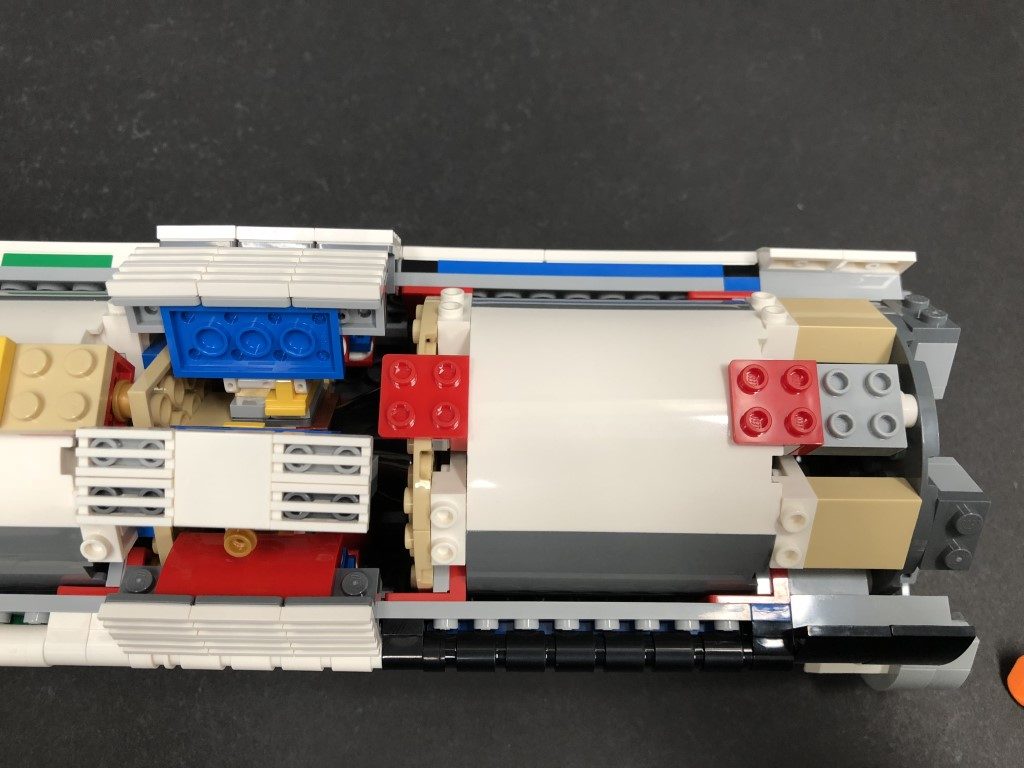
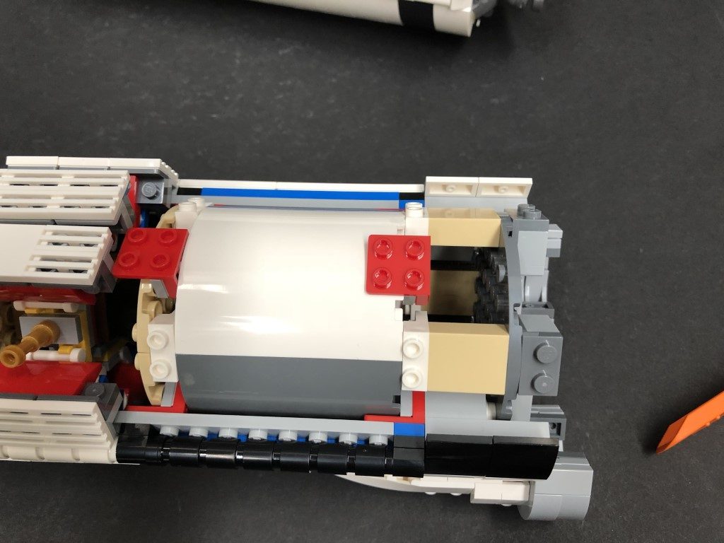
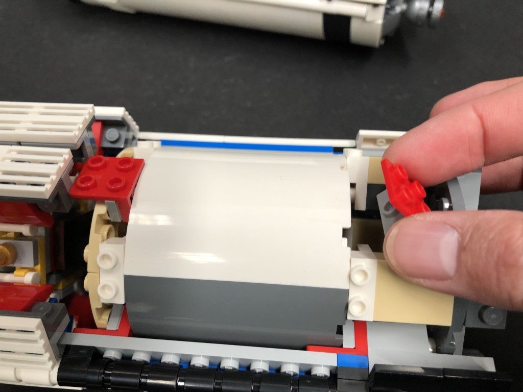
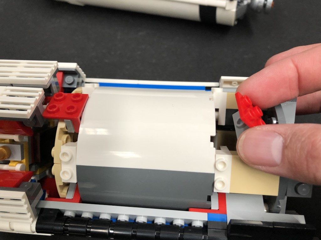
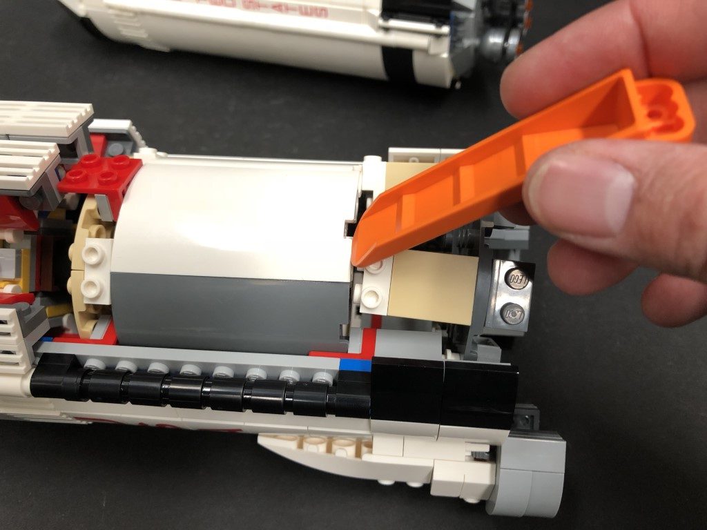
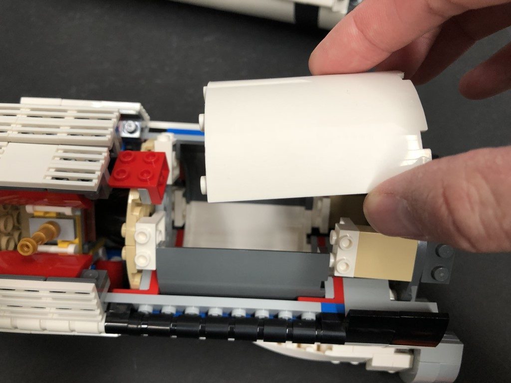
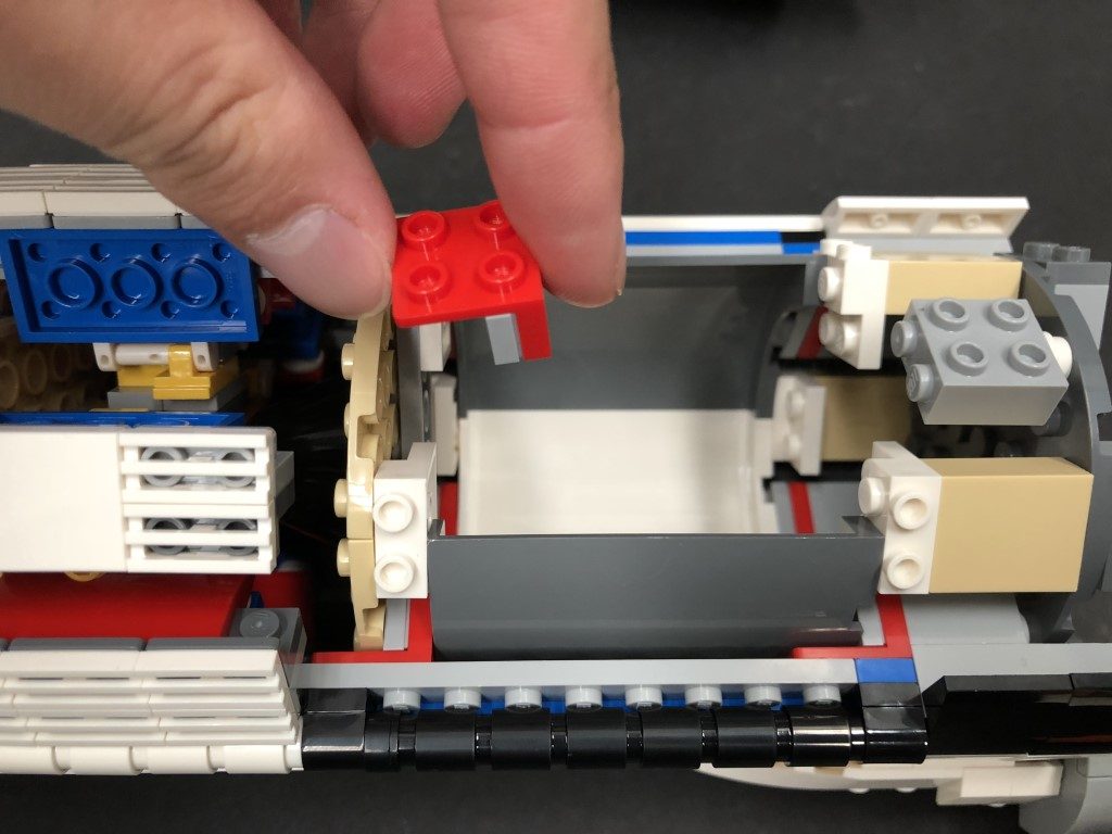
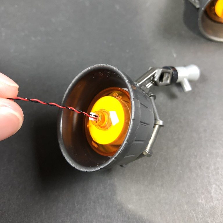
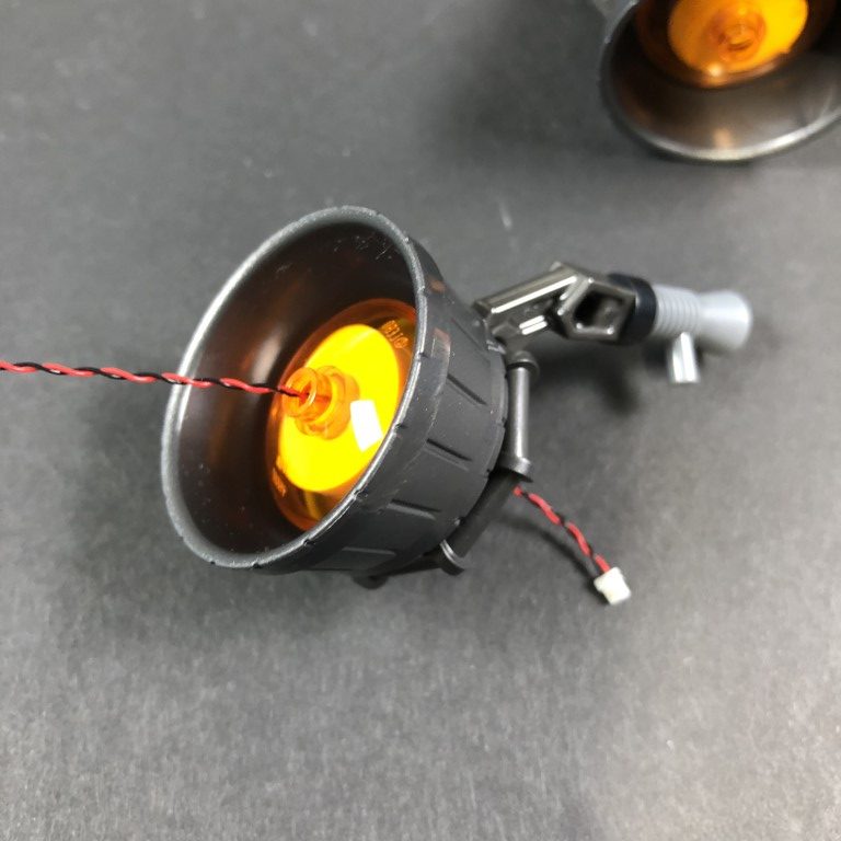
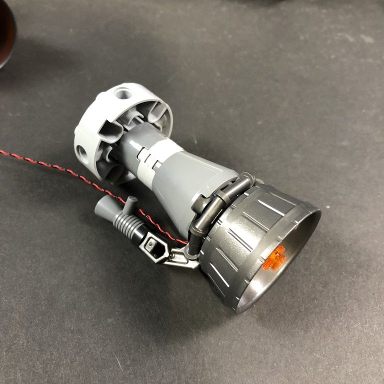
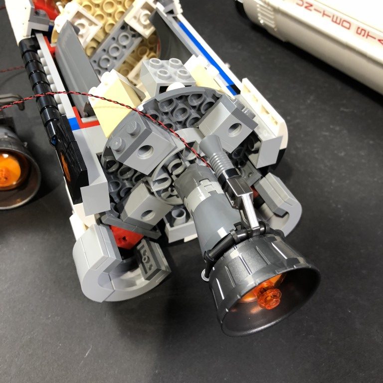
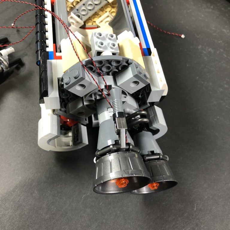
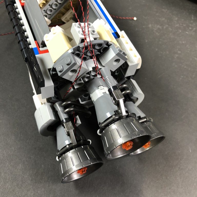
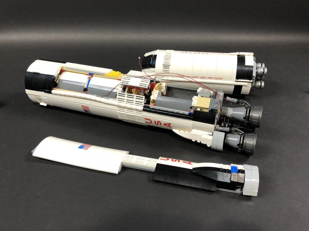
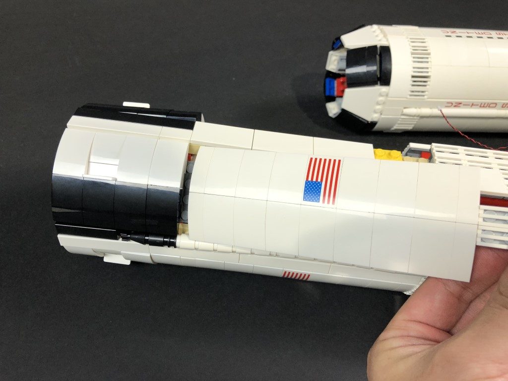
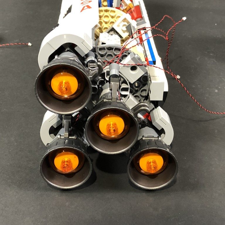
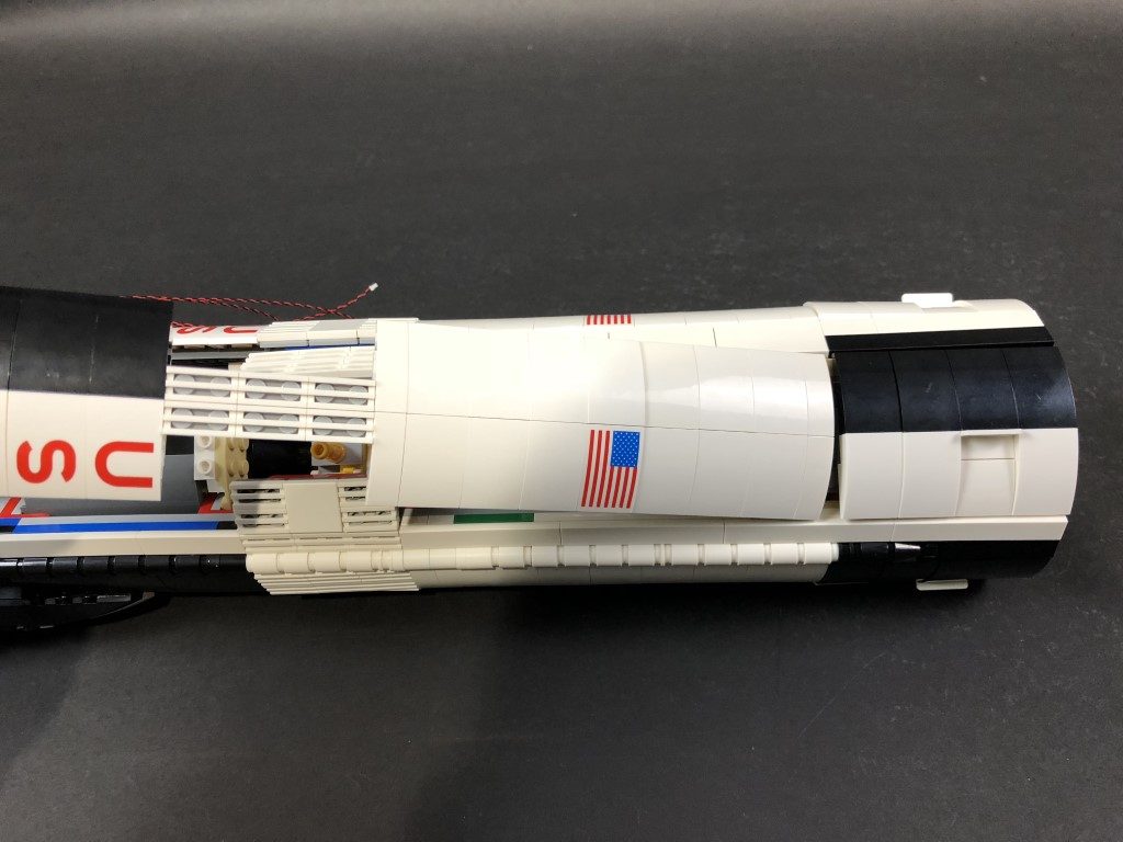
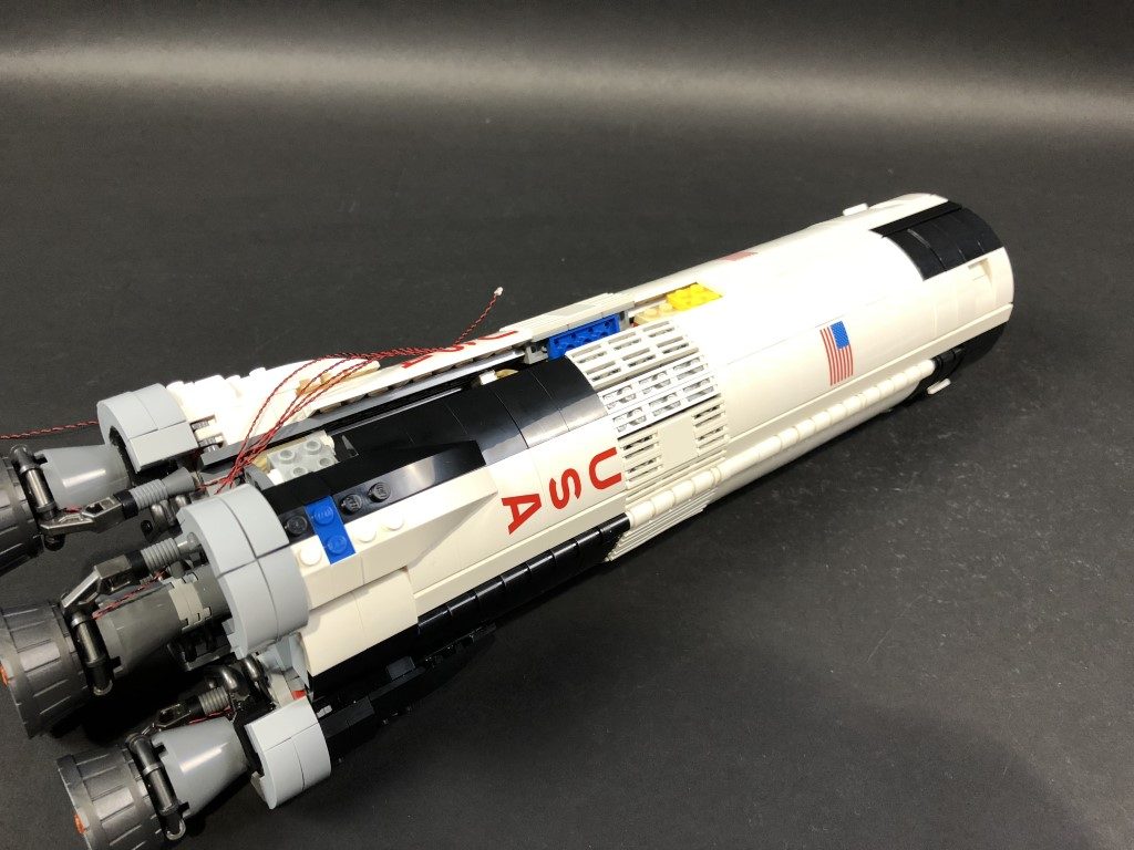
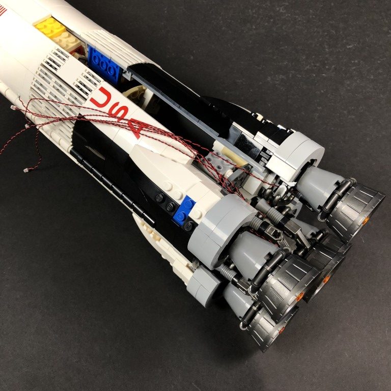
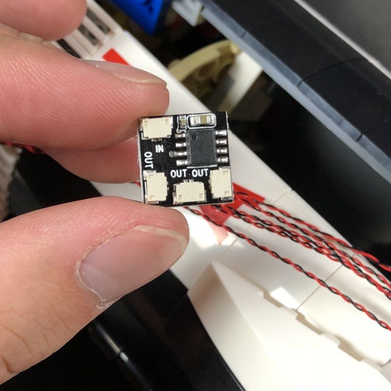
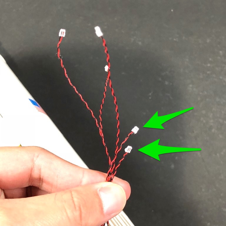
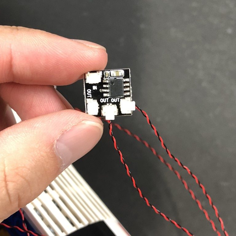
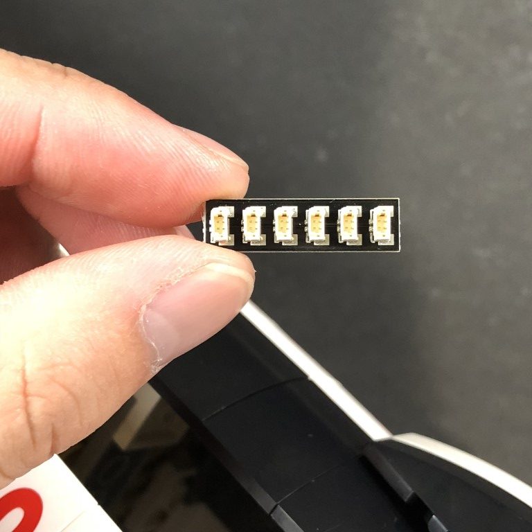
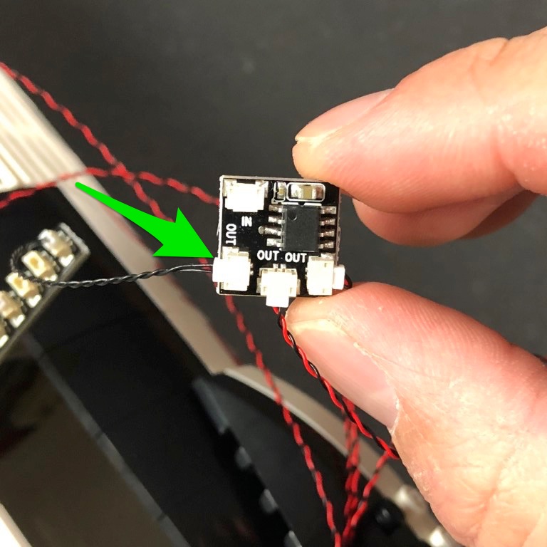
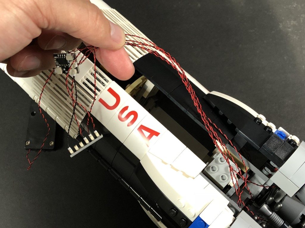
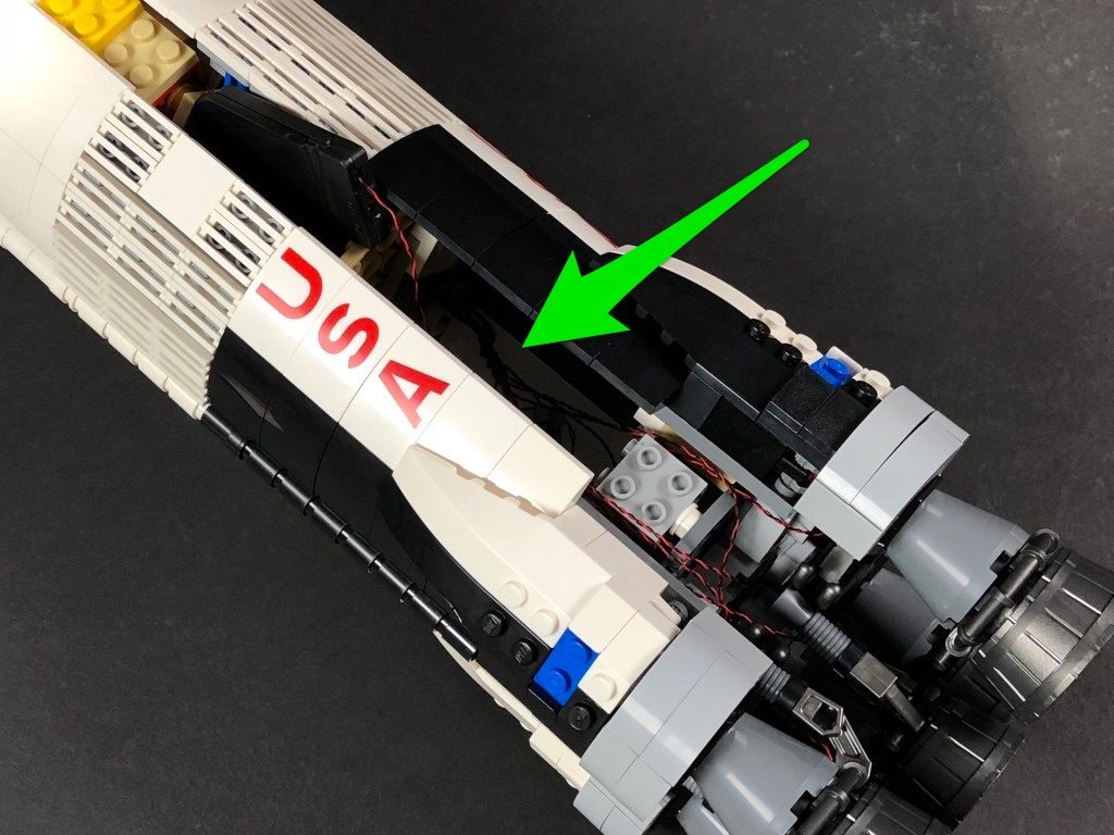
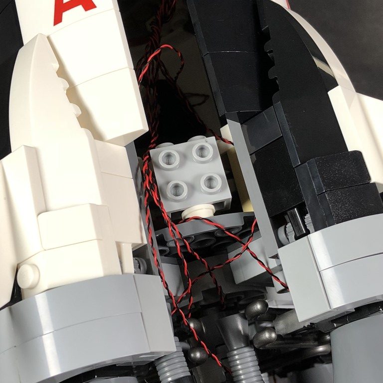
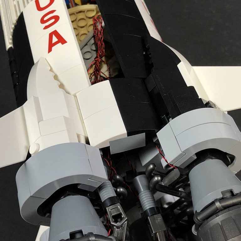
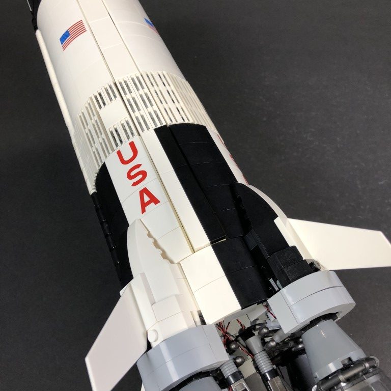
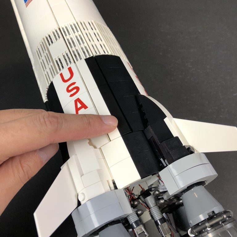
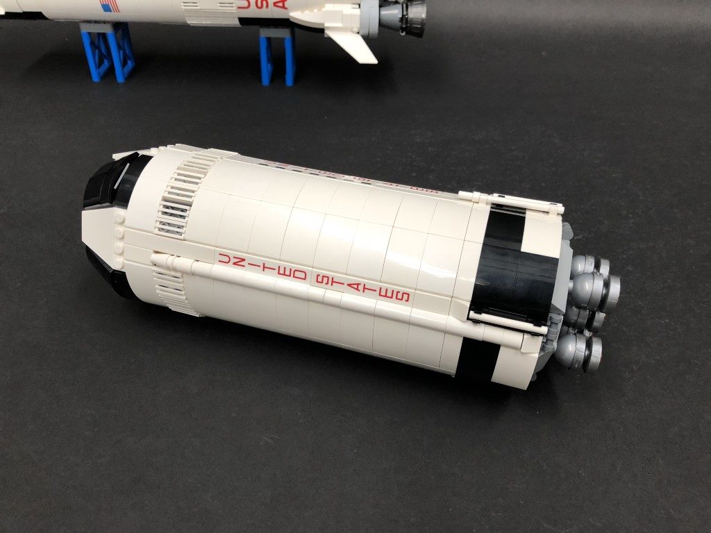
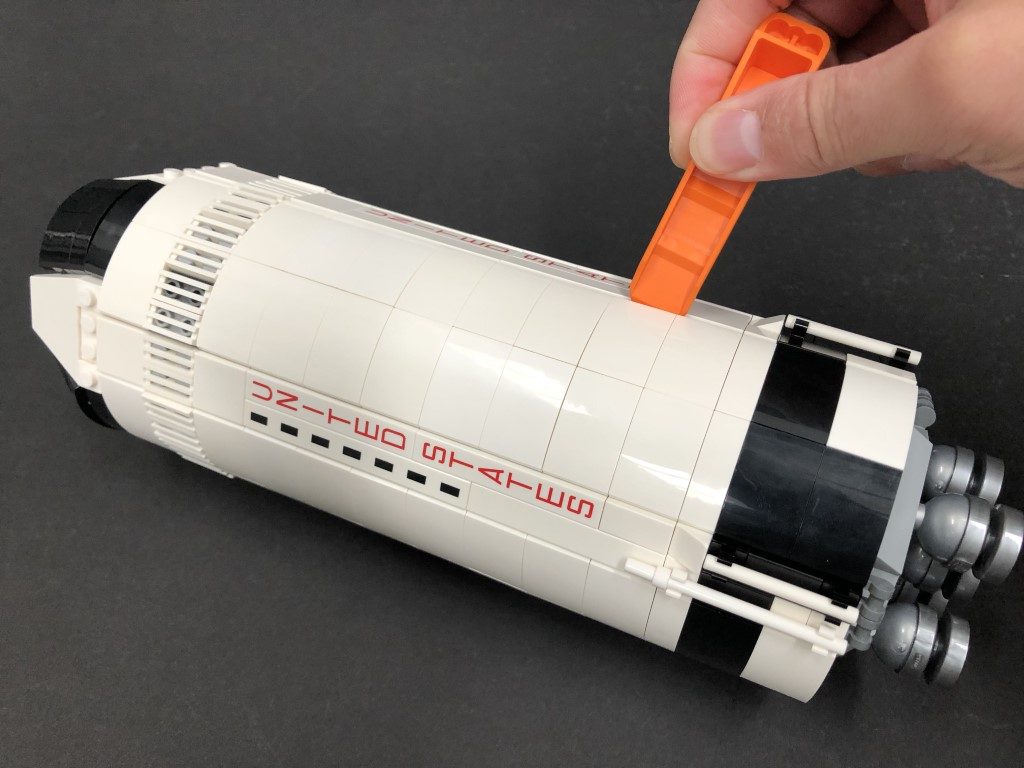
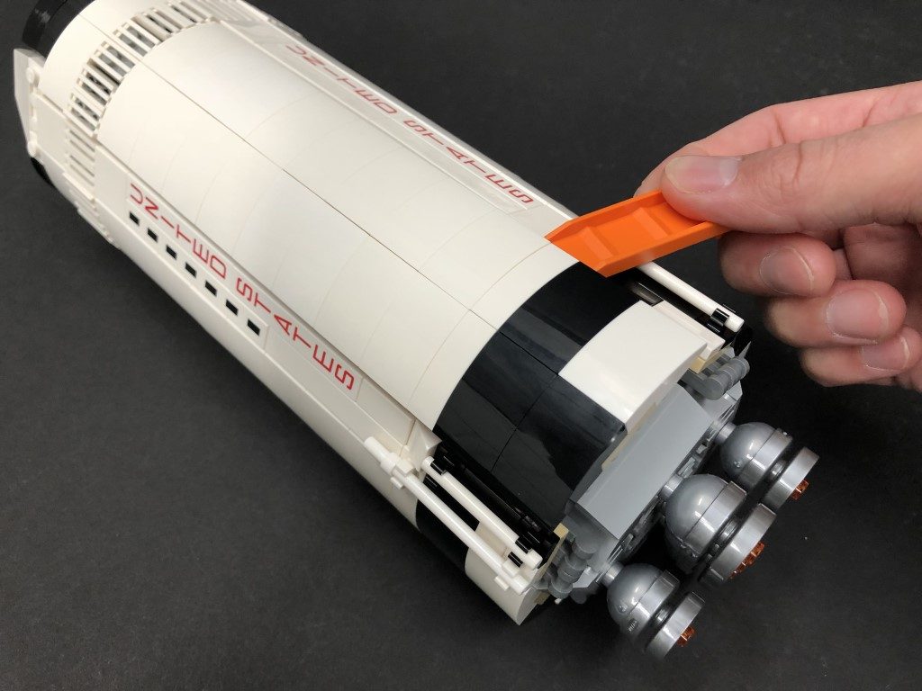
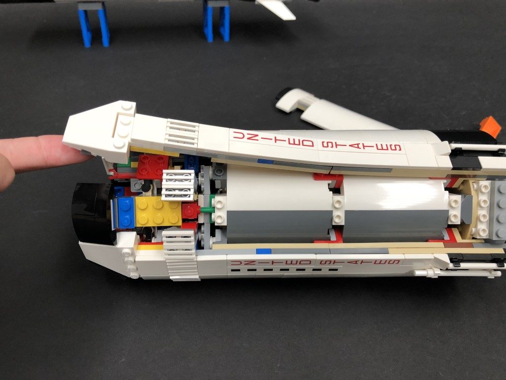
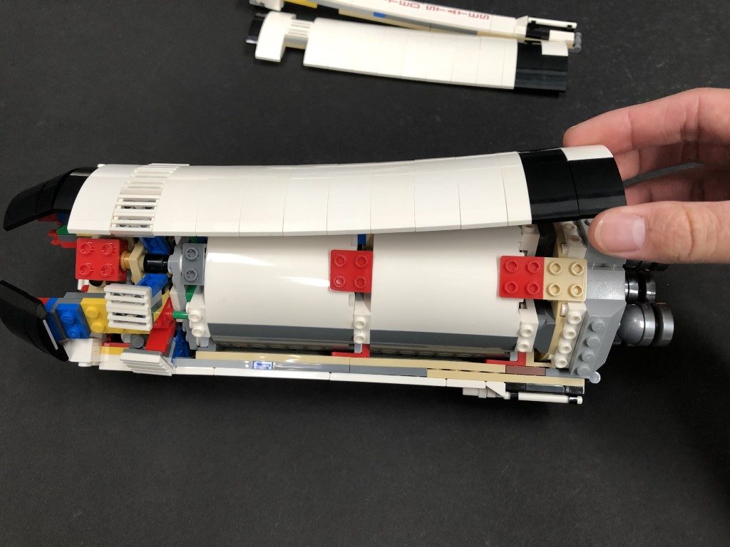
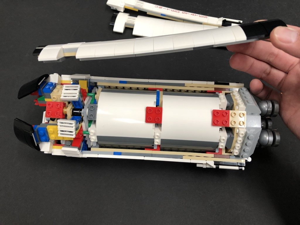
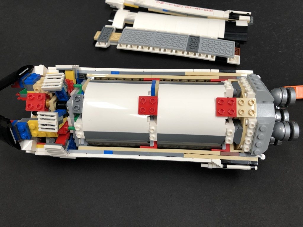
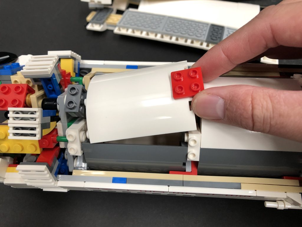
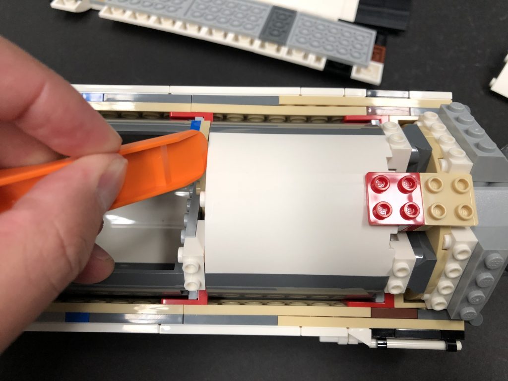
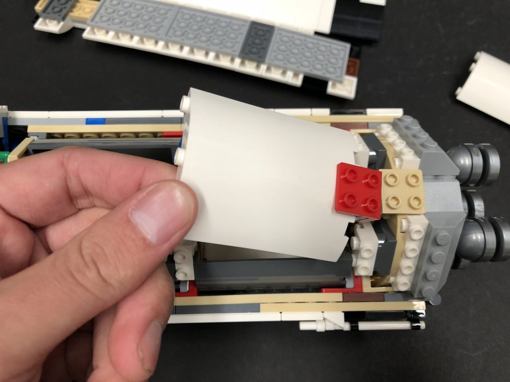
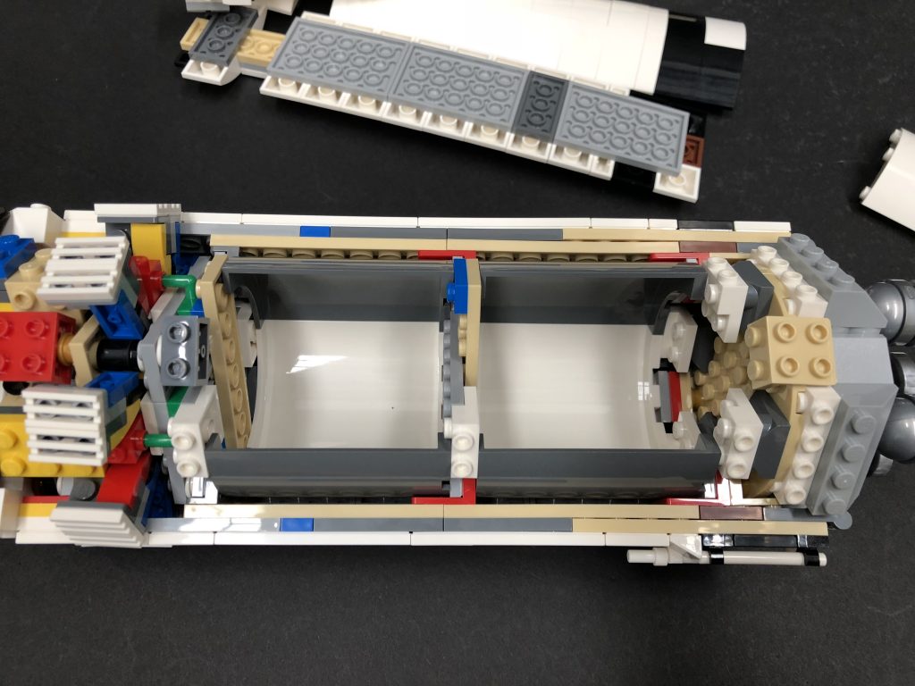
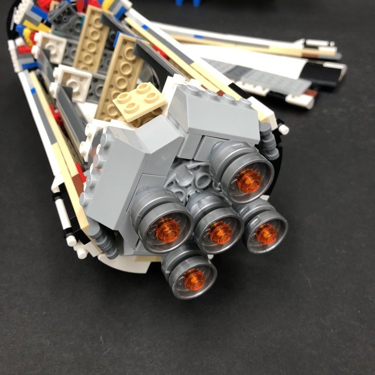
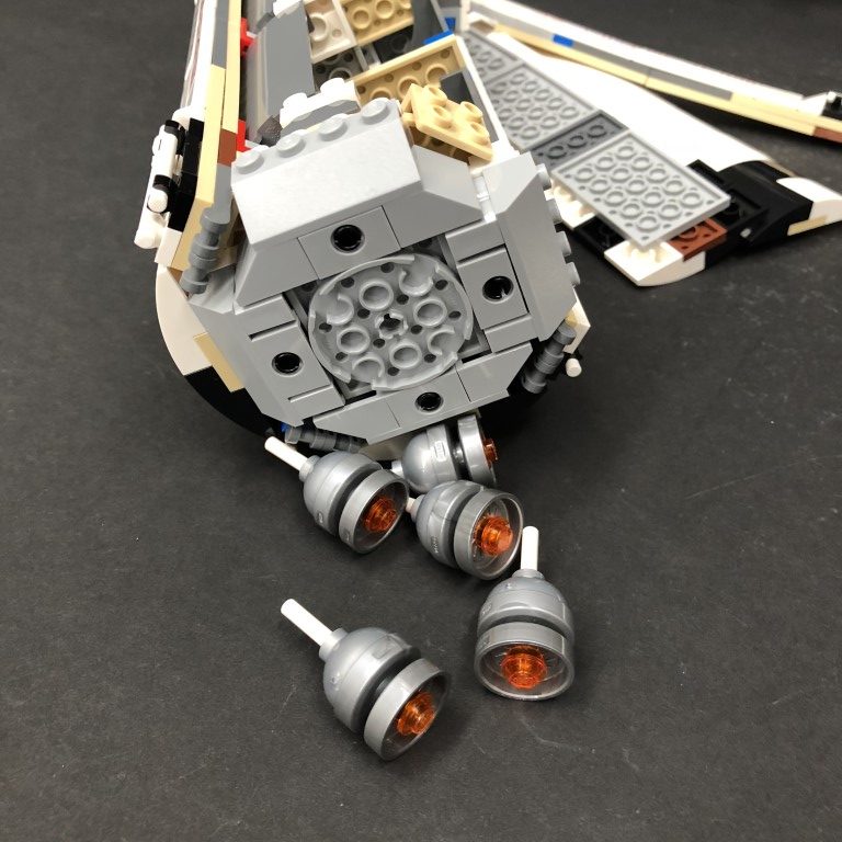
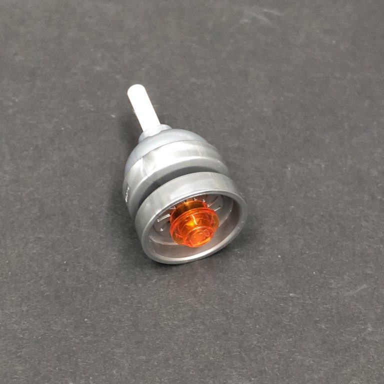
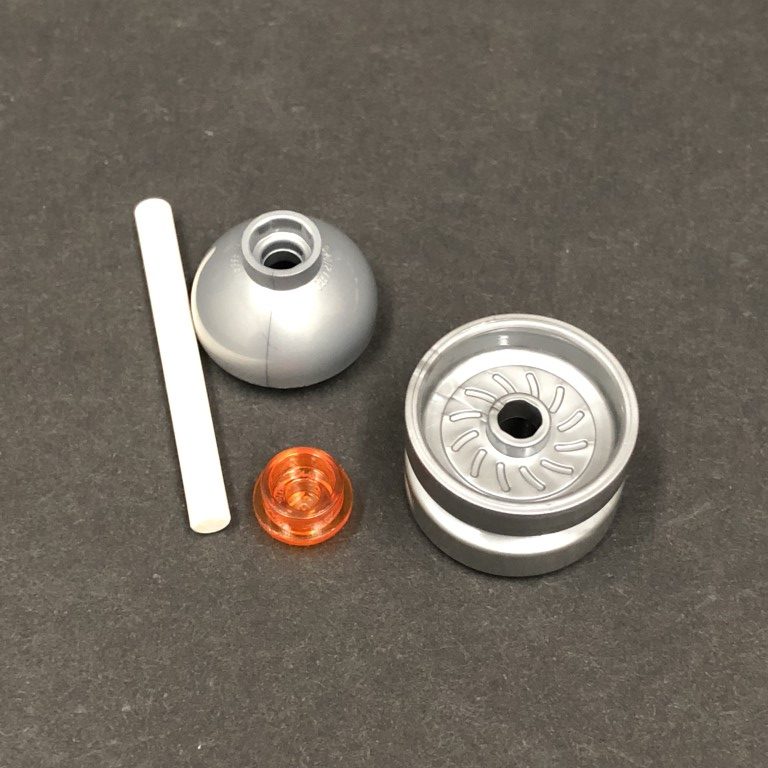
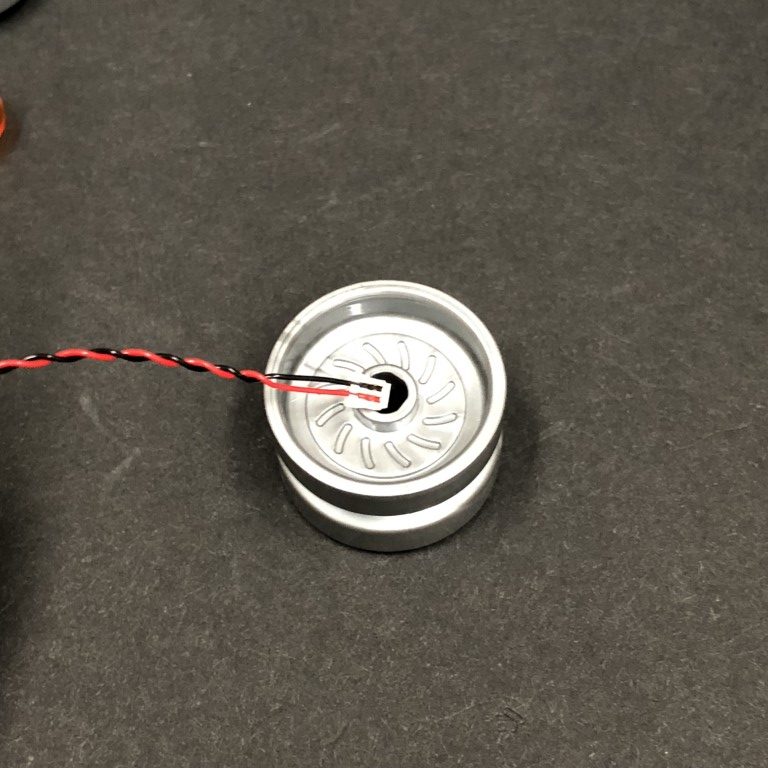
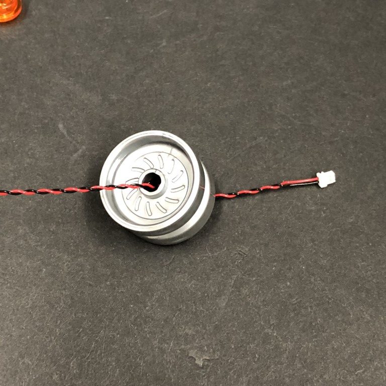
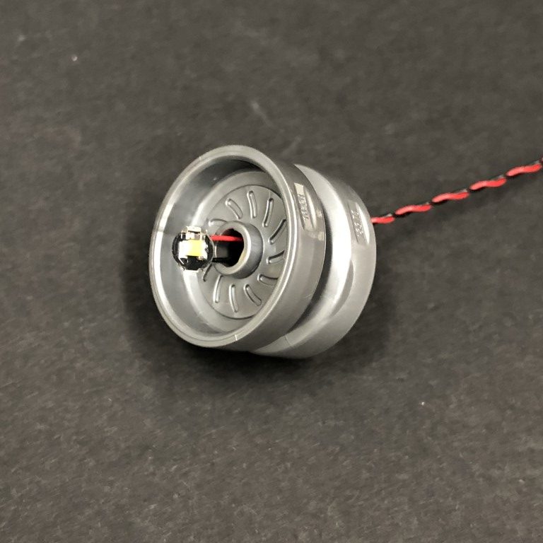
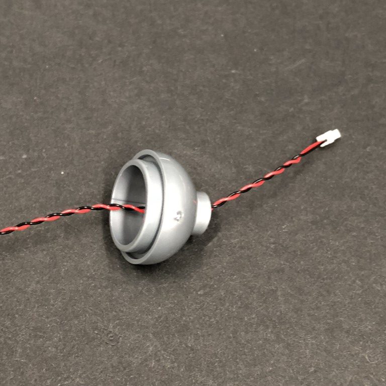
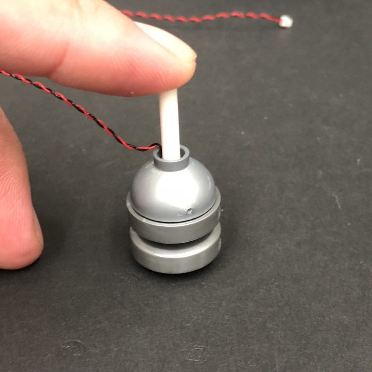
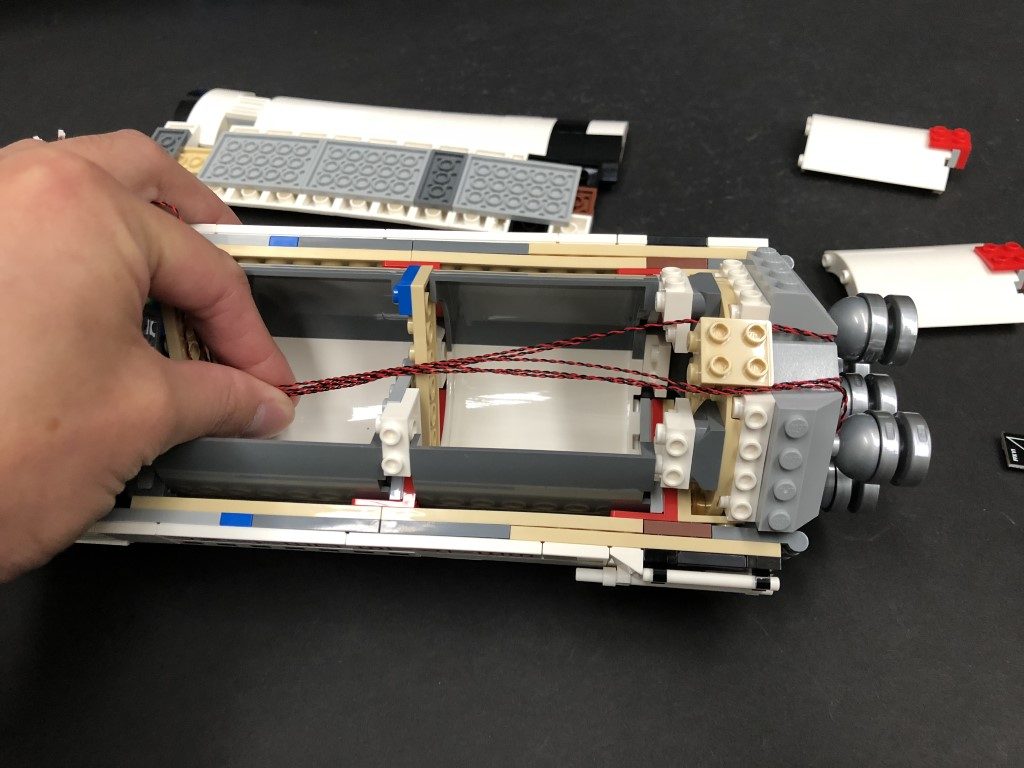
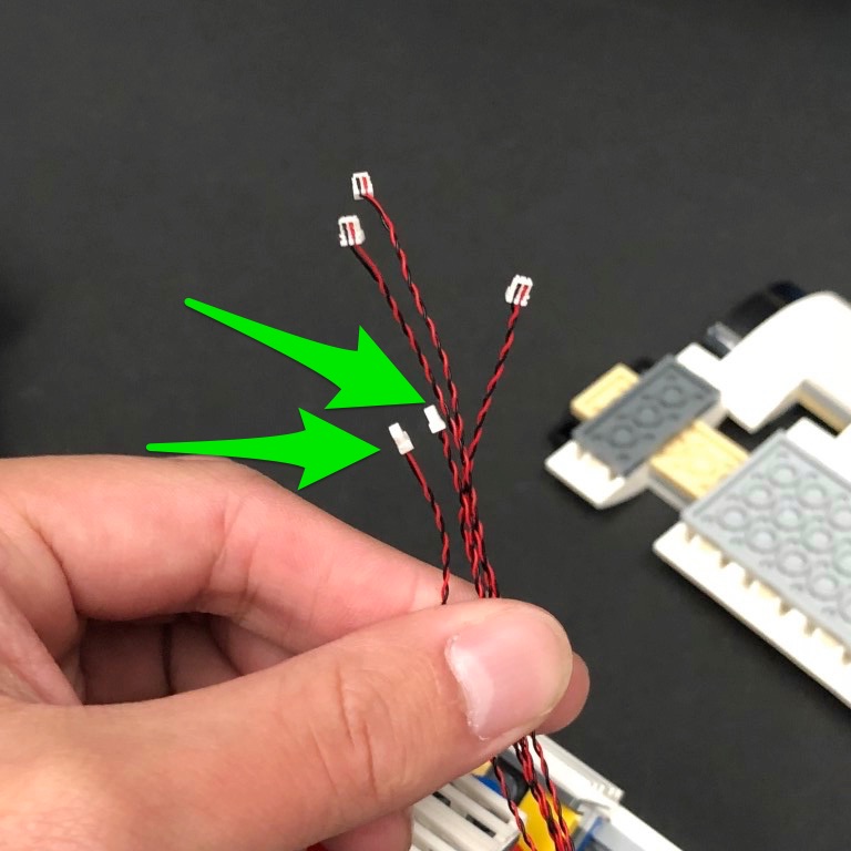
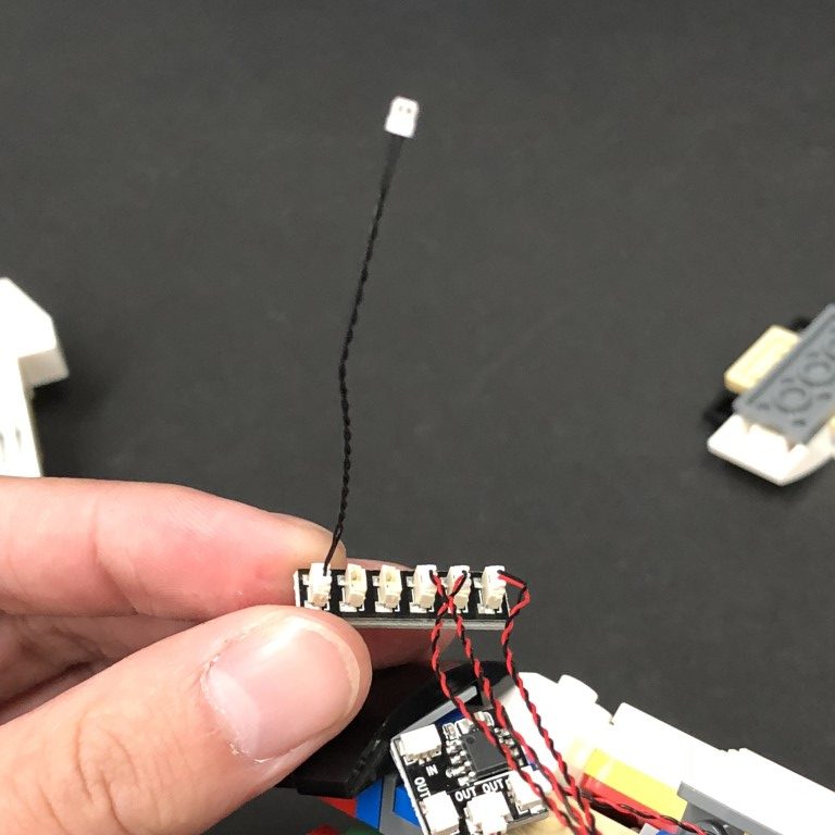
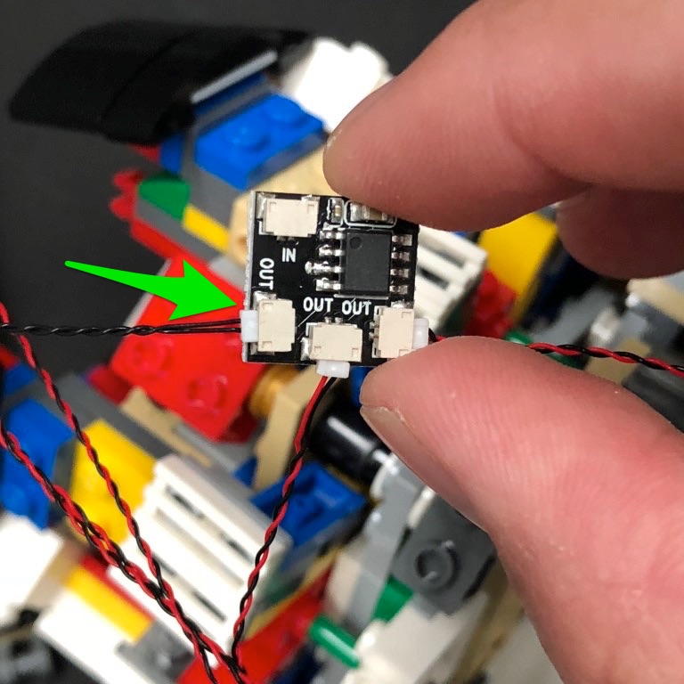
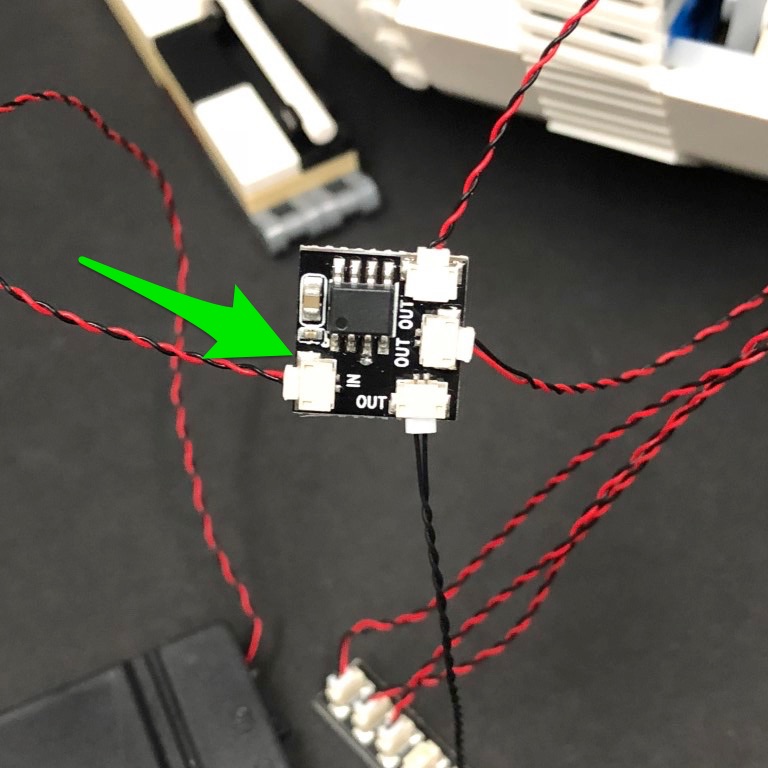
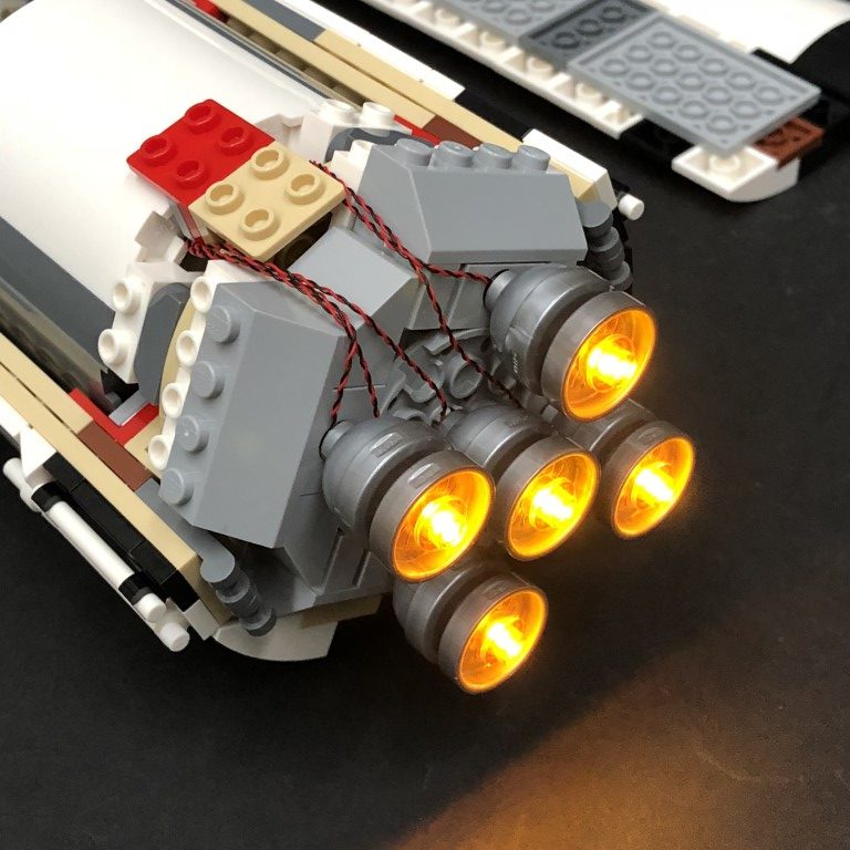
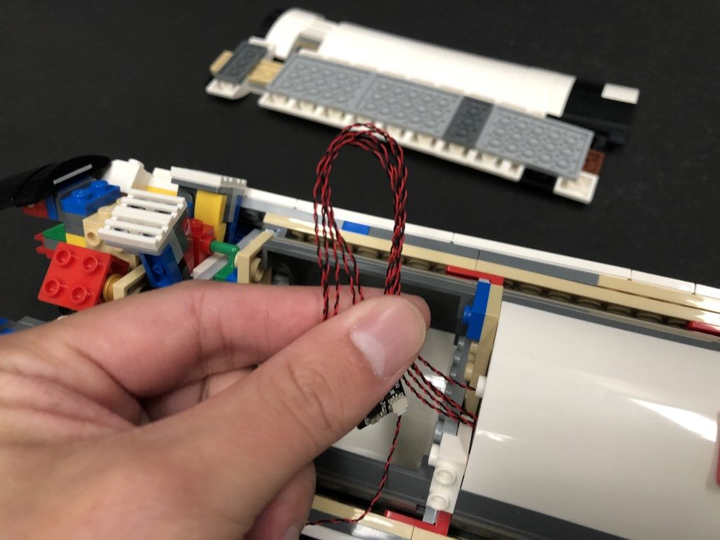
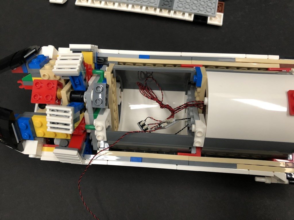
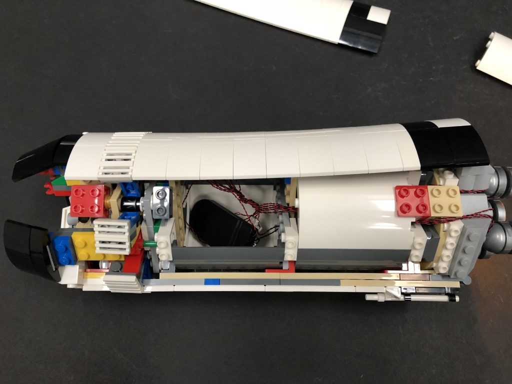
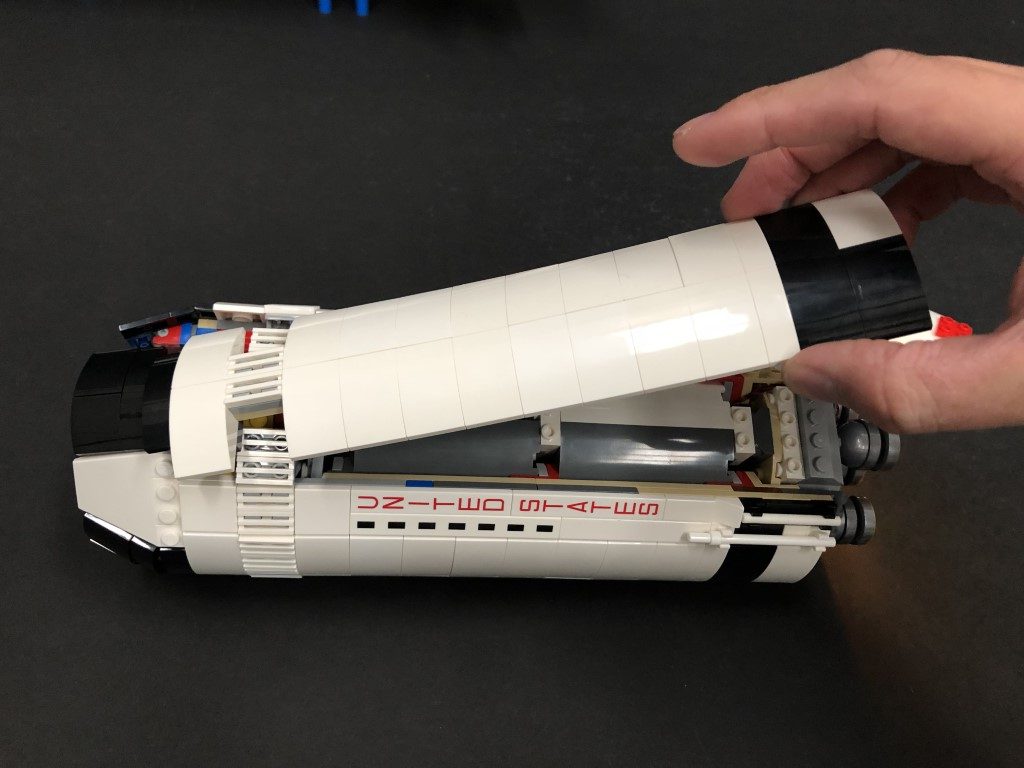
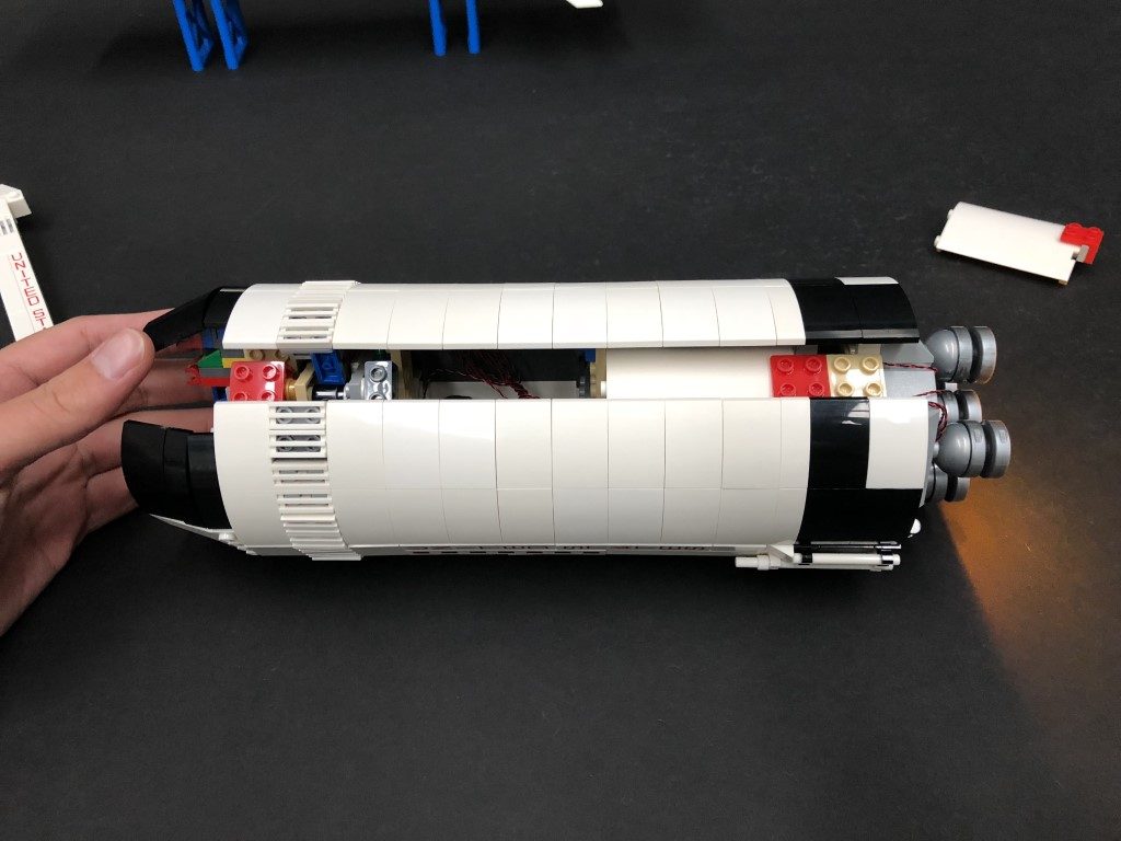
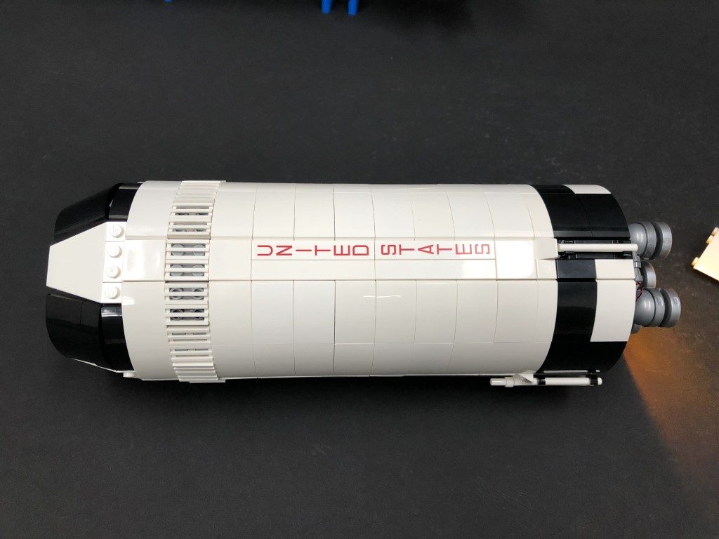
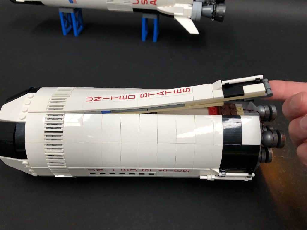
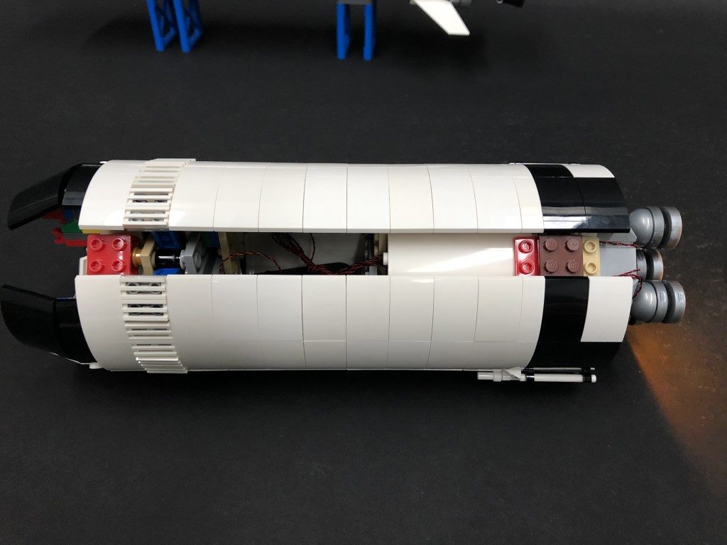
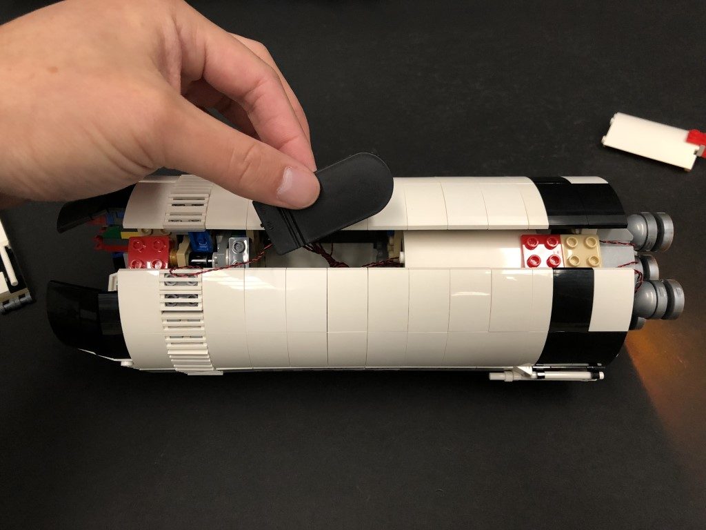
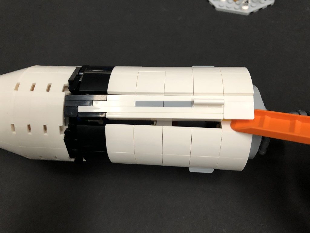
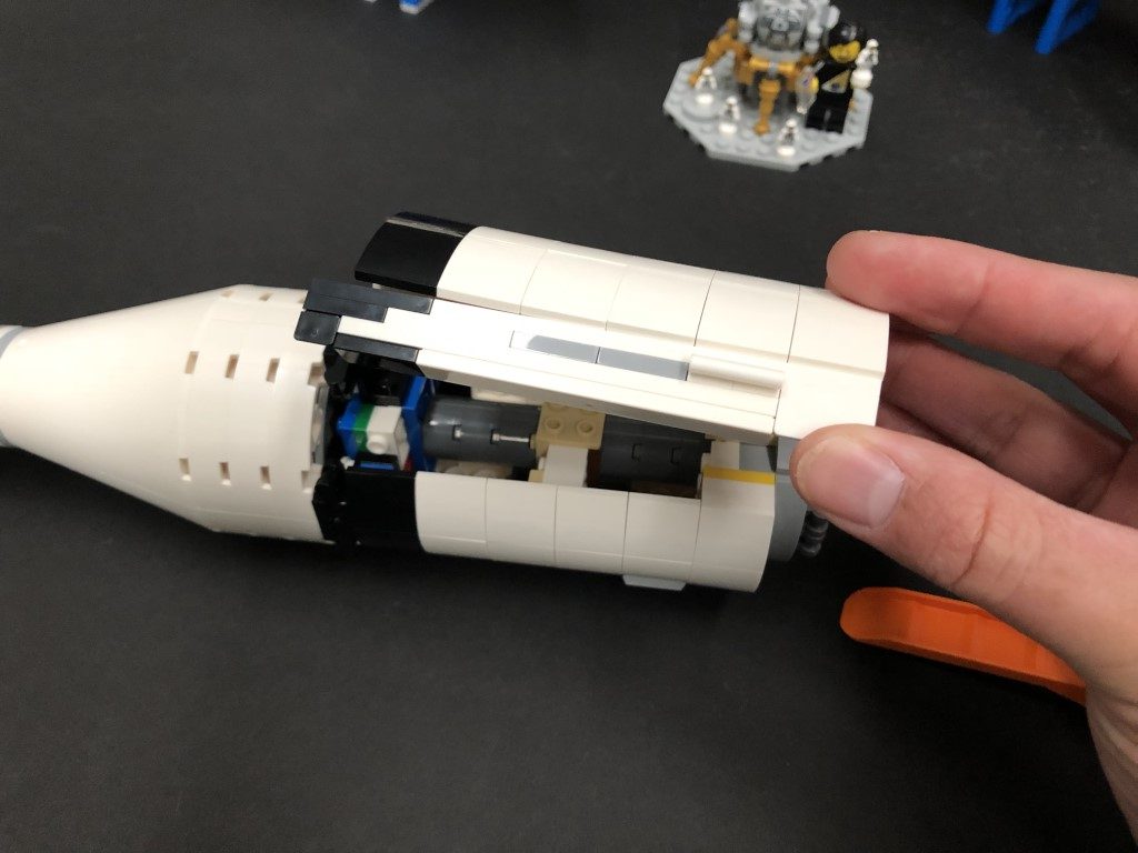
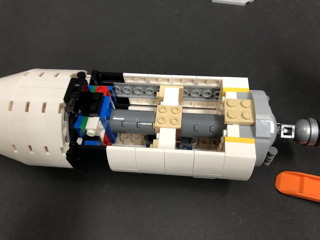
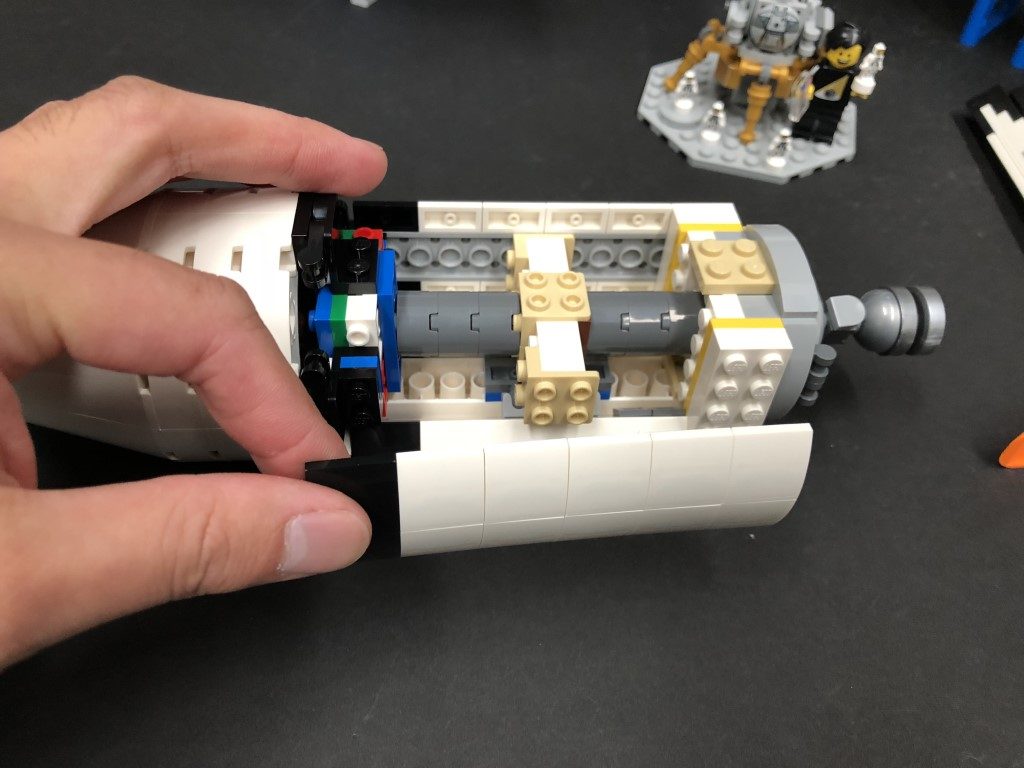
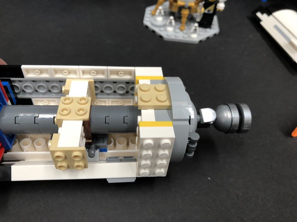
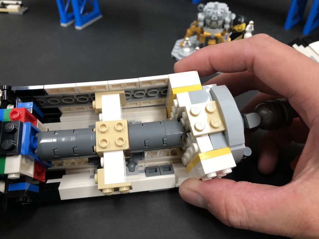
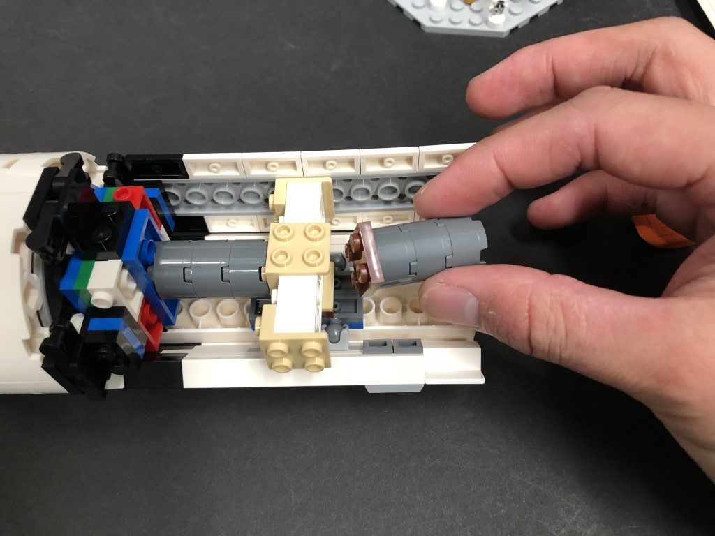
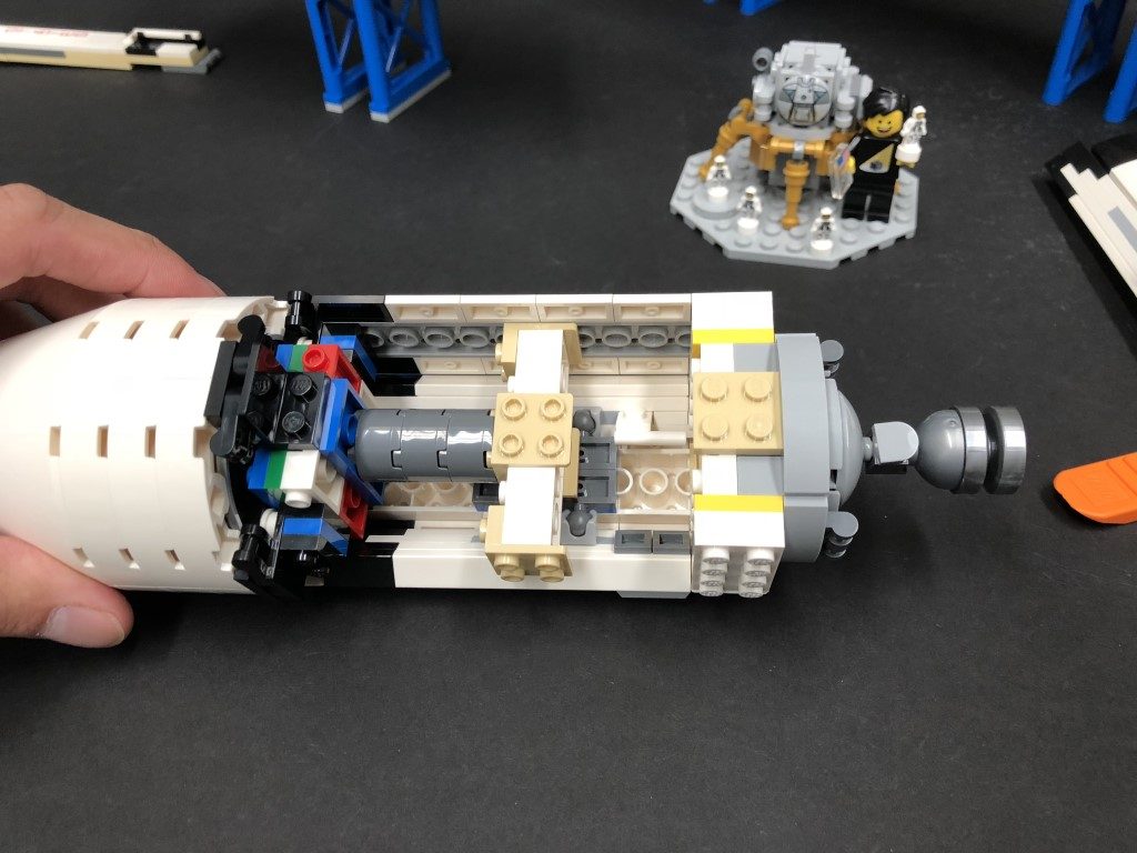
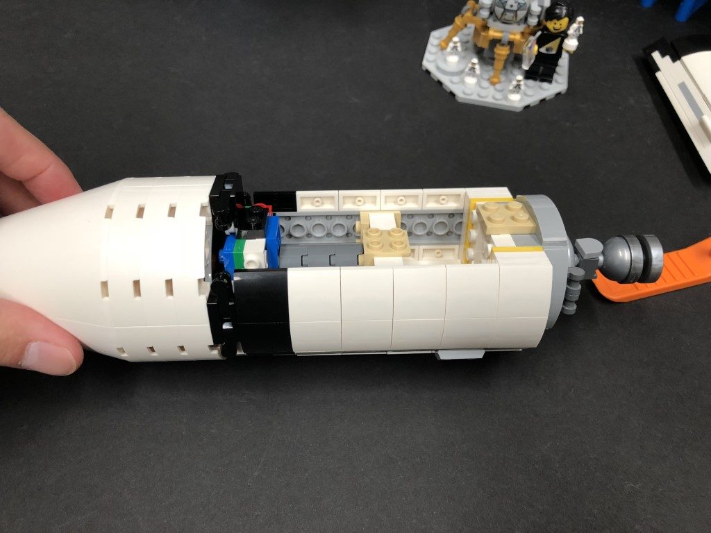
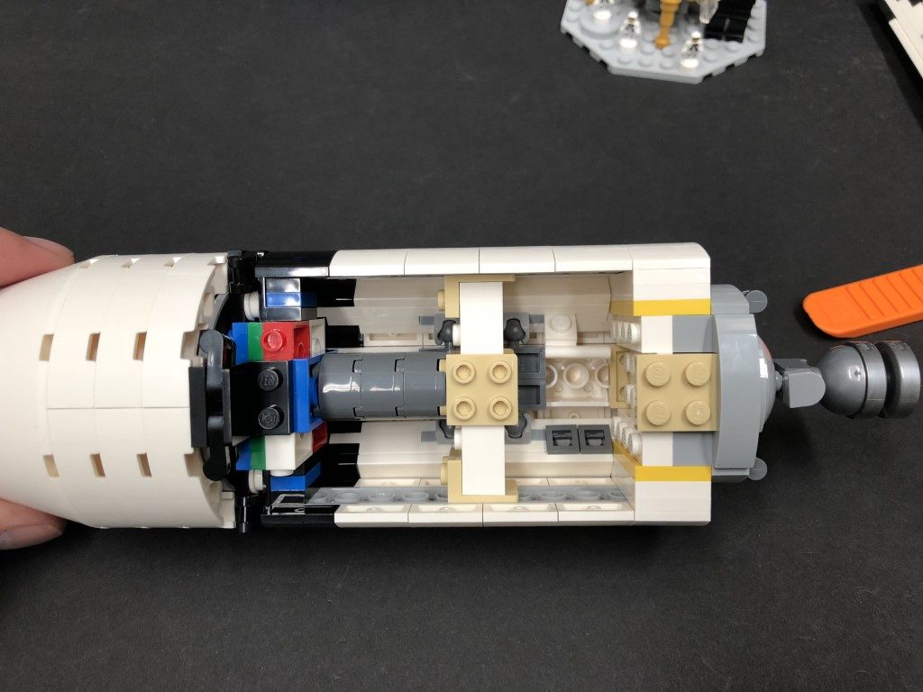
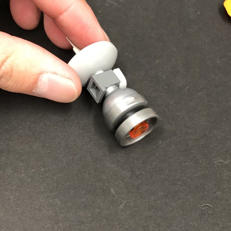
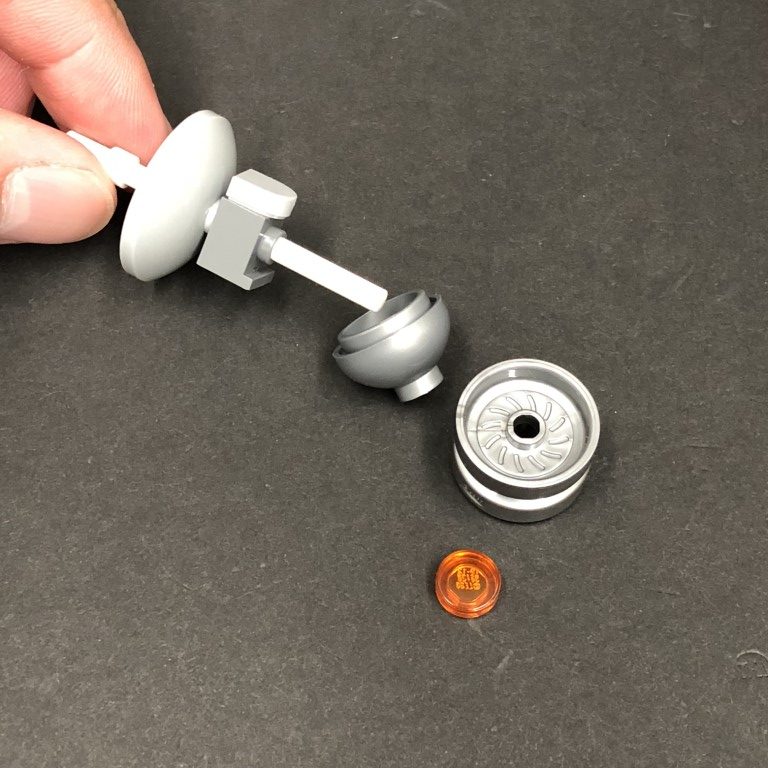
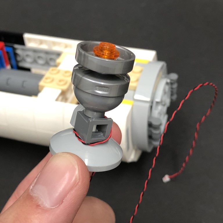
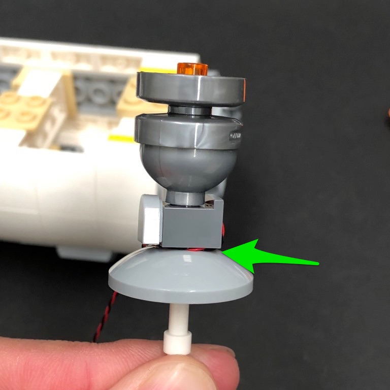
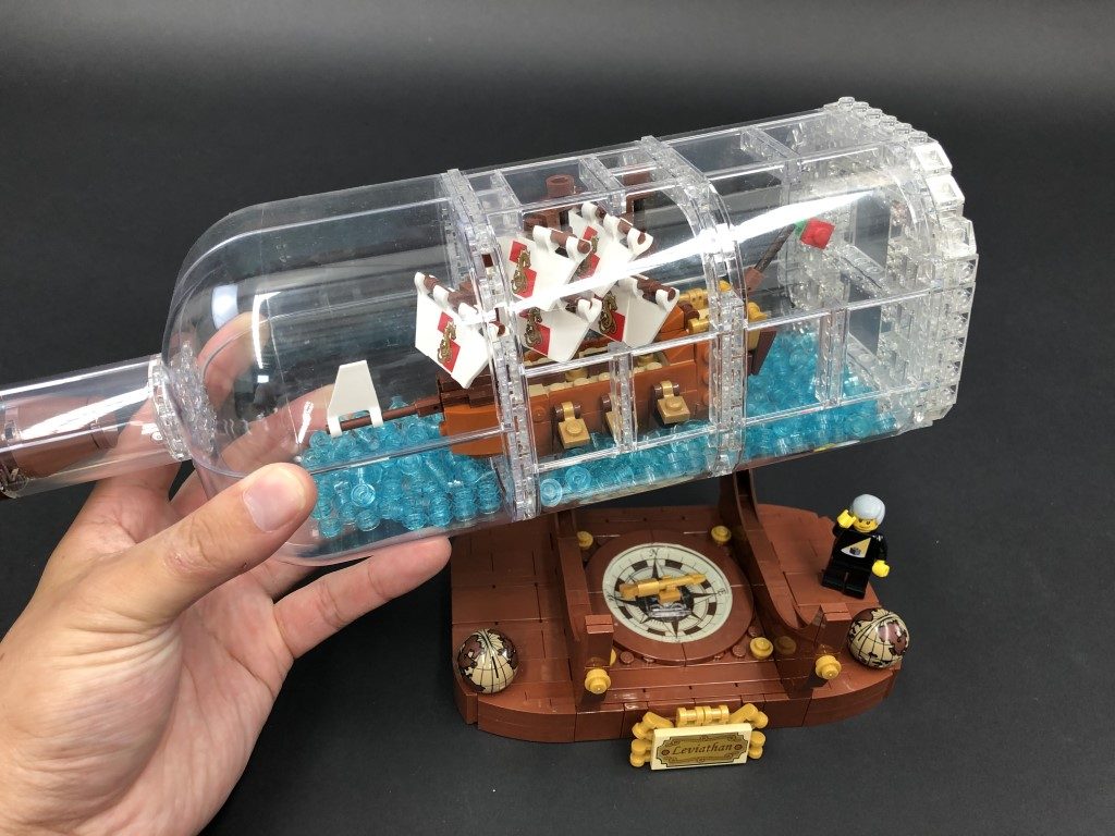
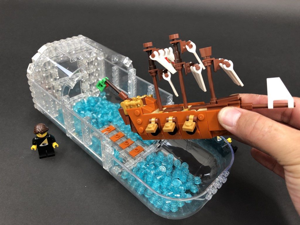
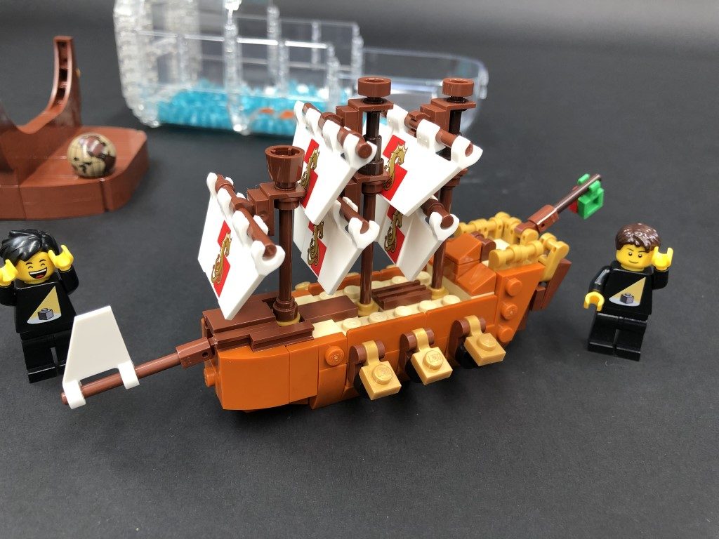
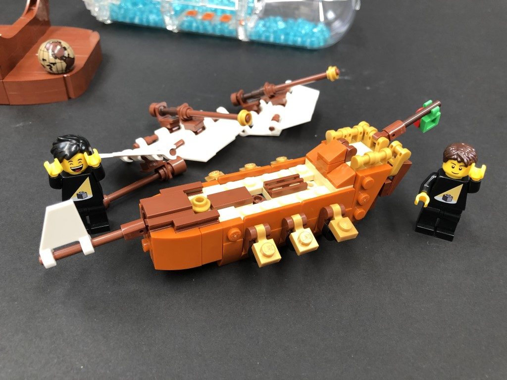
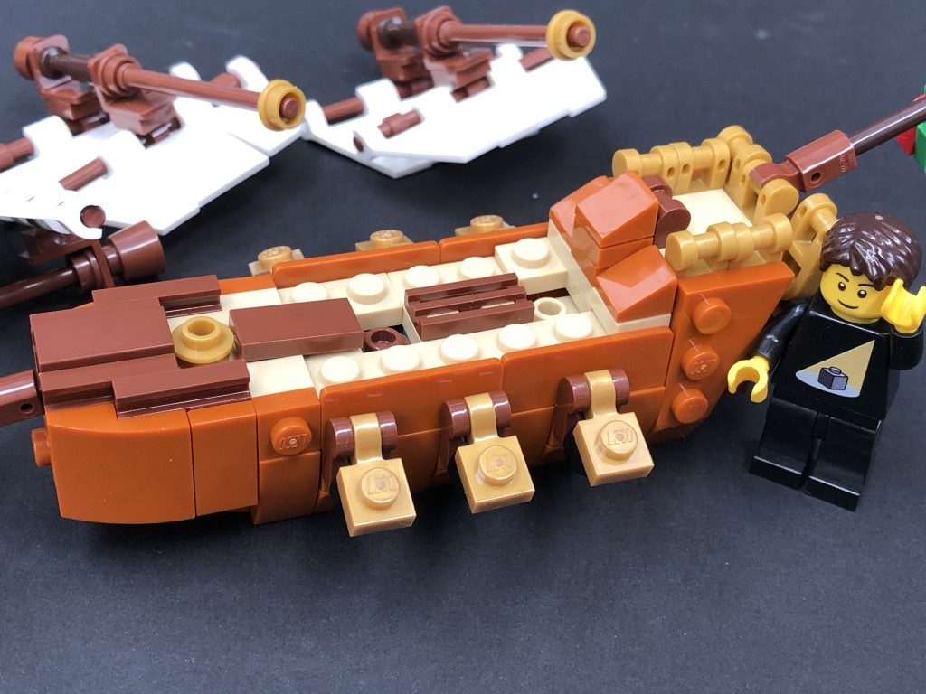
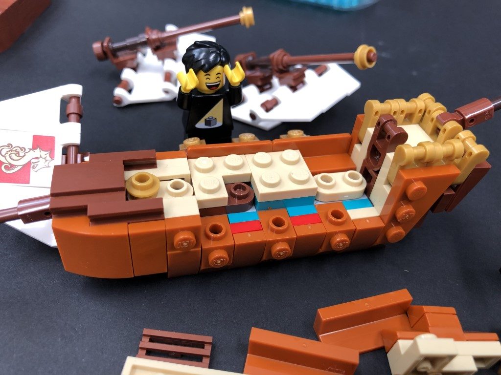
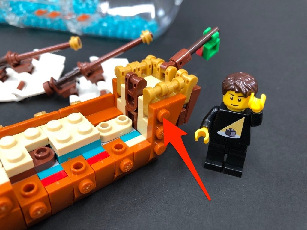
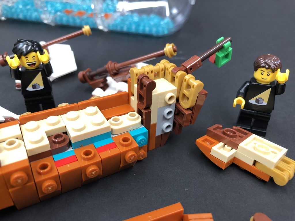
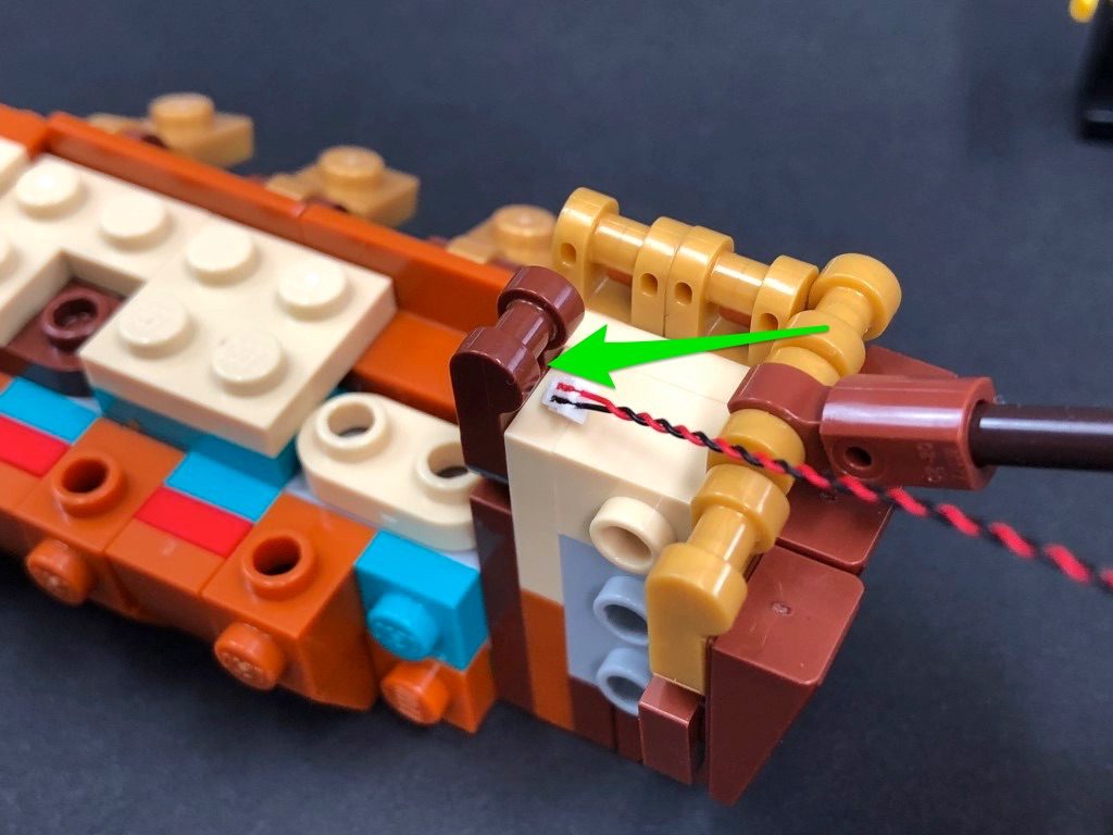
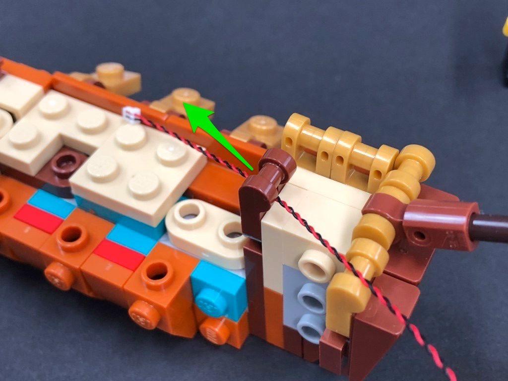
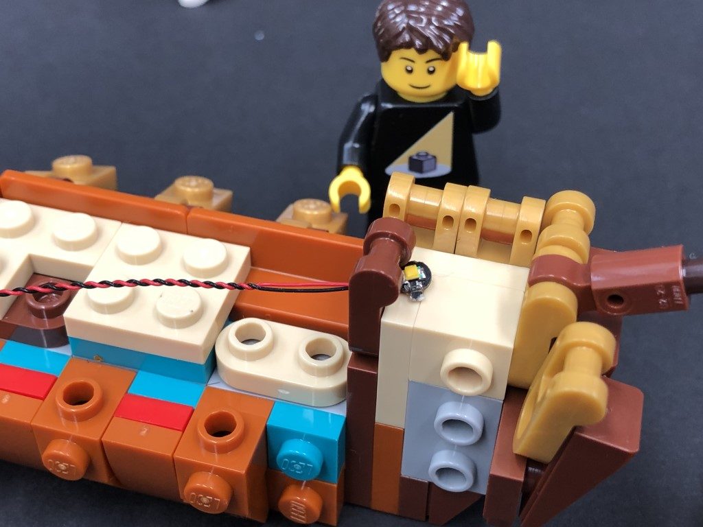
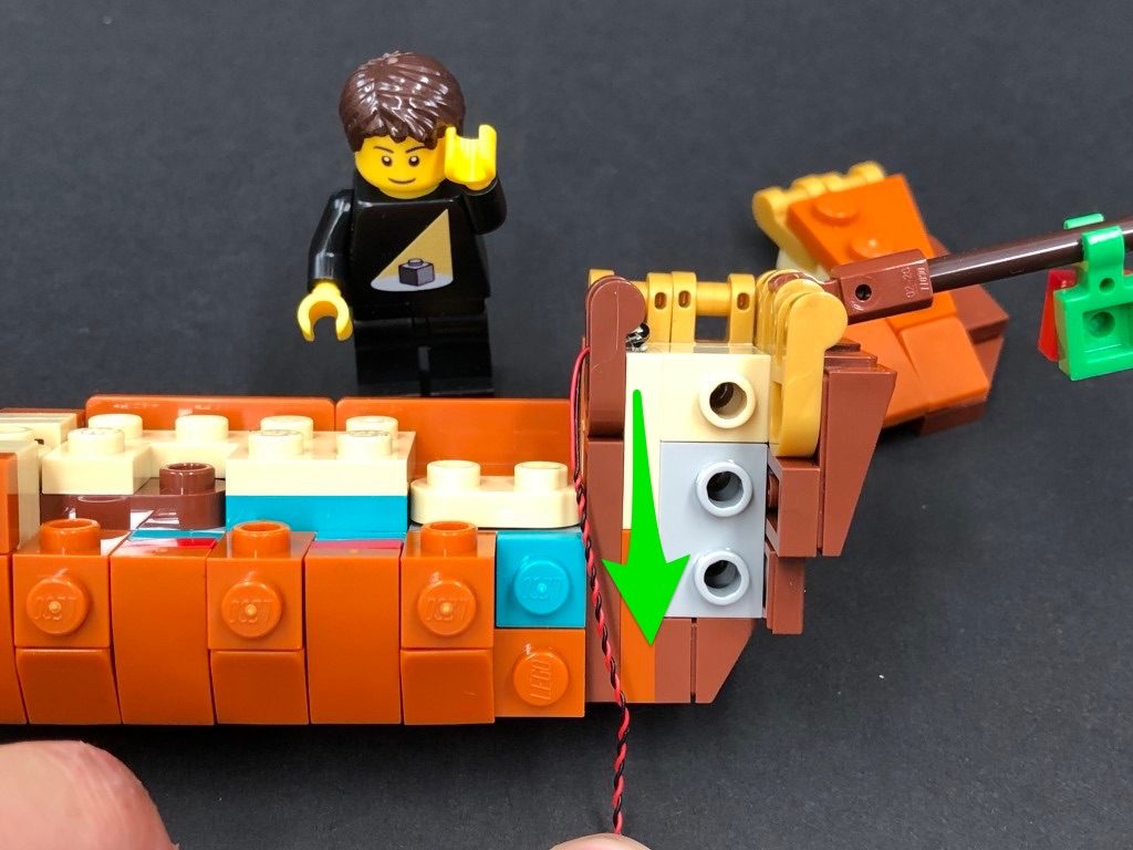
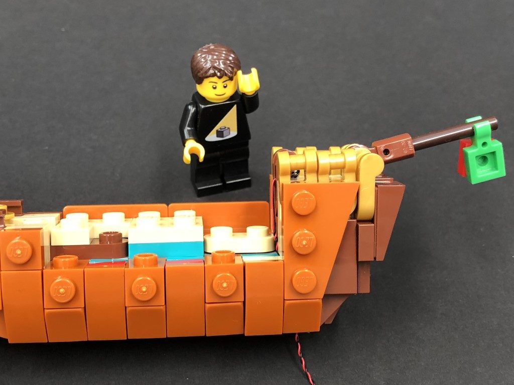
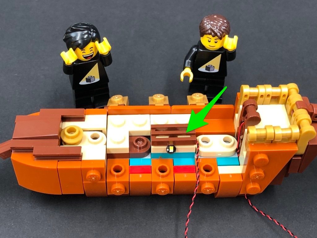
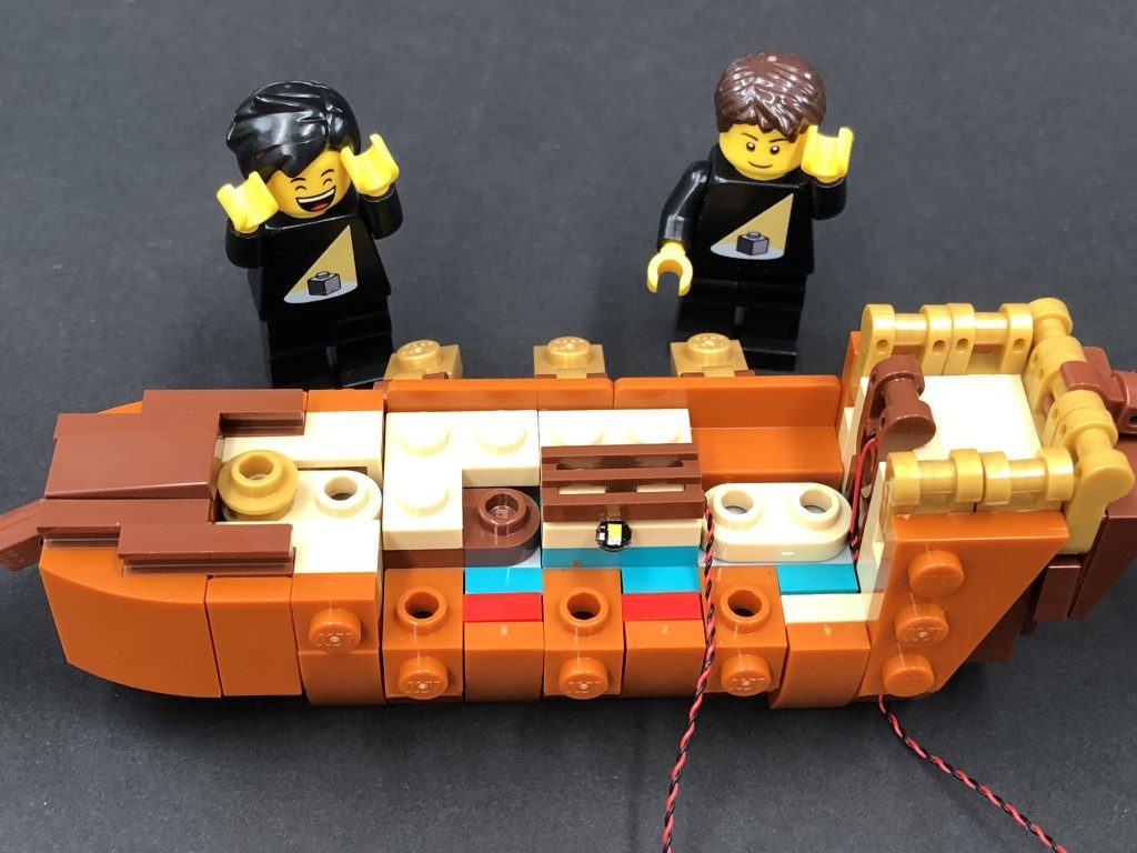
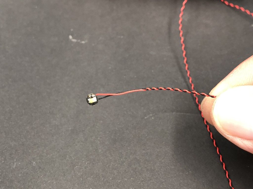
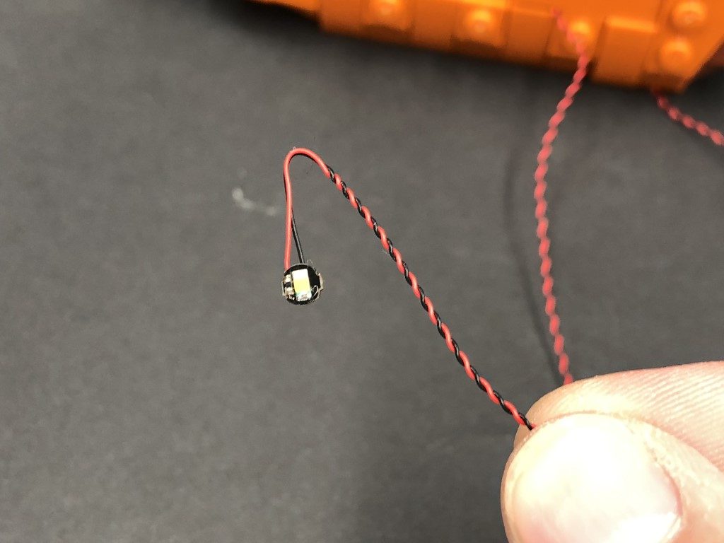
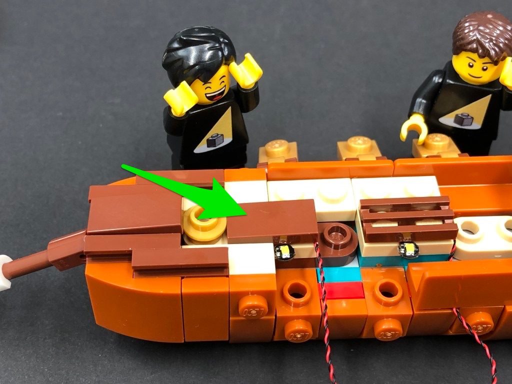
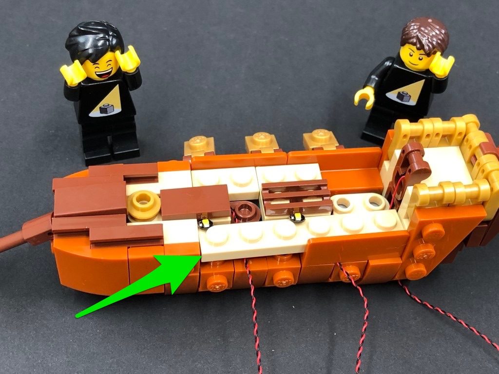
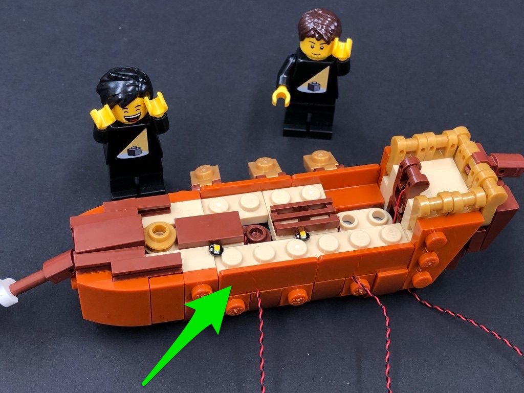
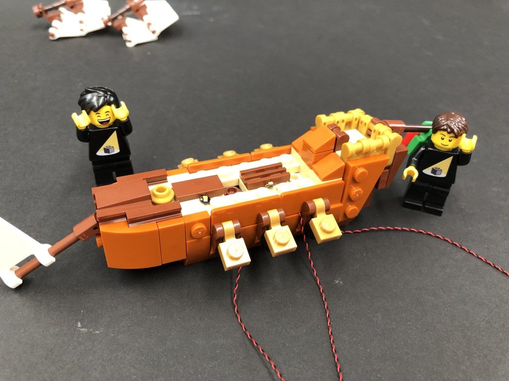
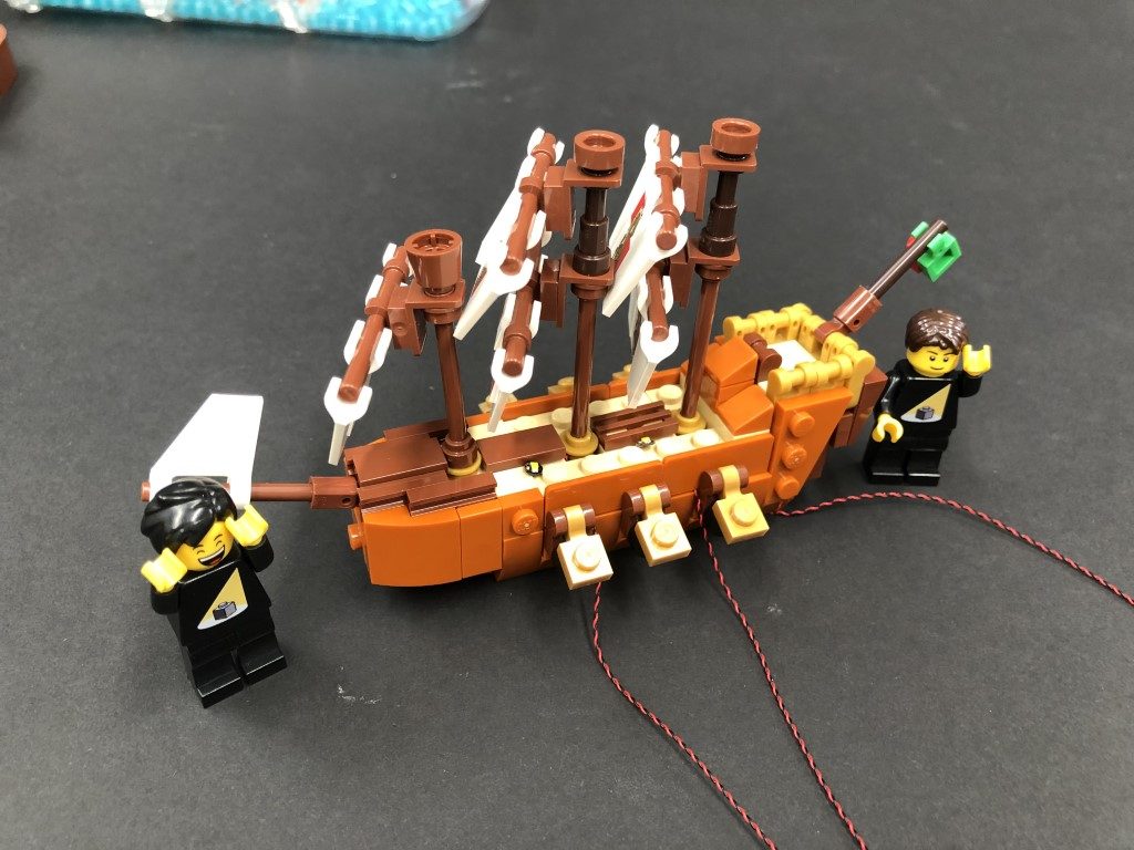
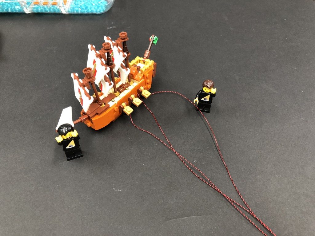
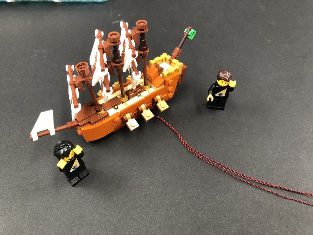
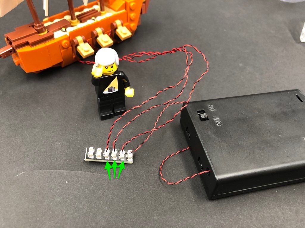
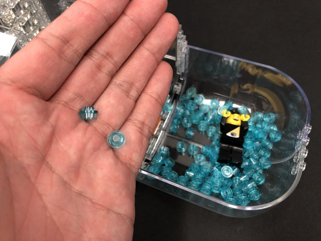
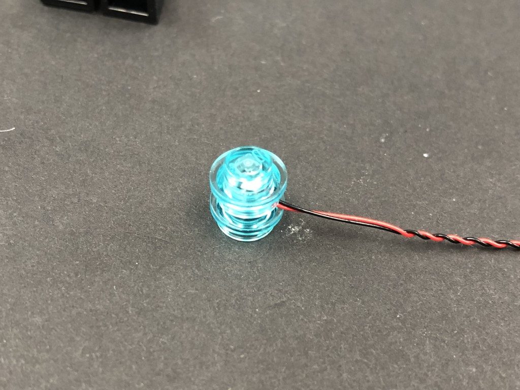
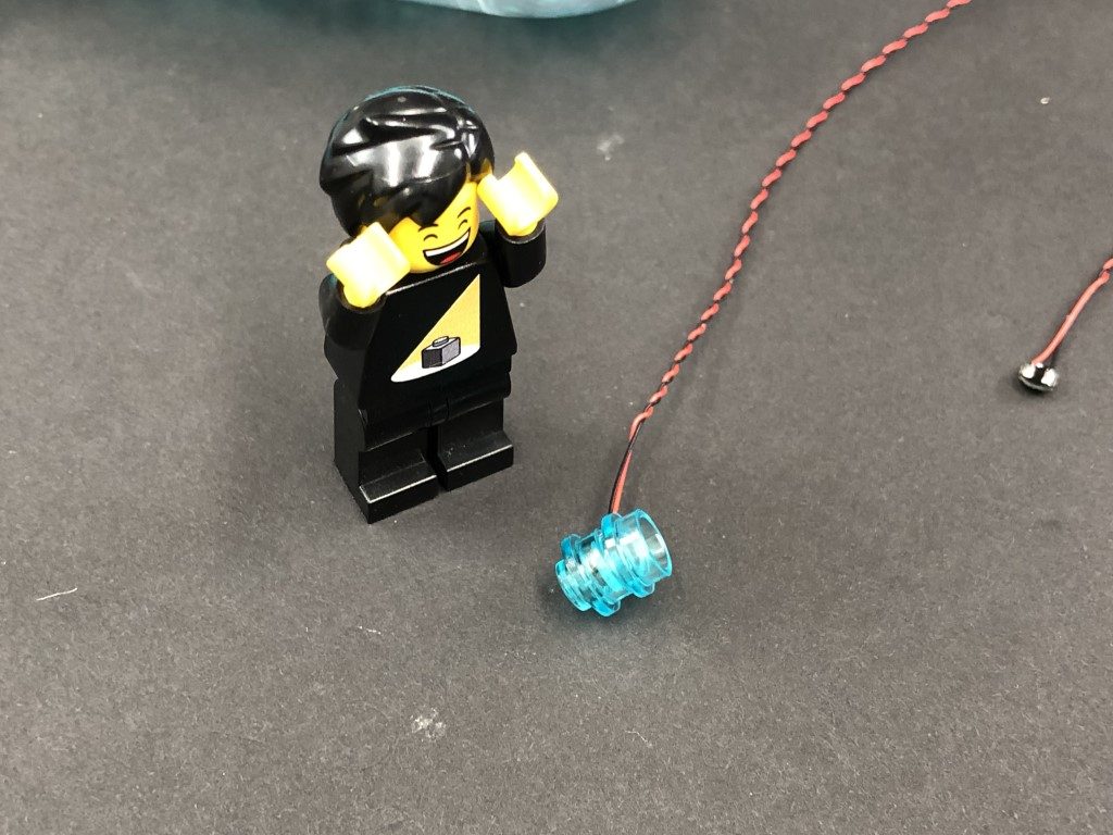
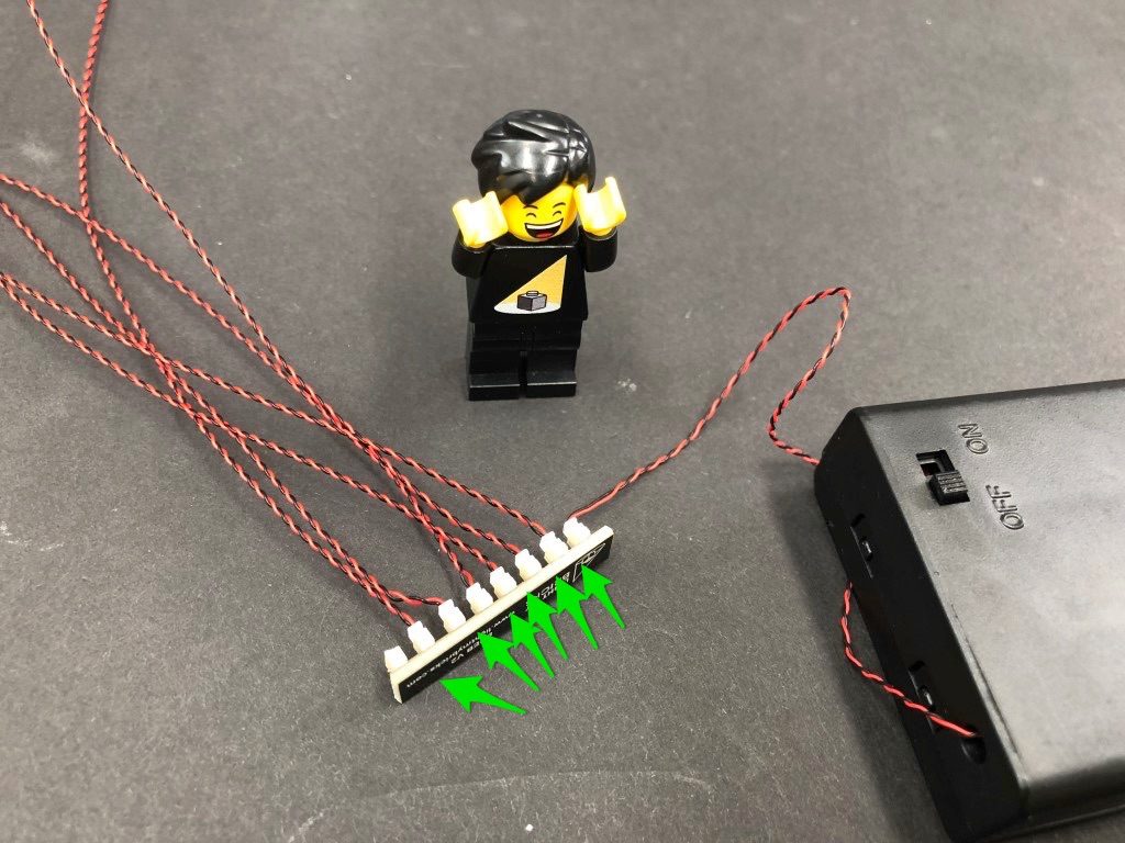
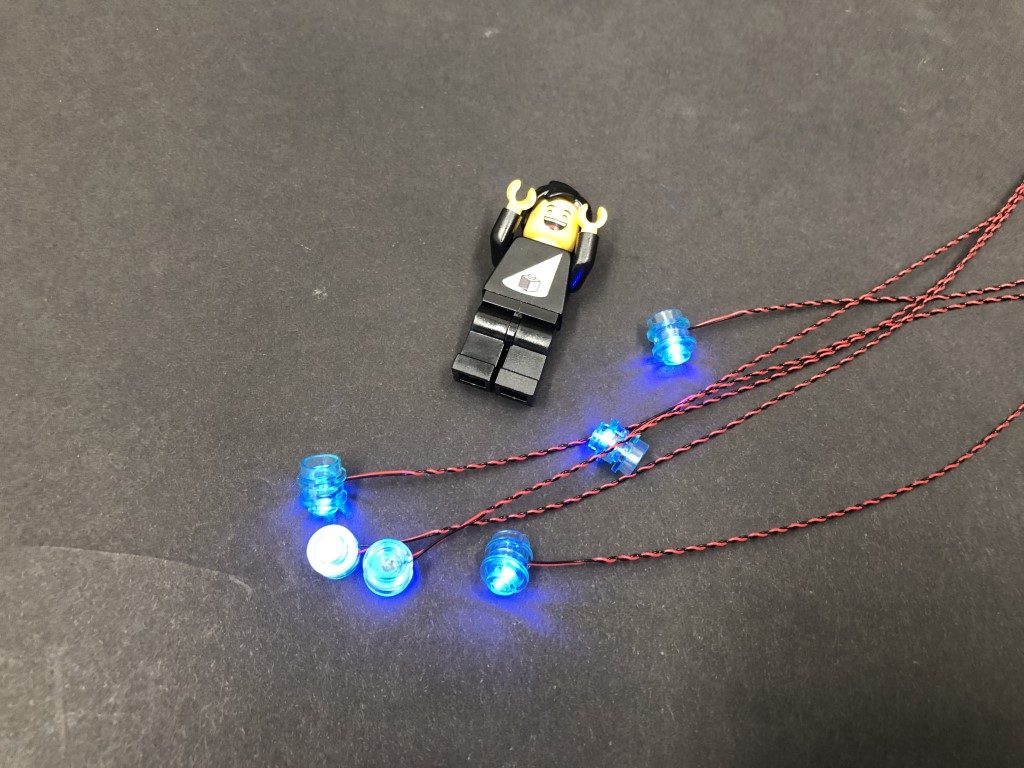
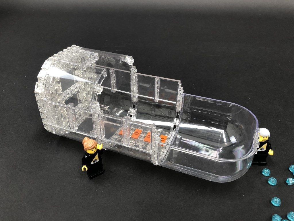
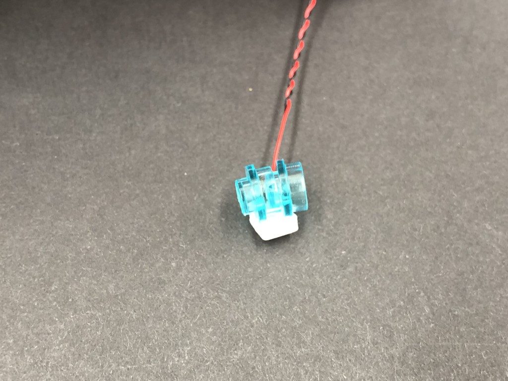
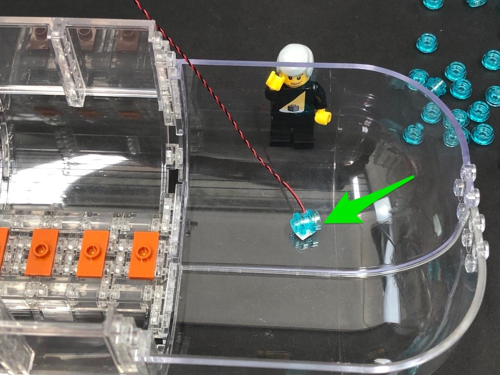
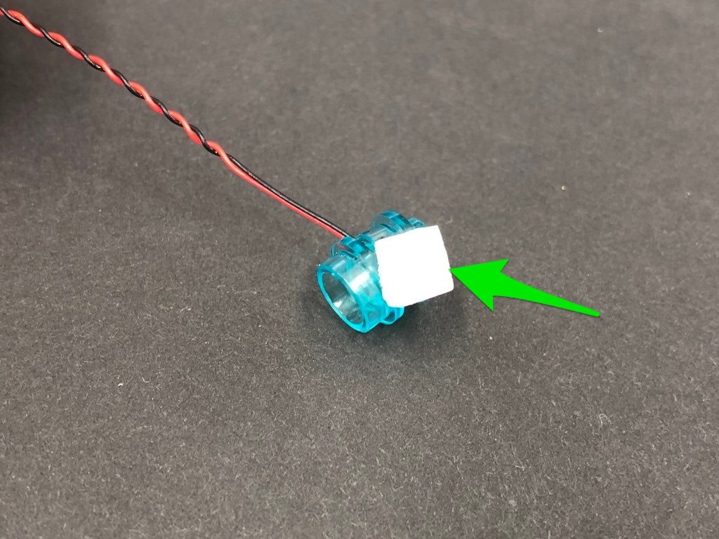
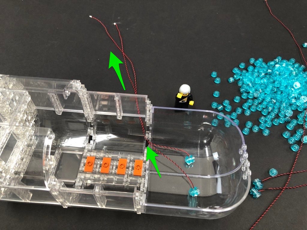
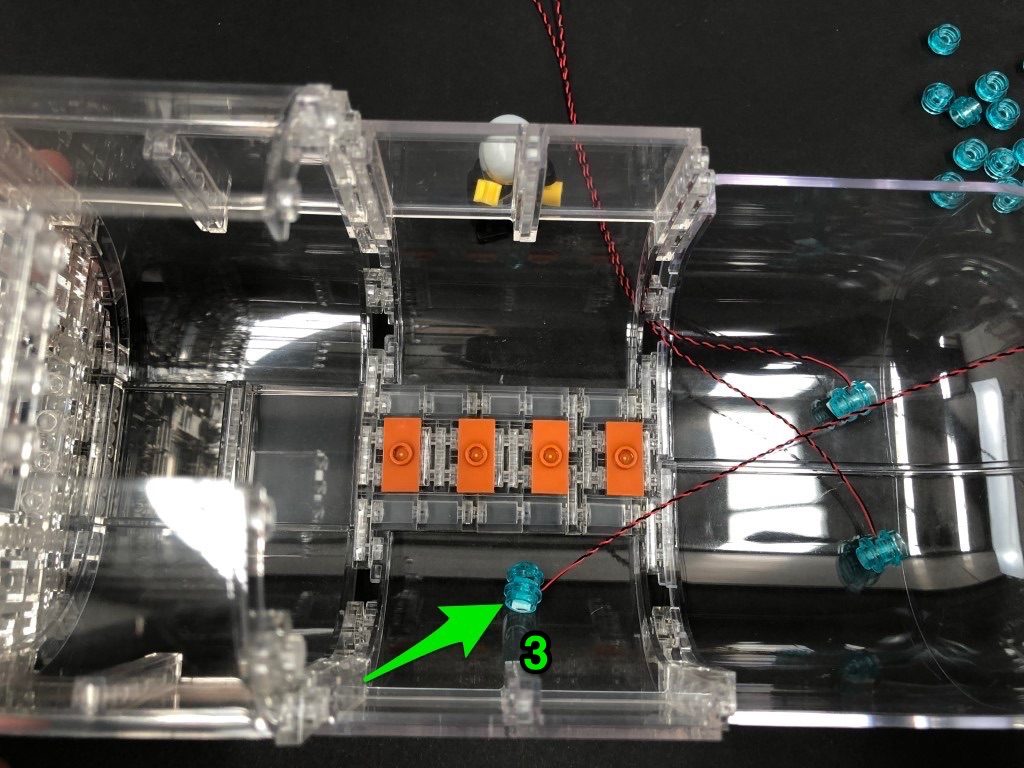
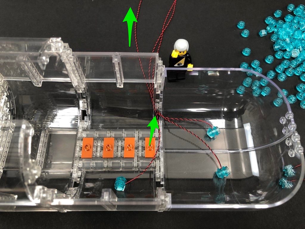
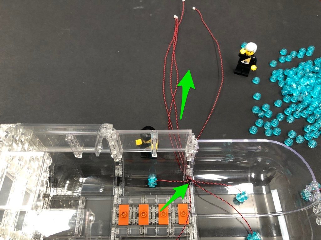
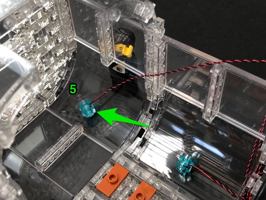
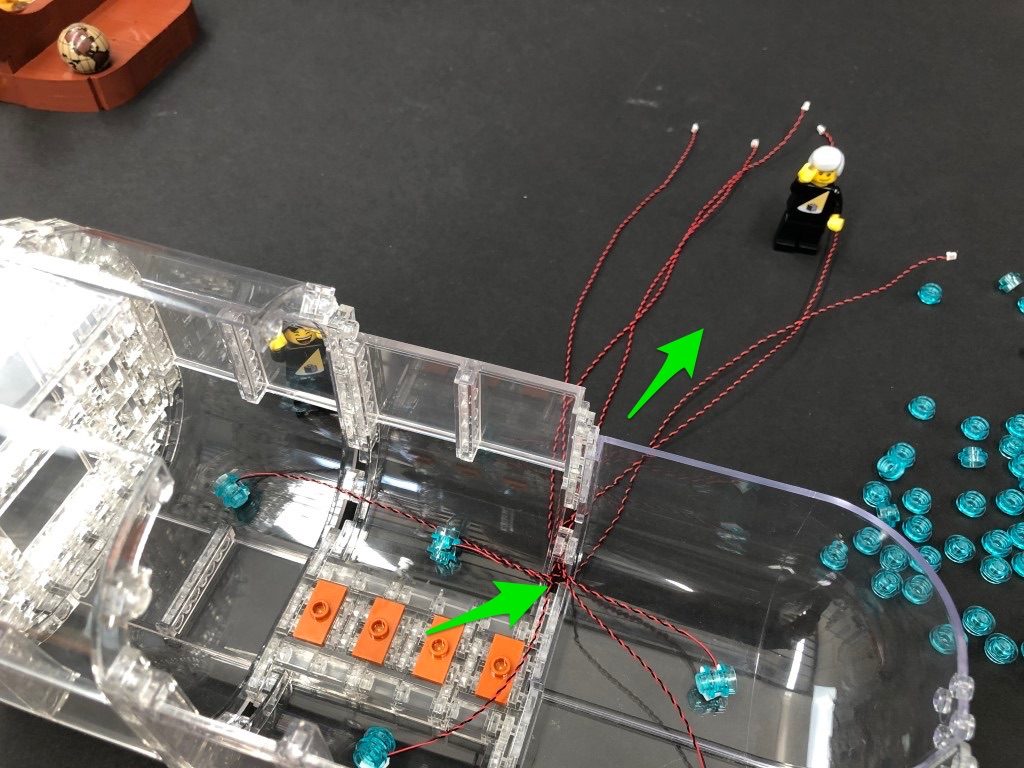
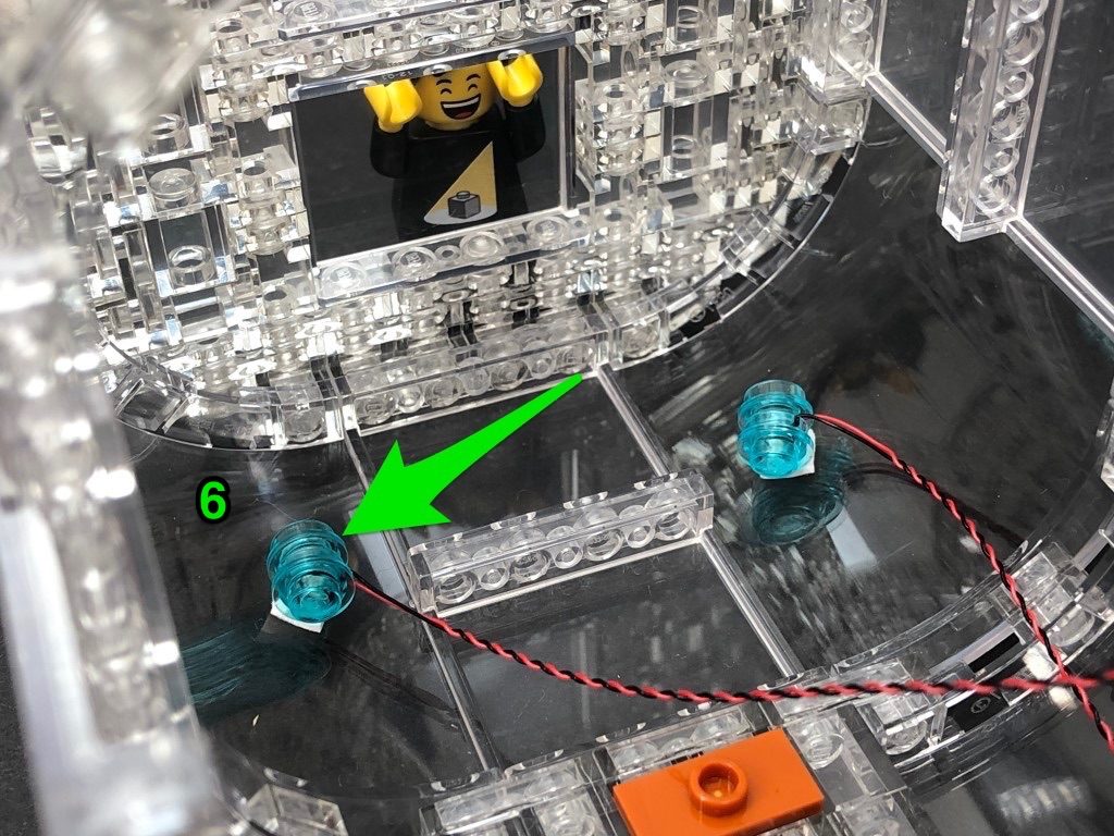
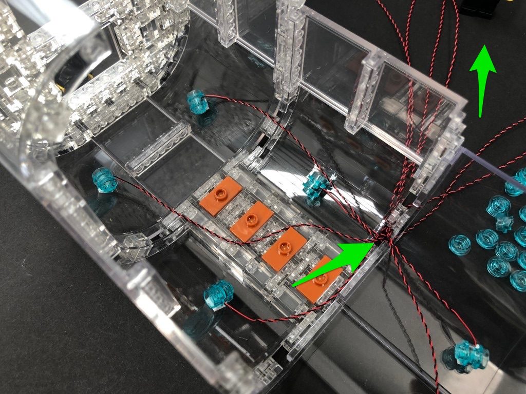
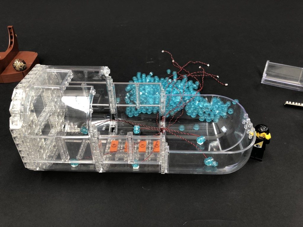
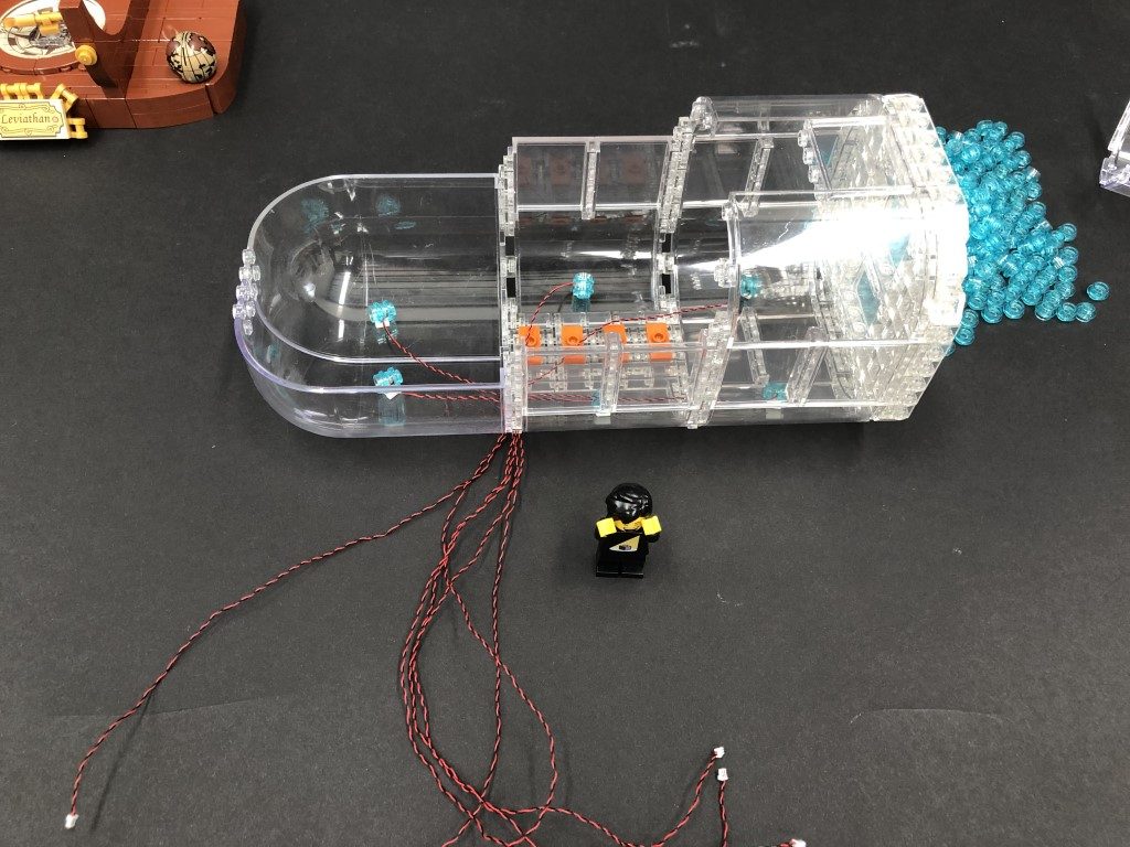
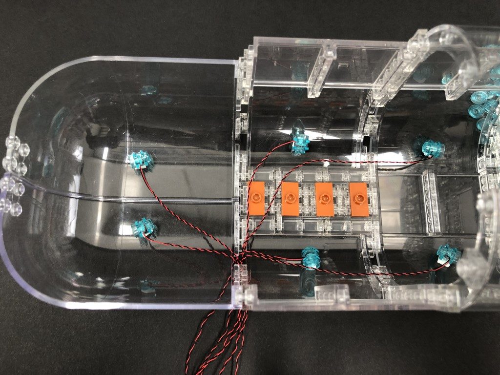
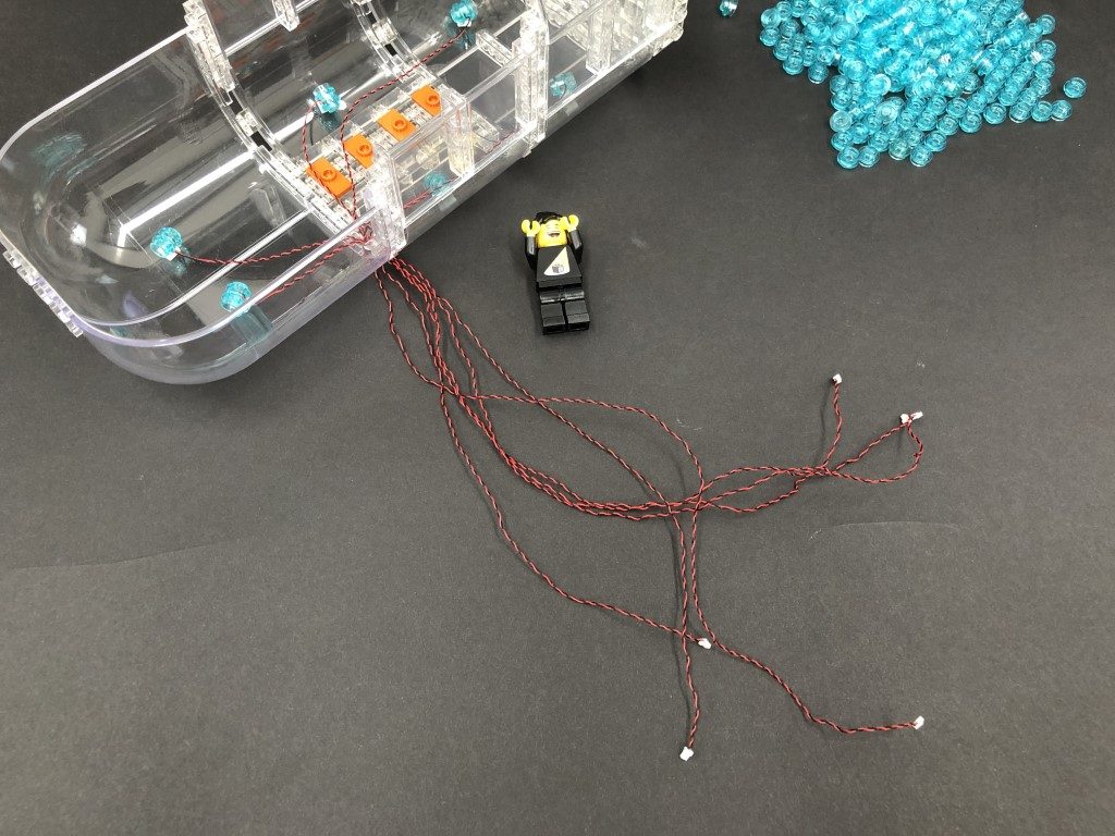
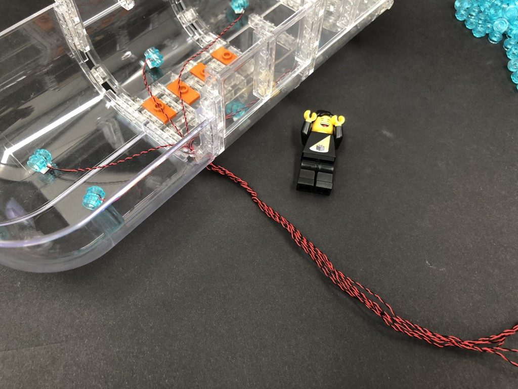
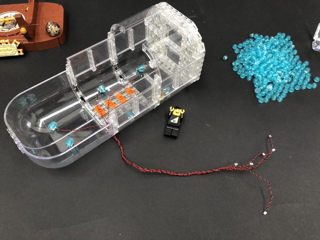
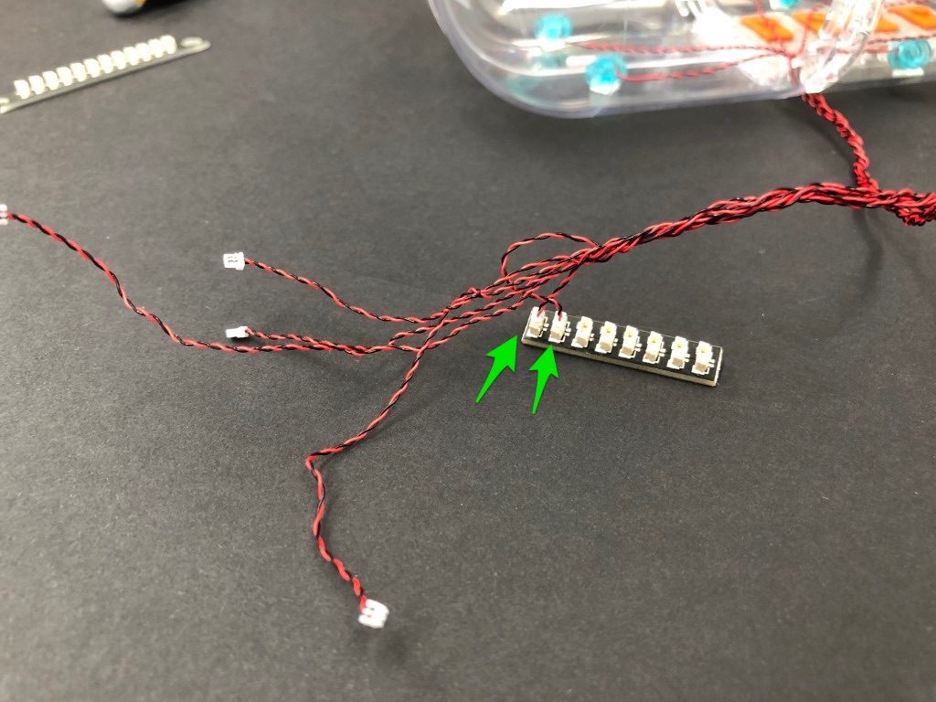
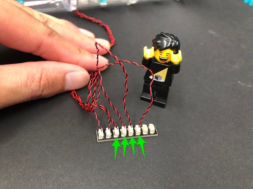
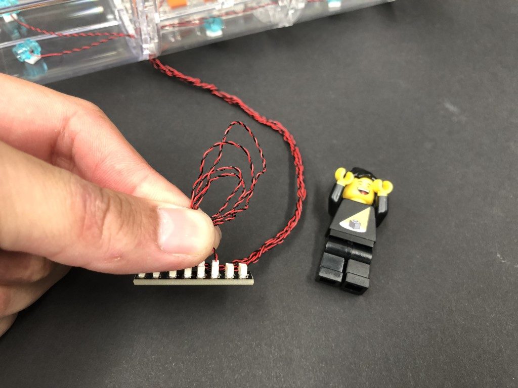
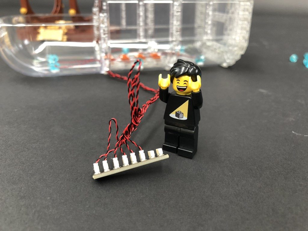
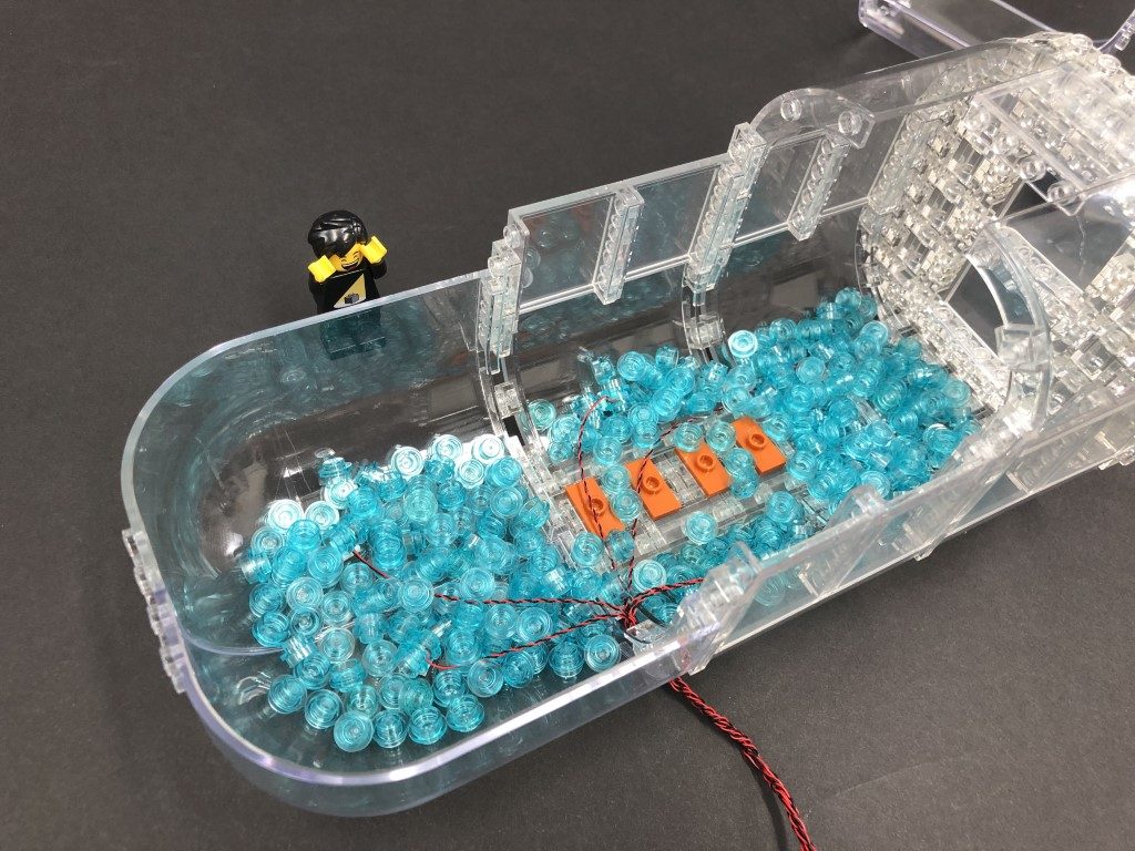
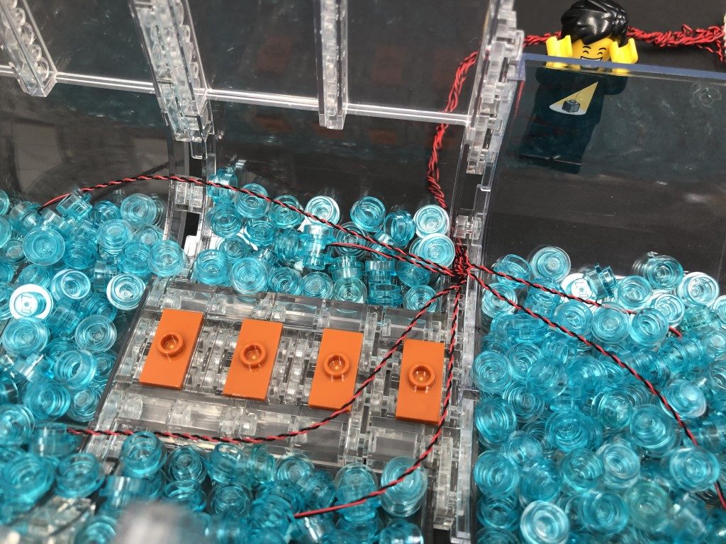
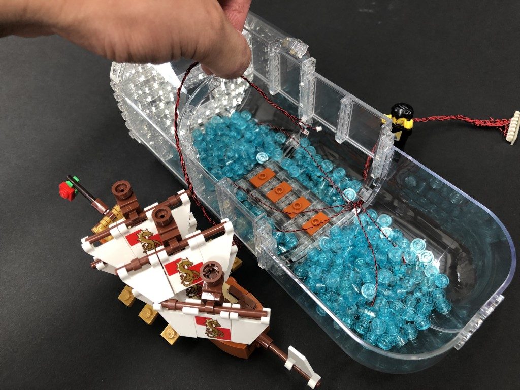
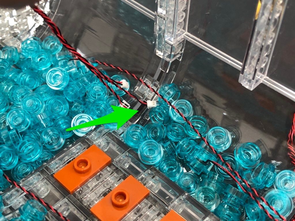
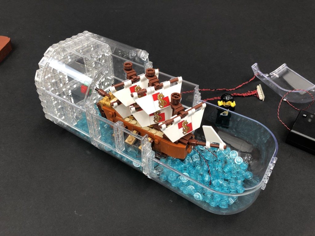
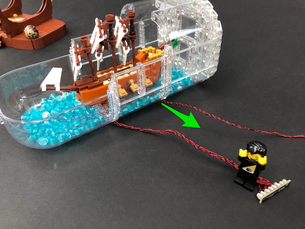
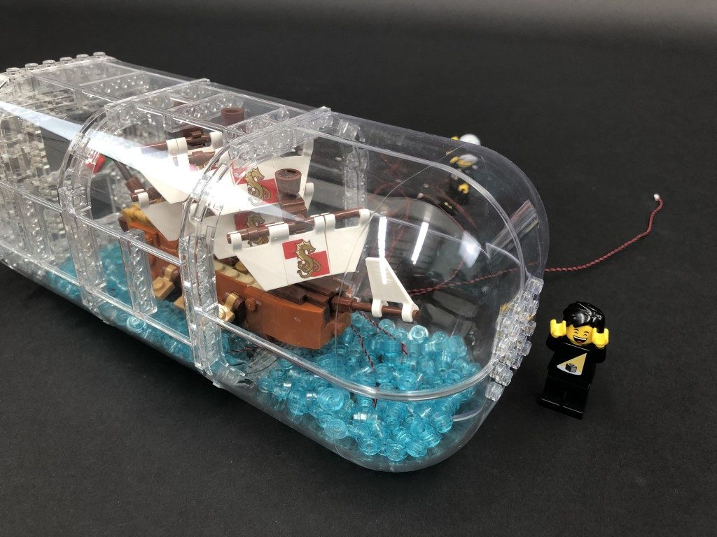
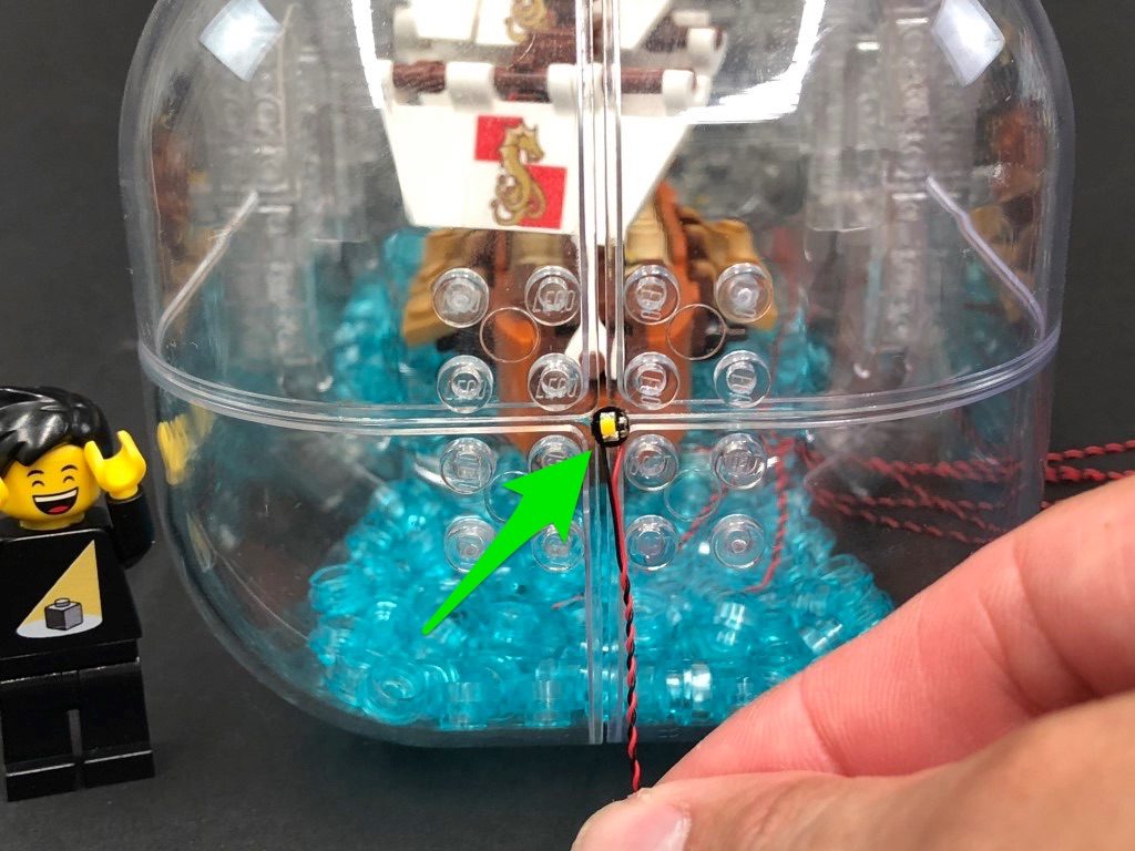
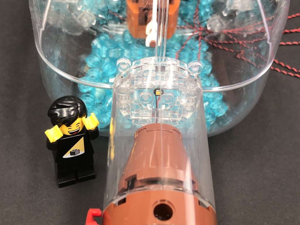
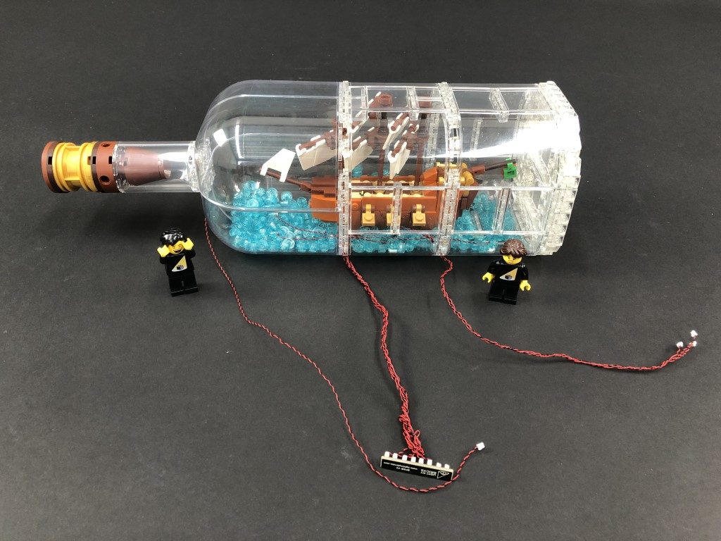
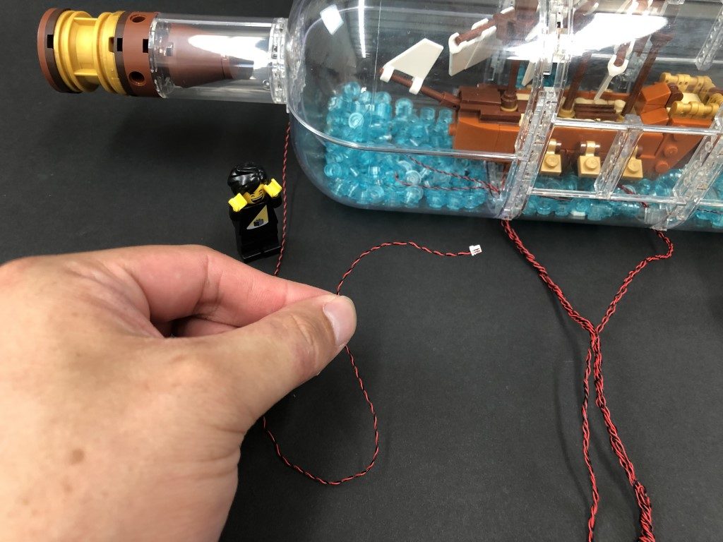
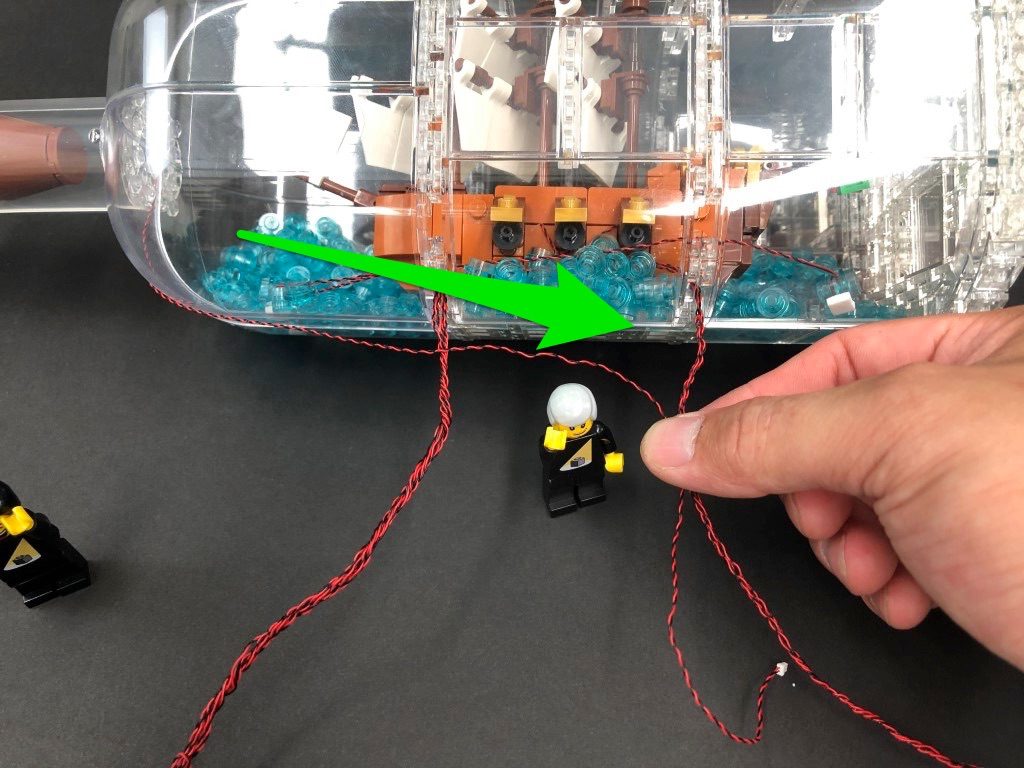
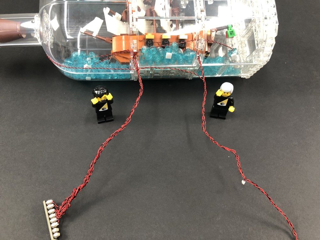
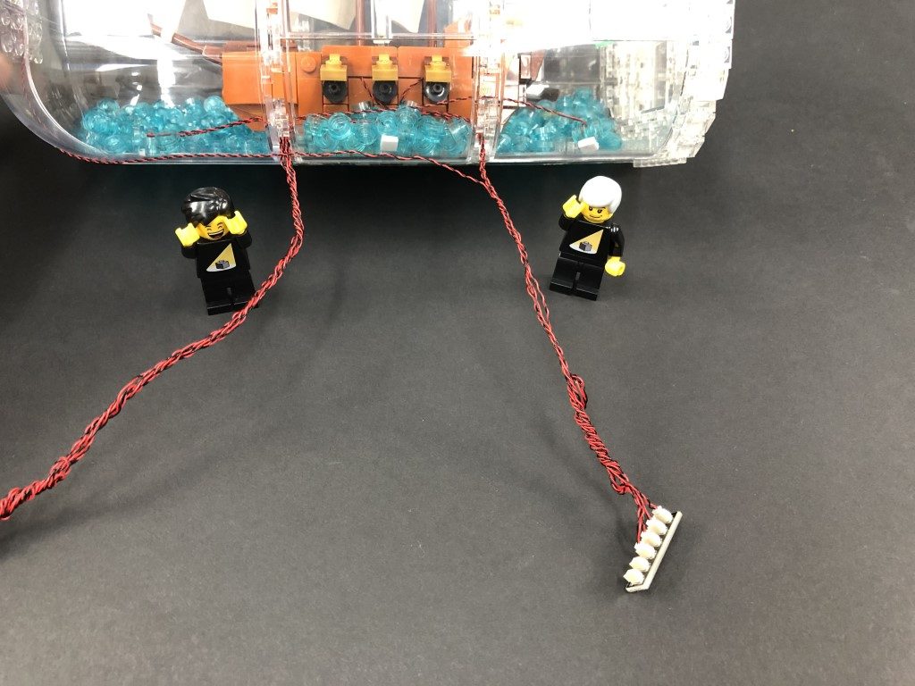
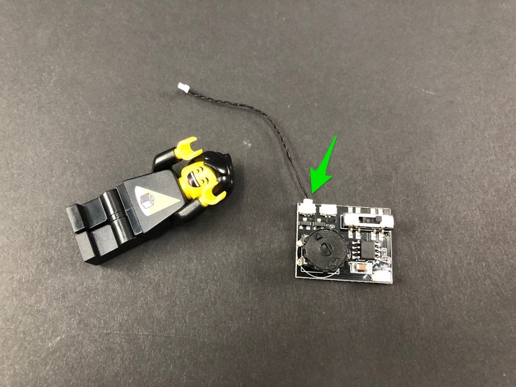
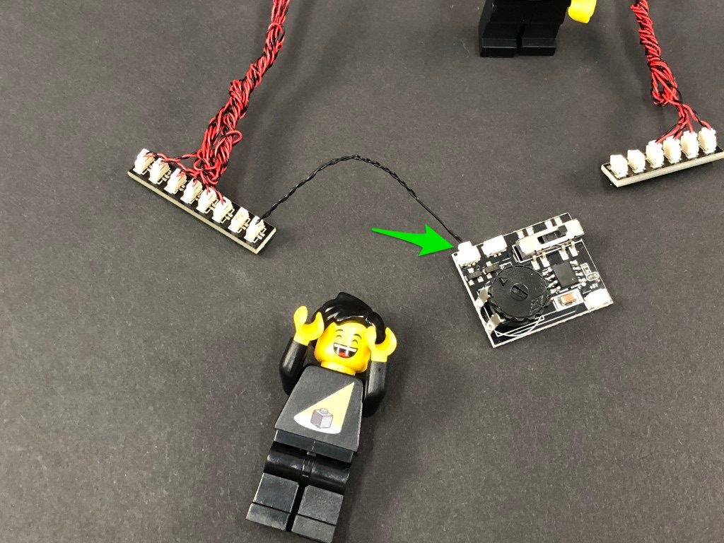
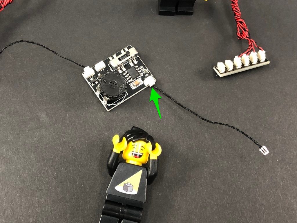
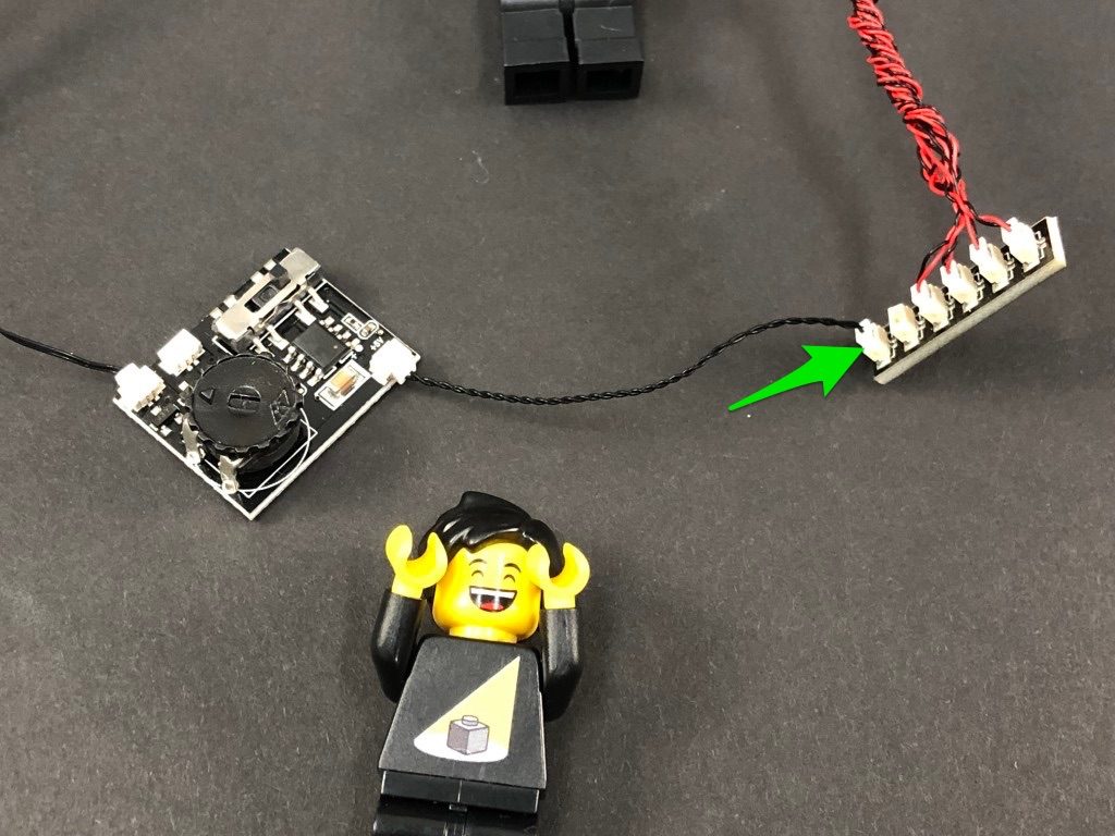
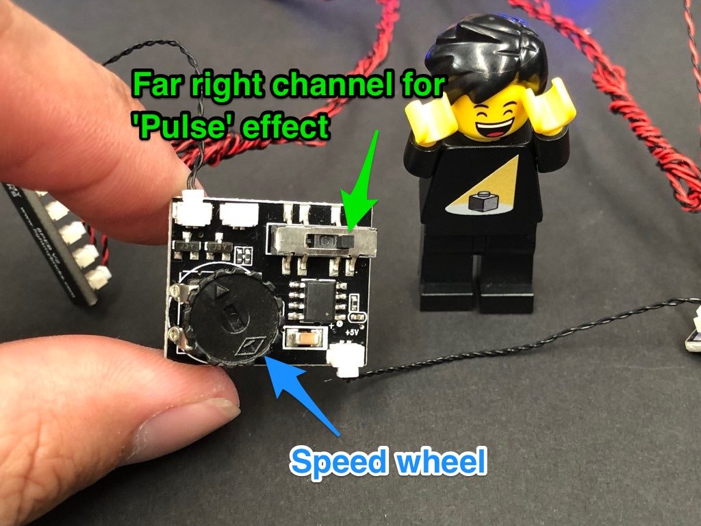
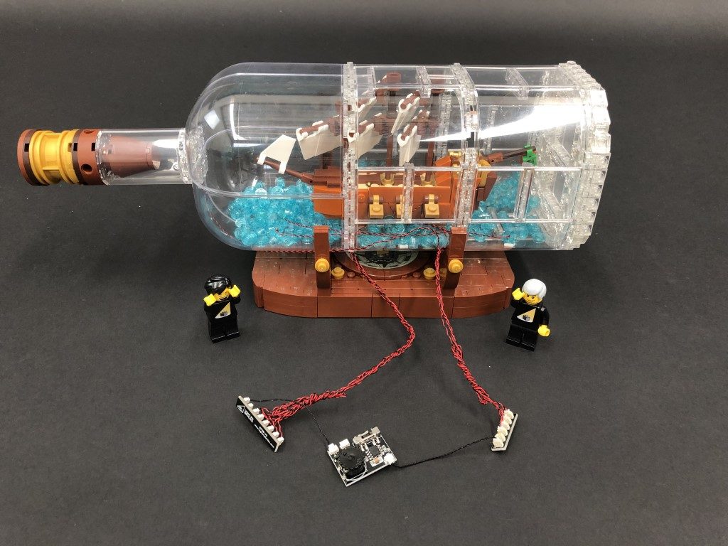
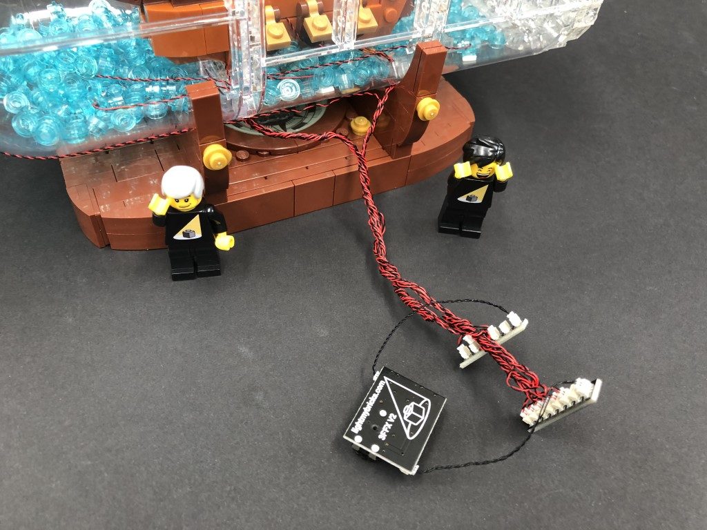
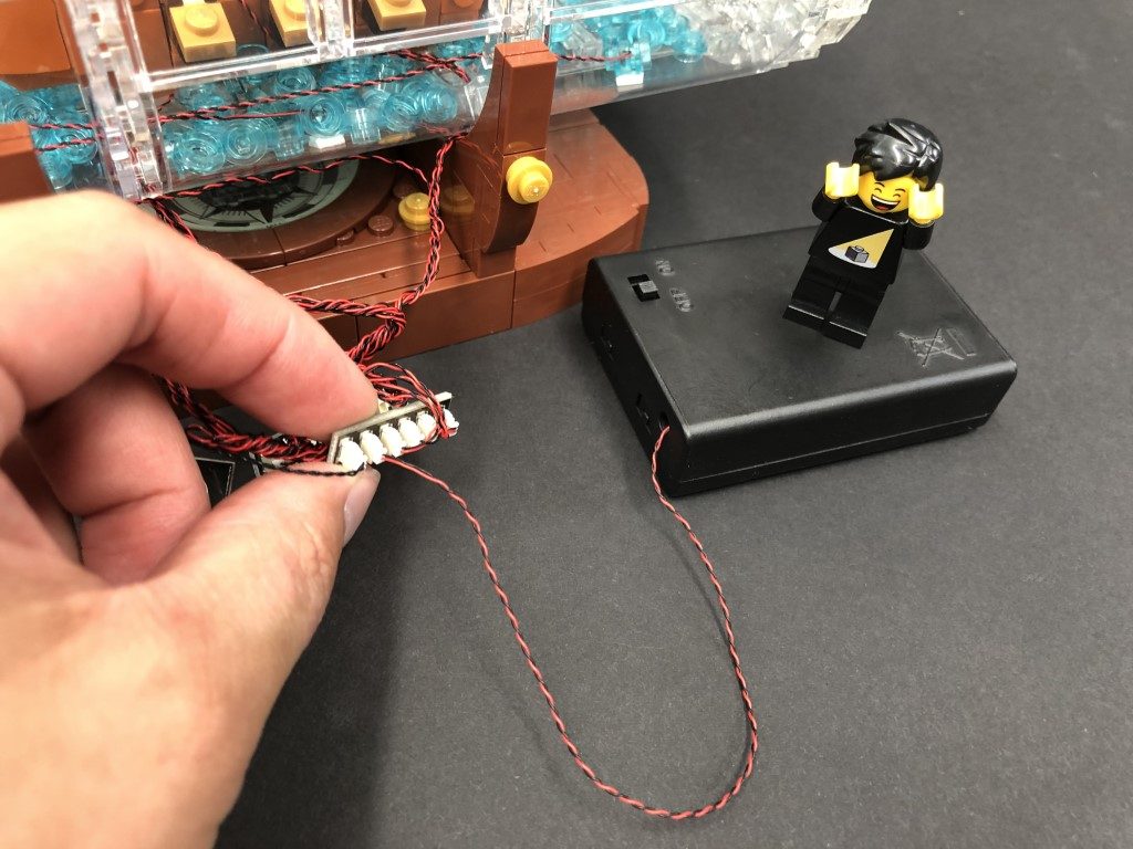
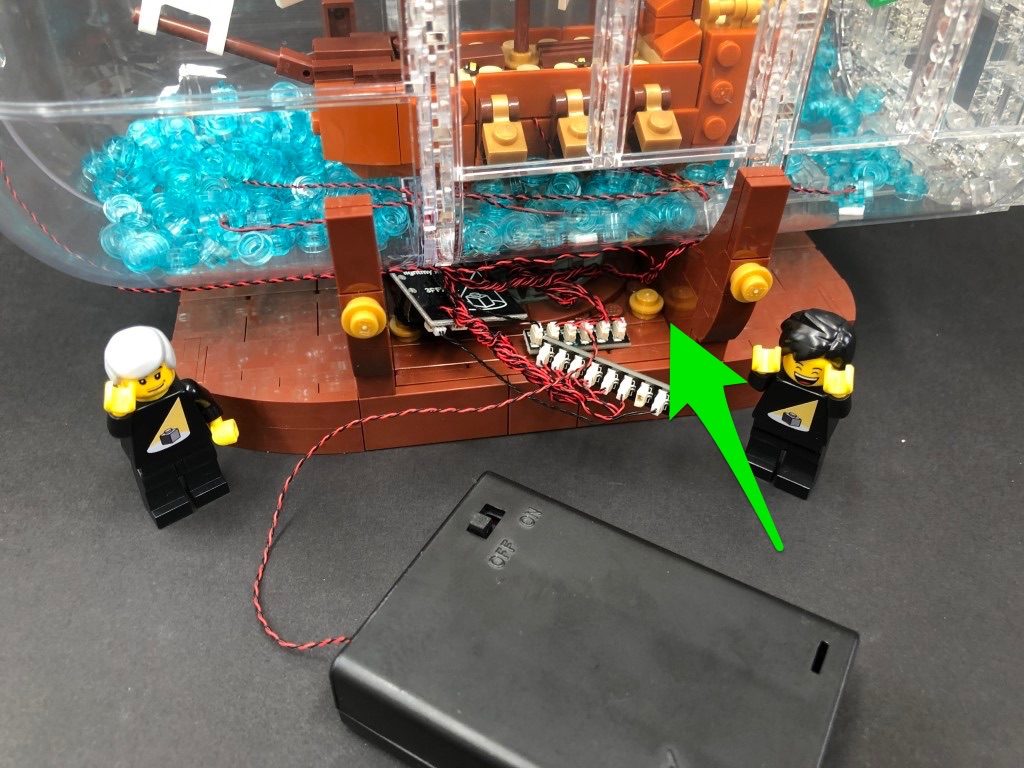
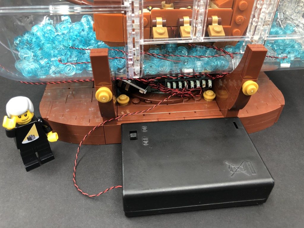
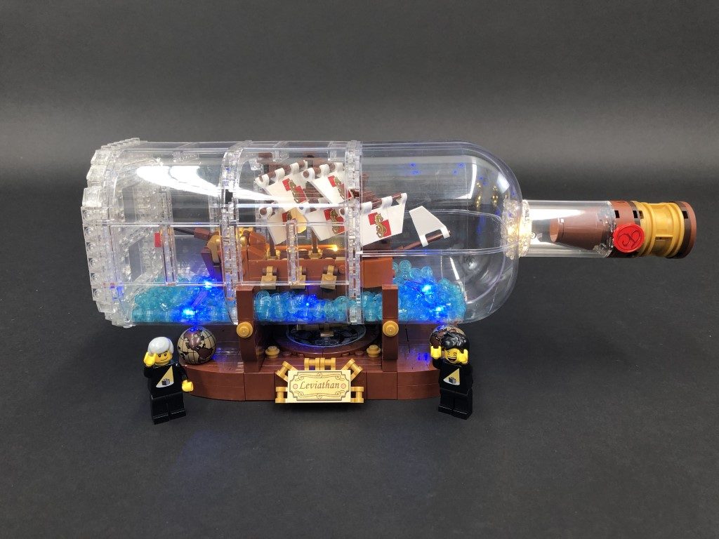
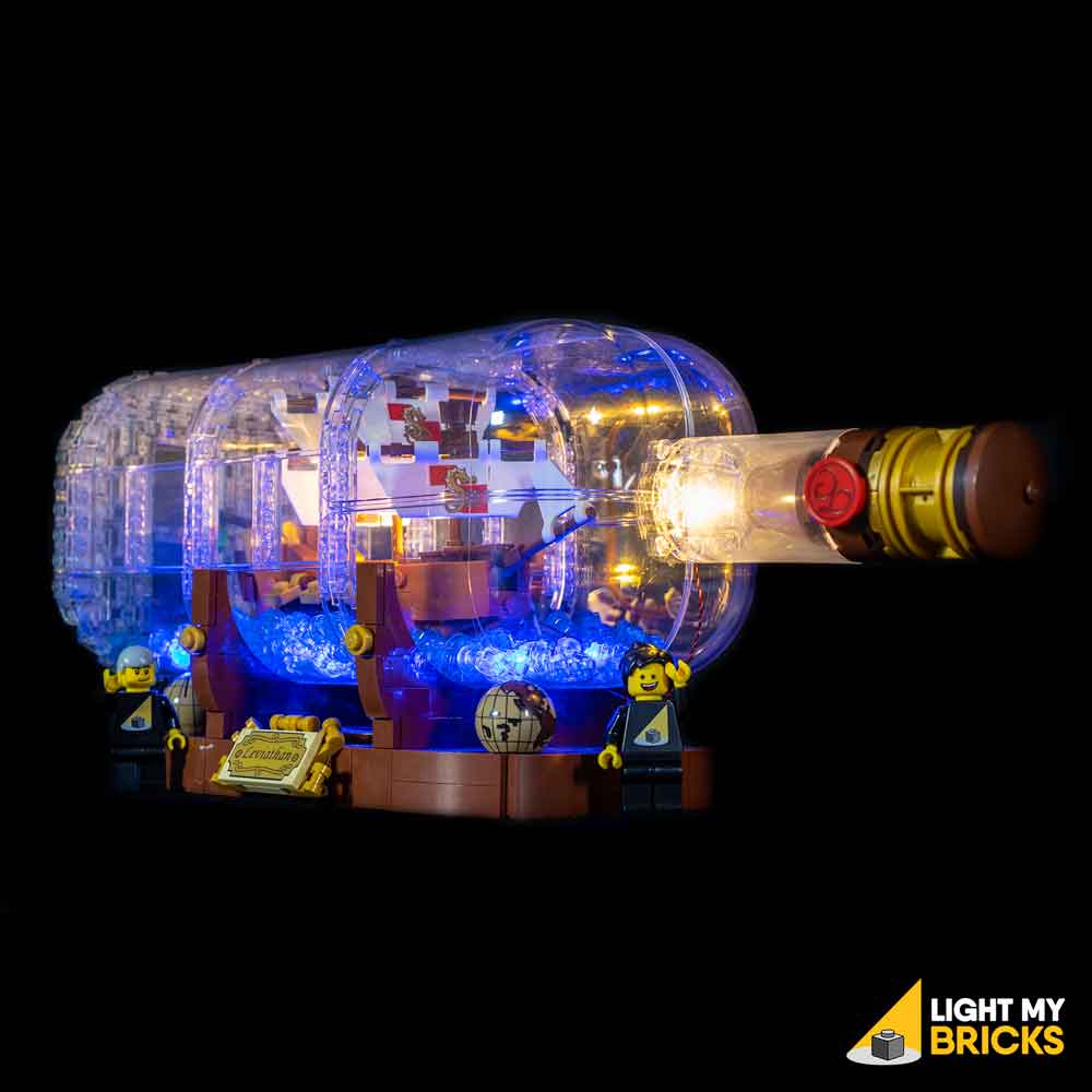
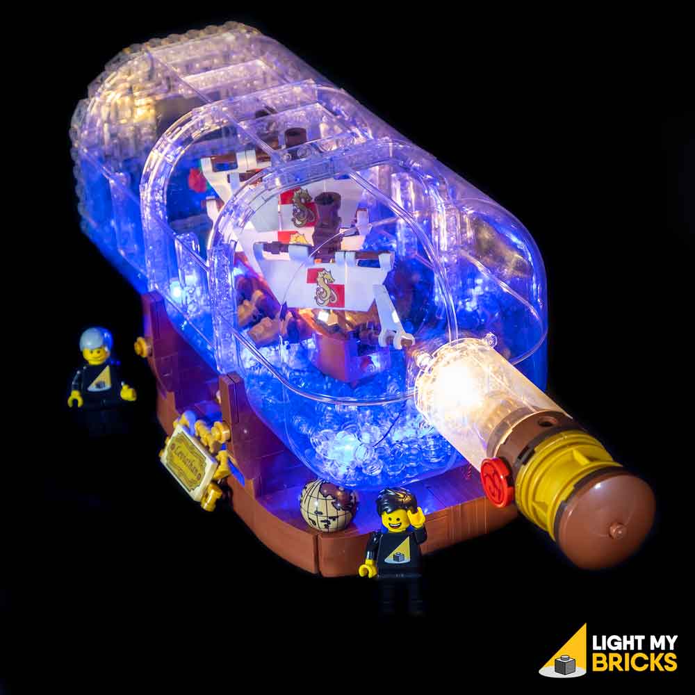
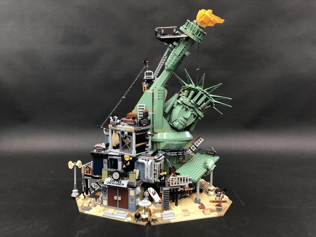
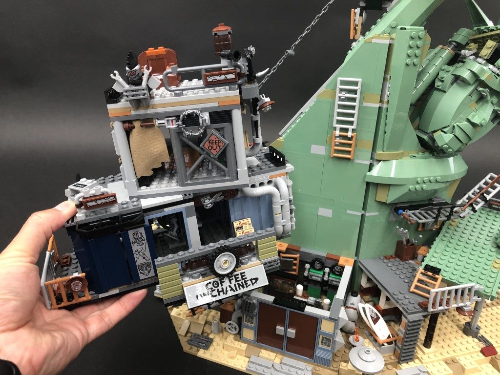
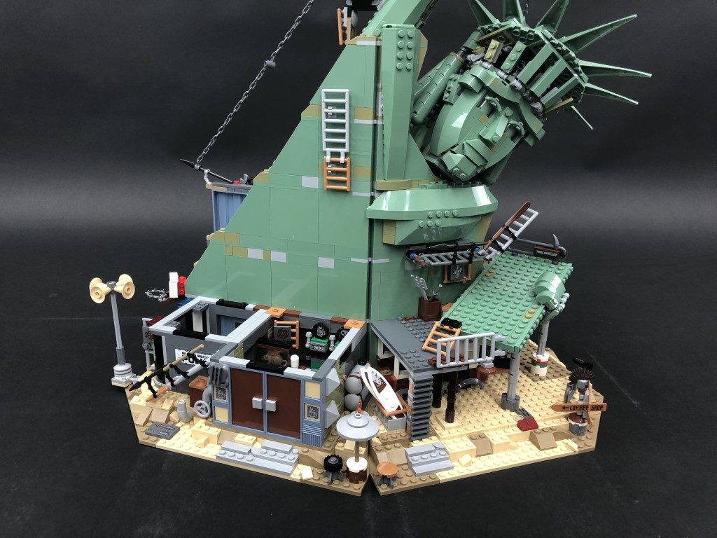
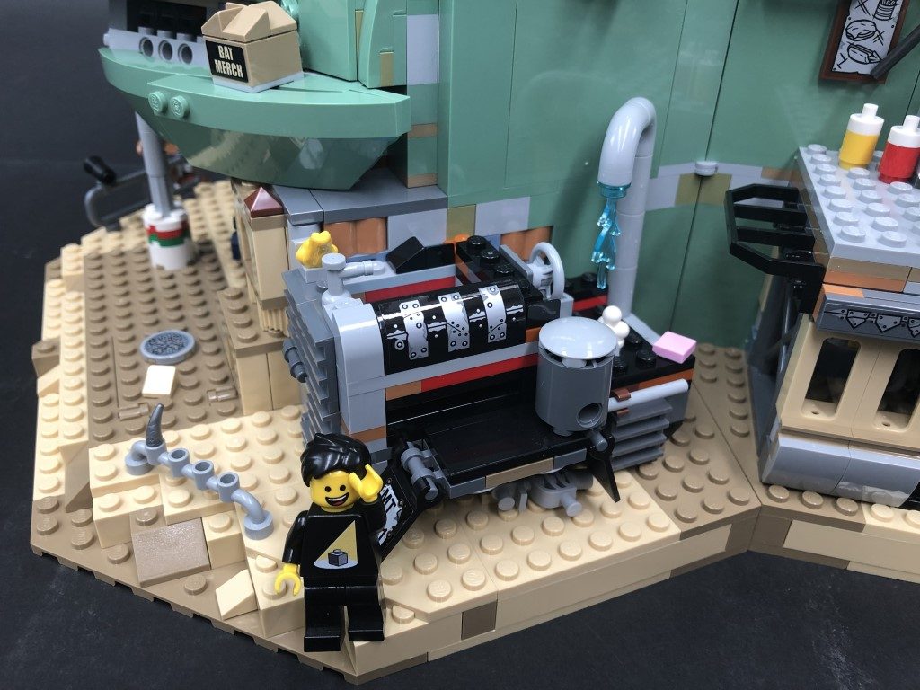
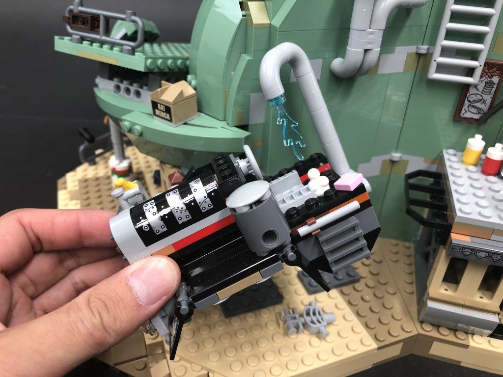
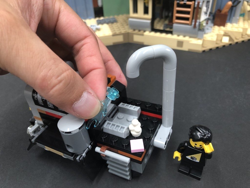
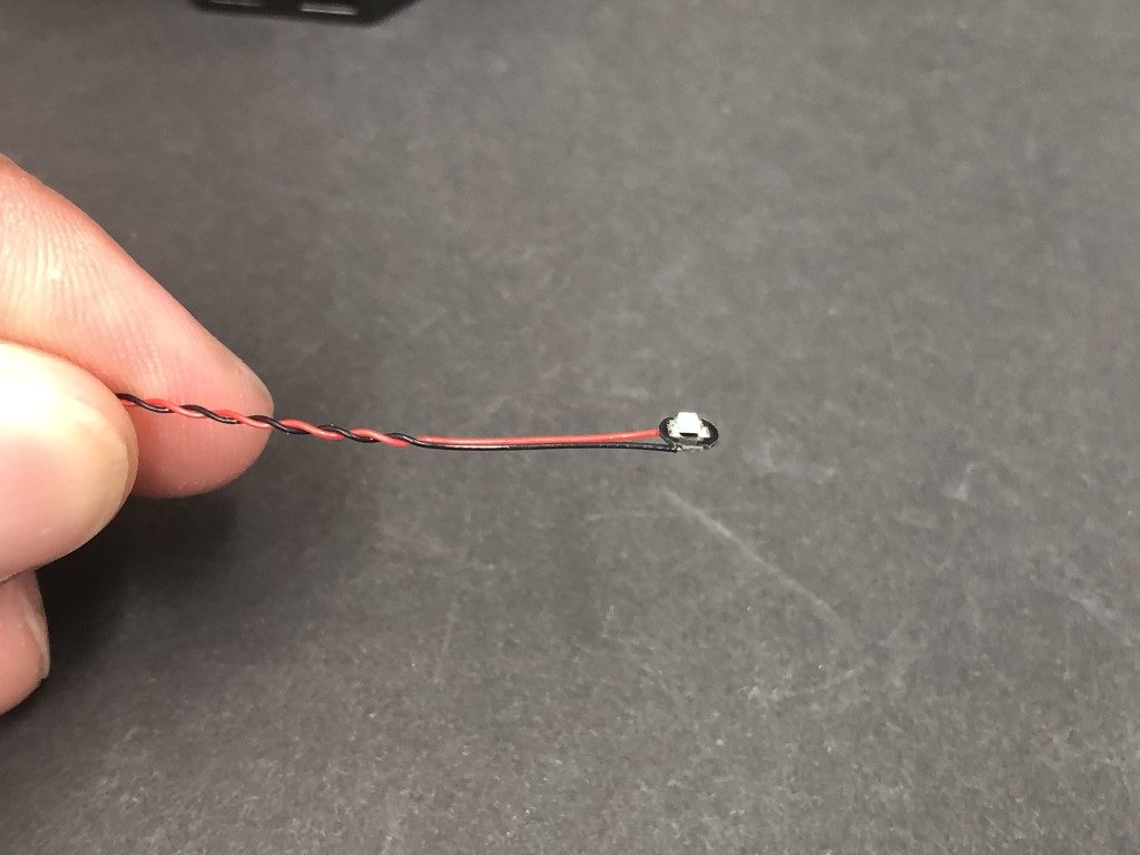
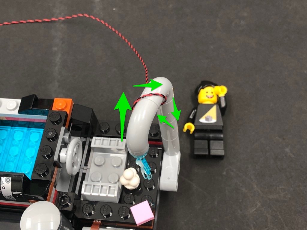
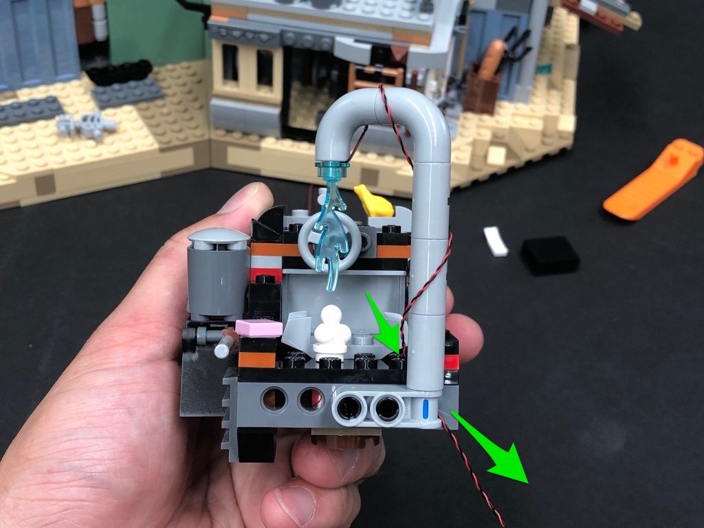
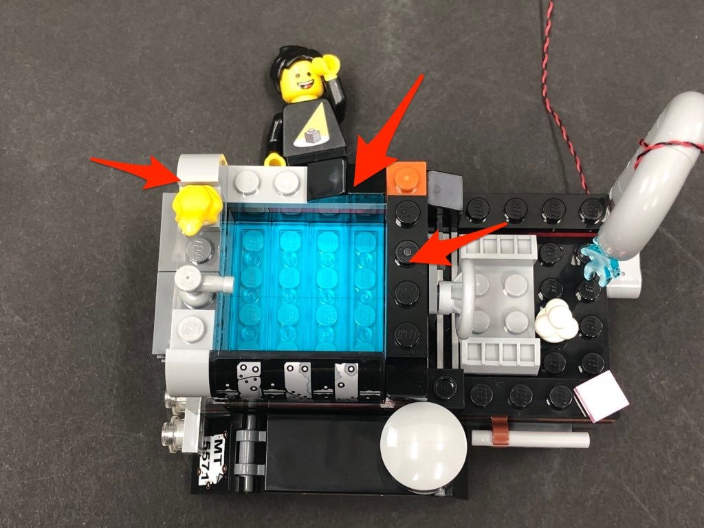
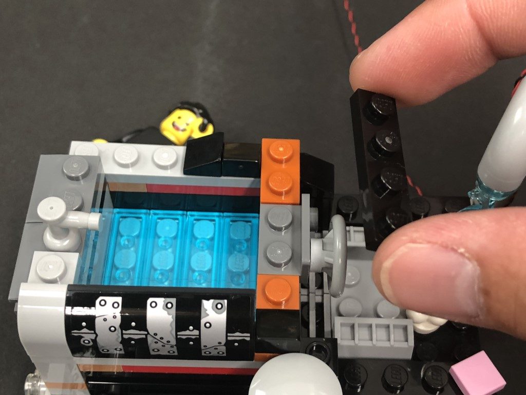
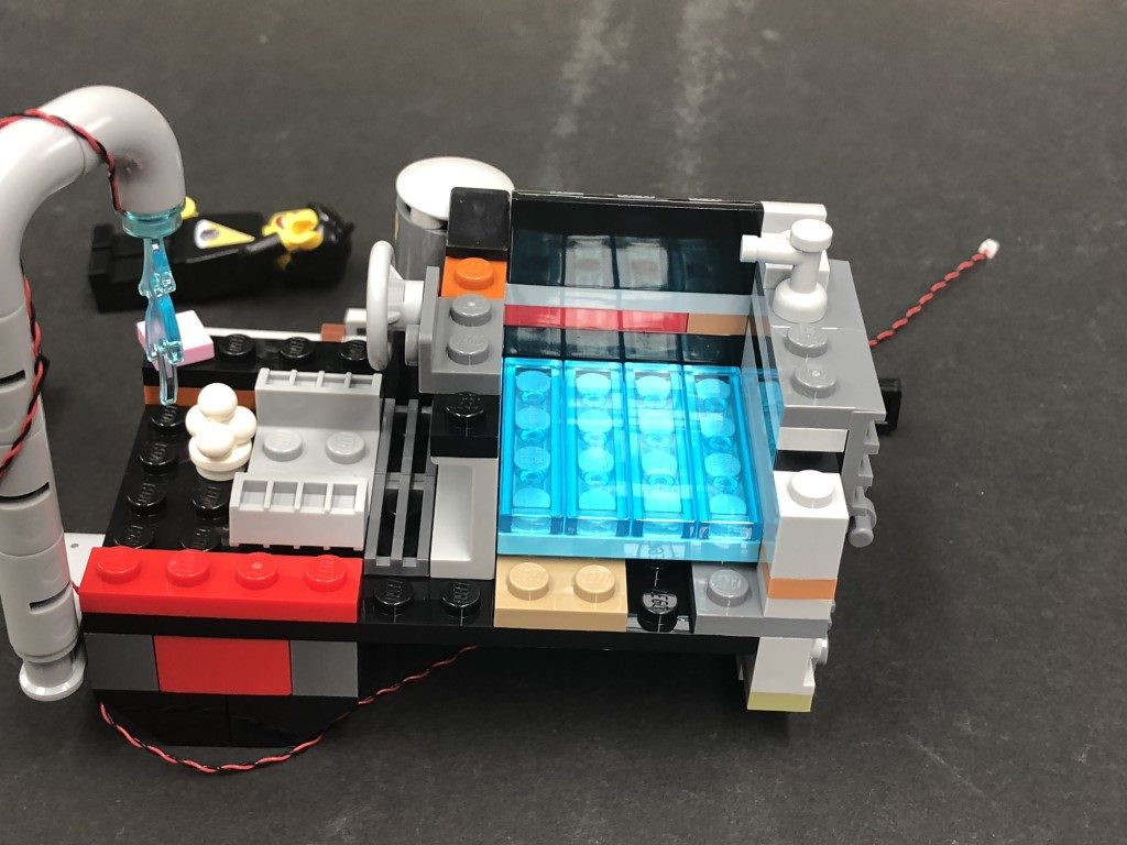
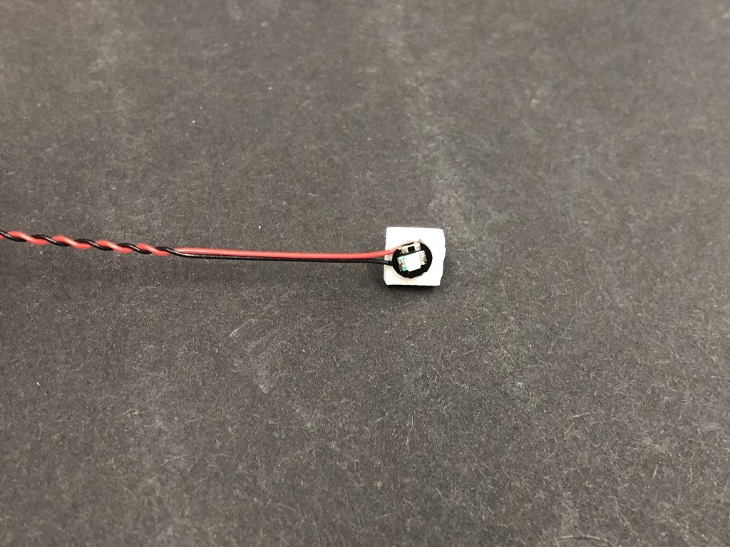
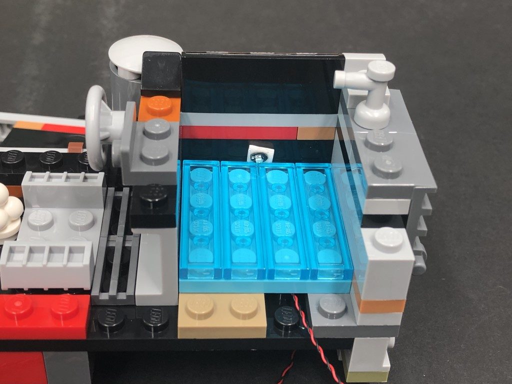
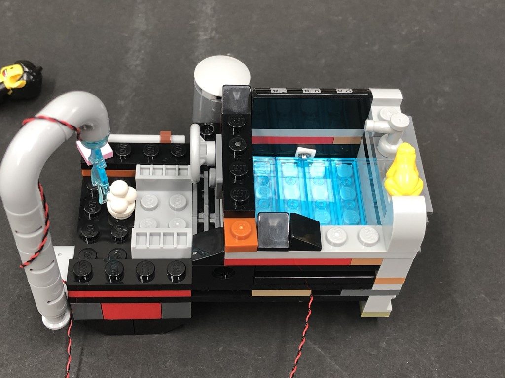
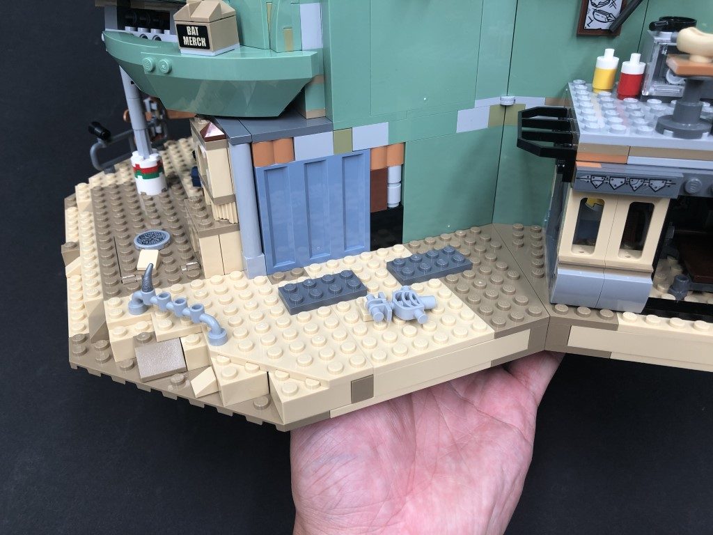
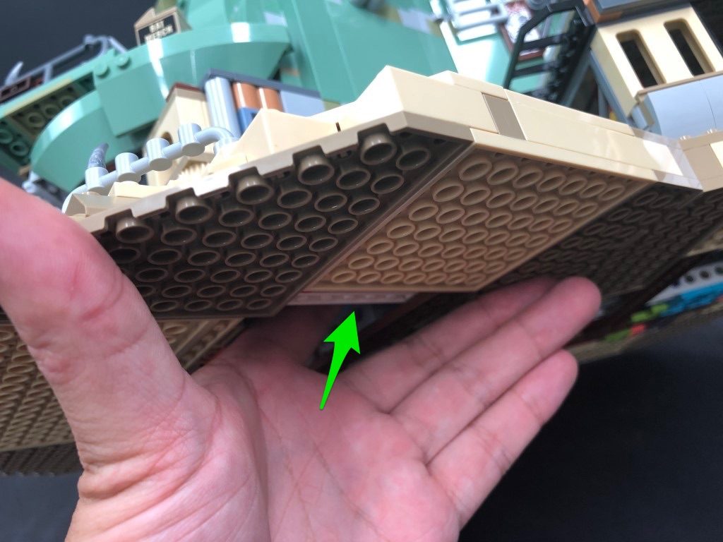
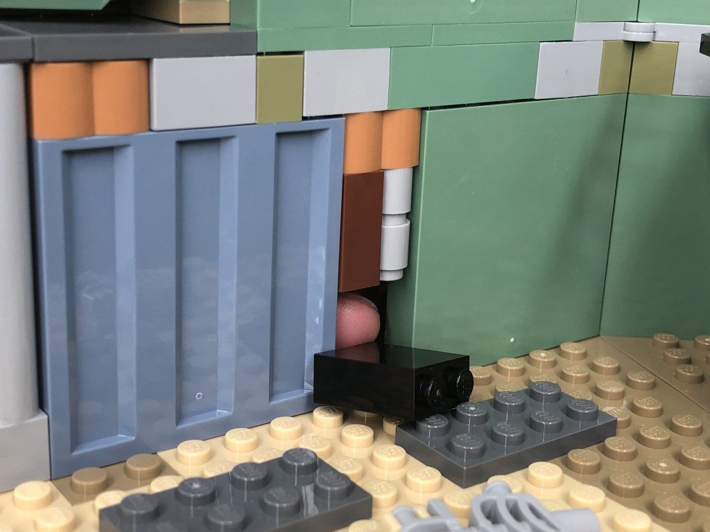
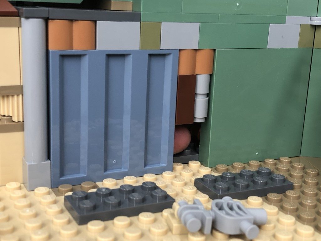
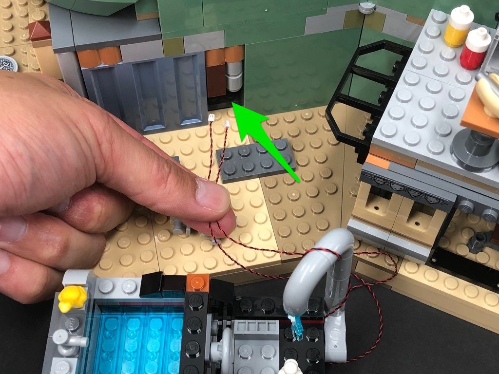
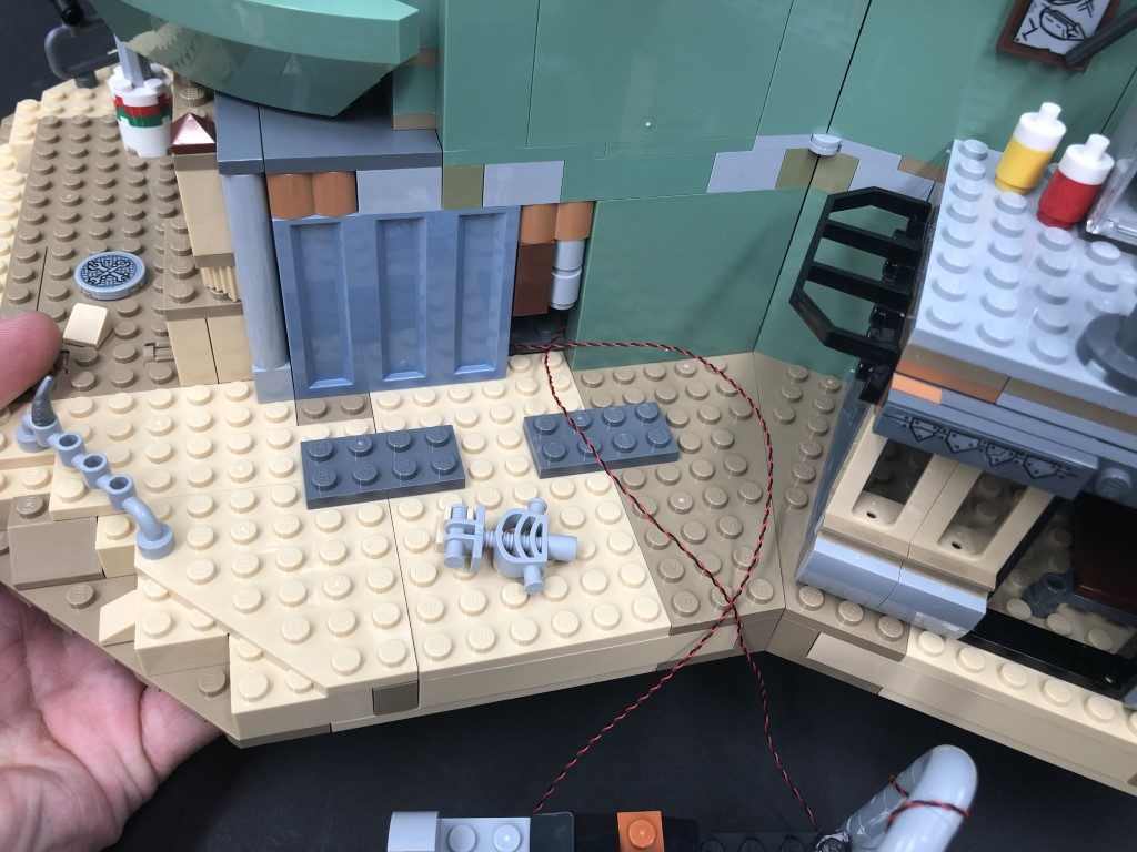
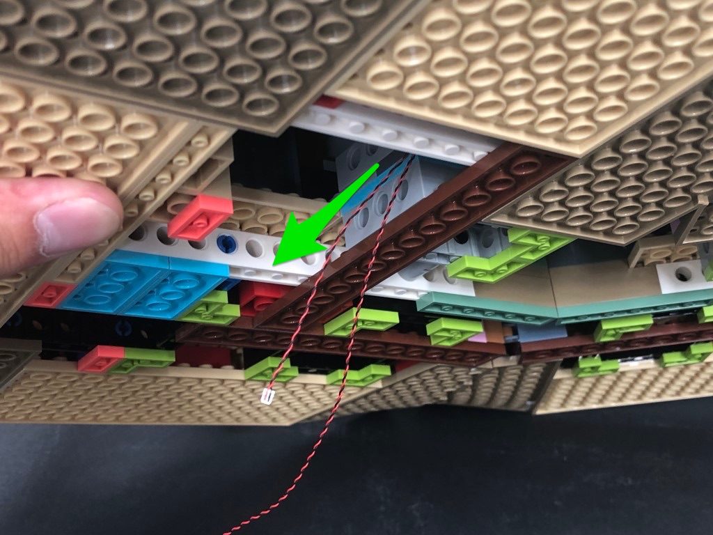
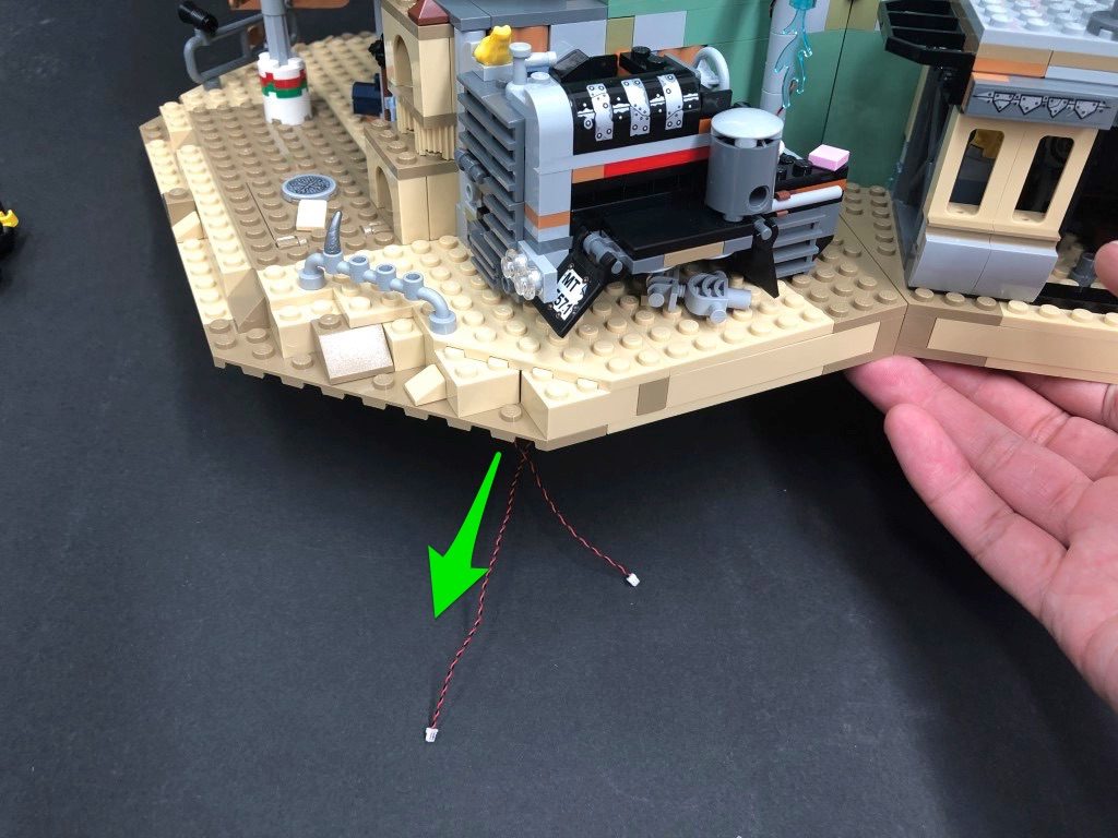
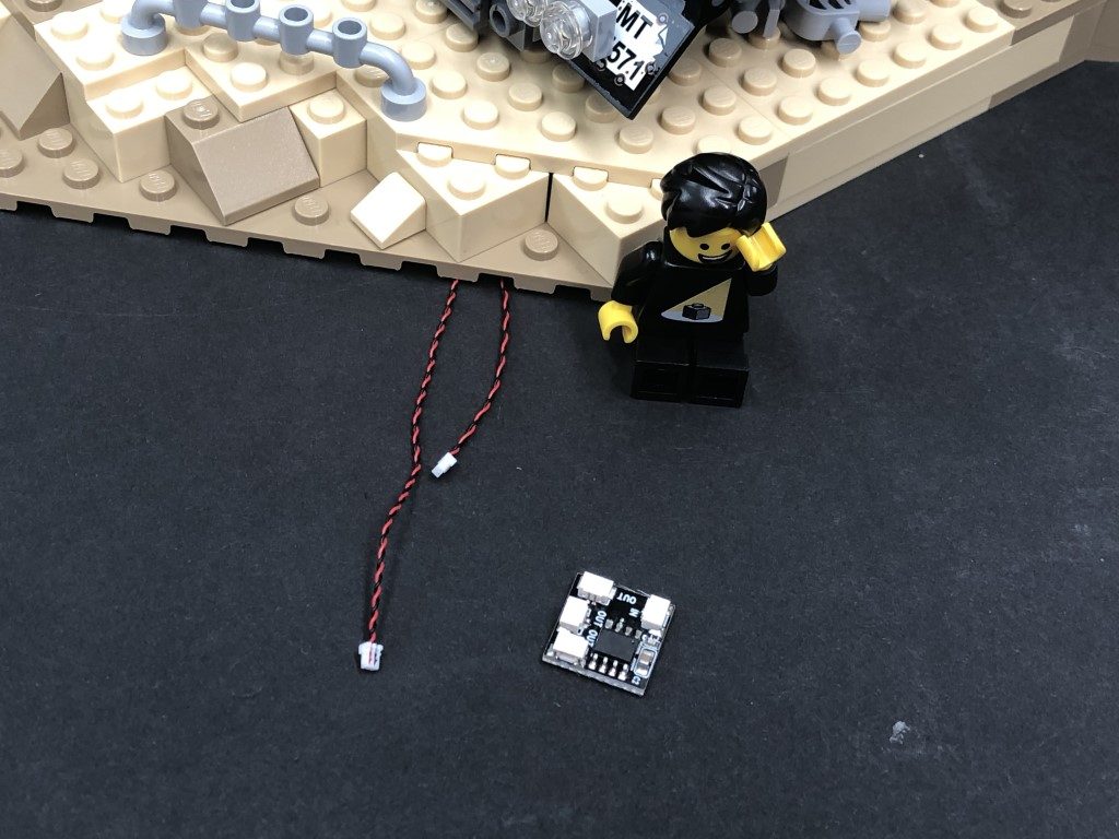
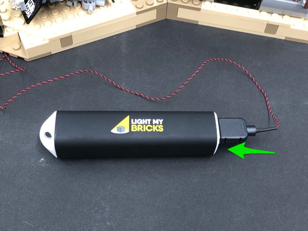
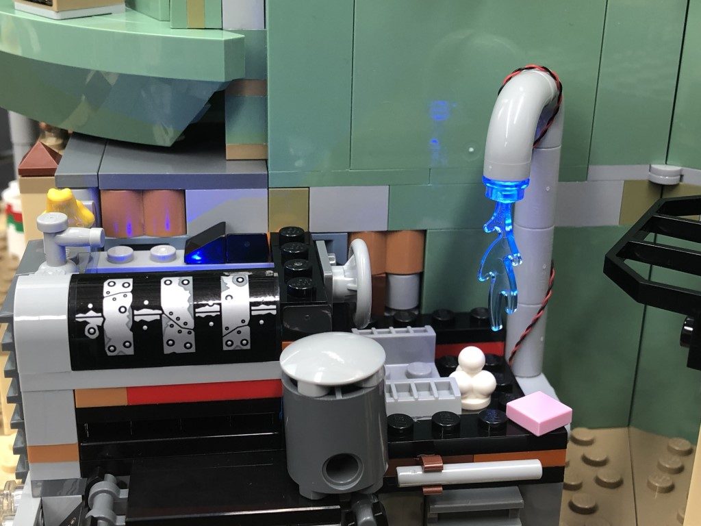
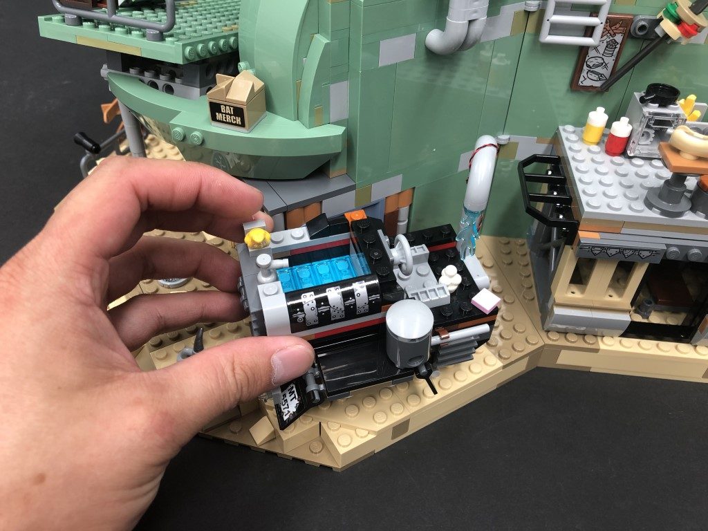
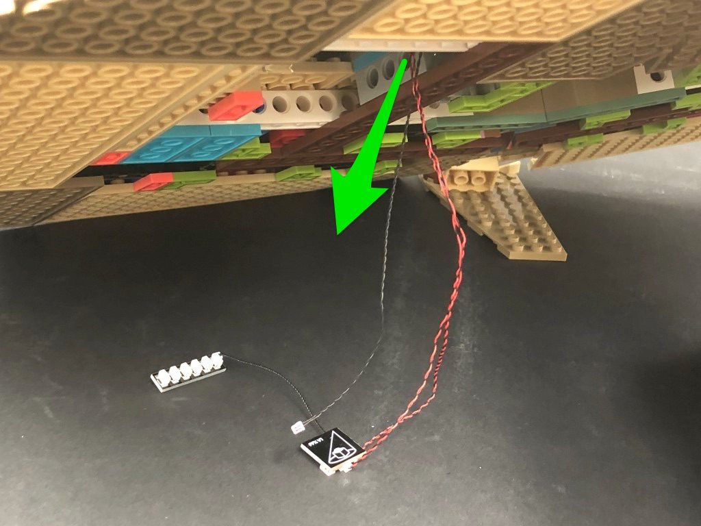
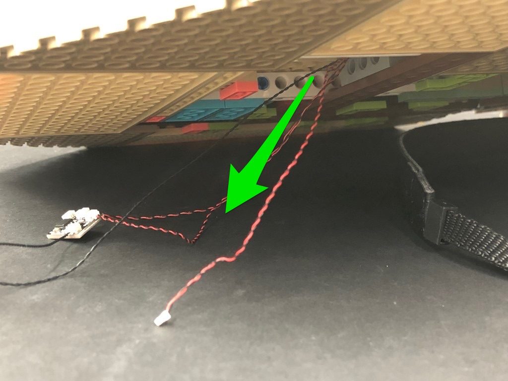
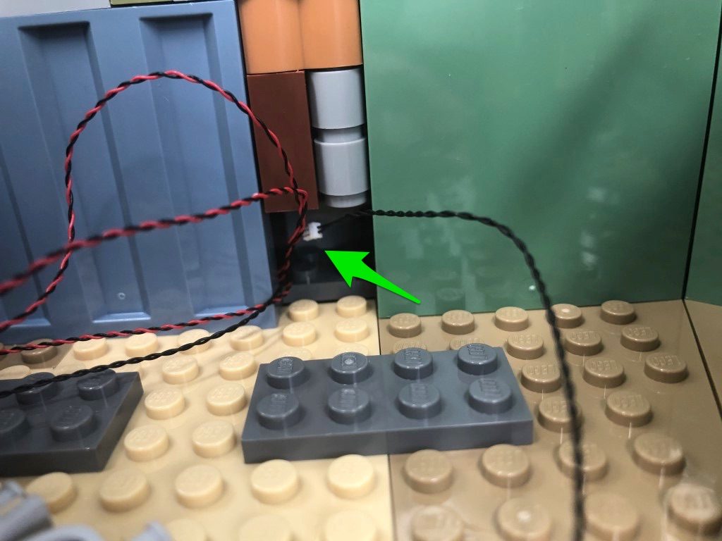
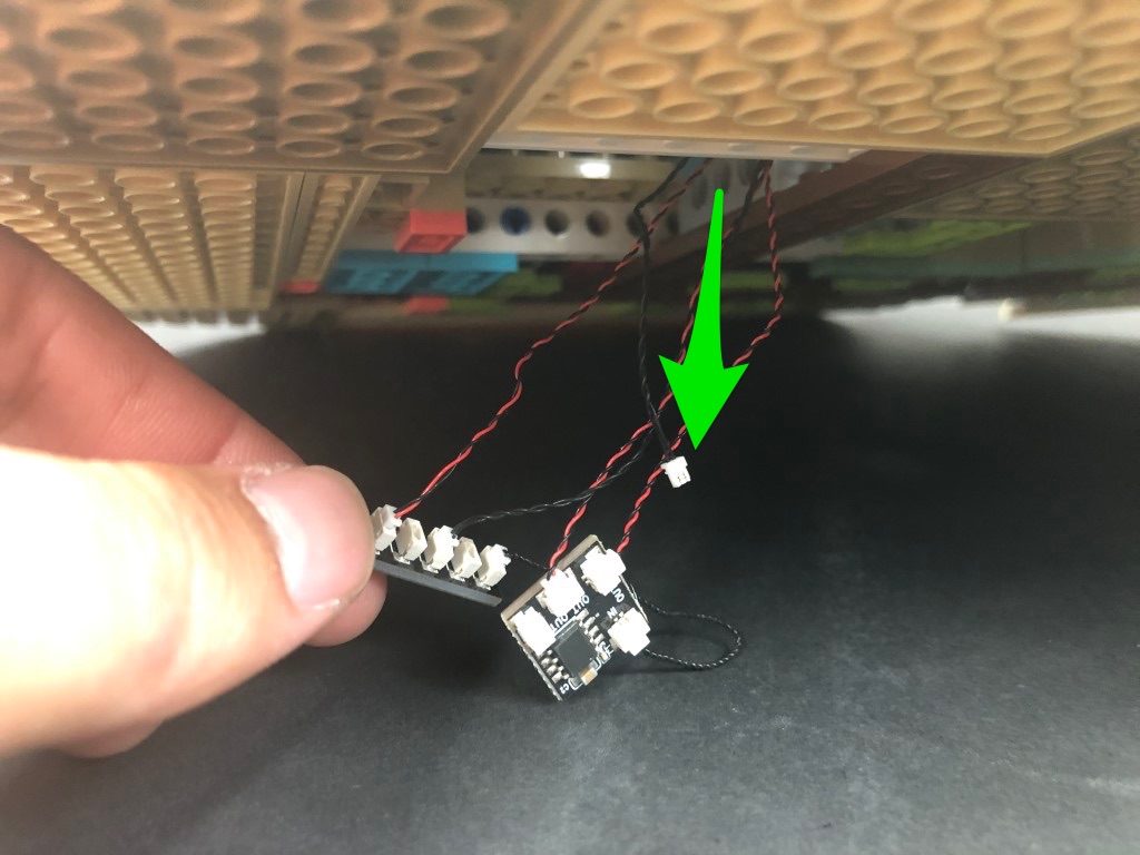
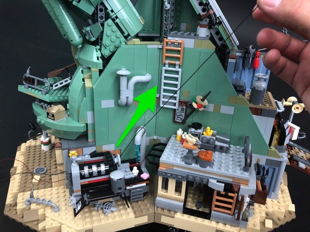
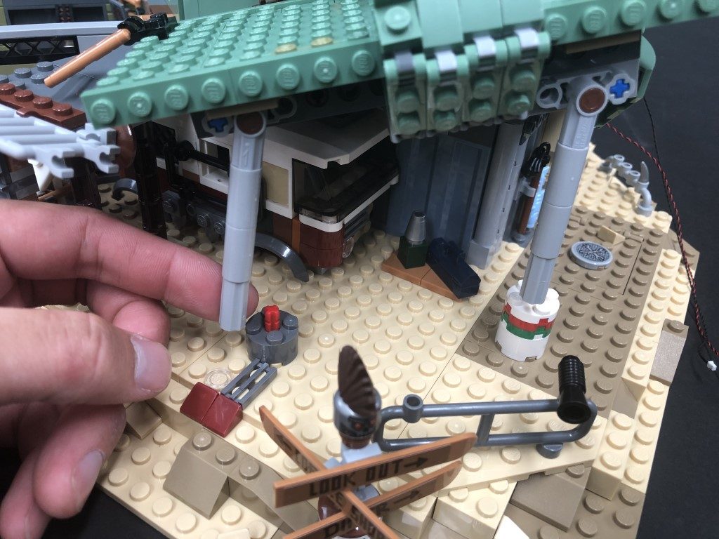
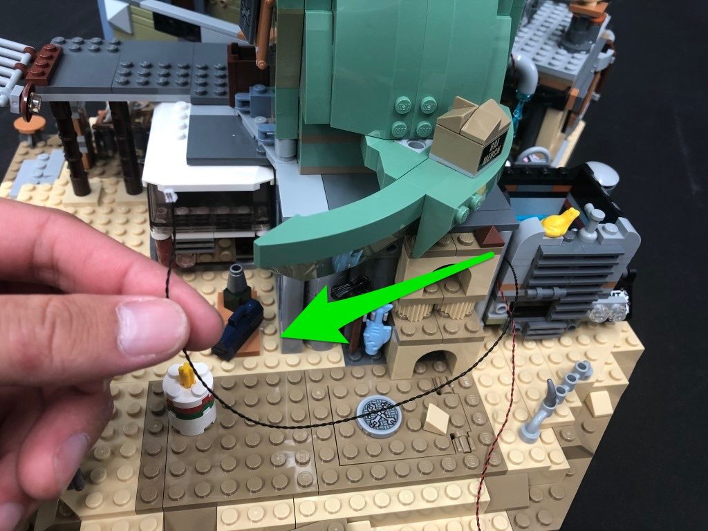
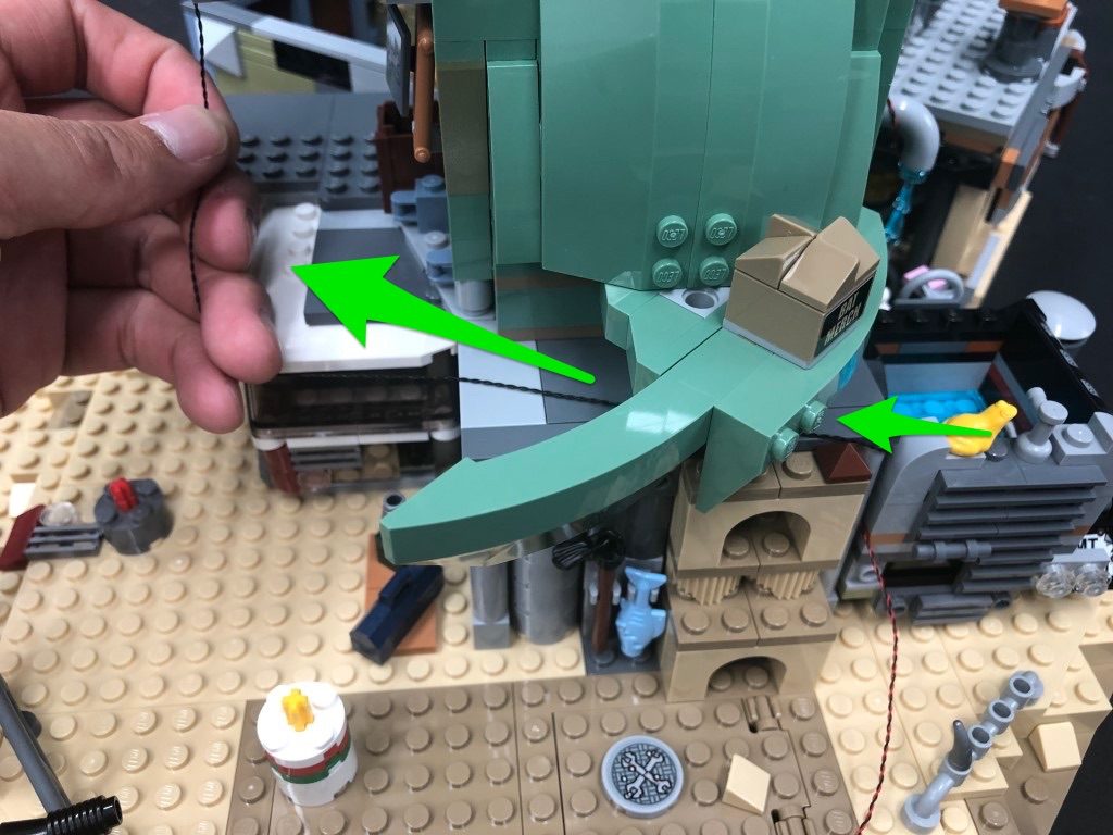
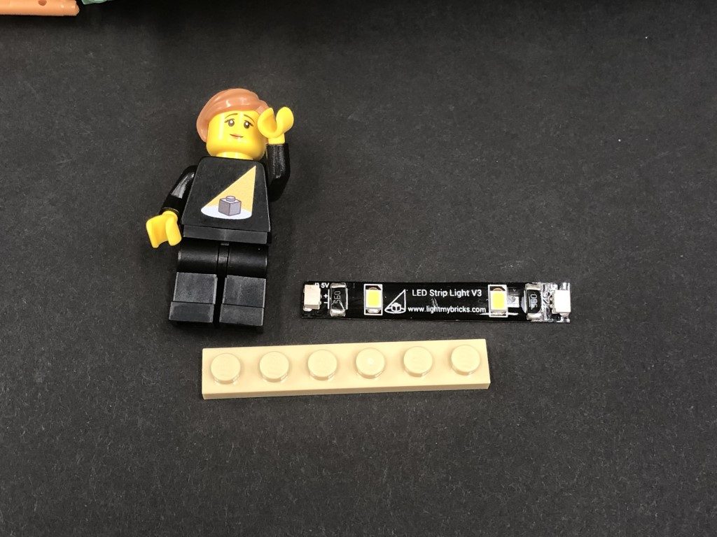
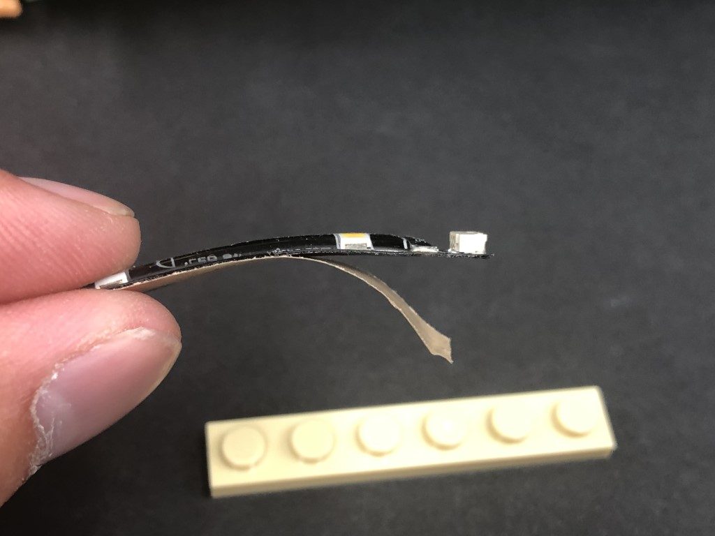
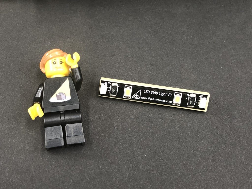
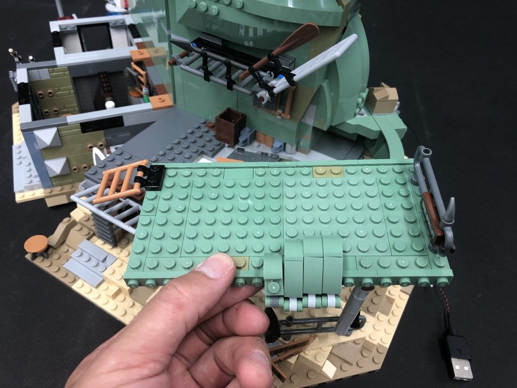
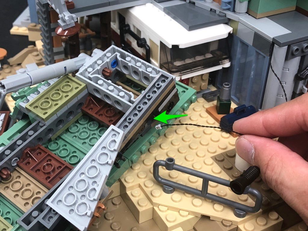
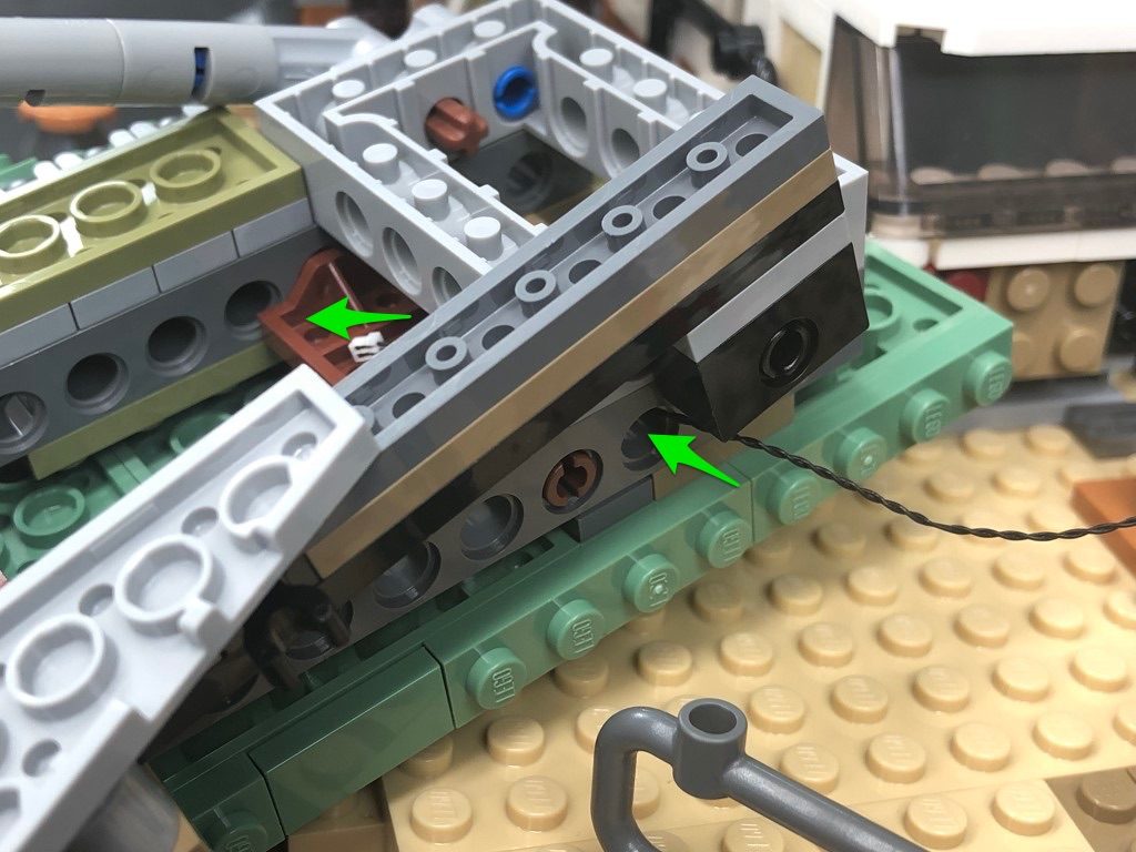
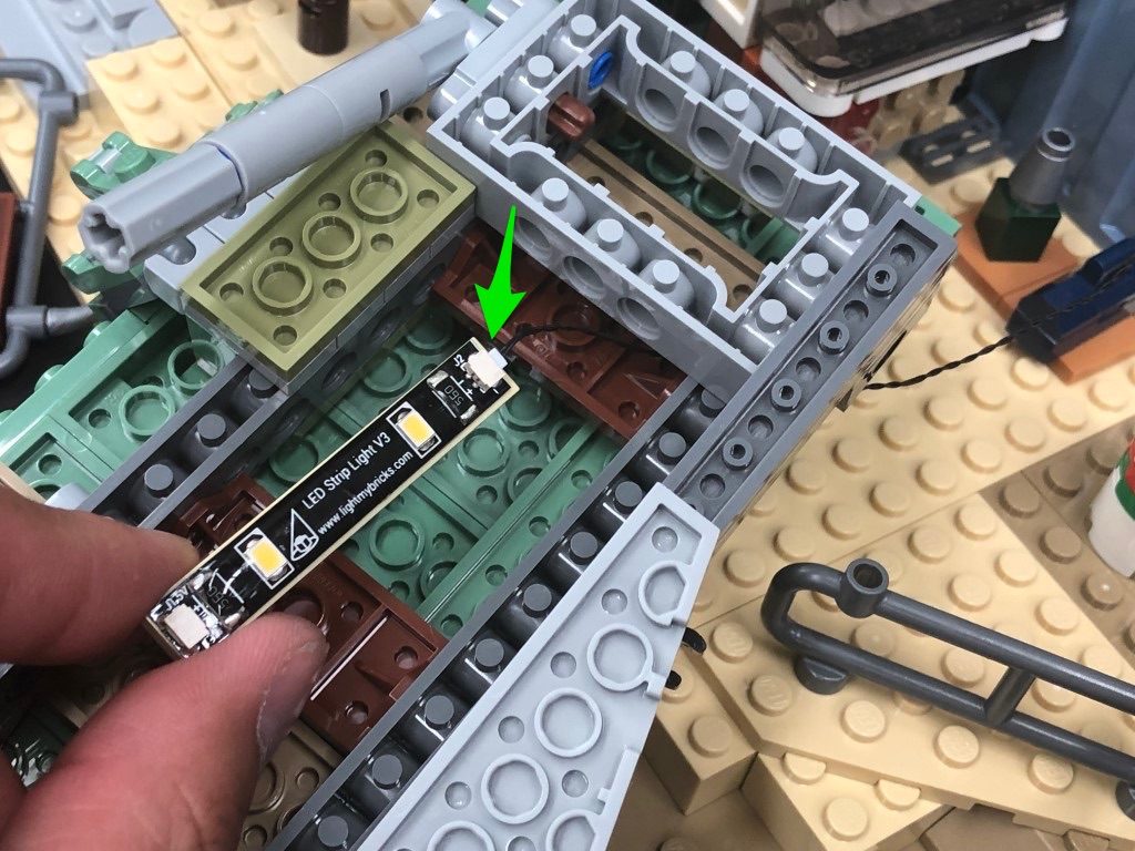
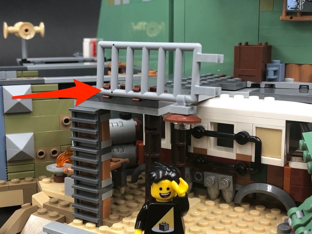
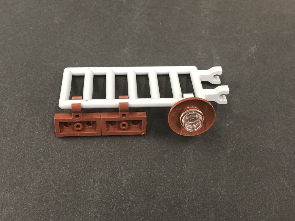
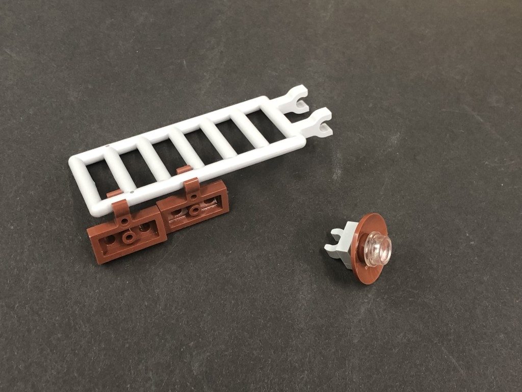
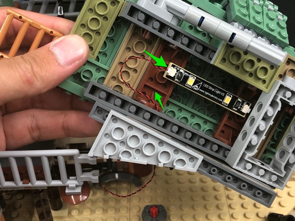
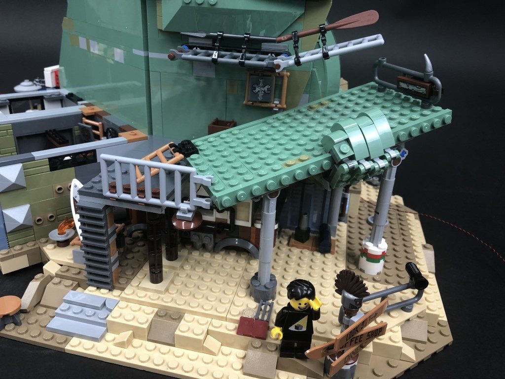
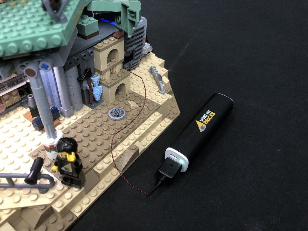
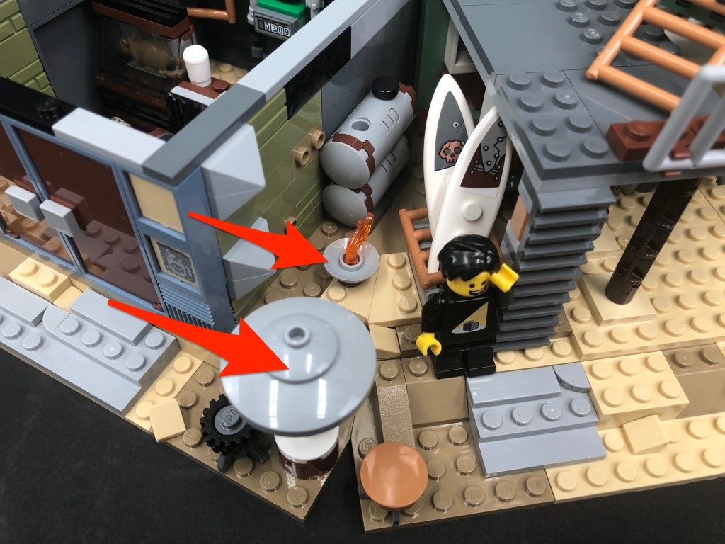
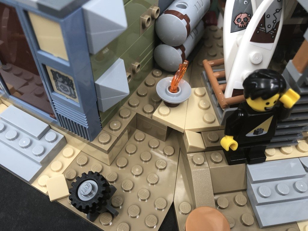
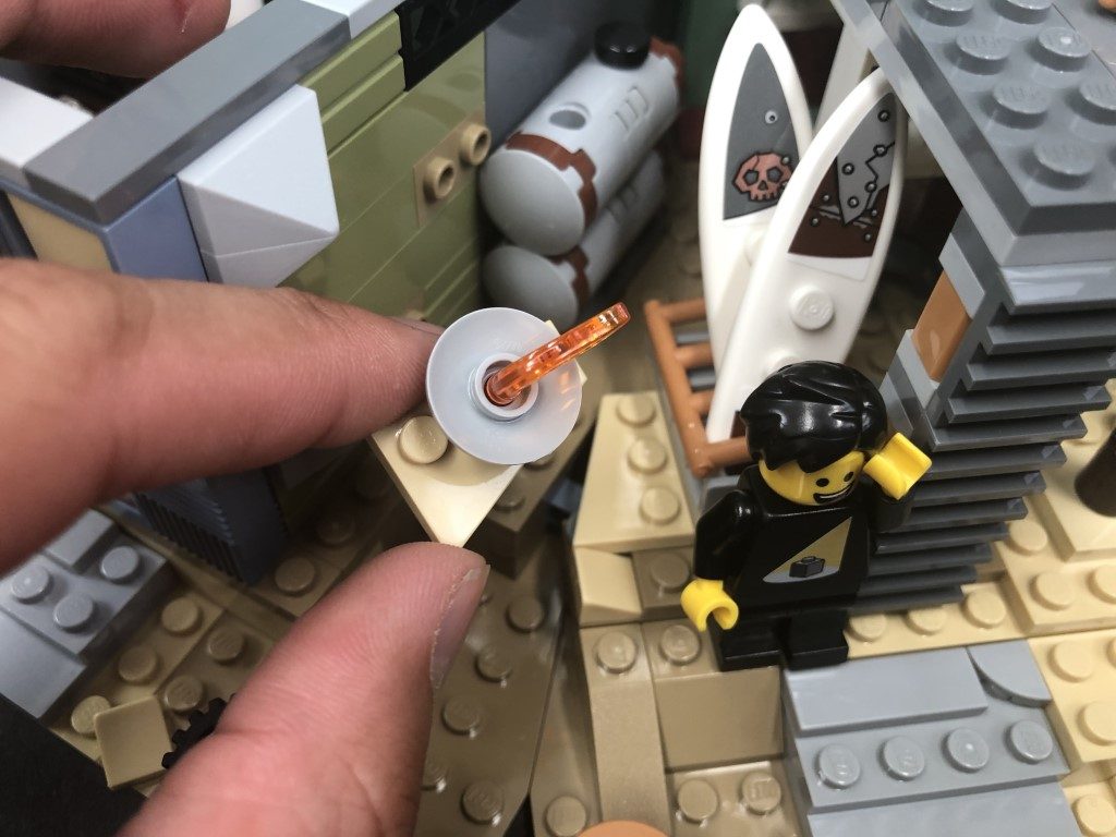
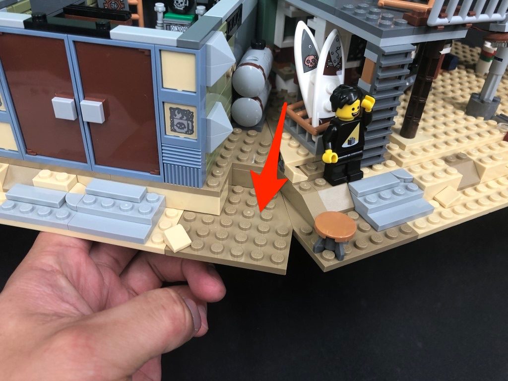
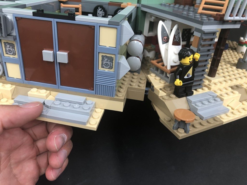
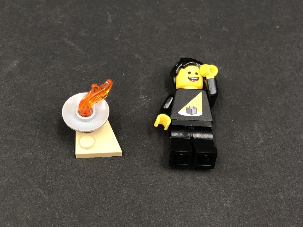
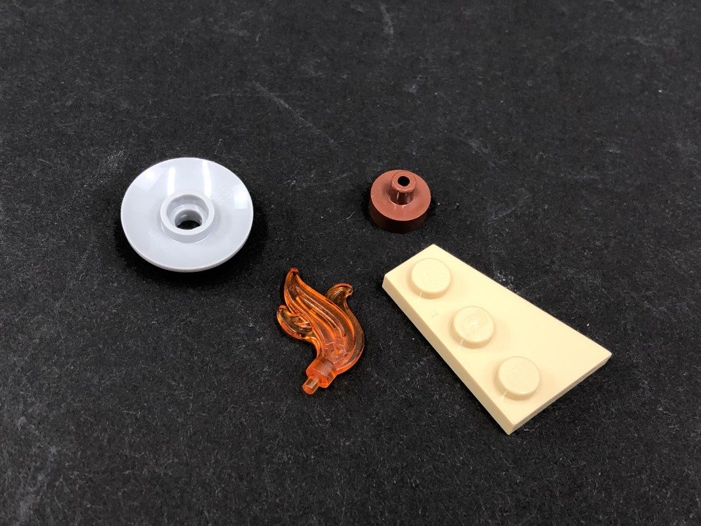
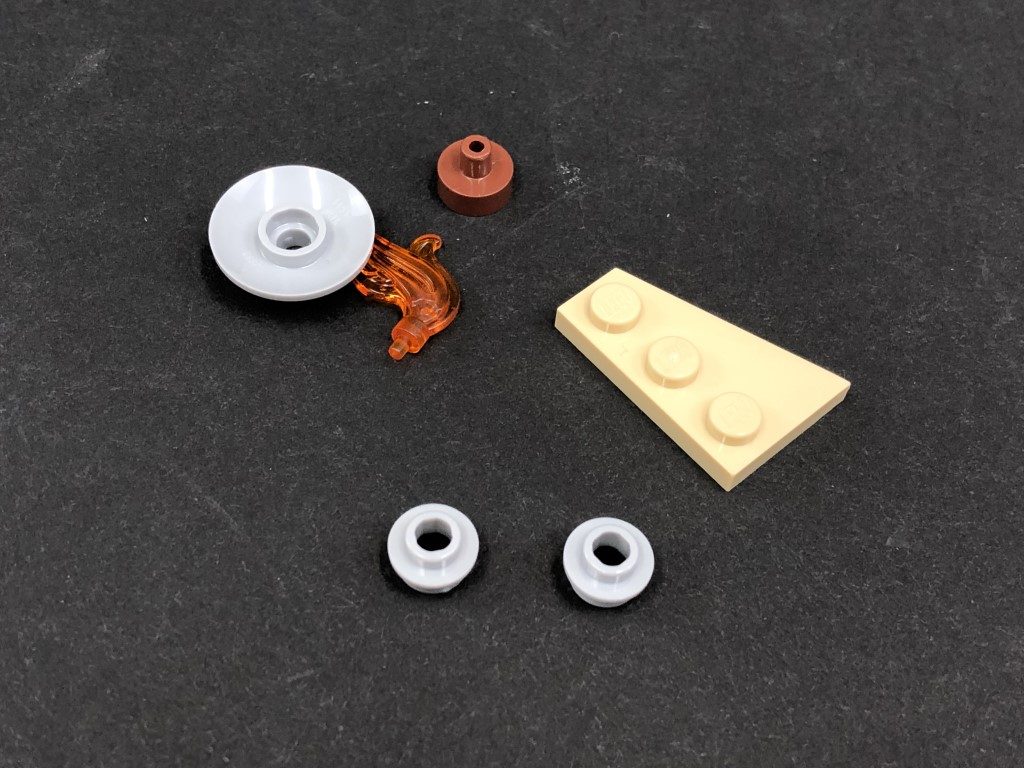
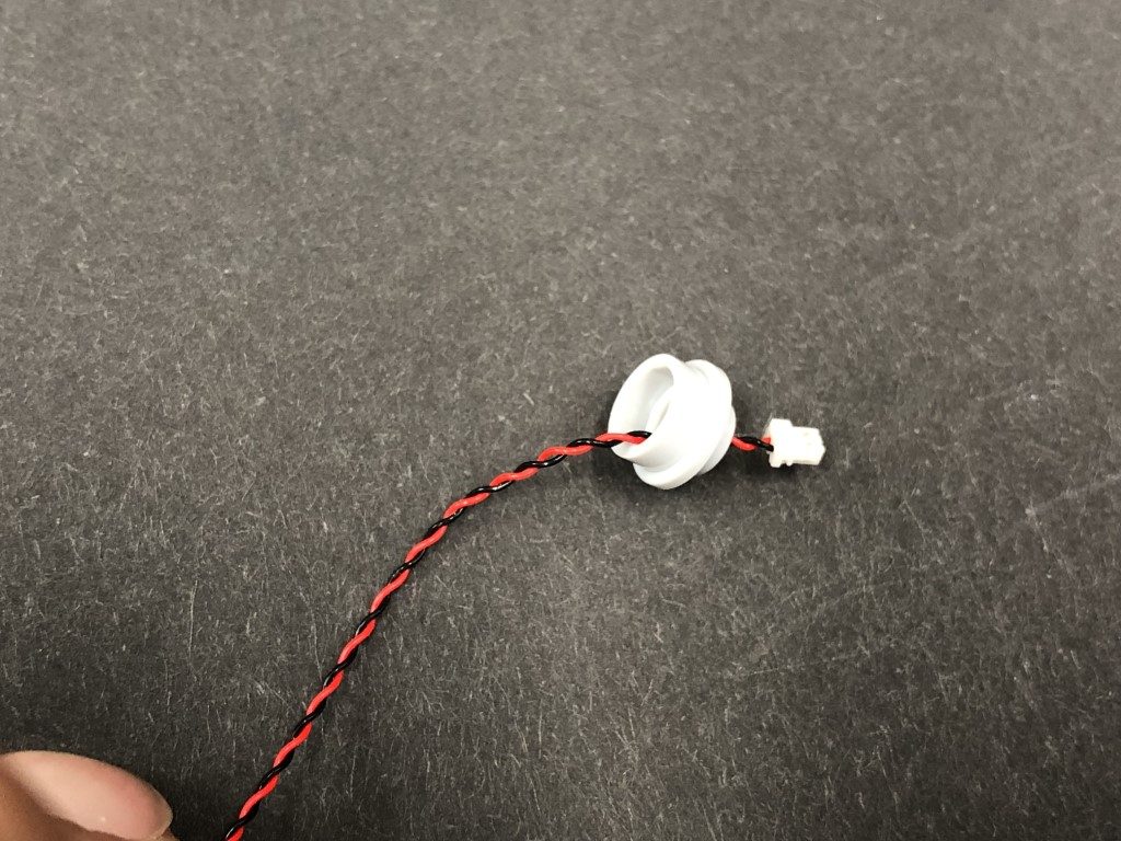
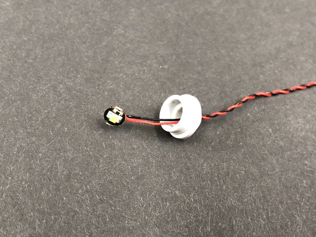
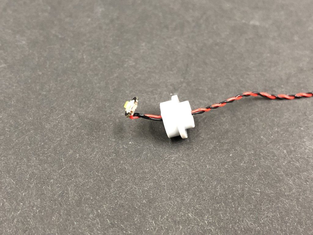
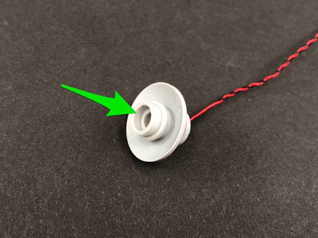
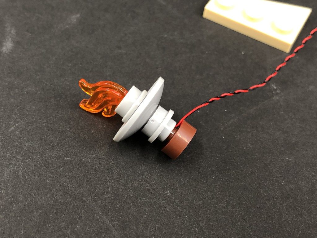
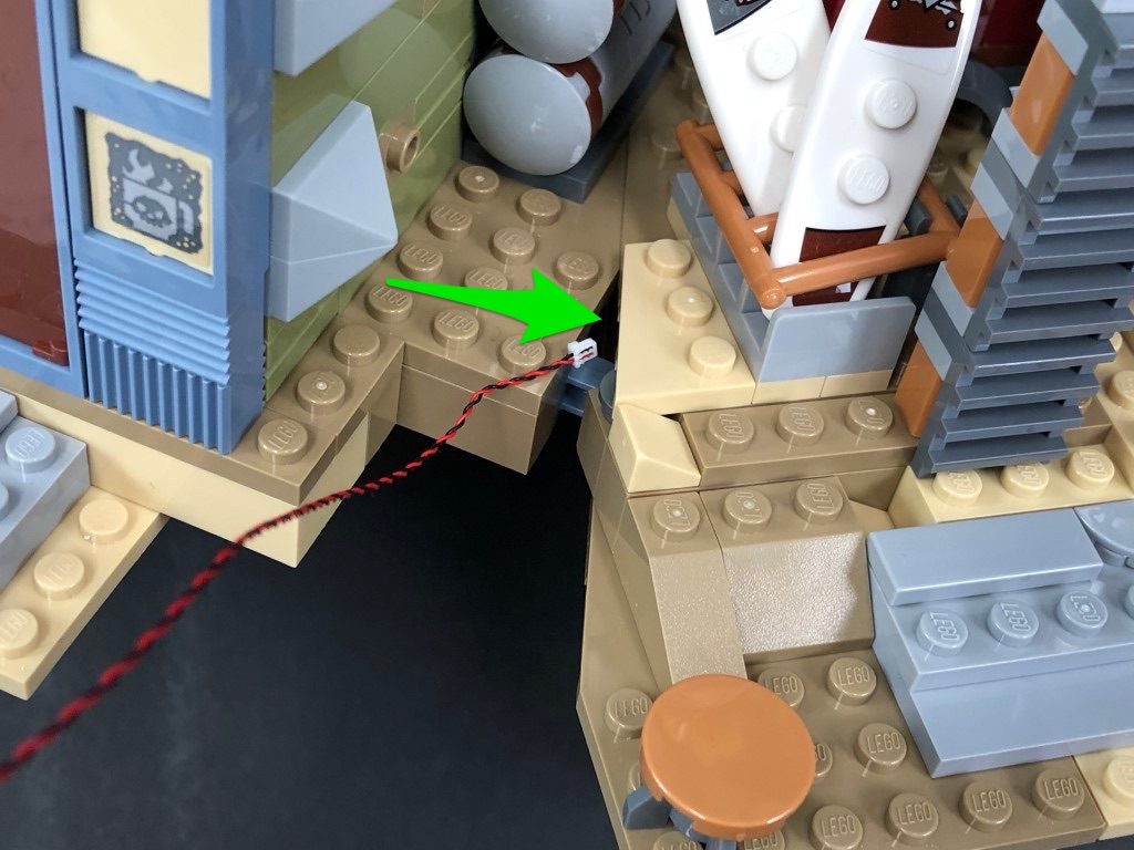
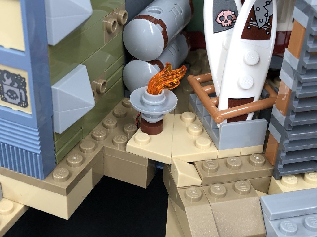
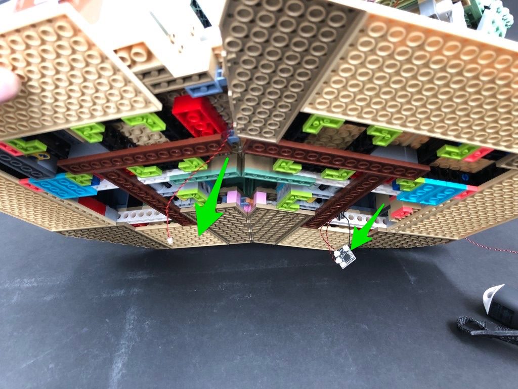
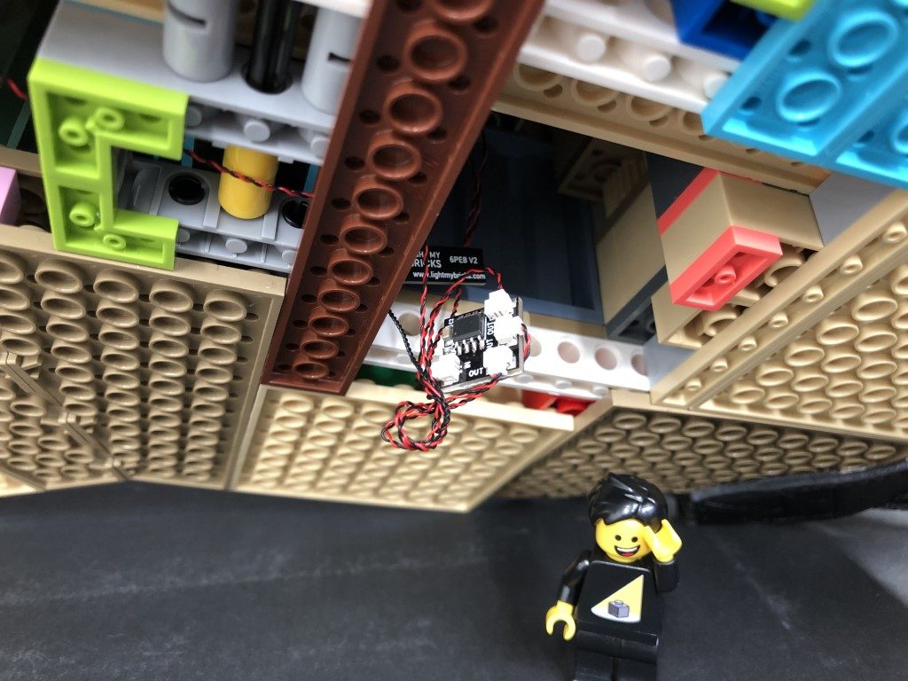
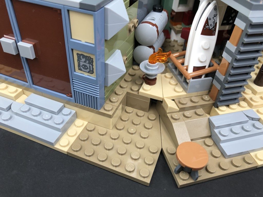
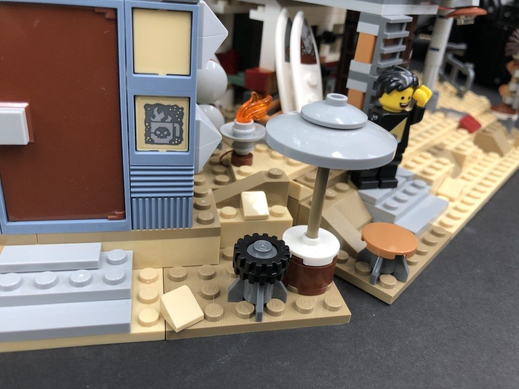
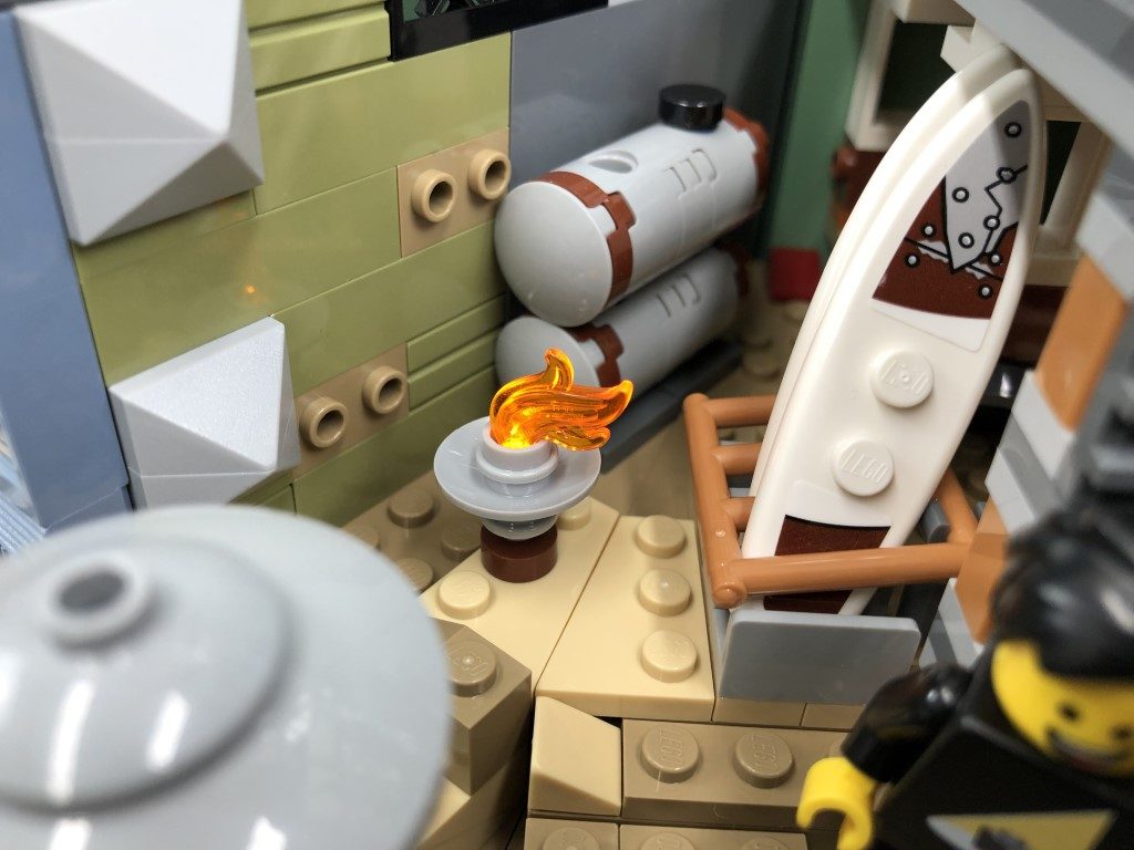
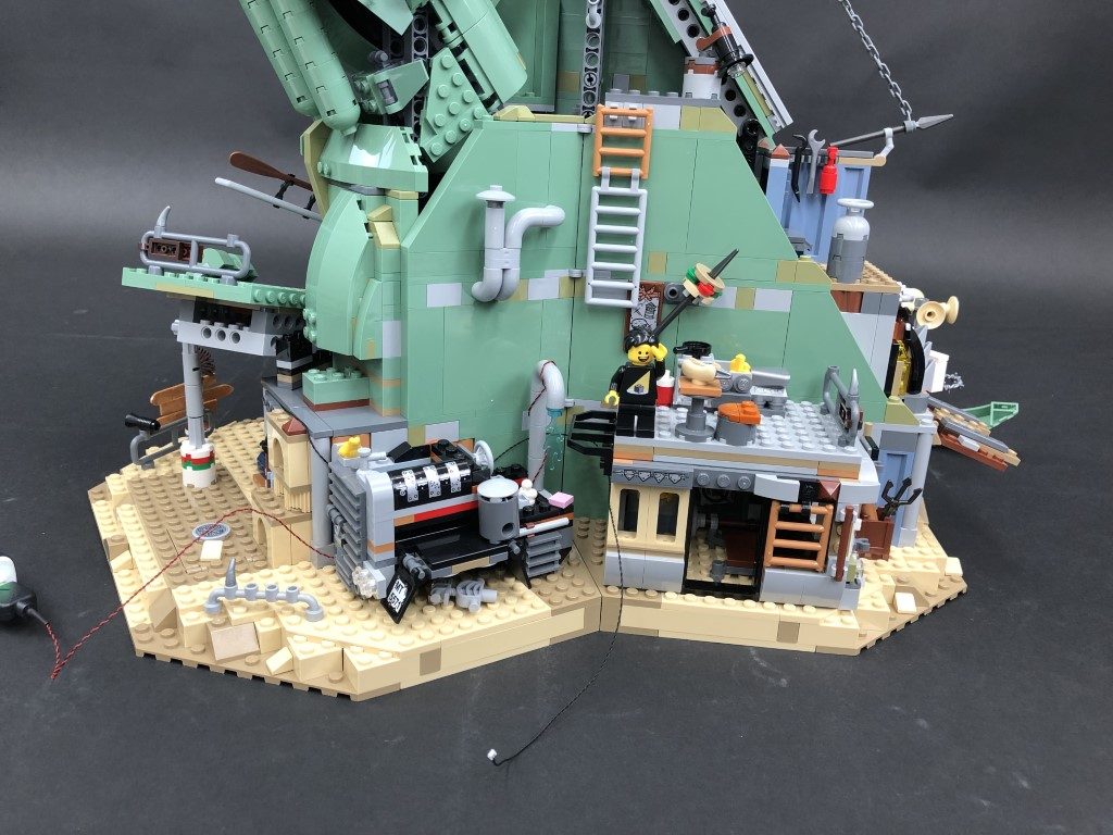
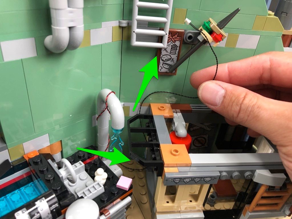
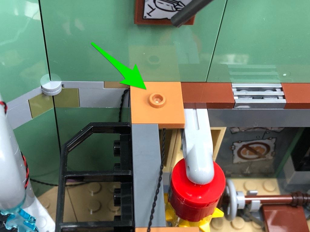
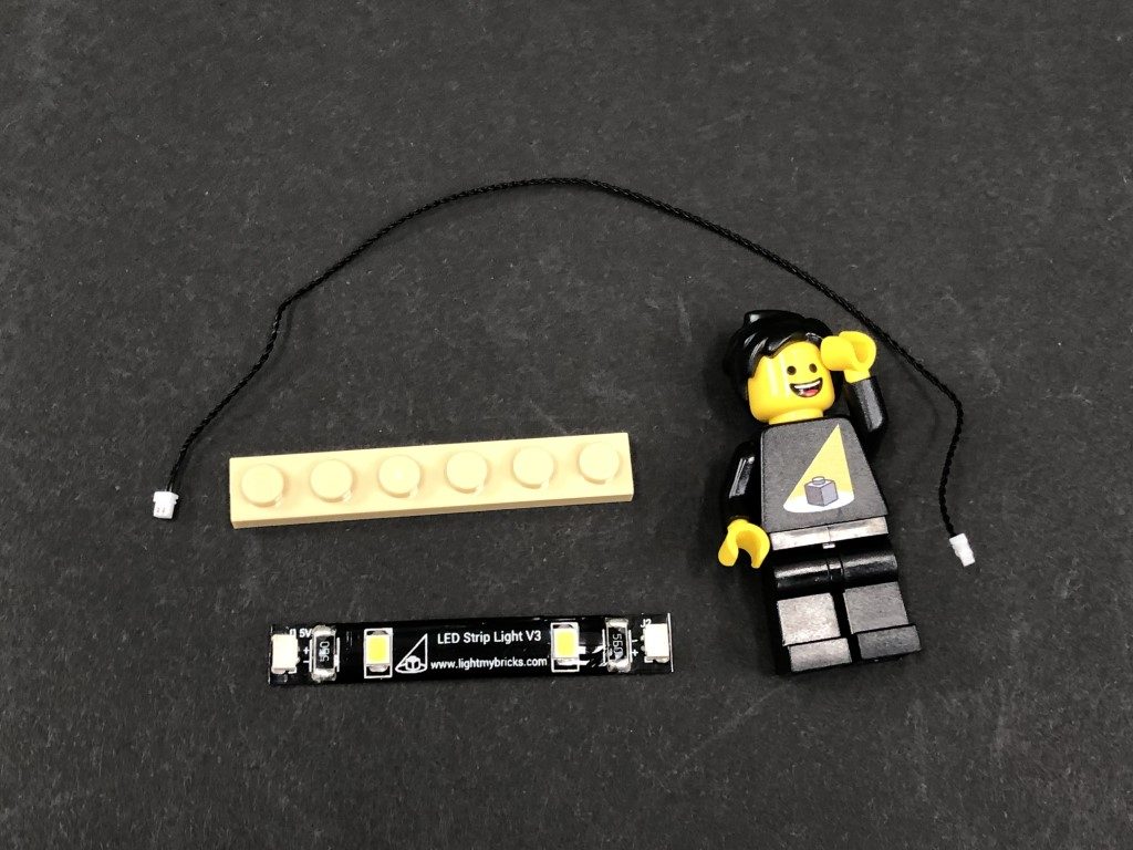
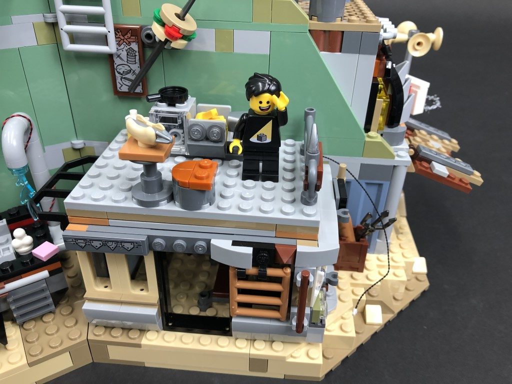
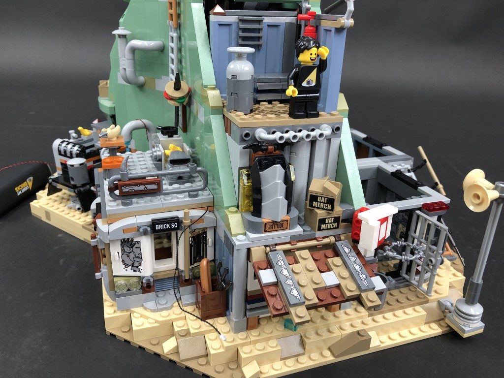
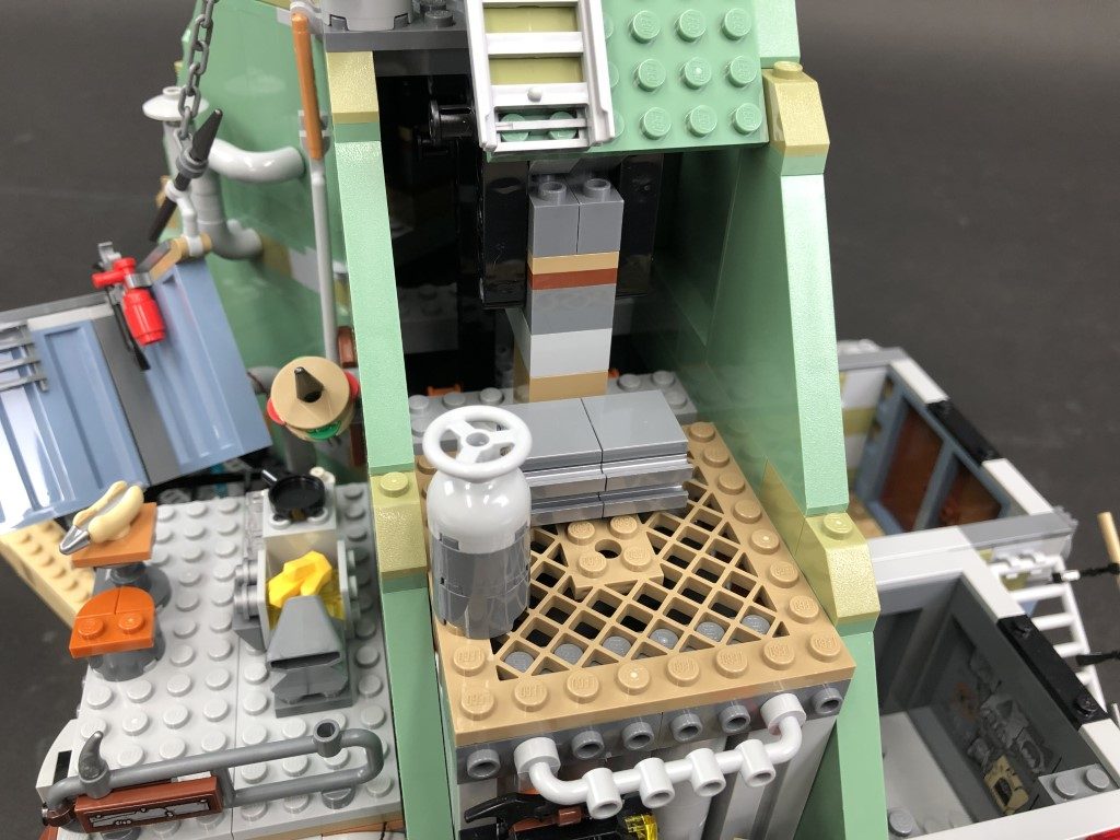
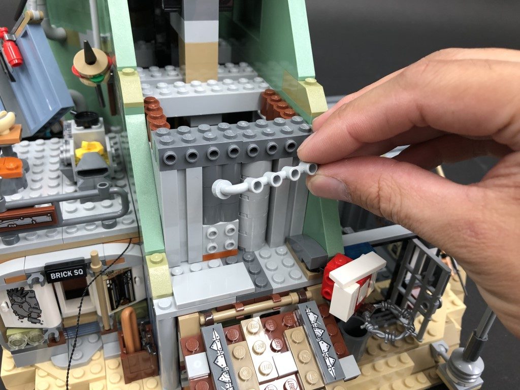
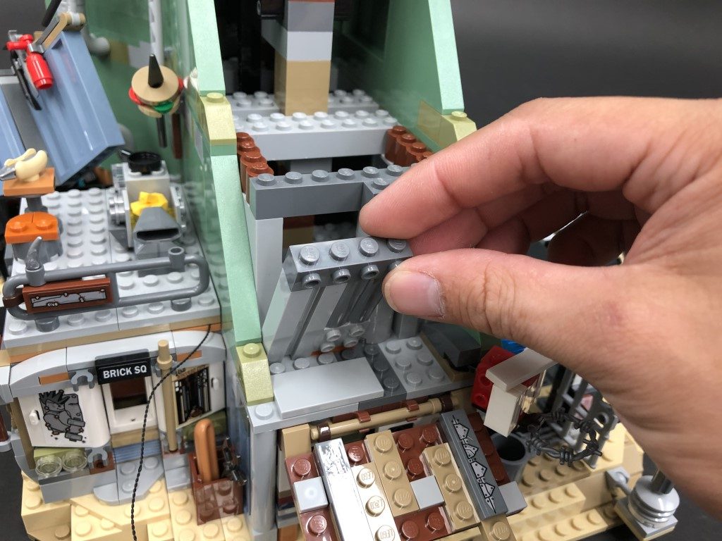
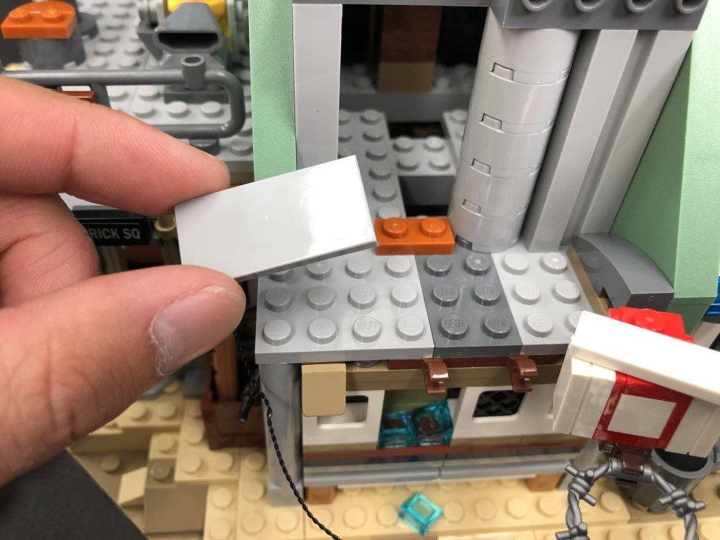
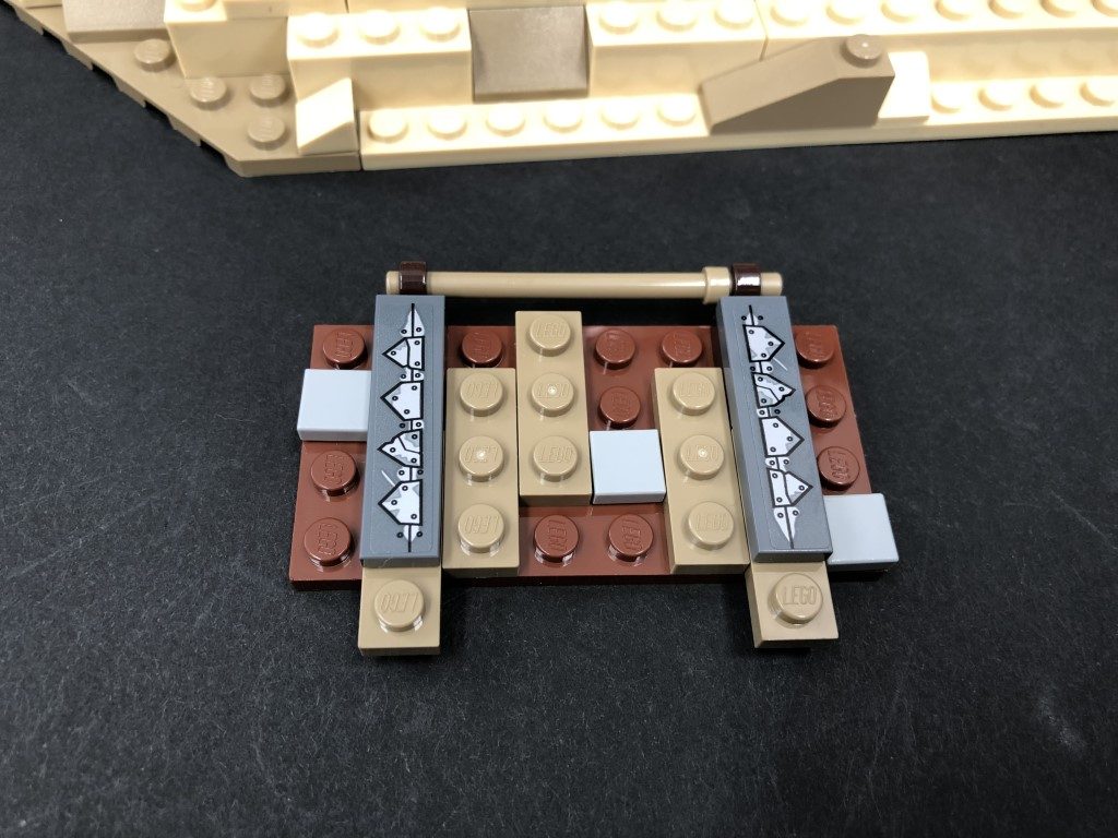
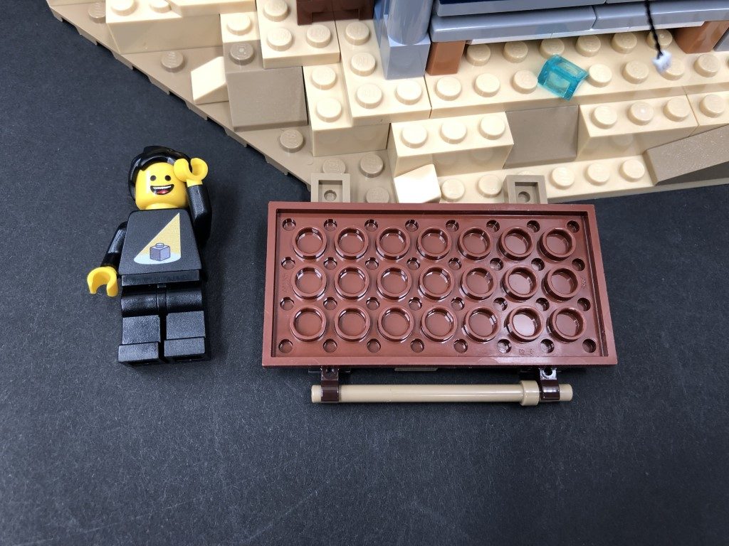
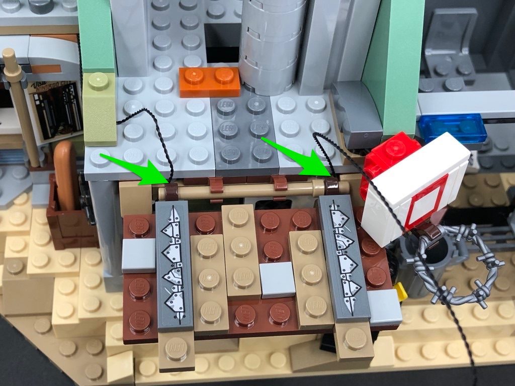
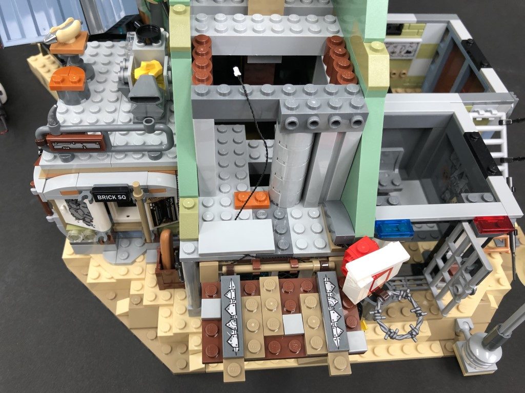
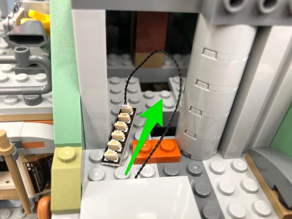
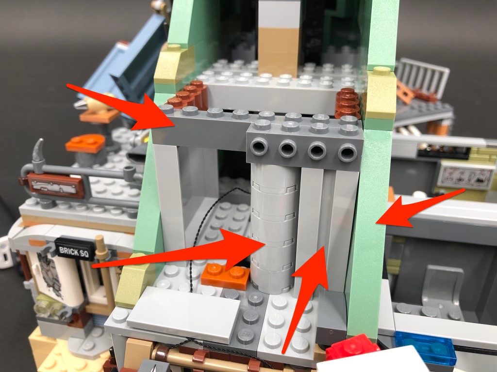
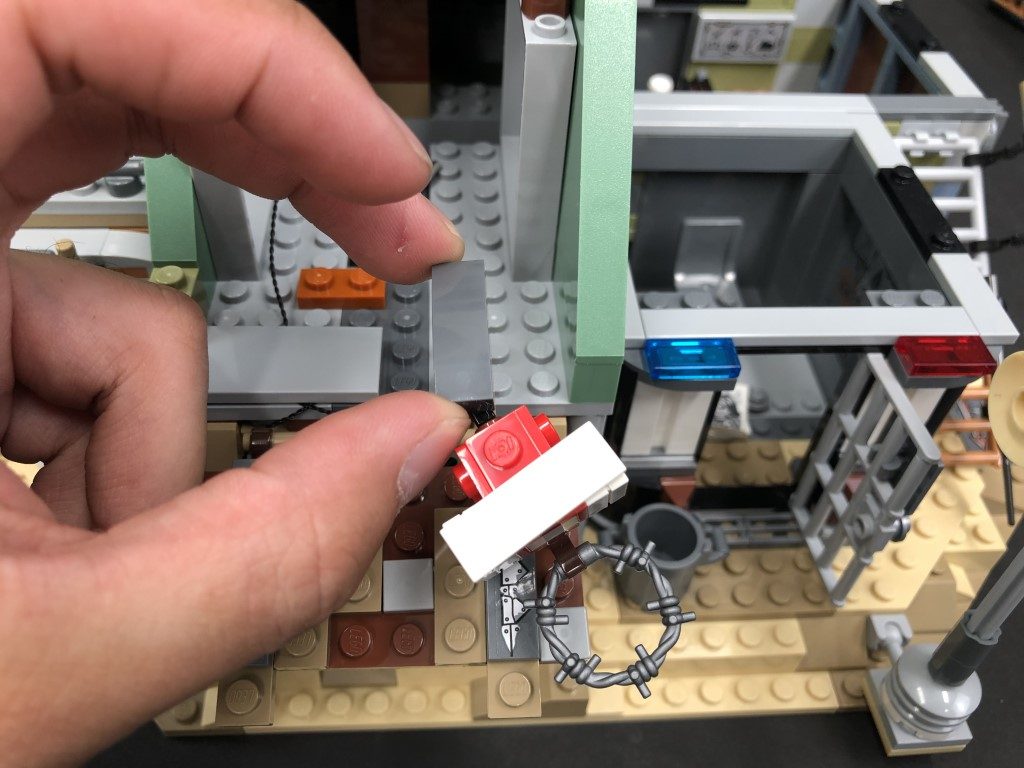
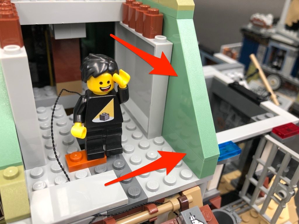
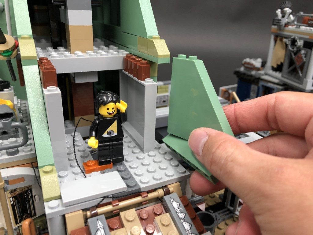
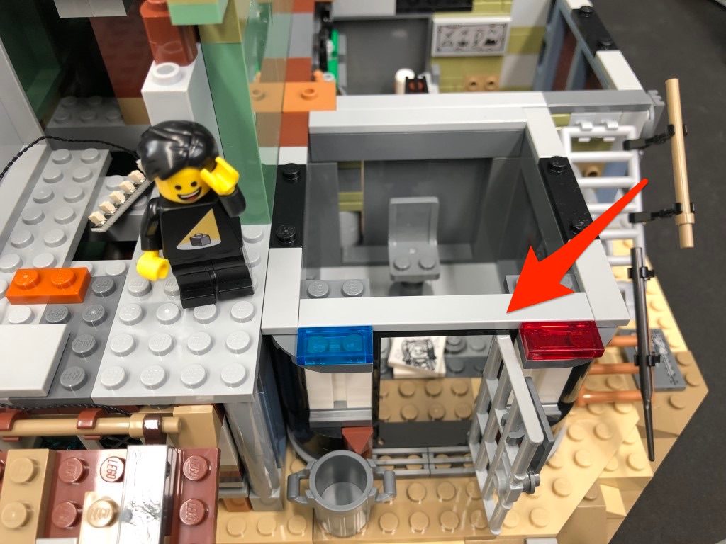
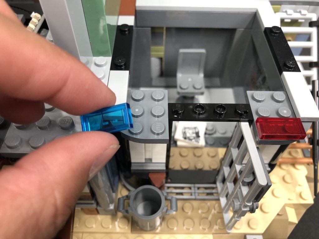
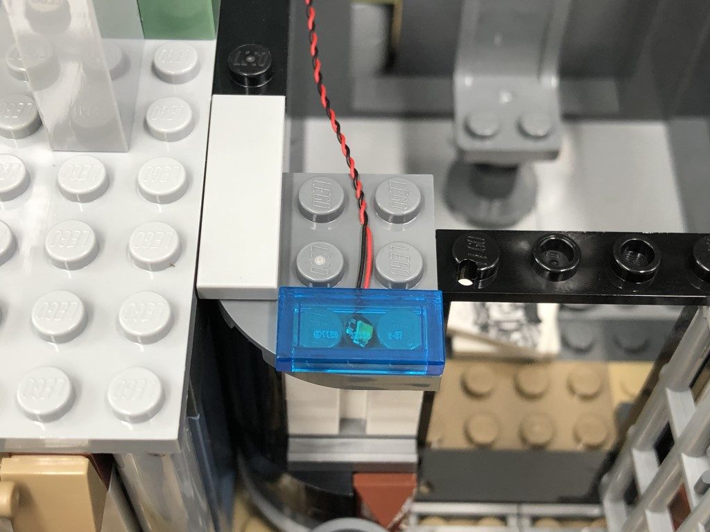
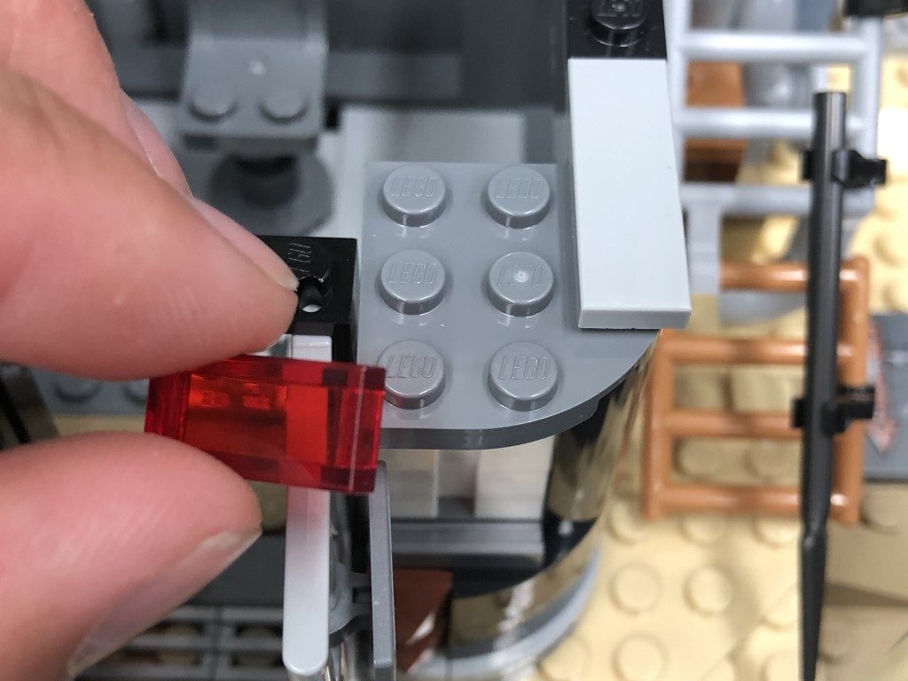
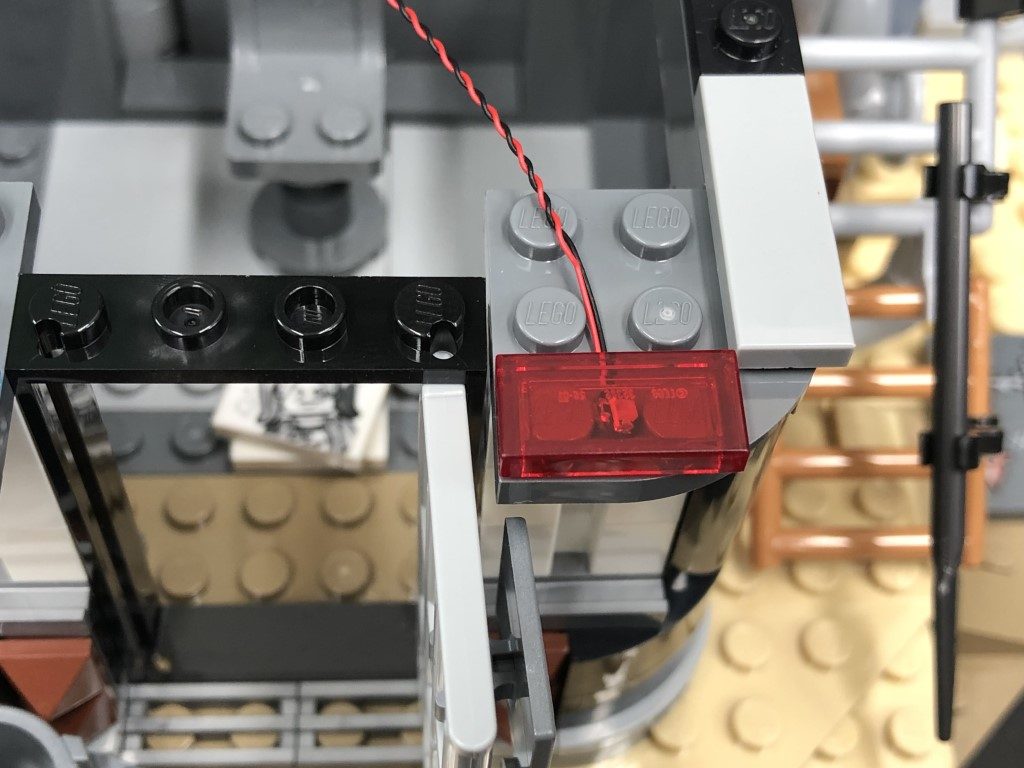
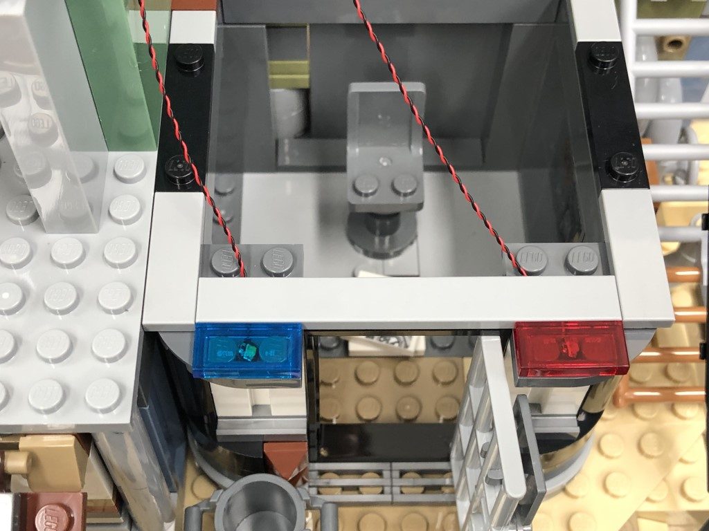
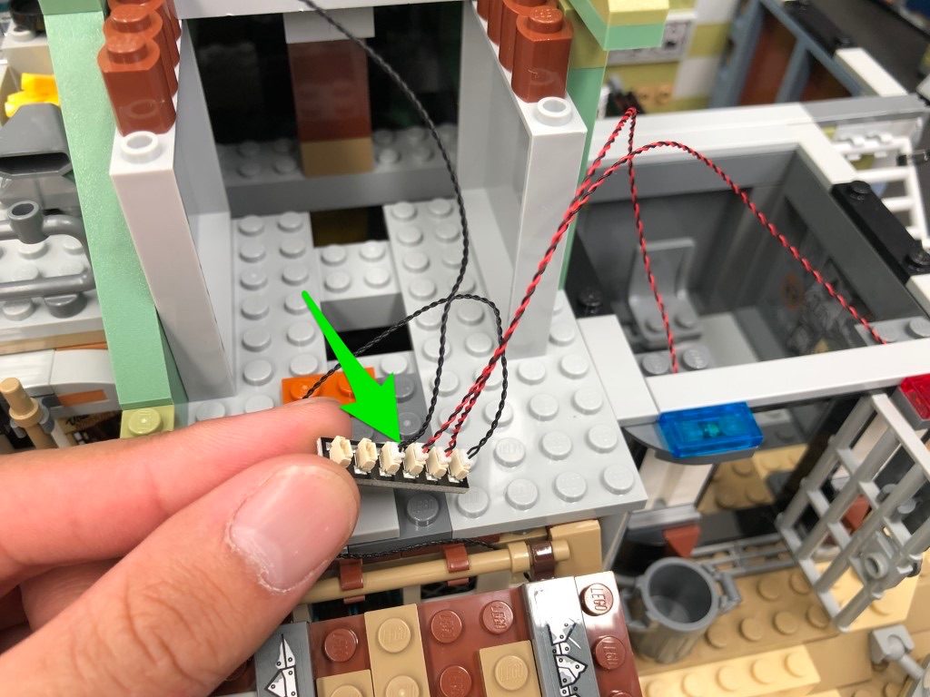
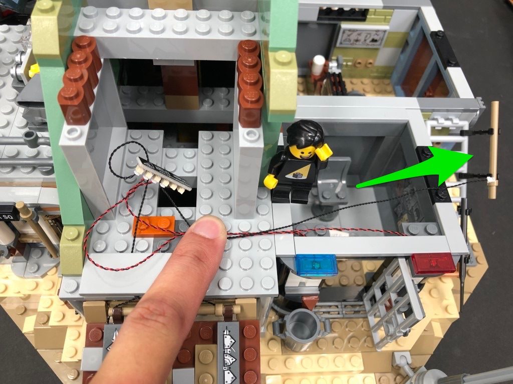
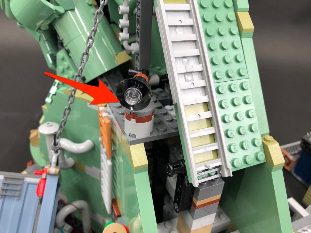
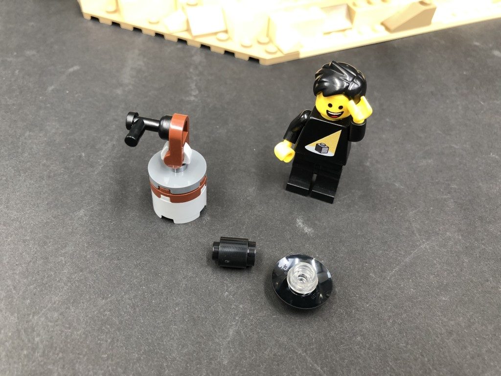
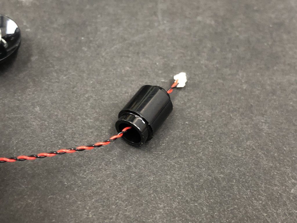
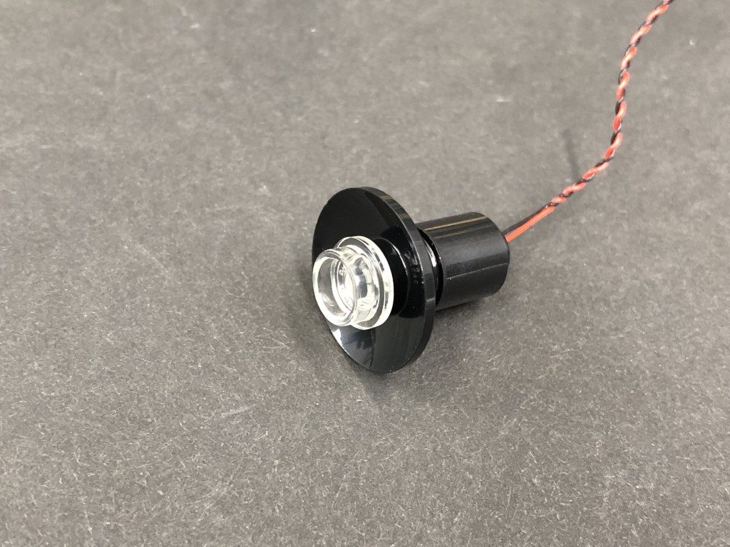
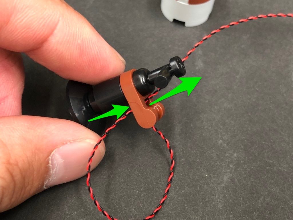
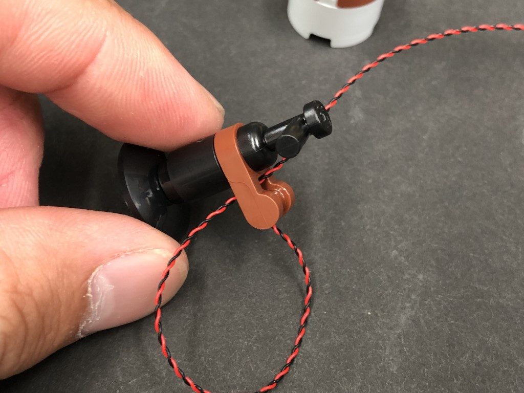
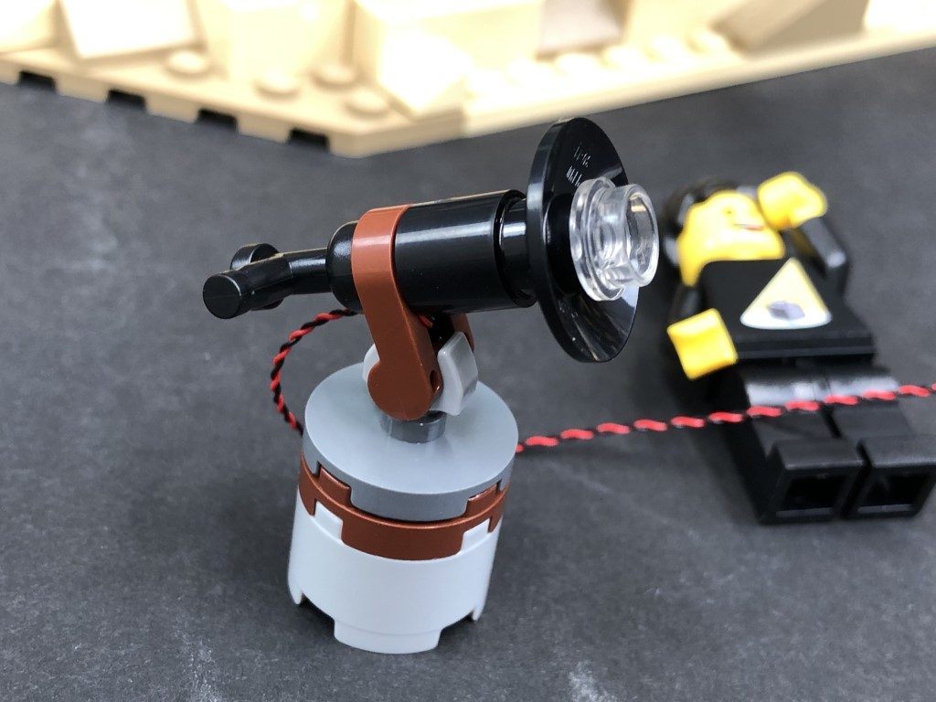
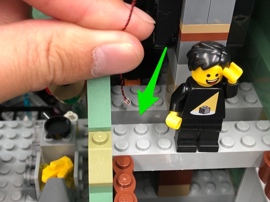
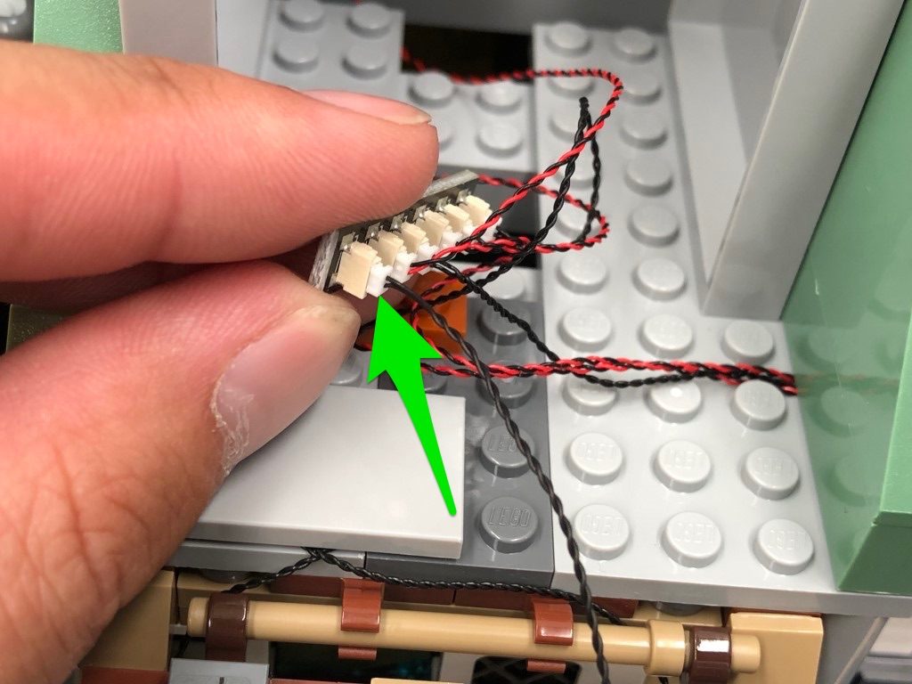
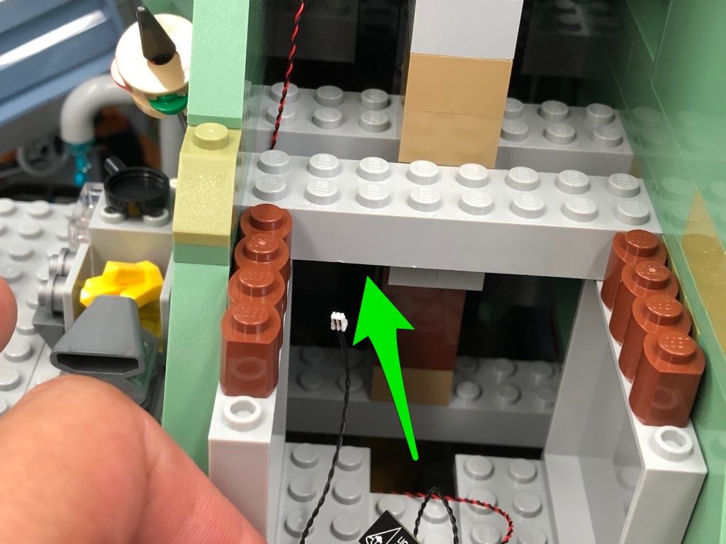
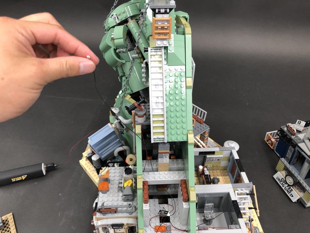
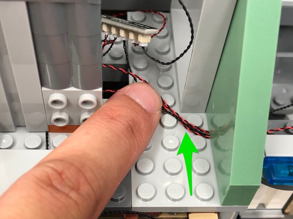
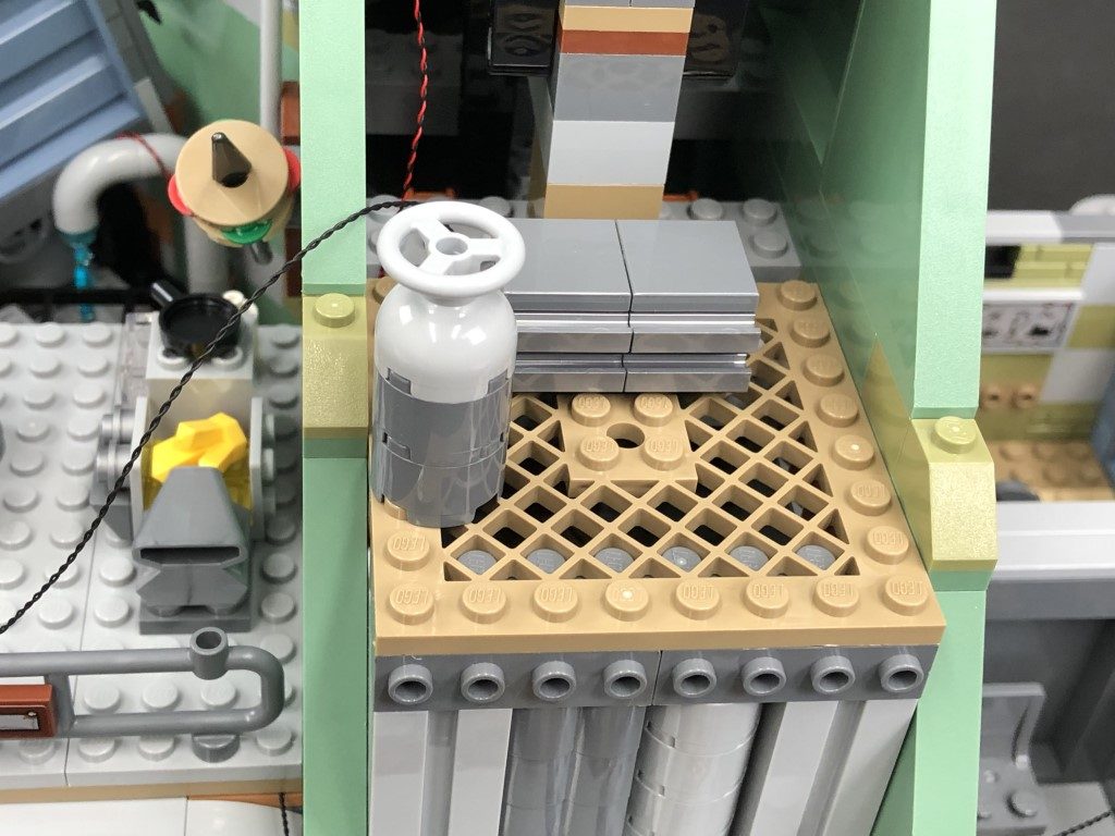
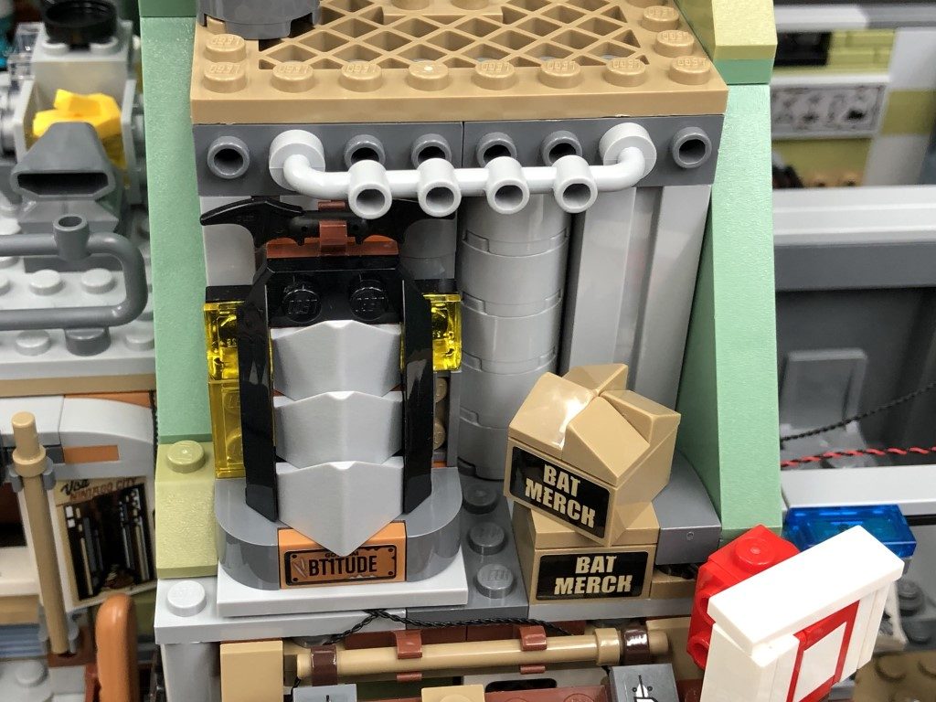
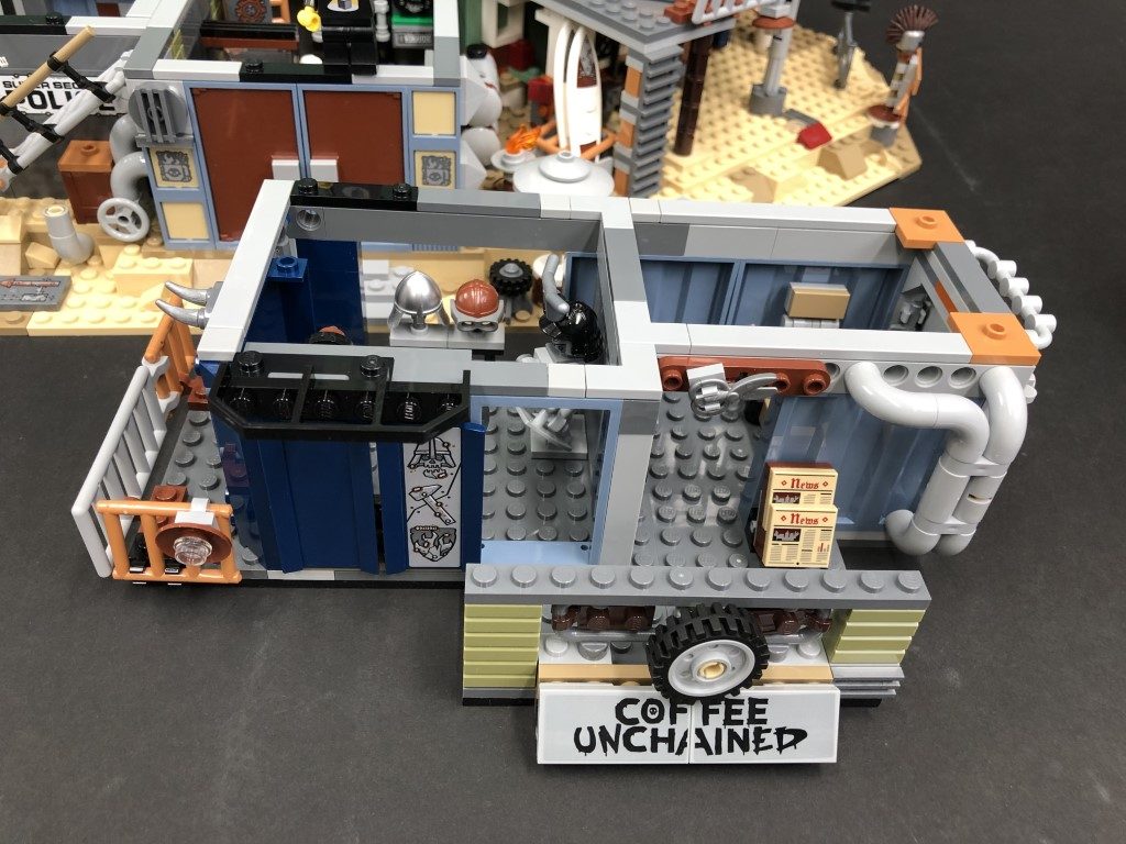
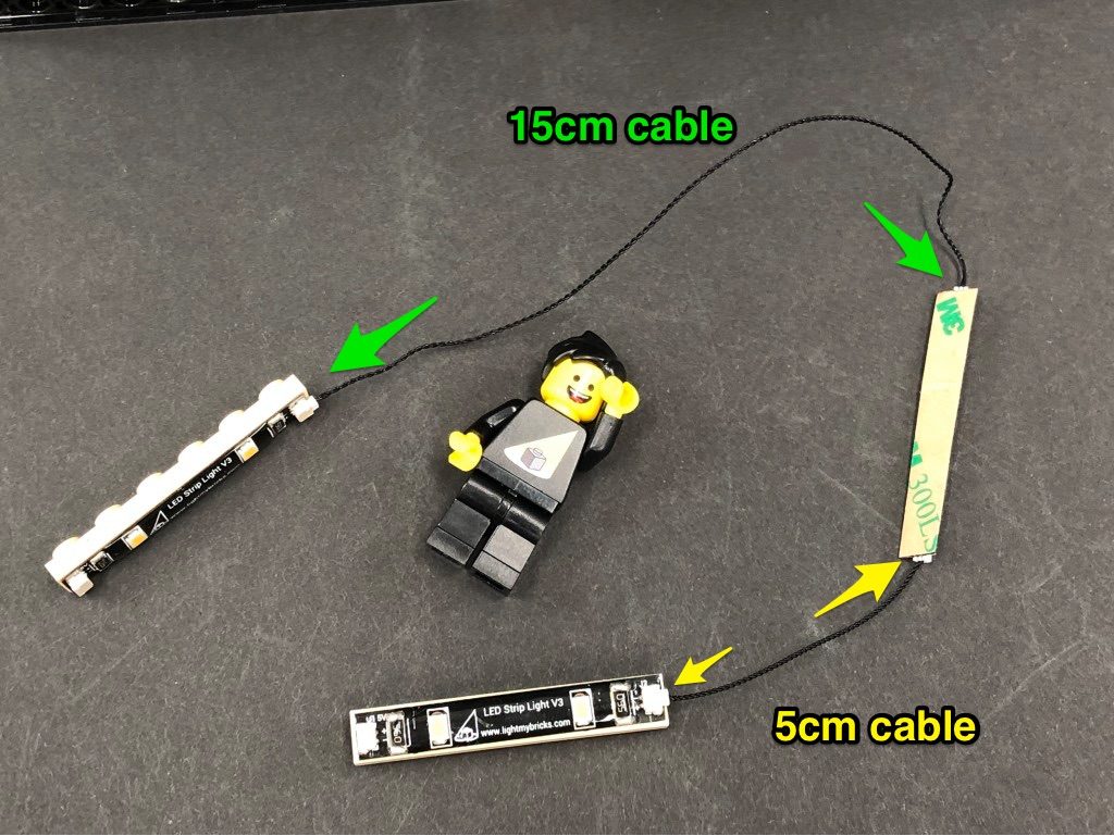
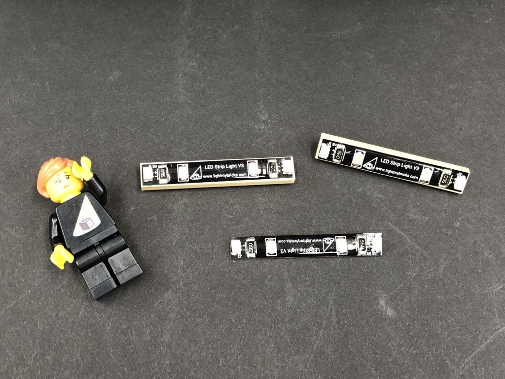
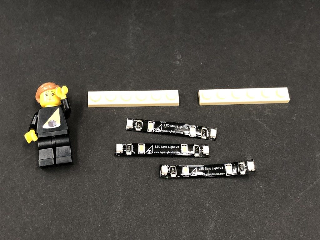
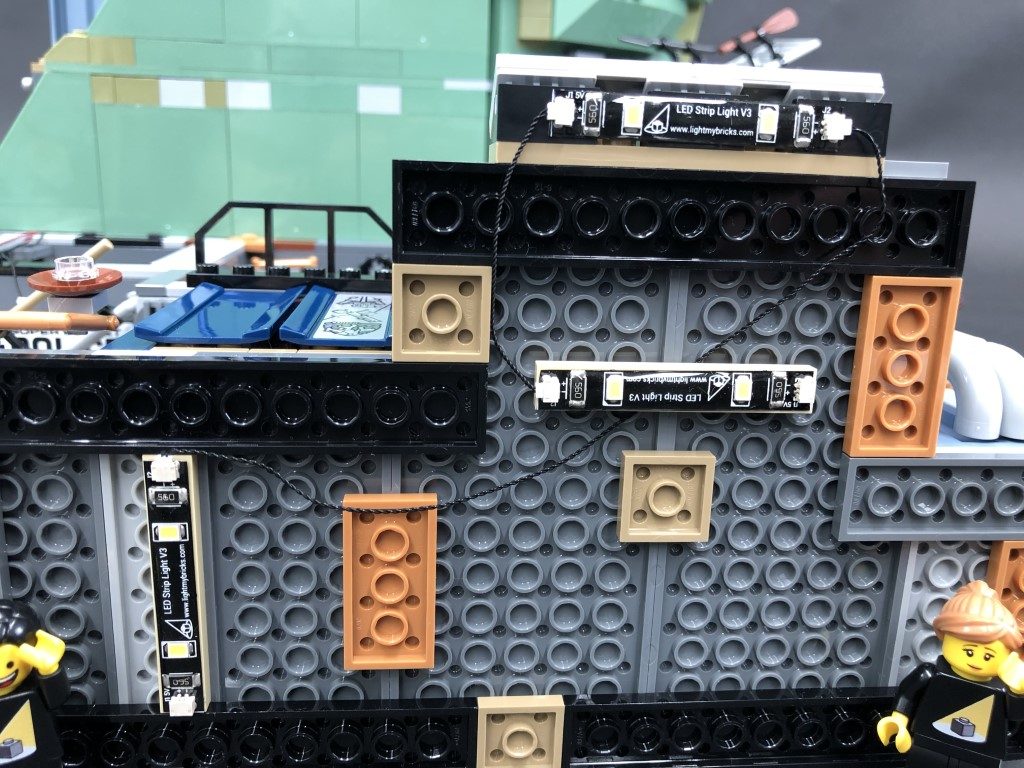
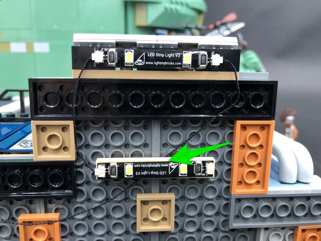
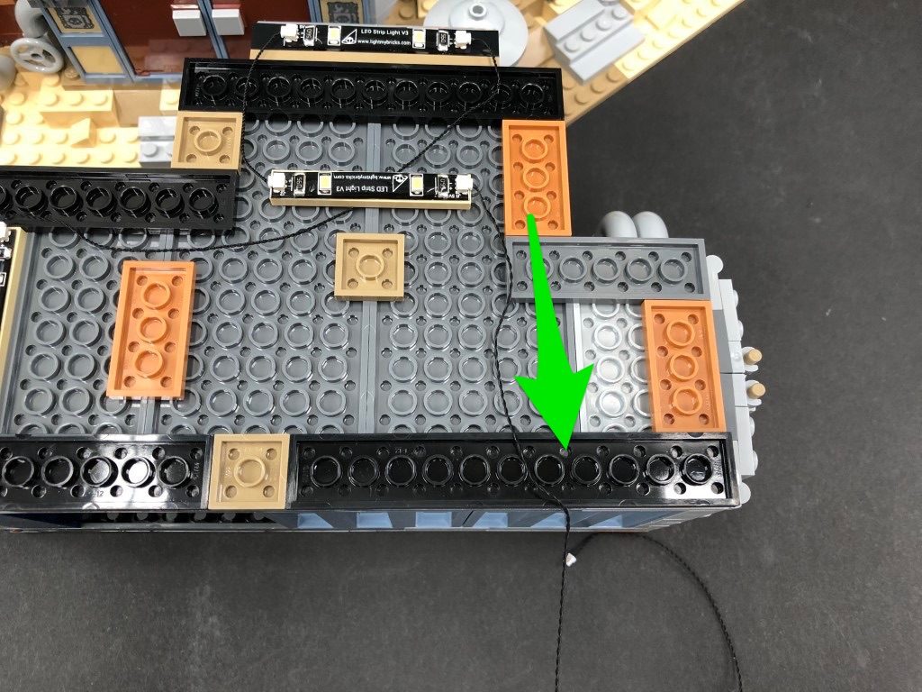
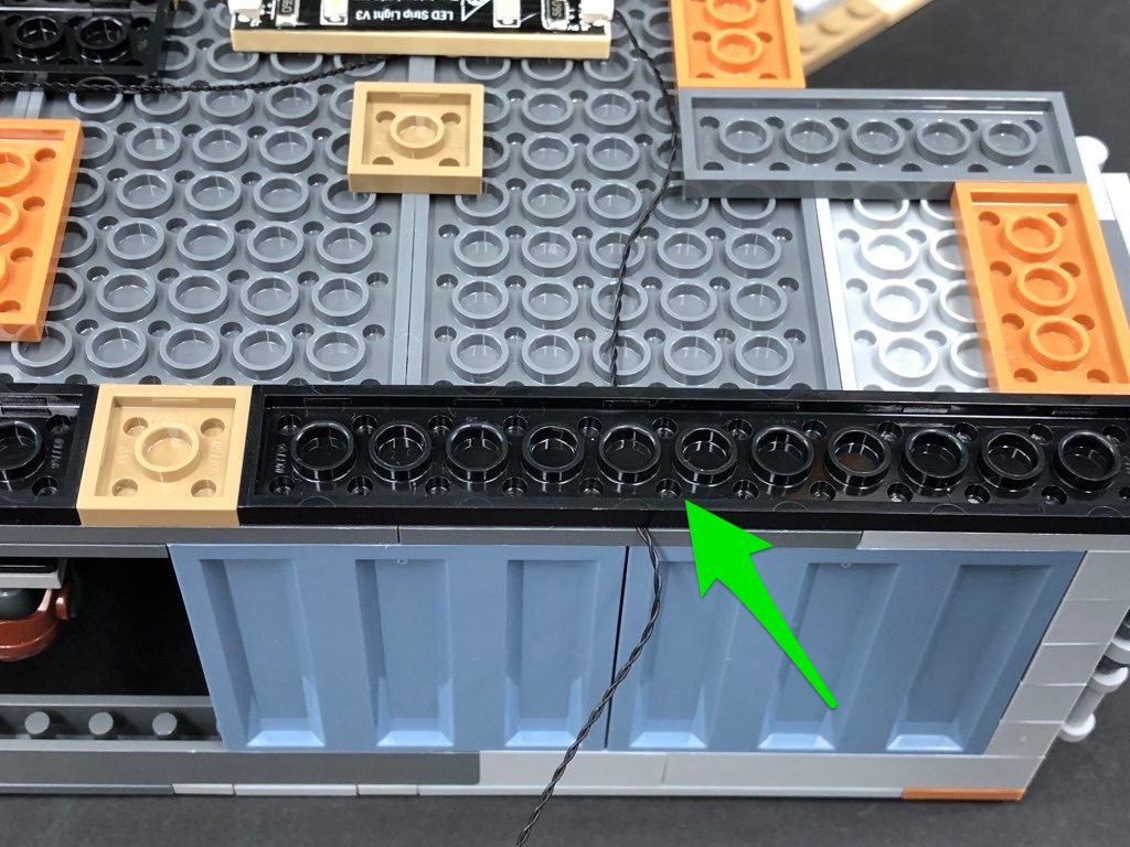
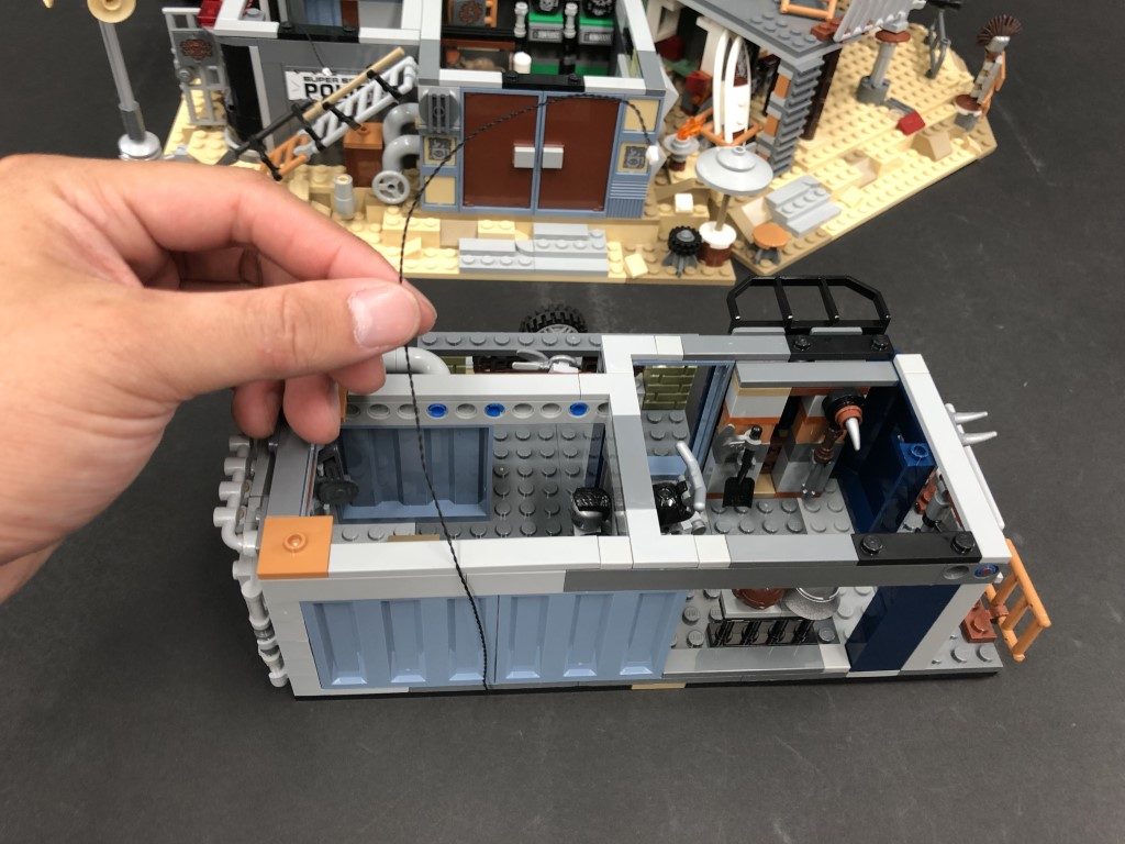
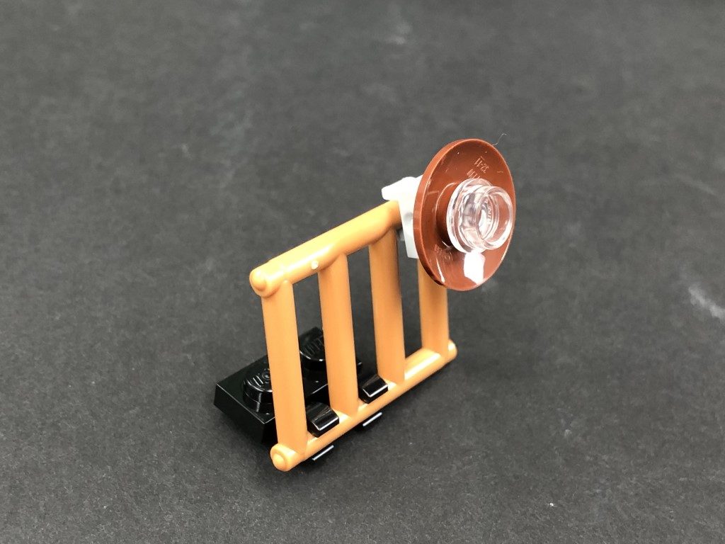
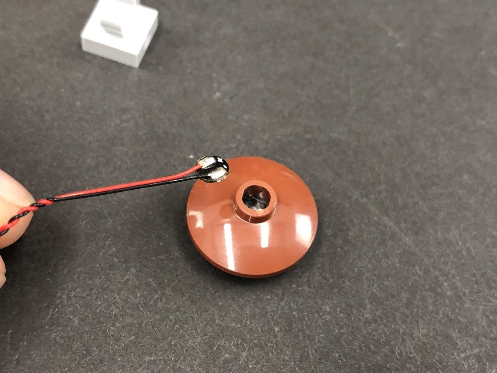
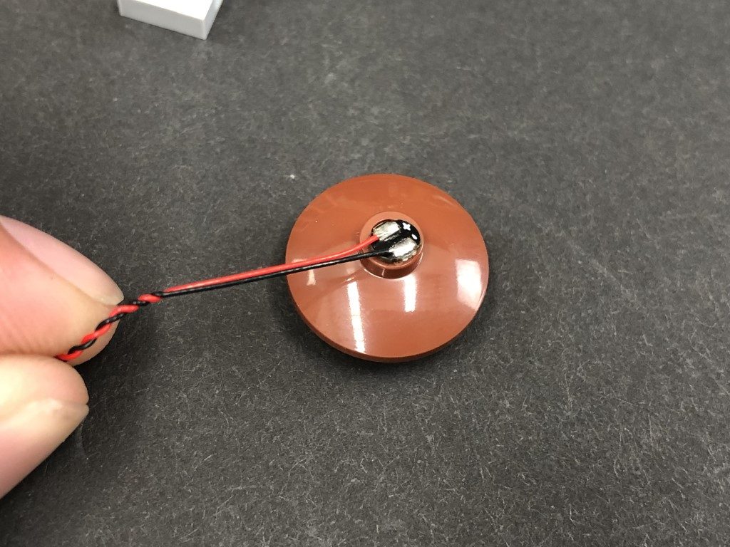
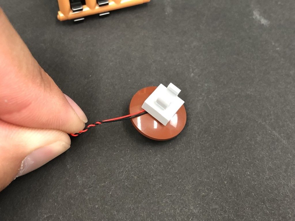
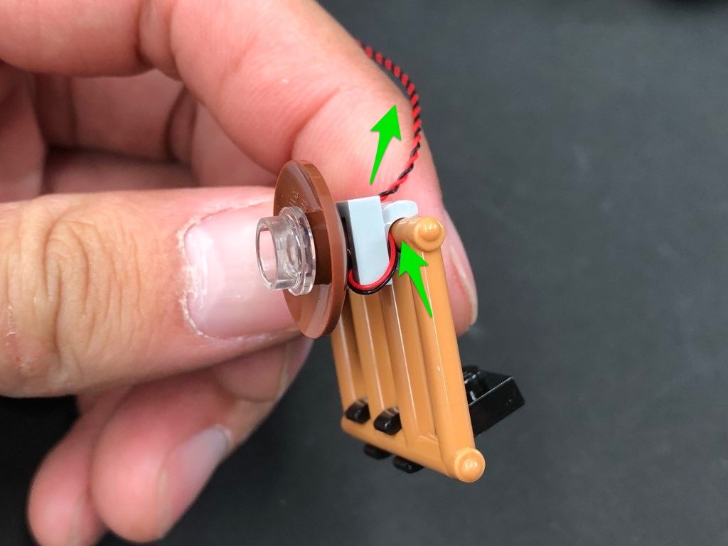
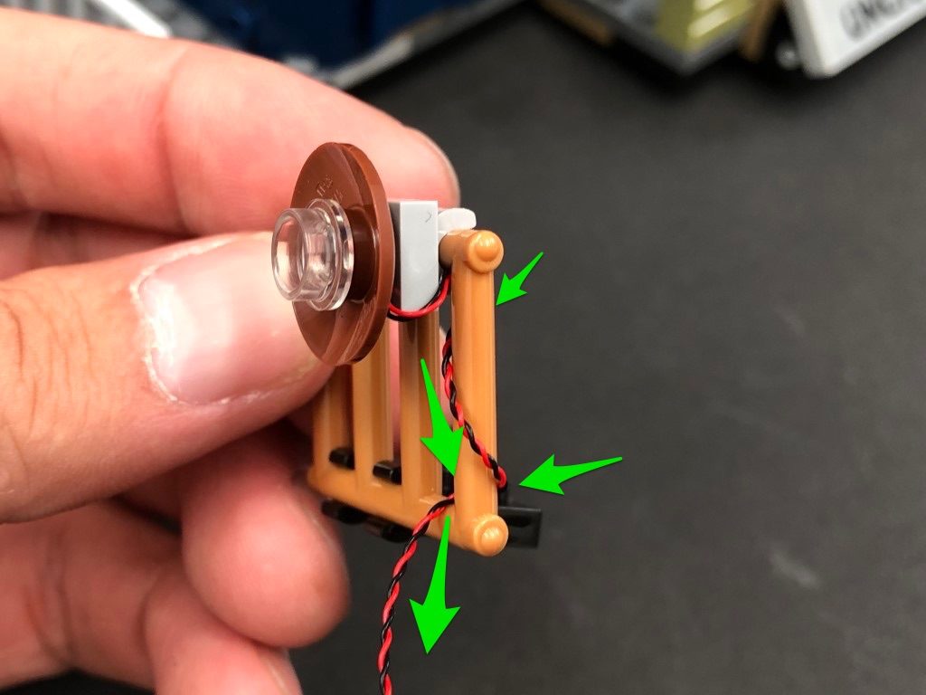
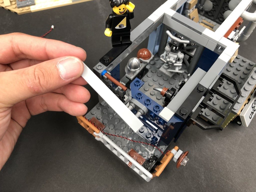
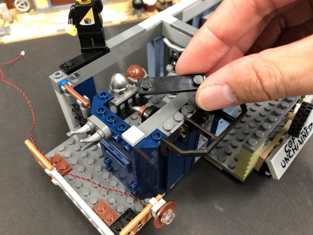
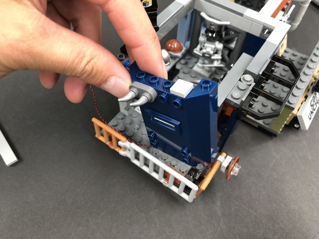
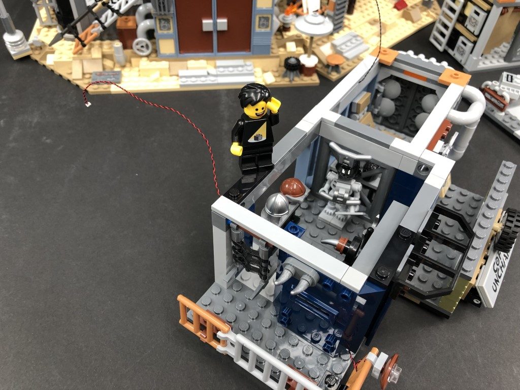
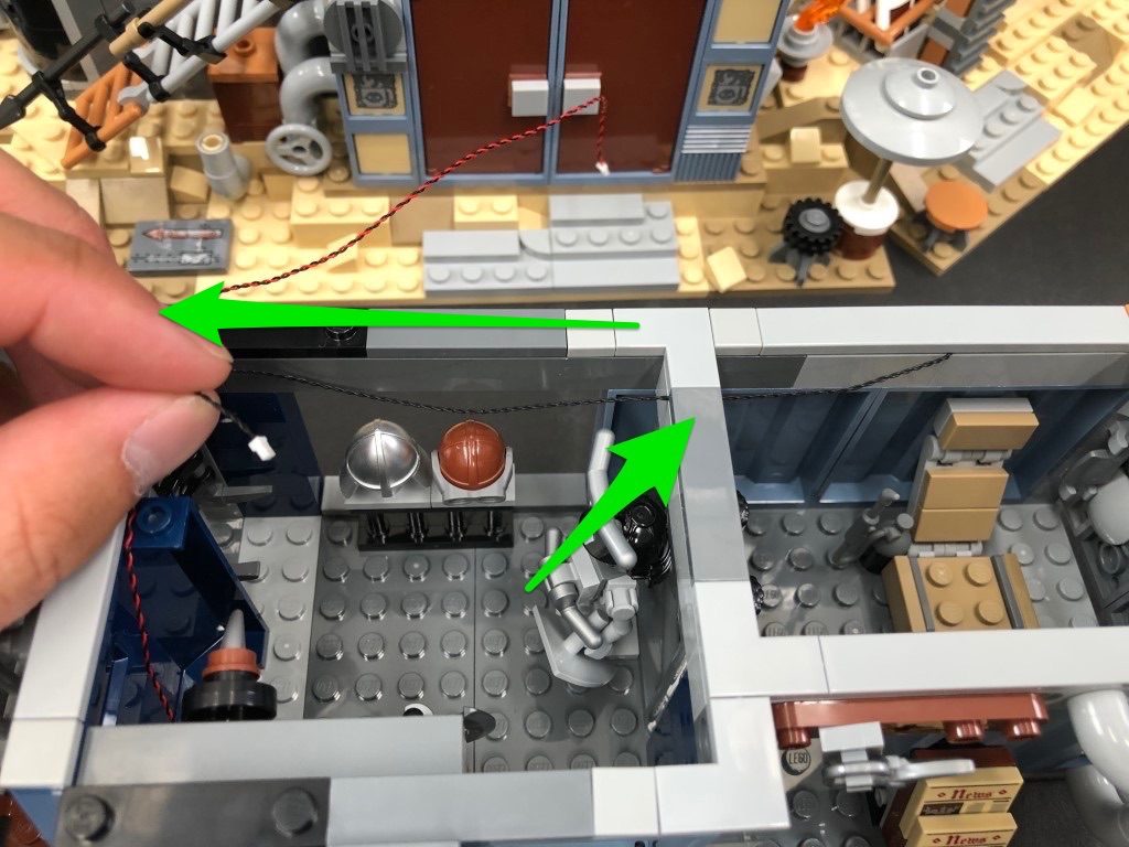
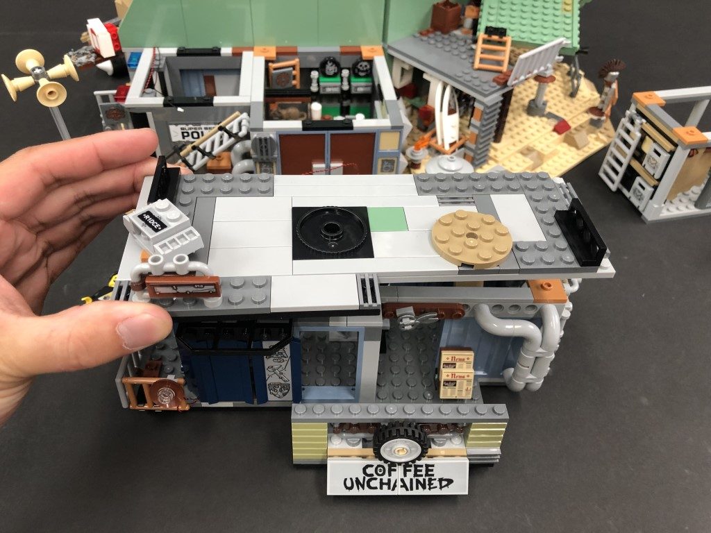
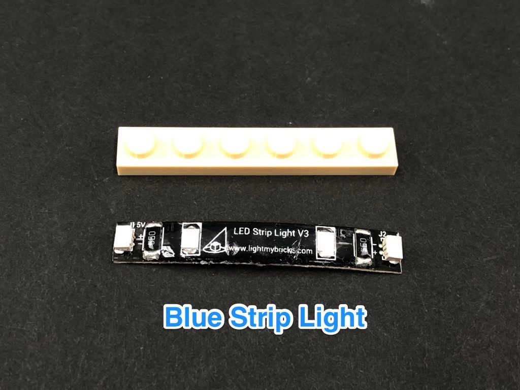
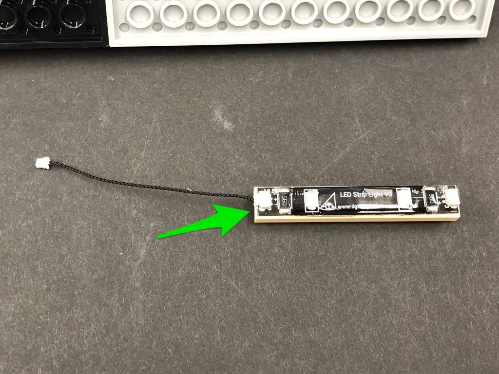
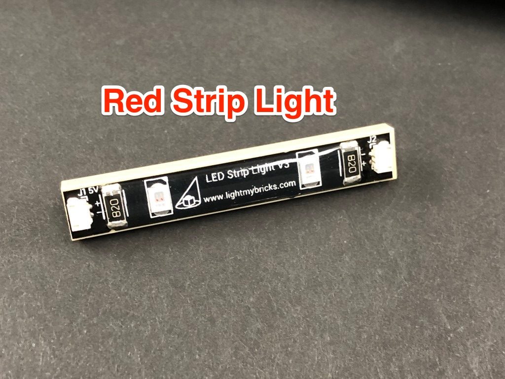
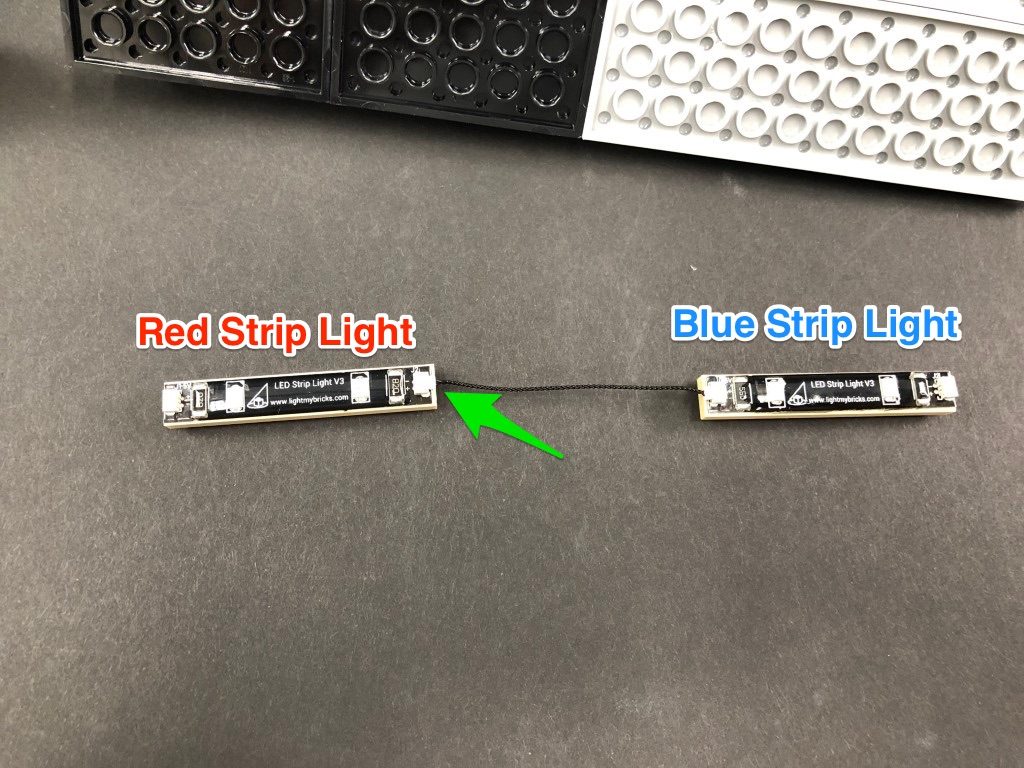
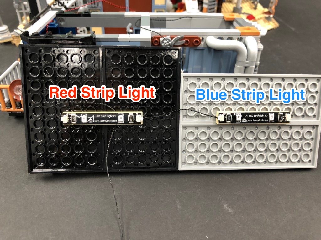
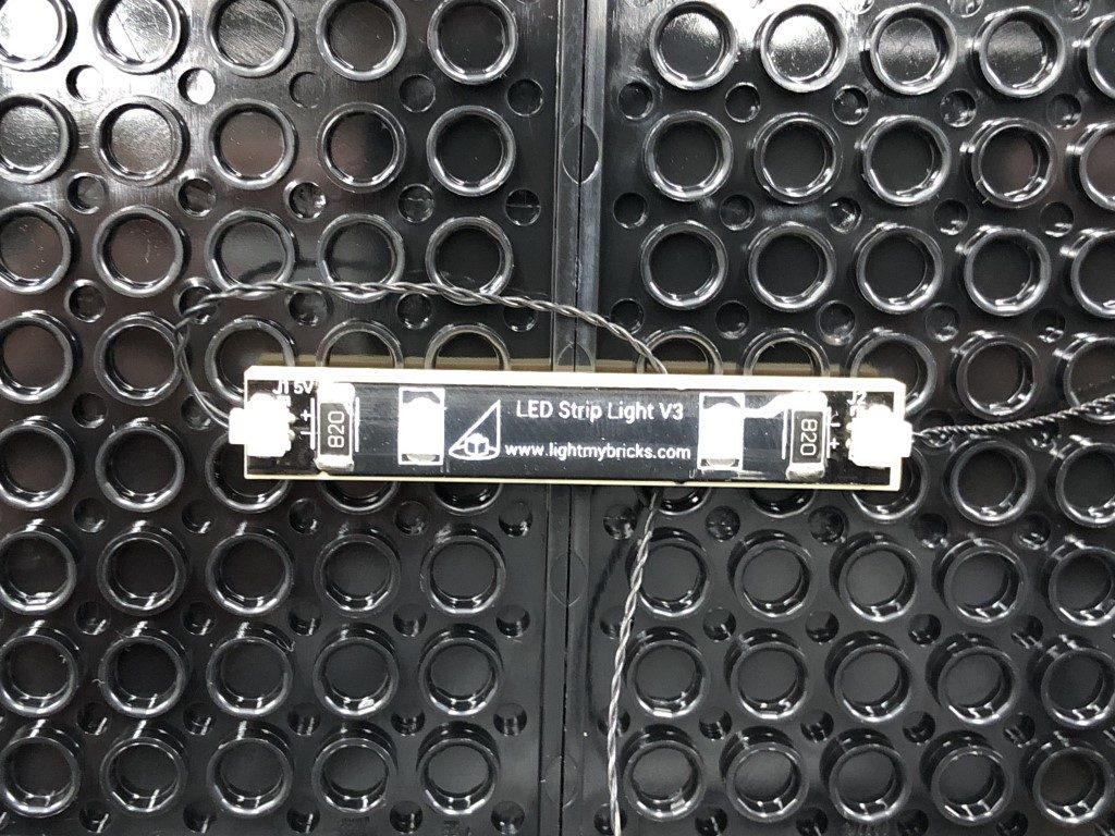
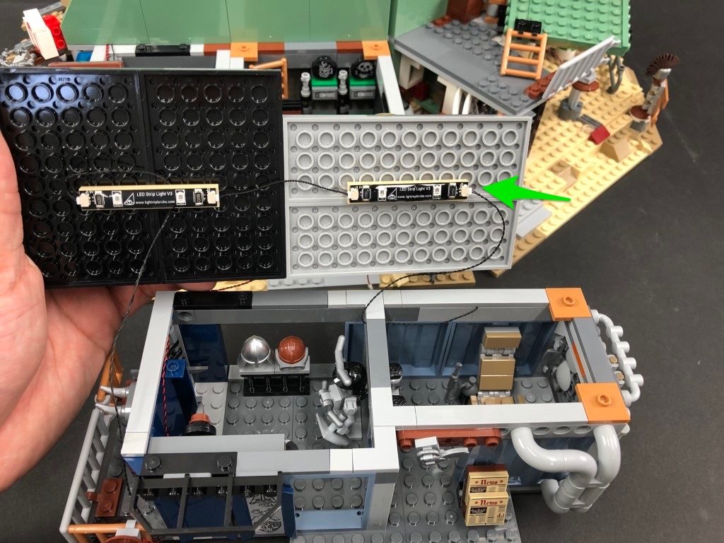
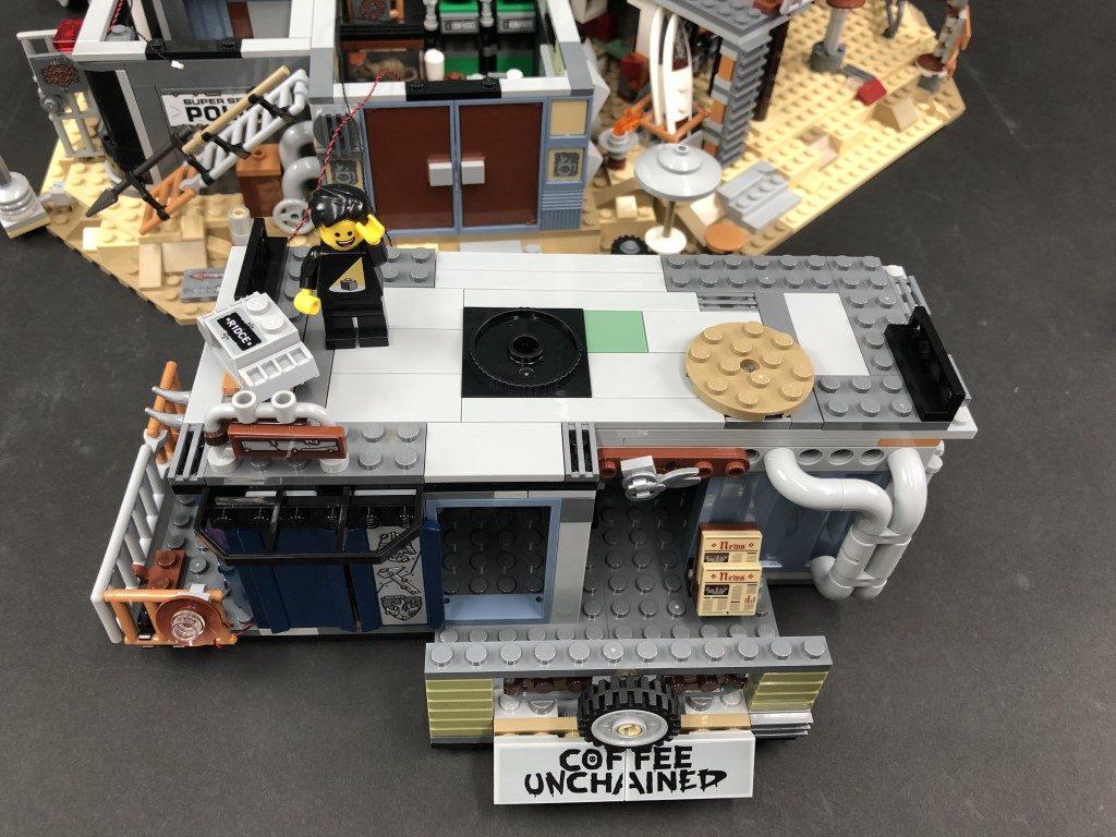
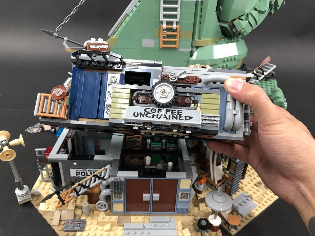
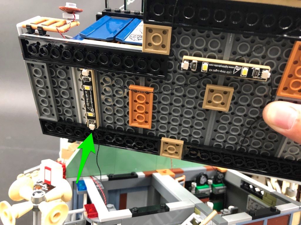
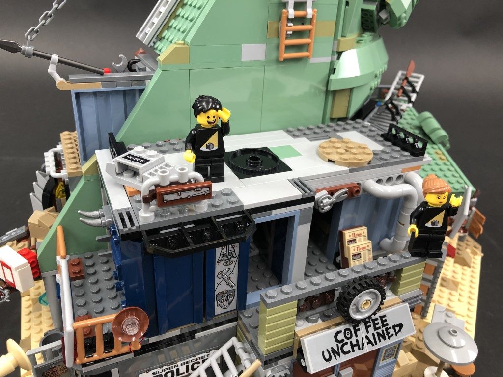
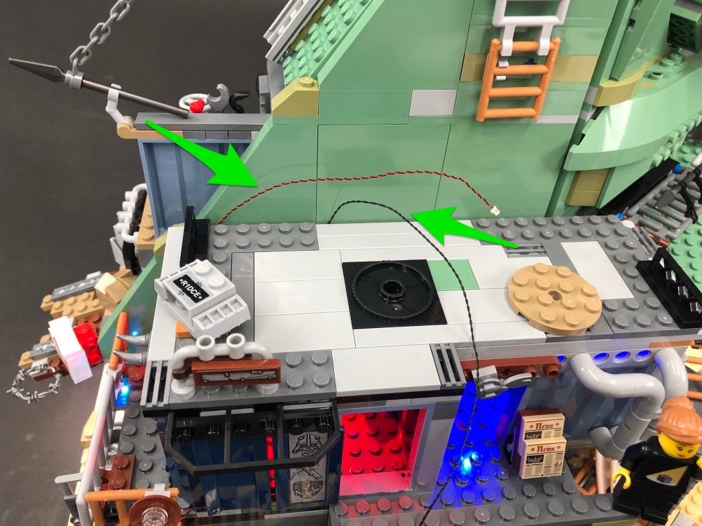
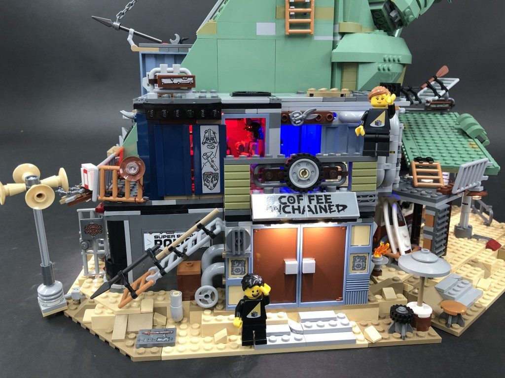
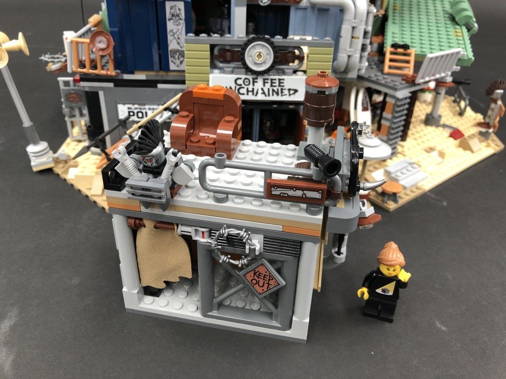
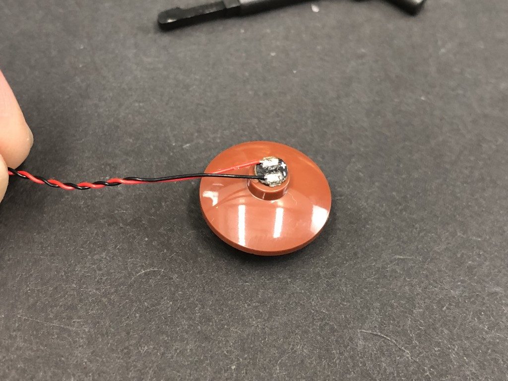
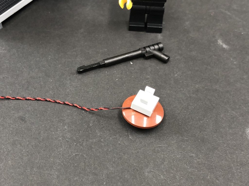
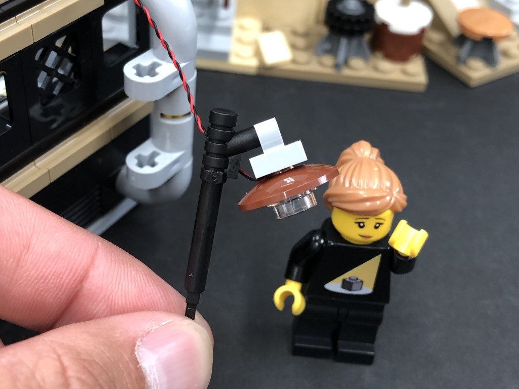
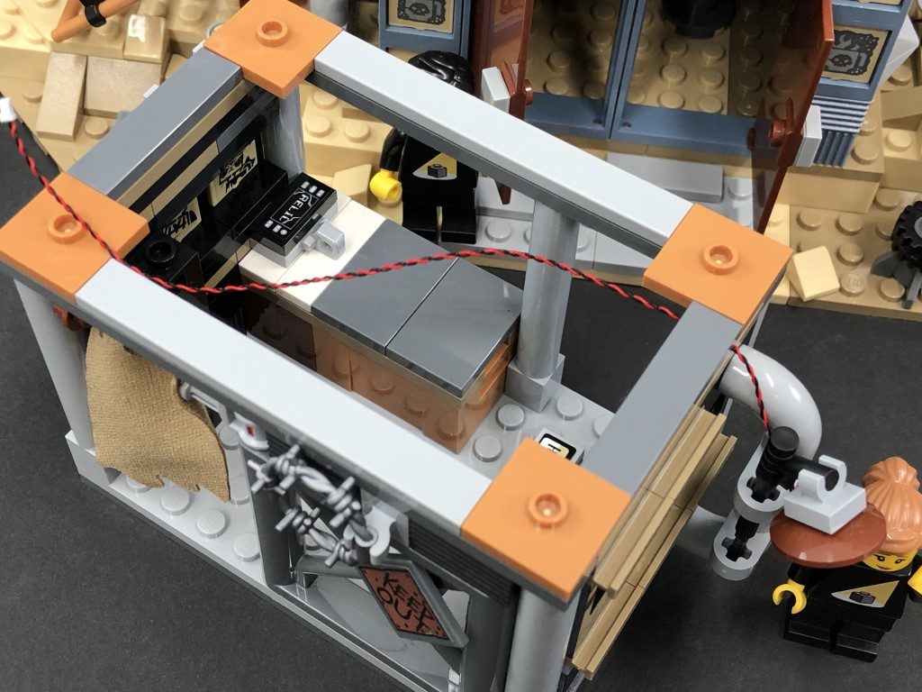
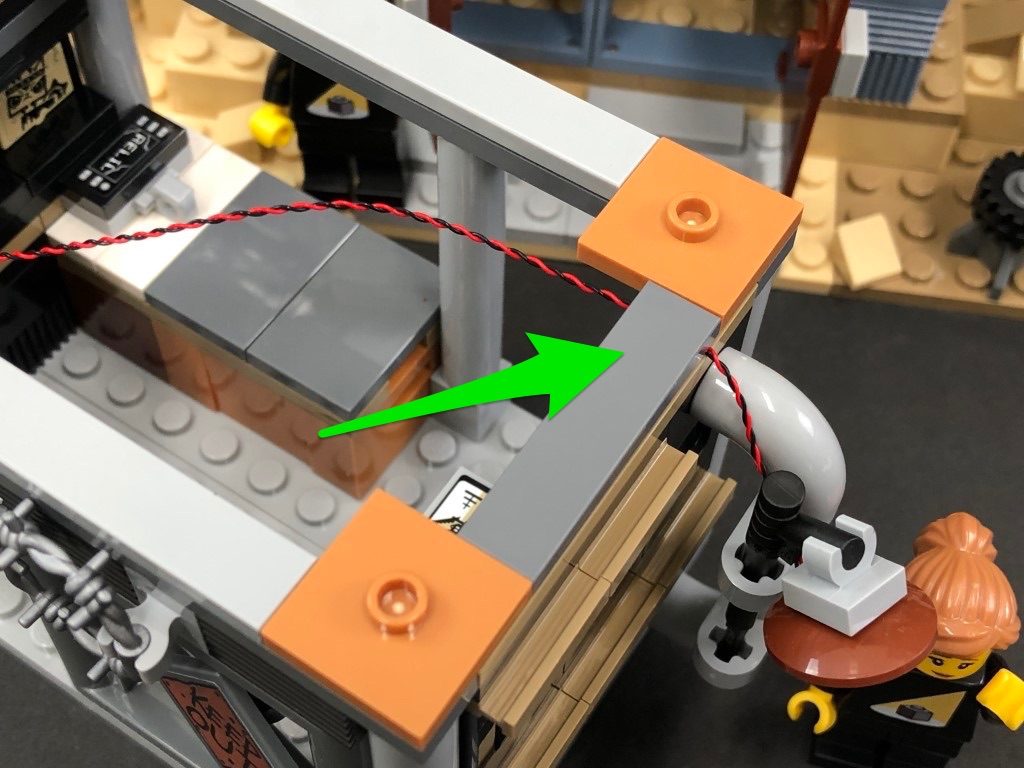
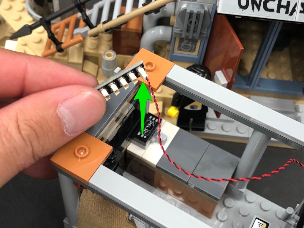
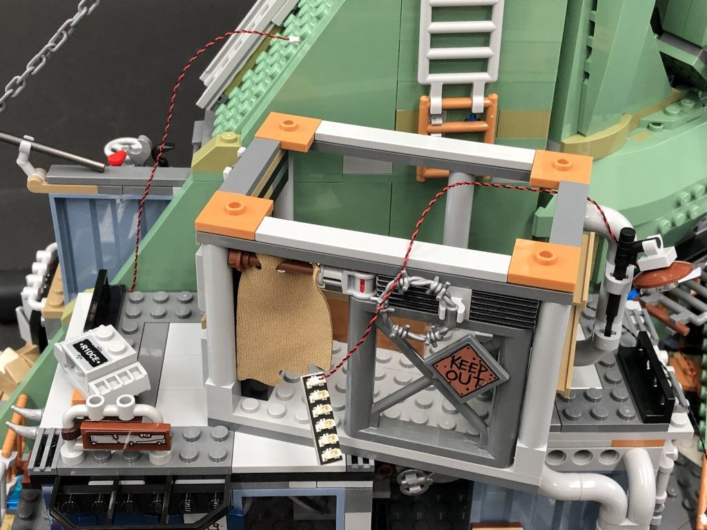
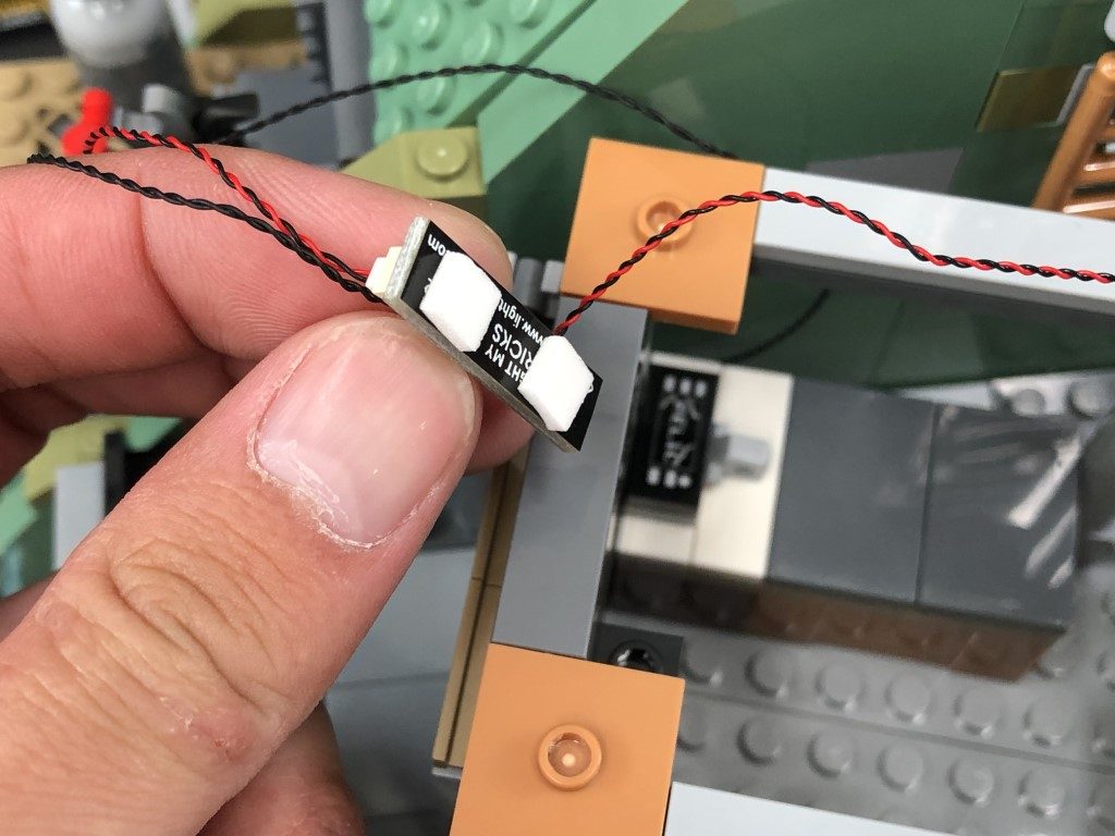
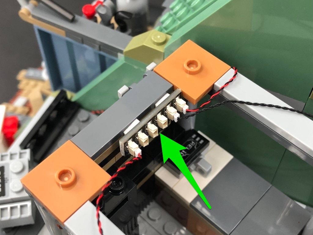
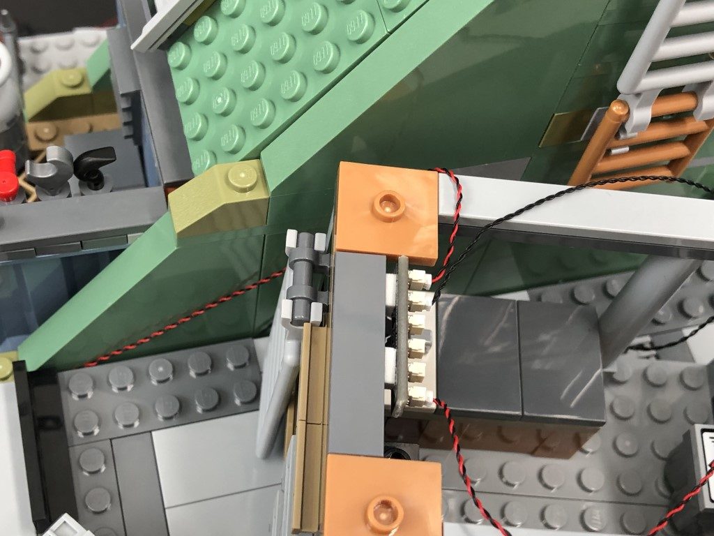
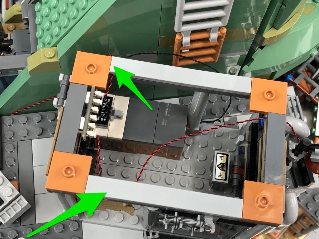
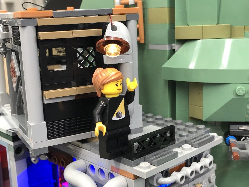
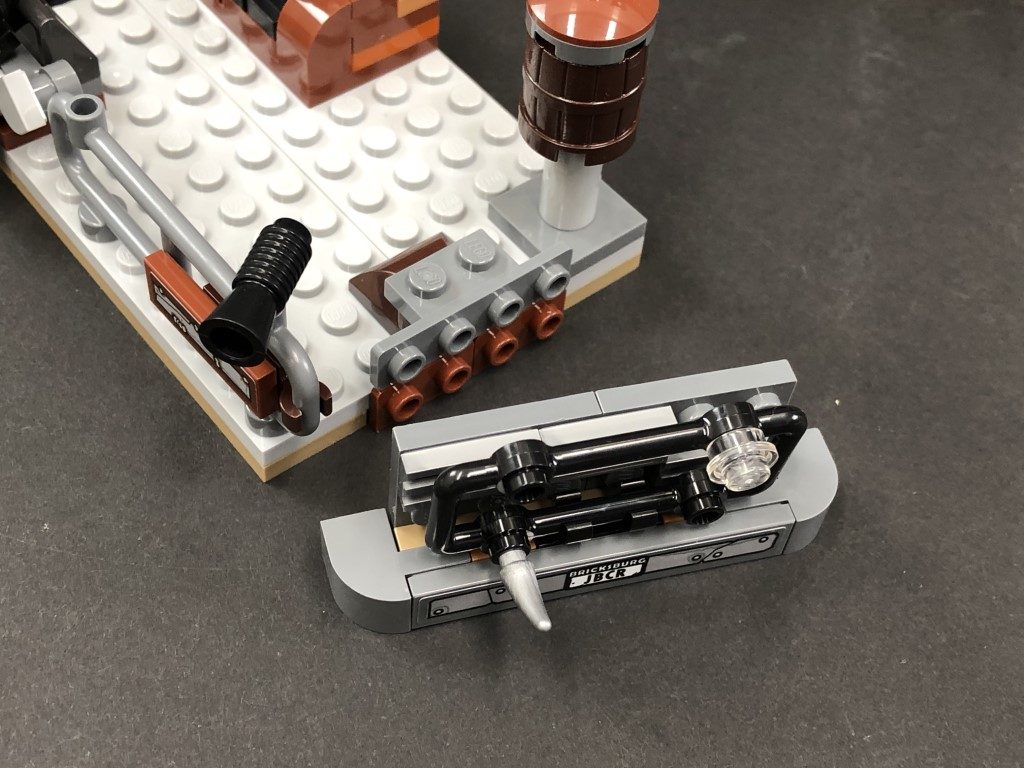
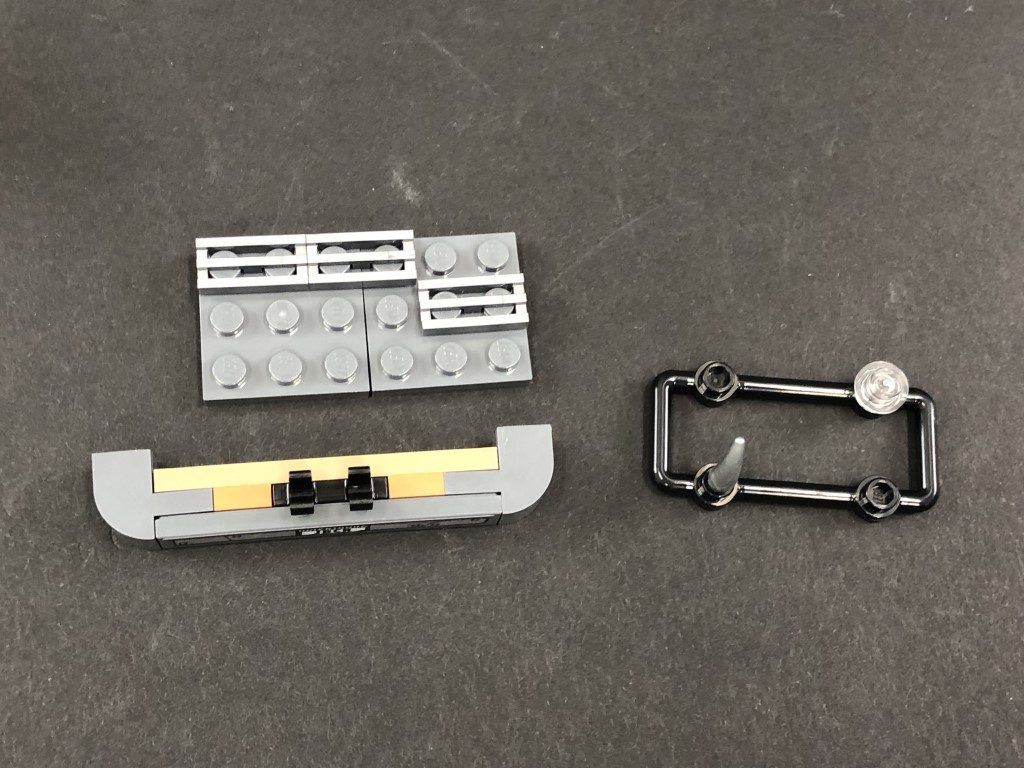
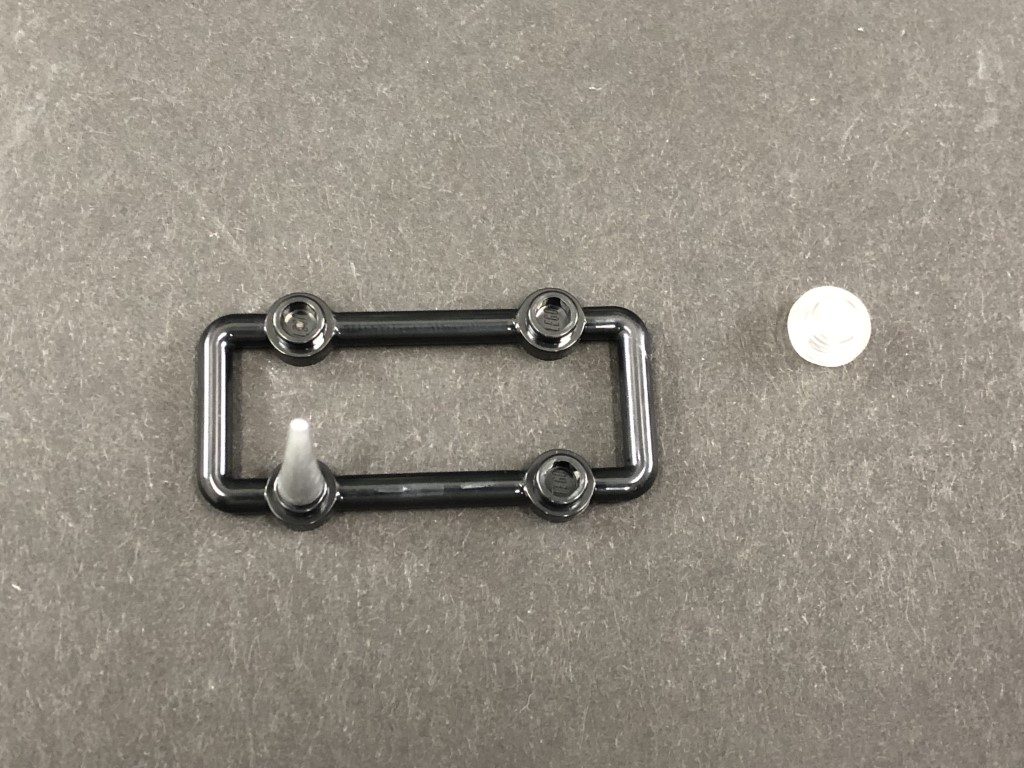
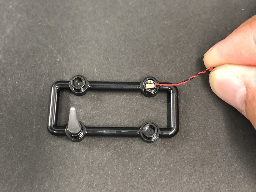
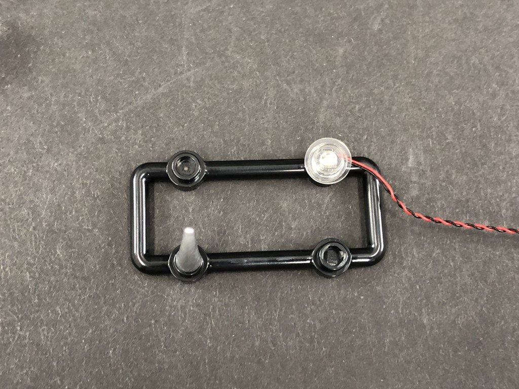
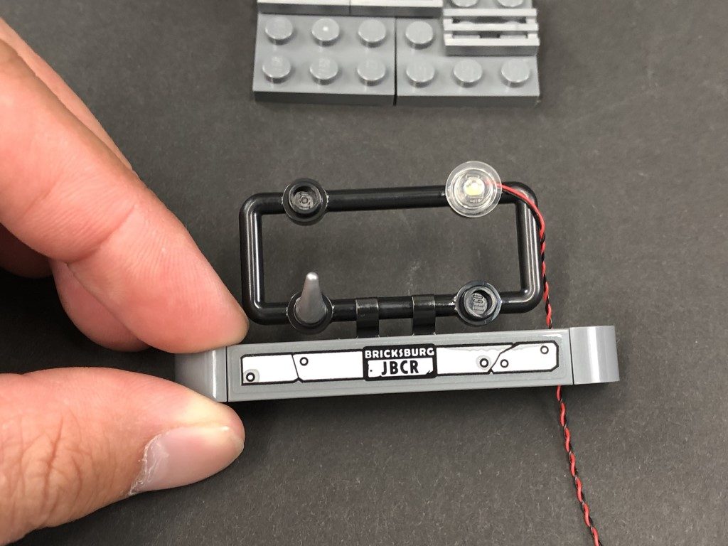
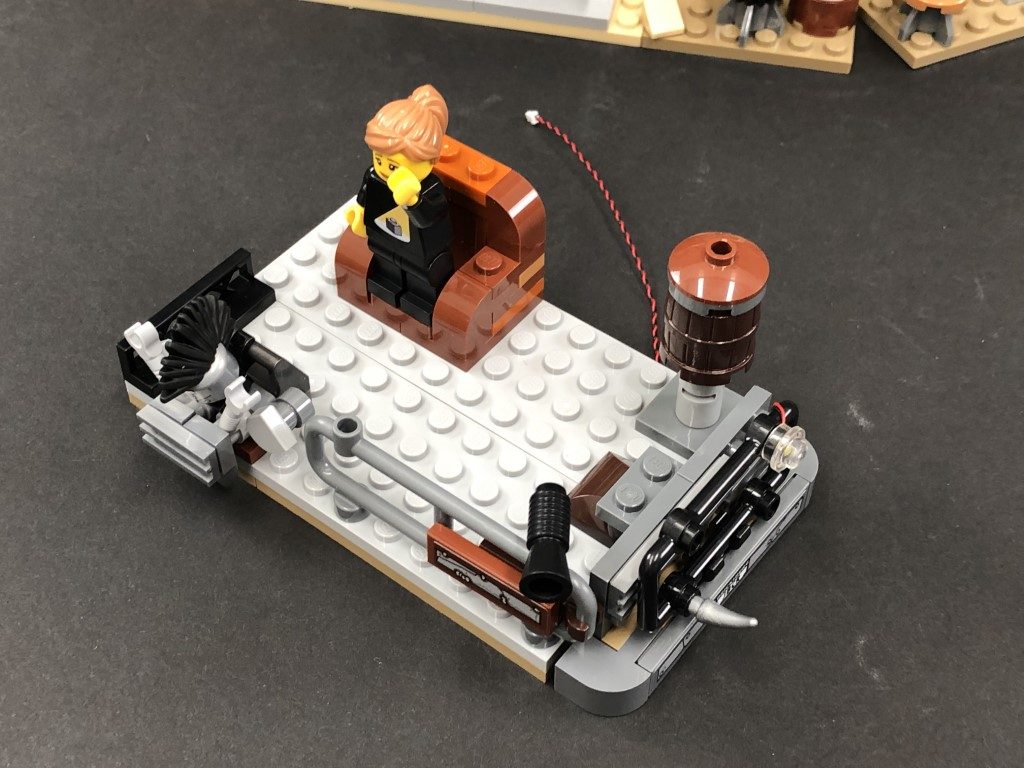
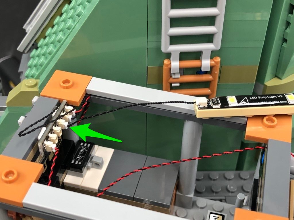
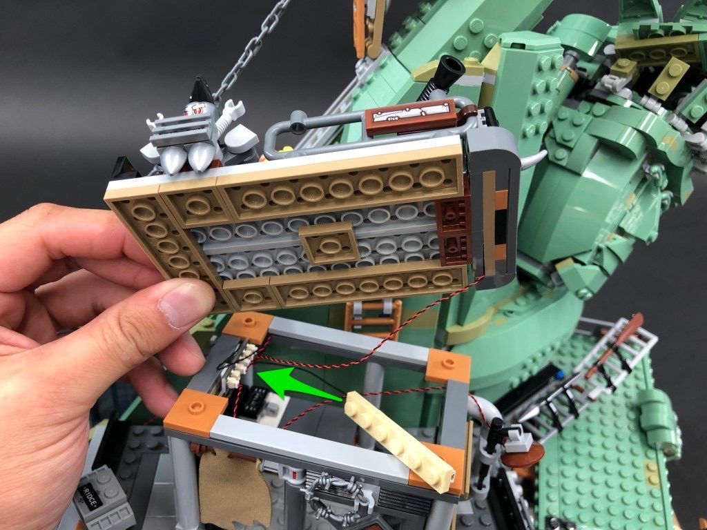
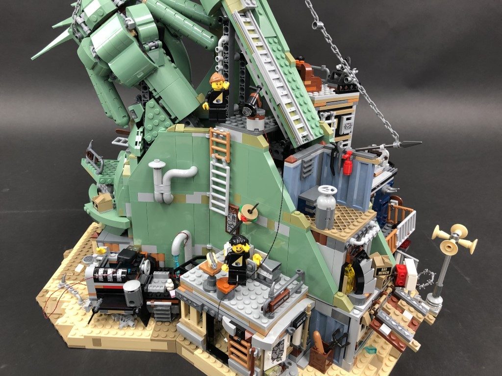
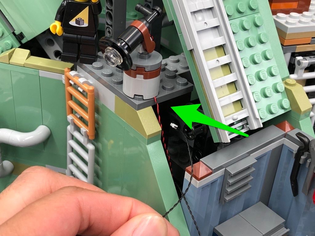
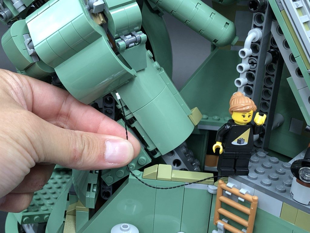
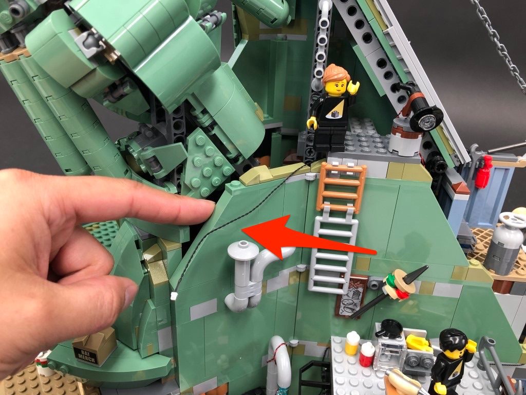
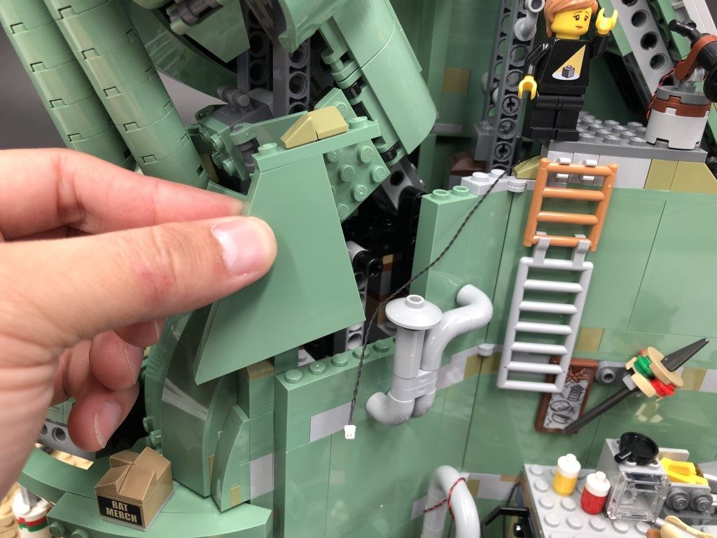
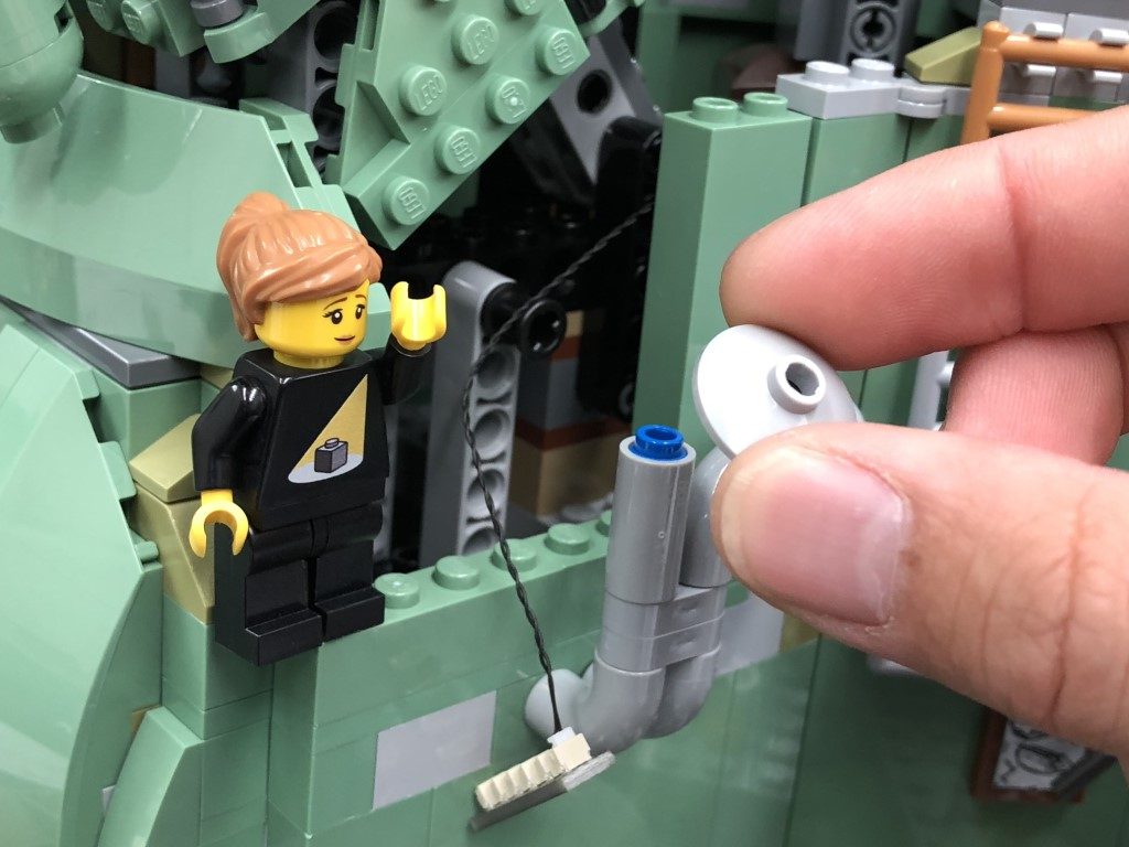
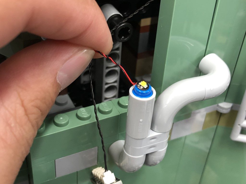
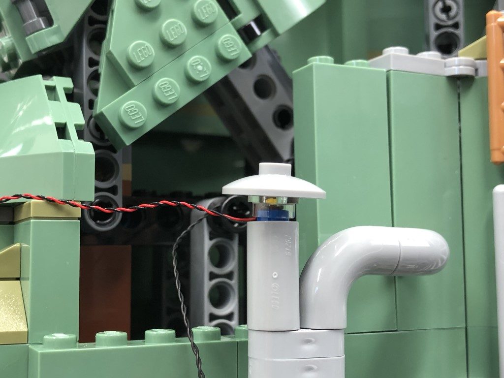
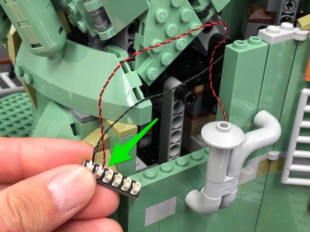
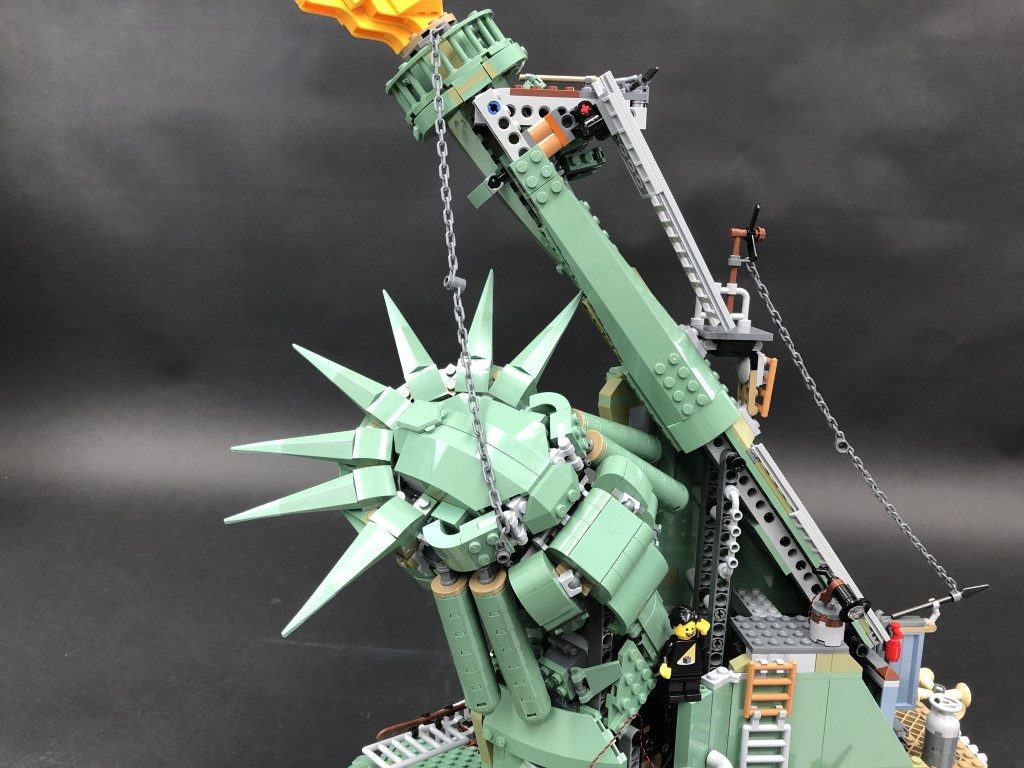
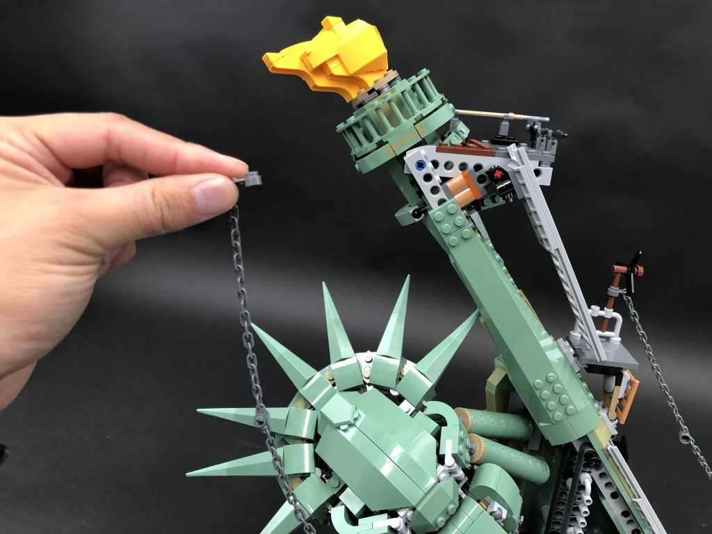
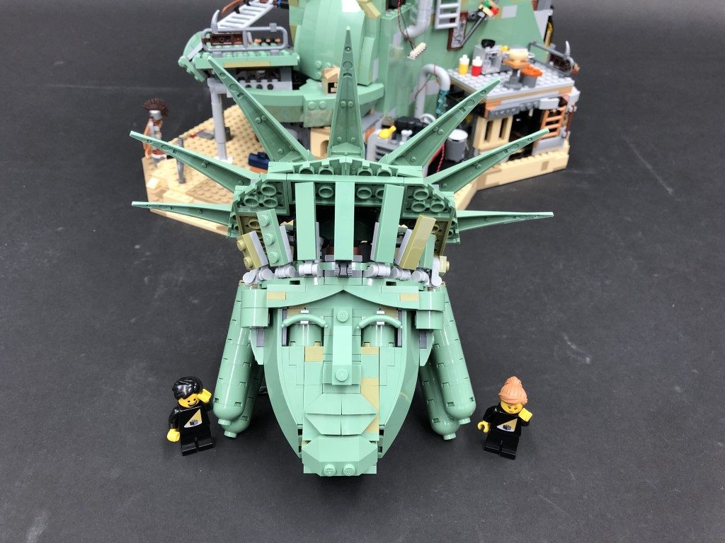
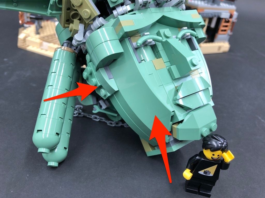
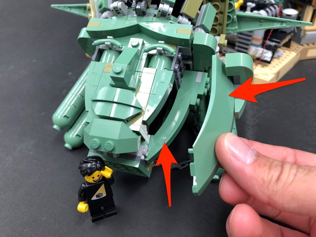
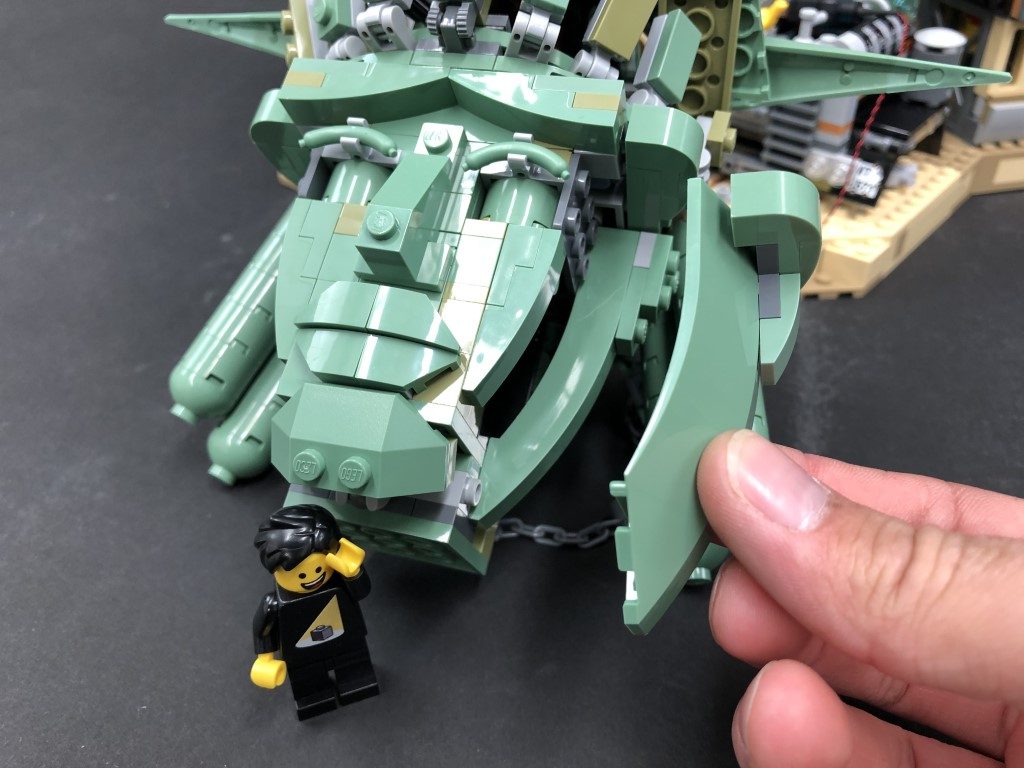
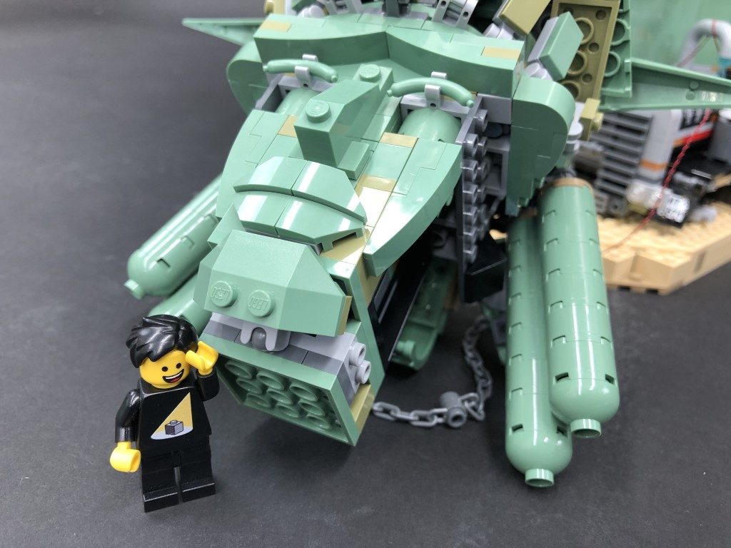
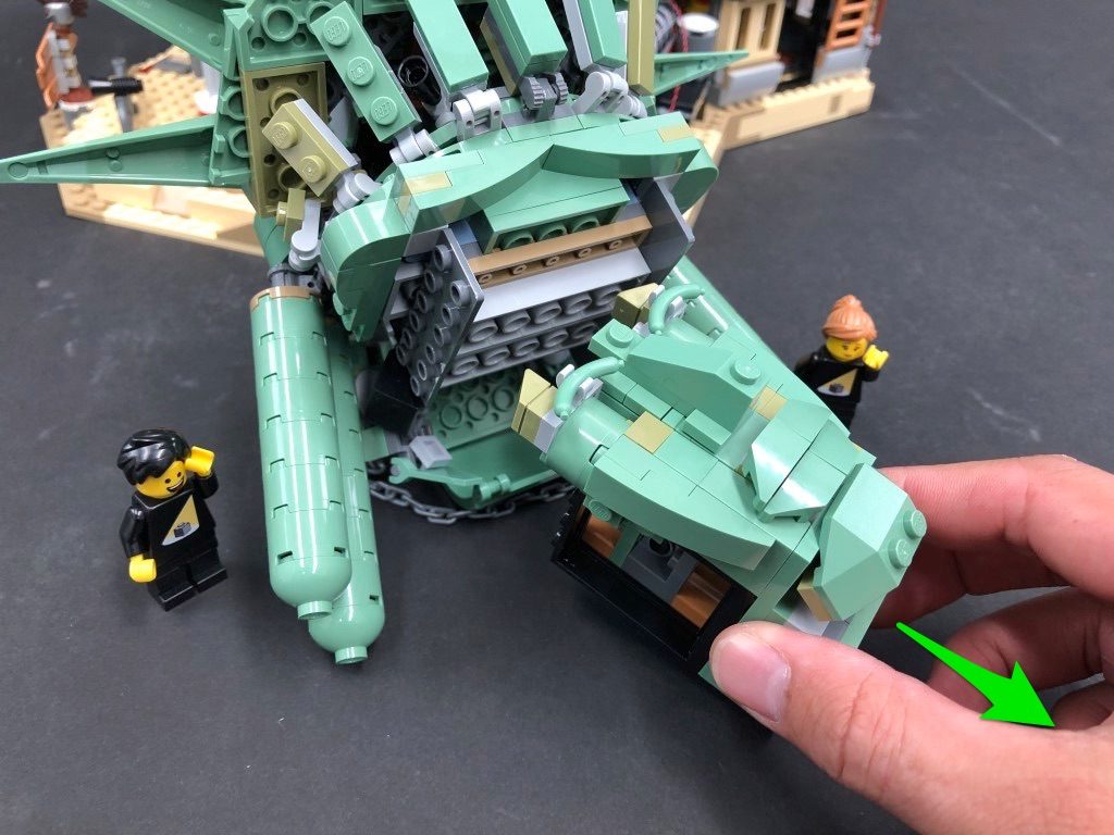
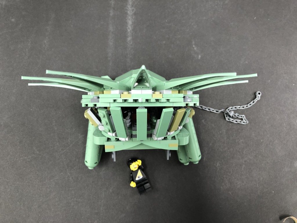
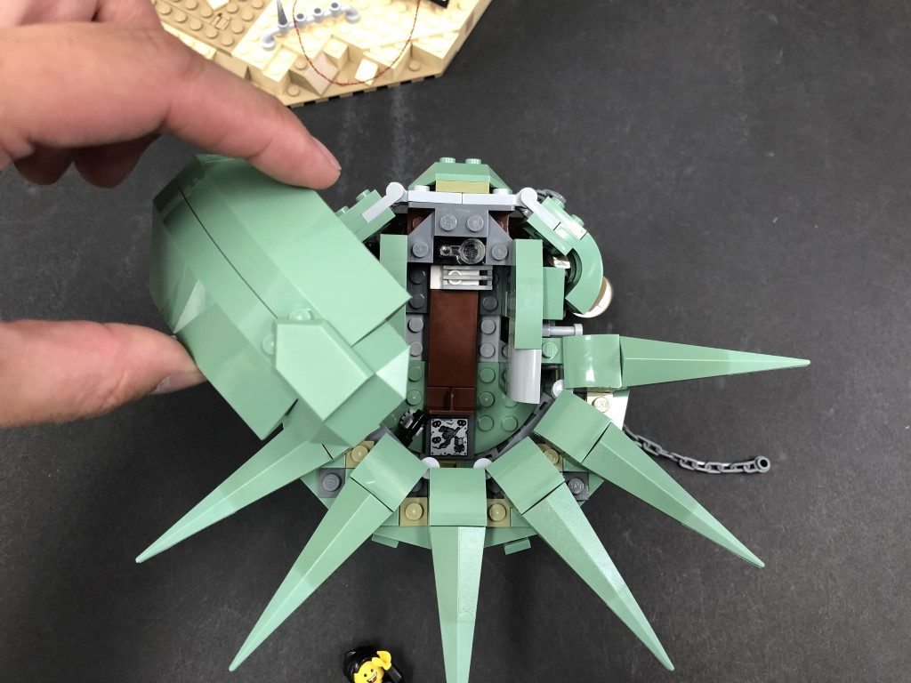
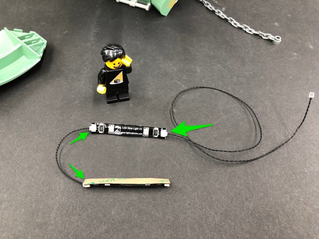
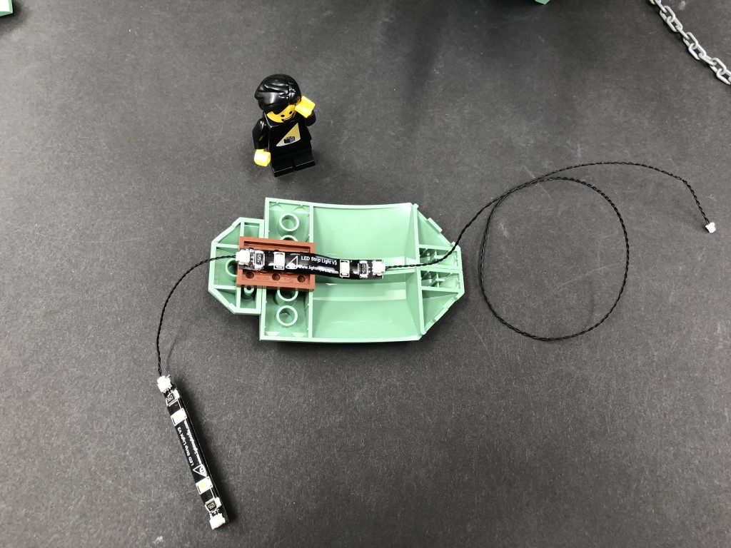
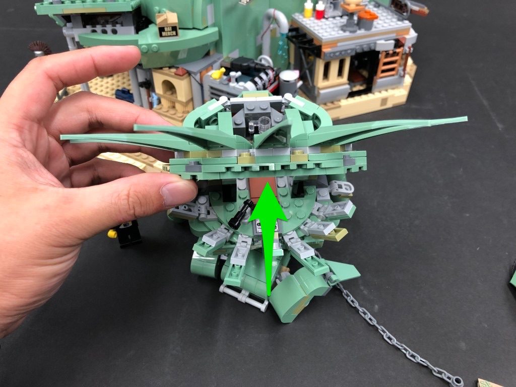
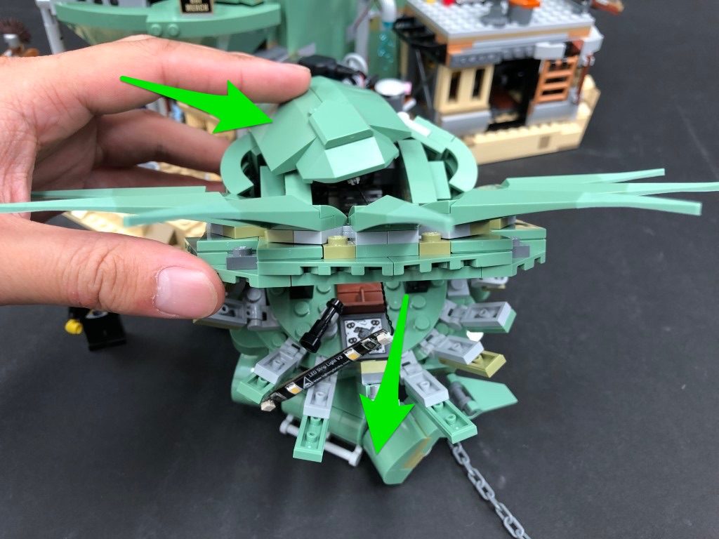
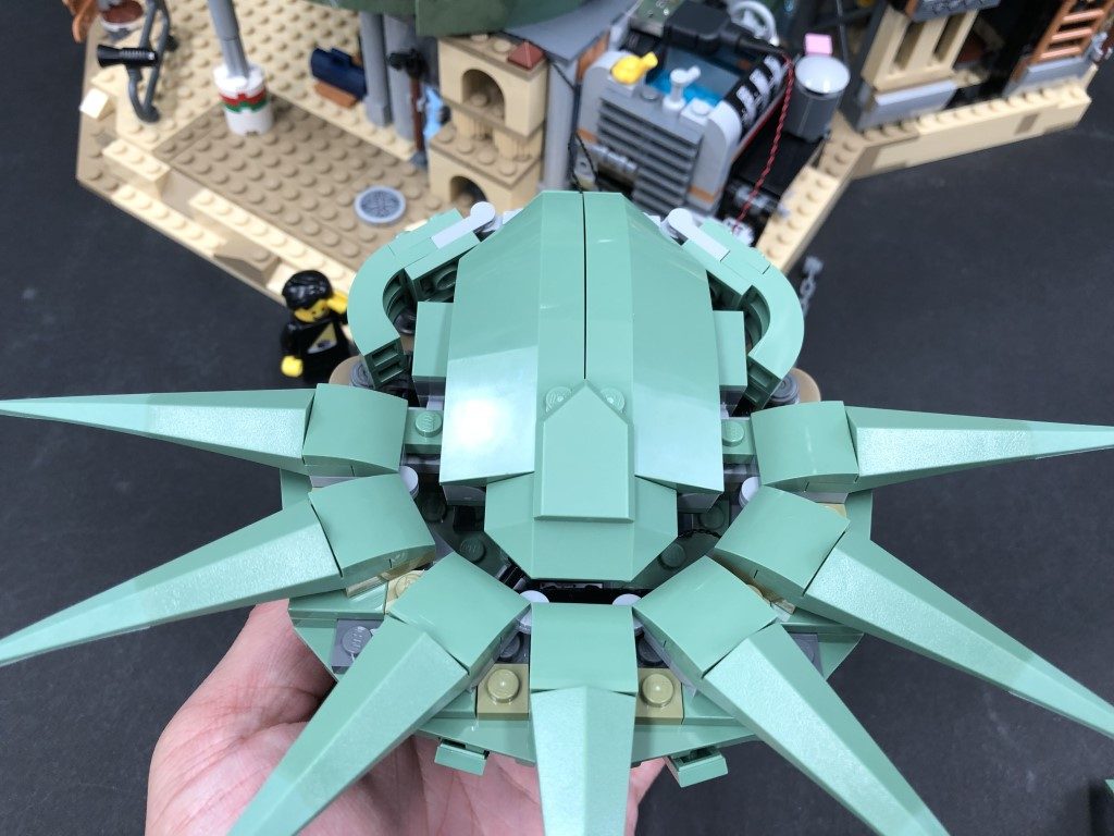
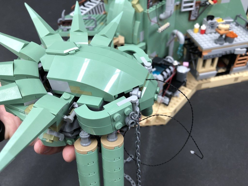
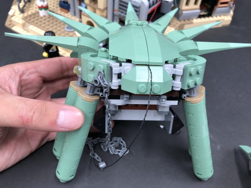
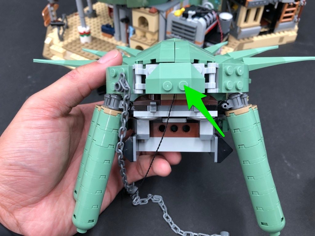
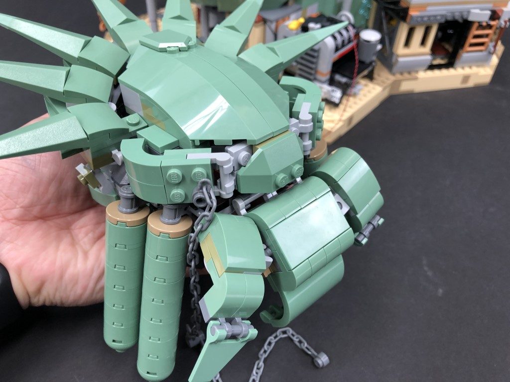
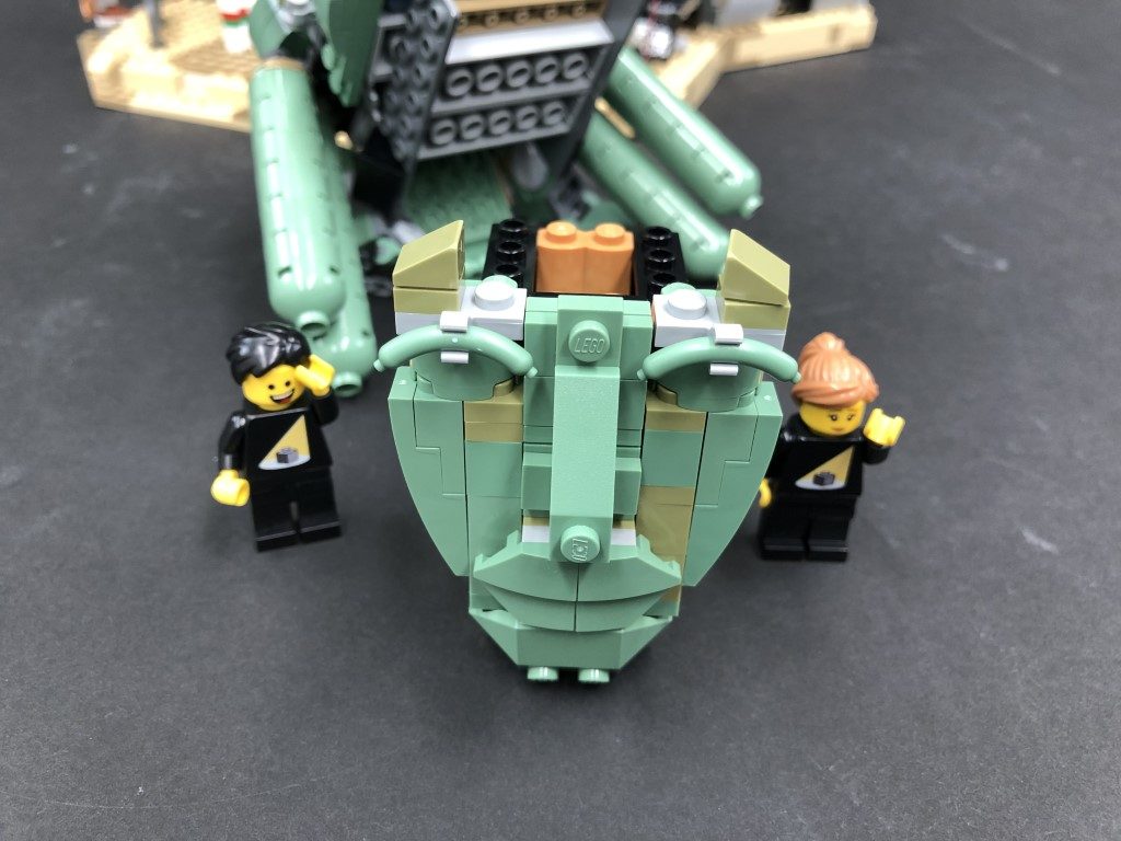
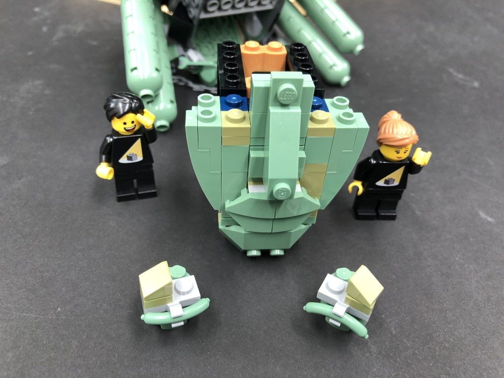
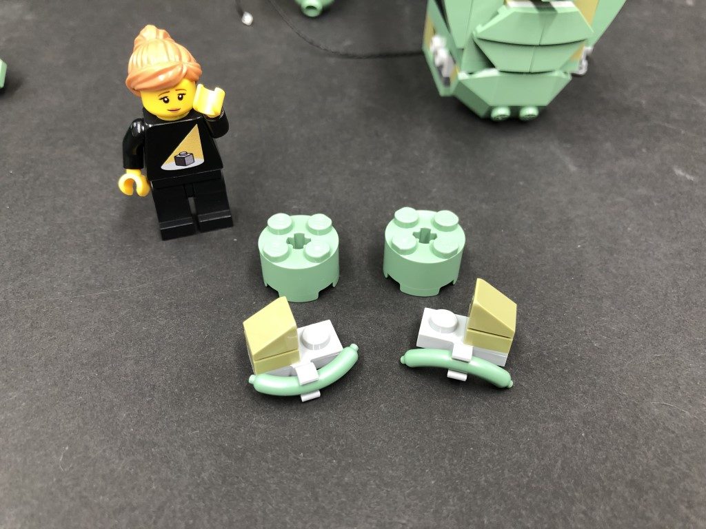
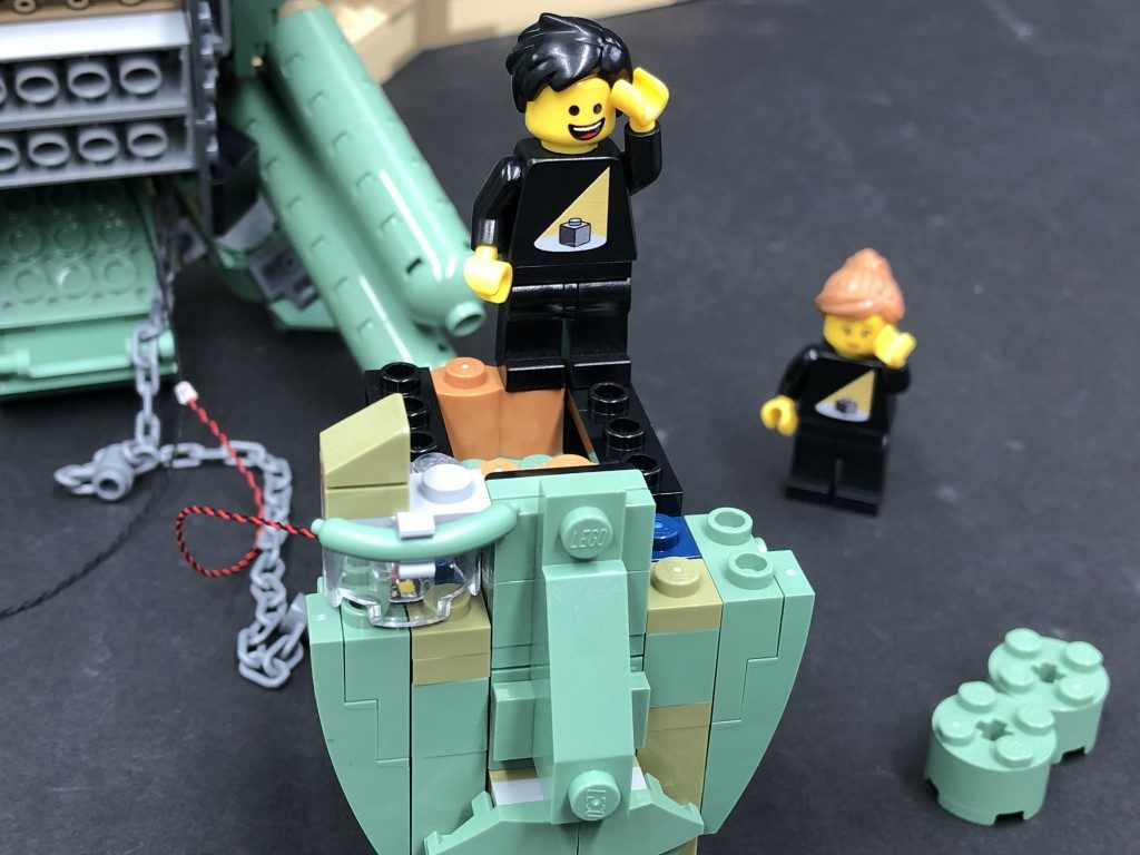
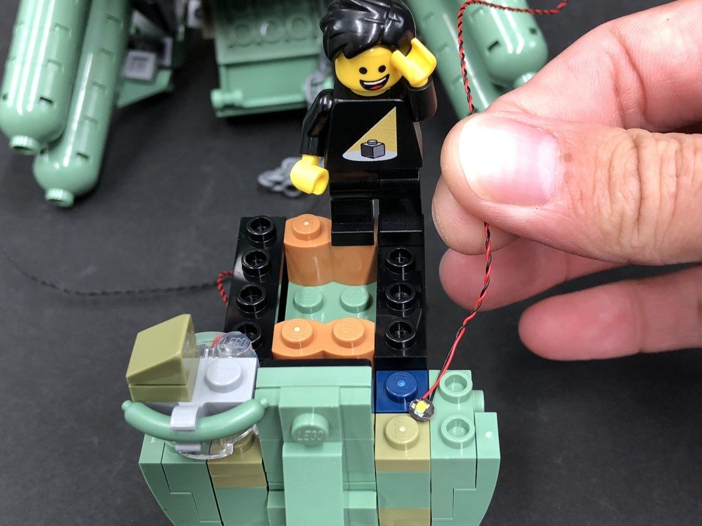
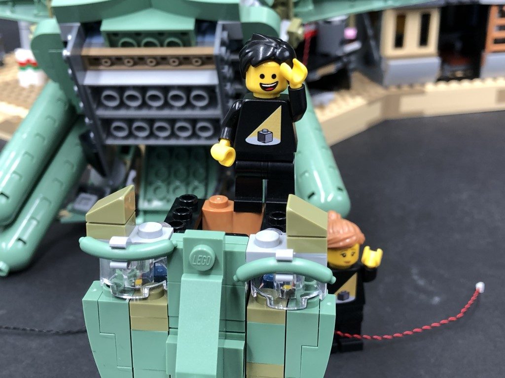
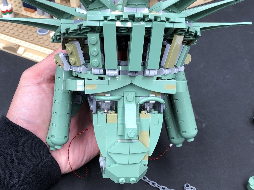
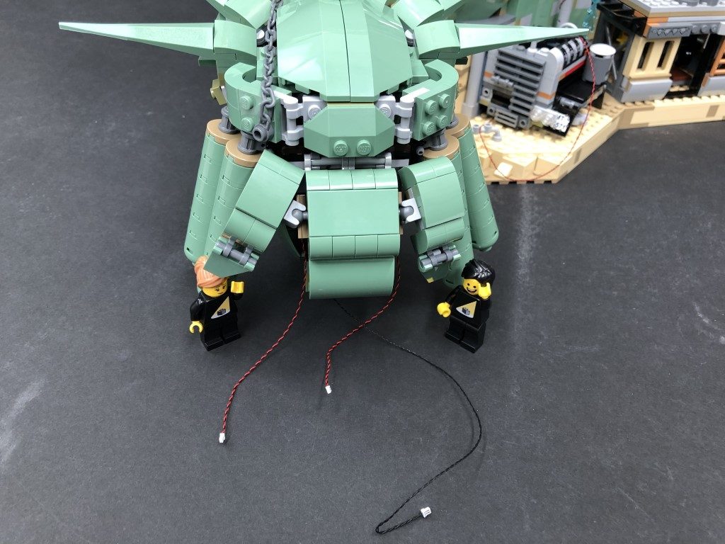
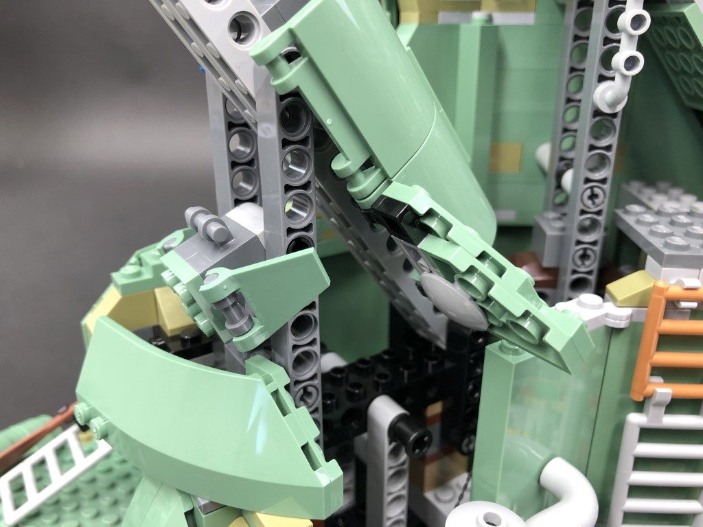
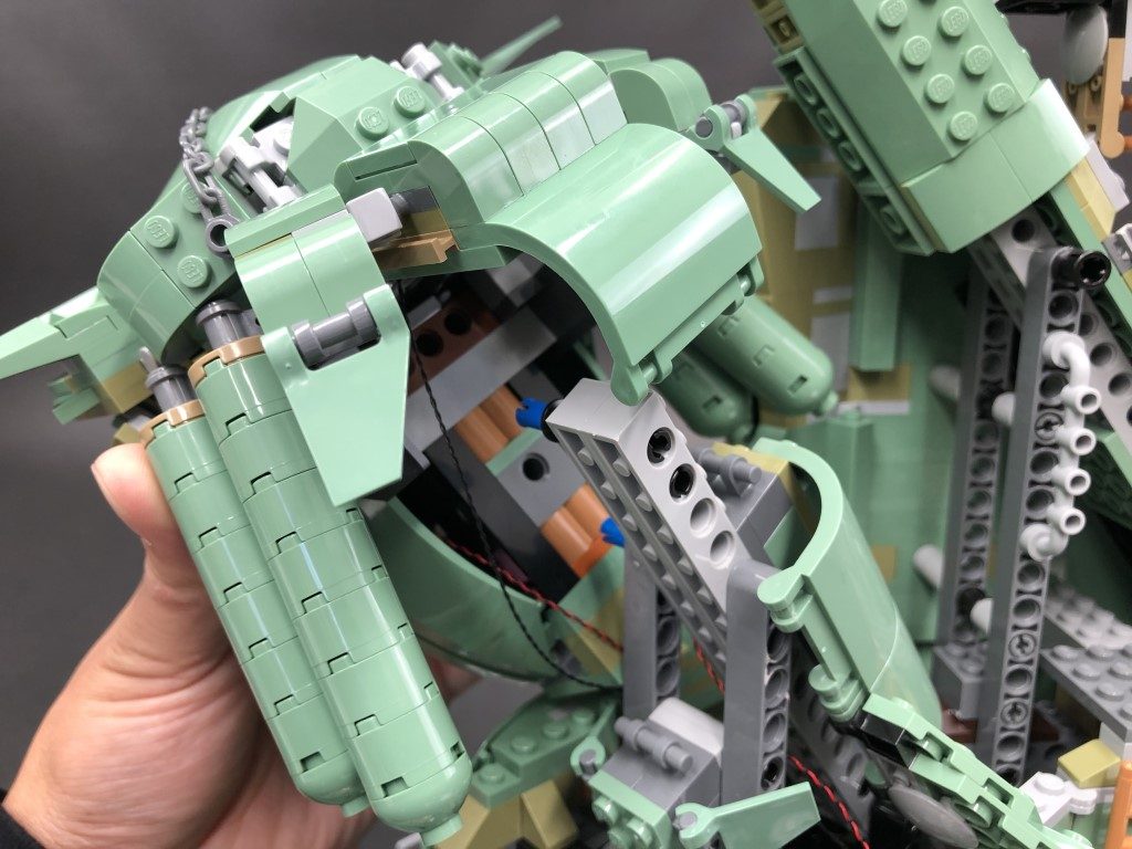
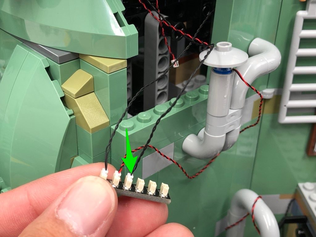
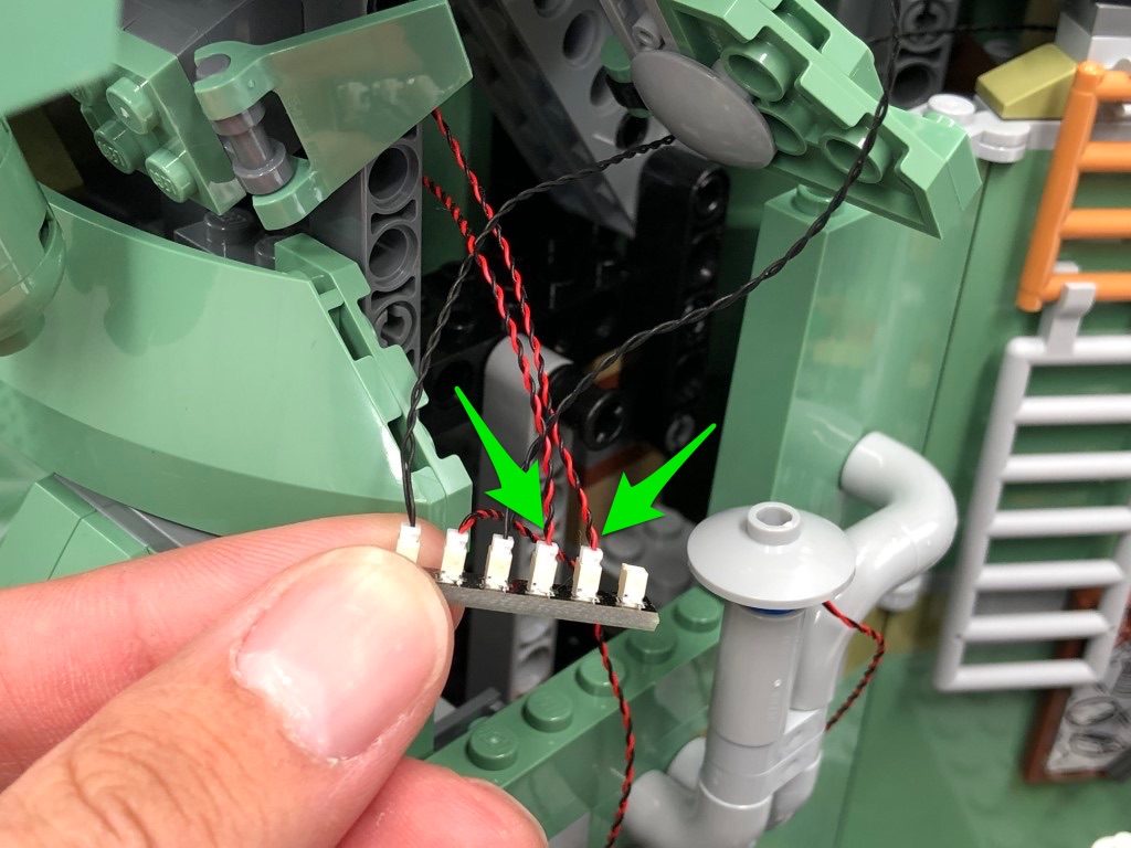
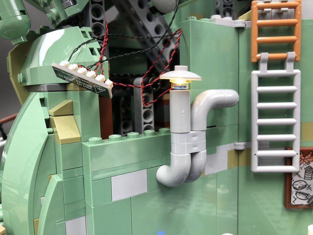
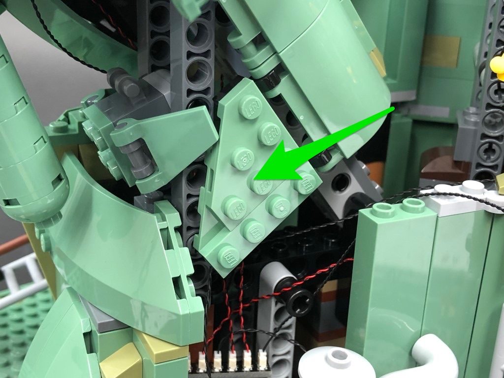
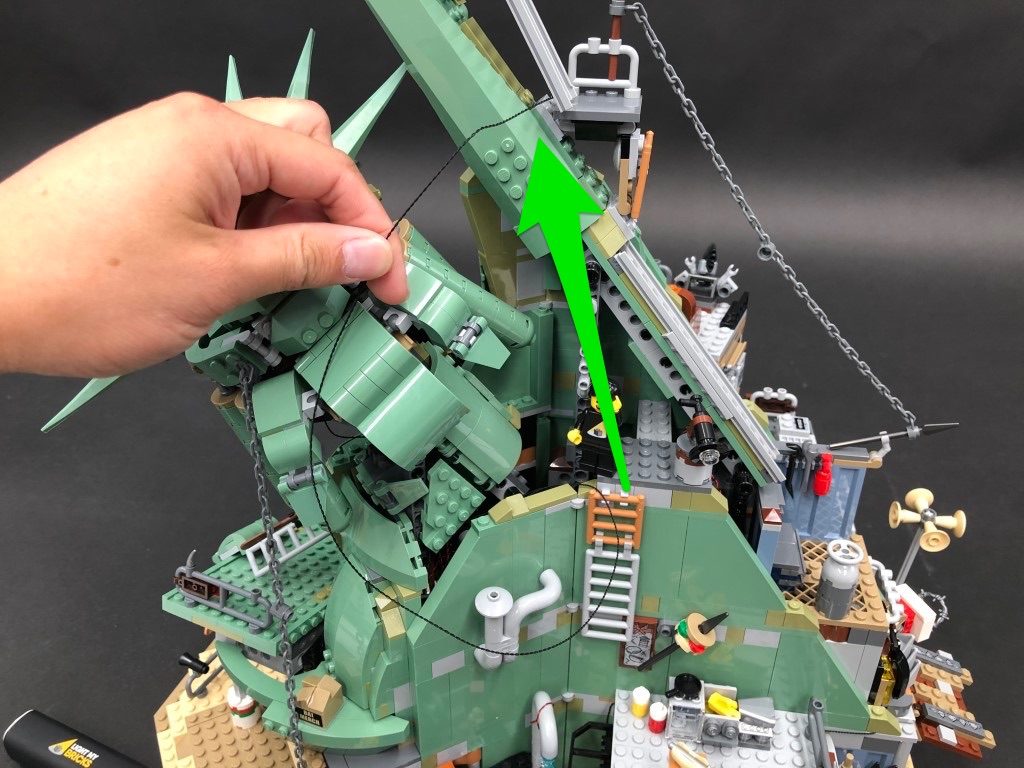
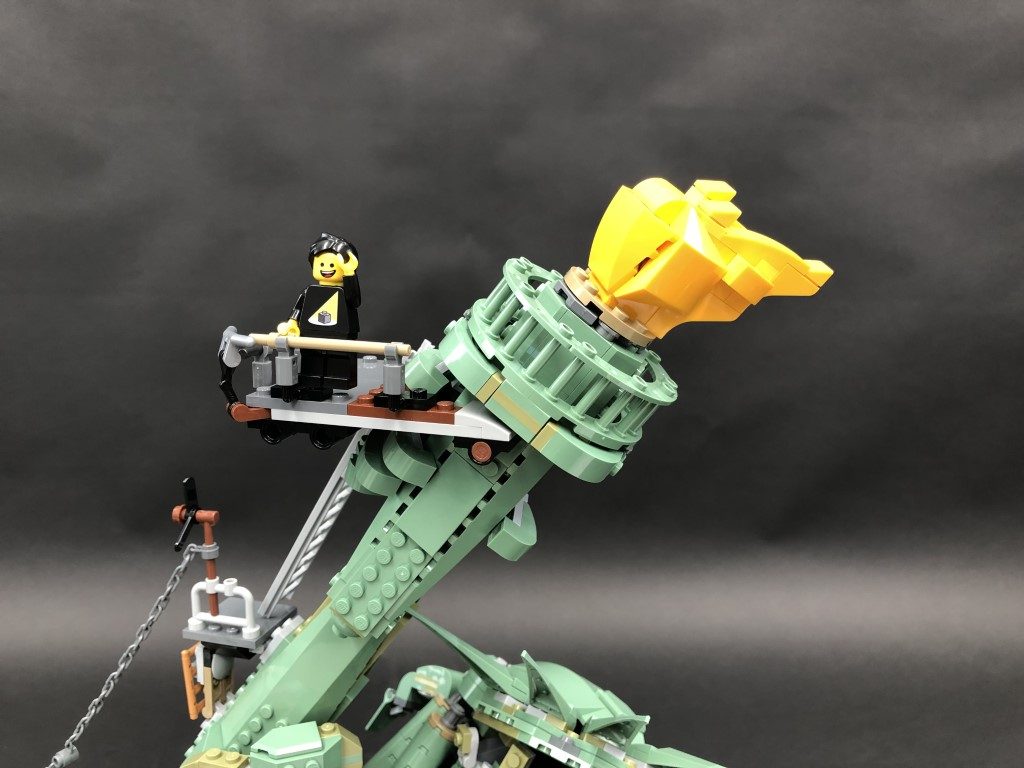
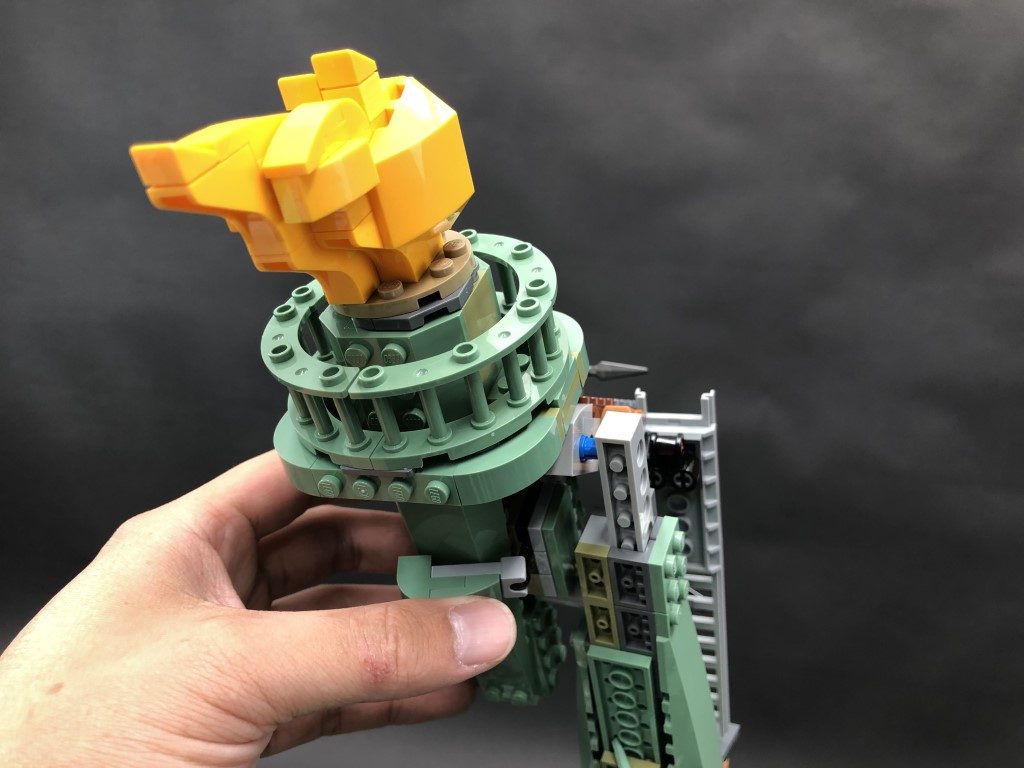
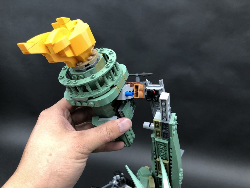
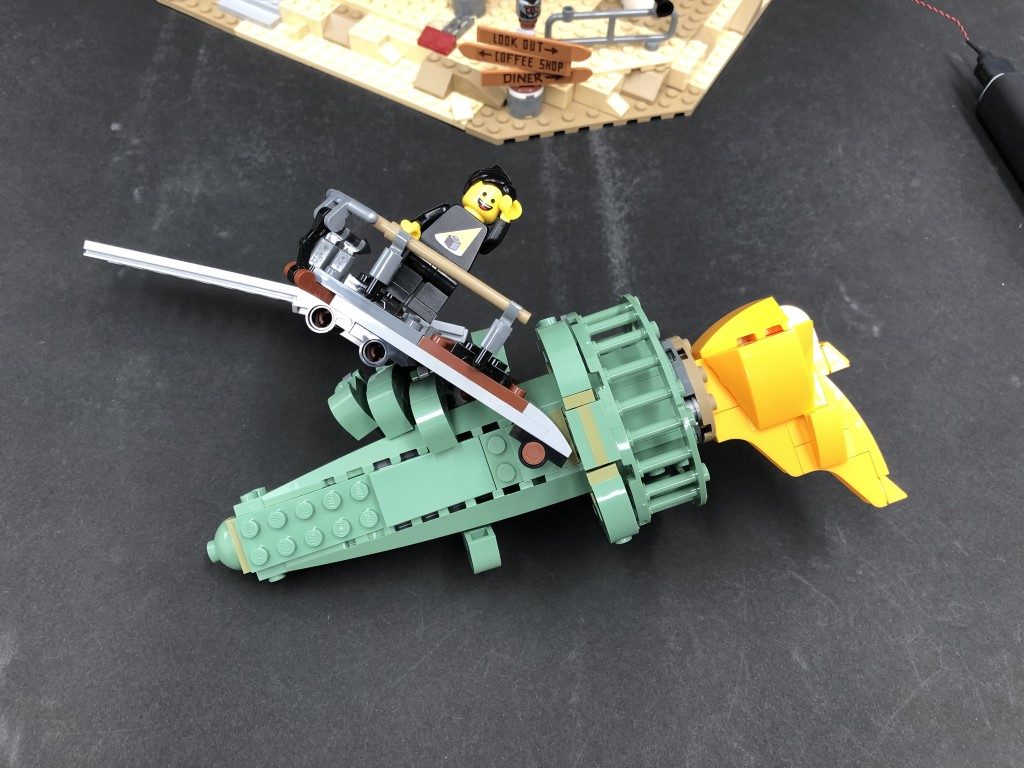
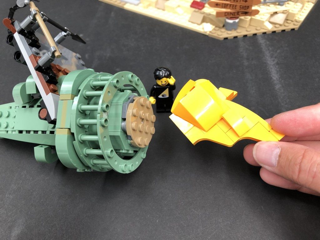
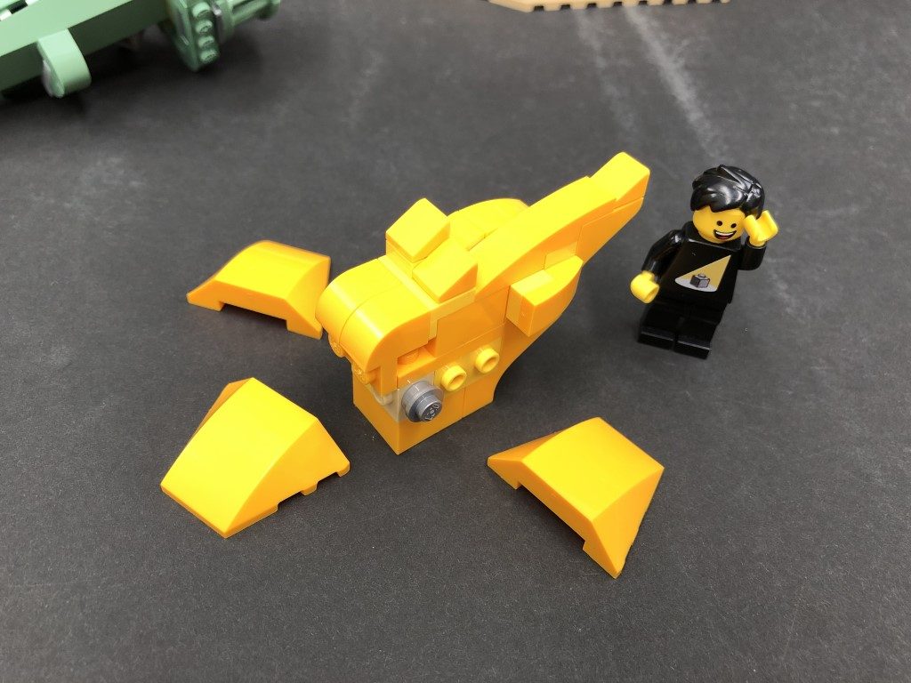
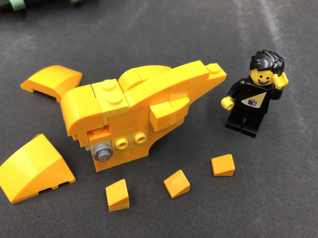
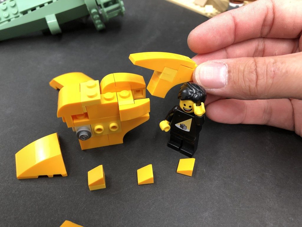
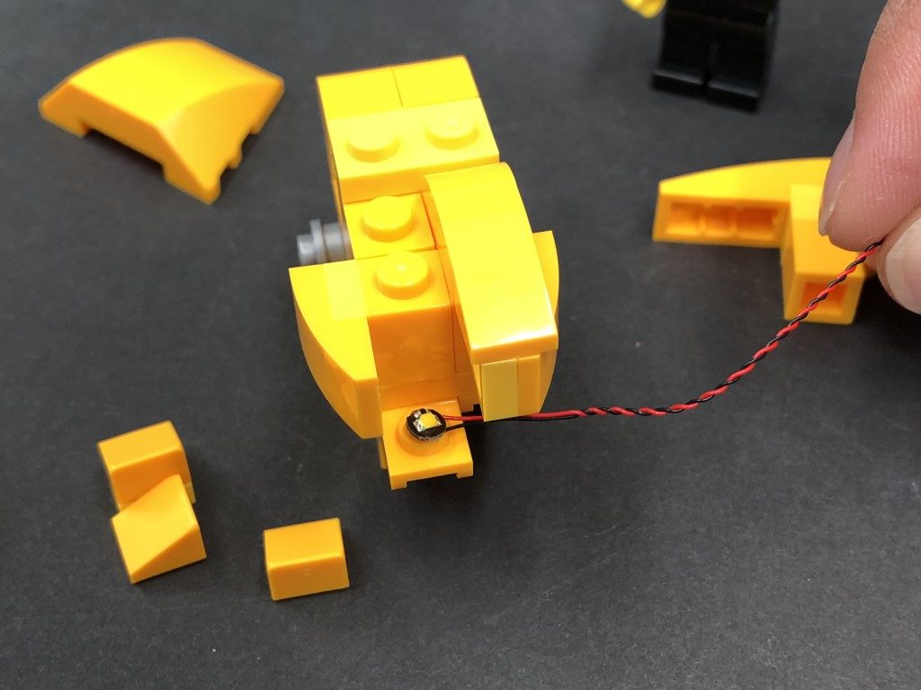
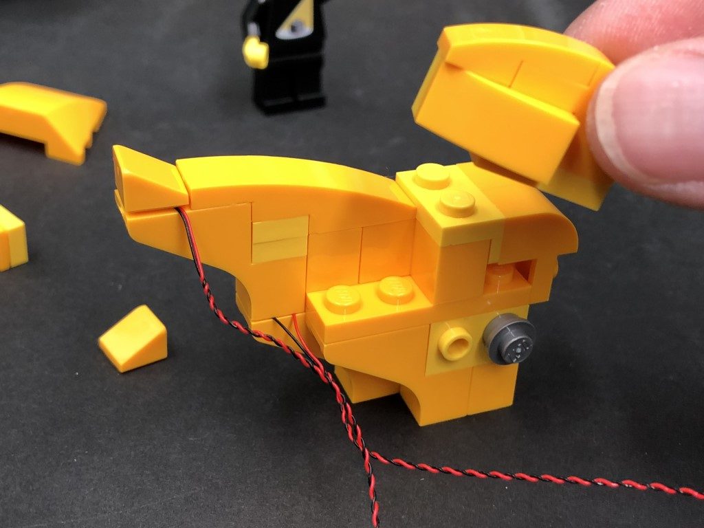
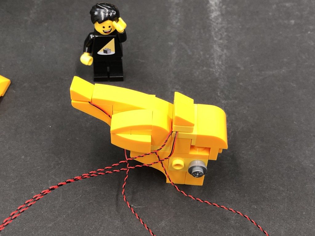
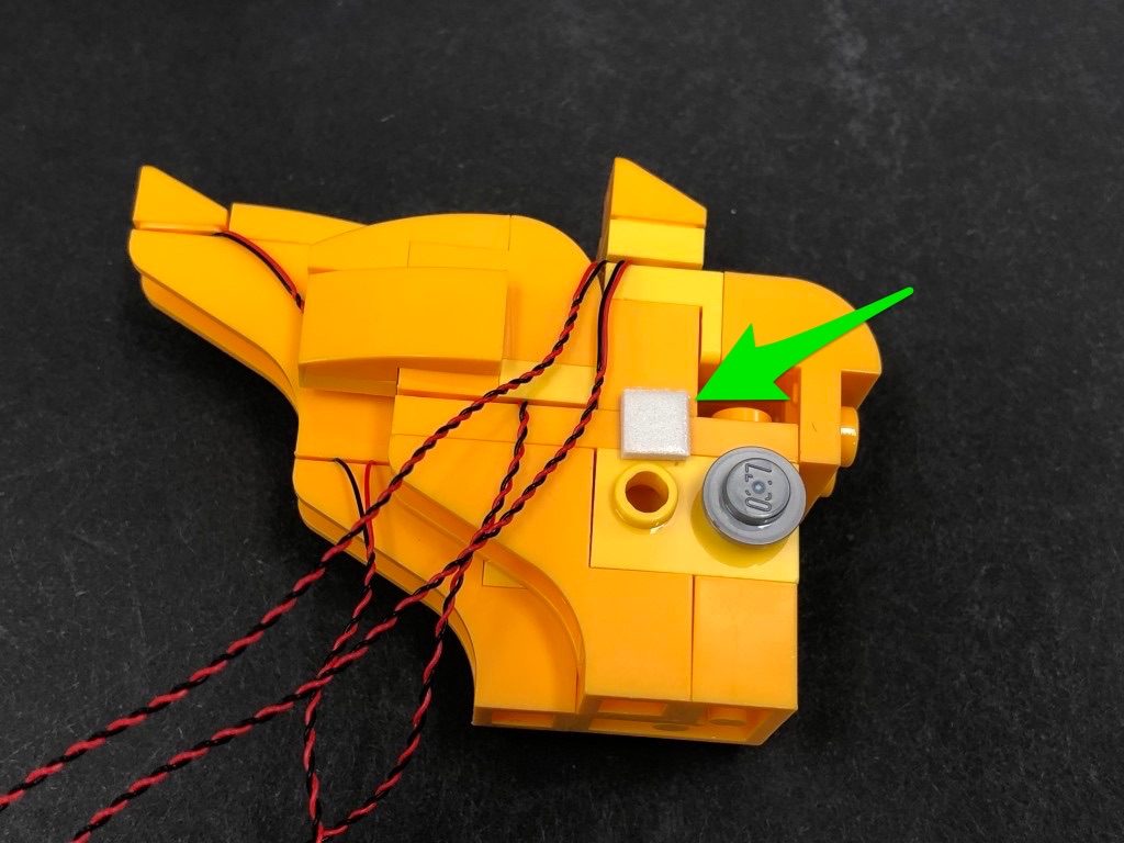
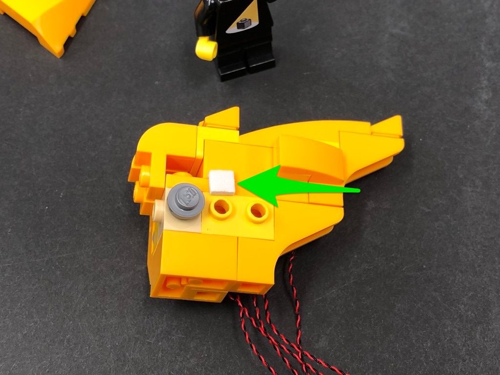
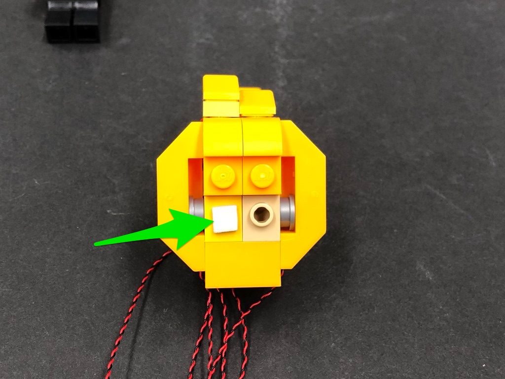
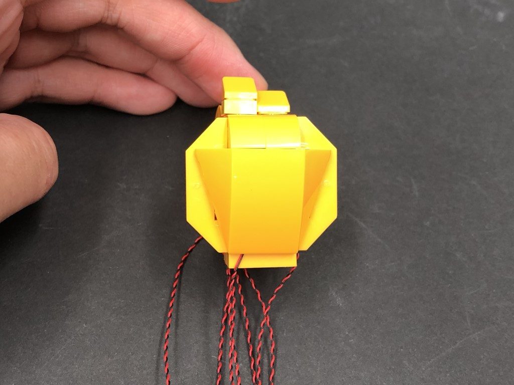
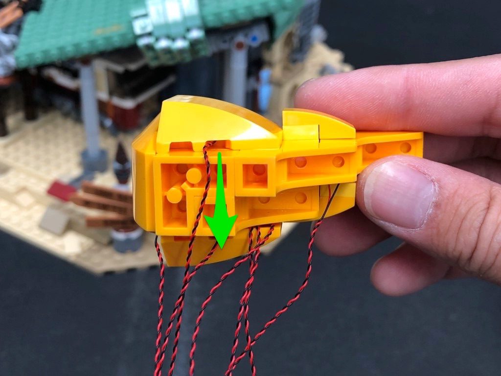
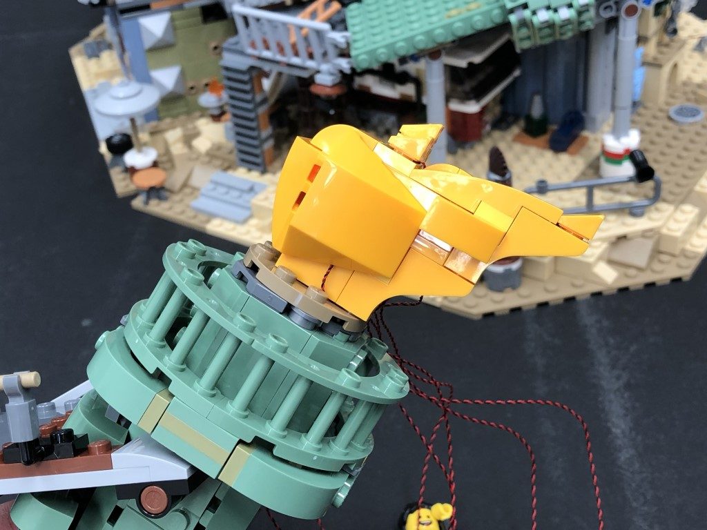
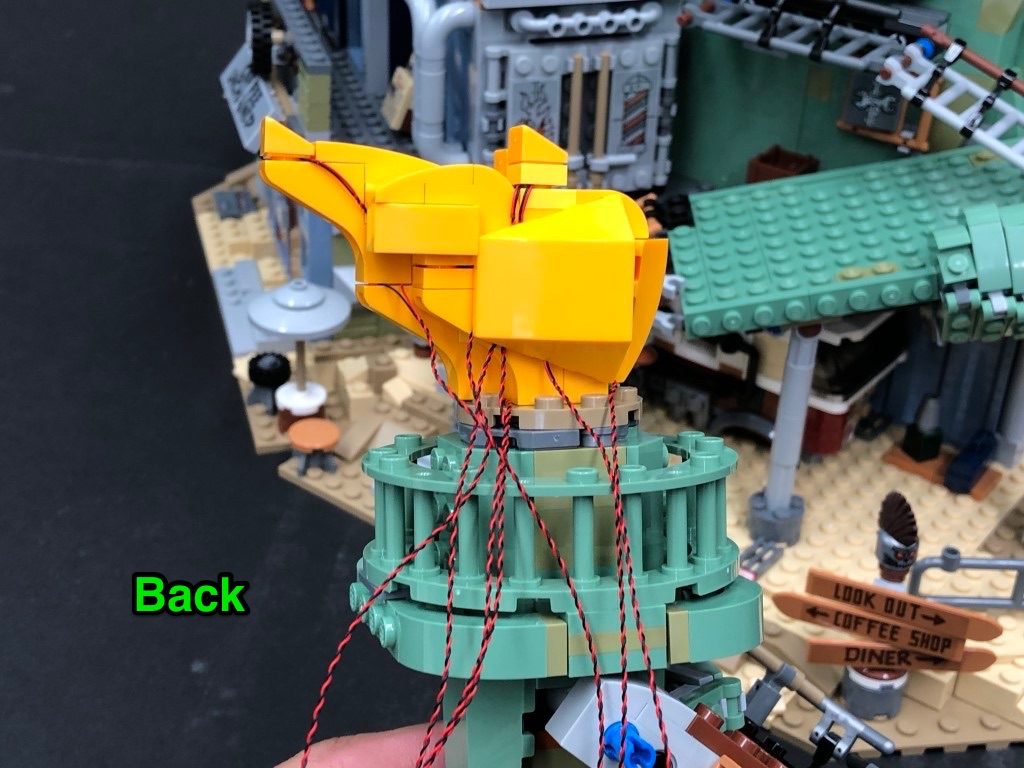
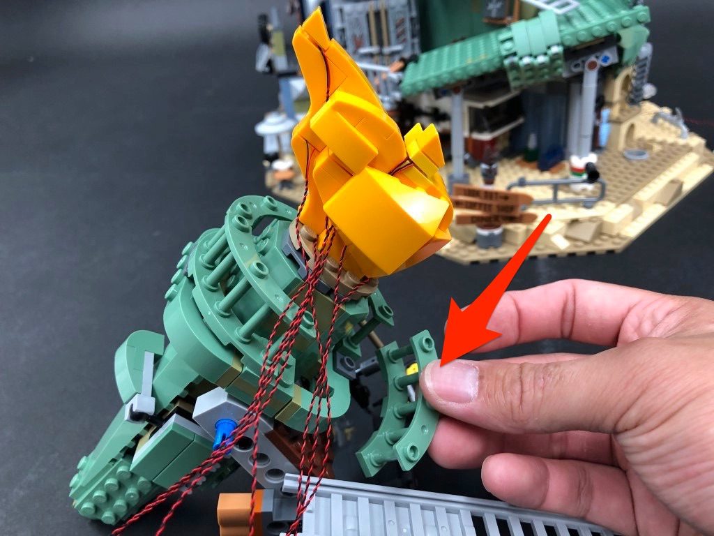
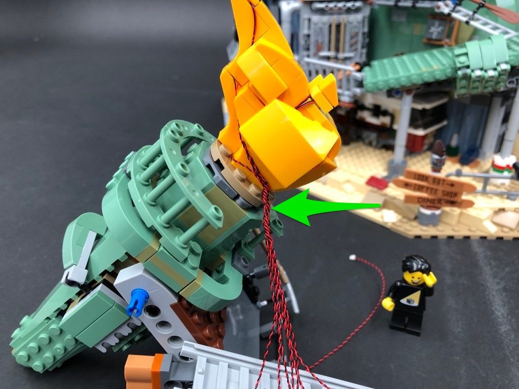
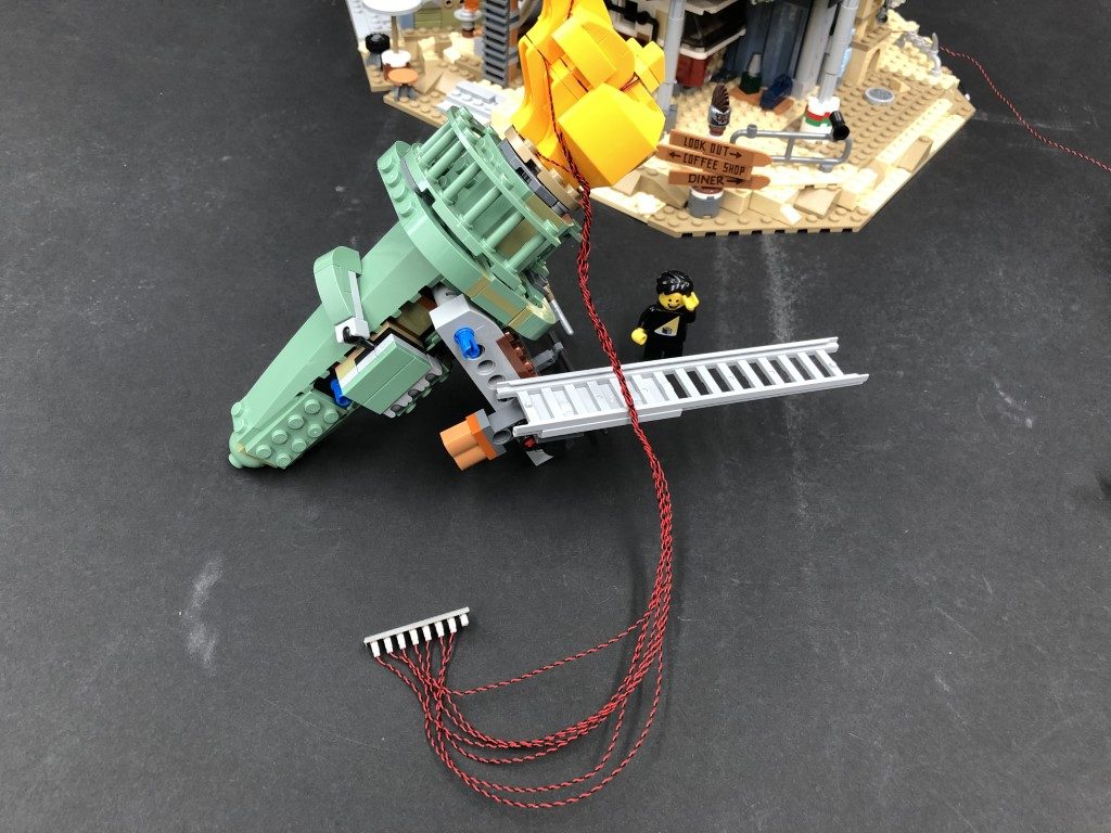
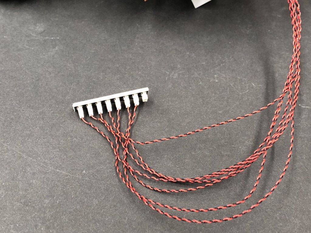
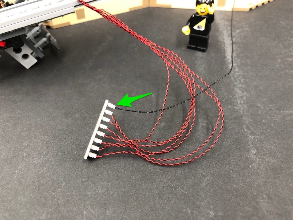
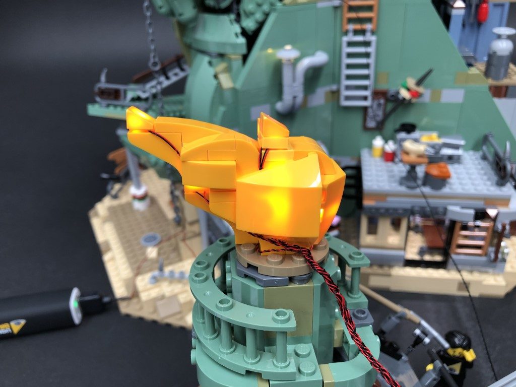
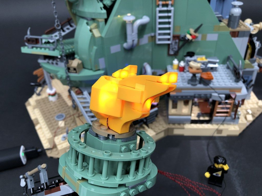
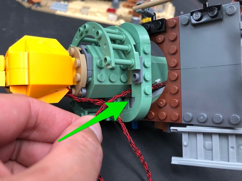
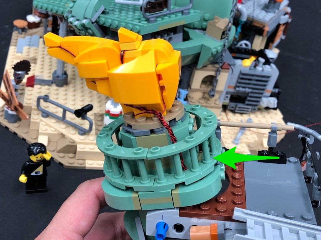
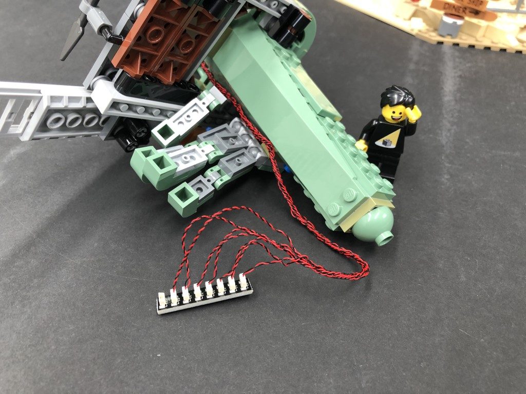
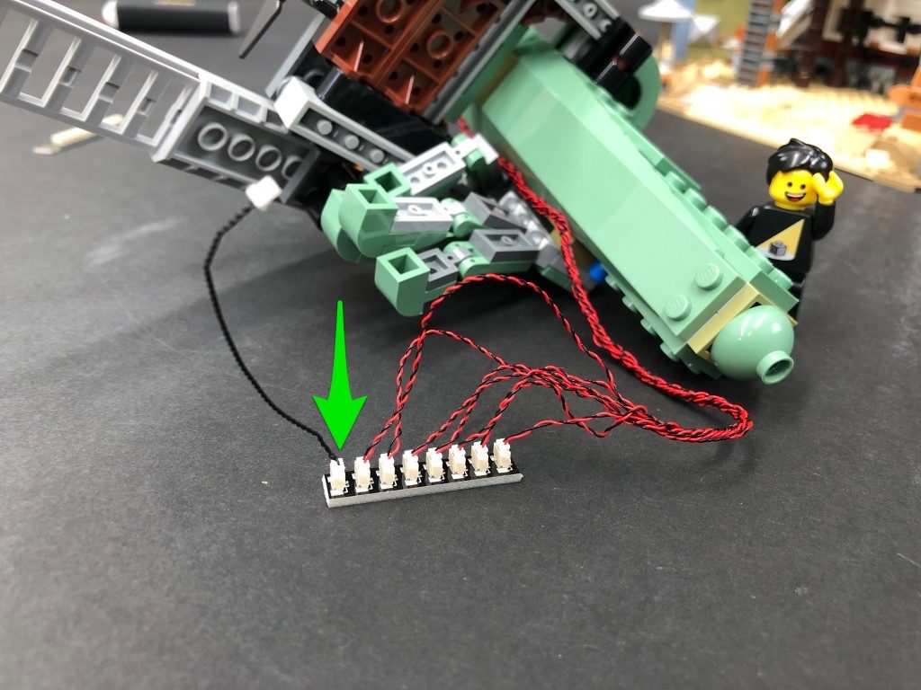
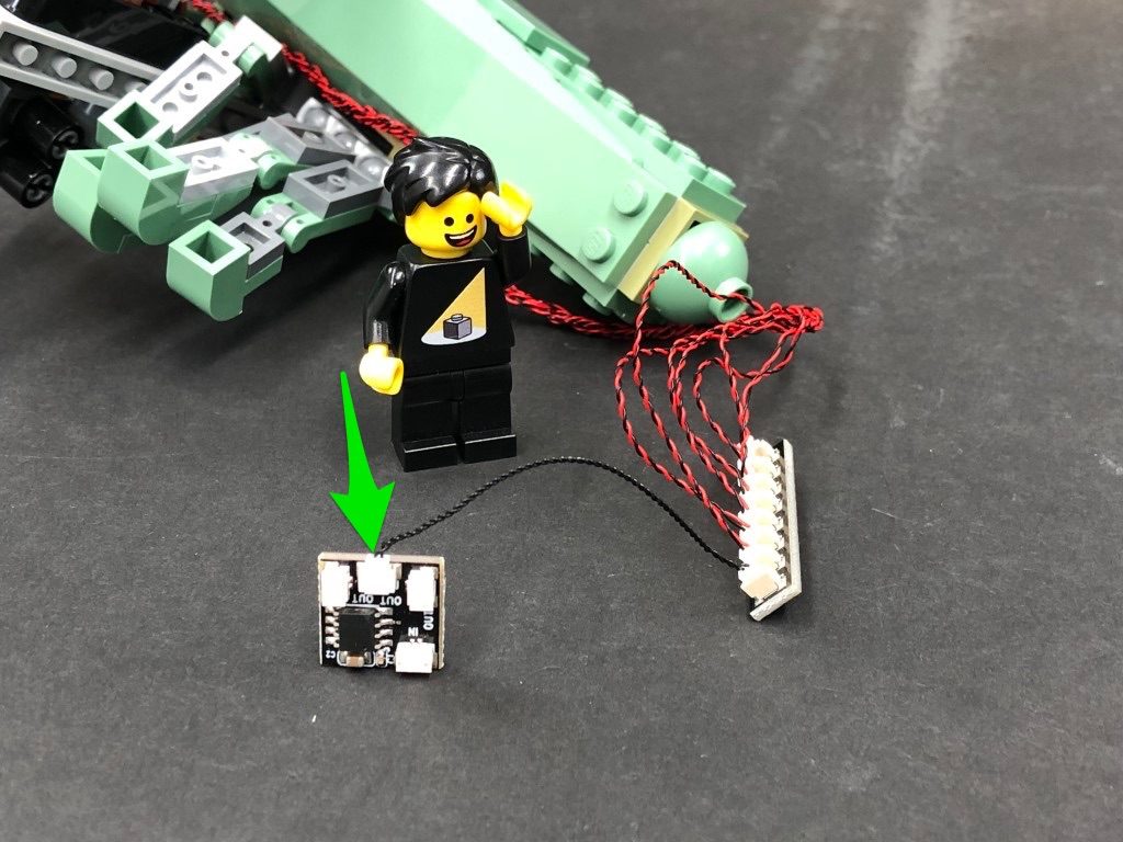
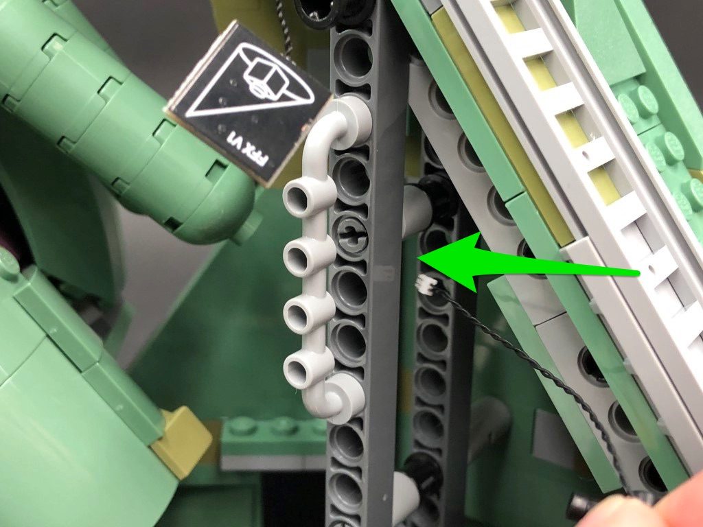
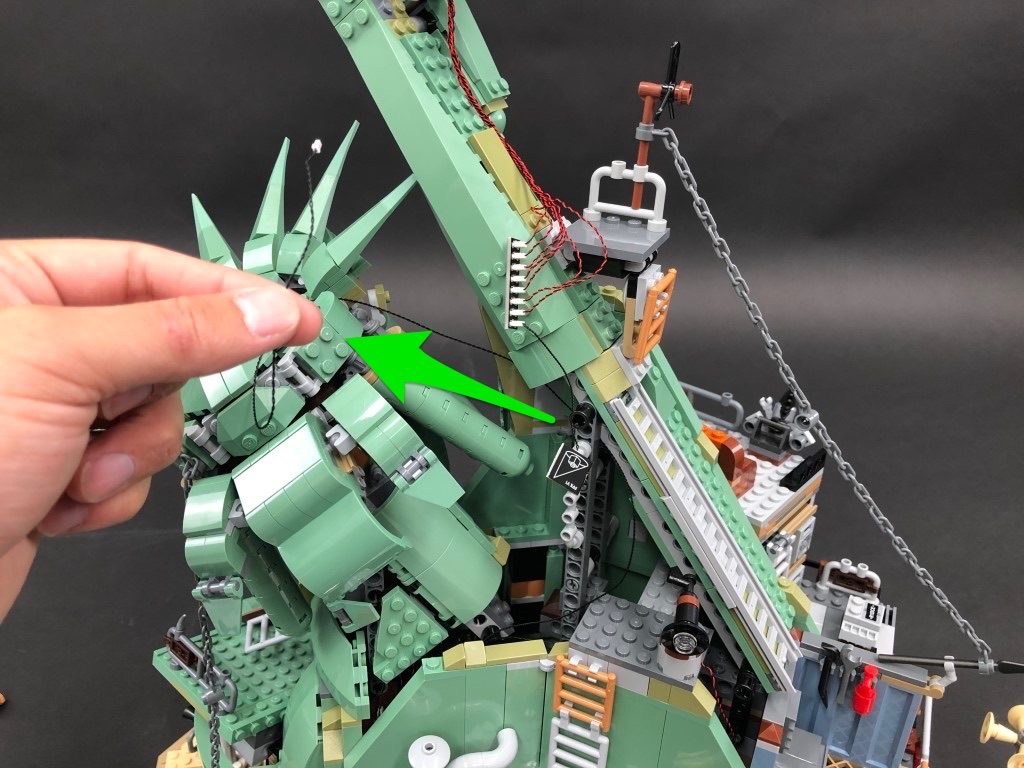
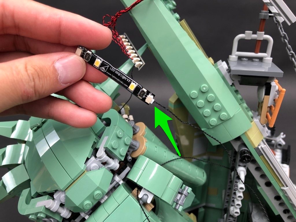
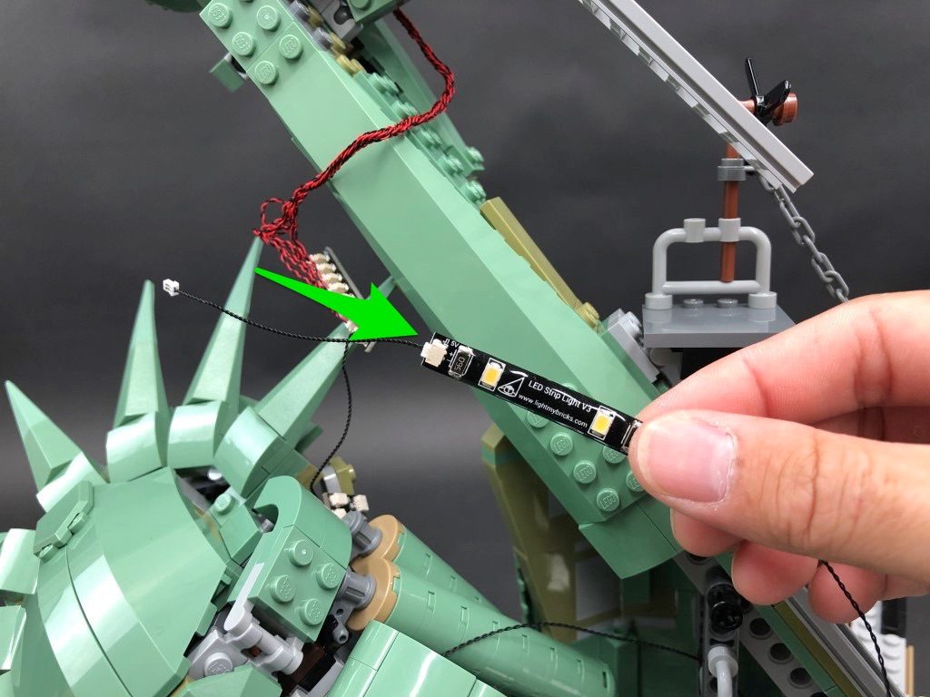
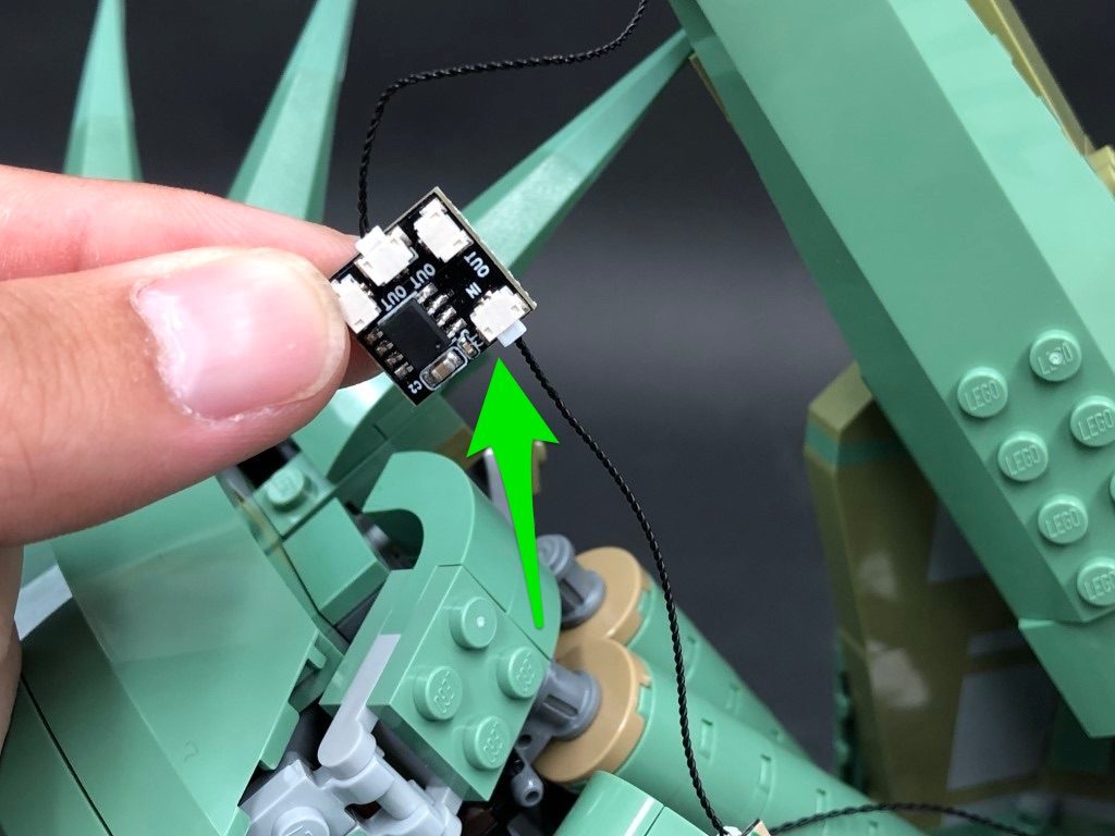
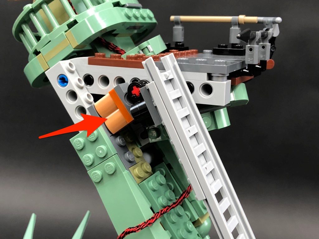
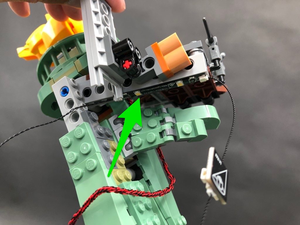
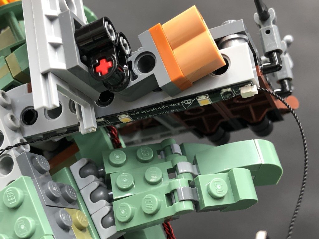
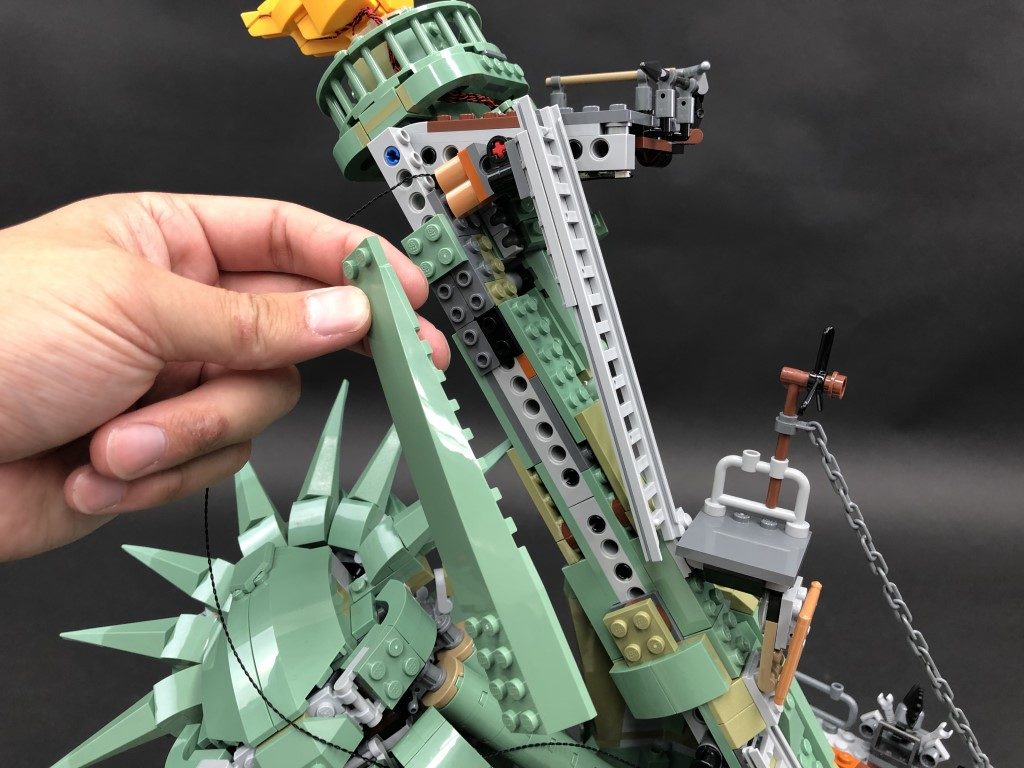
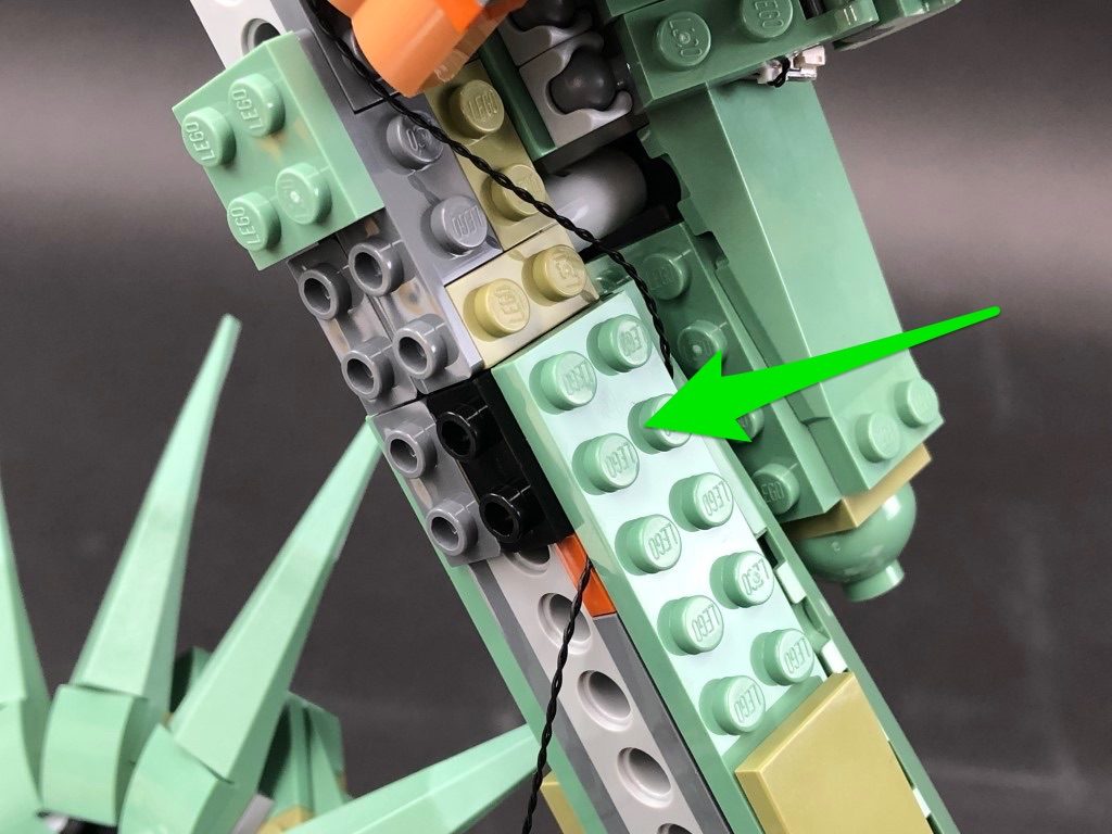
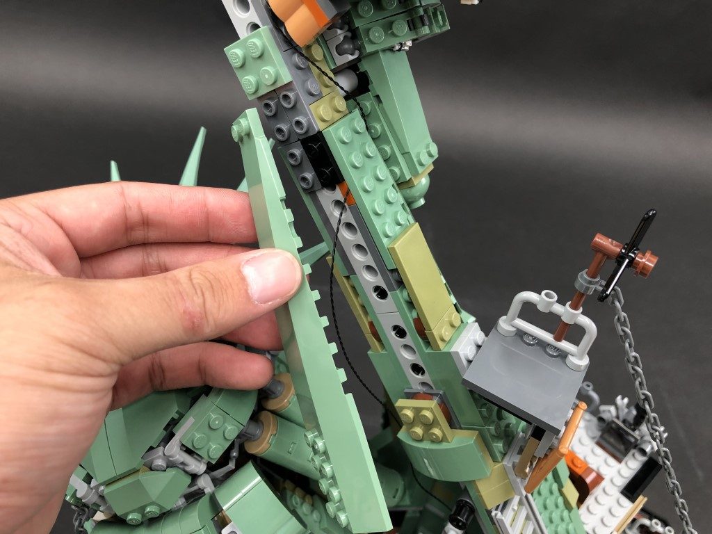
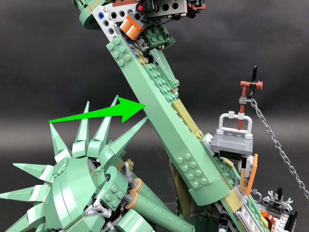
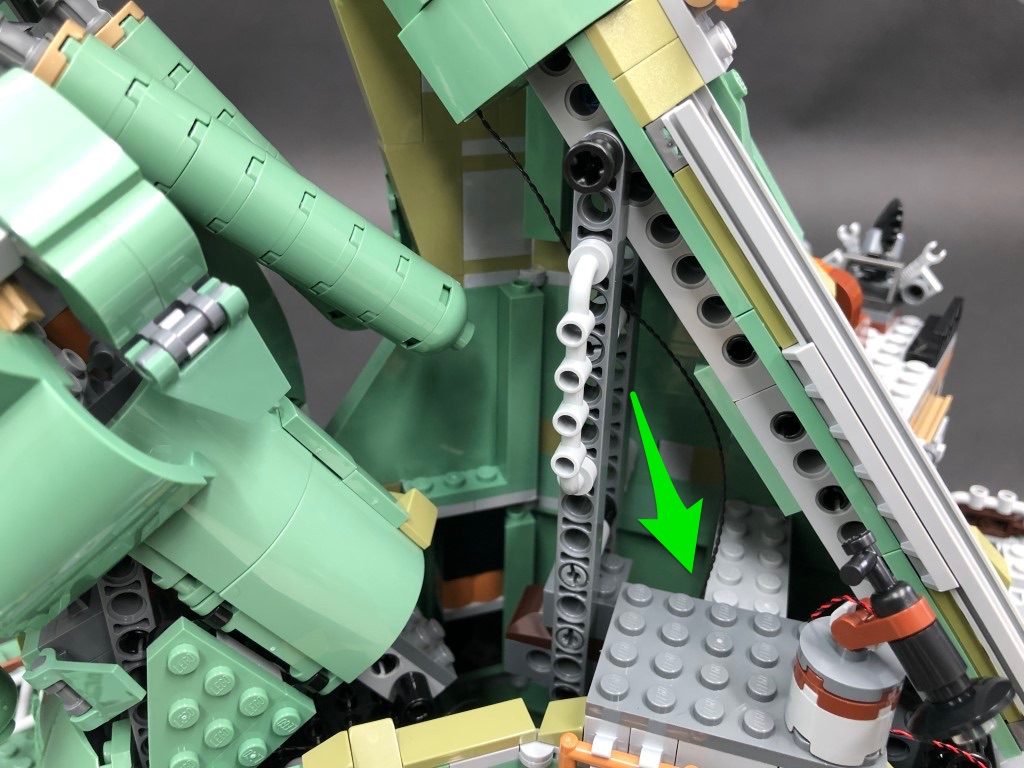
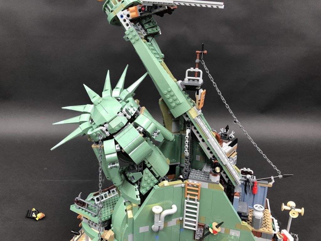
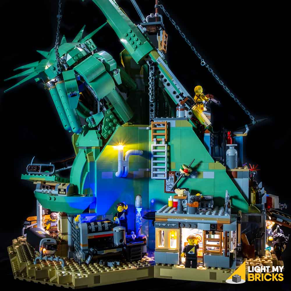
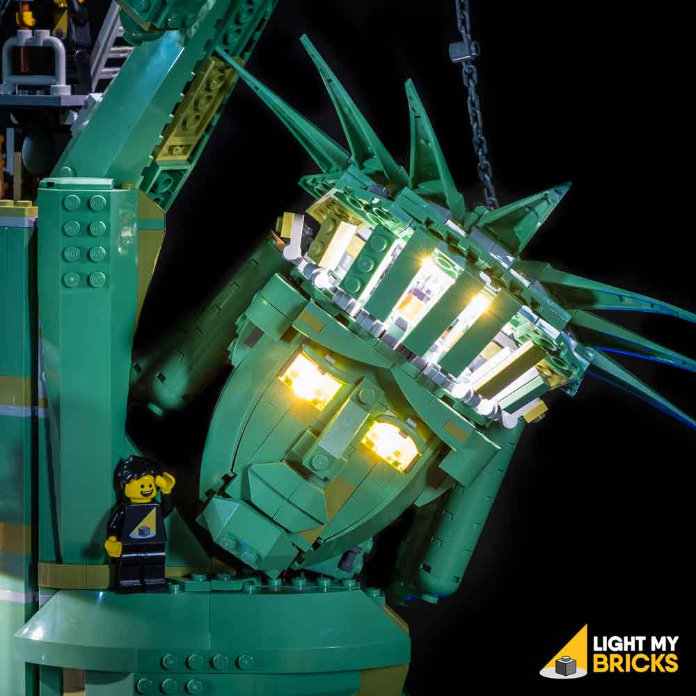
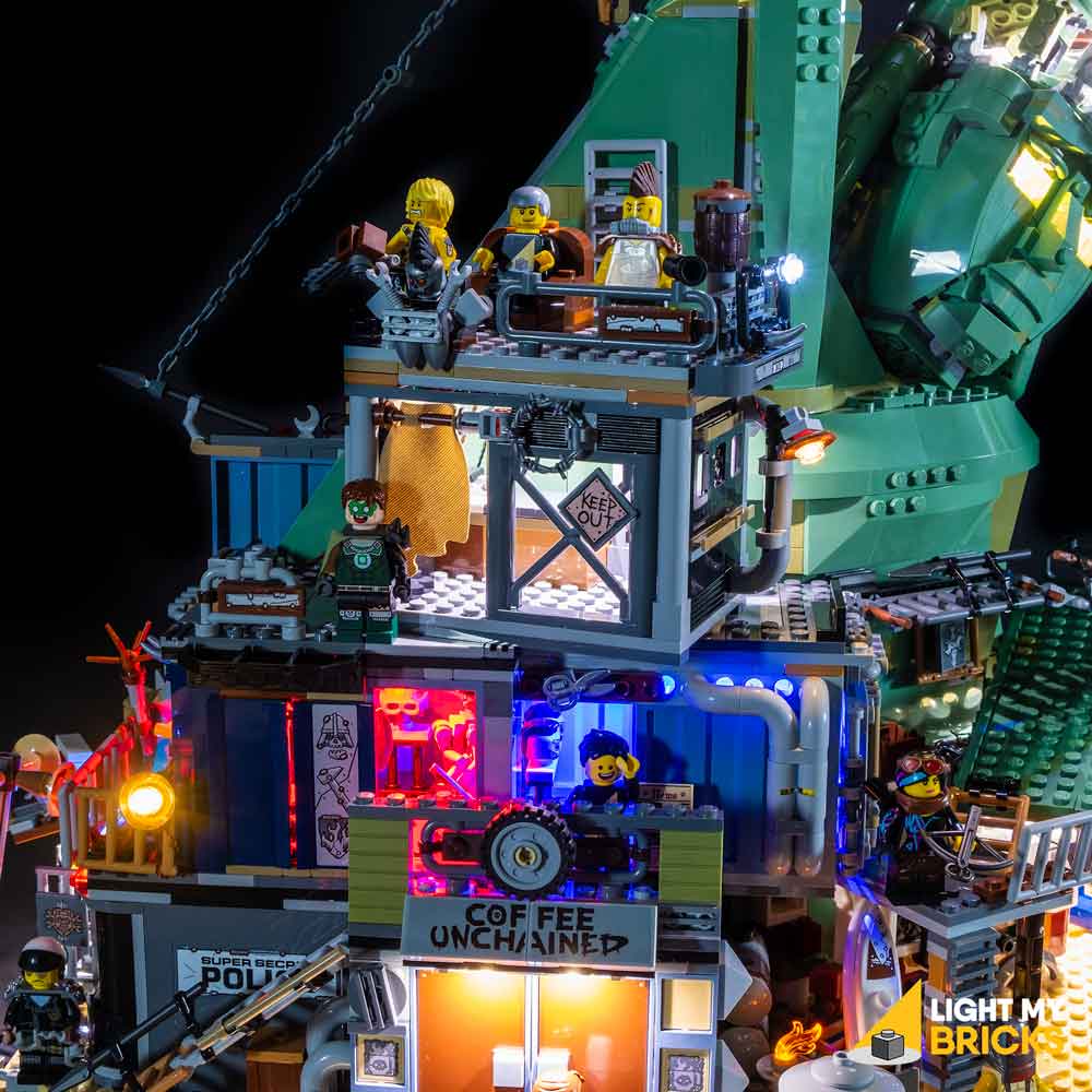
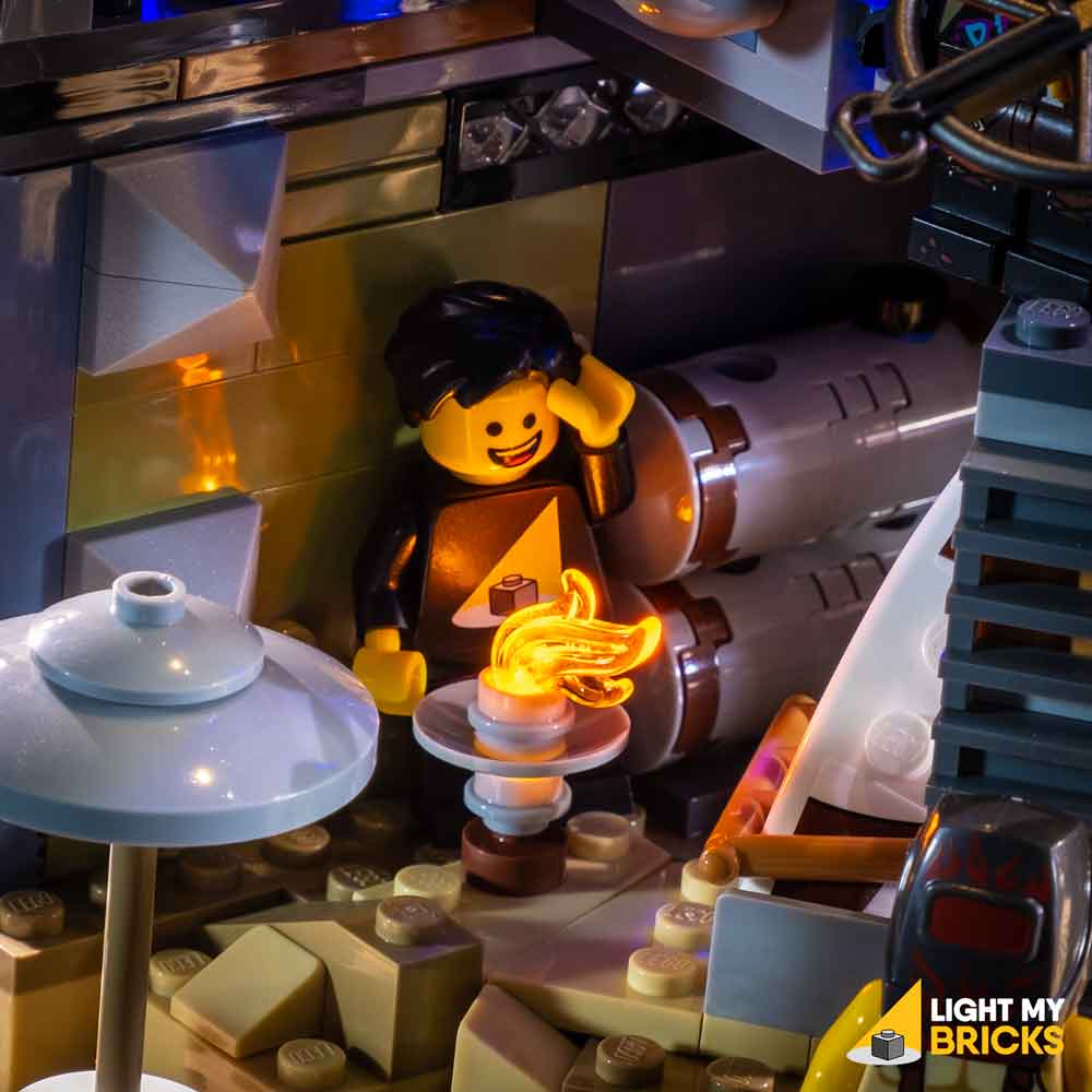
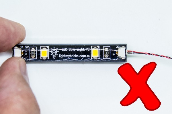
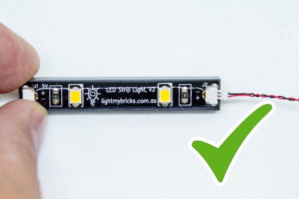
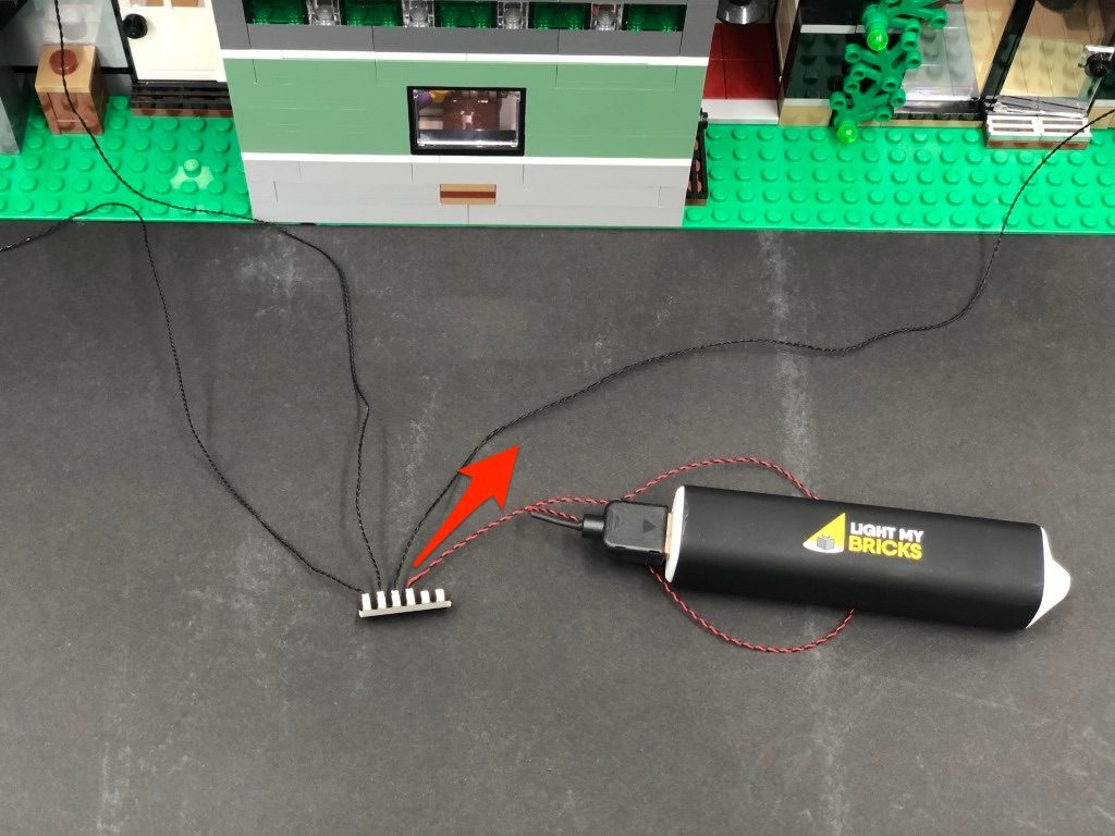
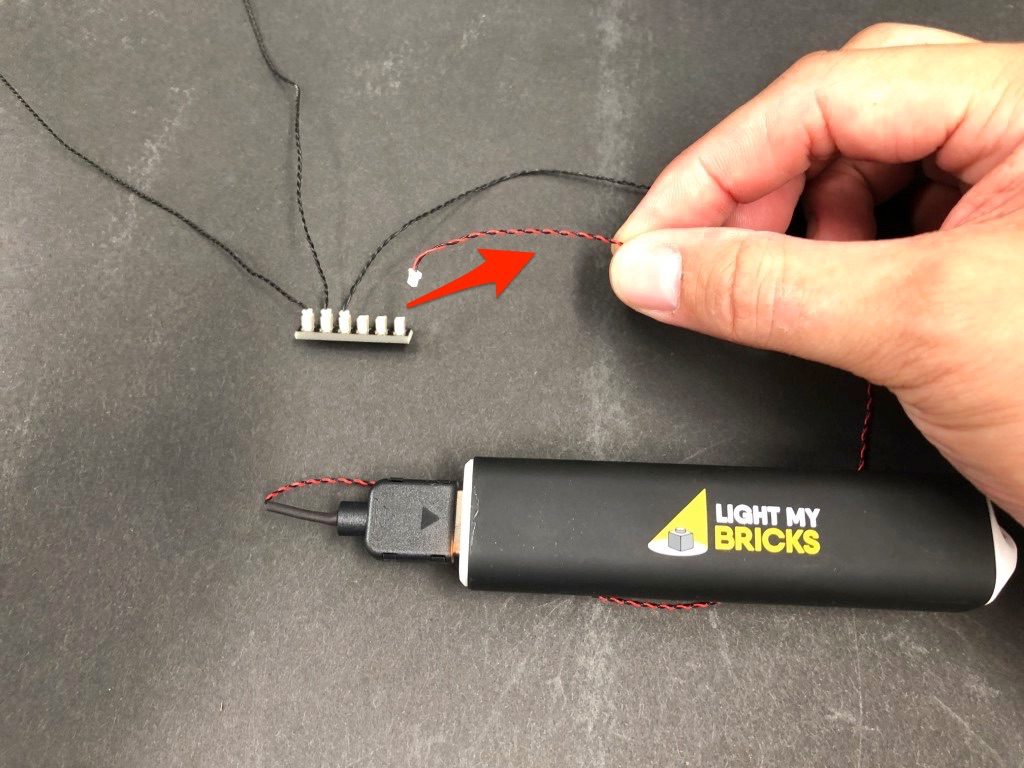
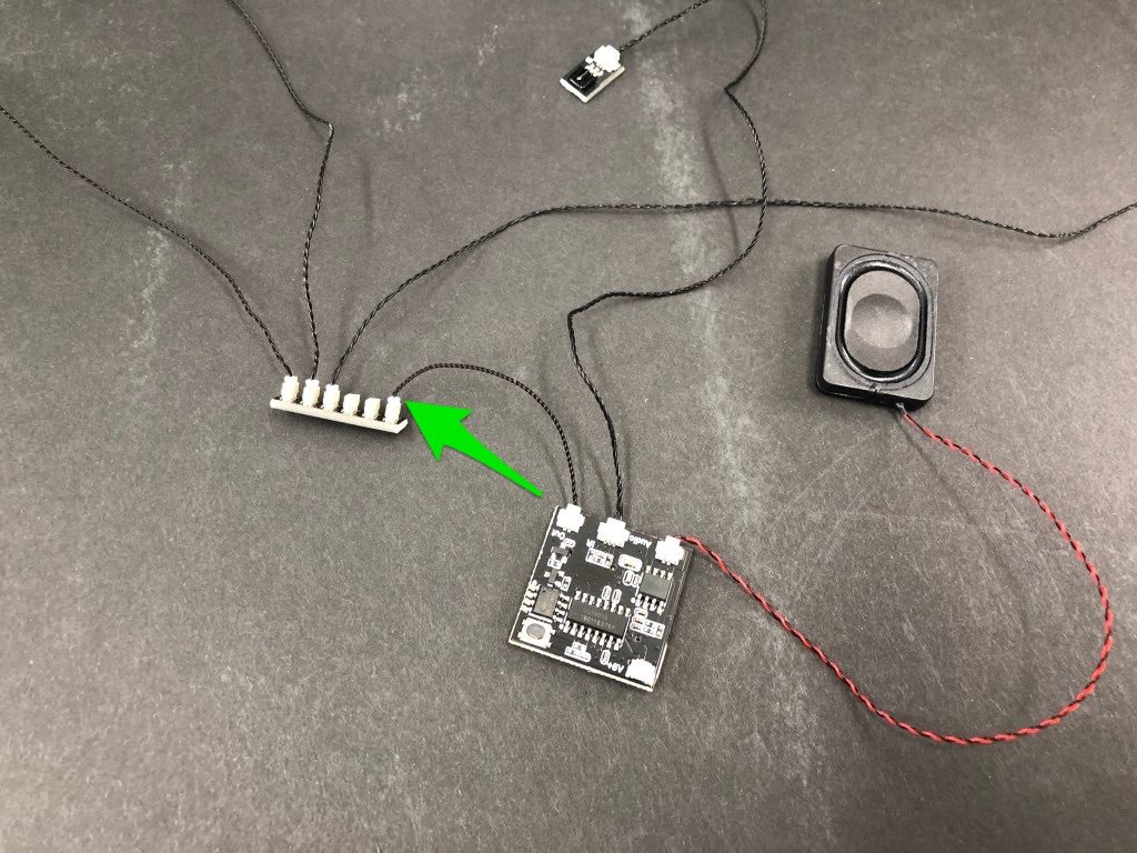
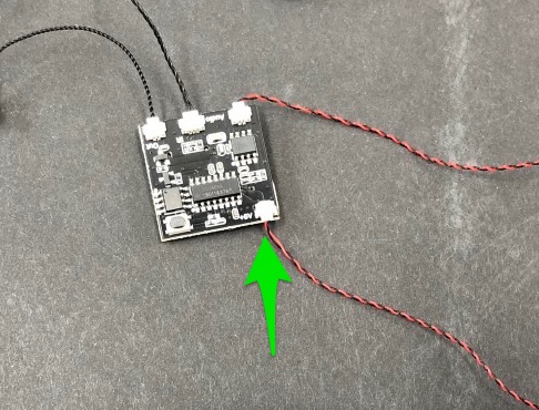
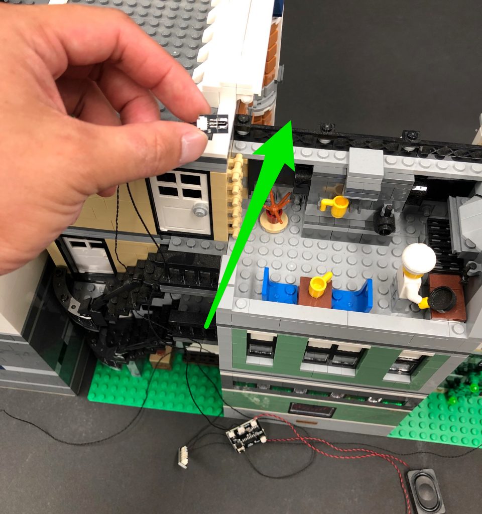
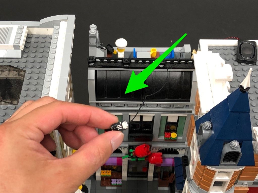
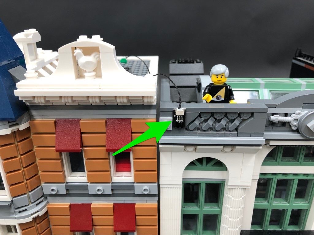
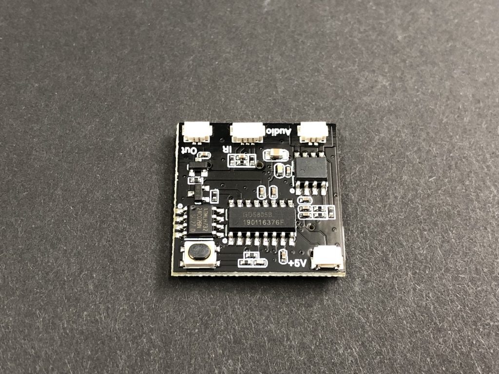
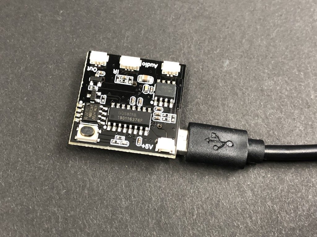
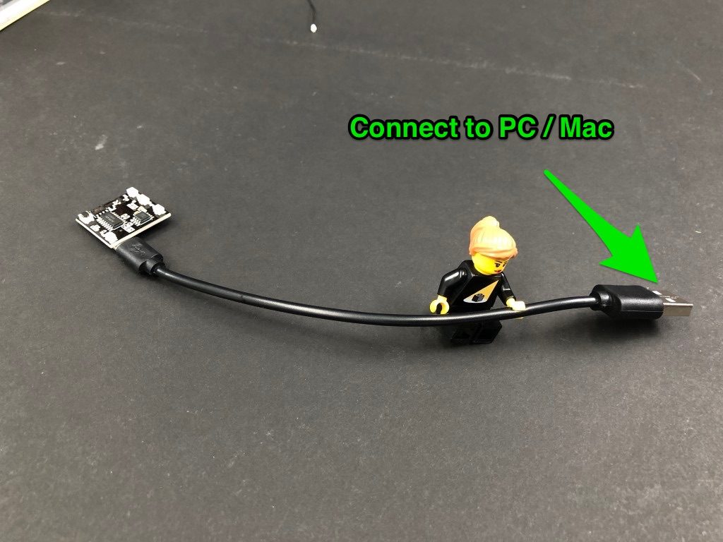
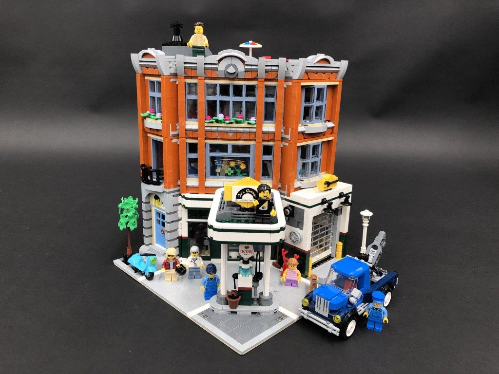
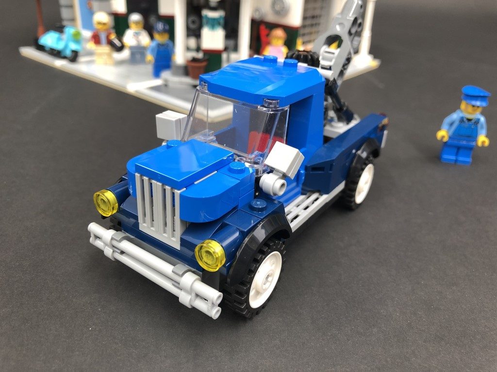
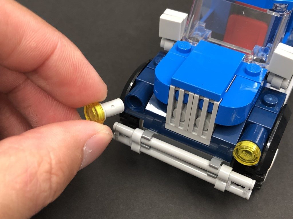
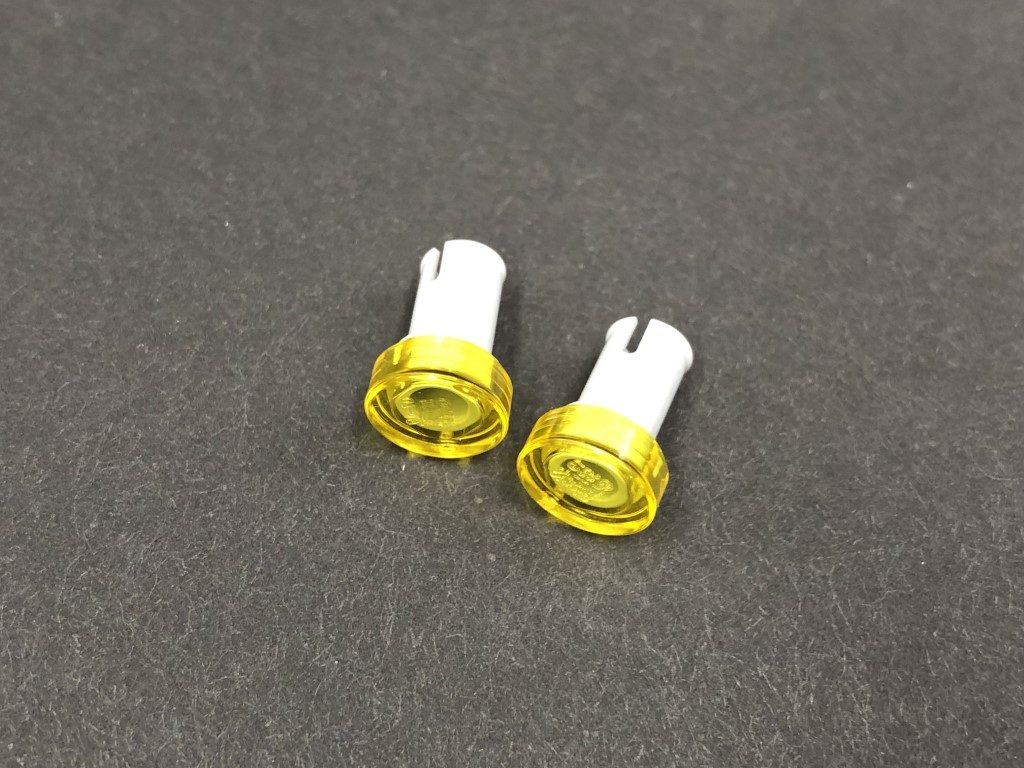
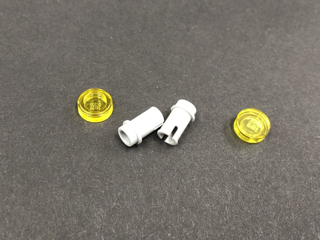
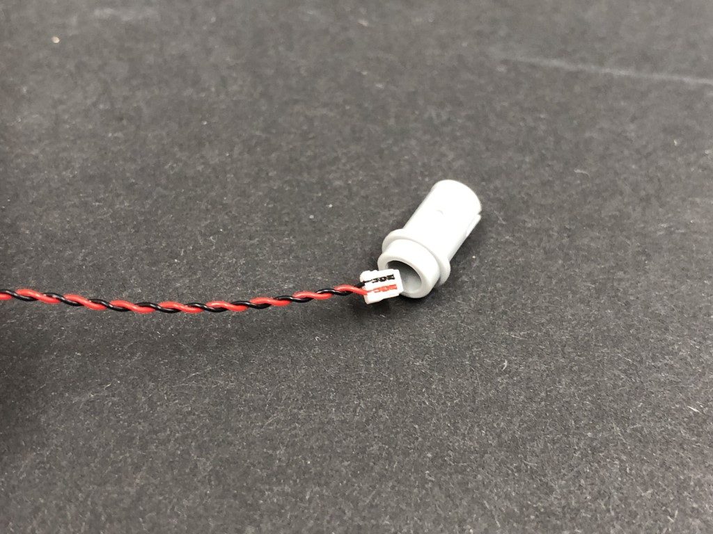
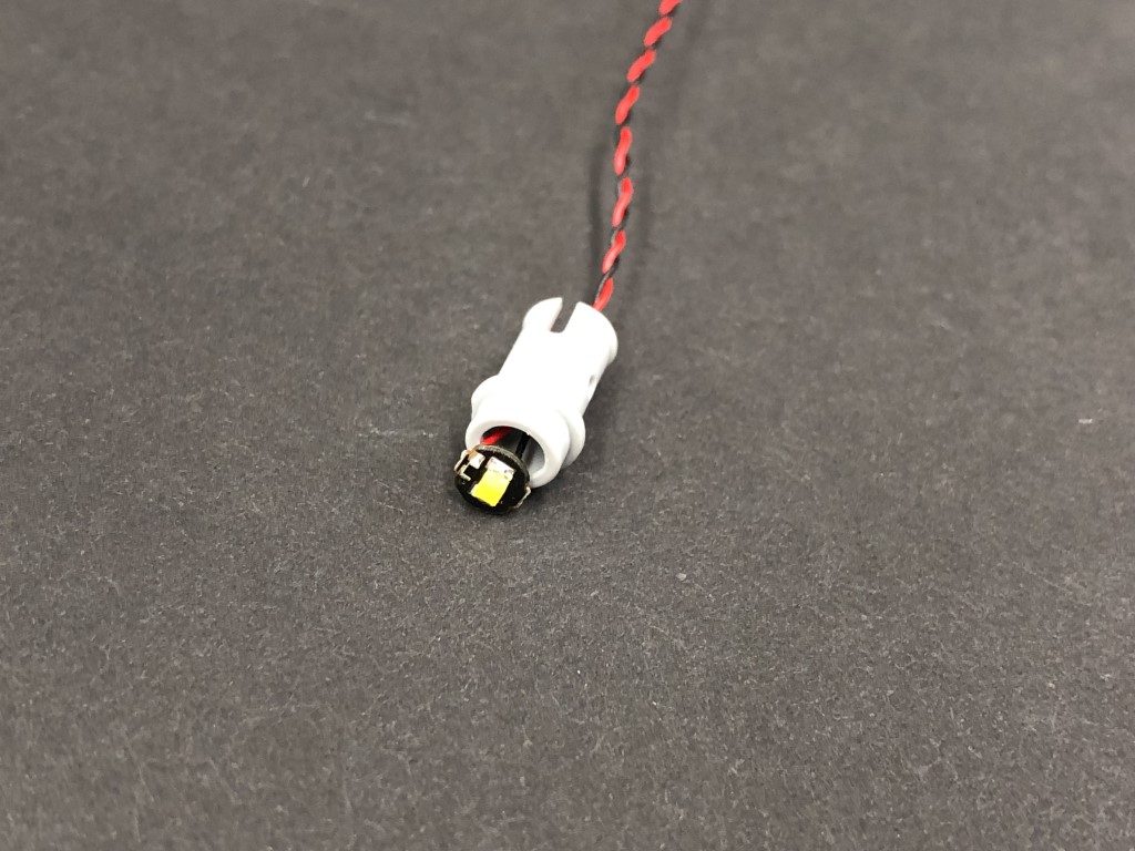
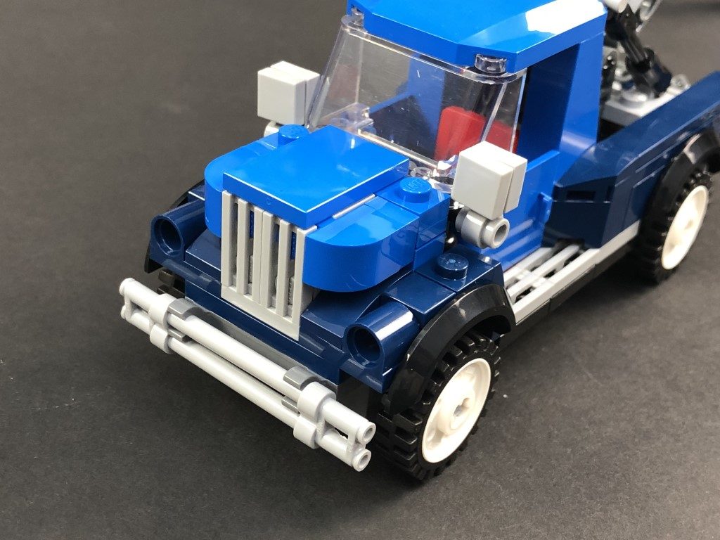
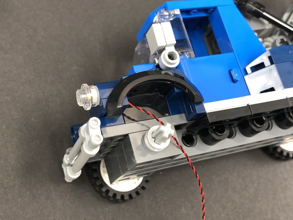
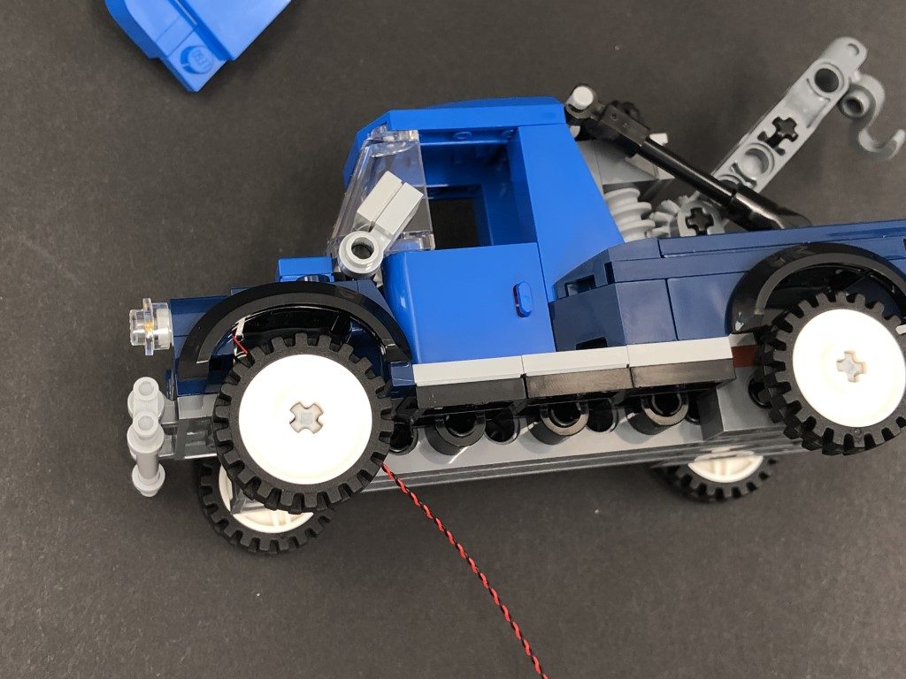
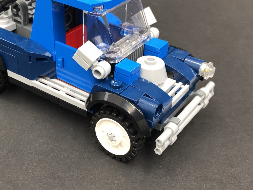
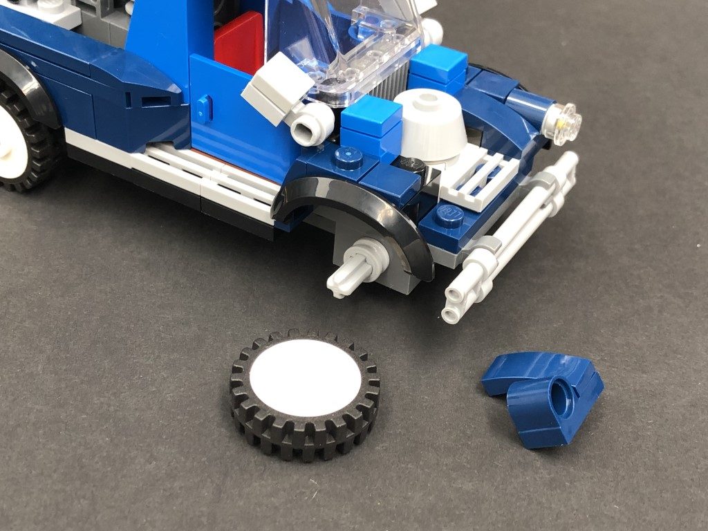
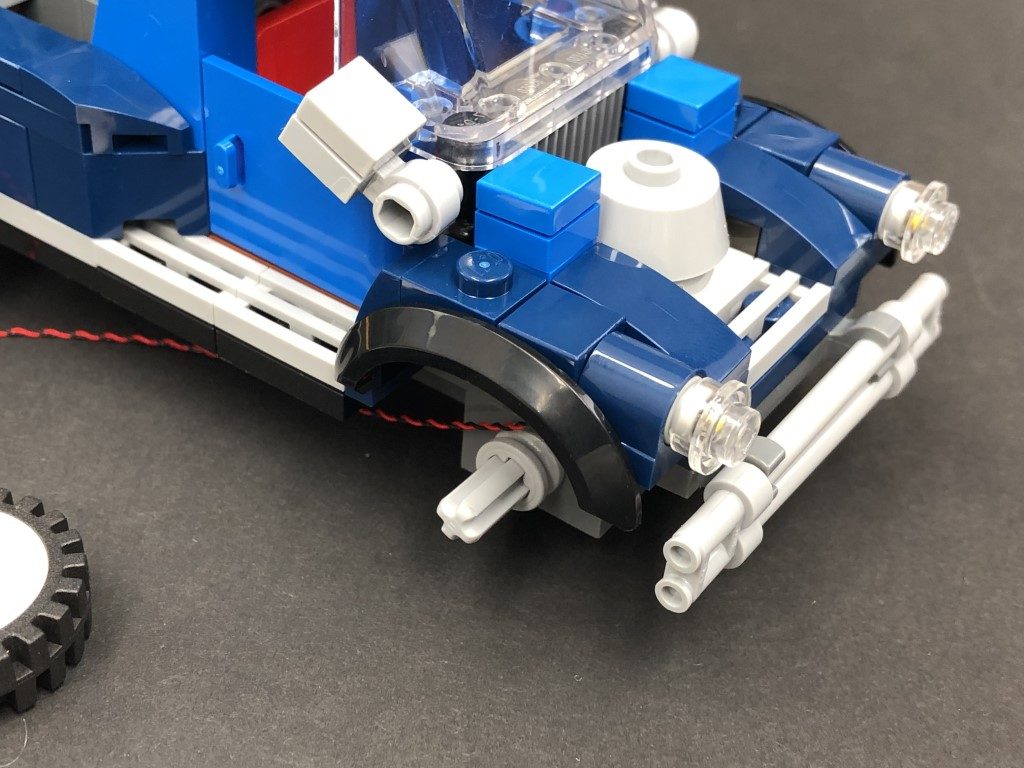
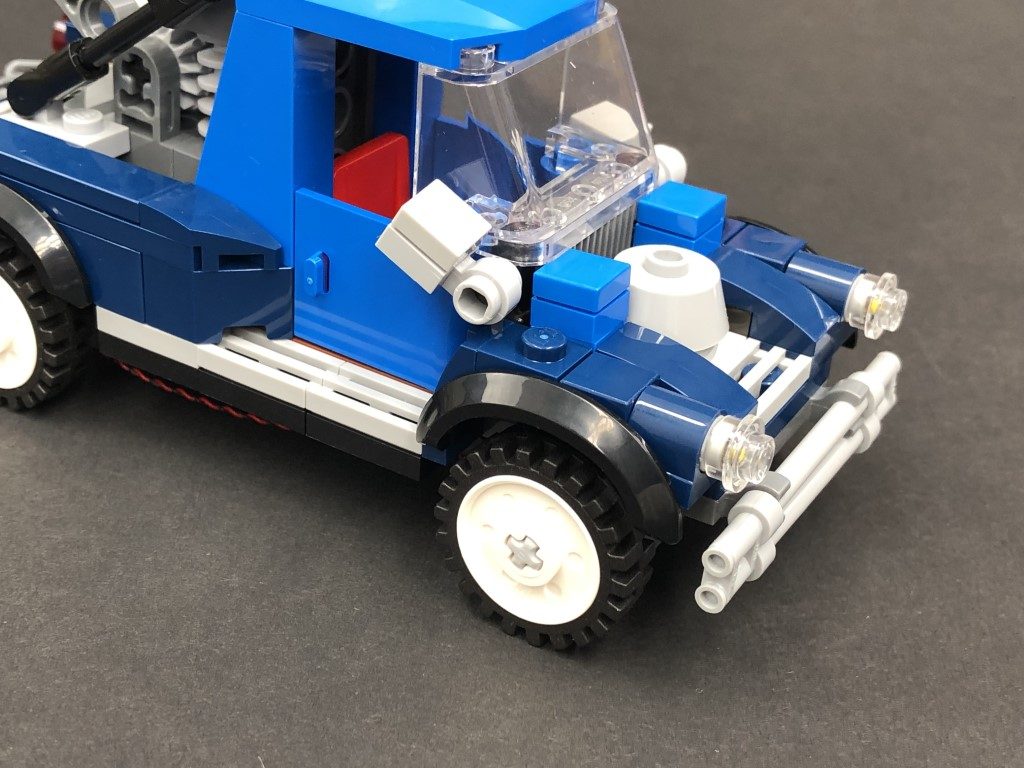
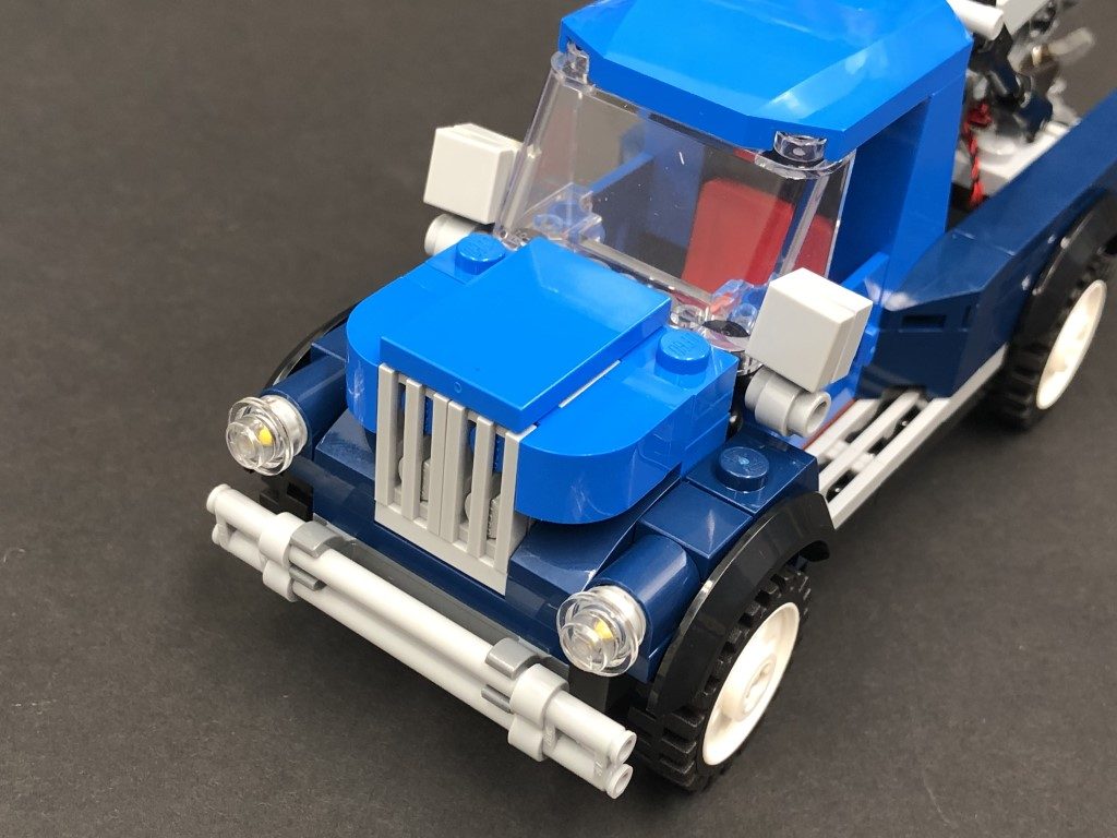
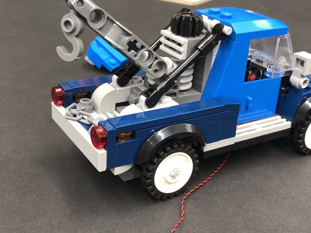
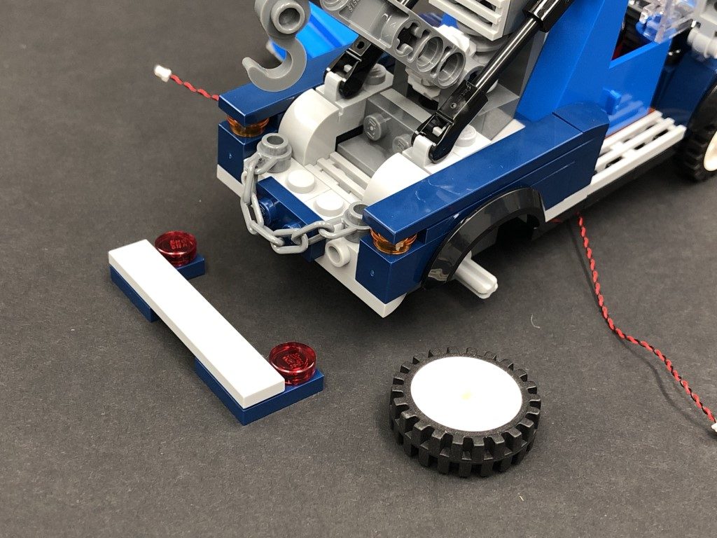
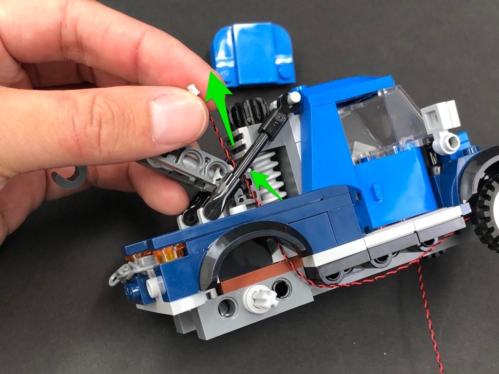
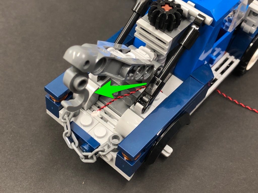
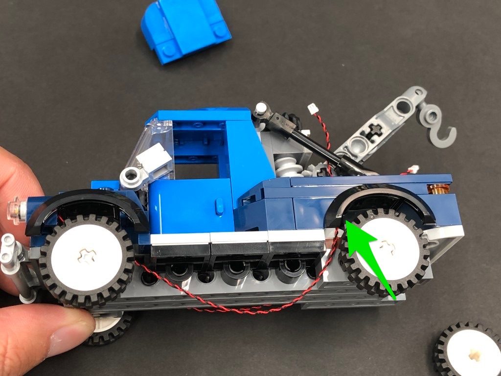
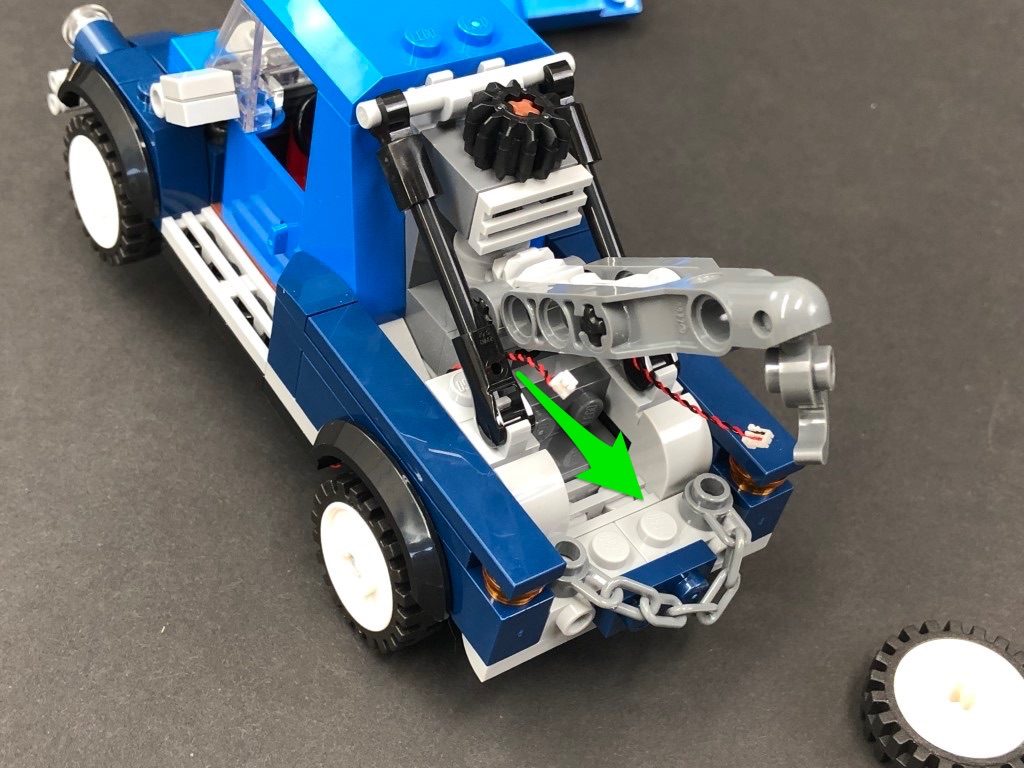
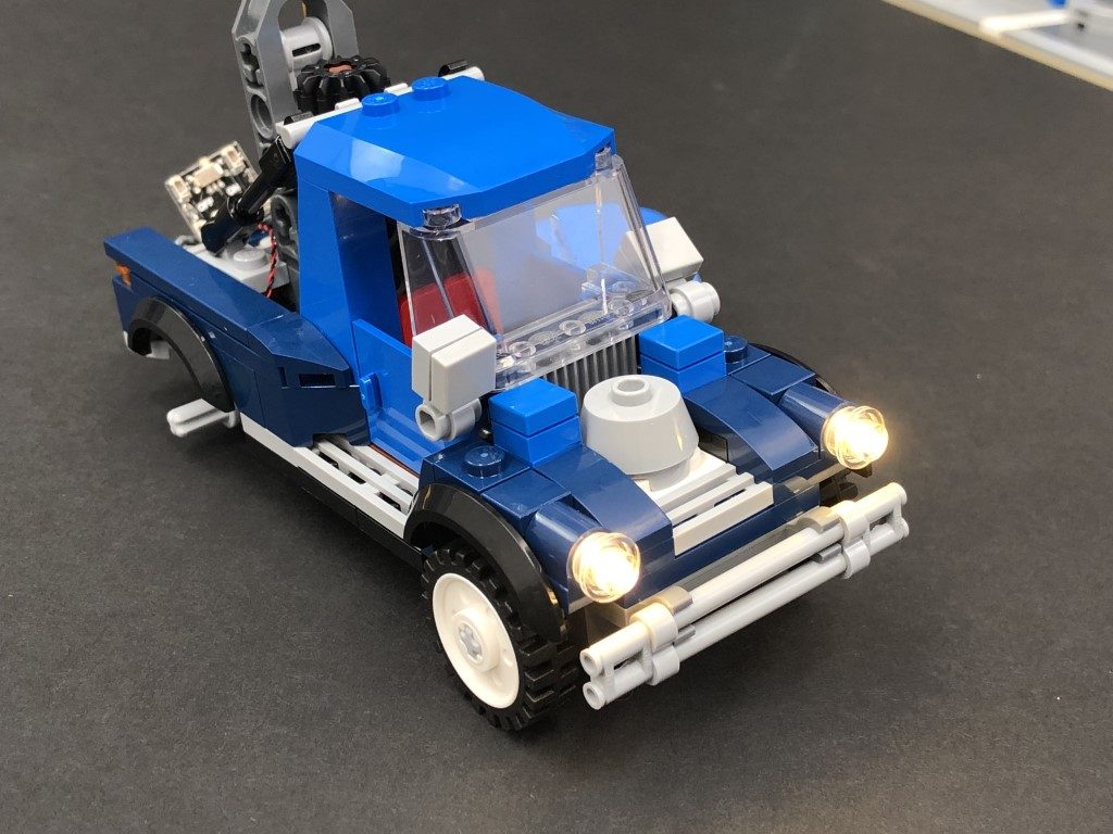
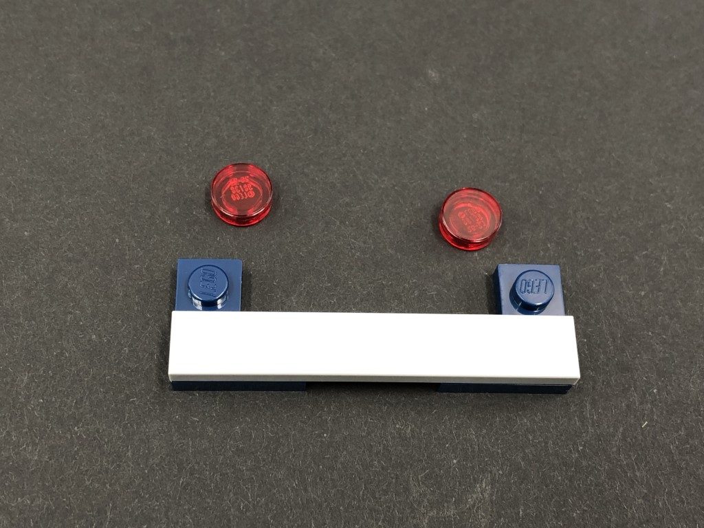
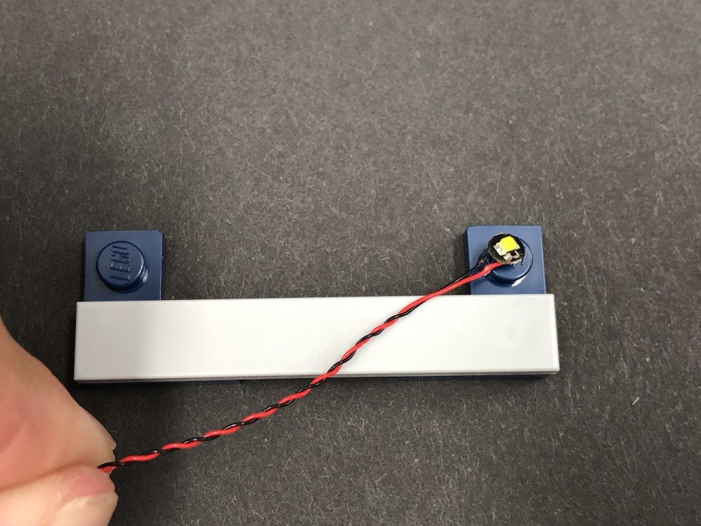
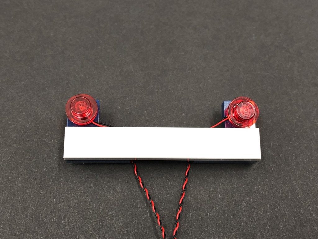
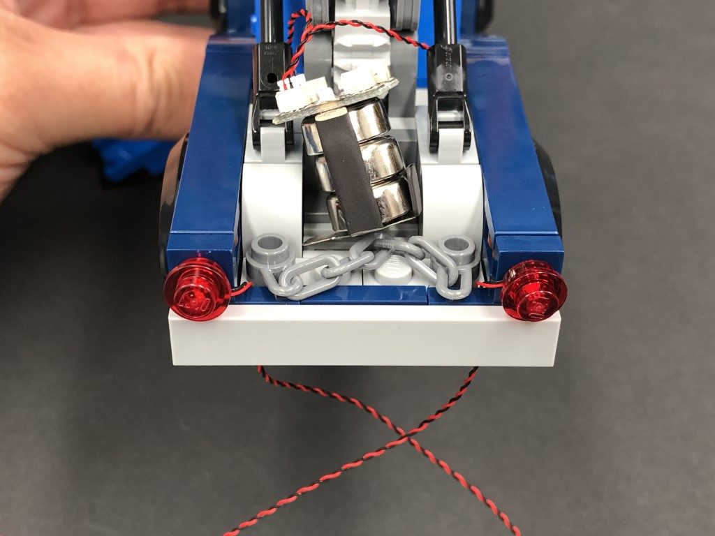
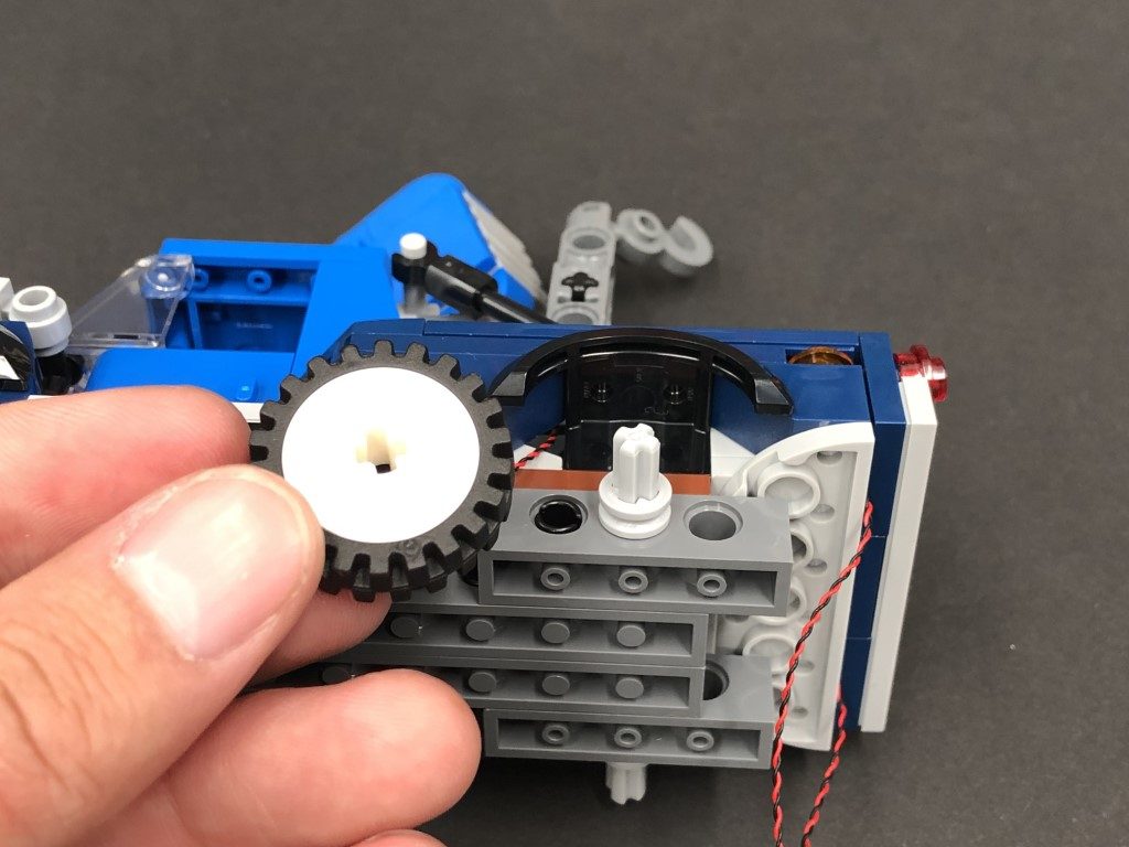
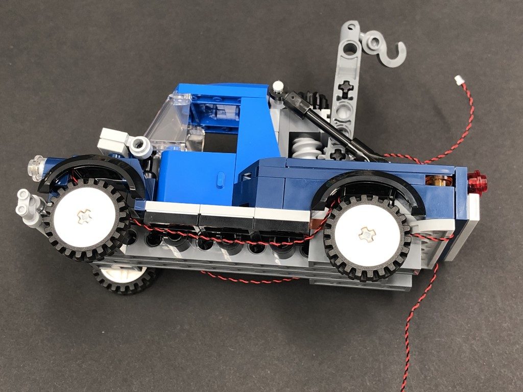
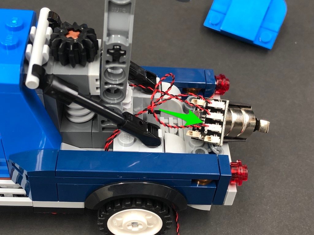
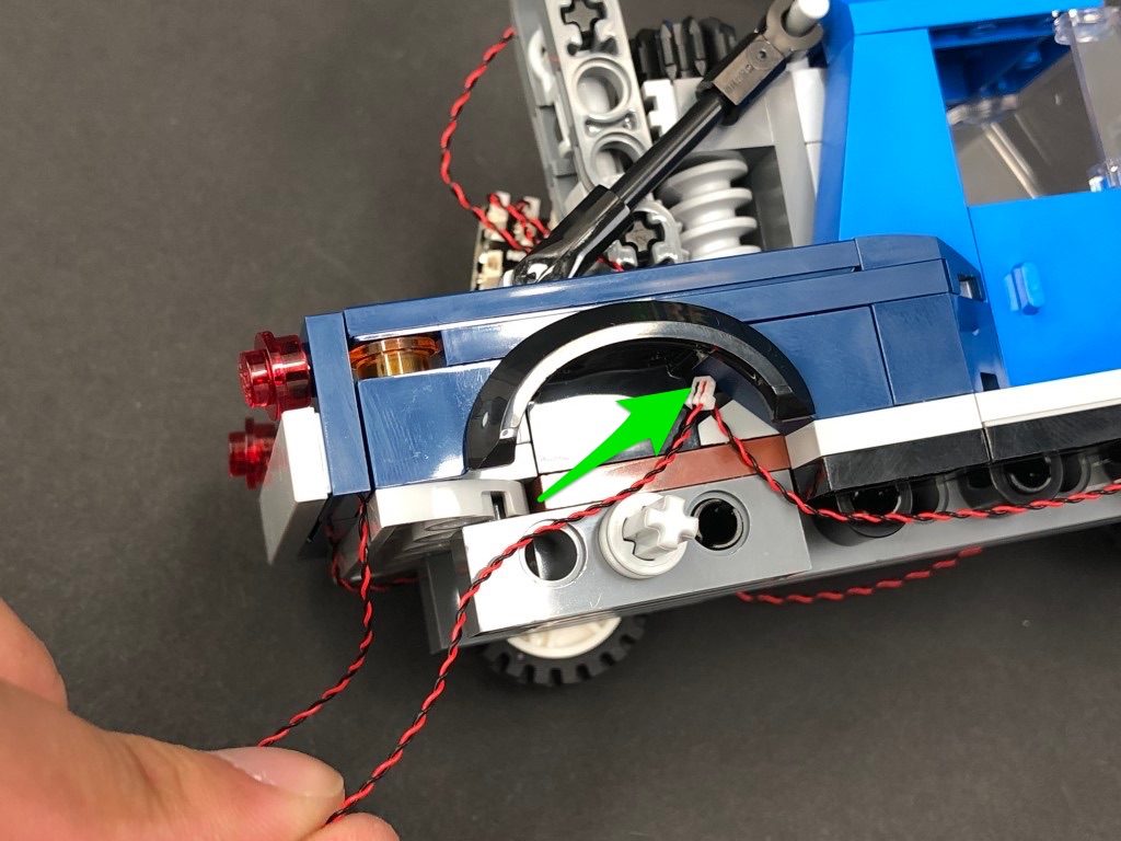
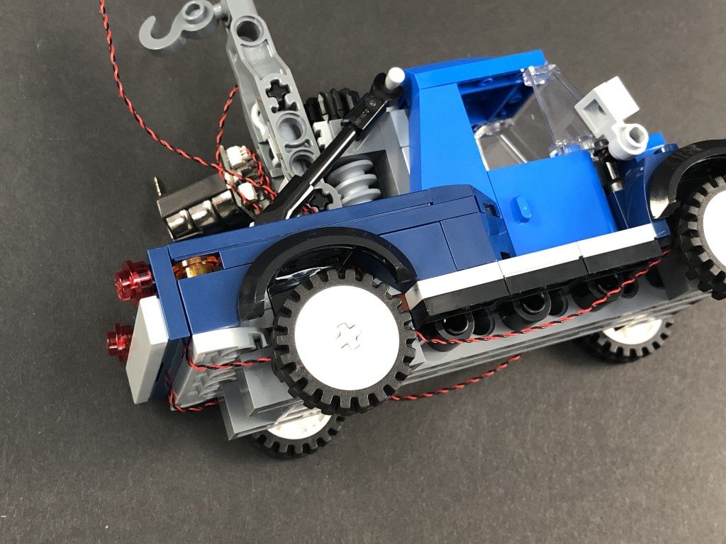
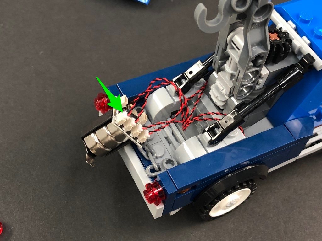
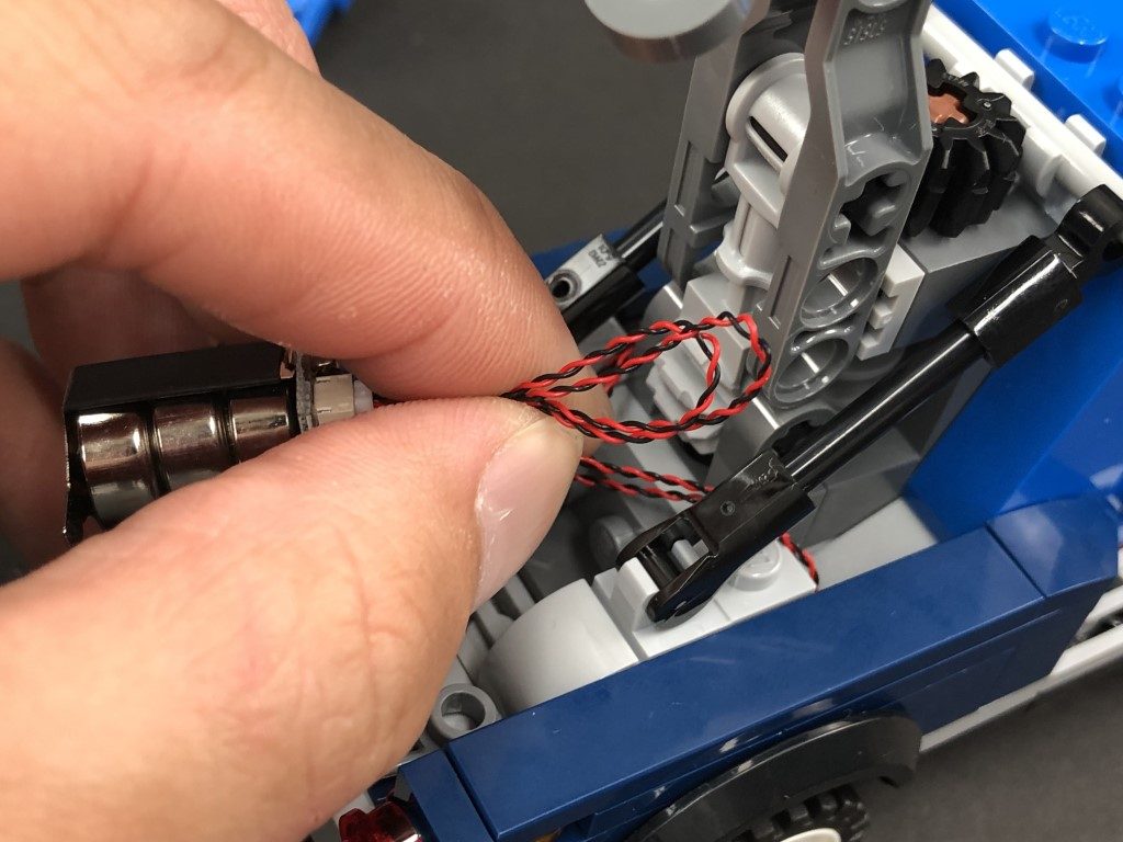
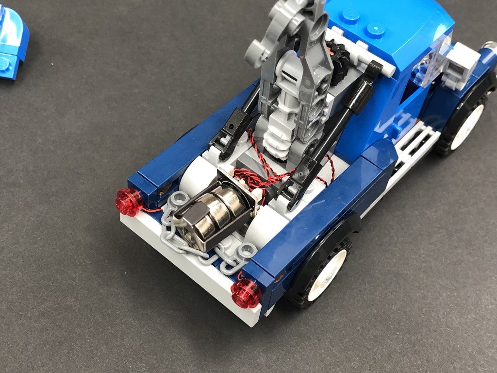
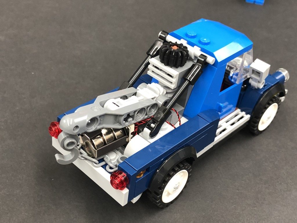
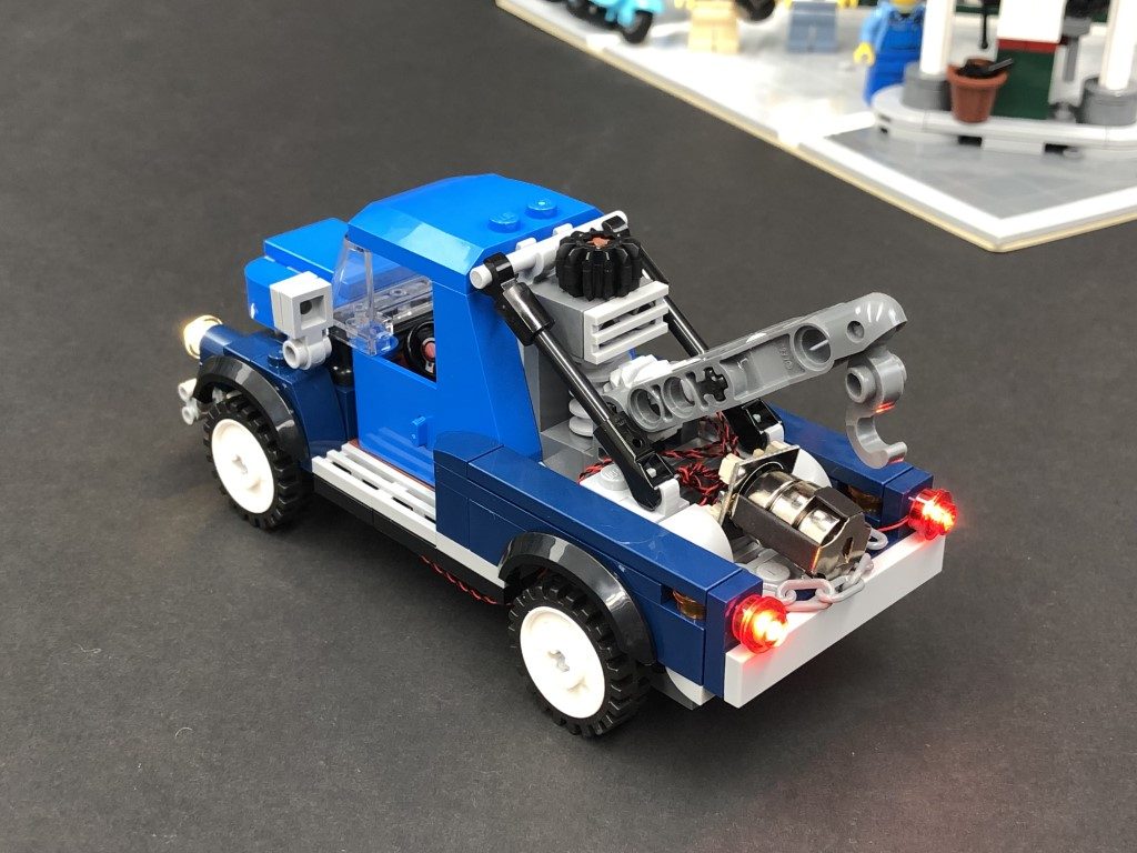
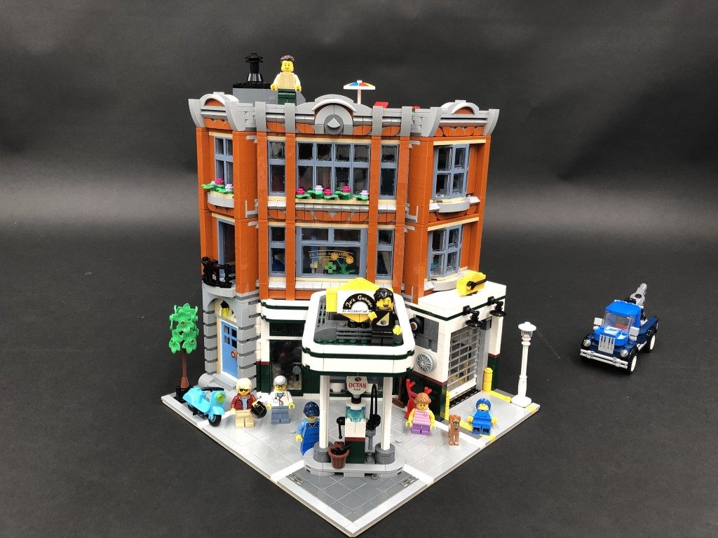
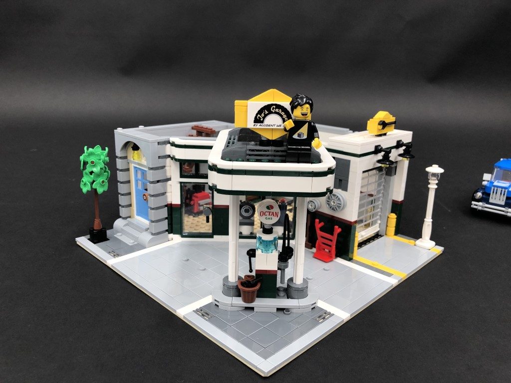
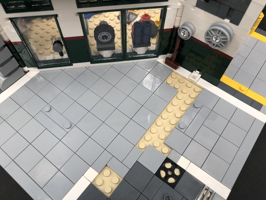
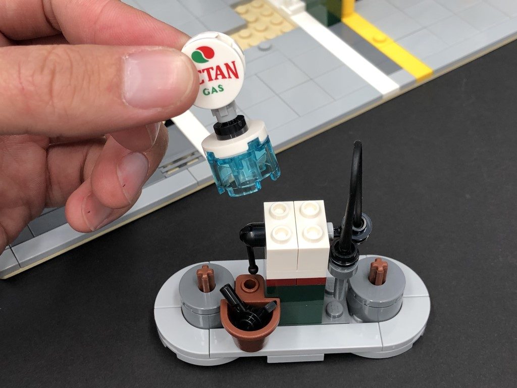
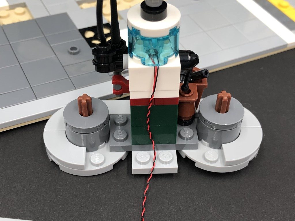
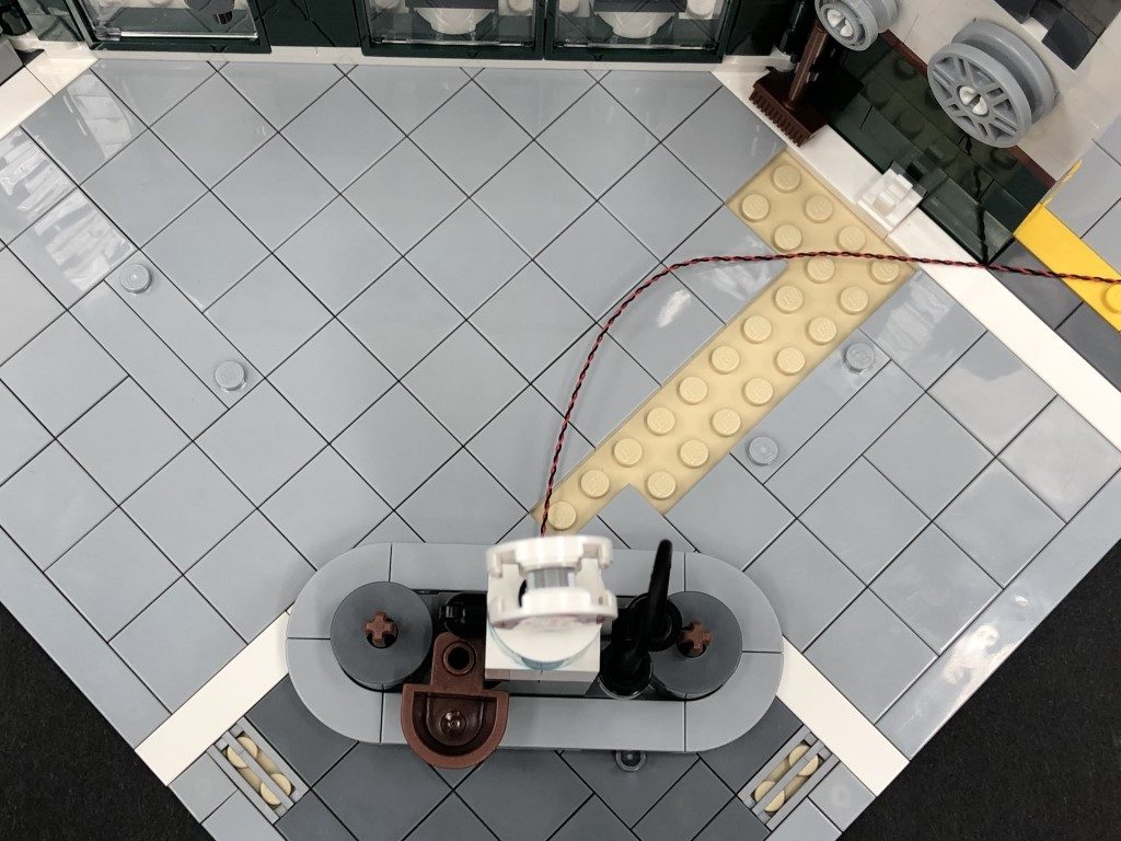
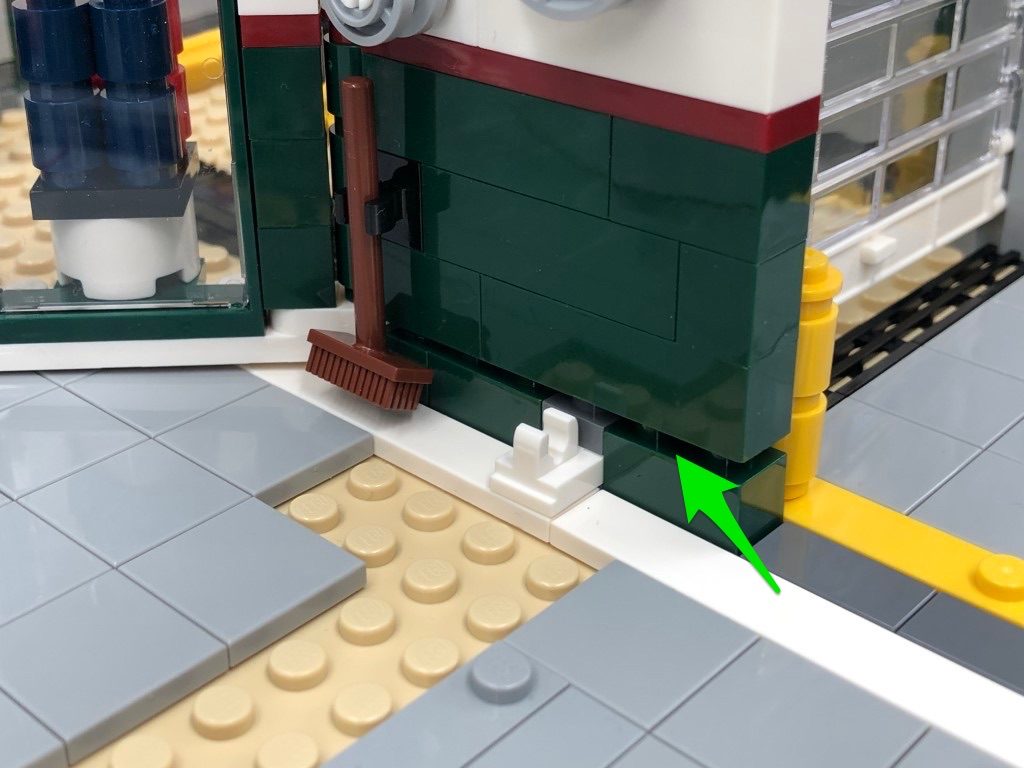
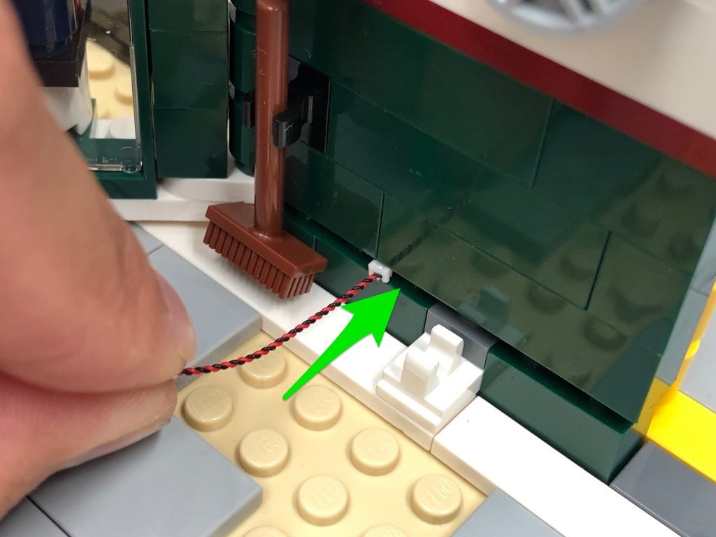
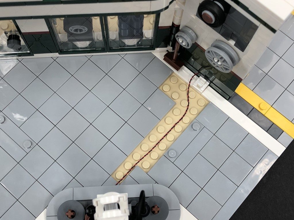
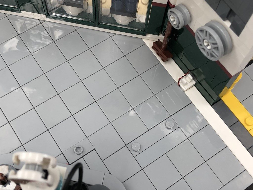
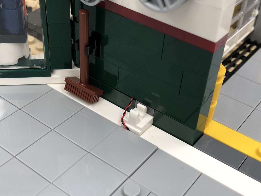
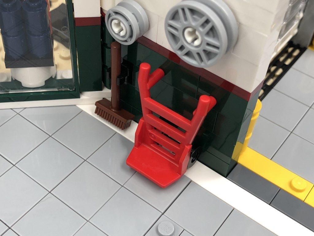
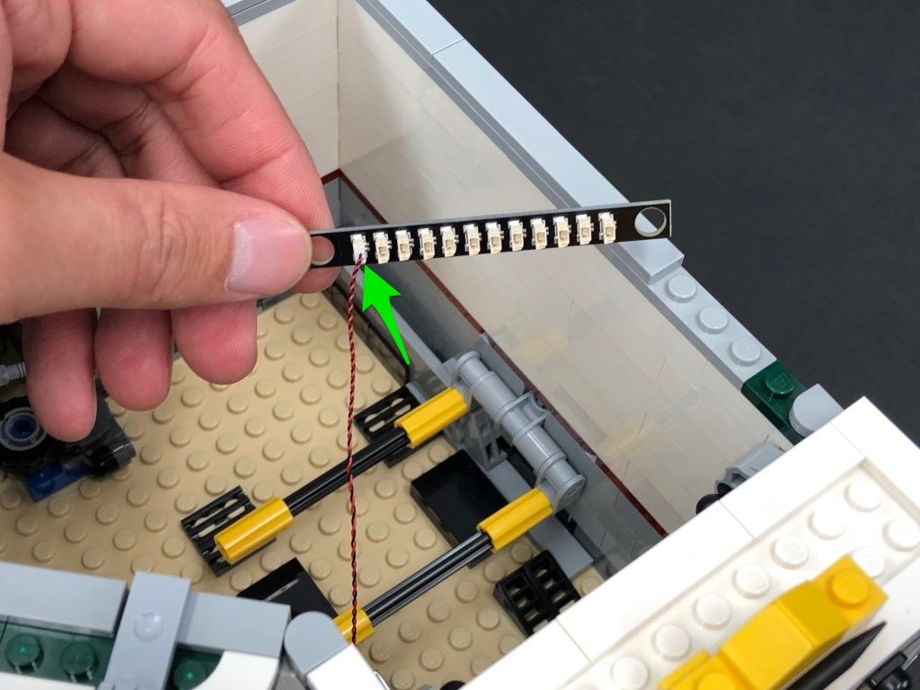
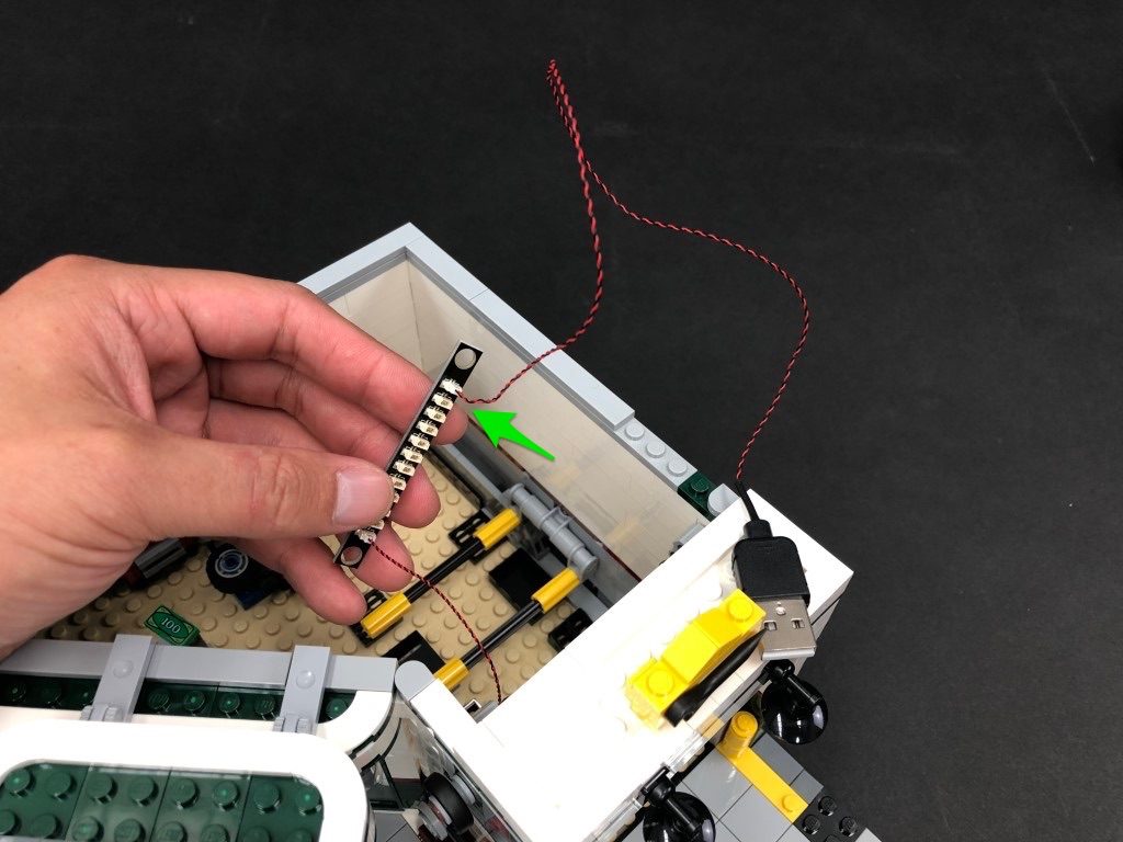
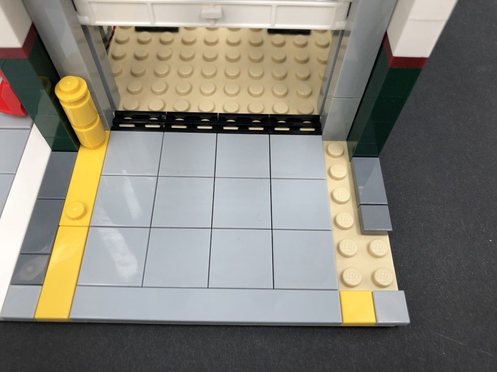
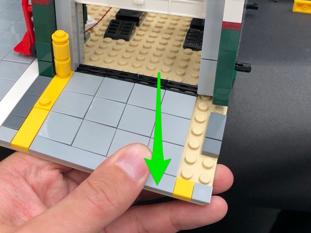
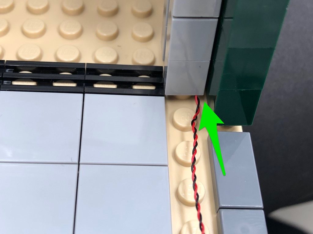
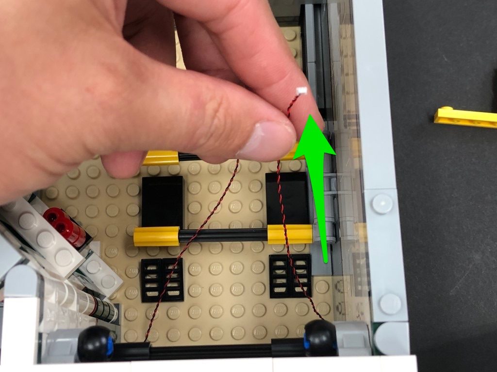
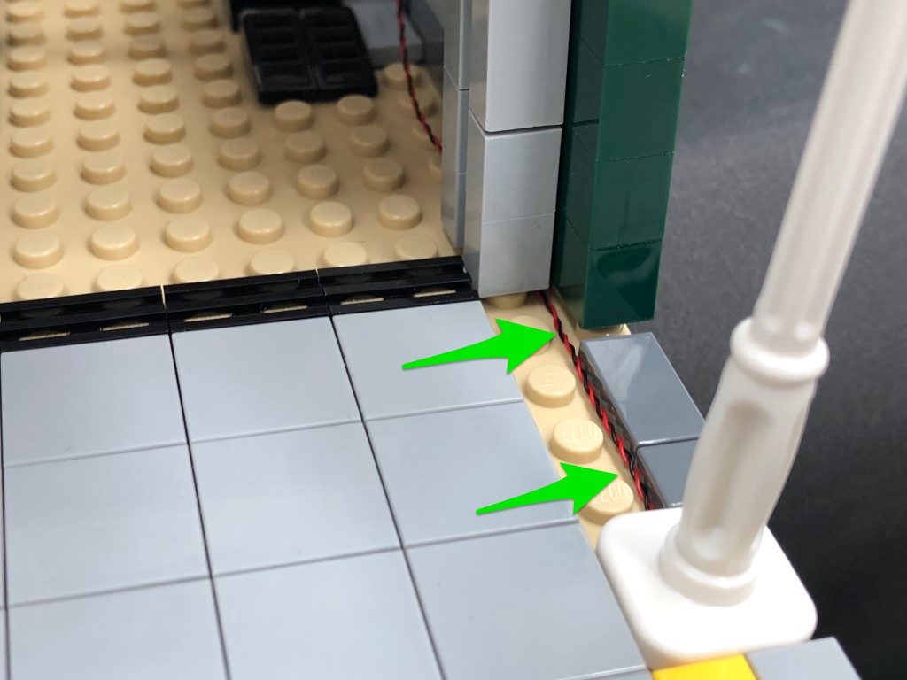
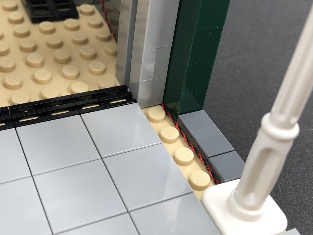
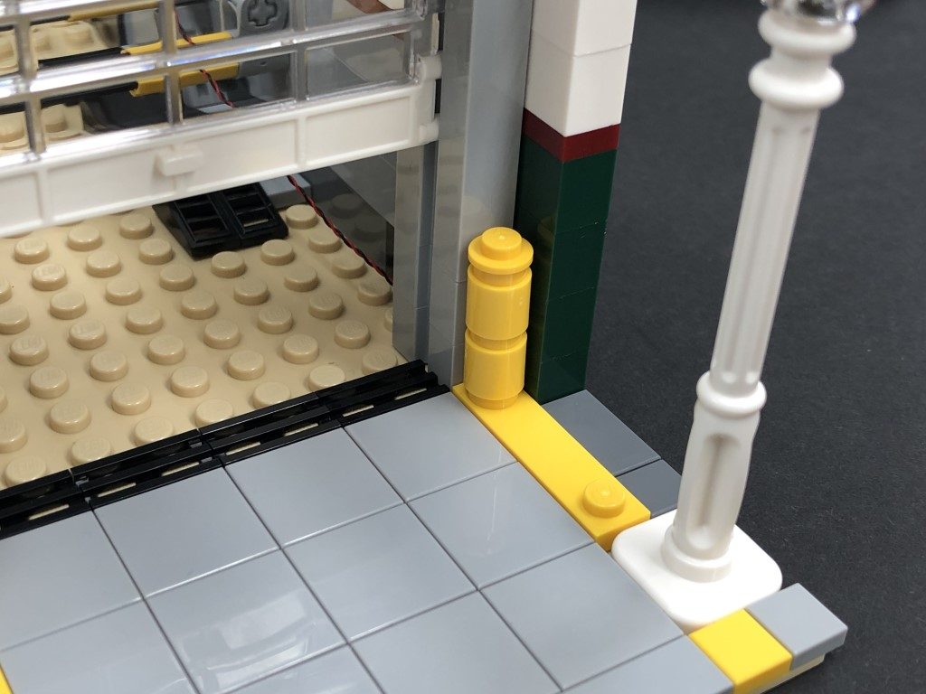
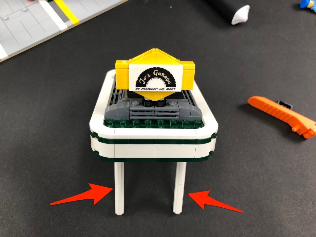
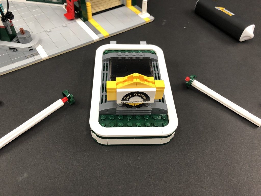
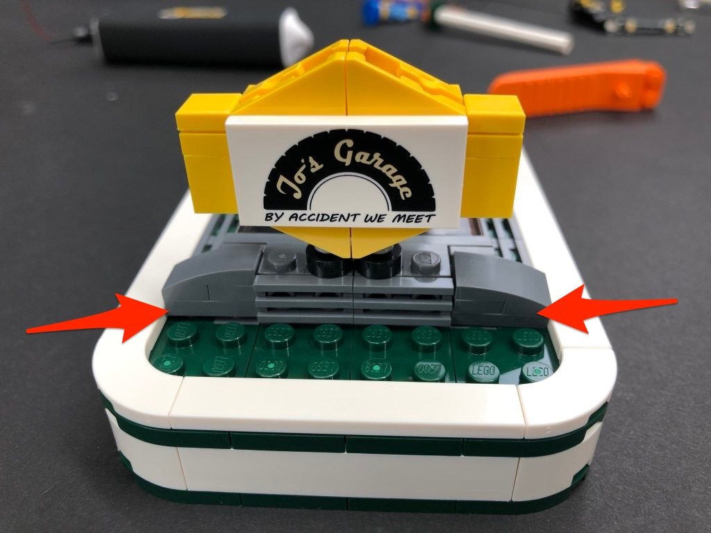
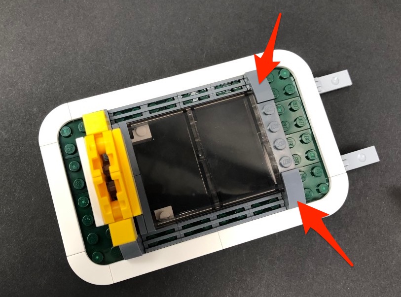
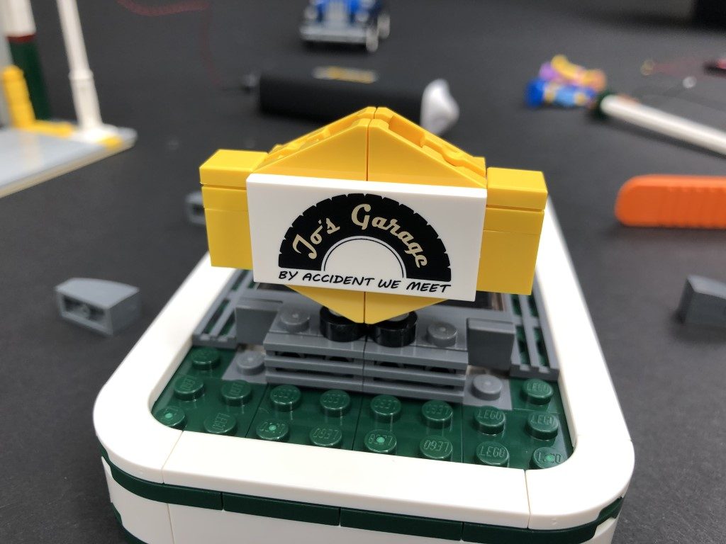
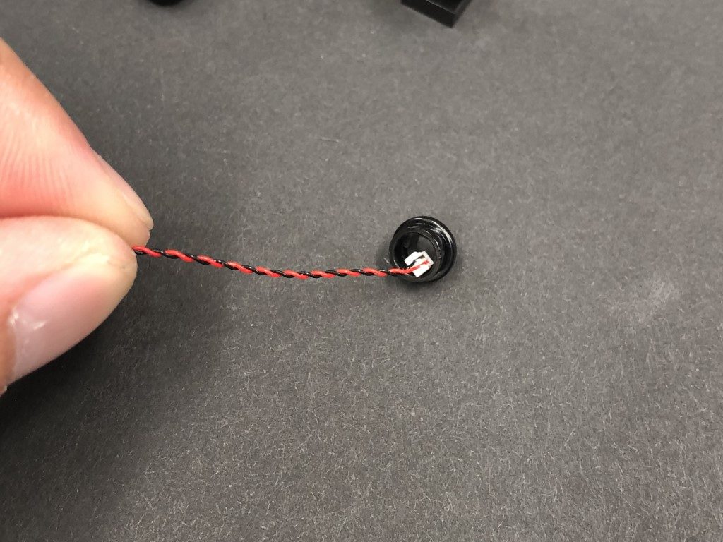
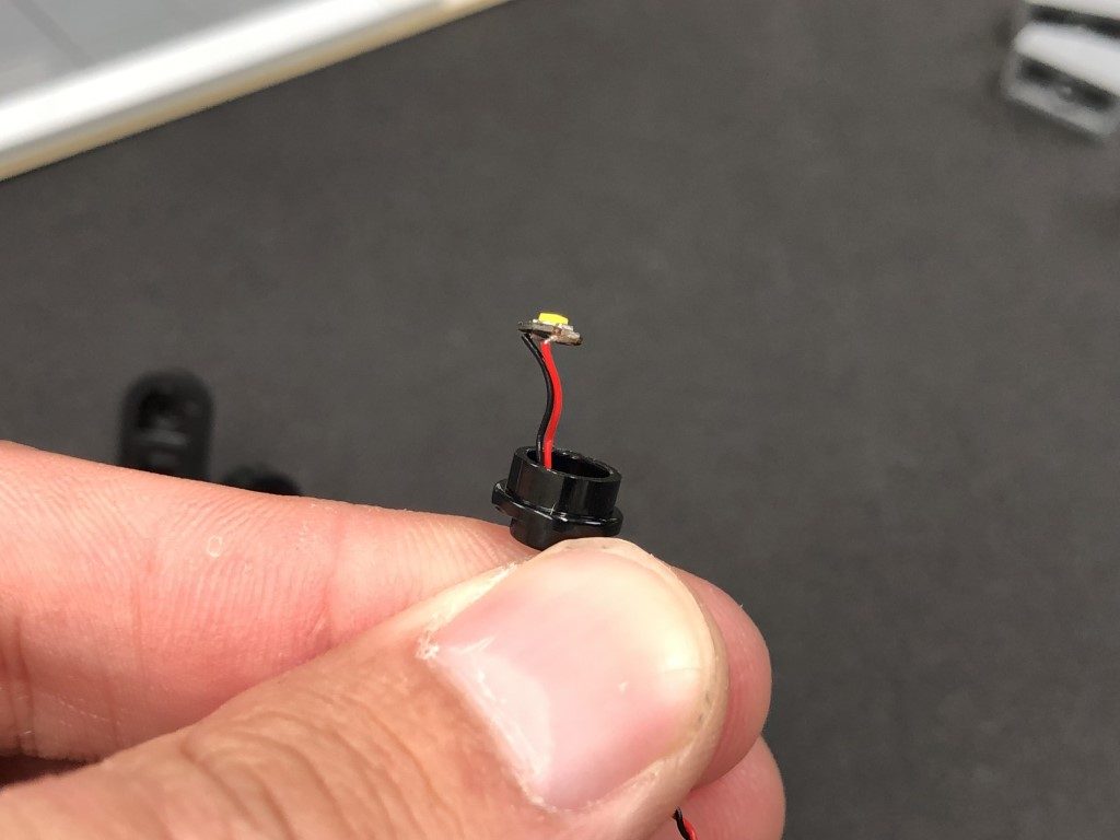
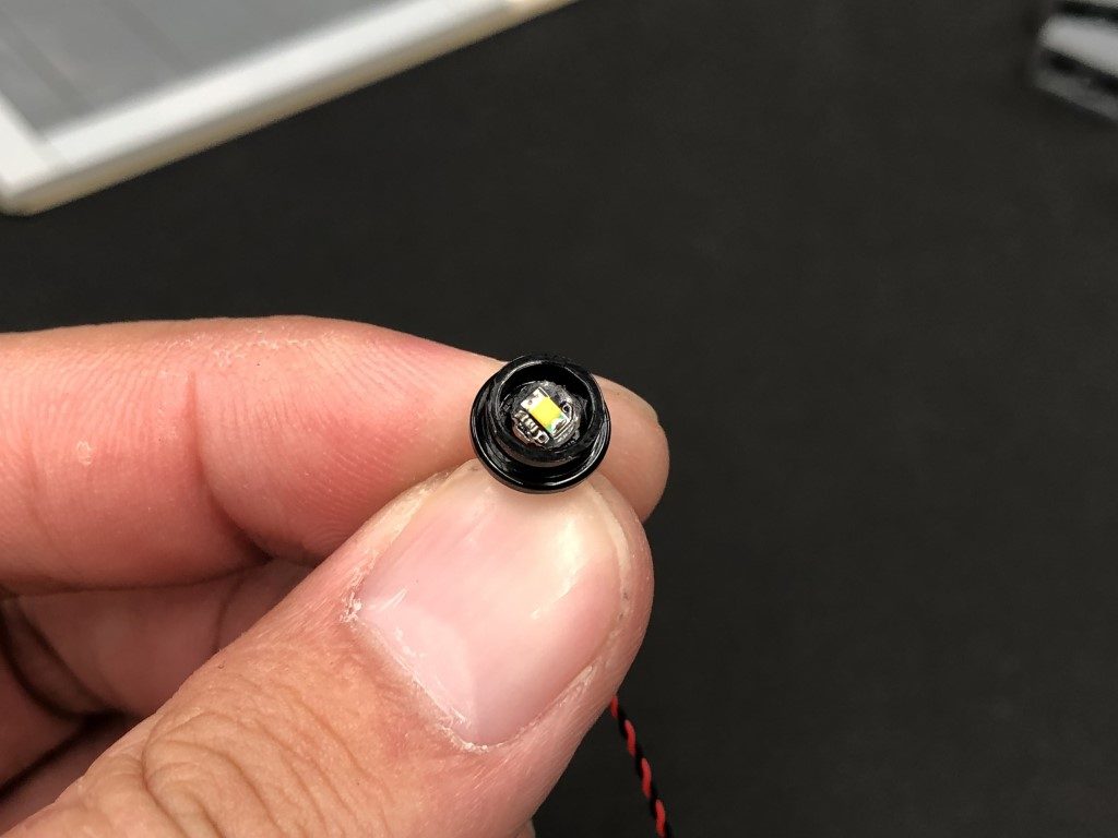
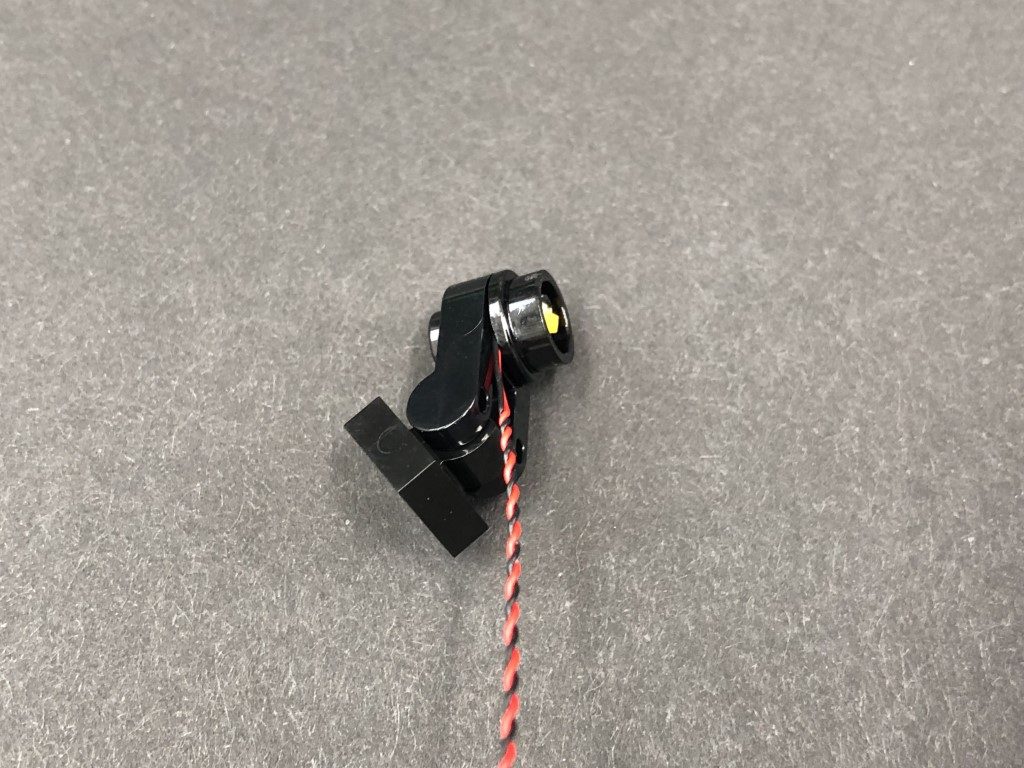
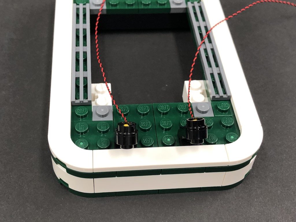
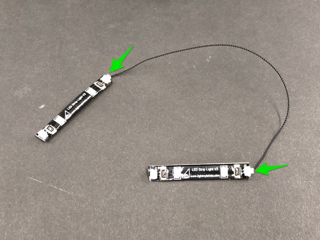
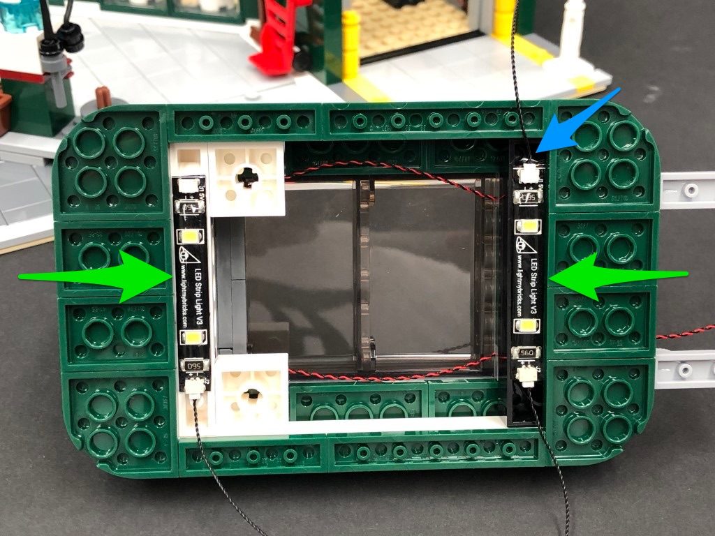
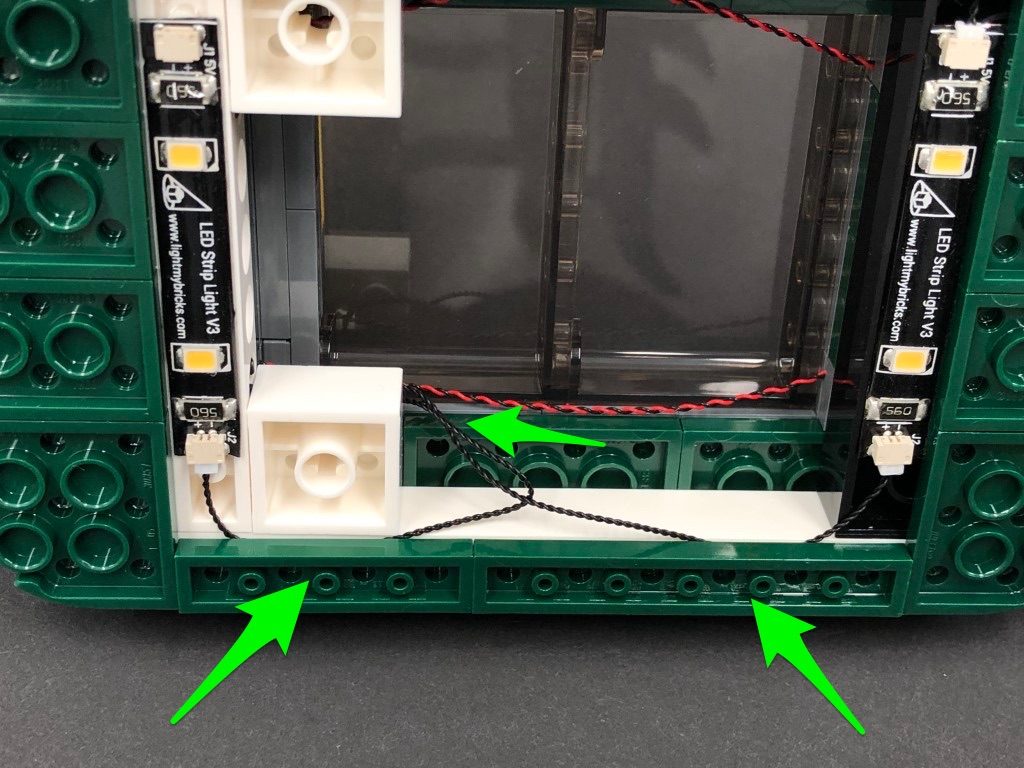
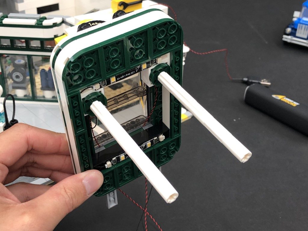
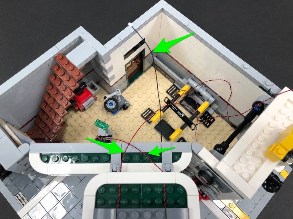
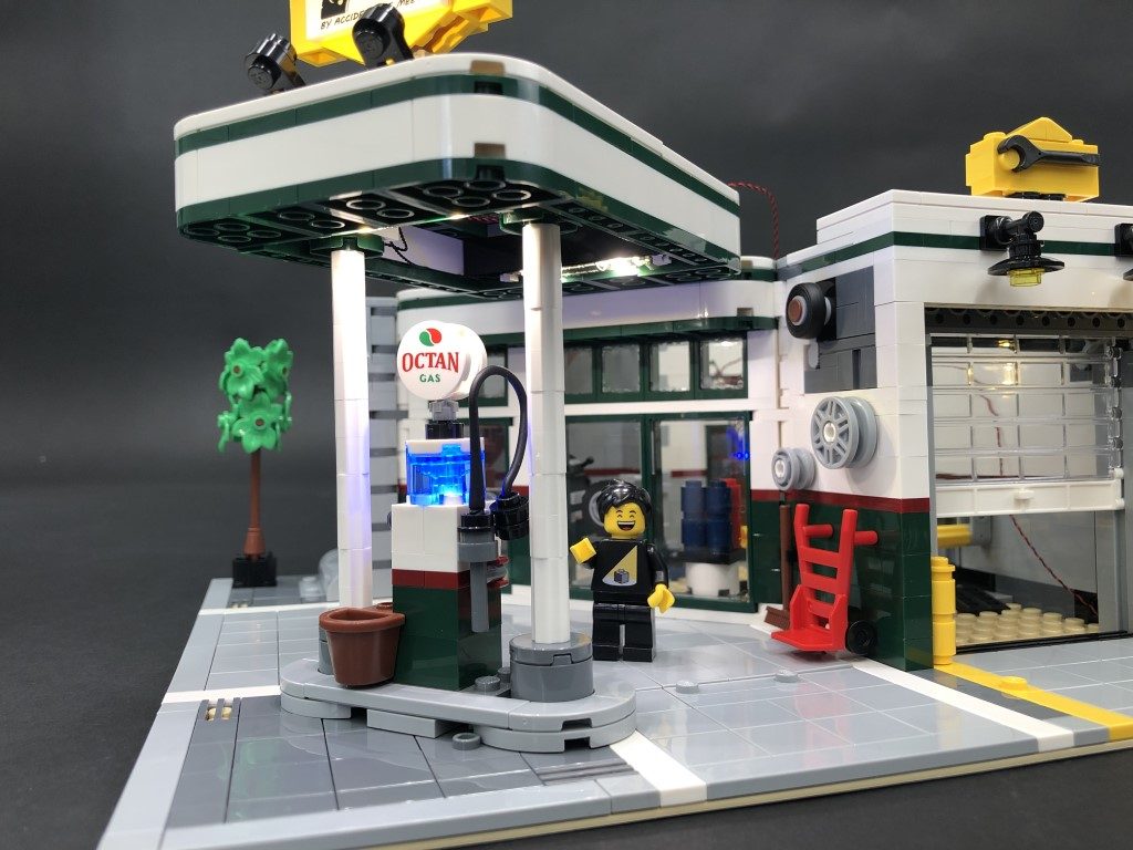
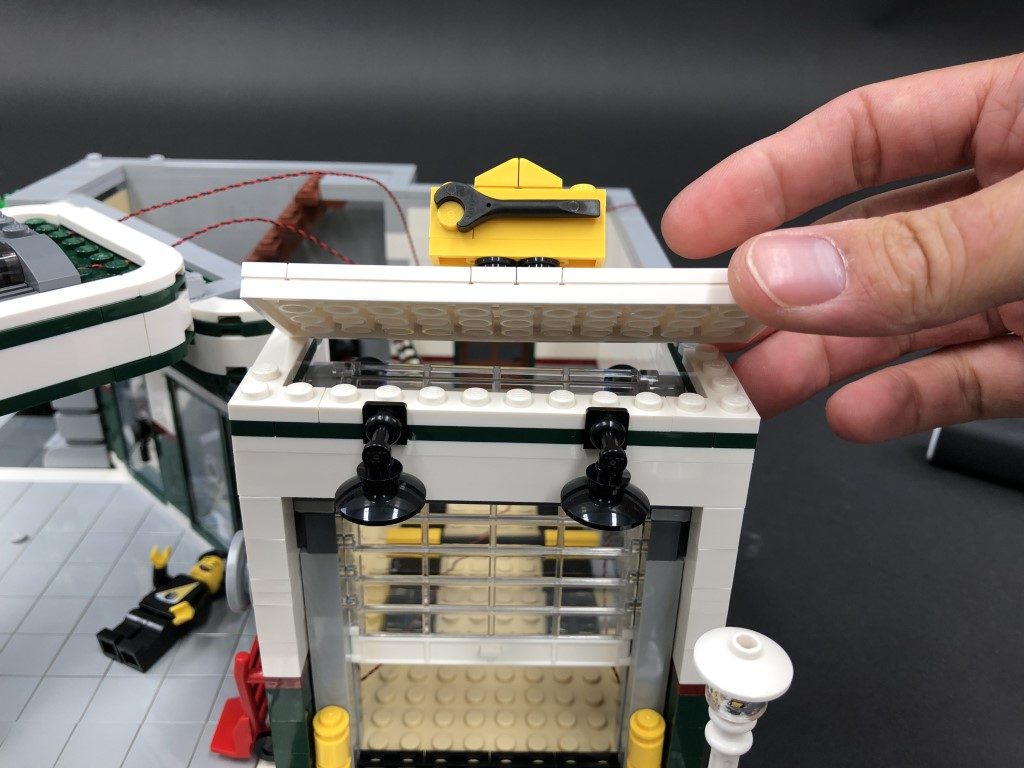
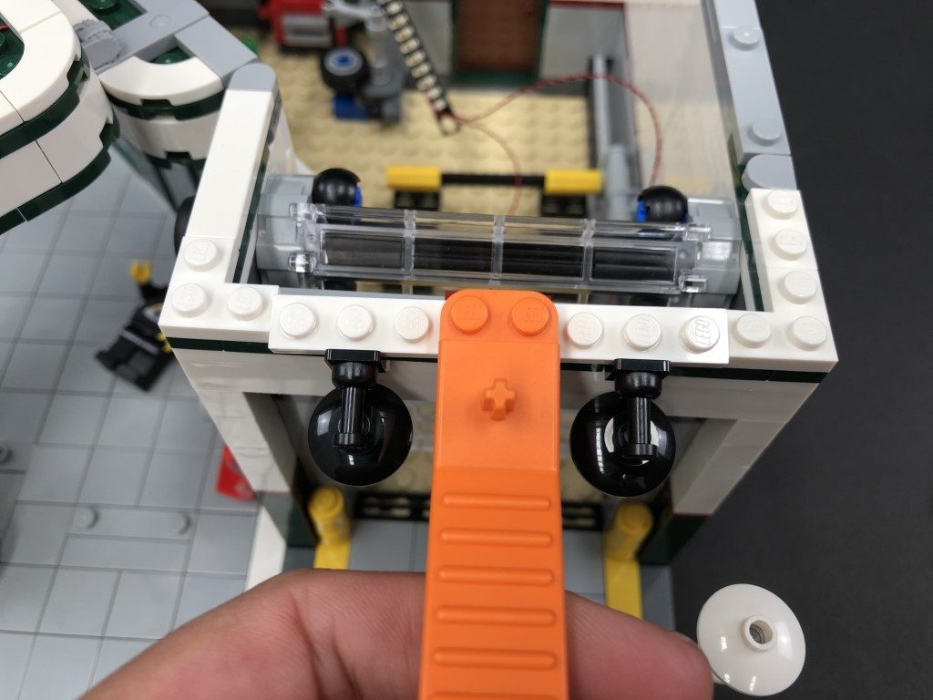
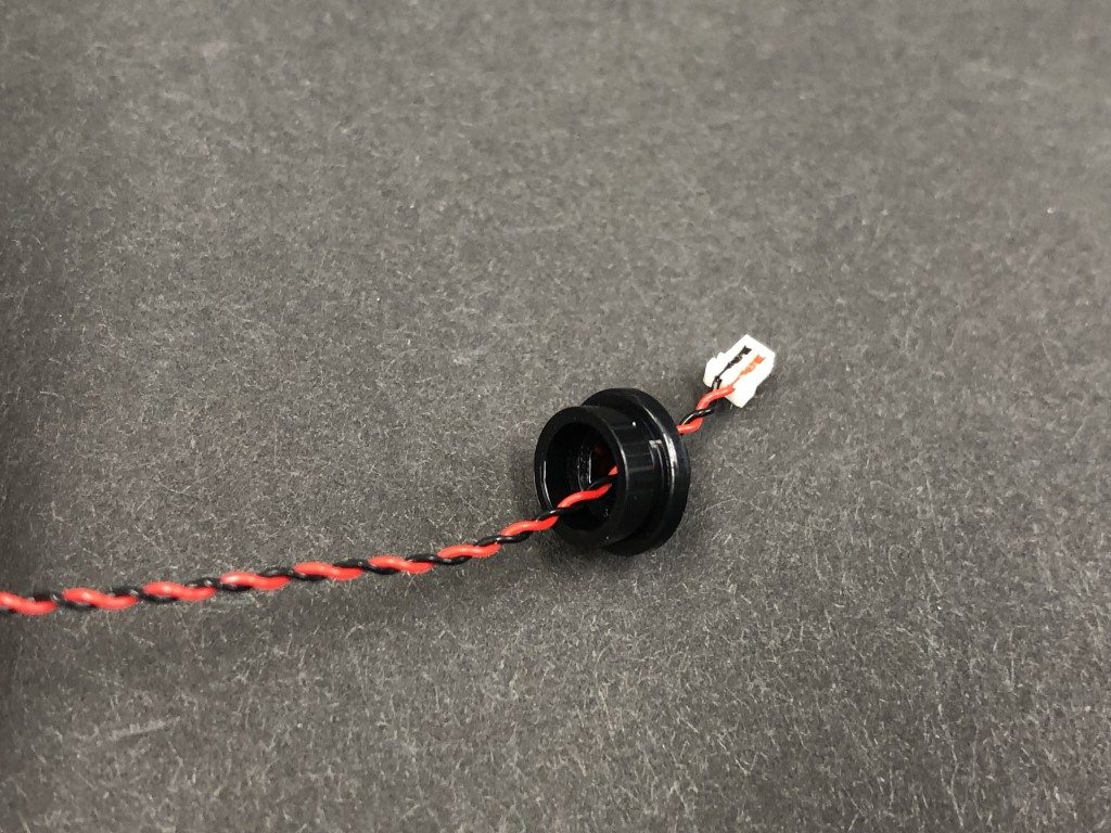
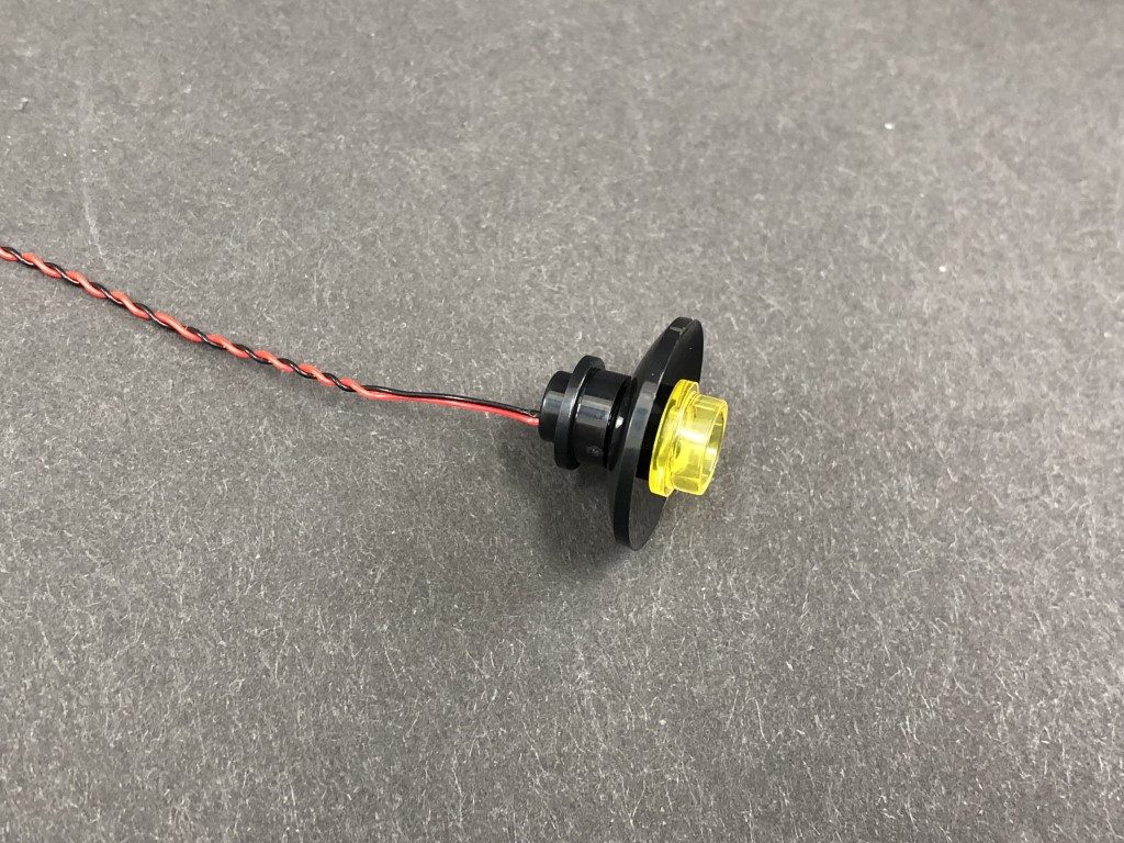
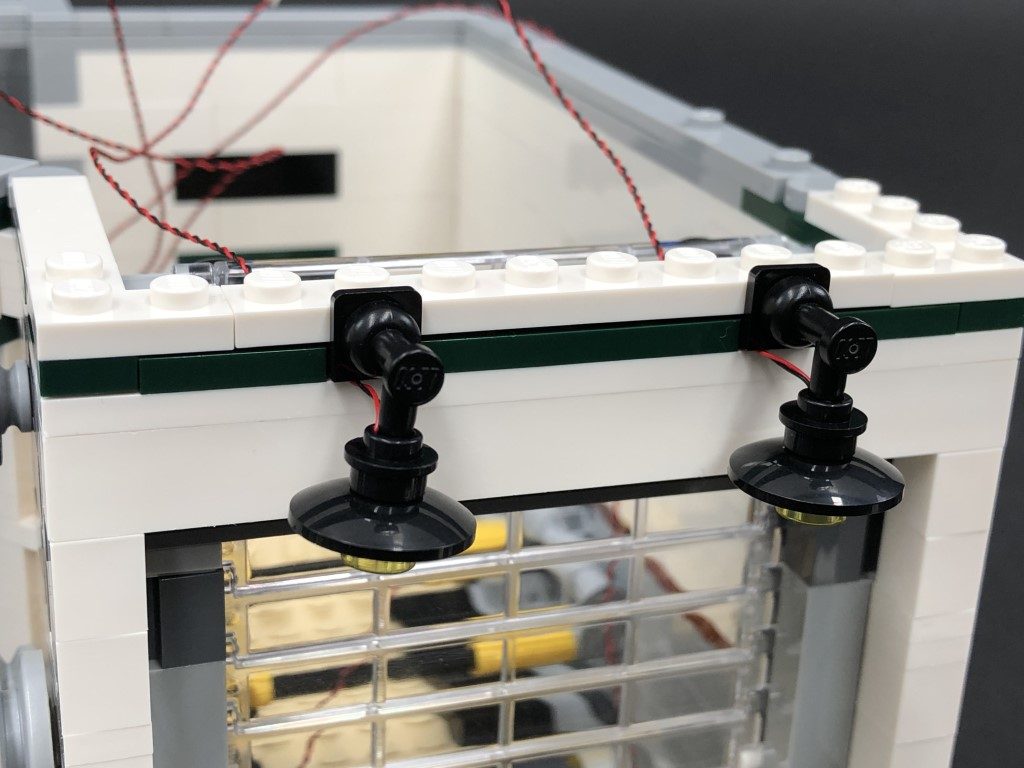
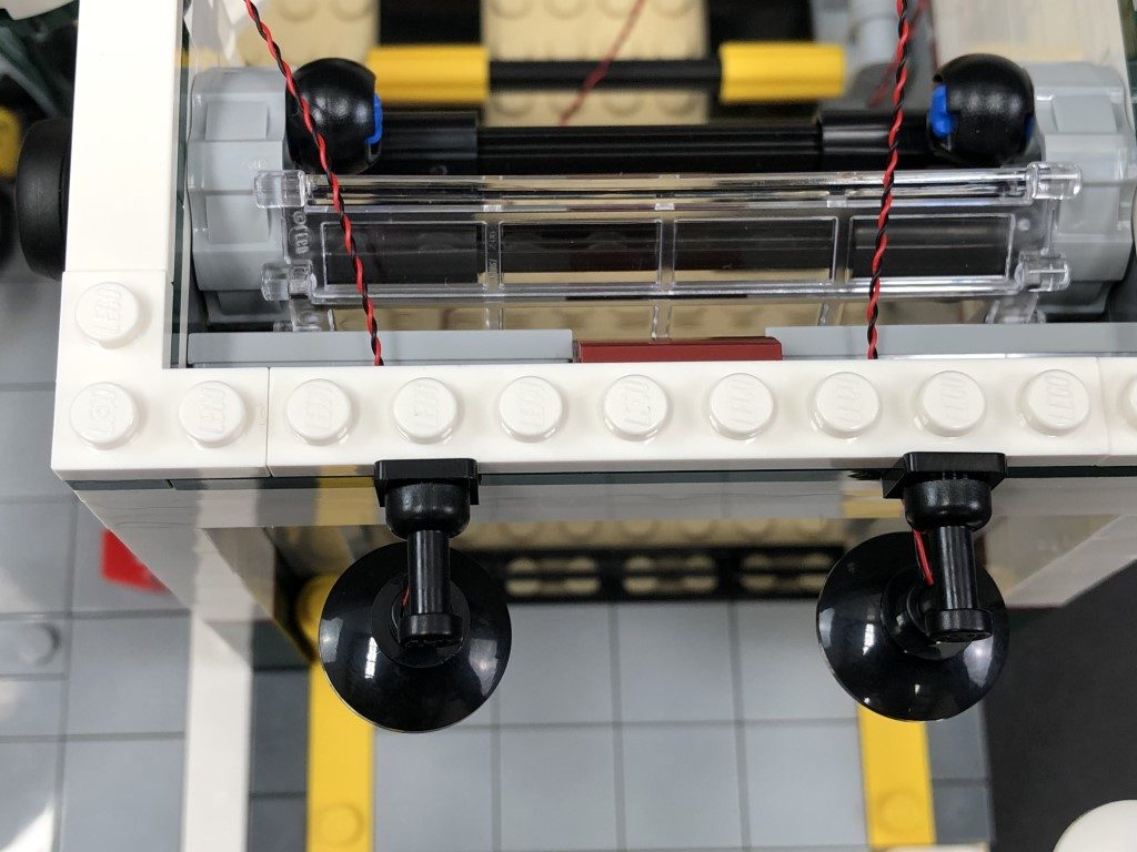
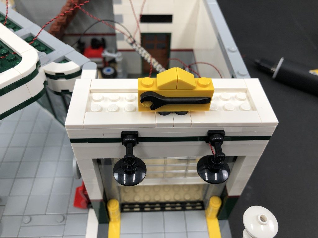
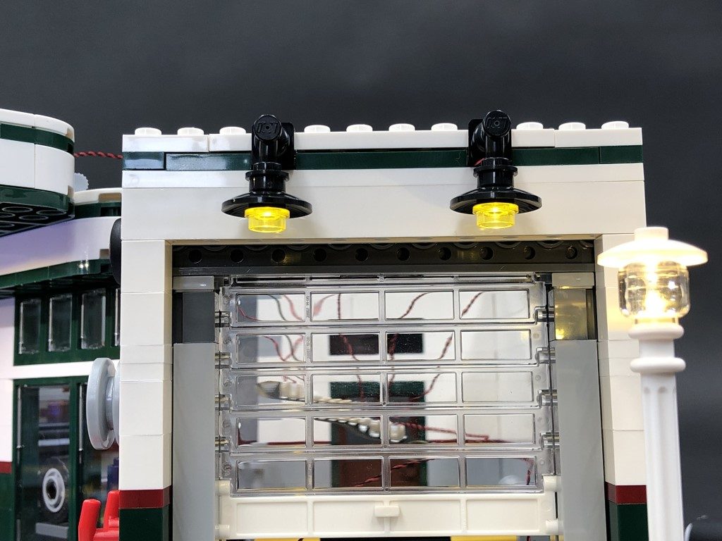
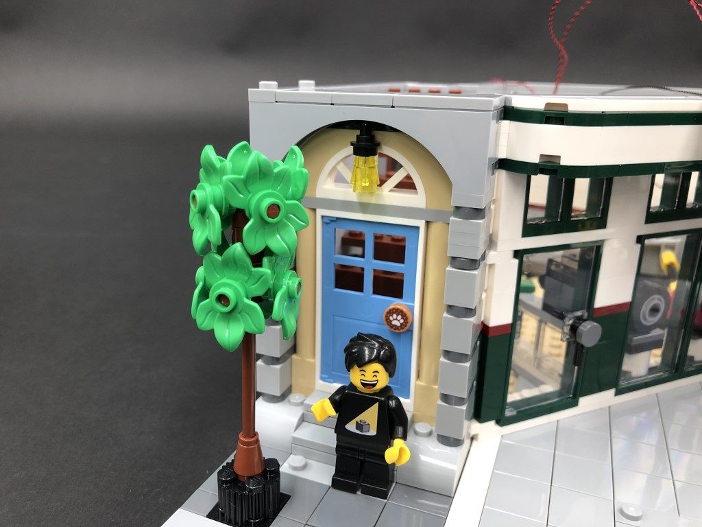
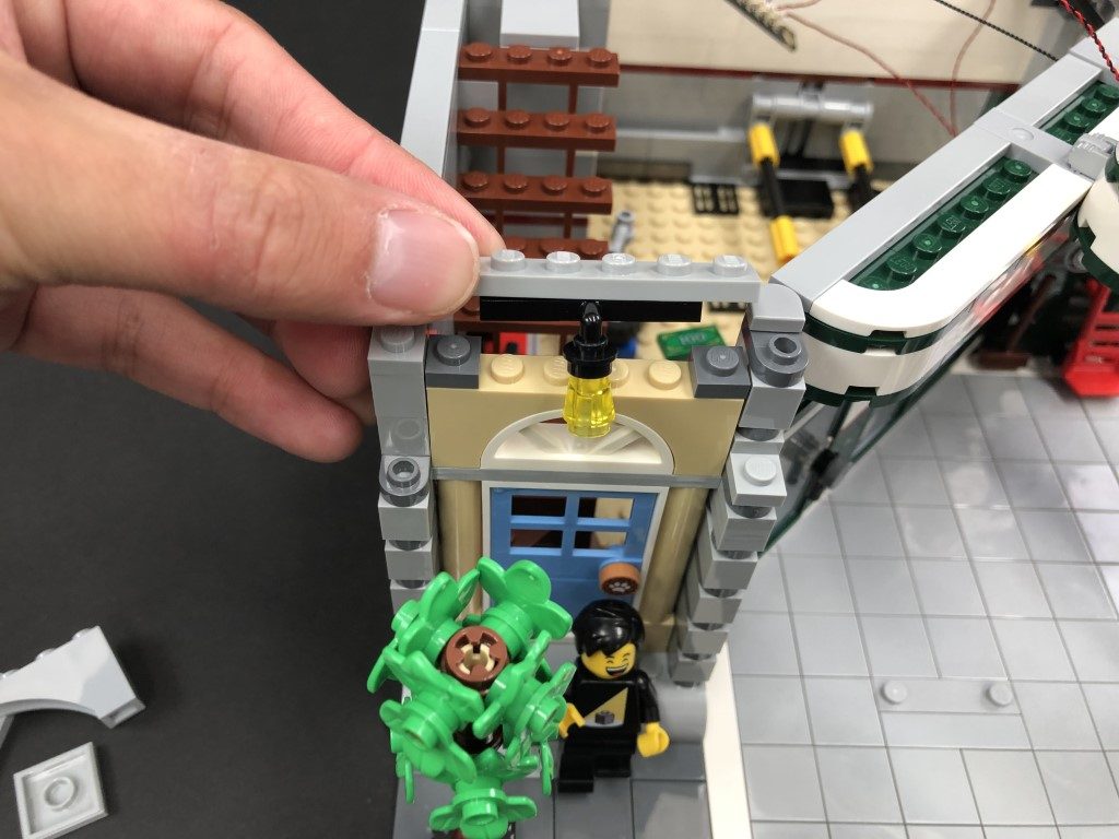
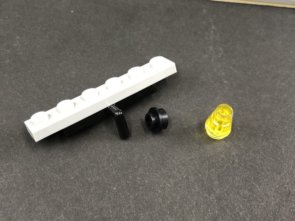
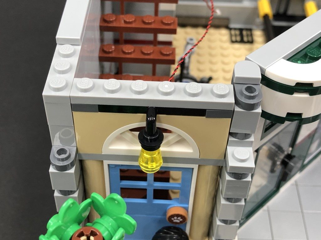
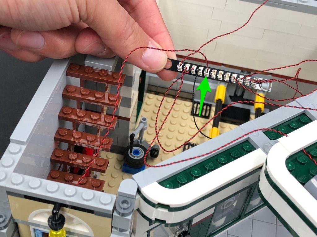
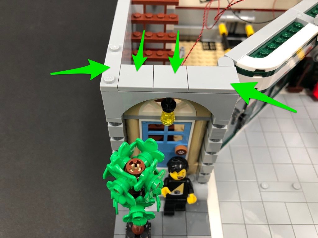
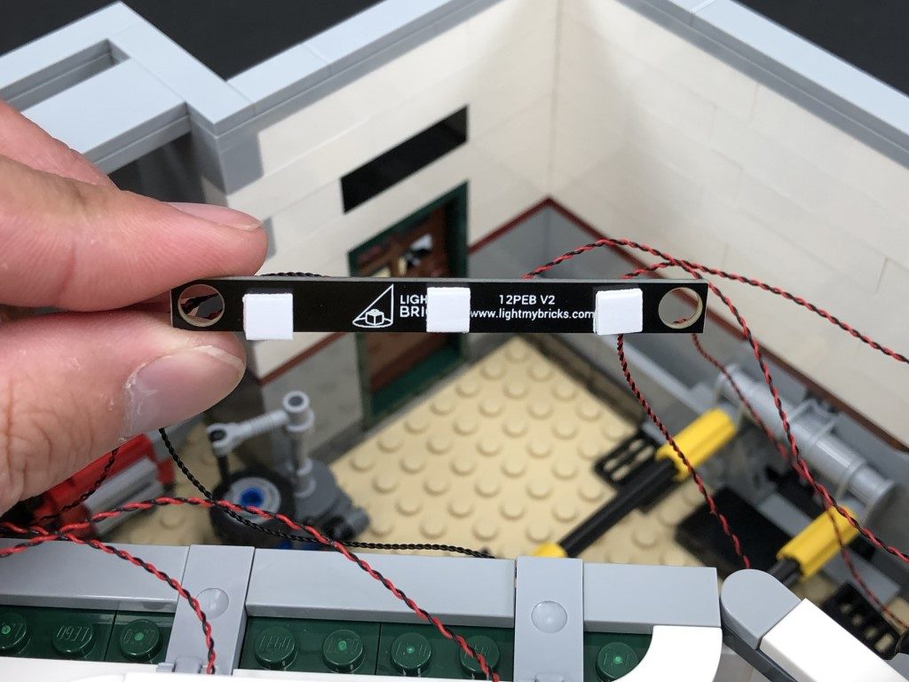
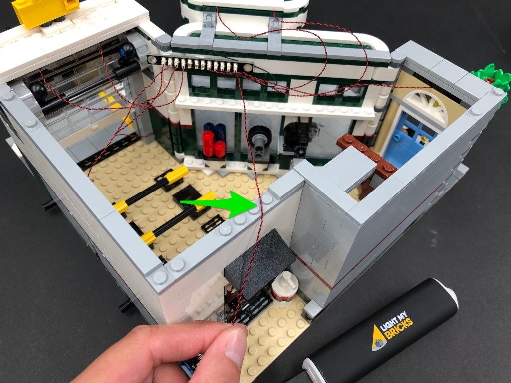
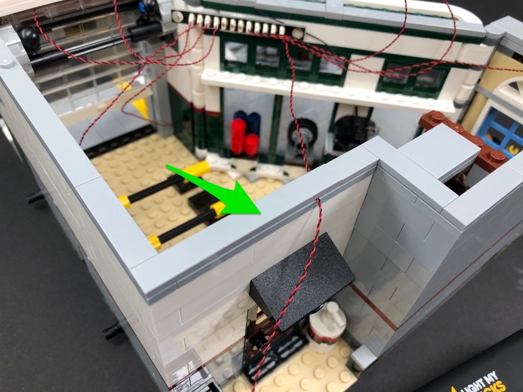
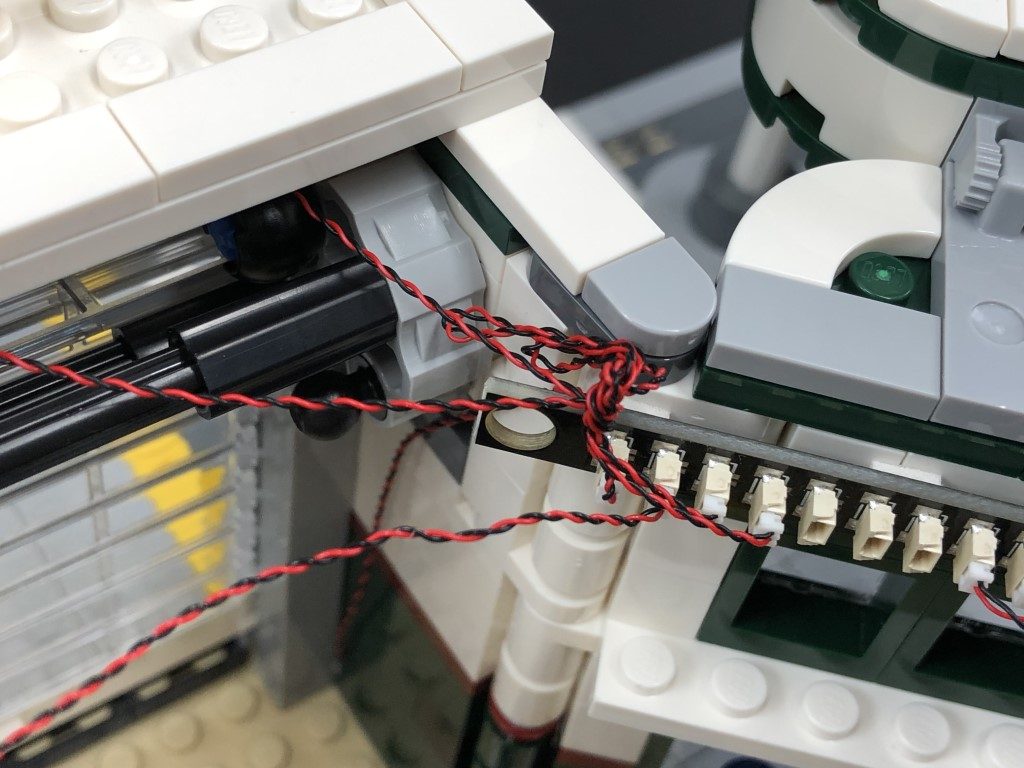
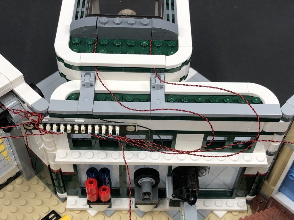
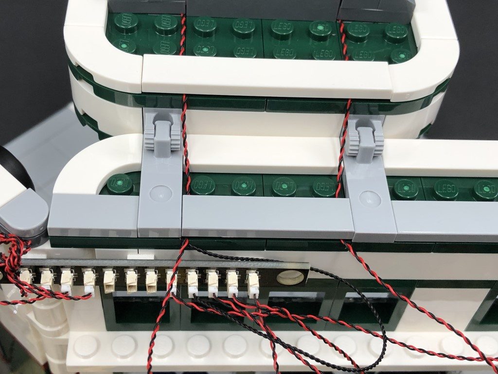
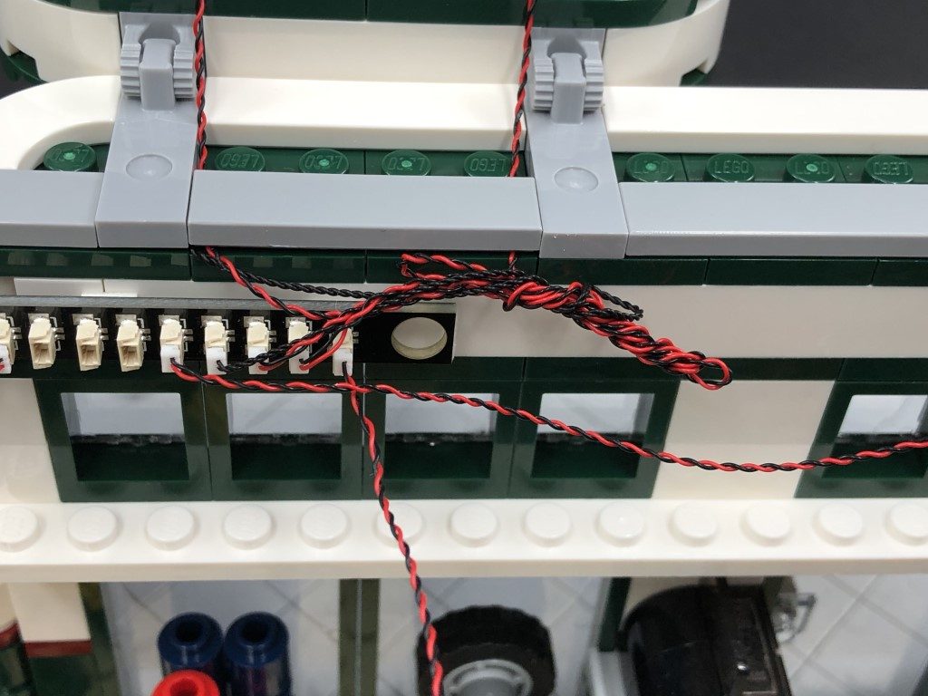
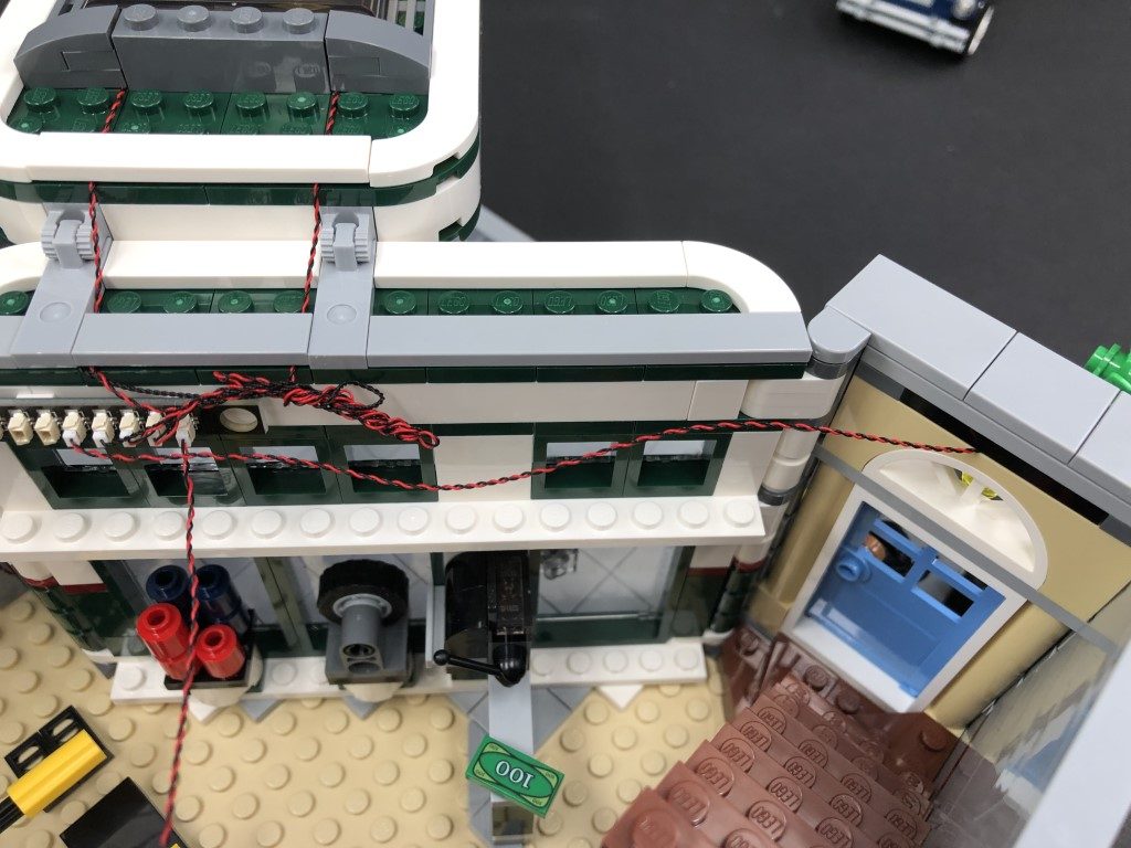
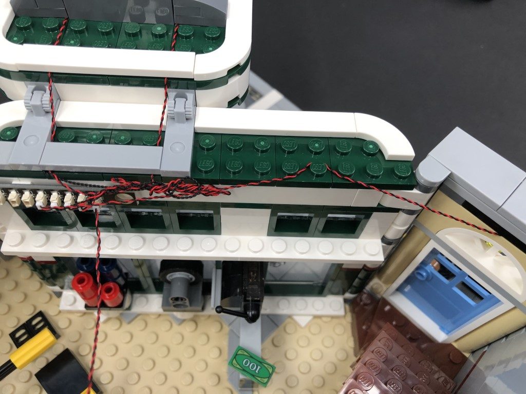
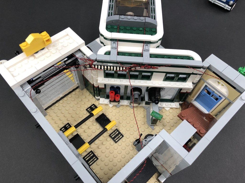
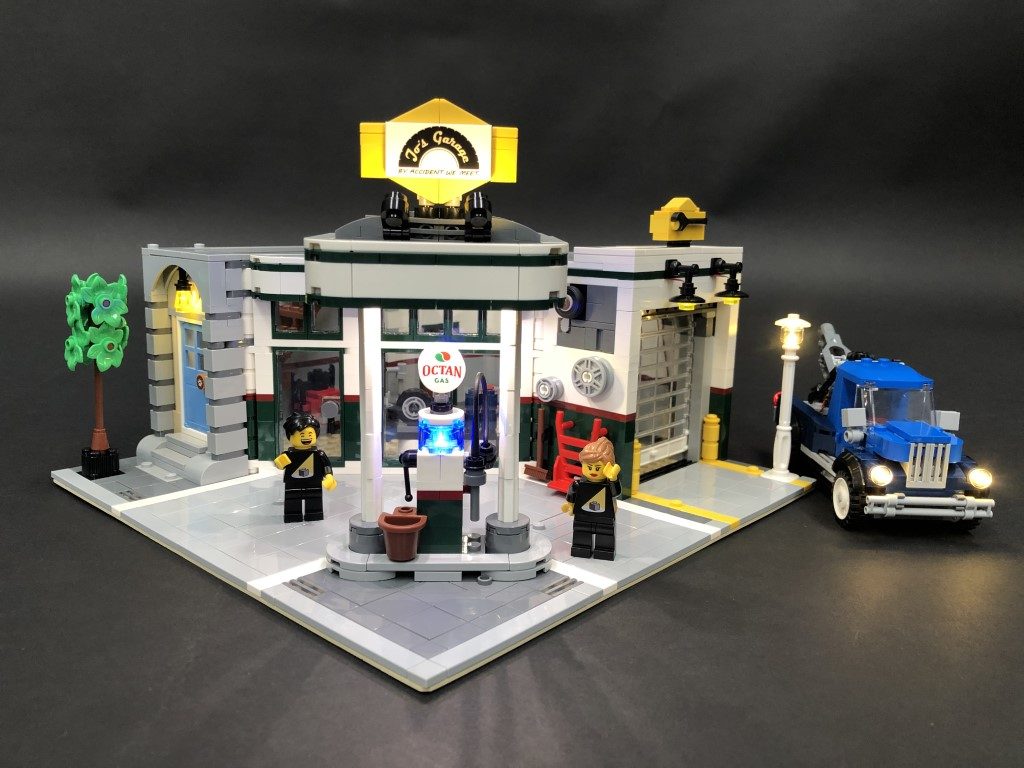
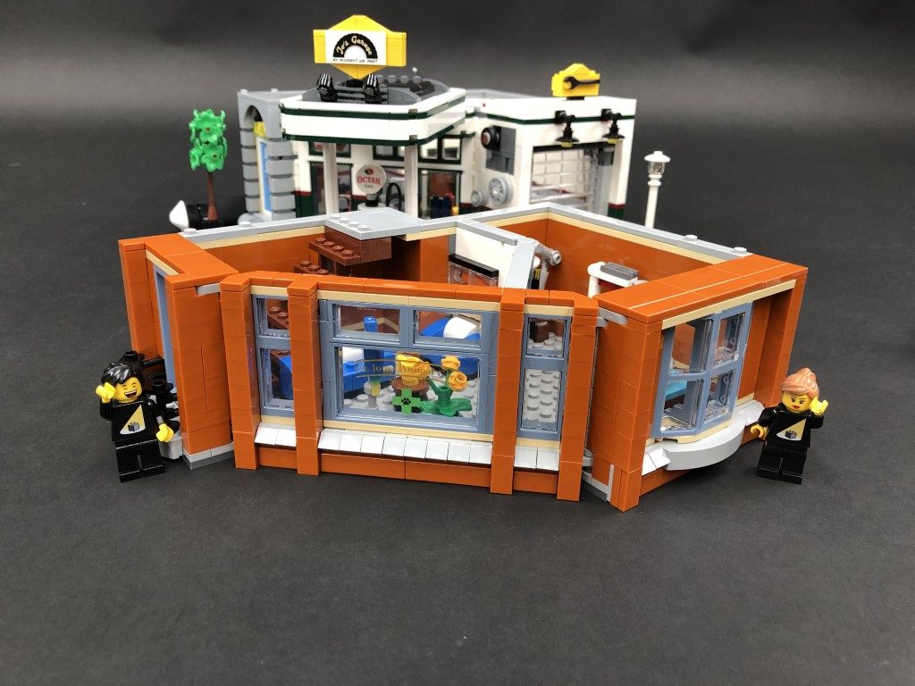
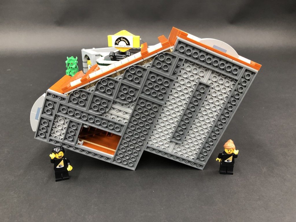
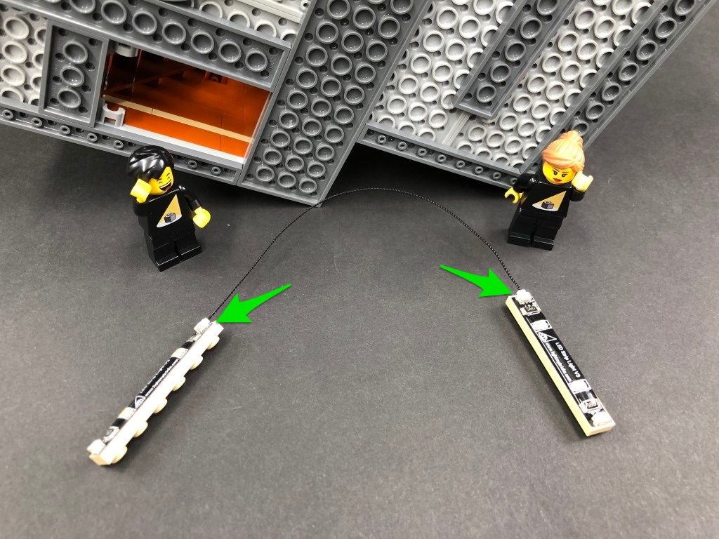
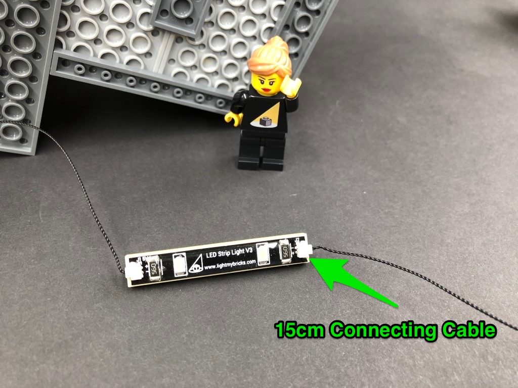
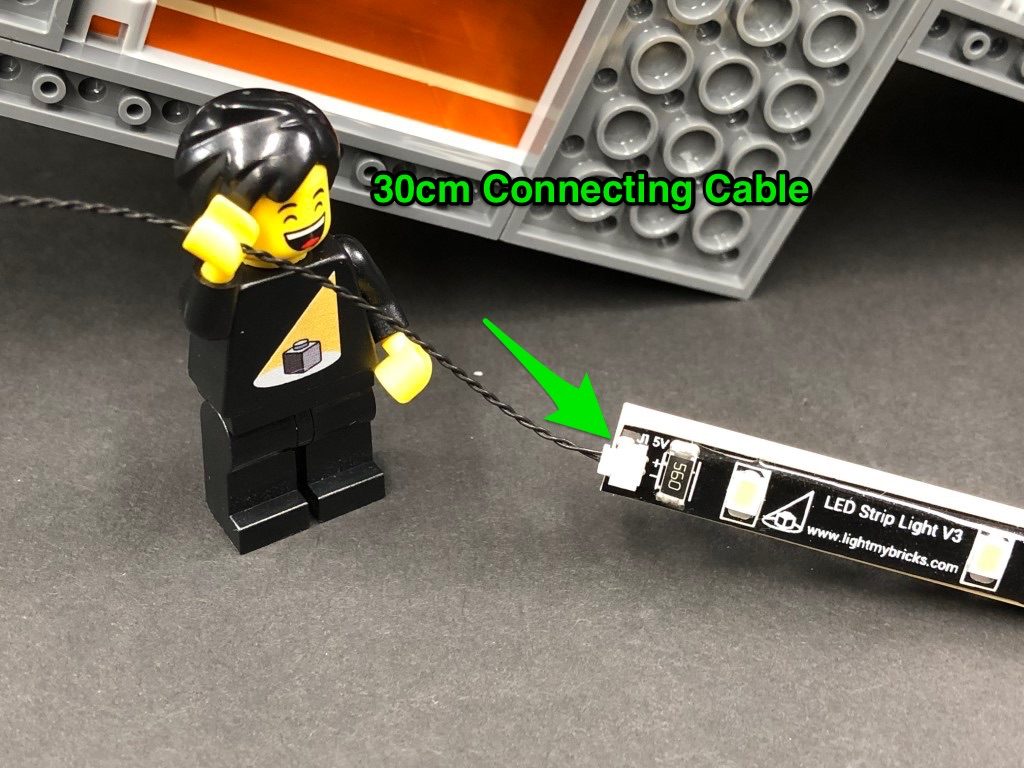
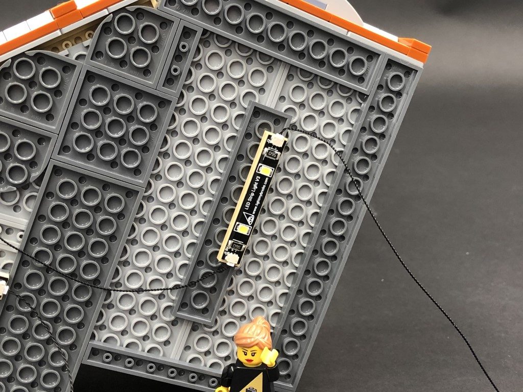
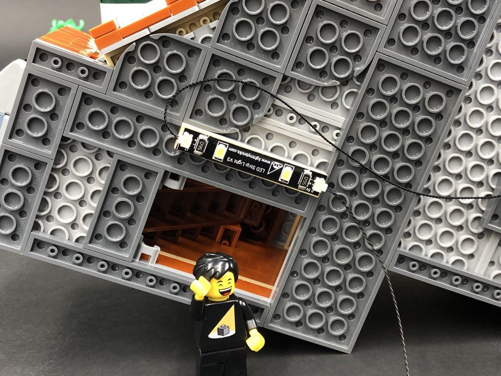
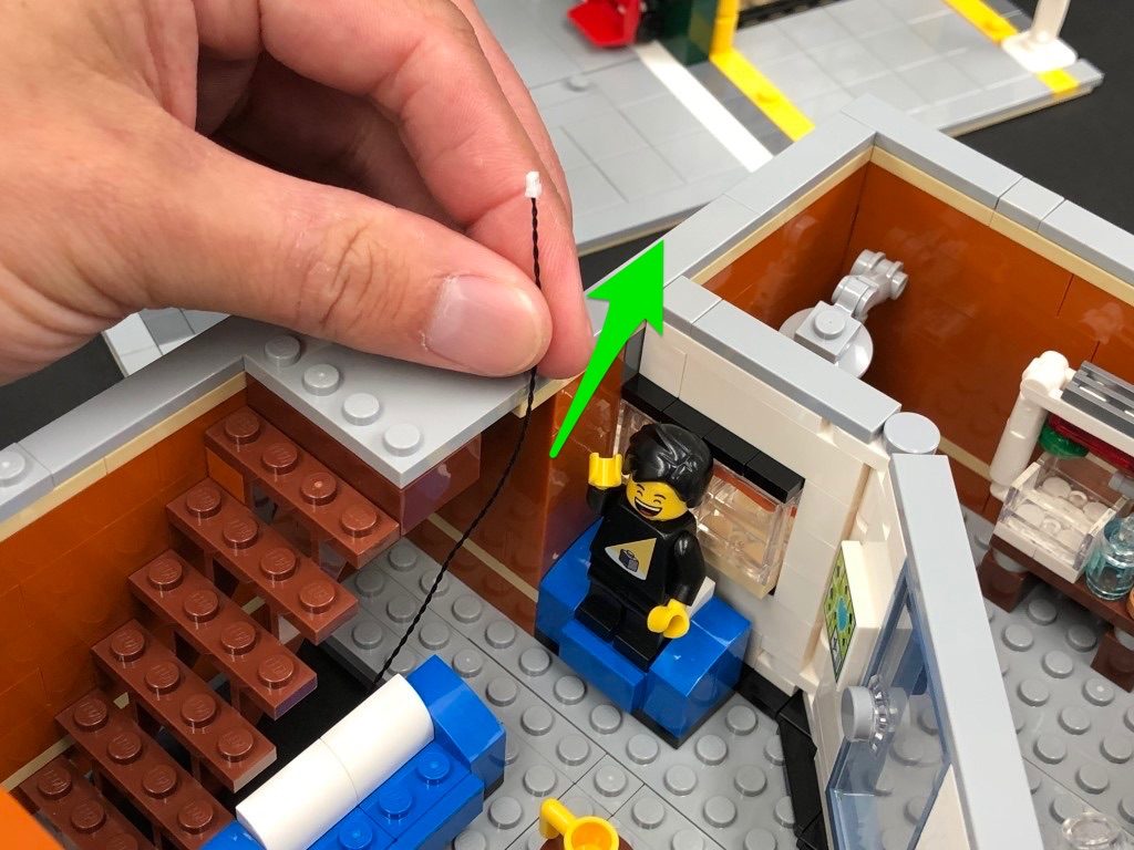
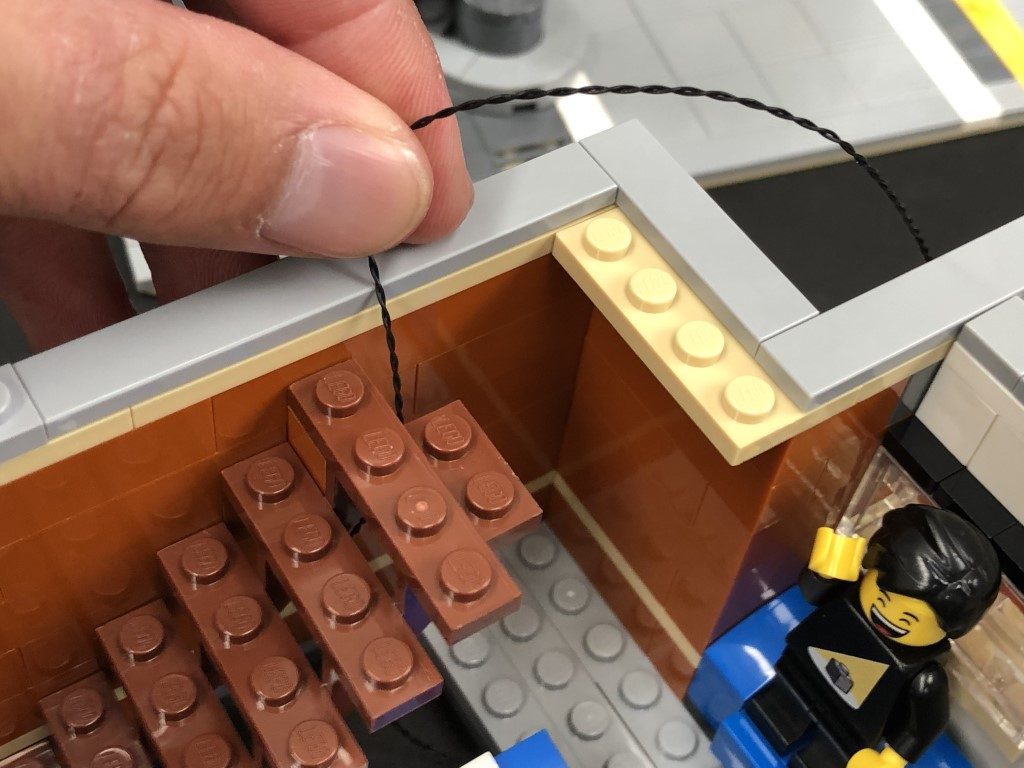
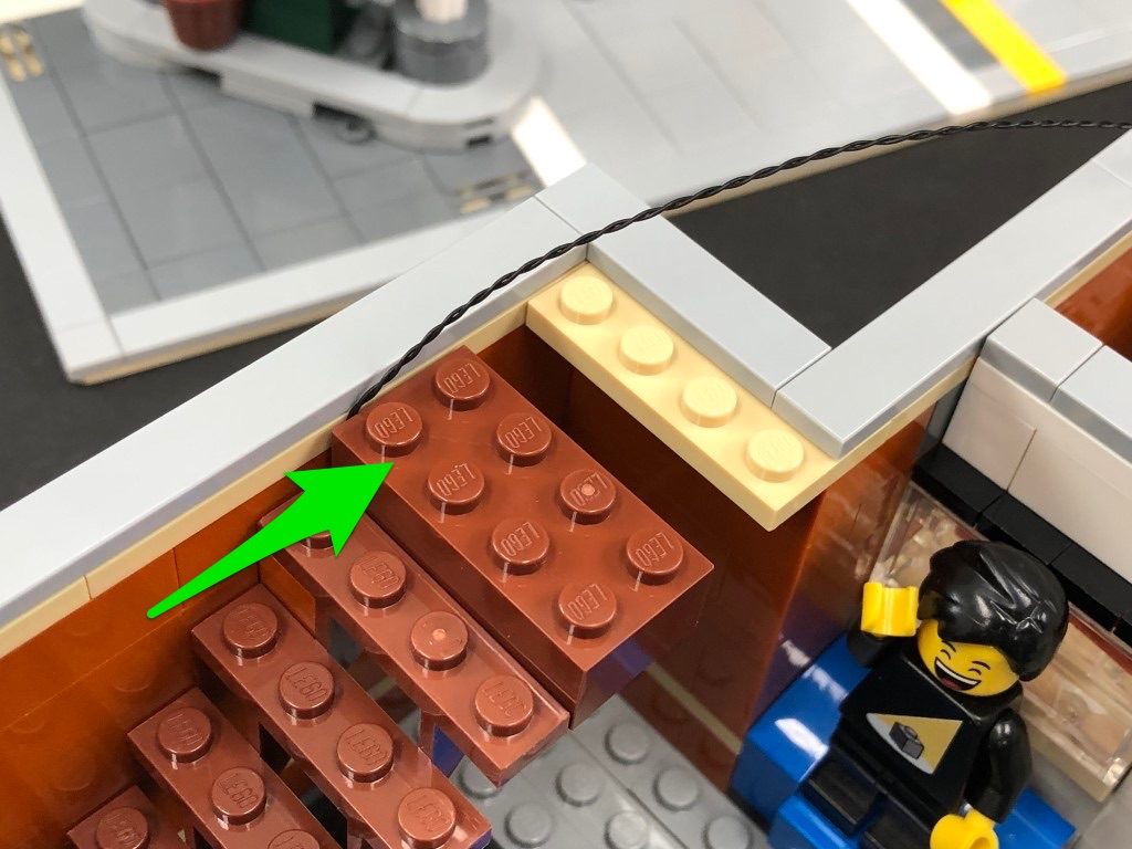
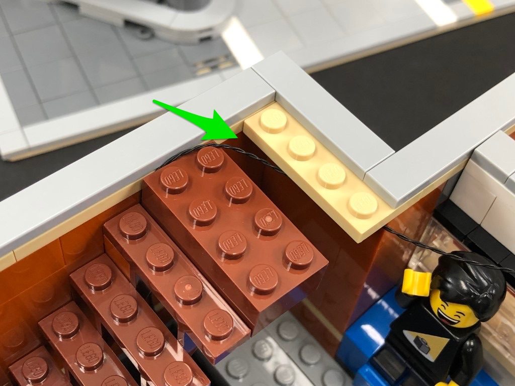
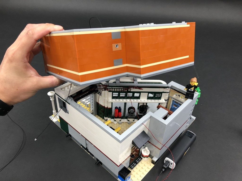
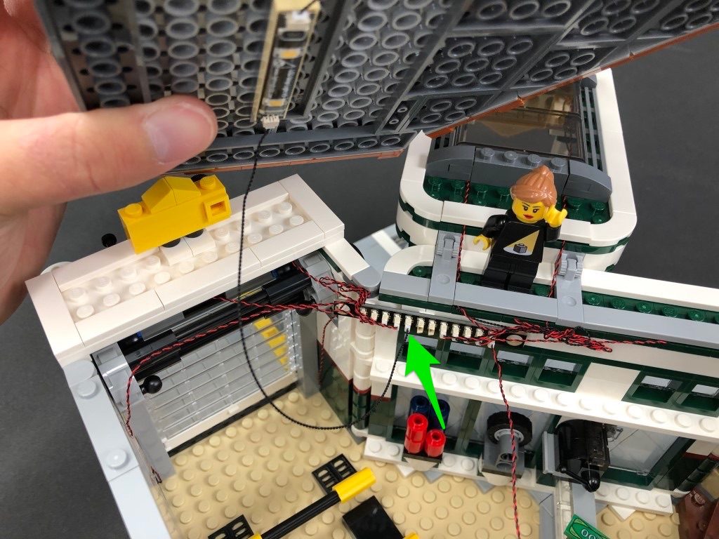
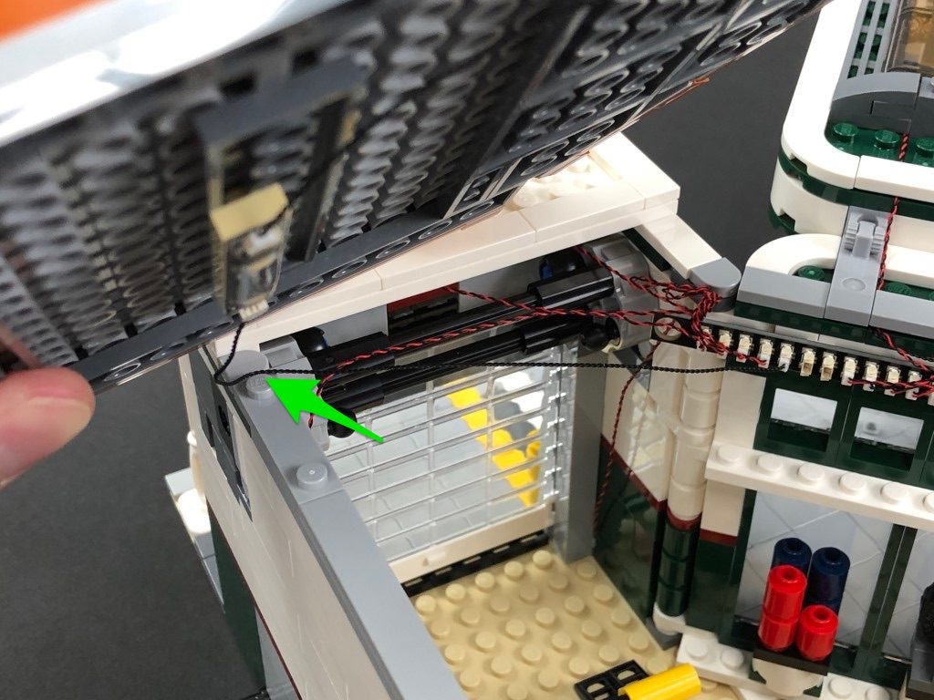
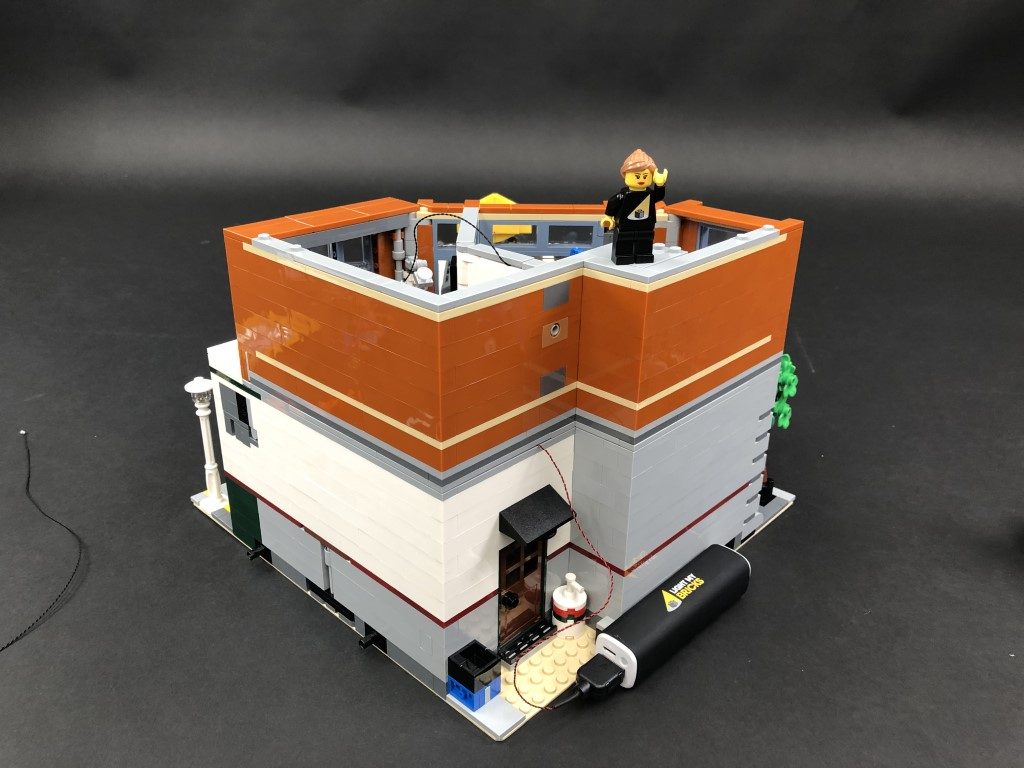
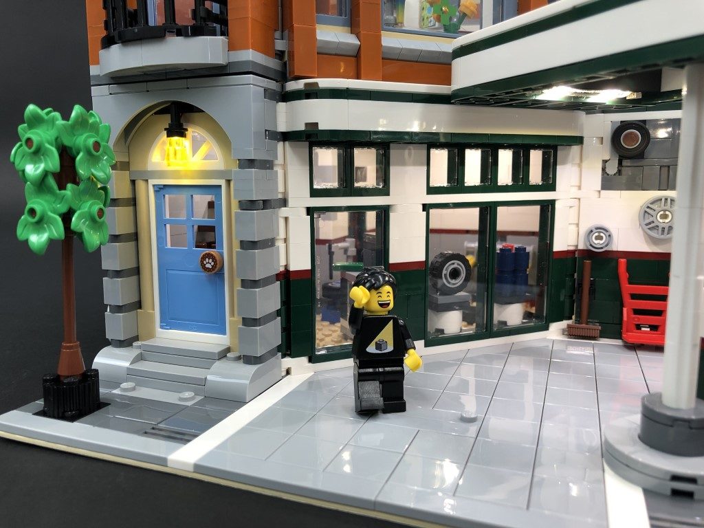
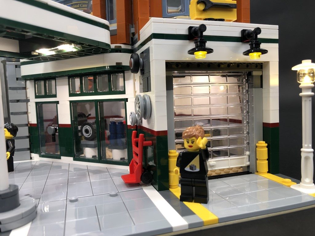
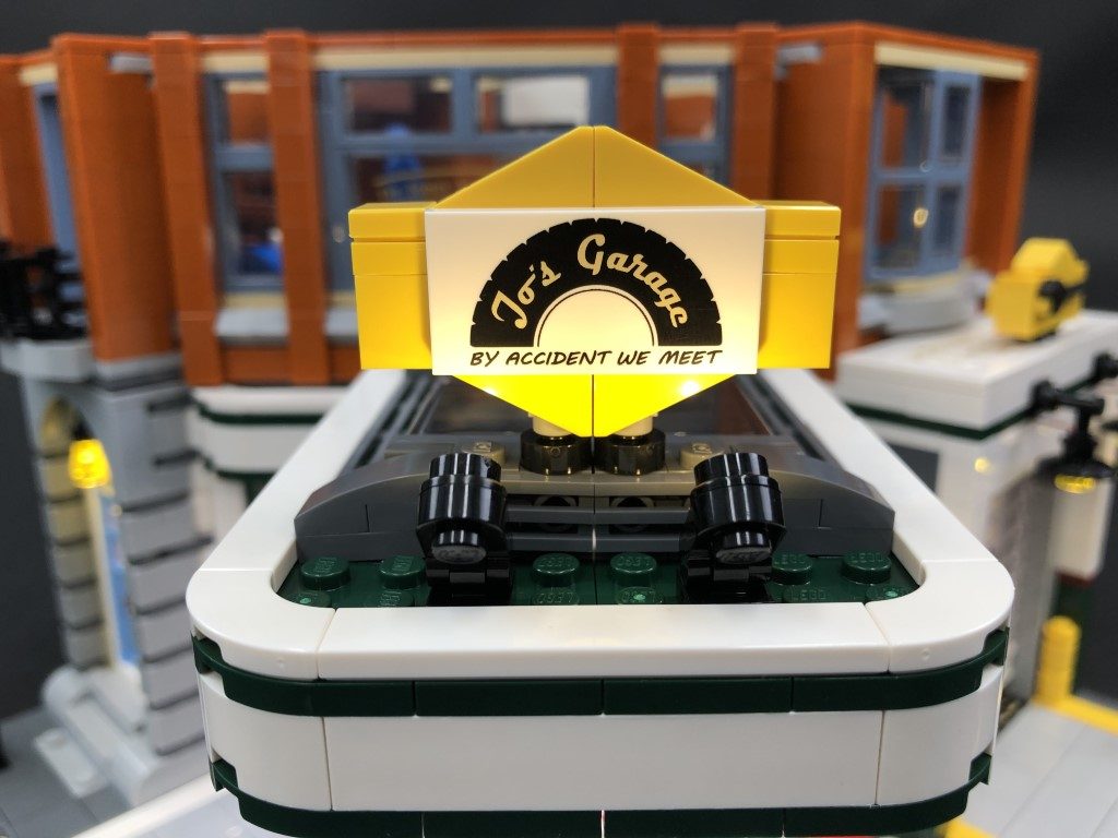
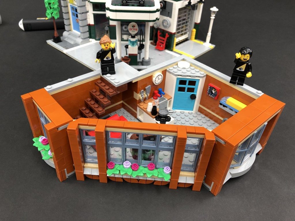
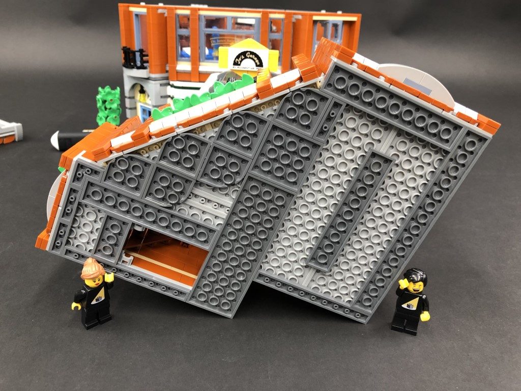
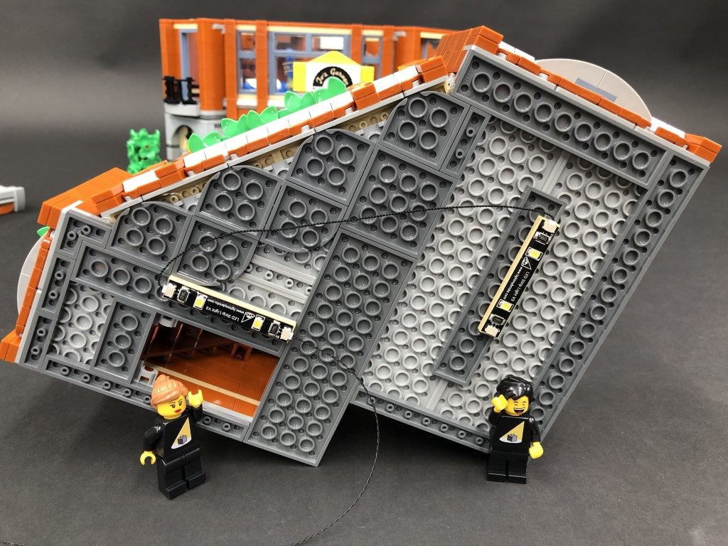
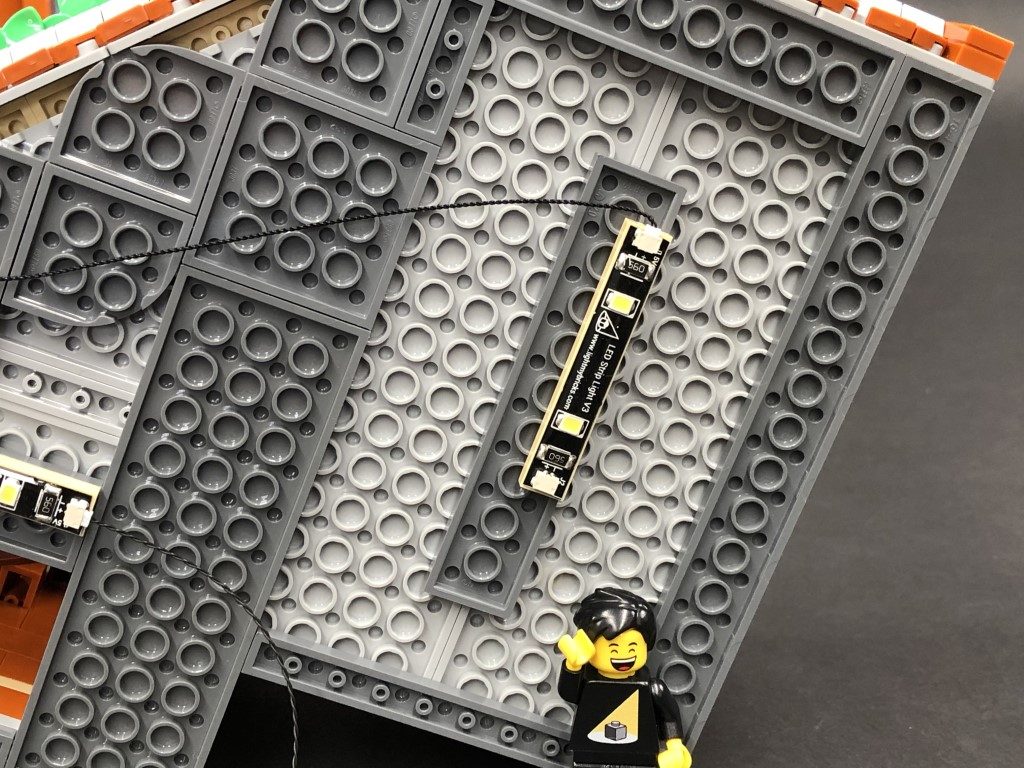
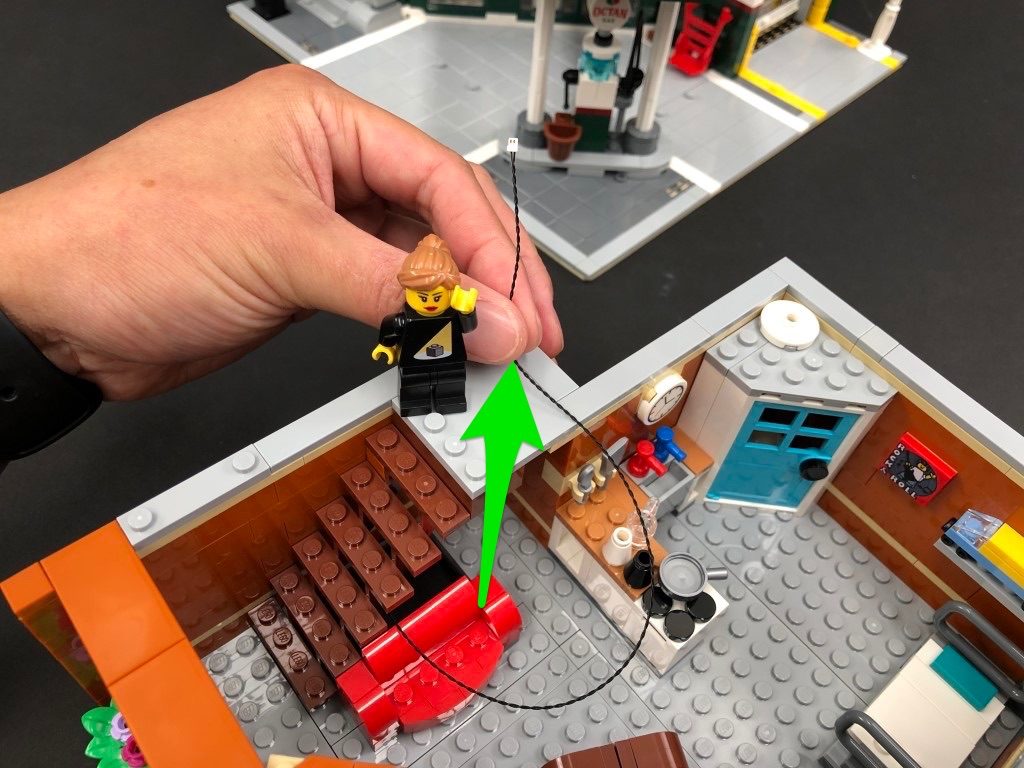
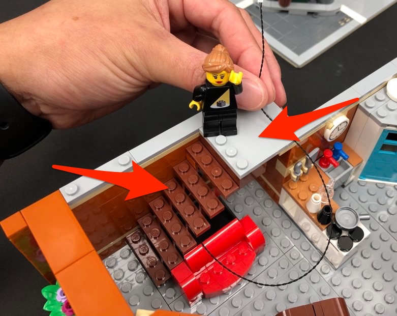
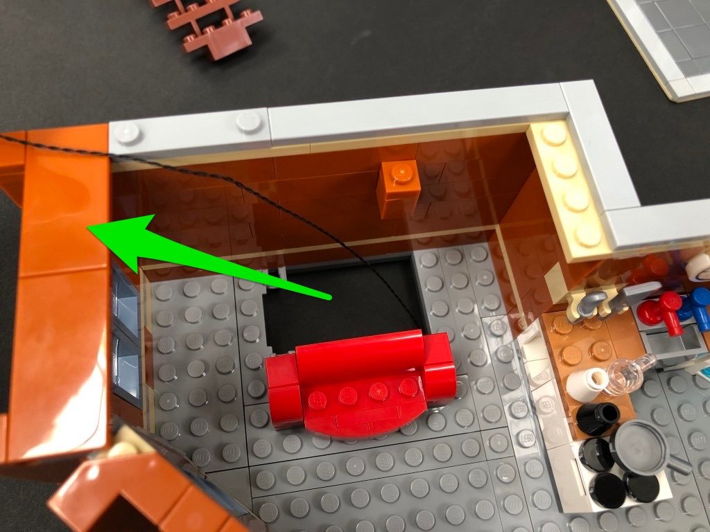
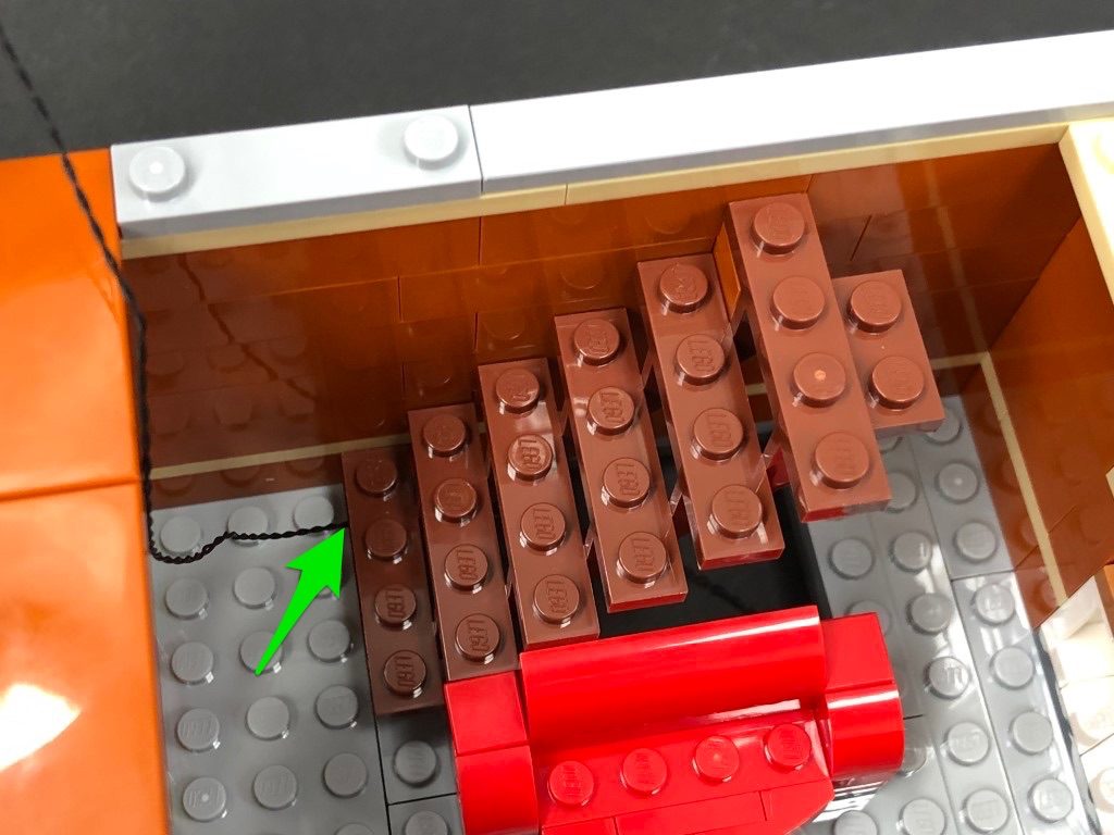
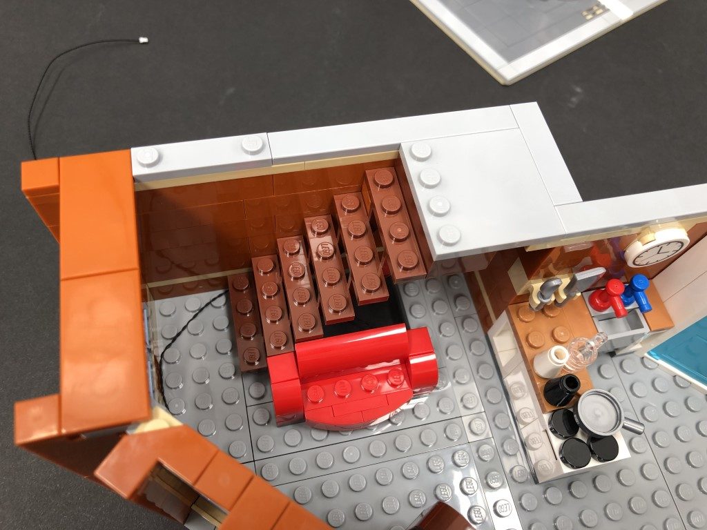
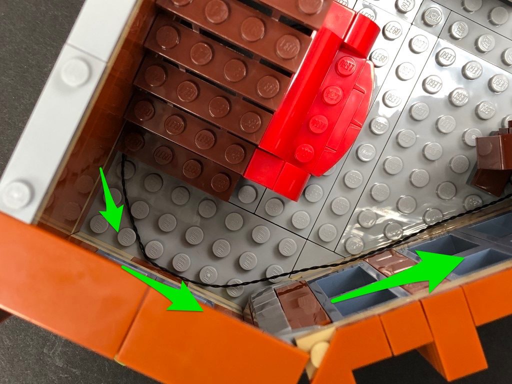
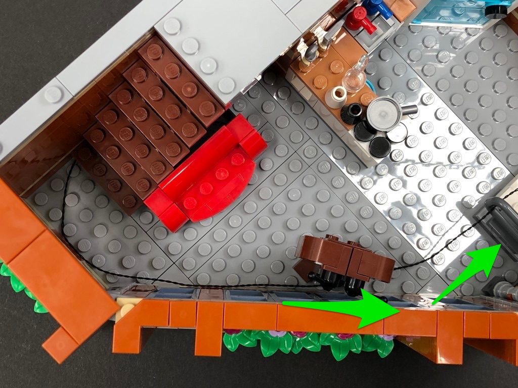
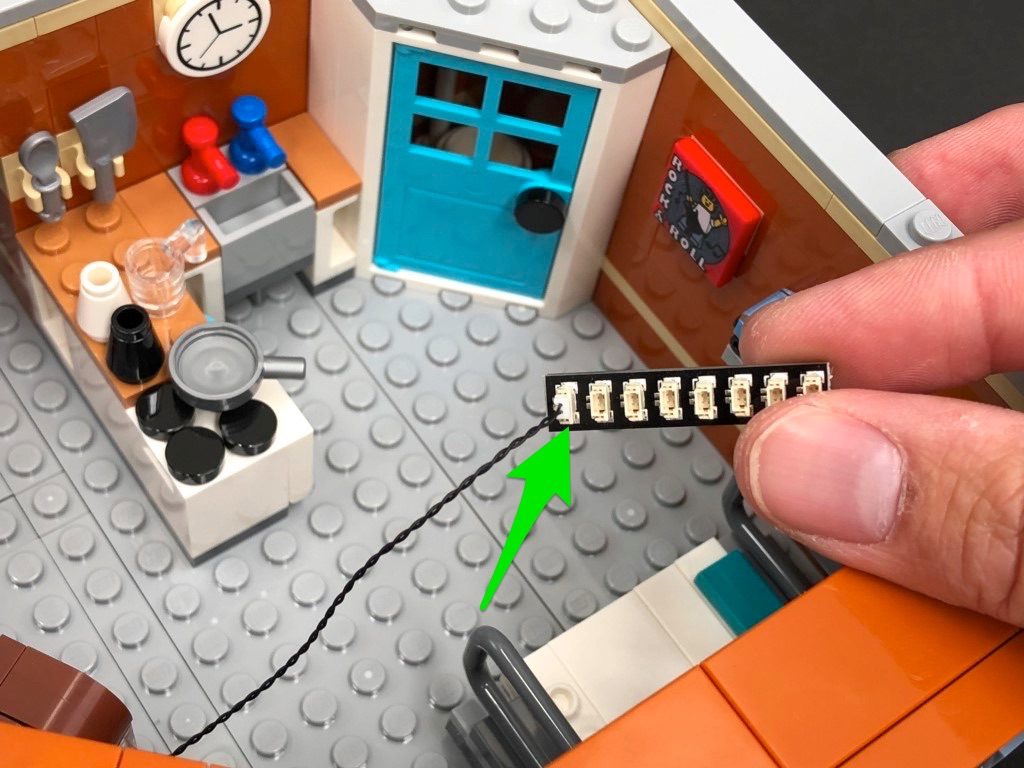
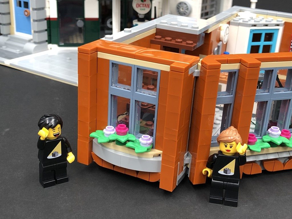
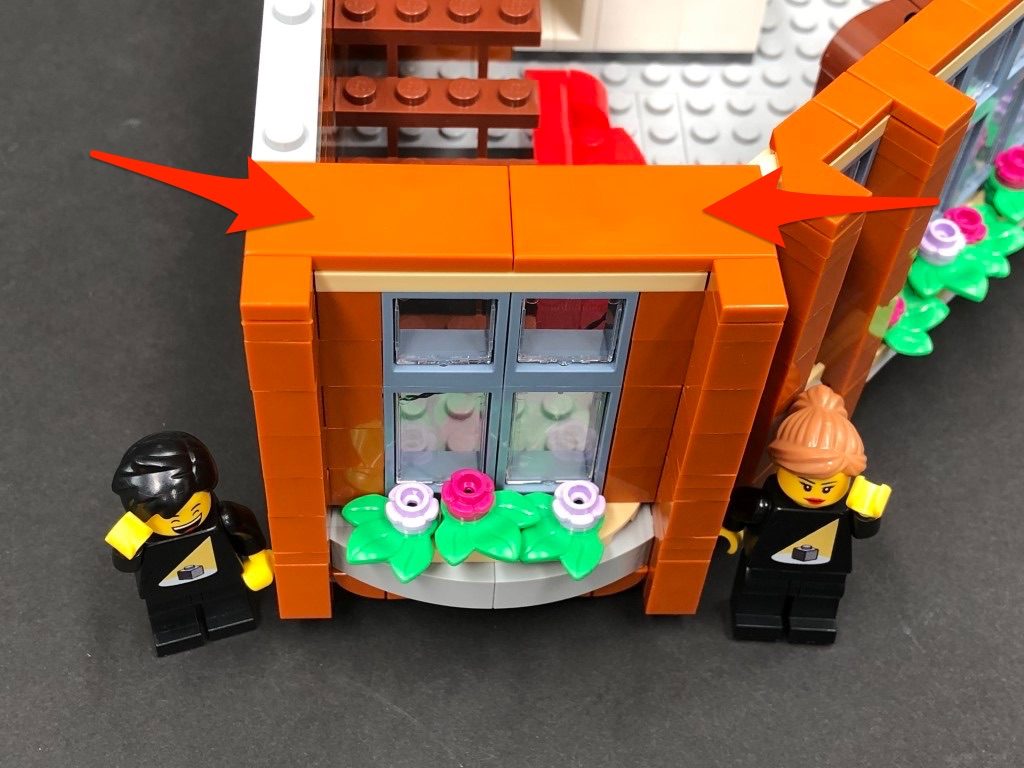
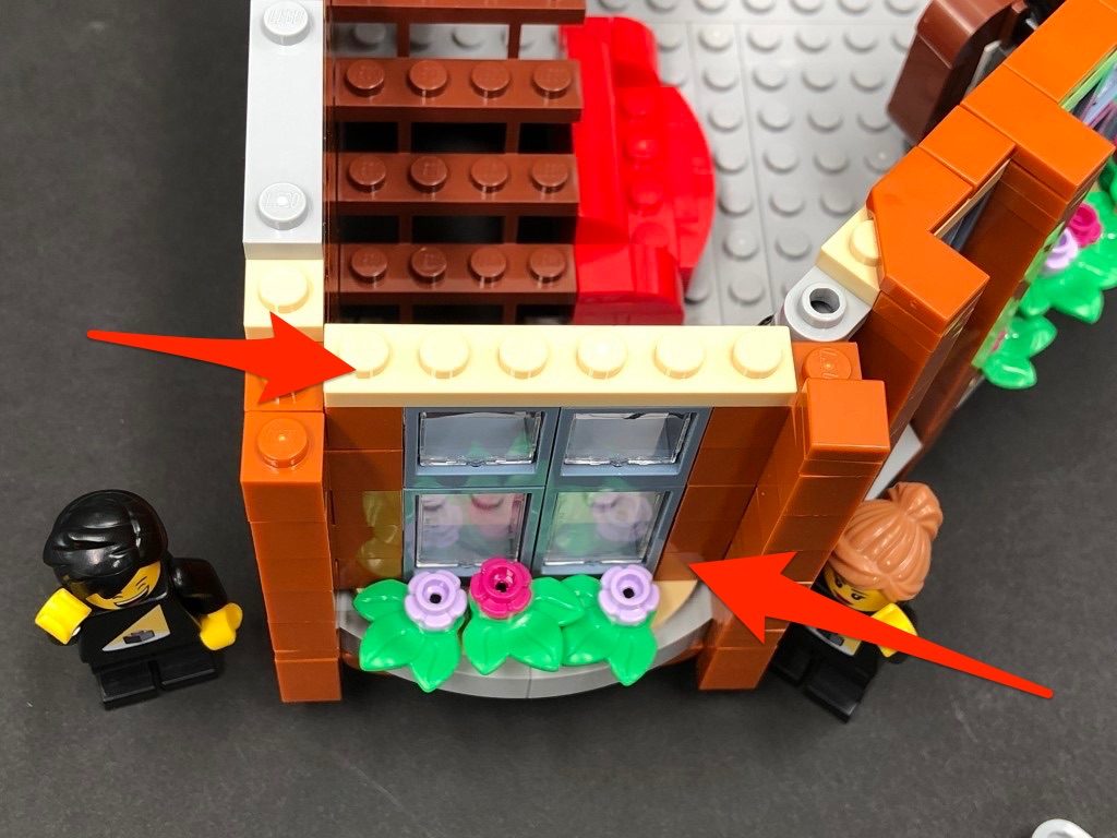
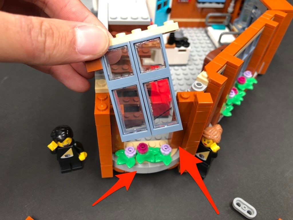
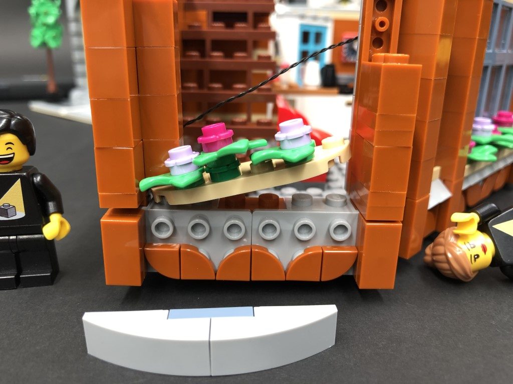
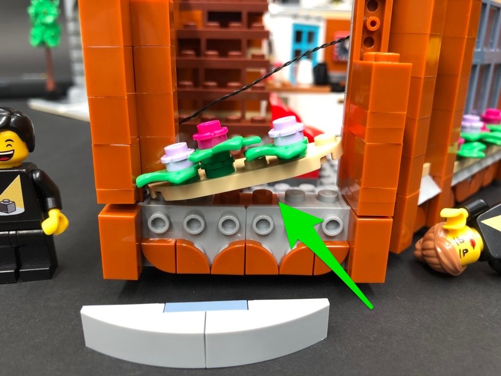
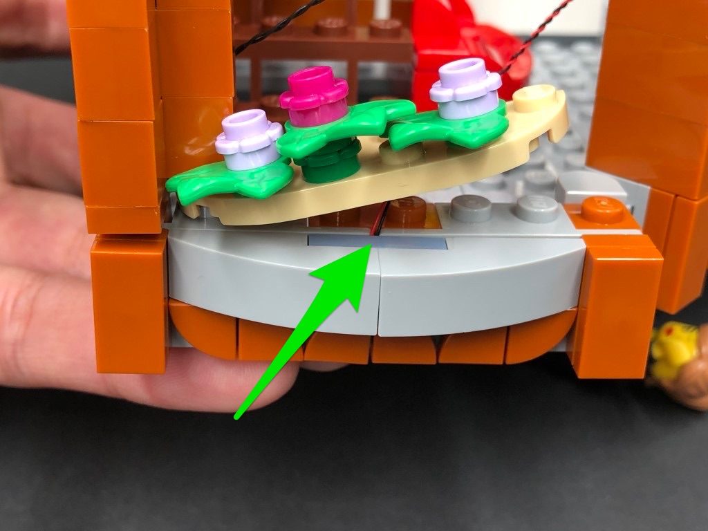
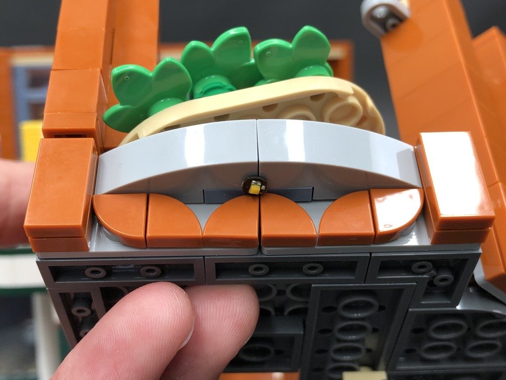
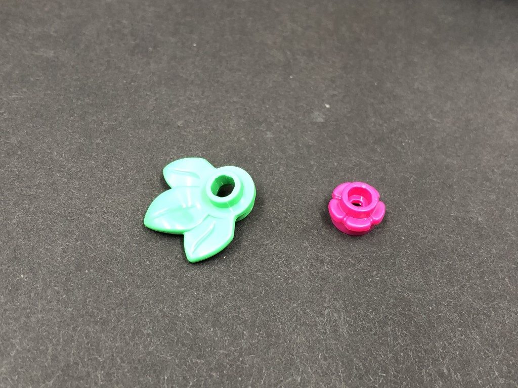
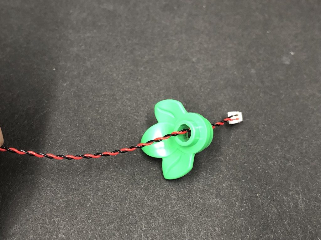
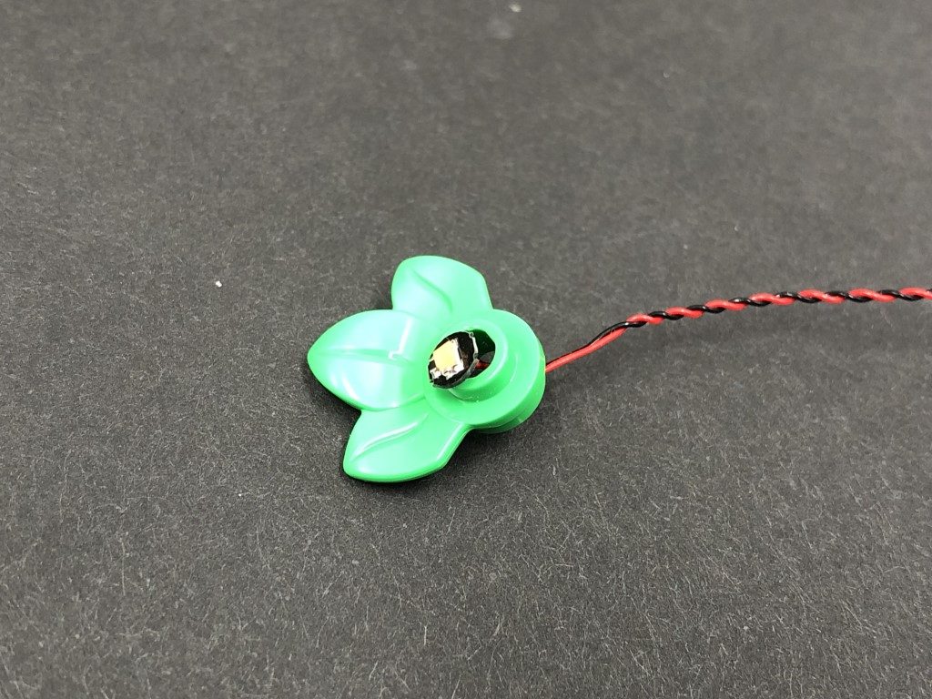
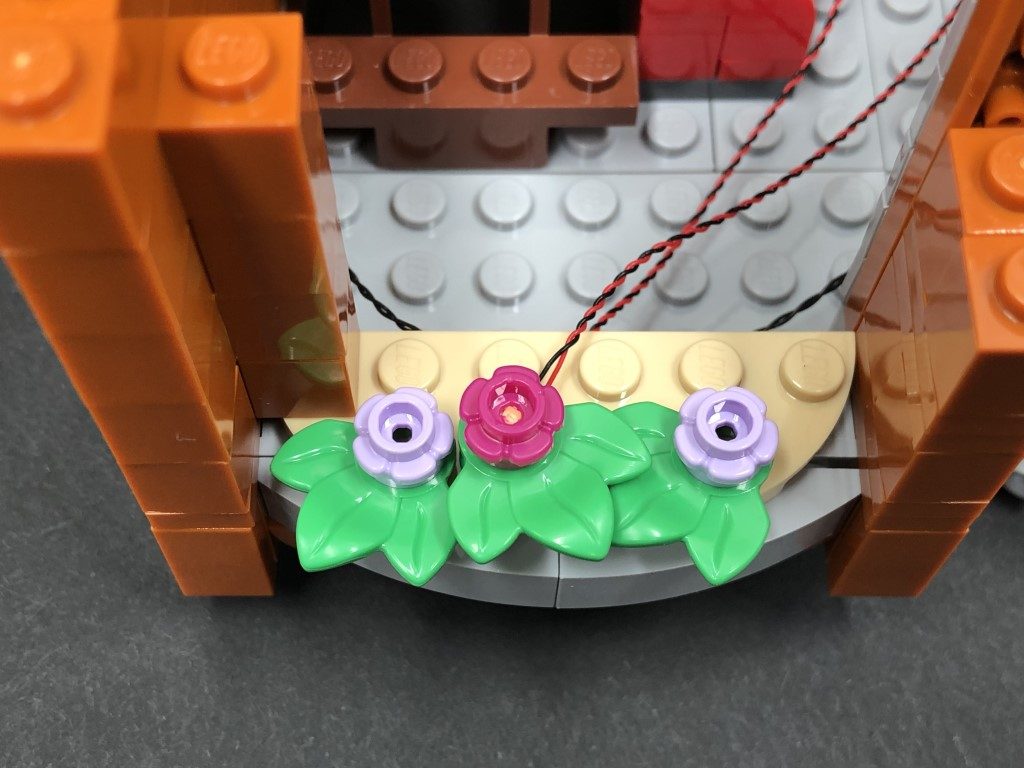
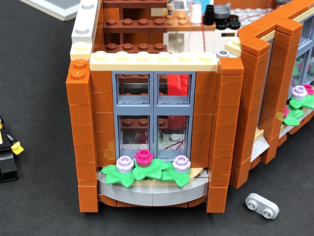
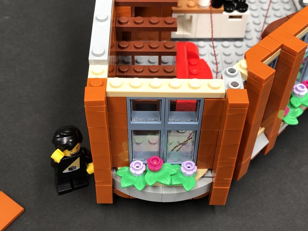
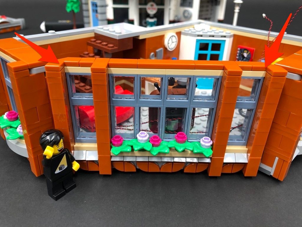
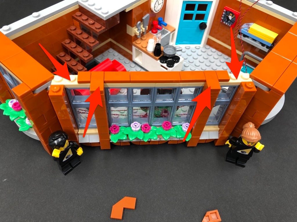
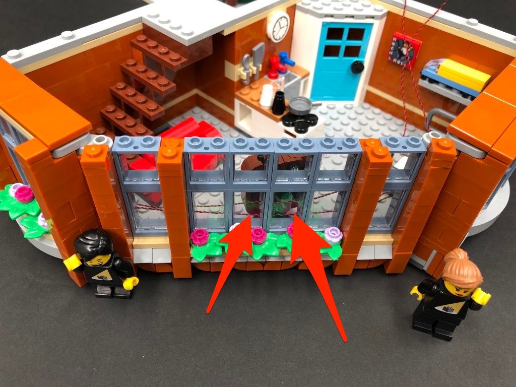
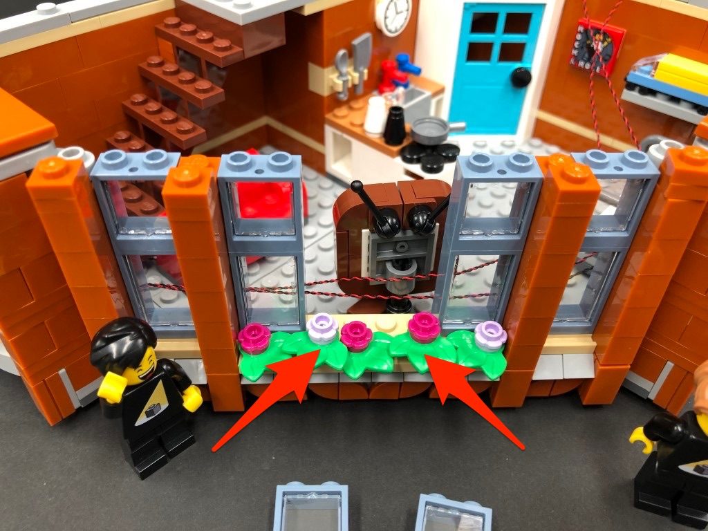
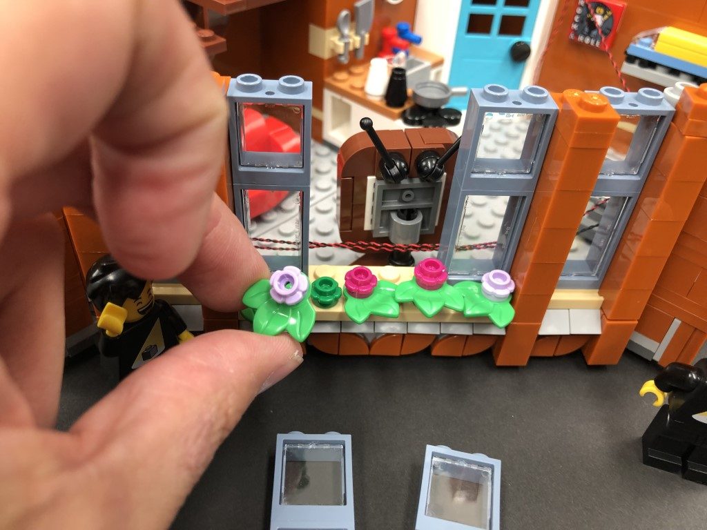
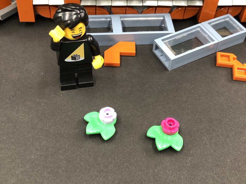
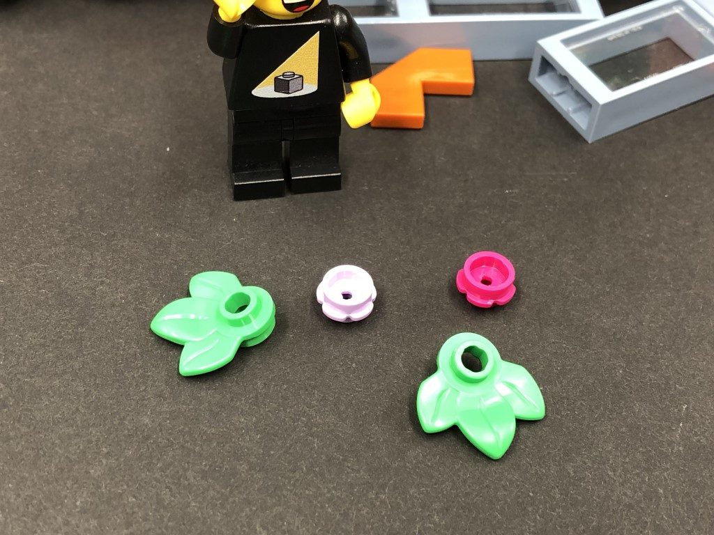
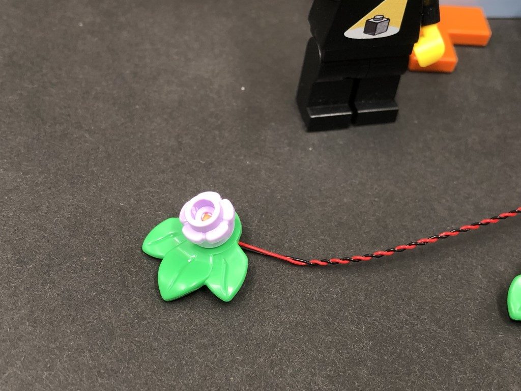
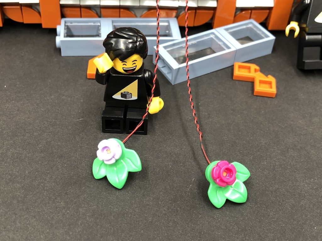
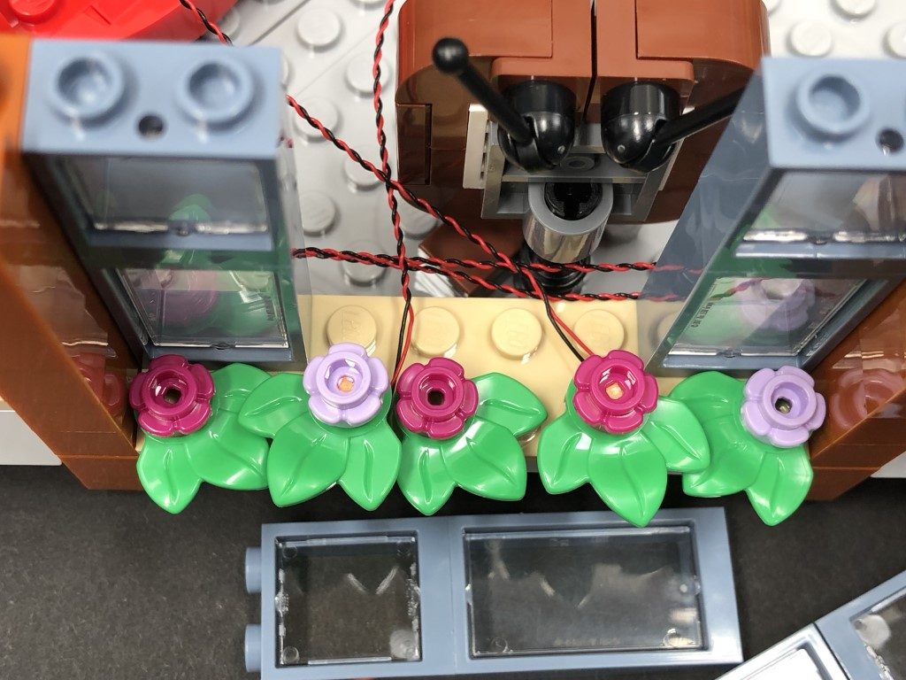
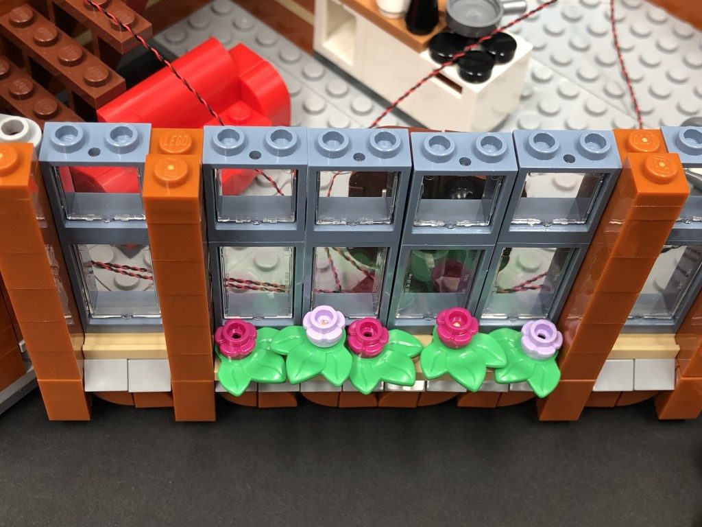
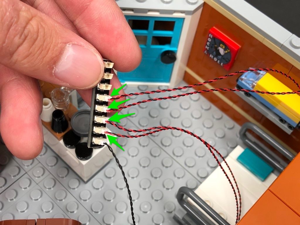
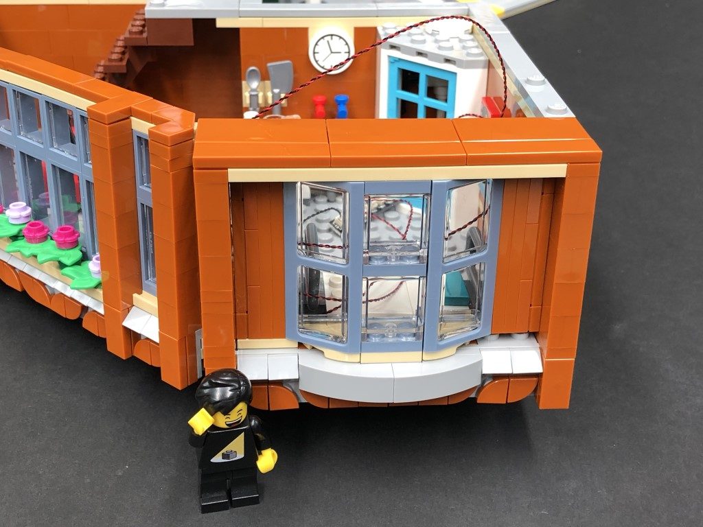
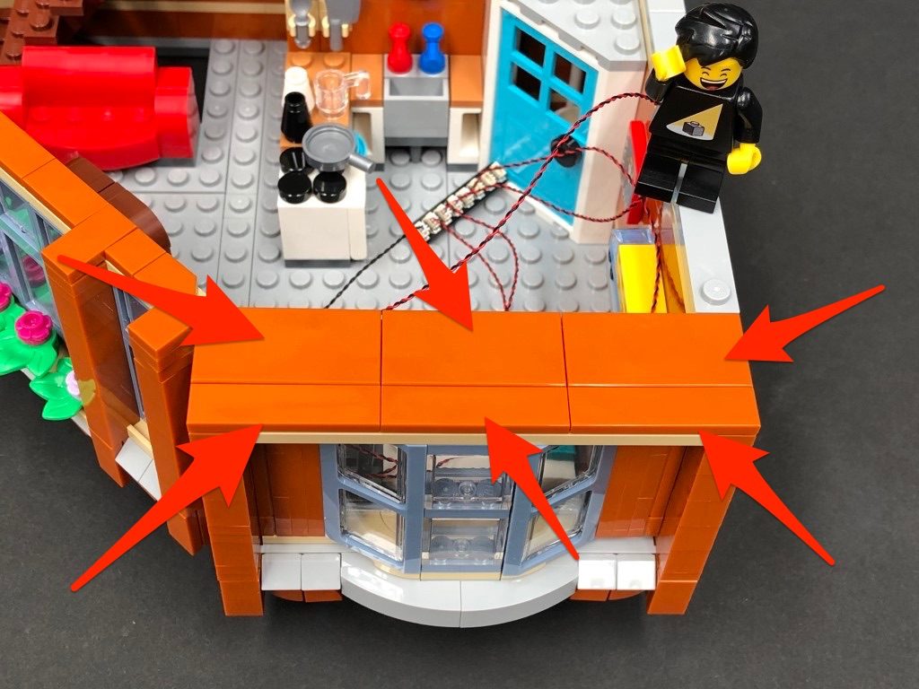
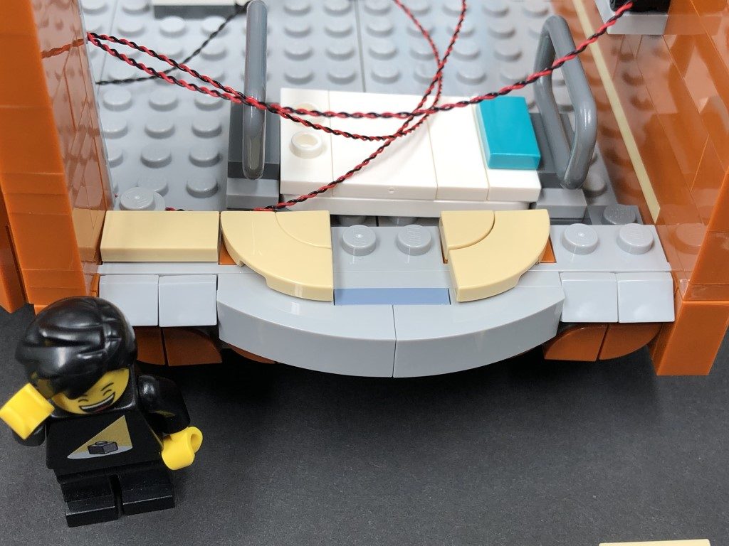
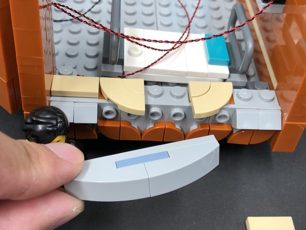
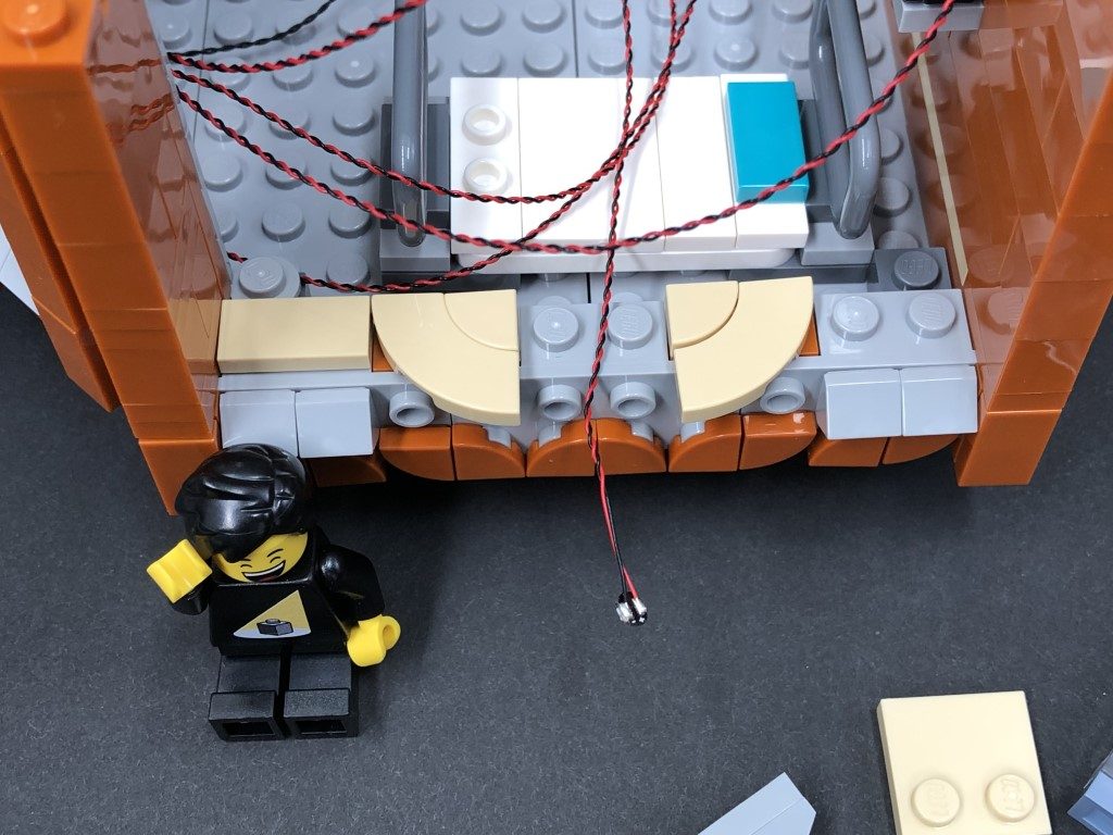
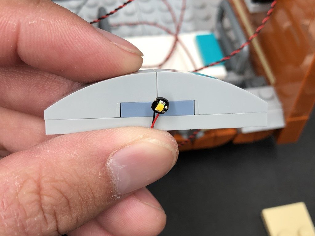
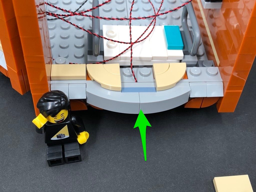
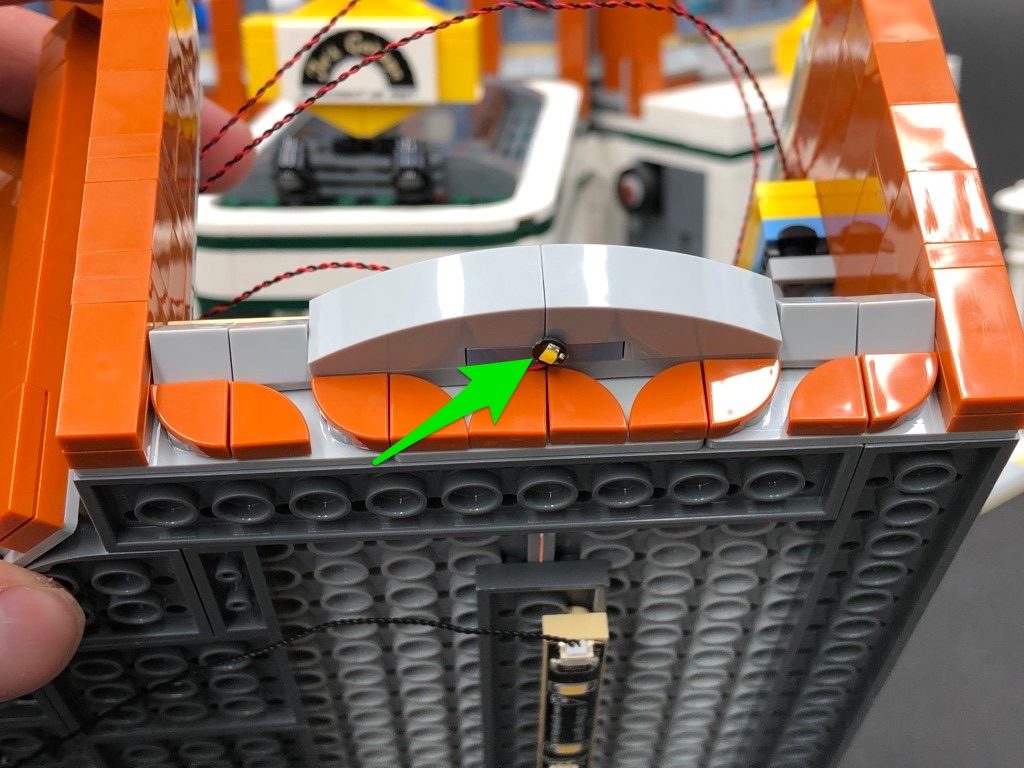
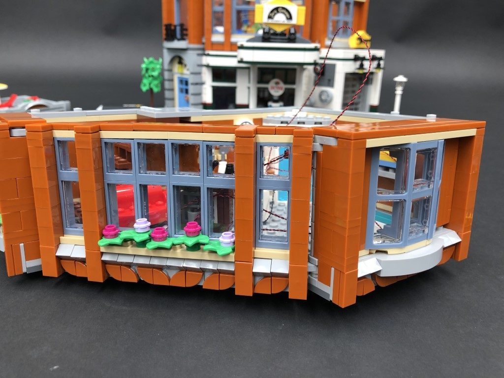
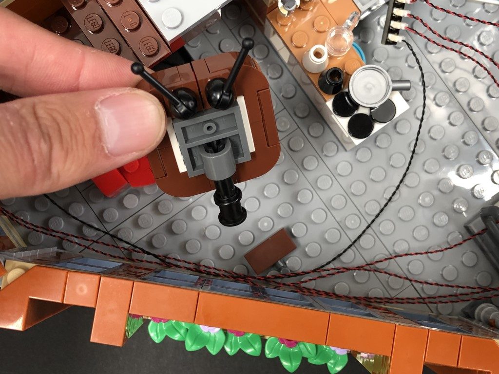
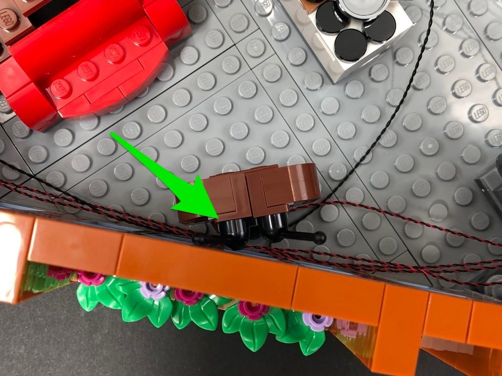
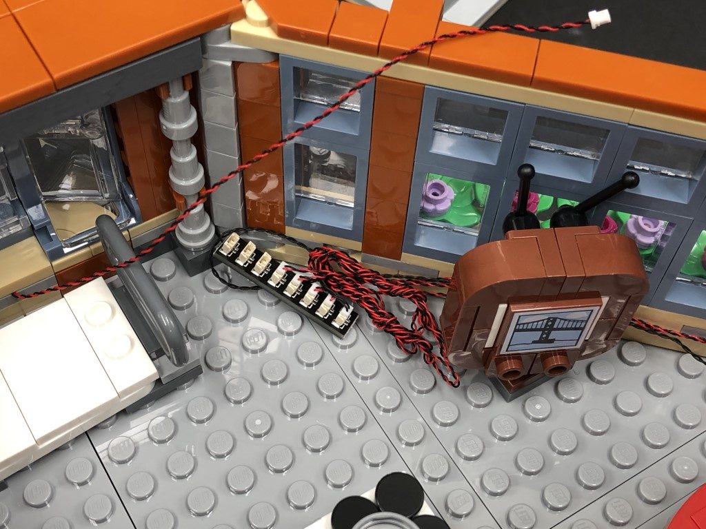
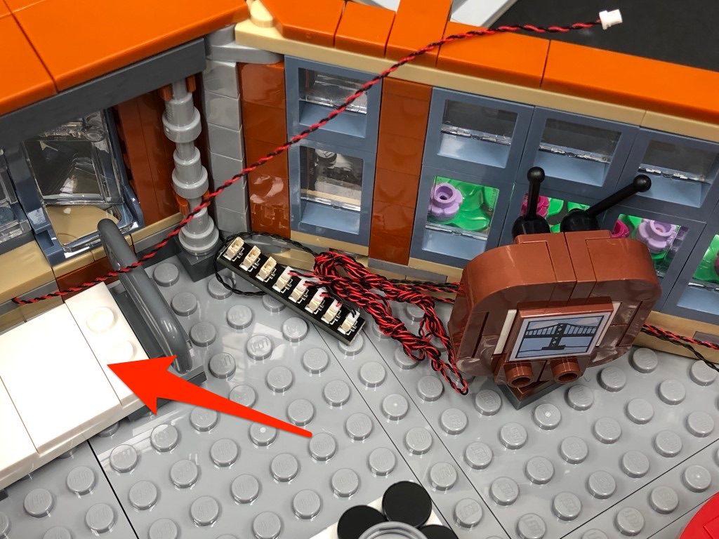
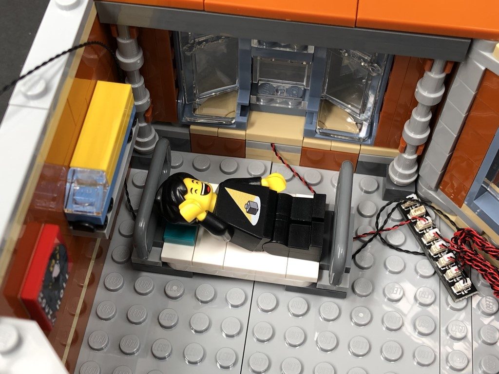
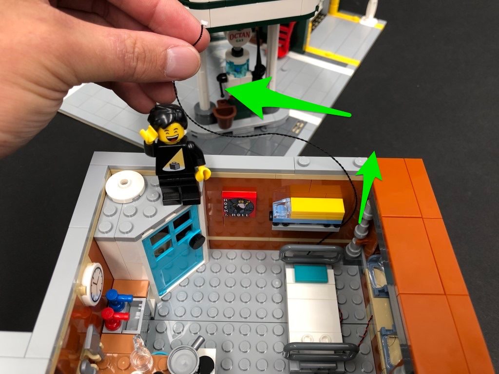
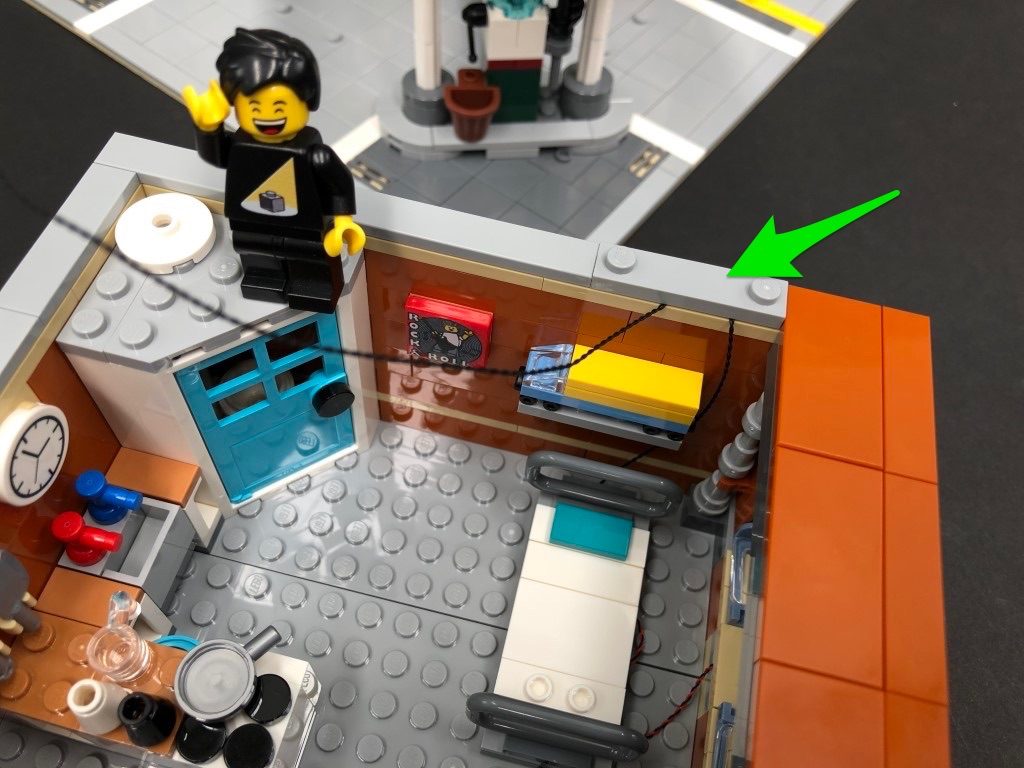
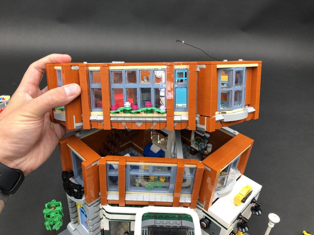
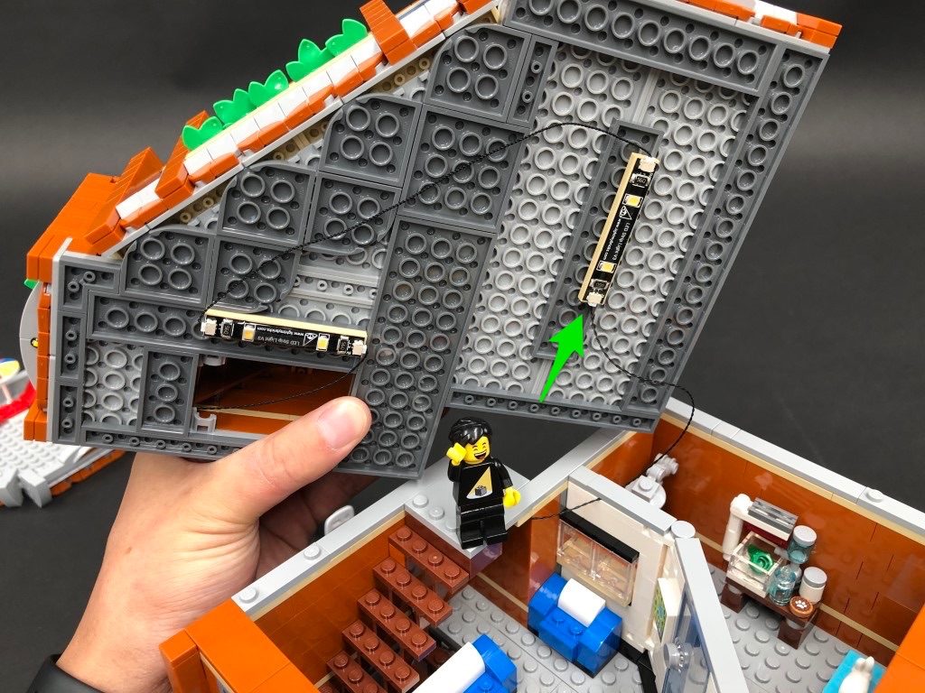
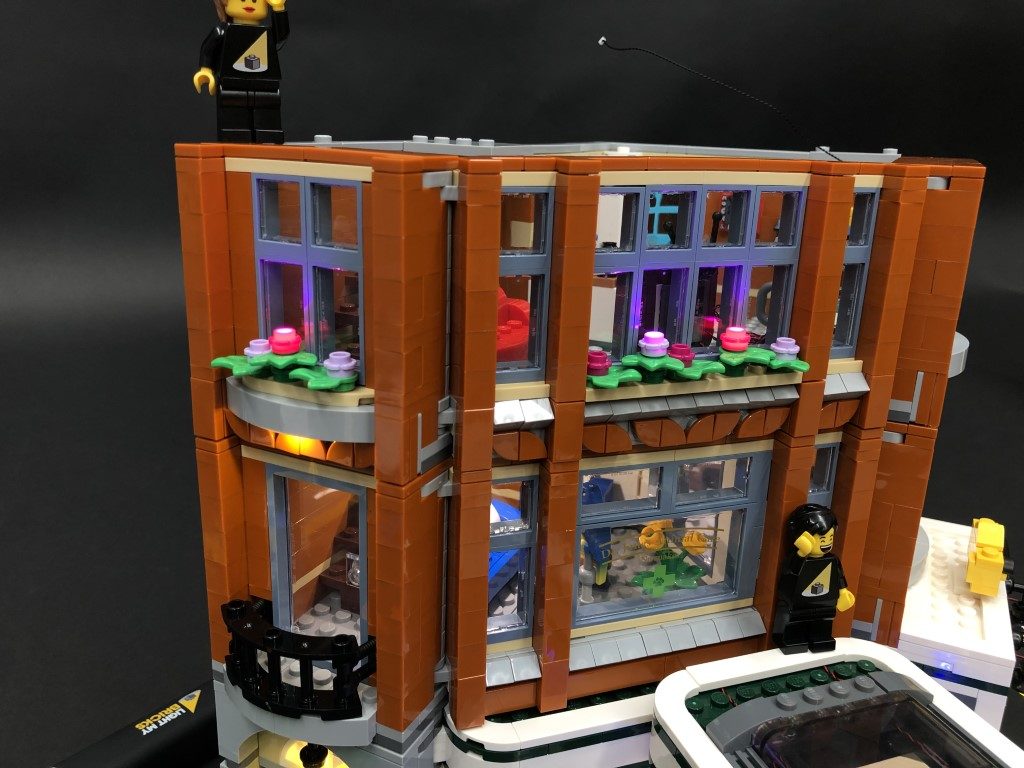
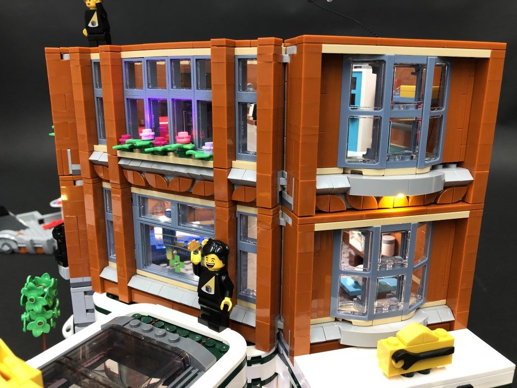
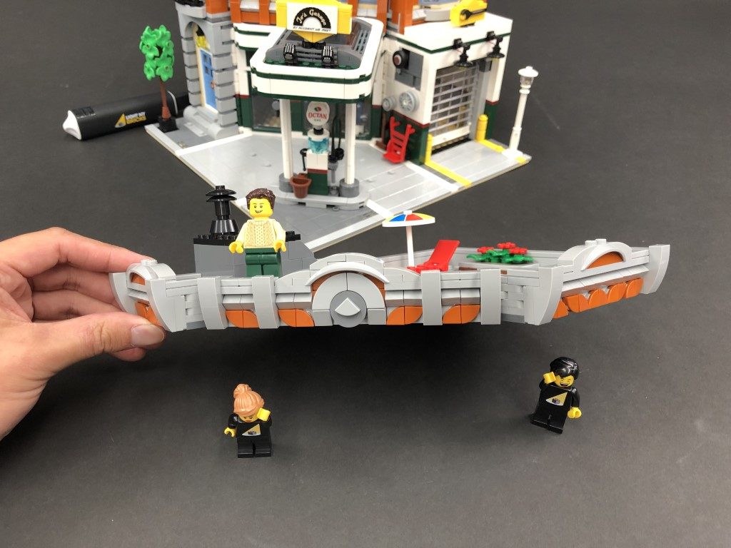
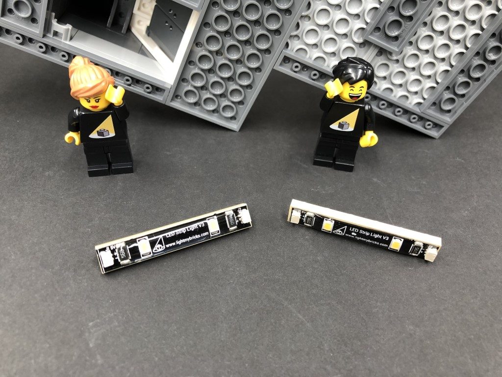
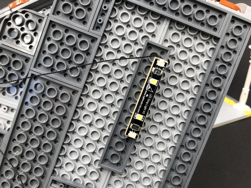
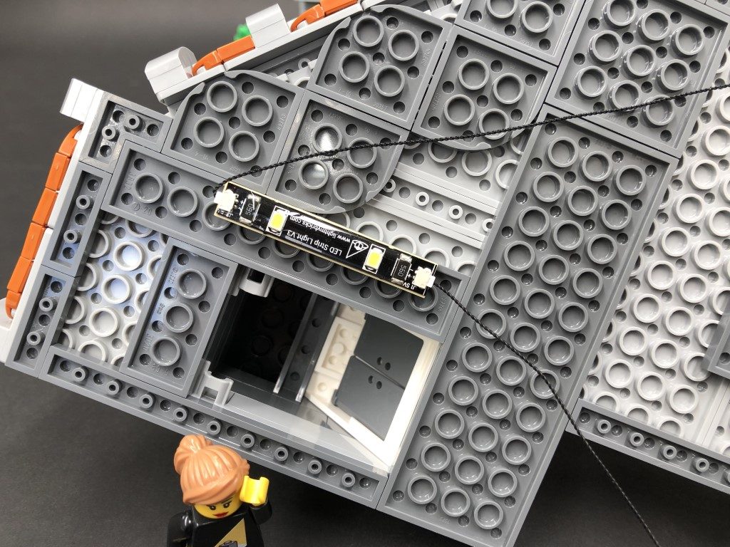
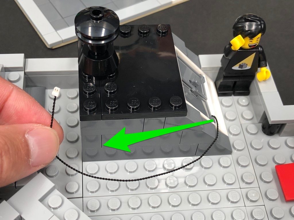
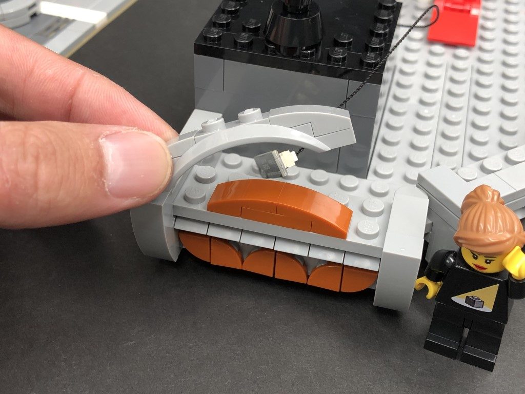
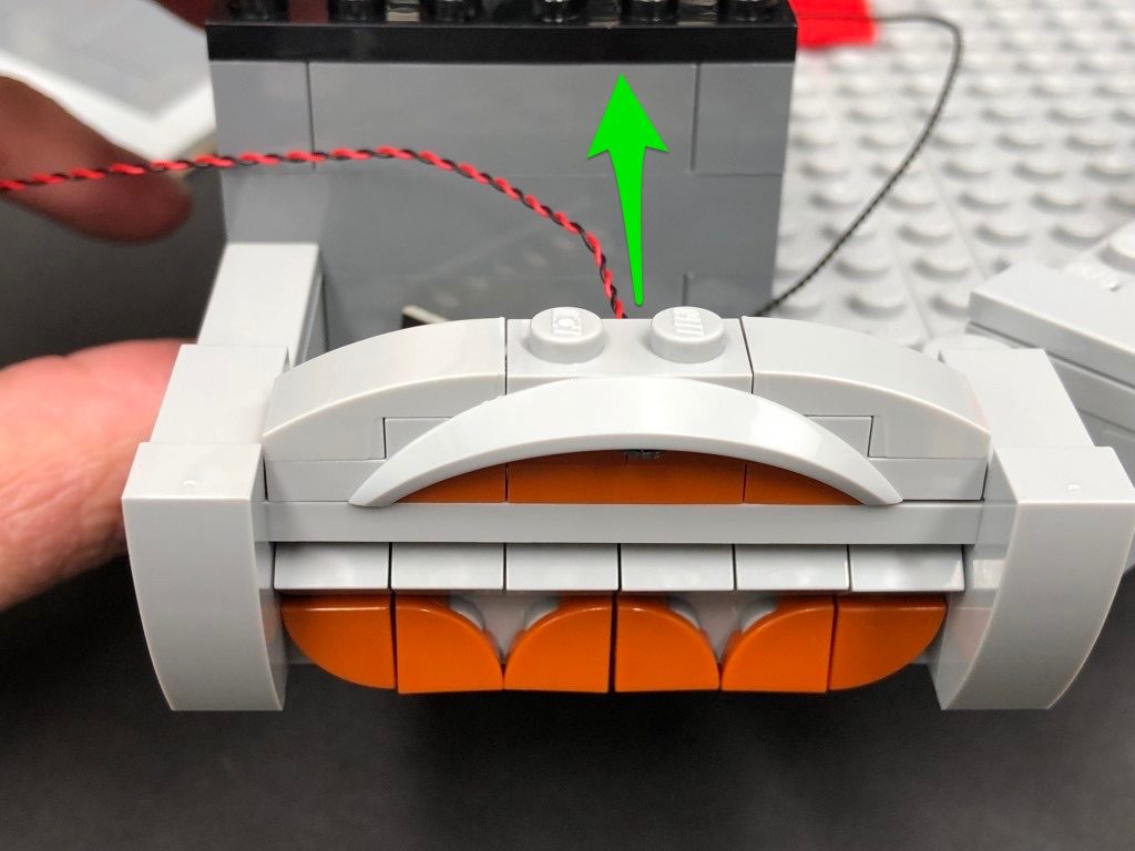
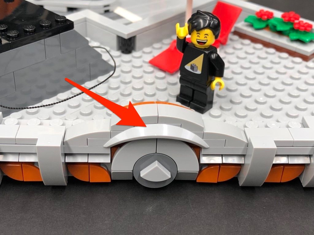
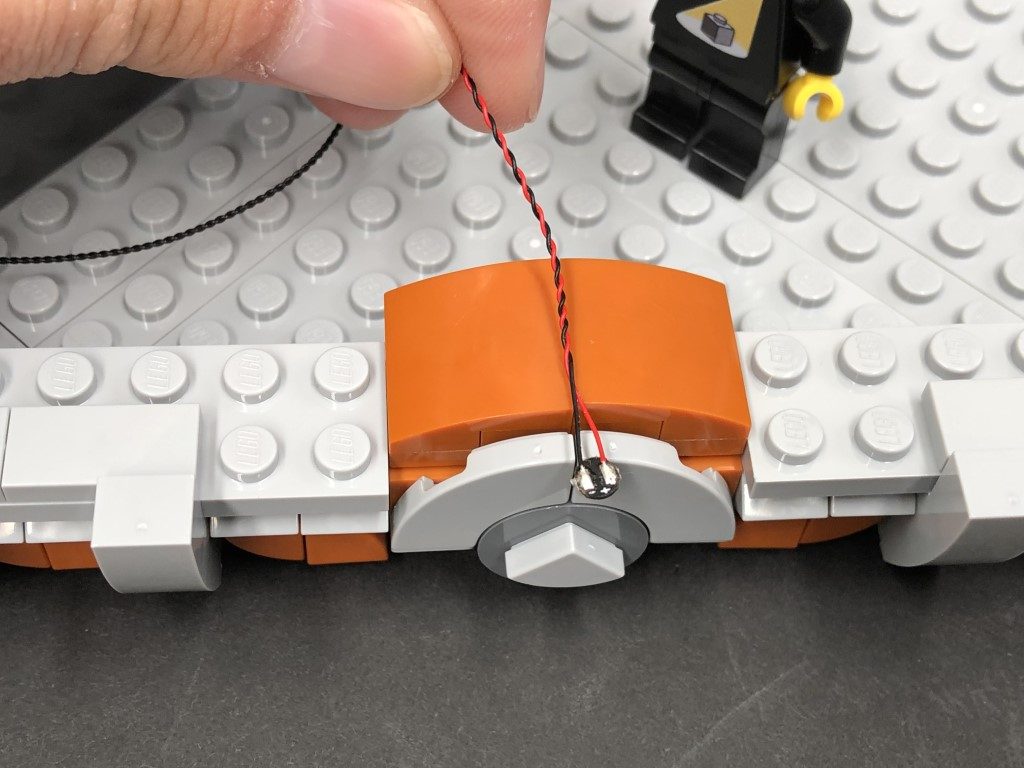
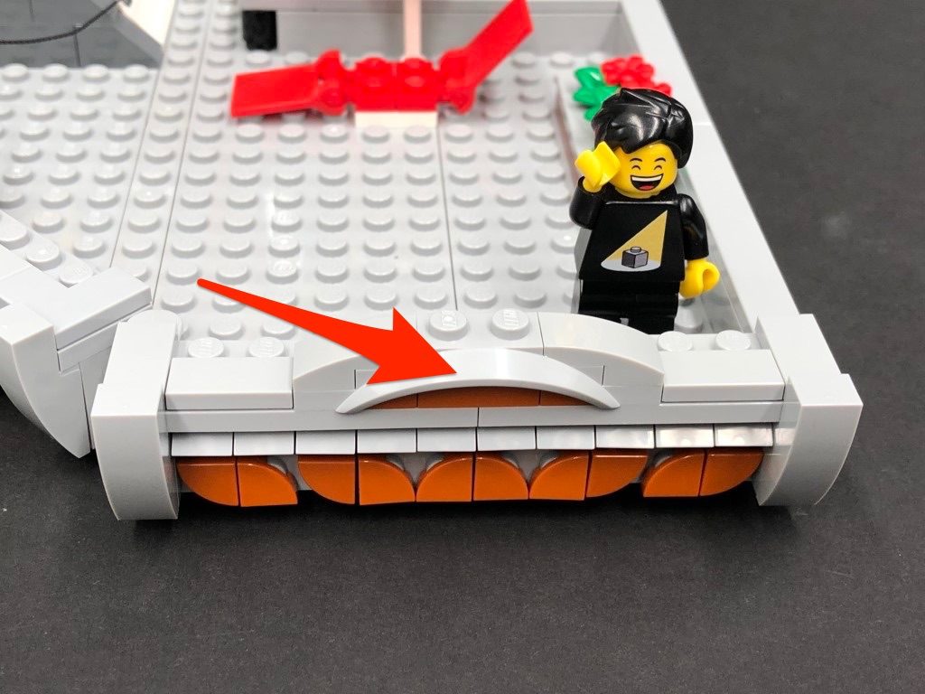
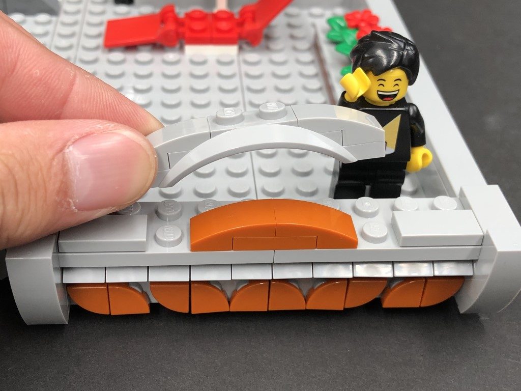
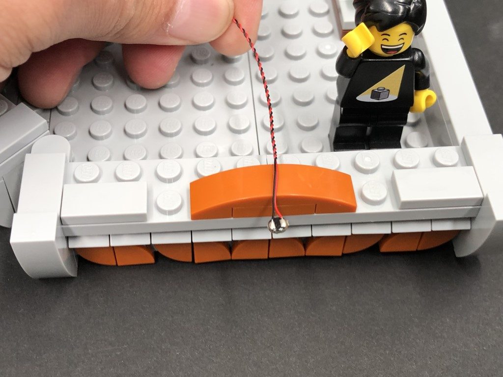
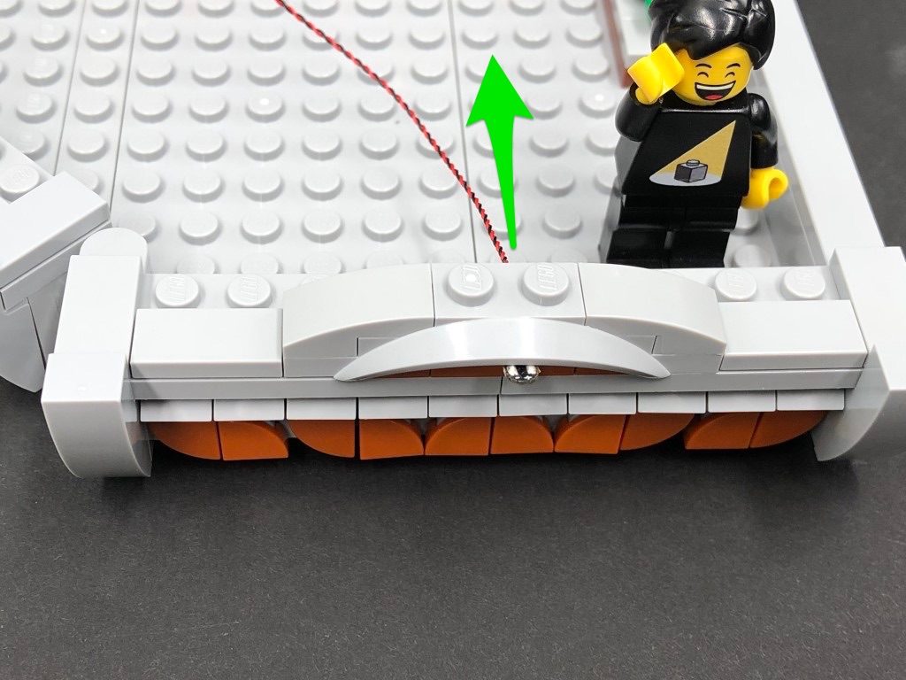
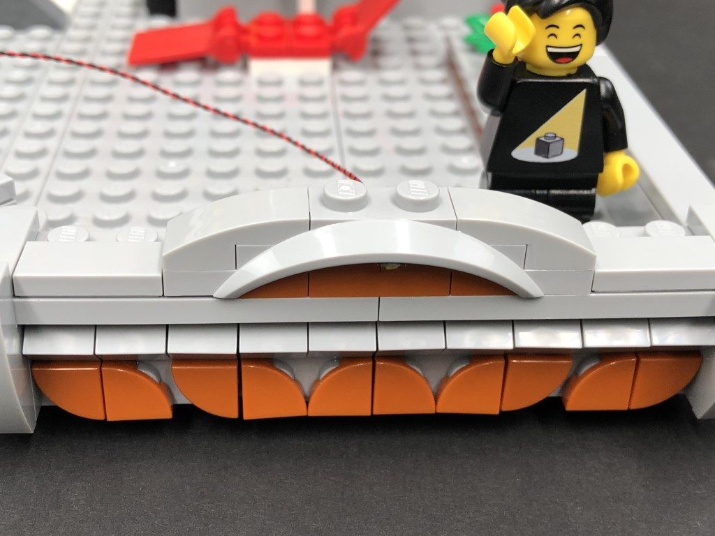
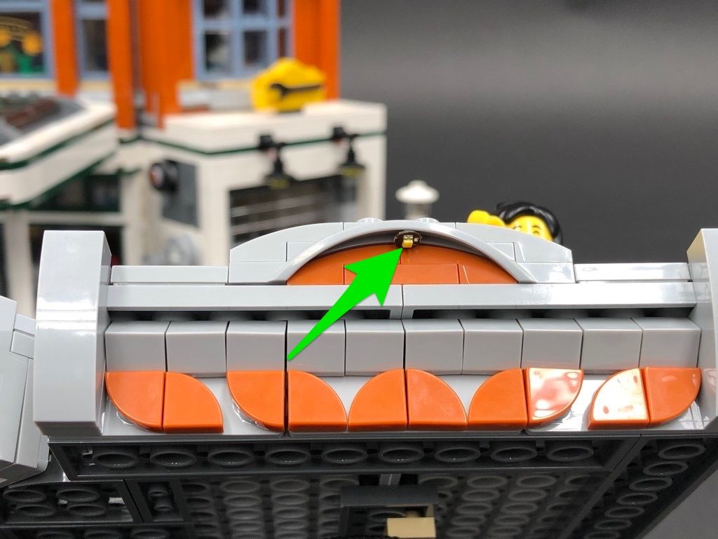
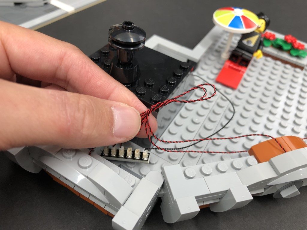
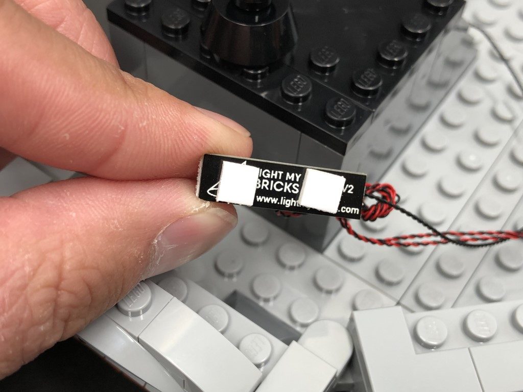
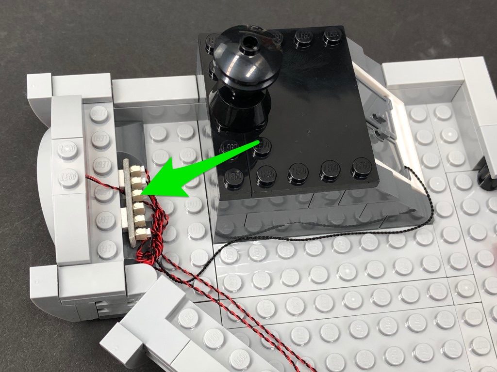
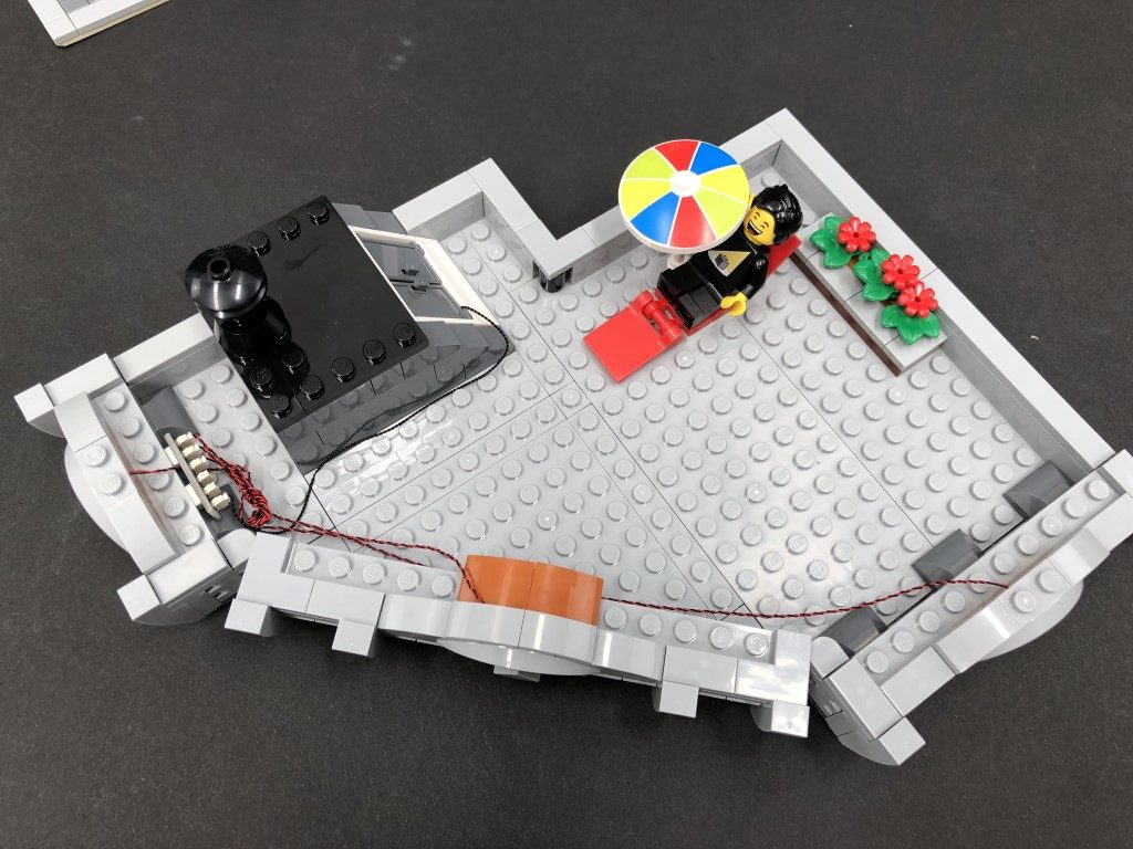
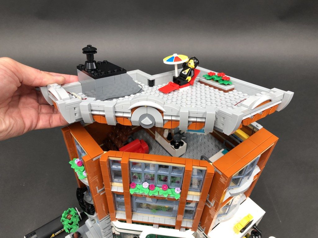
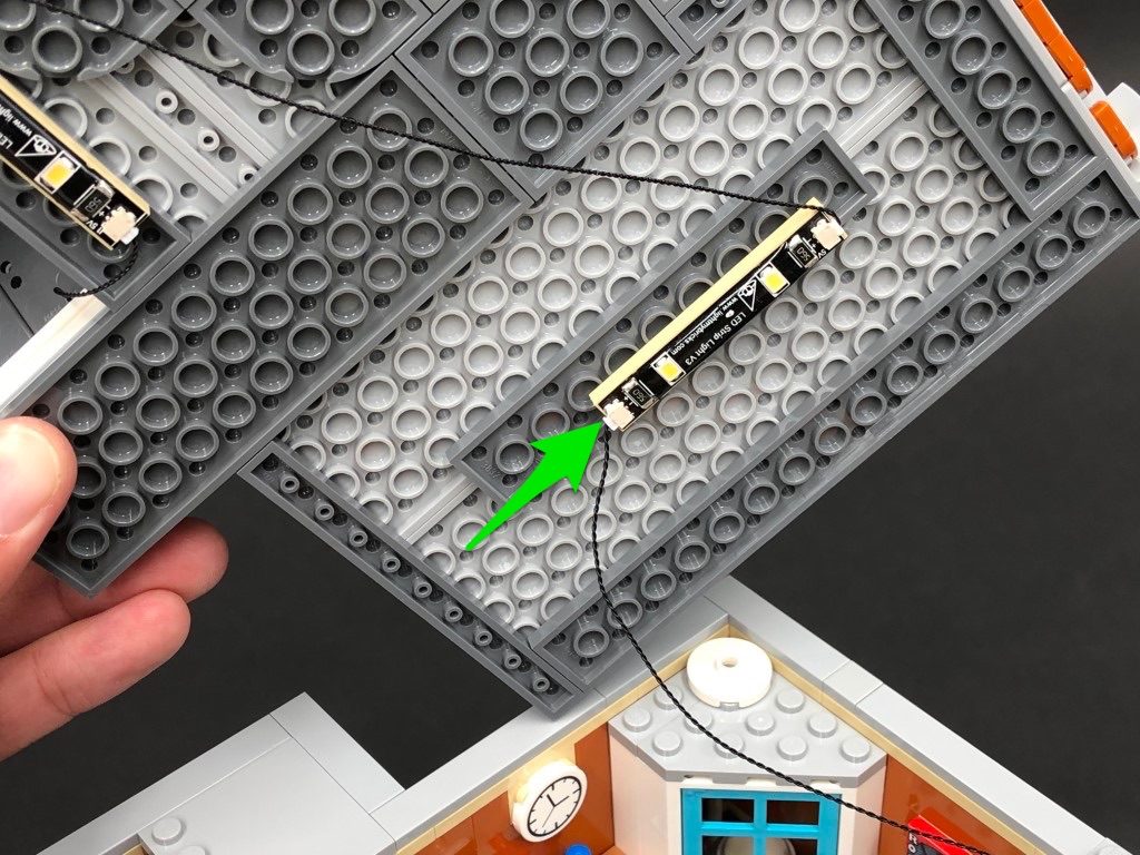
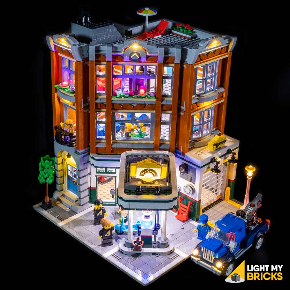
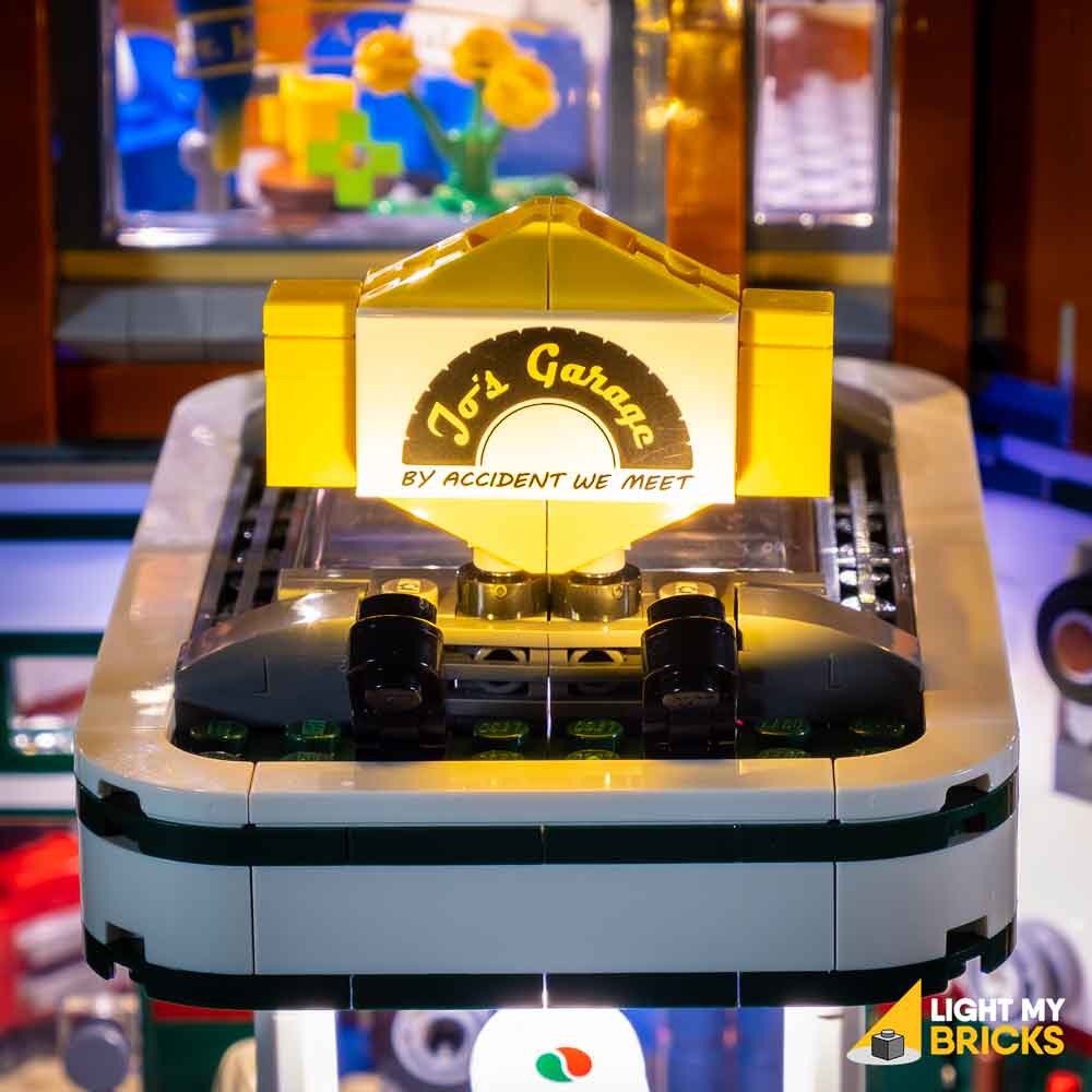
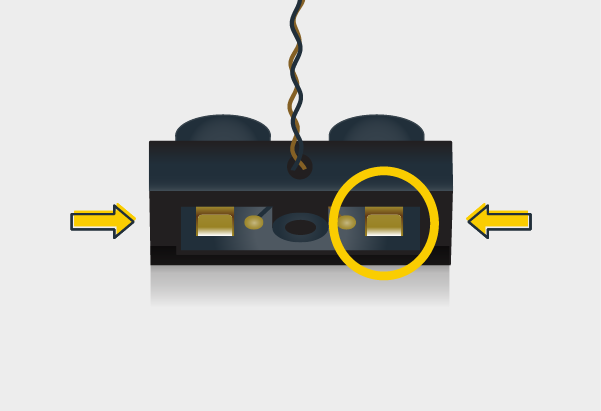
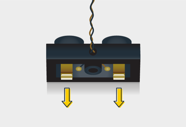
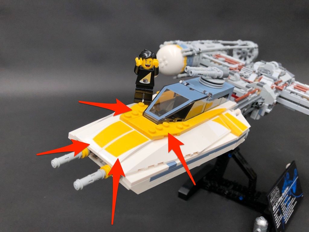
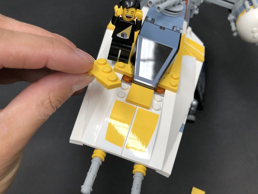
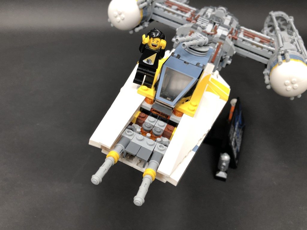
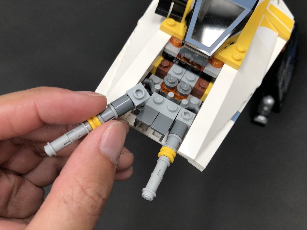
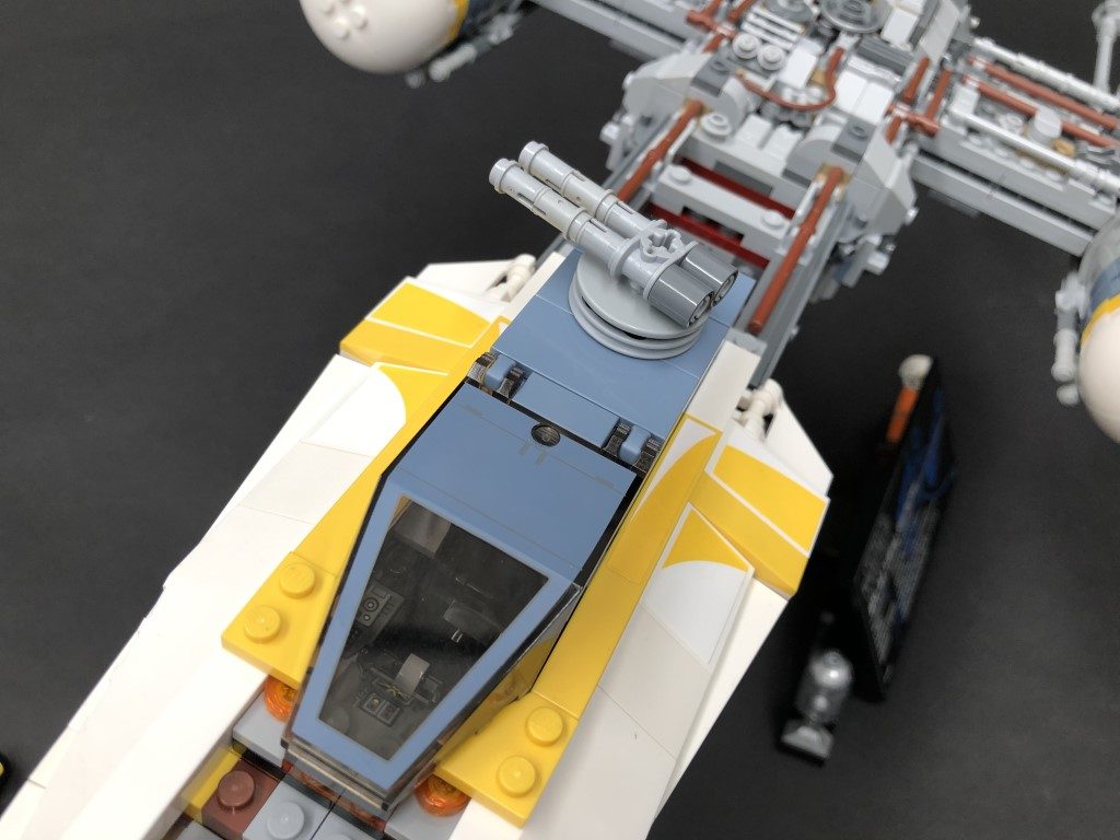
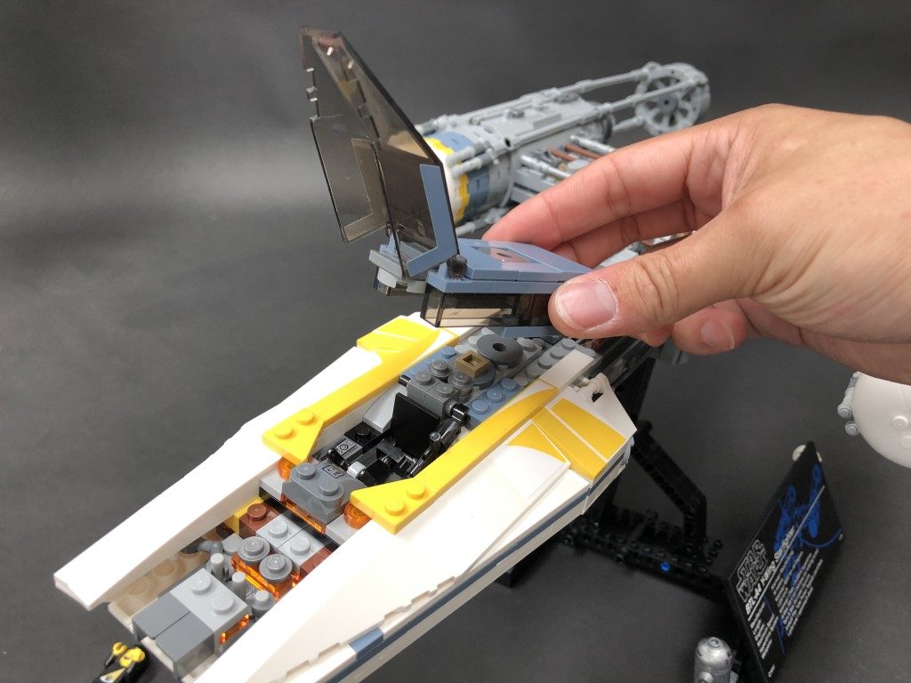
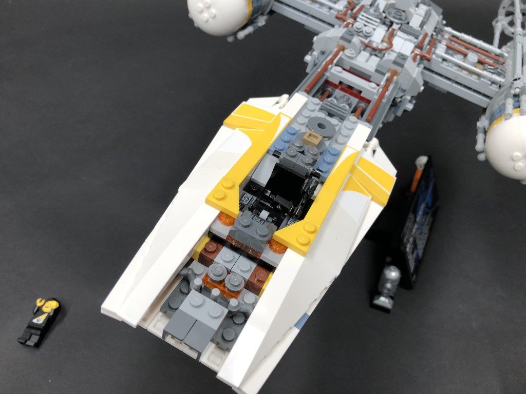
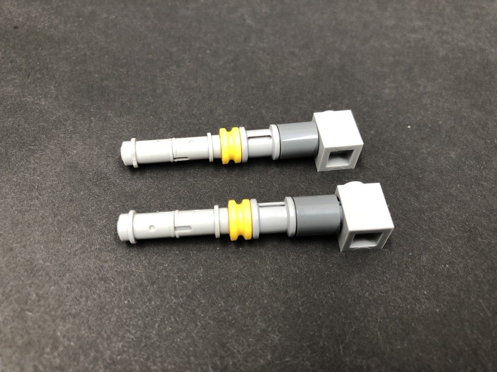
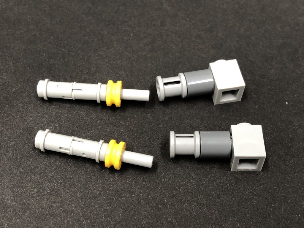
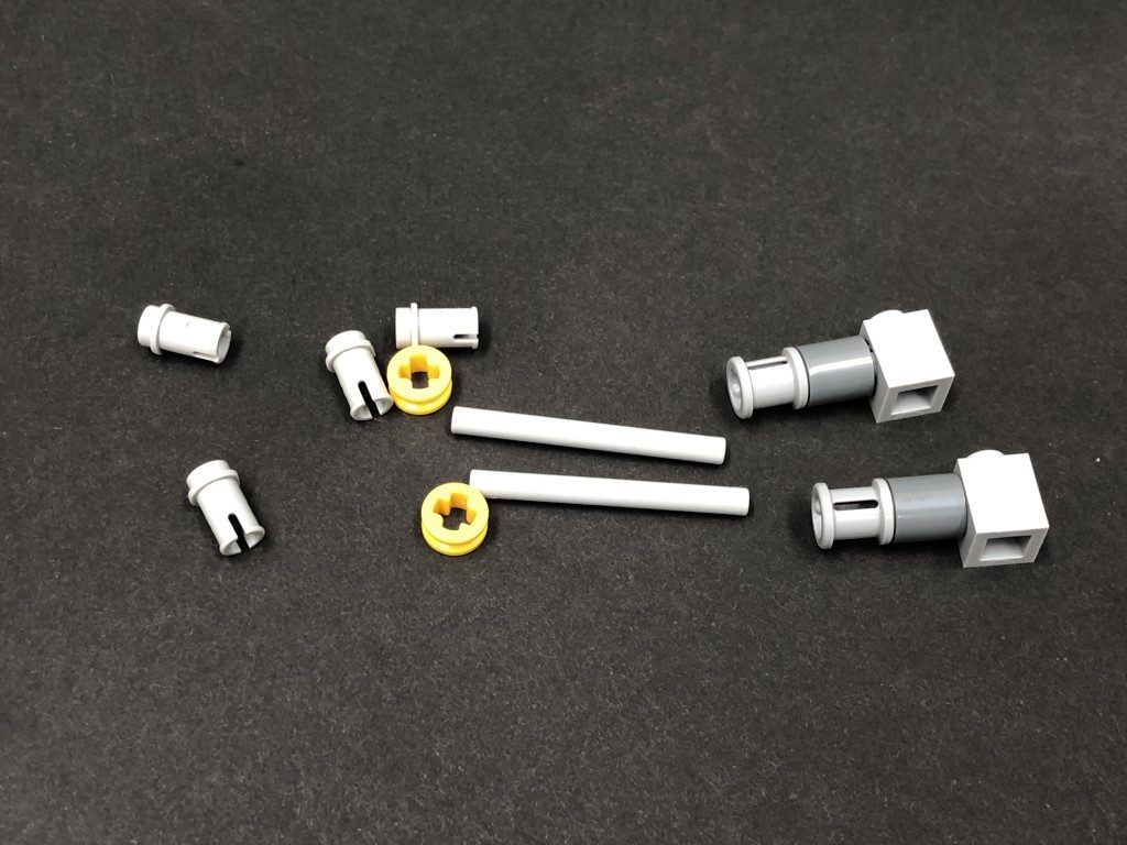
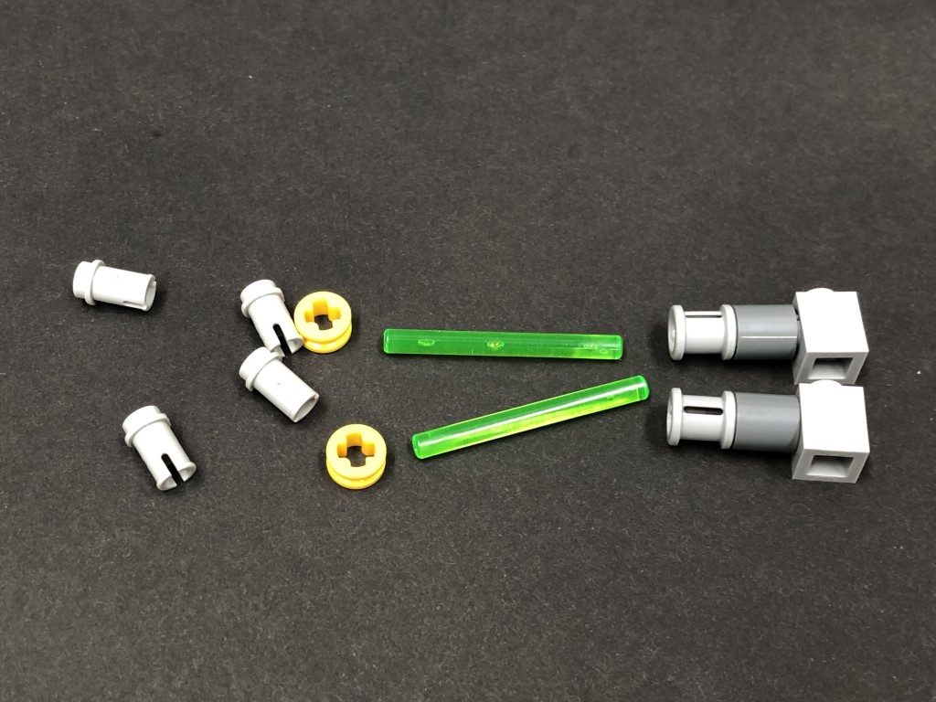
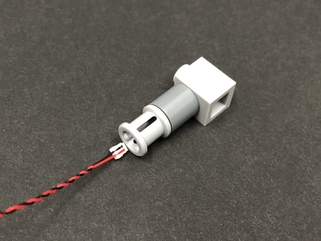
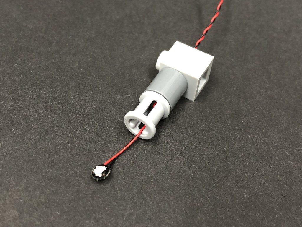
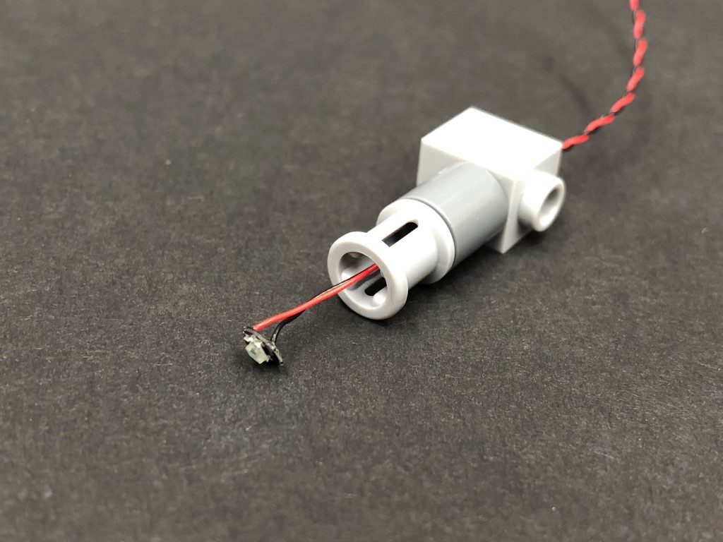
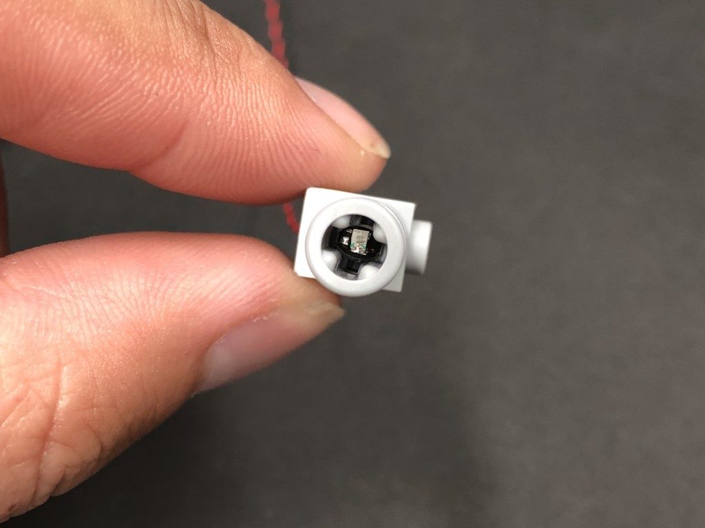
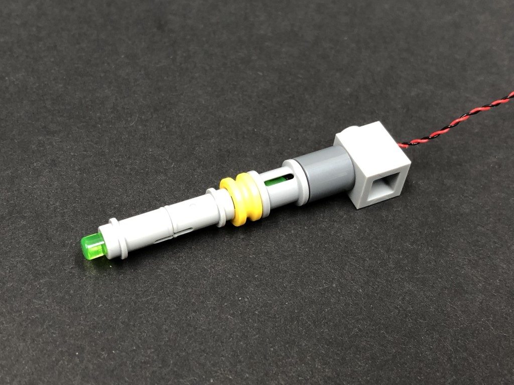
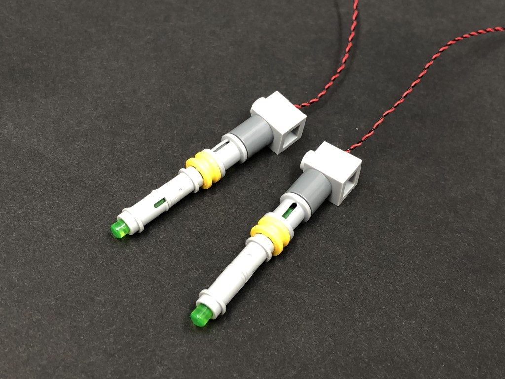
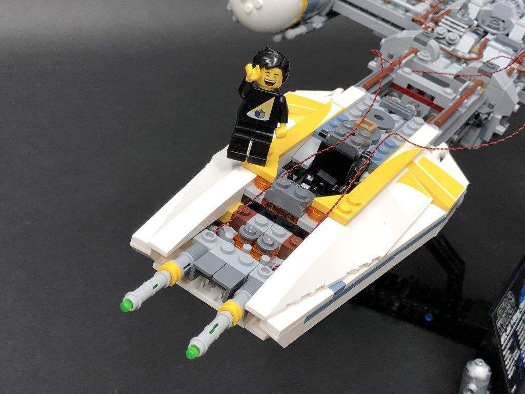
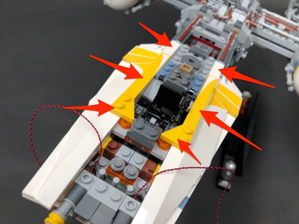
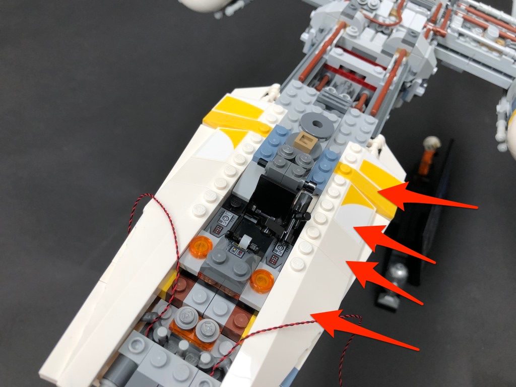
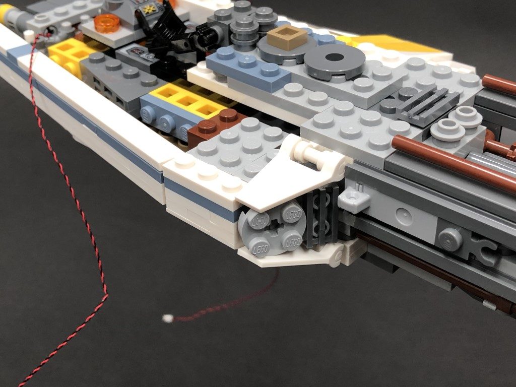
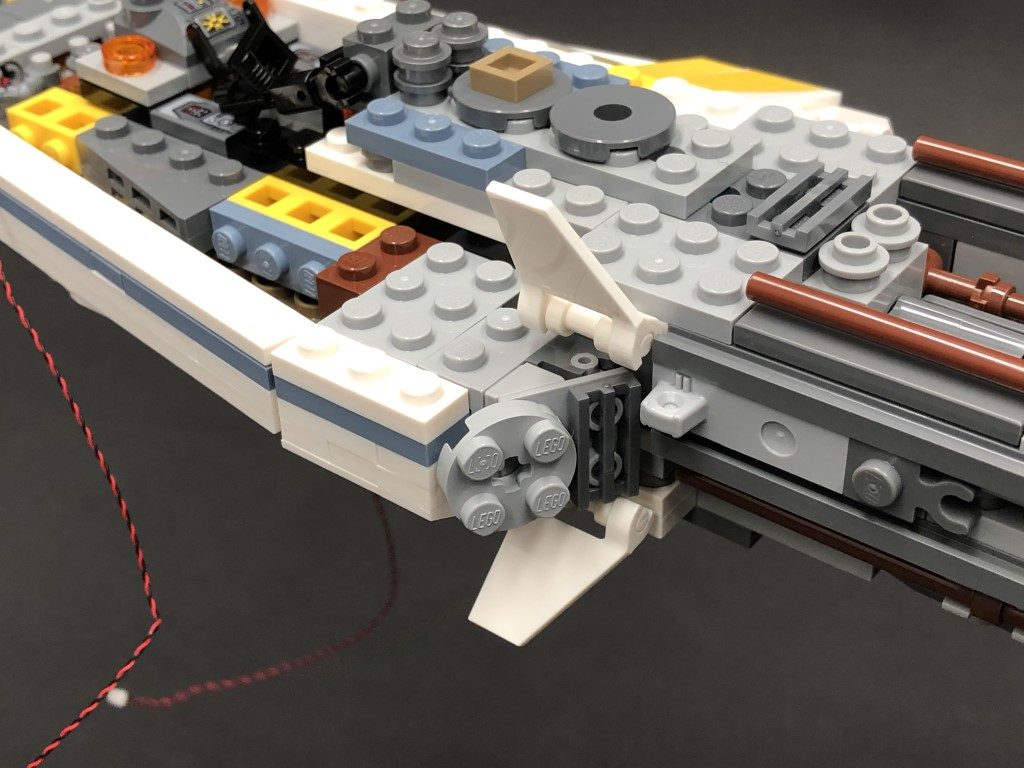
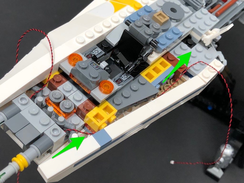
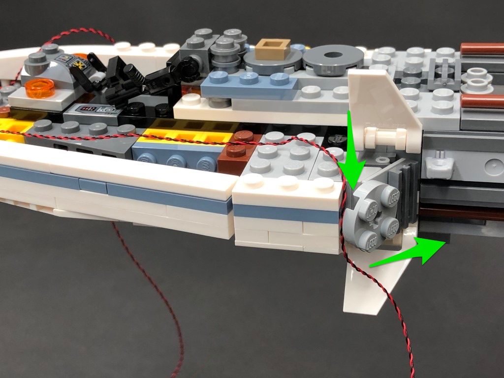
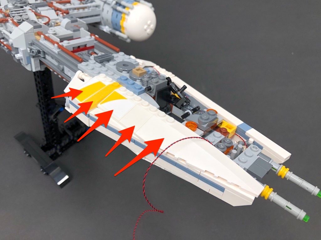
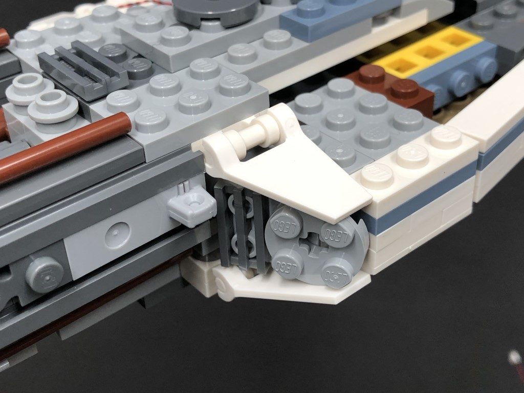
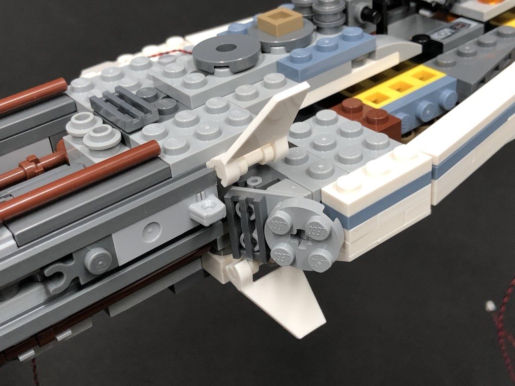
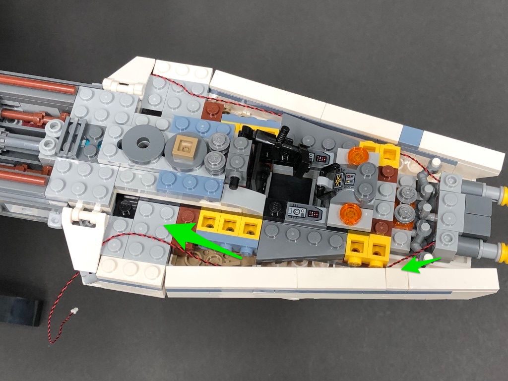
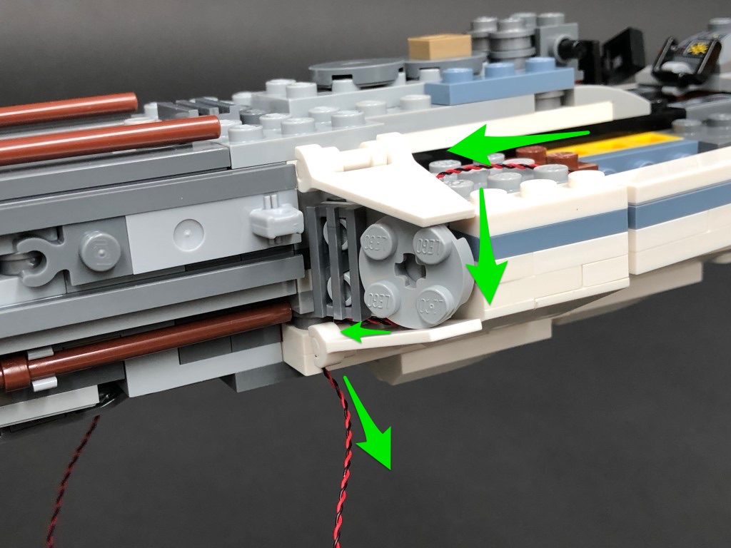
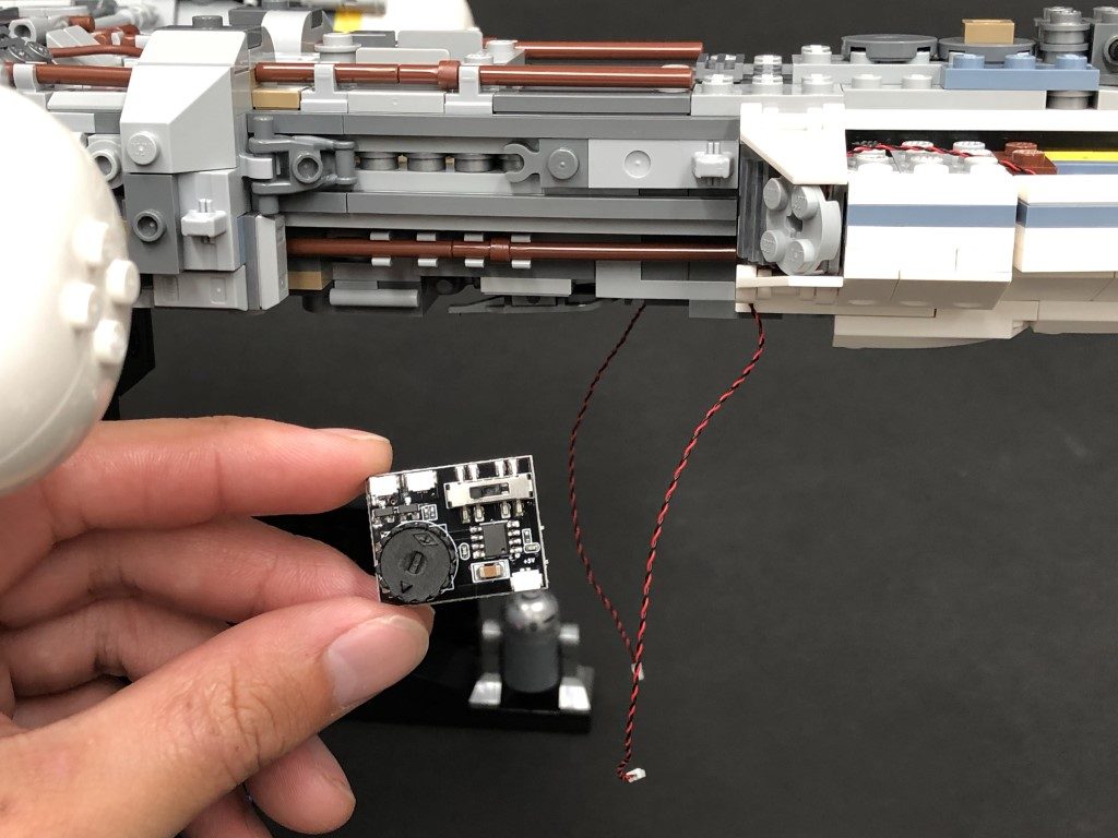
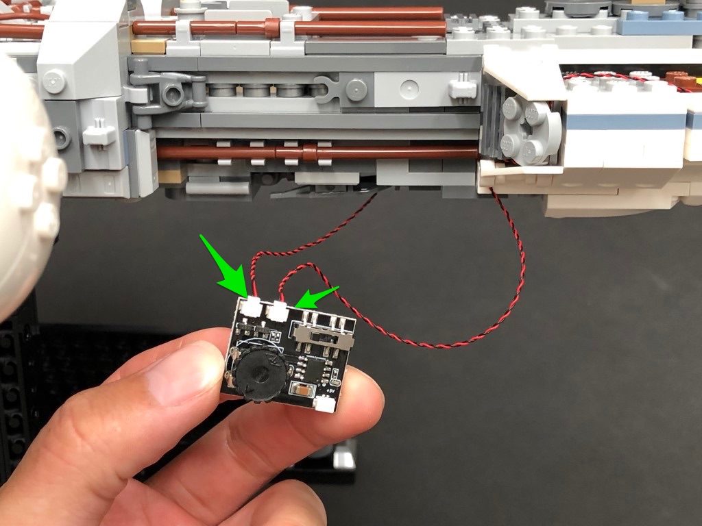
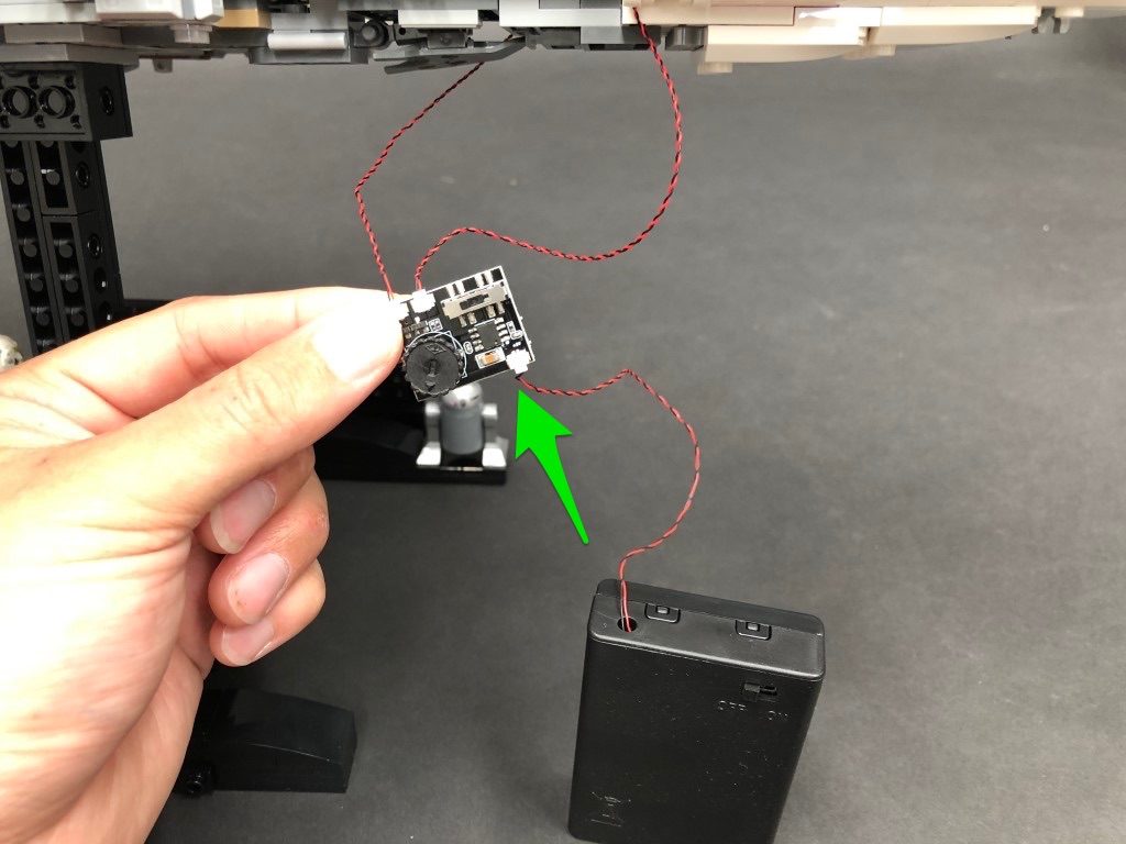
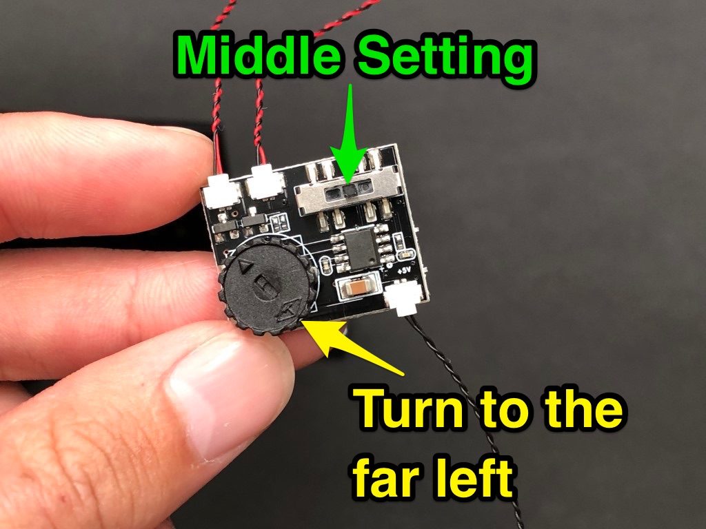
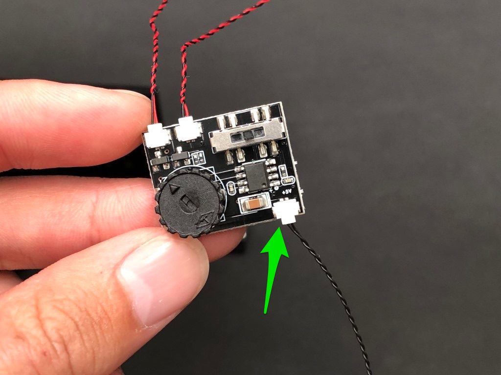
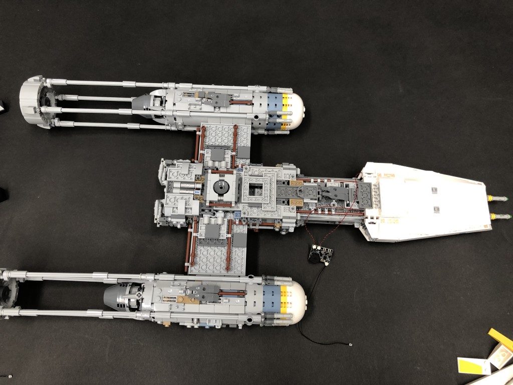
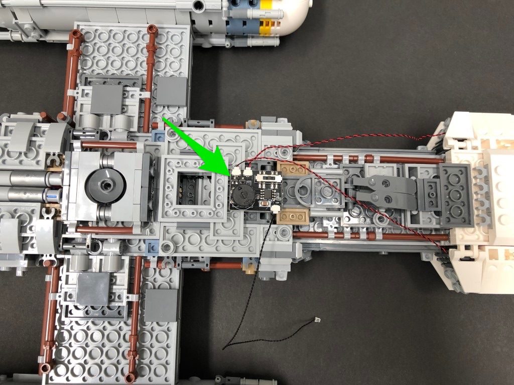
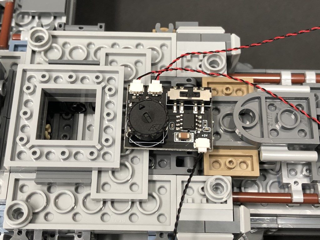
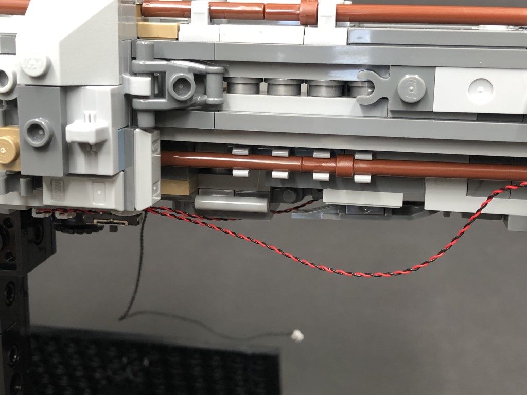
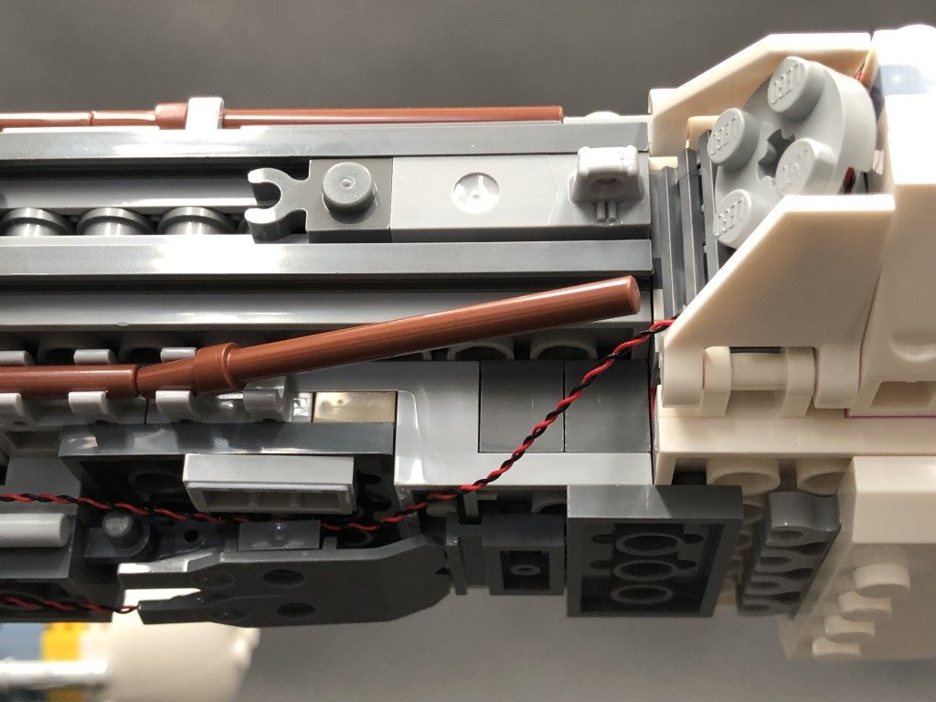
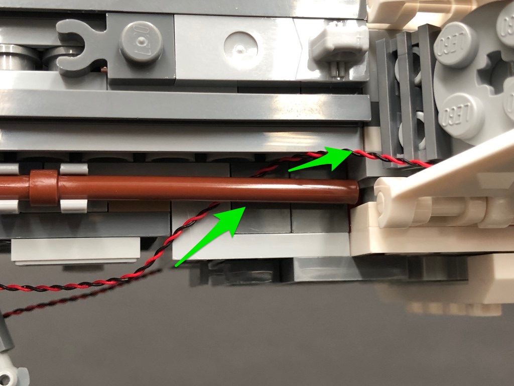
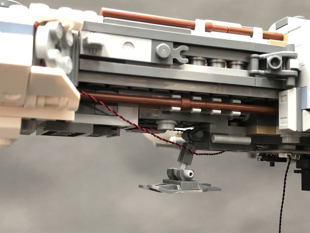
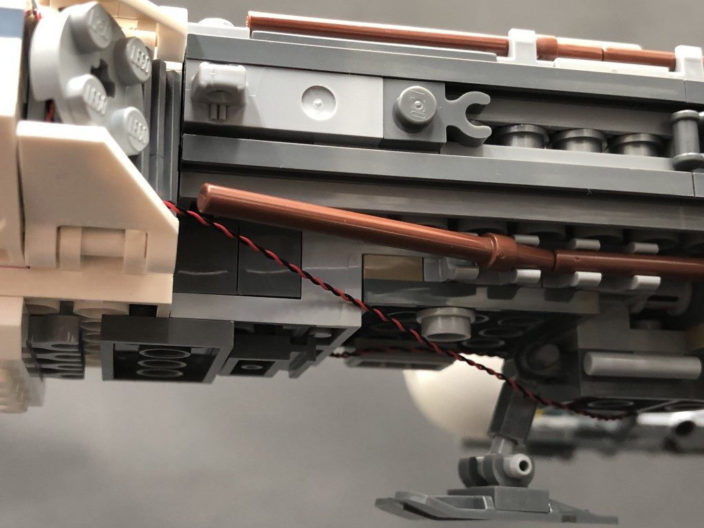
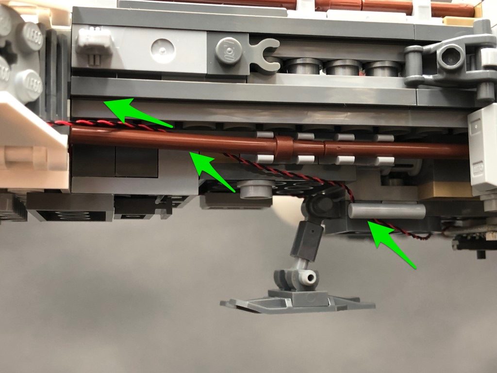
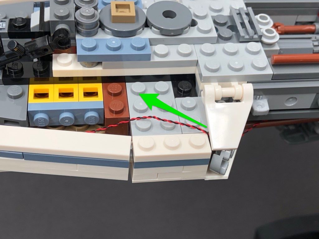
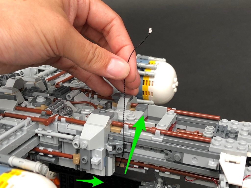
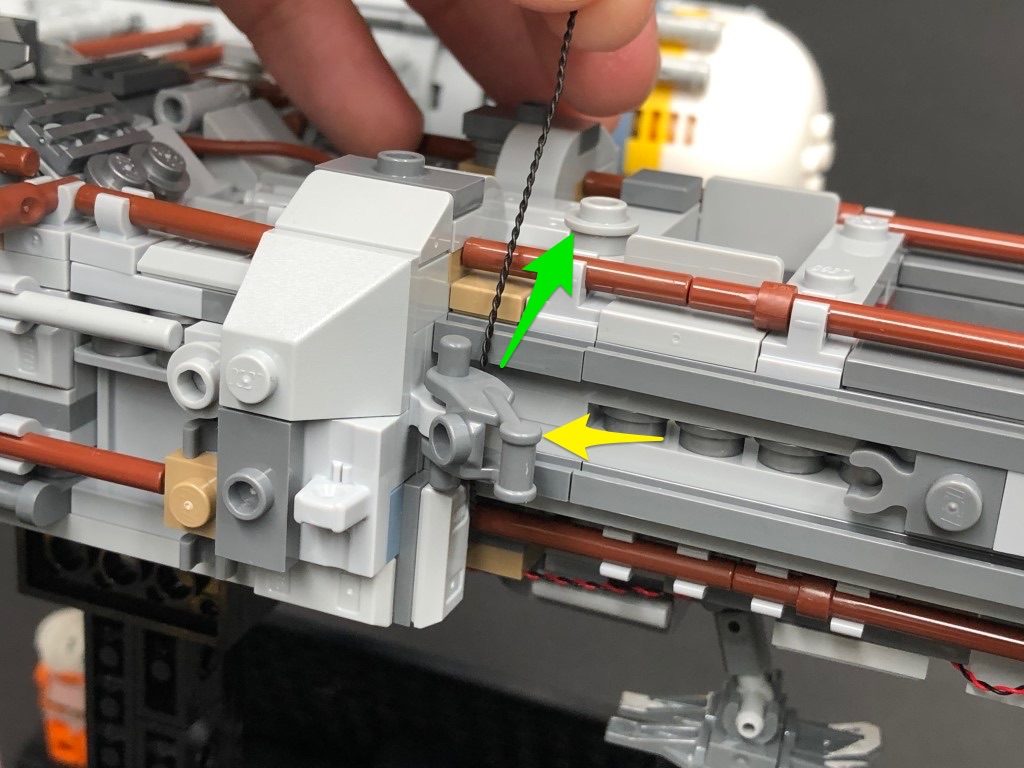
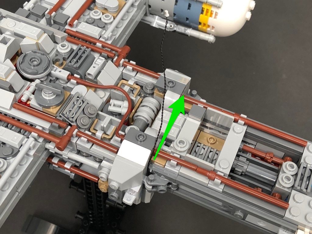
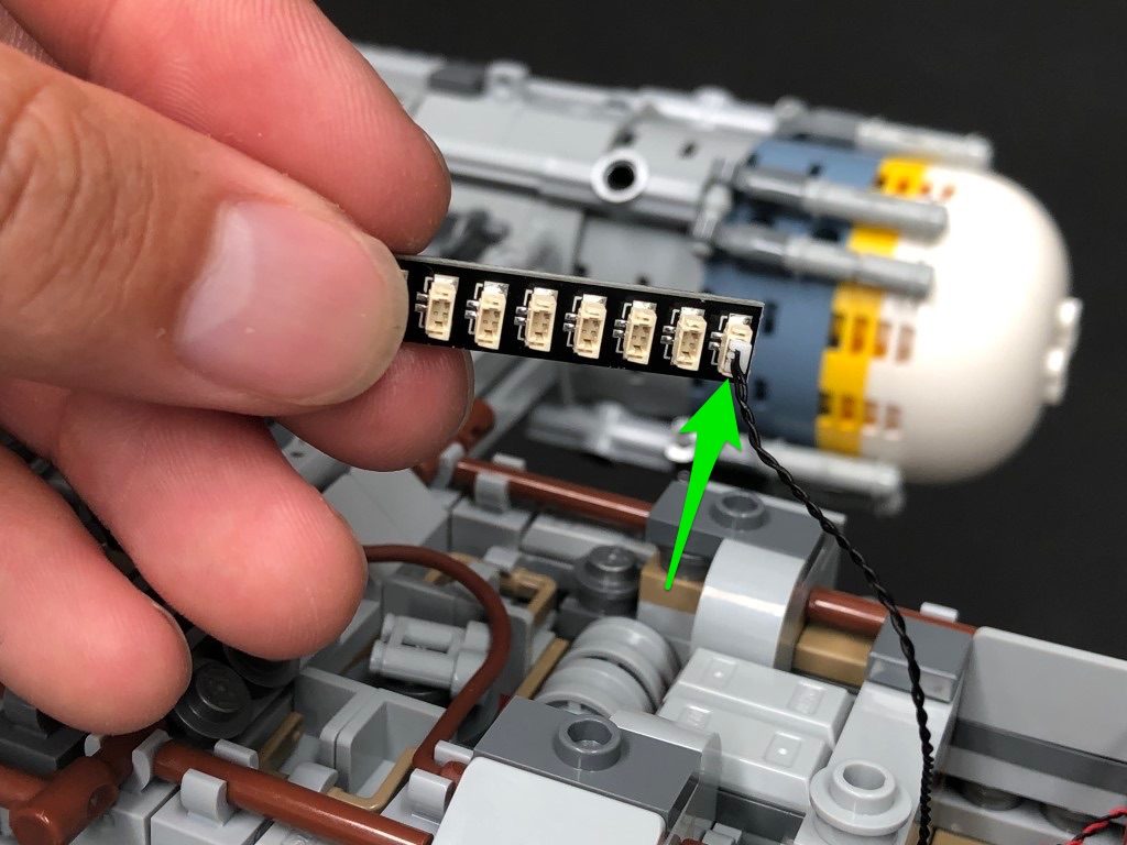
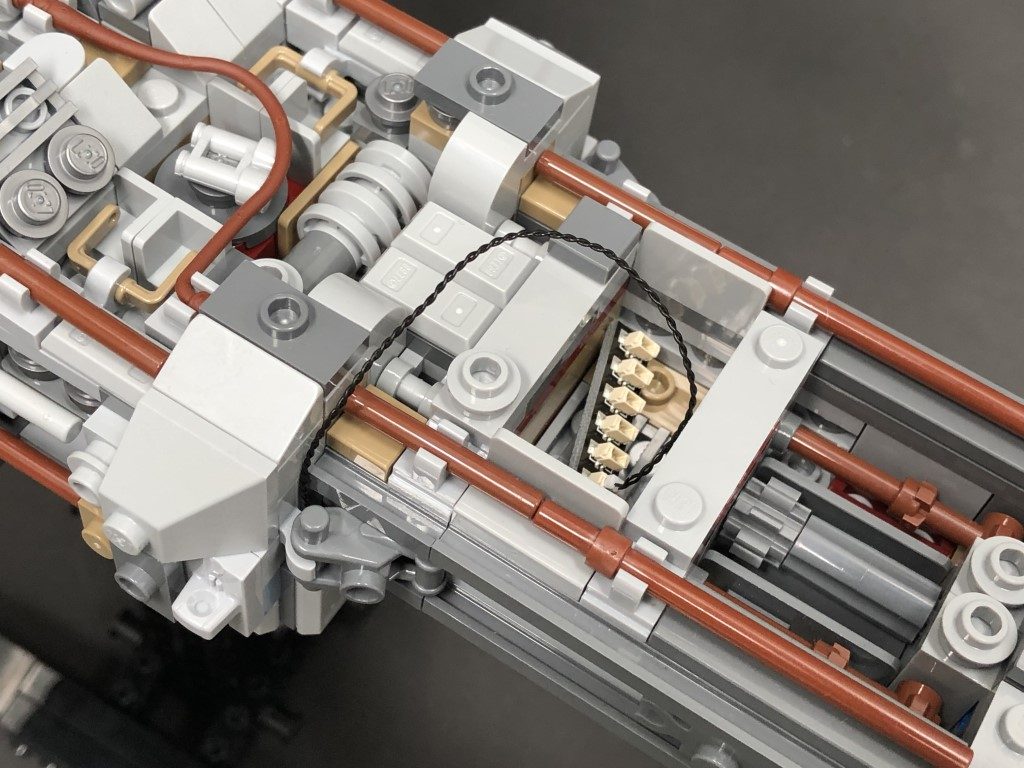
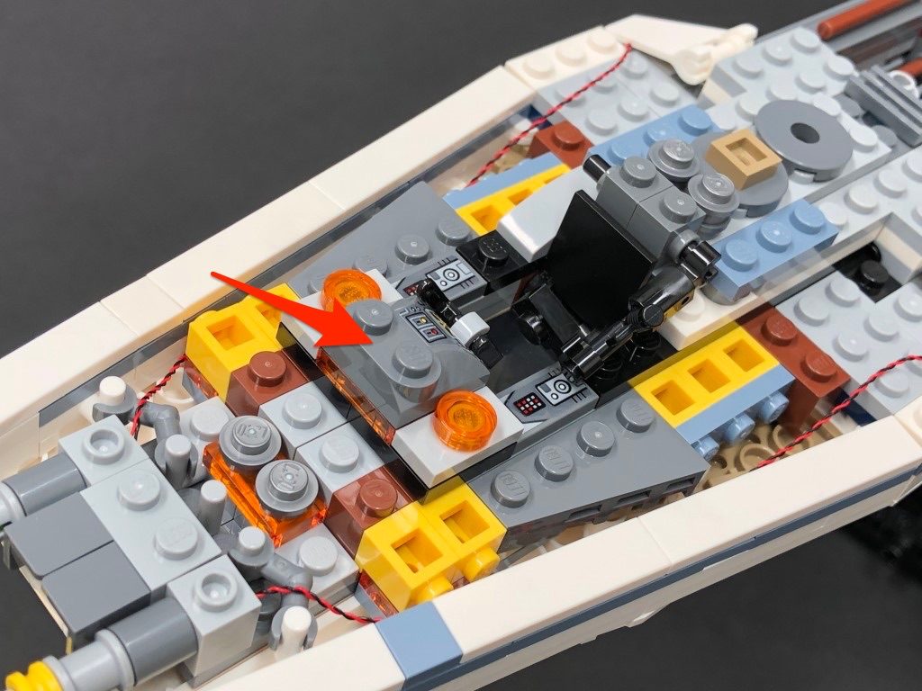
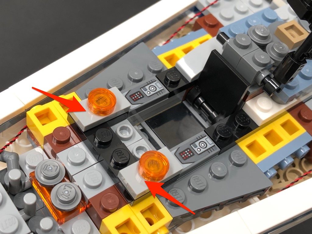
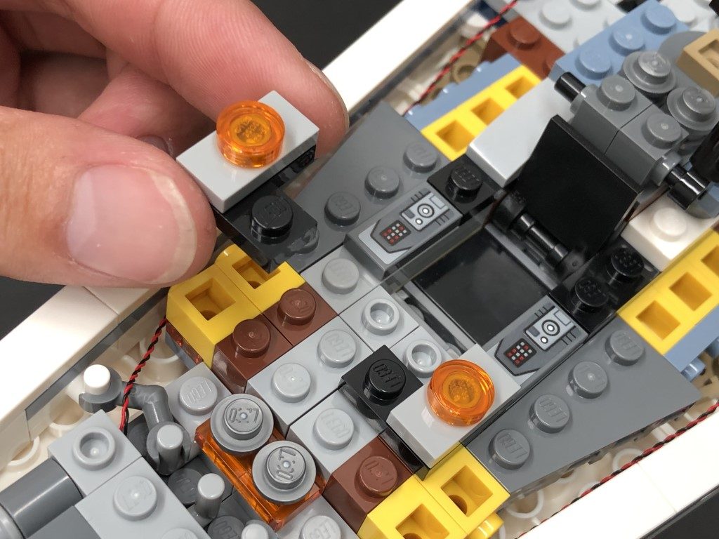
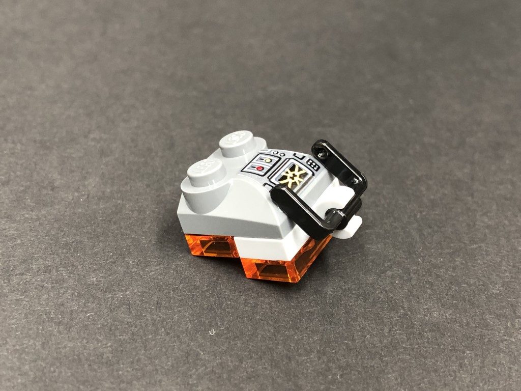
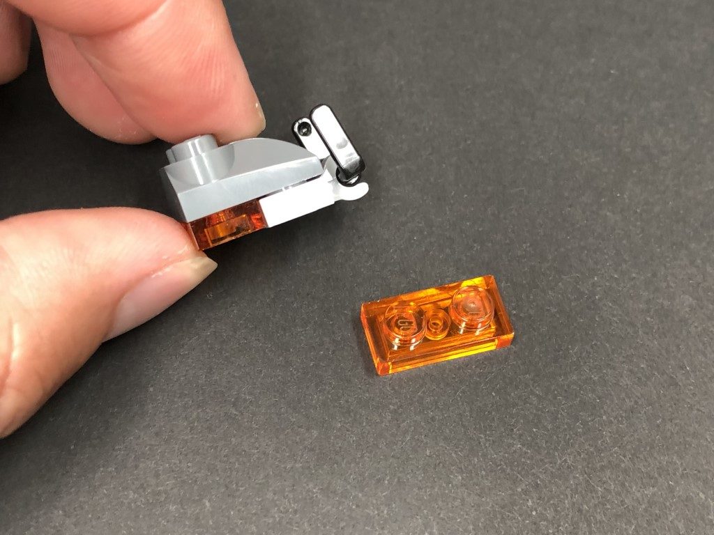
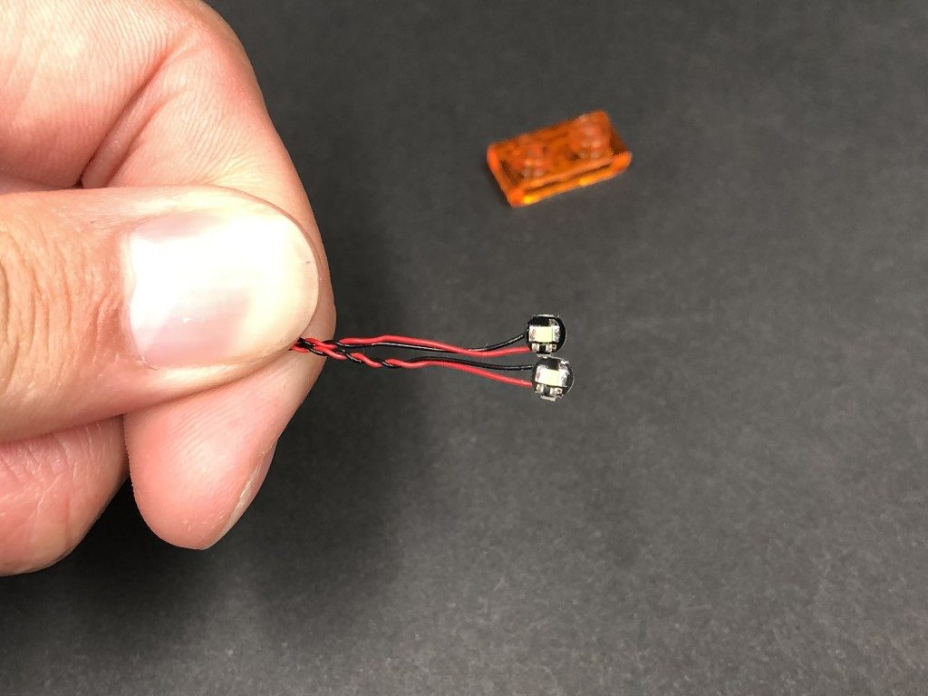
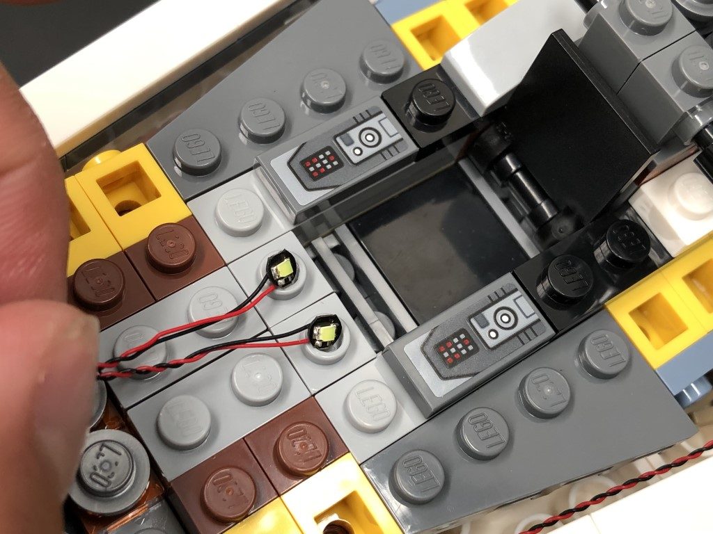
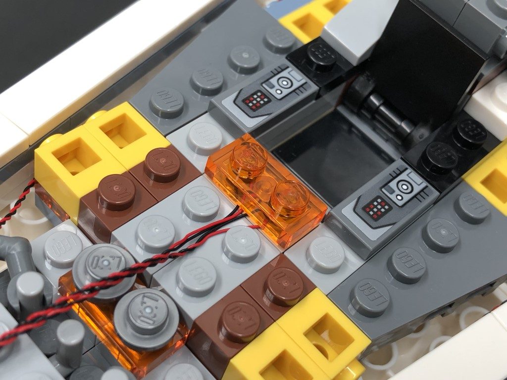
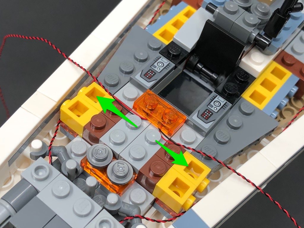
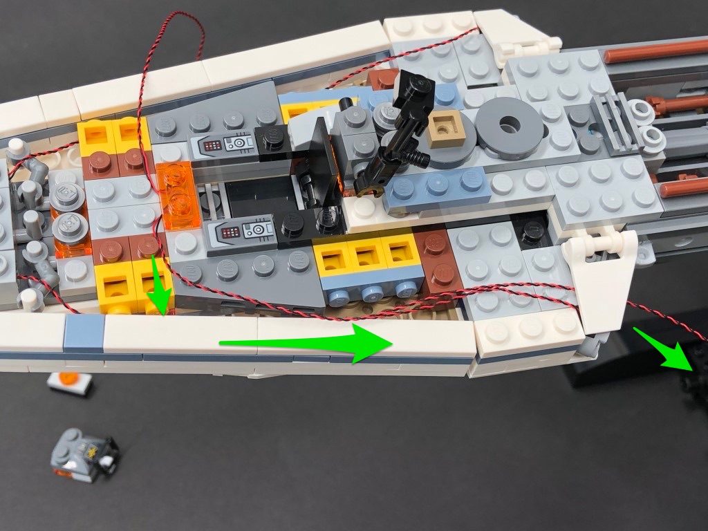
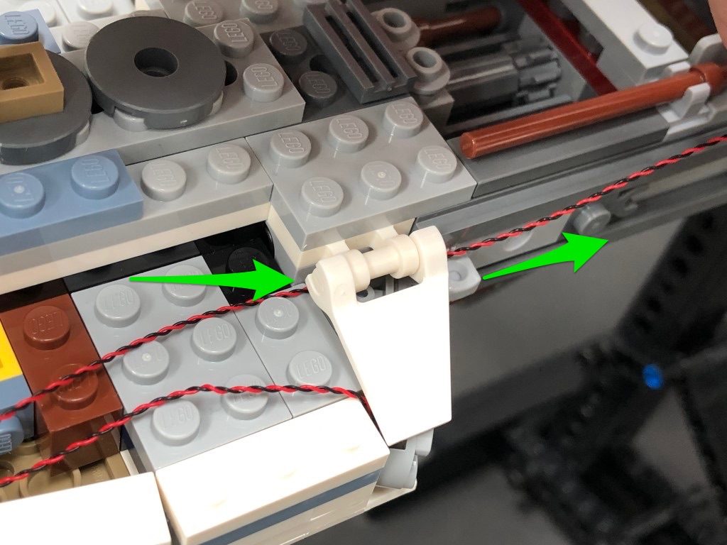
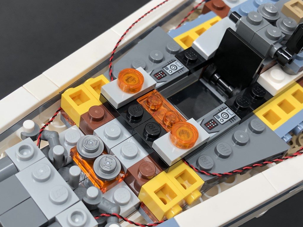
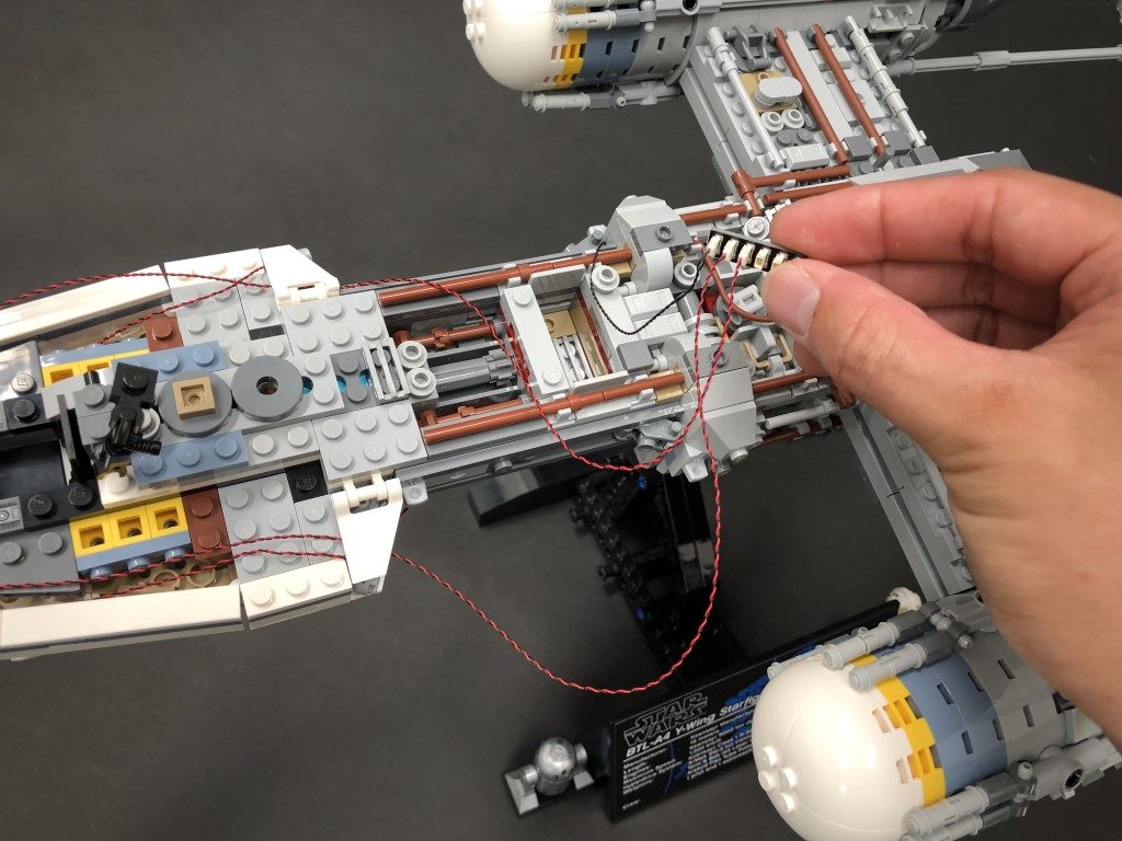
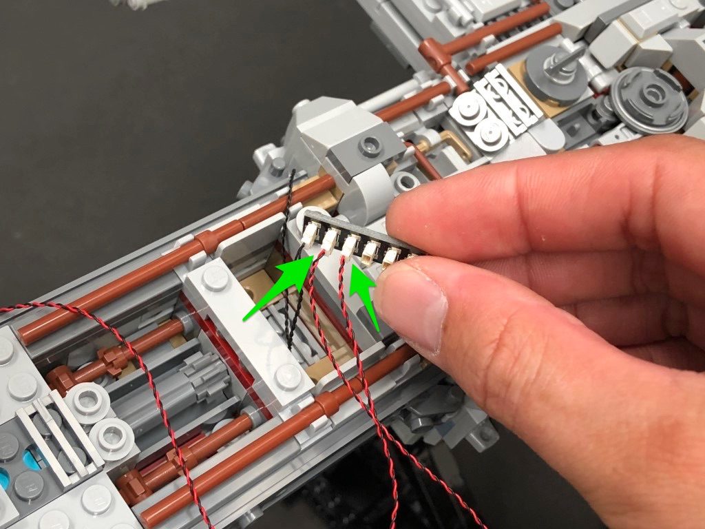
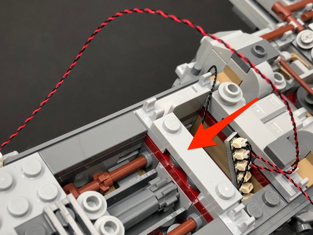
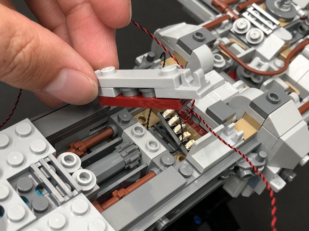
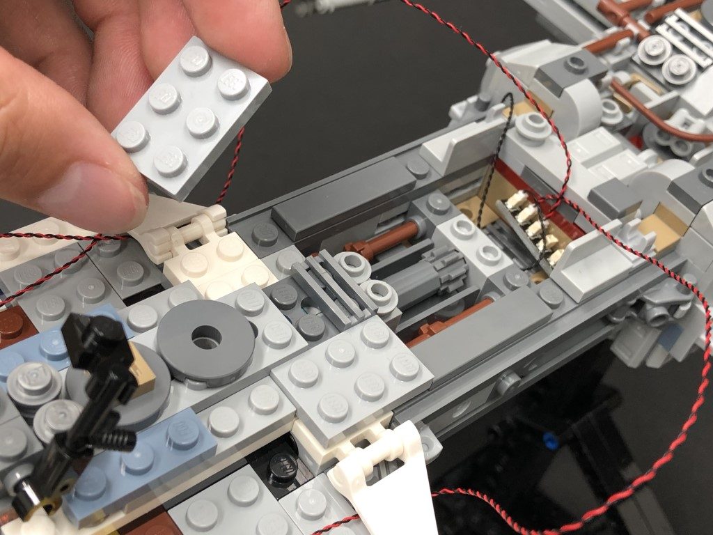
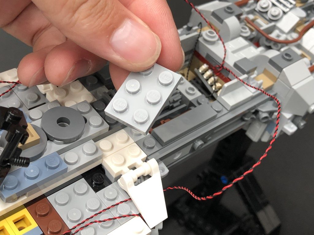
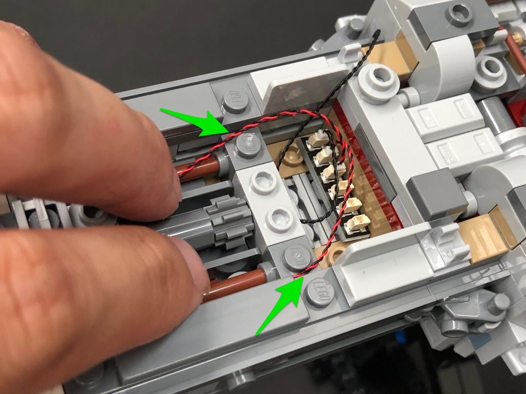
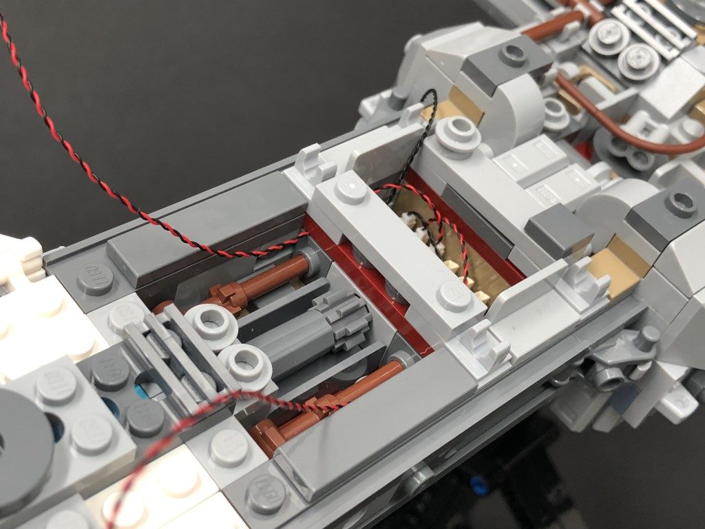
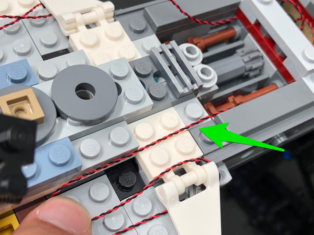
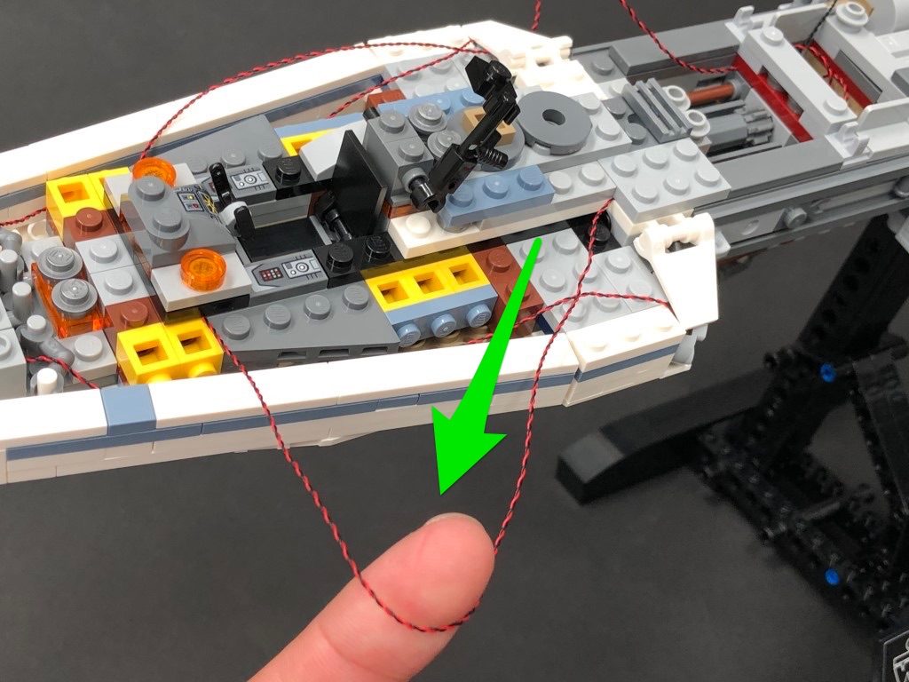
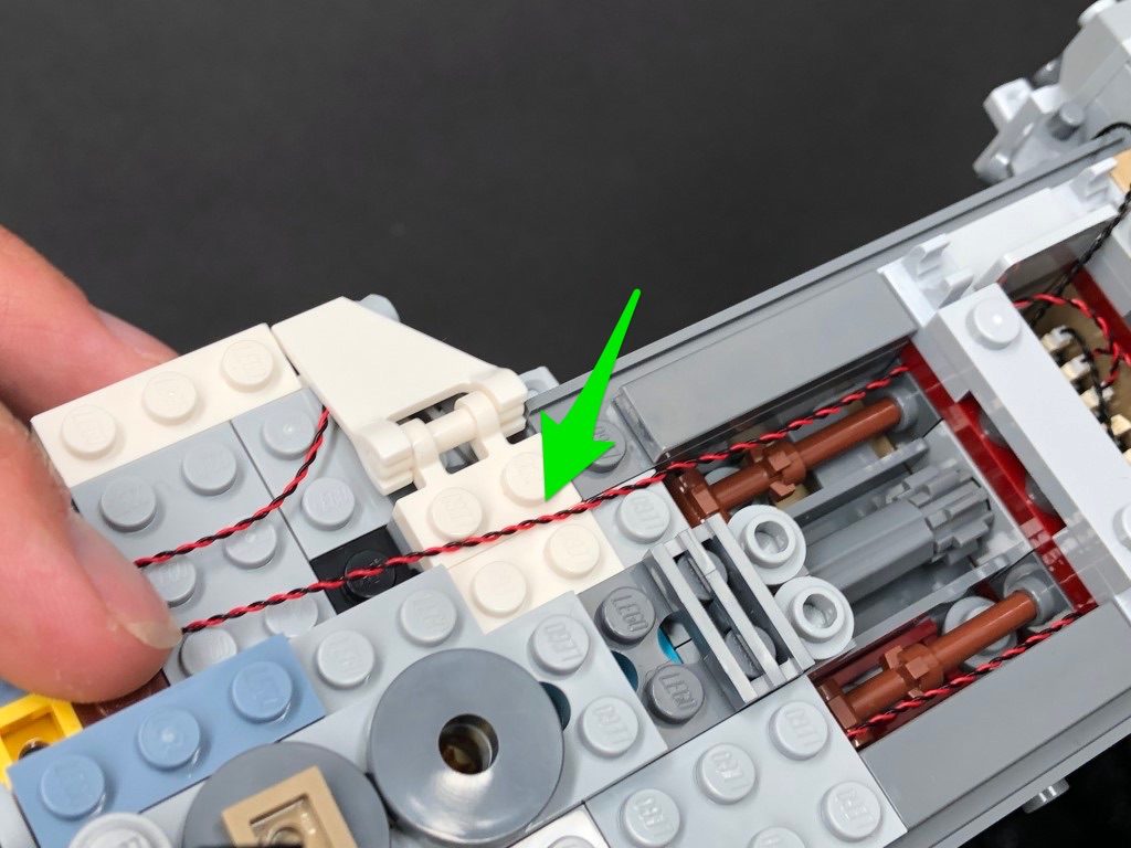
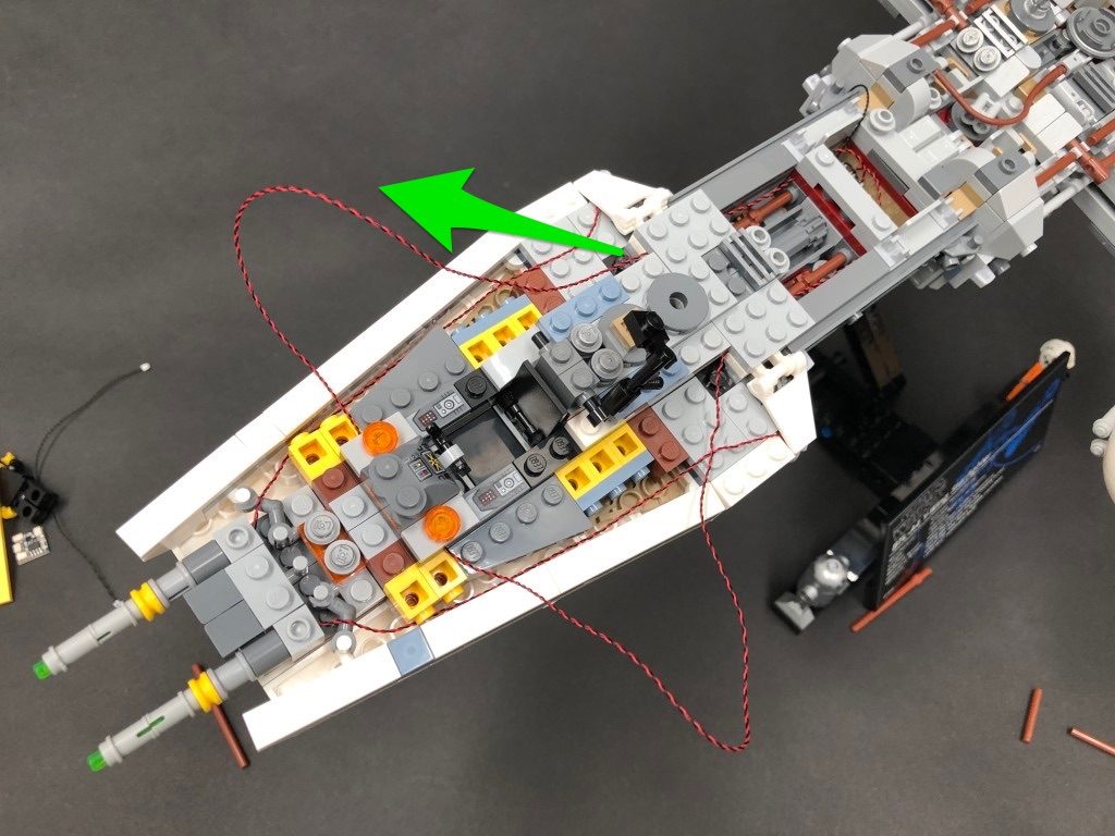
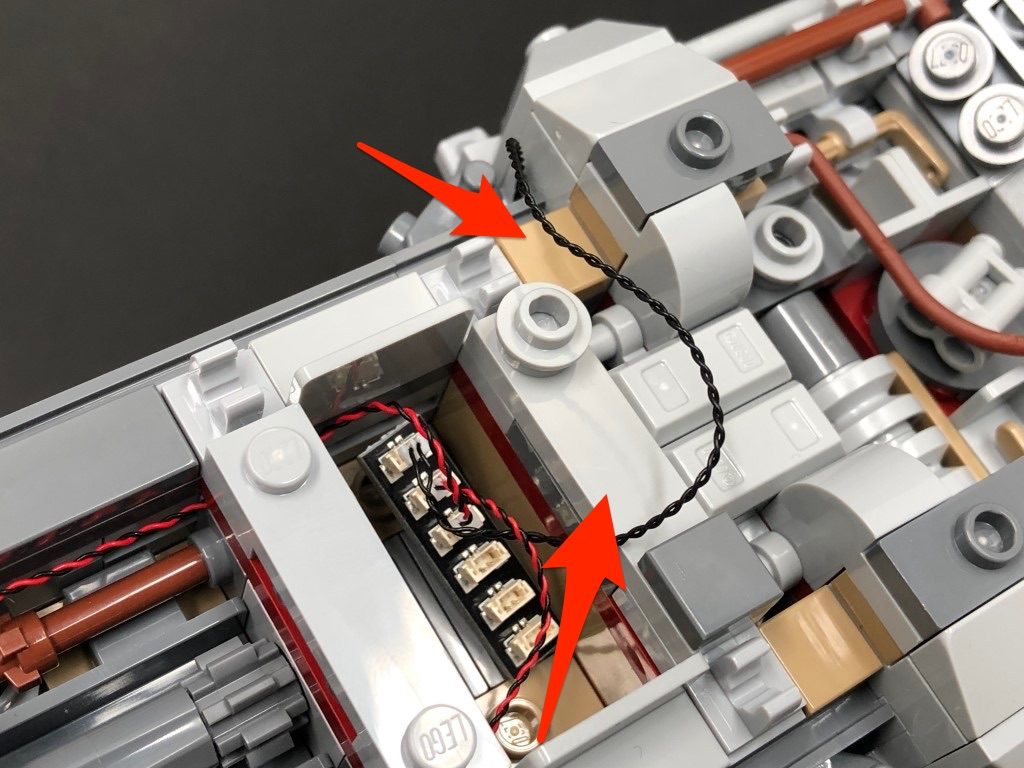
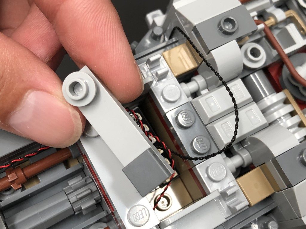
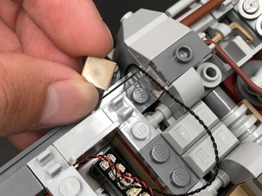
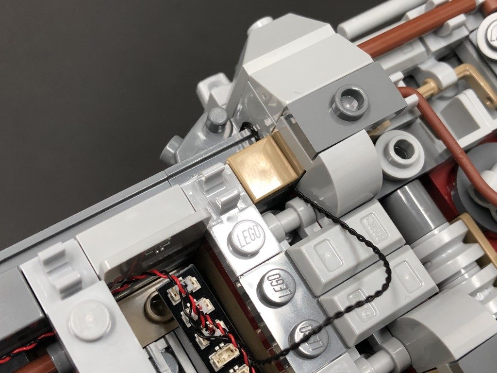
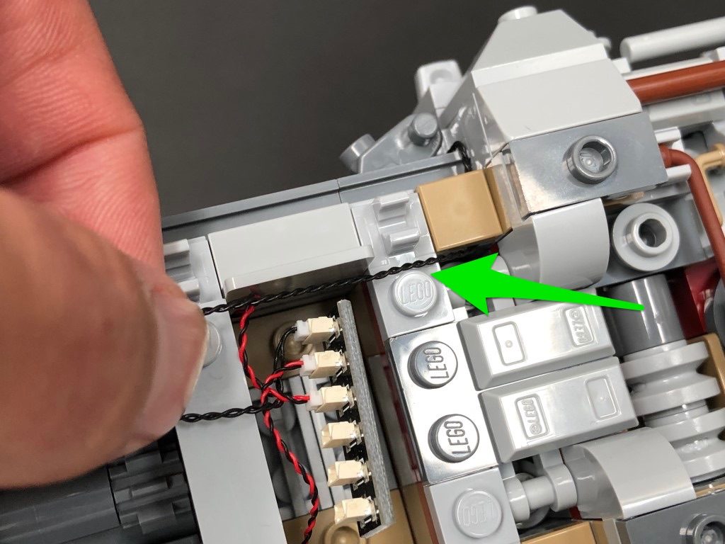
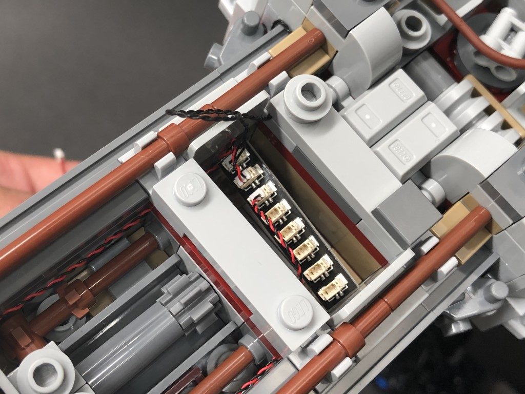
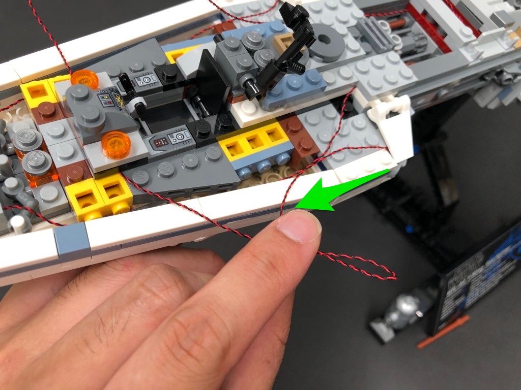
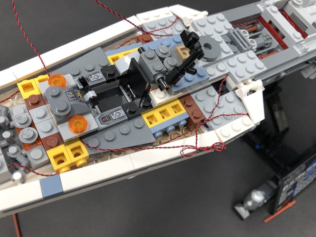
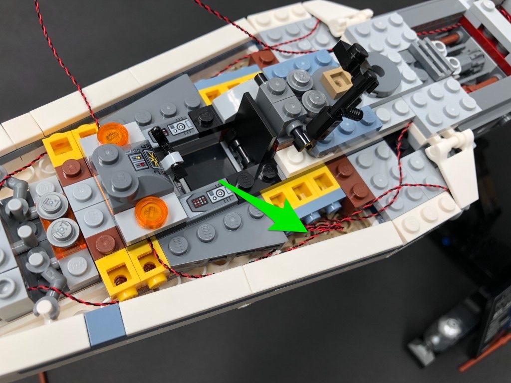
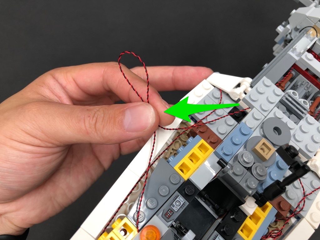
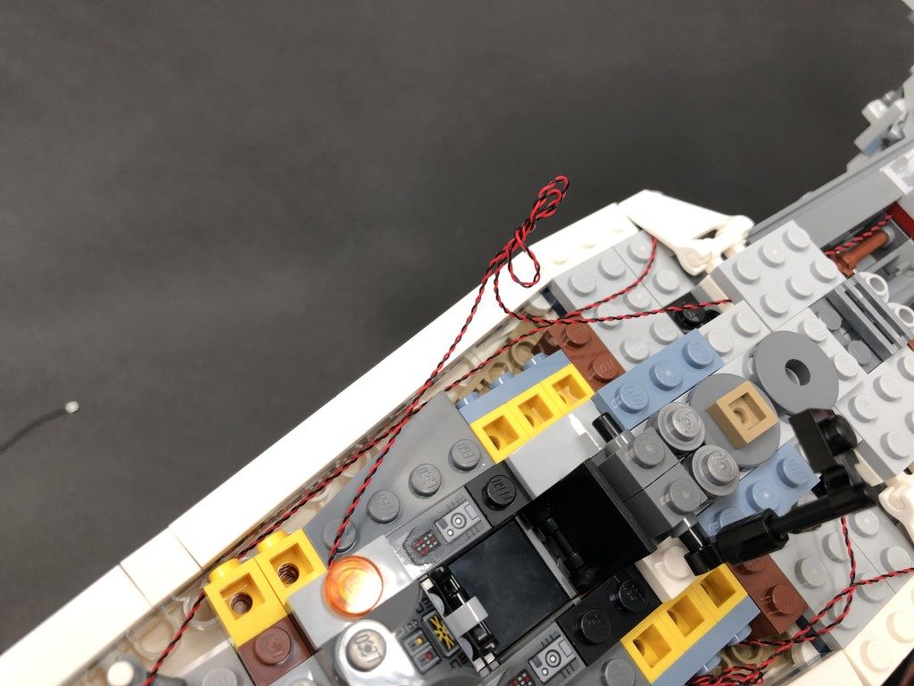
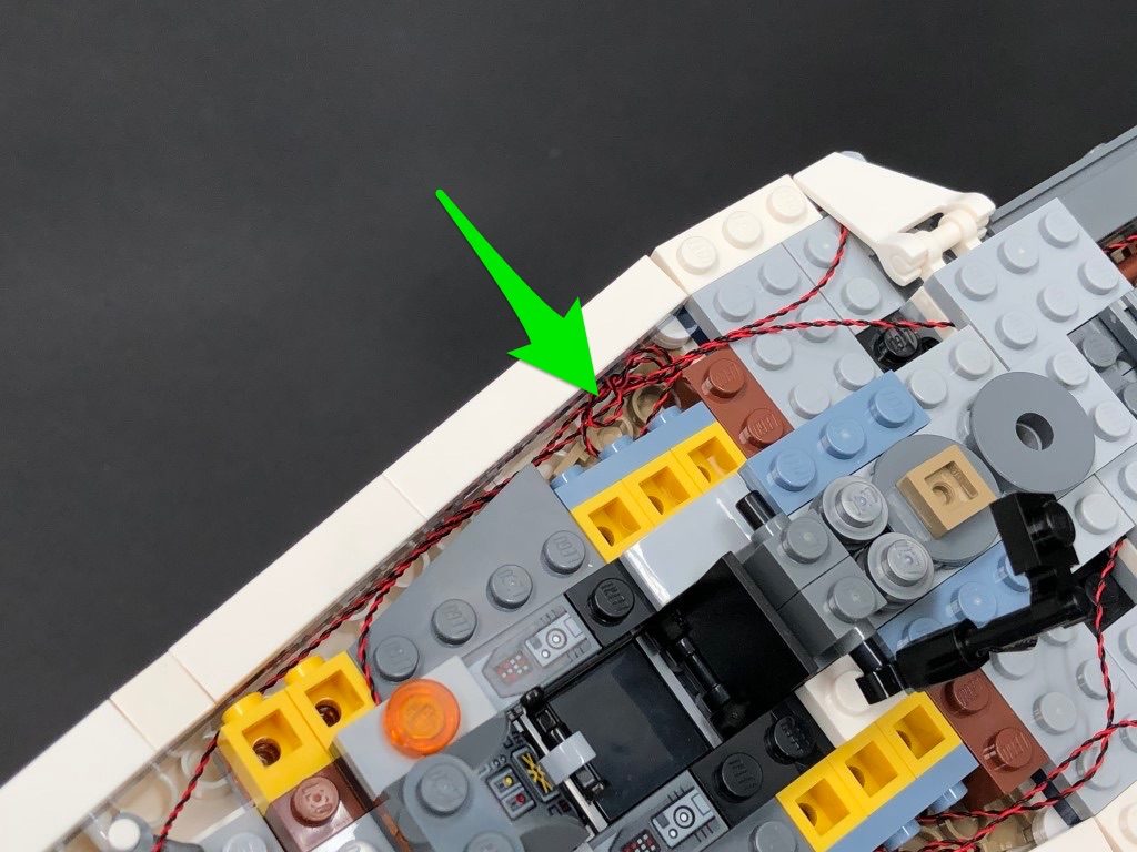
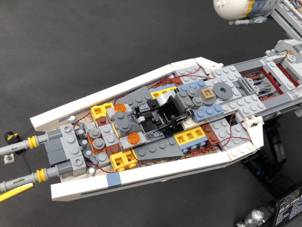
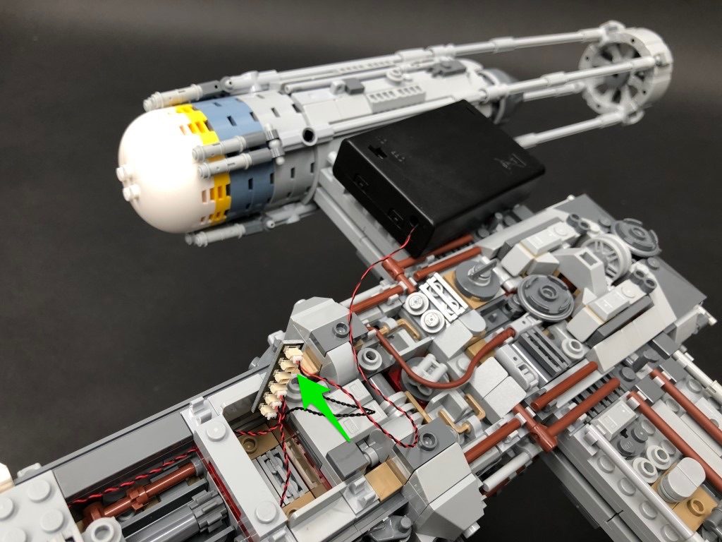
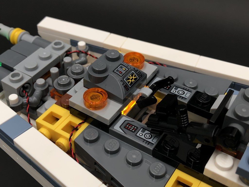
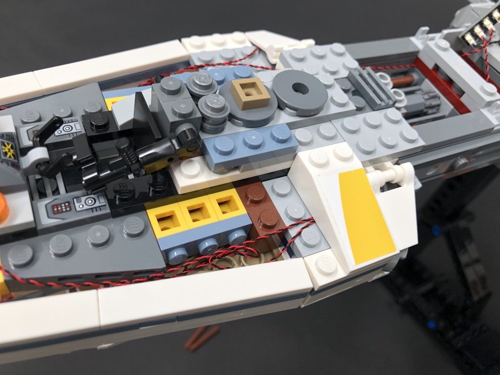
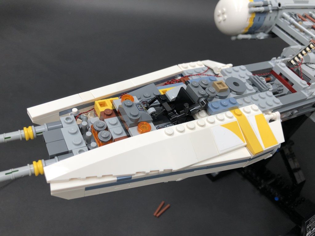
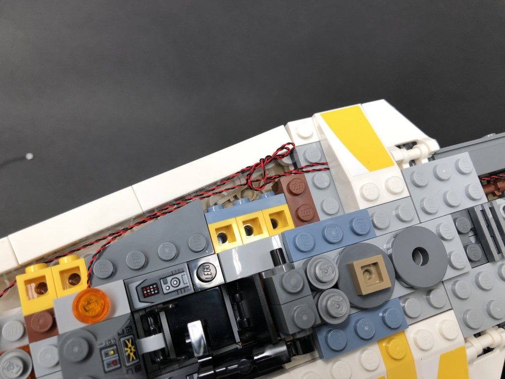
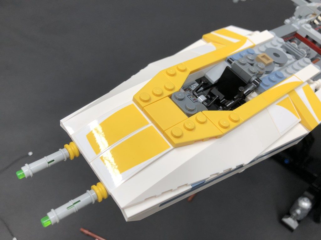
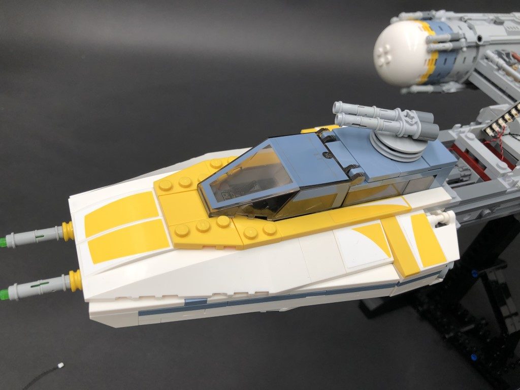
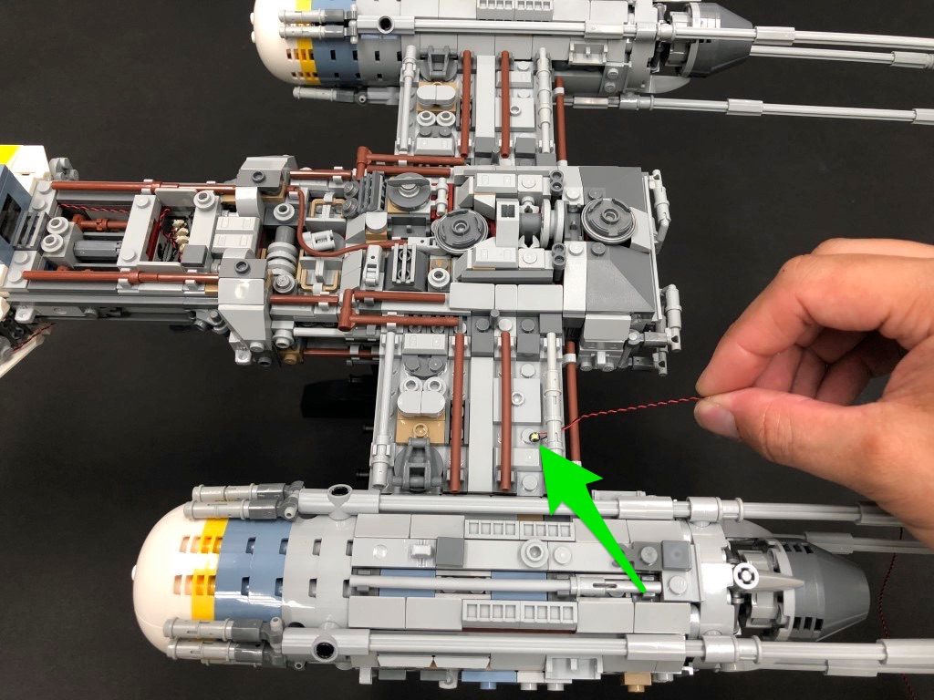
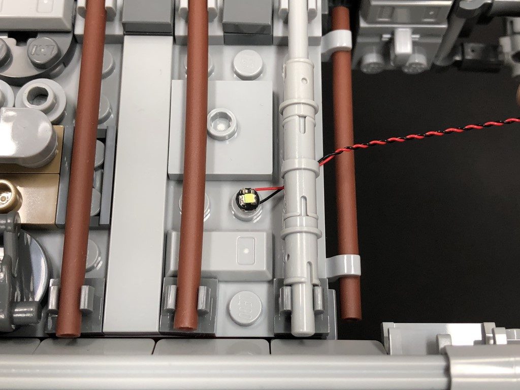
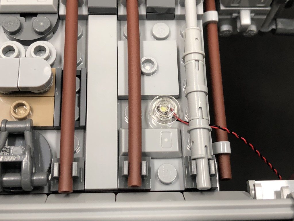
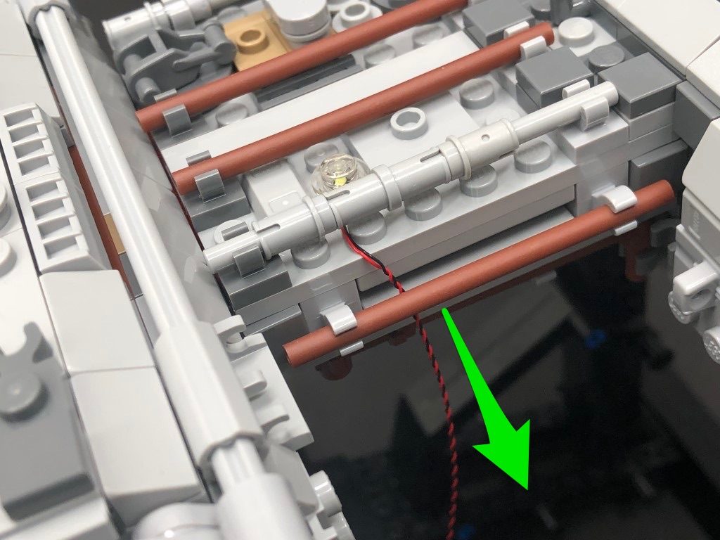
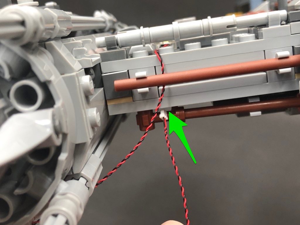
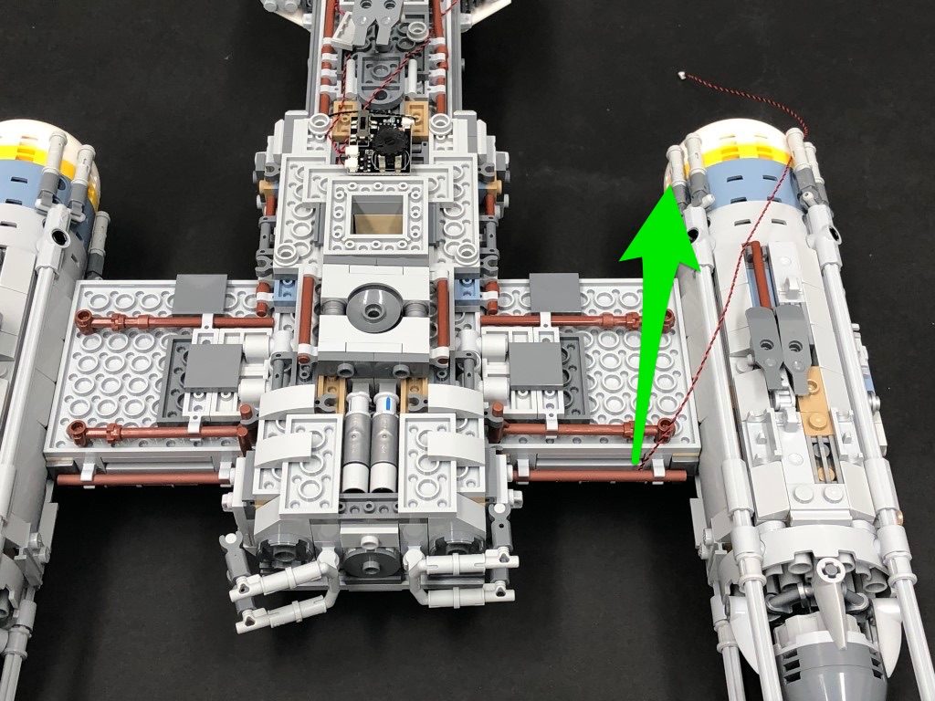
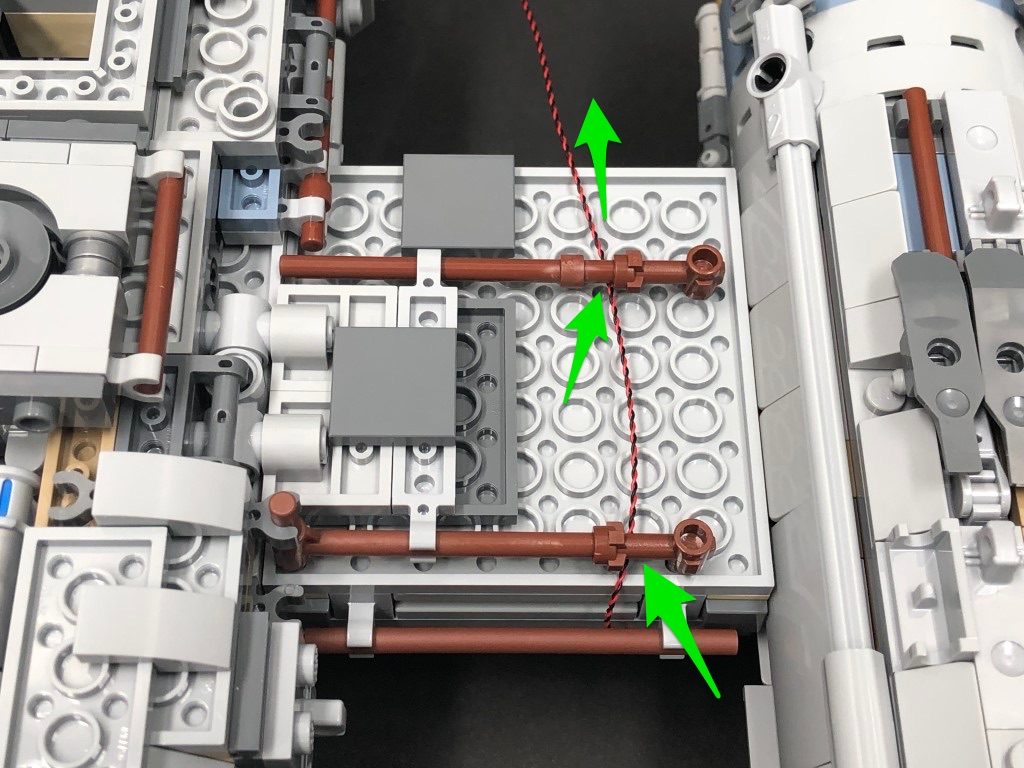
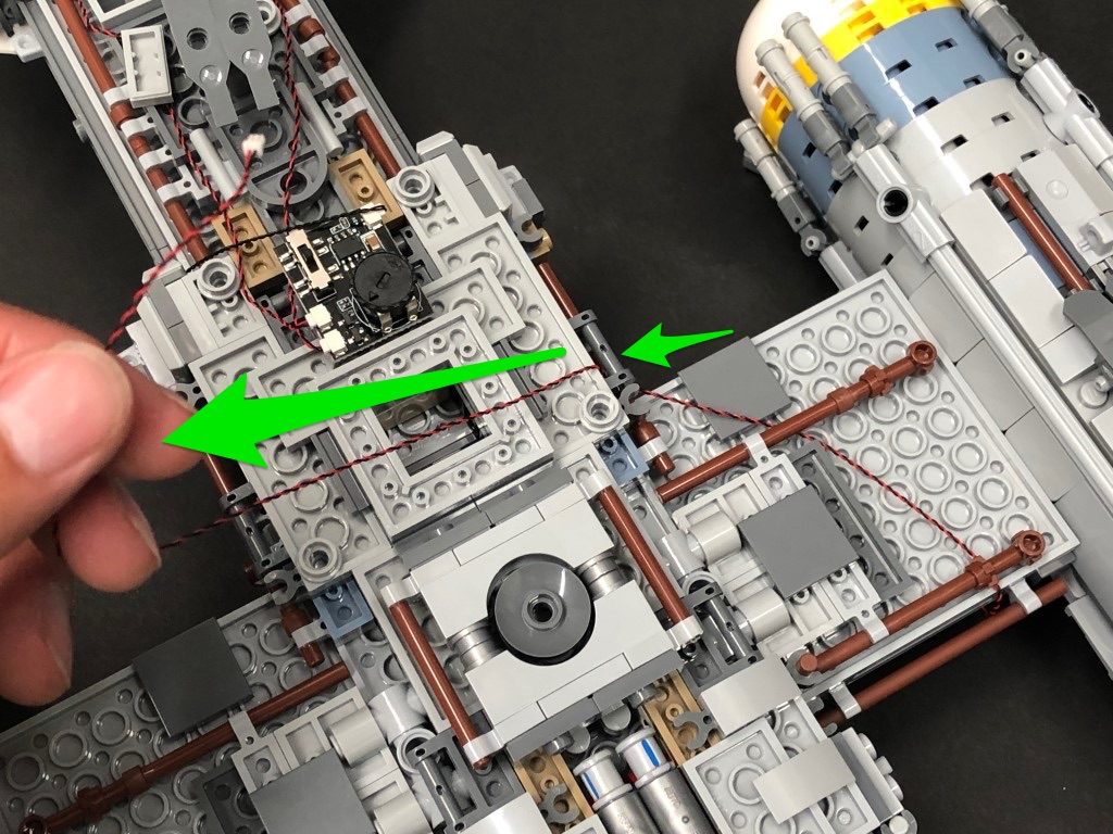
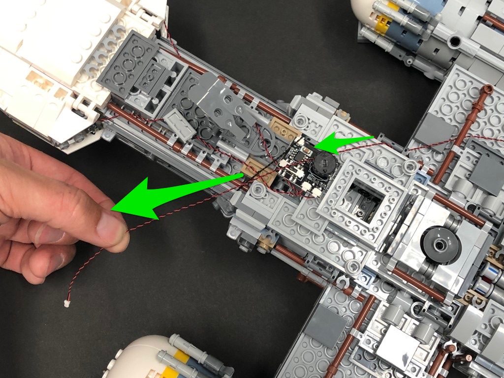
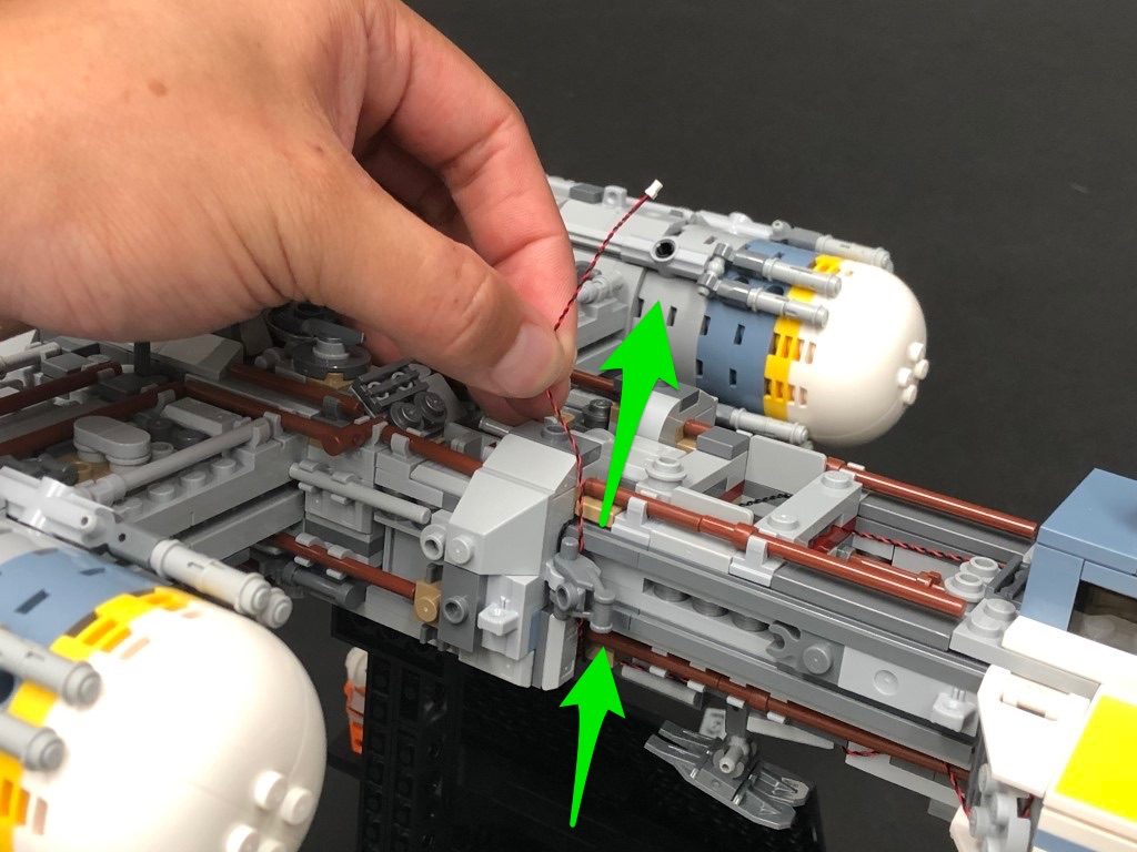
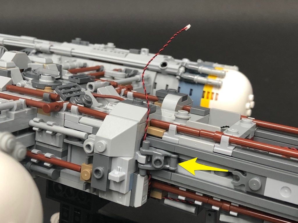
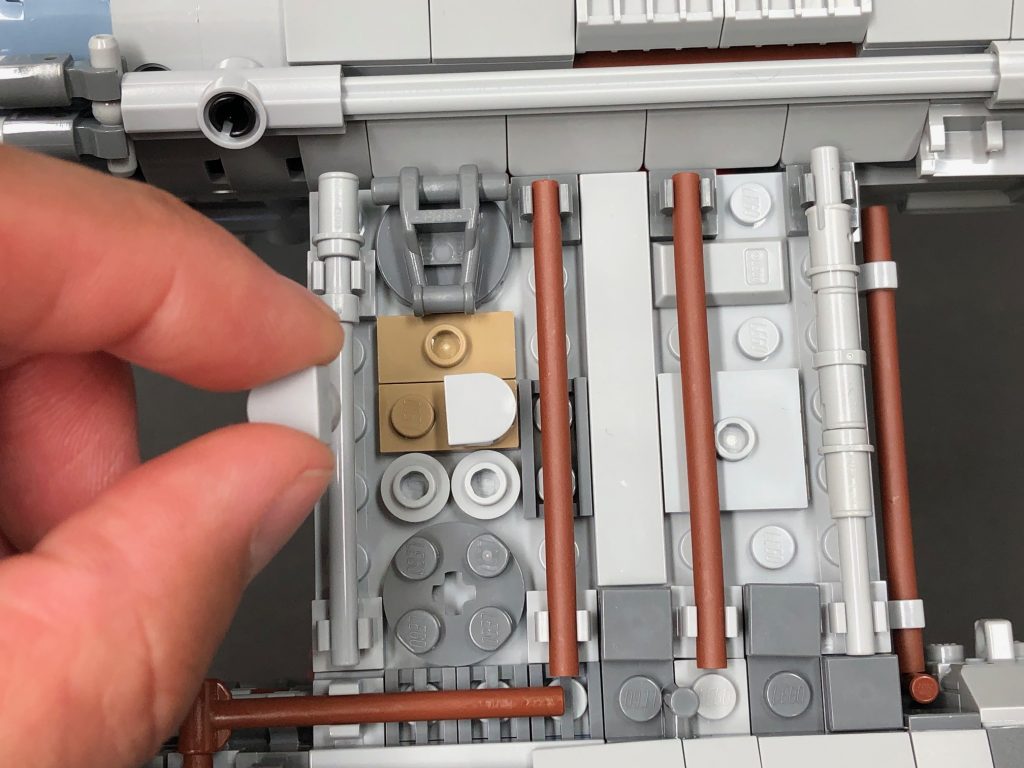
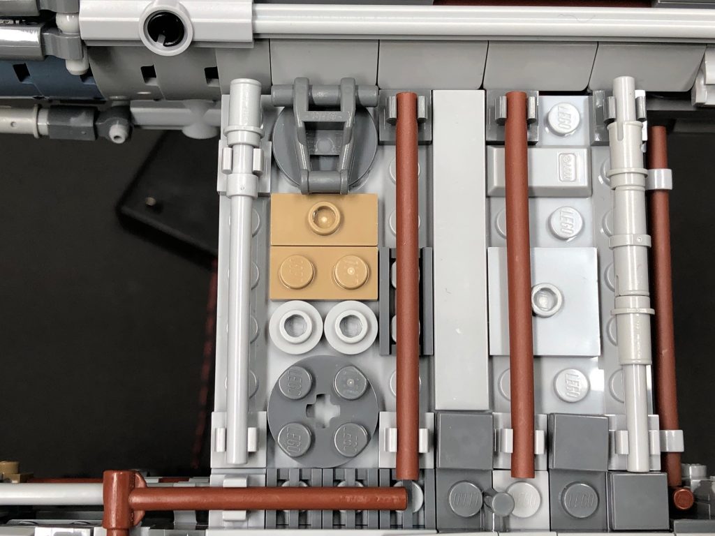
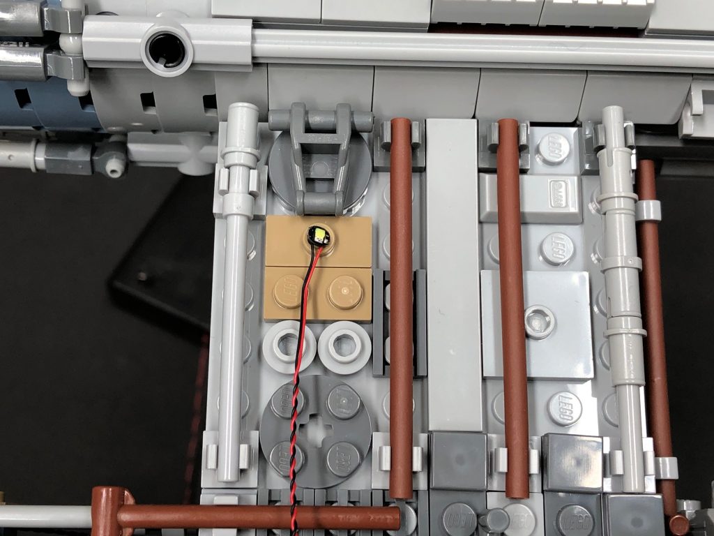
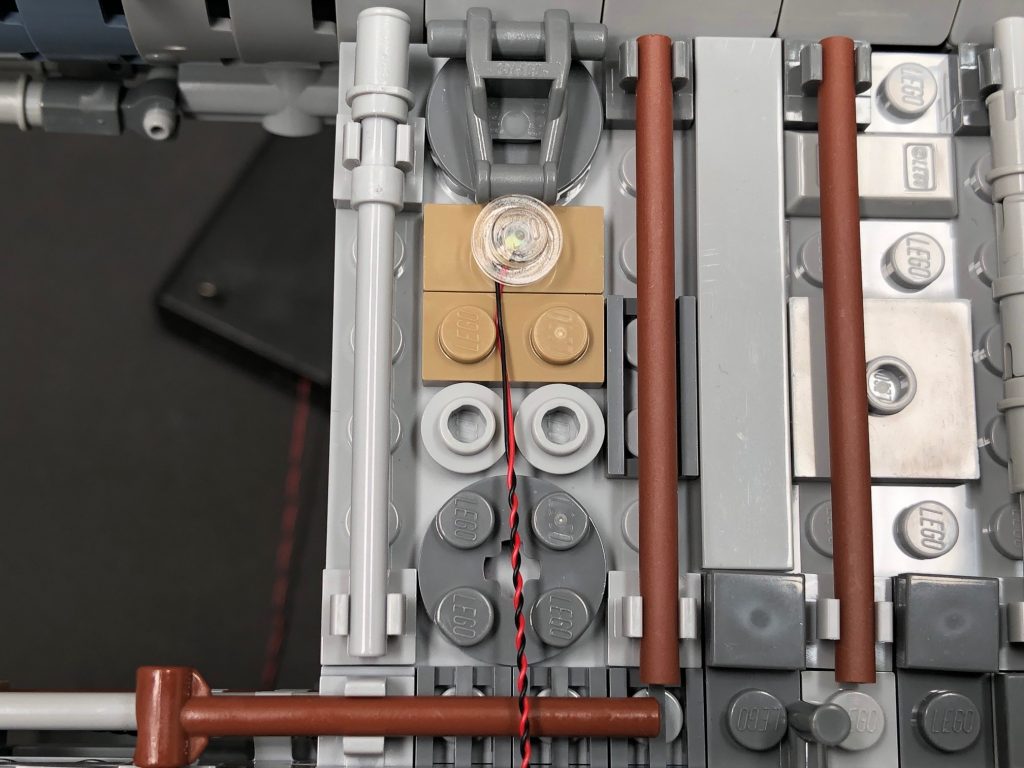
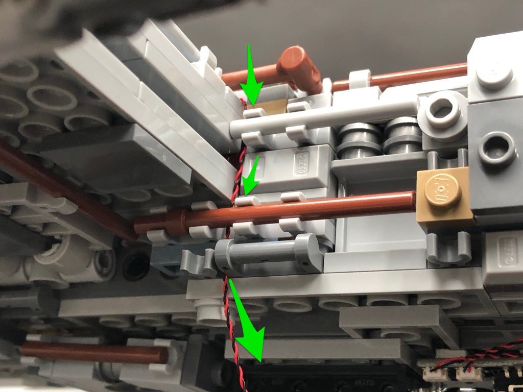
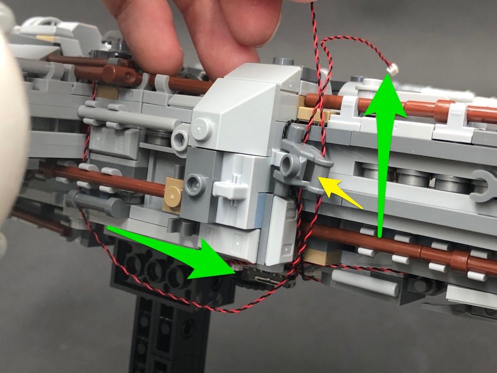
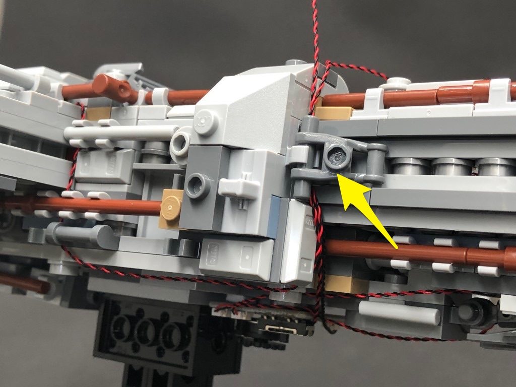
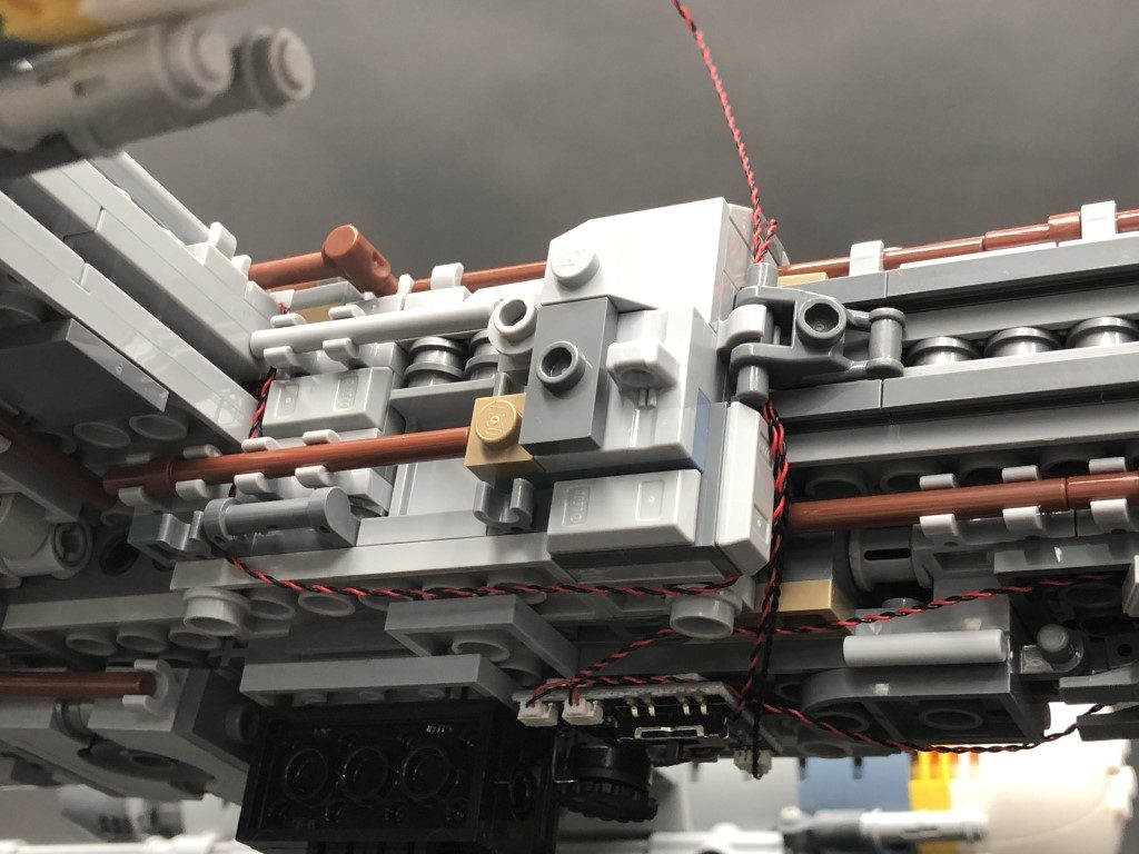
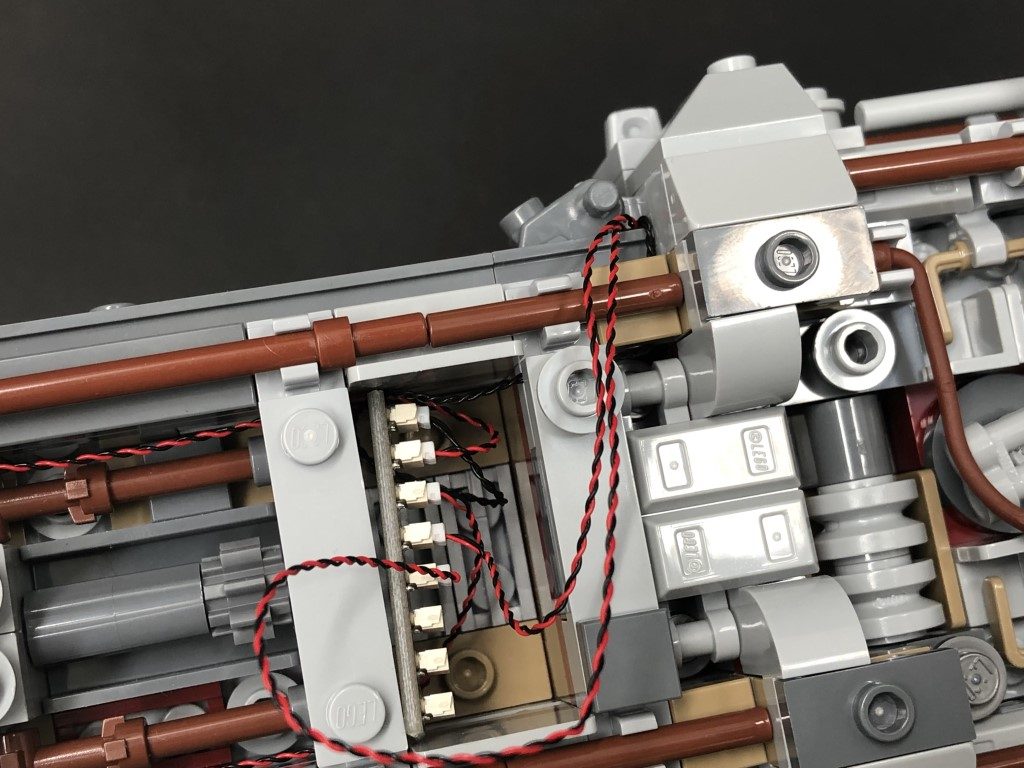
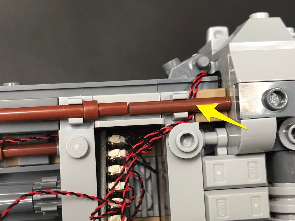
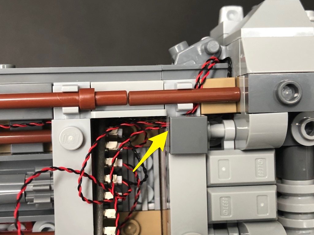
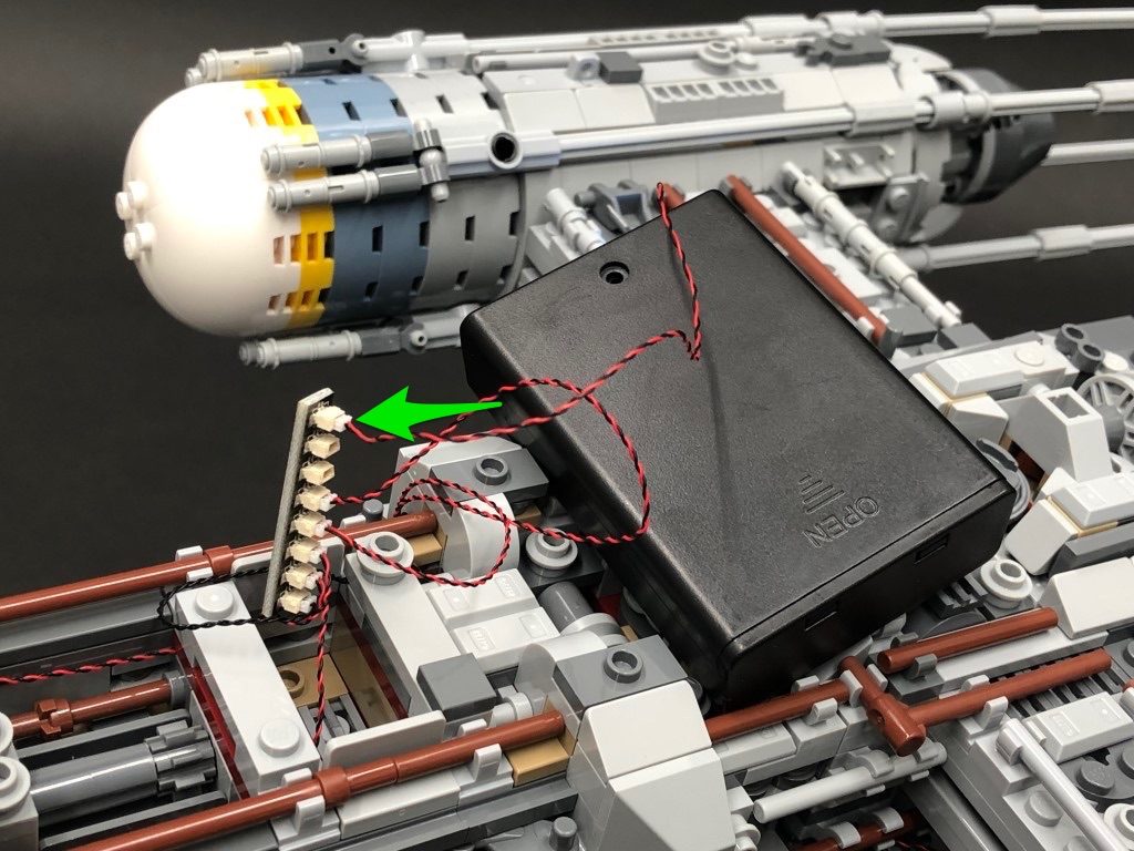
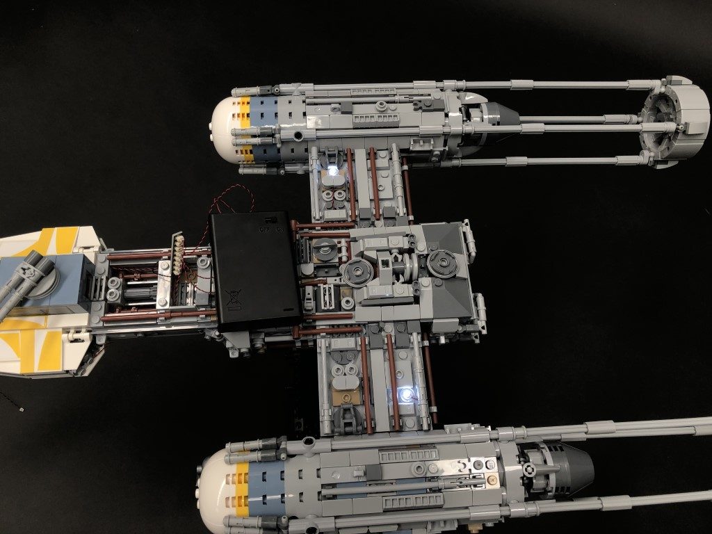
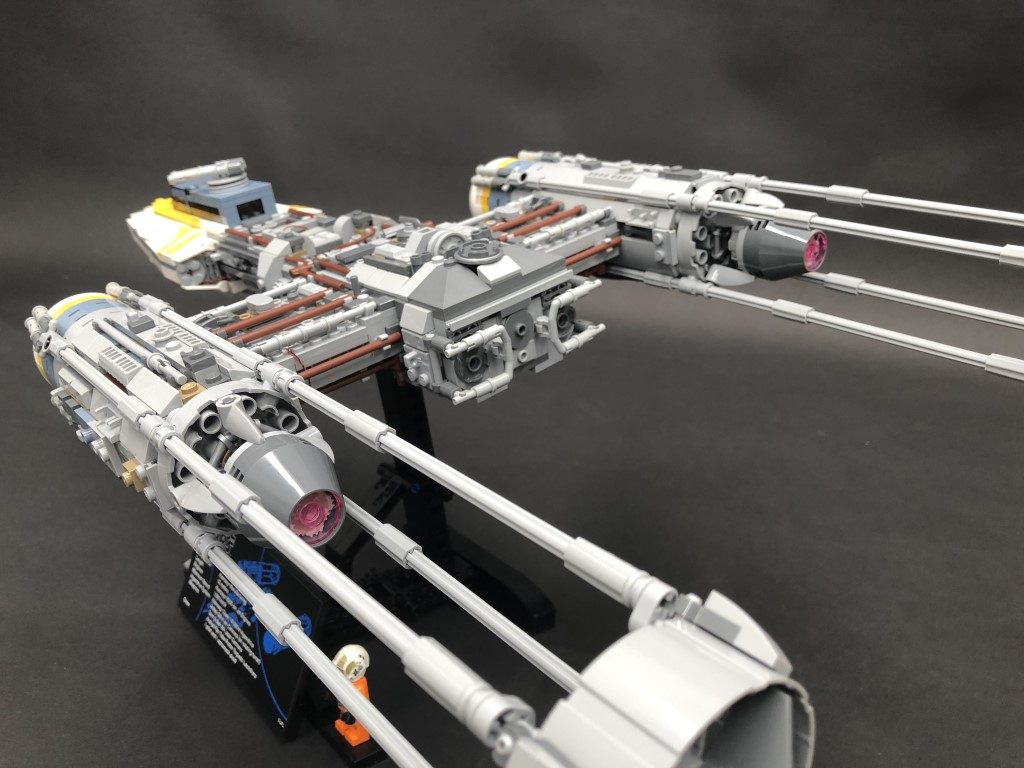
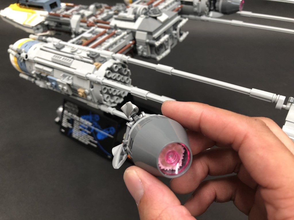
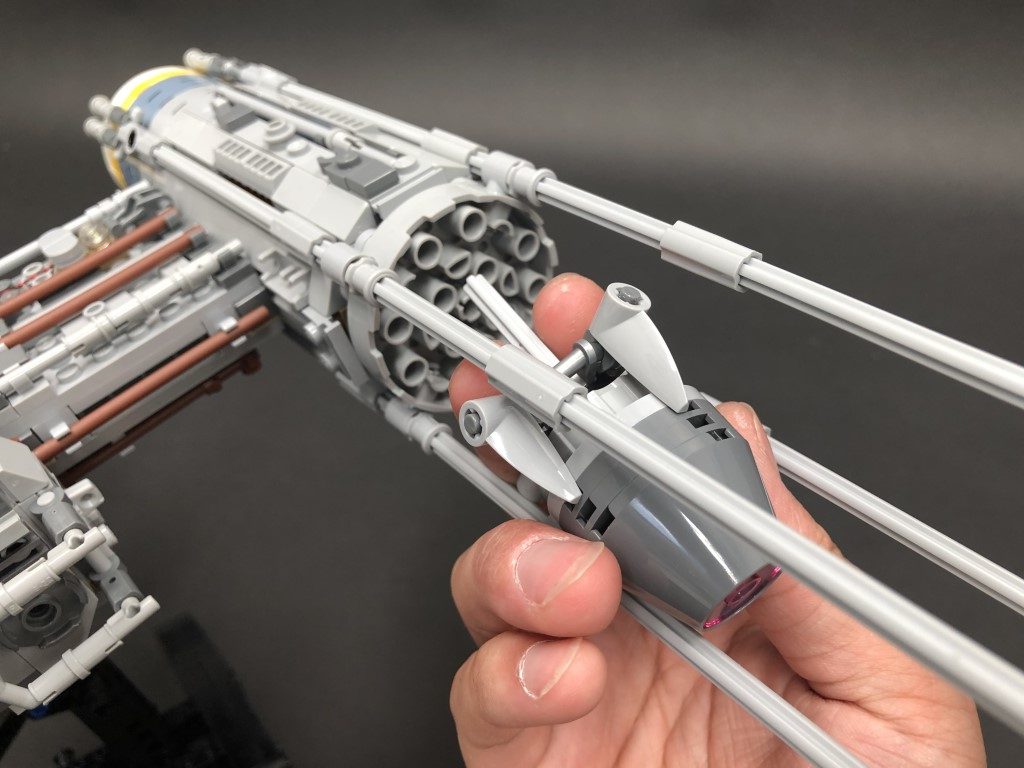
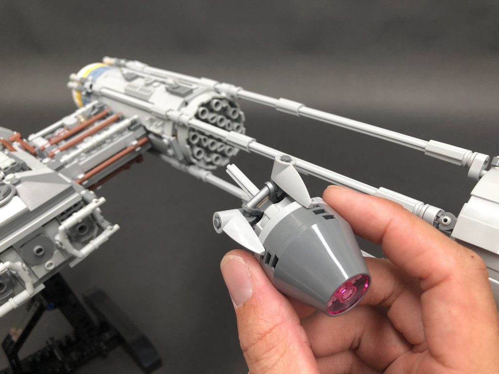
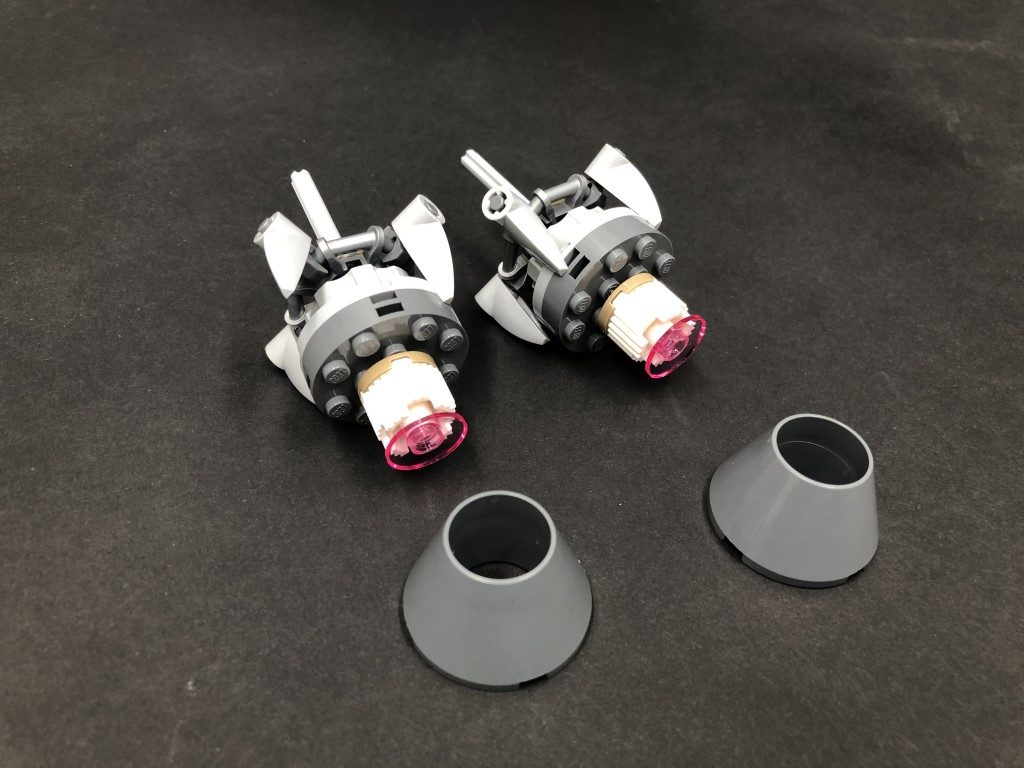
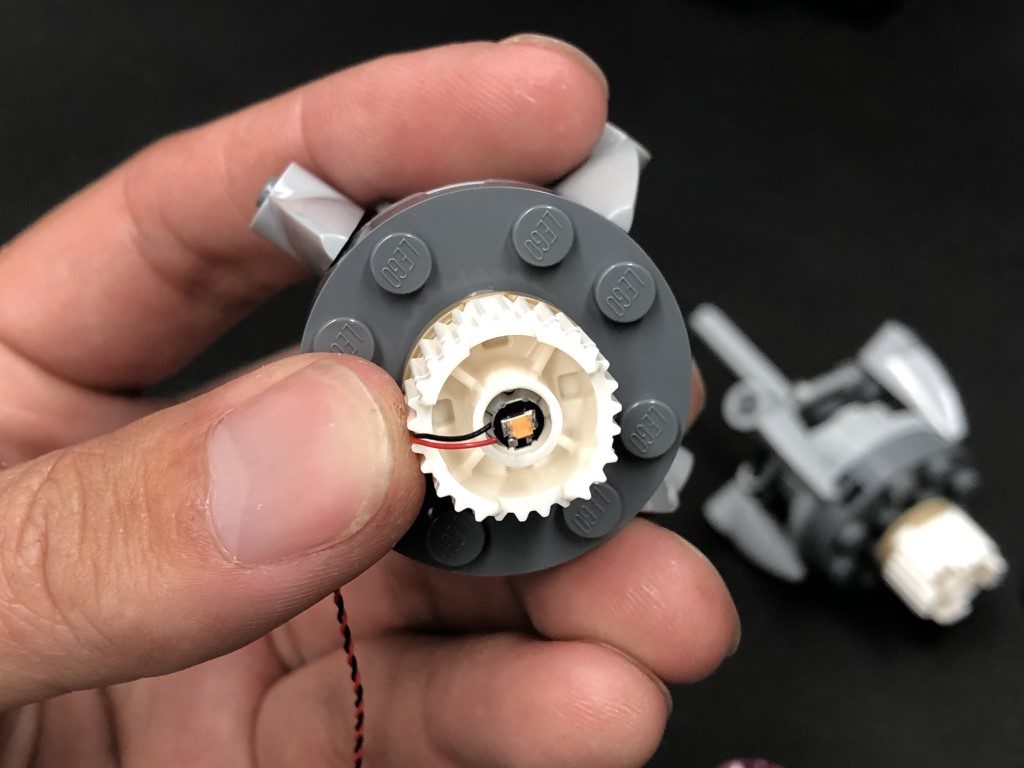
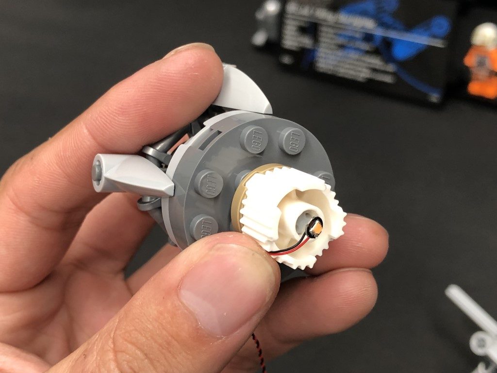
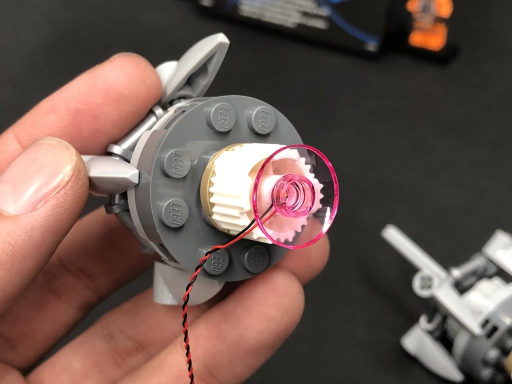
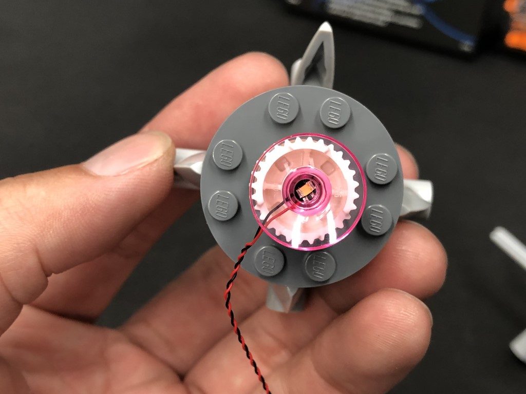
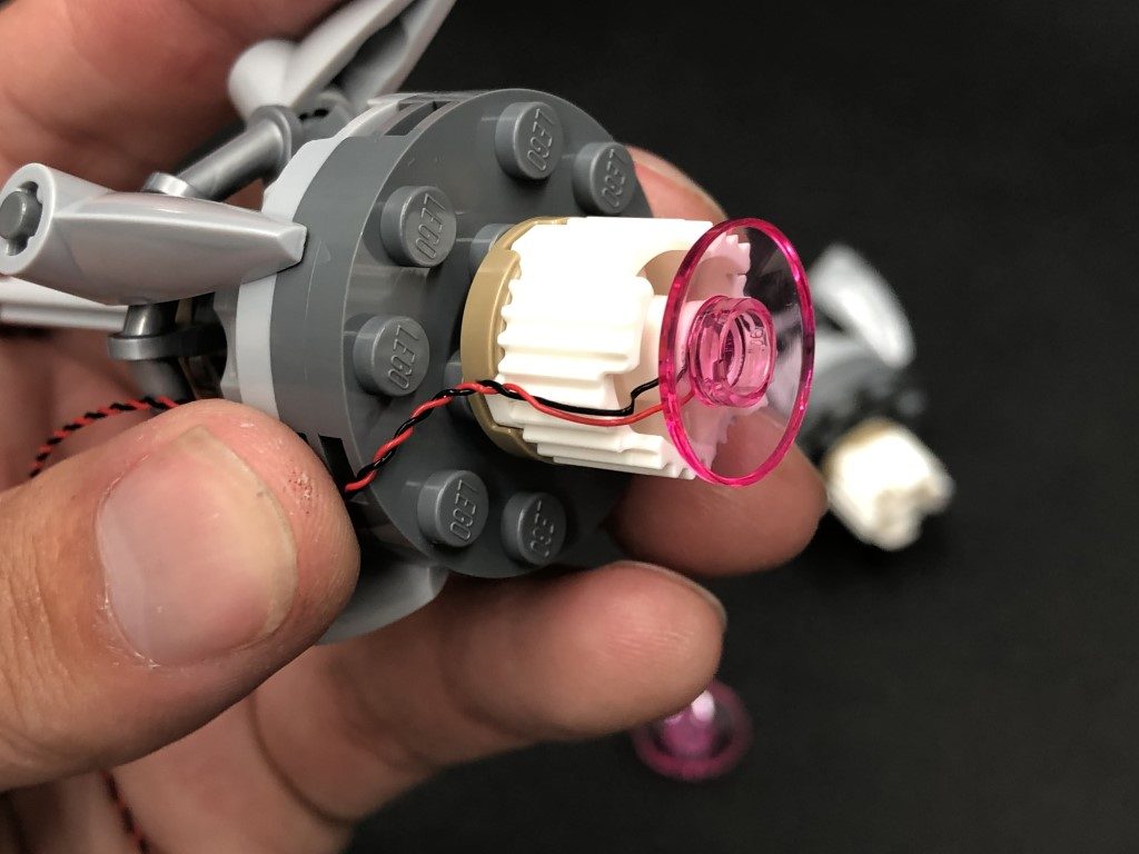
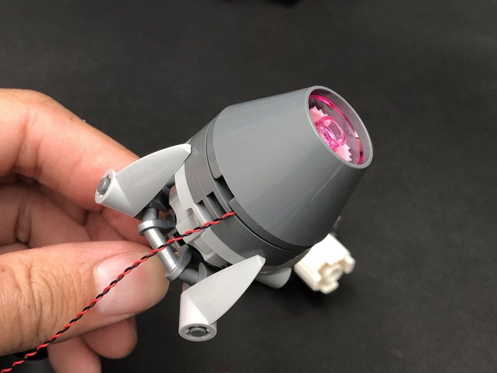
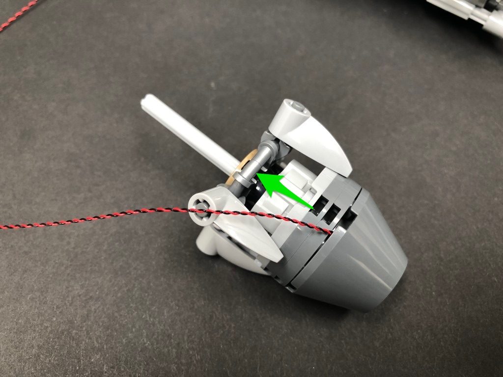
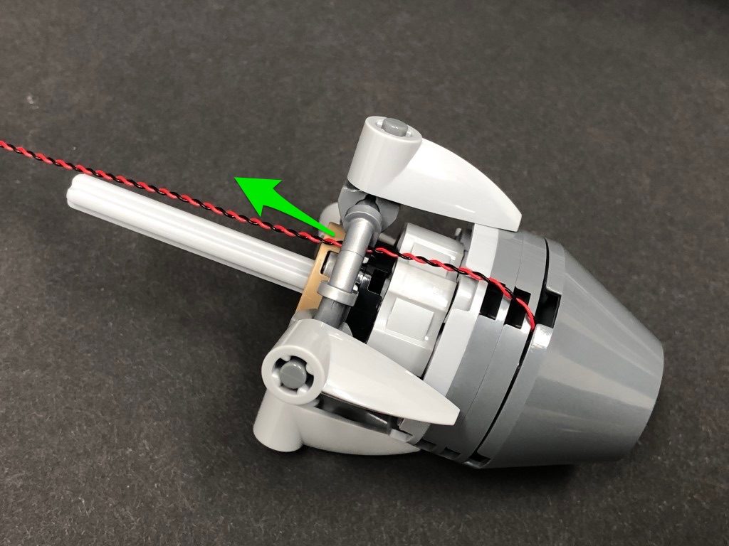
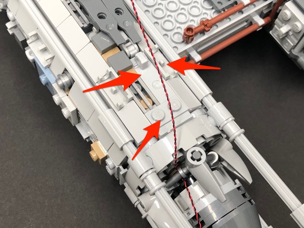
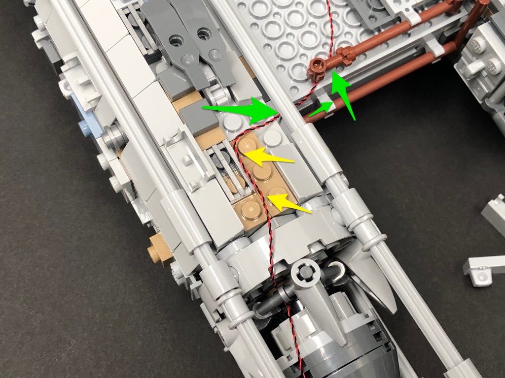
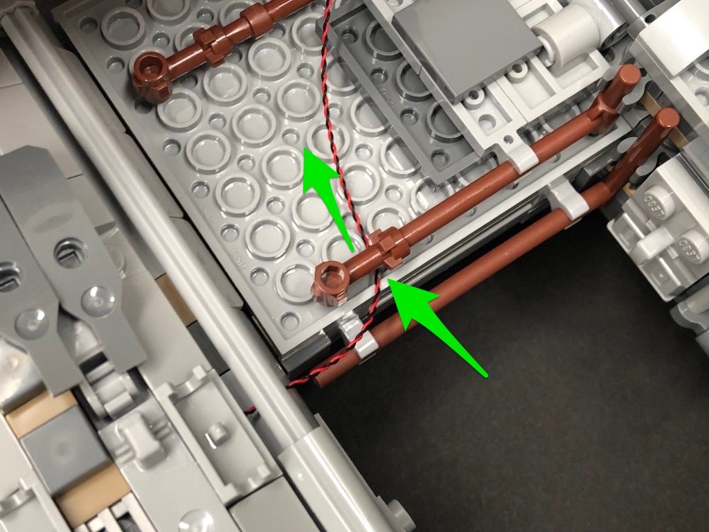
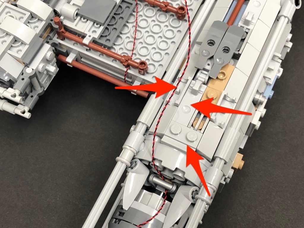
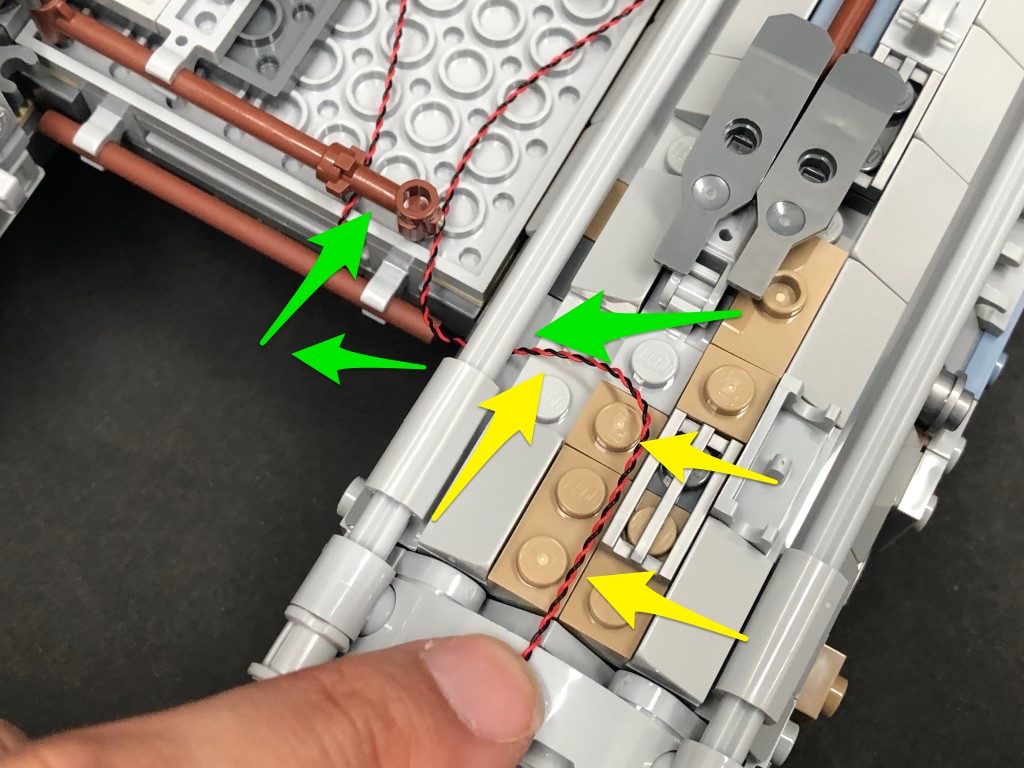
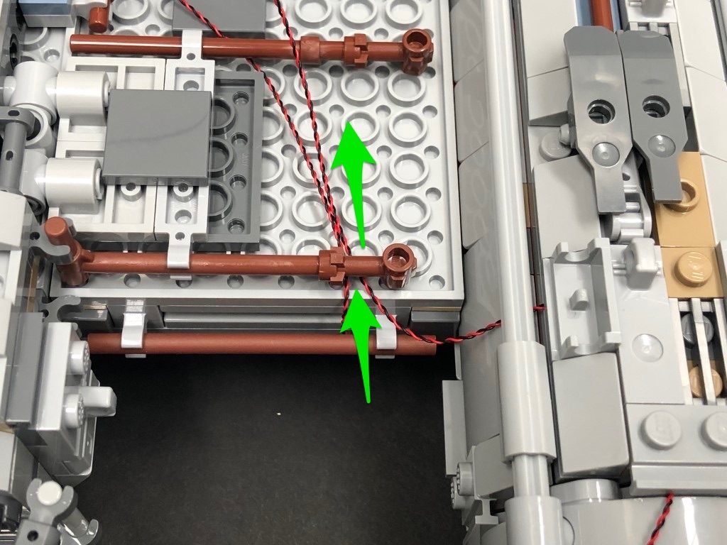
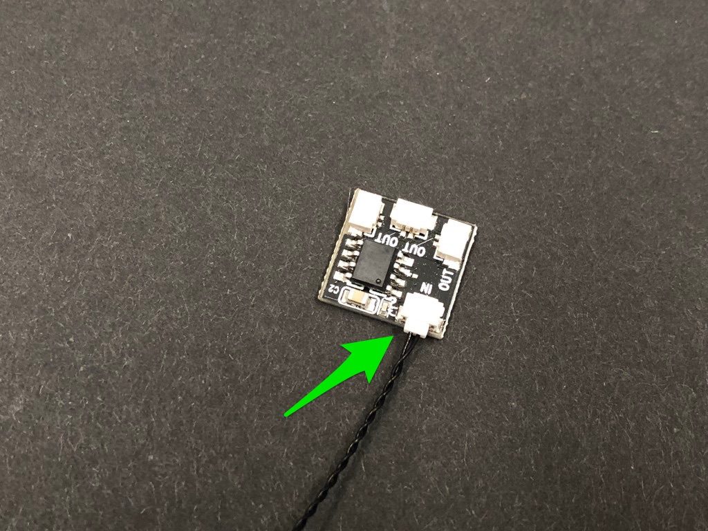
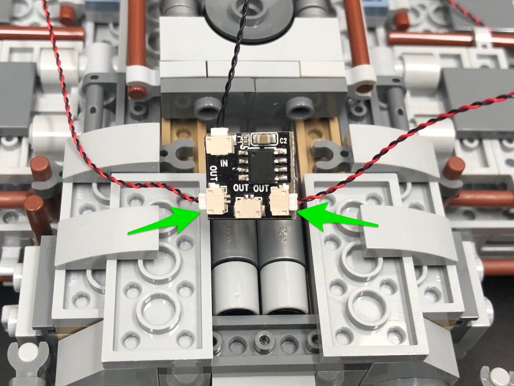
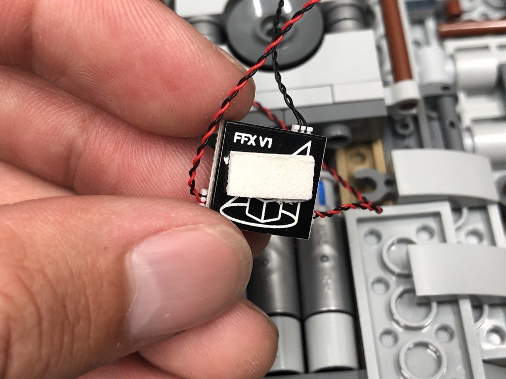
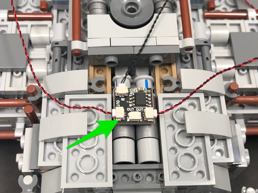
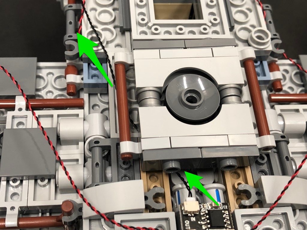
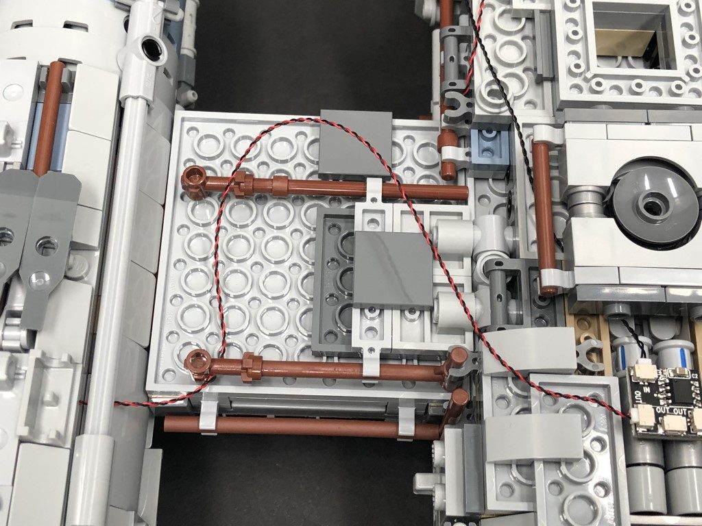
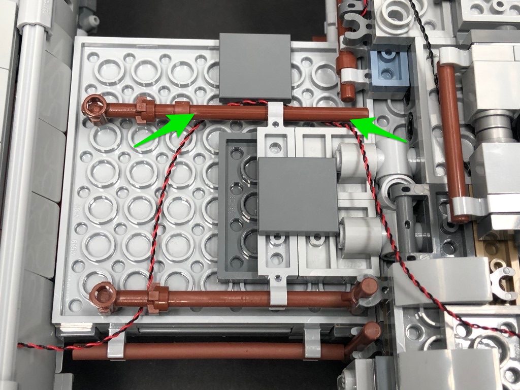
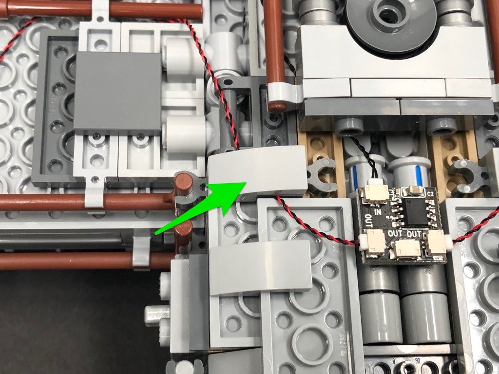
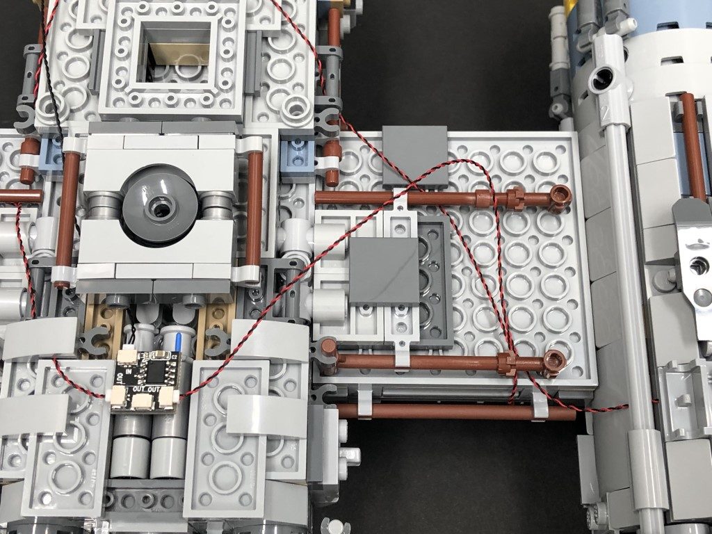
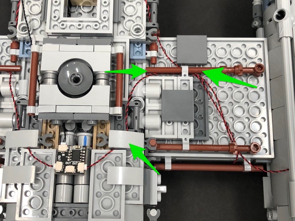
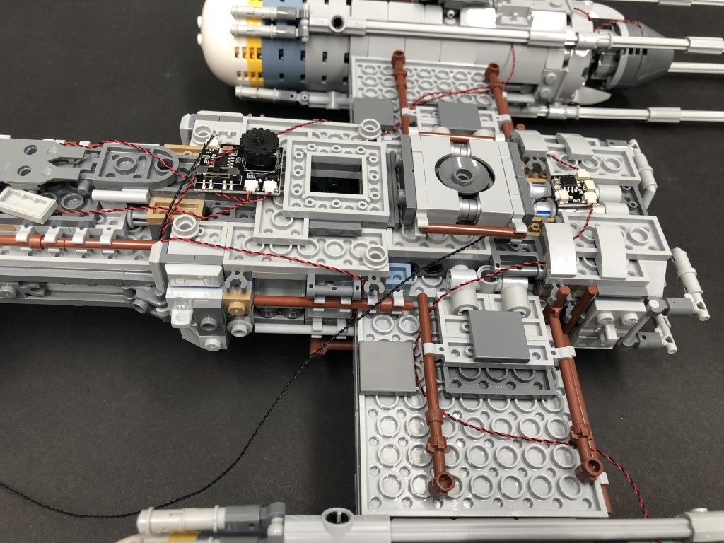
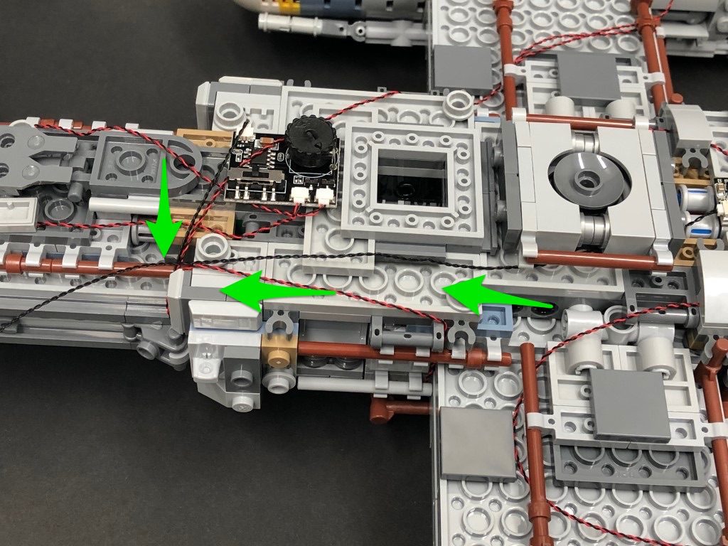
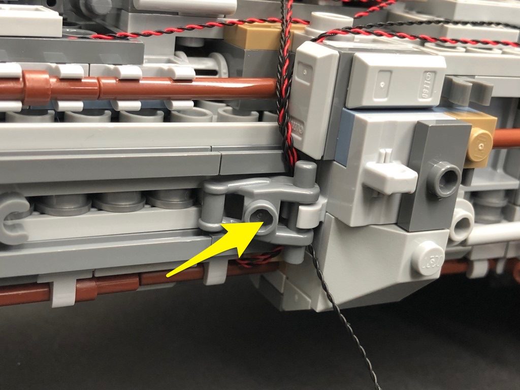
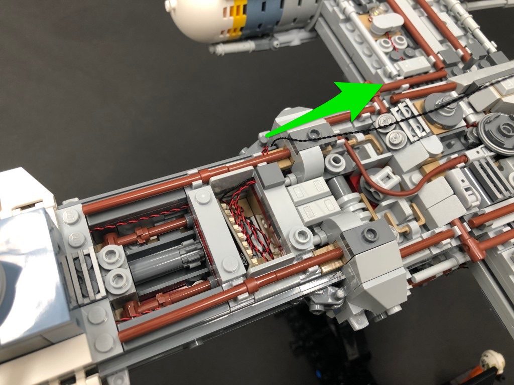
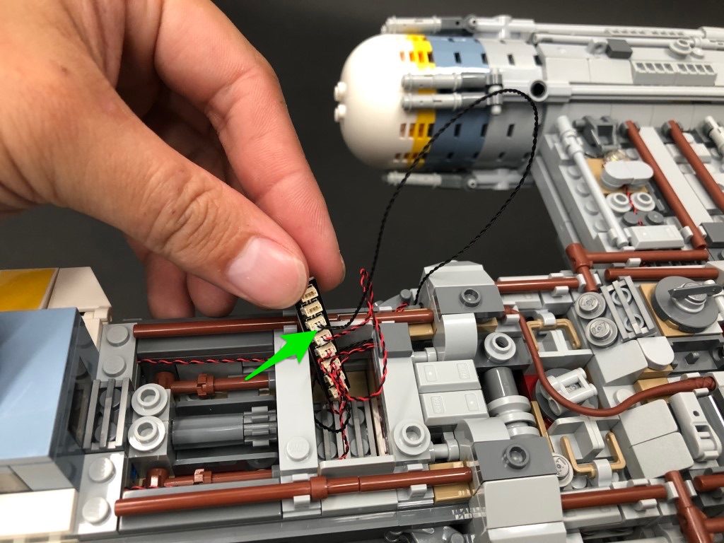
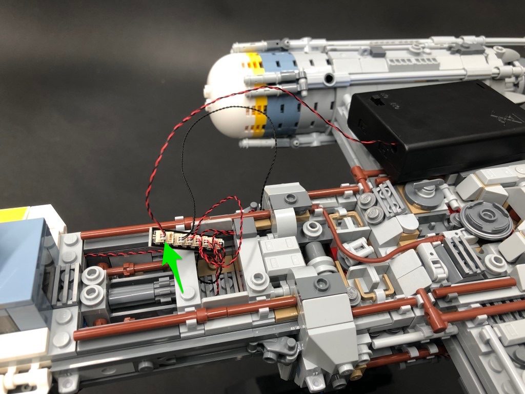
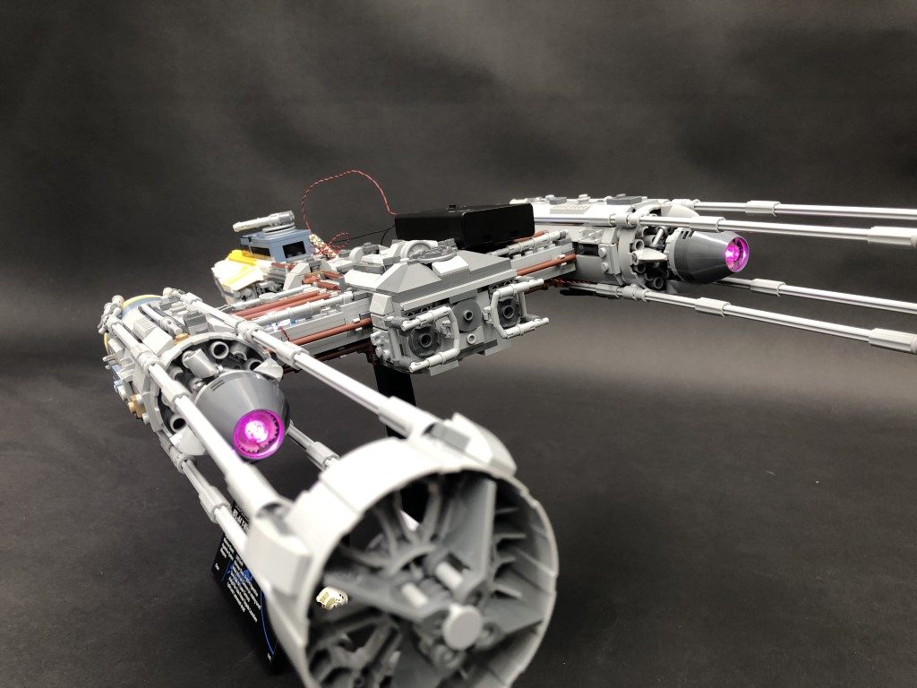
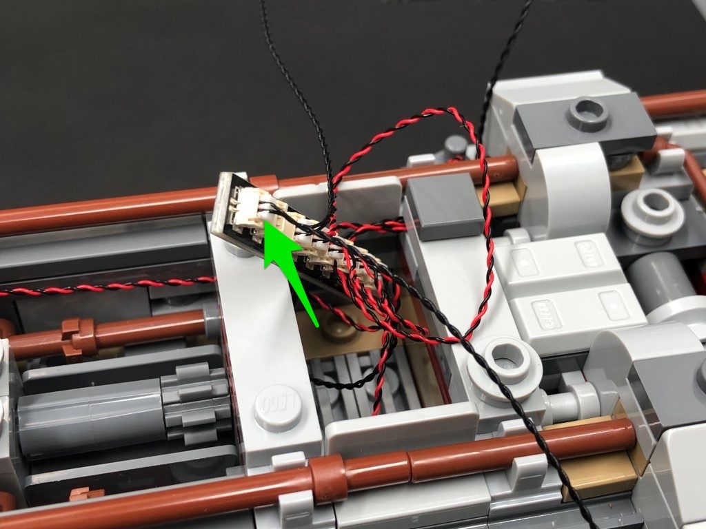
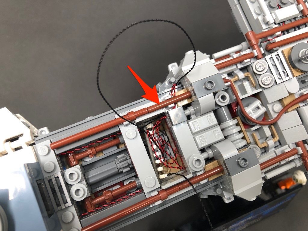
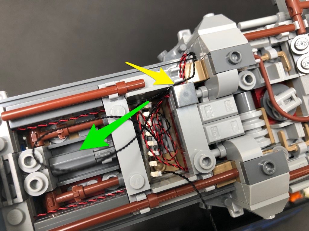
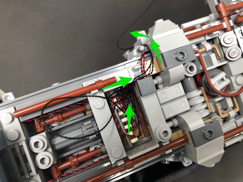
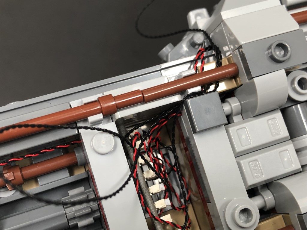
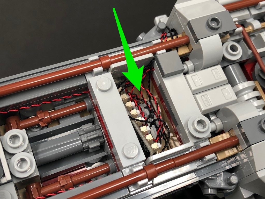
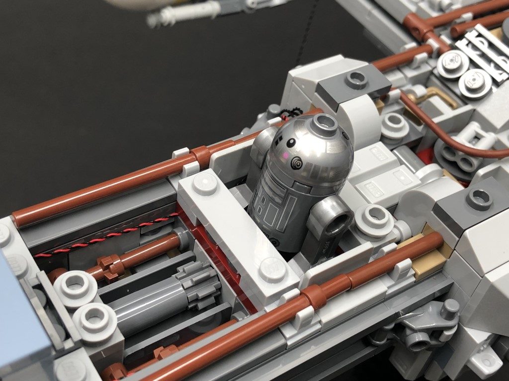
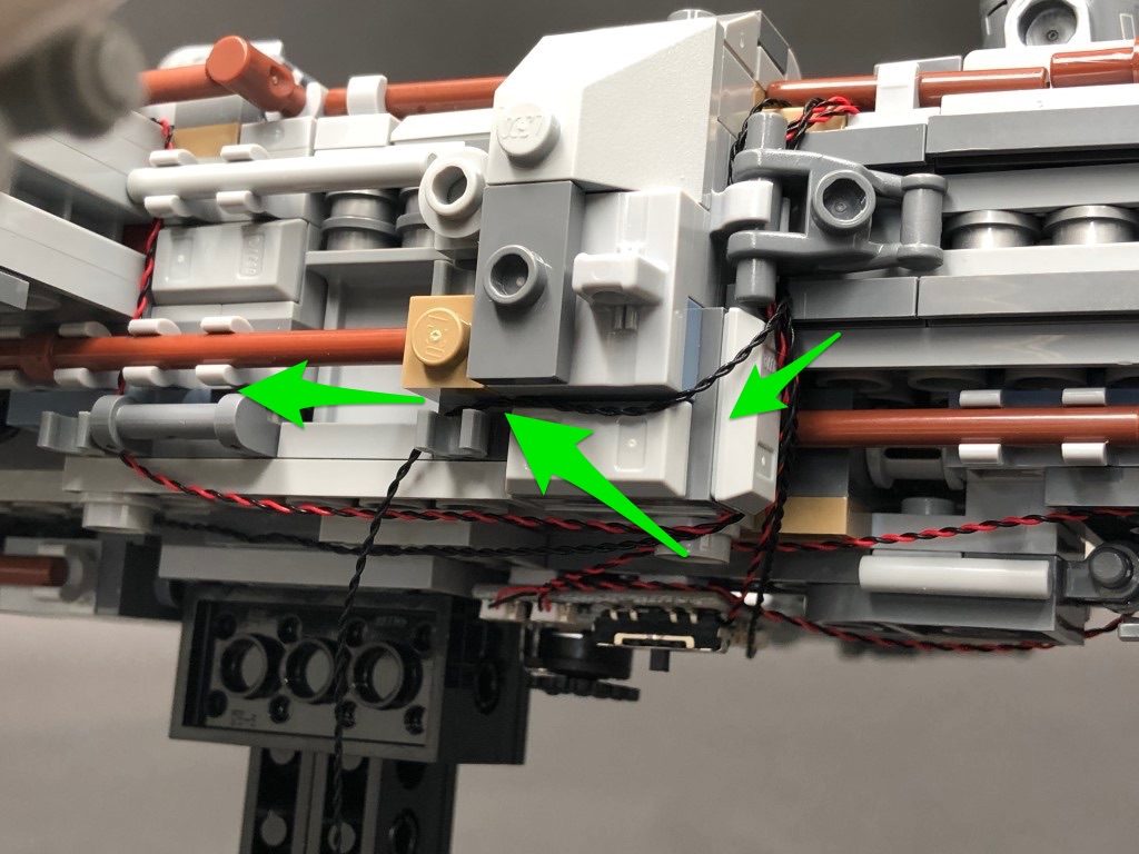
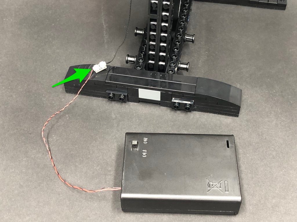
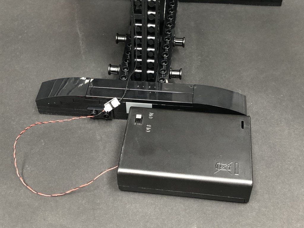
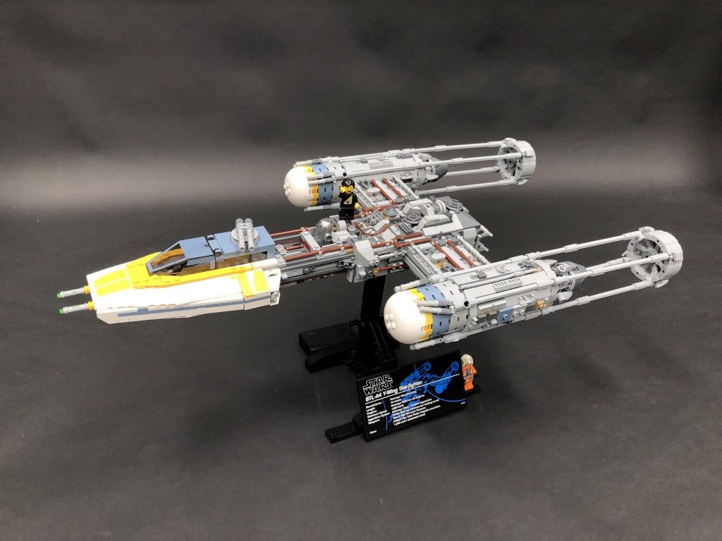
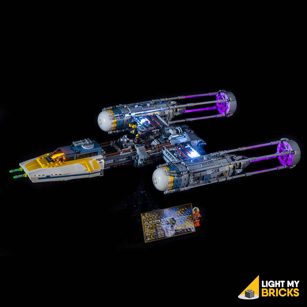
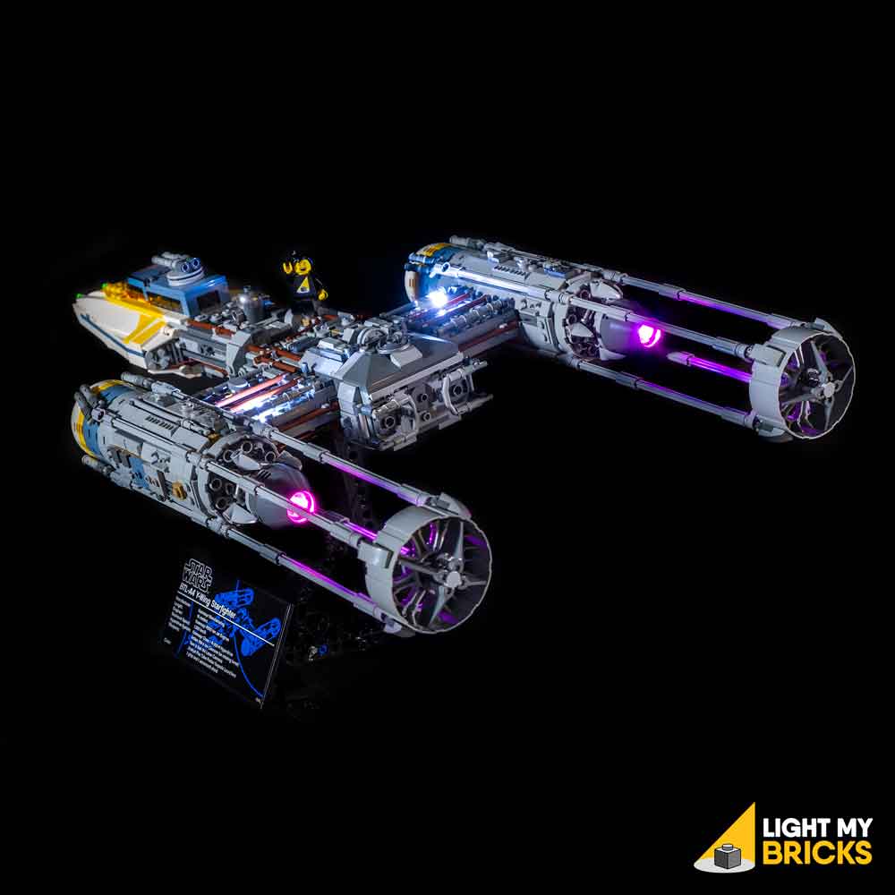
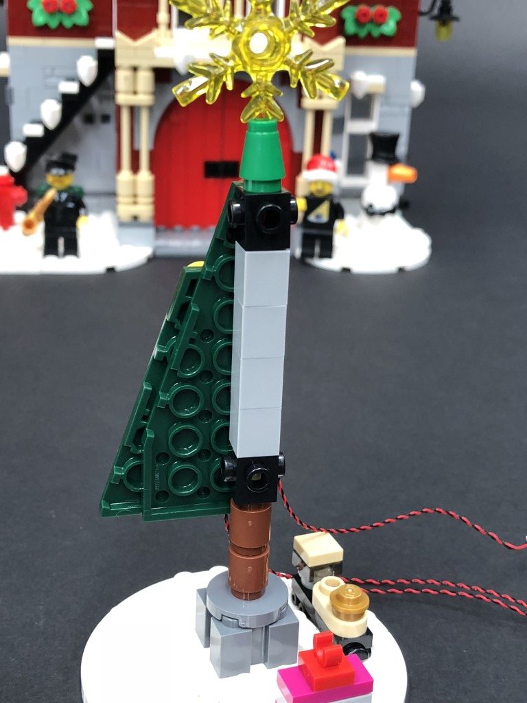
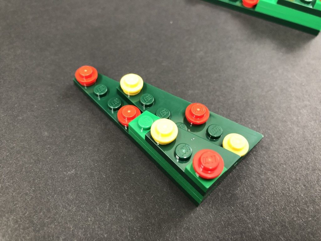
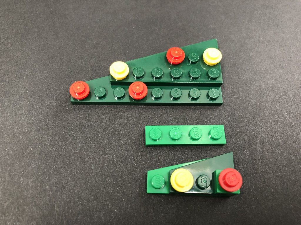
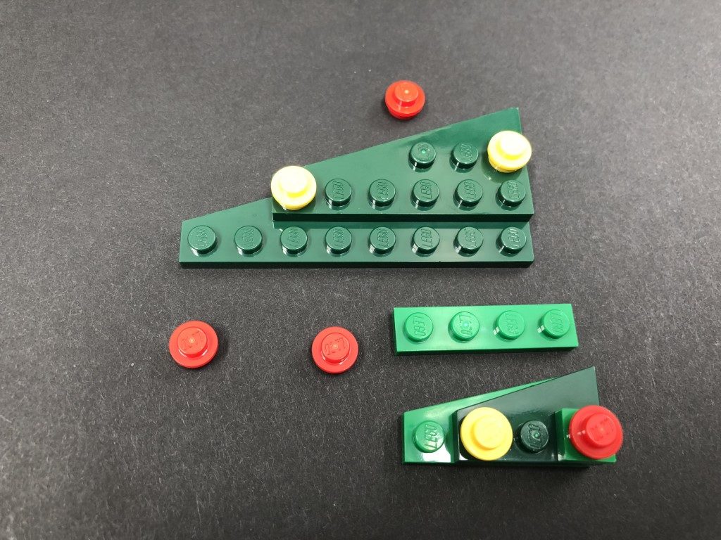
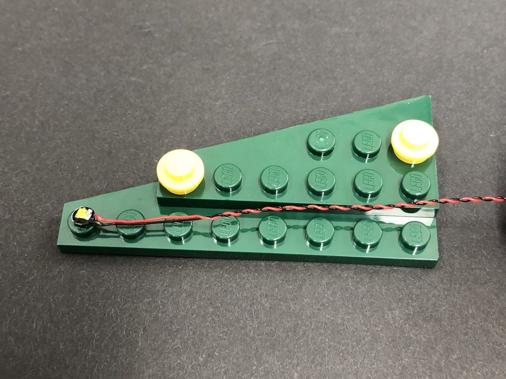
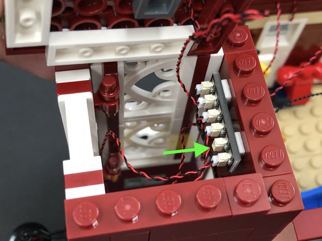
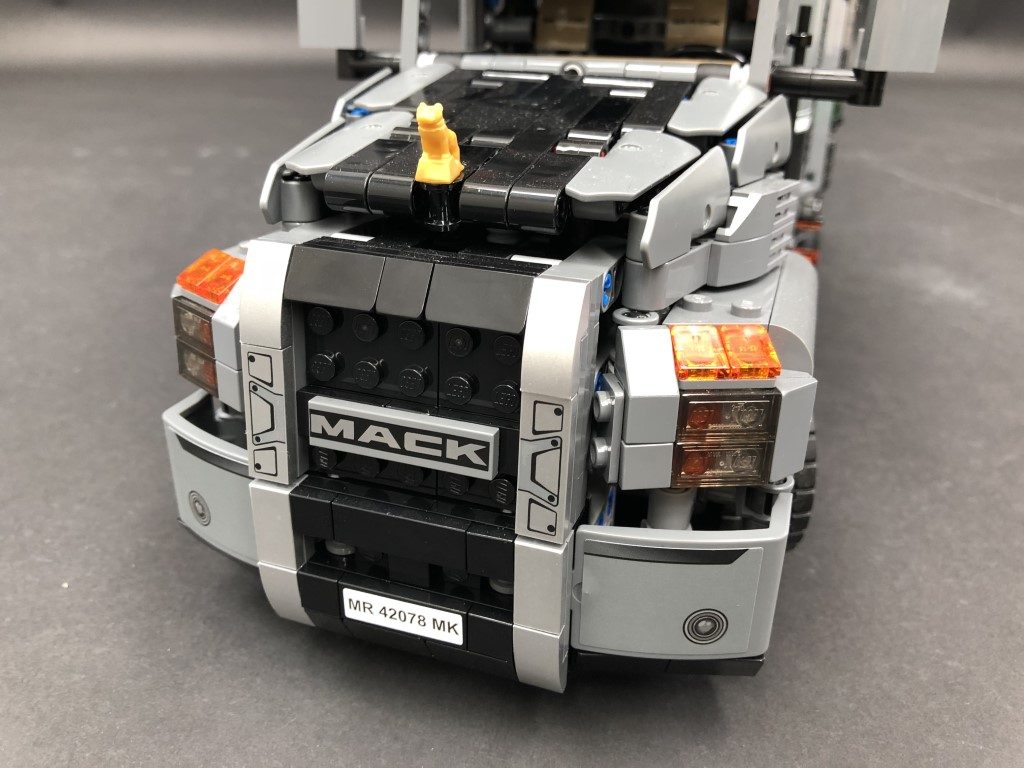
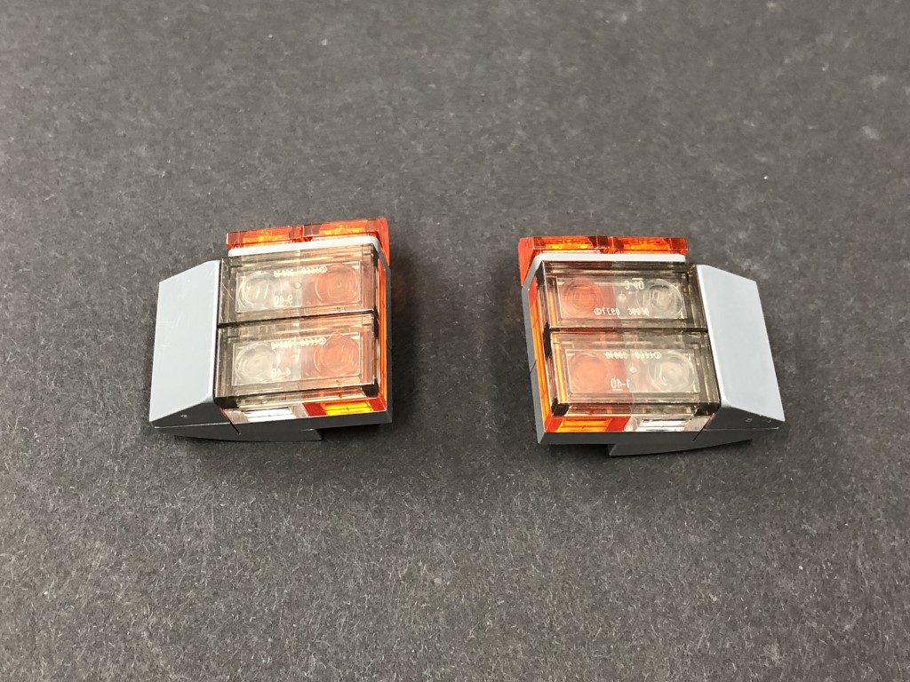
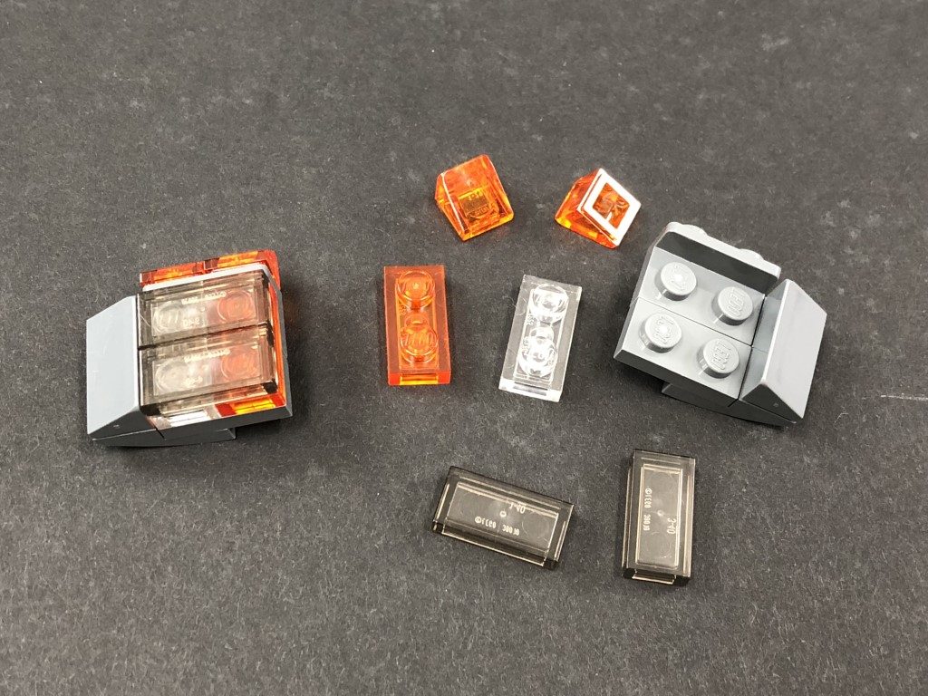
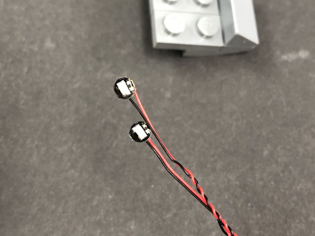
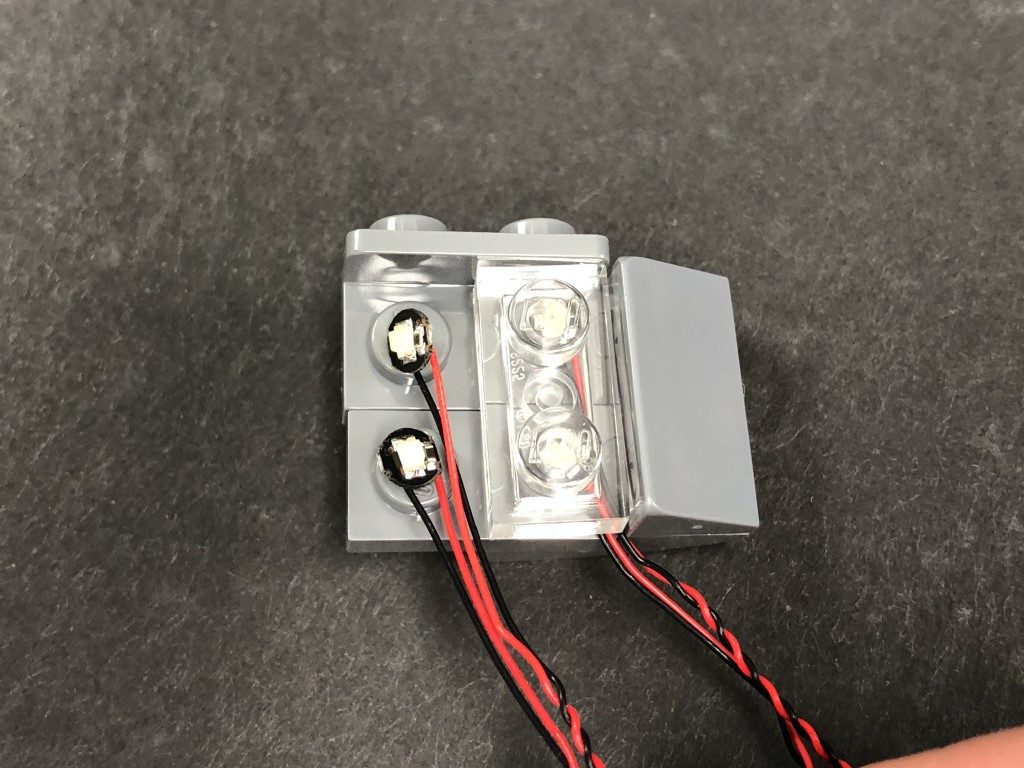
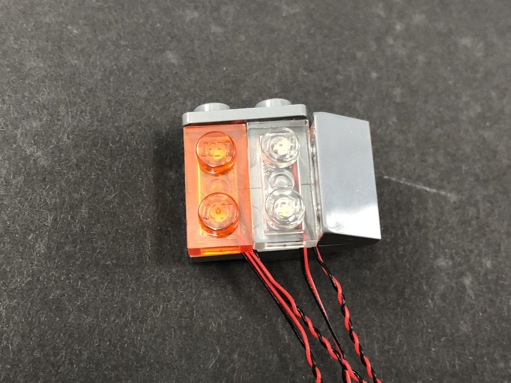
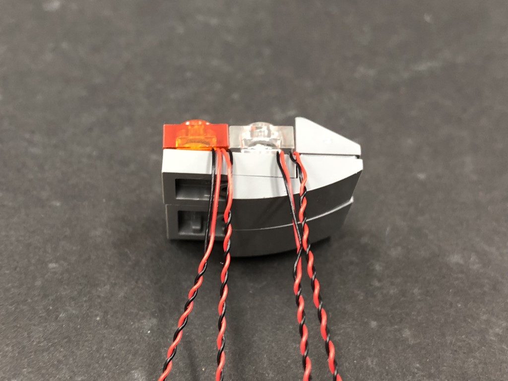
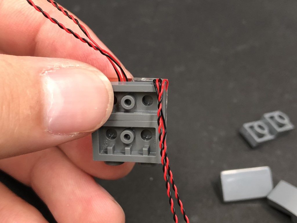
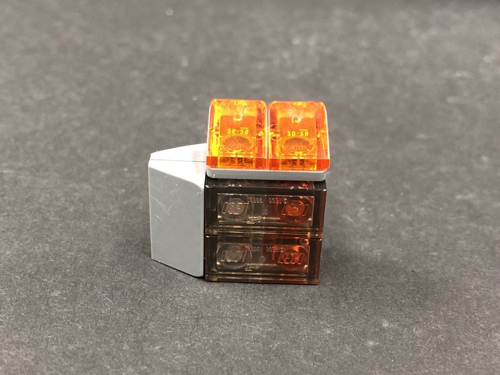
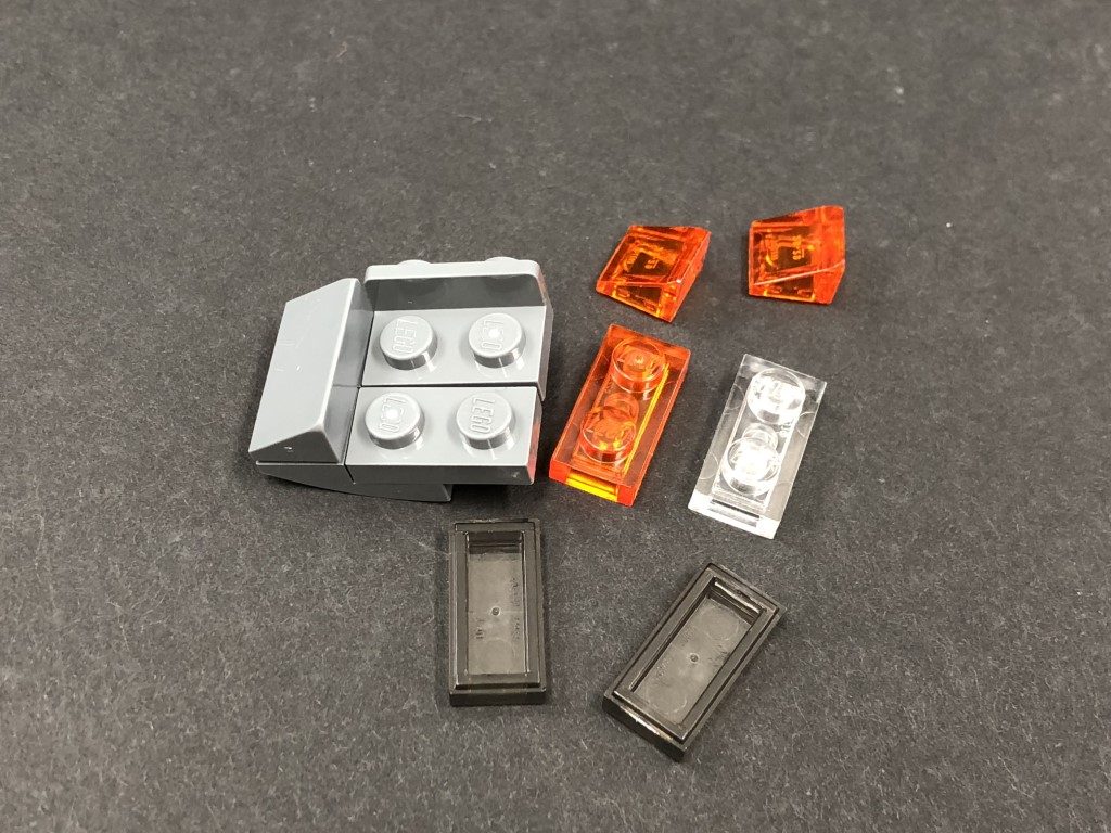
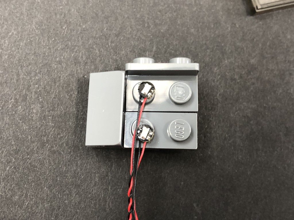
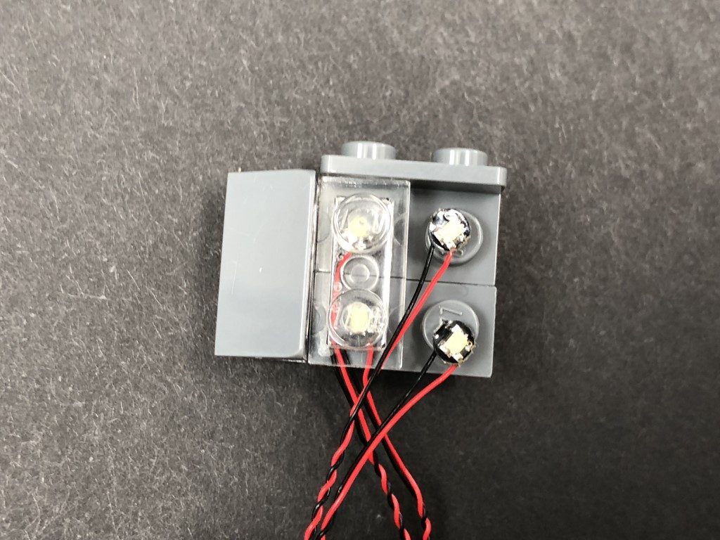
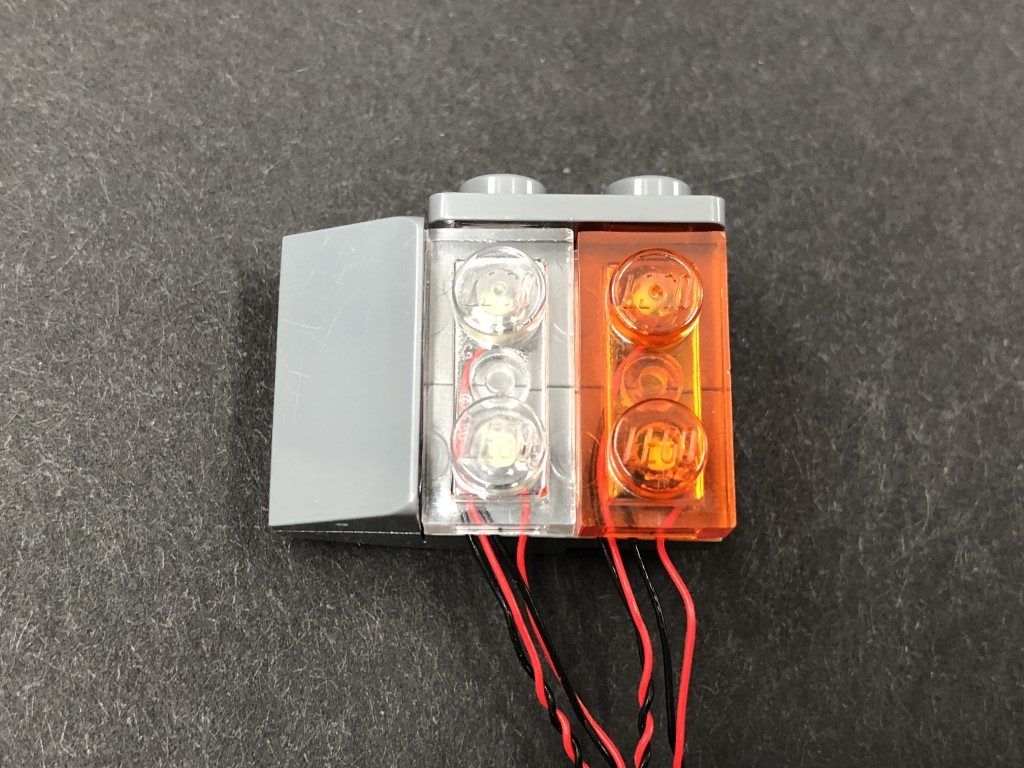
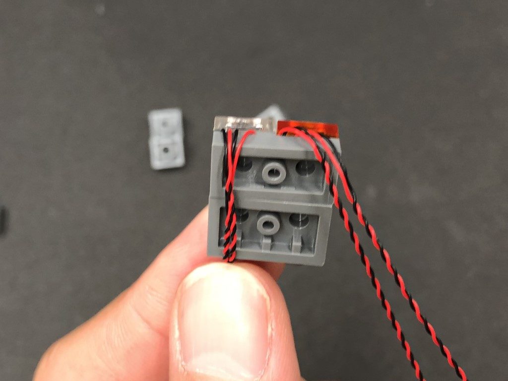
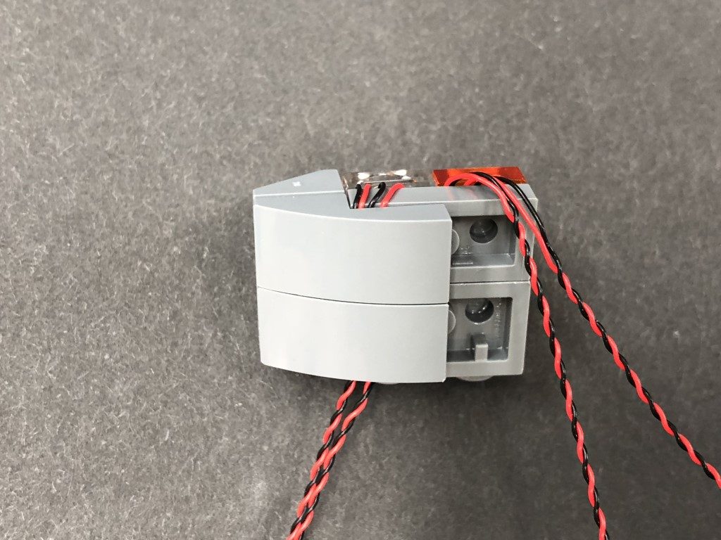
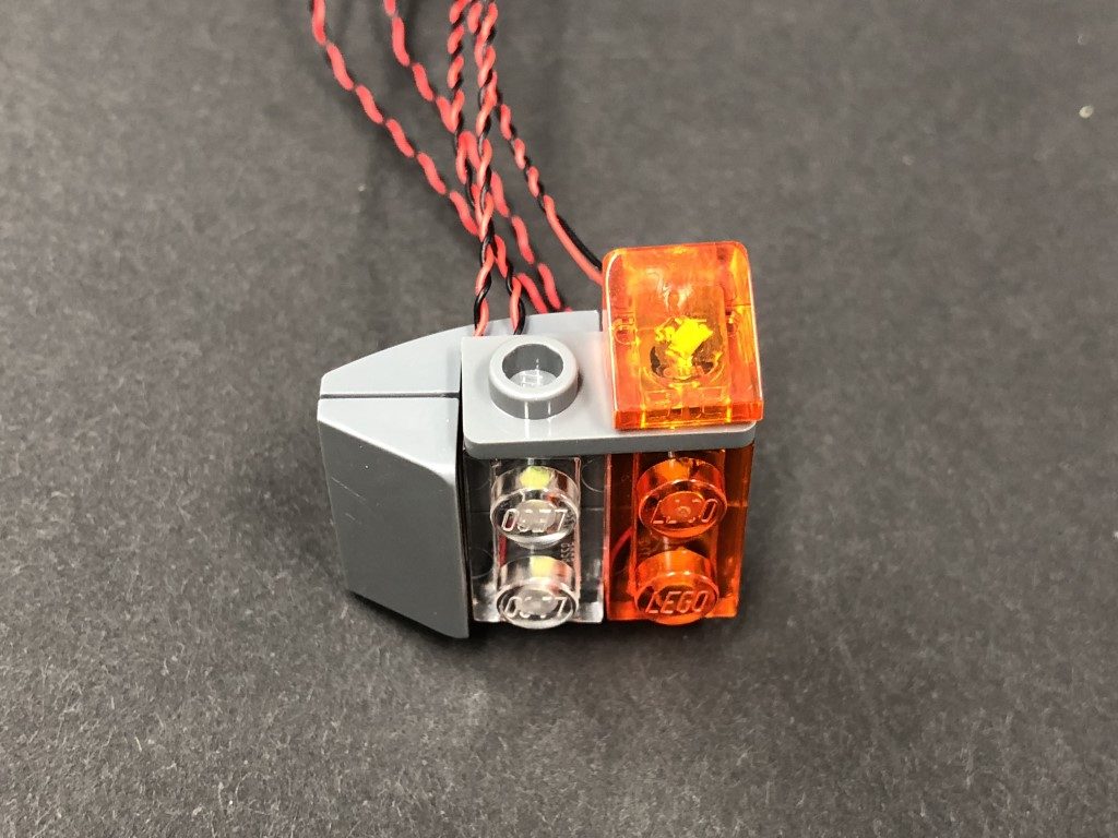
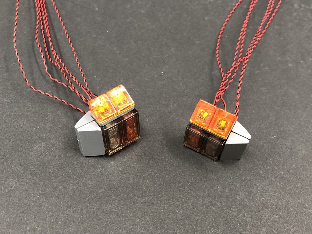
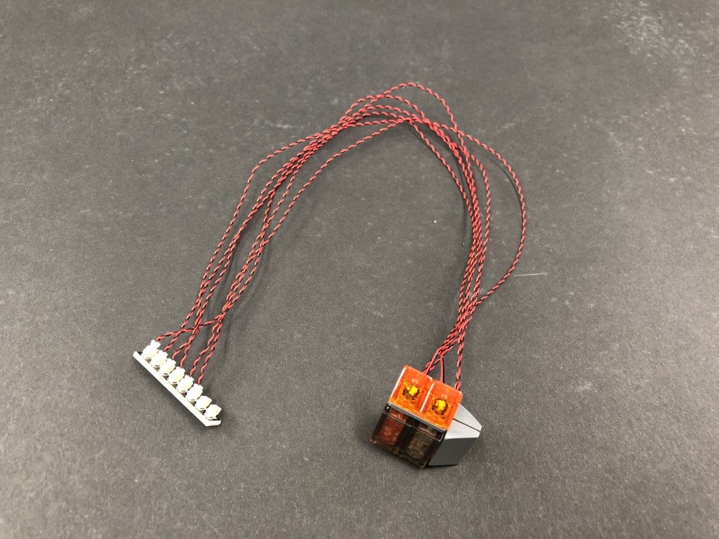
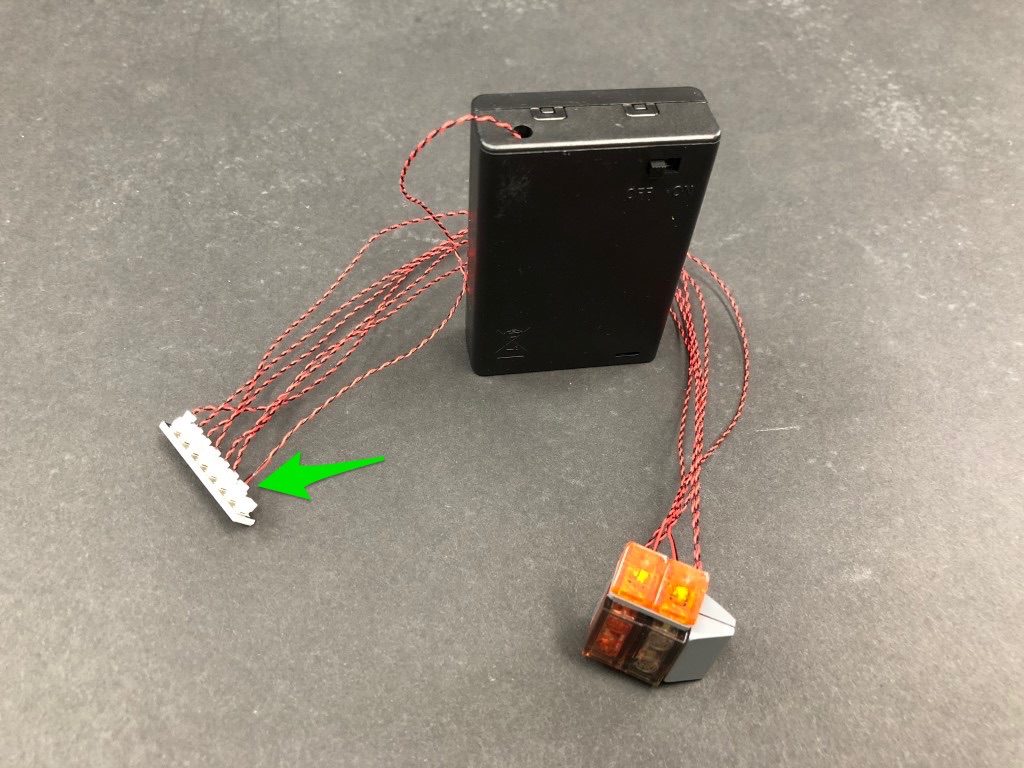
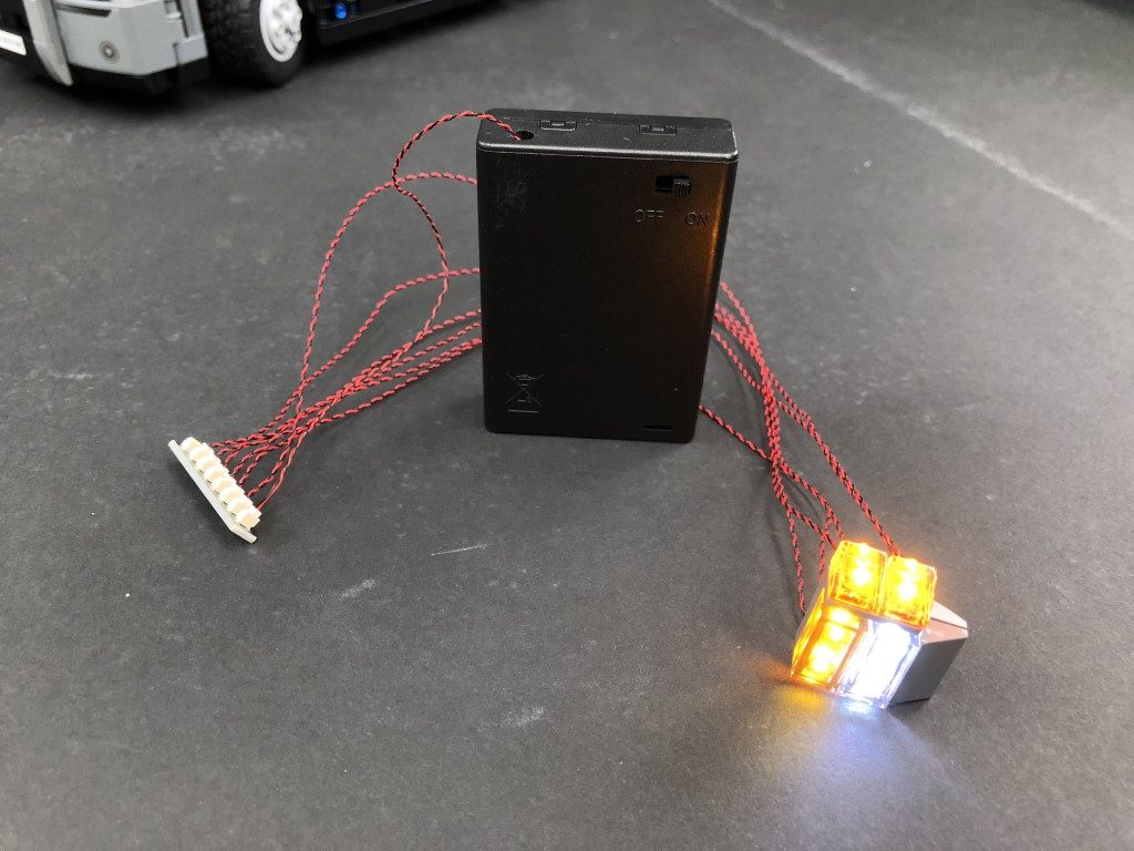
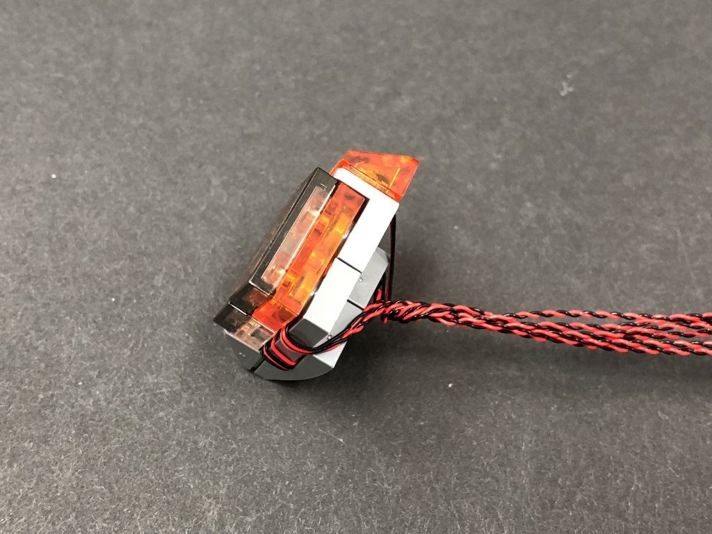
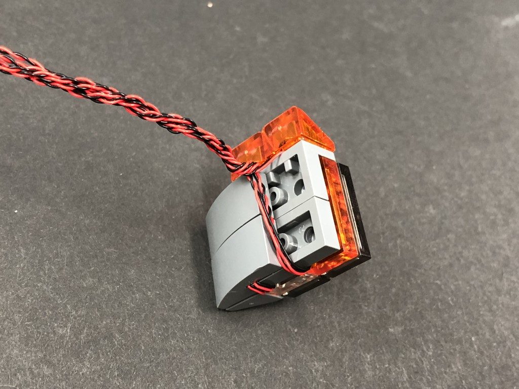
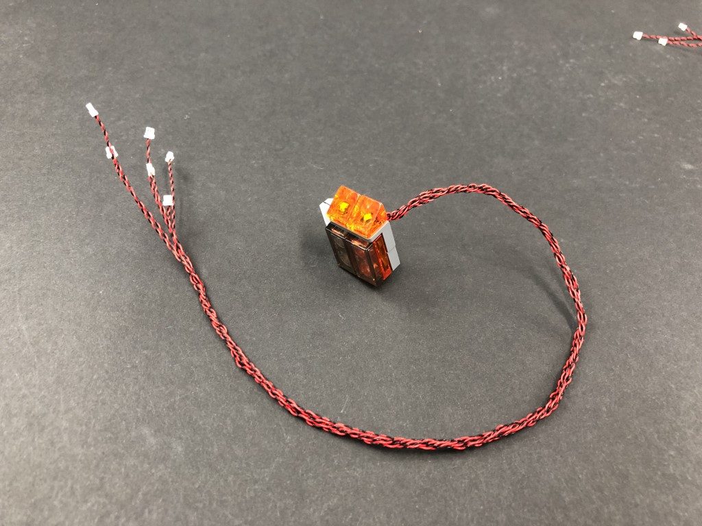
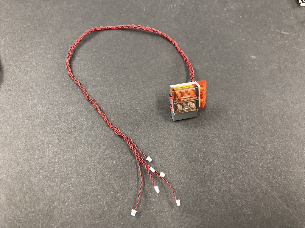
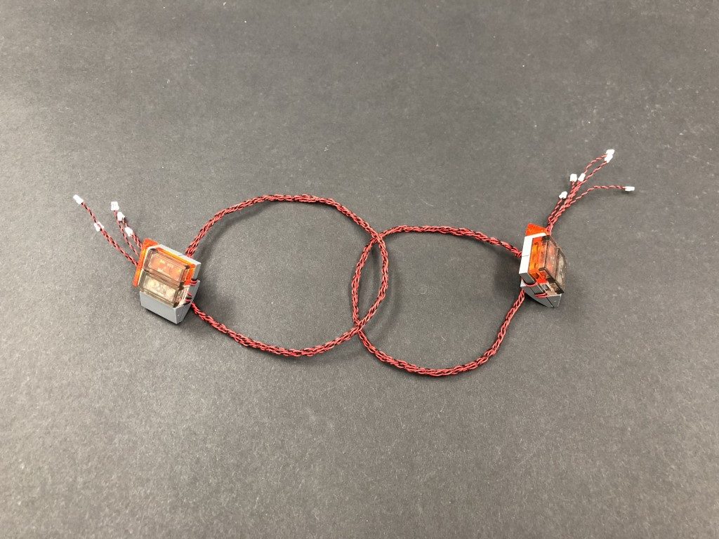
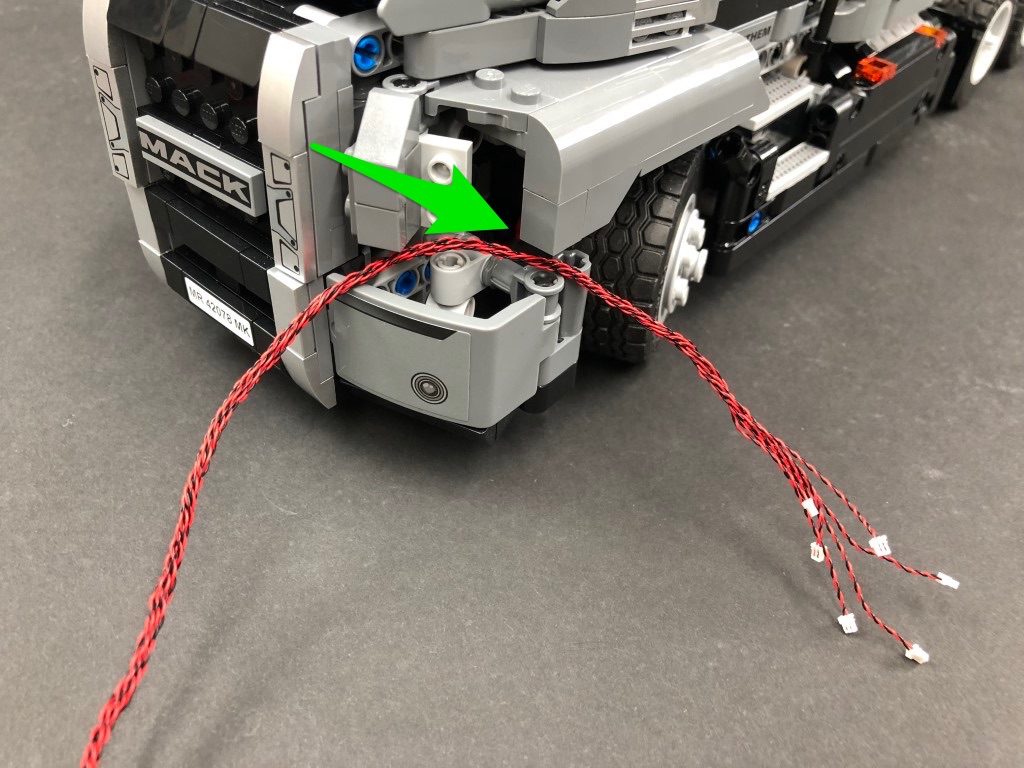
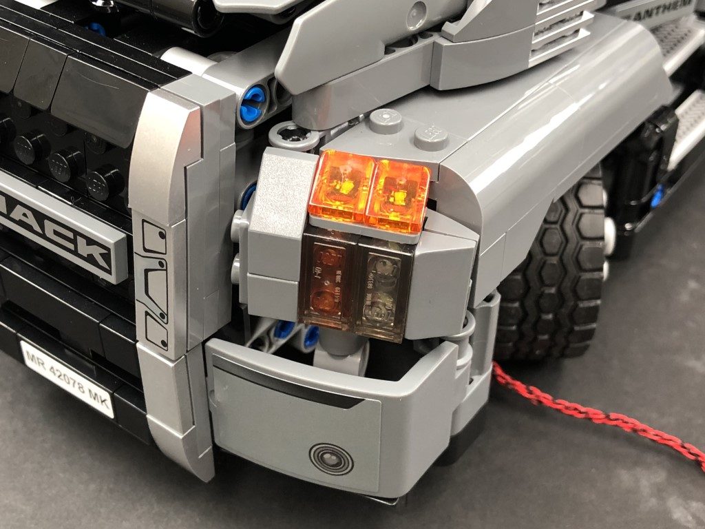
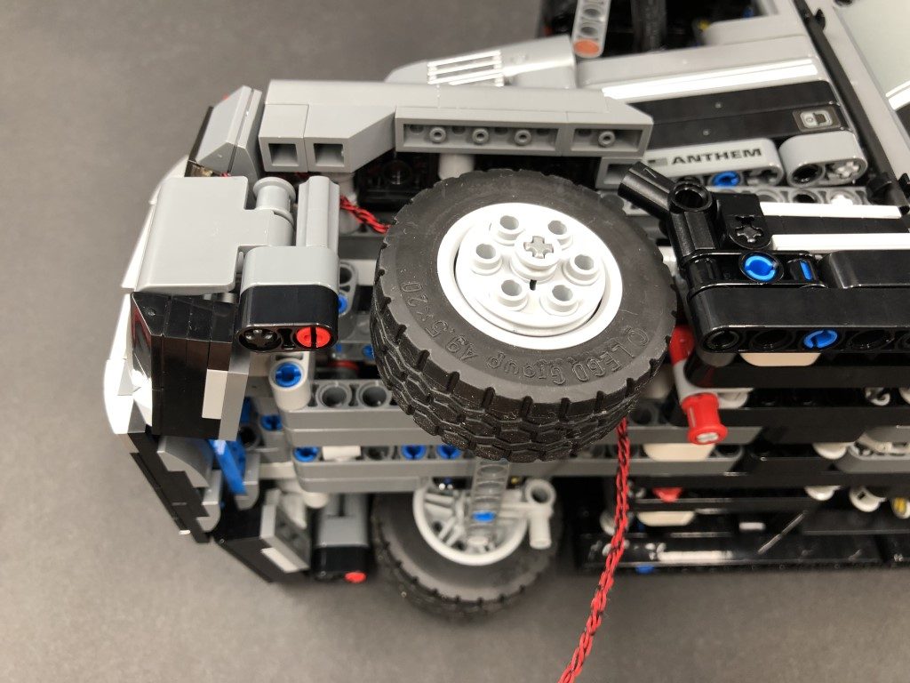
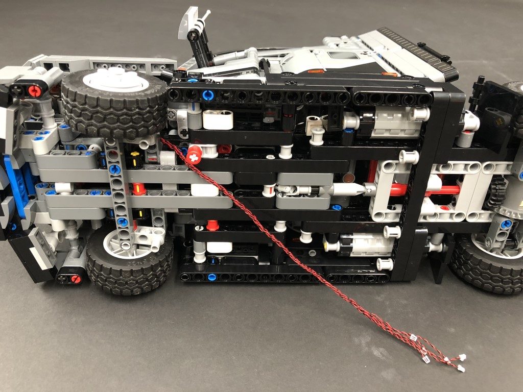
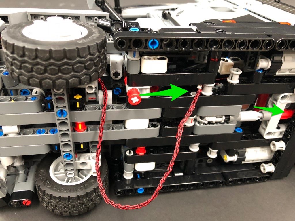
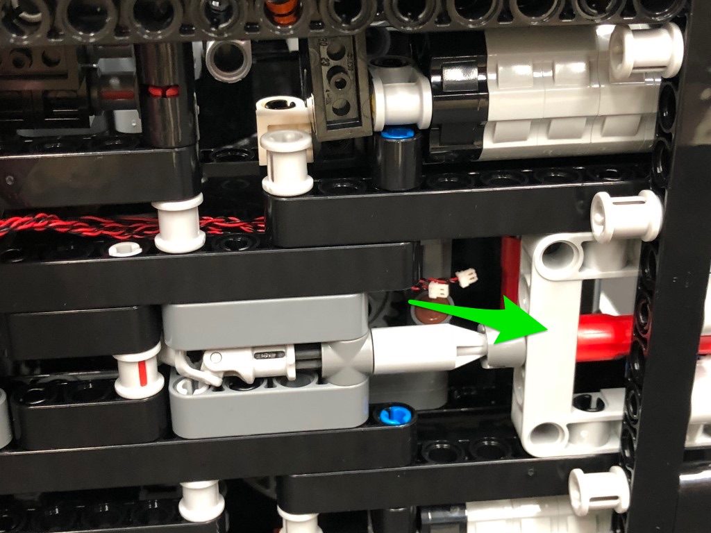
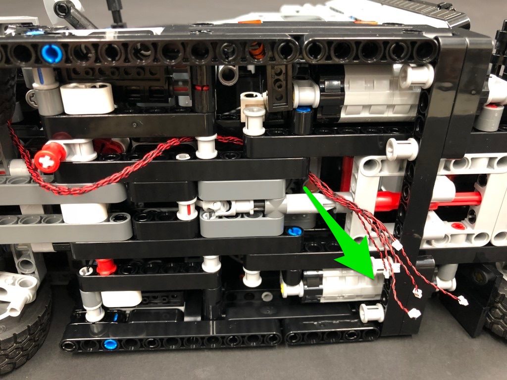
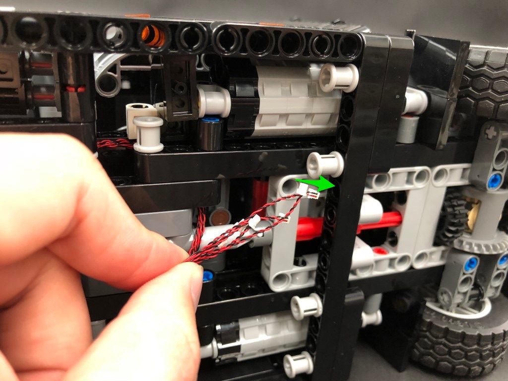
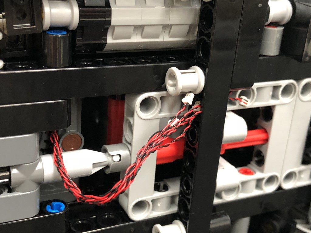
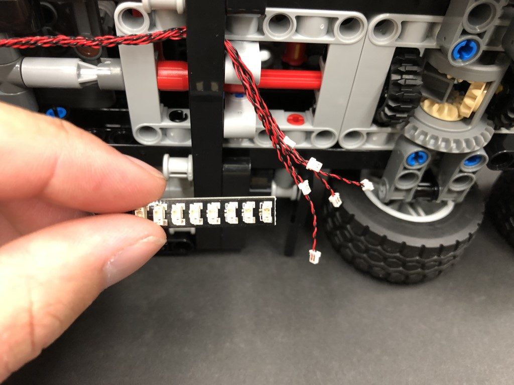
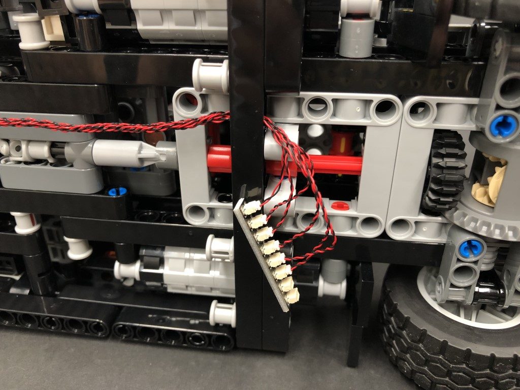
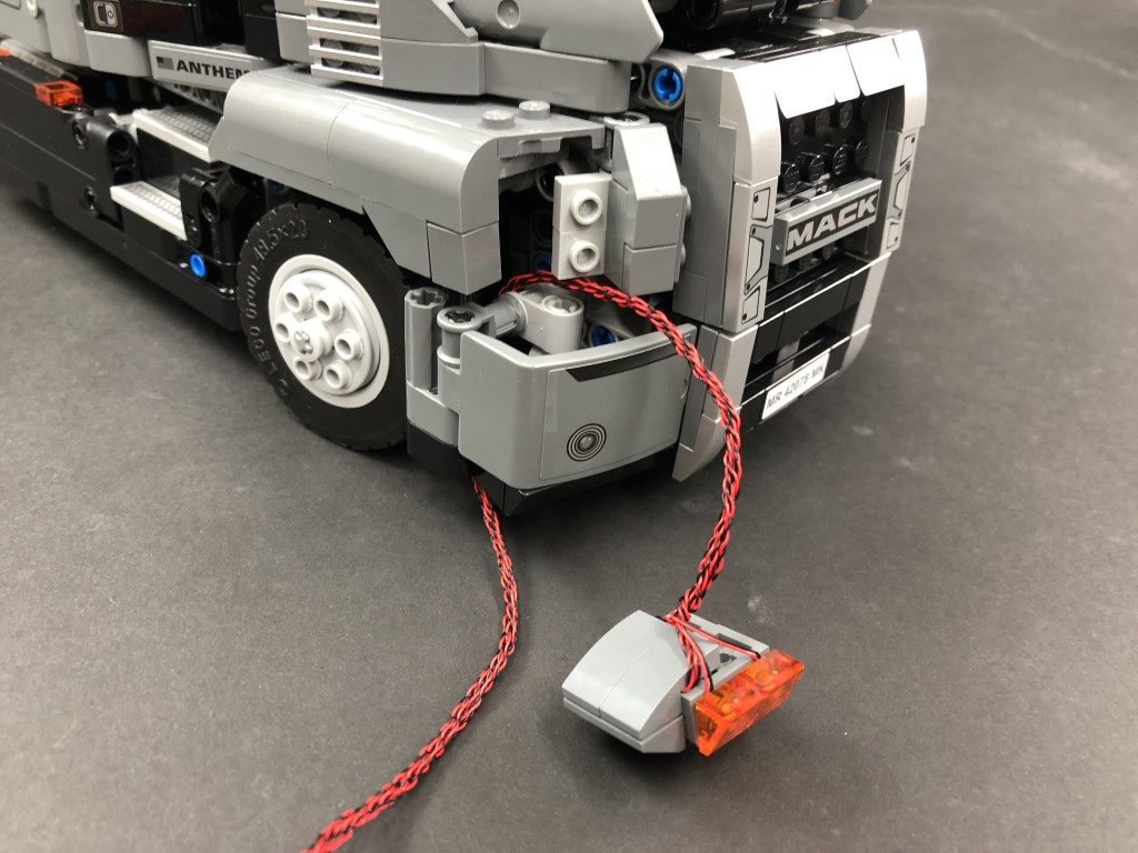
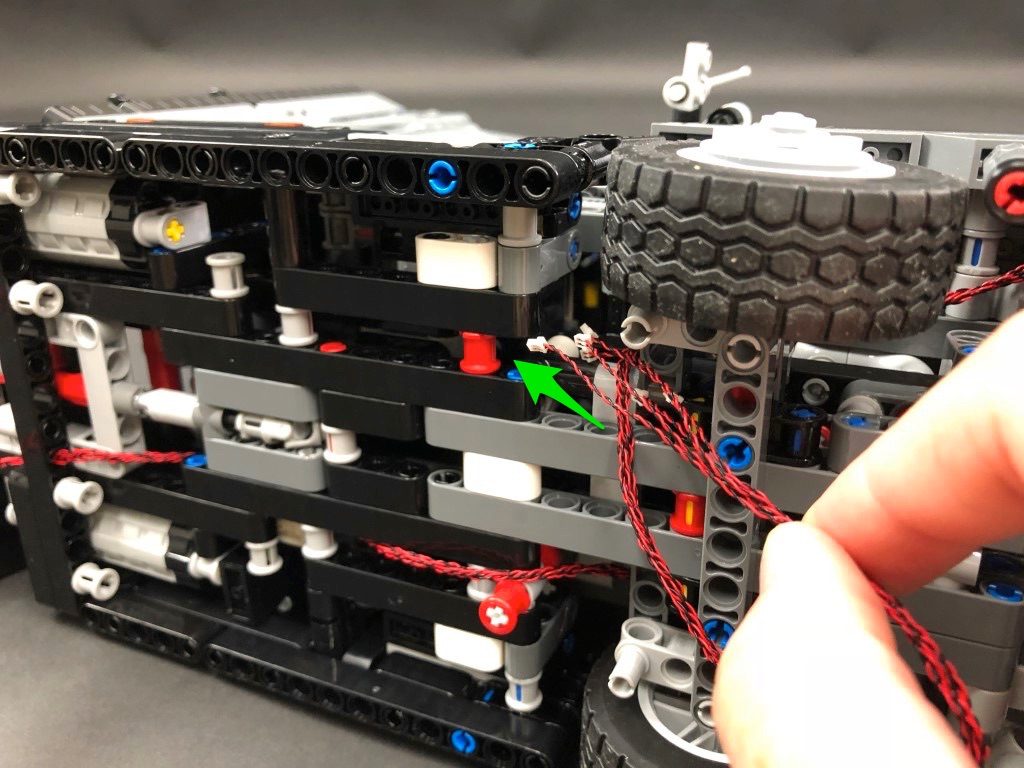
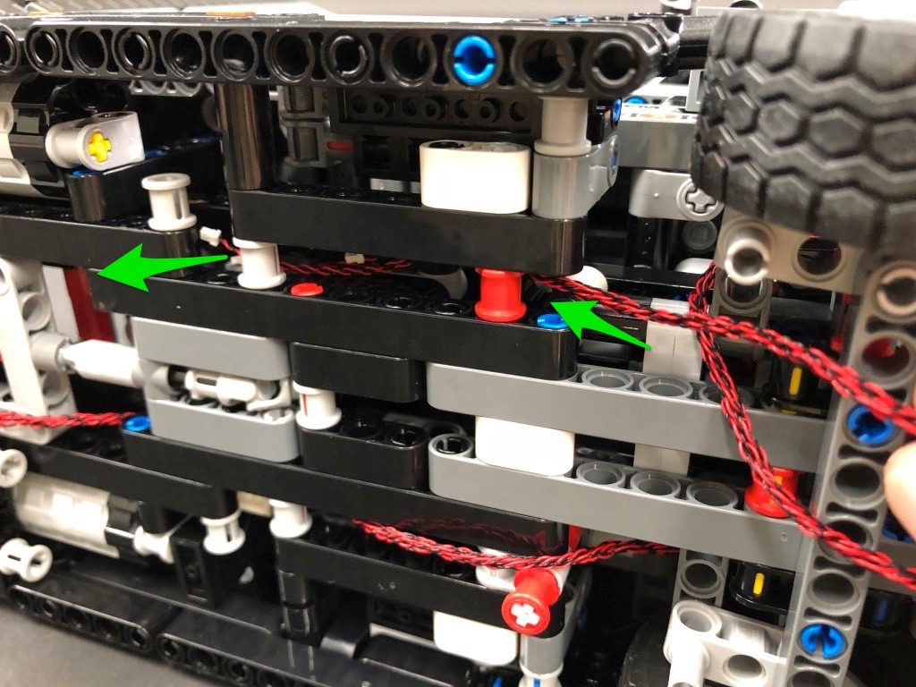
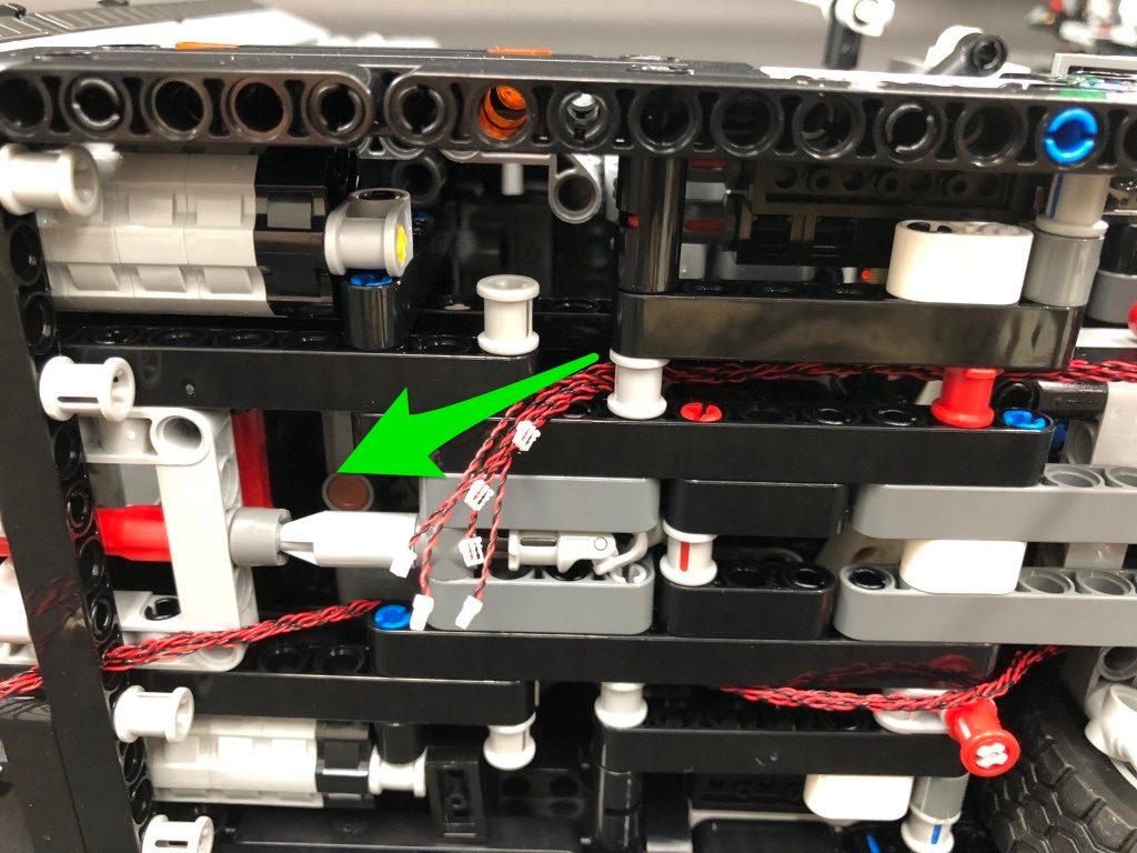
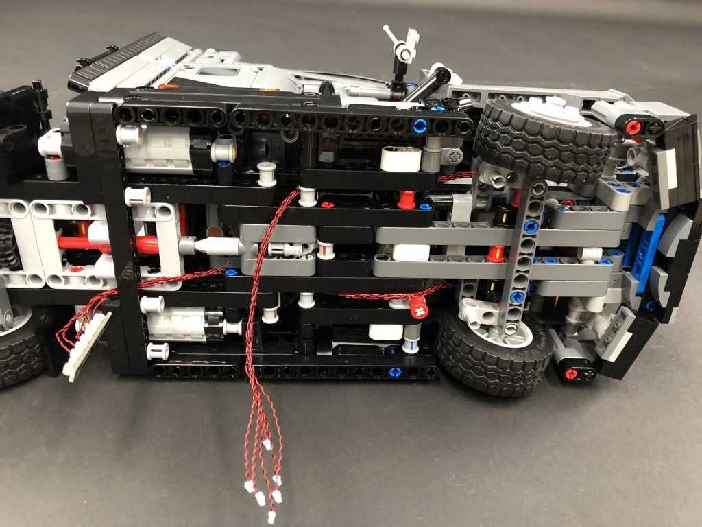
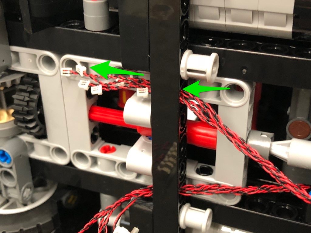
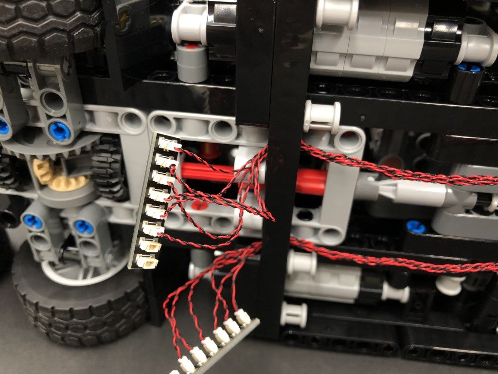
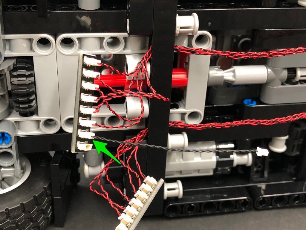
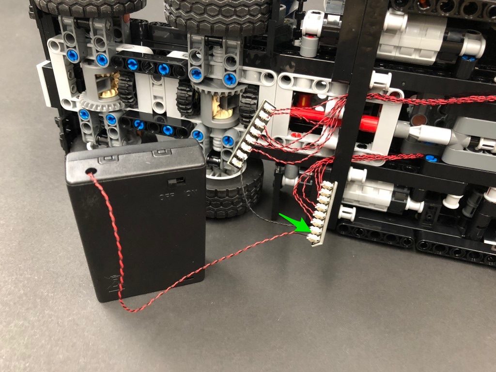
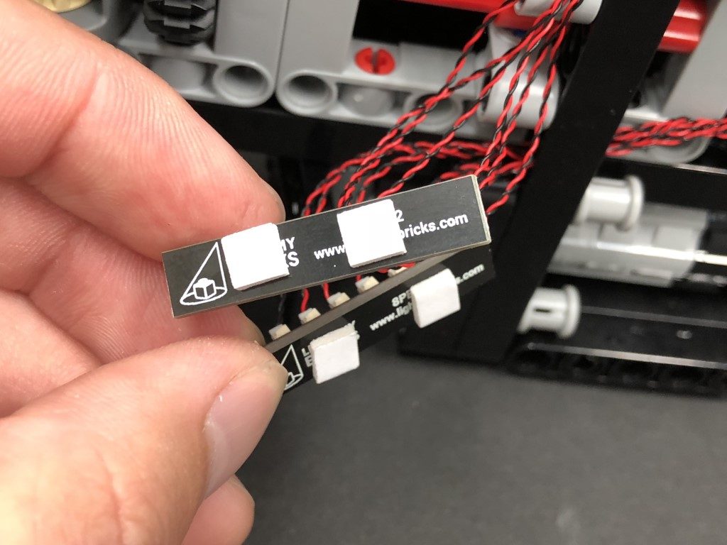
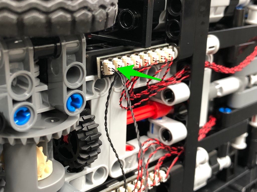
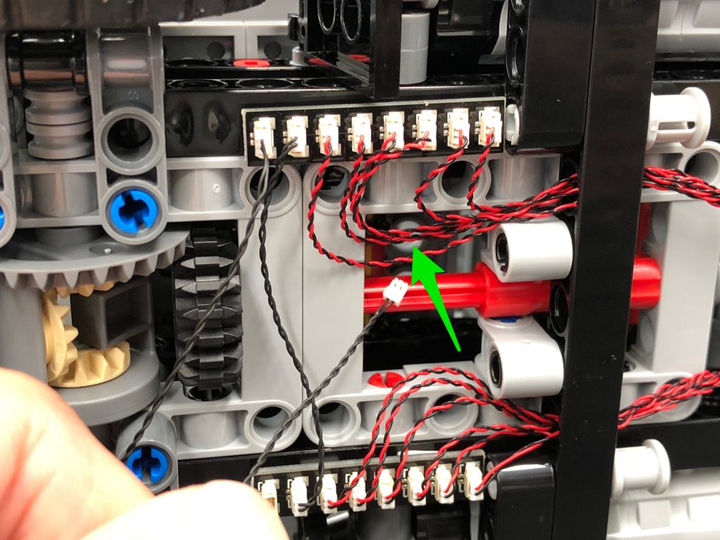
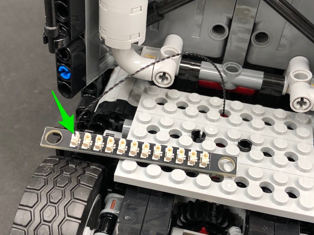
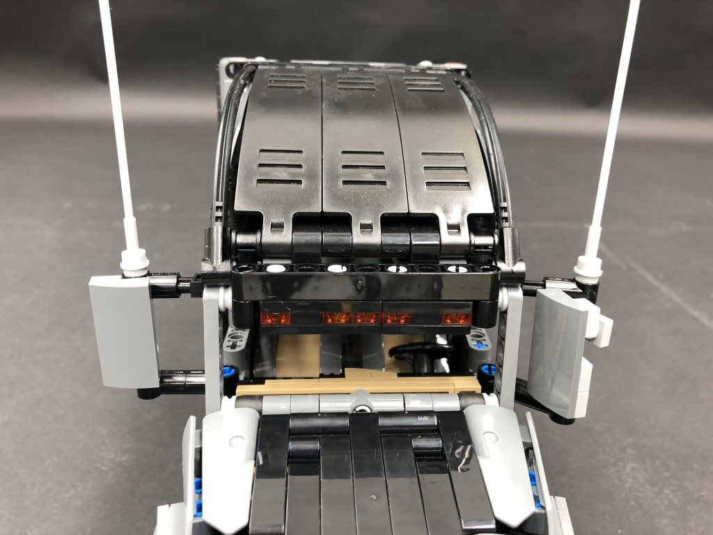
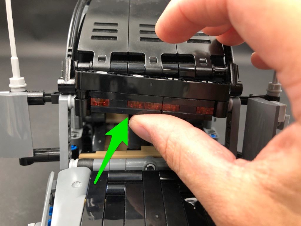
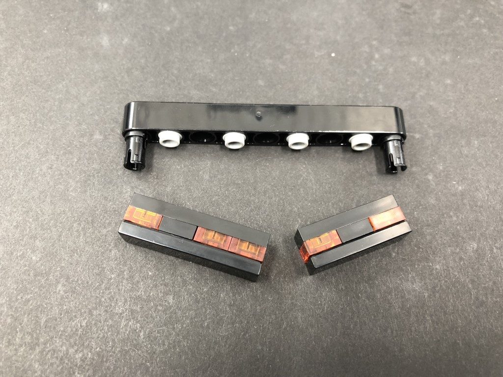
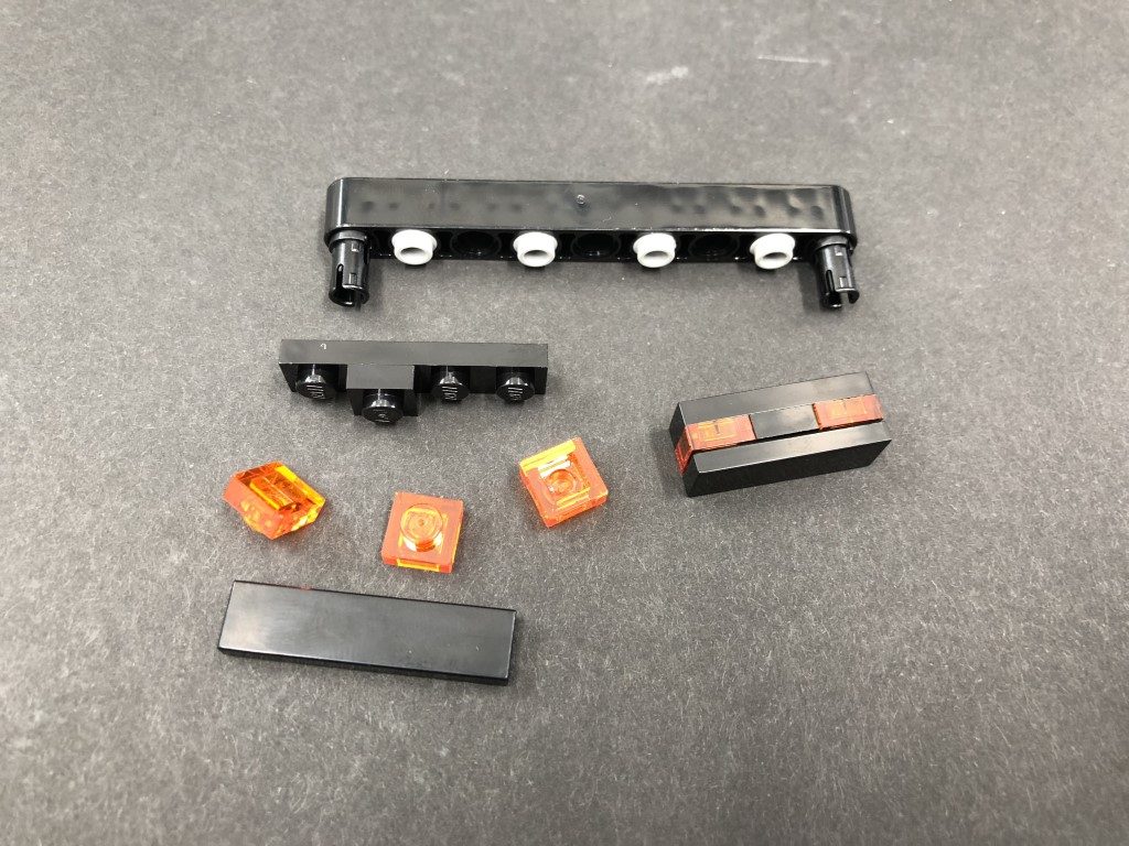
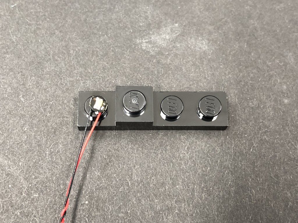
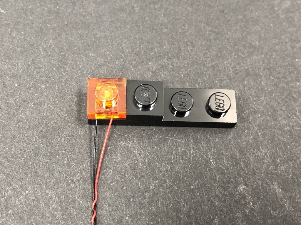
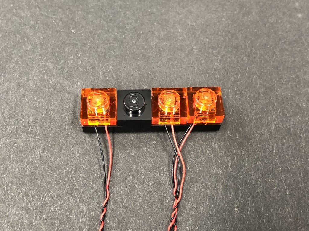
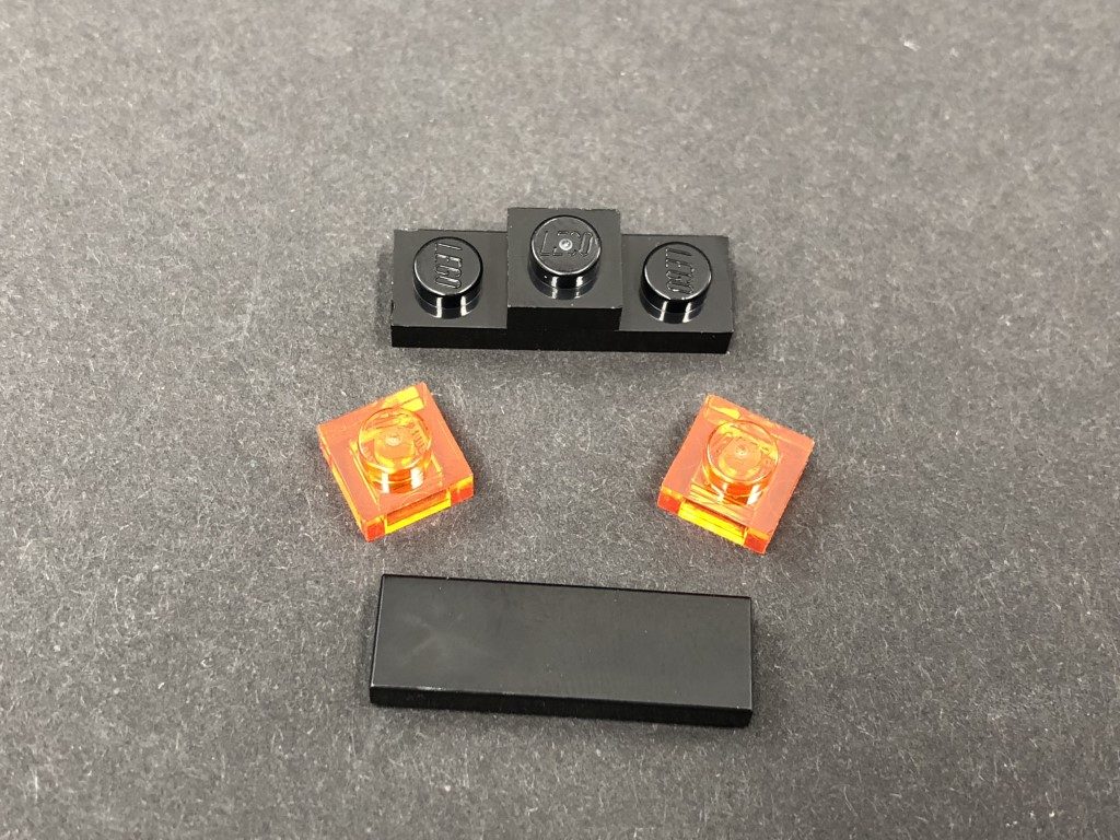
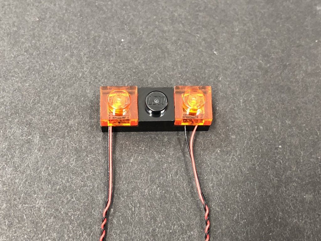
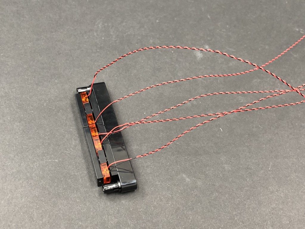
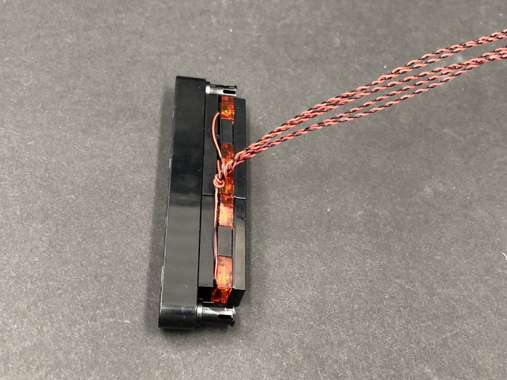
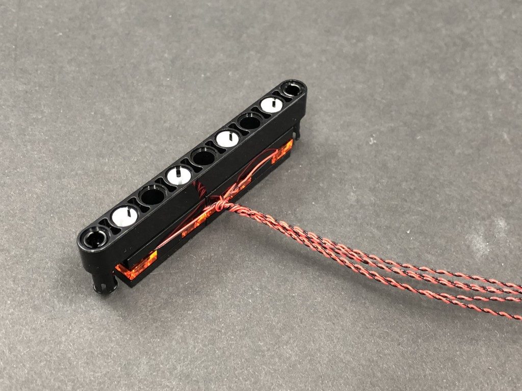
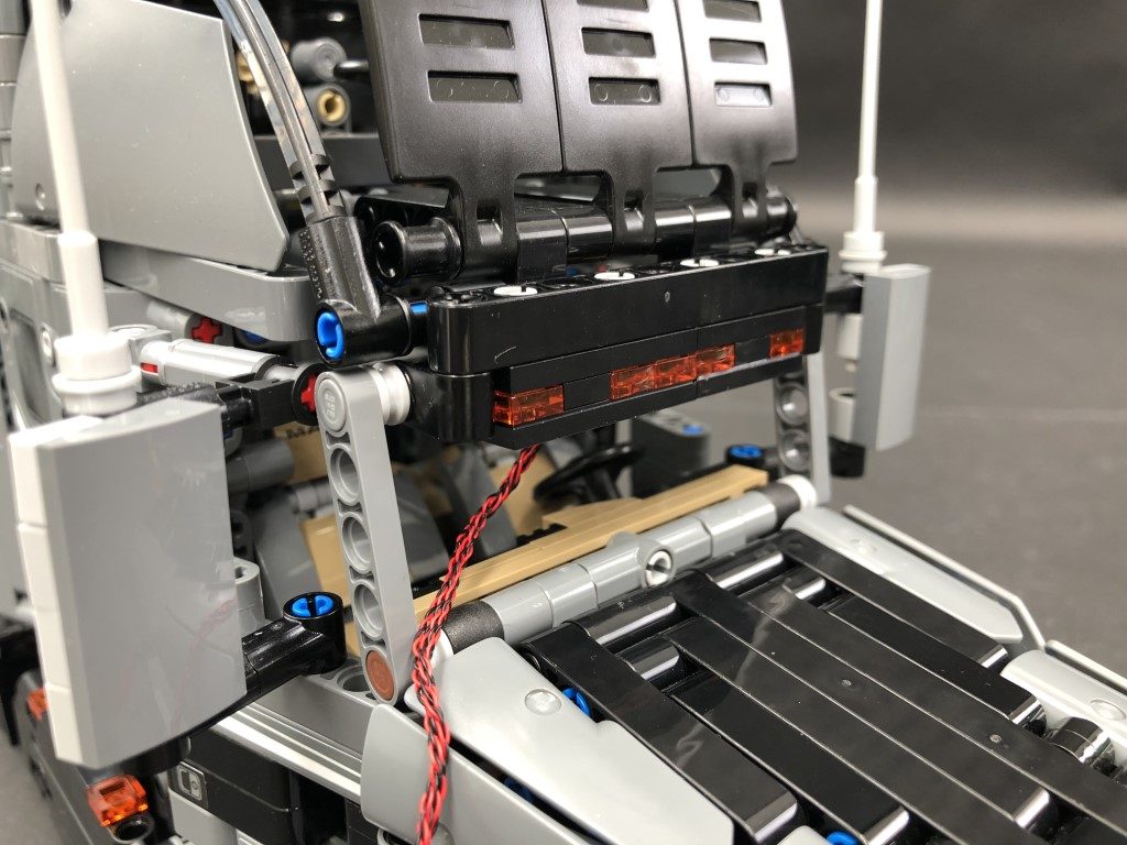
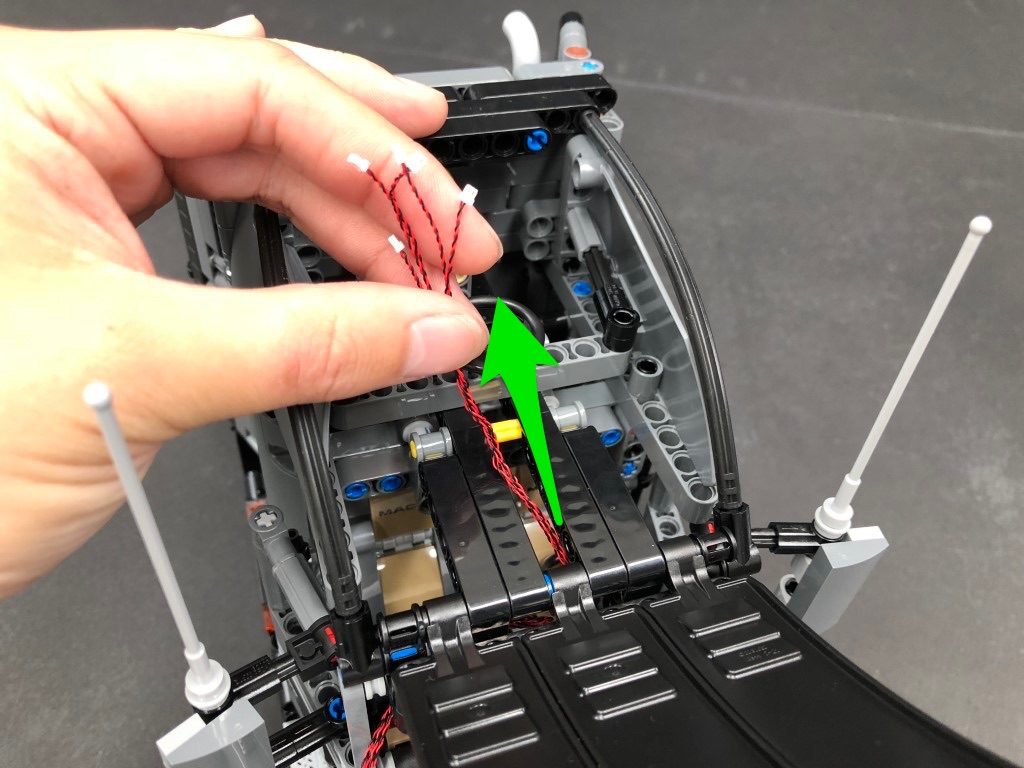
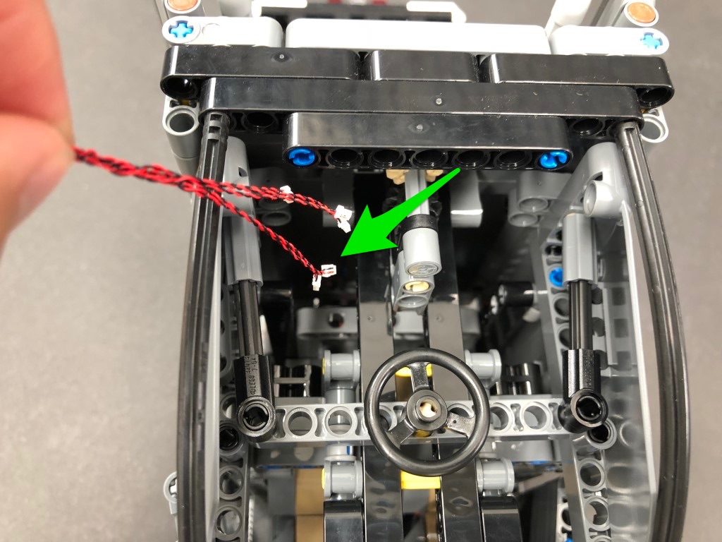
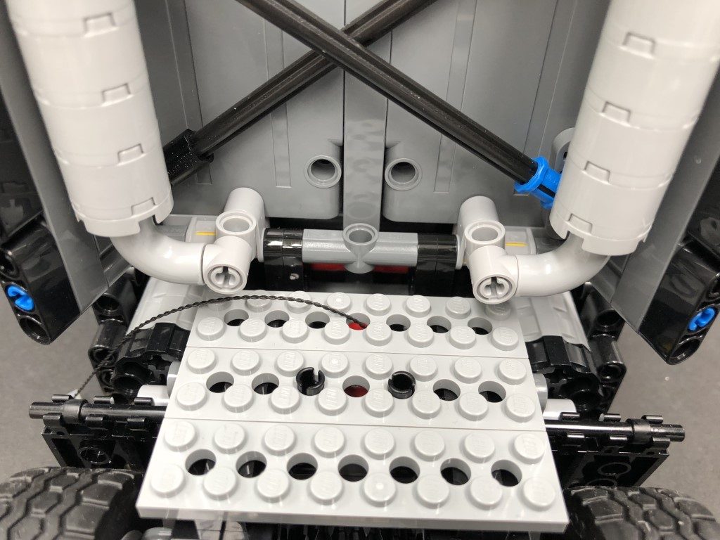
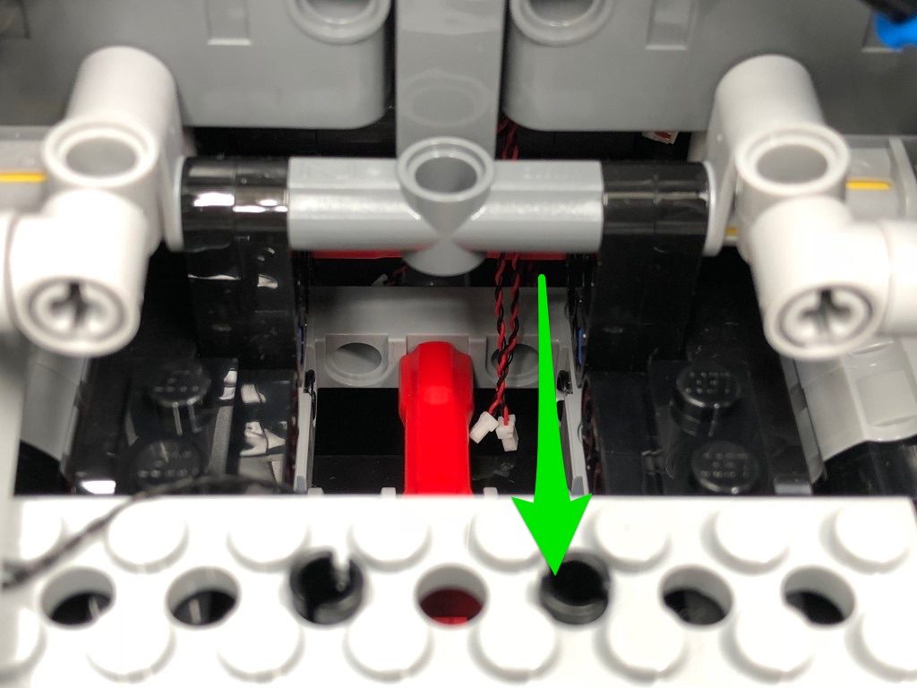
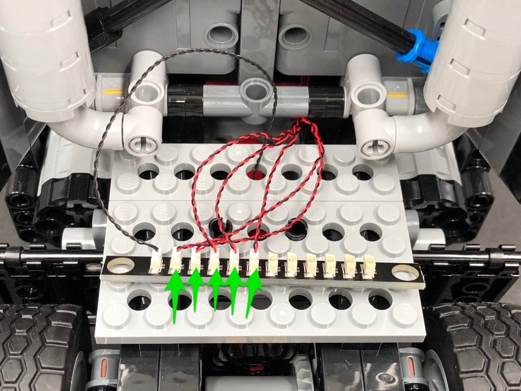
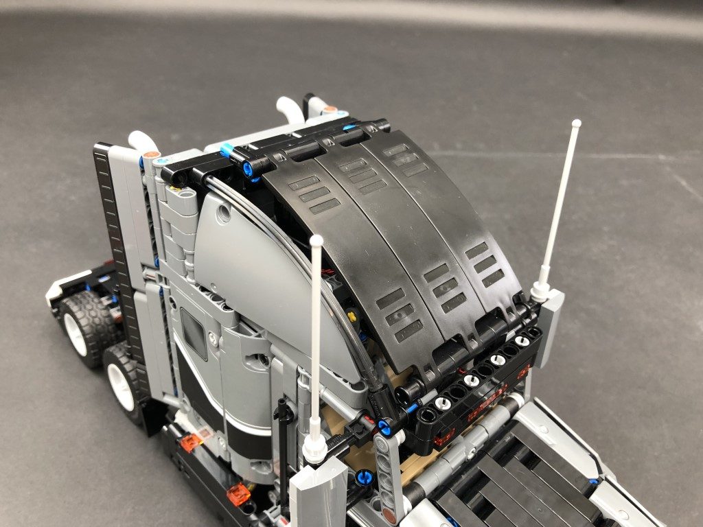
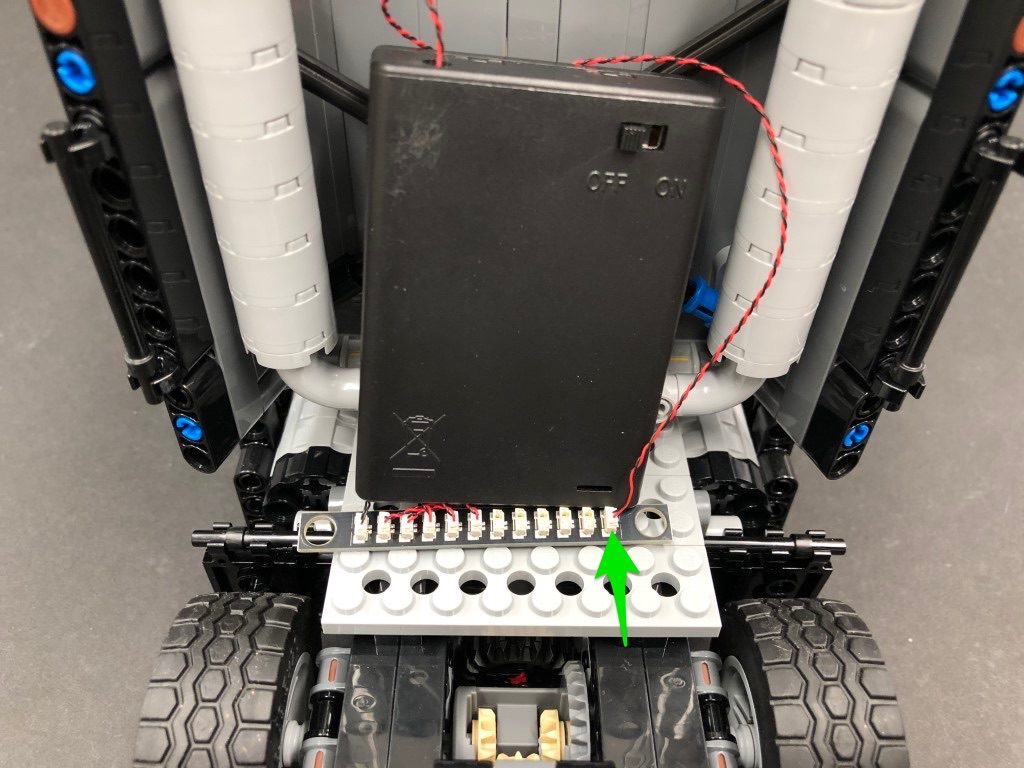
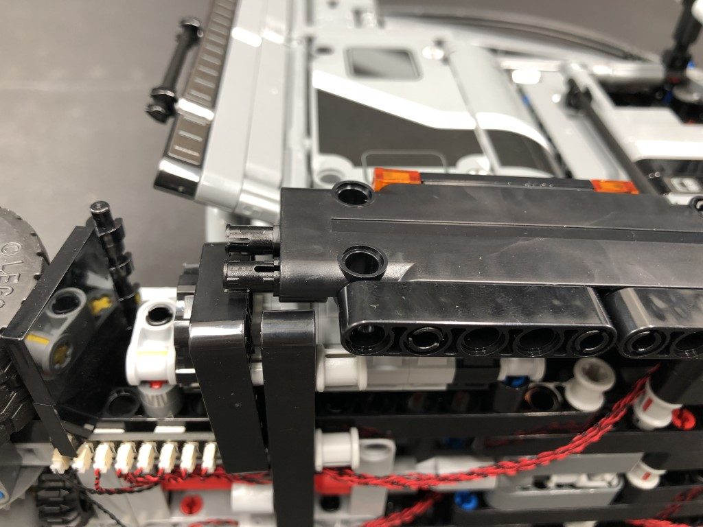
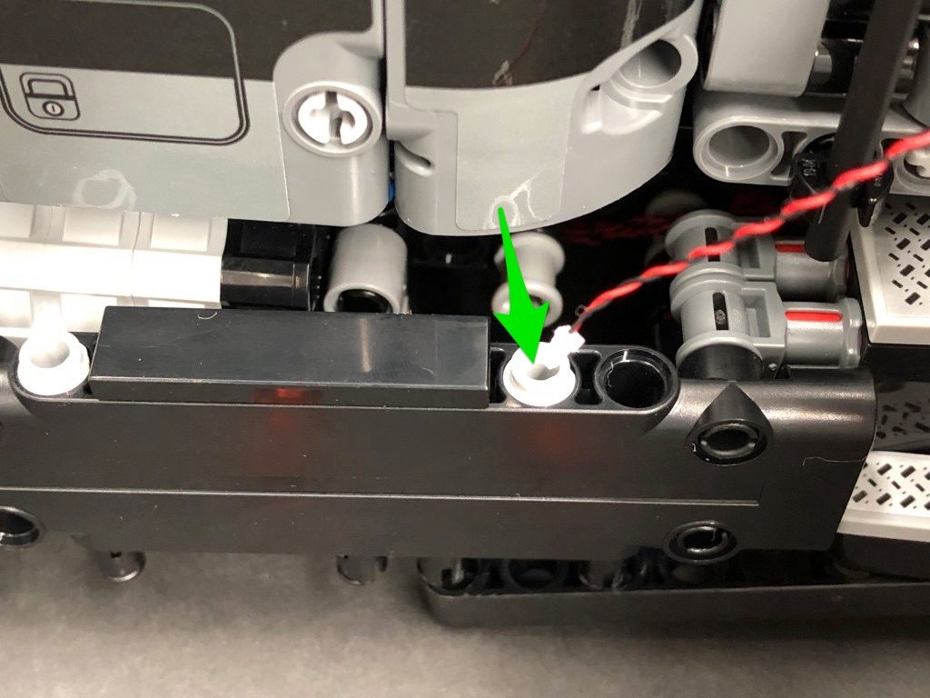
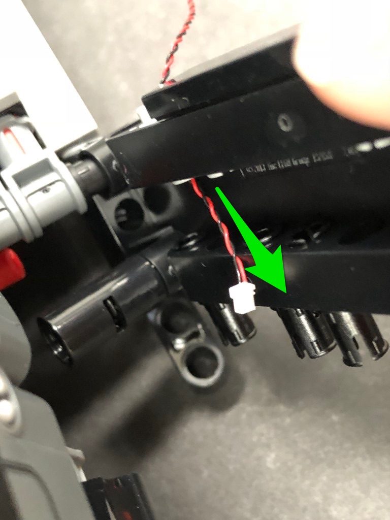
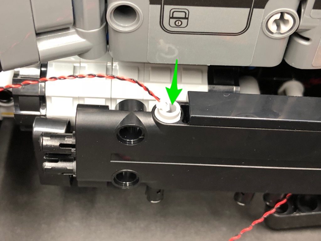
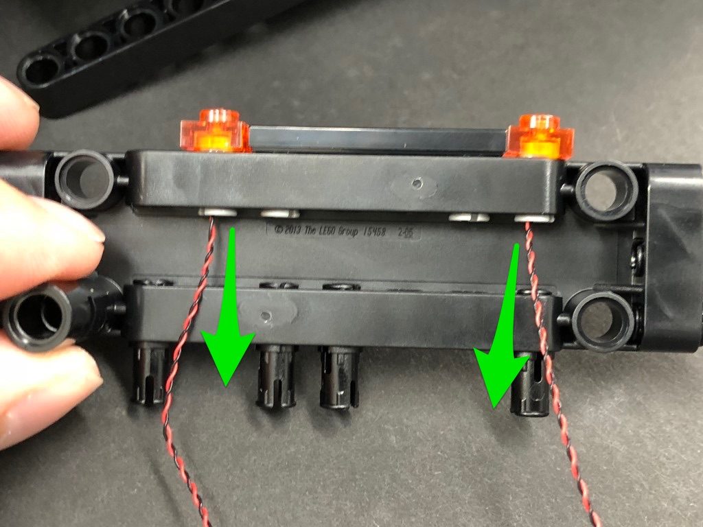
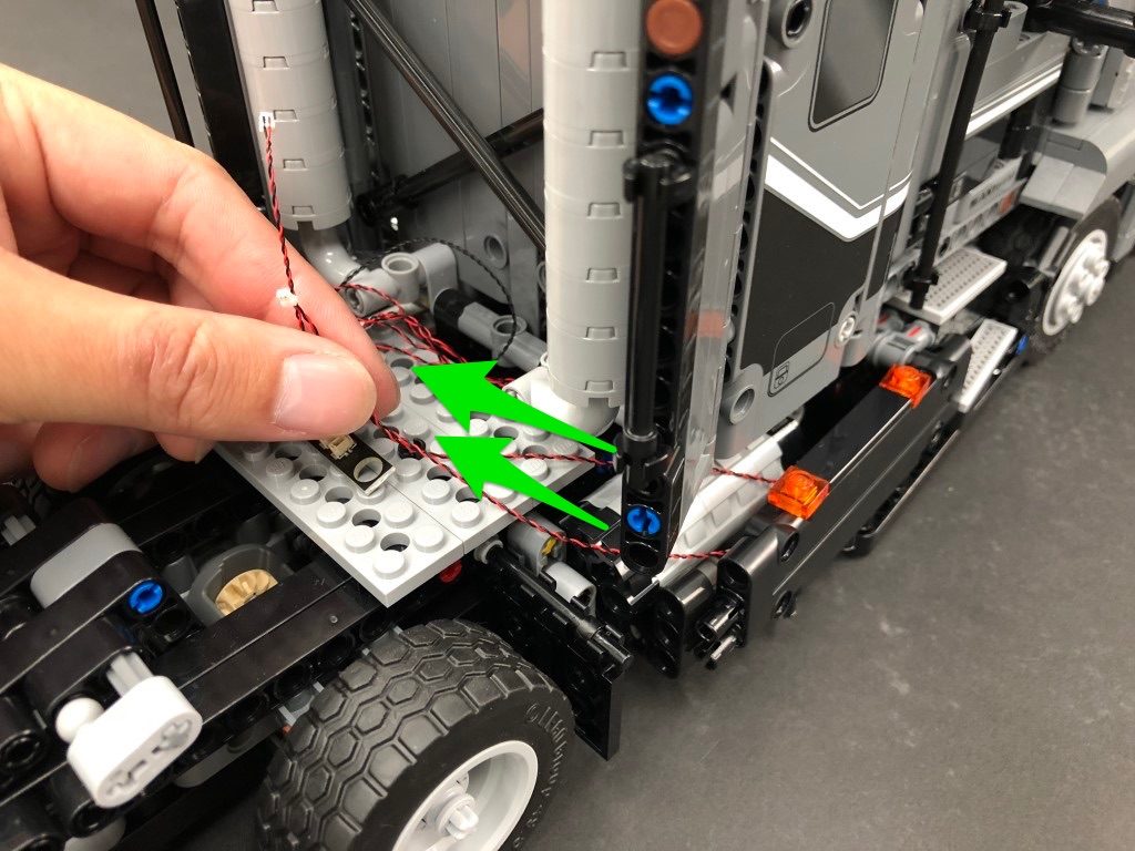
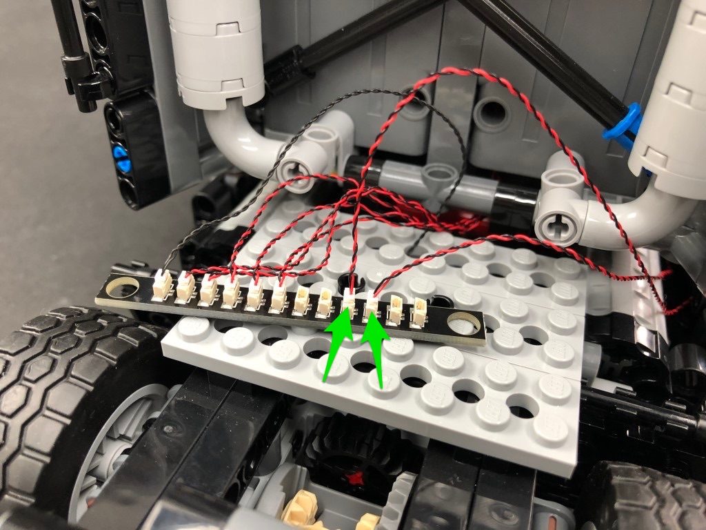
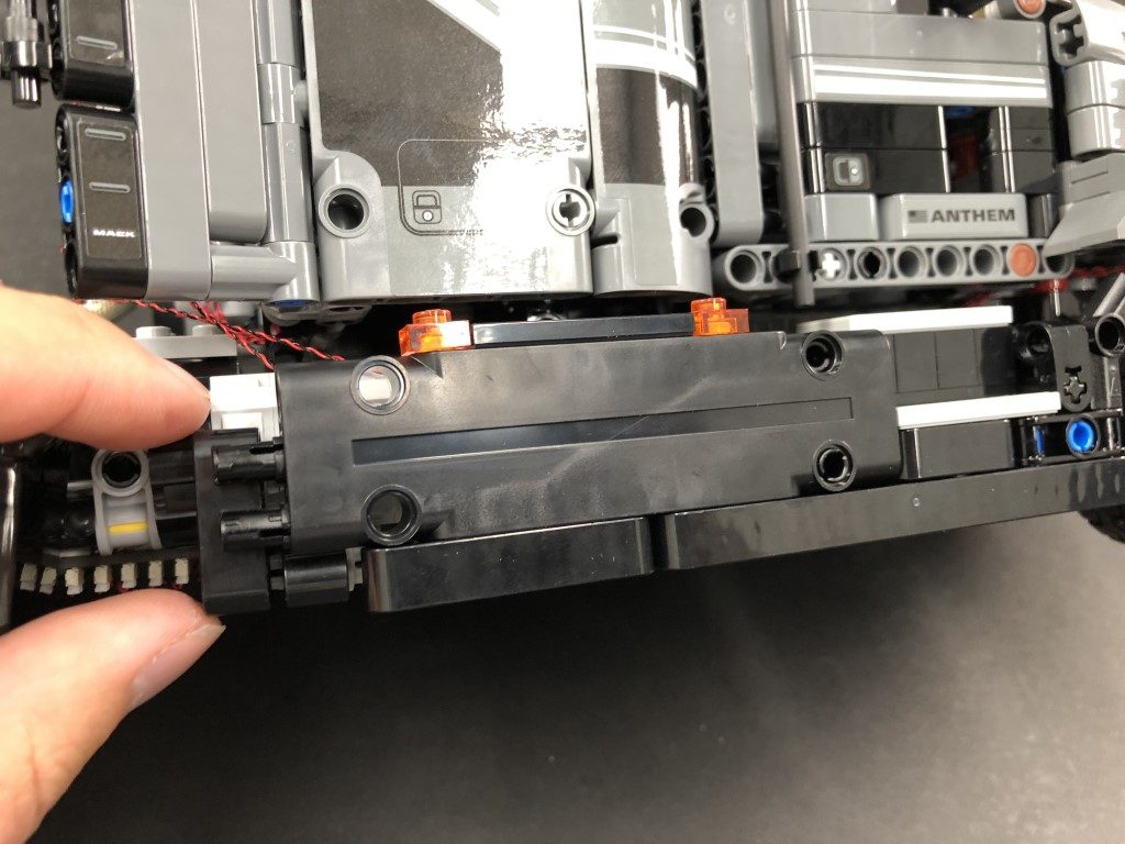
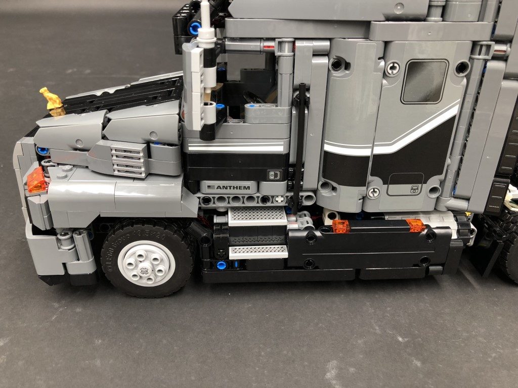
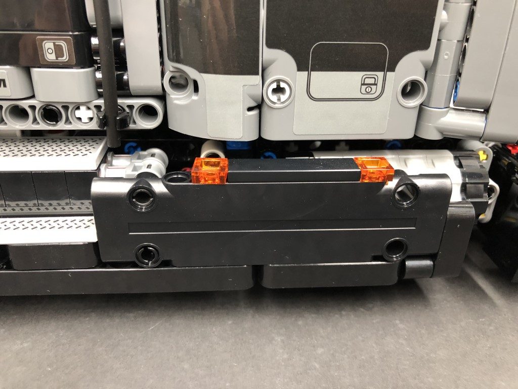
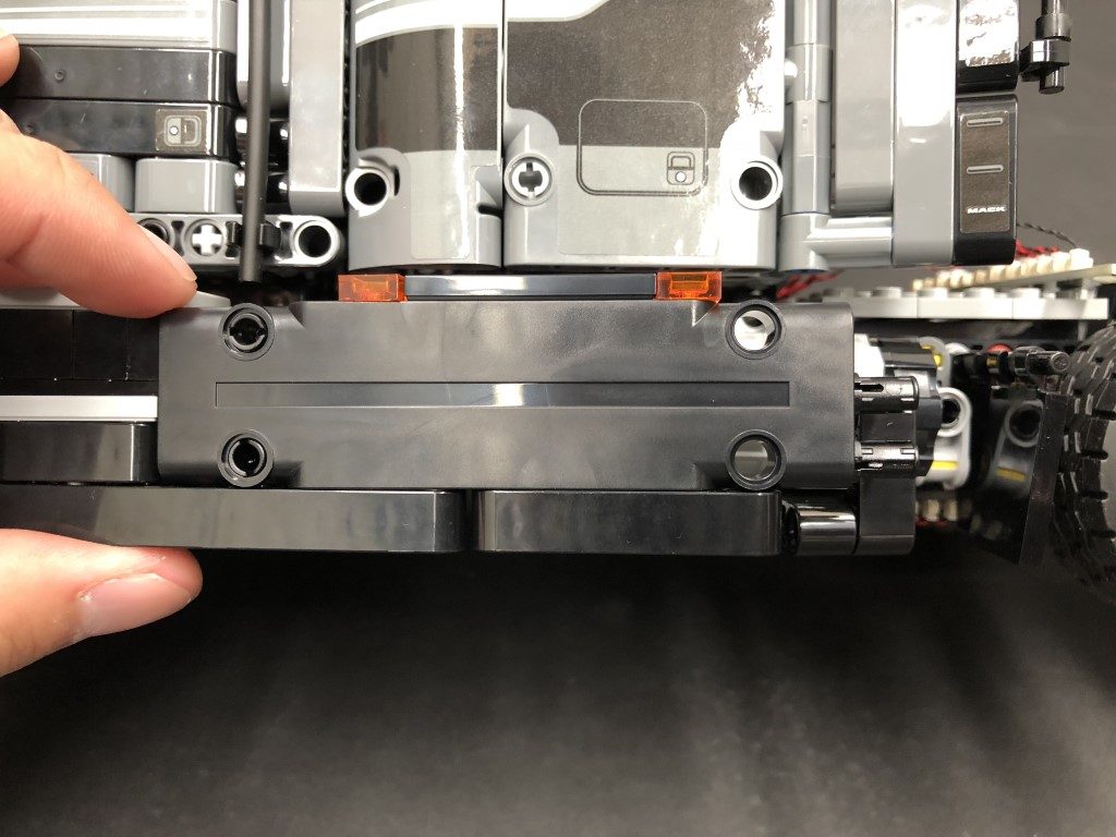
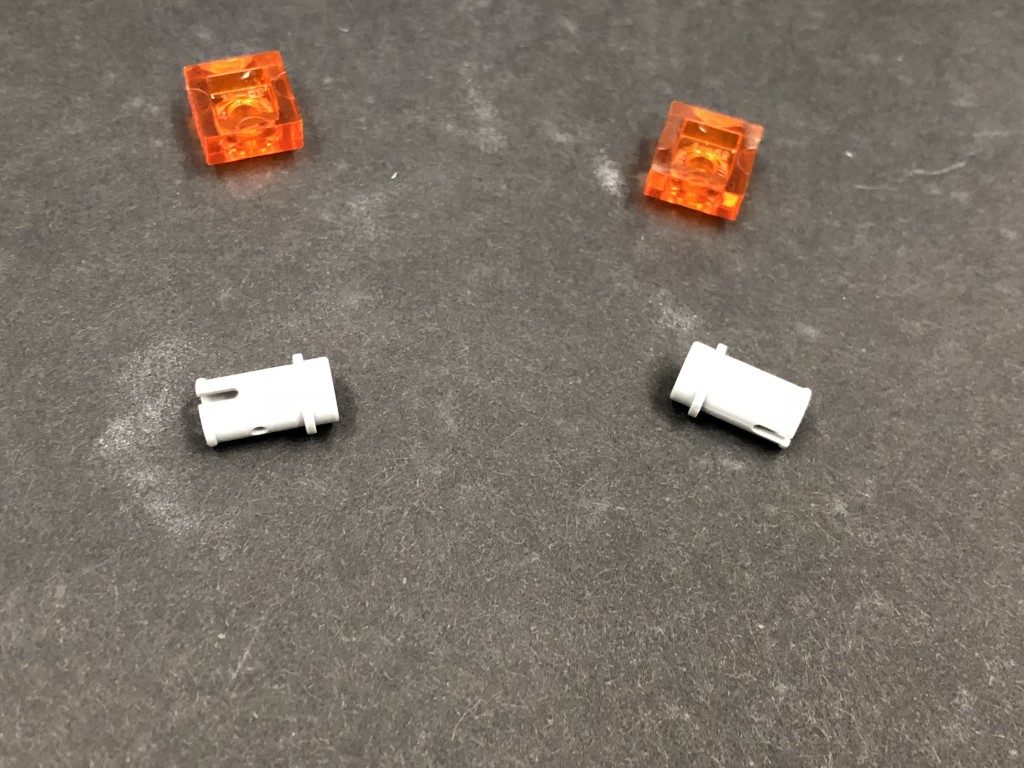
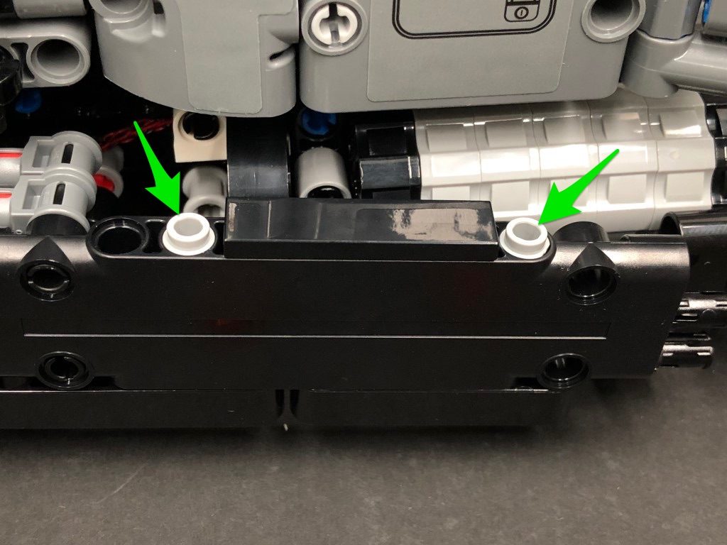
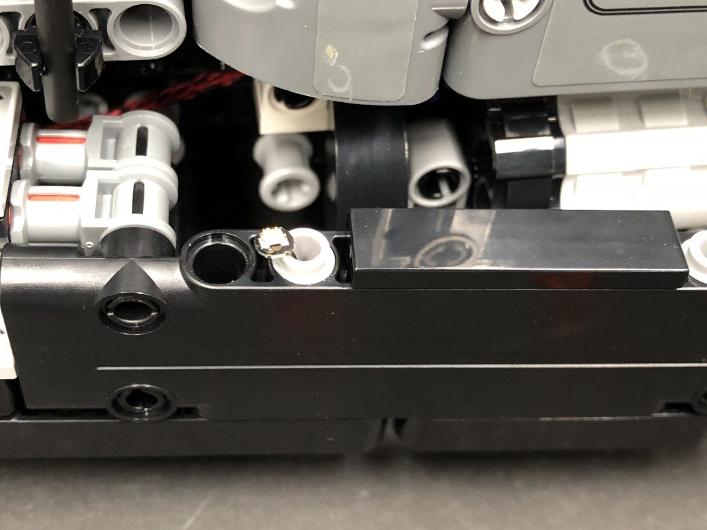
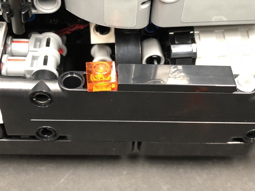
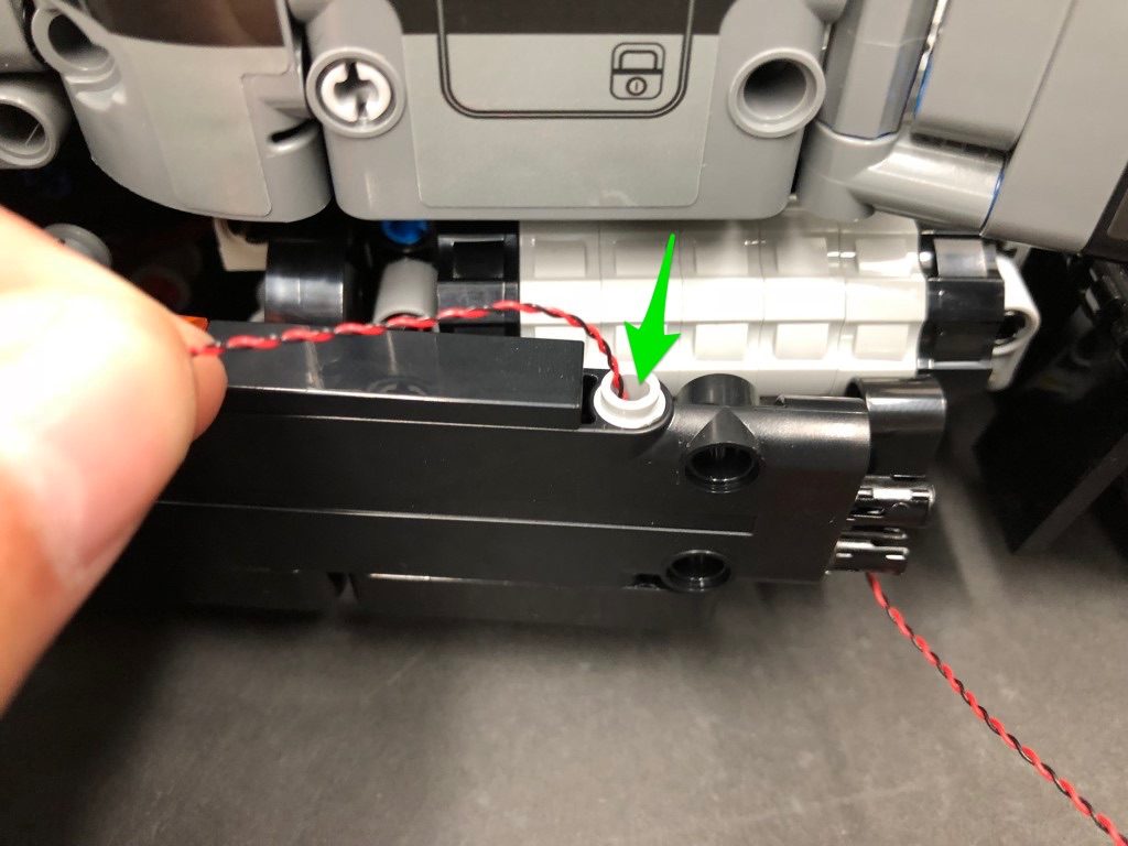
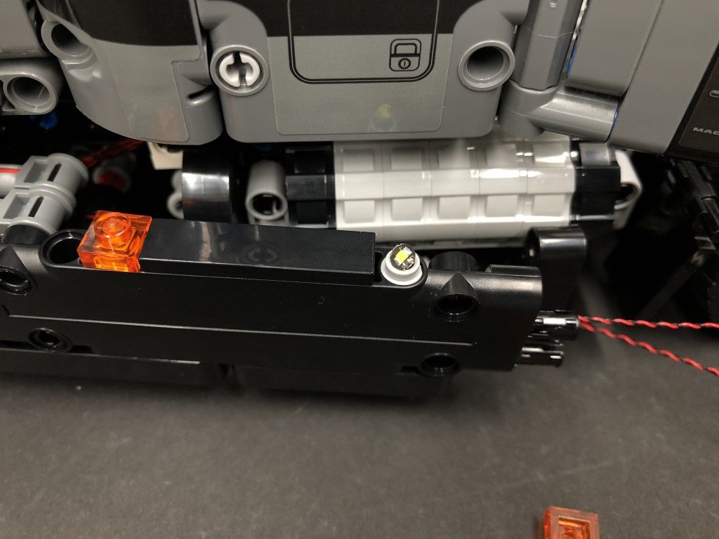
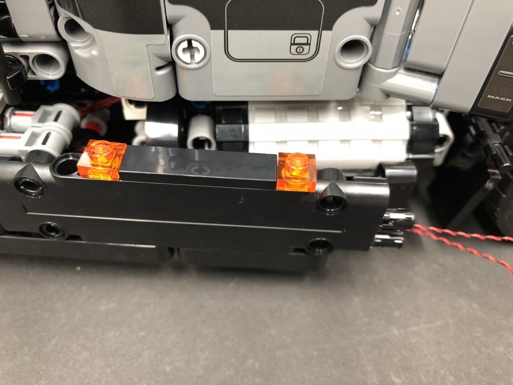
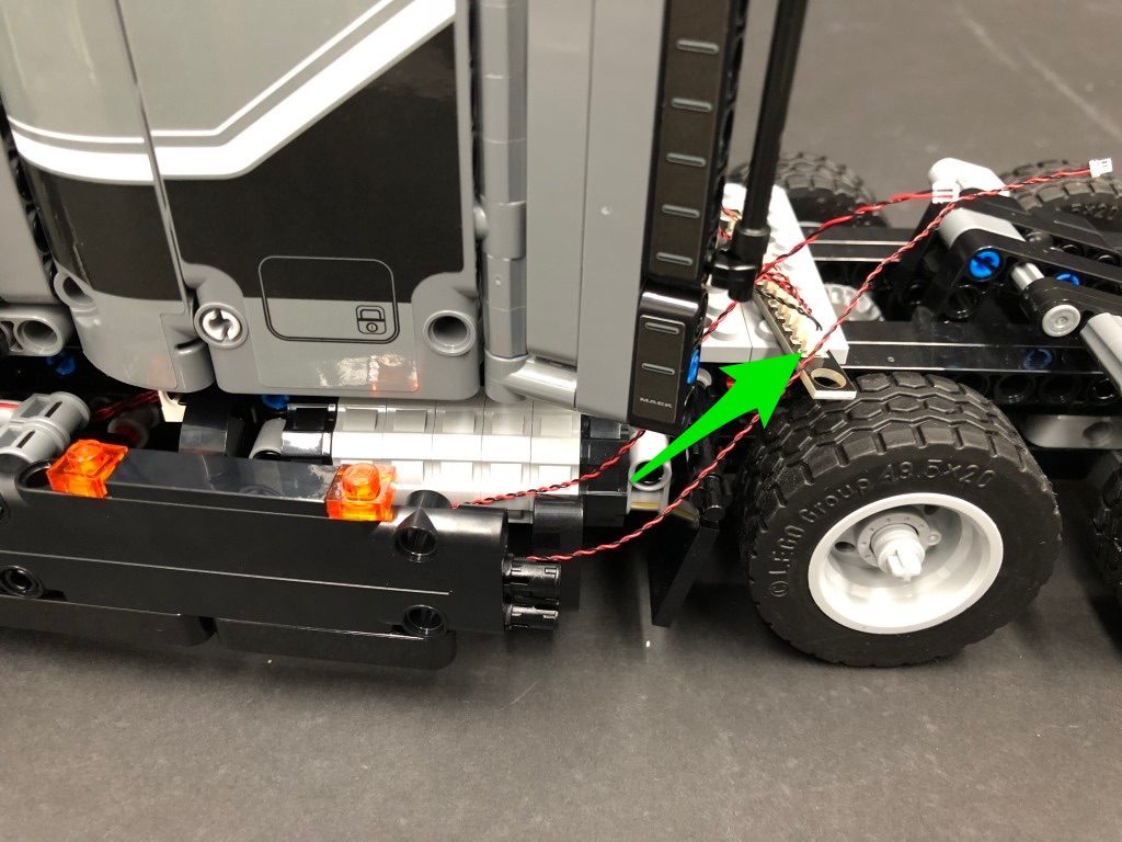
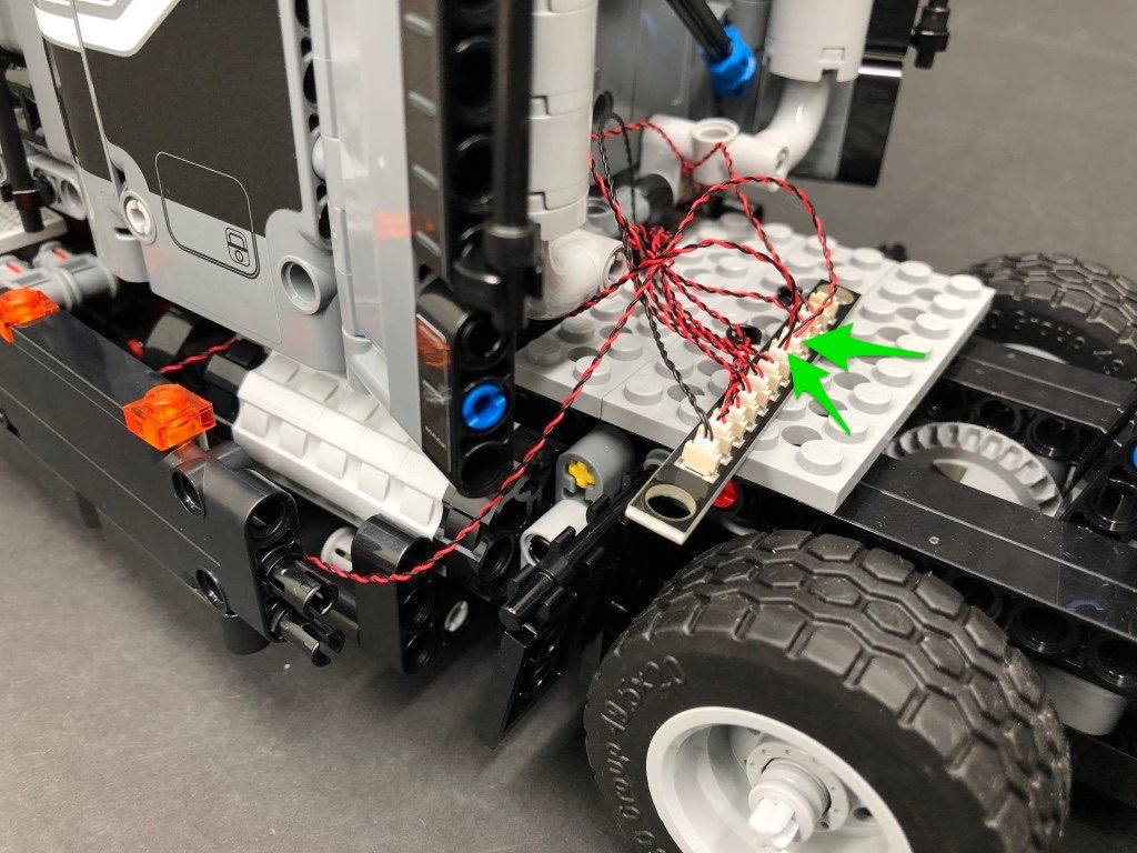
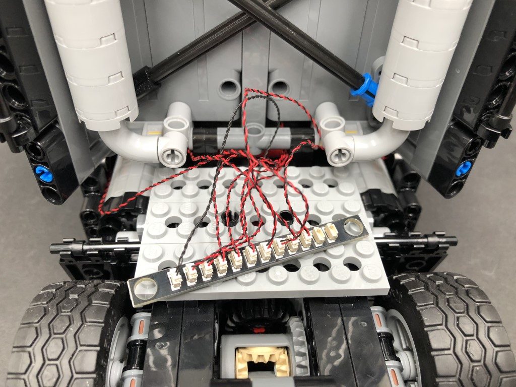
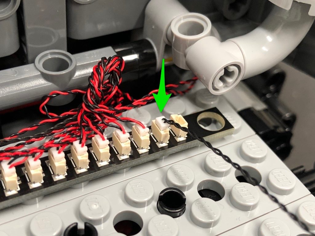
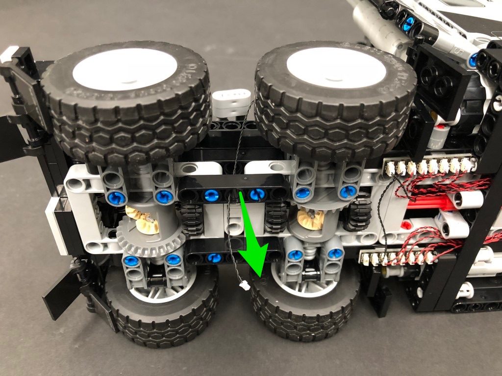
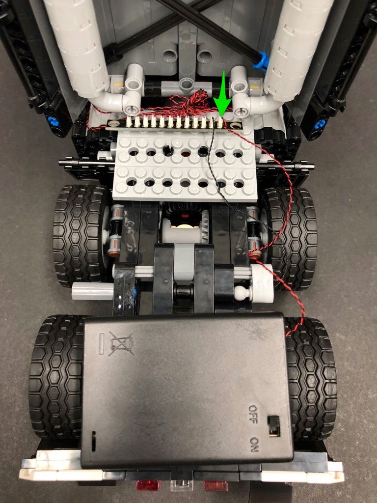
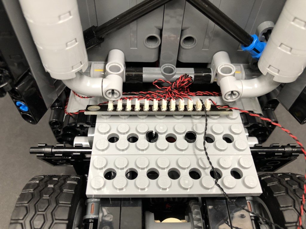
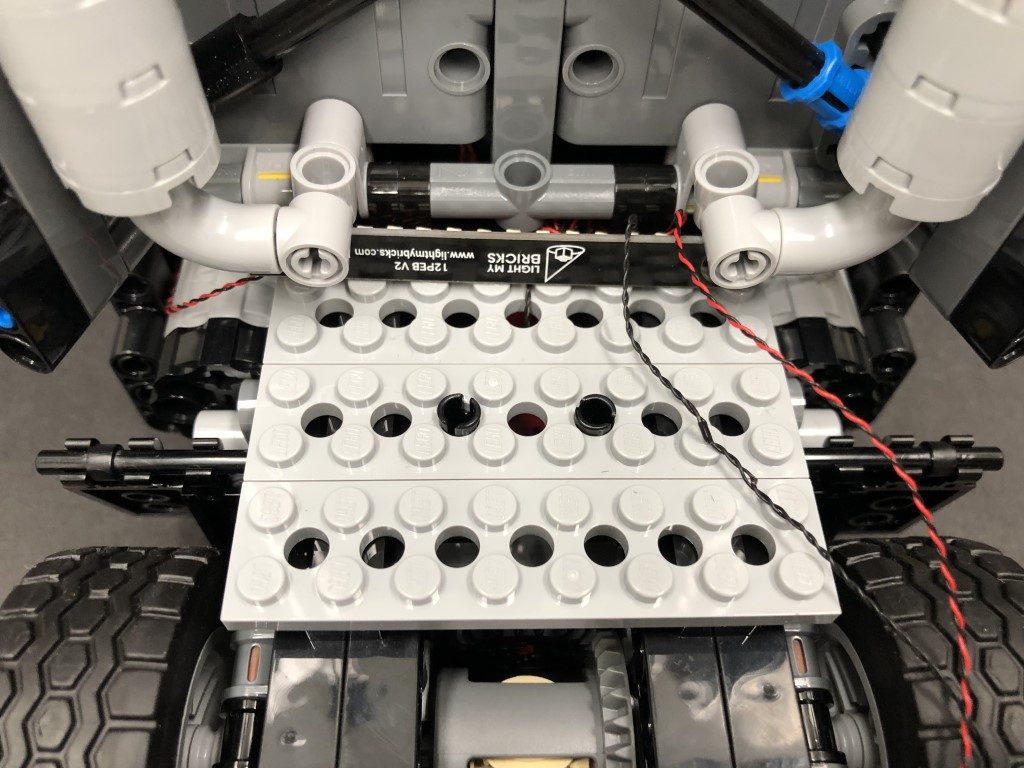
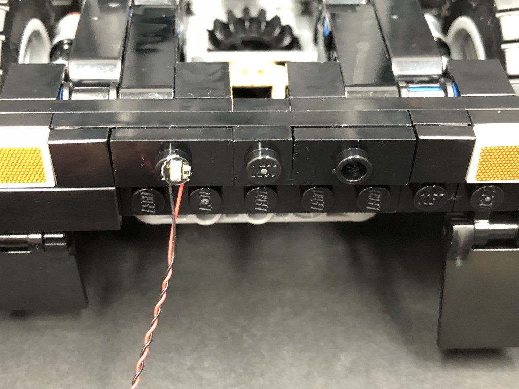
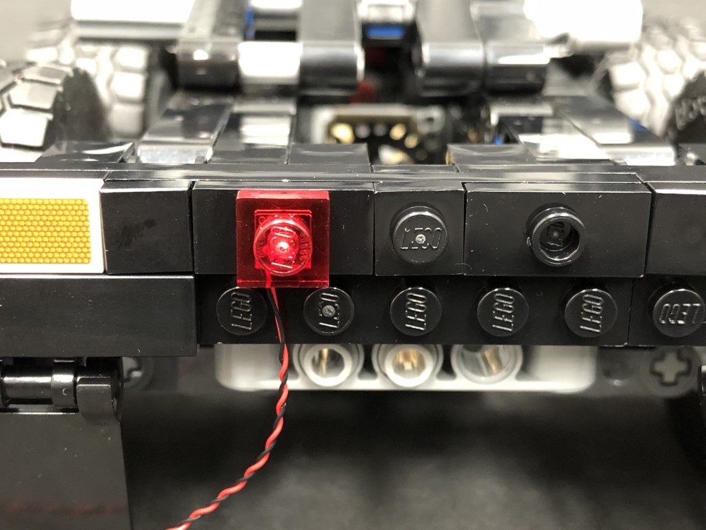
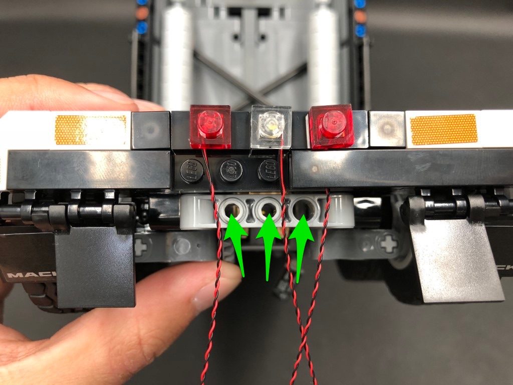
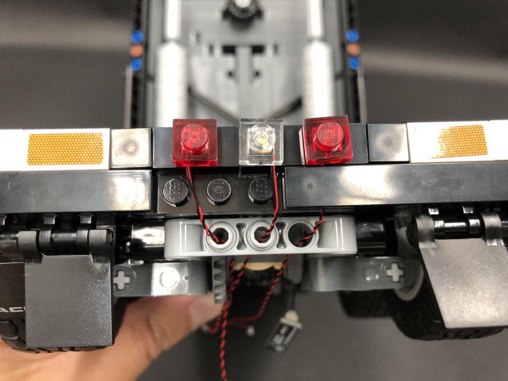
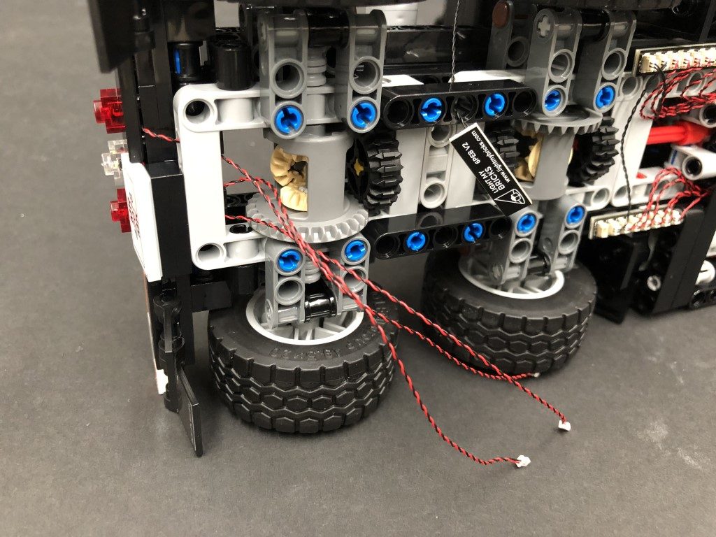
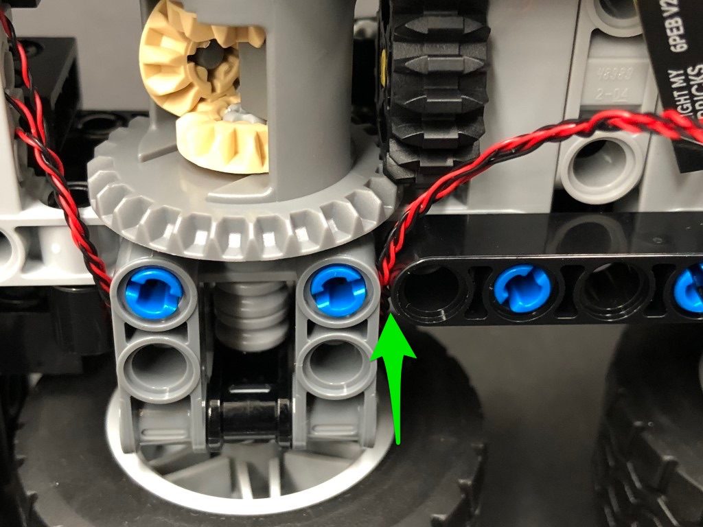
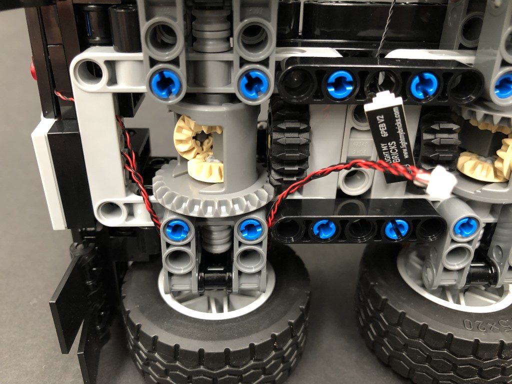
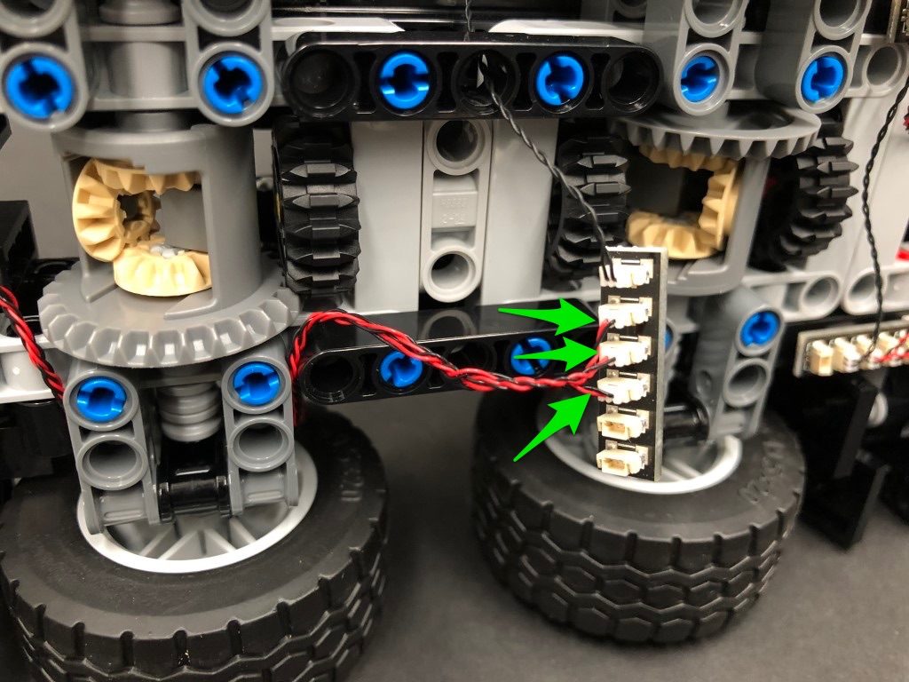
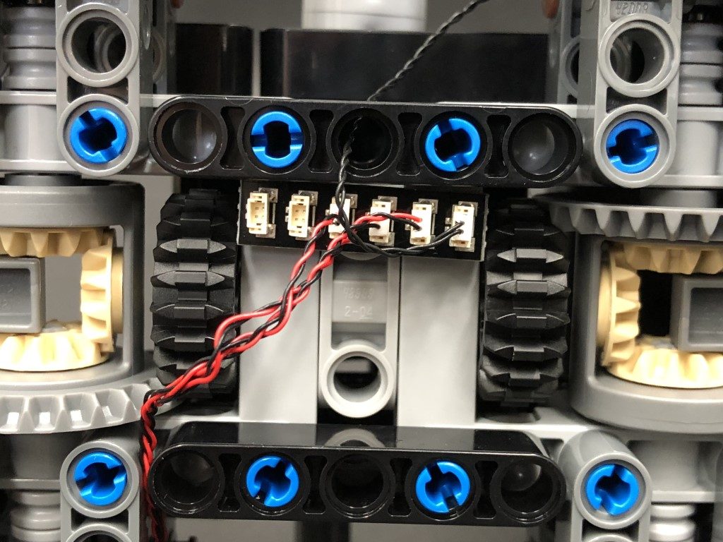
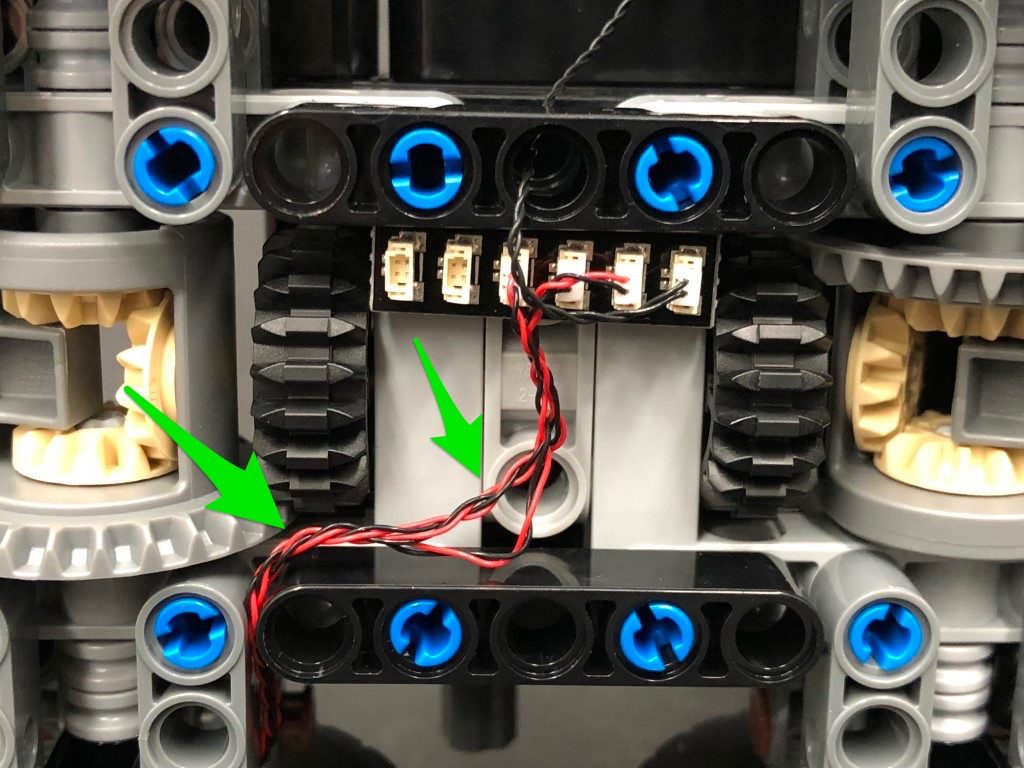
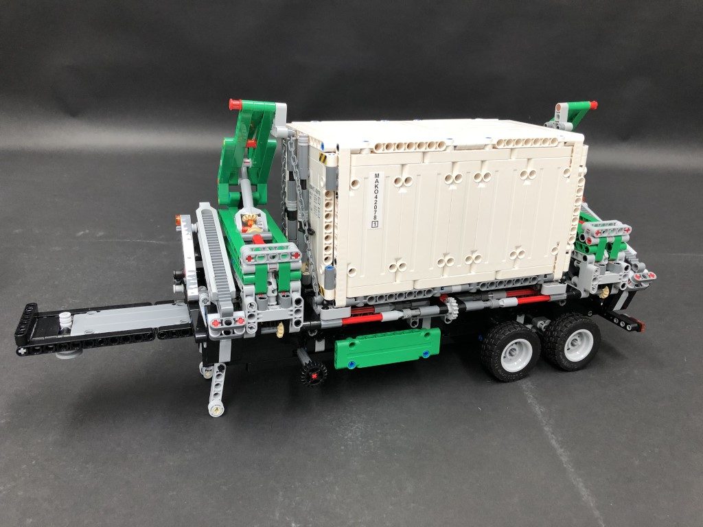
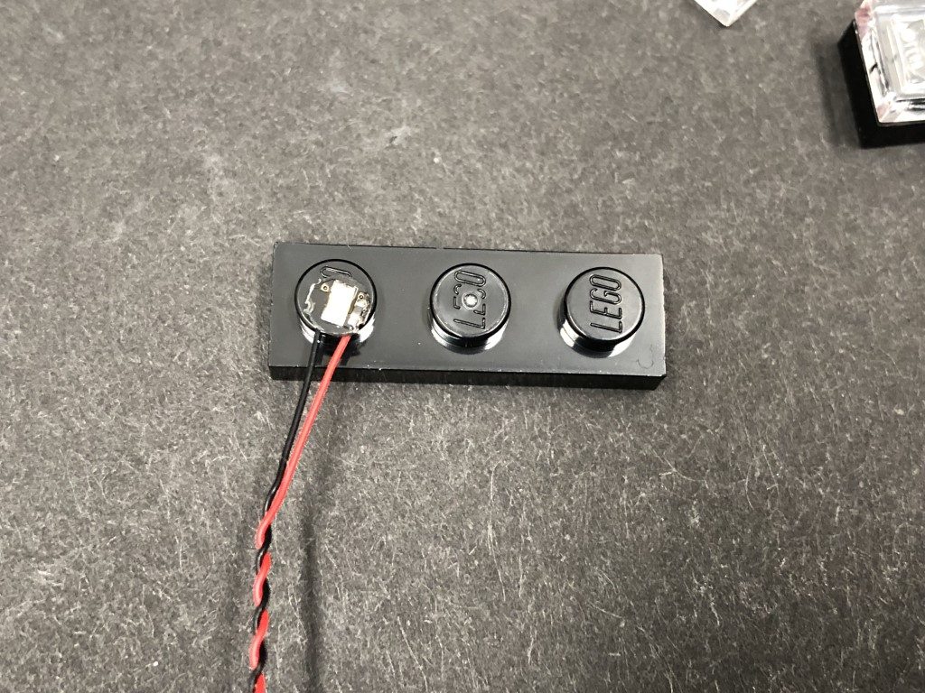
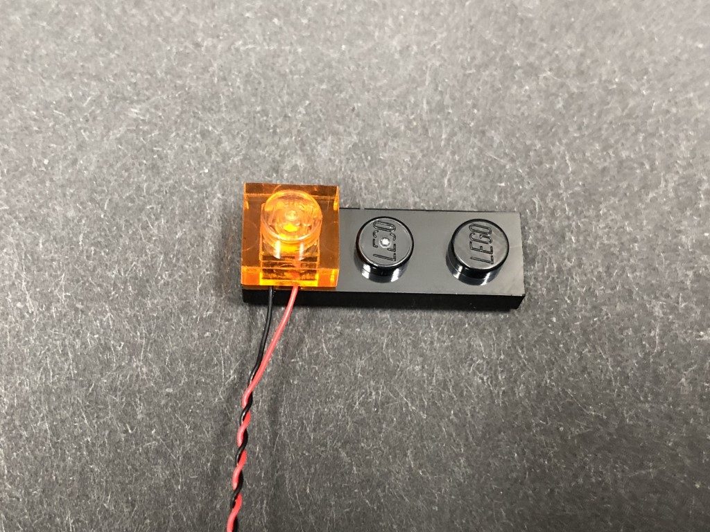
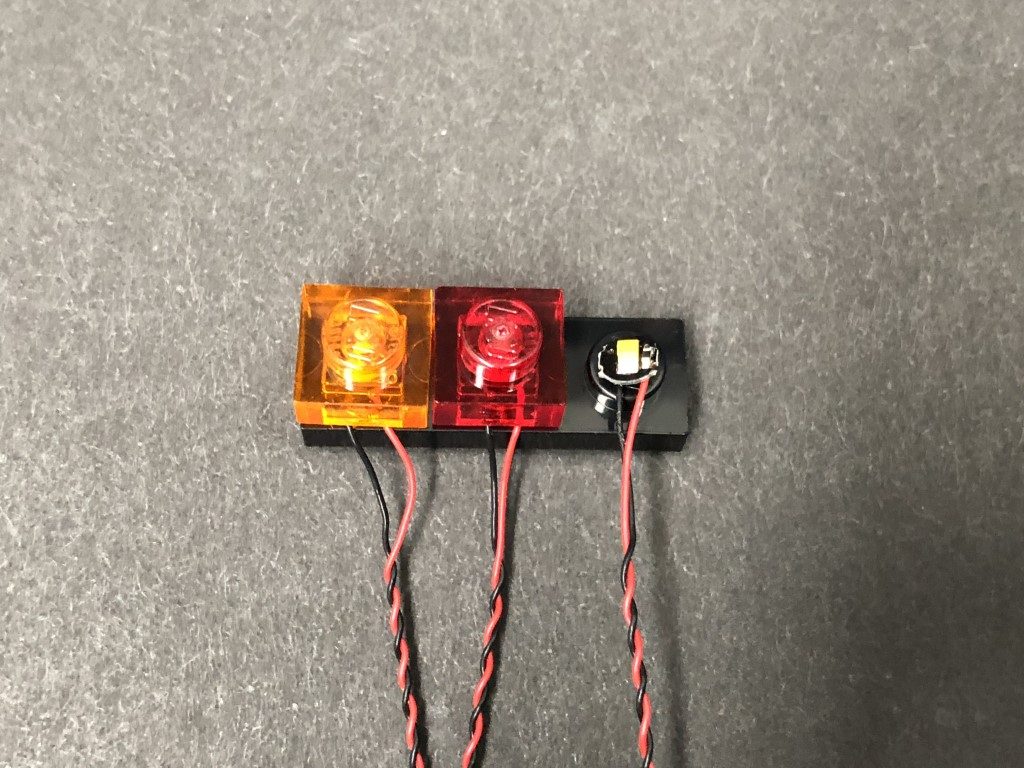
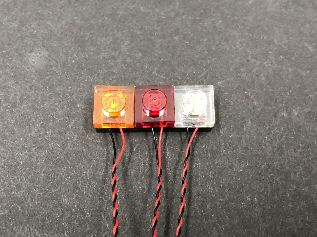
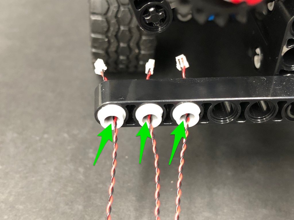
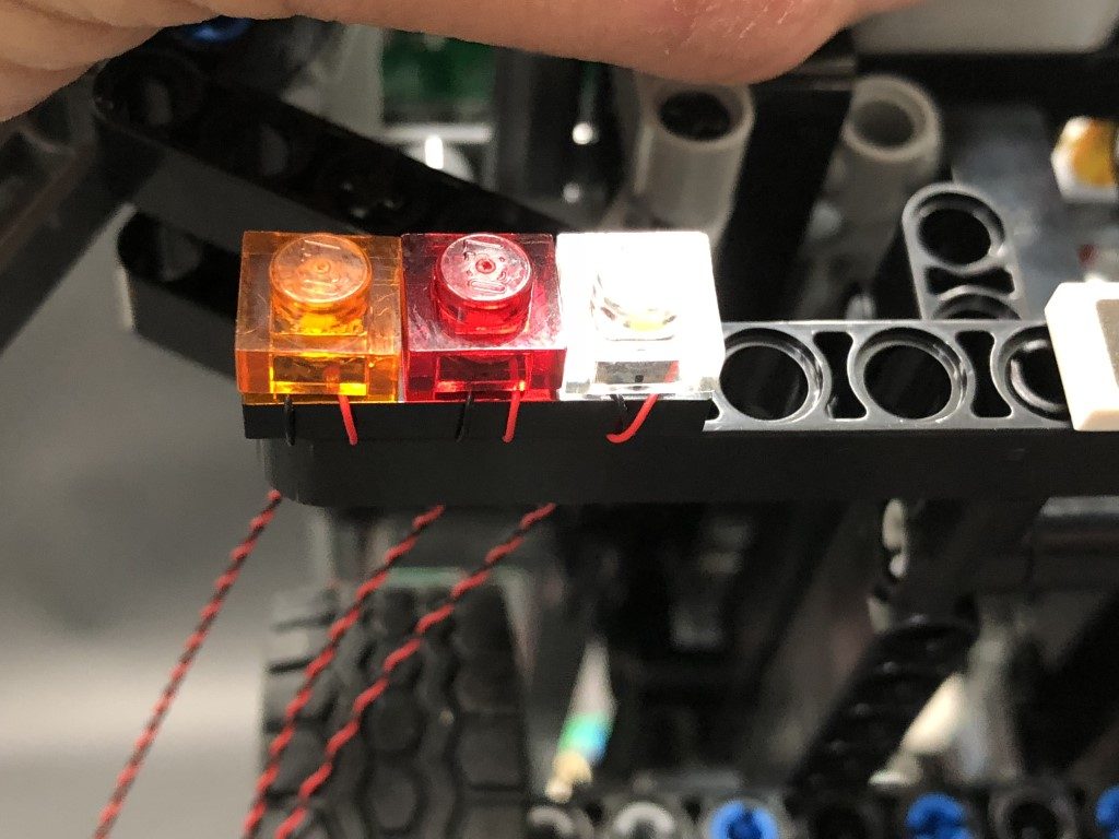
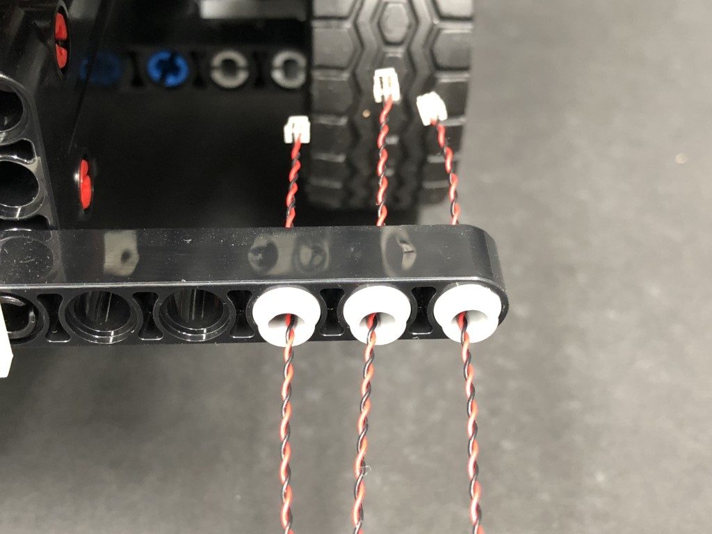
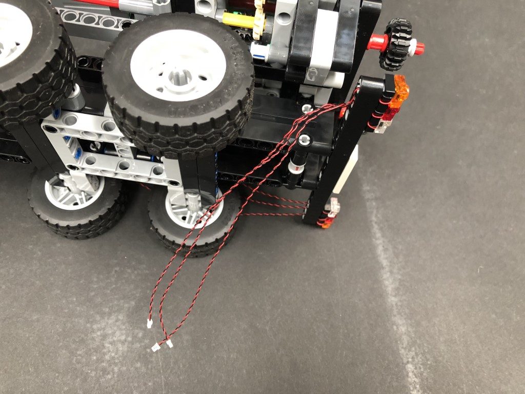
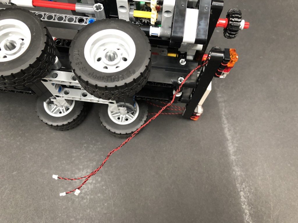
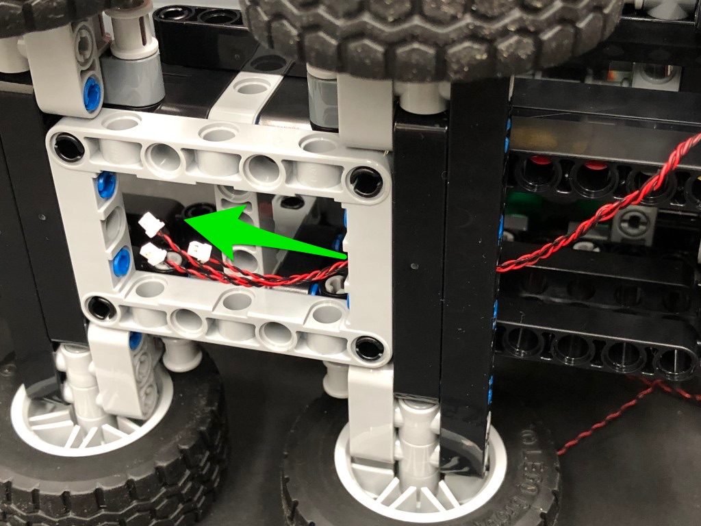
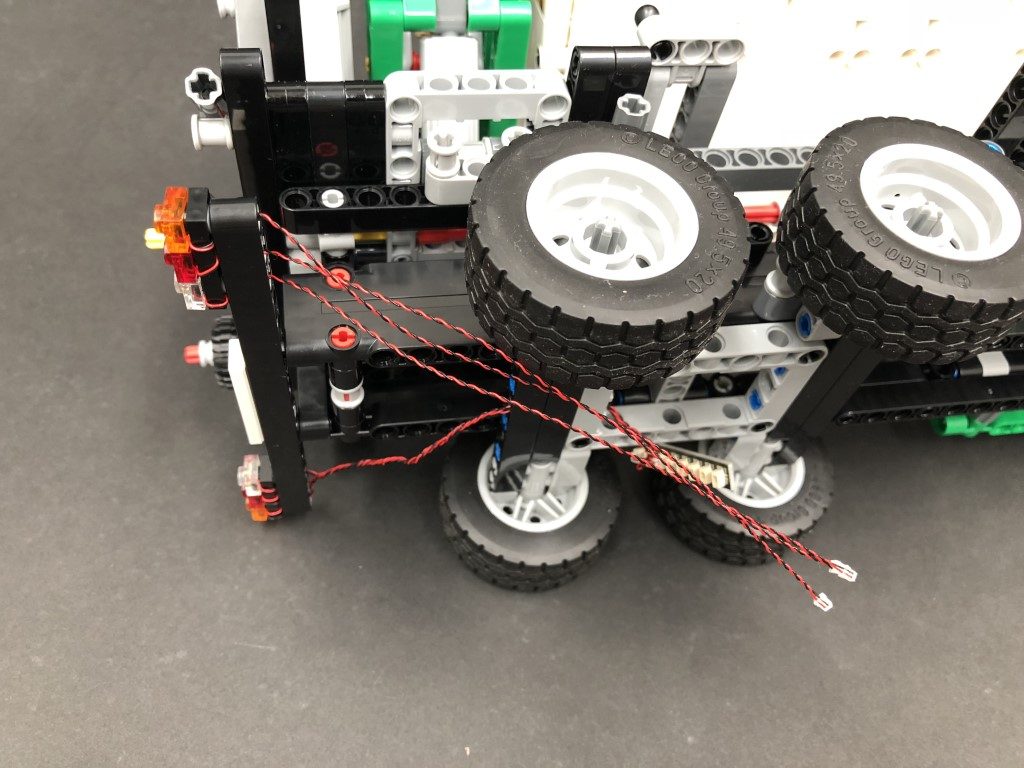
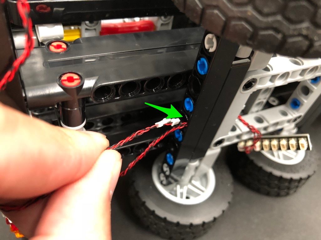
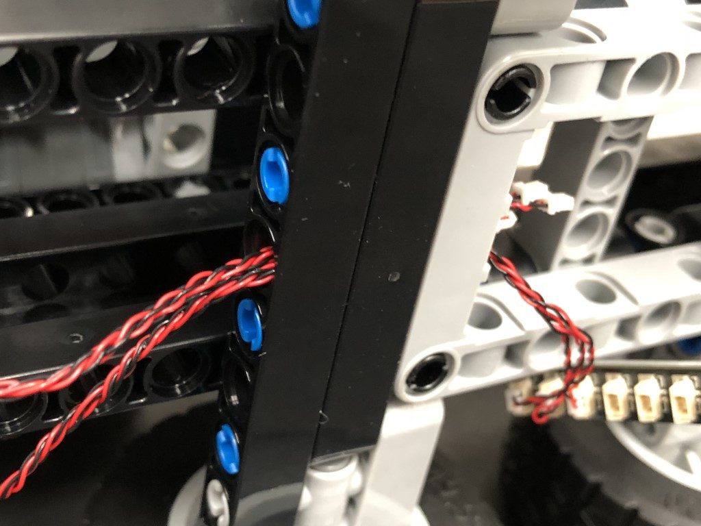
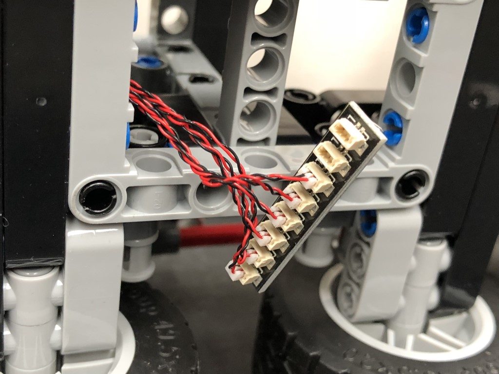
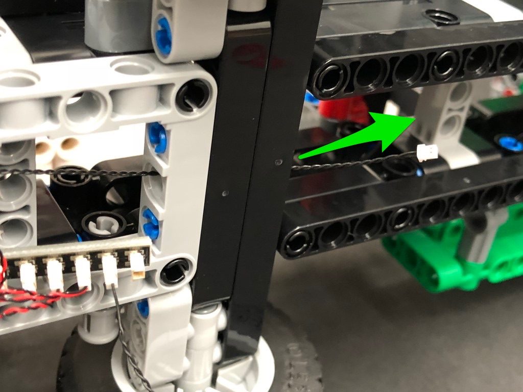
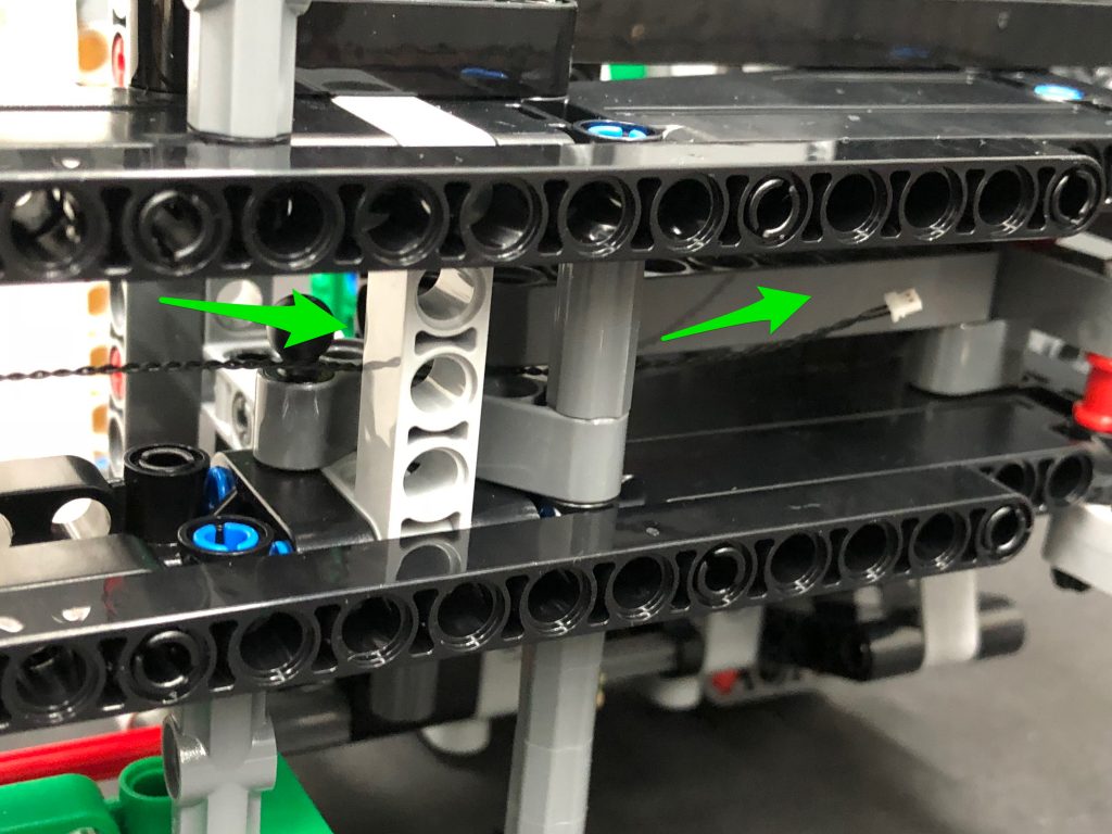
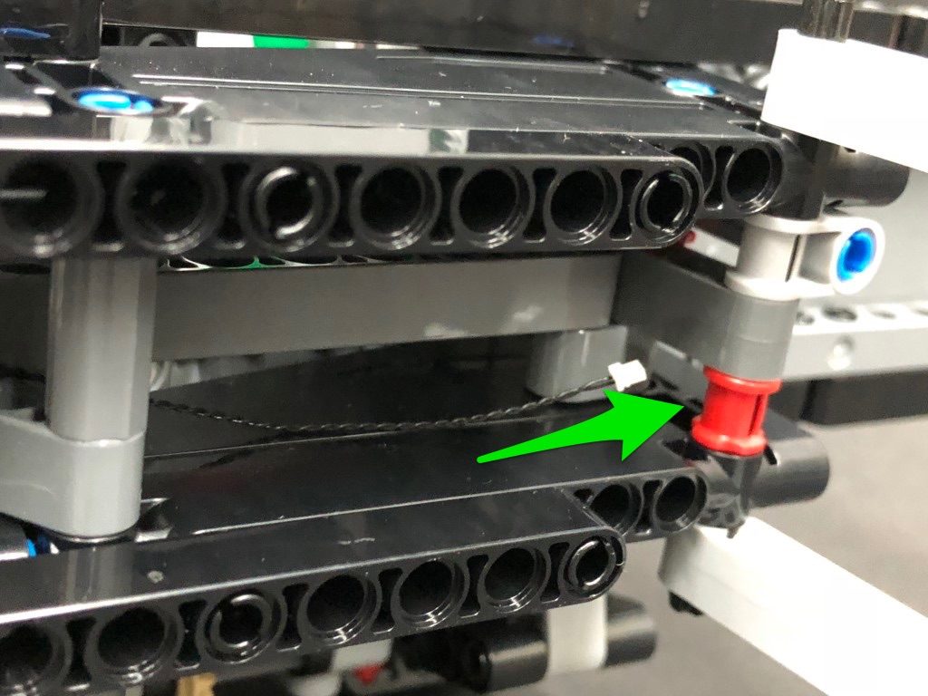
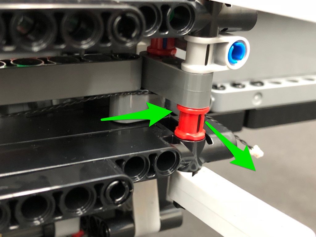
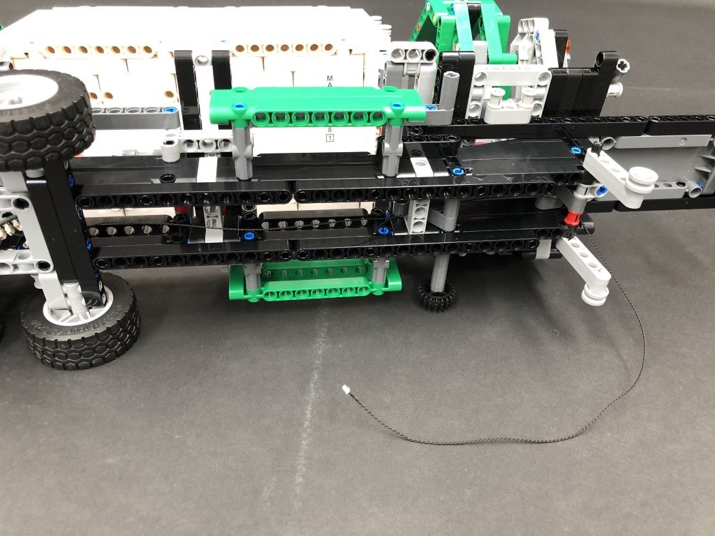
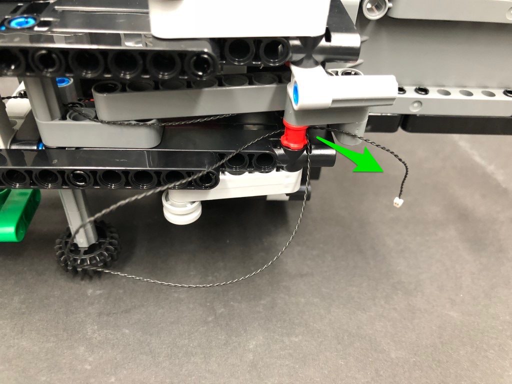
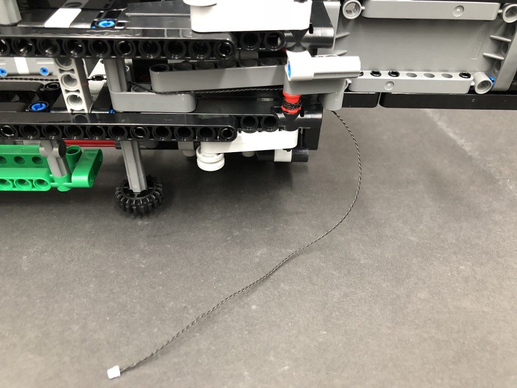
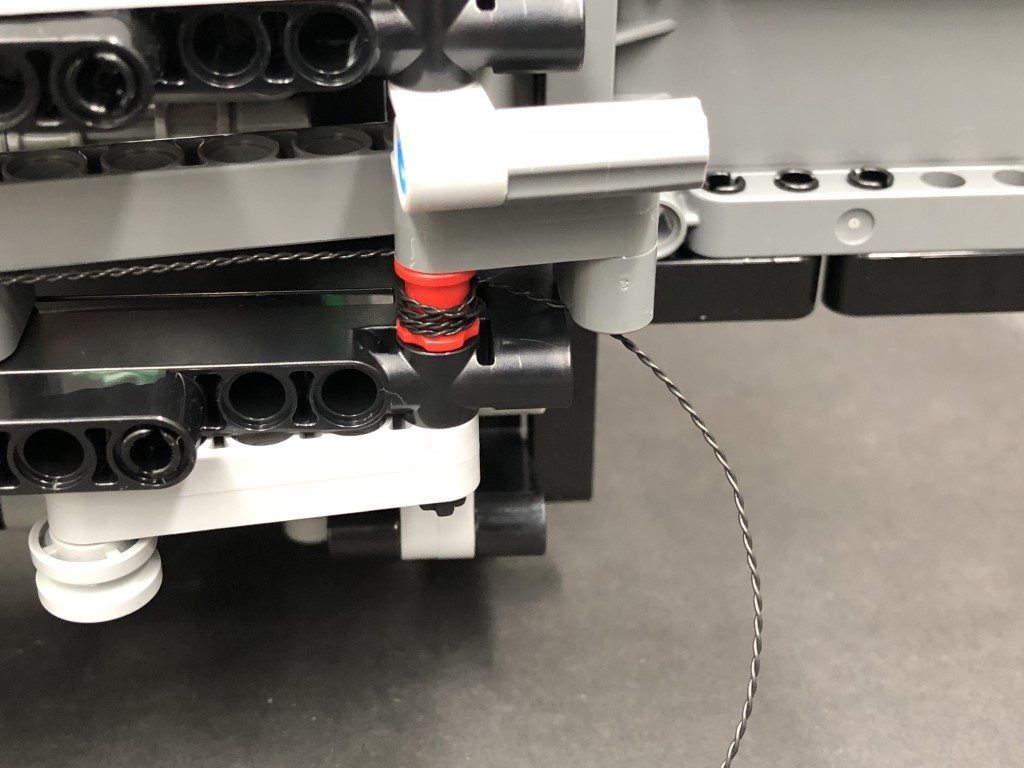
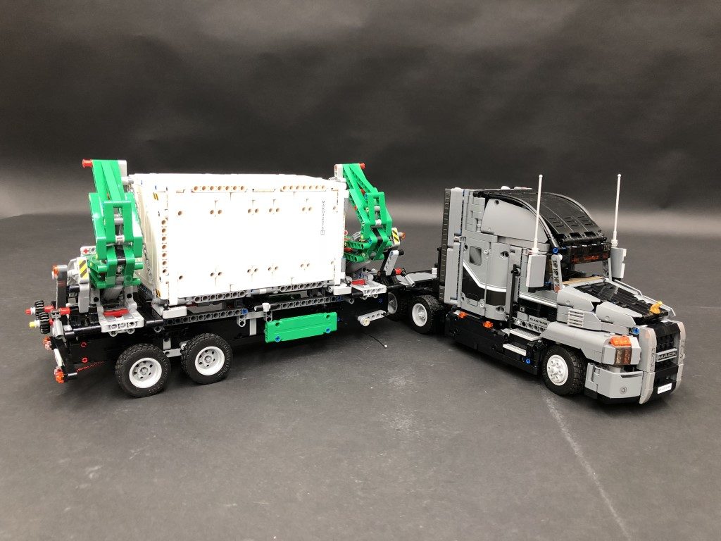
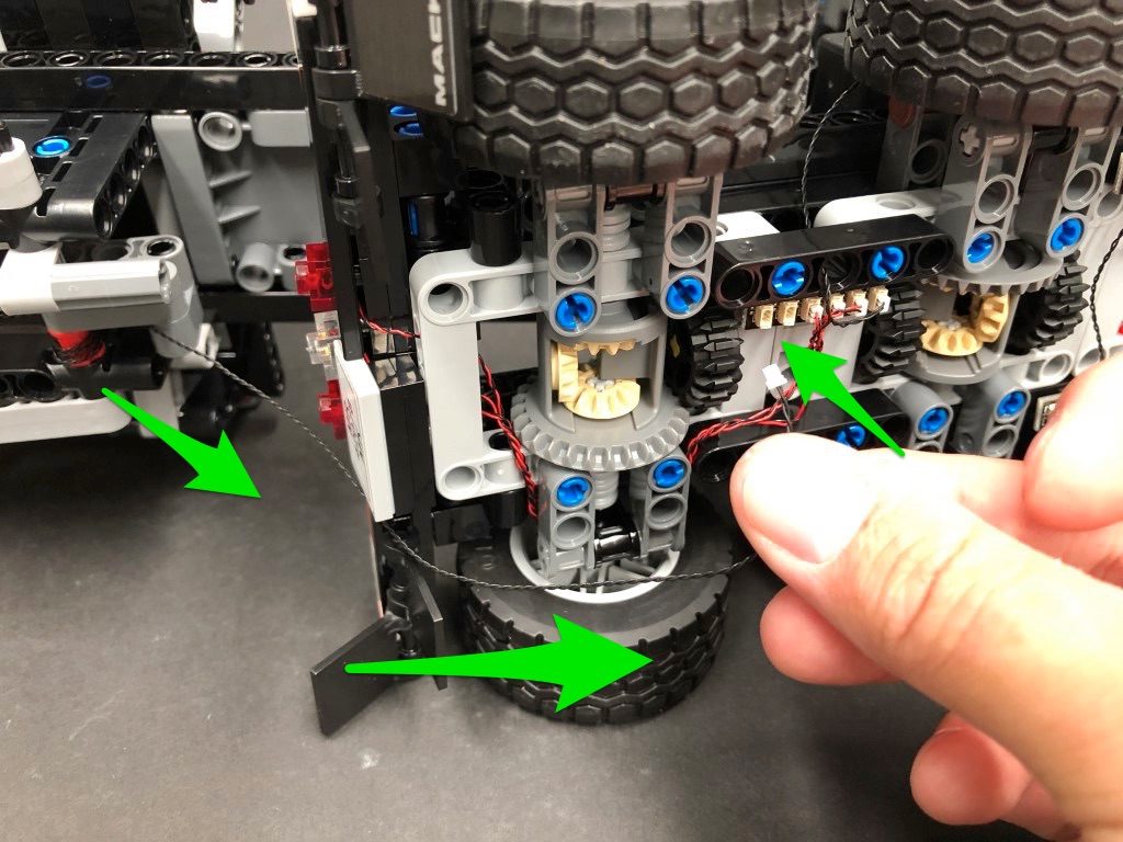
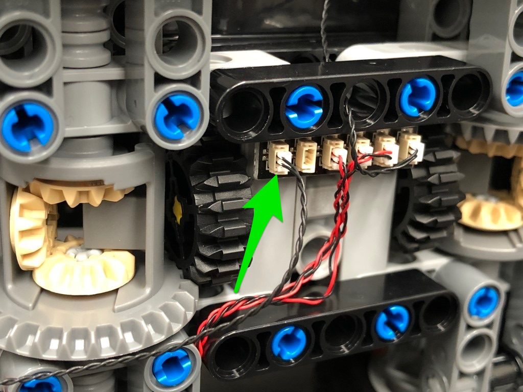
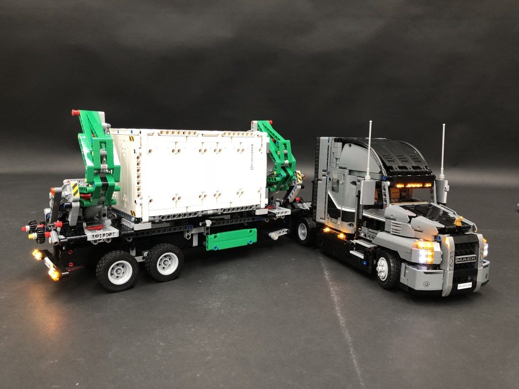
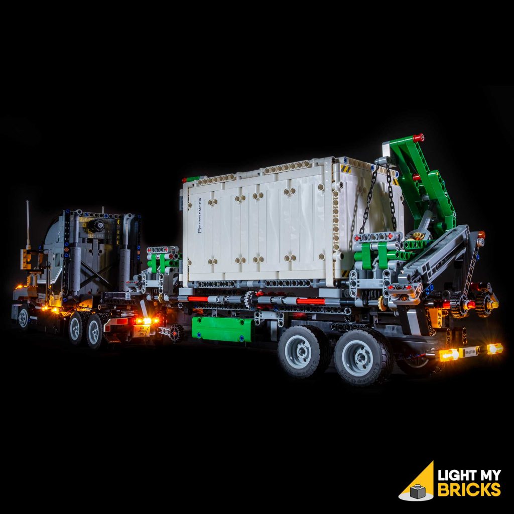
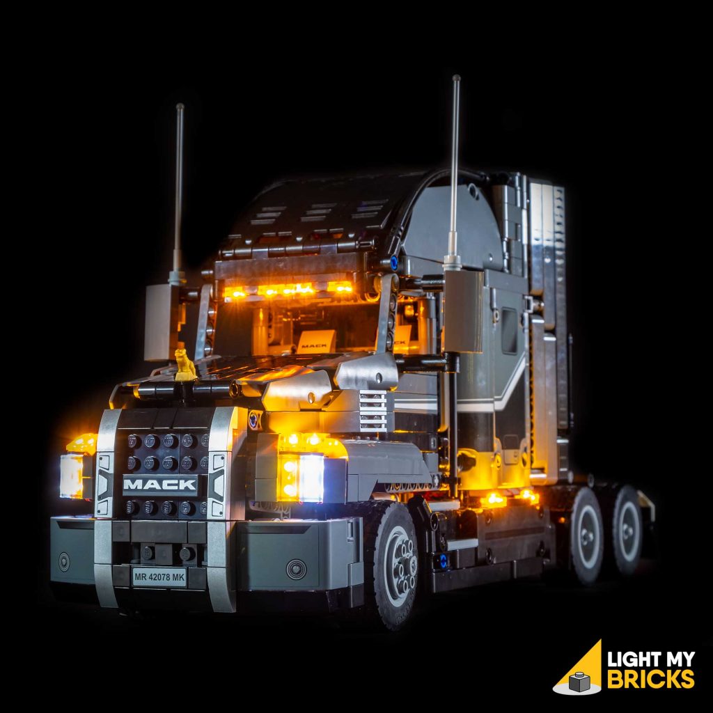
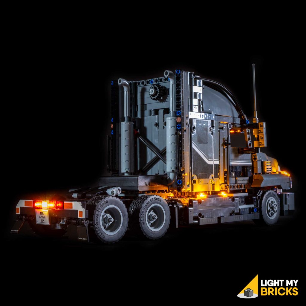
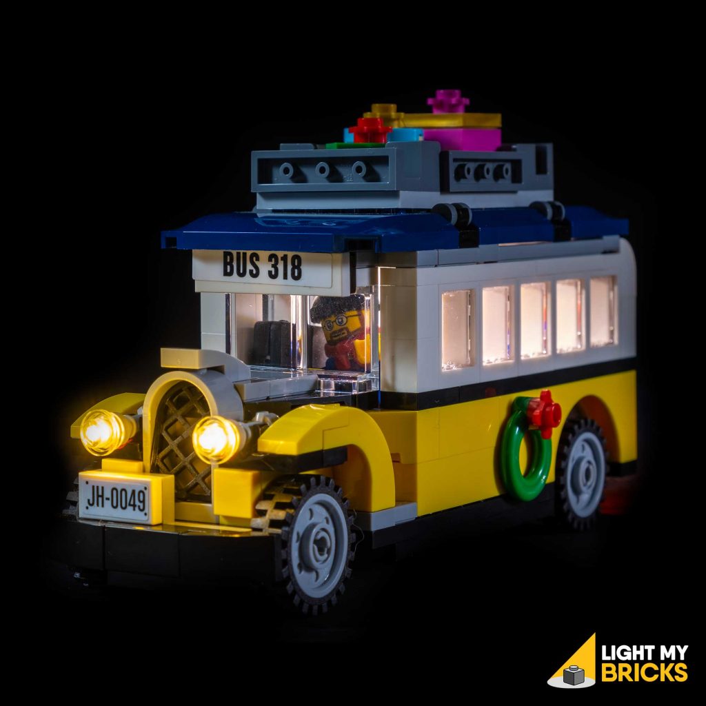