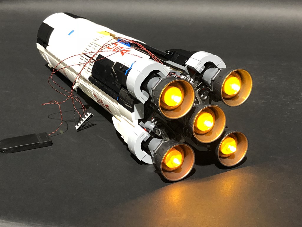
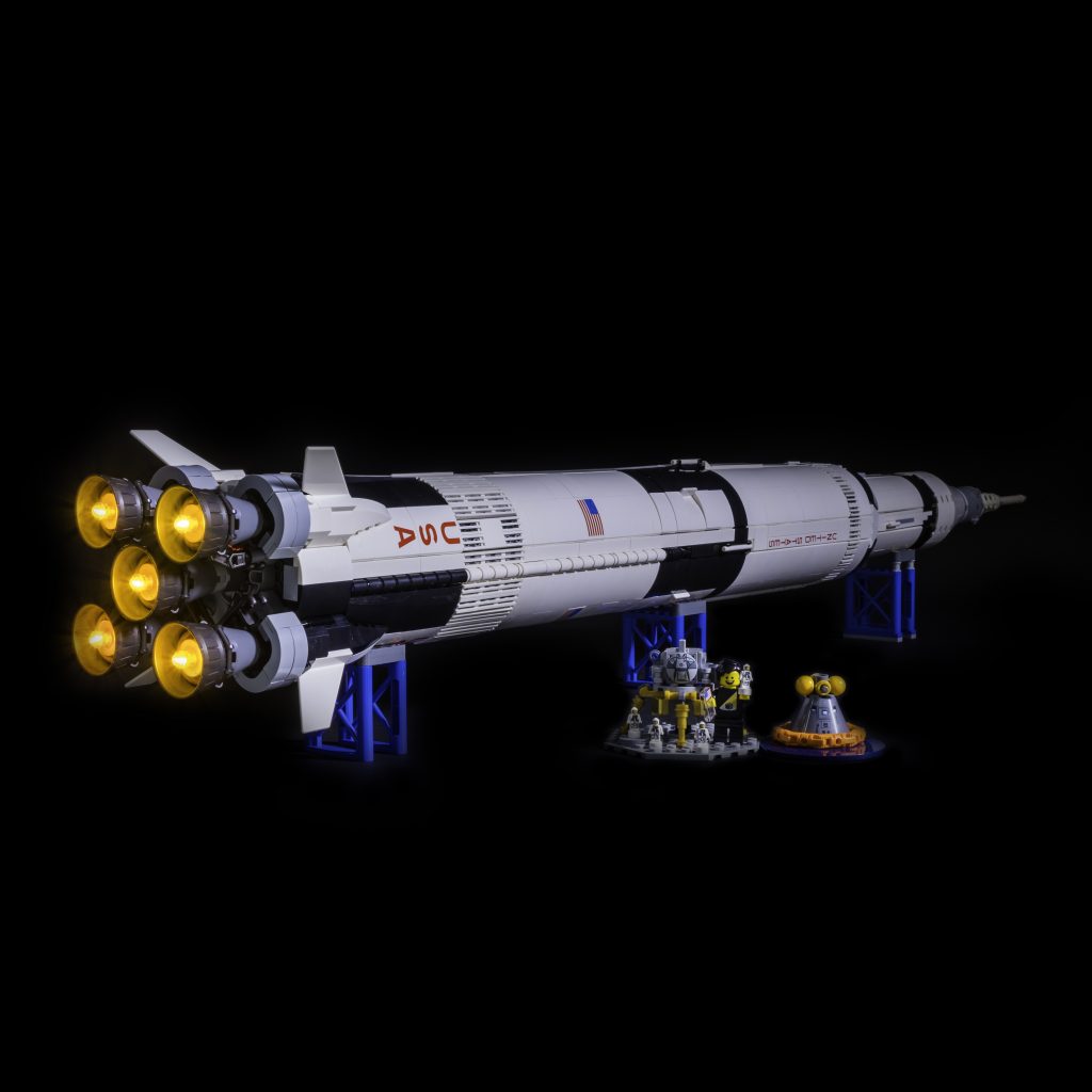
The following page is the instructions for the Light My Bricks LEGO NASA Apollo Saturn V (21309) LED light kit.
If you run into any issues, please refer to the online troubleshooting guide.
To ensure a trouble-free installation of your light kit, please read and follow each step carefully. These instructions can be downloaded in PDF format here
Please note: This page lists instructions for the LED light kit only. If you are wishing to purchase the Light My Bricks LEGO NASA Apollo Saturn V (21309) LED light kit , please click here to view the product page
Package Contents (Bottom Jets only):
- 5x White 30cm Bit Lights
- 1x Flicker Effects Board
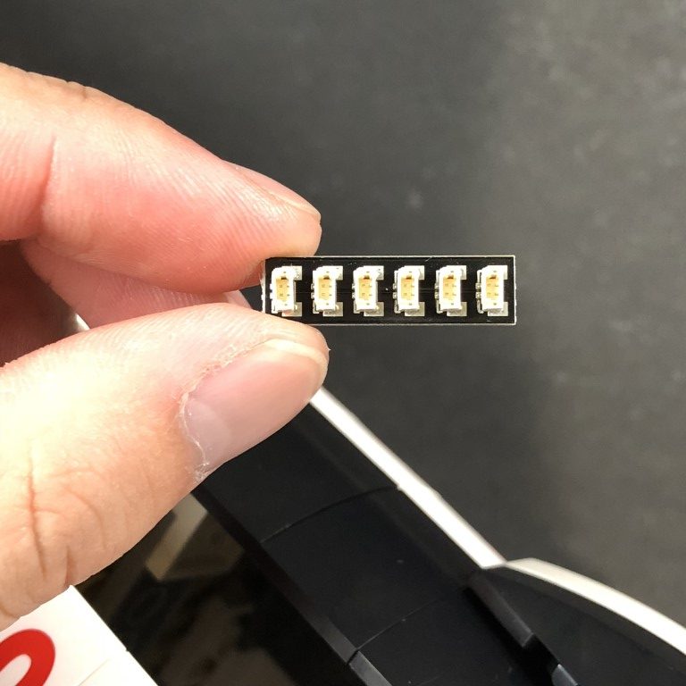
- 1x 6-Port Expansion Boards
- 1x 5cm Connecting Cables
- 1x Flat Battery Pack (requires 2x CR2032 Batteries)
LEGO PIECES:
- 5x Trans Orange Round Plate 1×1
Package Contents (All Three Jets):
- 11x White 30cm Bit Lights
- 3x Flicker Effects Board
- 2x 6-Port Expansion Boards
- 2x 5cm Connecting Cables
- 3x Flat Battery Packs (Each battery pack requires 2x CR2032 Batteries)
LEGO PIECES:
- 6x Trans Orange Round Plate 1×1
Important things to note:
Laying cables in between and underneath bricks
Cables can fit in between and underneath LEGO® bricks, plates, and tiles providing they are laid correctly between the LEGO® studs. Do NOT forcefully join LEGO® together around cables; instead ensure they are laying comfortably in between each stud.
CAUTION: Forcing LEGO® to connect over a cable can result in damaging the cable and light.
Connecting cable connectors to Expansion Boards
Take extra care when inserting connectors to ports of Expansion Boards. Connectors can be inserted only one way. With the expansion board facing up, look for the soldered “=” symbol on the left side of the port. The connector side with the wires exposed should be facing toward the soldered “=” symbol as you insert into the port. If a plug won’t fit easily into a port connector, do not force it.
Incorrectly inserting the connector can can result in bent pins inside the port or possible overheating of the expansion board when connected.
Connecting cable connectors to Strip Lights
Take extra care when inserting connectors to ports on the Strip Lights. Connectors can be inserted only one way. With the Strip Light facing up, ensure the side of the connector with the wires exposed is facing down. If a plug won’t fit easily into a port connector, don’t force it. Doing so will damage the plug and the connector.
Installing Bit Lights under LEGO® bricks and plates.
When installing Bit Lights under LEGO® pieces, ensure they are placed the correct way up (Yellow LED component exposed). You can either place them directly on top of LEGO® studs or in between.
OK, Let’s Begin!
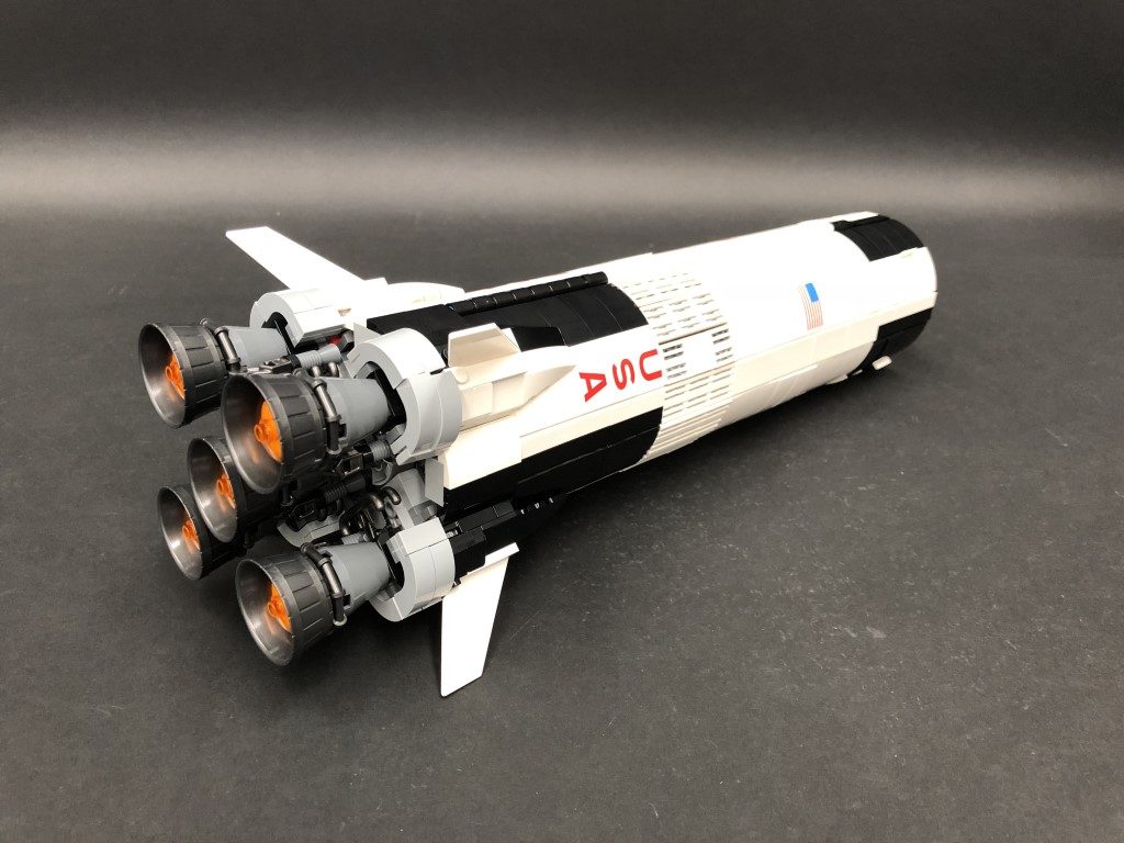
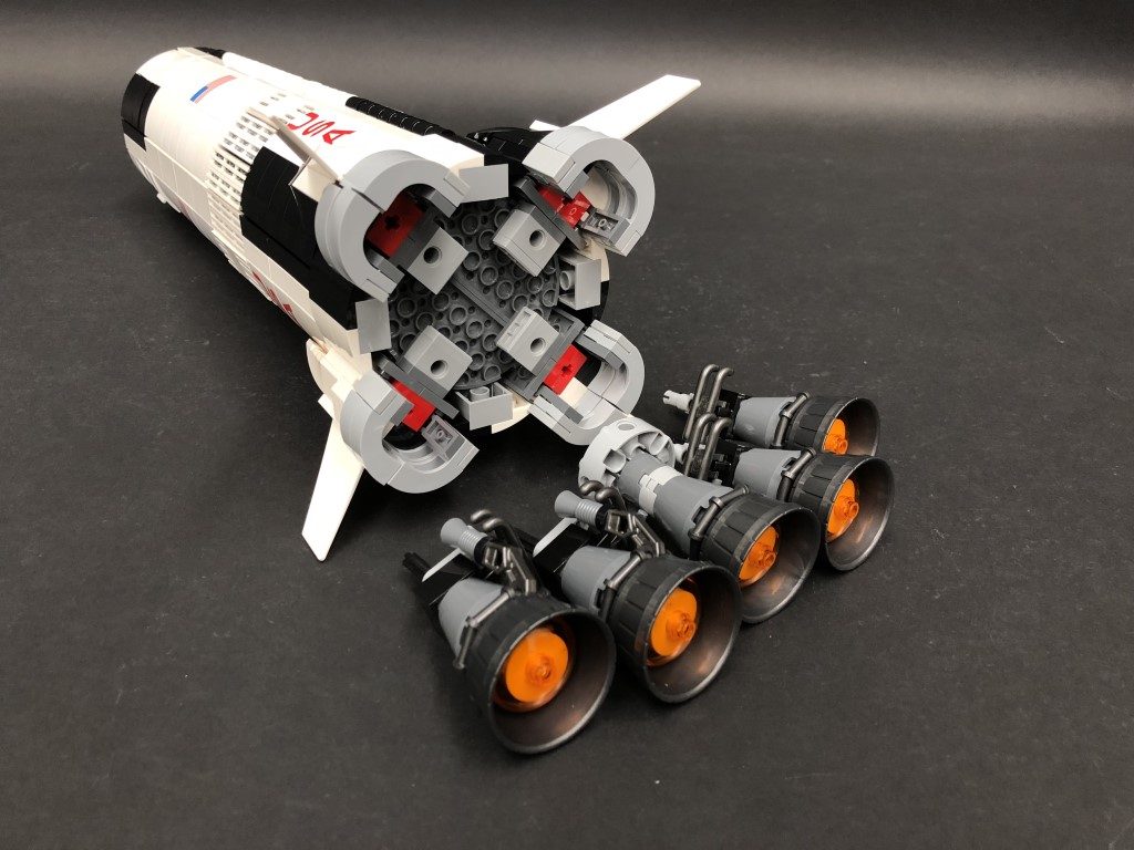
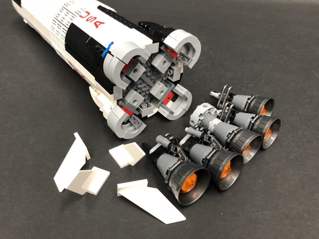
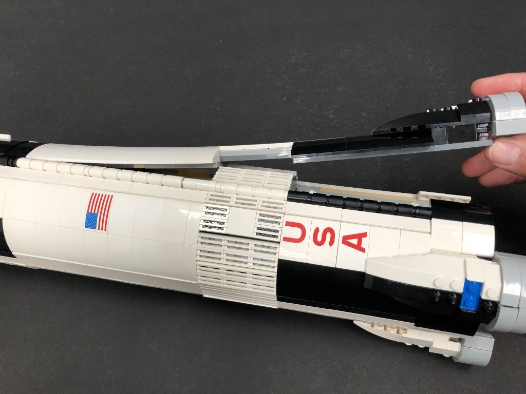
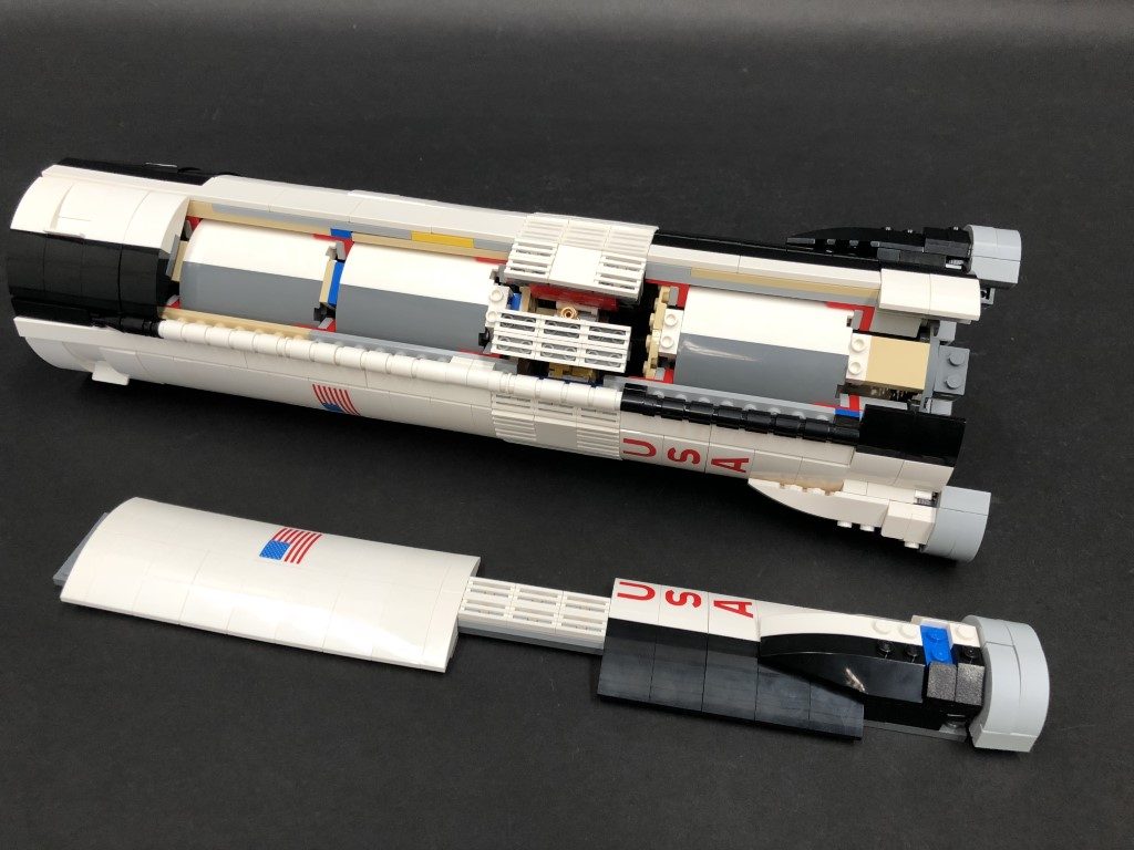
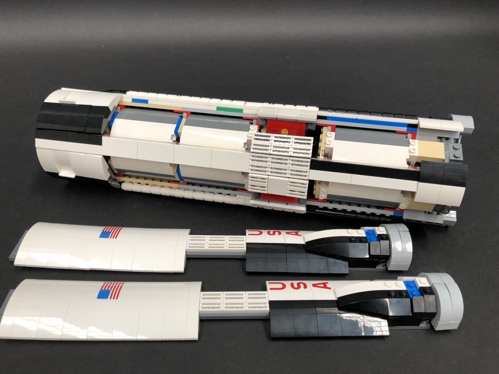
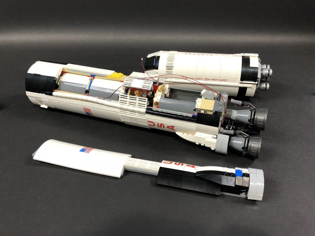
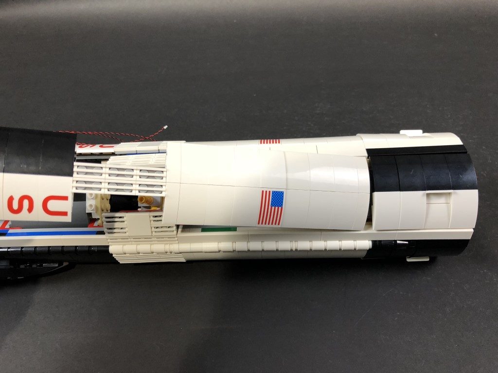
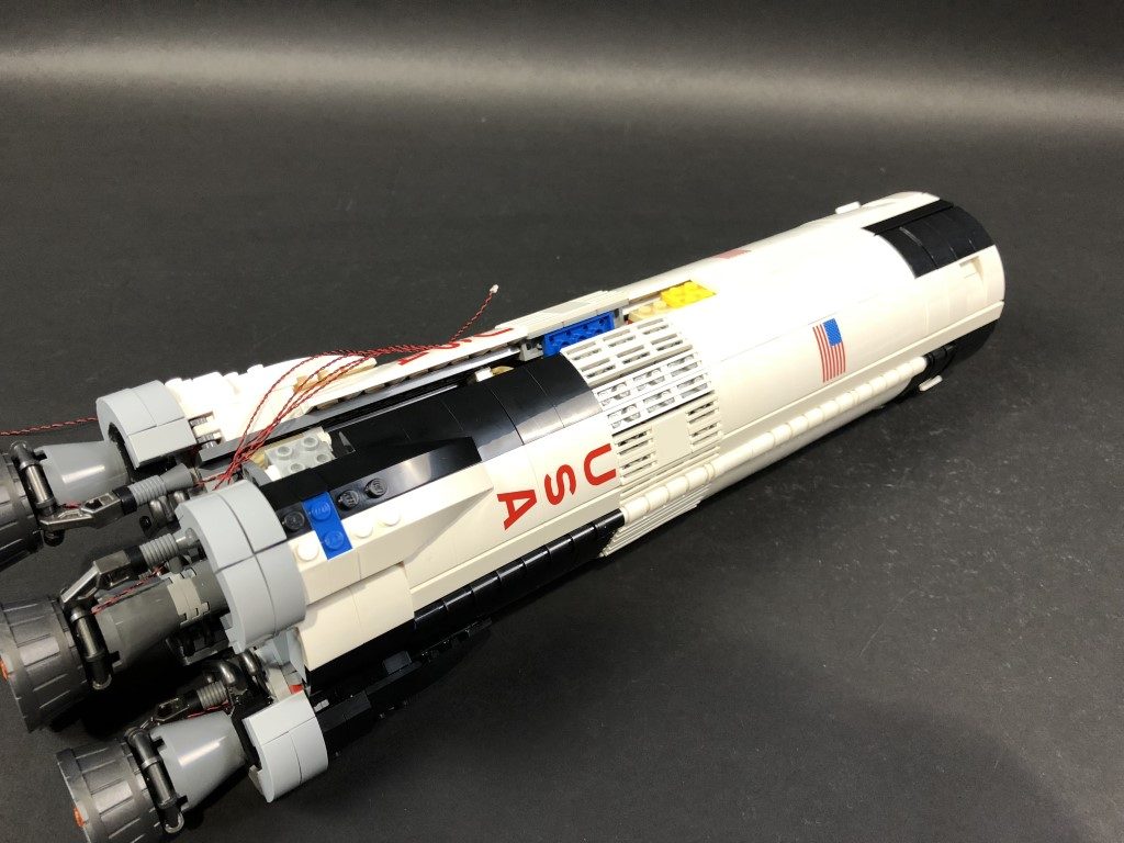
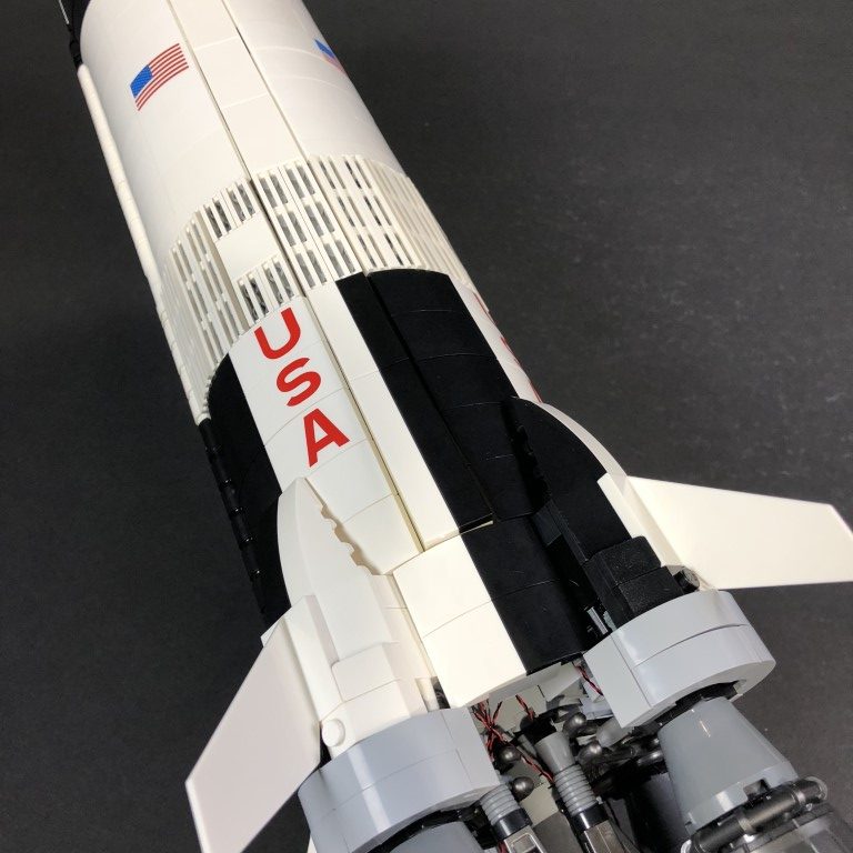
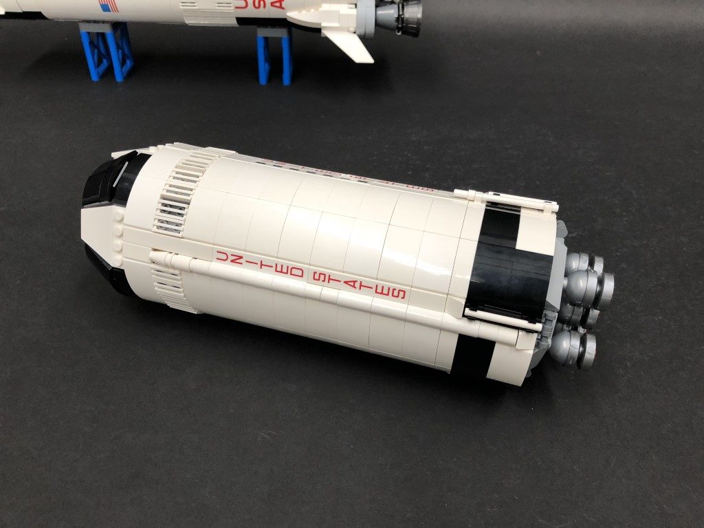
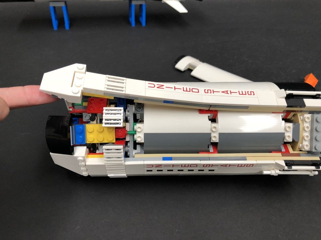
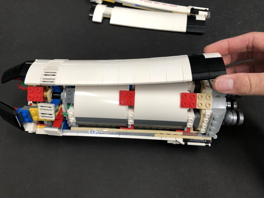
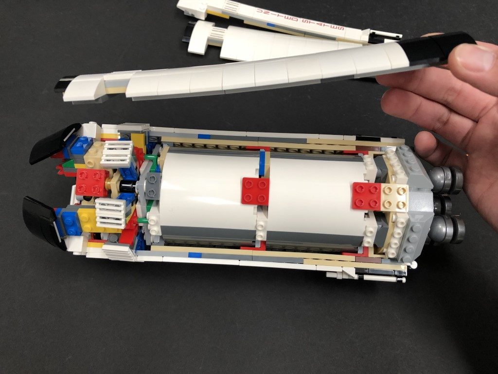
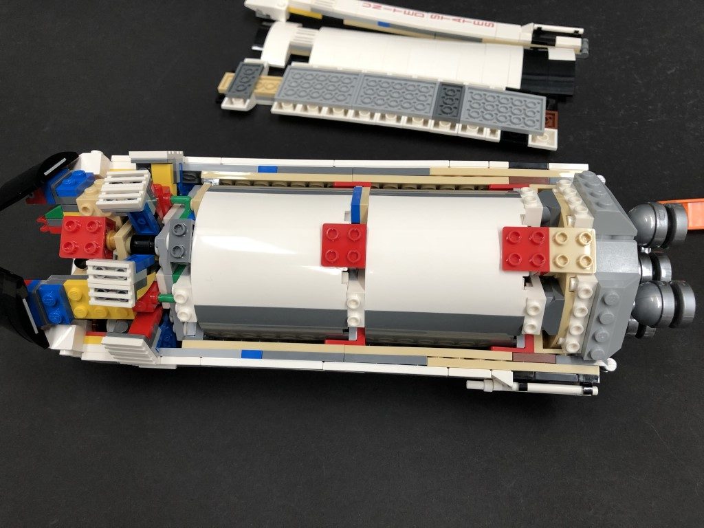
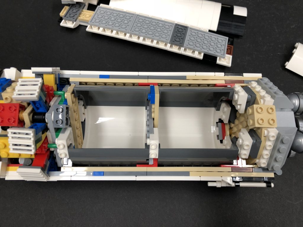
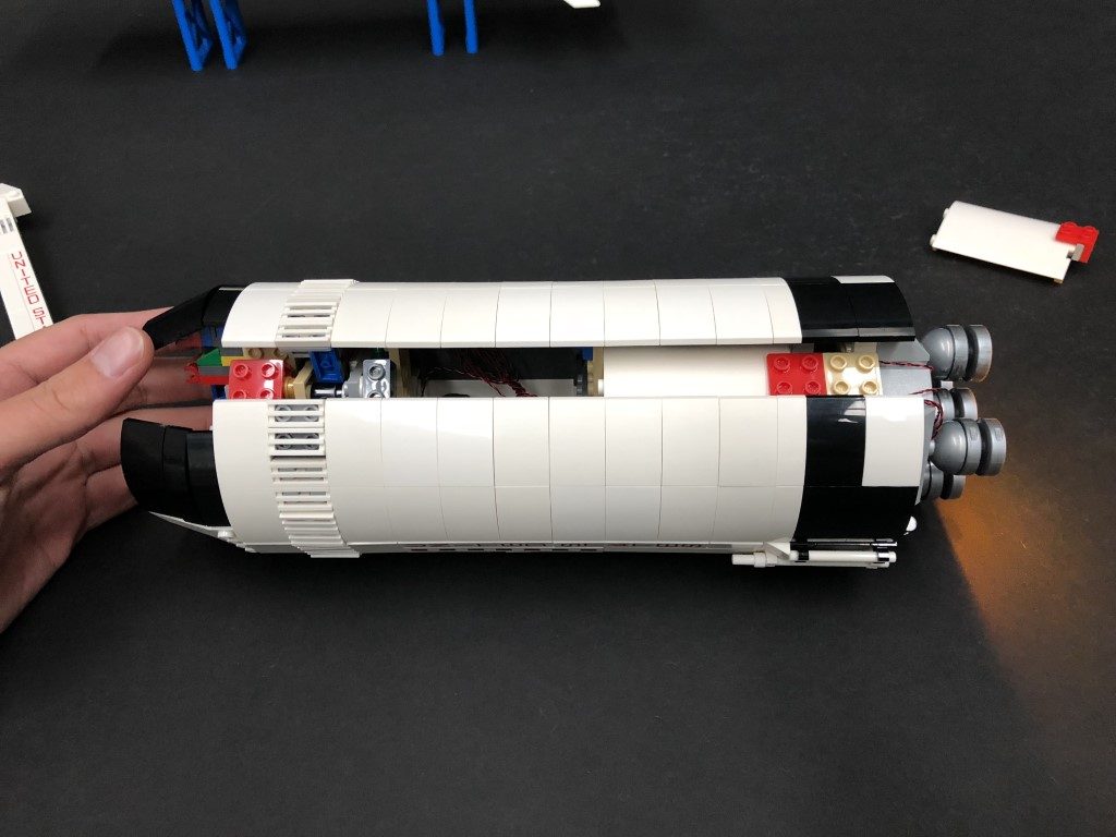
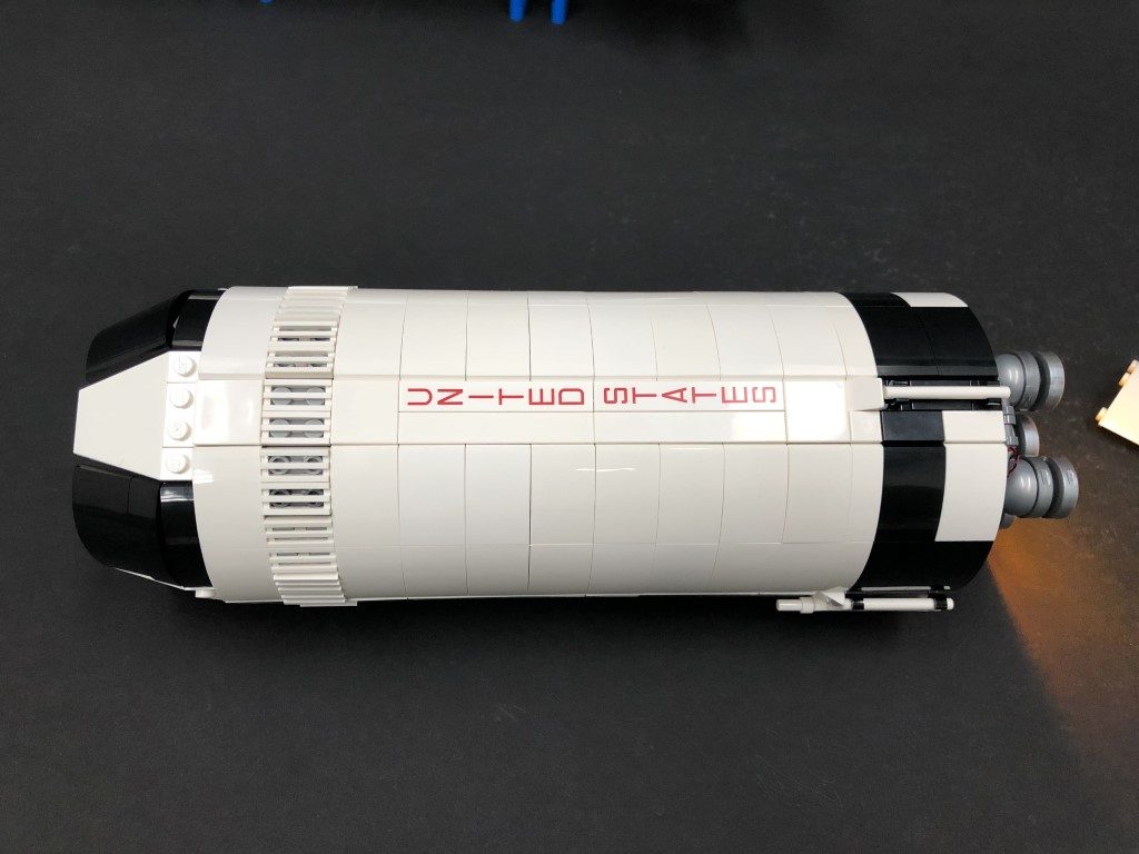
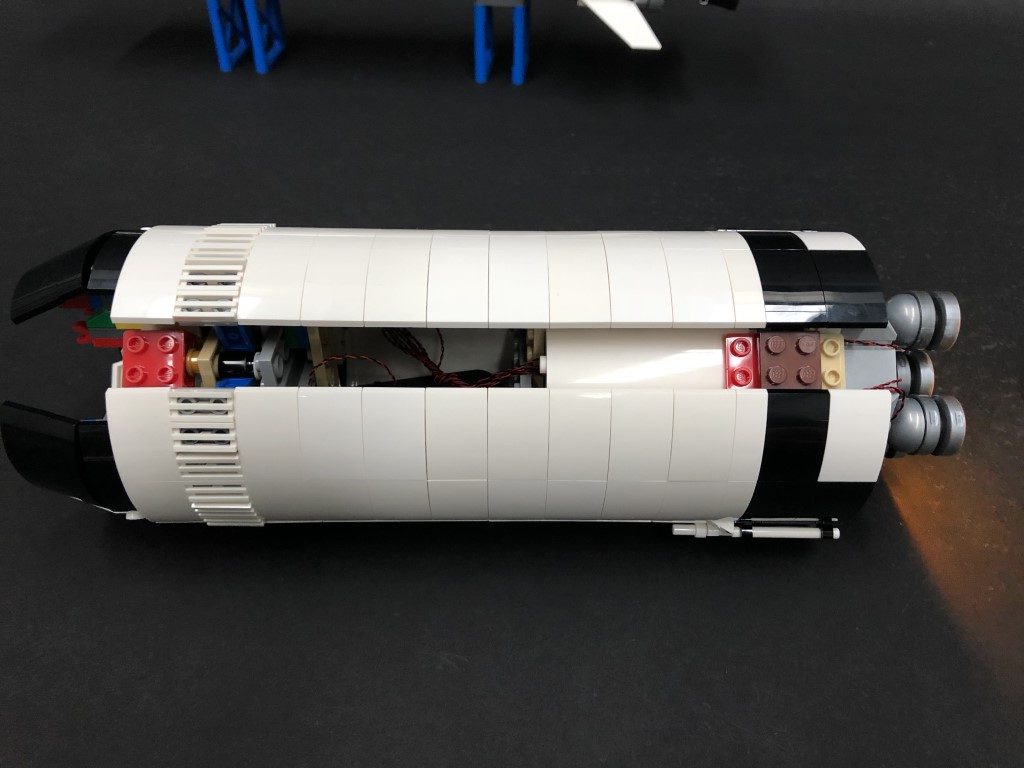
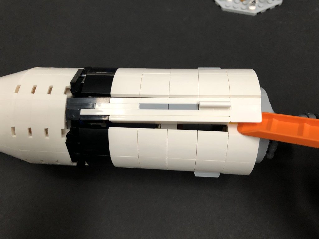
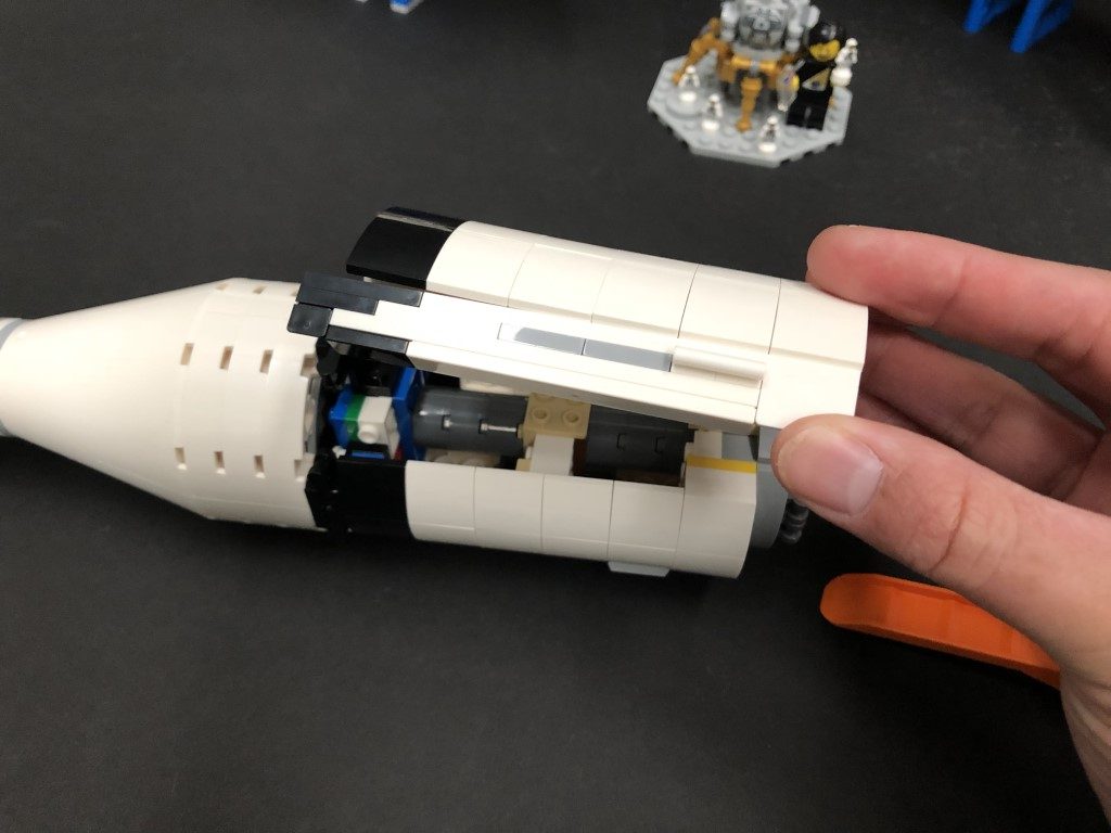
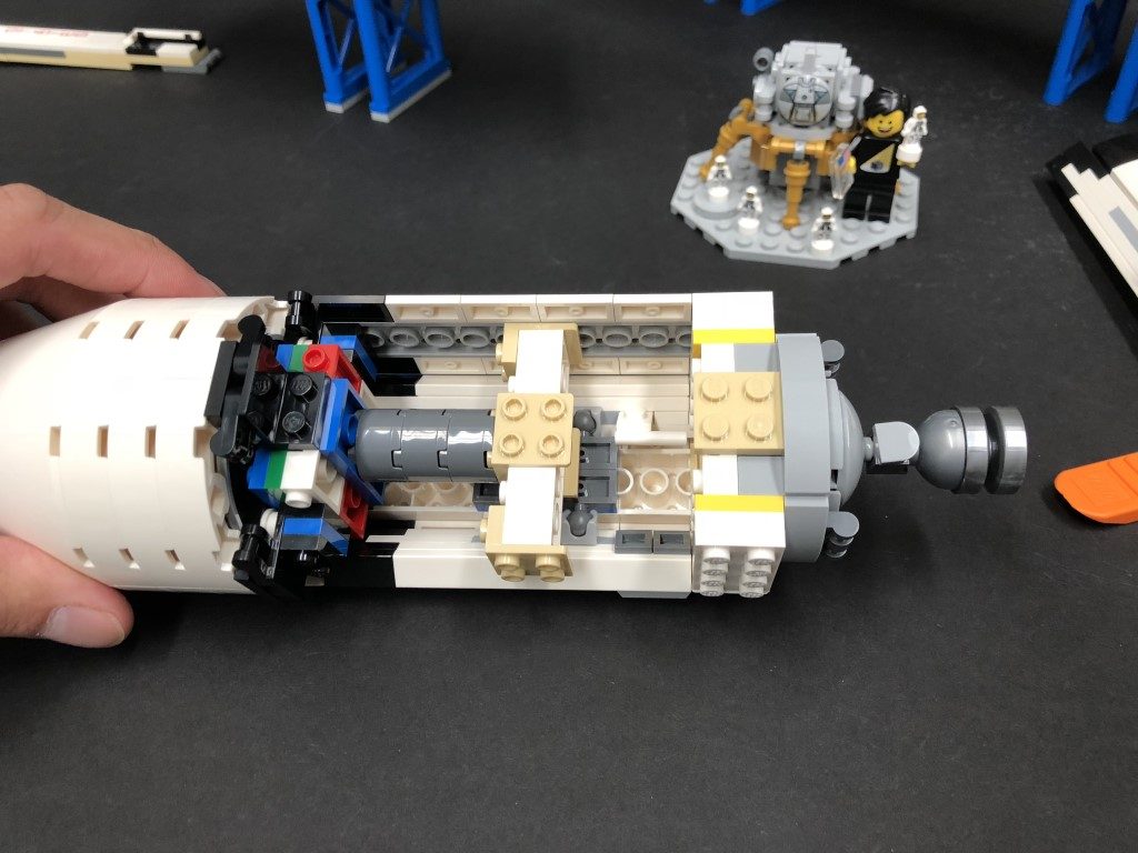
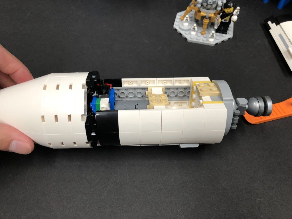
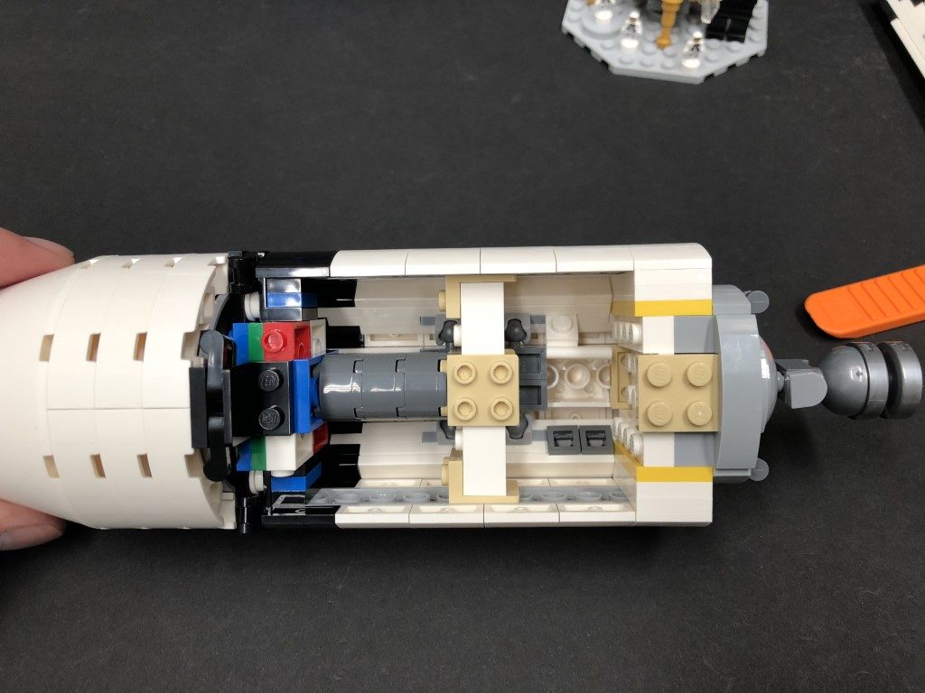
1.) We will install lights to the bottom rocket first. Start by disconnecting the bottom jet sections followed by the tail pieces as per below:
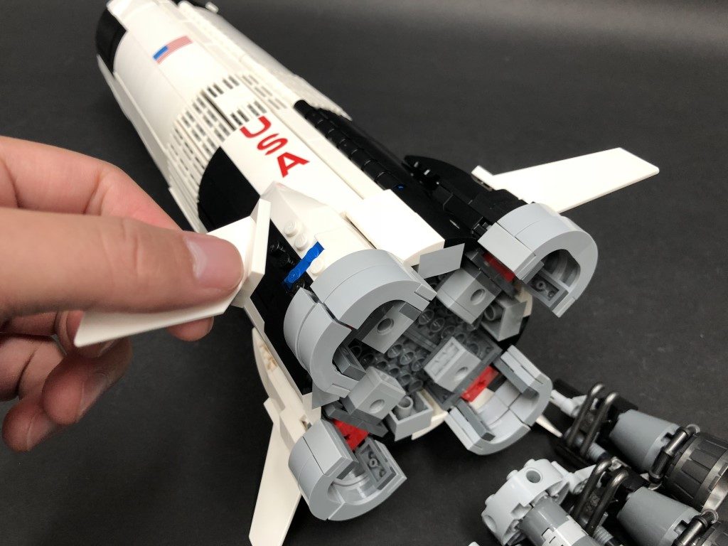
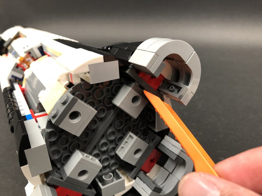
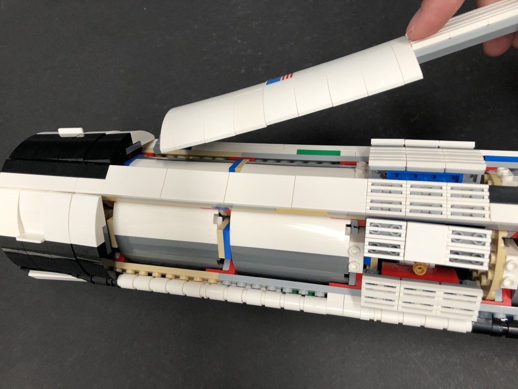
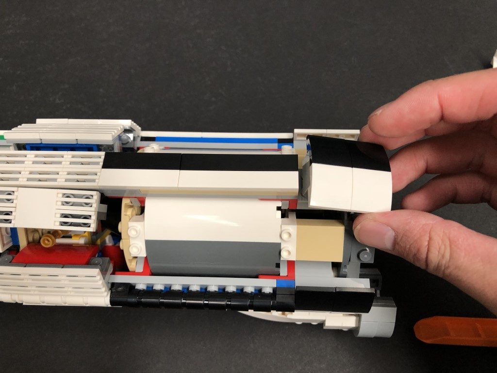
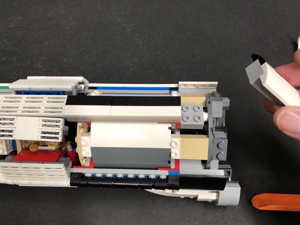
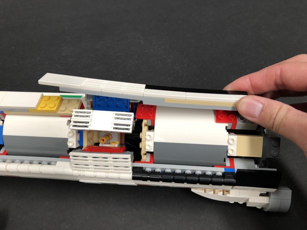
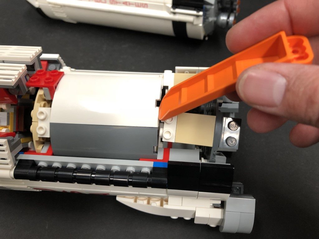
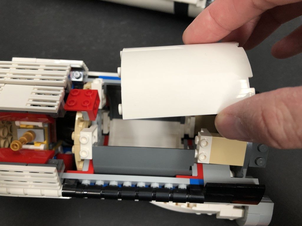
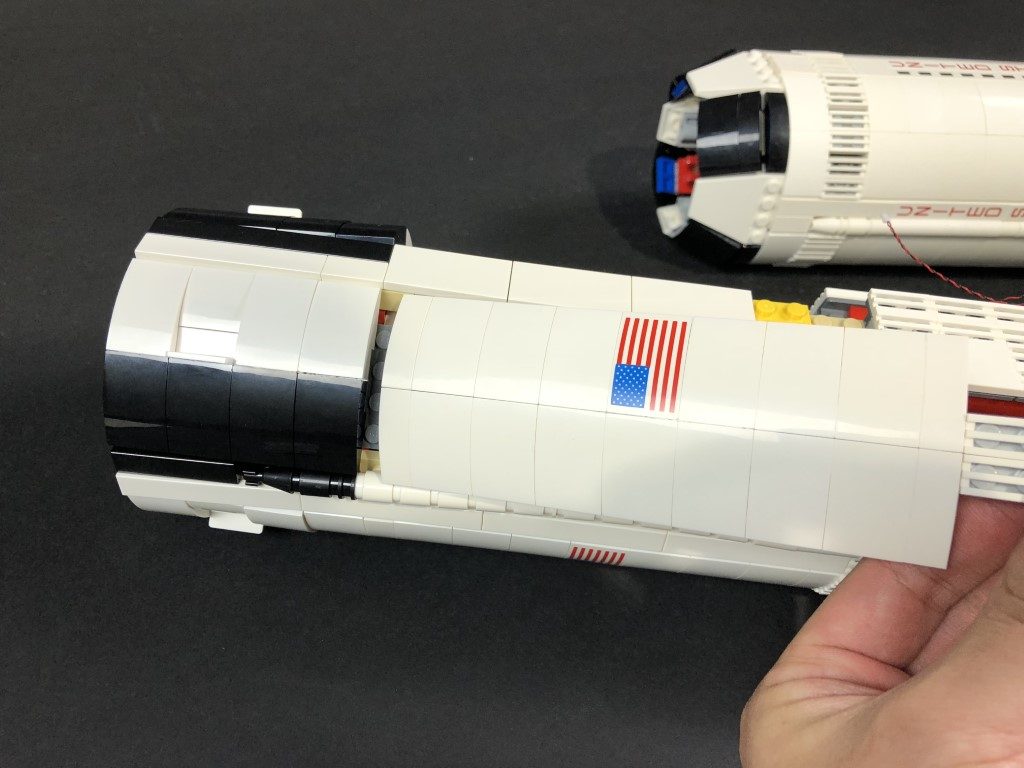
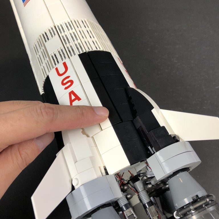
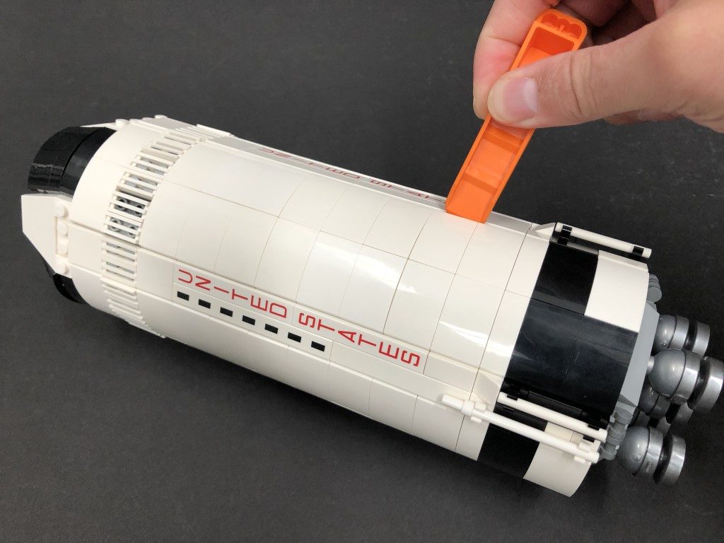
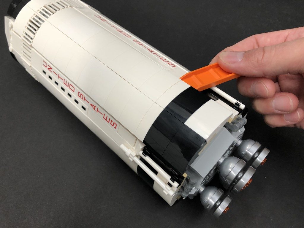
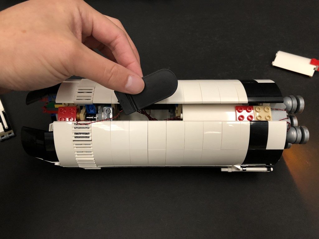
2.) Using the LEGO Removal tool, disconnect the following wall section from the bottom as shown below
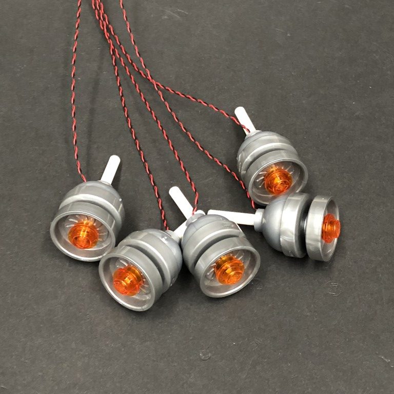
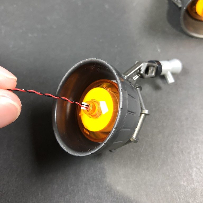
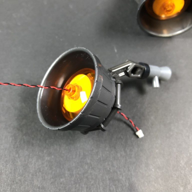
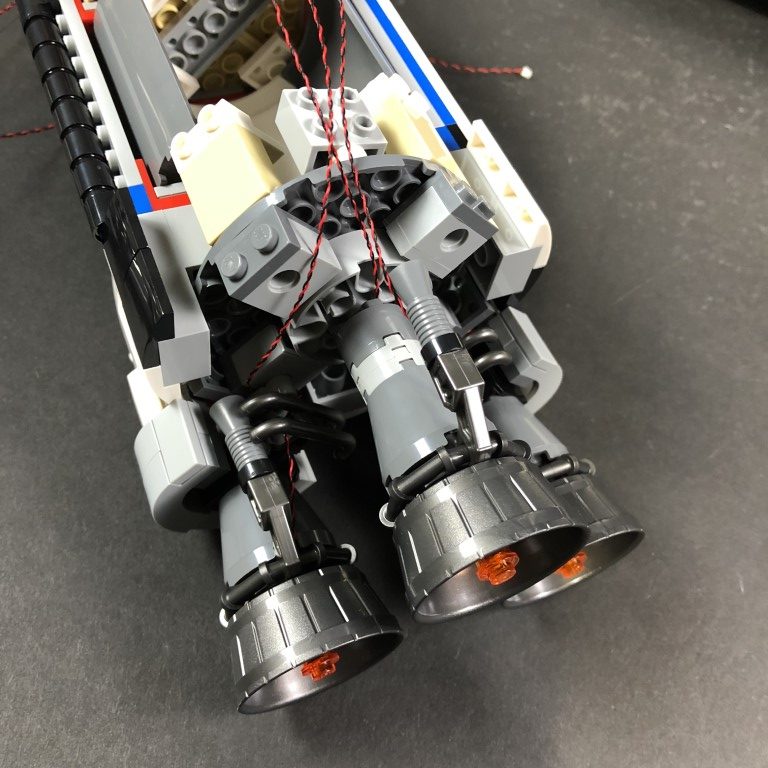
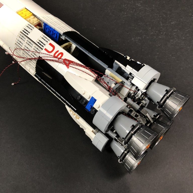
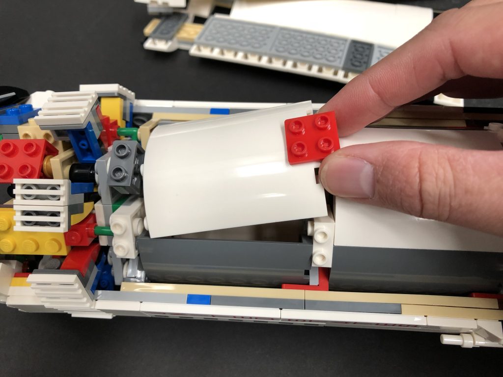
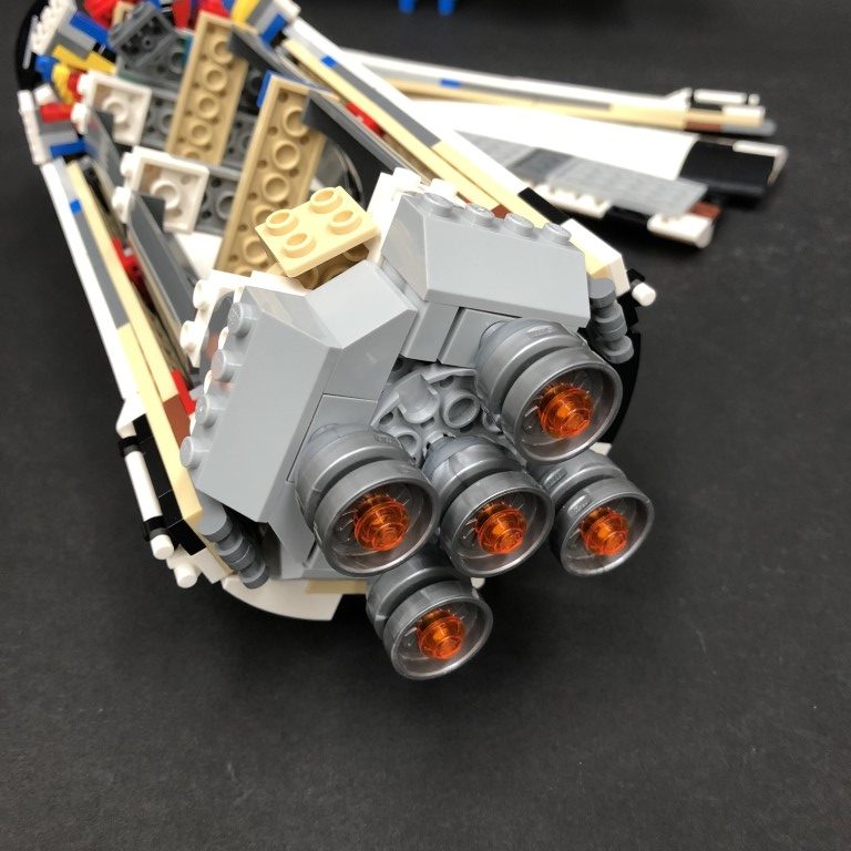
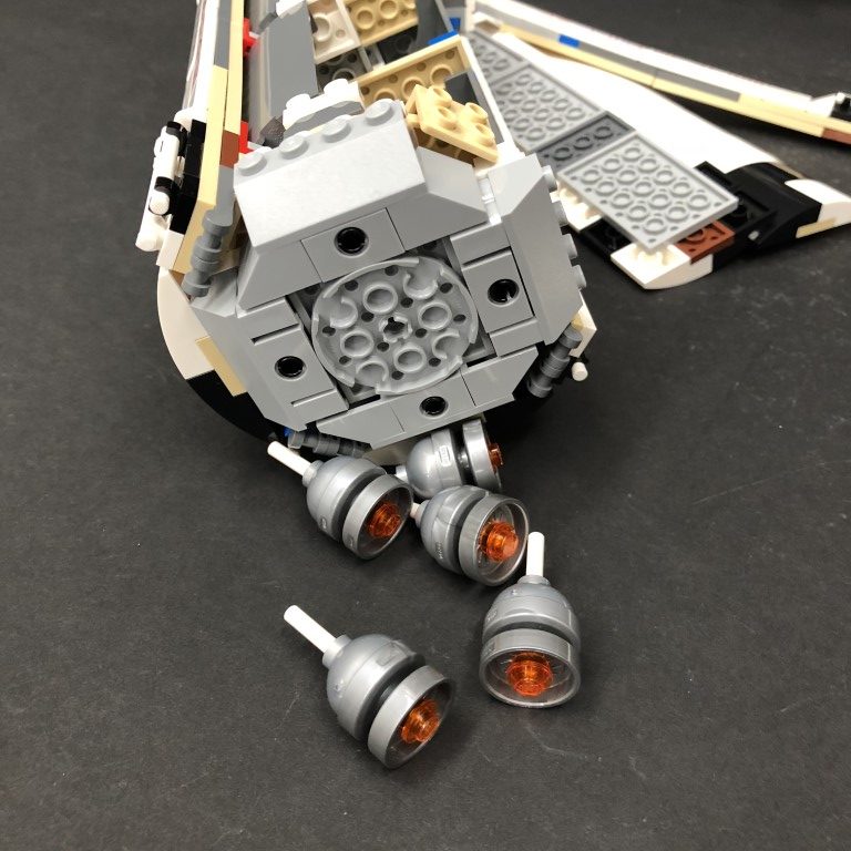
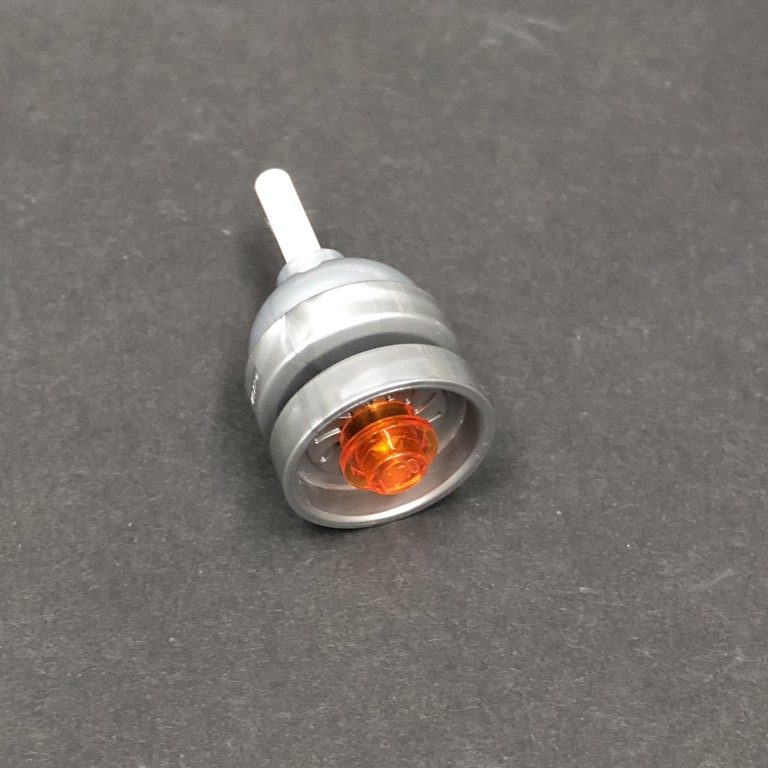
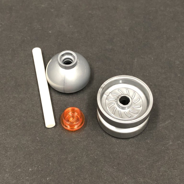
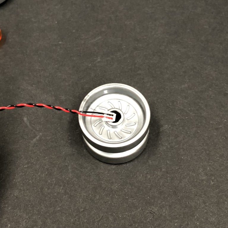
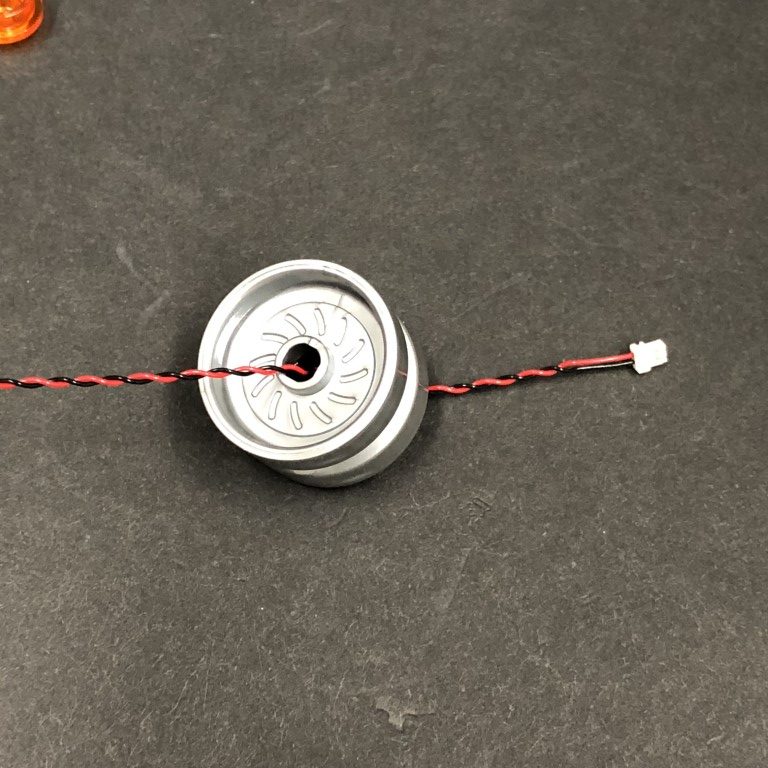
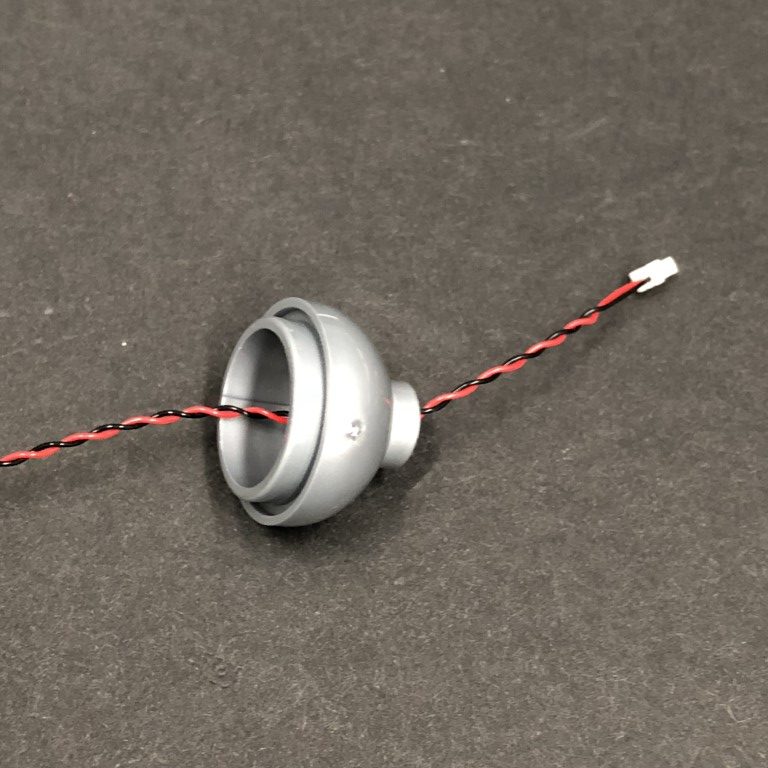
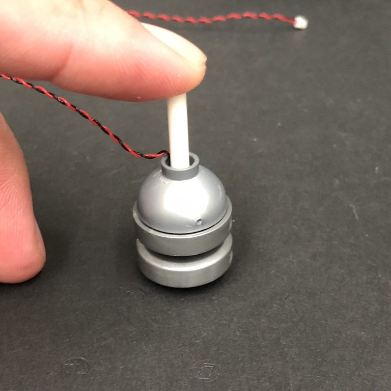
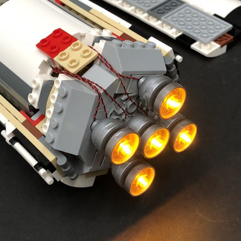
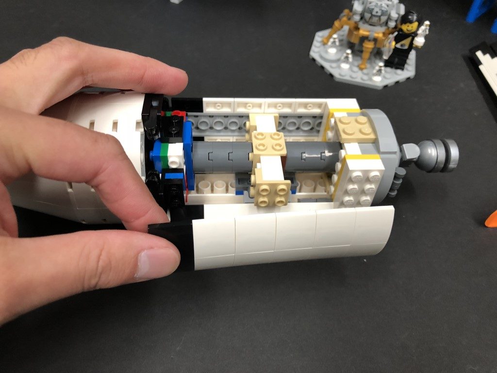
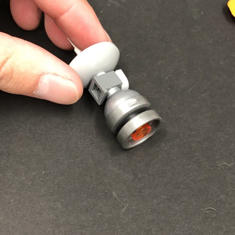
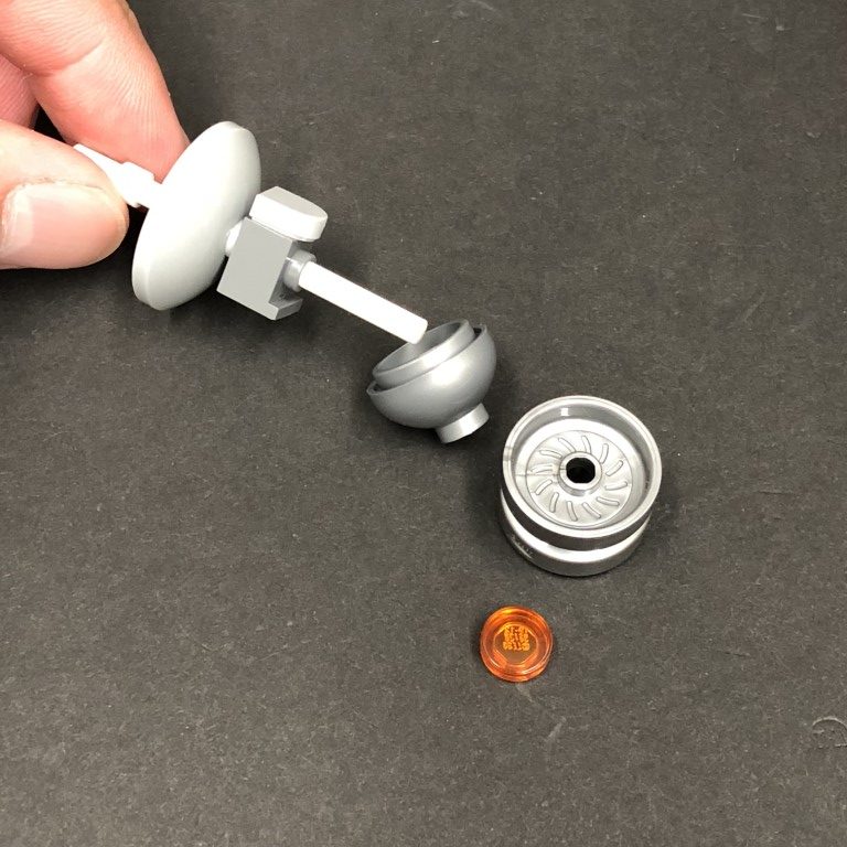
6.) Take the 5 jet sections and starting with one, disconnect the bottom half then take a White 30cm Bit Lightand thread the connector side of the cable down through the centre of the top of the jet (trans orange piece). Thread it all the way through until the Bit Light is right up against the edge of the trans orange piece.
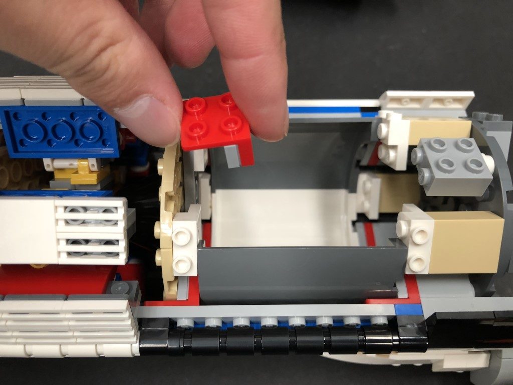
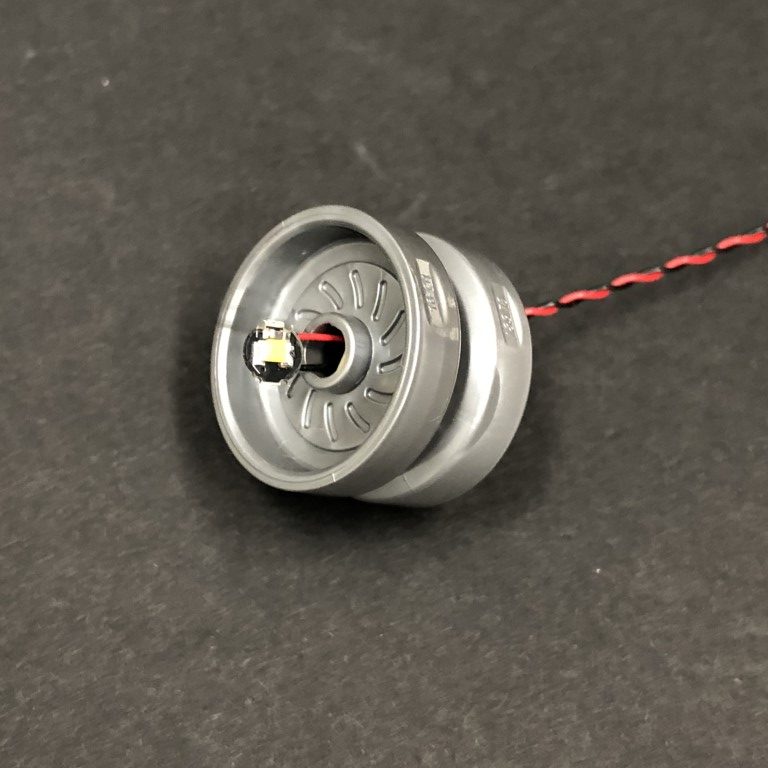
Slightly bend the Bit Light on a 90 degree angle so that it sits flat, then secure it in place by connecting one of the provided Trans Orange Round Plate 1×1over the top
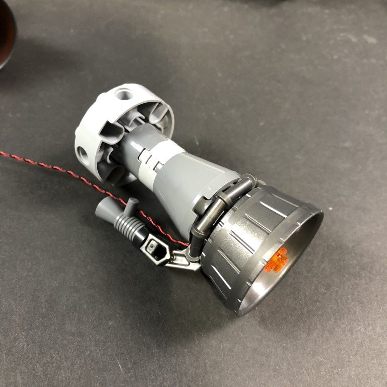
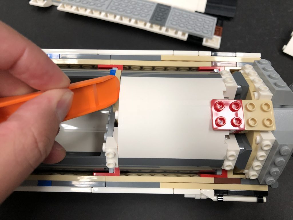
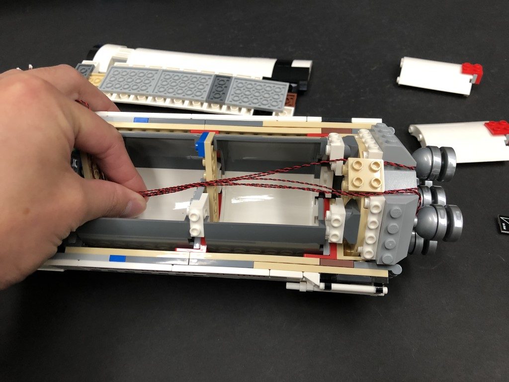
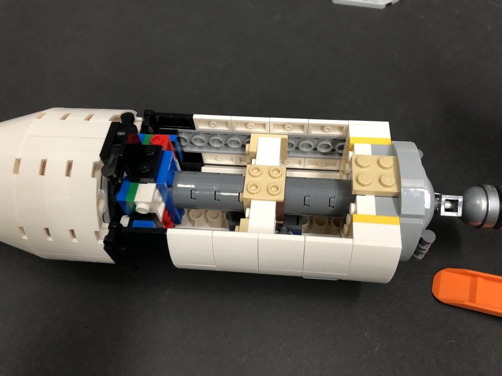
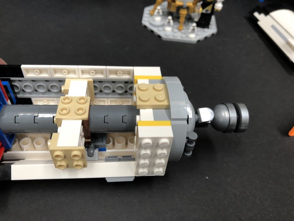
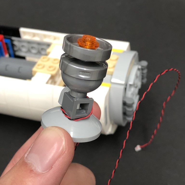
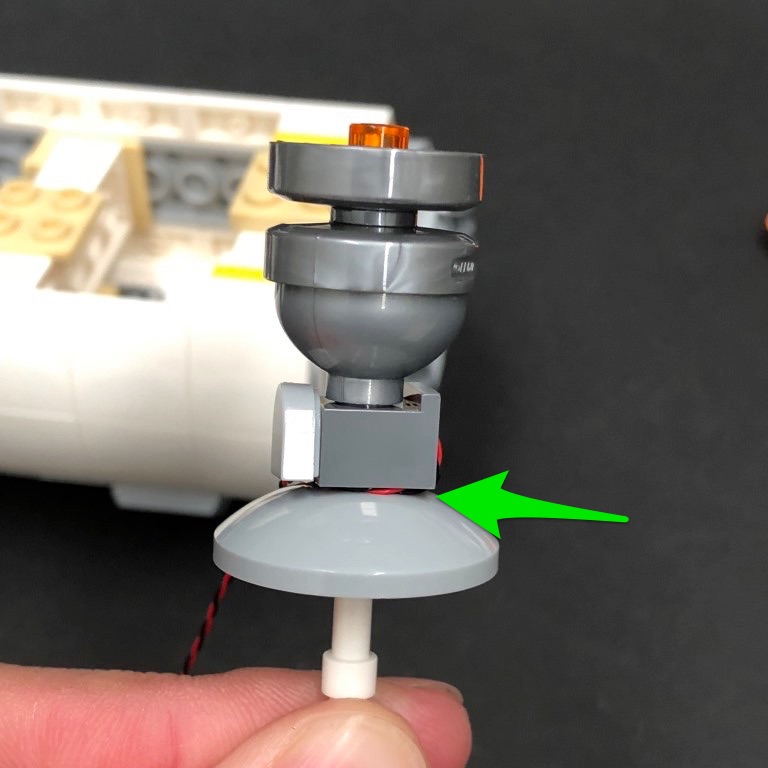
Reconnect the top half of the jet section back to the bottom half ensuring the cable from the Bit Light is tucked neatly underneath the dark grey bars.
Take caution when reconnecting to the bottom half and ensure there is enough cable slack between the jet section and bottom half for the technic bar to push against the cable as the two sections reconnect. If there is not enough cable slack, the technic bar will push the cable out and snap the cable.
7.)Repeat previous step to install White 30cm Bit Lights to the other four Jet sections using more of the provided Trans Orange Round Plate 1×1

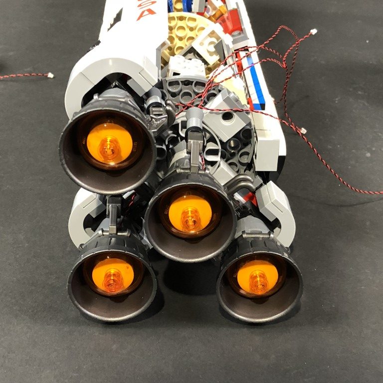
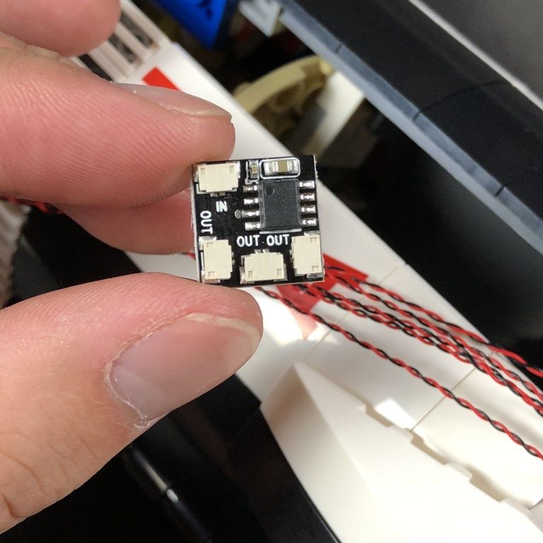
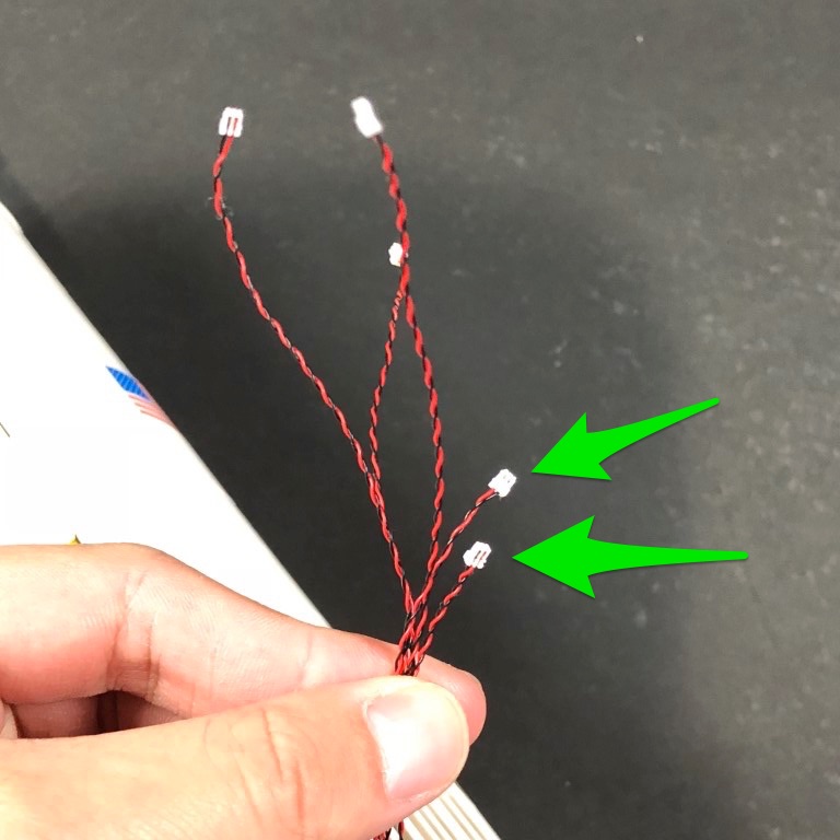
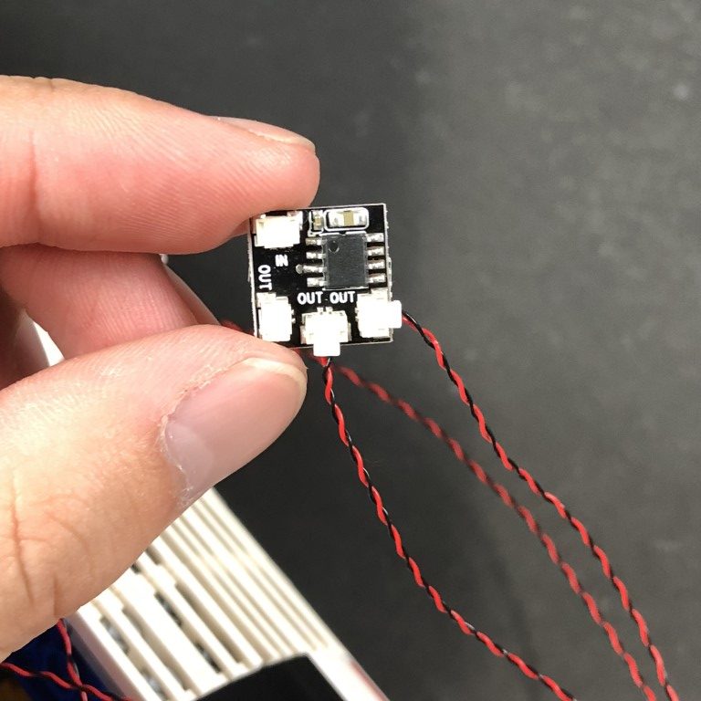
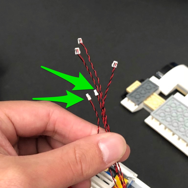
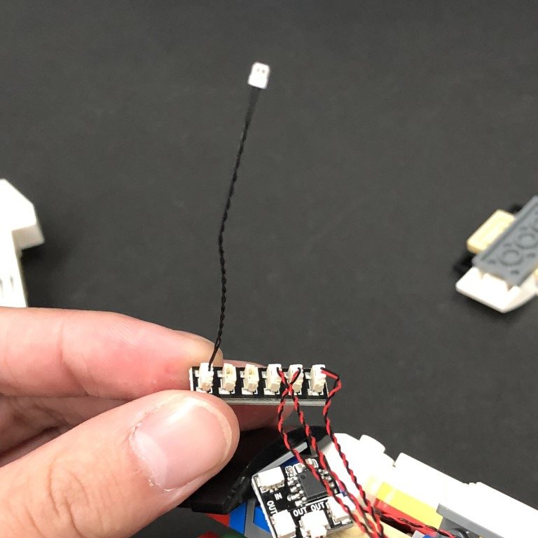
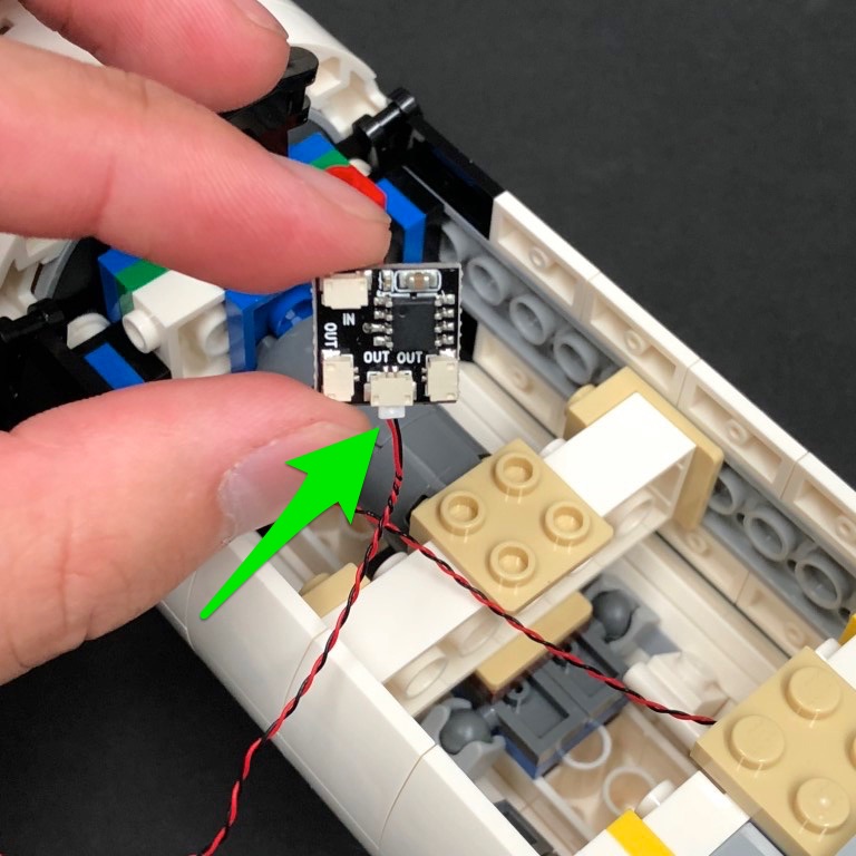
11.) Take 1x Flicker Effects Board and connect the two shortest Bit Light Cables to the OUT ports (There are 3 OUT ports in total).
Turn the Battery Pack on and confirm all lights and effects are working OK
Note: If you experience any issues with the lights not working and suspect an issue with a component, please try a different port on the expansion board to verify where the fault lies (with the light or expansion board). To correct any issues with expansion board ports, please view the section addressing expansion board issues on our online troubleshooting guide.
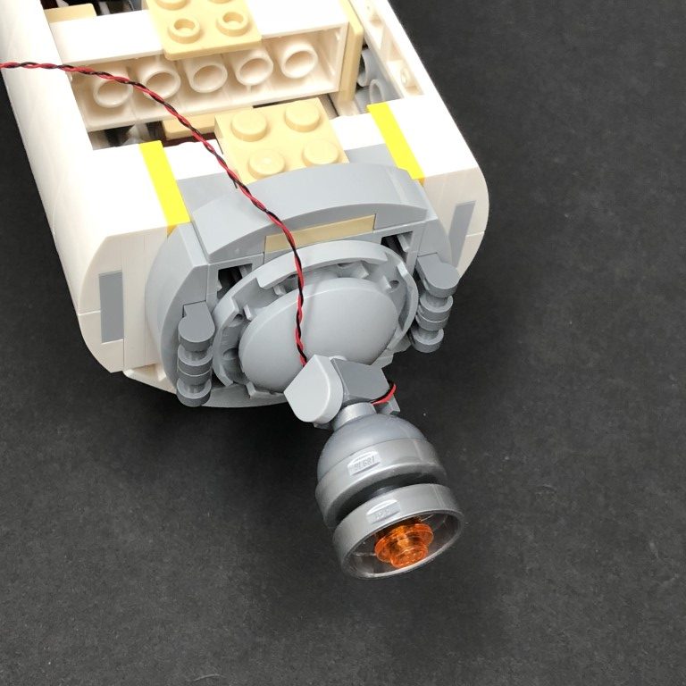
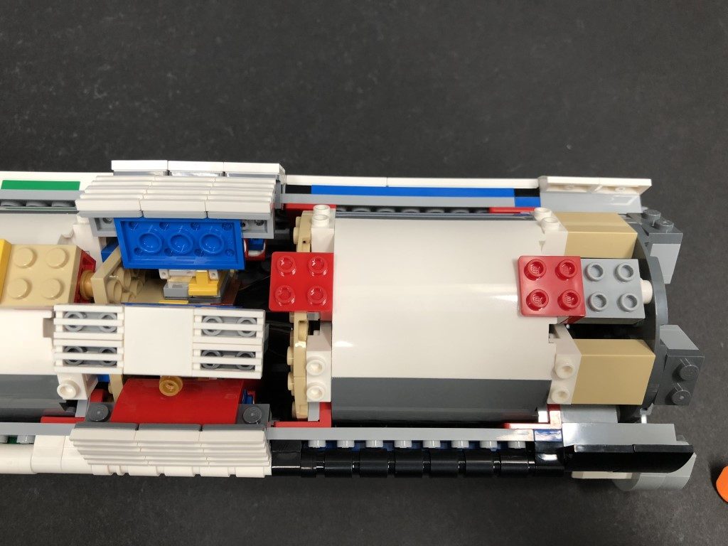
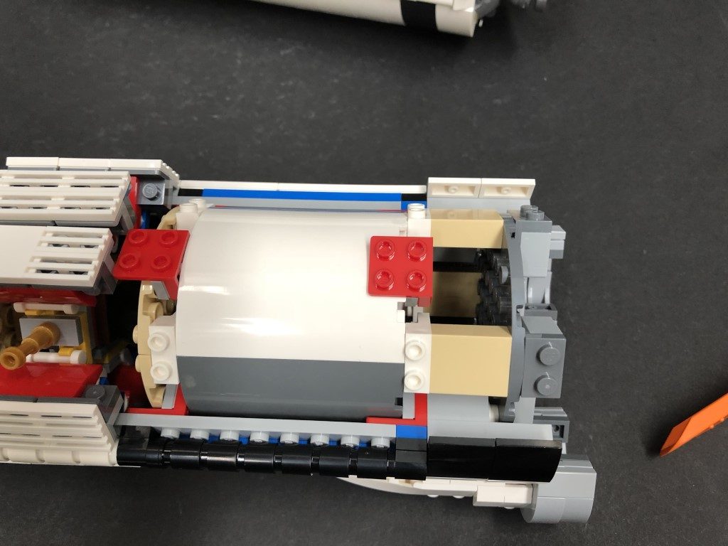
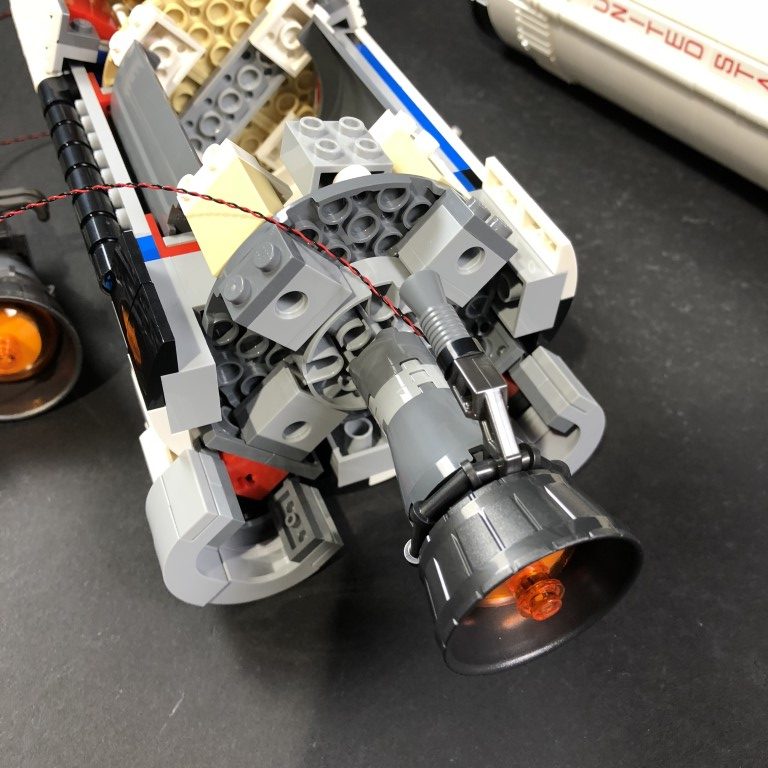
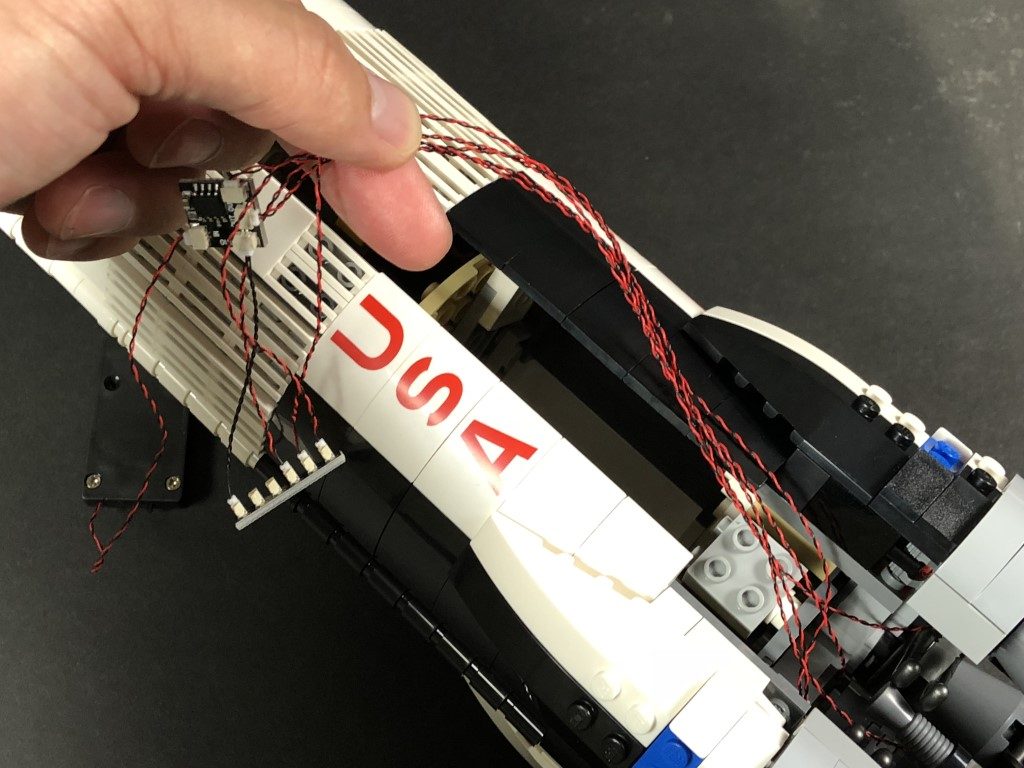
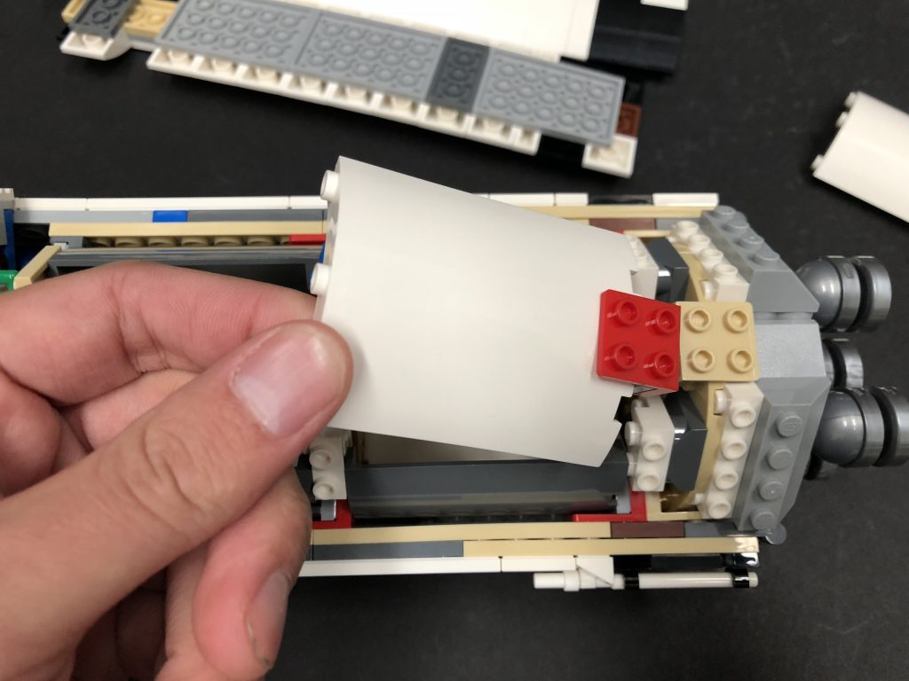
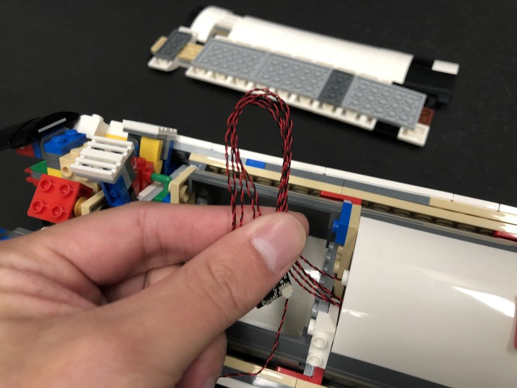
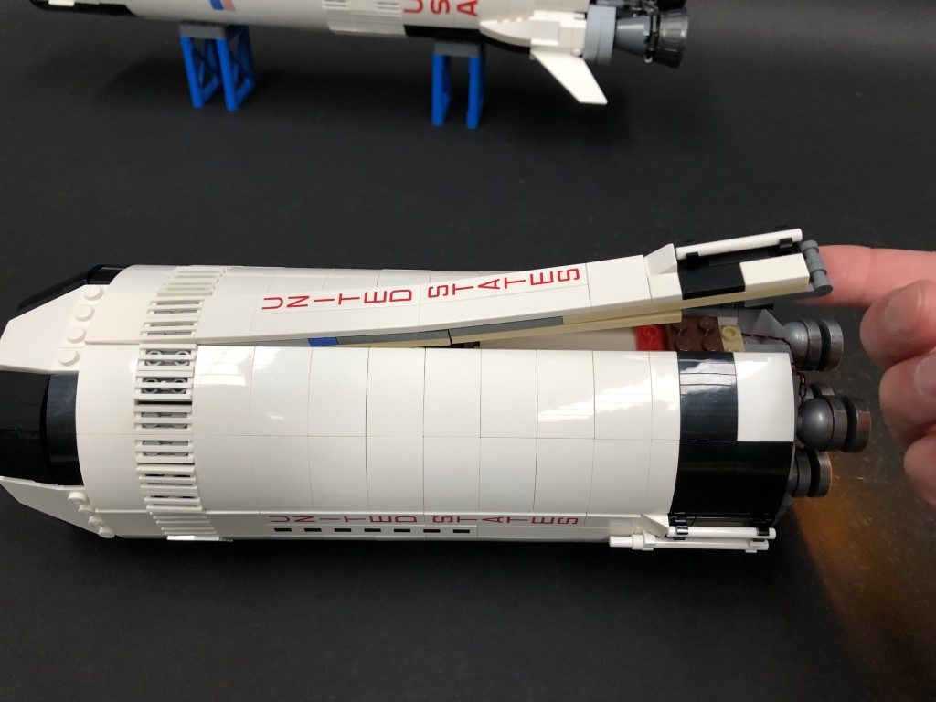
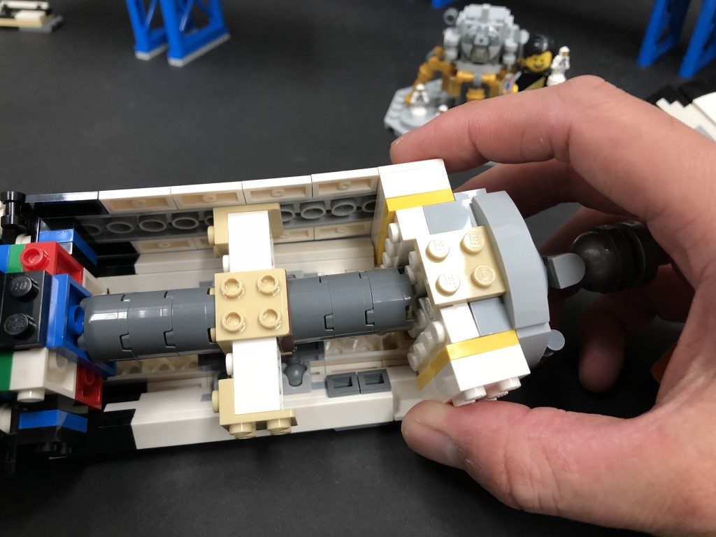
19.)Disassemble one of the Jets and then take a White 30cm Bit Light and then thread the connector side through the top of outer section. Thread it all the way through until the component is right up against the edge.
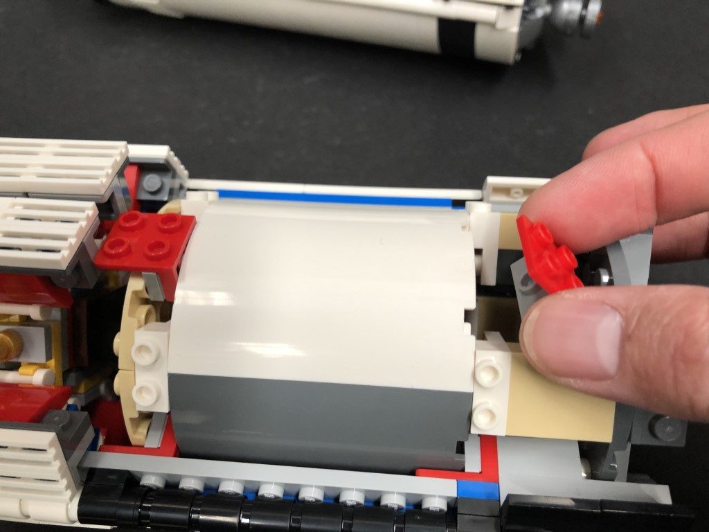
Carefully bend the Bit Light 90 degrees so that it now sits flat against the hole then secure it in place by reconnecting the Trans Orange Round Plate
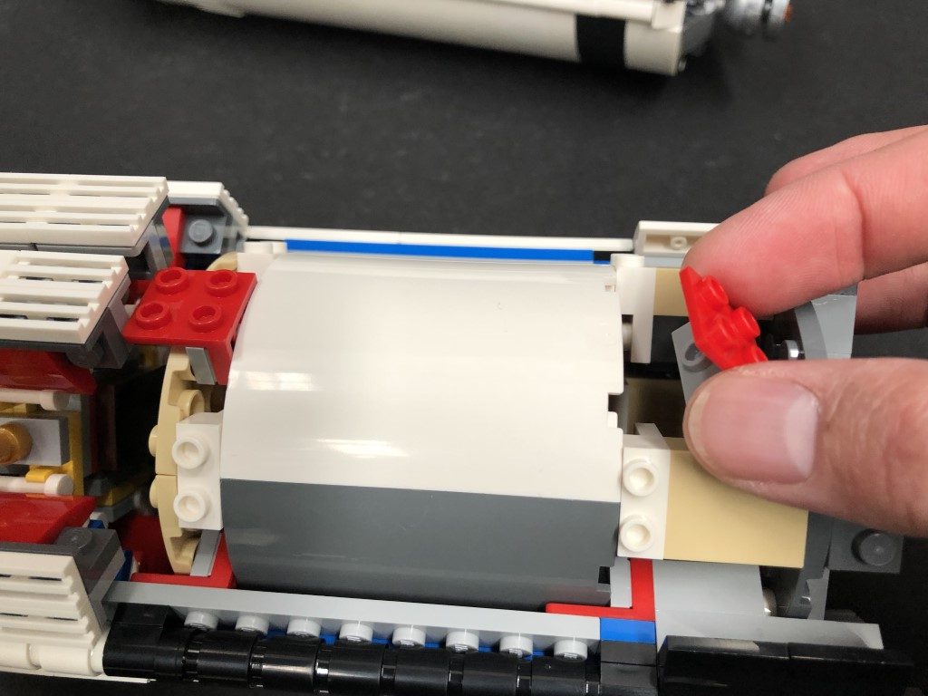
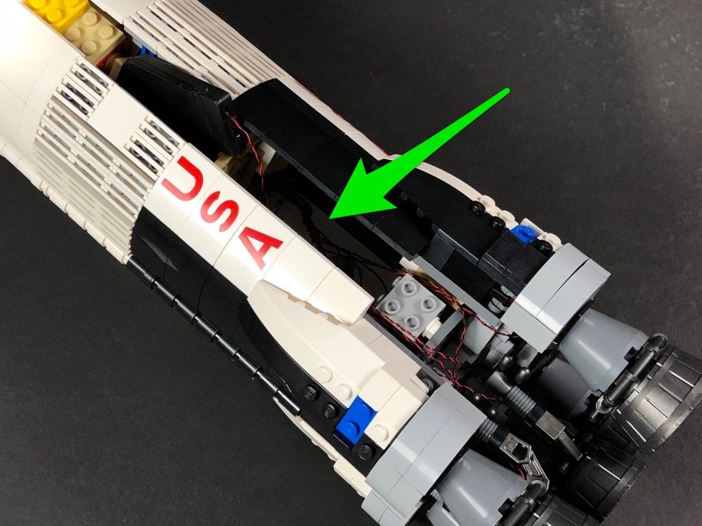
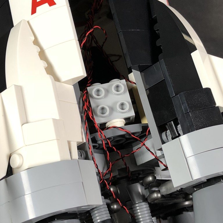
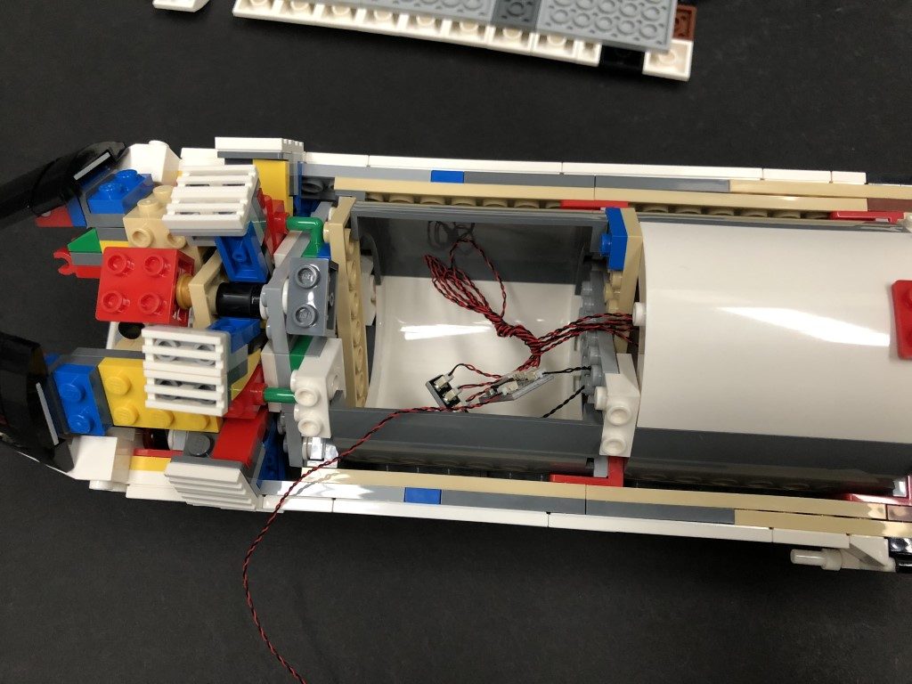
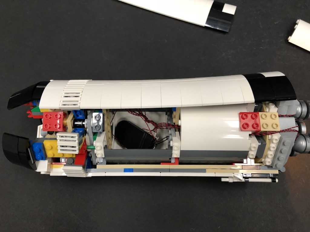
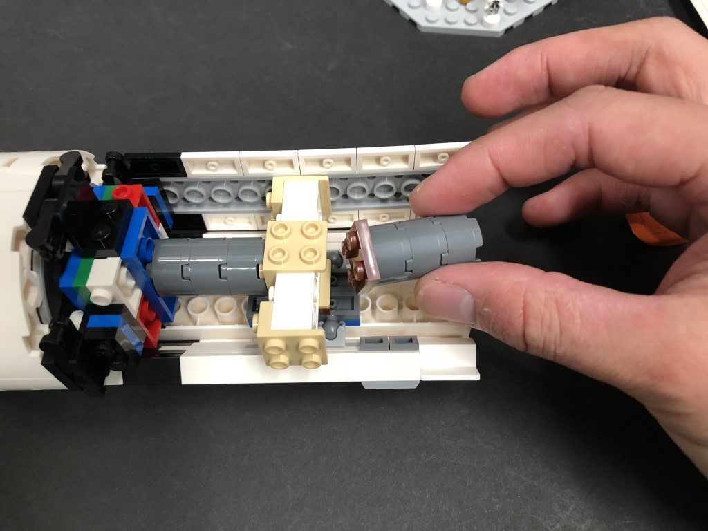
Thread the cable through the piece that connects behind and then carefully reconnect the white bar securing all pieces together.
Take caution when reconnecting to the white bar and ensure there is enough cable slack between the jet section and white bar for the bar to push against the cable as the two pieces reconnect. If there is not enough cable slack, the white bar will push the cable out and snap the cable.
Note: If you experience any issues with the lights not working and suspect an issue with a component, please try a different port on the expansion board to verify where the fault lies (with the light or expansion board). To correct any issues with expansion board ports, please view the section addressing expansion board issues on our online troubleshooting guide.
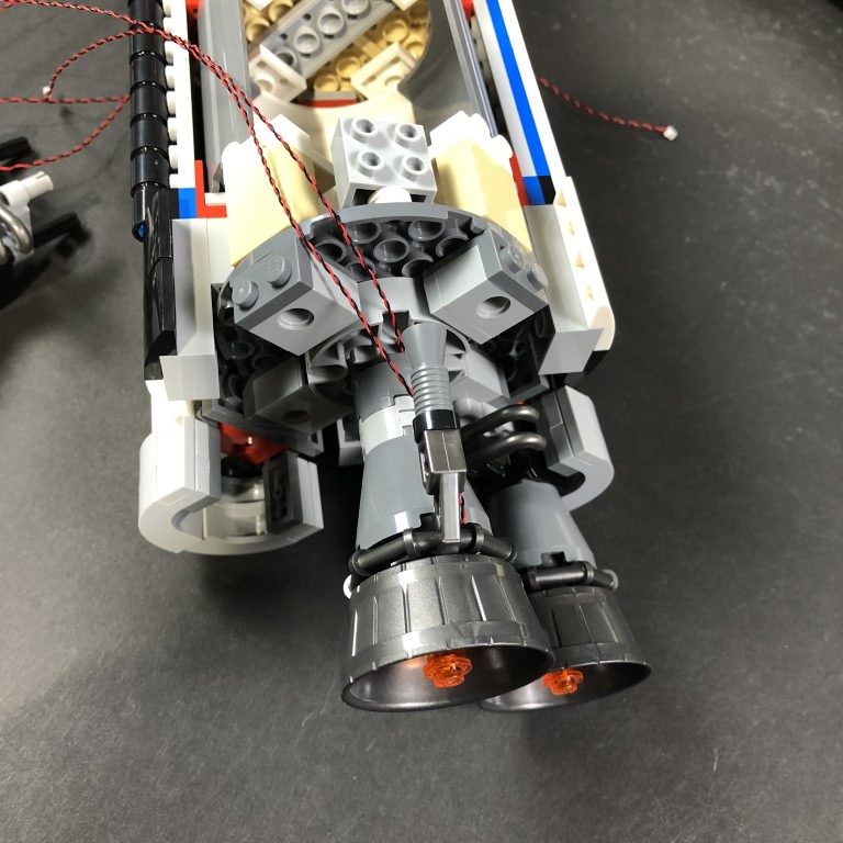
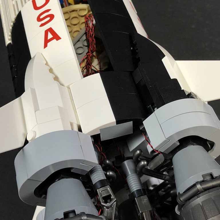
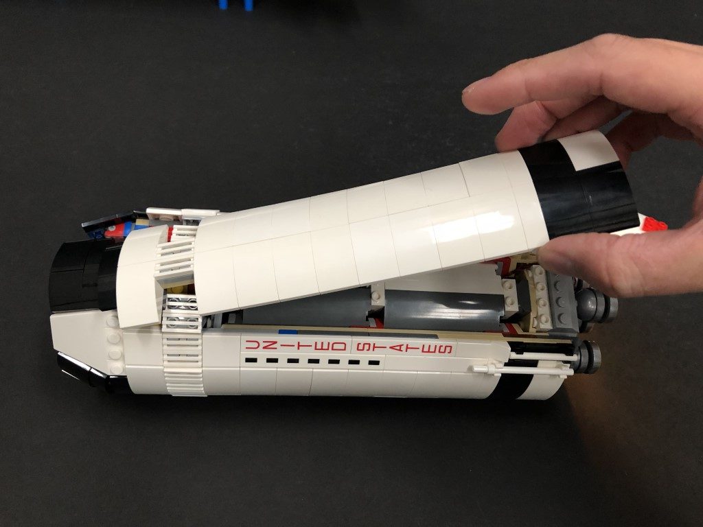
32.) Follow Step 19 to install the remaining White 30cm Bit Light to this Jet section using the provided Trans Orange Round Plate 1×1.
Take caution when reconnecting to the white bar and ensure there is enough cable slack between the jet section and white bar for the bar to push against the cable as the two pieces reconnect. If there is not enough cable slack, the white bar will push the cable out and snap the cable.
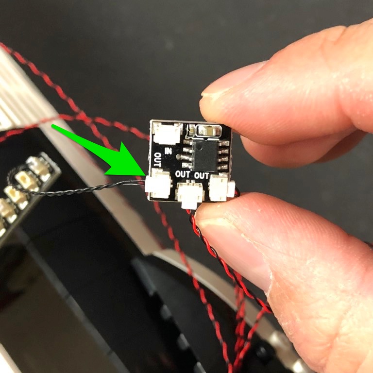
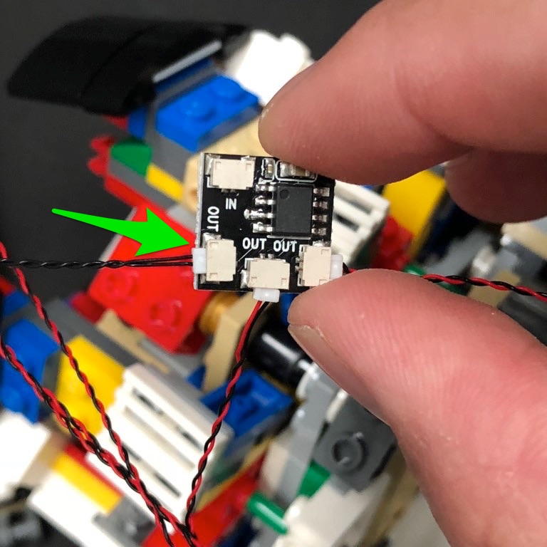
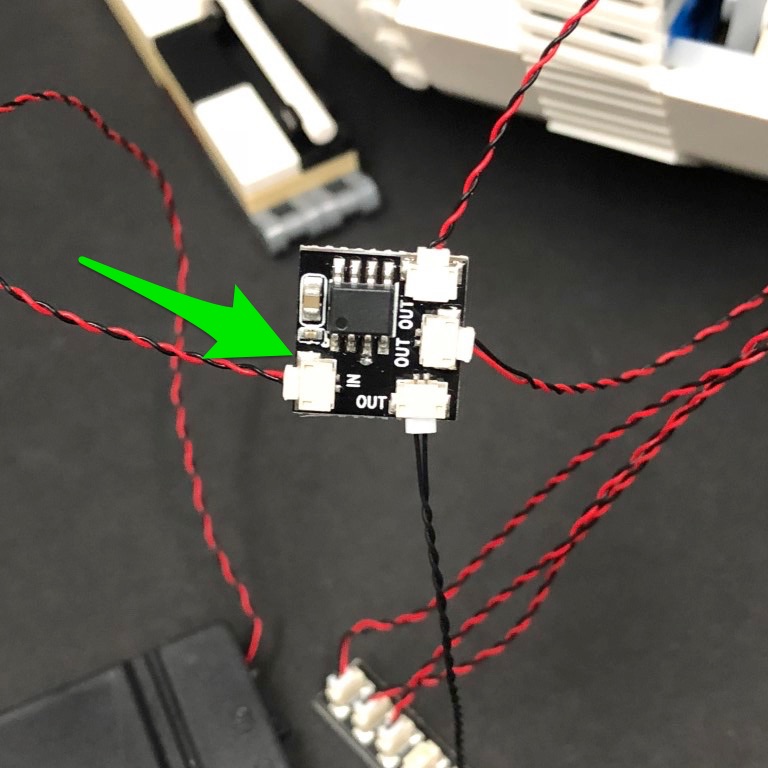
35.) Connect the other end of the Bit Light cable to any OUT port on the remaining Flicker Effects Board
Take the remaining Flat Battery Pack and insert 2x CR2032 Batteries to it. Connect the battery pack cable to the IN port on the Flicker Effects Board
