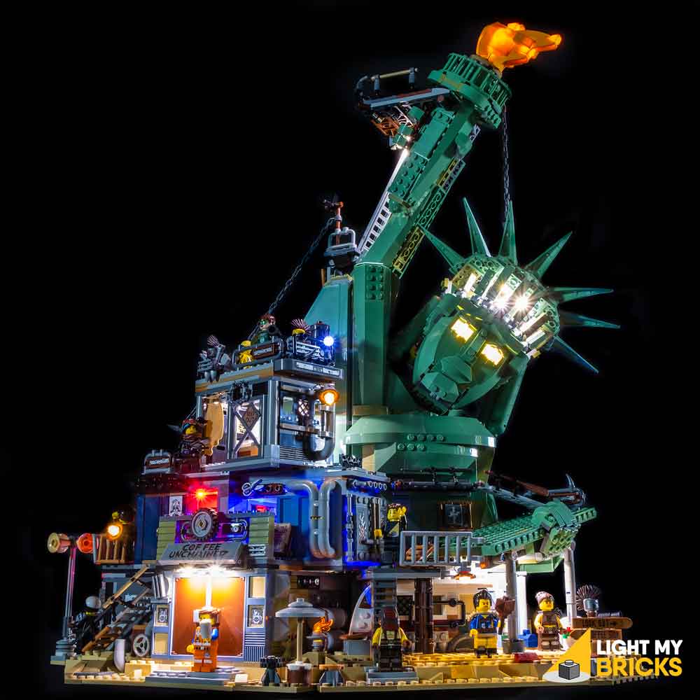
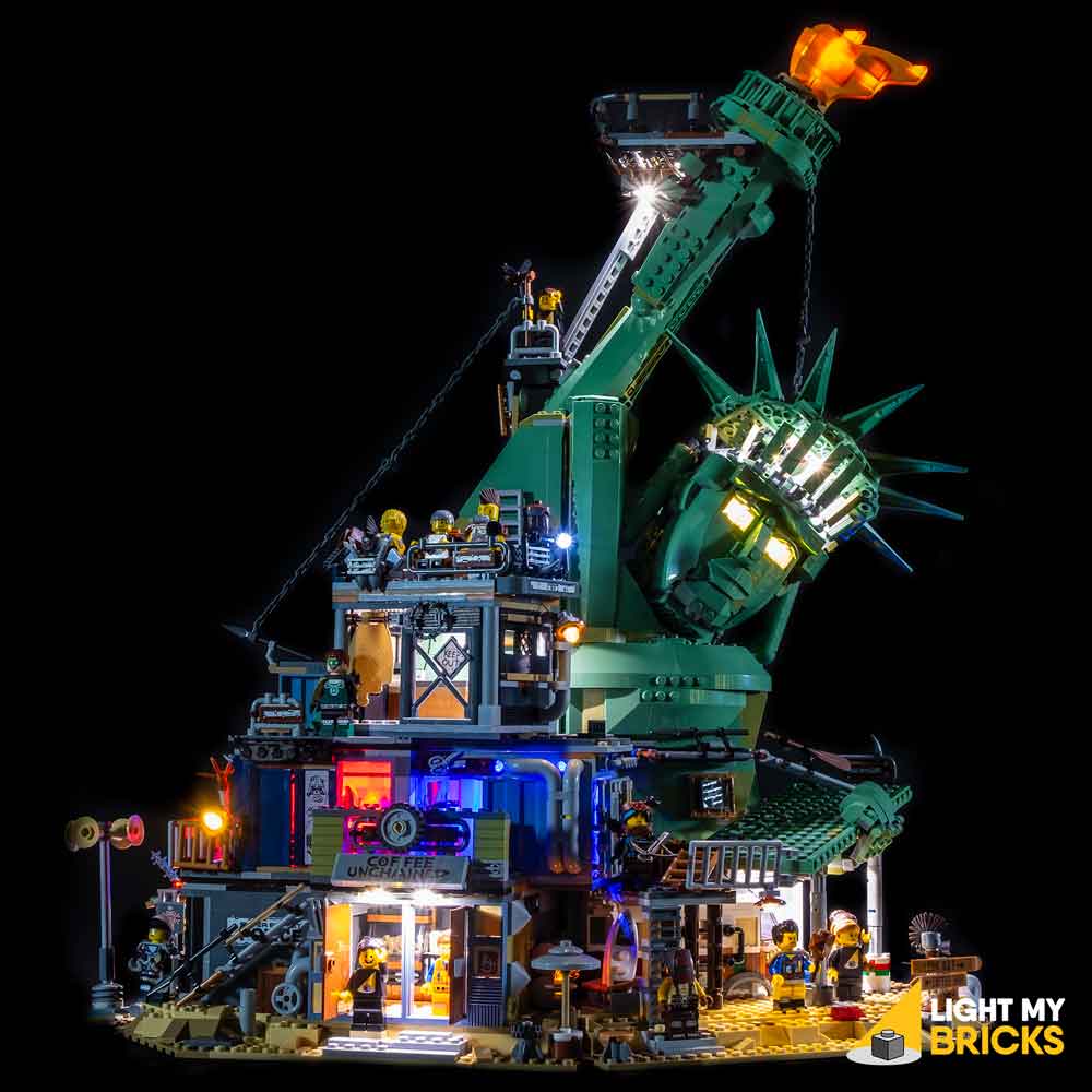
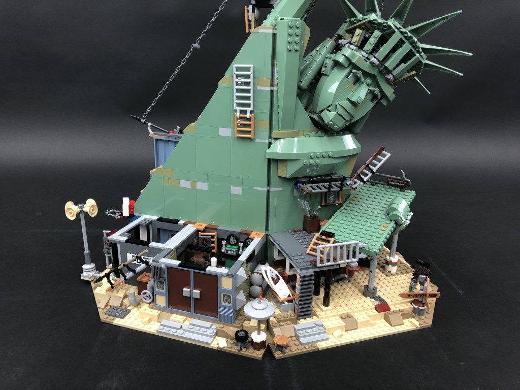
The following page is the instructions for the Light My Bricks LEGO Welcome To Apocalypseburg! (70840) LED light kit.
If you run into any issues, please refer to the online troubleshooting guide.
To ensure a trouble-free installation of your light kit, please read and follow each step carefully. These instructions can be downloaded in PDF format here
Please note: This page lists instructions for the LED light kit only. If you are wishing to purchase the Light My Bricks LEGO Welcome To Apocalypseburg! (70840) LED light kit , please click here to view the product page
Package Contents:
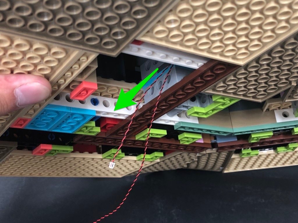
- 5x White 15cm Bit Lights
- 10x White 30cm Bit Lights
- 3x Flashing White 15cm Bit Lights
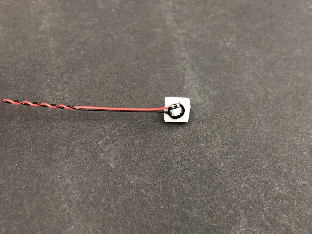
- 2x Blue 30cm Bit Lights
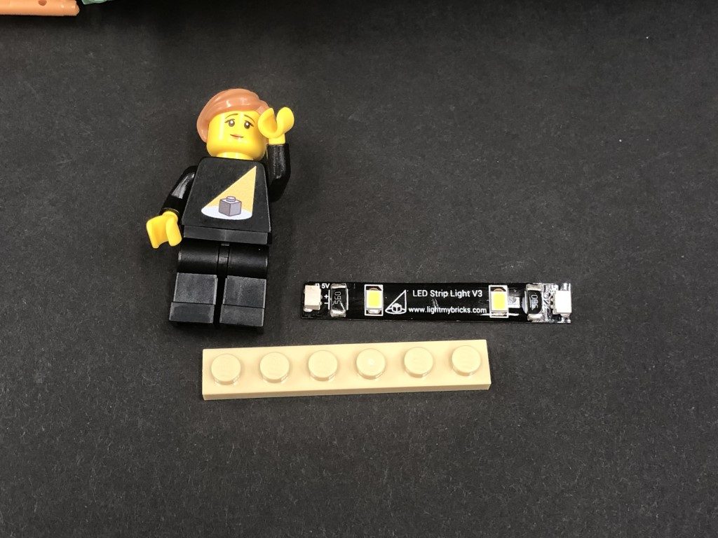
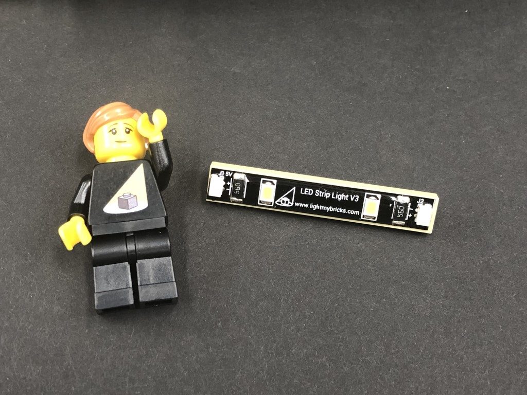
- 10x White Strip Lights
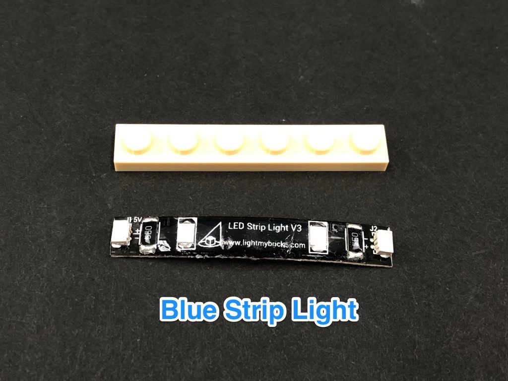
- 1x Blue Strip Light
- 1x Red Strip Light
- 2x Flicker Effects Boards
- 4x 6-Port Expansion Board
- 1x 8-Port Expansion Board
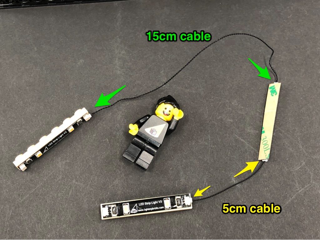
- 7x 5cm Connecting Cables
- 4x 15cm Connecting Cable
- 6x 30cm Connecting Cables
- 1x 50cm Conecting Cable
- 1x USB Power Cable
- 6x Adhesive Squares
LEGO Pieces:
- 1x Trans Clear Round Plate 1×1
- 7x Plate 1×6 (Any Colour)
- 2x Light Grey Round Plate 1×1 with Open Stud
- 2x Trans Clear Round Brick 2×2
Important things to note:
Laying cables in between and underneath bricks
Cables can fit in between and underneath LEGO® bricks, plates, and tiles providing they are laid correctly between the LEGO® studs. Do NOT forcefully join LEGO® together around cables; instead ensure they are laying comfortably in between each stud.
Connecting cable connectors to Expansion Boards
Take extra care when inserting connectors to ports of Expansion Boards. Connectors can be inserted only one way. With the expansion board facing up, look for the soldered “=” symbol on the left side of the port. The connector side with the wires exposed should be facing toward the soldered “=” symbol as you insert into the port. If a plug won’t fit easily into a port connector, do not force it.
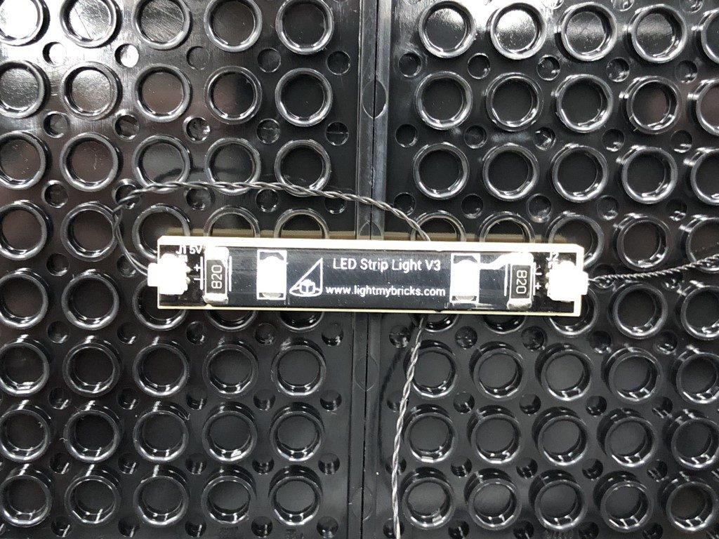
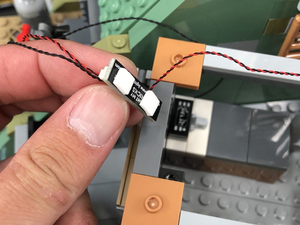
Connecting cable connectors to Strip Lights
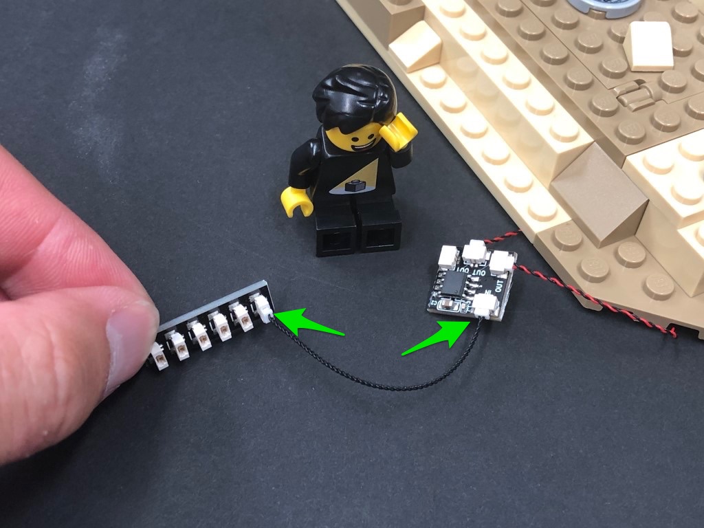
Take extra care when inserting connectors to ports on the Strip Lights. Connectors can be inserted only one way. With the Strip Light facing up, ensure the side of the connector with the wires exposed is facing down. If a plug won’t fit easily into a port connector, don’t force it. Doing so will damage the plug and the connector.
Installing Bit Lights under LEGO® bricks and plates.
When installing Bit Lights under LEGO® pieces, ensure they are placed the correct way up (Yellow LED component exposed). You can either place them directly on top of LEGO® studs or in between.
OK, Let’s Begin!
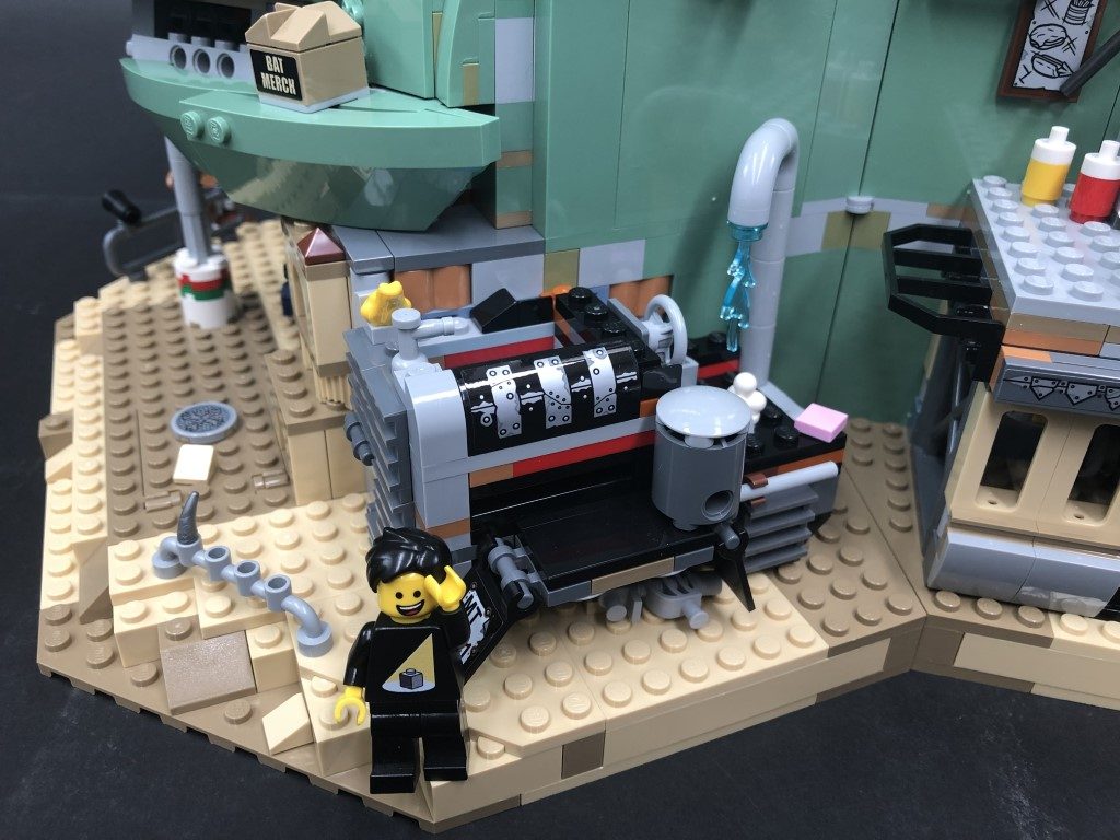
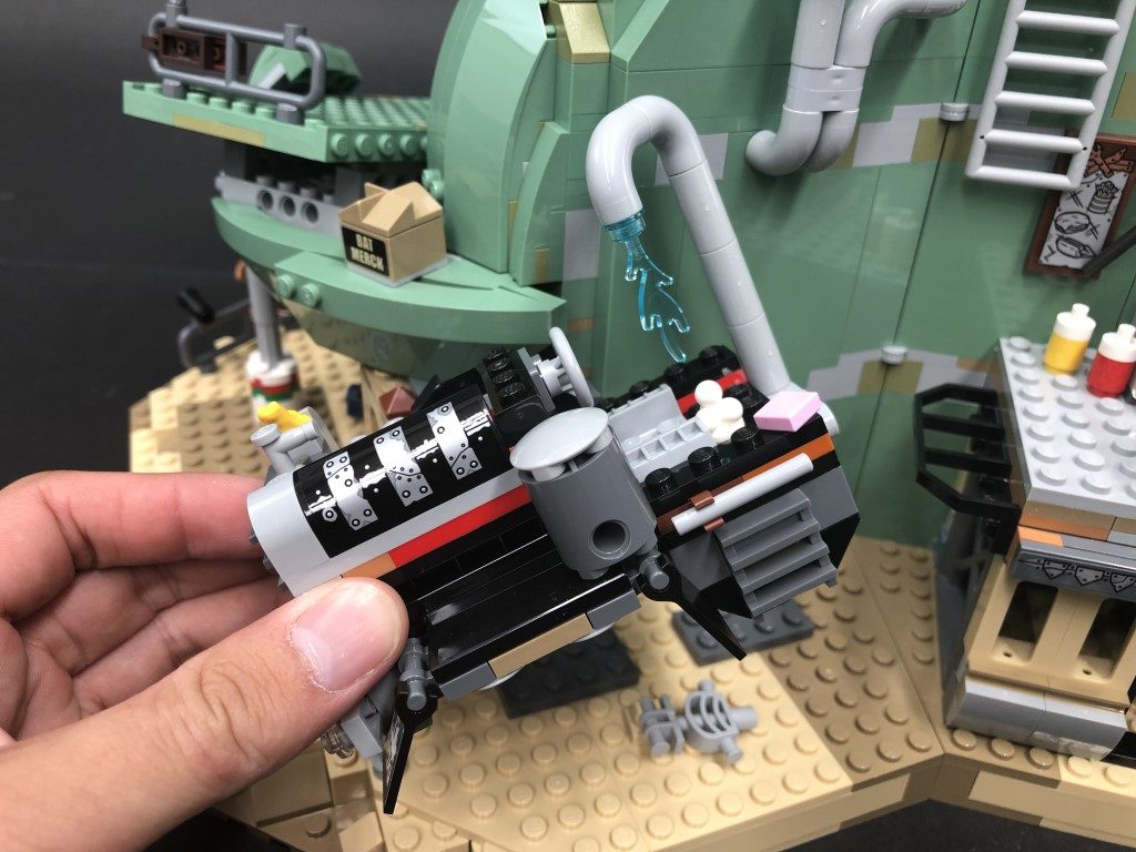
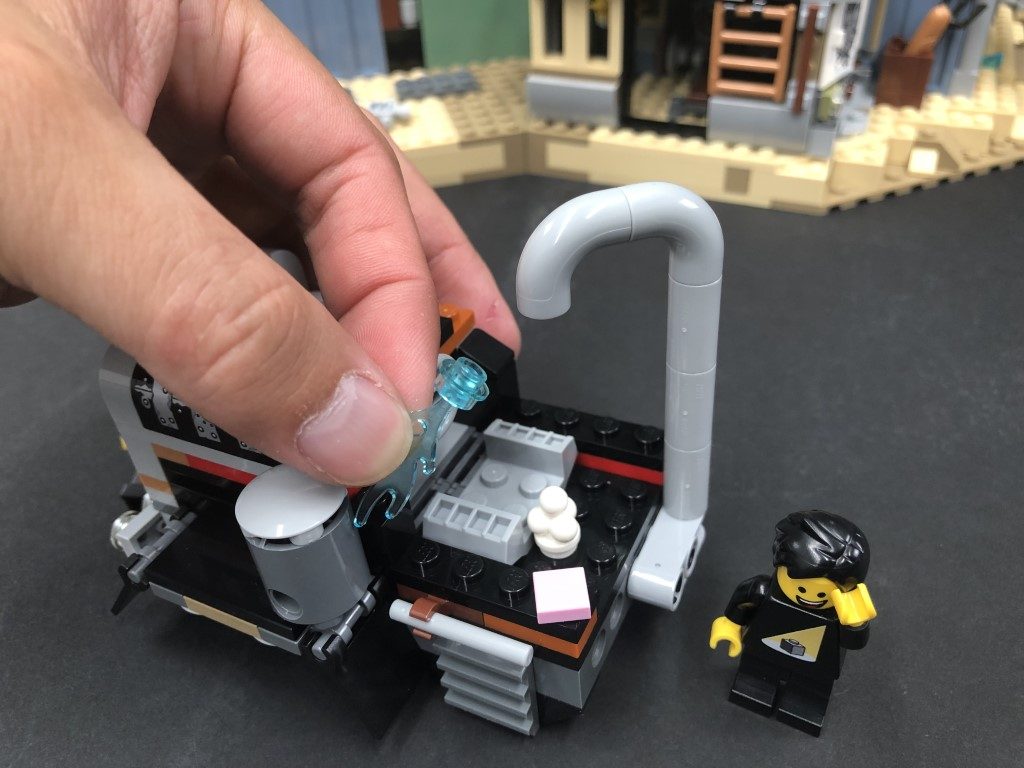
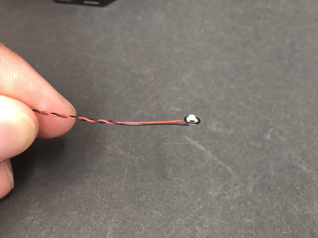
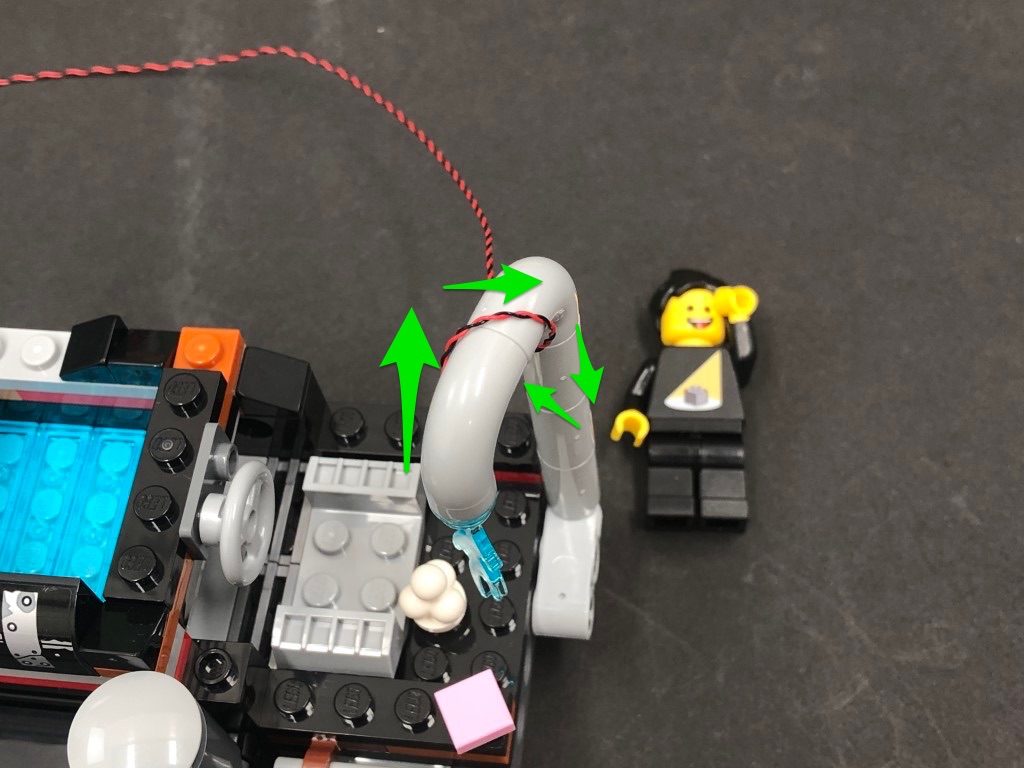
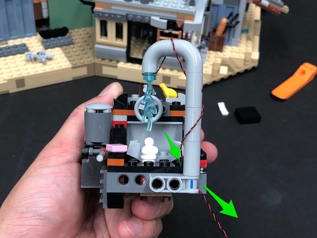
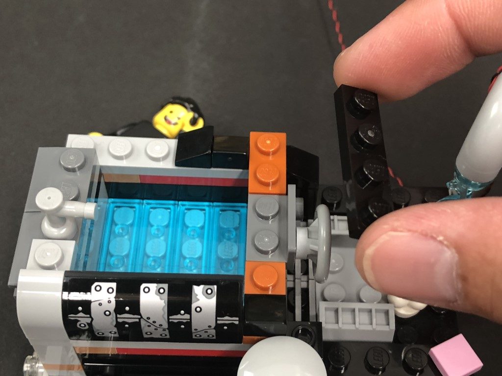
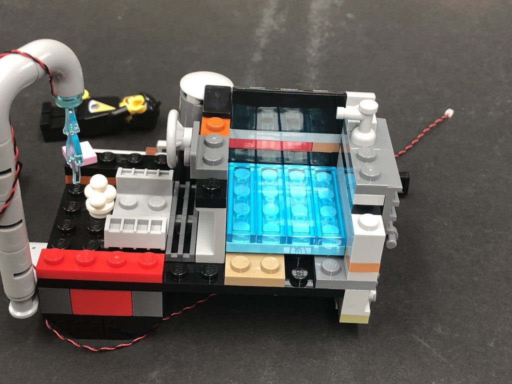
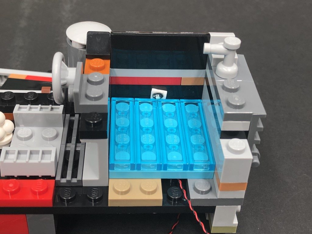
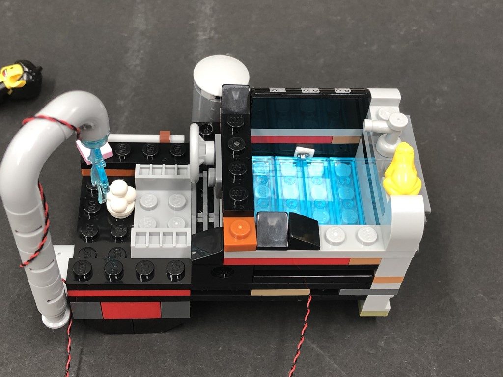
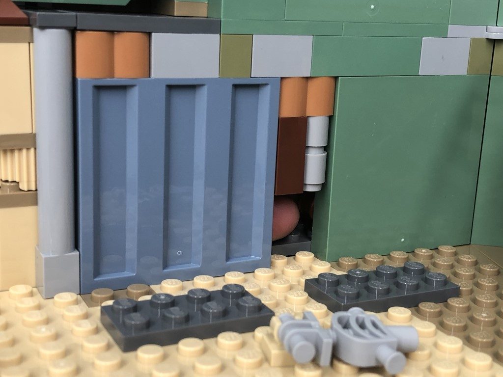
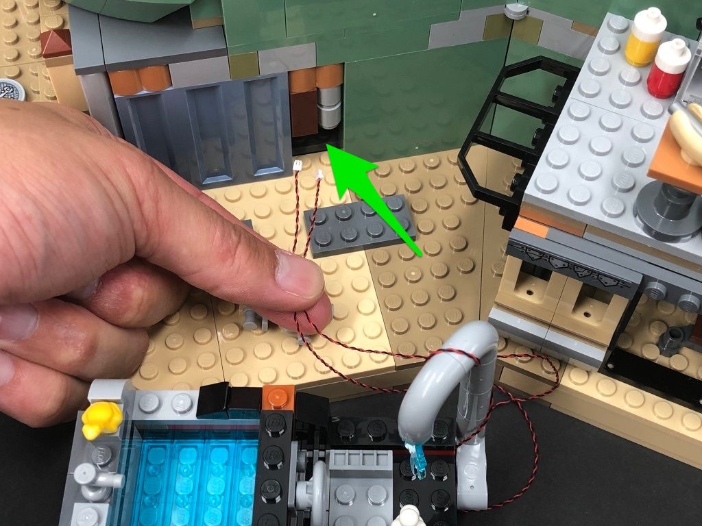
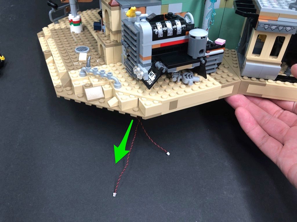
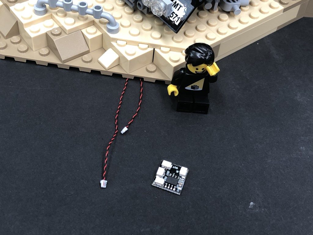
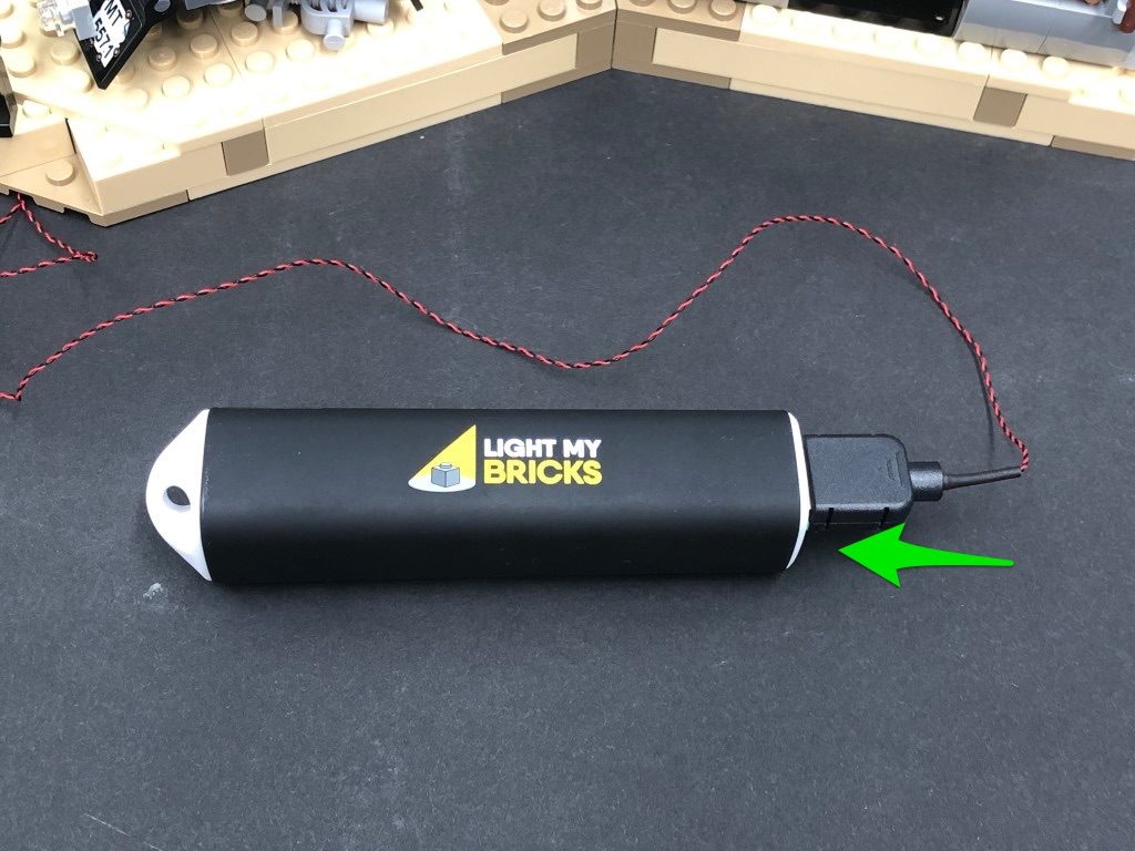
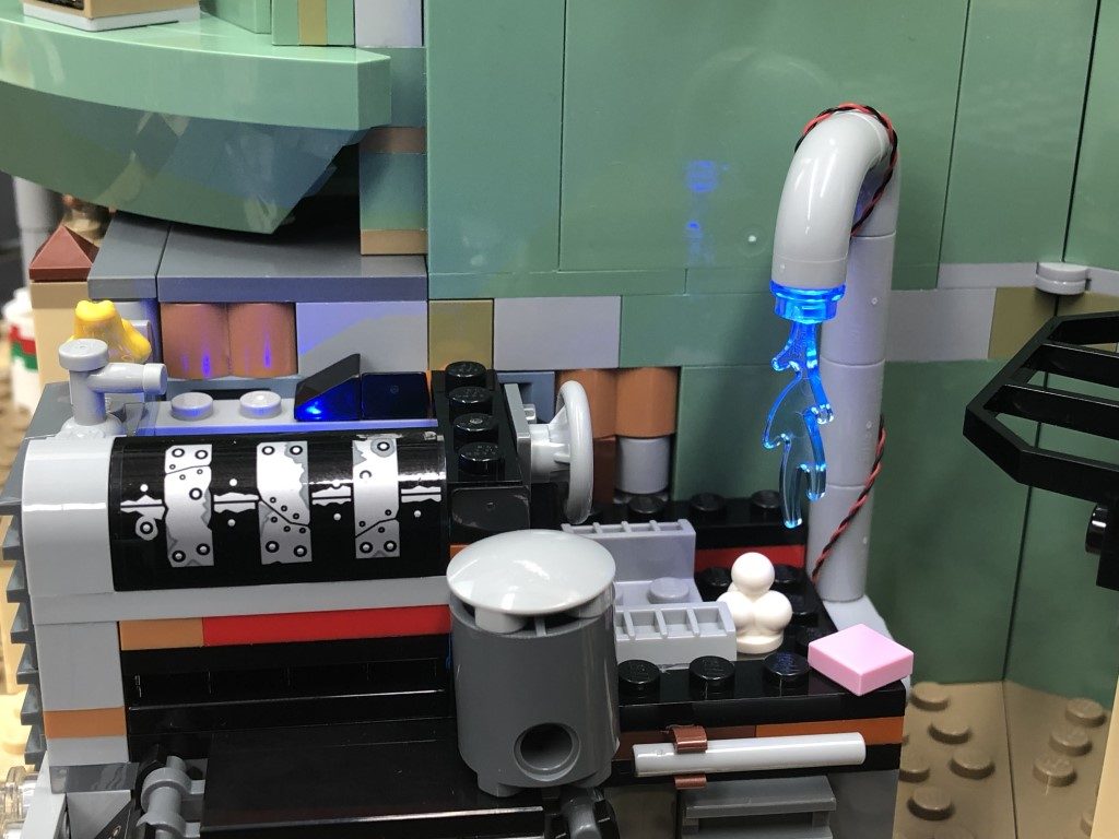
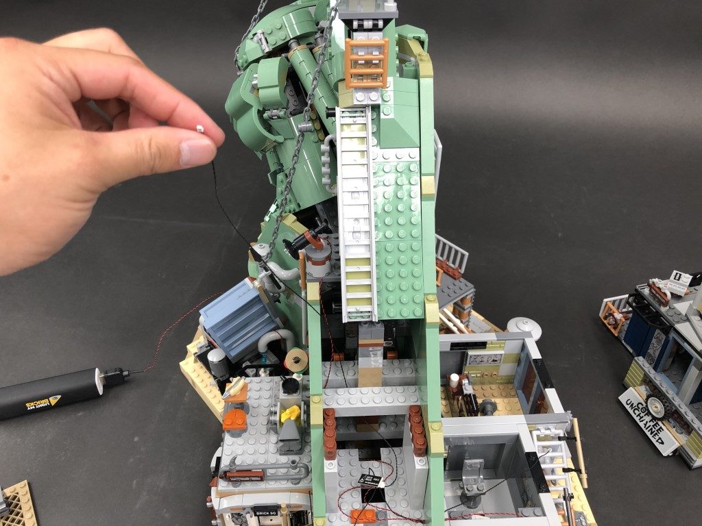
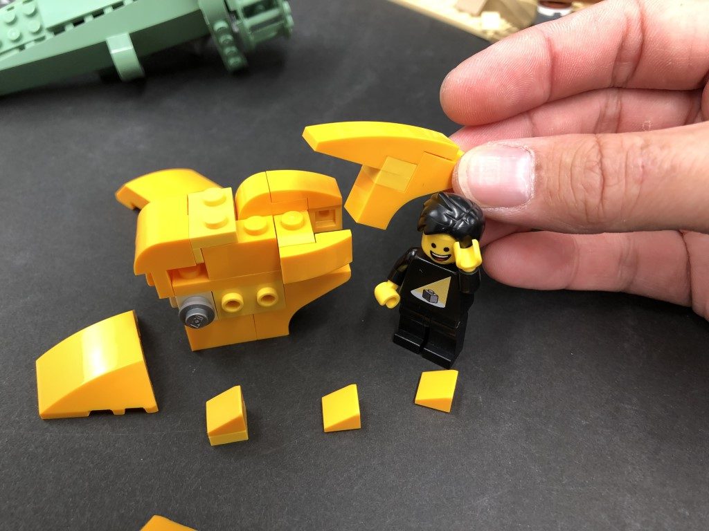
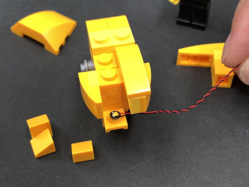
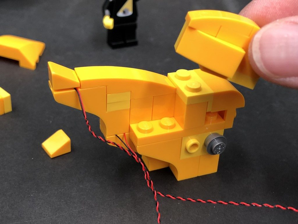
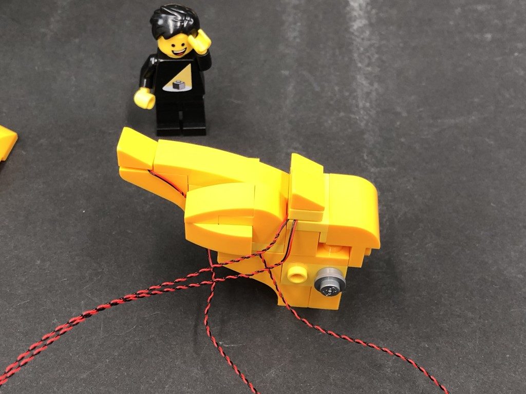
1.) First remove the second and third levels from the front, then turn the set around to the back and disconnect the water tank section. 2.) Disconnect the trans blue water piece from the pipe, then take a Blue 30cm Bit Light and carefully bend the led up on a 90 degree angle as shown below. Insert the Bit Light with (led facing down) up inside the pipe, then secure it in place by reconnecting the water piece. Wind the cable around the pipe as shown below, then secure it in place underneath the technic piece below: 3.) Remove the following sections around the water tank Turn the water tank around and disconnect the water plate then take another Blue 30cm Bit Light and using an Adhesive Square, stick it at the bottom of the inside of the front wall ensuring the cable is facing down Reconnect the water section plate ensuring the bit light cable is neatly laid in between studs, then reconnect the surround pieces we removed earlier. 4.) We now need to remove the black brick at the bottom of the wall behind the water tank. Carefully lift up the base, then using your index finger, push out the black brick from the inside. 5.) Take the two bit light cables from the water tank section and thread them through the space we just created, then pull them all the way out from underneath the base. Reconnect the water tank section. 6.) Connect both Bit Lights to the OUT ports on one of the Flicker Effects Boards. Take the USB Power Cable and connect it to the IN port on the flicker effects board. Connect the other side to your USB Power Bank (sold separately) and turn it on to test the blue lights are working and flickering OK. Disconnect the USB Power Cable and connect a 5cm Connecting Cable to the IN port on the flicker effects board. Connect the other side to a 6-Port Expansion Board.
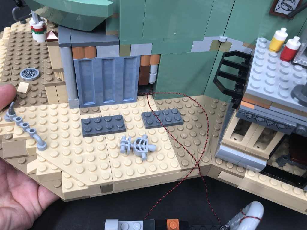
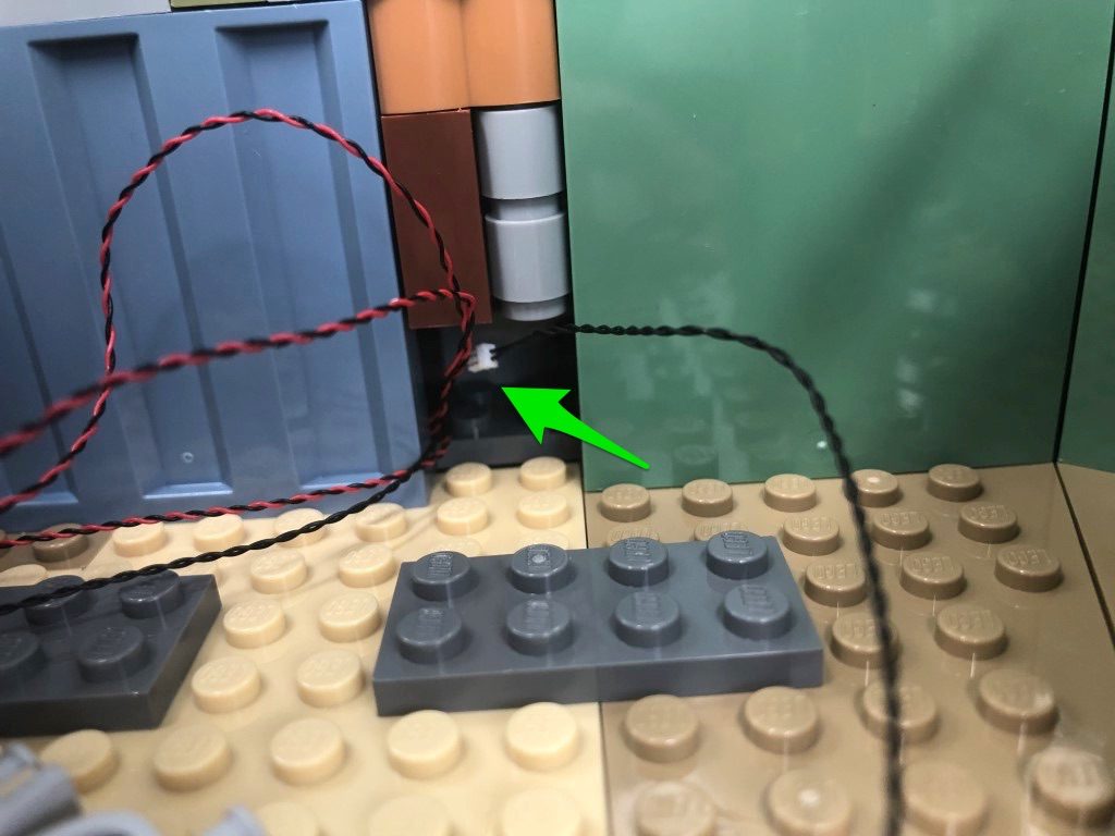
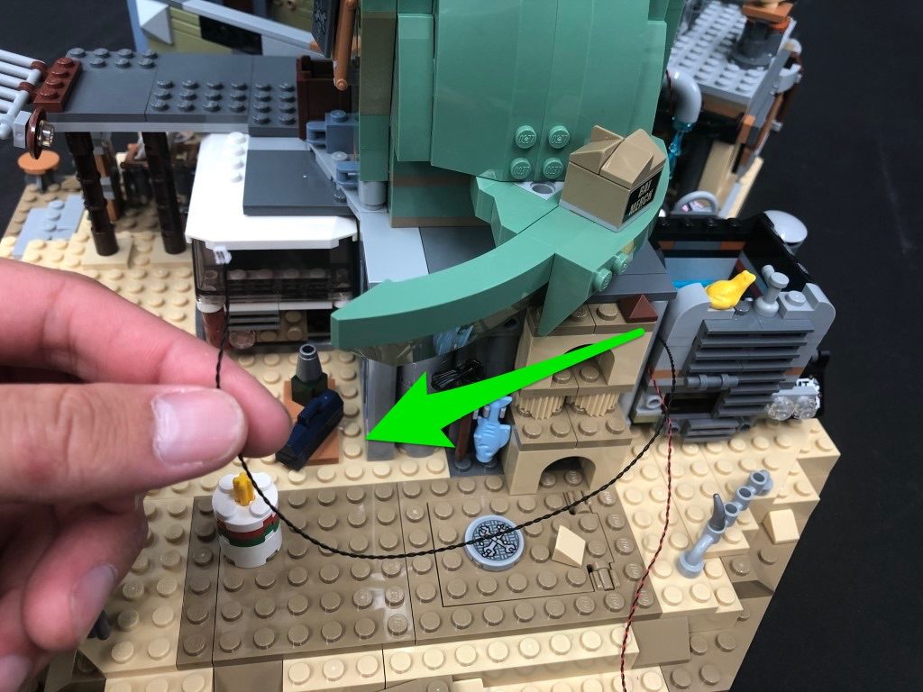
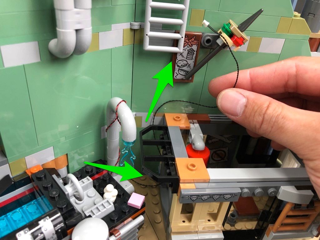
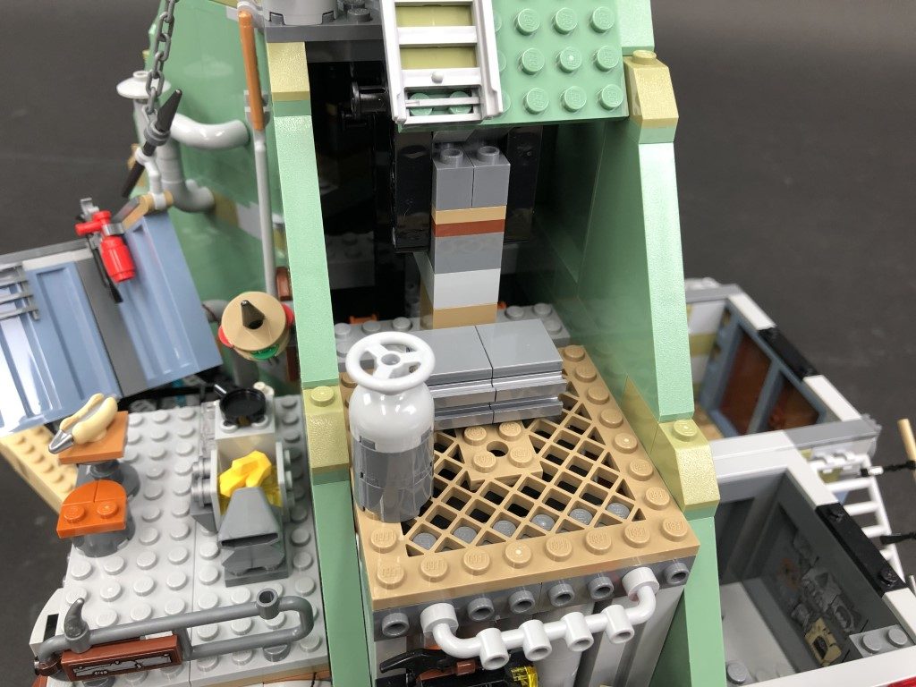
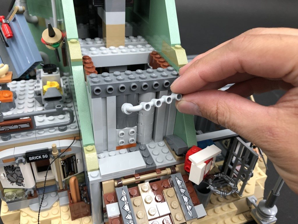
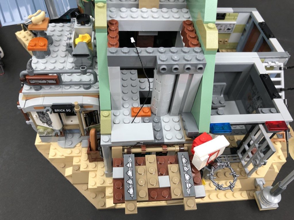
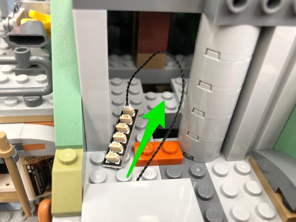
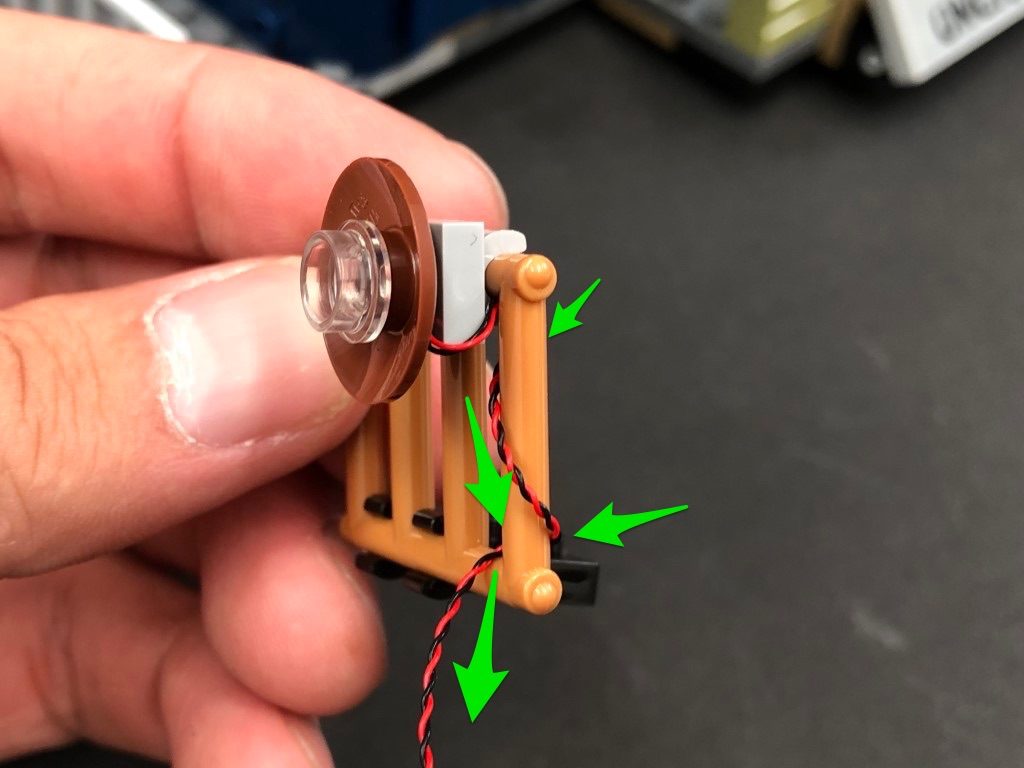
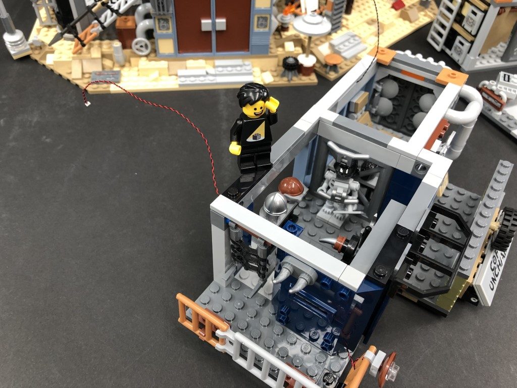
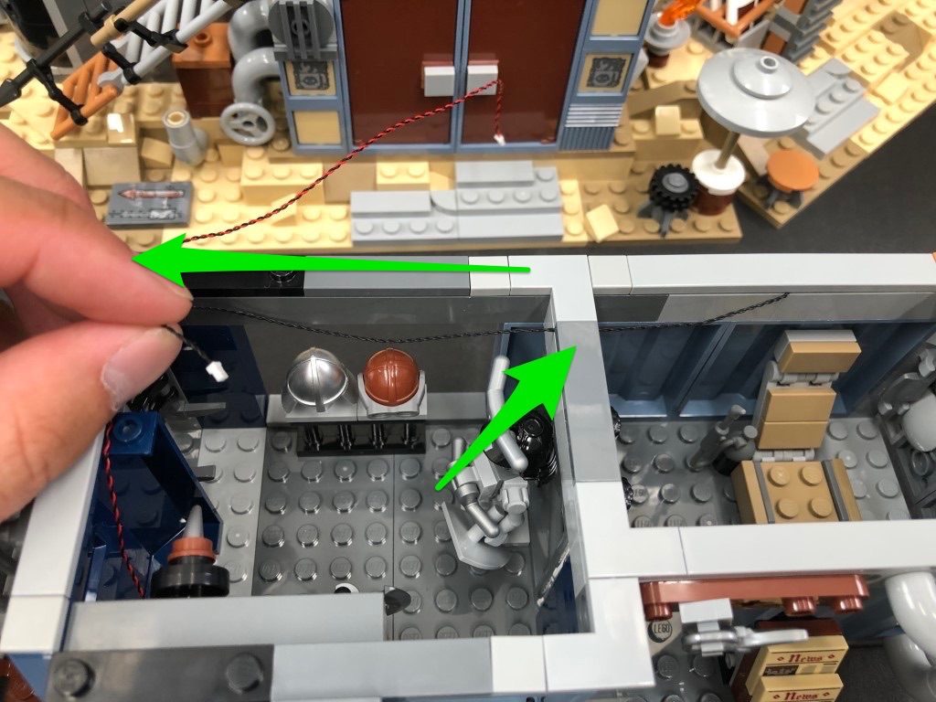
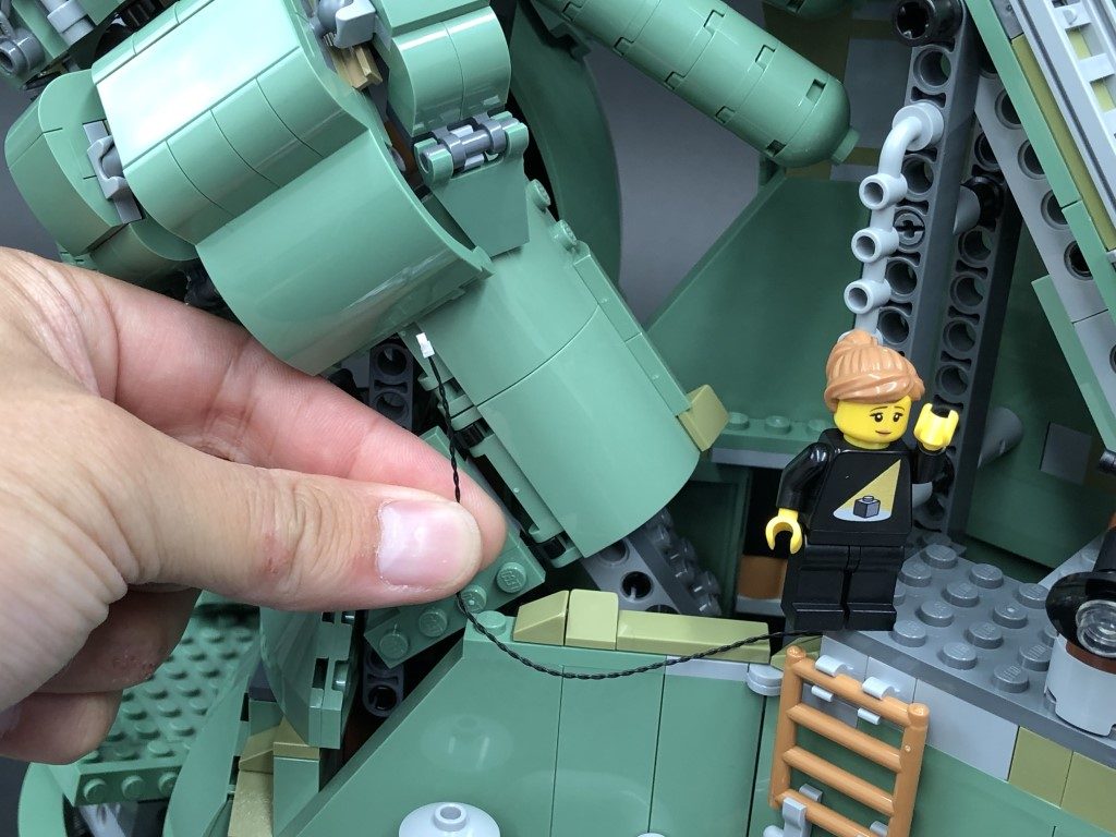
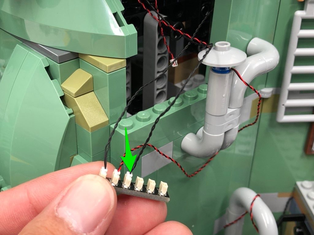
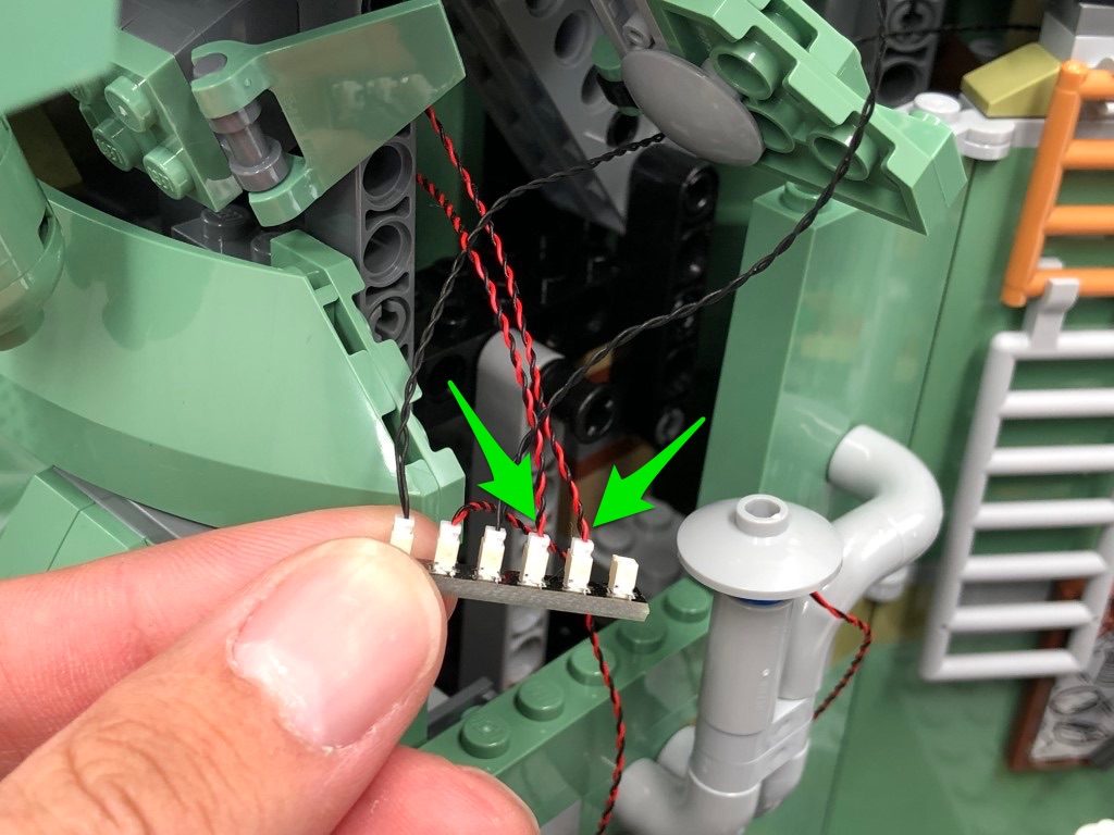
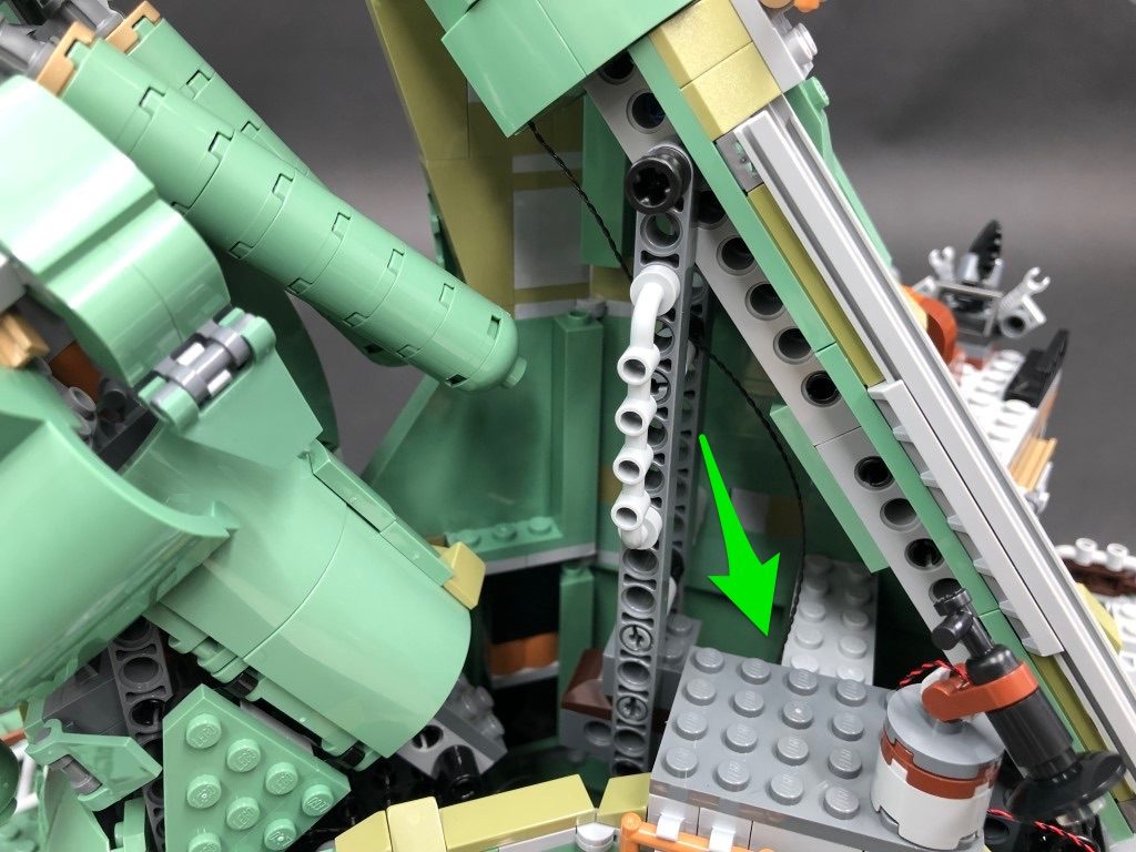
 7.) Move the water tank section out of the way, then take a 30cm Connecting Cable and thread one end of the cable through the space which leads underneath. Pull the cable out from underneath and connect it to the next port on the 6-Port Expansion Board.
Thread the USB Power Cable (connector side) through the same space, then pull it out from underneath and connect it to the next port on the 6-port Expansion Board.
Take another 30cm Connecting Cable and thread it through the same space, then pull it out from underneath and connect it to the next port on the 6-port Expansion Board.
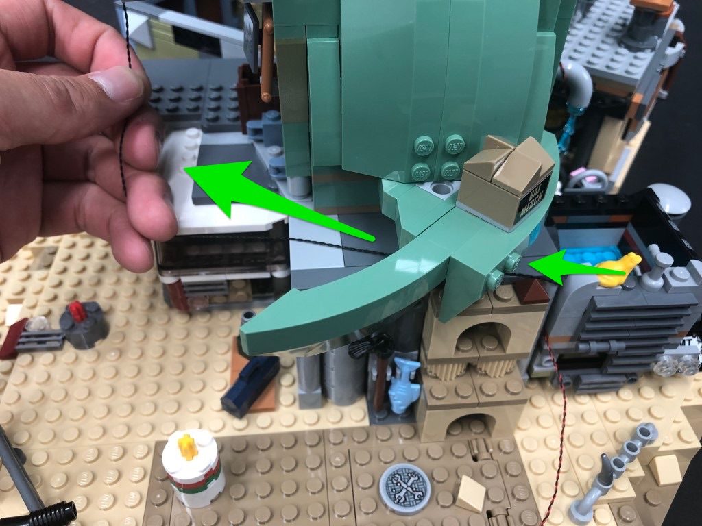
Pull the first 30cm Connecting Cable and USB Power Cable all the way out toward the left side of the water tank, then pull the other 30cm Connecting Cable all the way out the right side before reconnecting the water tank to cover up the space.
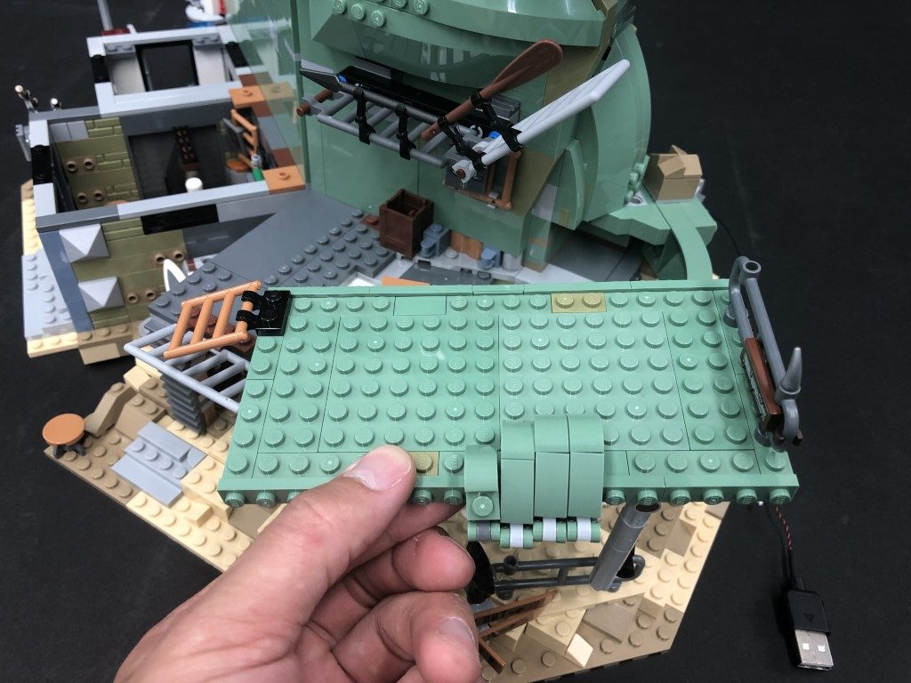
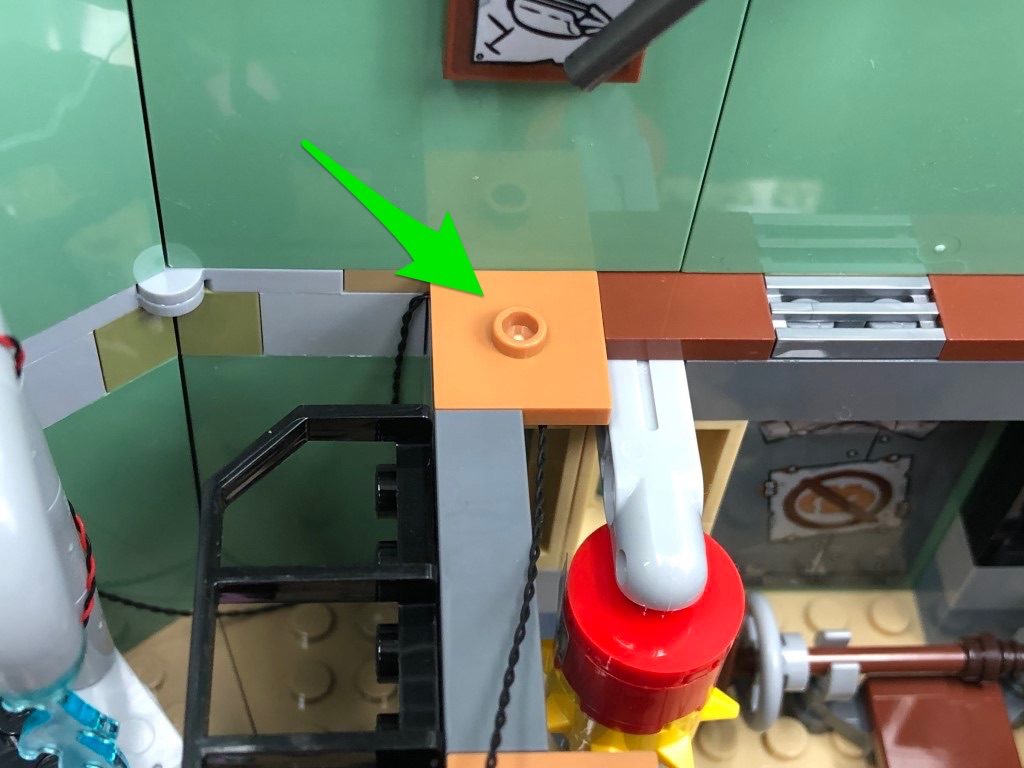
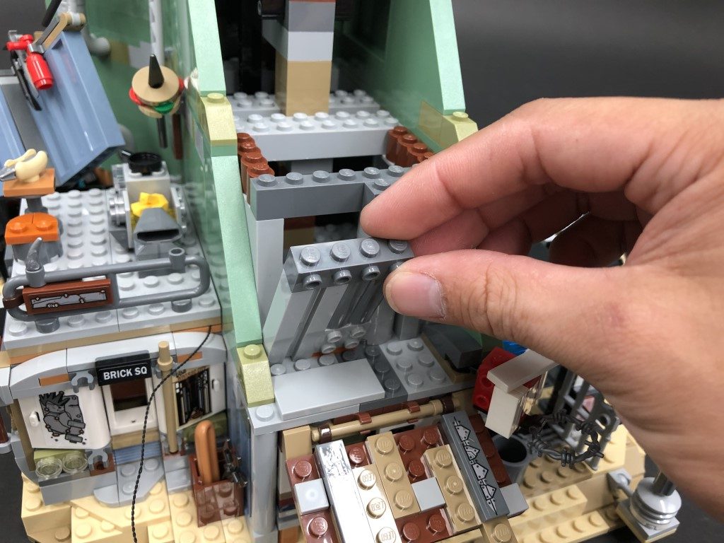
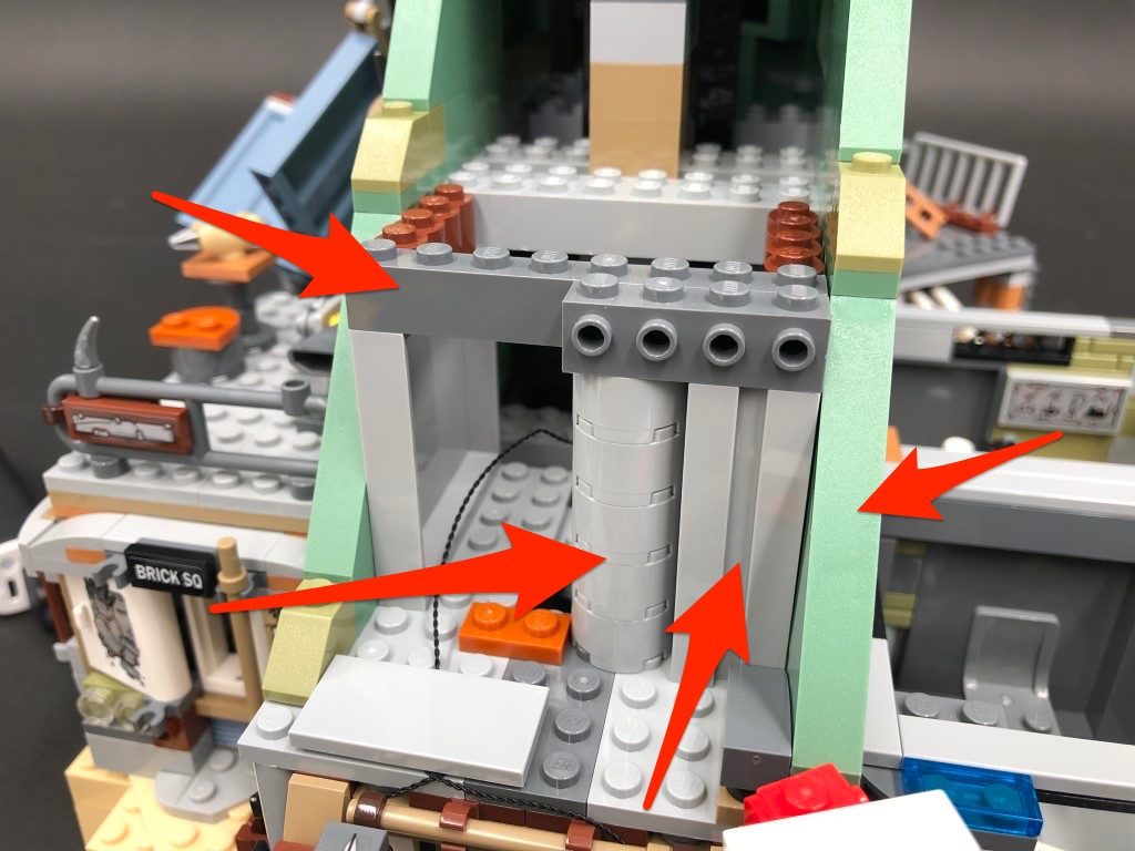
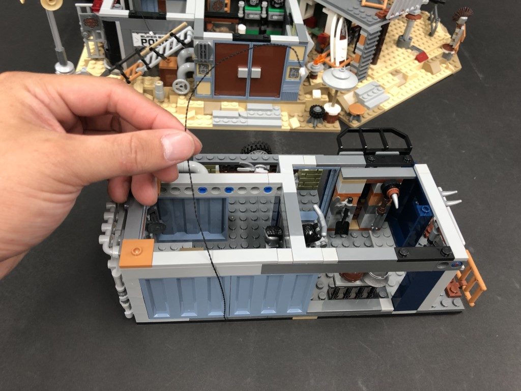
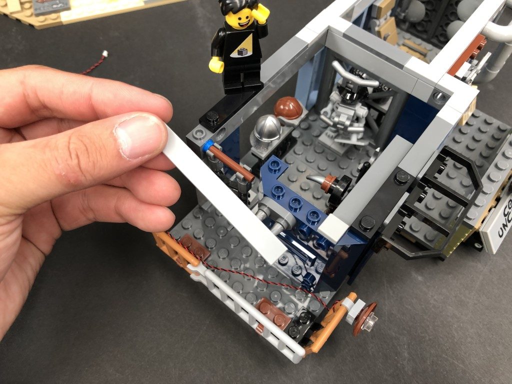
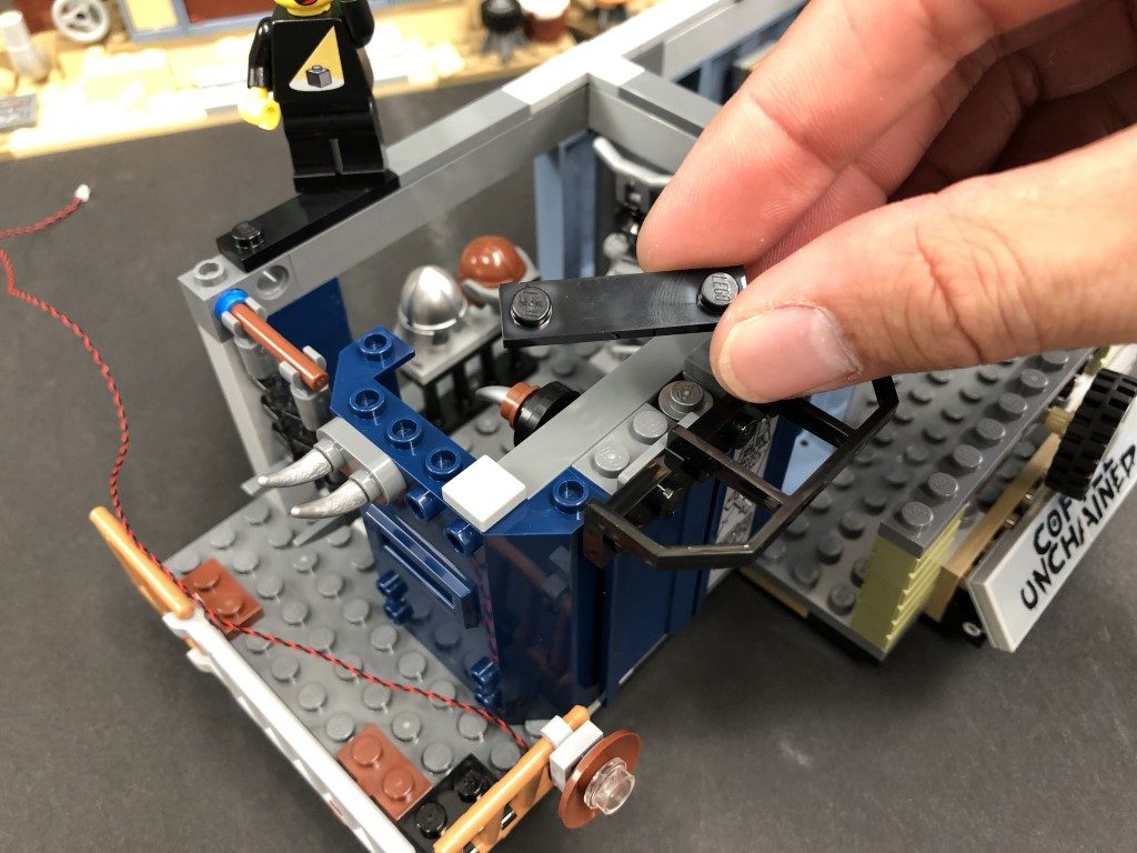
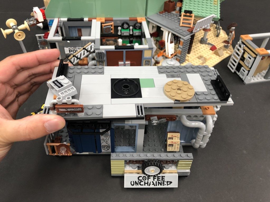
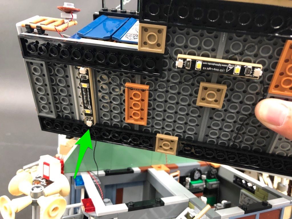
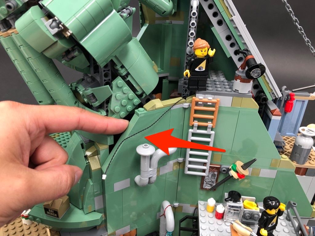
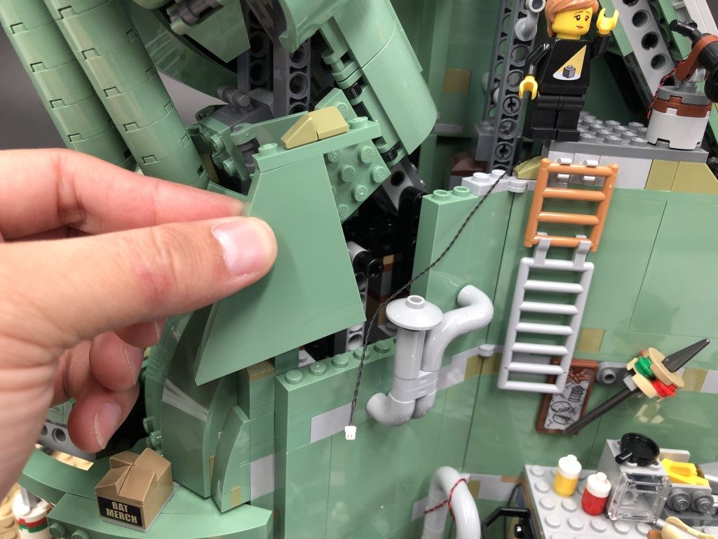
8.) Move the set along towards the left side and disconnect the roof off by first disconnecting the pillars to allow you to completely pull the roof off.
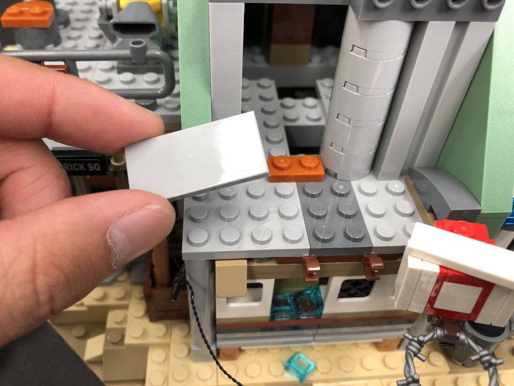
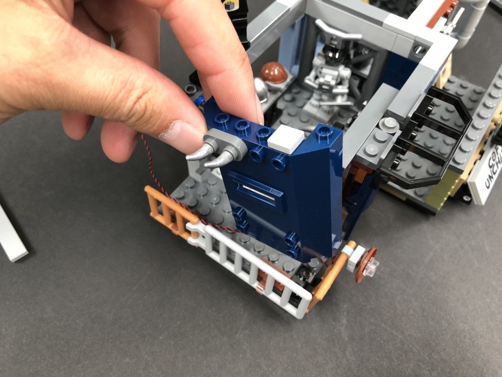
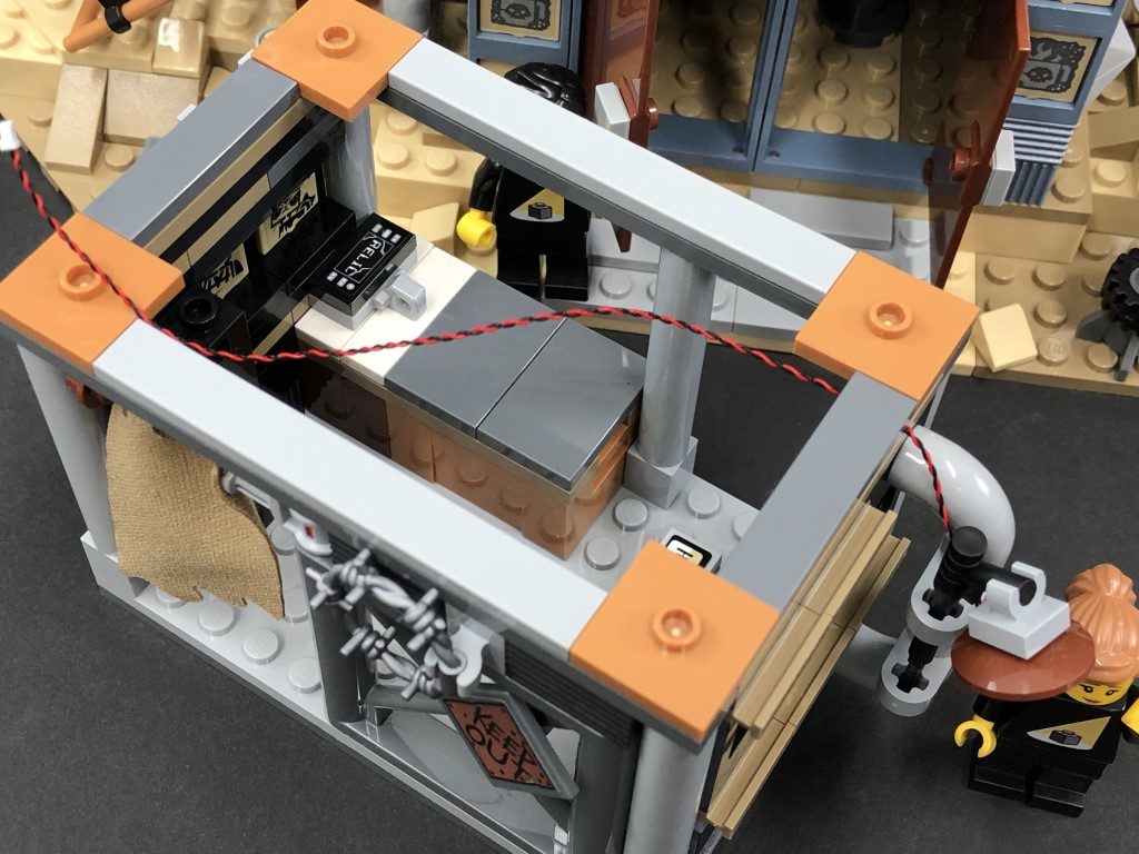
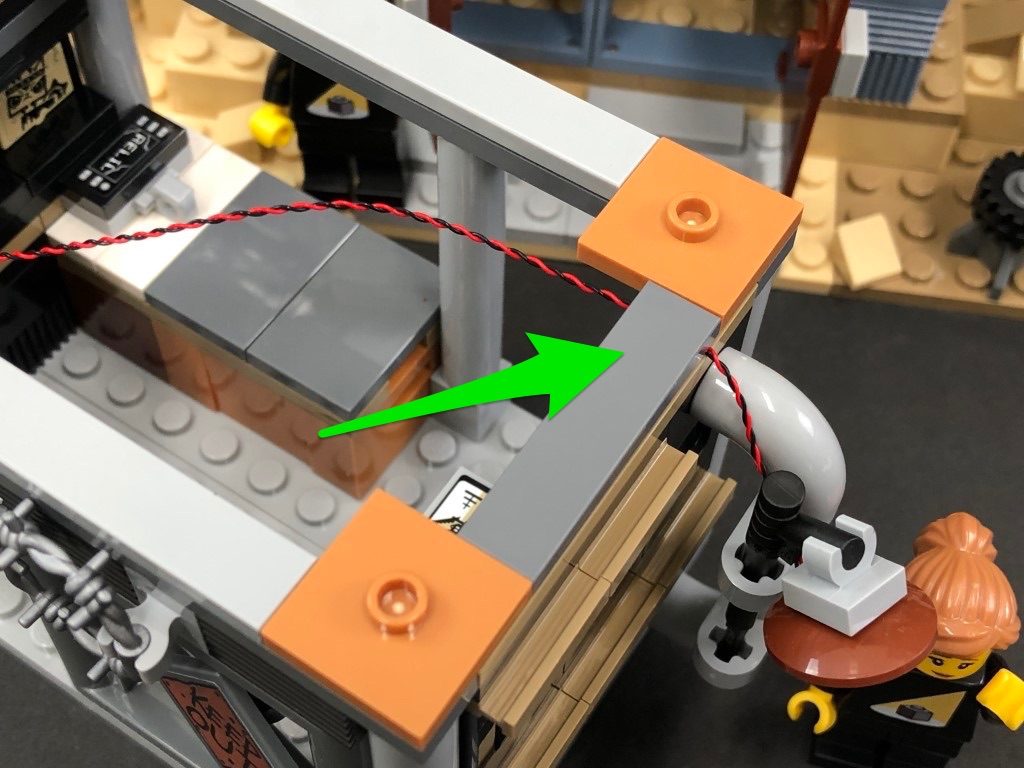
Bring the other end of the 30cm Connecting Cable from the left side of the water tank around to this side, then thread it underneath the following section. Secure the cable in place underneath the light grey tile.
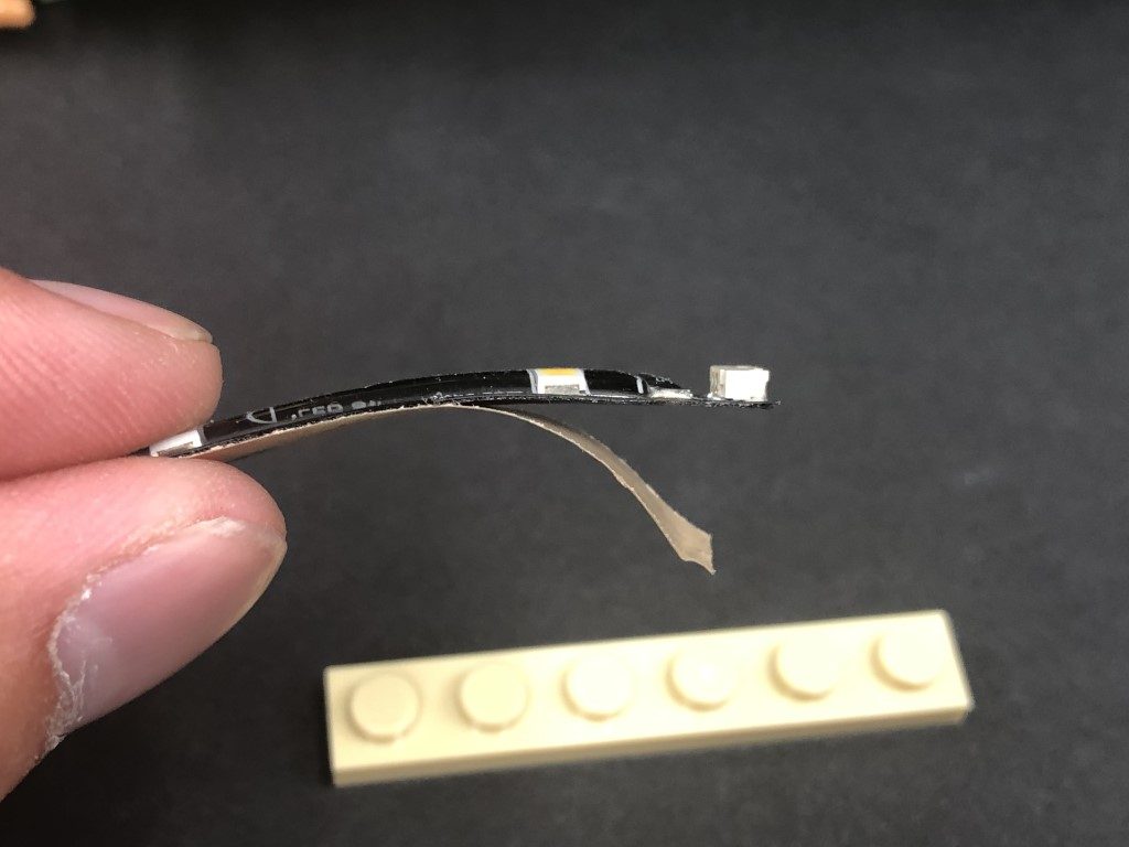
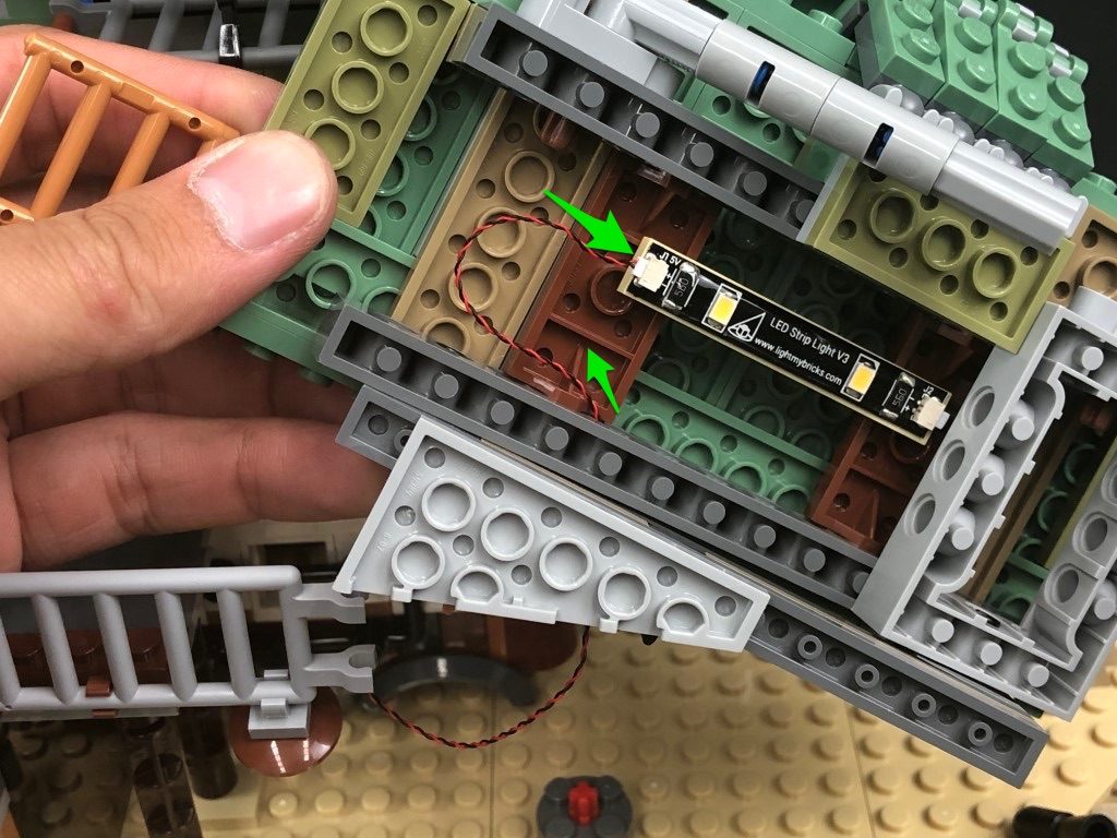
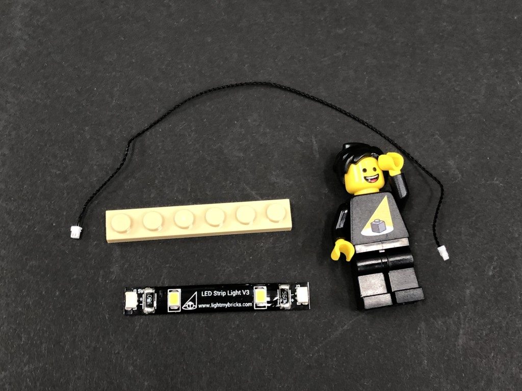
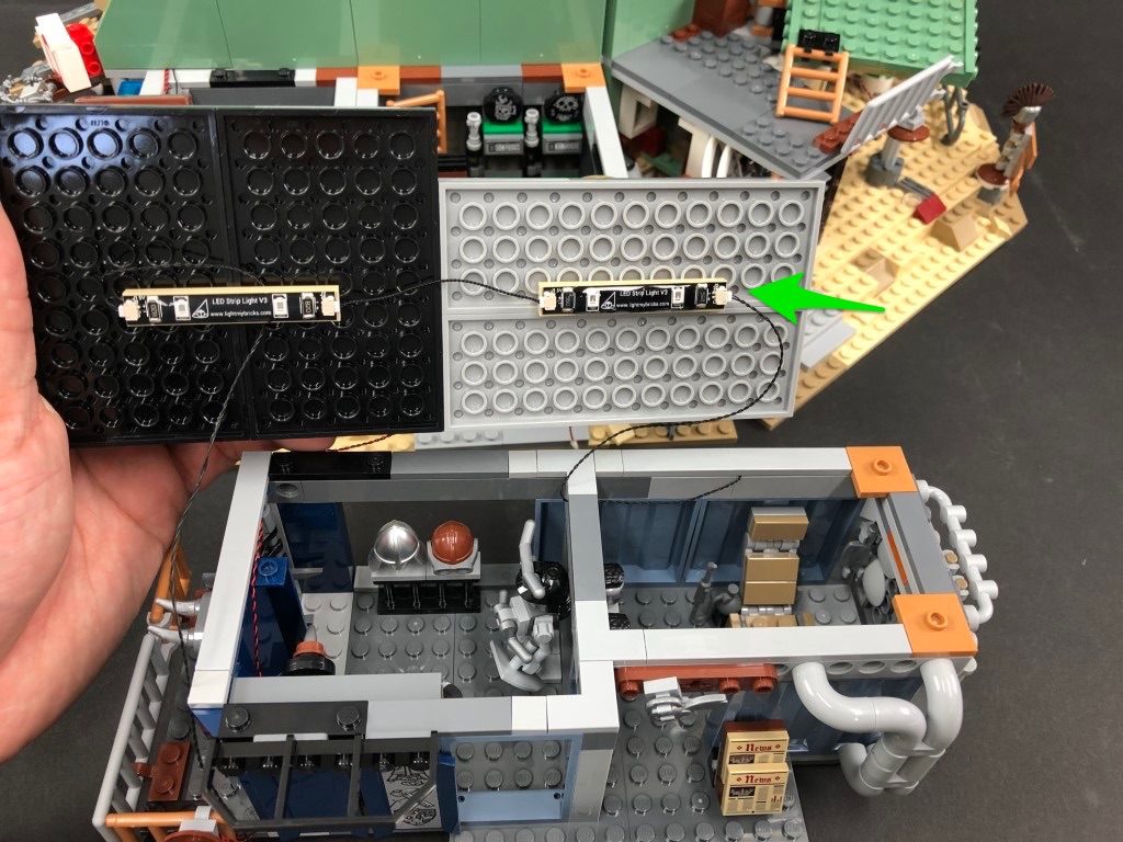
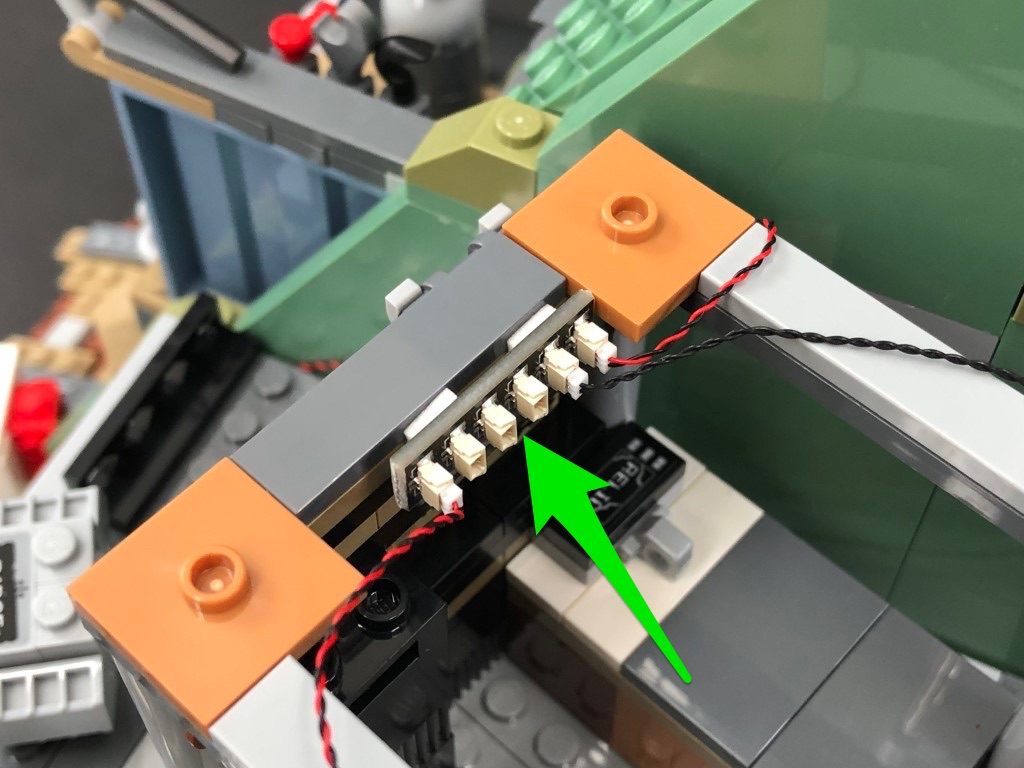
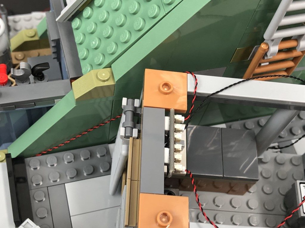
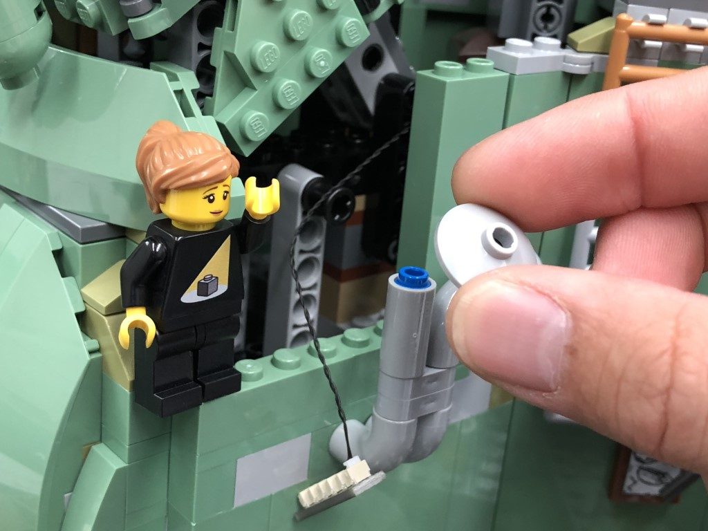
9.) Take a White Strip Light and using it’s adhesive backing, stick it onto the base of a provided LEGO Plate 1×6
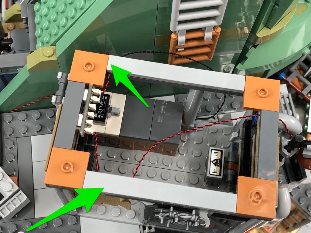
Take the roof section we removed and turn it over so we can access underneath. Thread the 30cm Connecting Cable we have brought over through the following technic brick hole underneath the roof section. Thread the cable through so that it comes out through the top, then connect it to the Strip Light. Mount the Strip Light underneath this section in the following position as shown below.
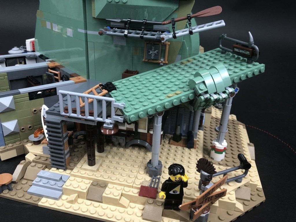
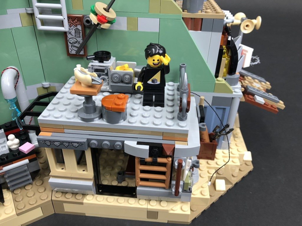
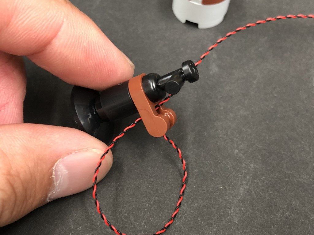
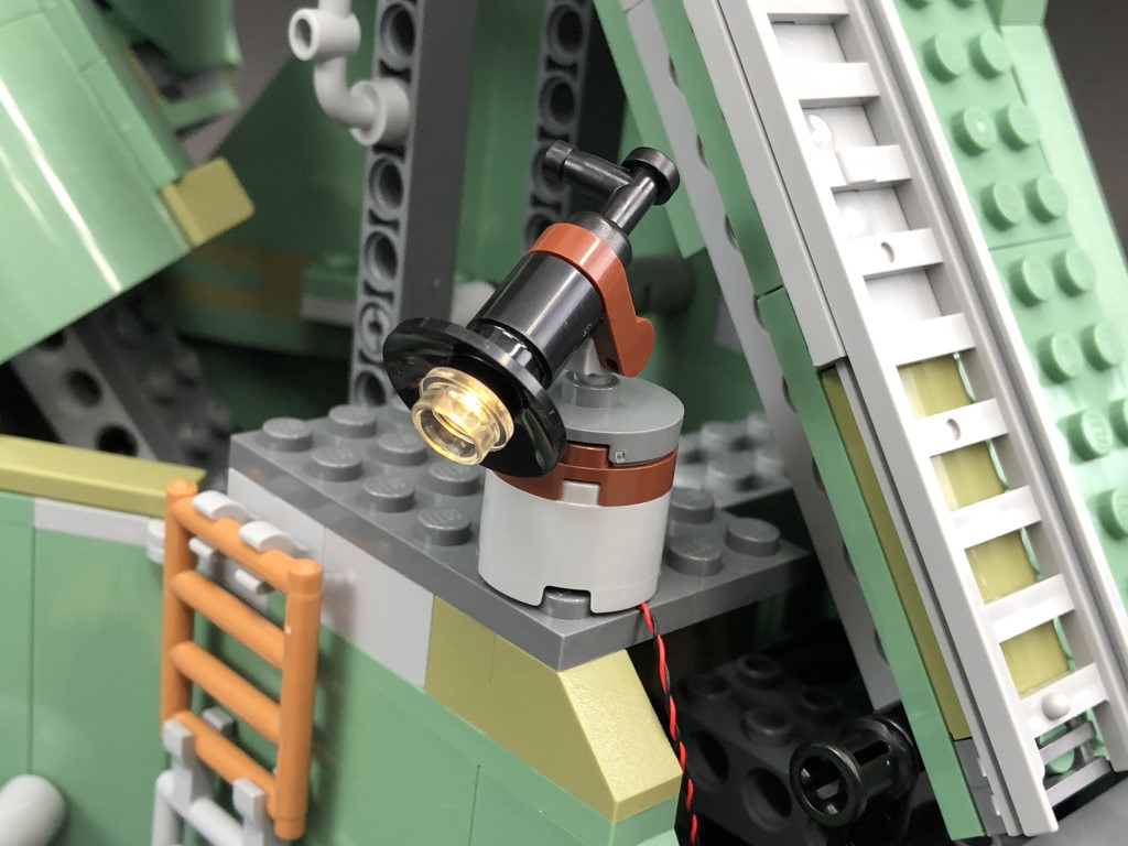
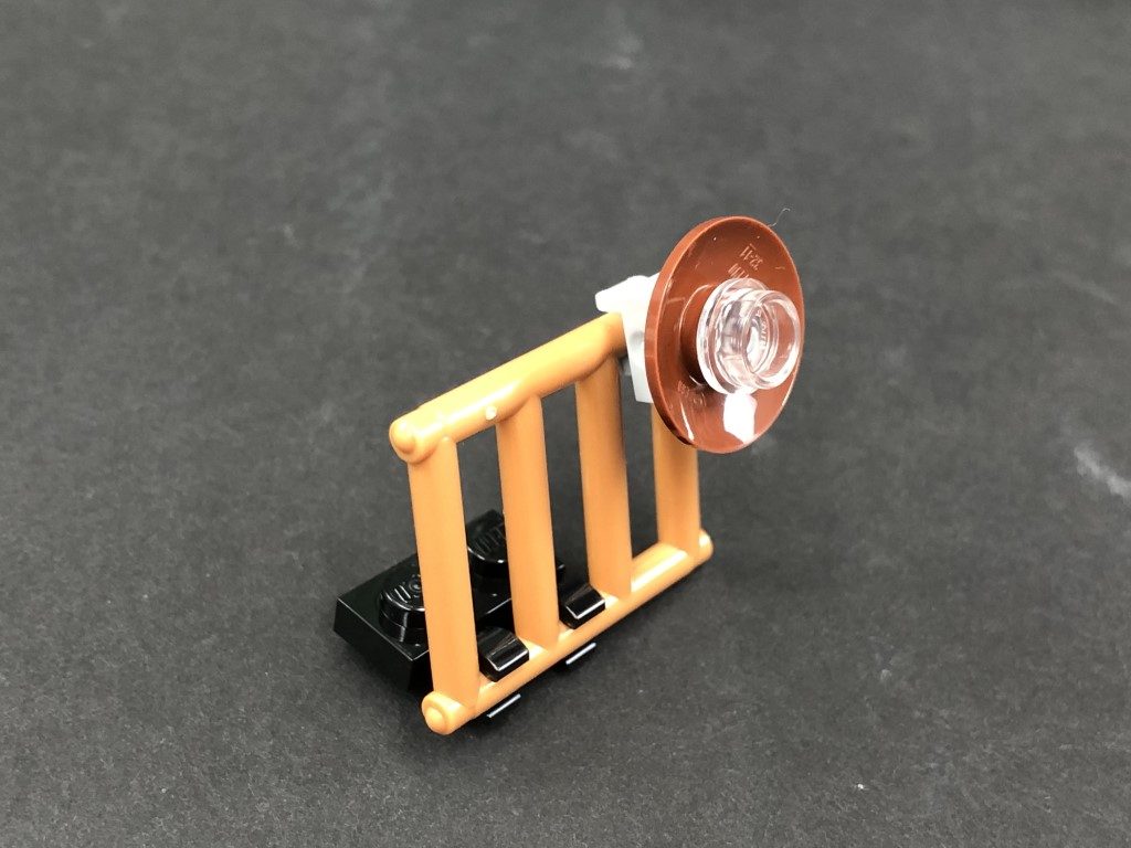
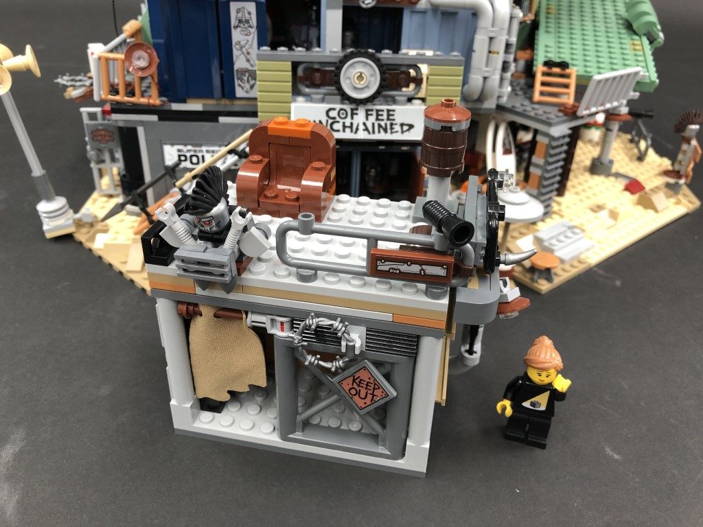
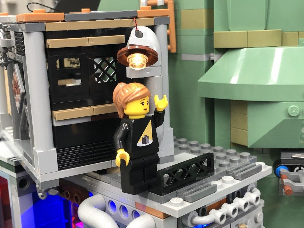
10.) Remove the following rail section then disconnect and disassemble the lamp.
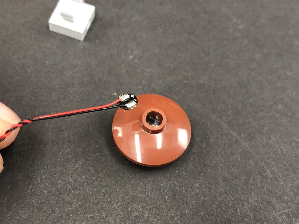
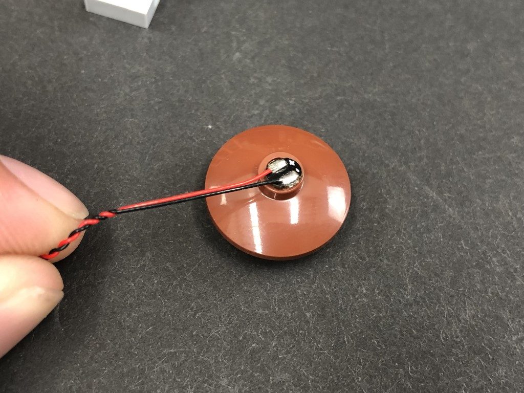
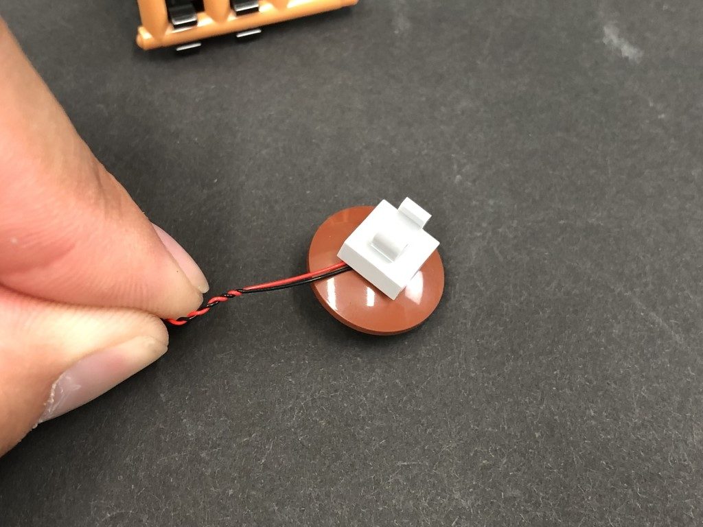
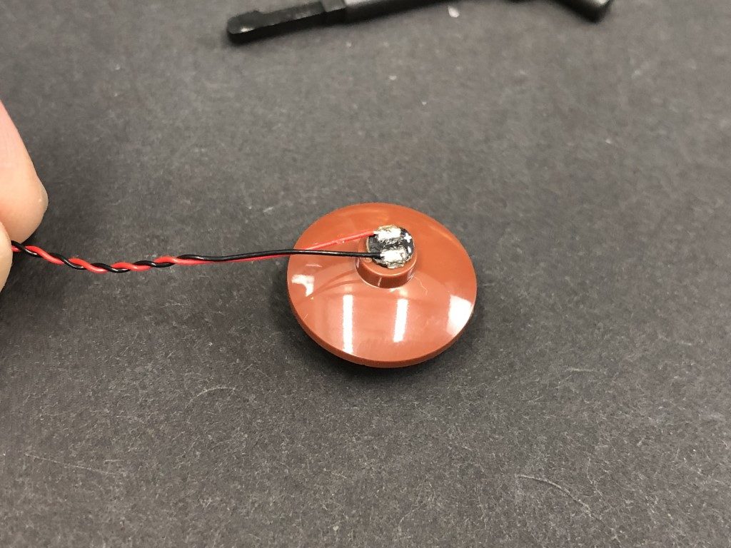
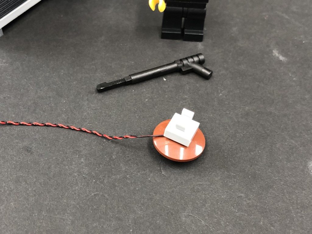
Take a White 15cm Bit Light and place the led face down over the hole on top of the brown dish. Secure the Bit Light in place by reconnecting the light grey plate with clip over the top.
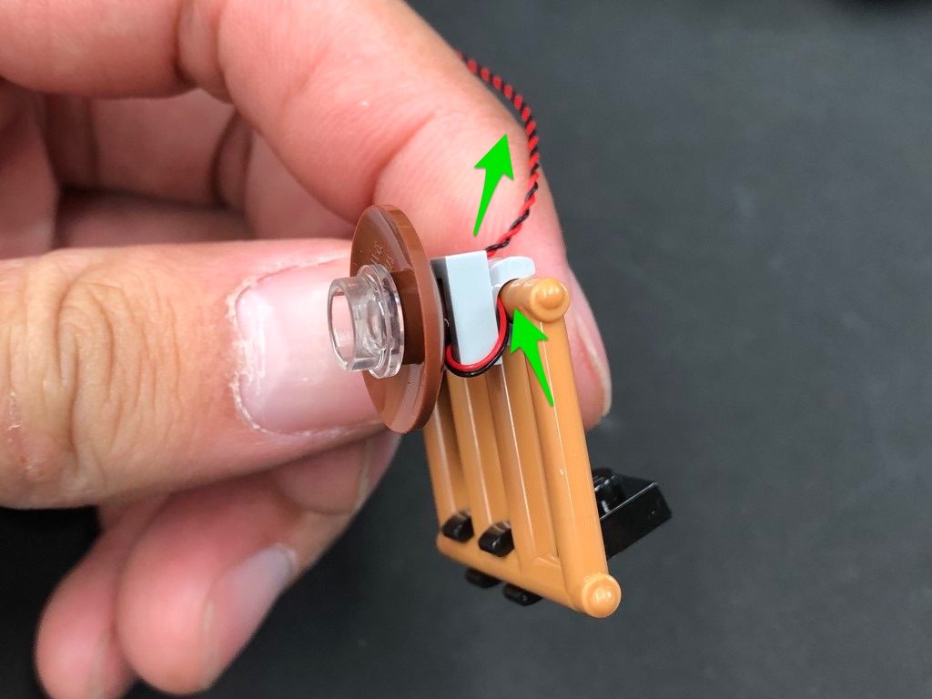
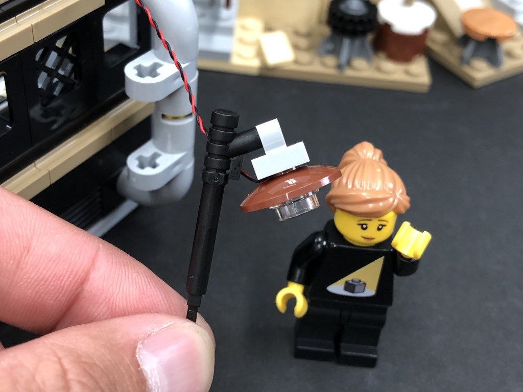
Reconnect the lamp back to the rail, then reconnect the rail to the roof ensuring the cable is facing behind.
11.) Take the roof section and turn it onto it’s front side (with back side facing up). Thread the Bit Light cable through the following technic brick hole, then turn the roof over and connect the bit light cable to the strip light’s other port.
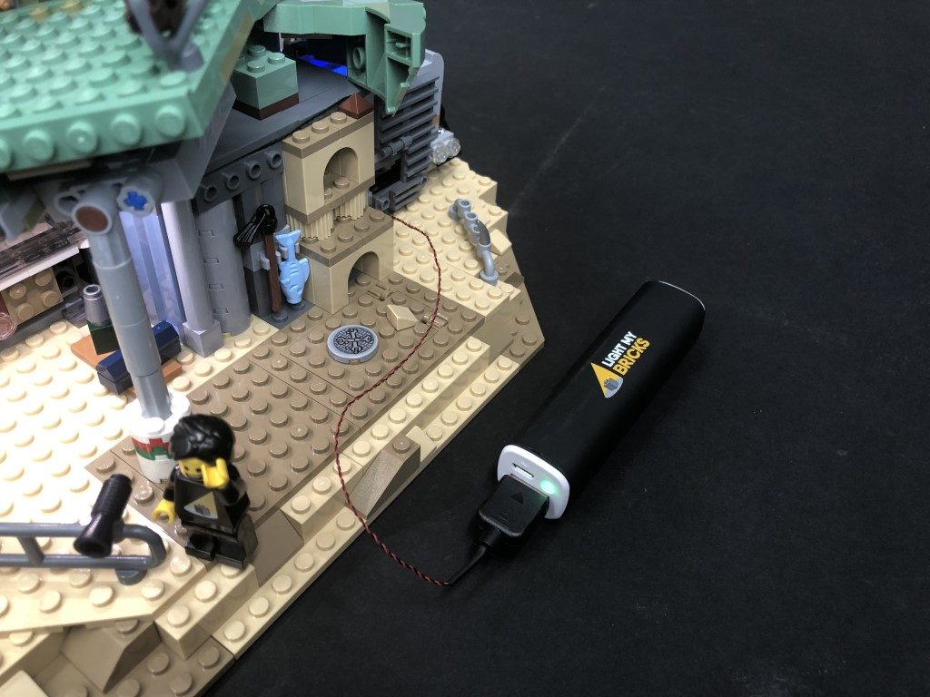
Reconnect the roof then connect the USB Cable to the power bank and test that the lights we have installed so far are working OK.
Note: If you experience any issues with the lights not working and suspect an issue with a component, please try a different port on the expansion board to verify where the fault lies (with the light or expansion board). To correct any issues with expansion board ports, please view the section addressing expansion board issues on our online troubleshooting guide.
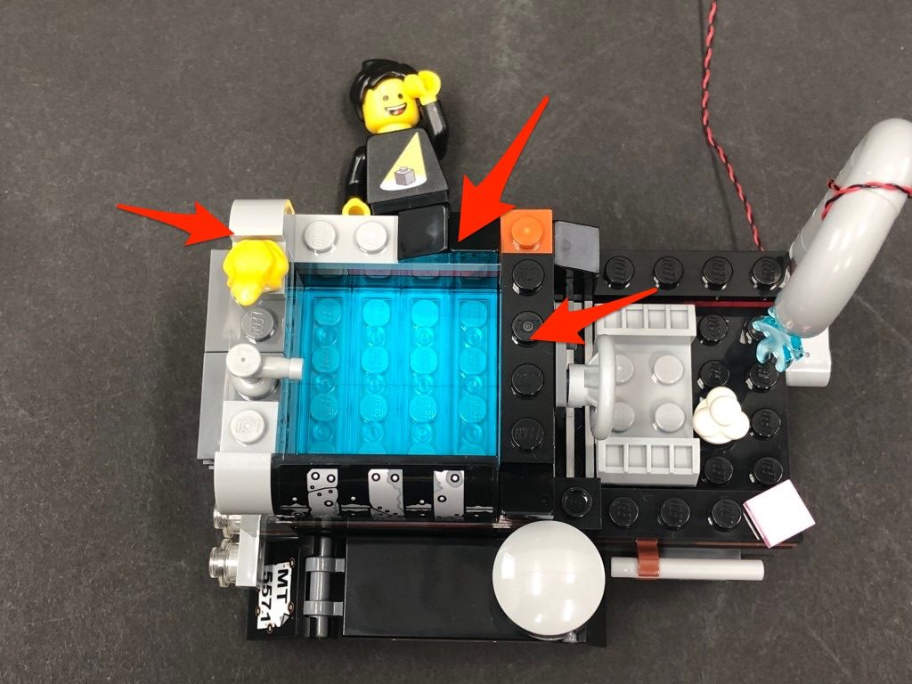
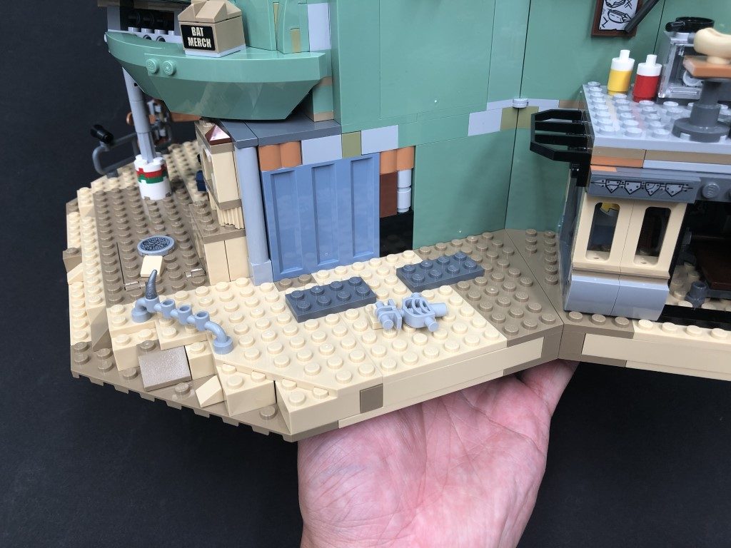
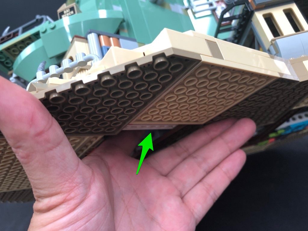
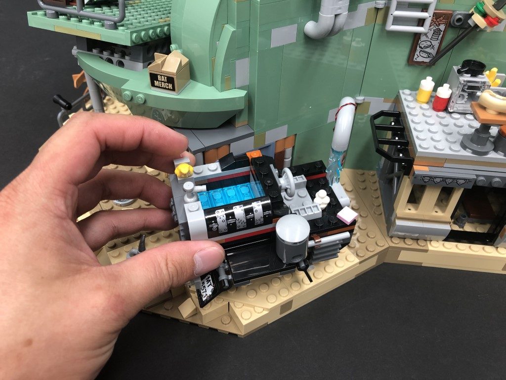
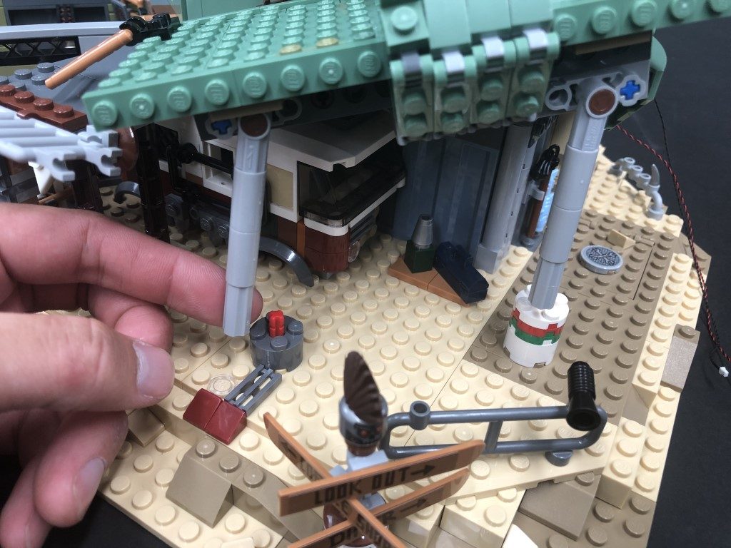
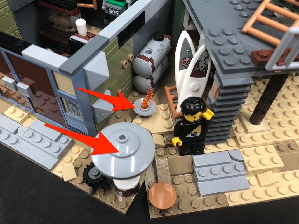
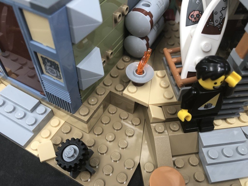
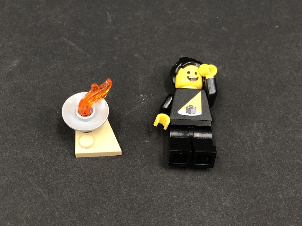
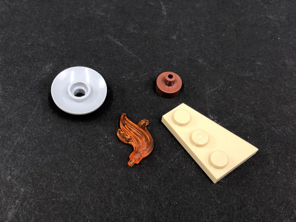
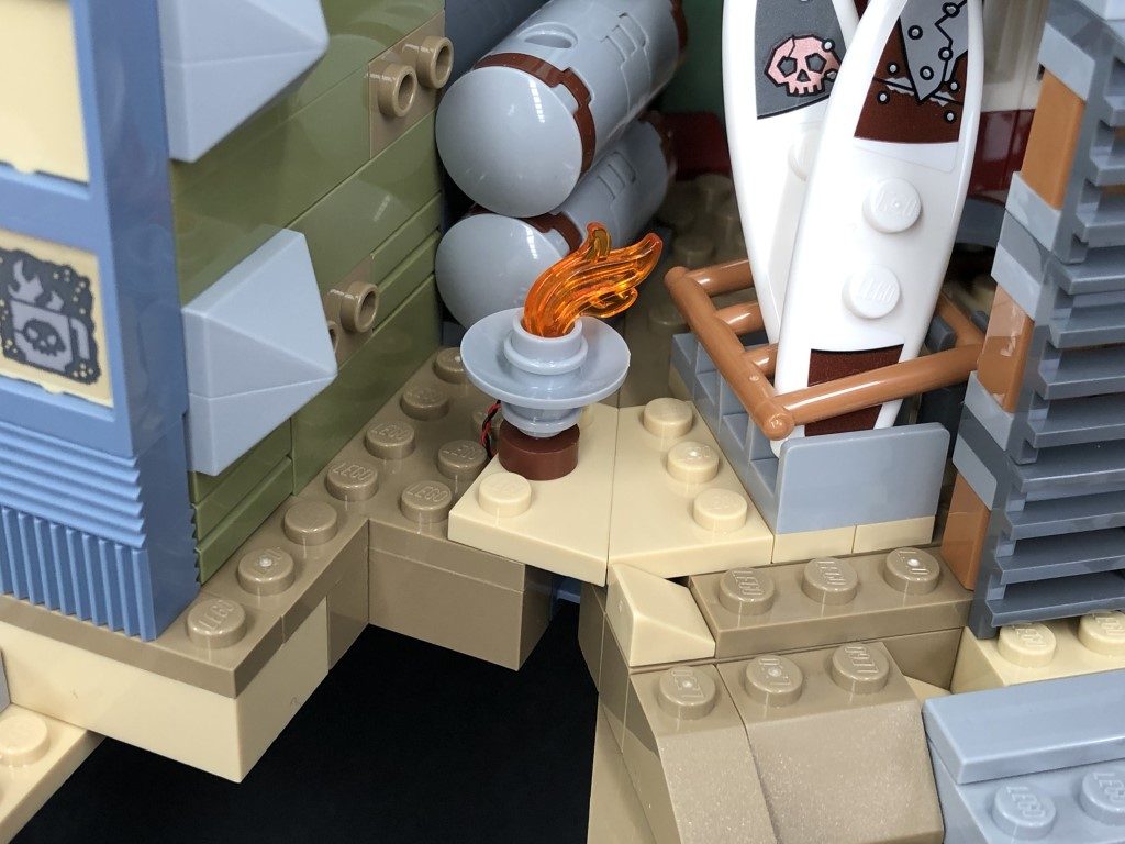
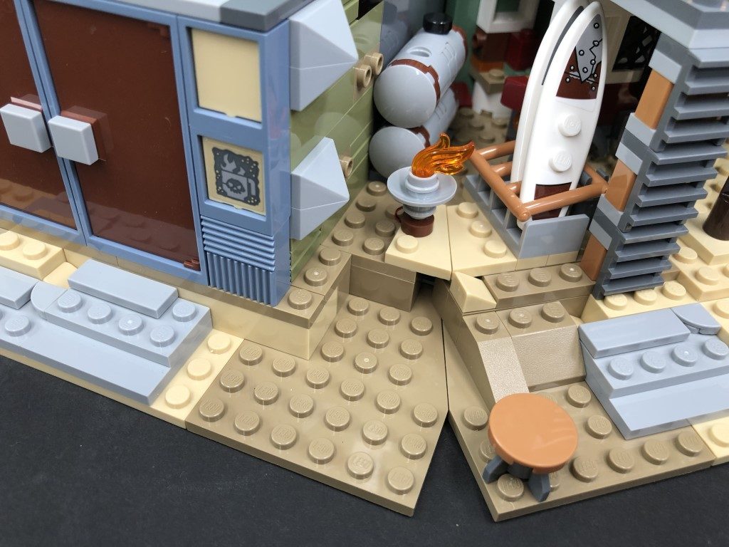
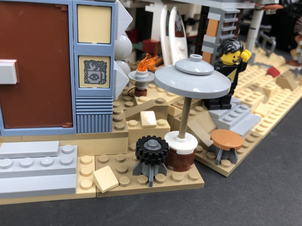
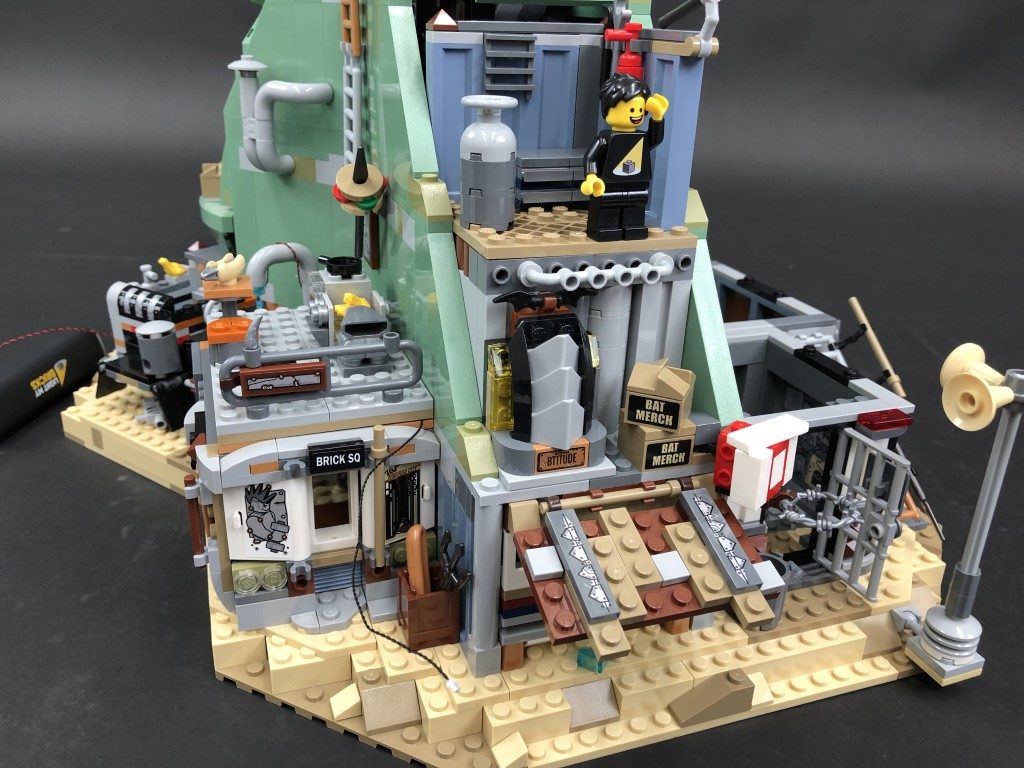
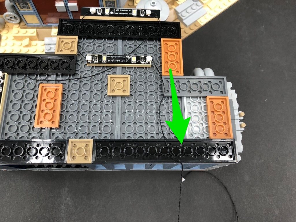
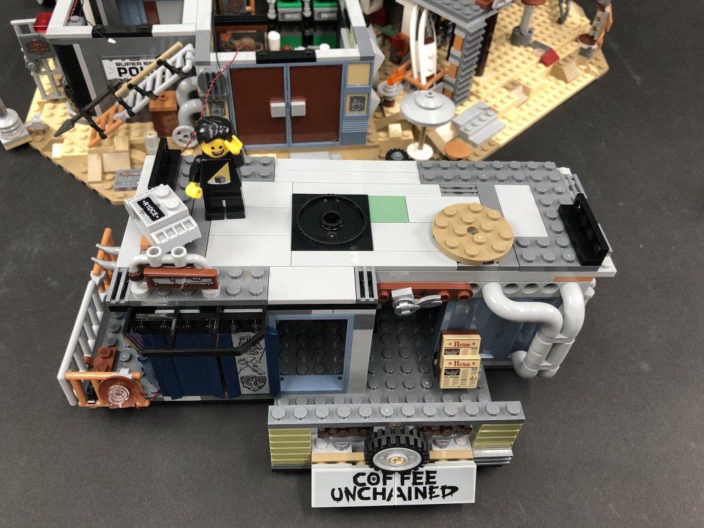
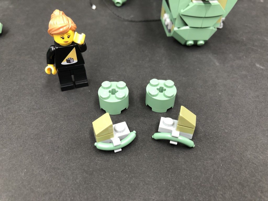
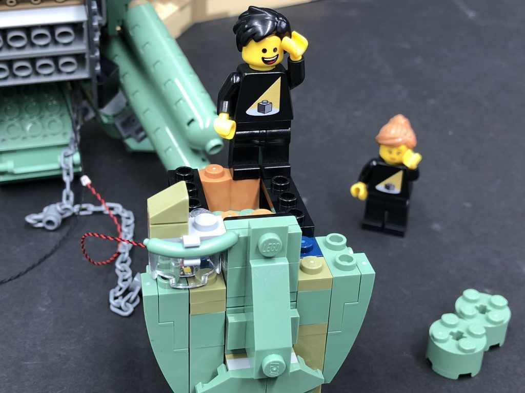
12.) Turn the set around to the front and disconnect the table/umbrella and plate where the fire pit sits on, then carefully lift up the base of the set and disconnect the darker tan plate as shown below:
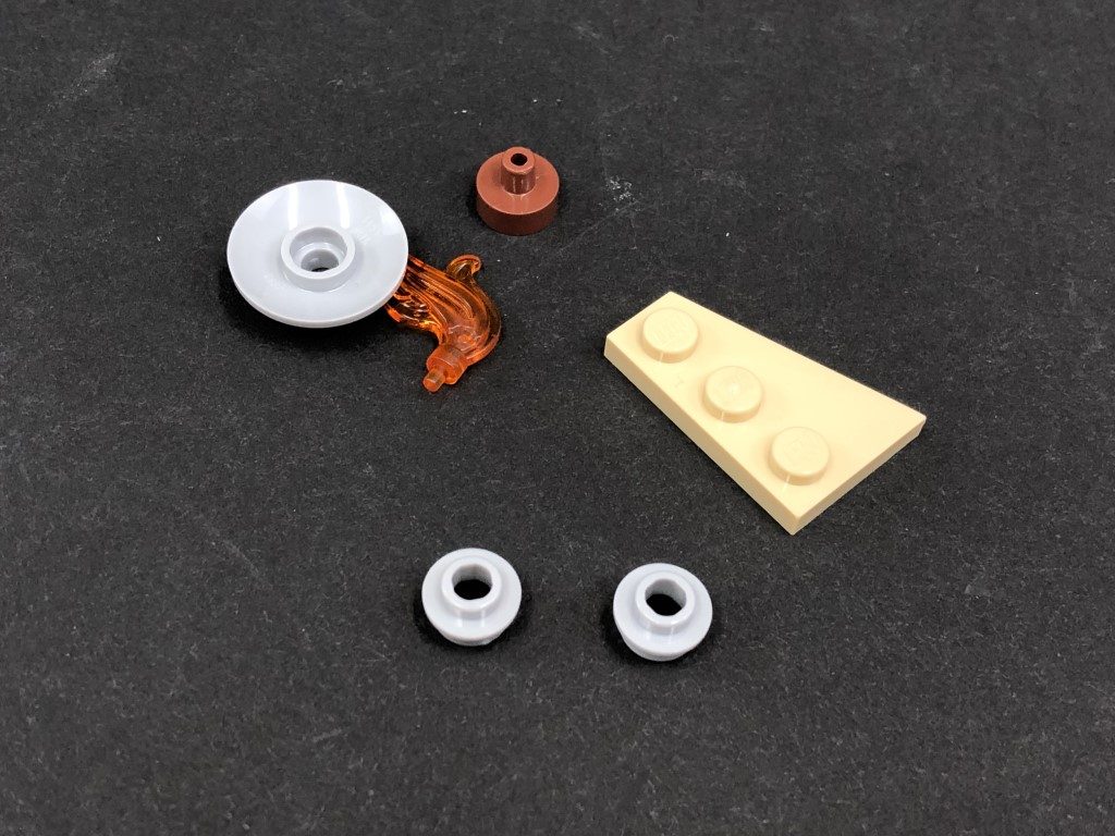
Take the fire pit section and disassemble as per below, then take out the provided 2x Light Grey Round Plate 1×1 with open stud
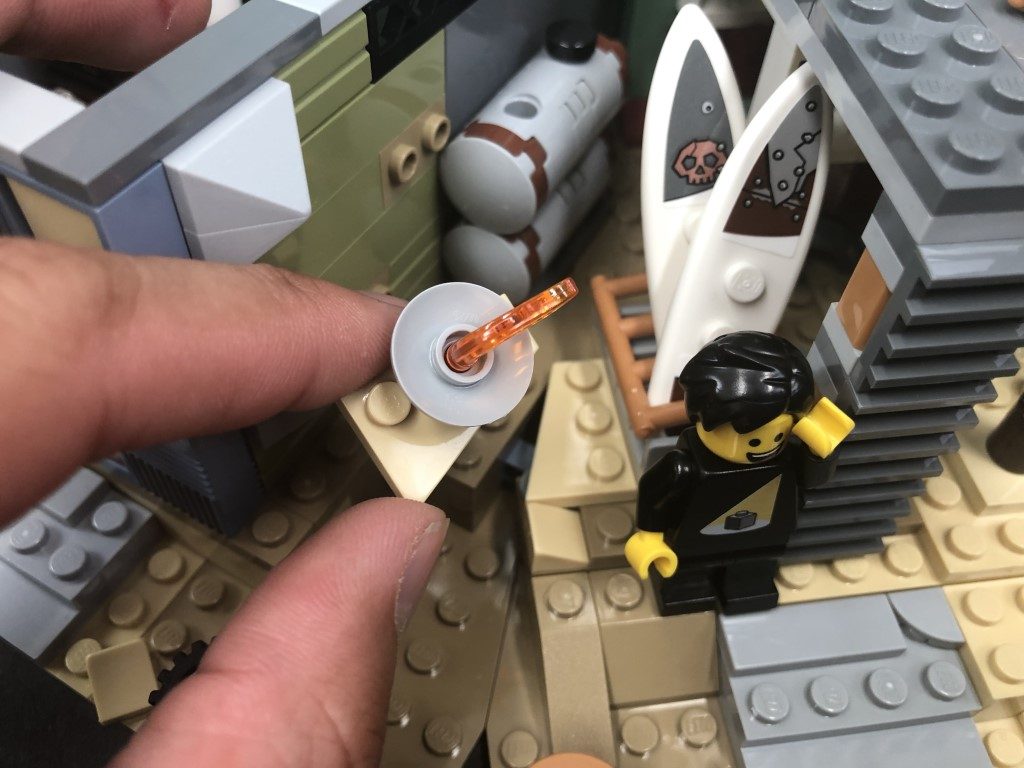
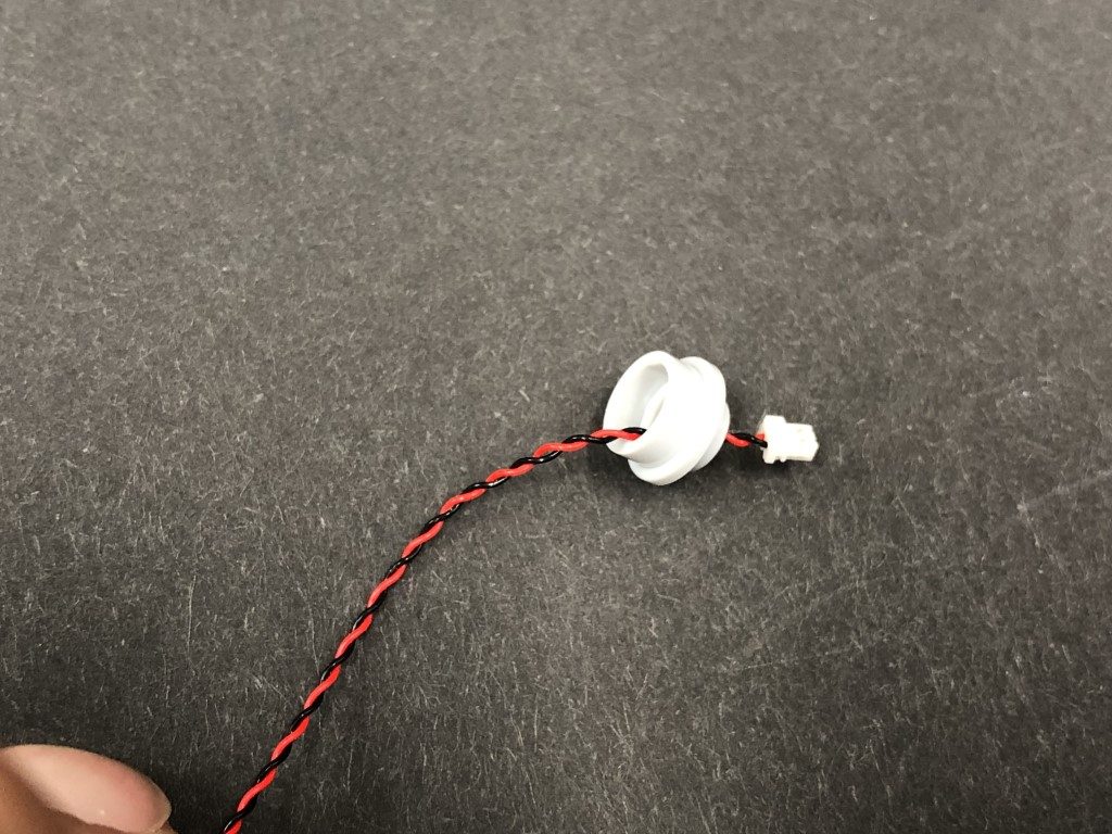
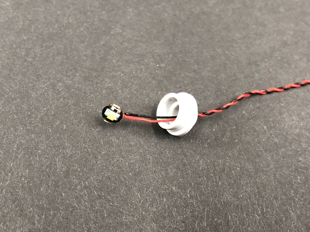
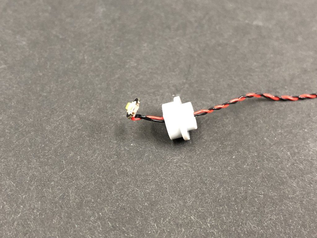
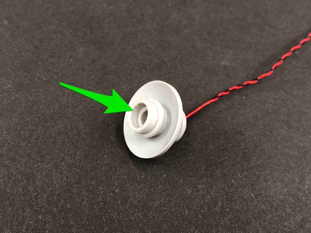
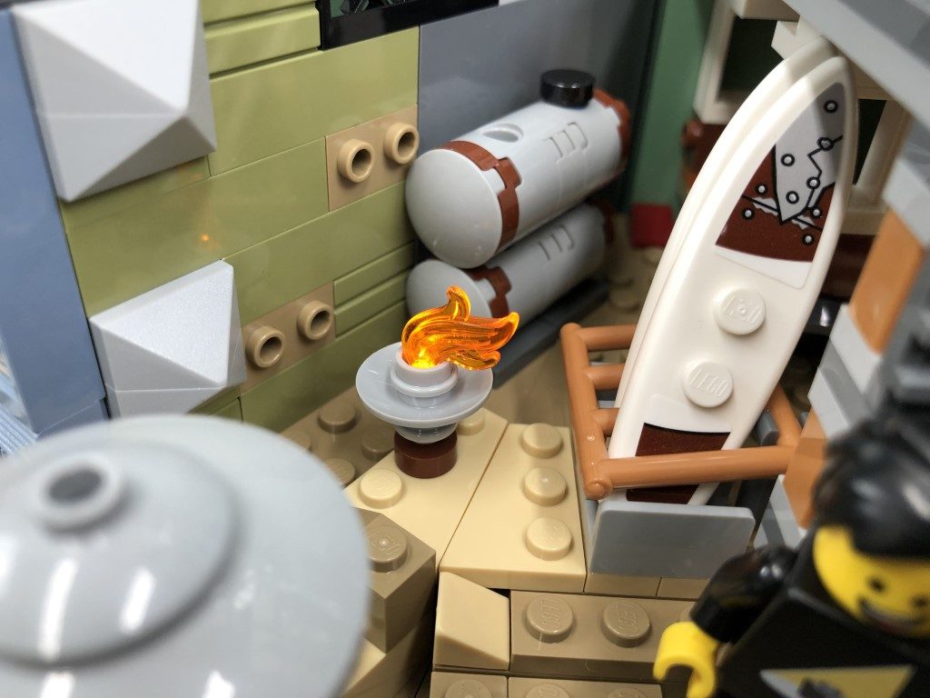
13.) Take a White 30cm Bit Light and thread the connector side of the cable through the base (larger hole) of one of the Light Grey Round Plate 1×1 with open stud. Thread the cable all the way through, then carefully bend the Bit Light on a 90 degree angle so that the Bit Light is facing up and flat against the edge of the hole.
Reconnect the Light Grey Dish over the top of the Bit Light, then take the other provided Light Grey Round Plate 1×1 with open stud and connect it on top of the dish.
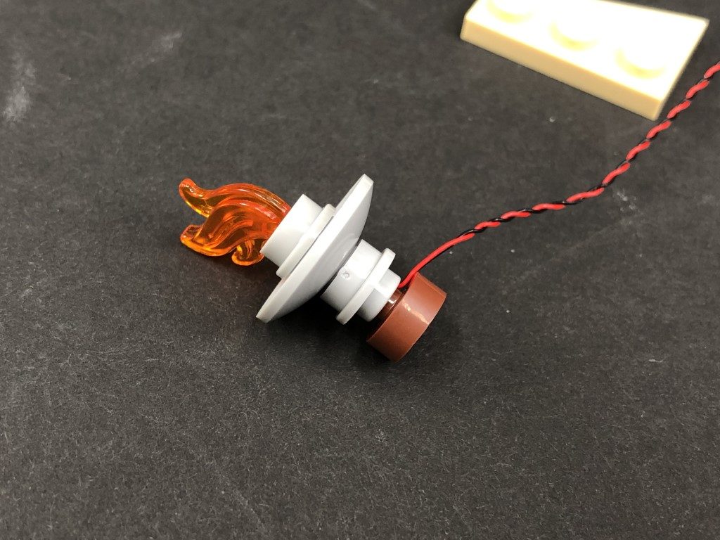
Reconnect the flame piece then reconnect the fire pit on top of the brown piece to connect back to the light tan plate ensuring the cable is behind.
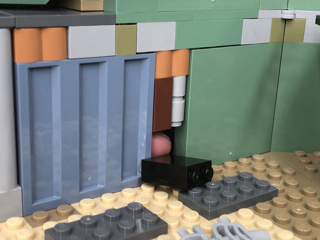
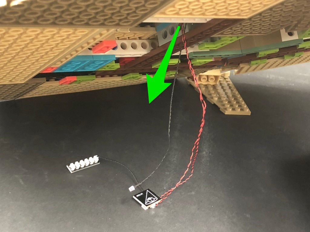
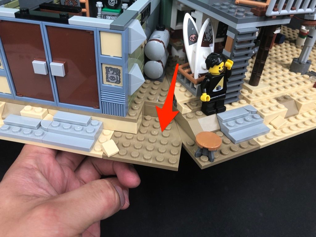
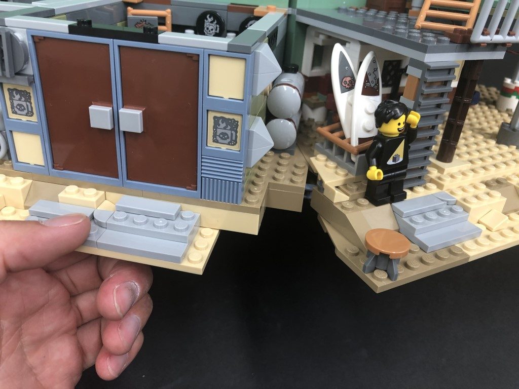
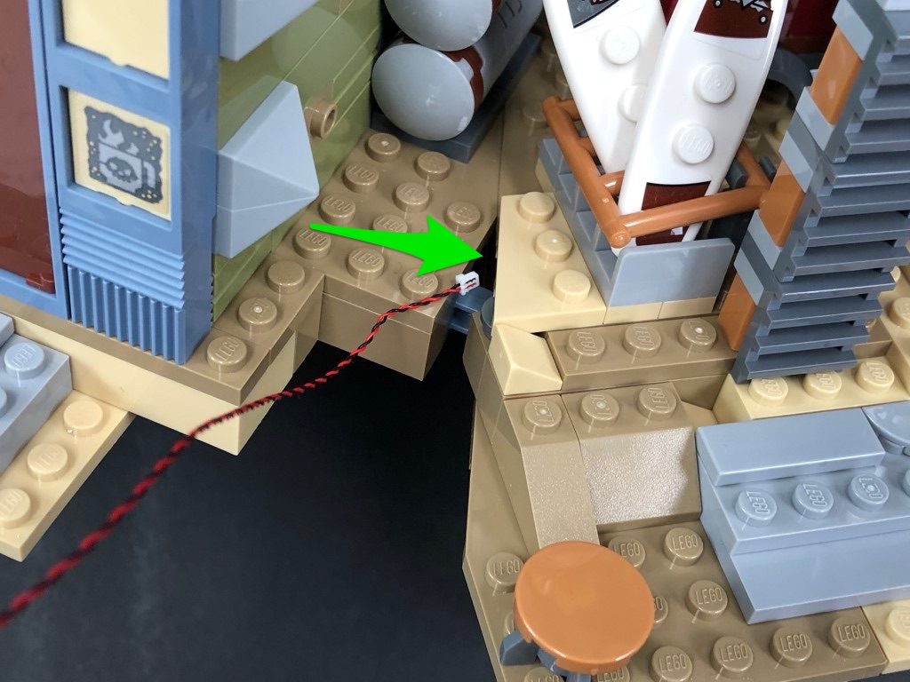
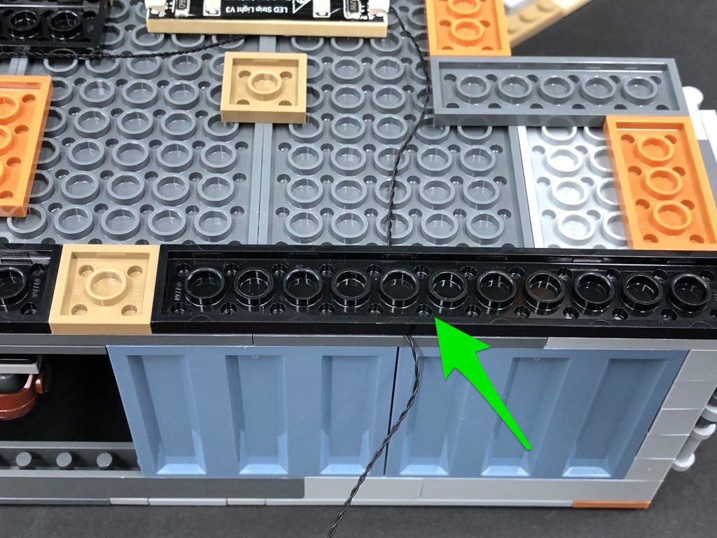
14.) Take the connector end of the Bit Light and thread it through the following space behind where the fire pit goes. Carefully lift up the base of the set and pull the cable all the way out then reconnect the fire pit section.
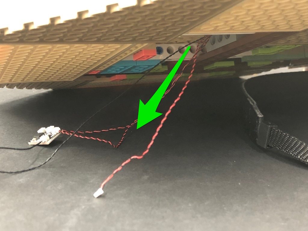
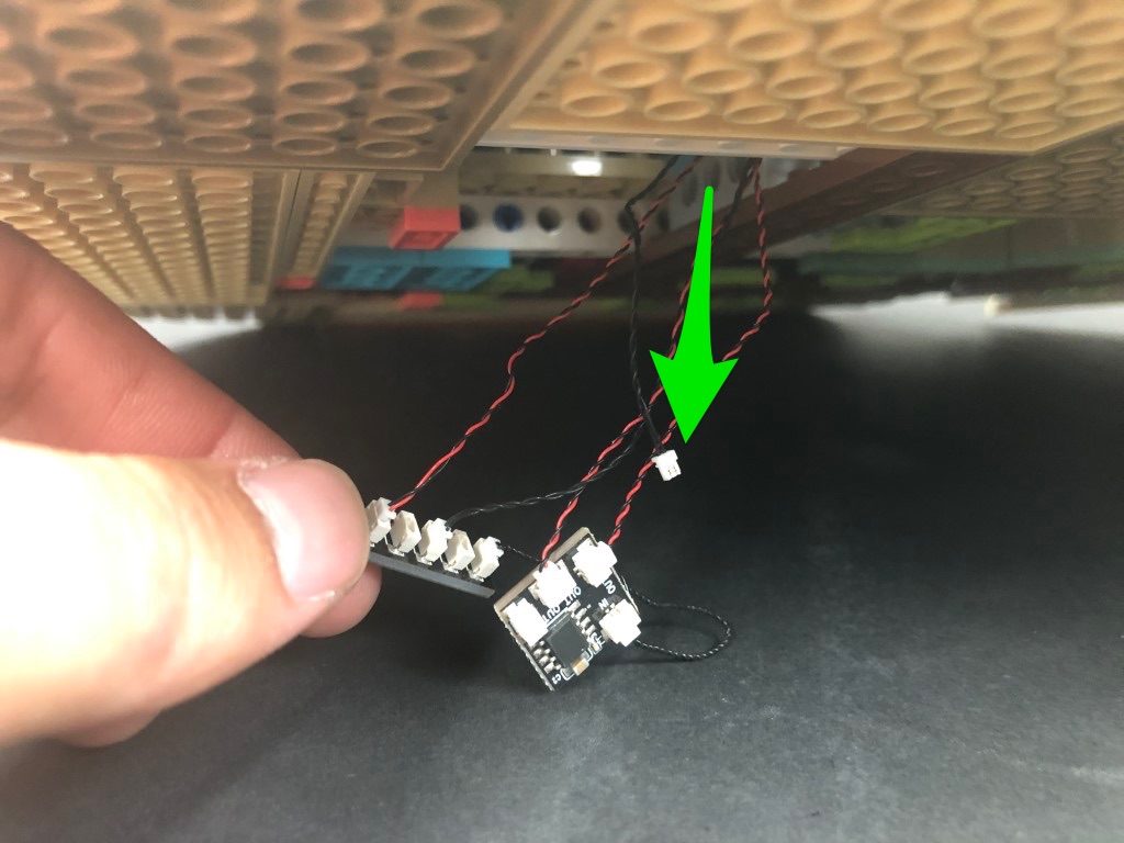
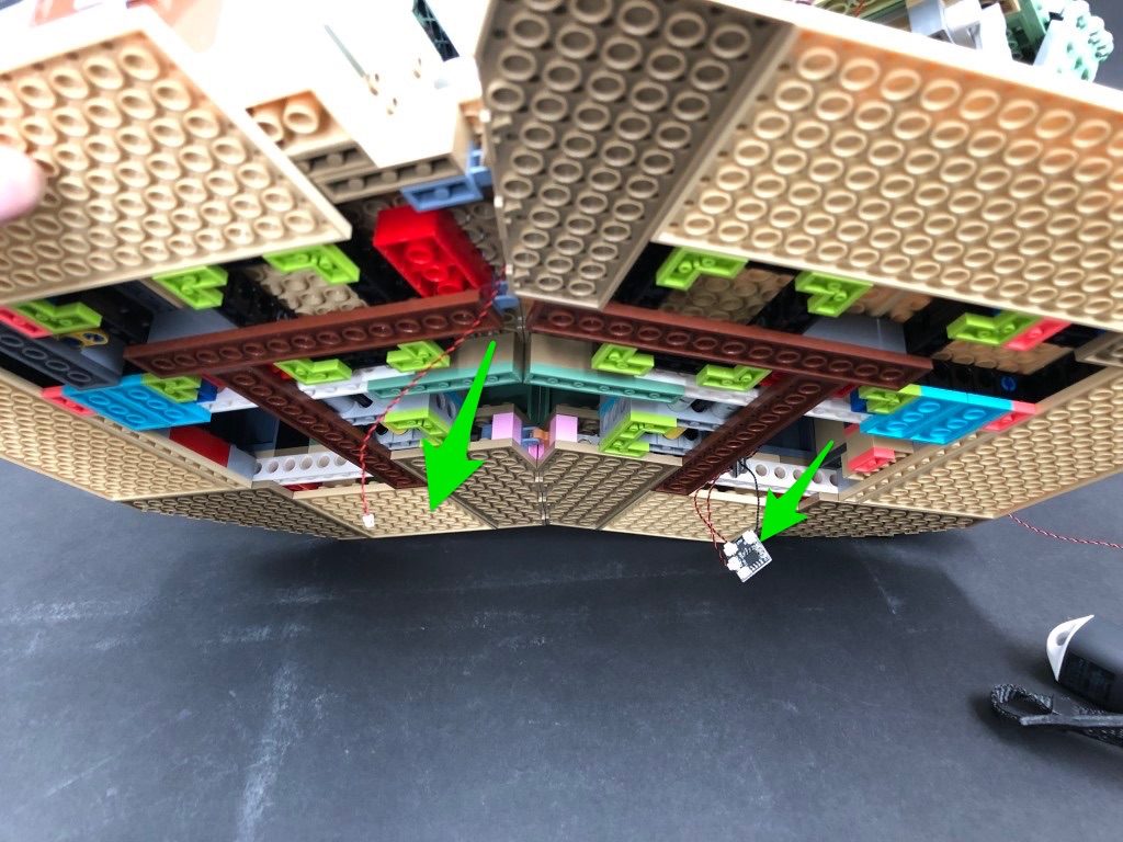
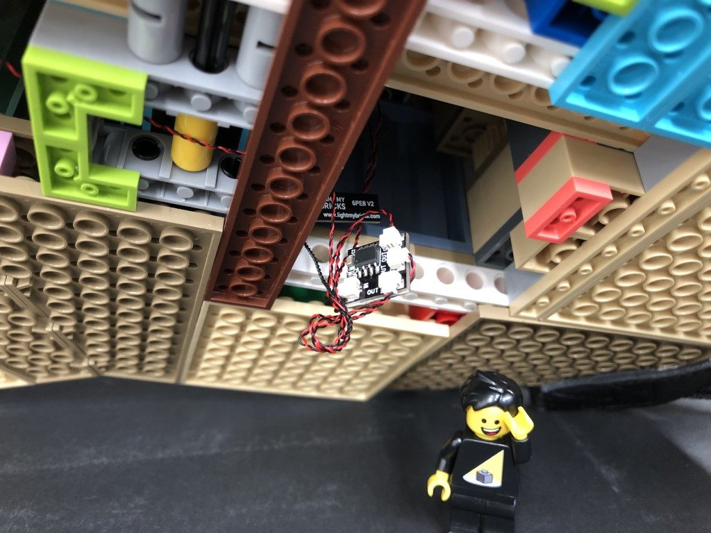
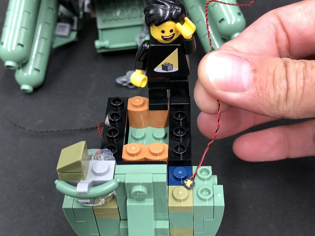
Carefully lift the set up again and pull down the flicker effects board from the right side. Thread the Bit Light cable from the fire pit through the following technic brick hole and pull it all the way out from the other side as shown below:
Thread the cable through another technic brick hole as per below, and pull it all the way out from the other side. Once through, connect the cable to the remaining OUT port on the flicker effects board
Group all the excess cables and twist wind them around each other so they bunch up neatly together, then tuck them up inside the space above.
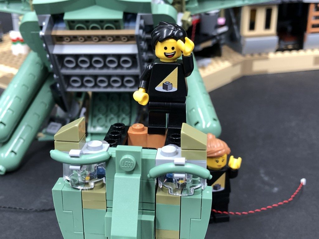
Place the set back down again and reconnect all sections surrounding the fire pit that we removed earlier. Test the fire pit light is working OK with the flicker effect by turning ON the USB Power Bank.
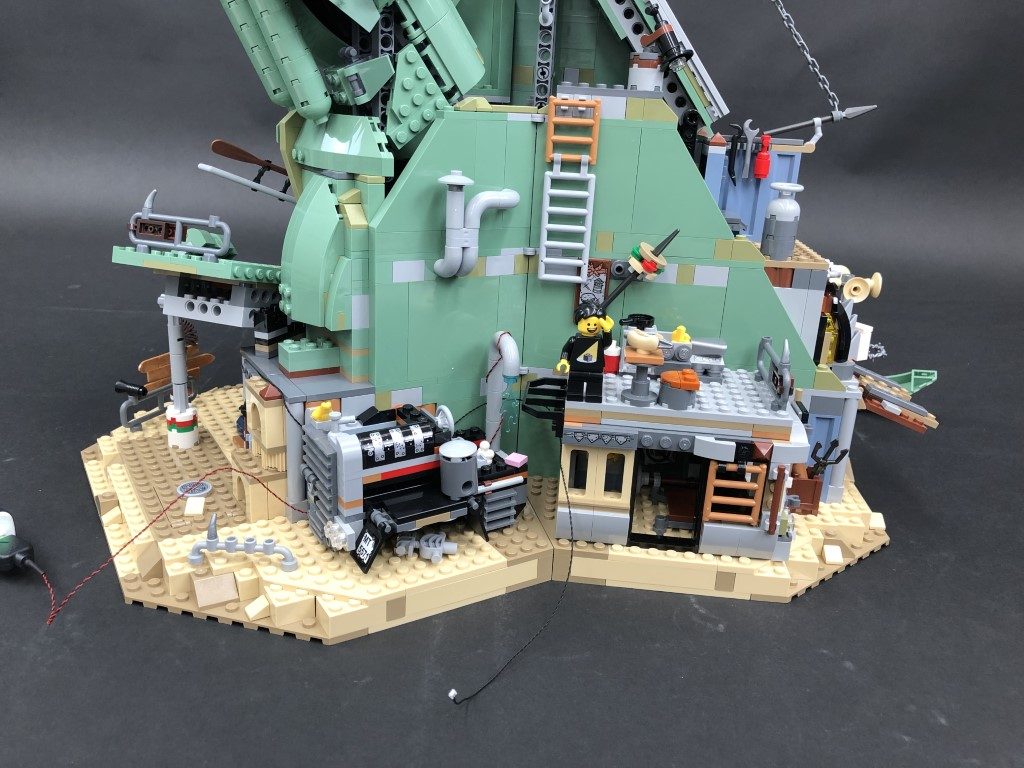
15.) Turn the set around to the back and disconnect the roof off the gym.
Take the end of the 30cm Connecting Cable we installed earlier and lay it down underneath the water pipe, then up along the left side of the gym. Secure it down by laying it underneath the 2×2 tile with stud.
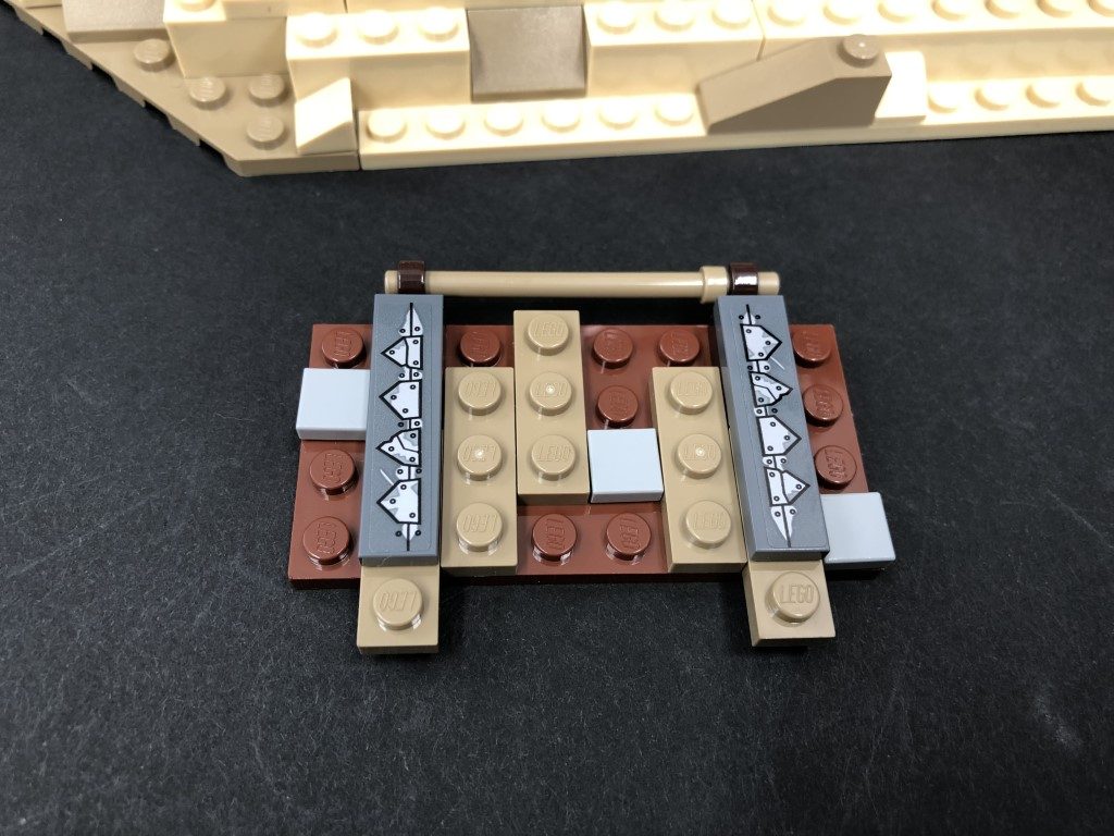
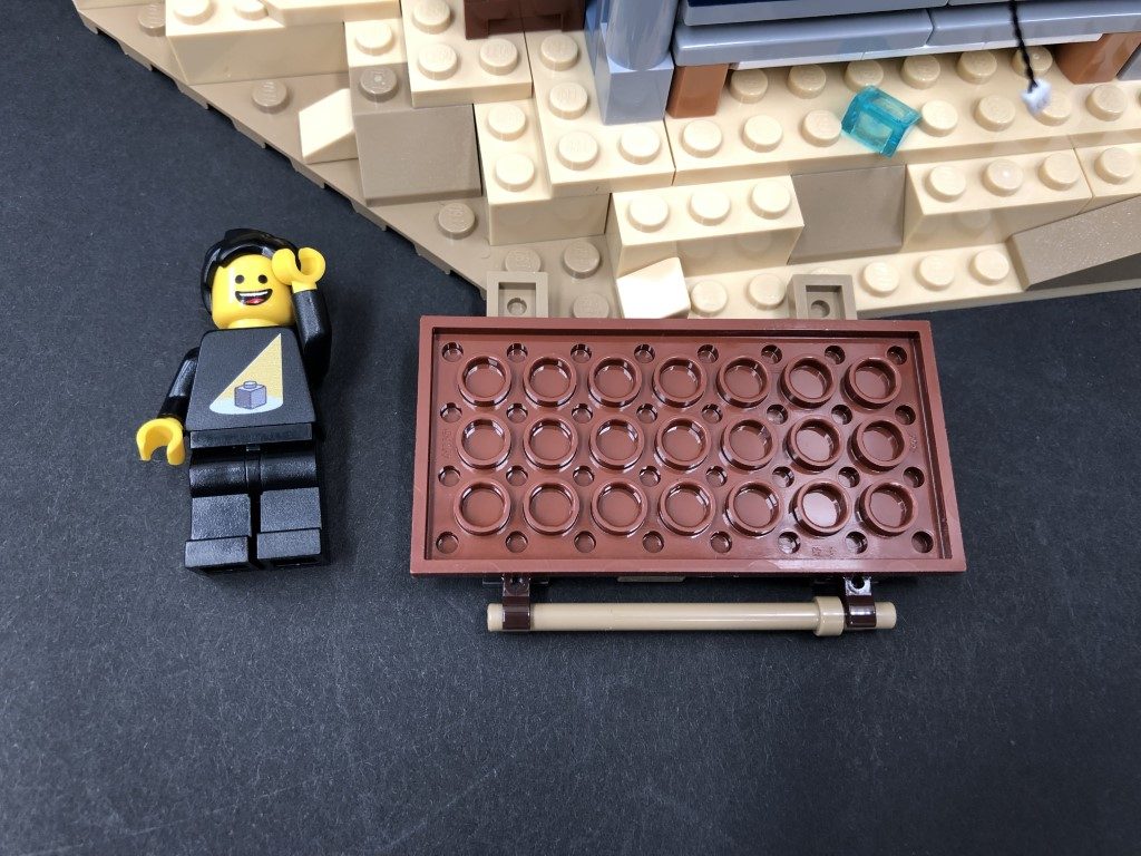
16.) Take a White Strip Light and using it’s adhesive backing, stick it to the base of a provided LEGO Plate 1×6. Take a 15cm Connecting Cable and connect it to the right side of the Strip Light then connect the other end of the 30cm Connecting cable to the left port on the strip light.
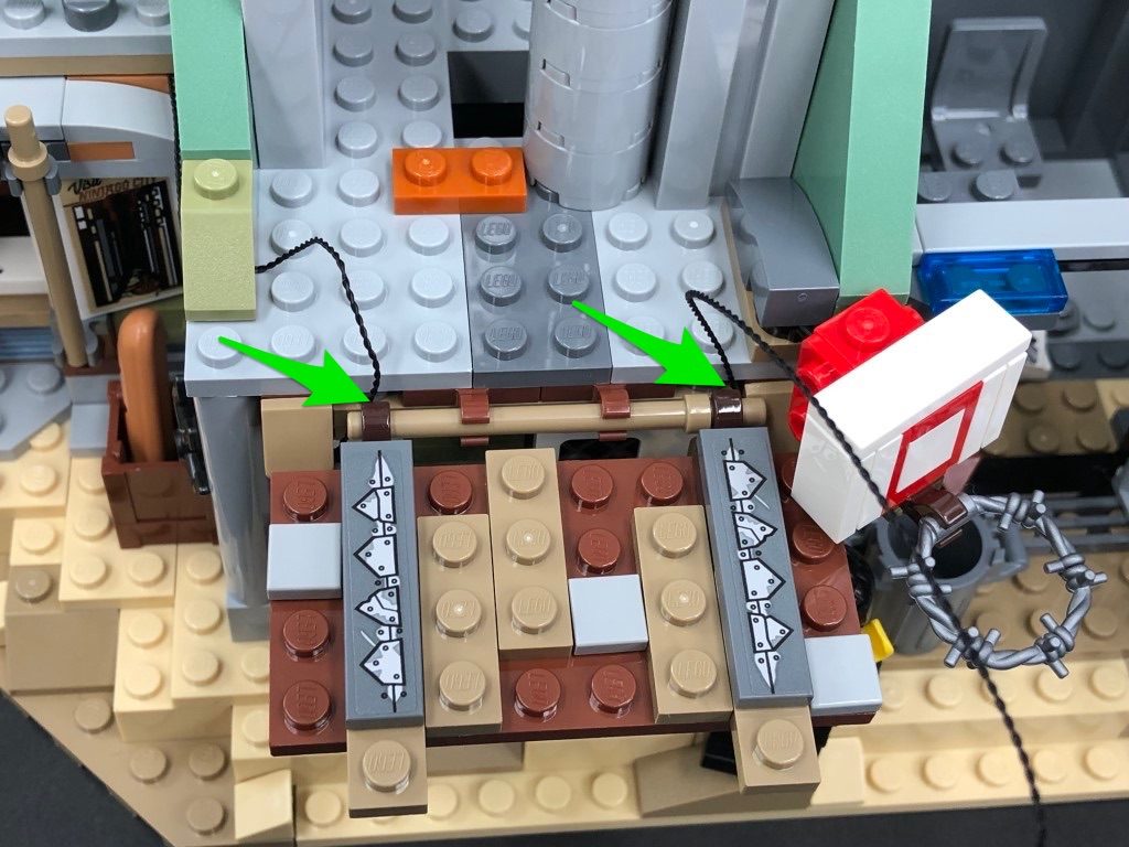
Mount the Strip Light underneath the roof of the gym in the following position then securely reconnect the roof ensuring the other end of the 15cm connecting cable is laid out the right side.
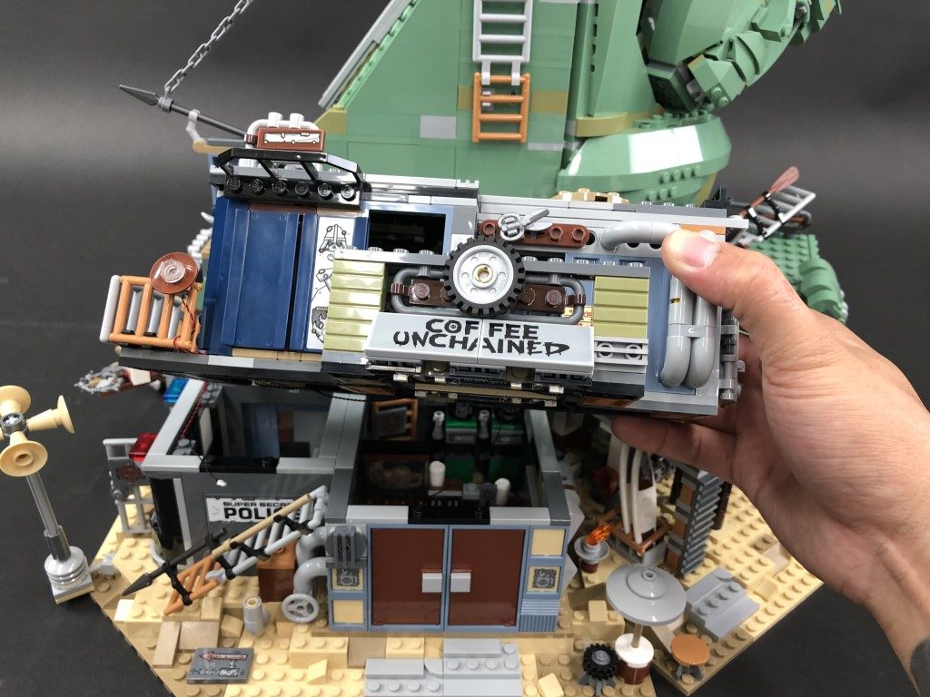
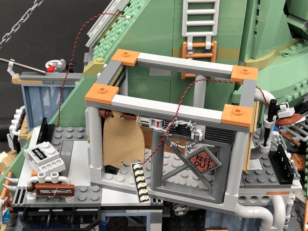
17.) Swing the set around toward the right side, then disconnect all of the following sections as shown below:
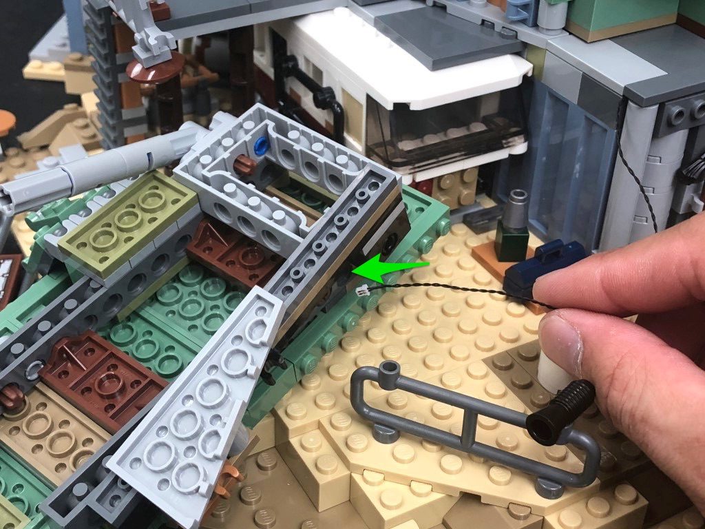
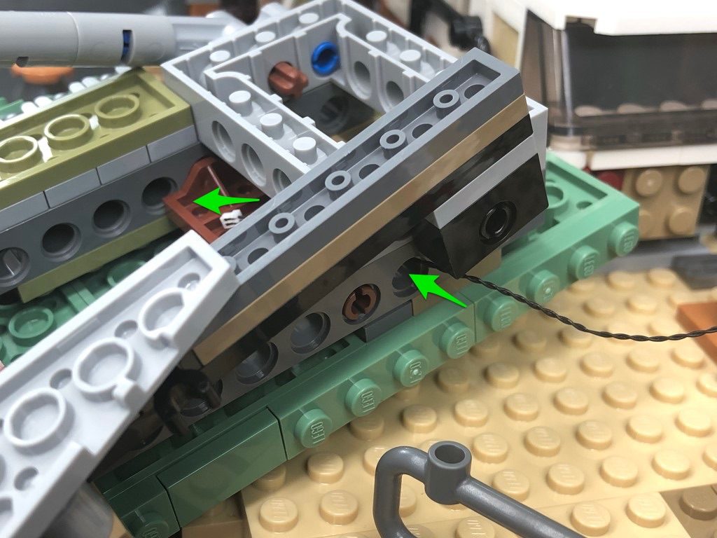
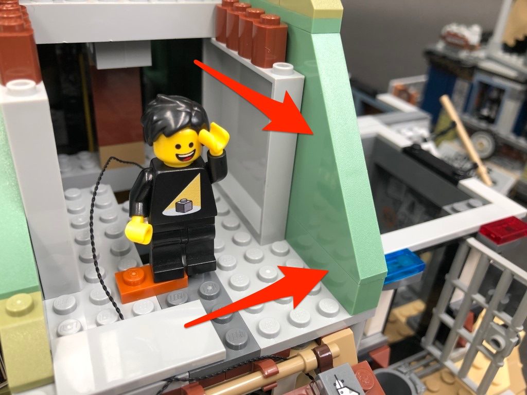
18.) Take the other end of the 15cm Connecting Cable from the left side and lay it down in between studs as shown below. Secure the cable in place by reconnecting the green angled brick over the top.
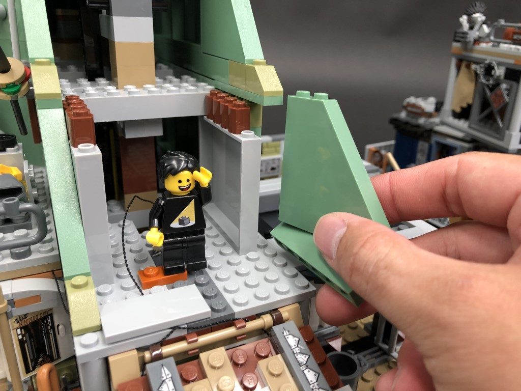
Disconnect the roof section and turn it upside down so we can access underneath.
19.) Take a White Strip Light and connect the other side of the 15cm Connecting cable to the left port. Take a new 15cm Connecting Cable and connect it to the strip light’s right port, then using it’s adhesive backing, stick the strip light underneath the roof section directly onto the plate in the following position.
Reconnect the roof section ensuring both cables are secured behind the clips. Bring the cable on the right side up and lay both cables in between studs as shown below. Secure them down by reconnecting the 2×4 tile over the top.
Connect the other end of the 15cm Connecting cable from the strip light’s right port to a new 6-Port Expansion Board, then tuck the cable inside the following space.
20.) Refer to the below images to disconnect the following sections:
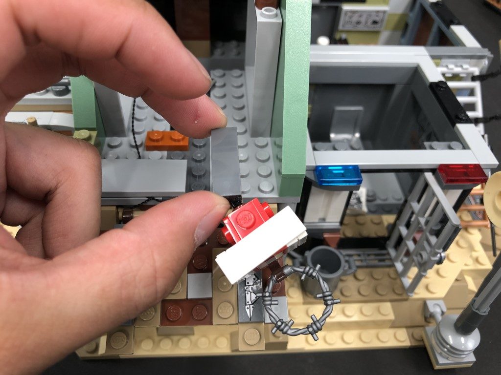
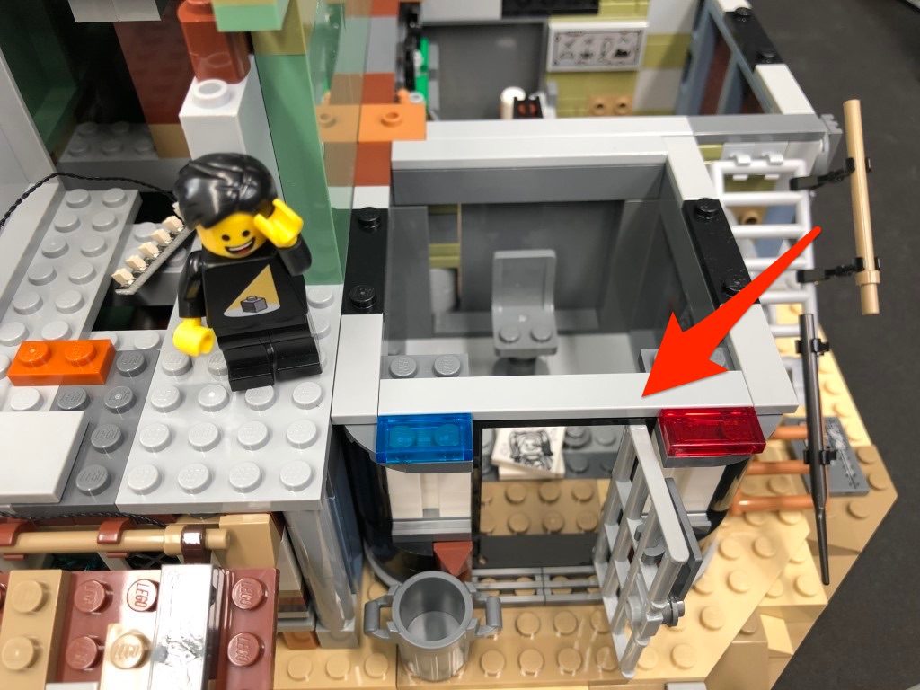
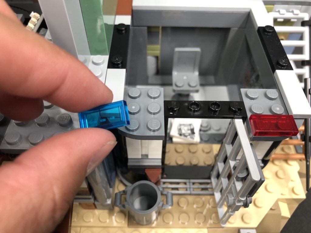
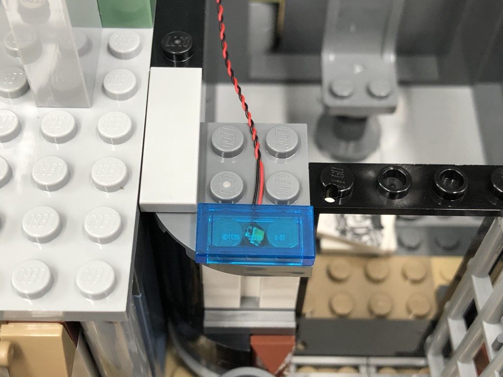
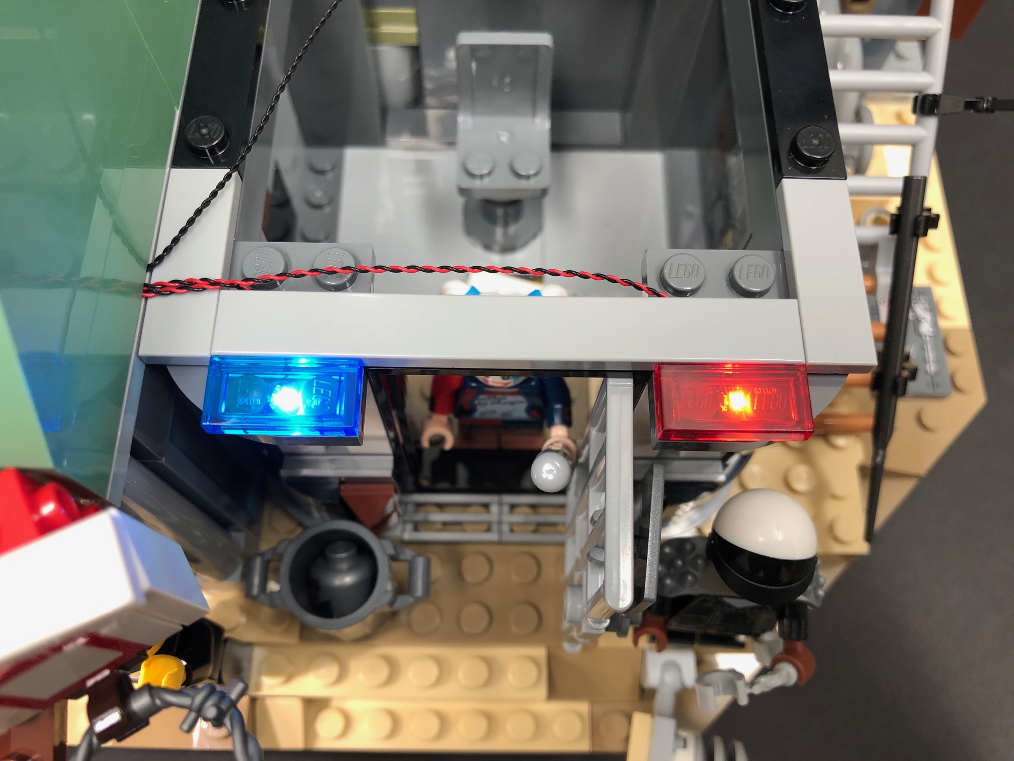
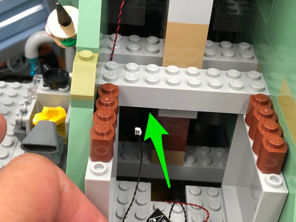
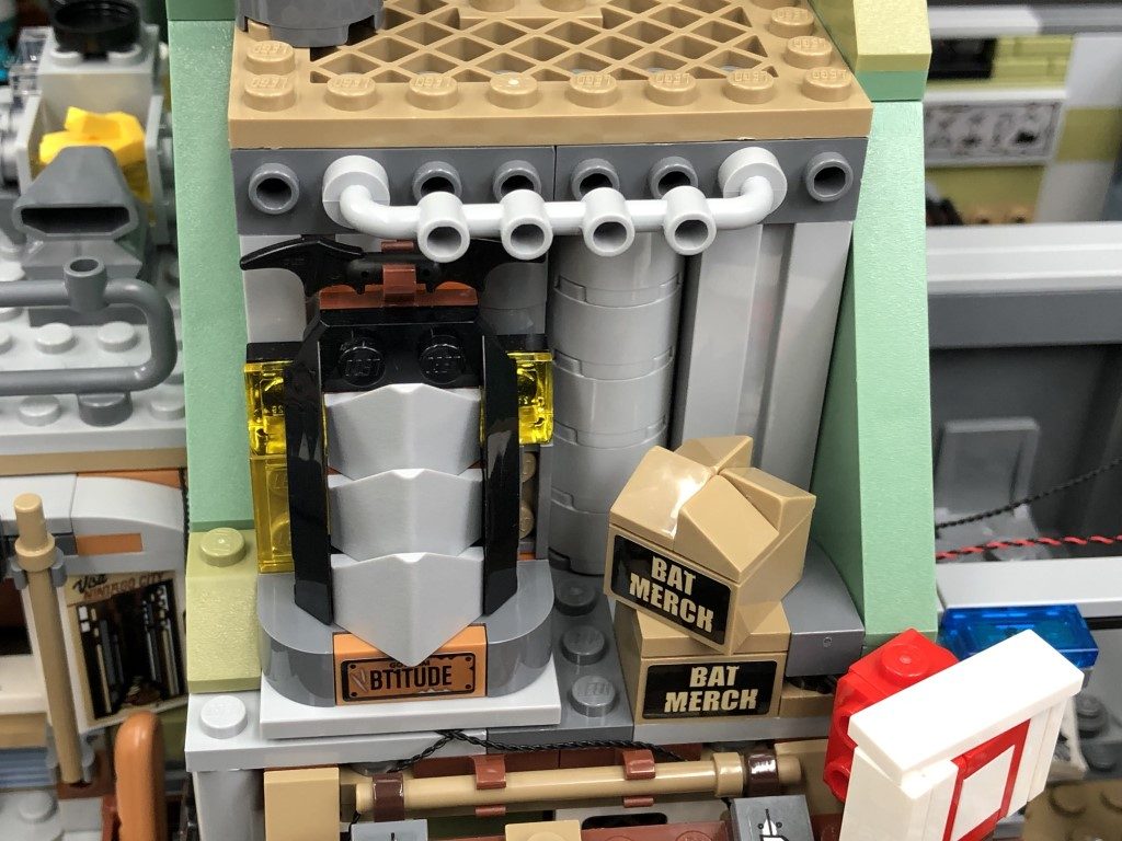
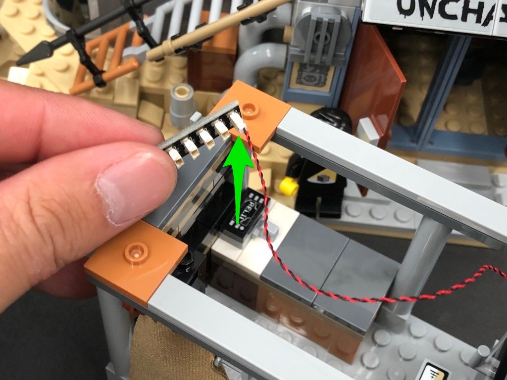
21.) We will now install flashing lights to the police station. First disconnect the trans blue tile, then take a Flashing White 15cm Bit Light and with the cable facing the inside of the building, place it down in between the following studs. Secure the light in place by reconnecting the trans blue tile over the top.
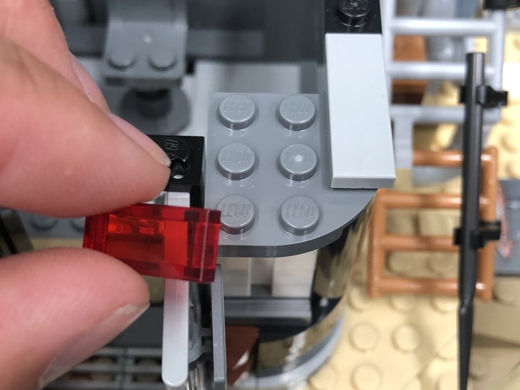
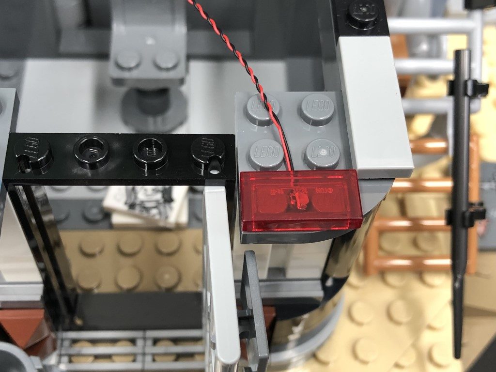
Repeat this process to install another Flashing White 15cm Bit Light underneath the trans red tile.
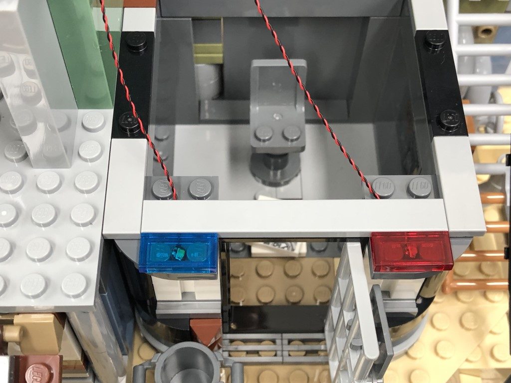
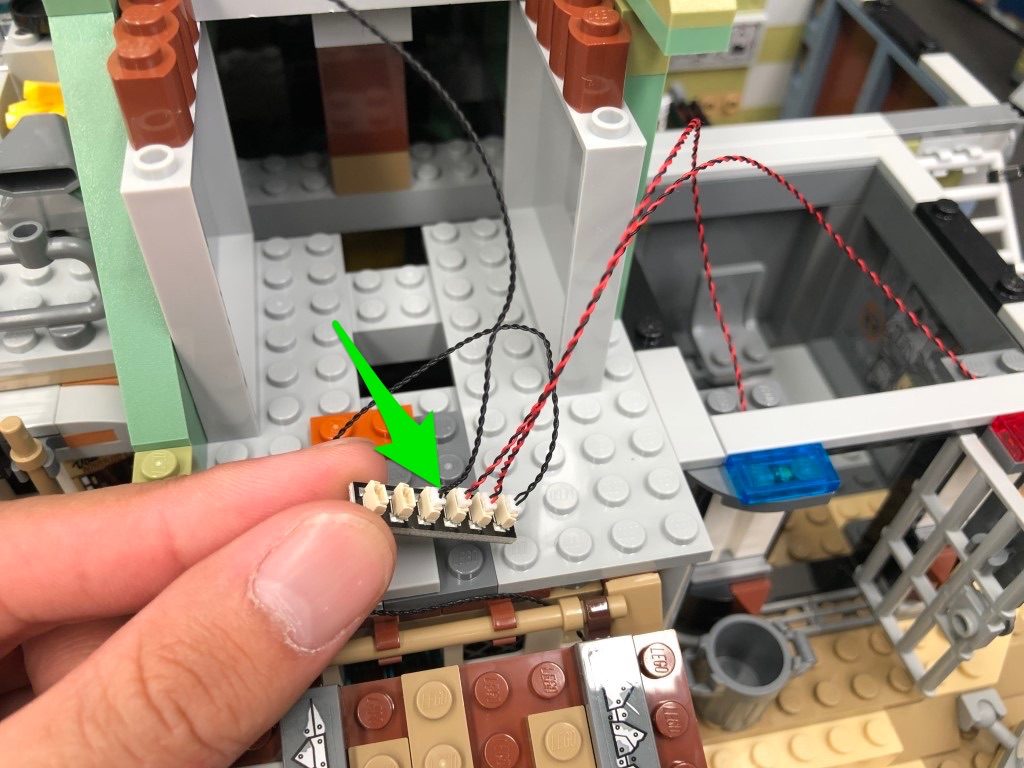
Reconnect the light grey tile, then connect both flashing bit lights to the 6-port expansion board on the left side.
Turn ON your usb power bank to test that all the lights are working OK.
7.) Move the water tank section out of the way, then take a 30cm Connecting Cable and thread one end of the cable through the space which leads underneath. Pull the cable out from underneath and connect it to the next port on the 6-Port Expansion Board.
Thread the USB Power Cable (connector side) through the same space, then pull it out from underneath and connect it to the next port on the 6-port Expansion Board.
Take another 30cm Connecting Cable and thread it through the same space, then pull it out from underneath and connect it to the next port on the 6-port Expansion Board.
Pull the first 30cm Connecting Cable and USB Power Cable all the way out toward the left side of the water tank, then pull the other 30cm Connecting Cable all the way out the right side before reconnecting the water tank to cover up the space.
8.) Move the set along towards the left side and disconnect the roof off by first disconnecting the pillars to allow you to completely pull the roof off.
Bring the other end of the 30cm Connecting Cable from the left side of the water tank around to this side, then thread it underneath the following section. Secure the cable in place underneath the light grey tile.
9.) Take a White Strip Light and using it’s adhesive backing, stick it onto the base of a provided LEGO Plate 1×6
Take the roof section we removed and turn it over so we can access underneath. Thread the 30cm Connecting Cable we have brought over through the following technic brick hole underneath the roof section. Thread the cable through so that it comes out through the top, then connect it to the Strip Light. Mount the Strip Light underneath this section in the following position as shown below.
10.) Remove the following rail section then disconnect and disassemble the lamp.
Take a White 15cm Bit Light and place the led face down over the hole on top of the brown dish. Secure the Bit Light in place by reconnecting the light grey plate with clip over the top.
Reconnect the lamp back to the rail, then reconnect the rail to the roof ensuring the cable is facing behind.
11.) Take the roof section and turn it onto it’s front side (with back side facing up). Thread the Bit Light cable through the following technic brick hole, then turn the roof over and connect the bit light cable to the strip light’s other port.
Reconnect the roof then connect the USB Cable to the power bank and test that the lights we have installed so far are working OK.
Note: If you experience any issues with the lights not working and suspect an issue with a component, please try a different port on the expansion board to verify where the fault lies (with the light or expansion board). To correct any issues with expansion board ports, please view the section addressing expansion board issues on our online troubleshooting guide.
12.) Turn the set around to the front and disconnect the table/umbrella and plate where the fire pit sits on, then carefully lift up the base of the set and disconnect the darker tan plate as shown below:
Take the fire pit section and disassemble as per below, then take out the provided 2x Light Grey Round Plate 1×1 with open stud
13.) Take a White 30cm Bit Light and thread the connector side of the cable through the base (larger hole) of one of the Light Grey Round Plate 1×1 with open stud. Thread the cable all the way through, then carefully bend the Bit Light on a 90 degree angle so that the Bit Light is facing up and flat against the edge of the hole.
Reconnect the Light Grey Dish over the top of the Bit Light, then take the other provided Light Grey Round Plate 1×1 with open stud and connect it on top of the dish.
Reconnect the flame piece then reconnect the fire pit on top of the brown piece to connect back to the light tan plate ensuring the cable is behind.
14.) Take the connector end of the Bit Light and thread it through the following space behind where the fire pit goes. Carefully lift up the base of the set and pull the cable all the way out then reconnect the fire pit section.
Carefully lift the set up again and pull down the flicker effects board from the right side. Thread the Bit Light cable from the fire pit through the following technic brick hole and pull it all the way out from the other side as shown below:
Thread the cable through another technic brick hole as per below, and pull it all the way out from the other side. Once through, connect the cable to the remaining OUT port on the flicker effects board
Group all the excess cables and twist wind them around each other so they bunch up neatly together, then tuck them up inside the space above.
Place the set back down again and reconnect all sections surrounding the fire pit that we removed earlier. Test the fire pit light is working OK with the flicker effect by turning ON the USB Power Bank.
15.) Turn the set around to the back and disconnect the roof off the gym.
Take the end of the 30cm Connecting Cable we installed earlier and lay it down underneath the water pipe, then up along the left side of the gym. Secure it down by laying it underneath the 2×2 tile with stud.
16.) Take a White Strip Light and using it’s adhesive backing, stick it to the base of a provided LEGO Plate 1×6. Take a 15cm Connecting Cable and connect it to the right side of the Strip Light then connect the other end of the 30cm Connecting cable to the left port on the strip light.
Mount the Strip Light underneath the roof of the gym in the following position then securely reconnect the roof ensuring the other end of the 15cm connecting cable is laid out the right side.
17.) Swing the set around toward the right side, then disconnect all of the following sections as shown below:
18.) Take the other end of the 15cm Connecting Cable from the left side and lay it down in between studs as shown below. Secure the cable in place by reconnecting the green angled brick over the top.
Disconnect the roof section and turn it upside down so we can access underneath.
19.) Take a White Strip Light and connect the other side of the 15cm Connecting cable to the left port. Take a new 15cm Connecting Cable and connect it to the strip light’s right port, then using it’s adhesive backing, stick the strip light underneath the roof section directly onto the plate in the following position.
Reconnect the roof section ensuring both cables are secured behind the clips. Bring the cable on the right side up and lay both cables in between studs as shown below. Secure them down by reconnecting the 2×4 tile over the top.
Connect the other end of the 15cm Connecting cable from the strip light’s right port to a new 6-Port Expansion Board, then tuck the cable inside the following space.
20.) Refer to the below images to disconnect the following sections:
21.) We will now install flashing lights to the police station. First disconnect the trans blue tile, then take a Flashing White 15cm Bit Light and with the cable facing the inside of the building, place it down in between the following studs. Secure the light in place by reconnecting the trans blue tile over the top.
Repeat this process to install another Flashing White 15cm Bit Light underneath the trans red tile.
Reconnect the light grey tile, then connect both flashing bit lights to the 6-port expansion board on the left side.
Turn ON your usb power bank to test that all the lights are working OK.
 Note: If you experience any issues with the lights not working and suspect an issue with a component, please try a different port on the expansion board to verify where the fault lies (with the light or expansion board). To correct any issues with expansion board ports, please view the section addressing expansion board issues on our online troubleshooting guide.
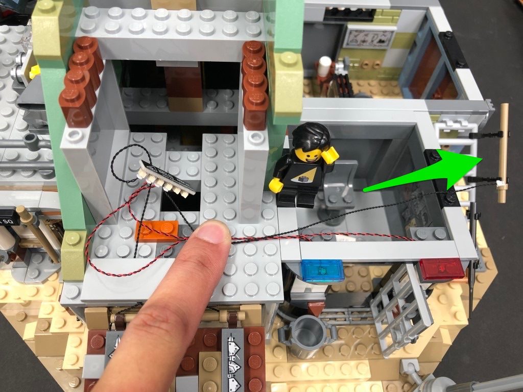
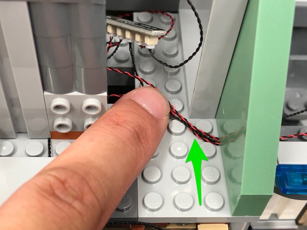
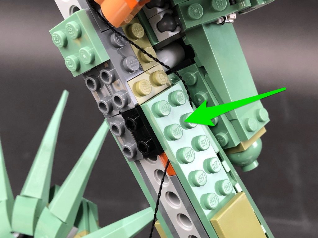
22.) Take a new 15cm Connecting Cable and connect it to the 6-port expansion board. Lay the other end of the cable toward the right then group the two flashing bit light cables together and lay all three cables down in between studs as shown below. Secure all three cables down by reconnecting the green 1×6 brick over the top, then reconnect the large angled brick.
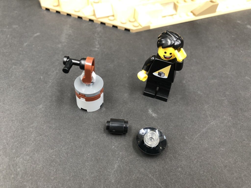
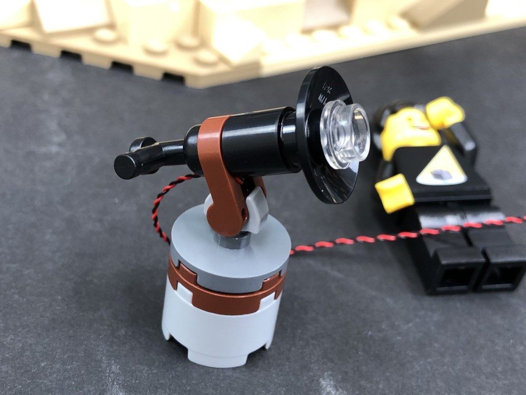
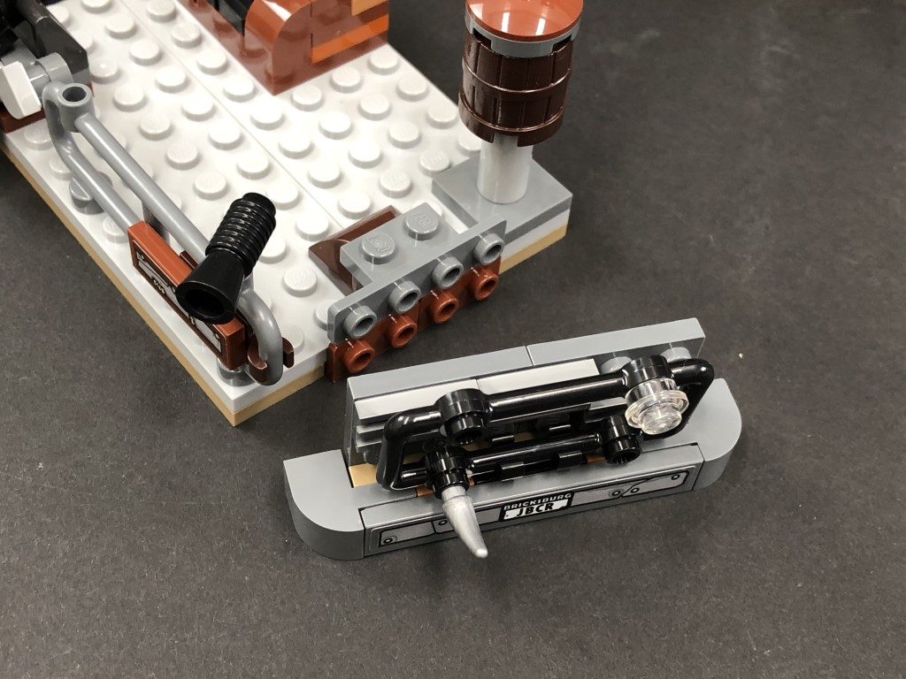
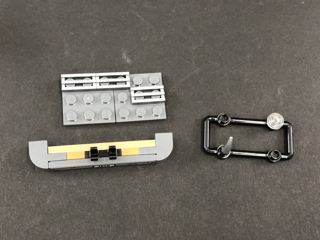
23.) Disconnect the following section and disassemble it as per below.
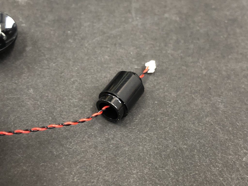
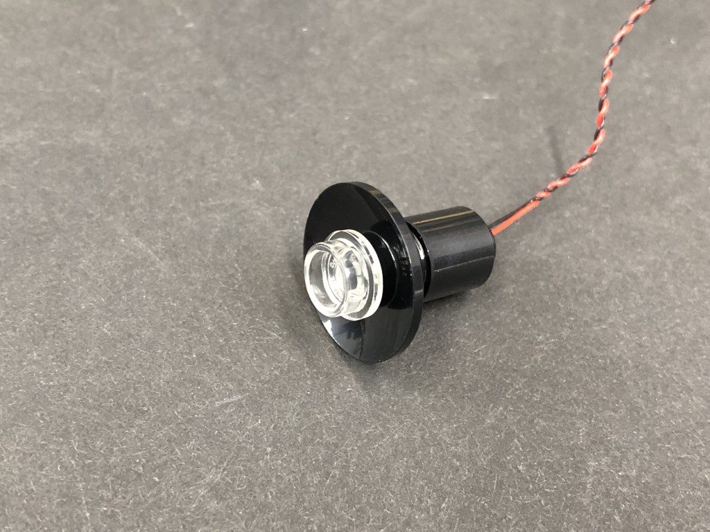
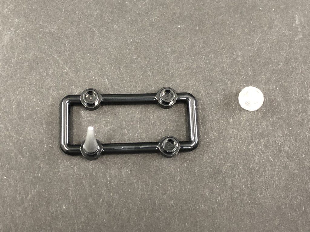
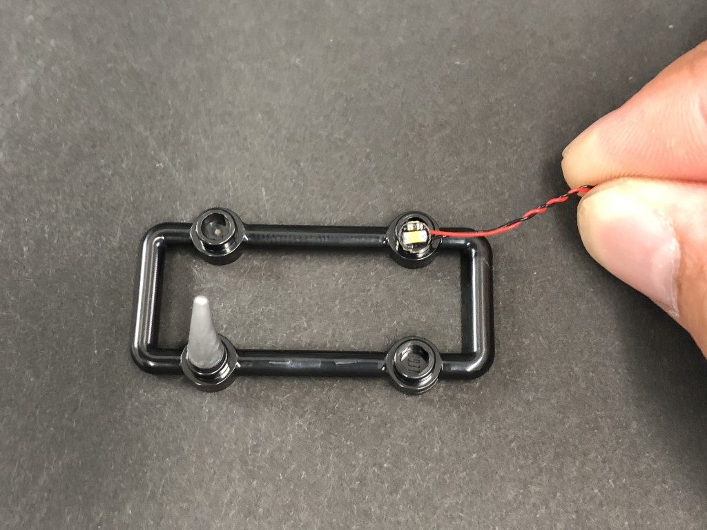
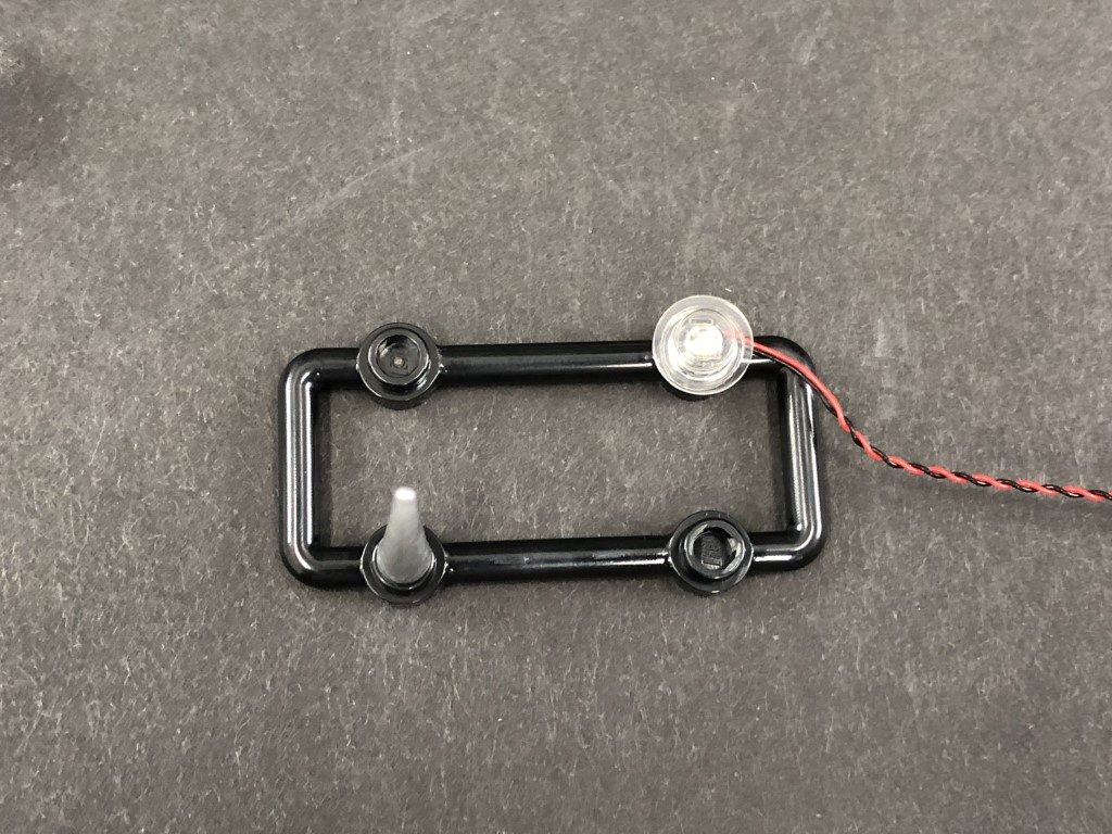
Take a White 30cm Bit Light and thread the connector side through the base (larger hole) of the Black 1×1 round brick. Thread it all the way through, then carefully bend the Bit Light on a 90 degree angle so that it is facing up and sitting flat against the edge of the base. Reconnect the black dish piece over the top.
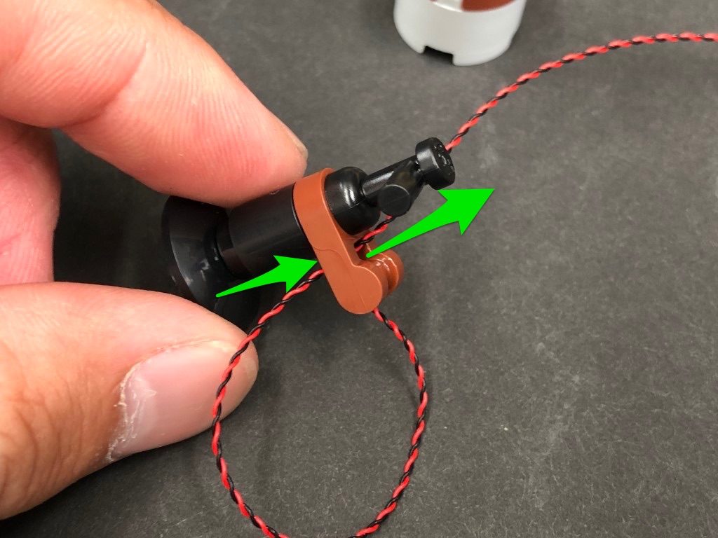
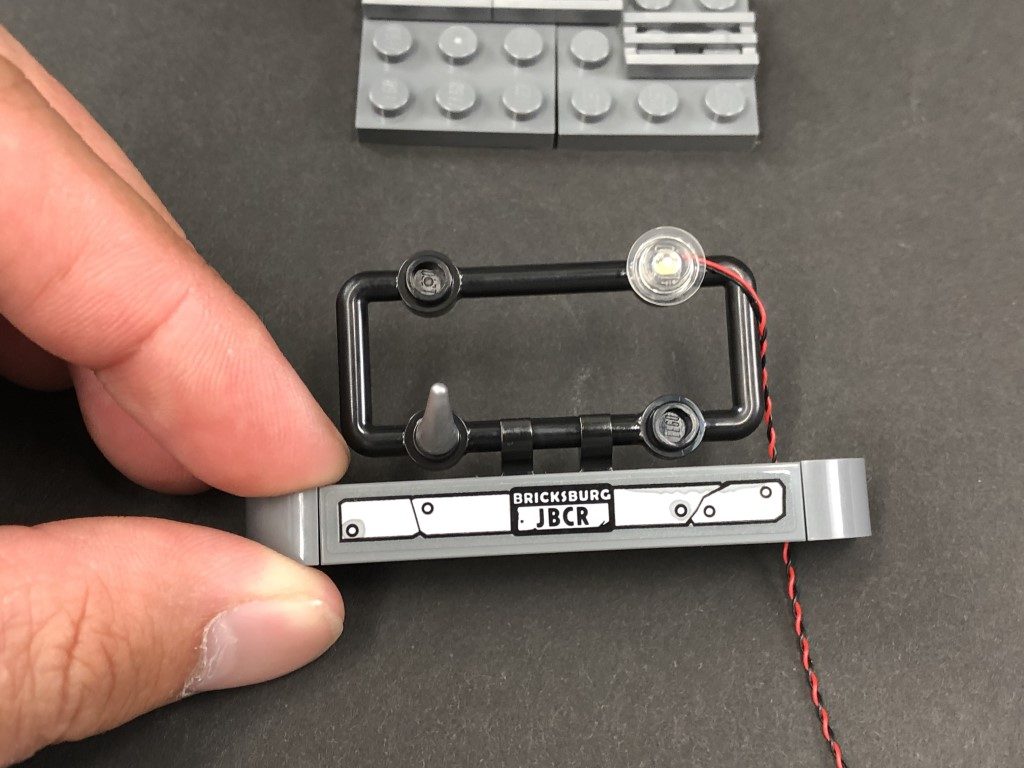
Reconnect the brown clip, then secure the cable by threading it through the front hole of the brown clip and pulling it all the way out from behind. Reconnect this section back to the set ensuring the cable is pulled down the left side, then tucked under the base (in between studs) and out the right side as shown below.
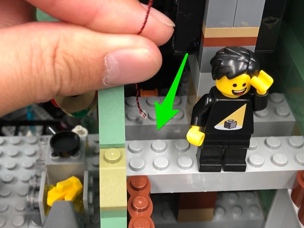
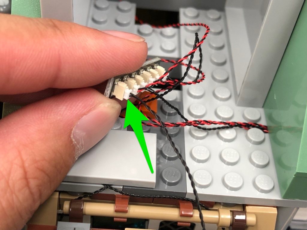
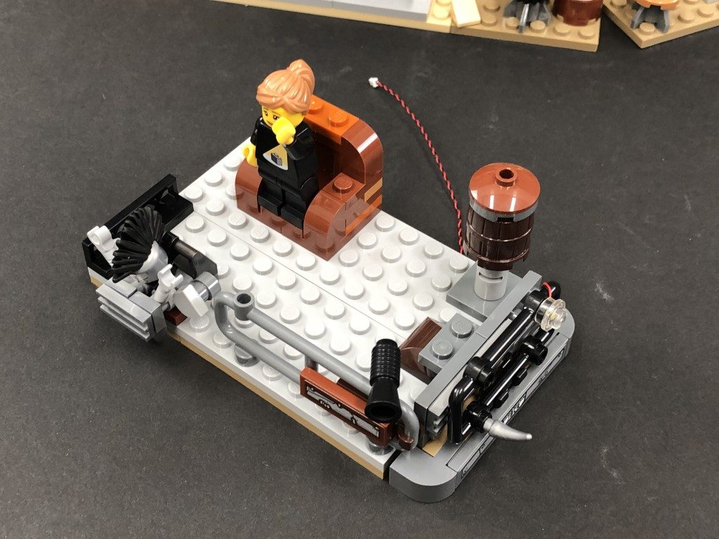
24.) Thread the Bit Light cable down the following space and pull it out from underneath to connect the the 6-port expansion board below.
Take a 30cm Connecting Cable and connect it to the remaining port on the 6-Port Expansion Board. Take the other end of the cable and thread it up the following space above then pull it all the way out.
Reconnect all the following sections we removed earlier ensuring all cables are laid in between studs before connecting bricks over the top.
Once all the sections are reconnected, turn ON the usb power bank to test all the lights are working OK.
Note: If you experience any issues with the lights not working and suspect an issue with a component, please try a different port on the expansion board to verify where the fault lies (with the light or expansion board). To correct any issues with expansion board ports, please view the section addressing expansion board issues on our online troubleshooting guide.
22.) Take a new 15cm Connecting Cable and connect it to the 6-port expansion board. Lay the other end of the cable toward the right then group the two flashing bit light cables together and lay all three cables down in between studs as shown below. Secure all three cables down by reconnecting the green 1×6 brick over the top, then reconnect the large angled brick.
23.) Disconnect the following section and disassemble it as per below.
Take a White 30cm Bit Light and thread the connector side through the base (larger hole) of the Black 1×1 round brick. Thread it all the way through, then carefully bend the Bit Light on a 90 degree angle so that it is facing up and sitting flat against the edge of the base. Reconnect the black dish piece over the top.
Reconnect the brown clip, then secure the cable by threading it through the front hole of the brown clip and pulling it all the way out from behind. Reconnect this section back to the set ensuring the cable is pulled down the left side, then tucked under the base (in between studs) and out the right side as shown below.
24.) Thread the Bit Light cable down the following space and pull it out from underneath to connect the the 6-port expansion board below.
Take a 30cm Connecting Cable and connect it to the remaining port on the 6-Port Expansion Board. Take the other end of the cable and thread it up the following space above then pull it all the way out.
Reconnect all the following sections we removed earlier ensuring all cables are laid in between studs before connecting bricks over the top.
Once all the sections are reconnected, turn ON the usb power bank to test all the lights are working OK.
 Note: If you experience any issues with the lights not working and suspect an issue with a component, please try a different port on the expansion board to verify where the fault lies (with the light or expansion board). To correct any issues with expansion board ports, please view the section addressing expansion board issues on our online troubleshooting guide.
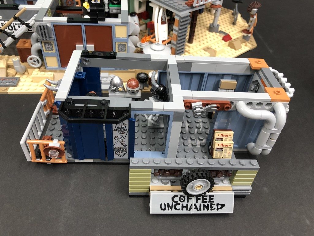
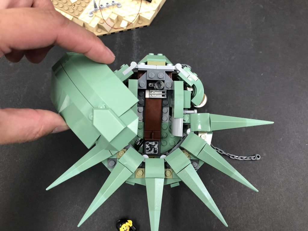
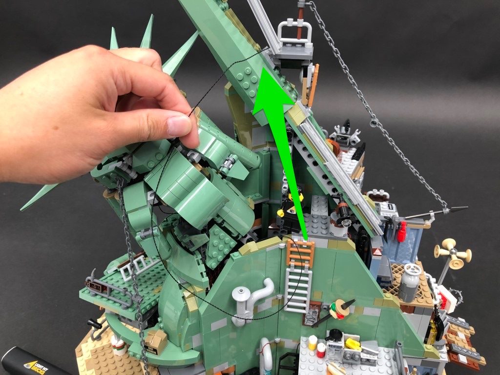
25.) Swing the set around to the front as we will now move onto lighting the second and third levels of the set. First, disconnect the third level as well as the roof off the second level. Turn the second level section over onto it’s back so we can access underneath it.
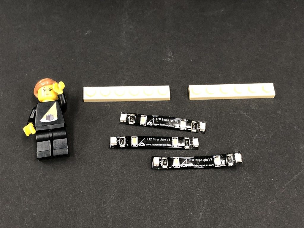
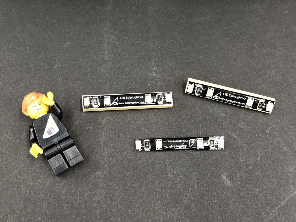
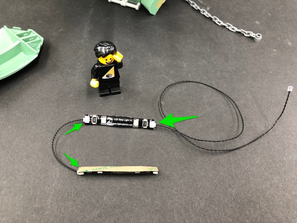
Take 3x White Strip Lights and stick 2 of 3 of them onto 2x provided LEGO Plate 1×6. Take a 15cm Connecting Cable and connect one end to one of the strip lights stuck to a lego plate. Connect the other end to the strip light without a lego plate. Take a 5cm Connecting Cable and connect one end to the strip light without the lego plate, then connect the other end to the the other strip light (stuck to a lego plate).
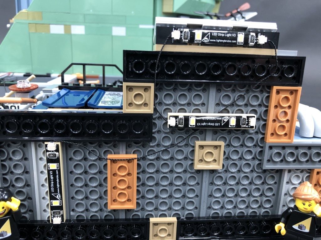
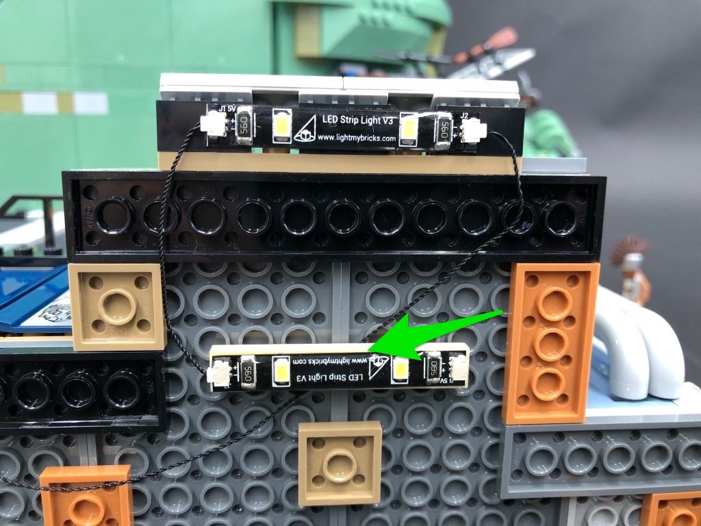
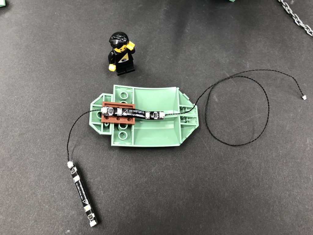
Mount the three strip lights underneath the second level section as shown below. Secure the 15cm connecting cable underneath the strip light with lego plate. This will prevent the cable from dangling down.
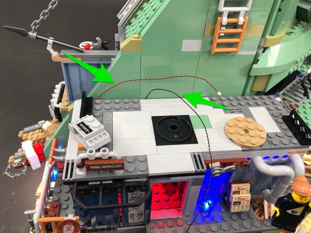
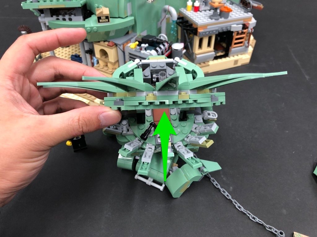
26.) Take a 30cm Connecting Cable and connect it to strip light on the right. Bring the cable down and secure it underneath the large black plate toward the bottom. Flip the second level back over and turn it to the back. Pull the cable all the way up then secure it underneath the light grey tile along the top.
27.) Turn the second level around to the front and disconnect the rail. Disassemble the lamp section from it as shown below:
Take a White 30cm Bit Light and place the led face down over the hole on top of the brown dish. Secure the Bit Light in place by reconnecting the light grey plate with clip over the top.
Reconnect the lamp back to the rail ensuring the cable is laid underneath the clip, then thread the cable around the rail as shown below then reconnect this section back to the second level ensuring the cable is laid toward the inside.
28.) Disconnect the light grey tile and black tile from the top of the level followed by the blue wall section. Bring the cable inside the room then reconnect the blue wall over the top (ensuring the cable is laid in between studs).
Bring the cable out toward the back of the room then lay it in between studs on the top before reconnecting the light grey tile. Reconnect the black tile.
Bring the 30cm Connecting Cable across toward the middle of the section and secure it underneath the following dark grey 1×4 tile.
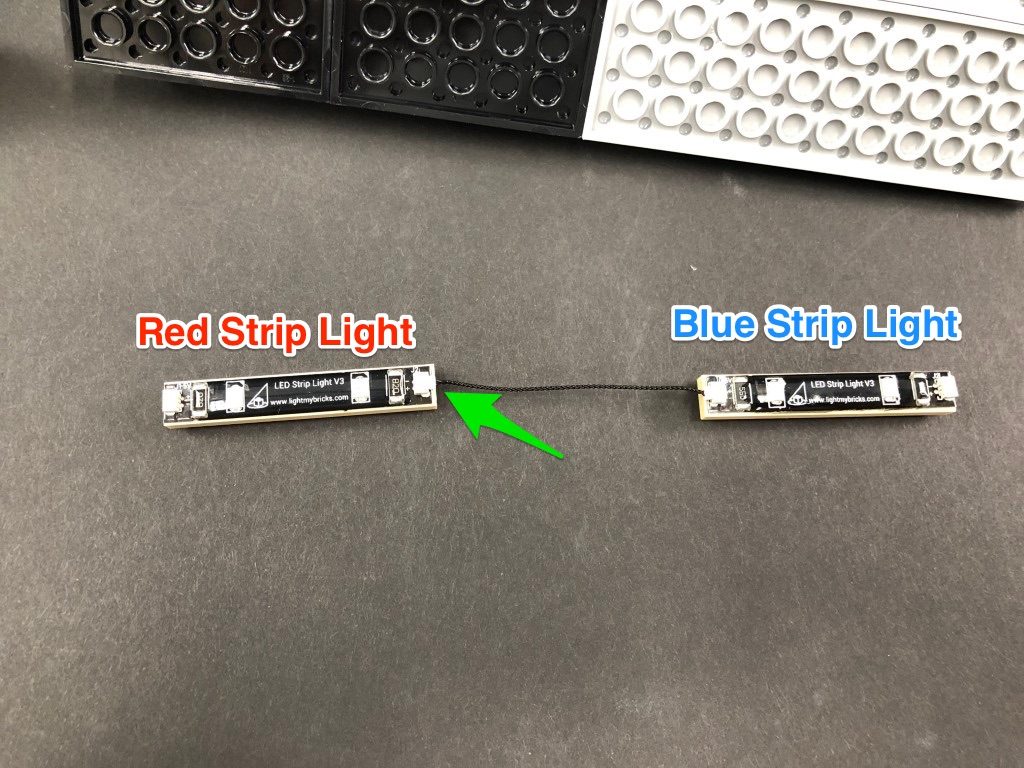
29.) Take the roof of the second level and turn it onto it’s back so we can access underneath. Take a Blue Strip Light and using it’s adhesive backing, stick it to the base of a provided LEGO Plate 1×6. Take a 5cm Connecting cable and connect it to the strip light’s left port.
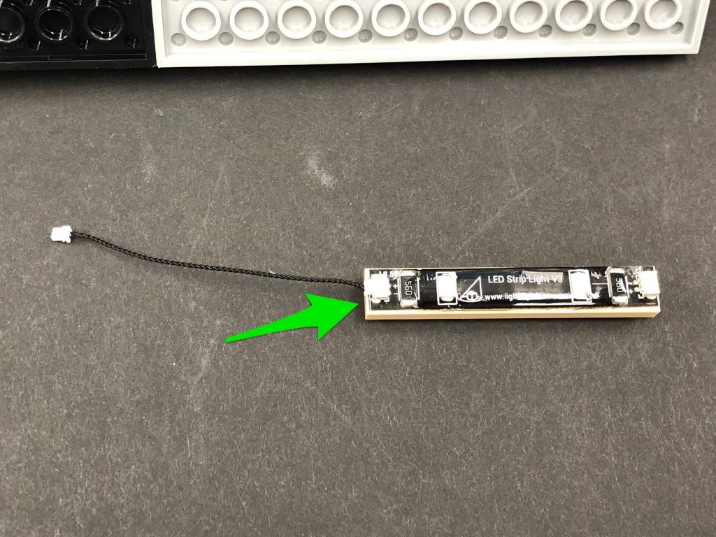
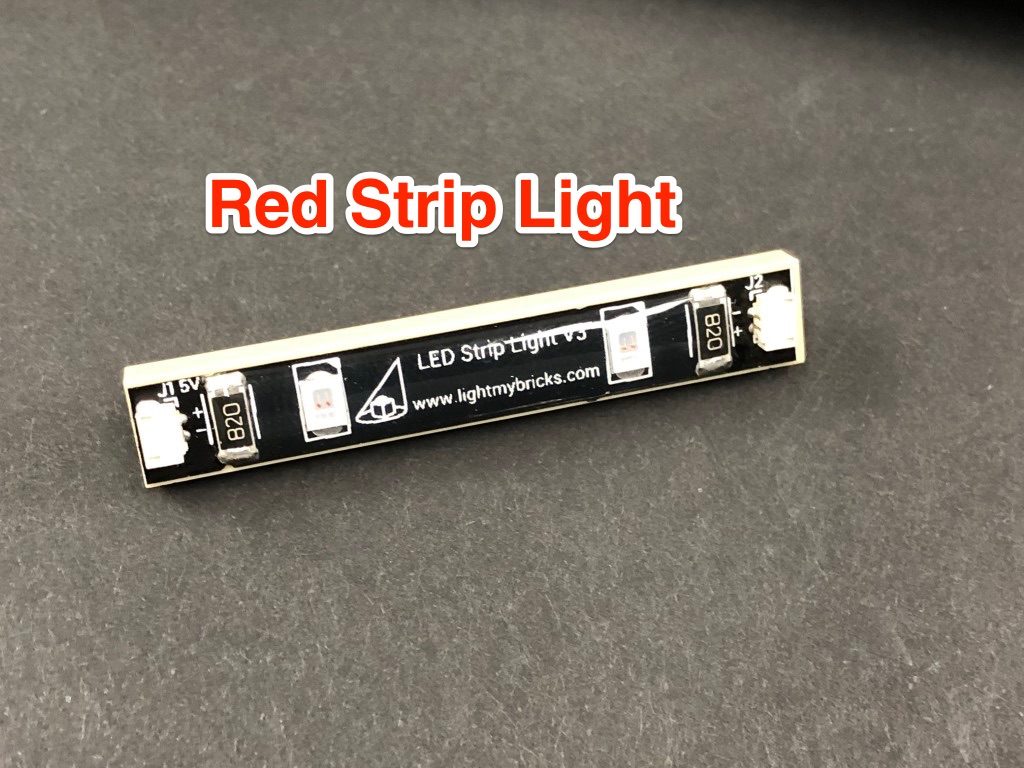
Take a Red Strip Light and using it’s adhesive backing, stick it to the base of a provided LEGO Plate 1×6. Connect the other end of the 5cm connecting cable to the red strip light’s right port then take a 30cm Connecting Cable and connect it to the left port.
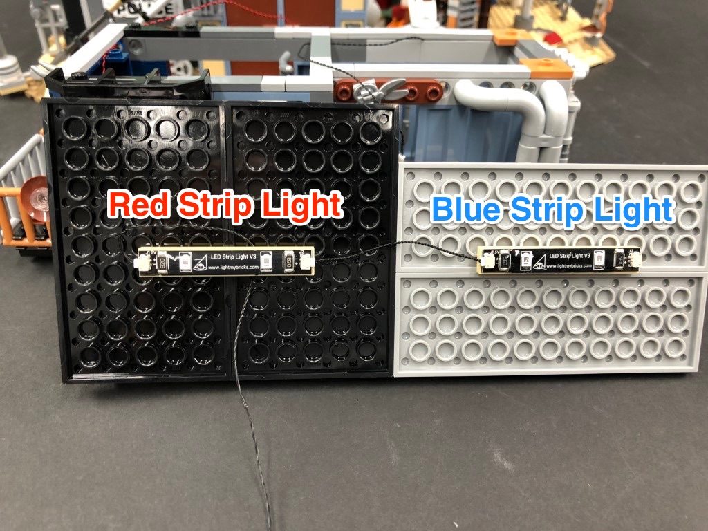
Mount both strip lights underneath the roof in the following positions. Ensure you loop the 30cm Connecting Cable underneath the red strip light as shown below.
30.) Bring the roof over the second level and connect the other end of the 30cm Connecting Cable below to the Blue Strip Light, then securely reconnect the roof.
Take the entire second level and bring it over the ground level. Locate the other end of the 15cm Connecting Cable from below and connect it to the Red Strip Light, then securely reconnect the second level on top. Ensure the other end of the 30cm Connecting Cable and Bit Light are pulled out and accessible.
Turn your USB Power Bank ON to test all the lights we have installed so far are working OK.
31.) Take the roof off the top level, then disconnect the lamp section and disassemble it as shown below:
Take a White 15cm Bit Light and place the led face down over the hole on top of the brown dish. Secure the Bit Light in place by reconnecting the light grey plate with clip over the top.
Reconnect the lamp section back to the pole, then reconnect it back to the top level ensuring the cable is facing inside the building. Secure the cable underneath the dark grey tile on top ensuring the cable is laid in between studs, then connect it to a new 6-Port Expansion Board. Securely reconnect the top level on top of the second level.
32.) Locate the other end of the Bit Light cable and 30cm Connecting Cable from below and connect them to the next available ports on the 6-port expansion board. Using 2x Adhesive Squares, mount the expansion board to the inside of the top floor in the below position.
Secure all the excess cables underneath the tiles along the top of the level then turn ON the USB Power Bank to test the lights are working OK.
Note: If you experience any issues with the lights not working and suspect an issue with a component, please try a different port on the expansion board to verify where the fault lies (with the light or expansion board). To correct any issues with expansion board ports, please view the section addressing expansion board issues on our online troubleshooting guide.
33.) Take the roof of the top floor and disconnect and disassemble the following section on the right.
Disconnect the trans clear round plate from the rail, then take a Flashing White 15cm Bit Light and with the cable facing the right, place it over the top left black stud. Secure the Bit Light in place by reconnecting the trans clear round plate over the top.
Bring the cable down, then reconnect the rail back to the clip ensuring the cable is laid behind. Reconnect everything back to the roof.
34.) Take a White Strip Light and using it’s adhesive backing, stick it to the base of the remaining provided LEGO Plate 1×6. Take a 5cm Connecting Cable and connect it to one side then connect the other side to the 6-port expansion board inside the top level.
Bring the roof over the top level and connect the other end of the flashing white 15cm bit light to the expansion board. Mount the strip light underneath the roof in the below position ensuring you connect the 1×6 plate over the flashing bit light cable.
Securely reconnect the roof then turn ON the USB Power Bank to test all the lights are working OK.
Note: If you experience any issues with the lights not working and suspect an issue with a component, please try a different port on the expansion board to verify where the fault lies (with the light or expansion board). To correct any issues with expansion board ports, please view the section addressing expansion board issues on our online troubleshooting guide.
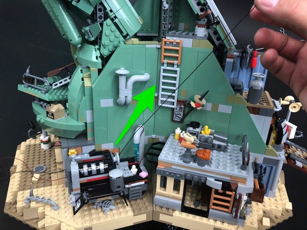
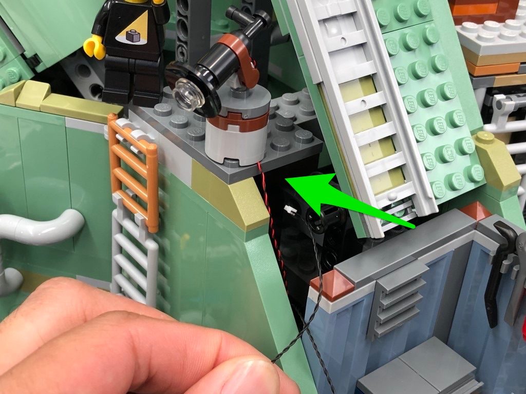
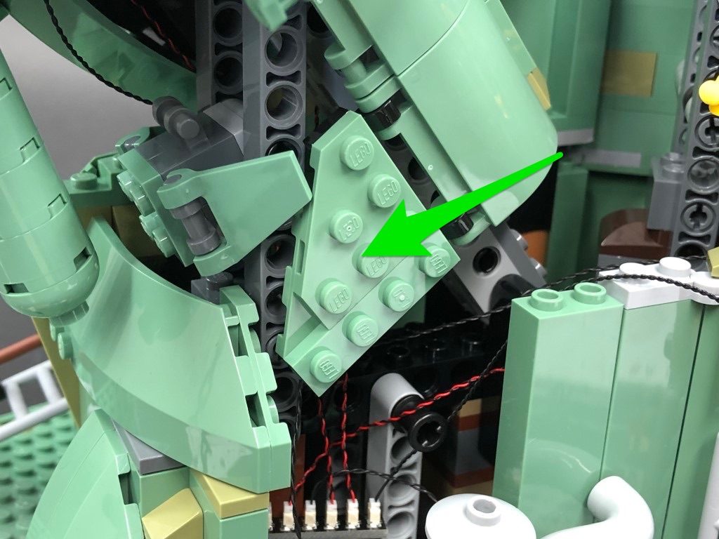
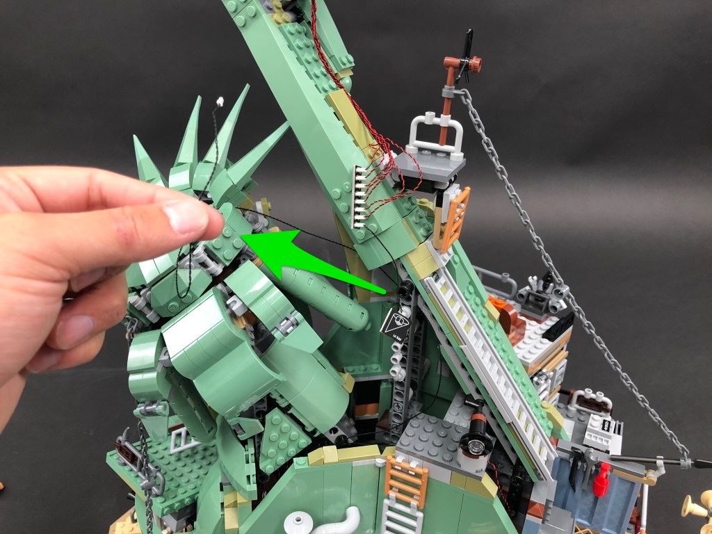
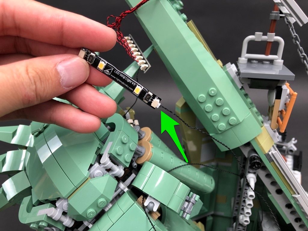
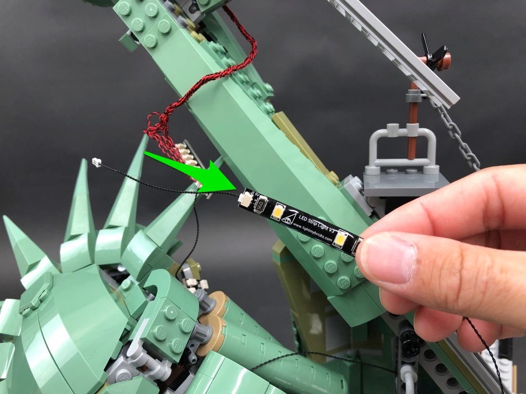
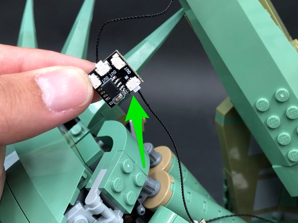
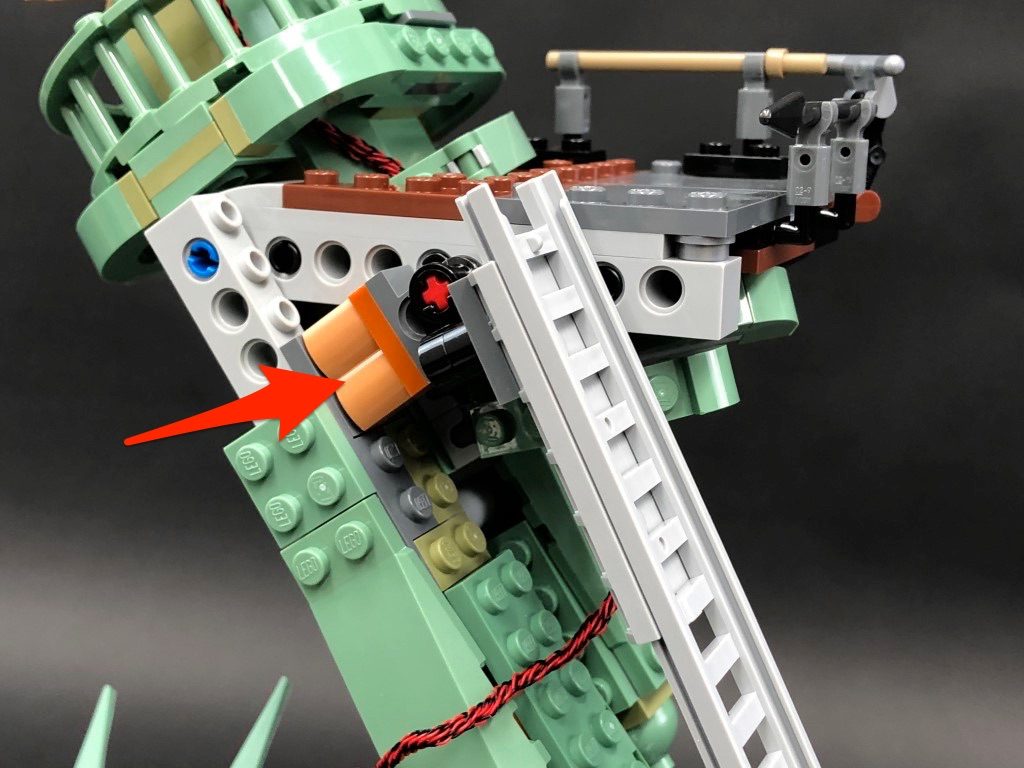
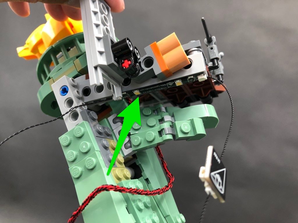
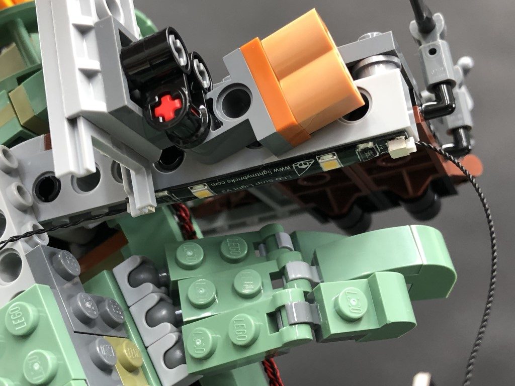
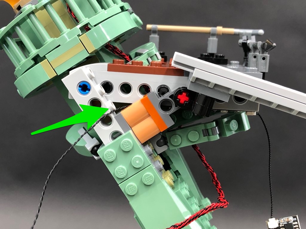
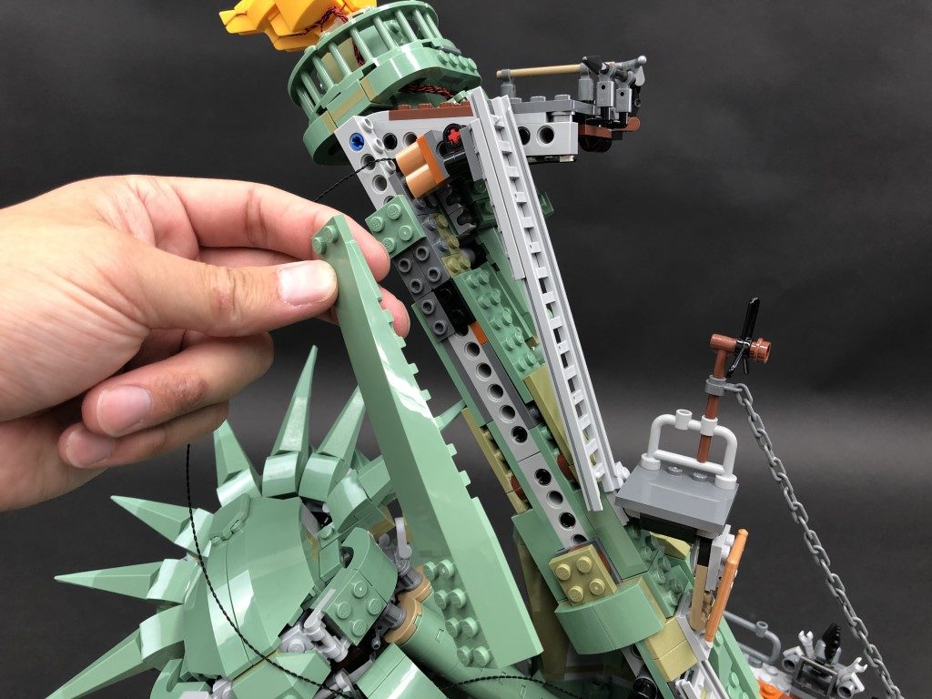
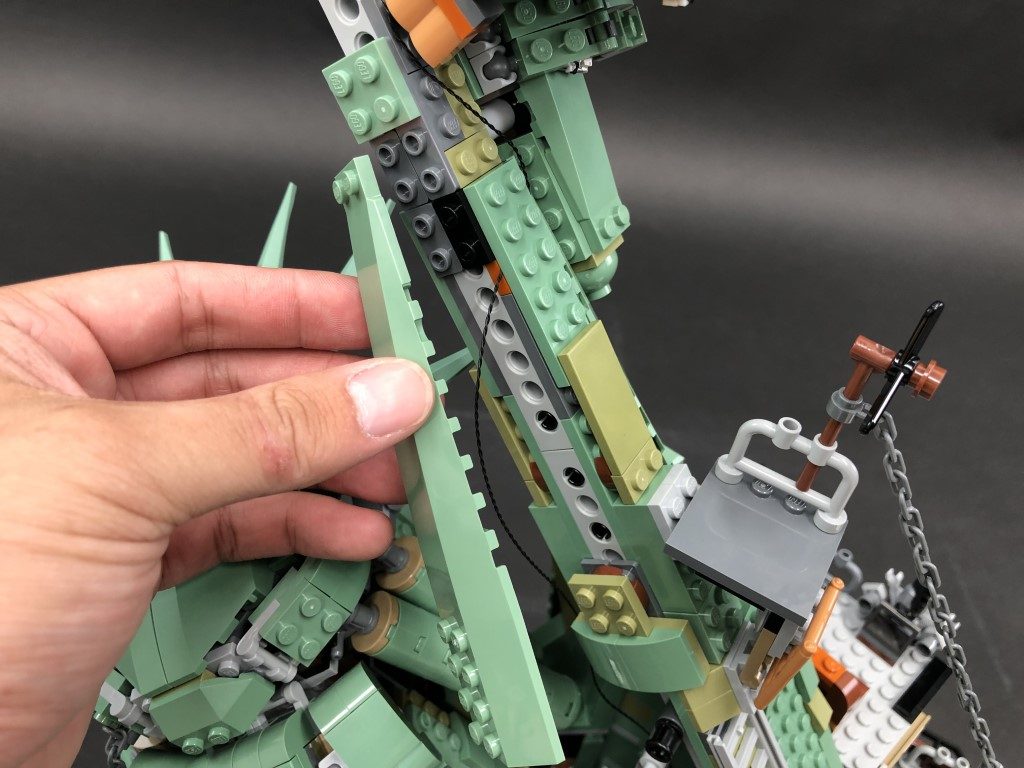
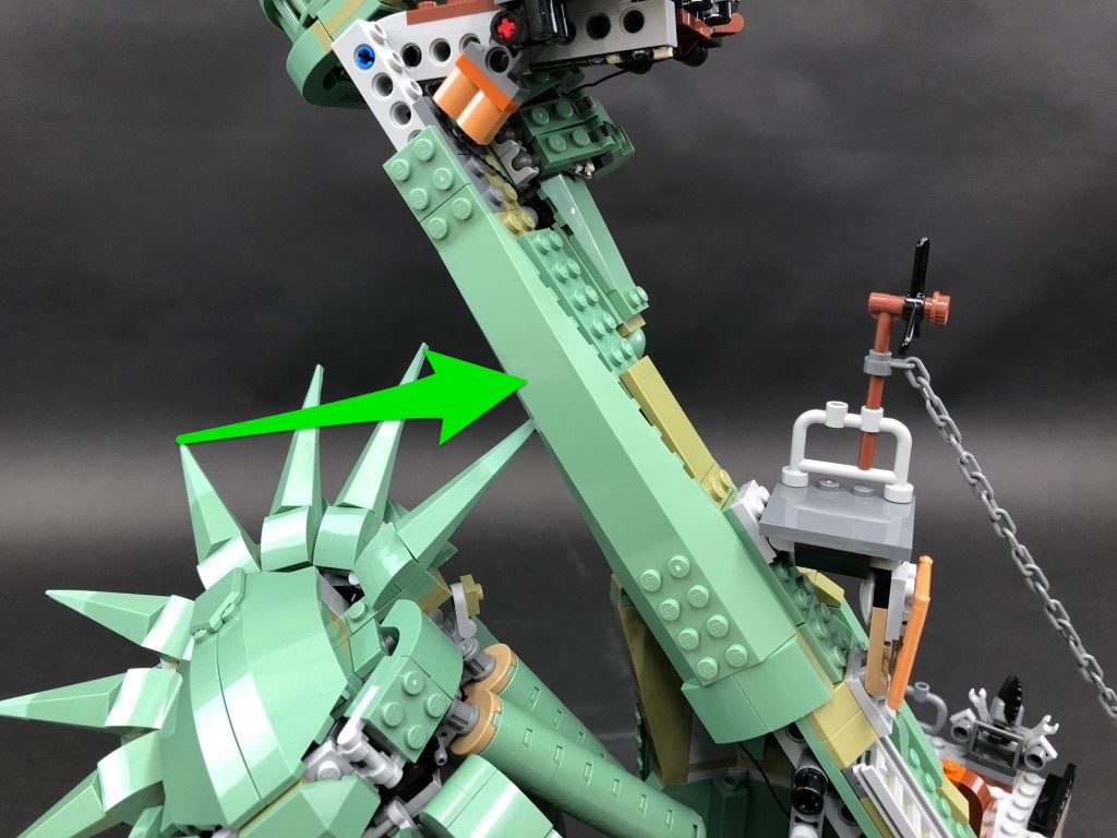
35.) Turn the set around to the back and locate the other end of the 30cm Connecting Cable from step 24. Thread the cable through the following space behind and pull it out from the other side. Disconnect the following section made up of the green angled brick, then connect the cable to a new 6-Port Expansion Board.
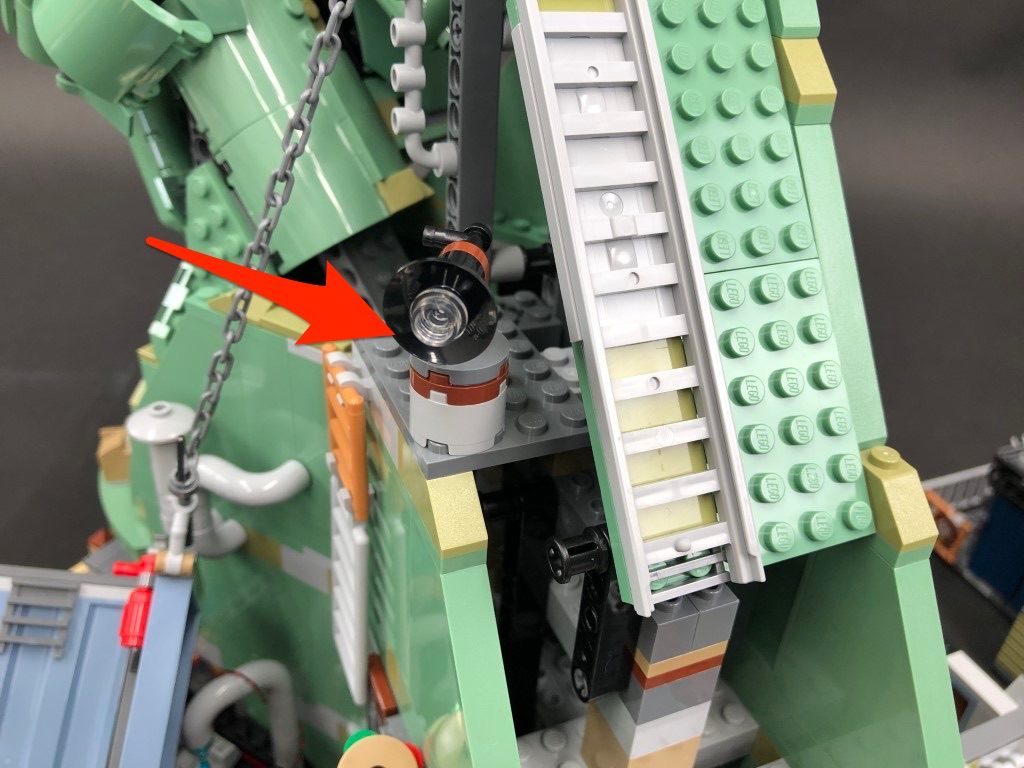
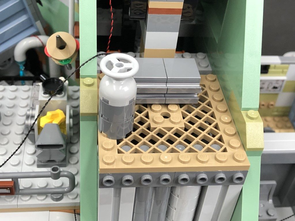
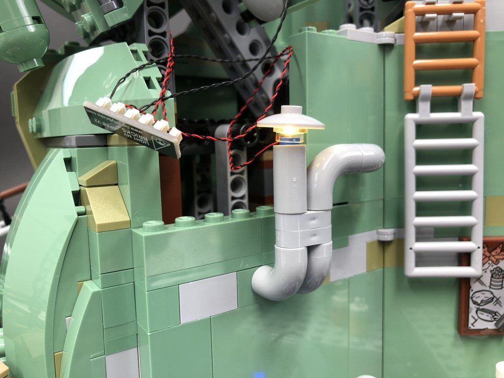
36.) We will now install a light to the top of the pipe nearby. Disconnect this section then disassemble as per below:
Replace the silver round plate 1×1 with a provided Trans Clear Round Plate 1×1 then take a White 15cm Bit Light and with the cable facing behind, place it over the top of the pipe. Secure it in place by reconnecting the dish and trans clear round plate over the top, then connect the bit light to the 6-port Expansion Board behind.
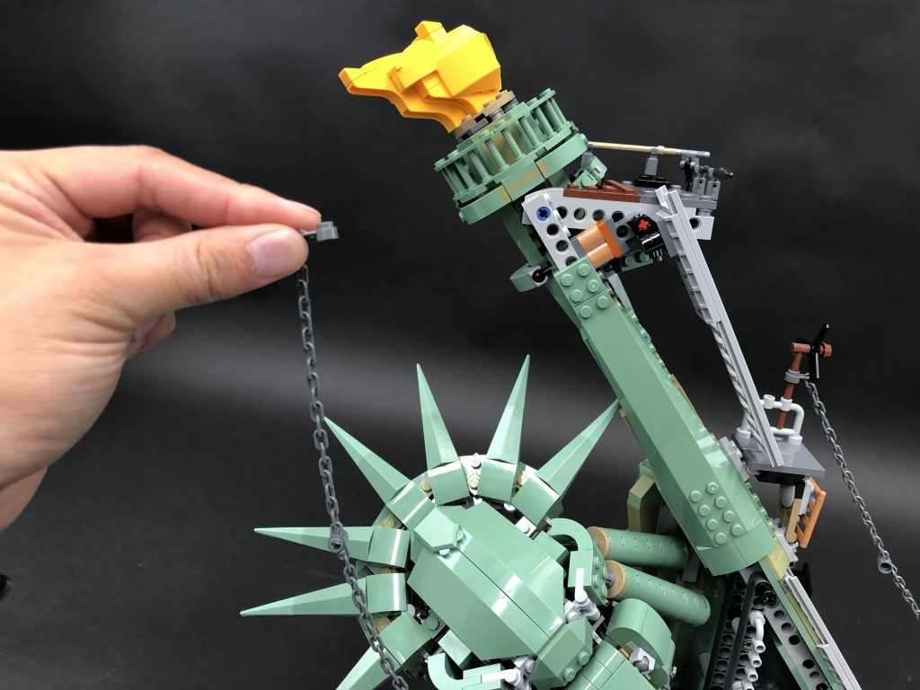
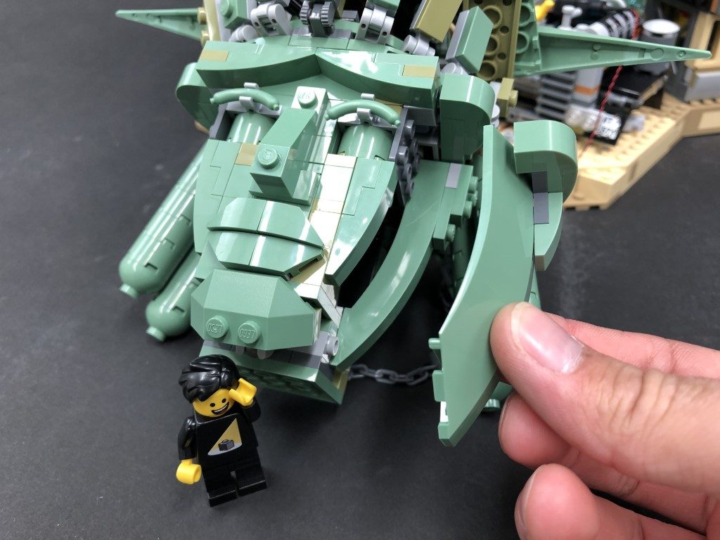
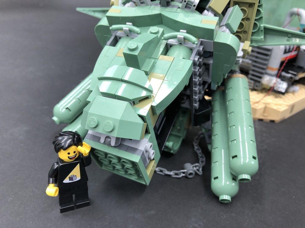
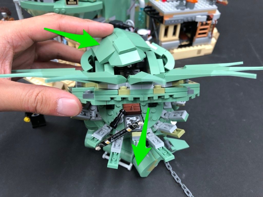
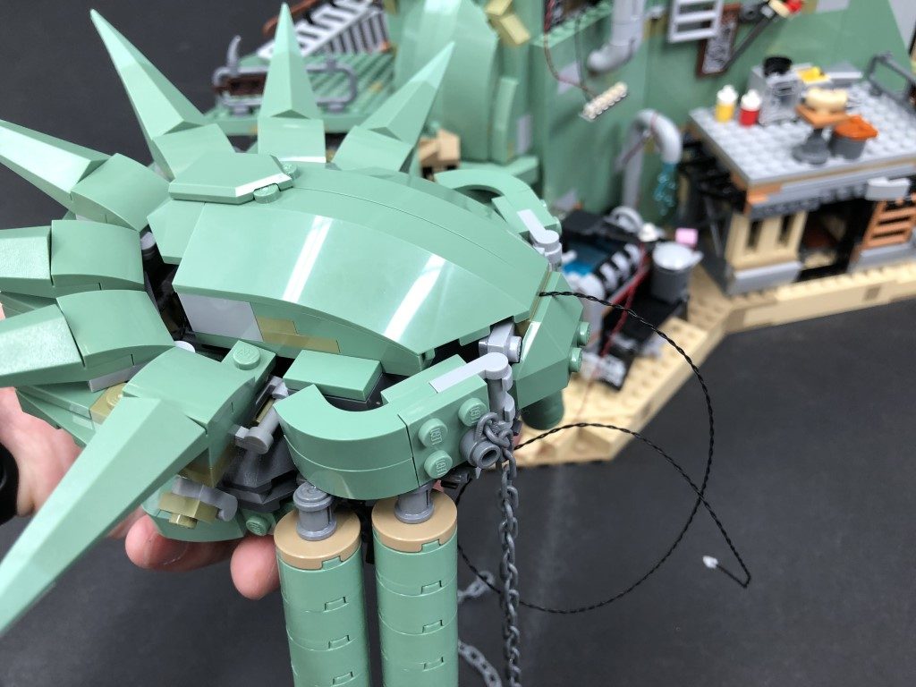
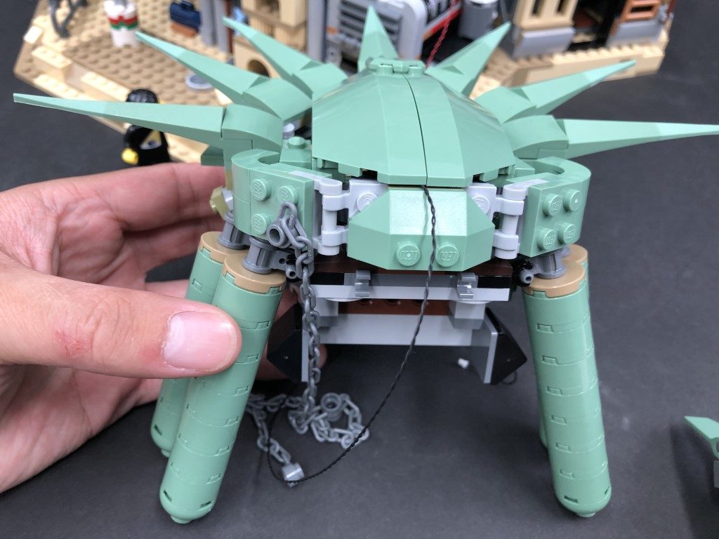
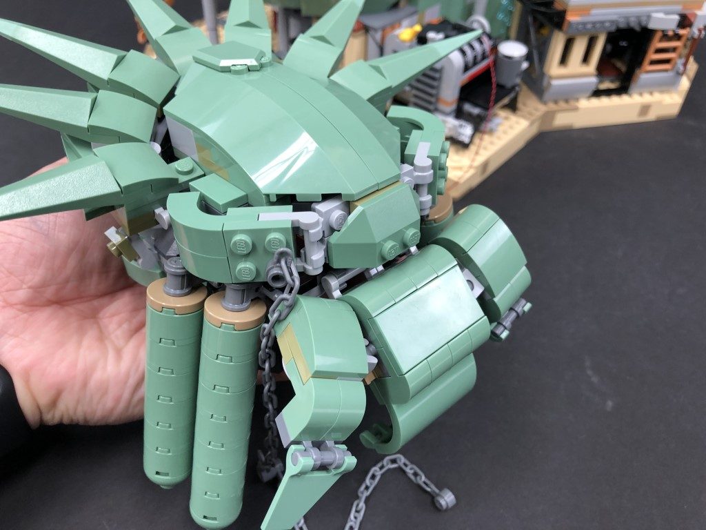
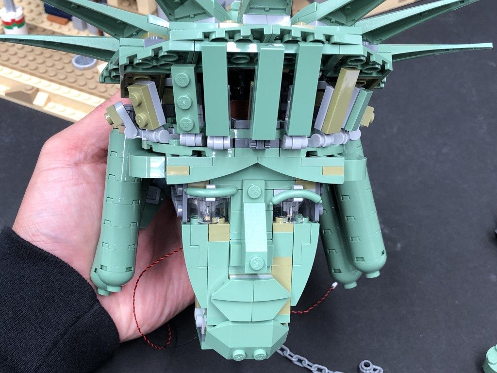
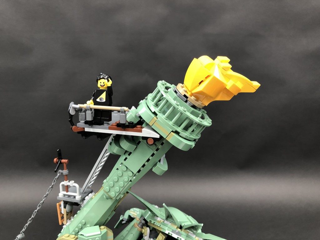
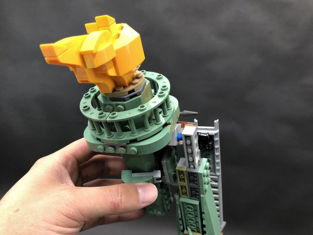
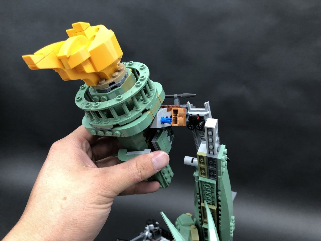
37.) Disconnect the chains connecting the torch and the liberty crown, then lift up the back section of the head to allow us to disconnect the head section.
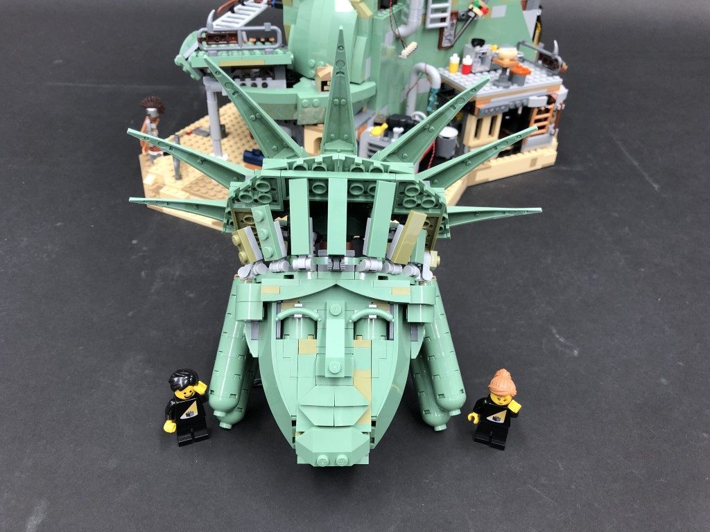
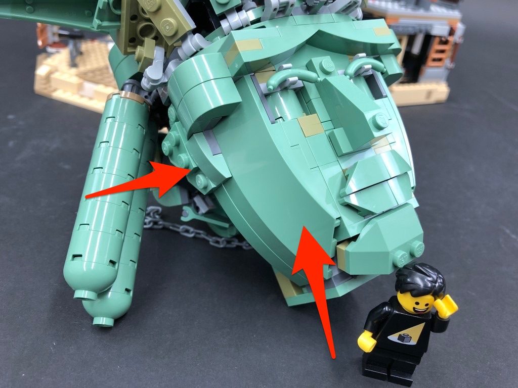
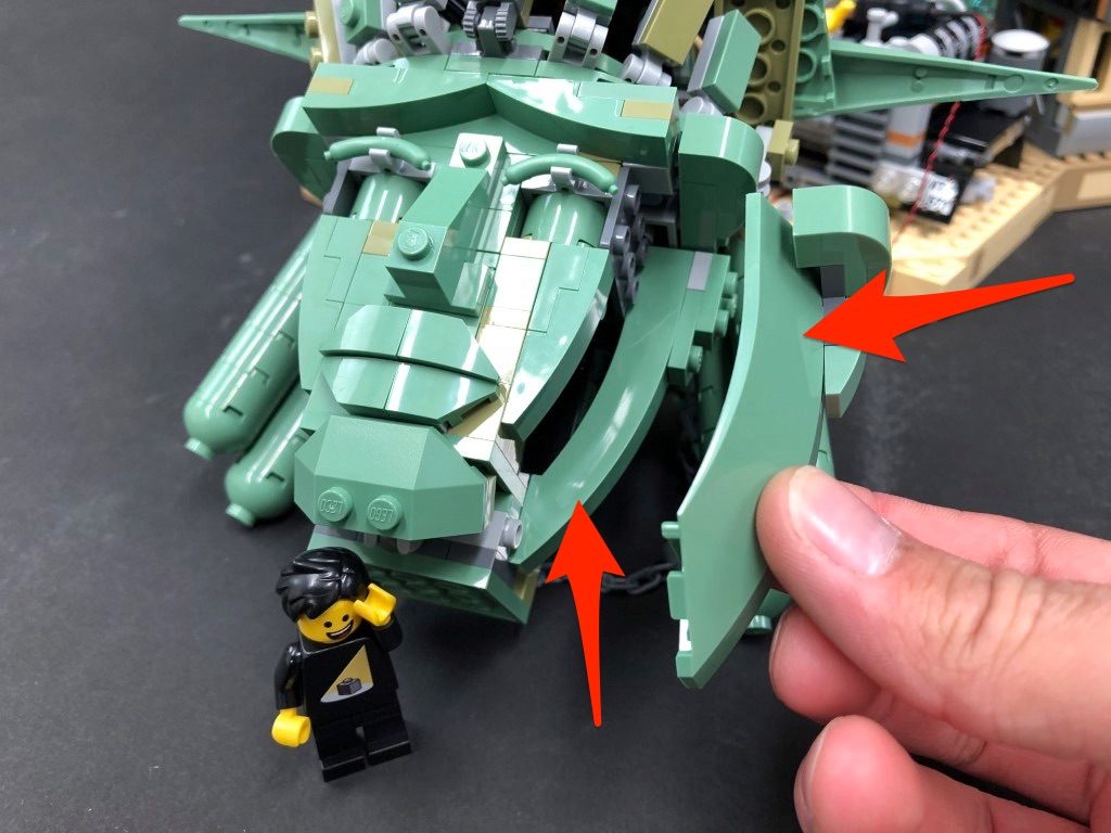
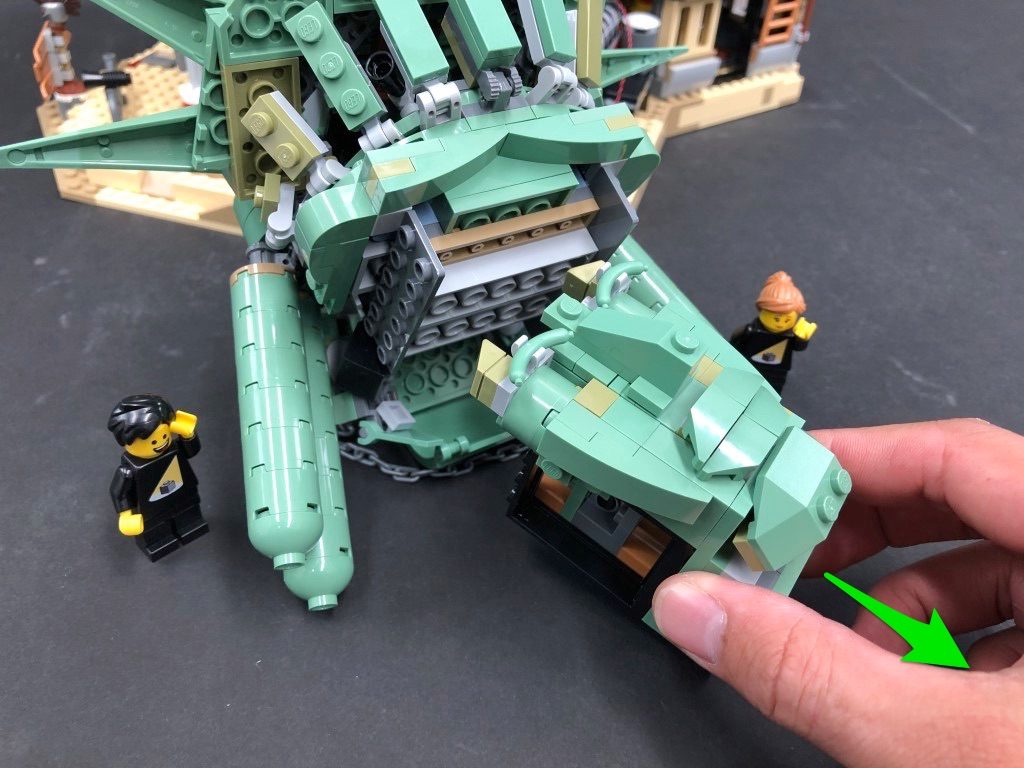
Disconnect the two sections from each side of the face as well as the back section, then disconnect the face section as shown below:
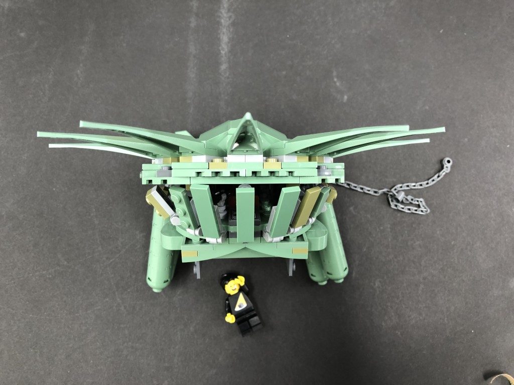
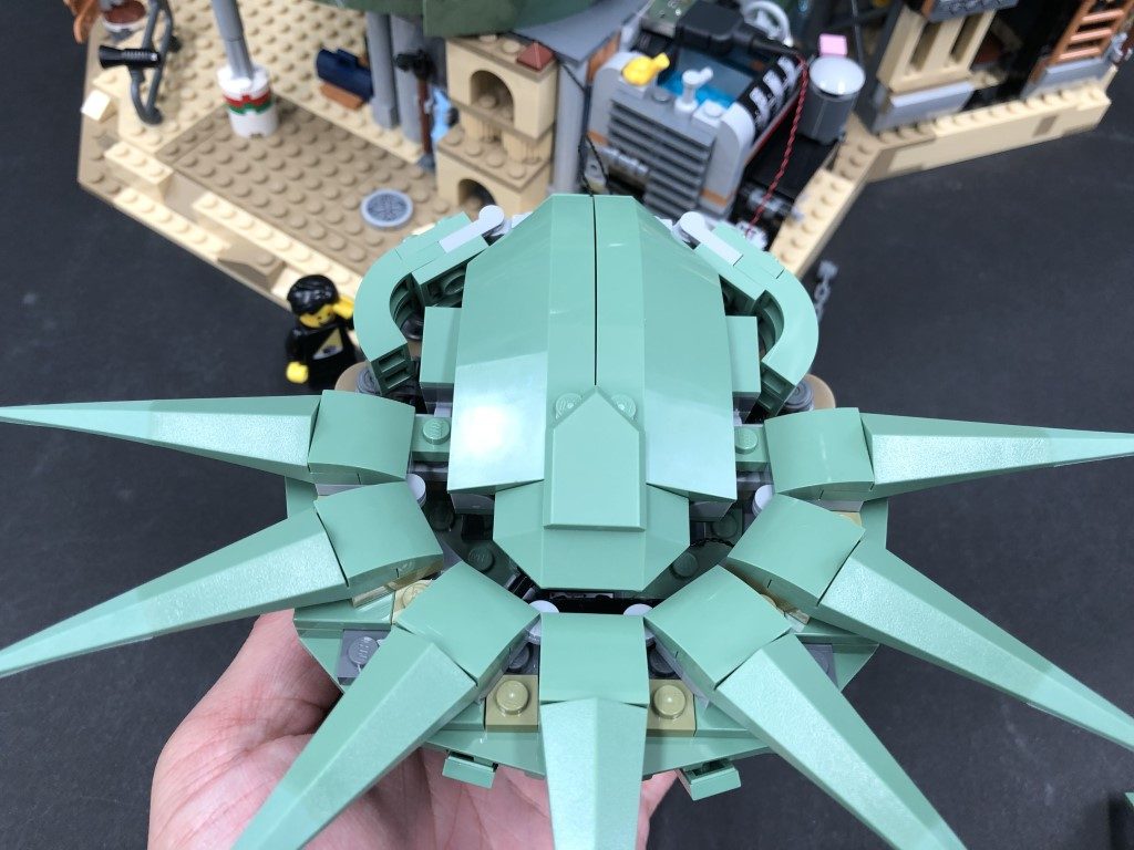
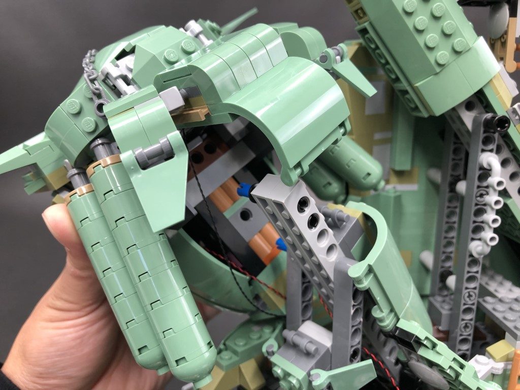
38.) Disconnect the very top section of the crown then flip this section we removed over so we can access underneath it.
Take out 2x White Strip Lights, a 30cm Connecting Cable and a 5cm Connecting Cable. Connect the two strip lights together using the 5cm connecting cable then connect the 30cm connecting cable to one of the strip light’s other port.
Using it’s adhesive backing, stick the second strip light underneath the crown’s top section as shown below. Ensure the 30cm cable is facing the back.
Lift up the bottom section of the liberty crown and fold down the individual bars underneath. Take the top part of the crown above and thread the first strip light through to the front to allow us to stick it underneath the bottom section as shown below:
39.) Push back down the bottom crown section and fold up the bars underneath, then securely reconnect the top ensuring the other end of the 30cm Connecting Cable is laid out behind. Secure the 30cm Connecting Cable underneath the following brick that connects to the back.
Reconnect the back section.
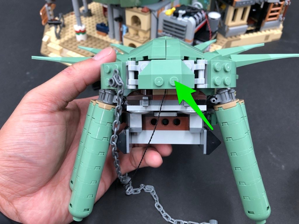
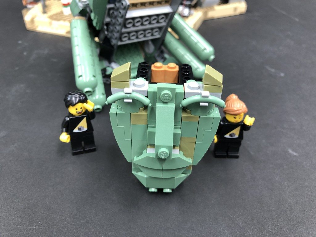
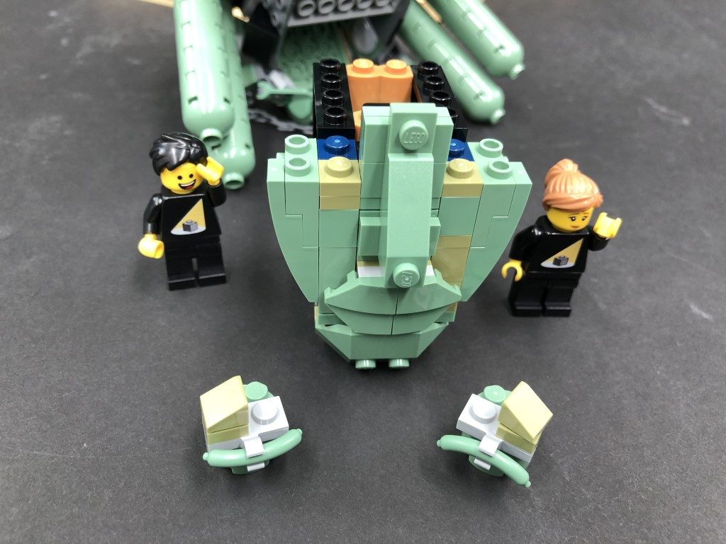
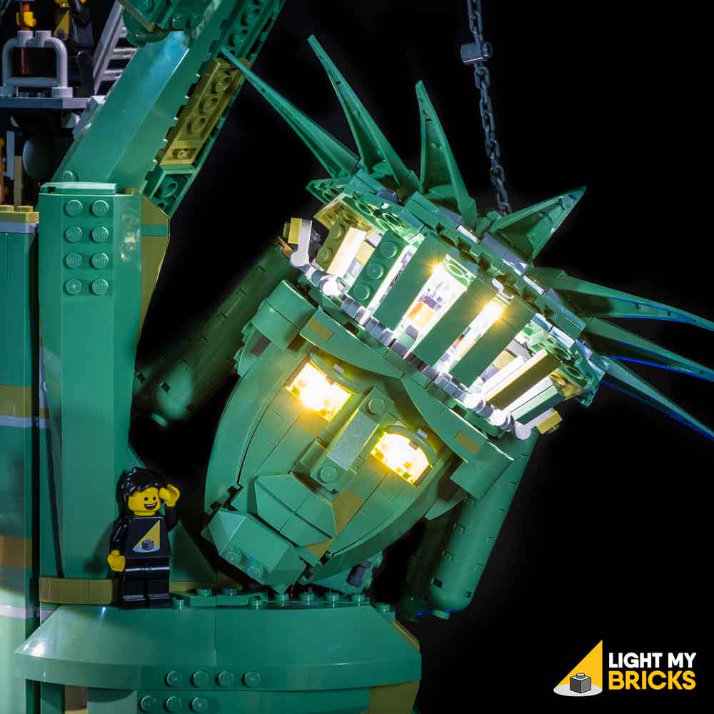
40.) Disconnect the two eye sections from the face then remove and discard the green round 2×2 bricks. Replace them with the provided Trans Clear Round Brick 2×2 and connect the eyebrow sections over them.
Take a White 15cm Bit Light and with the cable facing behind, place it in the centre of the four studs underneath the left eye section. Secure the Bit Light in place by reconnecting the left eye section over the top, ensuring the Bit Light is fitted underneath the hole of the trans clear brick.
Repeat this process to install another White 15cm Bit Light to the right eye section
41.) Reconnect the face back to the head section, then reconnect the two pieces back to each side of the face.
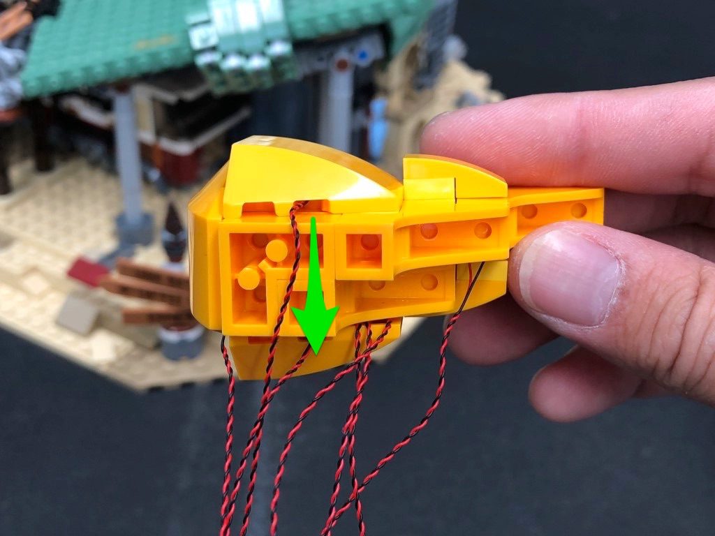
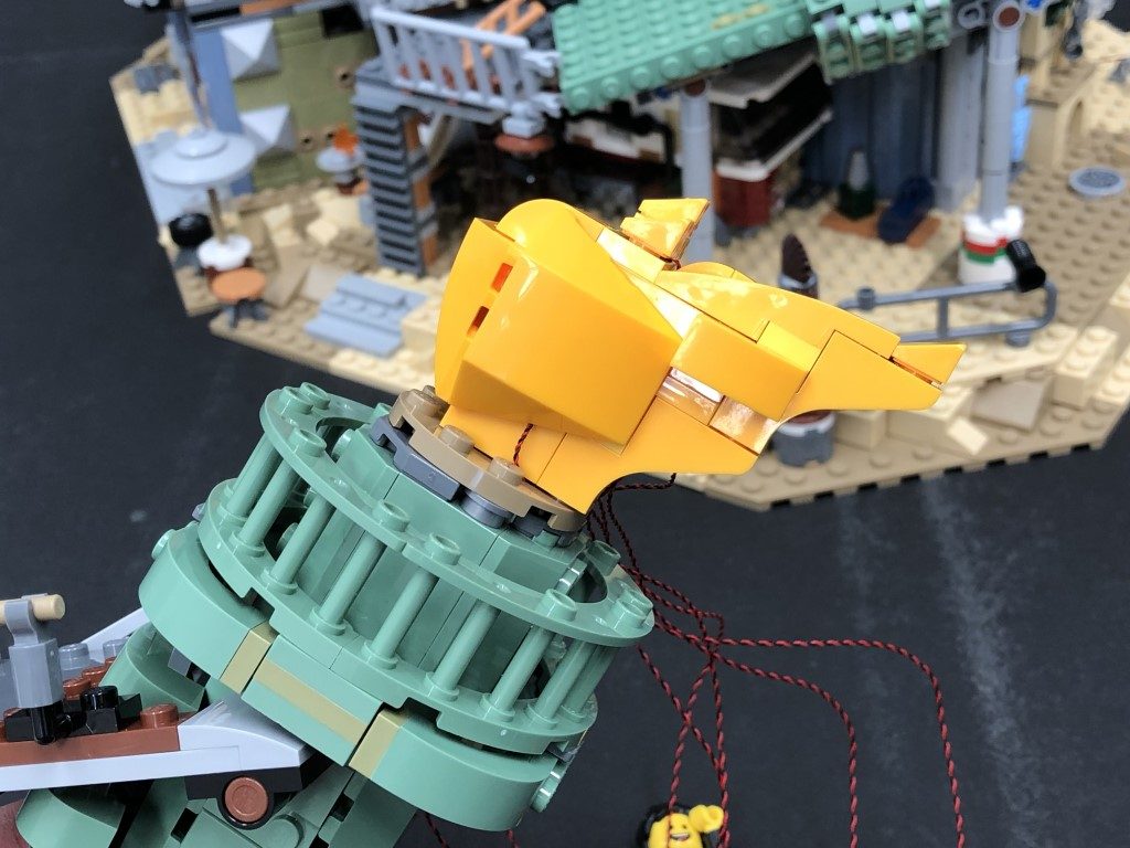
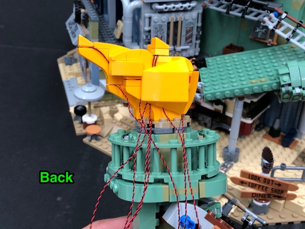
Lift up the following piece, then bring the head section up and thread the two bit light cables as well as the 30cm cable through the front and out the back as per below, then securely reconnect the head section.
Take all three cables and connect them to the 6-port expansion board below. Turn ON the USB Power Bank to test all the lights are working OK.
Note: If you experience any issues with the lights not working and suspect an issue with a component, please try a different port on the expansion board to verify where the fault lies (with the light or expansion board). To correct any issues with expansion board ports, please view the section addressing expansion board issues on our online troubleshooting guide.
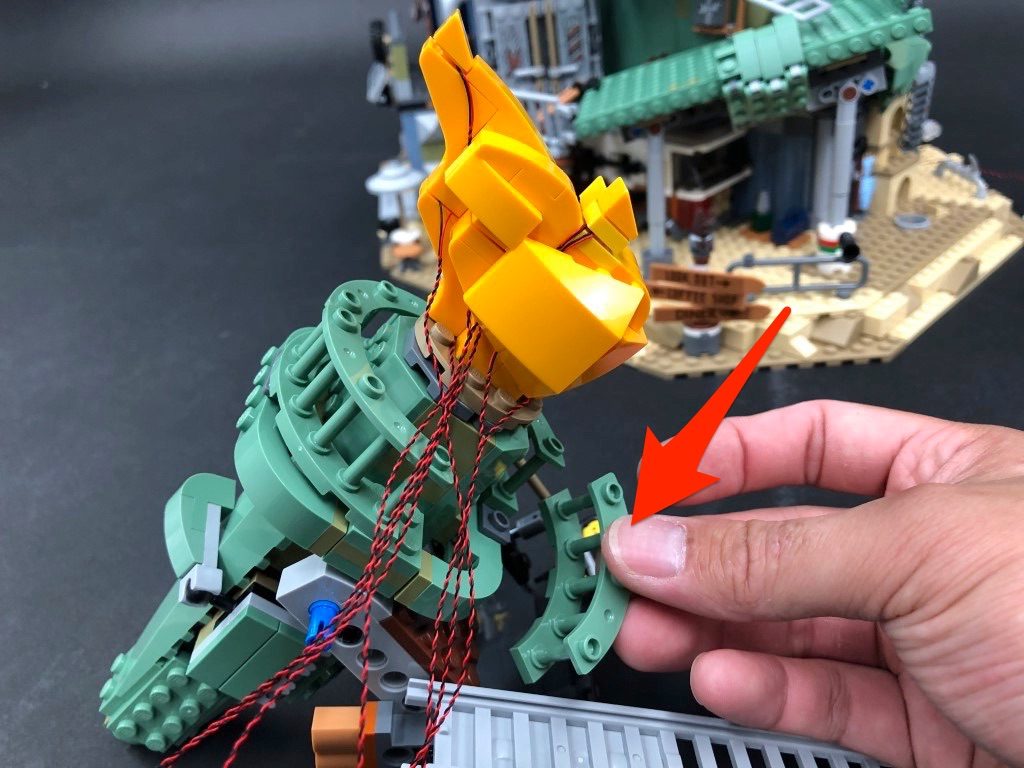
42.) Take a 50cm Connecting Cable and connect it to the 6-Port Expansion Board. Tuck all the components in (except for the 50cm cable) then close the flap and reconnect the wall section we removed earlier. Ensure the cable from the pipe light is laid in between studs underneath.
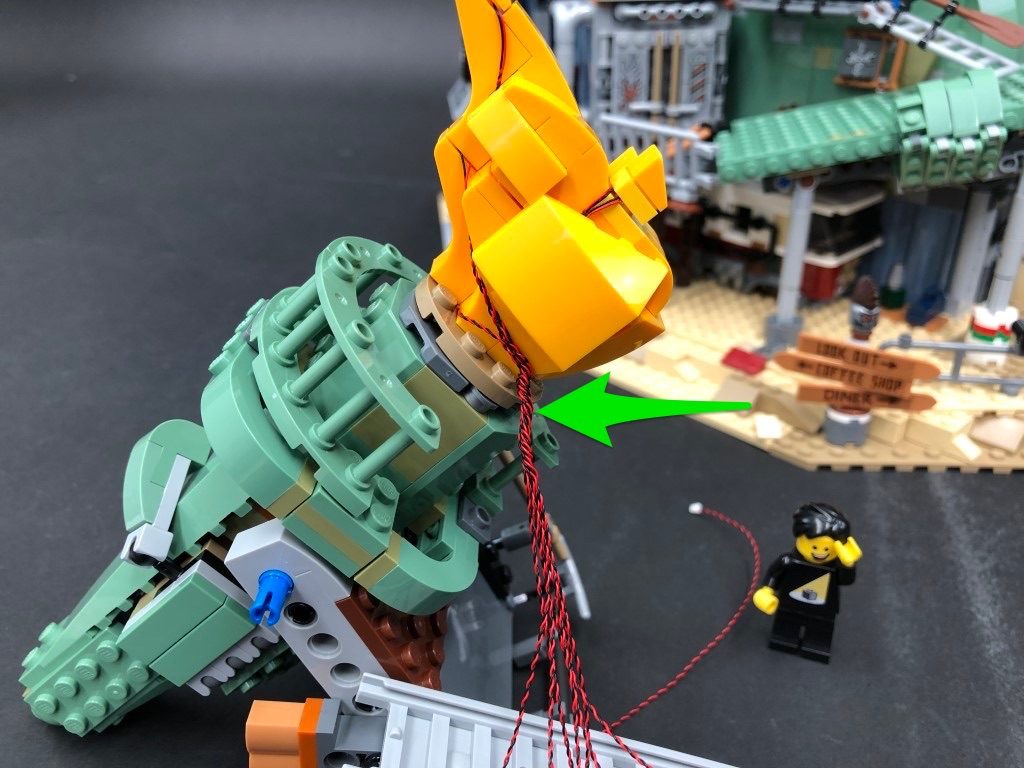
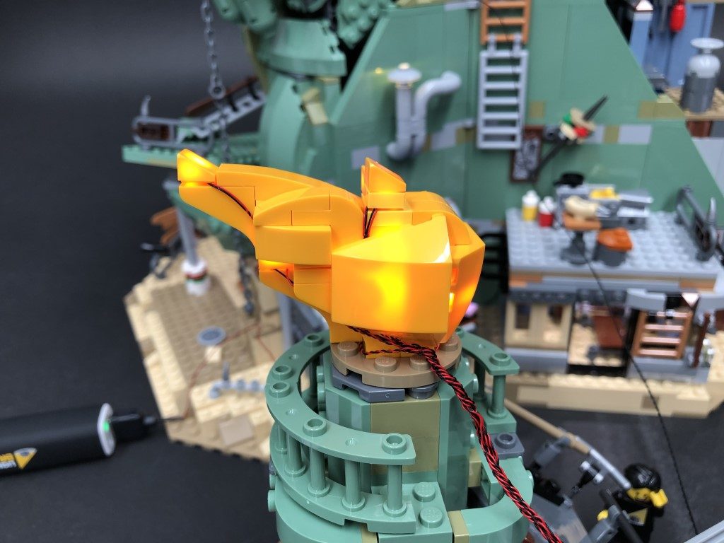
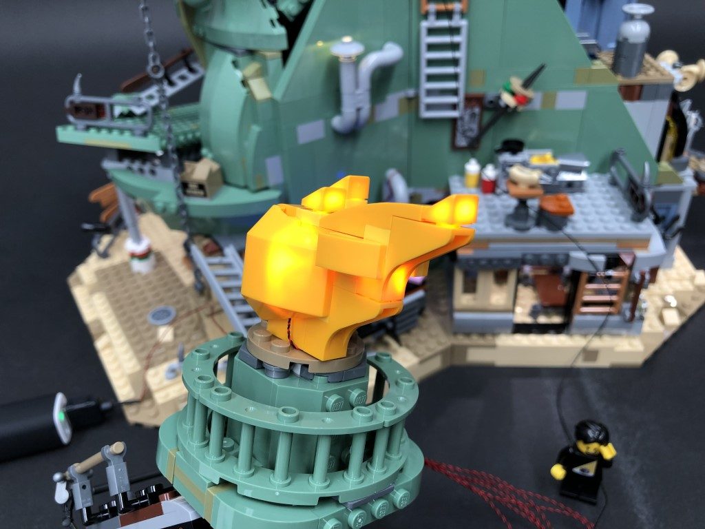
43.) We will now light up the statue of liberty torch. First disconnect the torch by pulling it out from the front, then disconnect and dissemble the flame section as shown below:
44.) Take a White 30cm Bit Light and with the cable facing the right (facing back of the flame), place it over the stud as per below. Secure it in place by reconnecting the section over the top.
Take another White 30cm Bit Light and with the cable facing the right (facing back of the flame), place it over the top stud. Secure it in place by reconnecting the angled tile over the top.
Turn the flame section around and disconnect the following pieces. Lay the cable from the second bit light down in between studs, then reconnect the pieces over the top to hide the cable.
45.) Take another 2x White 30cm Bit Lights and install them to the next studs to the right. Secure them in place by reconnecting the angled tiles over the top.
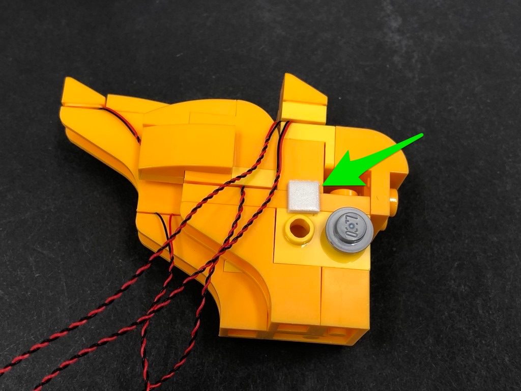
46.) Take an Adhesive Square and stick it to the following position. Take another White 30cm Bit Light and stick it down onto the adhesive square as shown below, then reconnect the large piece over the top.
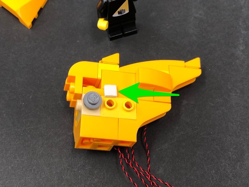
Flip the flame section over and using the same method as above, install another White 30cm Bit Light using another Adhesive Square.
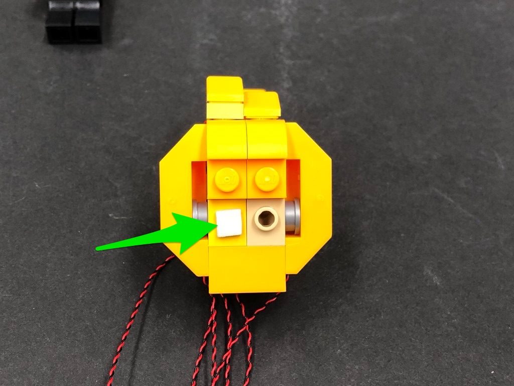
Repeat this step again, to install the remaining White 30cm Bit Light to the middle using another Adhesive Square.
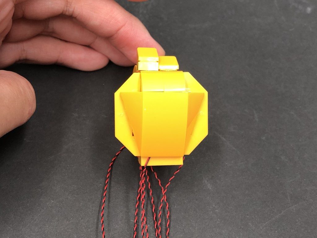
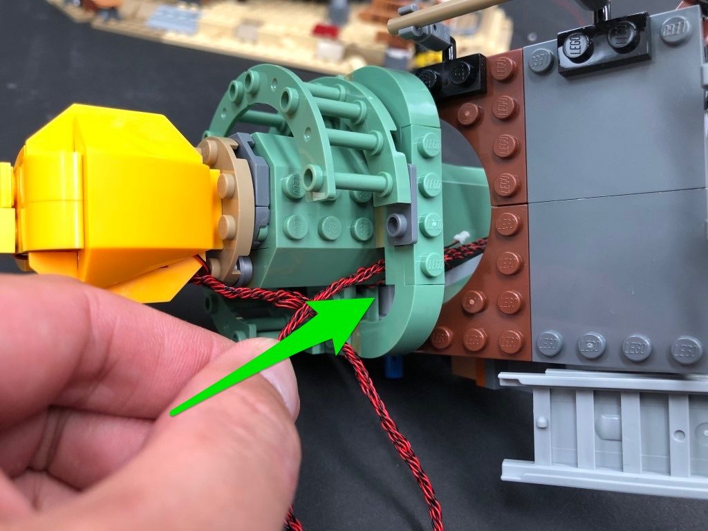
47.) Bring the cable from the front side of the flame down the base of the section before reconnecting the entire flame section back to the top of the torch. Ensure the cable we brought down the bottom is laid in between studs.
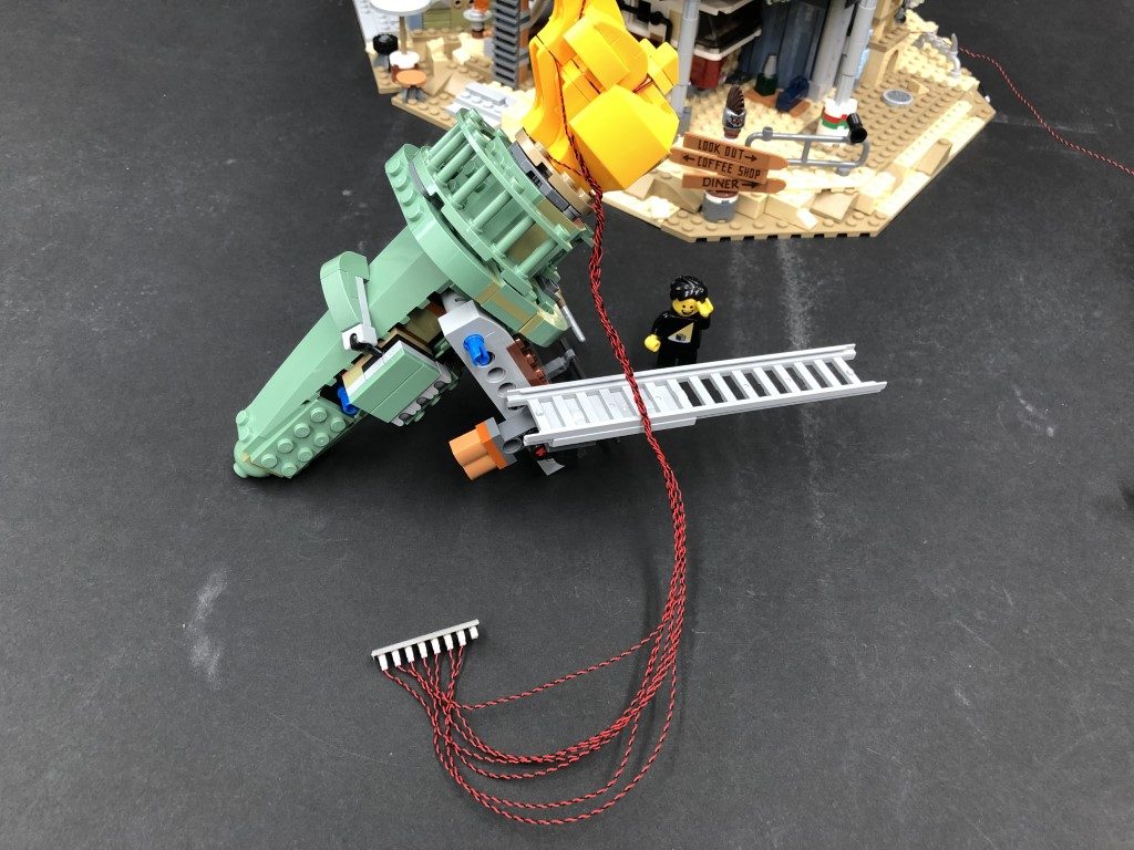
Disconnect the following rail section from the front right. Group all seven cables together and twist/wind them around each other 4-5 times so they lock in place together.
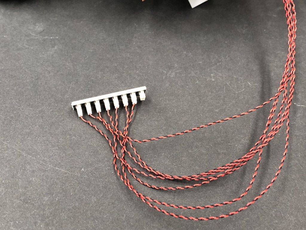
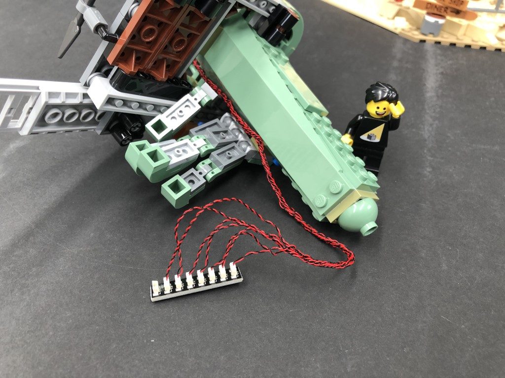
Connect all seven cables to the 8-Port Expansion Board then test all the flame lights are working OK by connecting the other end of the 50cm Connecting Cable from above to the expansion board and turning ON the USB Power Bank.
Note: If you experience any issues with the lights not working and suspect an issue with a component, please try a different port on the expansion board to verify where the fault lies (with the light or expansion board). To correct any issues with expansion board ports, please view the section addressing expansion board issues on our online troubleshooting guide.
48.) Disconnect the 50cm Connecting Cable as well as the lights from the expansion board, then continue to twist/wind all the bit light cables around each other all the way to the end so they come together forming one larger cable.
Open up the statue’s fingers then thread the cables down through the space where we removed the rail piece earlier. Pull the cables all the way out from underneath then reconnect the rail piece above. Reconnect all seven cables to the 8-port expansion board.
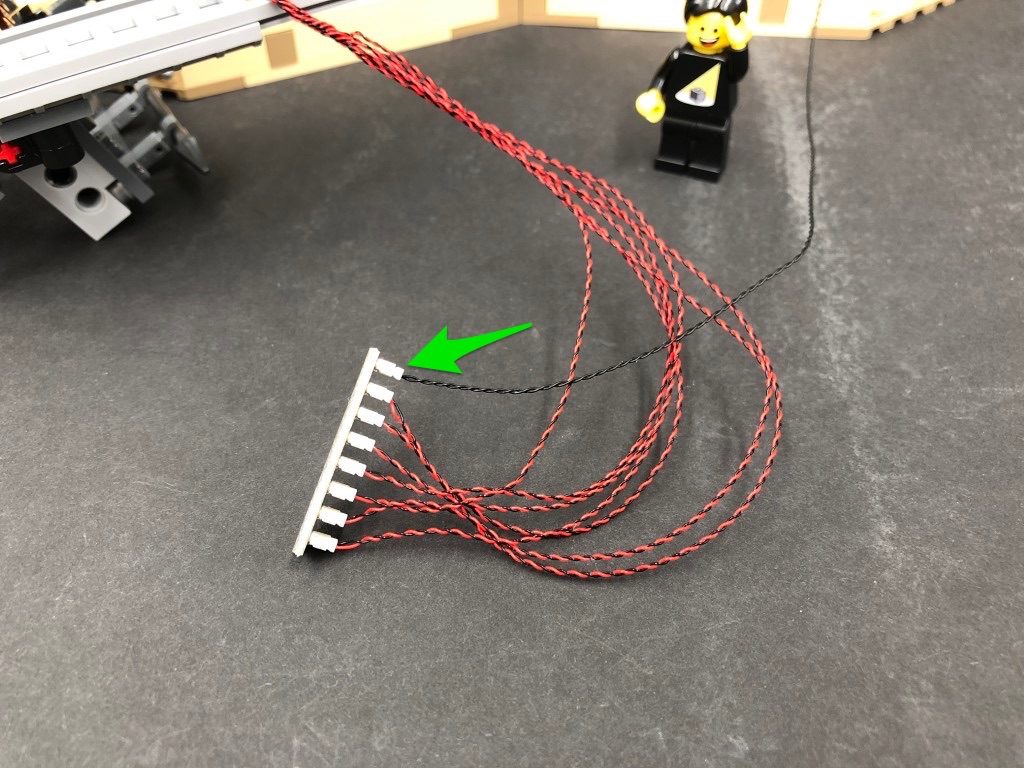
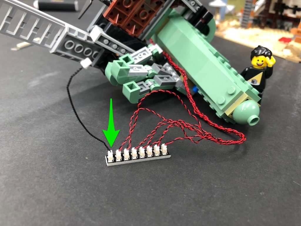
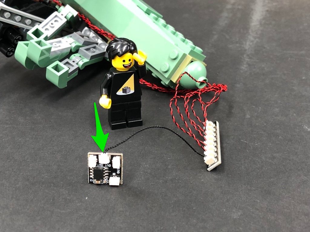
Take a 5cm Connecting Cable and connect one end to the expansion boards remaining port, then connect the other end to a new Flicker Effects Board‘s OUT port.
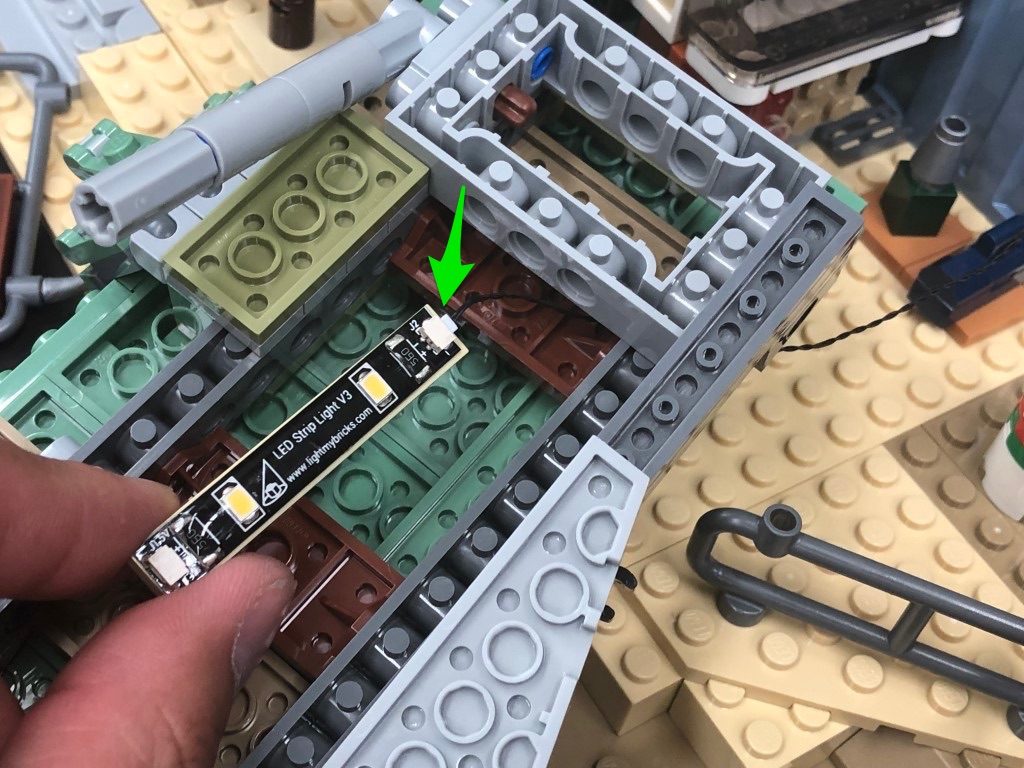
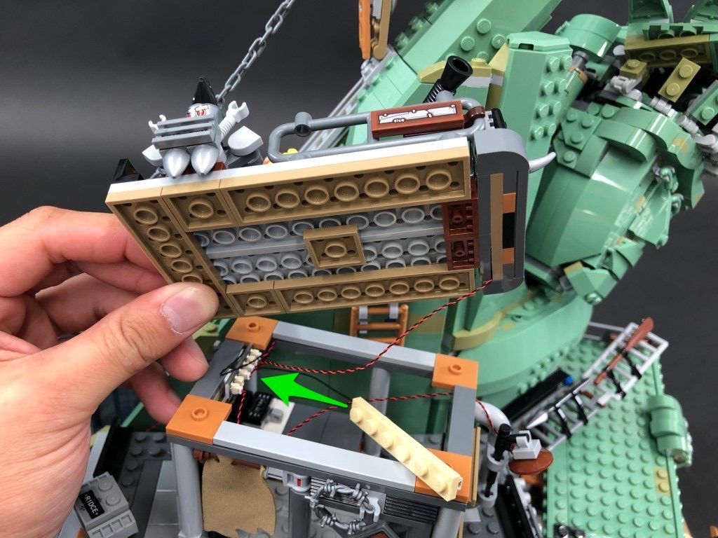
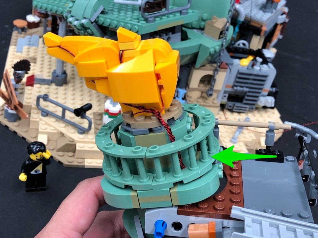
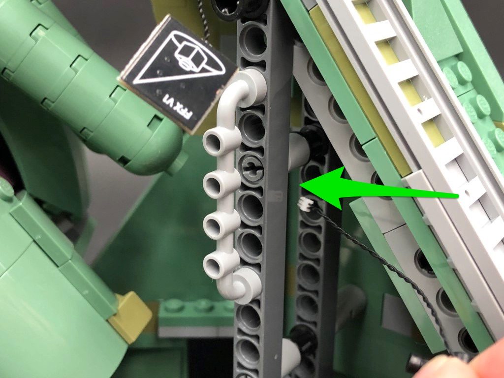
49.) Reconnect the torch section back to the set then take the other end of the 50cm Connecting Cable from underneath and thread it through the following space in the centre of set. Pull the cable all the way out, then connect it to the remaining White Strip Light.
Take the remaining 5cm Connecting Cable and connect one end of the cable to the White Strip Light and the other end to the IN port on the Flicker Effects Board.
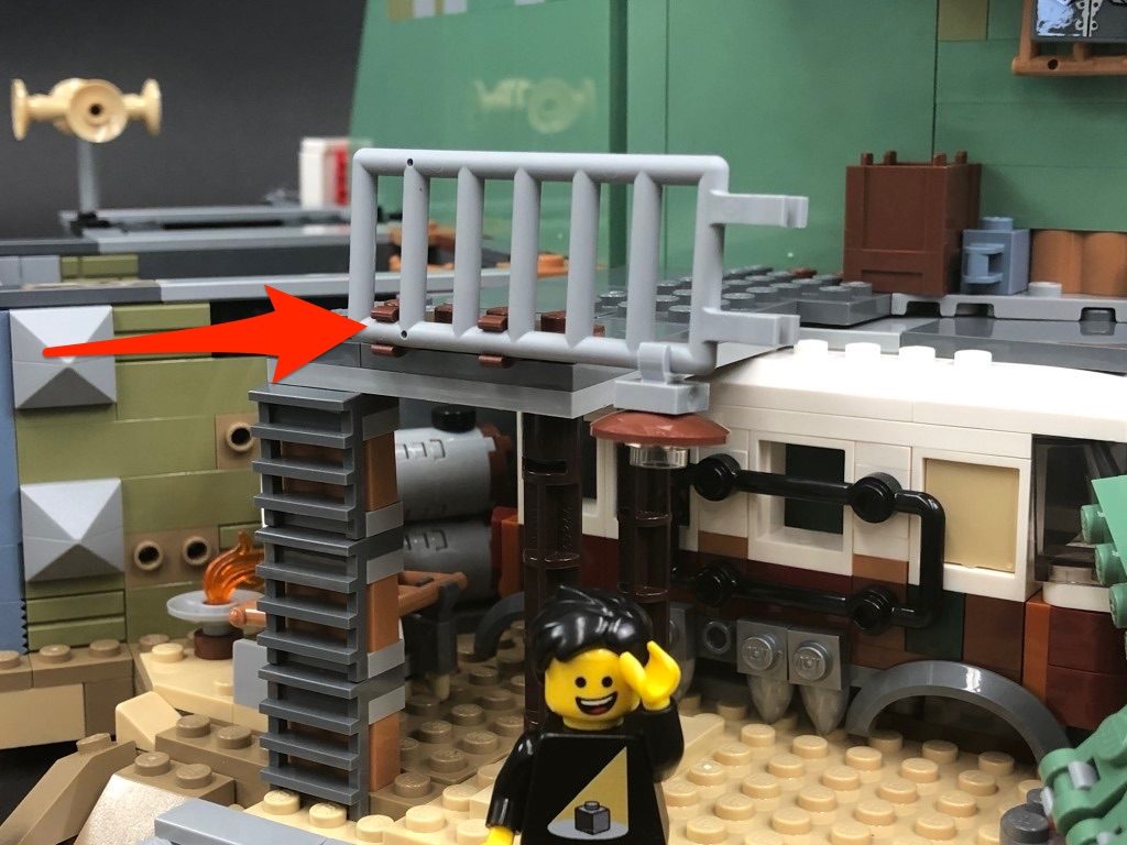
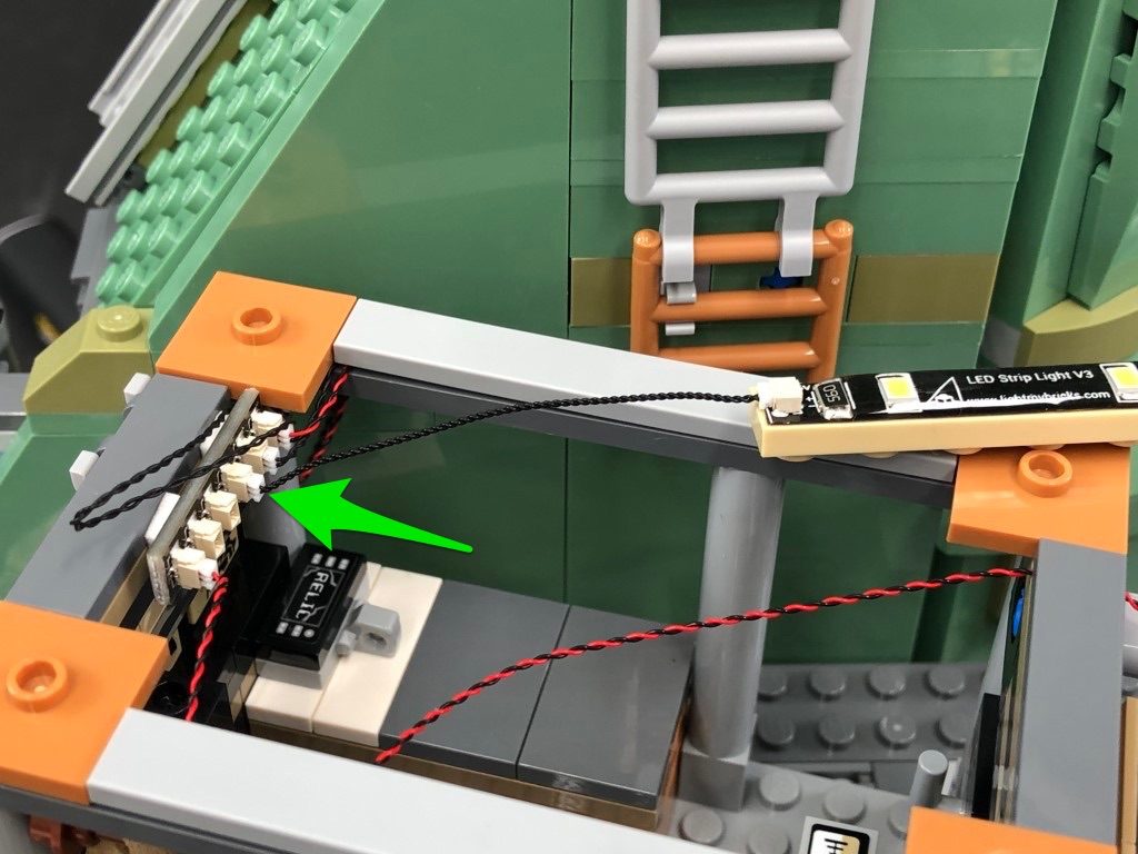
50.) Lift up the the ladder section so that it comes away from the set then using it’s adhesive backing, stick the Strip Light underneath the platform in the following position:
Reconnect the ladder section ensuring the 50cm cable is laid behind.
Note: If you experience any issues with the lights not working and suspect an issue with a component, please try a different port on the expansion board to verify where the fault lies (with the light or expansion board). To correct any issues with expansion board ports, please view the section addressing expansion board issues on our online troubleshooting guide.
25.) Swing the set around to the front as we will now move onto lighting the second and third levels of the set. First, disconnect the third level as well as the roof off the second level. Turn the second level section over onto it’s back so we can access underneath it.
Take 3x White Strip Lights and stick 2 of 3 of them onto 2x provided LEGO Plate 1×6. Take a 15cm Connecting Cable and connect one end to one of the strip lights stuck to a lego plate. Connect the other end to the strip light without a lego plate. Take a 5cm Connecting Cable and connect one end to the strip light without the lego plate, then connect the other end to the the other strip light (stuck to a lego plate).
Mount the three strip lights underneath the second level section as shown below. Secure the 15cm connecting cable underneath the strip light with lego plate. This will prevent the cable from dangling down.
26.) Take a 30cm Connecting Cable and connect it to strip light on the right. Bring the cable down and secure it underneath the large black plate toward the bottom. Flip the second level back over and turn it to the back. Pull the cable all the way up then secure it underneath the light grey tile along the top.
27.) Turn the second level around to the front and disconnect the rail. Disassemble the lamp section from it as shown below:
Take a White 30cm Bit Light and place the led face down over the hole on top of the brown dish. Secure the Bit Light in place by reconnecting the light grey plate with clip over the top.
Reconnect the lamp back to the rail ensuring the cable is laid underneath the clip, then thread the cable around the rail as shown below then reconnect this section back to the second level ensuring the cable is laid toward the inside.
28.) Disconnect the light grey tile and black tile from the top of the level followed by the blue wall section. Bring the cable inside the room then reconnect the blue wall over the top (ensuring the cable is laid in between studs).
Bring the cable out toward the back of the room then lay it in between studs on the top before reconnecting the light grey tile. Reconnect the black tile.
Bring the 30cm Connecting Cable across toward the middle of the section and secure it underneath the following dark grey 1×4 tile.
29.) Take the roof of the second level and turn it onto it’s back so we can access underneath. Take a Blue Strip Light and using it’s adhesive backing, stick it to the base of a provided LEGO Plate 1×6. Take a 5cm Connecting cable and connect it to the strip light’s left port.
Take a Red Strip Light and using it’s adhesive backing, stick it to the base of a provided LEGO Plate 1×6. Connect the other end of the 5cm connecting cable to the red strip light’s right port then take a 30cm Connecting Cable and connect it to the left port.
Mount both strip lights underneath the roof in the following positions. Ensure you loop the 30cm Connecting Cable underneath the red strip light as shown below.
30.) Bring the roof over the second level and connect the other end of the 30cm Connecting Cable below to the Blue Strip Light, then securely reconnect the roof.
Take the entire second level and bring it over the ground level. Locate the other end of the 15cm Connecting Cable from below and connect it to the Red Strip Light, then securely reconnect the second level on top. Ensure the other end of the 30cm Connecting Cable and Bit Light are pulled out and accessible.
Turn your USB Power Bank ON to test all the lights we have installed so far are working OK.
31.) Take the roof off the top level, then disconnect the lamp section and disassemble it as shown below:
Take a White 15cm Bit Light and place the led face down over the hole on top of the brown dish. Secure the Bit Light in place by reconnecting the light grey plate with clip over the top.
Reconnect the lamp section back to the pole, then reconnect it back to the top level ensuring the cable is facing inside the building. Secure the cable underneath the dark grey tile on top ensuring the cable is laid in between studs, then connect it to a new 6-Port Expansion Board. Securely reconnect the top level on top of the second level.
32.) Locate the other end of the Bit Light cable and 30cm Connecting Cable from below and connect them to the next available ports on the 6-port expansion board. Using 2x Adhesive Squares, mount the expansion board to the inside of the top floor in the below position.
Secure all the excess cables underneath the tiles along the top of the level then turn ON the USB Power Bank to test the lights are working OK.
Note: If you experience any issues with the lights not working and suspect an issue with a component, please try a different port on the expansion board to verify where the fault lies (with the light or expansion board). To correct any issues with expansion board ports, please view the section addressing expansion board issues on our online troubleshooting guide.
33.) Take the roof of the top floor and disconnect and disassemble the following section on the right.
Disconnect the trans clear round plate from the rail, then take a Flashing White 15cm Bit Light and with the cable facing the right, place it over the top left black stud. Secure the Bit Light in place by reconnecting the trans clear round plate over the top.
Bring the cable down, then reconnect the rail back to the clip ensuring the cable is laid behind. Reconnect everything back to the roof.
34.) Take a White Strip Light and using it’s adhesive backing, stick it to the base of the remaining provided LEGO Plate 1×6. Take a 5cm Connecting Cable and connect it to one side then connect the other side to the 6-port expansion board inside the top level.
Bring the roof over the top level and connect the other end of the flashing white 15cm bit light to the expansion board. Mount the strip light underneath the roof in the below position ensuring you connect the 1×6 plate over the flashing bit light cable.
Securely reconnect the roof then turn ON the USB Power Bank to test all the lights are working OK.
Note: If you experience any issues with the lights not working and suspect an issue with a component, please try a different port on the expansion board to verify where the fault lies (with the light or expansion board). To correct any issues with expansion board ports, please view the section addressing expansion board issues on our online troubleshooting guide.
35.) Turn the set around to the back and locate the other end of the 30cm Connecting Cable from step 24. Thread the cable through the following space behind and pull it out from the other side. Disconnect the following section made up of the green angled brick, then connect the cable to a new 6-Port Expansion Board.
36.) We will now install a light to the top of the pipe nearby. Disconnect this section then disassemble as per below:
Replace the silver round plate 1×1 with a provided Trans Clear Round Plate 1×1 then take a White 15cm Bit Light and with the cable facing behind, place it over the top of the pipe. Secure it in place by reconnecting the dish and trans clear round plate over the top, then connect the bit light to the 6-port Expansion Board behind.
37.) Disconnect the chains connecting the torch and the liberty crown, then lift up the back section of the head to allow us to disconnect the head section.
Disconnect the two sections from each side of the face as well as the back section, then disconnect the face section as shown below:
38.) Disconnect the very top section of the crown then flip this section we removed over so we can access underneath it.
Take out 2x White Strip Lights, a 30cm Connecting Cable and a 5cm Connecting Cable. Connect the two strip lights together using the 5cm connecting cable then connect the 30cm connecting cable to one of the strip light’s other port.
Using it’s adhesive backing, stick the second strip light underneath the crown’s top section as shown below. Ensure the 30cm cable is facing the back.
Lift up the bottom section of the liberty crown and fold down the individual bars underneath. Take the top part of the crown above and thread the first strip light through to the front to allow us to stick it underneath the bottom section as shown below:
39.) Push back down the bottom crown section and fold up the bars underneath, then securely reconnect the top ensuring the other end of the 30cm Connecting Cable is laid out behind. Secure the 30cm Connecting Cable underneath the following brick that connects to the back.
Reconnect the back section.
40.) Disconnect the two eye sections from the face then remove and discard the green round 2×2 bricks. Replace them with the provided Trans Clear Round Brick 2×2 and connect the eyebrow sections over them.
Take a White 15cm Bit Light and with the cable facing behind, place it in the centre of the four studs underneath the left eye section. Secure the Bit Light in place by reconnecting the left eye section over the top, ensuring the Bit Light is fitted underneath the hole of the trans clear brick.
Repeat this process to install another White 15cm Bit Light to the right eye section
41.) Reconnect the face back to the head section, then reconnect the two pieces back to each side of the face.
Lift up the following piece, then bring the head section up and thread the two bit light cables as well as the 30cm cable through the front and out the back as per below, then securely reconnect the head section.
Take all three cables and connect them to the 6-port expansion board below. Turn ON the USB Power Bank to test all the lights are working OK.
Note: If you experience any issues with the lights not working and suspect an issue with a component, please try a different port on the expansion board to verify where the fault lies (with the light or expansion board). To correct any issues with expansion board ports, please view the section addressing expansion board issues on our online troubleshooting guide.
42.) Take a 50cm Connecting Cable and connect it to the 6-Port Expansion Board. Tuck all the components in (except for the 50cm cable) then close the flap and reconnect the wall section we removed earlier. Ensure the cable from the pipe light is laid in between studs underneath.
43.) We will now light up the statue of liberty torch. First disconnect the torch by pulling it out from the front, then disconnect and dissemble the flame section as shown below:
44.) Take a White 30cm Bit Light and with the cable facing the right (facing back of the flame), place it over the stud as per below. Secure it in place by reconnecting the section over the top.
Take another White 30cm Bit Light and with the cable facing the right (facing back of the flame), place it over the top stud. Secure it in place by reconnecting the angled tile over the top.
Turn the flame section around and disconnect the following pieces. Lay the cable from the second bit light down in between studs, then reconnect the pieces over the top to hide the cable.
45.) Take another 2x White 30cm Bit Lights and install them to the next studs to the right. Secure them in place by reconnecting the angled tiles over the top.
46.) Take an Adhesive Square and stick it to the following position. Take another White 30cm Bit Light and stick it down onto the adhesive square as shown below, then reconnect the large piece over the top.
Flip the flame section over and using the same method as above, install another White 30cm Bit Light using another Adhesive Square.
Repeat this step again, to install the remaining White 30cm Bit Light to the middle using another Adhesive Square.
47.) Bring the cable from the front side of the flame down the base of the section before reconnecting the entire flame section back to the top of the torch. Ensure the cable we brought down the bottom is laid in between studs.
Disconnect the following rail section from the front right. Group all seven cables together and twist/wind them around each other 4-5 times so they lock in place together.
Connect all seven cables to the 8-Port Expansion Board then test all the flame lights are working OK by connecting the other end of the 50cm Connecting Cable from above to the expansion board and turning ON the USB Power Bank.
Note: If you experience any issues with the lights not working and suspect an issue with a component, please try a different port on the expansion board to verify where the fault lies (with the light or expansion board). To correct any issues with expansion board ports, please view the section addressing expansion board issues on our online troubleshooting guide.
48.) Disconnect the 50cm Connecting Cable as well as the lights from the expansion board, then continue to twist/wind all the bit light cables around each other all the way to the end so they come together forming one larger cable.
Open up the statue’s fingers then thread the cables down through the space where we removed the rail piece earlier. Pull the cables all the way out from underneath then reconnect the rail piece above. Reconnect all seven cables to the 8-port expansion board.
Take a 5cm Connecting Cable and connect one end to the expansion boards remaining port, then connect the other end to a new Flicker Effects Board‘s OUT port.
49.) Reconnect the torch section back to the set then take the other end of the 50cm Connecting Cable from underneath and thread it through the following space in the centre of set. Pull the cable all the way out, then connect it to the remaining White Strip Light.
Take the remaining 5cm Connecting Cable and connect one end of the cable to the White Strip Light and the other end to the IN port on the Flicker Effects Board.
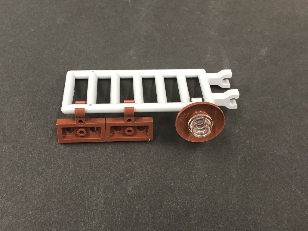
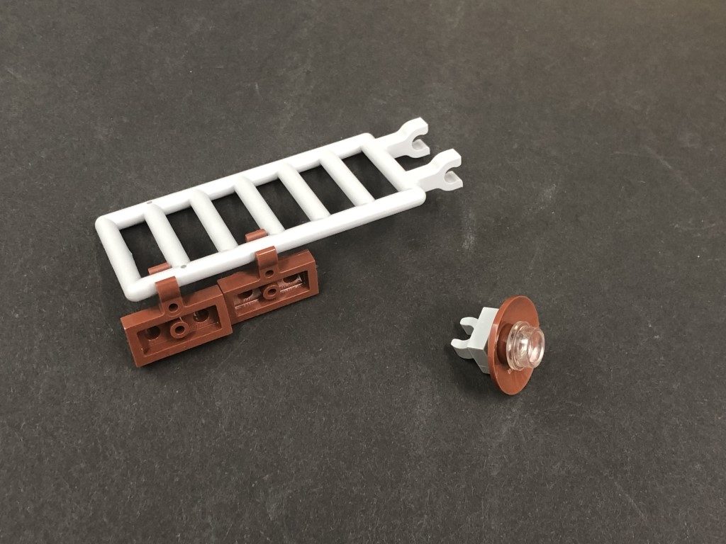
50.) Lift up the the ladder section so that it comes away from the set then using it’s adhesive backing, stick the Strip Light underneath the platform in the following position:
Reconnect the ladder section ensuring the 50cm cable is laid behind.
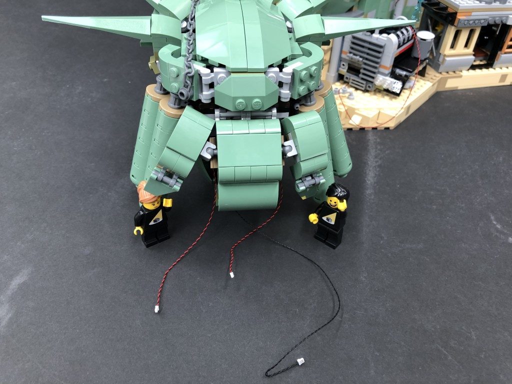
 Fold/twist the excess bit light cables into a neat bunch then tuck them along with the expansion board and effects board underneath the statue’s fingers as shown below:
51.) Secure the excess cable from the 50cm Connecting Cable by neatly laying it underneath the following LEGO pieces. Push down any excess cable down the spaces behind the set.
Turn on the USB Power Bank to test all lights are working OK.
Note: If you experience any issues with the lights not working and suspect an issue with a component, please try a different port on the expansion board to verify where the fault lies (with the light or expansion board). To correct any issues with expansion board ports, please view the section addressing expansion board issues on our online troubleshooting guide.
Fold/twist the excess bit light cables into a neat bunch then tuck them along with the expansion board and effects board underneath the statue’s fingers as shown below:
51.) Secure the excess cable from the 50cm Connecting Cable by neatly laying it underneath the following LEGO pieces. Push down any excess cable down the spaces behind the set.
Turn on the USB Power Bank to test all lights are working OK.
Note: If you experience any issues with the lights not working and suspect an issue with a component, please try a different port on the expansion board to verify where the fault lies (with the light or expansion board). To correct any issues with expansion board ports, please view the section addressing expansion board issues on our online troubleshooting guide.
This finally completes installation of the Light My Bricks Welcome to Apocalypseburg! Light Kit. We thank you for purchasing this product.