
The following page is the instructions for the Light My Bricks LEGO Winter Village Station (10259) LED light kit.
If you run into any issues, please refer to the online troubleshooting guide.
To ensure a trouble-free installation of your light kit, please read and follow each step carefully. These instructions can be downloaded in PDF format here
Please note: This page lists instructions for the LED light kit only. If you are wishing to purchase the Light My Bricks LEGO Winter Village Station (10259) LED light kit , please click here to view the product page
Package Contents:
- 7x White 30cm Bit Lights
- 6x White 15cm Bit Lights
- 4x White Strip Lights
- 1x Multi Colour Light String
- 1x 8-Port Expansion Board
- 1x 12-Port Expansion Board
- 2x 5cm Connecting Cables
- 2x 15cm Connecting Cables
- 1x 50cm Connecting Cable
- 1x AA Battery Pack
LEGO Pieces:
- 4x Plate 1×6 (Any Colour)
- 2x White Plates 1×4
- 2x Trans Clear Round Plate 1×1
- 2x Trans Orange Round Plate 1×1
- 1x Trans Clear Plate w Rounded Bottom 2×2
Important things to note:
Laying cables in between and underneath bricks
Cables can fit in between and underneath LEGO® bricks, plates, and tiles providing they are laid correctly between the LEGO® studs. Do NOT forcefully join LEGO® together around cables; instead ensure they are laying comfortably in between each stud.
Connecting cable connectors to Expansion Boards
Take extra care when inserting connectors to ports of Expansion Boards. Connectors can be inserted only one way. With the expansion board facing up, look for the soldered “=” symbol on the left side of the port. The connector side with the wires exposed should be facing toward the soldered “=” symbol as you insert into the port. If a plug won’t fit easily into a port connector, do not force it.
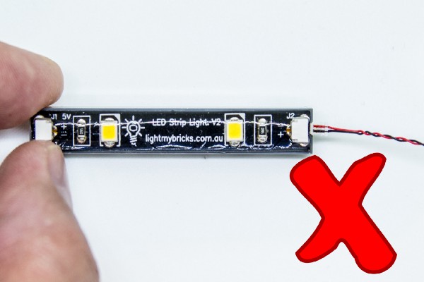
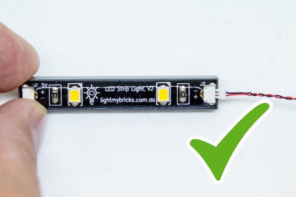
Connecting cable connectors to Strip Lights
Take extra care when inserting connectors to ports on the Strip Lights. Connectors can be inserted only one way. With the Strip Light facing up, ensure the side of the connector with the wires exposed is facing down. If a plug won’t fit easily into a port connector, don’t force it. Doing so will damage the plug and the connector.
Installing Bit Lights under LEGO® bricks and plates.
When installing Bit Lights under LEGO® pieces, ensure they are placed the correct way up (Yellow LED component exposed). You can either place them directly on top of LEGO® studs or in between.
OK, Let’s Begin!
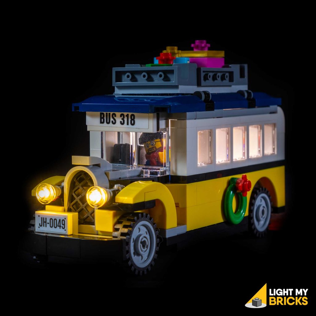
Install lights to the Bus
1.) We will start by installing lights to the bus. First take the bus and disconnect the roof as well as the following pieces so we can access the headlights.
Remove the trans clear round tile from each headlight then take a White 15cm Bit Light and place it over the top of one of the headlight pieces. Secure the Bit Light in place by connecting a provided Trans Clear Round Plate 1×1 over the top then fold the cable down the side. Repeat this process to install another White 15cm Bit Light to the other headlight, securing it in place using another provided Trans Clear Round Plate 1×1. 2.) Reconnect both headlights to the front of the bus ensuring the cable is on the bottom and in between each clip then lay each cable toward the inside of the bus in between the following studs.
Reconnect surrounding pieces at the front of the bus.
3.) Disconnect the front chair then bring the cable from the left headlight across and lay it in between studs before reconnecting the chair over the top.
Take a 8-Port Expansion Board and connect both cables from the headlights to the far right ports.
4.) Test the headlights by taking the Flat Battery Pack and inserting 2x CR2032 Batteries to it. Connect the battery pack cable to the expansion board and turn ON the battery pack to verify the headlights are working OK.
IMPORTANT NOTE:
Flat and Round Battery Packs (CR2032) have been removed as of June 2022 due to child safety regulations. Please use the 50cm Connecting Cable in place of the Battery Packs.
To test the lights, connect the 50cm Connecting Cable to a spare Expansion Board. Take the AA Battery Pack and with new batteries inserted, connect it to the expansion board. Turn the battery pack ON to test if all is working ok. Once tested, disconnect the Expansion Board and AA Battery Pack and set them aside.
Ensure the cable is running out from the side of the vehicle. This will then tether to 12-Port Expansion Board at the very end of this guide.
Reconnect the remaining pieces which make up the front of the Bus.
2.) Reconnect both headlights to the front of the bus ensuring the cable is on the bottom and in between each clip then lay each cable toward the inside of the bus in between the following studs.
Reconnect surrounding pieces at the front of the bus.
3.) Disconnect the front chair then bring the cable from the left headlight across and lay it in between studs before reconnecting the chair over the top.
Take a 8-Port Expansion Board and connect both cables from the headlights to the far right ports.
4.) Test the headlights by taking the Flat Battery Pack and inserting 2x CR2032 Batteries to it. Connect the battery pack cable to the expansion board and turn ON the battery pack to verify the headlights are working OK.
IMPORTANT NOTE:
Flat and Round Battery Packs (CR2032) have been removed as of June 2022 due to child safety regulations. Please use the 50cm Connecting Cable in place of the Battery Packs.
To test the lights, connect the 50cm Connecting Cable to a spare Expansion Board. Take the AA Battery Pack and with new batteries inserted, connect it to the expansion board. Turn the battery pack ON to test if all is working ok. Once tested, disconnect the Expansion Board and AA Battery Pack and set them aside.
Ensure the cable is running out from the side of the vehicle. This will then tether to 12-Port Expansion Board at the very end of this guide.
Reconnect the remaining pieces which make up the front of the Bus.
 5.) Turn the Bus around and disconnect the following pieces from the back of the vehicle.
6.) Disconnect the following two tail light sections and then disconnect the trans red plates from each side.
Take a White 15cm Bit Light and thread the connector end of the cable through the front hole of one of the yellow bricks. Pull the cable all the way out from the back of the brick then press down the Bit Light so that it sits flat against the front side of the brick.
Secure the Bit Light in place by reconnecting the Trans Red Round Plate over the top.
5.) Turn the Bus around and disconnect the following pieces from the back of the vehicle.
6.) Disconnect the following two tail light sections and then disconnect the trans red plates from each side.
Take a White 15cm Bit Light and thread the connector end of the cable through the front hole of one of the yellow bricks. Pull the cable all the way out from the back of the brick then press down the Bit Light so that it sits flat against the front side of the brick.
Secure the Bit Light in place by reconnecting the Trans Red Round Plate over the top.
 Repeat this process to install another White 15cm Bit Light to the other tail light.
 7.) Reconnect both tail lights to the back of the Bus and with both cables laid toward the inside of the bus and down in between studs, then reconnect the following side pieces.
Reconnect the remaining pieces which make up the back and side windows.
8.) Take the two tail light cables and connect them to the next spare ports on the Expansion Board, then turn ON the Flat Battery Pack to test the lights installed so far are working OK.
9.) Take the following top section and remove the trans orange round tiles.
With this top section flipped onto it’s back, place a White 15cm Bit Light over one of the black studs (with cable facing down). Secure the Bit Light in place by connecting a provided Trans Orange Round Plate 1×1 over the top.
Repeat this step the install another White 15cm Bit Light to the other upper rear light securing it in place using another provided Trans Orange Round Plate 1×1.
7.) Reconnect both tail lights to the back of the Bus and with both cables laid toward the inside of the bus and down in between studs, then reconnect the following side pieces.
Reconnect the remaining pieces which make up the back and side windows.
8.) Take the two tail light cables and connect them to the next spare ports on the Expansion Board, then turn ON the Flat Battery Pack to test the lights installed so far are working OK.
9.) Take the following top section and remove the trans orange round tiles.
With this top section flipped onto it’s back, place a White 15cm Bit Light over one of the black studs (with cable facing down). Secure the Bit Light in place by connecting a provided Trans Orange Round Plate 1×1 over the top.
Repeat this step the install another White 15cm Bit Light to the other upper rear light securing it in place using another provided Trans Orange Round Plate 1×1.
 10.) Reconnect the upper rear light section to the back of the bus ensuring the cables are laid inside, then connect both cables to the Expansion Board.
Turn ON the flat battery pack to test and ensure all lights are working OK.
10.) Reconnect the upper rear light section to the back of the bus ensuring the cables are laid inside, then connect both cables to the Expansion Board.
Turn ON the flat battery pack to test and ensure all lights are working OK.
 11.) Disconnect the Flat Battery Pack and then from the inside of the bus, lay the two cables from the upper rear lights down and then along the floor of the bus in the below positions, then reconnect the two seats over the top.
12.) Take the roof of the bus and flip it over to disconnect the two round dark grey 2×2 plates from underneath.
Take a White Strip Light and provided Plate 1×6. Using it’s adhesive backing, stick the Strip Light onto the base of the Plate 1×6 then mount the Strip Light underneath the roof of the bus in the following position.
13.) Take a 15cm Connecting Cable and connect it to the expansion board then reconnect the flat battery pack to the expansion board.
Neatly tuck all cables and expansion board in to the left side of the bus as per below (leave the other end of the 15cm cable out)
11.) Disconnect the Flat Battery Pack and then from the inside of the bus, lay the two cables from the upper rear lights down and then along the floor of the bus in the below positions, then reconnect the two seats over the top.
12.) Take the roof of the bus and flip it over to disconnect the two round dark grey 2×2 plates from underneath.
Take a White Strip Light and provided Plate 1×6. Using it’s adhesive backing, stick the Strip Light onto the base of the Plate 1×6 then mount the Strip Light underneath the roof of the bus in the following position.
13.) Take a 15cm Connecting Cable and connect it to the expansion board then reconnect the flat battery pack to the expansion board.
Neatly tuck all cables and expansion board in to the left side of the bus as per below (leave the other end of the 15cm cable out)
 14.) Neatly place the battery pack down the right side of the bus ensuring the switch is facing the front.
Tuck in any excess cables and then place your driver minifig in the front seat.
15.) Take the 15cm Connecting Cable and lay it down along the side, toward the back of the bus. Secure the end of the cable underneath the following tile on the back left of the bus.
Take the roof of the bus and connect the cable to the Strip Light before securely reconnecting on top.
Test all lights are working OK by turning ON the battery pack.
This completes installation of the lights for the Bus.
14.) Neatly place the battery pack down the right side of the bus ensuring the switch is facing the front.
Tuck in any excess cables and then place your driver minifig in the front seat.
15.) Take the 15cm Connecting Cable and lay it down along the side, toward the back of the bus. Secure the end of the cable underneath the following tile on the back left of the bus.
Take the roof of the bus and connect the cable to the Strip Light before securely reconnecting on top.
Test all lights are working OK by turning ON the battery pack.
This completes installation of the lights for the Bus.
Install lights to the Winter Village Station
1.) We will first install lights to the lamp posts on each side. Disconnect both of these and then dissemble one of them as shown below. 2.) Take a White 30cm Bit Light and place it in the middle of the studs on the base side of the black round 2×2 plate (with rounded bottom). Secure the bit light in place by reconnecting the trans yellow cone piece over the top then reconnect the trans clear cover. Thread the connector end of the cable through the top of the black brick and then pull it out from the back as shown below: Pull the cable all the way through before reconnecting the lamp to the black brick ensuring the cable is facing the back. 3.) Reconnect the lamp post to the right side of the station then wind the cable around the pole twice. Secure the cable down by laying it underneath the lamp post base in between studs with the cable facing the right side then thread the cable through to the back of the station. From the back of the station, secure the cable underneath the black base section and then bring it under and secure in between the platform and platform base as shown below: 4.) Repeat previous steps to install another White 30cm Bit Light to the other lamp post. Reconnect the lamp post to the left side of the station then wind the cable around the pole twice. Secure the cable down by laying it underneath the lamp post base in between studs with the cable facing the back side. Bring the cable toward the back of the station and then secure it in between bricks underneath the platform base as shown below. 5.) We will now install a light above the main entrance door to shine down. Take a White 30cm Bit Light and thread the connector end of the bit light through the space above the door as shown below: Thread it all the way through and pull it out from the inside of the station. With the LED facing down, push the bit light up the following hole then secure the Bit Light in place by taking a provided Trans Clear Plate w Rounded Bottom 2×2 and connecting it to the ceiling above the doorway as shown below. The Bit Light should be visible and in between the studs of the trans clear plate. 6.) From the back of the station, bring the cable from the bit light we just installed toward the right and then secure it underneath the Winter Village schedule plate ensuring the cable is laid in between studs. 7.) Take a 12-Port Expansion Board and connect this bit light cable, along with the two bit light cables from the lamp posts to the first few ports. Take the AA Battery Pack and insert 3x AA Batteries. Connect the battery pack cable to the expansion board and then turn the battery pack ON to test all the lights we have installed so far are working OK. 8.) We will now install a light above the ticket window. Carefully disconnect the front of the roof section to create a gap just above the window. Take a White 30cm Bit Light and thread the connector side of the cable through this space we have created. Pull the cable all the way out from the other side and then push the Bit Light up inside the hole of the ceiling as shown below (with LED facing down). Close up the gap by reconnecting the roof section to secure the Bit Light in place. 9.) Disconnect the entrance door bit light from the expansion board then group together this Bit Light along with the ticket booth Bit Light and twist/wind them around each other so they come together to form one larger cable. Bring the large cable down the side of the building, then bring it under the platform and secure it in between plates. Connect both cables to the 12-port expansion board Turn the Battery Pack ON to verify the light above the ticket window is working OK 10.) We will now install lights above the clock on each side of the tower. Open up the three roof sections and then disconnect the following sections from the top.
11.) Take a White 30cm Bit Light and with the LED facing down, split/seperate the two wires to allow you to place it over the right side’s green stud as shown below.
Secure the Bit Light in place by reconnecting the light grey section on the right side. The LED should be peeking out just above the clock on the right side to shine down.
12.) Pull the cable toward the left then, slip it in between bricks to lead to the back side as shown below:
10.) We will now install lights above the clock on each side of the tower. Open up the three roof sections and then disconnect the following sections from the top.
11.) Take a White 30cm Bit Light and with the LED facing down, split/seperate the two wires to allow you to place it over the right side’s green stud as shown below.
Secure the Bit Light in place by reconnecting the light grey section on the right side. The LED should be peeking out just above the clock on the right side to shine down.
12.) Pull the cable toward the left then, slip it in between bricks to lead to the back side as shown below:
 From the back of the set, take the Bit Light cable and thread it down through the following space just above the front door. Pull it all the way down from underneath.
13.) Take another White 30cm Bit Light and split/seperate the wire to place it over the green stud on the left side of the tower as shown below.
From the back of the set, take the Bit Light cable and thread it down through the following space just above the front door. Pull it all the way down from underneath.
13.) Take another White 30cm Bit Light and split/seperate the wire to place it over the green stud on the left side of the tower as shown below.
 Secure the Bit Light in place by reconnecting the light grey section on the left side. The LED should be peeking out just above the clock on the left side to shine down.
From the back of the station, thread the cable down the same space we did for the other Bit Light, then slip the cable in between bricks as shown below:
14.) Take another White 30cm Bit Light and using the same method we used for the other clock lights, install it to the front stud on the tower. Pull the cable behind and then slip it in between bricks before reconnecting the middle section back on top to secure the Bit Light in place. The LED should be peeking out just above the clock on the front side to shine down.
From the back of the station, thread the cable down the same space we did for the other Bit Lights
15.) Take all three cables from the clock tower and twist/wind them around each other so they come together to form a larger cable.
Bring the cable down the right side of the door frame and then lay it down across the floor in between studs underneath the corner section as shown below:
Connect all three cables to the next available ports on the 12-Port Expansion Board then turn the Battery Pack ON to verify all the lights from the clock tower are working OK.
16.) Reconnect sections that make up the roof.
17.) We will now install some strip lights underneath the roof.
Secure the Bit Light in place by reconnecting the light grey section on the left side. The LED should be peeking out just above the clock on the left side to shine down.
From the back of the station, thread the cable down the same space we did for the other Bit Light, then slip the cable in between bricks as shown below:
14.) Take another White 30cm Bit Light and using the same method we used for the other clock lights, install it to the front stud on the tower. Pull the cable behind and then slip it in between bricks before reconnecting the middle section back on top to secure the Bit Light in place. The LED should be peeking out just above the clock on the front side to shine down.
From the back of the station, thread the cable down the same space we did for the other Bit Lights
15.) Take all three cables from the clock tower and twist/wind them around each other so they come together to form a larger cable.
Bring the cable down the right side of the door frame and then lay it down across the floor in between studs underneath the corner section as shown below:
Connect all three cables to the next available ports on the 12-Port Expansion Board then turn the Battery Pack ON to verify all the lights from the clock tower are working OK.
16.) Reconnect sections that make up the roof.
17.) We will now install some strip lights underneath the roof.
 Take a White Strip Light and using it’s adhesive backing, stick it to the base of a provided Plate 1×6.
Take a 5cm Connecting Cable and connect it one side to one of the Strip Lights then take a new 5cm Connecting Cable and connect it to the other side of the Strip Light.
18.) Use the LEGO Removal tool to create a gap between the roof and the top of the wall as per below:
Thread the spare end of one of the 5cm Connecting Cables through this gap we just created, then mount the strip light to the ceiling as shown below. Ensure the cable we threaded through the gap is on the left side of the strip light then close up the gap by securely reconnecting the roof.
19.) Connect the other end of the 5cm Connecting Cable from the strip light we just mounted to a new White Strip Light. Take a 15cm Connecting Cable and connect it to the Strip Light’s other port.
Take a provided Plate 1×6 and connect it underneath the roof on the right side of the station as shown below.
Using it’s adhesive backing, stick the Strip Light directly underneath the roof on the right side ensuring the 15cm connecting cable is on the right side. Push the 5cm connecting cable in between the strip lights up so that it is not hanging down.
20.) Thread the other end of the 15cm Connecting Cable through to the back side of the station then wind it around the black post a few times before connecting it to the 12-Port Expansion Board.
21.) Take another White Strip Light and using it’s adhesive backing, stick it to the base of a provide Plate 1×6. From the inside of the train station, take the other end of the 5cm Connecting Cable we threaded through the gap and connect it to the White Strip Light.
Mount the Strip Light underneath the first floor as shown below then turn ON the Battery Pack to verify all the strip lights we installed are working OK.
22.) Take a Multi-Coloured Light String and place the top end of the cable upside down on the roof of the left side of the station in the below position. Secure the Light String by connecting a provided White Plate 1×4 over the top ensuring you are connecting it over in between the LEDs.
Pull the Light String over to the roof of the clock tower and then secure it in place by disconnecting then reconnecting the white tiles over the top ensuring you are connecting the plates over in between the LEDs.
Take a White Strip Light and using it’s adhesive backing, stick it to the base of a provided Plate 1×6.
Take a 5cm Connecting Cable and connect it one side to one of the Strip Lights then take a new 5cm Connecting Cable and connect it to the other side of the Strip Light.
18.) Use the LEGO Removal tool to create a gap between the roof and the top of the wall as per below:
Thread the spare end of one of the 5cm Connecting Cables through this gap we just created, then mount the strip light to the ceiling as shown below. Ensure the cable we threaded through the gap is on the left side of the strip light then close up the gap by securely reconnecting the roof.
19.) Connect the other end of the 5cm Connecting Cable from the strip light we just mounted to a new White Strip Light. Take a 15cm Connecting Cable and connect it to the Strip Light’s other port.
Take a provided Plate 1×6 and connect it underneath the roof on the right side of the station as shown below.
Using it’s adhesive backing, stick the Strip Light directly underneath the roof on the right side ensuring the 15cm connecting cable is on the right side. Push the 5cm connecting cable in between the strip lights up so that it is not hanging down.
20.) Thread the other end of the 15cm Connecting Cable through to the back side of the station then wind it around the black post a few times before connecting it to the 12-Port Expansion Board.
21.) Take another White Strip Light and using it’s adhesive backing, stick it to the base of a provide Plate 1×6. From the inside of the train station, take the other end of the 5cm Connecting Cable we threaded through the gap and connect it to the White Strip Light.
Mount the Strip Light underneath the first floor as shown below then turn ON the Battery Pack to verify all the strip lights we installed are working OK.
22.) Take a Multi-Coloured Light String and place the top end of the cable upside down on the roof of the left side of the station in the below position. Secure the Light String by connecting a provided White Plate 1×4 over the top ensuring you are connecting it over in between the LEDs.
Pull the Light String over to the roof of the clock tower and then secure it in place by disconnecting then reconnecting the white tiles over the top ensuring you are connecting the plates over in between the LEDs.
 23.) Bring the Light String across to the front side of the roof and secure it underneath the white 1×4 tile on this side.
 Bring the Light String across to the right side of the roof and then secure it underneath the white 1×4 tile on this side.
 Bring the Light String down the right roof section and underneath the winter village sign, then bring the cable up and across to the right. Secure the Light String underneath the 1×2 brick (underneath the Winter Village Sign).
24.) Bring the Light String over to the roof on the right side of the station and then secure it by connecting a provided White Plate 1×4 over the top. Loop and bend the Light String at the top of the roof to bring the cable over to the other side.
From the other side, bring the cable down and wind it around the black pole a few times before connecting it up to a spare port on the 12-Port Expansion Board.
Finally, if you used a 50cm Connecting Cable for the vehicle instead of a Battery Pack, connect it to the 12-Port Expansion Board.
Turn the Battery Pack ON to verify all the lights are working OK.
Bring the Light String down the right roof section and underneath the winter village sign, then bring the cable up and across to the right. Secure the Light String underneath the 1×2 brick (underneath the Winter Village Sign).
24.) Bring the Light String over to the roof on the right side of the station and then secure it by connecting a provided White Plate 1×4 over the top. Loop and bend the Light String at the top of the roof to bring the cable over to the other side.
From the other side, bring the cable down and wind it around the black pole a few times before connecting it up to a spare port on the 12-Port Expansion Board.
Finally, if you used a 50cm Connecting Cable for the vehicle instead of a Battery Pack, connect it to the 12-Port Expansion Board.
Turn the Battery Pack ON to verify all the lights are working OK.
 25.) Finally, neaten up any messy cables at the back of the station, then tuck the expansion board and Battery Pack in neatly.
26.) Lastly, if you intend to have the Winter Village Station setup with the Winter Holiday Train light kit, you will need to remove the following pieces along the railway crossing tracks. This is so the components on the bottom of the train are not caught against the track as it passes.
25.) Finally, neaten up any messy cables at the back of the station, then tuck the expansion board and Battery Pack in neatly.
26.) Lastly, if you intend to have the Winter Village Station setup with the Winter Holiday Train light kit, you will need to remove the following pieces along the railway crossing tracks. This is so the components on the bottom of the train are not caught against the track as it passes.
This finally completes installation of your Light My Bricks Winter Village Light Kit. We hope you enjoy and we thank you for purchasing this product.