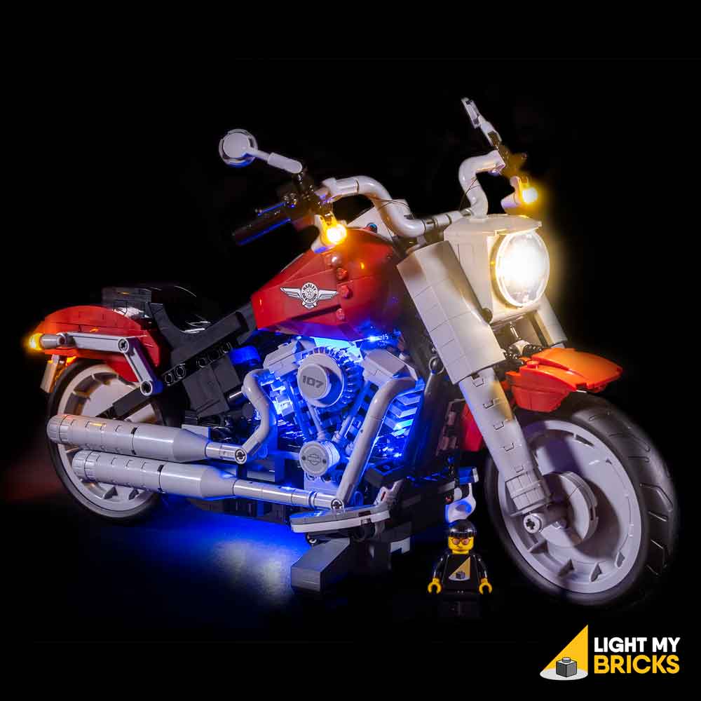
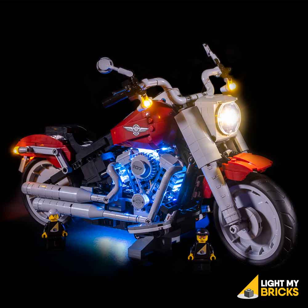
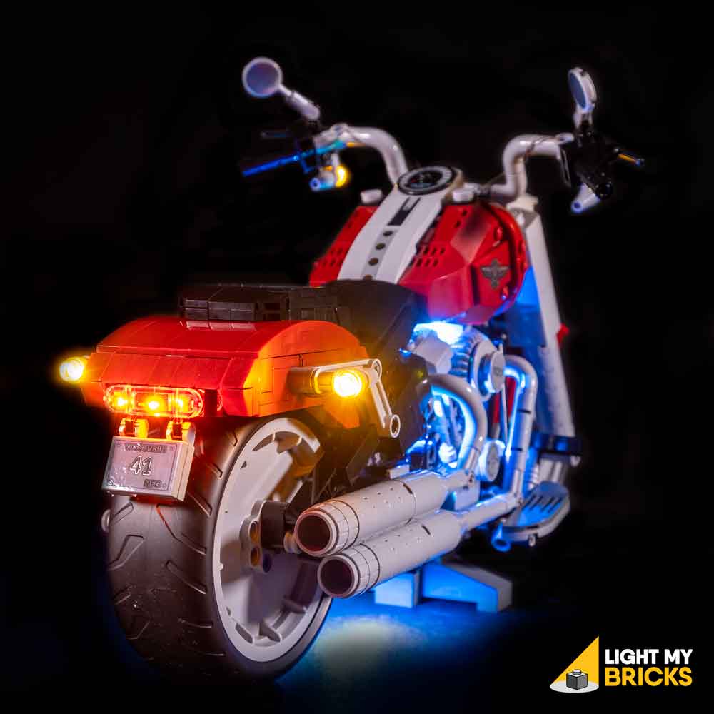
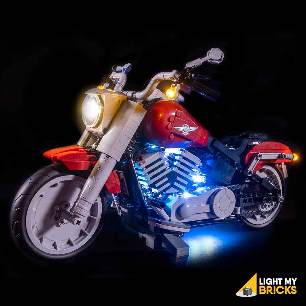
The following page is the instructions for the Light My Bricks LEGO Harley-Davidson Fatboy (10269) LED light kit.
If you run into any issues, please refer to the online troubleshooting guide.
To ensure a trouble-free installation of your light kit, please read and follow each step carefully. These instructions can be downloaded in PDF format here
Please note: This page lists instructions for the LED light kit only. If you are wishing to purchase the Light My Bricks LEGO Harley-Davidson Fatboy (10269) LED light kit , please click here to view the product page
Package Contents:
- 5x White 15cm Micro Bit Lights
- 2x White 30cm Micro Bit Lights
- 1x Warm White 30cm Large Bit Light
- 2x Micro 4-Port Expansion Boards
- 1x 6-Port Expansion Board
- 2x 5cm Connecting Cable
- 1x 30cm Connecting Cables
- 1x RGB Remote Control and RGB Control Board
- 4x RGB Strip Lights
- 4x RGB Connecting Cable 15cm
- 1x USB Power Cable
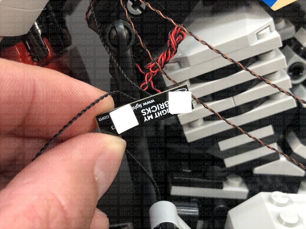
- 8x 3M Adhesive Squares
Important things to note:
Laying cables in between and underneath bricks
Cables can fit in between and underneath LEGO® bricks, plates, and tiles providing they are laid correctly between the LEGO® studs. Do NOT forcefully join LEGO® together around cables; instead ensure they are laying comfortably in between each stud.
Connecting cable connectors to Expansion Boards
Take extra care when inserting connectors to ports of Expansion Boards. Connectors can be inserted only one way. With the expansion board facing up, look for the soldered “=” symbol on the left side of the port. The connector side with the wires exposed should be facing toward the soldered “=” symbol as you insert into the port. If a plug won’t fit easily into a port connector, do not force it.
Connecting cable connectors to Strip Lights
Take extra care when inserting connectors to ports on the Strip Lights. Connectors can be inserted only one way. With the Strip Light facing up, ensure the side of the connector with the wires exposed is facing down. If a plug won’t fit easily into a port connector, don’t force it. Doing so will damage the plug and the connector.
Connecting Micro Cable connectors to Micro Expansion Board Ports
Take extra care when inserting the micro connectors to micro ports of Micro Expansion Boards. Connecting Micro Bit Lights to Micro Expansion Boards is similar to connecting lights and cables to Strip Lights. With the expansion board facing up, ensure the side of the connector with the wires exposed is facing down. If a plug won’t fit easily into a port connector, do not force it. Use your fingernail to push the plastic part of the connector to the micro port.
Installing Bit Lights under LEGO® bricks and plates.
When installing Bit Lights under LEGO® pieces, ensure they are placed the correct way up (Yellow LED component exposed). You can either place them directly on top of LEGO® studs or in between.
OK, Let’s Begin!
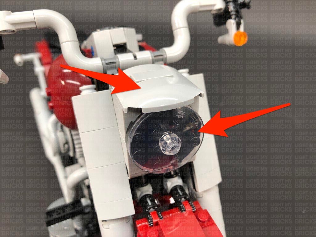
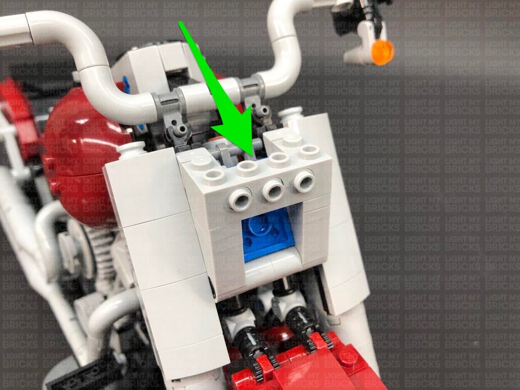
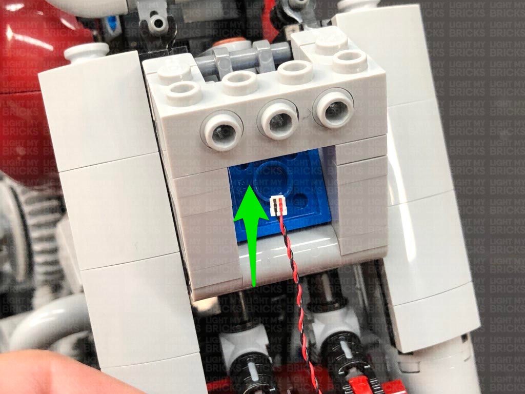
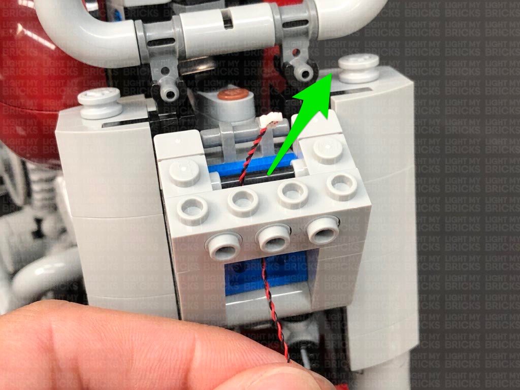
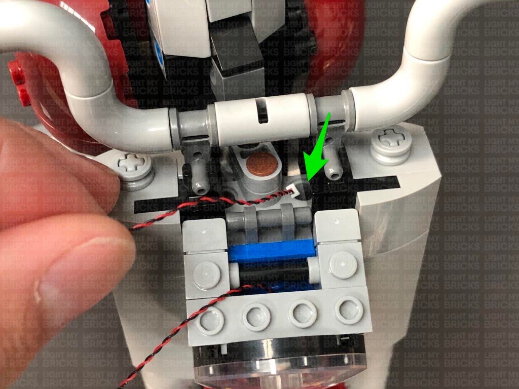
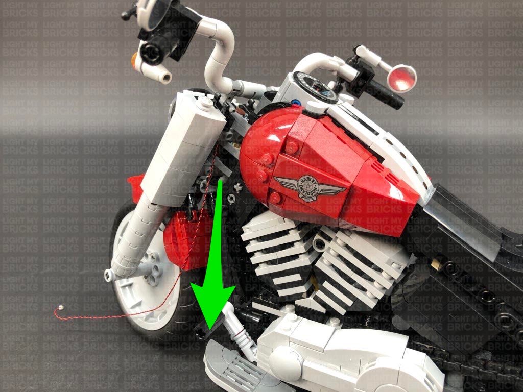
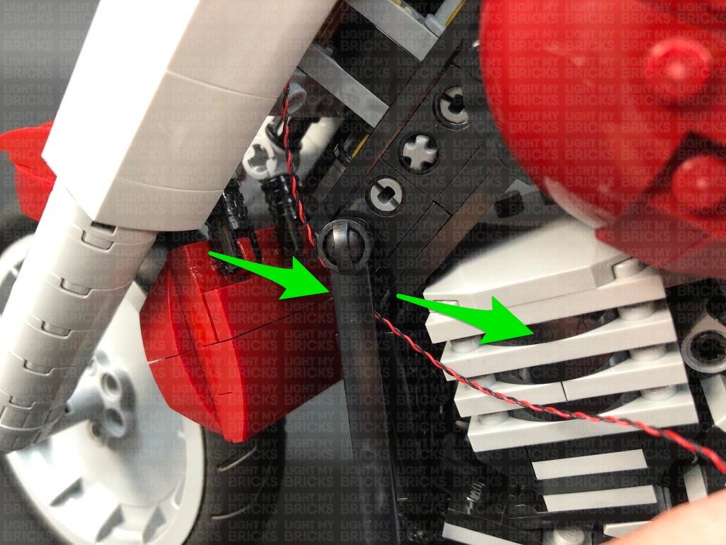
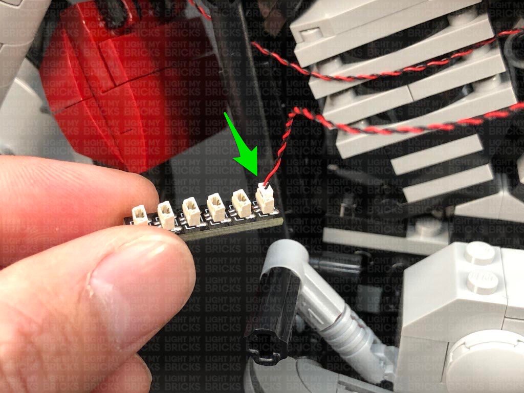
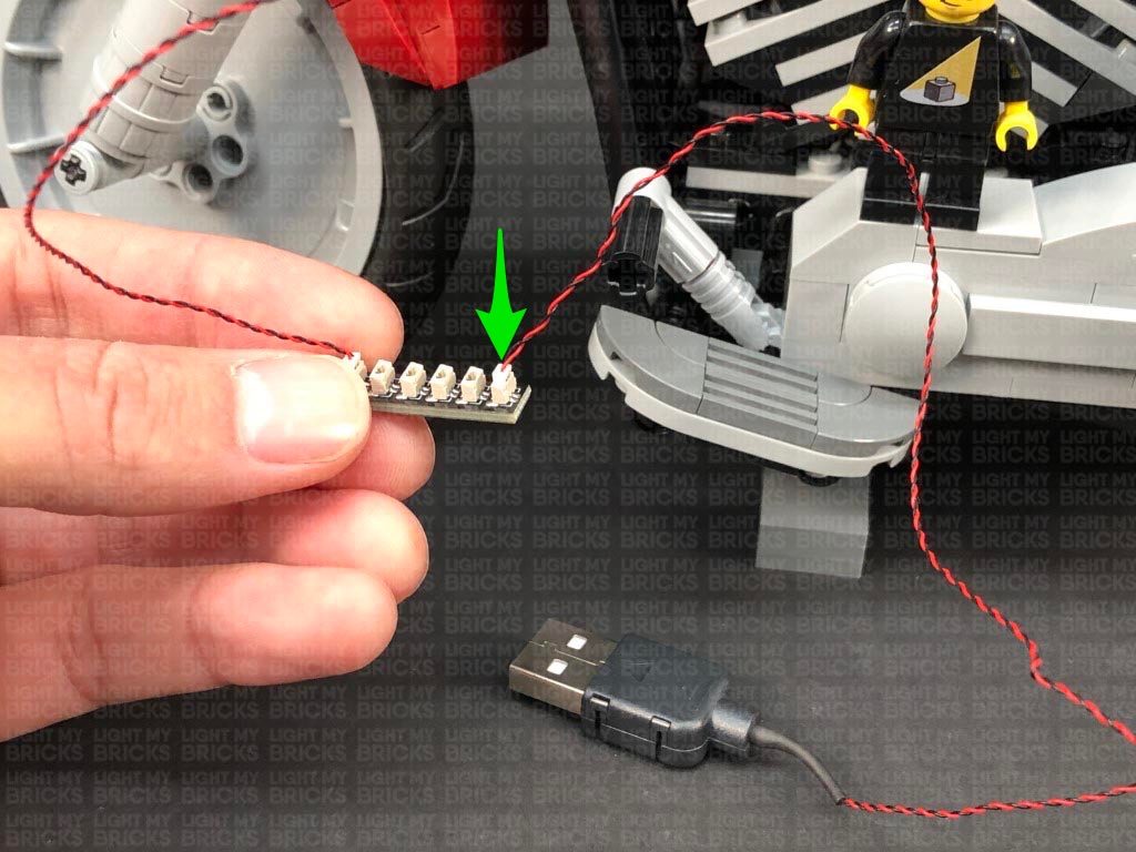
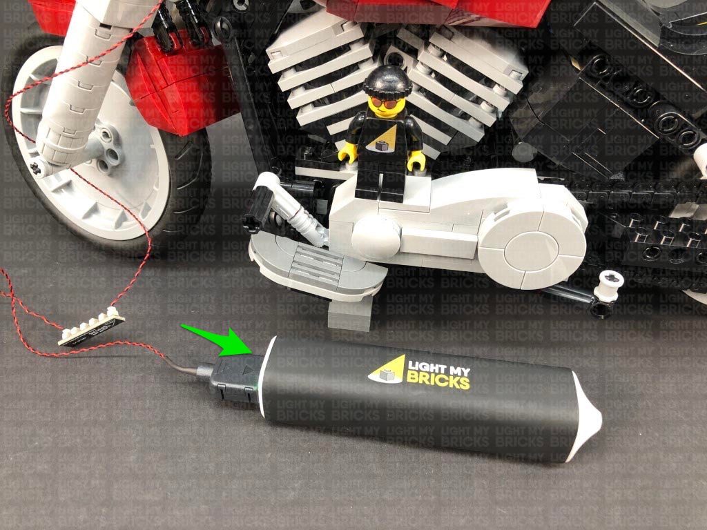
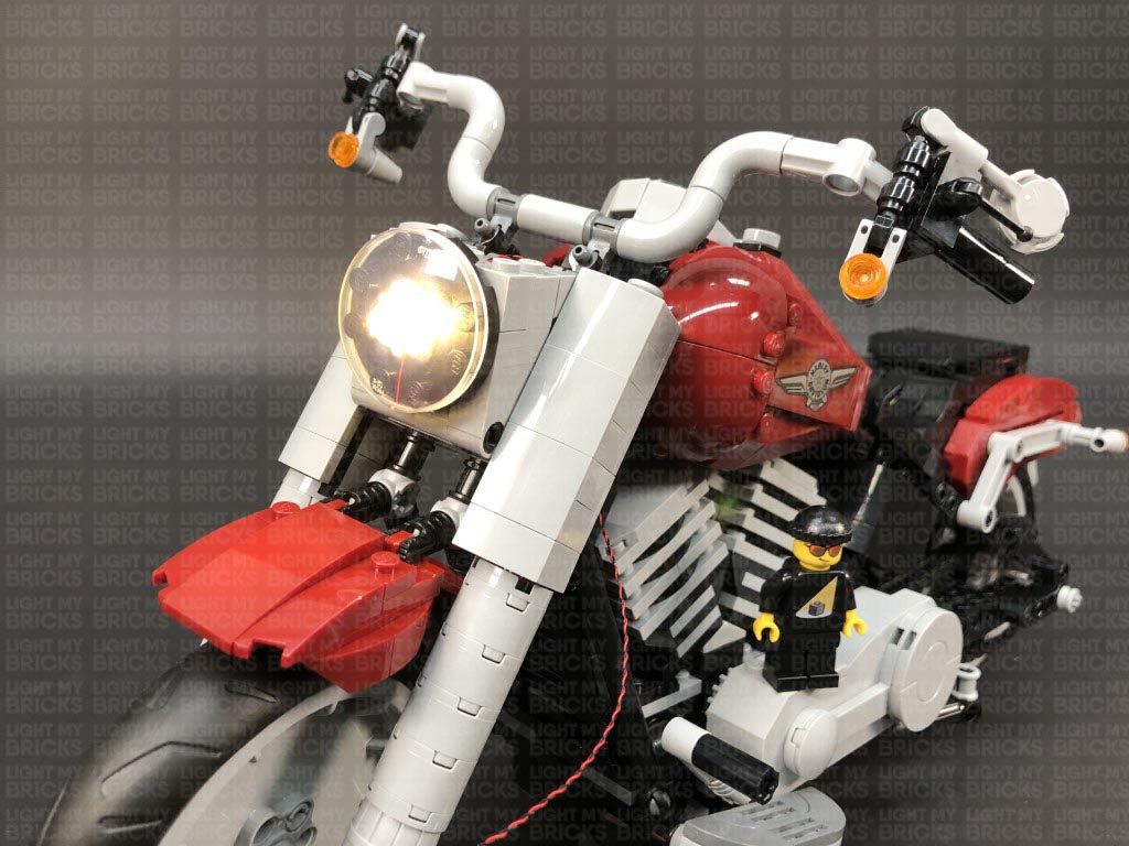
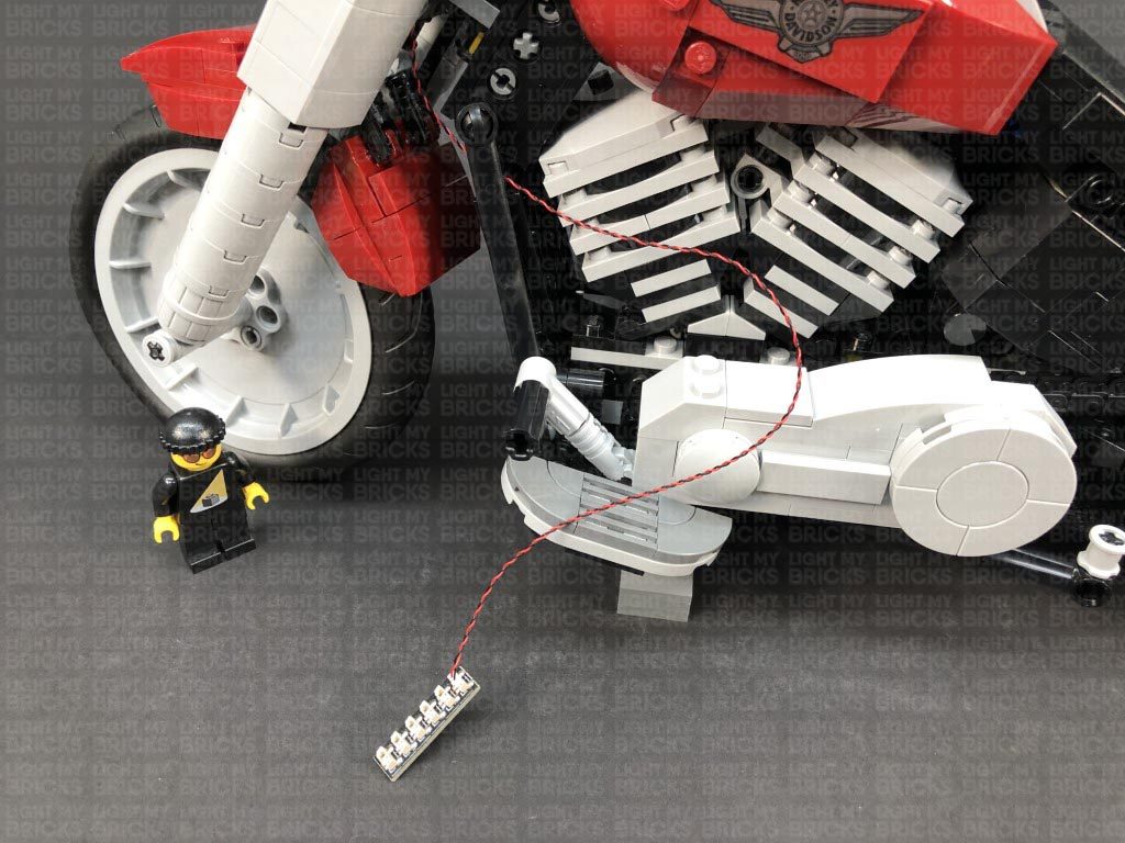
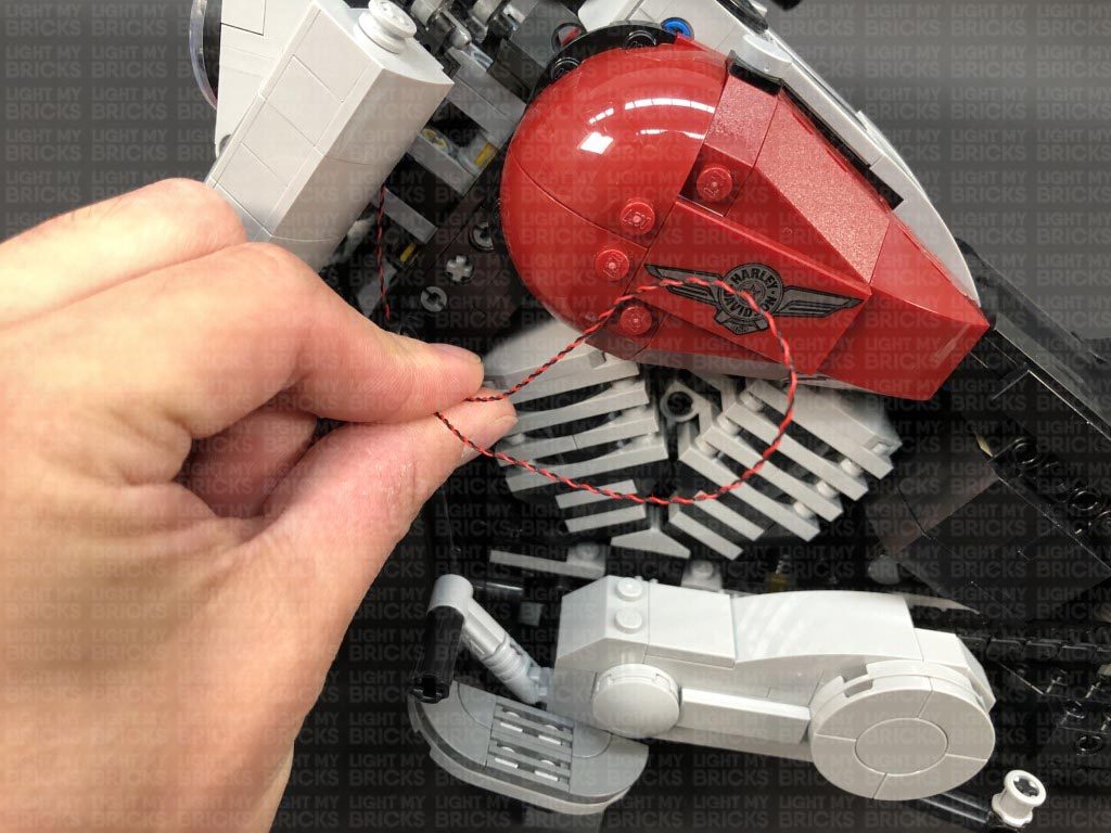
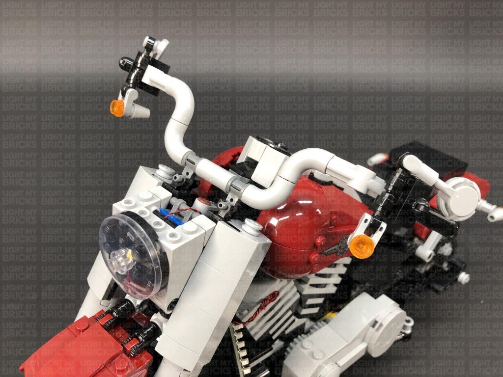
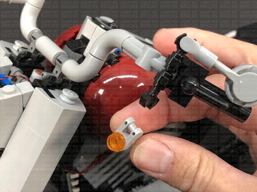
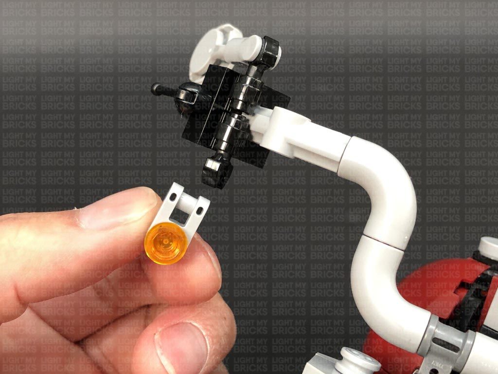
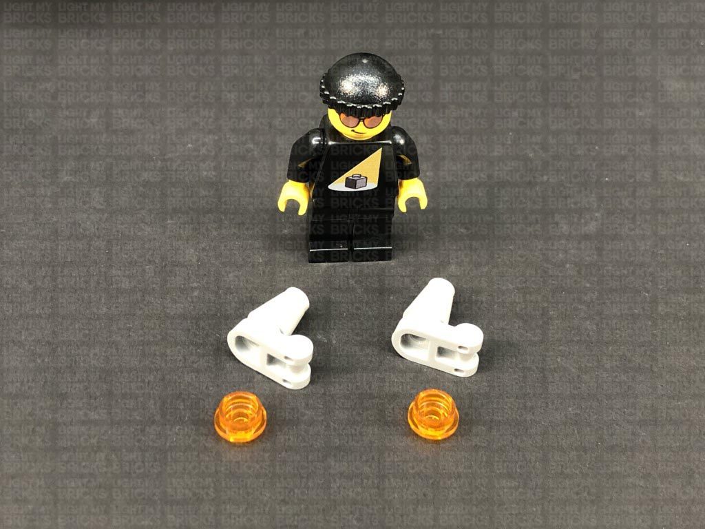
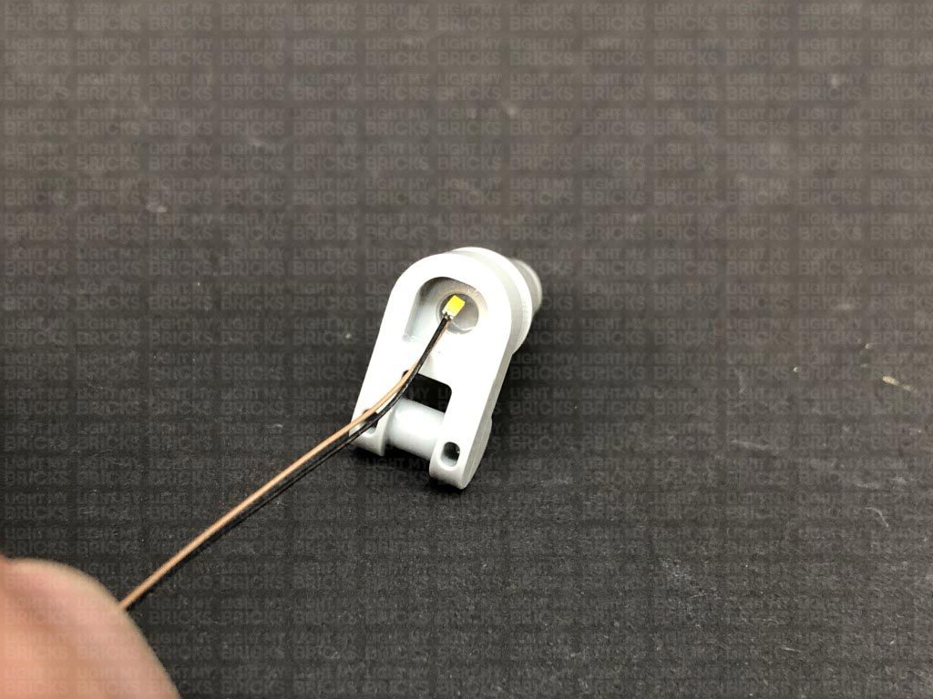
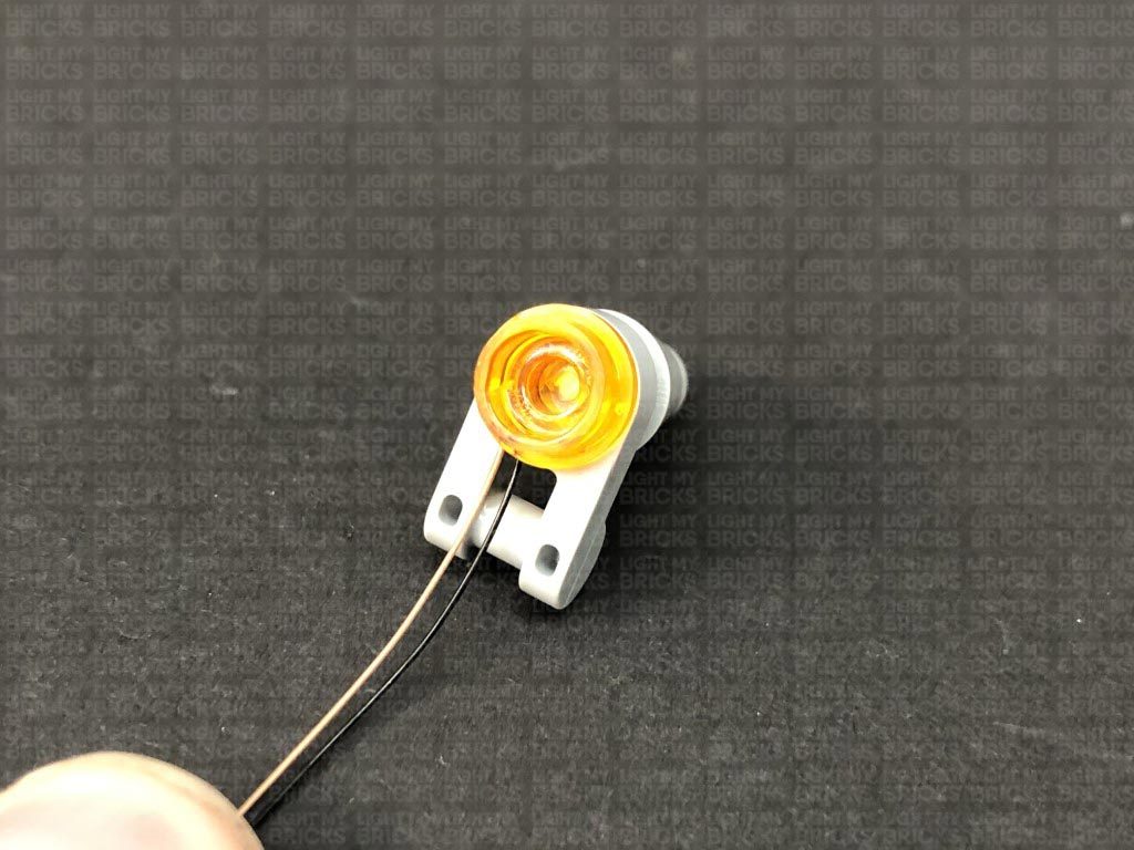
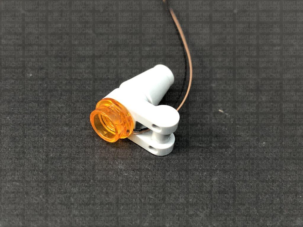
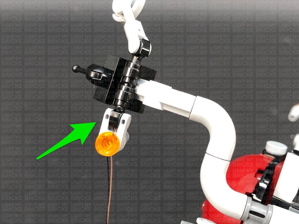
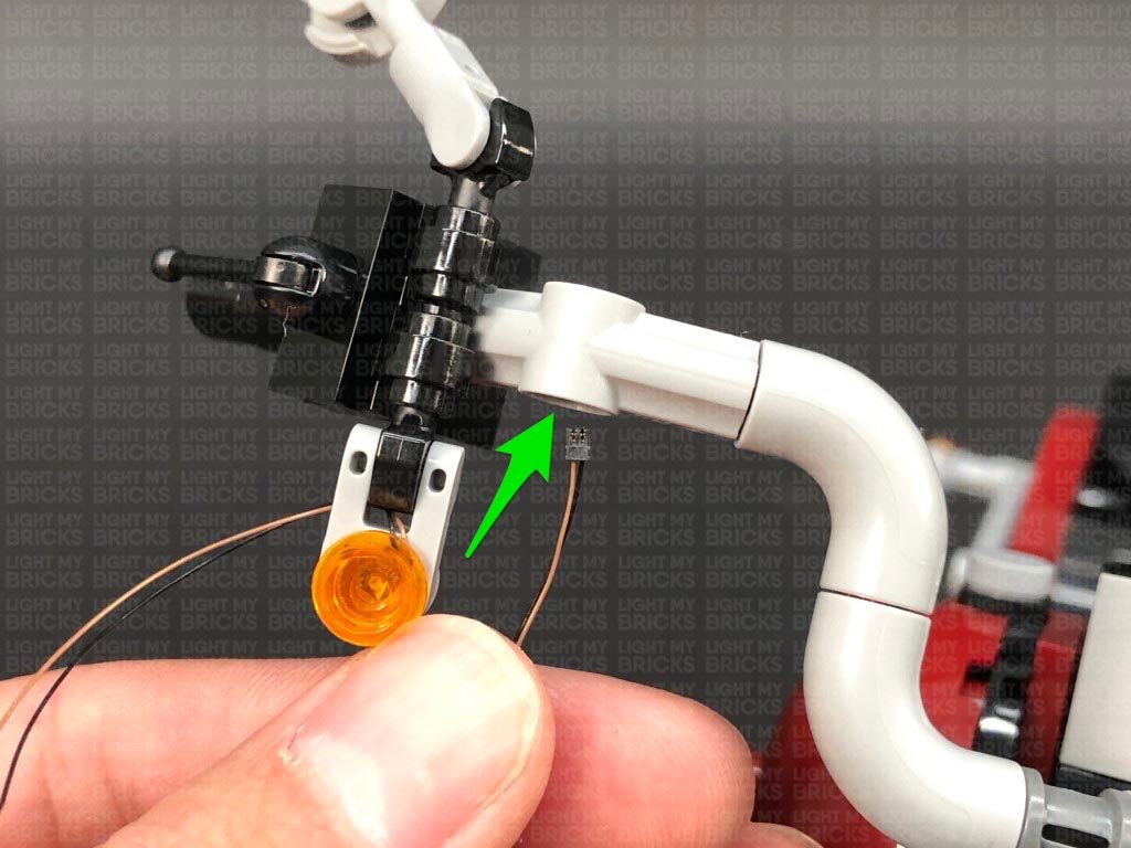
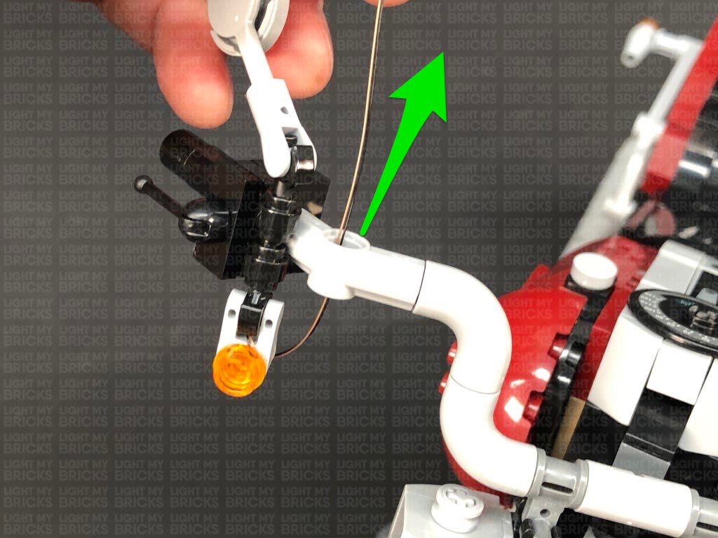
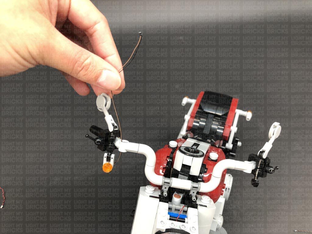
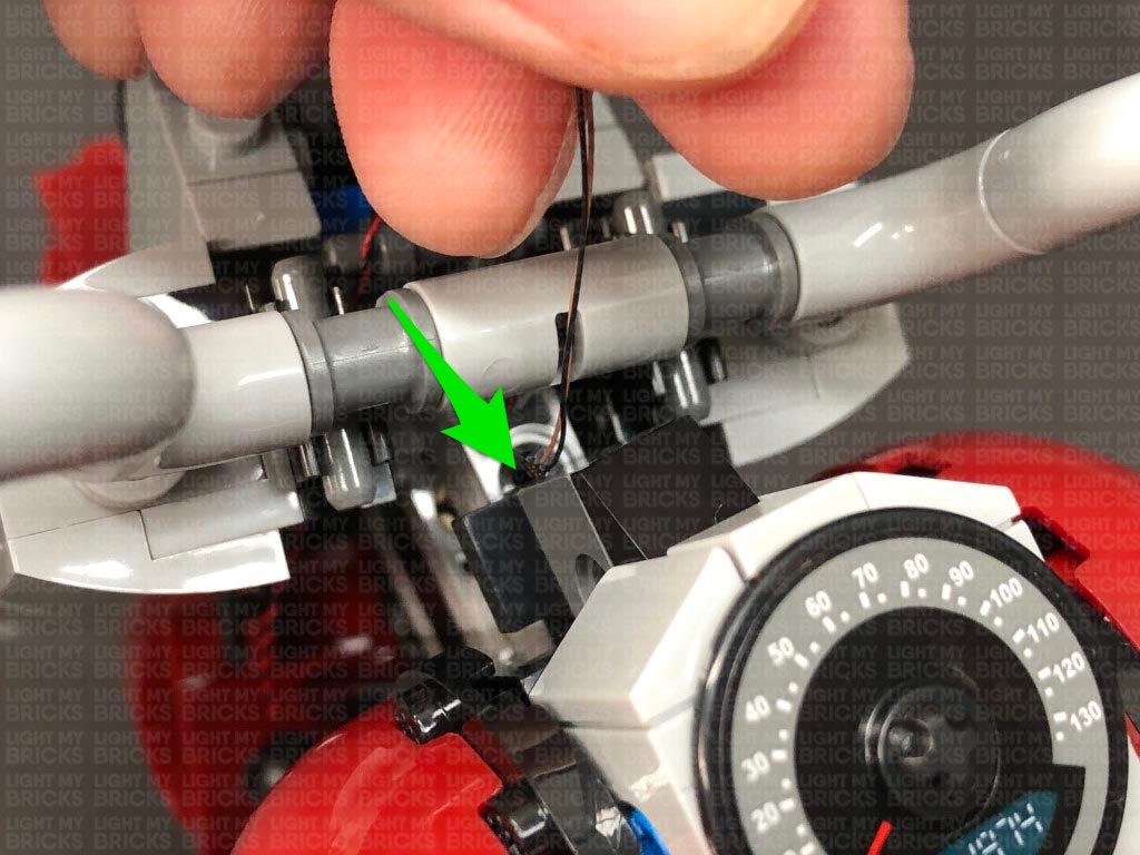
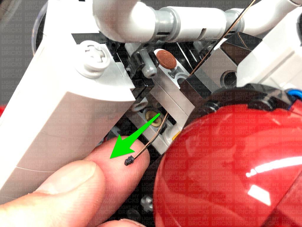
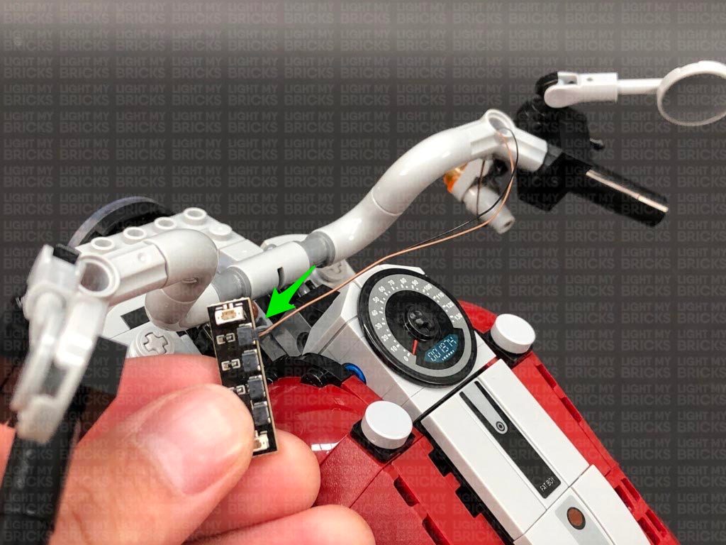
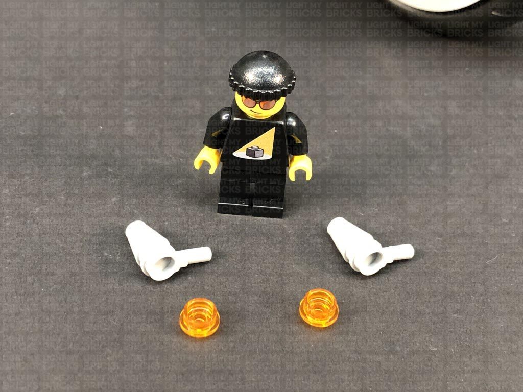
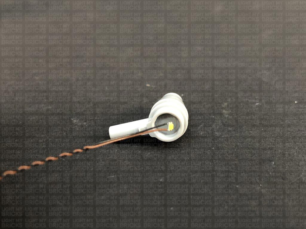
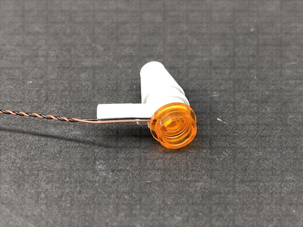
1.) We will first install the headlights and the front indicator lights. To start, disconnect and disassemble the following sections as shown below: Take a White 30cm Large Bit Light and place it in the centre of the black round plate. Secure the Large Bit Light in place by reconnecting the trans clear dish over the top. Pull down the following section, then thread the connector end of the Bit Light cable underneath the middle of this section. Pull the cable all the way up from the top, then reconnect the headlight ensuring the cable of the light is facing the bottom of the headlight. 2.) Thread the Large Bit Light cable down the light grey technic brick hole on the right side. Turn the Harley around to the left side and pull the cable all the way out as shown below: Thread the cable behind the following bar, then connect the Bit Light to a 6-Port Expansion Board. Take your USB Power Cable and connect it to the end port on the expansion board. Connect the USB Connector to a USB Power Bank or wall adaptor (sold separately) and turn it ON to test the headlight is working OK. Note: If you experience any issues with the lights not working and suspect an issue with a component, please try a different port on the expansion board to verify where the fault lies (with the light or expansion board). To correct any issues with expansion board ports, please view the section addressing expansion board issues on our online troubleshooting guide. Reconnect the plate above the headlight, then disconnect the USB Power Cable from the expansion board. Eliminate excess cable by folding and twisting the cable around itself a few times into a neat bunch. 3.) We will now install the front indicator lights. First disconnect both of these sections and disassemble them as shown below: Take one of the grey sections and place it onto it’s side with the handle on the bottom. Take a White 15cm Micro Bit Light and place the led inside the plate. Ensure the cable is facing down and the LED is facing the correct side up. Secure the Micro Bit Light in place by reconnecting the trans orange round plate. Thread the cable through the space in between the handle bar and plate, then pull the cable all the way out from behind. Repeat this step to install another White 15cm Micro Bit Light to the other indicator light.
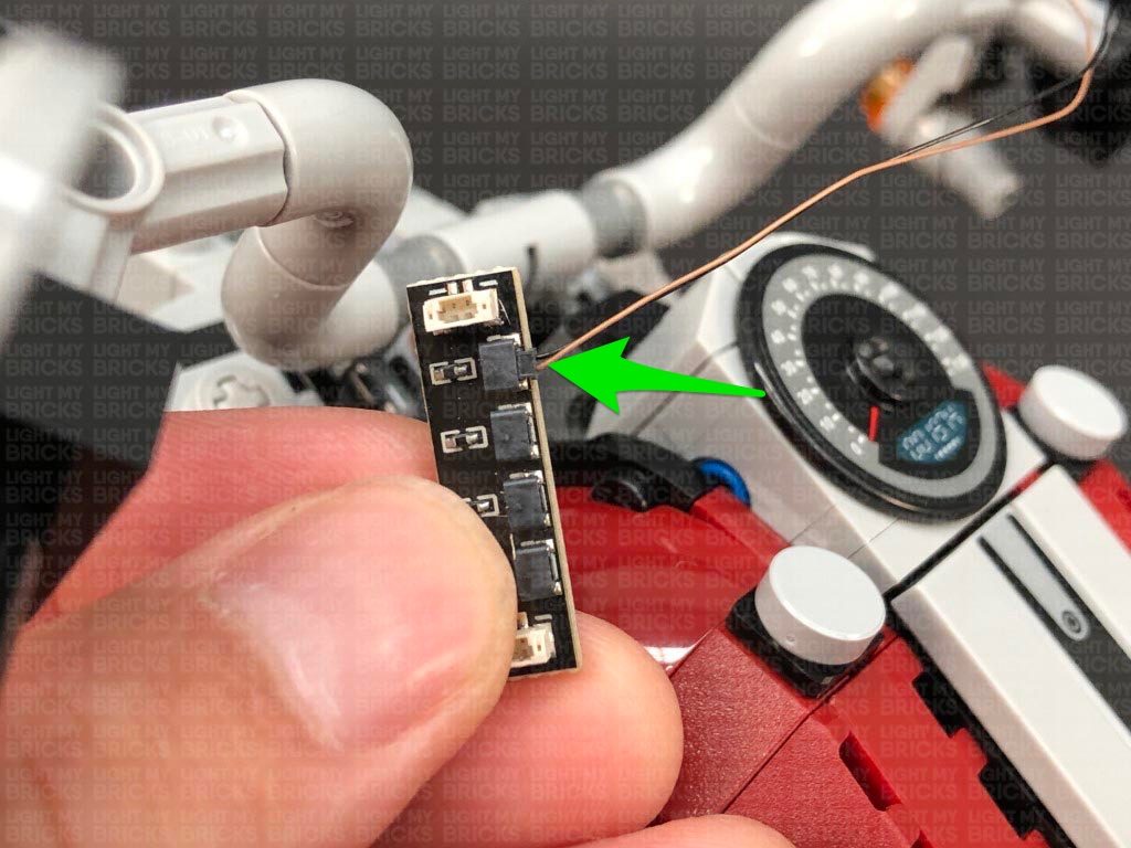
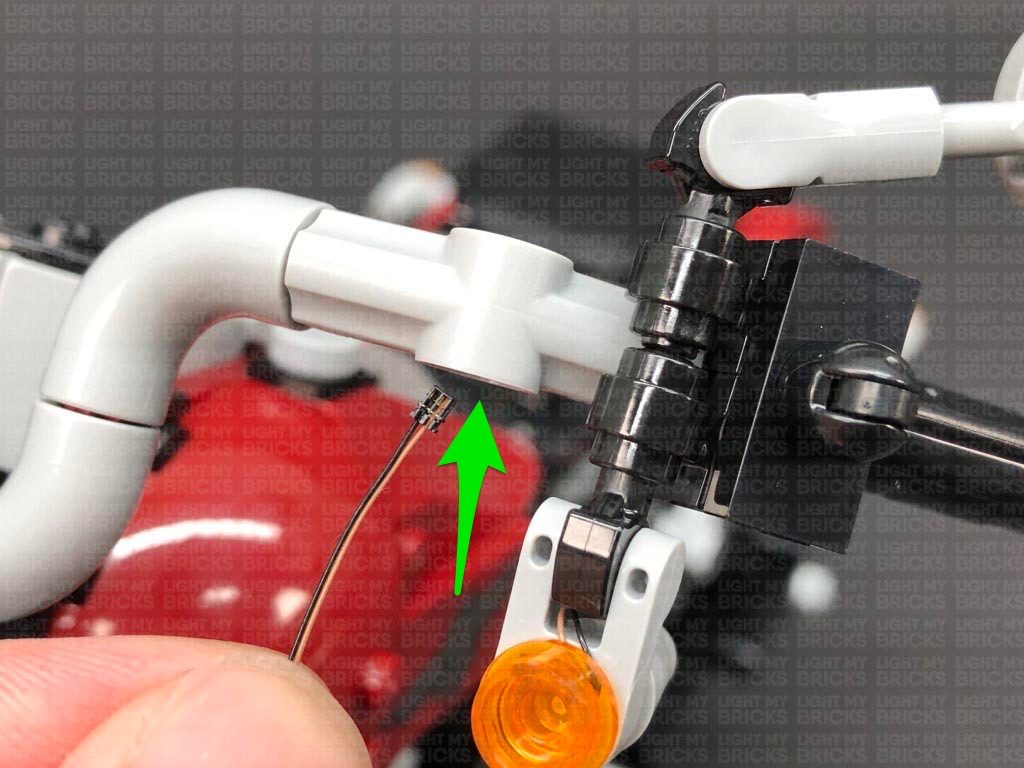
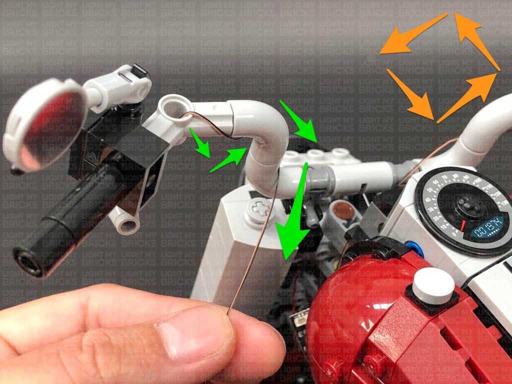
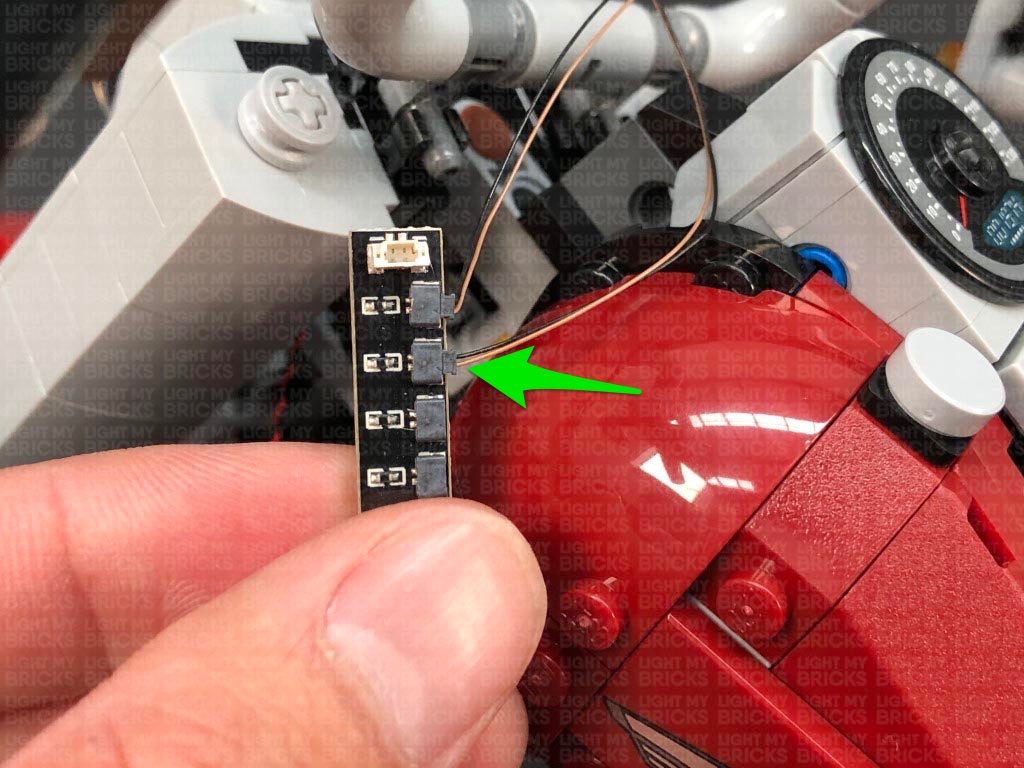
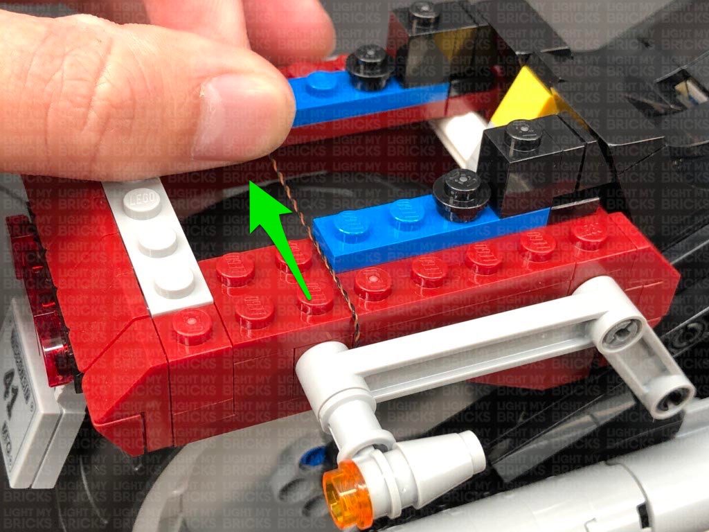
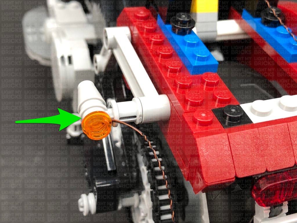
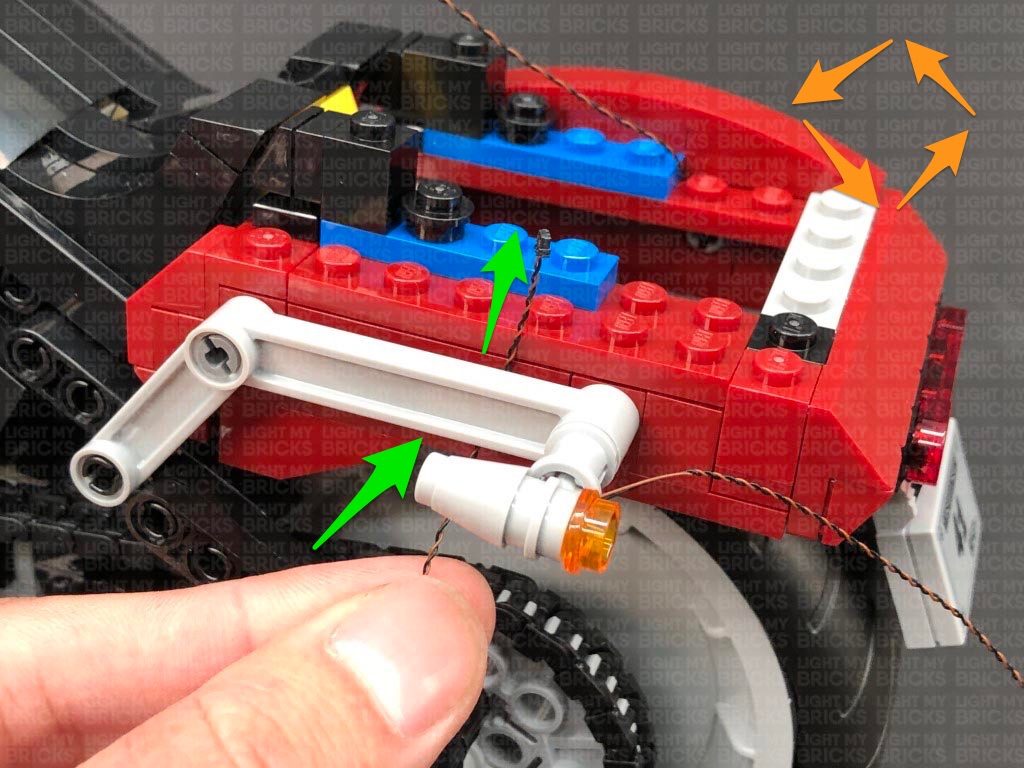
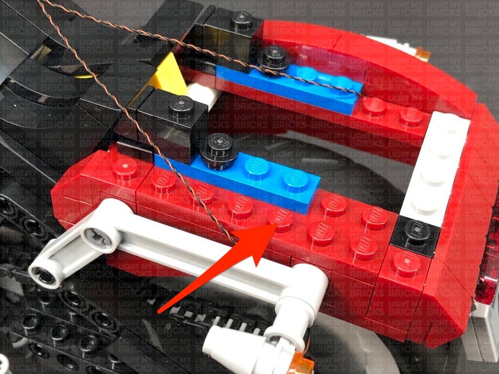
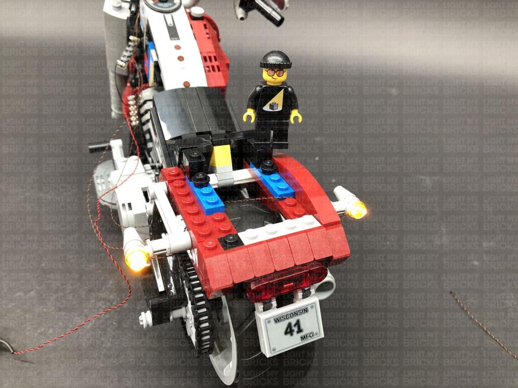
 4.) Reconnect the right indicator light, then thread the cable up the technic brick hole to the right of it. Pull the cable all the way out from the top then from the other side of the vehicle, wind the cable around the handle bar. Thread the cable down the following technic brick hole in the centre of the bike, then connect it to a Micro 4-Port Expansion Board.
Reconnect the left indicator light section, then thread the cable up the hole toward the left. Pull the cable all the way out, then from the left side of the bike, thread the cable around the handle bars as shown below to then connect to the Micro 4-Port Expansion Board.
5.) Connect the USB Power Cable and to the Expansion Board’s larger port and turn ON the USB Power Bank to test the indicator lights are working OK.
Disconnect the USB Power Cable from the Micro Expansion Board and connect a 5cm Connecting Cable to the large port instead. Connect the other end of the cable to a spare port on the 6-Port Expansion Board below.
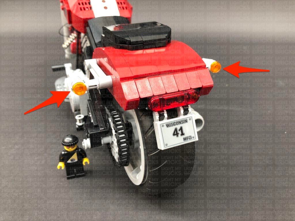
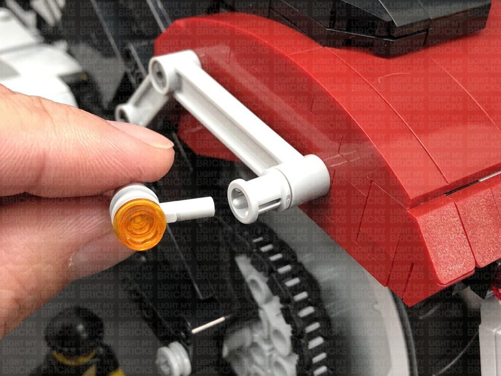
6.) We will now install the rear indicator lights. Disconnect each indicator section and disassemble them as shown below:
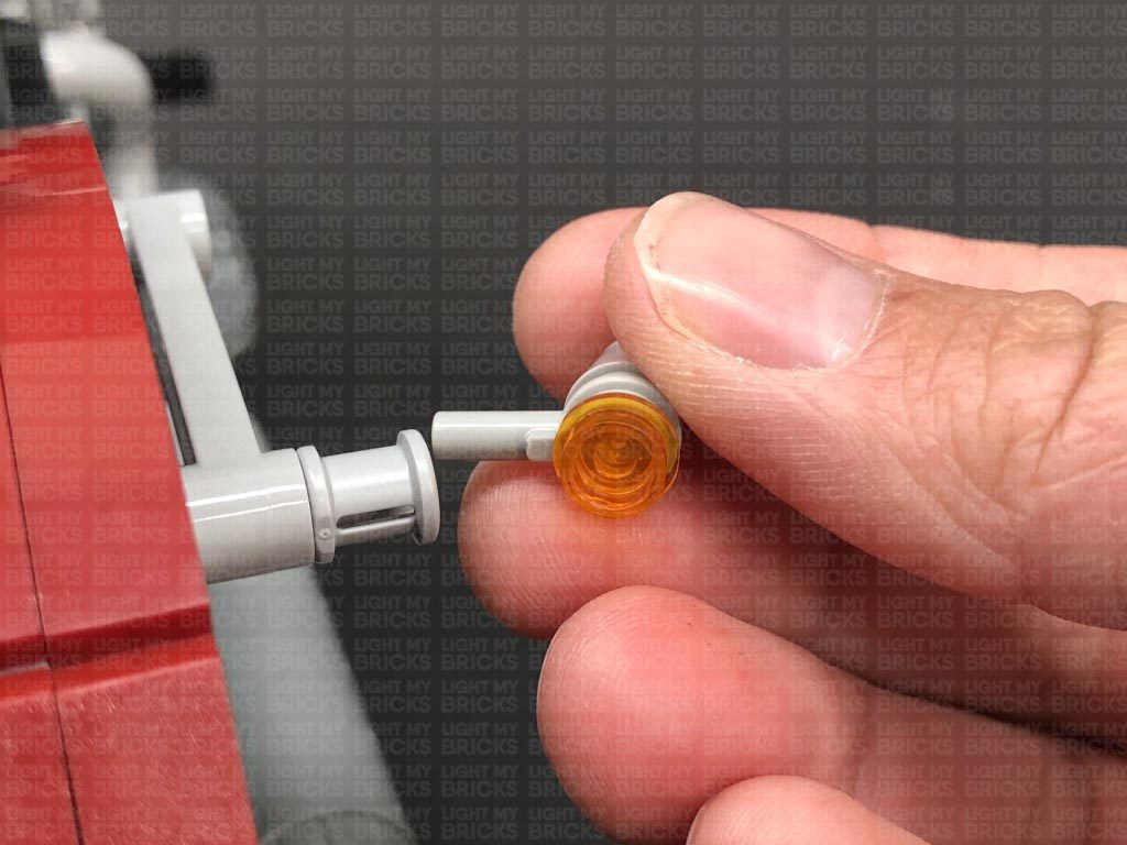
Take a White 30cm Micro Bit Light and with the lego pin facing the same way as the connector side of the cable, place the LED inside the grey plate. Secure the Micro Bit Light in place by reconnecting the trans orange round plate over the top.
Repeat this step to install another White 30cm Micro Bit Light to the other rear light section.
4.) Reconnect the right indicator light, then thread the cable up the technic brick hole to the right of it. Pull the cable all the way out from the top then from the other side of the vehicle, wind the cable around the handle bar. Thread the cable down the following technic brick hole in the centre of the bike, then connect it to a Micro 4-Port Expansion Board.
Reconnect the left indicator light section, then thread the cable up the hole toward the left. Pull the cable all the way out, then from the left side of the bike, thread the cable around the handle bars as shown below to then connect to the Micro 4-Port Expansion Board.
5.) Connect the USB Power Cable and to the Expansion Board’s larger port and turn ON the USB Power Bank to test the indicator lights are working OK.
Disconnect the USB Power Cable from the Micro Expansion Board and connect a 5cm Connecting Cable to the large port instead. Connect the other end of the cable to a spare port on the 6-Port Expansion Board below.
6.) We will now install the rear indicator lights. Disconnect each indicator section and disassemble them as shown below:
Take a White 30cm Micro Bit Light and with the lego pin facing the same way as the connector side of the cable, place the LED inside the grey plate. Secure the Micro Bit Light in place by reconnecting the trans orange round plate over the top.
Repeat this step to install another White 30cm Micro Bit Light to the other rear light section.
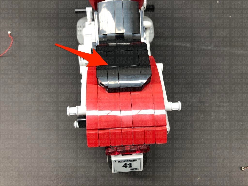
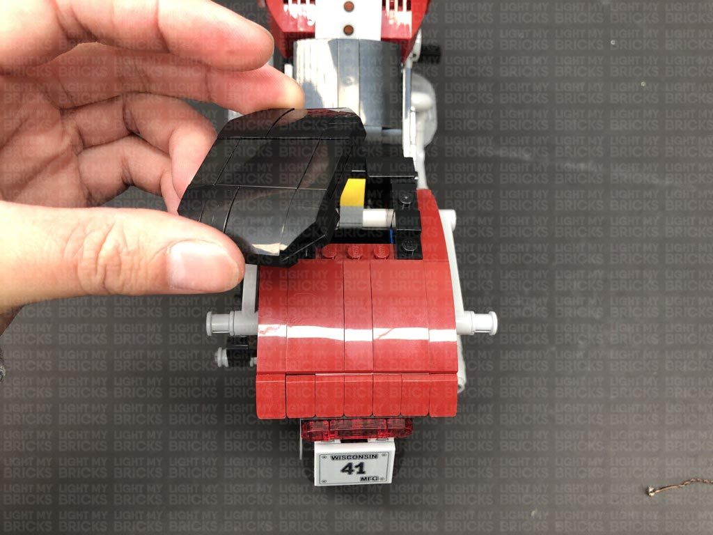
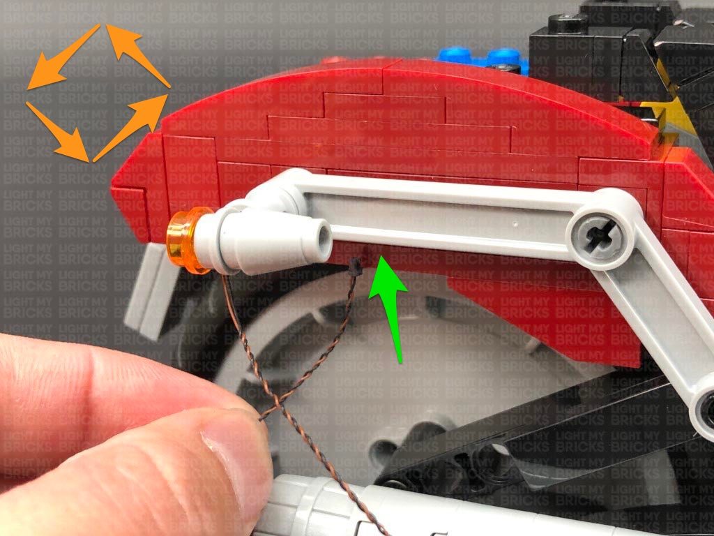
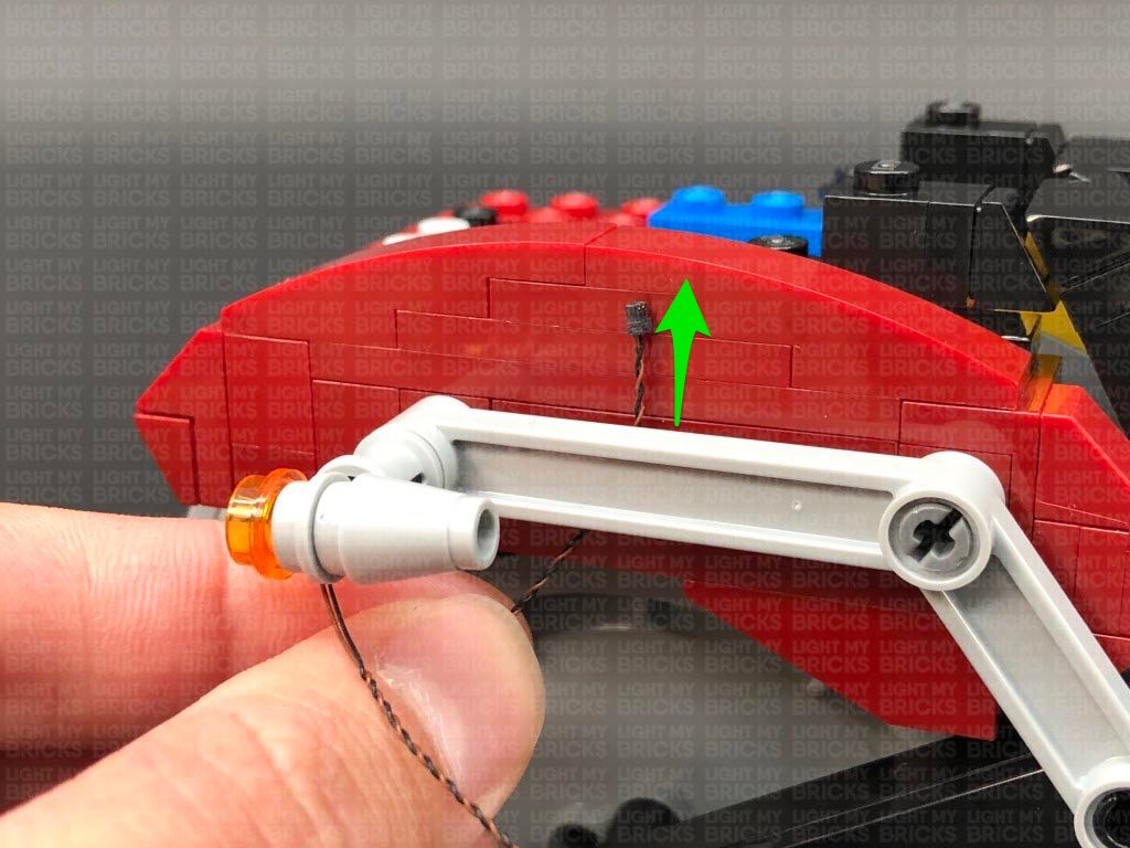
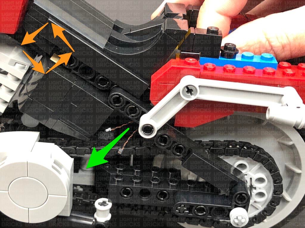
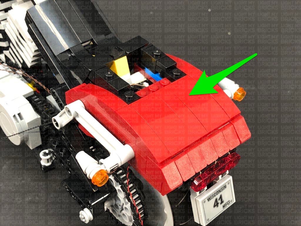
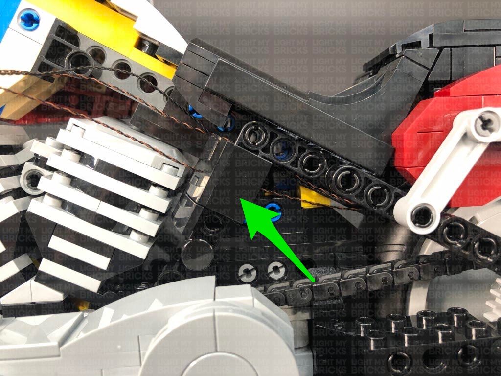
 7.) Follow the below images to disconnect sections surrounding the back of the Harley.
Reconnect the rear right indicator section, then from the right side of the vehicle, thread the cable up behind the grey technic piece. Pull the cable up, then disconnect the dark red section above. Bring the cable over to the other side and lay it in between studs before reconnecting the dark red section.
Reconnect the rear left light section, then from the left side of the vehicle, thread the cable up behind the grey technic piece. Disconnect the following plate above, then lay the cable toward the centre, in between studs. Reconnect the plate over the cable.
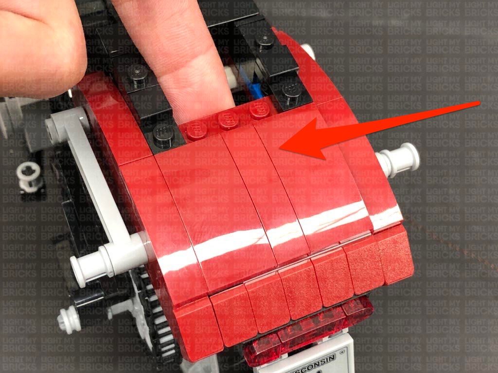
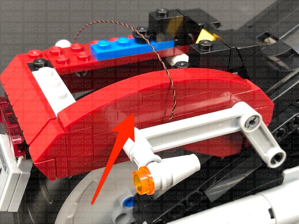
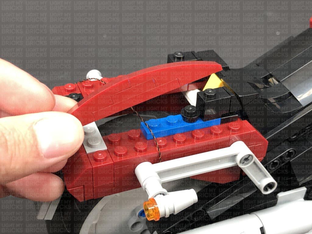
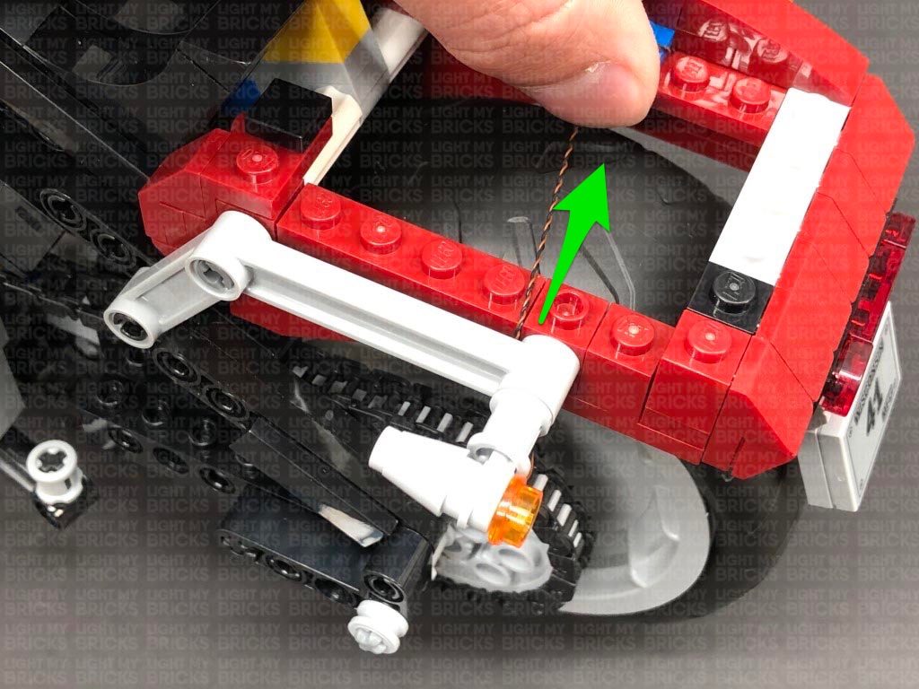
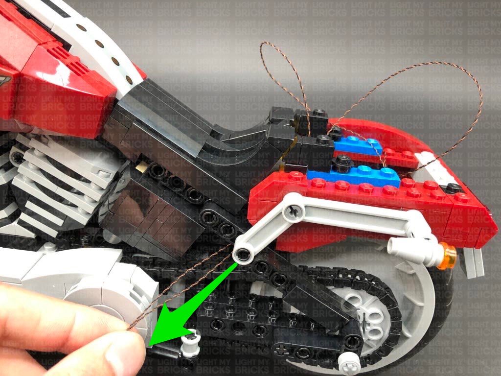
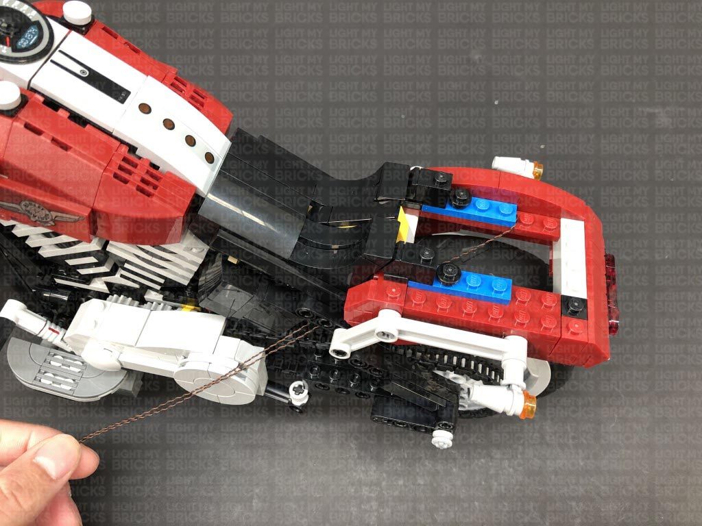
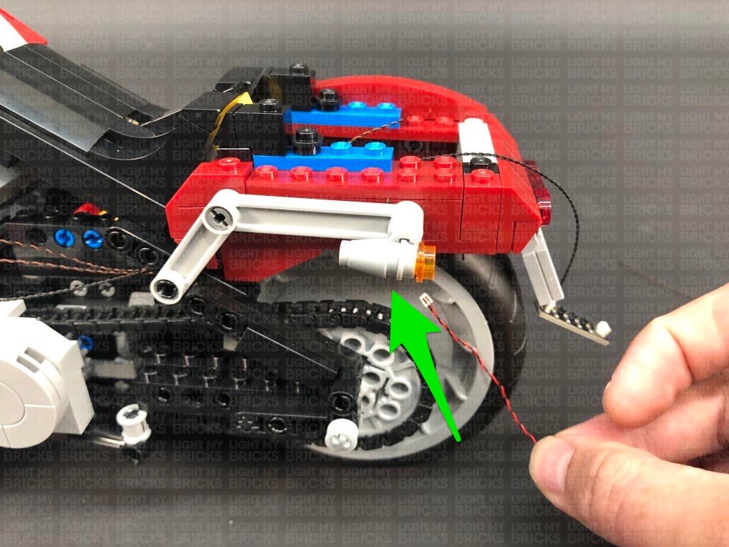
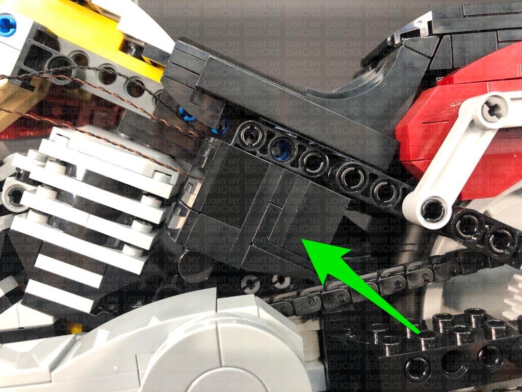
8.) Group the two rear light cables together, then thread them down the space at the front of the rear wheel. From the left side of the vehicle, pull the cables out the space just above the bike chain. Pull the cables all the way out.
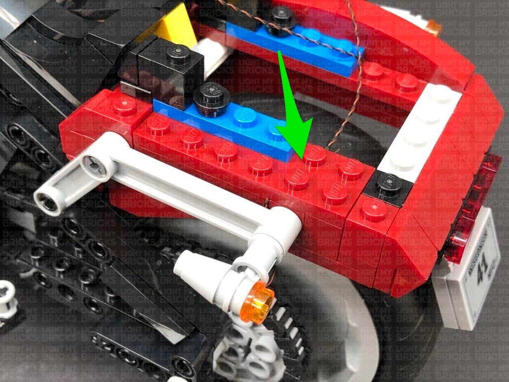
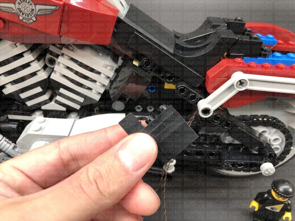
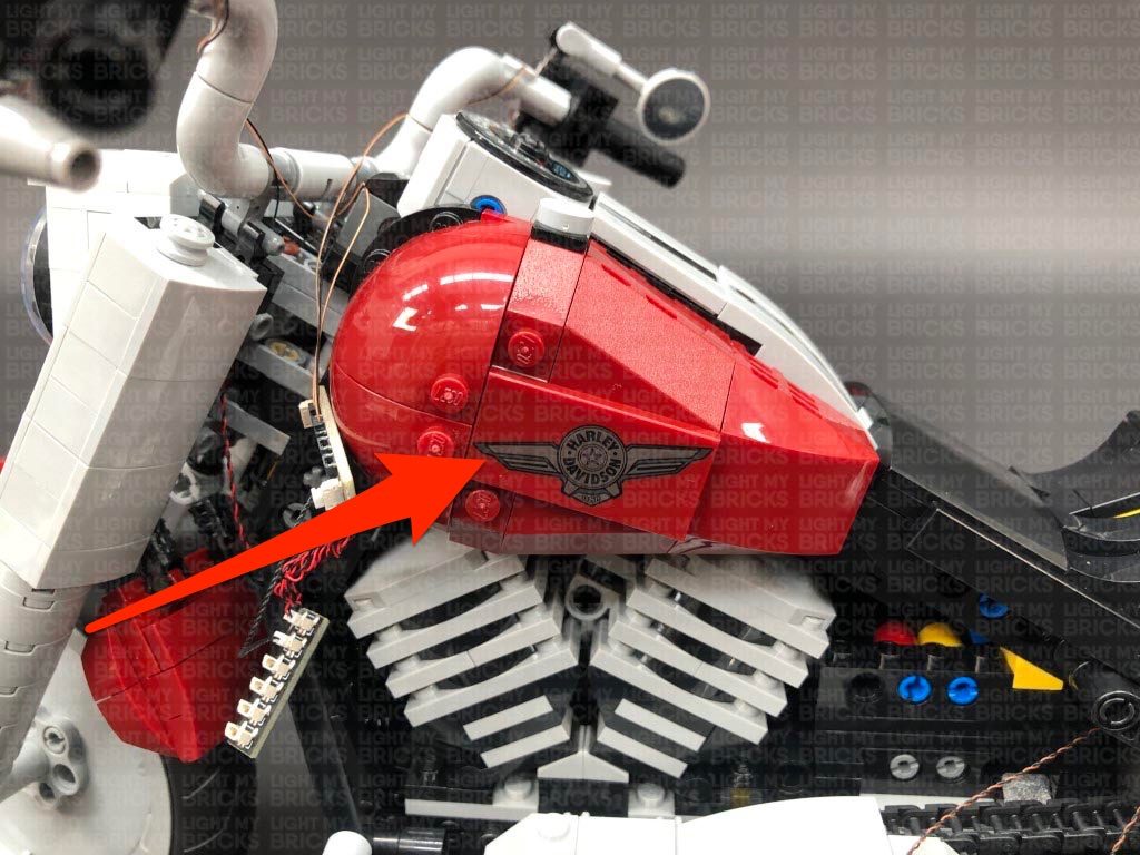
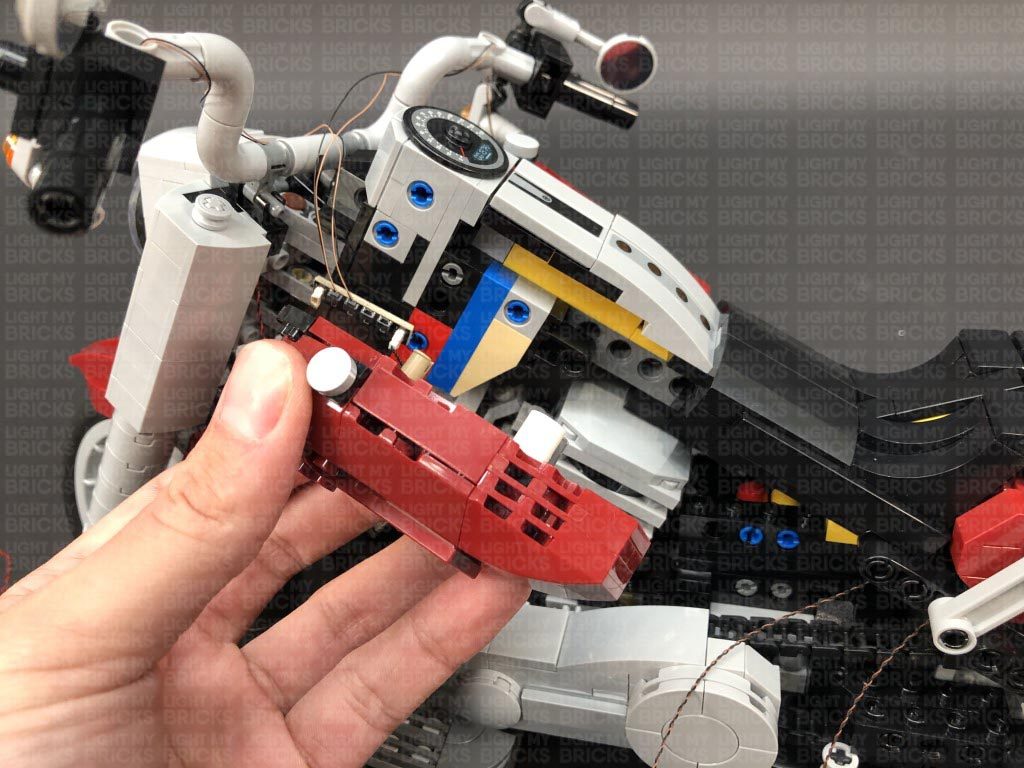
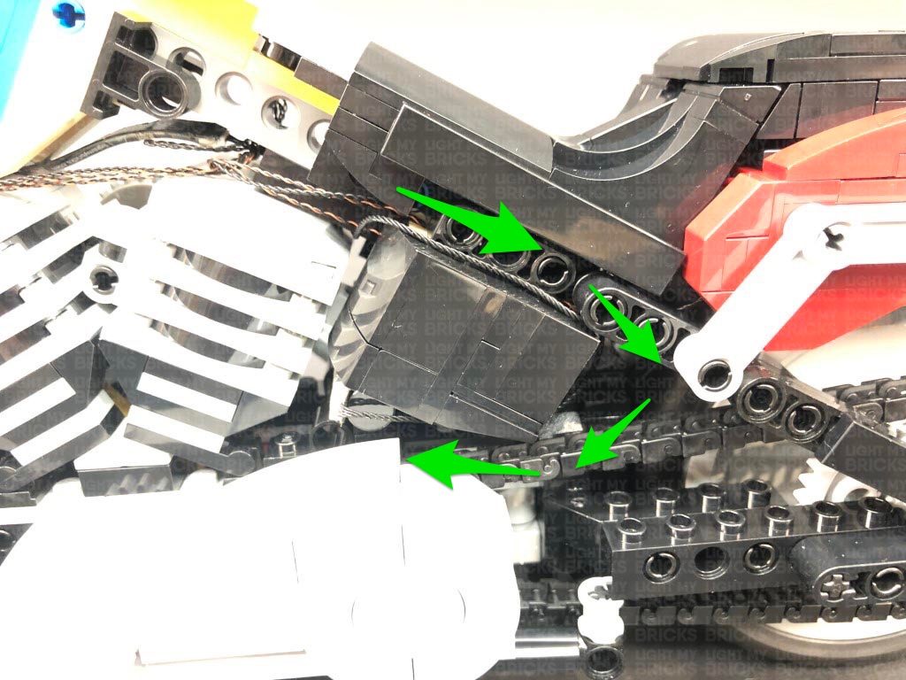
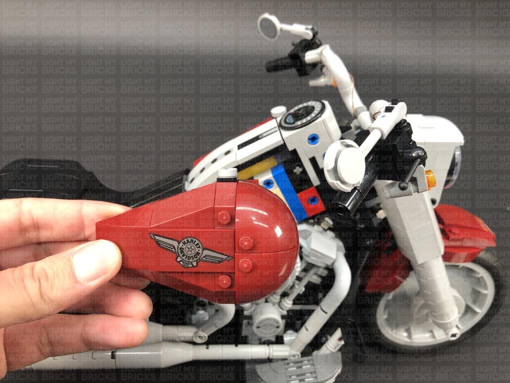
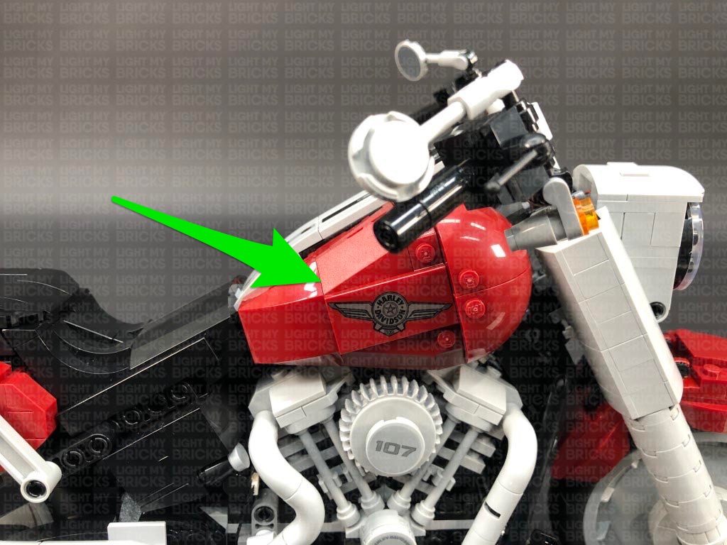
Disconnect the following black section to the left of the cables, then disconnect the Harley Davidson fuel tank section.
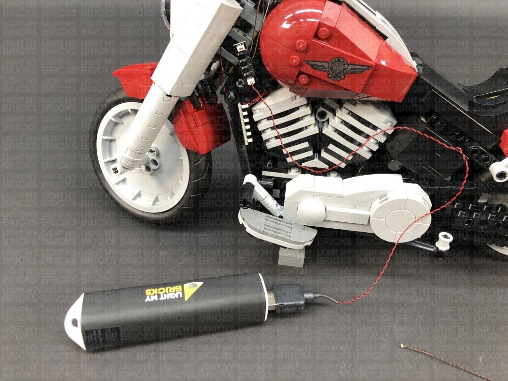
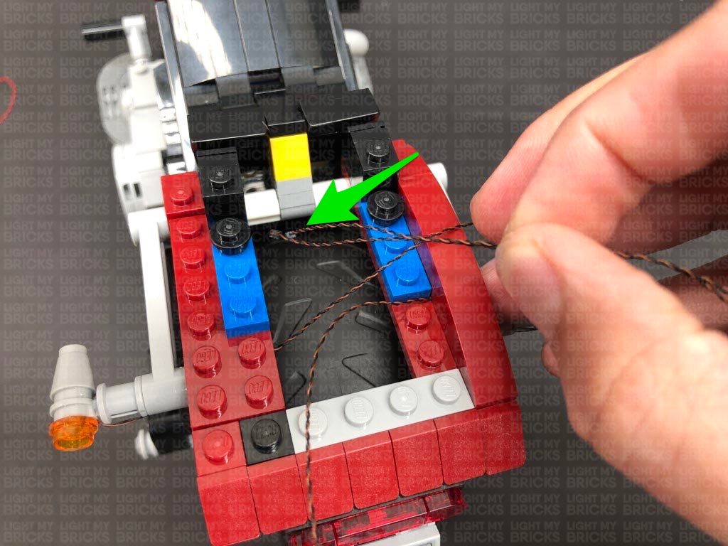
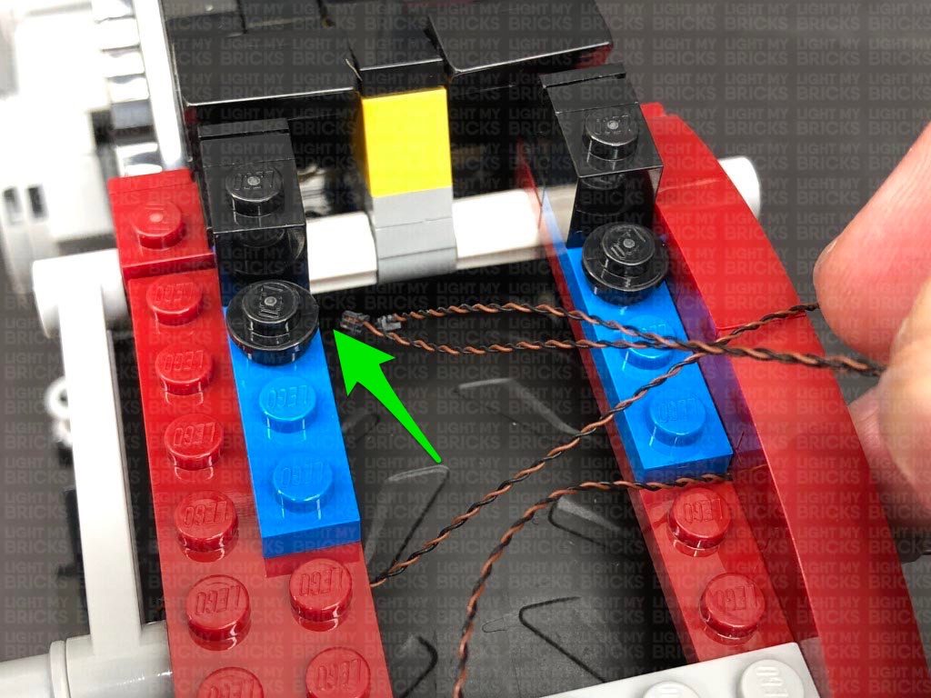
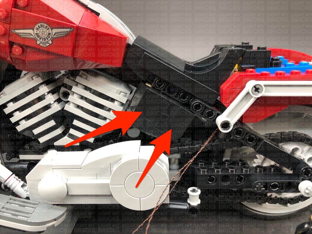
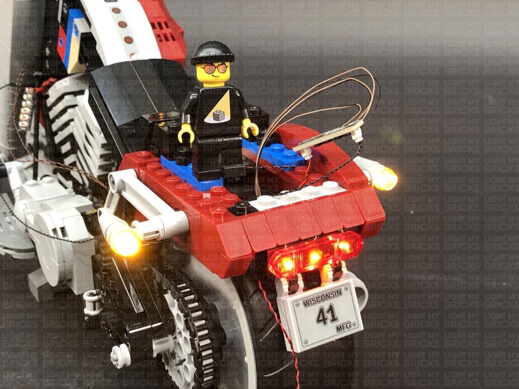
9.) Take the two rear indicator light cables and connect them to the Micro Expansion Board at the front. Take the USB Power Cable and connect it to the 6-Port Expansion Board, then turn the power bank ON to test the rear indicator lights are working OK.
Note: If you experience any issues with the lights not working and suspect an issue with a component, please try a different port on the expansion board to verify where the fault lies (with the light or expansion board). To correct any issues with expansion board ports, please view the section addressing expansion board issues on our online troubleshooting guide.
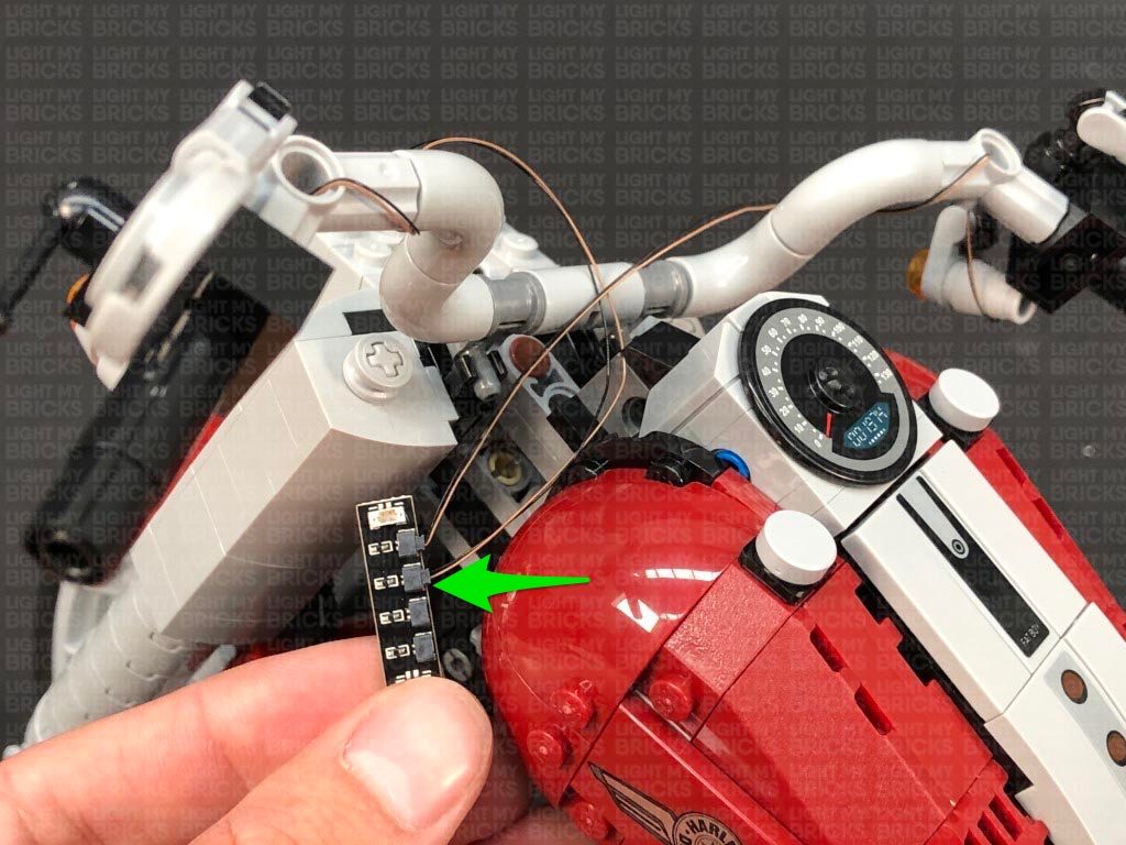
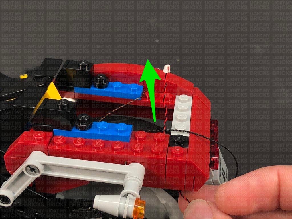
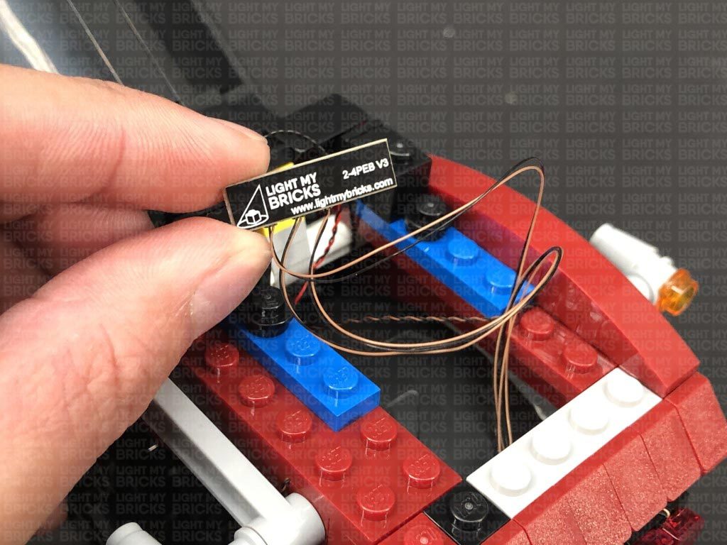
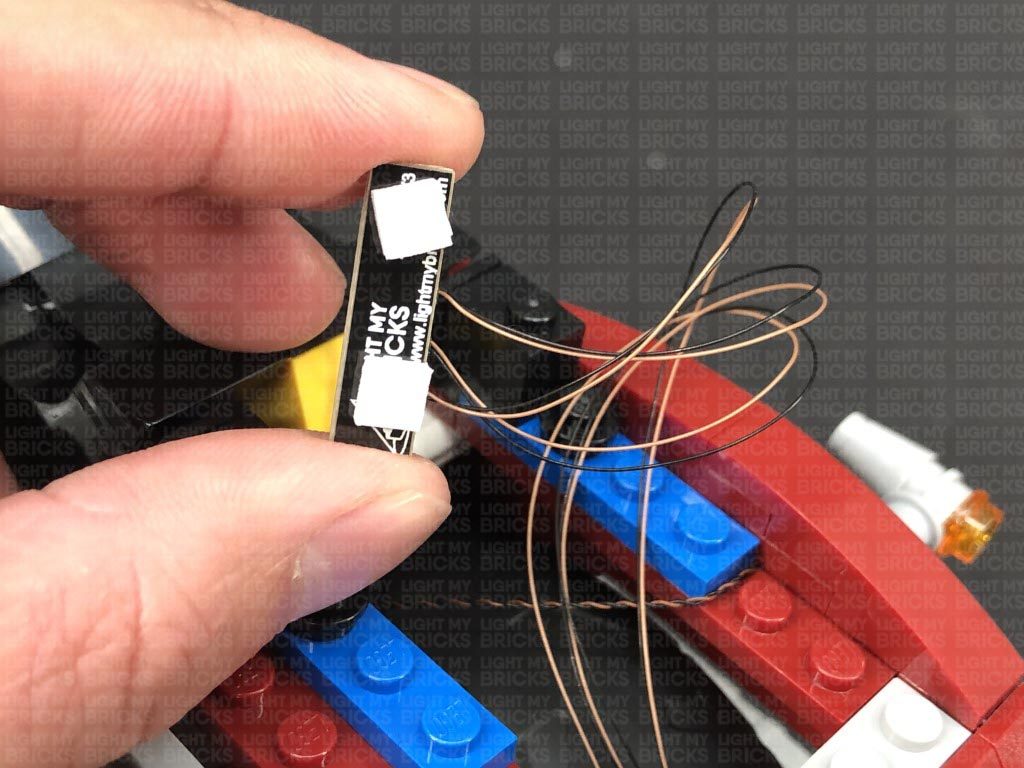
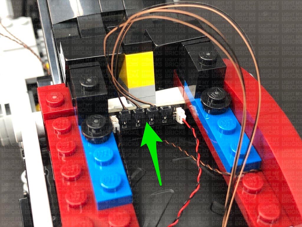
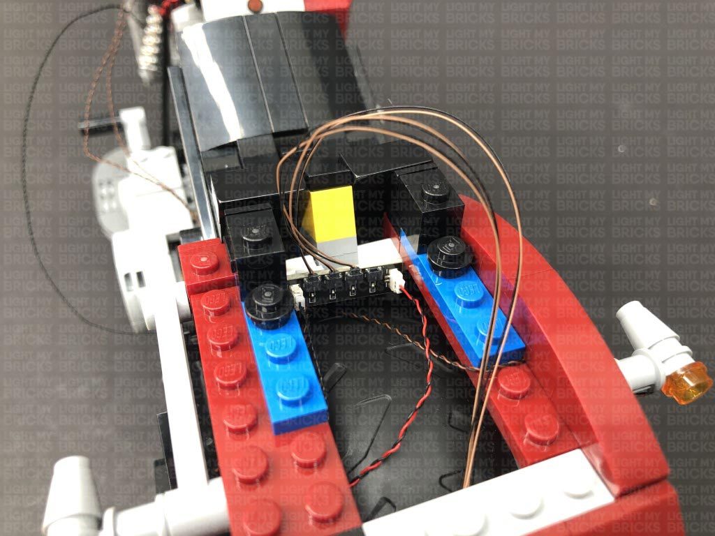
10.) Take 2x Adhesive Squares and stick them to the back of the Micro Expansion Board. Tuck the expansion board inside just above the back of the front wheel. Mount the expansion board inside on the light grey technic studs as shown below.
Take a 30cm Connecting Cable and connect it to a spare port on the 6-Port Expansion Board, then bring the cable over toward the back of the bike. Thread the cable up the space just above the bike chain that leads into the section behind the bike seat. Pull the cable all the way out and connect it to the large port on a new Micro 4-Port Expansion Board.
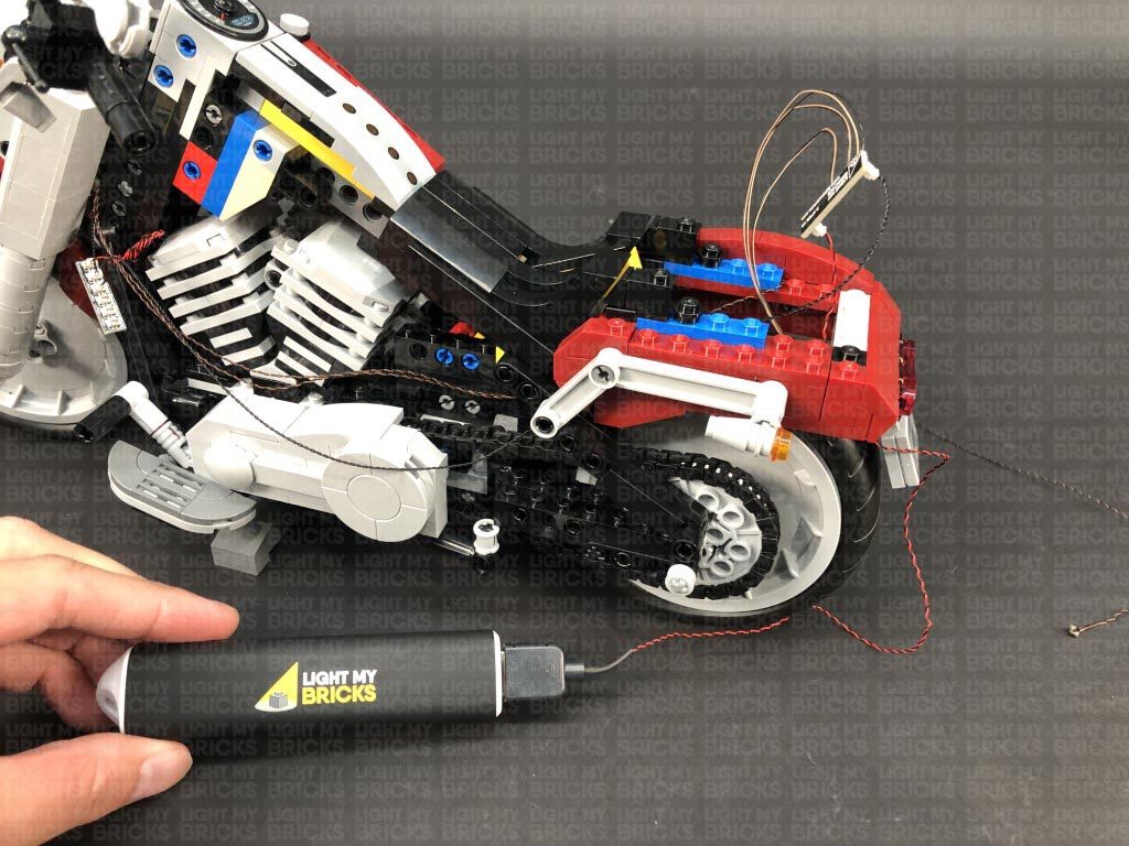
Take the USB Power Cable and thread it through the space behind the back wheel, then pull it up from the other side and connect it to the other large port on the Micro Expansion Board. This will be the permanent position of the USB Power Cable. Turn the Power ON to ensure all is working so far.
7.) Follow the below images to disconnect sections surrounding the back of the Harley.
Reconnect the rear right indicator section, then from the right side of the vehicle, thread the cable up behind the grey technic piece. Pull the cable up, then disconnect the dark red section above. Bring the cable over to the other side and lay it in between studs before reconnecting the dark red section.
Reconnect the rear left light section, then from the left side of the vehicle, thread the cable up behind the grey technic piece. Disconnect the following plate above, then lay the cable toward the centre, in between studs. Reconnect the plate over the cable.
8.) Group the two rear light cables together, then thread them down the space at the front of the rear wheel. From the left side of the vehicle, pull the cables out the space just above the bike chain. Pull the cables all the way out.
Disconnect the following black section to the left of the cables, then disconnect the Harley Davidson fuel tank section.
9.) Take the two rear indicator light cables and connect them to the Micro Expansion Board at the front. Take the USB Power Cable and connect it to the 6-Port Expansion Board, then turn the power bank ON to test the rear indicator lights are working OK.
Note: If you experience any issues with the lights not working and suspect an issue with a component, please try a different port on the expansion board to verify where the fault lies (with the light or expansion board). To correct any issues with expansion board ports, please view the section addressing expansion board issues on our online troubleshooting guide.
10.) Take 2x Adhesive Squares and stick them to the back of the Micro Expansion Board. Tuck the expansion board inside just above the back of the front wheel. Mount the expansion board inside on the light grey technic studs as shown below.
Take a 30cm Connecting Cable and connect it to a spare port on the 6-Port Expansion Board, then bring the cable over toward the back of the bike. Thread the cable up the space just above the bike chain that leads into the section behind the bike seat. Pull the cable all the way out and connect it to the large port on a new Micro 4-Port Expansion Board.
Take the USB Power Cable and thread it through the space behind the back wheel, then pull it up from the other side and connect it to the other large port on the Micro Expansion Board. This will be the permanent position of the USB Power Cable. Turn the Power ON to ensure all is working so far.
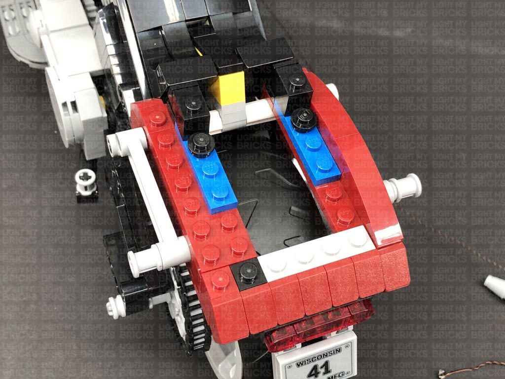
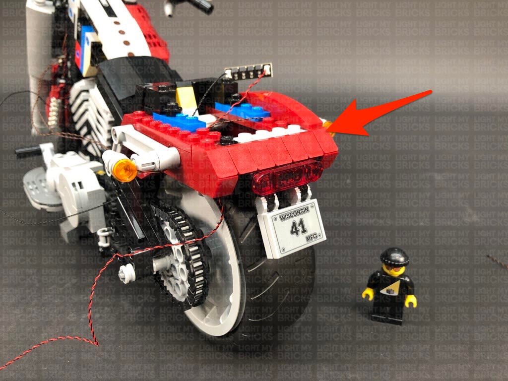
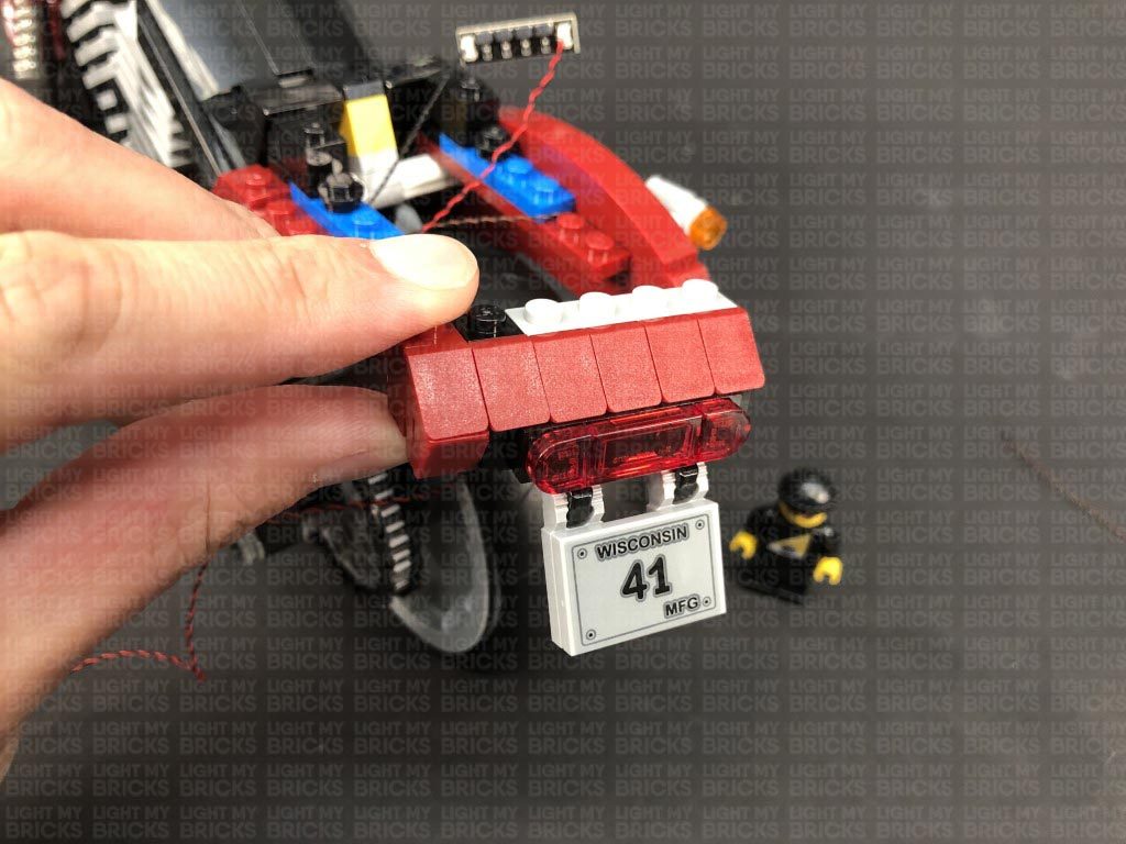
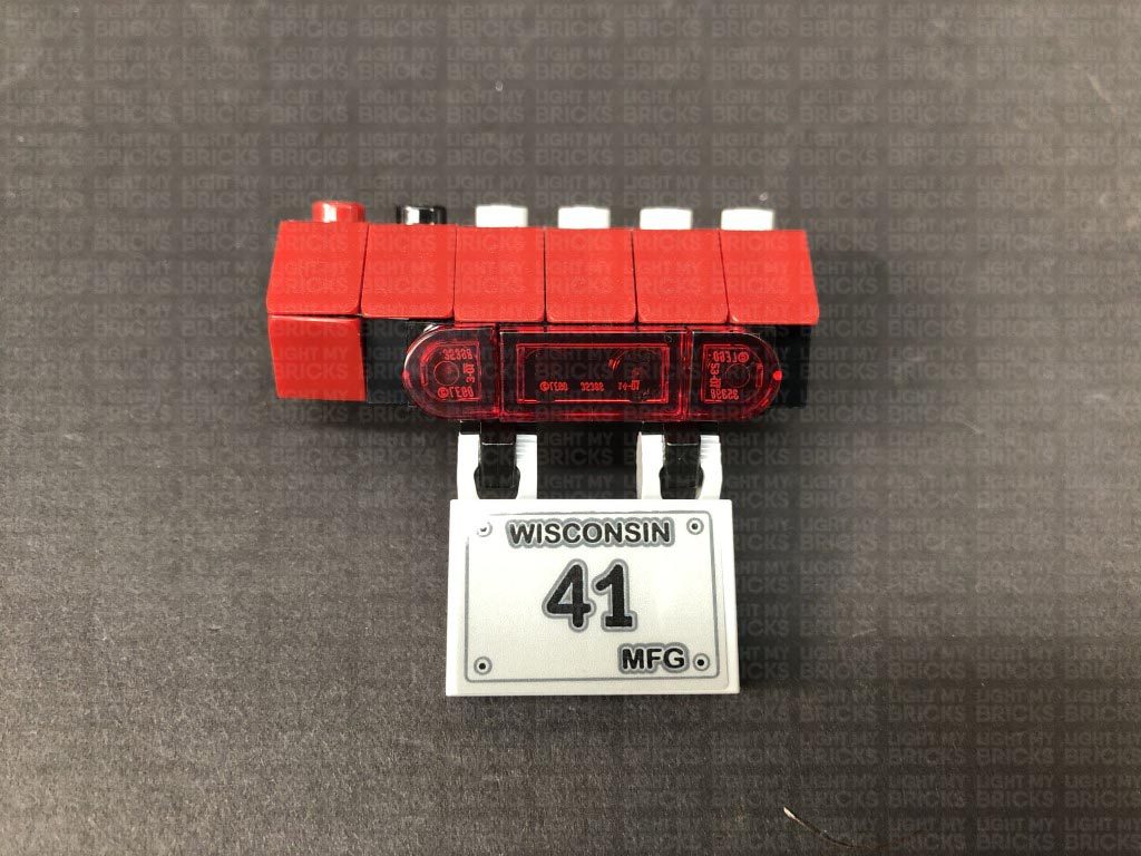
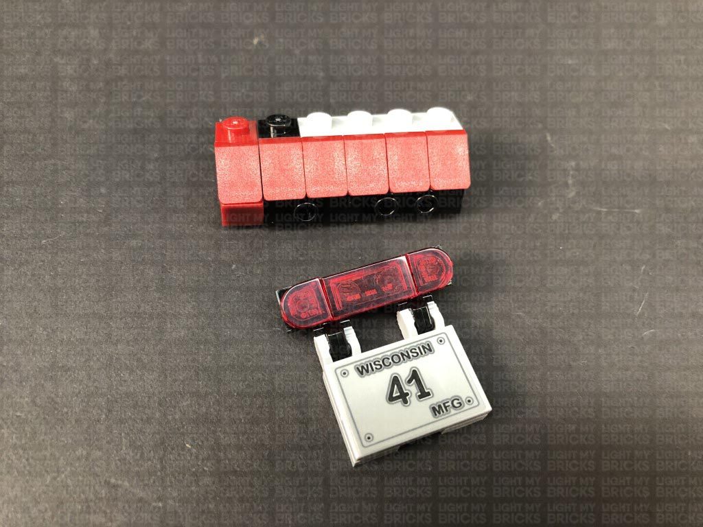
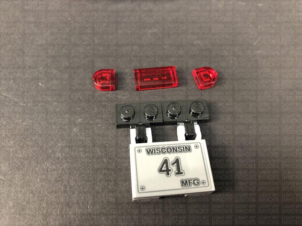
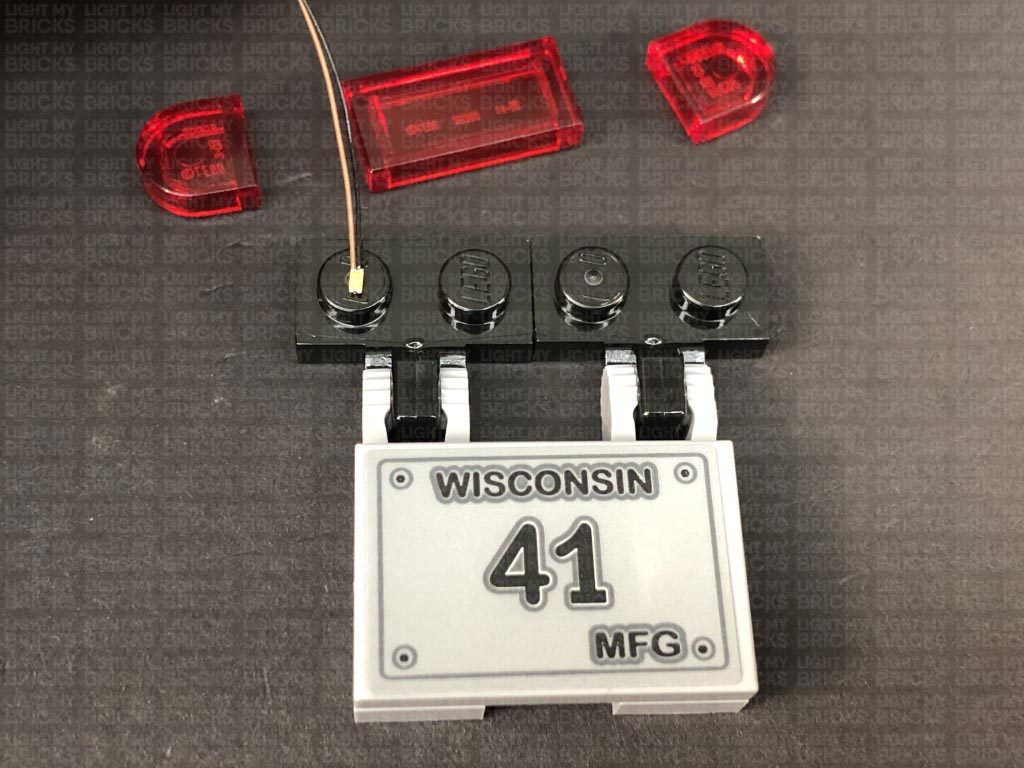
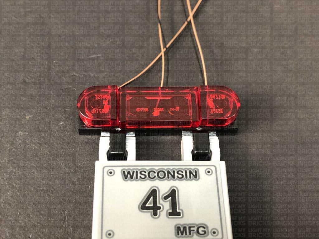
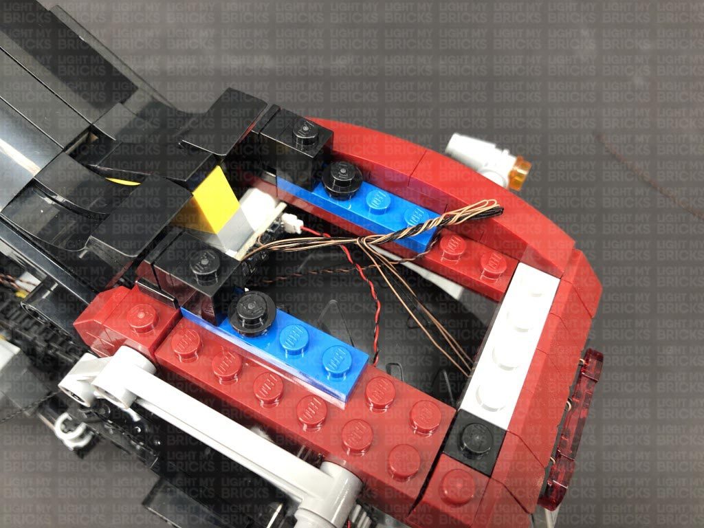
 11.) We will now install the rear lights. Disconnect the entire back section, then disassemble it as shown below:
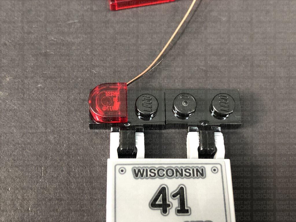
Take a White 15cm Micro Bit Light and with the cable facing up, place it over the far left black stud. Ensuring the LED is facing the correct way up, secure the Micro Bit Light in place by reconnecting the left trans red tile over the top.
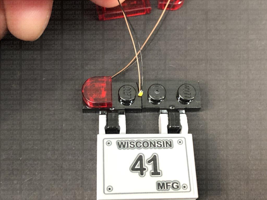
Take another White 15cm Micro Bit Light and with the cable facing up, place it in between the second and third black stud. Ensuring the LED is facing the correct way up, secure the Micro Bit Light in place by reconnecting the left trans red tile over the top.
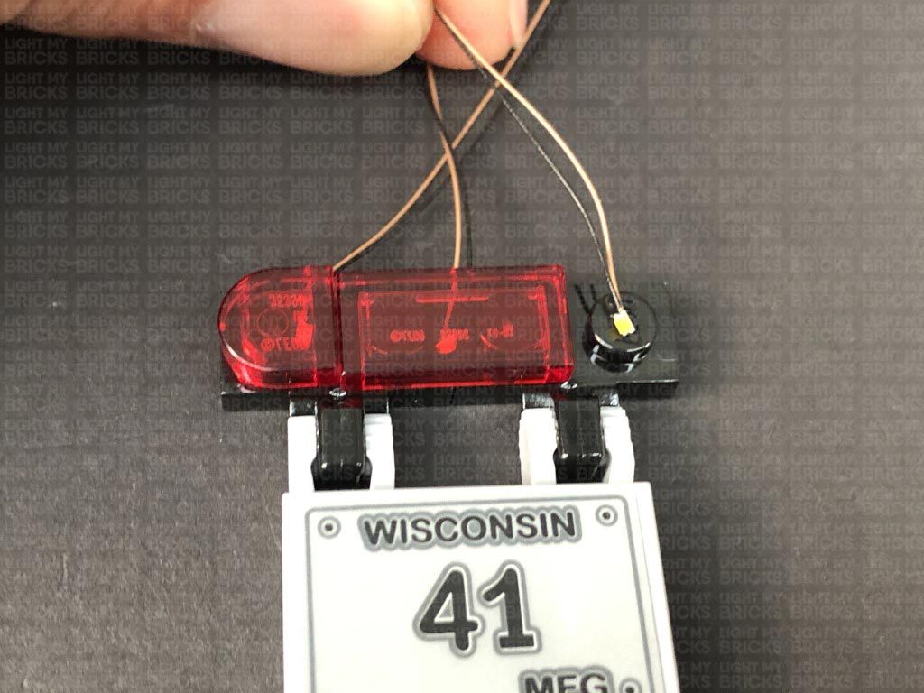
Take the remaining White 15cm Micro Bit Light and with the cable facing up, place it over the far right black stud. Ensuring the LED is facing the correct way up, secure the Micro Bit Light in place by reconnecting the left trans red tile over the top.
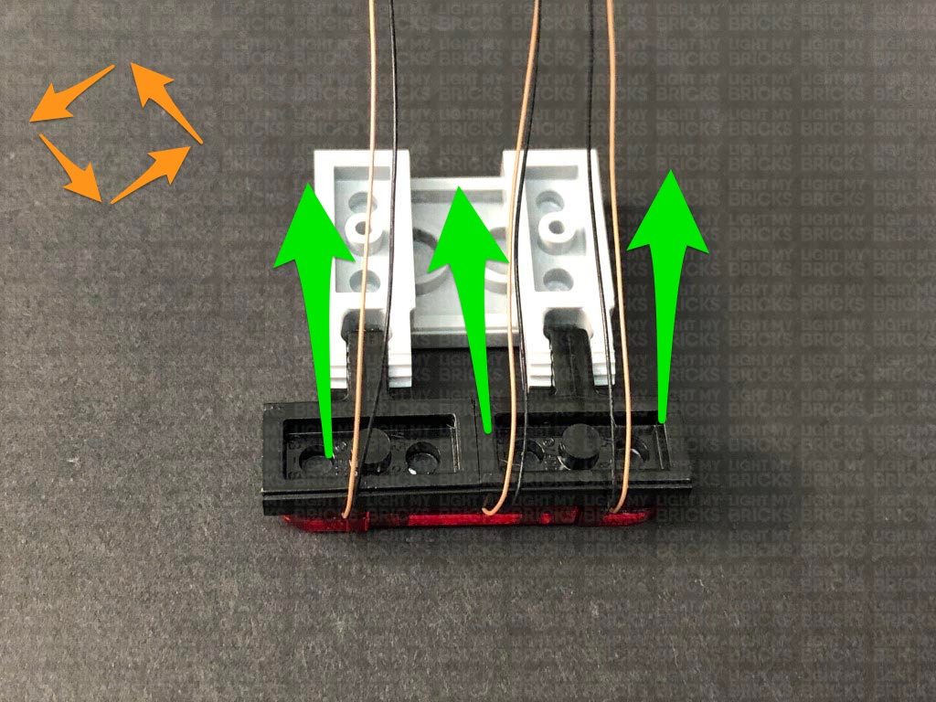
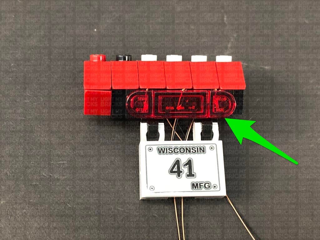
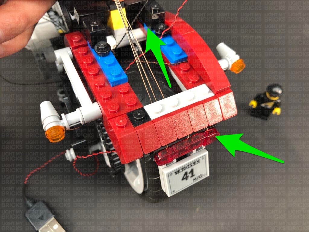
12.) Turn the section over and fold the cables down underneath, then flip it back over and reconnect it to the upper section ensuring the cables are laid in between studs underneath.
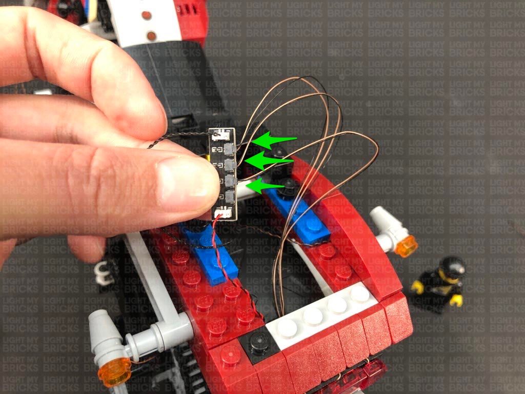
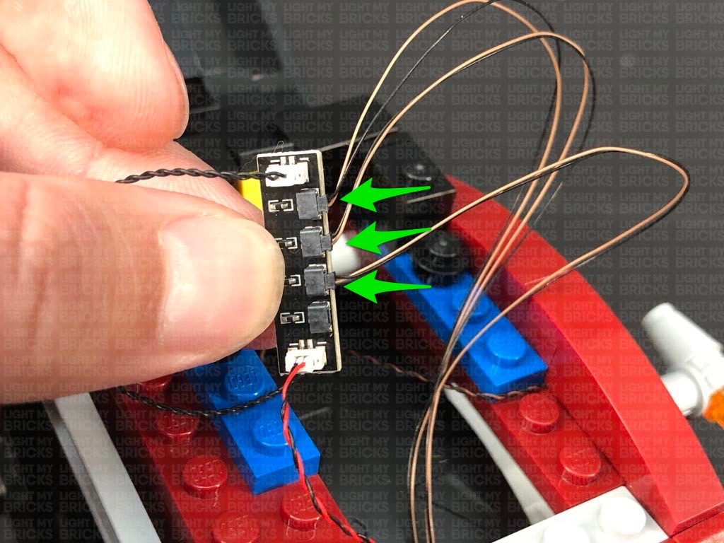
Reconnect this section to the back of the bike, then bring the three cables up from inside of the space behind the seat and connect them to the Micro Expansion Board. Turn the power ON to test the three lights we have just installed are working OK.
Note: If you experience any issues with the lights not working and suspect an issue with a component, please try a different port on the expansion board to verify where the fault lies (with the light or expansion board). To correct any issues with expansion board ports, please view the section addressing expansion board issues on our online troubleshooting guide.
13.) Take 2x Adhesive Squares and stick them to the back of the Micro Expansion Board. Mount the expansion board inside this space in the following position.
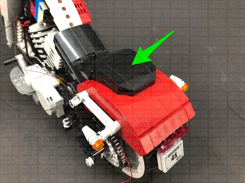
Neaten up excess cables by twisting the micro bit light cables into a neat bunch. Ensure the cables are pulled up so they are not dangling down over the back wheel. Reconnect the two back sections as shown below
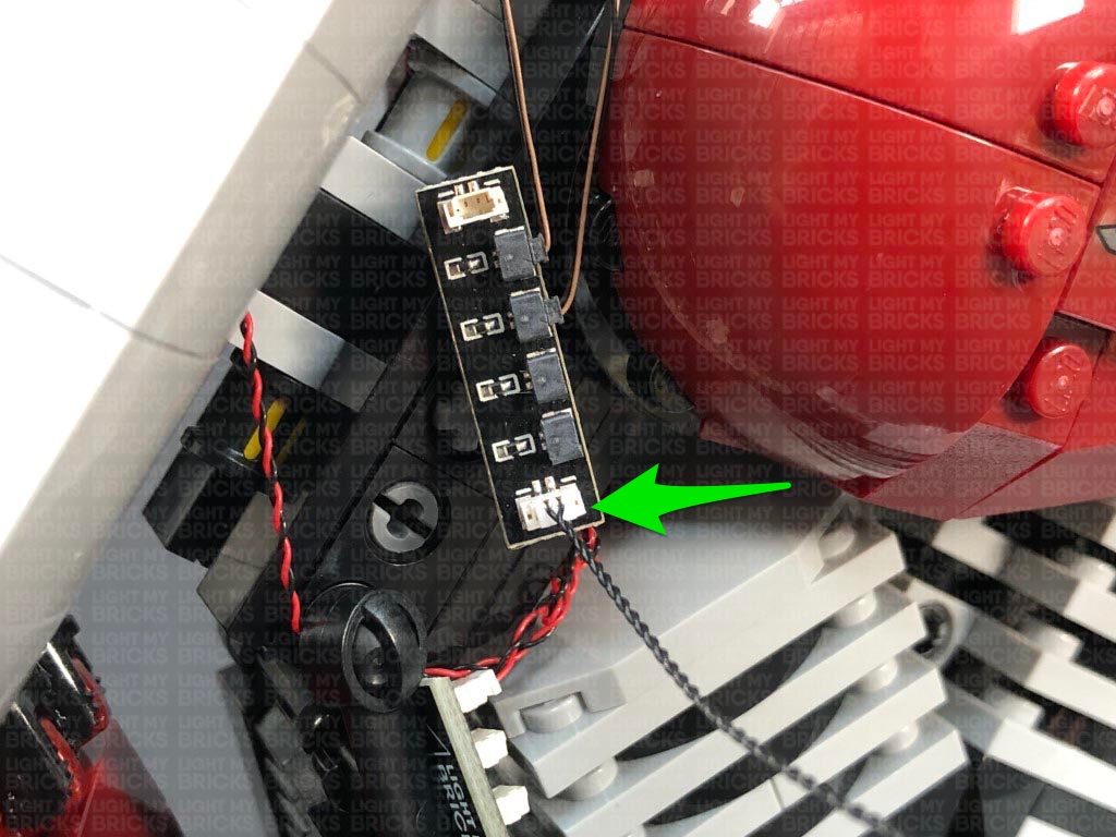
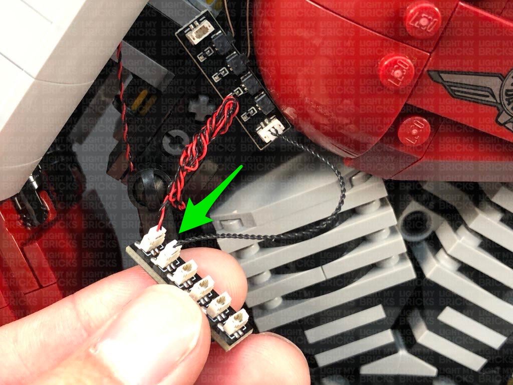
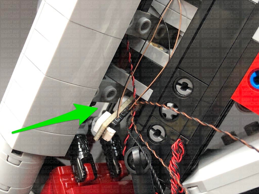
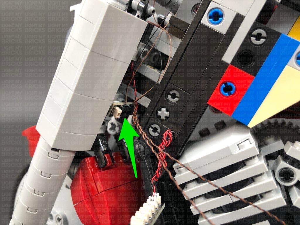
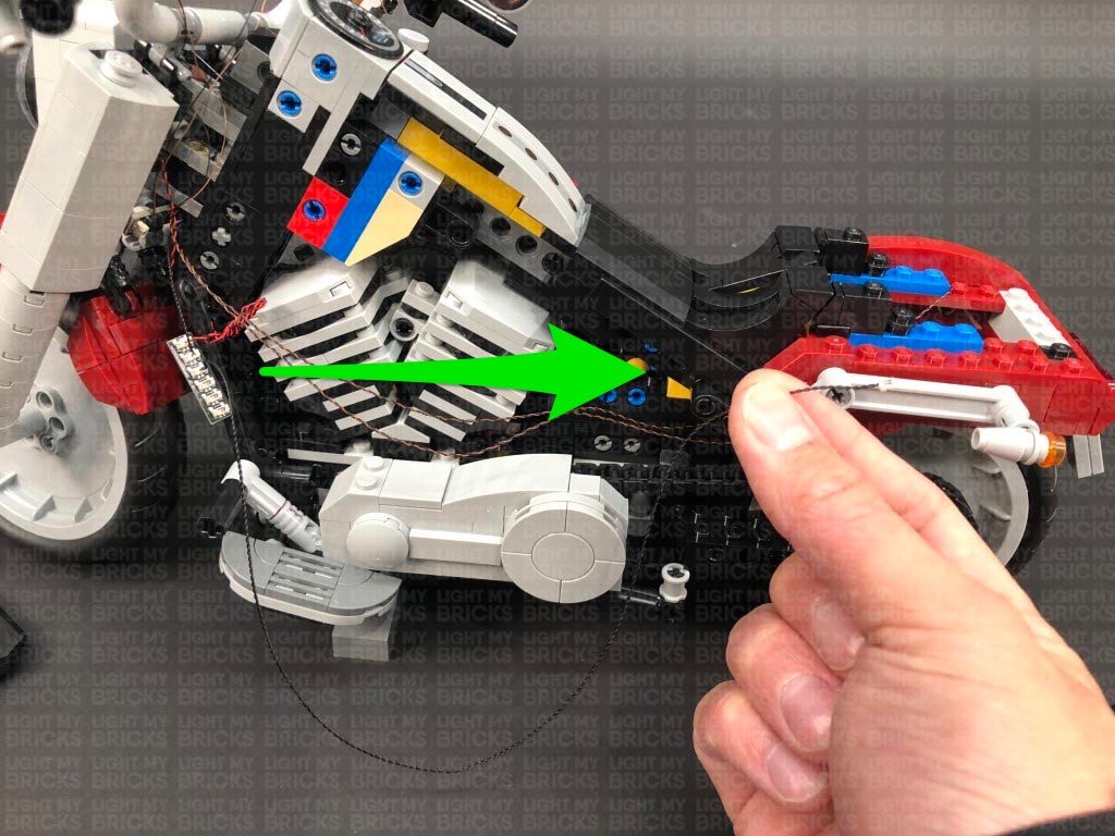
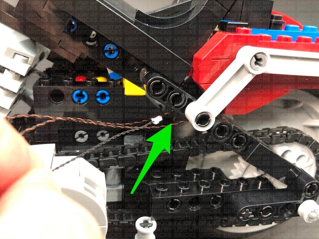
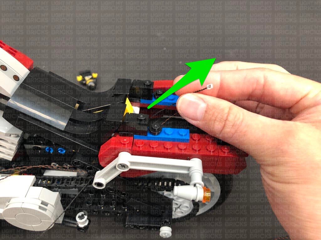
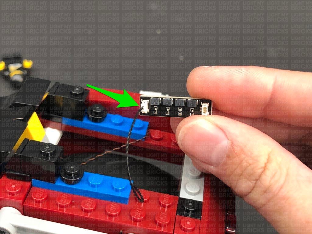
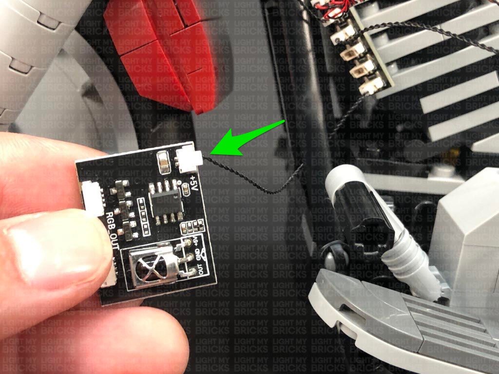
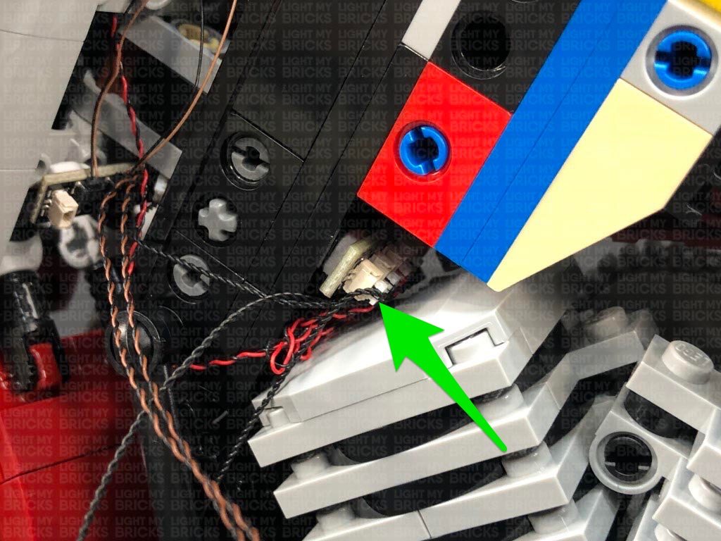
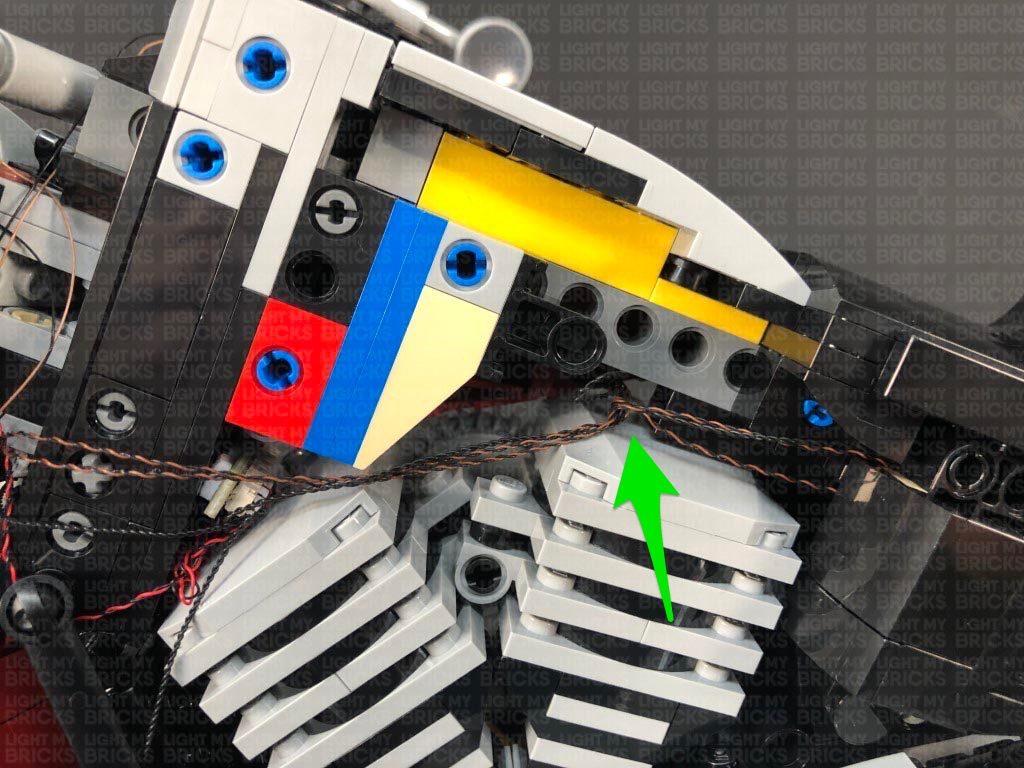
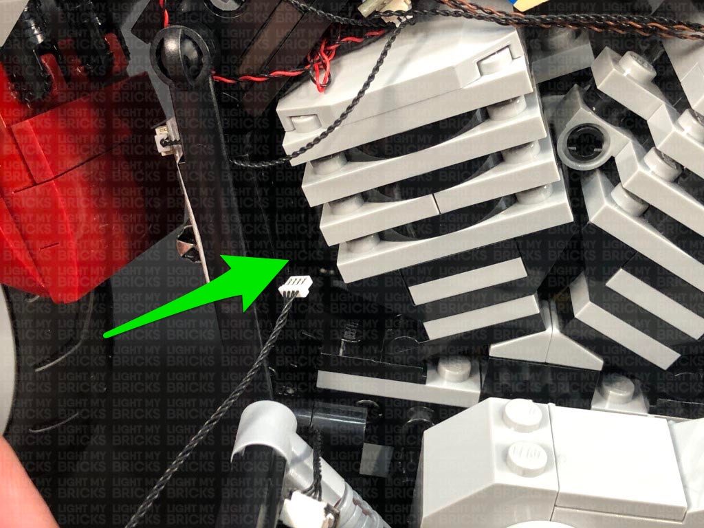
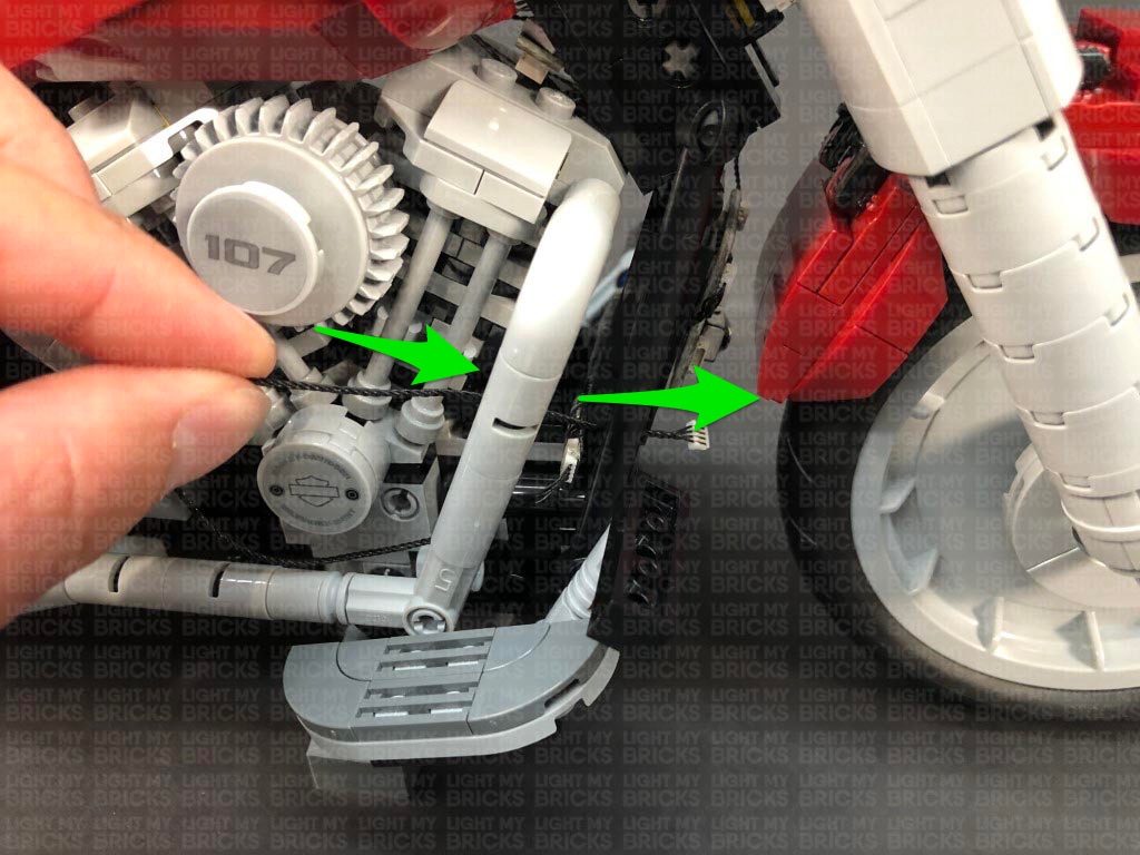
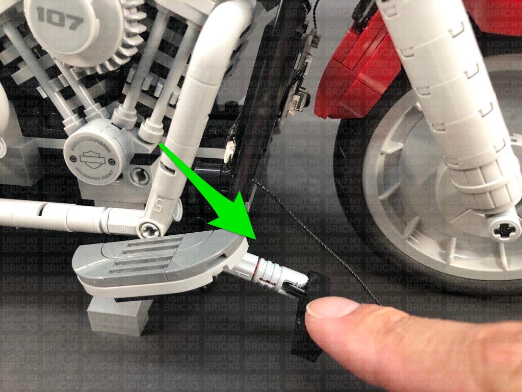
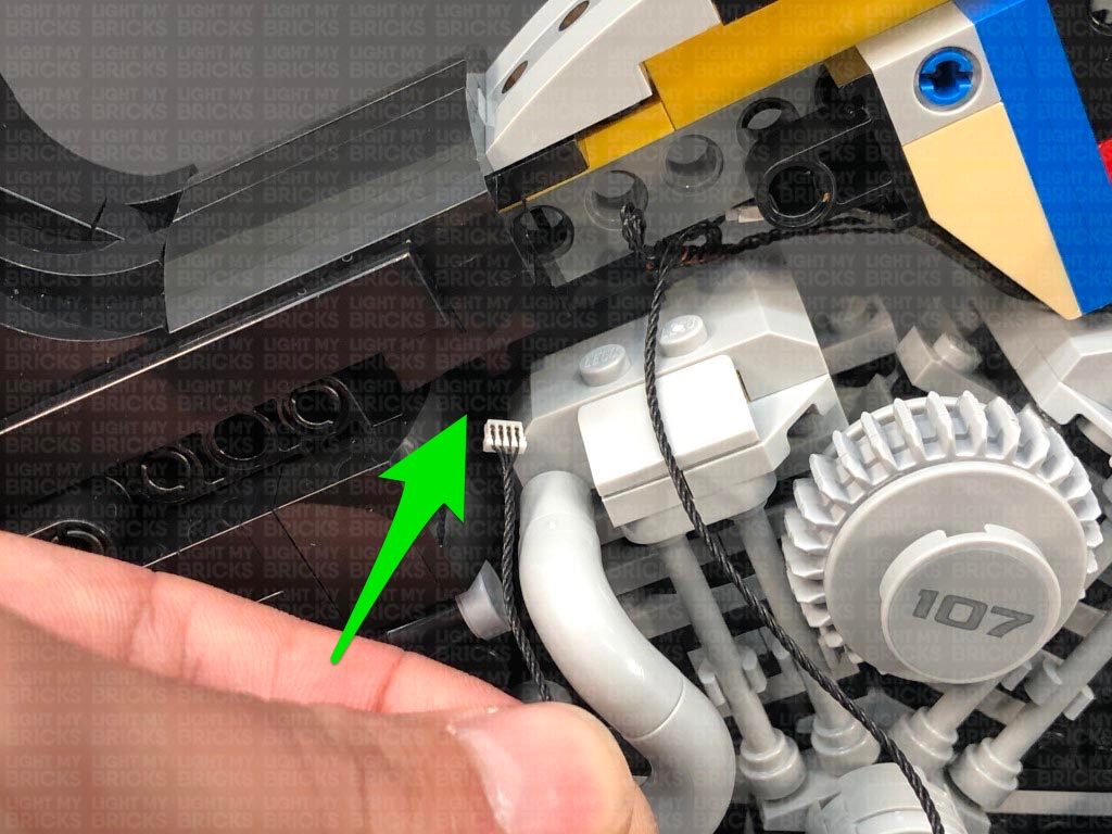
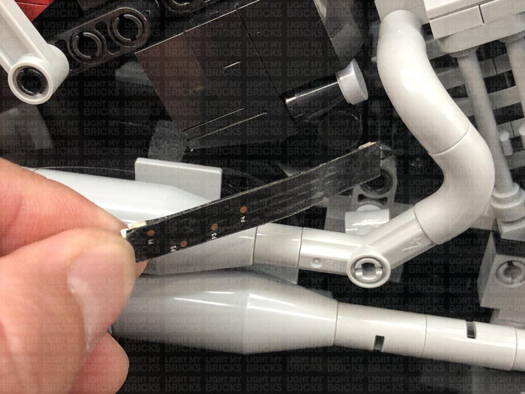
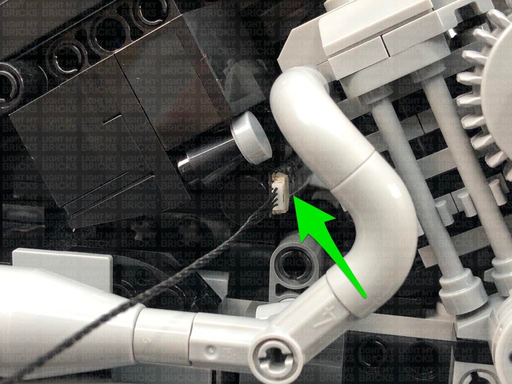
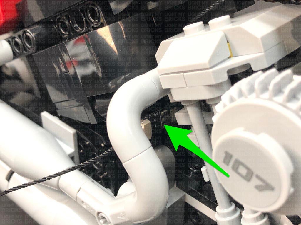
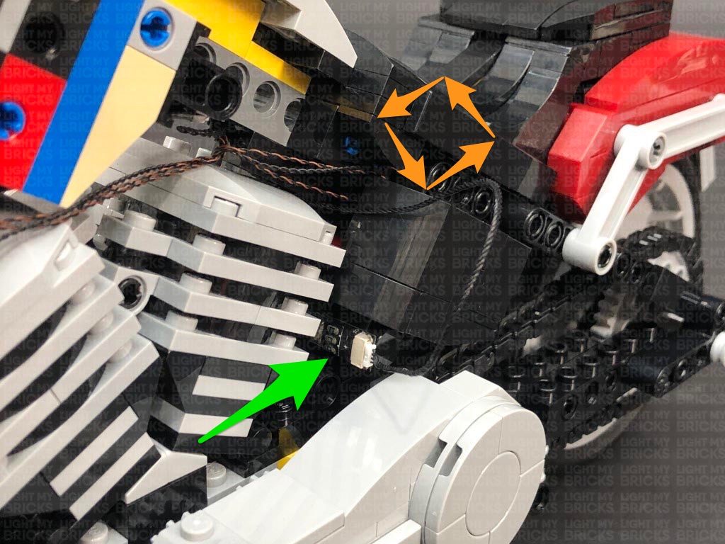
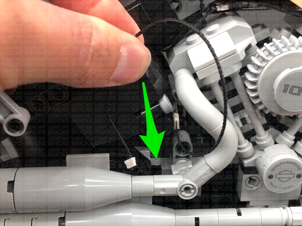
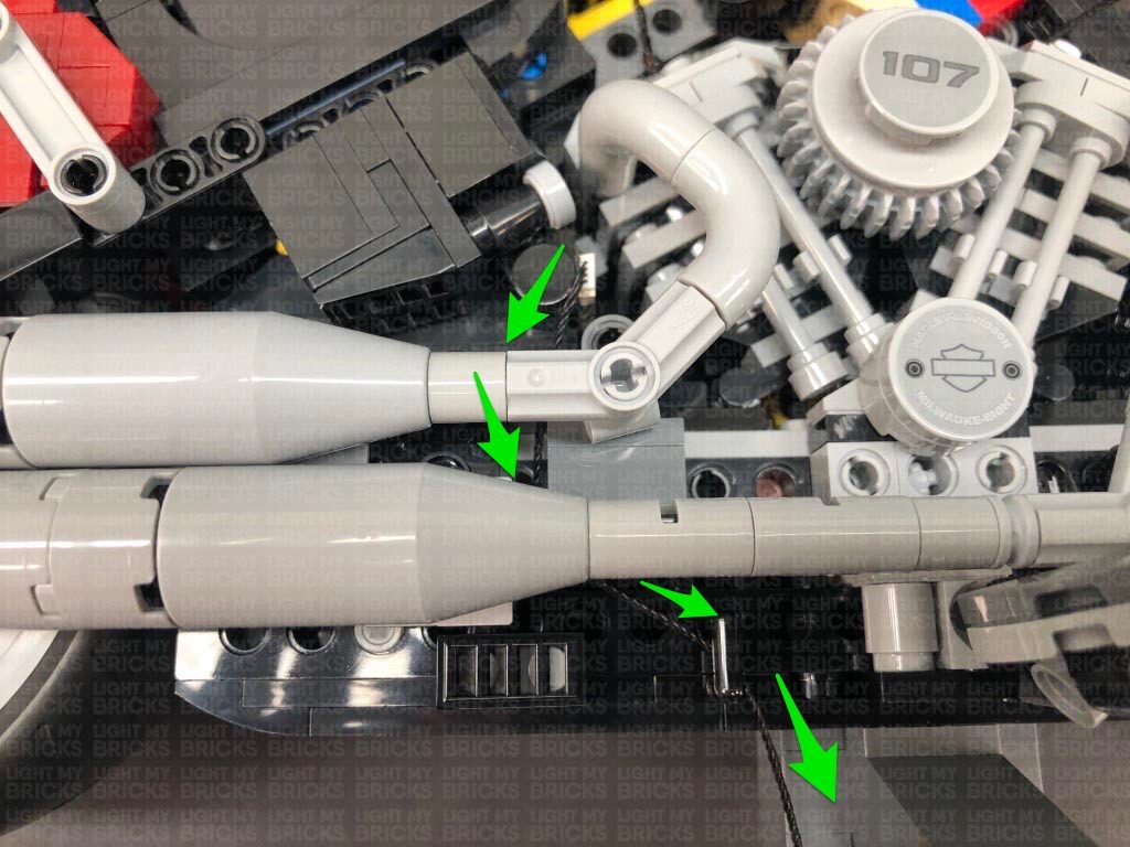
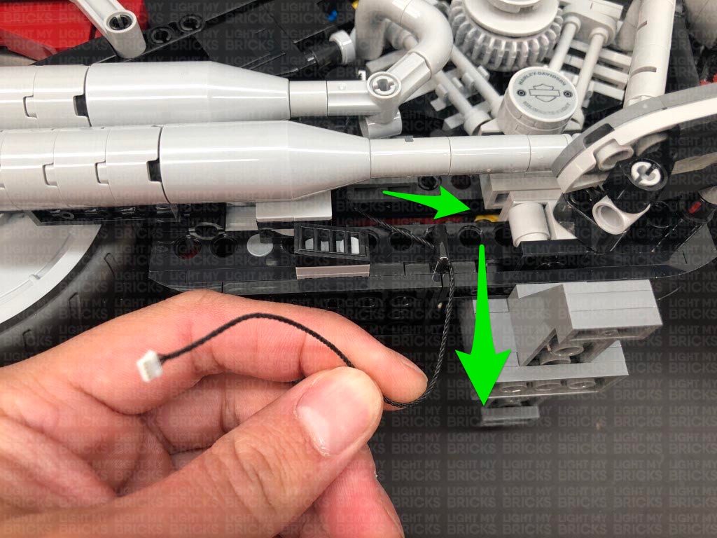
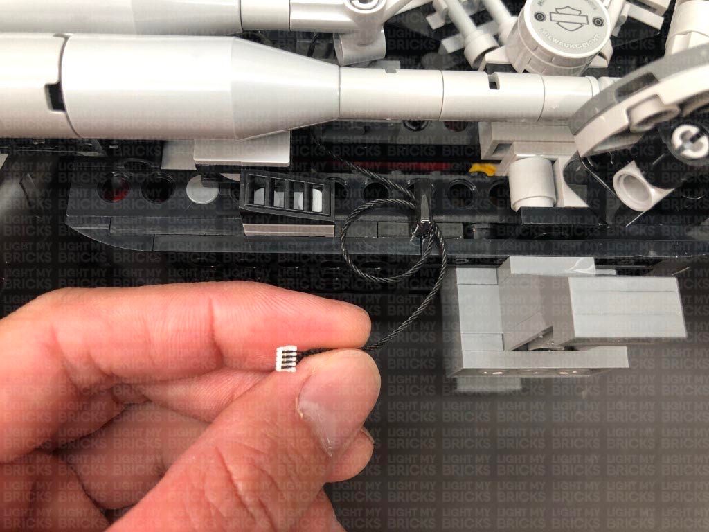
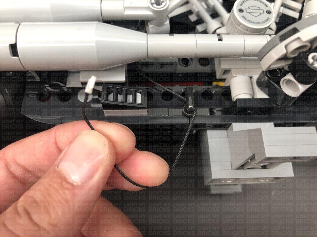
14.) Take a 5cm Connecting Cable and connect it to a spare port on the 6-Port Expansion Board at the front of the bike. Thread the other end of the connecting cable behind the black technic flat bar, then connect it to the IN port (+5V) of the RGB Control Board.
Take a RGB Connecting Cable 15cm and connect it to one of the OUT ports on the RGB Control Board. Leave the other end of the cable as is for now as we will connect this to the RGB Strip Lights later on
11.) We will now install the rear lights. Disconnect the entire back section, then disassemble it as shown below:
Take a White 15cm Micro Bit Light and with the cable facing up, place it over the far left black stud. Ensuring the LED is facing the correct way up, secure the Micro Bit Light in place by reconnecting the left trans red tile over the top.
Take another White 15cm Micro Bit Light and with the cable facing up, place it in between the second and third black stud. Ensuring the LED is facing the correct way up, secure the Micro Bit Light in place by reconnecting the left trans red tile over the top.
Take the remaining White 15cm Micro Bit Light and with the cable facing up, place it over the far right black stud. Ensuring the LED is facing the correct way up, secure the Micro Bit Light in place by reconnecting the left trans red tile over the top.
12.) Turn the section over and fold the cables down underneath, then flip it back over and reconnect it to the upper section ensuring the cables are laid in between studs underneath.
Reconnect this section to the back of the bike, then bring the three cables up from inside of the space behind the seat and connect them to the Micro Expansion Board. Turn the power ON to test the three lights we have just installed are working OK.
Note: If you experience any issues with the lights not working and suspect an issue with a component, please try a different port on the expansion board to verify where the fault lies (with the light or expansion board). To correct any issues with expansion board ports, please view the section addressing expansion board issues on our online troubleshooting guide.
13.) Take 2x Adhesive Squares and stick them to the back of the Micro Expansion Board. Mount the expansion board inside this space in the following position.
Neaten up excess cables by twisting the micro bit light cables into a neat bunch. Ensure the cables are pulled up so they are not dangling down over the back wheel. Reconnect the two back sections as shown below
14.) Take a 5cm Connecting Cable and connect it to a spare port on the 6-Port Expansion Board at the front of the bike. Thread the other end of the connecting cable behind the black technic flat bar, then connect it to the IN port (+5V) of the RGB Control Board.
Take a RGB Connecting Cable 15cm and connect it to one of the OUT ports on the RGB Control Board. Leave the other end of the cable as is for now as we will connect this to the RGB Strip Lights later on
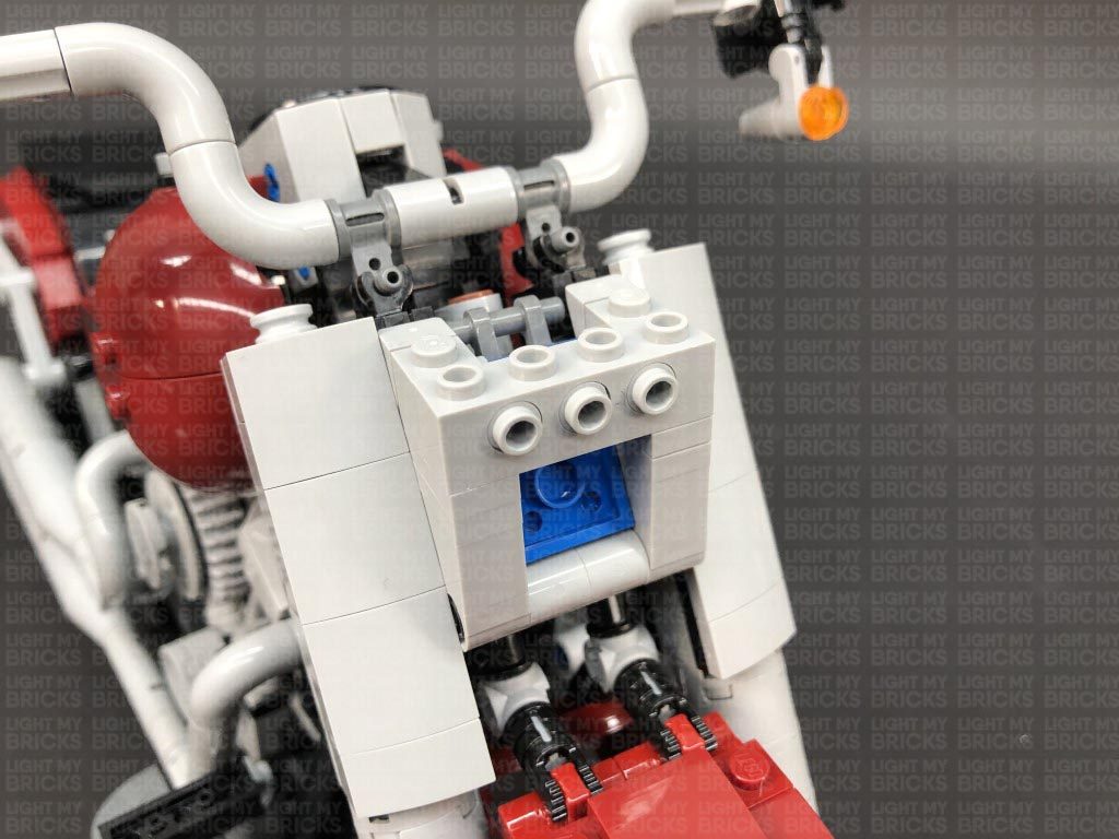
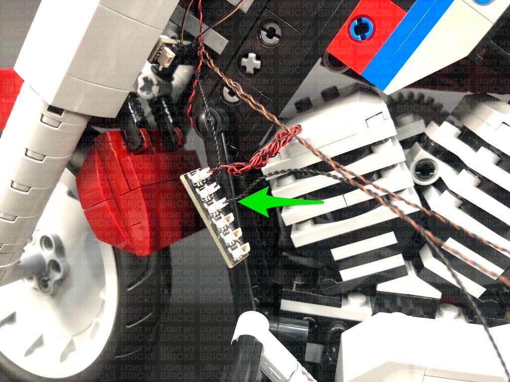
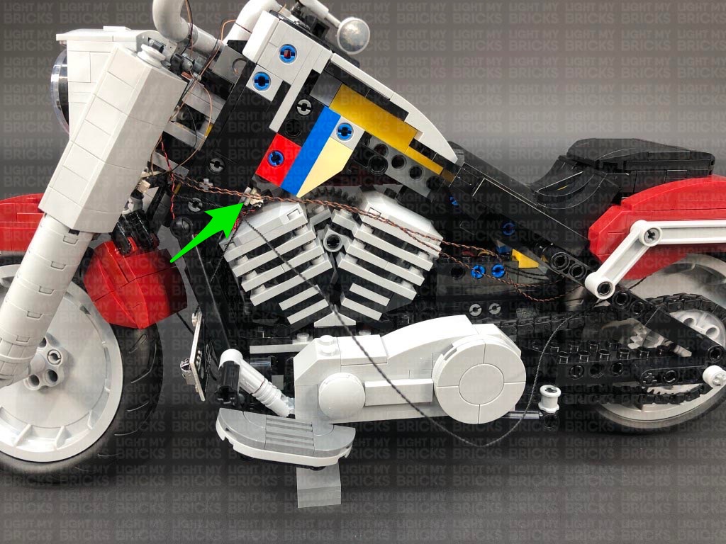
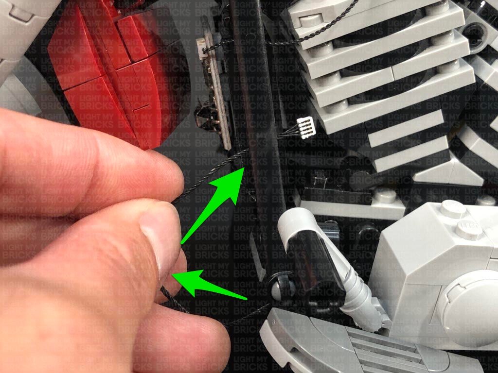
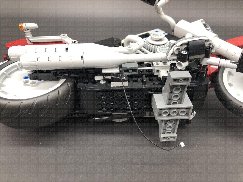
 Take 2x Adhesive Squares and stick them to the back of the 6-Port Expansion Board. Slide the expansion board inside the gap just above the light grey motor section and stick them to the black bricks as shown below.
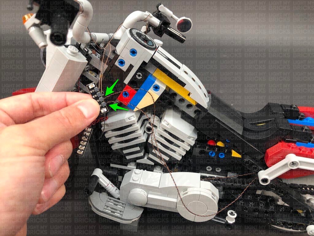
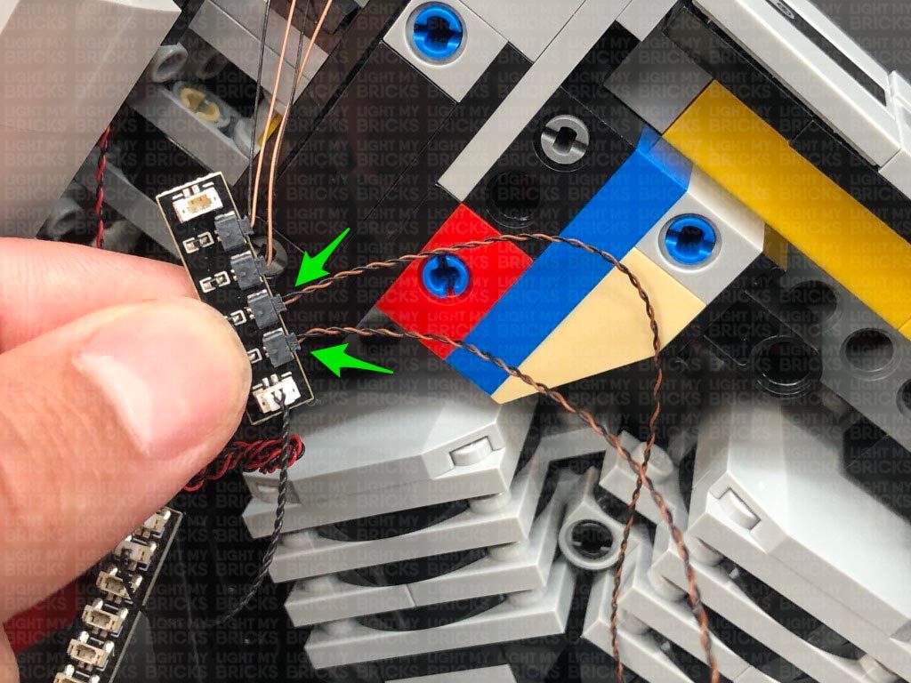
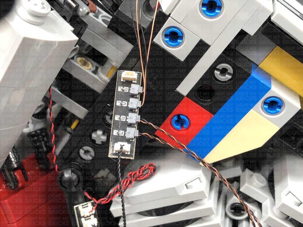
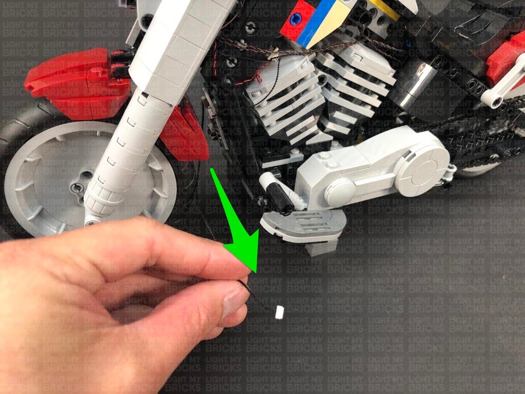
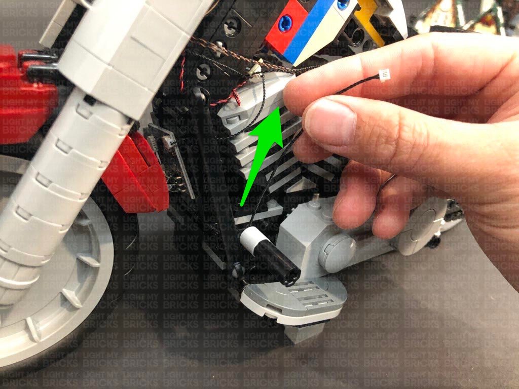
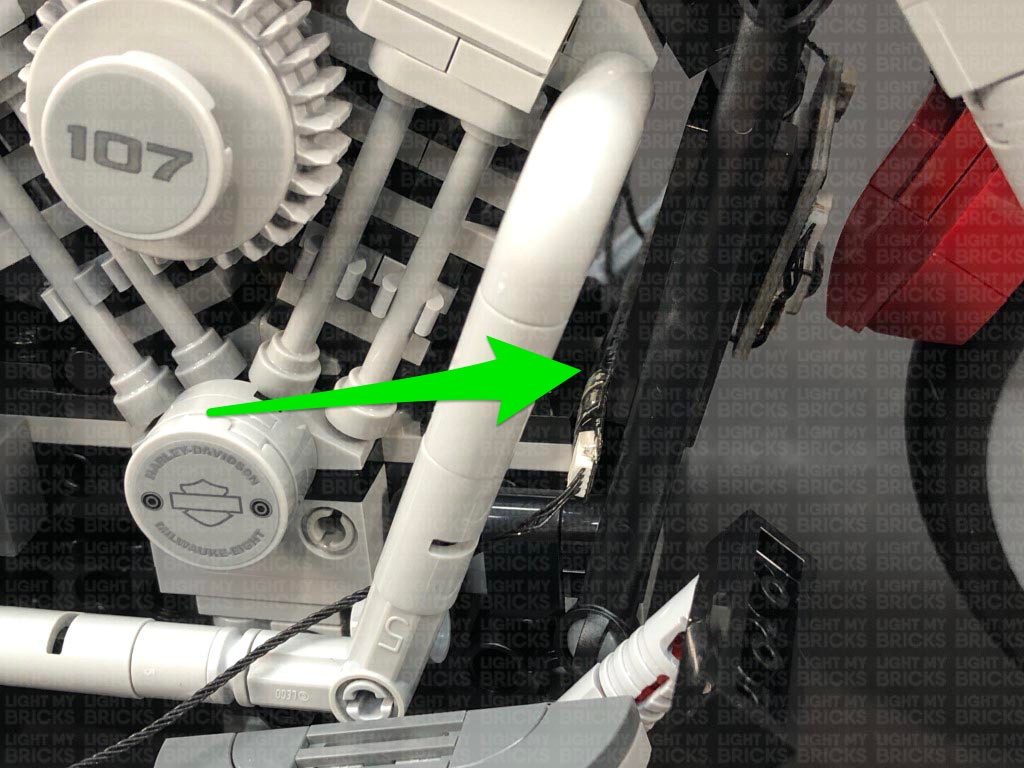
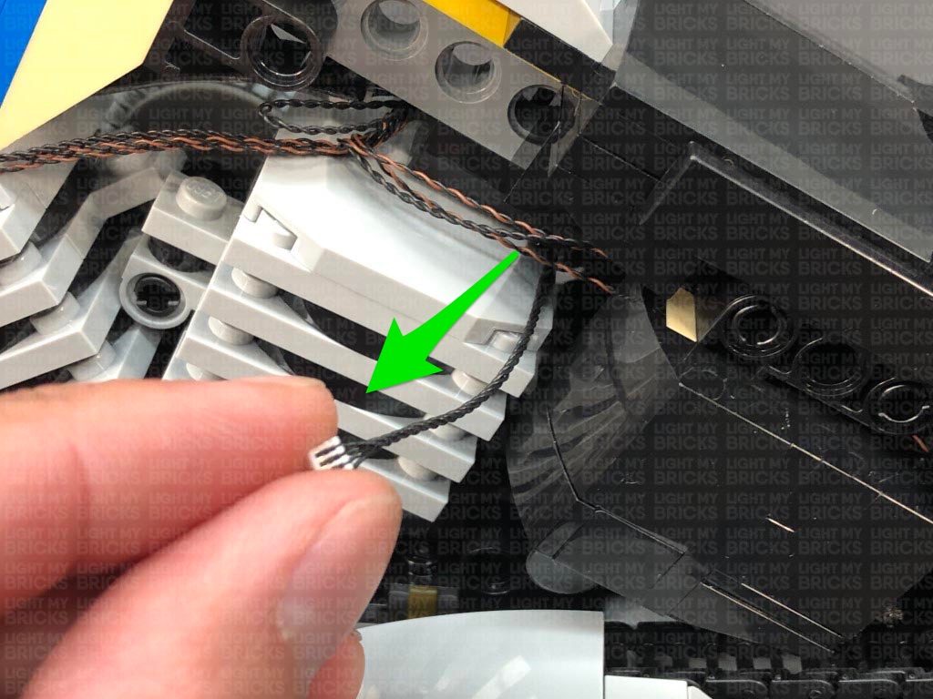
 15.) Group the two micro bit light cables from the rear indicator lights as well as the 30cm connecting cable and pull them back toward the front of the bike. Secure the cables by reconnecting the black section just above the bike chain (section we disconnected back in step 8)
Neaten up the excess cables from the three cables by twisting and folding them around each other into a neat bunch, then tuck this neat bunch inside the bike just above the motor section as shown below:
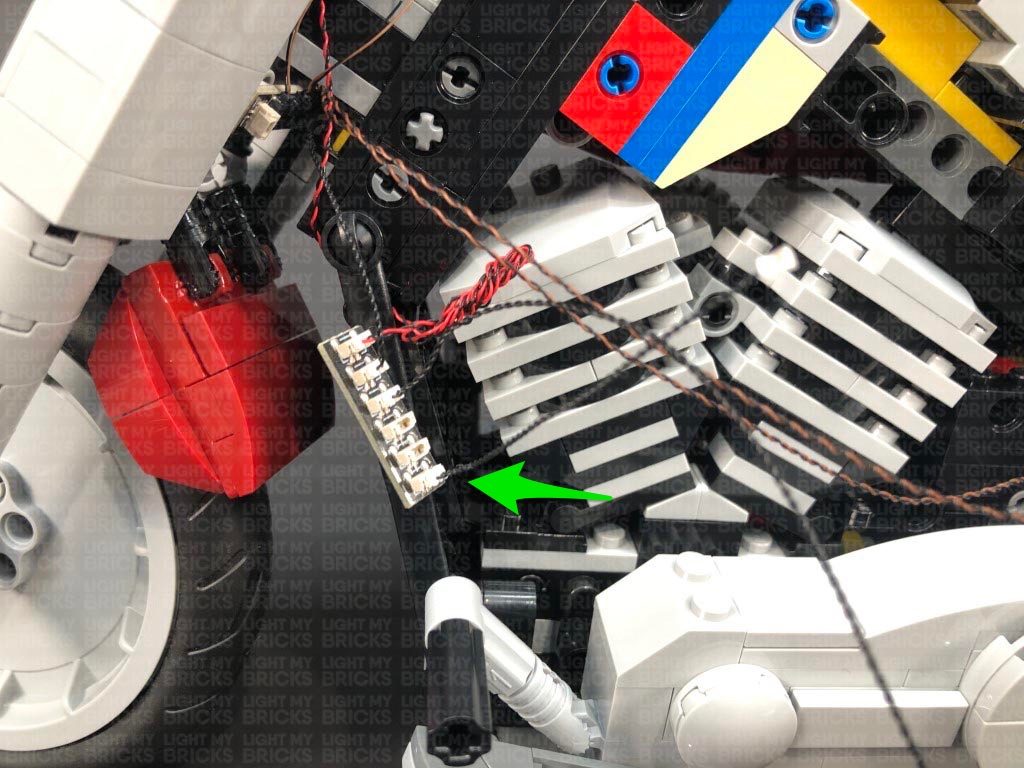
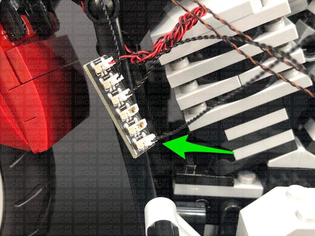
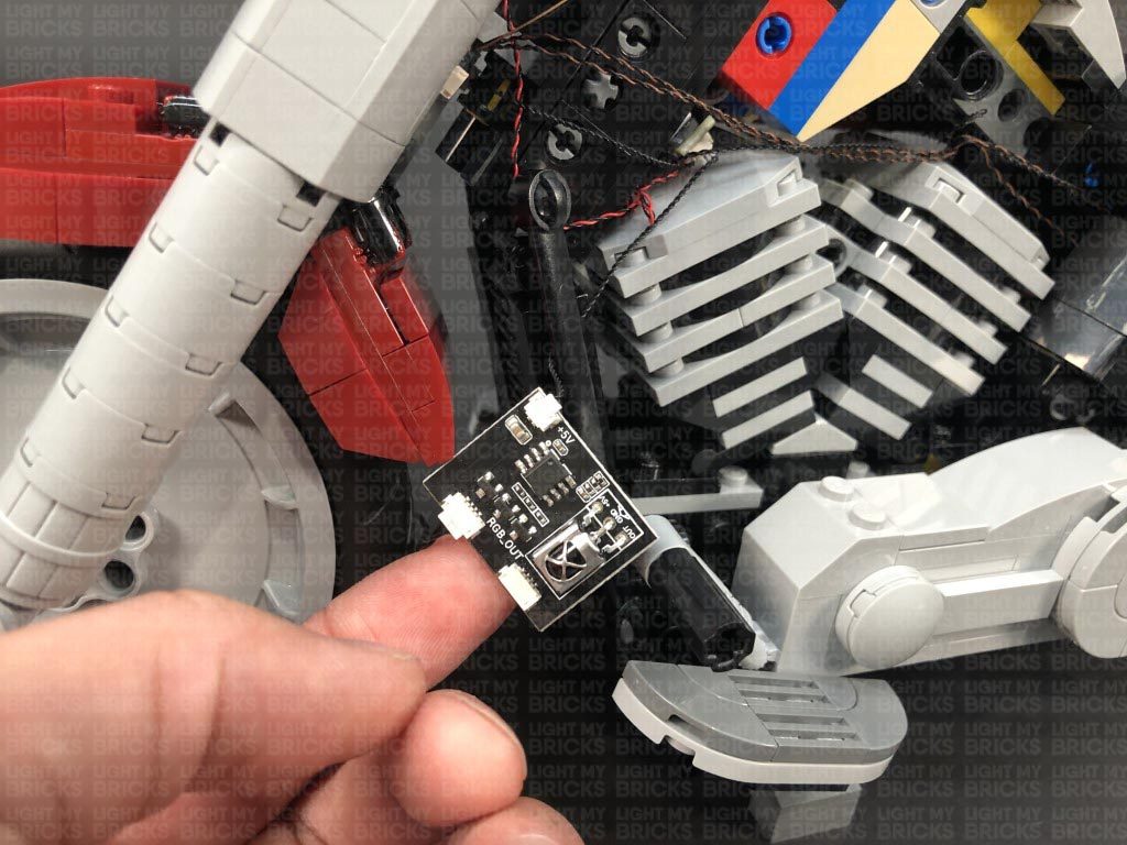
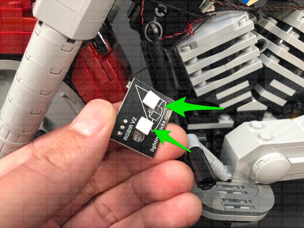
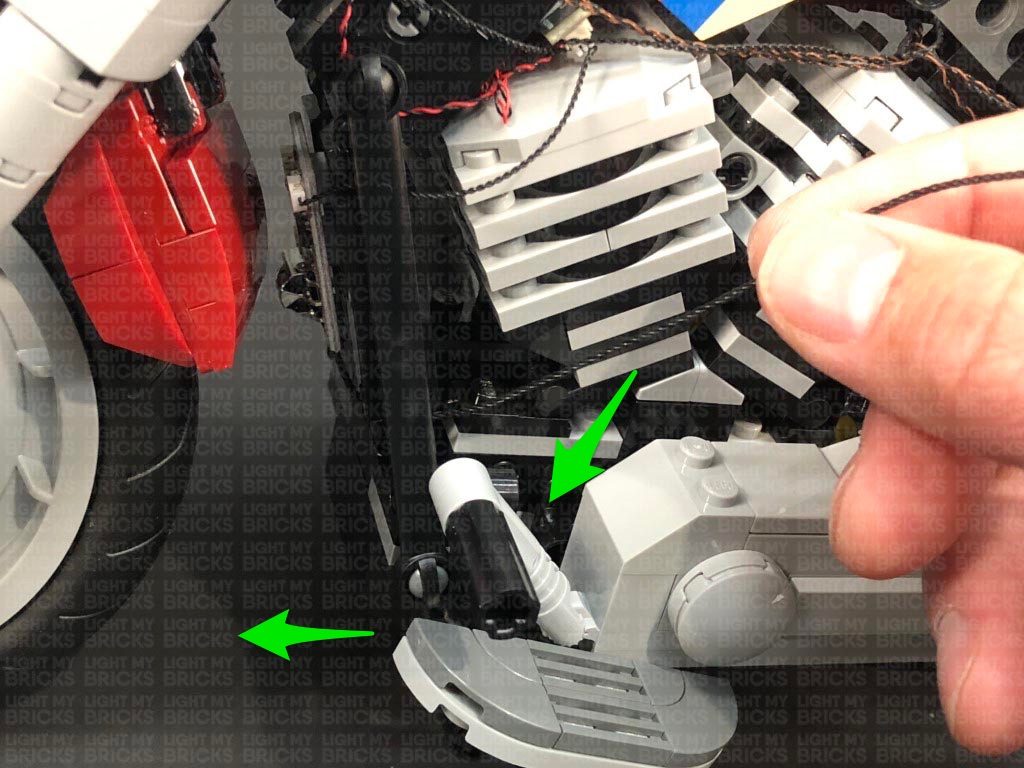
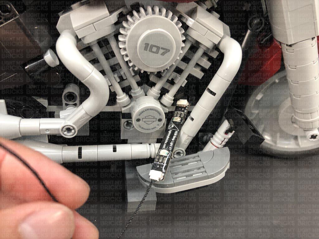
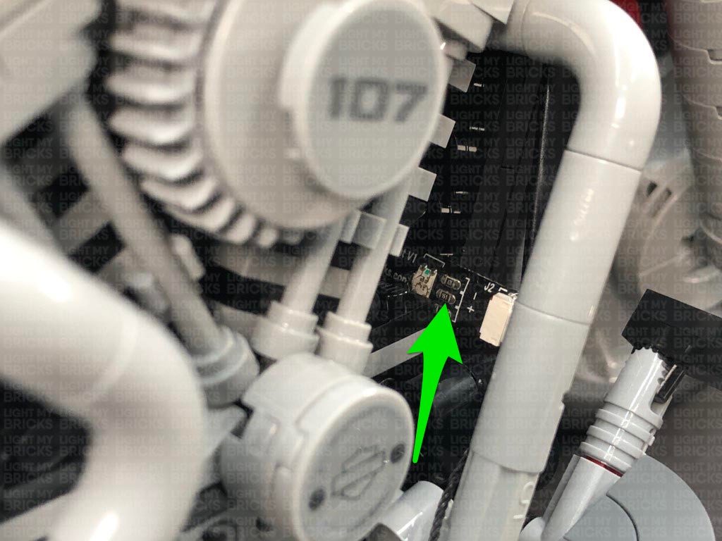
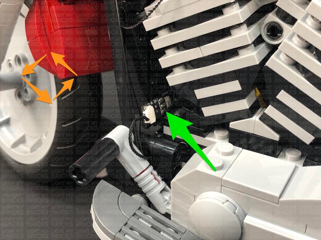
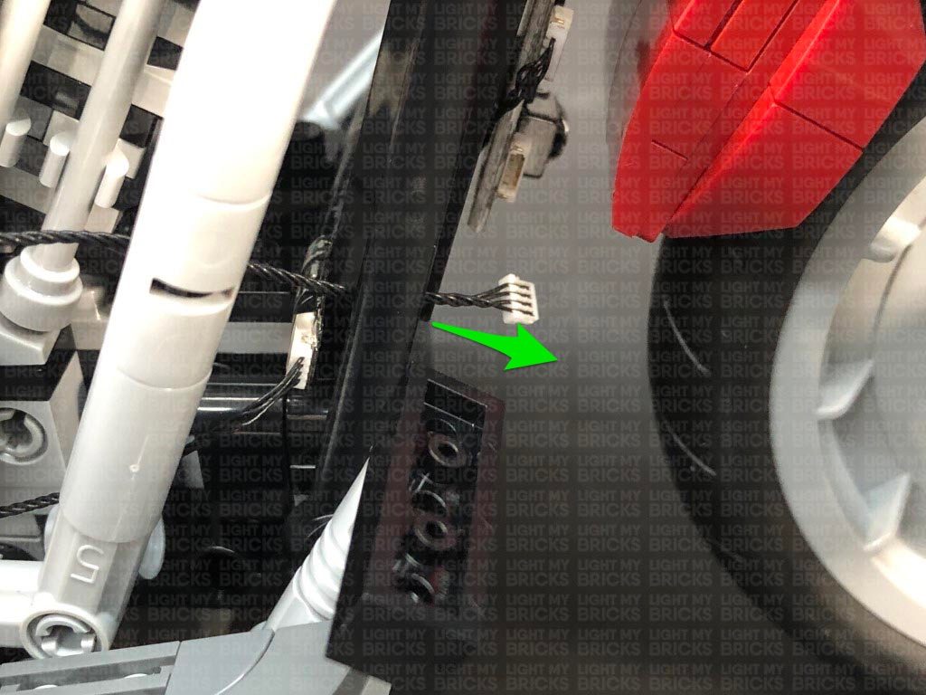
Take 2x Adhesive Squares and stick them on the back of the RGB Control Board in the below positions.
With the IR Sensor on the bottom, stick the RGB Control Board to the following position behind the front wheel. Ensure the board is stuck to the flat side of the black pieces.
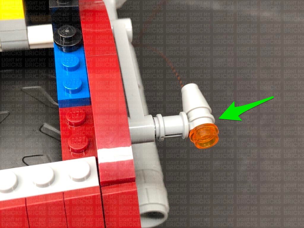
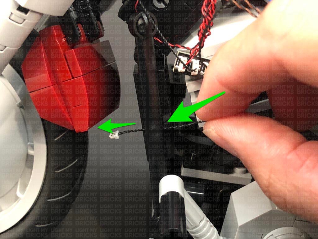
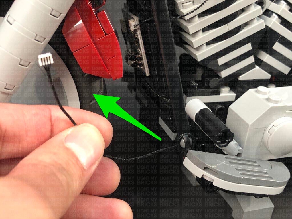
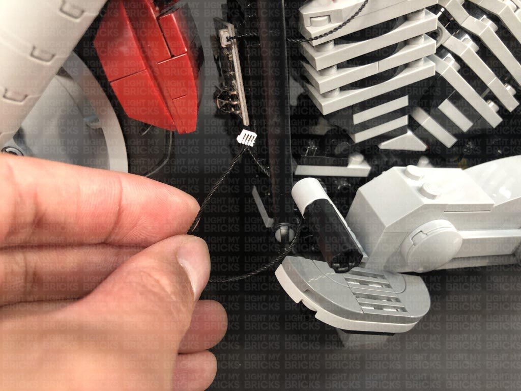
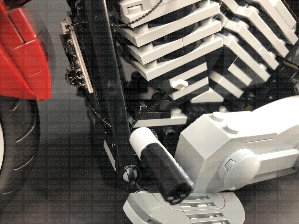
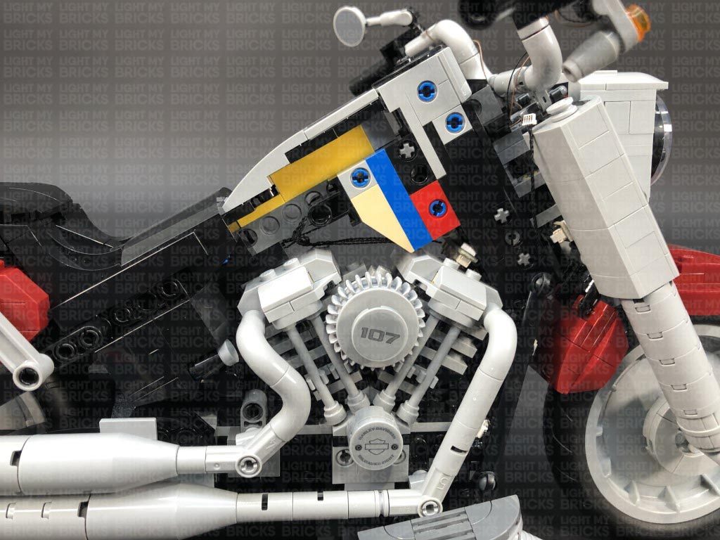
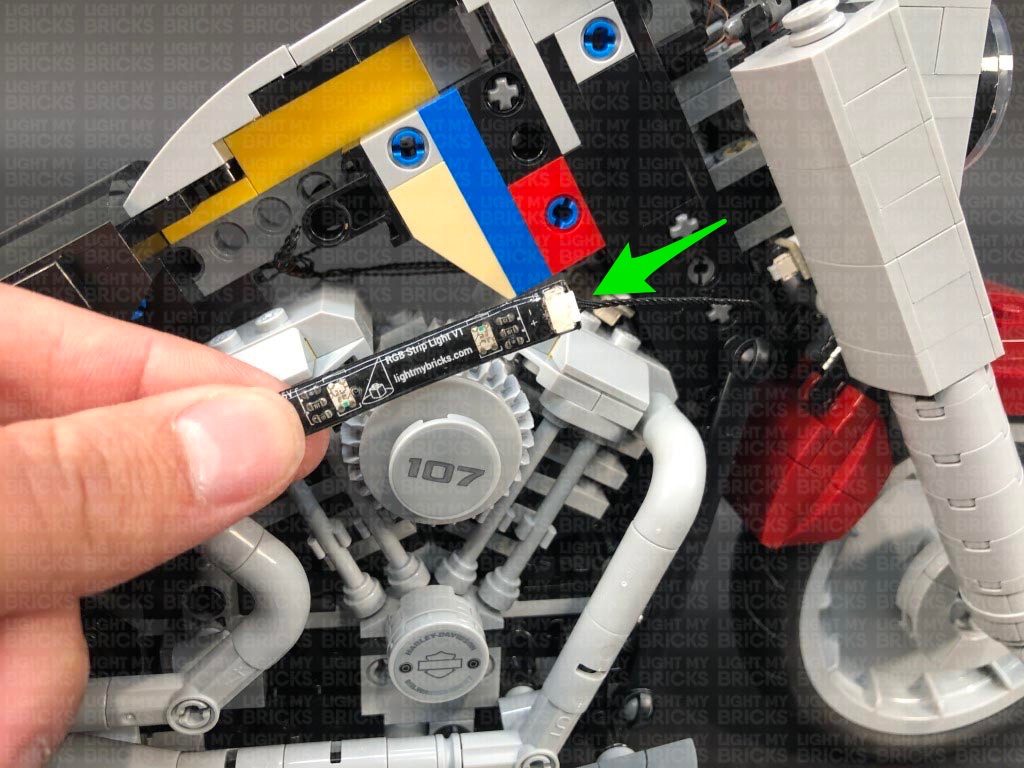
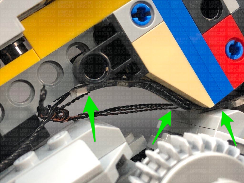
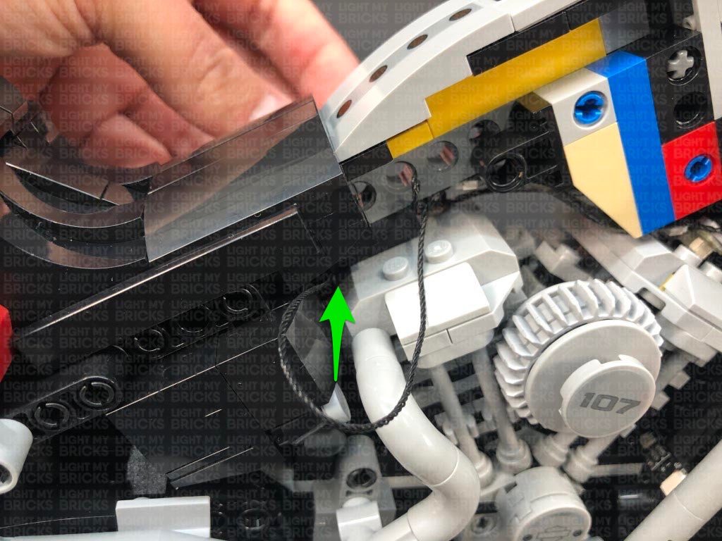
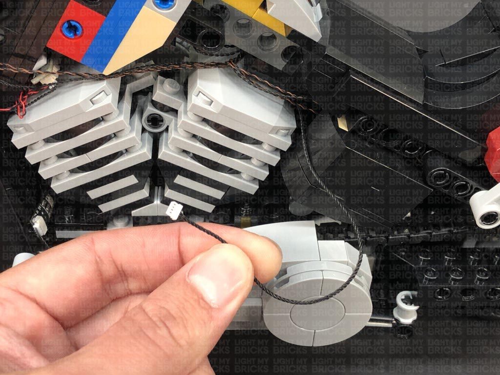
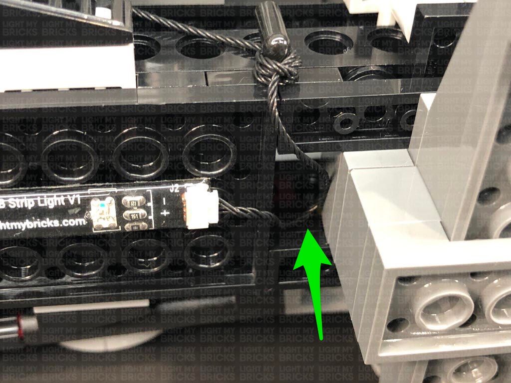
16.) Bring the other end of the RGB Connecting Cable out the left side of the bike and thread it behind the black flat bar. Pull the cable all the way out then loop it around the bottom of the black flat bar a few times to eliminate excess cable. When you get to the 3rd of 4th loop, secure the cable by looping it into a knot.
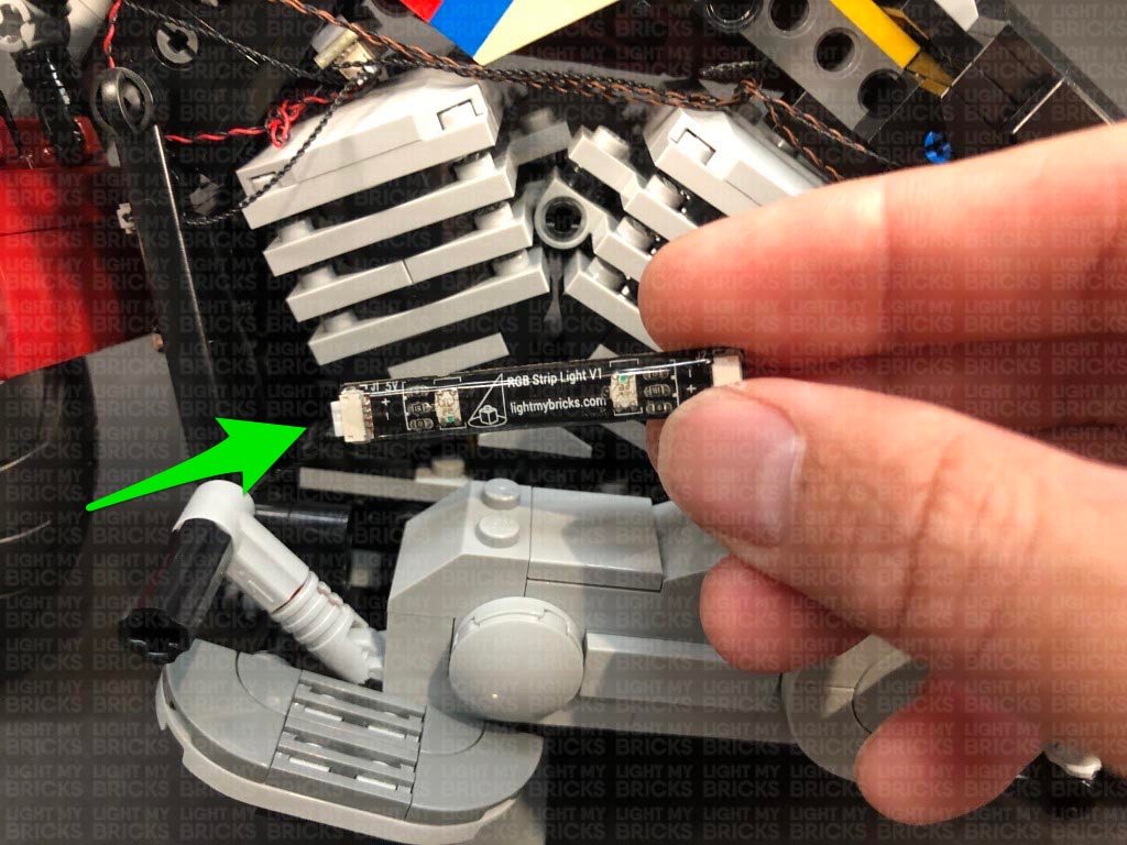
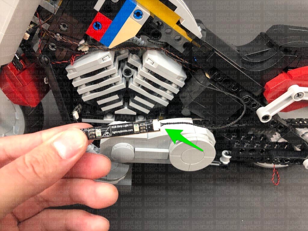
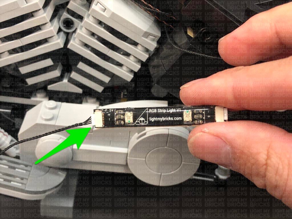
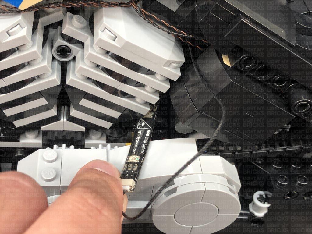
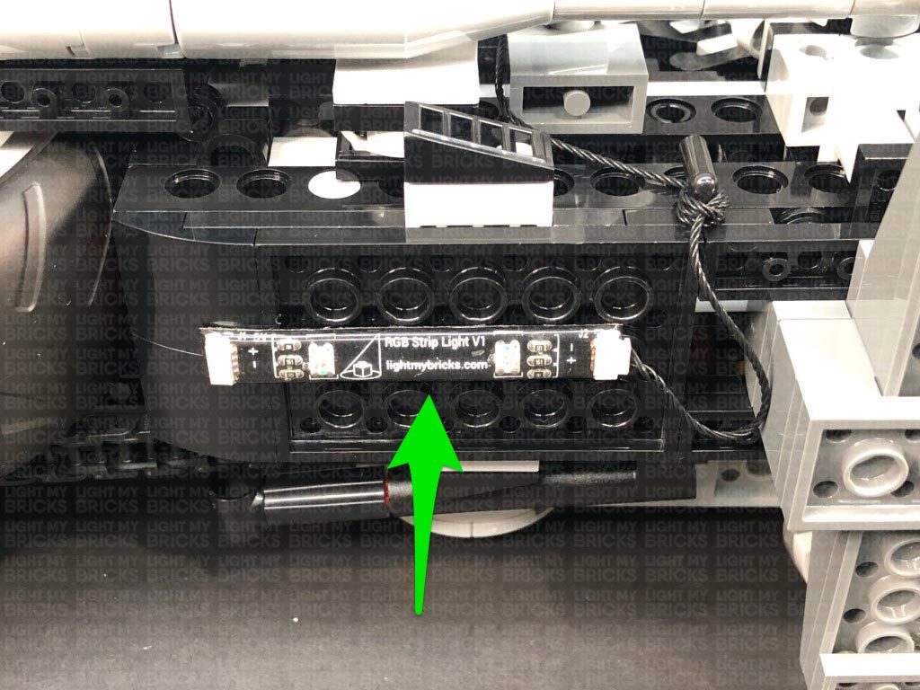
Connect the RGB Connecting Cable to a RGB Strip Light. Take a new RGB Connecting Cable 15cm and connect it to the strip light’s other port.
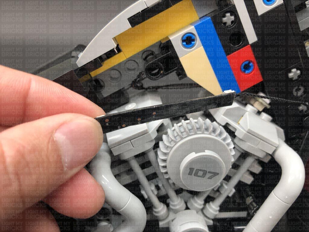
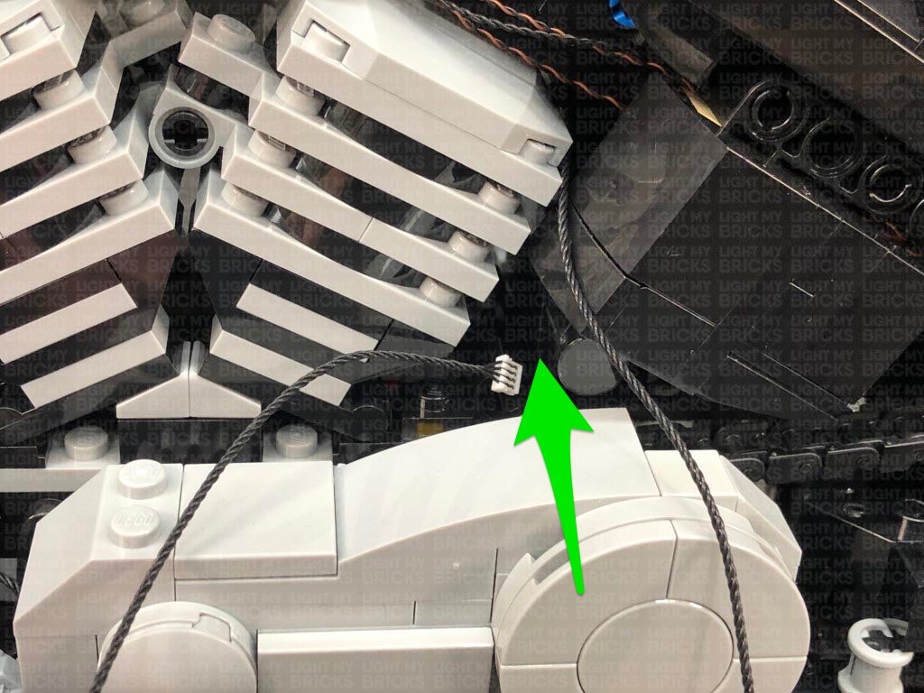
Thread the other end of the RGB Connecting Cable through the following space, then turn the bike around to the right side and pull the cable all the way out..
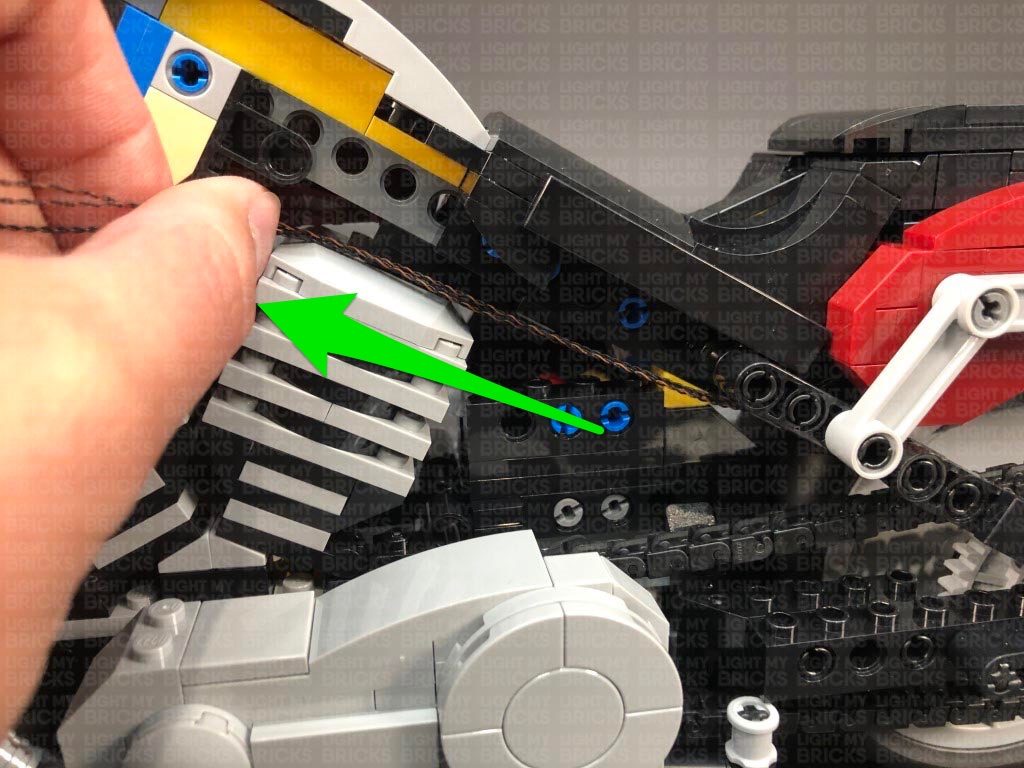
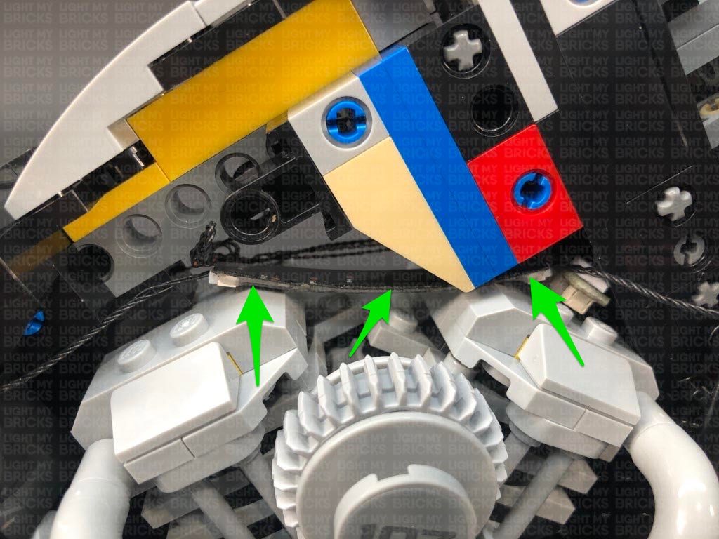
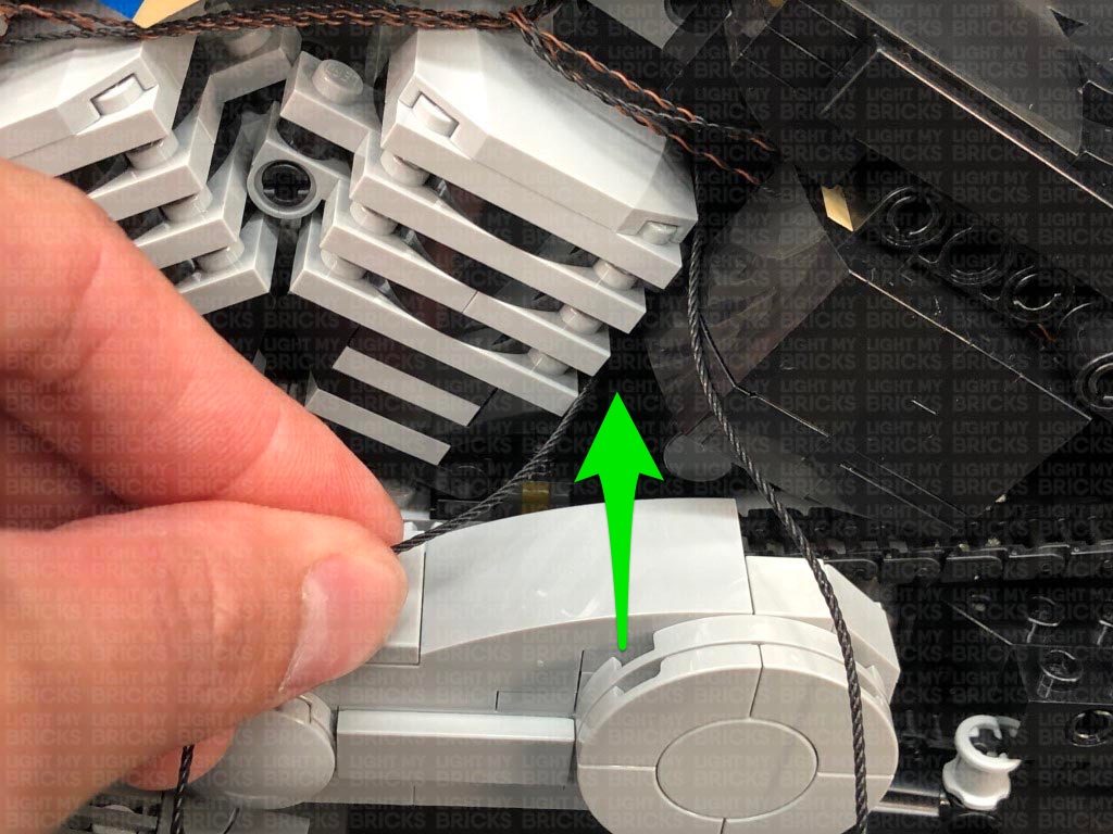
Using it’s adhesive backing, stick the strip light inside the space in the bottom of the motor, ensuring the strip light is facing the centre as shown below:
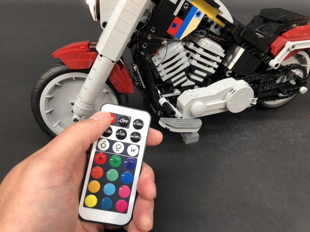
17.) Controlling the RGB Strip Lights
Use the provided RGB Remote Control to control the RGB Strip Lights in the engine section of the Harley Davidson. Prior to using it, ensure you remove the plastic tag to activate the batteries inside.
By default the RGB lights are turned off even when the other lights have been turned on.
To control the RGB lights, point the front of the remote control directly toward the RGB Control Board (we mounted at the behind the front wheel) and turn the lights on via the ON button. Choose your desired colour by pressing any of the coloured buttons. You can also control the brightness as well as choose from one of the following effects:
15.) Group the two micro bit light cables from the rear indicator lights as well as the 30cm connecting cable and pull them back toward the front of the bike. Secure the cables by reconnecting the black section just above the bike chain (section we disconnected back in step 8)
Neaten up the excess cables from the three cables by twisting and folding them around each other into a neat bunch, then tuck this neat bunch inside the bike just above the motor section as shown below:
Take 2x Adhesive Squares and stick them on the back of the RGB Control Board in the below positions.
With the IR Sensor on the bottom, stick the RGB Control Board to the following position behind the front wheel. Ensure the board is stuck to the flat side of the black pieces.
16.) Bring the other end of the RGB Connecting Cable out the left side of the bike and thread it behind the black flat bar. Pull the cable all the way out then loop it around the bottom of the black flat bar a few times to eliminate excess cable. When you get to the 3rd of 4th loop, secure the cable by looping it into a knot.
Connect the RGB Connecting Cable to a RGB Strip Light. Take a new RGB Connecting Cable 15cm and connect it to the strip light’s other port.
Thread the other end of the RGB Connecting Cable through the following space, then turn the bike around to the right side and pull the cable all the way out..
Using it’s adhesive backing, stick the strip light inside the space in the bottom of the motor, ensuring the strip light is facing the centre as shown below:
17.) Controlling the RGB Strip Lights
Use the provided RGB Remote Control to control the RGB Strip Lights in the engine section of the Harley Davidson. Prior to using it, ensure you remove the plastic tag to activate the batteries inside.
By default the RGB lights are turned off even when the other lights have been turned on.
To control the RGB lights, point the front of the remote control directly toward the RGB Control Board (we mounted at the behind the front wheel) and turn the lights on via the ON button. Choose your desired colour by pressing any of the coloured buttons. You can also control the brightness as well as choose from one of the following effects:
- Flash – Flash effect on your chosen colour
- Strobe – Will flash quickly while cycling through all the colours
- Fade – Will cycle through all the colours 3 seconds at each colour
- Smooth – Will cycle through all the colours 7 seconds at each colour
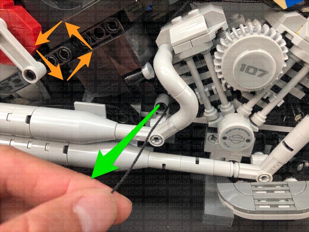
 20.) Thread the other end of the RGB connecting Cable through the following space above the back side of the motor, then turn the bike around to the left side and pull the cable all the way out. Connect the cable to a new RGB Strip Light
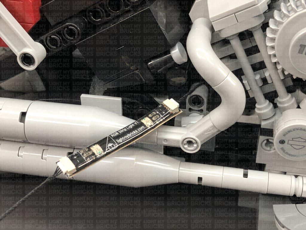
Connect the remaining RGB Connecting Cable 15cm to the strip light’s other port, then thread the cable through the following space just above the bike chain cover. Turn the bike around to the right side and pull the cable out as shown below
Using it’s adhesive backing, stick the strip light inside the following space, ensuring the light is facing the motor.
Turn ON the RGB lights via the remote control to test they are all working OK.
20.) Thread the other end of the RGB connecting Cable through the following space above the back side of the motor, then turn the bike around to the left side and pull the cable all the way out. Connect the cable to a new RGB Strip Light
Connect the remaining RGB Connecting Cable 15cm to the strip light’s other port, then thread the cable through the following space just above the bike chain cover. Turn the bike around to the right side and pull the cable out as shown below
Using it’s adhesive backing, stick the strip light inside the following space, ensuring the light is facing the motor.
Turn ON the RGB lights via the remote control to test they are all working OK.
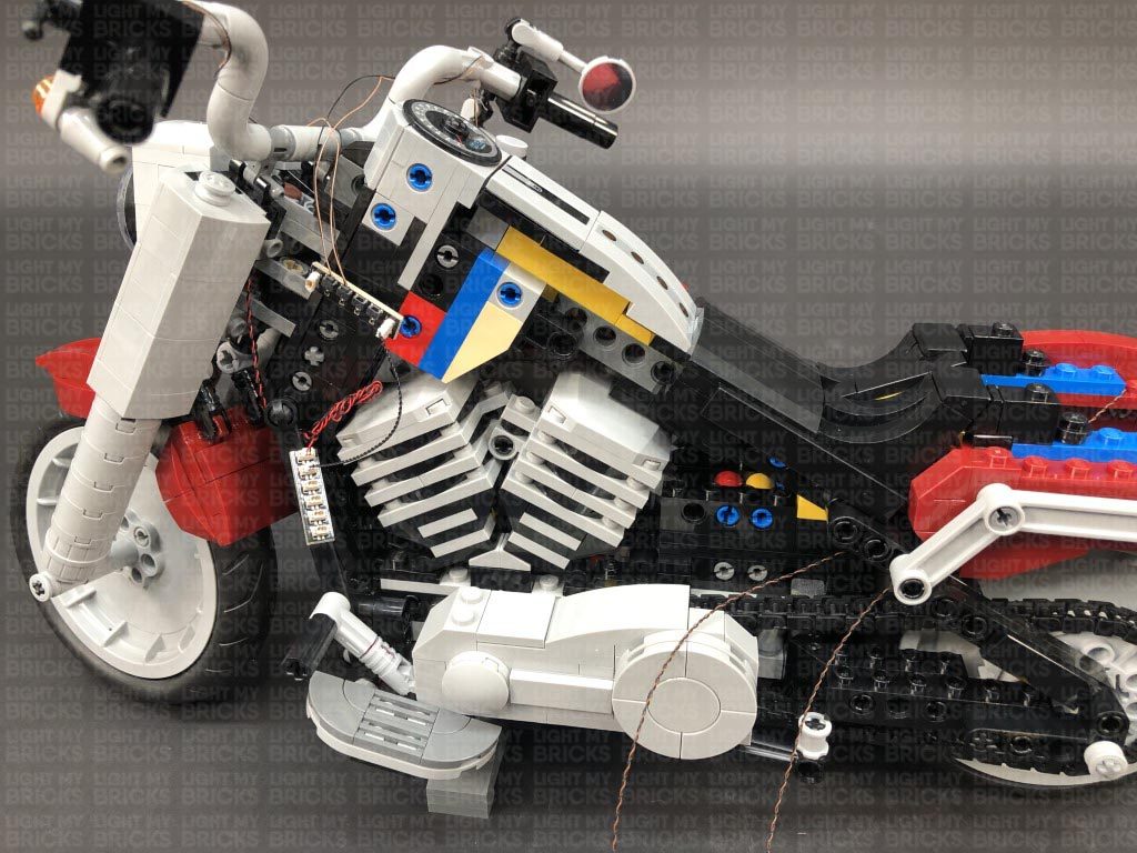
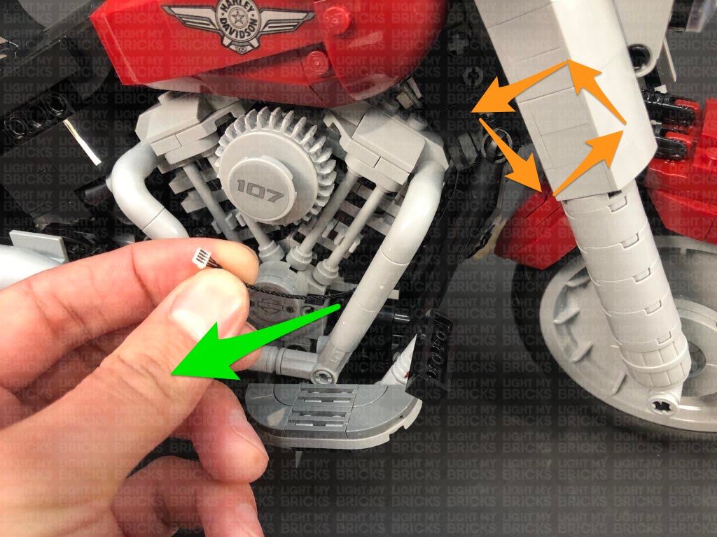
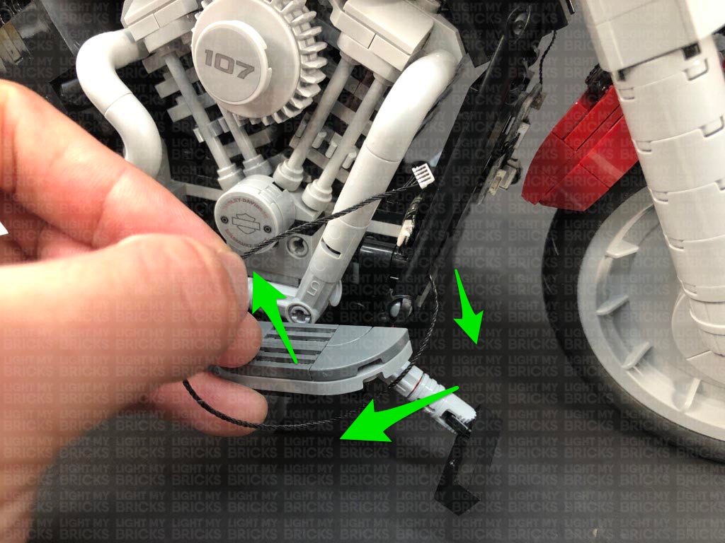
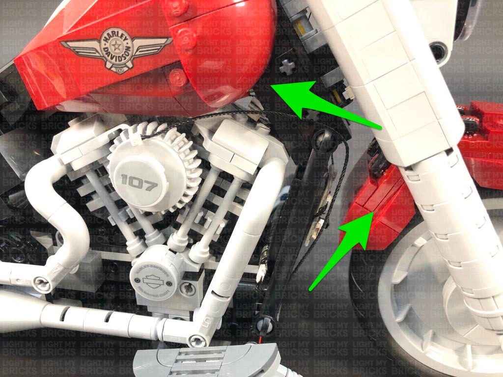
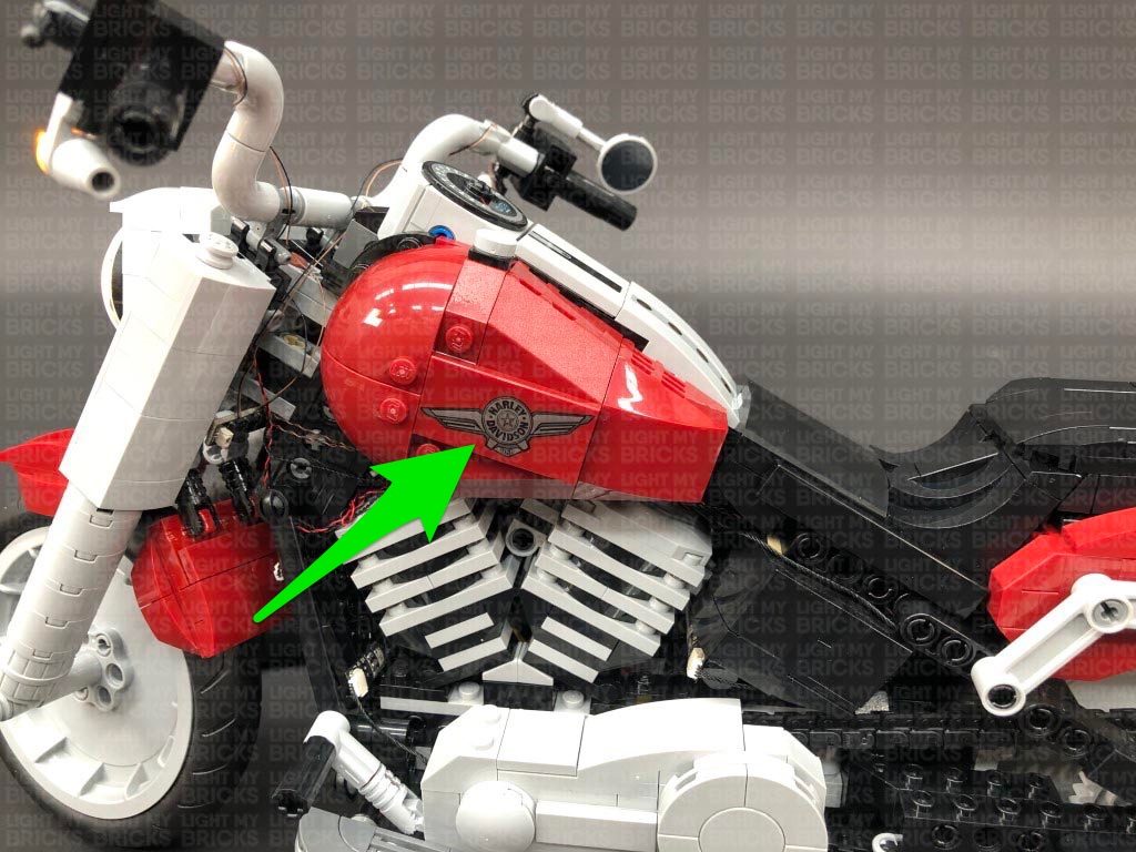
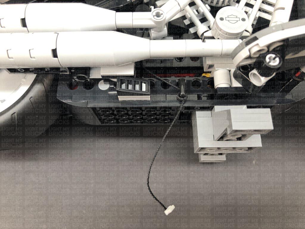
 21.) Secure the excess cable from the 15cm cable by laying it around the black motor section as shown below, then reconnect the fuel tank sections on both left and right sides of the motorbike
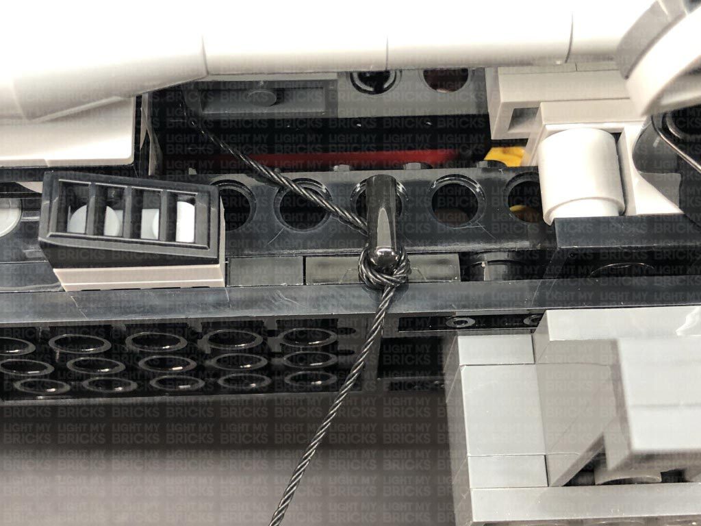
Turn the bike around to the right side and thread the connecting cable down behind the two exhaust pipes. Pull the cable all the way down then place the bike onto it’s left side so we can access underneath the bike.
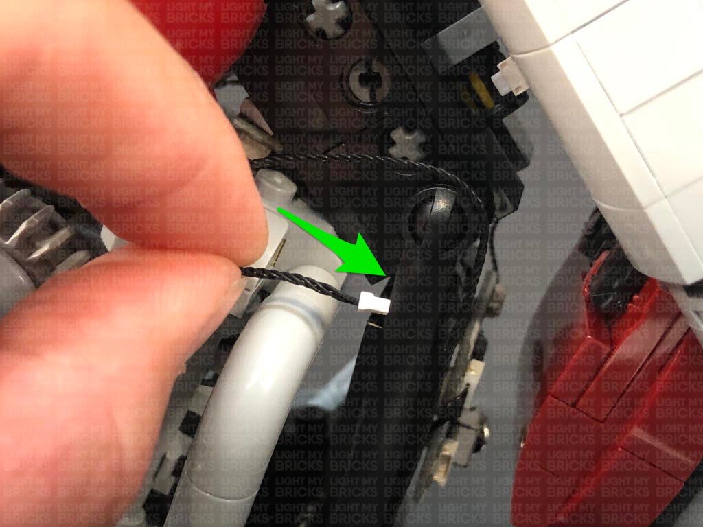
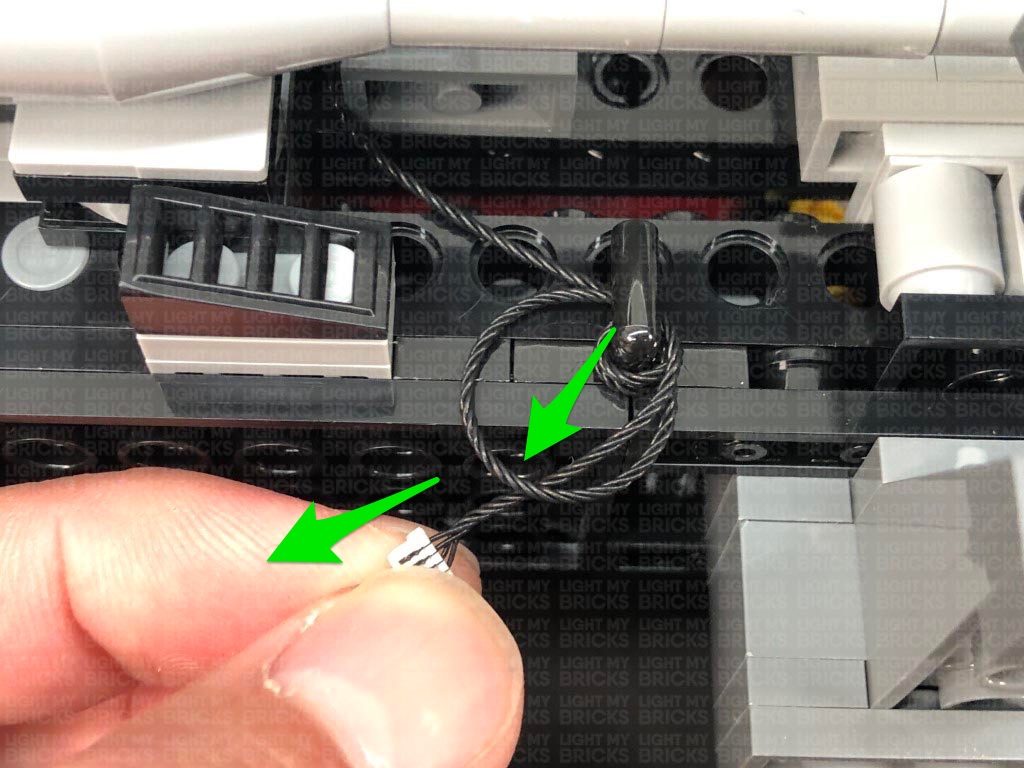
Bring the cable down behind pieces, then bring it around the black handle bar on the right side. Loop the cable around this bar 3 times before tying a knot to lock the cable in place.
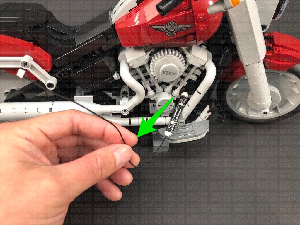
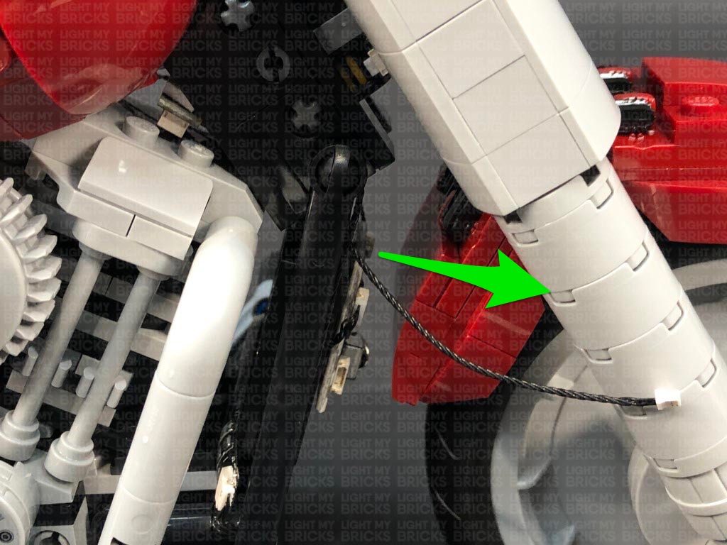
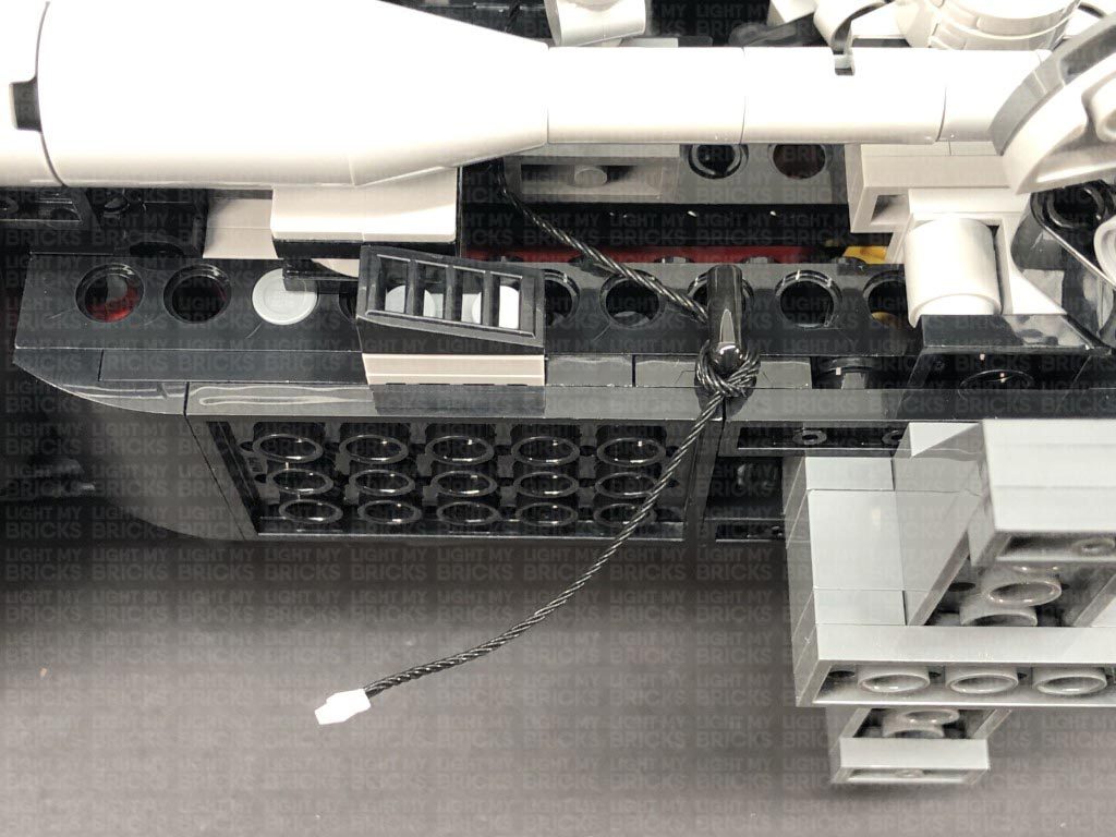
22.) Connect the cable to the remaining RGB Strip Light, then using it’s adhesive backing, stick the strip light underneath the bike in the following position. Tuck the excess cable up the space to the right, then turn the Harley back over and test all lights are working OK.
21.) Secure the excess cable from the 15cm cable by laying it around the black motor section as shown below, then reconnect the fuel tank sections on both left and right sides of the motorbike
Turn the bike around to the right side and thread the connecting cable down behind the two exhaust pipes. Pull the cable all the way down then place the bike onto it’s left side so we can access underneath the bike.
Bring the cable down behind pieces, then bring it around the black handle bar on the right side. Loop the cable around this bar 3 times before tying a knot to lock the cable in place.
22.) Connect the cable to the remaining RGB Strip Light, then using it’s adhesive backing, stick the strip light underneath the bike in the following position. Tuck the excess cable up the space to the right, then turn the Harley back over and test all lights are working OK.
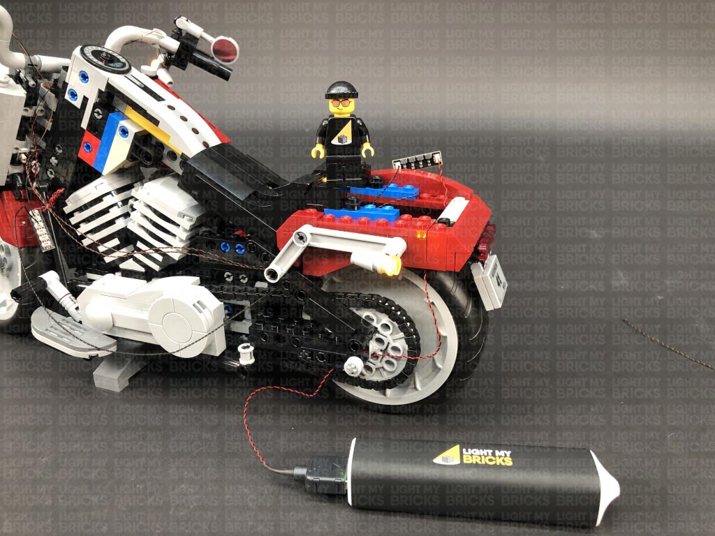
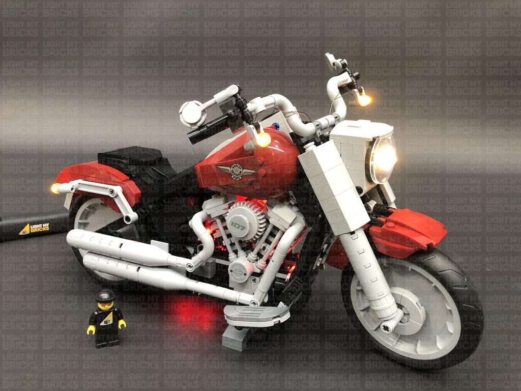
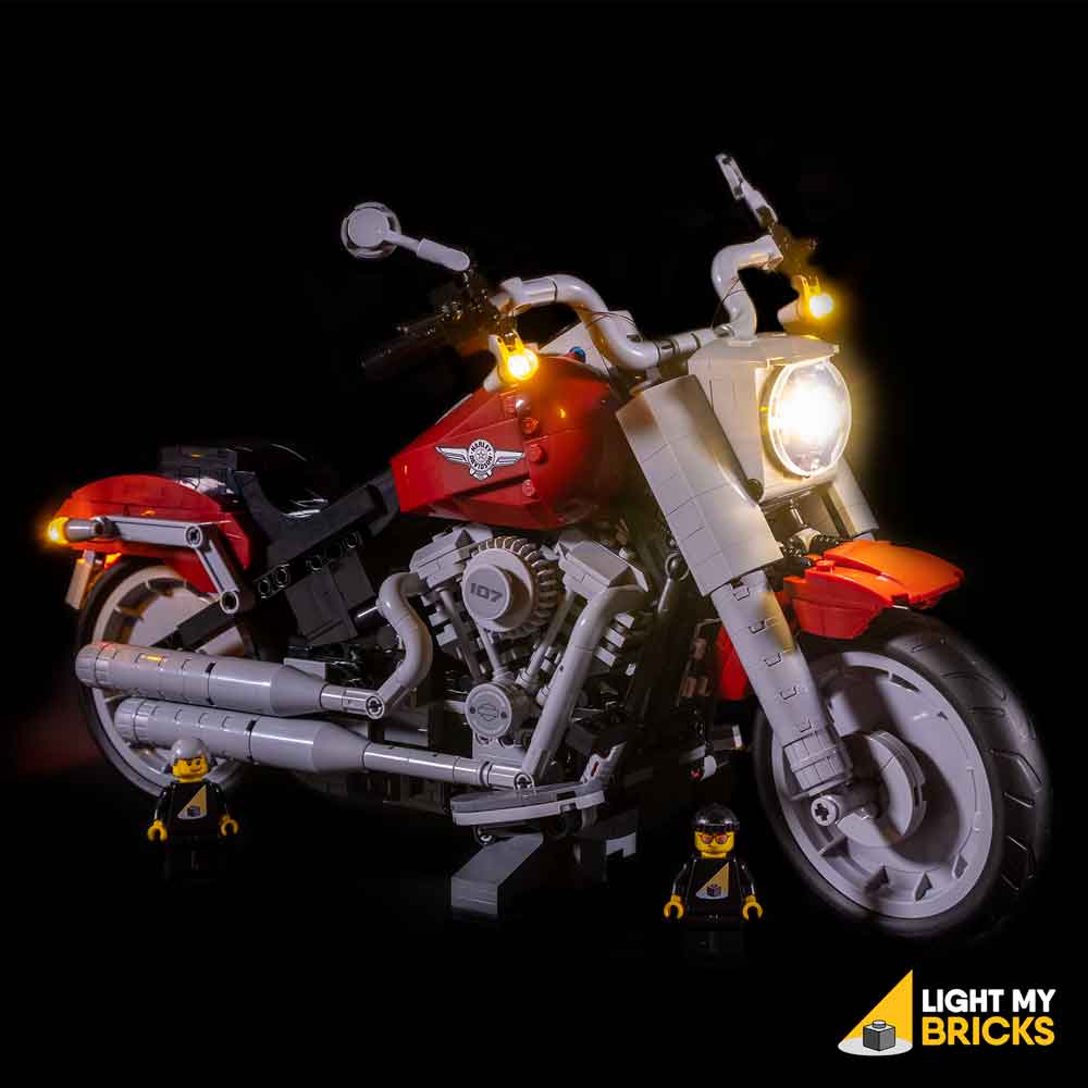
This finally completes installation of the Light My Bricks LEGO Harley-Davidson Fatboy Light Kit.
We thank you for purchasing this product and hope you ENJOY!