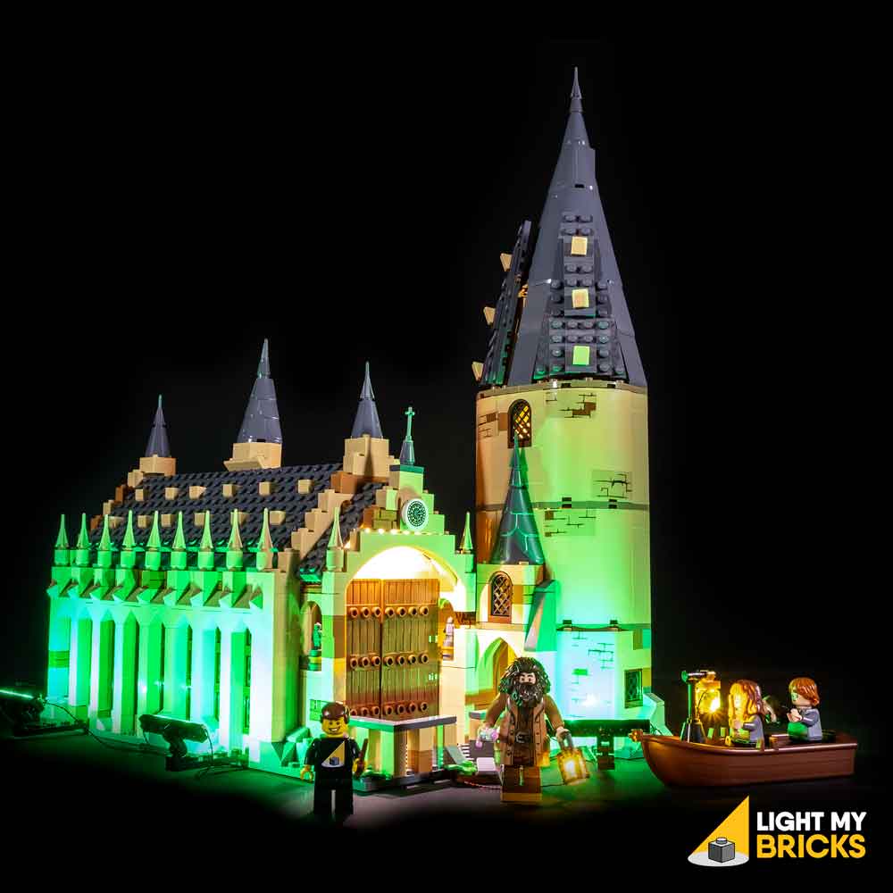

The following page is the instructions for the Light My Bricks LEGO Hogwarts Great Hall (75954) LED light kit.
If you run into any issues, please refer to the online troubleshooting guide.
To ensure a trouble-free installation of your light kit, please read and follow each step carefully. These instructions can be downloaded in PDF format here
Please note: This page lists instructions for the LED light kit only. If you are wishing to purchase the Light My Bricks LEGO Hogwarts Great Hall (75954) LED light kit , please click here to view the product page
Package Contents:
- 8x White 30cm Bit Lights
- 4x White 15cm Micro Bit Lights
- 3x Green Strip Lights
- 1x White Strip Light
- 1x Flicker Effects Boards
- 1x Micro 4-Port Expansion Board
- 2x 6-Port Expansion Boards
- 2x 5cm Connecting Cables
- 3x 15cm Connecting Cables
- 2x 30cm Connecting Cables
- 1x AA Battery Pack (Requires 3x AA Batteries)
- 6x Adhesive Squares
LEGO Pieces:
- 6x Black Plate 1×6
- 4x Black Tile 1×1 with Clip
- 4x Black 1×1 Modified Plate Rounded with Handle
- 1x Black Round Plate 1×1 with open stud
- 1x Black Plate 1×2 modified with stud jumper
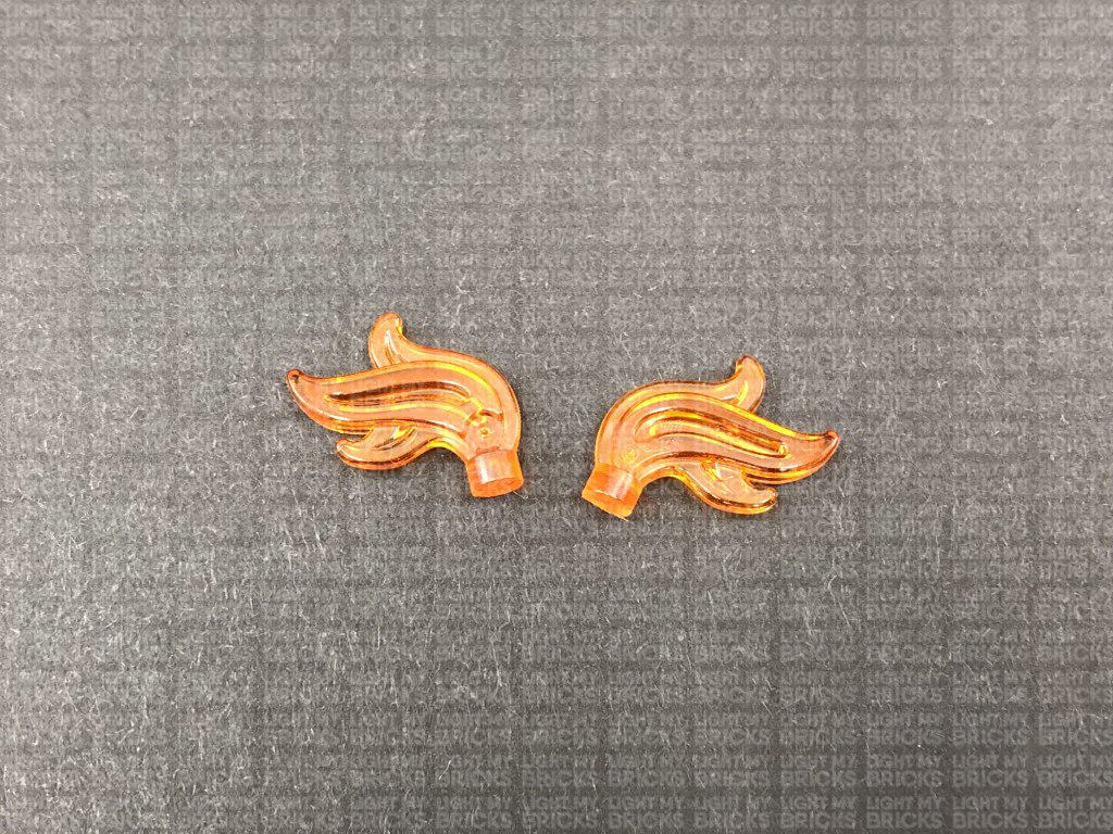
- 3x Trans Clear Plate w Rounded Bottom 2×2
Important things to note:
Laying cables in between and underneath bricks
Cables can fit in between and underneath LEGO® bricks, plates, and tiles providing they are laid correctly between the LEGO® studs. Do NOT forcefully join LEGO® together around cables; instead ensure they are laying comfortably in between each stud.
Connecting cable connectors to Expansion Boards
Take extra care when inserting connectors to ports of Expansion Boards. Connectors can be inserted only one way. With the expansion board facing up, look for the soldered “=” symbol on the left side of the port. The connector side with the wires exposed should be facing toward the soldered “=” symbol as you insert into the port. If a plug won’t fit easily into a port connector, do not force it.
Connecting cable connectors to Strip Lights
Take extra care when inserting connectors to ports on the Strip Lights. Connectors can be inserted only one way. With the Strip Light facing up, ensure the side of the connector with the wires exposed is facing down. If a plug won’t fit easily into a port connector, don’t force it. Doing so will damage the plug and the connector.
Connecting micro cable connectors to Micro Expansion Board Ports
Take extra care when inserting the micro connectors to micro ports of Micro Expansion Boards. Connecting Micro Bit Lights to Micro Expansion Boards is similar to connecting lights and cables to Strip Lights. With the expansion board facing up, ensure the side of the connector with the wires exposed is facing down. If a plug won’t fit easily into a port connector, do not force it. Use your fingernail to push the plastic part of the connector to the micro port.
Installing Bit Lights under LEGO® bricks and plates.
When installing Bit Lights under LEGO® pieces, ensure they are placed the correct way up (Yellow LED component exposed). You can either place them directly on top of LEGO® studs or in between.
OK, Let’s Begin!
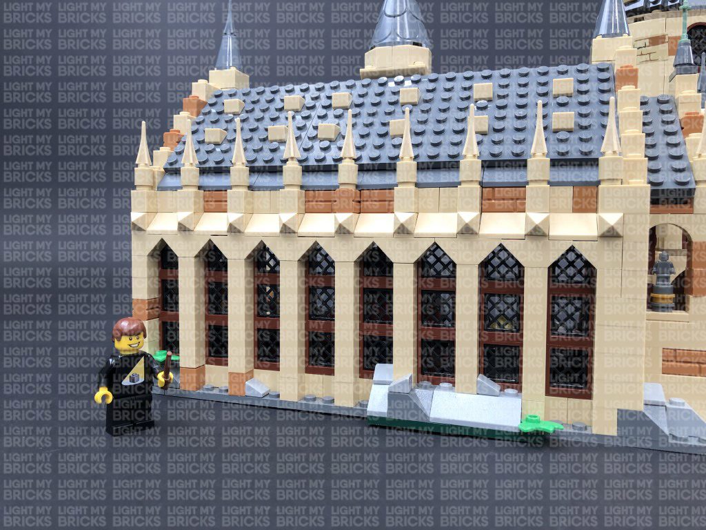
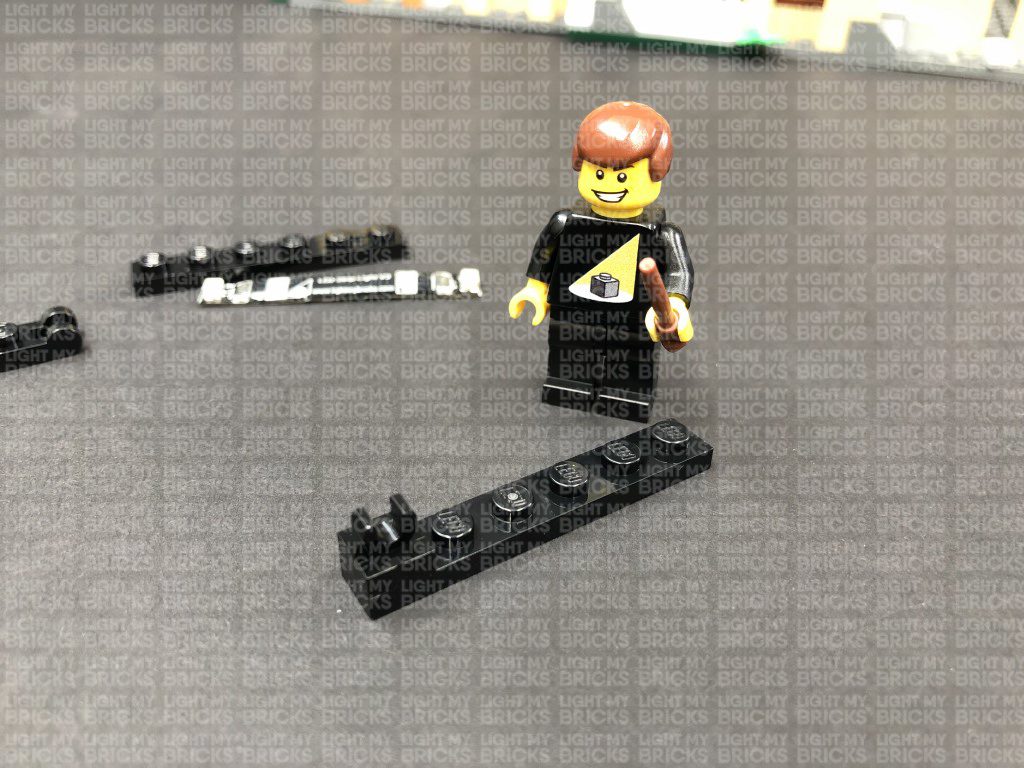
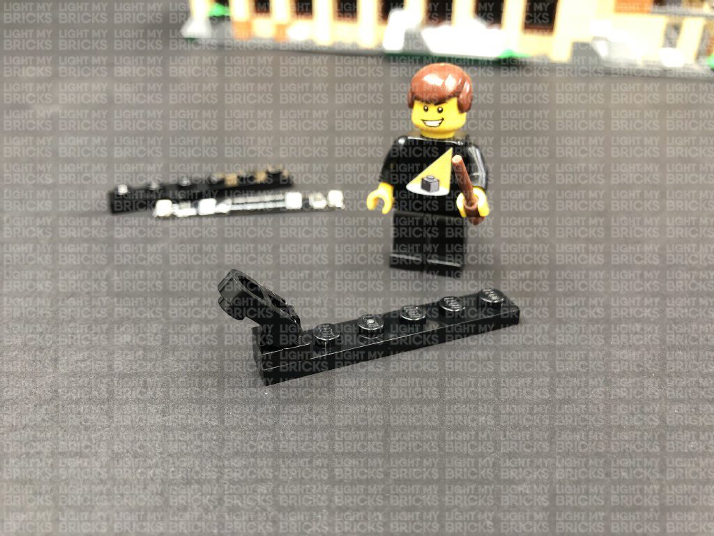
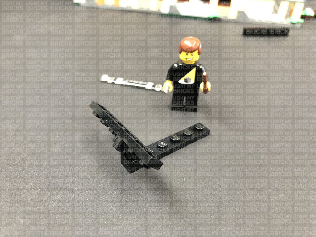
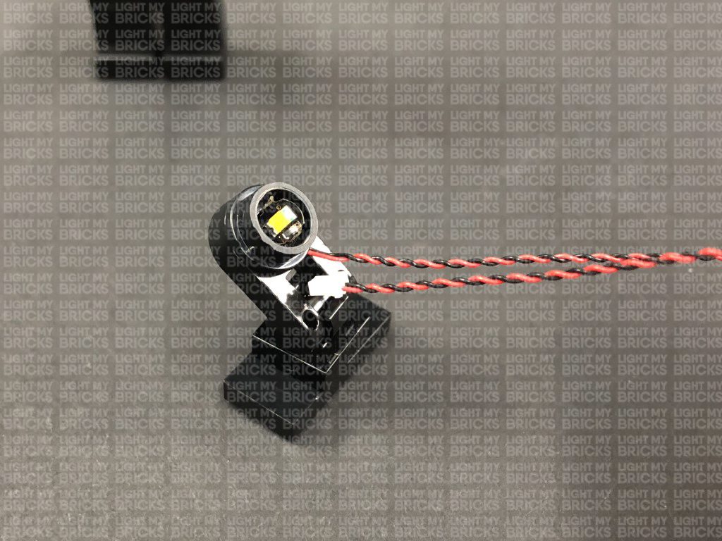
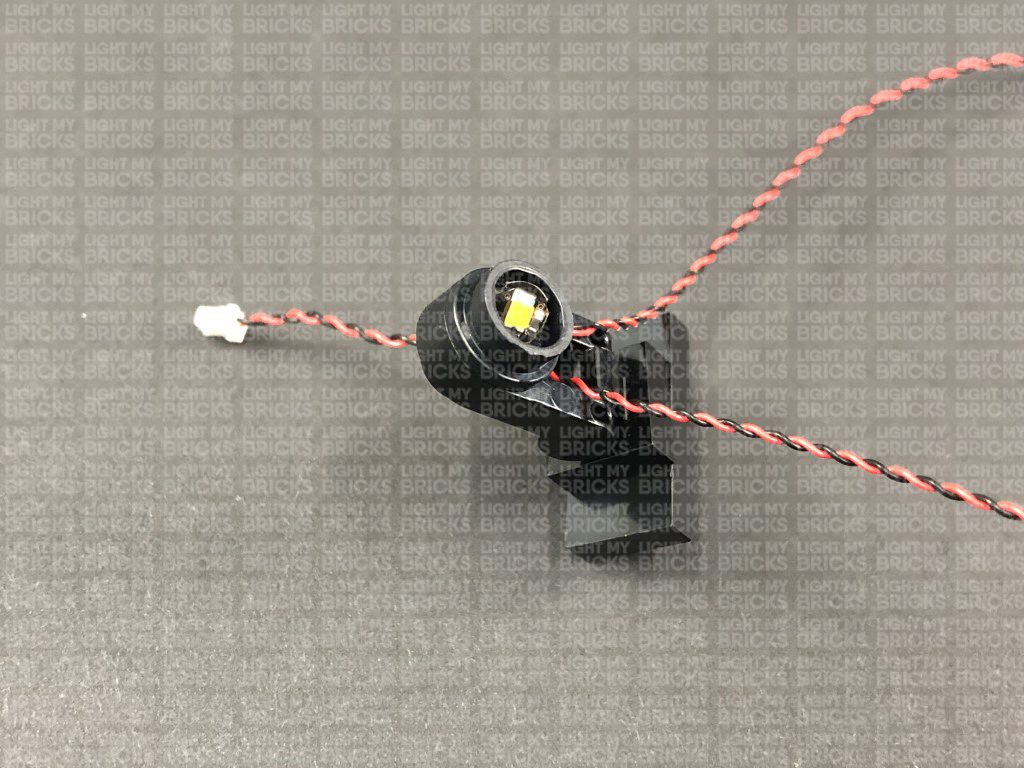
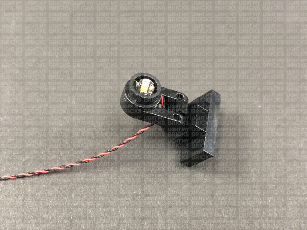
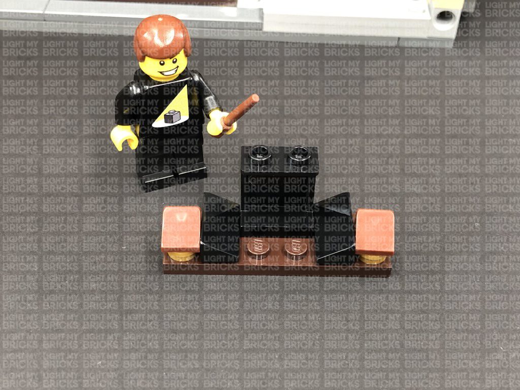
1.) We will begin with installing spot lights to the exterior of the Great Hall. First, take out the following provided LEGO pieces to make up an angled spot light.- 2x Black Plate 1×6
- 1x Black Tile 1×1 with Clip
- 1x Black 1×1 Modified Plate Rounded with Handle
- 4x Black Plate 1×6
- 2x Black Tile 1×1 with Clip
- 2x Black 1×1 Modified Plate Rounded with Handle
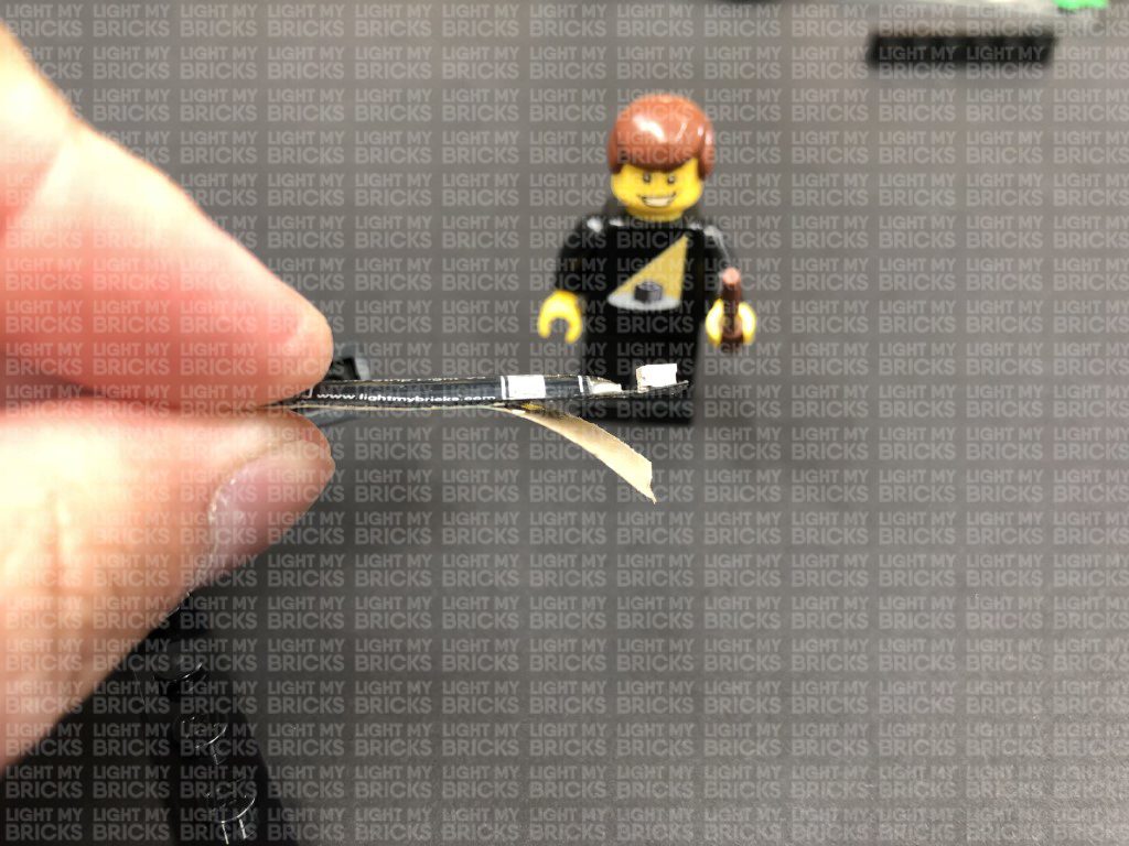
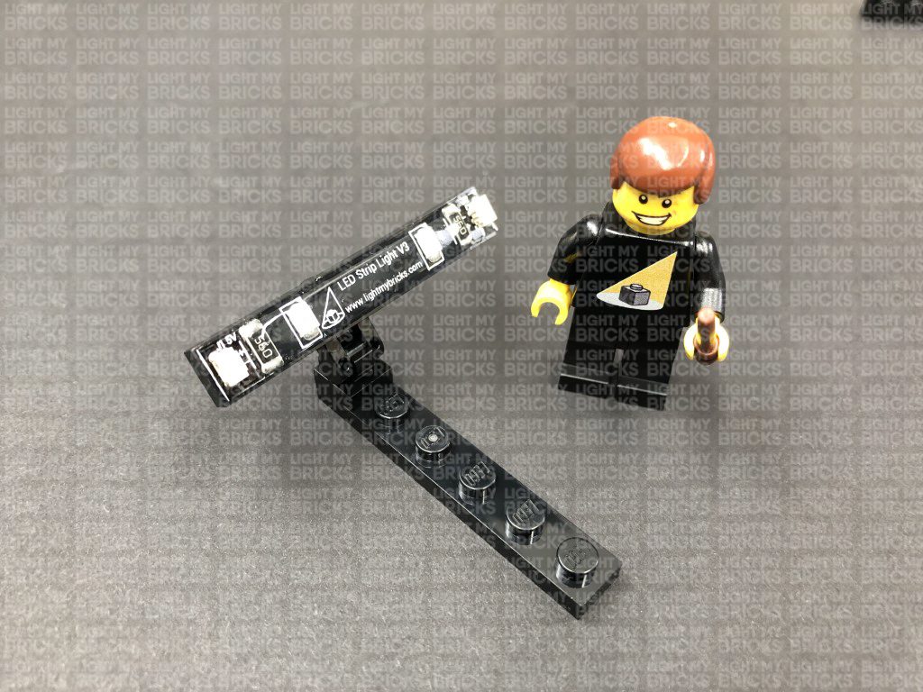
- 2x Green Strip Lights
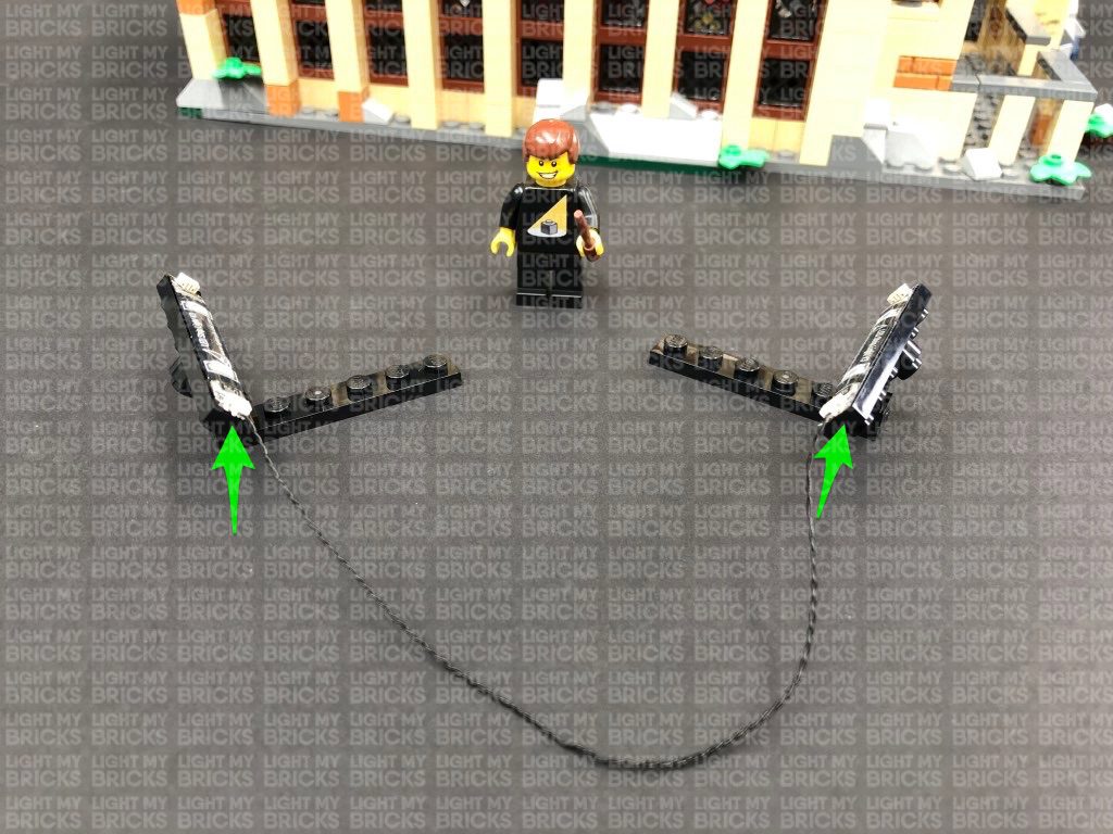
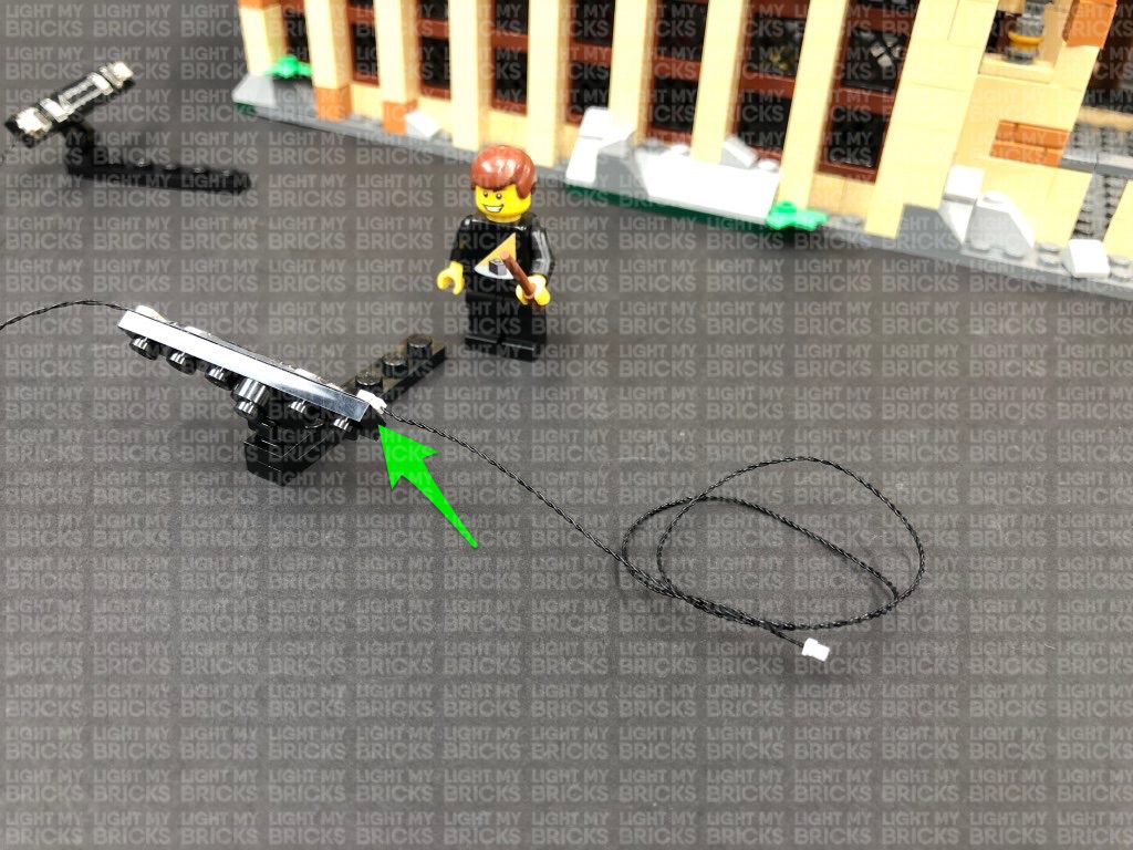
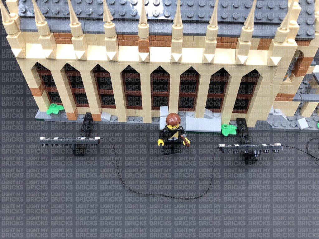
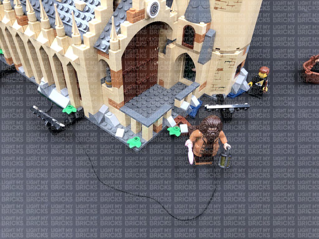
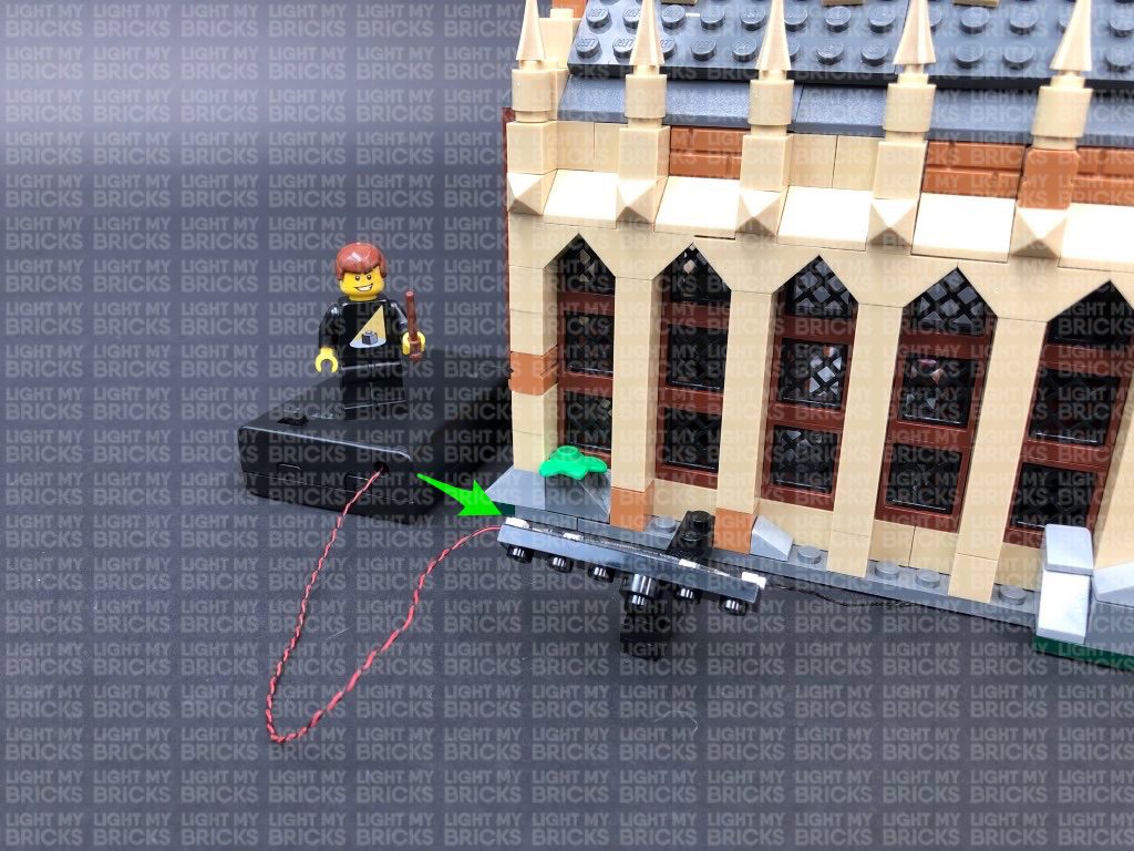
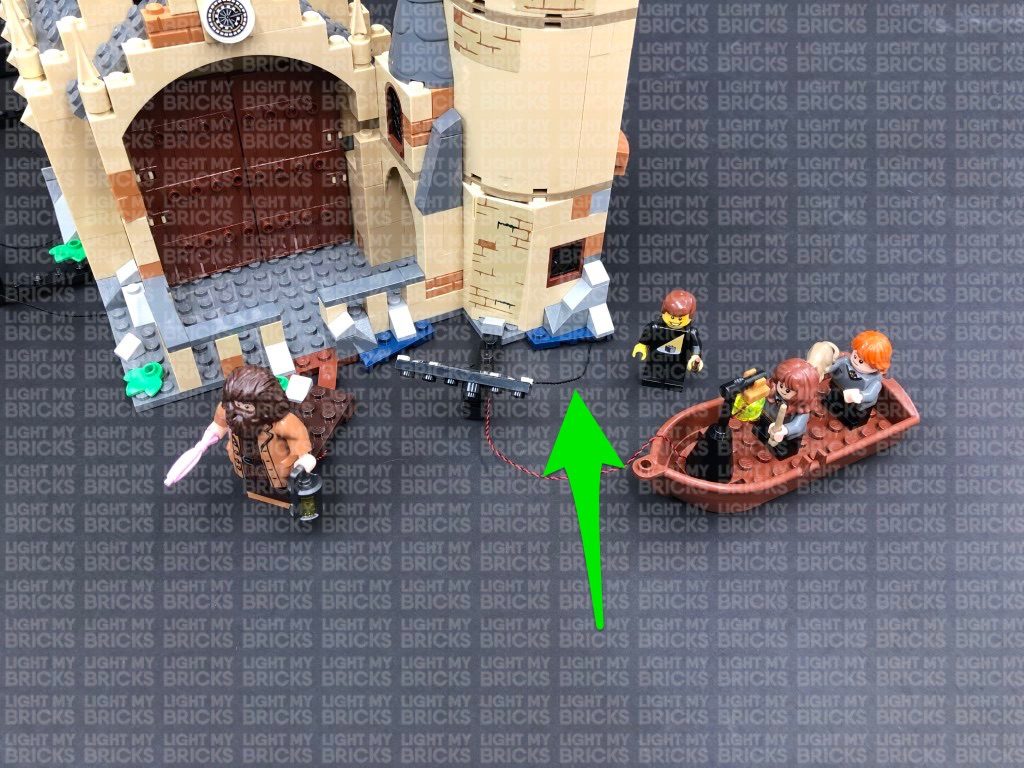
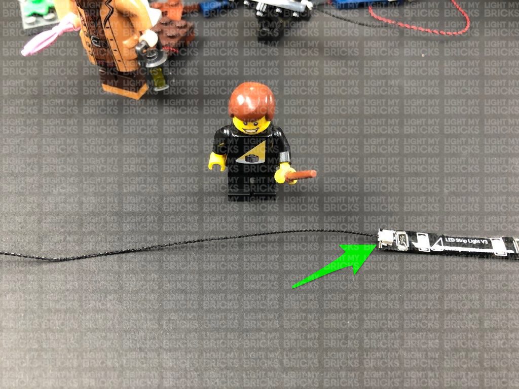
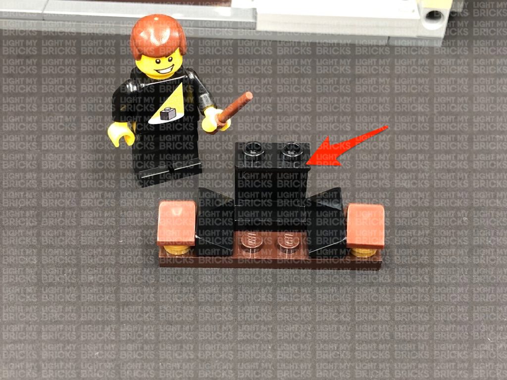
 3.) Take a 15cm Connecting Cable and connect it between two of the spot lights, then take a 30cm Connecting Cable and connect one end to the right strip light as shown below:
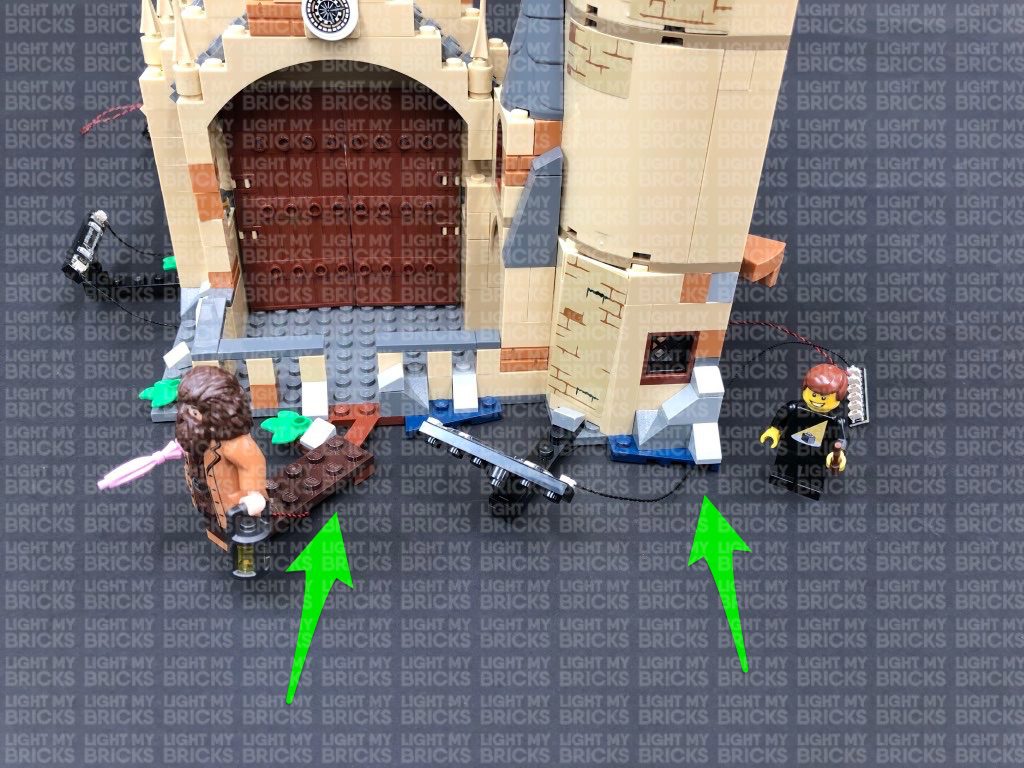
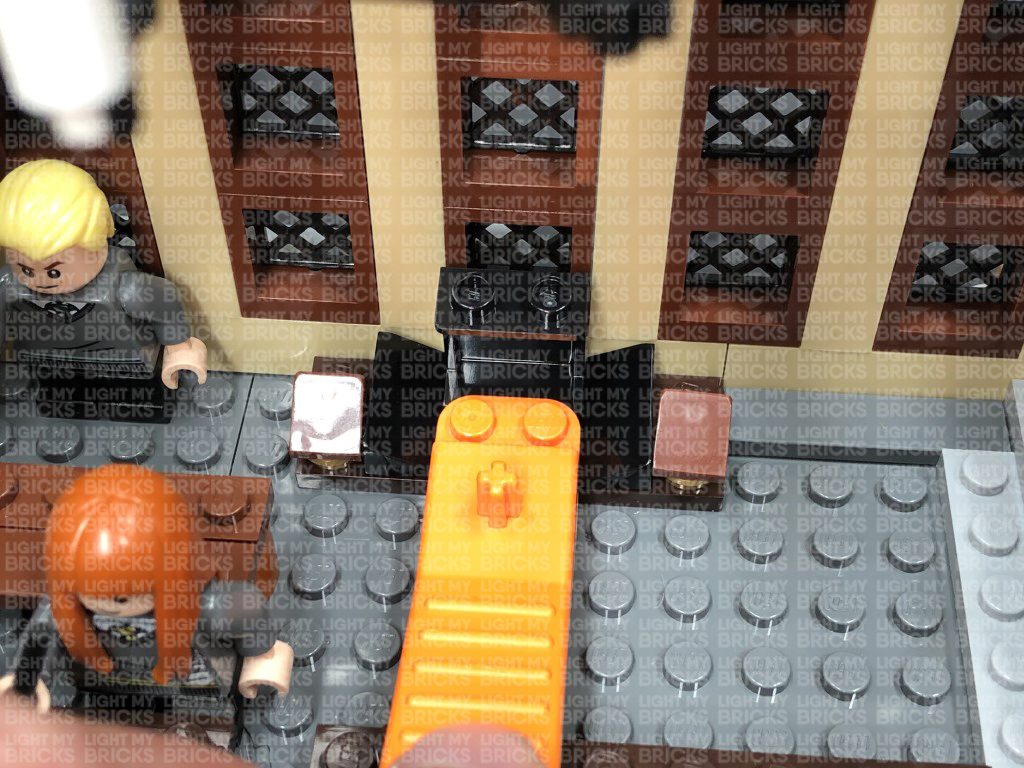
Connect the two spot lights to the front of the great hall in the below positions, then tuck the 15cm connecting cable underneath the base of the hall.
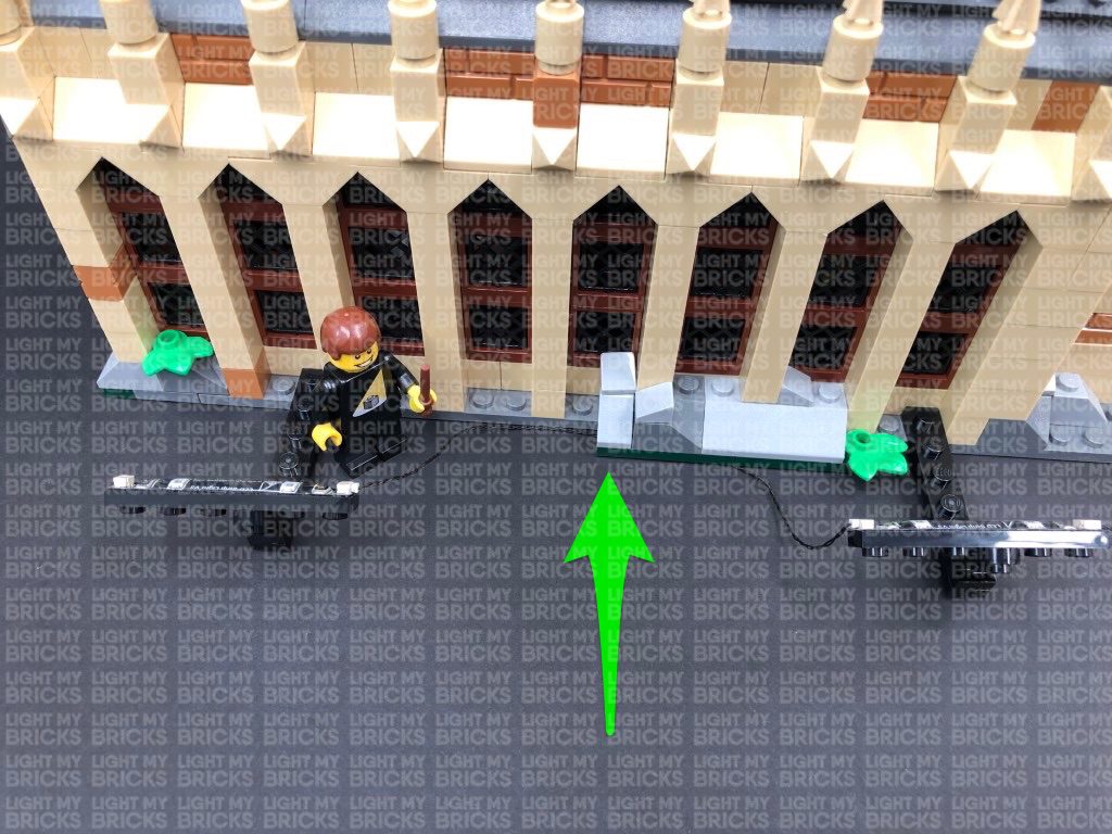
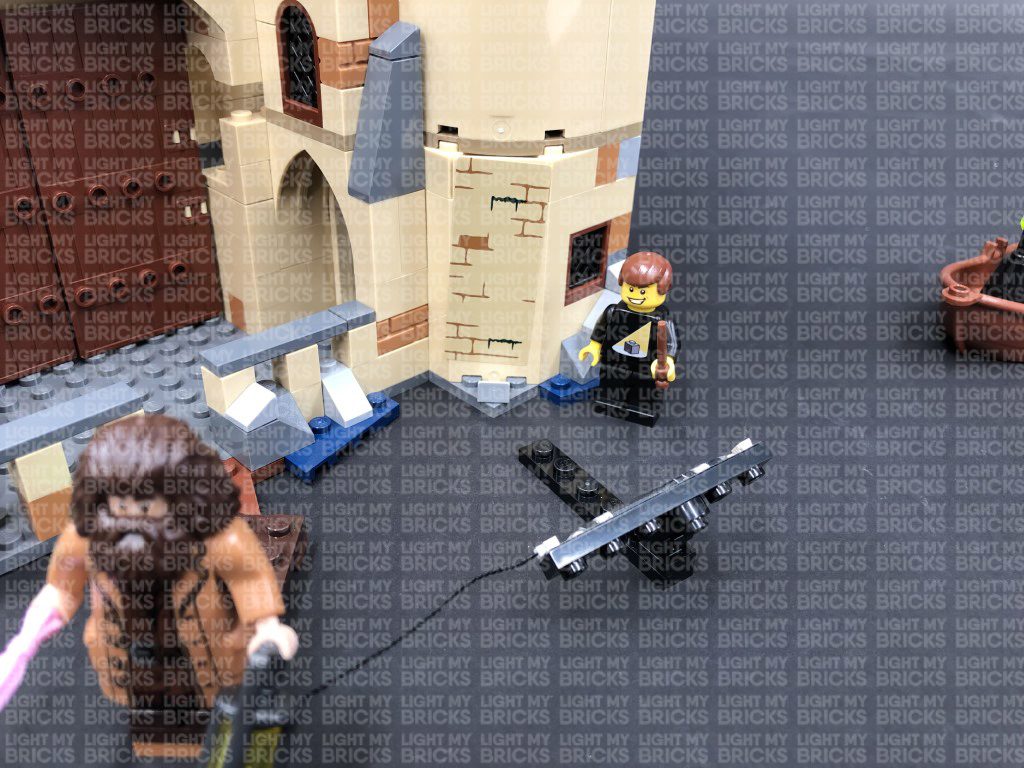
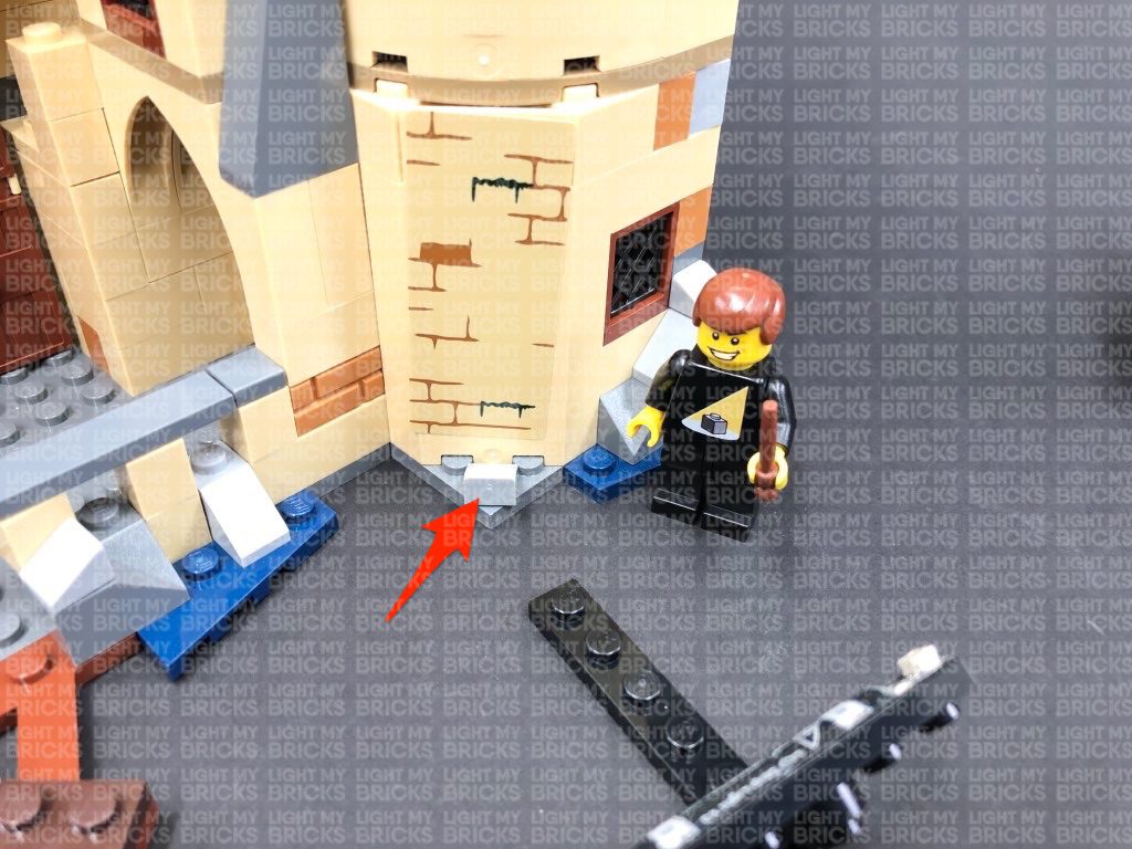
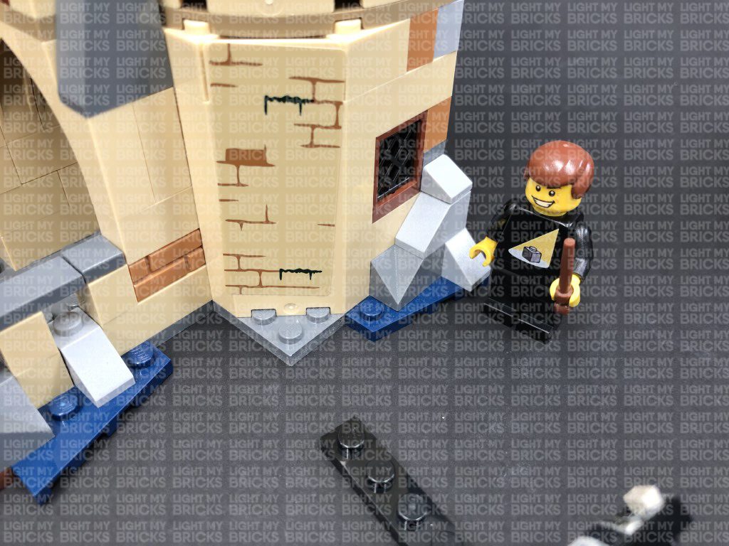
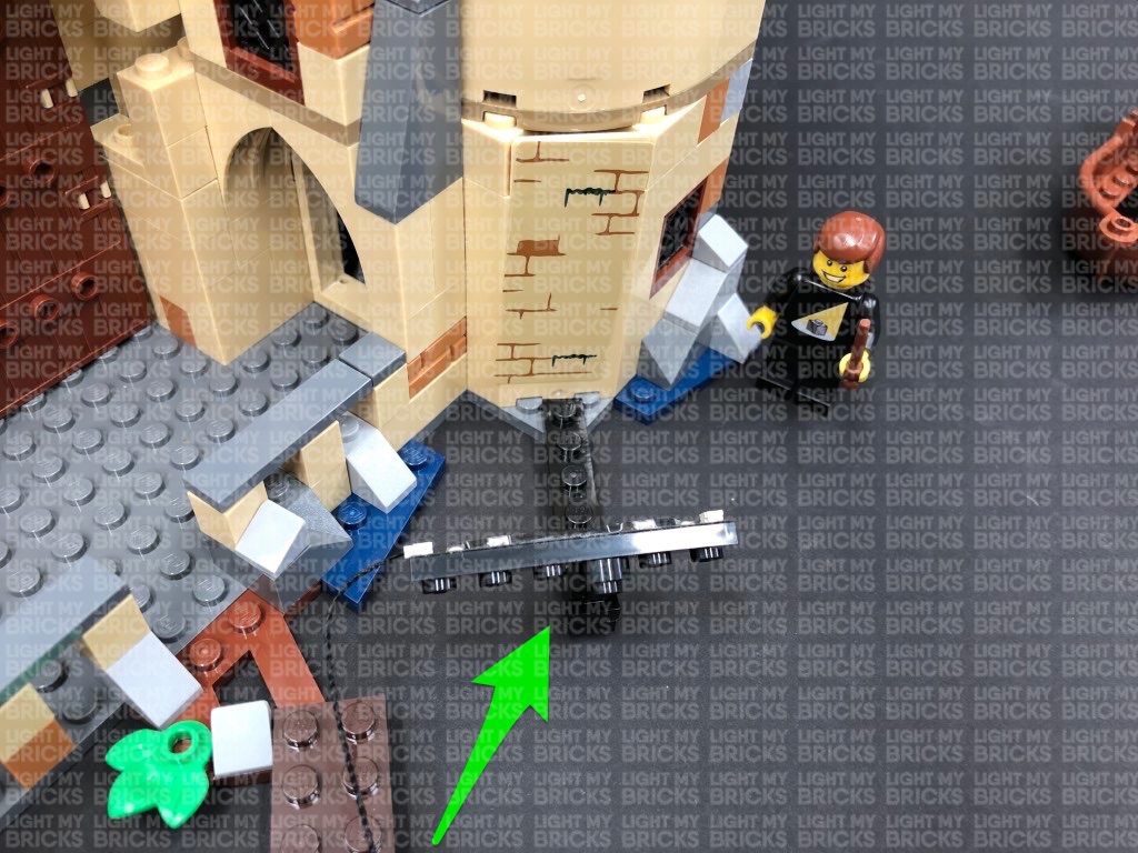
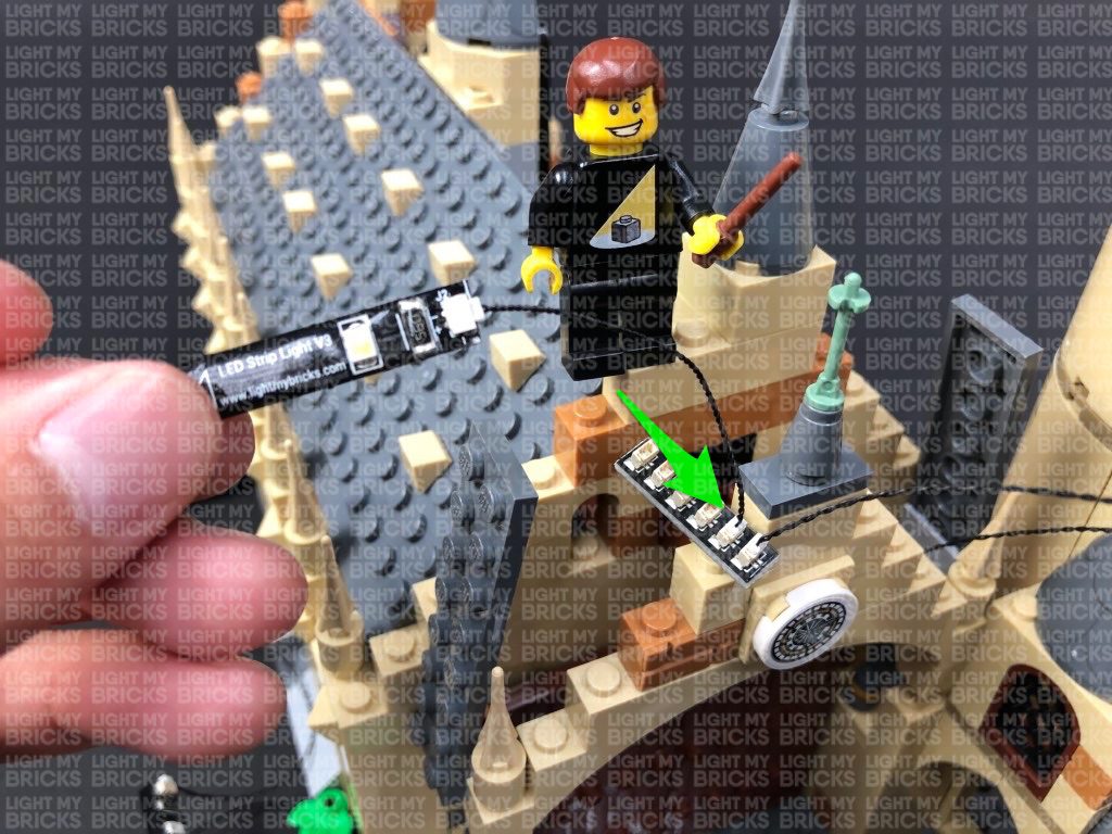
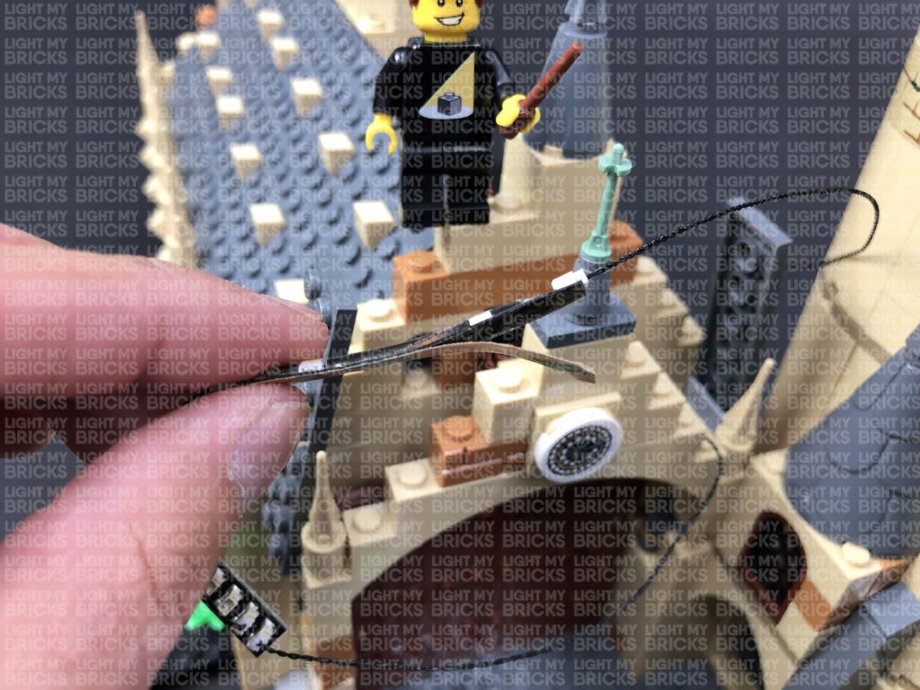
4.) Take the other end of the 30cm Connecting Cable and connect it to the third spot light (green strip light’s left port), then bring it around to the right side of the hall. Disconnect and discard the following grey angled tile and connect the spot light to this position.
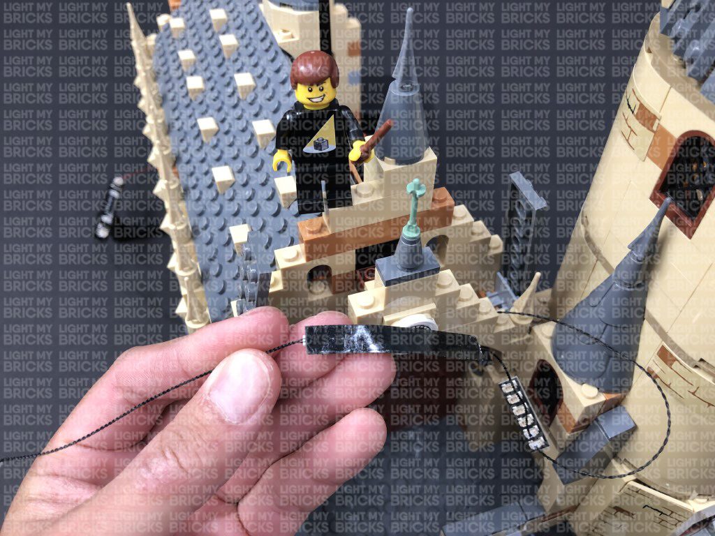
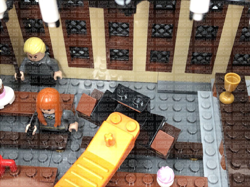
Hide the 30cm cable in between the spot lights underneath the base of the hall as shown below.
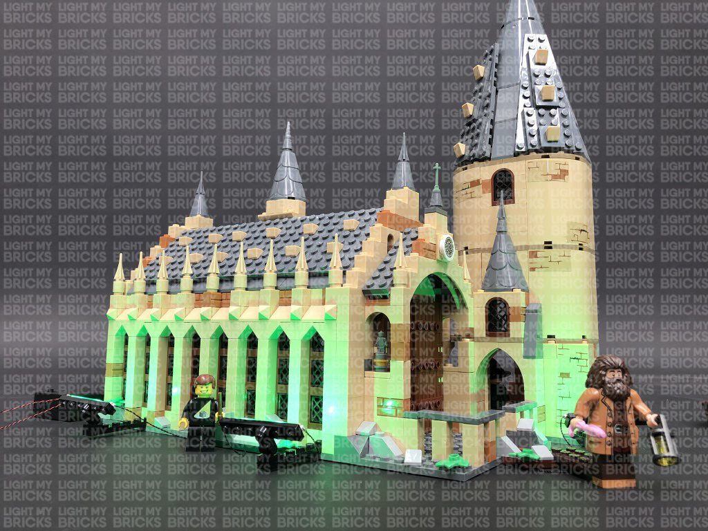
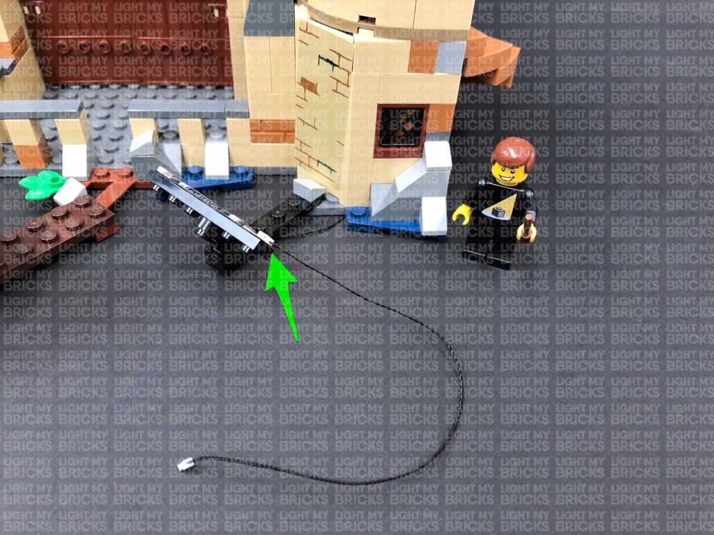
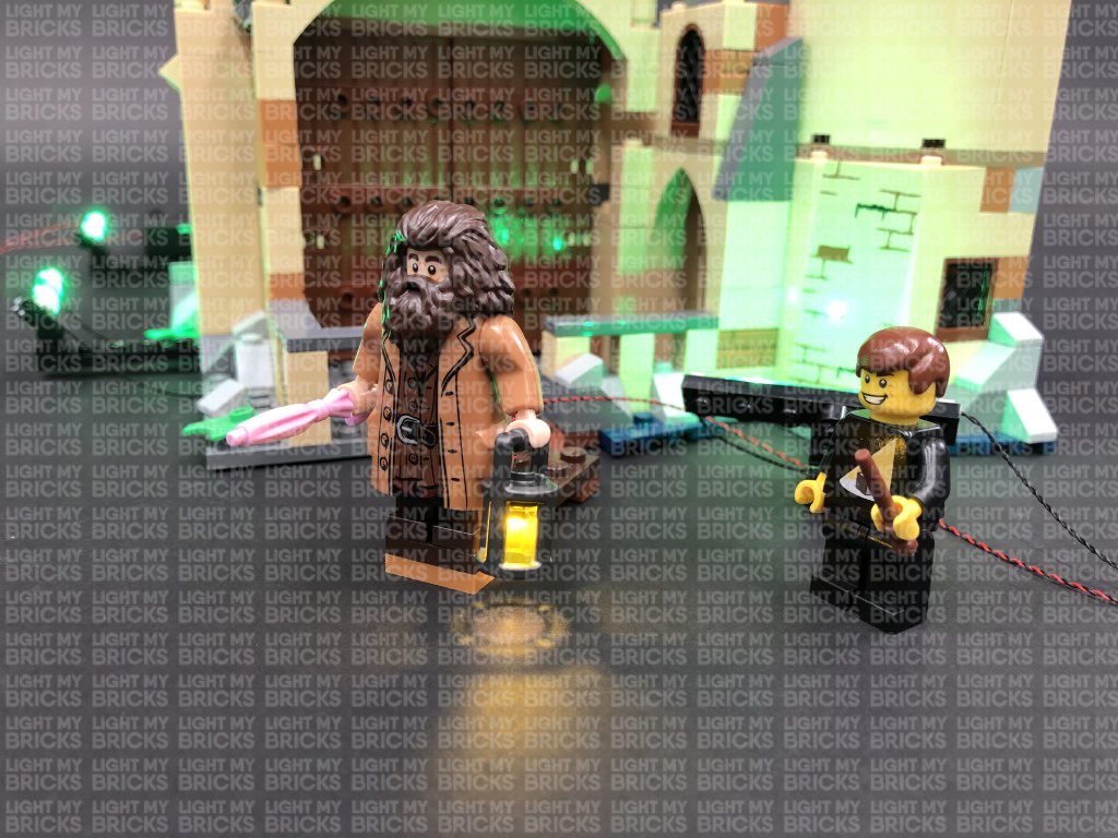
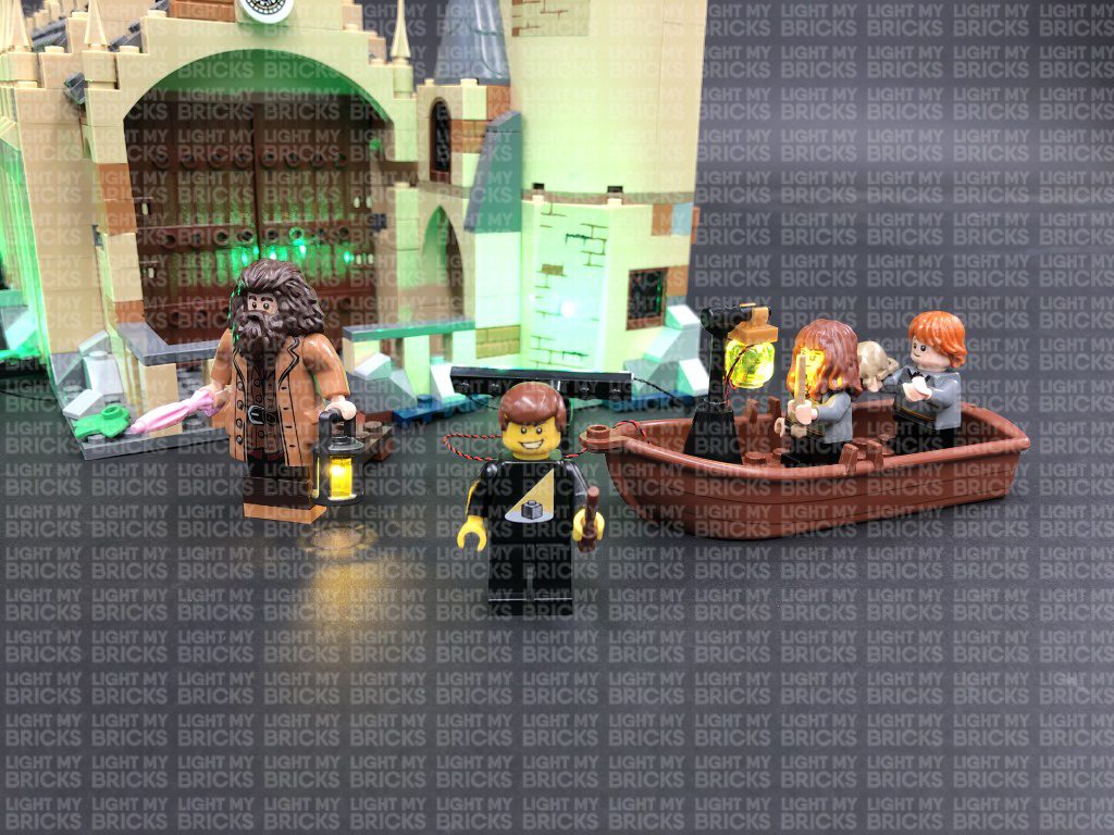
5.) Take the AA Battery Pack and insert 3x AA Batteries to it. Connect the battery pack cable to the left port on the spot light on the left of the Hall. Turn ON the battery pack to test the spot lights are working OK.
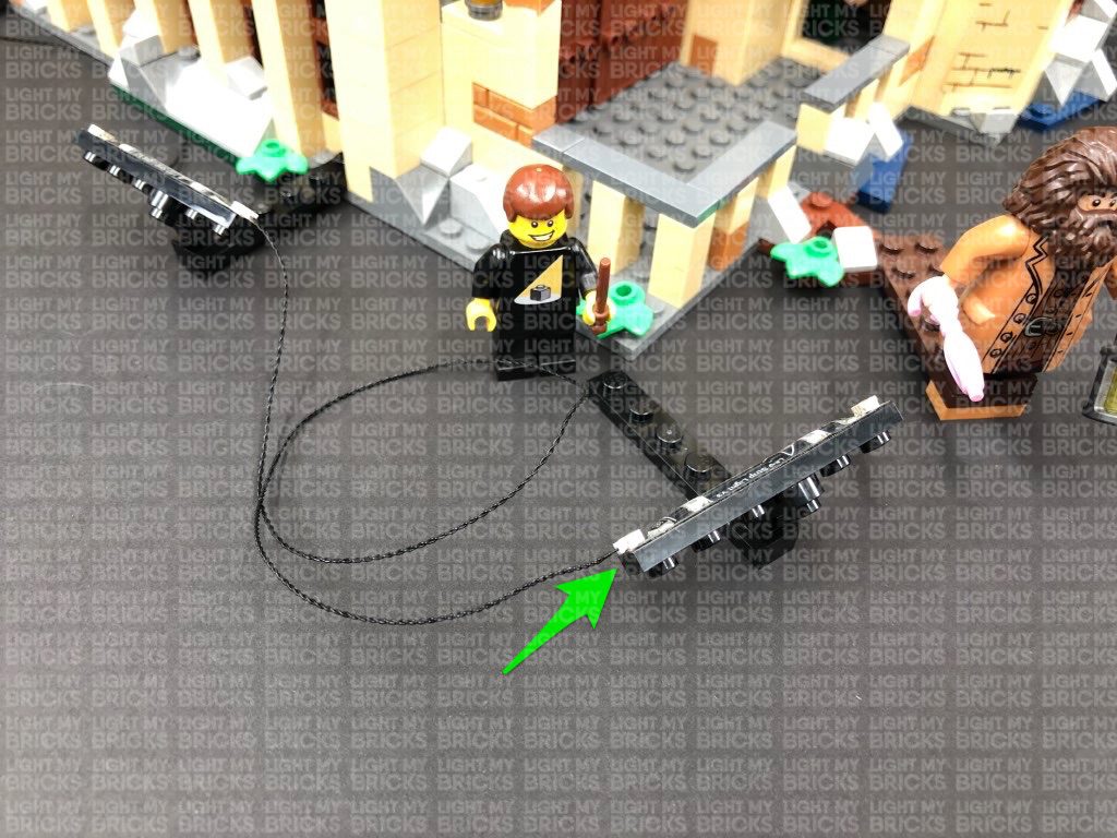
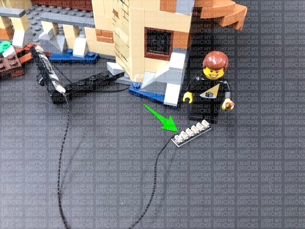
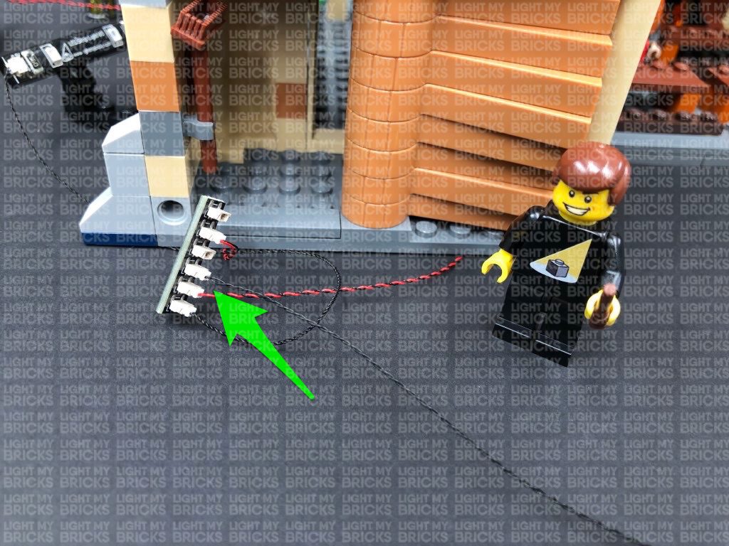
6.) Take a new 15cm Connecting Cable and connect it to the third green Strip Light. Connect the other end of the cable to a 6-Port Expansion Board.
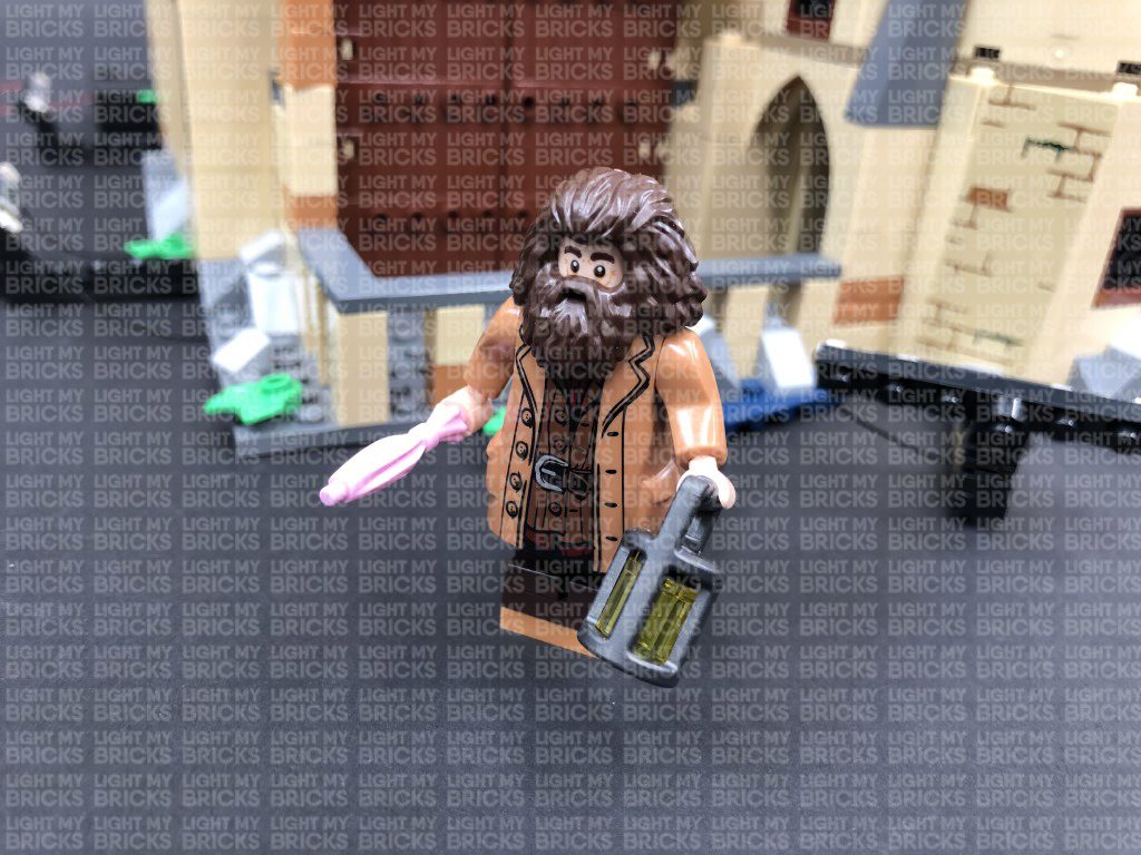
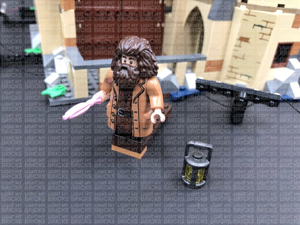
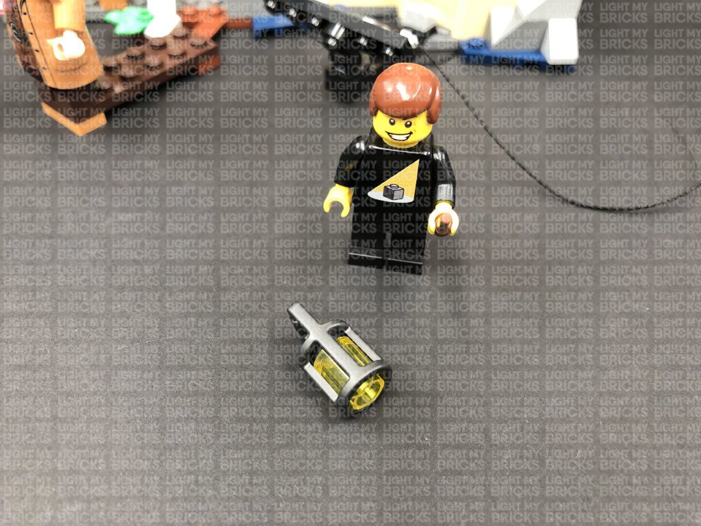
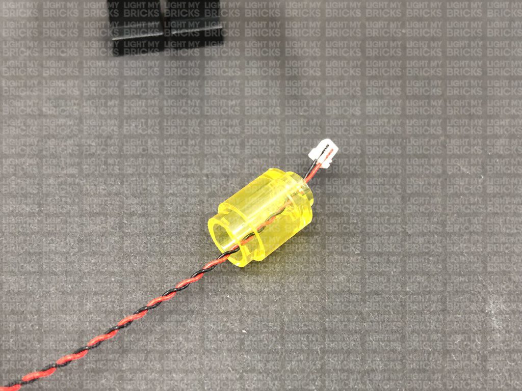
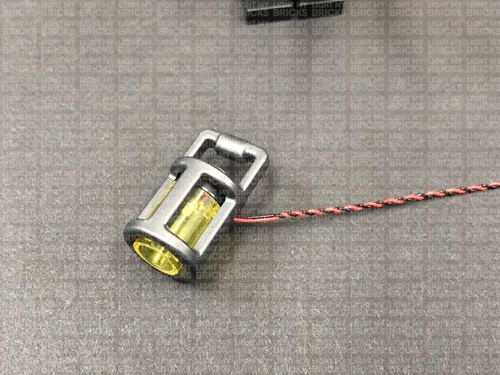
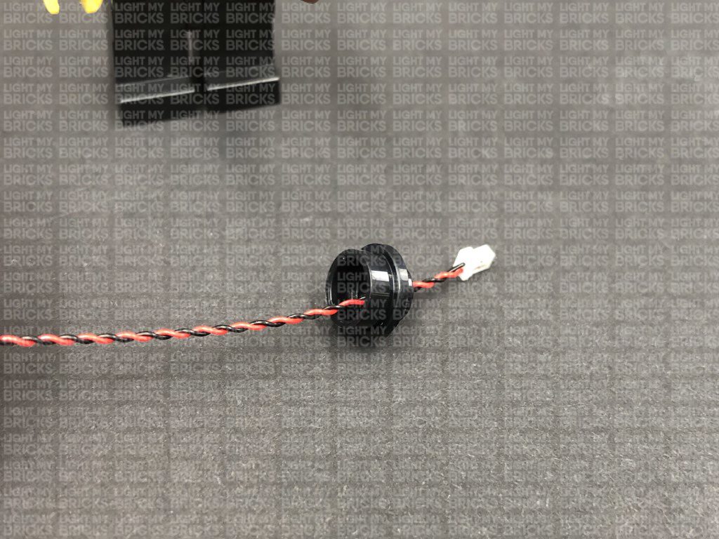
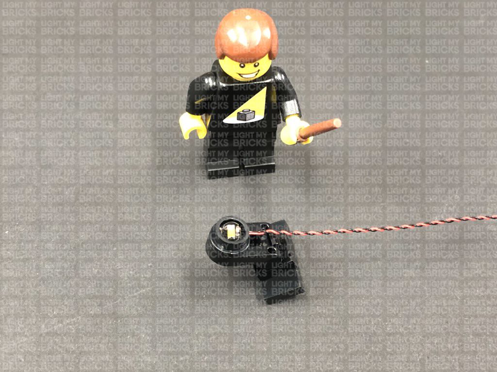
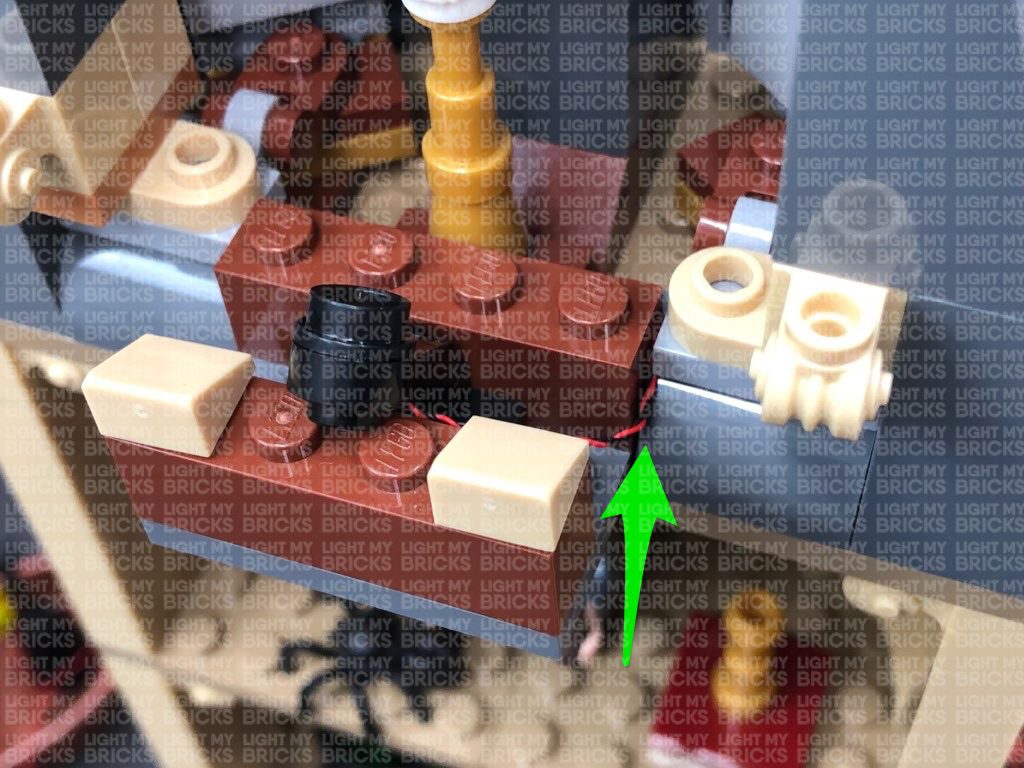
Disconnect the lamp from Hagrid, then disconnect the trans yellow round brick from inside.
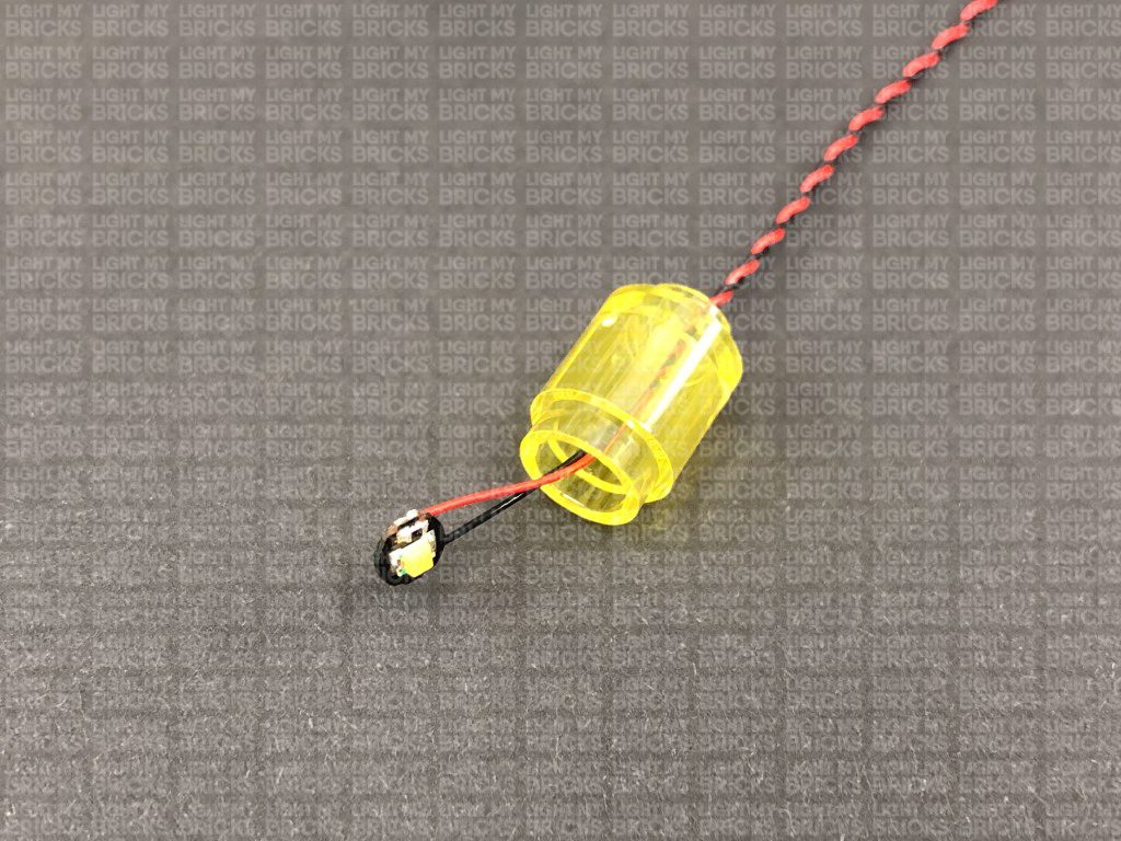
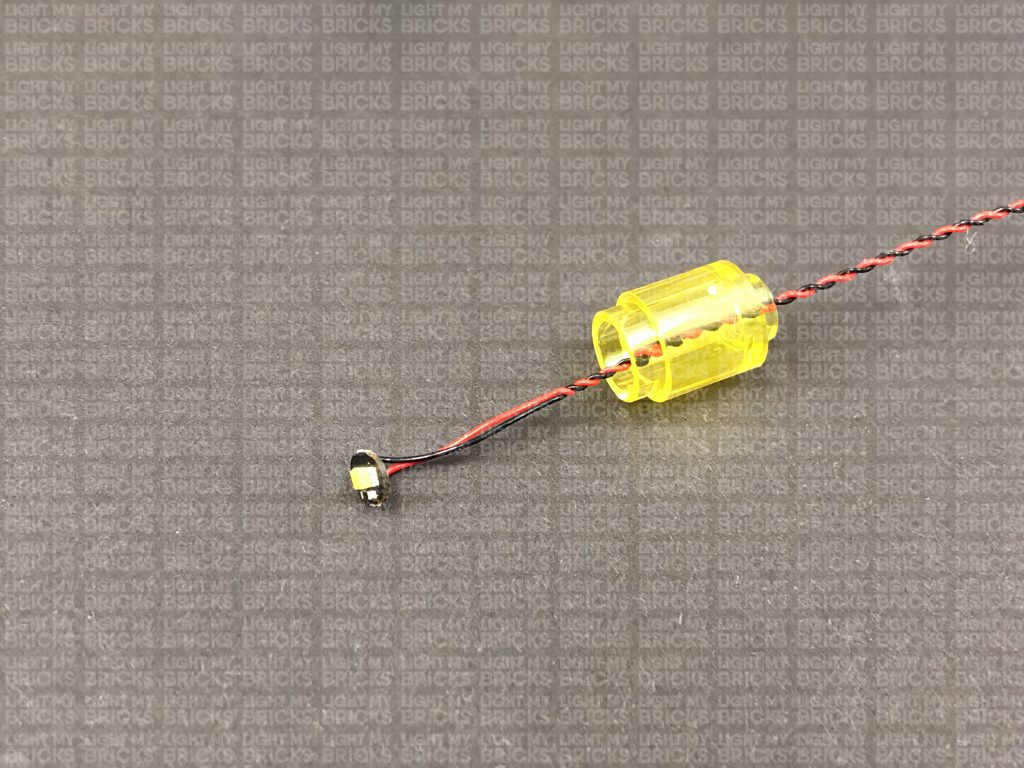
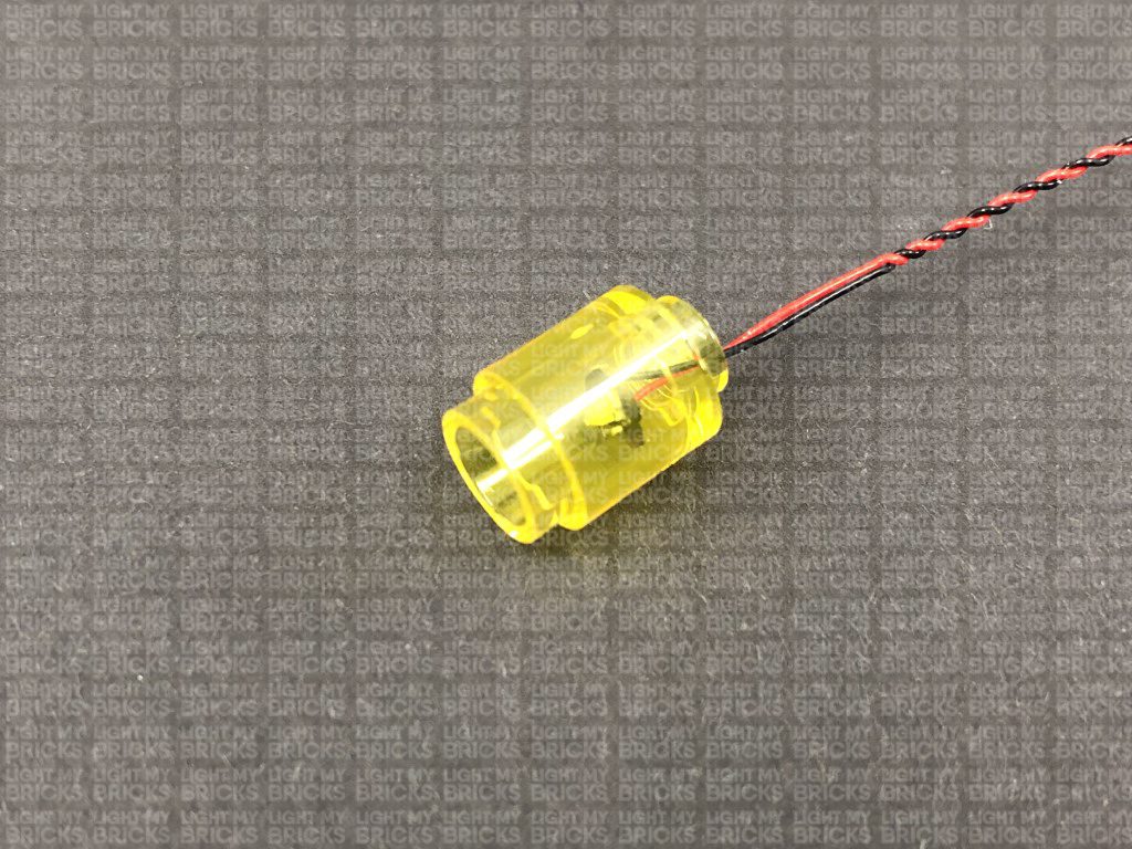
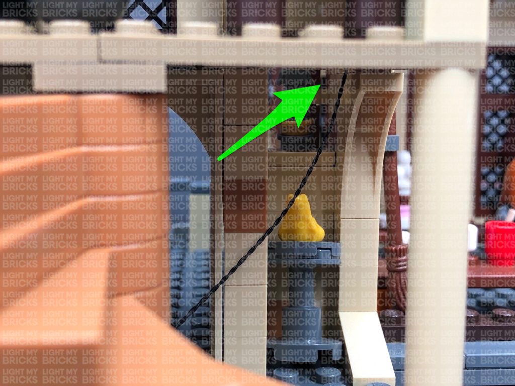
7.) Take a White 30cm Bit Light and thread the connector end of the cable through the bottom of the trans yellow round brick (larger hole). Thread it all the way through the brick, then slightly bend the LED component so that it is facing down before you pull the cable all the way out from the other side.
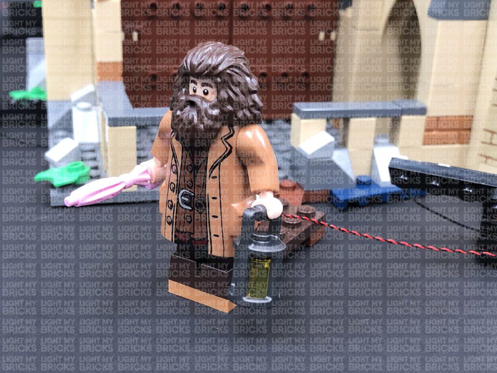
Thread the connector end of the bit light through the inside of the lamp then all the way out before reconnecting the trans yellow round brick inside. Reconnect the lamp to Hagrid’s hand, then connect the bit light cable to the 6-Port Expansion Board. Turn ON the AA Battery Pack to test the lamp light is working OK.
Note: If you experience any issues with the lights not working and suspect an issue with a component, please try a different port on the expansion board to verify where the fault lies (with the light or expansion board). To correct any issues with expansion board ports, please view the section addressing expansion board issues on our online troubleshooting guide.
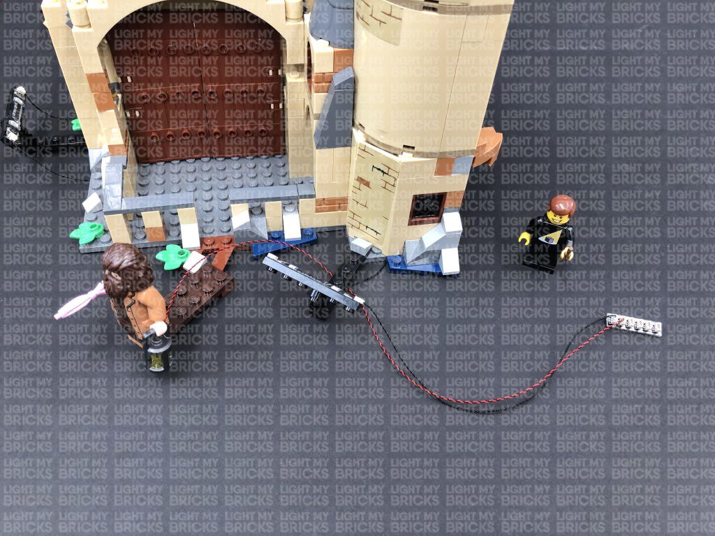
Tuck both 15cm connecting cable and bit light cable underneath the bases of the set as shown below:
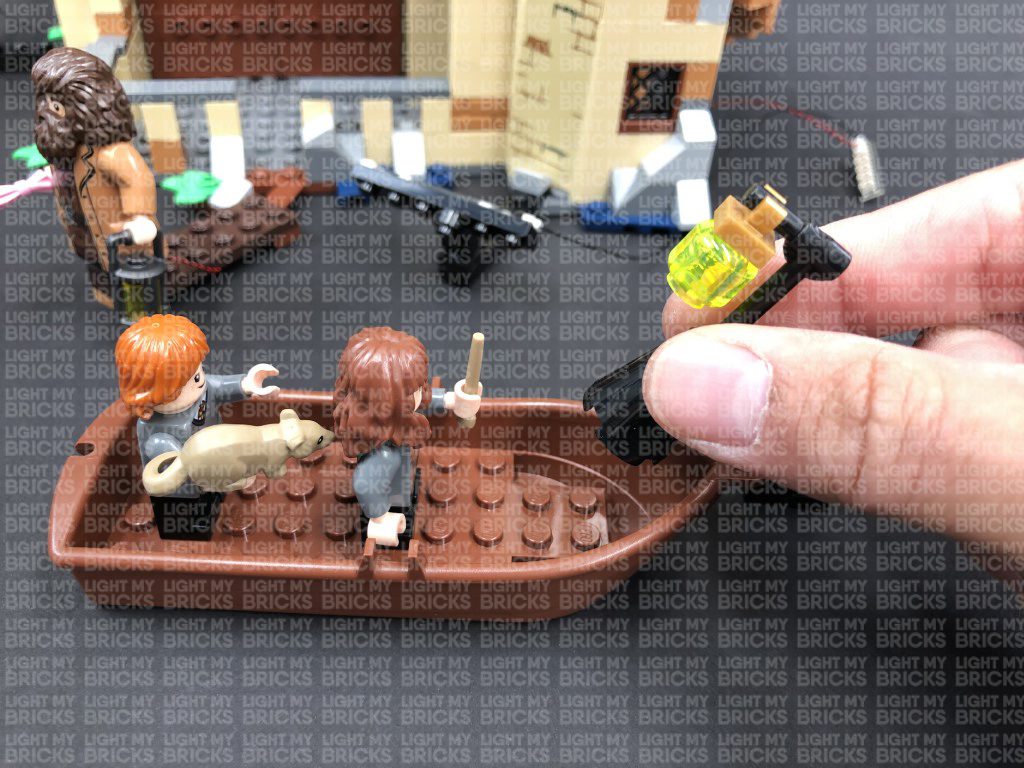
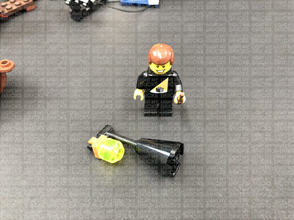
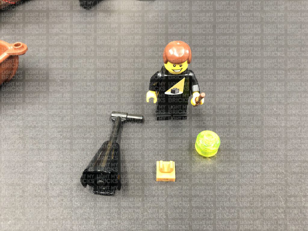
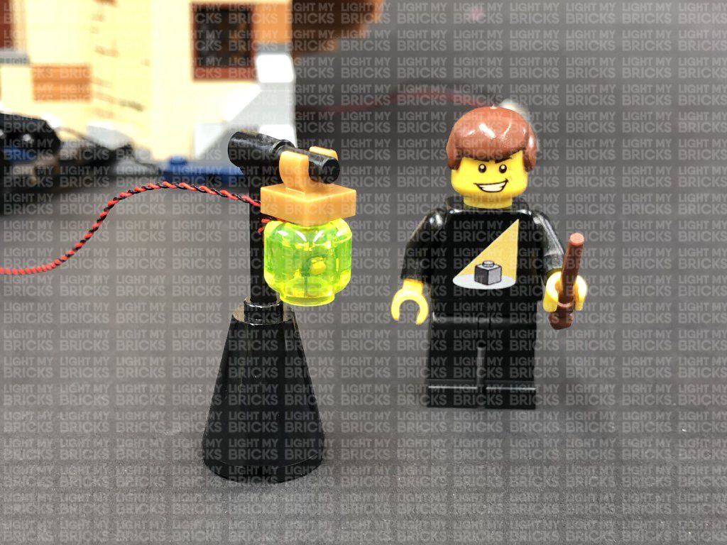
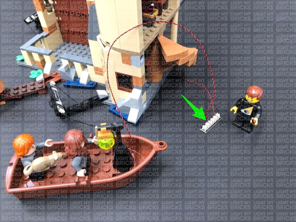
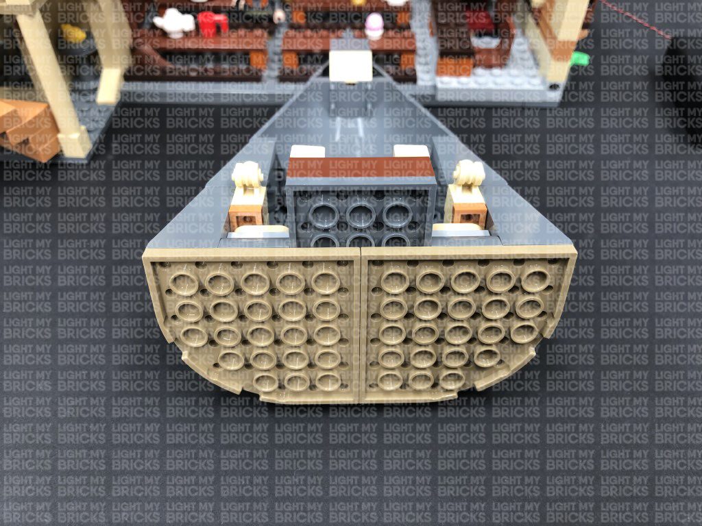
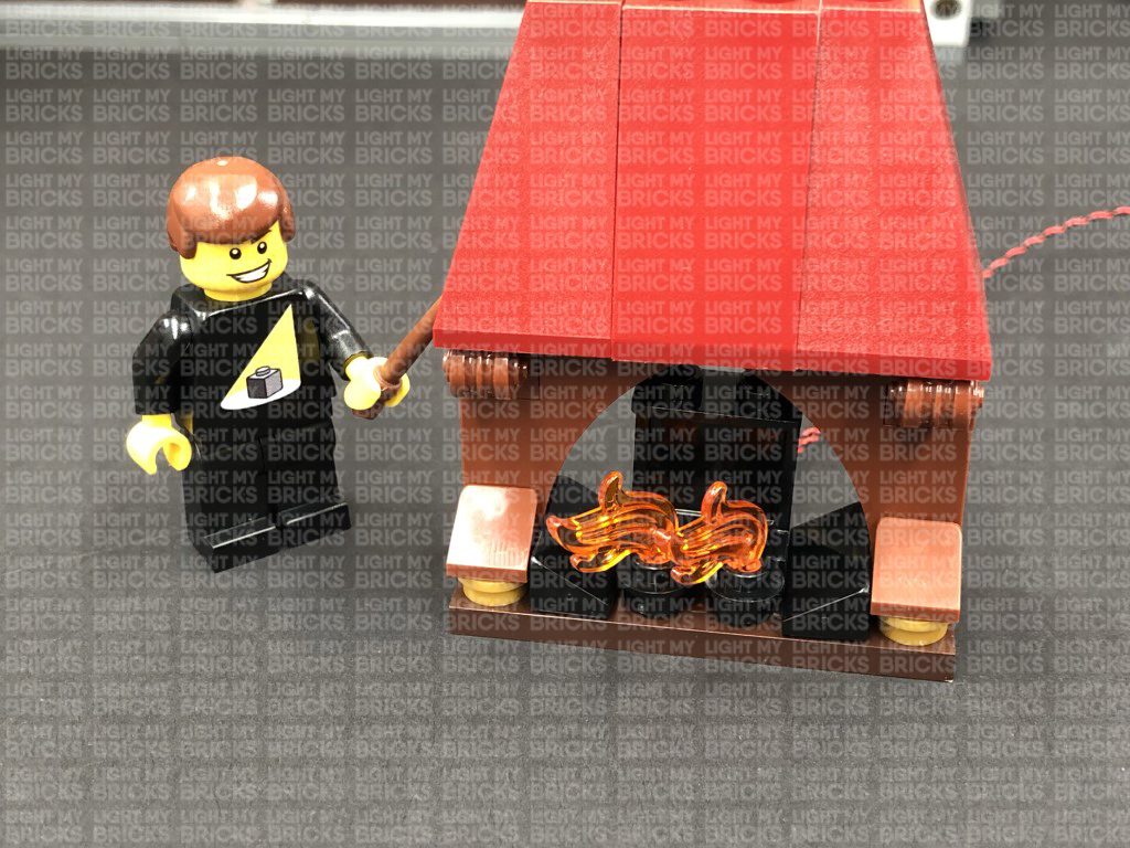
8.) Disconnect the lamp from the boat and disassemble as shown below:
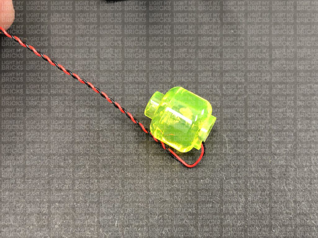
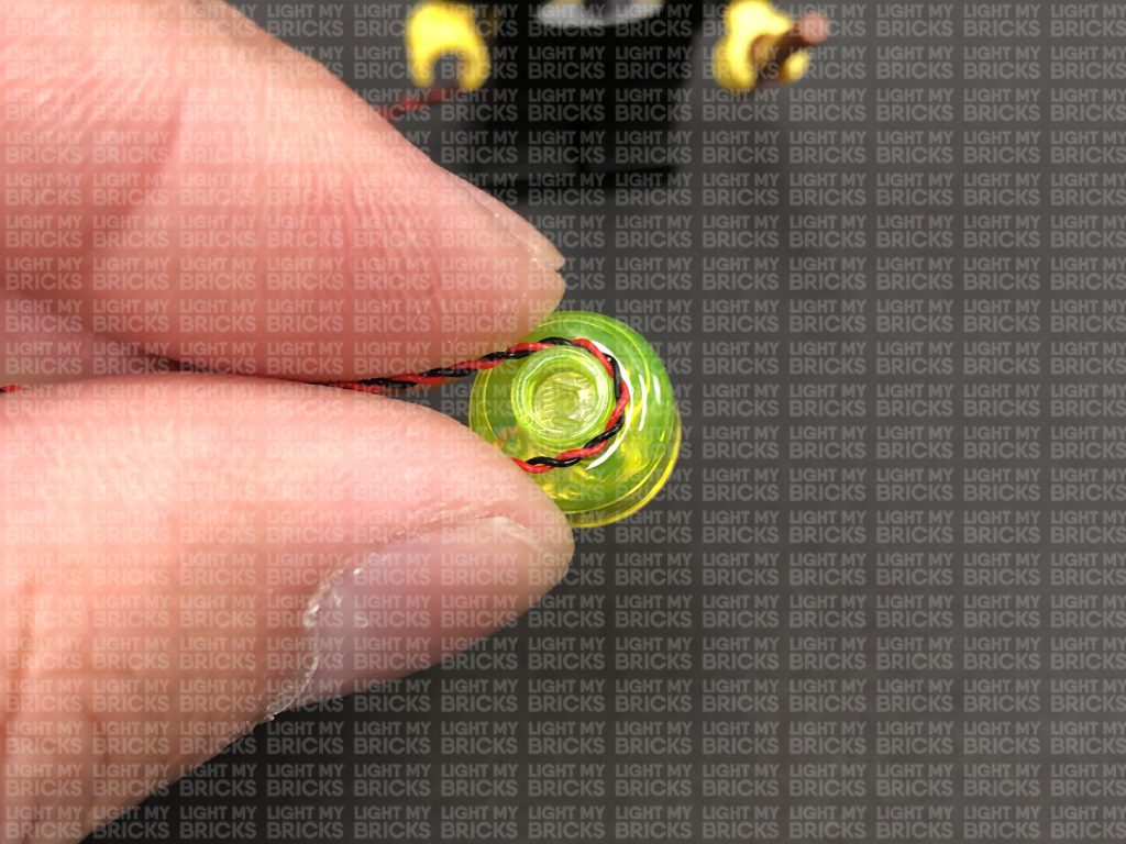
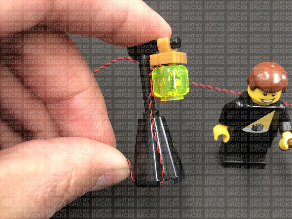
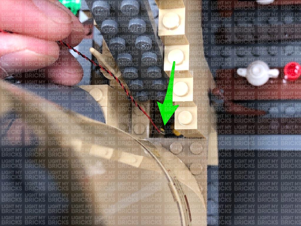
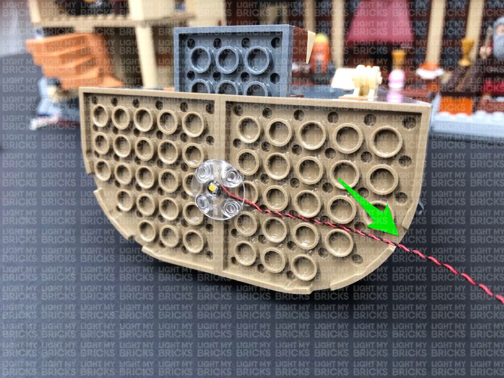
Take a White 30cm Bit Light and bend the cable into a hook with the Bit Light facing out. Thread the Bit Light inside the trans bright yellow brick, then bring the cable to the top and loop it around the stud on top before reconnecting it to the gold tile with clip. Ensure the Bit Light component is facing the outside before re-clipping the gold tile back to the lamp post.
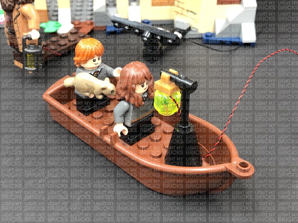
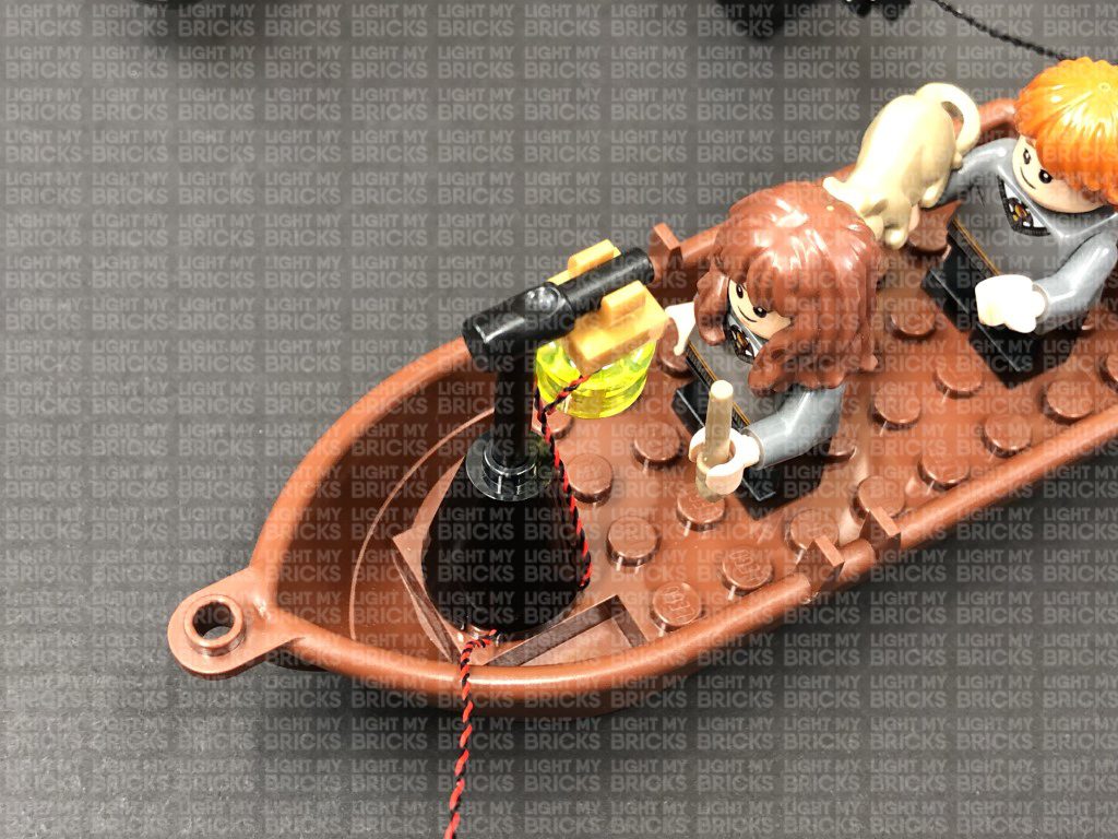
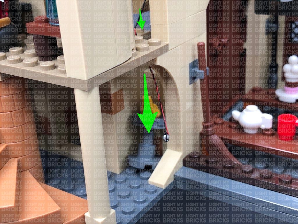
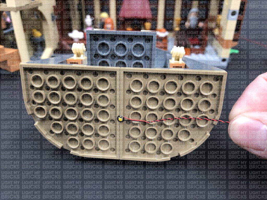
9.) Pull the cable down the front of the lamp post then loop it underneath the base before reconnecting it to the boat.
Connect the bit light into the next port on the 6-port expansion board, then tuck the cable underneath the base of the castle. Turn the AA Battery Pack ON to test the boat light is working OK.
Note: If you experience any issues with the lights not working and suspect an issue with a component, please try a different port on the expansion board to verify where the fault lies (with the light or expansion board). To correct any issues with expansion board ports, please view the section addressing expansion board issues on our online troubleshooting guide.
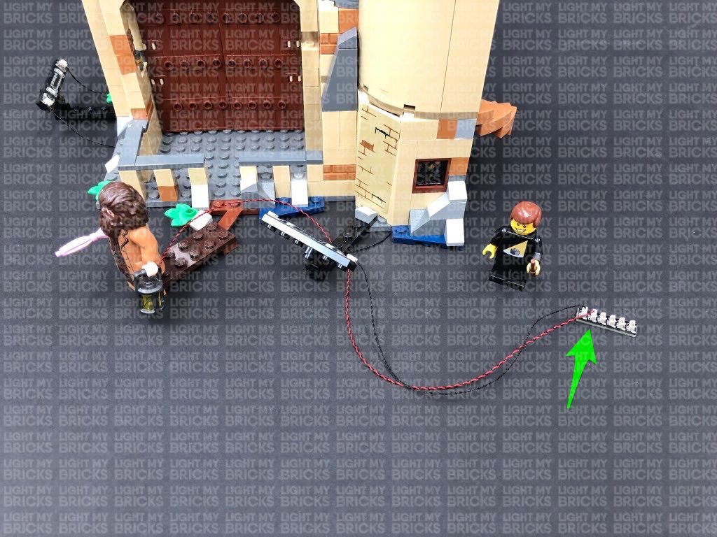
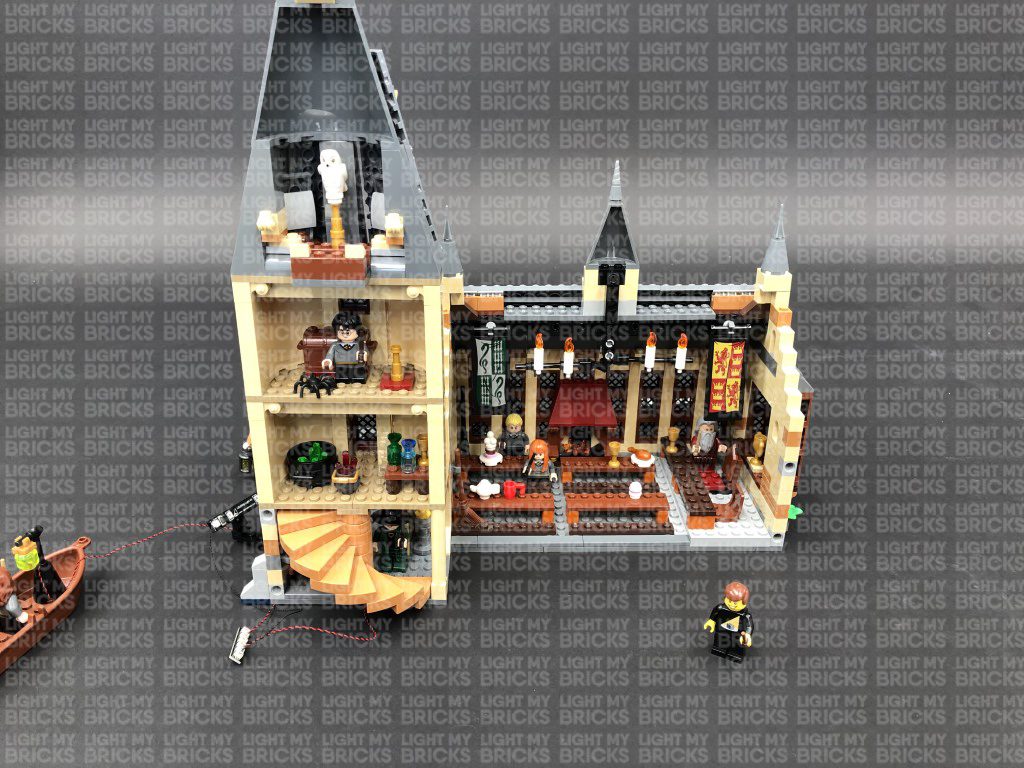
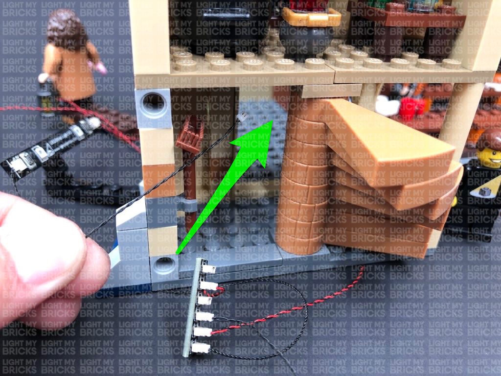
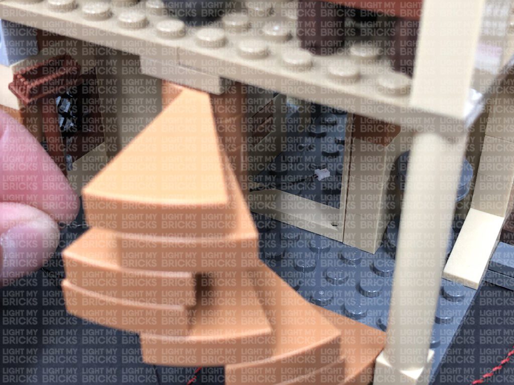
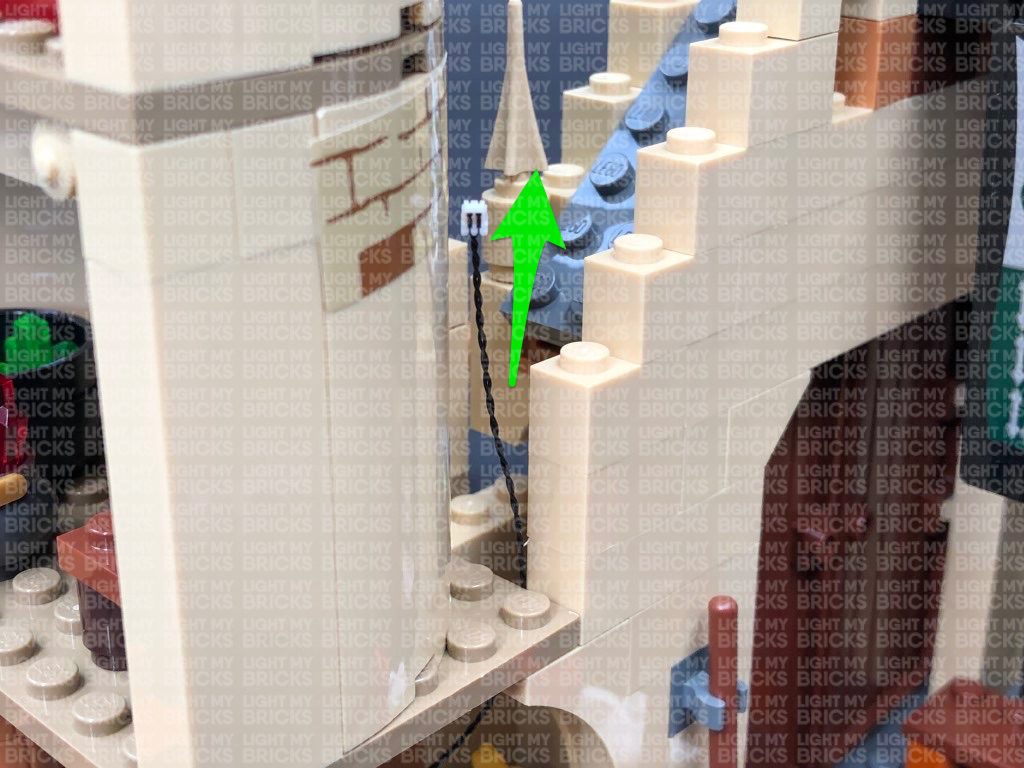
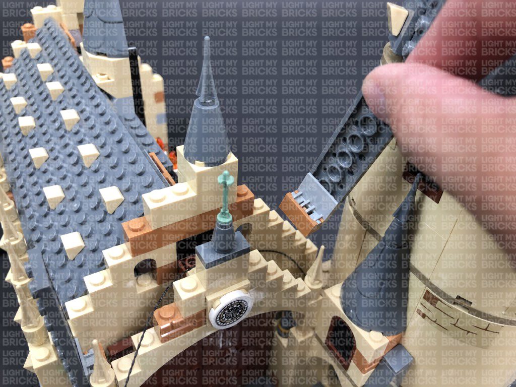
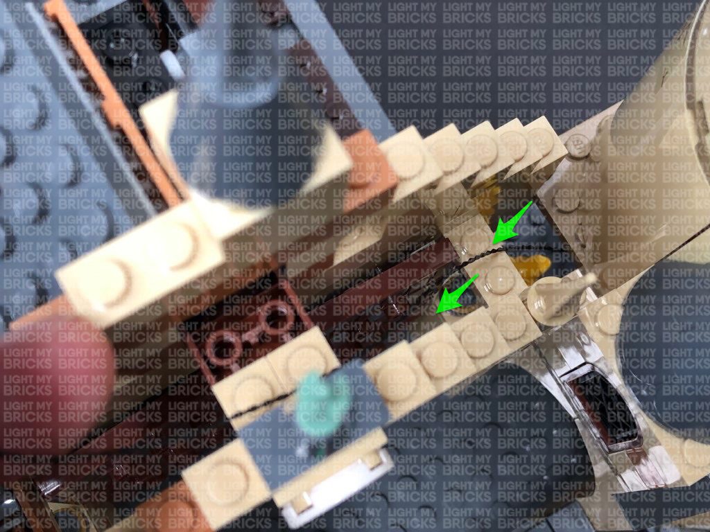
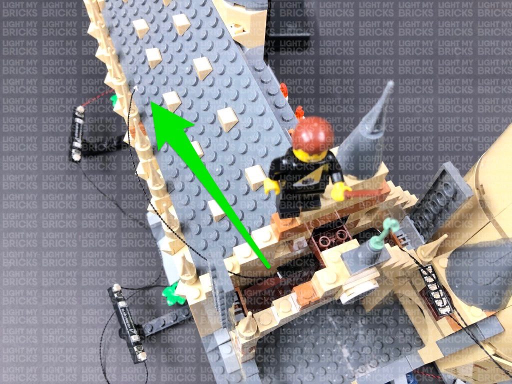
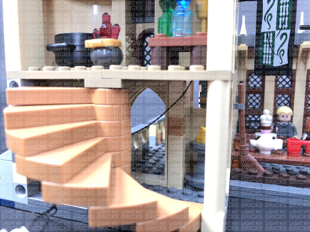
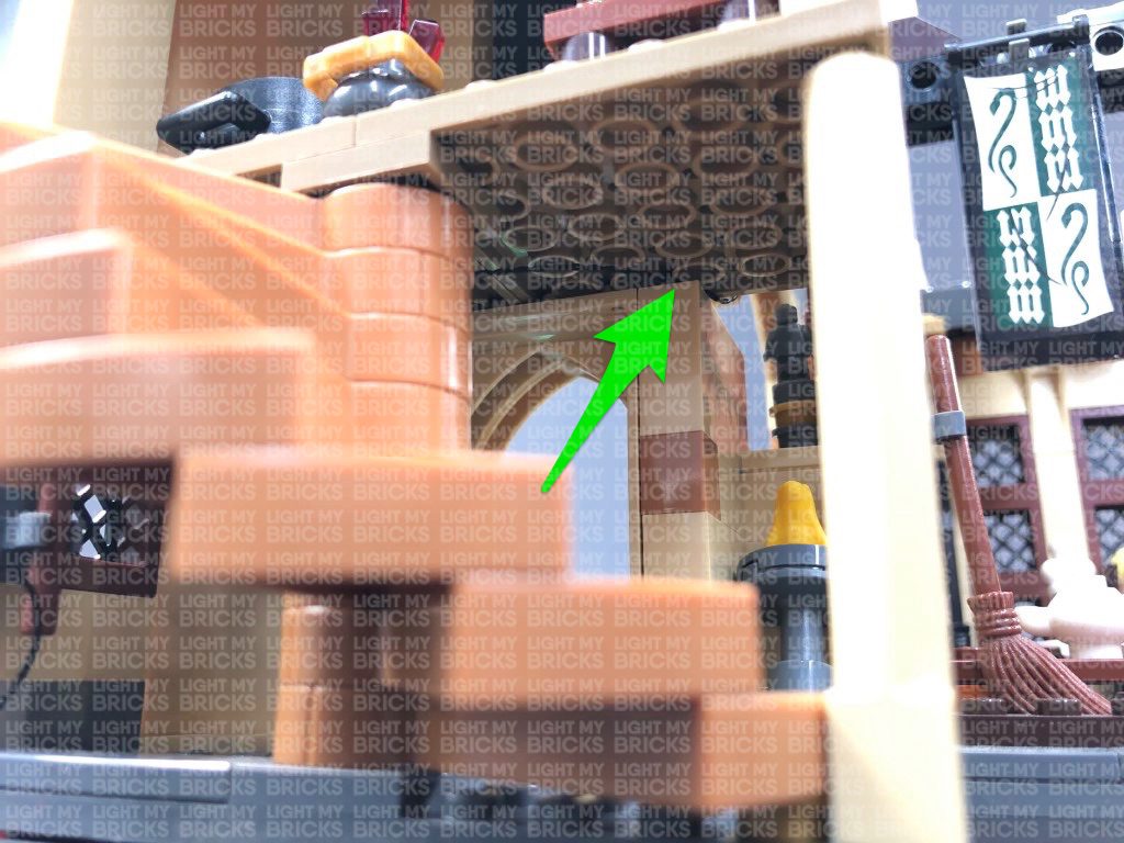
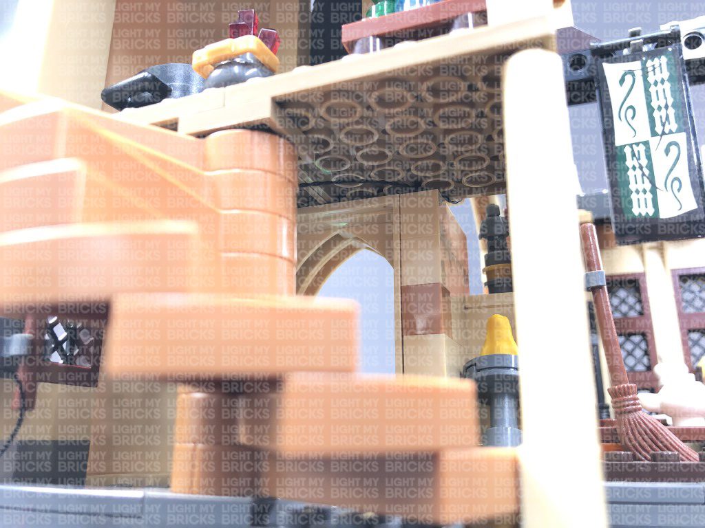
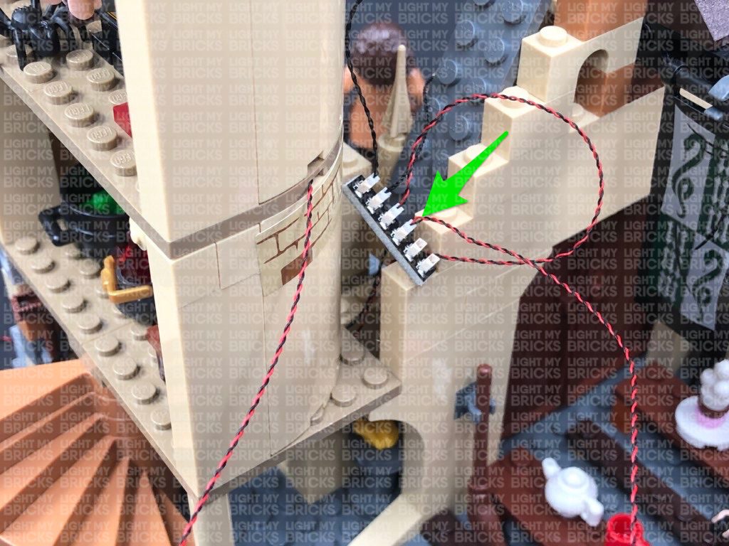
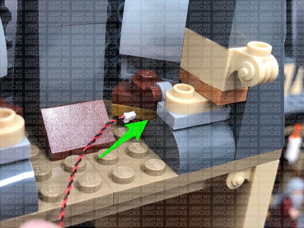
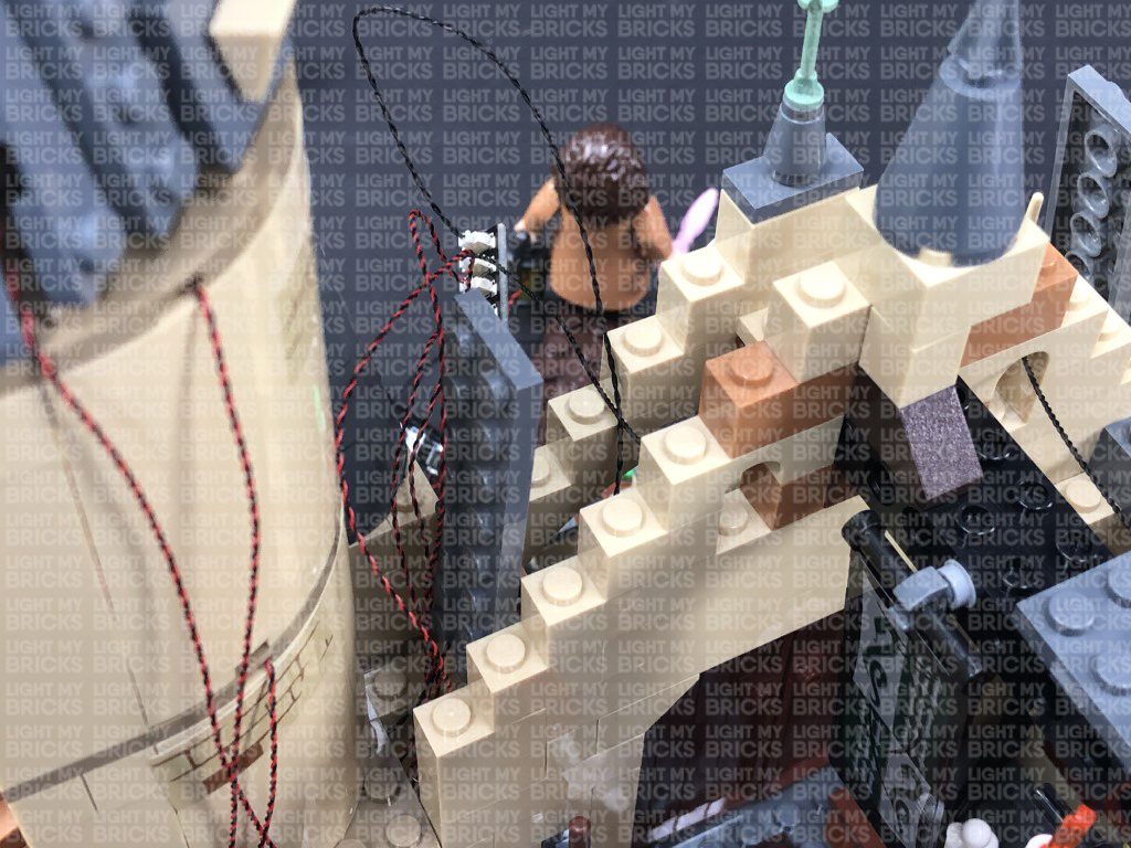
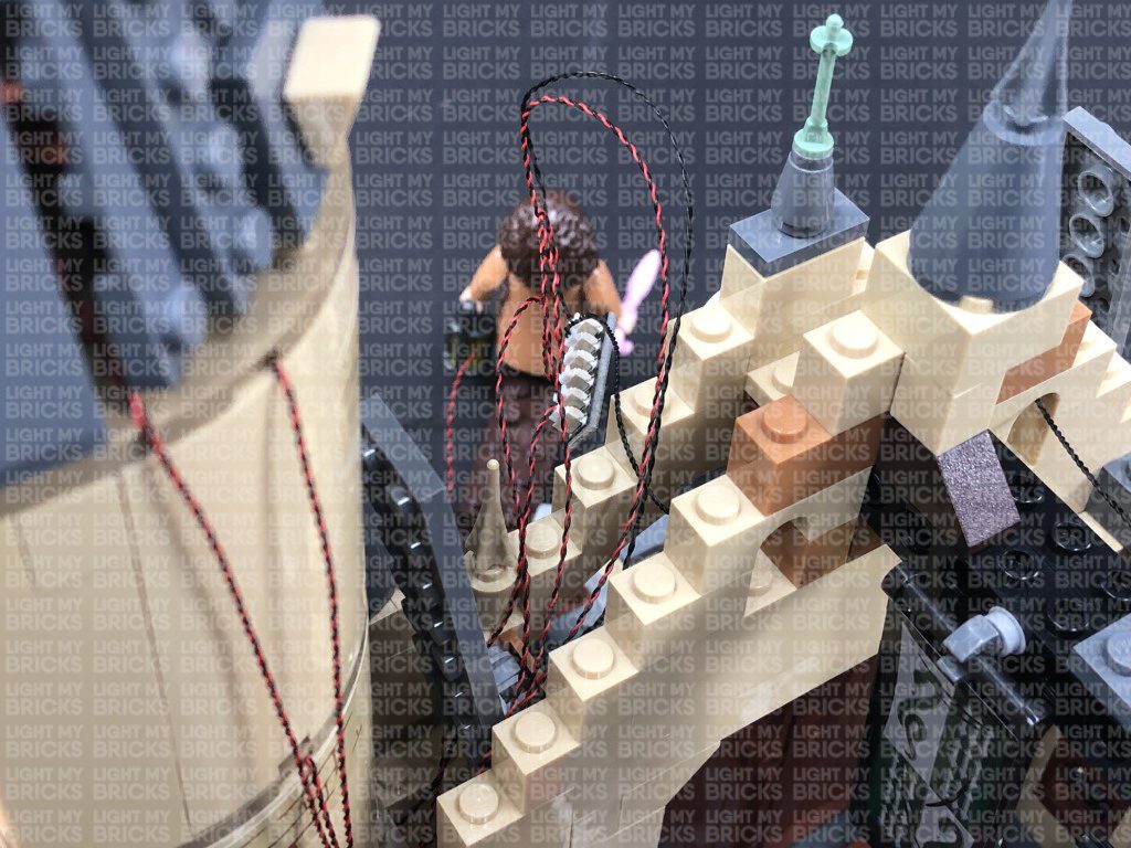
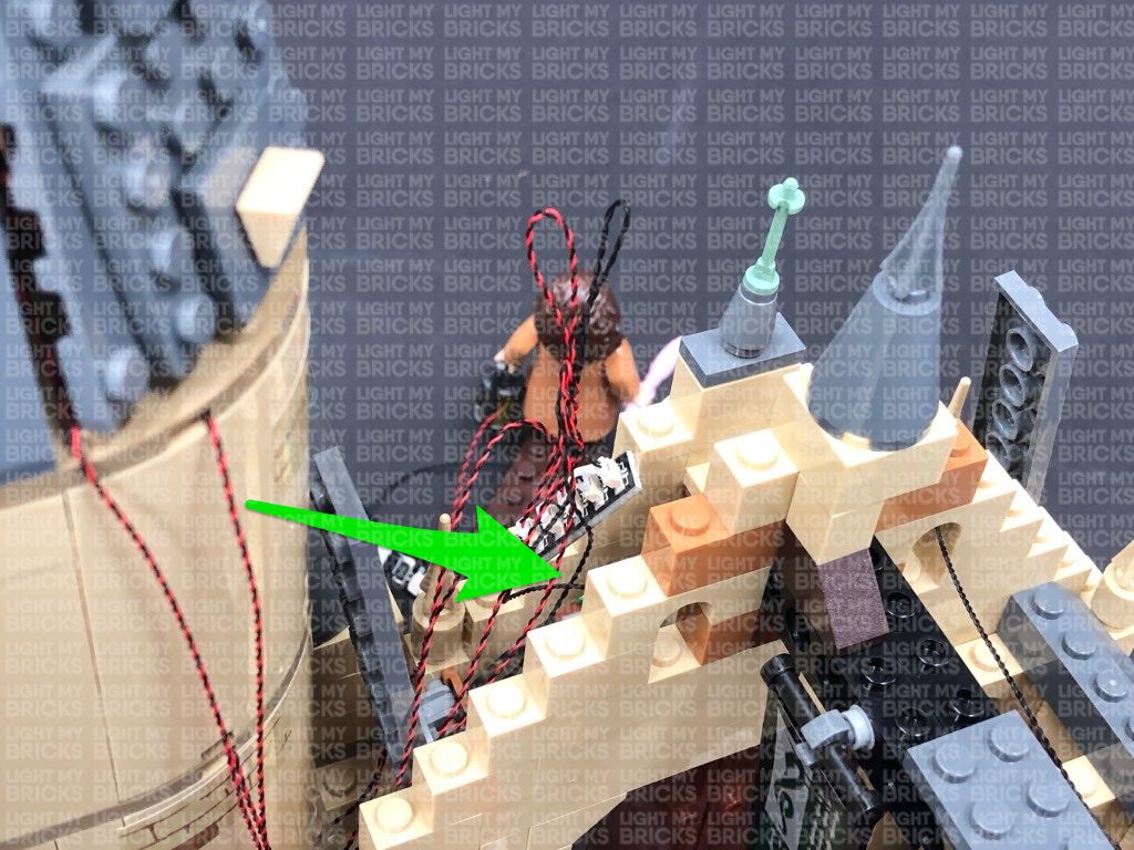
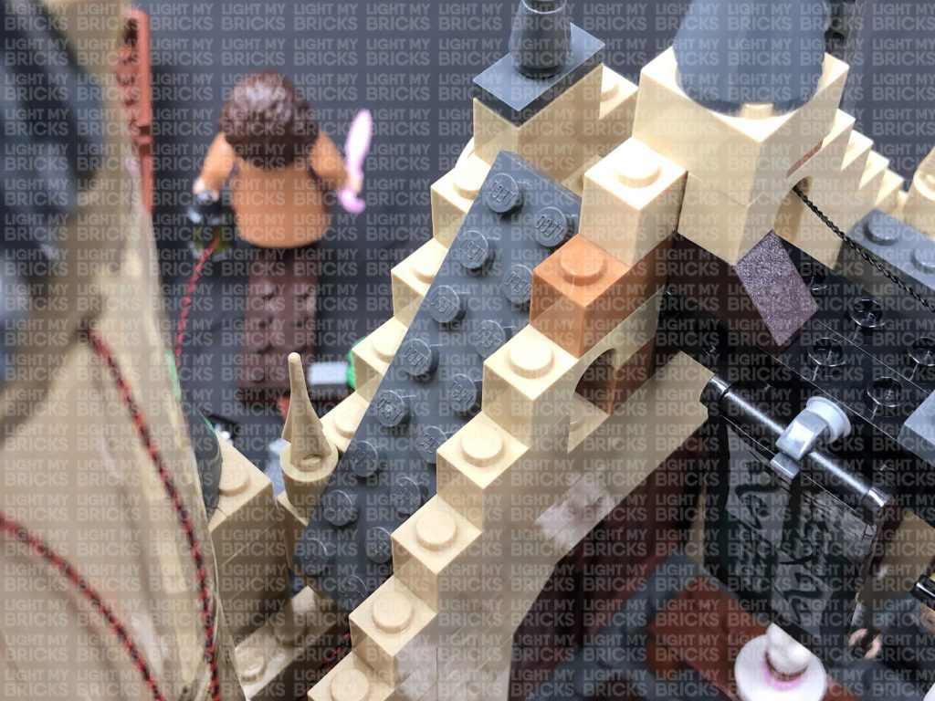
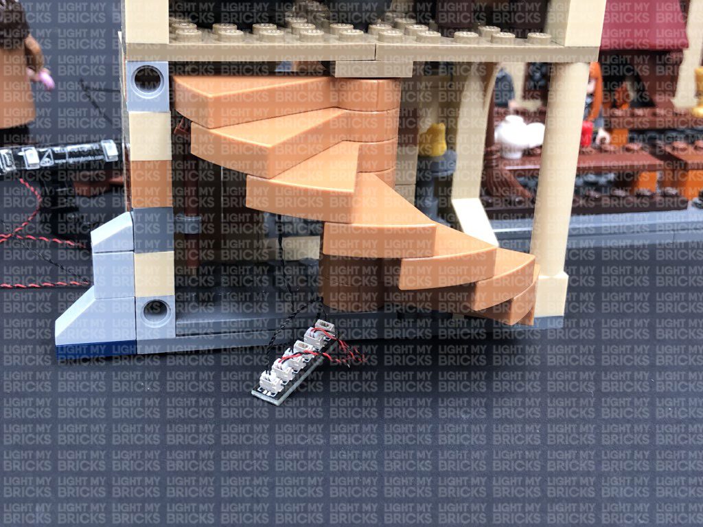
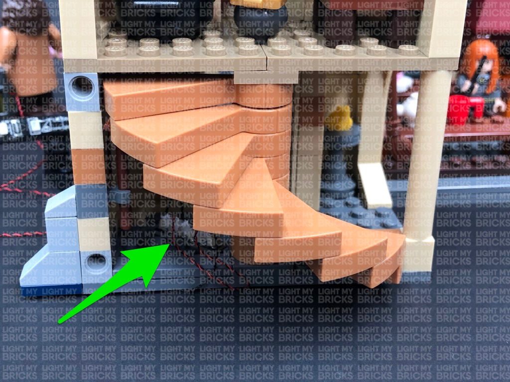
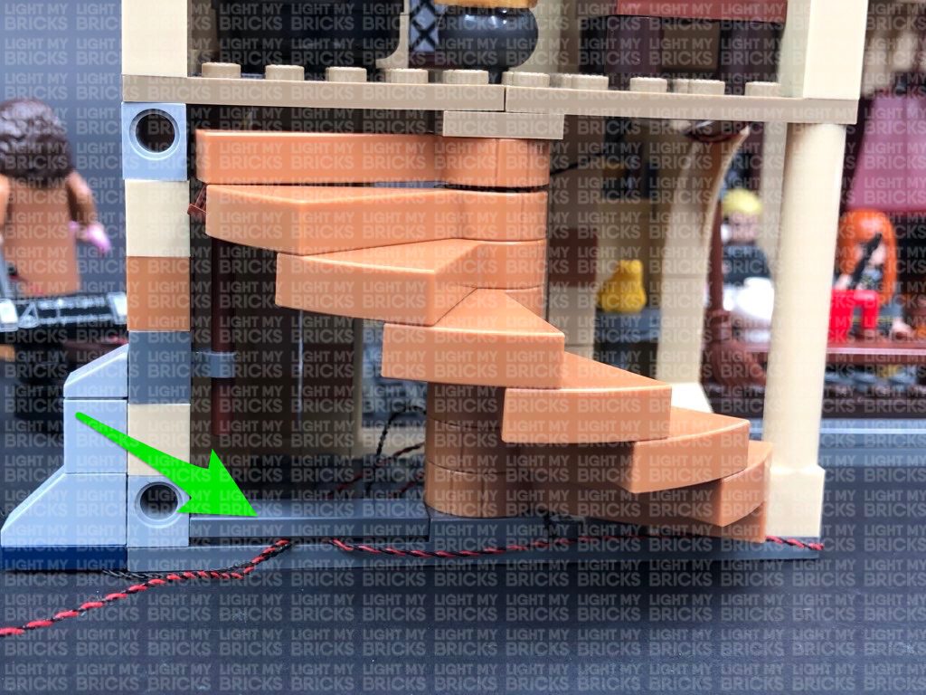
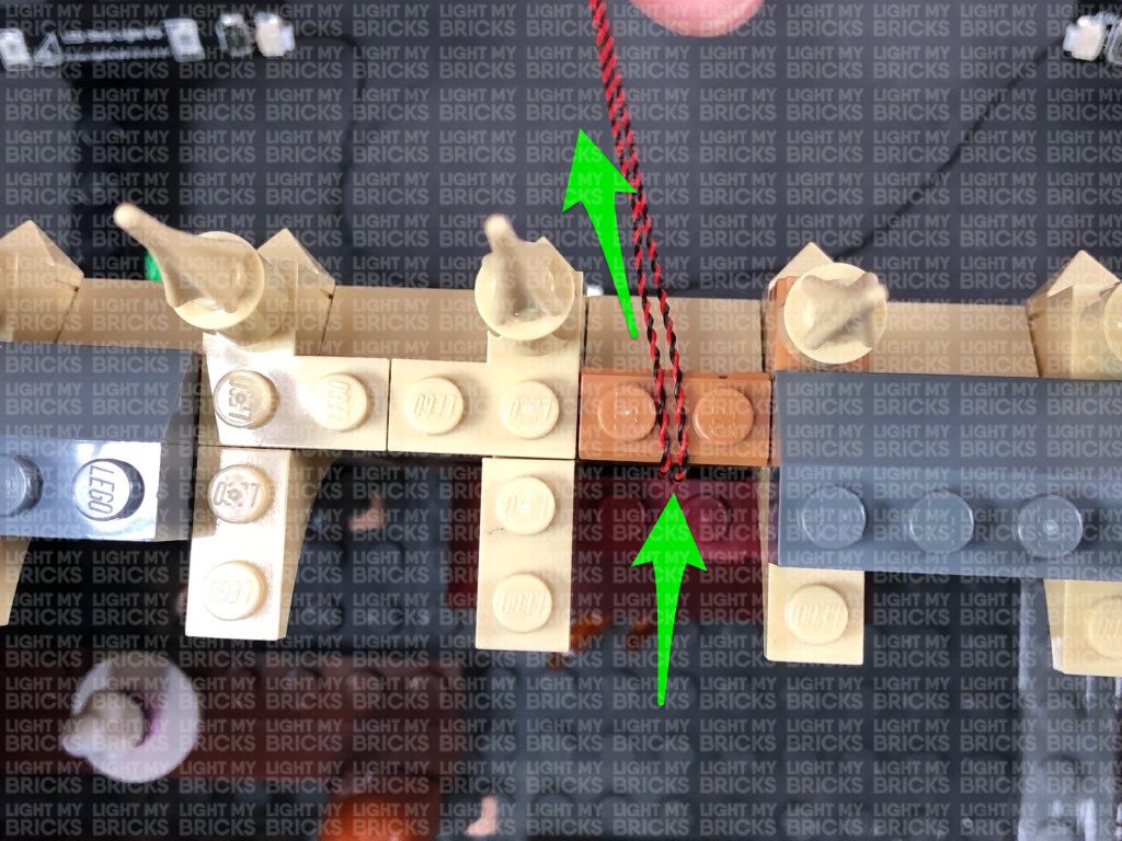
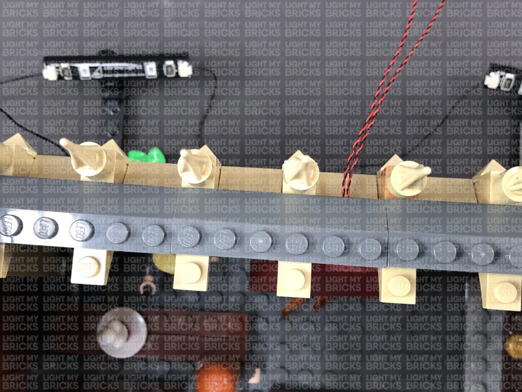
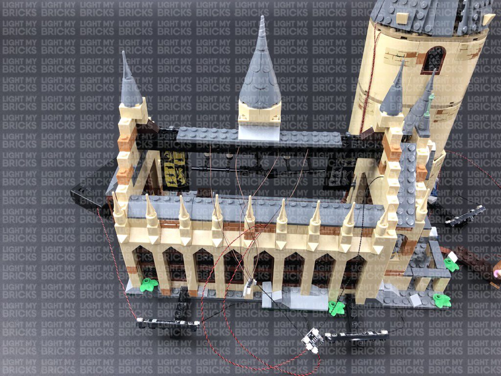
10.) Turn the set around to the back, then connect a new 30cm Connecting Cable to the 6-port expansion board. Close up the staircase, then thread the other end of the 30cm cable through the following space that leads to the right side of the tower. Pull it out from the right side as shown below:
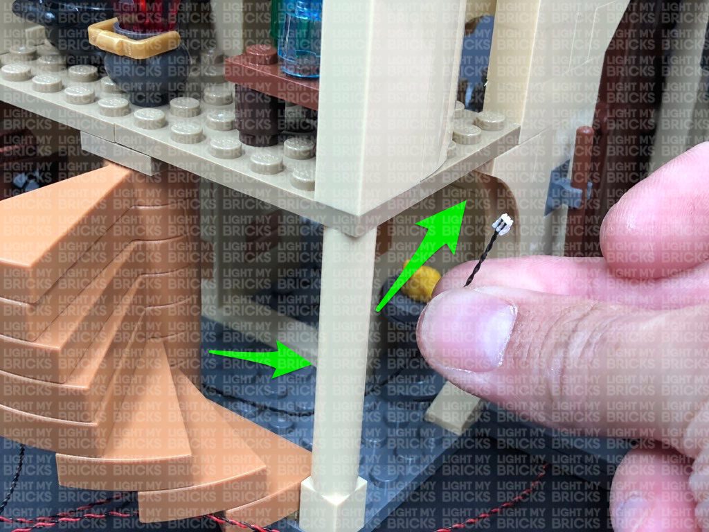
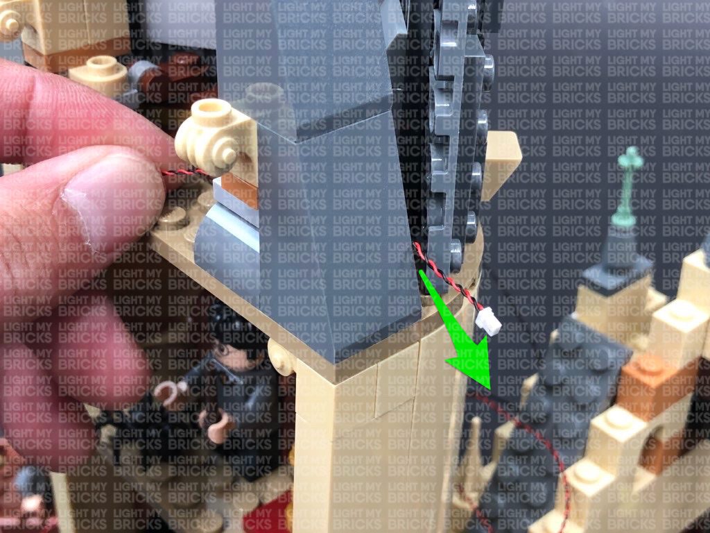
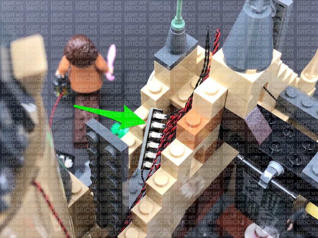
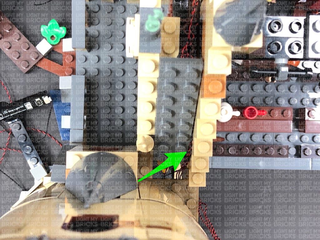
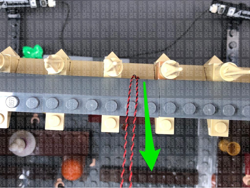
Thread the cable back underneath and up the space which leads to the gap on the second floor. Pull the cable all the way out.
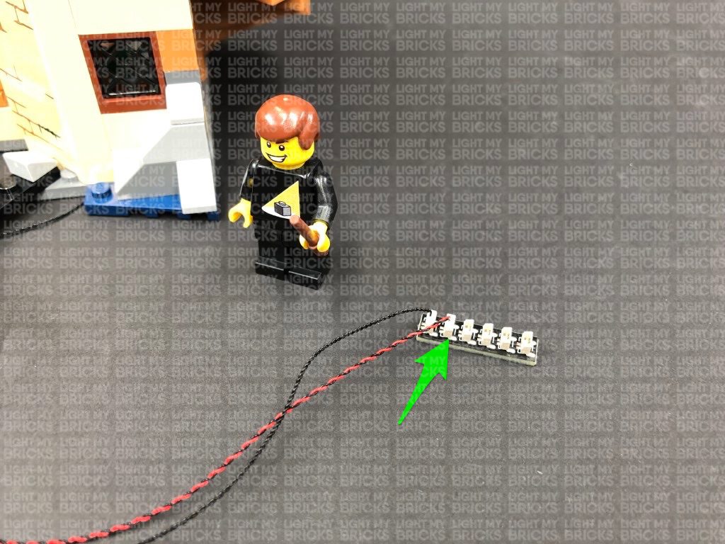
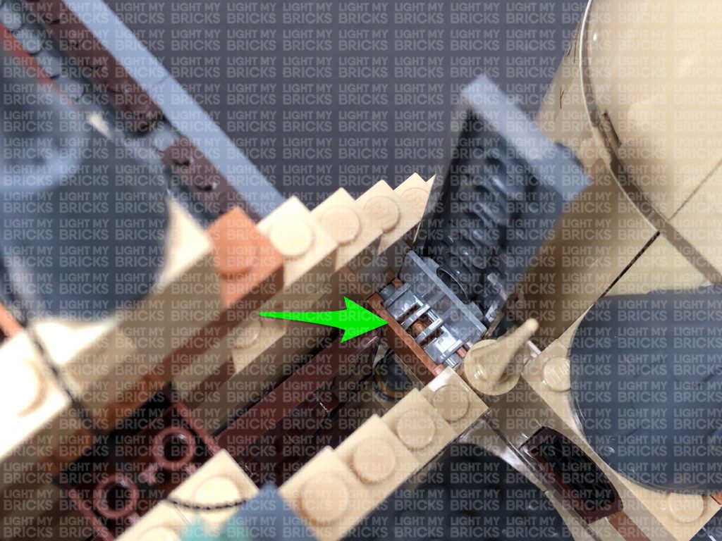
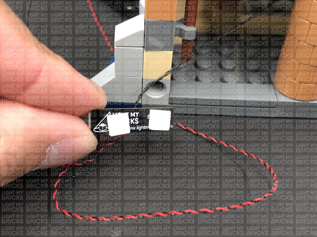
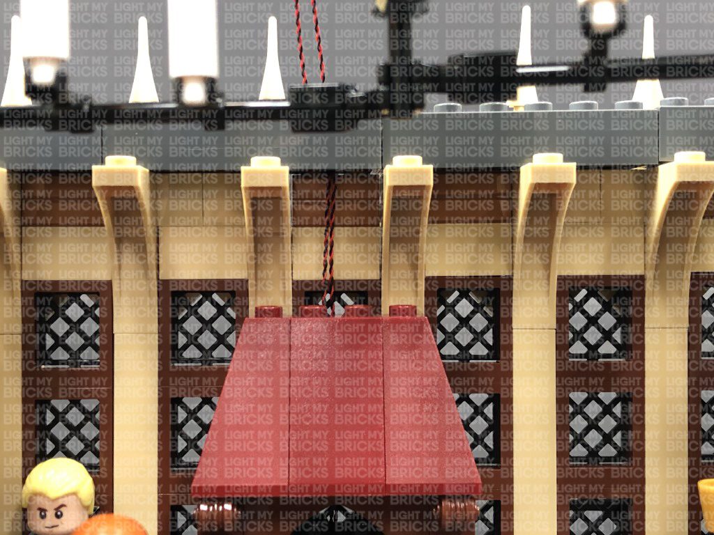
11.) From the front of the set, lift up the two side roof sections above the front door. Pull the other end of the 30cm cable over to this side and secure it by disconnecting the right roof side section and reconnecting it over the cable, ensuring the cable is laid in between studs.
Connect the other end of the 30cm connecting cable to a new 6-Port Expansion Board
3.) Take a 15cm Connecting Cable and connect it between two of the spot lights, then take a 30cm Connecting Cable and connect one end to the right strip light as shown below:
Connect the two spot lights to the front of the great hall in the below positions, then tuck the 15cm connecting cable underneath the base of the hall.
4.) Take the other end of the 30cm Connecting Cable and connect it to the third spot light (green strip light’s left port), then bring it around to the right side of the hall. Disconnect and discard the following grey angled tile and connect the spot light to this position.
Hide the 30cm cable in between the spot lights underneath the base of the hall as shown below.
5.) Take the AA Battery Pack and insert 3x AA Batteries to it. Connect the battery pack cable to the left port on the spot light on the left of the Hall. Turn ON the battery pack to test the spot lights are working OK.
6.) Take a new 15cm Connecting Cable and connect it to the third green Strip Light. Connect the other end of the cable to a 6-Port Expansion Board.
Disconnect the lamp from Hagrid, then disconnect the trans yellow round brick from inside.
7.) Take a White 30cm Bit Light and thread the connector end of the cable through the bottom of the trans yellow round brick (larger hole). Thread it all the way through the brick, then slightly bend the LED component so that it is facing down before you pull the cable all the way out from the other side.
Thread the connector end of the bit light through the inside of the lamp then all the way out before reconnecting the trans yellow round brick inside. Reconnect the lamp to Hagrid’s hand, then connect the bit light cable to the 6-Port Expansion Board. Turn ON the AA Battery Pack to test the lamp light is working OK.
Note: If you experience any issues with the lights not working and suspect an issue with a component, please try a different port on the expansion board to verify where the fault lies (with the light or expansion board). To correct any issues with expansion board ports, please view the section addressing expansion board issues on our online troubleshooting guide.
Tuck both 15cm connecting cable and bit light cable underneath the bases of the set as shown below:
8.) Disconnect the lamp from the boat and disassemble as shown below:
Take a White 30cm Bit Light and bend the cable into a hook with the Bit Light facing out. Thread the Bit Light inside the trans bright yellow brick, then bring the cable to the top and loop it around the stud on top before reconnecting it to the gold tile with clip. Ensure the Bit Light component is facing the outside before re-clipping the gold tile back to the lamp post.
9.) Pull the cable down the front of the lamp post then loop it underneath the base before reconnecting it to the boat.
Connect the bit light into the next port on the 6-port expansion board, then tuck the cable underneath the base of the castle. Turn the AA Battery Pack ON to test the boat light is working OK.
Note: If you experience any issues with the lights not working and suspect an issue with a component, please try a different port on the expansion board to verify where the fault lies (with the light or expansion board). To correct any issues with expansion board ports, please view the section addressing expansion board issues on our online troubleshooting guide.
10.) Turn the set around to the back, then connect a new 30cm Connecting Cable to the 6-port expansion board. Close up the staircase, then thread the other end of the 30cm cable through the following space that leads to the right side of the tower. Pull it out from the right side as shown below:
Thread the cable back underneath and up the space which leads to the gap on the second floor. Pull the cable all the way out.
11.) From the front of the set, lift up the two side roof sections above the front door. Pull the other end of the 30cm cable over to this side and secure it by disconnecting the right roof side section and reconnecting it over the cable, ensuring the cable is laid in between studs.
Connect the other end of the 30cm connecting cable to a new 6-Port Expansion Board
 12.) Take a 5cm Connecting Cable and connect it a White Strip Light. Take a 15cm Connecting Cable and connect one end to the other port on the White Strip Light. Connect the other end of the 5cm Connecting Cable to the 6-port Expansion Board we just installed.
Peel off the White Strip Light’s adhesive backing, then bring it underneath the centre (right side) and stick the strip light underneath this centre section as shown below. Pull the other end of the 15cm Connecting Cable from the strip light out from the other side (left side).
Turn the AA Battery Pack ON to test the white strip light is working OK.
12.) Take a 5cm Connecting Cable and connect it a White Strip Light. Take a 15cm Connecting Cable and connect one end to the other port on the White Strip Light. Connect the other end of the 5cm Connecting Cable to the 6-port Expansion Board we just installed.
Peel off the White Strip Light’s adhesive backing, then bring it underneath the centre (right side) and stick the strip light underneath this centre section as shown below. Pull the other end of the 15cm Connecting Cable from the strip light out from the other side (left side).
Turn the AA Battery Pack ON to test the white strip light is working OK.
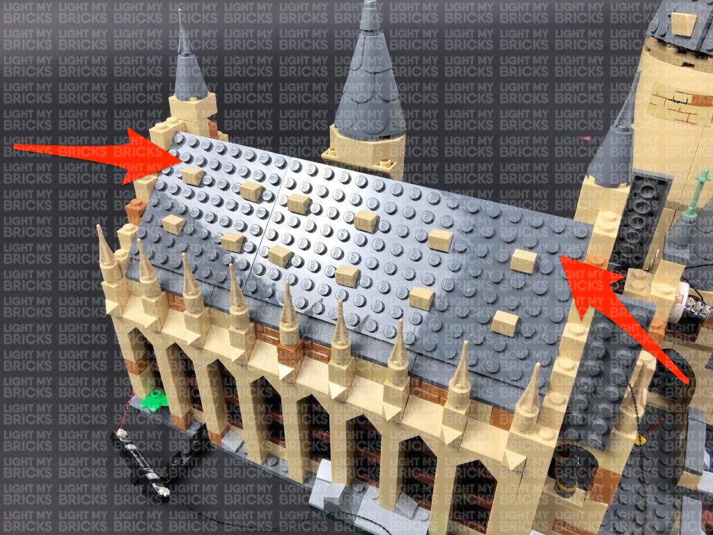
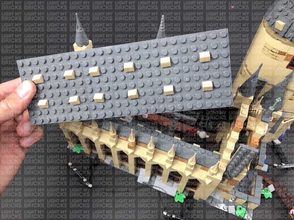
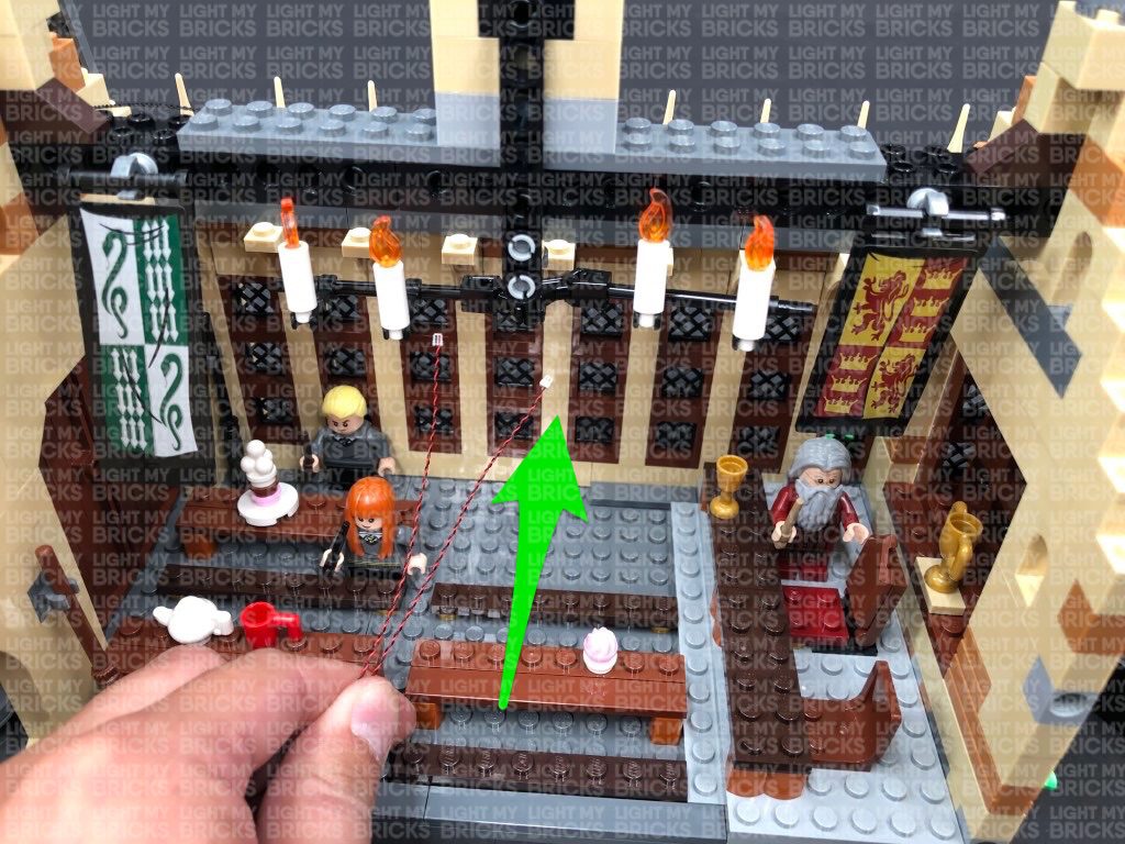
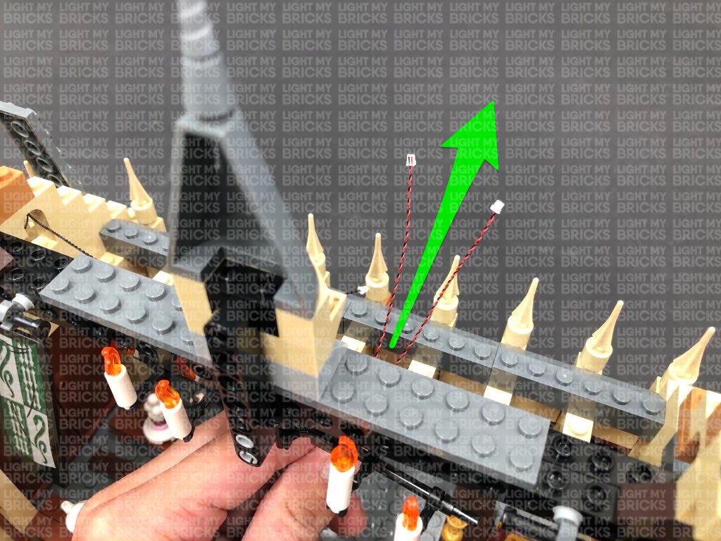
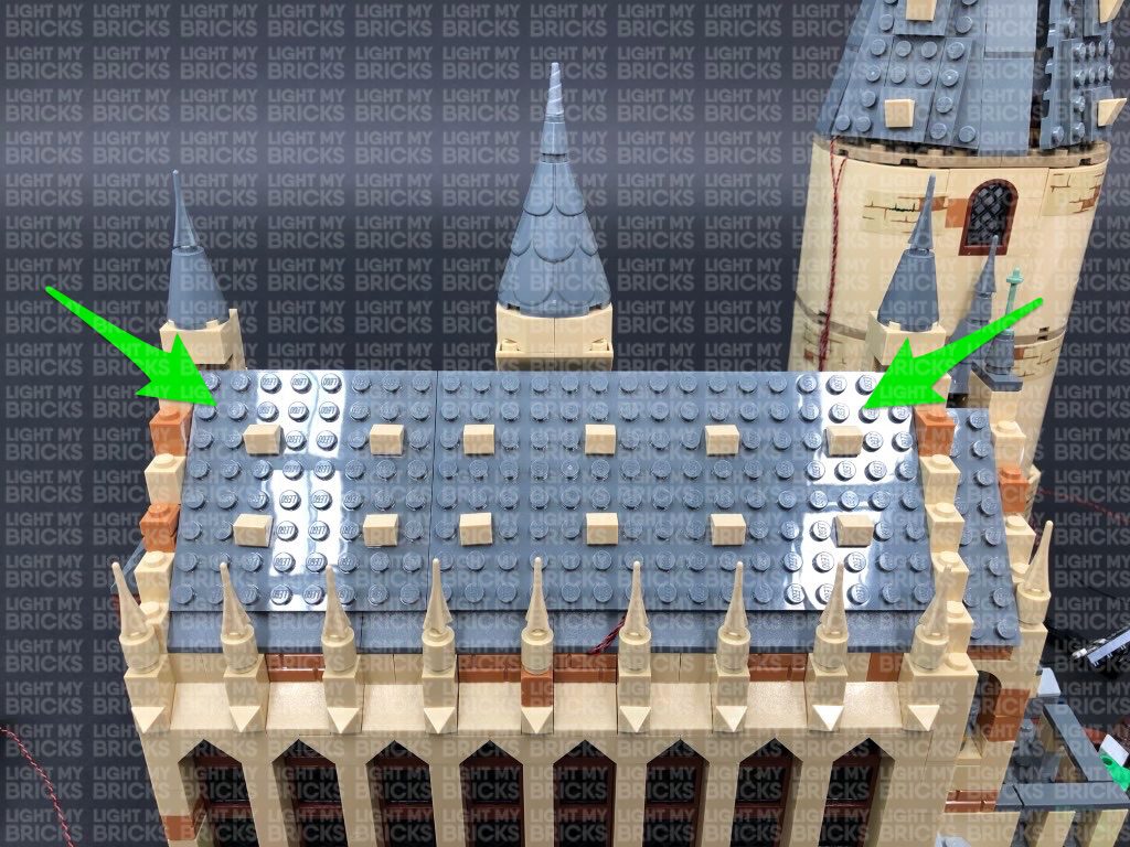
 13.) Remove the entire roof off the great hall at each side as shown below, then thread the other end of the 15cm Connecting Cable from previous step through the archway nearby. Pull the cable all the way out, then place the expansion board inside the top of the front entrance.
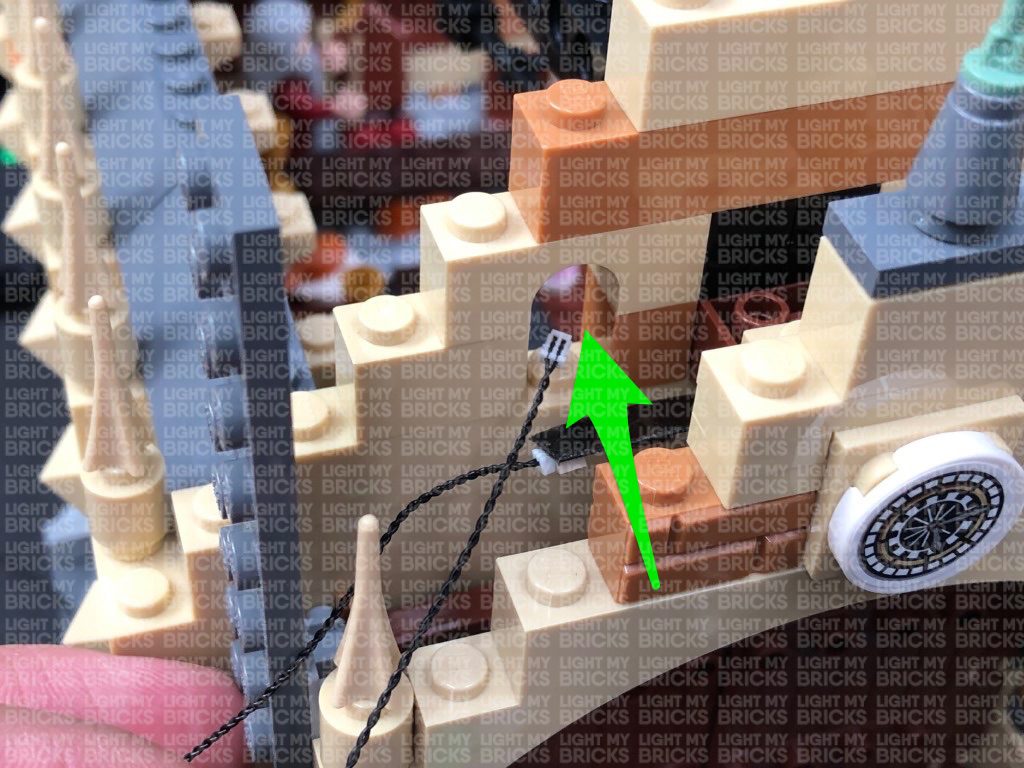
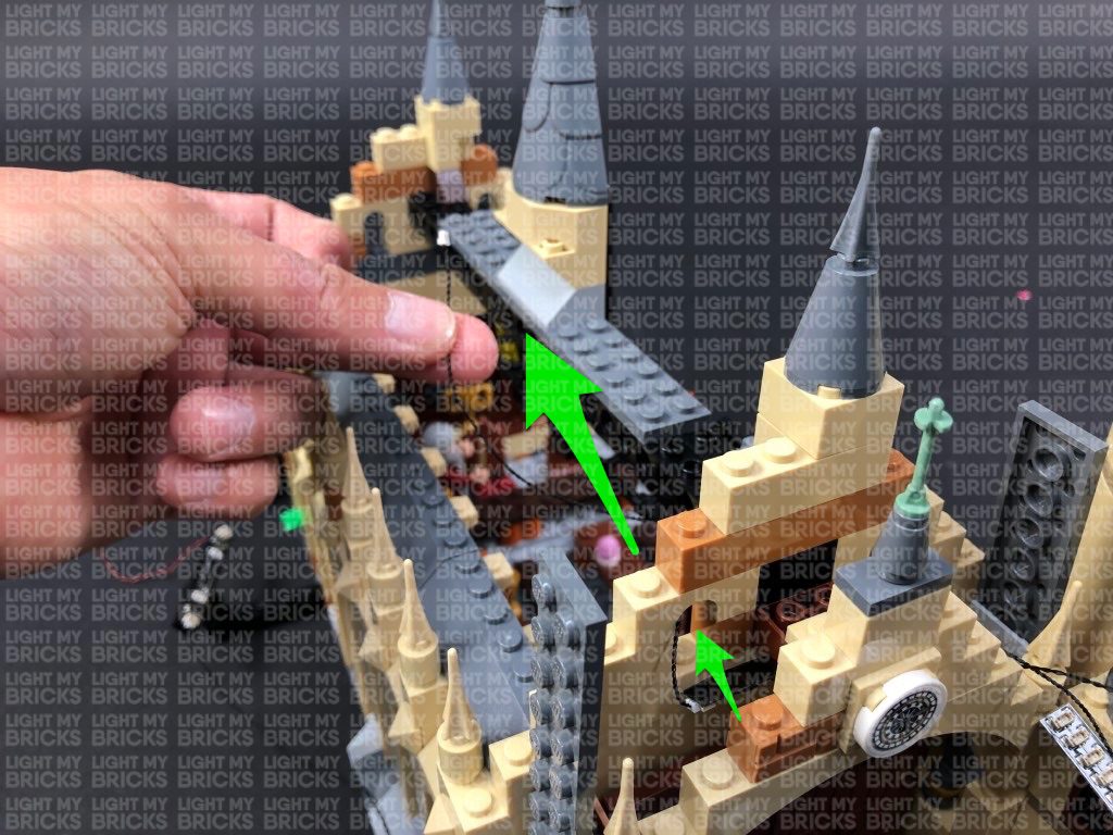
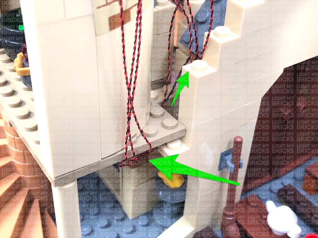
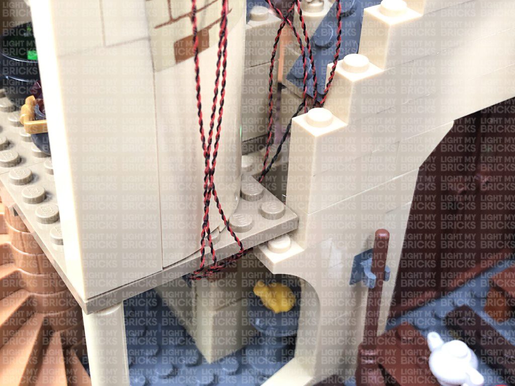
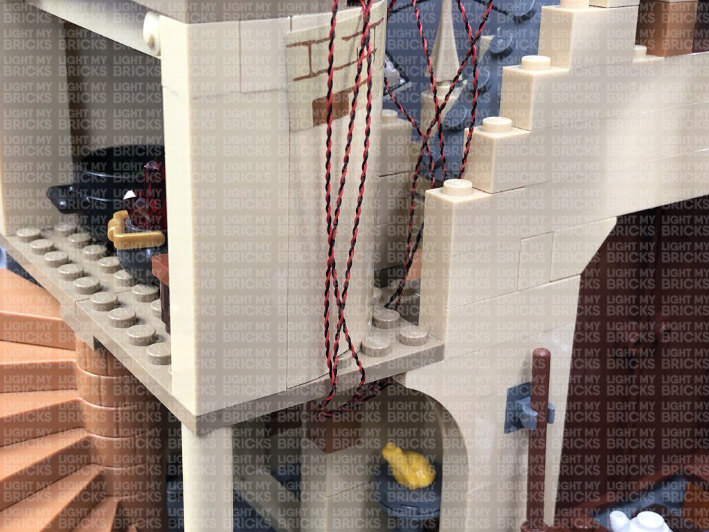
Secure the dangling cable from the inside of the tower ground floor by connecting it underneath the base plate of the second floor as shown below:
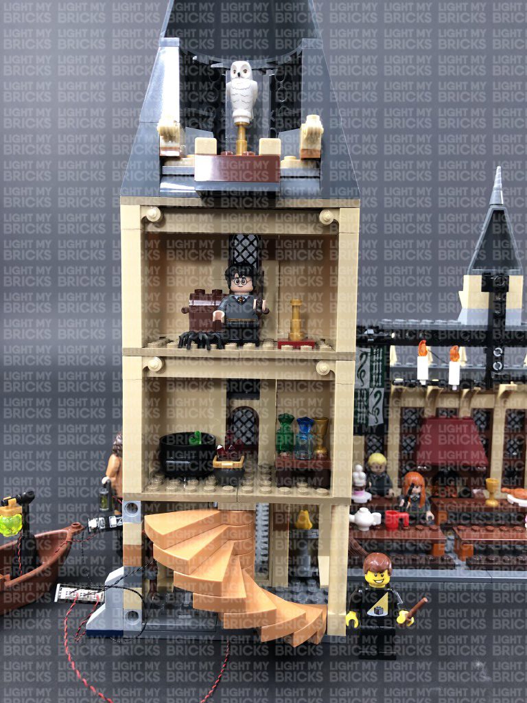
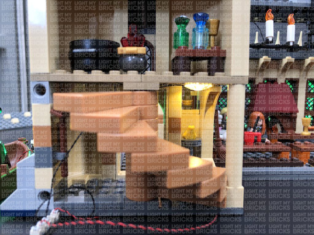
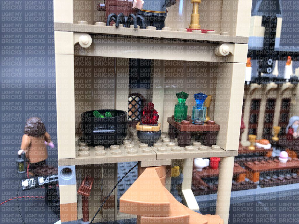
14.) We will now light the tower section of the set, starting with the ground floor. We will be using trans clear 2×2 with rounded bottom plates to secure bit lights to the roof of each floor.
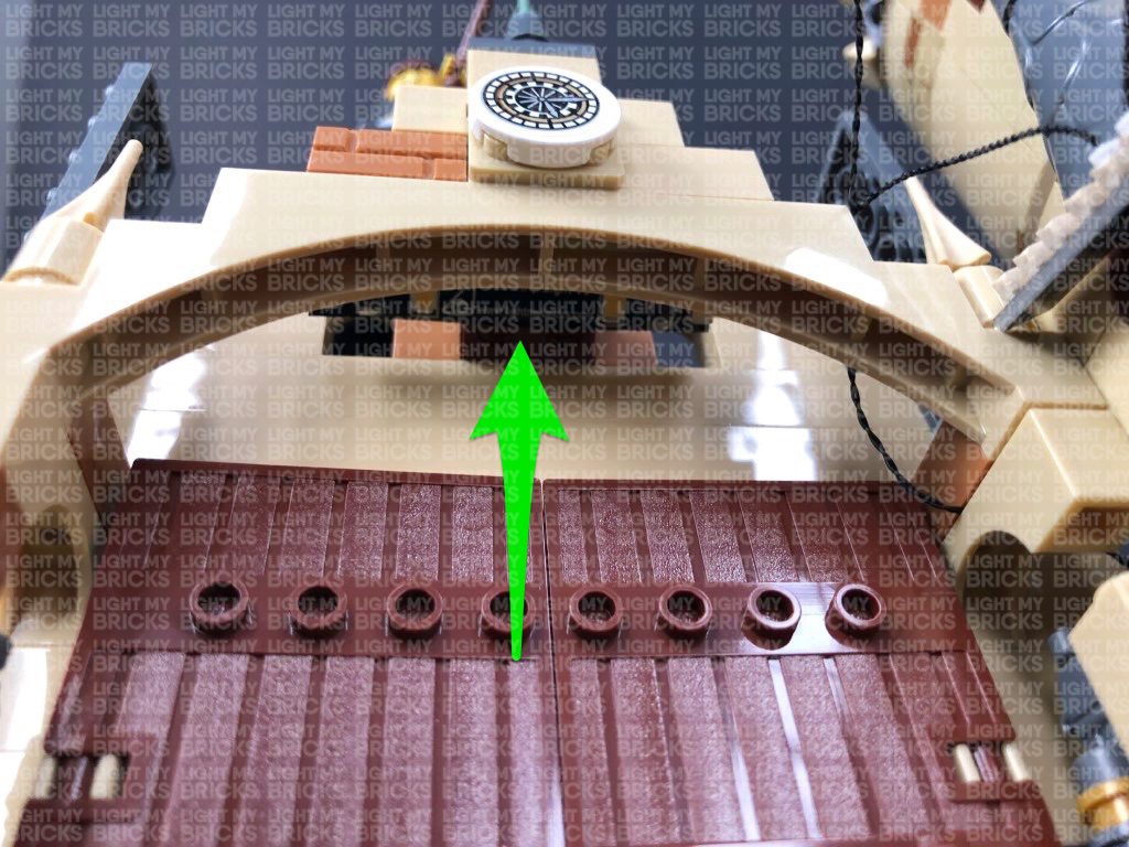
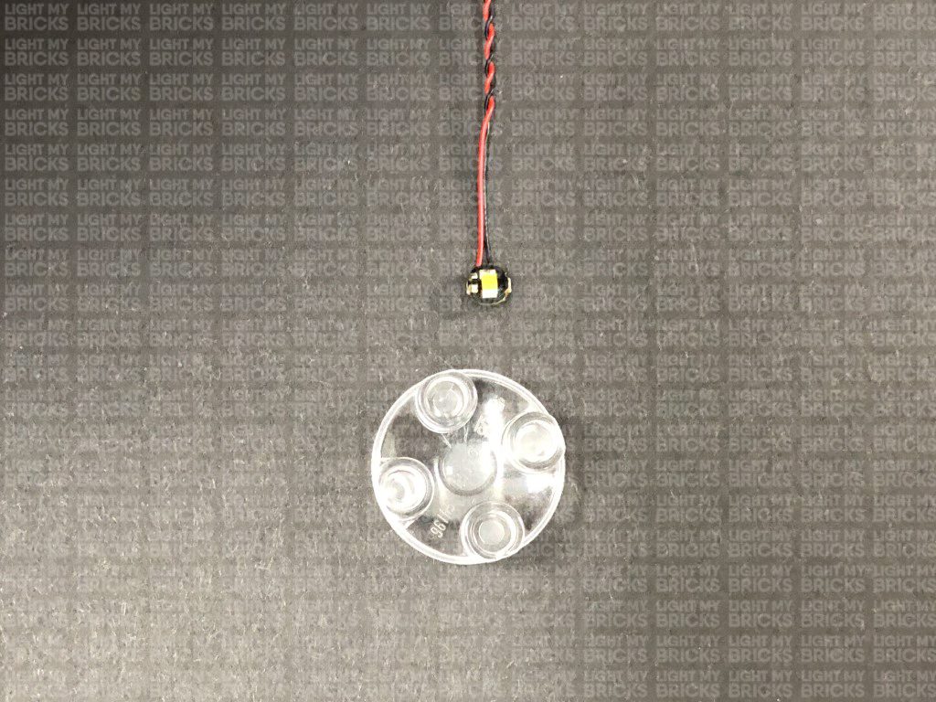
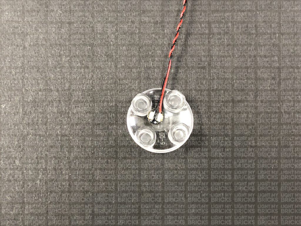
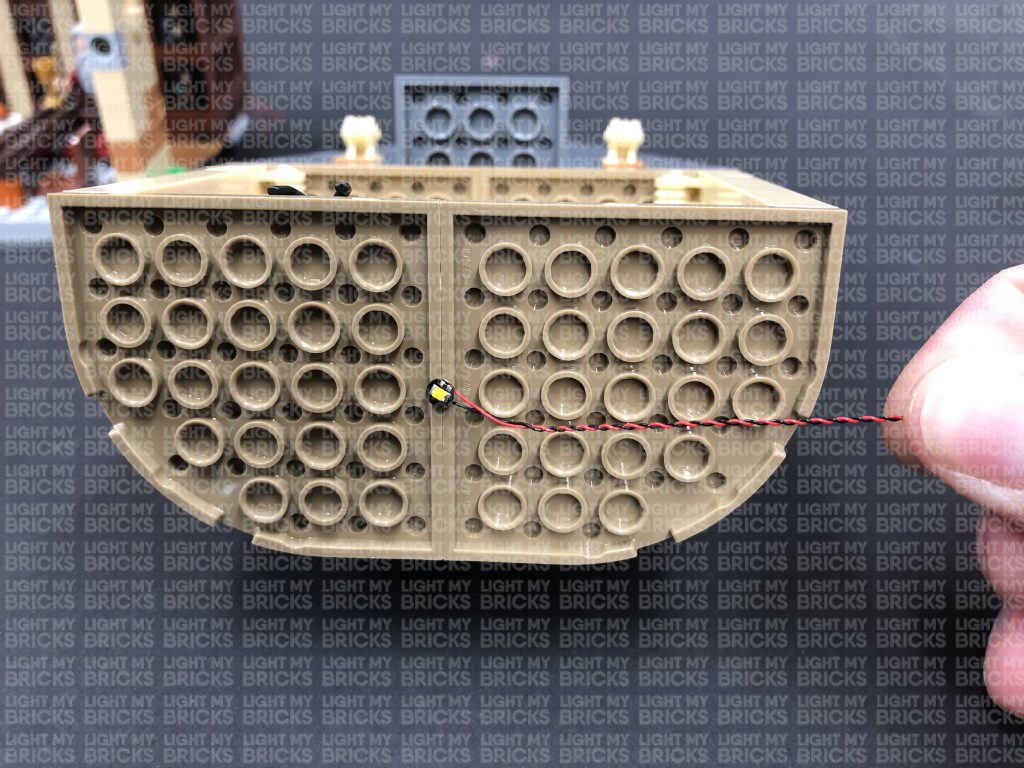
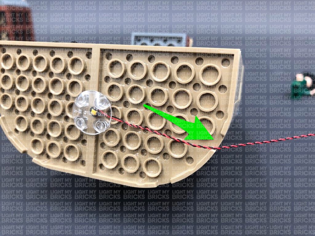
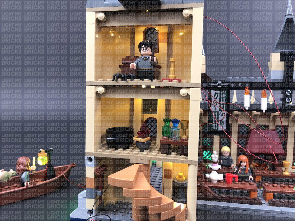
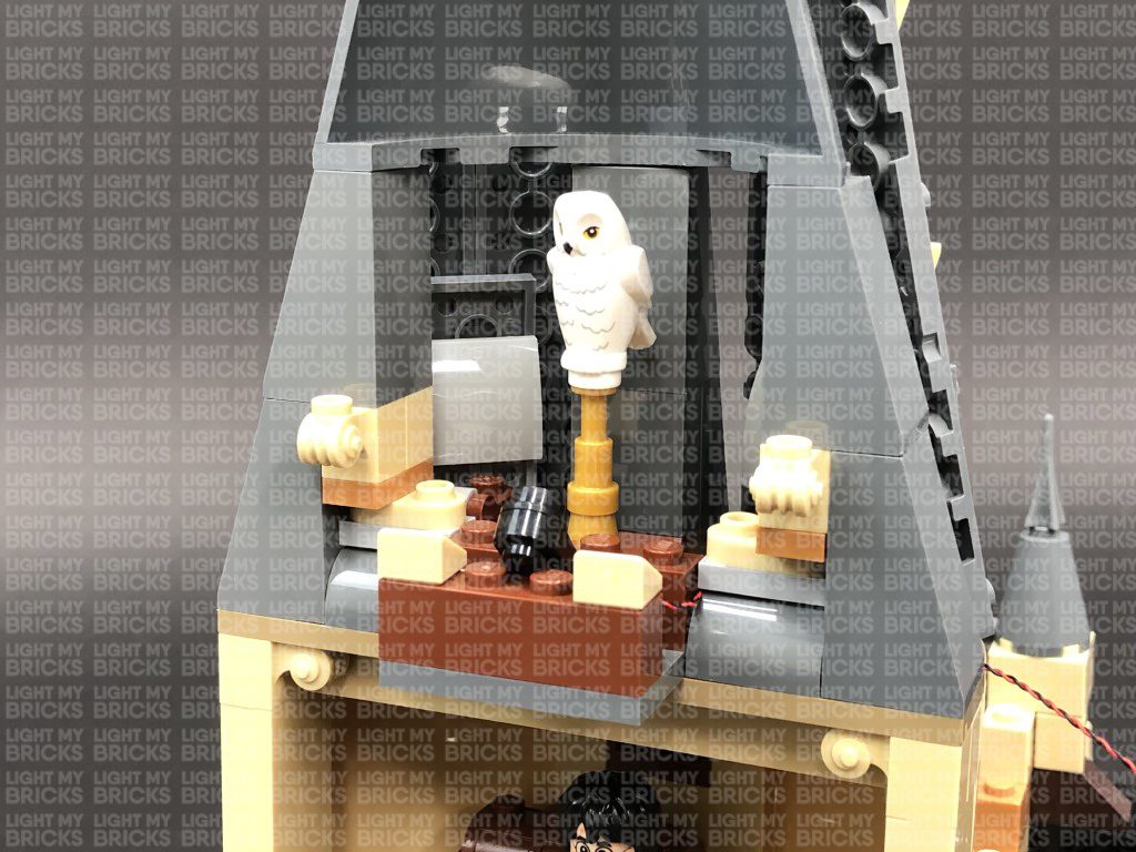
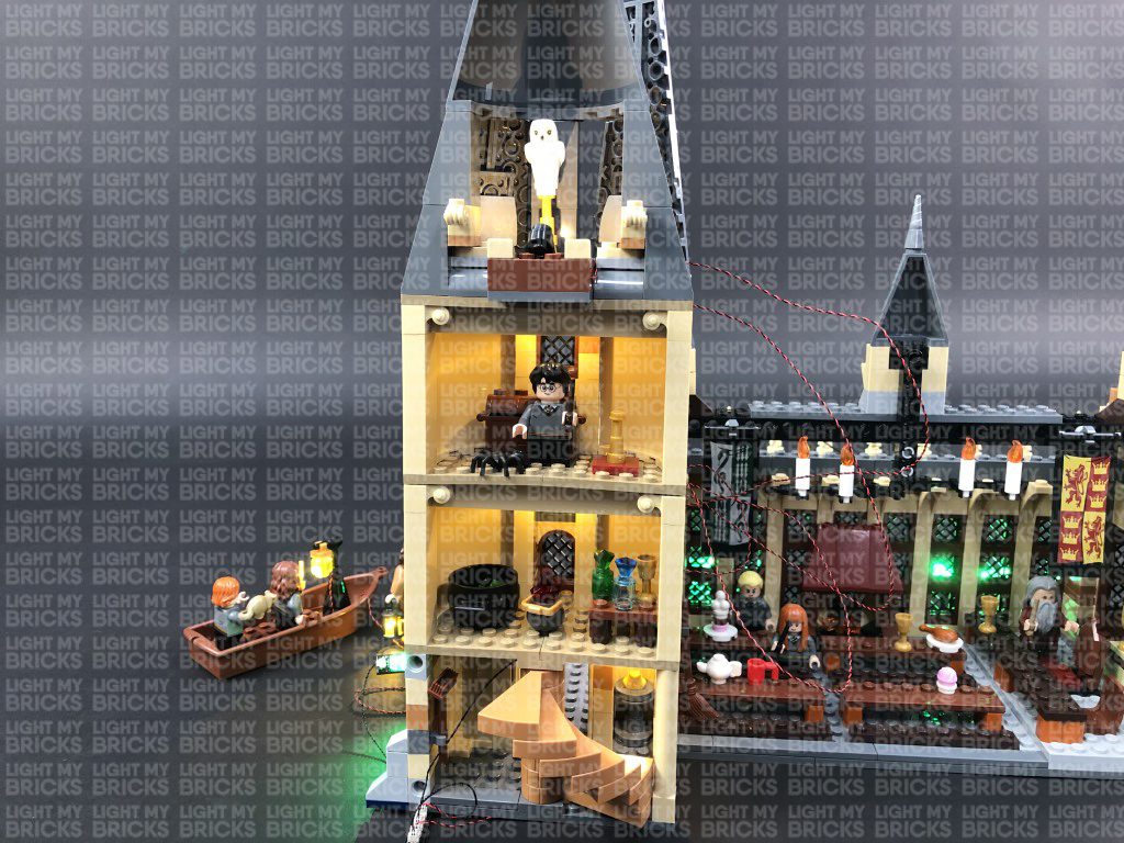
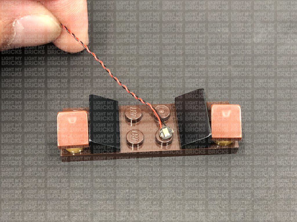
First take a White 30cm Bit Light and thread the bit light through the top where the front entrance roof is. Thread the bit light down so that it comes through to the ground floor. Take a provided Trans Clear Plate w Rounded Bottom 2×2 and place the LED component of the Bit Light in the centre of the plate. Ensuring the bit light is facing down, connect the trans clear plate to the roof of the ground floor in the below position:
Bring the other end of the Bit Light cable over and tuck it into the side of the roof section. Connect it to the 6-port expansion board above the front entrance, then turn the AA Battery Pack ON to test the ground floor light is working OK.
Note: If you experience any issues with the lights not working and suspect an issue with a component, please try a different port on the expansion board to verify where the fault lies (with the light or expansion board). To correct any issues with expansion board ports, please view the section addressing expansion board issues on our online troubleshooting guide.
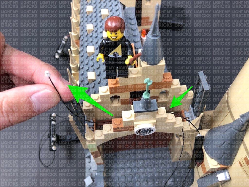
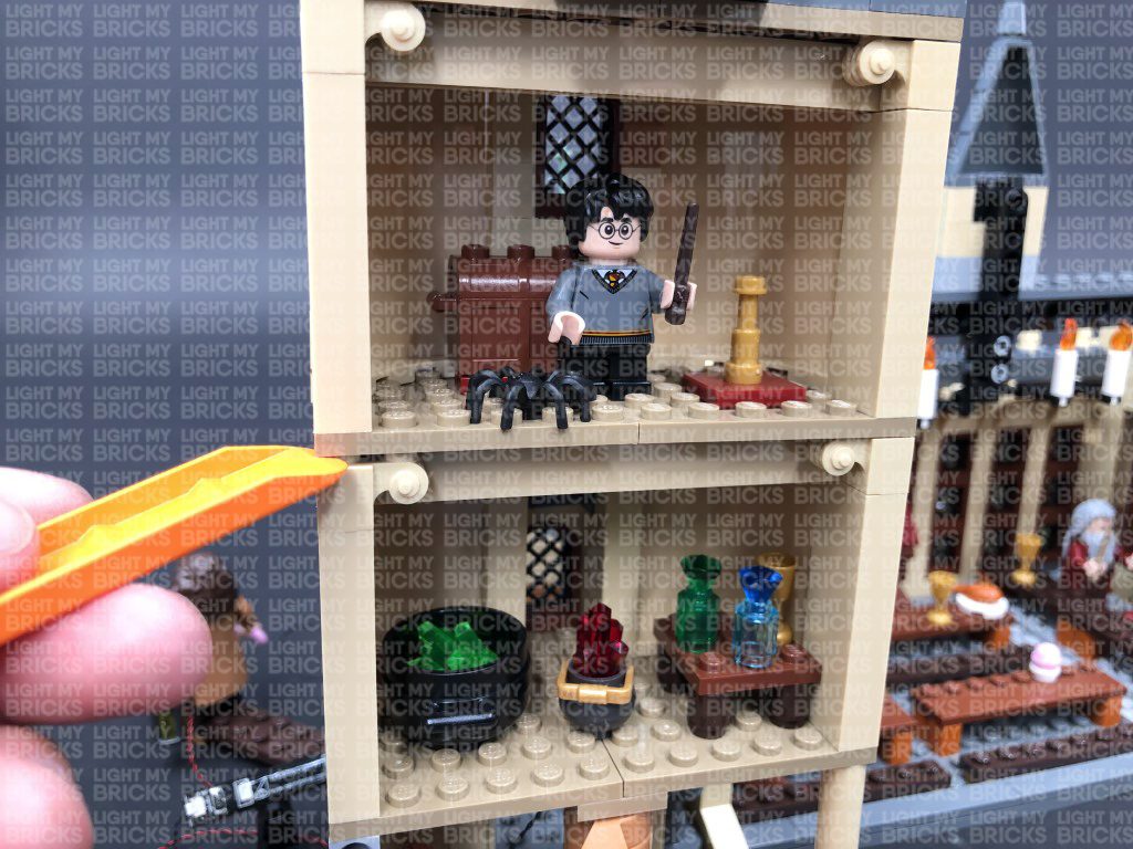
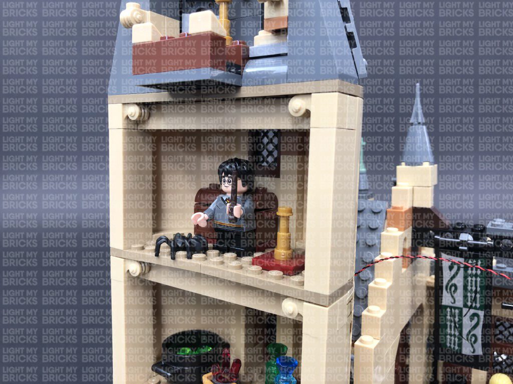
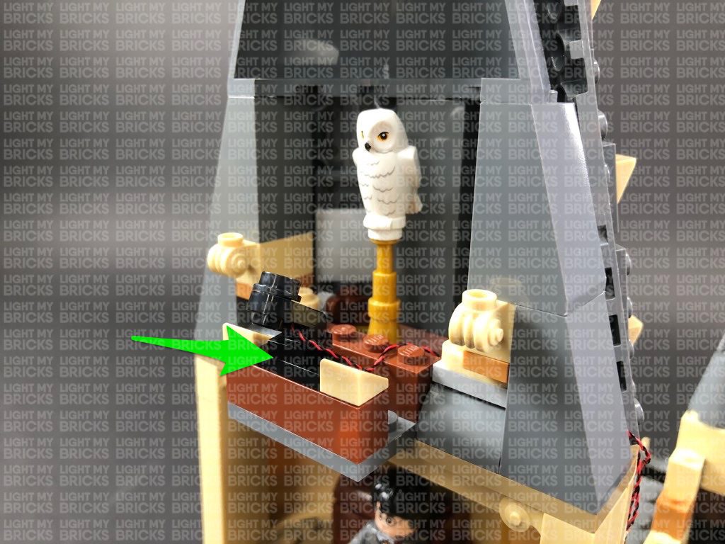
15.) We will now light the second floor of the tower. First disconnect the top section just above the second floor using a LEGO Removal Tool, then place the top section onto it’s front so we can access underneath.
Take a White 30cm Bit Light and with the cable facing the right, place the LED underneath this section in the centre position as shown below. Ensuring the LED is facing down, secure it in place by connecting a provided Trans Clear Plate w Rounded Bottom 2×2 over the top.
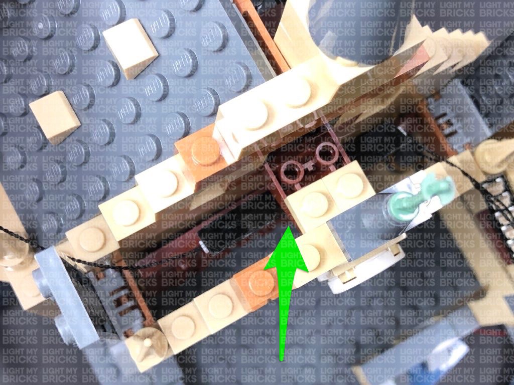
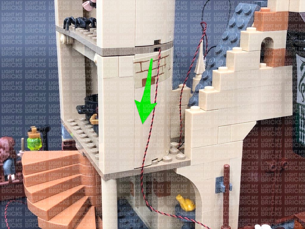
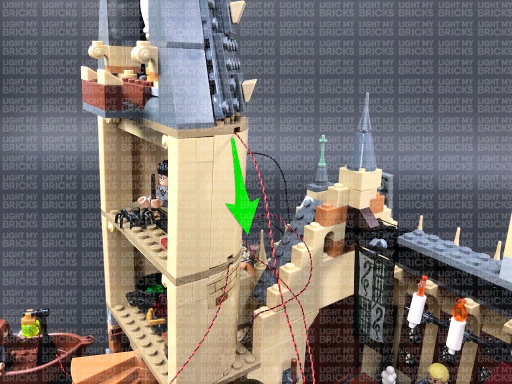
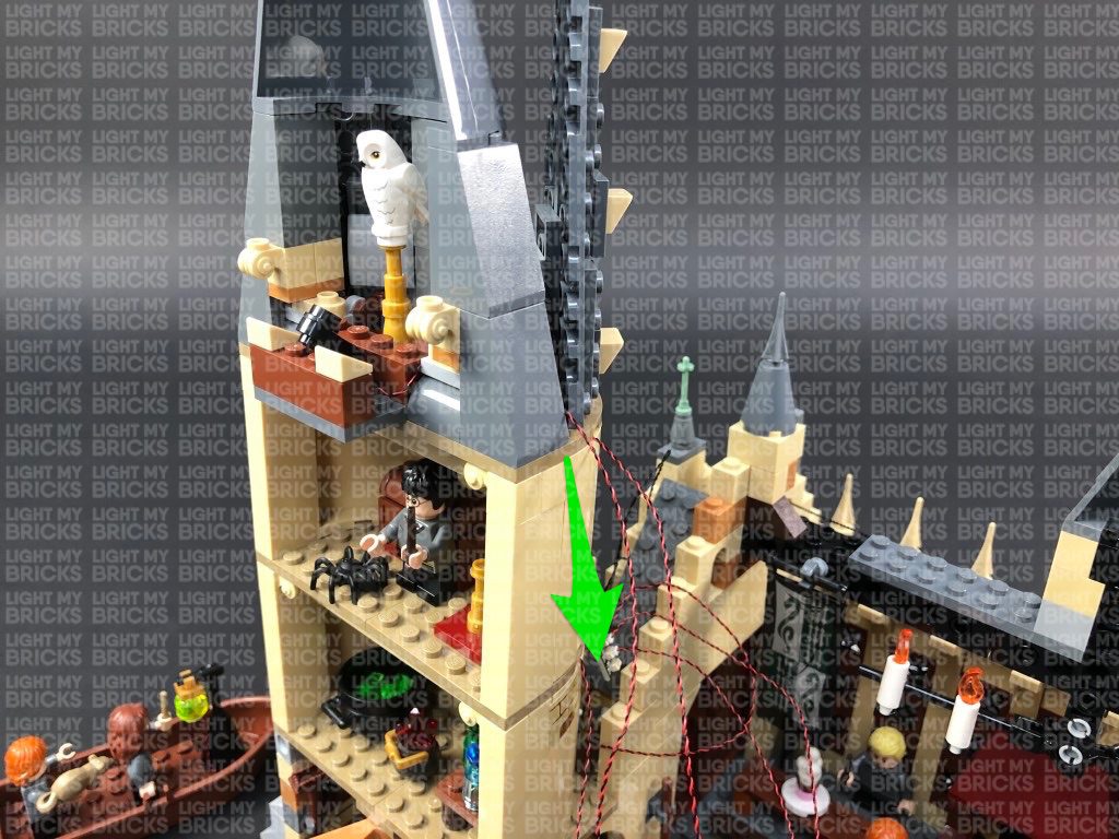
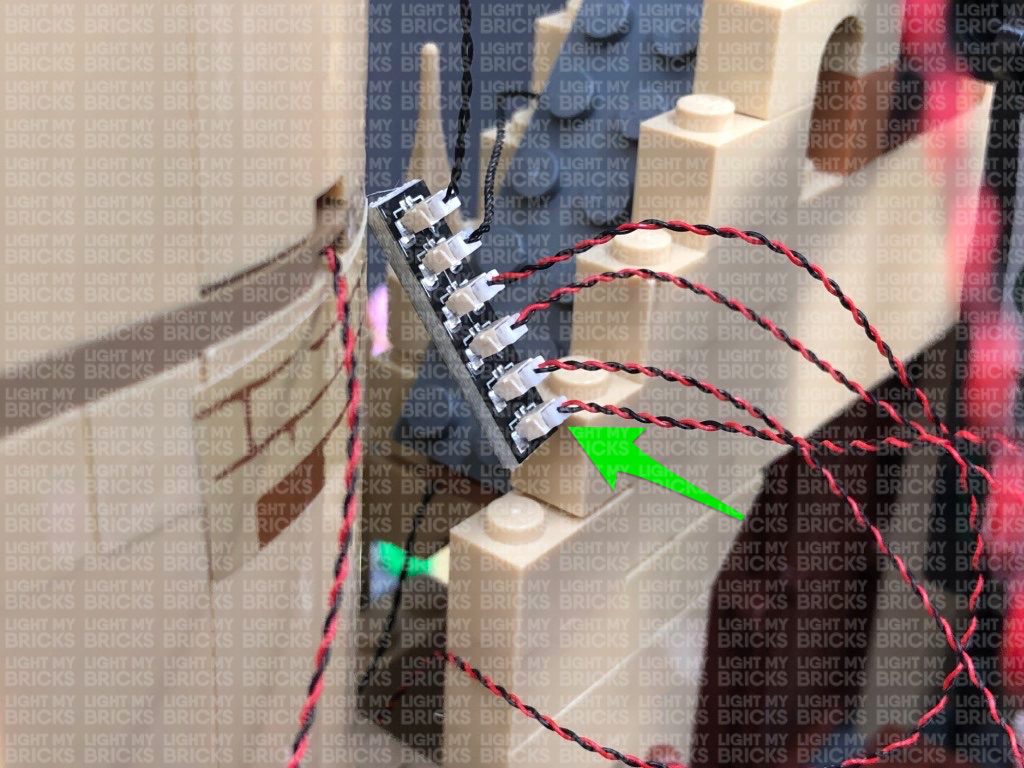
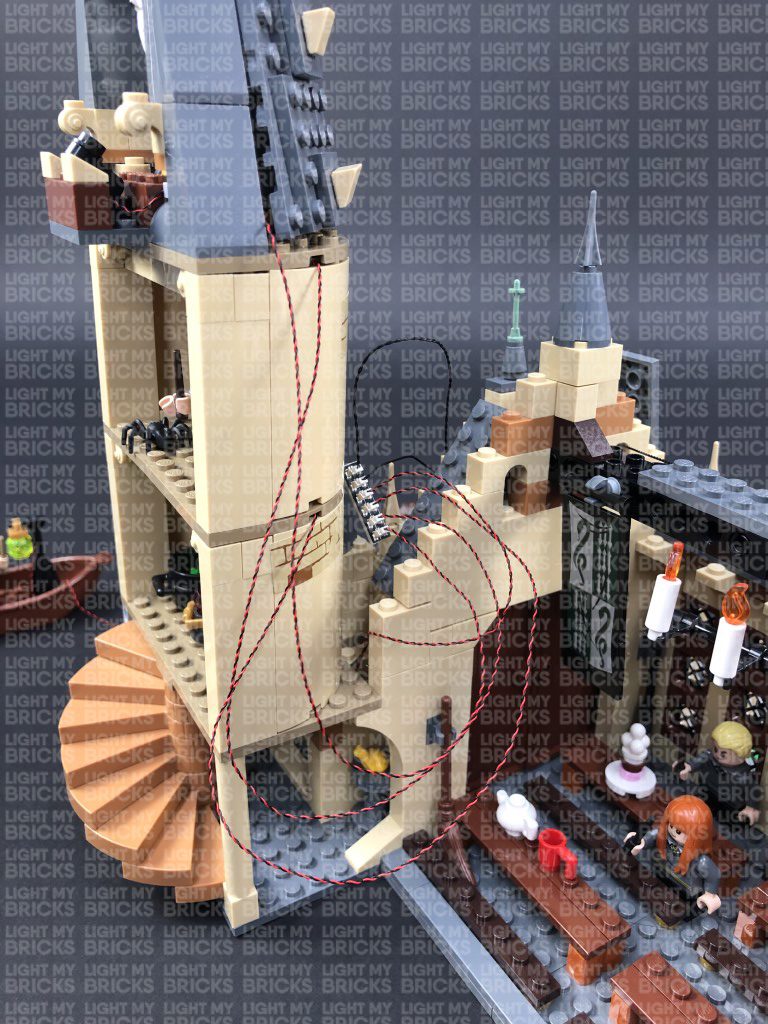
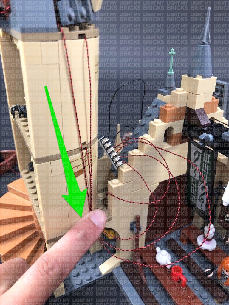
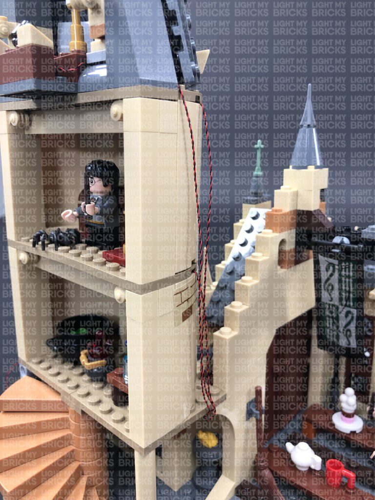
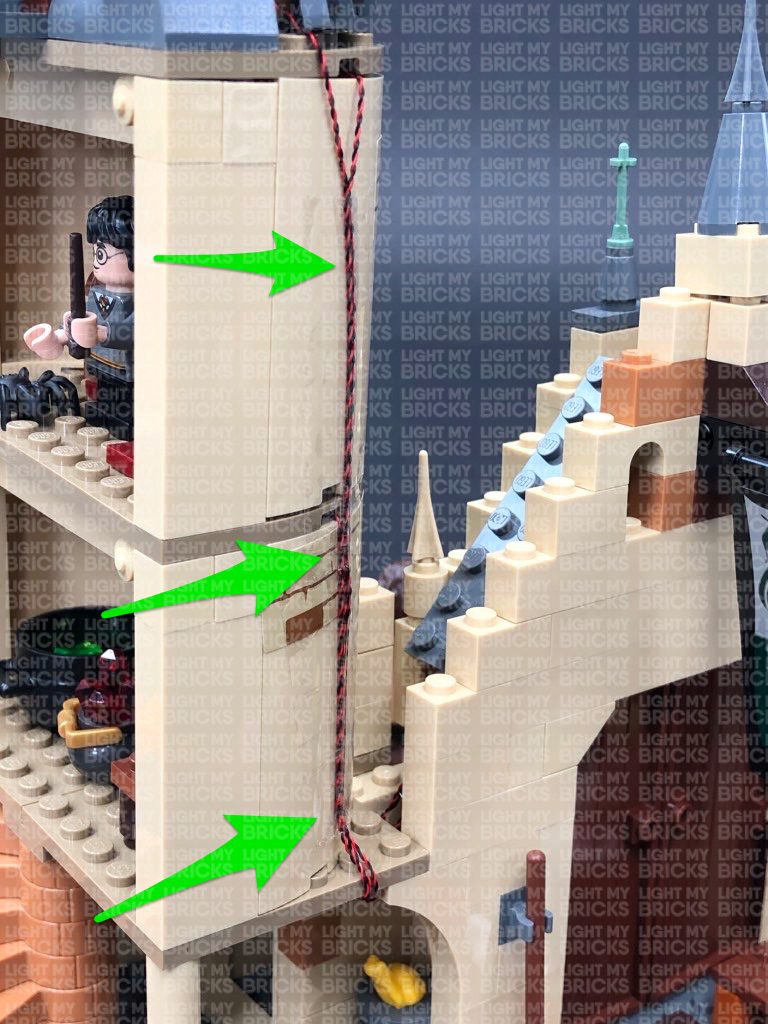
16.) Lay the cable down in between the indent, then reconnect the tower on top of the second floor. Bring the cable from the bit light down the right side of the tower and connect it to the next available port on the 6-port Expansion board. Turn the AA Battery Pack ON to test all lights installed so far are working OK.
Note: If you experience any issues with the lights not working and suspect an issue with a component, please try a different port on the expansion board to verify where the fault lies (with the light or expansion board). To correct any issues with expansion board ports, please view the section addressing expansion board issues on our online troubleshooting guide.
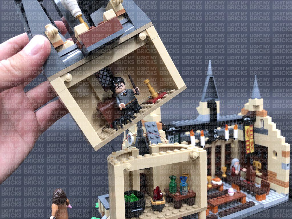
17.) Use the LEGO removal tool to disconnect the tower roof section from the top of the third floor. Turn this section over onto it’s front so we can access underneath it as shown below:
Take a White 30cm Bit Light and with the cable facing the right, place the LED underneath this section in the middle position as shown below. Ensuring the LED is facing down, secure it in place by connecting a provided Trans Clear Plate w Rounded Bottom 2×2 over the top.
18.) Lay the cable down in between the following indent, then reconnect the tower on top of the second floor. Bring the cable from the bit light down the right side of the tower and connect it to the next available port on the 6-port Expansion board. Turn the AA Battery Pack ON to test all lights installed so far are working OK.
Note: If you experience any issues with the lights not working and suspect an issue with a component, please try a different port on the expansion board to verify where the fault lies (with the light or expansion board). To correct any issues with expansion board ports, please view the section addressing expansion board issues on our online troubleshooting guide.
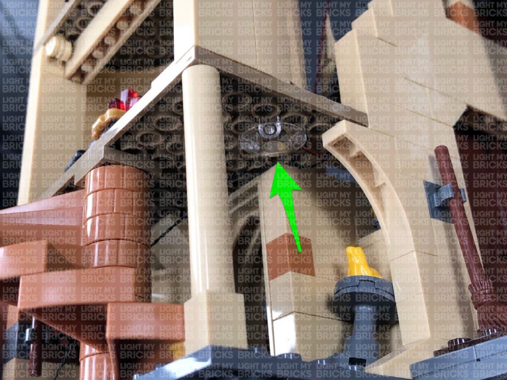
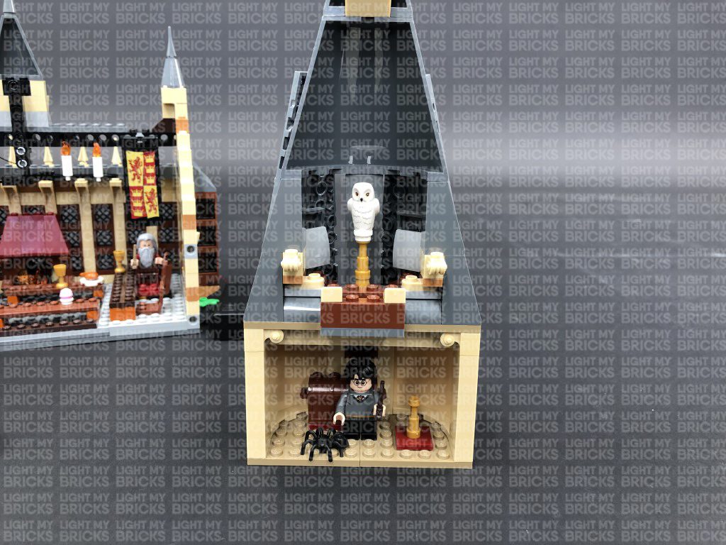
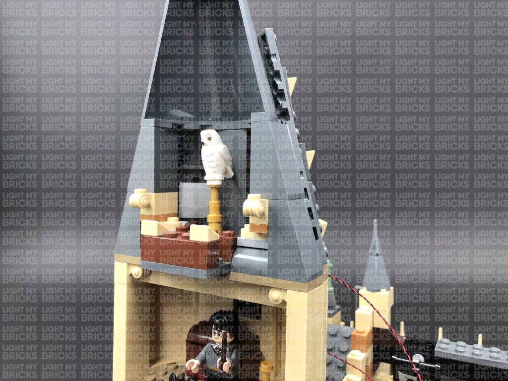
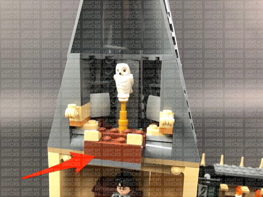
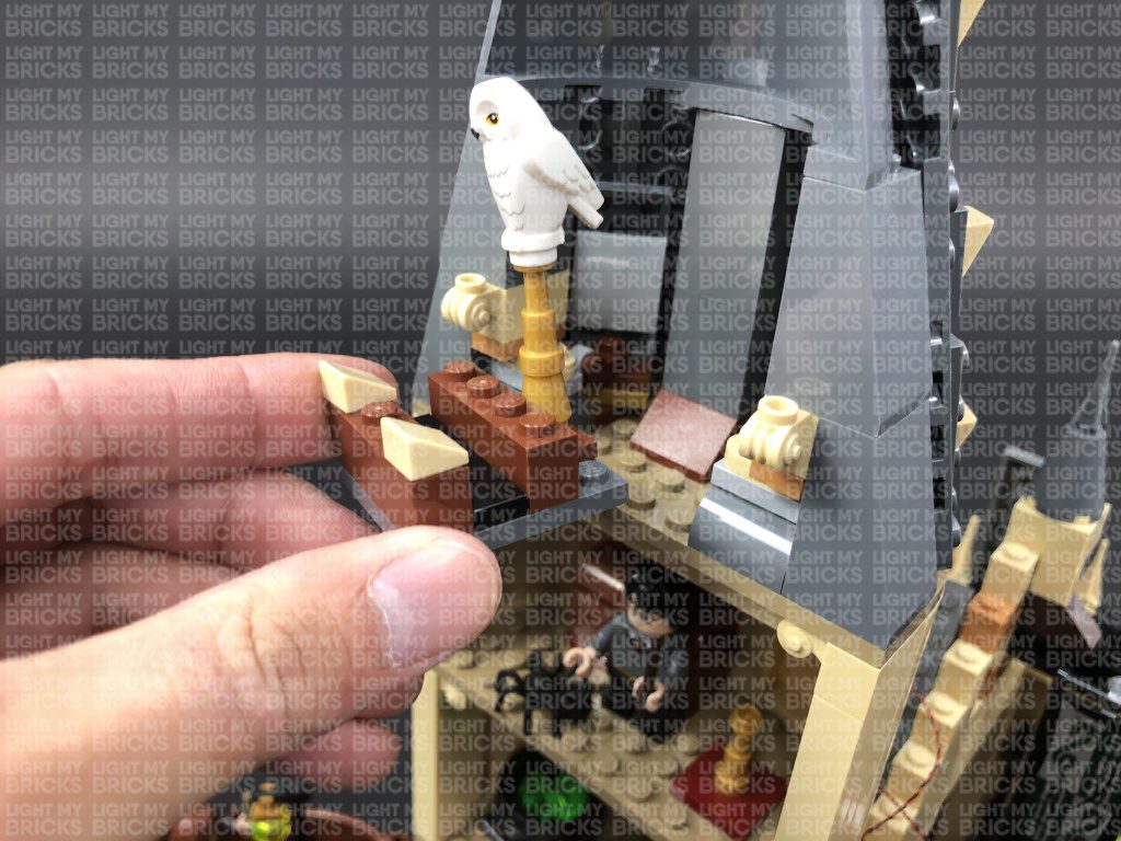
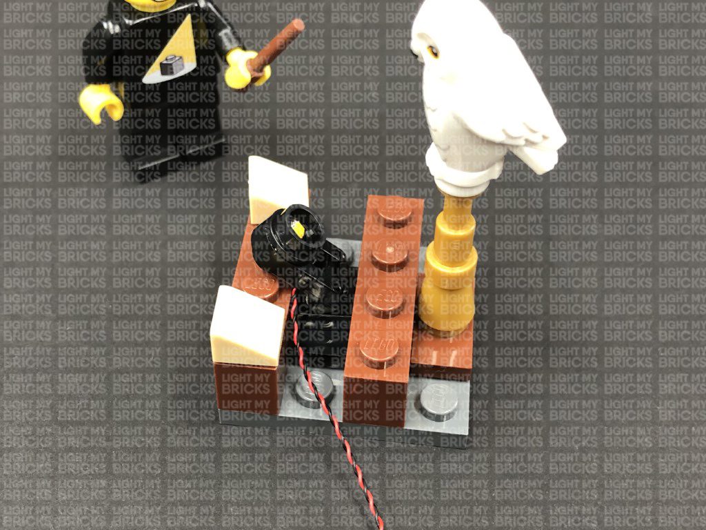
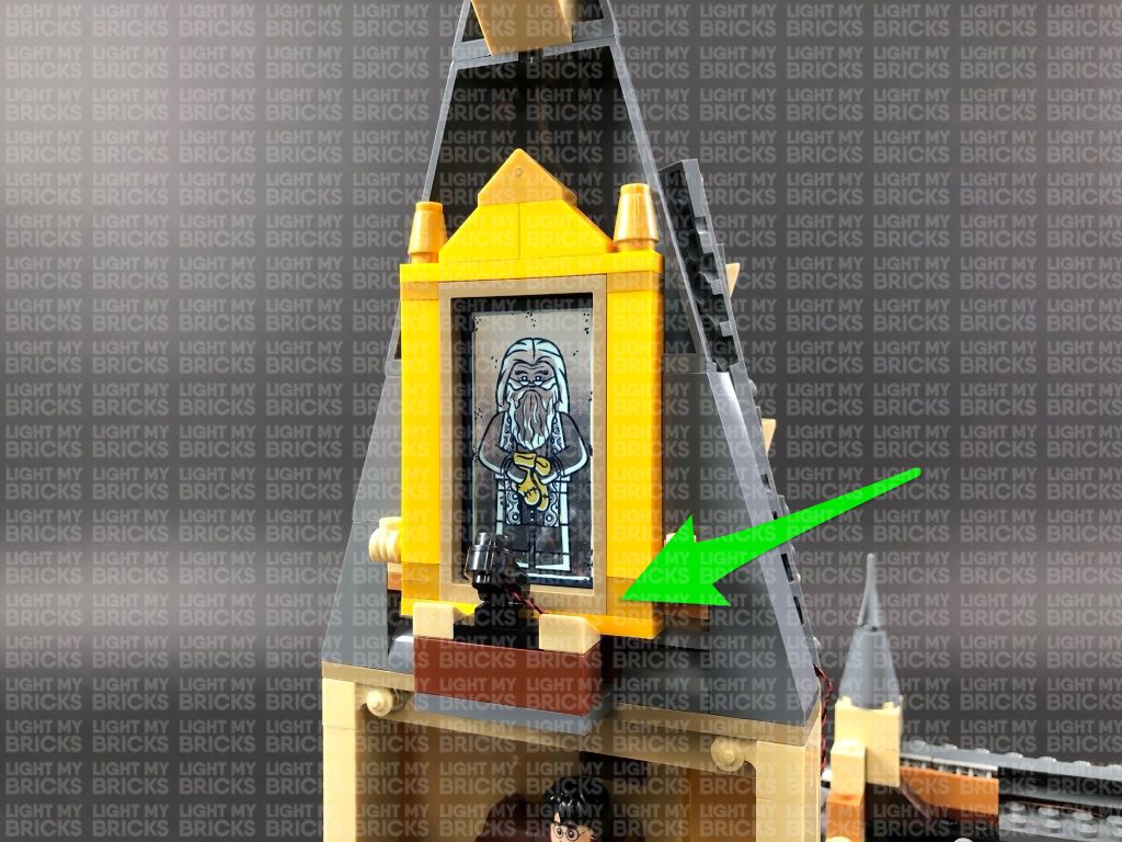
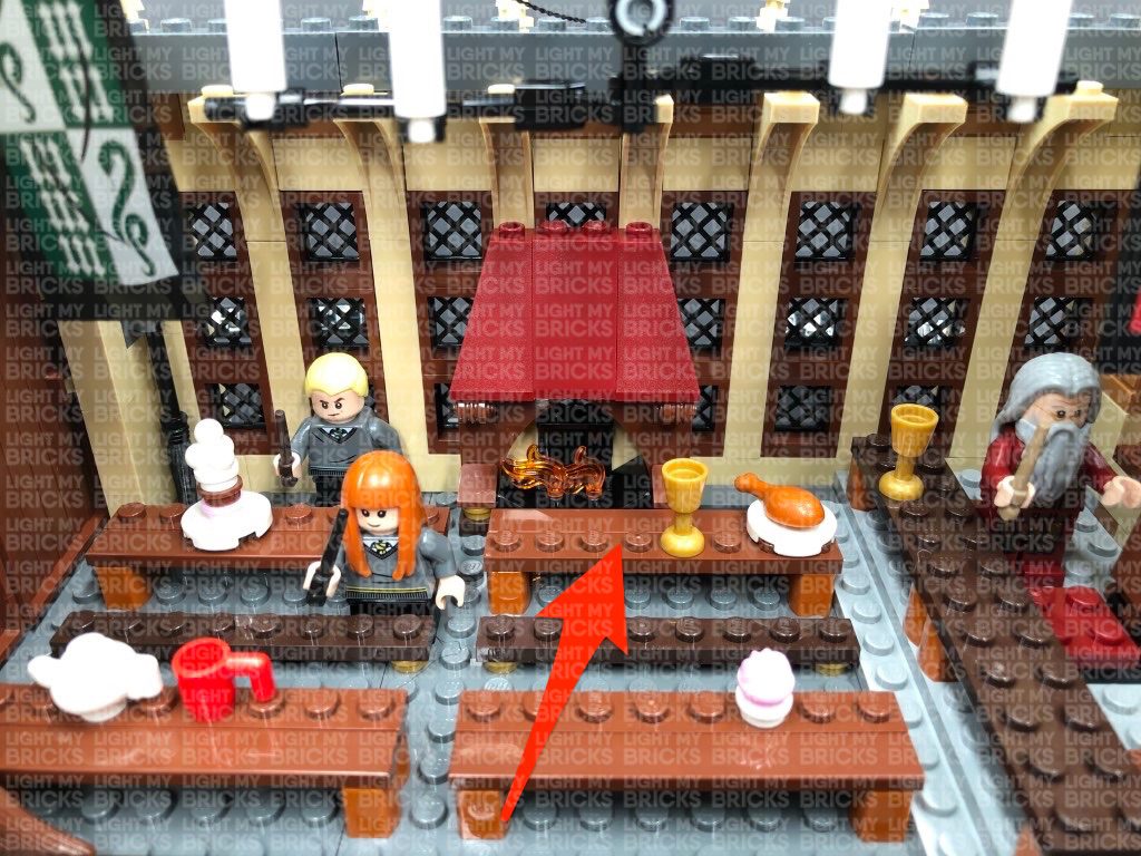
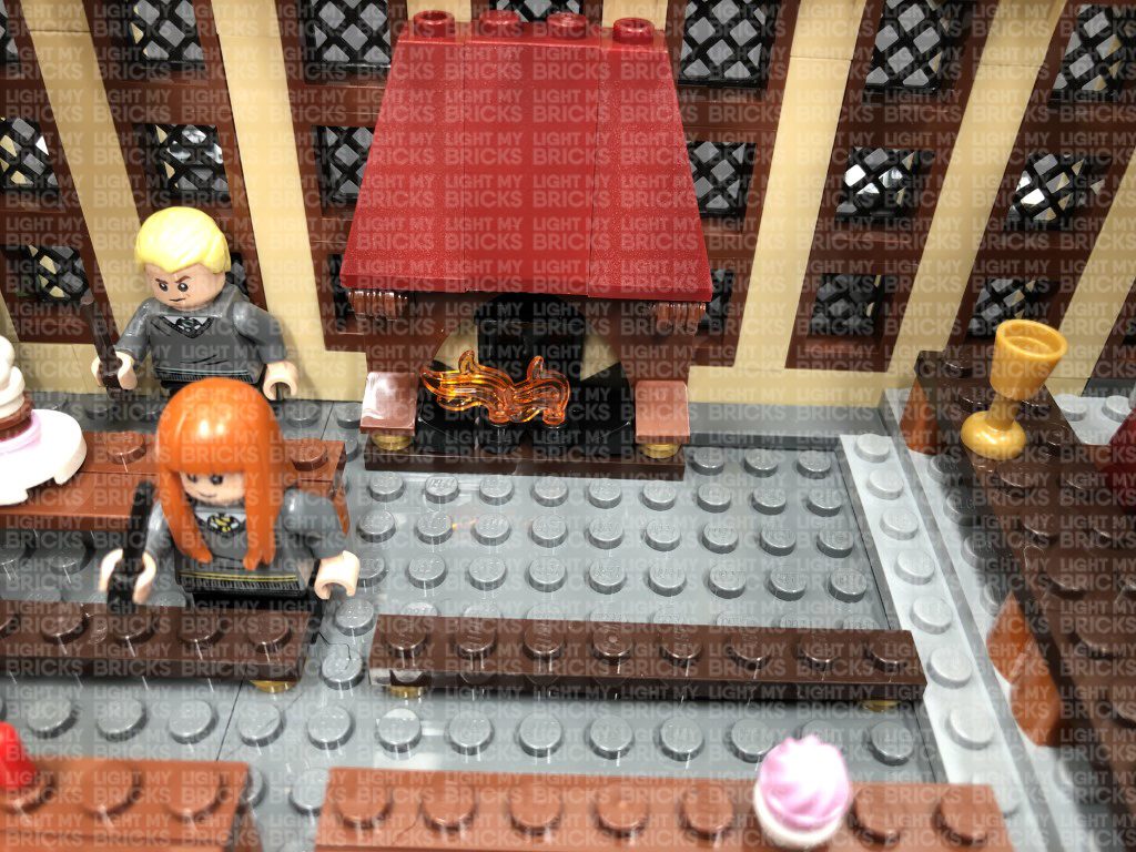
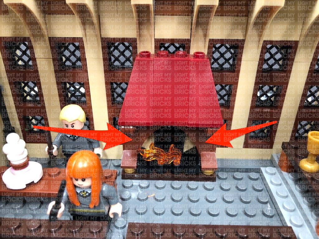
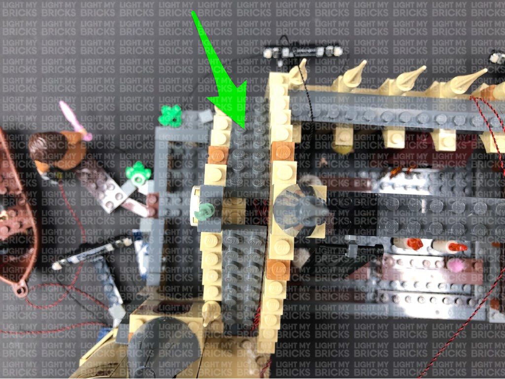
18.) We will now install a spot light inside the roof section to shine up onto an object. In this case have chosen to place the Owl here instead of Fawkes the phoenix. First, remove this whole section at the 4×4 dark grey plate, then disconnect the black 1×4 tile as we will be connecting our spotlight here. (If wish to keep the mirror of erised here, then leave this tile connected as you can place the spotlight on the front edge instead).
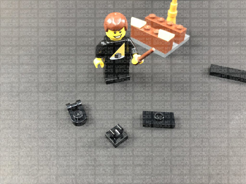
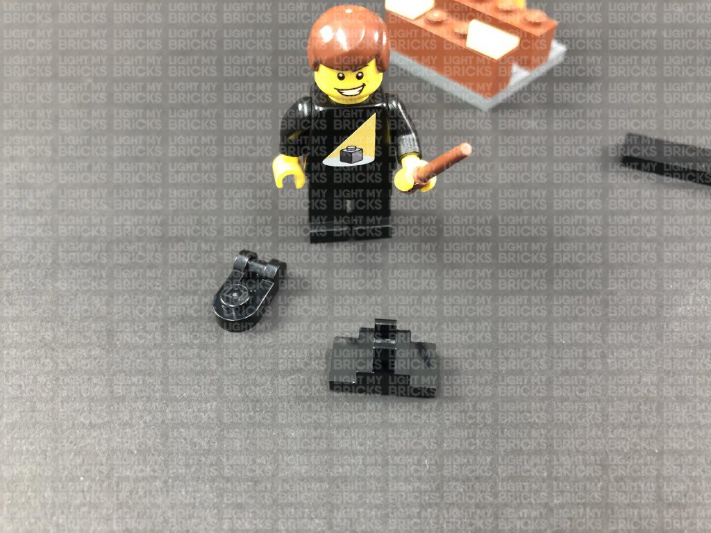
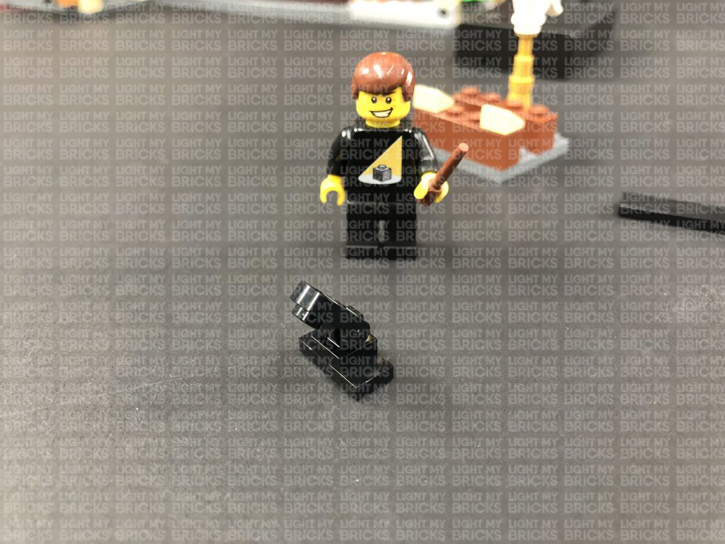
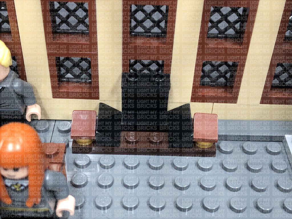
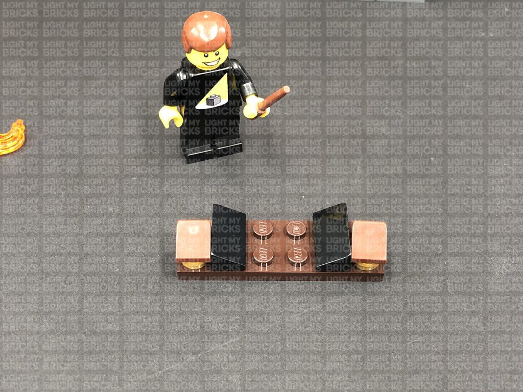
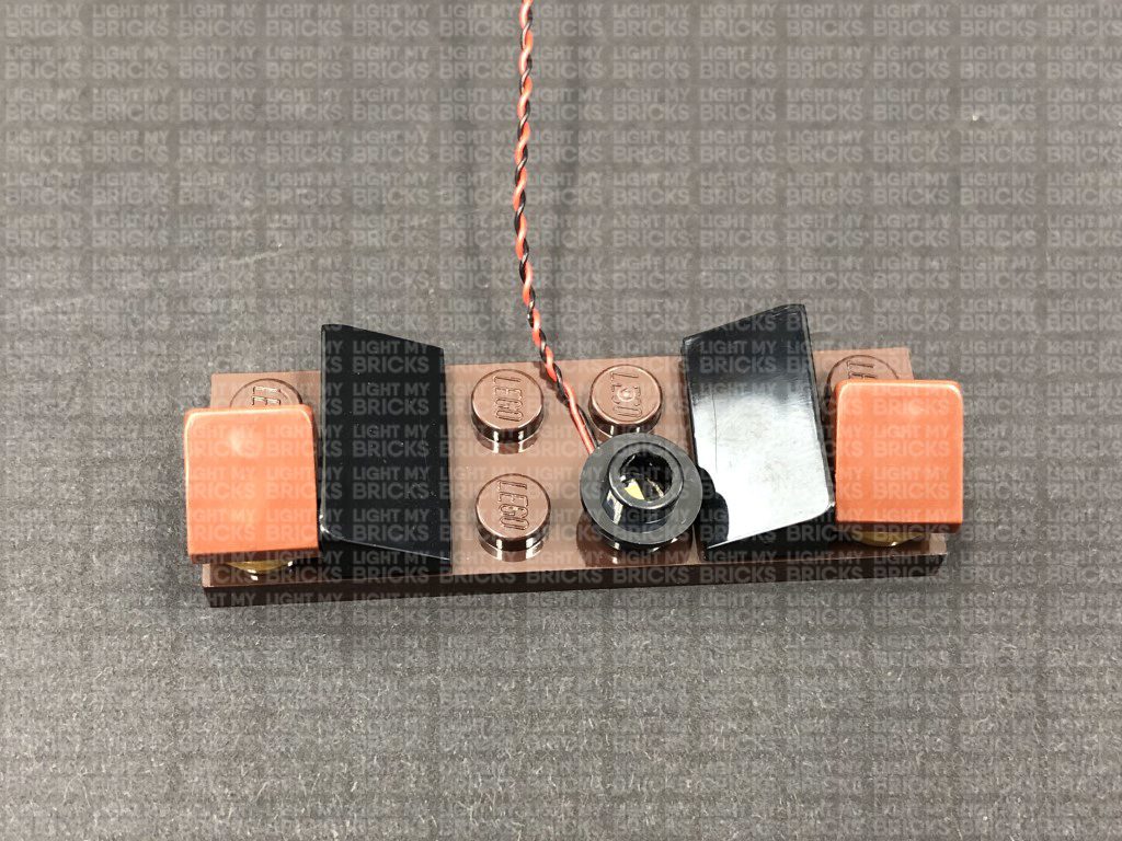
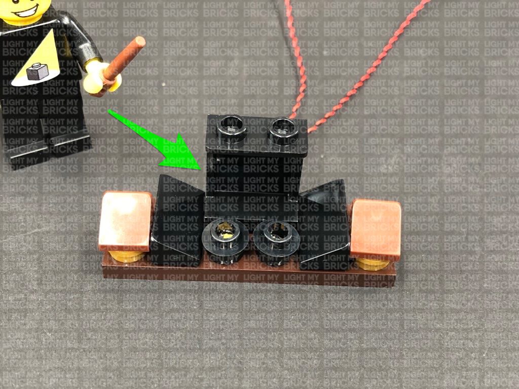
19.) Take out the following provided pieces, then build them into a spot light as shown below:
13.) Remove the entire roof off the great hall at each side as shown below, then thread the other end of the 15cm Connecting Cable from previous step through the archway nearby. Pull the cable all the way out, then place the expansion board inside the top of the front entrance.
Secure the dangling cable from the inside of the tower ground floor by connecting it underneath the base plate of the second floor as shown below:
14.) We will now light the tower section of the set, starting with the ground floor. We will be using trans clear 2×2 with rounded bottom plates to secure bit lights to the roof of each floor.
First take a White 30cm Bit Light and thread the bit light through the top where the front entrance roof is. Thread the bit light down so that it comes through to the ground floor. Take a provided Trans Clear Plate w Rounded Bottom 2×2 and place the LED component of the Bit Light in the centre of the plate. Ensuring the bit light is facing down, connect the trans clear plate to the roof of the ground floor in the below position:
Bring the other end of the Bit Light cable over and tuck it into the side of the roof section. Connect it to the 6-port expansion board above the front entrance, then turn the AA Battery Pack ON to test the ground floor light is working OK.
Note: If you experience any issues with the lights not working and suspect an issue with a component, please try a different port on the expansion board to verify where the fault lies (with the light or expansion board). To correct any issues with expansion board ports, please view the section addressing expansion board issues on our online troubleshooting guide.
15.) We will now light the second floor of the tower. First disconnect the top section just above the second floor using a LEGO Removal Tool, then place the top section onto it’s front so we can access underneath.
Take a White 30cm Bit Light and with the cable facing the right, place the LED underneath this section in the centre position as shown below. Ensuring the LED is facing down, secure it in place by connecting a provided Trans Clear Plate w Rounded Bottom 2×2 over the top.
16.) Lay the cable down in between the indent, then reconnect the tower on top of the second floor. Bring the cable from the bit light down the right side of the tower and connect it to the next available port on the 6-port Expansion board. Turn the AA Battery Pack ON to test all lights installed so far are working OK.
Note: If you experience any issues with the lights not working and suspect an issue with a component, please try a different port on the expansion board to verify where the fault lies (with the light or expansion board). To correct any issues with expansion board ports, please view the section addressing expansion board issues on our online troubleshooting guide.
17.) Use the LEGO removal tool to disconnect the tower roof section from the top of the third floor. Turn this section over onto it’s front so we can access underneath it as shown below:
Take a White 30cm Bit Light and with the cable facing the right, place the LED underneath this section in the middle position as shown below. Ensuring the LED is facing down, secure it in place by connecting a provided Trans Clear Plate w Rounded Bottom 2×2 over the top.
18.) Lay the cable down in between the following indent, then reconnect the tower on top of the second floor. Bring the cable from the bit light down the right side of the tower and connect it to the next available port on the 6-port Expansion board. Turn the AA Battery Pack ON to test all lights installed so far are working OK.
Note: If you experience any issues with the lights not working and suspect an issue with a component, please try a different port on the expansion board to verify where the fault lies (with the light or expansion board). To correct any issues with expansion board ports, please view the section addressing expansion board issues on our online troubleshooting guide.
18.) We will now install a spot light inside the roof section to shine up onto an object. In this case have chosen to place the Owl here instead of Fawkes the phoenix. First, remove this whole section at the 4×4 dark grey plate, then disconnect the black 1×4 tile as we will be connecting our spotlight here. (If wish to keep the mirror of erised here, then leave this tile connected as you can place the spotlight on the front edge instead).
19.) Take out the following provided pieces, then build them into a spot light as shown below:
- Black Tile 1×1 with Clip
- Black 1×1 Modified Plate Rounded with Handle
- Black Plate 1×2 modified with stud jumper
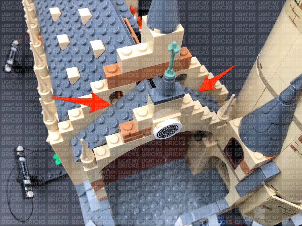
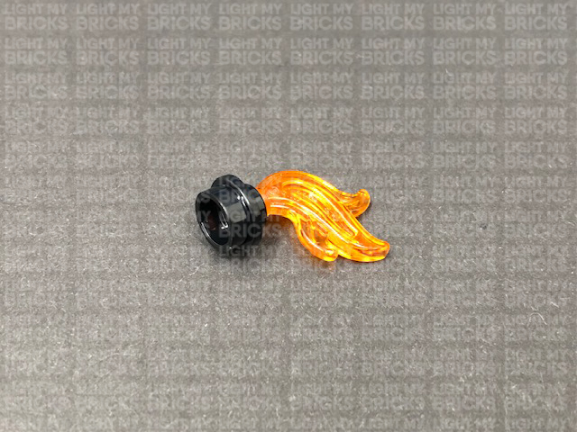
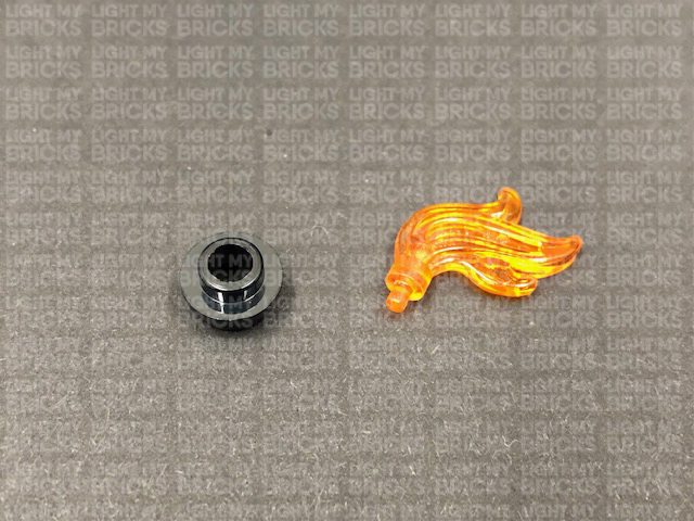
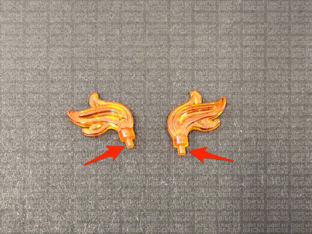
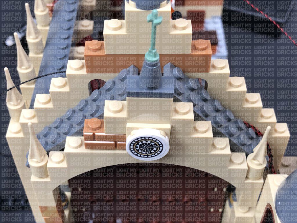
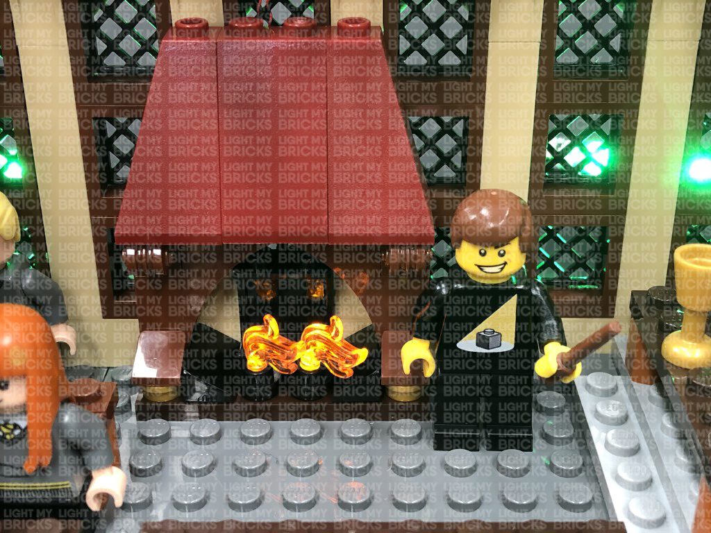
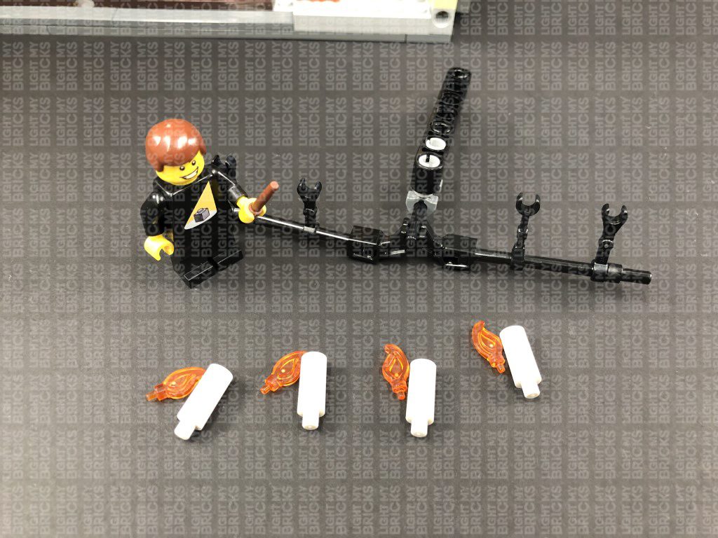
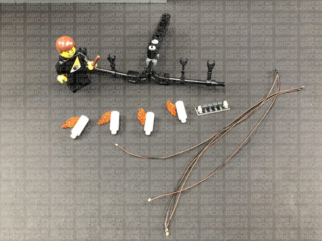
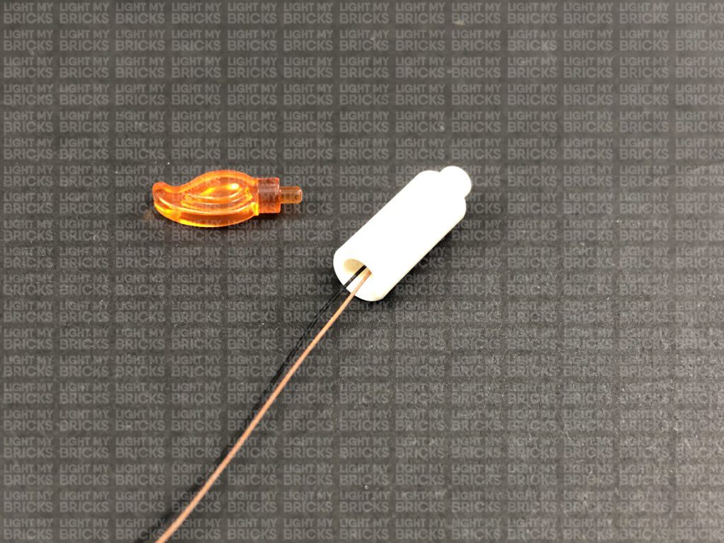
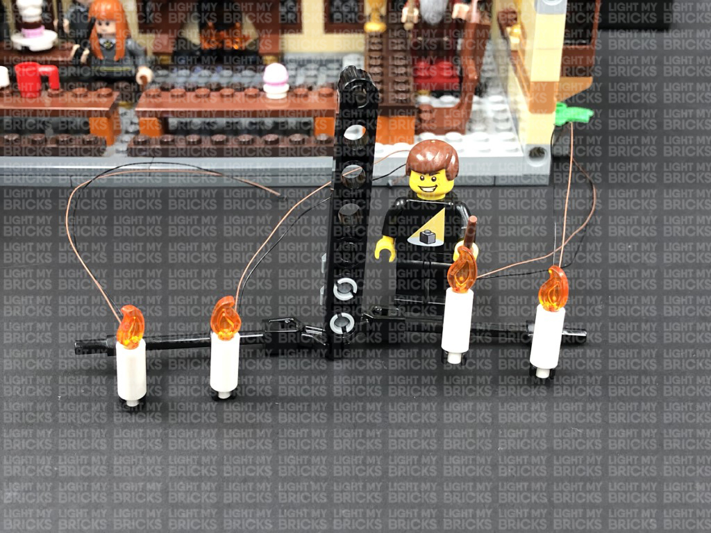
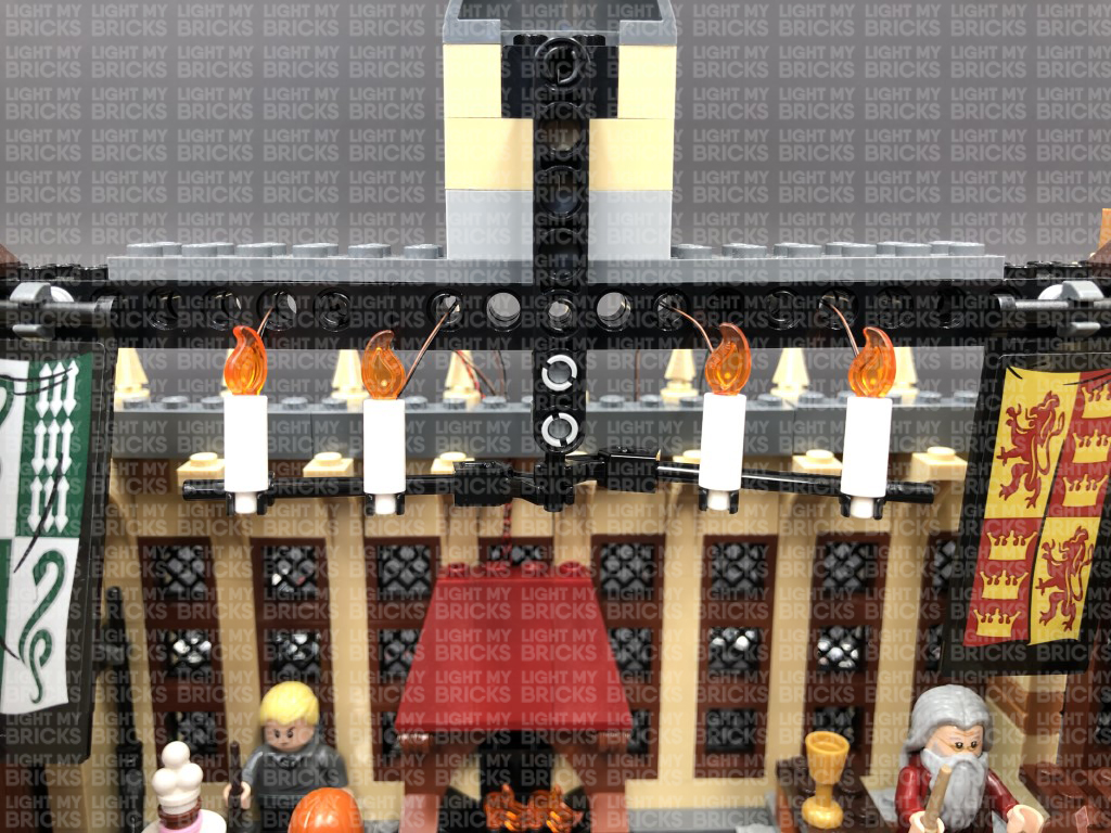
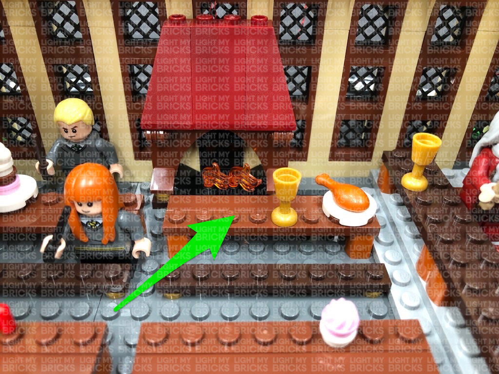 29.) We will now light up the candles on the roof. First disconnect this section by pulling them out at the technic brick holes, then disconnect the candle and flame pieces as shown below:
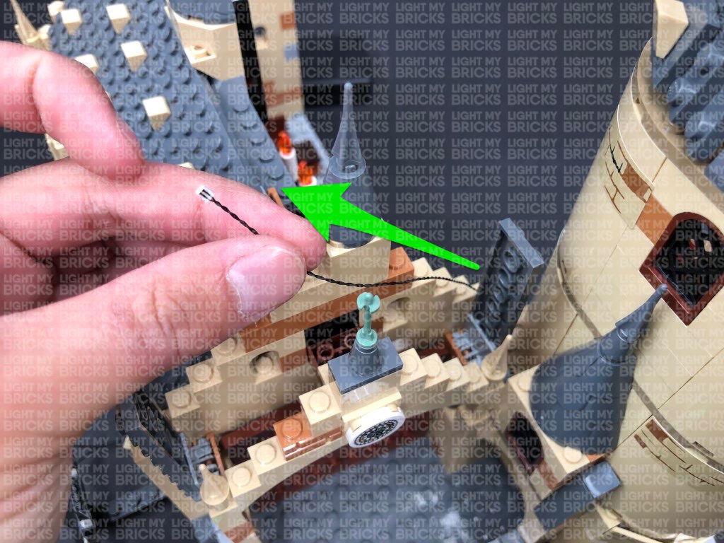
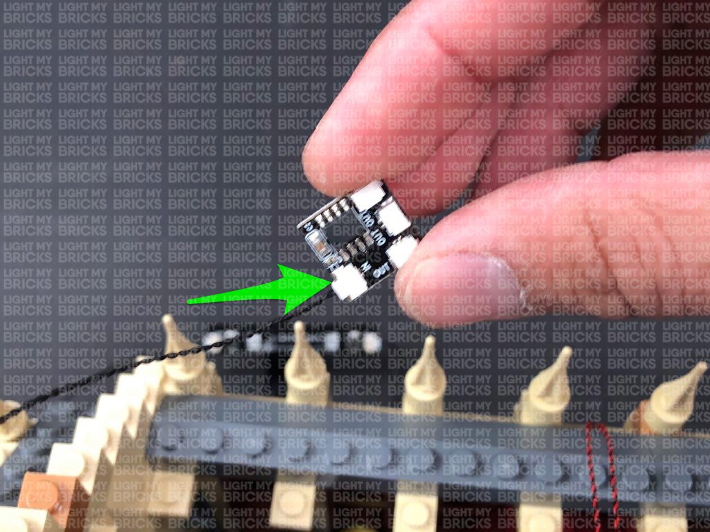
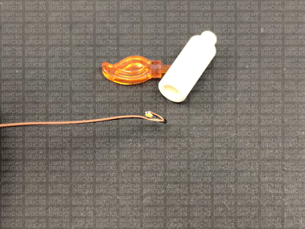
Take out a White Micro 15cm Bit Light and carefully bend the LED back as shown in the below image.
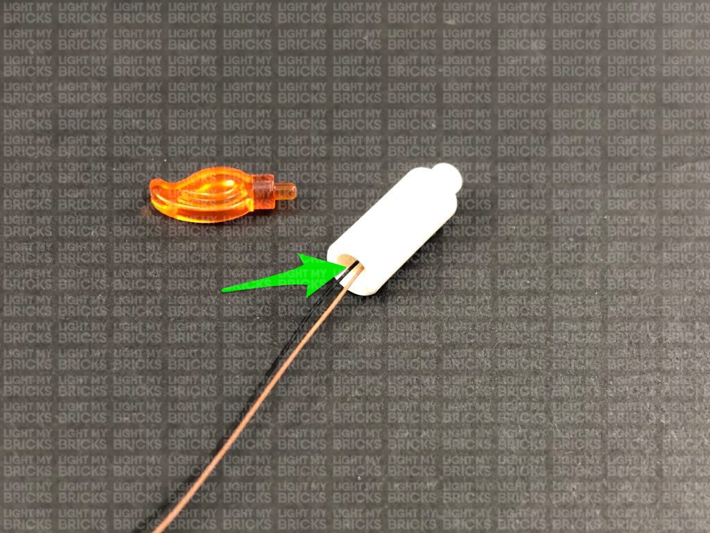
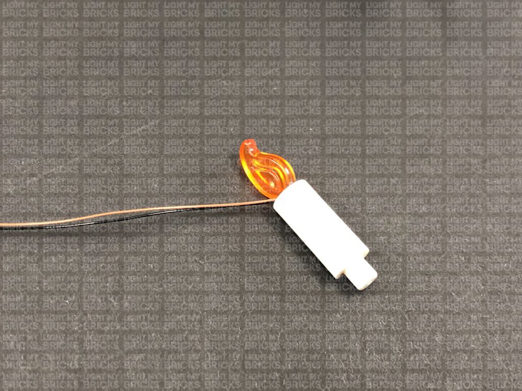
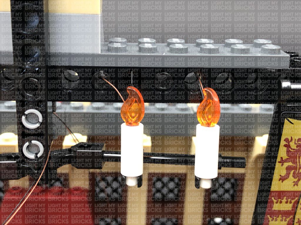
Thread the Bit Light into the hole of the candle piece as shown below, then reconnect the flame piece. We want the LED to be as close to the flame tip as possible therefore, threading the cable all the way to the end of the hole is not necessary.
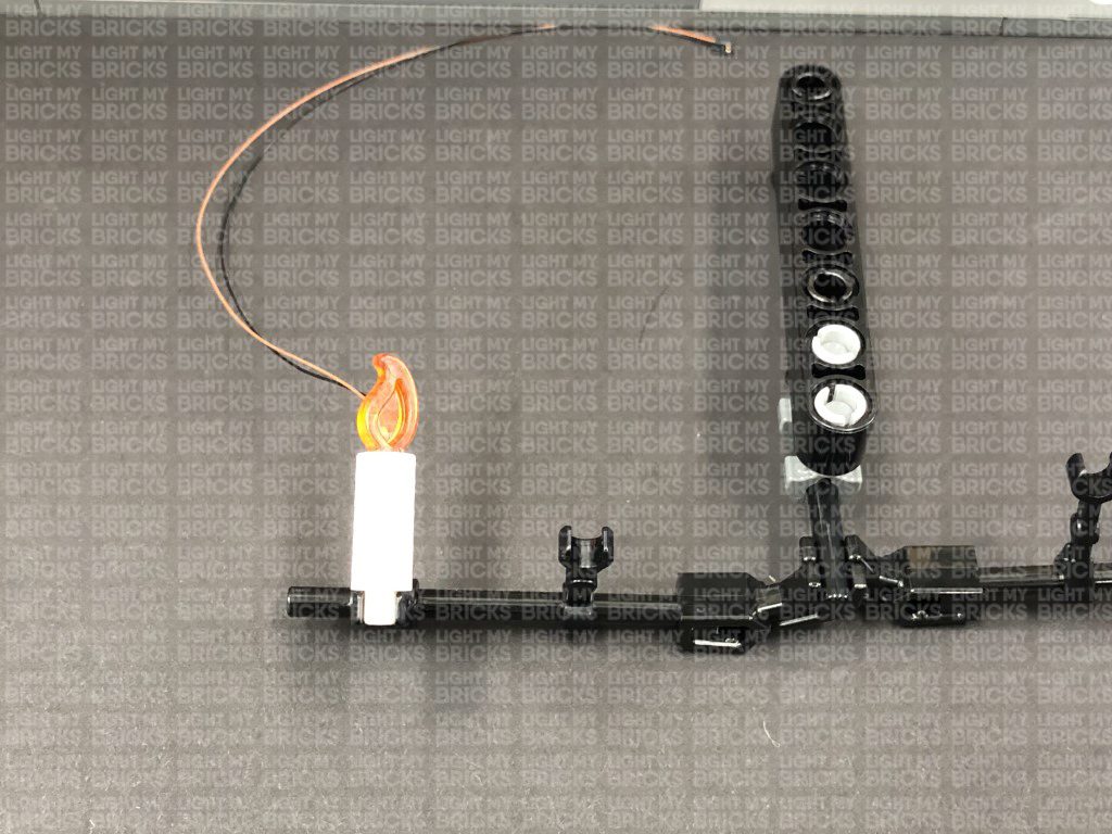
30.) Reconnect the candle to the roof frame, then repeat previous process to install another 3x White Micro 15cm Bit Lights to the remaining 3x candles.
29.) We will now light up the candles on the roof. First disconnect this section by pulling them out at the technic brick holes, then disconnect the candle and flame pieces as shown below:
Take out a White Micro 15cm Bit Light and carefully bend the LED back as shown in the below image.
Thread the Bit Light into the hole of the candle piece as shown below, then reconnect the flame piece. We want the LED to be as close to the flame tip as possible therefore, threading the cable all the way to the end of the hole is not necessary.
30.) Reconnect the candle to the roof frame, then repeat previous process to install another 3x White Micro 15cm Bit Lights to the remaining 3x candles.
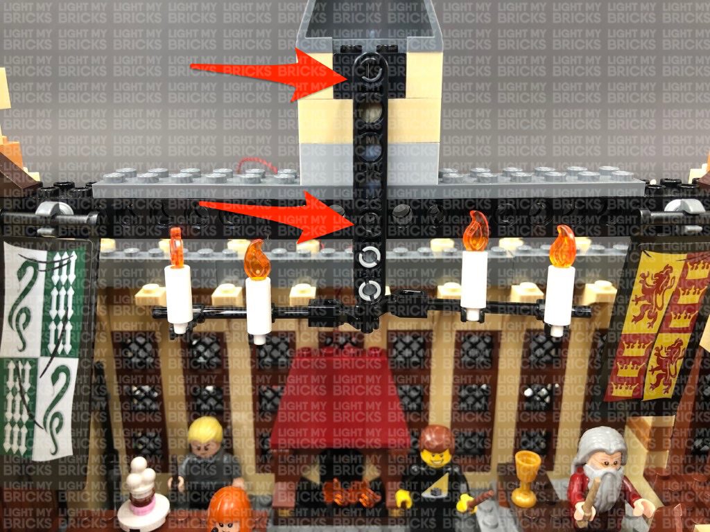
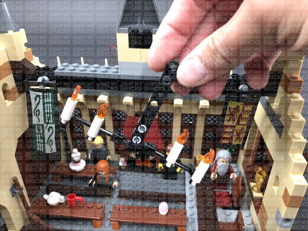
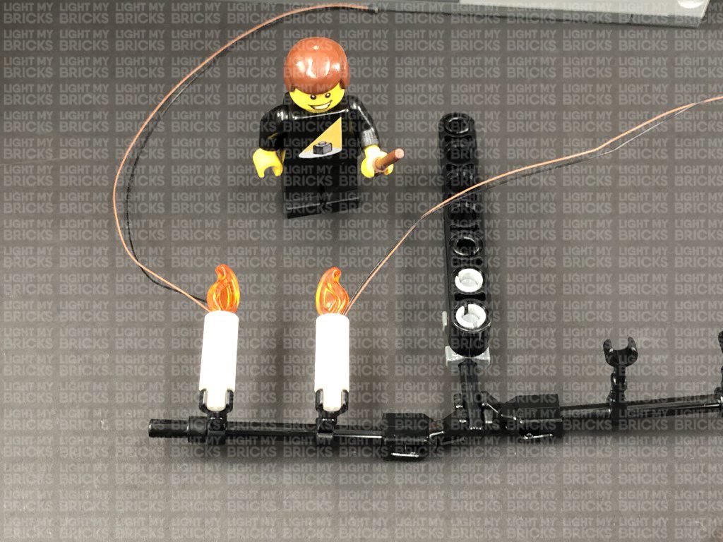
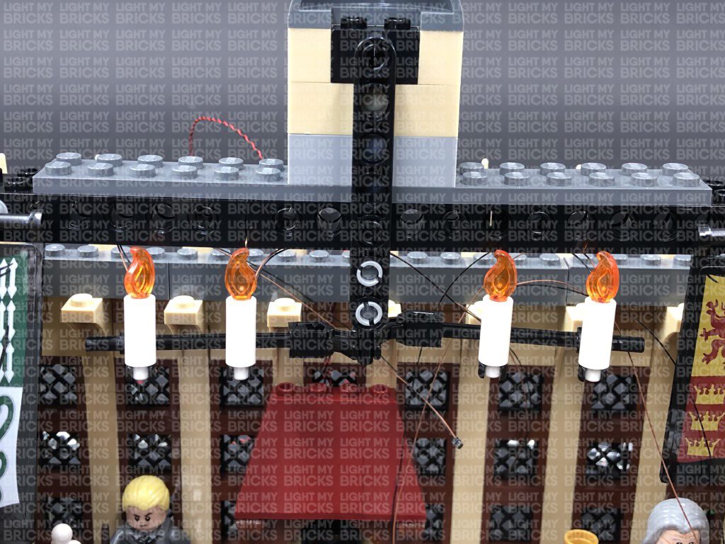
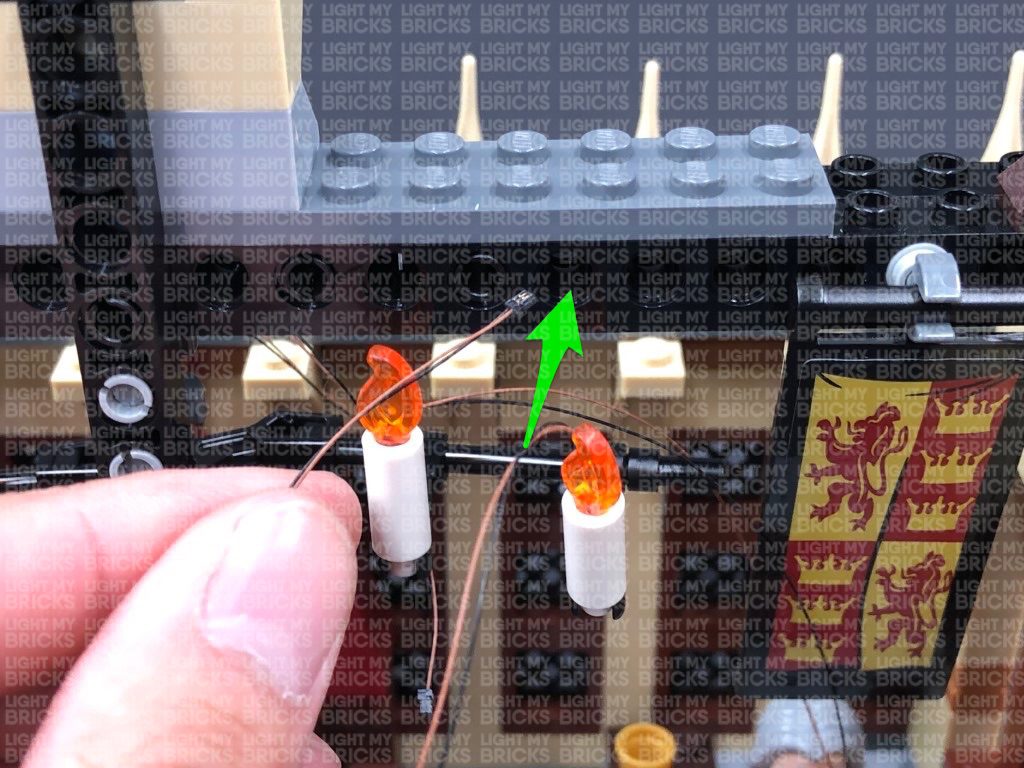
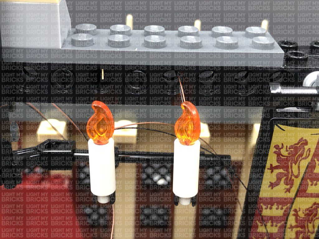
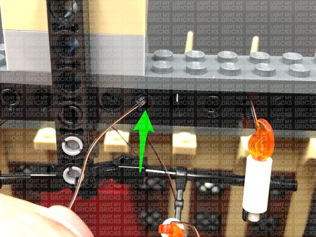
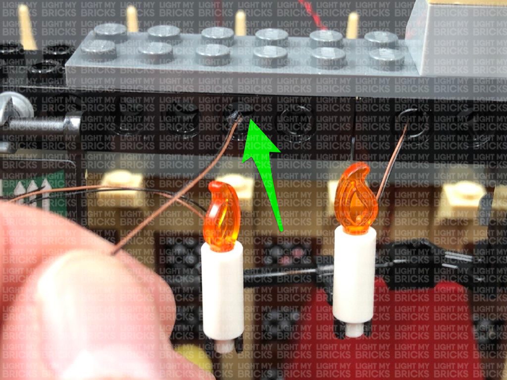
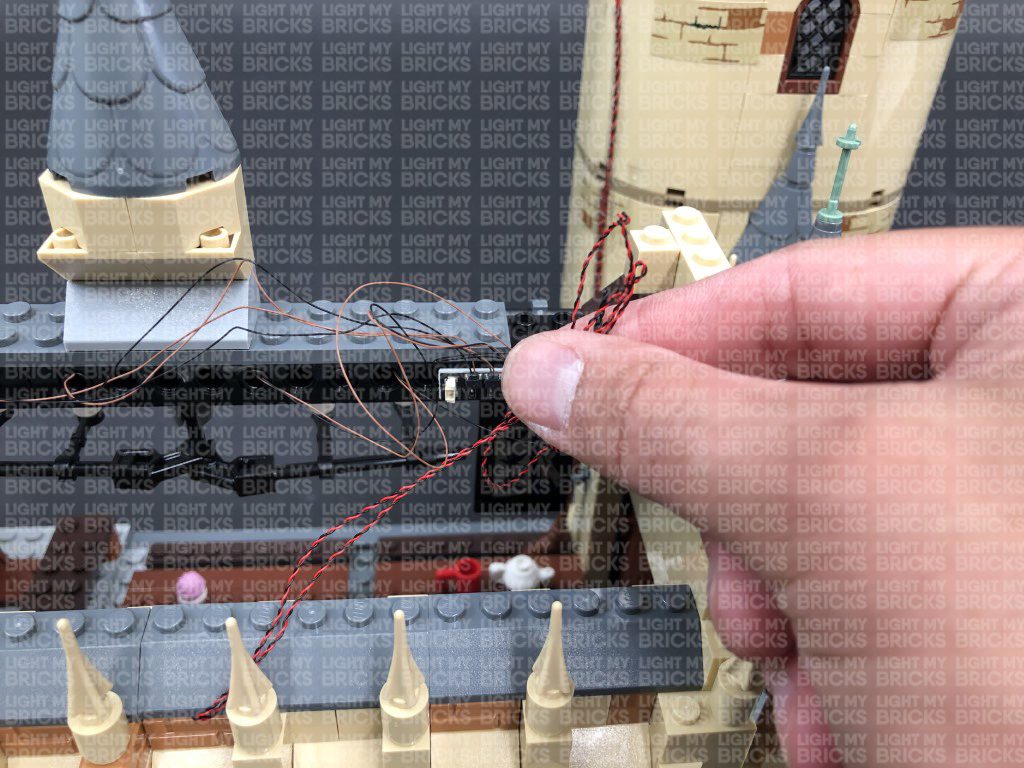
 31.) Reconnect the candle frame section to the Great Hall roof, then thread each candle light cable through the following holes of the black technic brick above.
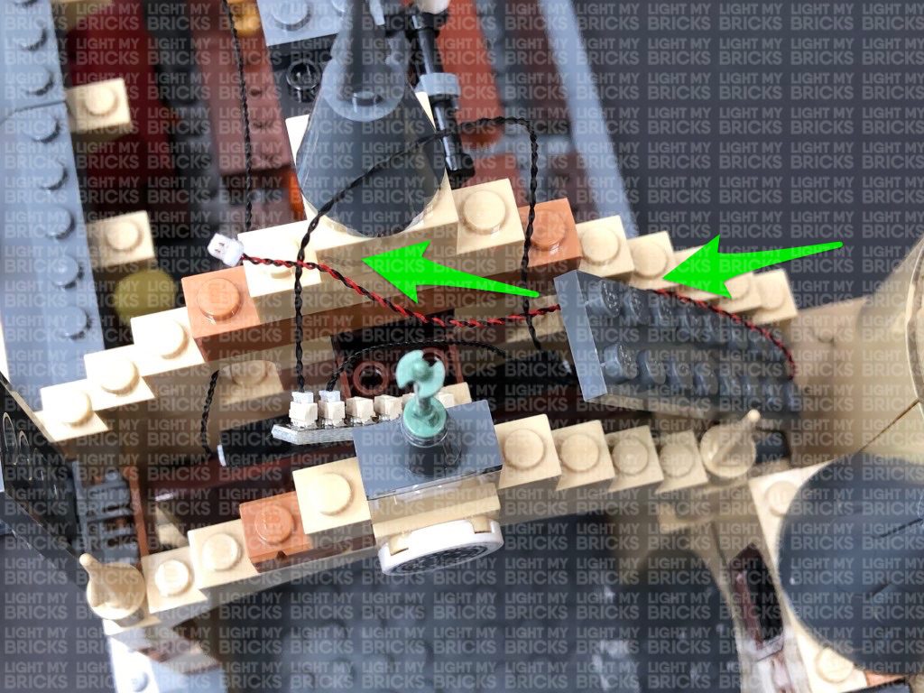
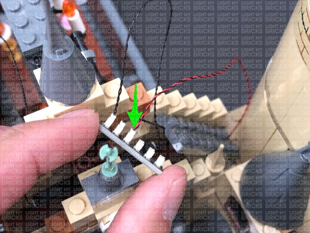
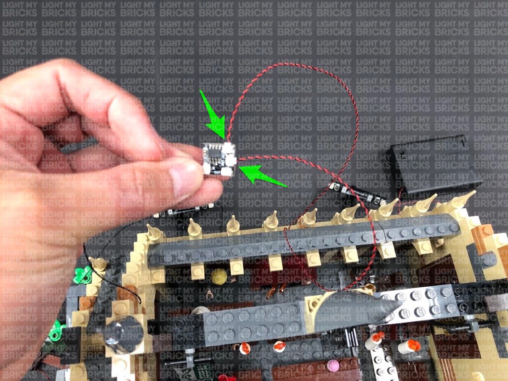
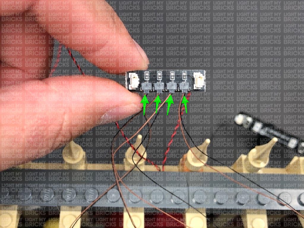
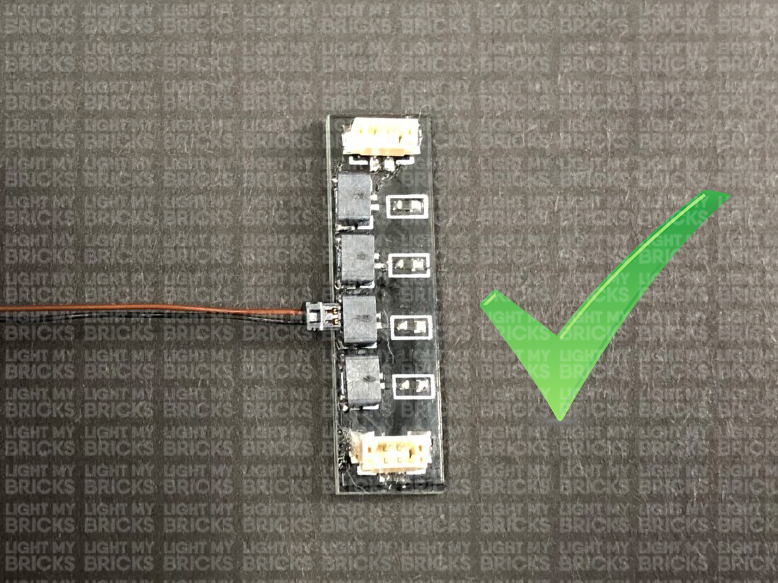
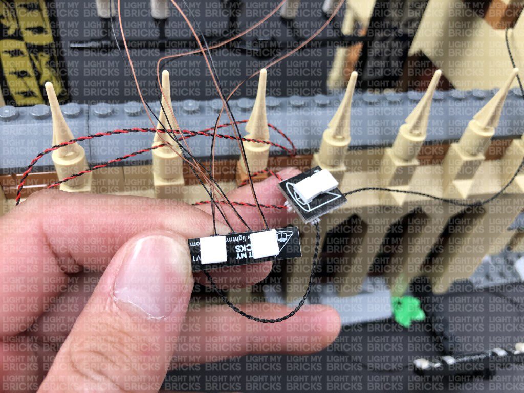
 32.) Connect each Micro Bit Light to the ports on the Micro 4-Port Expansion Board. Ensure you follow the below images to ensure you are connecting the light cables into each port correctly.
Take a 5cm Connecting Cable and connect it to one of the larger ports on the Micro 4-Port Expansion Board. Connect the other end of the connecting cable to the remaining OUT port on the flicker effects board. Turn the AA Battery Pack ON to test the candle lights are working OK with the flickering effect.
Note: If you experience any issues with the lights not working and suspect an issue with a component, please try a different port on the expansion board to verify where the fault lies (with the light, expansion board, or effects board). To correct any issues with expansion board ports, please view the section addressing expansion board issues on our online troubleshooting guide.
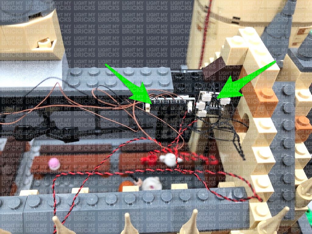
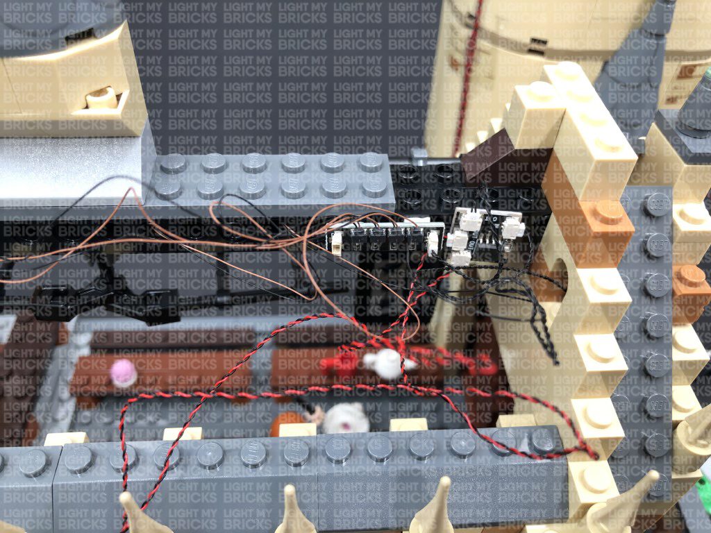
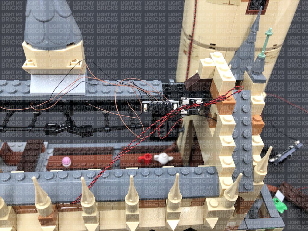
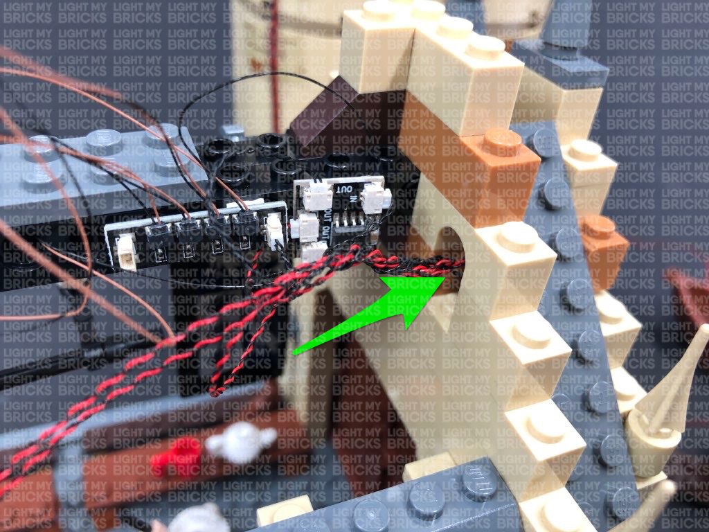
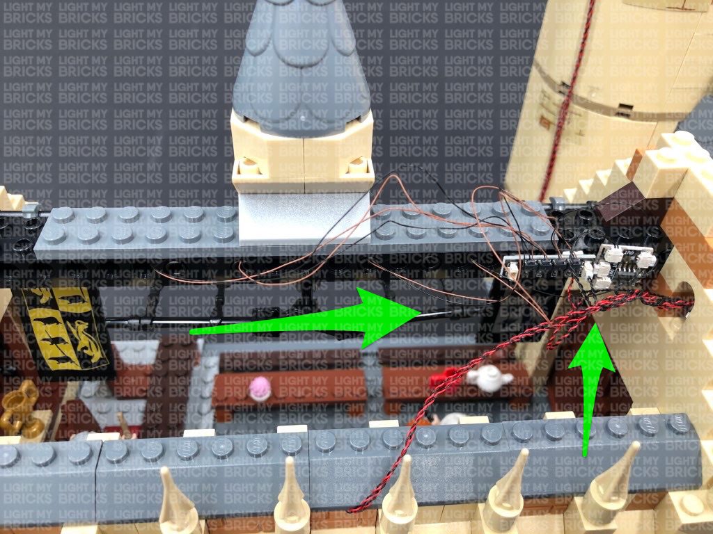
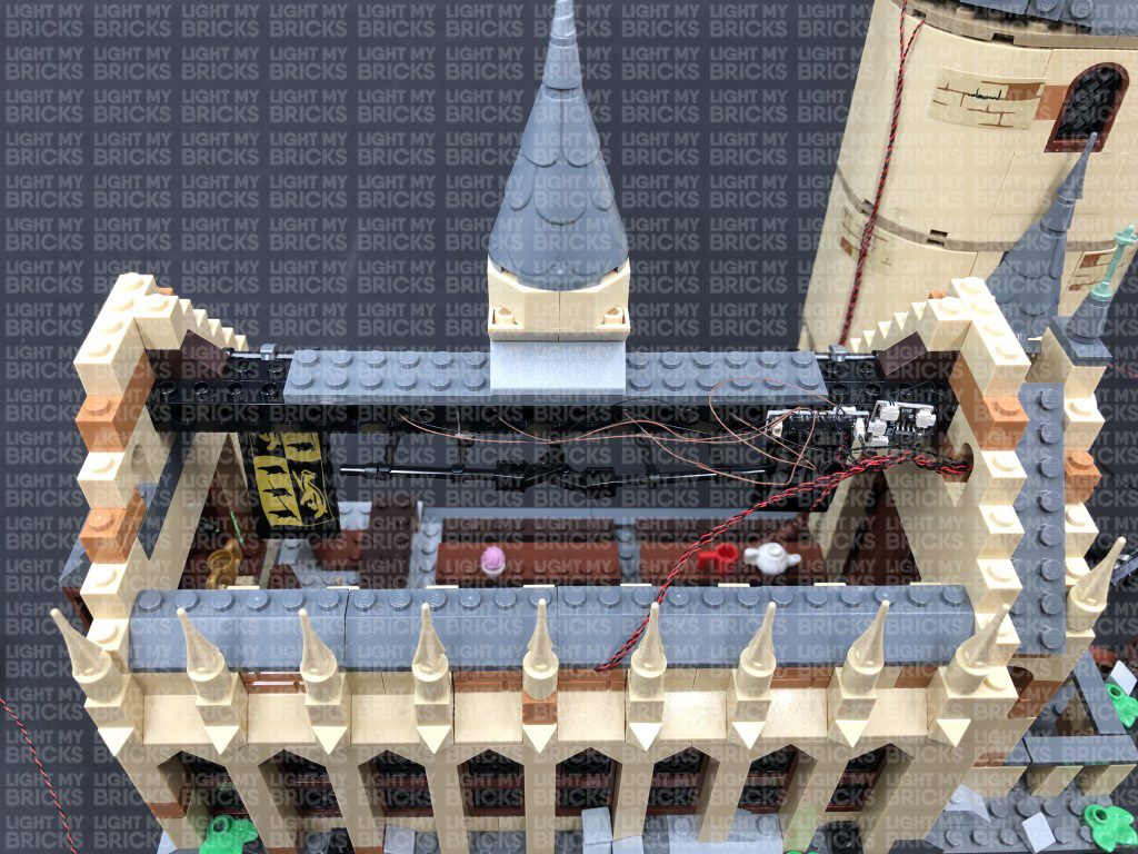
33.) Turn the set over to the front, then take 4x Adhesive Squares and stick two to the back of the Flicker Effects Board, and another two to the back of the Micro 4-Port Expansion Board. Mount the two boards to the right side of the black technic brick as shown below:
Neaten up the wiring by grouping the two bit light cables from the fireplace and twisting/folding them around each other into a neat bunch. Tuck the bunched up cables through the archway space on the right, then pull the micro bit light cables toward the right side as shown below. Do your best prevent any wiring from dangling down and being seen from the inside of the hall.
The last step is to reconnect the main roof section.
32.) Connect each Micro Bit Light to the ports on the Micro 4-Port Expansion Board. Ensure you follow the below images to ensure you are connecting the light cables into each port correctly.
Take a 5cm Connecting Cable and connect it to one of the larger ports on the Micro 4-Port Expansion Board. Connect the other end of the connecting cable to the remaining OUT port on the flicker effects board. Turn the AA Battery Pack ON to test the candle lights are working OK with the flickering effect.
Note: If you experience any issues with the lights not working and suspect an issue with a component, please try a different port on the expansion board to verify where the fault lies (with the light, expansion board, or effects board). To correct any issues with expansion board ports, please view the section addressing expansion board issues on our online troubleshooting guide.
33.) Turn the set over to the front, then take 4x Adhesive Squares and stick two to the back of the Flicker Effects Board, and another two to the back of the Micro 4-Port Expansion Board. Mount the two boards to the right side of the black technic brick as shown below:
Neaten up the wiring by grouping the two bit light cables from the fireplace and twisting/folding them around each other into a neat bunch. Tuck the bunched up cables through the archway space on the right, then pull the micro bit light cables toward the right side as shown below. Do your best prevent any wiring from dangling down and being seen from the inside of the hall.
The last step is to reconnect the main roof section.
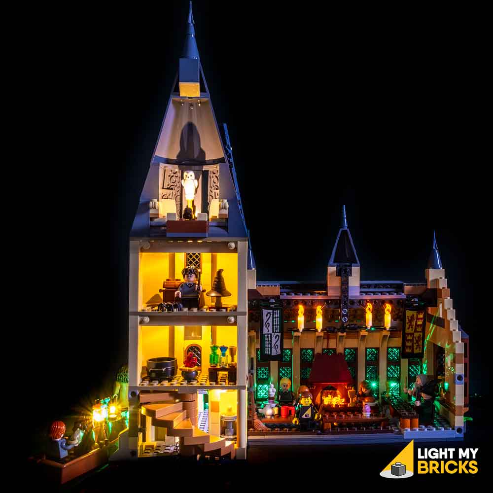
This finally completes installation of the Light My Bricks Hogwarts Great Hall Light Kit. We thank you for purchasing this product and hope you enjoy!