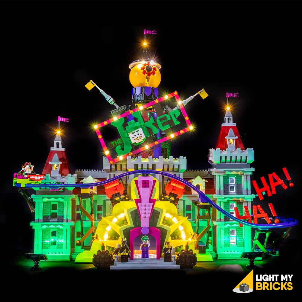
The following page is the instructions for the Light My Bricks LEGO Joker Manor (70922) LED light kit.
If you run into any issues, please refer to the online troubleshooting guide.
To ensure a trouble-free installation of your light kit, please read and follow each step carefully. These instructions can be downloaded in PDF format here
Please note: This page lists instructions for the LED light kit only. If you are wishing to purchase the Light My Bricks LEGO Joker Manor (70922) LED light kit , please click here to view the product page
Package Contents:
- 4x White 30cm Bit Lights
- 17x White 15cm Bit Lights
- 12x Flashing White 30cm Bit Lights
- 12x Flashing White 15cm Bit Lights
- 2x Blue 30cm Bit Lights
- 4x White 15cm Micro Bit Lights
- 8x White Strip Lights
- 1x Green Strip Lights
- 2x Multi Colour Strip Lights
- 1x Micro 4 Port Expansion Board
- 3x 6-Port Expansion Boards
- 3x 8-Port Expansion Boards
- 3x 12-Port Expansion Boards
- 1x Flicker Effects Board
- 4x 5cm Connecting Cables
- 8x 15cm Connecting Cables
- 9x 30cm Connecting Cable
- 1x USB Power Cable
- 6x Adhesive Squares
LEGO Pieces:
- 3x Trans Clear Round Plate 1×1
- 2x Trans Clear Plate w Rounded Bottom 2×2
- 2x Black Dish Inverted 3×3
- 2x Black Plate 2×6
- 2x Black Plate 1×2 modified w Handle on End
- 2x Black Tile 1×1 w Clip
- 4x Black Plate 1×2 modified with stud jumper
Important things to note:
Laying cables in between and underneath bricks
Cables can fit in between and underneath LEGO® bricks, plates, and tiles providing they are laid correctly between the LEGO® studs. Do NOT forcefully join LEGO® together around cables; instead ensure they are laying comfortably in between each stud.
Connecting cable connectors to Expansion Boards
Take extra care when inserting connectors to ports of Expansion Boards. Connectors can be inserted only one way. With the expansion board facing up, look for the soldered “=” symbol on the left side of the port. The connector side with the wires exposed should be facing toward the soldered “=” symbol as you insert into the port. If a plug won’t fit easily into a port connector, do not force it.
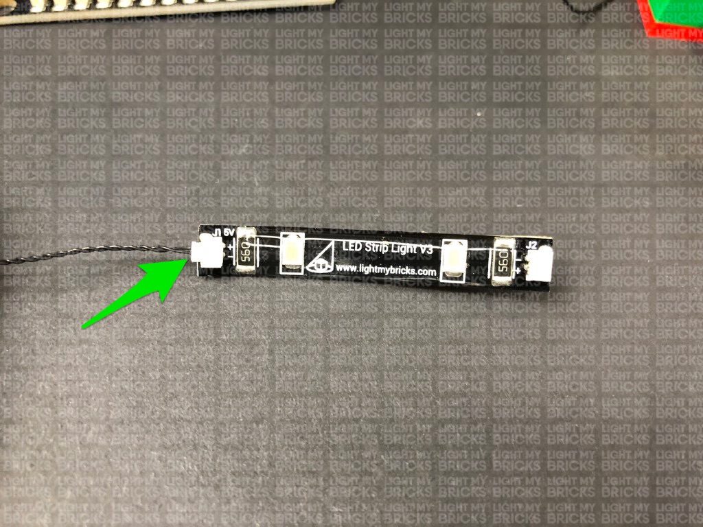
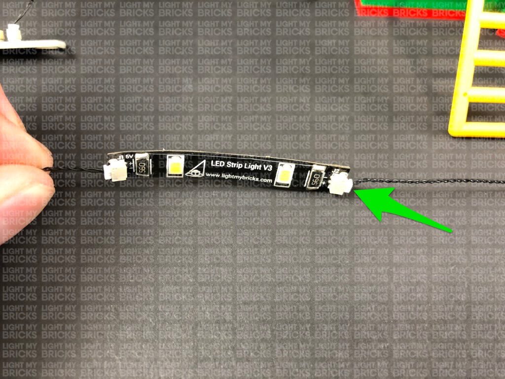
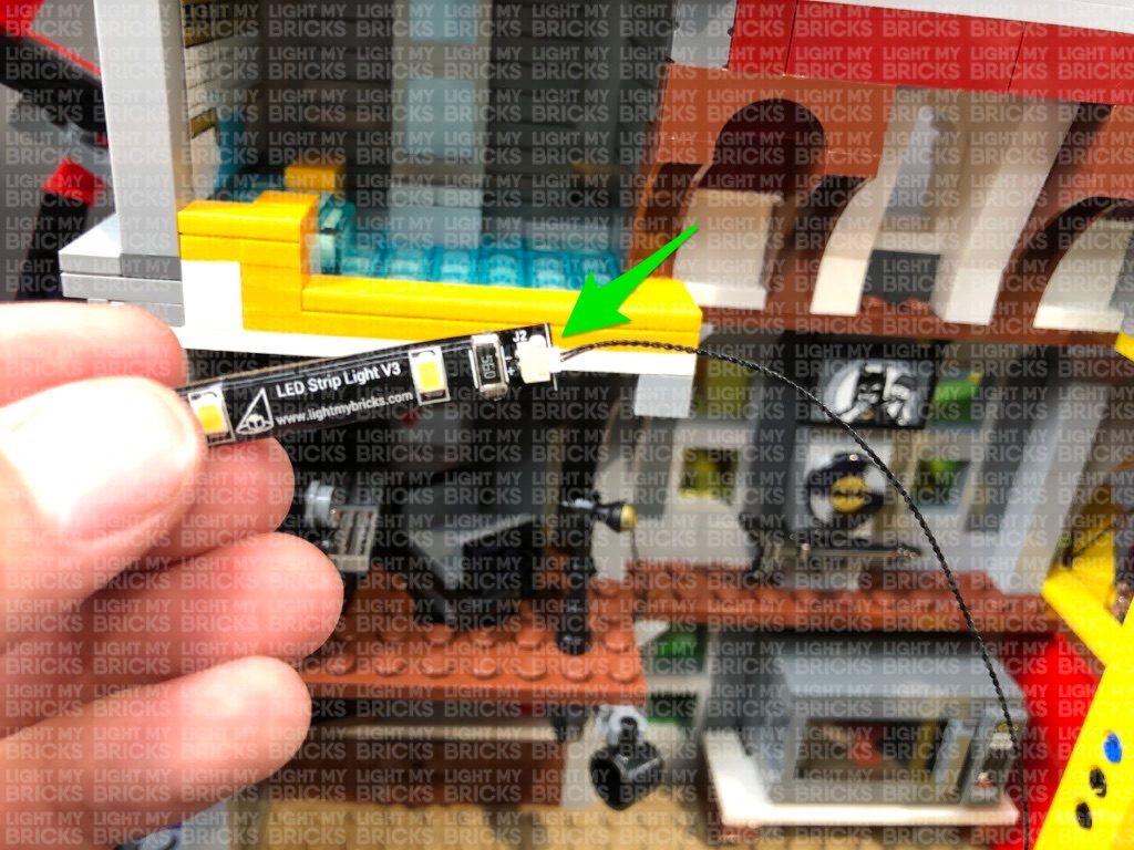
Connecting cable connectors to Strip Lights
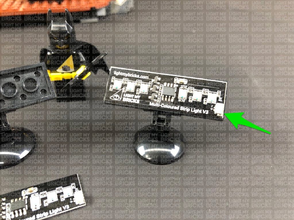
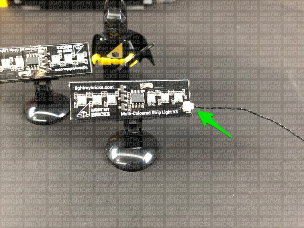
Take extra care when inserting connectors to ports on the Strip Lights. Connectors can be inserted only one way. With the Strip Light facing up, ensure the side of the connector with the wires exposed is facing down. If a plug won’t fit easily into a port connector, don’t force it. Doing so will damage the plug and the connector.
Connecting micro cable connectors to Micro Expansion Board Ports
Take extra care when inserting the micro connectors to micro ports of Micro Expansion Boards. Connecting Micro Bit Lights to Micro Expansion Boards is similar to connecting lights and cables to Strip Lights. With the expansion board facing up, ensure the side of the connector with the wires exposed is facing down. If a plug won’t fit easily into a port connector, do not force it. Use your fingernail to push the plastic part of the connector to the micro port.
Installing Bit Lights under LEGO® bricks and plates.
When installing Bit Lights under LEGO® pieces, ensure they are placed the correct way up (Yellow LED component exposed). You can either place them directly on top of LEGO® studs or in between.
OK, Let’s Begin!
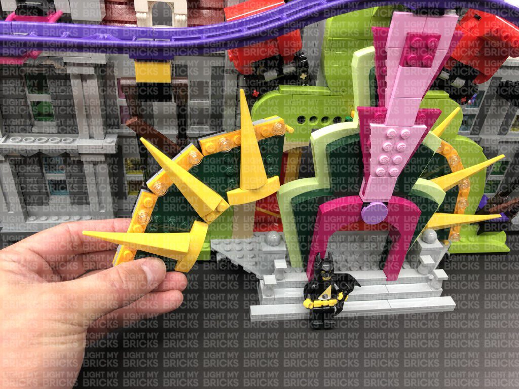
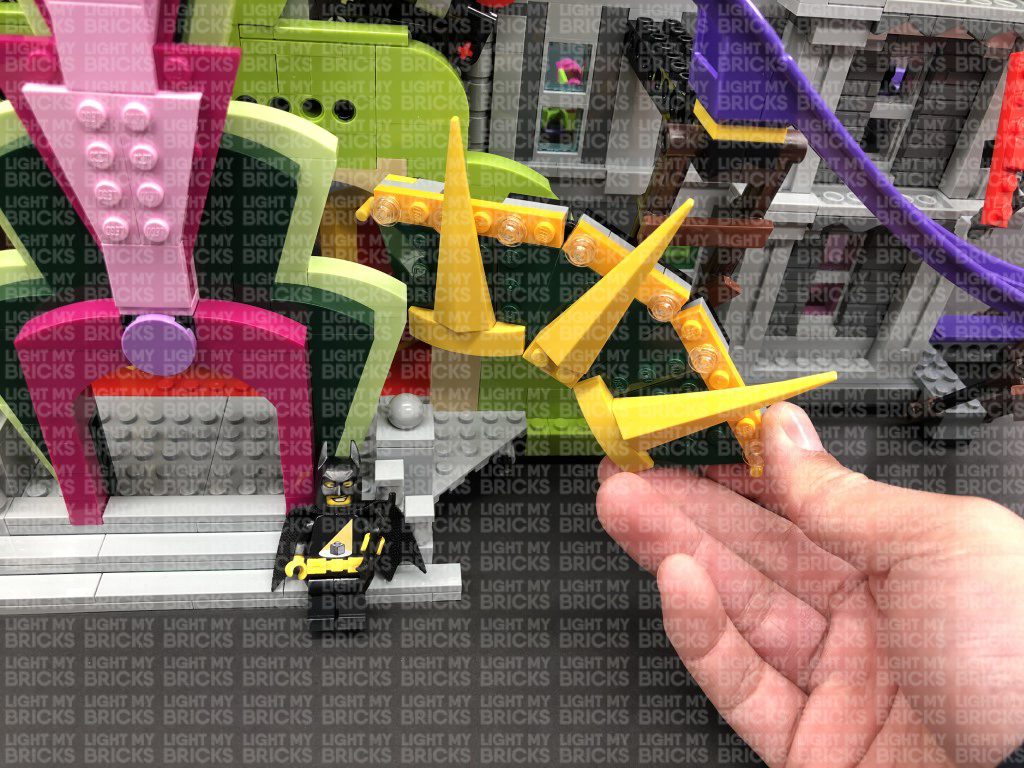
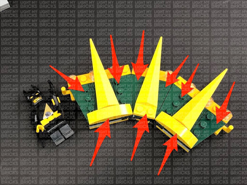
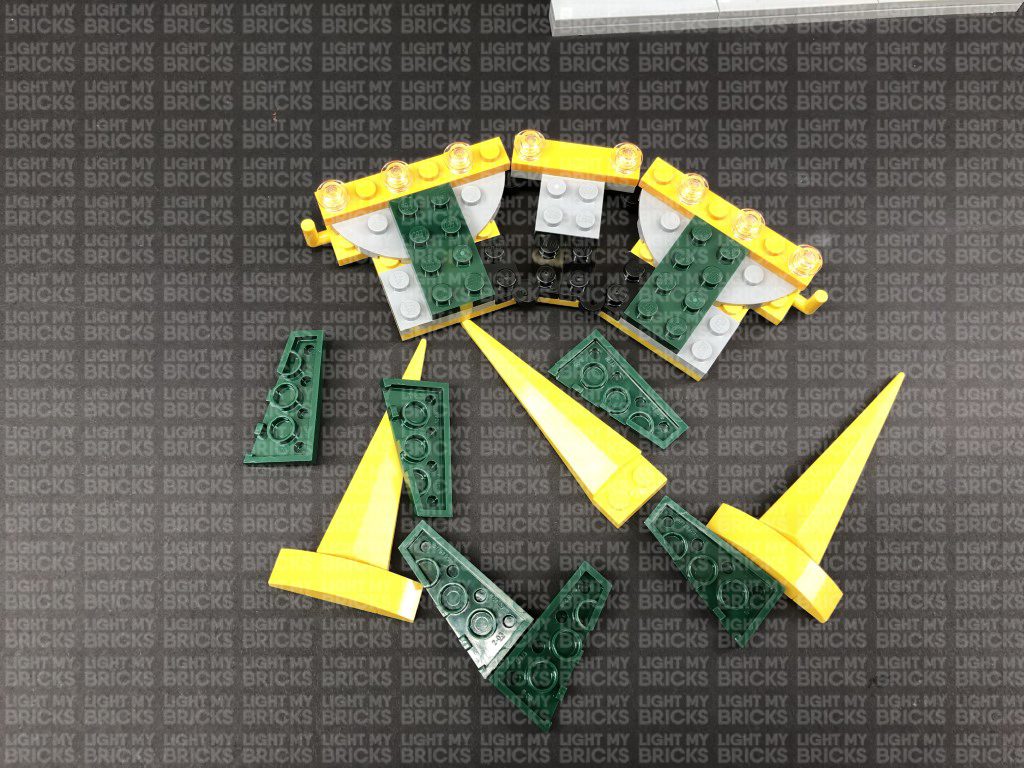
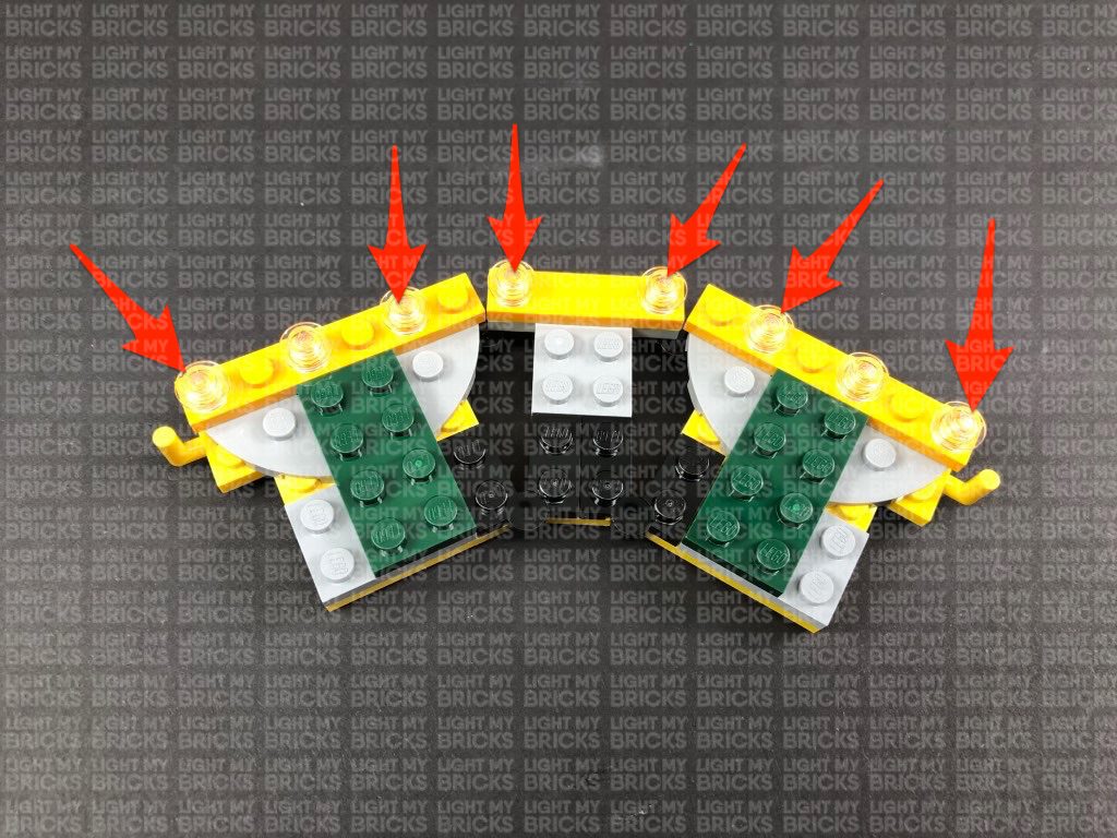
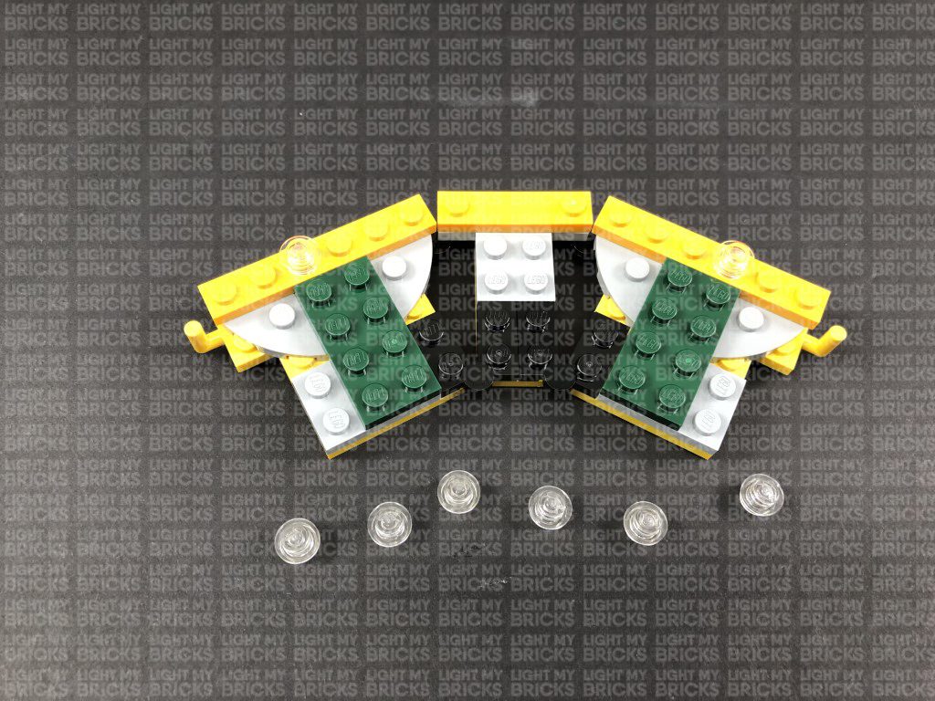
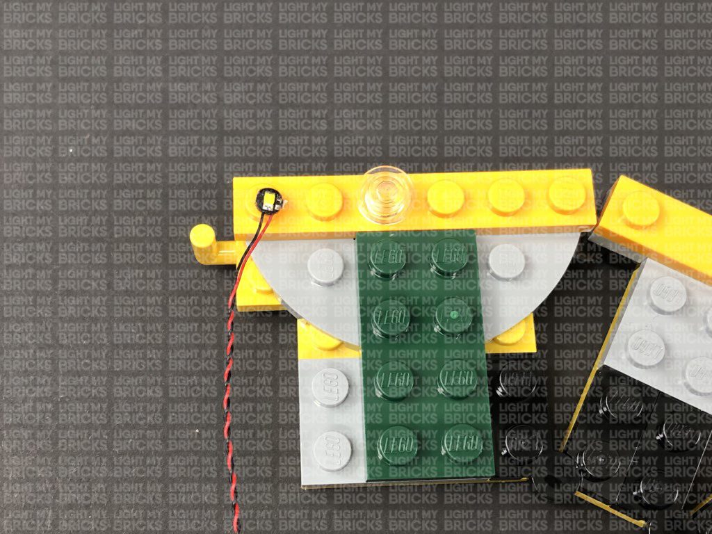
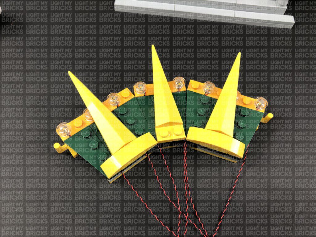
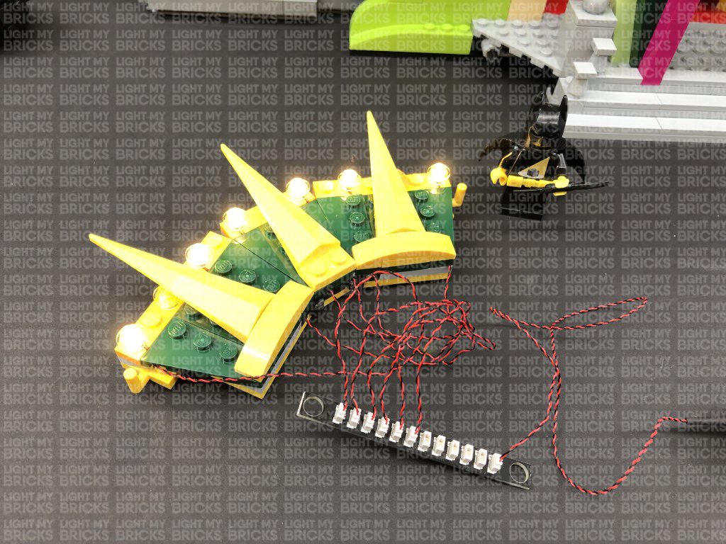
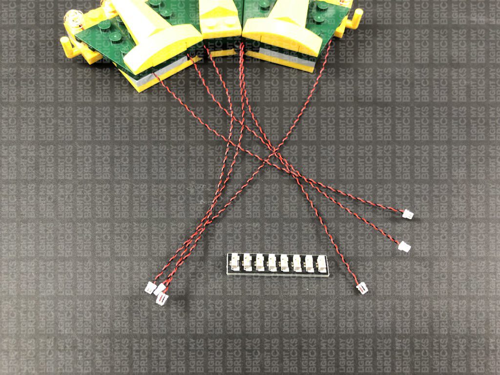
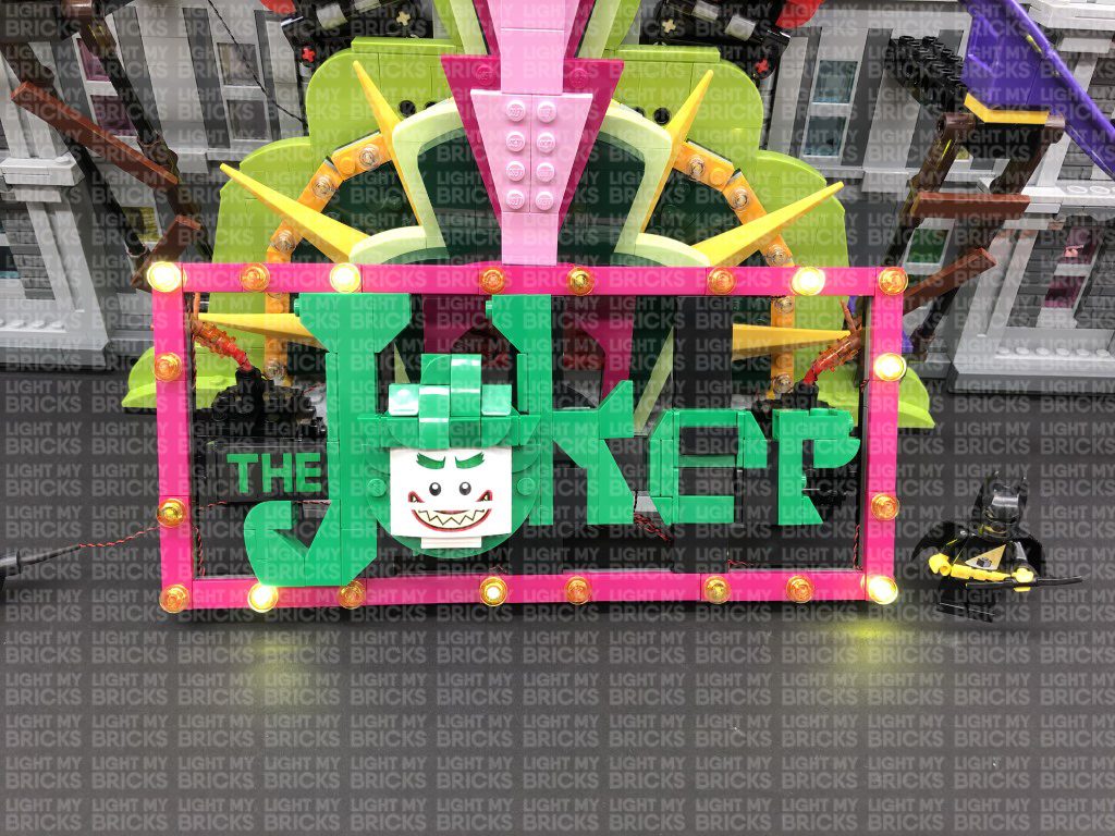
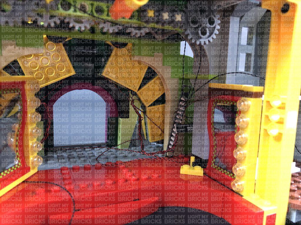
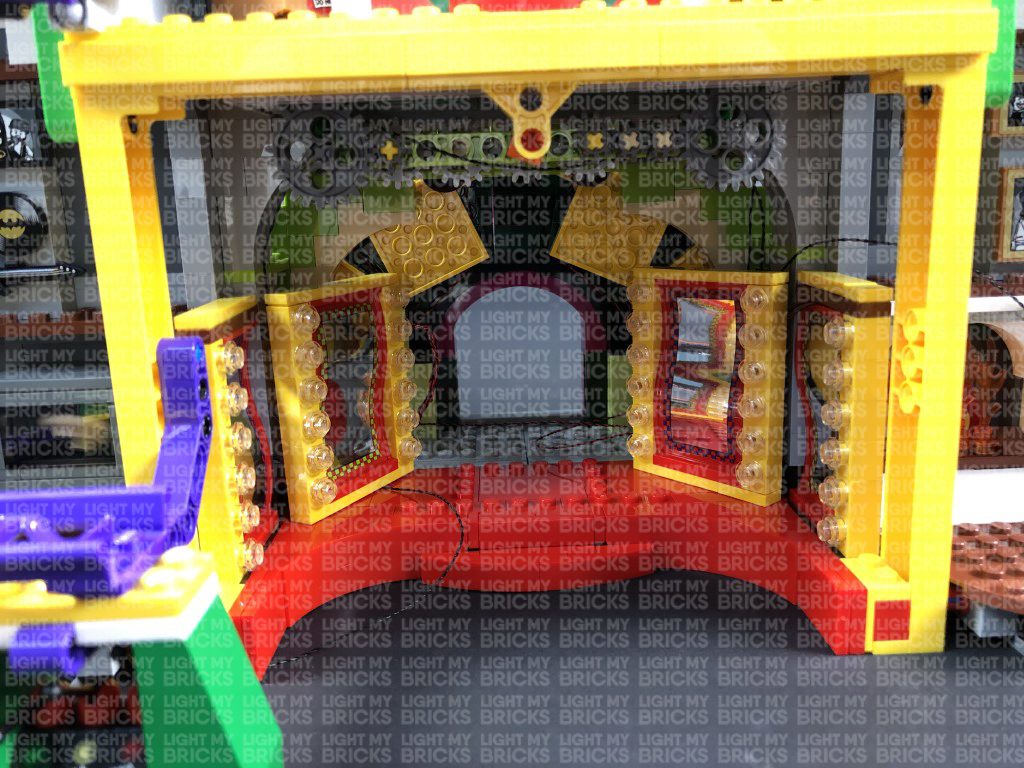
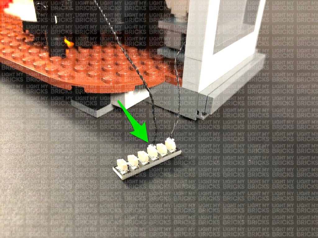
1.) We will start by lighting up the front entrance. First disconnect the cherry bombs on either side as well as the two light sections surrounding the entrance. 2.) Take the left light section and disconnect the following pieces as well as trans clear round plates: Take a White 15cm Bit Light and with the cable facing down, place it over the far left stud on this section. Secure the Bit Light in place by reconnecting one of the trans clear round plates over the top. 3.) Repeat previous step to install another 5x White 15cm Bit Lights to this section as shown below:
 Fold the cables down at the edge of the yellow plates, then reconnect the pieces we removed earlier. Folding the cables down will prevent them from snapping when you reconnect pieces over the top. Ensure the cables underneath plates are laid in between studs.
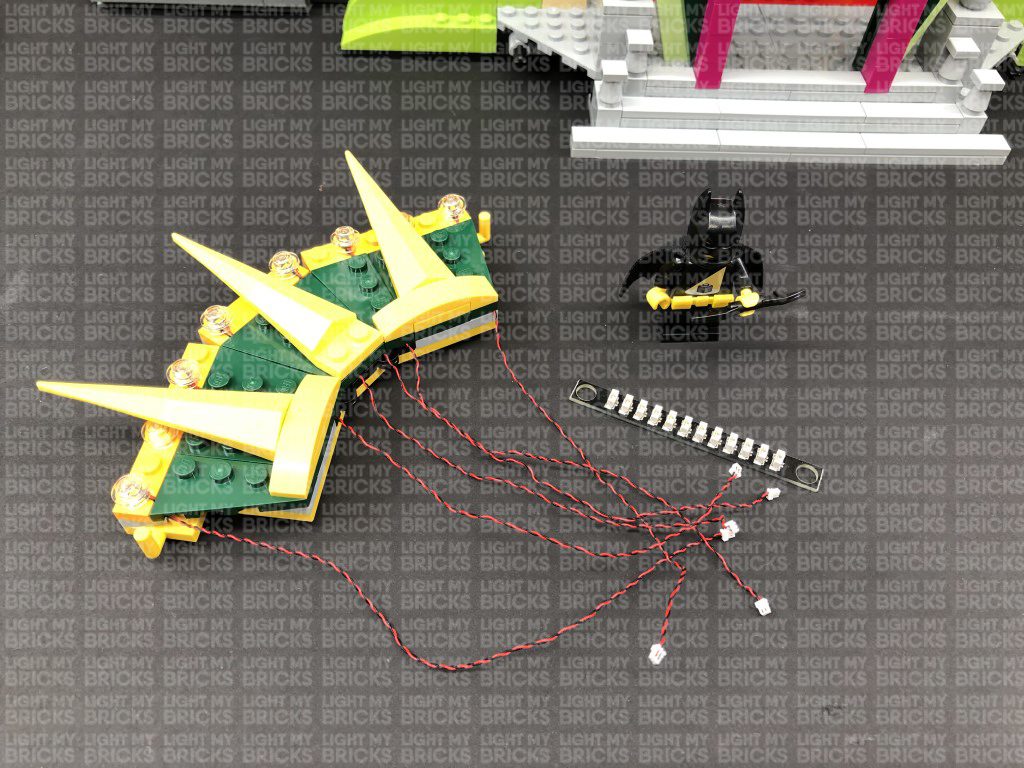
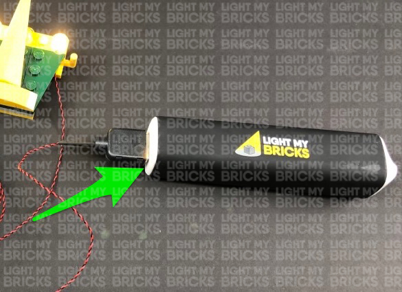
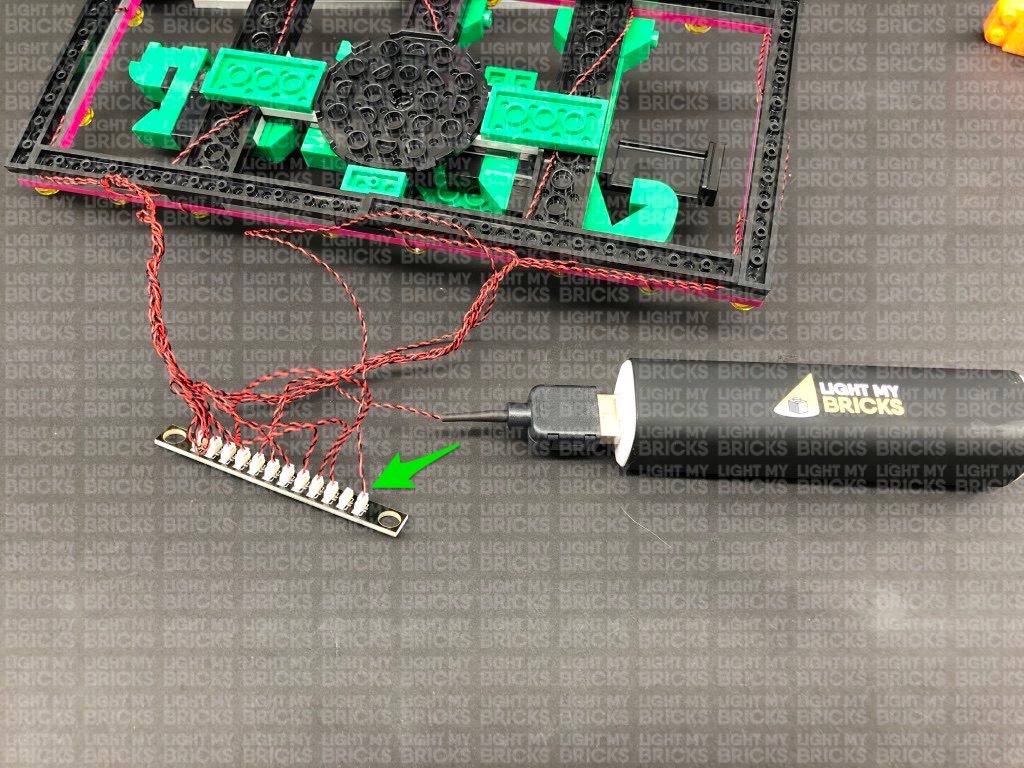
4.) Take a 12-Port Expansion Board and connect all six cables to it. Take a USB Power Cable and connect it to the expansion board, then connect the other end of it to your USB Power Bank (sold separately). Turn the power bank ON to test all lights are working OK.
Note: If you experience any issues with the lights not working and suspect an issue with a component, please try a different port on the expansion board to verify where the fault lies (with the light or expansion board). To correct any issues with expansion board ports, please view the section addressing expansion board issues on our online troubleshooting guide.
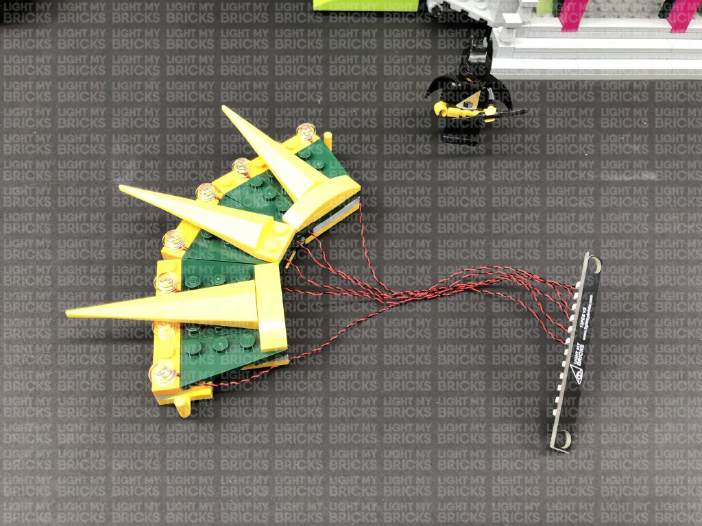
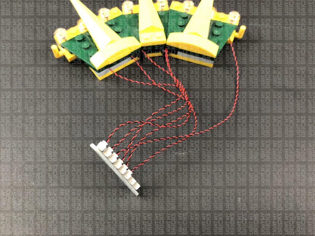
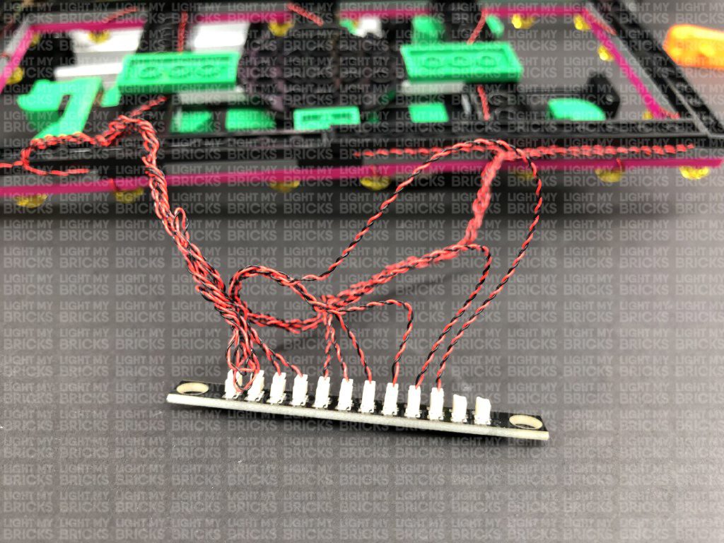
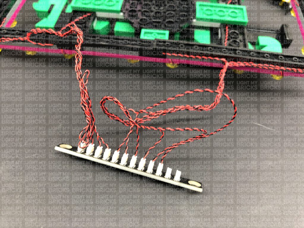
Disconnect the USB Power Cable from the expansion board, then turn the light section over and bring all six cables together and twist/wind them around each other closest to the top. Continue to twist/wind the cables all the way to the end so they come together to form a larger neat cable.
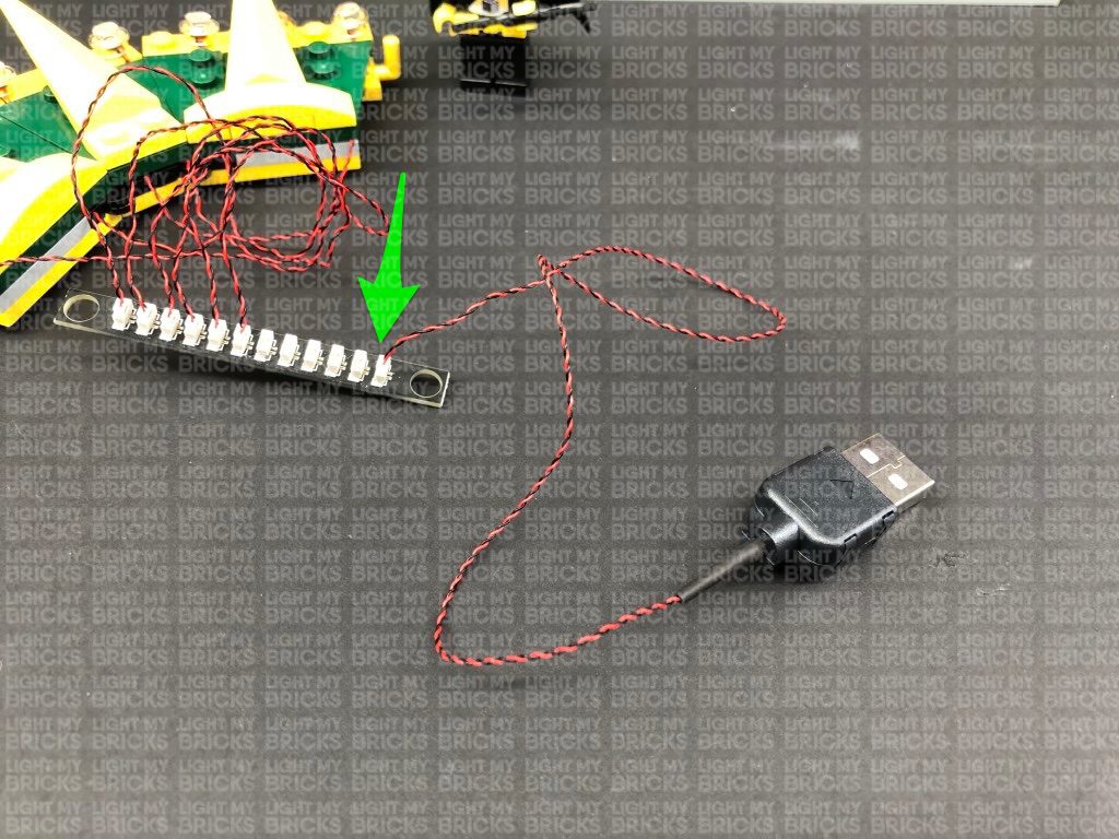
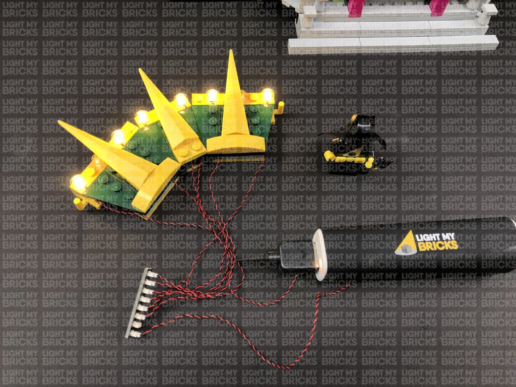
5.) Take 3x 30cm Connecting Cables and connect one end of each of them to the 12-port Expansion Board.
Take a Flicker Effects Board and connect a 5cm Connecting Cable to the IN port. Connect the other end of the cable to the 12-port expansion board.
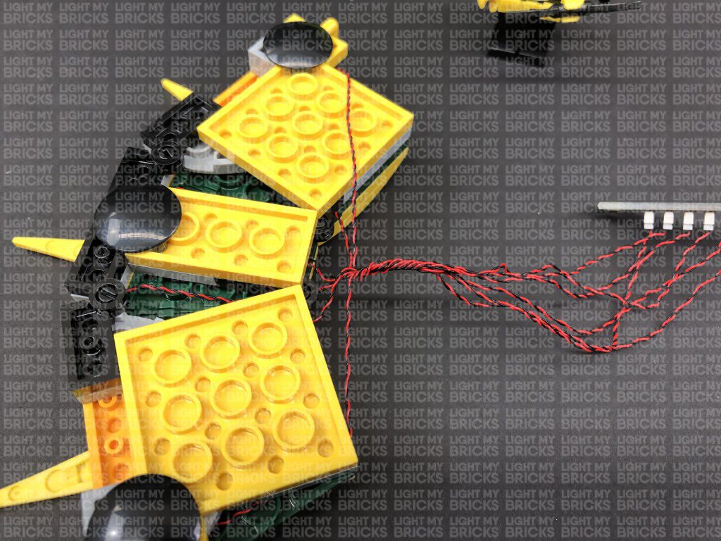
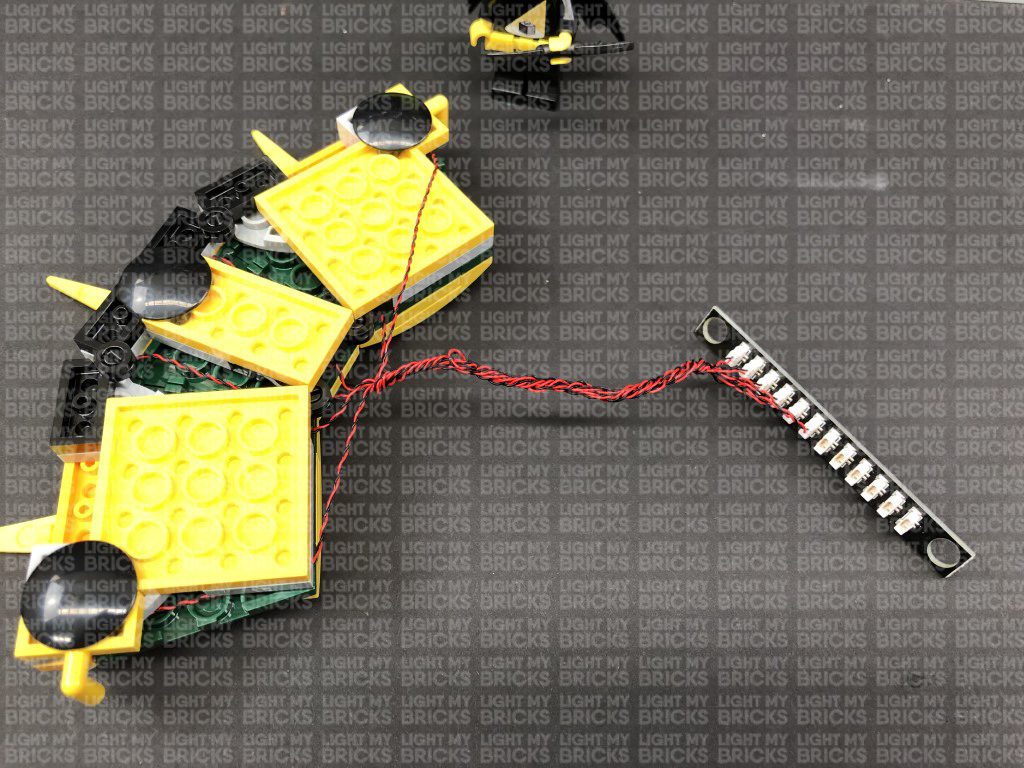
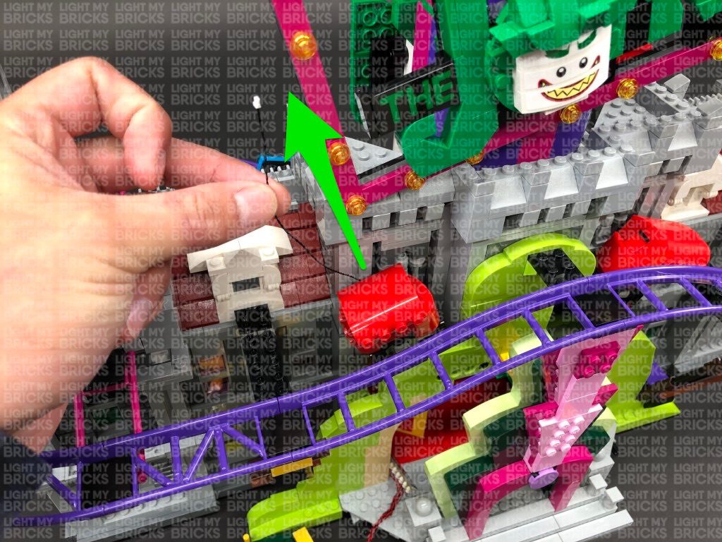
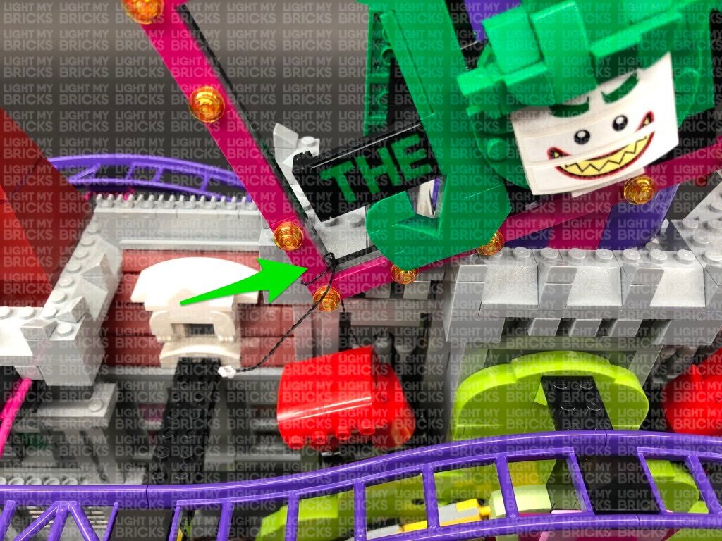
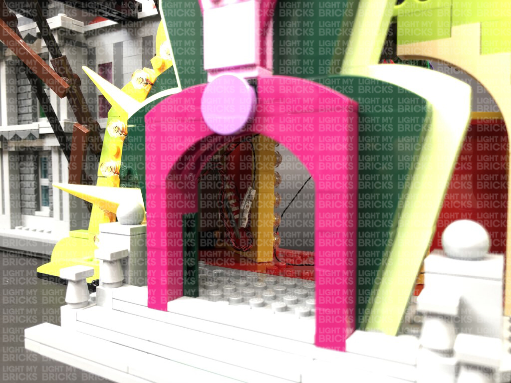
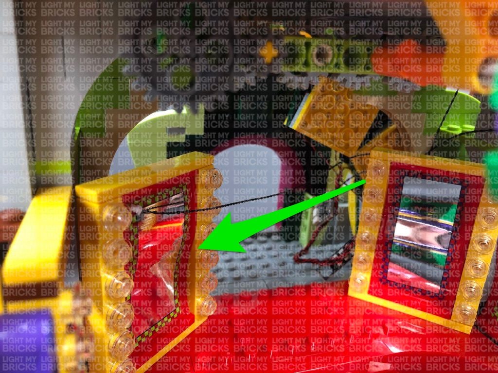
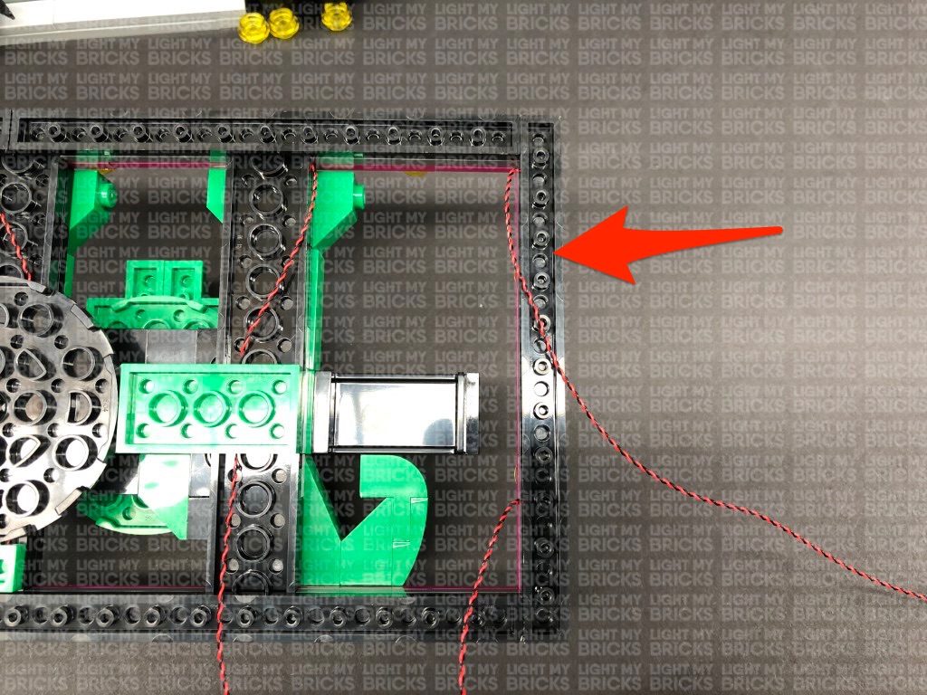
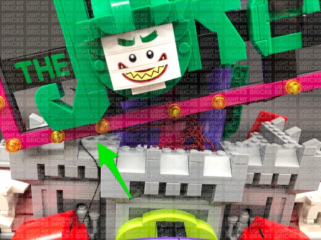
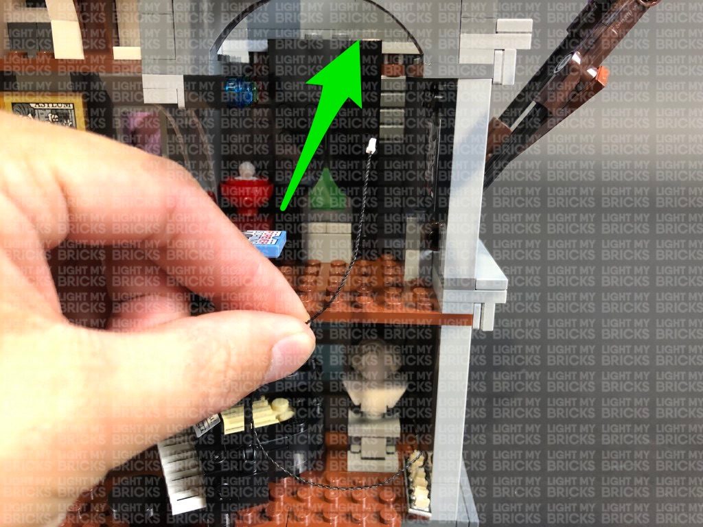
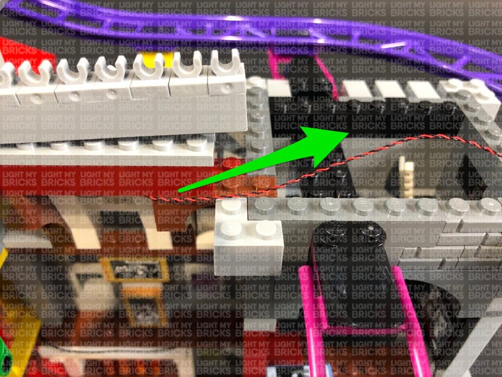
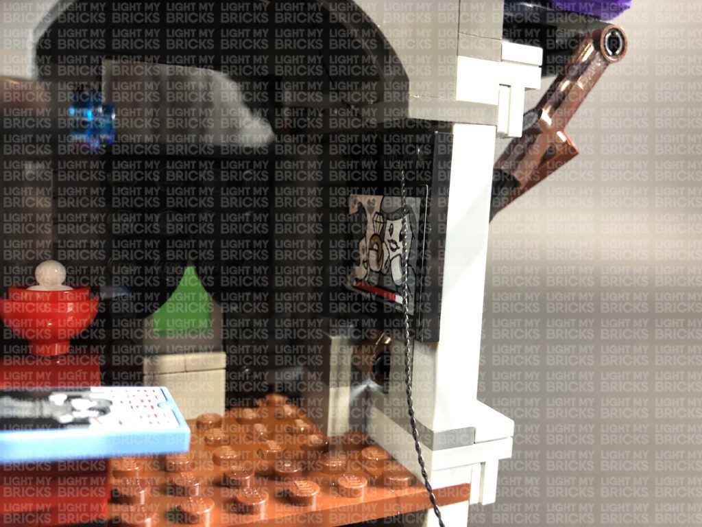
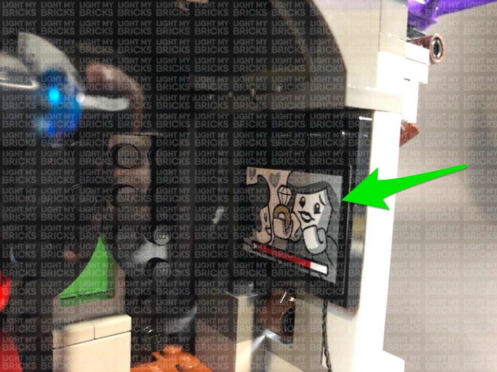
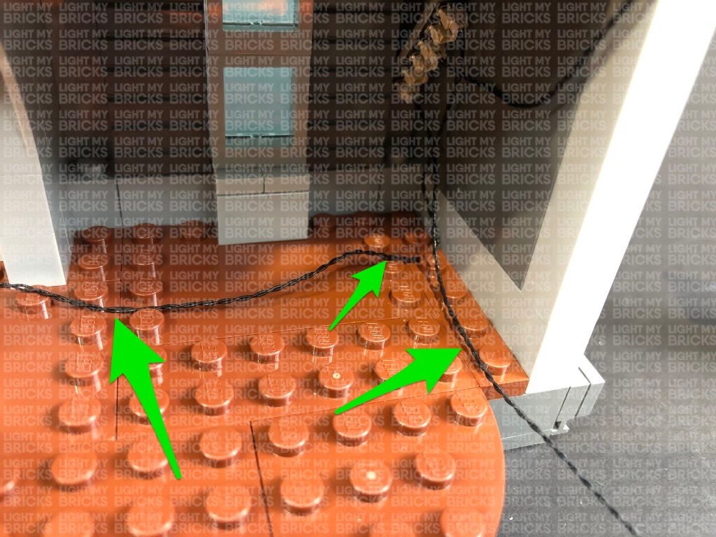
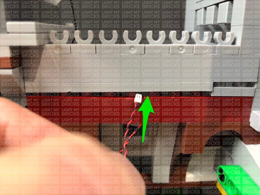
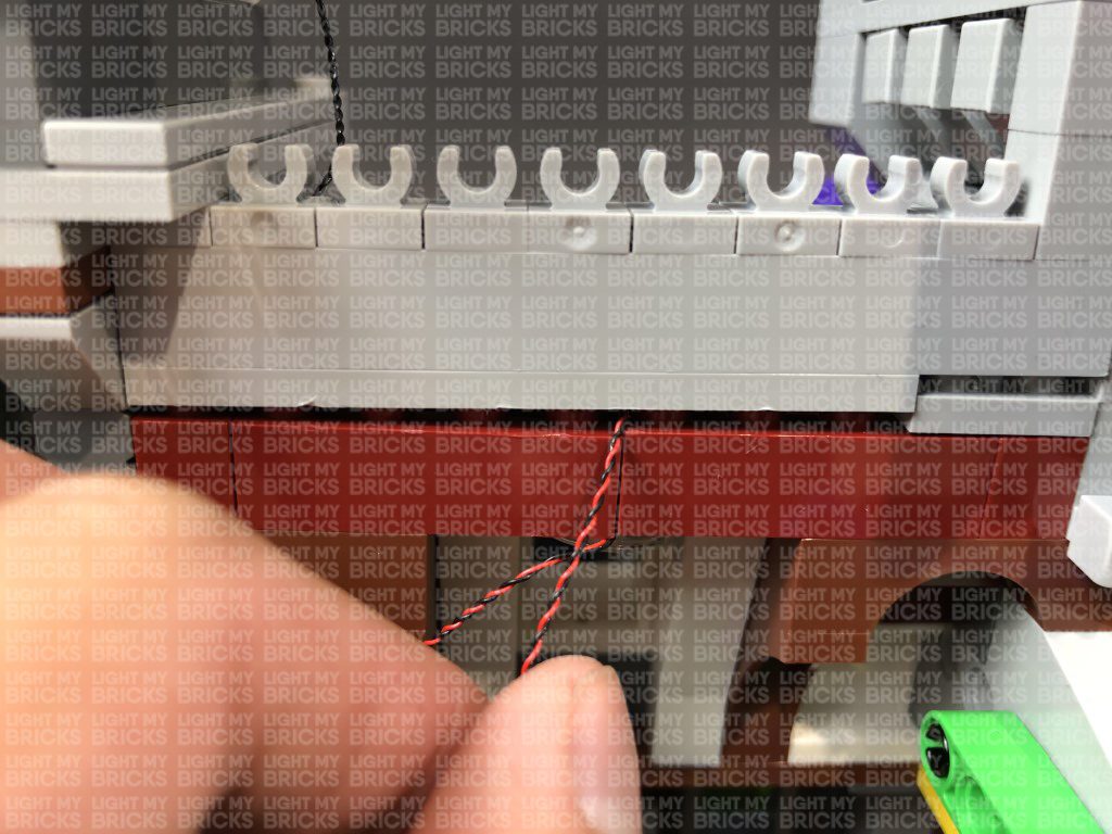
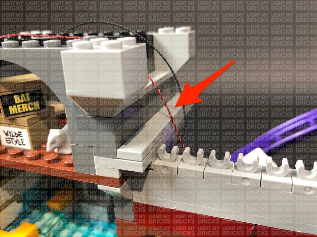
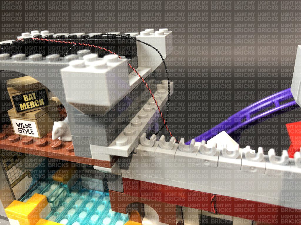
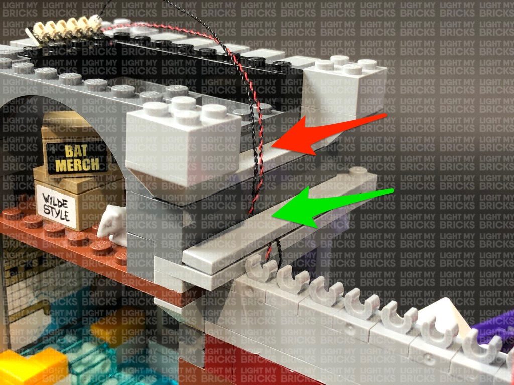
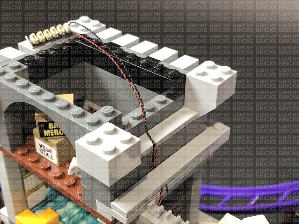
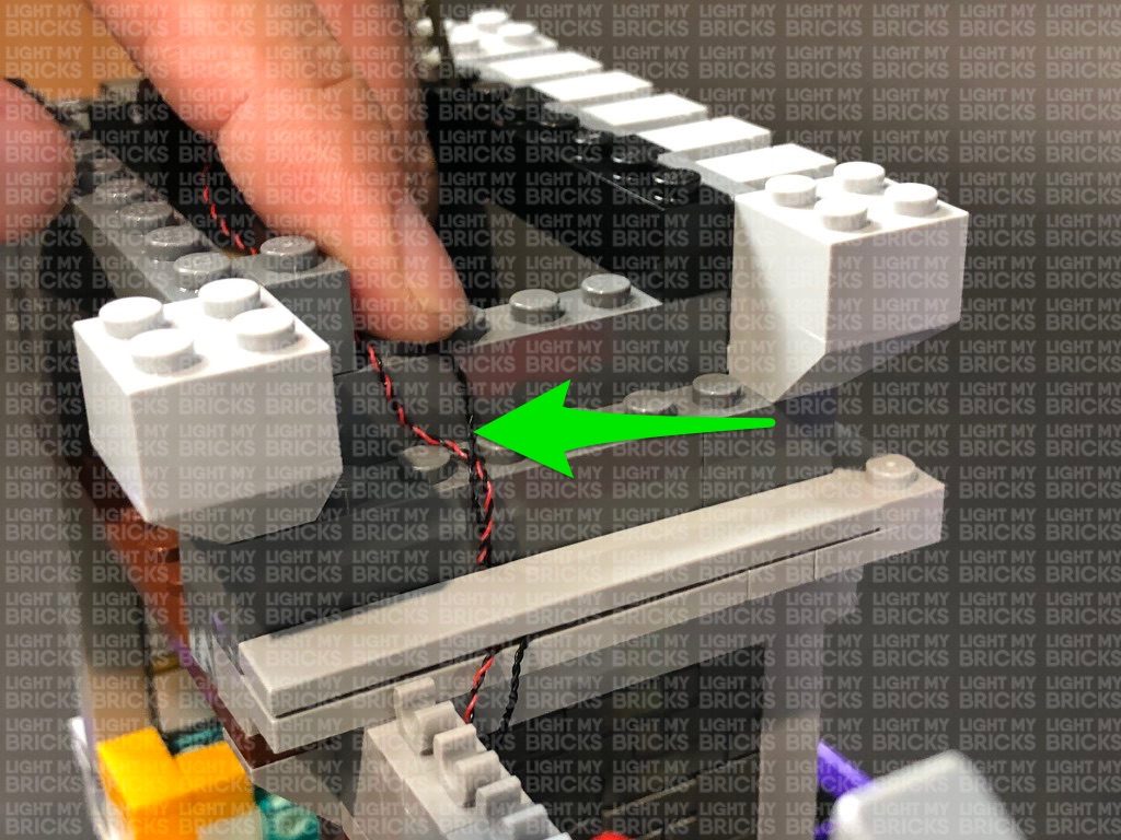
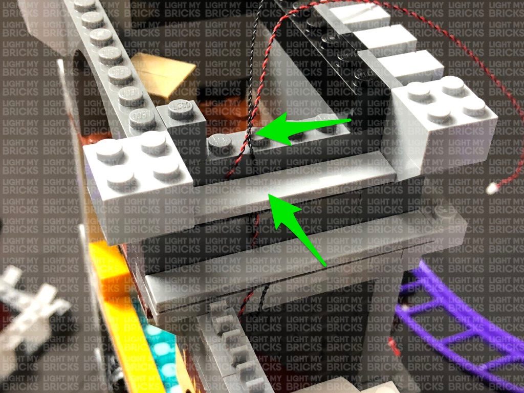
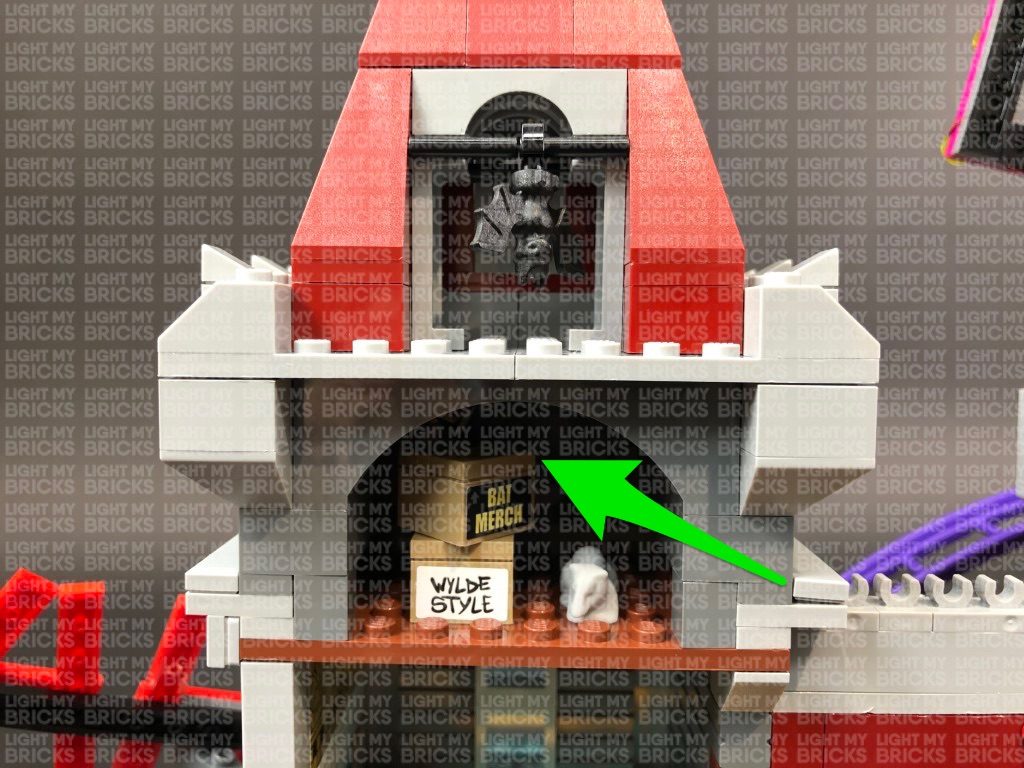
6.) Take the other of the last 30cm Connecting Cable connected to the 12-port expansion board and thread it through the left side of the entrance space. Pull it out from the other side and pull it all the way up behind the left “boxing glove”. Secure the cable underneath the bottom of the “Joker” sign by looping it around the frame a few times. Reconnect the left light section of the entrance using the clip on top as shown below:
Fold the cables down at the edge of the yellow plates, then reconnect the pieces we removed earlier. Folding the cables down will prevent them from snapping when you reconnect pieces over the top. Ensure the cables underneath plates are laid in between studs.
4.) Take a 12-Port Expansion Board and connect all six cables to it. Take a USB Power Cable and connect it to the expansion board, then connect the other end of it to your USB Power Bank (sold separately). Turn the power bank ON to test all lights are working OK.
Note: If you experience any issues with the lights not working and suspect an issue with a component, please try a different port on the expansion board to verify where the fault lies (with the light or expansion board). To correct any issues with expansion board ports, please view the section addressing expansion board issues on our online troubleshooting guide.
Disconnect the USB Power Cable from the expansion board, then turn the light section over and bring all six cables together and twist/wind them around each other closest to the top. Continue to twist/wind the cables all the way to the end so they come together to form a larger neat cable.
5.) Take 3x 30cm Connecting Cables and connect one end of each of them to the 12-port Expansion Board.
Take a Flicker Effects Board and connect a 5cm Connecting Cable to the IN port. Connect the other end of the cable to the 12-port expansion board.
6.) Take the other of the last 30cm Connecting Cable connected to the 12-port expansion board and thread it through the left side of the entrance space. Pull it out from the other side and pull it all the way up behind the left “boxing glove”. Secure the cable underneath the bottom of the “Joker” sign by looping it around the frame a few times. Reconnect the left light section of the entrance using the clip on top as shown below:
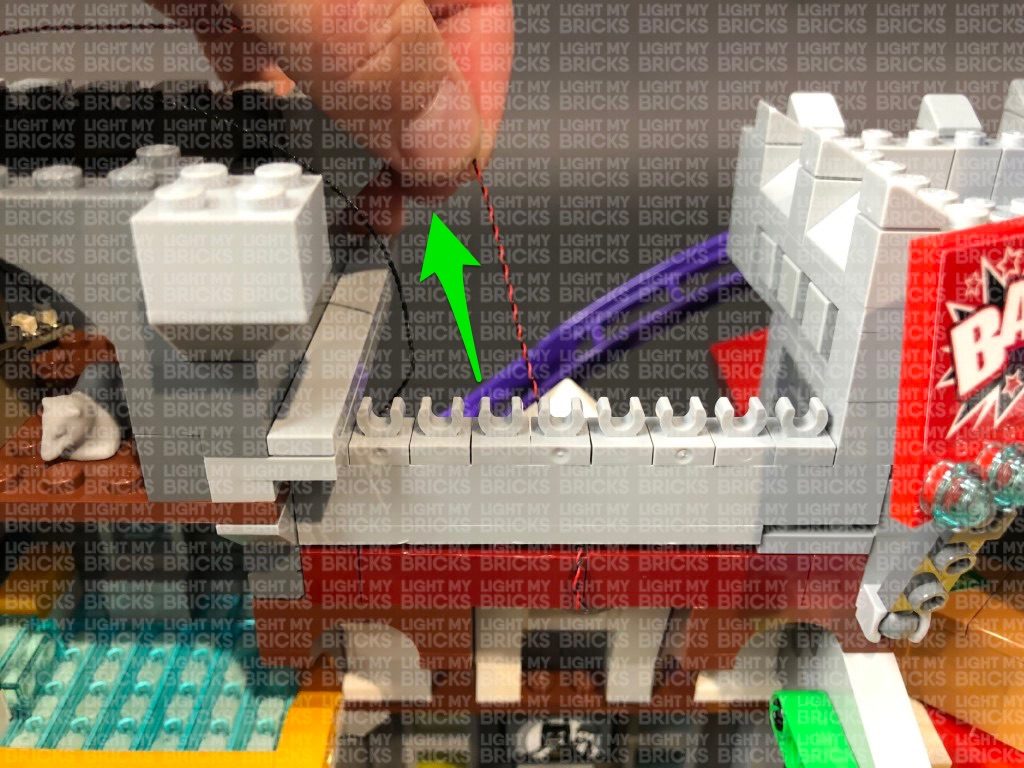
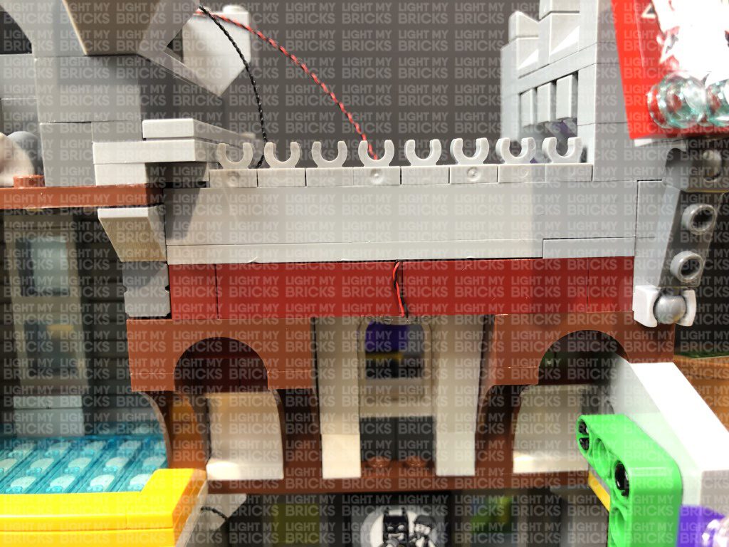
 Thread the other two 30cm Connecting Cables all the way through the entrance, then hide the expansion board and effects board toward the inside left.
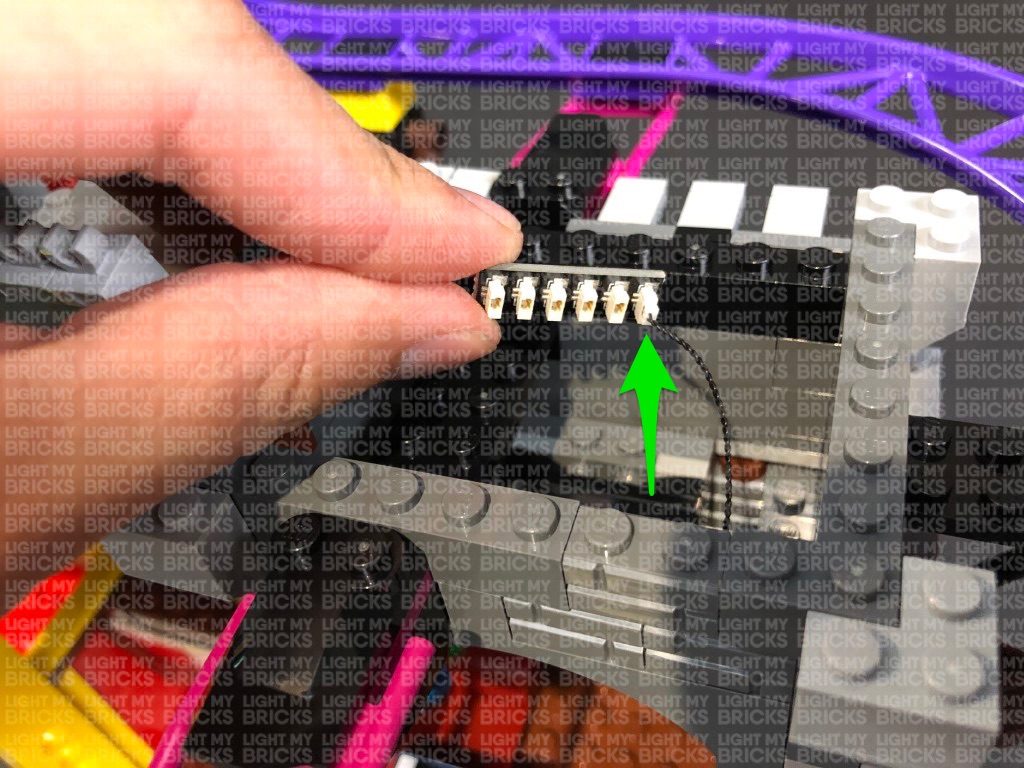
 7.) Repeat steps 2- 3 to install another 6x White 15cm Bit Lights to the right entrance light section.
8.) Take an 8-Port Expansion Board and connect all six bit light cables to it. Take your USB Power Cable and connect it to the expansion board, then connect the other end to your USB Power Bank to test the lights on this side are working OK.
Note: If you experience any issues with the lights not working and suspect an issue with a component, please try a different port on the expansion board to verify where the fault lies (with the light or expansion board). To correct any issues with expansion board ports, please view the section addressing expansion board issues on our online troubleshooting guide.
Disconnect the USB Power Cable from the expansion board, then turn the light section over and bring all six cables together and twist/wind them around each other closest to the top. Continue to twist/wind the cables all the way to the end so they come together to form a larger neat cable.
9.) Take a new 30cm Connecting Cable and connect it to the 8-port expansion board. Thread the other end of the cable through the entrance before reconnecting this right side section to the front of the building.
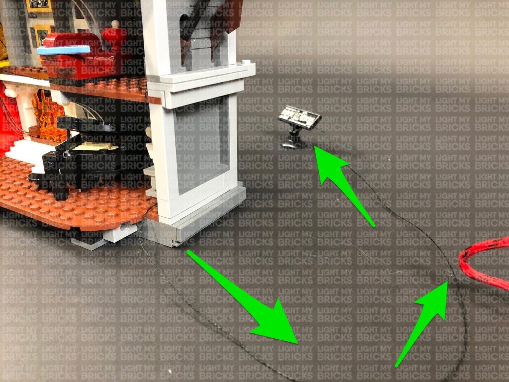
Turn the Joker Manor around to the back side and pull the other end of the 30cm Connecting Cable out and feed it toward the left underneath the roller coaster track. Connect the cable to a new 12-Port Expansion Board then connect the USB power Cable (connected to the USB Power Bank) to the expansion board.
10.) To make the installation of the lights to the back easier, disconnect the following roller coaster track sections.
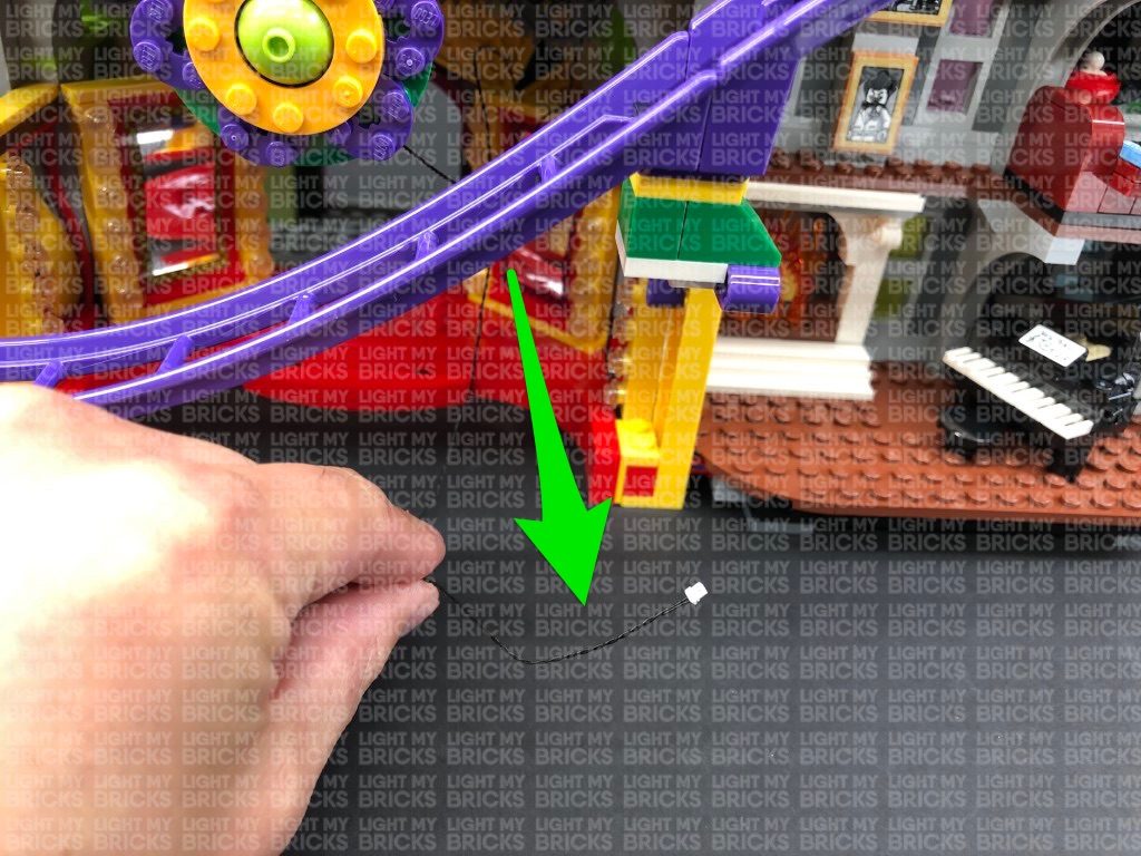
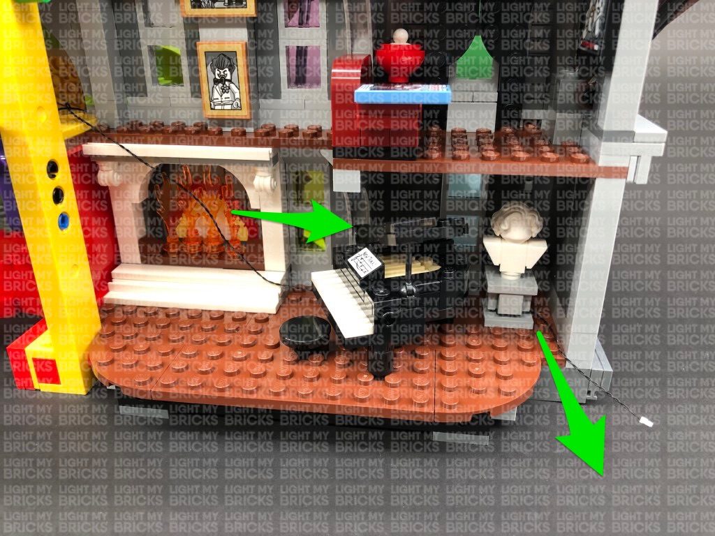
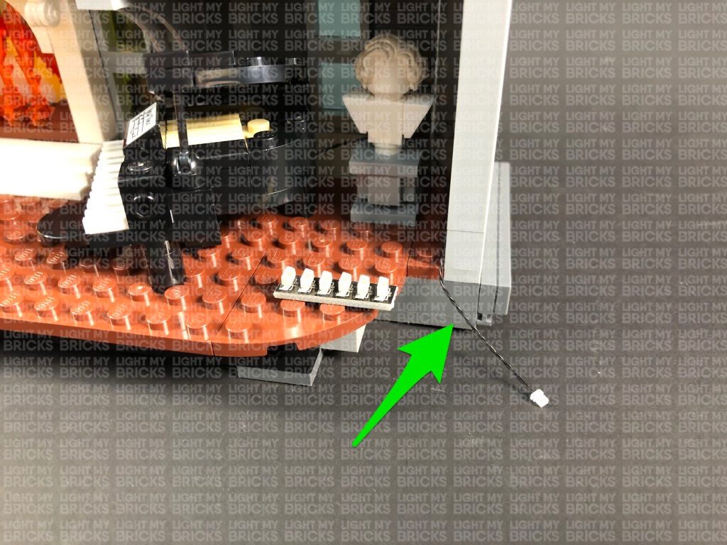
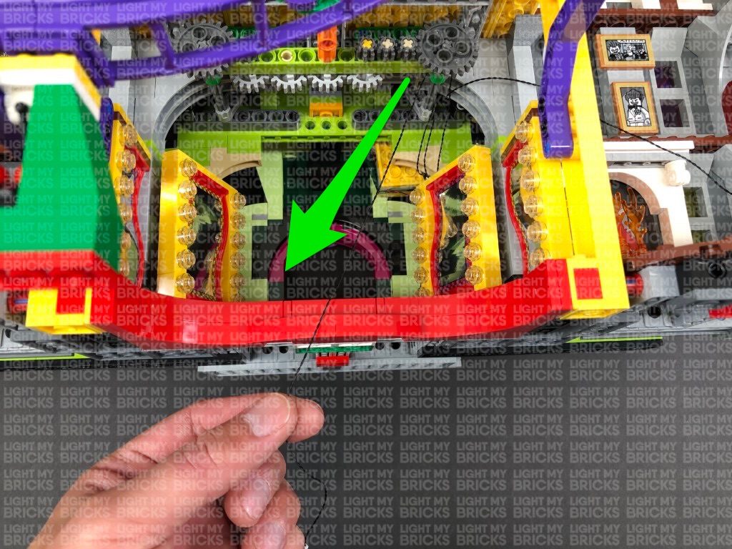
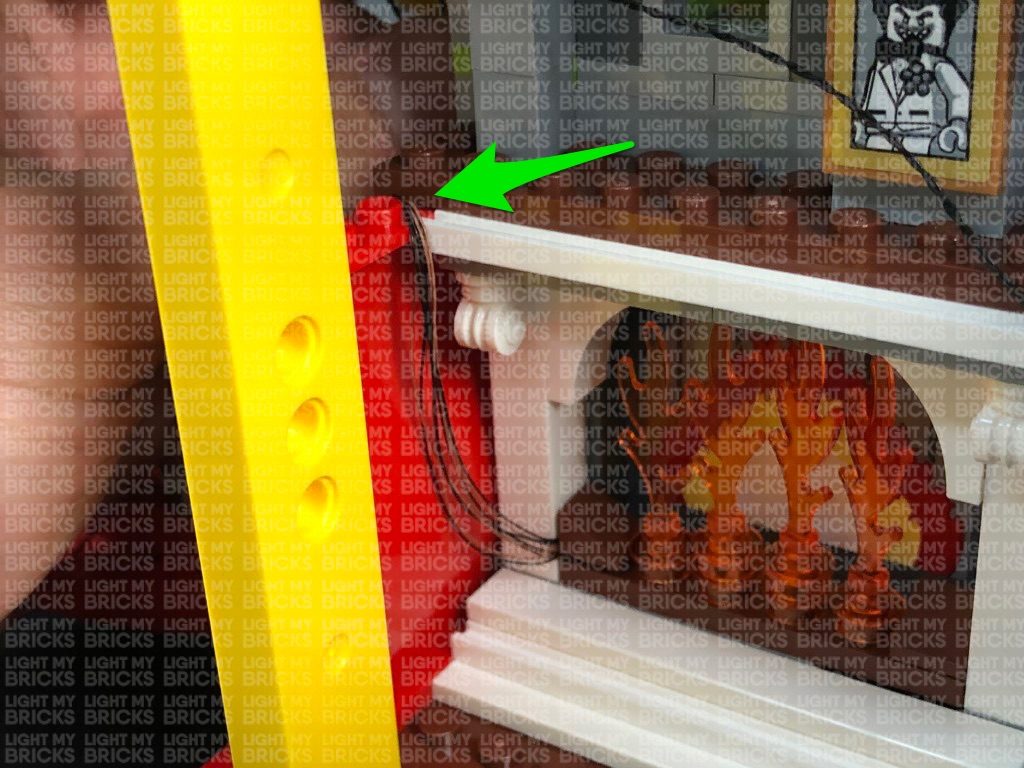
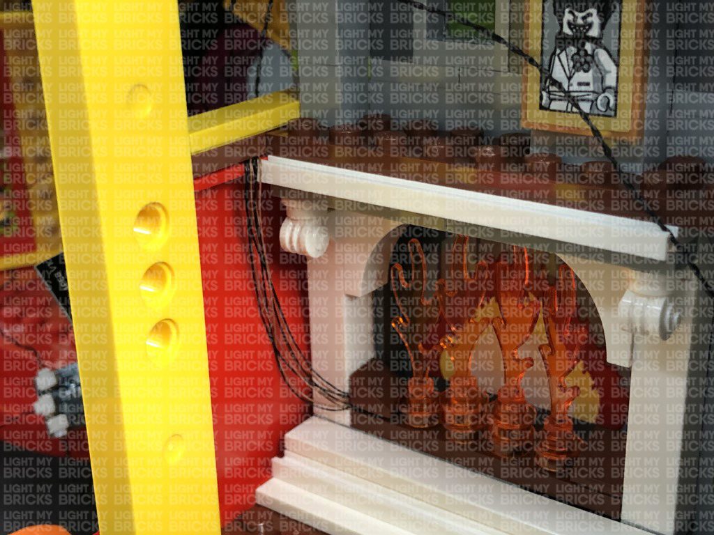
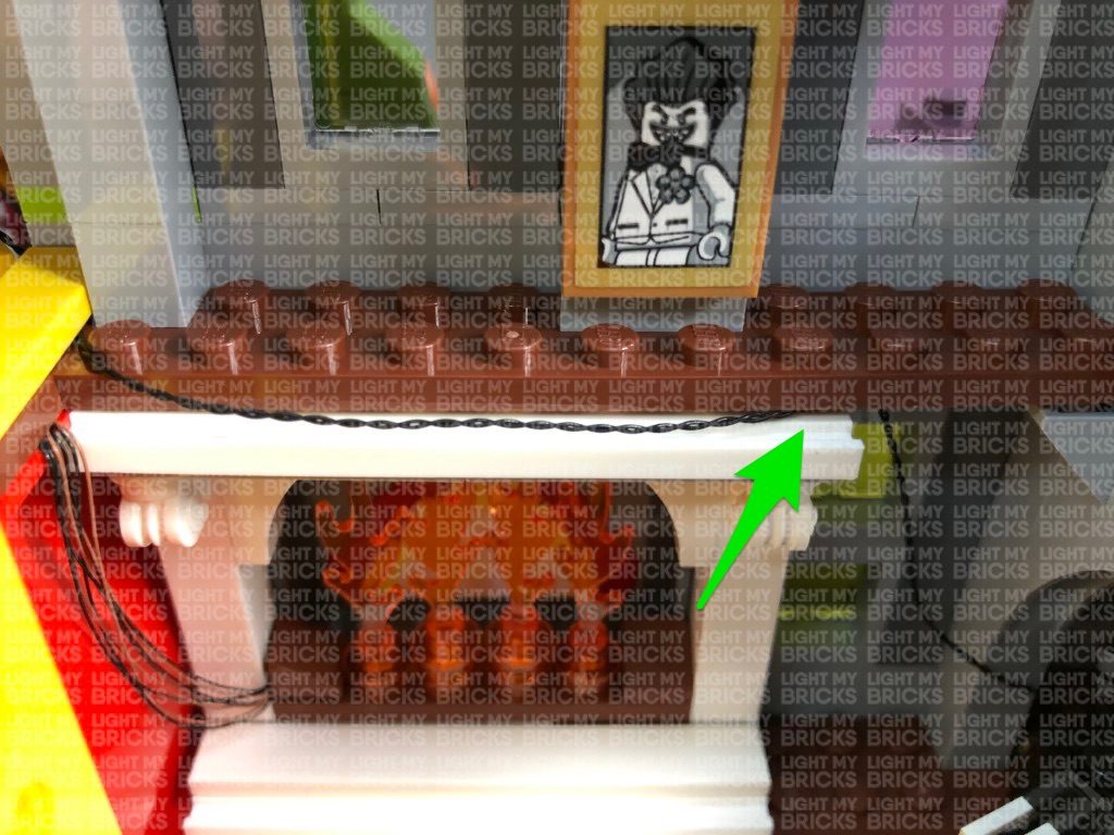
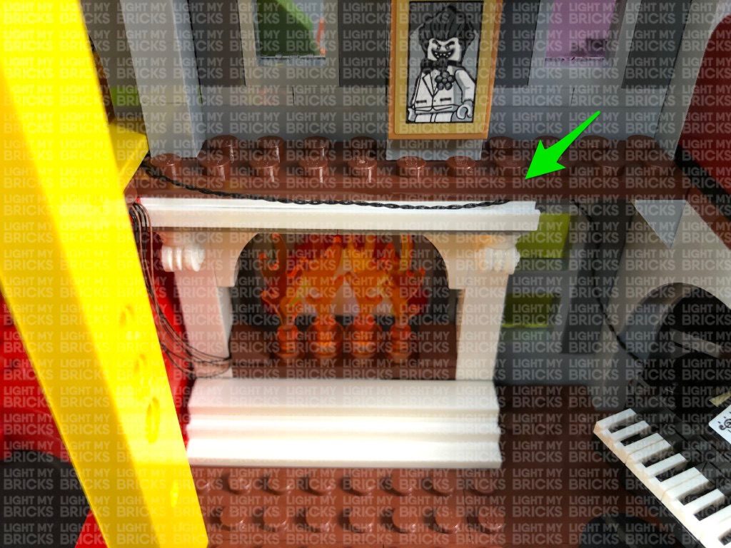
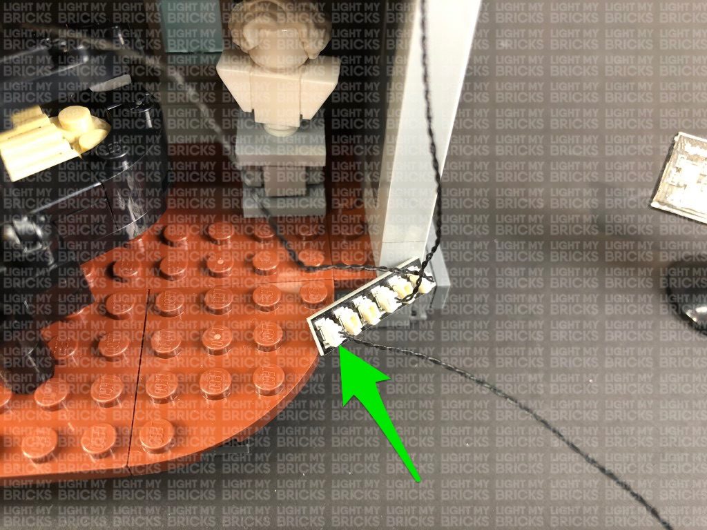
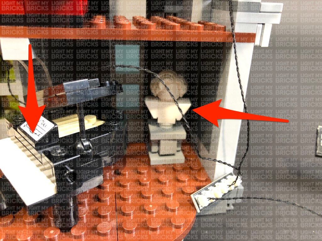
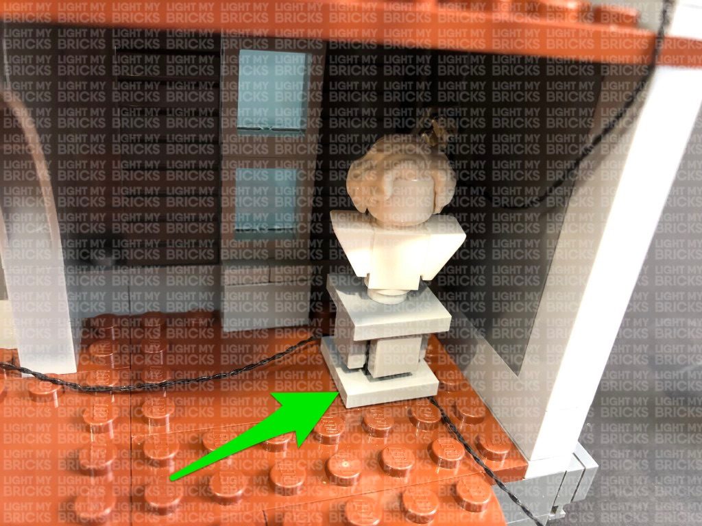
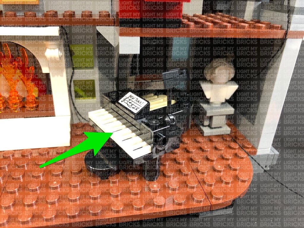
11.) Pull out the other end of one of the 30cm Connecting Cables from the left entrance light section (12-port expansion board) and thread it through the space on the right over the fire place. Pull the cable all the way out then thread it behind the piano and white bust as shown below:
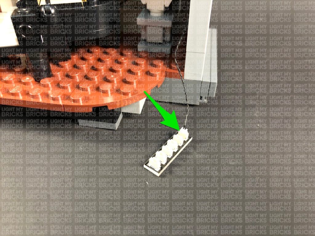
Take a 6-Port Expansion Board and connect the other end of the 30cm Connecting Cable to it.
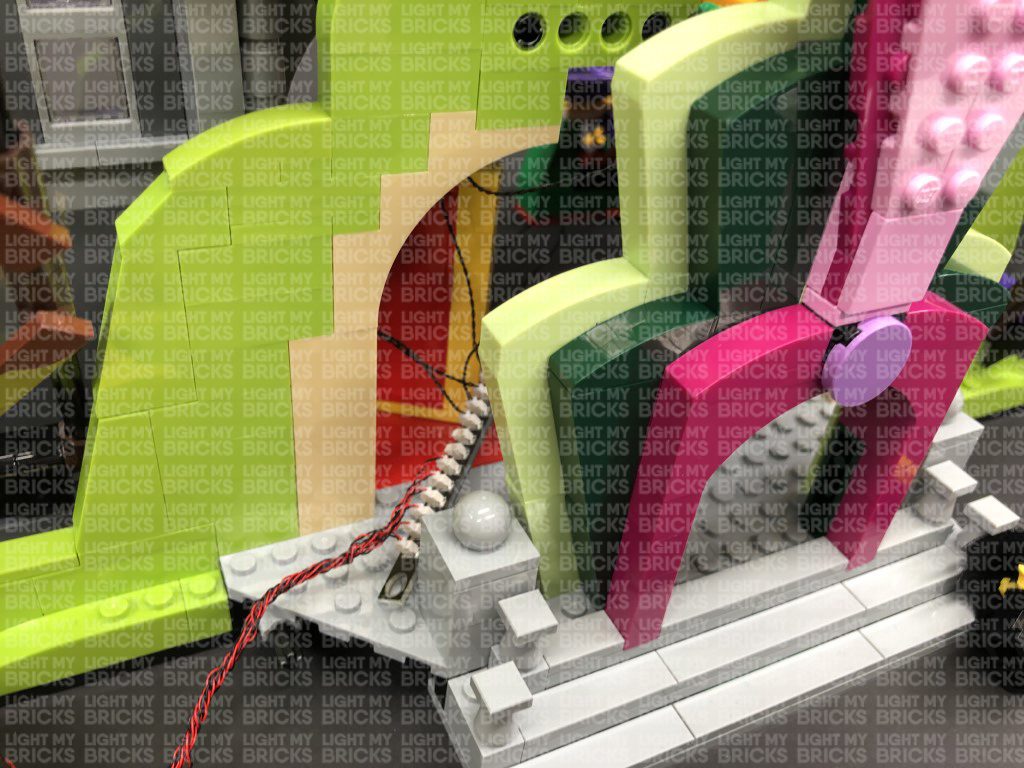
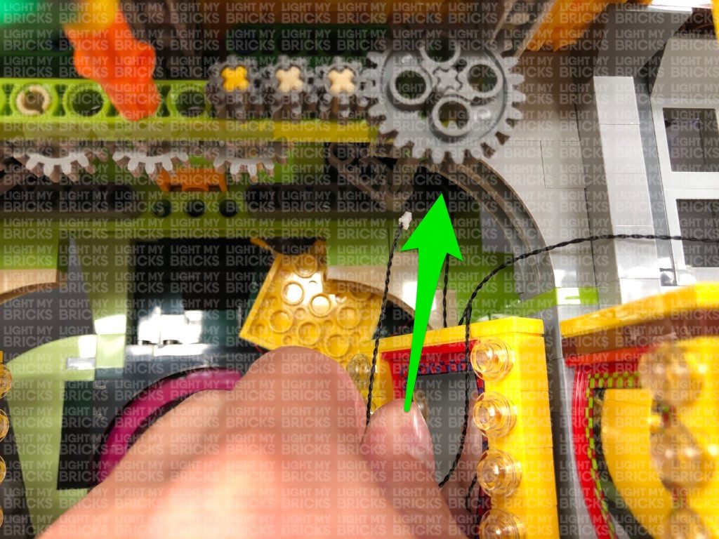
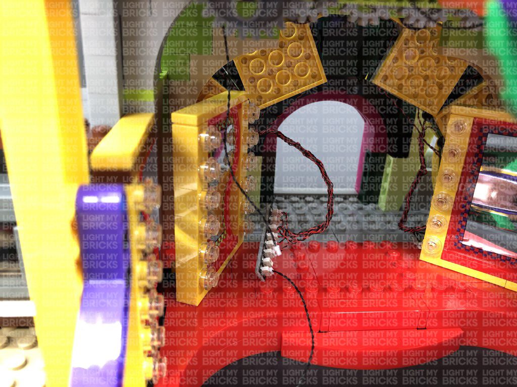
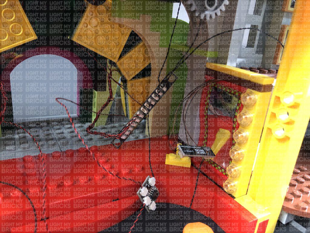
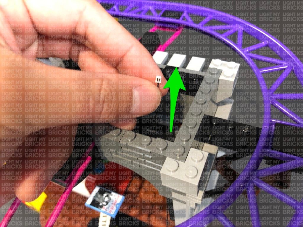
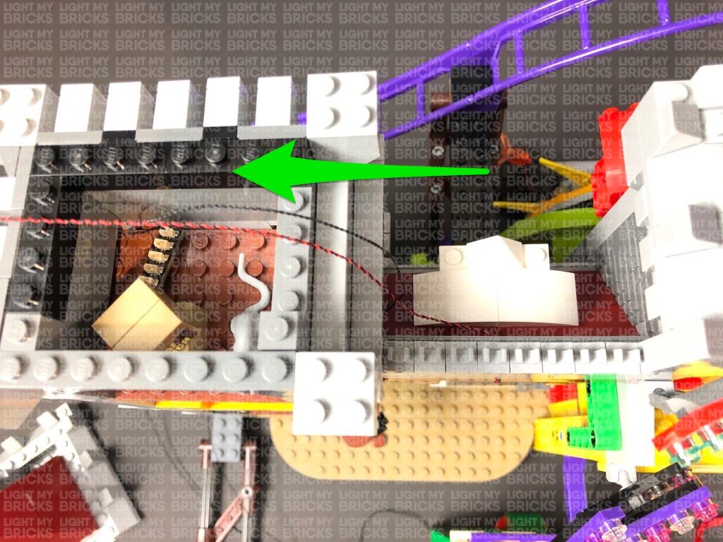
12.) Take the other end of the other 30cm Connecting Cable from the left entrance light section (12-port expansion board) and pull it out and thread it over right side of the ceiling technic pieces (grey gears) directly above. Pull the cable all the way out over the technic pieces as shown below.
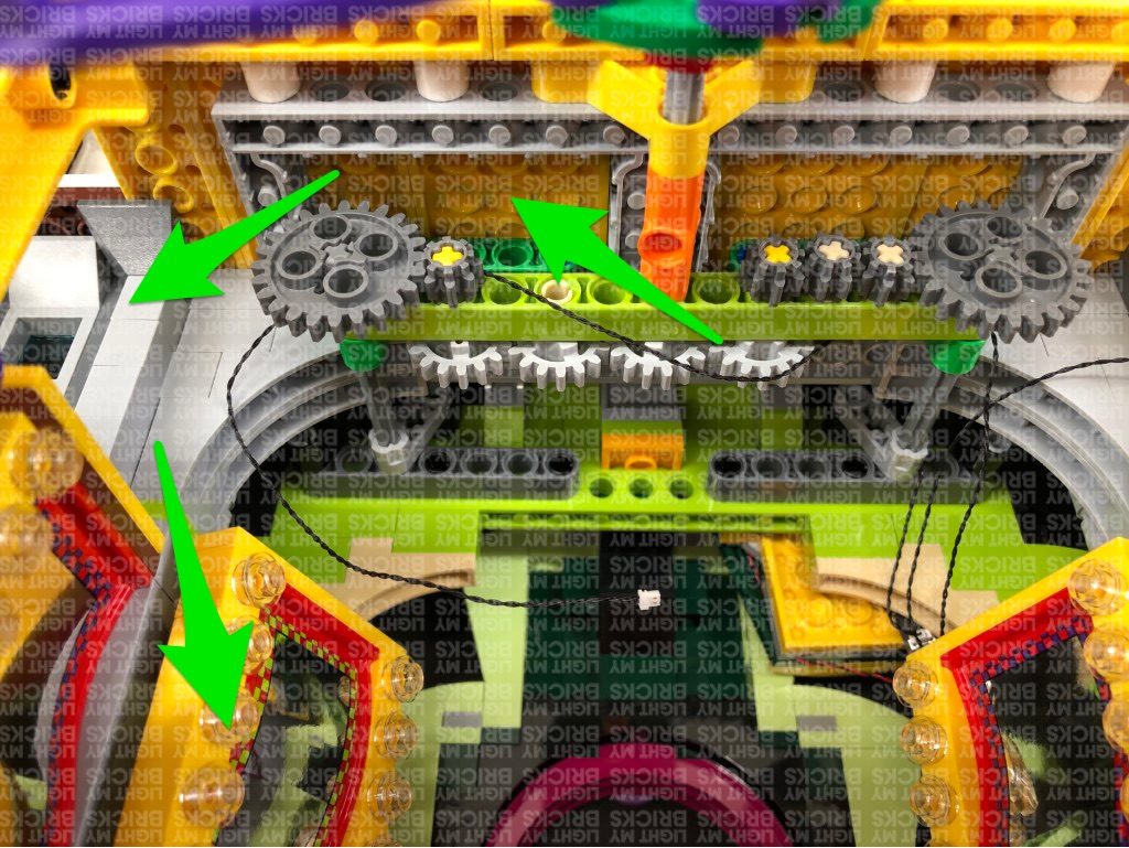
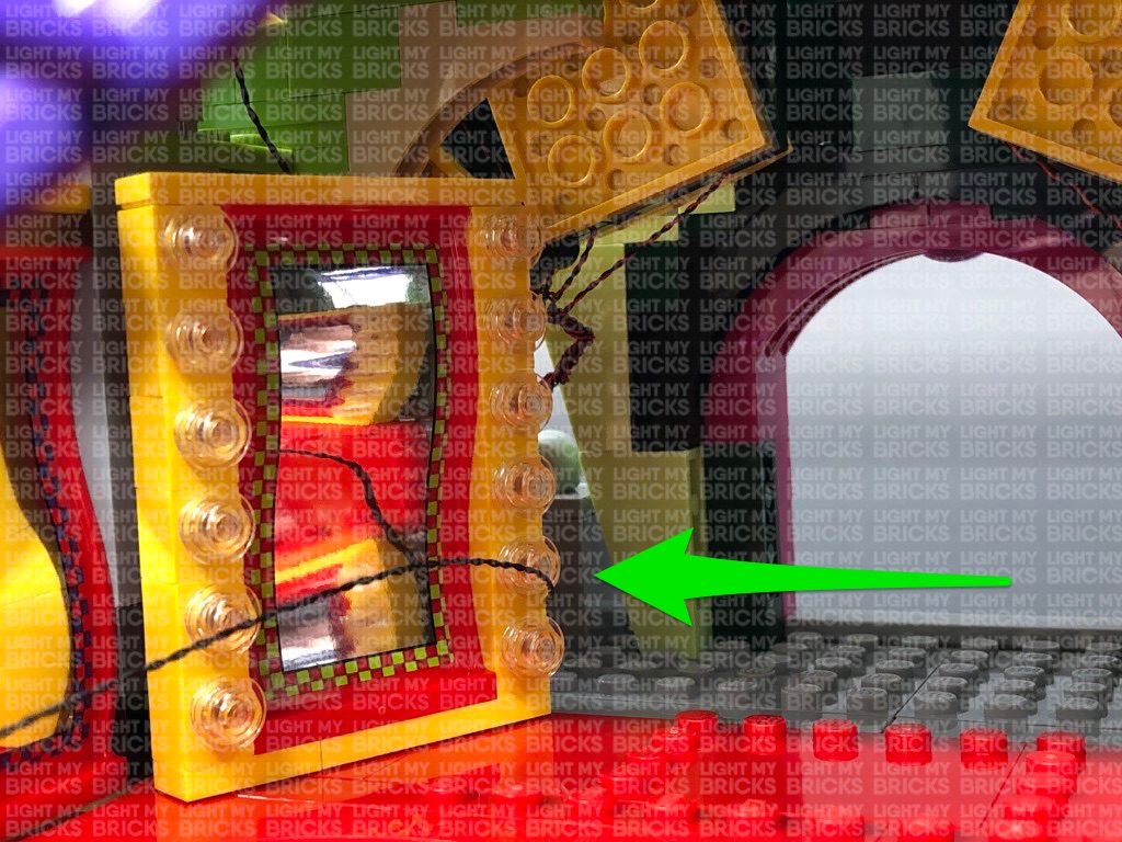
Thread the cable through over the technic pieces (grey gears) on the left side as shown below. Pull the cable down all the way out over the left side behind the first yellow mirror.
Take caution when threading the cable over the technic gears. Ensure the cable is laid out of the way of the gear teeth as we don’t want the cable getting caught when we operate the boxing gloves function.
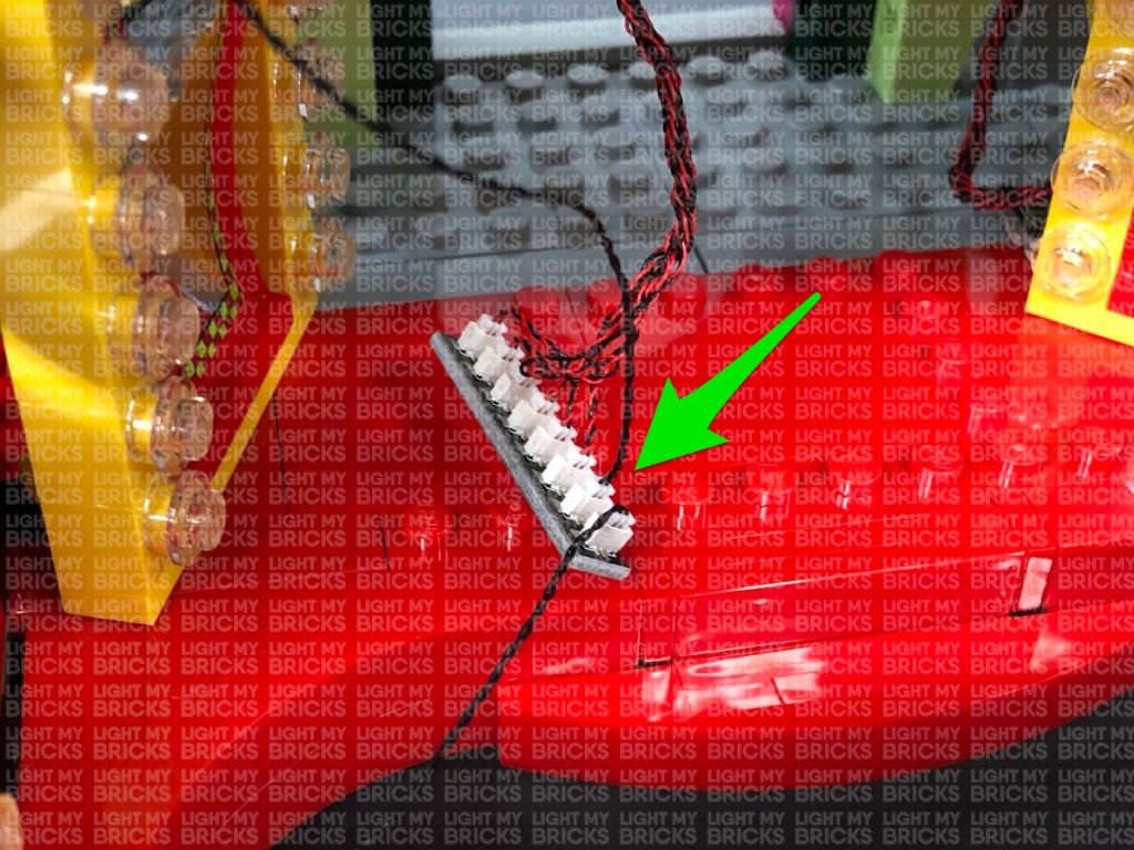
Connect the 30cm Connecting Cable to the 8-port Expansion Board nearby, then tuck the expansion board behind the mirror to the left.
Turn your USB Power Bank ON to test all the lights at the front entrance are working OK.
Note: If you experience any issues with the lights not working and suspect an issue with a component, please try a different port on the expansion board to verify where the fault lies (with the light or expansion board). To correct any issues with expansion board ports, please view the section addressing expansion board issues on our online troubleshooting guide.
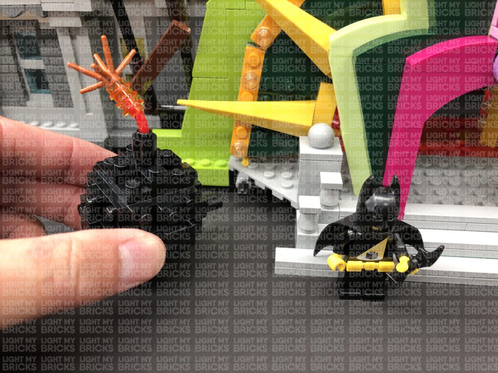
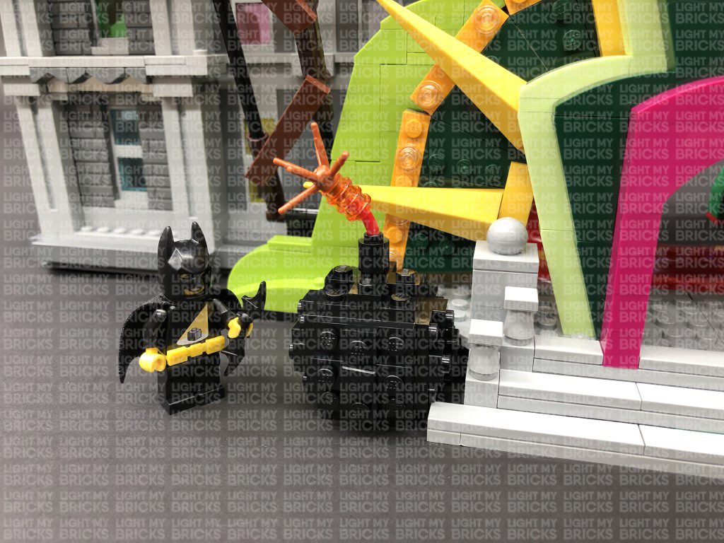
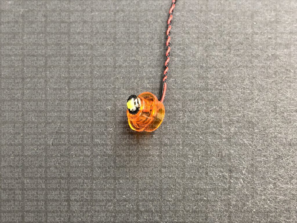
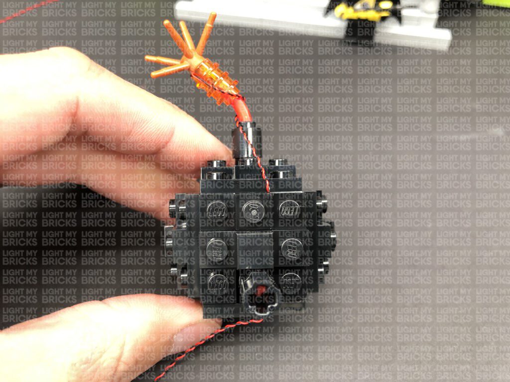
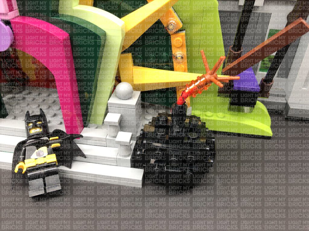
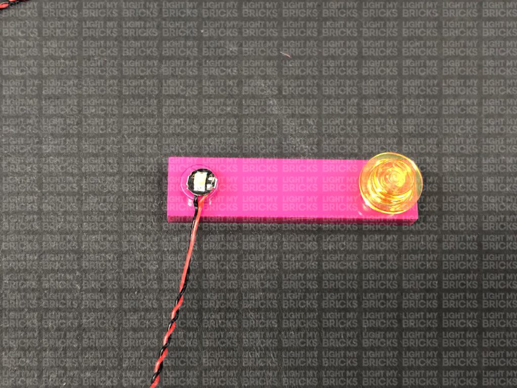
13.) We will now light up the cherry bombs on either side of the front entrance. First take the left bomb and disassemble the top spark pieces as shown below:
Take a White 30cm Bit Light and thread the connector end of the cable through the top of one of the trans orange round plates with open stud. Thread it all the way through, then carefully bend the LED so that it sits flat against the edge of the stud.
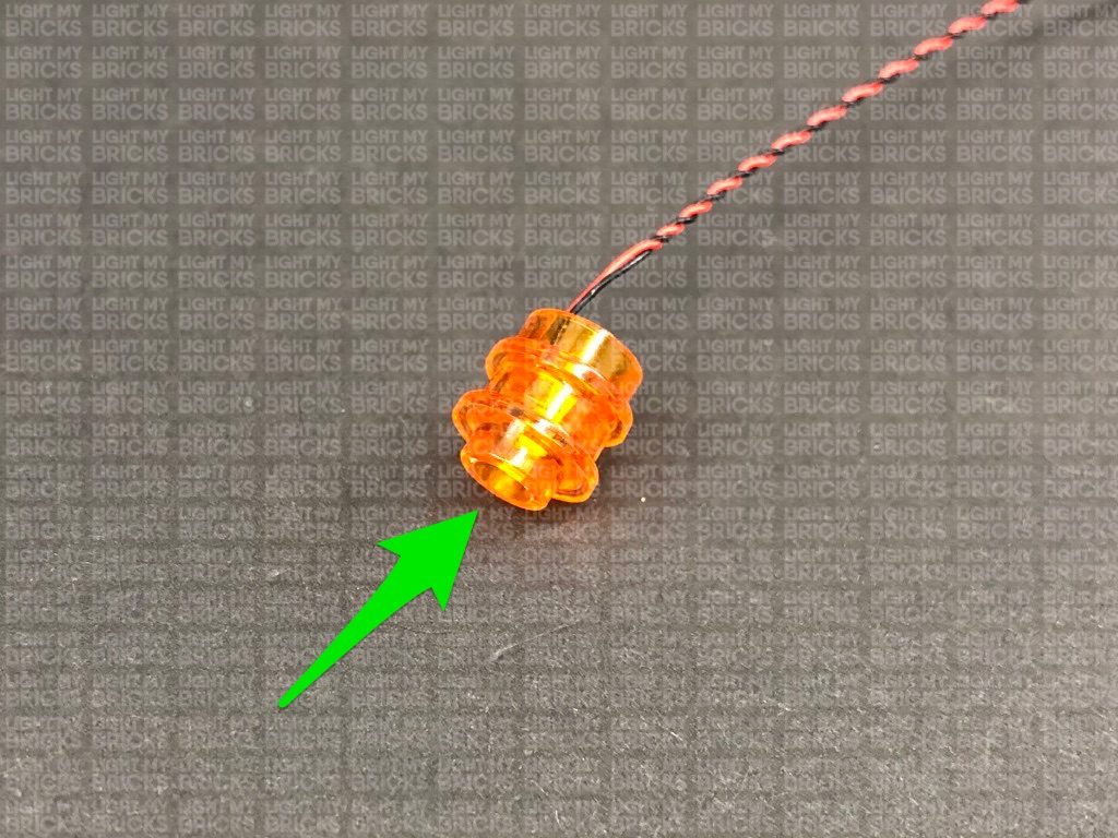
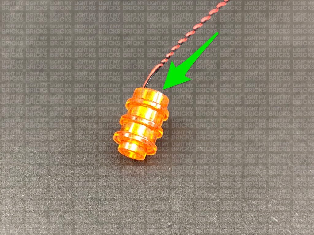
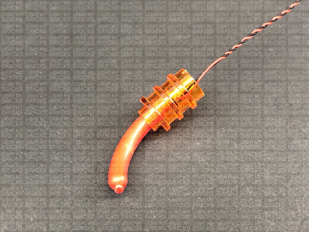
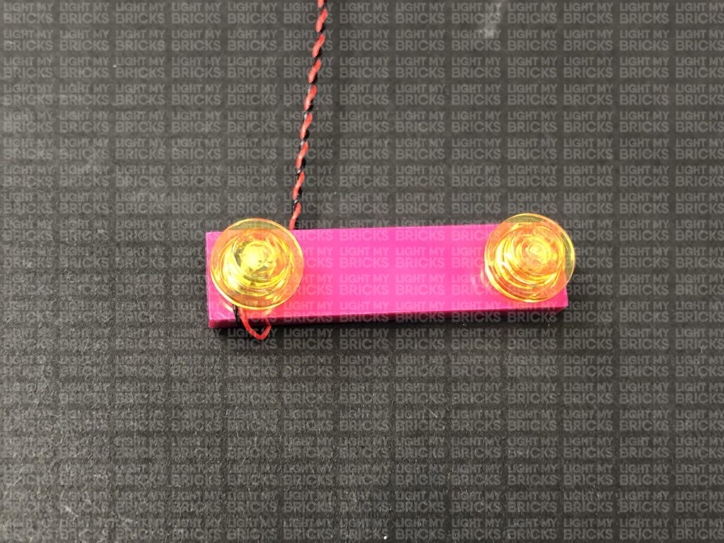
Reconnect a trans orange round plate with open stud on top, then connect the remaining trans orange round plate with open stud to the bottom. Reconnect the sausage piece to the bottom, then reconnect the branch piece to the top.
Reconnect this spark section to the bomb ensuring the cable is facing away from the spark (toward the right of the bomb) then twist the cable to the left around the sausage piece. Remove the following pieces on the back of the bomb, then lay the cable all the way down before reconnecting the pieces over the top of the cable.
14.) Repeat the previous step to install White 30cm Bit Light to the right cherry bomb.
Reconnect this spark section to the bomb ensuring the cable is facing away from the spark (toward the left of the bomb) then twist the cable to the right around the sausage piece. Remove the following pieces on the back of the bomb, then lay the cable all the way down before reconnecting the pieces over the top of the cable.
7.) Repeat steps 2- 3 to install another 6x White 15cm Bit Lights to the right entrance light section.
8.) Take an 8-Port Expansion Board and connect all six bit light cables to it. Take your USB Power Cable and connect it to the expansion board, then connect the other end to your USB Power Bank to test the lights on this side are working OK.
Note: If you experience any issues with the lights not working and suspect an issue with a component, please try a different port on the expansion board to verify where the fault lies (with the light or expansion board). To correct any issues with expansion board ports, please view the section addressing expansion board issues on our online troubleshooting guide.
Disconnect the USB Power Cable from the expansion board, then turn the light section over and bring all six cables together and twist/wind them around each other closest to the top. Continue to twist/wind the cables all the way to the end so they come together to form a larger neat cable.
9.) Take a new 30cm Connecting Cable and connect it to the 8-port expansion board. Thread the other end of the cable through the entrance before reconnecting this right side section to the front of the building.
Turn the Joker Manor around to the back side and pull the other end of the 30cm Connecting Cable out and feed it toward the left underneath the roller coaster track. Connect the cable to a new 12-Port Expansion Board then connect the USB power Cable (connected to the USB Power Bank) to the expansion board.
10.) To make the installation of the lights to the back easier, disconnect the following roller coaster track sections.
11.) Pull out the other end of one of the 30cm Connecting Cables from the left entrance light section (12-port expansion board) and thread it through the space on the right over the fire place. Pull the cable all the way out then thread it behind the piano and white bust as shown below:
Take a 6-Port Expansion Board and connect the other end of the 30cm Connecting Cable to it.
12.) Take the other end of the other 30cm Connecting Cable from the left entrance light section (12-port expansion board) and pull it out and thread it over right side of the ceiling technic pieces (grey gears) directly above. Pull the cable all the way out over the technic pieces as shown below.
Thread the cable through over the technic pieces (grey gears) on the left side as shown below. Pull the cable down all the way out over the left side behind the first yellow mirror.
Take caution when threading the cable over the technic gears. Ensure the cable is laid out of the way of the gear teeth as we don’t want the cable getting caught when we operate the boxing gloves function.
Connect the 30cm Connecting Cable to the 8-port Expansion Board nearby, then tuck the expansion board behind the mirror to the left.
Turn your USB Power Bank ON to test all the lights at the front entrance are working OK.
Note: If you experience any issues with the lights not working and suspect an issue with a component, please try a different port on the expansion board to verify where the fault lies (with the light or expansion board). To correct any issues with expansion board ports, please view the section addressing expansion board issues on our online troubleshooting guide.
13.) We will now light up the cherry bombs on either side of the front entrance. First take the left bomb and disassemble the top spark pieces as shown below:
Take a White 30cm Bit Light and thread the connector end of the cable through the top of one of the trans orange round plates with open stud. Thread it all the way through, then carefully bend the LED so that it sits flat against the edge of the stud.
Reconnect a trans orange round plate with open stud on top, then connect the remaining trans orange round plate with open stud to the bottom. Reconnect the sausage piece to the bottom, then reconnect the branch piece to the top.
Reconnect this spark section to the bomb ensuring the cable is facing away from the spark (toward the right of the bomb) then twist the cable to the left around the sausage piece. Remove the following pieces on the back of the bomb, then lay the cable all the way down before reconnecting the pieces over the top of the cable.
14.) Repeat the previous step to install White 30cm Bit Light to the right cherry bomb.
Reconnect this spark section to the bomb ensuring the cable is facing away from the spark (toward the left of the bomb) then twist the cable to the right around the sausage piece. Remove the following pieces on the back of the bomb, then lay the cable all the way down before reconnecting the pieces over the top of the cable.
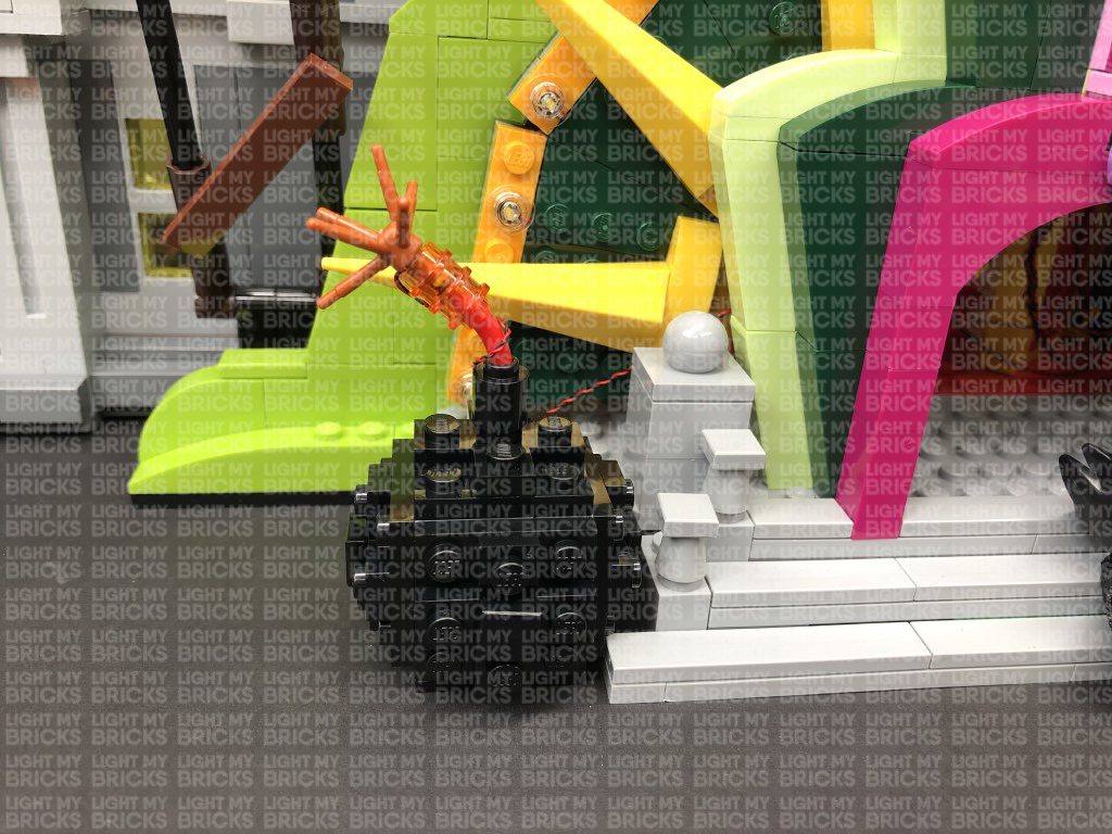
 15.) Take both cherry bombs and thread their Bit Light cable all the way through the side of the entrance underneath the light sections before reconnecting the bombs to the set.
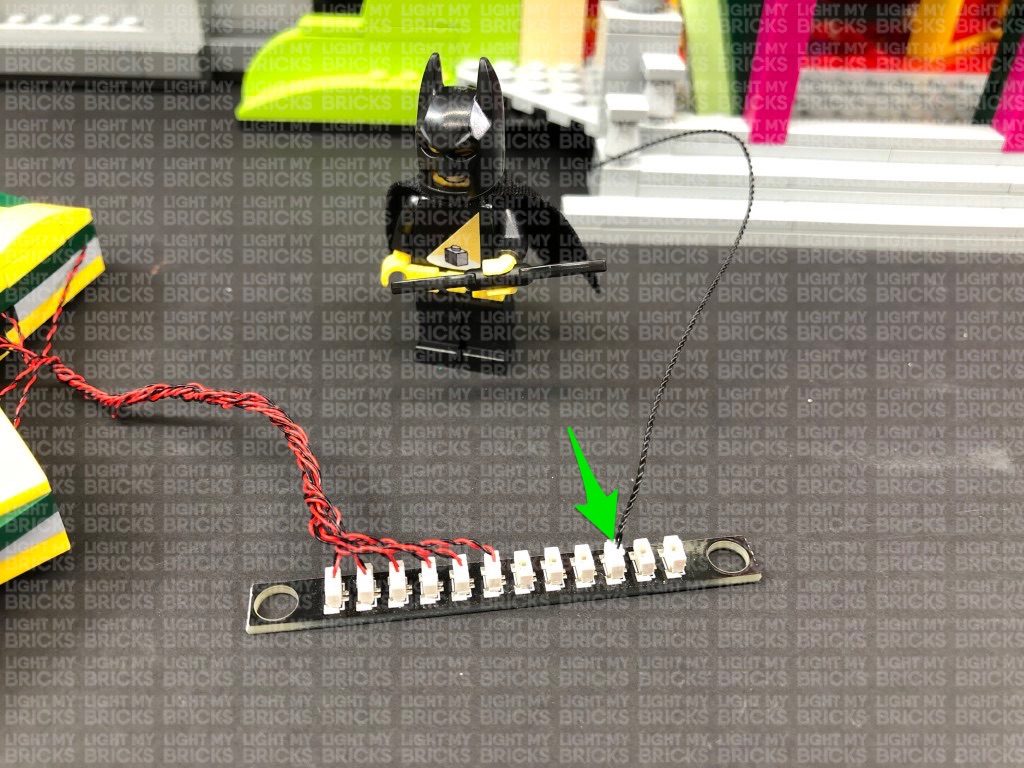
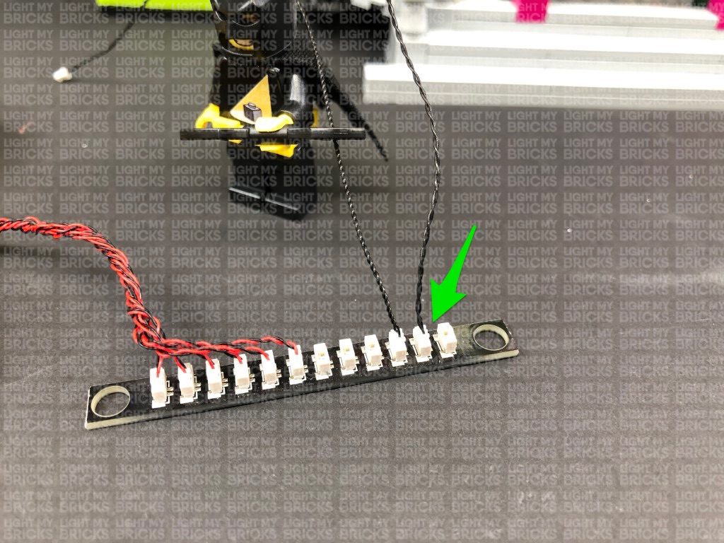
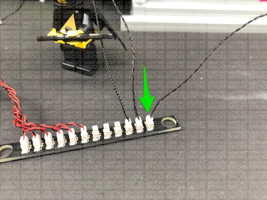
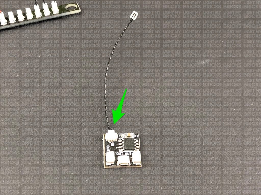
Turn the set around to the back, then pull both cables from the cherry bombs all the way out. Connect each cable to the OUT ports on the Flicker Effects Board.
Turn your USB Power Bank ON to test the bomb spark lights are flickering OK.
15.) Take both cherry bombs and thread their Bit Light cable all the way through the side of the entrance underneath the light sections before reconnecting the bombs to the set.
Turn the set around to the back, then pull both cables from the cherry bombs all the way out. Connect each cable to the OUT ports on the Flicker Effects Board.
Turn your USB Power Bank ON to test the bomb spark lights are flickering OK.
 Note: If you experience any issues with the lights not working and suspect an issue with a component, please try a different port on the expansion board to verify where the fault lies (with the light, expansion board, or effects board). To correct any issues with expansion board ports, please view the section addressing expansion board issues on our online troubleshooting guide.
Disconnect the USB Power Cable and Power Bank from the expansion board at the back as we will require these to test lights we are about to install to the front of the building.
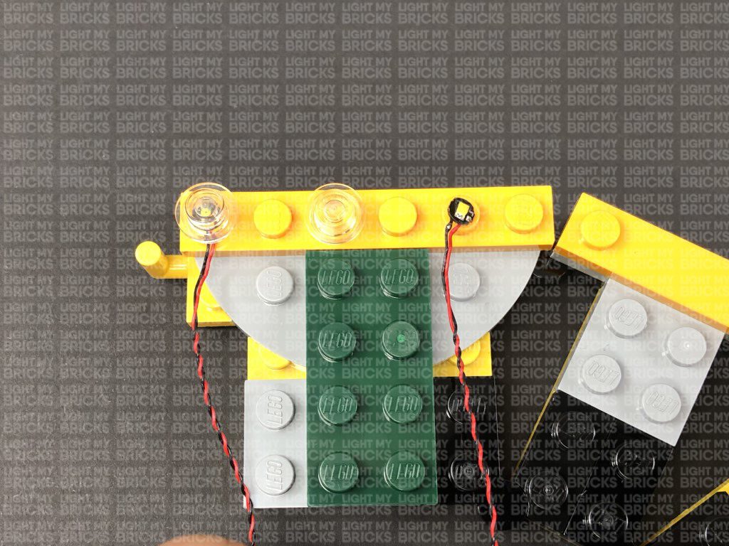
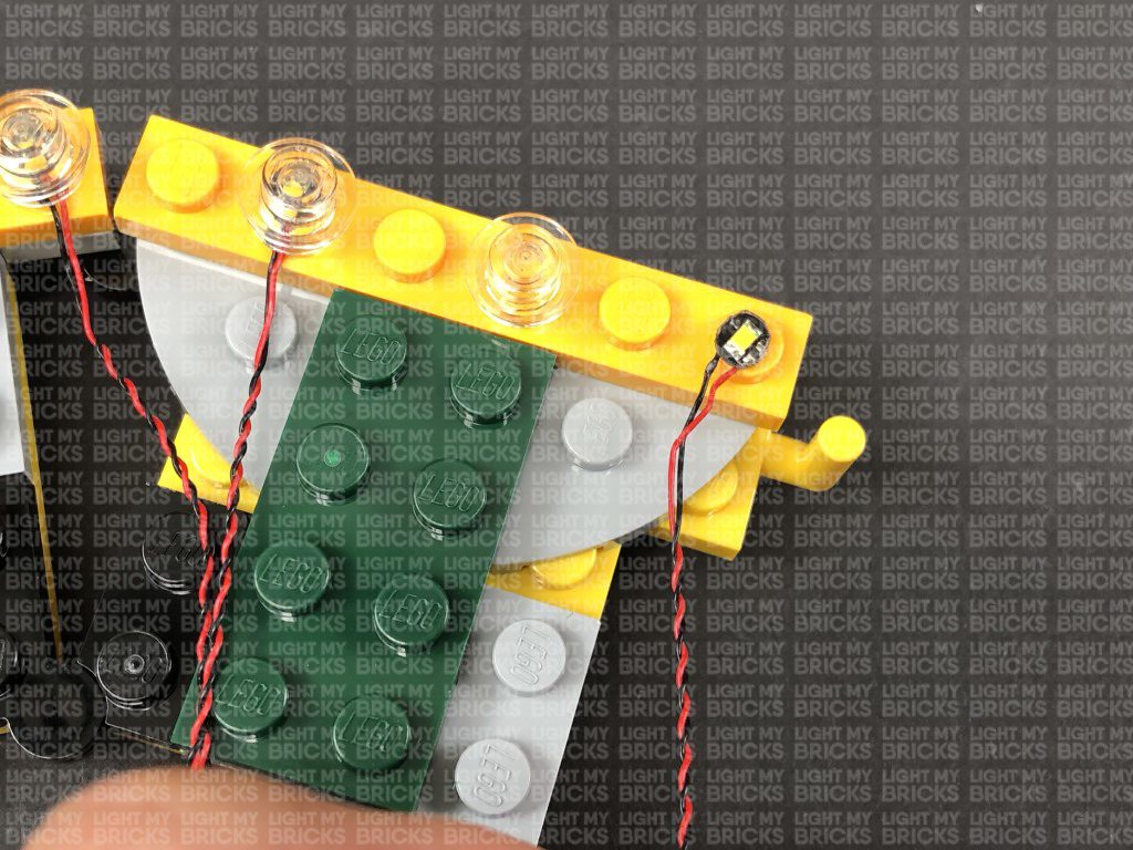
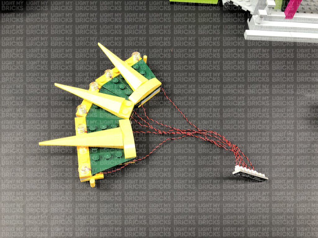
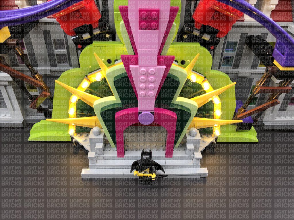
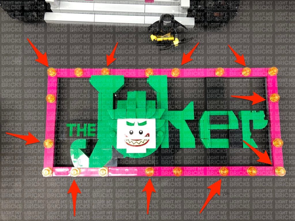
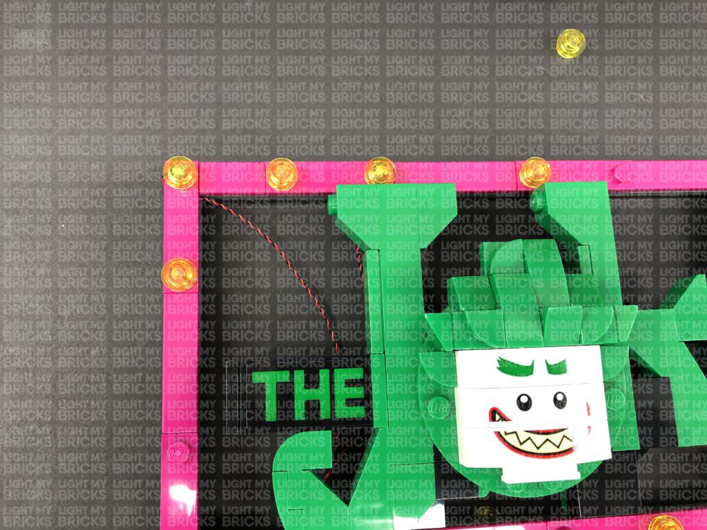
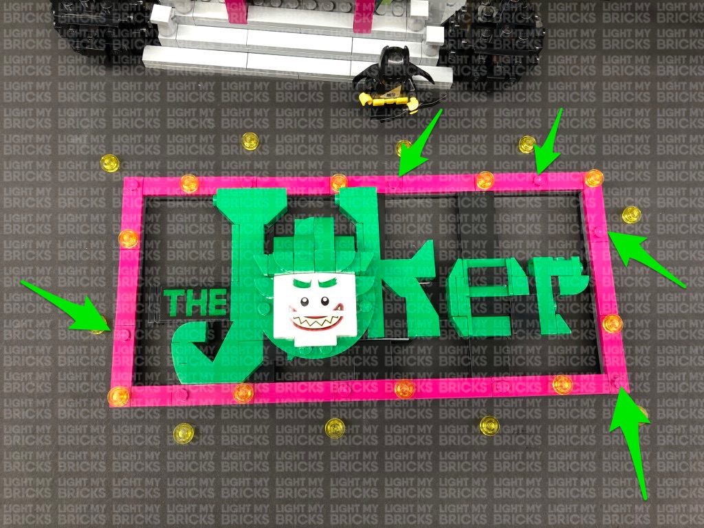
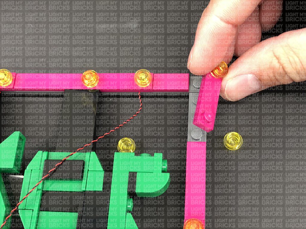
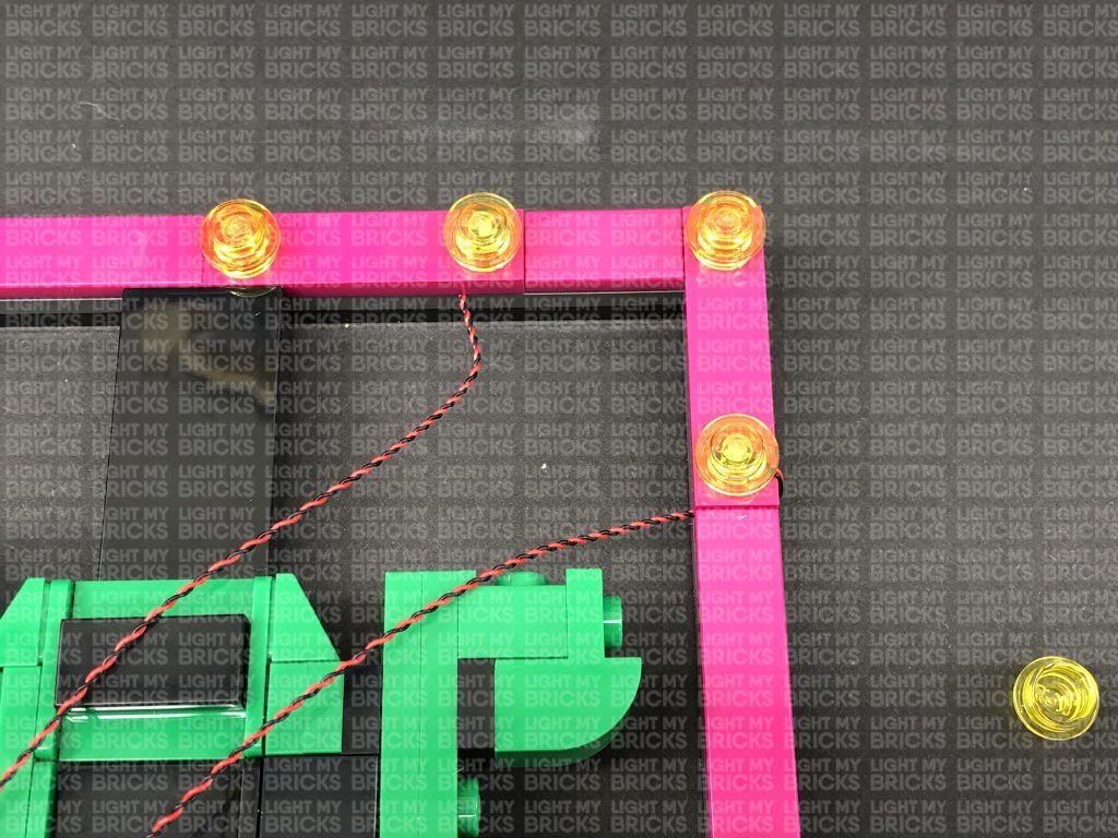
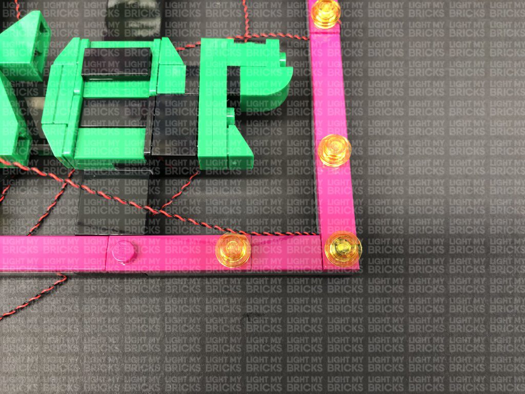
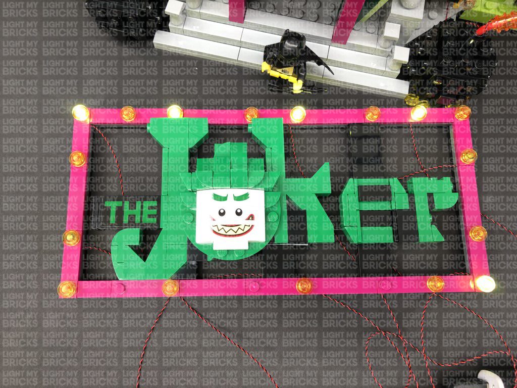
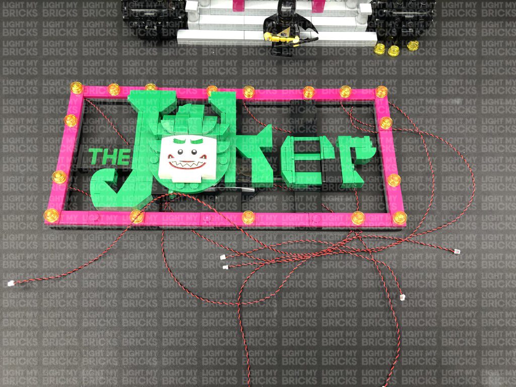
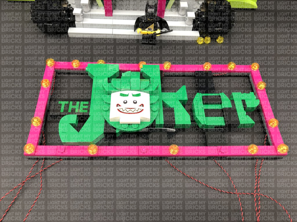
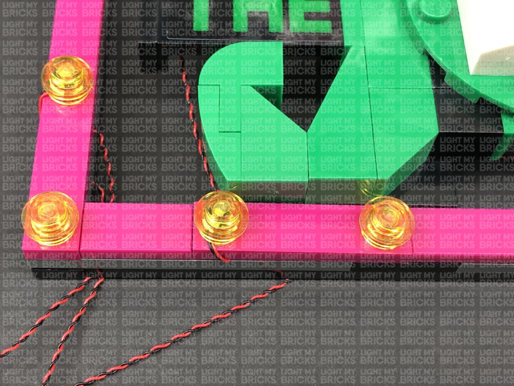
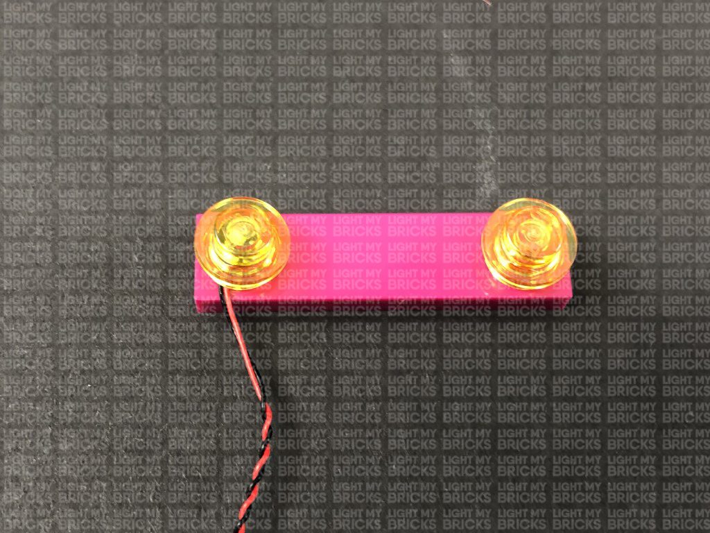
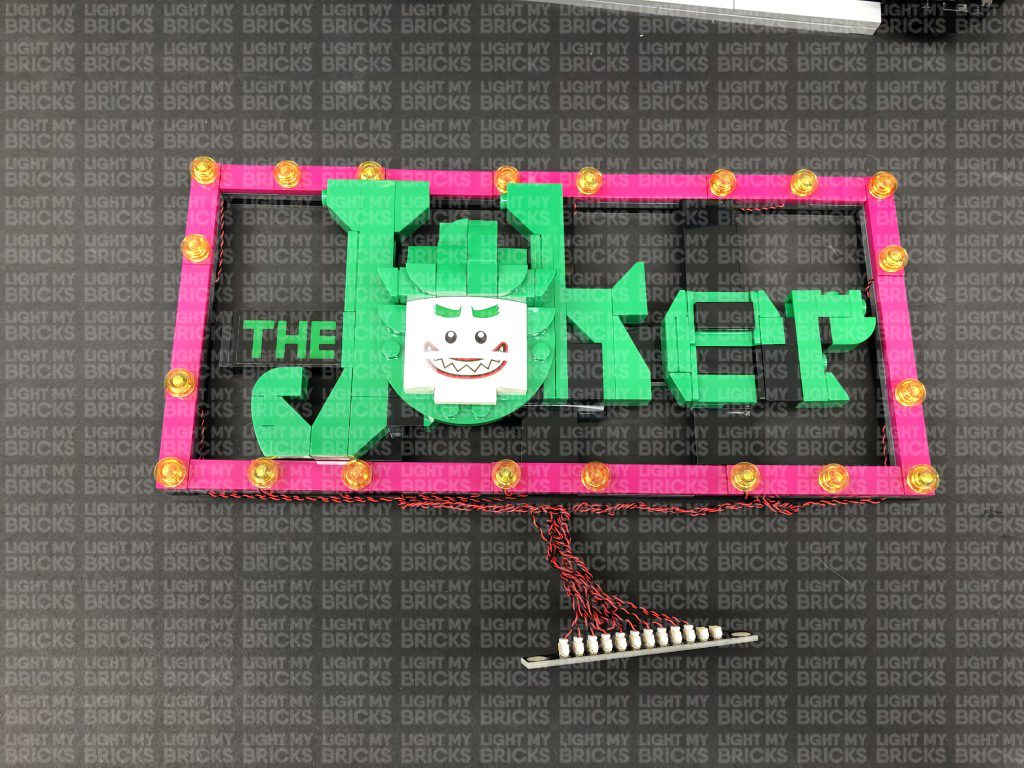
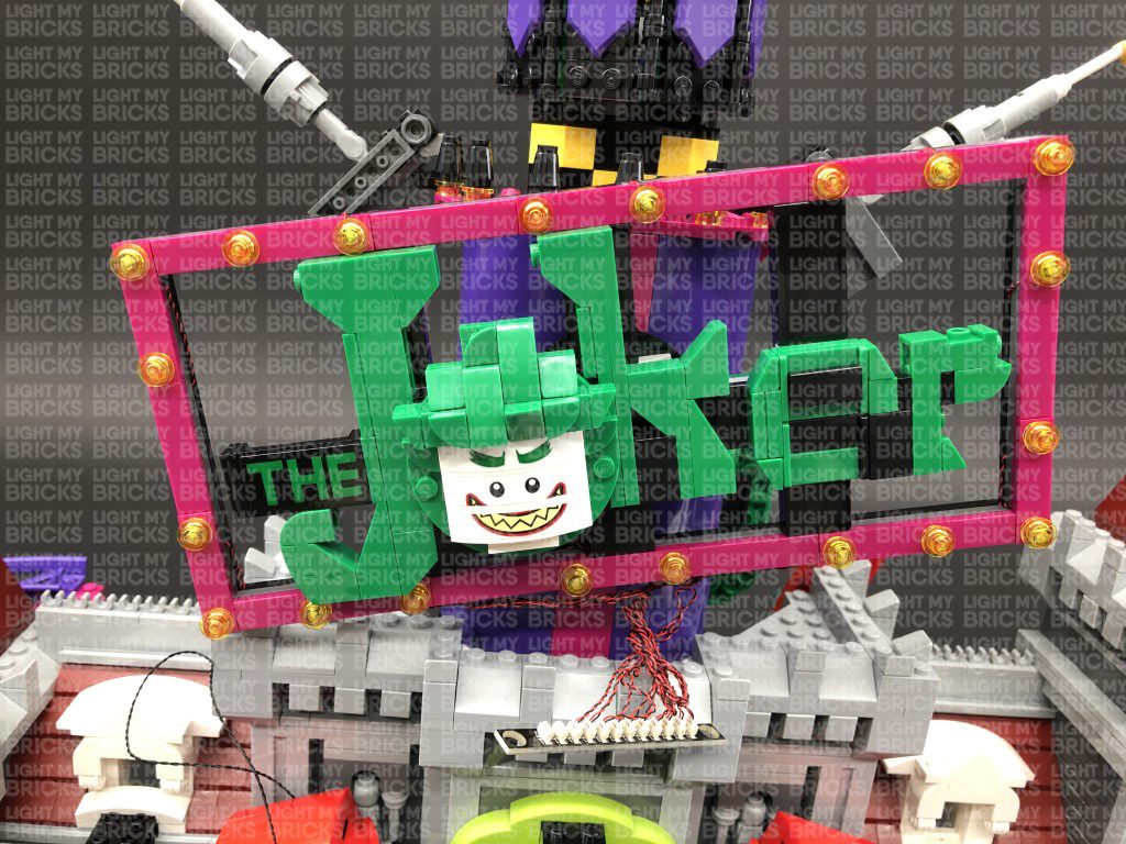
16.) We will now light up the Joker Sign at the front of the building. Disconnect the sign, then disconnect the following trans yellow round plates from the borders (every second one).
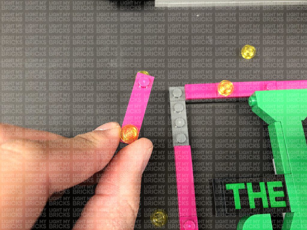
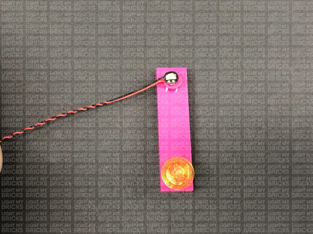
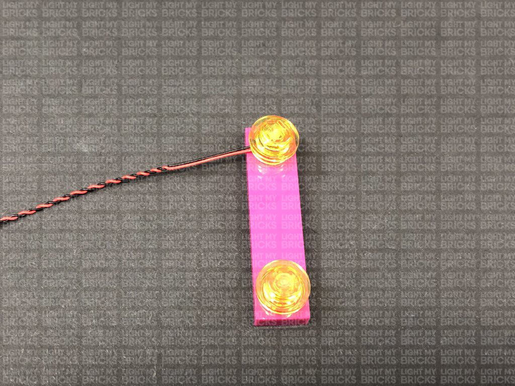
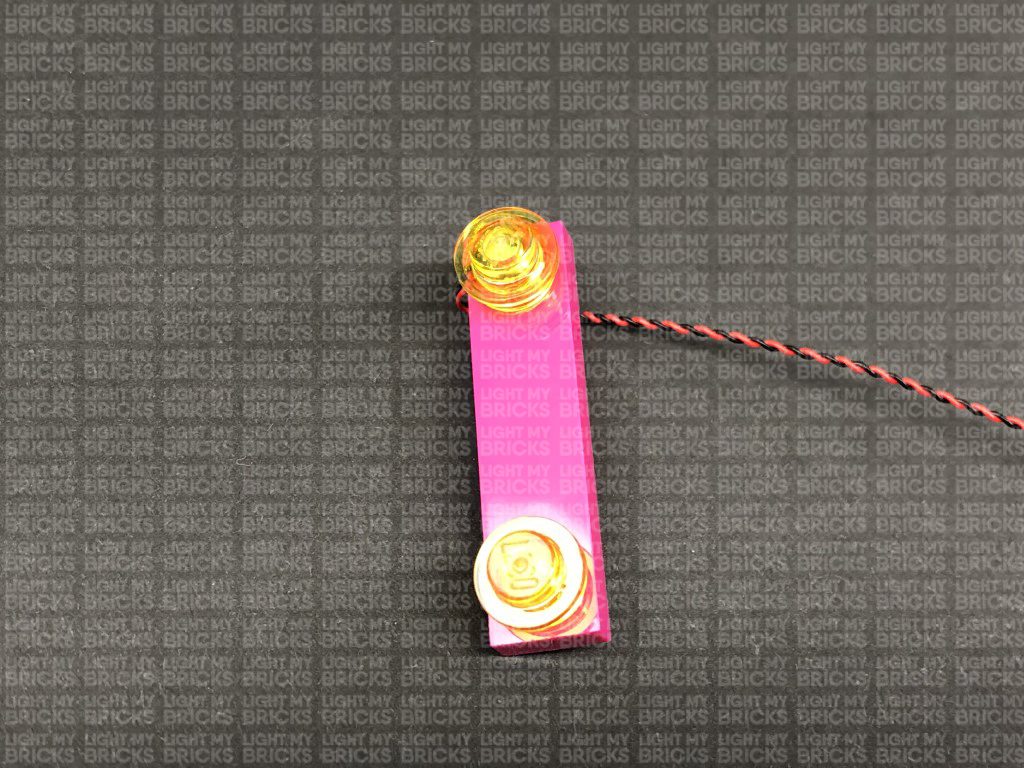
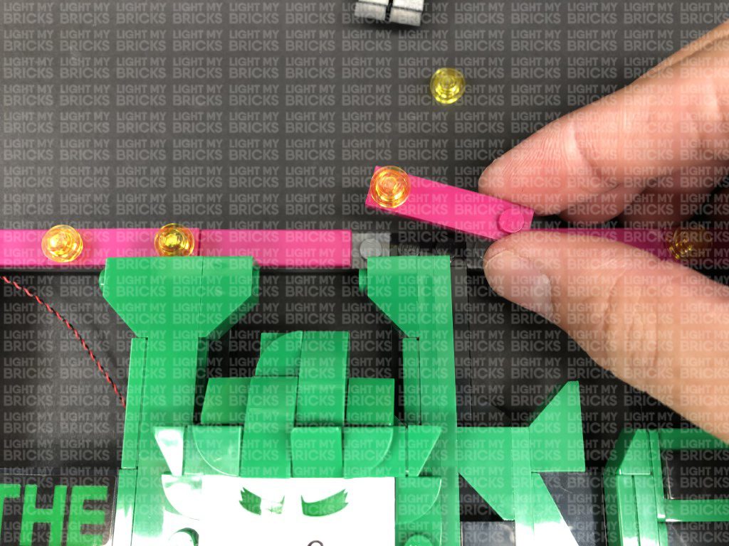
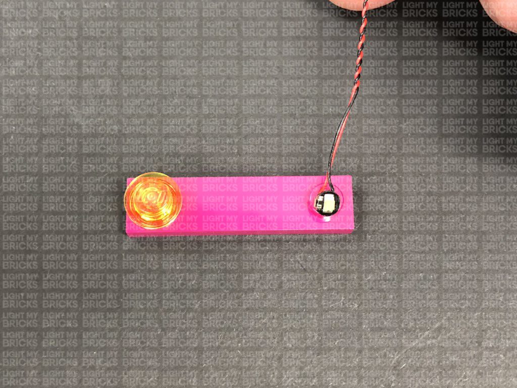
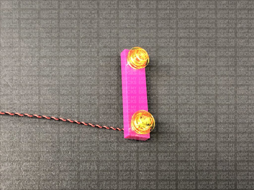
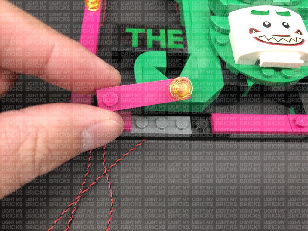
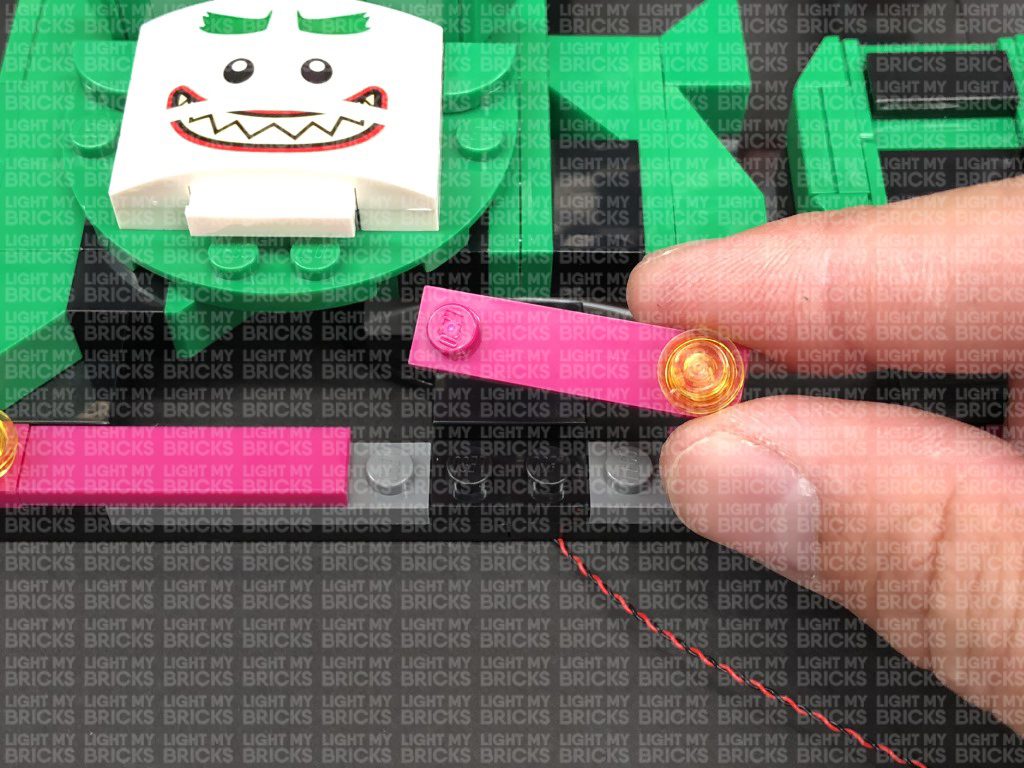
Disconnect the top left pink plate, then take a Flashing White 30cm Bit Light and with the cable facing the left side, place the LED directly over the pink stud. Secure the Bit Light in place by reconnecting one of the trans yellow round plates over the top.
Fold the cable underneath the plate then reconnect the plate to the sign ensuring the cable is laid in between studs underneath.
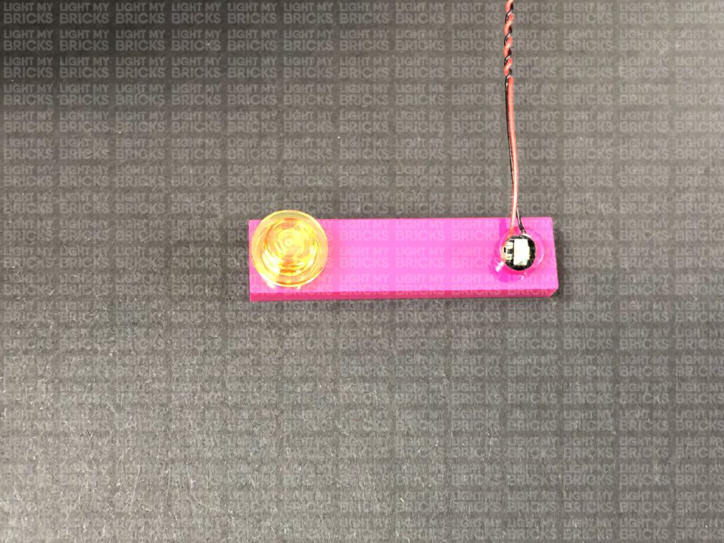
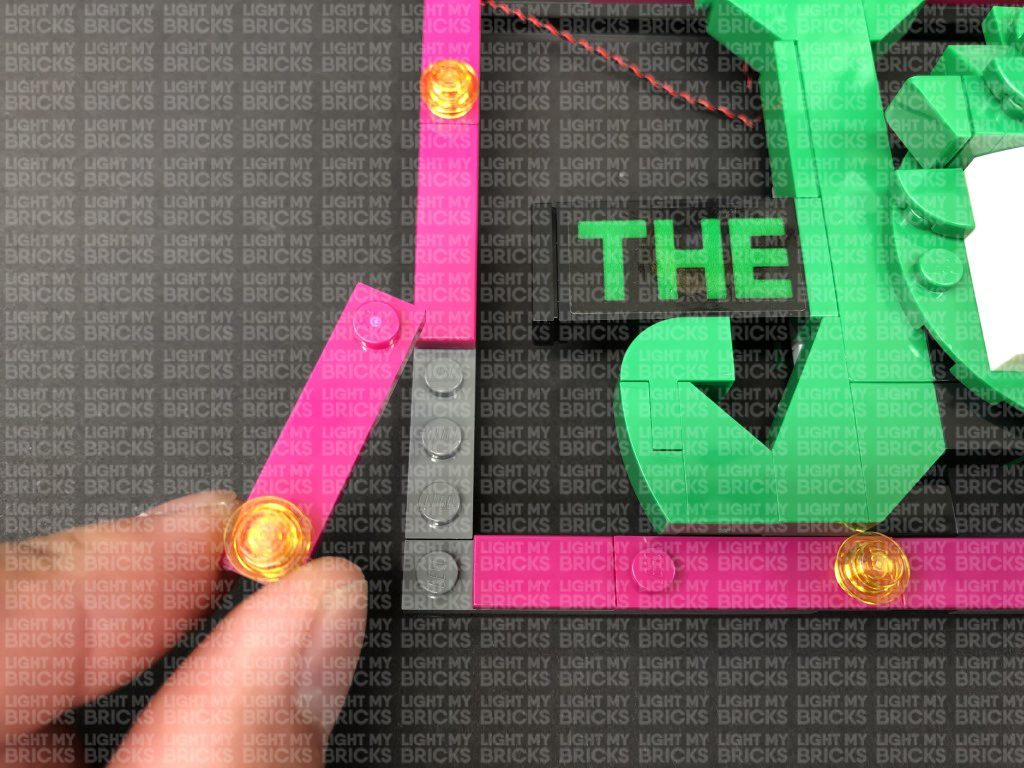
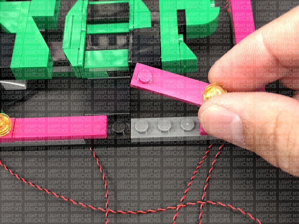
17.) Disconnect the pink plate to the right, then using the same method in the previous step, install another Flashing White 30cm Bit Light. When reconnecting the pink plate, lay the cable behind the “J”
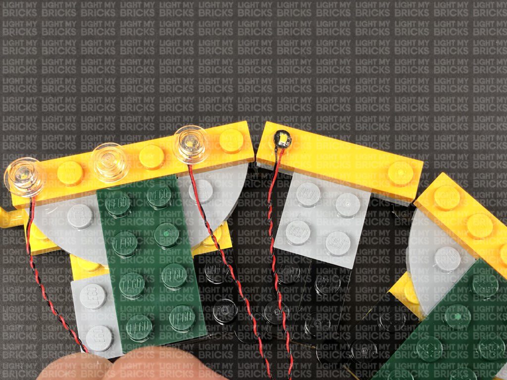
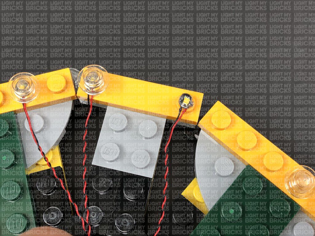
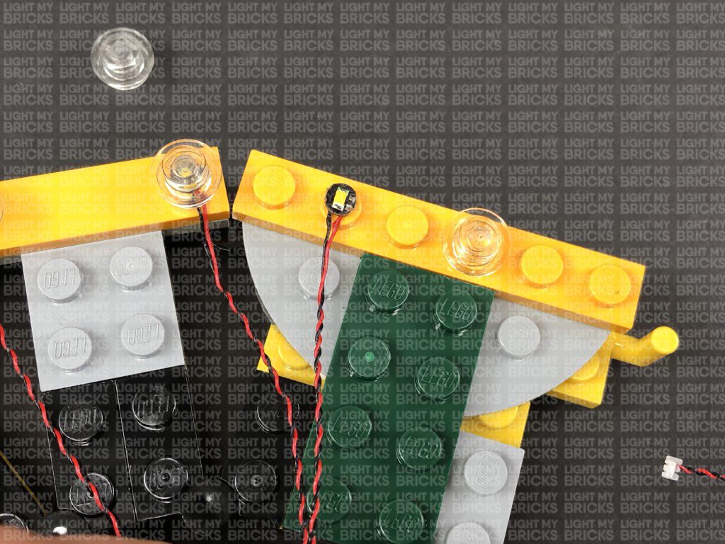
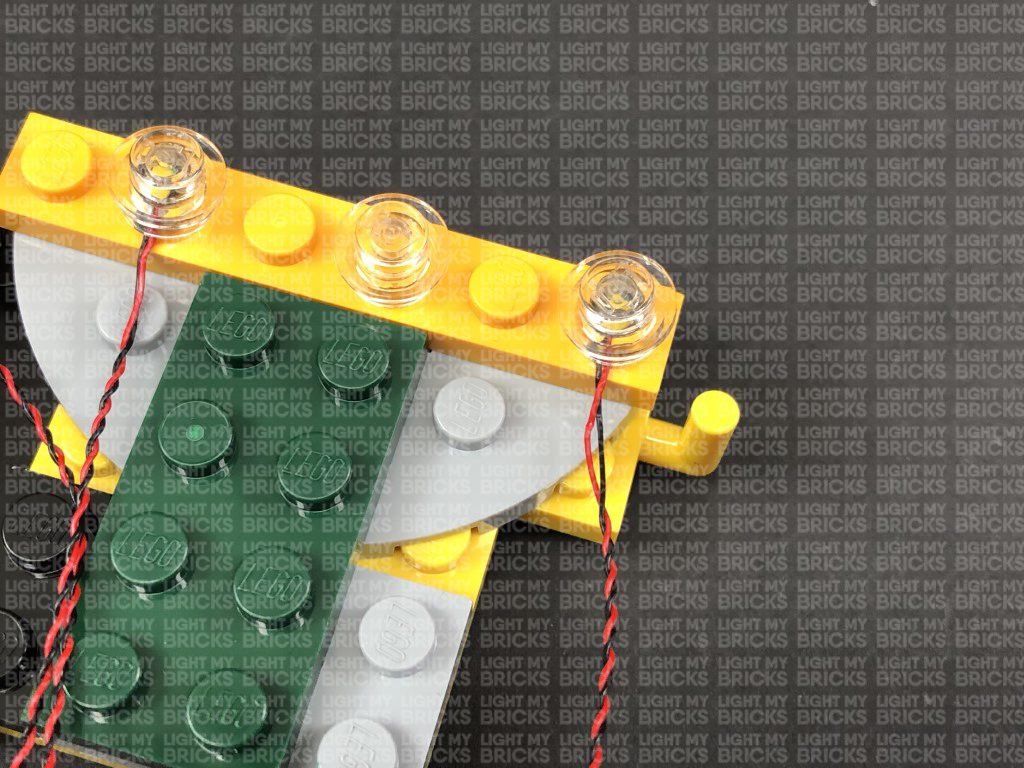
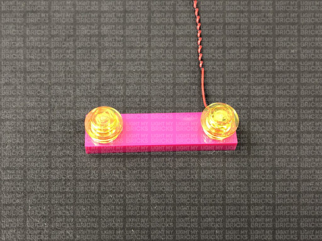
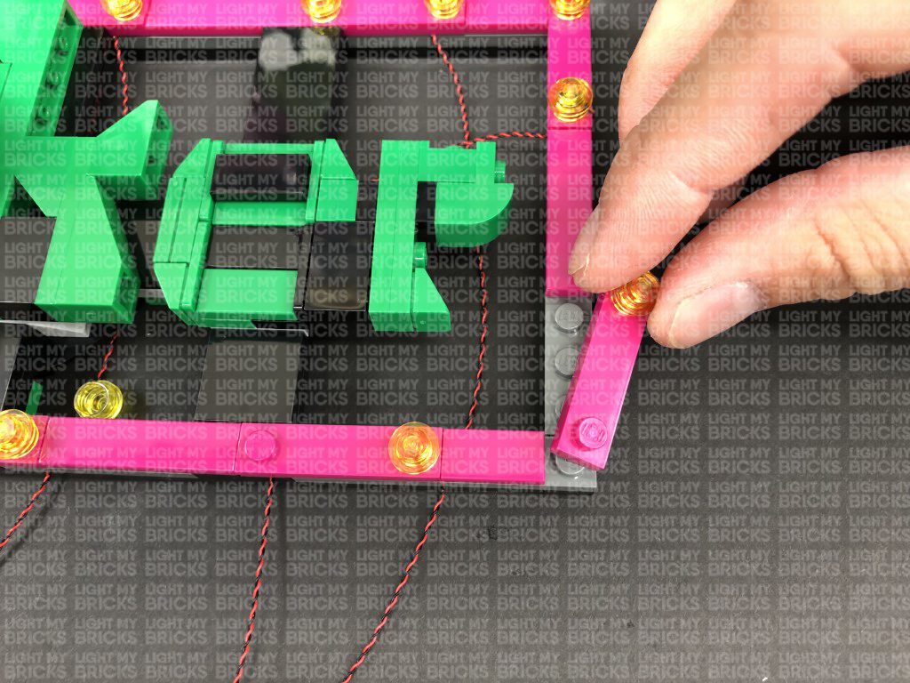
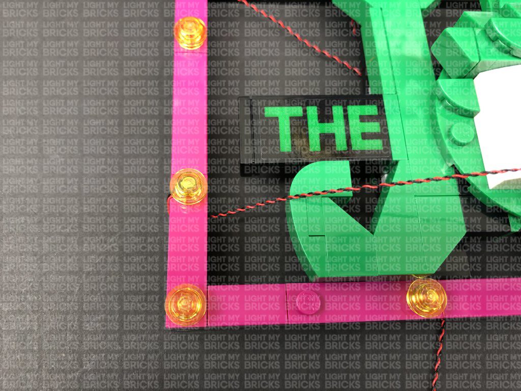
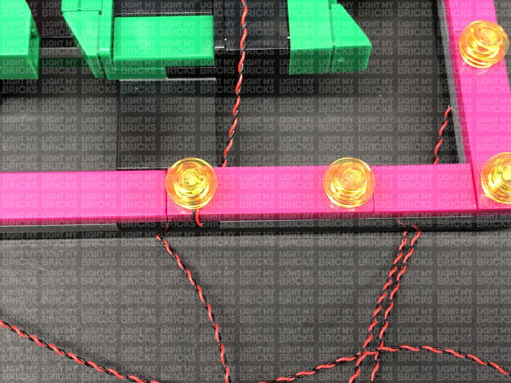
18.) Repeat previous steps install another 5x Flashing White 30cm Bit Lights at the following sections. Ensure the cables are folded underneath each plate facing the inside of the sign before reconnecting them.
Note: If you experience any issues with the lights not working and suspect an issue with a component, please try a different port on the expansion board to verify where the fault lies (with the light, expansion board, or effects board). To correct any issues with expansion board ports, please view the section addressing expansion board issues on our online troubleshooting guide.
Disconnect the USB Power Cable and Power Bank from the expansion board at the back as we will require these to test lights we are about to install to the front of the building.
16.) We will now light up the Joker Sign at the front of the building. Disconnect the sign, then disconnect the following trans yellow round plates from the borders (every second one).
Disconnect the top left pink plate, then take a Flashing White 30cm Bit Light and with the cable facing the left side, place the LED directly over the pink stud. Secure the Bit Light in place by reconnecting one of the trans yellow round plates over the top.
Fold the cable underneath the plate then reconnect the plate to the sign ensuring the cable is laid in between studs underneath.
17.) Disconnect the pink plate to the right, then using the same method in the previous step, install another Flashing White 30cm Bit Light. When reconnecting the pink plate, lay the cable behind the “J”
18.) Repeat previous steps install another 5x Flashing White 30cm Bit Lights at the following sections. Ensure the cables are folded underneath each plate facing the inside of the sign before reconnecting them.
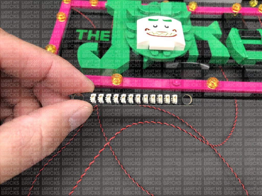
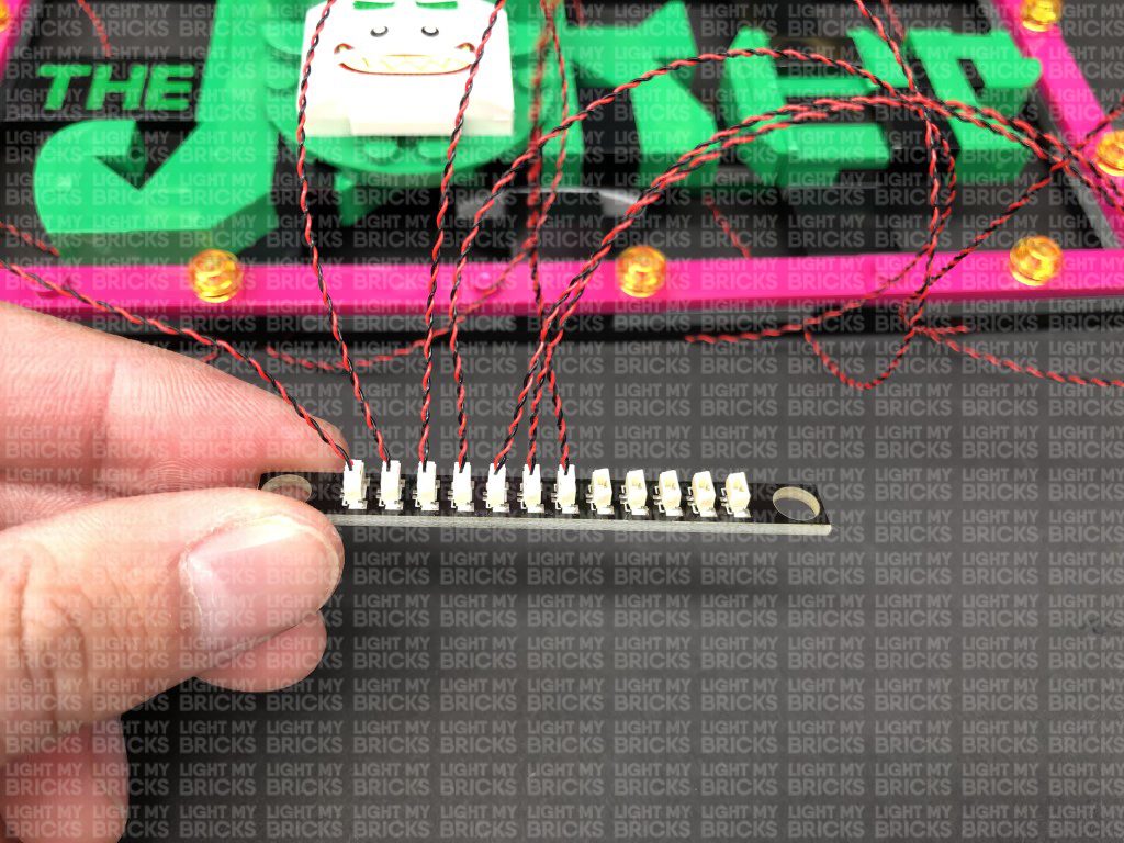
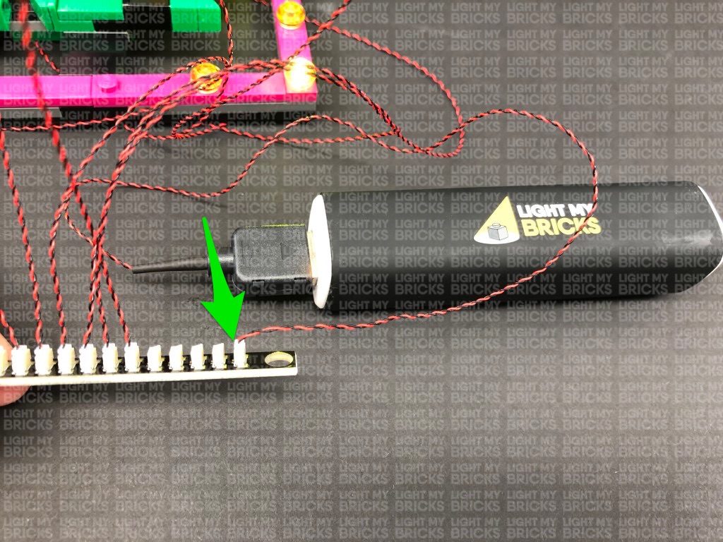
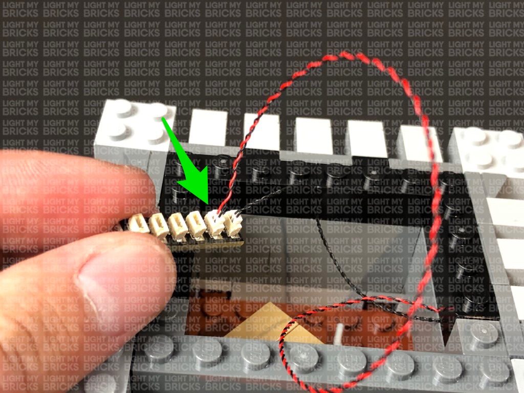
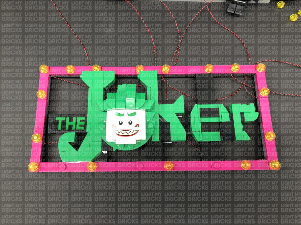 19.) Connect the seven flashing lights installed so far to a new 12-Port Expansion Board. Connect the USB Power Cable to the expansion board and connect up the usb power bank. Turn the USB Power Bank ON to test the flashing lights installed so far are working OK.
Note: If you experience any issues with the lights not working and suspect an issue with a component, please try a different port on the expansion board to verify where the fault lies (with the light or expansion board). To correct any issues with expansion board ports, please view the section addressing expansion board issues on our online troubleshooting guide.
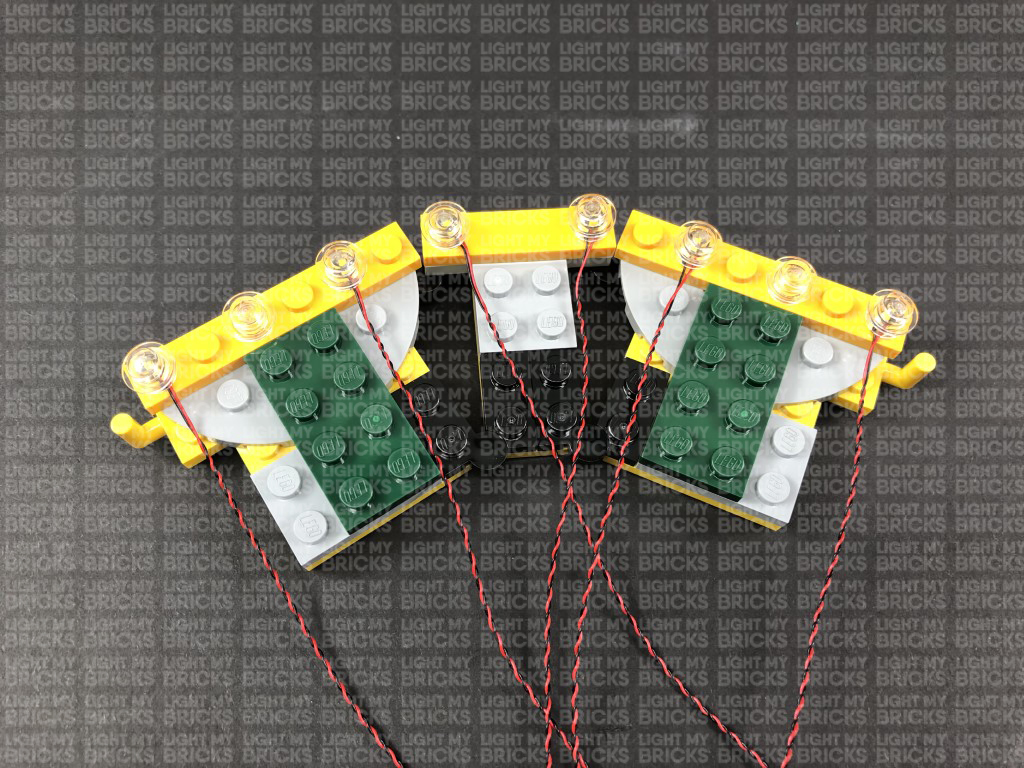
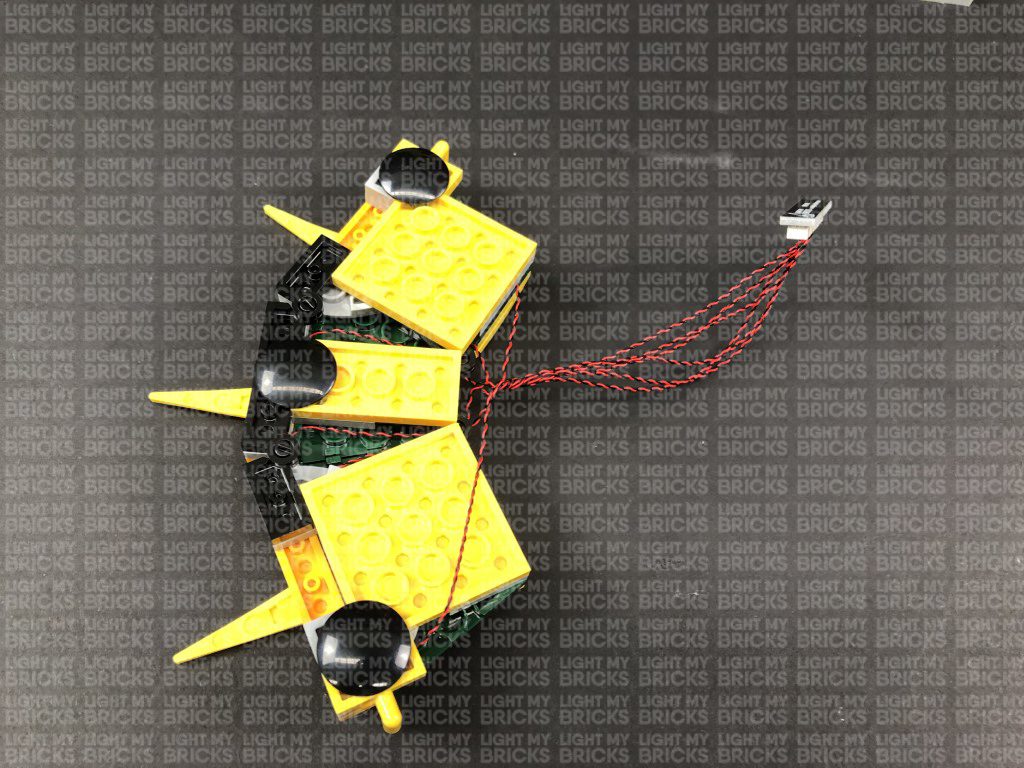
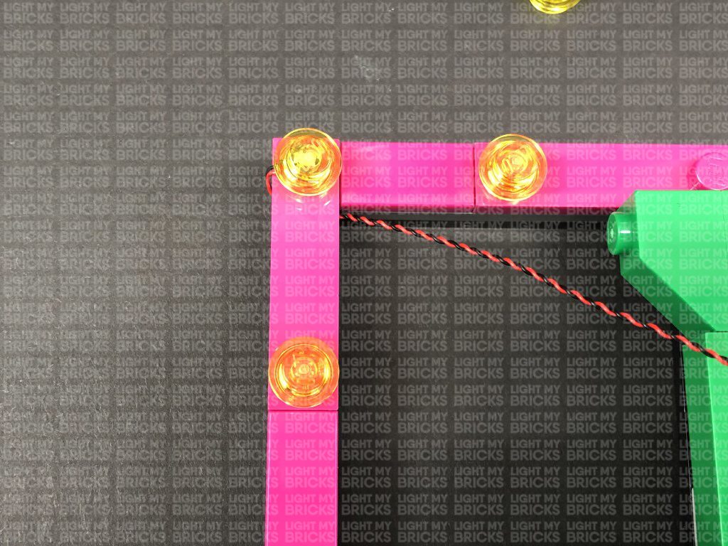
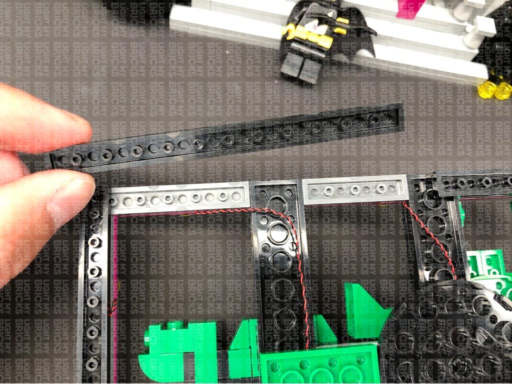
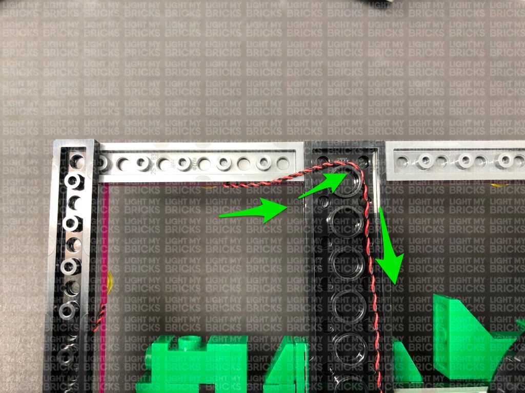
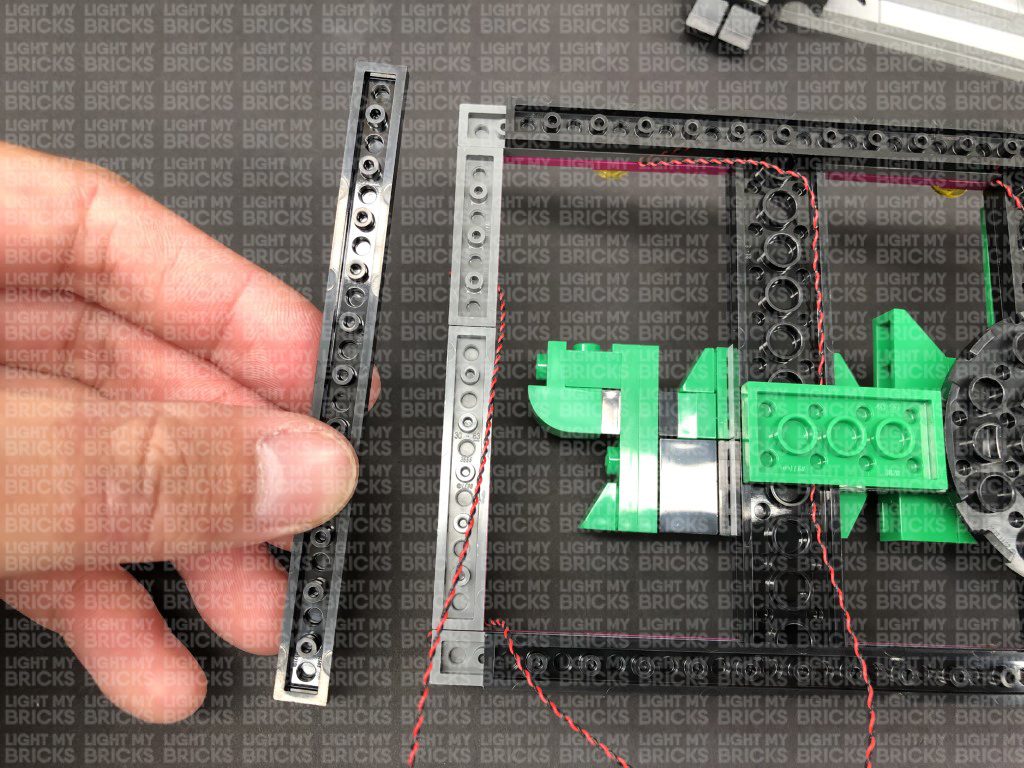
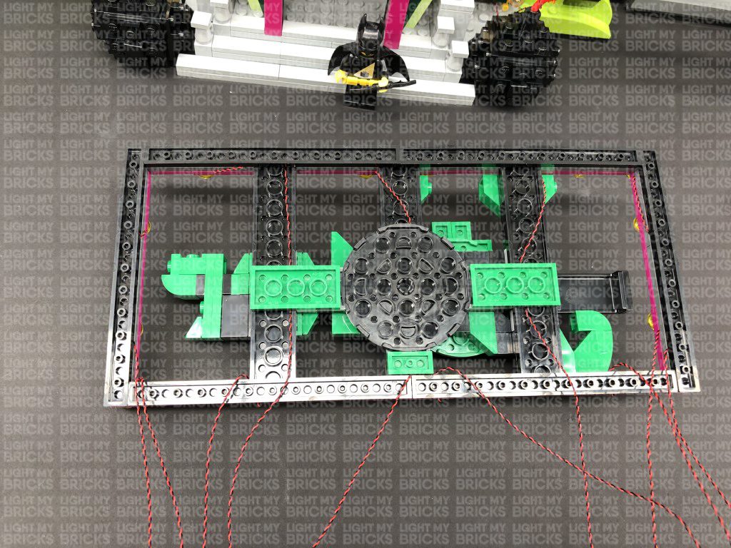
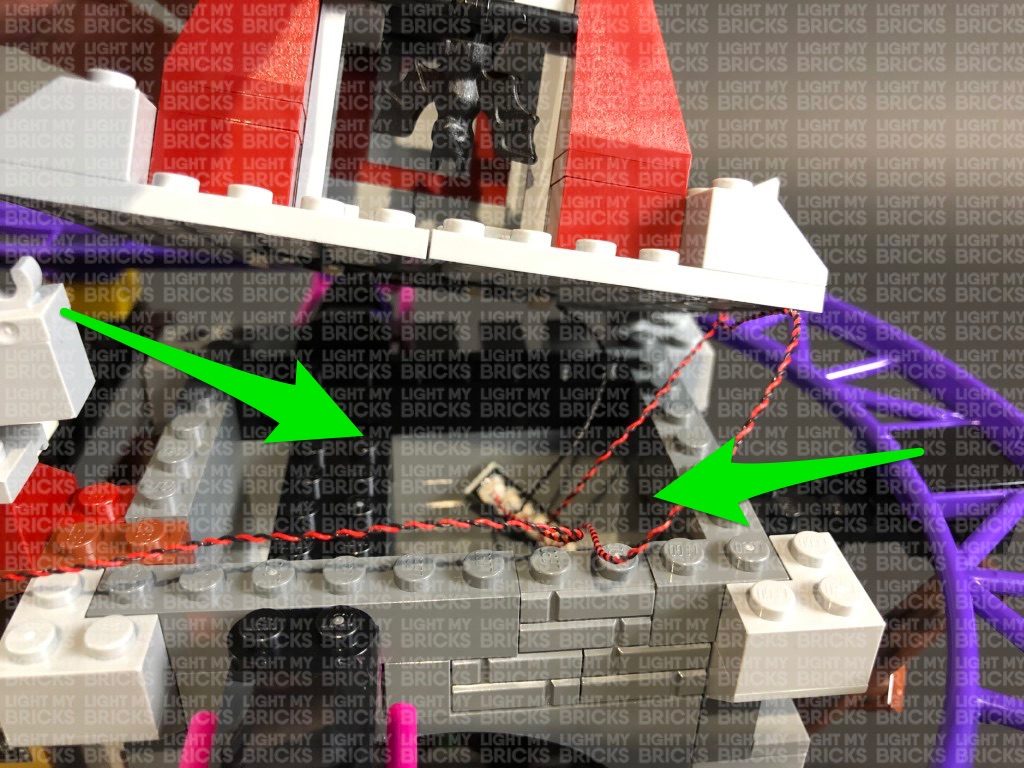
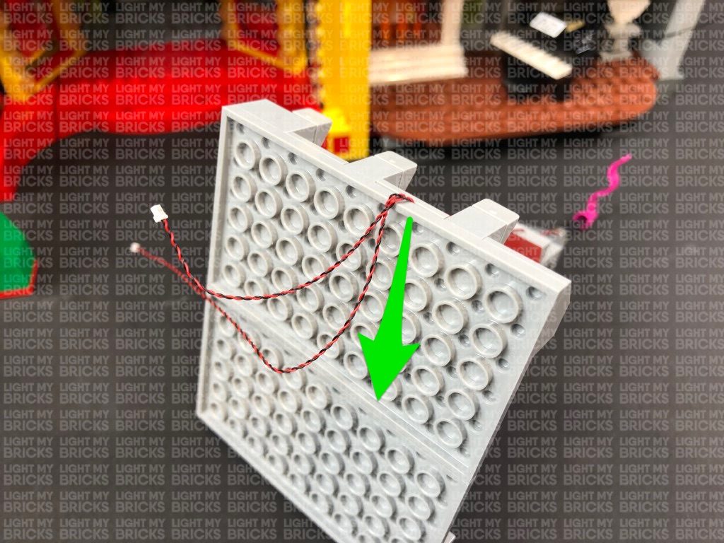
20.) Disconnect the lights from the 12-port expansion board, then turn the Joker sign over as we will now neaten up the wires. Lay out the top left corner wires as shown below (one to each side), then disconnect the black plate on the top of the sign. Lay the cable going across the right in between studs before reconnecting the plate over the top as shown below:
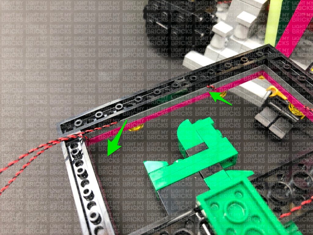
Disconnect the green 2×4 plate and lay the right wire down underneath before reconnecting the green plate over the top.
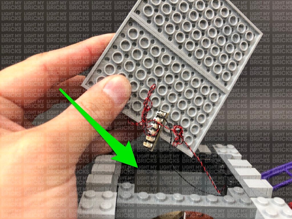
Disconnect the following pieces from the back of the Joker Sign then lay the next two wires to the right down, before reconnecting the pieces over the top. Ensure all wires are laid in the middle of the pieces and in between studs.
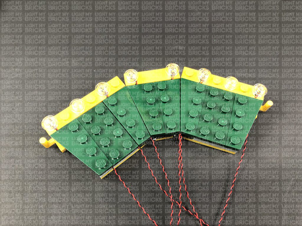
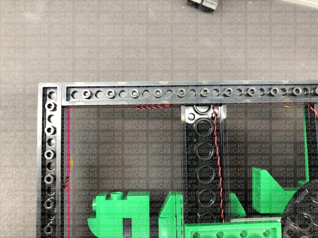
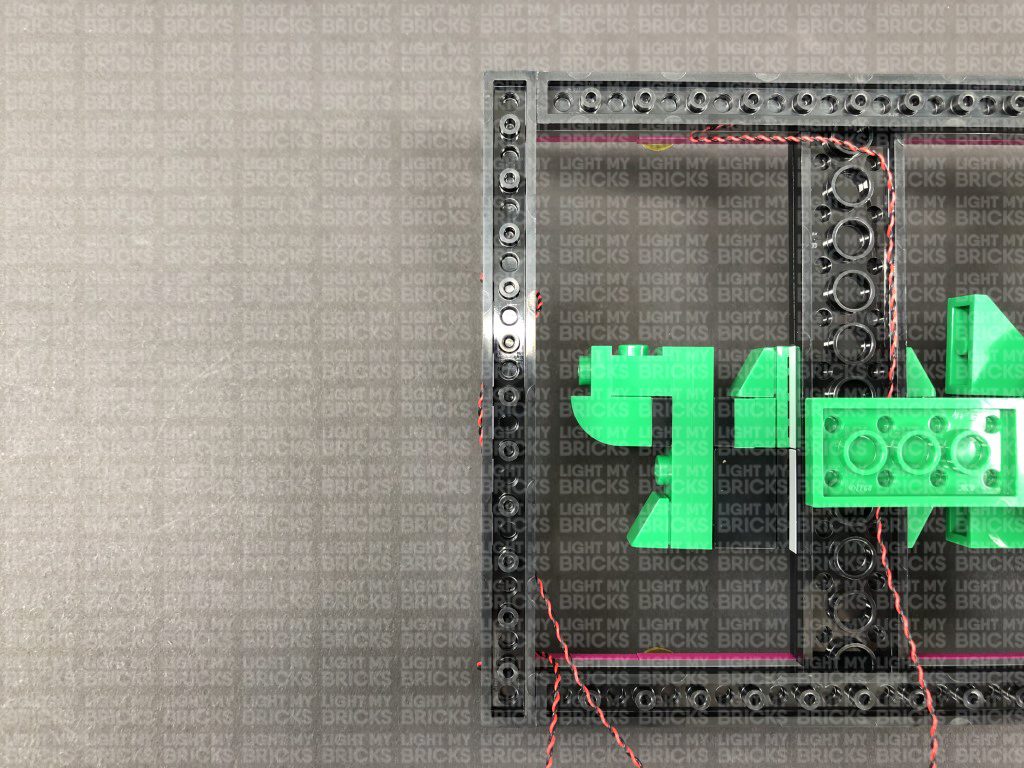
21.) Disconnect the black plate on the left side of the sign. Lay the wire on the left side down then reconnect the black plate ensuring you secure the wire in between studs as shown below:
Repeat the same process to hide and secure the wire on the right side underneath the black plate.
Turn the Joker Sign back over. There should be no dangling wires shown.
19.) Connect the seven flashing lights installed so far to a new 12-Port Expansion Board. Connect the USB Power Cable to the expansion board and connect up the usb power bank. Turn the USB Power Bank ON to test the flashing lights installed so far are working OK.
Note: If you experience any issues with the lights not working and suspect an issue with a component, please try a different port on the expansion board to verify where the fault lies (with the light or expansion board). To correct any issues with expansion board ports, please view the section addressing expansion board issues on our online troubleshooting guide.
20.) Disconnect the lights from the 12-port expansion board, then turn the Joker sign over as we will now neaten up the wires. Lay out the top left corner wires as shown below (one to each side), then disconnect the black plate on the top of the sign. Lay the cable going across the right in between studs before reconnecting the plate over the top as shown below:
Disconnect the green 2×4 plate and lay the right wire down underneath before reconnecting the green plate over the top.
Disconnect the following pieces from the back of the Joker Sign then lay the next two wires to the right down, before reconnecting the pieces over the top. Ensure all wires are laid in the middle of the pieces and in between studs.
21.) Disconnect the black plate on the left side of the sign. Lay the wire on the left side down then reconnect the black plate ensuring you secure the wire in between studs as shown below:
Repeat the same process to hide and secure the wire on the right side underneath the black plate.
Turn the Joker Sign back over. There should be no dangling wires shown.
 22.) We will now install flashing lights with shorter cables to the remaining bottom section. Using the same method as above, install 3x Flashing White 15cm Bit Lights as per below:
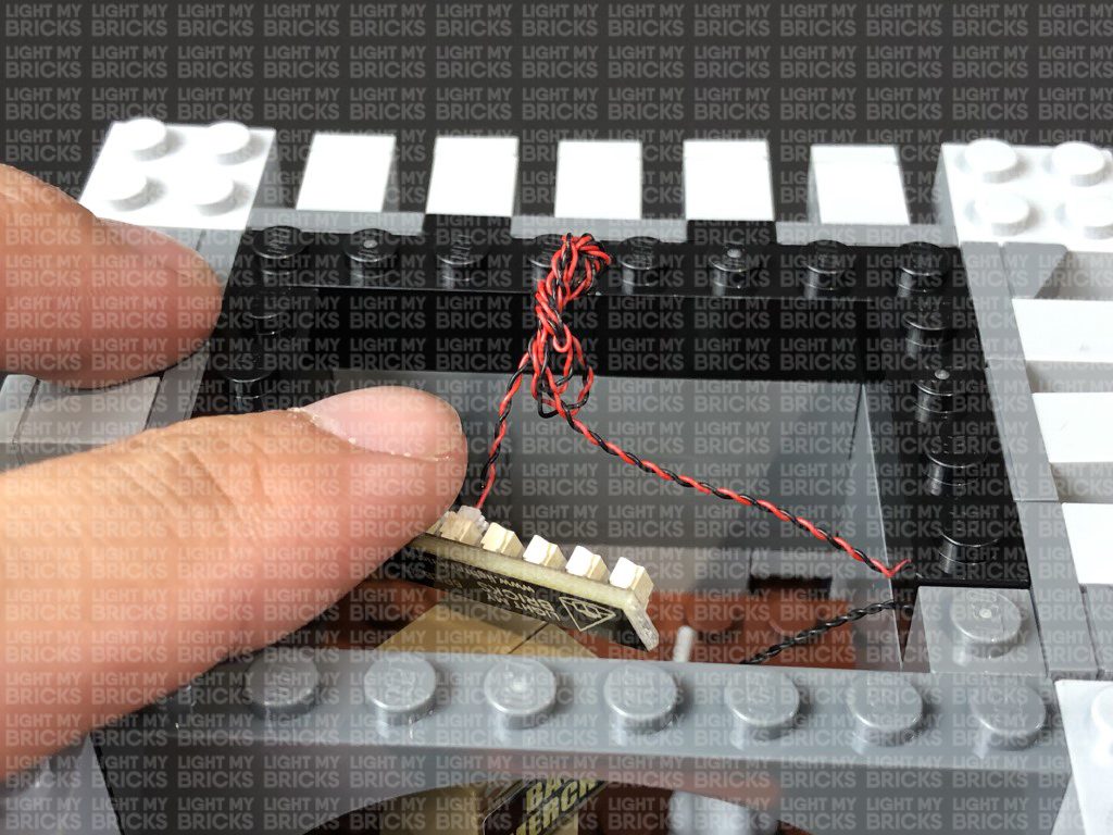
 23.) Turn the Joker Sign over. Secure the following 4 wires underneath the bottom black plate as shown below, ensuring the two on each side are laid in between studs.
Take the two lots of wires and twist/wind them around each other all the way to their ends so they come together to form one larger cable.
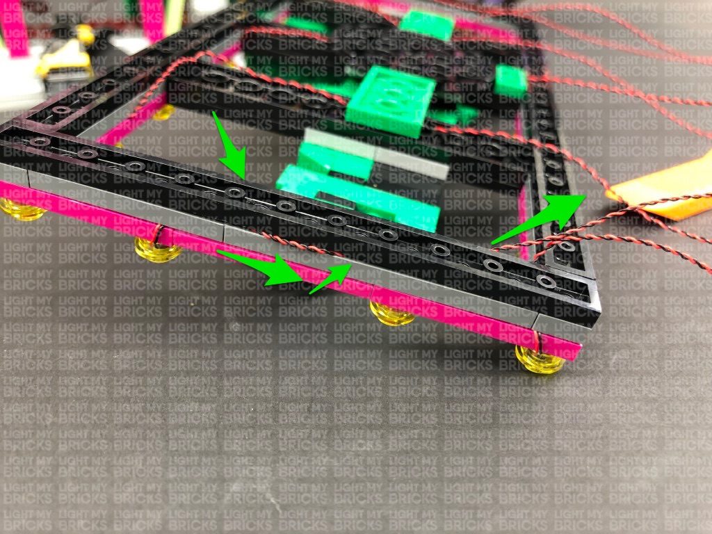
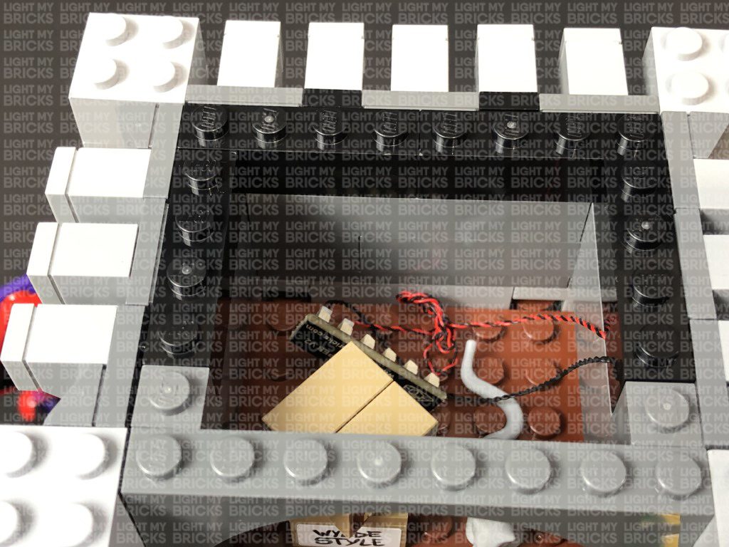
24.) Disconnect the black plate on the right side, then lay the six wires down in between studs before reconnecting the black plate over the top.
Group the six wires and twist/wind them around each other all the way to their ends so they come together to form one larger cable.
23.) Turn the Joker Sign over. Secure the following 4 wires underneath the bottom black plate as shown below, ensuring the two on each side are laid in between studs.
Take the two lots of wires and twist/wind them around each other all the way to their ends so they come together to form one larger cable.
24.) Disconnect the black plate on the right side, then lay the six wires down in between studs before reconnecting the black plate over the top.
Group the six wires and twist/wind them around each other all the way to their ends so they come together to form one larger cable.
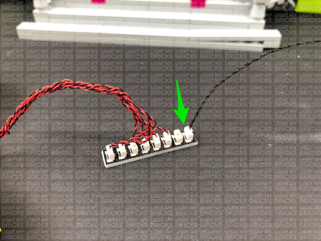
 25.) Take the 12-Port Expansion Board from step 18 and connect the four light cables on the left side to it. Once connected, twist/wind the excess cables around each other as shown below:
Connect the six light cables from the right side to the expansion board, then connect up the USB Power Cable to connect to your USB Power Bank. Turn on the power bank to test all 10 flashing lights are working OK.
Note: If you experience any issues with the lights not working and suspect an issue with a component, please try a different port on the expansion board to verify where the fault lies (with the light or expansion board). To correct any issues with expansion board ports, please view the section addressing expansion board issues on our online troubleshooting guide.
26.) Disconnect the USB Power Cable, then twist/wind excess cables from the right side around each other neatly as shown below:
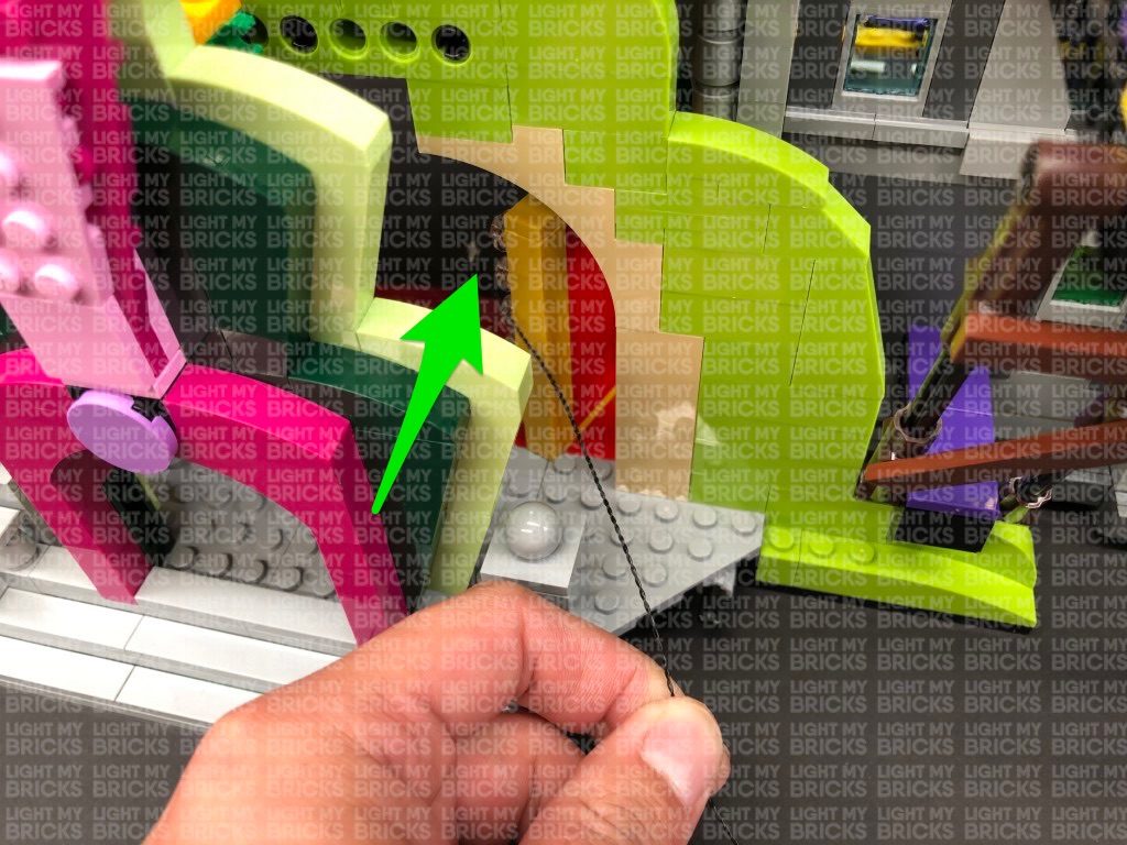
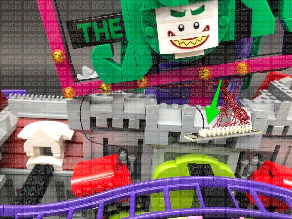
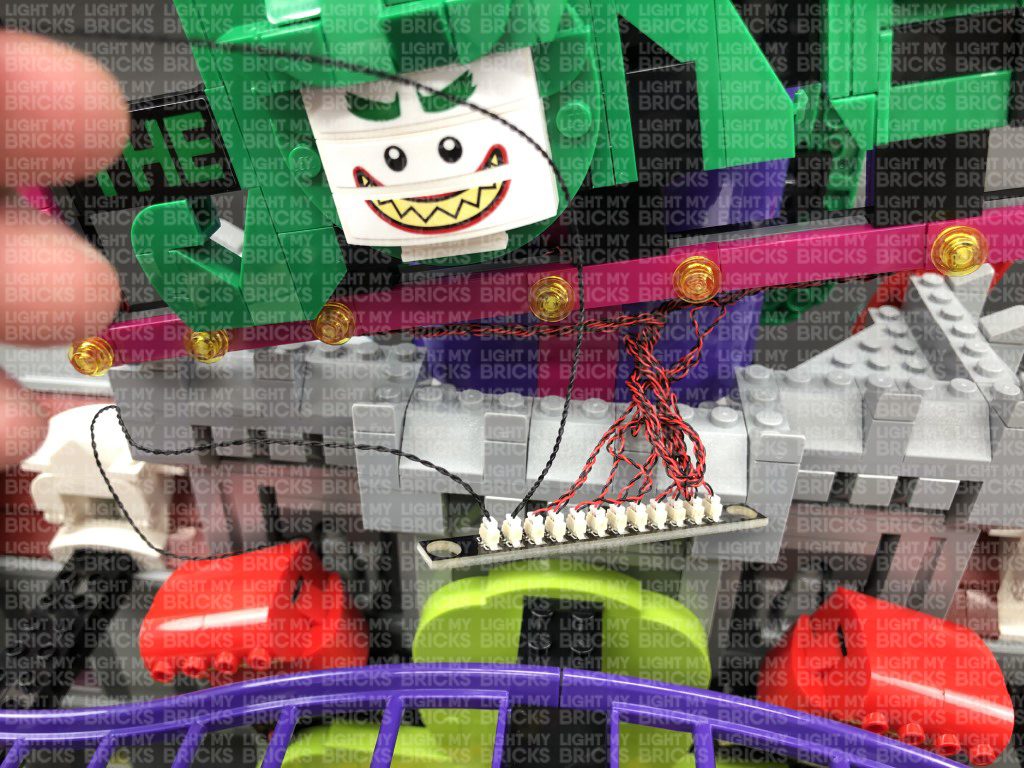
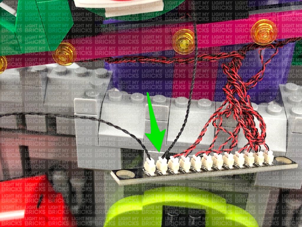
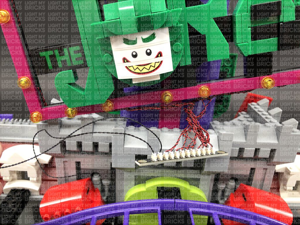
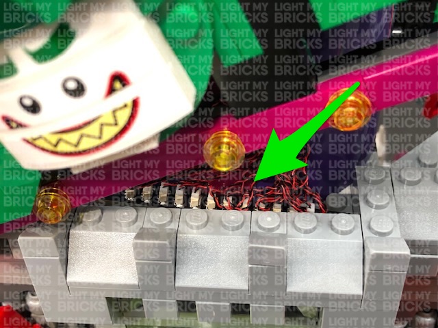
Turn the Joker Sign around, then twist/wind the two groups of cables into a neat bunch. Reconnect the Joker Sign to the front of the building, then connect the other end of the 30cm Connecting Cable that we pulled up from below (step 6) to a spare port on the 12-port Expansion Board.
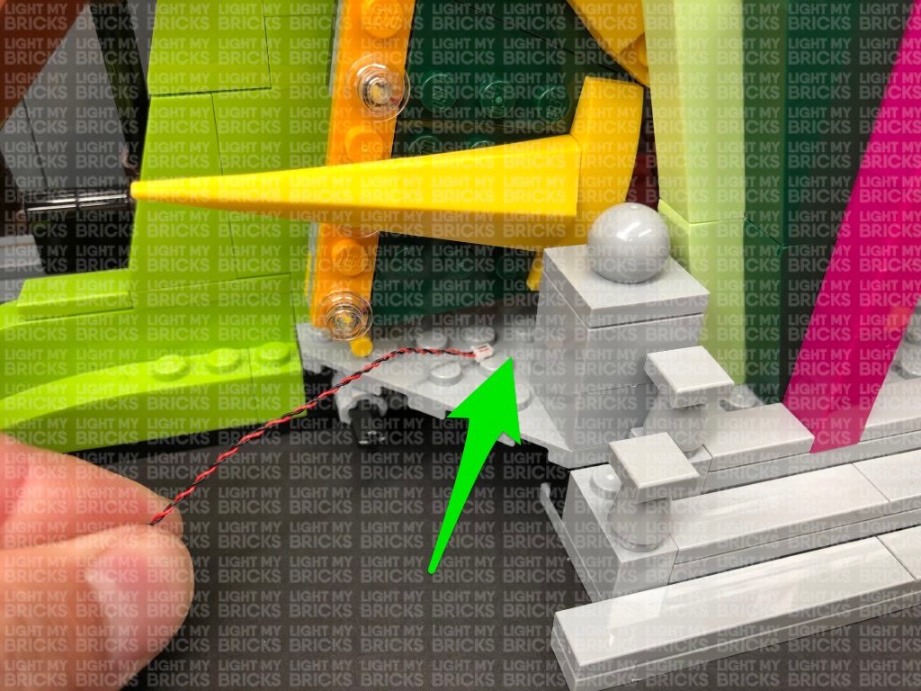
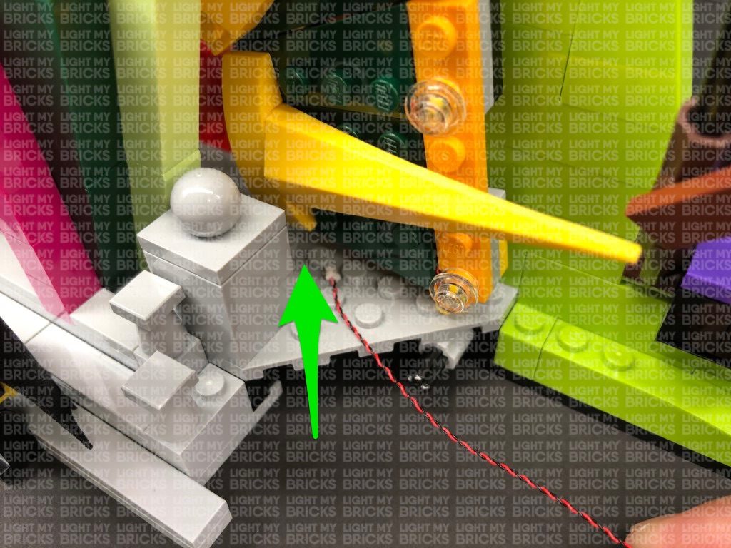
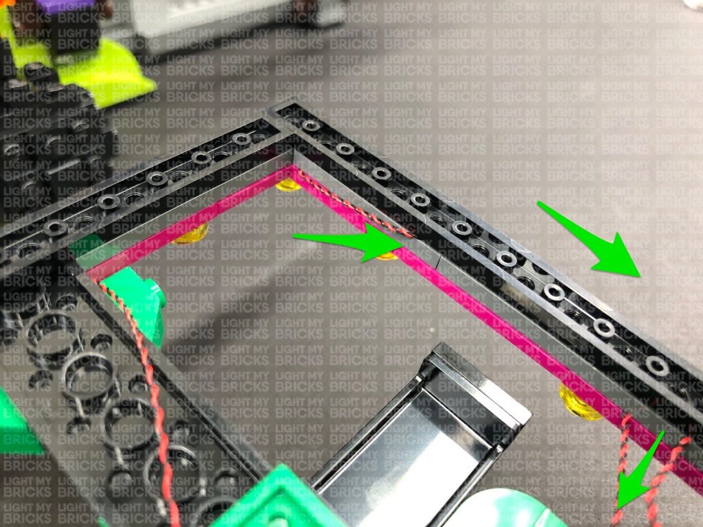
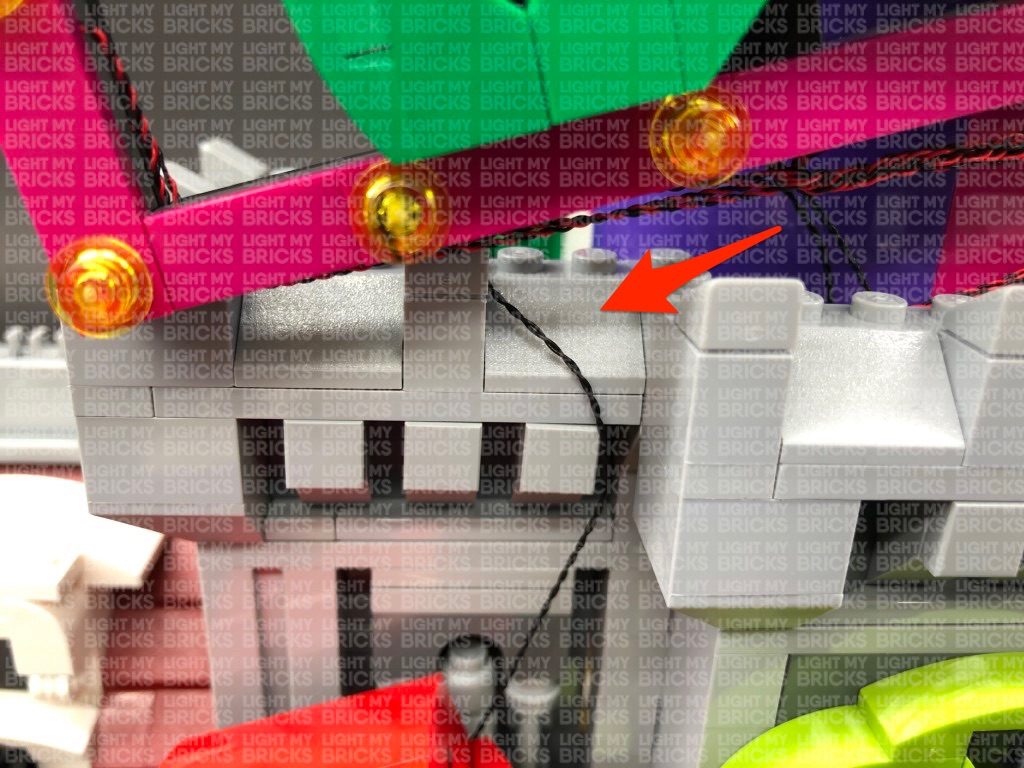
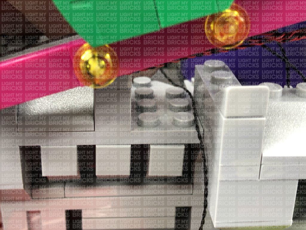
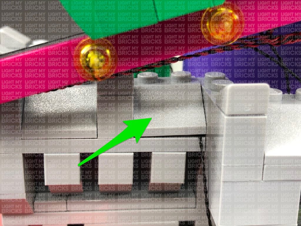
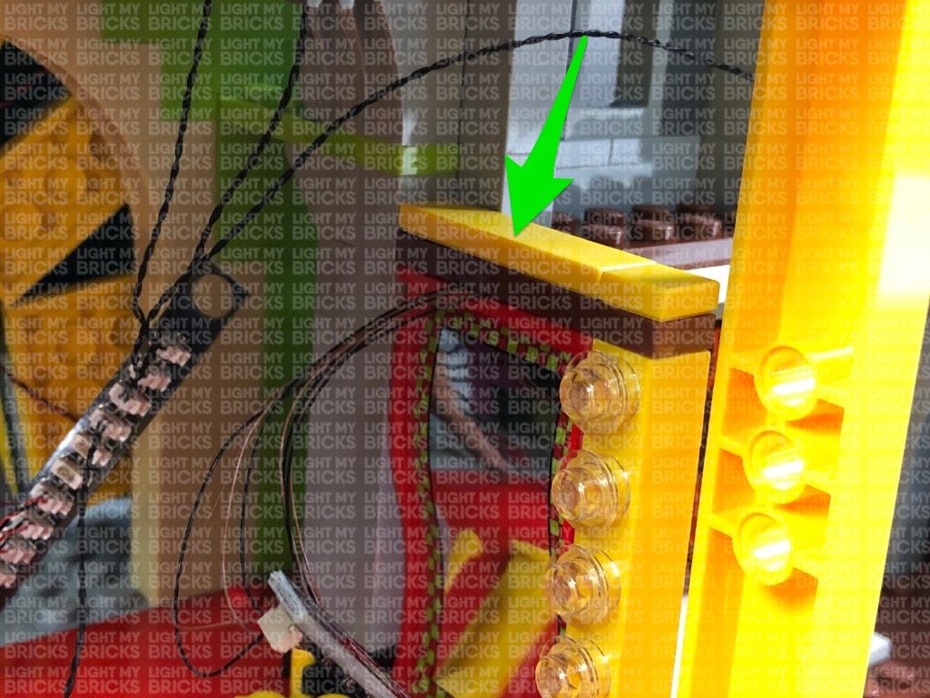
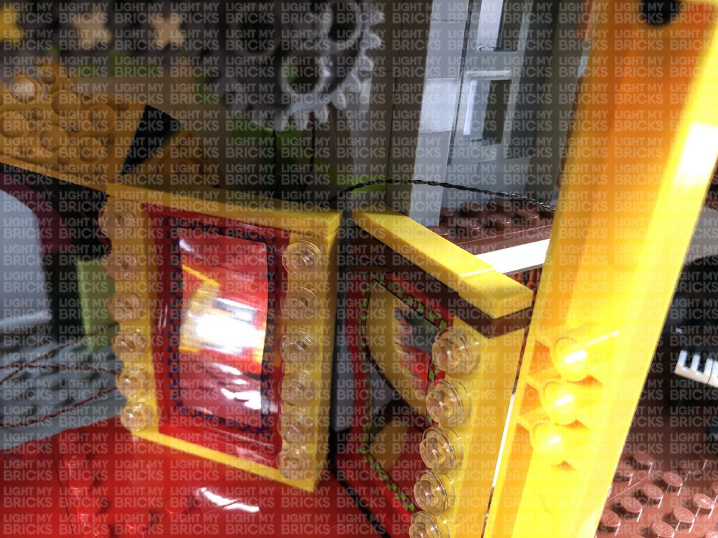
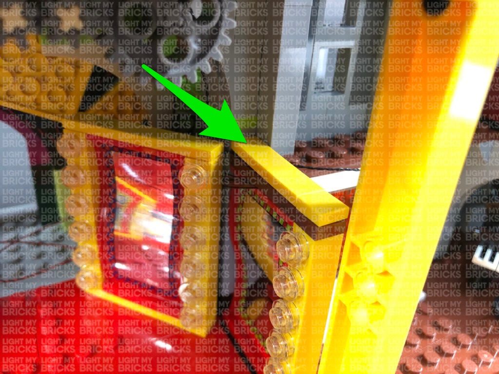
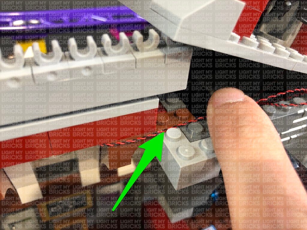
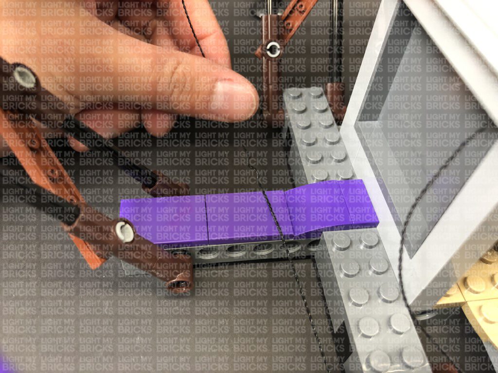
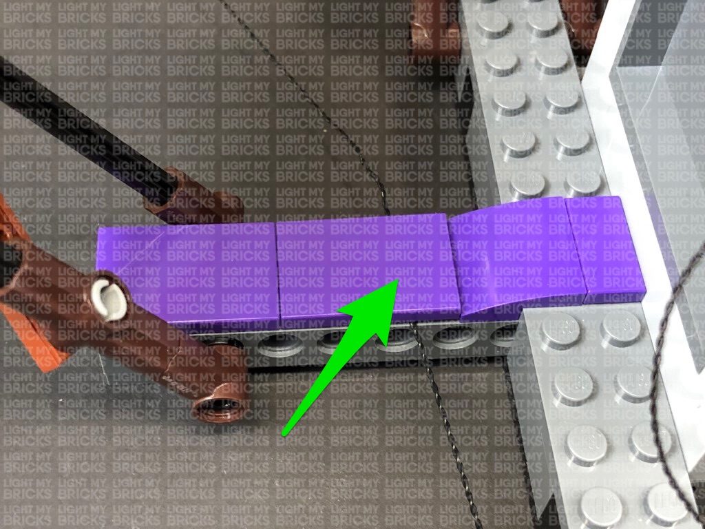
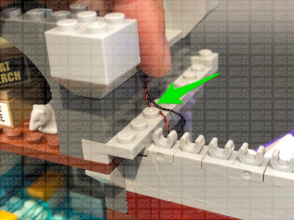
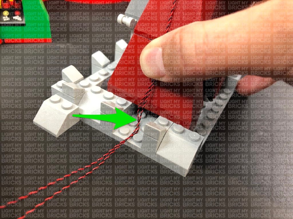
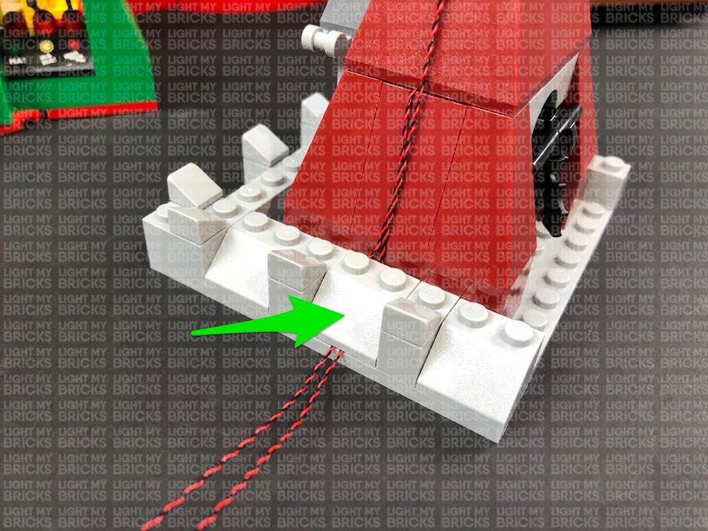
Take a new 30cm Connecting Cable and connect it to the remaining port on the 12-Port Expansion Board. Neatly place the expansion board down the space in between the wall edge and the joker sign. Thread both 30cm Cables underneath and behind the bottom of the Joker Sign, then secure 30cm cable from below underneath the following angled brick.
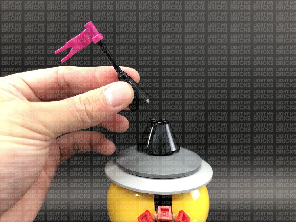
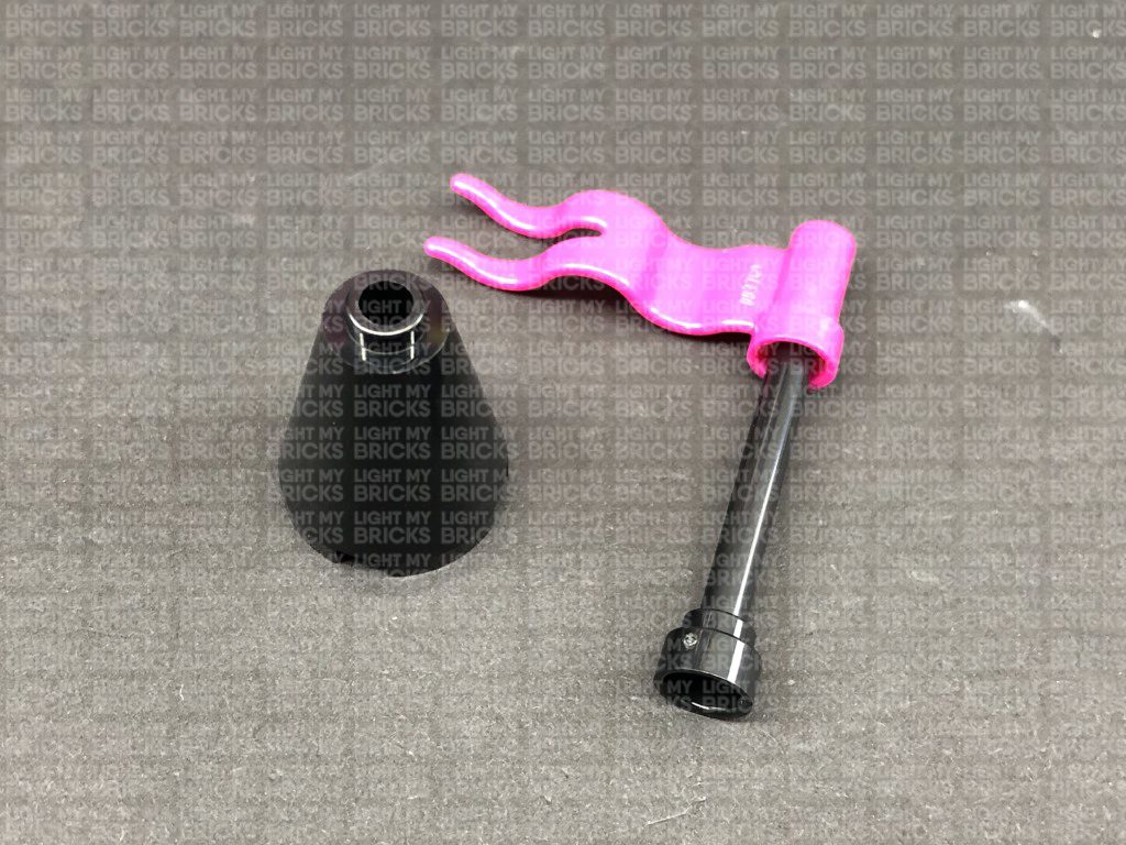
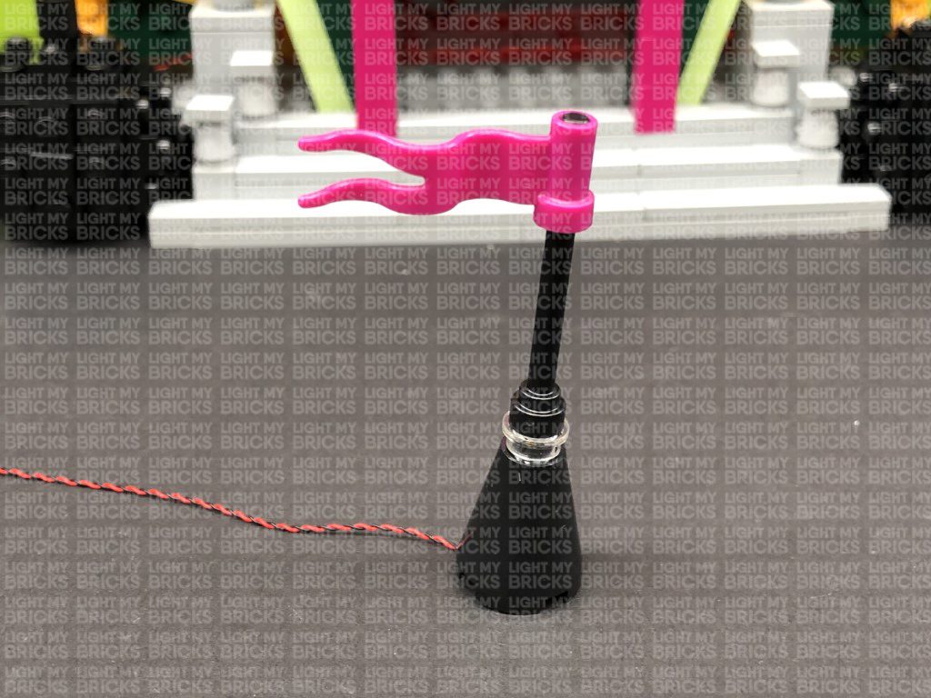
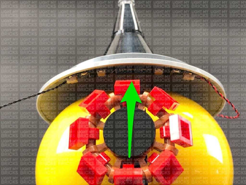
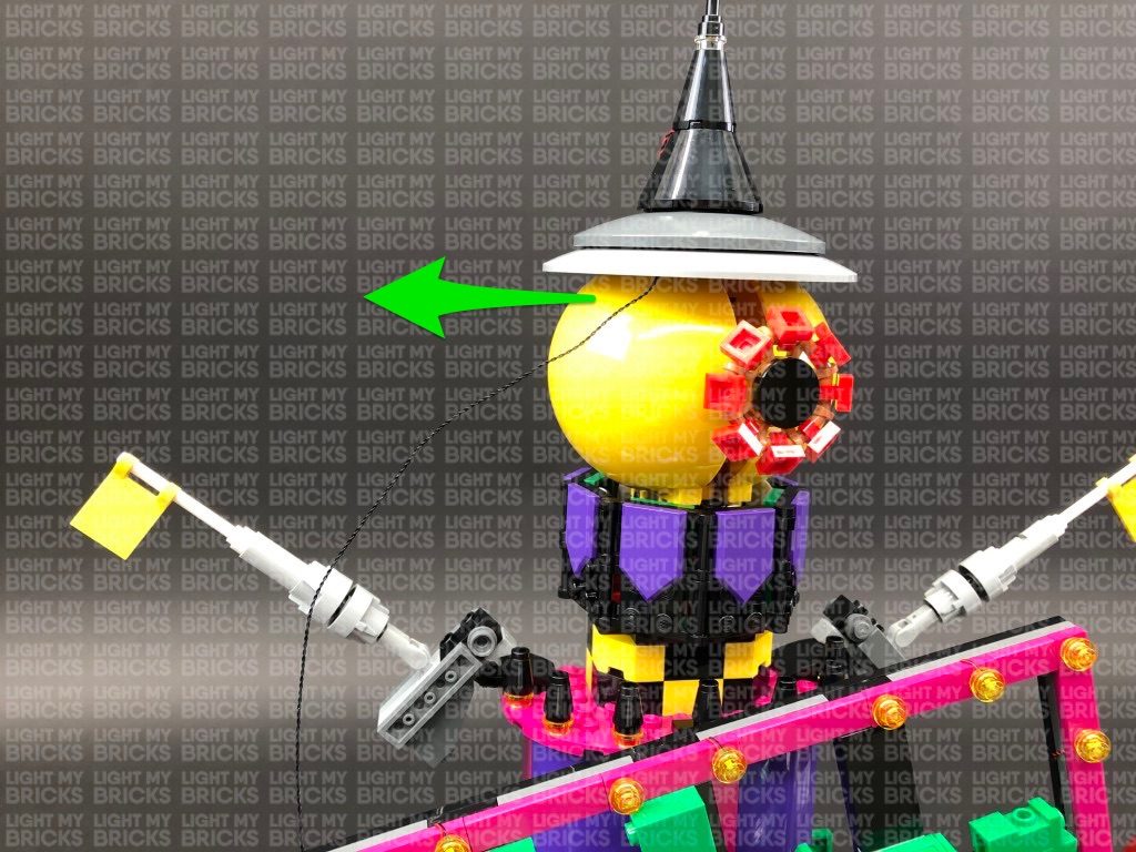
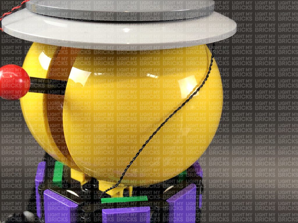
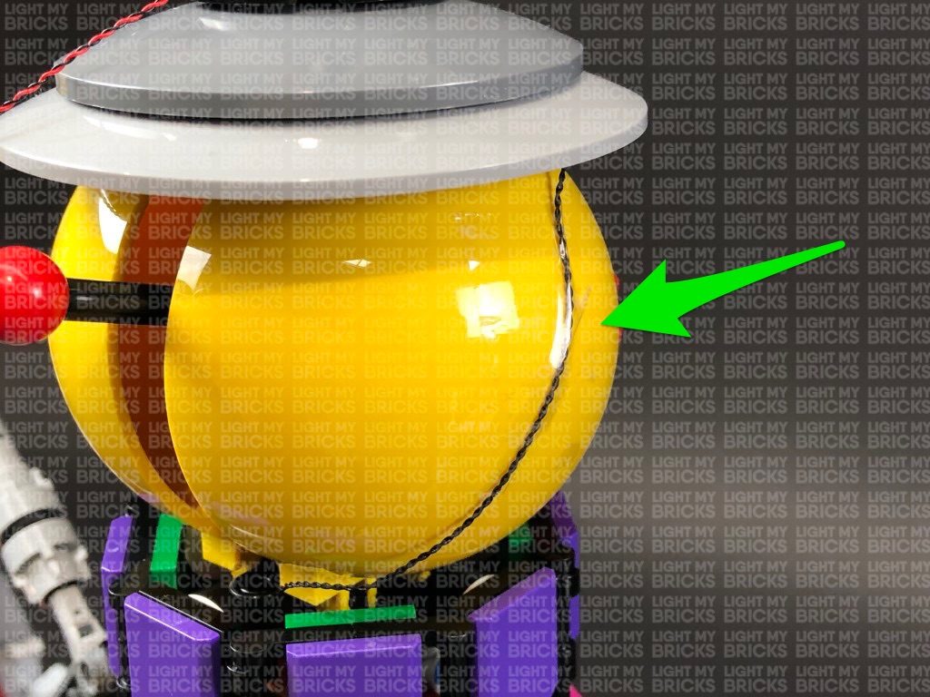
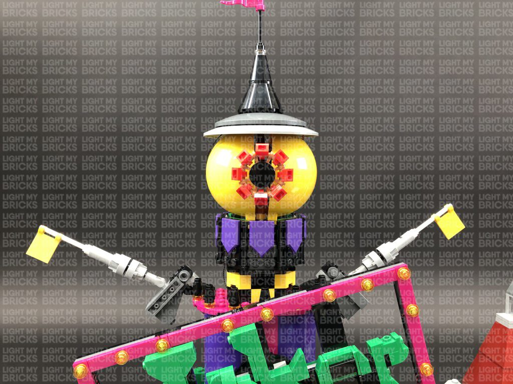
27.) Disconnect the following sections on top of the giant eyeball then disconnect the black cone piece at the bottom of it.
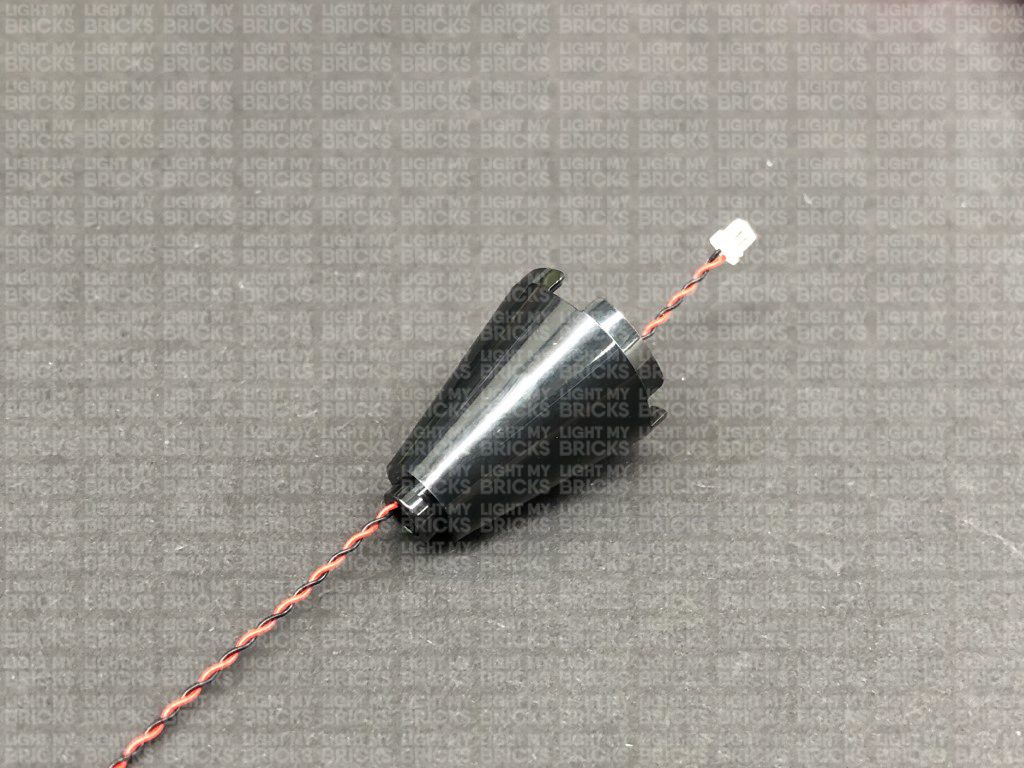
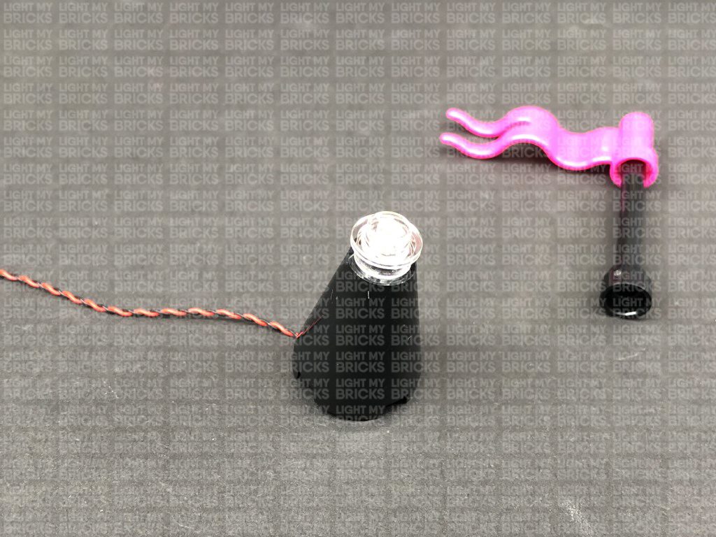
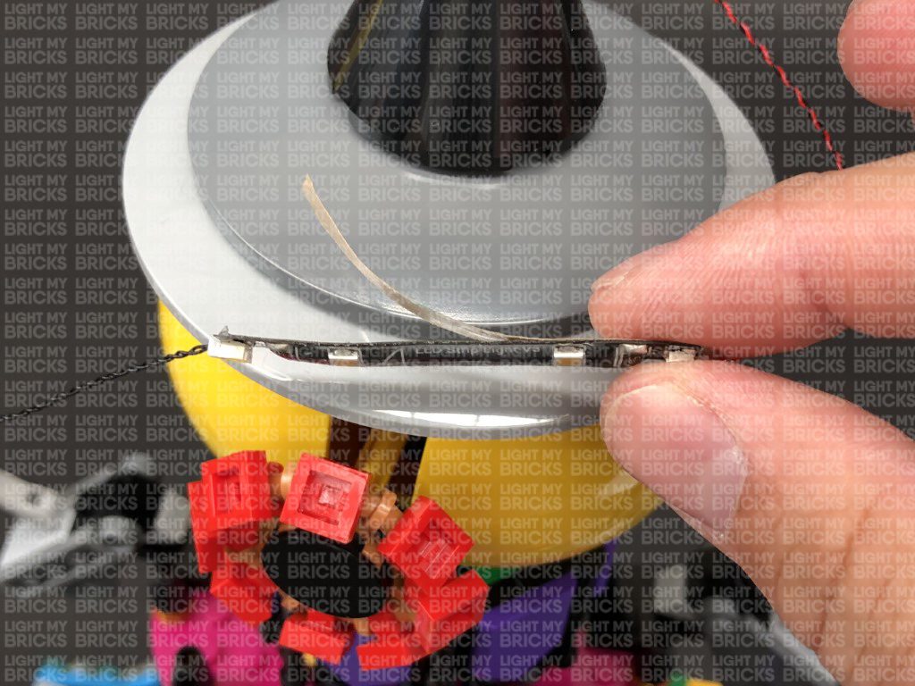
Take a White 15cm Bit Light and thread the connector end of the cable through the top of the black cone piece. Gently bend the LED so that it sits flat against the edge of the stud, then secure the Bit Light in place by connecting a provided Trans Clear Round Plate 1×1 over the top. Reconnect the flag and pole to the top before reconnecting this whole section back on top of the giant eyeball
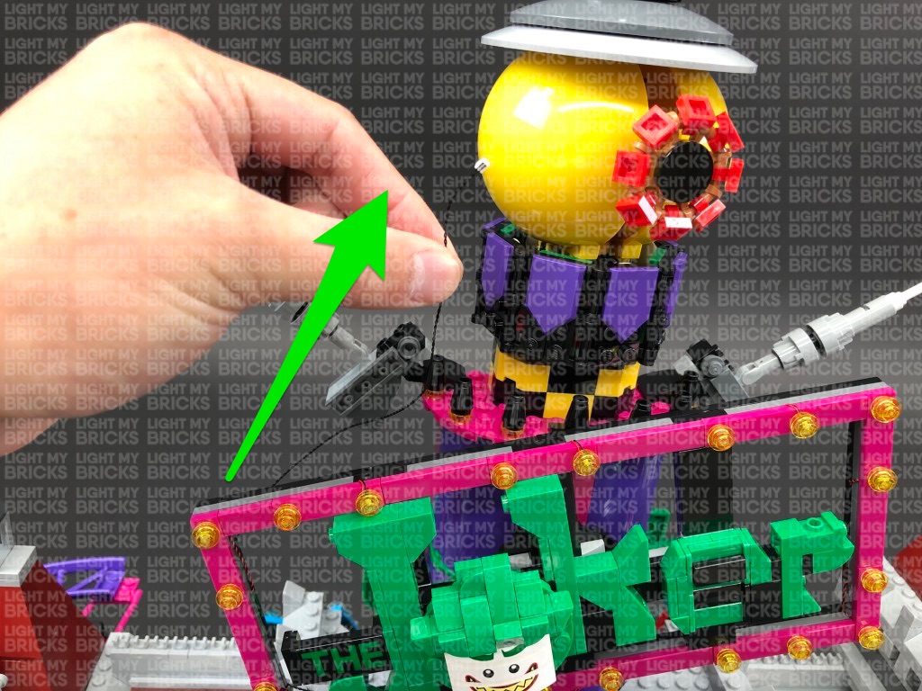
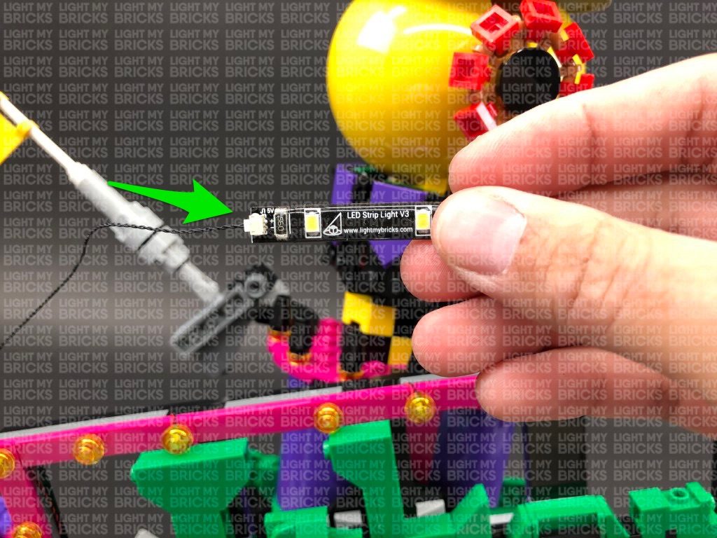
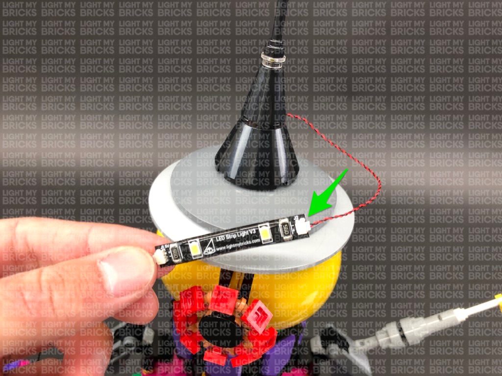
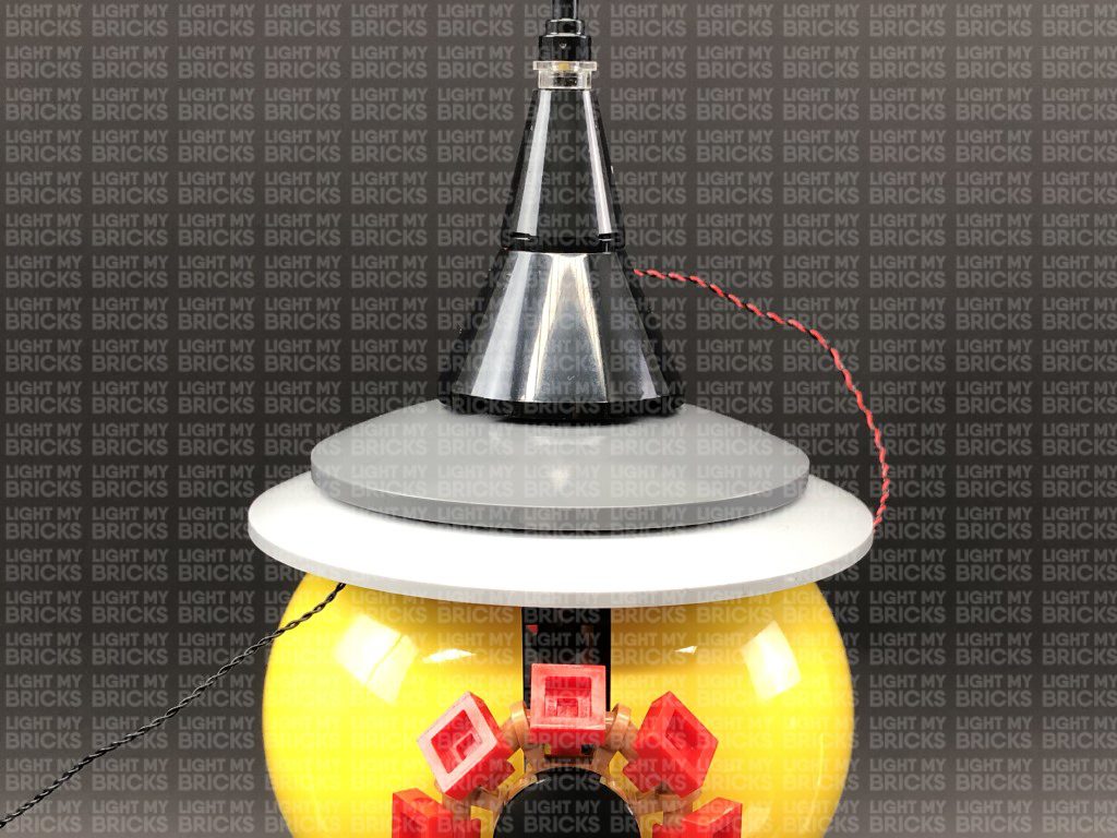
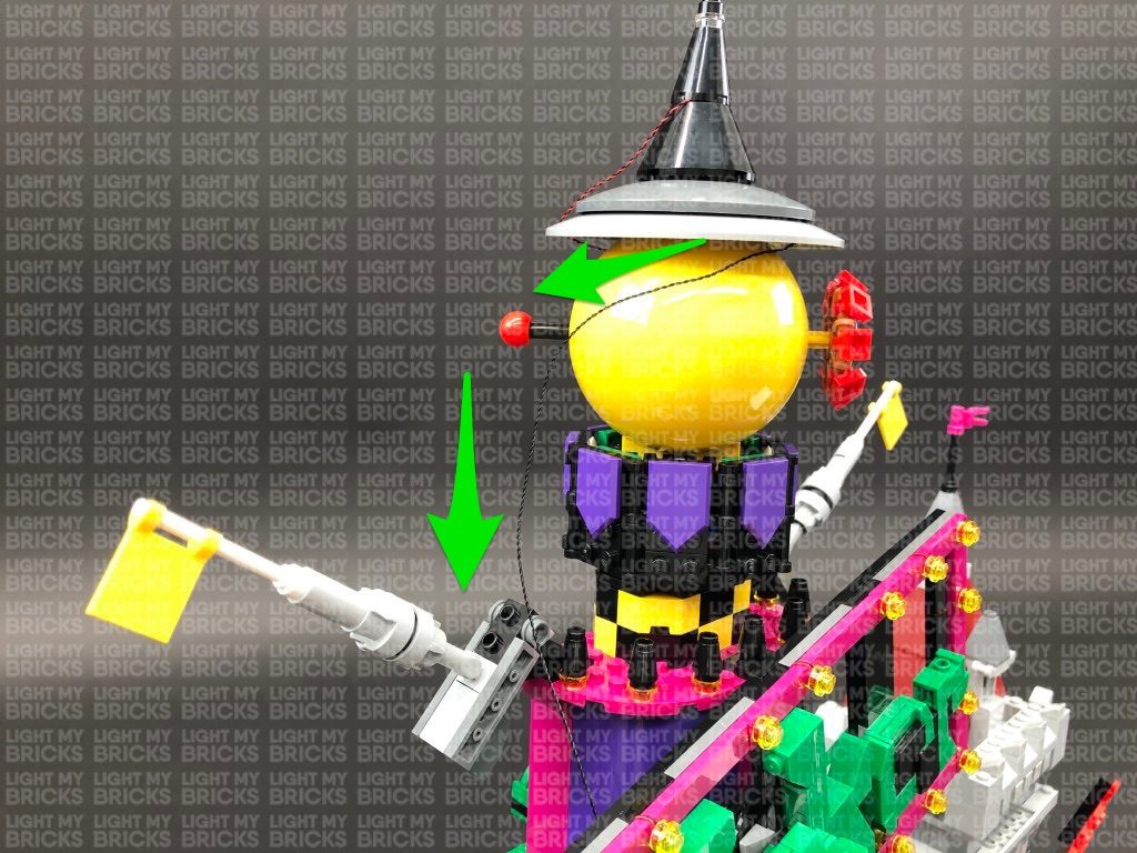
28.) Pull the other end of the 30cm Connecting Cable from previous step up behind the Joker Sign then connect it to a White Strip Light. Connect the White 15cm Bit Light from above the giant eyeball to the right port on the strip light. Using it’s adhesive backing, stick the Strip Light underneath the roof of the giant eyeball in the below position so that it shines down onto the eye.
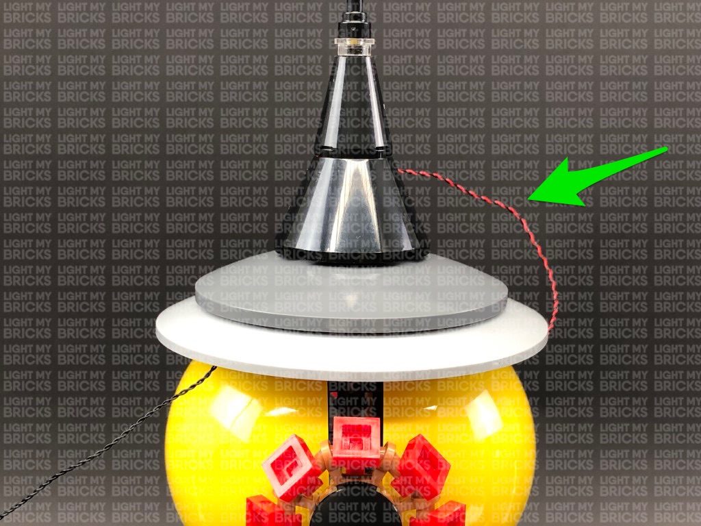
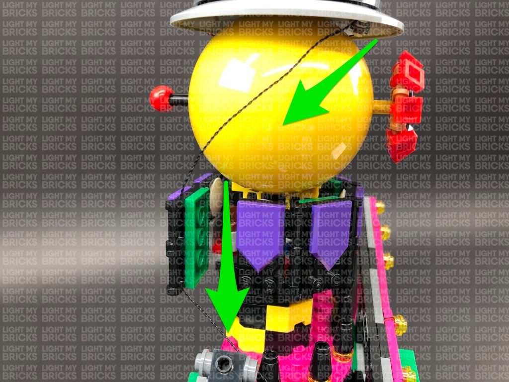
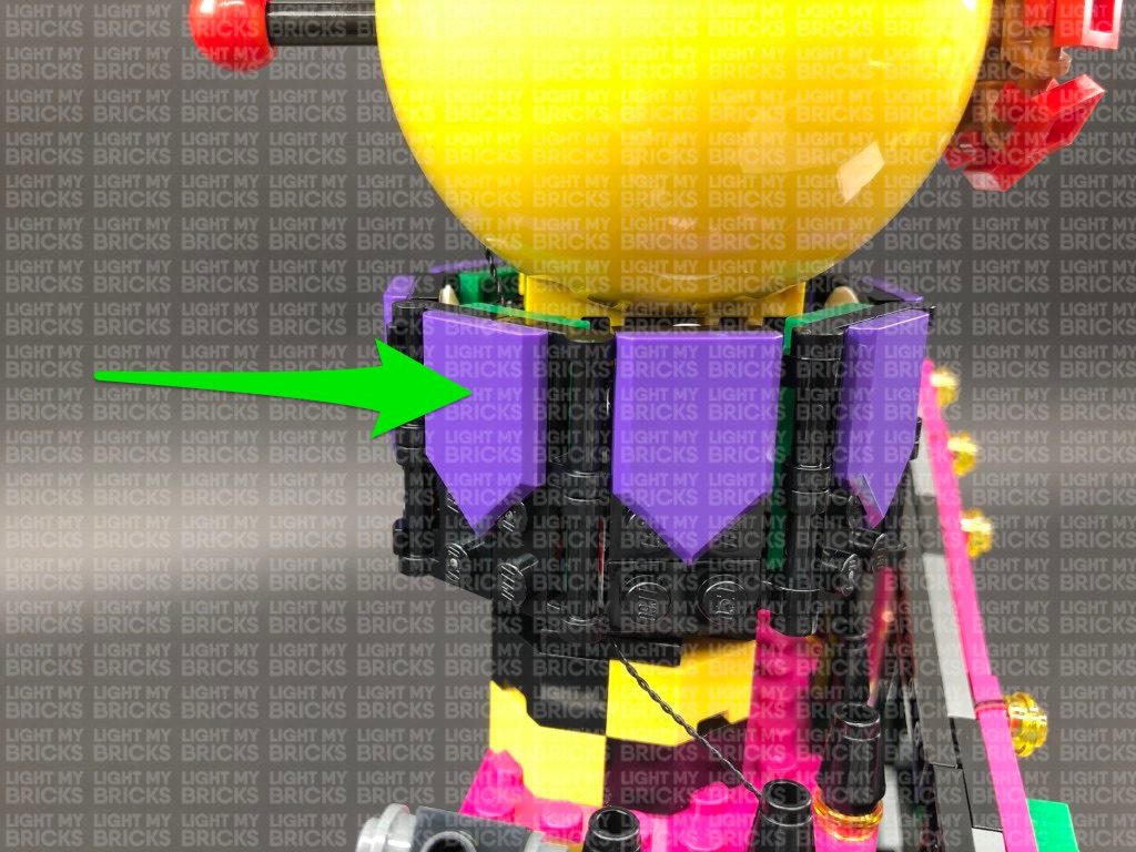
Secure the cable from the bit light around the back of the roof to the left side, then bring the connecting cable around the back of the eyeball to the left side. Secure the connecting cable underneath the purple flap section then use some tape to secure the cable to the back of the giant eyeball as shown below:
Connect the USB power cable (connected to power bank) to the 12-Port Expansion Board on the back of the set (as per step 9). Turn ON the USB Power Bank to test all the lights installed to the front of the Joker Manor are working OK.
Note: If you experience any issues with the lights not working and suspect an issue with a component, please try a different port on the expansion board to verify where the fault lies (with the light or expansion board). To correct any issues with expansion board ports, please view the section addressing expansion board issues on our online troubleshooting guide.
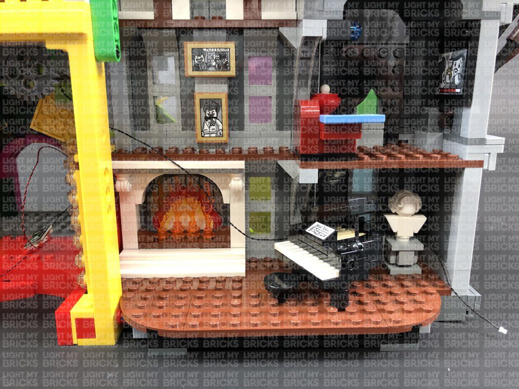
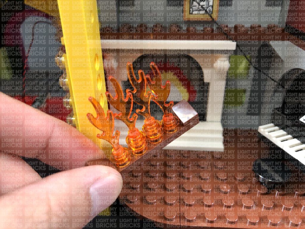
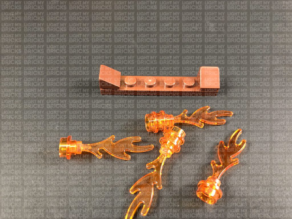
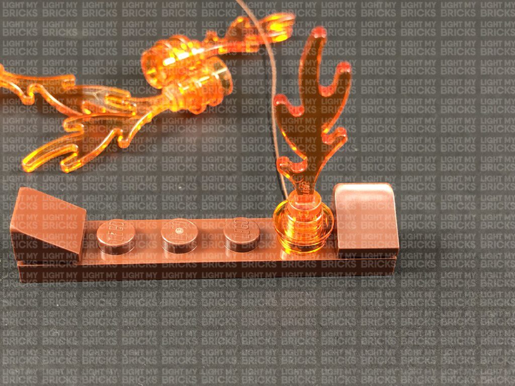
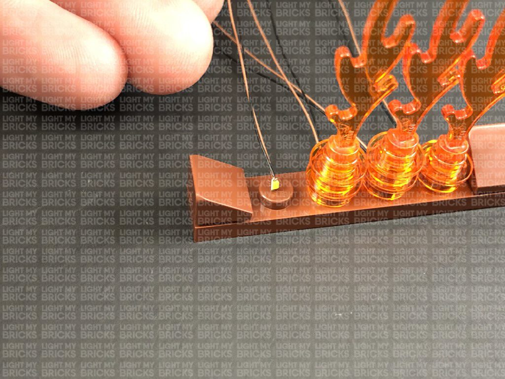
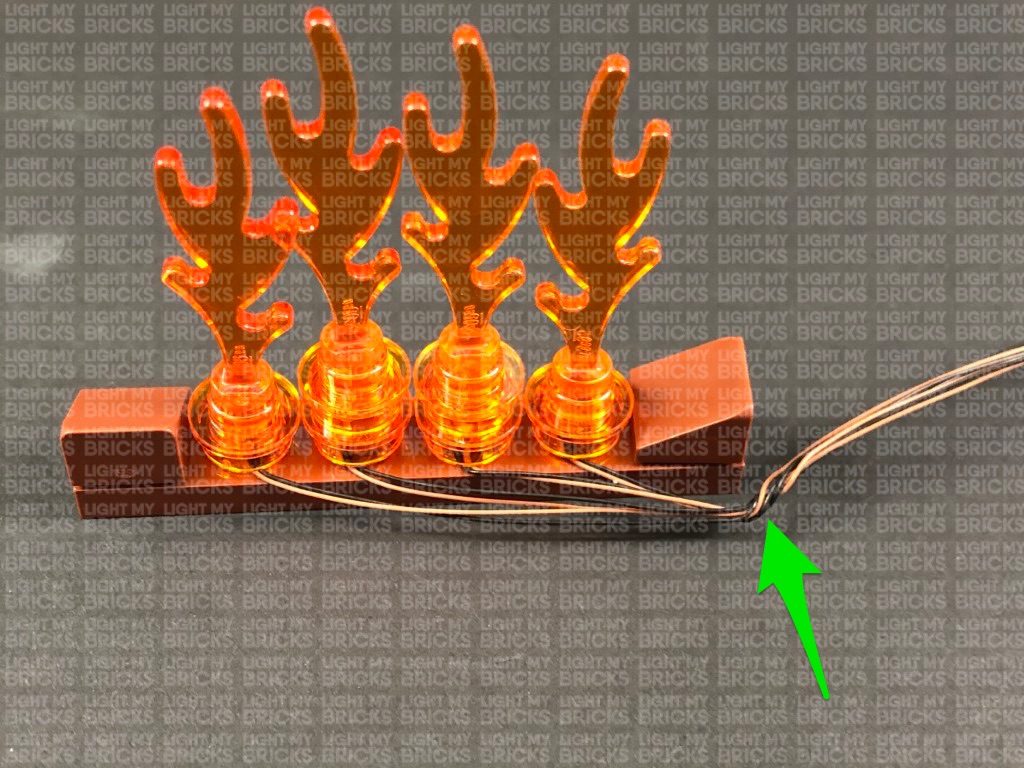
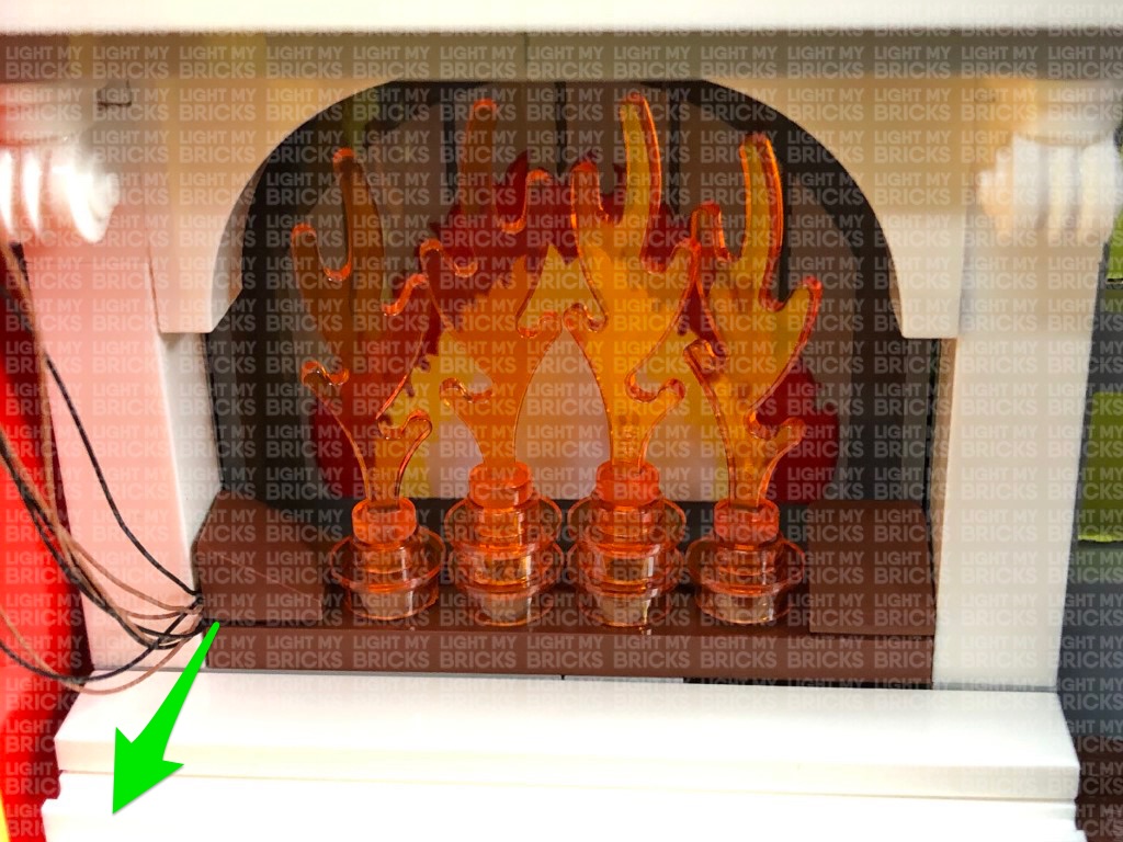
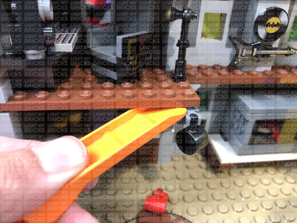
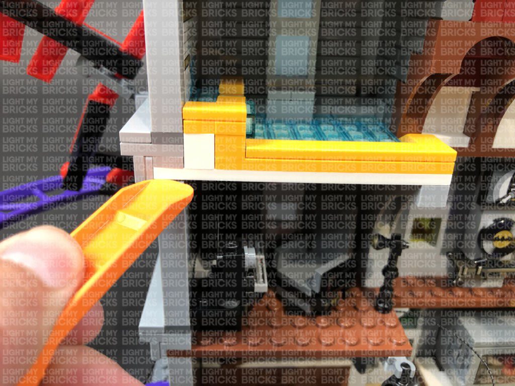
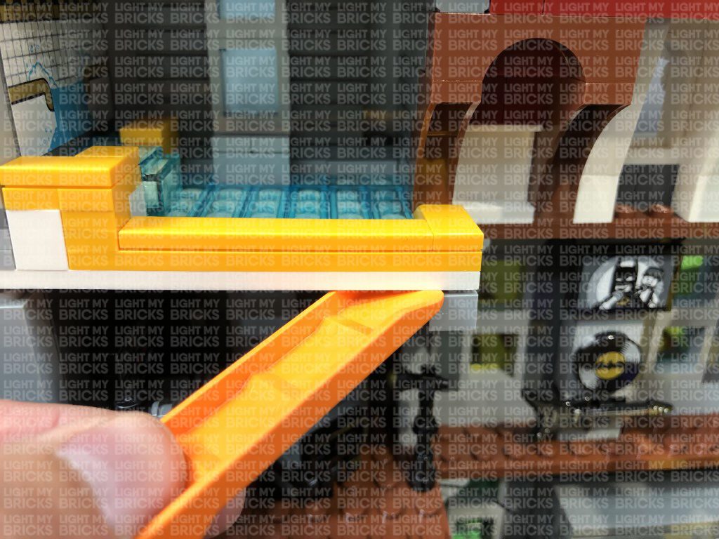
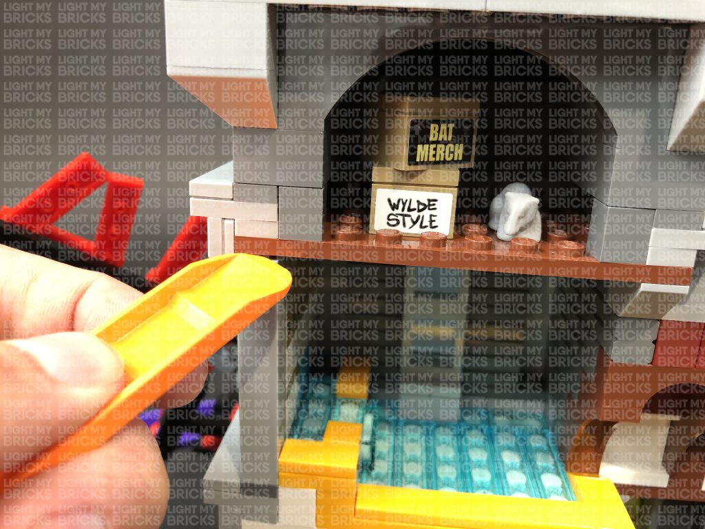
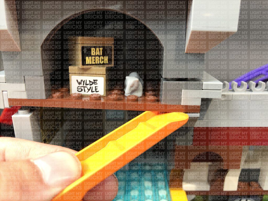
29.) Turn the entire set around to the back as we will now light the inside of the Joker Manor starting with fire place. Using your LEGO removal tool, remove the flame section at the brown plate, then disconnect the flame pieces.
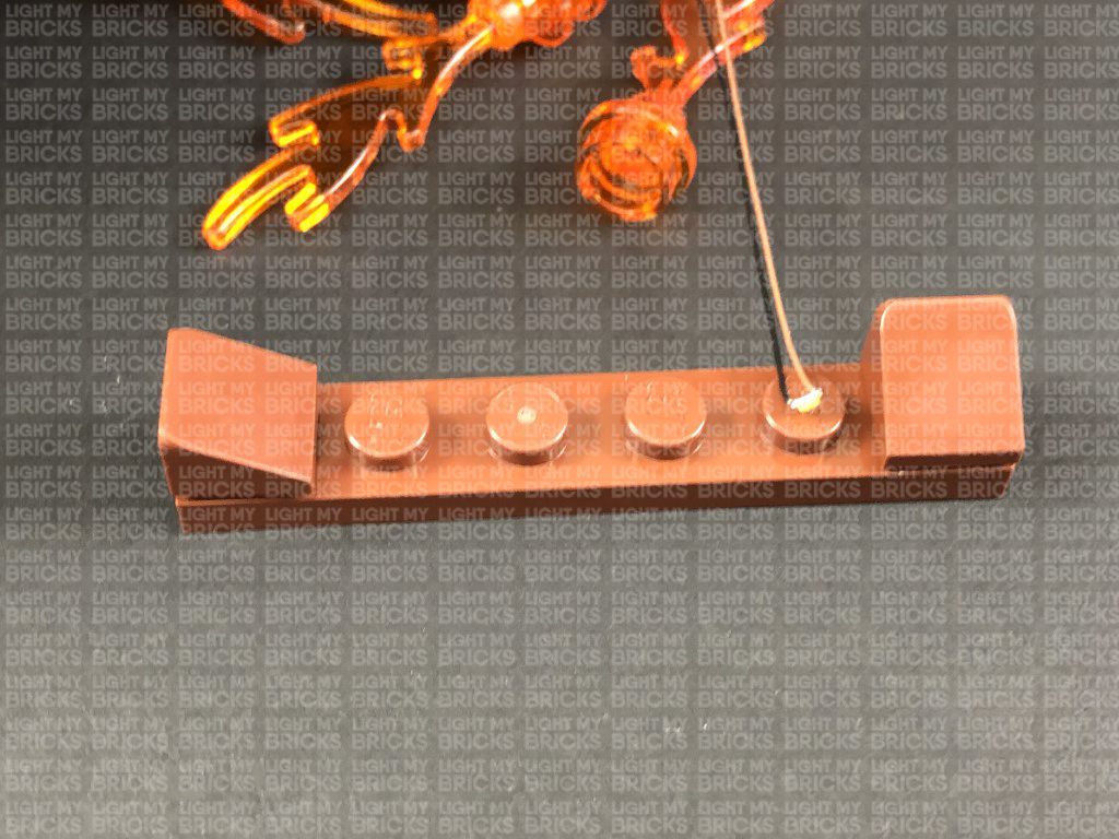
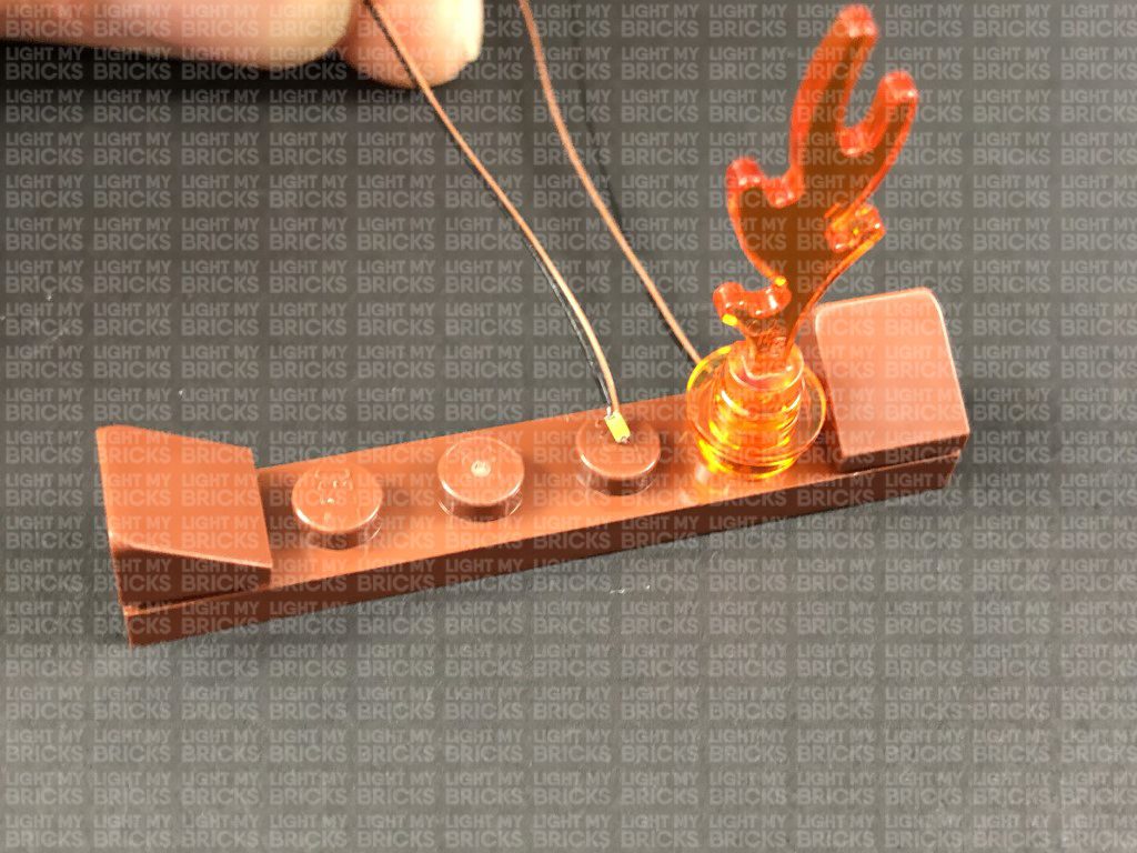
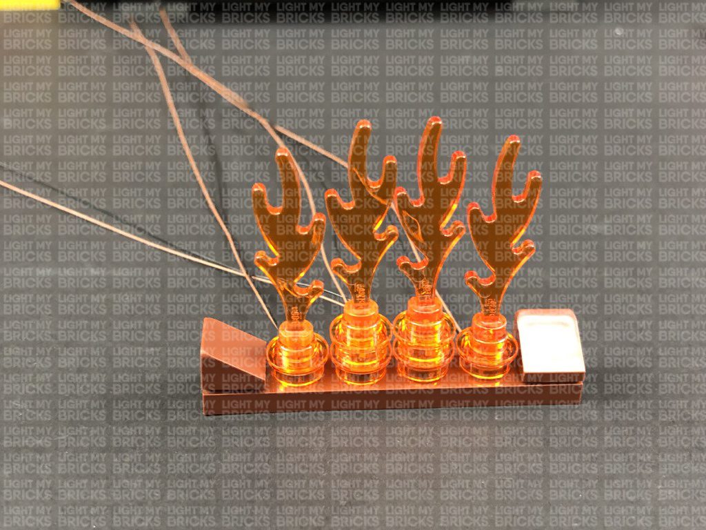
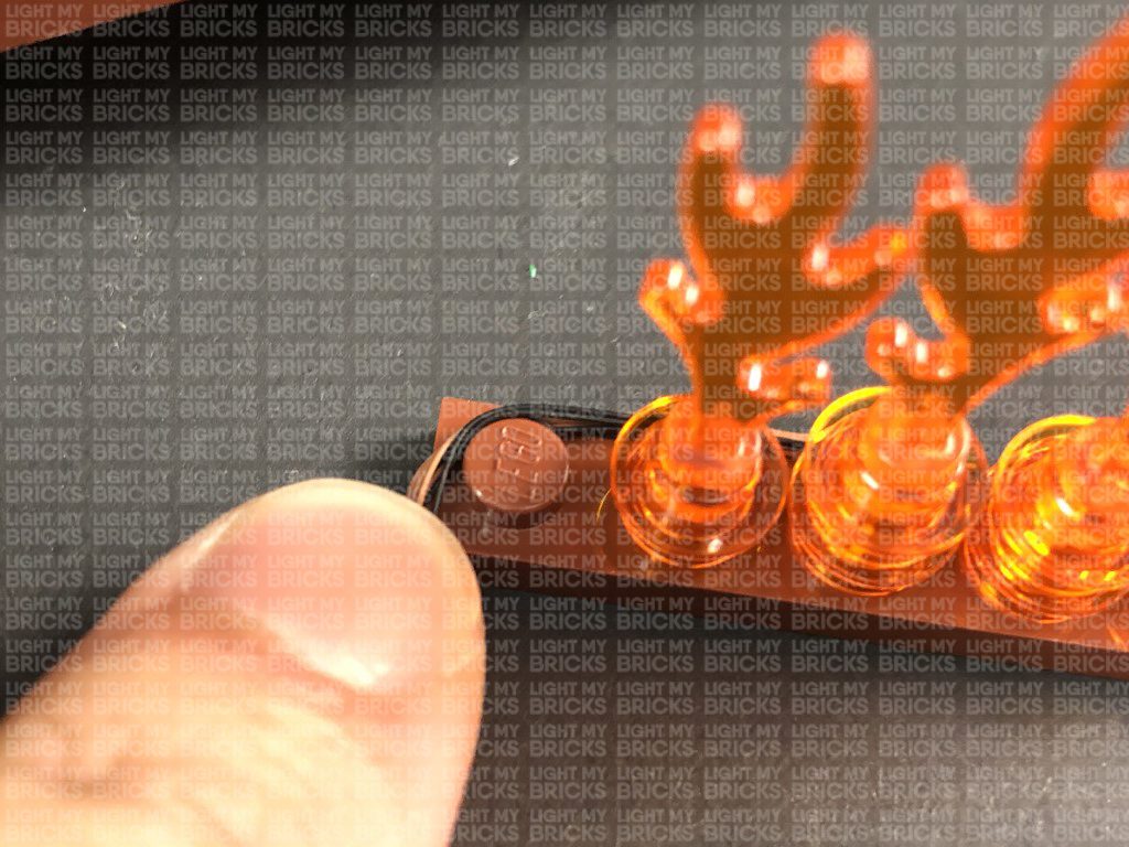
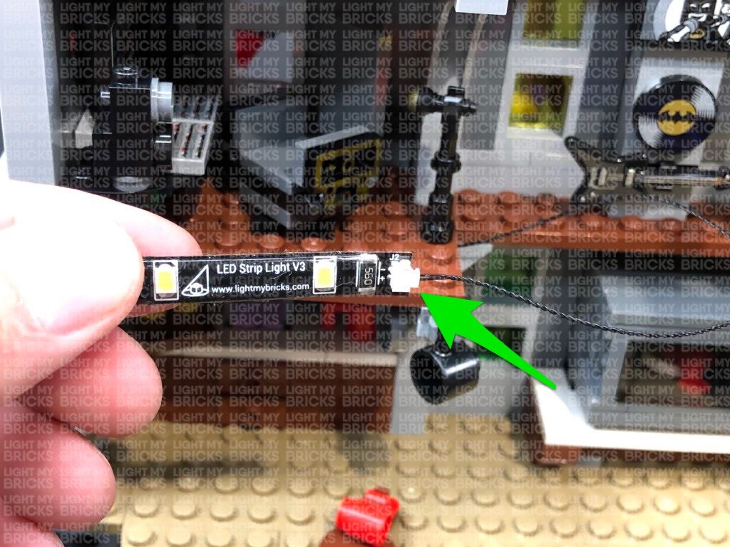
Take a White 15cm Micro Bit Light and with the cable facing the back and led facing up, place it over the following stud. Secure the Micro Bit Light in place by reconnecting the flame piece over the top.
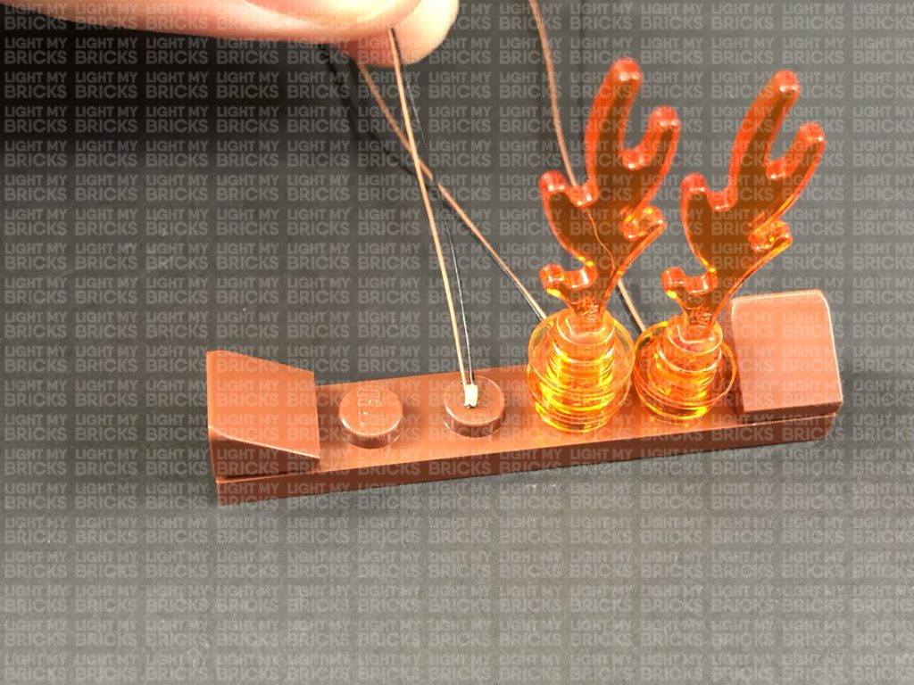
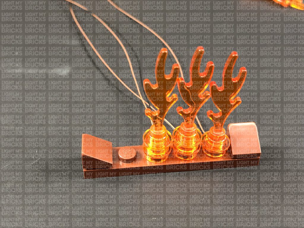
Using the same method as above, install another 3x White 15cm Micro Bit Lights to the fire place.
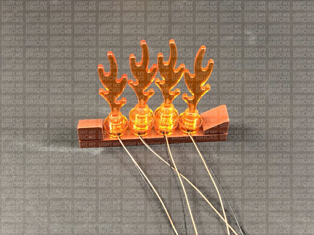
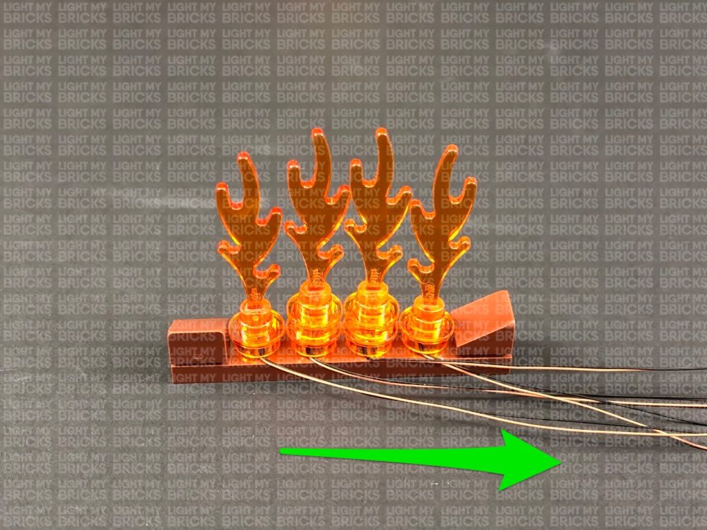
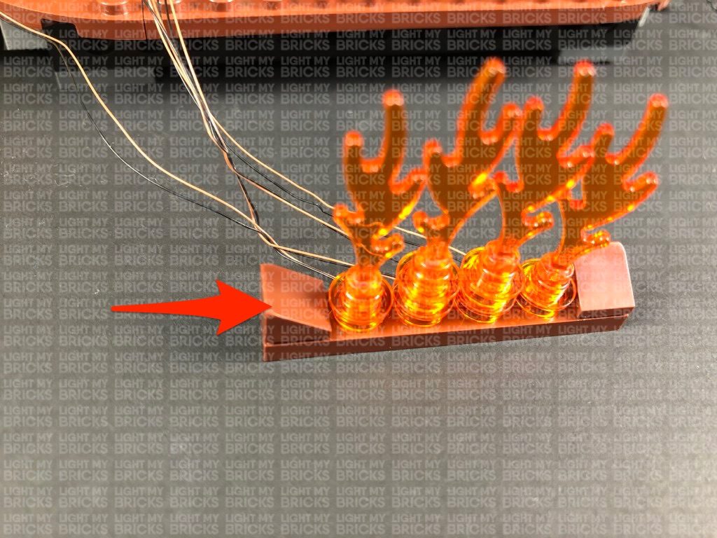
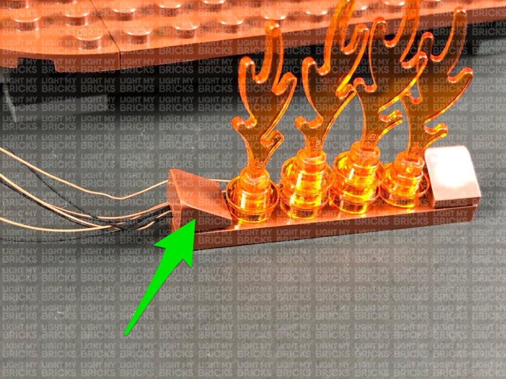
30.) Turn the fireplace section around, then lay the cables toward the right side. Secure them together by twisting them around each other a few times in the right corner, then turn the section around and secure the cables underneath the angled tile on the left side as shown below:
Reconnect the fireplace section ensuring the cable is laid toward the left side in between pieces.
25.) Take the 12-Port Expansion Board from step 18 and connect the four light cables on the left side to it. Once connected, twist/wind the excess cables around each other as shown below:
Connect the six light cables from the right side to the expansion board, then connect up the USB Power Cable to connect to your USB Power Bank. Turn on the power bank to test all 10 flashing lights are working OK.
Note: If you experience any issues with the lights not working and suspect an issue with a component, please try a different port on the expansion board to verify where the fault lies (with the light or expansion board). To correct any issues with expansion board ports, please view the section addressing expansion board issues on our online troubleshooting guide.
26.) Disconnect the USB Power Cable, then twist/wind excess cables from the right side around each other neatly as shown below:
Turn the Joker Sign around, then twist/wind the two groups of cables into a neat bunch. Reconnect the Joker Sign to the front of the building, then connect the other end of the 30cm Connecting Cable that we pulled up from below (step 6) to a spare port on the 12-port Expansion Board.
Take a new 30cm Connecting Cable and connect it to the remaining port on the 12-Port Expansion Board. Neatly place the expansion board down the space in between the wall edge and the joker sign. Thread both 30cm Cables underneath and behind the bottom of the Joker Sign, then secure 30cm cable from below underneath the following angled brick.
27.) Disconnect the following sections on top of the giant eyeball then disconnect the black cone piece at the bottom of it.
Take a White 15cm Bit Light and thread the connector end of the cable through the top of the black cone piece. Gently bend the LED so that it sits flat against the edge of the stud, then secure the Bit Light in place by connecting a provided Trans Clear Round Plate 1×1 over the top. Reconnect the flag and pole to the top before reconnecting this whole section back on top of the giant eyeball
28.) Pull the other end of the 30cm Connecting Cable from previous step up behind the Joker Sign then connect it to a White Strip Light. Connect the White 15cm Bit Light from above the giant eyeball to the right port on the strip light. Using it’s adhesive backing, stick the Strip Light underneath the roof of the giant eyeball in the below position so that it shines down onto the eye.
Secure the cable from the bit light around the back of the roof to the left side, then bring the connecting cable around the back of the eyeball to the left side. Secure the connecting cable underneath the purple flap section then use some tape to secure the cable to the back of the giant eyeball as shown below:
Connect the USB power cable (connected to power bank) to the 12-Port Expansion Board on the back of the set (as per step 9). Turn ON the USB Power Bank to test all the lights installed to the front of the Joker Manor are working OK.
Note: If you experience any issues with the lights not working and suspect an issue with a component, please try a different port on the expansion board to verify where the fault lies (with the light or expansion board). To correct any issues with expansion board ports, please view the section addressing expansion board issues on our online troubleshooting guide.
29.) Turn the entire set around to the back as we will now light the inside of the Joker Manor starting with fire place. Using your LEGO removal tool, remove the flame section at the brown plate, then disconnect the flame pieces.
Take a White 15cm Micro Bit Light and with the cable facing the back and led facing up, place it over the following stud. Secure the Micro Bit Light in place by reconnecting the flame piece over the top.
Using the same method as above, install another 3x White 15cm Micro Bit Lights to the fire place.
30.) Turn the fireplace section around, then lay the cables toward the right side. Secure them together by twisting them around each other a few times in the right corner, then turn the section around and secure the cables underneath the angled tile on the left side as shown below:
Reconnect the fireplace section ensuring the cable is laid toward the left side in between pieces.
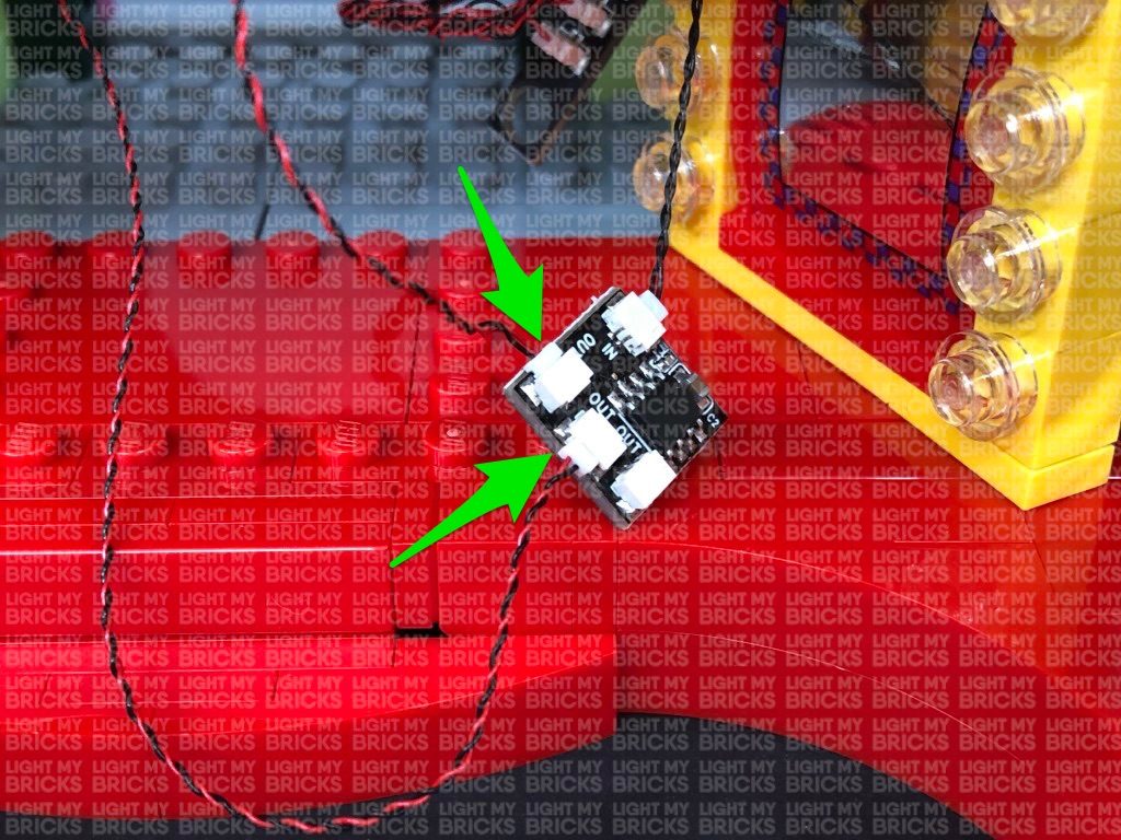
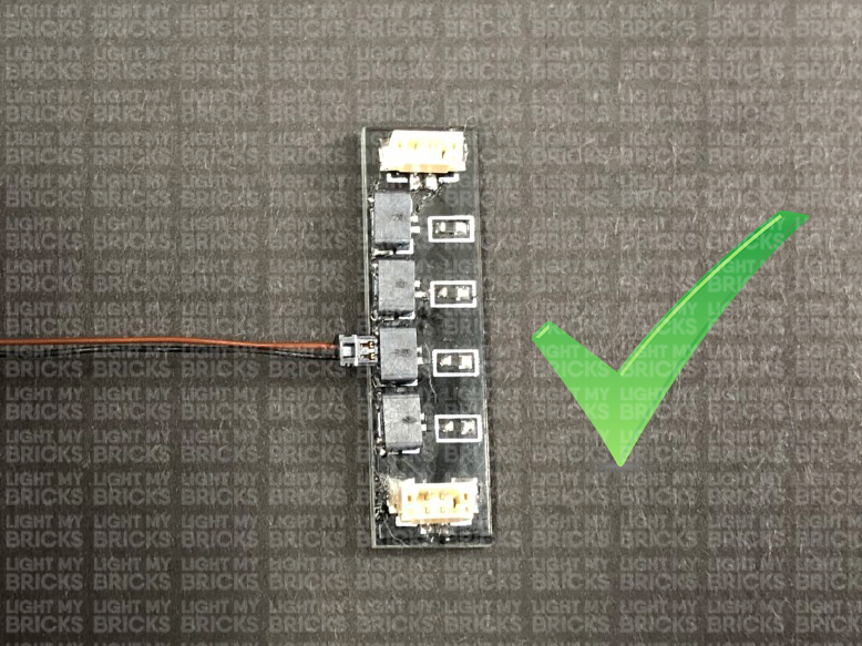
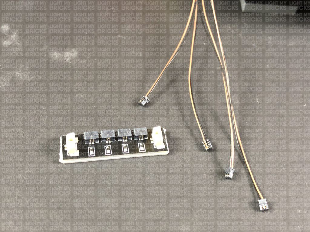
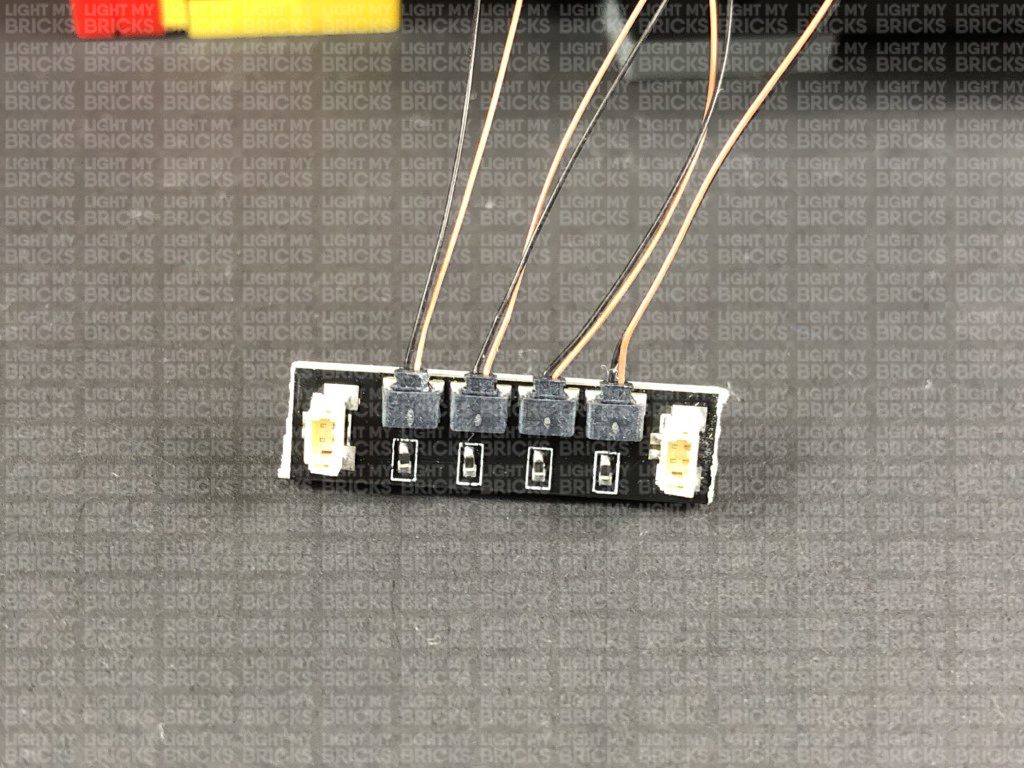
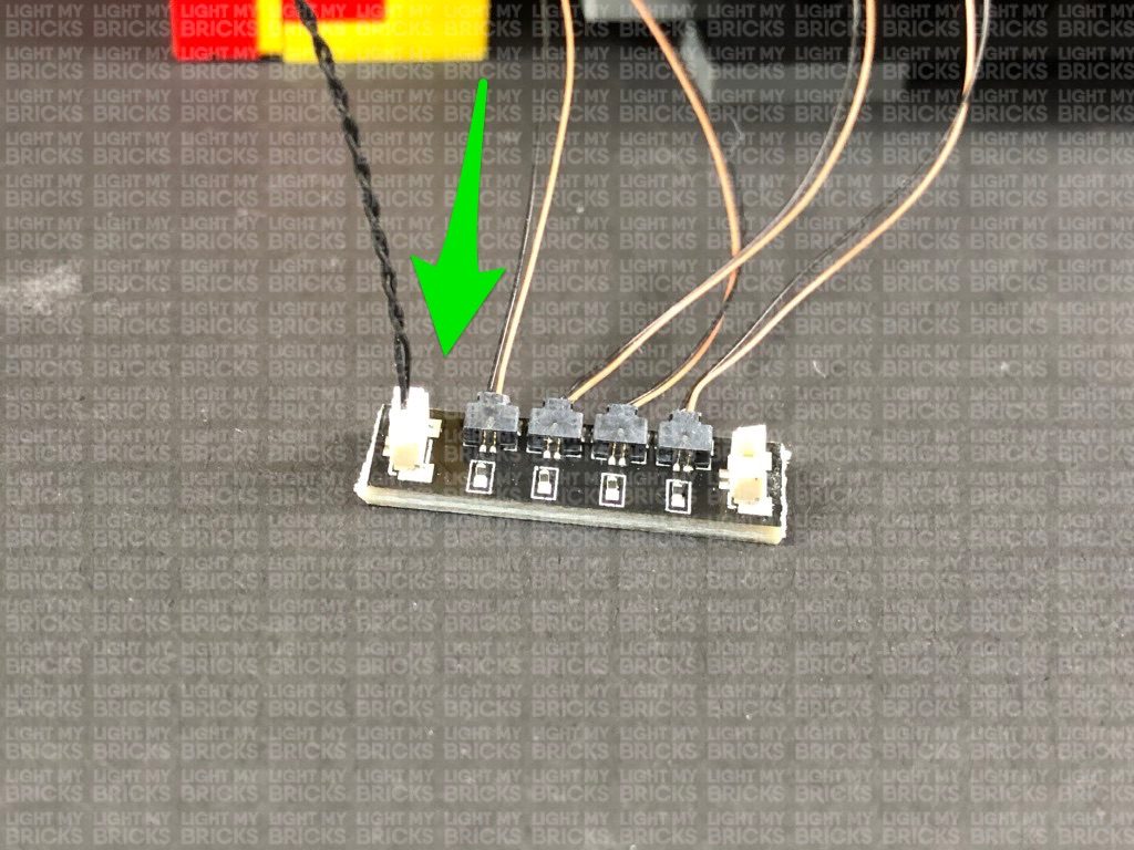
 Connect the four Micro Bit Lights to the Micro 2-4 Port Expansion Board. The micro bit light connectors only connect to the expansion board port one way. Follow the below image guides to ensure you connect the micro bit lights correctly to the expansion board.
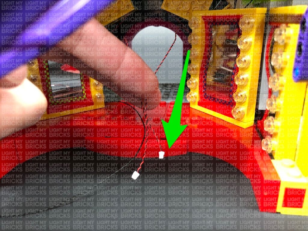
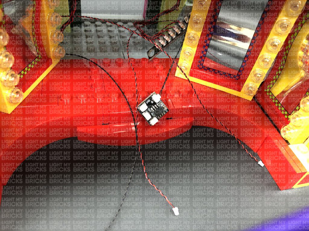
31.) Take a 5cm Connecting Cable and connect it to the larger port on the Micro Expansion Board then bring everything over the mirror on the left side. Pull the Flicker Effects Board out, then connect the other end of the 5cm Connecting Cable to the remaining OUT port on the Flicker Effects Board.
Turn your USB Power Bank ON to test all lights in the fire place are lit and flickering OK.
Connect the four Micro Bit Lights to the Micro 2-4 Port Expansion Board. The micro bit light connectors only connect to the expansion board port one way. Follow the below image guides to ensure you connect the micro bit lights correctly to the expansion board.
31.) Take a 5cm Connecting Cable and connect it to the larger port on the Micro Expansion Board then bring everything over the mirror on the left side. Pull the Flicker Effects Board out, then connect the other end of the 5cm Connecting Cable to the remaining OUT port on the Flicker Effects Board.
Turn your USB Power Bank ON to test all lights in the fire place are lit and flickering OK.
 Note: If you experience any issues with the lights not working and suspect an issue with a component, please try a different port on the expansion board to verify where the fault lies (with the light, expansion board, or effects board). To correct any issues with expansion board ports, please view the section addressing expansion board issues on our online troubleshooting guide.
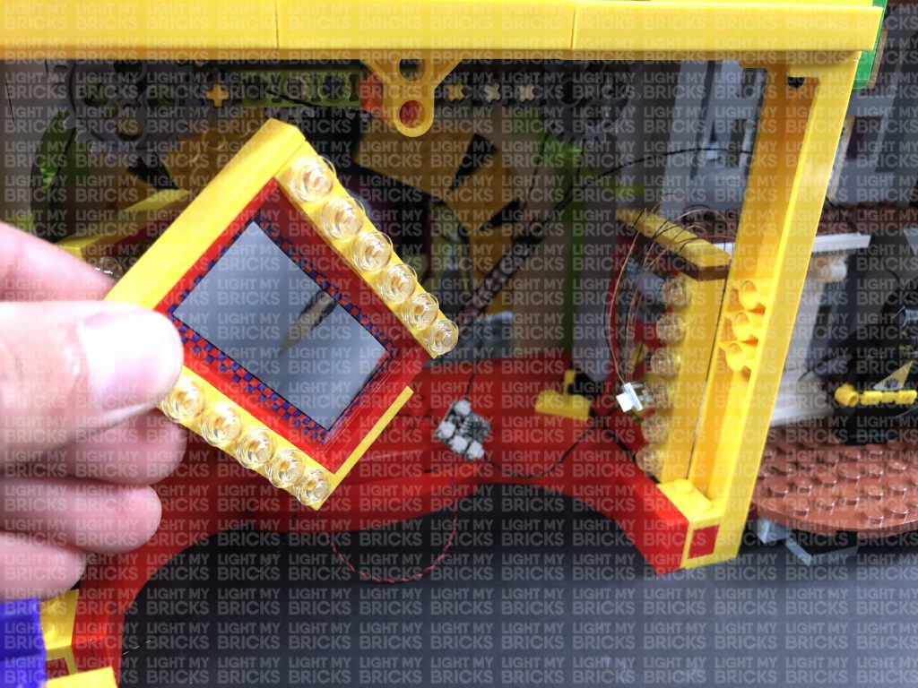
32.) Disconnect the first mirror, then disconnect the brown plate with yellow tile on top of the second mirror. Neatly lay the four micro bit ligiht cables in between studs before reconnecting the brown plate with yellow tile over the top.
Group all the components together and push them to right side before reconnecting the first mirror to hide them behind.
Secure the 30cm Connecting Cable leading to the right side underneath the yellow tile then use your LEGO Removal tool to slightly lift up the brown plate above the fire place. Slip the 30cm Connecting Cable in between before reconnecting the brown plate over the top.
Disconnect the second mirror from the left side, then tuck the 30cm connecting cable (leading to the 12-port expansion board on the left) inside and behind the yellow 1×2 plate with bar before reconnecting the mirror over the top.
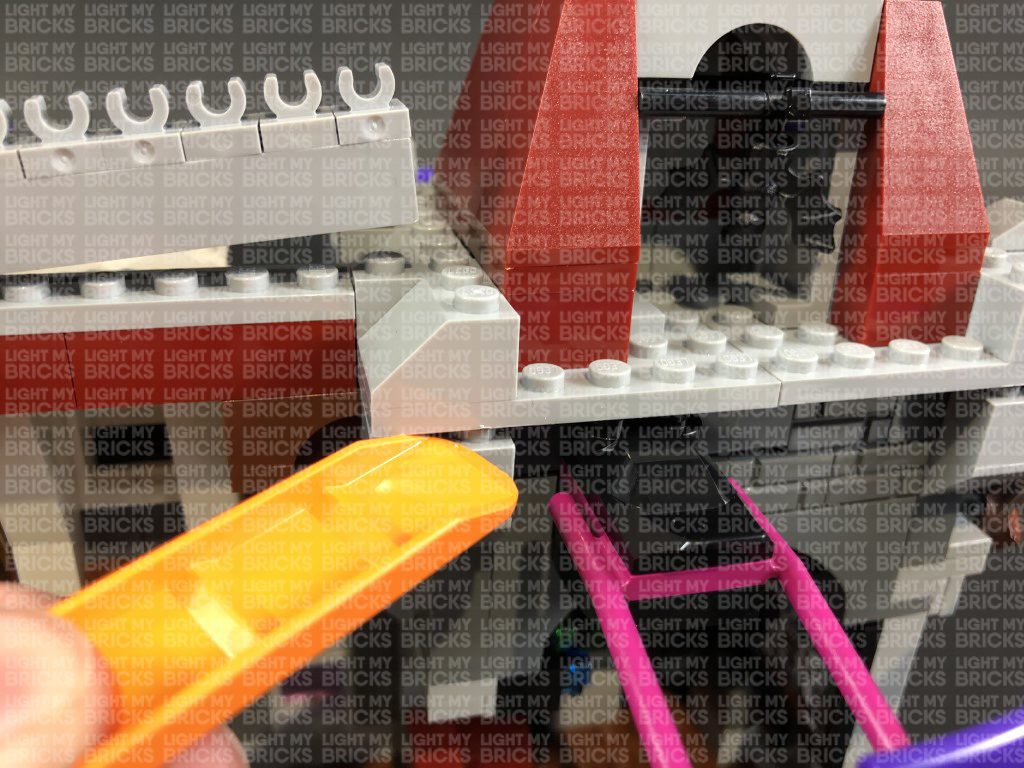
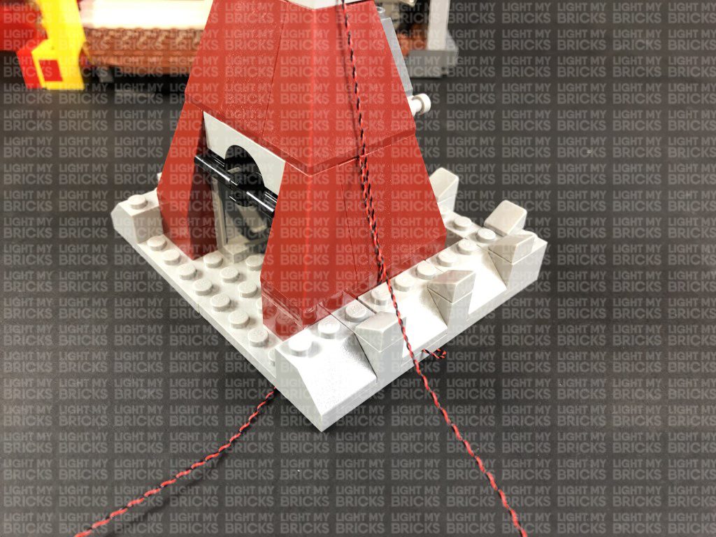
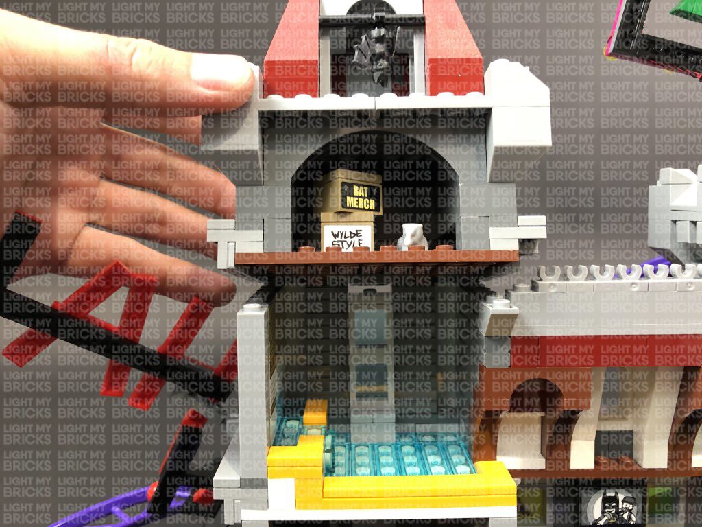
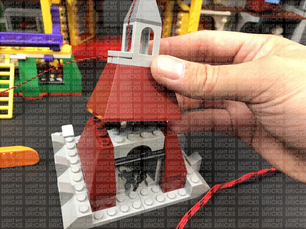
33.) Slightly disconnect the following grey brick, then using your LEGO Removal Tool, completely disconnect the top section as shown below:
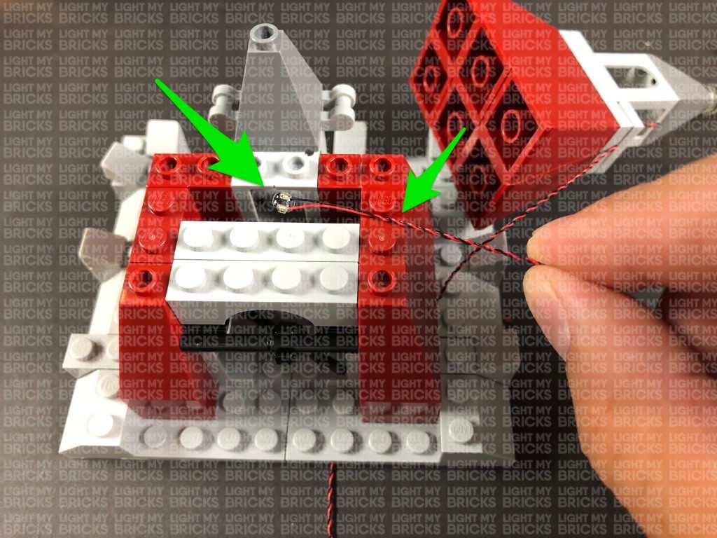
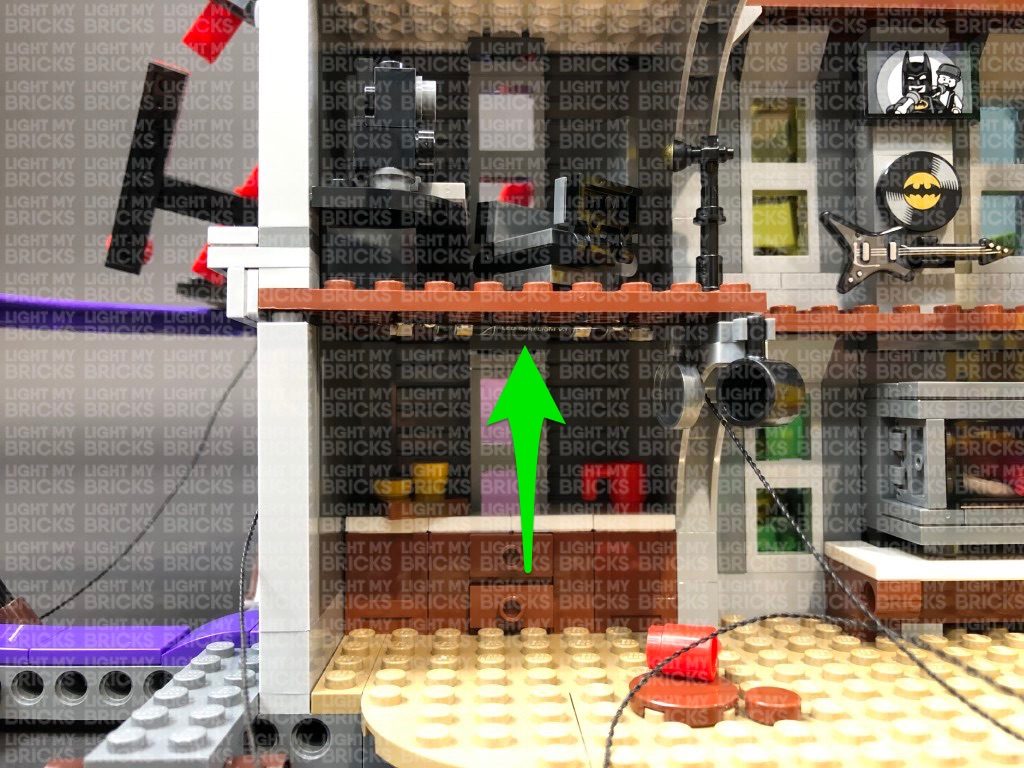
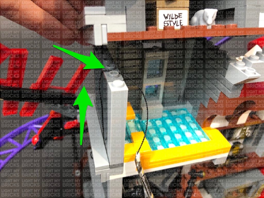
Take a 15cm Connecting Cable and connect one end to the next port on the 6-Port Expansion Board at the very bottom. Pull the other end of the connecting cable up and thread it through the inside of the theatre room and to the top. Pull the cable all the way out from above and connect it to a new 6-Port Expansion Board.
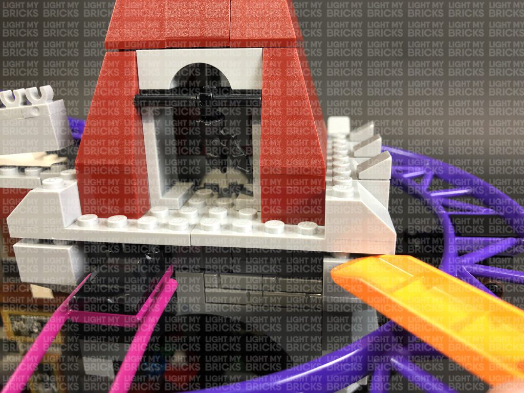
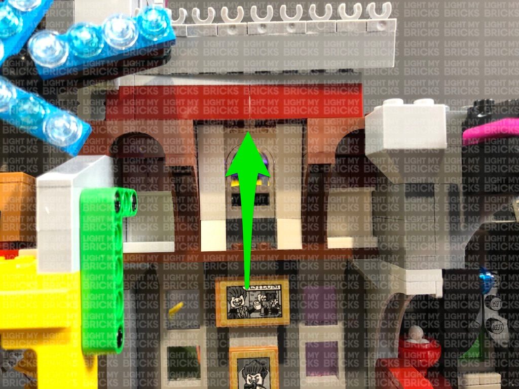
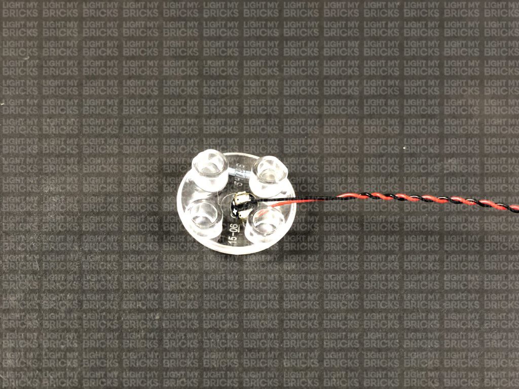
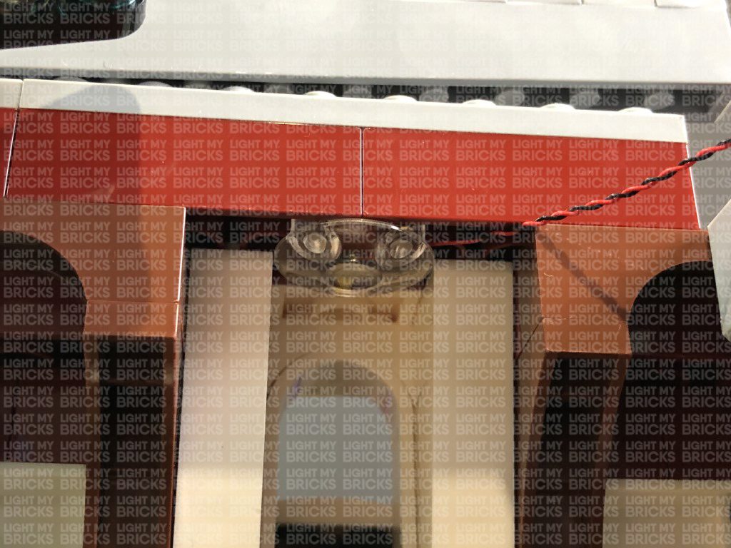
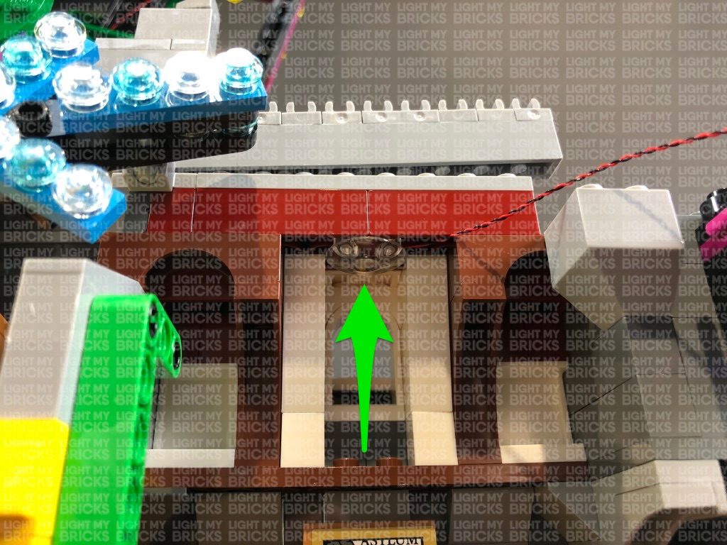
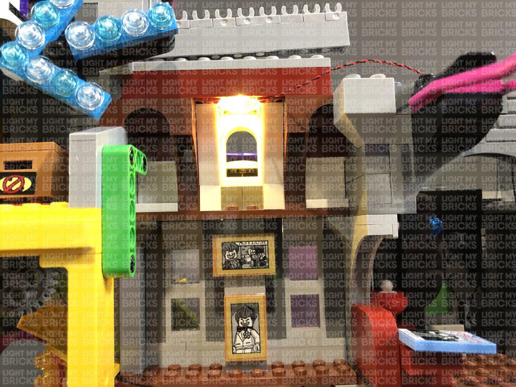
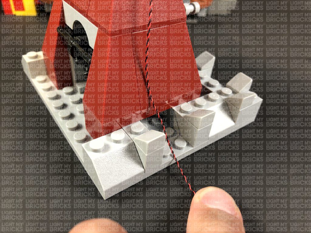
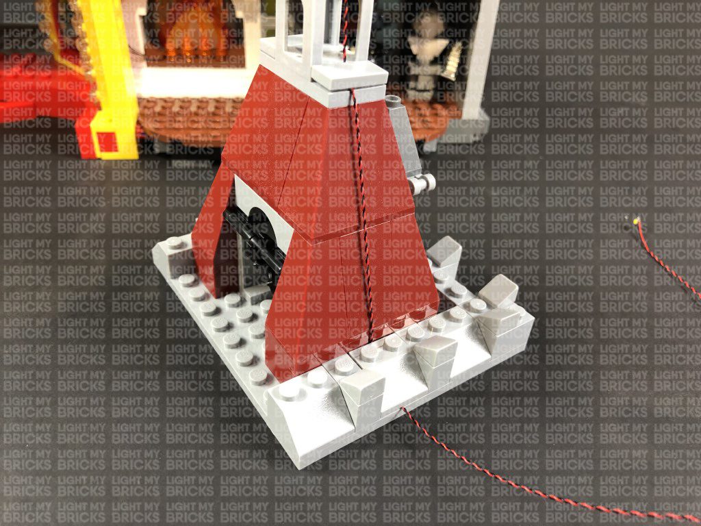
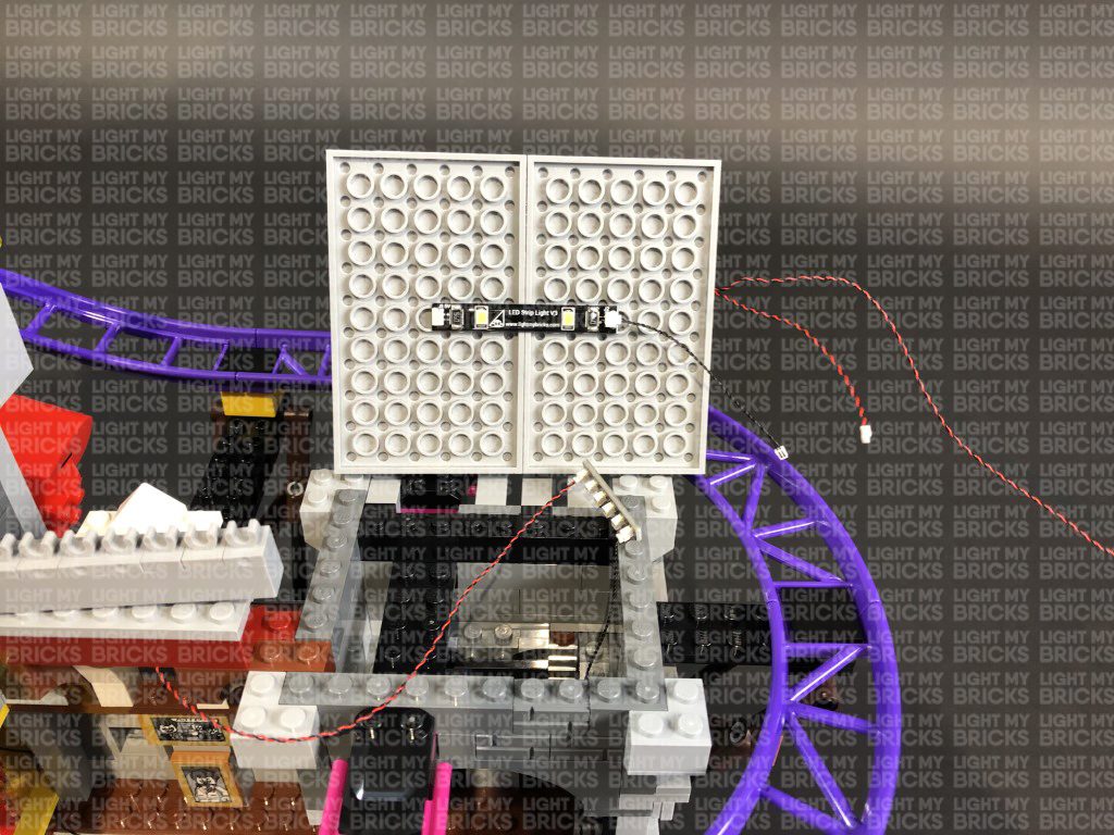
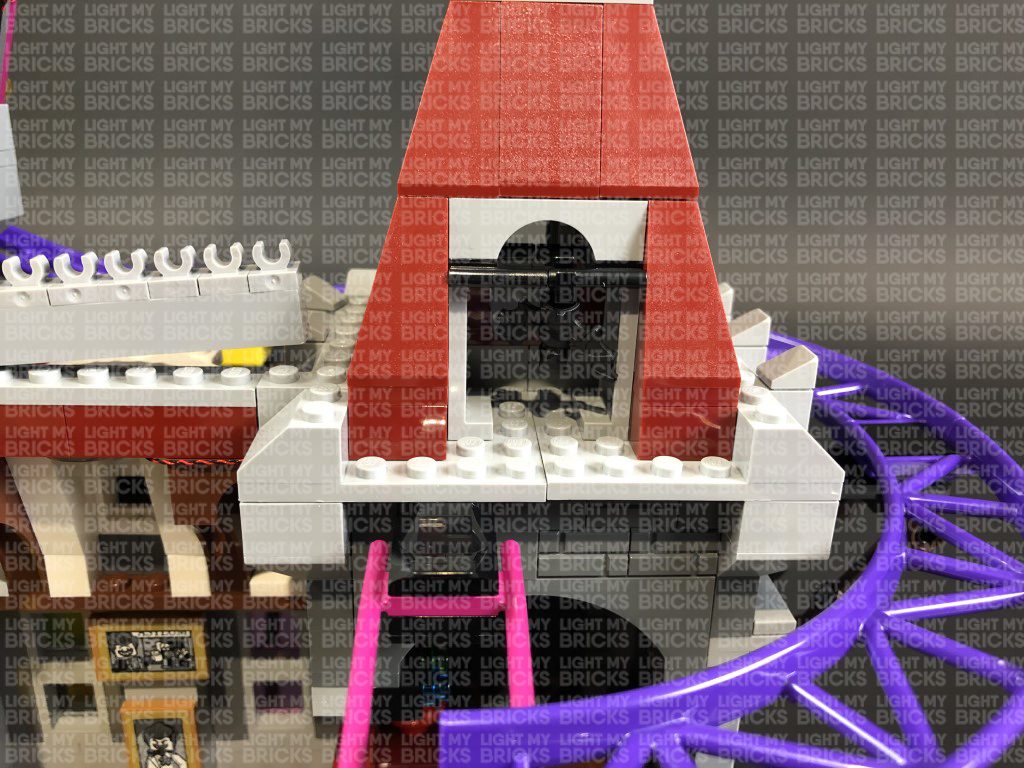
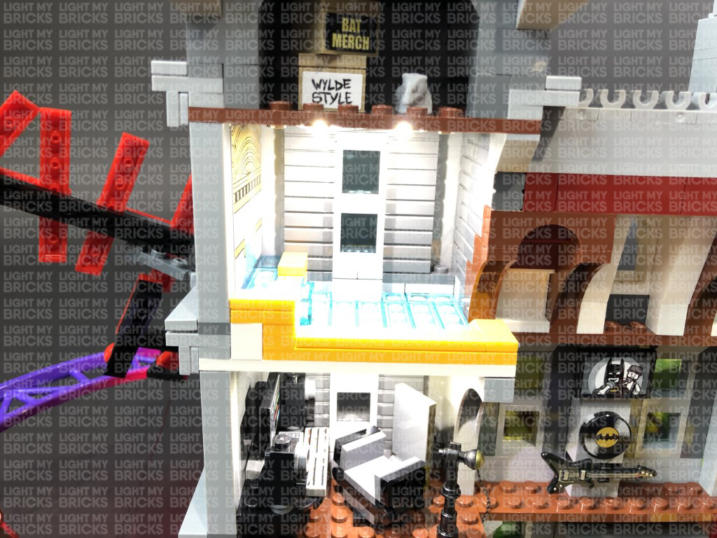
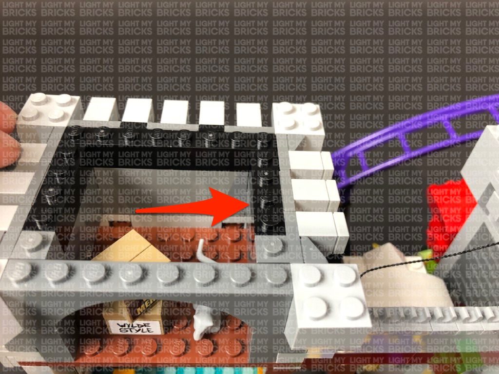
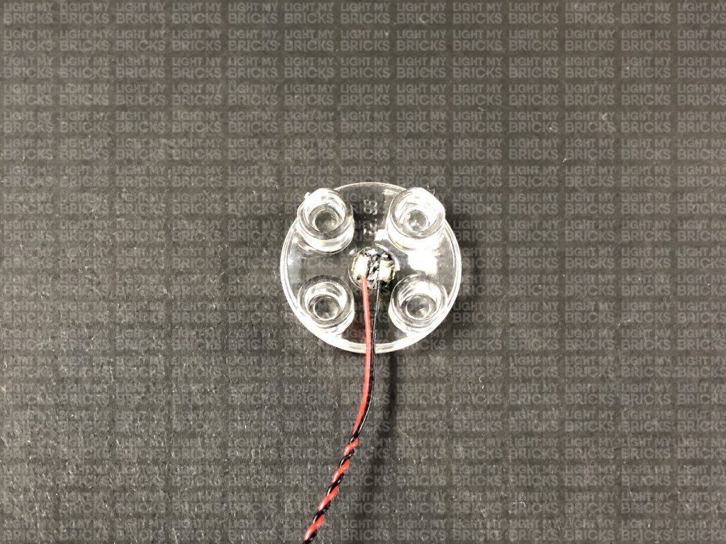
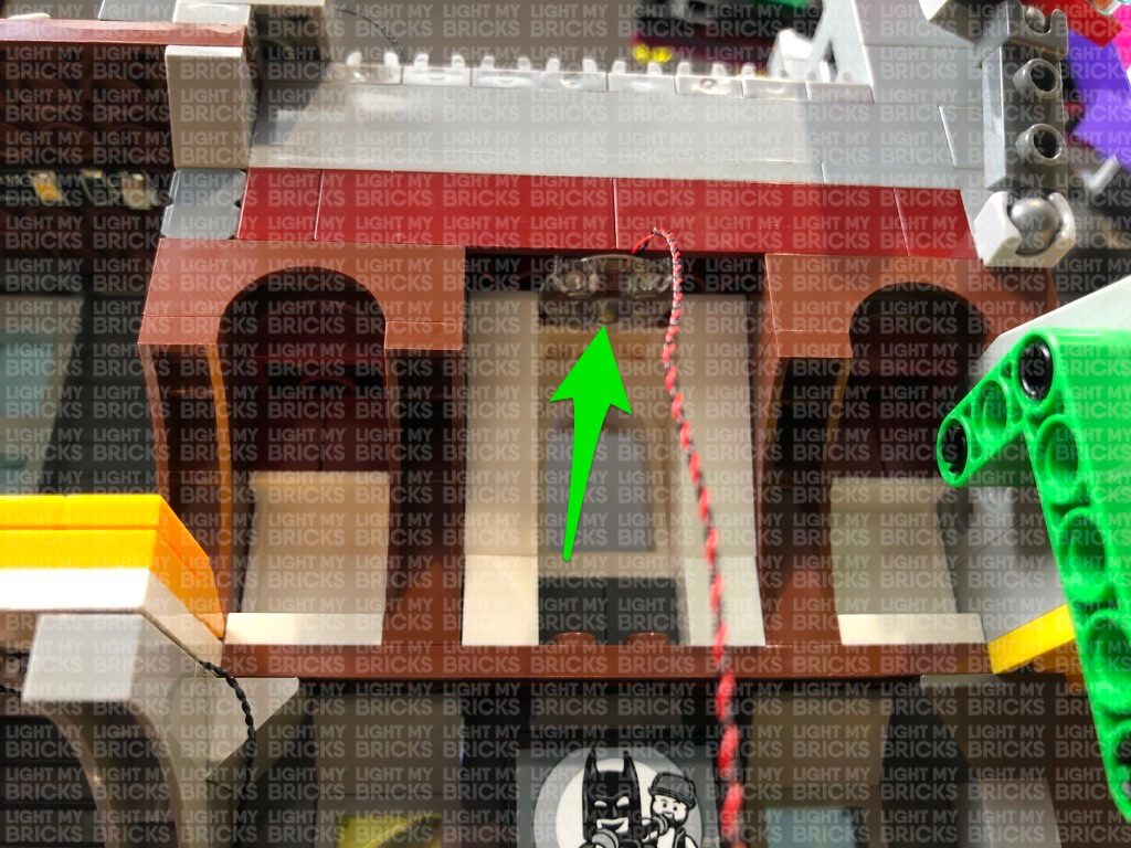
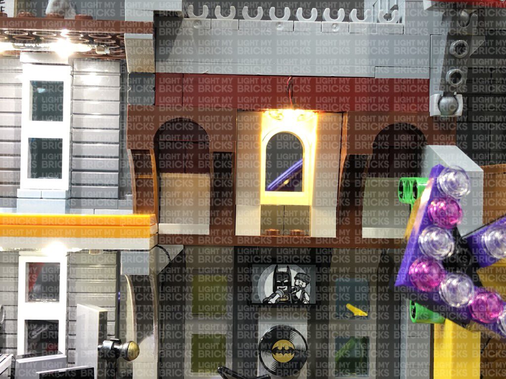
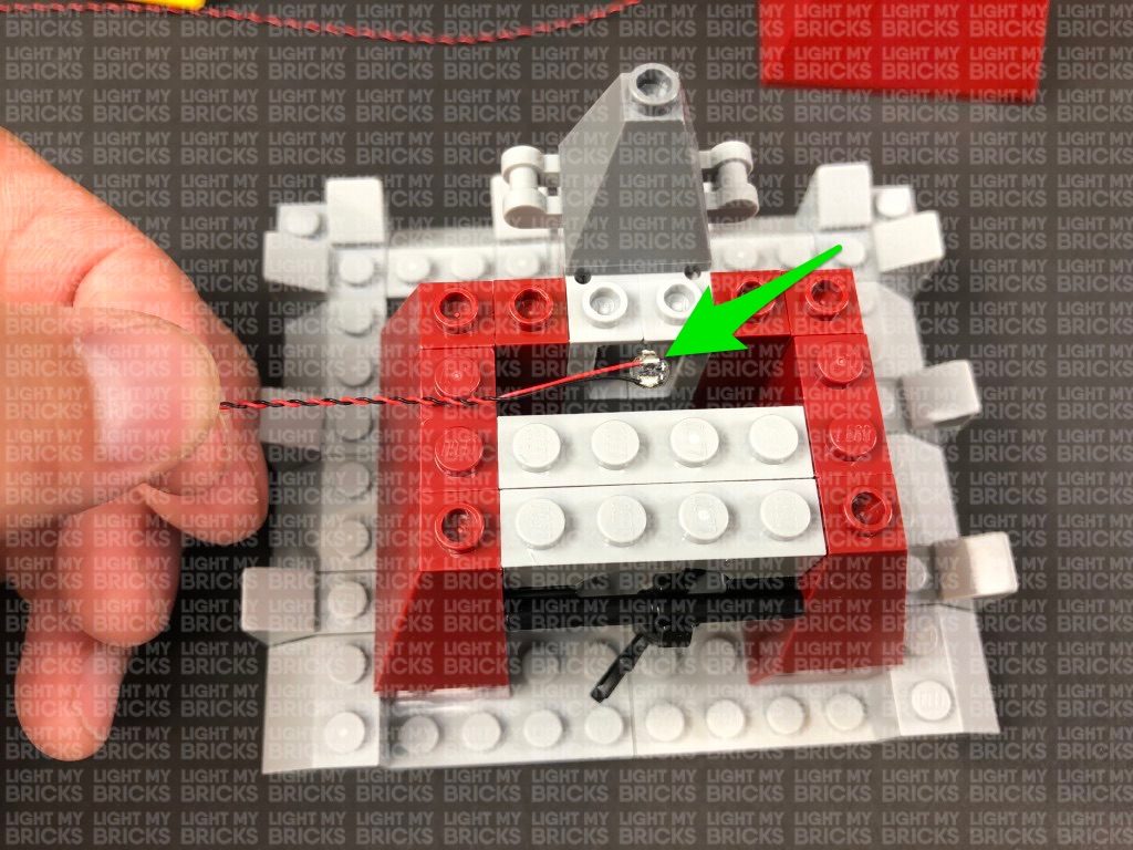
34.) We will now install a Bit Light underneath the top of the arch window. First take out a White 15cm Bit Light and with the LED facing down and cable to the right, place it in the centre of the base of a provided Trans Clear Plate w Rounded Bottom 2×2. Connect the trans clear plate underneath the following red bricks in the below position, ensuring the Bit Light is securely in the middle of the trans clear plate.
Bring the Bit Light cable across and lay in between studs, then connect it to the 6-Port Expansion Board on top of the theatre room. Turn the USB Power Bank ON to confirm the light is working OK.
Note: If you experience any issues with the lights not working and suspect an issue with a component, please try a different port on the expansion board to verify where the fault lies (with the light or expansion board). To correct any issues with expansion board ports, please view the section addressing expansion board issues on our online troubleshooting guide.
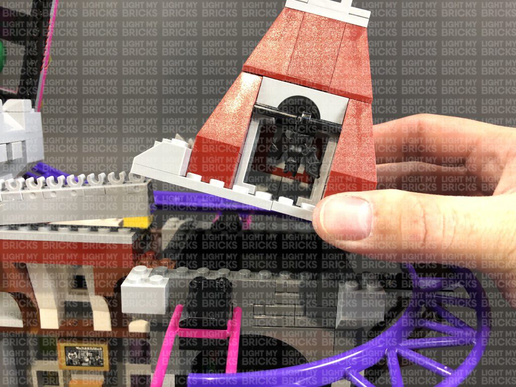
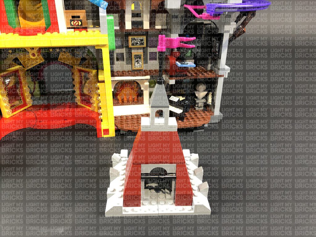
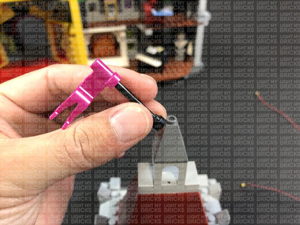
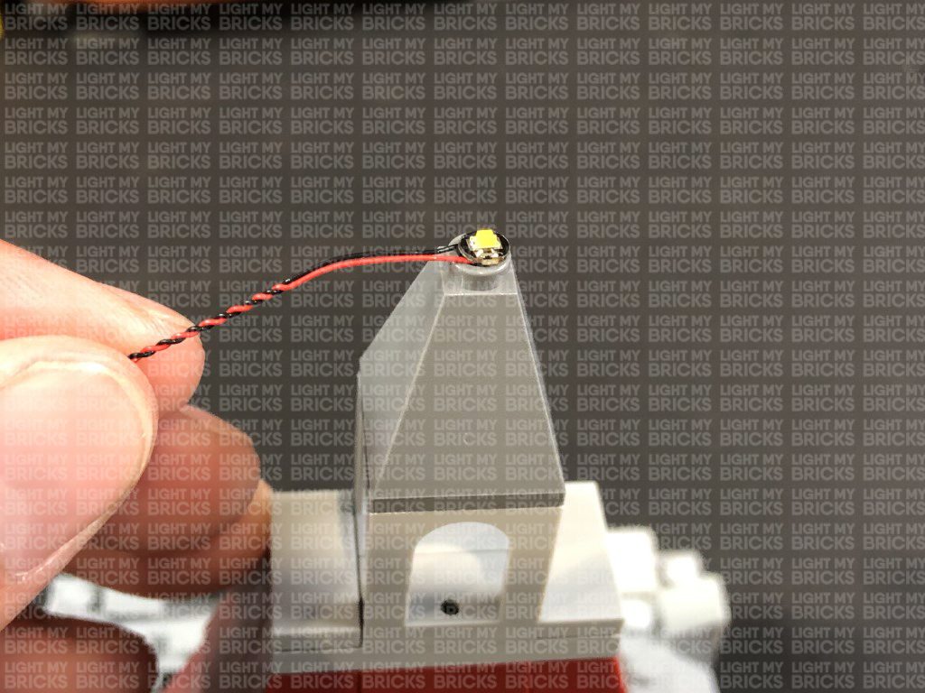
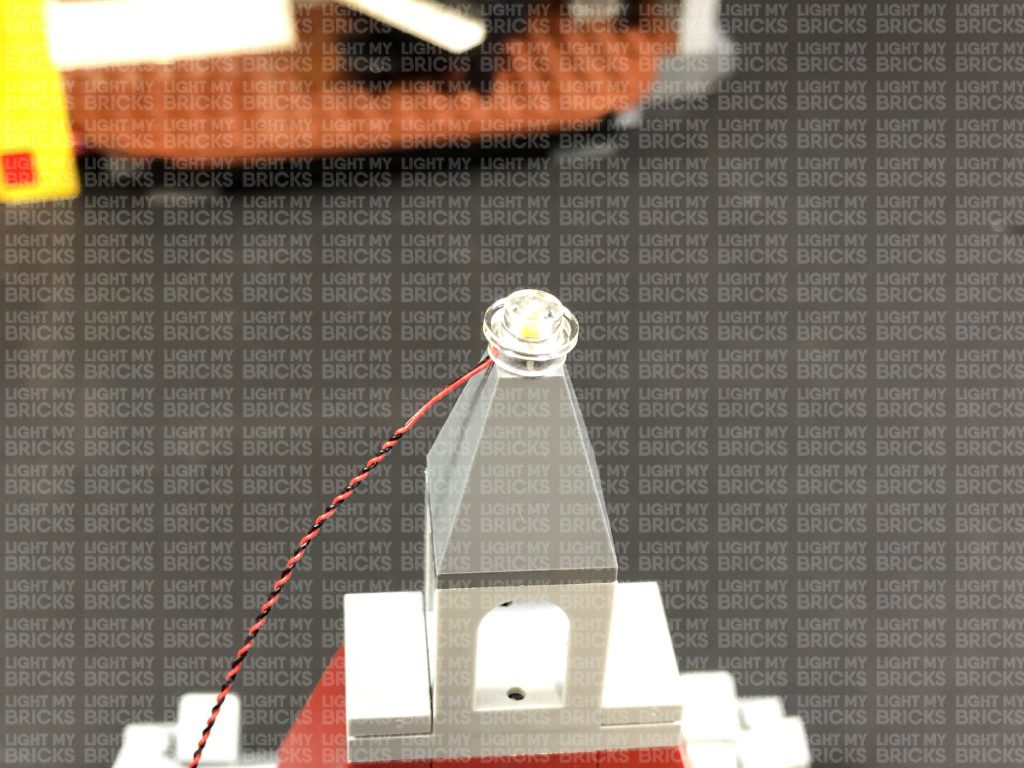
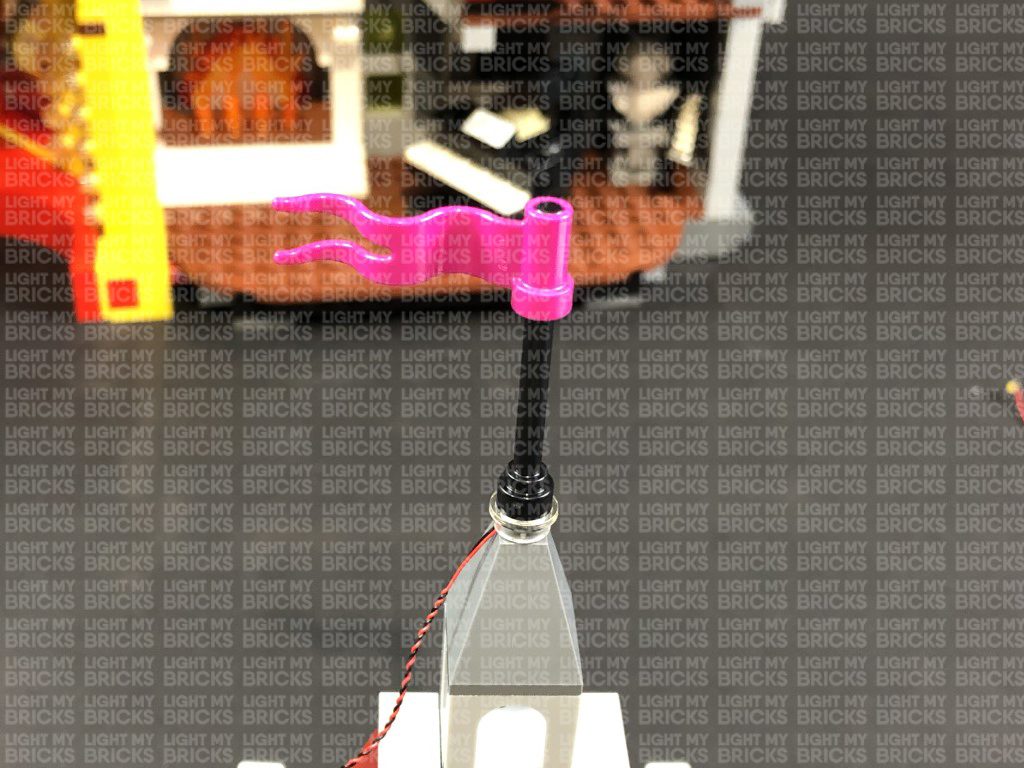
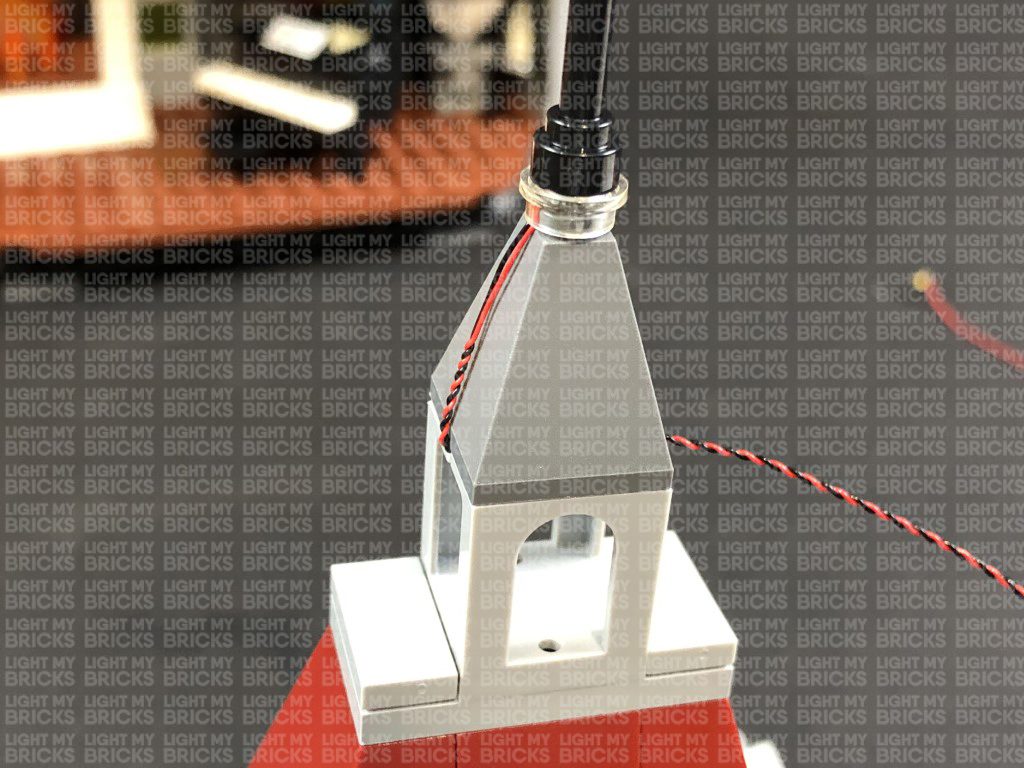
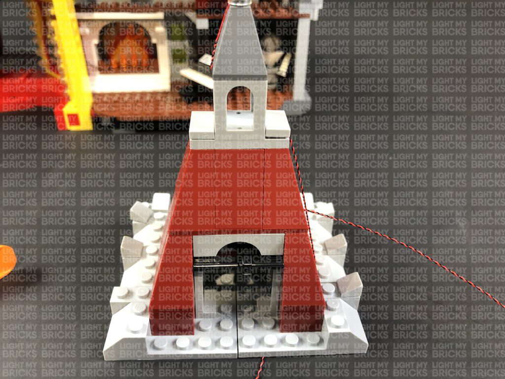
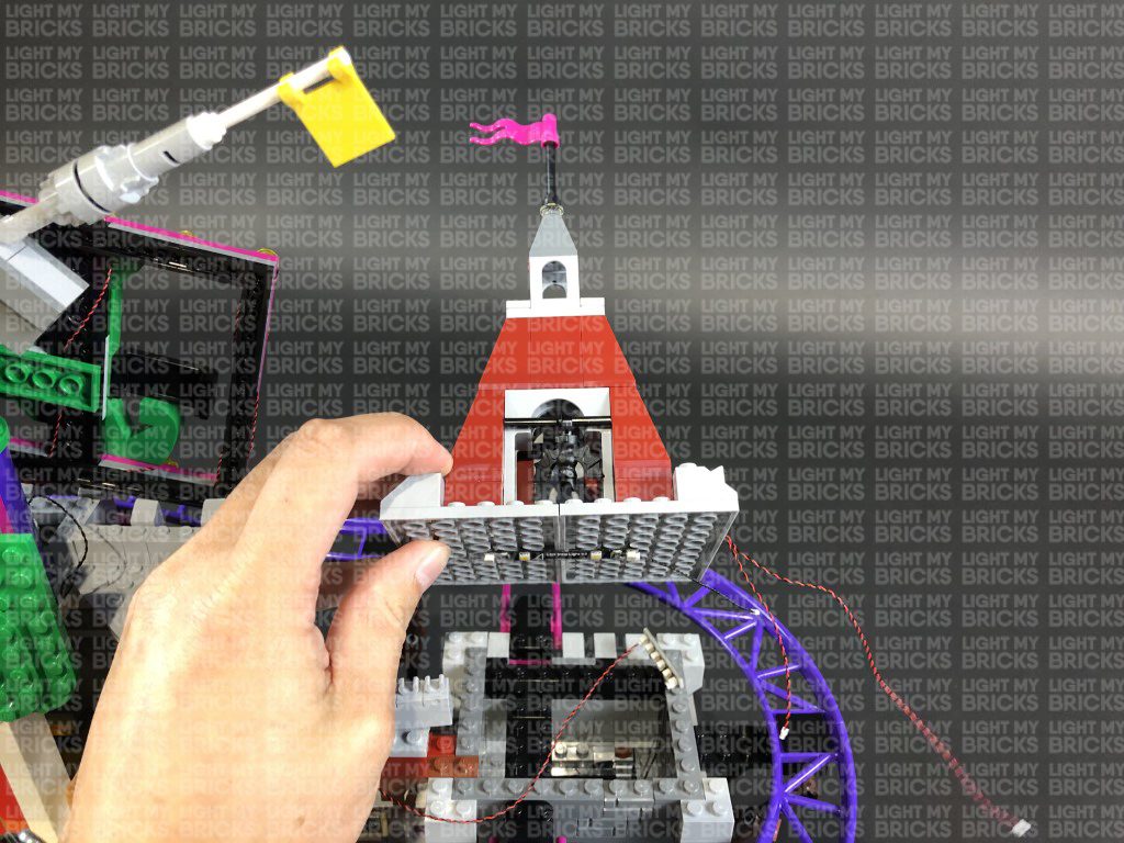
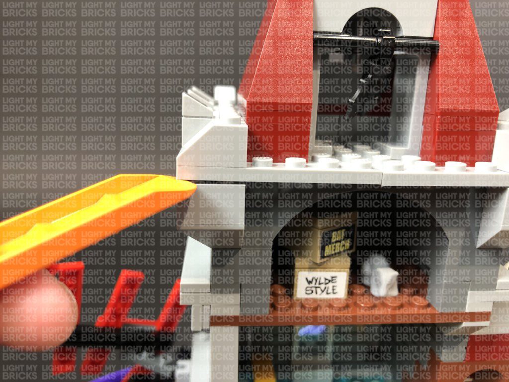
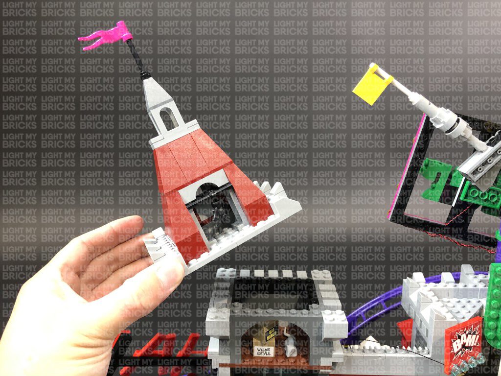
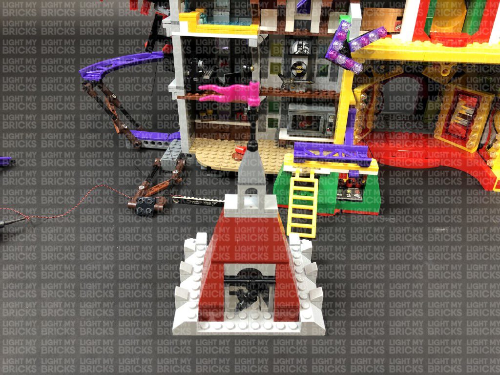
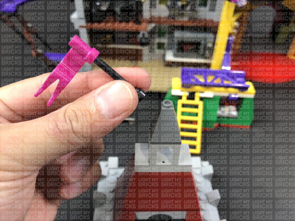
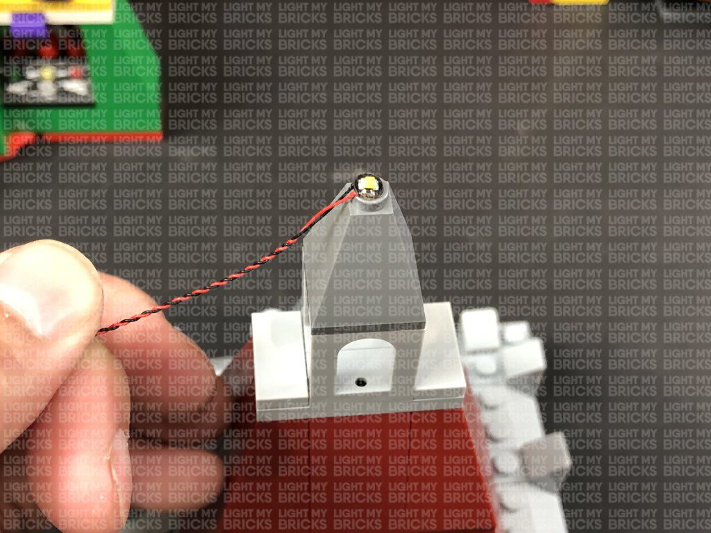
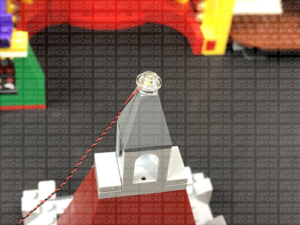
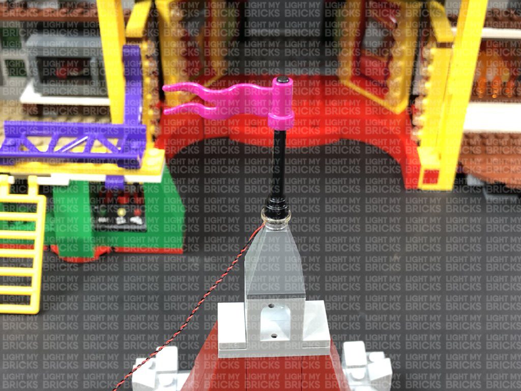
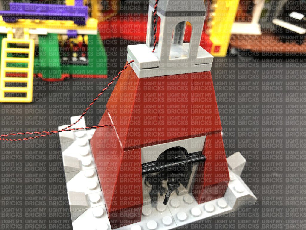
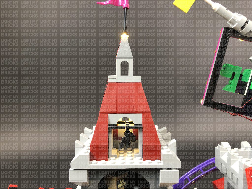
35.) Take the top section we removed in previous step and disconnect the flag pole. Take a White 30cm Bit Light and with the cable facing to the left, place it over the grey stud. Secure the Bit Light in place by connecting a provided Trans Clear Round Plate 1×1 over the top, then reconnect the flag pole.
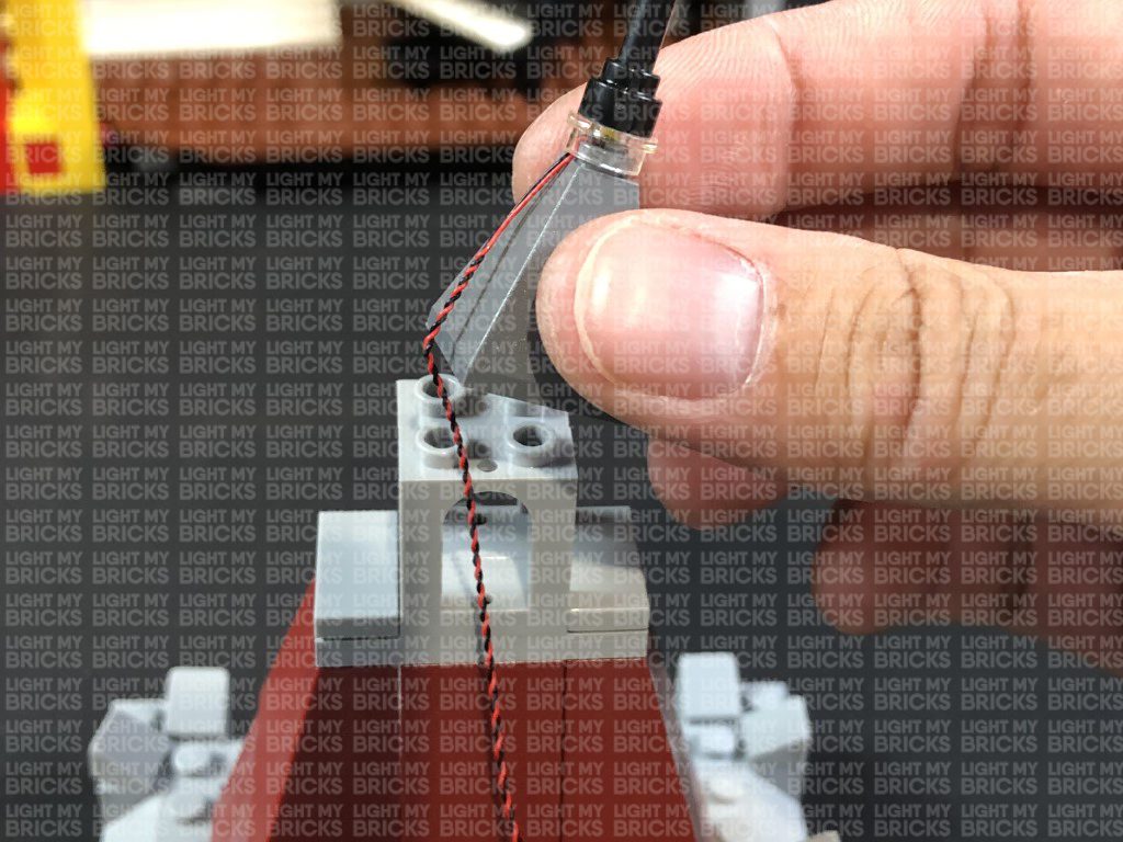
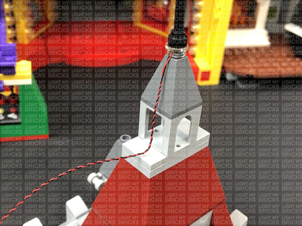
Disconnect the grey roof piece and fold the cable underneath it. Reconnect it ensuring the cable is laid in between studs.
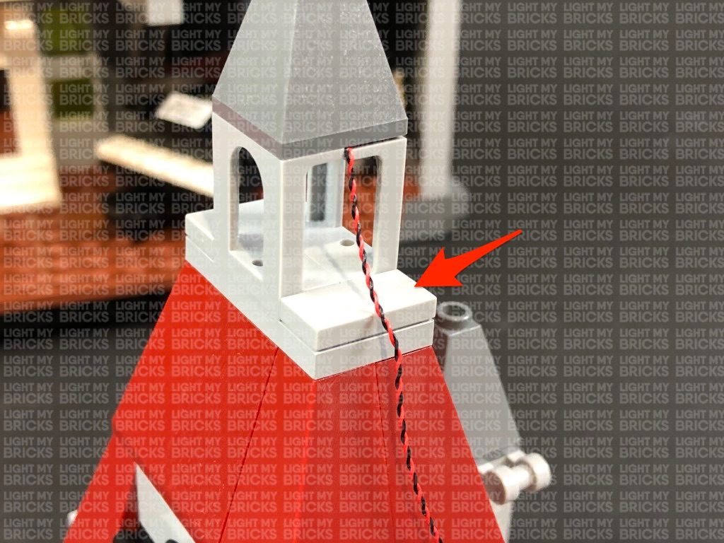
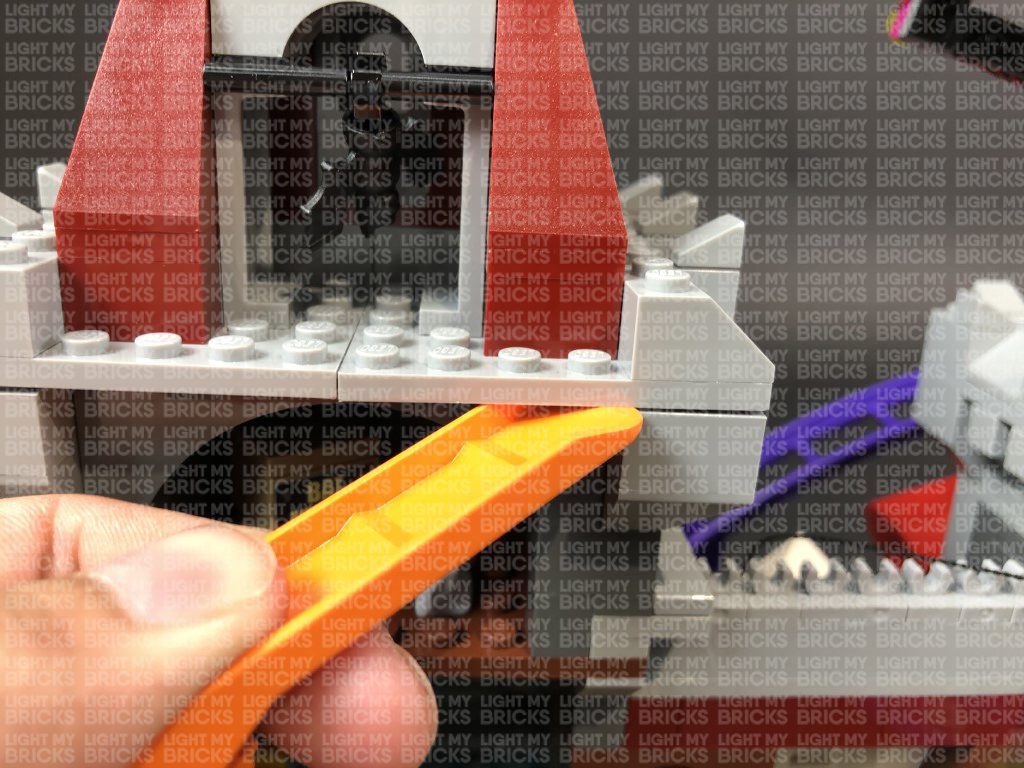
Disconnect the grey tile on the right side, then lay the cable down in between studs. Ensure you push the cable in the corner before reconnecting the tile over the top. This will prevent the cable from snapping when you reconnect the tile.
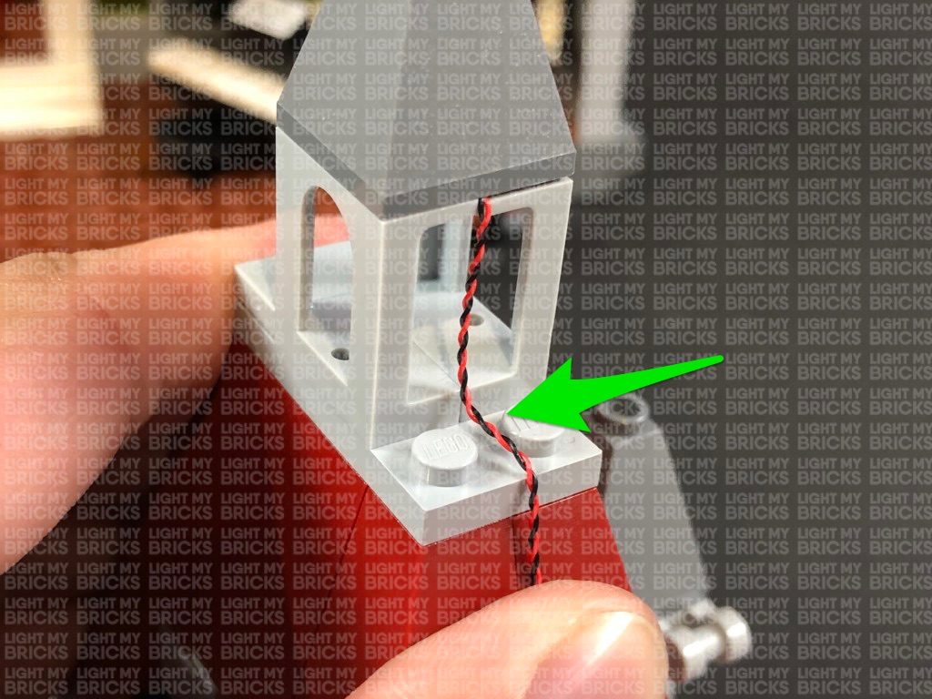
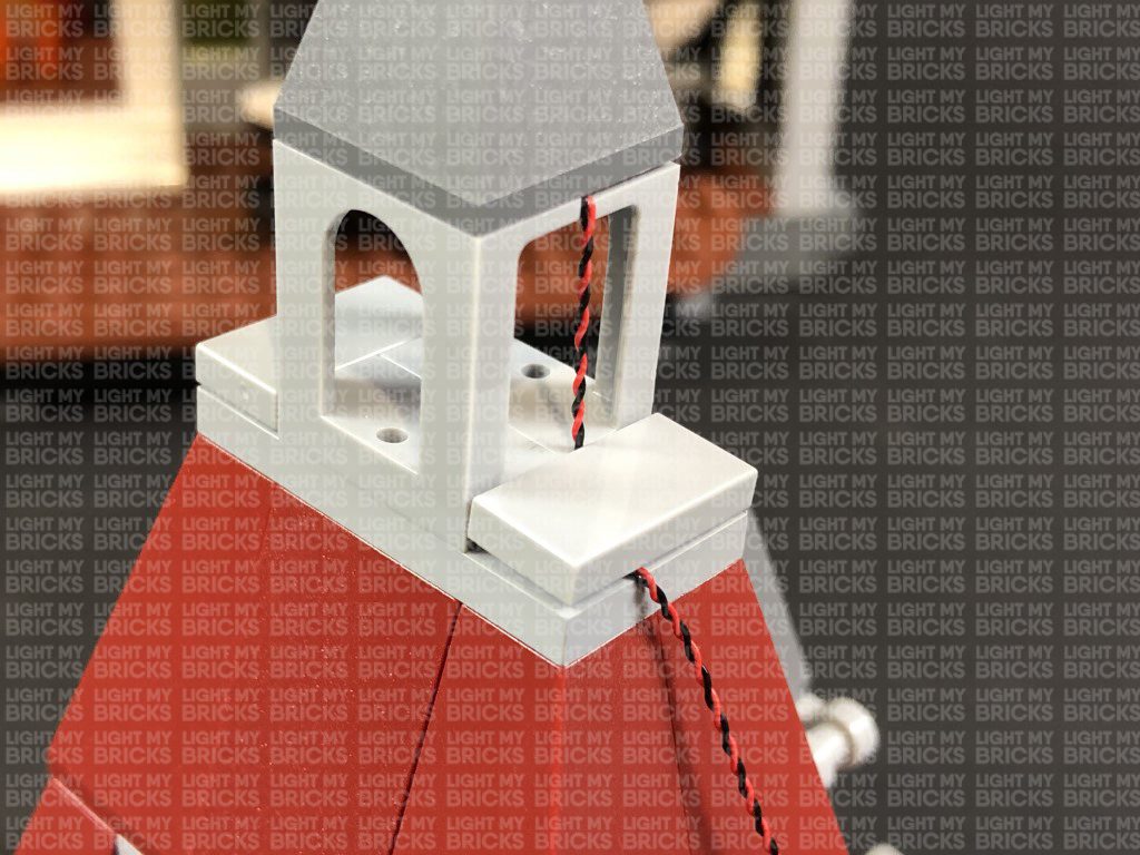
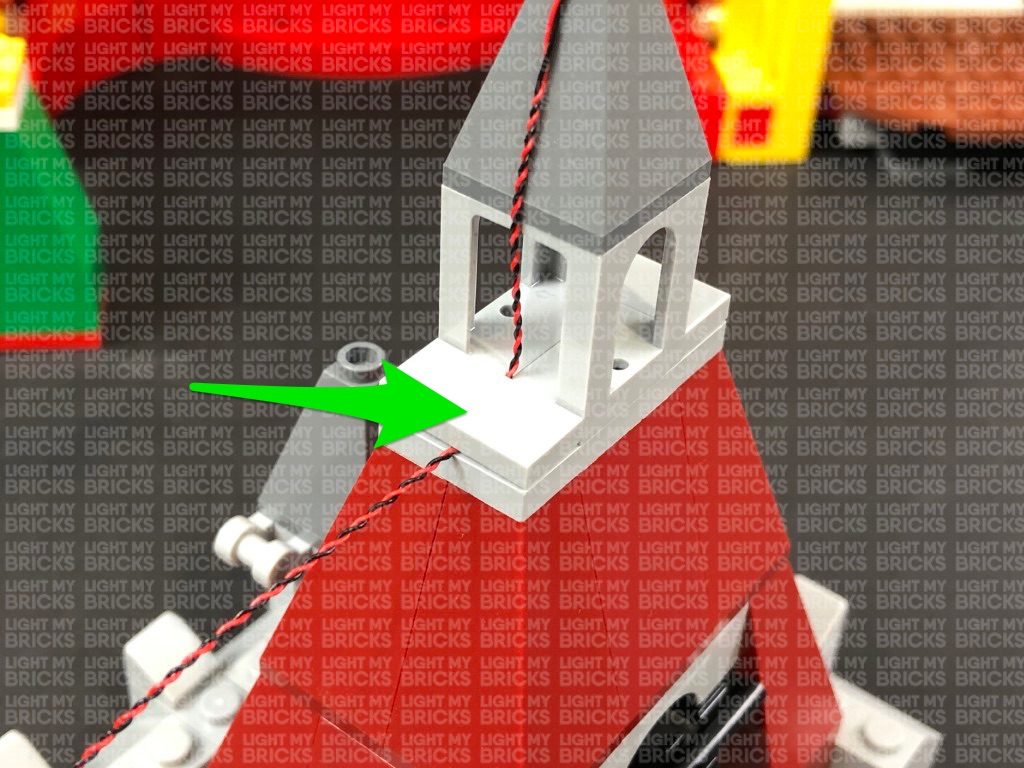
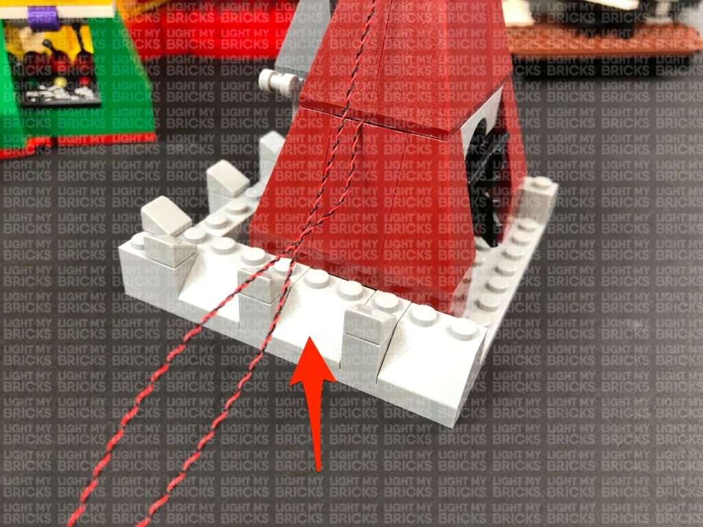
Bring the cable down the right side of the roof, then disconnect the following angled brick. Lay the cable in between studs, and push the cable down in the corner to ensure you have enough cable slack before reconnecting the brick over the top. This will prevent the cable from snapping when you reconnect the angled brick.
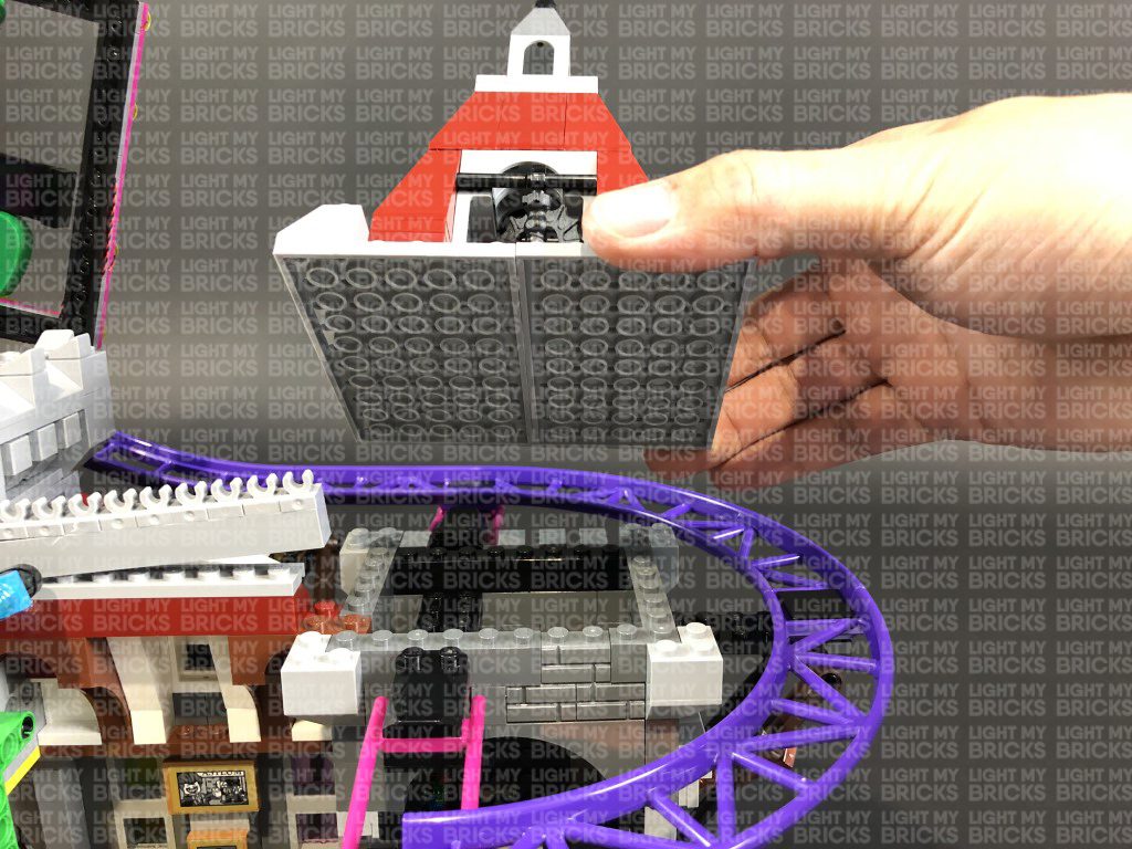
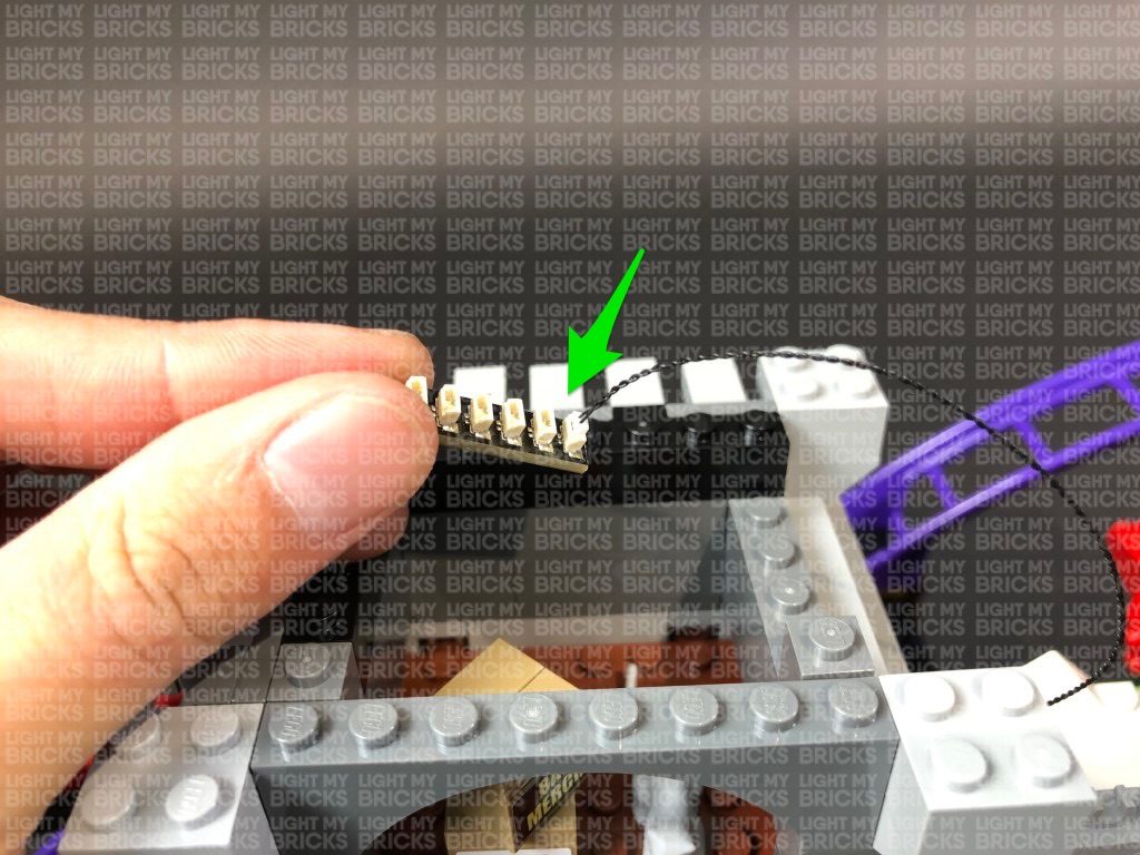
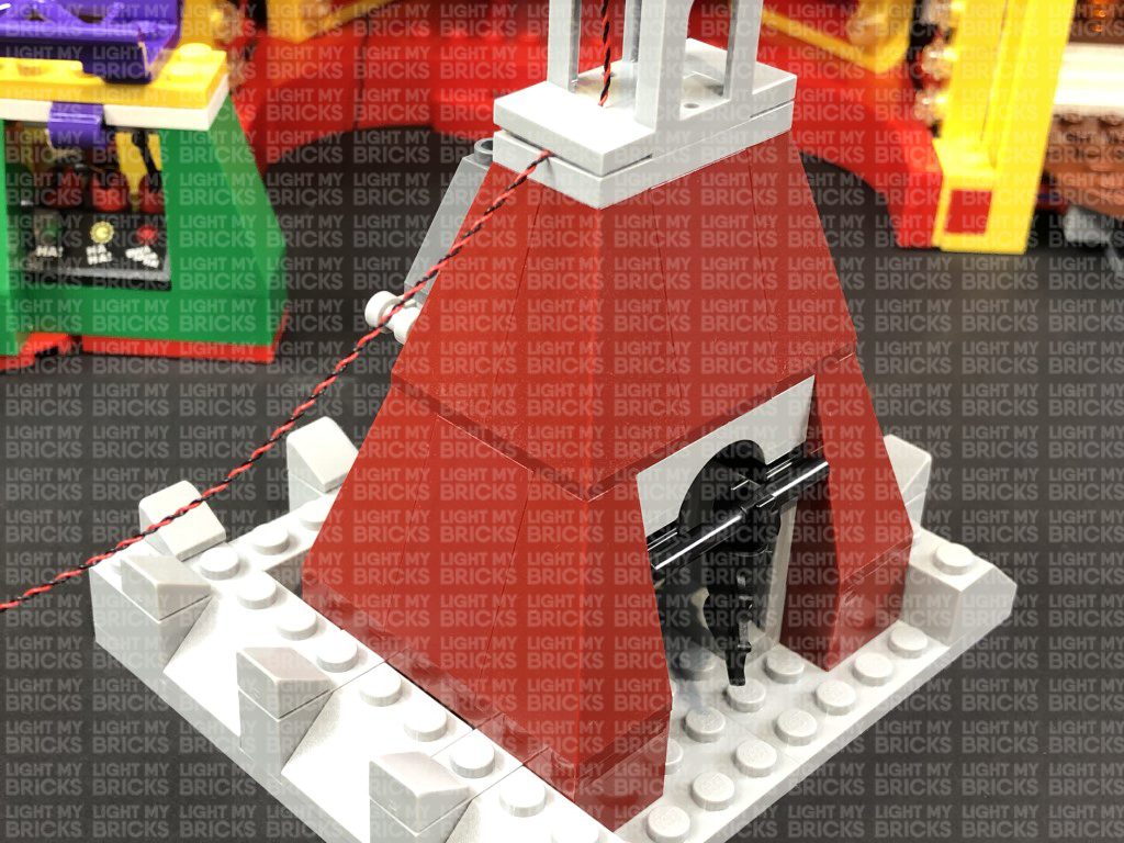
36.) Use your LEGO Removal Tool to disconnect the top section of the roof as shown below then take a White 15cm Bit Light and with the LED facing down and cable facing to the right, place it over the roof. Ensuring the cable is laid in between studs, reconnect the top section of the roof as shown to secure the light and cable in place.
Bring the cable down the right side of the roof and secure it underneath the same angled brick as previous step.
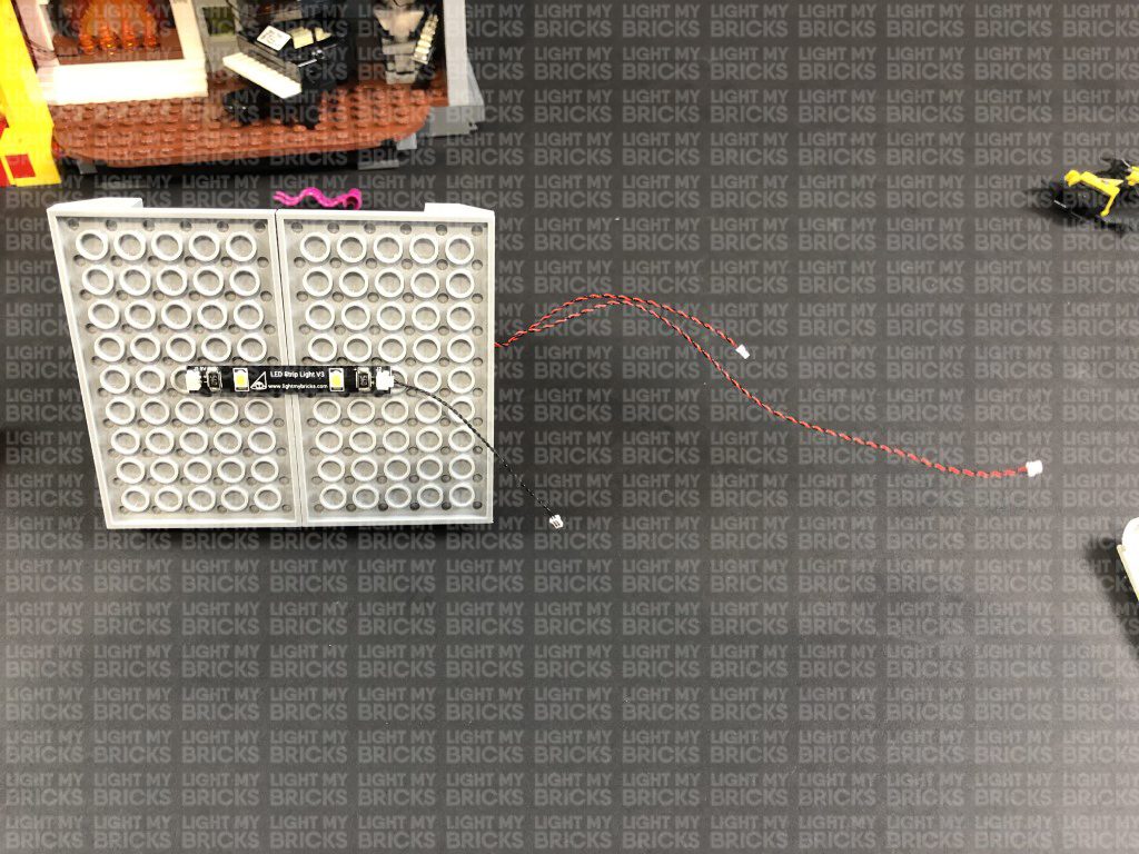
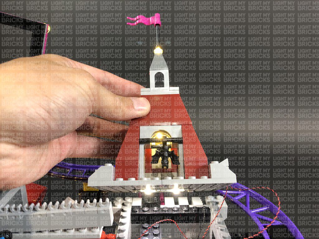
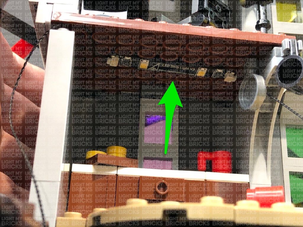
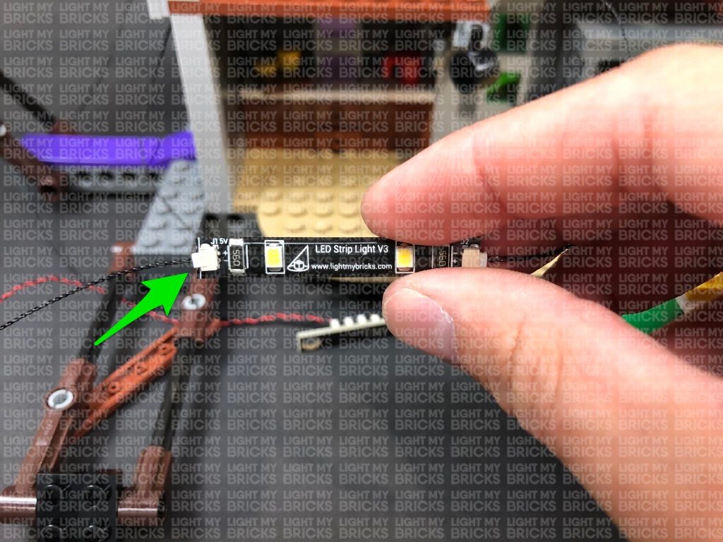
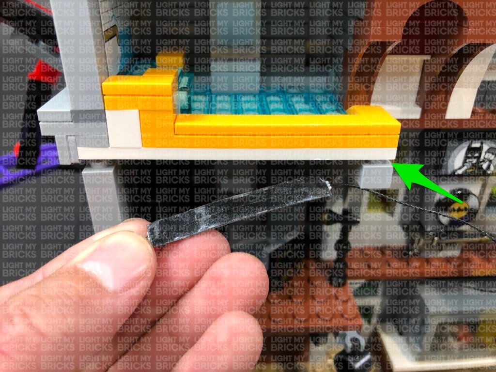
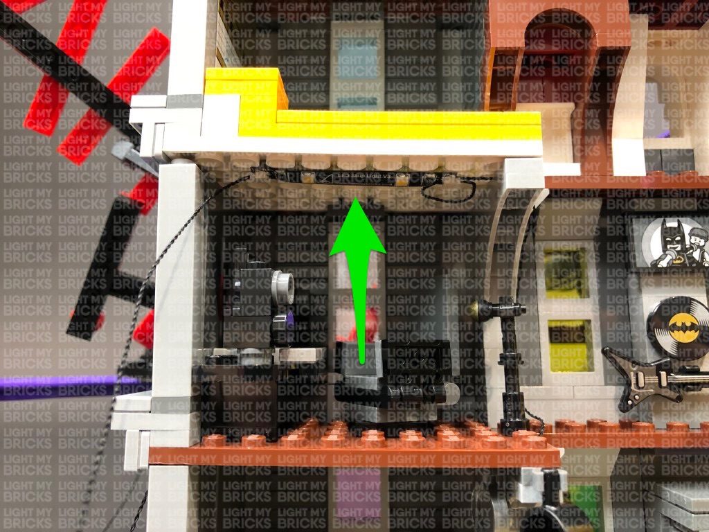
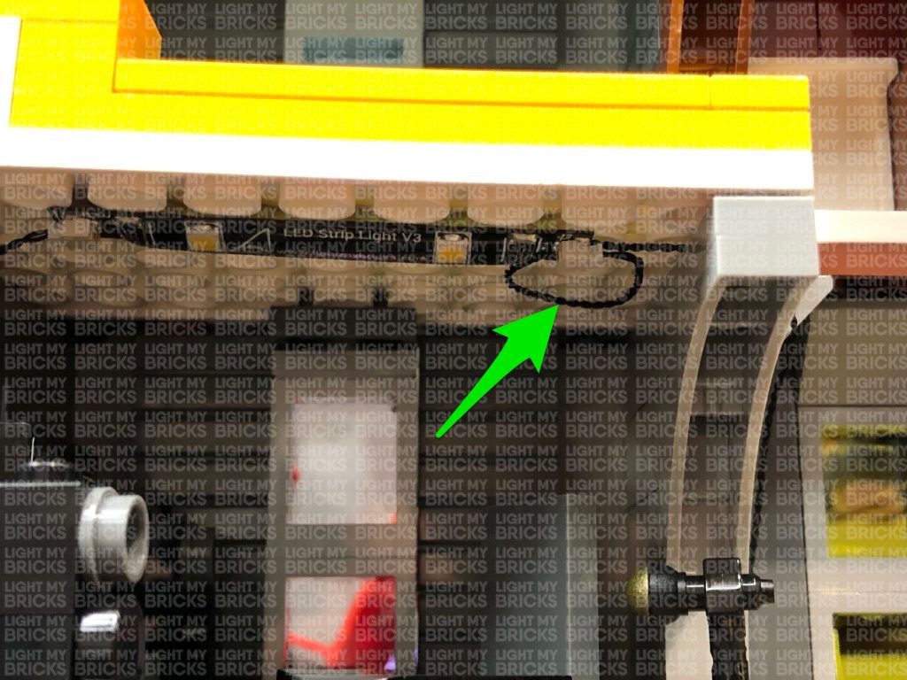
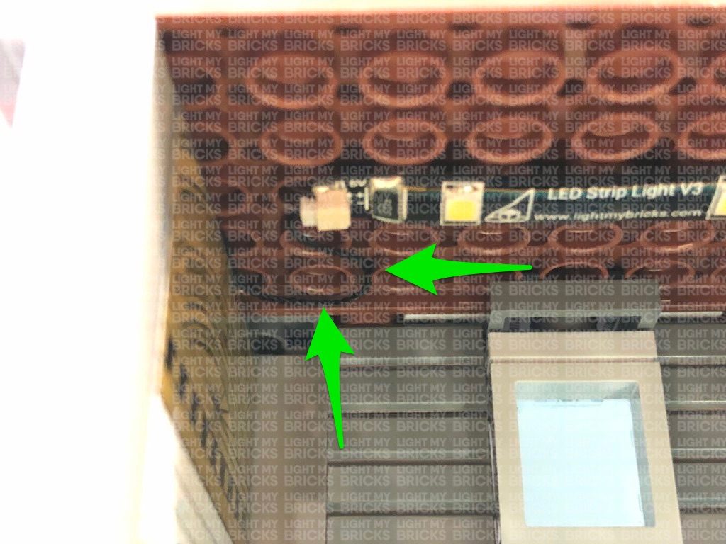
37.) Turn this roof section onto it’s front so we can access underneath. Take a White Strip Light and connect a 5cm Connecting Cable to the right port. Using it’s adhesive backing, stick the strip light underneath this section in the below position ensuring the 5cm cable is facing the right.
Bring this section over the top of the building and connect the other end of the 5cm Connecting Cable to the 6-Port Expansion Board underneath. Turn the USB Power Bank ON to test the lights installed to the top section are all working OK.
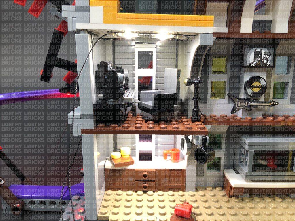
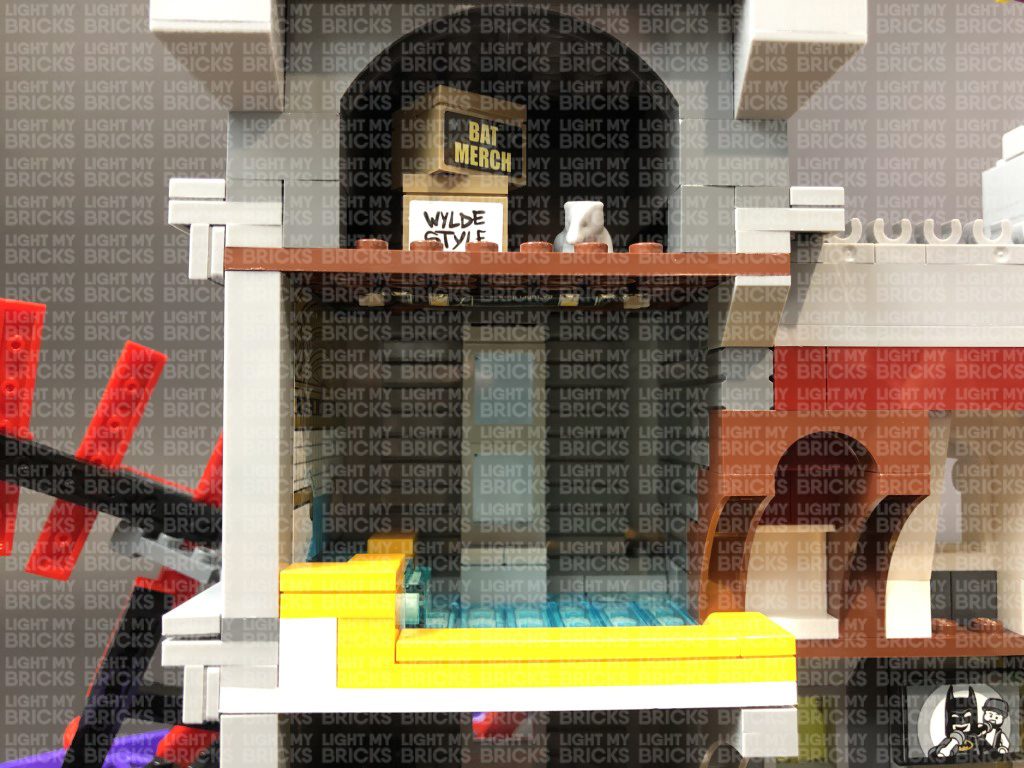
38.) Ensure all cables are neatly laid in between studs and that all components are neatly placed inside the building before reconnecting the roof and surrounding pieces.
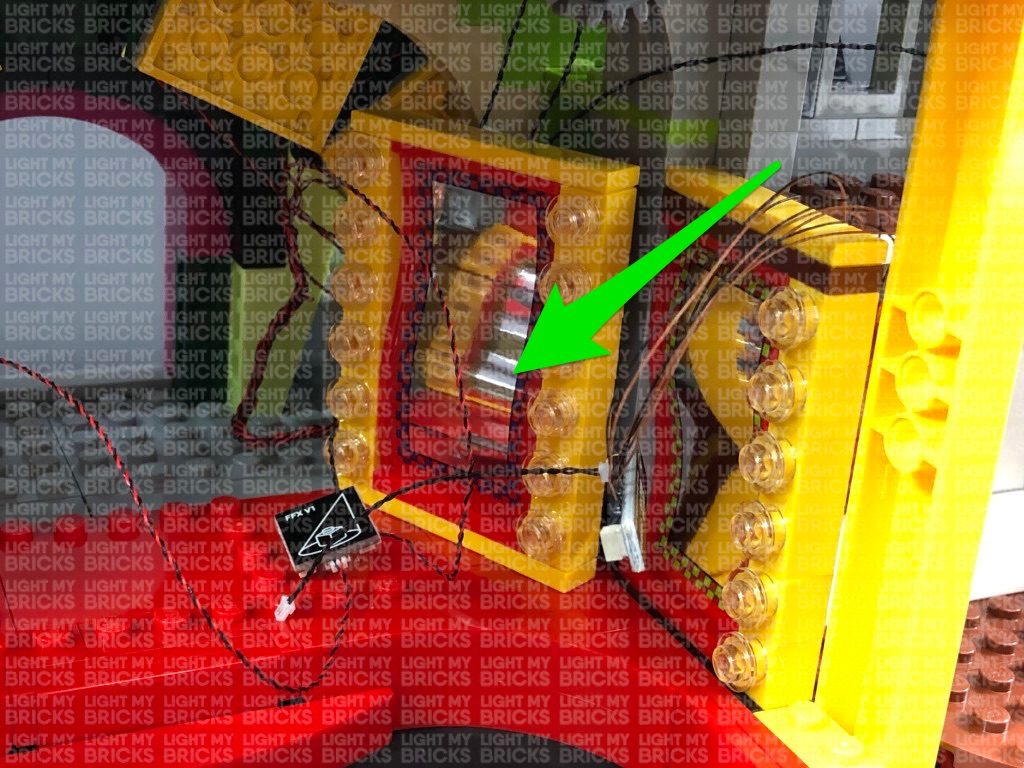
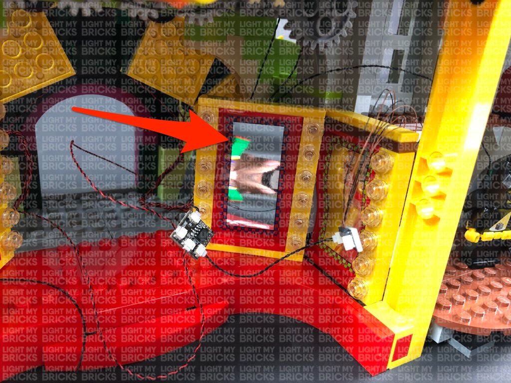
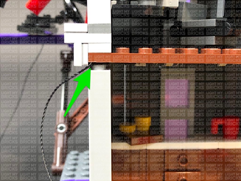
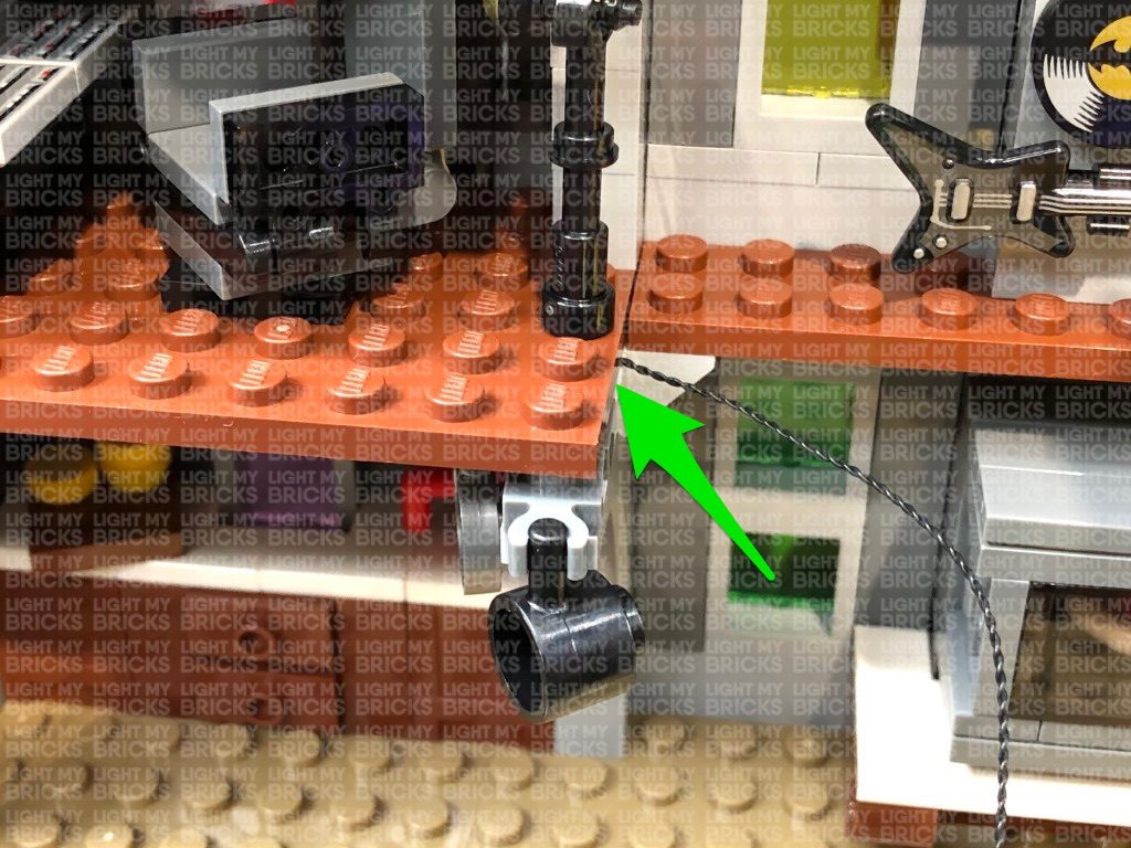
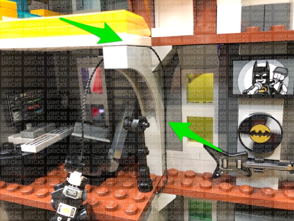
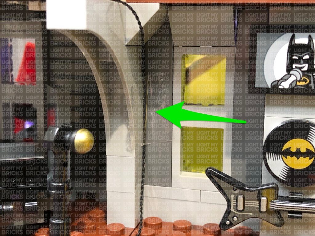
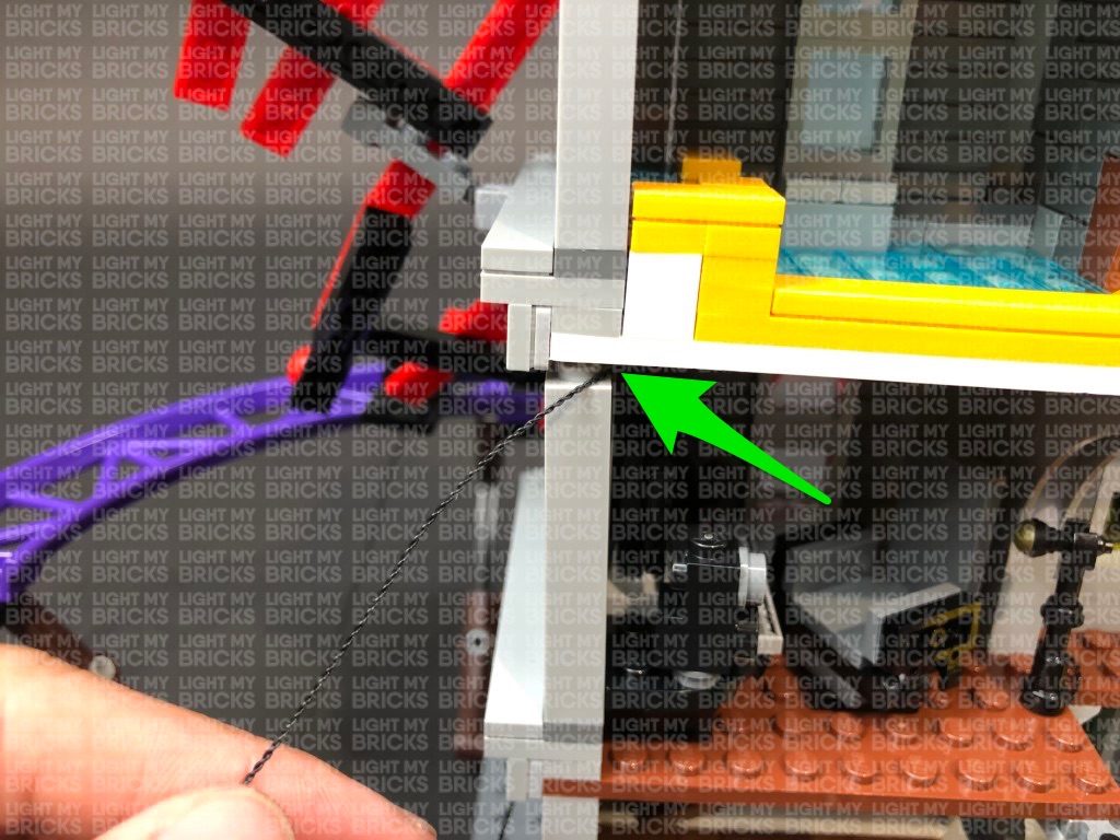
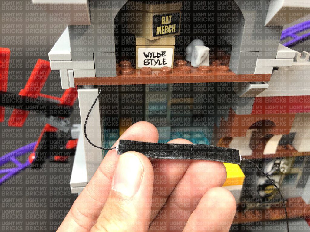
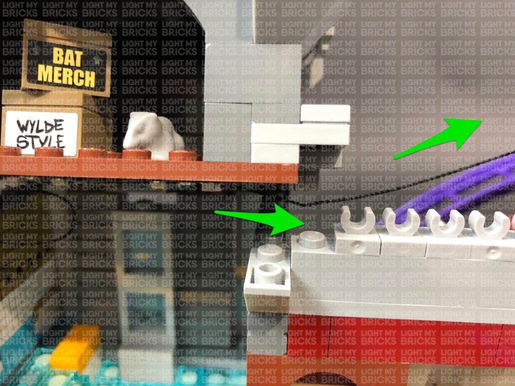
Secure the 15cm Connecting Cable dangling down the side of the theatre room behind the theatre screen as shown below:
Turn the USB Power Bank ON to test the lights installed to the right section are all working OK.
Note: If you experience any issues with the lights not working and suspect an issue with a component, please try a different port on the expansion board to verify where the fault lies (with the light, expansion board, or effects board). To correct any issues with expansion board ports, please view the section addressing expansion board issues on our online troubleshooting guide.
32.) Disconnect the first mirror, then disconnect the brown plate with yellow tile on top of the second mirror. Neatly lay the four micro bit ligiht cables in between studs before reconnecting the brown plate with yellow tile over the top.
Group all the components together and push them to right side before reconnecting the first mirror to hide them behind.
Secure the 30cm Connecting Cable leading to the right side underneath the yellow tile then use your LEGO Removal tool to slightly lift up the brown plate above the fire place. Slip the 30cm Connecting Cable in between before reconnecting the brown plate over the top.
Disconnect the second mirror from the left side, then tuck the 30cm connecting cable (leading to the 12-port expansion board on the left) inside and behind the yellow 1×2 plate with bar before reconnecting the mirror over the top.
33.) Slightly disconnect the following grey brick, then using your LEGO Removal Tool, completely disconnect the top section as shown below:
Take a 15cm Connecting Cable and connect one end to the next port on the 6-Port Expansion Board at the very bottom. Pull the other end of the connecting cable up and thread it through the inside of the theatre room and to the top. Pull the cable all the way out from above and connect it to a new 6-Port Expansion Board.
34.) We will now install a Bit Light underneath the top of the arch window. First take out a White 15cm Bit Light and with the LED facing down and cable to the right, place it in the centre of the base of a provided Trans Clear Plate w Rounded Bottom 2×2. Connect the trans clear plate underneath the following red bricks in the below position, ensuring the Bit Light is securely in the middle of the trans clear plate.
Bring the Bit Light cable across and lay in between studs, then connect it to the 6-Port Expansion Board on top of the theatre room. Turn the USB Power Bank ON to confirm the light is working OK.
Note: If you experience any issues with the lights not working and suspect an issue with a component, please try a different port on the expansion board to verify where the fault lies (with the light or expansion board). To correct any issues with expansion board ports, please view the section addressing expansion board issues on our online troubleshooting guide.
35.) Take the top section we removed in previous step and disconnect the flag pole. Take a White 30cm Bit Light and with the cable facing to the left, place it over the grey stud. Secure the Bit Light in place by connecting a provided Trans Clear Round Plate 1×1 over the top, then reconnect the flag pole.
Disconnect the grey roof piece and fold the cable underneath it. Reconnect it ensuring the cable is laid in between studs.
Disconnect the grey tile on the right side, then lay the cable down in between studs. Ensure you push the cable in the corner before reconnecting the tile over the top. This will prevent the cable from snapping when you reconnect the tile.
Bring the cable down the right side of the roof, then disconnect the following angled brick. Lay the cable in between studs, and push the cable down in the corner to ensure you have enough cable slack before reconnecting the brick over the top. This will prevent the cable from snapping when you reconnect the angled brick.
36.) Use your LEGO Removal Tool to disconnect the top section of the roof as shown below then take a White 15cm Bit Light and with the LED facing down and cable facing to the right, place it over the roof. Ensuring the cable is laid in between studs, reconnect the top section of the roof as shown to secure the light and cable in place.
Bring the cable down the right side of the roof and secure it underneath the same angled brick as previous step.
37.) Turn this roof section onto it’s front so we can access underneath. Take a White Strip Light and connect a 5cm Connecting Cable to the right port. Using it’s adhesive backing, stick the strip light underneath this section in the below position ensuring the 5cm cable is facing the right.
Bring this section over the top of the building and connect the other end of the 5cm Connecting Cable to the 6-Port Expansion Board underneath. Turn the USB Power Bank ON to test the lights installed to the top section are all working OK.
38.) Ensure all cables are neatly laid in between studs and that all components are neatly placed inside the building before reconnecting the roof and surrounding pieces.
Secure the 15cm Connecting Cable dangling down the side of the theatre room behind the theatre screen as shown below:
Turn the USB Power Bank ON to test the lights installed to the right section are all working OK.
 Note: If you experience any issues with the lights not working and suspect an issue with a component, please try a different port on the expansion board to verify where the fault lies (with the light or expansion board). To correct any issues with expansion board ports, please view the section addressing expansion board issues on our online troubleshooting guide.
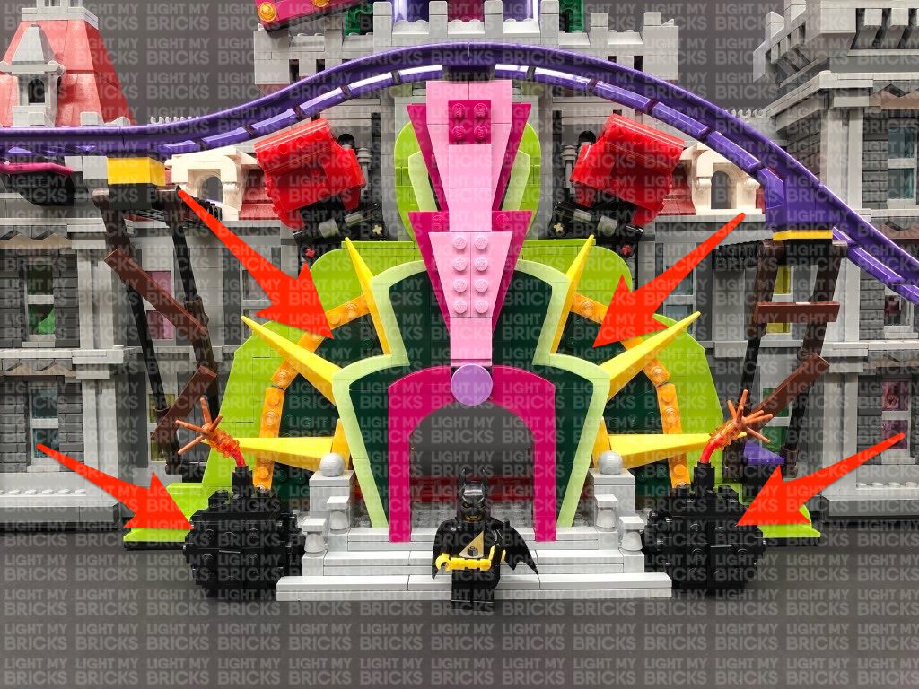
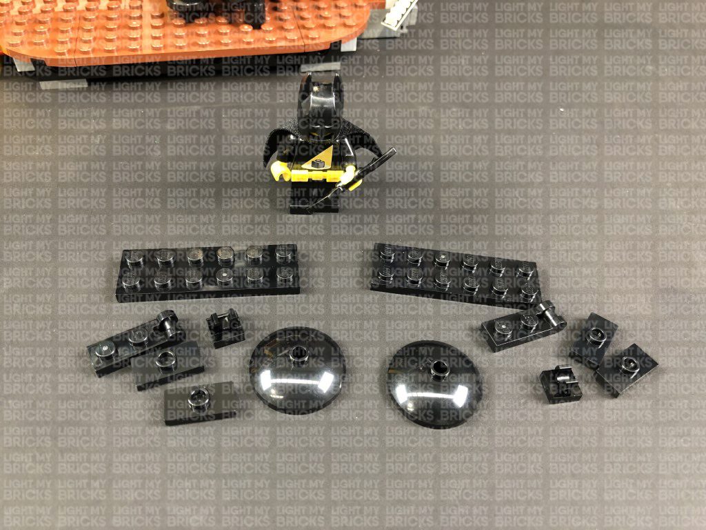
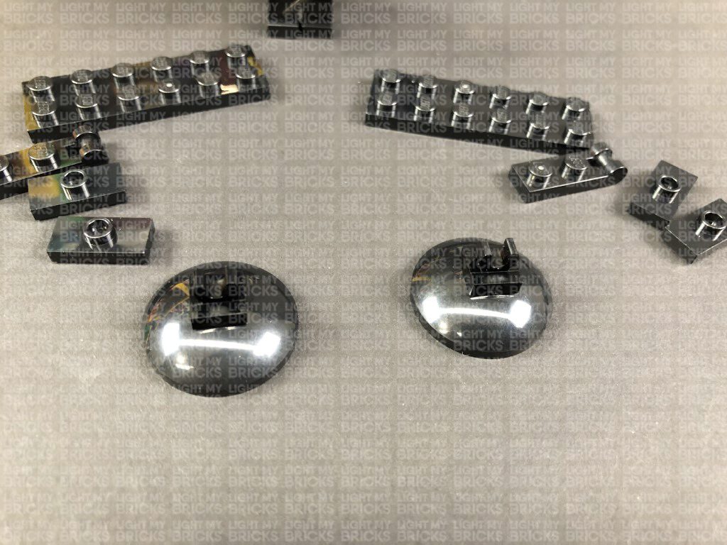
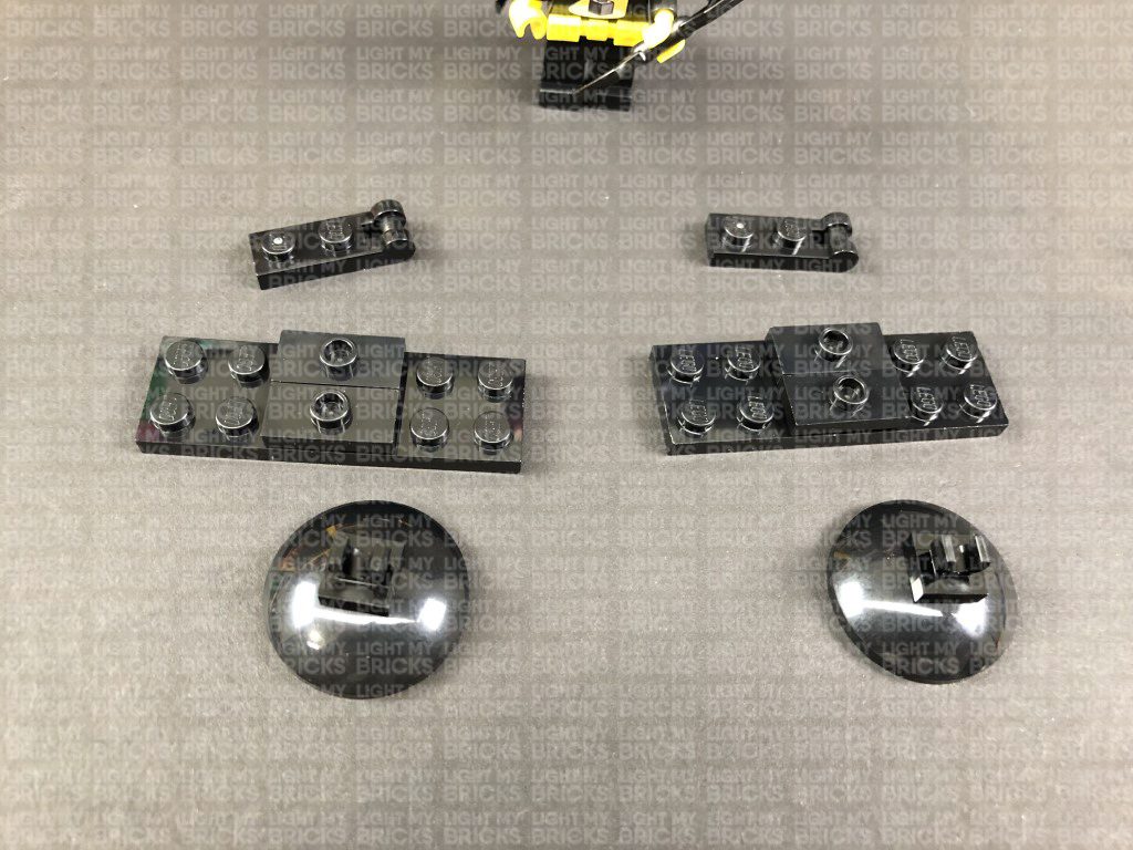
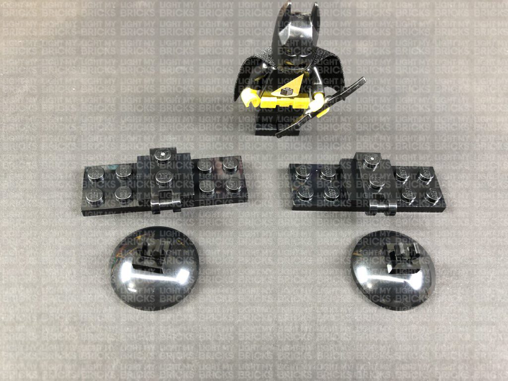
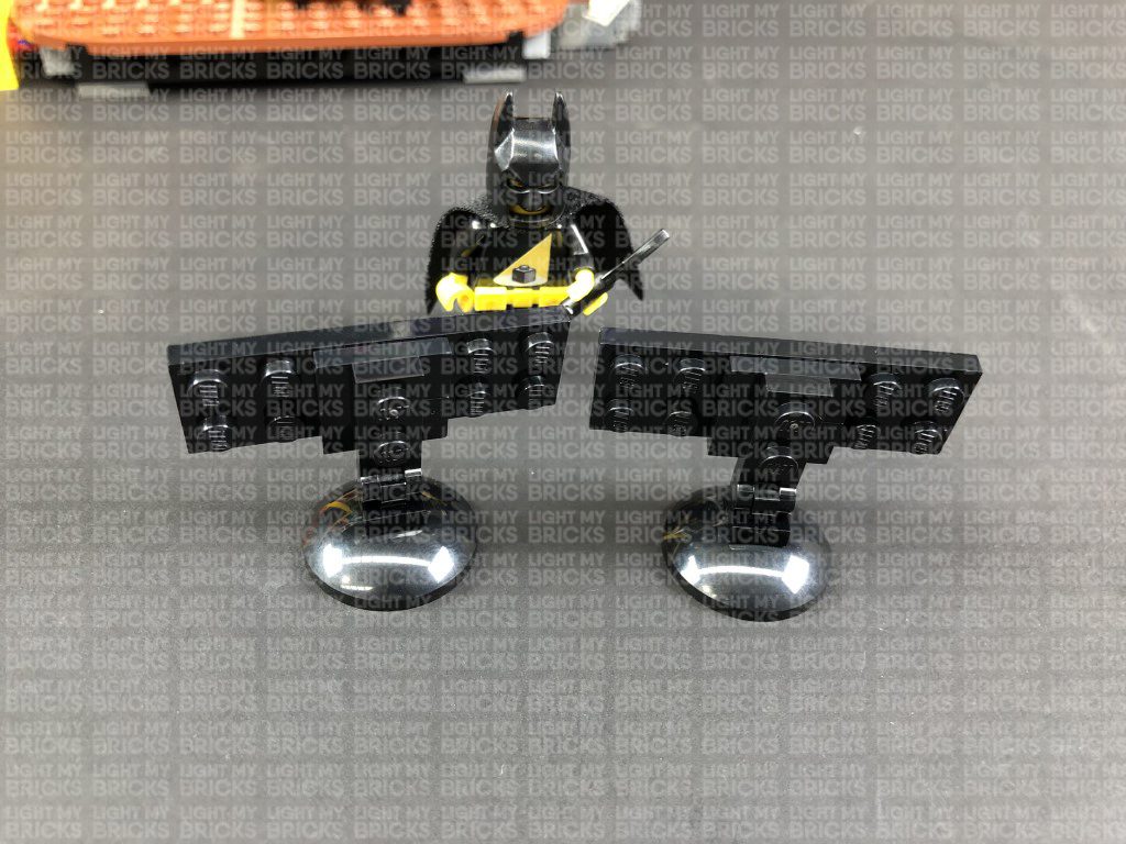
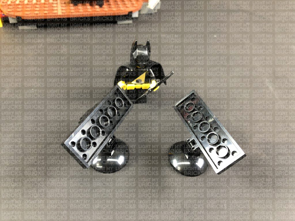
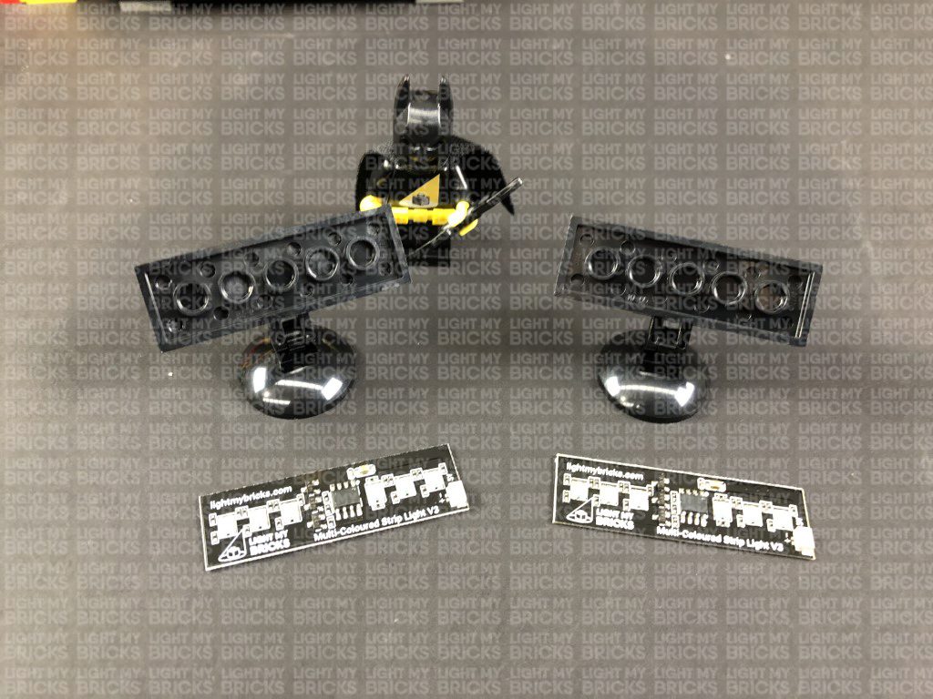
39.) Take out the following provided LEGO Pieces and assemble them according to the below images to build two spot lights.
Note: If you experience any issues with the lights not working and suspect an issue with a component, please try a different port on the expansion board to verify where the fault lies (with the light or expansion board). To correct any issues with expansion board ports, please view the section addressing expansion board issues on our online troubleshooting guide.
39.) Take out the following provided LEGO Pieces and assemble them according to the below images to build two spot lights.
- 2x Black Dish Inverted 3×3
- 2x Black Plate 2×6
- 2x Black Plate 1×2 modified w Handle on End
- 2x Black Tile 1×1 w Clip
- 4x Black Plate 1×2 modified with stud jumper
 Note: If you experience any issues with the lights not working and suspect an issue with a component, please try a different port on the expansion board to verify where the fault lies (with the strip light or expansion board). To correct any issues with expansion board ports, please view the section addressing expansion board issues on our online troubleshooting guide.
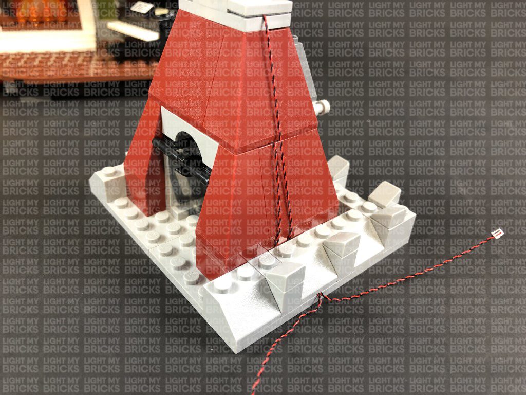
46.) Use your LEGO Removal tool to completely disconnect the roof section, then disconnect the top of the right wall as show below:
Take the other end of the 15cm Connecting Cable from below and connect it to a 6-Port Expansion Board.
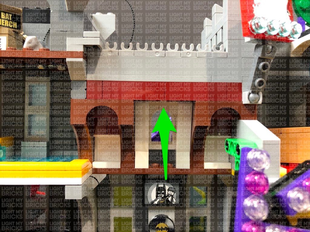
47.) We will now install a Bit Light to shine down just above the arch window (similar to the one on the right side in step 34). Take out a White 15cm Bit Light and with the LED facing down and cable to towards you, place it in the centre of the base of a provided Trans Clear Plate w Rounded Bottom 2×2. Connect the trans clear plate underneath the red bricks in the following position, ensuring the Bit Light is securely in the centre and LED facing down.
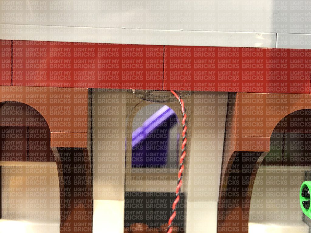
Use your LEGO Removal Tool to create a gap in between the red and grey bricks above to allow you to thread the Bit Light cable through this space. Pull the cable all the way out from the other side before closing up the gap ensuring the cable is laid in between studs.
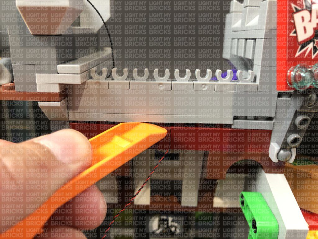
48.) Bring the Bit Light Cable over the wall to the left, while securing it down (both bit light cable and connecting cable) underneath the following two grey tiles. Ensure the two cables are both pressed down into the corners to ensure the cables do not snap when reconnecting the tiles over the top.
Reconnect the top left wall section over the two cables ensuring they are also laid in between studs underneath before connecting the Bit Light cable to the 6-Port Expansion Board. Turn ON the USB Power Bank to test the Bit Light is working OK.
Note: If you experience any issues with the lights not working and suspect an issue with a component, please try a different port on the expansion board to verify where the fault lies (with the strip light or expansion board). To correct any issues with expansion board ports, please view the section addressing expansion board issues on our online troubleshooting guide.
Neaten up excess cable by folding and twisting the Bit Light cable around itself a few times, then neatly place the bunched up cables and expansion board in the corner behind the boxes.
49.) Take the roof section and disconnect the flag pole. Take a White 30cm Bit Light and with the cable on the left side, place it over the stud on the roof. Secure it in place by connecting a provided Trans Clear Round Plate 1×1 over the top.
Reconnect the flag pole, then bring the wire down the left side of the roof and secure it underneath the grey tile. Ensure the cable is pressed down in the corner before reconnecting the tile as this will prevent the cable snapping.
50.) Use the LEGO Removal tool to disconnect the roof at the following section. Take a White 15cm Bit Light and with the cable on the left and the LED facing down, place the Bit Light in the middle of this section. Reconnect the roof to secure the bit light and cable in place ensuring the cable underneath is laid in between studs.
Secure both cables underneath the following angled brick. Ensure both cables are pressed down in the corners before reconnecting the angled brick over the top to ensure the cables do not snap due to lack of cable slack.
Fold both cables underneath, then bring this section over the attic. Connect both bit light cables to the 6-port expansion board below, then place neatly place components underneath (behind the boxes) before reconnecting the roof section. Turn the USB Power Bank ON to test all lights in the top section are working OK.
Note: If you experience any issues with the lights not working and suspect an issue with a component, please try a different port on the expansion board to verify where the fault lies (with the strip light or expansion board). To correct any issues with expansion board ports, please view the section addressing expansion board issues on our online troubleshooting guide.
46.) Use your LEGO Removal tool to completely disconnect the roof section, then disconnect the top of the right wall as show below:
Take the other end of the 15cm Connecting Cable from below and connect it to a 6-Port Expansion Board.
47.) We will now install a Bit Light to shine down just above the arch window (similar to the one on the right side in step 34). Take out a White 15cm Bit Light and with the LED facing down and cable to towards you, place it in the centre of the base of a provided Trans Clear Plate w Rounded Bottom 2×2. Connect the trans clear plate underneath the red bricks in the following position, ensuring the Bit Light is securely in the centre and LED facing down.
Use your LEGO Removal Tool to create a gap in between the red and grey bricks above to allow you to thread the Bit Light cable through this space. Pull the cable all the way out from the other side before closing up the gap ensuring the cable is laid in between studs.
48.) Bring the Bit Light Cable over the wall to the left, while securing it down (both bit light cable and connecting cable) underneath the following two grey tiles. Ensure the two cables are both pressed down into the corners to ensure the cables do not snap when reconnecting the tiles over the top.
Reconnect the top left wall section over the two cables ensuring they are also laid in between studs underneath before connecting the Bit Light cable to the 6-Port Expansion Board. Turn ON the USB Power Bank to test the Bit Light is working OK.
Note: If you experience any issues with the lights not working and suspect an issue with a component, please try a different port on the expansion board to verify where the fault lies (with the strip light or expansion board). To correct any issues with expansion board ports, please view the section addressing expansion board issues on our online troubleshooting guide.
Neaten up excess cable by folding and twisting the Bit Light cable around itself a few times, then neatly place the bunched up cables and expansion board in the corner behind the boxes.
49.) Take the roof section and disconnect the flag pole. Take a White 30cm Bit Light and with the cable on the left side, place it over the stud on the roof. Secure it in place by connecting a provided Trans Clear Round Plate 1×1 over the top.
Reconnect the flag pole, then bring the wire down the left side of the roof and secure it underneath the grey tile. Ensure the cable is pressed down in the corner before reconnecting the tile as this will prevent the cable snapping.
50.) Use the LEGO Removal tool to disconnect the roof at the following section. Take a White 15cm Bit Light and with the cable on the left and the LED facing down, place the Bit Light in the middle of this section. Reconnect the roof to secure the bit light and cable in place ensuring the cable underneath is laid in between studs.
Secure both cables underneath the following angled brick. Ensure both cables are pressed down in the corners before reconnecting the angled brick over the top to ensure the cables do not snap due to lack of cable slack.
Fold both cables underneath, then bring this section over the attic. Connect both bit light cables to the 6-port expansion board below, then place neatly place components underneath (behind the boxes) before reconnecting the roof section. Turn the USB Power Bank ON to test all lights in the top section are working OK.
 Note: If you experience any issues with the lights not working and suspect an issue with a component, please try a different port on the expansion board to verify where the fault lies (with the strip light or expansion board). To correct any issues with expansion board ports, please view the section addressing expansion board issues on our online troubleshooting guide.
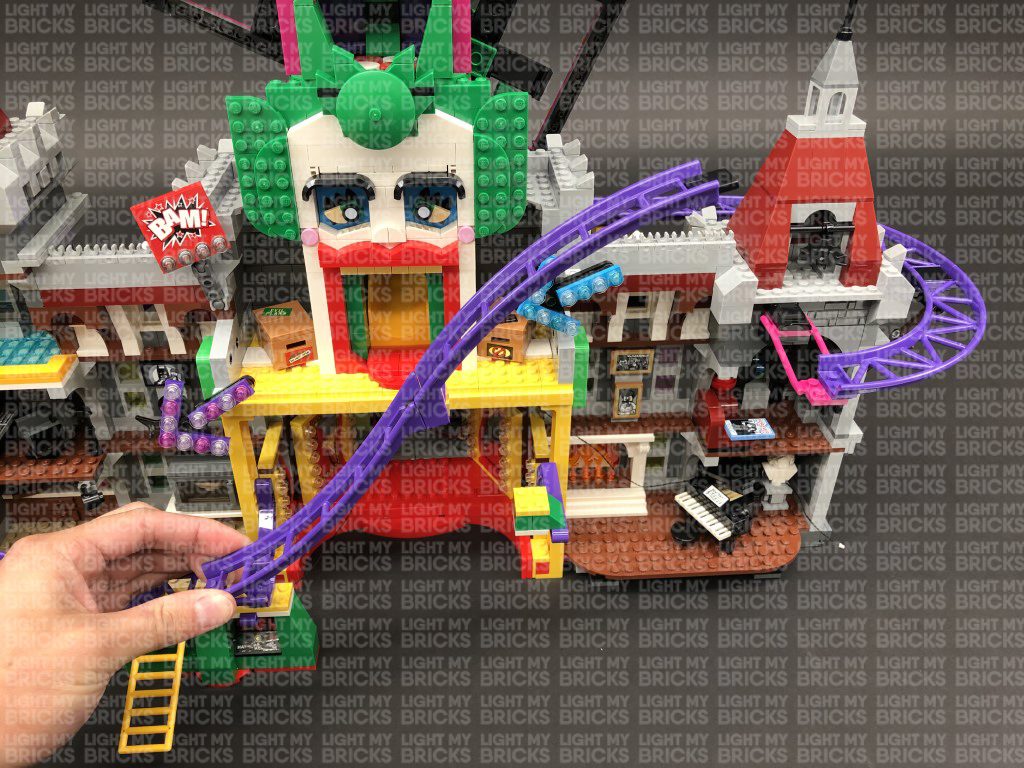
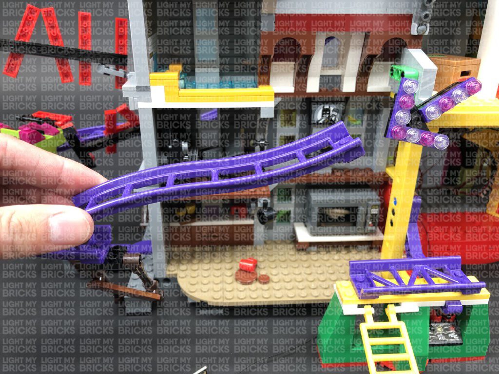
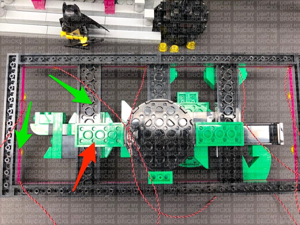
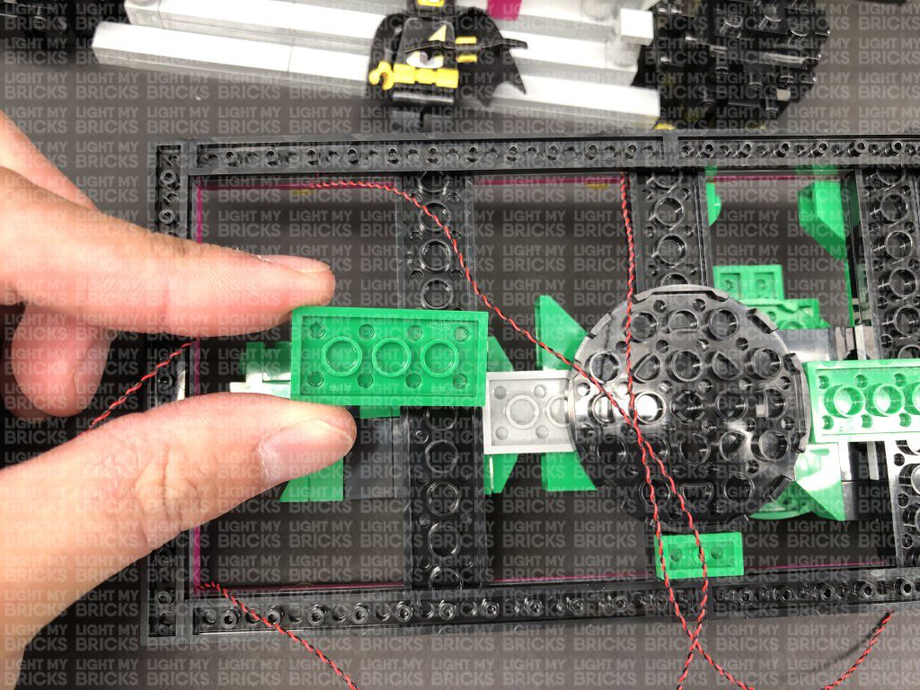
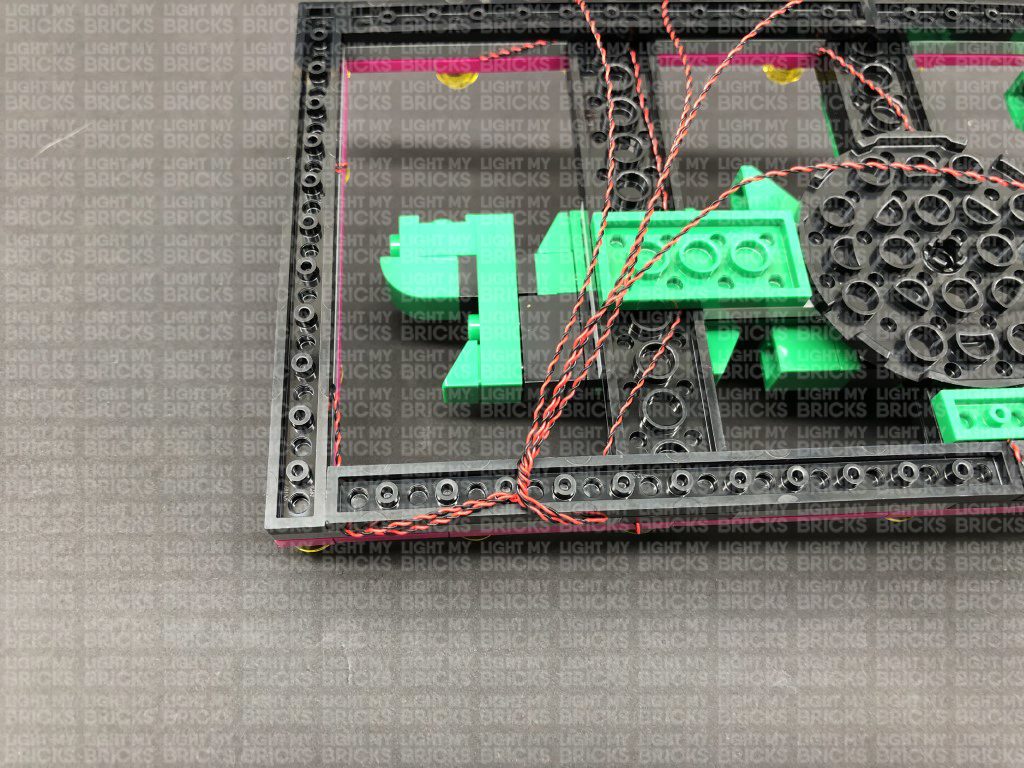
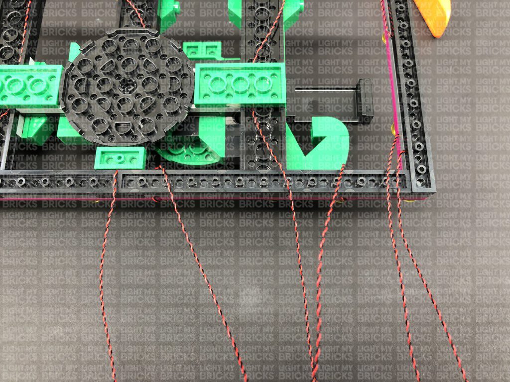
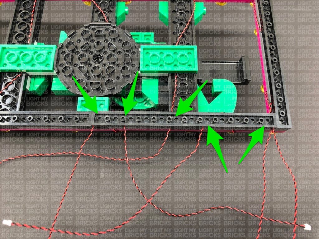
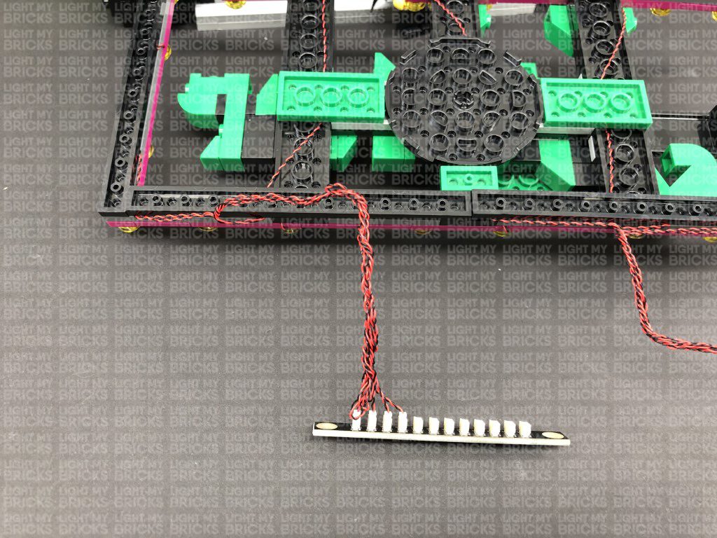
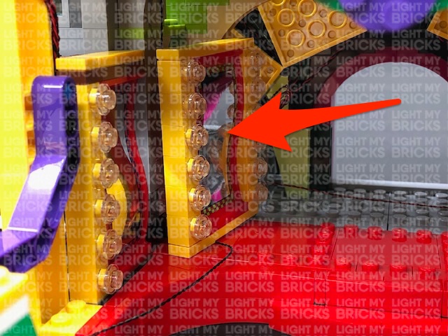
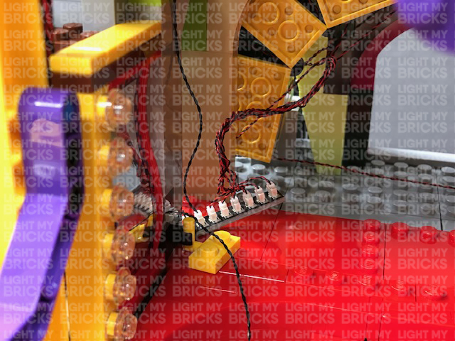
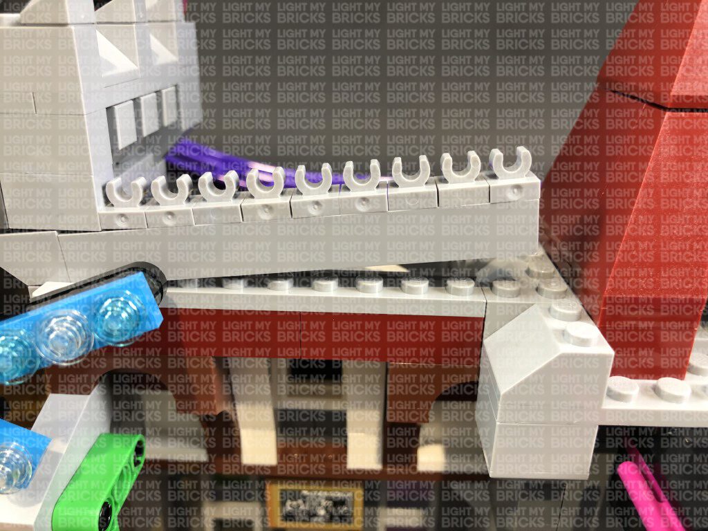
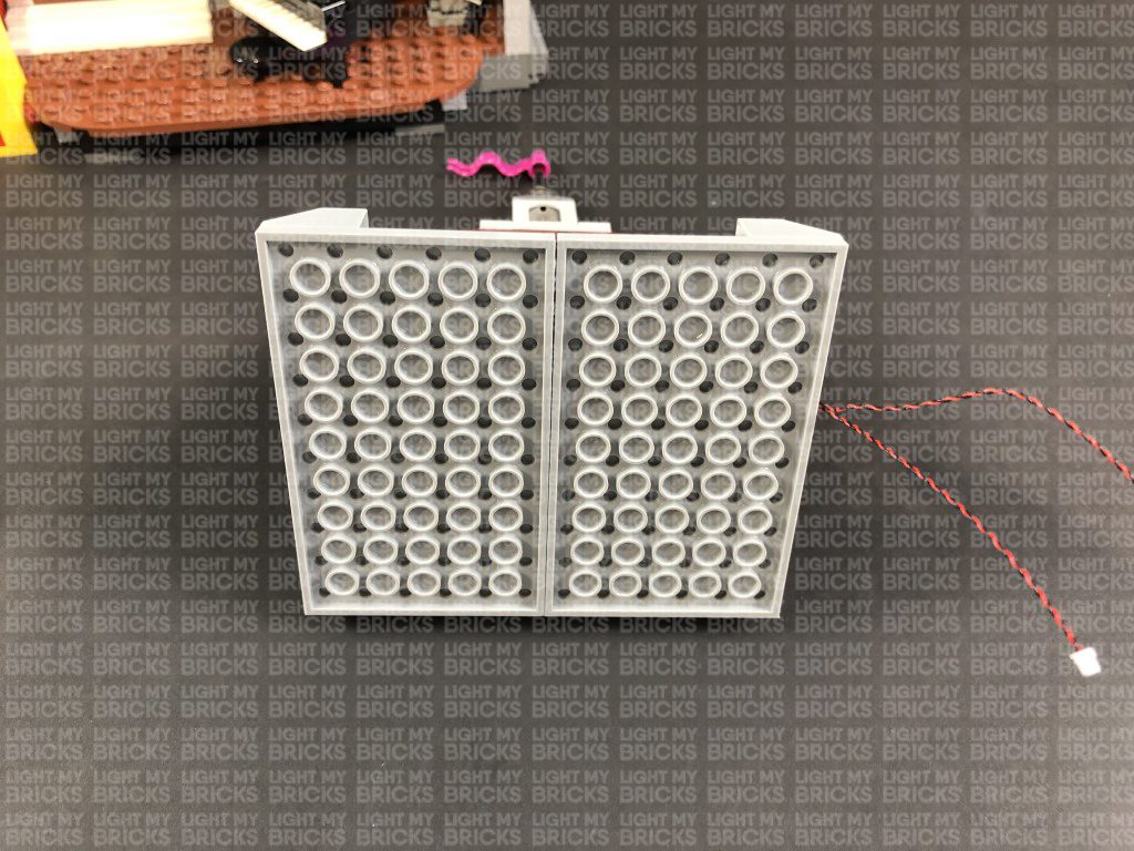
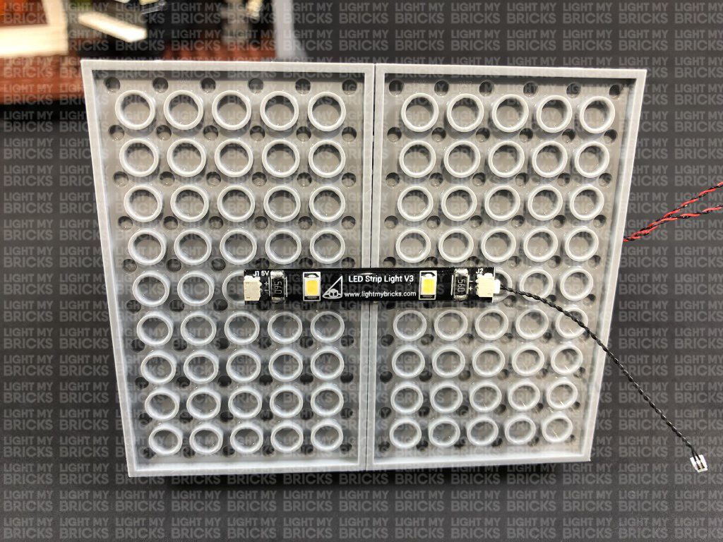
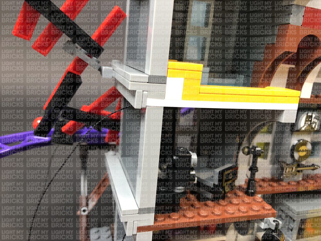
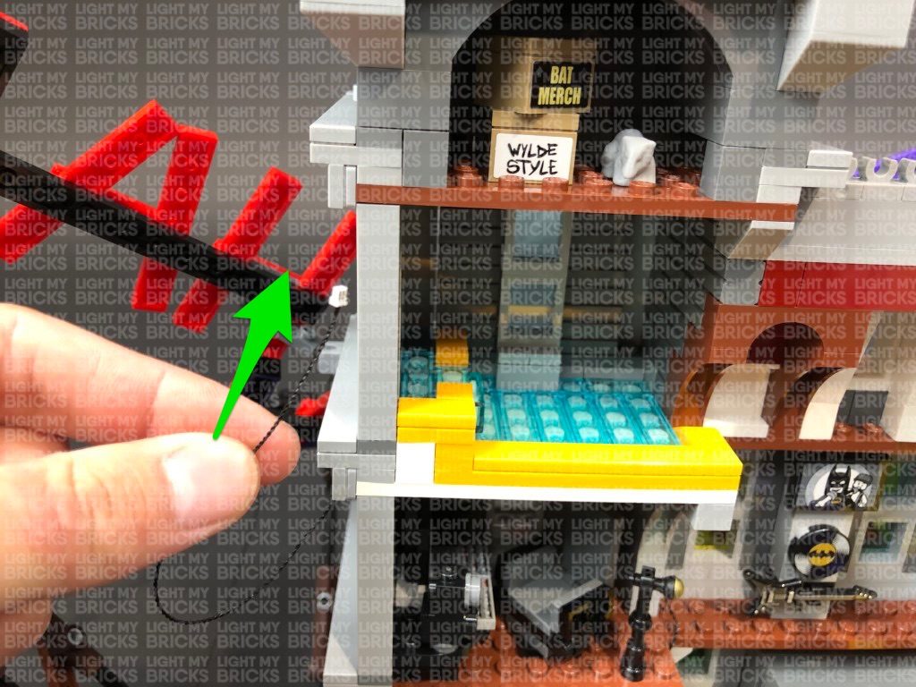
51.) Take a new 30cm Connecting Cable and connect it to a spare port on the 12-Port Expansion Board on the bottom of the left side. Bring the other end of the cable over to the right and thread it through the following technic pin. Pull the cable out from the other side.
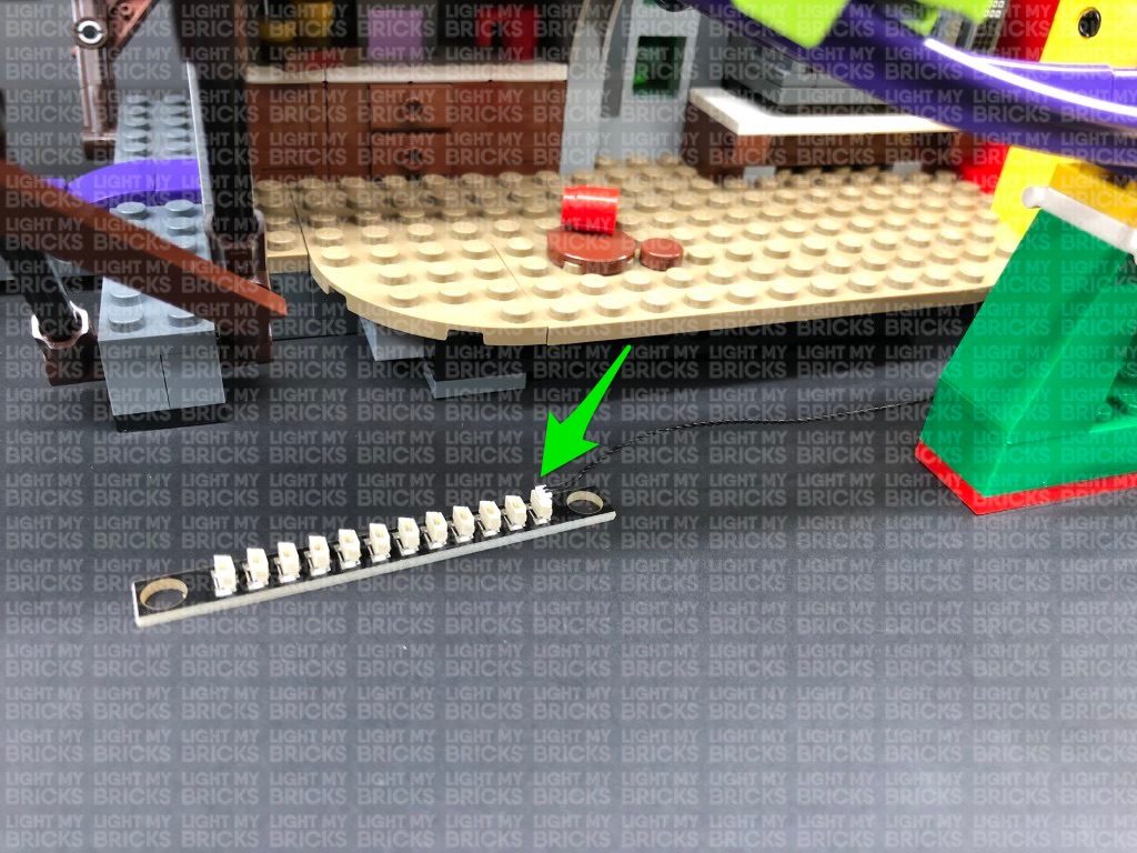
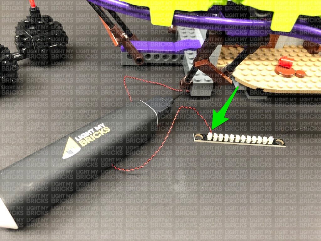
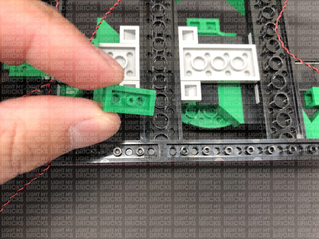
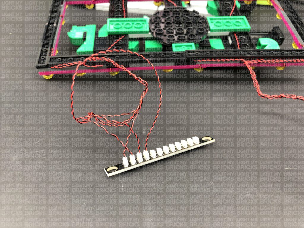
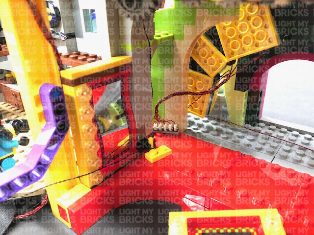
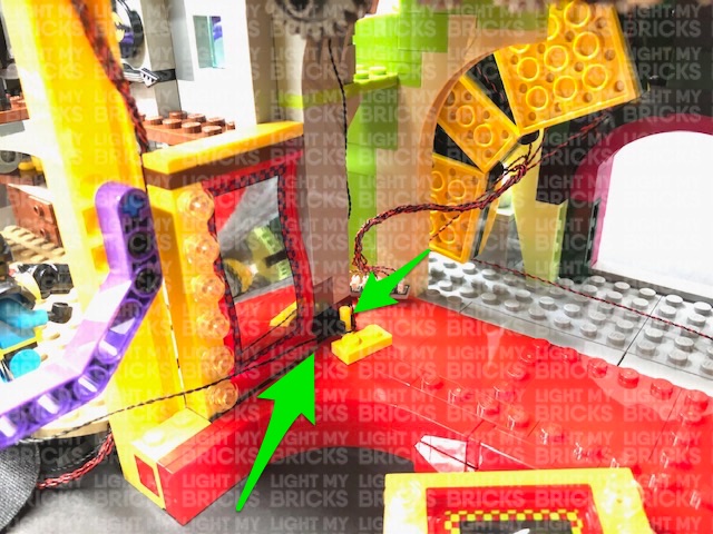
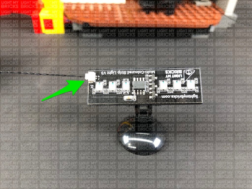
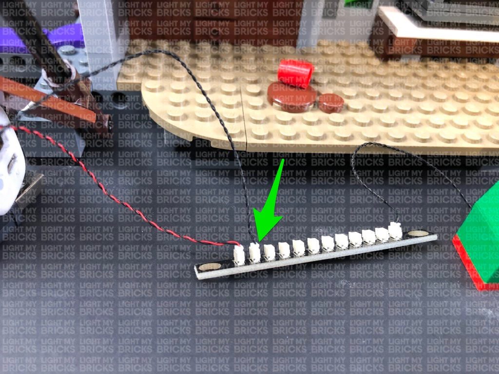
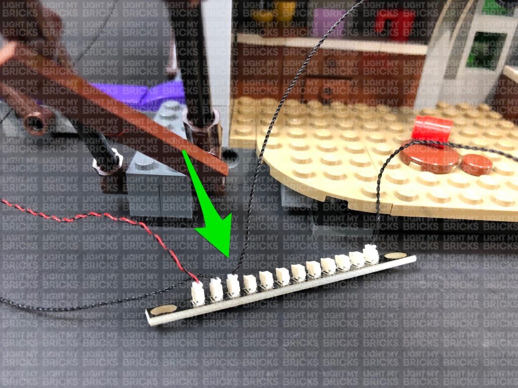
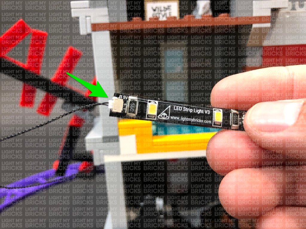
Take 2x White Strip Lights and connect them together using a 5cm Connecting Cable. Take the other end of the 30cm Connecting Cable and connect it to one of the Strip Lights. Take a 15cm Connecting Cable and connect it to the other end of the other White Strip Light. Thread the other end of the 15cm Connecting Cable through the technic pin on the right, pulling it all the way out from the other side.
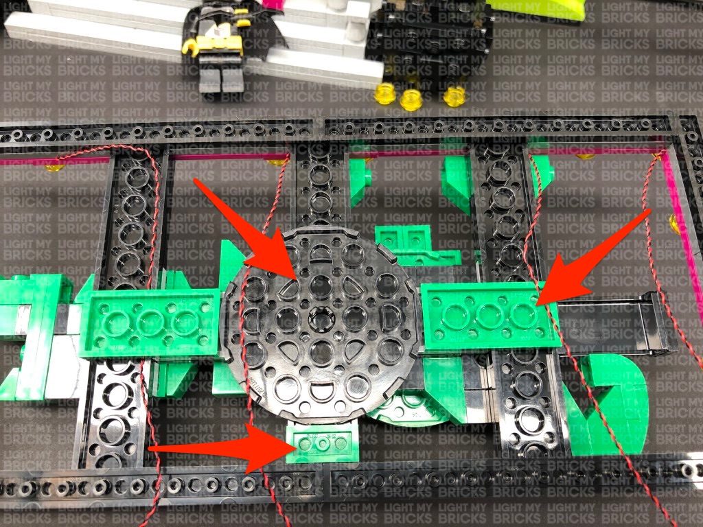
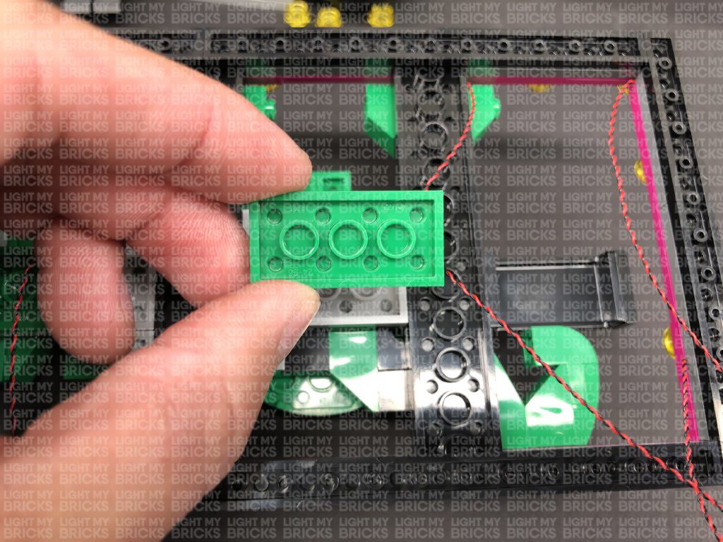
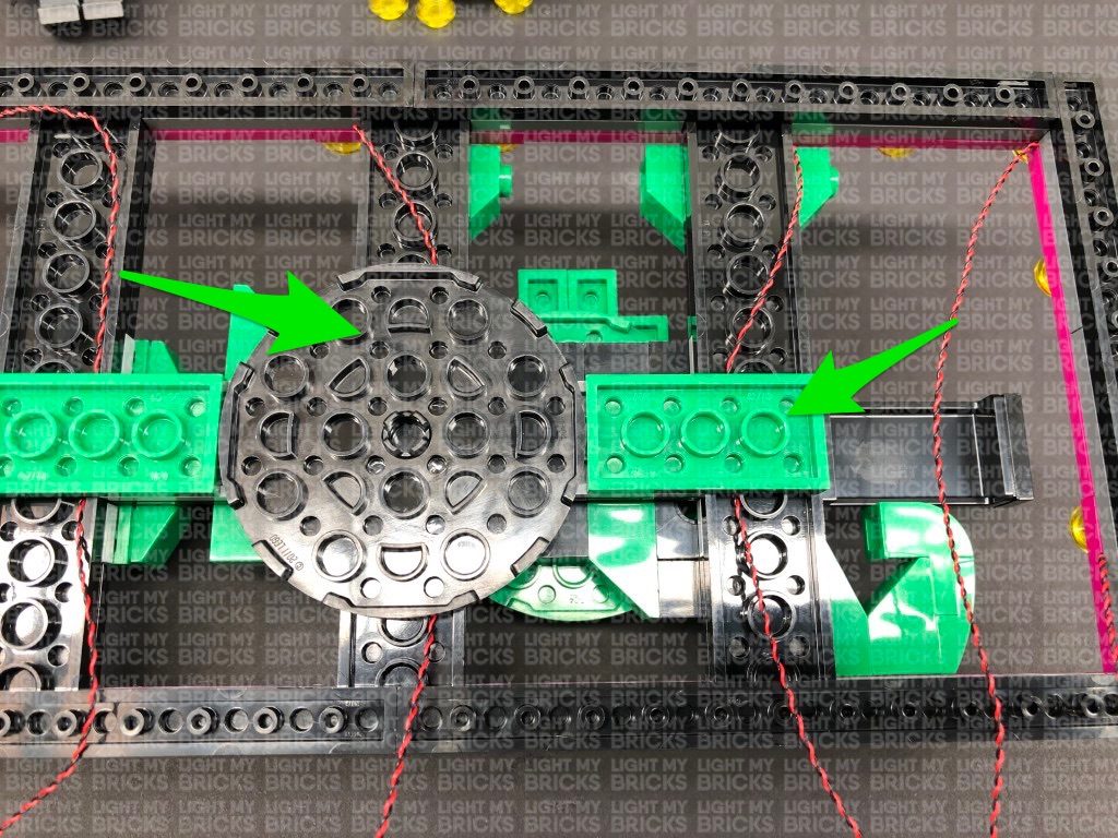
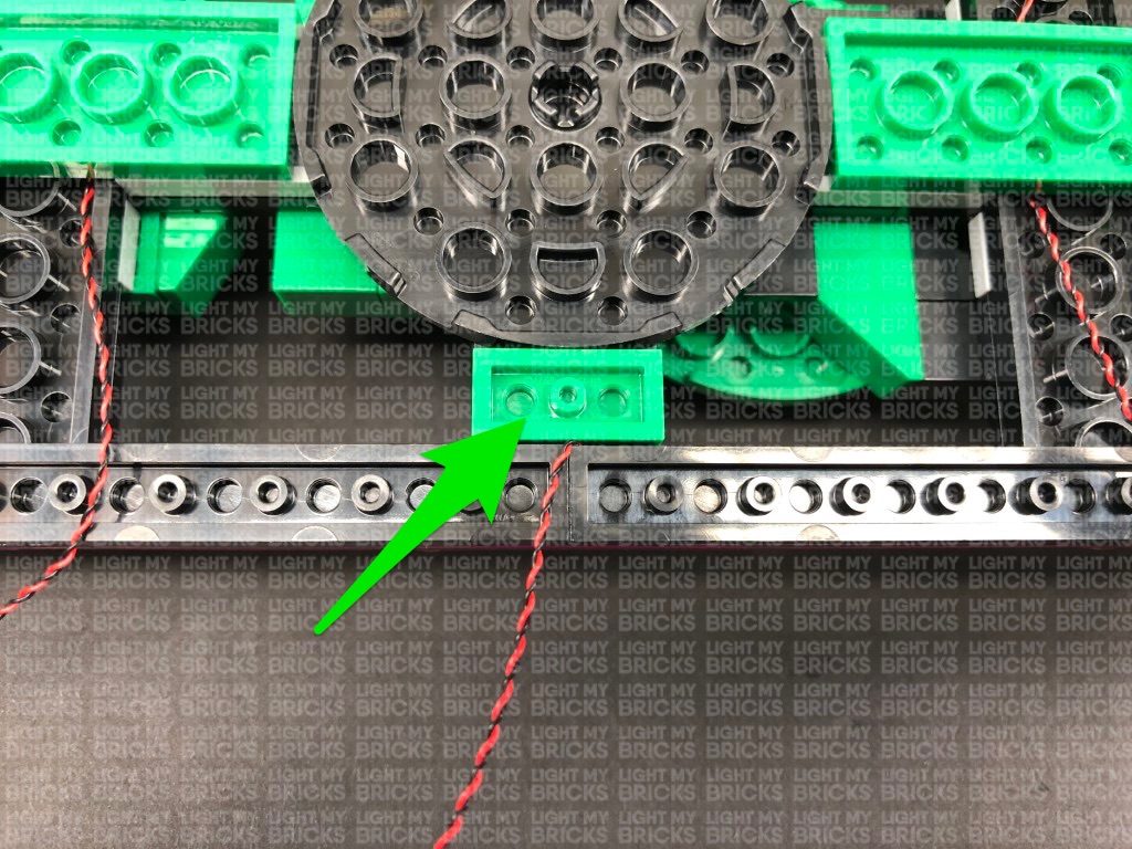
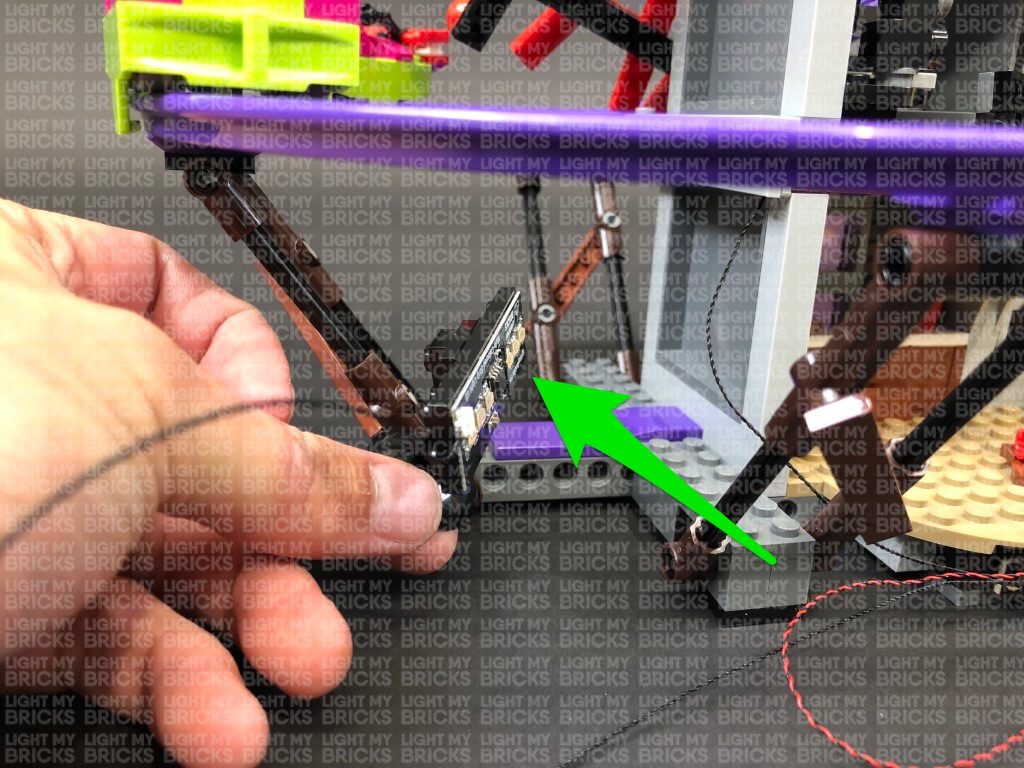
Using their adhesive backings, stick both strip lights to the green technic bricks in the below position. Loop the 5cm cable in between and push it up to prevent it from dangling down. Turn the USB Power Bank ON to test the strip lights are working OK.
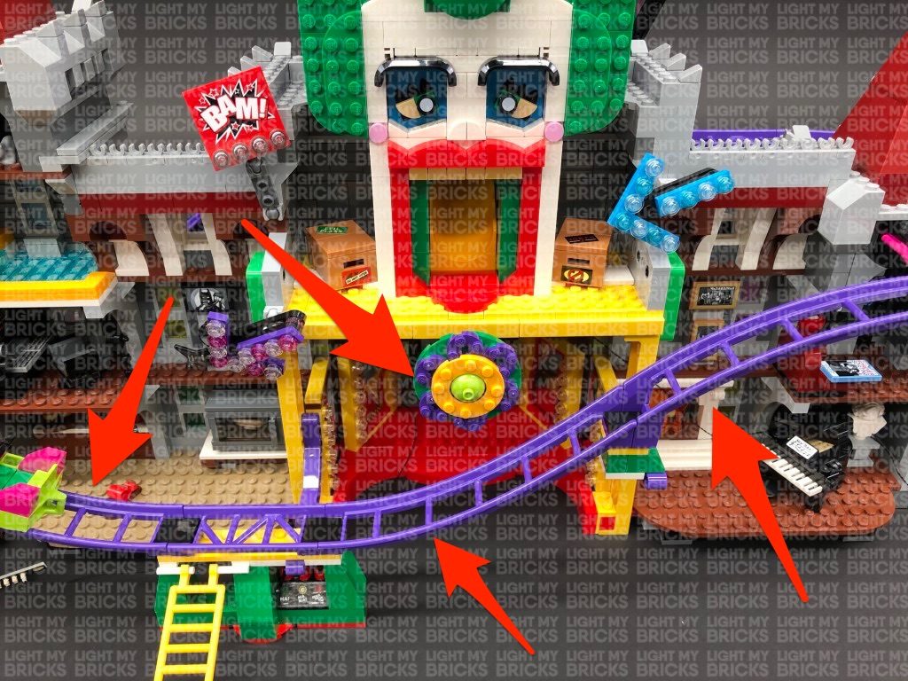
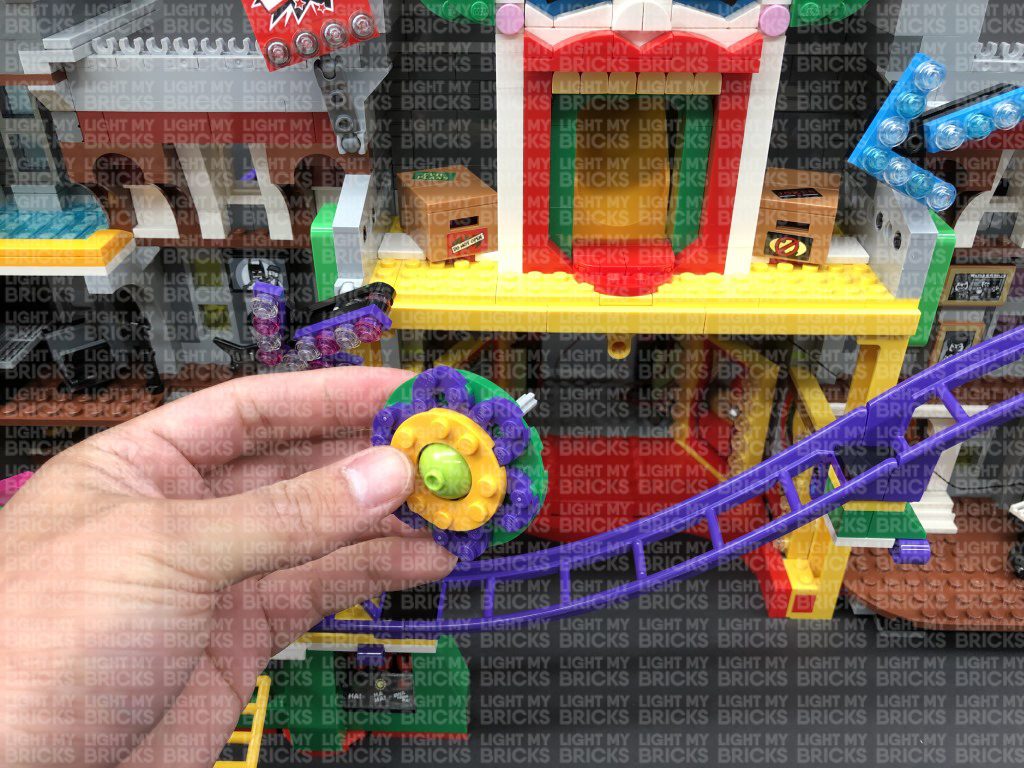
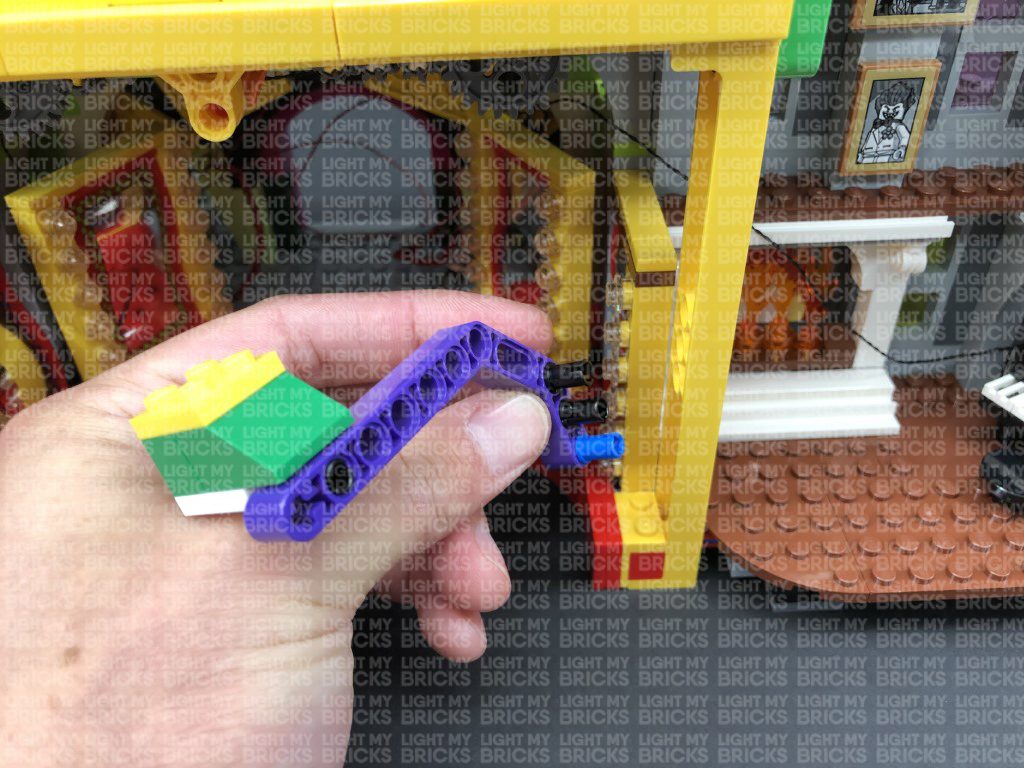
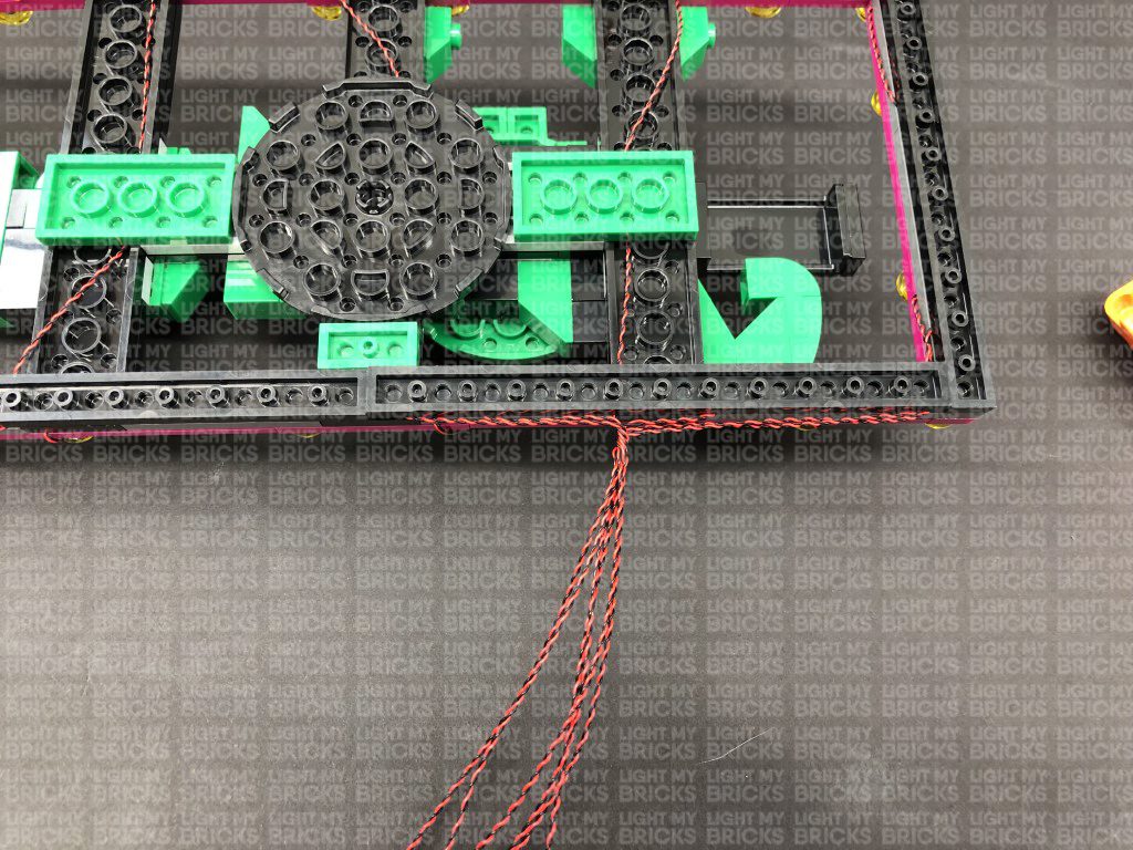
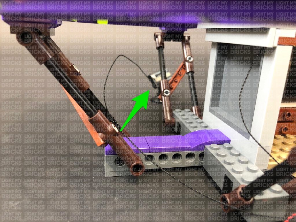
Ensure there are no dangling cables inside the entrance area, then reconnect the flower section that turns the gears for the boxing gloves
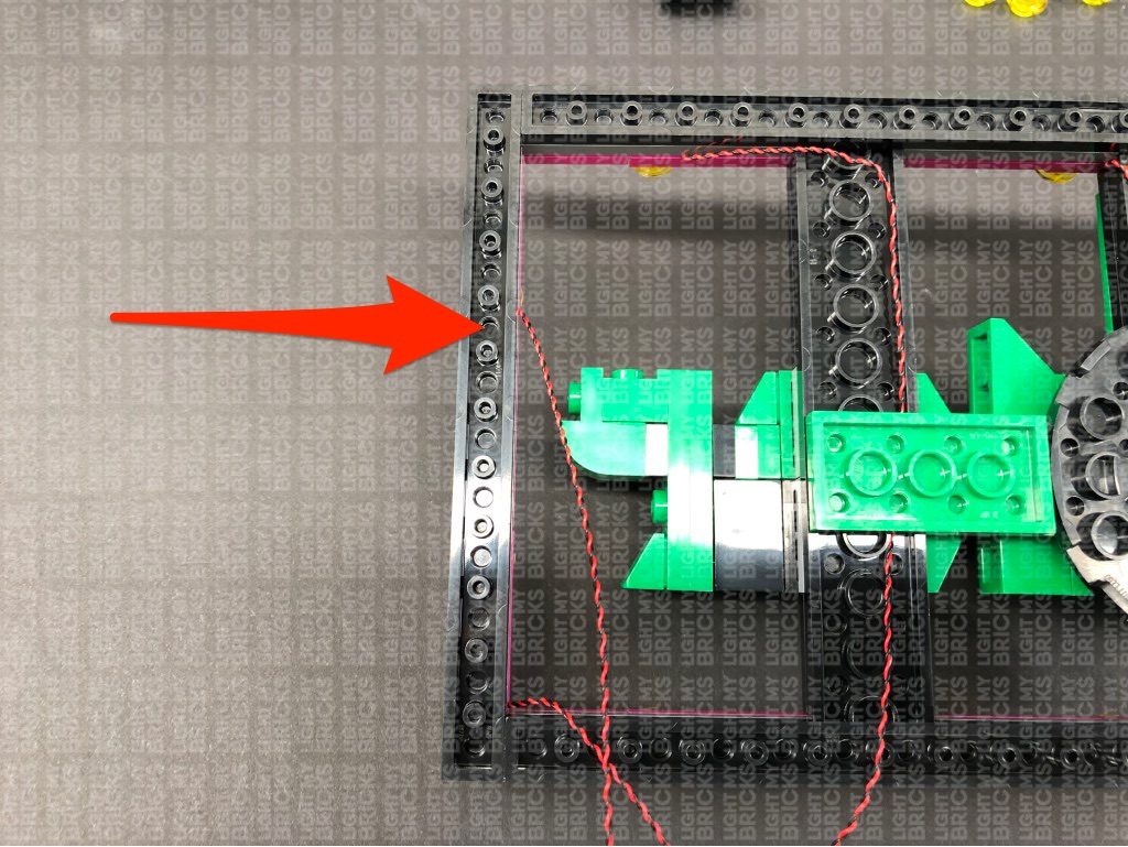
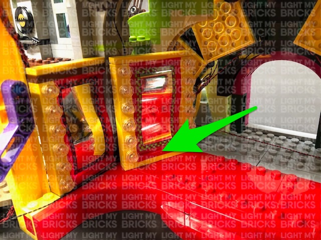
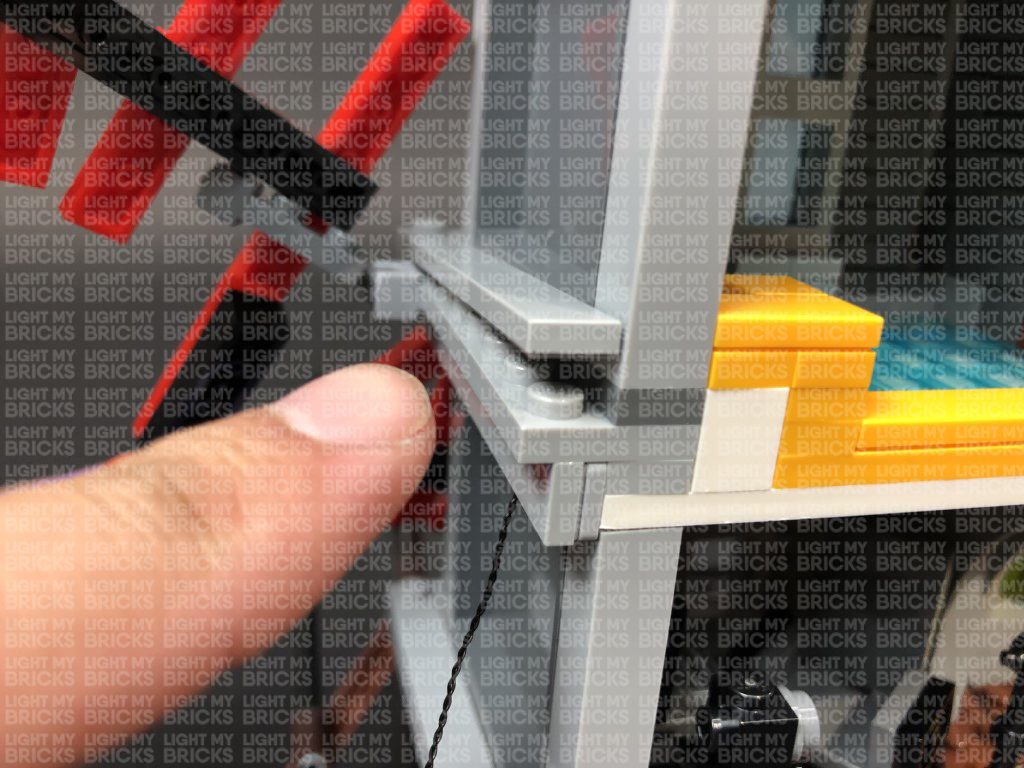
52.) Pull the 30cm Connecting Cable back out from the left beam, then bring it around to the right and secure it in between the mirror and beam.
Pull the other end of the 15cm Connecting Cable all the way out from the right beam then thread it through the technic pin above that leads into the second level. Pull the cable all the way out, then connect it to a new 8-Port Expansion Board. Remove the “Jokes” Box.
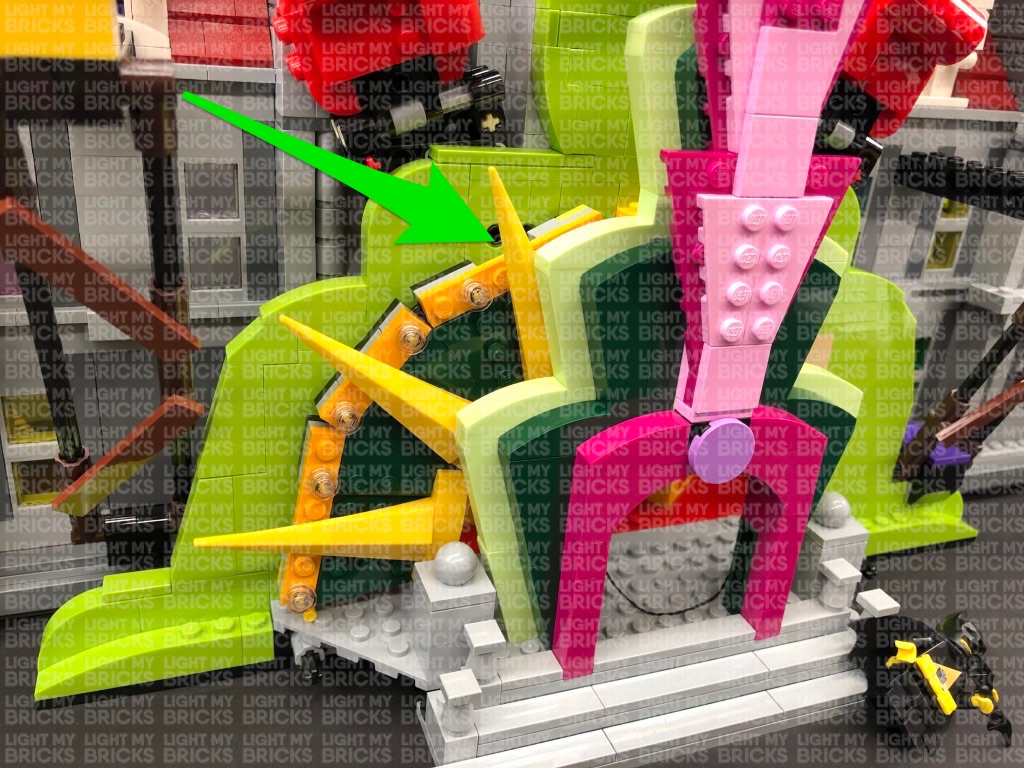
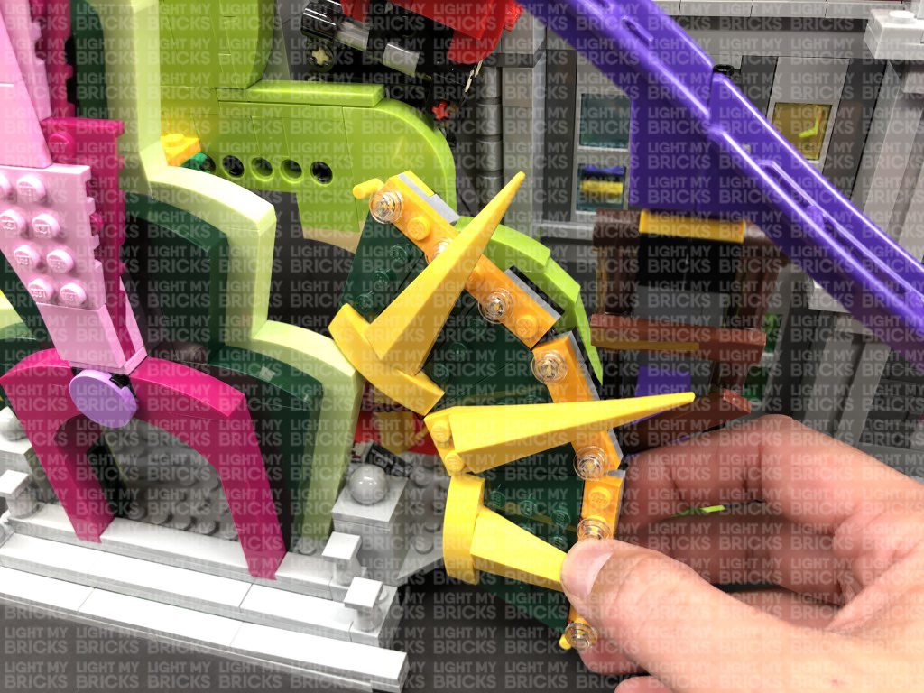
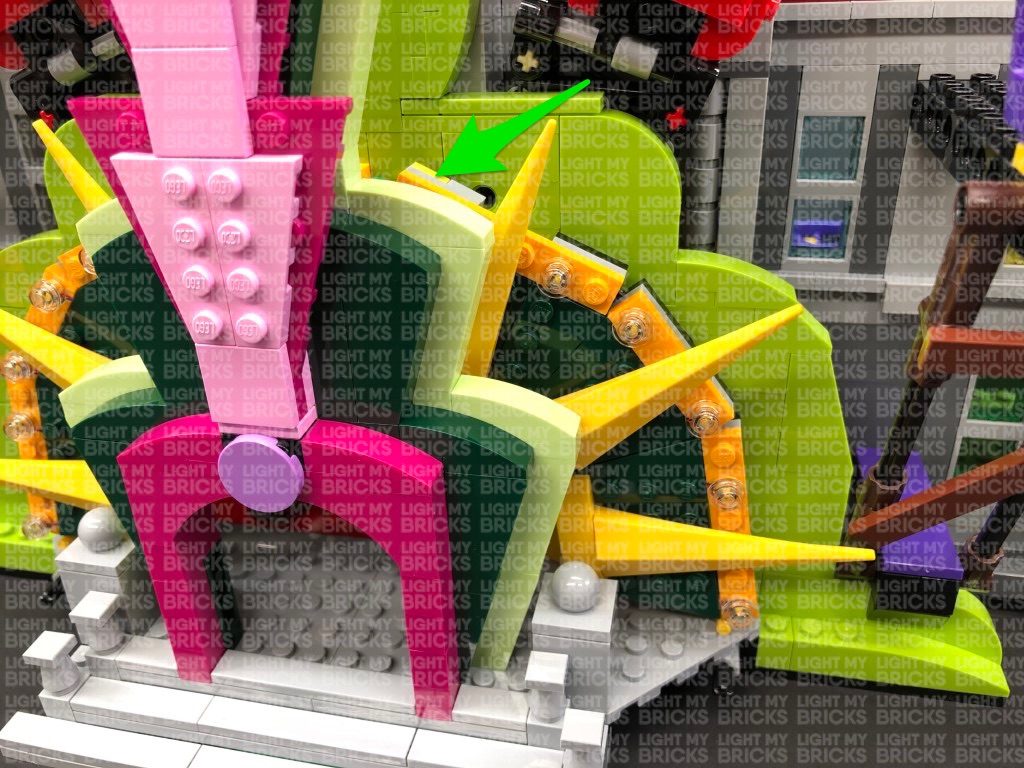
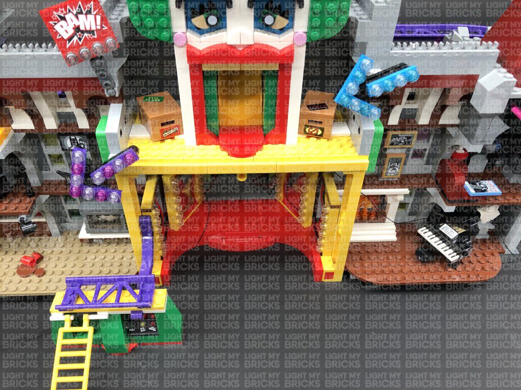
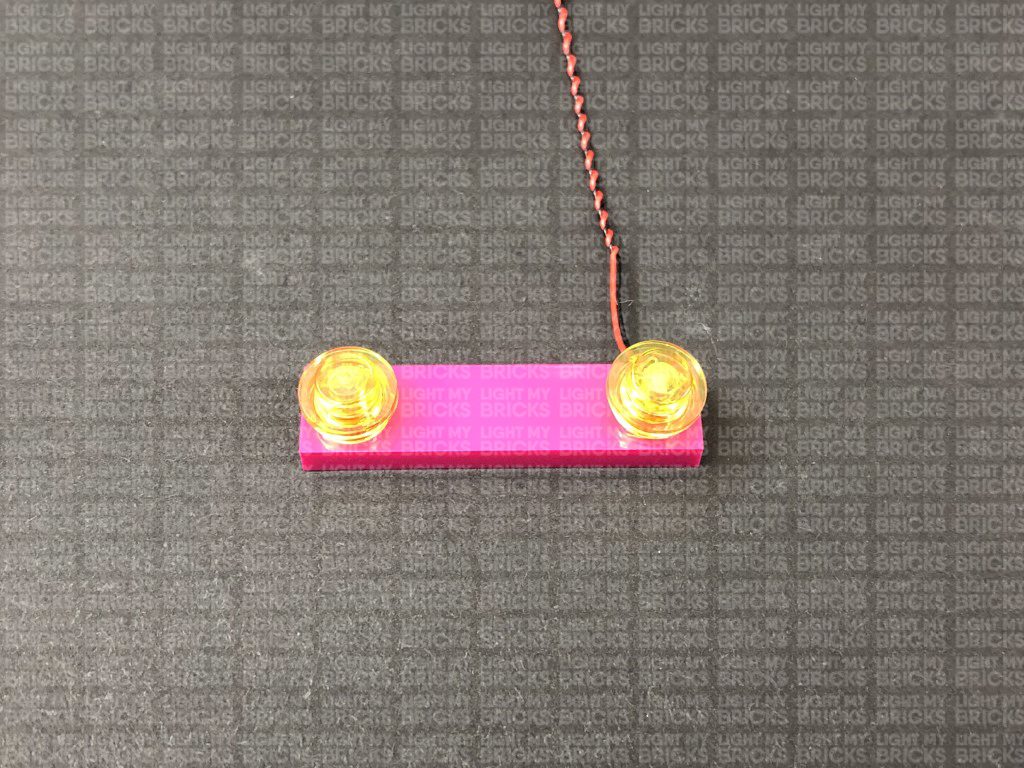
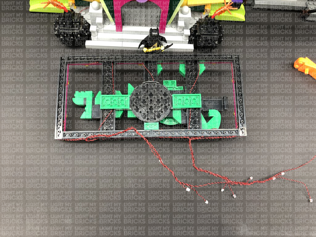
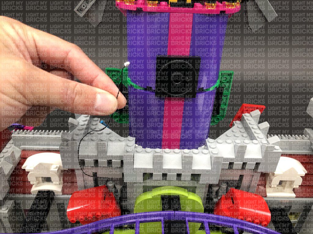
53.) We will now install some flashing lights to the purple arrow sign. First disconnect this section, then disconnect the five trans pink round plates. Turn the section around and disconnect the technic gear bar from underneath, then disconnect the black and purple plates..
Take a Flashing White 30cm Bit Light and with the cable facing the right, place it over the following stud. Secure the light in place by reconnecting one of the trans pink round plates over the top.
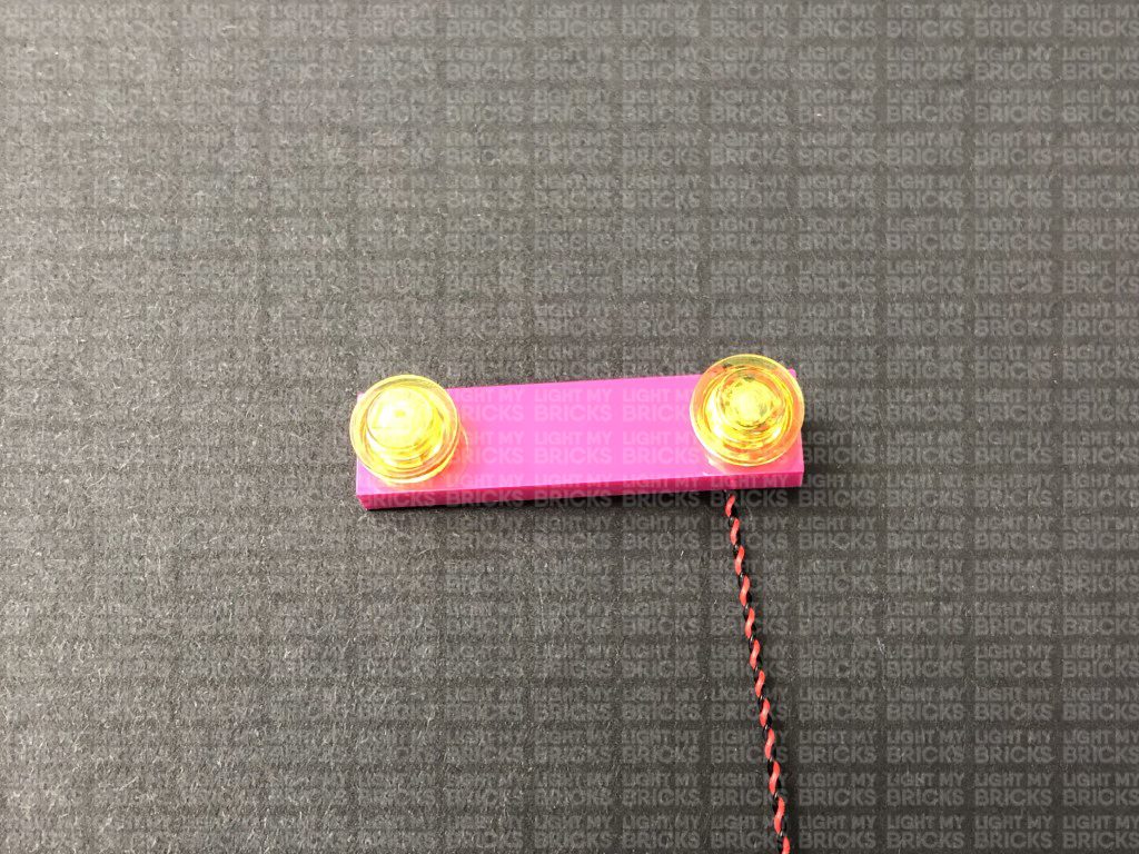
54.) Following the same method used in the previous step, install another 2x Flashing White 30cm Bit Lights to this section.
Take the purple and black plates and install another 2x Flashing White 30cm Bit Lights to them ensuring both cables are facing up. Fold both cables down underneath the plates before reconnecting this section back to the arrow sign.
Reconnect the technic gear bar to the back of the sign then connect all five bit light cables to the 12-port expansion board on the bottom left. Turn ON the USB Power Bank to test the flashing lights are working OK.
Note: If you experience any issues with the lights not working and suspect an issue with a component, please try a different port on the expansion board to verify where the fault lies (with the strip light or expansion board). To correct any issues with expansion board ports, please view the section addressing expansion board issues on our online troubleshooting guide.
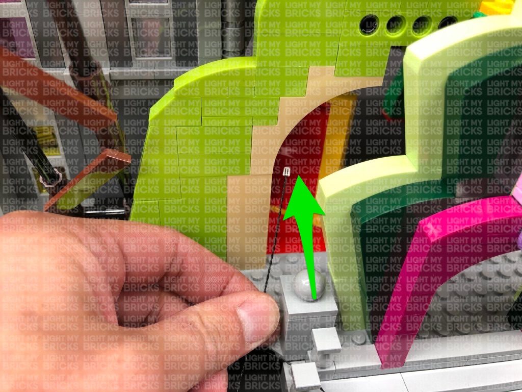
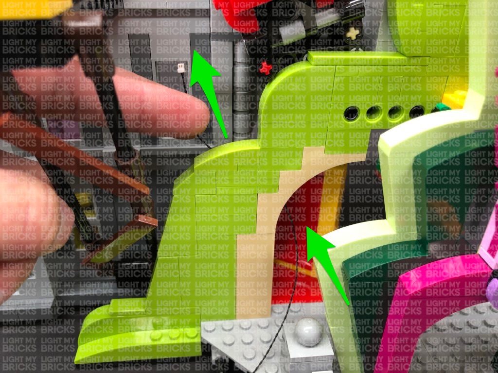
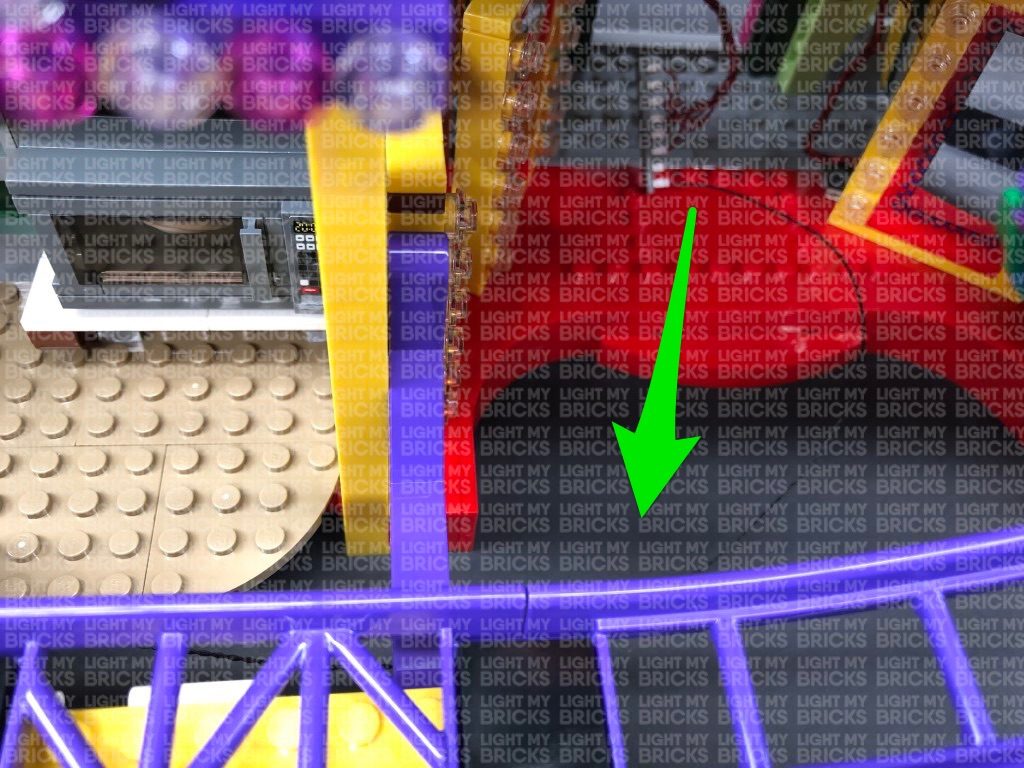
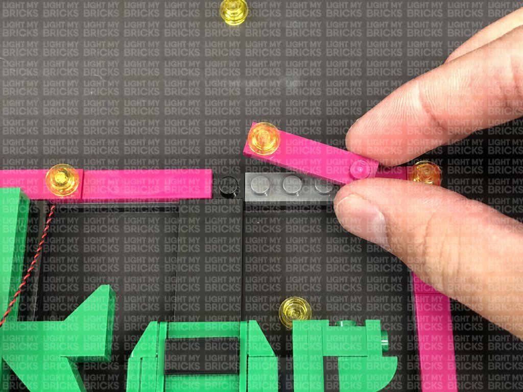
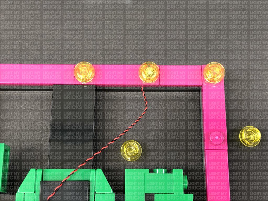
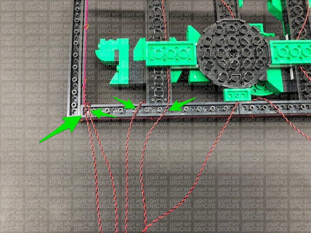
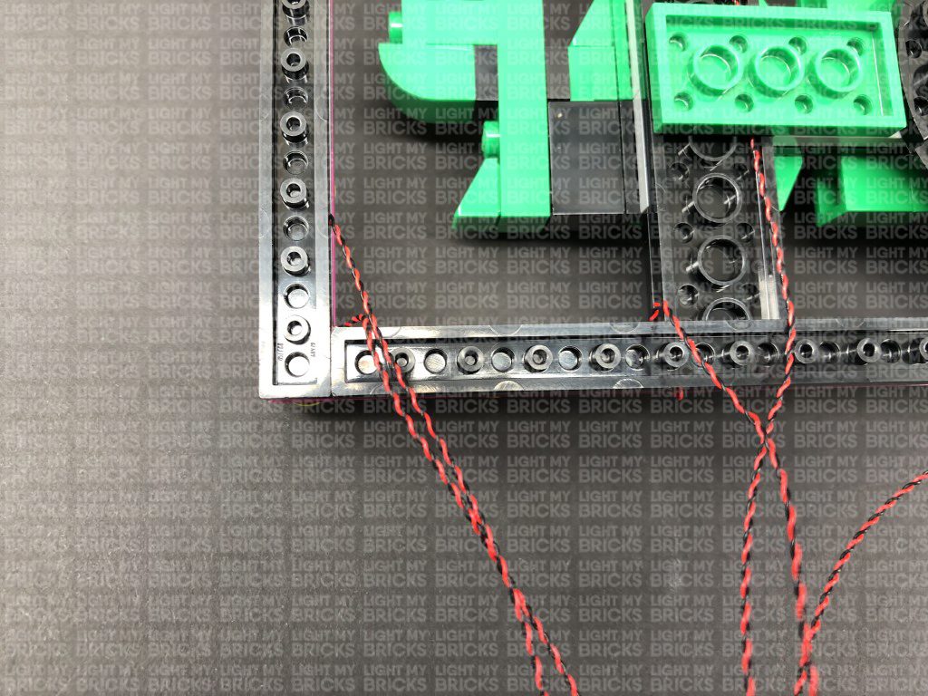
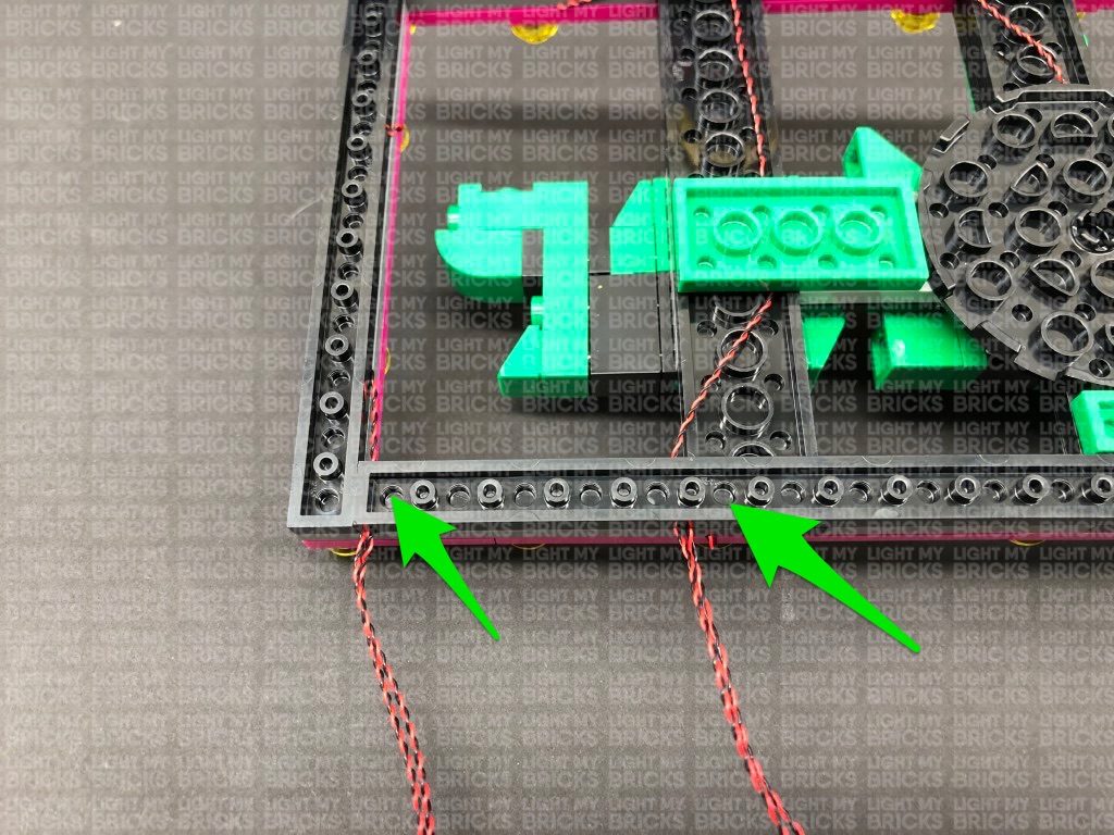
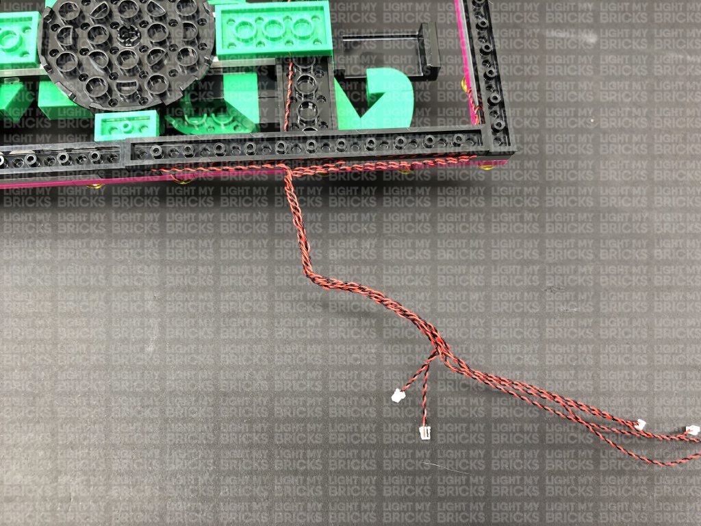
55.) Disconnect the bit lights from the expansion board, then take the two left cables and thread them up the space in between plates as shown below. Pull the two cables all the way out from the top side, then thread them back down the next space in between plates. Pull the two cables all the way out from below.
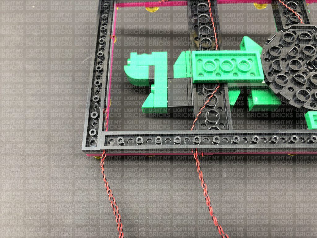
Twist and wind all five cables around each other all the way to the ends so they all come together to form one large cable.
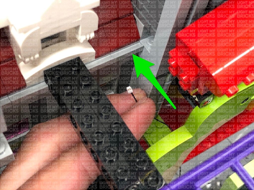
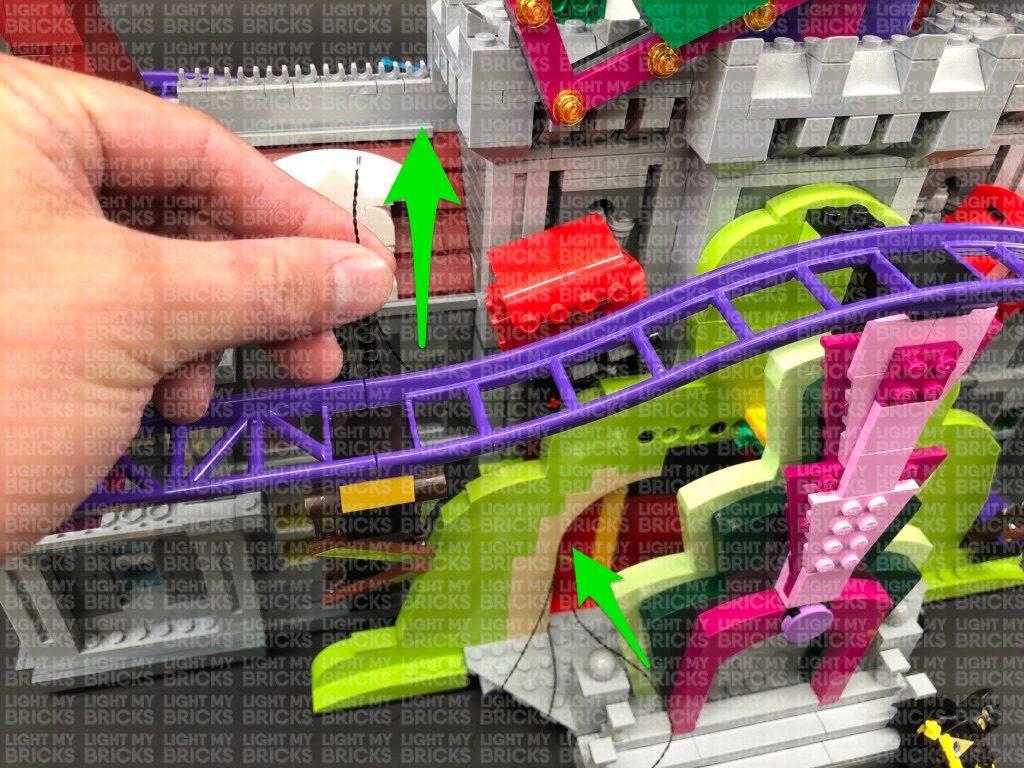
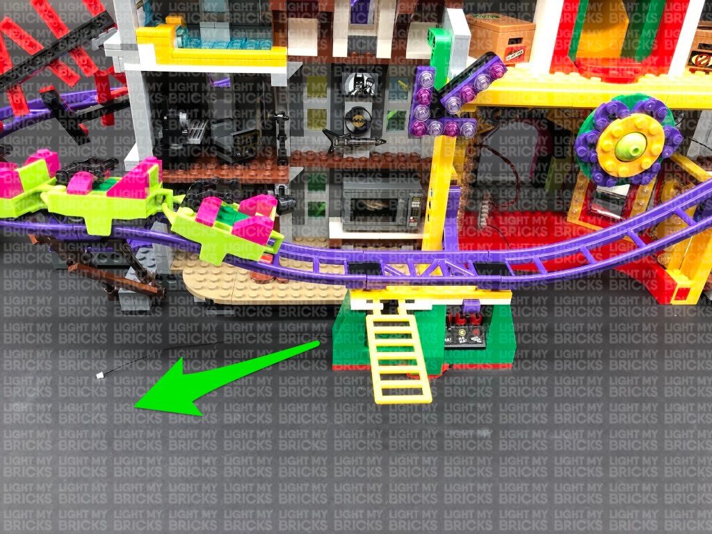
56.) Reconnect the arrow sign to the set, then thread the cable behind and through the left side over the mirror. Pull the cable out from the other side and reconnect the five lights to the 12 port expansion board. Secure the bit light cables as well as connecting cable to the yellow beam using tape.
Take 3x Adhesive Squares and stick them to the base of the 12-Port Expansion Board at the bottom of the left side of the building. Mount the expansion board underneath the base plate in the below position.
57.) We will now light up the blue arrow sign on the second level. Disconnect this section and remove the technic gear bar from the back, then disconnect the following pieces from the front.
58.) Following the same method used to install lights to the purple arrow sign, install 5x Flashing White 15cm Bit Lights to the blue arrow sign (steps 53-55). Thread the two left cables through the bottom middle of the plates, then back down before connecting them to the 8-port Expansion board in previous step (step 56). Turn on your USB Power Bank to test the flashing lights are working OK.
Disconnect the cables from the 8-port Expansion Board, then twist and wind all five cables around each other all the way to the ends so they all come together to form one large cable.
59.) Reconnect the blue arrow sign to the set, then thread the cable behind the sign toward the left and reconnect the five lights to the 8-port expansion board. Take a new 15cm Connecting Cable and connect one end to a spare port on the expansion board.
Disconnect the Evil Plans Box on the left side of the joker slide, then thread the other end of the 15cm Connecting cable through the right behind the joker slide and pull it all the way out from the left side. Connect the cable to a new 8-Port Expansion Board.
Tuck the 8-port expansion board from the right side of the joker slide into the space to the left before reconnecting the Jokes box.
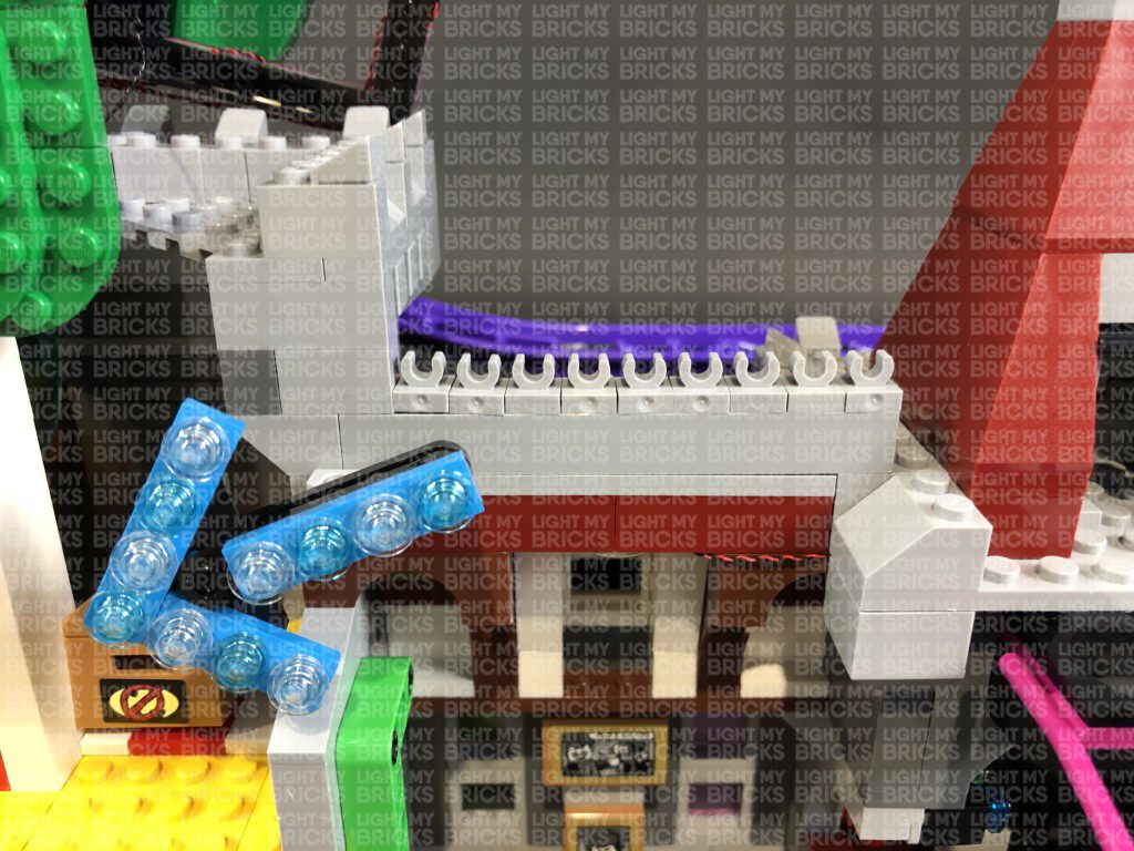
60.) We will now light up the BAM! sign. Remove this section and disconnect the trans light blue round plates from it.
Take a Flashing White 15cm Bit Light and with the cable facing down, place it directly over the left stud. Secure the light in place by reconnecting one of the trans light blue round plates over the top.
Repeat this process to install another 3x Flashing White 15cm Bit Lights to the BAM! sign.
61.) Connect the four lights into the 8-port expansion board on the left side of the joker slide, then turn ON the USB Power Bank to test the lights are working OK.
Note: If you experience any issues with the lights not working and suspect an issue with a component, please try a different port on the expansion board to verify where the fault lies (with the strip light or expansion board). To correct any issues with expansion board ports, please view the section addressing expansion board issues on our online troubleshooting guide.
Disconnect the bit lights from the expansion board and turn the sign over. Bring the two cables from each side together and twist/wind all four cables around each other all the way to the ends to create one larger cable.
Reconnect the BAM! sign and reconnect the four cables to the 8-port expansion board. Turn the USB Power bank on again to test all the flashing lights are working OK.
62.) We will now install lights above the eyes of the Joker slide. Disconnect the following hair sections from each side, then using a LEGO Removal Tool, create gaps just underneath the eyebrows to allow you to disconnect the front end of the top section as shown below. Do not completely disconnect the top of his head, just the front half.
Take 2x Blue 30cm Bit Lights, group them together and create a curve, then thread the connector ends through the top of the face and down the joker slide.
Take 2x Adhesive Squares and stick each one to the back of each Blue Bit Light. Stick each Blue Bit Light underneath the eyebrow sections in the middle of the black eyebrow plates. Pull the other end of the cables down the slide, then reconnecting the top section.
63.) Thread the other end of the cables back through the inside of the slide through the left side. Pull the cables all the way out from the other side, then connect them to the 8-Port Expansion Board. Turn the USB Power Bank ON to test the Blue Lights above the eyes are working OK.
Note: If you experience any issues with the lights not working and suspect an issue with a component, please try a different port on the expansion board to verify where the fault lies (with the strip light or expansion board). To correct any issues with expansion board ports, please view the section addressing expansion board issues on our online troubleshooting guide.
51.) Take a new 30cm Connecting Cable and connect it to a spare port on the 12-Port Expansion Board on the bottom of the left side. Bring the other end of the cable over to the right and thread it through the following technic pin. Pull the cable out from the other side.
Take 2x White Strip Lights and connect them together using a 5cm Connecting Cable. Take the other end of the 30cm Connecting Cable and connect it to one of the Strip Lights. Take a 15cm Connecting Cable and connect it to the other end of the other White Strip Light. Thread the other end of the 15cm Connecting Cable through the technic pin on the right, pulling it all the way out from the other side.
Using their adhesive backings, stick both strip lights to the green technic bricks in the below position. Loop the 5cm cable in between and push it up to prevent it from dangling down. Turn the USB Power Bank ON to test the strip lights are working OK.
Ensure there are no dangling cables inside the entrance area, then reconnect the flower section that turns the gears for the boxing gloves
52.) Pull the 30cm Connecting Cable back out from the left beam, then bring it around to the right and secure it in between the mirror and beam.
Pull the other end of the 15cm Connecting Cable all the way out from the right beam then thread it through the technic pin above that leads into the second level. Pull the cable all the way out, then connect it to a new 8-Port Expansion Board. Remove the “Jokes” Box.
53.) We will now install some flashing lights to the purple arrow sign. First disconnect this section, then disconnect the five trans pink round plates. Turn the section around and disconnect the technic gear bar from underneath, then disconnect the black and purple plates..
Take a Flashing White 30cm Bit Light and with the cable facing the right, place it over the following stud. Secure the light in place by reconnecting one of the trans pink round plates over the top.
54.) Following the same method used in the previous step, install another 2x Flashing White 30cm Bit Lights to this section.
Take the purple and black plates and install another 2x Flashing White 30cm Bit Lights to them ensuring both cables are facing up. Fold both cables down underneath the plates before reconnecting this section back to the arrow sign.
Reconnect the technic gear bar to the back of the sign then connect all five bit light cables to the 12-port expansion board on the bottom left. Turn ON the USB Power Bank to test the flashing lights are working OK.
Note: If you experience any issues with the lights not working and suspect an issue with a component, please try a different port on the expansion board to verify where the fault lies (with the strip light or expansion board). To correct any issues with expansion board ports, please view the section addressing expansion board issues on our online troubleshooting guide.
55.) Disconnect the bit lights from the expansion board, then take the two left cables and thread them up the space in between plates as shown below. Pull the two cables all the way out from the top side, then thread them back down the next space in between plates. Pull the two cables all the way out from below.
Twist and wind all five cables around each other all the way to the ends so they all come together to form one large cable.
56.) Reconnect the arrow sign to the set, then thread the cable behind and through the left side over the mirror. Pull the cable out from the other side and reconnect the five lights to the 12 port expansion board. Secure the bit light cables as well as connecting cable to the yellow beam using tape.
Take 3x Adhesive Squares and stick them to the base of the 12-Port Expansion Board at the bottom of the left side of the building. Mount the expansion board underneath the base plate in the below position.
57.) We will now light up the blue arrow sign on the second level. Disconnect this section and remove the technic gear bar from the back, then disconnect the following pieces from the front.
58.) Following the same method used to install lights to the purple arrow sign, install 5x Flashing White 15cm Bit Lights to the blue arrow sign (steps 53-55). Thread the two left cables through the bottom middle of the plates, then back down before connecting them to the 8-port Expansion board in previous step (step 56). Turn on your USB Power Bank to test the flashing lights are working OK.
Disconnect the cables from the 8-port Expansion Board, then twist and wind all five cables around each other all the way to the ends so they all come together to form one large cable.
59.) Reconnect the blue arrow sign to the set, then thread the cable behind the sign toward the left and reconnect the five lights to the 8-port expansion board. Take a new 15cm Connecting Cable and connect one end to a spare port on the expansion board.
Disconnect the Evil Plans Box on the left side of the joker slide, then thread the other end of the 15cm Connecting cable through the right behind the joker slide and pull it all the way out from the left side. Connect the cable to a new 8-Port Expansion Board.
Tuck the 8-port expansion board from the right side of the joker slide into the space to the left before reconnecting the Jokes box.
60.) We will now light up the BAM! sign. Remove this section and disconnect the trans light blue round plates from it.
Take a Flashing White 15cm Bit Light and with the cable facing down, place it directly over the left stud. Secure the light in place by reconnecting one of the trans light blue round plates over the top.
Repeat this process to install another 3x Flashing White 15cm Bit Lights to the BAM! sign.
61.) Connect the four lights into the 8-port expansion board on the left side of the joker slide, then turn ON the USB Power Bank to test the lights are working OK.
Note: If you experience any issues with the lights not working and suspect an issue with a component, please try a different port on the expansion board to verify where the fault lies (with the strip light or expansion board). To correct any issues with expansion board ports, please view the section addressing expansion board issues on our online troubleshooting guide.
Disconnect the bit lights from the expansion board and turn the sign over. Bring the two cables from each side together and twist/wind all four cables around each other all the way to the ends to create one larger cable.
Reconnect the BAM! sign and reconnect the four cables to the 8-port expansion board. Turn the USB Power bank on again to test all the flashing lights are working OK.
62.) We will now install lights above the eyes of the Joker slide. Disconnect the following hair sections from each side, then using a LEGO Removal Tool, create gaps just underneath the eyebrows to allow you to disconnect the front end of the top section as shown below. Do not completely disconnect the top of his head, just the front half.
Take 2x Blue 30cm Bit Lights, group them together and create a curve, then thread the connector ends through the top of the face and down the joker slide.
Take 2x Adhesive Squares and stick each one to the back of each Blue Bit Light. Stick each Blue Bit Light underneath the eyebrow sections in the middle of the black eyebrow plates. Pull the other end of the cables down the slide, then reconnecting the top section.
63.) Thread the other end of the cables back through the inside of the slide through the left side. Pull the cables all the way out from the other side, then connect them to the 8-Port Expansion Board. Turn the USB Power Bank ON to test the Blue Lights above the eyes are working OK.
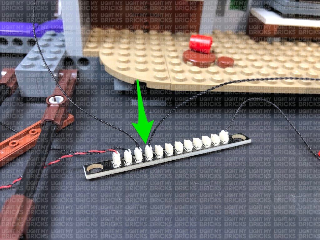
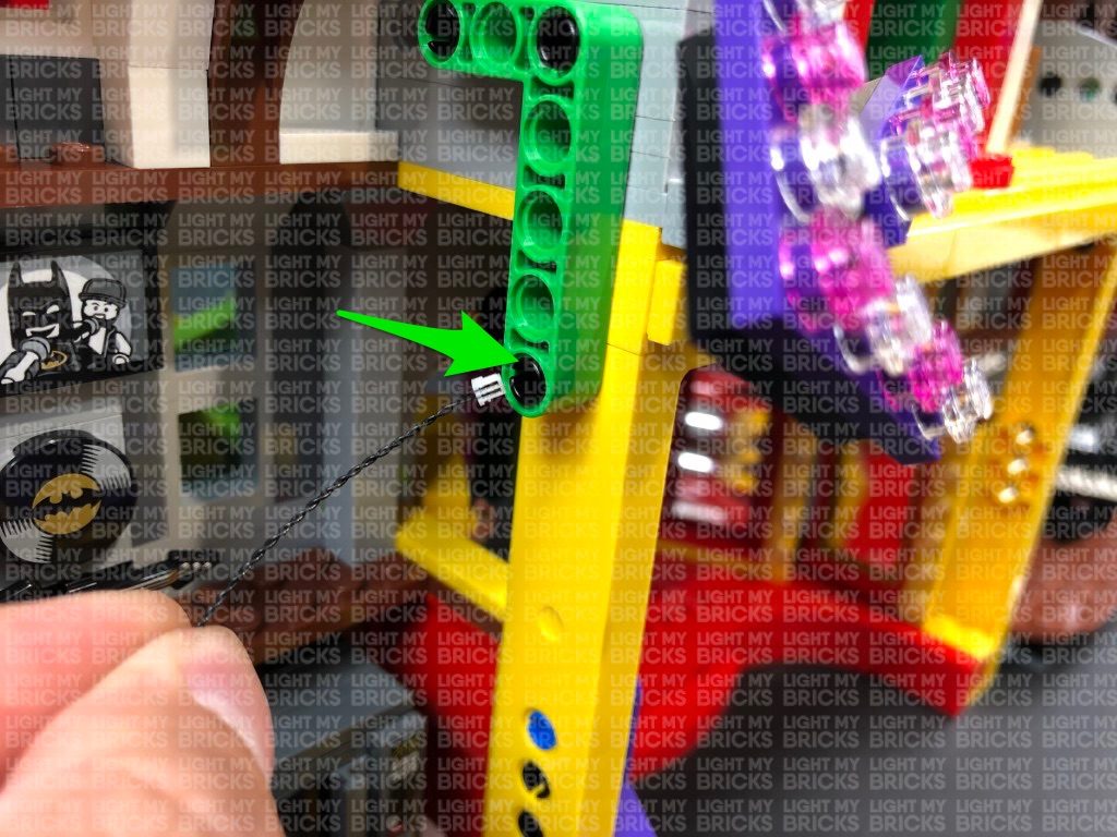
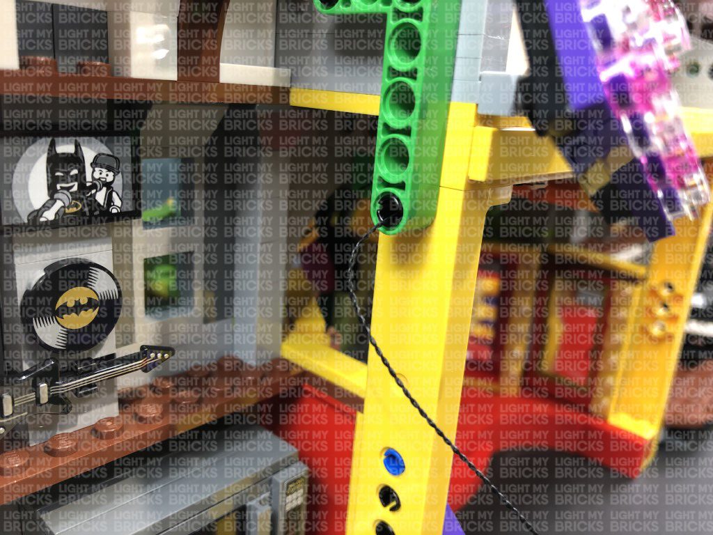
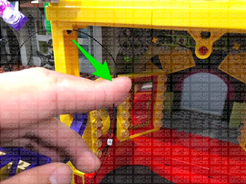
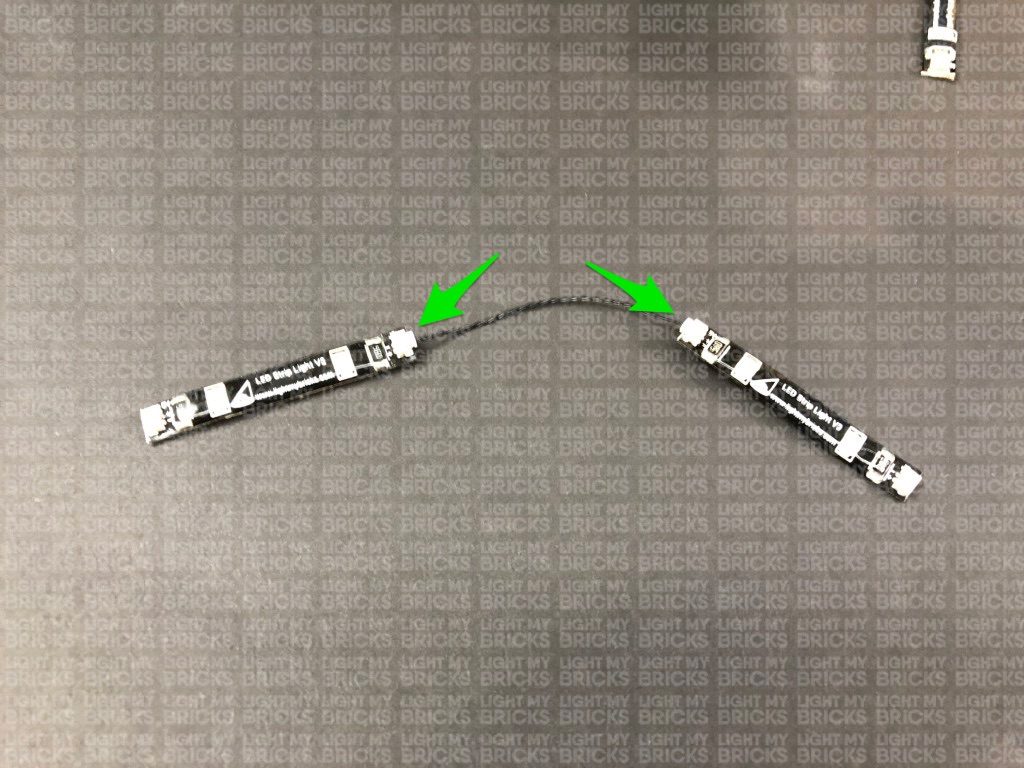
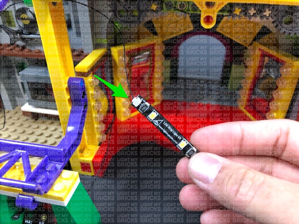
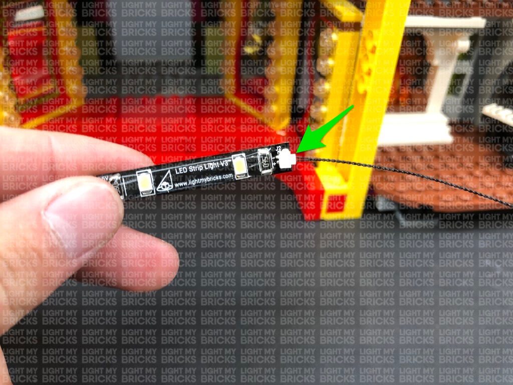
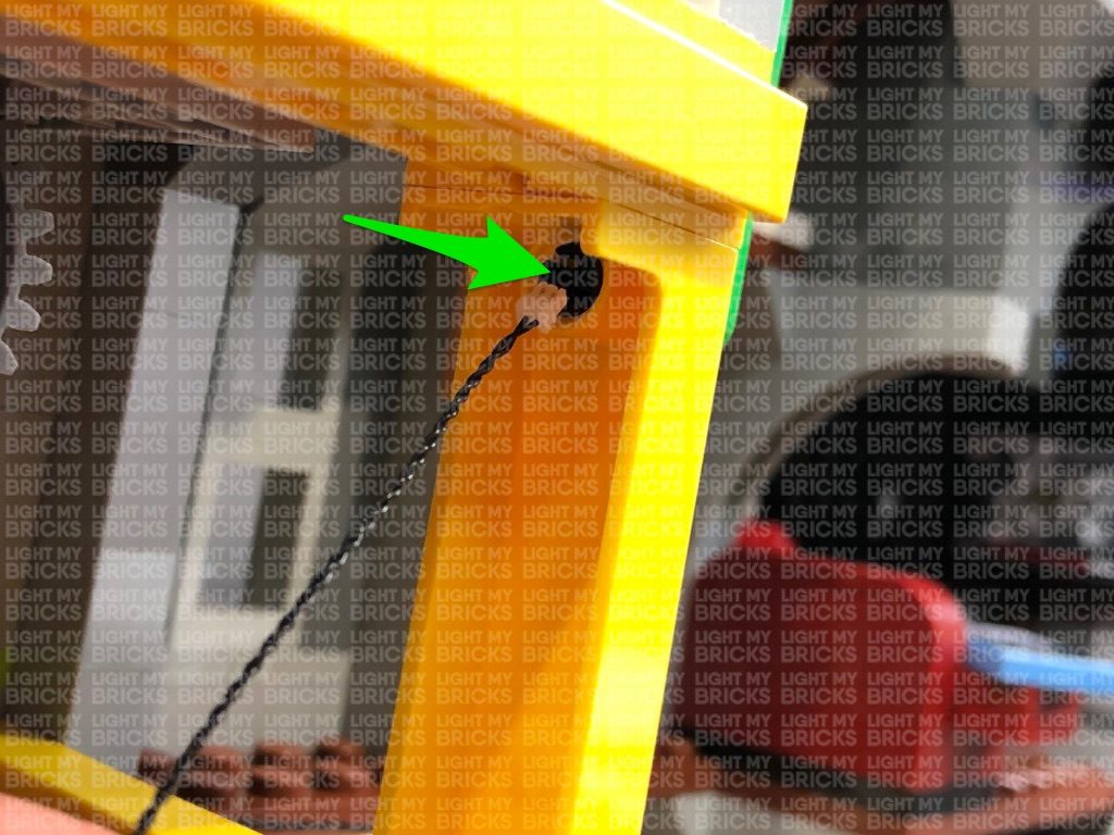
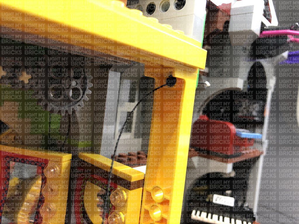
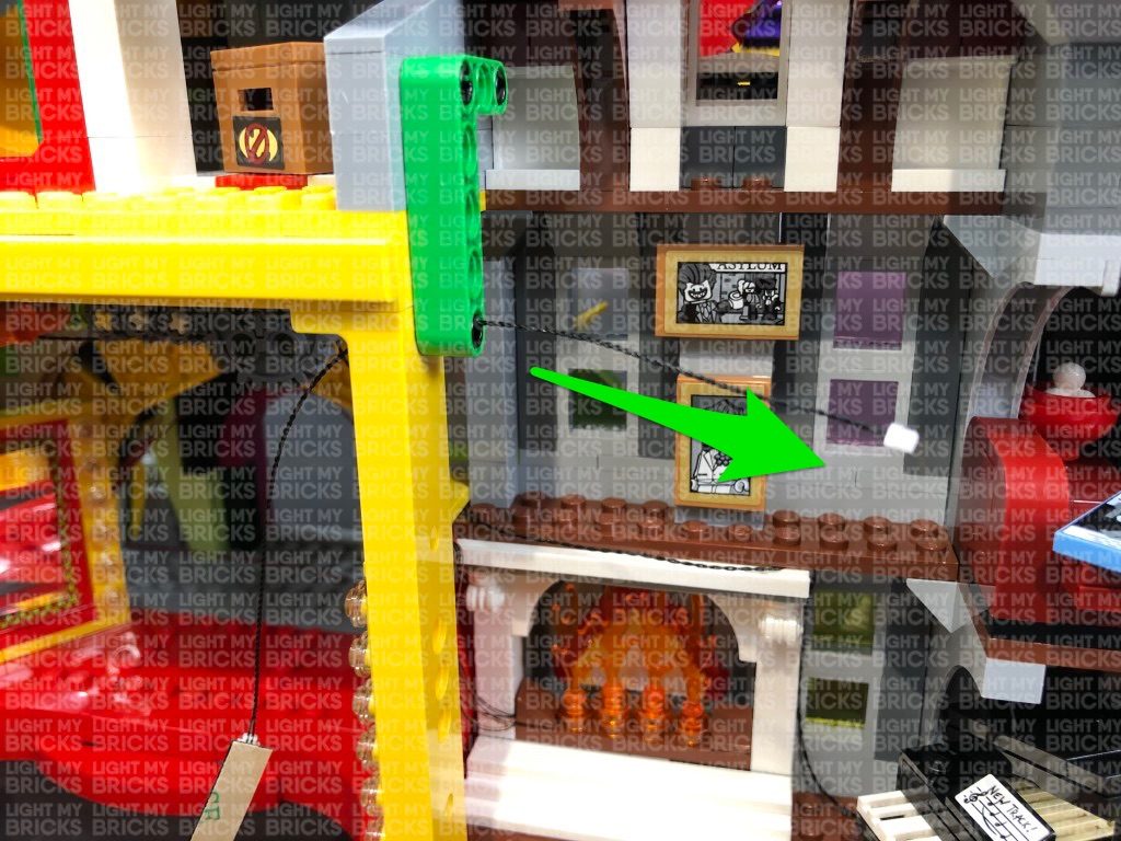
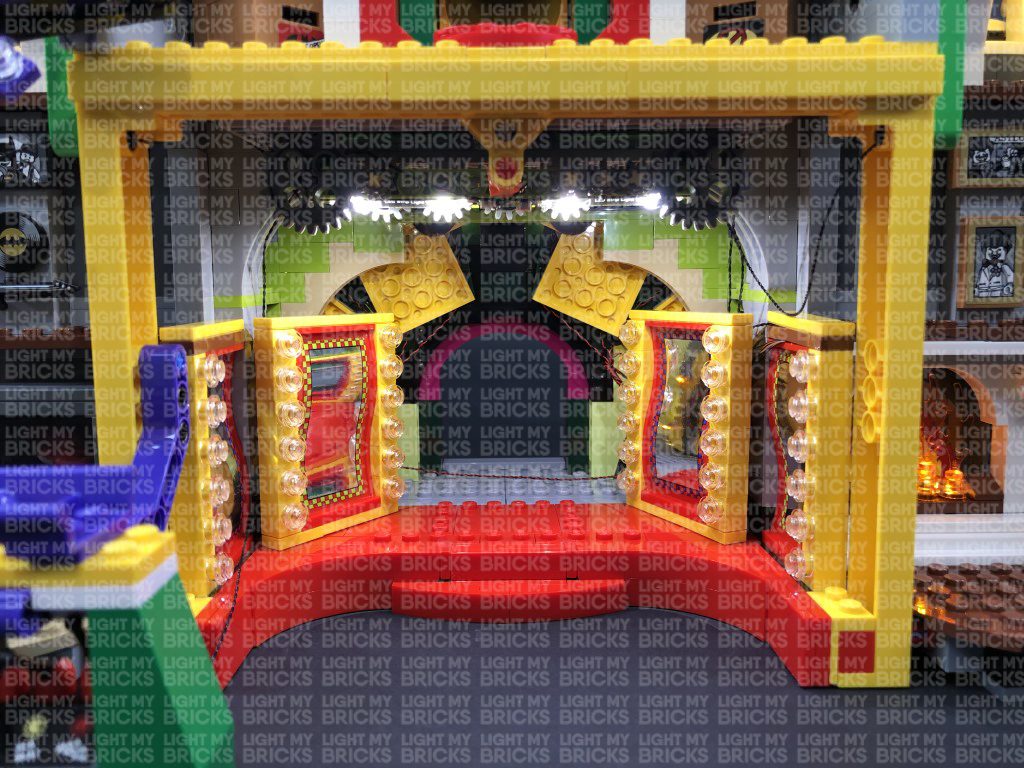
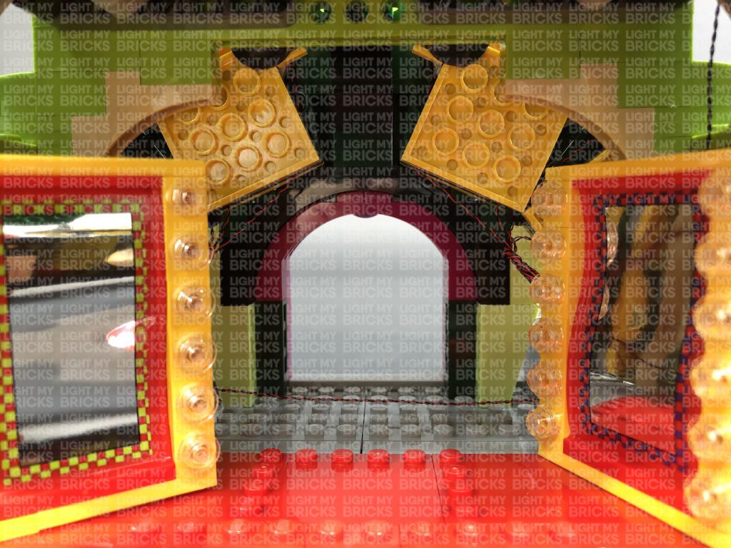
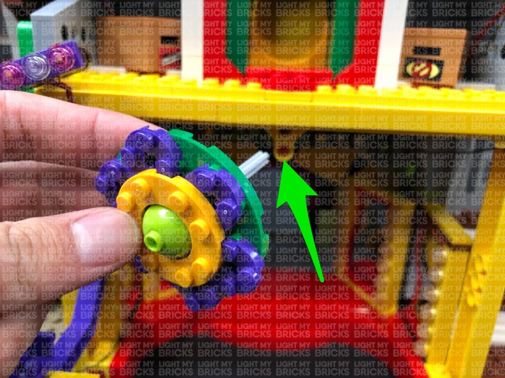
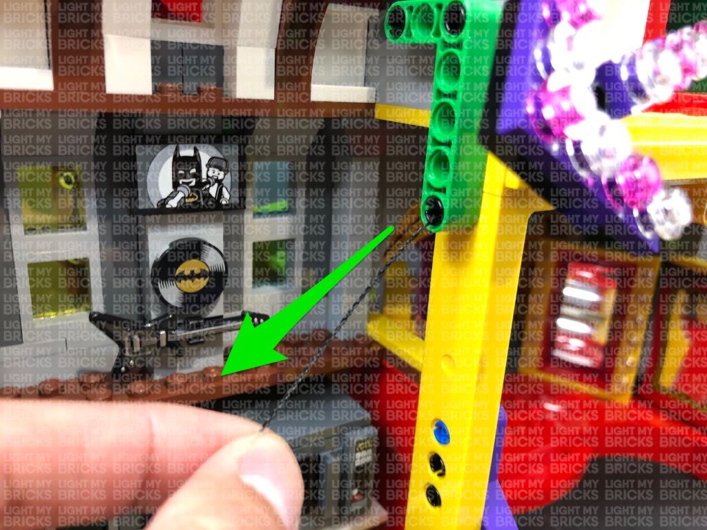
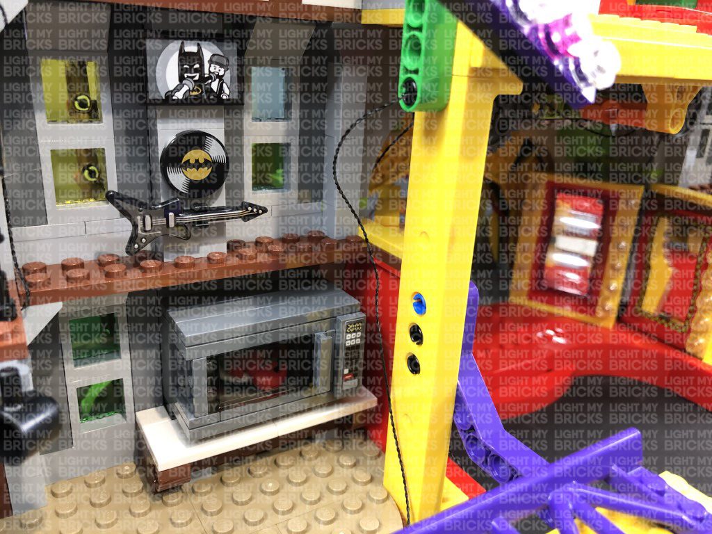
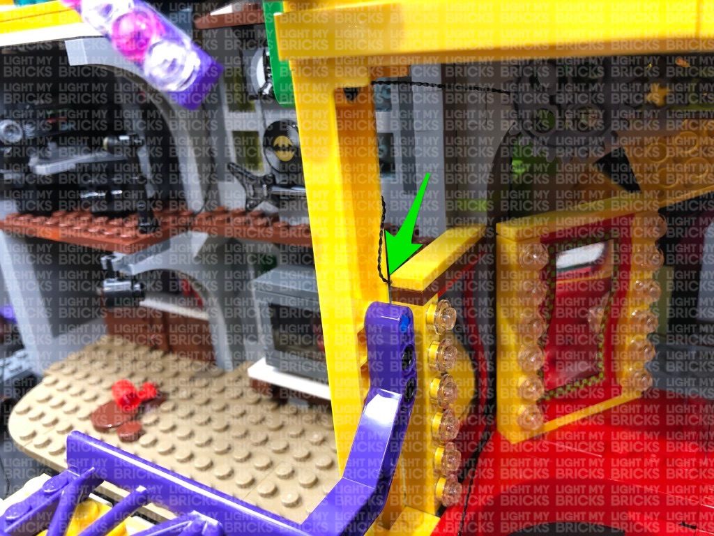
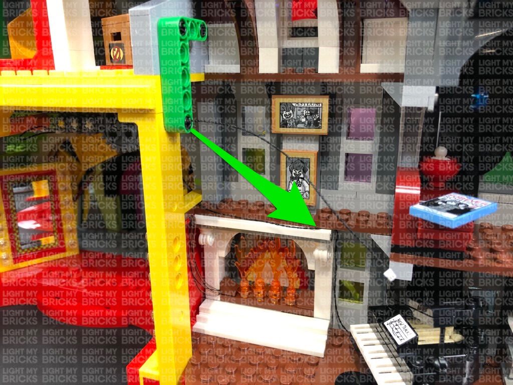
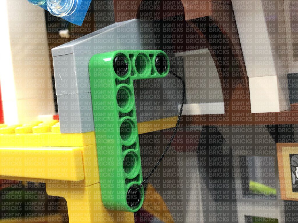
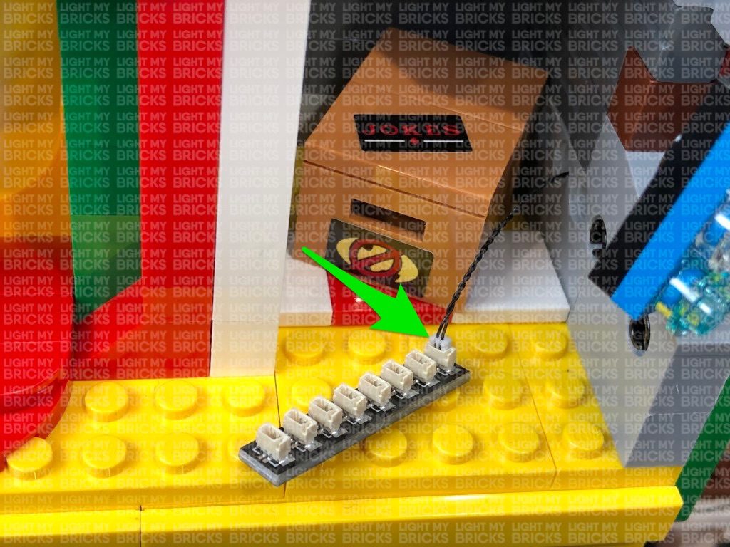
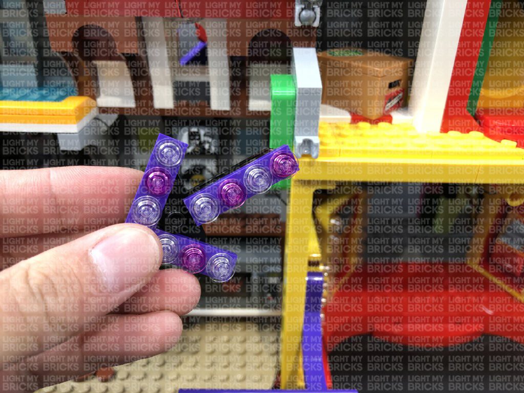
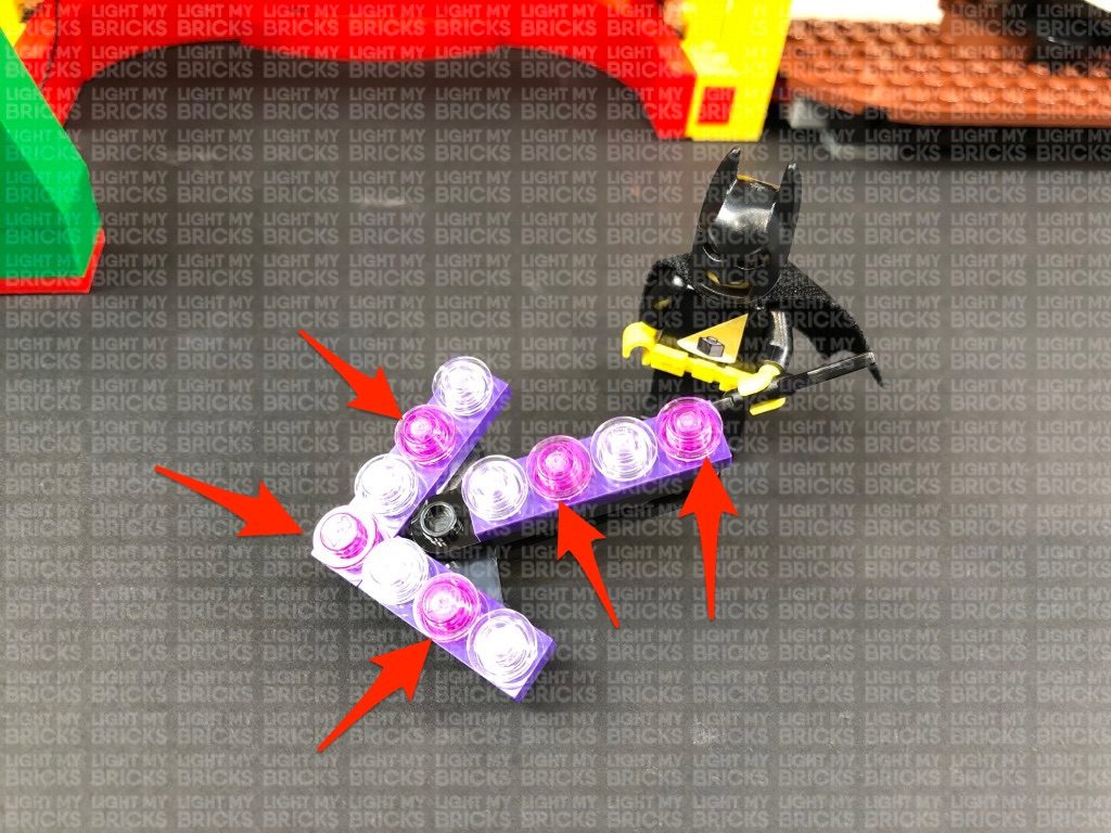
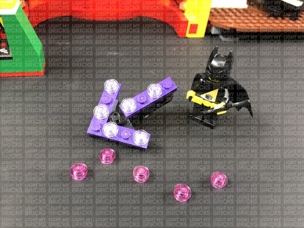
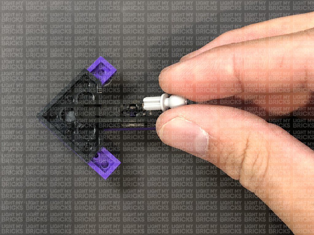
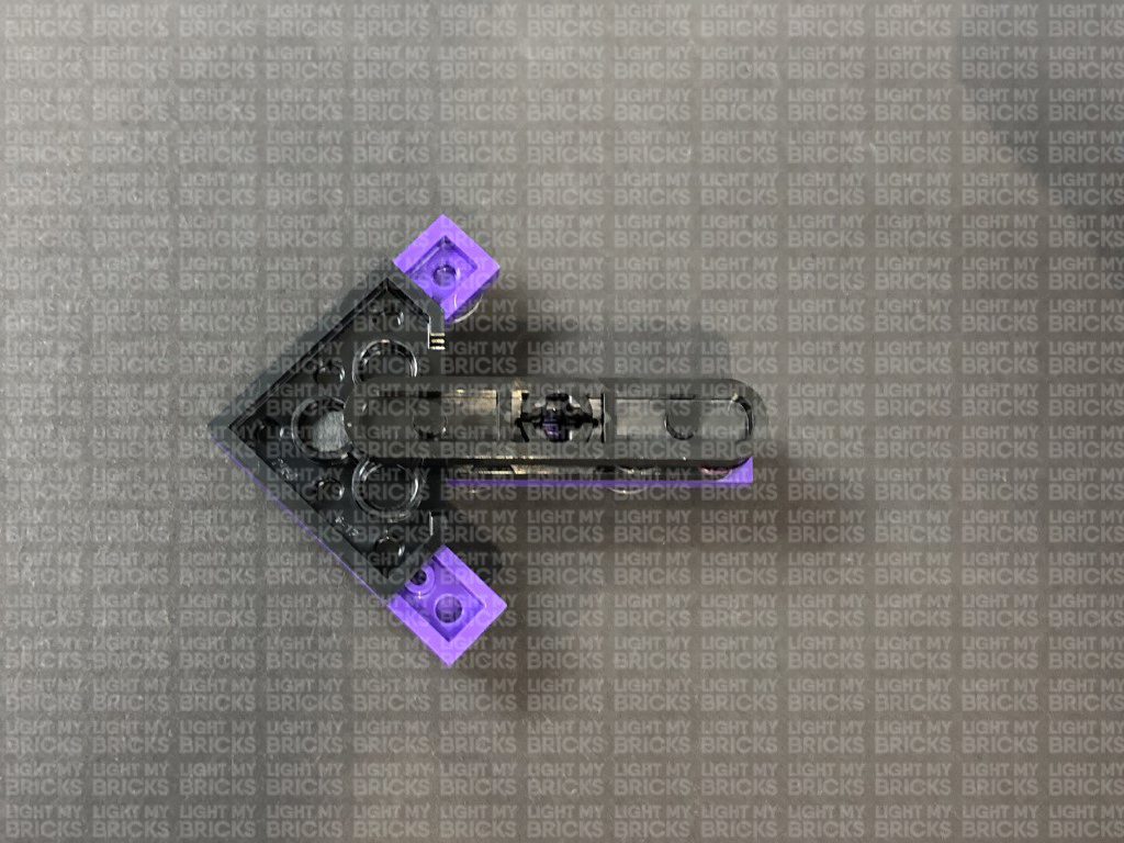
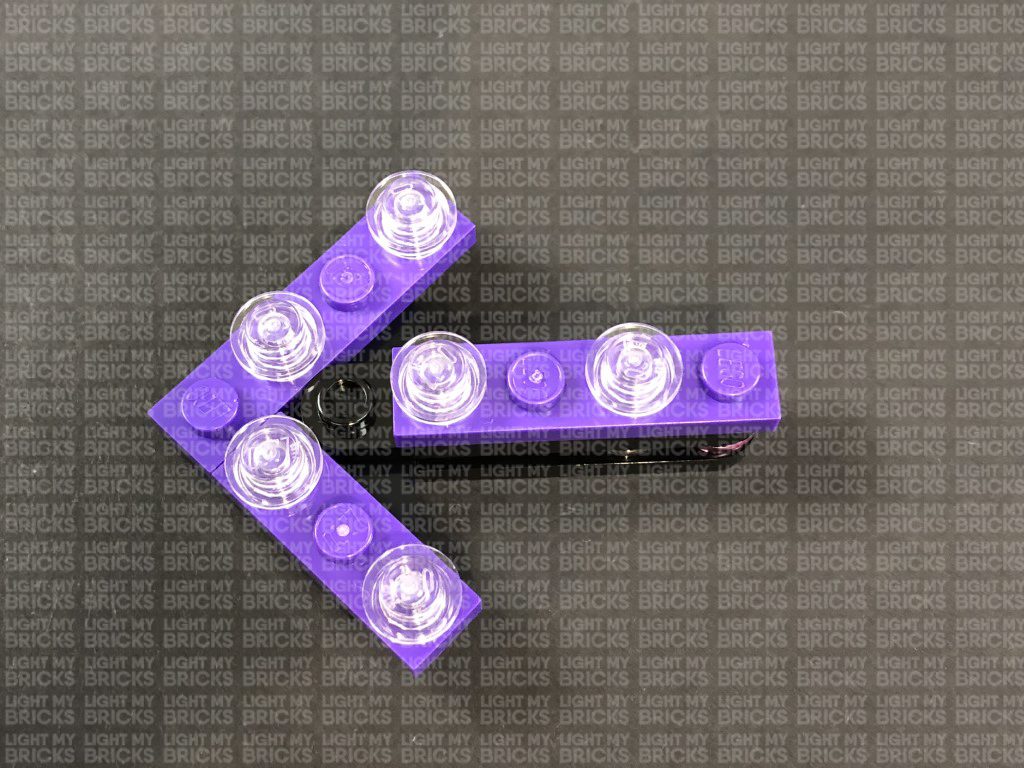
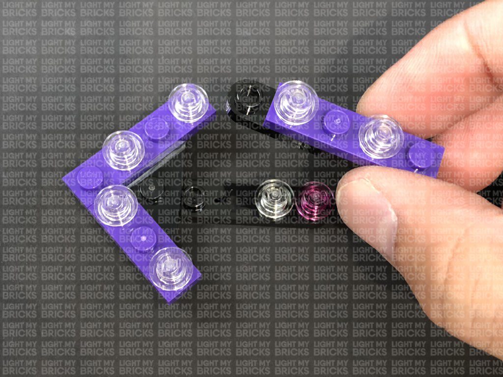
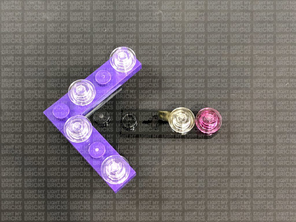
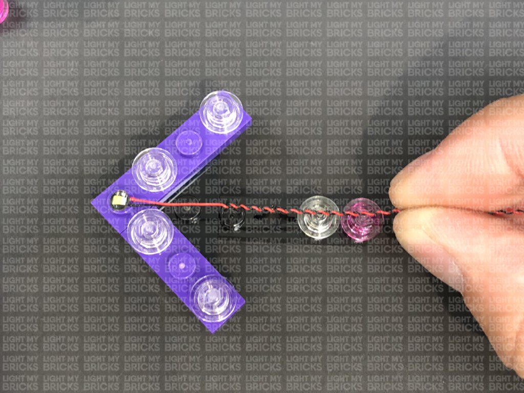
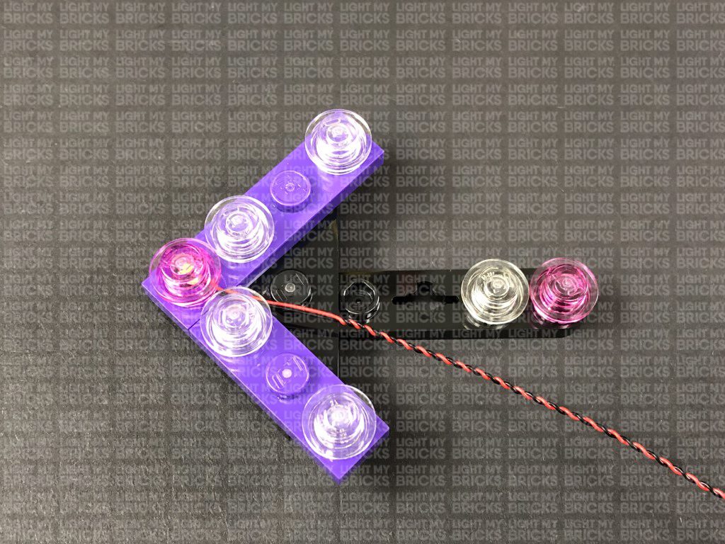
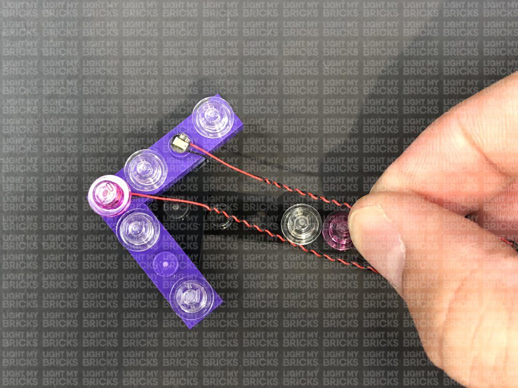
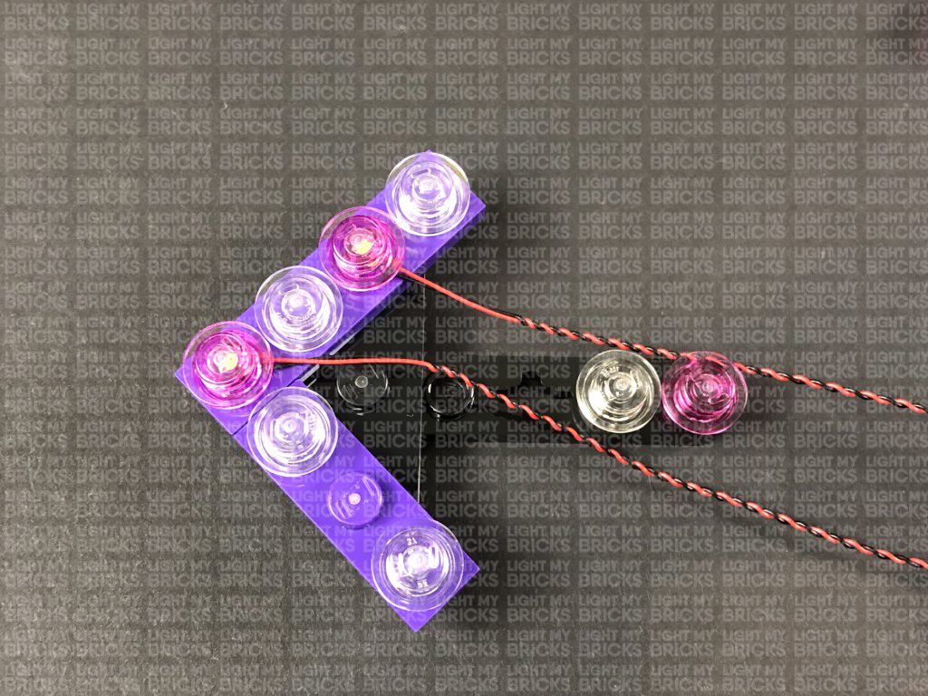
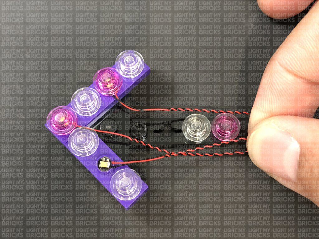
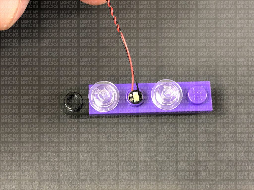
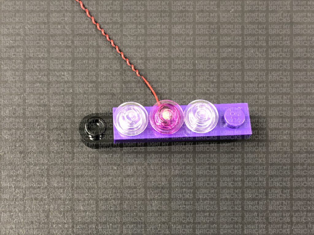
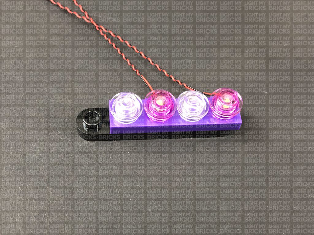
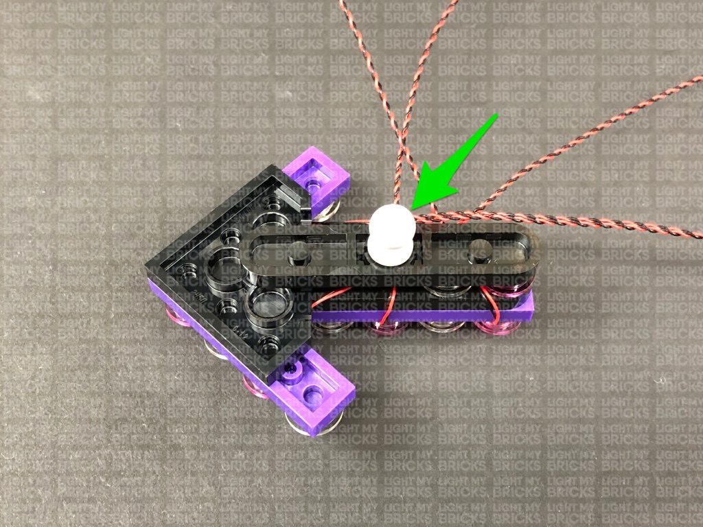
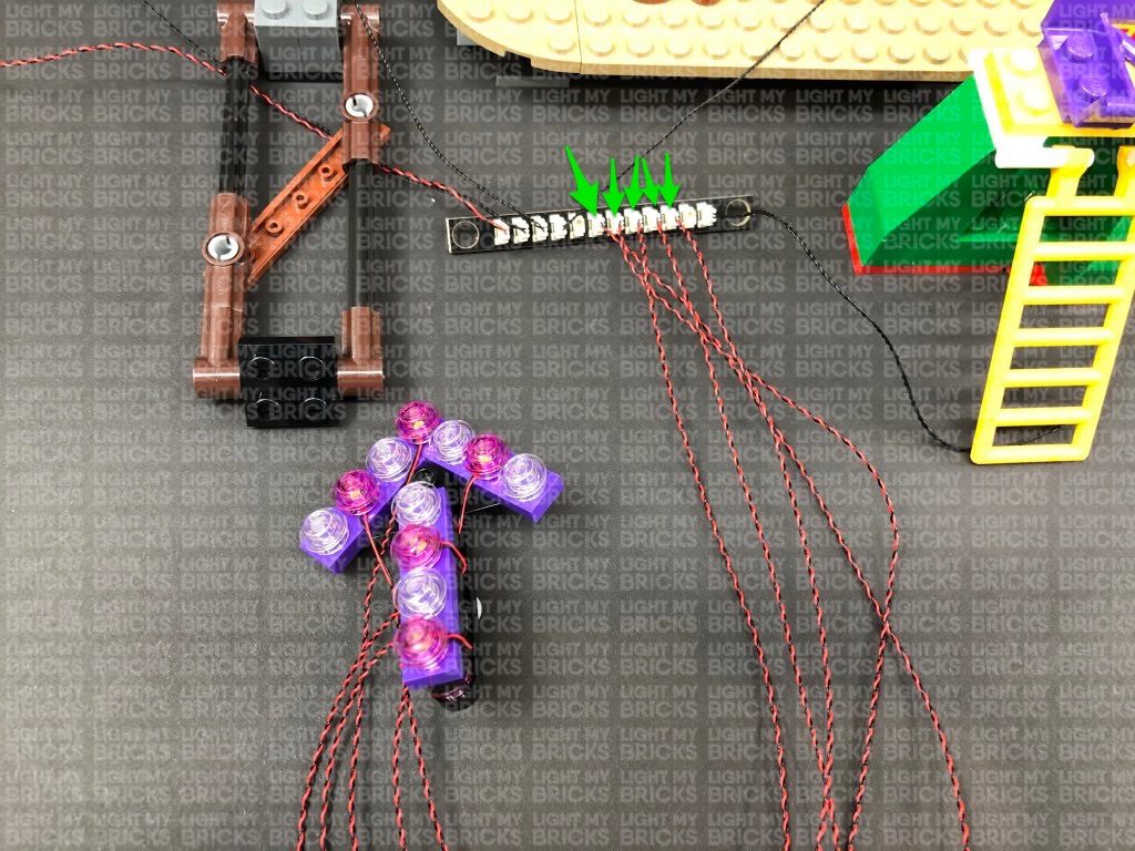
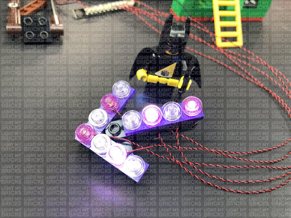
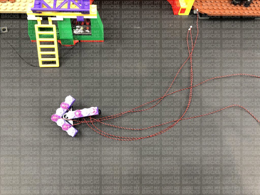
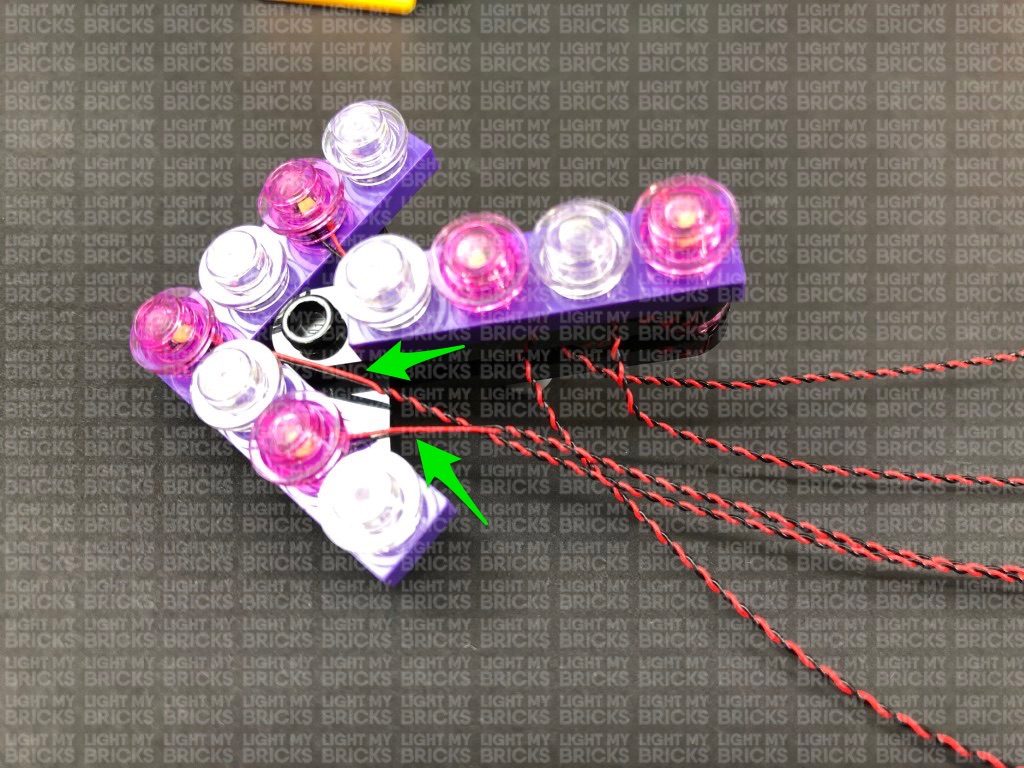
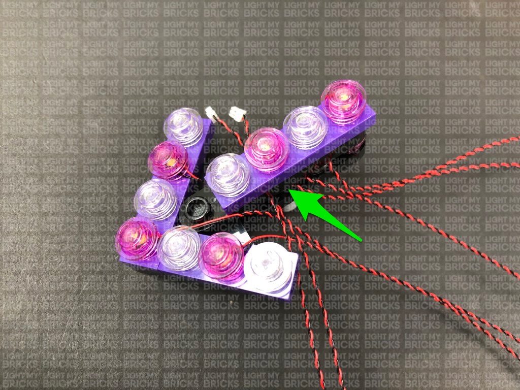
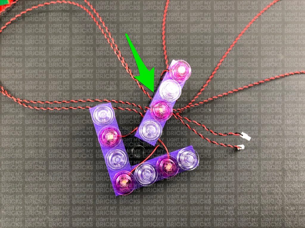
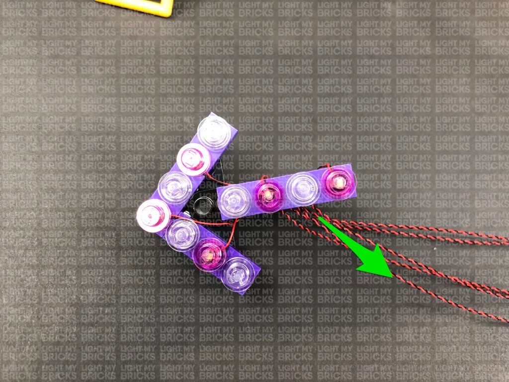
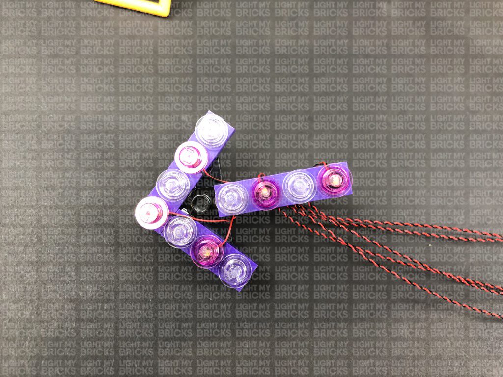
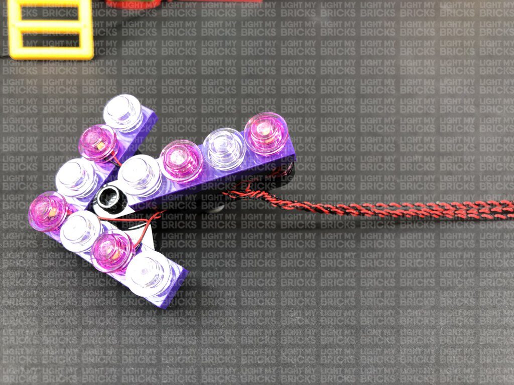
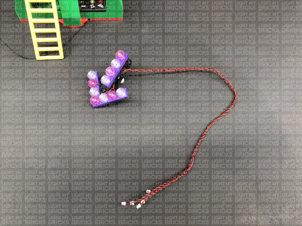
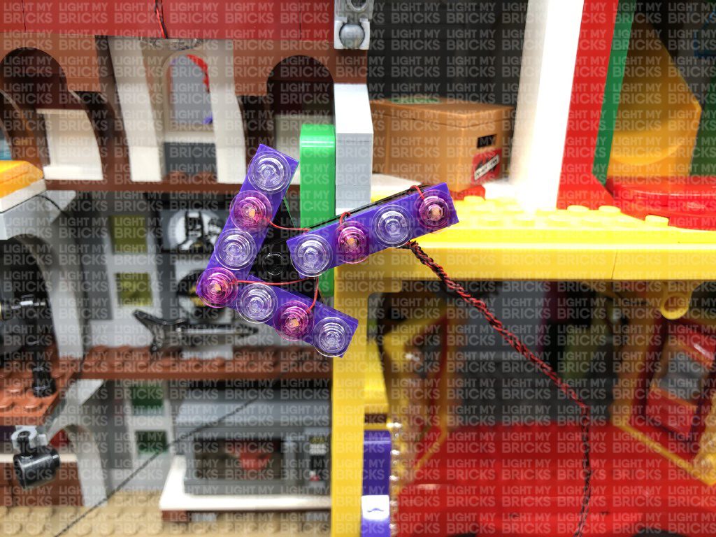
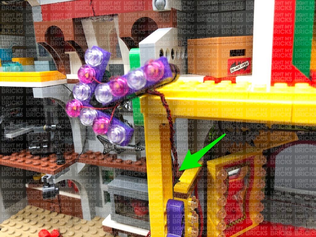
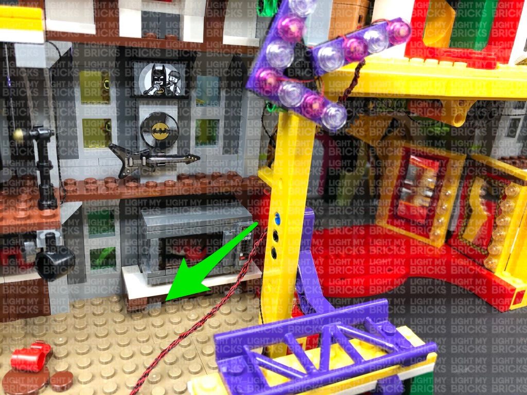
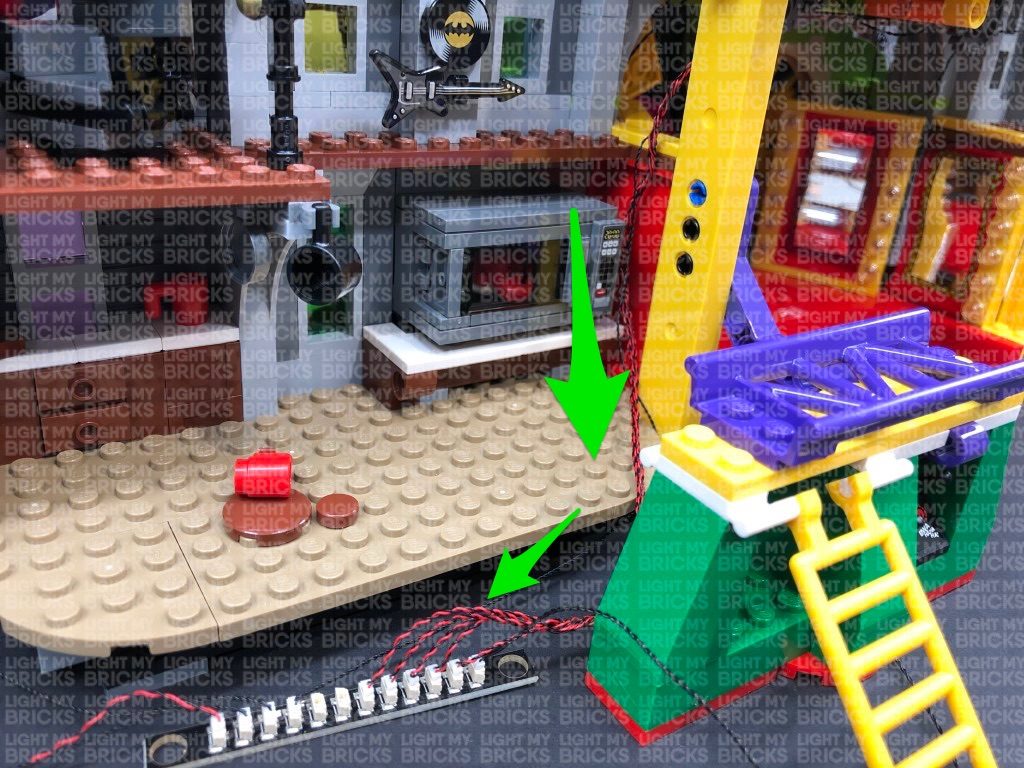
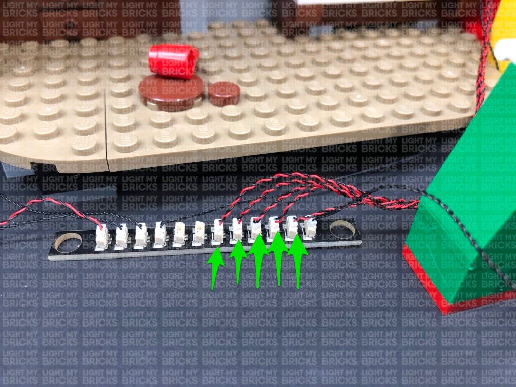
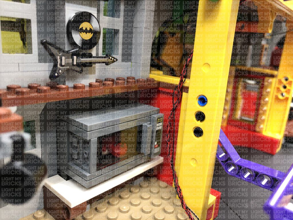
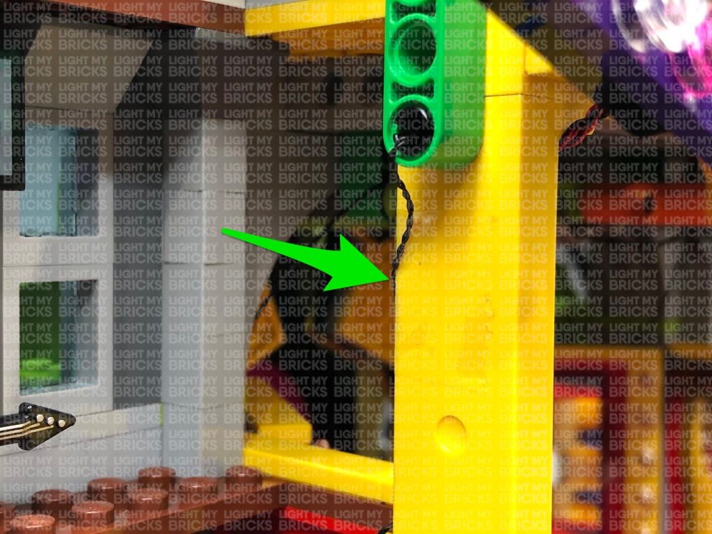
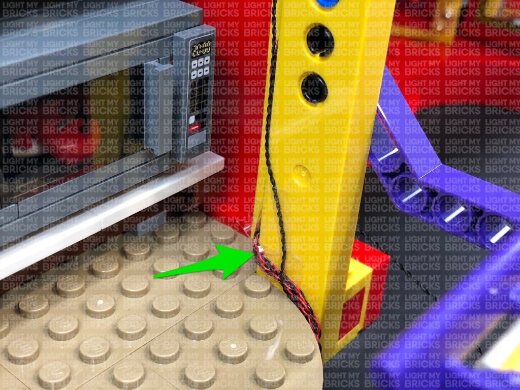
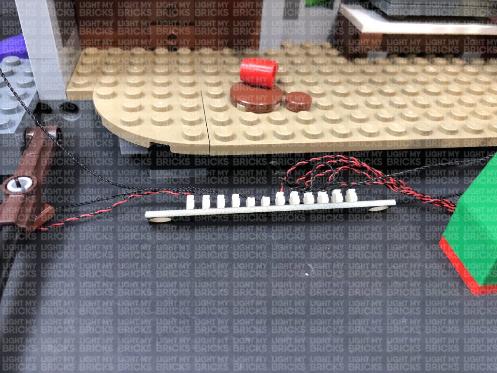
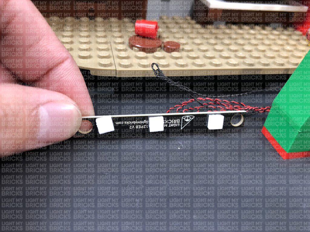
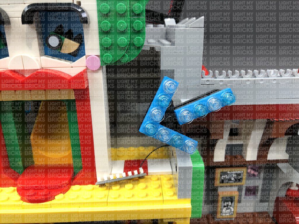
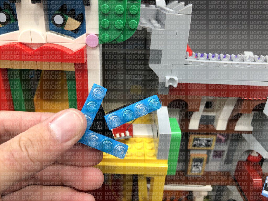
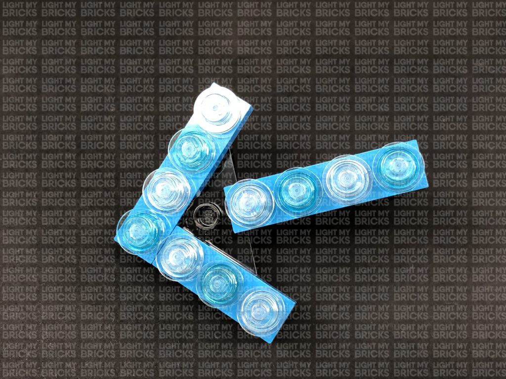
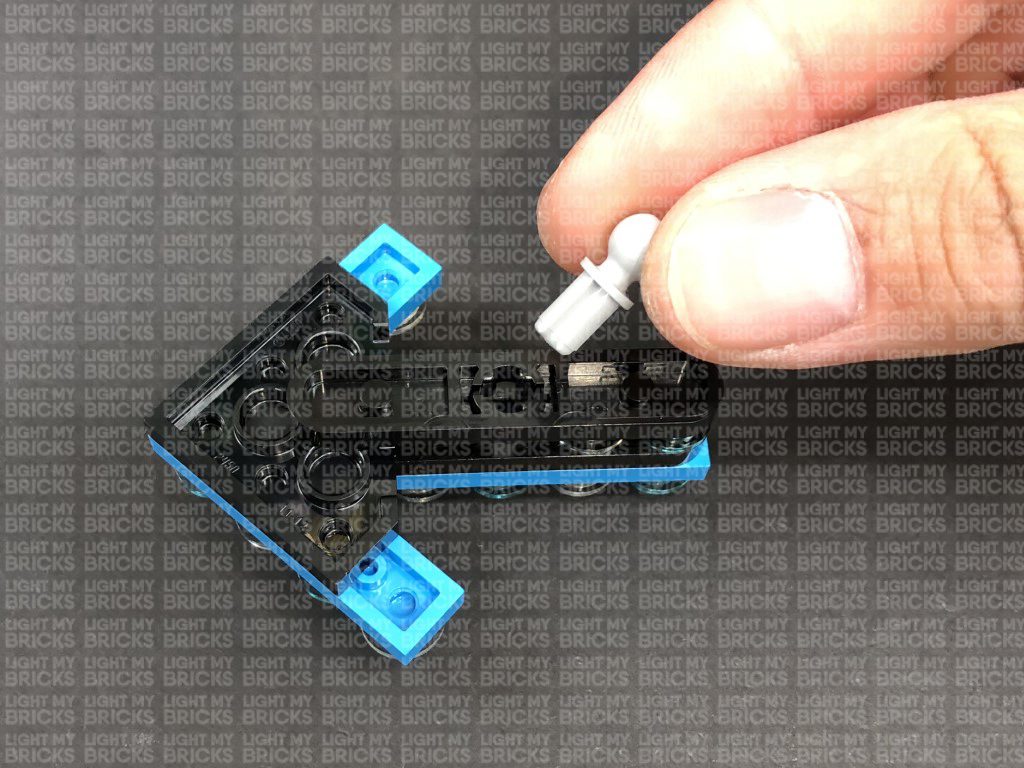
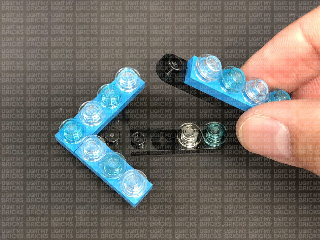
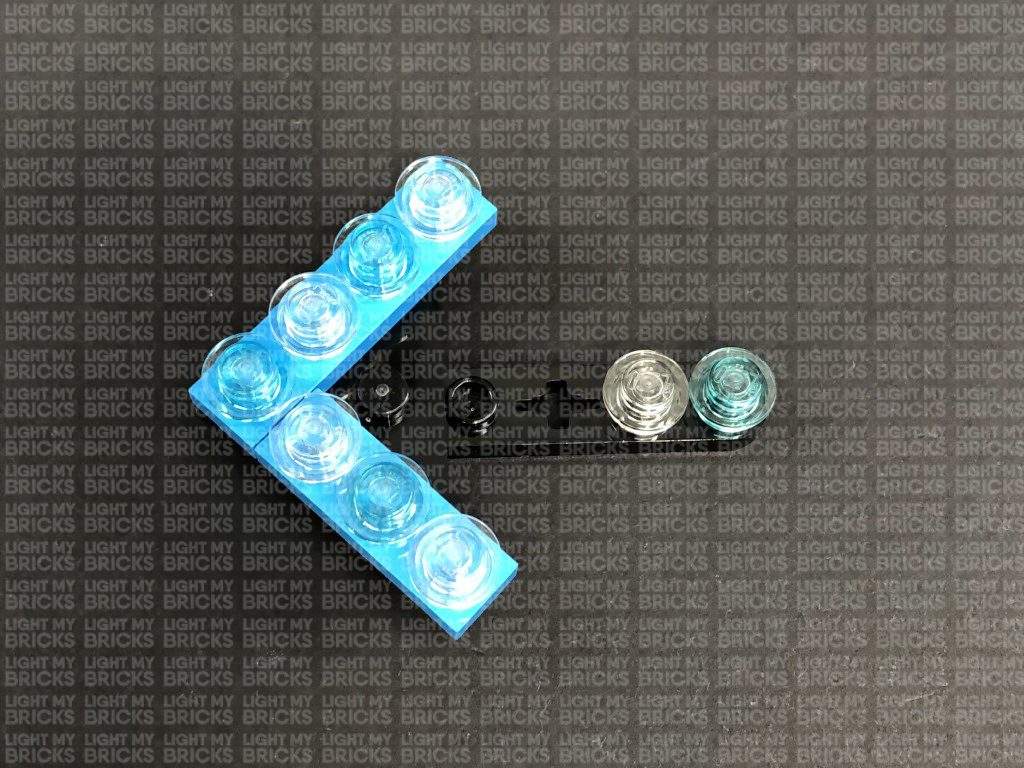
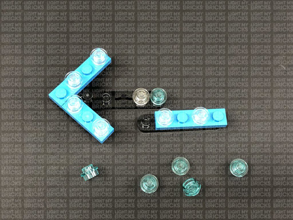
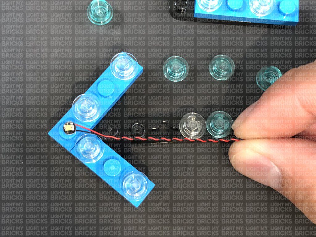
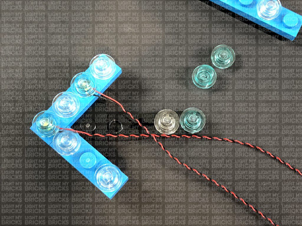
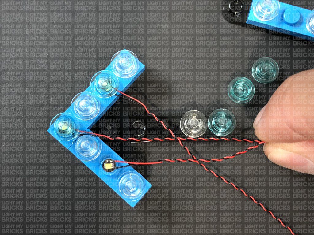
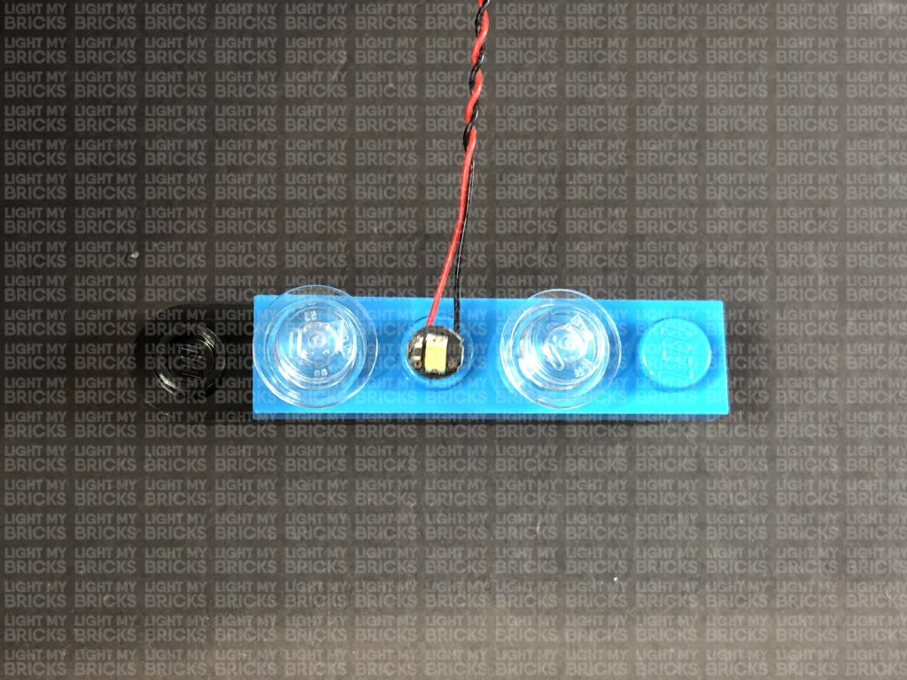
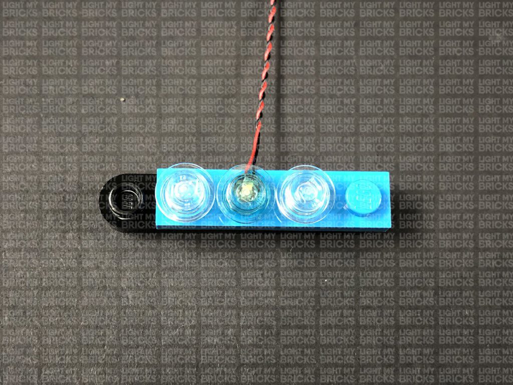
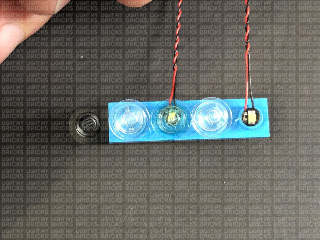
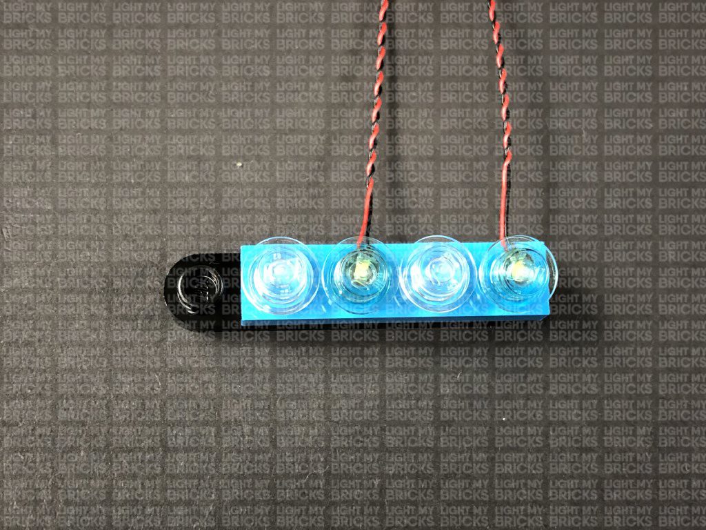
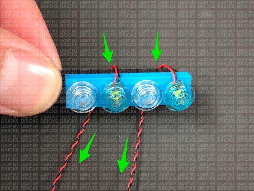
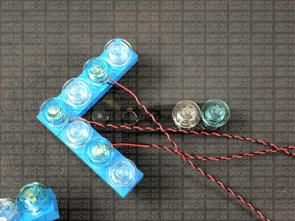
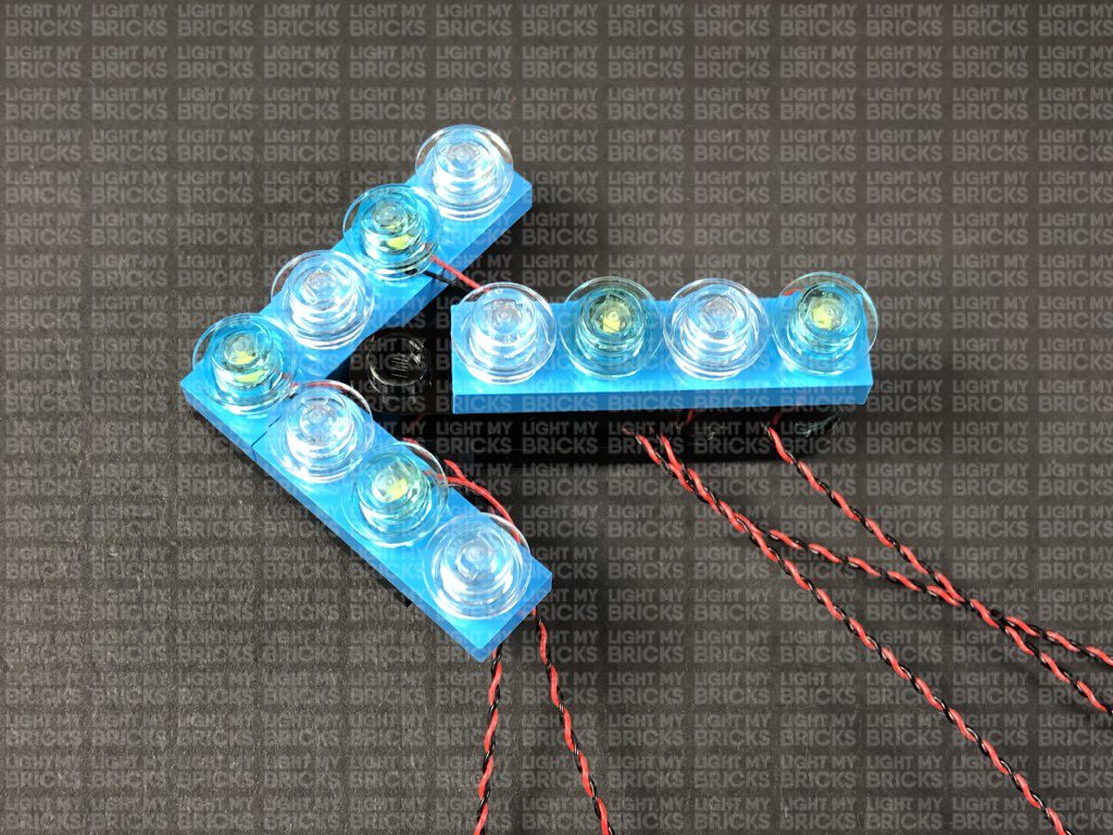
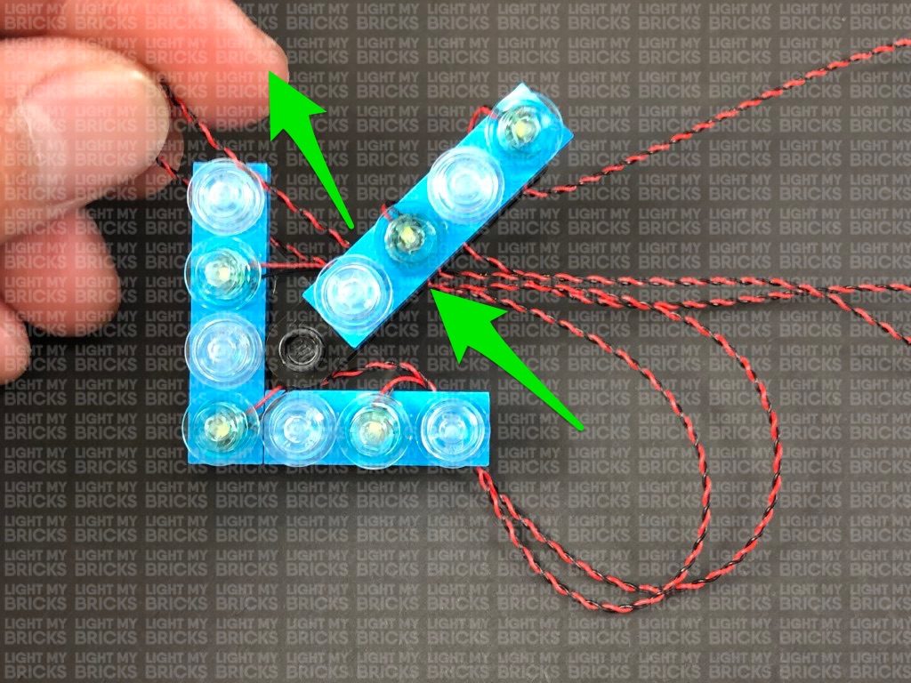
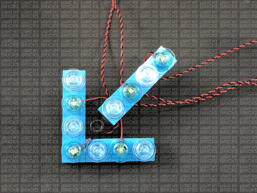
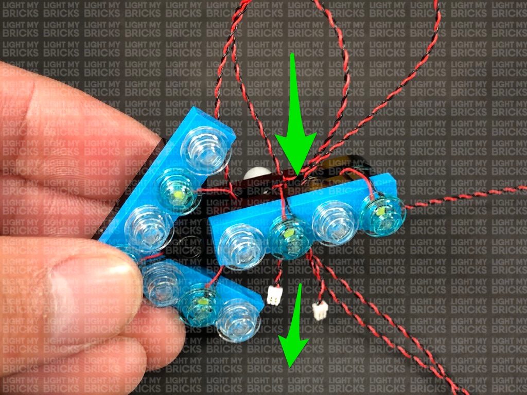
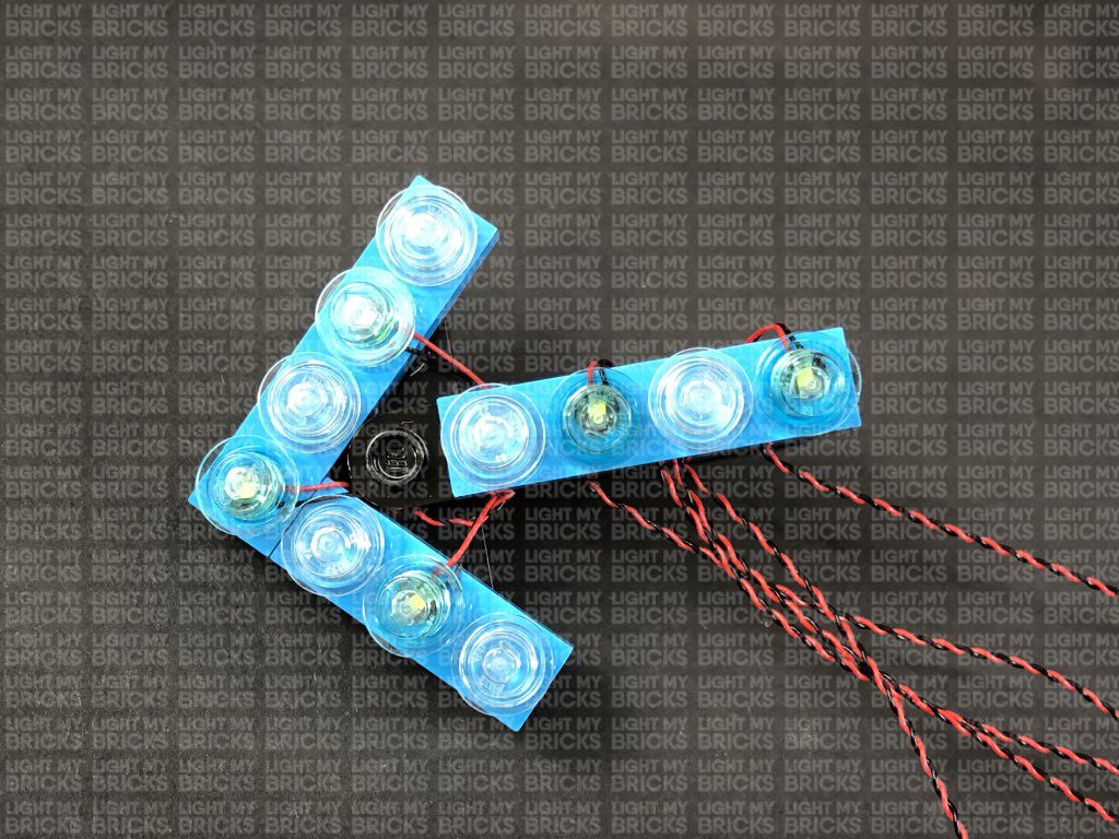
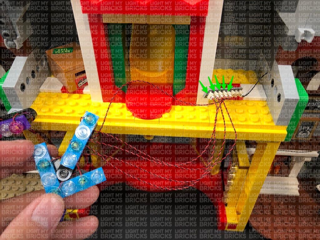
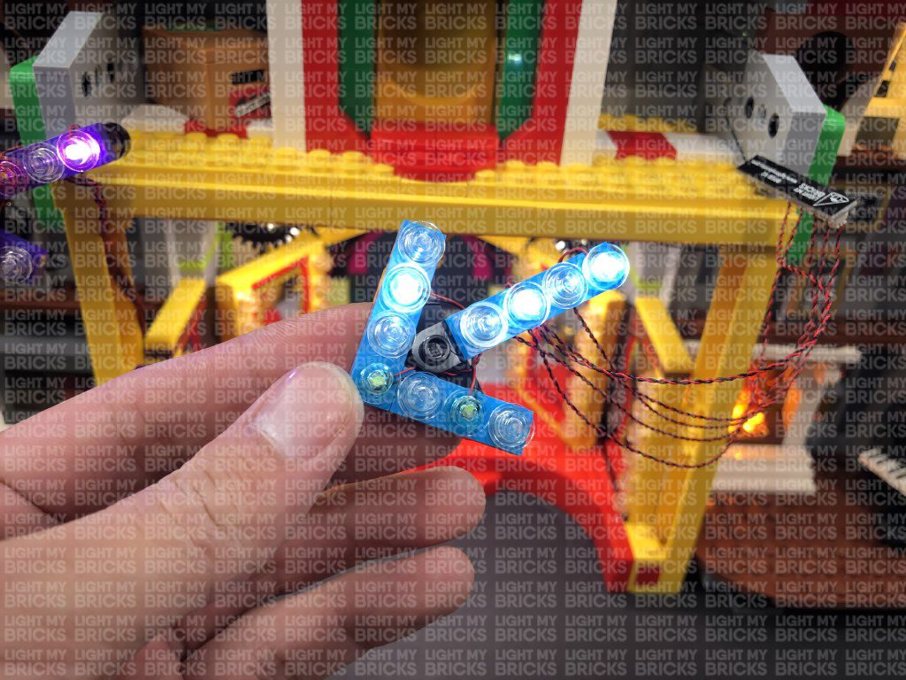
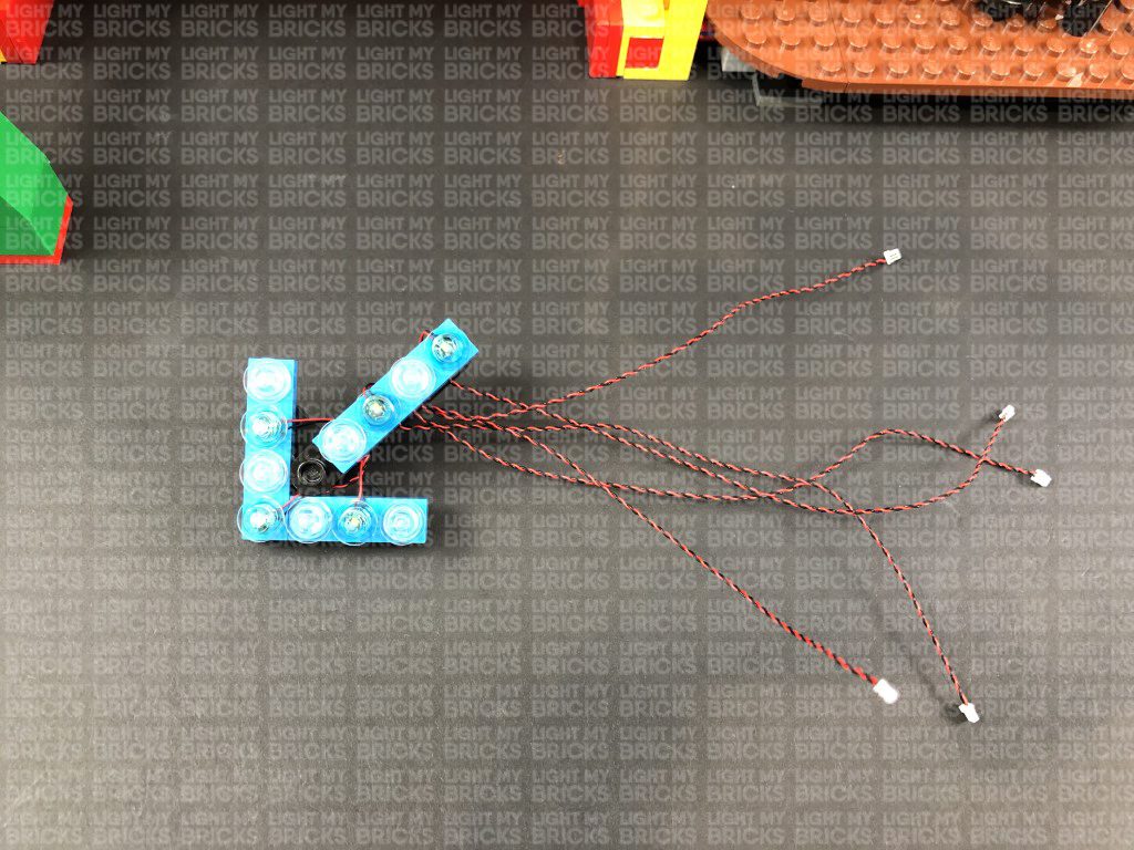
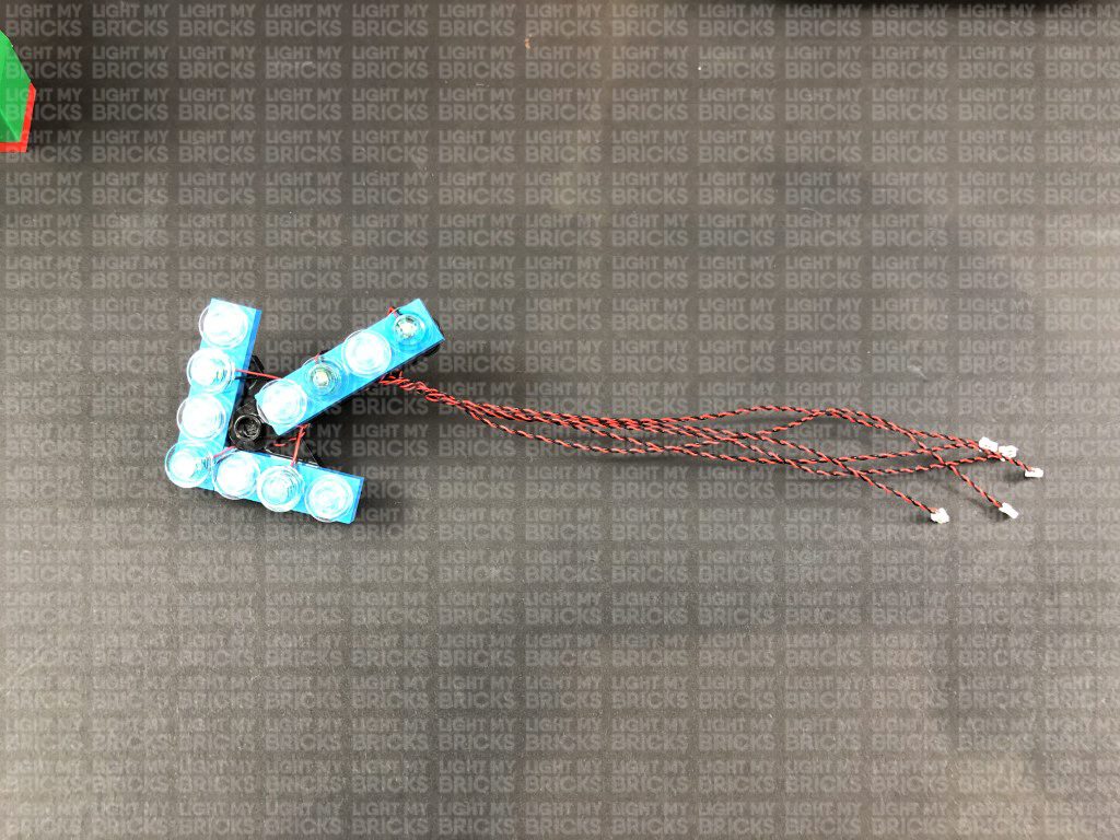
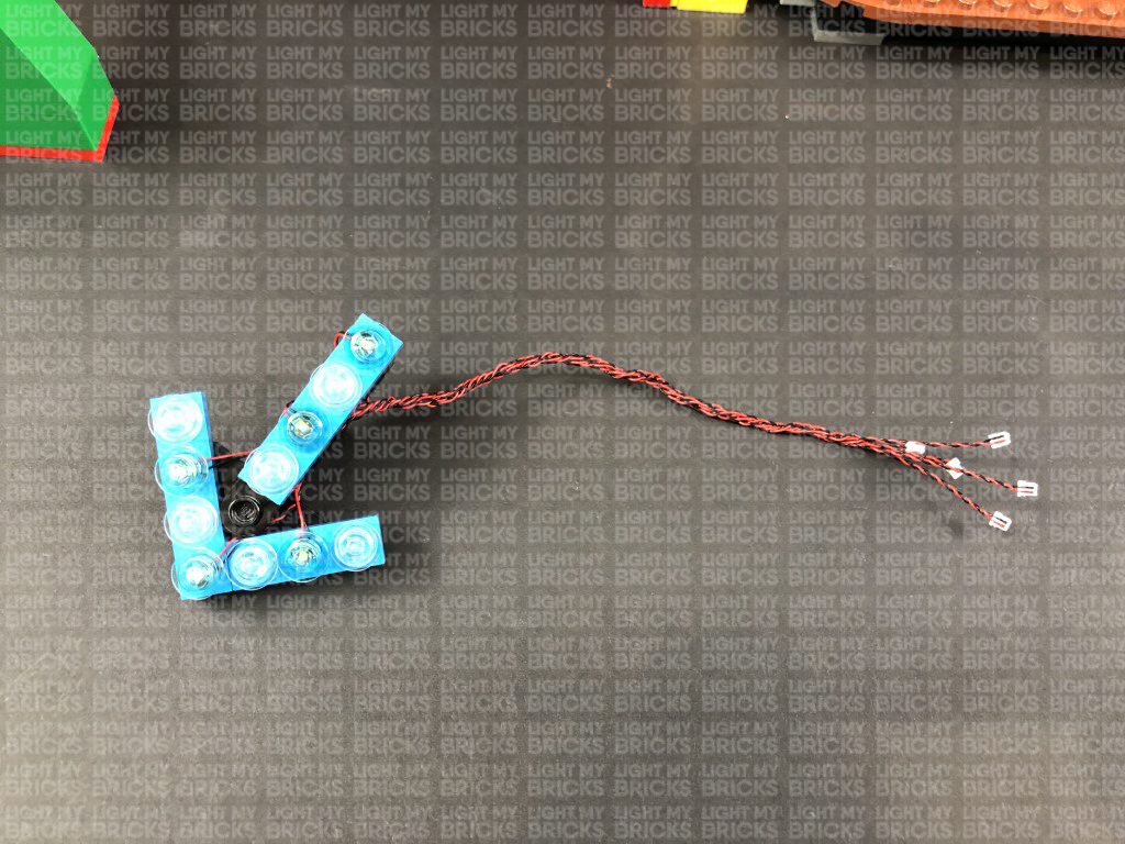
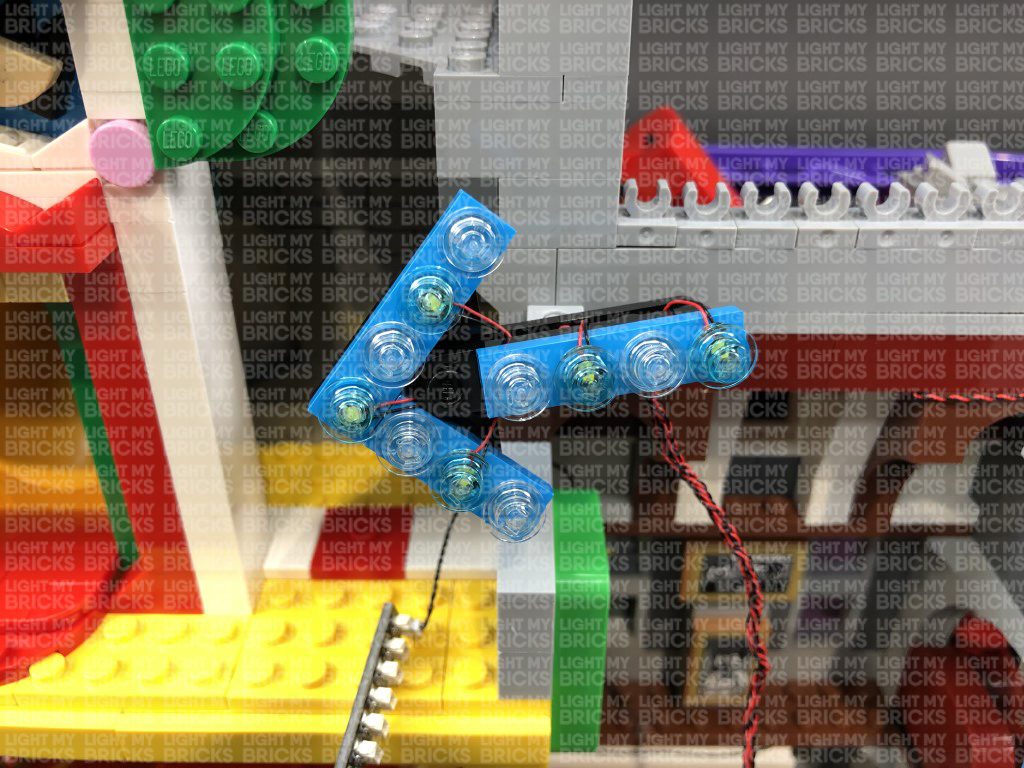
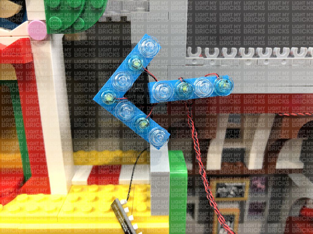
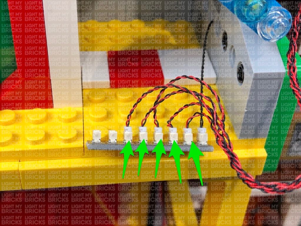
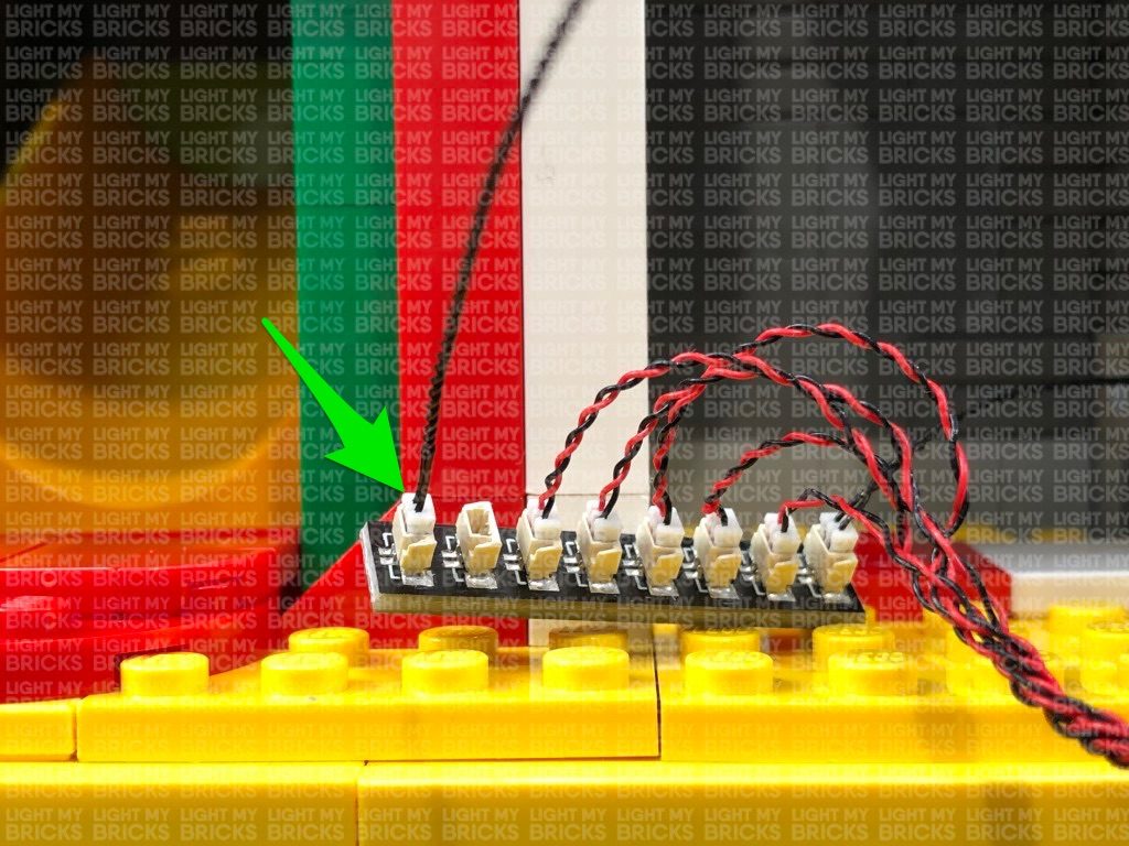
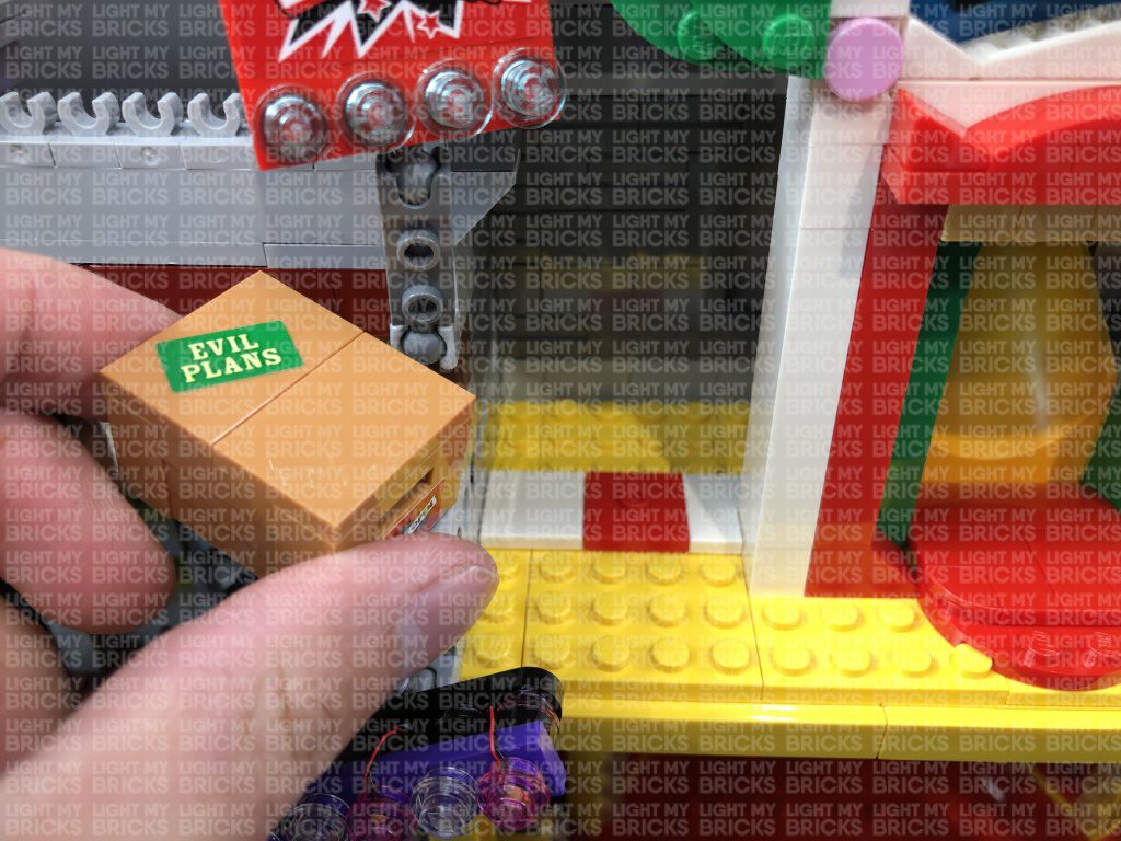
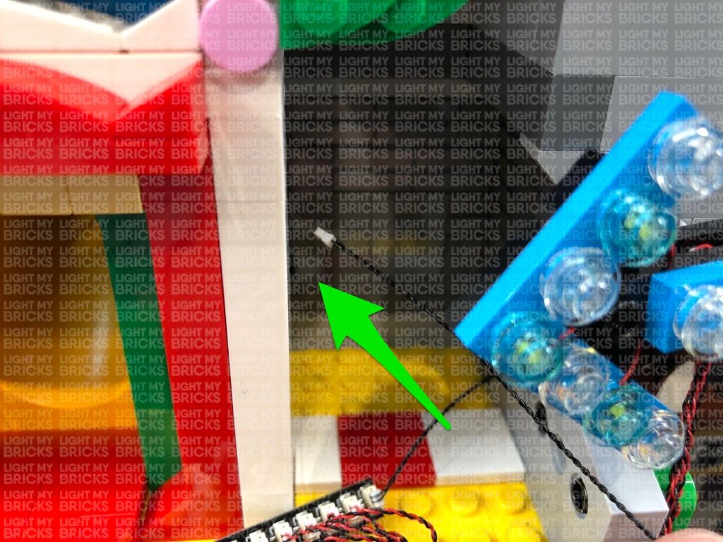
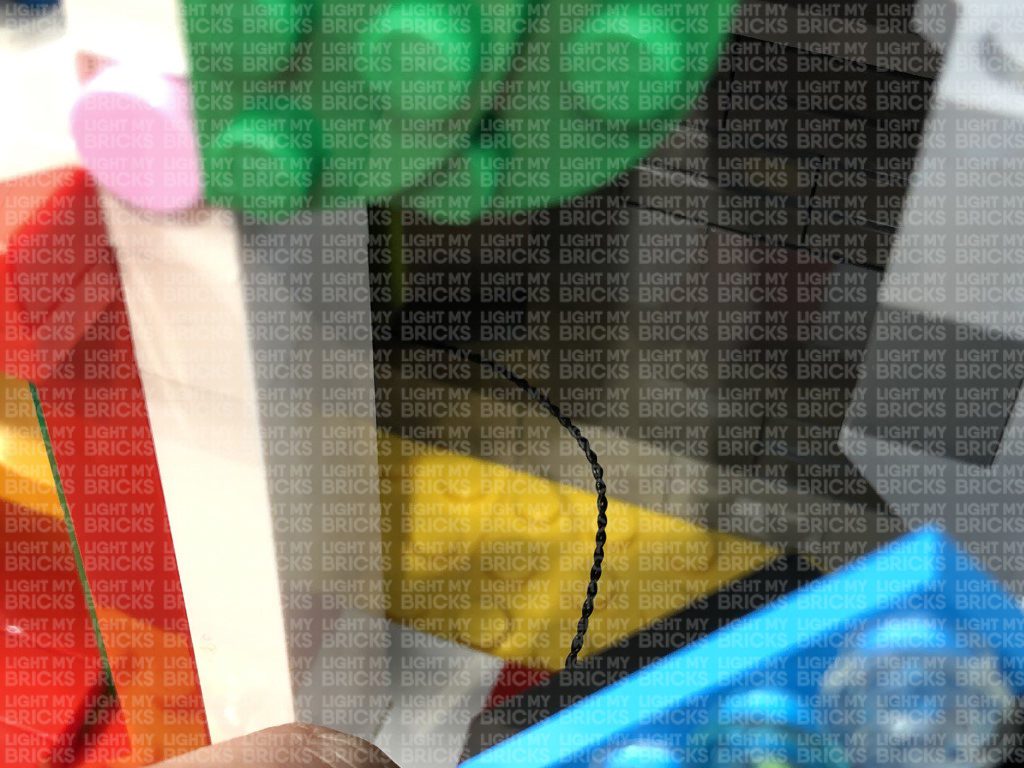
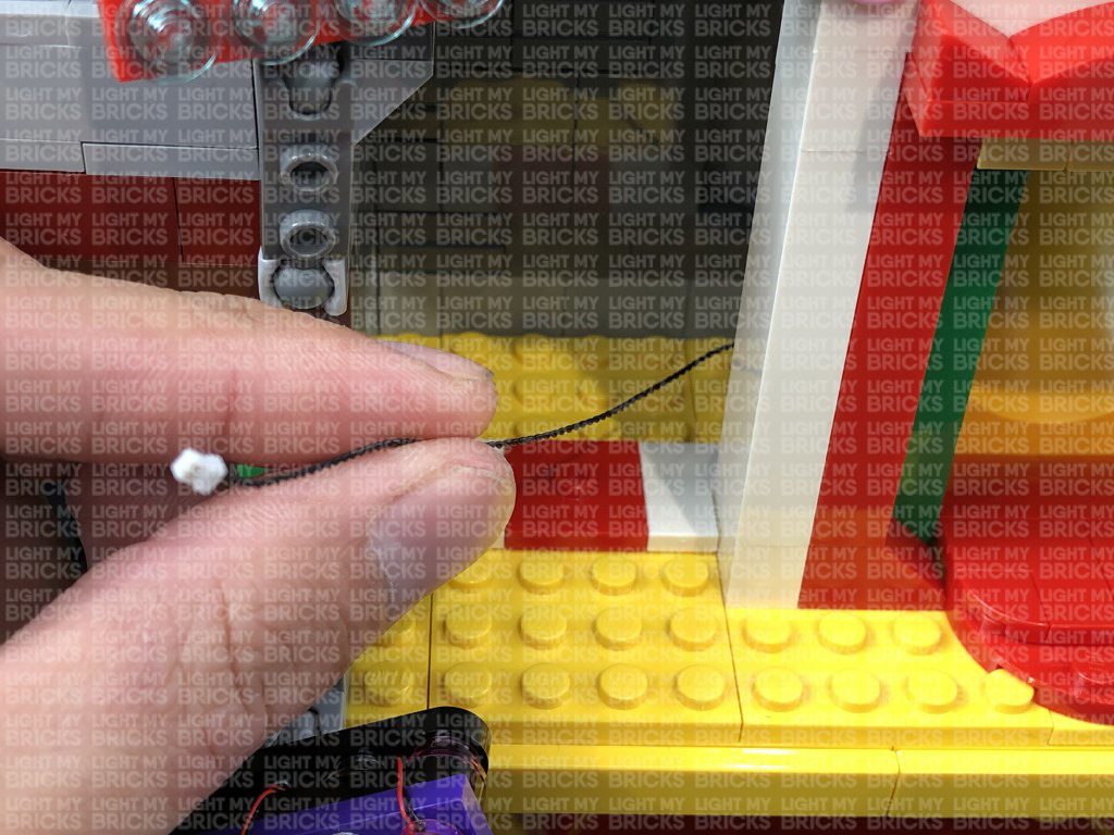
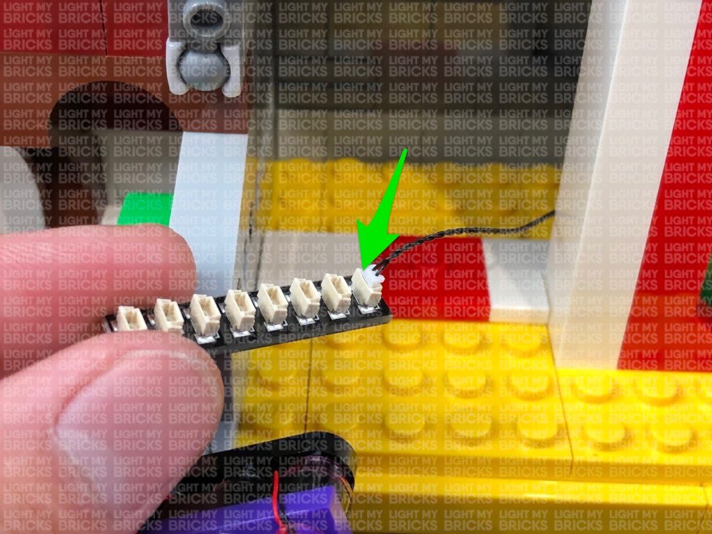
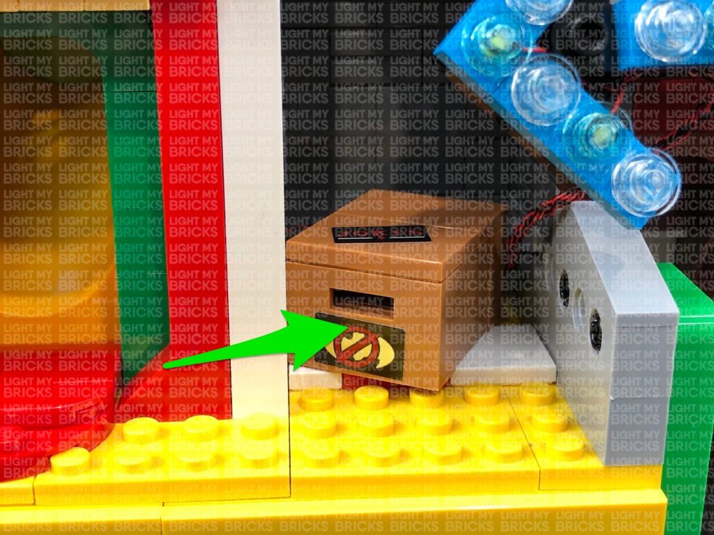
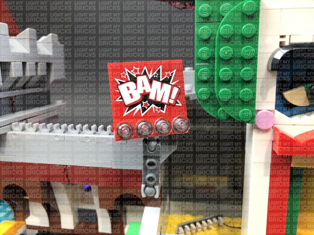
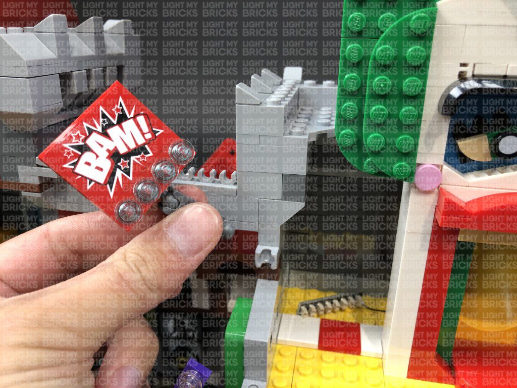
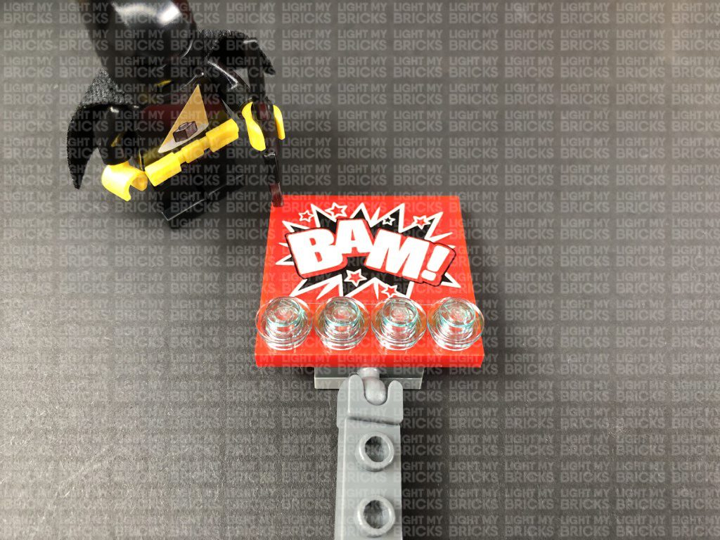
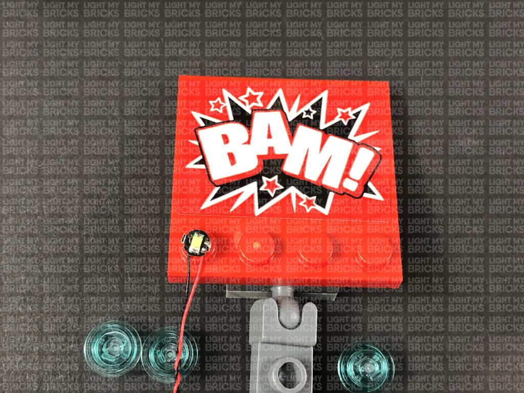
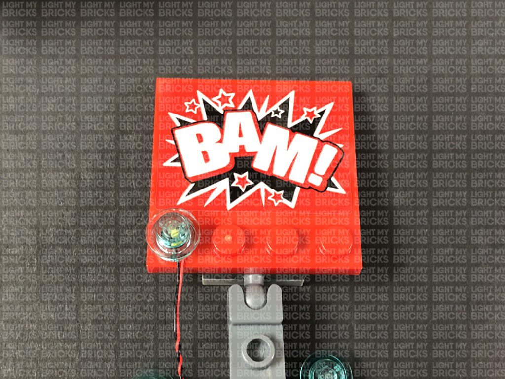
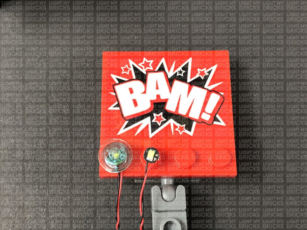
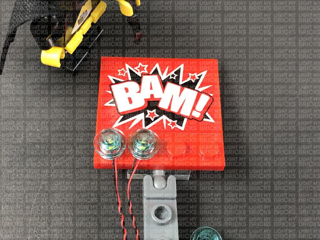
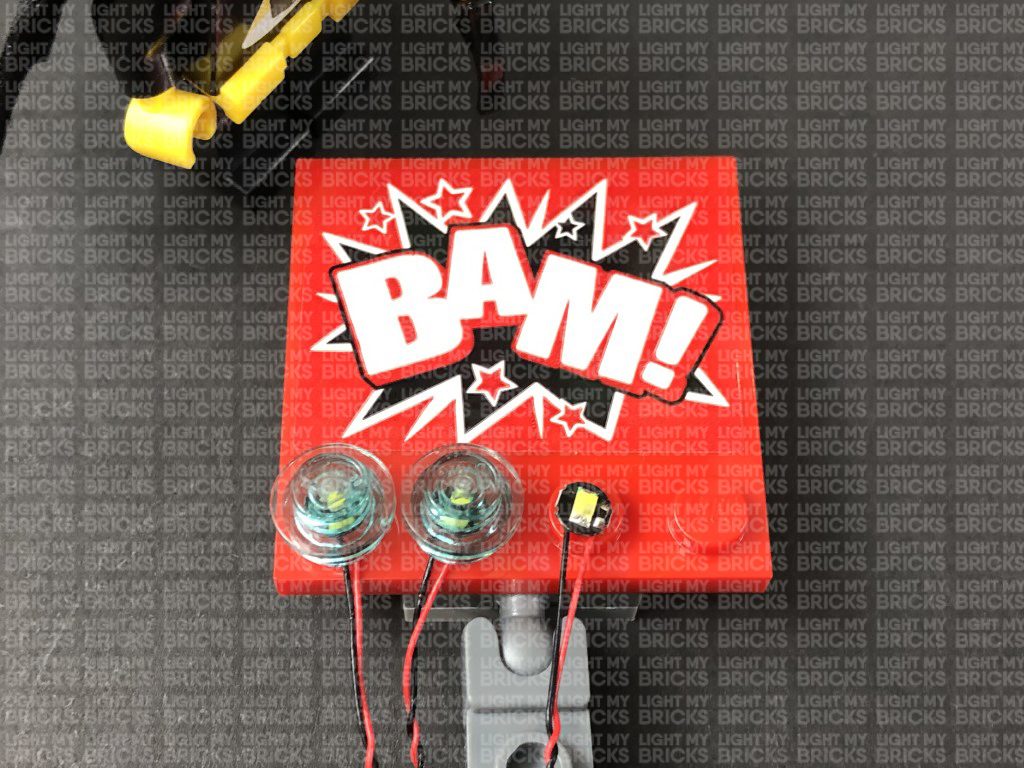
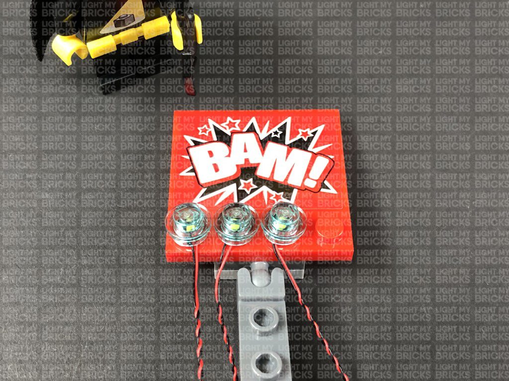
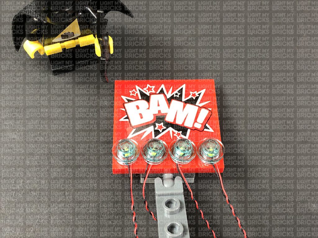
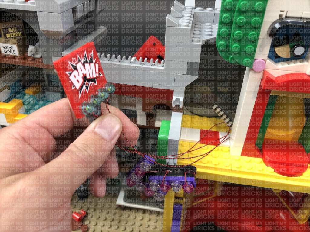
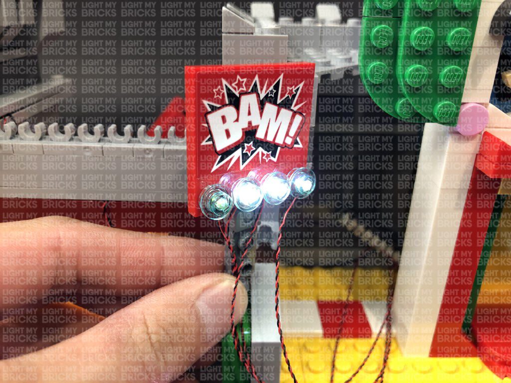
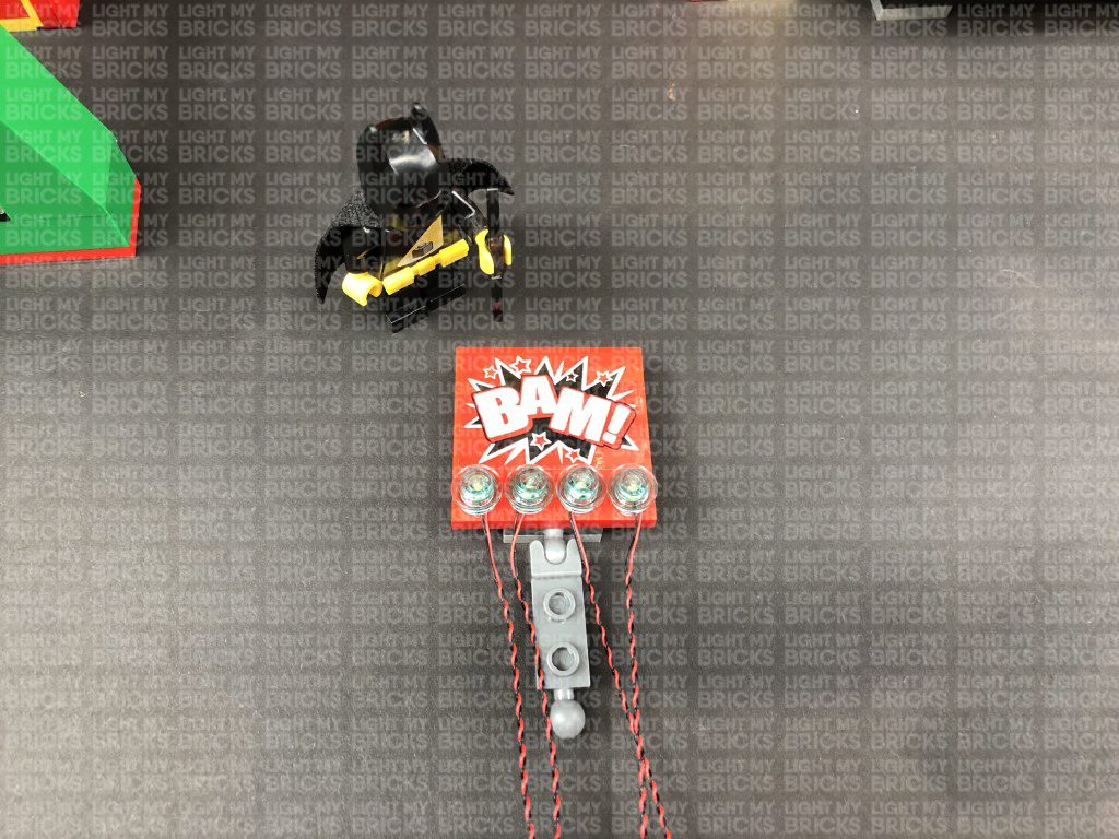
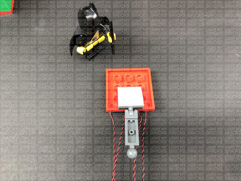
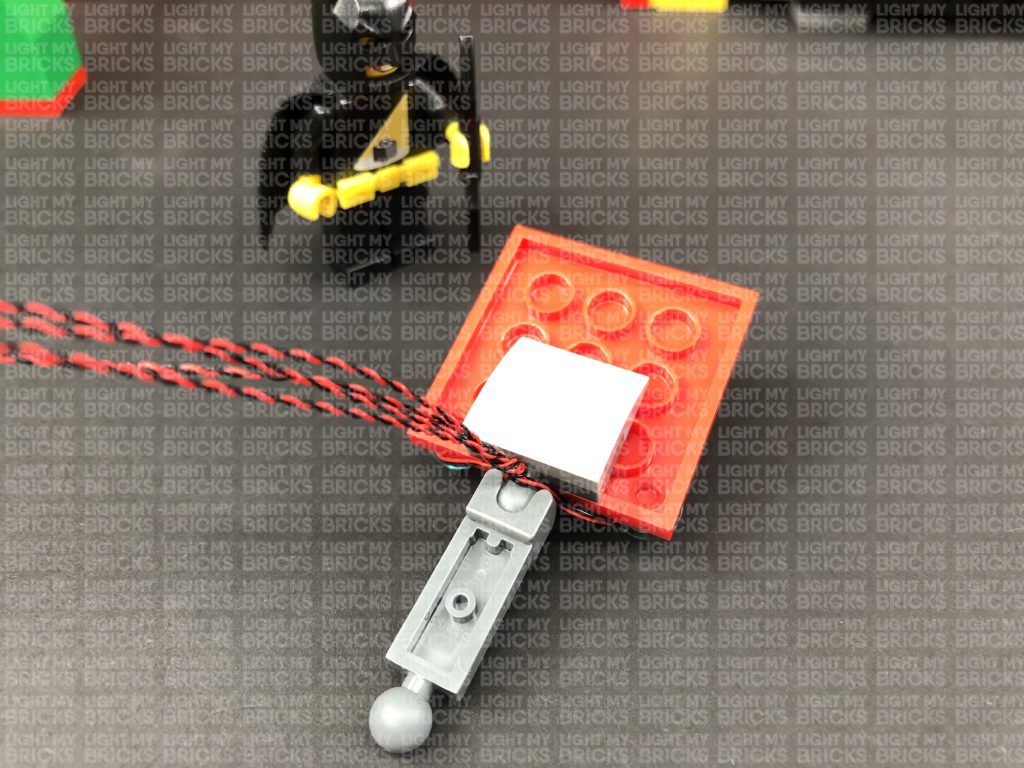
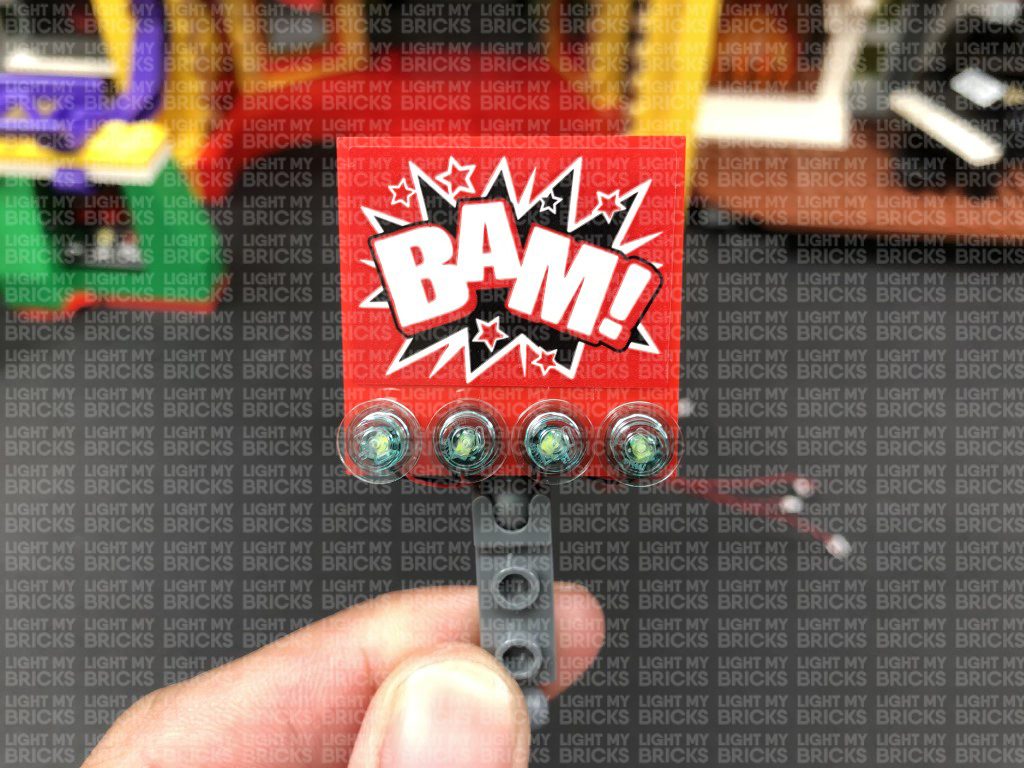
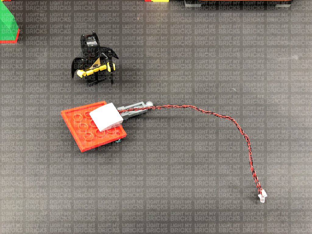
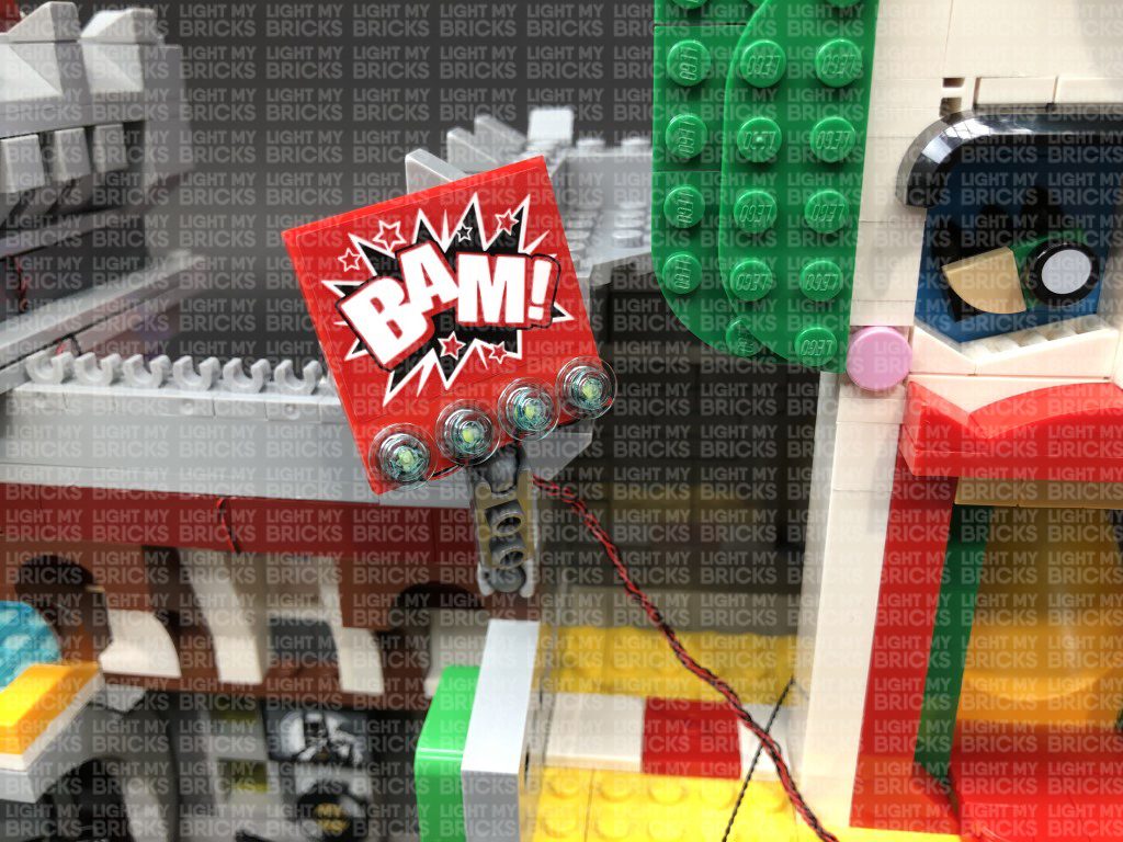
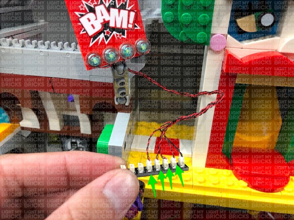
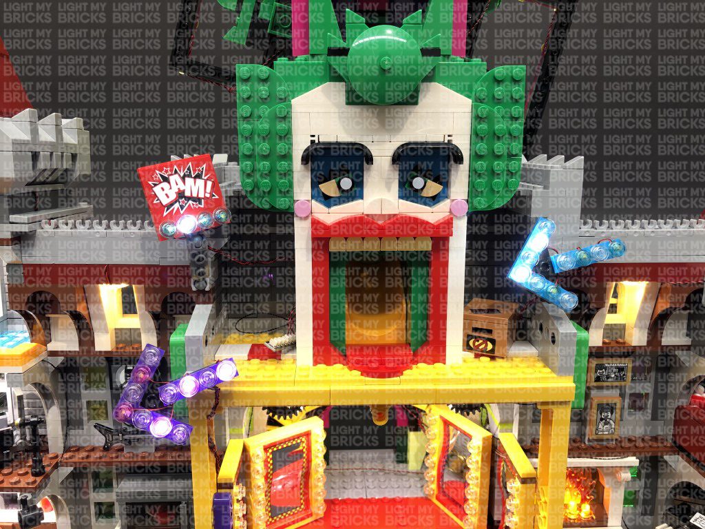
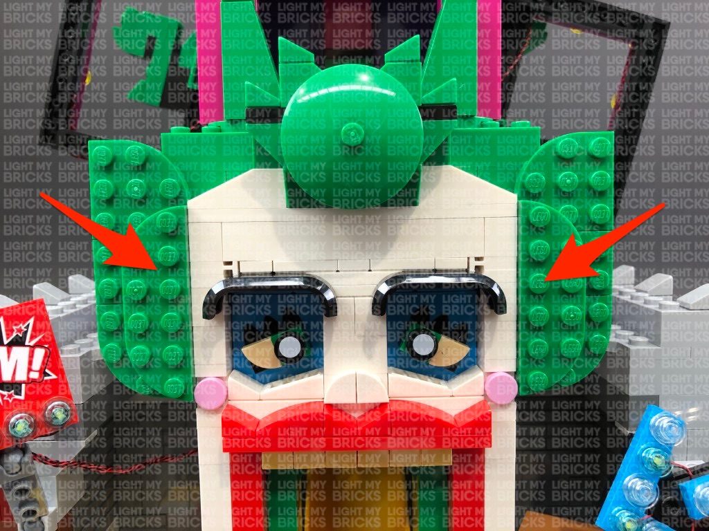
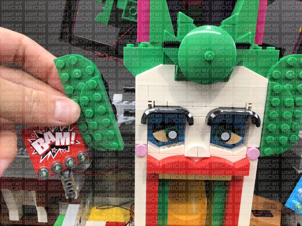
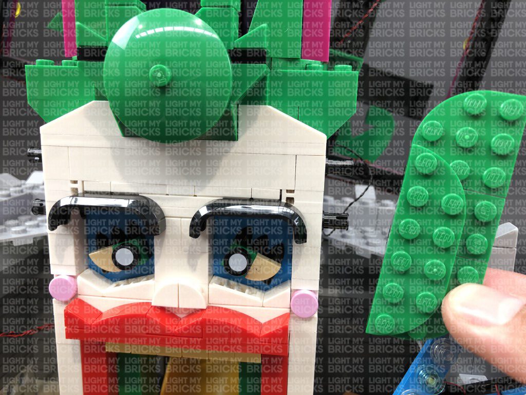
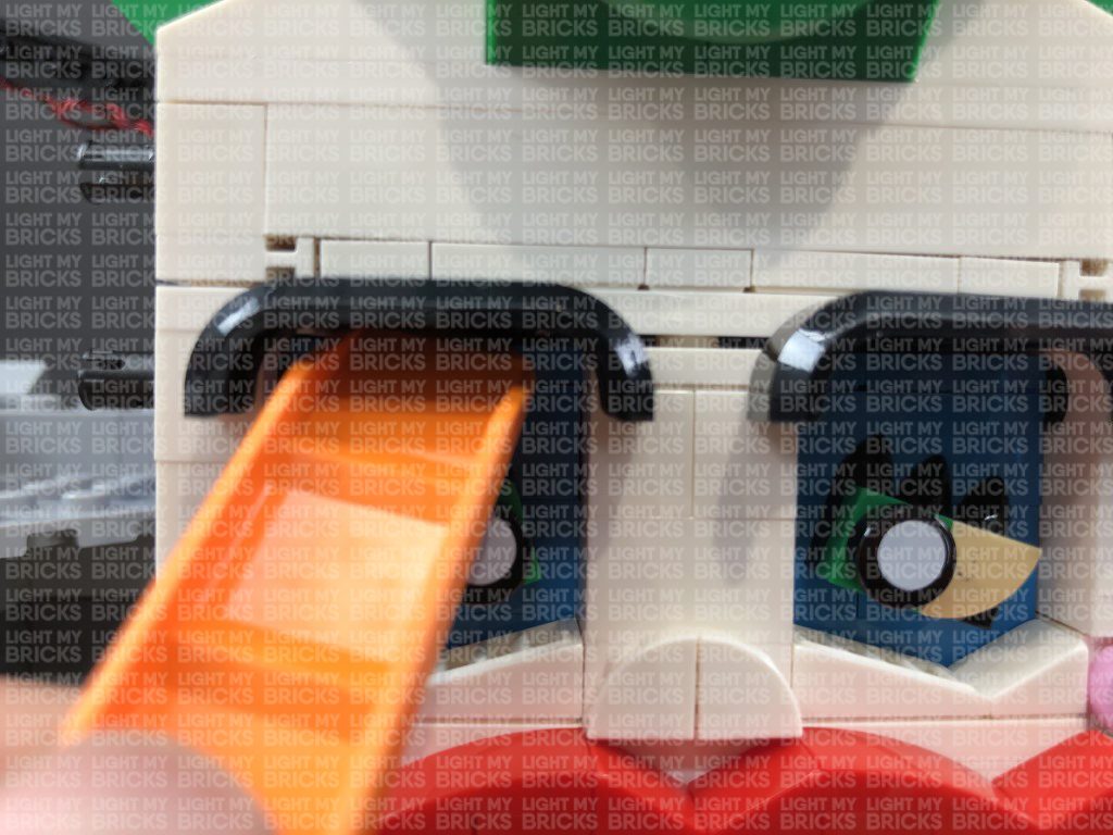
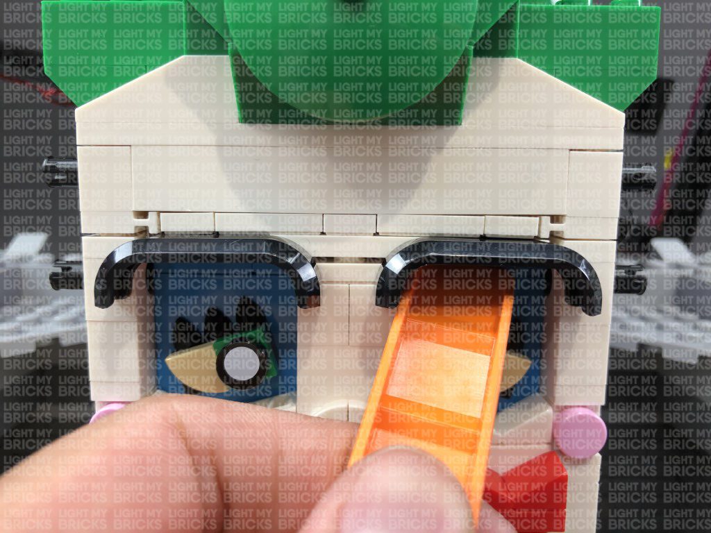
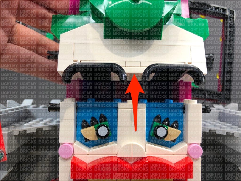
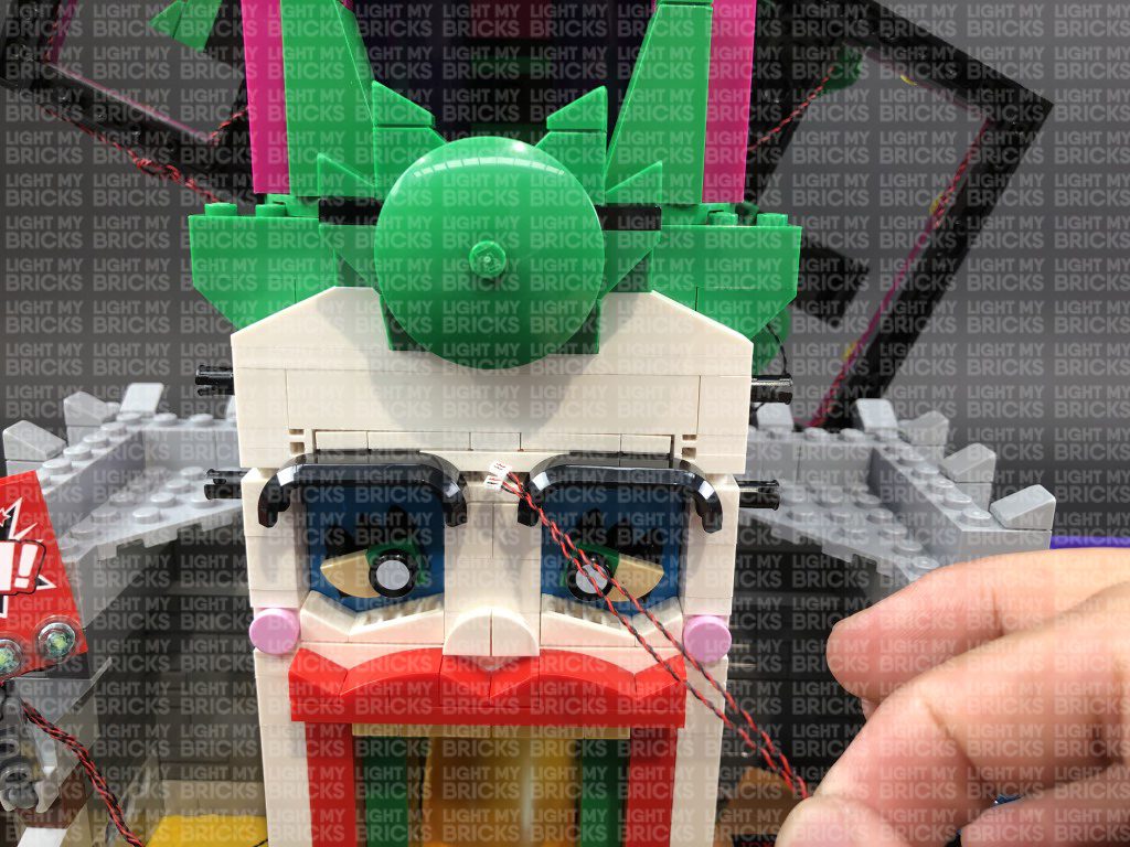
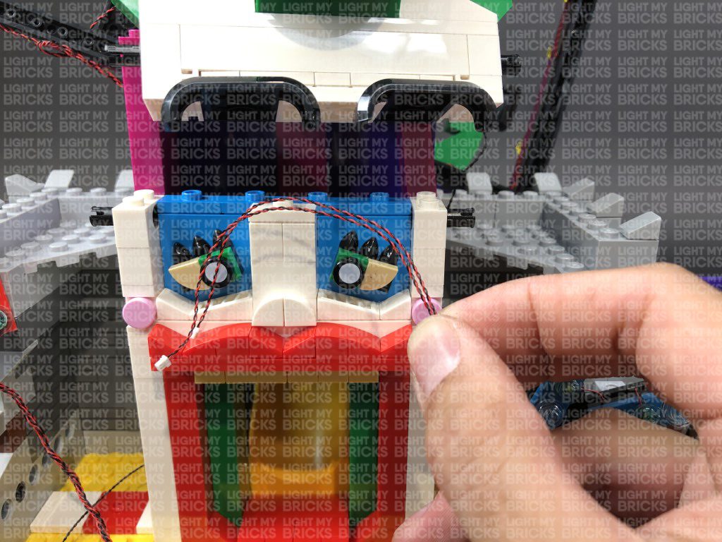
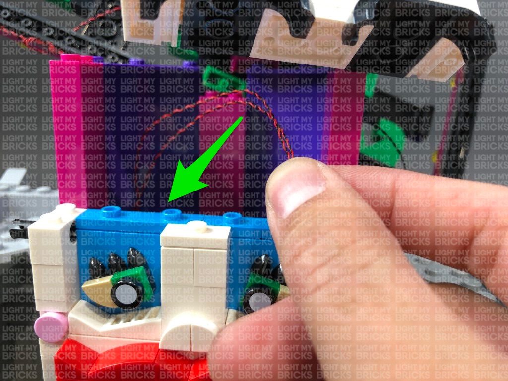
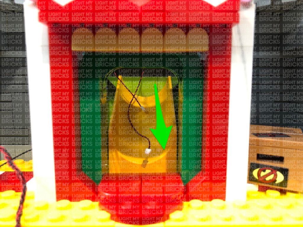
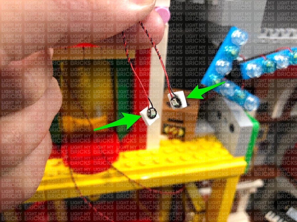
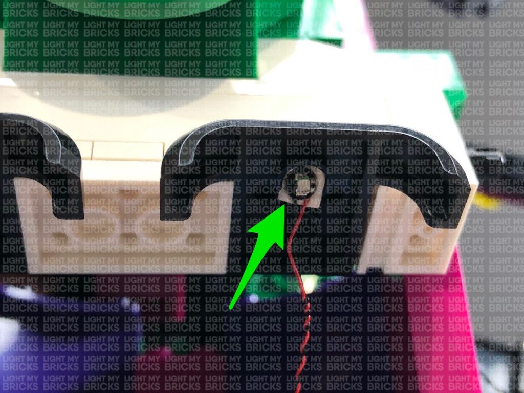
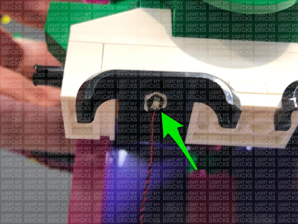
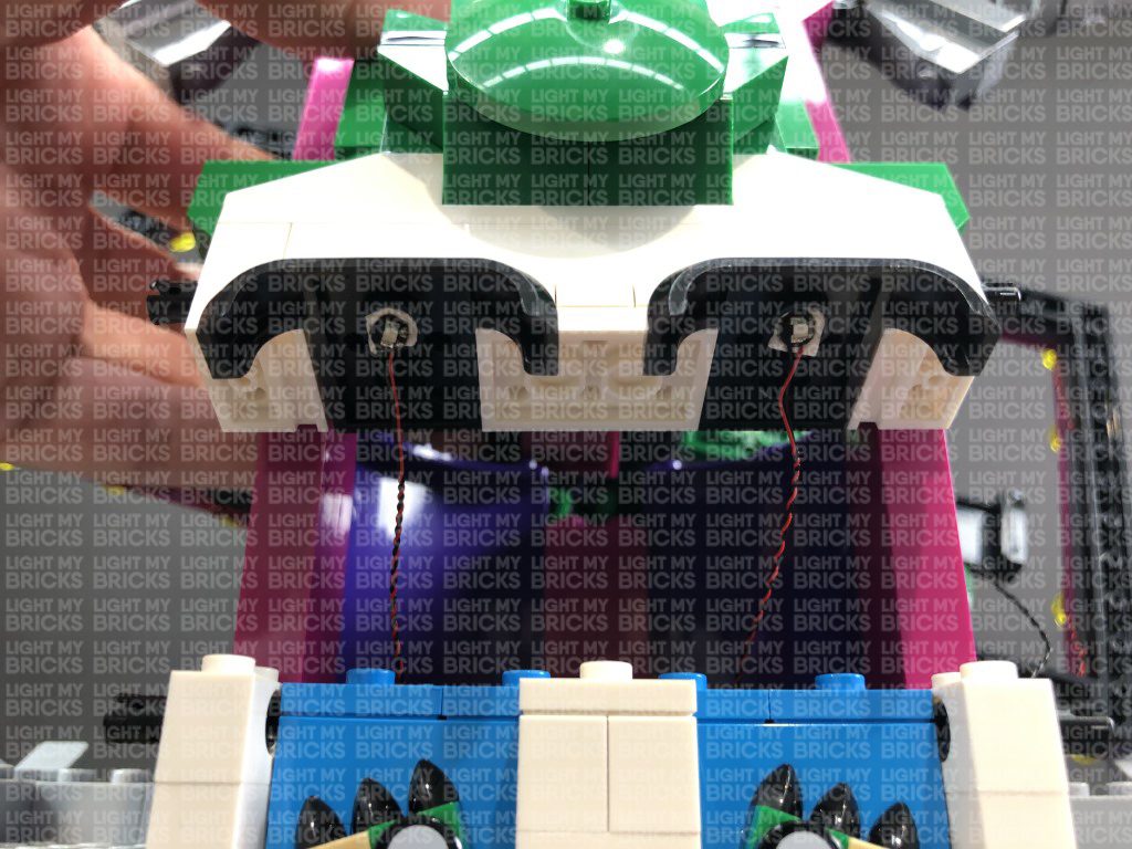
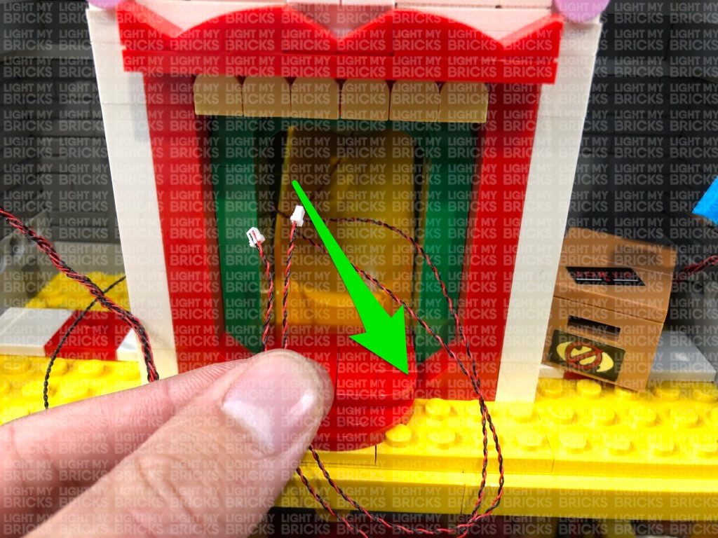
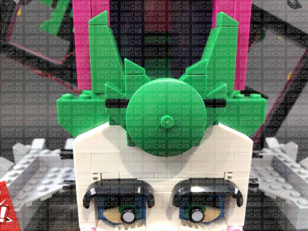
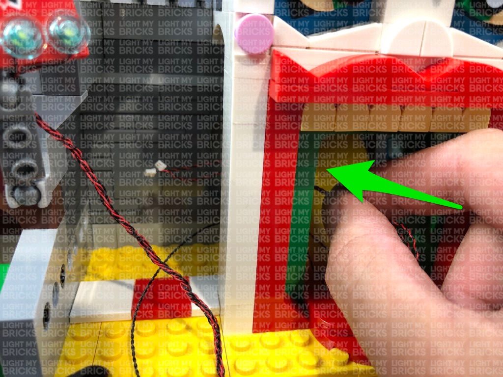
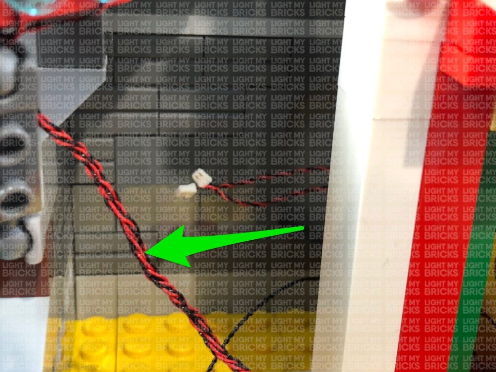
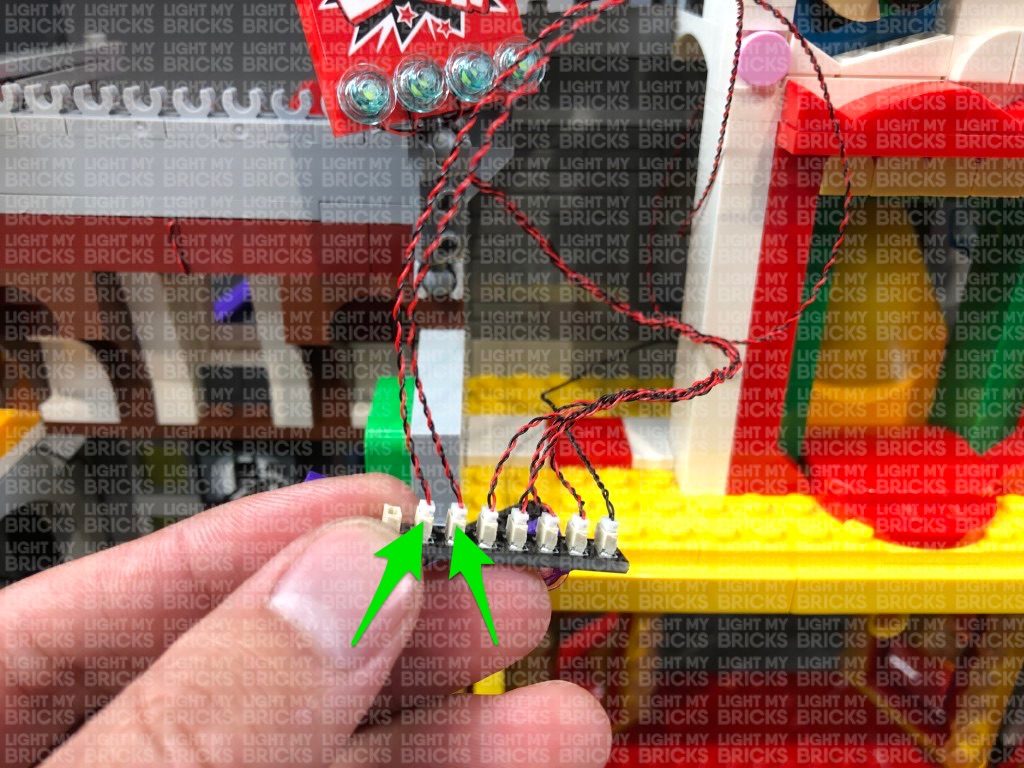
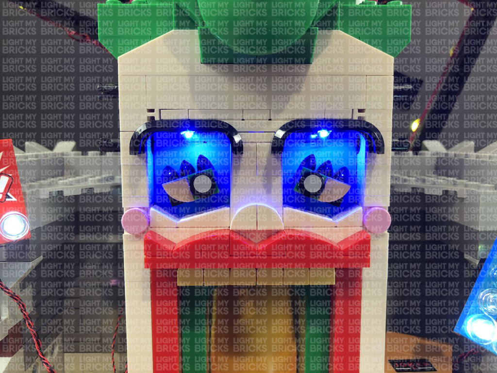 Note: If you experience any issues with the lights not working and suspect an issue with a component, please try a different port on the expansion board to verify where the fault lies (with the strip light or expansion board). To correct any issues with expansion board ports, please view the section addressing expansion board issues on our online troubleshooting guide.
Twist and fold the excess Bit Light cables around each other into a neat bunch
64.) Take a White Strip Light and connect a 15cm Connecting cable to the left port. Thread the other end of the 15cm Connecting Cable through the gap in the top left corner just underneath the Joker teeth. Pull the cable all the way out from behind the left side until the Strip Light touches the corner, then connect the other end of the cable to the remaining port on the 8-Port Expansion Board.
Take 30cm Connecting Cable and connect it to the right port on the White Strip Light, then thread the other end of the cable through the gap in the top right corner underneath the Joker teeth. Pull the cable all the way out from behind the right side until the Strip Light touches the corner, then using it’s adhesive backing, stick the White Strip Light directly underneath the teeth section.
Neatly tuck the 8-port expansion board and cables on the left side of the Joker Slide inside the space to the right before reconnecting the Evil Plans Box. Use tape to secure the Bit Light cables from the BAM! sign to the wall.
Turn ON the USB Power Bank to test the White Strip Light just above the Joker slide is working OK.
Note: If you experience any issues with the lights not working and suspect an issue with a component, please try a different port on the expansion board to verify where the fault lies (with the strip light or expansion board). To correct any issues with expansion board ports, please view the section addressing expansion board issues on our online troubleshooting guide.
Twist and fold the excess Bit Light cables around each other into a neat bunch
64.) Take a White Strip Light and connect a 15cm Connecting cable to the left port. Thread the other end of the 15cm Connecting Cable through the gap in the top left corner just underneath the Joker teeth. Pull the cable all the way out from behind the left side until the Strip Light touches the corner, then connect the other end of the cable to the remaining port on the 8-Port Expansion Board.
Take 30cm Connecting Cable and connect it to the right port on the White Strip Light, then thread the other end of the cable through the gap in the top right corner underneath the Joker teeth. Pull the cable all the way out from behind the right side until the Strip Light touches the corner, then using it’s adhesive backing, stick the White Strip Light directly underneath the teeth section.
Neatly tuck the 8-port expansion board and cables on the left side of the Joker Slide inside the space to the right before reconnecting the Evil Plans Box. Use tape to secure the Bit Light cables from the BAM! sign to the wall.
Turn ON the USB Power Bank to test the White Strip Light just above the Joker slide is working OK.
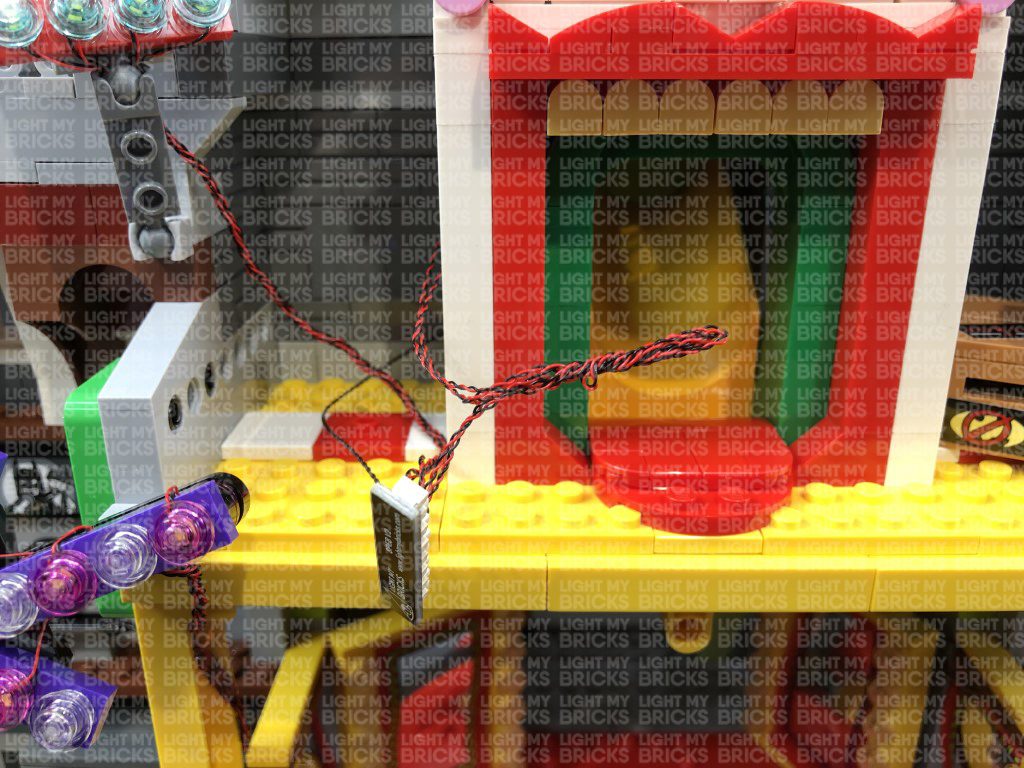
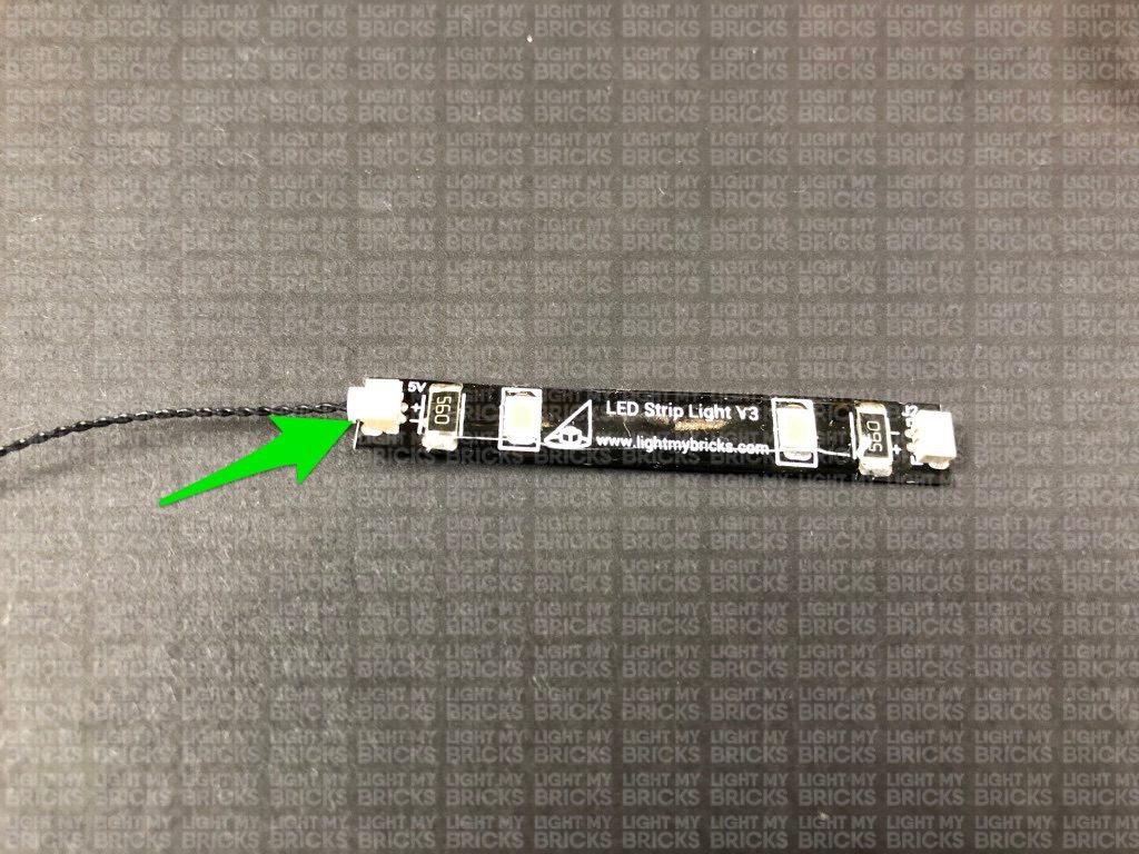
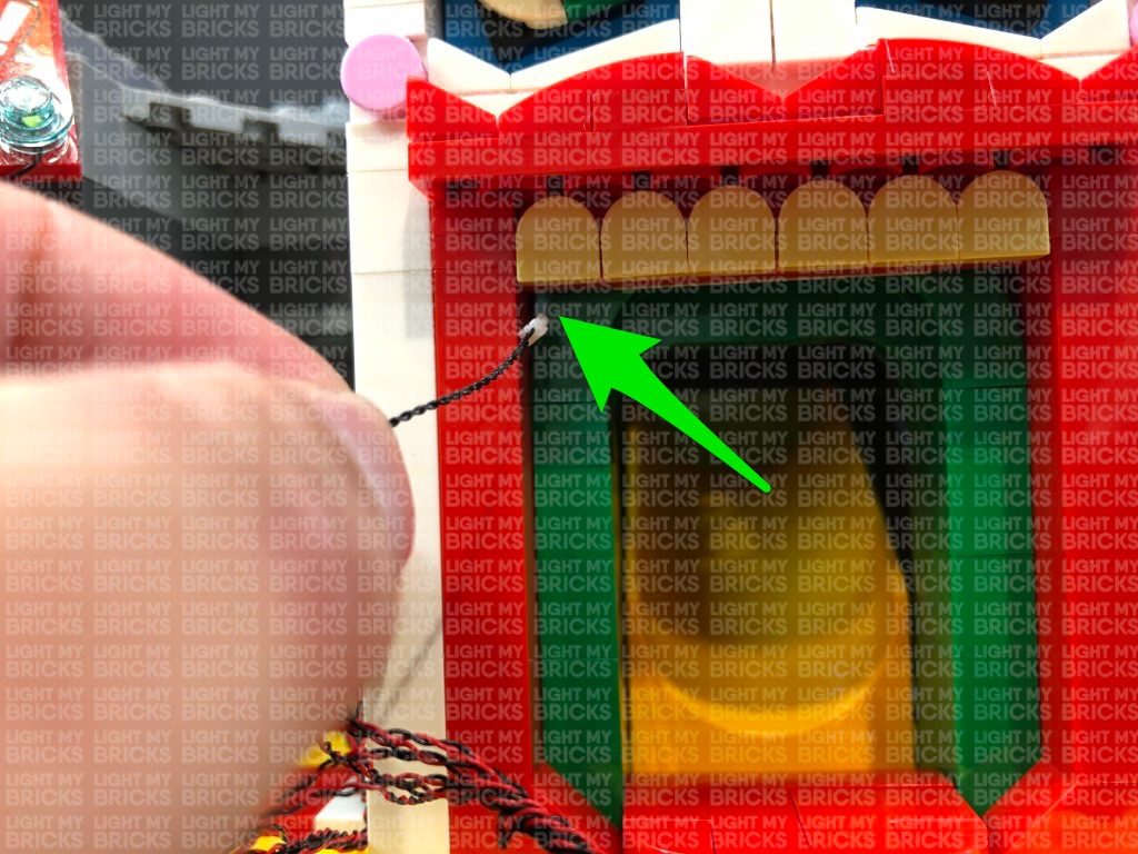
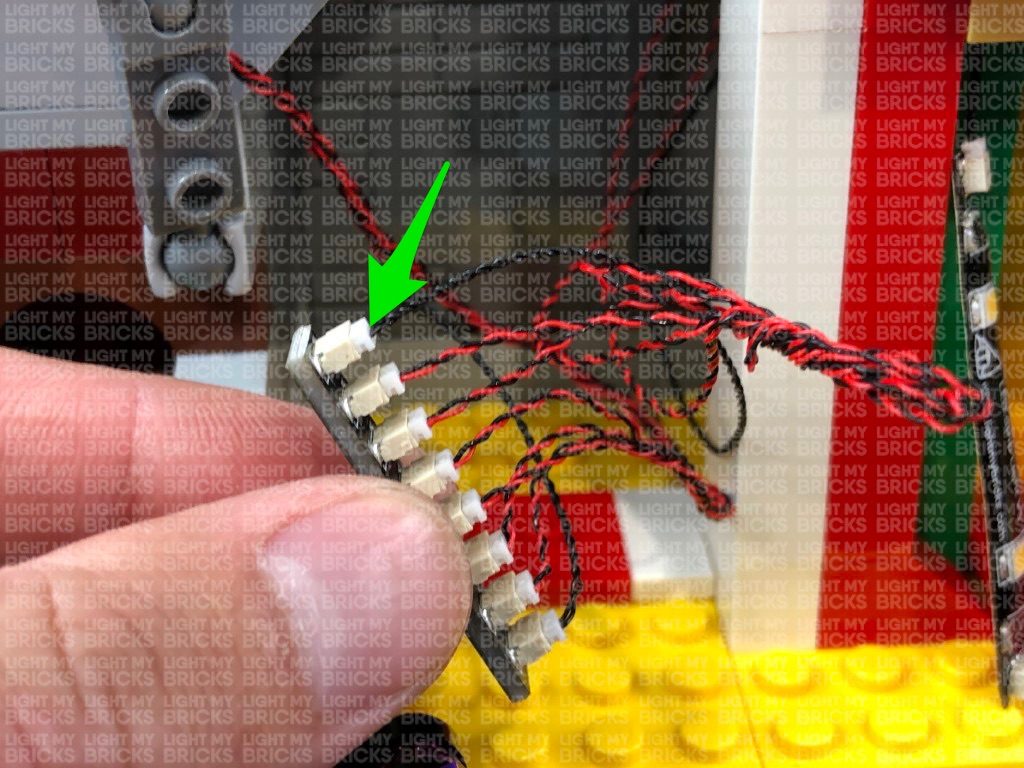
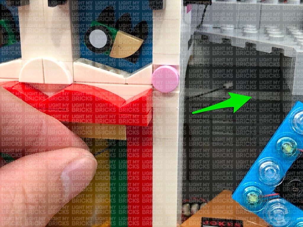
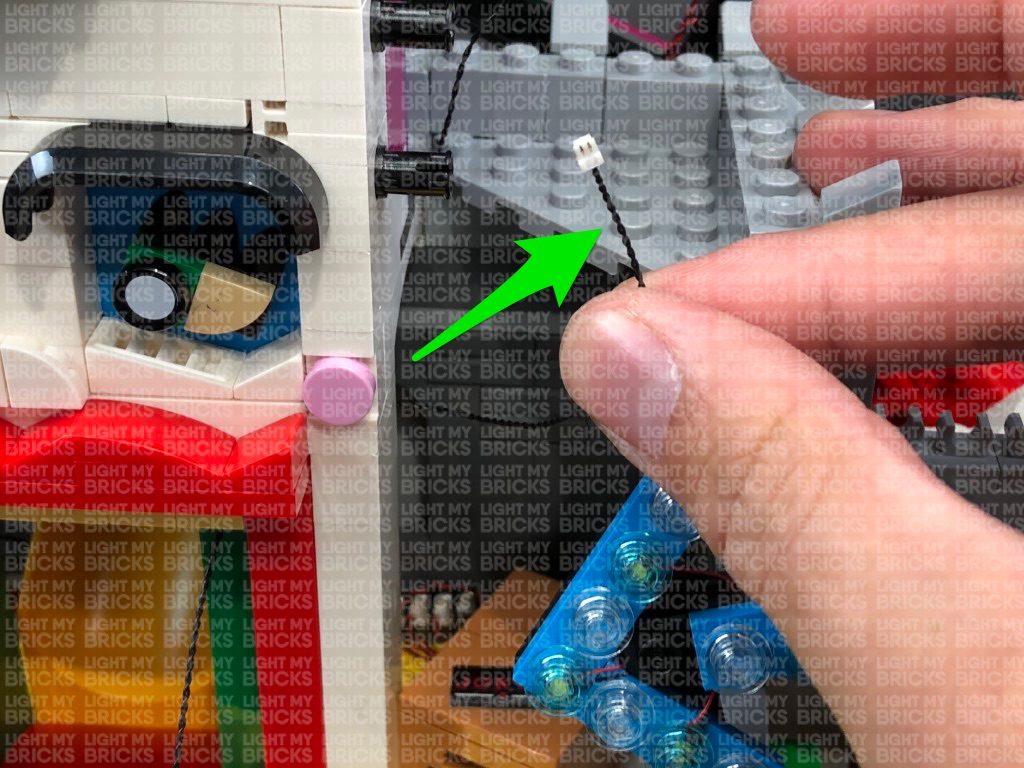
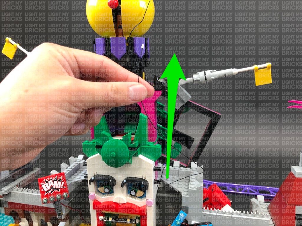
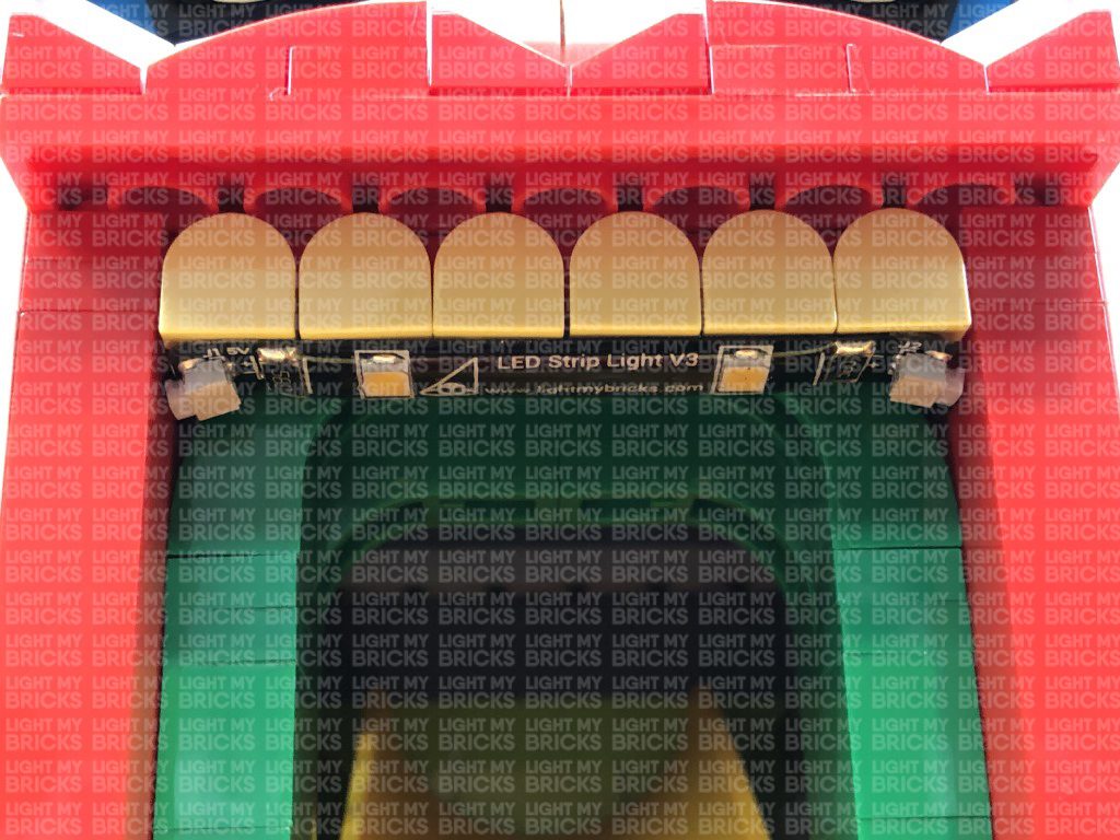
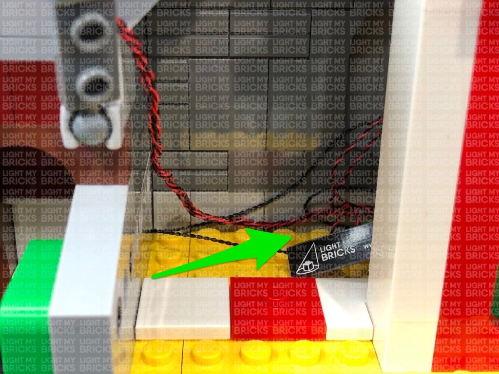
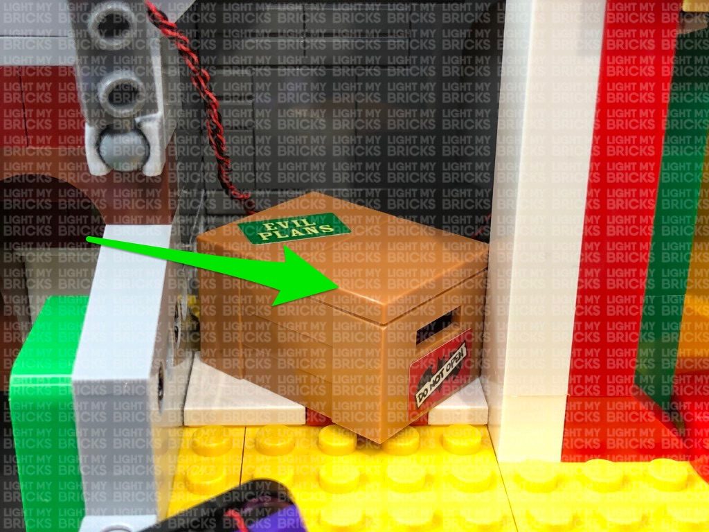
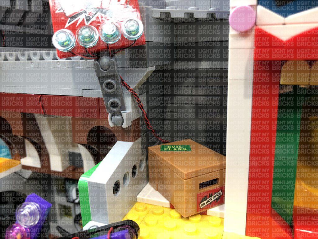
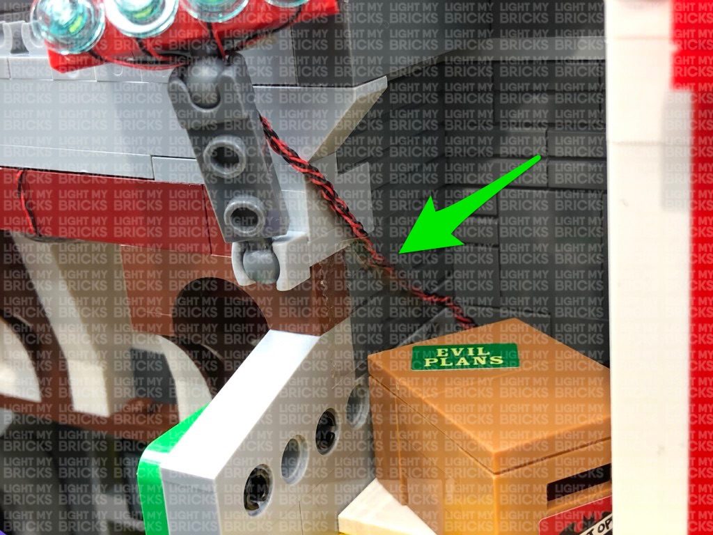
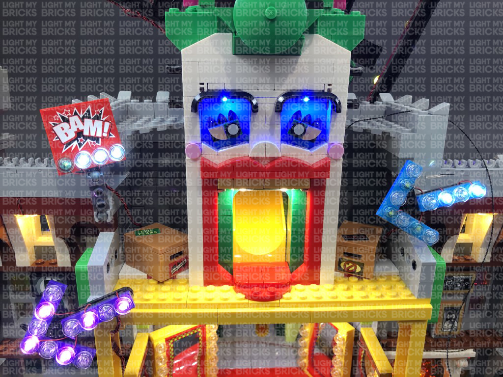 Note: If you experience any issues with the lights not working and suspect an issue with a component, please try a different port on the expansion board to verify where the fault lies (with the strip light or expansion board). To correct any issues with expansion board ports, please view the section addressing expansion board issues on our online troubleshooting guide.
65.) Using the LEGO Removal Tool, create a gap on the right side above the Joker slide trap room, just below the pink curved plate.
Thread the other end of the 30cm Connecting Cable through the gap in the front side of the set (between pink and purple pieces), leading to the inside of the trap room. Pull the cable out from the inside and connect it to a Green Strip Light.
Using it’s adhesive backing, stick the Green Strip Light underneath the pink plates as shown below.
Pull the excess 30cm Connecting Cable back out the right side. Pull the cable down, then wind it around the two black technic pins where the hair section connects to. Securely reconnect the pink plate back on top to close up the gap, then turn ON your USB Power Bank to test the Green Strip Light is working OK.
Reconnect the left and right hair sections, then secure the excess cable down the right side of the Joker face using tape.
66.) Finally, reconnect all the sections which make up the roller coaster tracks, which we removed earlier back in step 10.
Turn the USB Power Bank ON to test that all lights are working OK.
Note: If you experience any issues with the lights not working and suspect an issue with a component, please try a different port on the expansion board to verify where the fault lies (with the strip light or expansion board). To correct any issues with expansion board ports, please view the section addressing expansion board issues on our online troubleshooting guide.
65.) Using the LEGO Removal Tool, create a gap on the right side above the Joker slide trap room, just below the pink curved plate.
Thread the other end of the 30cm Connecting Cable through the gap in the front side of the set (between pink and purple pieces), leading to the inside of the trap room. Pull the cable out from the inside and connect it to a Green Strip Light.
Using it’s adhesive backing, stick the Green Strip Light underneath the pink plates as shown below.
Pull the excess 30cm Connecting Cable back out the right side. Pull the cable down, then wind it around the two black technic pins where the hair section connects to. Securely reconnect the pink plate back on top to close up the gap, then turn ON your USB Power Bank to test the Green Strip Light is working OK.
Reconnect the left and right hair sections, then secure the excess cable down the right side of the Joker face using tape.
66.) Finally, reconnect all the sections which make up the roller coaster tracks, which we removed earlier back in step 10.
Turn the USB Power Bank ON to test that all lights are working OK.
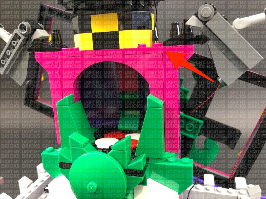
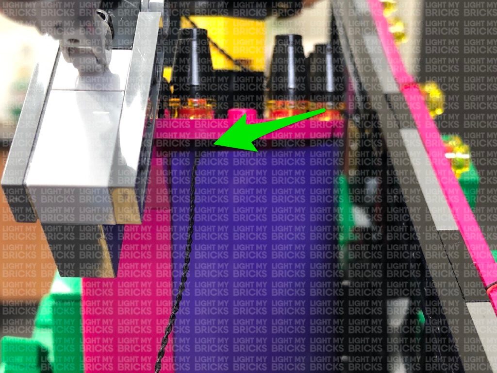
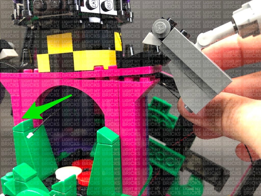
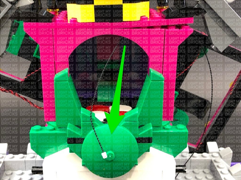
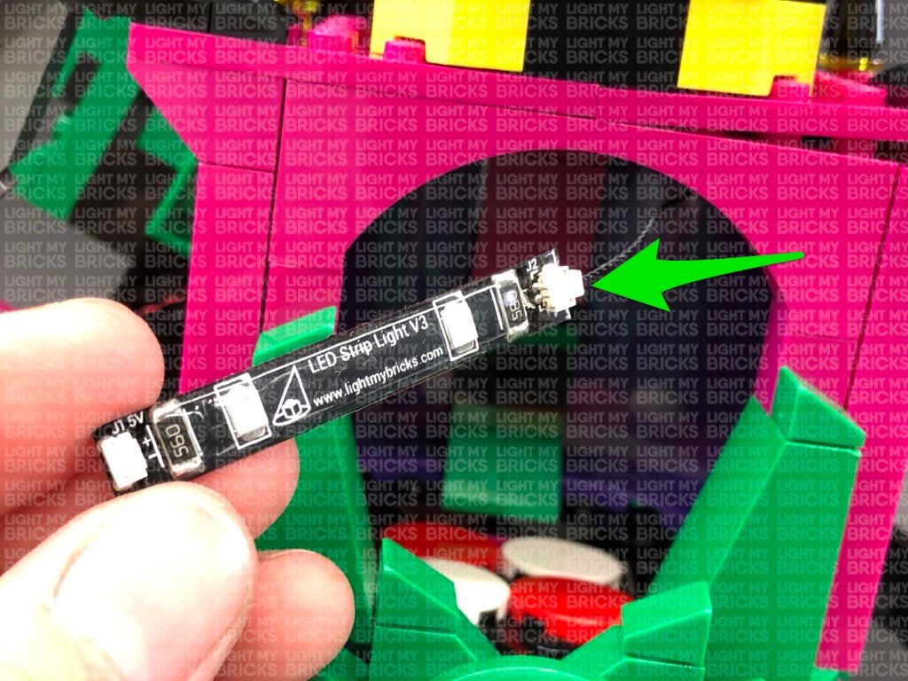
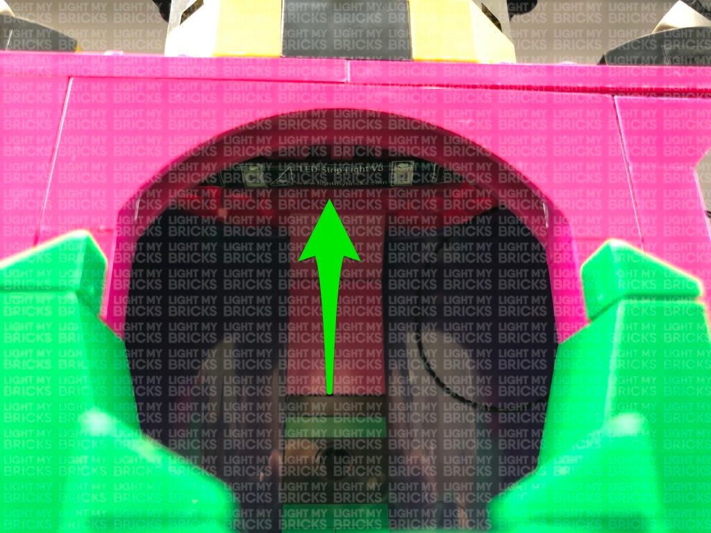
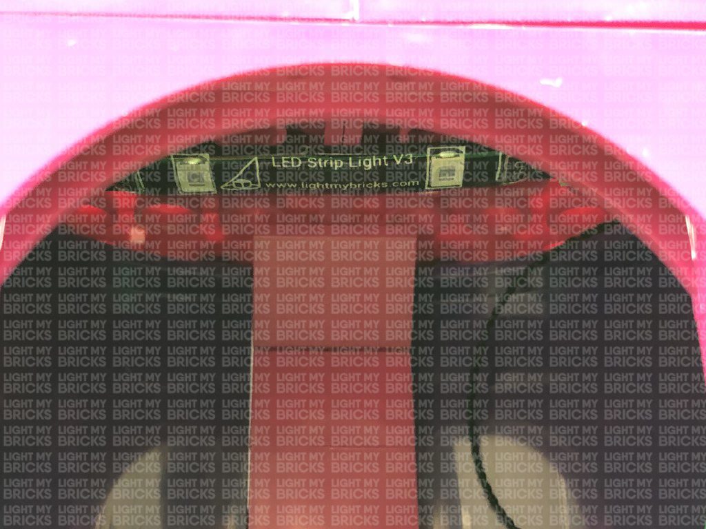
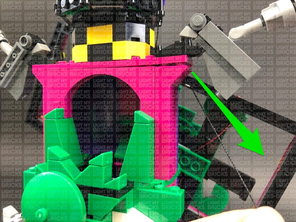
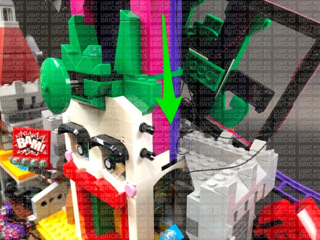
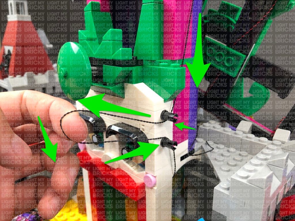
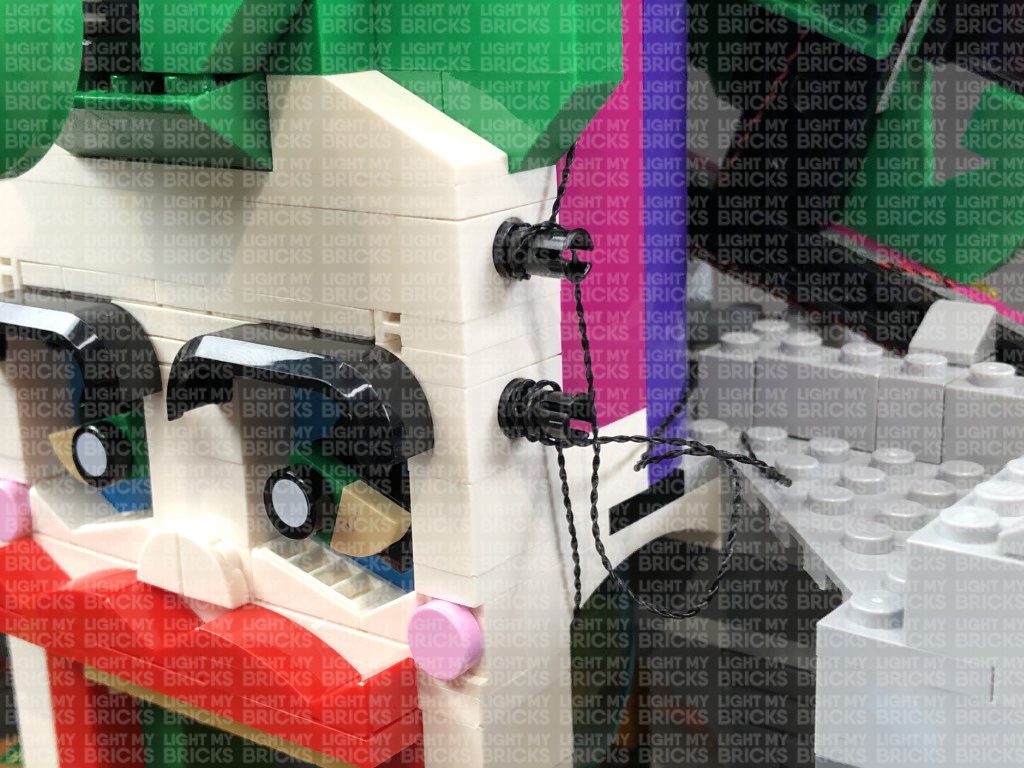
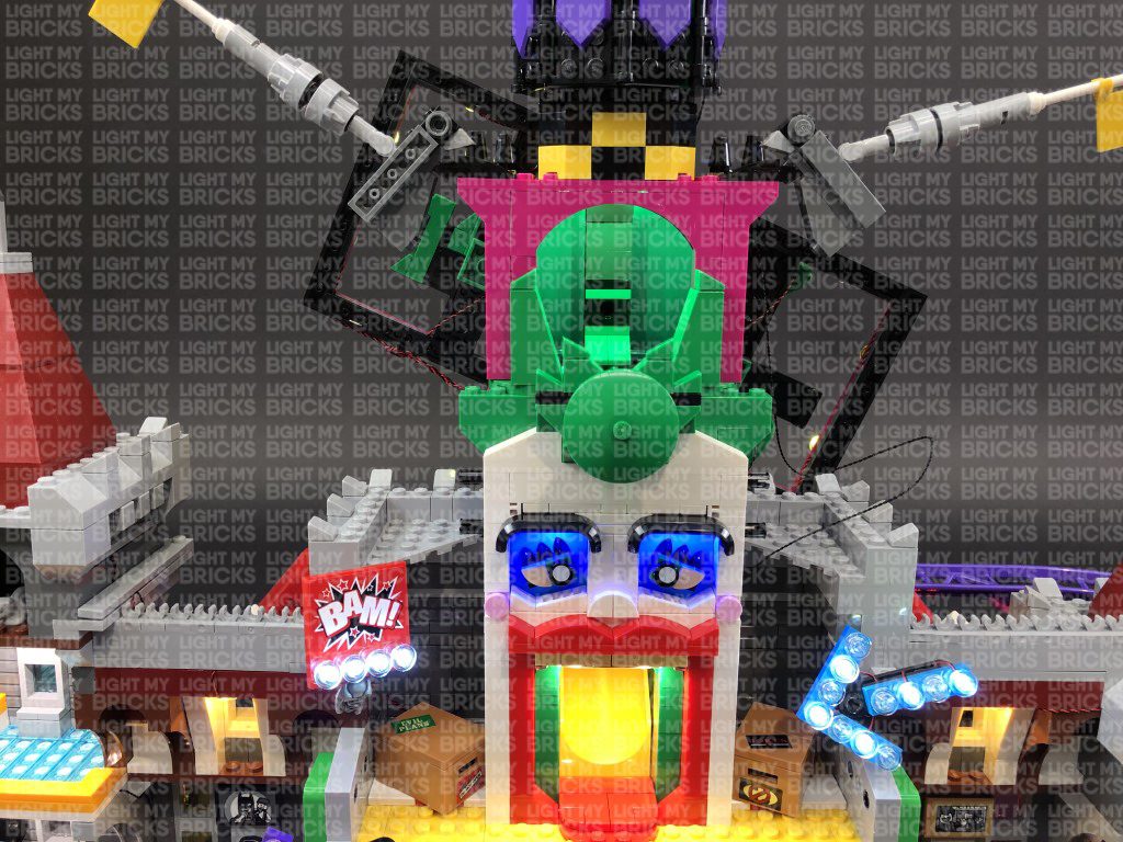
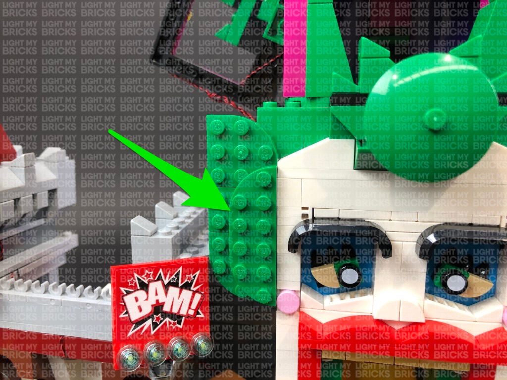
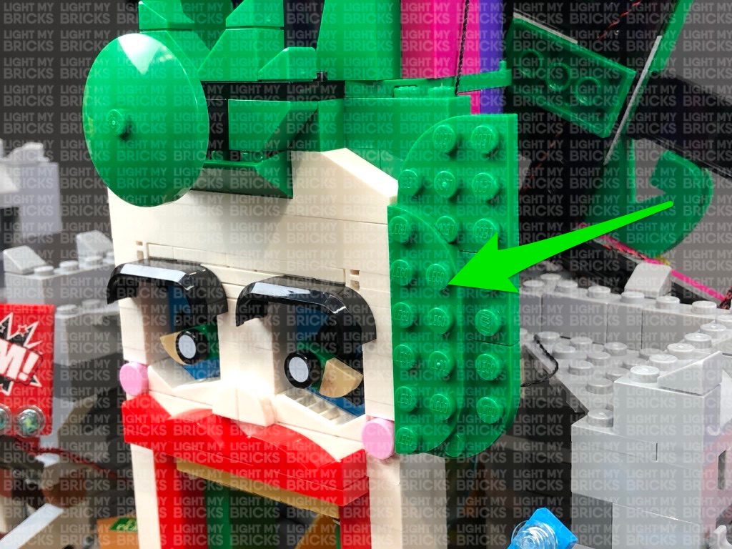
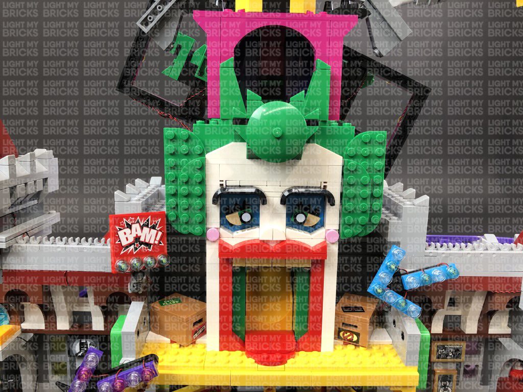
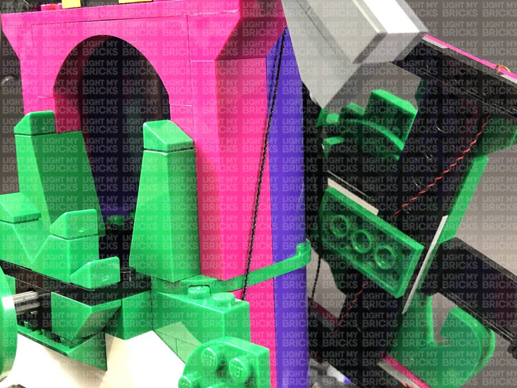
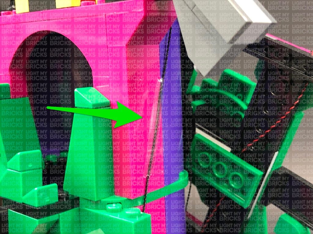
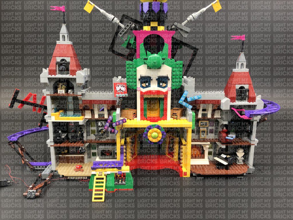
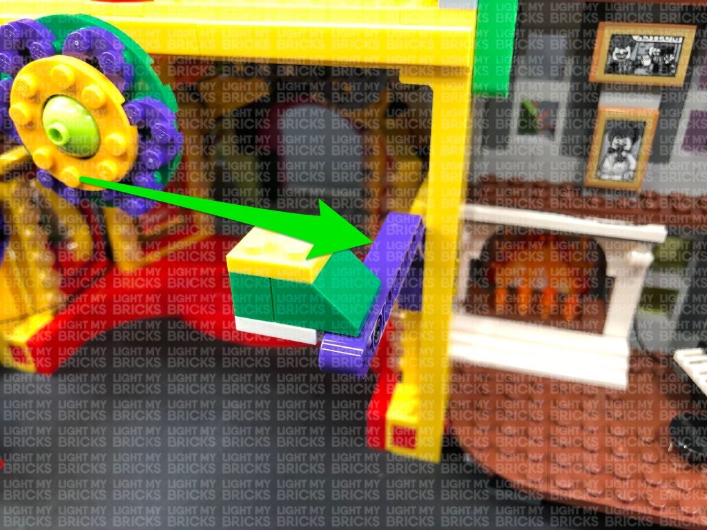
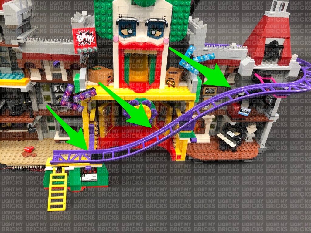
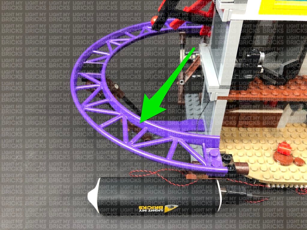
 Note: If you experience any issues with the lights not working and suspect an issue with a component, please try a different port on the expansion board to verify where the fault lies (with the strip light or expansion board). To correct any issues with expansion board ports, please view the section addressing expansion board issues on our online troubleshooting guide.
Congratulations, this finally complete’s installation of your Light My Bricks Joker Manor Light Kit. We thank you for purchasing this product and hope you enjoy!
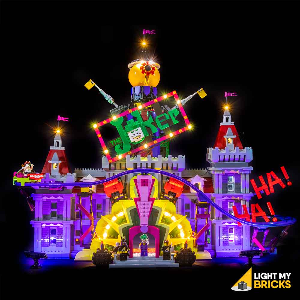
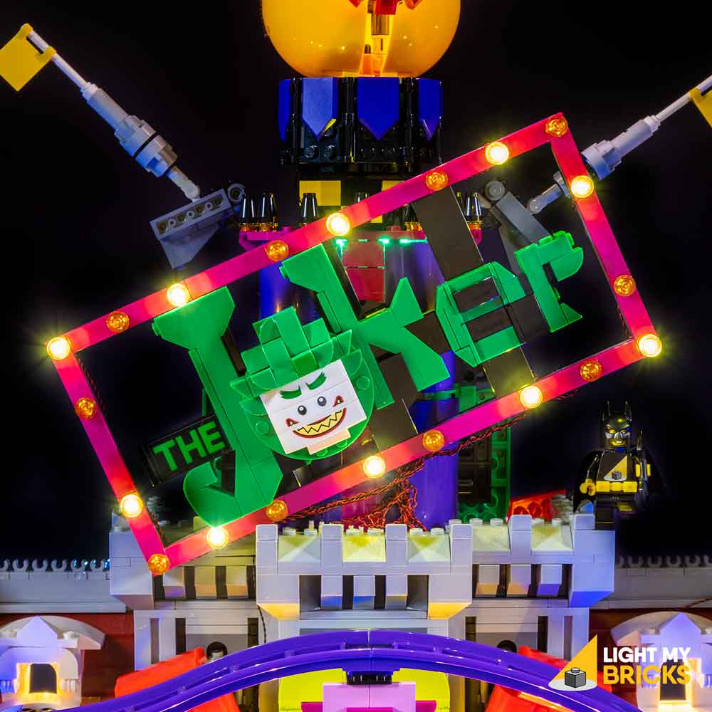
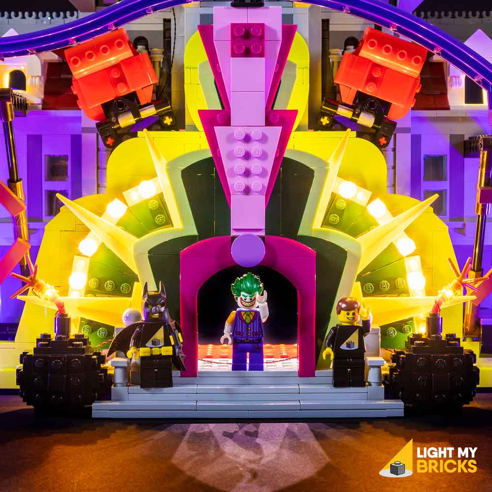
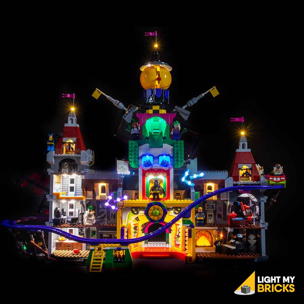
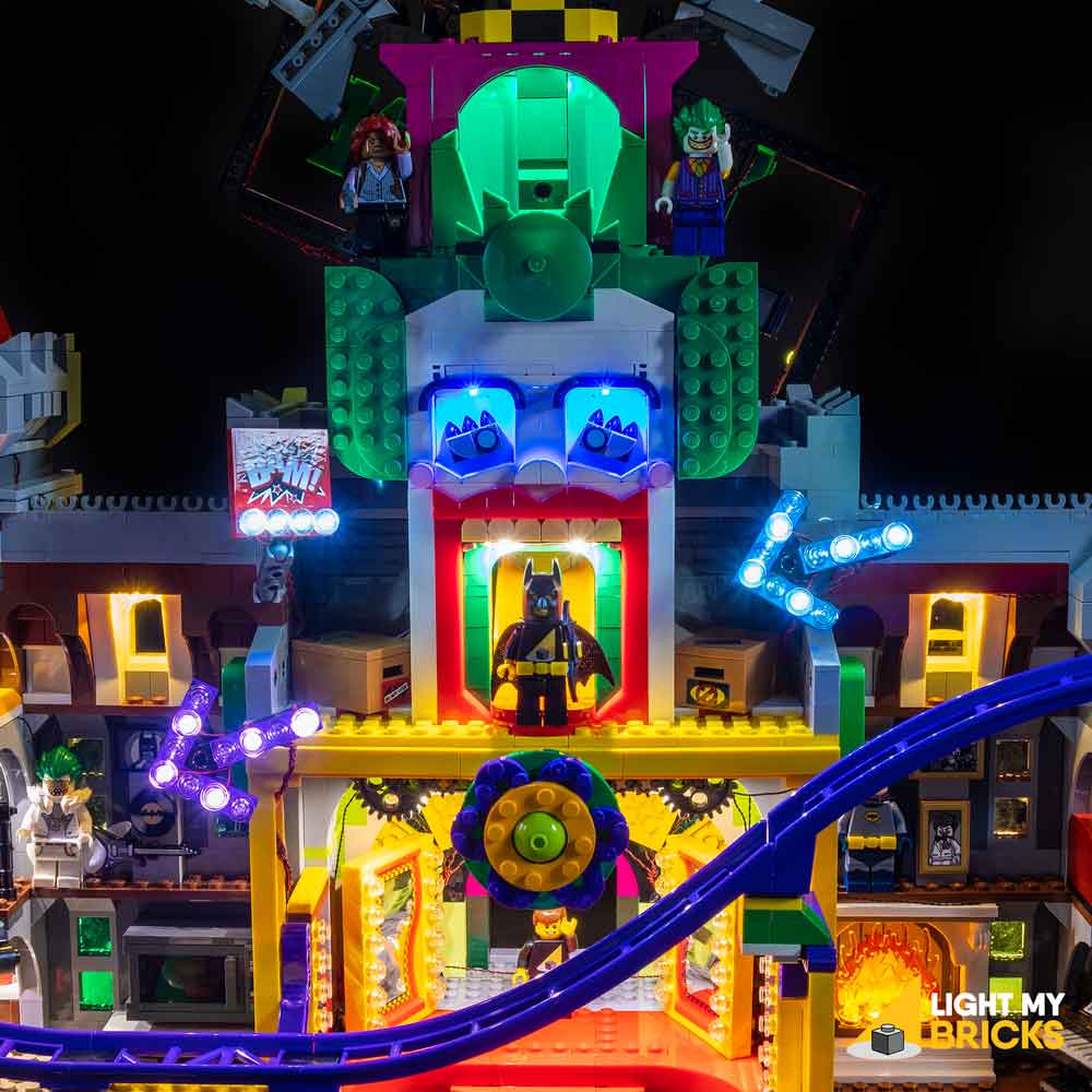