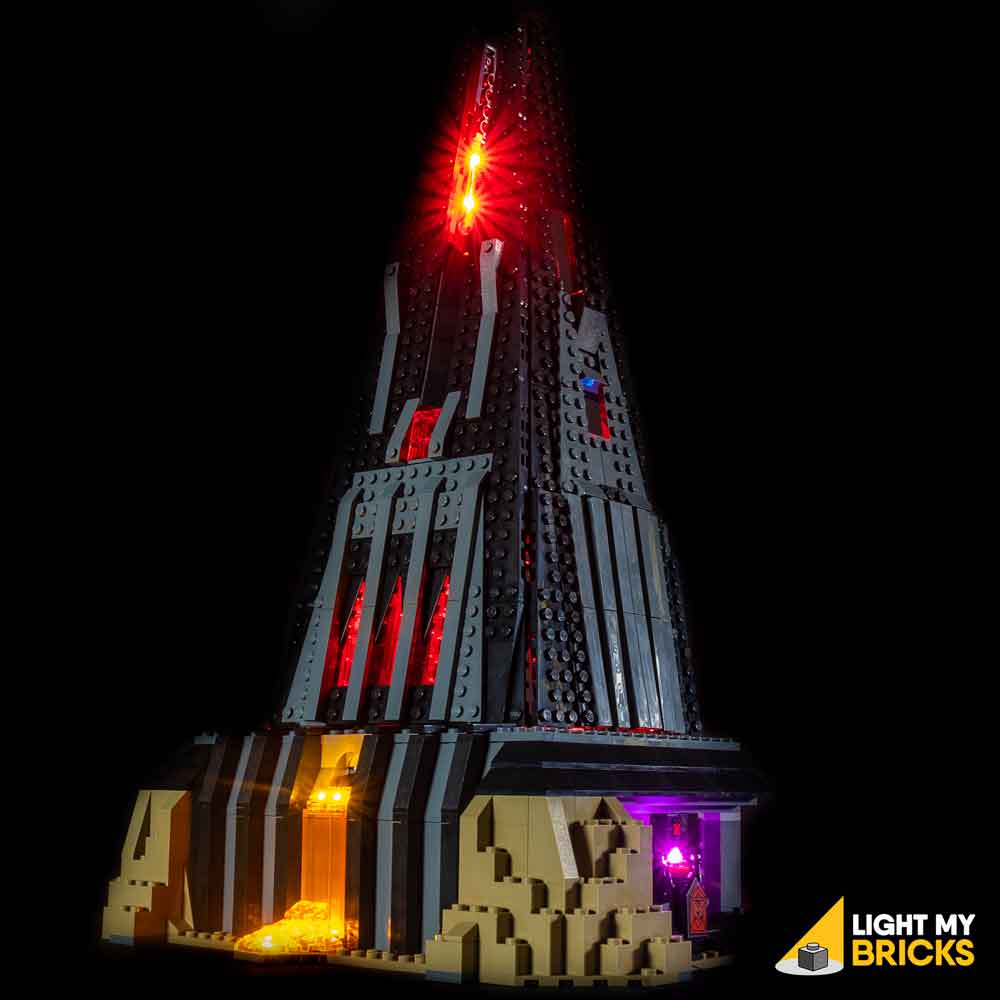
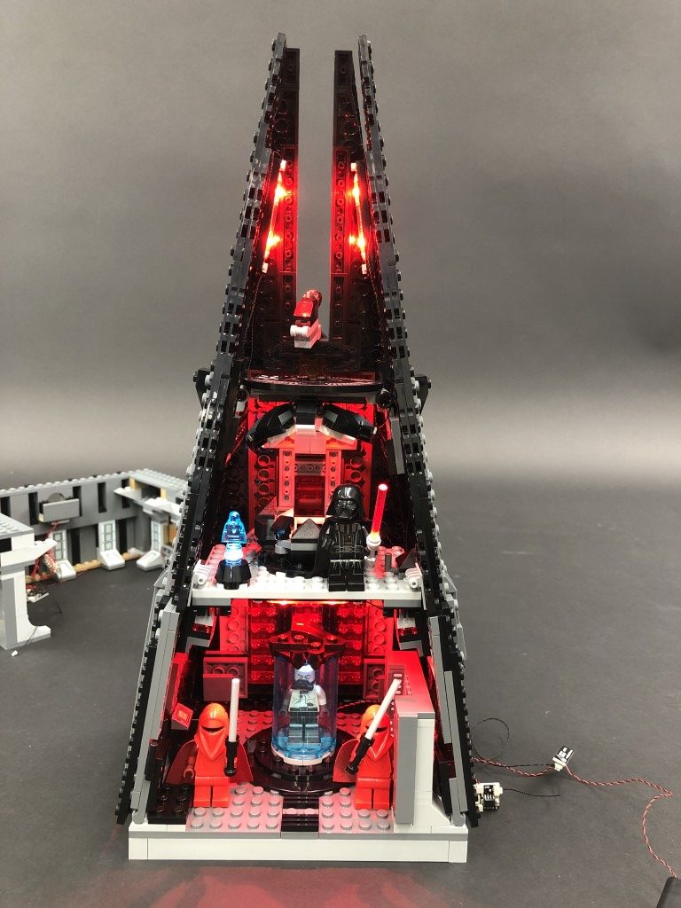
The following page is the instructions for the Light My Bricks LEGO Star Wars Darth Vader Castle (75251) LED light kit.
If you run into any issues, please refer to the online troubleshooting guide.
To ensure a trouble-free installation of your light kit, please read and follow each step carefully. These instructions can be downloaded in PDF format here
Please note: This page lists instructions for the LED light kit only. If you are wishing to purchase the Light My Bricks LEGO Star Wars Darth Vader Castle (75251) LED light kit , please click here to view the product page
Package Contents:
- 5x White 15cm Bit Lights
- 2x Cool White 30cm Bit Lights
- 1x Pink 30cm Bit Light
- 1x Flashing White 30cm Bit Light
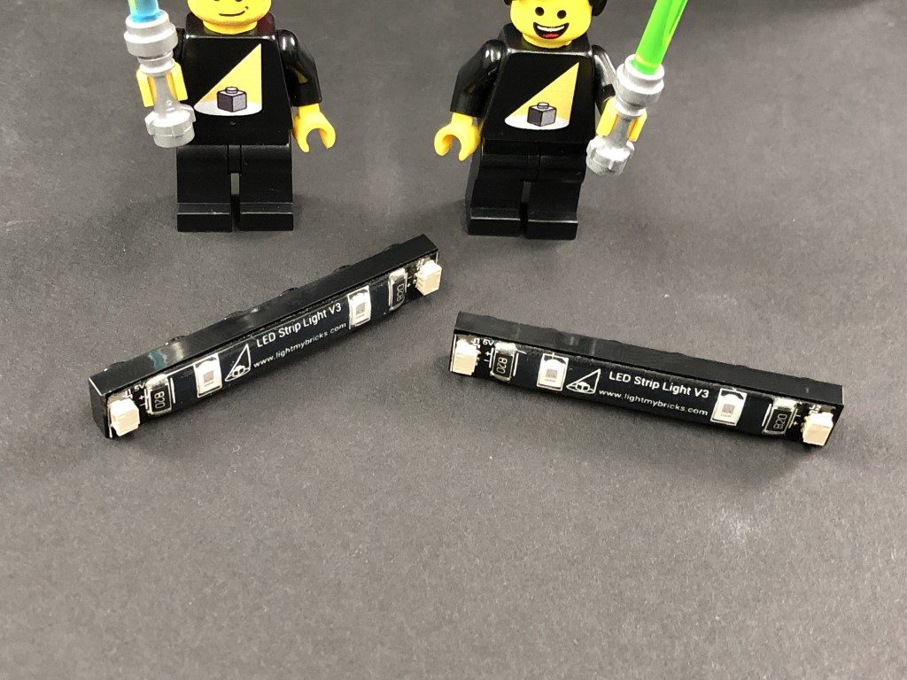
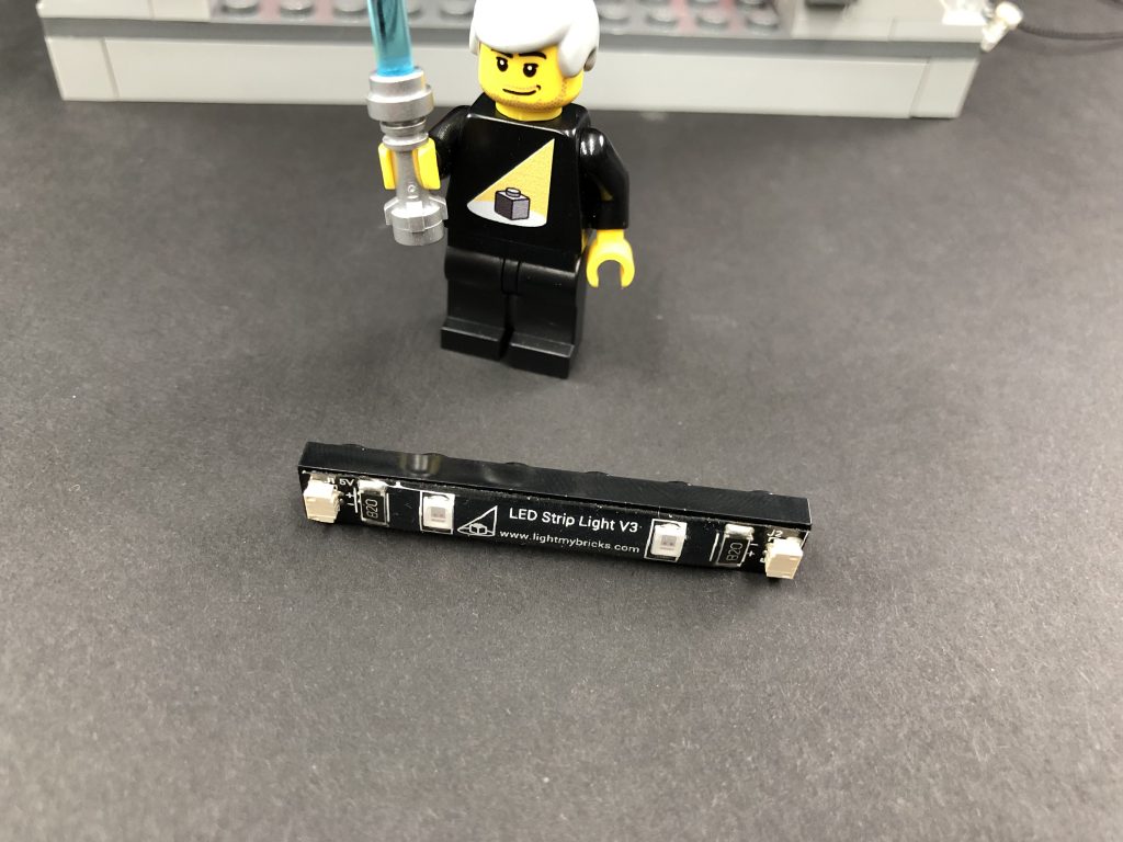
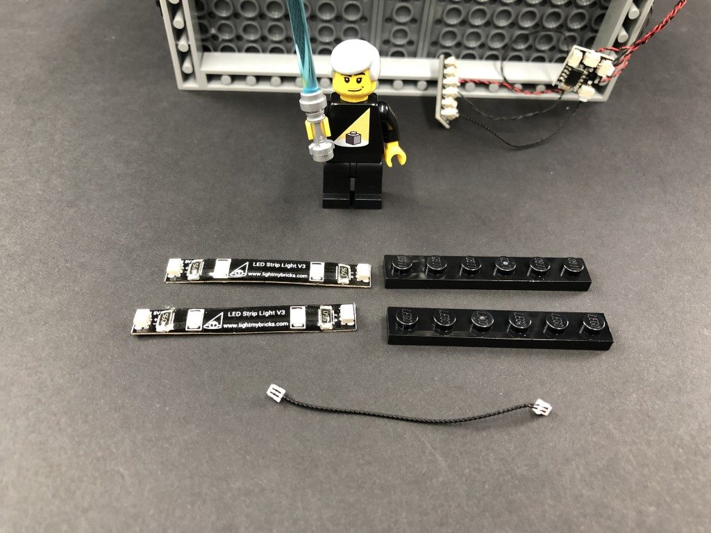
- 5x Red Strip Lights
- 2x White Strip Lights
- 1x Red Light My Bricks Lightsaber
- 1x Multi Effects Board
- 1x Flicker Effects Board
- 3x 6-Port Expansion Board
- 6x 5cm Connecting Cables
- 3x 15cm Connecting Cables
- 2x 30cm Connecting Cables
- 1x AA Battery Pack
- 4x Adhesive Squares
LEGO Pieces:
- 7x Black Plate 1×6
- 1x Trans Green Round Plate 1×1
- 1x Trans Light Blue Round Plate 1×1
Important things to note:
Laying cables in between and underneath bricks
Cables can fit in between and underneath LEGO® bricks, plates, and tiles providing they are laid correctly between the LEGO® studs. Do NOT forcefully join LEGO® together around cables; instead ensure they are laying comfortably in between each stud.
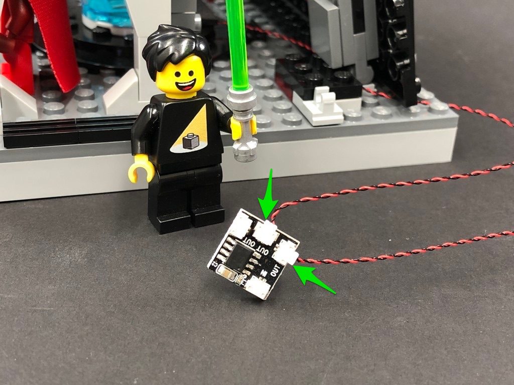
Connecting cable connectors to Expansion Boards
Take extra care when inserting connectors to ports of Expansion Boards. Connectors can be inserted only one way. With the expansion board facing up, look for the soldered “=” symbol on the left side of the port. The connector side with the wires exposed should be facing toward the soldered “=” symbol as you insert into the port. If a plug won’t fit easily into a port connector, do not force it.
Connecting cable connectors to Strip Lights
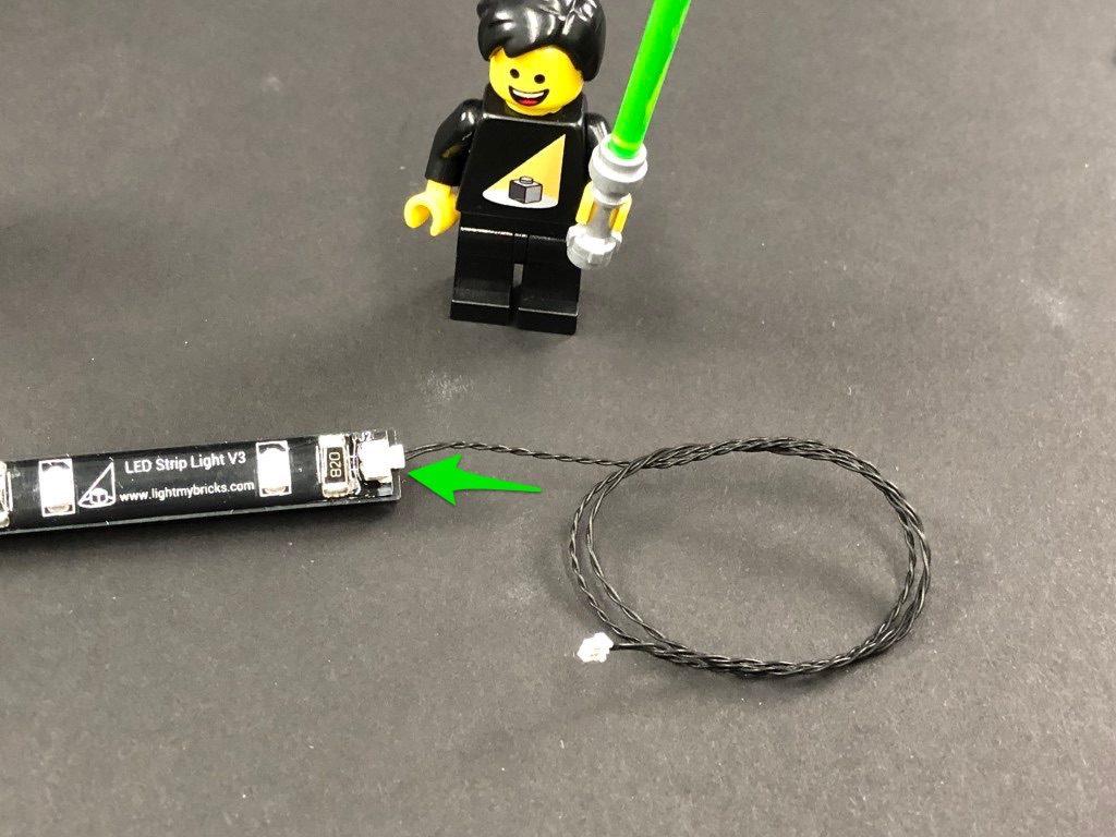
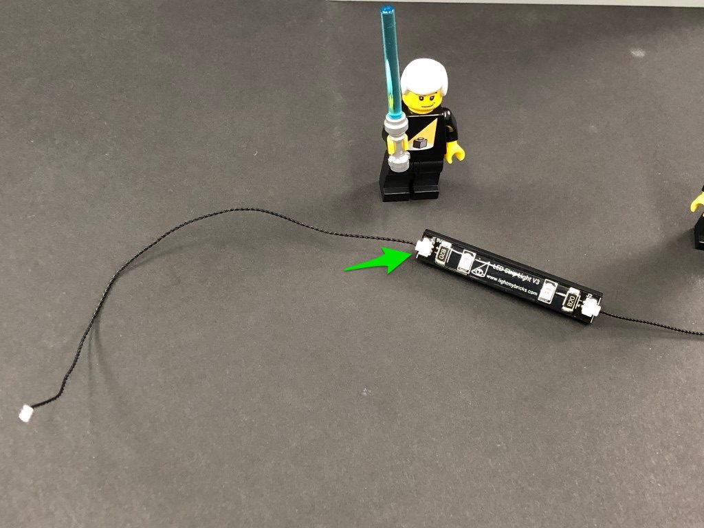
Take extra care when inserting connectors to ports on the Strip Lights. Connectors can be inserted only one way. With the Strip Light facing up, ensure the side of the connector with the wires exposed is facing down. If a plug won’t fit easily into a port connector, don’t force it. Doing so will damage the plug and the connector.
Installing Bit Lights under LEGO® bricks and plates.
When installing Bit Lights under LEGO® pieces, ensure they are placed the correct way up (Yellow LED component exposed). You can either place them directly on top of LEGO® studs or in between.
OK, Let’s Begin!
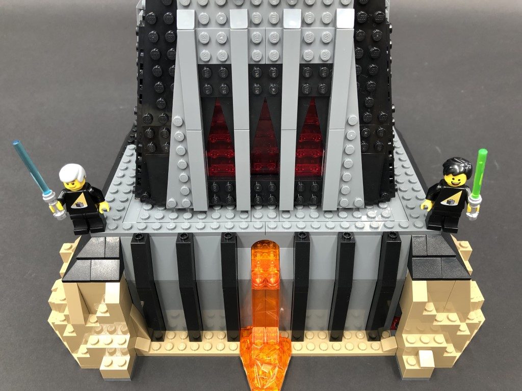
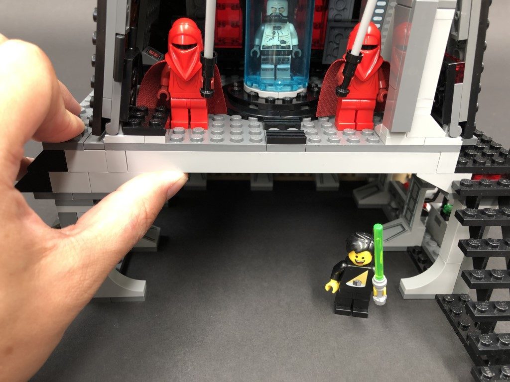
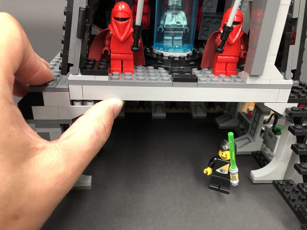
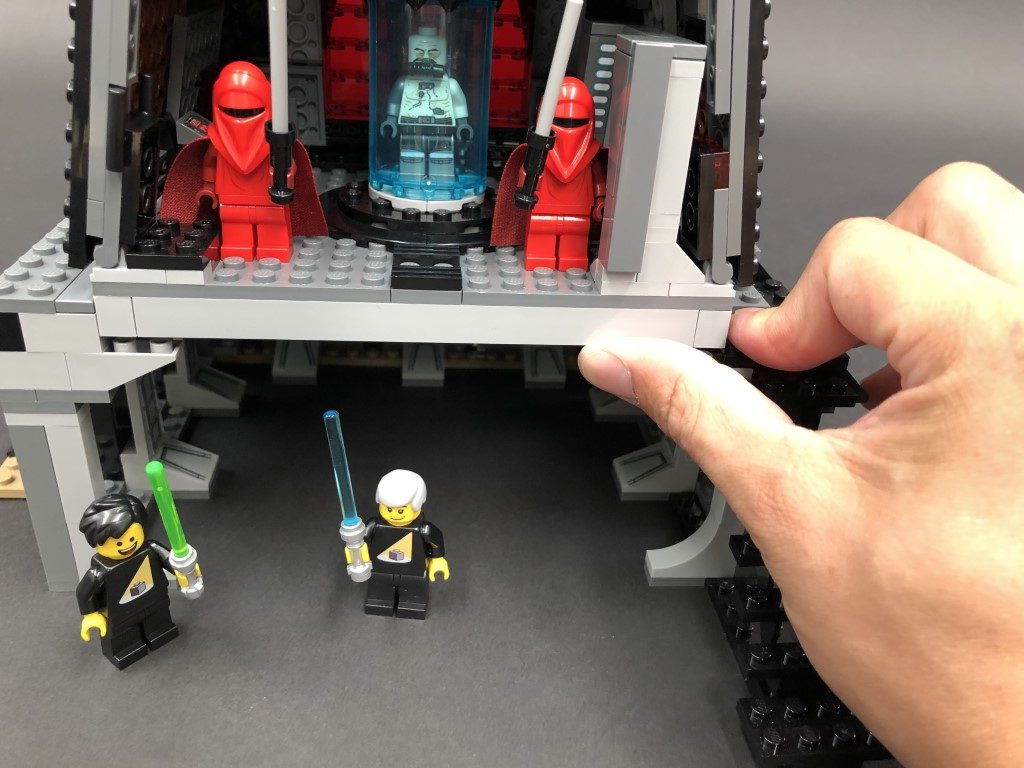
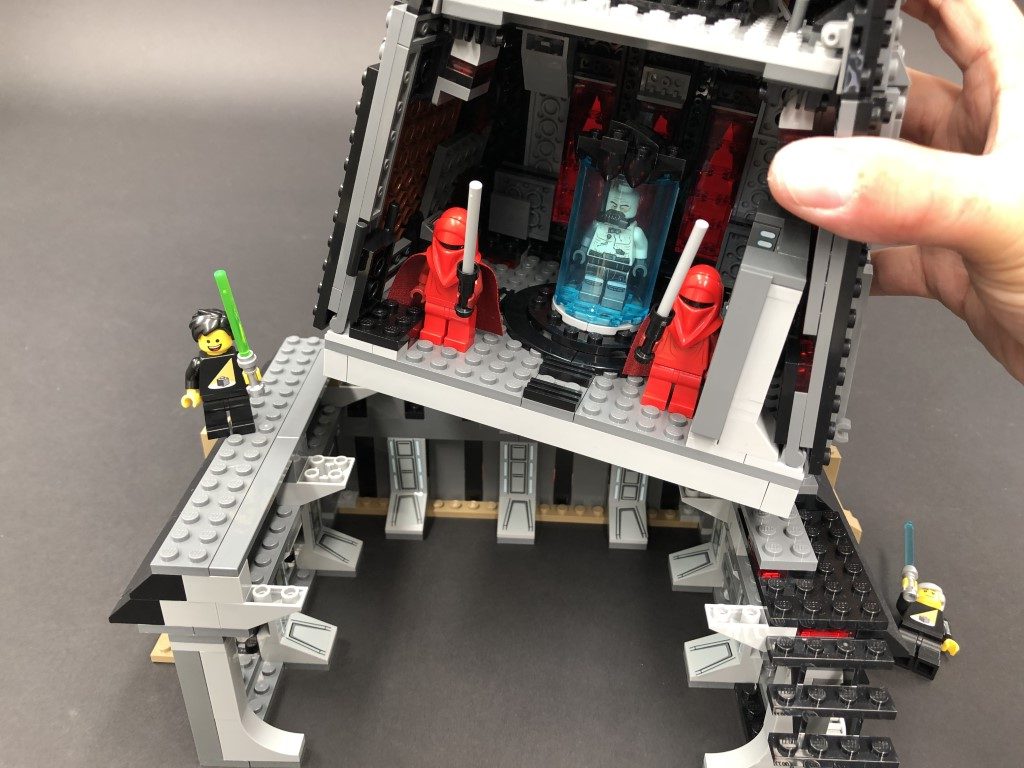
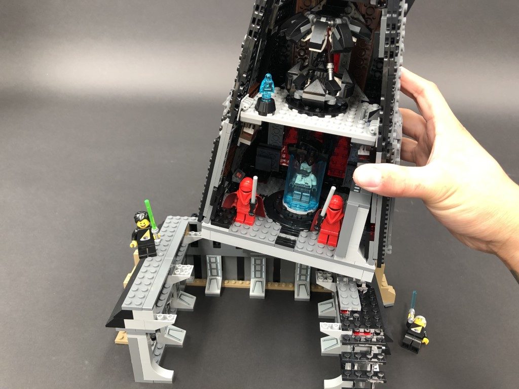
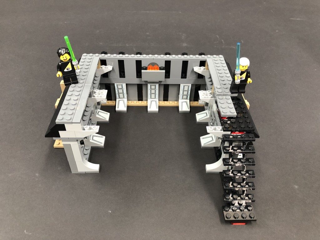
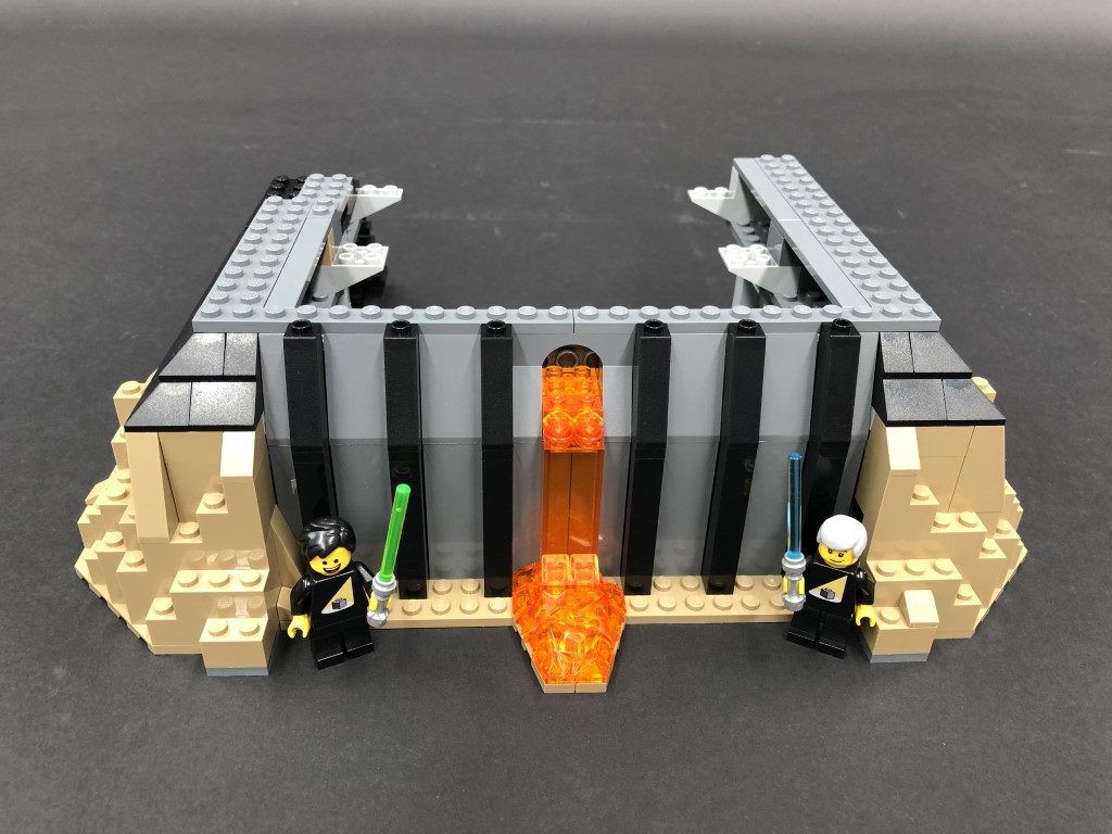
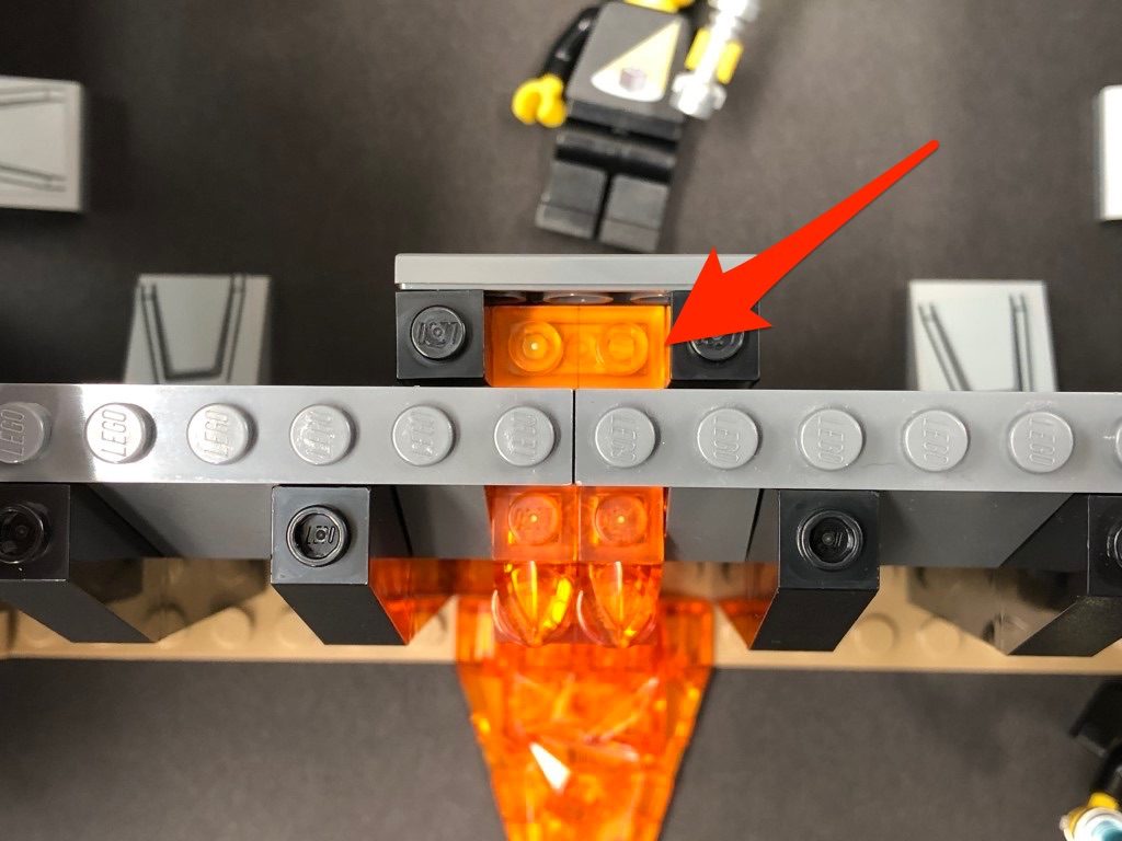
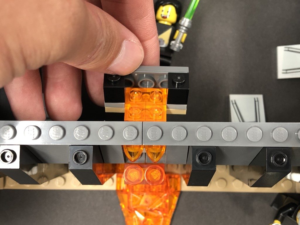
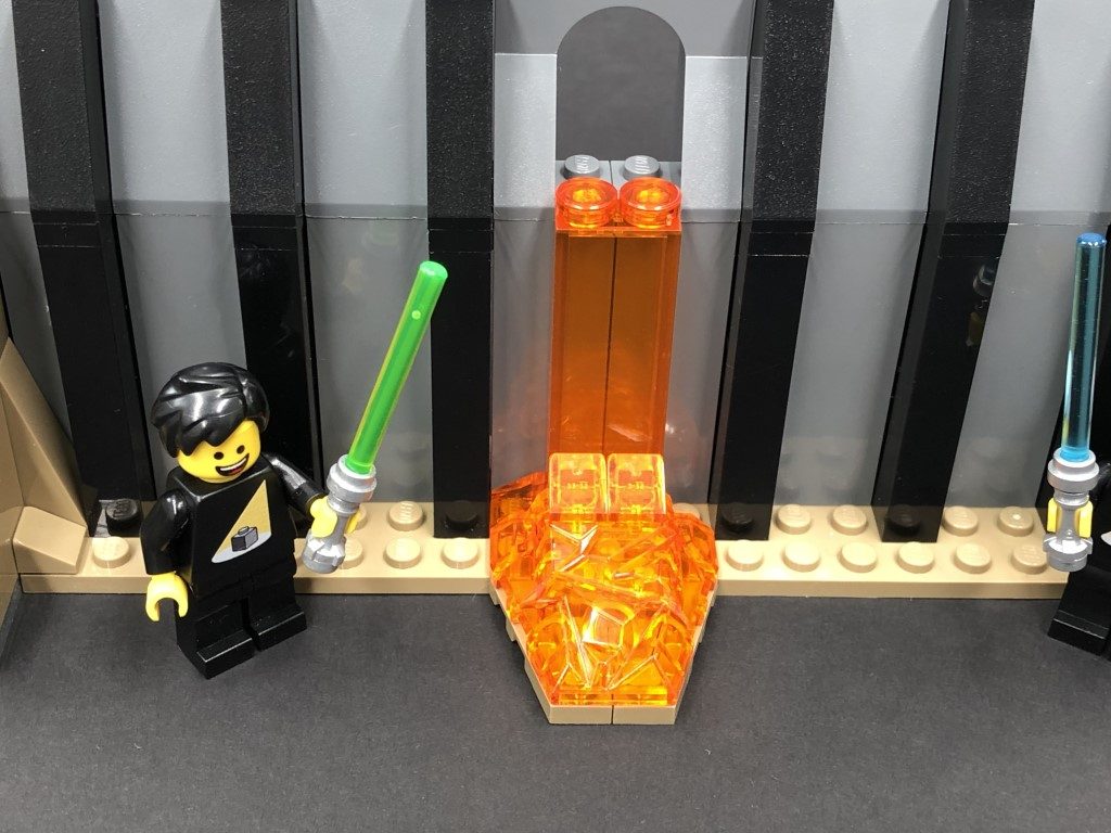
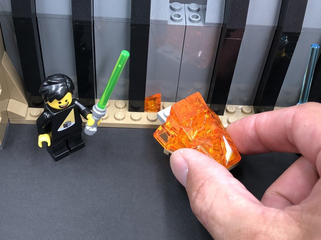
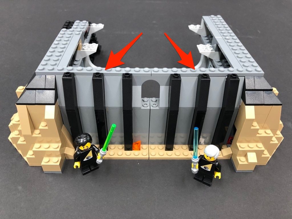
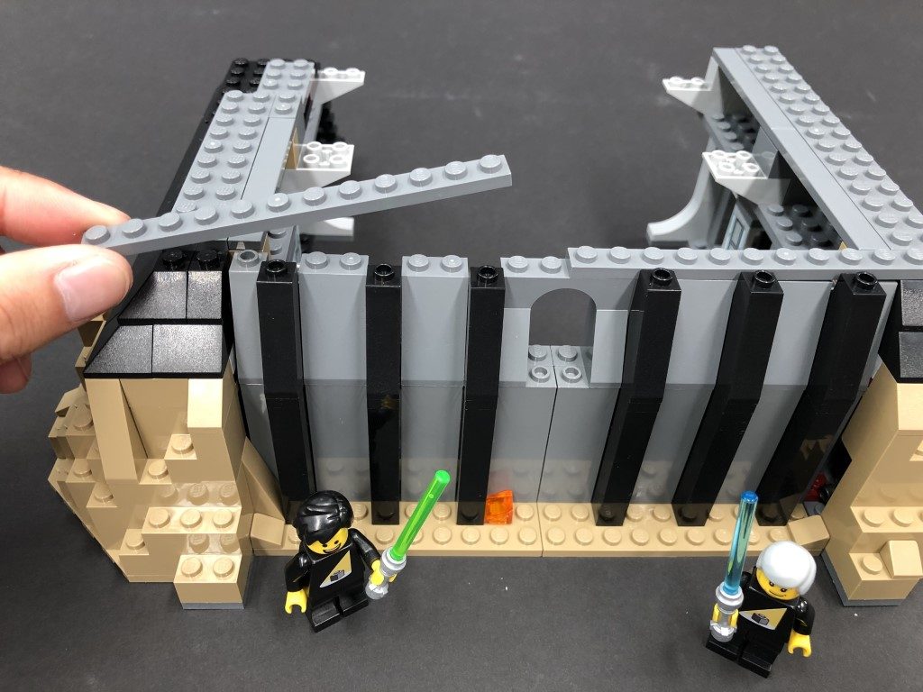
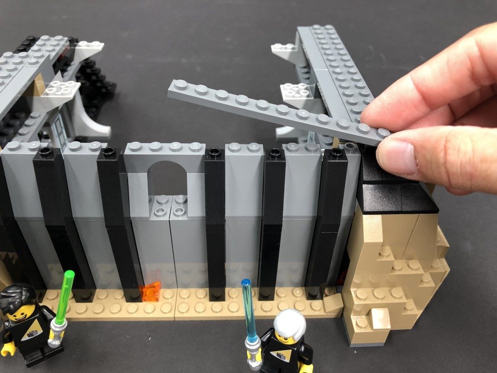
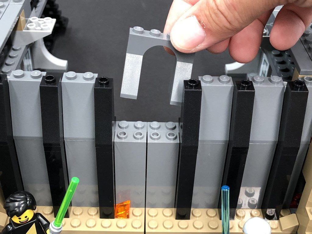
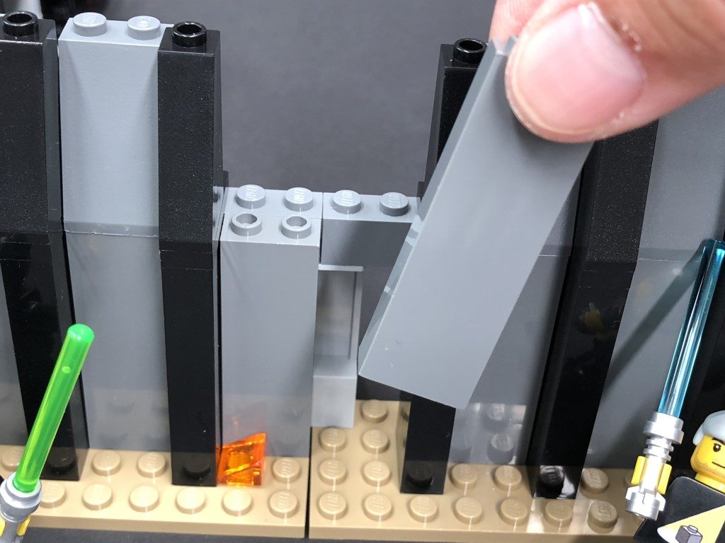
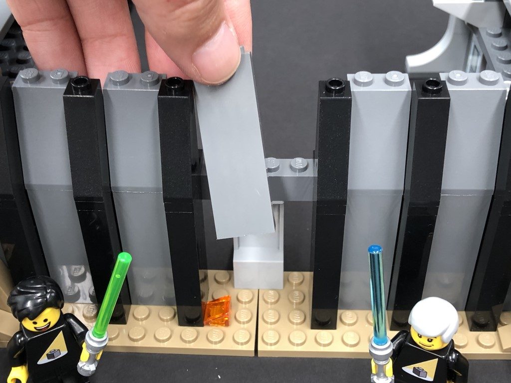
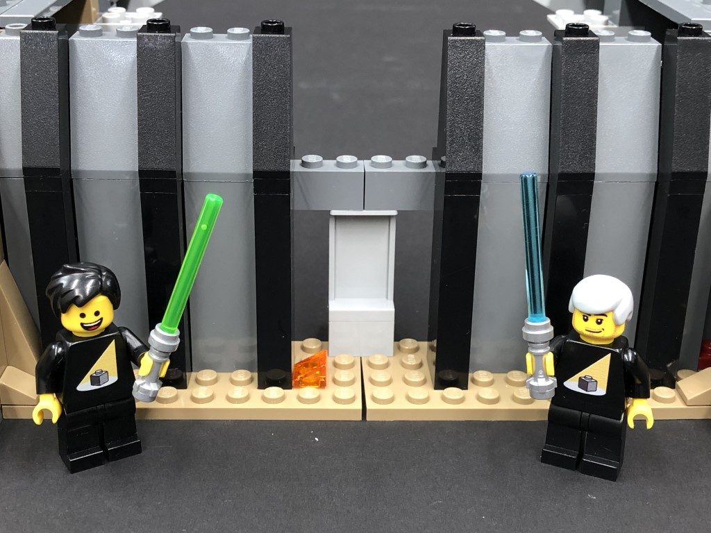
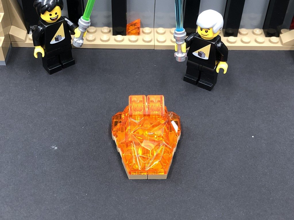
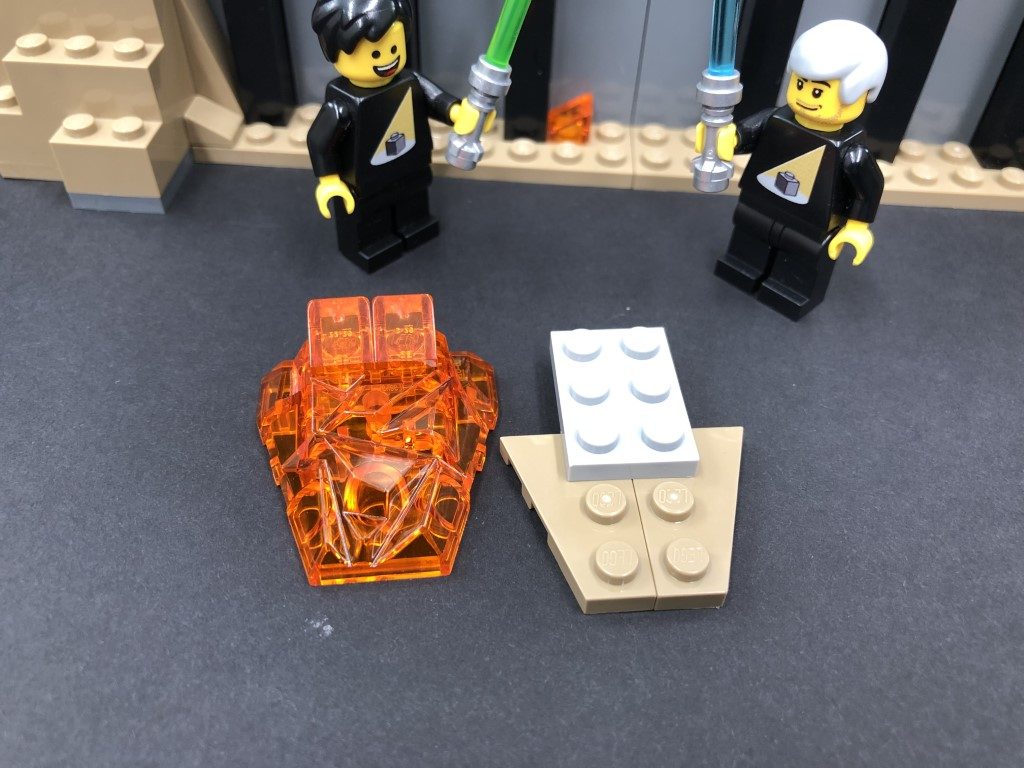
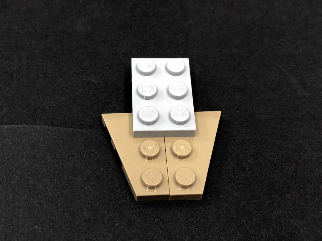
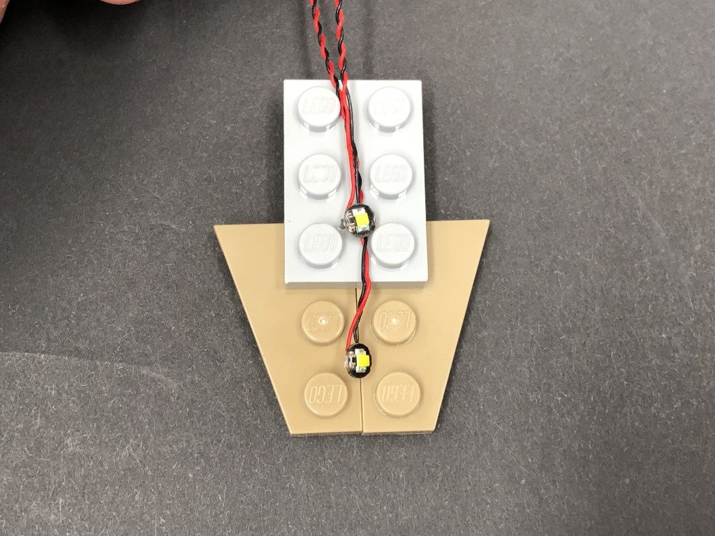
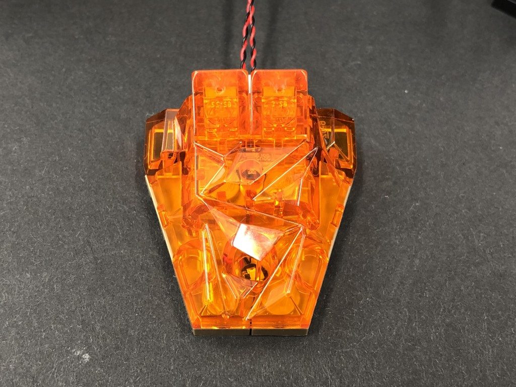
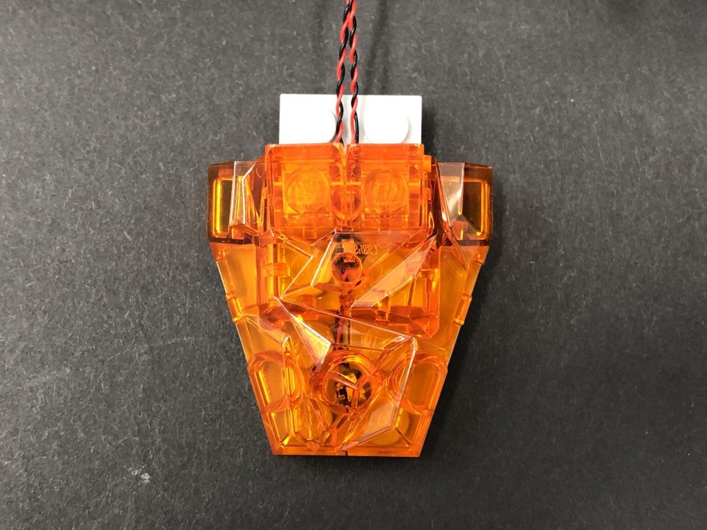
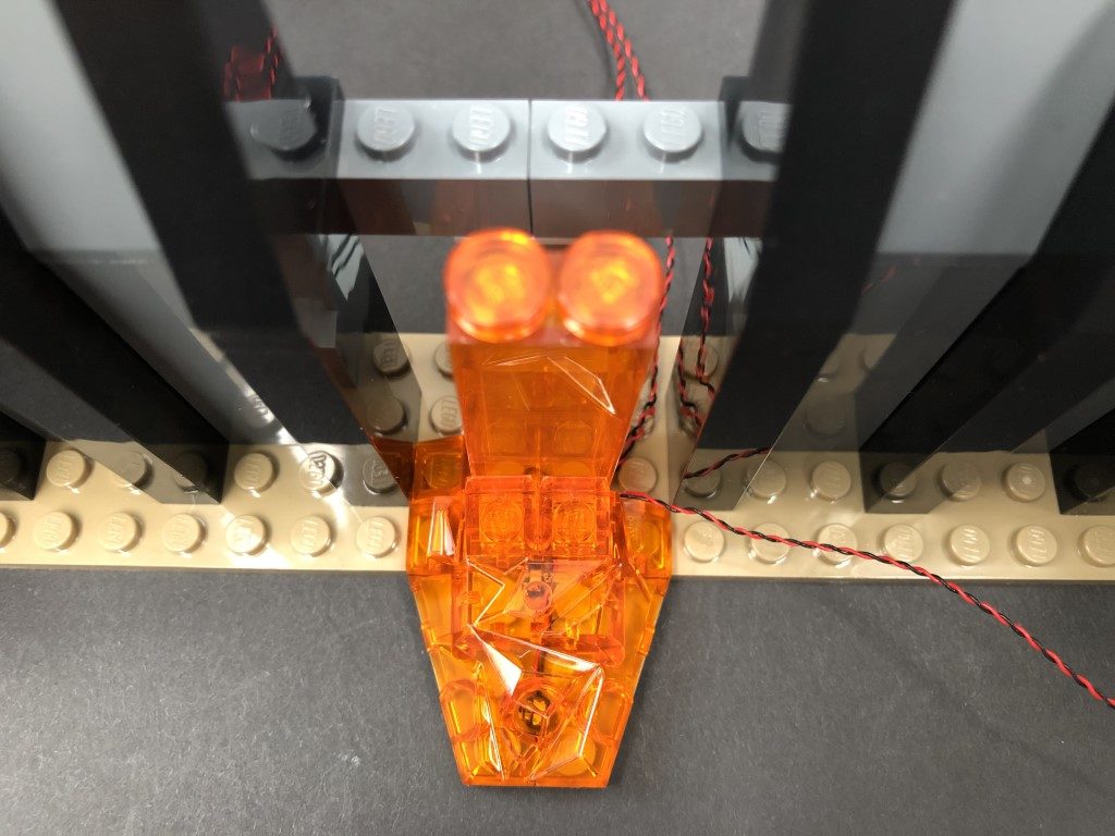
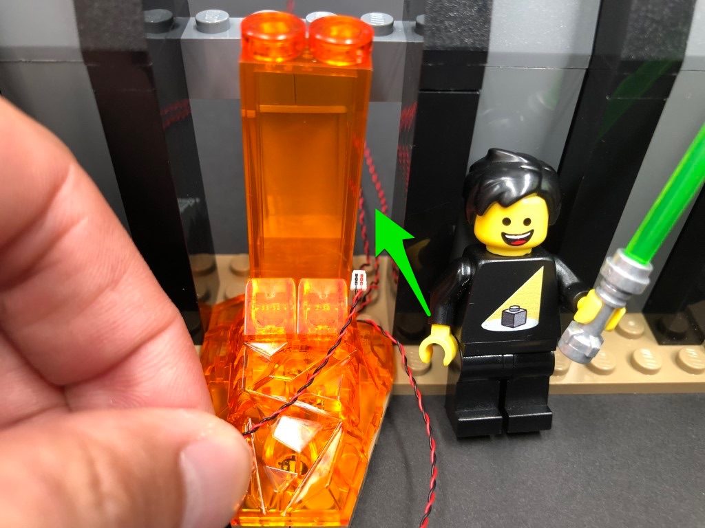
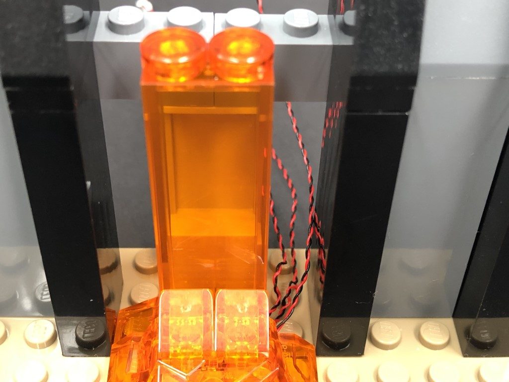
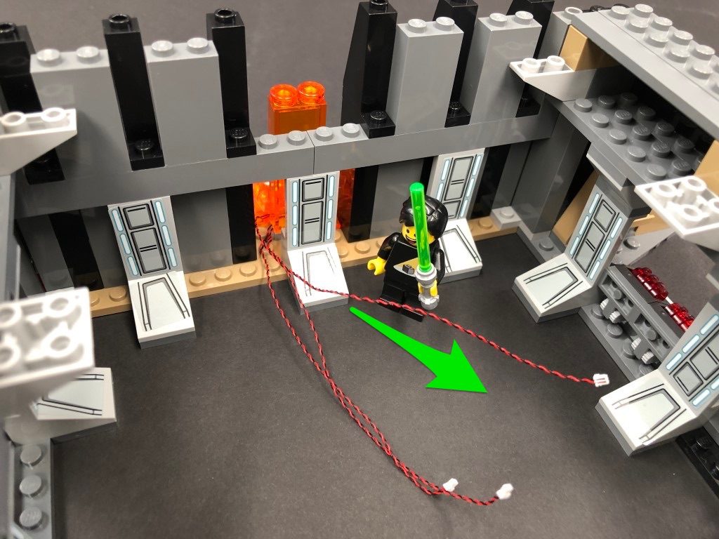
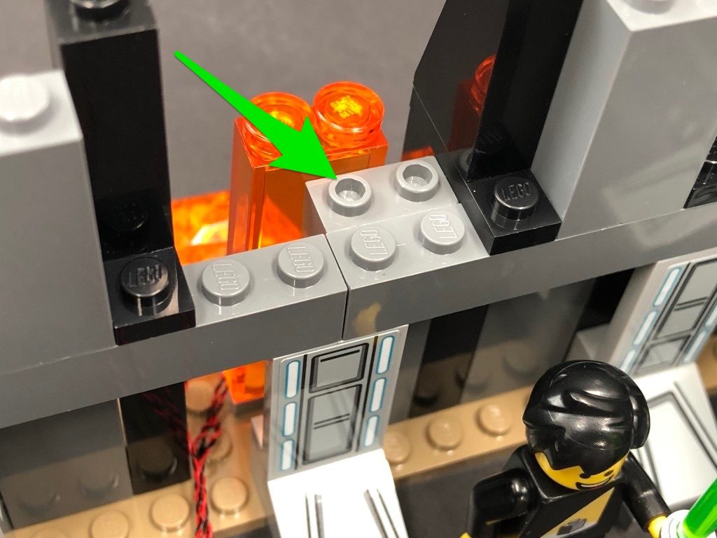
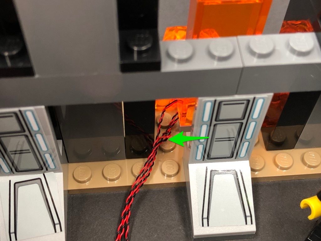
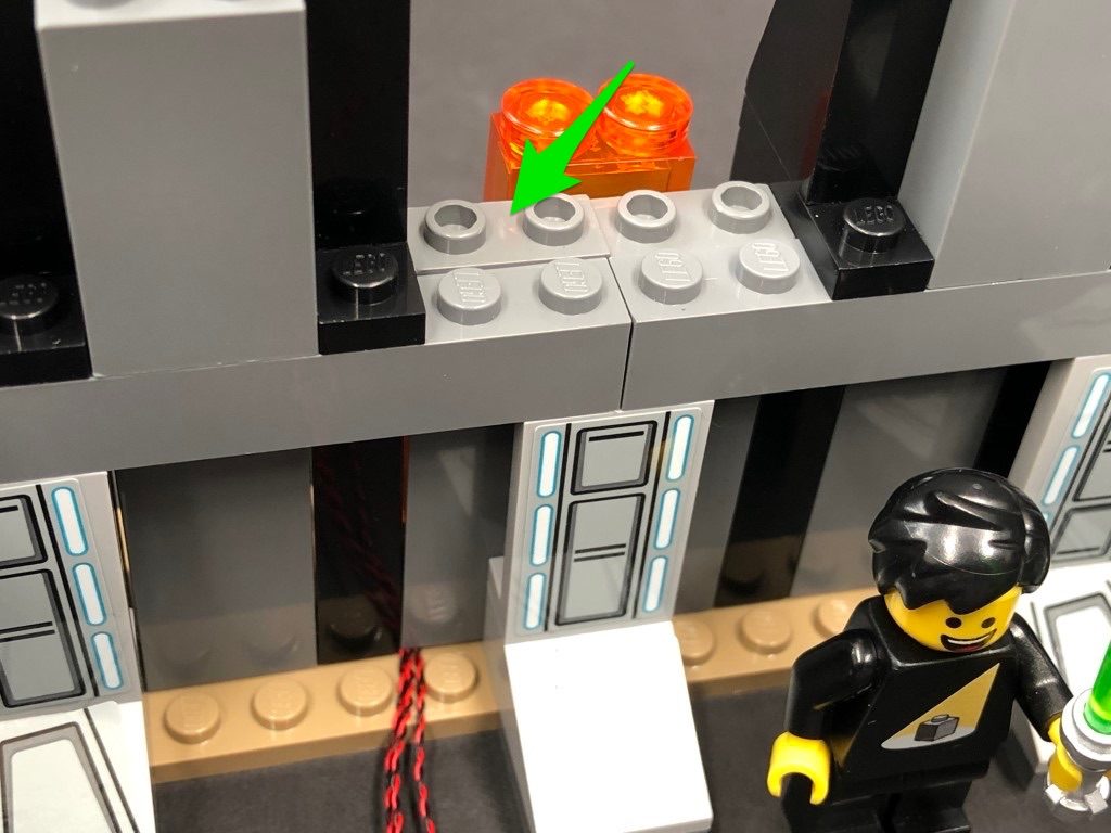
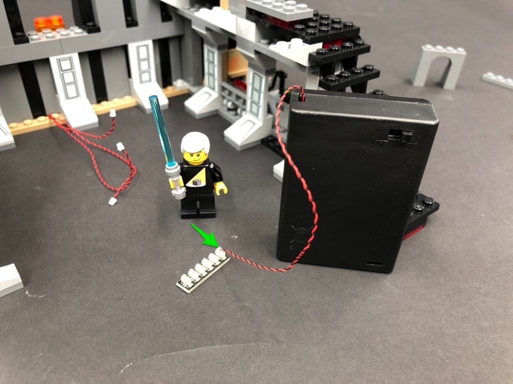
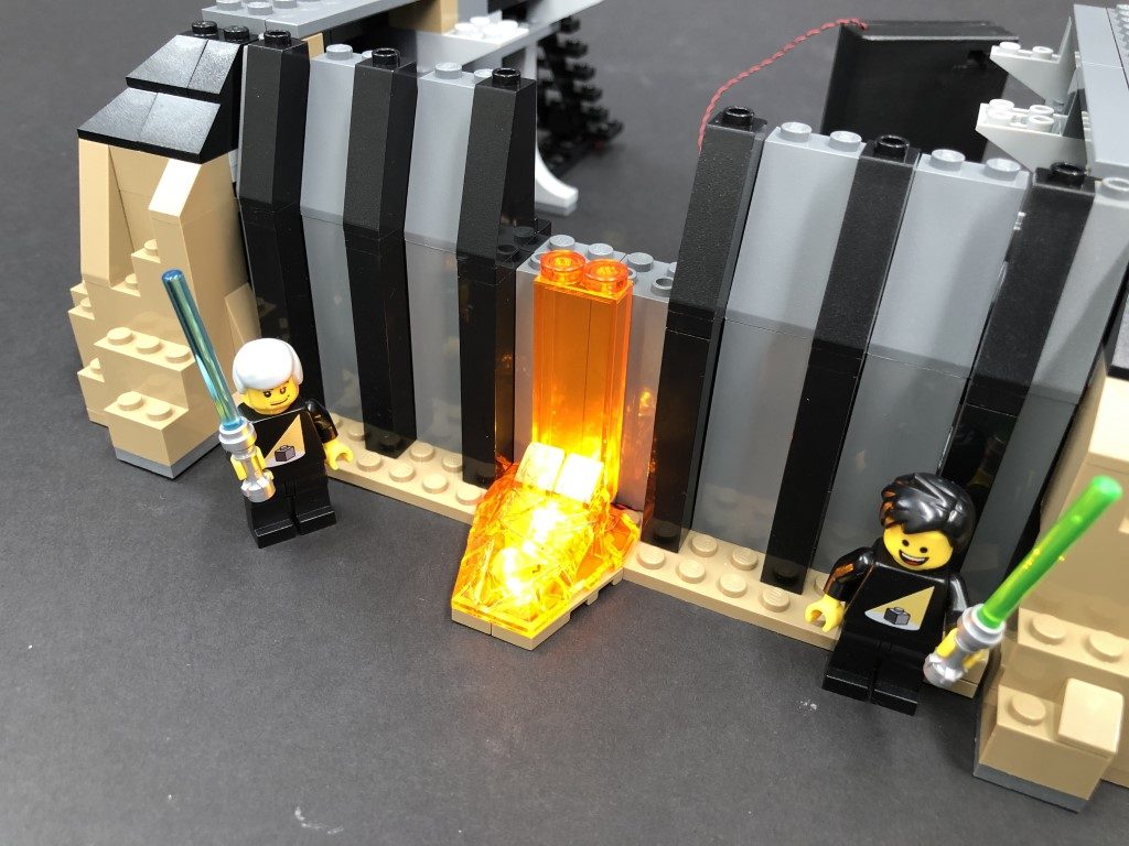
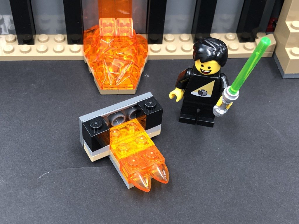
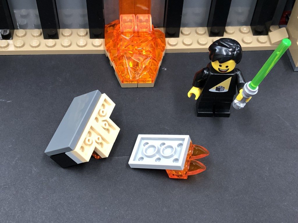
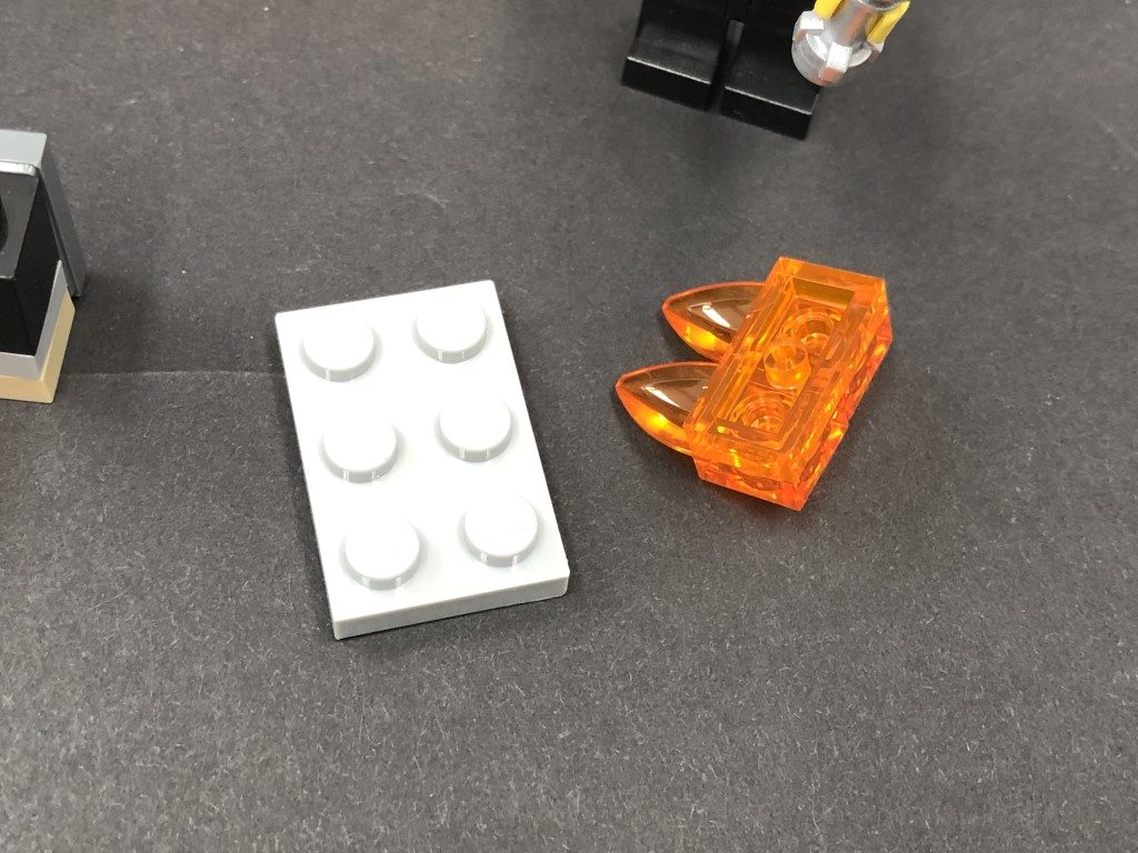
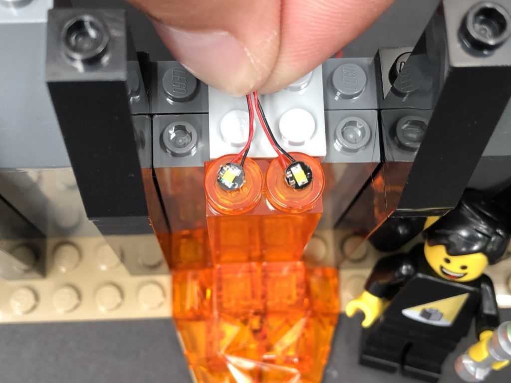
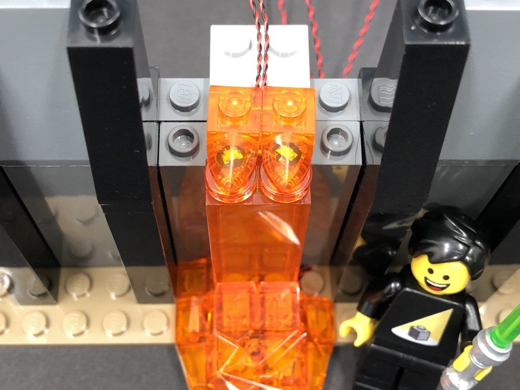
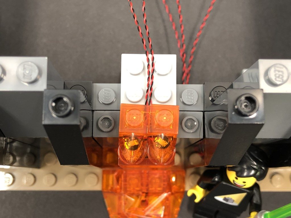
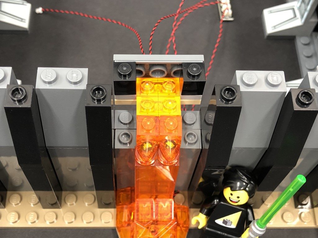
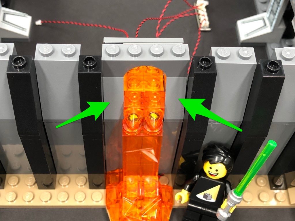
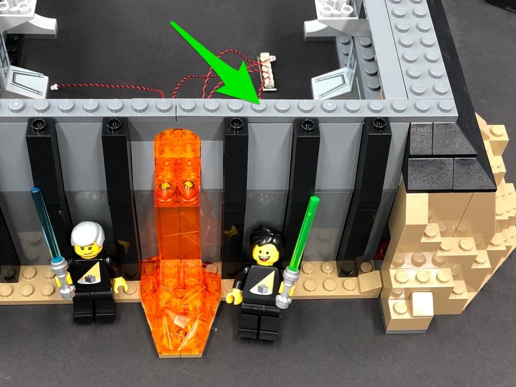
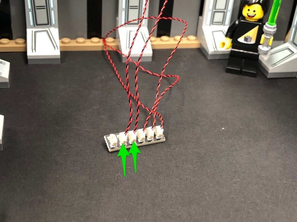
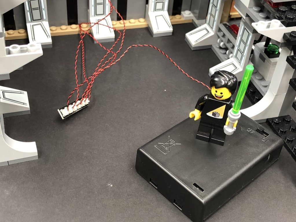
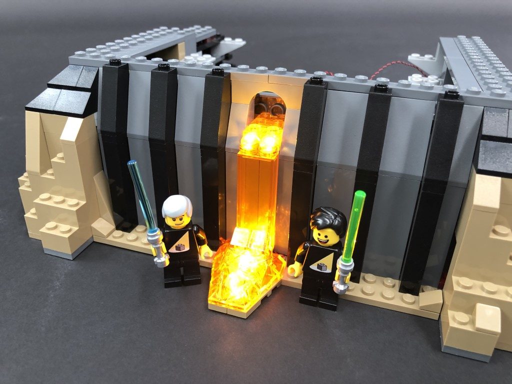
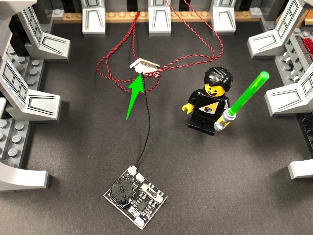
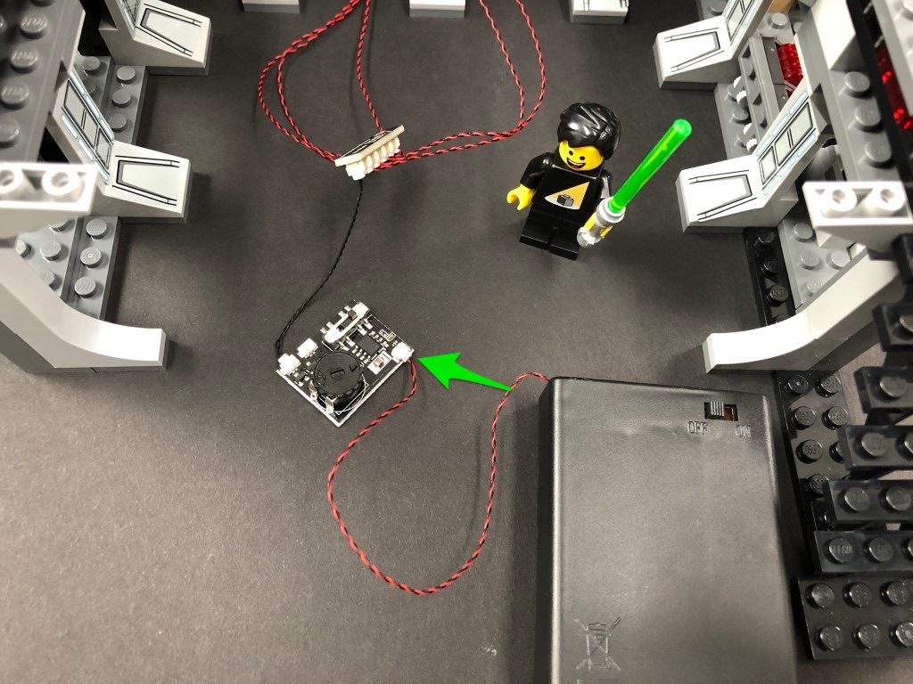
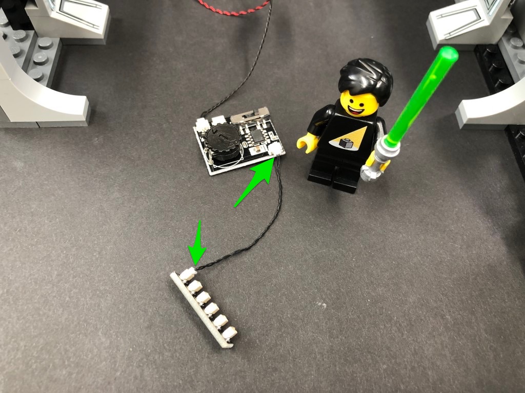
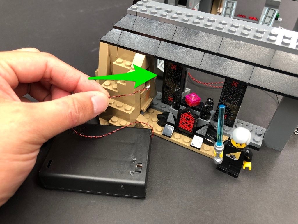
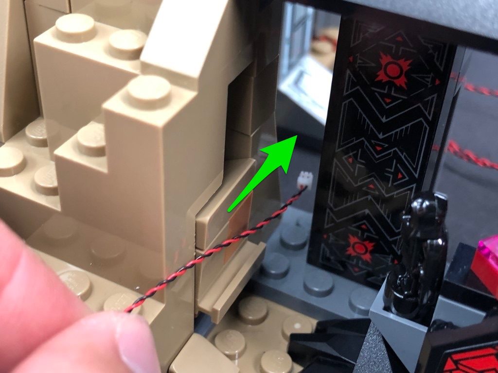
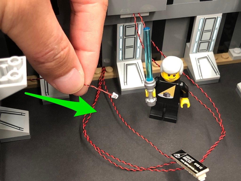
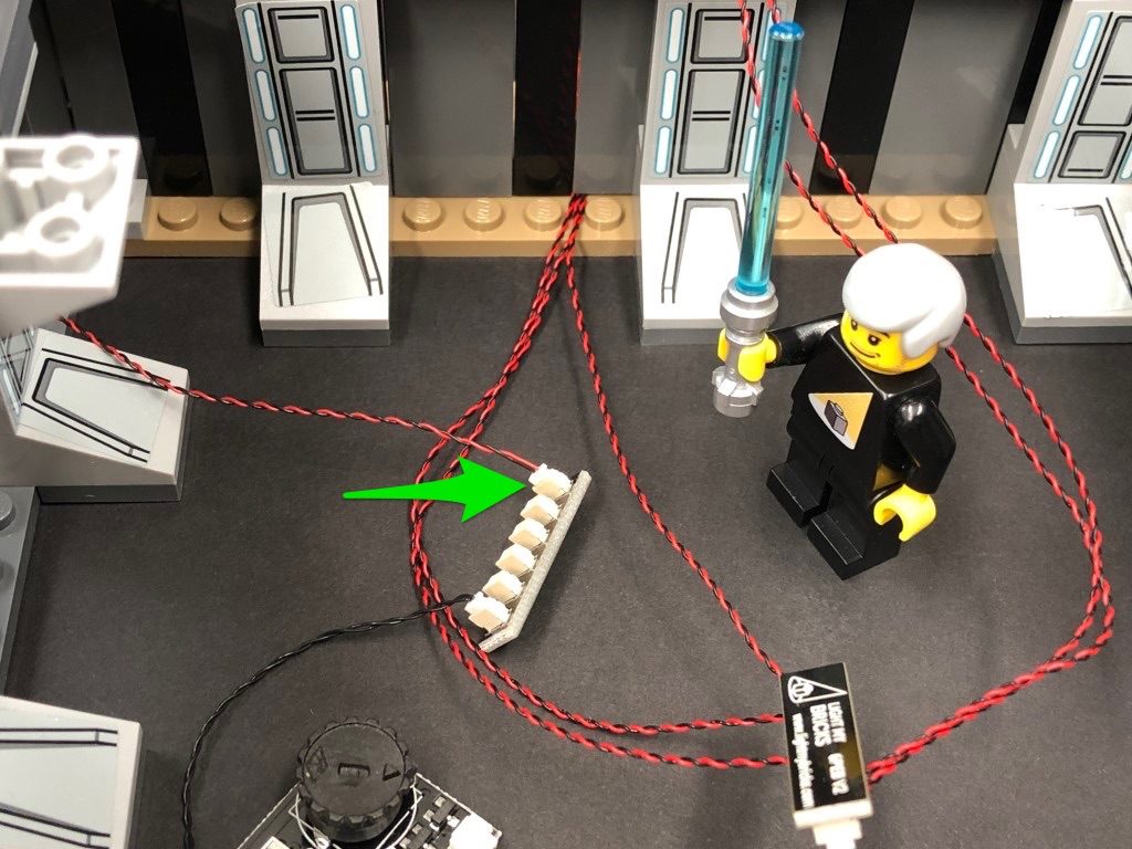
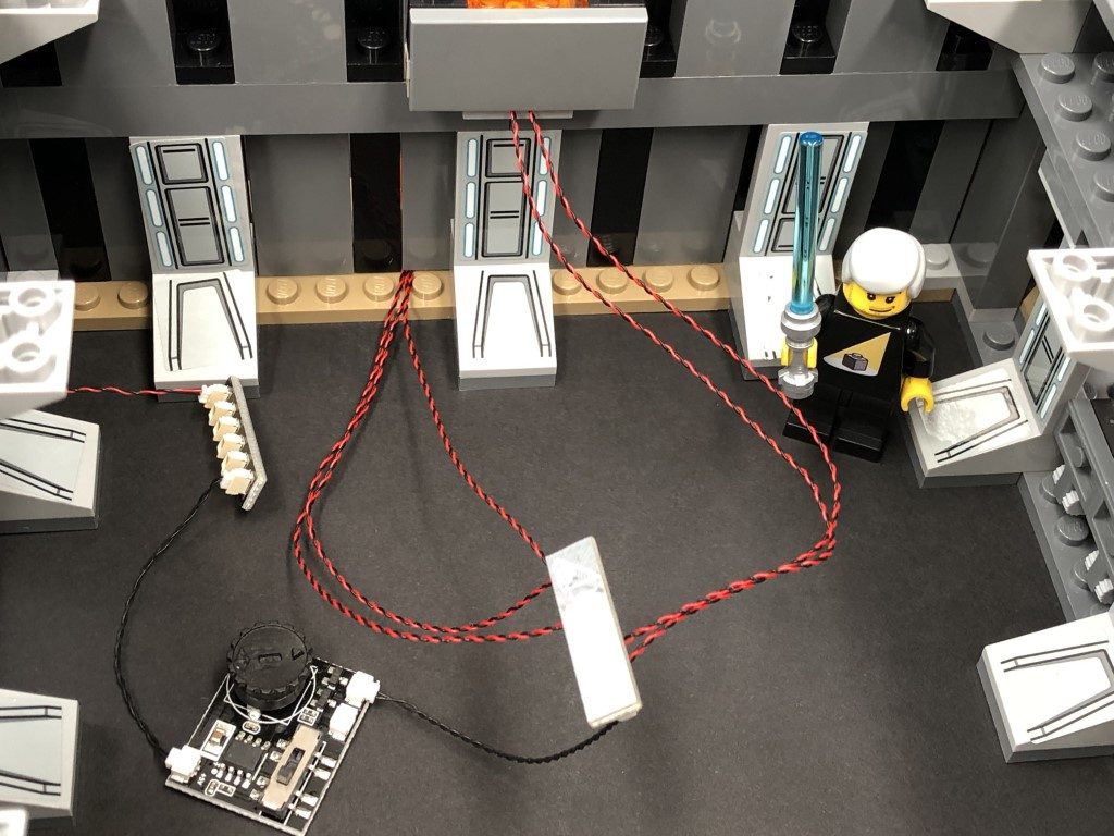
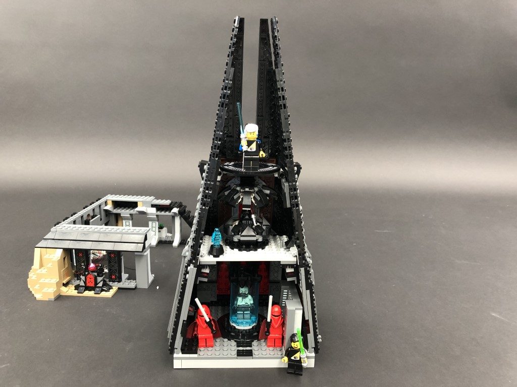
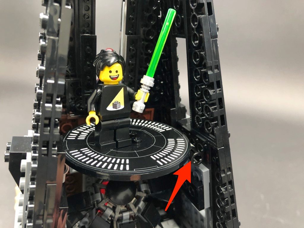
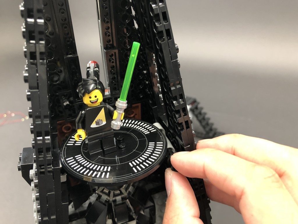
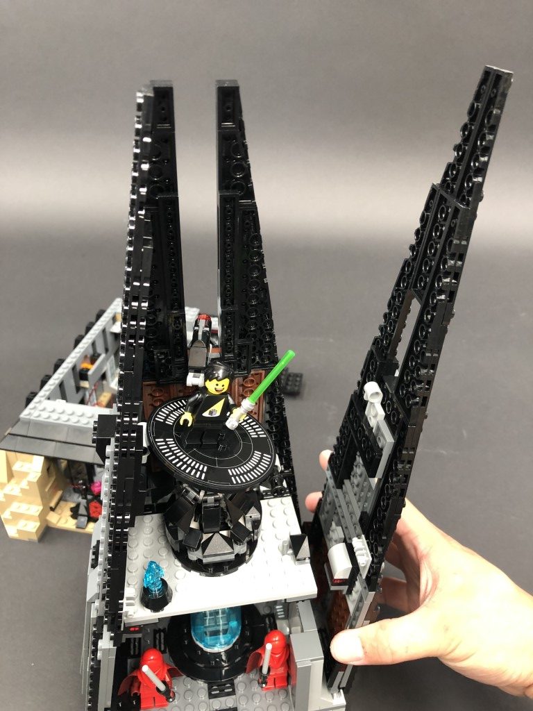
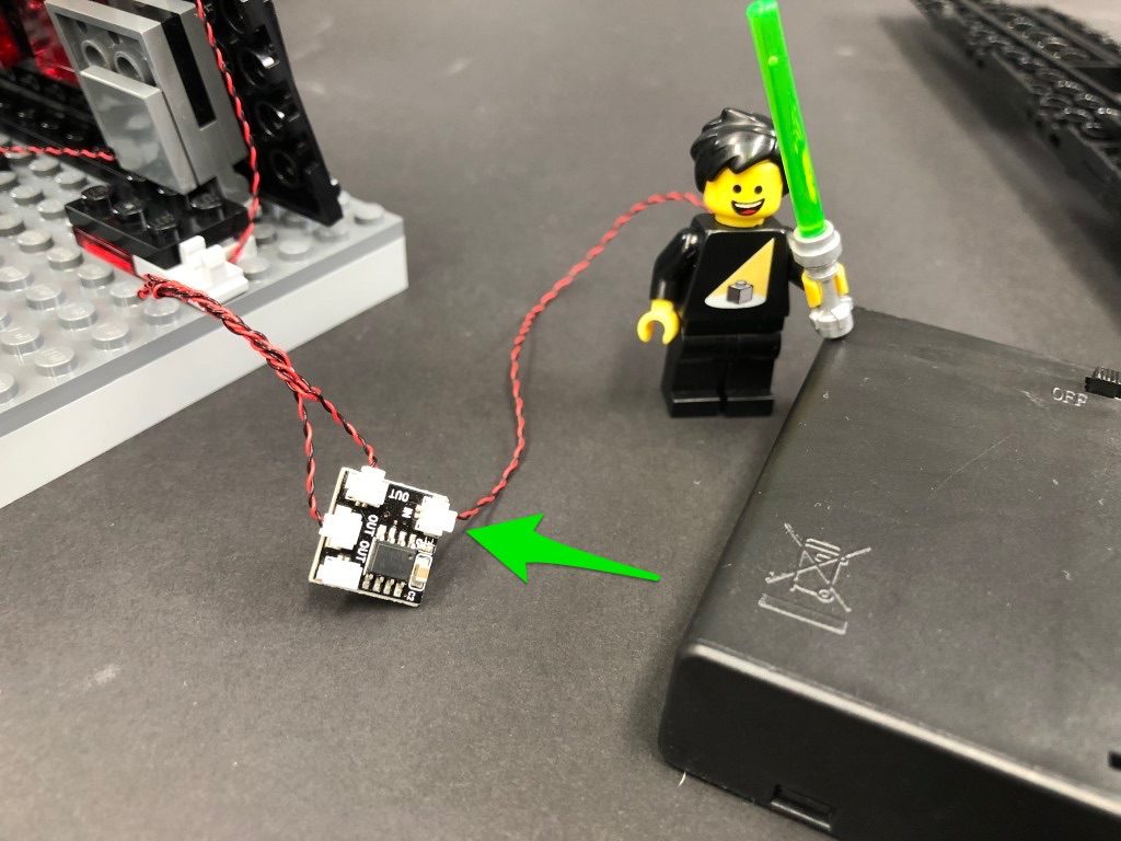
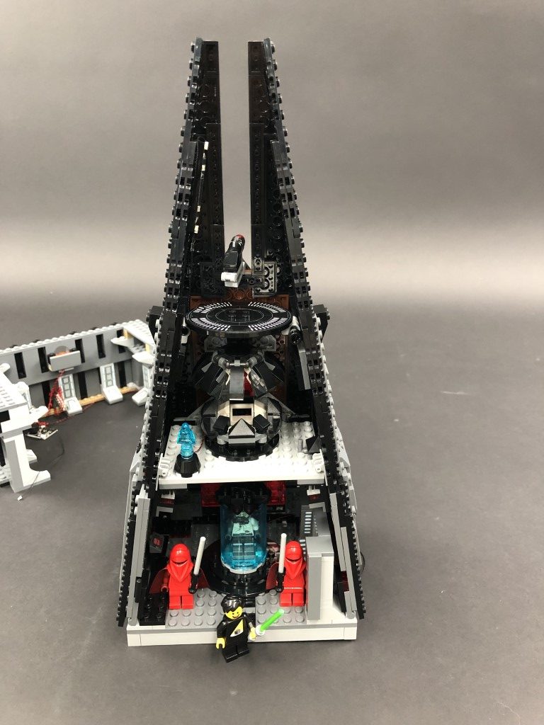
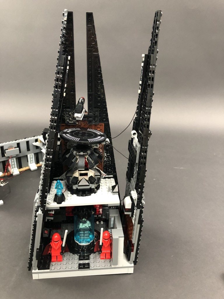
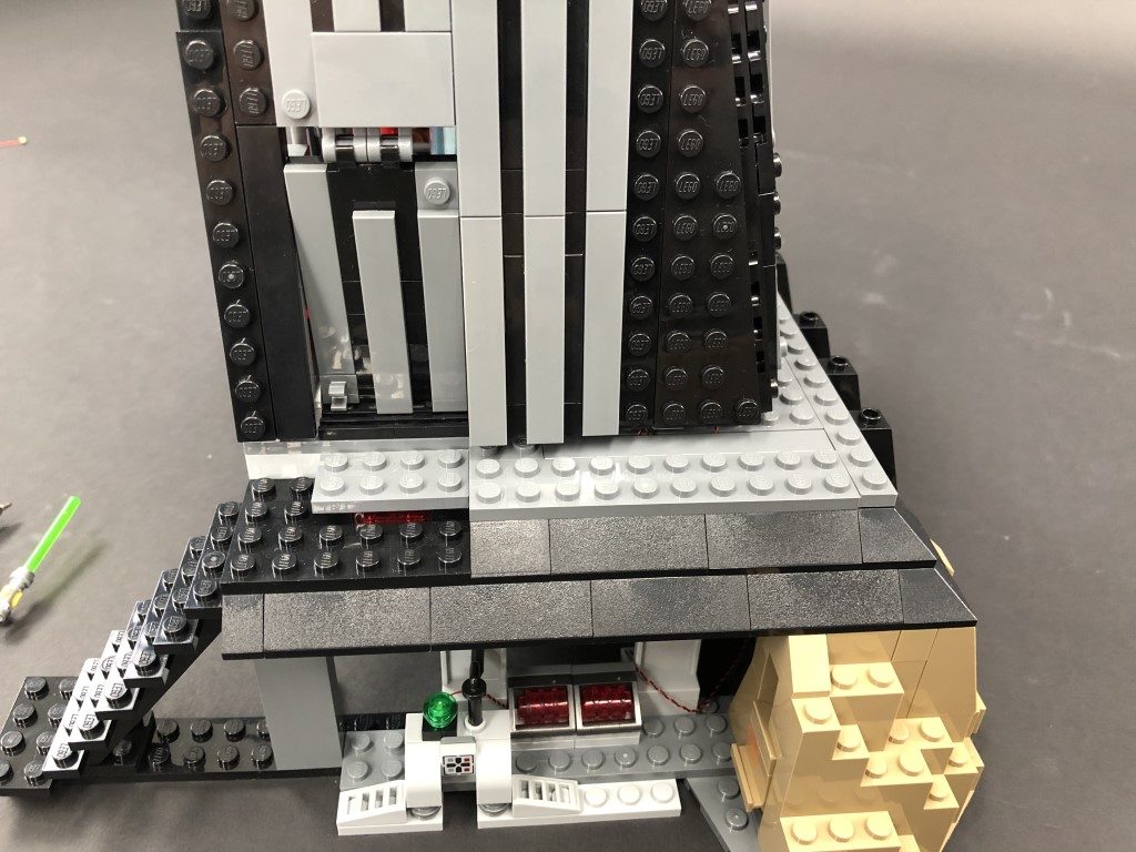
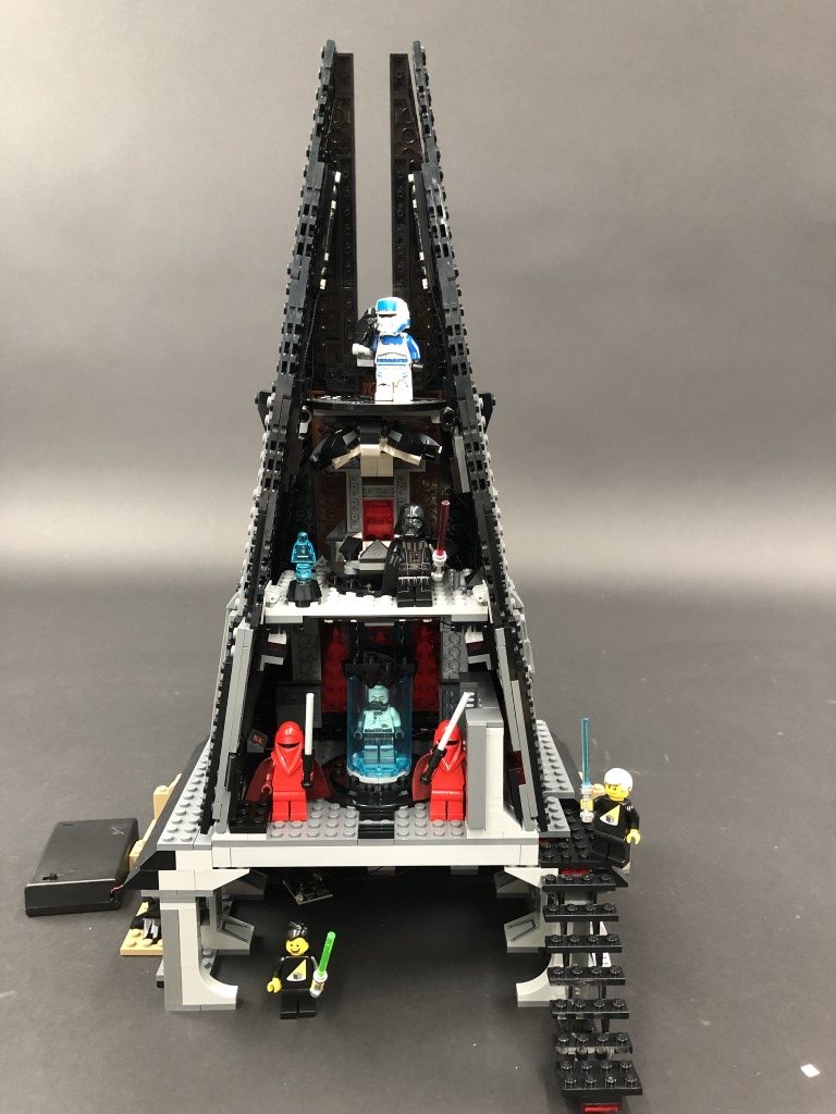
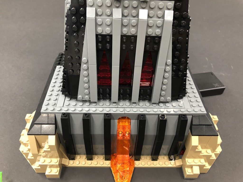
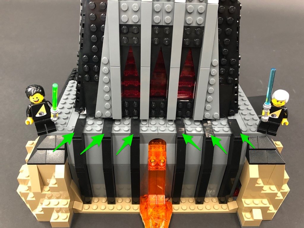
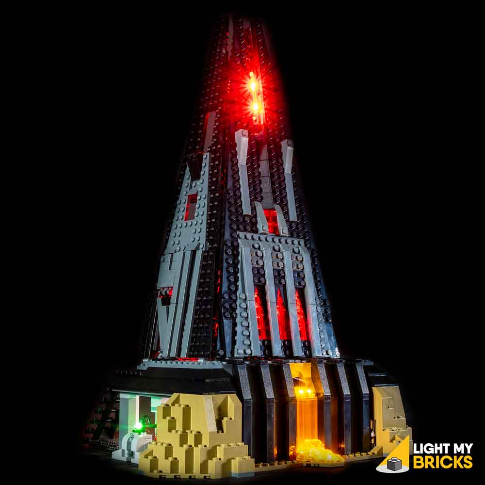
1.) We will start by first installing lights to the lava at the front of the castle. First disconnect the following black tiles at the front, then turn the castle around and remove the tie fighter. Gently press up against the following sections to lift up the entire top half of the castle. Turn the base of the castle back around to the front and remove following sections: 2.) Take the following section and disconnect all the trans coloured pieces, then take 2x White 15cm Bit Lights and with the cables facing up, place the bit lights down in the following positions, in between studs. Secure the lights in place by reconnecting the trans coloured section over the top. Ensure both Bit Lights are secured directly in between studs as shown below: 3.) Take both cables and thread them through the space on the right, which leads to the inside of the castle. Pull the cables all the way out from the inside, then reconnect the lava section. Ensure both cables are neatly laid along the right of the following light grey stud. 4.) Take another White 15cm Bit Light and with the other end of the cable facing the right, place the bit light in between the two grey studs. Ensuring the cable is laid toward the right around the side closest to the front, secure the bit light in place by reconnecting the trans orange wall piece over the top. It is very important that the cable is laid on the side of the grey stud closest to the front. This will prevent the cable from snapping later on when the pieces are reconnected on top. Take the other end of the Bit Light cable and thread it through the space on the right, then pull it all the way out from the inside of the castle. Reconnect the two dark grey wall sections starting with the one on the right. Ensure the three cables are laid around the far left stud before reconnecting the left wall section over the top. 5.) Take your AA Battery Pack and insert 3x AA Batteries to it. Connect the battery pack cable to a 6-Port Expansion Board, then connect the three bit light cables to it. Turn the battery pack ON to test that all three lights are working OK. Note: If you experience any issues with the lights not working and suspect an issue with a component, please try a different port on the expansion board to verify where the fault lies (with the light or expansion board). To correct any issues with expansion board ports, please view the section addressing expansion board issues on our online troubleshooting guide. 6.) Take the following section we removed earlier and disconnect the light grey plate from underneath. Disconnect the trans orange section, then reconnect the light grey plate to the front of the castle. Take 2x White 15cm Bit Lights and with the cables facing the back, place them over the two trans orange round tiles. Ensuring both cables are laid in between the studs in the centre, reconnect the trans orange section over the top to secure them in place. Reconnect the section we removed the light grey plate from earlier, ensuring the cables are first laid in between studs. Continue to reconnect surrounding sections we removed in step 1. 7.) From the inside of the castle, connect the two bit light cables we just installed to the next ports along the 6-port expansion board, then turn ON the battery Pack to test all the lava lights are working OK. Note: If you experience any issues with the lights not working and suspect an issue with a component, please try a different port on the expansion board to verify where the fault lies (with the light or expansion board). To correct any issues with expansion board ports, please view the section addressing expansion board issues on our online troubleshooting guide. Disconnect the AA Battery Pack, then take a Multi Effects Board and connect a 5cm Connecting Cable to one of the OUT ports (side with 2 ports). Connect the other end of the 5cm cable to the 6-port expansion board, then connect your AA Battery Pack to the IN port on the multi-effects board (side with 1 port) 8.) We will now configure the Multi Effects Board. Turn ON the AA Battery Pack and configure your desired effect by simply flicking the switch and adjusting the speed wheel. To configure the effect used in the Light My Bricks example, set the switch to the far right for ‘pulse’ effect. Turn the wheel all the way to left for the slowest speed.
 Once you are happy with the chosen effect, disconnect the AA Battery Pack from the effects board. Take a new 5cm Connecting Cable and connect it to a new 6-Port Expansion Board. Connect the other end of the 5cm cable to the IN port on the Multi Effects Board (where we disconnected the battery pack from).
 9.) Thread your AA Battery Pack through the space on the left side of the castle. Pull the cable in from the inside and connect it to the second 6-port expansion board we installed.
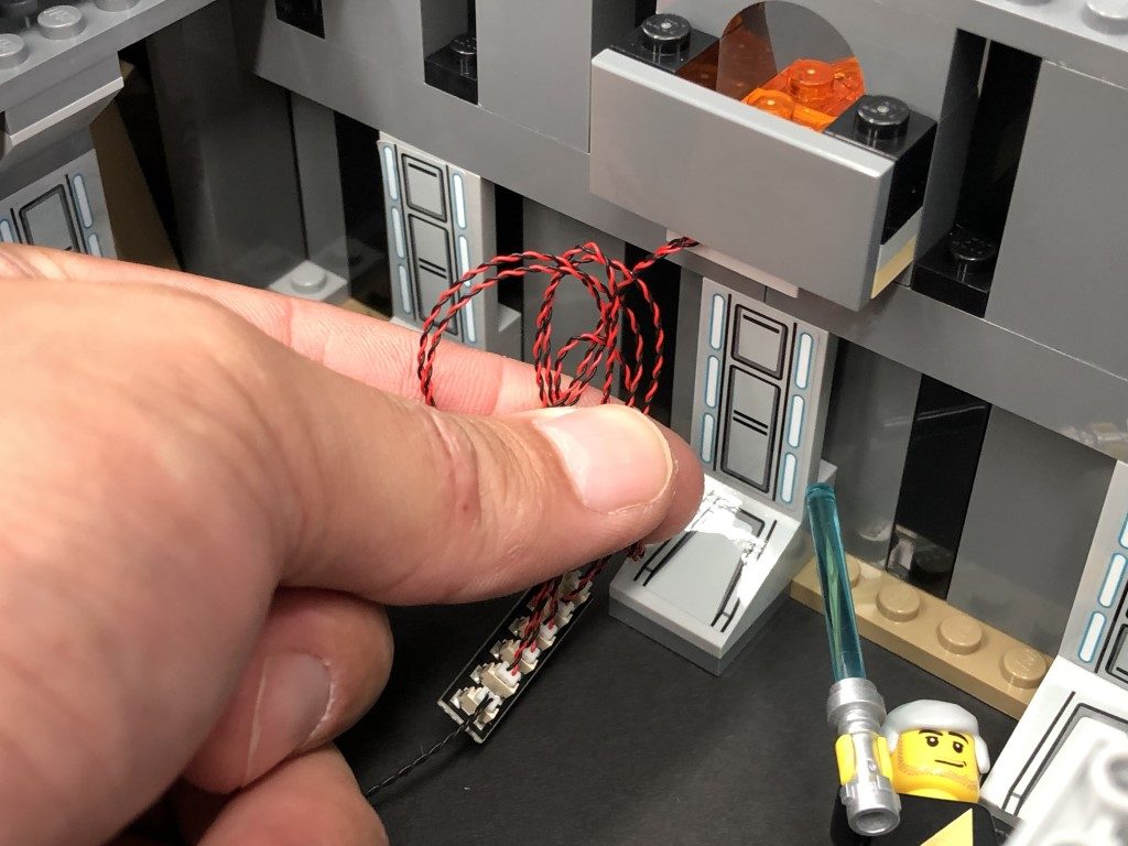
Neaten up cabling from the inside of the castle by grouping all the cables from the lava section and twisting/folding them together to form a neat bunch.
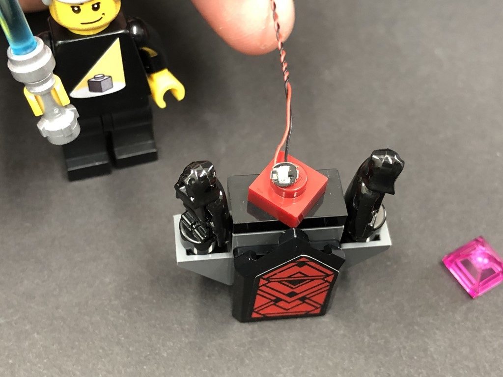
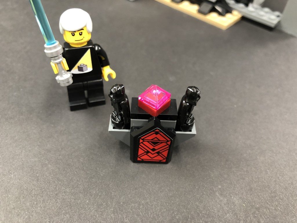
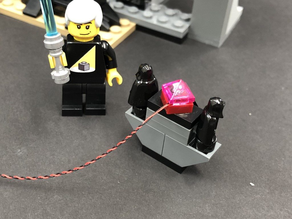
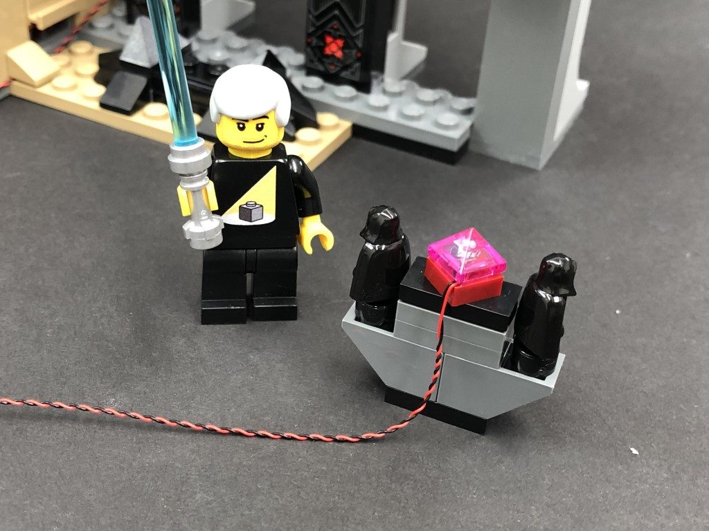
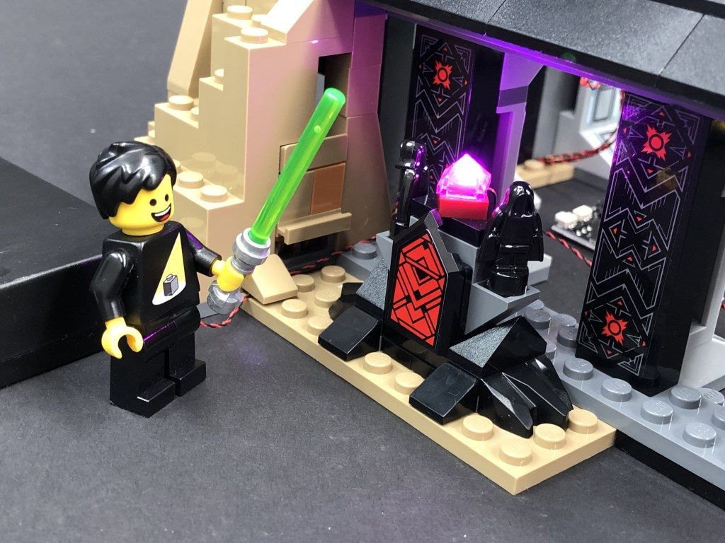
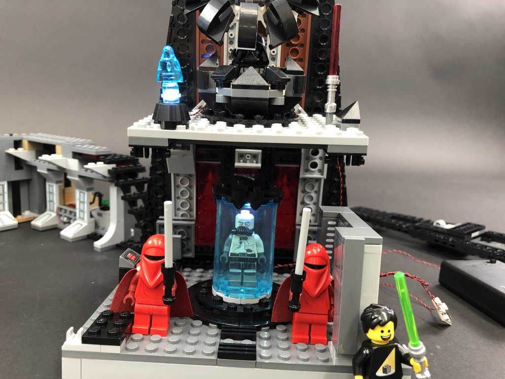
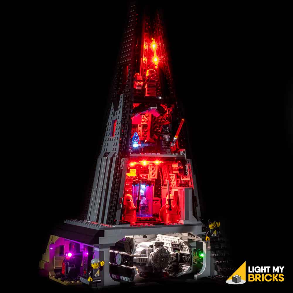
10.) We will now install a light to the pink diamond on the outside of the castle. First disconnect the wall section it sits on then disconnect the trans pink piece. Take a Pink 30cm Bit Light and with the cable facing behind, place it over the red stud. Secure the Bit Light in place by reconnecting the trans pink piece over the top.
Turn this section around to the back, then fold the cable down the back of the section.
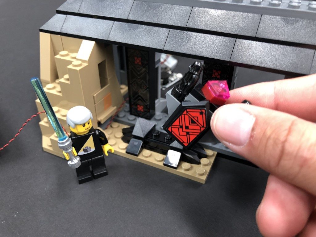
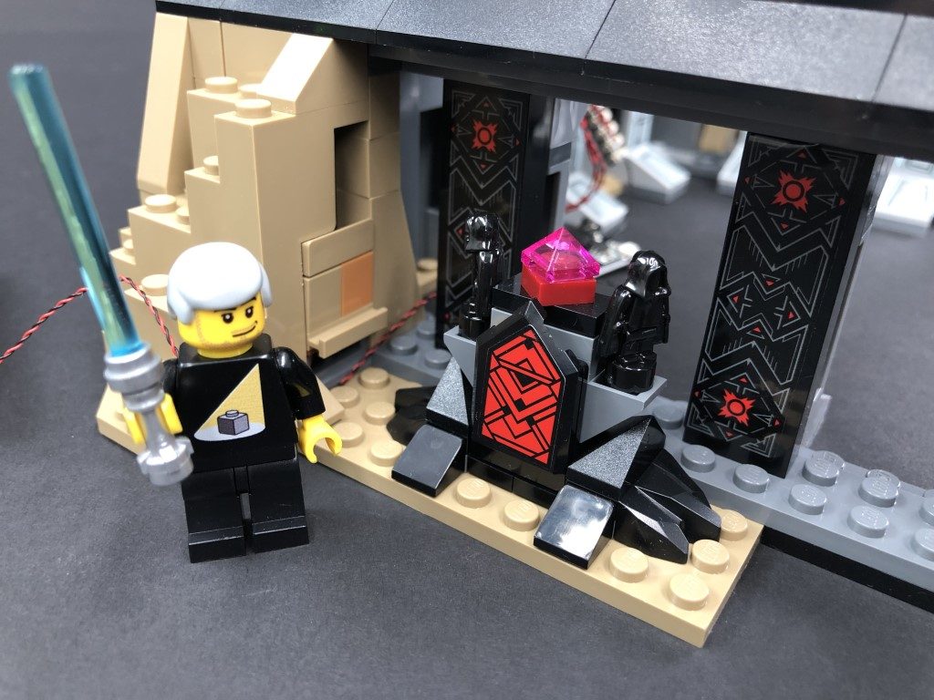
Reconnect this section to the castle base, then thread the pink bit light cable through the same space we threaded the battery pack cable through. Pull it all the way out from the inside then connect it to the second 6-port expansion board we installed. Turn ON the battery pack to test the light is working OK.
Note: If you experience any issues with the lights not working and suspect an issue with a component, please try a different port on the expansion board to verify where the fault lies (with the light or expansion board). To correct any issues with expansion board ports, please view the section addressing expansion board issues on our online troubleshooting guide.
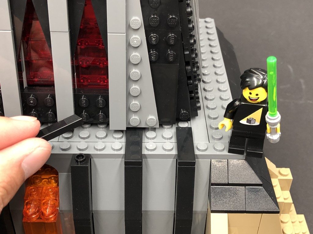
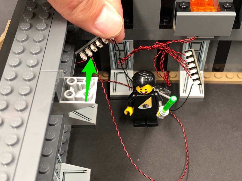
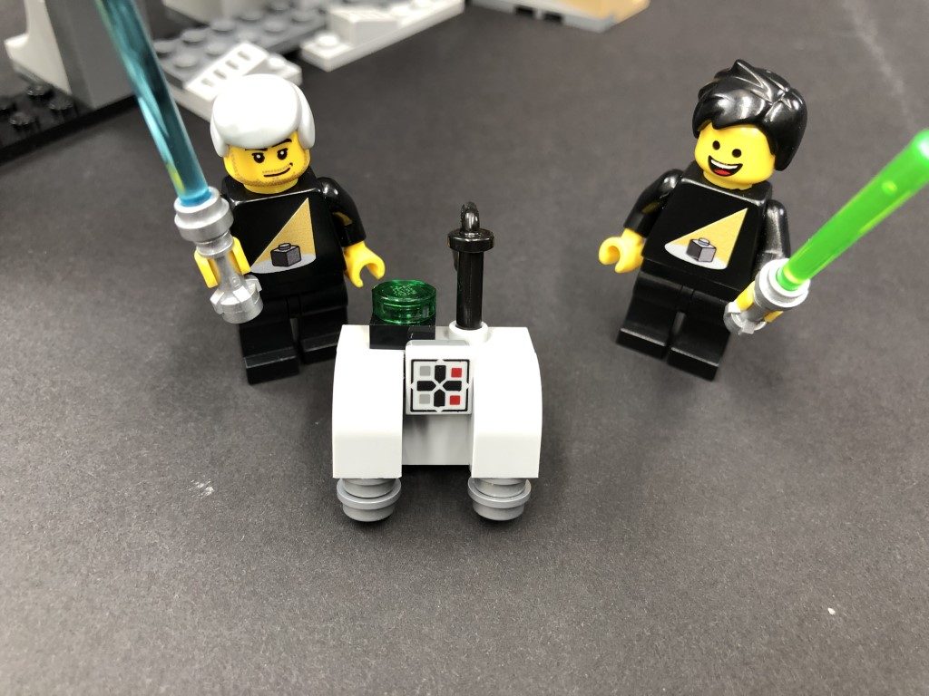
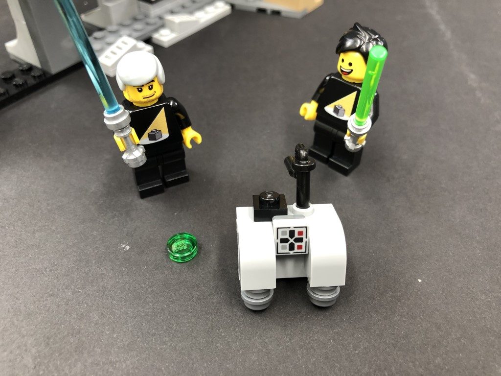
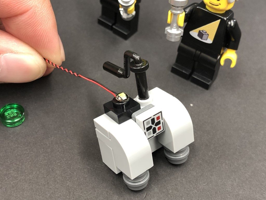
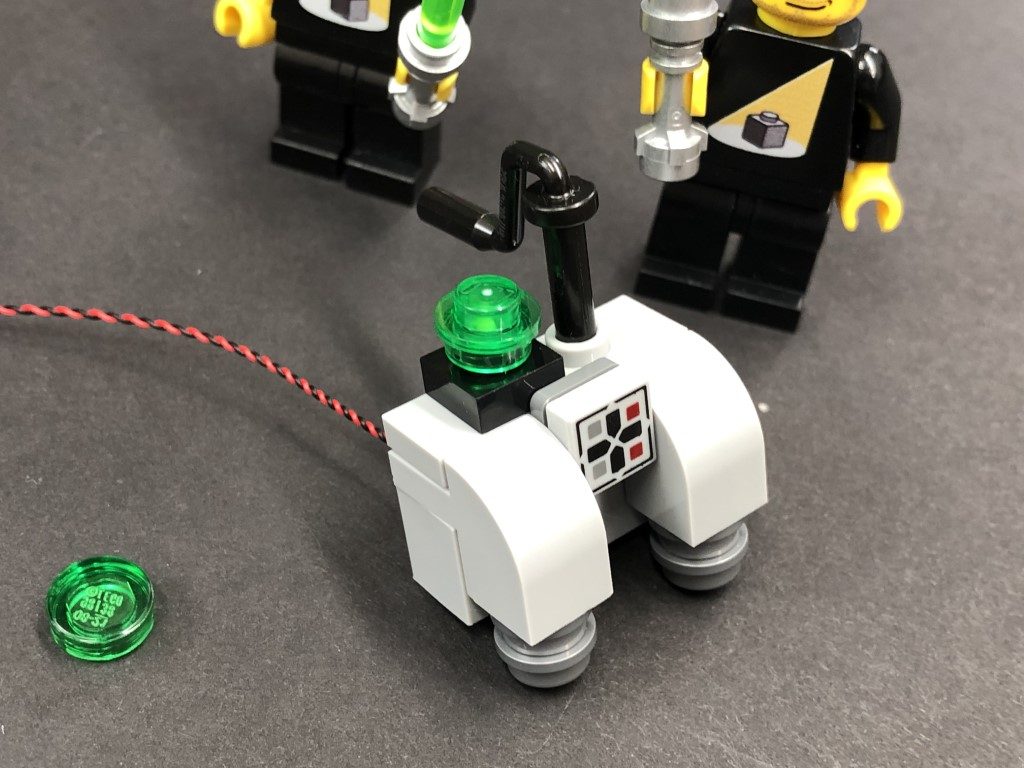
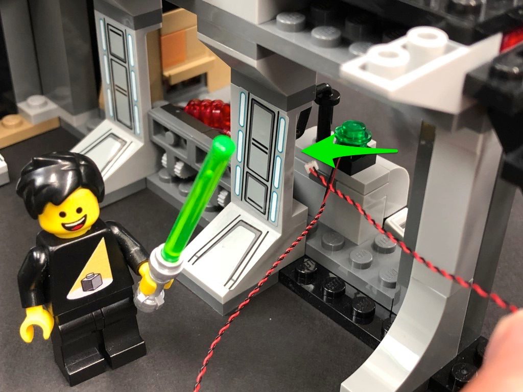
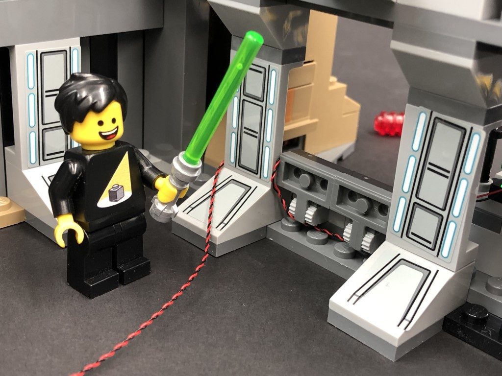
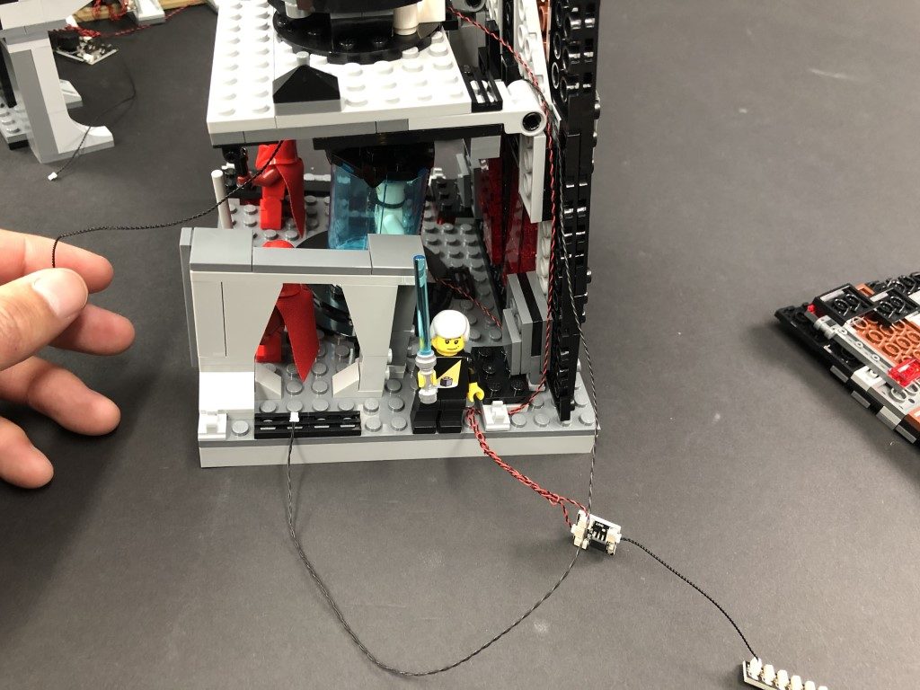
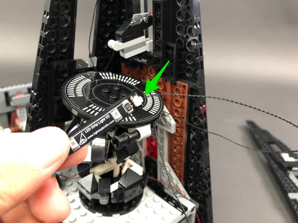
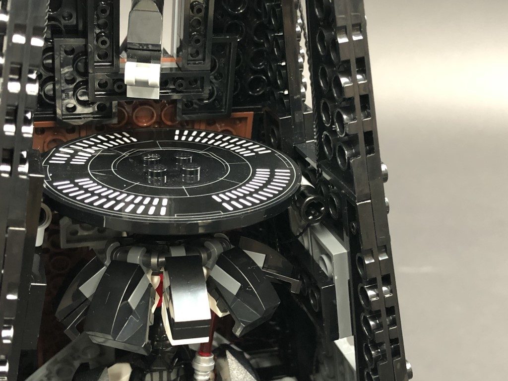
11.) We will now install a flashing light over to the right side of the castle. First disconnect the control panel section, then disconnect the trans green round tile. Take a Flashing White 30cm Bit Light and with the cable facing behind, place it over the black stud. Secure the light in place by connecting a provided Trans Green Round Plate 1×1 over the top.
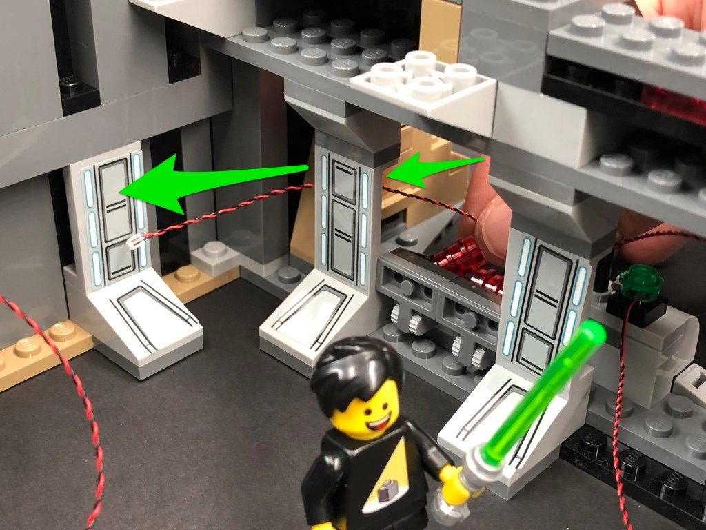
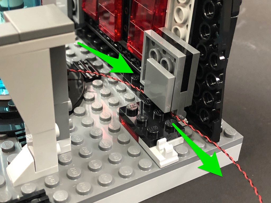
Reconnect the control panel, then thread the other end of the cable through the following space. Pull it all the way out from the inside of the castle, then thread the cable in between the wall and control panel. Continue to thread it around the next wall section to lead back inside the castle.
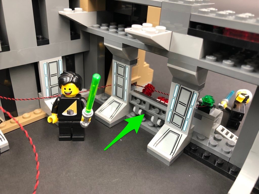
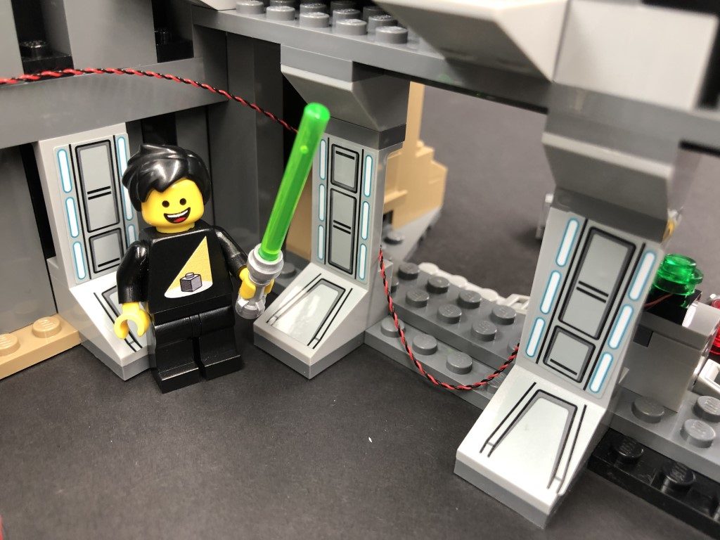
Hide the cable by disconnecting the following section, then reconnecting it over the top of the cable as shown below.
Connect the flashing white bit light cable it to the next spare port on the 6-port expansion board, then turn ON the battery pack to test the light is working OK.
Note: If you experience any issues with the lights not working and suspect an issue with a component, please try a different port on the expansion board to verify where the fault lies (with the light or expansion board). To correct any issues with expansion board ports, please view the section addressing expansion board issues on our online troubleshooting guide.
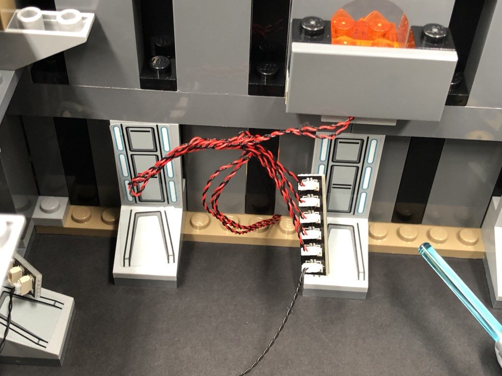
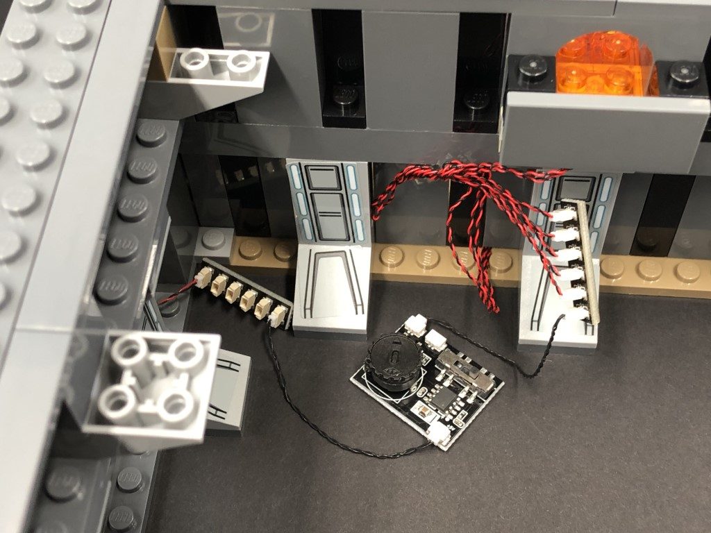
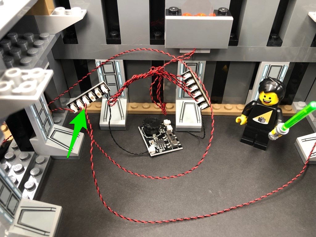
12.) Disconnect the Battery Pack cable from the expansion board inside the castle, then neaten up cabling by grouping all cables connected to the second 6-port expansion board and twisting/folding around each other to form a neat bunch.
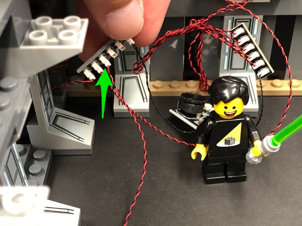
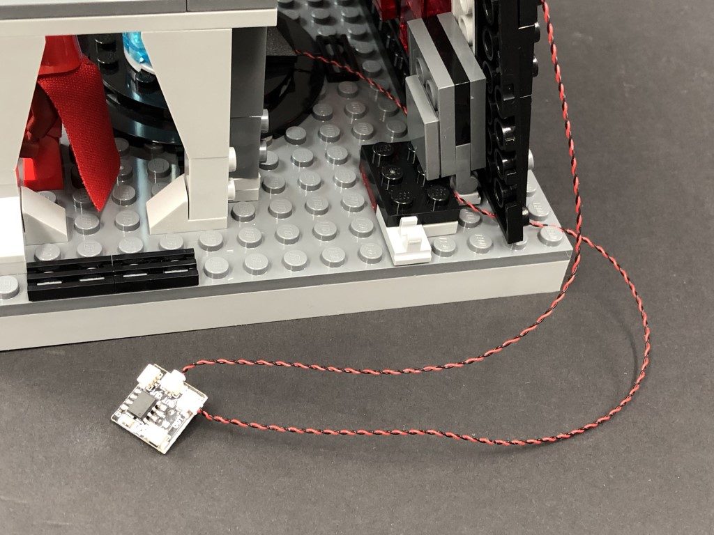
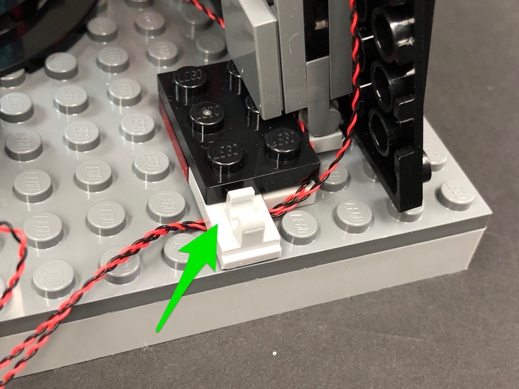
Lift up the section so we can access underneath, then secure the flashing white 30cm bit light cable underneath the following 2×2 plate.
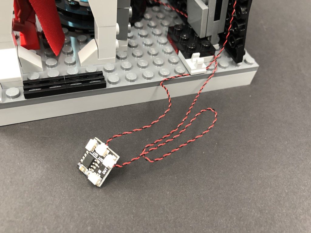
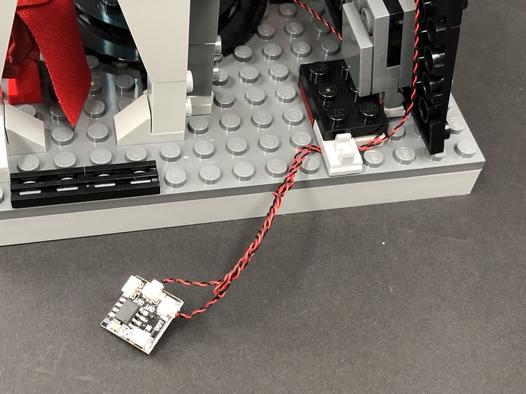
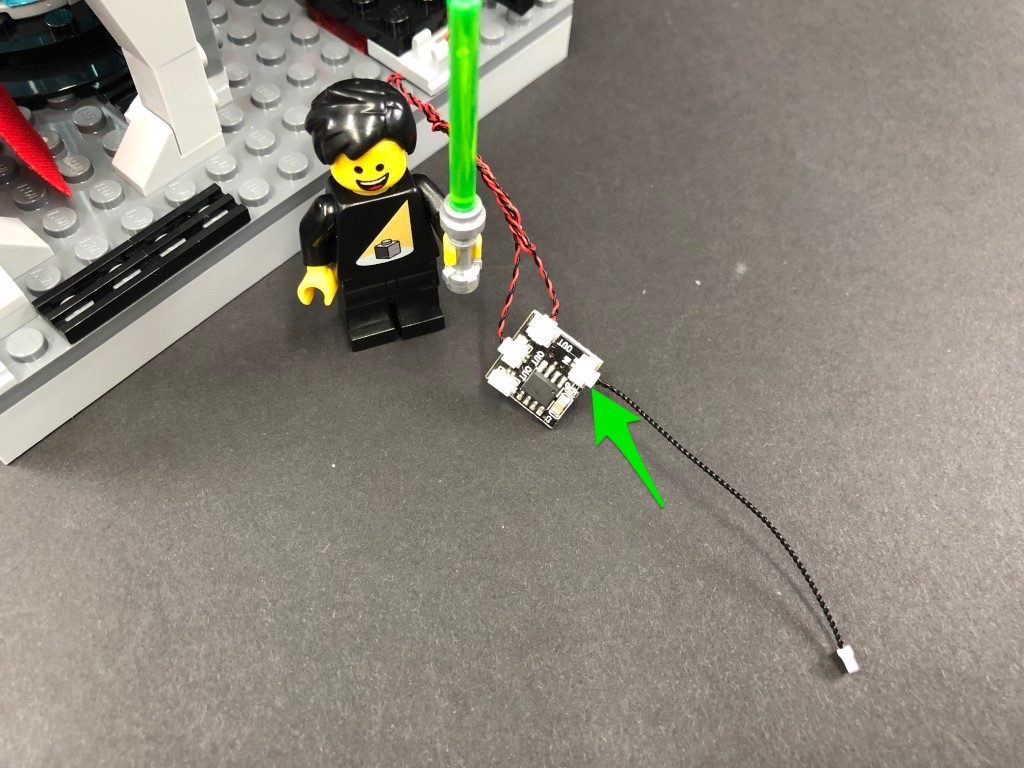
Take a 15cm Connecting cable and connect one end to a spare port on the second 6-port Expansion Board.
9.) Thread your AA Battery Pack through the space on the left side of the castle. Pull the cable in from the inside and connect it to the second 6-port expansion board we installed.
Neaten up cabling from the inside of the castle by grouping all the cables from the lava section and twisting/folding them together to form a neat bunch.
10.) We will now install a light to the pink diamond on the outside of the castle. First disconnect the wall section it sits on then disconnect the trans pink piece. Take a Pink 30cm Bit Light and with the cable facing behind, place it over the red stud. Secure the Bit Light in place by reconnecting the trans pink piece over the top.
Turn this section around to the back, then fold the cable down the back of the section.
Reconnect this section to the castle base, then thread the pink bit light cable through the same space we threaded the battery pack cable through. Pull it all the way out from the inside then connect it to the second 6-port expansion board we installed. Turn ON the battery pack to test the light is working OK.
Note: If you experience any issues with the lights not working and suspect an issue with a component, please try a different port on the expansion board to verify where the fault lies (with the light or expansion board). To correct any issues with expansion board ports, please view the section addressing expansion board issues on our online troubleshooting guide.
11.) We will now install a flashing light over to the right side of the castle. First disconnect the control panel section, then disconnect the trans green round tile. Take a Flashing White 30cm Bit Light and with the cable facing behind, place it over the black stud. Secure the light in place by connecting a provided Trans Green Round Plate 1×1 over the top.
Reconnect the control panel, then thread the other end of the cable through the following space. Pull it all the way out from the inside of the castle, then thread the cable in between the wall and control panel. Continue to thread it around the next wall section to lead back inside the castle.
Hide the cable by disconnecting the following section, then reconnecting it over the top of the cable as shown below.
Connect the flashing white bit light cable it to the next spare port on the 6-port expansion board, then turn ON the battery pack to test the light is working OK.
Note: If you experience any issues with the lights not working and suspect an issue with a component, please try a different port on the expansion board to verify where the fault lies (with the light or expansion board). To correct any issues with expansion board ports, please view the section addressing expansion board issues on our online troubleshooting guide.
12.) Disconnect the Battery Pack cable from the expansion board inside the castle, then neaten up cabling by grouping all cables connected to the second 6-port expansion board and twisting/folding around each other to form a neat bunch.
Lift up the section so we can access underneath, then secure the flashing white 30cm bit light cable underneath the following 2×2 plate.
Take a 15cm Connecting cable and connect one end to a spare port on the second 6-port Expansion Board.
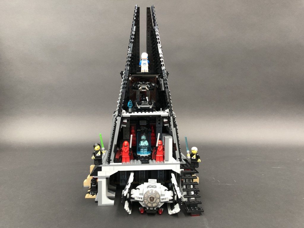
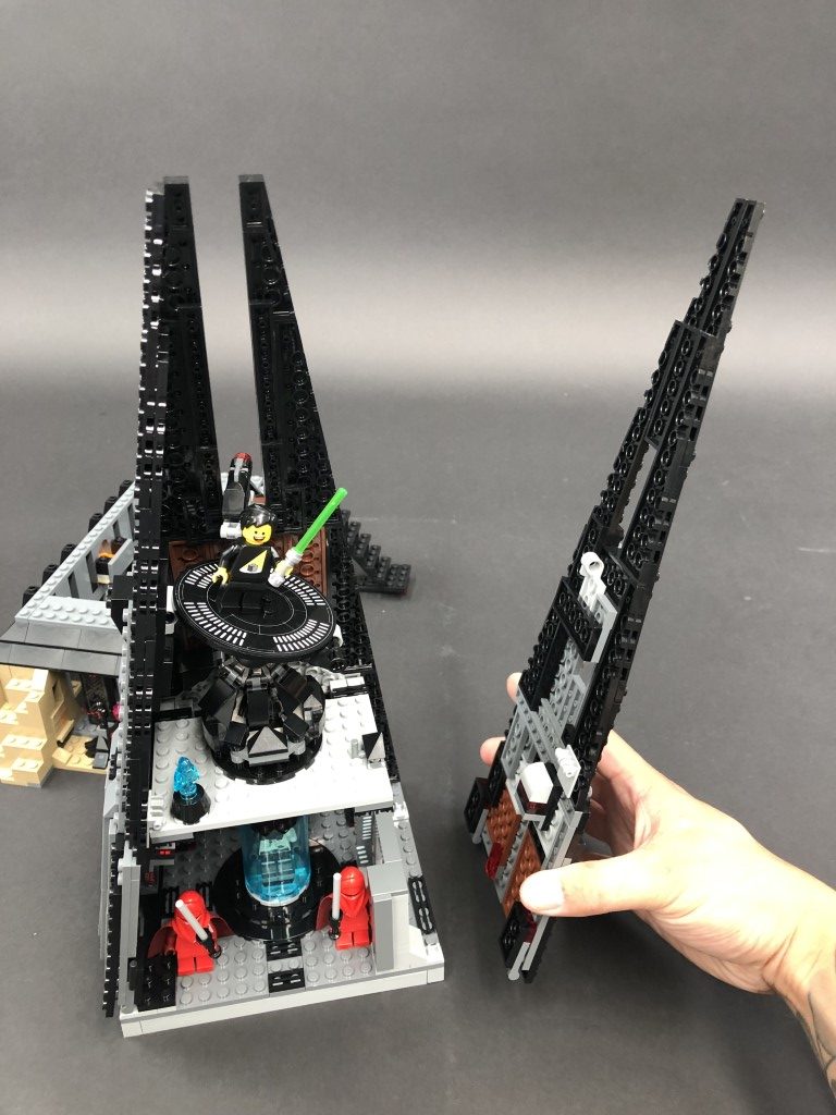
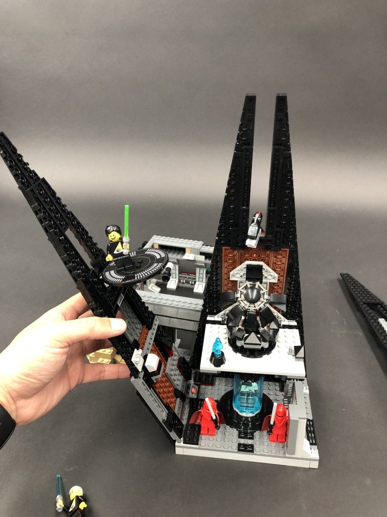
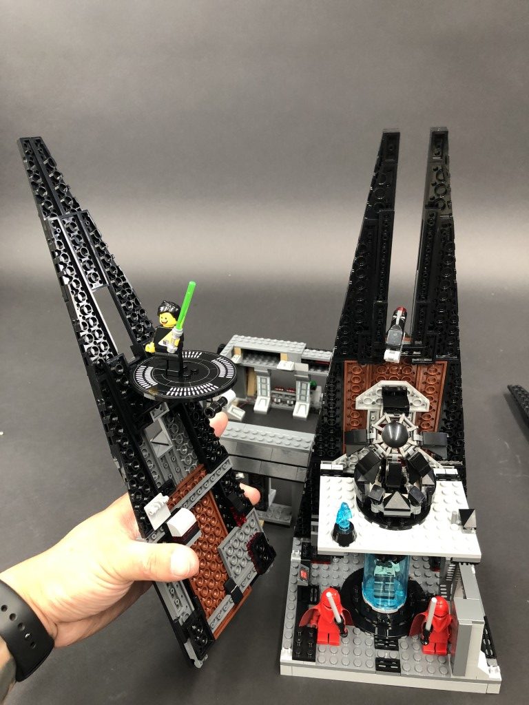
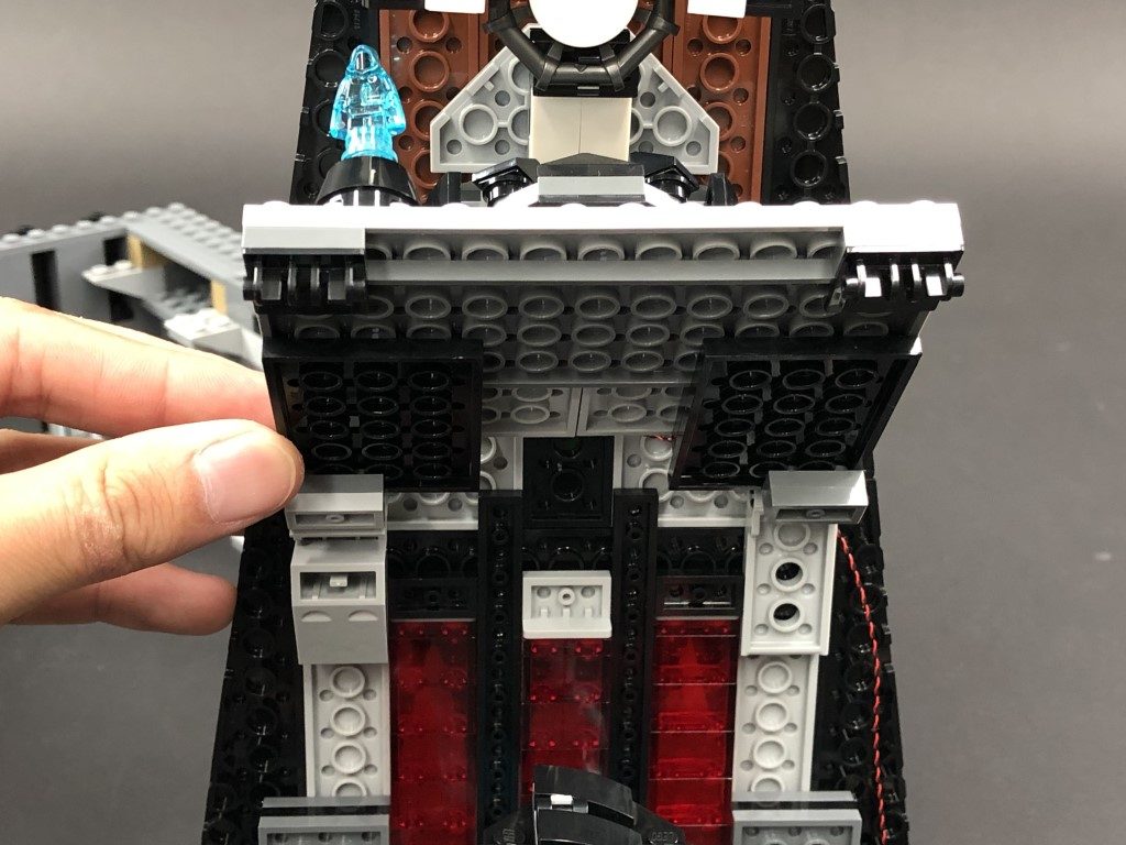
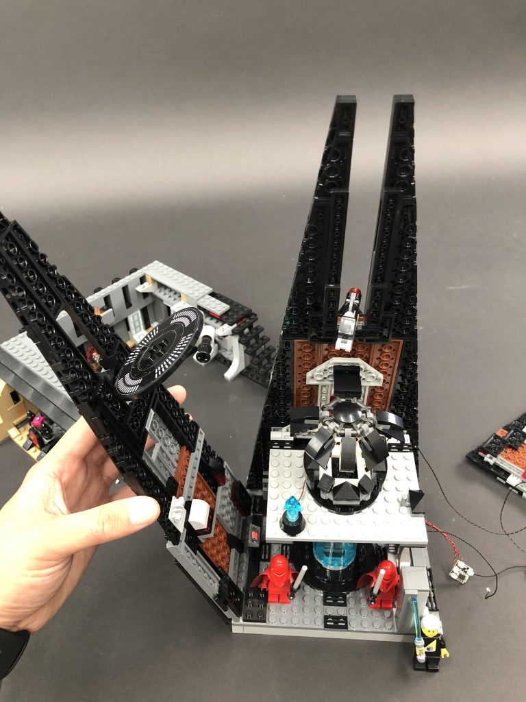
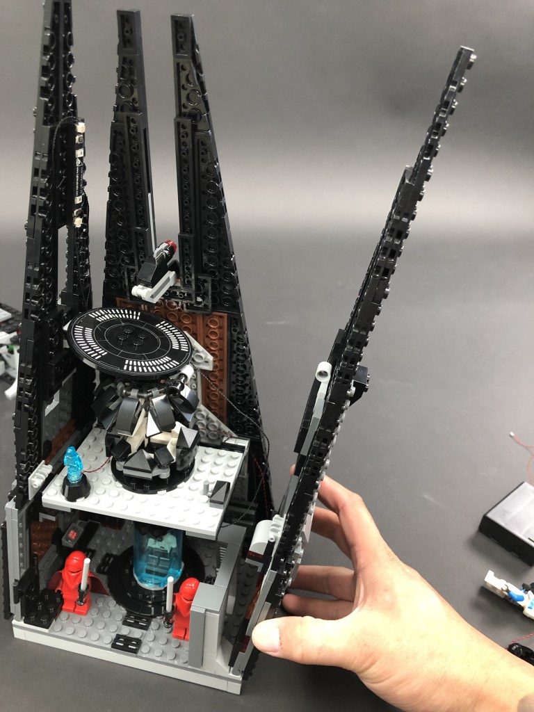
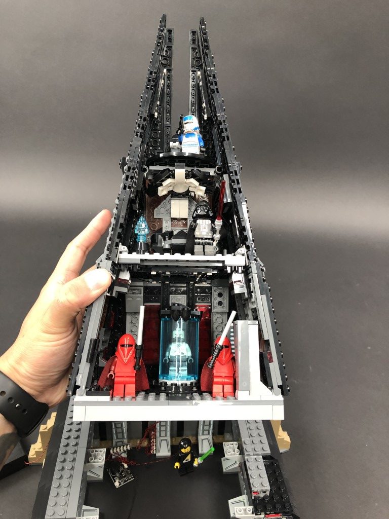
 13.) We will now install lights to the main section of the castle. First pull out the black technic pin on the right side, then disconnect the two walls by unclipping them from the bottom.
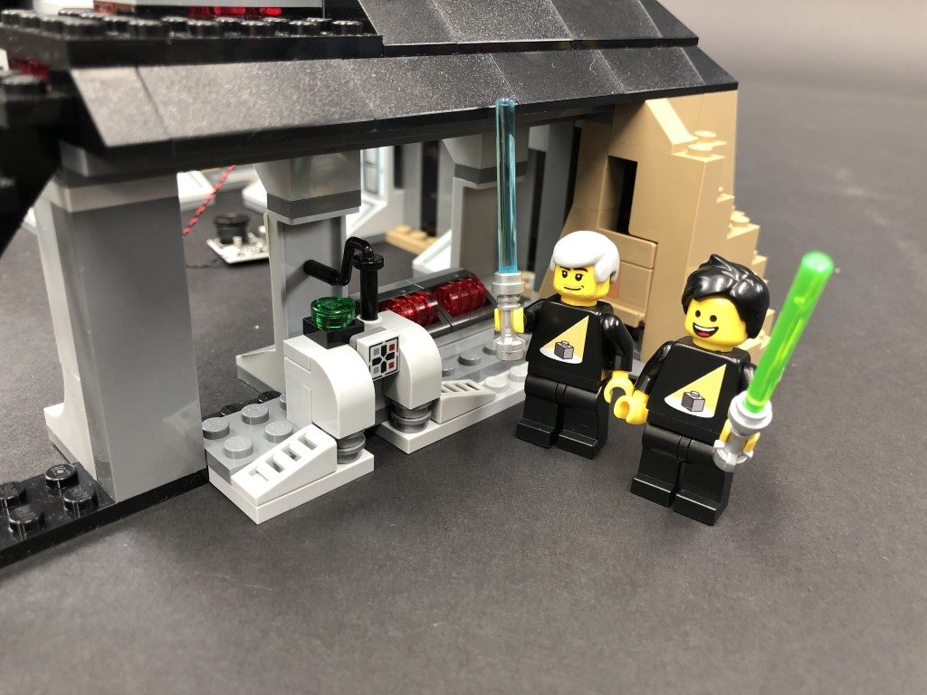
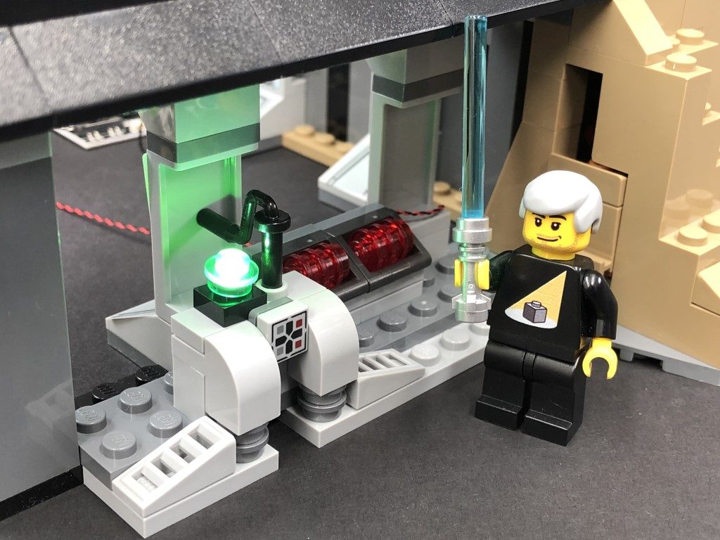
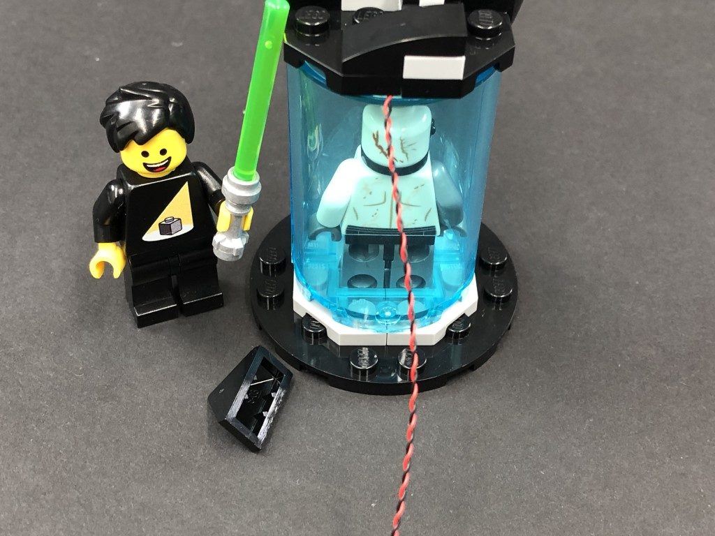
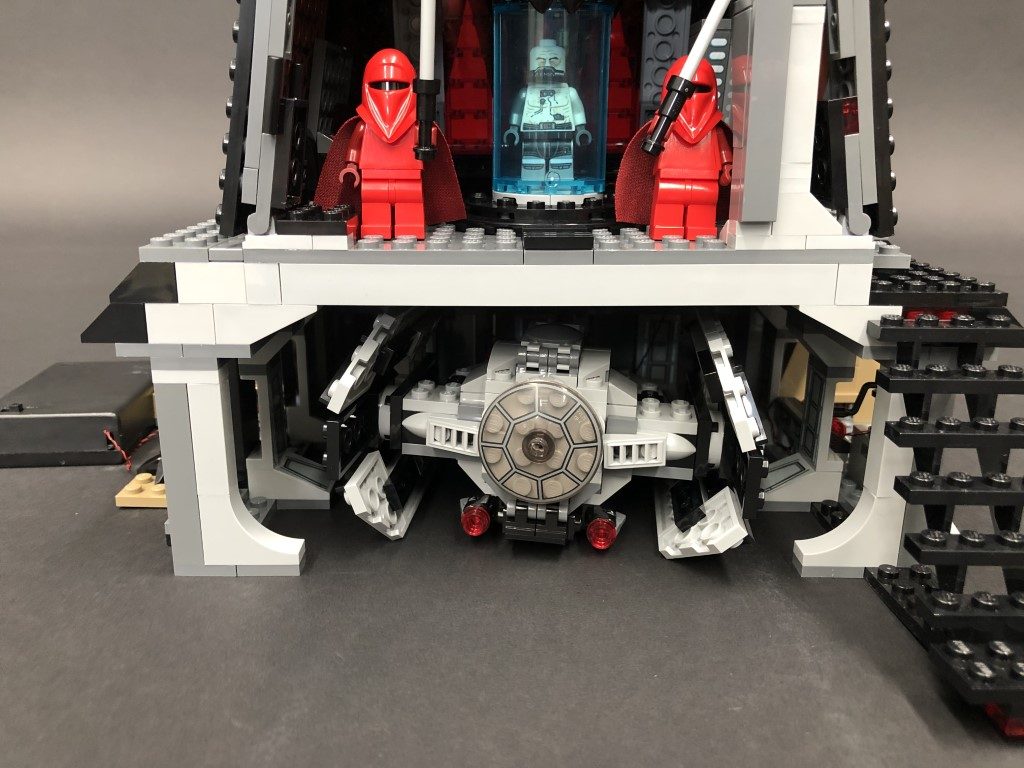
Remove the Darth Vader’s bacta tank, disconnect the top of it as shown below:
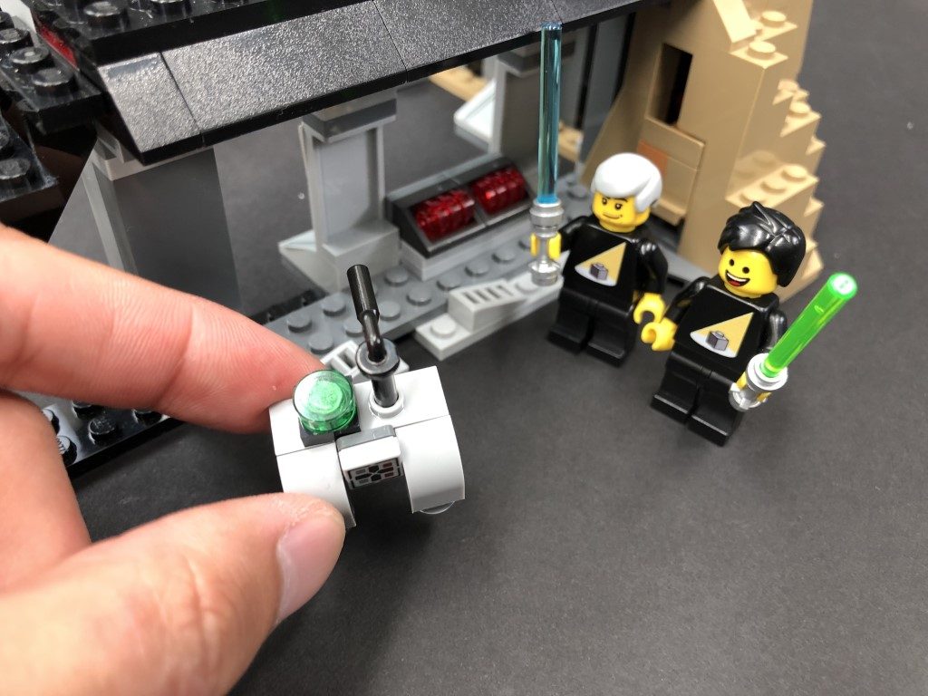
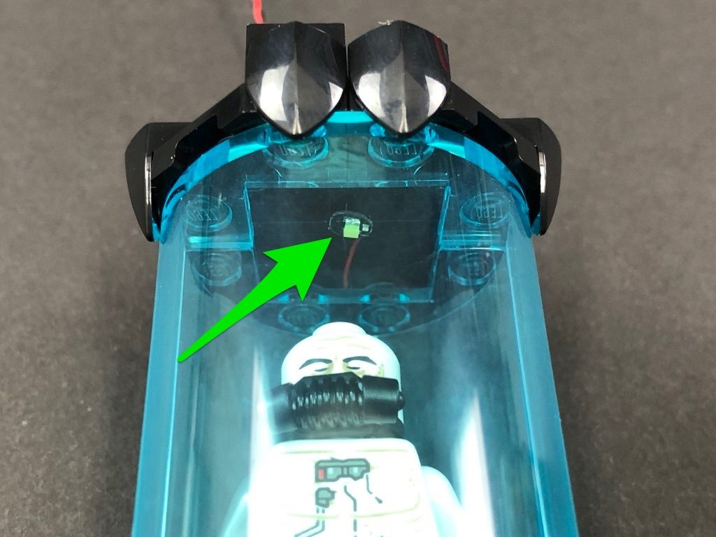
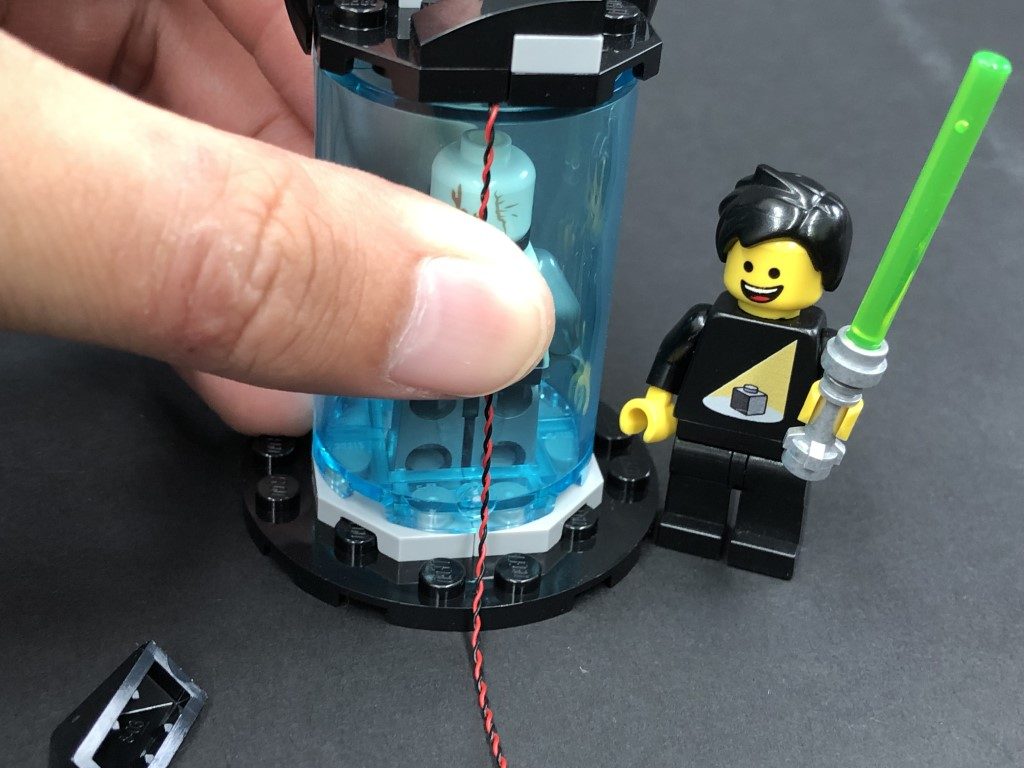
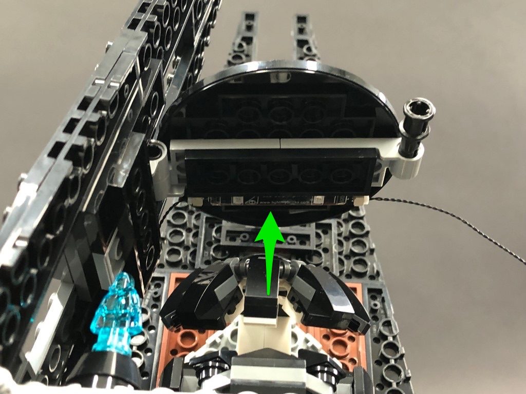
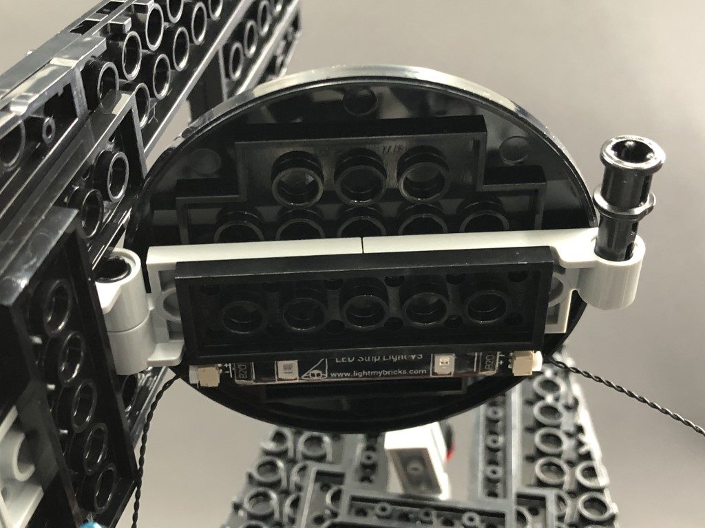
14.) Take a Cool White 30cm Bit Light and with the led facing down and cable laid behind, place if over the top of the tank, then secure it in place by reconnecting the top section. If you look up from the front of the tank, you should be able to see the Bit Light facing down.
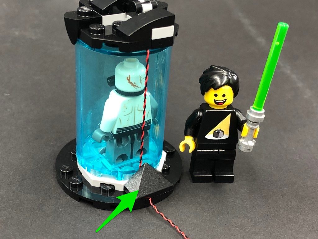
Turn the tank around to the back and fold the cable down and secure it underneath the black angled brick at the bottom.
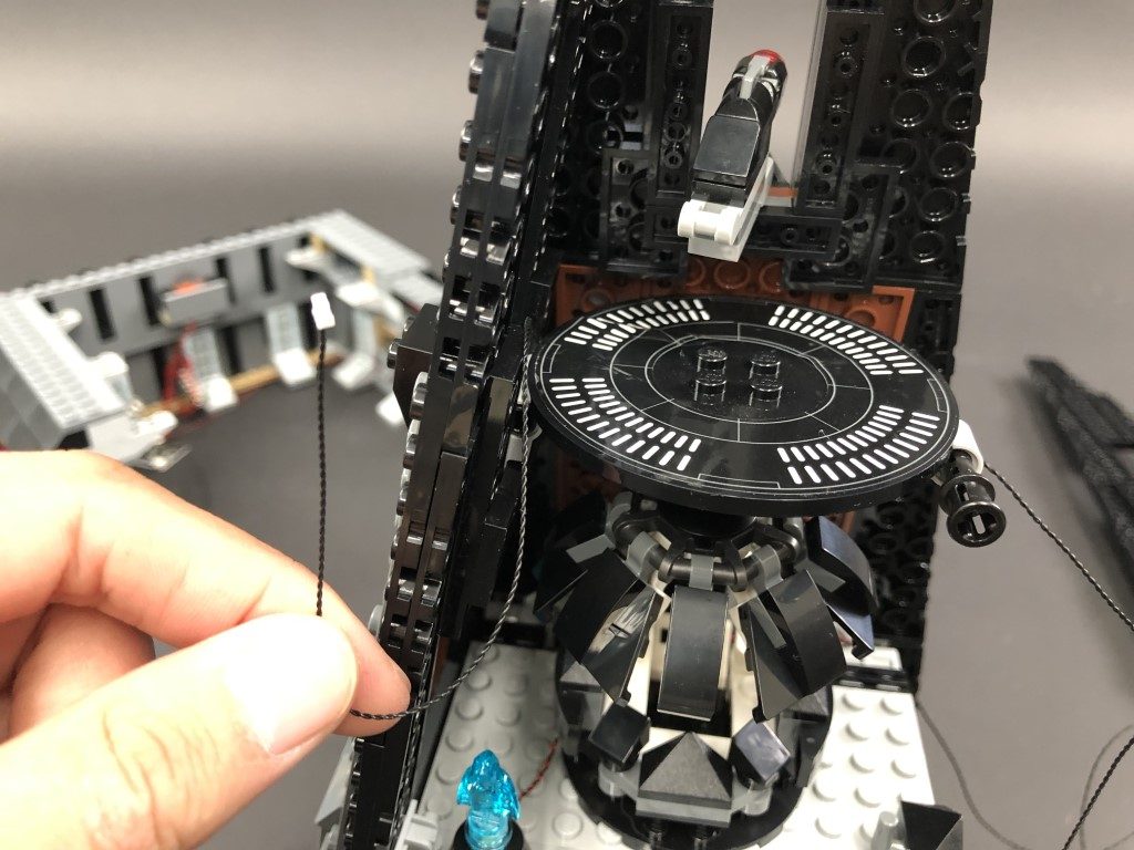
Reconnect the bacta tank then thread the cable behind and out the right side of this section.
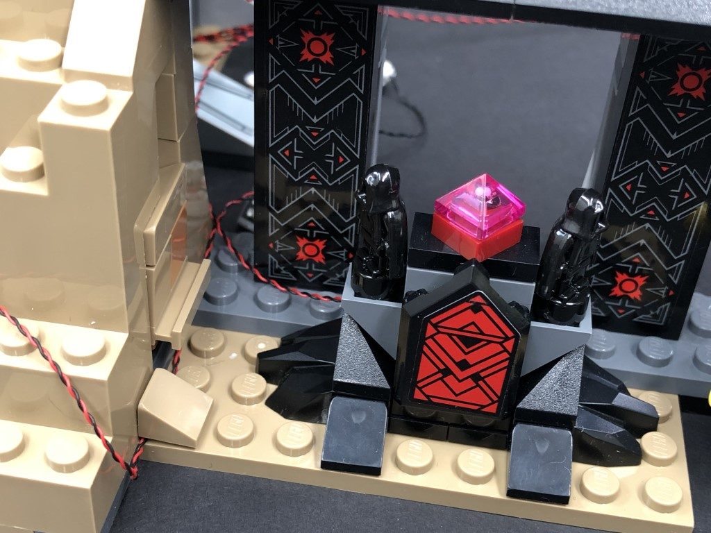
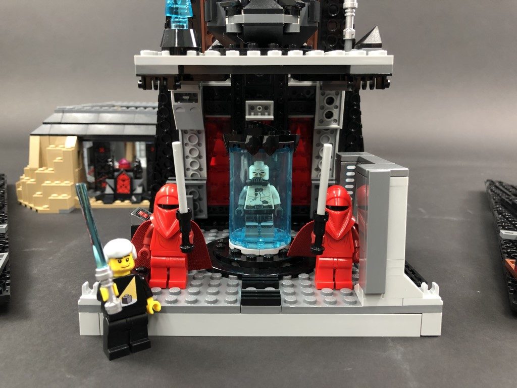
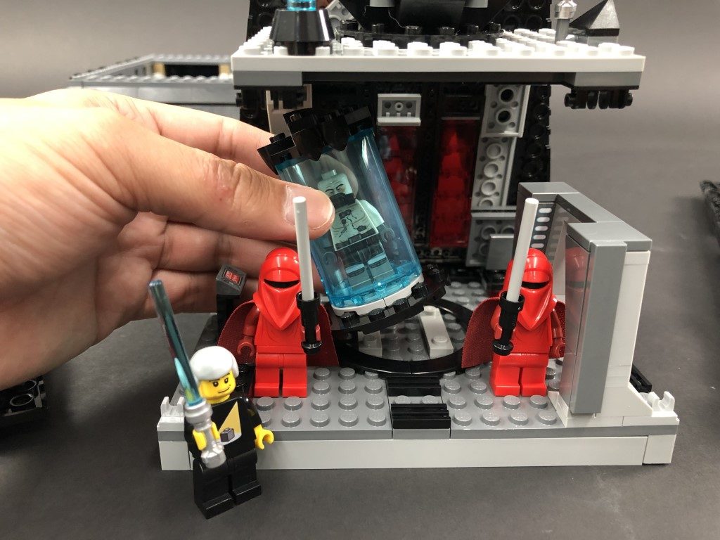
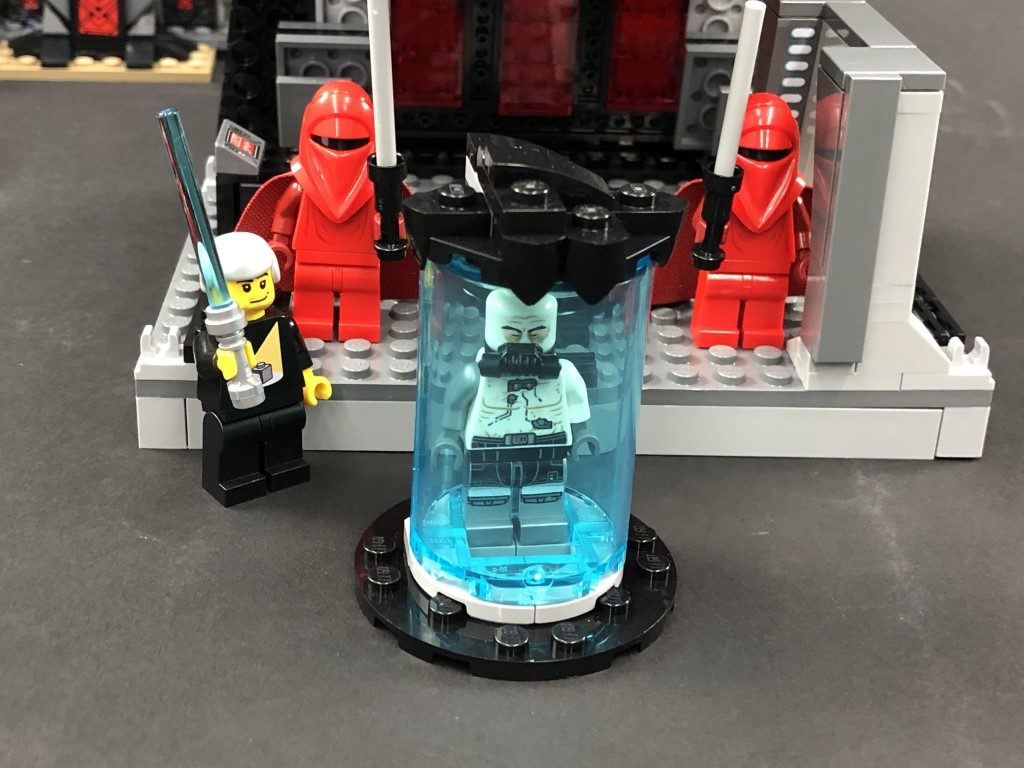
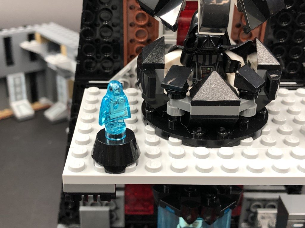
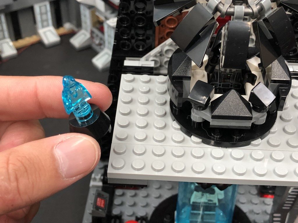
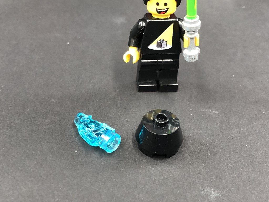
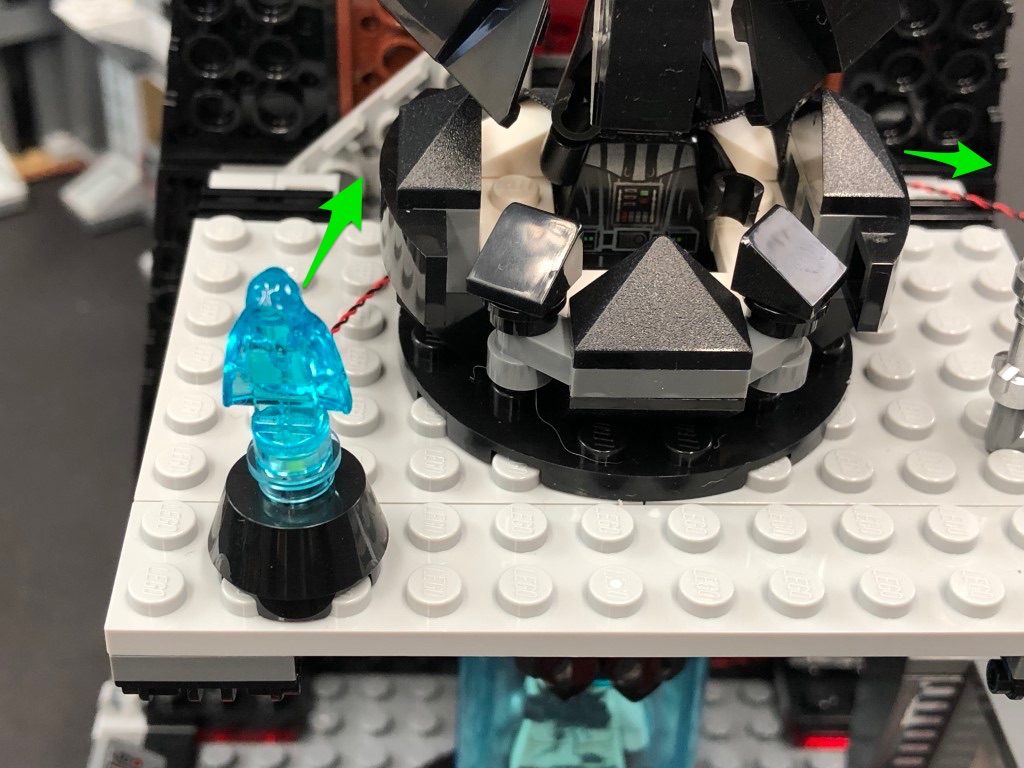
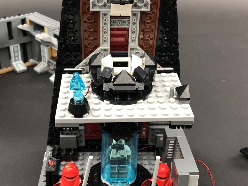
15.) Remove the Darth Sidious hologram from the level above and disassemble it as shown below:
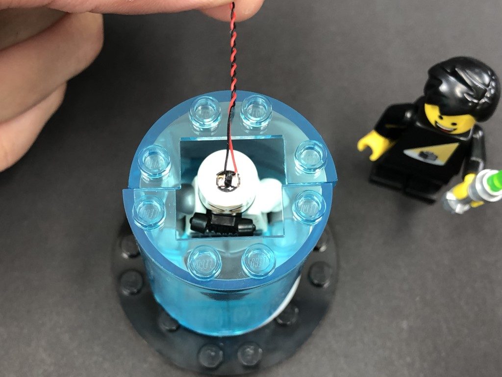
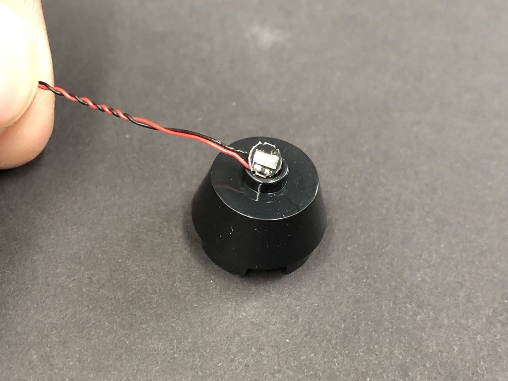
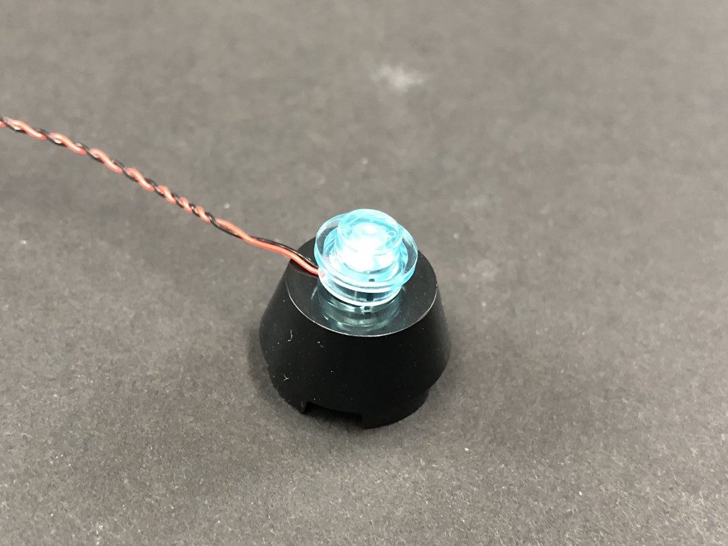
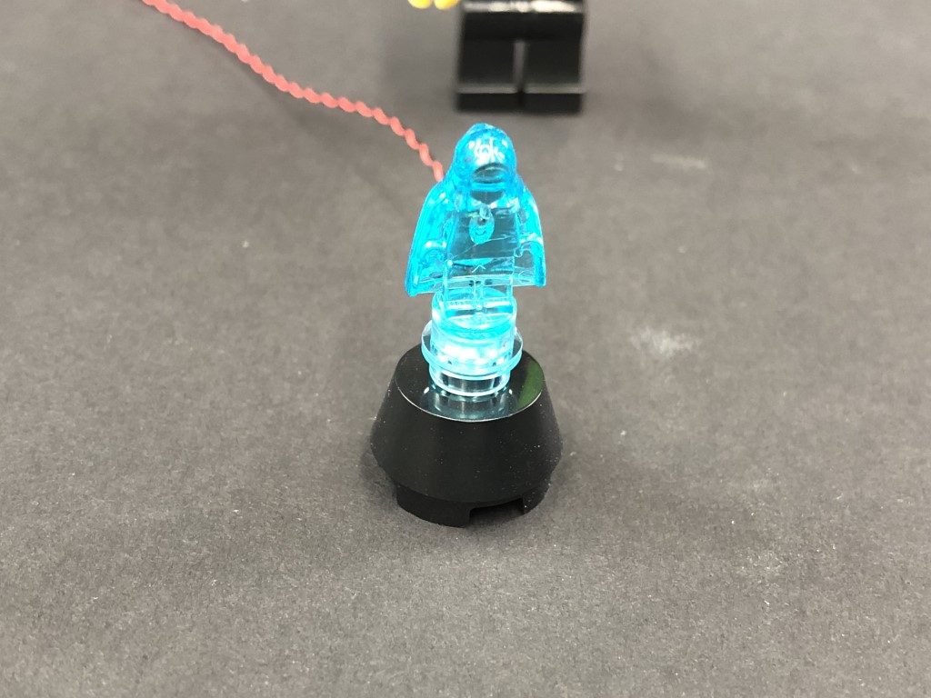
Take another Cool White 30cm Bit Light and place it over the black base’s stud. Secure the bit light in place by connecting a provided Trans Light Blue Round Plate 1×1 over the top, then reconnect the hologram piece ensuring the cable is facing the back.
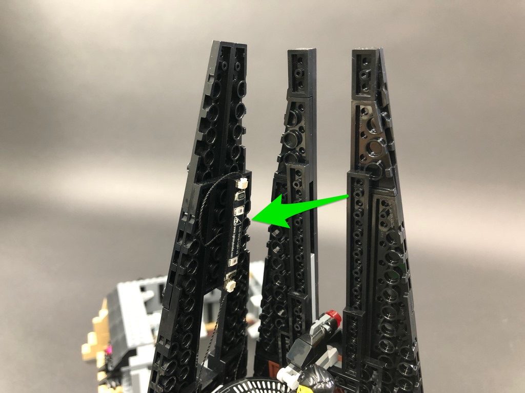
Reconnect this section back to the castle, then lay the cable behind Darth Vader’s throne and around to the right.
16.) Take both ends of the Cool White Bit Light cables and connect each to one of the OUT ports on a Flicker effects Board
Secure both cables underneath the following light grey plate with clip, then fold/twist the two cables around each other into a neat bunch as shown below:
Test the flickering lights by connecting your AA Battery Pack to the IN port on the Flicker Effects Board. Turn the battery pack on to see the bacta tank and hologram come to life.
Note: If you experience any issues with the lights not working and suspect an issue with a component, please try a different port on the expansion board to verify where the fault lies (with the light, expansion board or effects board). To correct any issues with expansion board ports, please view the section addressing expansion board issues on our online troubleshooting guide.
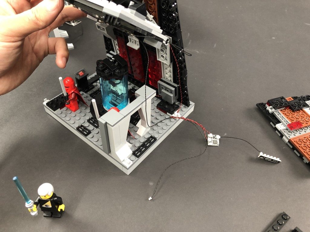
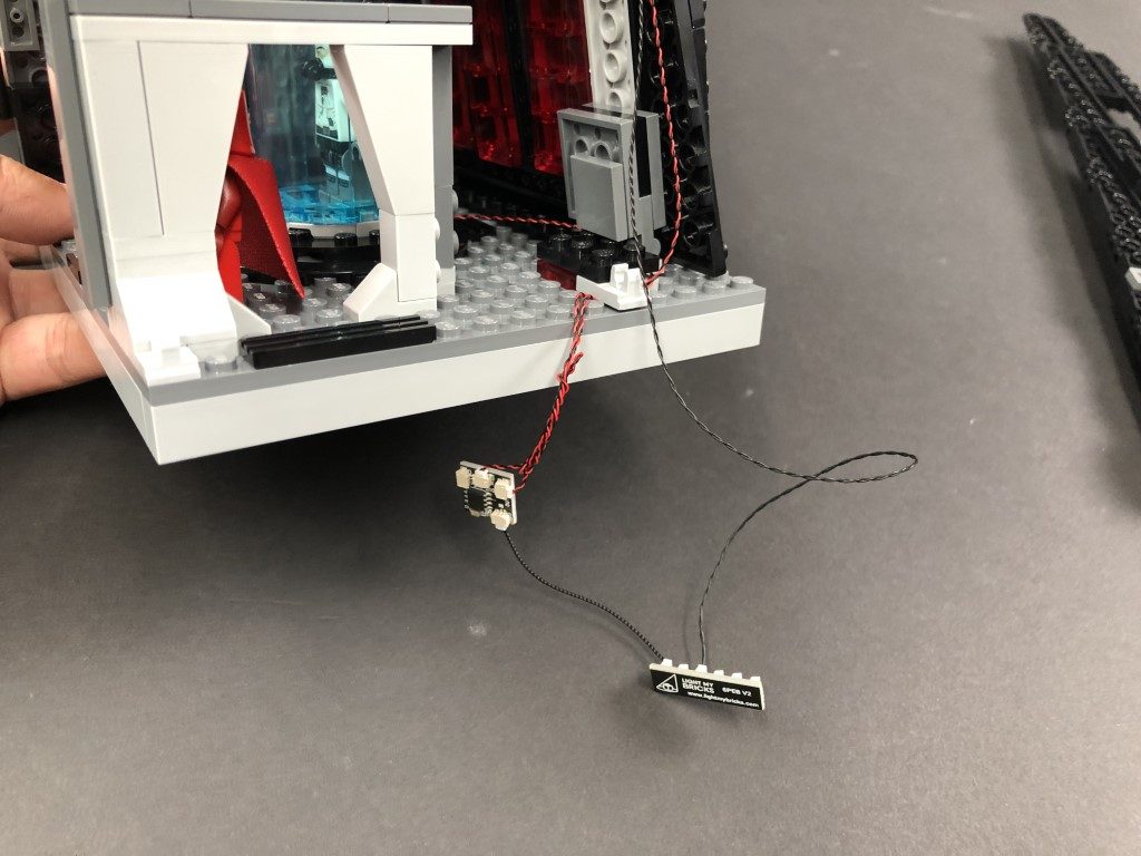
17.) Disconnect the AA Battery Pack, then connect a 5cm Connecting Cable to the IN port on the flicker effects board. Connect the other end of the cable to a new 6-Port Expansion Board.
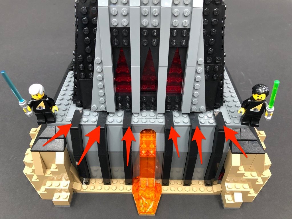
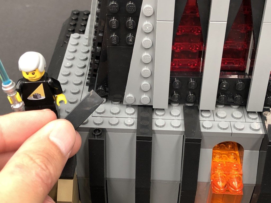
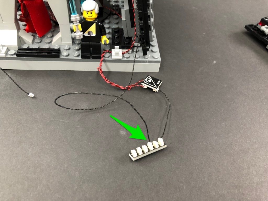
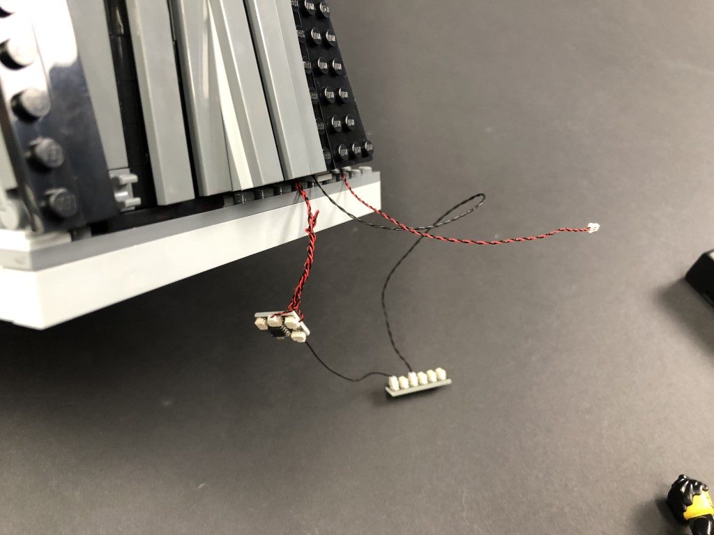
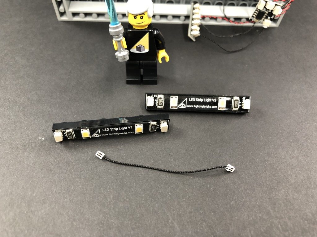
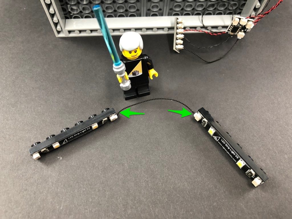
18.) Take 2x Red Strip Lights and using their adhesive backing, stick them to the bases of the provided 2x Black Plate 1×6, then connect the two strip lights together using a 5cm Connecting Cable.
Take a 30cm Connecting Cable and connect one end to the right strip light, then take a 15cm Connecting Cable and connect one end to the left strip light.
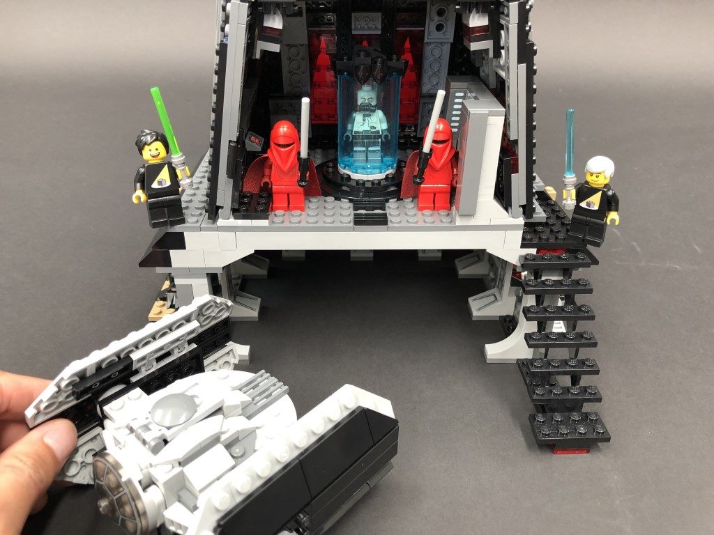
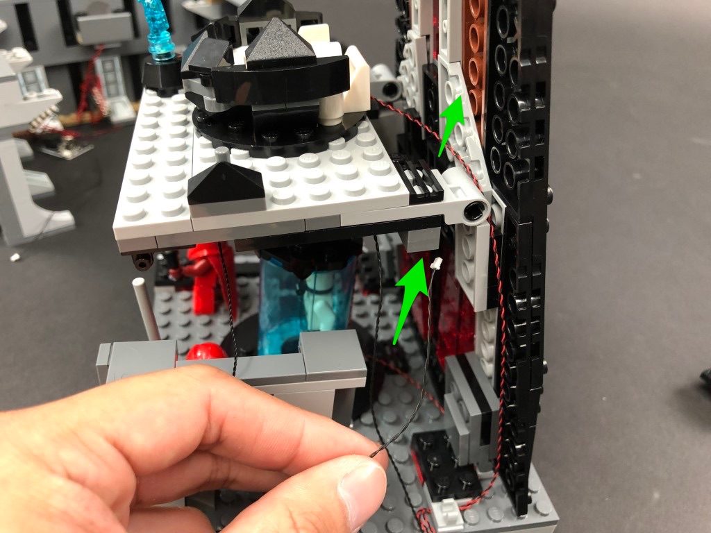
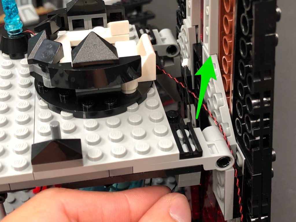
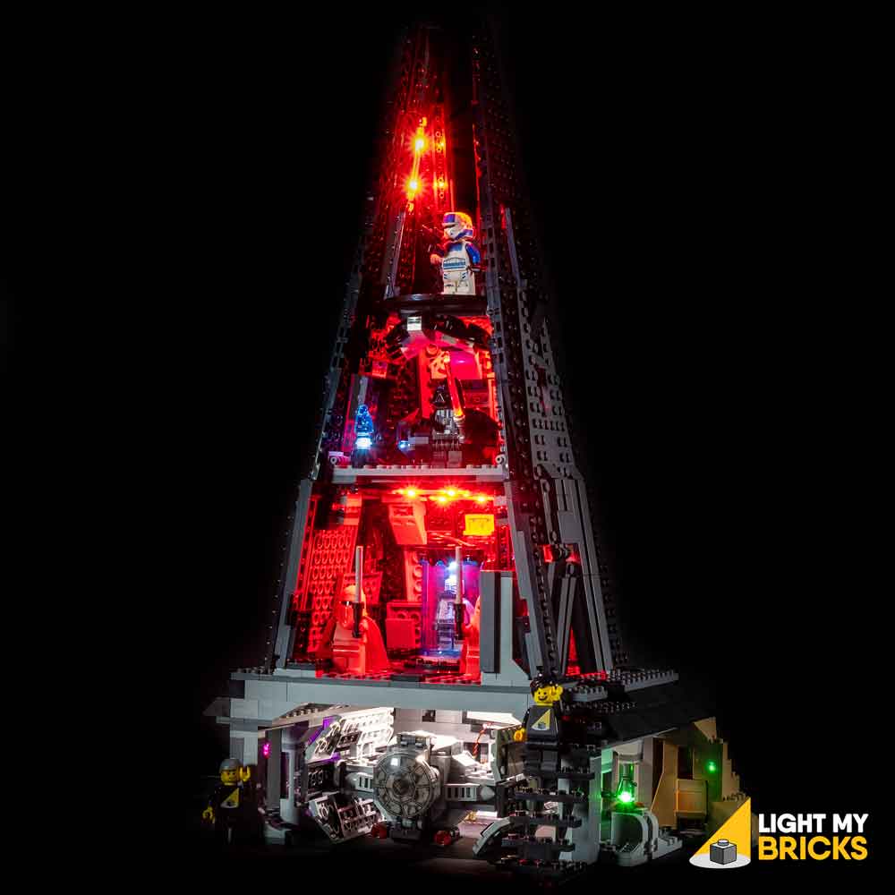
19.) Lift up the base where the darth vader meditation chamber is, then mount both Red Strip Lights underneath it in the below positions. Ensure the 30cm Connecting cable is closest to the back.
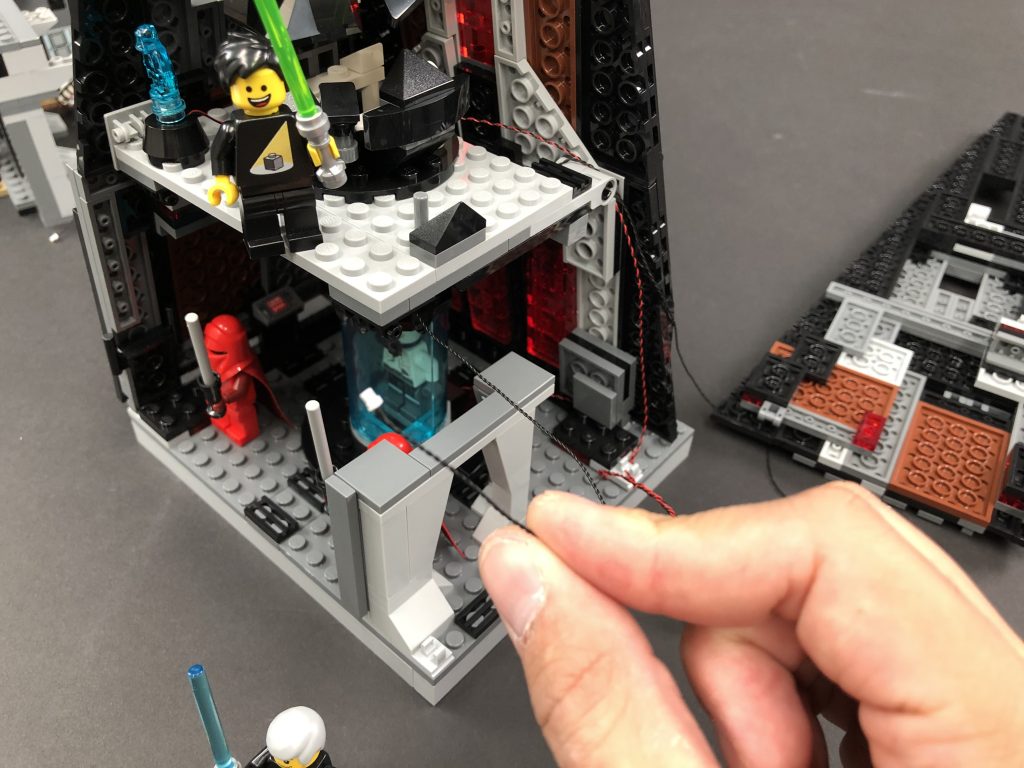
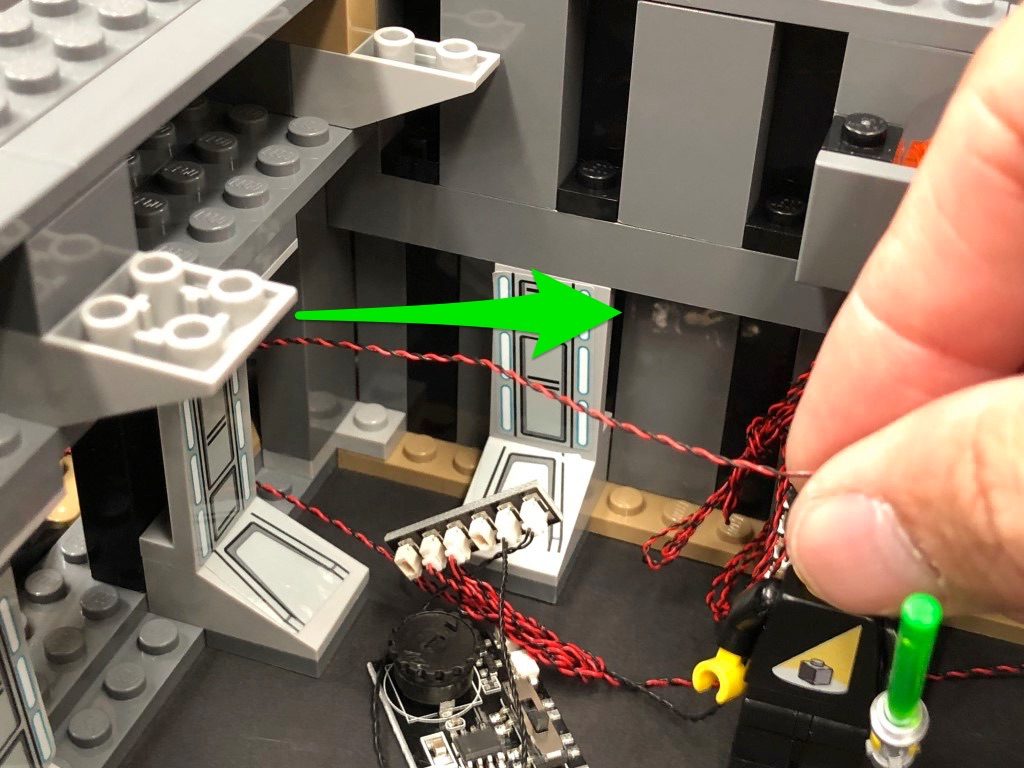
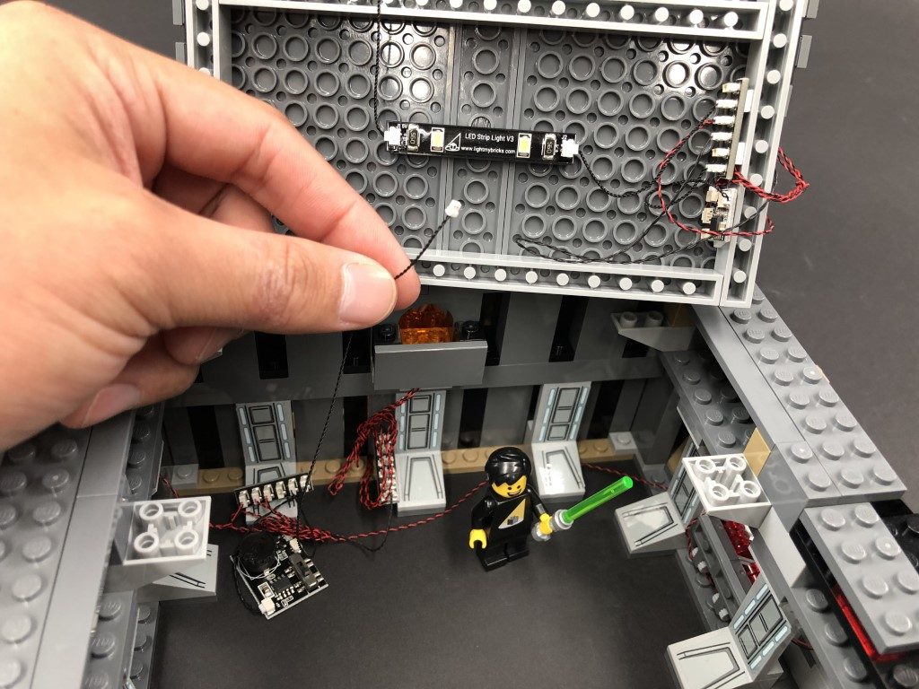
Take the other end of the 30cm Connecting Cable and thread it up the following space, which leads to the floor above (darth vader chamber). Pull the cable all the way out.
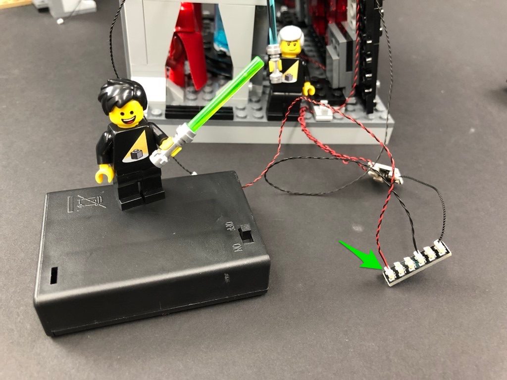
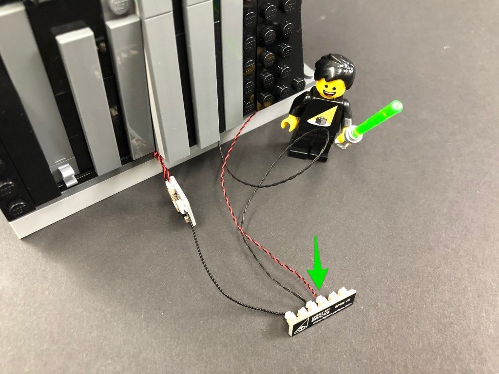
Connect the other end of the 30cm cable to the 6-Port Expansion Board below, then connect your AA Battery Pack to another spare port on the expansion board. Turn ON the battery pack to test the red strip lights are working OK.
Note: If you experience any issues with the lights not working and suspect an issue with a component, please try a different port on the expansion board to verify where the fault lies (with the light or expansion board). To correct any issues with expansion board ports, please view the section addressing expansion board issues on our online troubleshooting guide.
20.) Take the entire left wall section and reconnect it by clipping it to the base of this section as shown below:
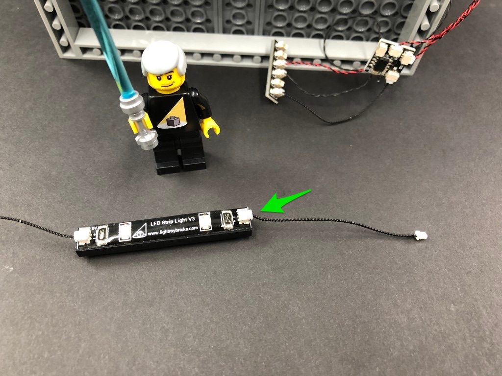
Take another Red Strip Light and using it’s adhesive backing, stick it to the bast of another provided Black Plate 1×6. Take the other end of the 15cm Connecting Cable from the red strip light from previous step and connect it to the Red Strip light from this step.
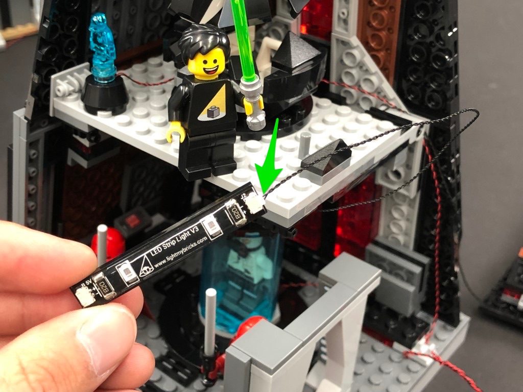
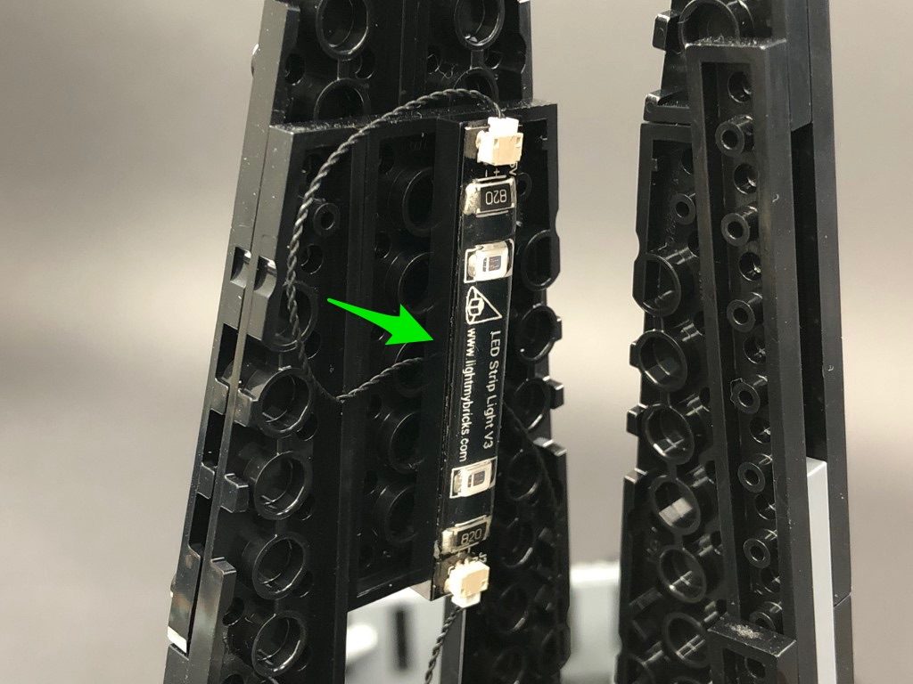
Take a new 15cm Connecting Cable and connect it to the other port on the Red Strip Light, then Mount the strip light underneath the top level as shown below. Ensure the spare end of the 15cm cable is facing the left.
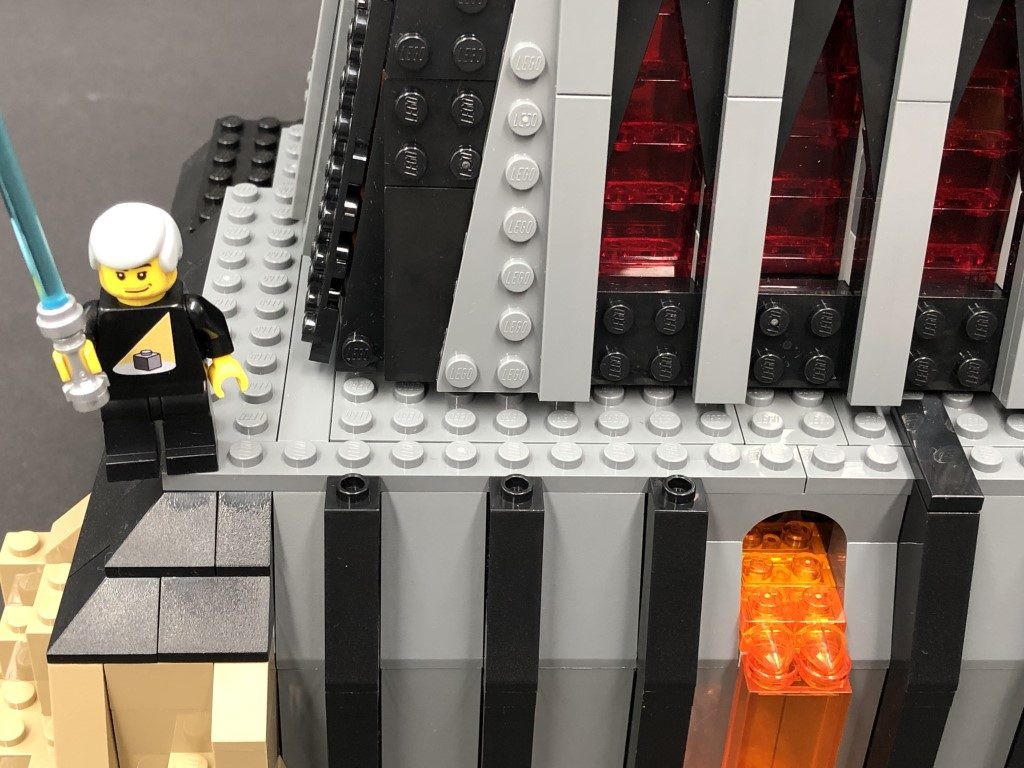
21.) Take another 2x Red Strip Lights and using their adhesive backings, stick them to the bases of another provided 2x Black Plate 1×6.
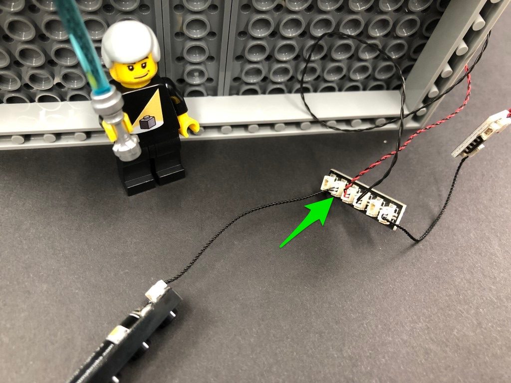
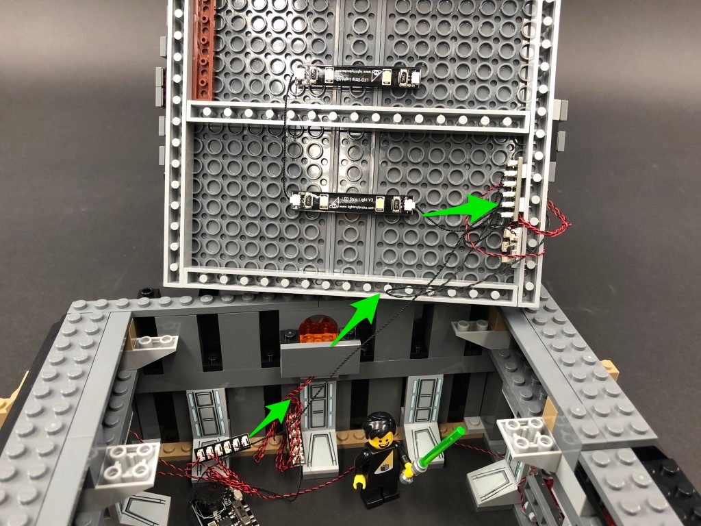
Take the other end of the 15cm Connecting Cable and thread it up to the top level and connect it to one of the Red Strip Lights. Take a new 30cm Connecting Cable and connect one end to the other side of the Red Strip Light.
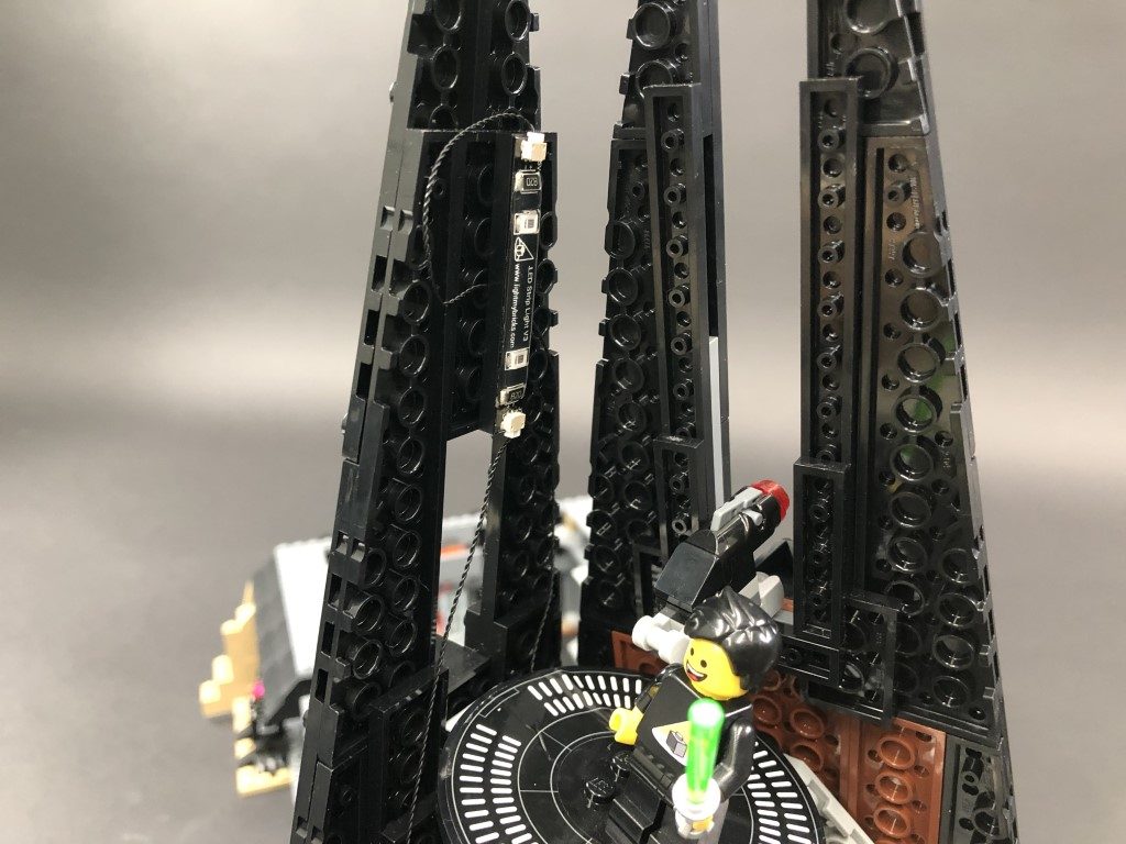
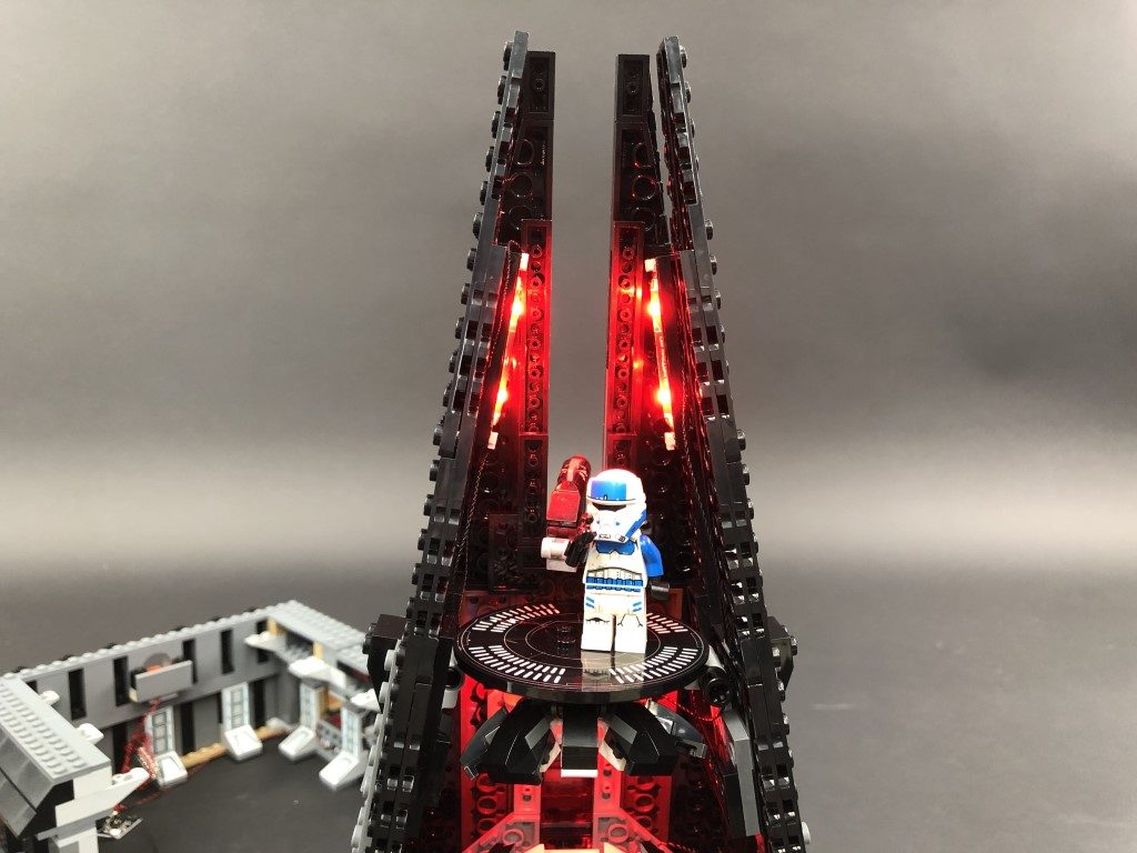
22.) Mount the Red Strip Light to the inside of the left wall in the following position. Ensure you loop the 15cm connecting cable underneath the 1×6 plate in order to eliminate excess cable.
Bring the other end of the 30cm Connecting Cable underneath the top level to bring it around to the right side. Connect it to the other spare Red Strip Light from previous step.
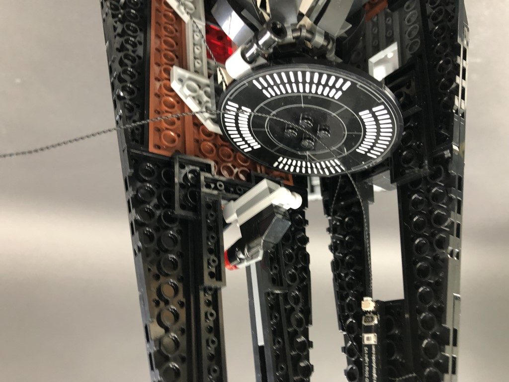
23.) Before reconnecting the main right wall section, ensure the bit light cables and connecting cable are laid to the left side of the light grey clip.
Mount the Red Strip Light from previous step to the inside of the right wall in the following position. Eliminate excess cable by looping the connecting cable underneath the black 1×6 plate.
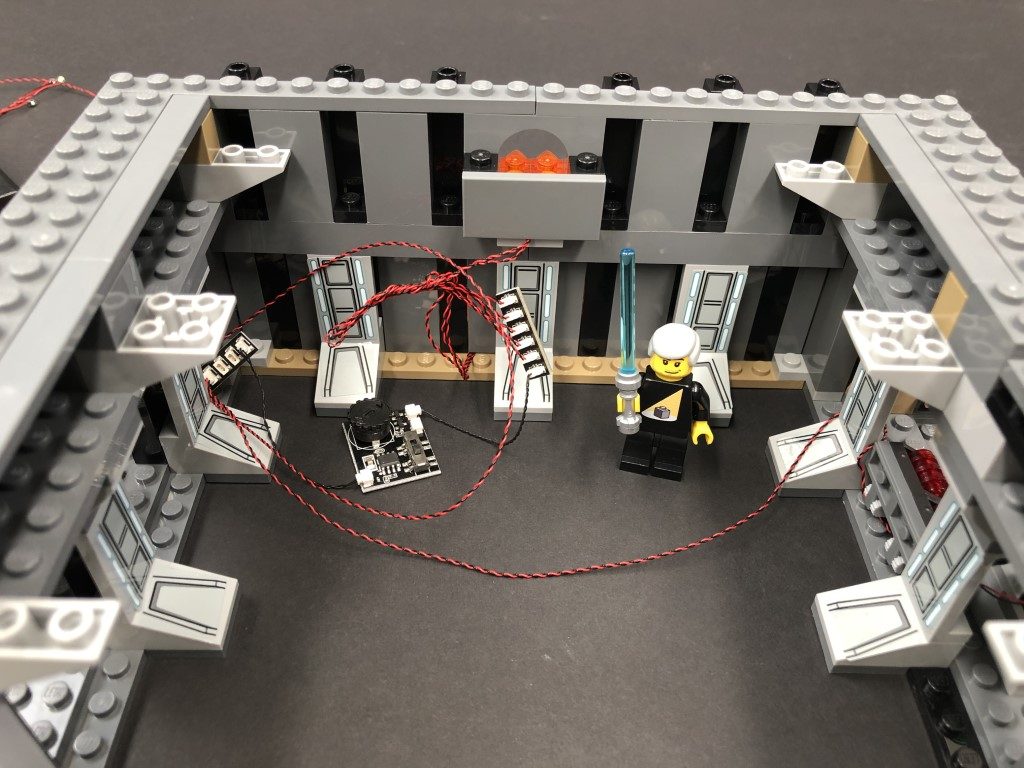
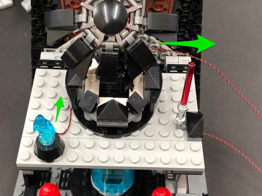
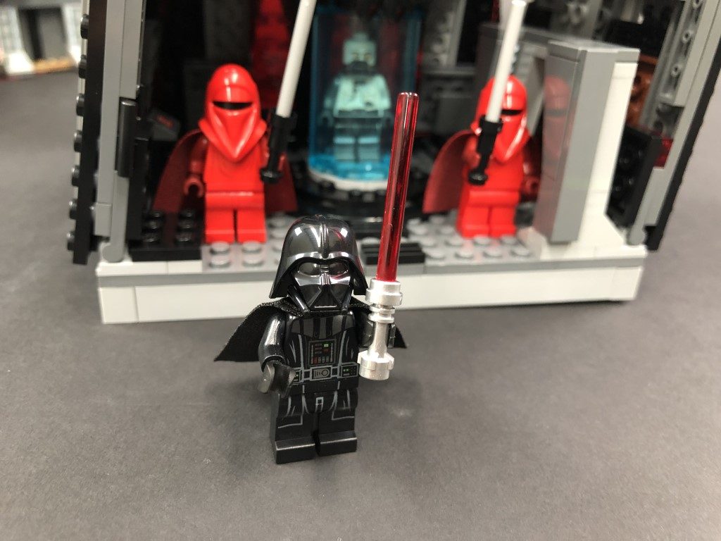
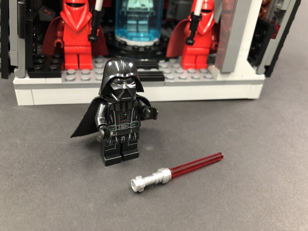
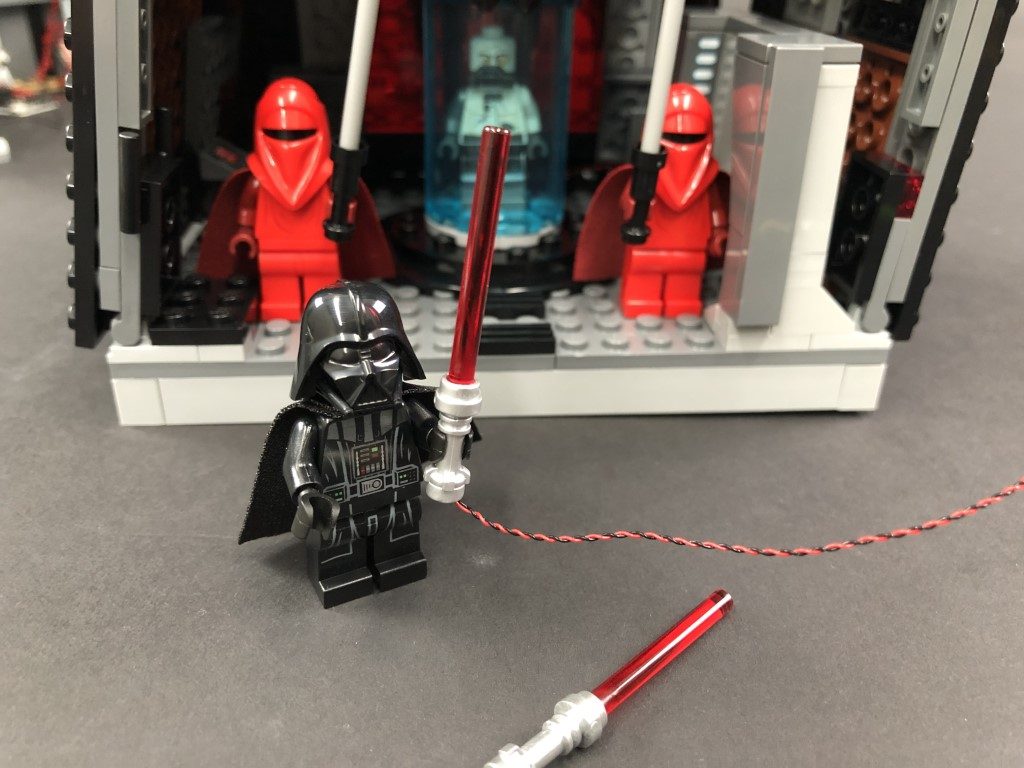
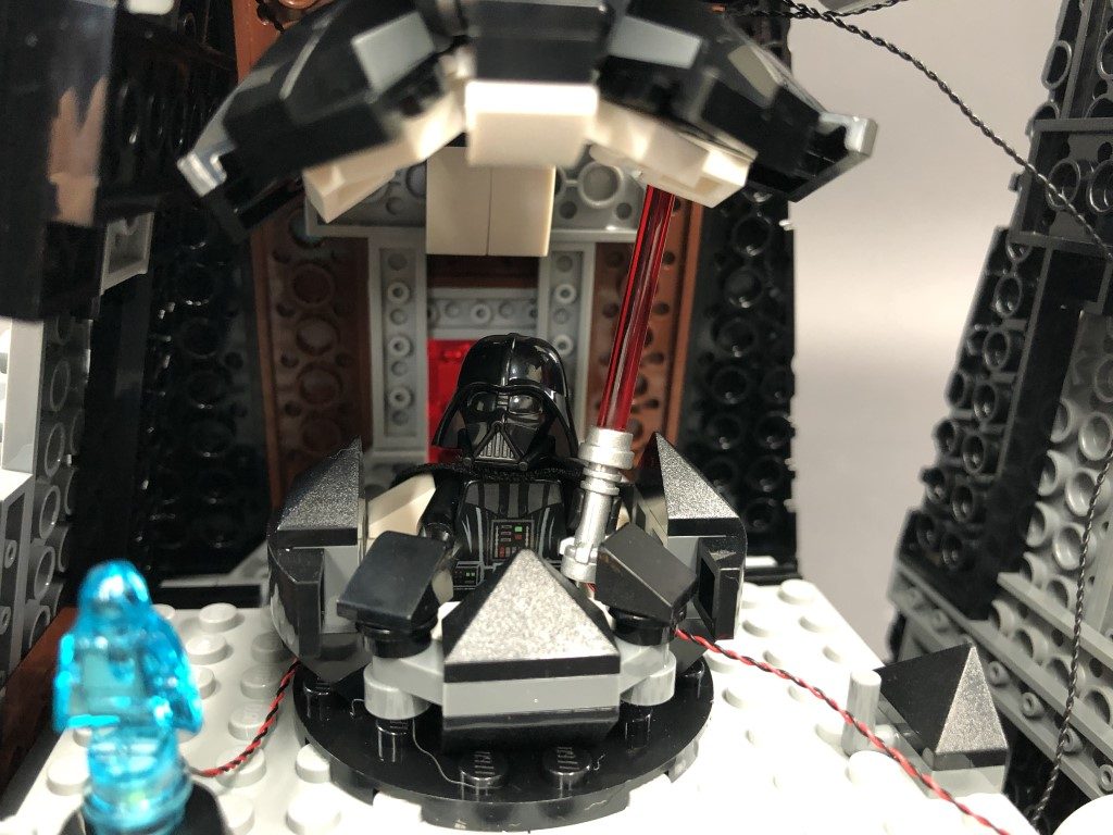
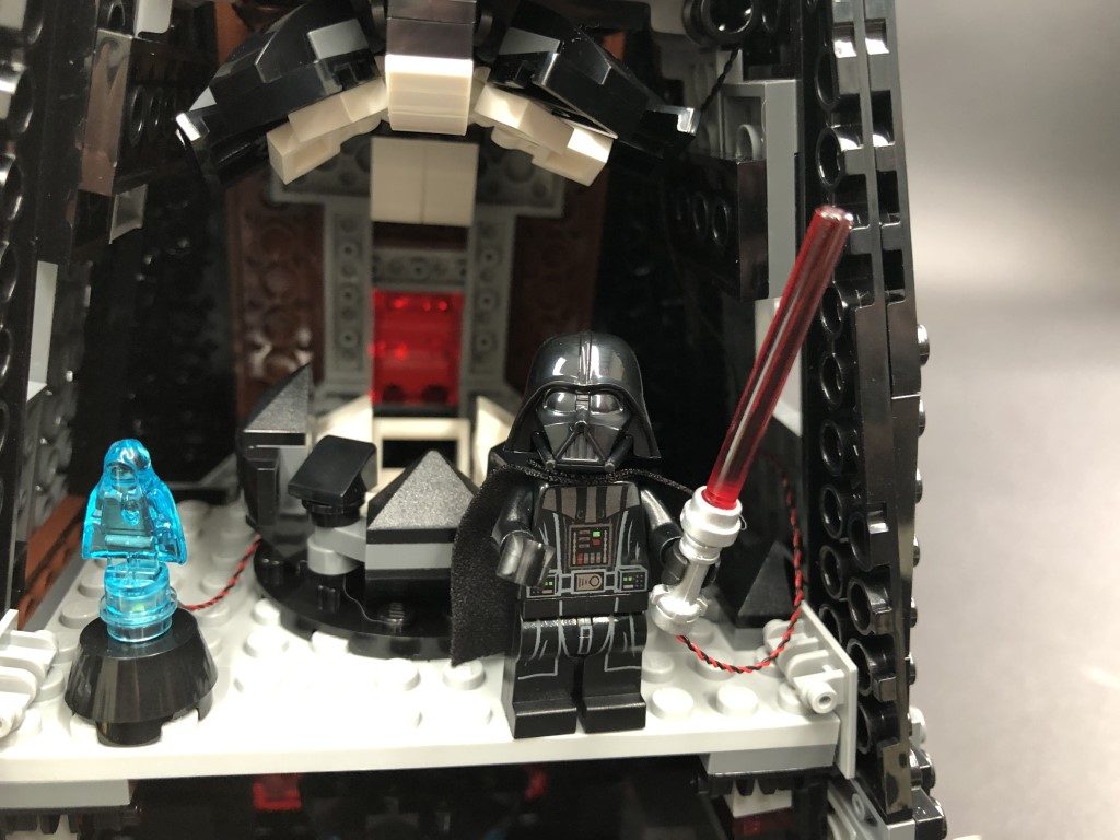
24.) Take Darth Vader and disconnect his lightsaber and replace it with the provided Red Light My Bricks Lightsaber.
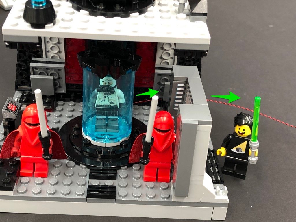
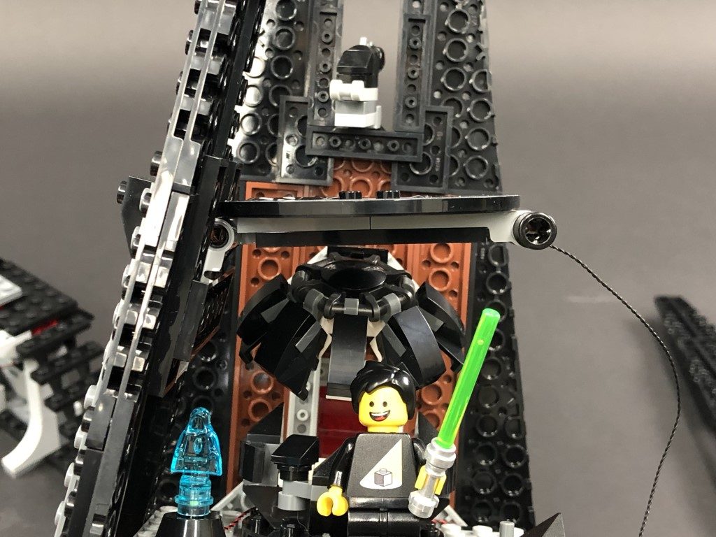
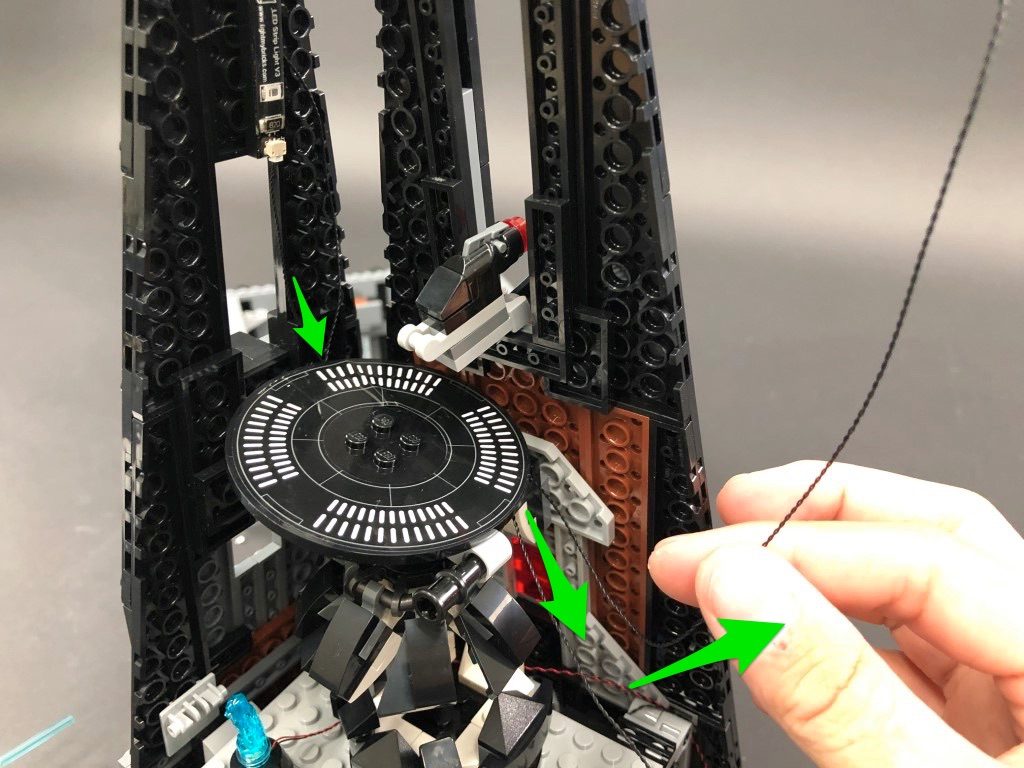
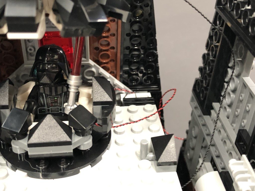
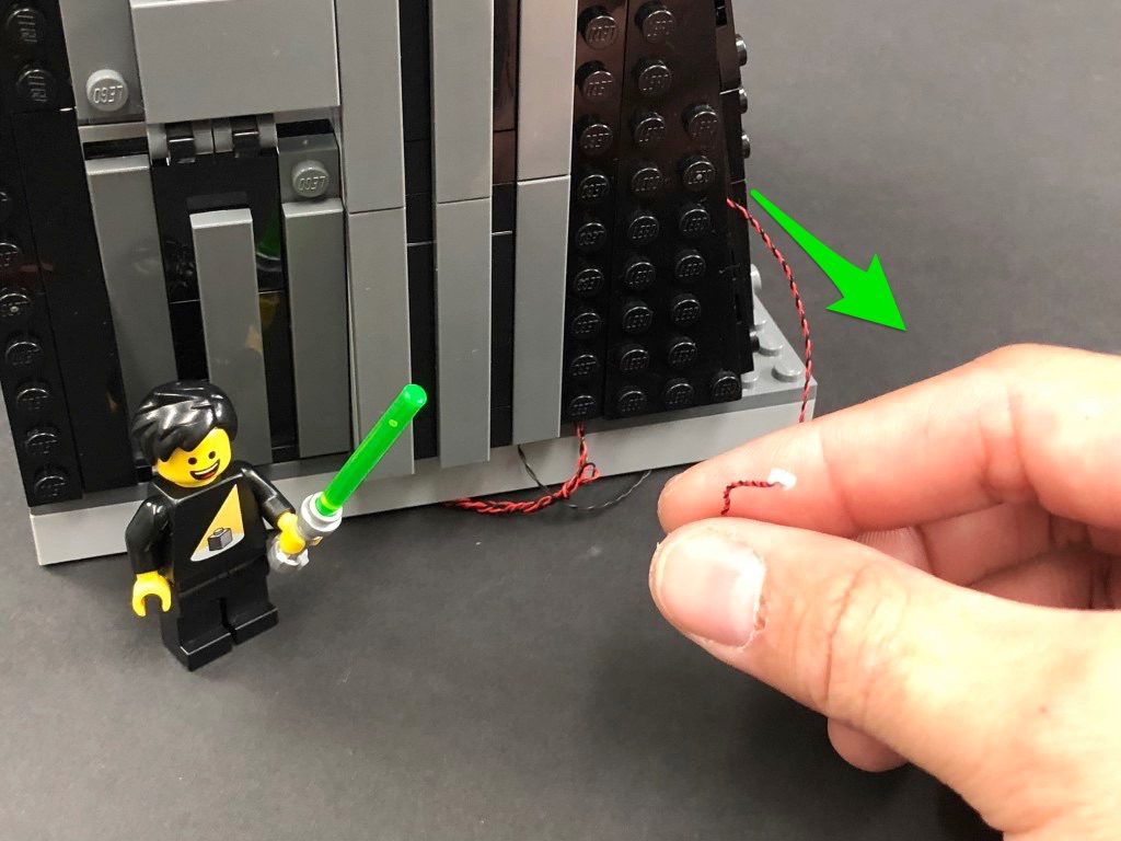
Place Darth Vader in his chamber (or anywhere on this floor) and bring the lightsaber cable behind and thread it through space in between this floor and the right wall. Pull the cable down from the outside, then secure it underneath the right wall.
Securely reconnect the right wall section by pushing in the black technic pin on the right, then connect the lightsaber cable to the 6-port Expansion Board underneath.
Connect the AA Battery Pack to a spare port on the 6-port Expansion Board and turn it ON to test all the lights in this main section are working OK.
Note: If you experience any issues with the lights not working and suspect an issue with a component, please try a different port on the expansion board to verify where the fault lies (with the light, expansion board or effects board). To correct any issues with expansion board ports, please view the section addressing expansion board issues on our online troubleshooting guide.
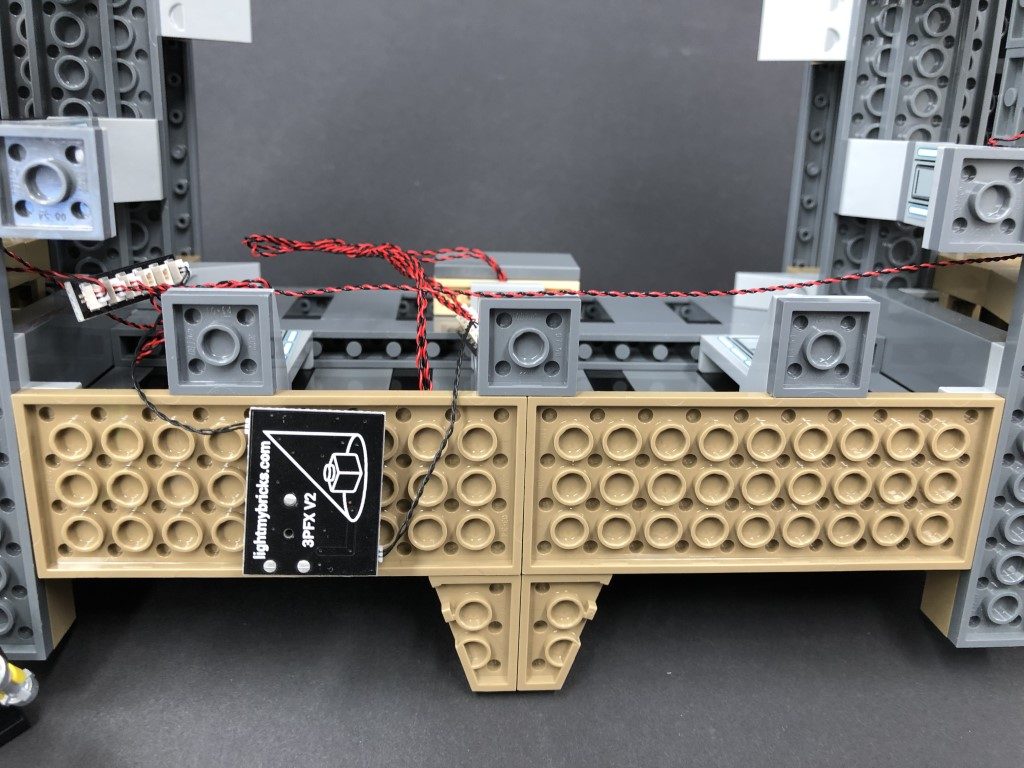
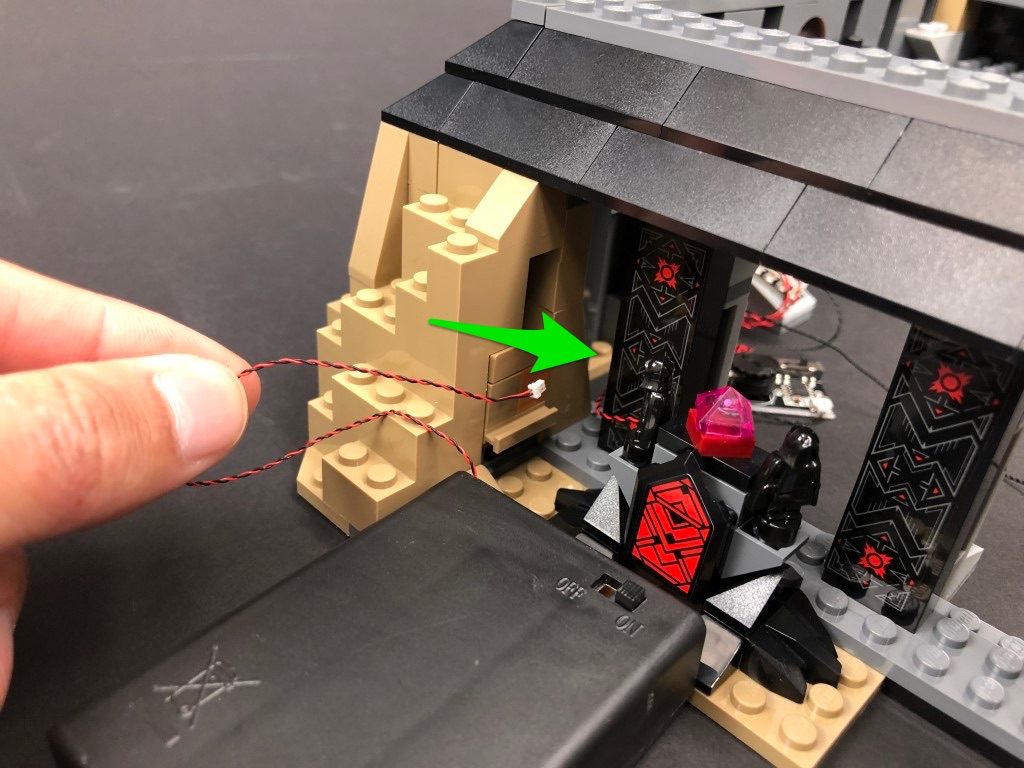
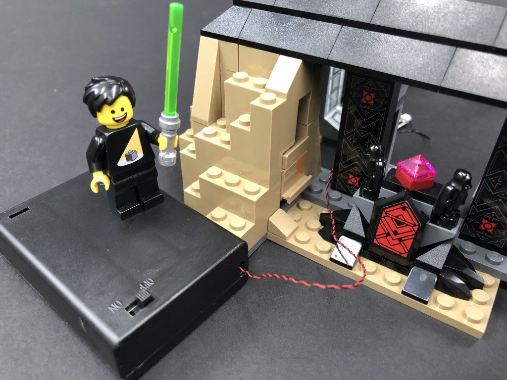
25.) Disconnect the AA Battery Pack and place it at the bottom of the castle on the left side. Thread the cable through the gap on the left side that leads to the inside of the castle. Connect the cable to a spare port on the second 6-port expansion board from step 8. Ensure you do not connect the battery pack to the 6-port expansion board with the “lava lights” connected to it.
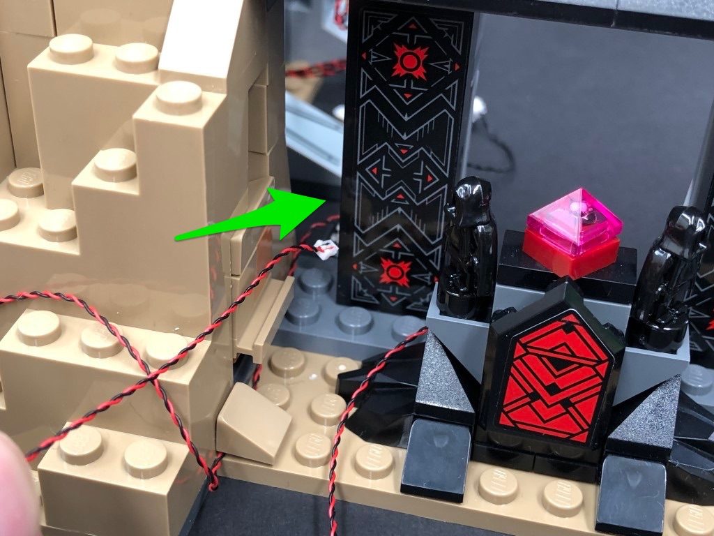
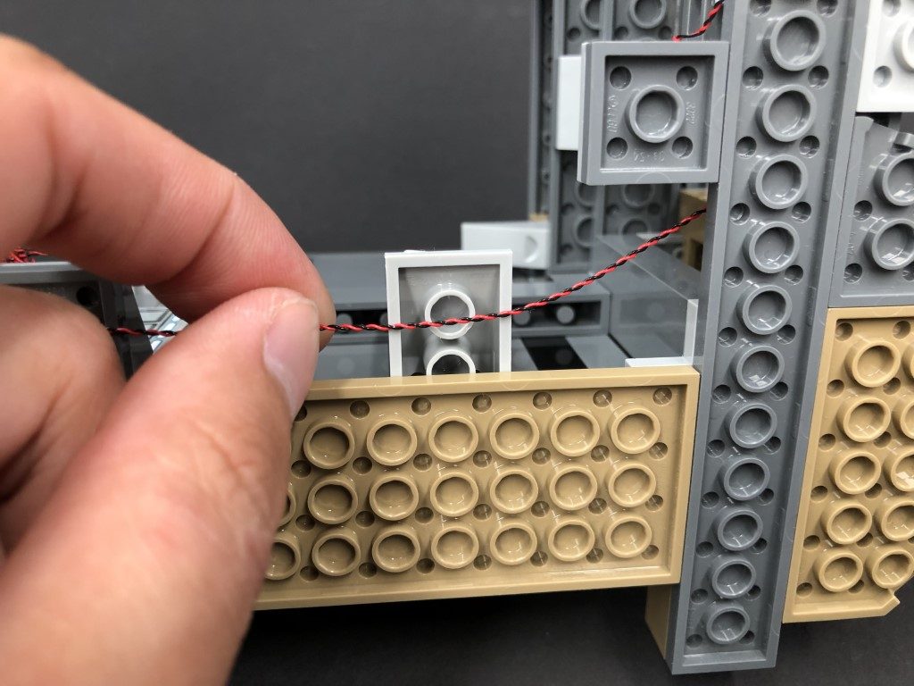
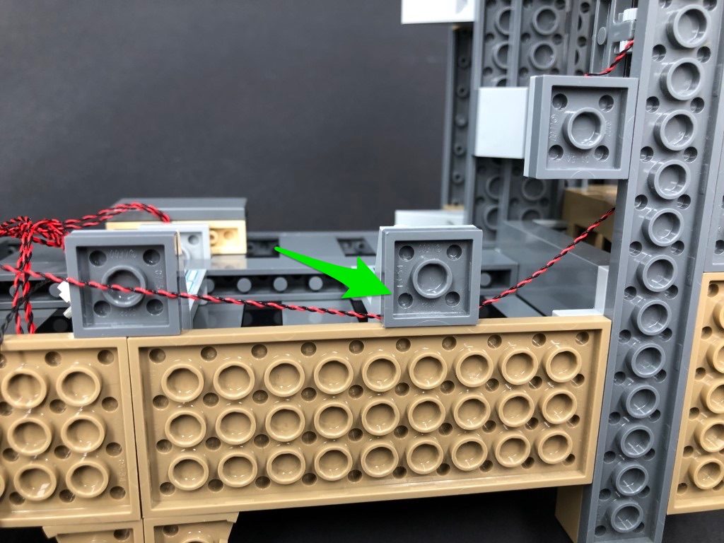
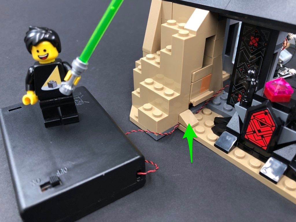
Secure the cable in place by laying it underneath the tan coloured 1×1 angled tile.
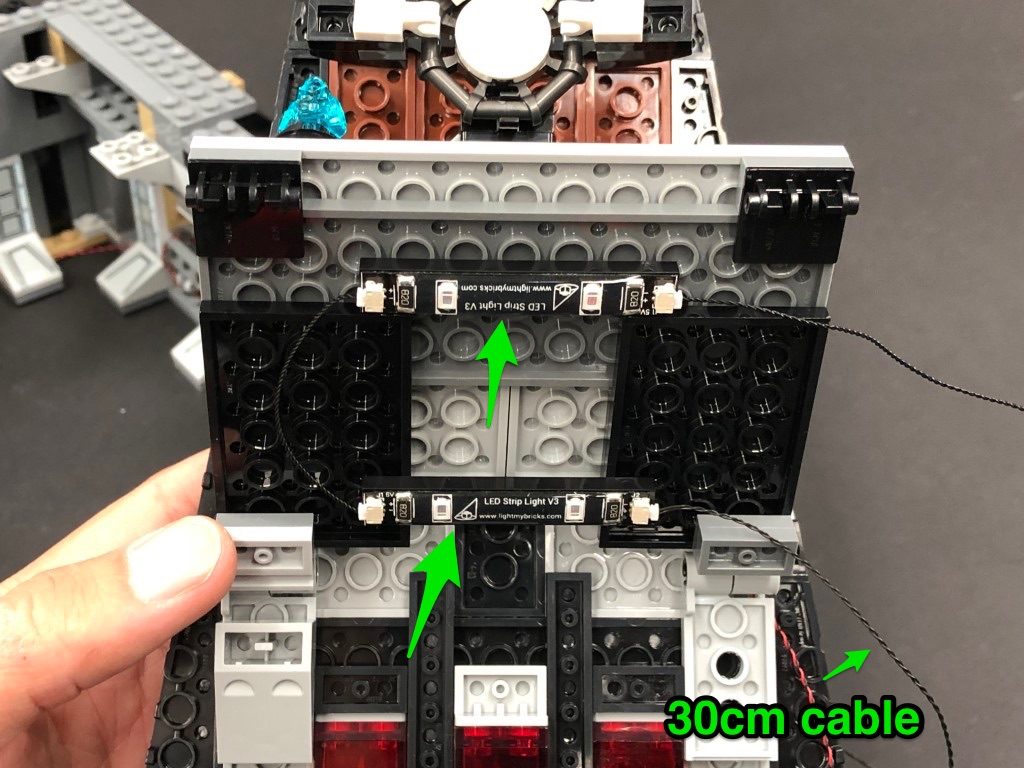
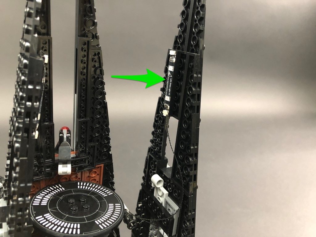
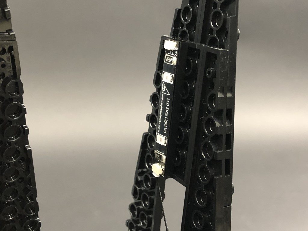
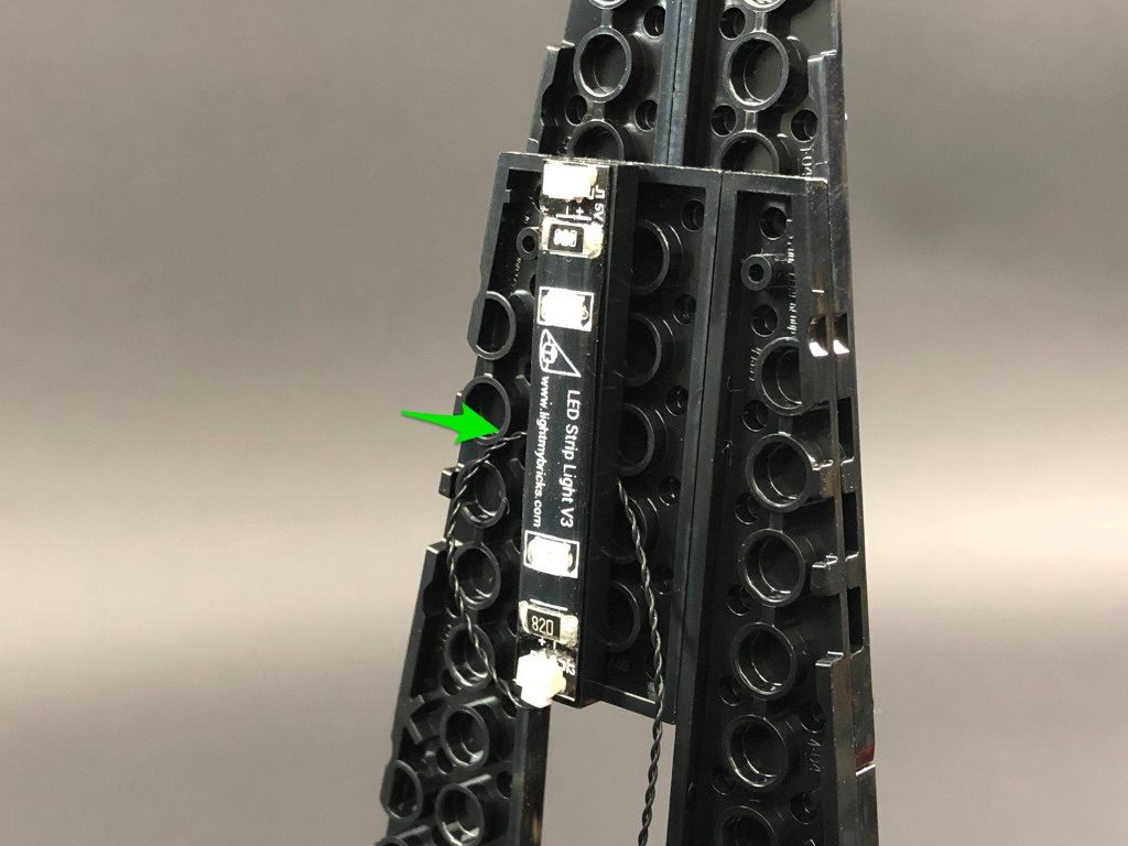
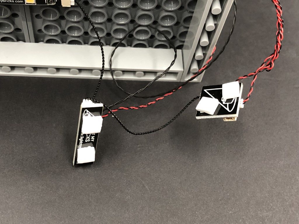
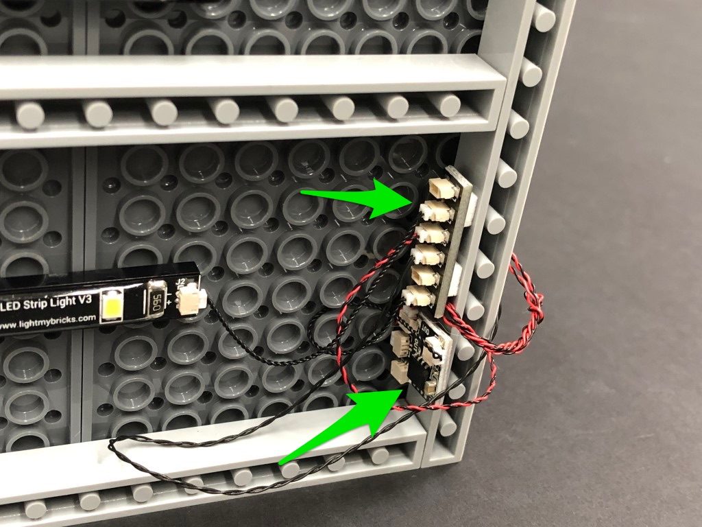
26.) Carefully turn the main section of the castle onto it’s front so we can access underneath. Take 2x White Strip Lights and using their adhesive backings, stick them to the bases of provided 2x Black Plate 1×6. Connect the two strip lights together using a 5cm Connecting Cable.
Take a new 5cm Connecting Cable and connect it to the other end of one of the white strip lights. Connect the other end of the cable to the 6-port expansion board underneath this section.
27.) Mount both strip lights underneath the main section of the castle in the following positions. Ensure the strip light connected to the expansion board is closest to the back.
13.) We will now install lights to the main section of the castle. First pull out the black technic pin on the right side, then disconnect the two walls by unclipping them from the bottom.
Remove the Darth Vader’s bacta tank, disconnect the top of it as shown below:
14.) Take a Cool White 30cm Bit Light and with the led facing down and cable laid behind, place if over the top of the tank, then secure it in place by reconnecting the top section. If you look up from the front of the tank, you should be able to see the Bit Light facing down.
Turn the tank around to the back and fold the cable down and secure it underneath the black angled brick at the bottom.
Reconnect the bacta tank then thread the cable behind and out the right side of this section.
15.) Remove the Darth Sidious hologram from the level above and disassemble it as shown below:
Take another Cool White 30cm Bit Light and place it over the black base’s stud. Secure the bit light in place by connecting a provided Trans Light Blue Round Plate 1×1 over the top, then reconnect the hologram piece ensuring the cable is facing the back.
Reconnect this section back to the castle, then lay the cable behind Darth Vader’s throne and around to the right.
16.) Take both ends of the Cool White Bit Light cables and connect each to one of the OUT ports on a Flicker effects Board
Secure both cables underneath the following light grey plate with clip, then fold/twist the two cables around each other into a neat bunch as shown below:
Test the flickering lights by connecting your AA Battery Pack to the IN port on the Flicker Effects Board. Turn the battery pack on to see the bacta tank and hologram come to life.
Note: If you experience any issues with the lights not working and suspect an issue with a component, please try a different port on the expansion board to verify where the fault lies (with the light, expansion board or effects board). To correct any issues with expansion board ports, please view the section addressing expansion board issues on our online troubleshooting guide.
17.) Disconnect the AA Battery Pack, then connect a 5cm Connecting Cable to the IN port on the flicker effects board. Connect the other end of the cable to a new 6-Port Expansion Board.
18.) Take 2x Red Strip Lights and using their adhesive backing, stick them to the bases of the provided 2x Black Plate 1×6, then connect the two strip lights together using a 5cm Connecting Cable.
Take a 30cm Connecting Cable and connect one end to the right strip light, then take a 15cm Connecting Cable and connect one end to the left strip light.
19.) Lift up the base where the darth vader meditation chamber is, then mount both Red Strip Lights underneath it in the below positions. Ensure the 30cm Connecting cable is closest to the back.
Take the other end of the 30cm Connecting Cable and thread it up the following space, which leads to the floor above (darth vader chamber). Pull the cable all the way out.
Connect the other end of the 30cm cable to the 6-Port Expansion Board below, then connect your AA Battery Pack to another spare port on the expansion board. Turn ON the battery pack to test the red strip lights are working OK.
Note: If you experience any issues with the lights not working and suspect an issue with a component, please try a different port on the expansion board to verify where the fault lies (with the light or expansion board). To correct any issues with expansion board ports, please view the section addressing expansion board issues on our online troubleshooting guide.
20.) Take the entire left wall section and reconnect it by clipping it to the base of this section as shown below:
Take another Red Strip Light and using it’s adhesive backing, stick it to the bast of another provided Black Plate 1×6. Take the other end of the 15cm Connecting Cable from the red strip light from previous step and connect it to the Red Strip light from this step.
Take a new 15cm Connecting Cable and connect it to the other port on the Red Strip Light, then Mount the strip light underneath the top level as shown below. Ensure the spare end of the 15cm cable is facing the left.
21.) Take another 2x Red Strip Lights and using their adhesive backings, stick them to the bases of another provided 2x Black Plate 1×6.
Take the other end of the 15cm Connecting Cable and thread it up to the top level and connect it to one of the Red Strip Lights. Take a new 30cm Connecting Cable and connect one end to the other side of the Red Strip Light.
22.) Mount the Red Strip Light to the inside of the left wall in the following position. Ensure you loop the 15cm connecting cable underneath the 1×6 plate in order to eliminate excess cable.
Bring the other end of the 30cm Connecting Cable underneath the top level to bring it around to the right side. Connect it to the other spare Red Strip Light from previous step.
23.) Before reconnecting the main right wall section, ensure the bit light cables and connecting cable are laid to the left side of the light grey clip.
Mount the Red Strip Light from previous step to the inside of the right wall in the following position. Eliminate excess cable by looping the connecting cable underneath the black 1×6 plate.
24.) Take Darth Vader and disconnect his lightsaber and replace it with the provided Red Light My Bricks Lightsaber.
Place Darth Vader in his chamber (or anywhere on this floor) and bring the lightsaber cable behind and thread it through space in between this floor and the right wall. Pull the cable down from the outside, then secure it underneath the right wall.
Securely reconnect the right wall section by pushing in the black technic pin on the right, then connect the lightsaber cable to the 6-port Expansion Board underneath.
Connect the AA Battery Pack to a spare port on the 6-port Expansion Board and turn it ON to test all the lights in this main section are working OK.
Note: If you experience any issues with the lights not working and suspect an issue with a component, please try a different port on the expansion board to verify where the fault lies (with the light, expansion board or effects board). To correct any issues with expansion board ports, please view the section addressing expansion board issues on our online troubleshooting guide.
25.) Disconnect the AA Battery Pack and place it at the bottom of the castle on the left side. Thread the cable through the gap on the left side that leads to the inside of the castle. Connect the cable to a spare port on the second 6-port expansion board from step 8. Ensure you do not connect the battery pack to the 6-port expansion board with the “lava lights” connected to it.
Secure the cable in place by laying it underneath the tan coloured 1×1 angled tile.
26.) Carefully turn the main section of the castle onto it’s front so we can access underneath. Take 2x White Strip Lights and using their adhesive backings, stick them to the bases of provided 2x Black Plate 1×6. Connect the two strip lights together using a 5cm Connecting Cable.
Take a new 5cm Connecting Cable and connect it to the other end of one of the white strip lights. Connect the other end of the cable to the 6-port expansion board underneath this section.
27.) Mount both strip lights underneath the main section of the castle in the following positions. Ensure the strip light connected to the expansion board is closest to the back.
 Take 4x Adhesive Squares and stick two to the back of the expansion board, and another two to the back of the flicker effects board. Mount both expansion board and effects board to the side of the underneath section as shown below:
28.) Take the main section of the castle over the top of the base section. Locate the other end of the 15cm Connecting Cable from step 12 and connect it to a spare port on the 6-port expansion board underneath the main section of the castle.
Securely reconnect the main section on top of the base section ensuring you first connect the right side (to prevent pinching cables on the right side)
29.) Reconnect the black tiles along the front of the castle to secure the main section down, then place the tie fighter back to the bottom section of the castle.
This finally completes installation of the Light My Bricks Darth Vader Castle Light Kit. We thank YOU for purchasing this product and hope you enjoy!
Take 4x Adhesive Squares and stick two to the back of the expansion board, and another two to the back of the flicker effects board. Mount both expansion board and effects board to the side of the underneath section as shown below:
28.) Take the main section of the castle over the top of the base section. Locate the other end of the 15cm Connecting Cable from step 12 and connect it to a spare port on the 6-port expansion board underneath the main section of the castle.
Securely reconnect the main section on top of the base section ensuring you first connect the right side (to prevent pinching cables on the right side)
29.) Reconnect the black tiles along the front of the castle to secure the main section down, then place the tie fighter back to the bottom section of the castle.
This finally completes installation of the Light My Bricks Darth Vader Castle Light Kit. We thank YOU for purchasing this product and hope you enjoy!