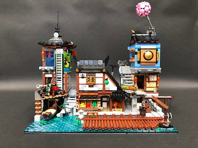
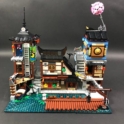
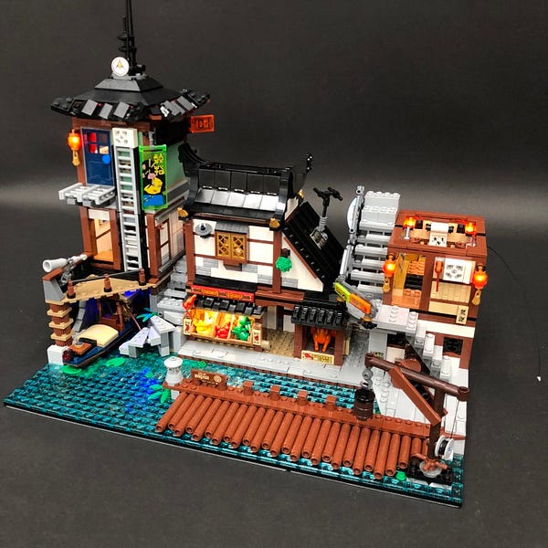
The following page is the instructions for the Light My Bricks LEGO Ninjago City Docks (70657) LED light kit.
To ensure a trouble-free installation of your light kit, please read and follow each step carefully.
If you run into any issues, please refer to the online troubleshooting guide.
To download this instructions guide in PDF format please click here.
Please note: This page lists instructions for the LED light kit only. If you are wishing to purchase the Light My Bricks LEGO Ninjago City Docks (70657) LED light kit , please click here to view the product page
Package Contents:
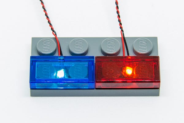
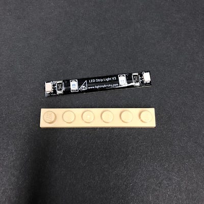
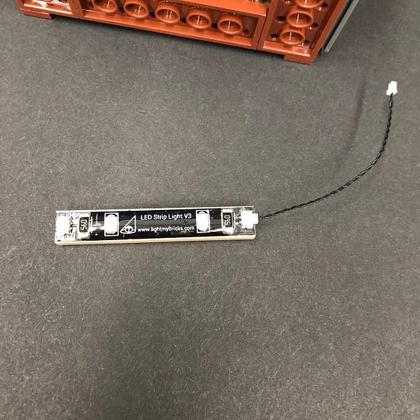
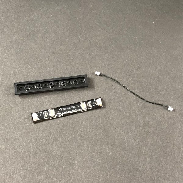
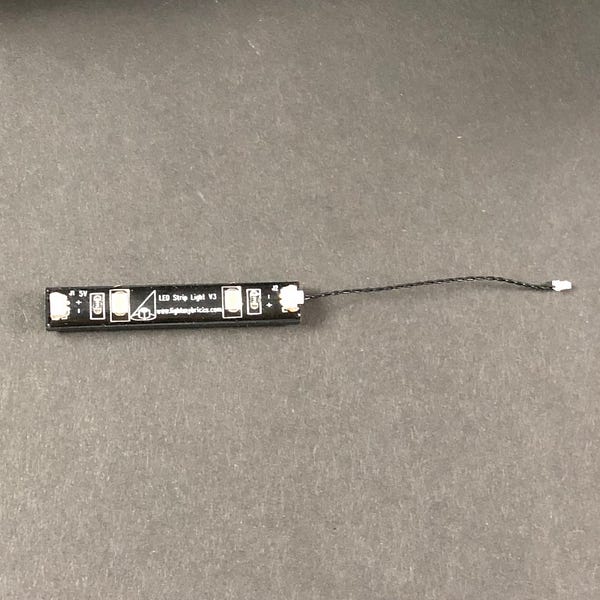
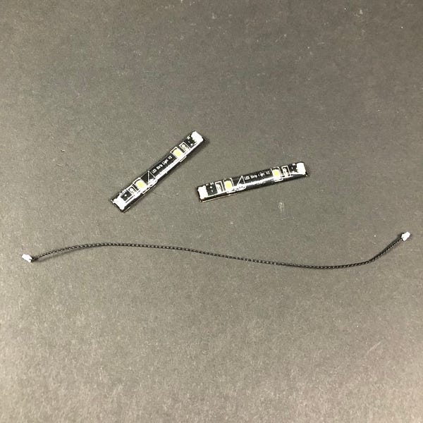
- 8x White Strip Lights
- 1x Blue Strip Light
- 10x White 15cm Bit Lights
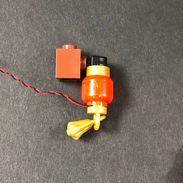
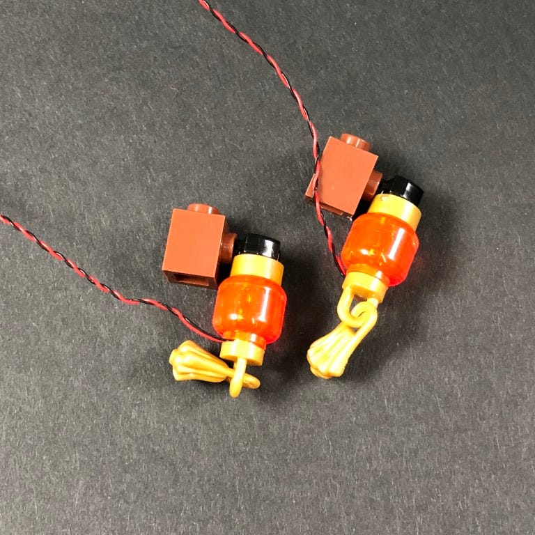
- 2x Orange 30cm Bit Lights
- 4x 6-Port Expansion Boards
- 1x 8-Port Expansion Board
- 1x Flicker Effects Board
- 5x 5cm Connecting Cables
- 6x 15cm Connecting Cables
- 3x 30cm Connecting Cables
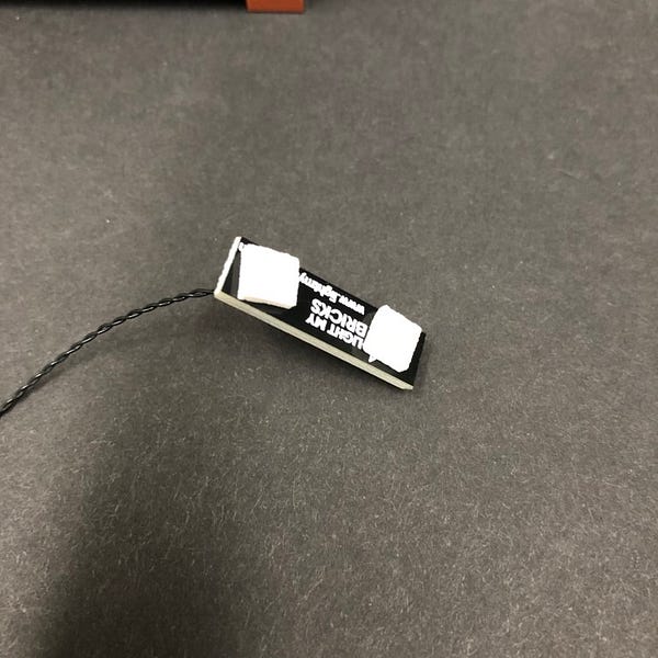
- 12x Adhesive Squares
- 1x Battery Pack (requires 3x AA Batteries)
OR - 1x USB Power Cable
Note – Battery Pack will be replaced with USB Power Cables from mid April 2020
LEGO Pieces:
- 5x Plate 1×6 (any colour)
Important things to note:
Laying cables in between and underneath bricks
Cables can fit in between and underneath LEGO® bricks, plates, and tiles providing they are laid correctly between the LEGO® studs. Do NOT forcefully join LEGO® together around cables; instead ensure they are laying comfortably in between each stud.
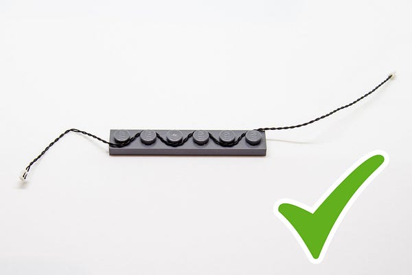
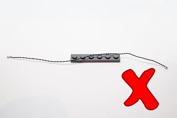
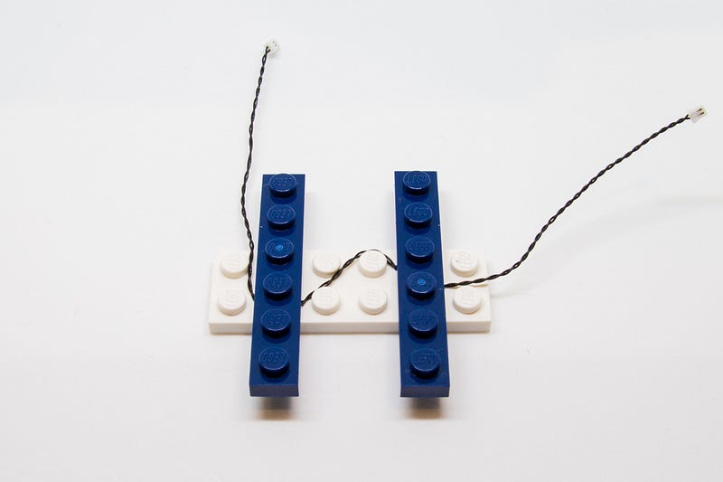
CAUTION: Forcing LEGO® to connect over a cable can result in damaging the cable and light.
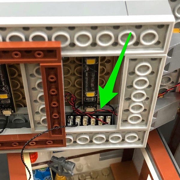
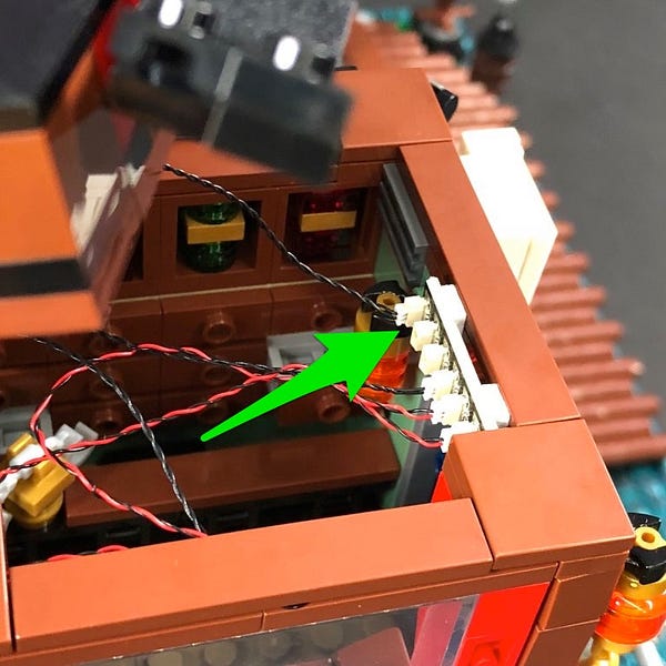
Connecting cable connectors to Expansion Boards
Take extra care when inserting connectors to ports of Expansion Boards. Connectors can be inserted only one way. With the expansion board facing up, look for the soldered “=” symbol on the left side of the port. The connector side with the wires exposed should be facing toward the soldered “=” symbol as you insert into the port. If a plug won’t fit easily into a port connector, do not force it.
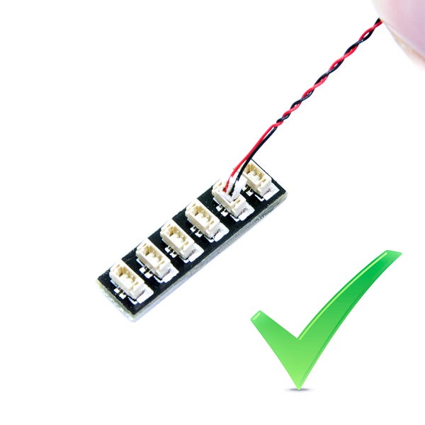
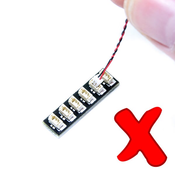
Incorrectly inserting the connector can can result in bent pins inside the port or possible overheating of the expansion board when connected.
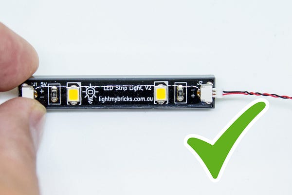
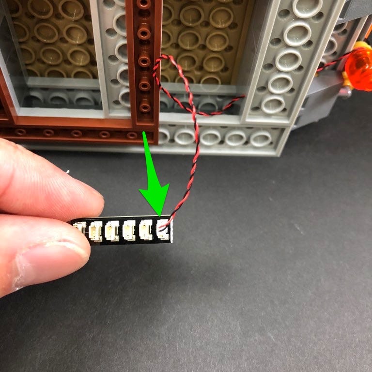
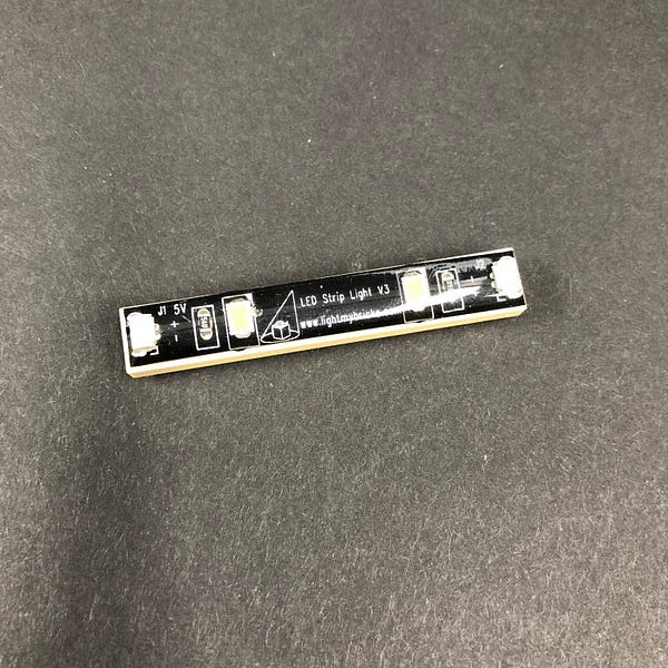
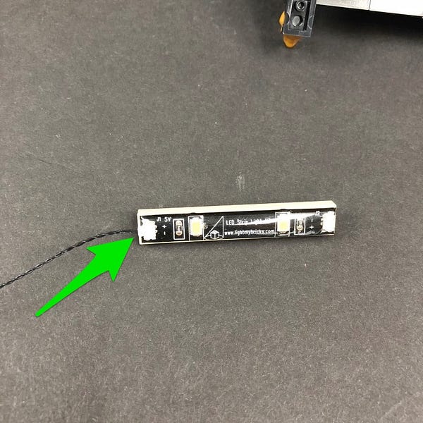
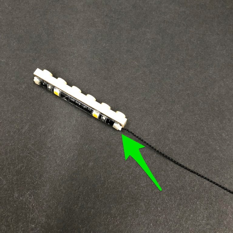
Connecting cable connectors to Strip Lights
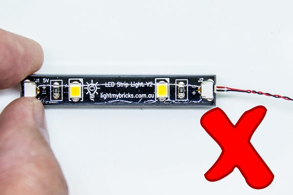
Take extra care when inserting connectors to ports on the Strip Lights. Connectors can be inserted only one way. With the Strip Light facing up, ensure the side of the connector with the wires exposed is facing down. If a plug won’t fit easily into a port connector, don’t force it. Doing so will damage the plug and the connector.
Installing Bit Lights under LEGO® bricks and plates.
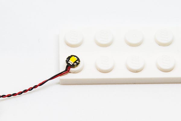
When installing Bit Lights under LEGO® pieces, ensure they are placed the correct way up (Yellow LED component exposed). You can either place them directly on top of LEGO® studs or in between.
OK, Let’s Begin!
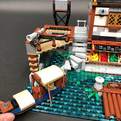
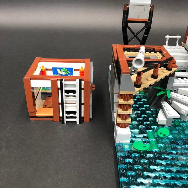
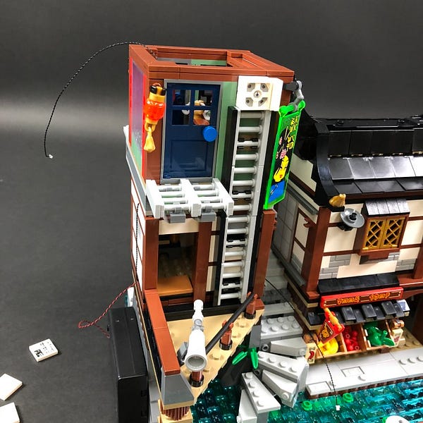
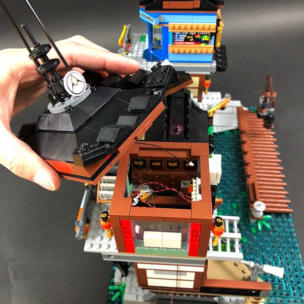
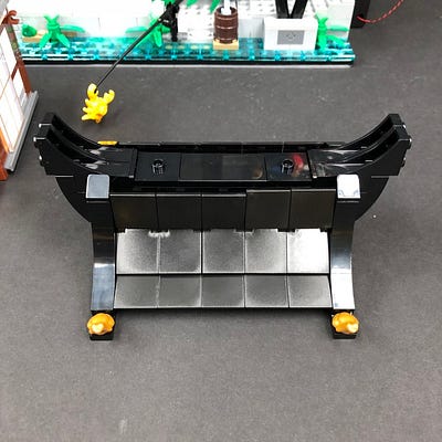
1.) We will start by installing lights to the left side of the building. First remove all levels as well as the boat from the set.
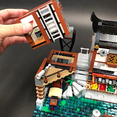
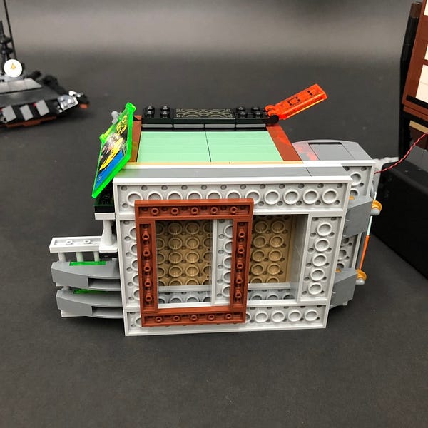
Take the second floor and place it on its back so we can access underneath.
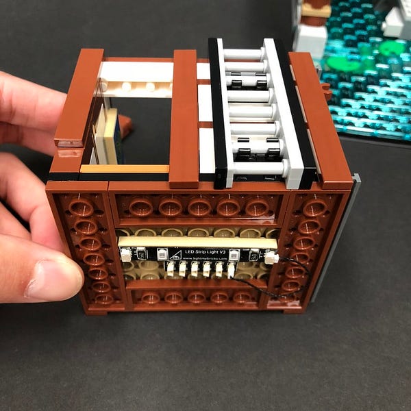
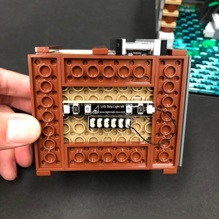
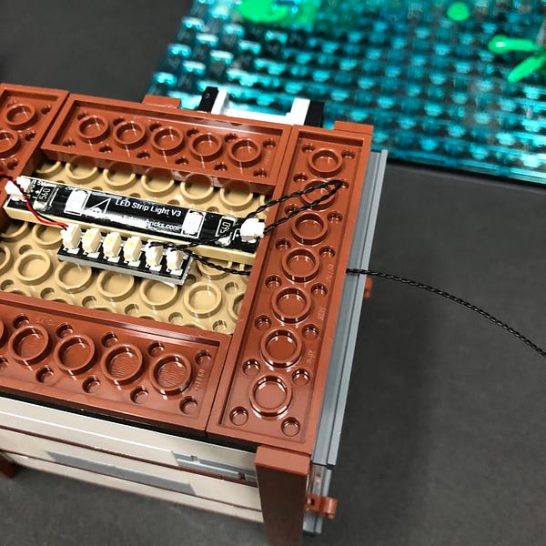
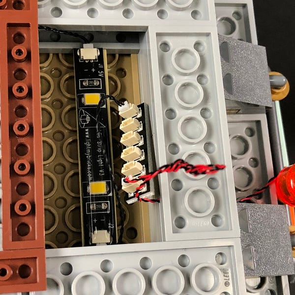
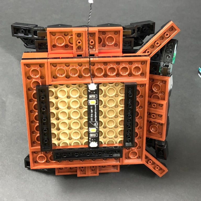
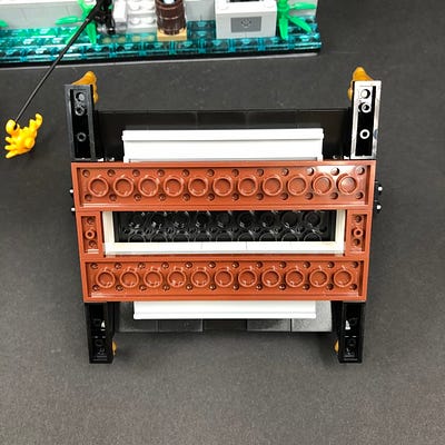
2.) Take the Blue Strip Light and using it’s adhesive backing, stick it to the base of a provided LEGO Plate 1×6
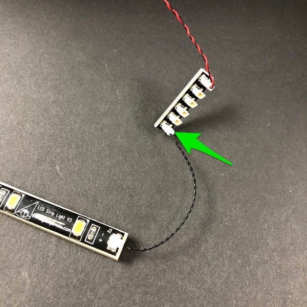
Take a 5cm Connecting Cable and connect it to the strip light. Connect the other end of the cable to the end port of a 6-Port Expansion Board
Stick 2x Adhesive Squares to the base of the expansion board and then mount both expansion board and strip light underneath the second floor in the below position.
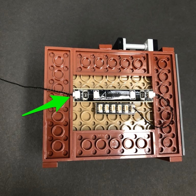
3.) Take a 15cm Connecting Cable and connect it to the left port on the Blue Strip Light. Lay the cable underneath the 2×8 Plate in between studs as per below.
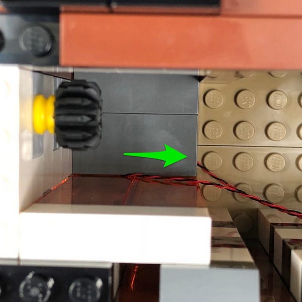
Take the AA Battery Pack and insert 3x AA batteries to it. Connect the Battery Pack cable to the 6-port expansion board as per below.
If you’re using the USB Power Cable, connect this to the board this instead of the battery pack.
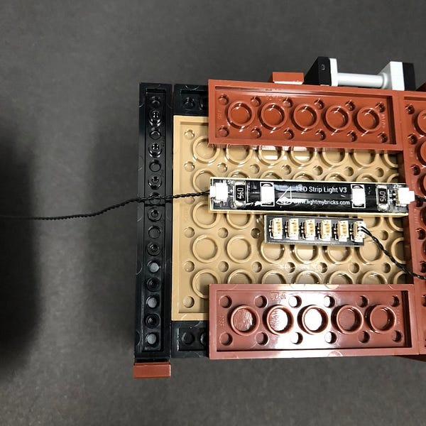
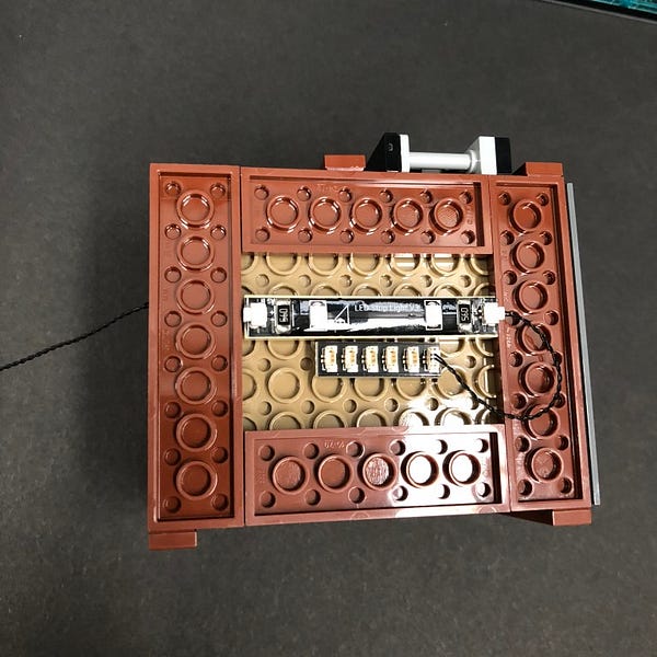
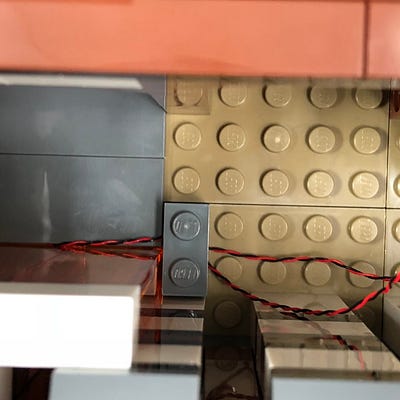
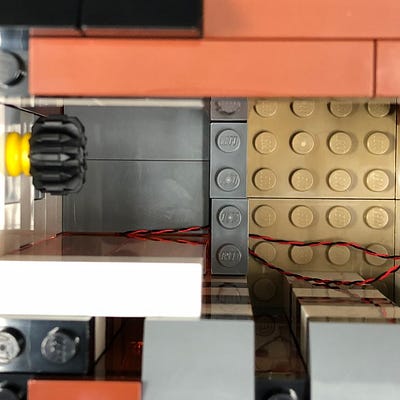
4.) Take another 15cm Connecting Cable and connect it to one of the ports on the 6-port Expansion Board. Lay the cable underneath the right 2×8 plate ensuring it is laid in between studs.
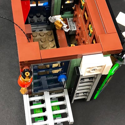
Turn the floor over and then reconnect it back on top of the ground floor ensuring the 15cm Connecting Cable from each side is sticking out.
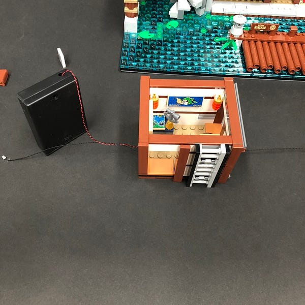
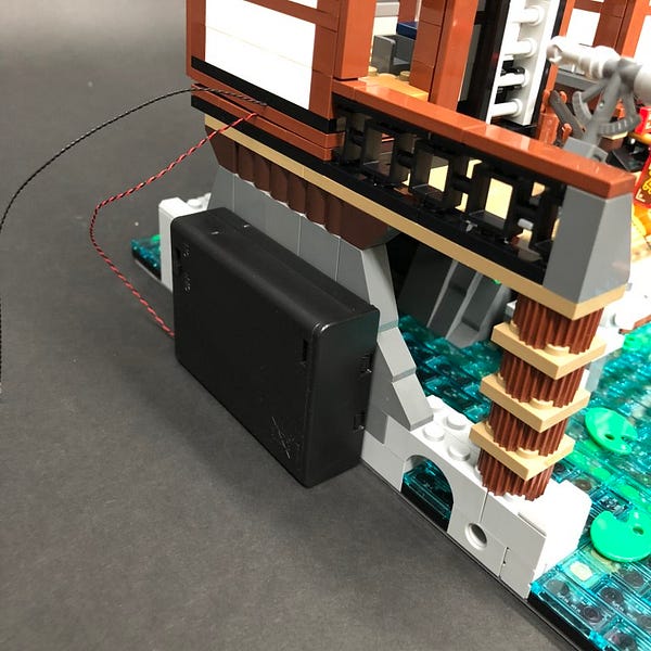
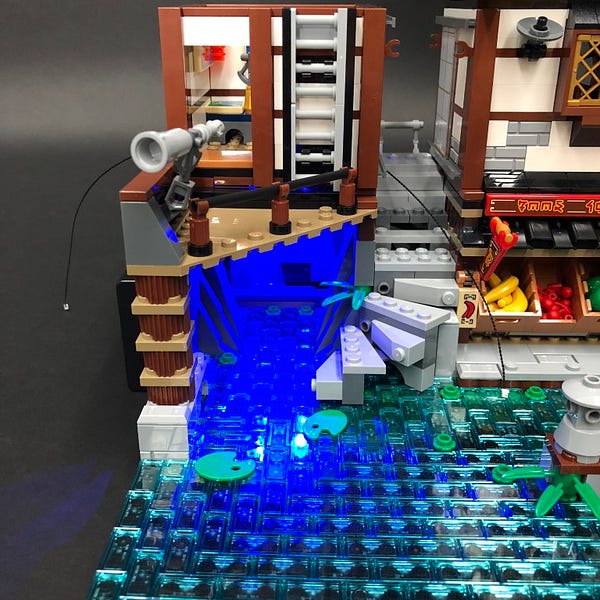
The AA Battery Pack/usb cable can be positioned against the wall as per below. Turn it on the test the Blue Strip Light is working OK.
If you’re using the USB Cable, connect this to a USB Power Bank or wall adaptor (sold separately) and turn it ON to test the front lights are working OK.
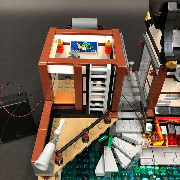
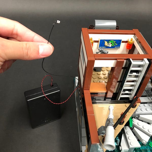
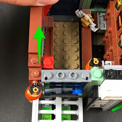
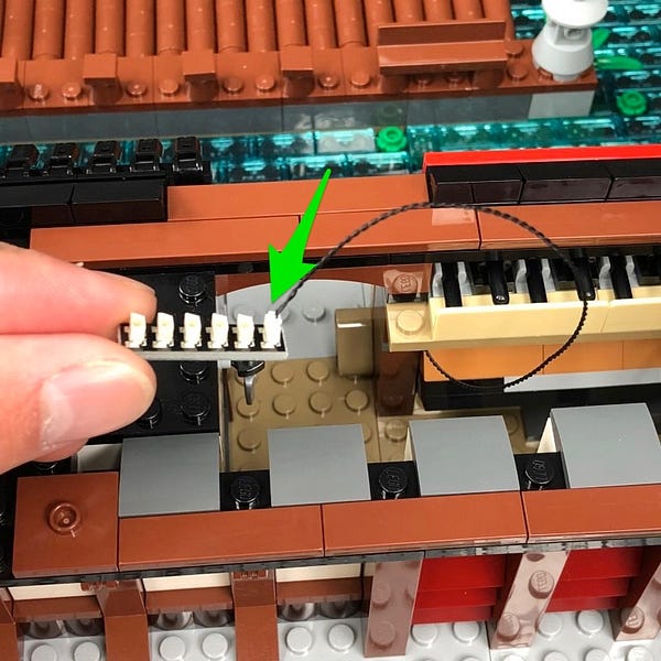
5.) Take the other end of the 15cm cable from the left side and then pull it up and then secure it underneath the 1×8 tile on the top of the floor.
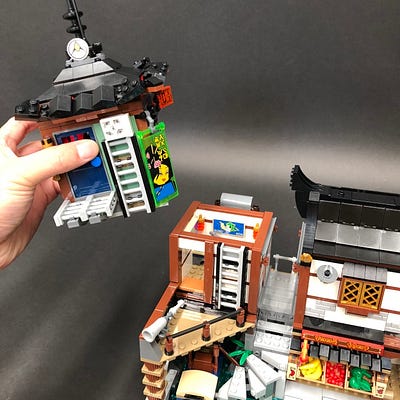
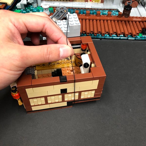
6.) Take the third floor and remove the lantern piece from the behind and then turn the whole floor onto it’s left flat side so that we can access underneath.
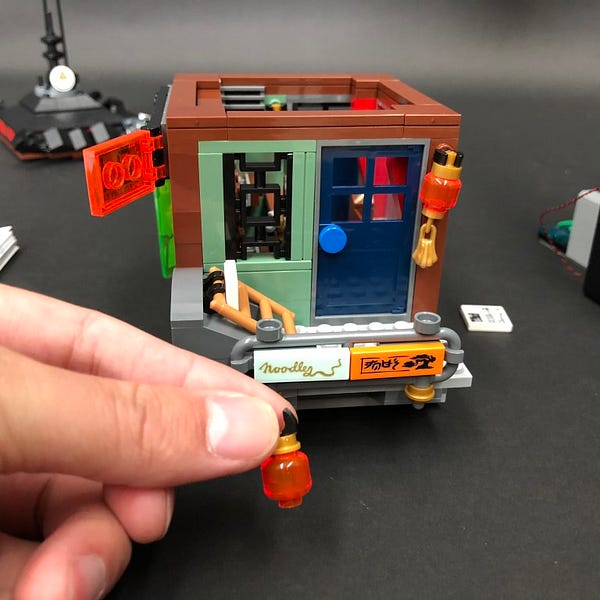
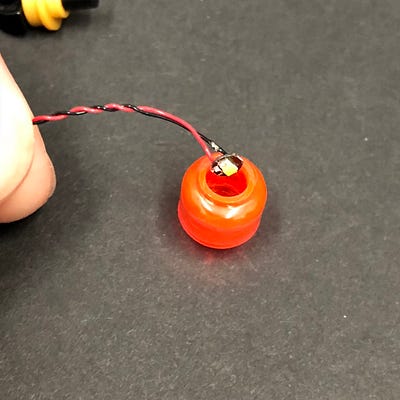
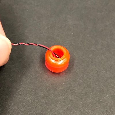
7.) Remove the pieces from the top of the lantern.
Take a White 15cm Bit Light and place it inside the hole of the lantern piece. Secure it in place by reconnecting the pieces we removed earlier ensuring the LED component is facing the front of the lantern and that the cable is facing the back.
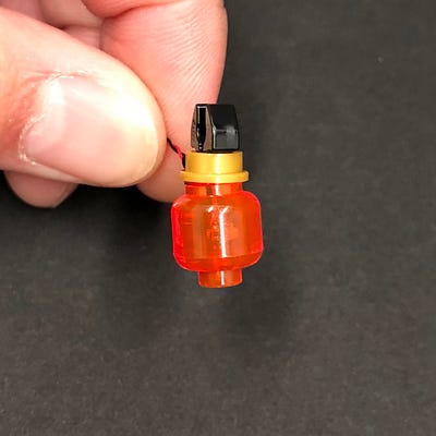
Reconnect the lantern back to the bottom of the third floor then lay the cable toward the inside of the building underneath the light grey 2×6 plate ensuring the cable is laid in between studs.
Connect the other end of the Bit Light cable from the lantern to a new 6-Port Expansion Board.
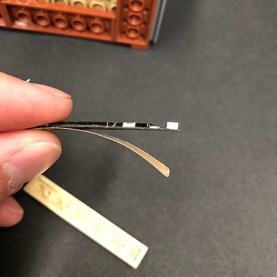
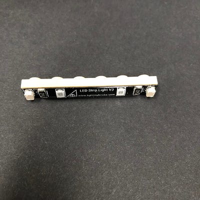
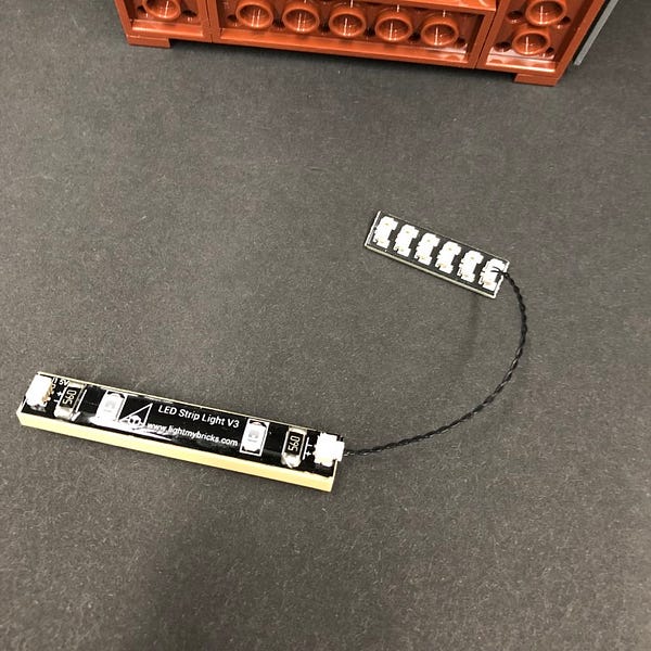
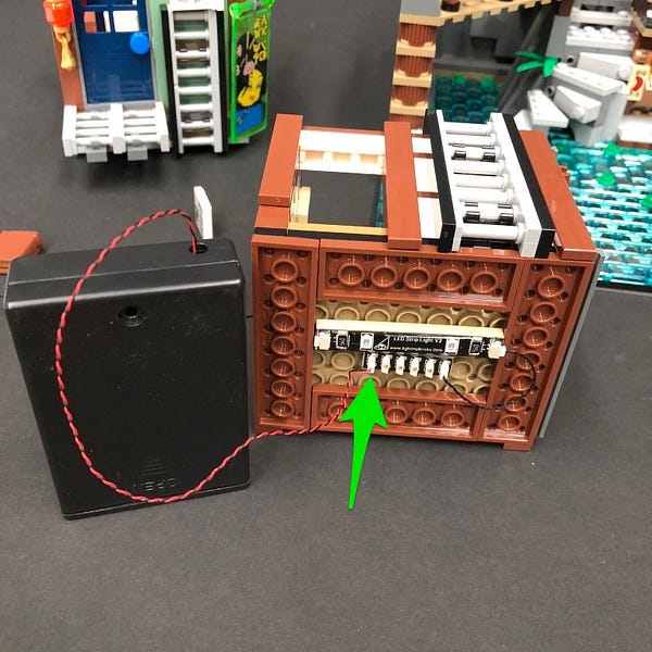
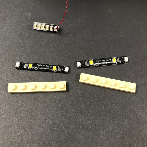
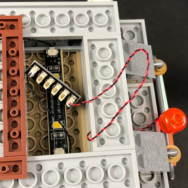
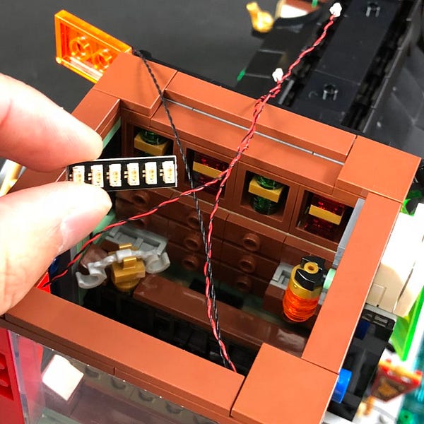
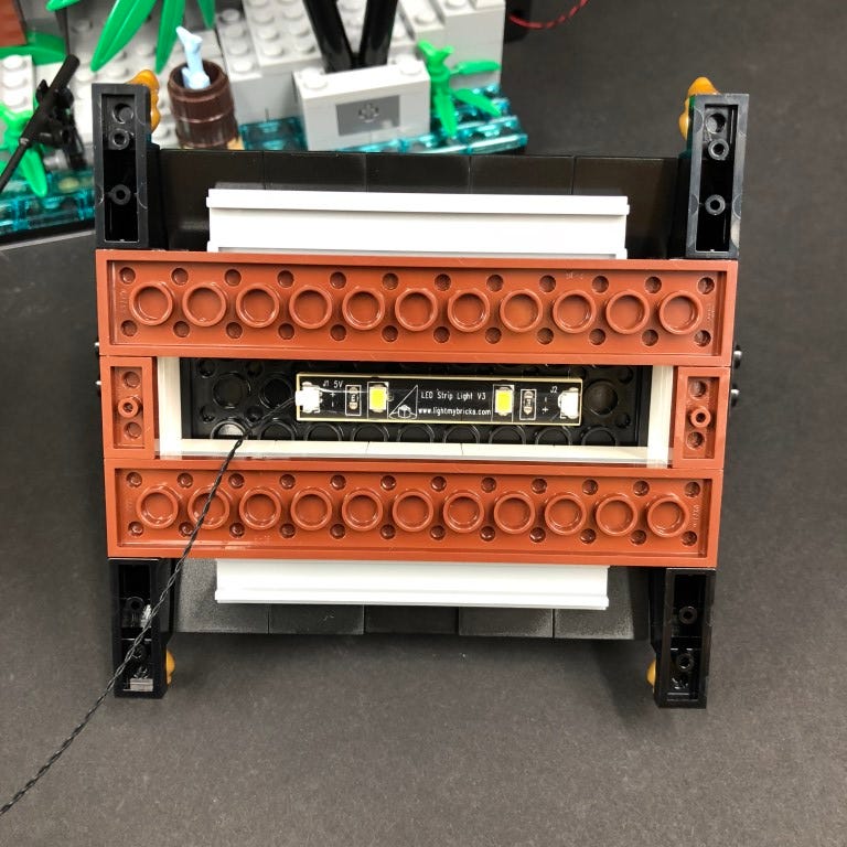
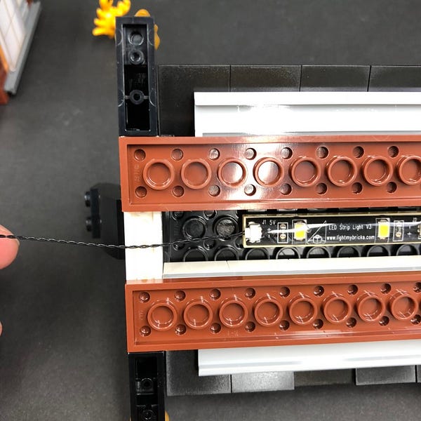
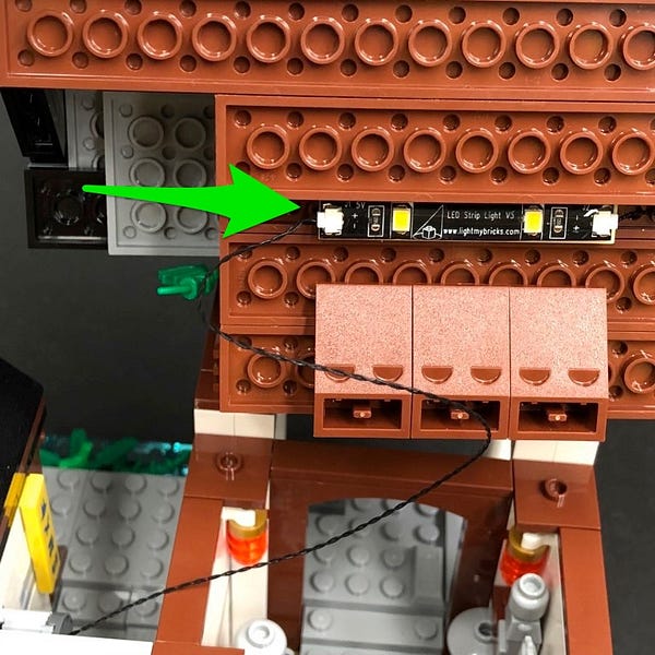
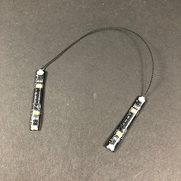
8.) Take 2x White Strip Lights and stick them to 2x Provided LEGO Plates 1×6.
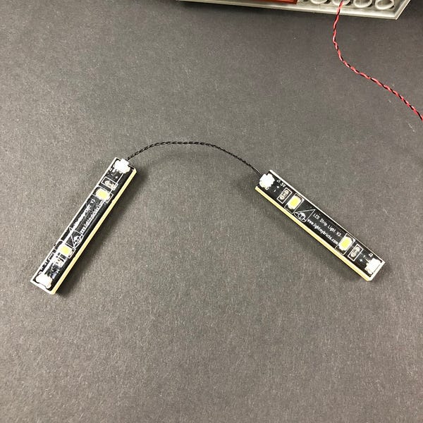
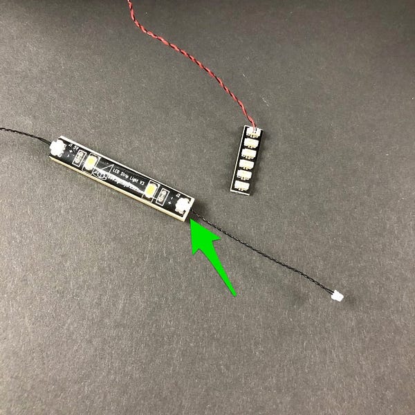
Connect them together using a 5cm Connecting Cable then take another 5cm Connecting Cable and connect it to the outside port of one of the strip lights.
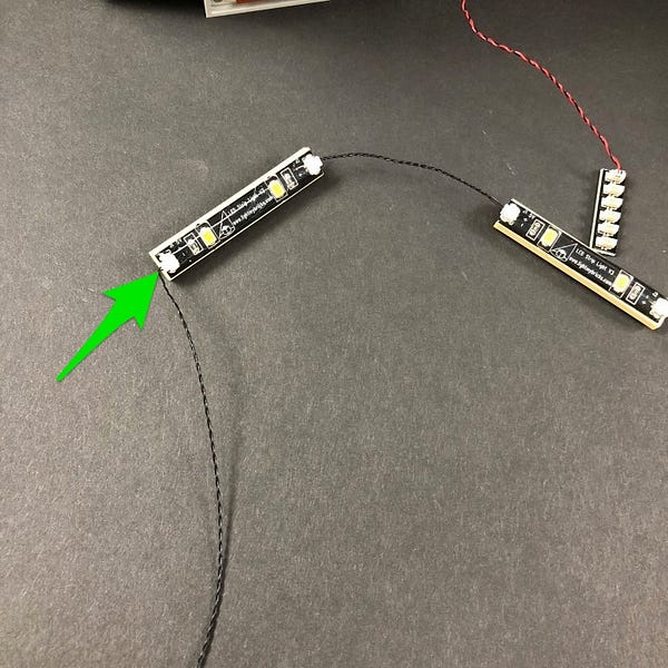
Connect the other end of the 5cm connecting cable to the 6 port expansion board and then take a 30cm Connecting Cable and connect it to left port on the other Strip Light.
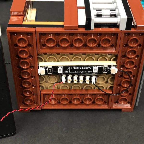
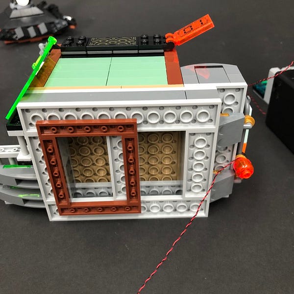
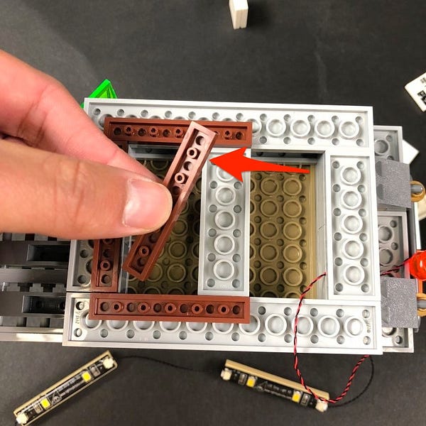
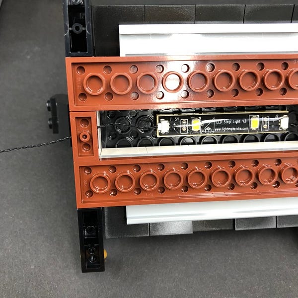
9.) Disconnect the brown 1×6 plate on the right side underneath the third flood, then mount both strip lights underneath in the below position ensuring the 30cm Connecting cable is facing the bottom.
Reconnect the brown 1×6 plate we removed earlier and then lay the 30cm connecting cable underneath the bottom brown 1×6 plate.
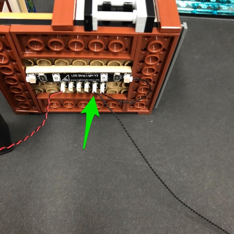
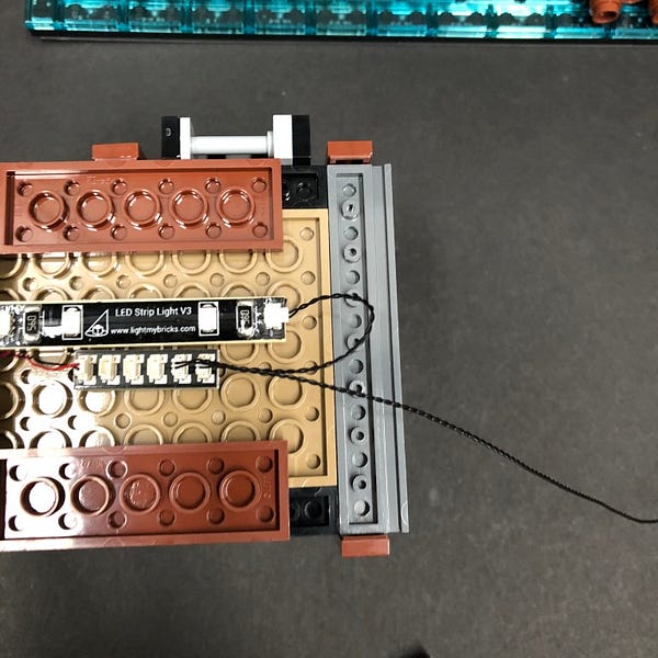
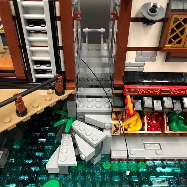
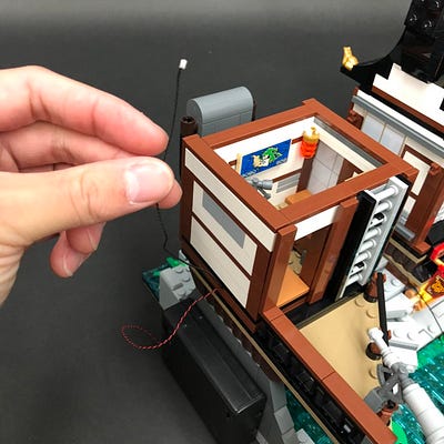
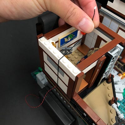
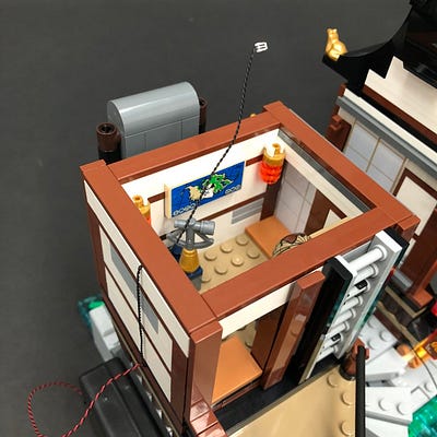
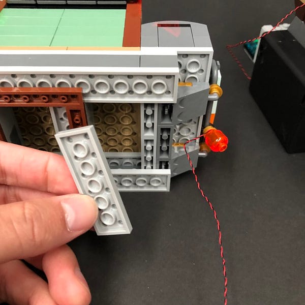
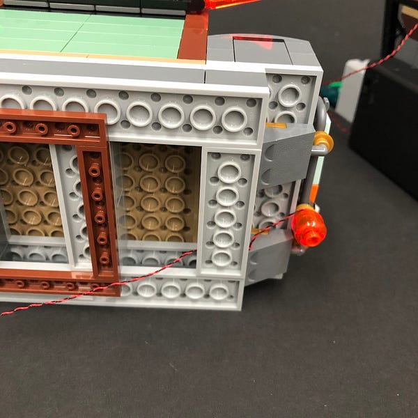
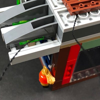
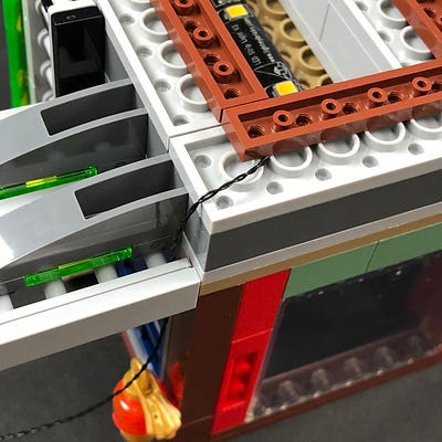
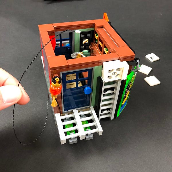
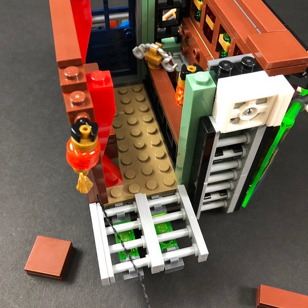
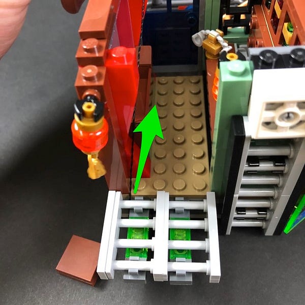
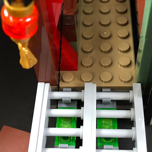
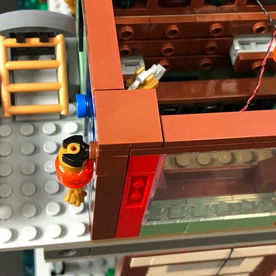
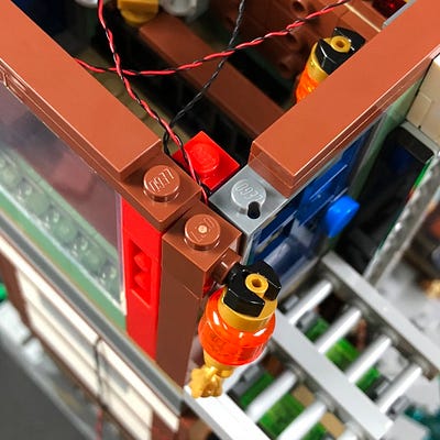
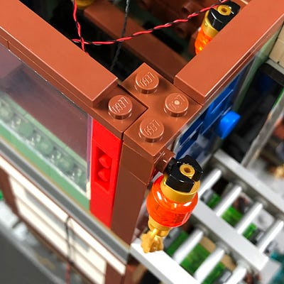
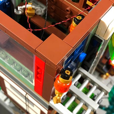
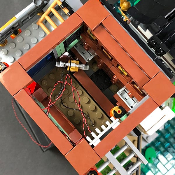
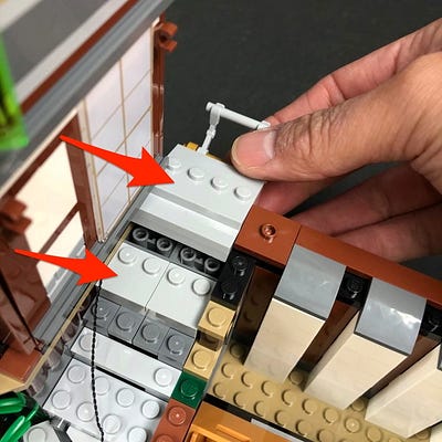
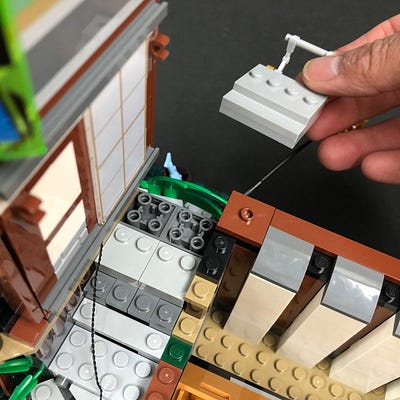
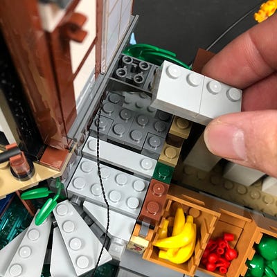
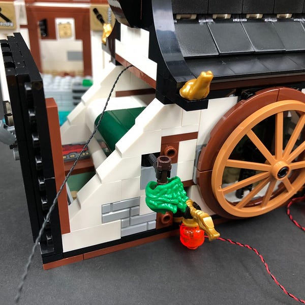
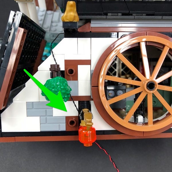
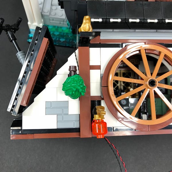
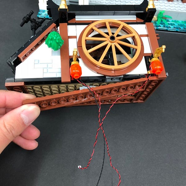
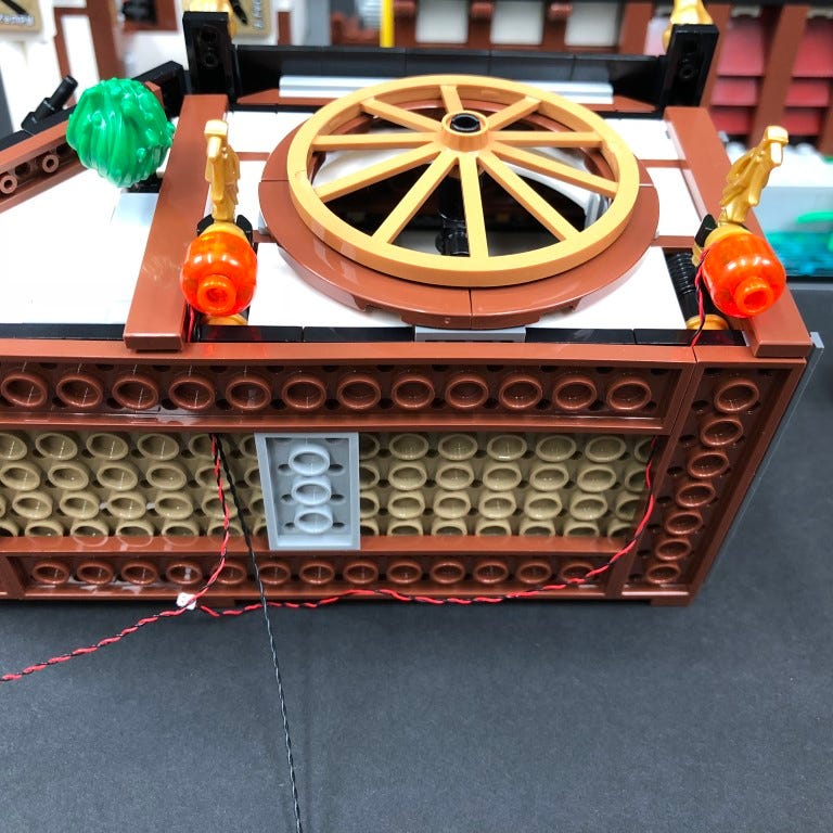
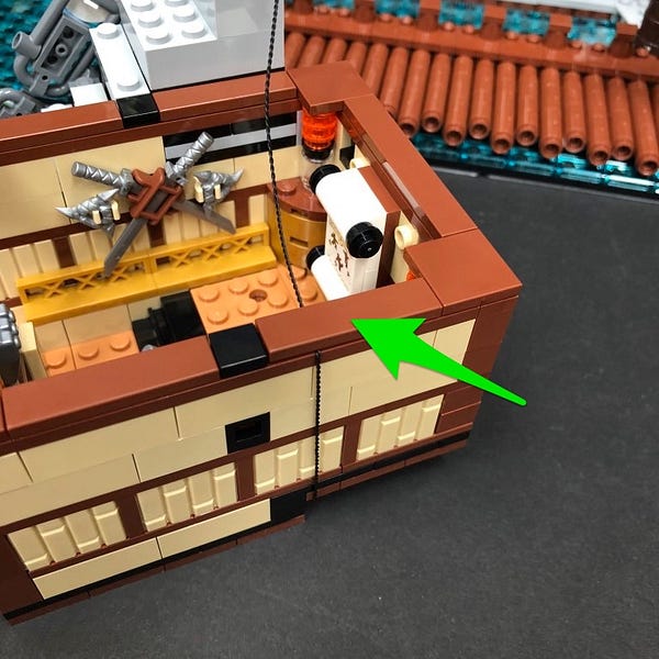
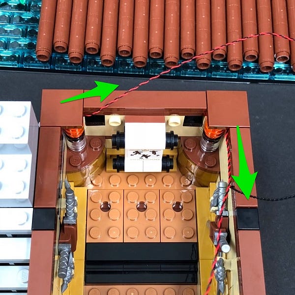
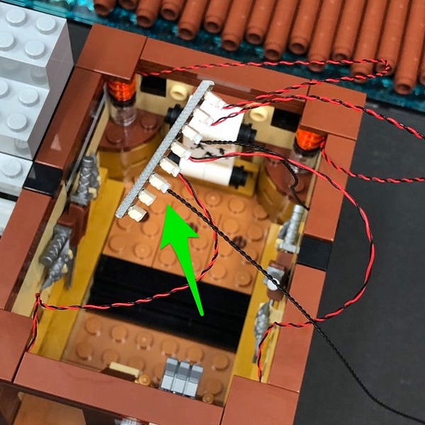
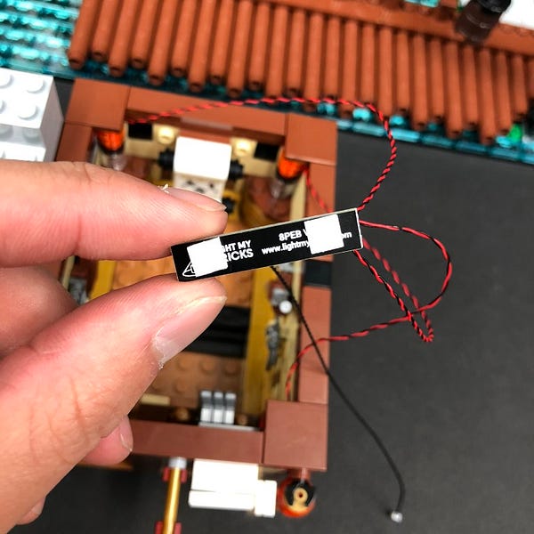
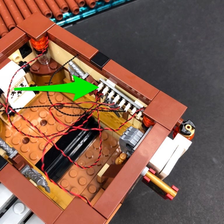
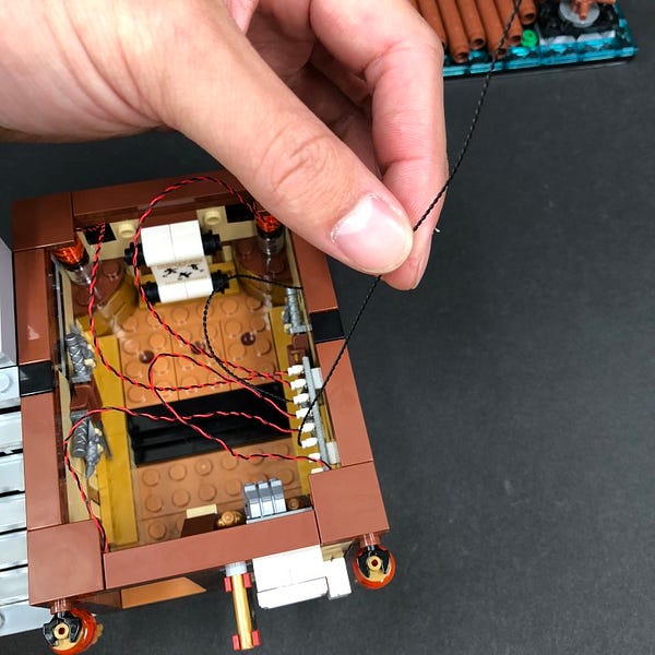
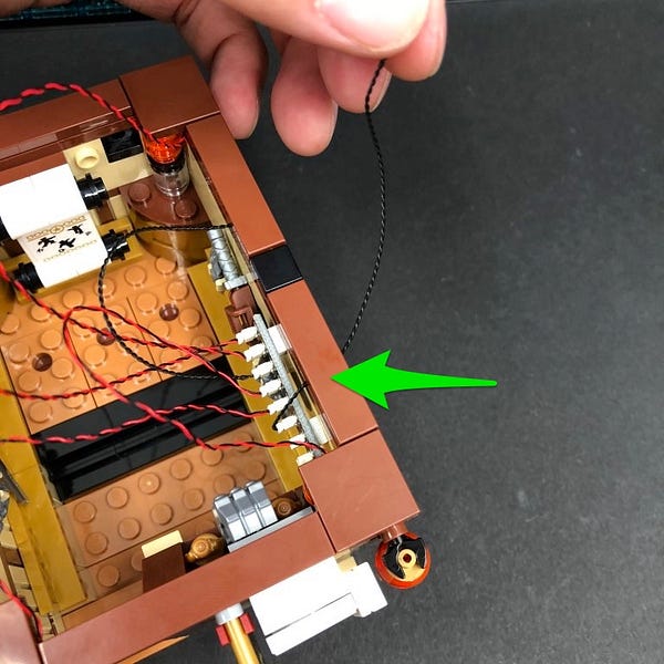
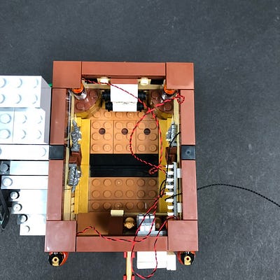
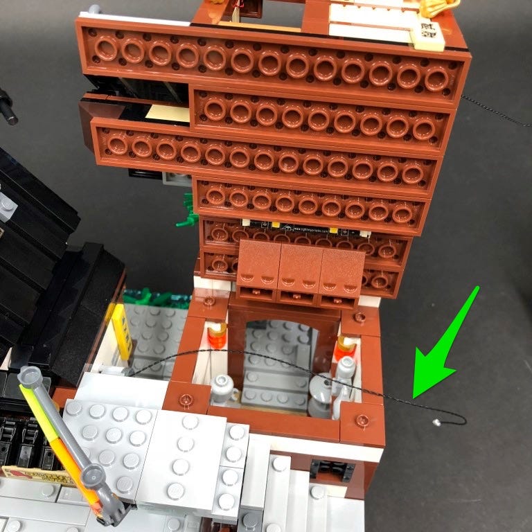
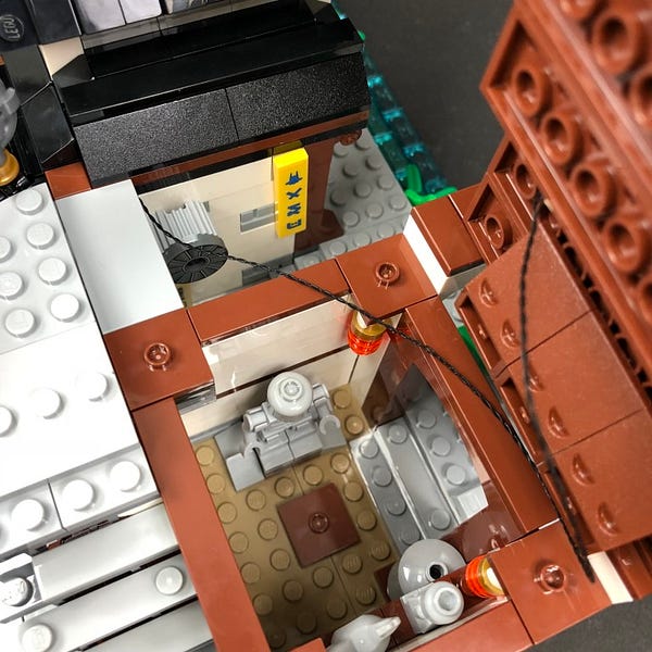
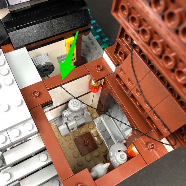
10.) Take the other end of the 30cm Connecting Cable and thread it down the following space in the corner. Pull it all the way out from underneath.
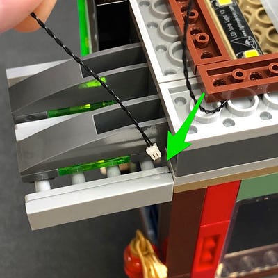
Eliminate excess cable from the lantern bit light by folding and then twisting the cable around itself a few times.
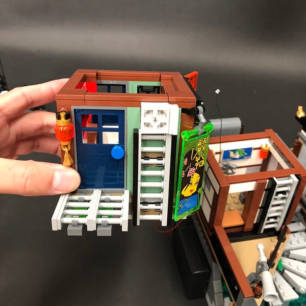
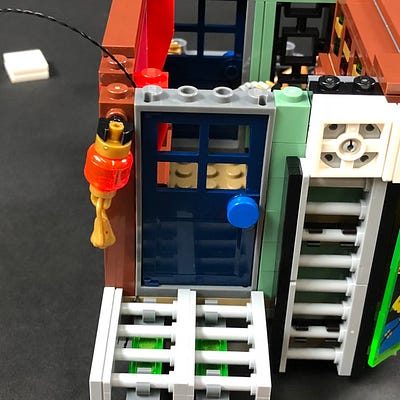
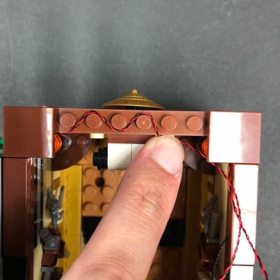
11.) Turn the third floor over and remove the following tiles from the top to allow us to remove the door section.
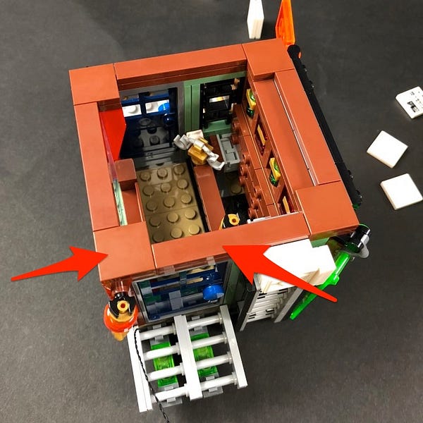
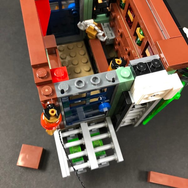
Pull the cable up inside the room and then with the cable in the corner, reconnect the door ensuring the cable is pulled up in between the door and red bricks before reconnecting the tiles over the top.
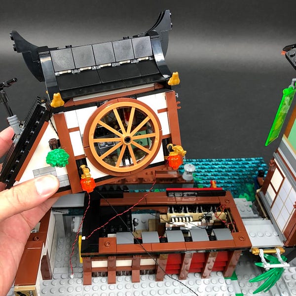
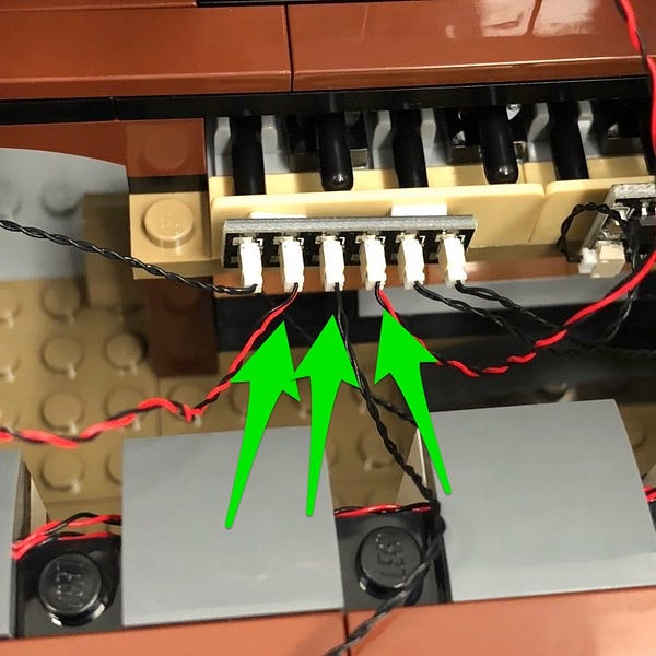
12.) Take the third floor and place it over the second floor. Take the 15cm connecting cable from the left side underneath the brown tile and connect it to the 6-port expansion board below.
Tuck the expansion board and cables inside the space underneath as per below before securing the third floor on top of the second floor.
Turn the battery pack ON to test all lights are working OK.
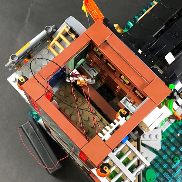
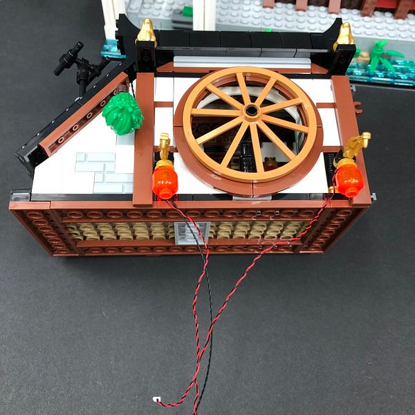
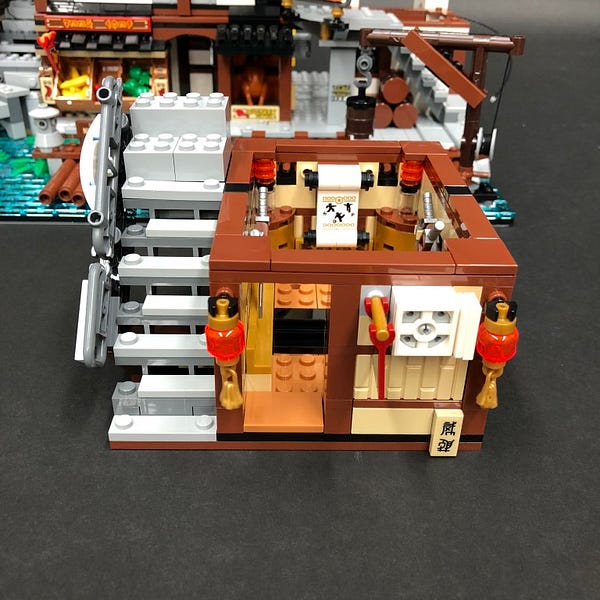
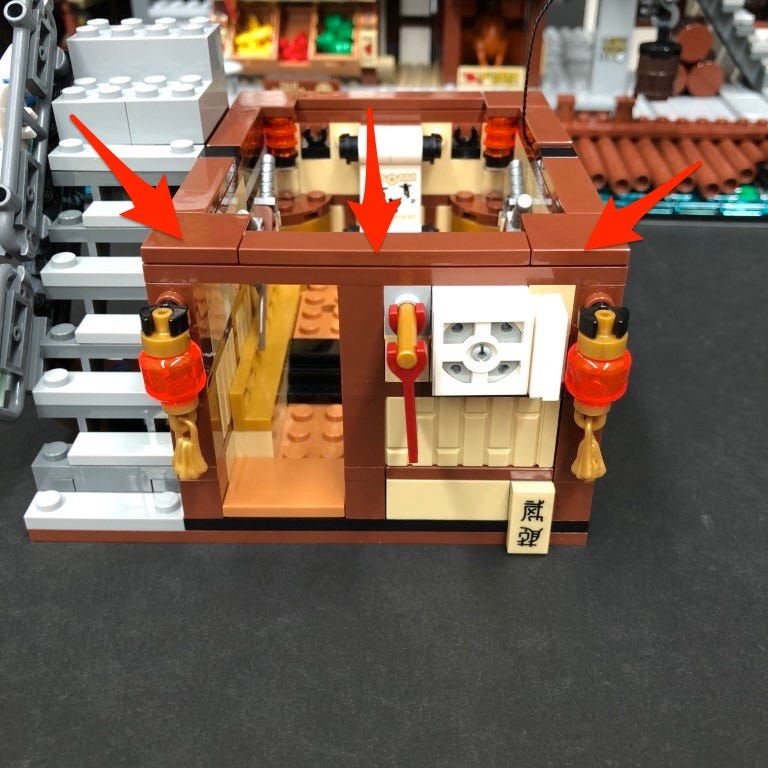
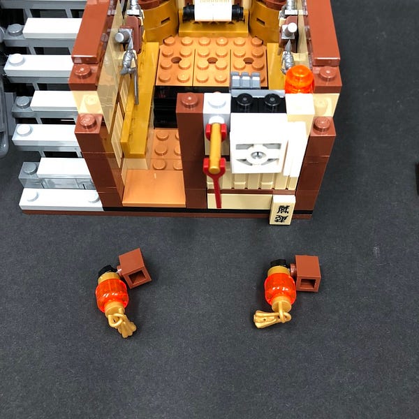
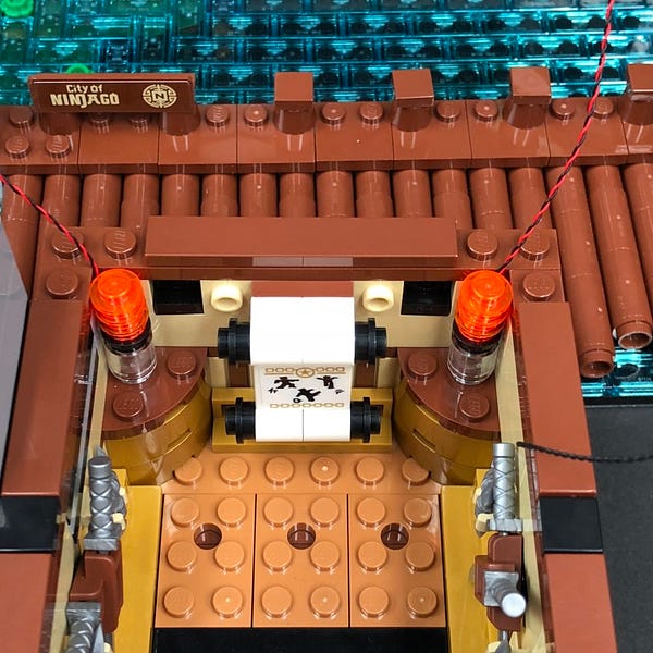
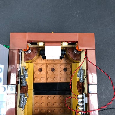
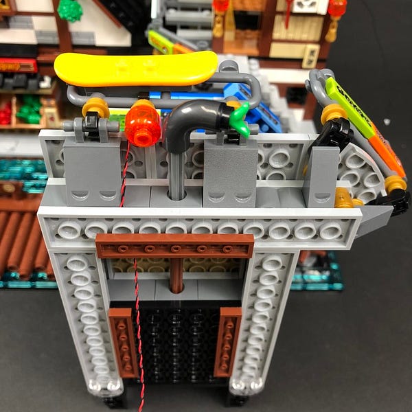
13.) We will now light up the lanterns on the third floor. First disconnect the square tiles and pieces from the two left corners to allow us to remove the lantern sections.
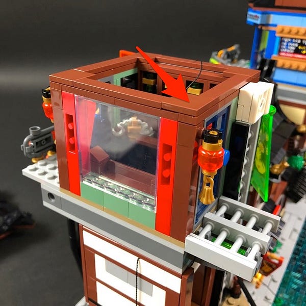
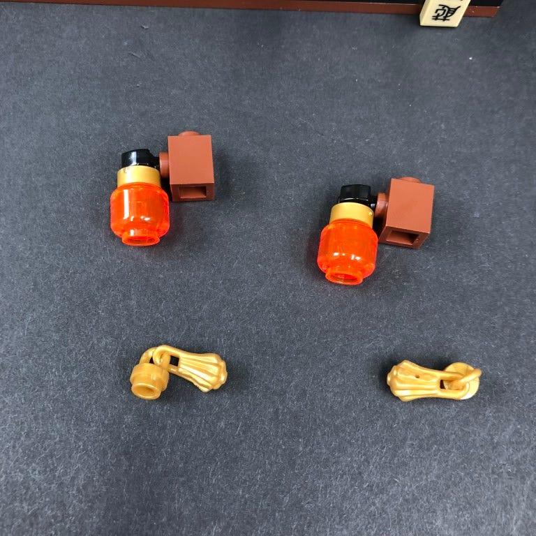
Disconnect the gold pieces from underneath each lantern.
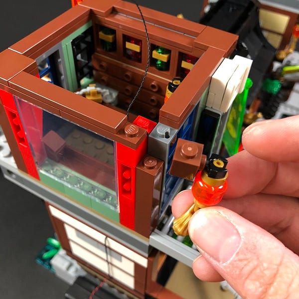
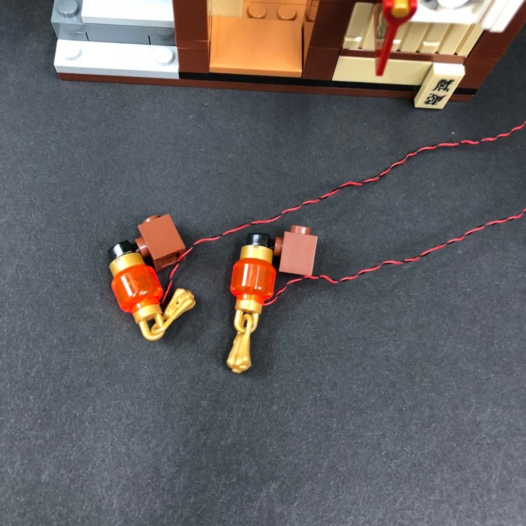
14.) Take a White 15cm Bit Light and with the LED facing the front of the lantern, place it up inside the hole of the lantern piece. Press the cable up along the back side of the lantern before reconnecting the gold piece underneath.

Repeat this process to install another White 15cm Bit Light to the other lantern
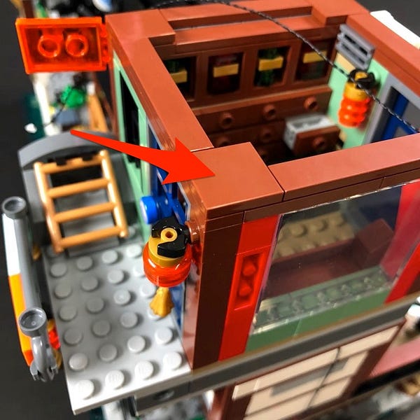
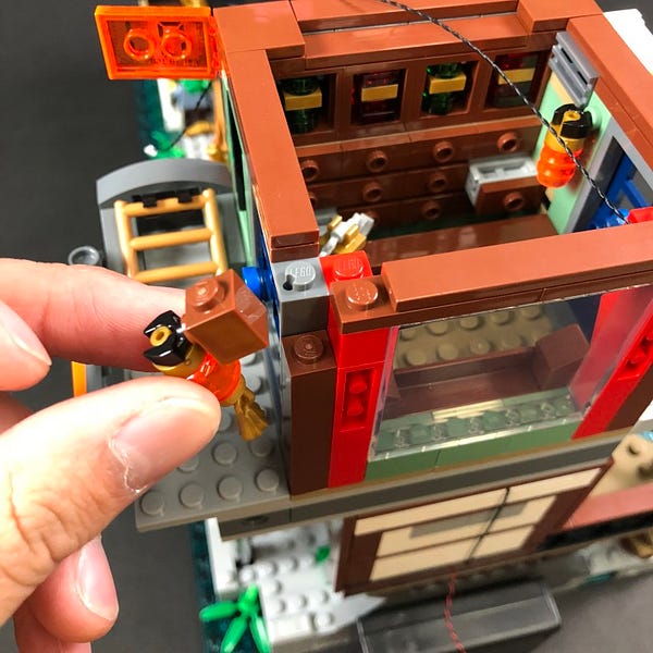
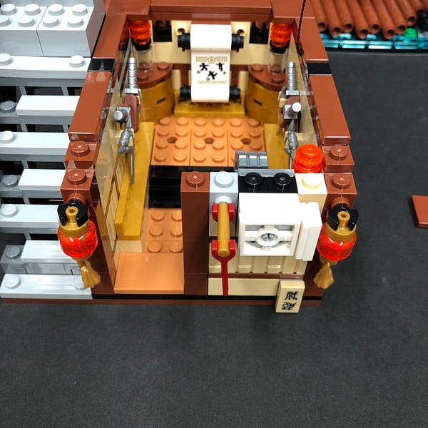
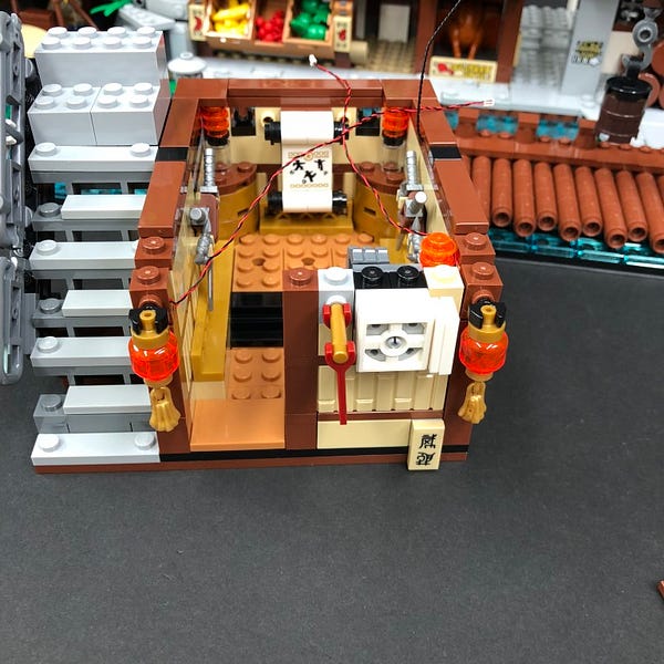
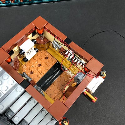
15.) Reconnect each lantern to the top corners of the third floor. Ensure the cables are laid in between bricks and studs before reconnecting the square tiles and pieces over the top.
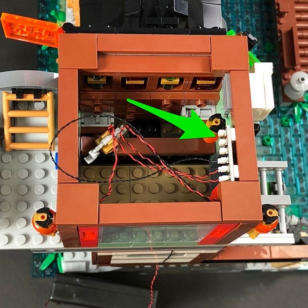
Take a new 6-port Expansion Board and connect the two lantern bit light cables as well as the 30cm connecting cable (from underneath) to it.
Test the two lanterns are working OK.
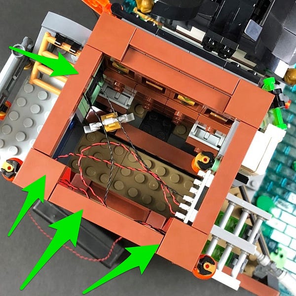
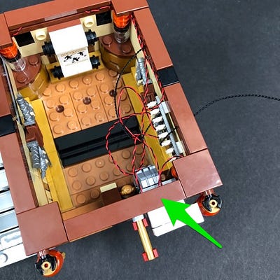
16.) Take 2x Adhesive Squares and stick them underneath the 6-port Expansion Board. Mount the expansion board to the inside top of the front wall as per below.
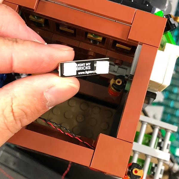
Hide excess cables and prevent them from hanging down and visibile from the window by laying them underneath the tiles on the top of the floor as per below.
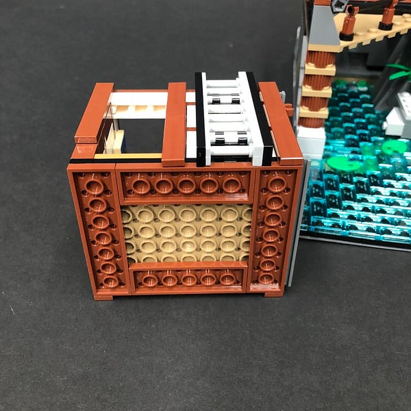
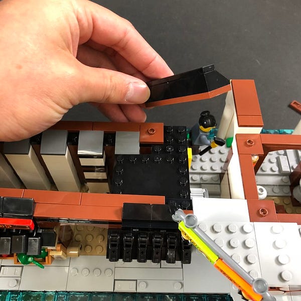
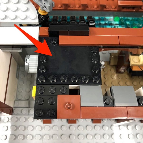
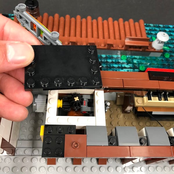
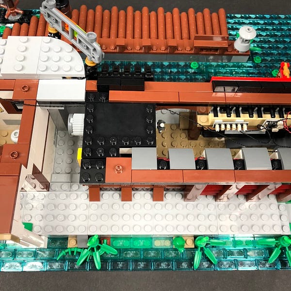
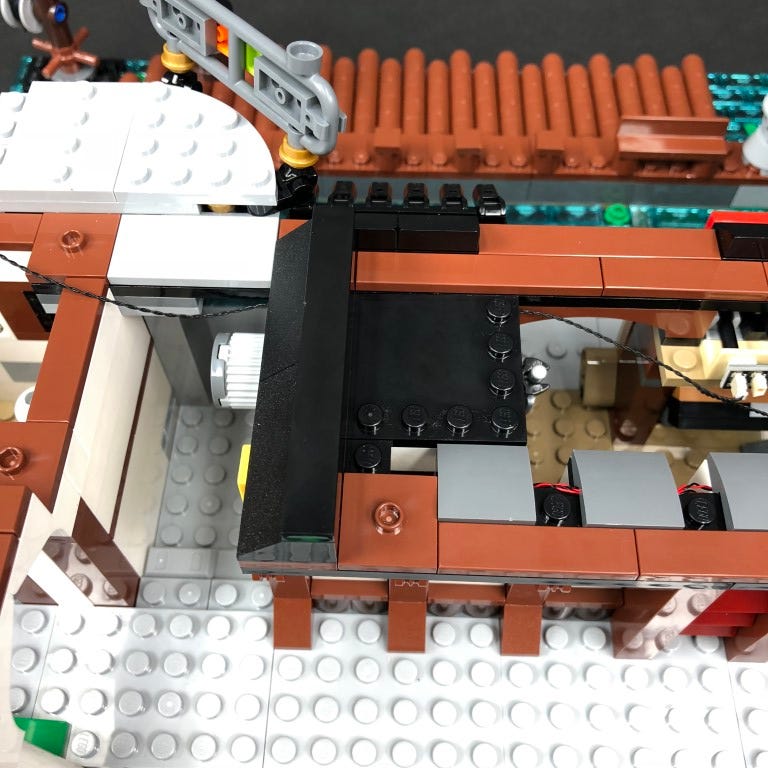
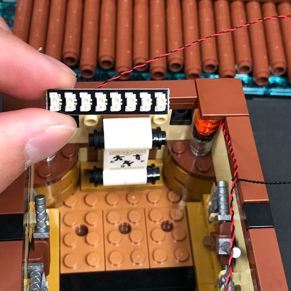
17.) Take the roof of the left building and turn it over onto it’s back so we can access underneath. Disconnect the following black 1×6 plate from underneath.
Take a White Strip Light and stick it to the base of the black 1×6 plate we just removed. Take a 5cm Connecting Cable and connect it to one end of the strip light.
Mount the strip light underneath the roof in the following position ensuring the cable is facing up.
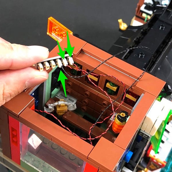
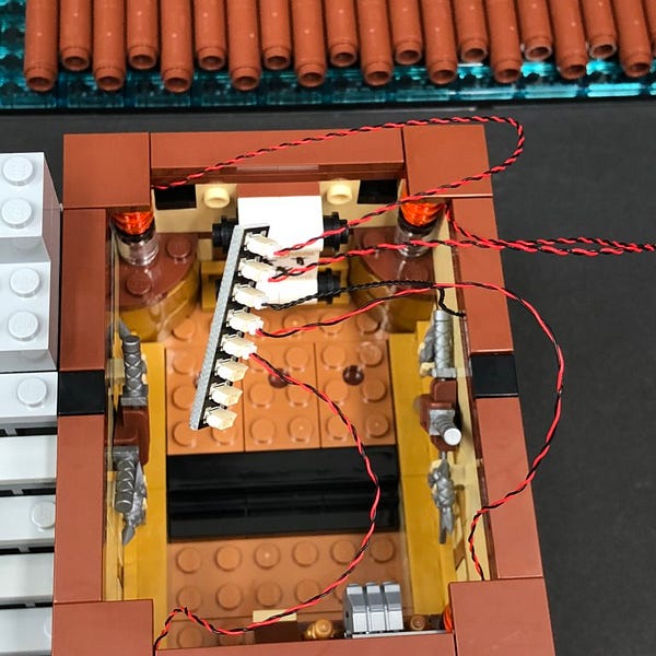
18.) Take the roof above the third floor and connect the other end of the 5cm connecting cable to a spare port on the 6-port expansion board underneath before securely reconnecting the roof.
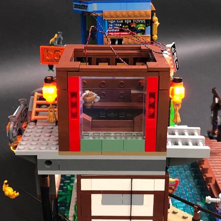
Test all lights in the left building are working OK.
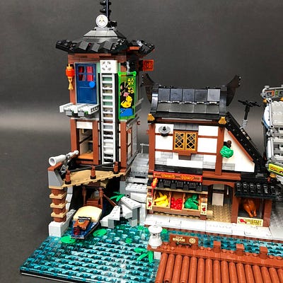
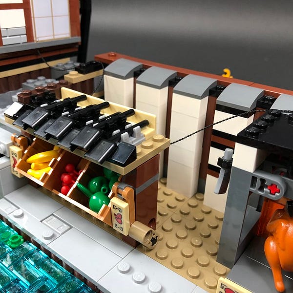
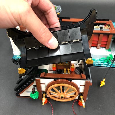
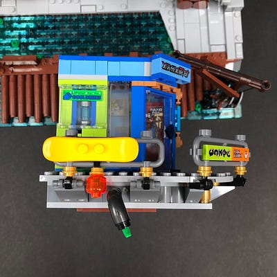
19.) We will now light up the middle building. Start by removing all upper sections and then follow the images below to remove sections from the top of the fruit market.
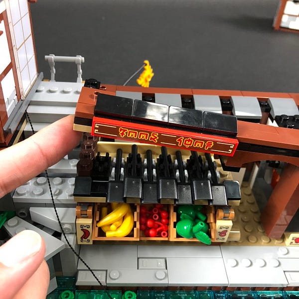
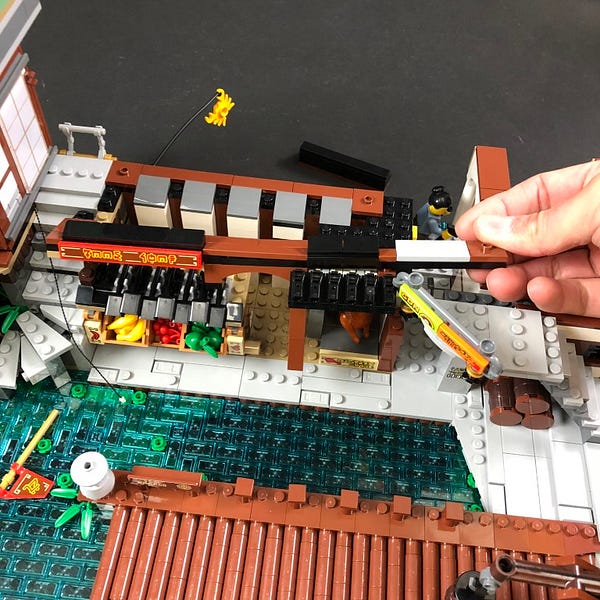
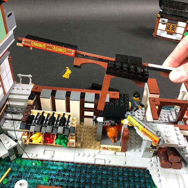
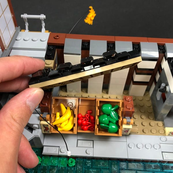
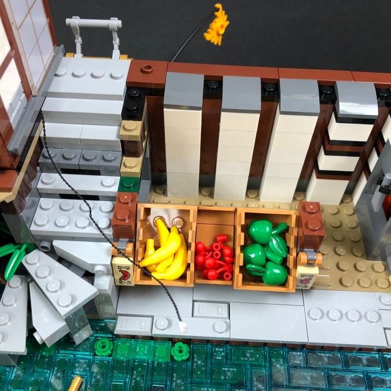
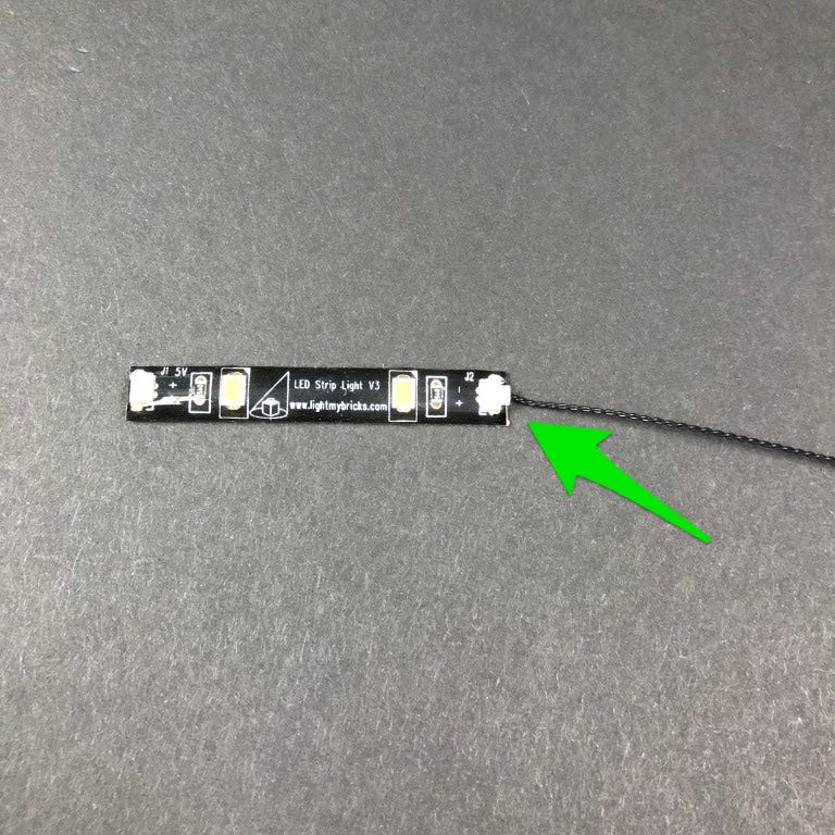
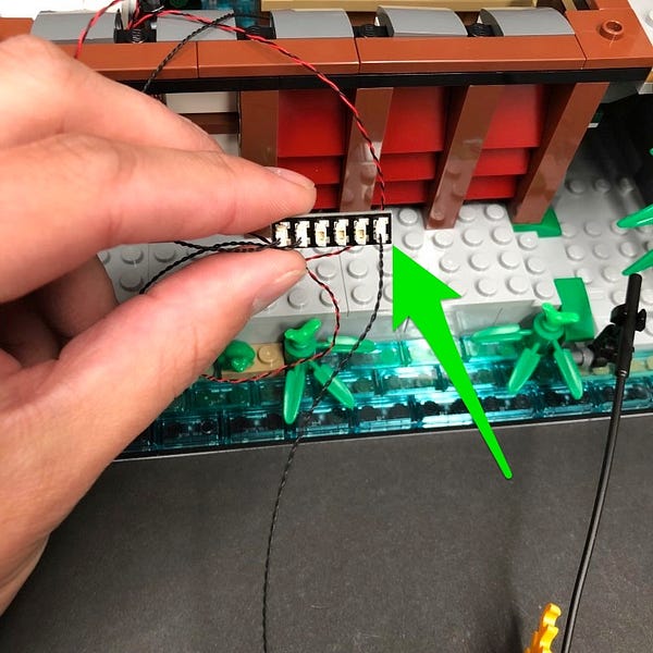
20.) Take a White Strip Light and connect a 15cm Connecting Cable to the right port.
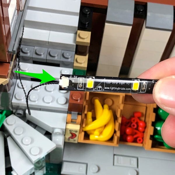
Take the other end of the 15cm connecting cable from the left building and connect it to the left port on the strip light. Stick the strip light underneath the fruit market roof in the below position.

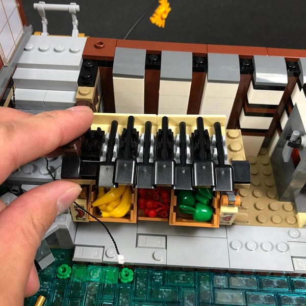
22.) Remove the following pieces from the steps in between left and middle buildings.
Reconnect the fruit market roof ensuring cables are facing inside.
Lay the cable from the left building underneath the black and tan pieces on the right of the steps.
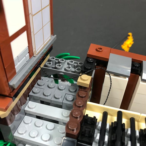
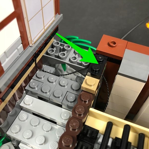
Reconnect pieces from the steps ensuring the cable is laid underneath in between studs.
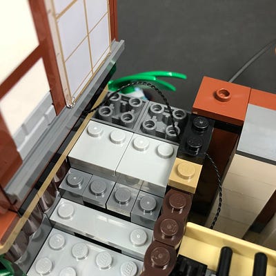
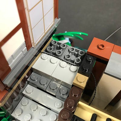
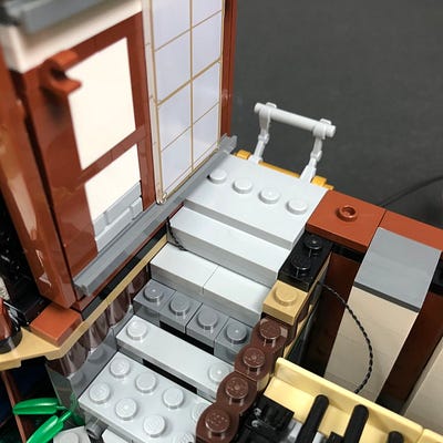
Reconnect the pieces on top of the fruit market.
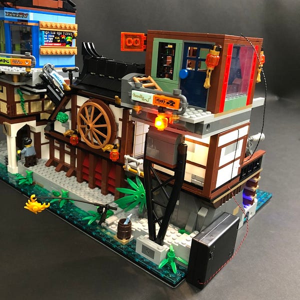
23.) Turn the set around to the back and then take a 6-port Expansion Board and connect the 15cm connecting cable from the fruit market roof strip light to it.
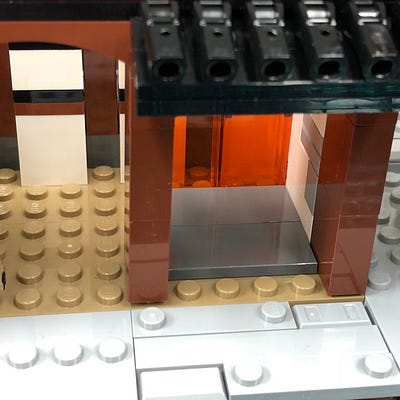
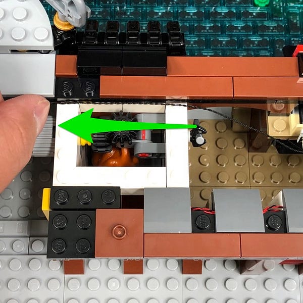
Remove the following pieces from chicken area.
Turn the set around and use the LEGO removal tool to remove more pieces from the front of the chicken area.
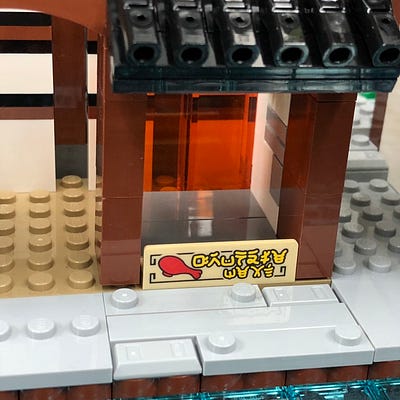
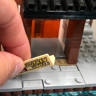
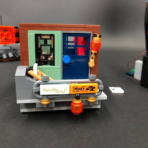
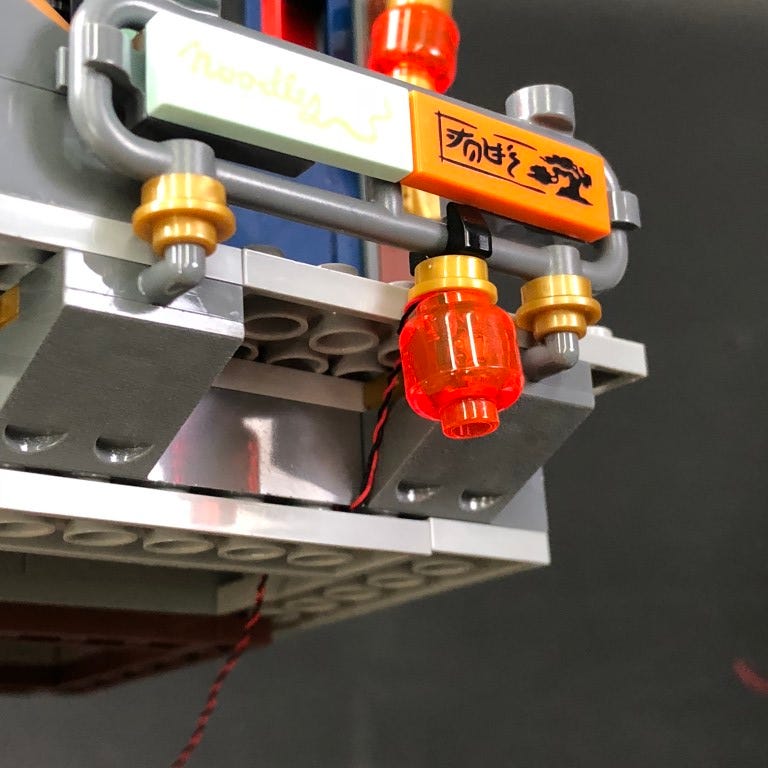
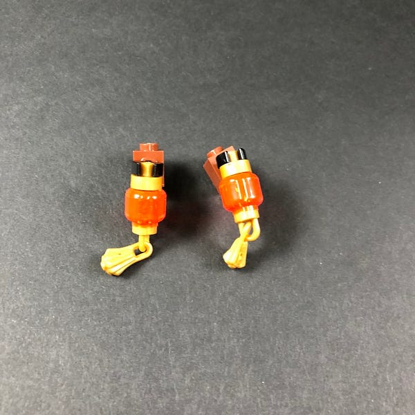
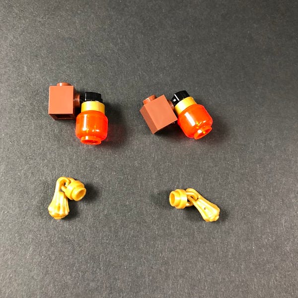
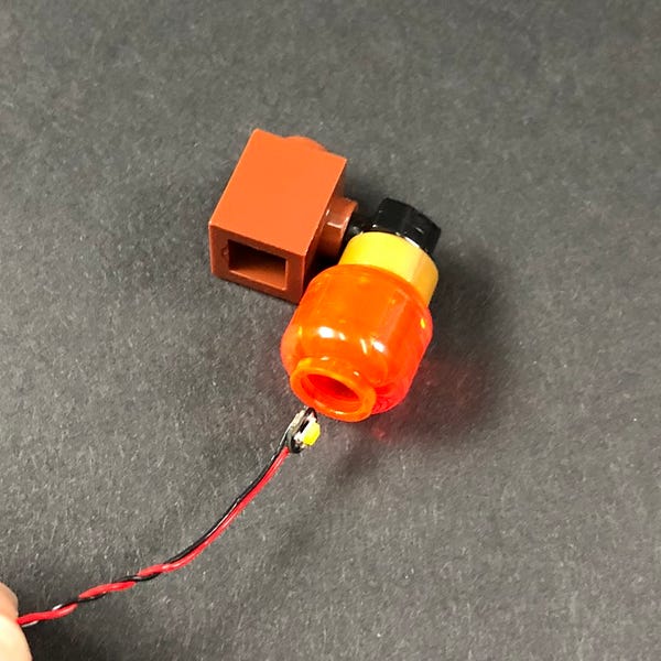
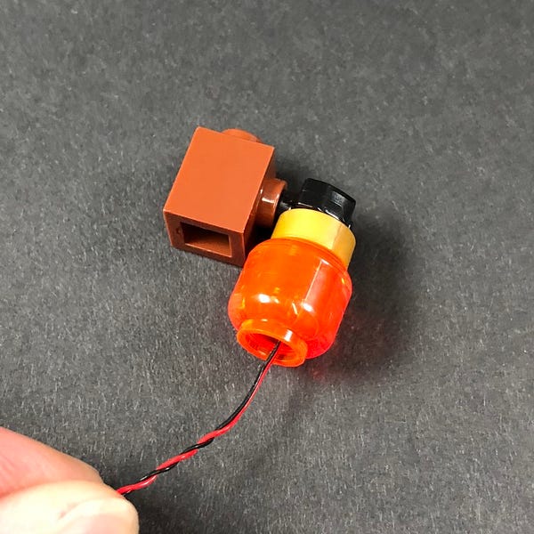
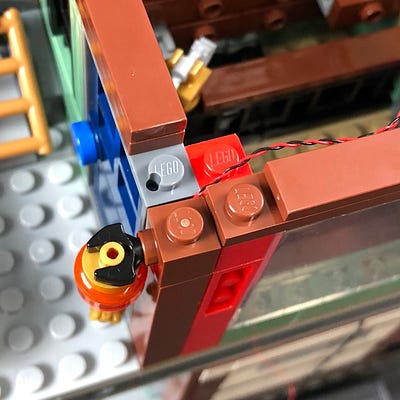
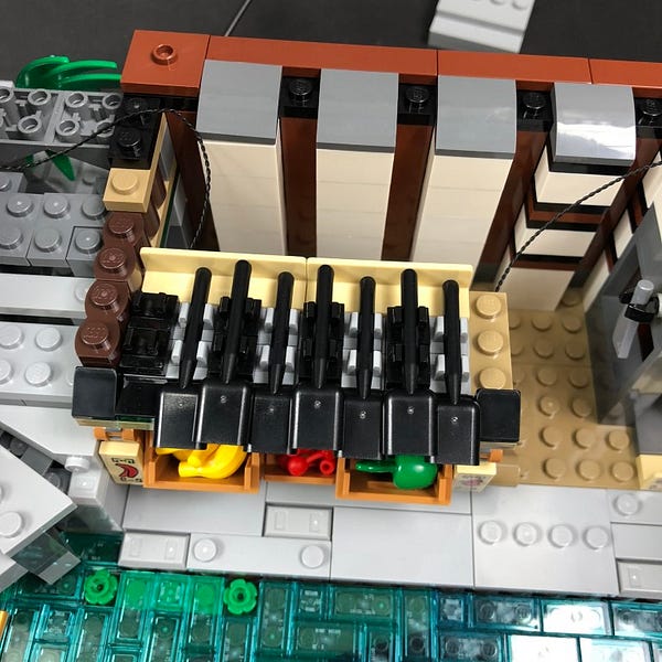
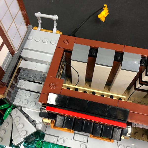
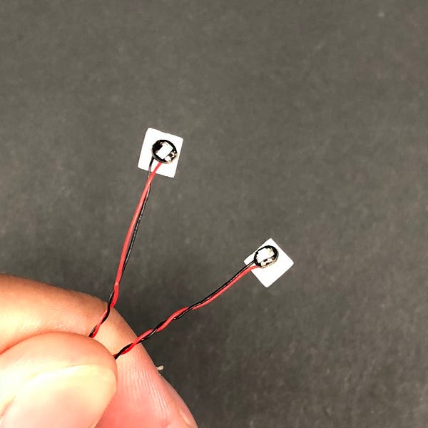
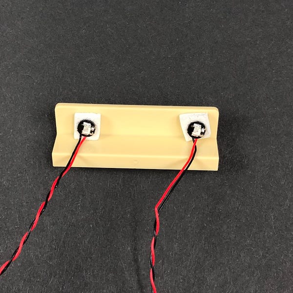
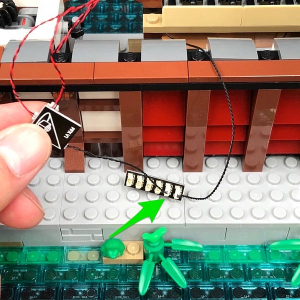
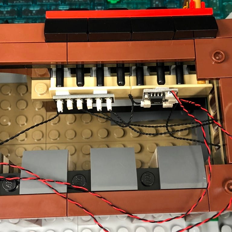
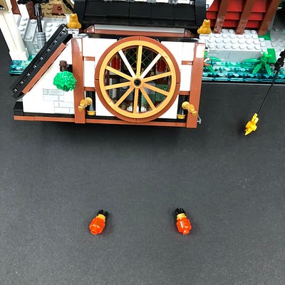
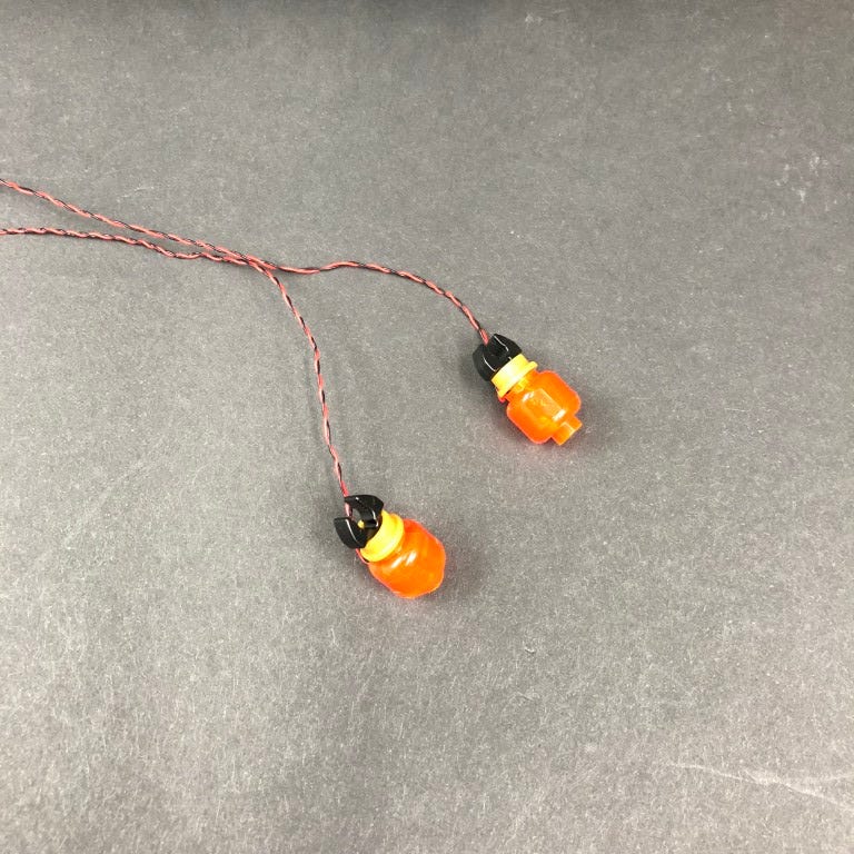
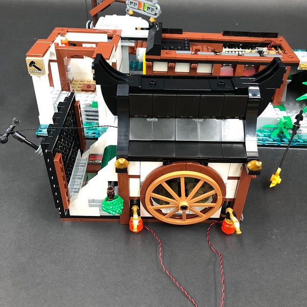
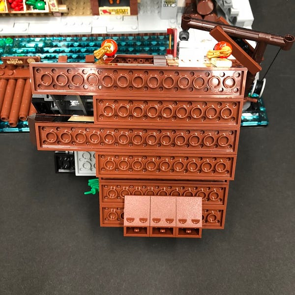
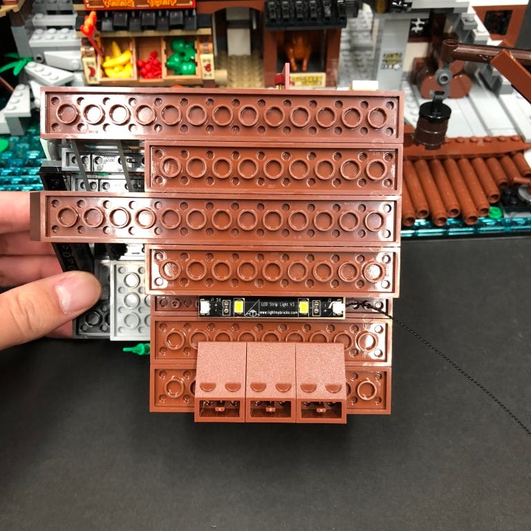
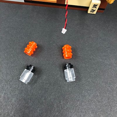
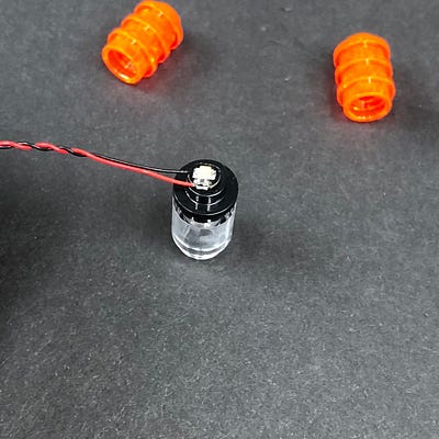
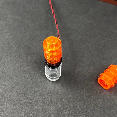
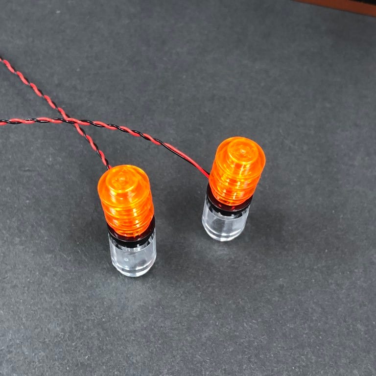
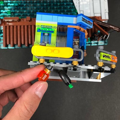
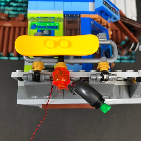
24.) Take 2x Orange 30cm Bit Lights and then stick them to the back of the chicken sign in the below position using 2x Adhesive Squares
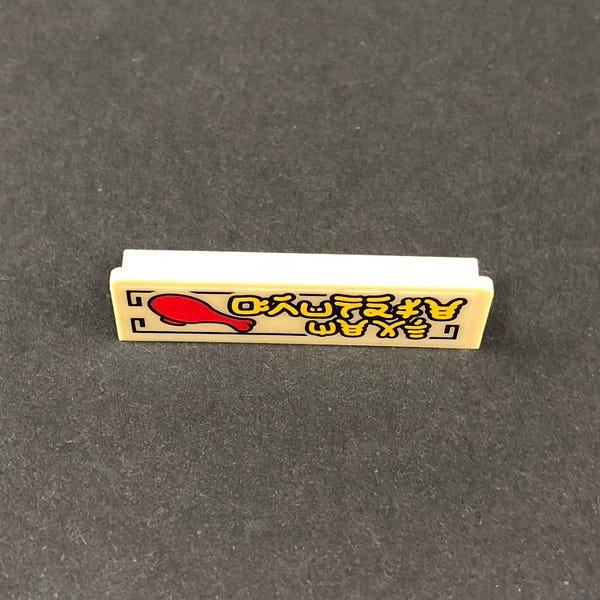
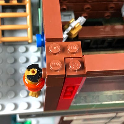
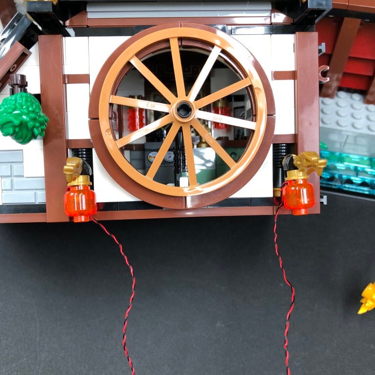
Reconnect the chicken sign to the front ensuring the cables are first threaded inside then reconnect the first dark grey tile over the top.
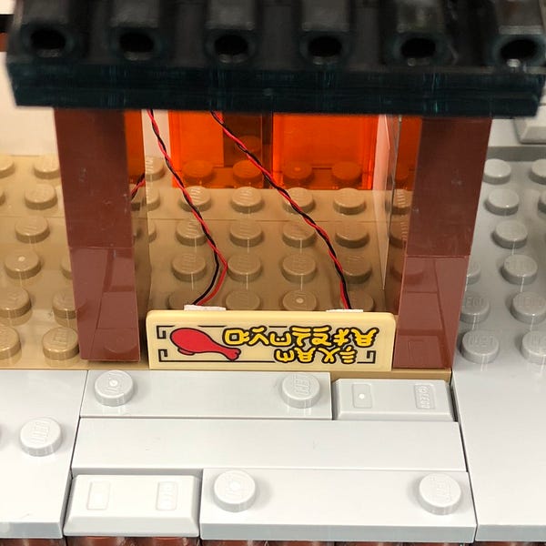
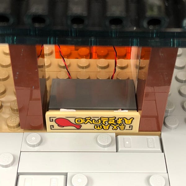
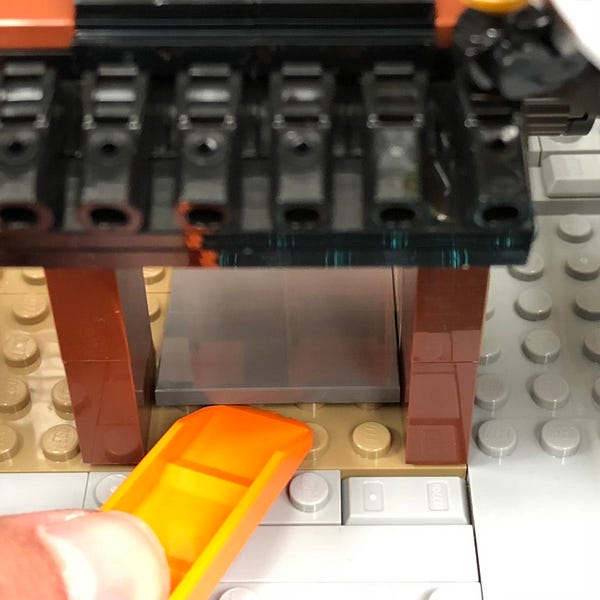
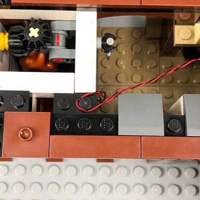
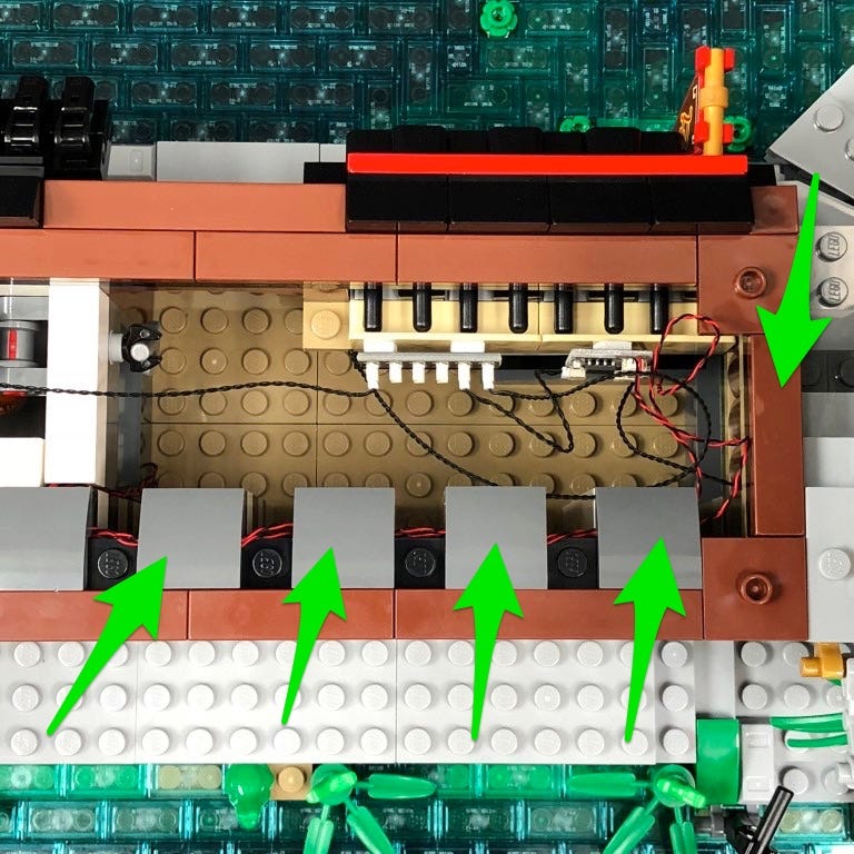
Turn the set around to the back and lay the cables toward the back and then to the right before reconnecting the remaining pieces over the top.
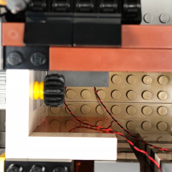
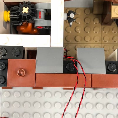
Pull both cables up and secure them underneath the dark grey curved tile on the top as per below.
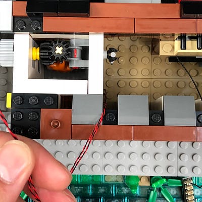
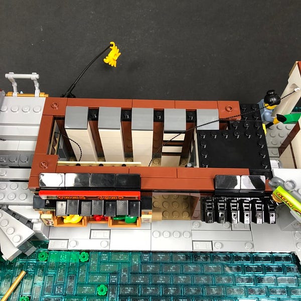
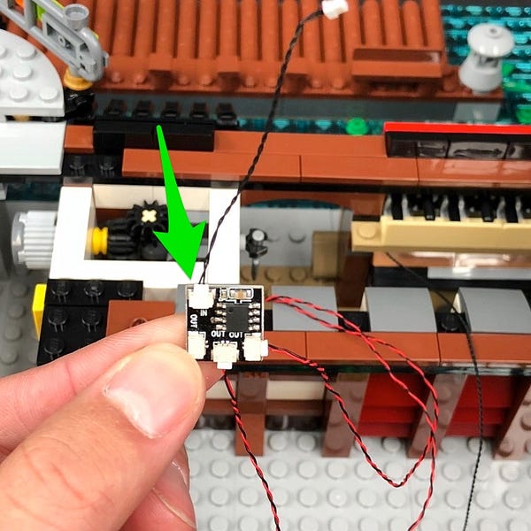
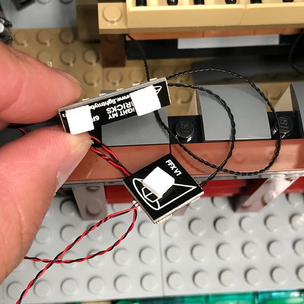
25.) Take the Flicker Effects Board and connect the two Orange Bit Light cables to the OUT ports.
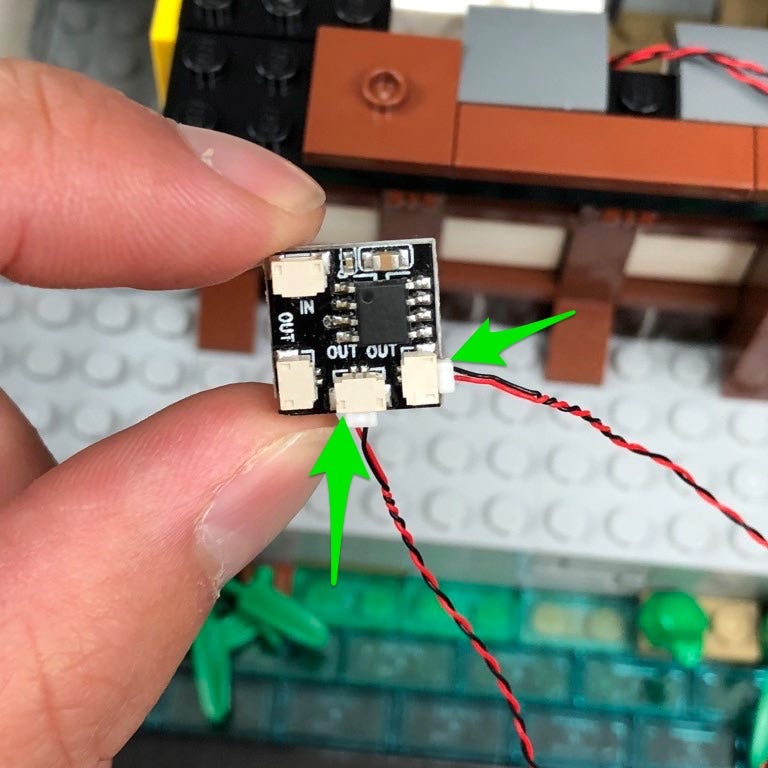
Take a 5cm Connecting Cable and connect it to the IN port and then connect the other end to the 6-port expansion board underneath.
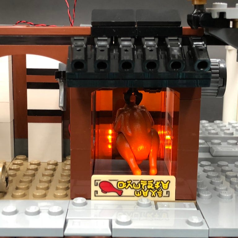
Turn the battery pack ON to test the orange lights and flicker effect is working OK in the chicken area.
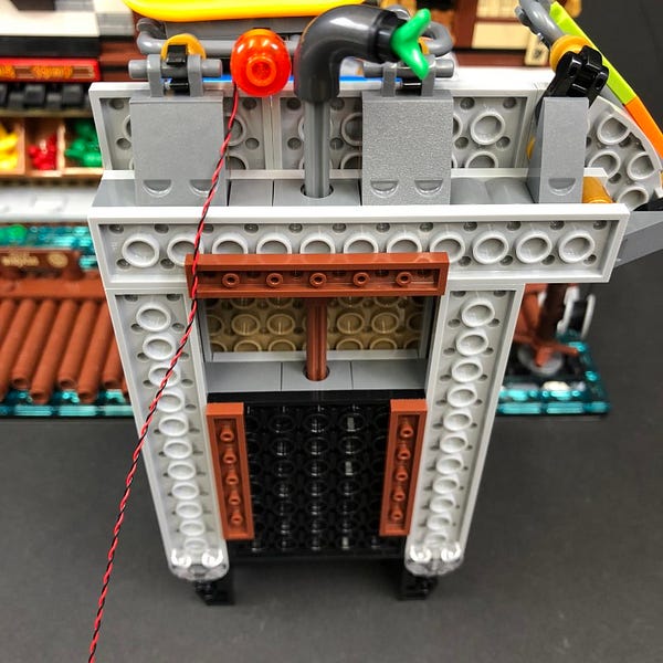
26.) Take a 30cm Connecting Cable and connect it to the 6-port expansion board, then using 3x Adhesive Squares, mount the expansion board and flicker effects board to the inside of the fruit market in the below position
Tidy up cables by laying the excess orange bit light cables underneath the dark grey curved tiles and brown tiles along the top.
Pull the 30cm Connecting Cable to the left and lay it in between studs in the top corner before reconnecting the the black plate and left roof section.
27.) Take the upper middle section and disconnect the two lanterns.
Follow the same process used in step 7 to install 2x White 15cm Bit Lights to the two lanterns.
28.) Reconnect the lanterns to the upper level then disconnect the roof and place it on it’s back so we can access underneath.
29.) Take a White Strip Light and stick it to a provided LEGO Plate 1×6. Take a 30cm Connecting Cable and connect one end to the Strip Light.
Mount the Strip Light underneath the roof in the below position ensuring the cable is facing the left side as per below.
Secure the cable underneath the brown 1×2 plate
Reconnect the roof to the upper level then bring the cable down in between the left angled roof.
Pull the cable down and lay it underneath the long vertical brown tile as per below.
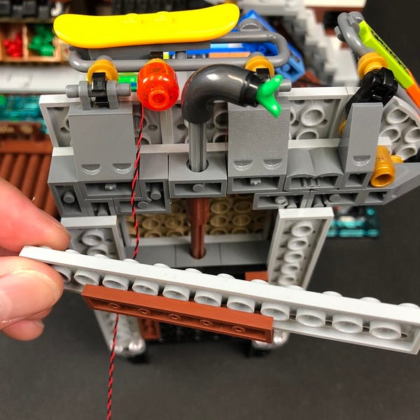
30.) Disconnect the 2×14 brown plate from bottom of the upper level then lay all cables underneath toward the inside in between studs before reconnecting the 2×14 plate.
Bring the entire upper level over the fruit market and connect all three cables to the 6-port expansion board underneath.
Secure the upper level on top of the fruit market and test that all lights installed so far are working OK
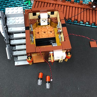
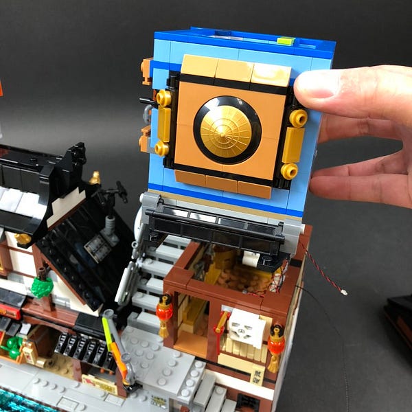
31.) Turn the set back around to the front then take the second level from the right building and turn it onto it’s back so we can access underneath.
32.) Take another White Strip Light and stick it to a provided LEGO Plate 1×6. Take a 15cm Connecting Cable and connect it to the strip light’s right port.
Mount the strip light underneath the second level in the following position ensuring the cable is facing the right.
Turn the second level over and pull the 15cm cable up the right side. Secure it underneath the brown tile on the top.
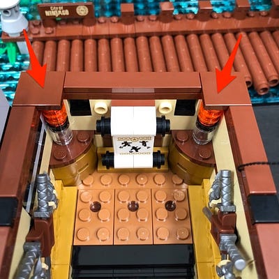
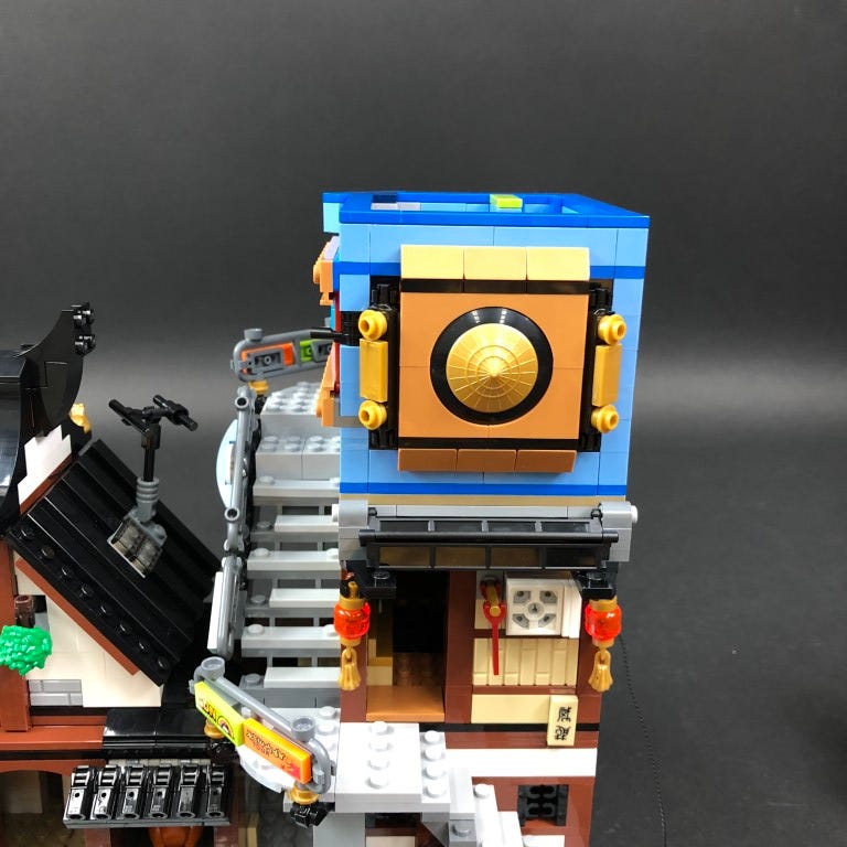
33.) We will now install lights to the lanterns outside the entrance. First disconnect the following pieces on the top to allow us to remove the two lantern sections
34.) Follow the process used in step 14 to install another 2x White 15cm Bit Lights to the lantern pieces
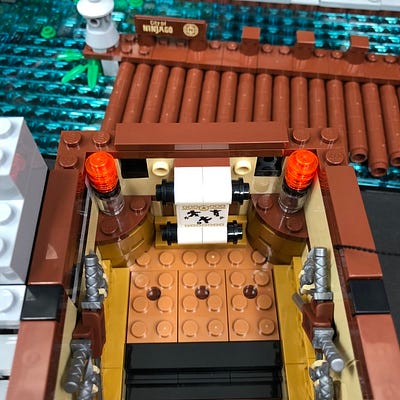
Reconnect the two lantern pieces back to the front of the second level then reconnect pieces along the top ensuring cables are laid in between bricks and studs.
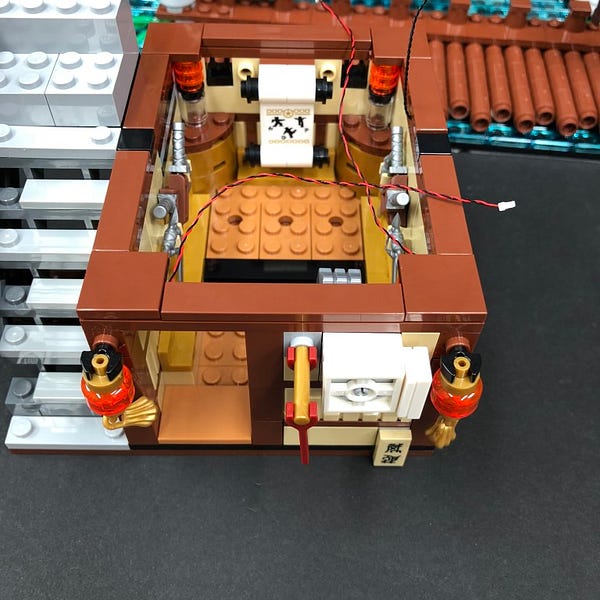
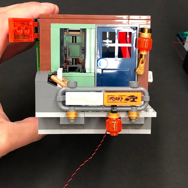
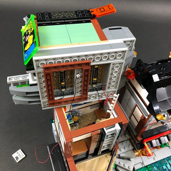
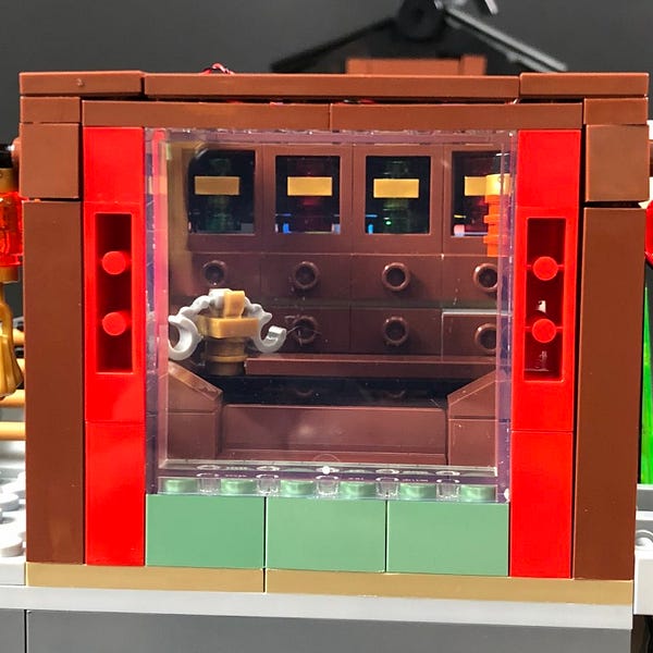
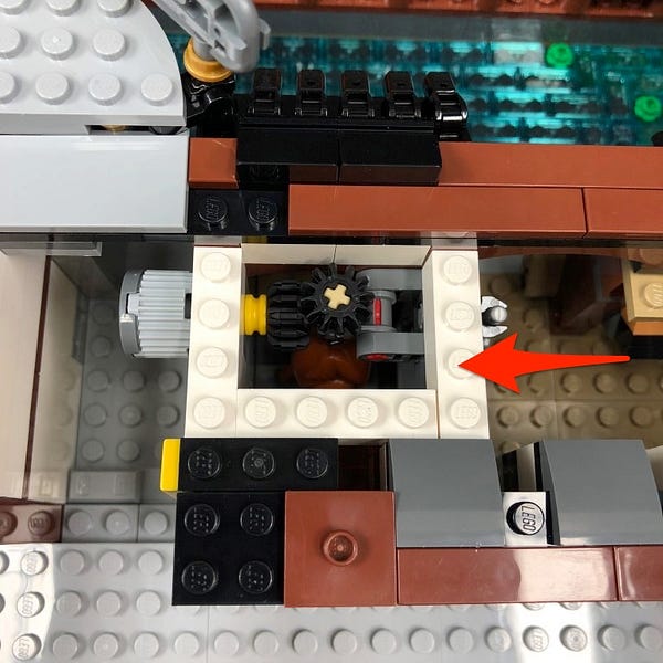
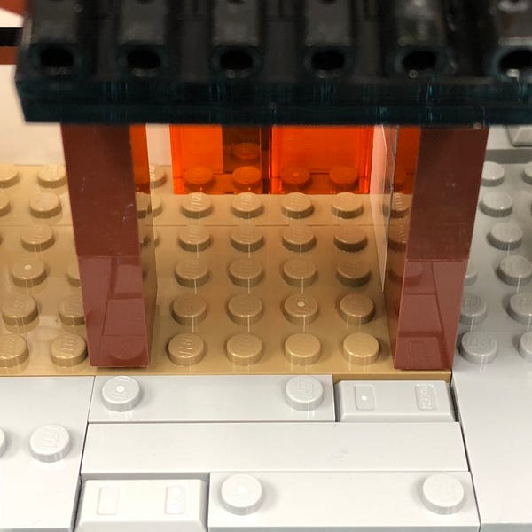
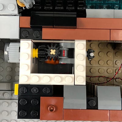
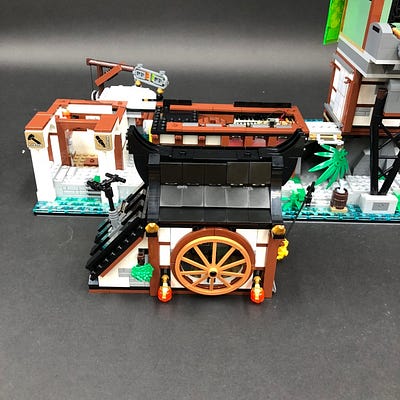
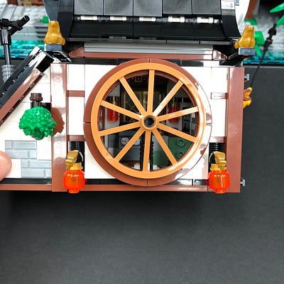
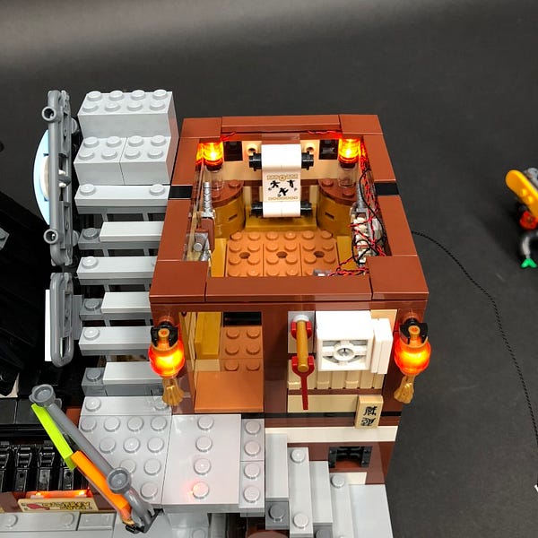
35.) We will now install lights to the lamps inside the room. First disconnect the tiles in each top corner to allow us to disconnect the lamp sections.
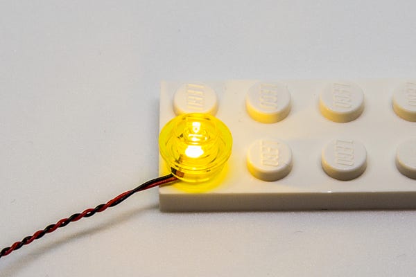
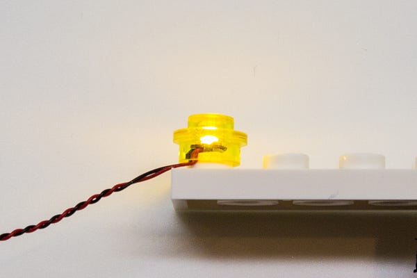
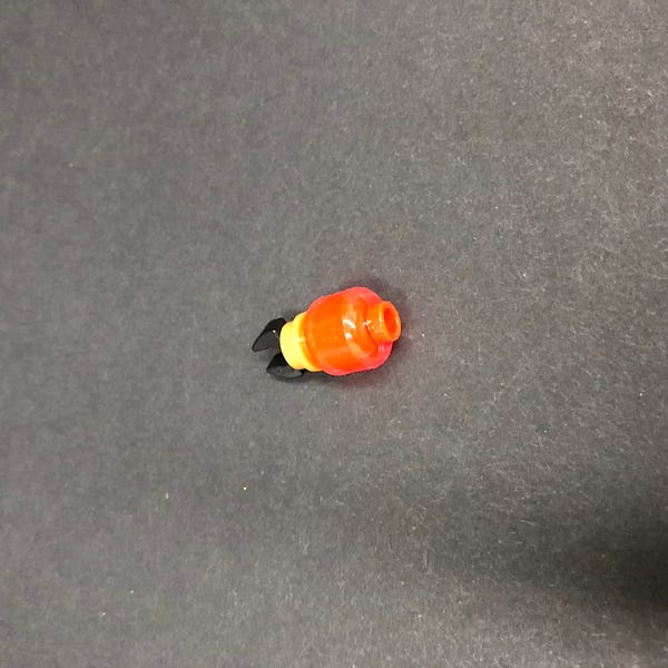
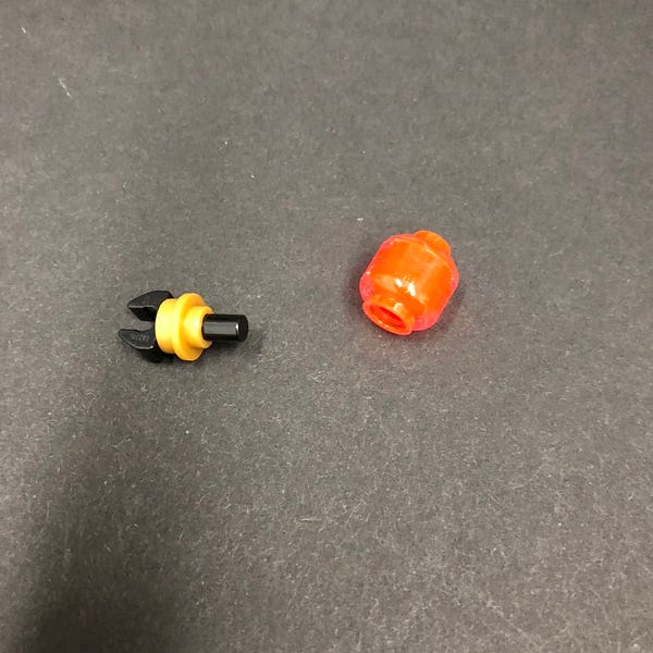
Disconnect the trans orange round plates from each lamp then take a White 15cm Bit Light and place it directly over one of the lamps. Secure the bit light in place by reconnecting the trans orange round plates from one side over the top.
Repeat this process to install another White 15cm Bit Light to the other lamp.
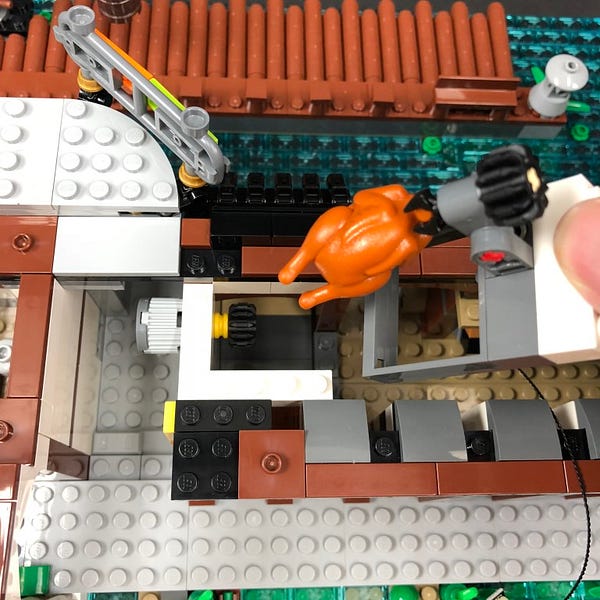
Reconnect the lamps to the inside of the room and then reconnect the brown tiles over the top ensuring the cables are laid the same way as shown below
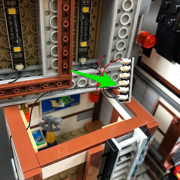
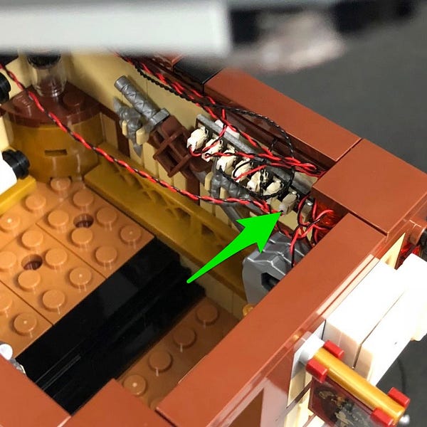
36.) Take an 8-Port Expansion Board and connect all four bit light cables as well as 15cm cable from underneath to it
Take a new 15cm Connecting Cable and connect it to a spare port on the expansion board then stick 2x Adhesive Squares to the back.
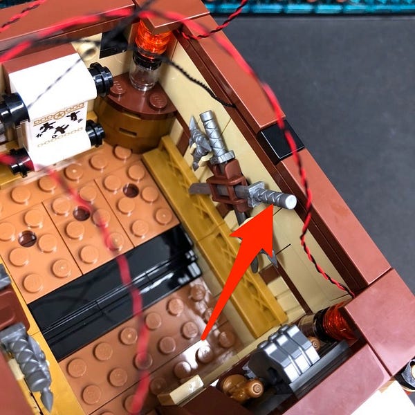
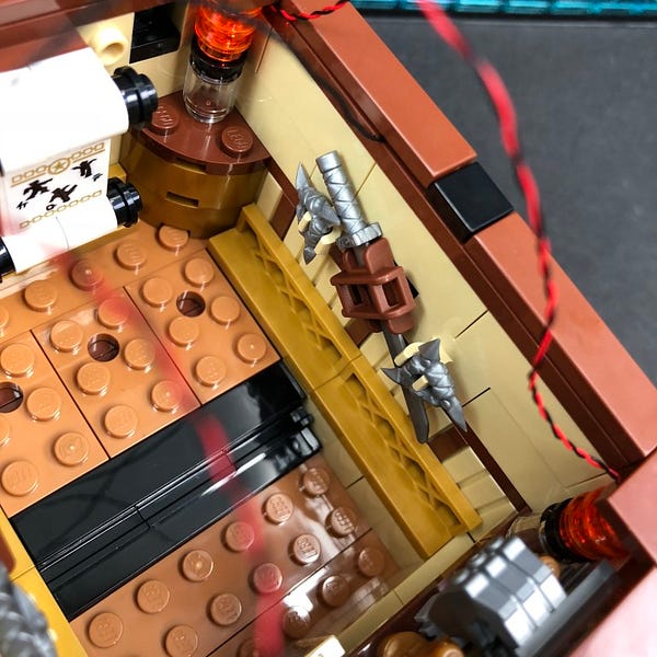
Remove the right sword from the right wall and then mount the expansion board to the inside of the room along the top as shown below.
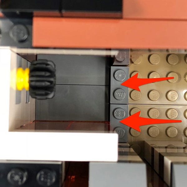
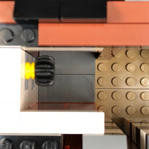
37.) Pull the 15cm cable out toward the right of the building and then secure it underneath the following brown tile.
Neaten up cables and prevent them from hanging down and visible by hiding them underneath the tiles along the top as shown below.

38.) Bring the entire second level above the ground level then take the other end of the 30cm cable from the fruit market and lay it underneath the following tile.
Connect the cable to the strip light underneath the second level before securing he second level on top.

Test all lights are working OK but turning the battery pack ON.
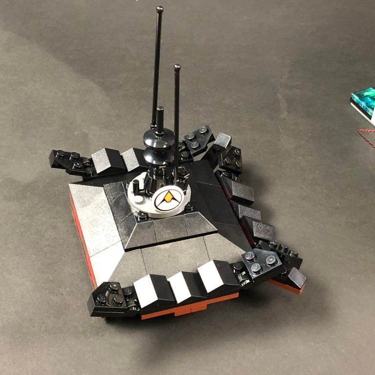
39.) Take the third level from the right building and disconnect the roof as well as lantern from the back.
Follow the same process used in step 7 to install a White 15cm Bit Light to the lantern.
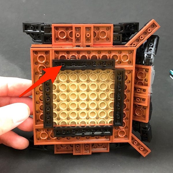
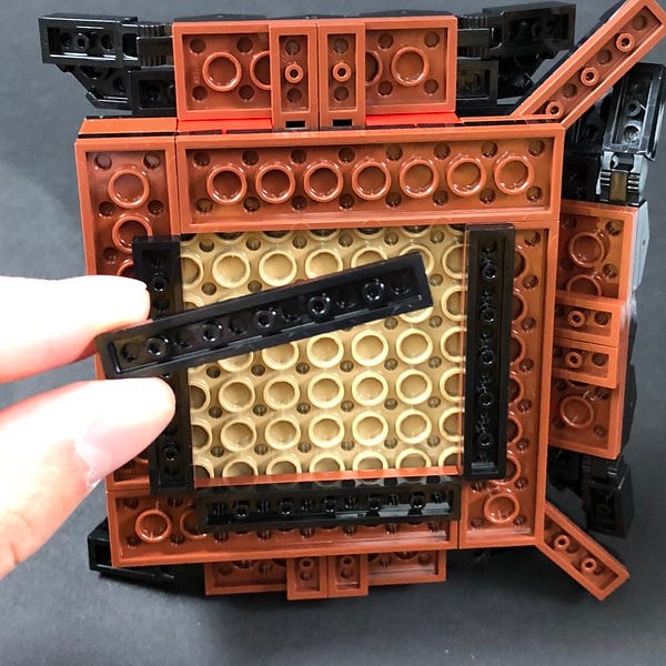
Reconnect the lantern then disconnect the light grey 2×12 plate from the bottom of the floor and lay the lantern cable underneath it ensuring it is in between studs before reconnecting the 2×12 plate.
40.) Bring the entire third level over the second level and connect the lantern bit light cable to a spare port on the 8-port expansion board underneath before securing the third level on top.
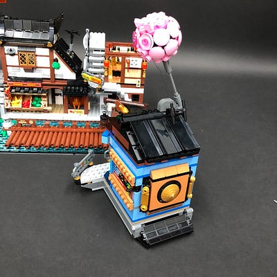
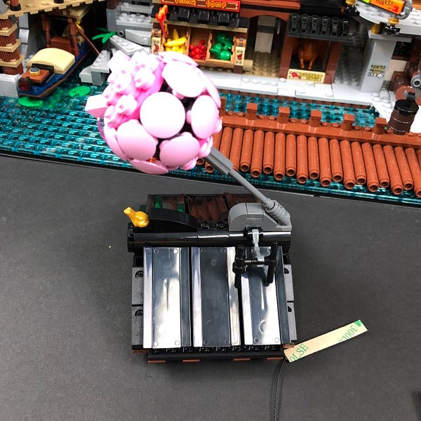
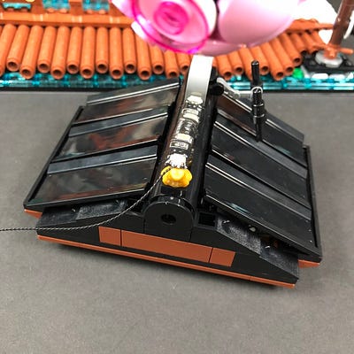
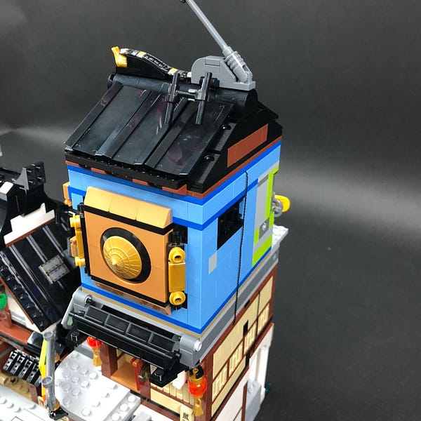
41.) Take a 2x White Strip Lights and connect them together using the remaining 15cm Connecting Cable.
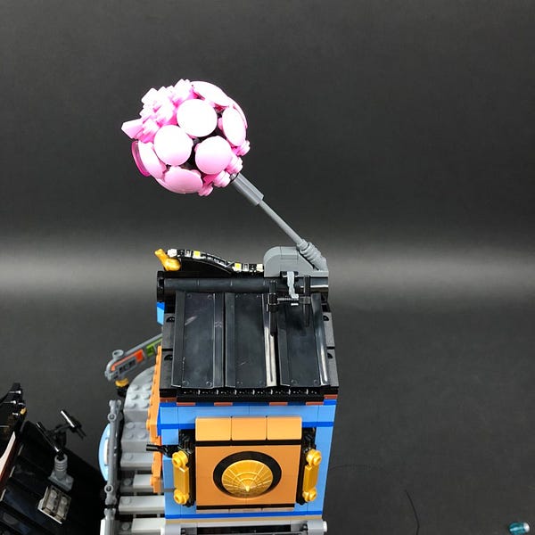
Take one of the Strip Lights and stick it directly to the roof of the third floor ensuring the cable is facing the left as shown below. This will be used to shine up on to the pink roof feature.
Pull the cable down the side and secure itunderneath the black round tile with hole.
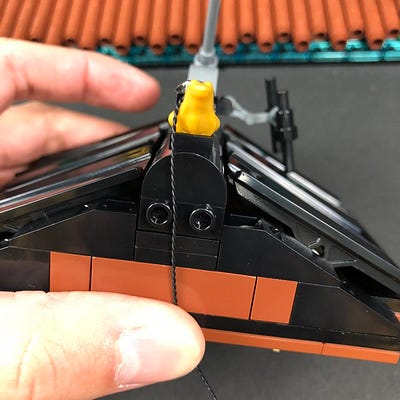
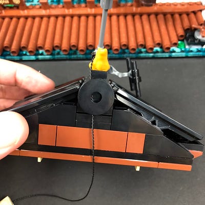
42.) Place the roof on to it’s right side so we can access underneath. Bring the cable down and lay it underneath the 1×8 tile as shown below
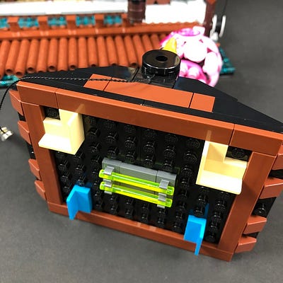
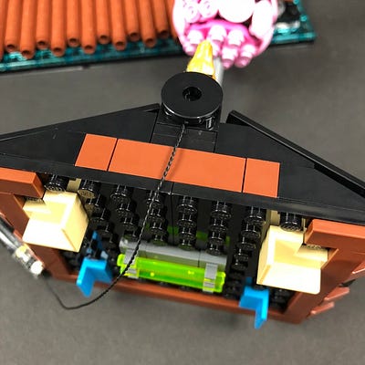
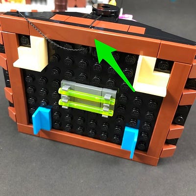
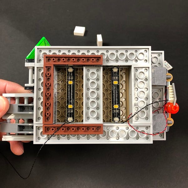
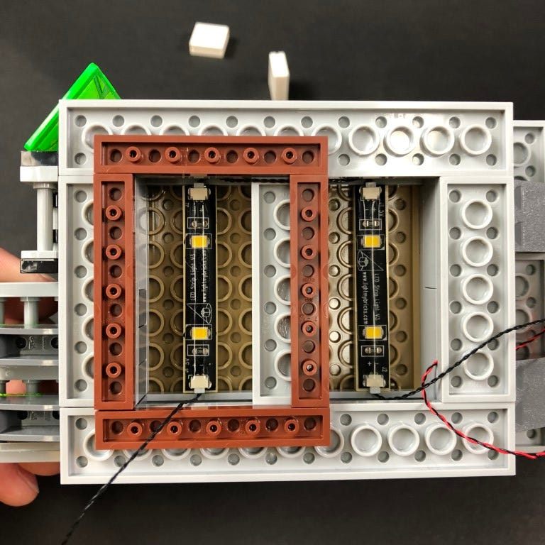
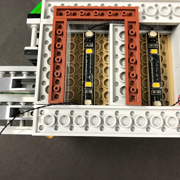
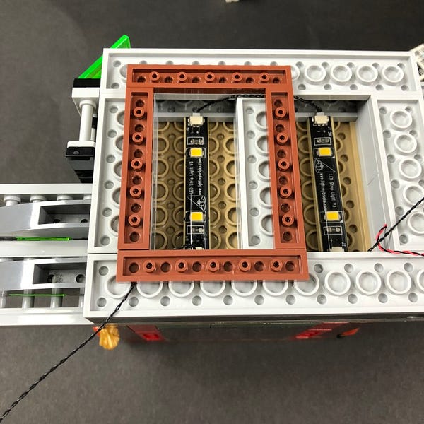
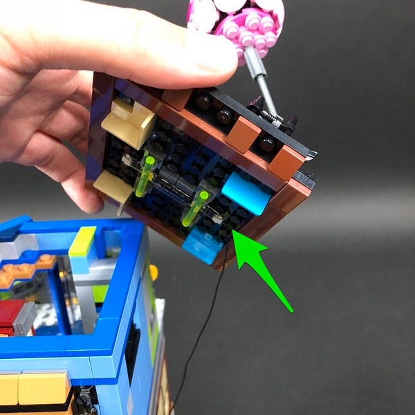
Disconnect the two trans bright green bars as well as the four dark grey clips from the ceiling.
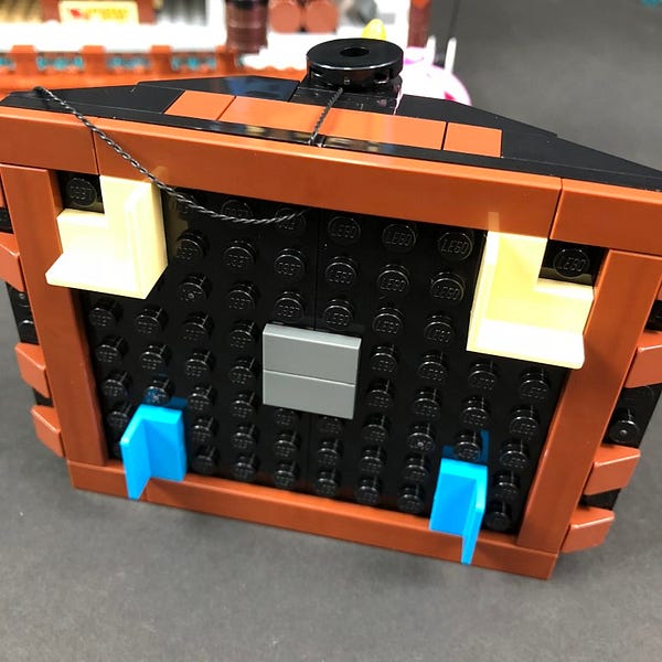
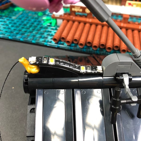
Stick the second strip light to the dark grey tile in the following position.
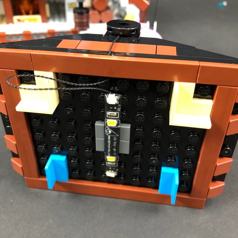
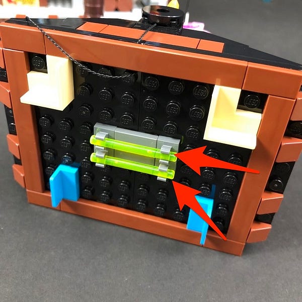
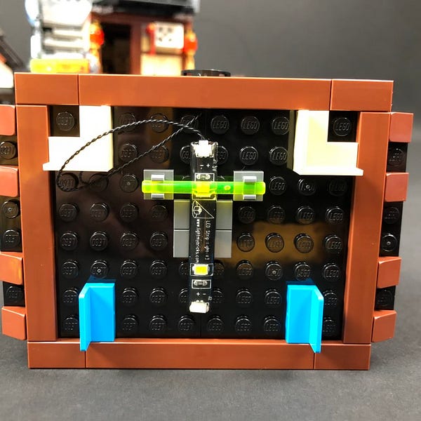
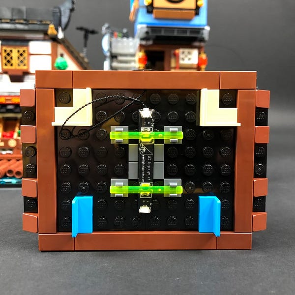
Connect the trans bright green bars with clips to new positions as per below, so that the trans bright green bars are directly over the top of the strip light LEDs.
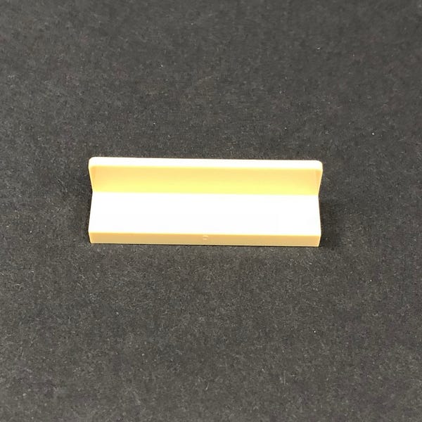
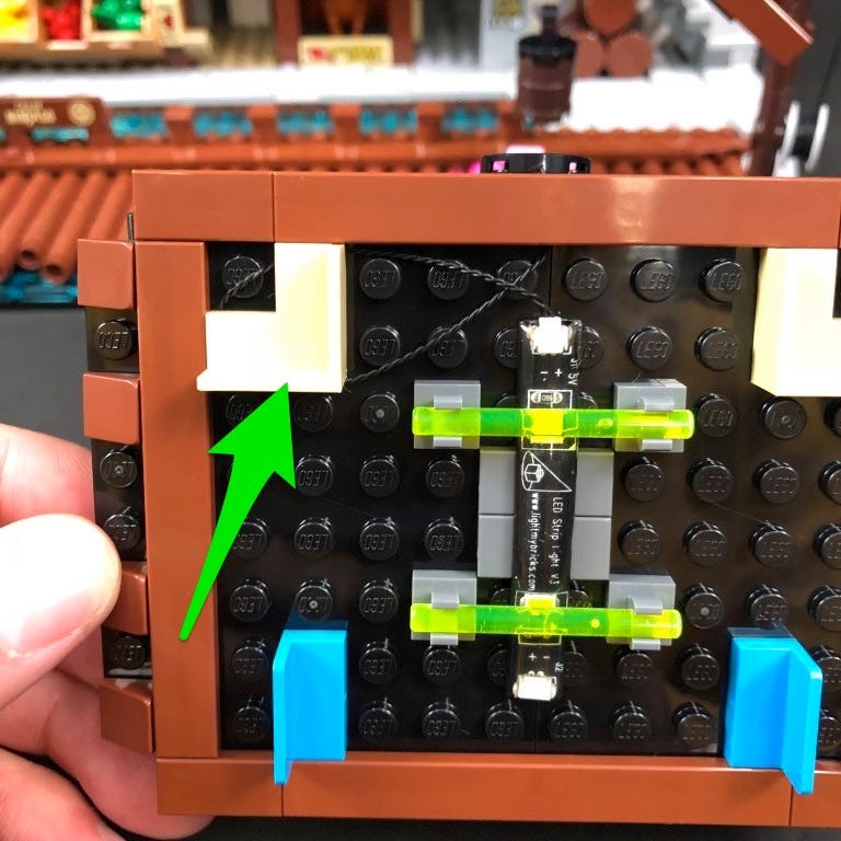
Hide the connecting cable underneath the cream coloured ‘L’ piece.
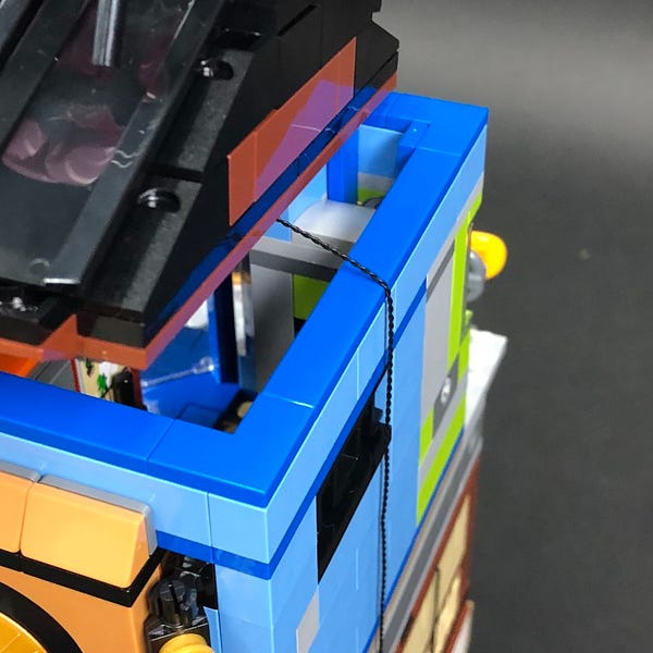
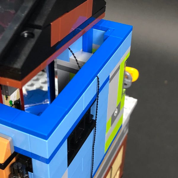
43.) Place the roof over the third level and then locate the loose 15cm connecting cable from the right side of the building and connect it to the Strip Light on the roof ceiling.
Before securing the roof, secure the cable underneath the blue tile on top of the third floor.
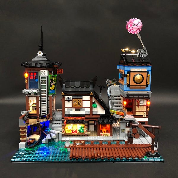
This finally completes installation of the Ninjago City Docks 70657 Light Kit.