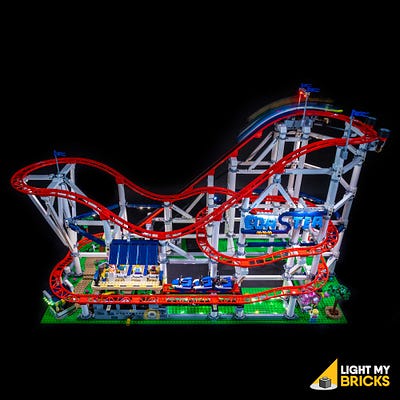
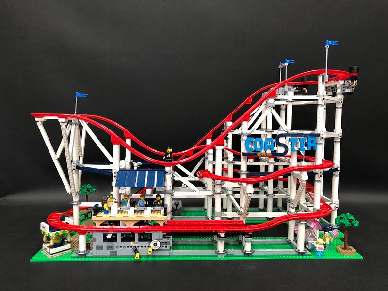
The following page is the instructions for the Light My Bricks LEGO Roller Coaster (10261) LED light kit.
To ensure a trouble-free installation of your light kit, please read and follow each step carefully.
If you run into any issues, please refer to the online troubleshooting guide.
To download this instructions guide in PDF format please click here.
Please note: This page lists instructions for the LED light kit only. If you are wishing to purchase the Light My Bricks LEGO Roller Coaster (10261) LED light kit , please click here to view the product page
Package Contents:
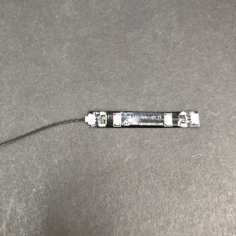
- 14x White Strip Lights
- 14x Flashing White 15cm Bit Lights
- 3x Flashing Red 30cm Bit Lights
- 1x Cool White 30cm Bit Lights
- 2x Multi Colour Light Strings
- 1x Multi Effects Board
- 3x 6-Port Expansion Board
- 1x 8-Port Expansion Board
- 1x 5cm Connecting Cable
- 7x 15cm Connecting Cables
- 10x 30cm Connecting Cables
- 6x Adhesive Squares
- 2x Micro Battery Packs (requires 3x LR 44 Batteries each pack)
- 1x AA Battery Pack (requires 3x AA Batteries)
OR - 1x USB Power Cable
Note – AA Battery Pack will be replaced with USB Power Cables from mid April 2020
LEGO Pieces:
- 3x Trans Green Round Plate 1×1
- 3x Trans Yellow Round Plate 1×1
- 1x Trans Clear Round Plate 1×1
- 3x Trans Red Round Plate 1×1
- 2x Plate 1×1 Modified w Horizontal Clip (Light Grey)
- 3x Plate 1×6 White
- 1x Plate 1×4 White
Laying cables in between and underneath bricks
Cables can fit in between and underneath LEGO® bricks, plates, and tiles providing they are laid correctly between the LEGO® studs. Do NOT forcefully join LEGO® together around cables; instead ensure they are laying comfortably in between each stud.
CAUTION: Forcing LEGO® to connect over a cable can result in damaging the cable and light.
Connecting cable connectors to Expansion Boards
Take extra care when inserting connectors to ports of Expansion Boards. Connectors can be inserted only one way. With the expansion board facing up, look for the soldered “=” symbol on the left side of the port. The connector side with the wires exposed should be facing toward the soldered “=” symbol as you insert into the port. If a plug won’t fit easily into a port connector, do not force it.
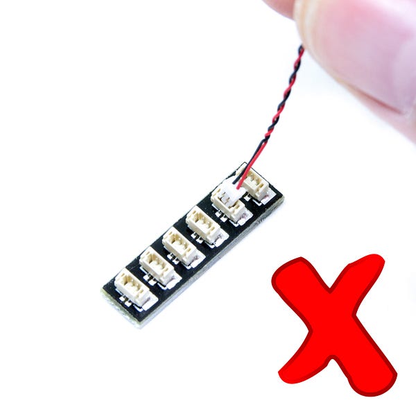
Incorrectly inserting the connector can can result in bent pins inside the port or possible overheating of the expansion board when connected.
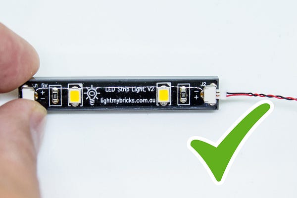
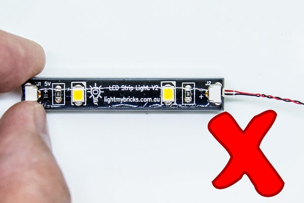
Connecting cable connectors to Strip Lights
Take extra care when inserting connectors to ports on the Strip Lights. Connectors can be inserted only one way. With the Strip Light facing up, ensure the side of the connector with the wires exposed is facing down. If a plug won’t fit easily into a port connector, don’t force it. Doing so will damage the plug and the connector.
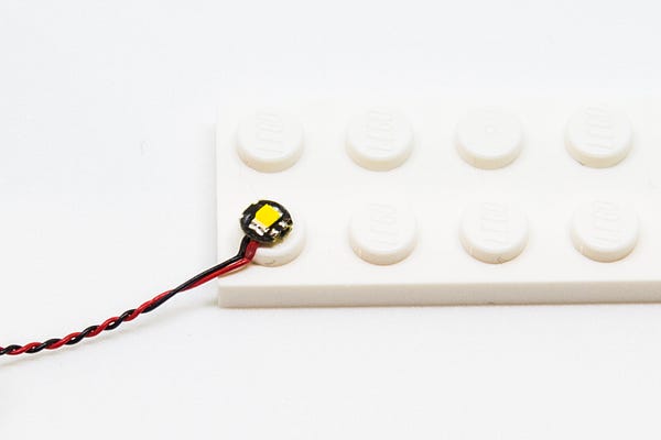
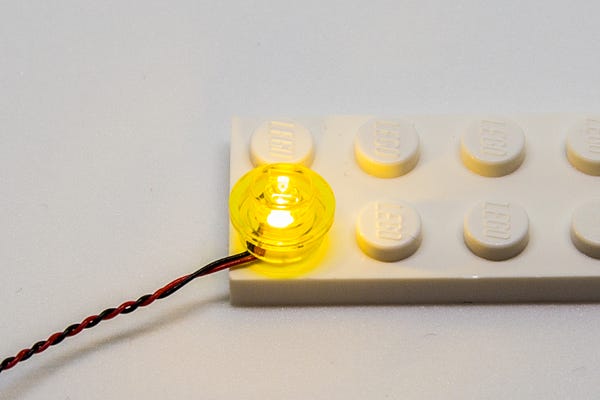
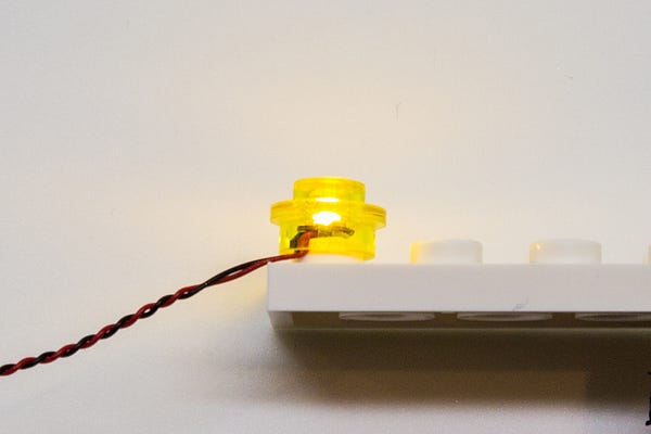
Installing Bit Lights under LEGO® bricks and plates.
When installing Bit Lights under LEGO® pieces, ensure they are placed the correct way up (Yellow LED component exposed). You can either place them directly on top of LEGO® studs or in between.
OK, Let’s Begin!
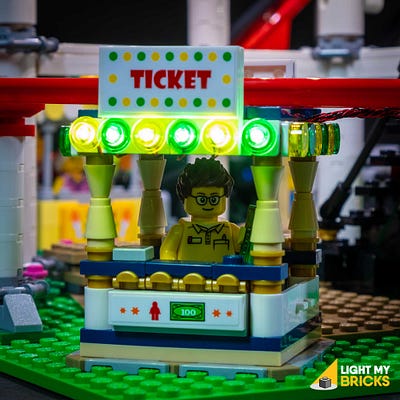
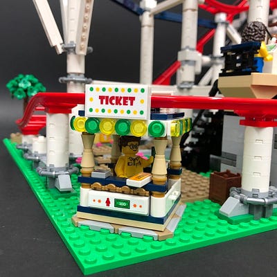
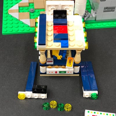
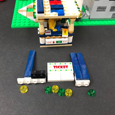
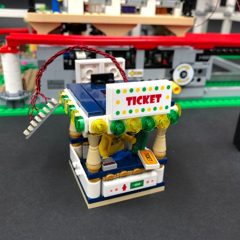
1.) The first thing we will light will be the ticket booth. Start by carefully disconnecting this section and then remove the front ‘Ticket’ sign and disconnect the four trans round tiles from it.
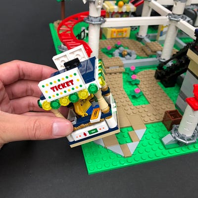
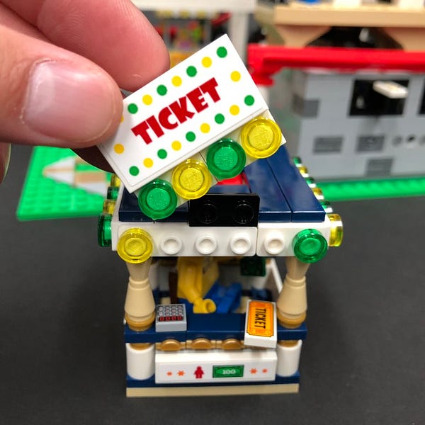
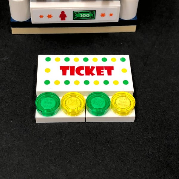
Disconnect the following side sections on the left and right of the Ticket sign and then disconnect the trans round tiles from each side.
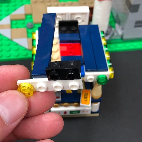
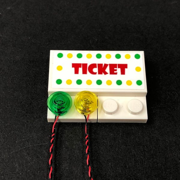
2.) Take a Flashing White 15cm Bit Light and place it directly over the far left stud on the left side section. Secure it in place by connecting a provided LEGO Trans Yellow Round Plate 1×1 over the top.
Reconnect this side section back to the top of the ticket booth ensuring the cable is laid toward the centre as per below.
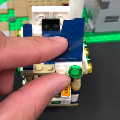
Take another Flashing White 15cm Bit Light and install it to the right side section, securing it in place with a provided LEGO Trans Green Round Plate 1×1.
Reconnect the right section to the top of the ticket booth ensuring the cable is laid toward the centre as per below (toward the left)
To make it easier to install the rest of the lights to the ticket booth, disconnect the roof.
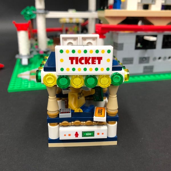
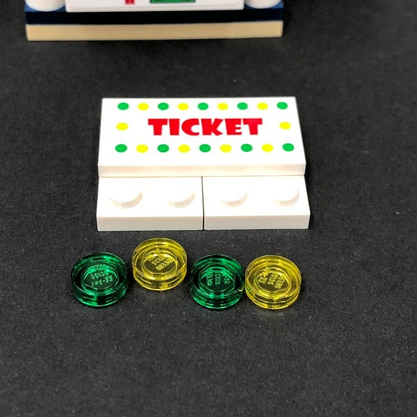
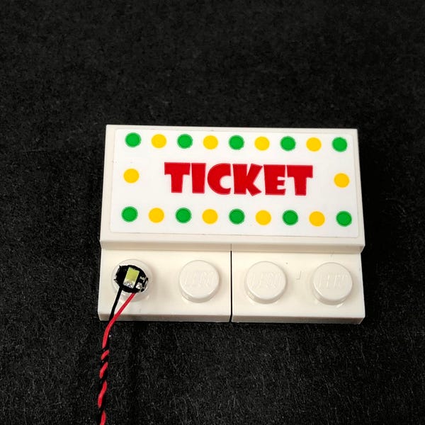
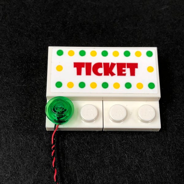
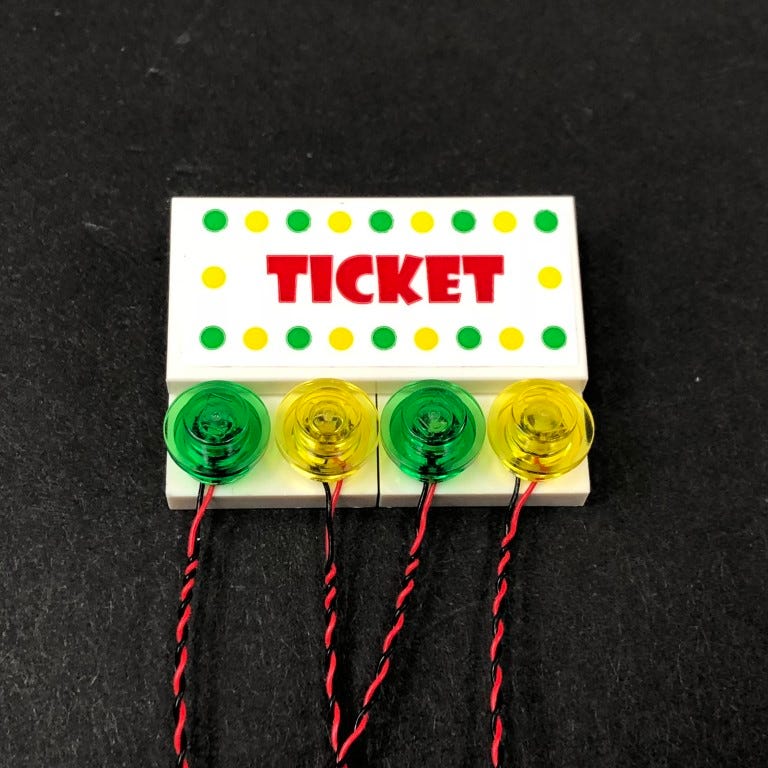
3.) Take another Flashing White 15cm Bit Light and place it over the far left stud of the Ticket sign with the cable facing down. Secure it in place using a provided LEGO Trans Green Round Plate 1×1
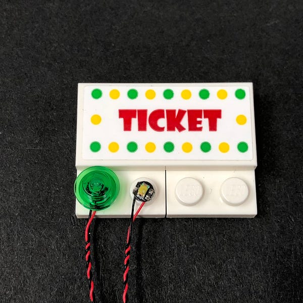
Install another Flashing White 15cm Bit Light to the next stud along, securing it in place using a provided LEGO Trans Yellow Round Plate 1×1.
Install another 2x Flashing White 15cm Bit Lights to the next two studs, securing them using another provided Trans Green and Trans Yellow Round Plates 1×1.
4.) Fold the four cables underneath the Ticket sign and then hold the cables in place at the top of the back of the sign. This will allow us to reconnect the sign to the roof ensuring the cables are laid in between studs.
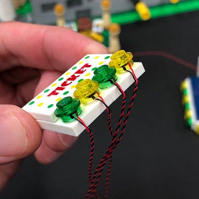
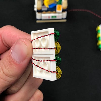
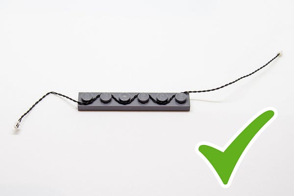
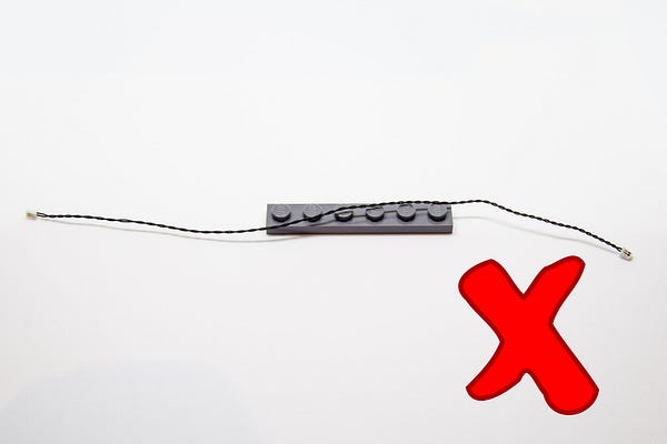
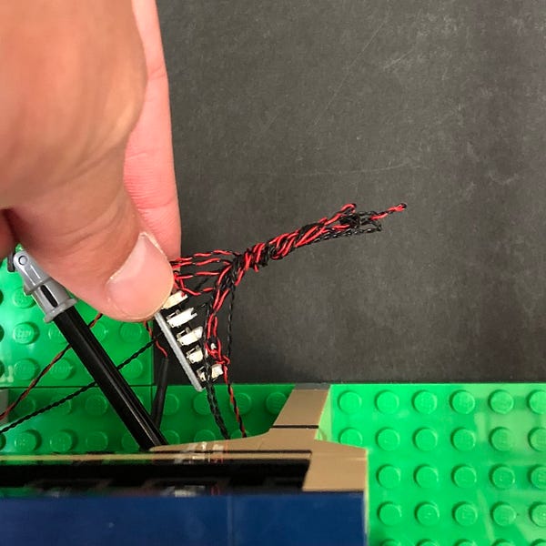
Group all the cables together and then twist them around each other all the way to the top to form one larger cable
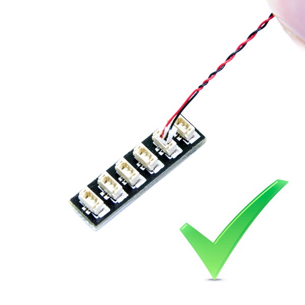
5.) Take an 8-Port Expansion Board and then connect all six cables to it
Test the flashing lights we have installed by taking the AA Battery Pack and inserting 3x AA Batteries to it. Connect the battery pack cable to a spare port on the expansion board and then turn it ON to verify the flashing lights are working OK
If you’re using the USB Power Cable, connect this to the board this instead of the battery pack, and connect the other end to a USB Power Bank or wall adaptor (sold separately) and turn it ON to test the front lights are working OK.
Disconnect the battery pack /usb cable from the expansion board and then reconnect the roof to the ticket booth.
Take a 30cm Connecting Cable and connect one end to a spare port on the 8-port expansion board and then connect the other end to a 6-Port Expansion Board
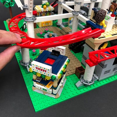
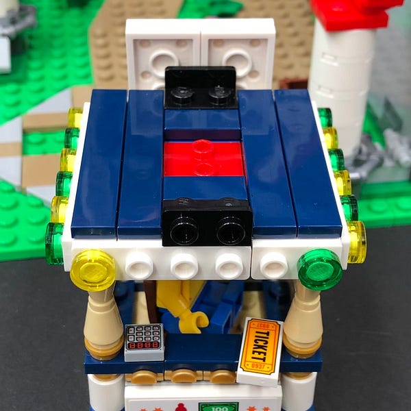
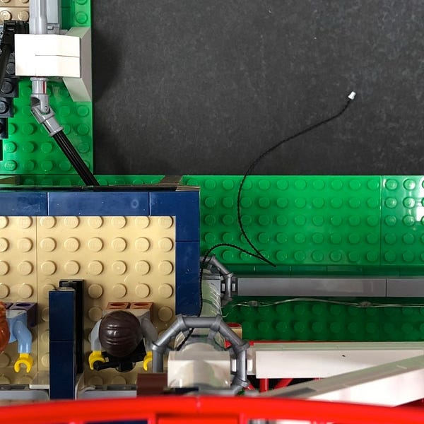
6.) Reconnect the ticket booth back to the roller coaster base, then disconnect the two dark blue tiles on the right of the roof.
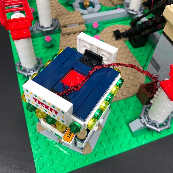
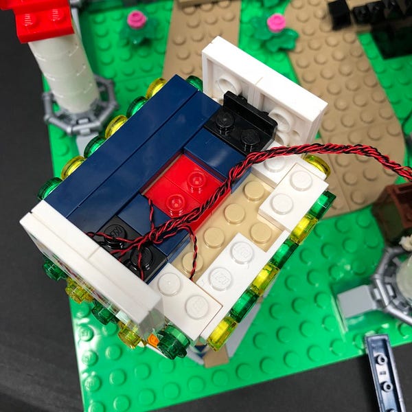
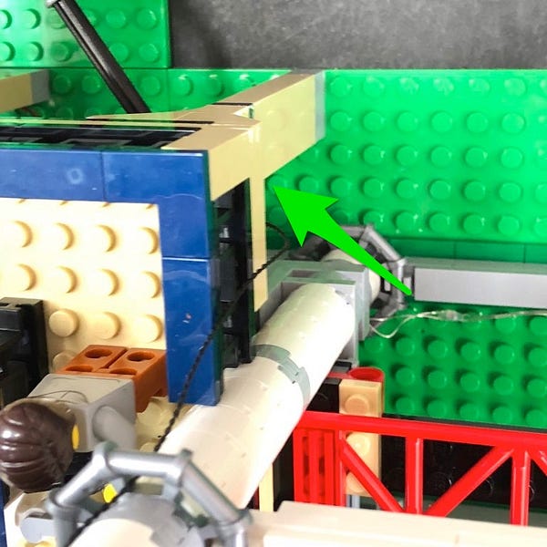
Lay the thick cable in between white studs as shown below before reconnecting the dark blue tiles over the top.
Reconnect the roller coaster track and then ensure all cables are pushed down and laying as flat as possible to prevent the roller coaster carriage wheels from getting stuck as it passes.
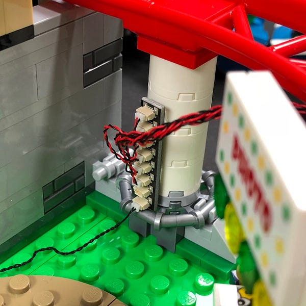
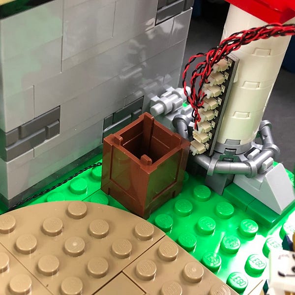
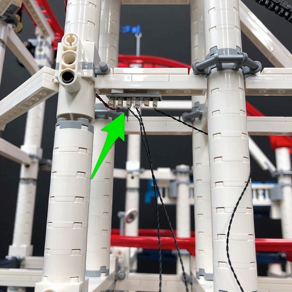
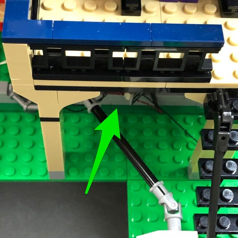
7.) Take 2x Adhesive Squares and stick them on the base side of the 8-port Expansion Board. Bring the cable over to the right and then mount the 8-port expansion board on the back of the front Roller Coaster pillar as per below.
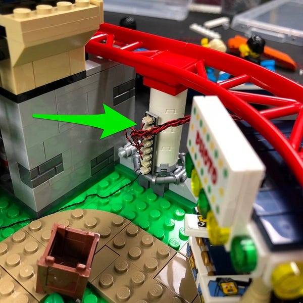
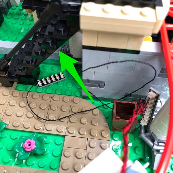
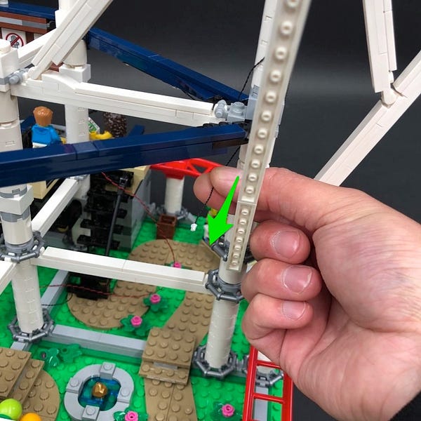
Take the 6-port expansion board which is connected to the other end of the 30cm connecting cable and then push it through underneath the stairs behind the roller coaster platform
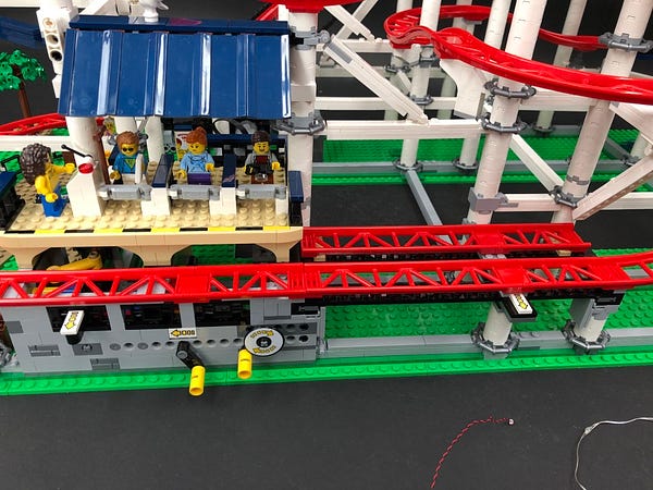
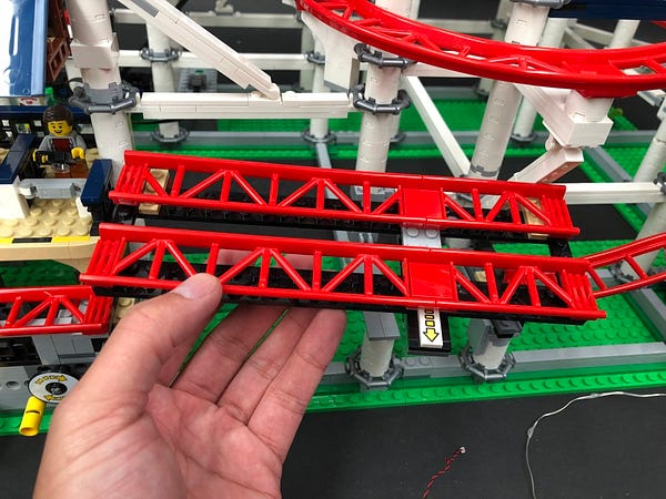
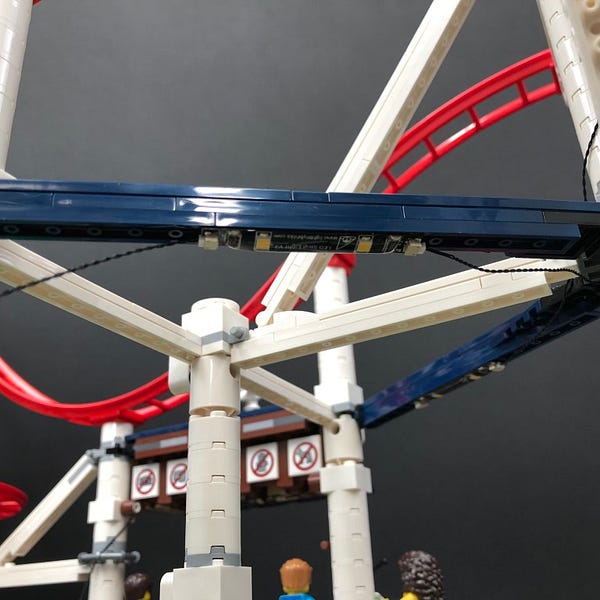
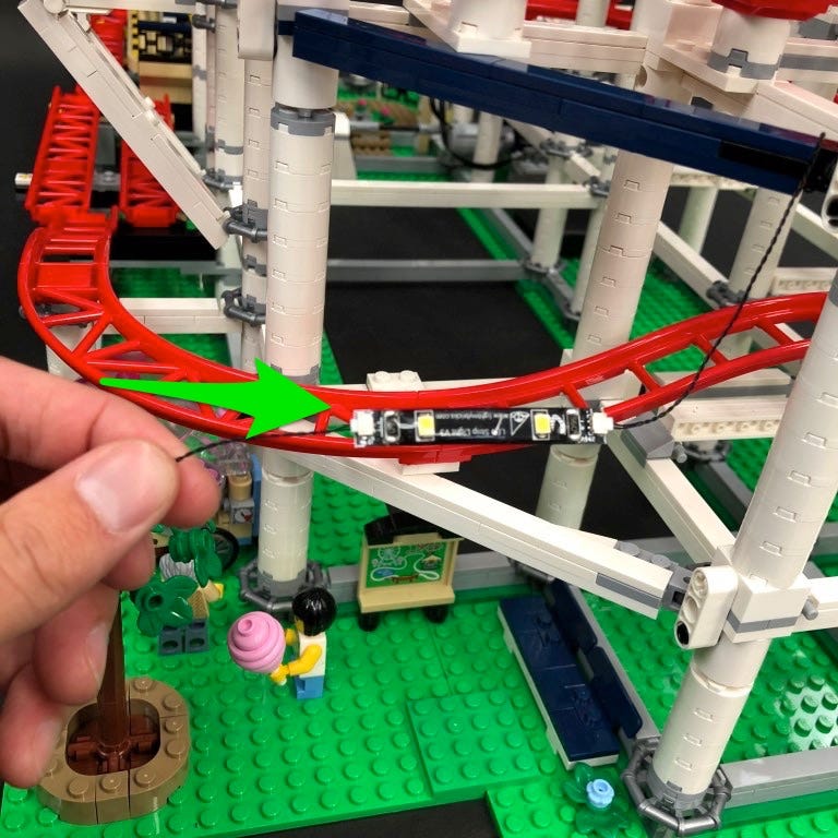
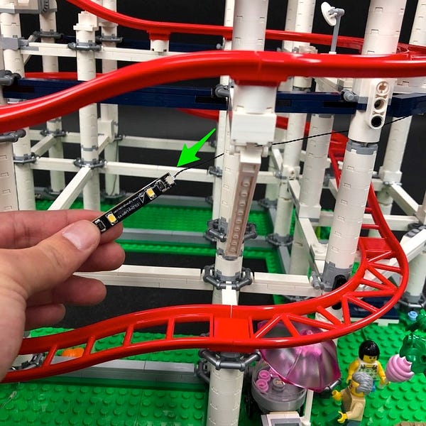
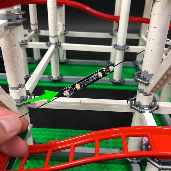
8.) We will now install lights underneath the front tracks. First disconnect the following double track section as per below then take out a Multi Colour Light String.
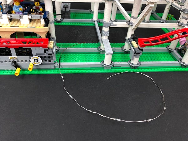
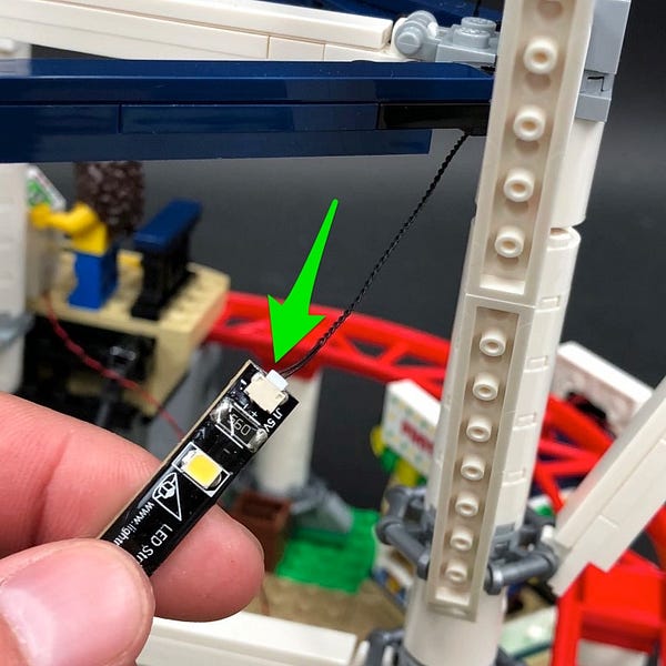
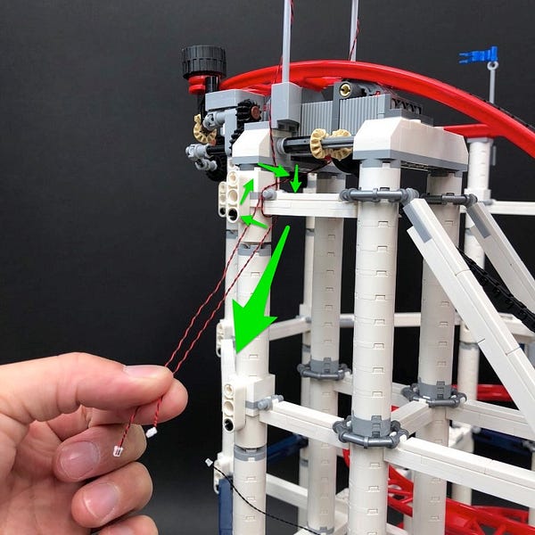
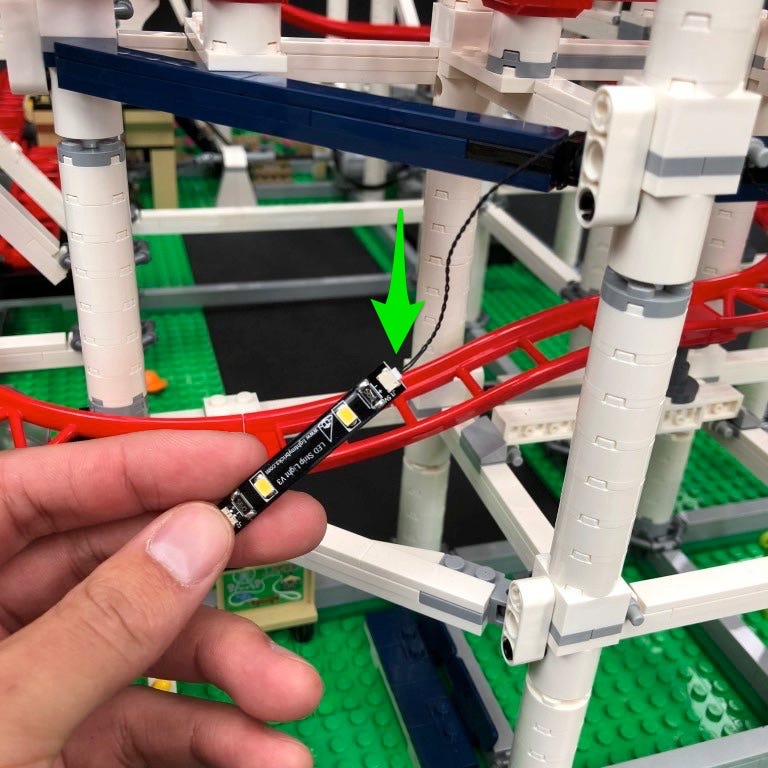
Thread the connector side of the light string underneath the platform through the left side. Pull it out from the left side behind the plat form and then connect it to a spare port on the 6–port expansion board we threaded through in the previous step.
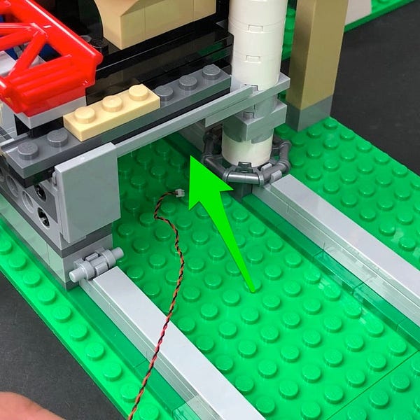
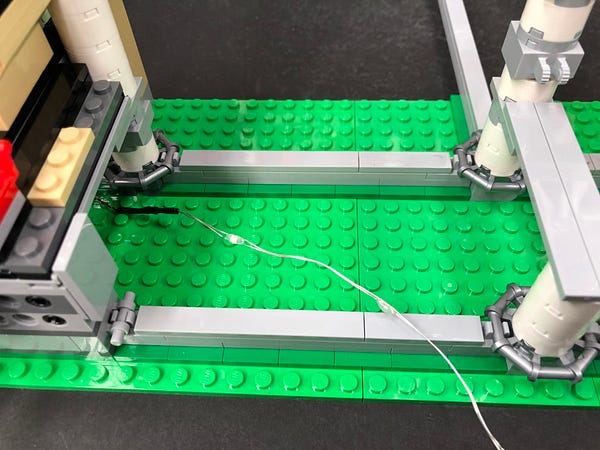
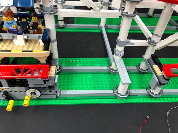
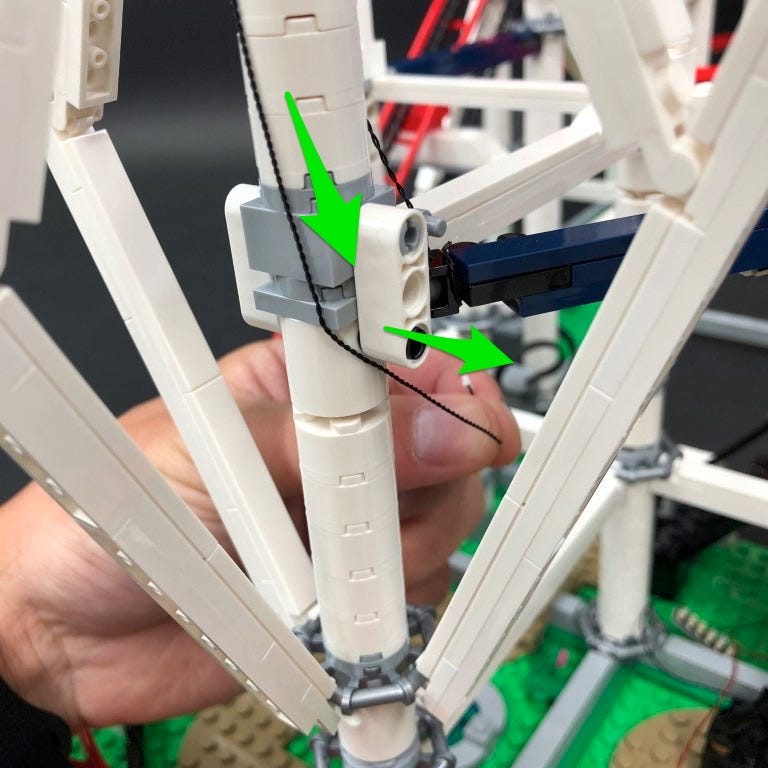
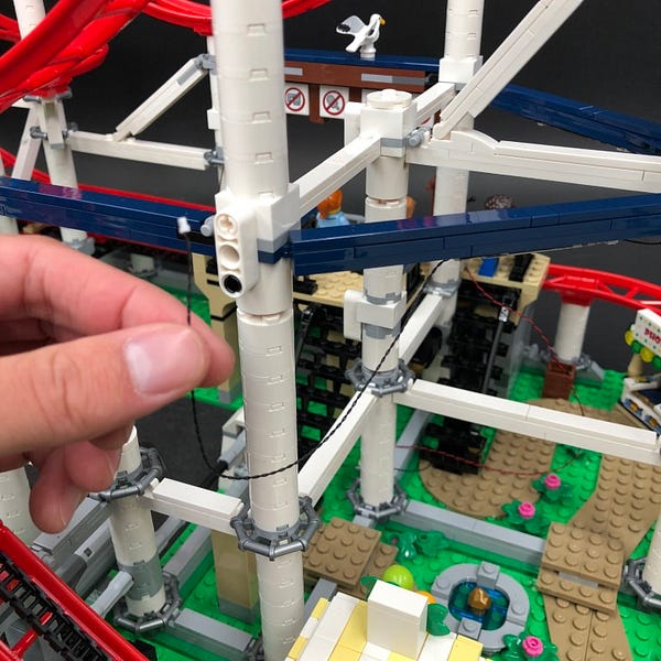
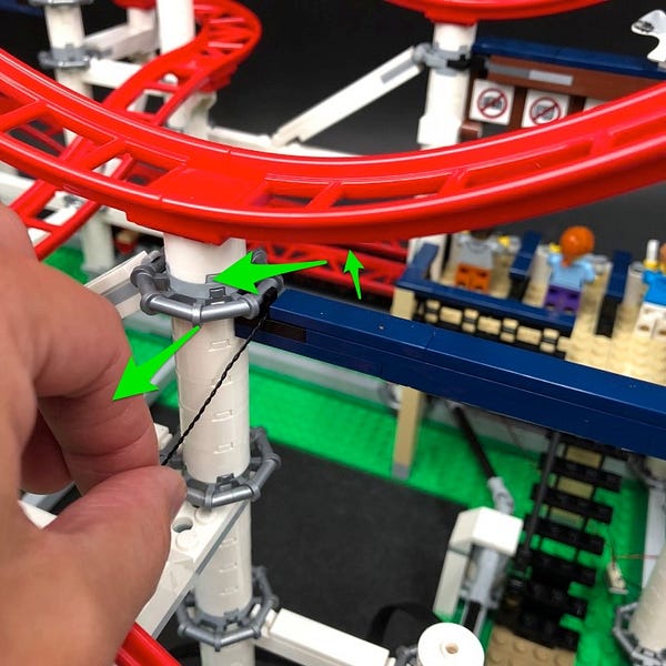
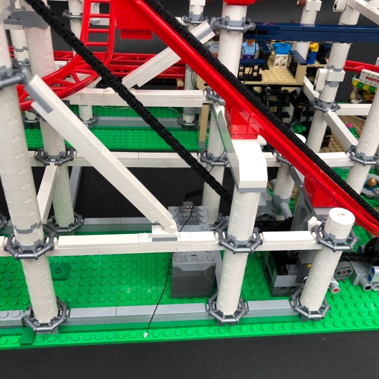
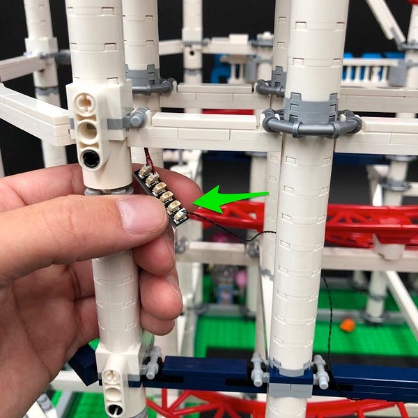
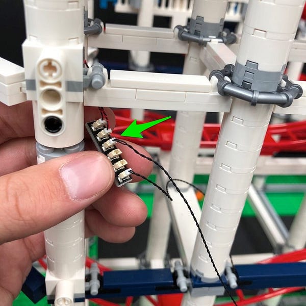
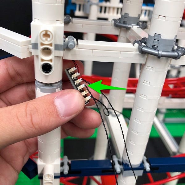
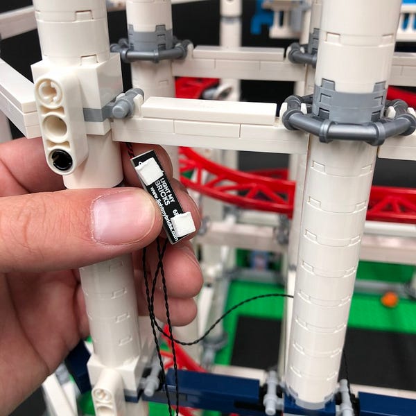
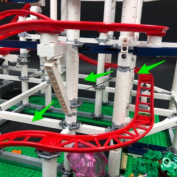
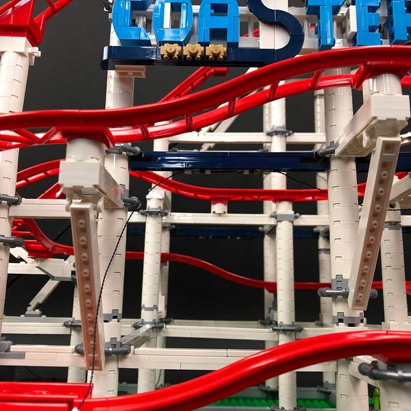
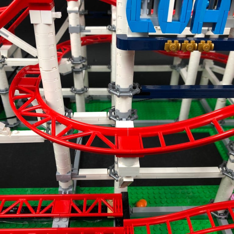
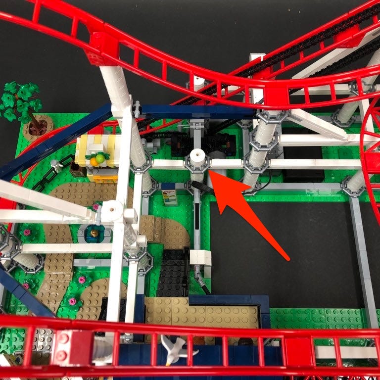
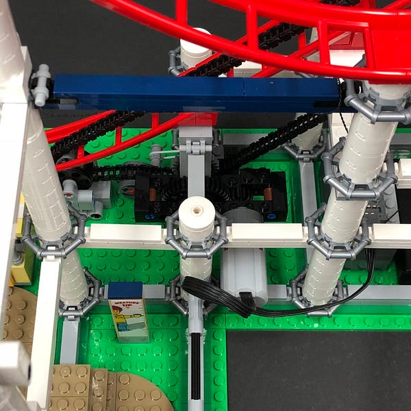
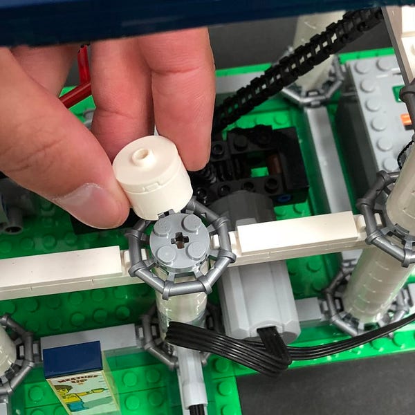
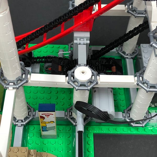
Slightly disconnect the three front pillars at the bottom white round 2×2 brick as shown below:
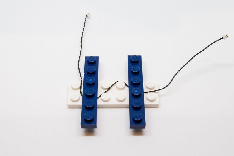
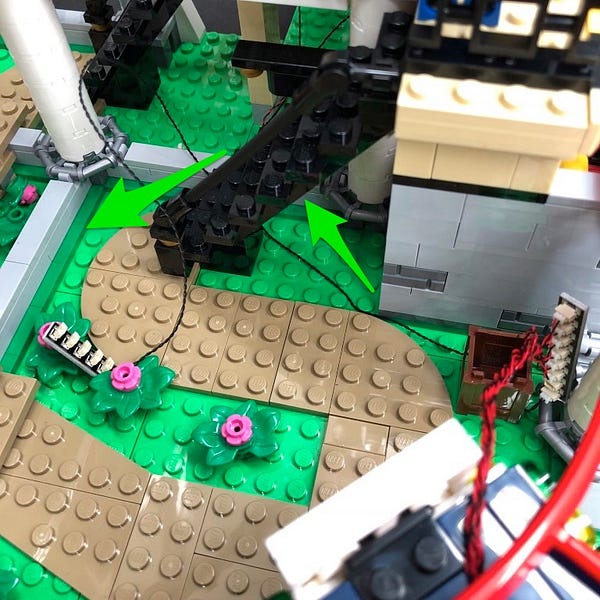
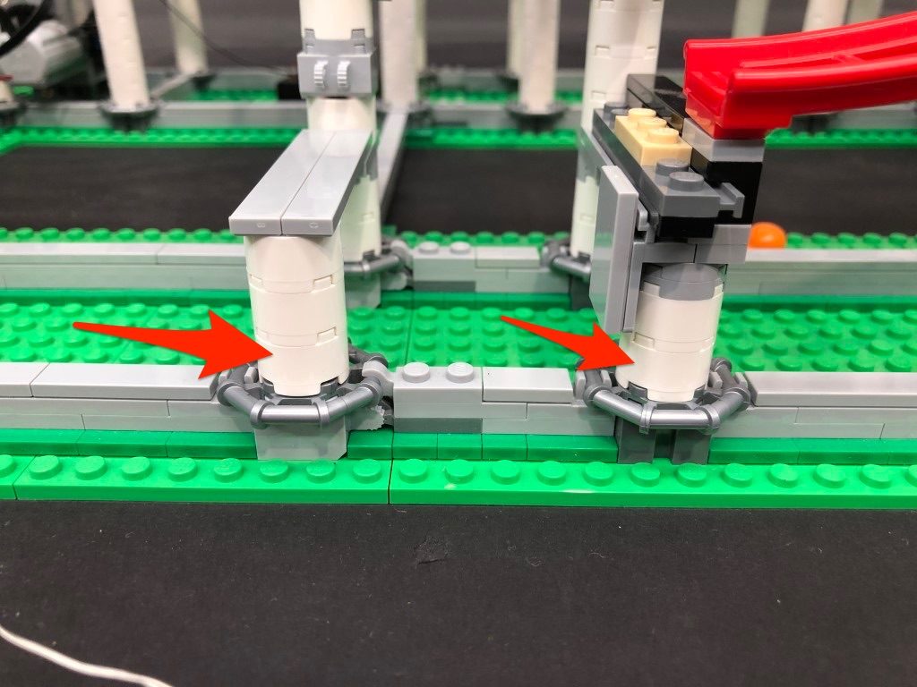
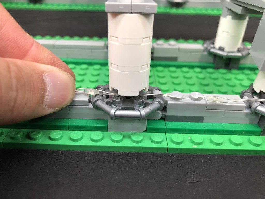
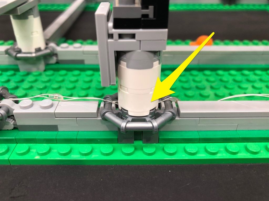
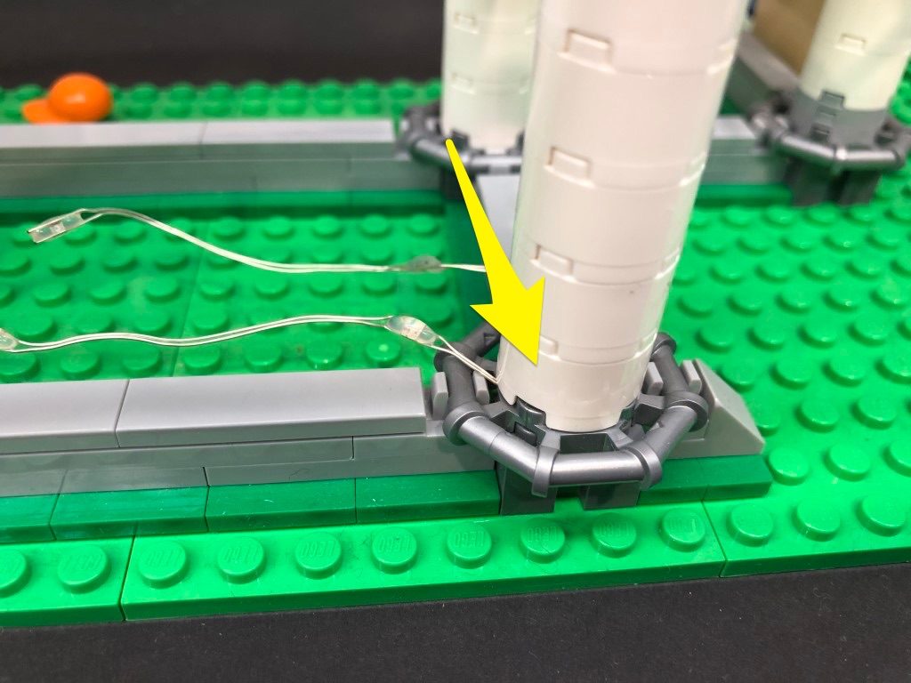
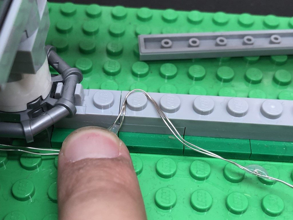
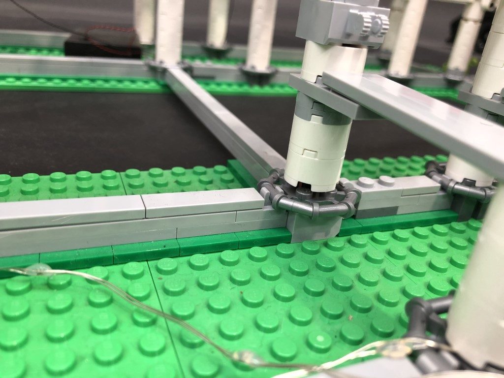
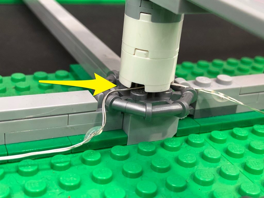
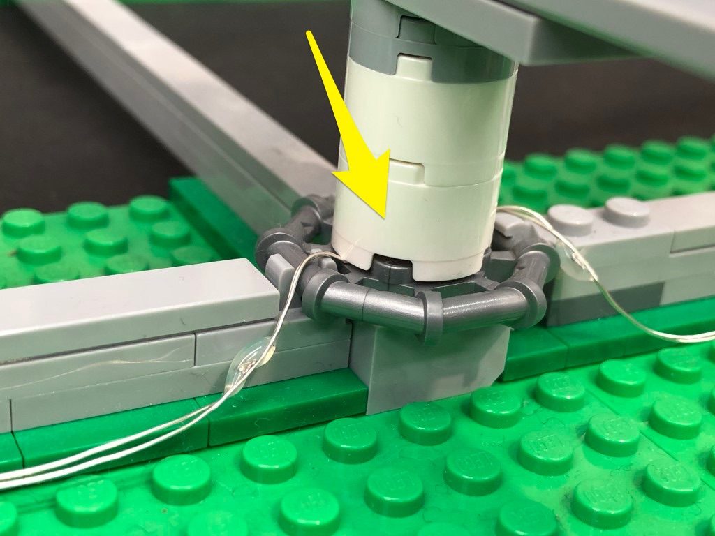
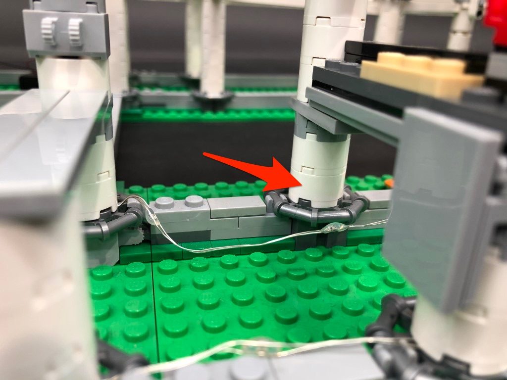
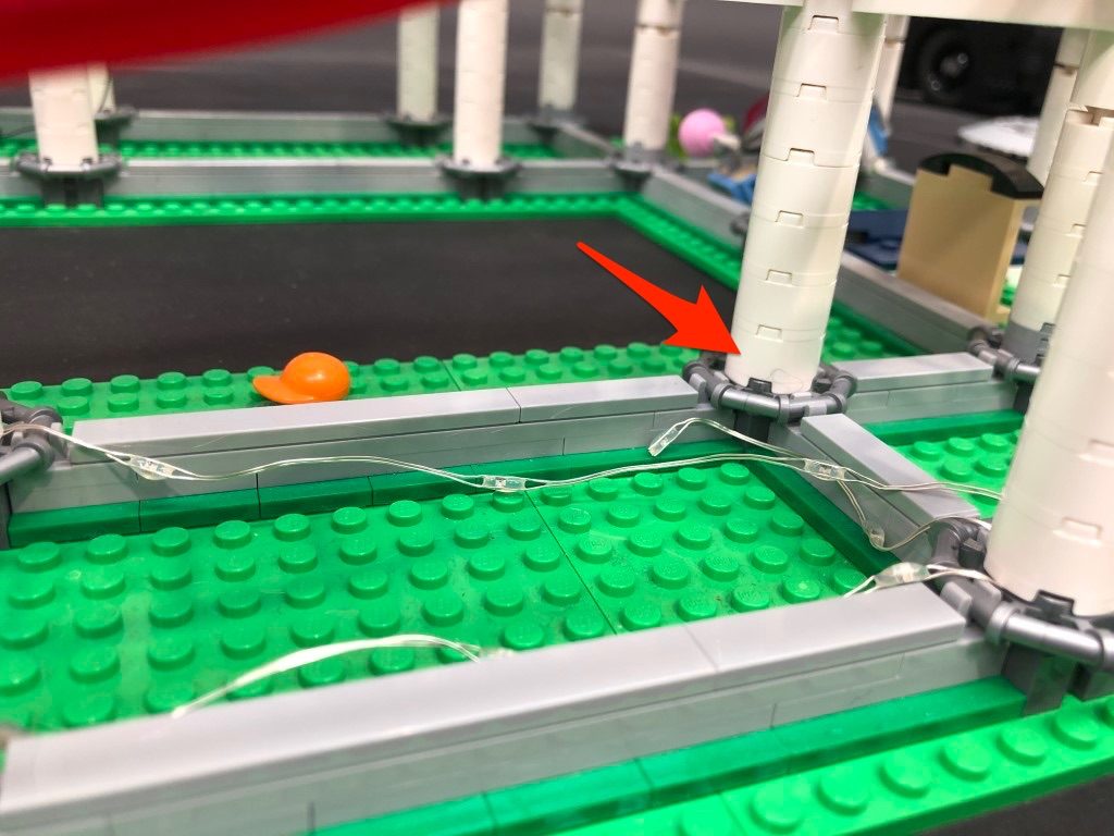
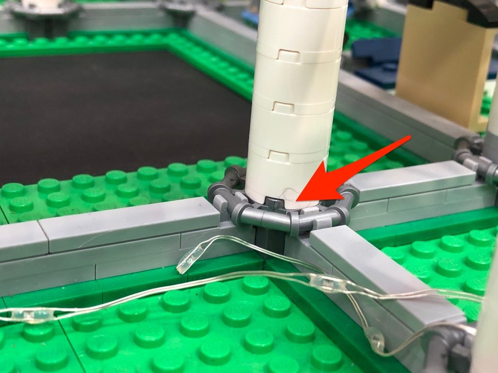
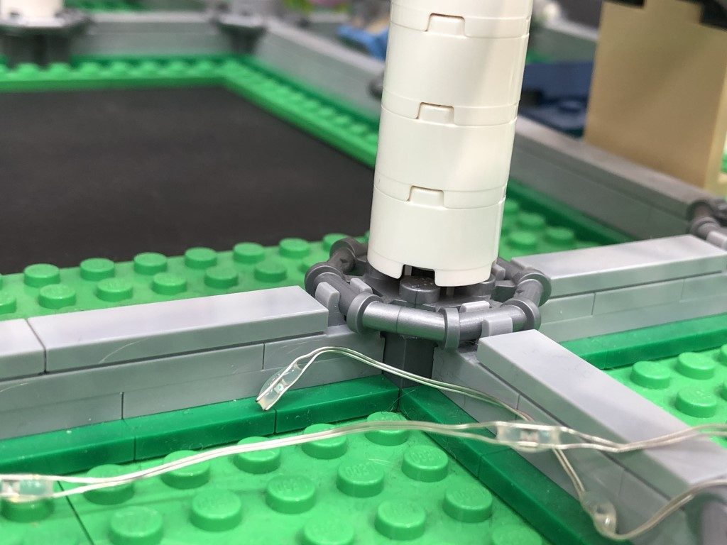
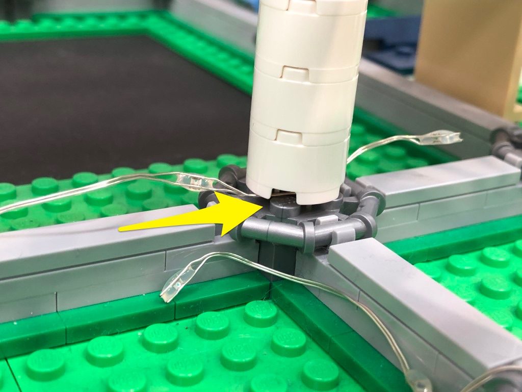
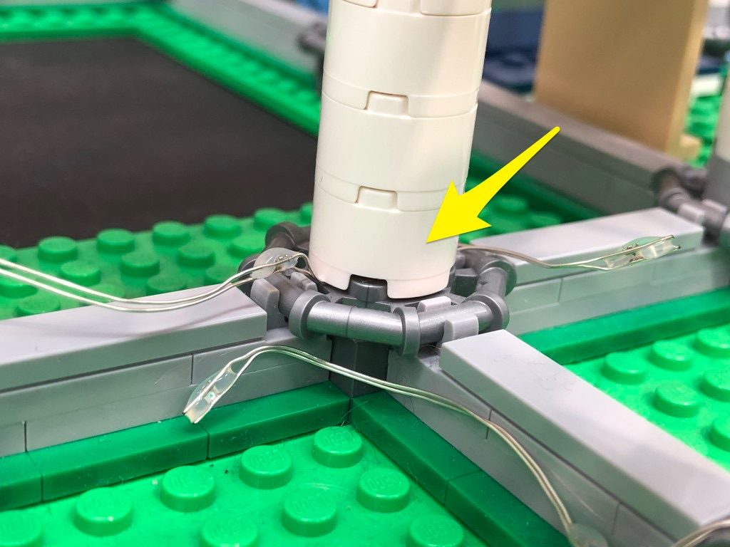
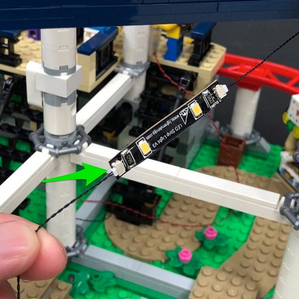
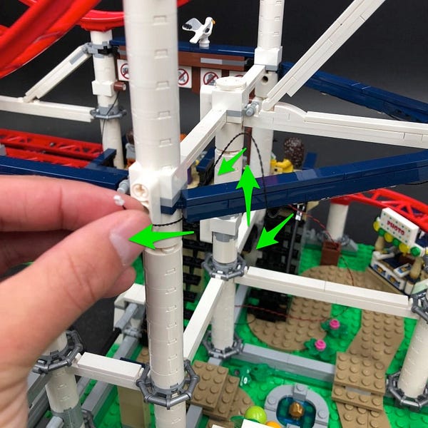
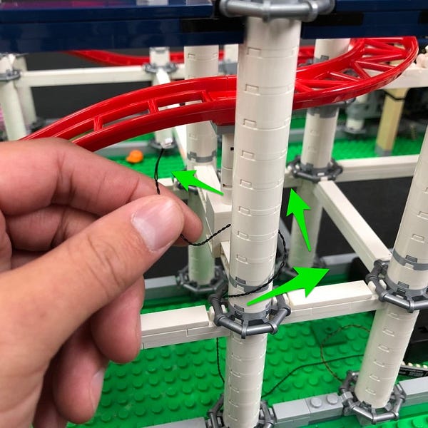
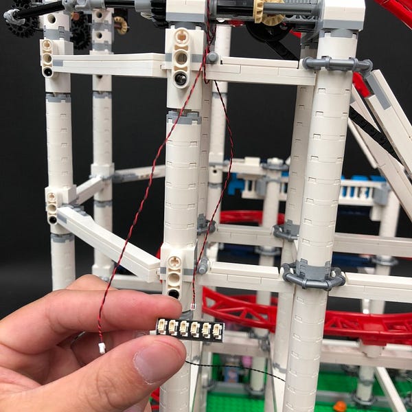
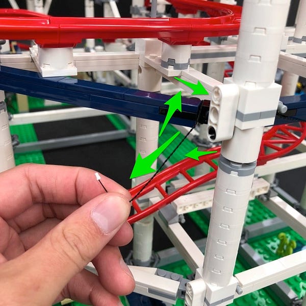
9.) Lay the wire in between the 4th and 5th LED along the light string underneath the first pillar. Lay the wire in between studs, then secure it in place by pushing the pillar of white round bricks down over the top.
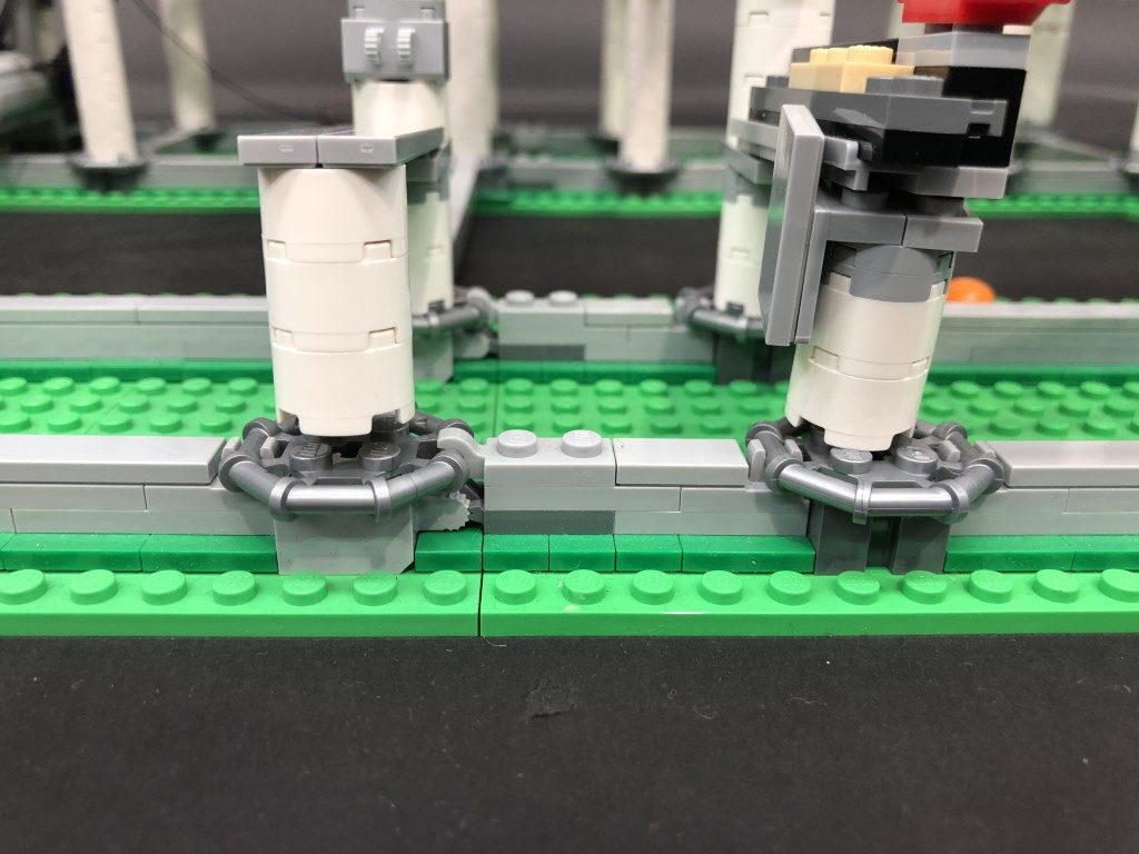
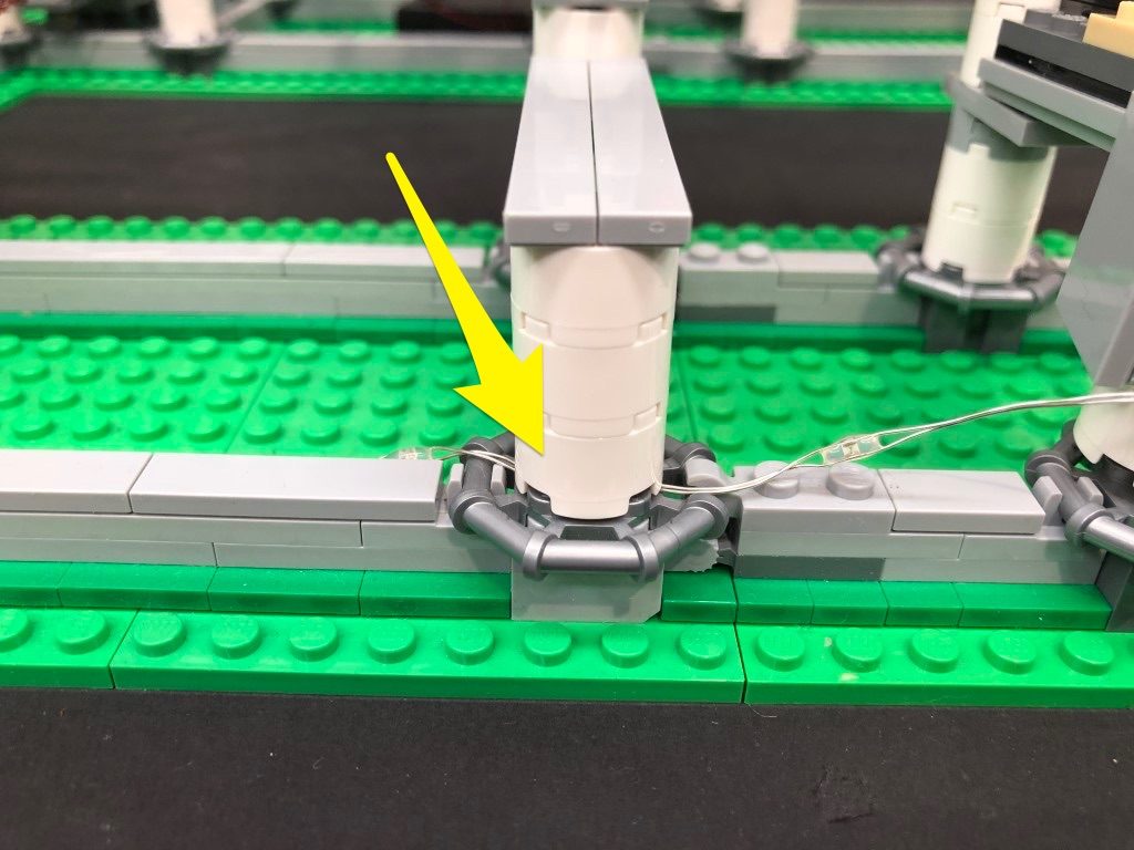
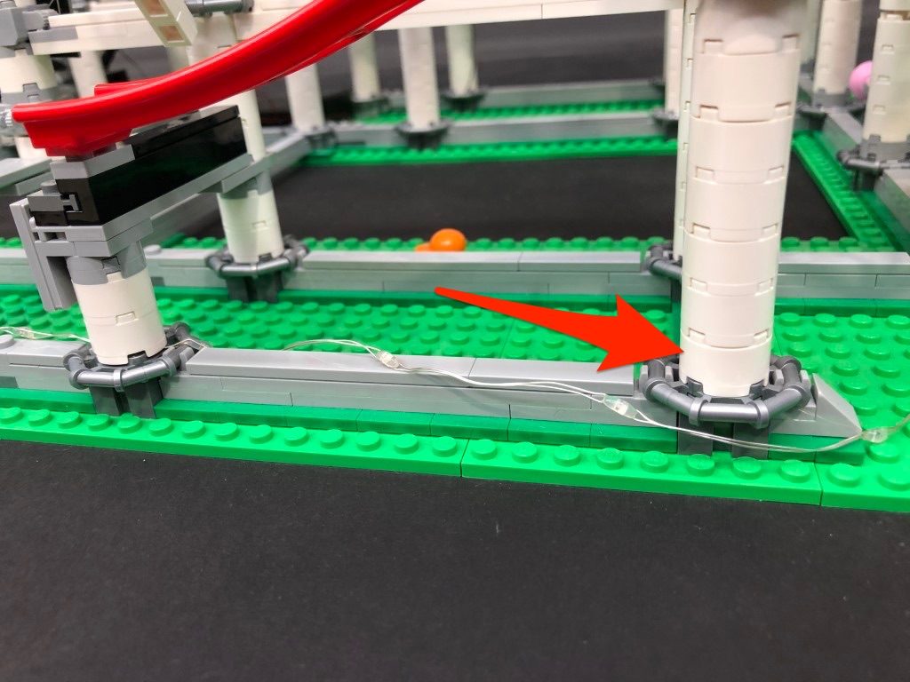
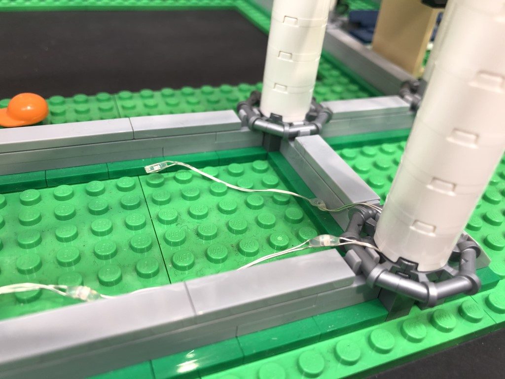
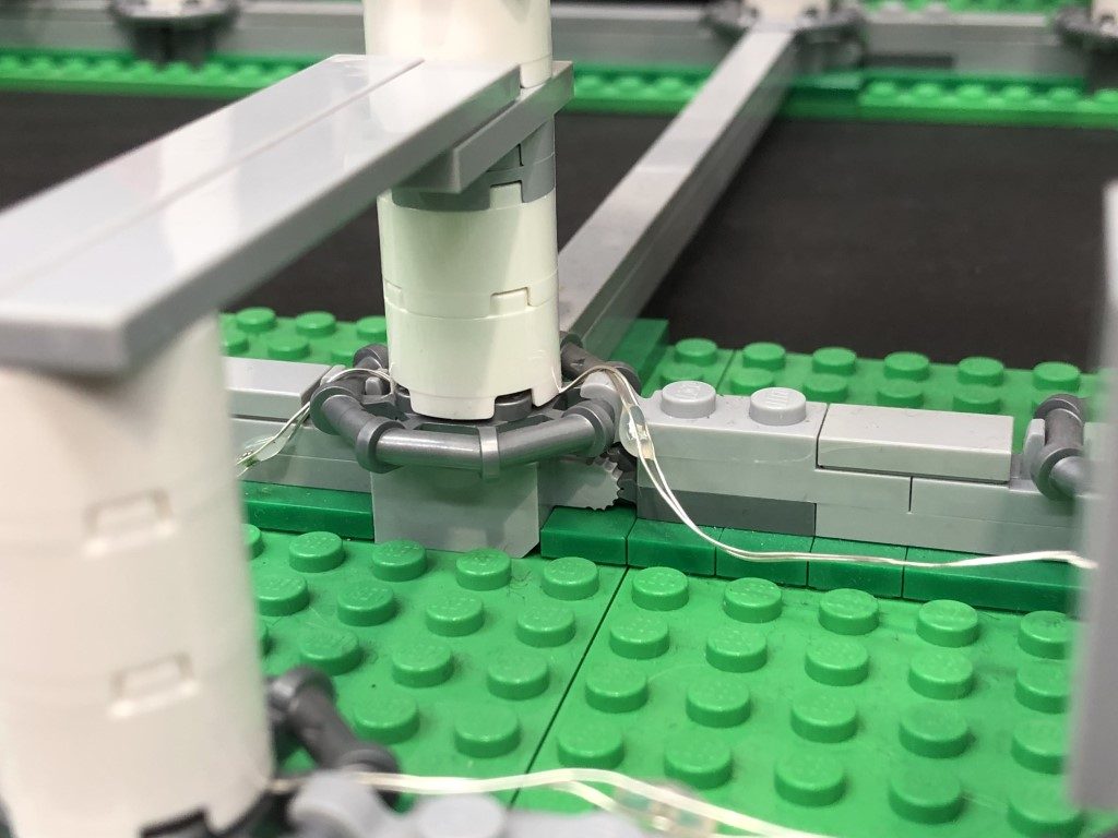
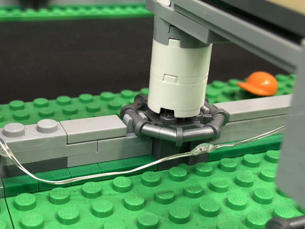
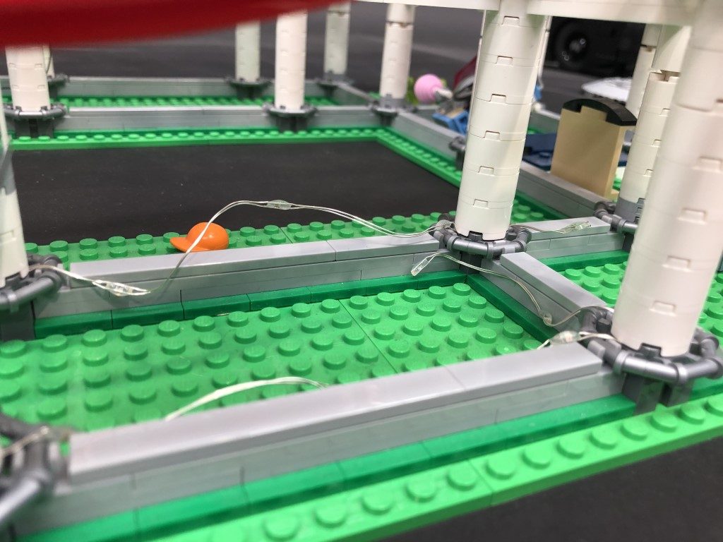
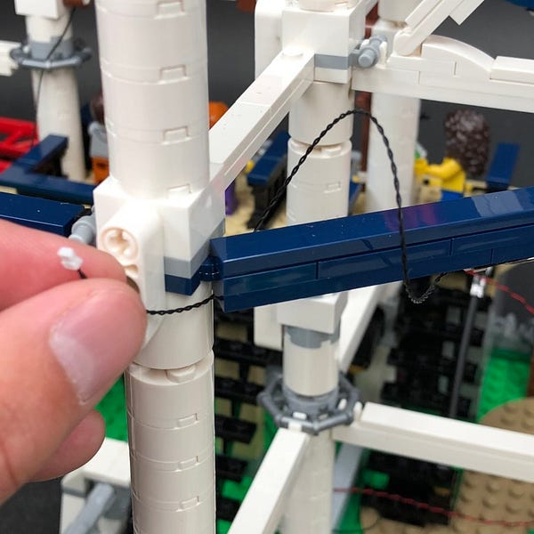
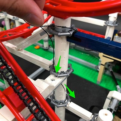
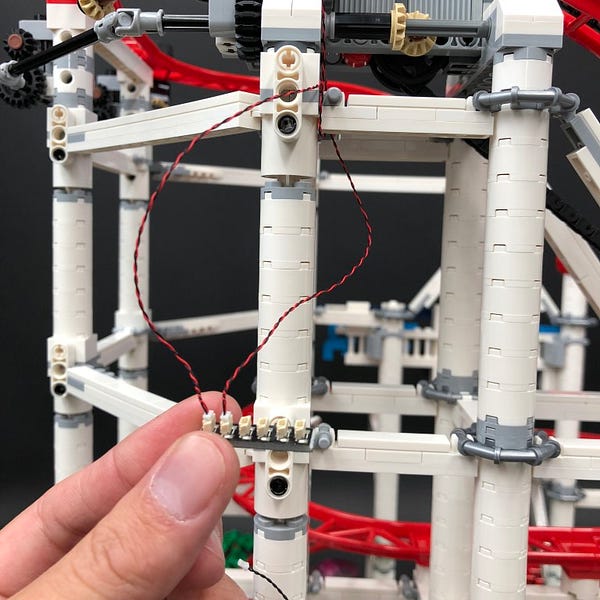
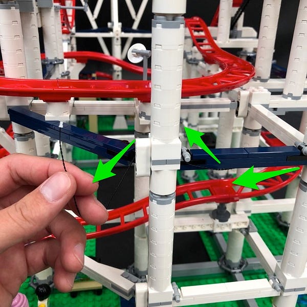
Continue to lay the light string underneath the next pillar of white round bricks in between the 5th and 6th LED on the light string. Secure the light string by pushing down the pillar over the top.
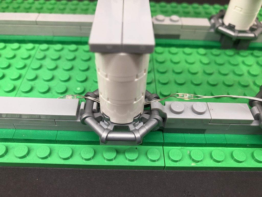
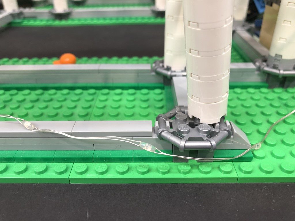
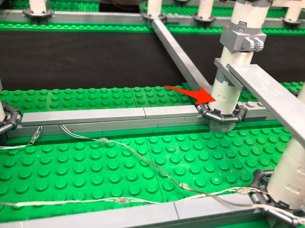
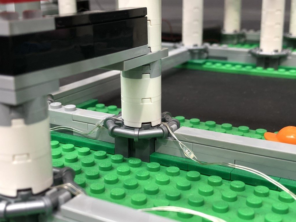
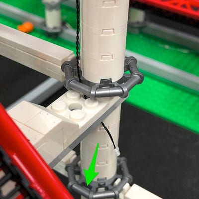
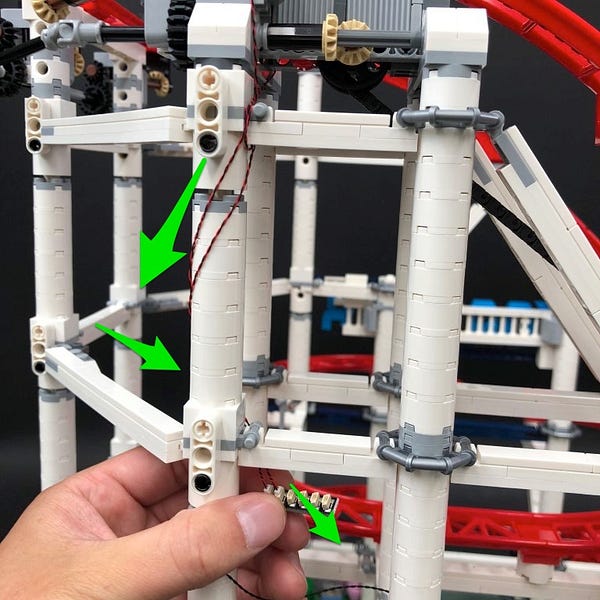
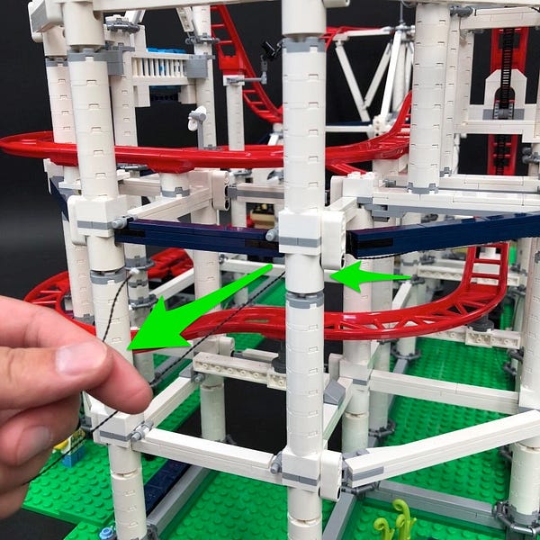
Slightly disconnect the next white pillar of white bricks, then lay the light string down underneath in between bricks. Lay the light string up towards the white pillar behind, then secure it by reconnecting the white pillar of round bricks.
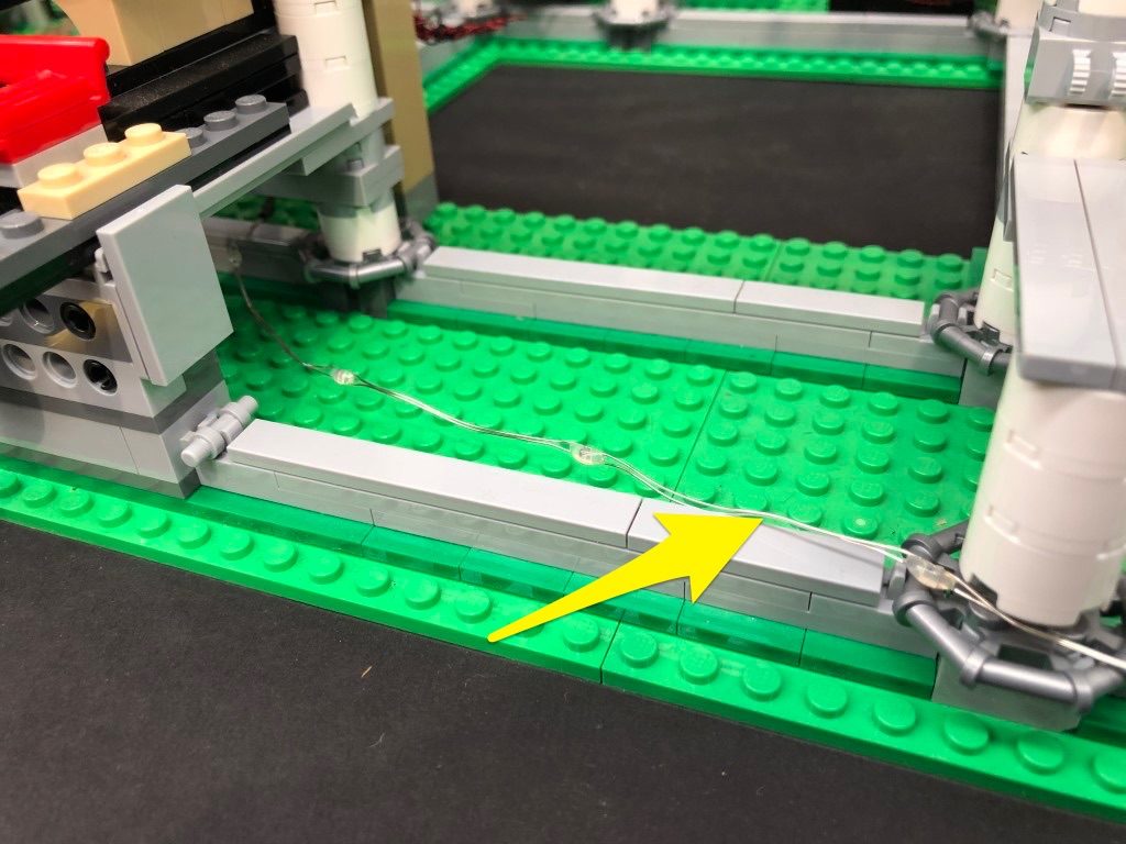
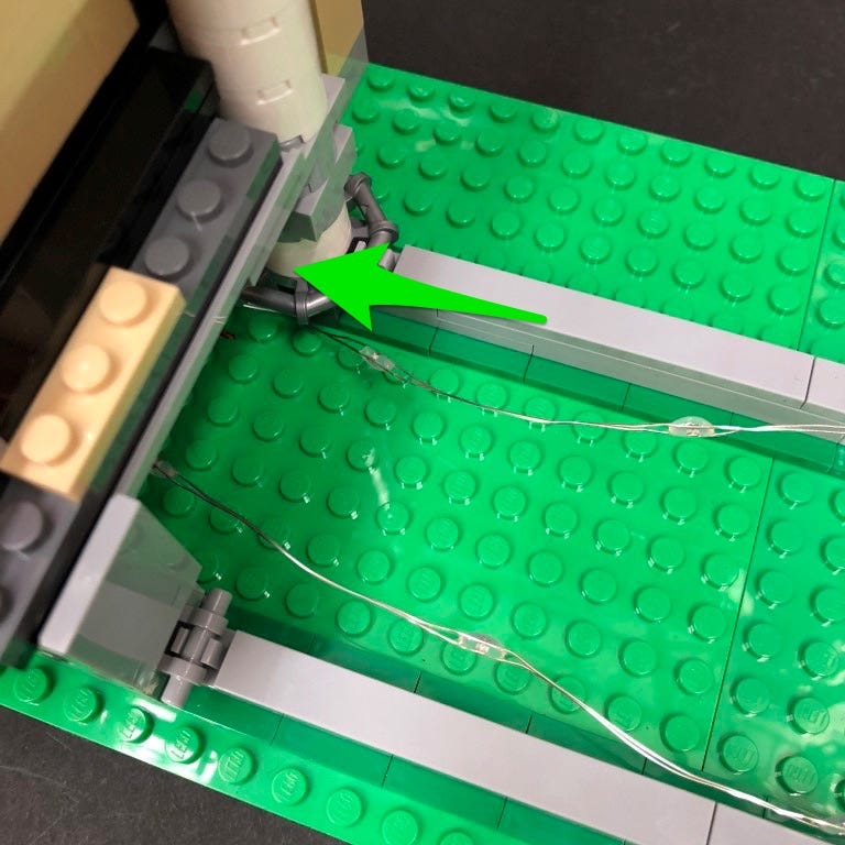
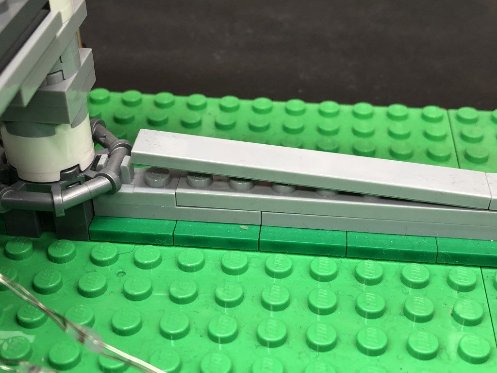
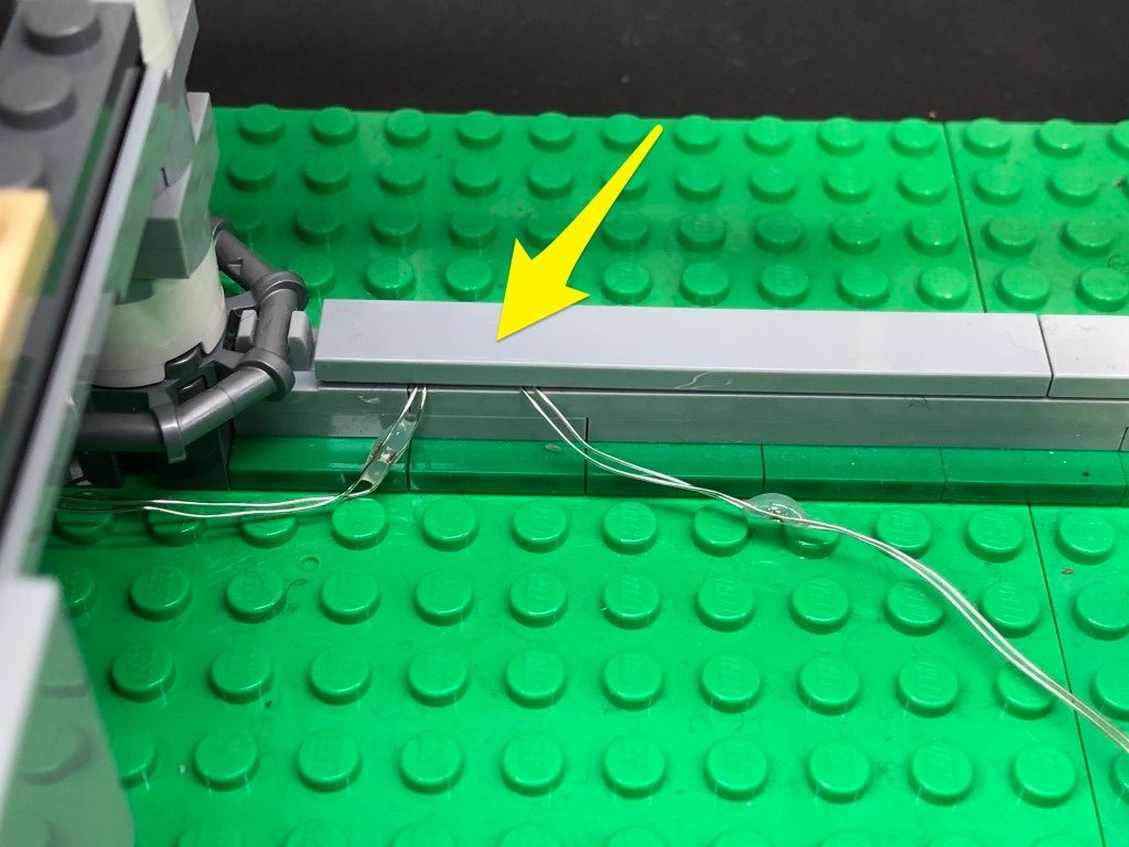
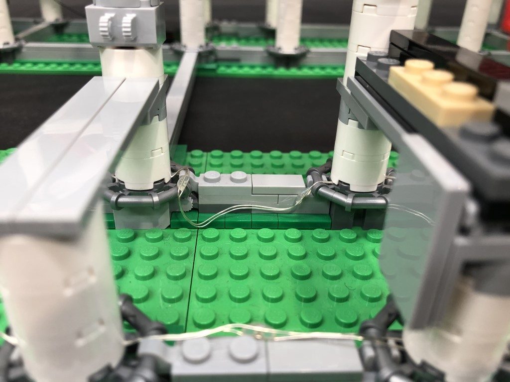
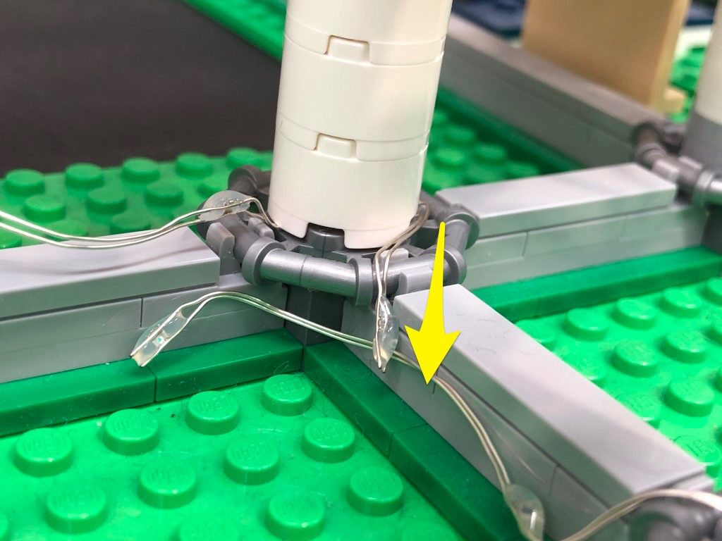
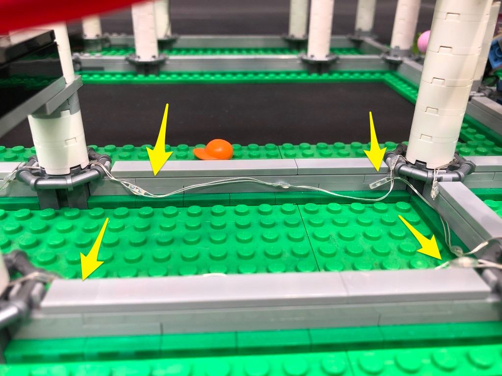
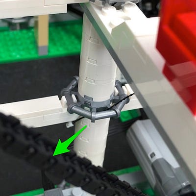
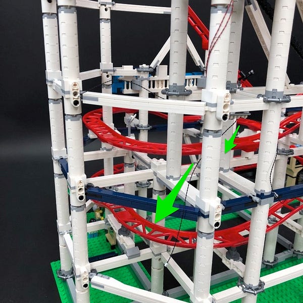
Neatly lay the cable down toward the side of the light grey bricks as shown below:
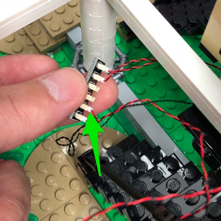
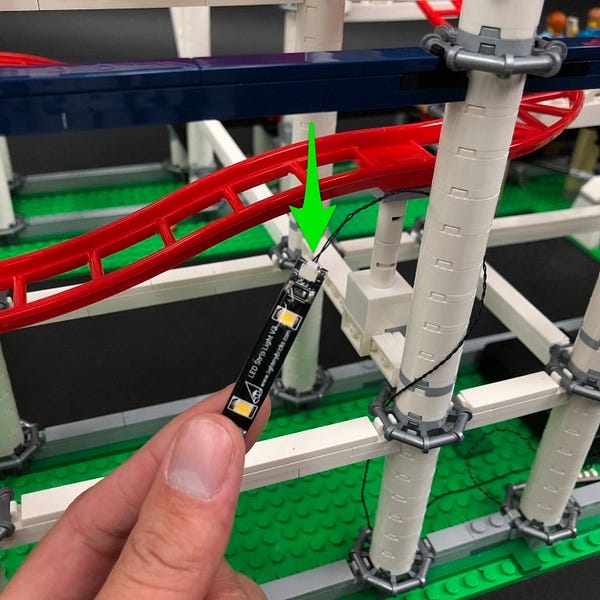
10.) Pull the 6-port expansion board out from underneath behind the platform and then connect another Multi Colour Light String to the next port along.
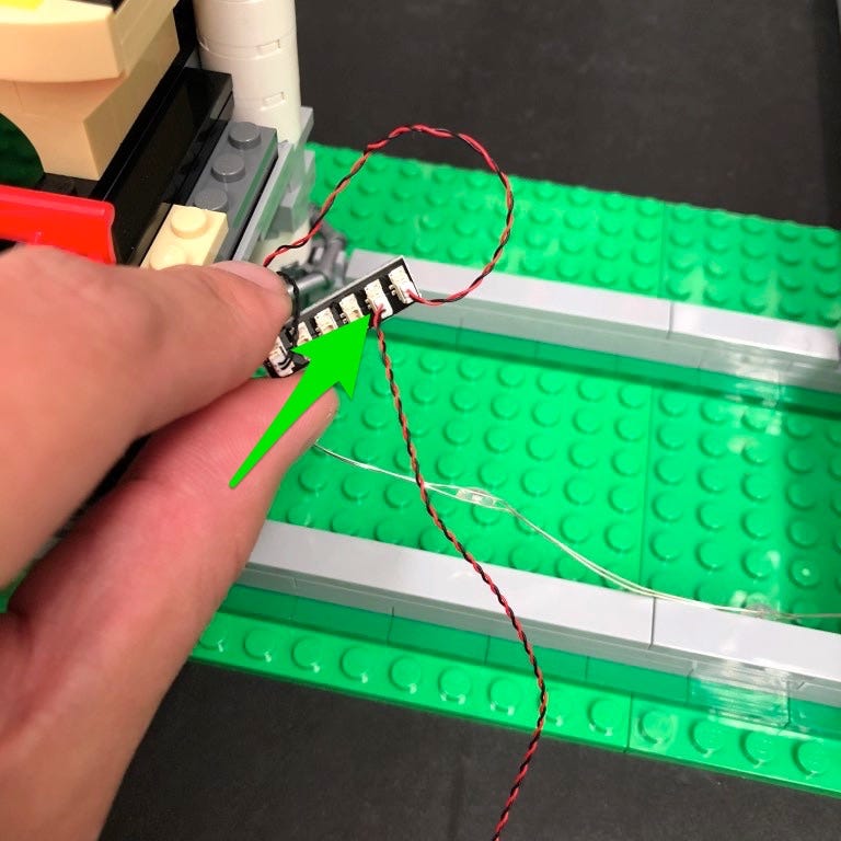
Push all the components back underneath the platform until you can just see the second LED on the Light String
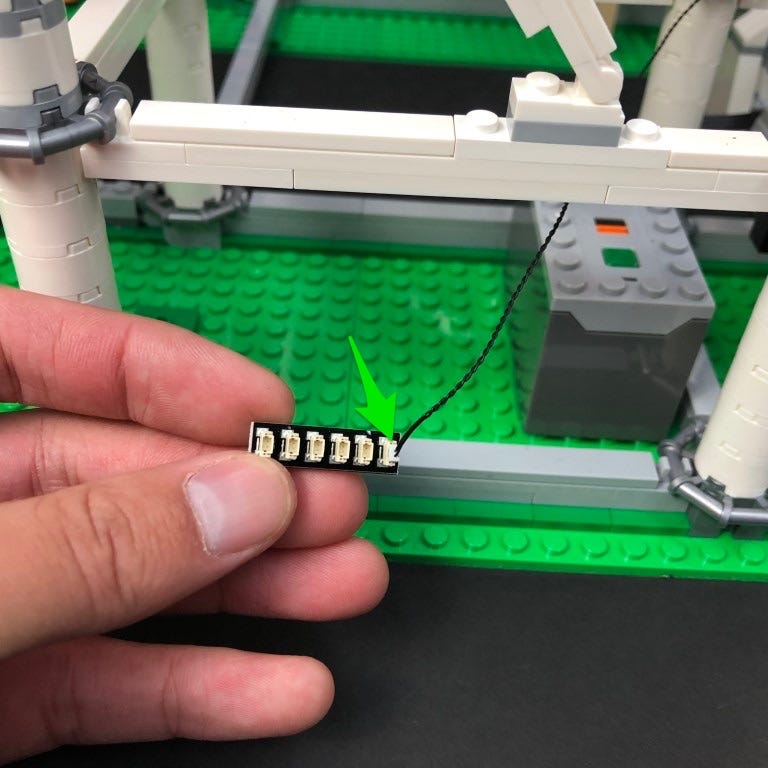
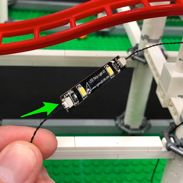
Disconnect the light grey tile along the back and lay the wire in between the 2nd and 3rd LED underneath in between studs. Reconnect the tile over the top
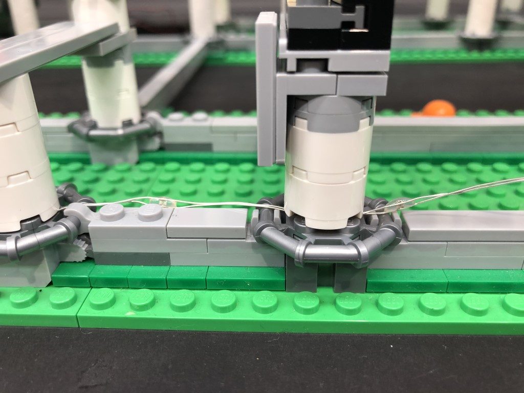
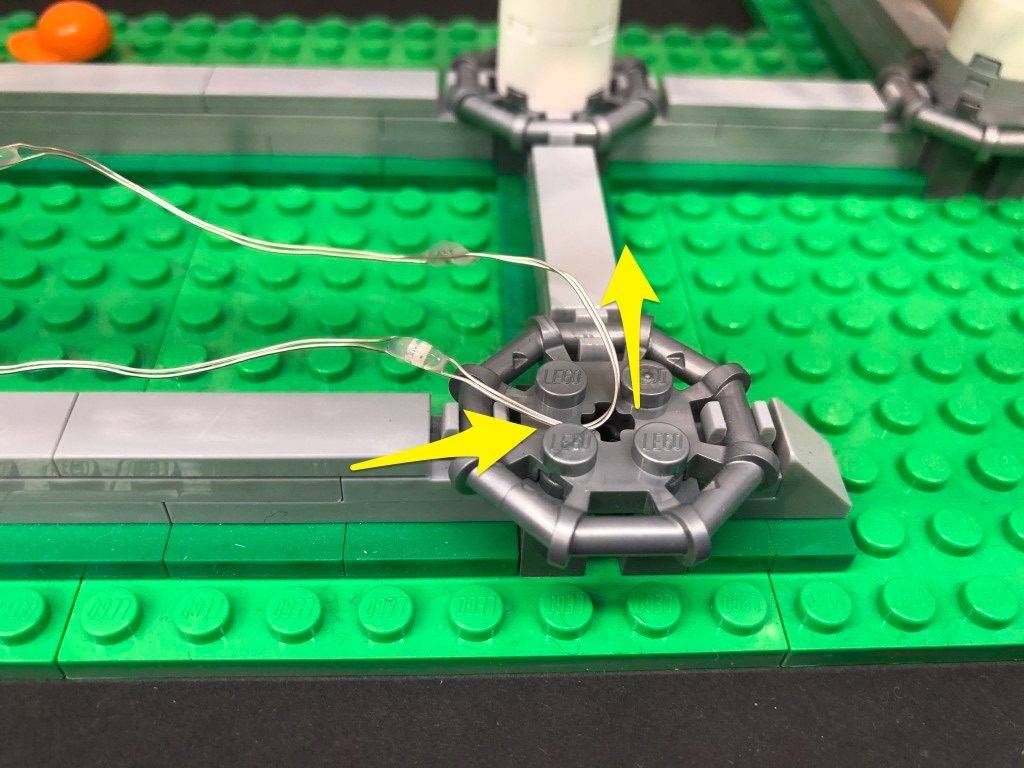
Lay the multi colour light string down underneath the first pillar in between the 4th and 5th LED, following the same method as we did for the first multi colour light string.
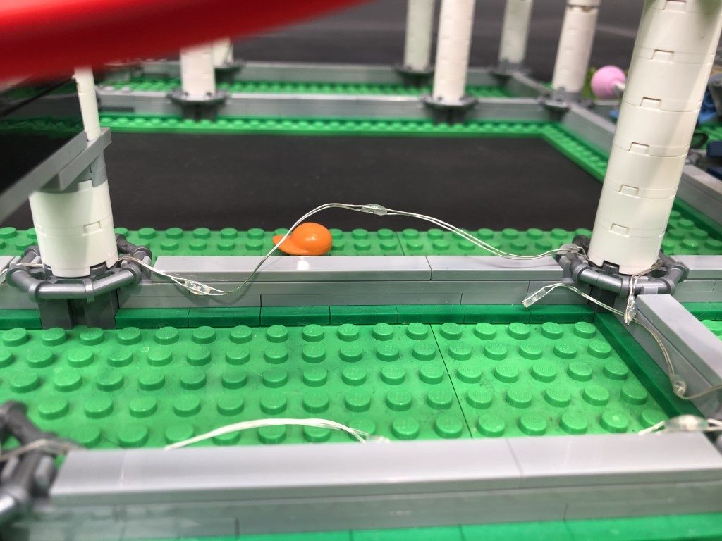
Continue to lay the light string underneath the next pillar, then again underneath the next pillar in between the 9th and 10th LED.
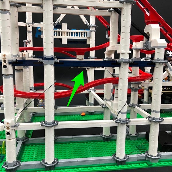
Bend the end of the light string down toward the front, then neaten up the two multi colour light strings by pushing the wires down along the side of the grey bricks as shown below.
Reconnect the tracks we removed earlier.
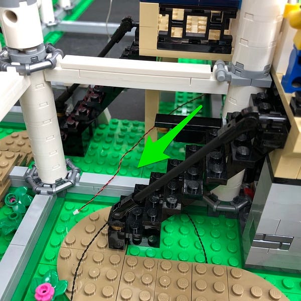
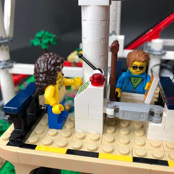
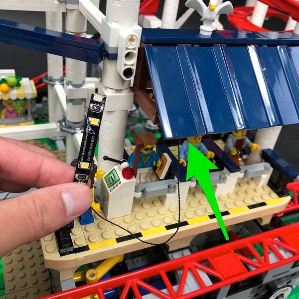
11.) We will now install a flashing light to the roller coaster control on the platform. First disconnect this section and then remove the trans red round tile.
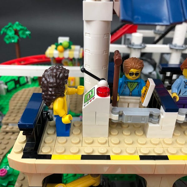
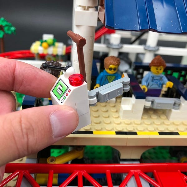
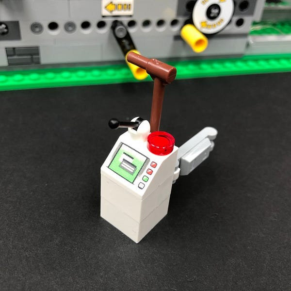
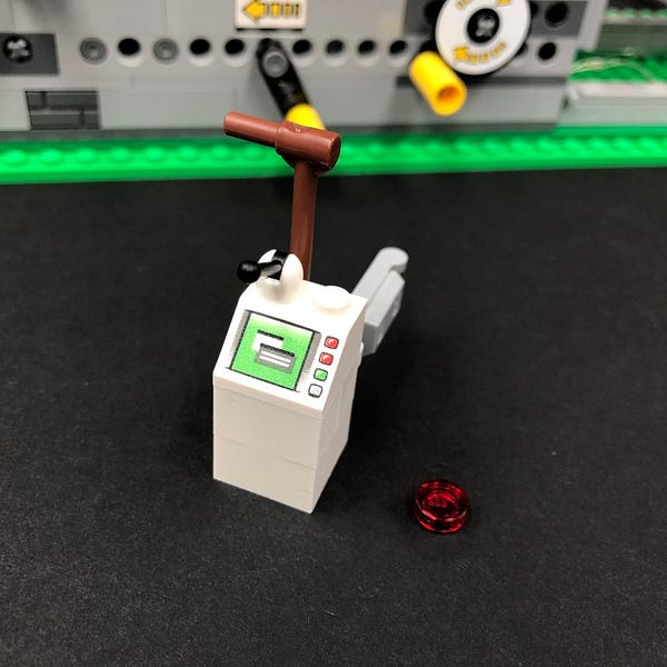
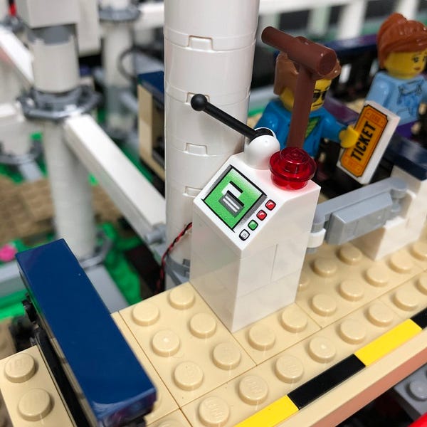
Take a Flashing Red 30cm Bit Light and then with the cable facing behind, place it over the white stud. Secure it in place by connecting a provided LEGO Trans Red Round Plate 1×1 over the top. Pull the cable around to the left side and then hide the cable underneath the lever.

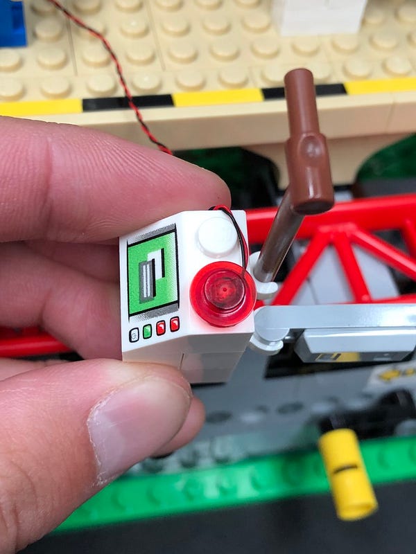
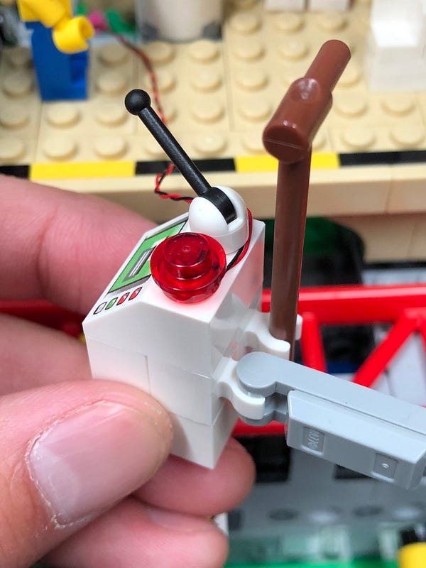
Reconnect the control panel ensuring the cable is neatly laid behind. Pull the cable behind and then down the stair case to connect to a spare port on the 6-port expansion board below.
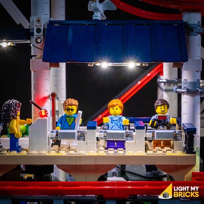
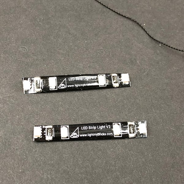
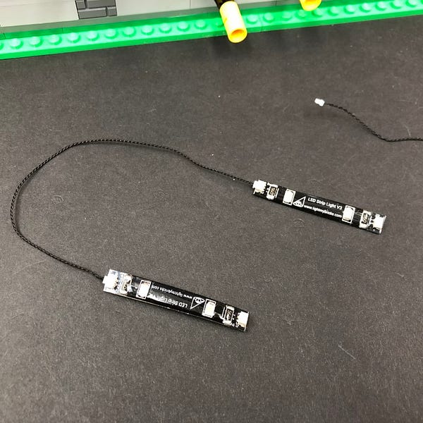
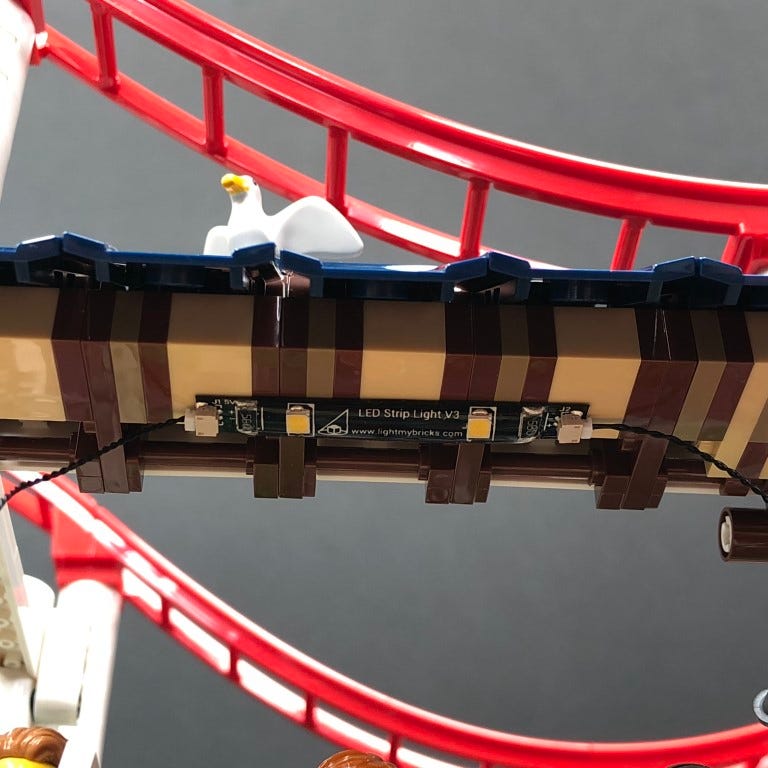
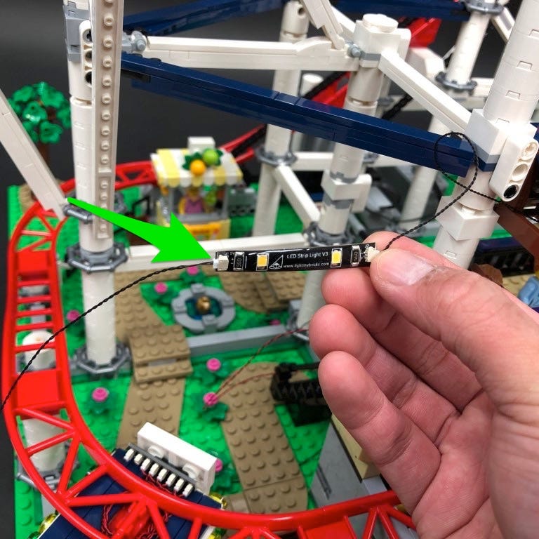
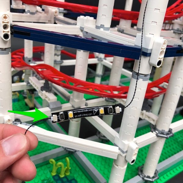
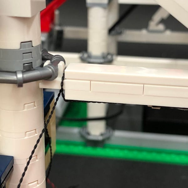
12.) Take 2x White Strip Lights and connect them together using a 15cm Connecting Cable. Take a 30cm Connecting Cable and connect one end to one of the Strip Light’s spare ports.
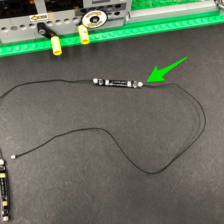
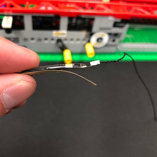
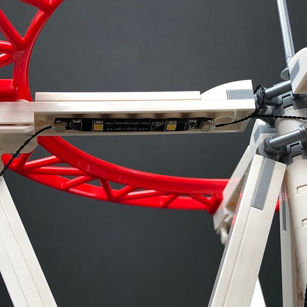
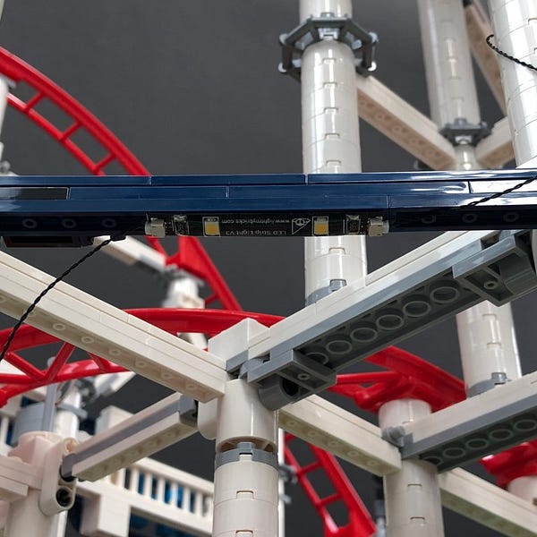
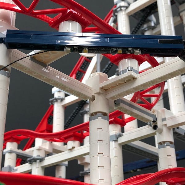
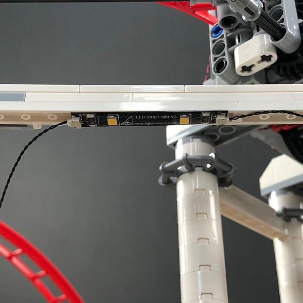
Take the Strip Light with the 30cm connecting cable connected to it and using it’s adhesive backing, stick it underneath the roof of the platform in the following position. Ensure the 30cm connecting cable is facing the right.
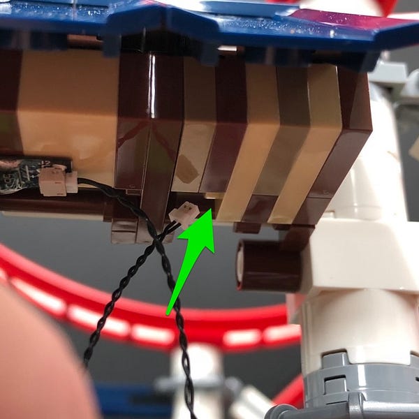
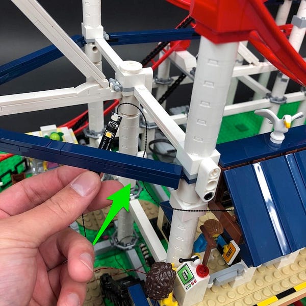
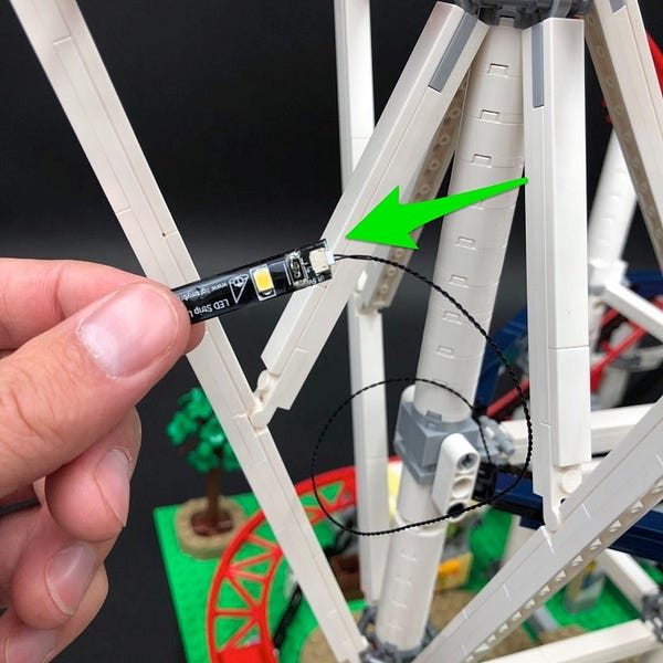
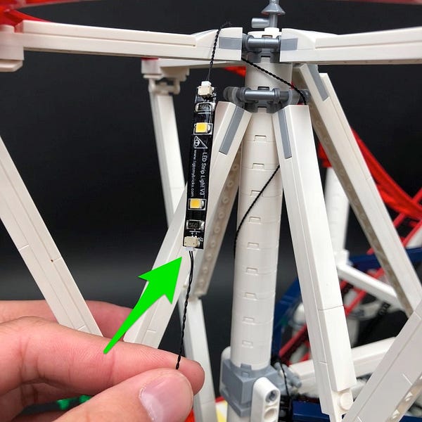
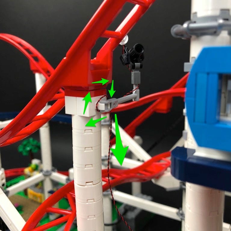
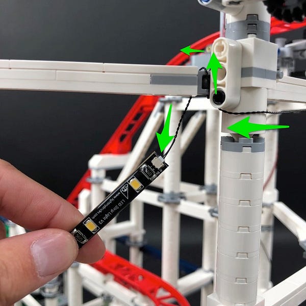
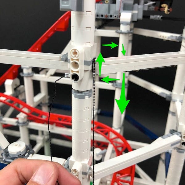
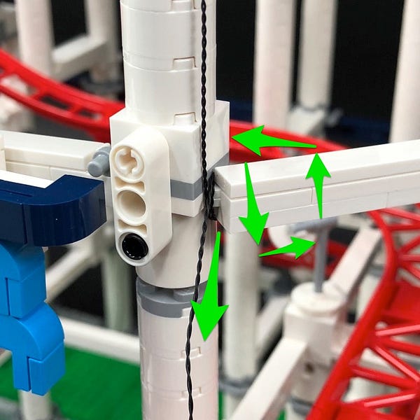
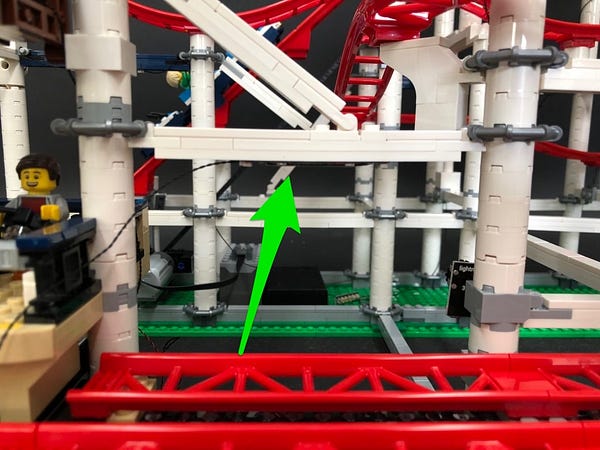
13.) Take the 30cm connecting cable from the strip light and then thread it up the following space on the right underneath the roof. Pull the cable out from the right side of the roof and then thread it toward the back in between roof and the pillar.
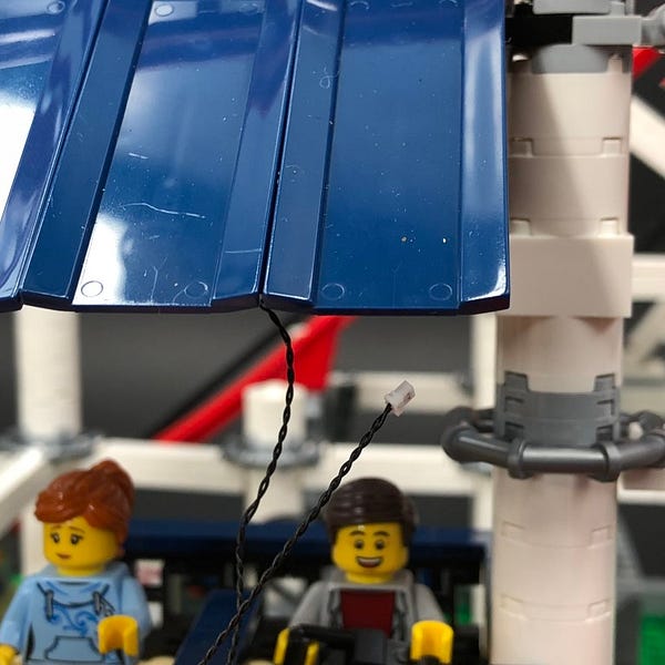
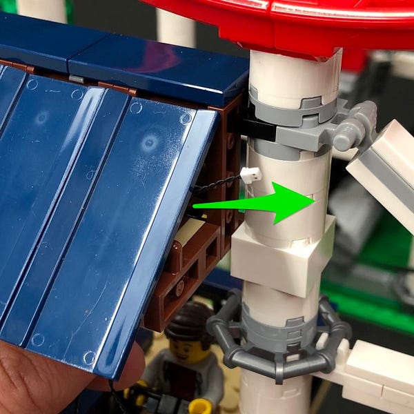
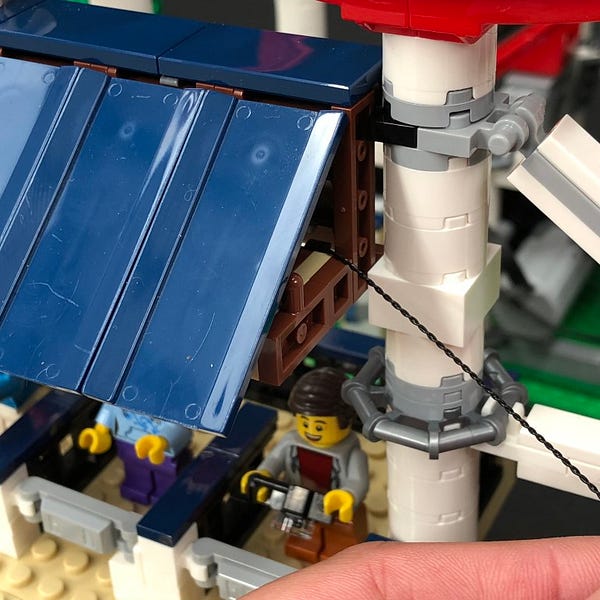
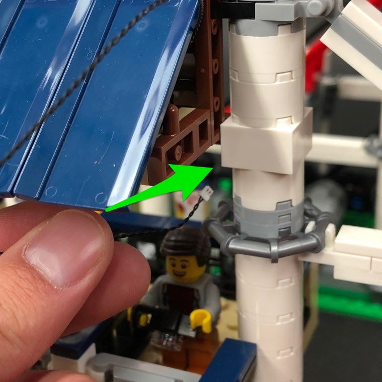
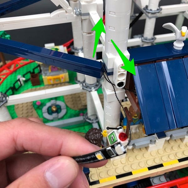
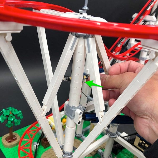
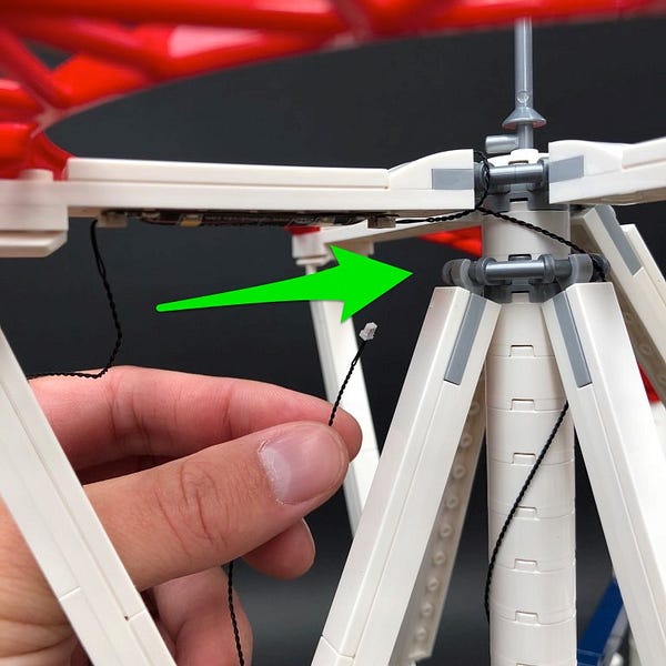
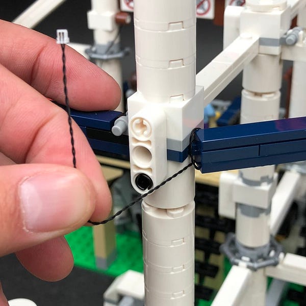
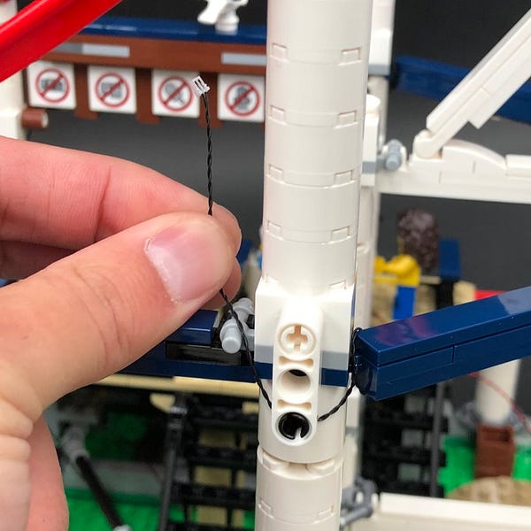
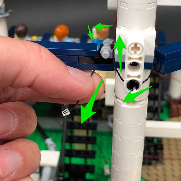
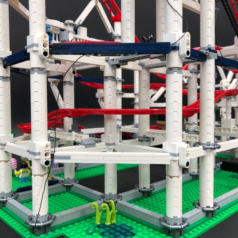
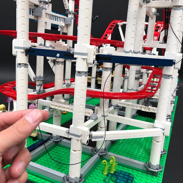
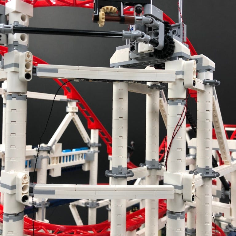
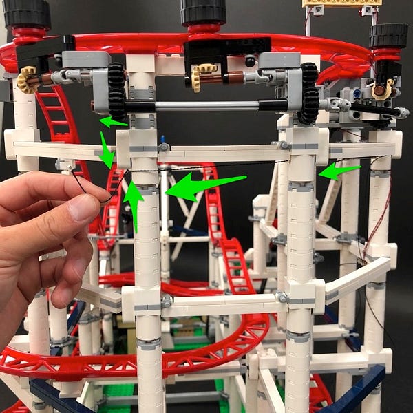
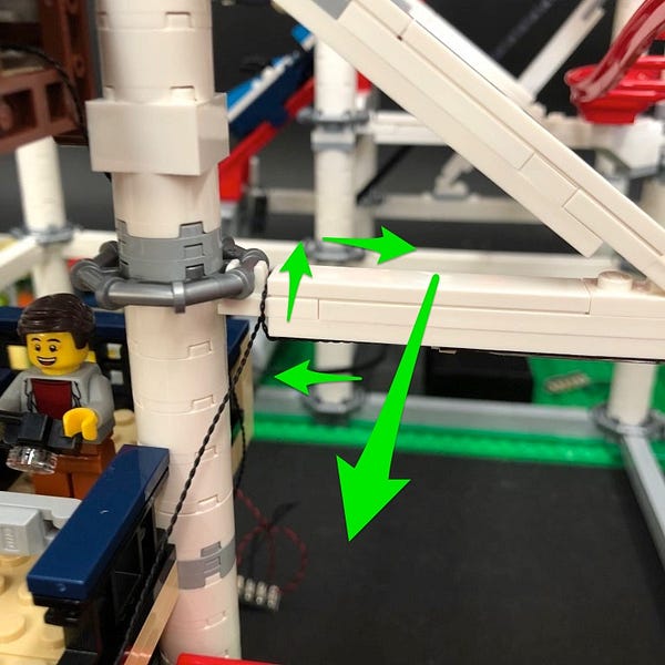
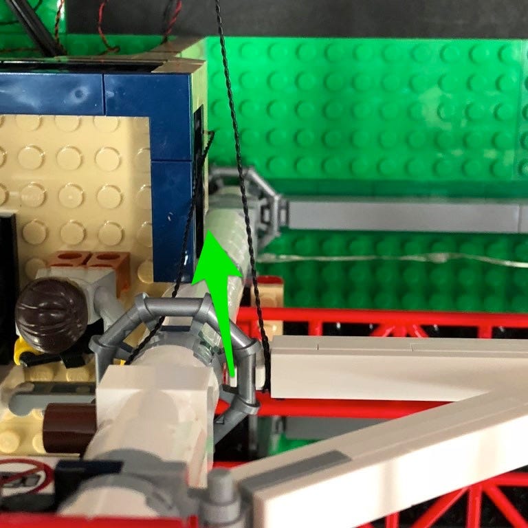
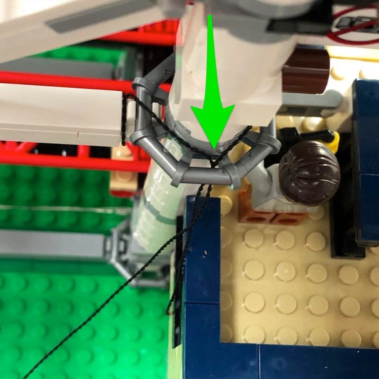
Pull the cable out from behind and then thread the 30cm connecting cable down the following space of the pillar
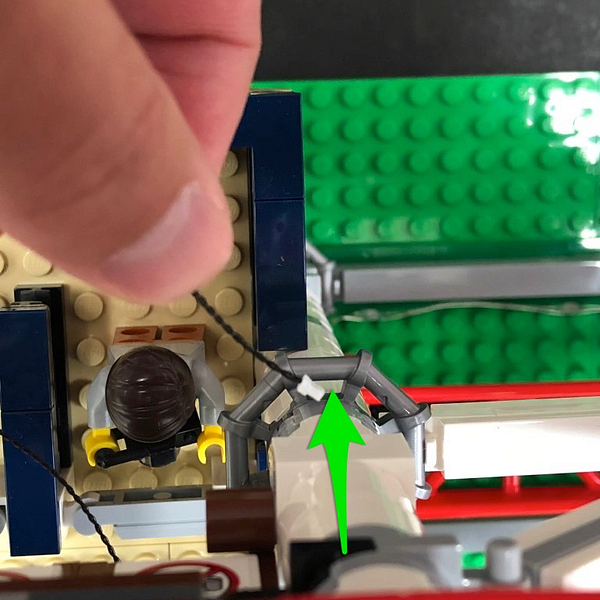
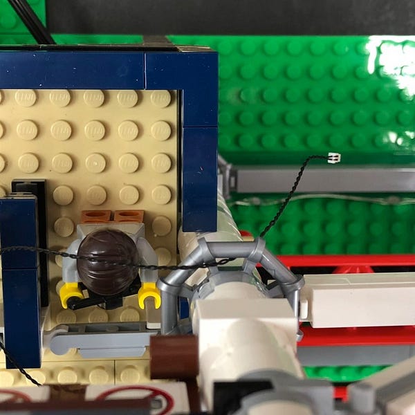
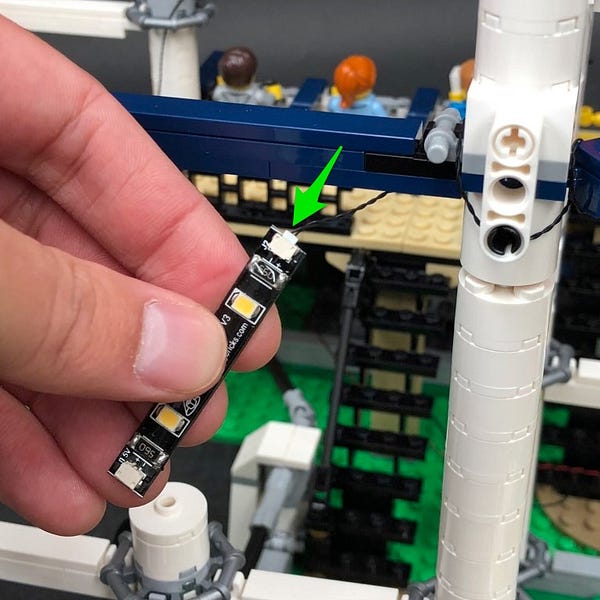
Pull the cable all the way down and then thread it inside toward the left underneath the platform to then connect to a spare port on the 6-port expansion board.
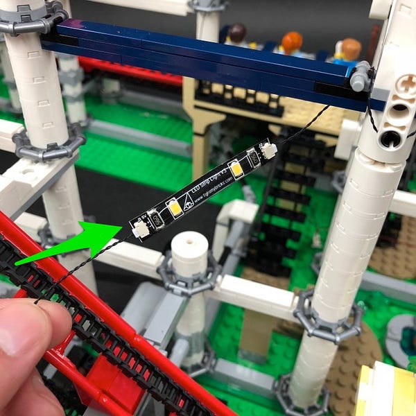
14.) Take the other Strip Light and then thread it underneath the roof toward the left and then pull it out from the left side of the roof as per below
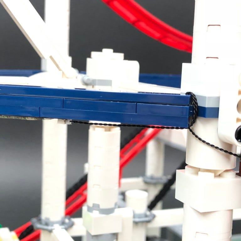
Take a 30cm Connecting Cable and connect it to the other end of the Strip Light then loop the strip light around the right corner of the dark blue horizontal bar a few times as shown below.
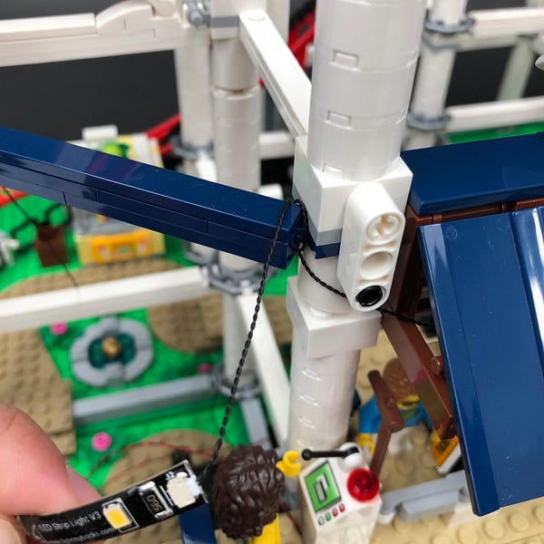
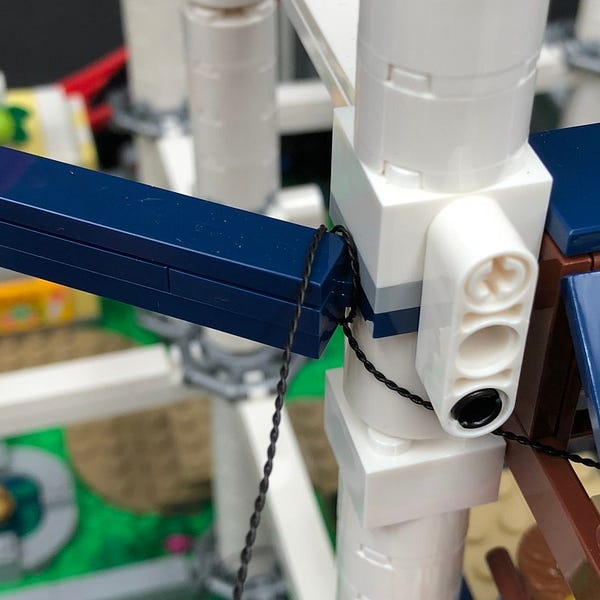
Stick the Strip Light using it’s adhesive backing underneath the railing in the following position.
Do your best to eliminate excess cable by ensuring the cable is wound tight around the corner of the horizontal rail.
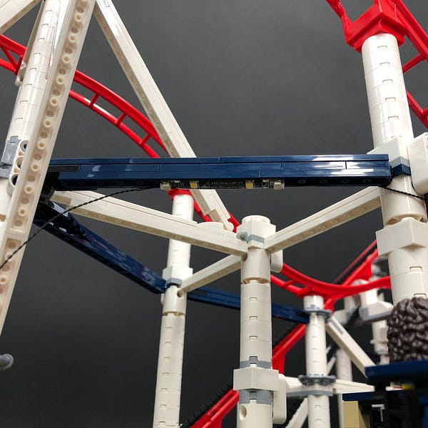
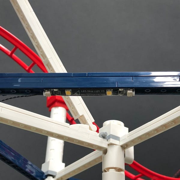
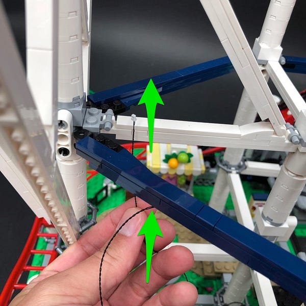
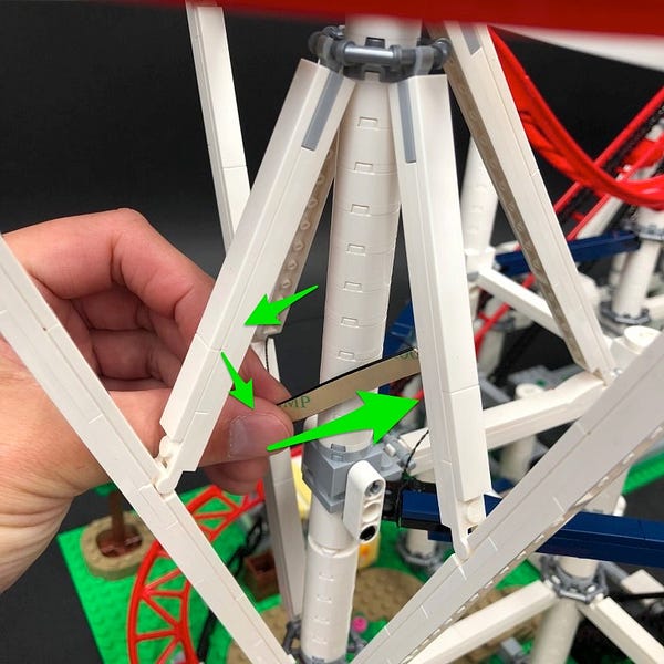
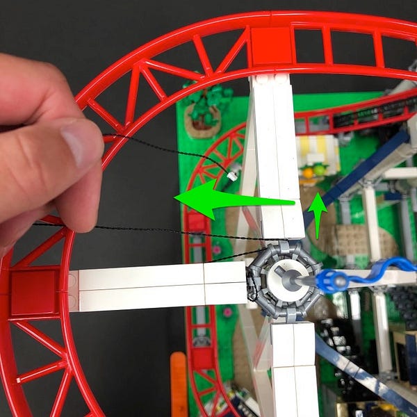
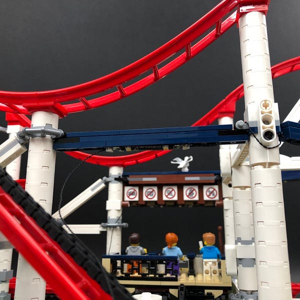
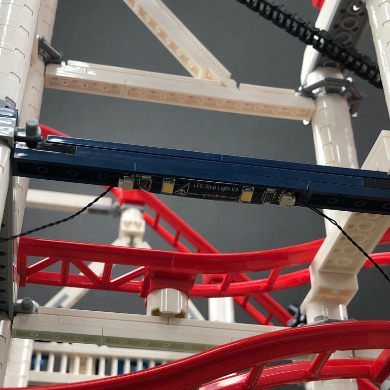
15.) Thread the other end of the 30cm Connecting Cable up in between the blue and white horizontal bars and then loop around twice before connecting it to a new White Strip Light
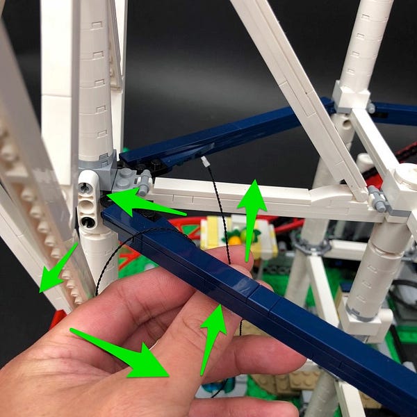
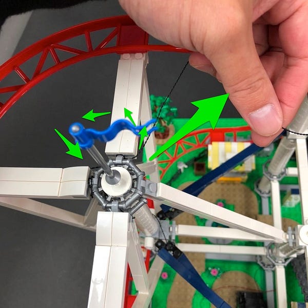
Thread the Strip Light behind the centre round pillar and then loop around toward the top then pull the cable across to the left and then up in between the two white horizontal bars as shown below
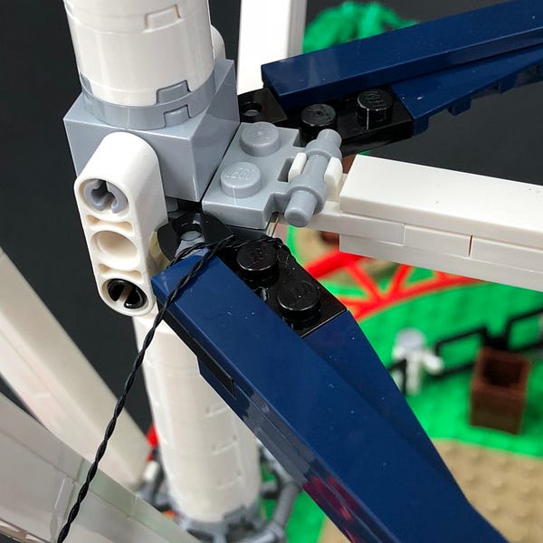
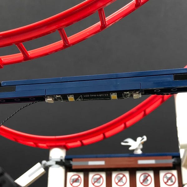
Pull the cable over the corner of the horizontal bar and then connect another 30cm Connecting Cable to the end of the Strip Light
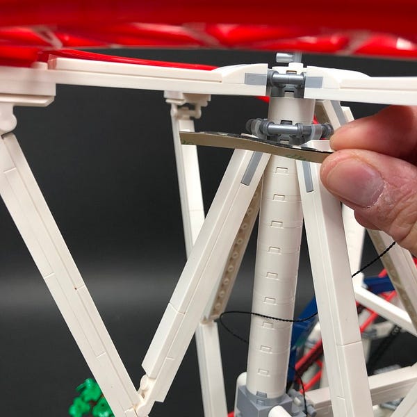
Stick the White Strip Light underneath the white horizontal bar (top far left) in the following position.

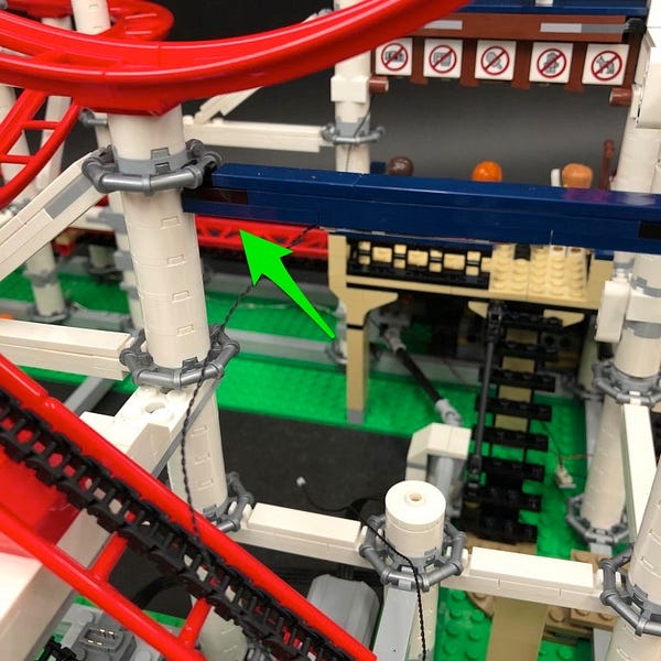
16.) Take the other end of the 30cm connecting cable and then pull it across to the right side underneath the white bar. Loop it around the centre corner twice and then pull it down diagonally to the right
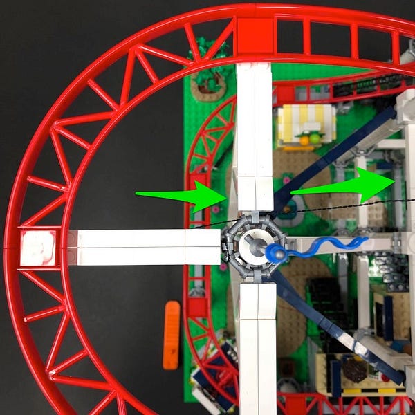
Thread the cable through the following space on the right then turn the set around
Pull the cable out from the other side and then connect it to a new White Strip Light
17.) Take a new 15cm Connecting Cable and connect it to the other end of the Strip Light before sticking the strip light underneath the dark blue horizontal bar in the following position.
Take the other end of the 15cm connecting cable and then thread it behind and then over the bar twice. Pull the cable so that it locks in place in the corner as shown below.
Pull the other end of the 15cm connecting cable underneath the white verticle technic brick and then loop it over the corner of the next dark blue horizontal bar
18.) Connect the other end of the cable to a new White Strip Light. Take a 30cm Connecting Cable and connect it to the other end of the strip light.
Stick the strip light underneath the next horizontal bar in the following position.
18.) Thread the other end of the 30cm connecting cable behind the horizontal bar and then pull it back over the corner.
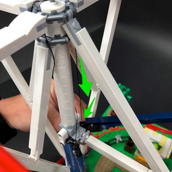
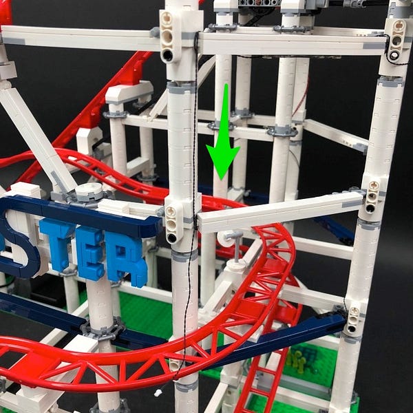
Thread the cable down through the following two spaces down the white pillar.
Pull the cable all the way out at the bottom to then connect to a new 6-Port Expansion Board
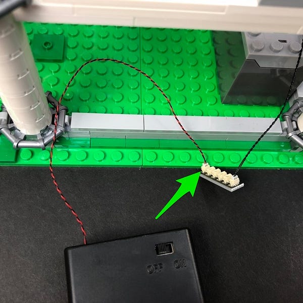
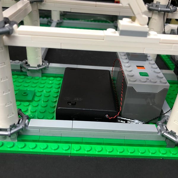
19.) Take the AA Battery Pack /USB cable and connect it’s cable to the 6-port expansion board. Neatly place the AA Battery Pack /USB Cable next to the power functions power box. You can also take this time to test all lights are working by turning ON the battery pack.
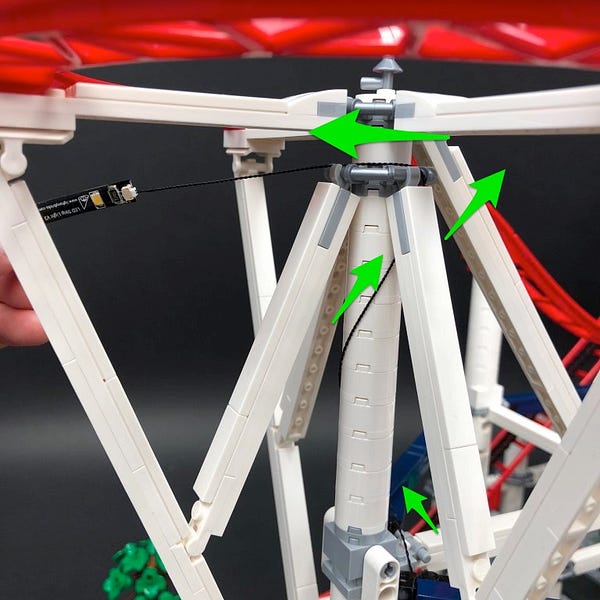
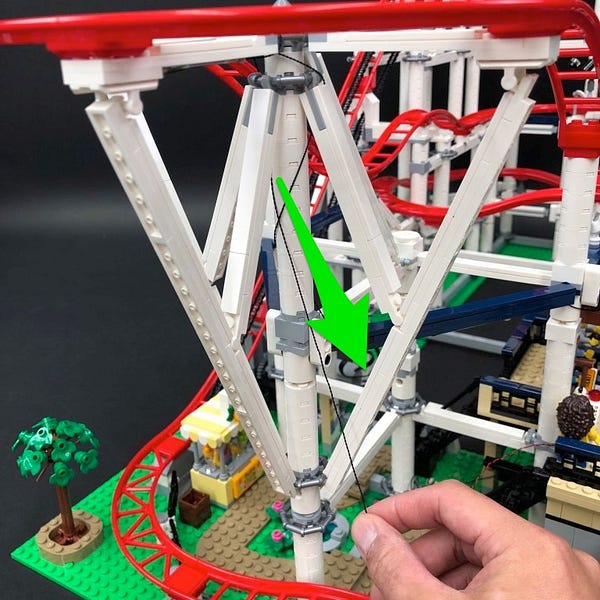
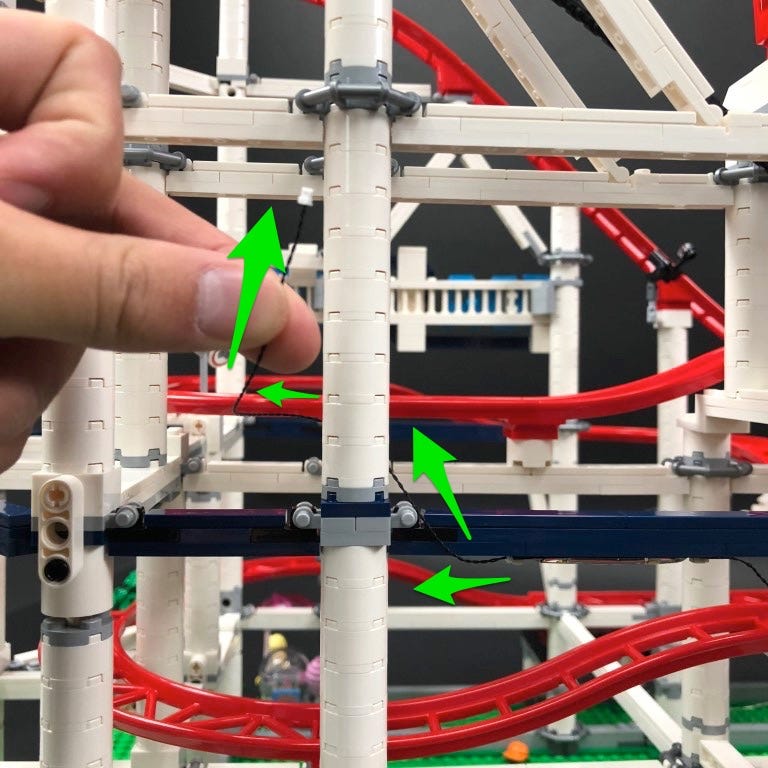
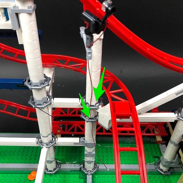
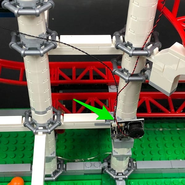
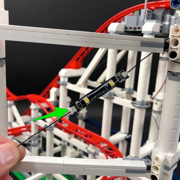
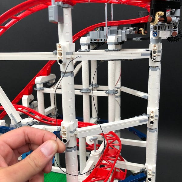
20.) Take another 30cm Connecting Cable and connect one end of the cable to a spare port on the 6-port Expansion Board. Thread the other end of the cable to the left behind the pillars then thread the cable up the space at the base of the second pillar to the left of the battery pack.
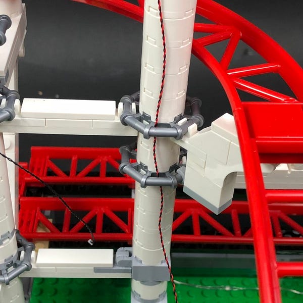
Pull the cable up and then thread it up the next space up along the pillar.
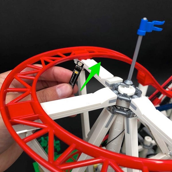
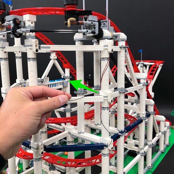
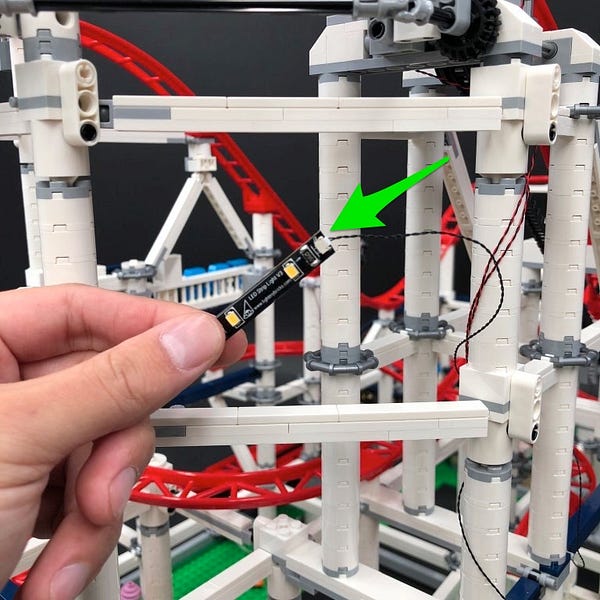
Pull the cable up and then loop it around and up the pillar before connecting it to a new White Strip Light
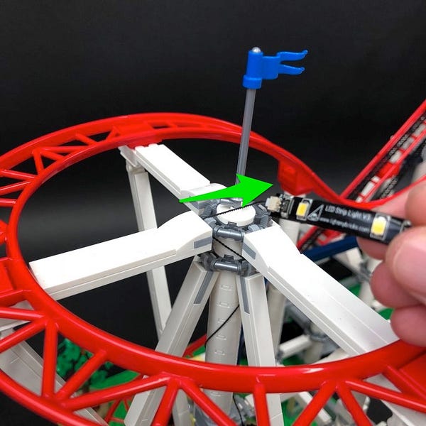
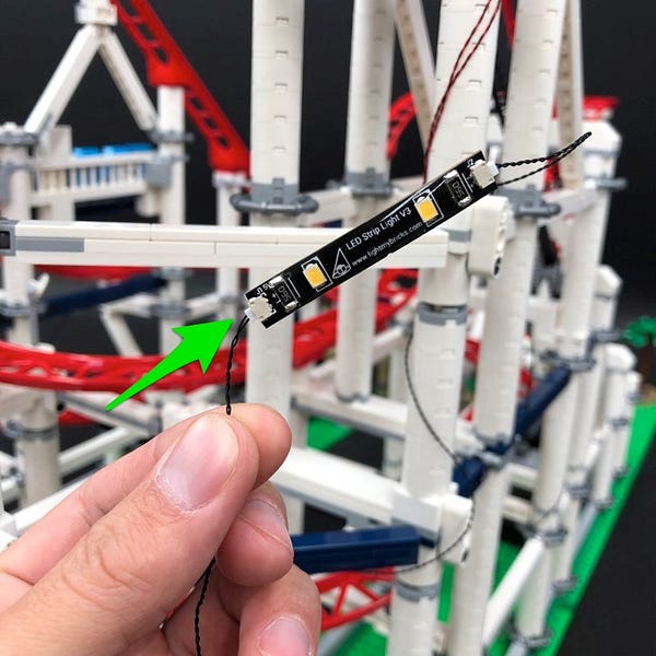
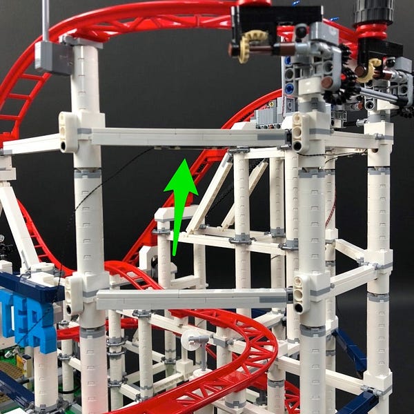
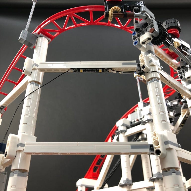
21.) Take a 15cm Connecting Cable and connect it to the other end of the strip light before sticking the strip light underneath the dark blue horizontal bar above.
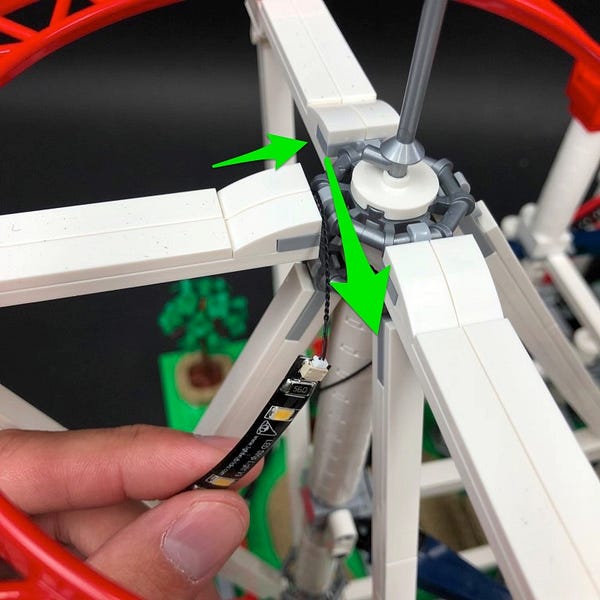
Pull the other end of the 15cm cable up behind the white pillar and the pull out from the left side. Leave the cable aside for now as we will connect it to an expansion board later.
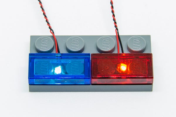
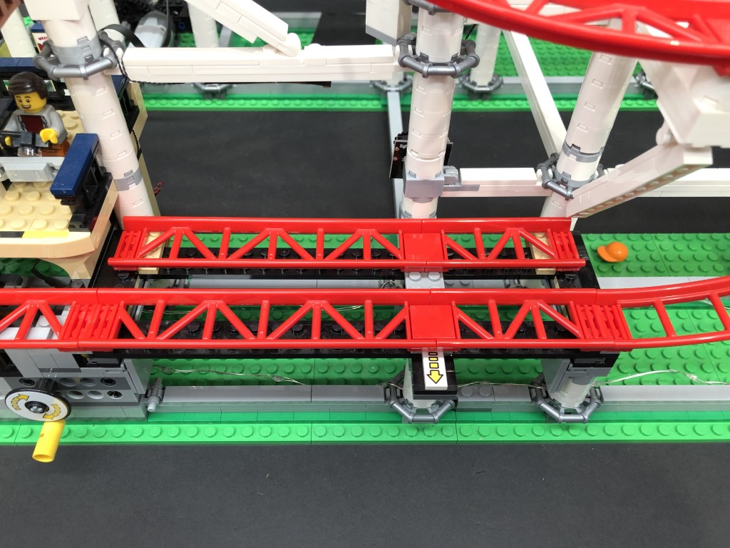
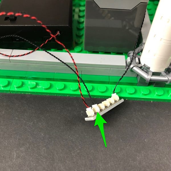
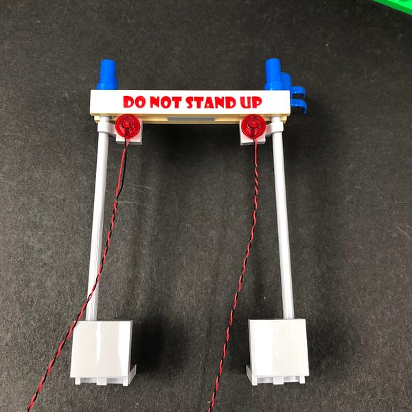
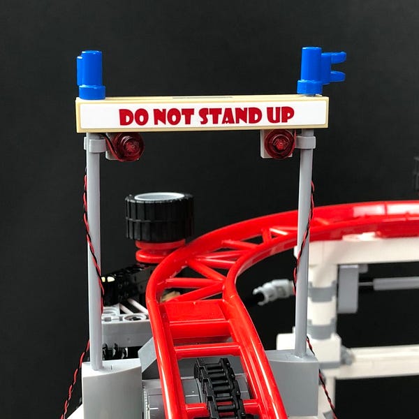
22.) We will now install flashing lights to the “Do Not Stand” sign. First disconnect the sign at the light grey pieces of the base and then set aside.
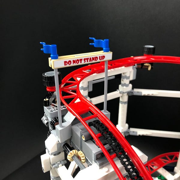
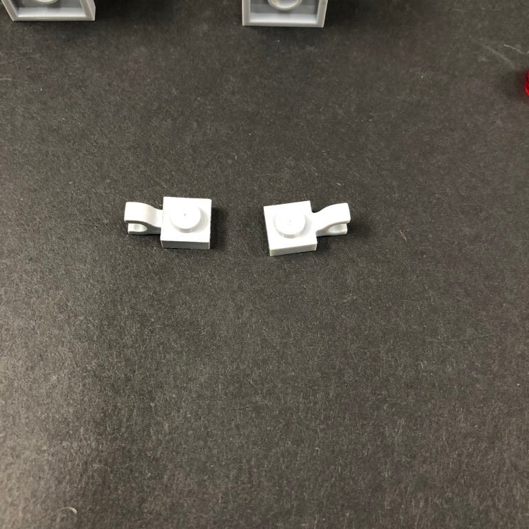
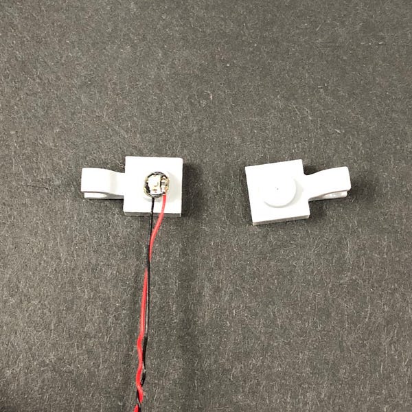
Take the 2x provided Lego Plate 1×1 Modified w Horizontal Clip (Light Grey) and then take a Flashing Red 30cm Bit Light and place it over the stud of the left lego plate. Secure the light in place by connecting a provided Trans Red Round Plate 1×1 over the top.
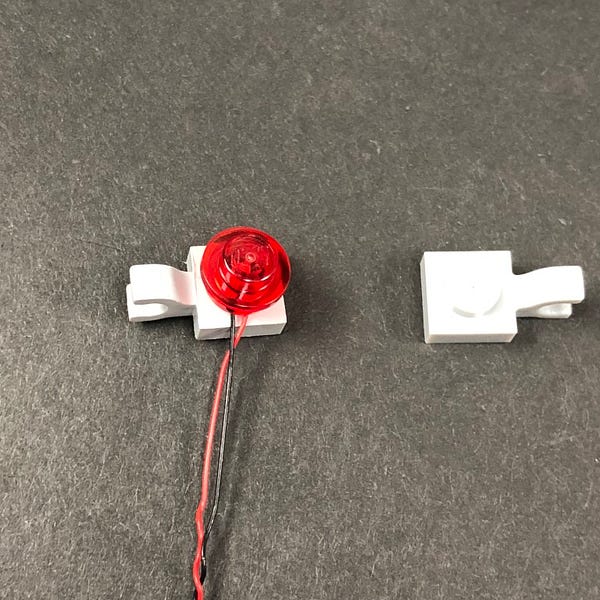
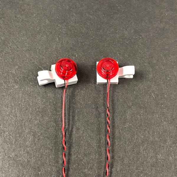
Use the same method to install another Flashing Red 30cm Bit Light to the next plate using another provided Trans Red Round Plate 1×1 and then reconnect the two sections underneath the ‘Do Not Enter sign’ as per below.
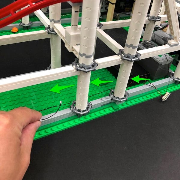
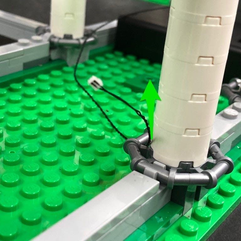
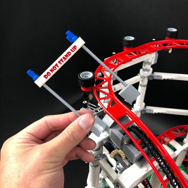
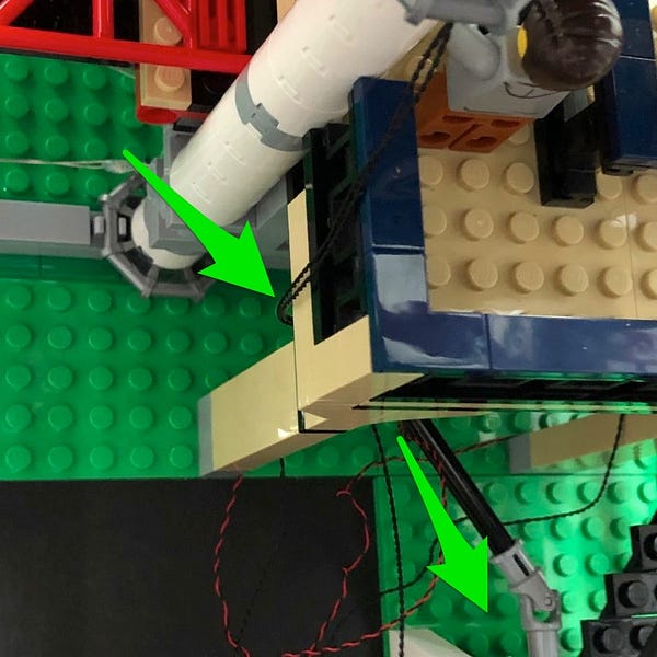
23.) Reconnect the sign back to the Roller Coaster and then loop the cable behind the light grey plate with clip.
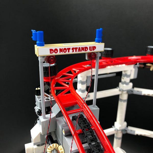
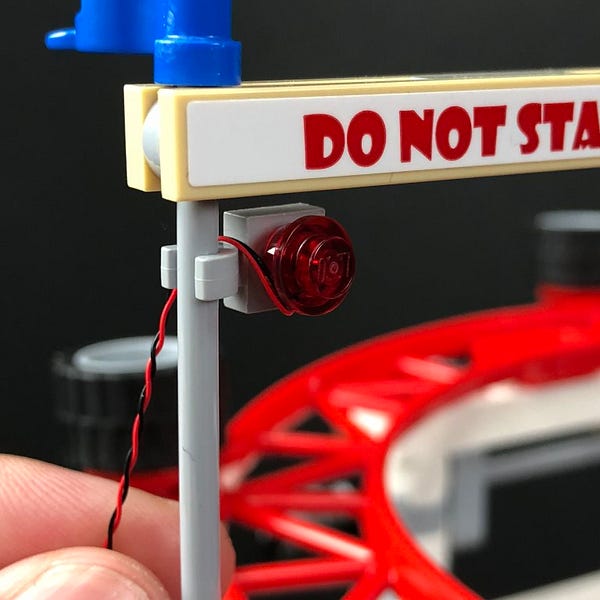
Pull the cable down and wind it around the pole as per below. Repeat this for the cable on the other side.
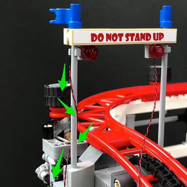
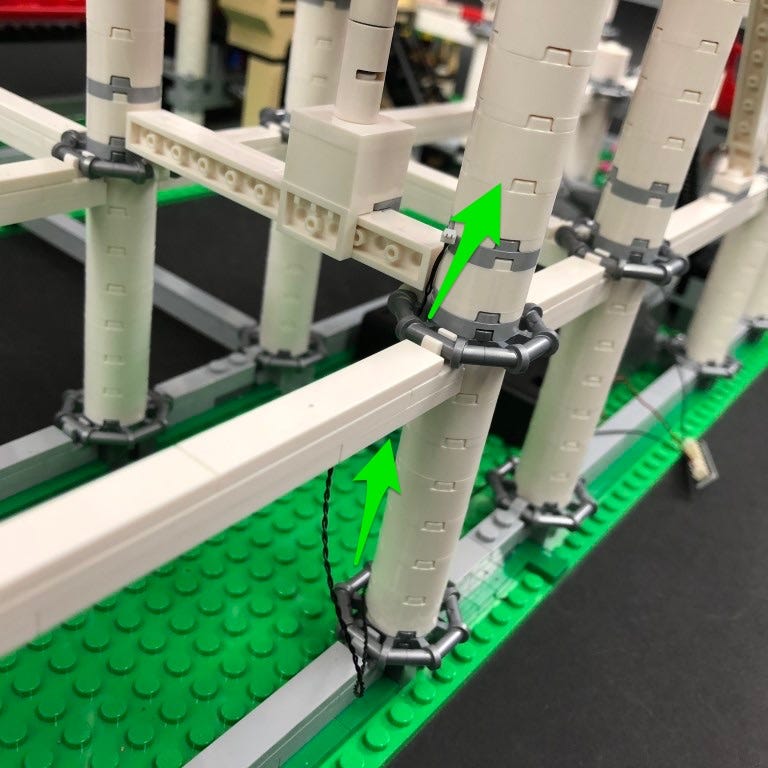
Pull the cable from the right light across to the left and underneath the track.
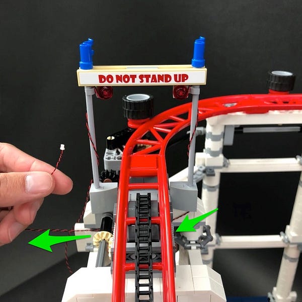
Take the cable from the left light and then thread it down the following space and then loop it around the horizontal bar. This will eliminate excess cable from this side and to ensure both cables are approx. the same length.
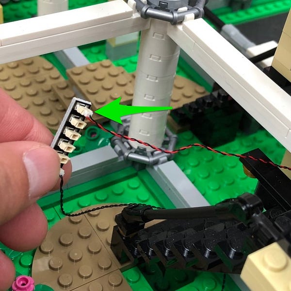
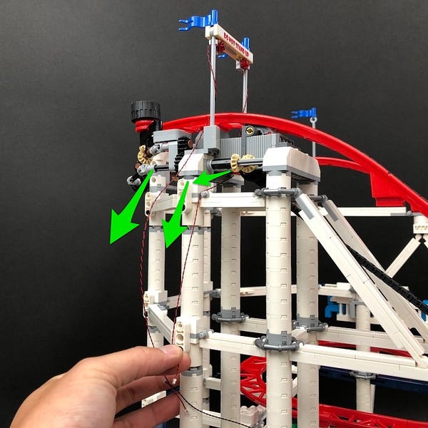
24.) Take a new 6-port Expansion Board and connect both light cables to it.
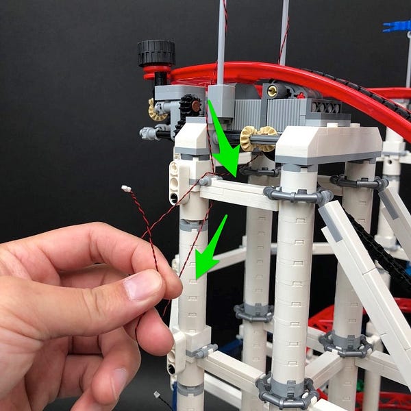
Pull the cables and expansion board down diagonally and wind them toward the left and then pull it out from underneath. Take the other end of the 15cm connecting cable from the strip light below and connect it to a spare port on the 6-port expansion board.
25.) Take 2x 15cm Connecting Cables and connect them both to spare ports on the 6-port expansion board.
Take 2x Adhesive Squares and stick them on the base of the 6-port expansion board to allow us to mount the expansion board underneath the white horizontal bar above.
26.) Take the other end of one of the 15cm connecting cables from the 6-port expansion boar and then thread it behind the pillar and then pull it out from the other side and connect it to a new White Strip Light
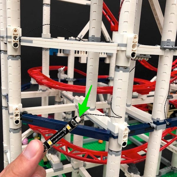
Take a 30cm Connecting Cable and connect it to the other side of the strip light and then stick it underneath the dark blue horizontal bar on the back right corner of the set.
27.) Take the other end of the 30cm connecting cable and pull it across to the left of the set ensuring the cable is pulled behind pillars
When you get to the next corner (front right corner), pull the cable over the dark blue horizontal bar and then loop it around the corner a few times before connecting it to a new White Strip Light.
28.) Take a 15cm Connecting Cable and connect it to the other side of the White Strip Light and then stick the strip light underneath the dark blue horizontal bar on the front right corner of the set in the following position.
Pull the other end of the cable left through the the middle of the pillars and then connect it to another White Strip Light
29.) Take another 15cm Connecting Cable and connect it to the other end of the Strip Light and then stick the Strip Light underneath the lower vertical blue horizontal bar.
Set aside the other end of the 15cm cable for now.
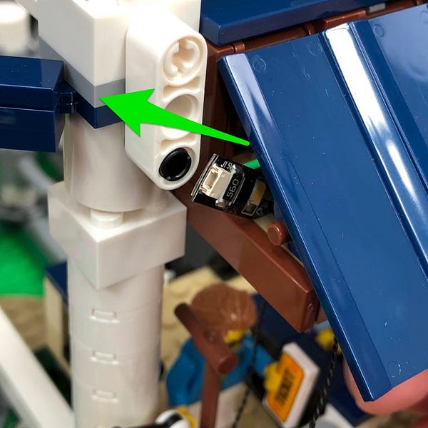
30.) We will now install a light to the camera. First disconnect it at the following section and then disassemble pieces as shown below
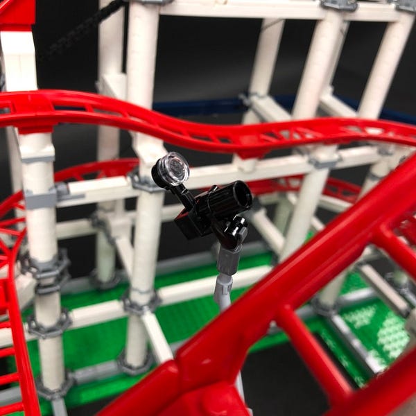
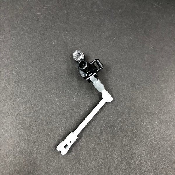
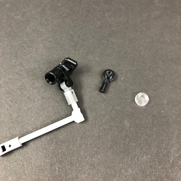
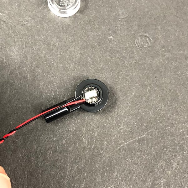
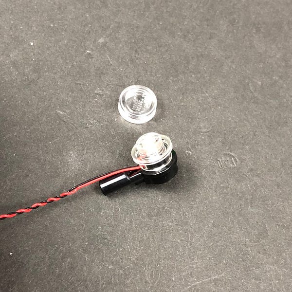
Take a Cool White 30cm Bit Light and place it over the following piece with cable facing the same way as shown below. Secure the light in place by connecting a provided Trans Clear Round Plate 1×1
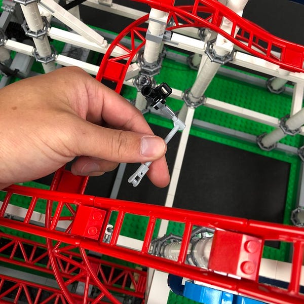
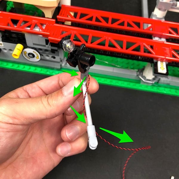
Reconnect the flash section to the rest of the camera and then wind the cable down around the pole as shown below before reconnecting everything back to the roller coaster.
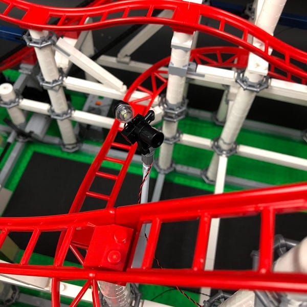
31.) Loop the cable around the corner close to the pillar as shown below.
Turn the entire set around so you can access the back side of the camera then thread the cable down the following two spaces down along the pillar.
32.) Take the Multi Effects Board and connect the camera light cable to one of the OUT ports (side with 2 ports). Take the other end of the 15cm Connecting cable from the strip light in step 29 and connect it to the IN port of the effects board (side with one port)
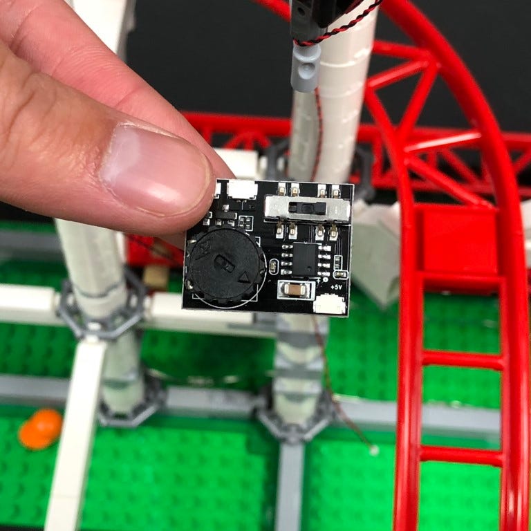
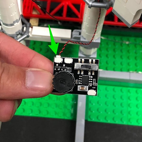
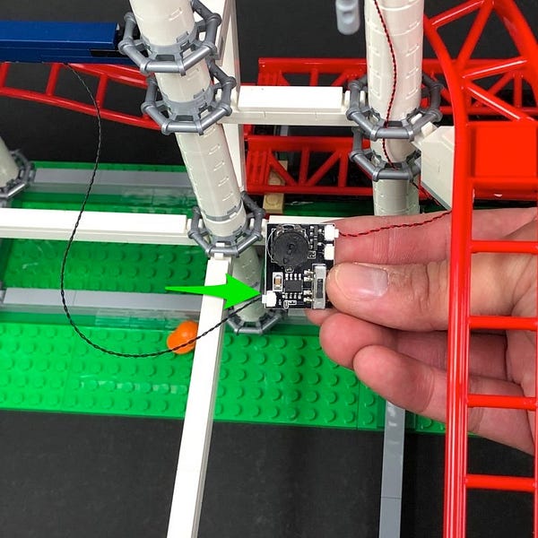
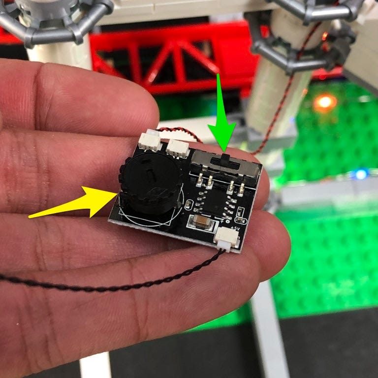
Set the switch on the effects board to the middle for the desired camera flash effect. With the effects board facing the same way as shown below, turn the wheel all the way to the left for the slowest speed.
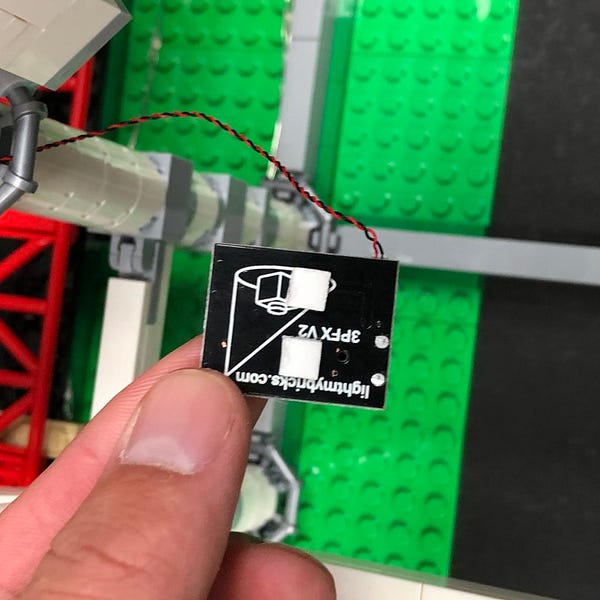
Stick 2x Adhesive Squares to the back of the multi effects board and then mount it to the back side of the pillar as shown below.
33.) Turn the set back around to the back side and then locate the end of the other 15cm Connecting Cable from step 25. Pull it across to the left and then connect it to a new White Strip Light.
Take a 30cm Connecting Cable and connect it to the other side of the White Strip Light and then stick the white strip underneath the top horizontal bar (back right corner of this set) just below the rail in the following position.
Take the other end of the 30cm Connecting Cable and then pull it across to the left behind the first pillar along, then in front of the next pillar. Pull the cable over the corner of the horizontal bar and then pull down and then connect it to a new White Strip Light.
34.) Take another 30cm Connecting Cable and connect it to the other end of the Strip Light then stick the strip light underneath the top horizontal bar in the following position (front right corner of this set).
Loop the 30cm Connecting Cable over the corner twice and then pull it down to lock it in place.
Pull the cable down to the next horizontal bar corner and loop it around twice.
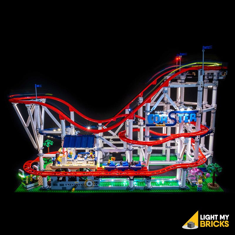
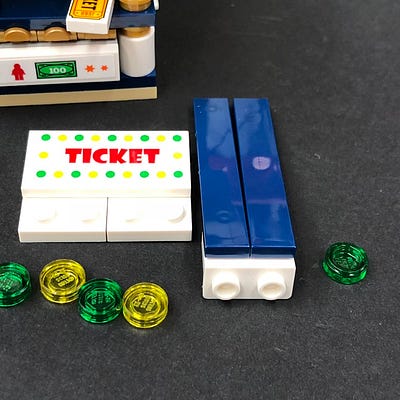
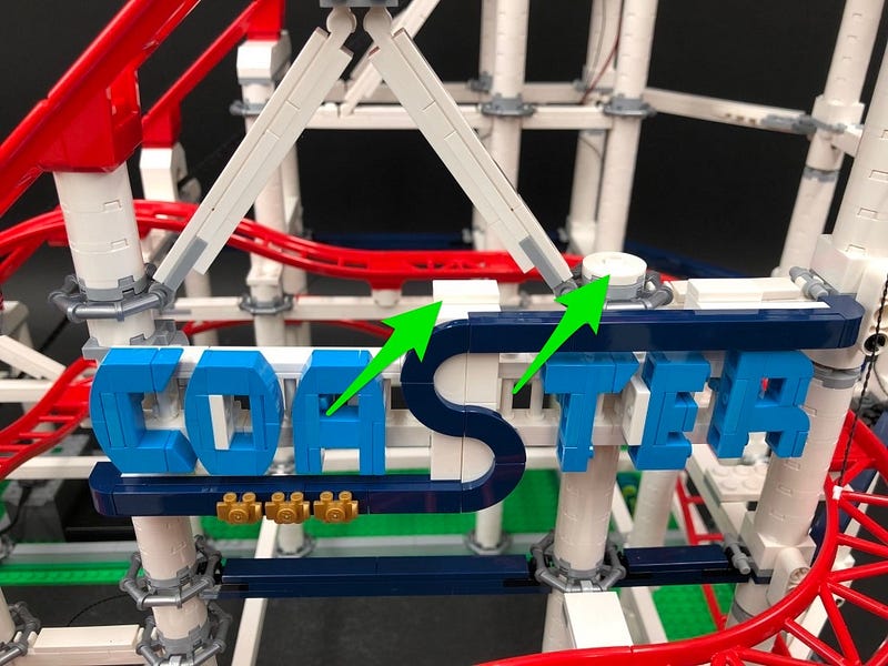
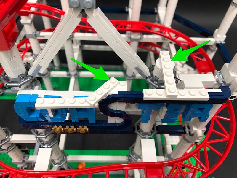
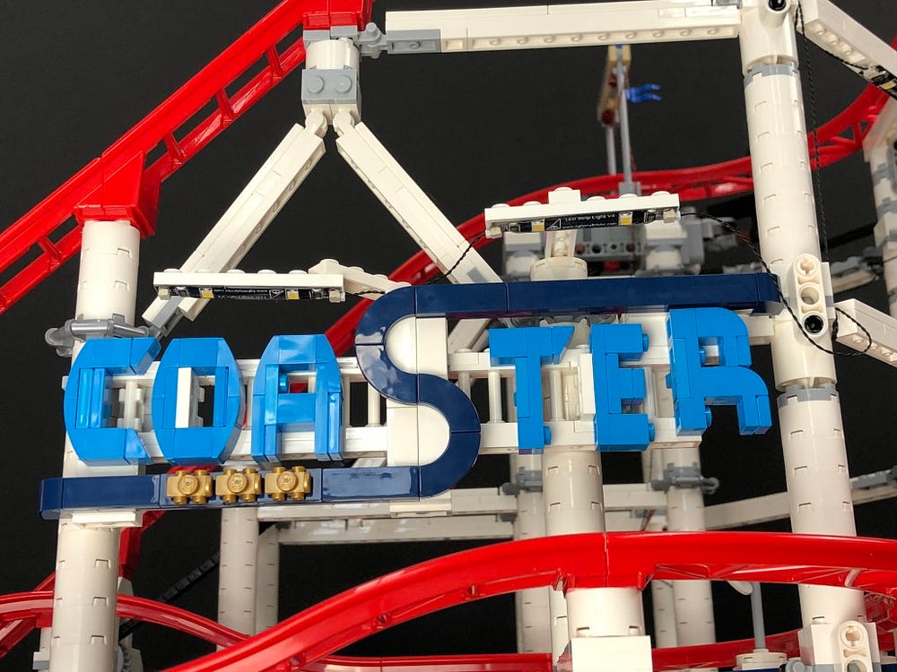
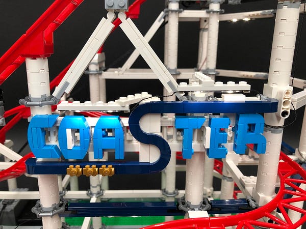
35.) We will now install strip lights to shine down on the Coaster sign. We will need relocate and use pieces from this set to build a bracket for the strip lights to stick up to.
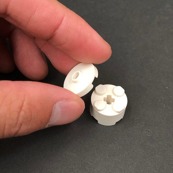
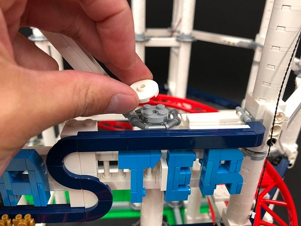
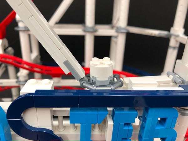
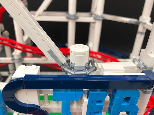
The first piece we will require will be the White Round 2×2 Brick that sits on top of one of the pillars at the bottom of the rail climb.
Disconnect this piece and then remove the round tile with open stud from the top and then reconnect this directly to the light grey round plate underneath (without the white round 2×2 brick).
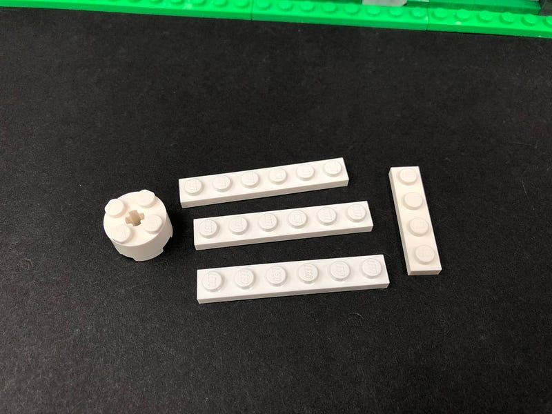
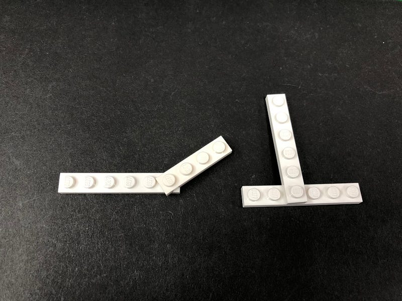
36.) Take out the following provided White LEGO pieces that came in this light kit along with the White Round 2×2 Brick we removed earlier:
- 3x Plates 1×6 (White)
- 1x Plate 1×4 (White)
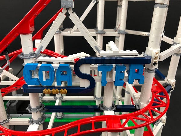
Disconnect the following pieces from the top of the Coaster sign
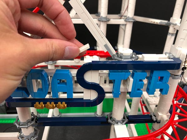
Connect the White Round 2×2 Brick we took out earlier and then reconnect the white round tile with open stud over the top.
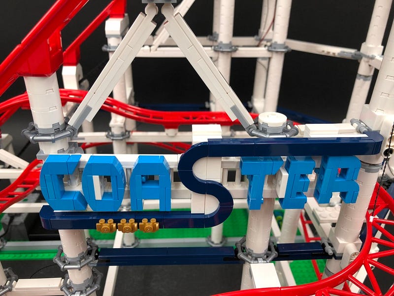
Assemble the provided white plates as per below before connecting them to the top of the Coaster sign.
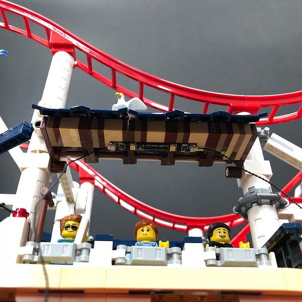
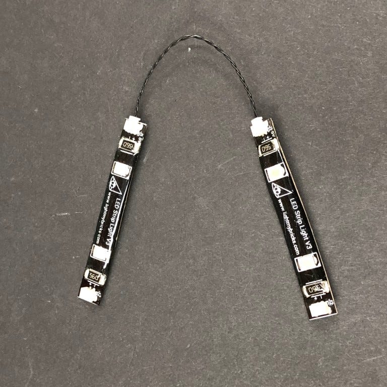
37.) Take 2x White Strip Lights and connect them together using a 5cm Connecting Cable.
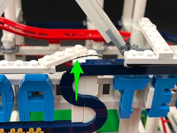
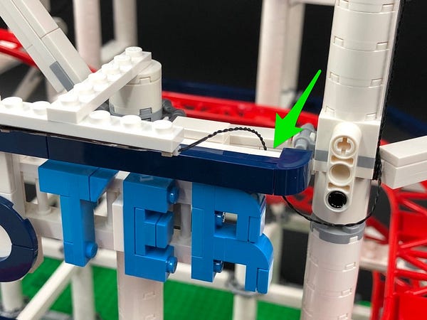
Connect the other end of the 30cm connecting cable from step 34 to one of the strip lights then stick both strip lights to the white 1×6 plates we connected on top of the Coaster sign.
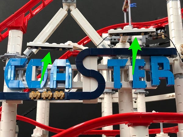
Push in the connecting cable between the two strip lights and then tuck the 30cm connecting cable behind right side of the ‘R’.
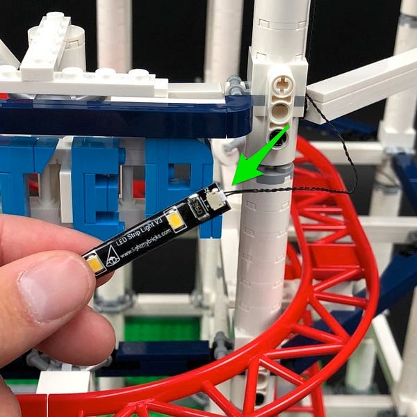
38.) We will now install the remaining Strip Light to the front of the roller coaster. Take the last White Strip Light and connect a 30cm Connecting Cable to one end.
With the cable facing the left, stick the Strip Light underneath the lower horizontal bar toward the right of the platform.

39.) Loop the connecting cable over the left corner of the bar twice before pulling it behind.
Turn the entire set around so we can access the back side of the platform, then take the cable and thread it down the pillar through the following space.
Thread the cable underneath platform toward the right as shown below and then connect it to the remaining port on the 6-port expansion board underneath.
40.) Turn the entire set back around to the front and then neaten up all the cabling behind the platform by pulling the expansion board all the way out then looping all the cables and then twisting them around each other to bring them all together.
From the back of the set, tuck everything neatly under the platform.
This completes installation of the lights for the Roller Coaster set. We now need to install the remaining components to light up the two roller coaster carriages.
Lighting the Roller Coaster Carriages
1.) Starting with one set, disconnect the three carriages
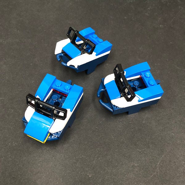
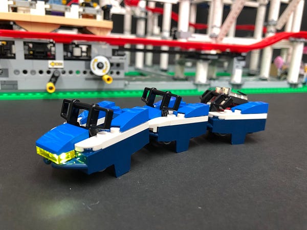
Take the front carriage and then disassemble pieces as shown below
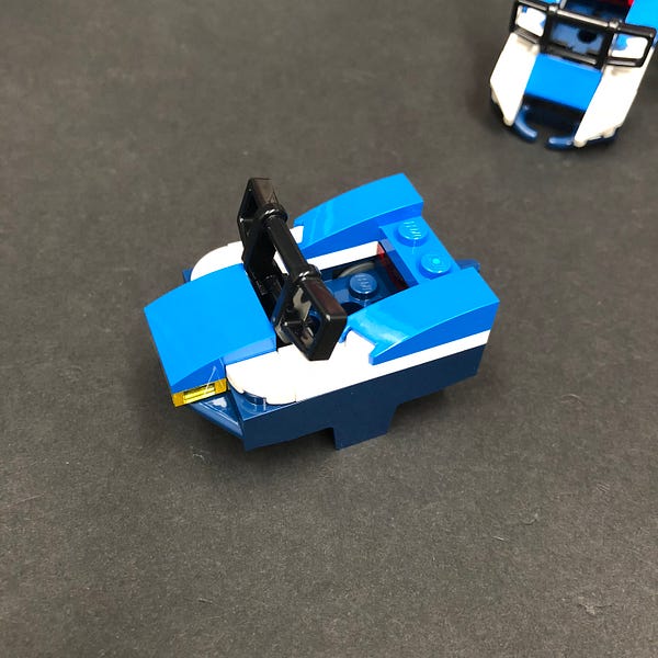
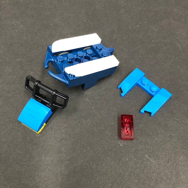
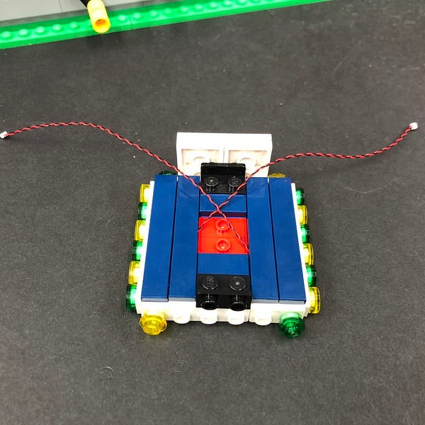
Take the following front section and then flip it over.
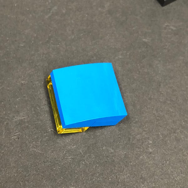
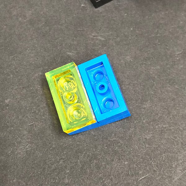
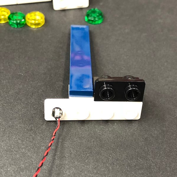
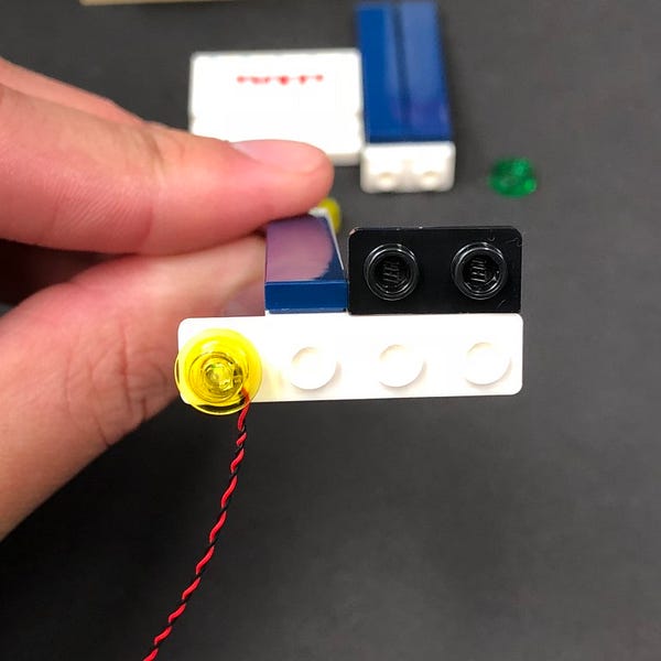
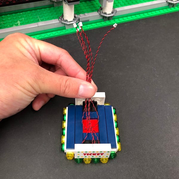
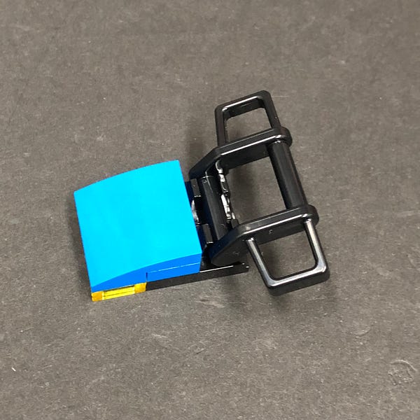
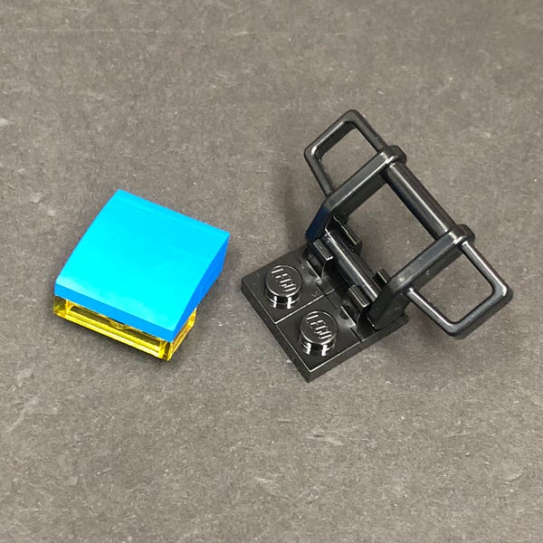
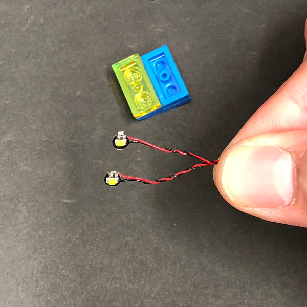
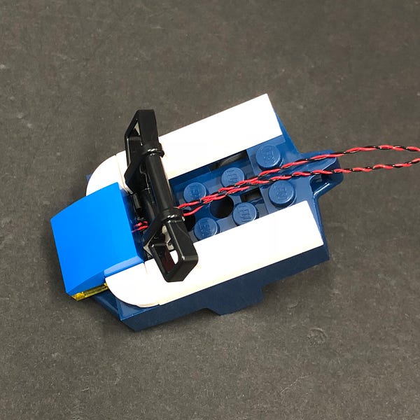
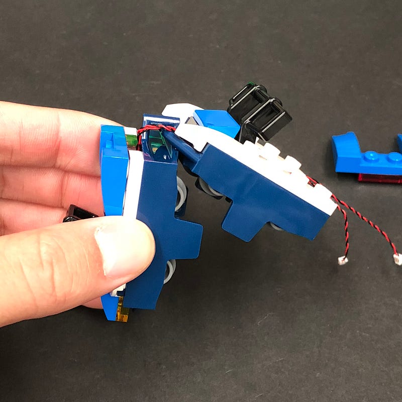
2.) Take 2x Flashing White 15cm Bit Lights and then hold both of them together and then place them both upside down over the inside of the trans yellow 1×2 plate.
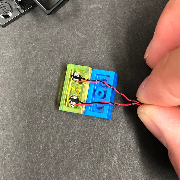
Reconnect the black section we disconnected earlier ensuring the cables are laid together in between the studs, then flip this front section over.
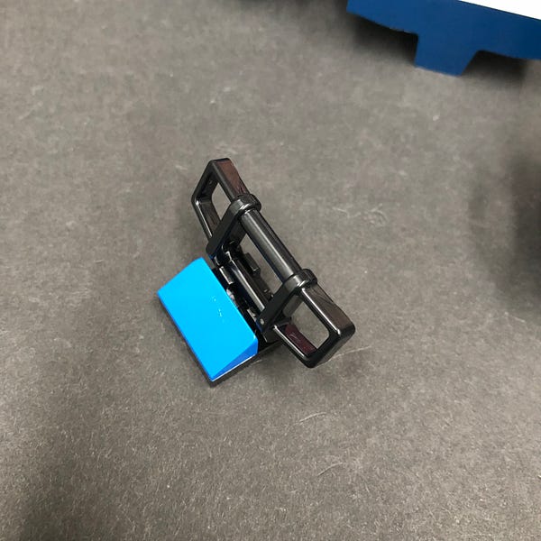
Disconnect the black rail and then lay cables underneath in between clips before reconnecting the black rail over the top
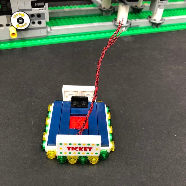
3.) Reconnect this section back to the front carriage ensuring the cables are laid down the middle in between studs.
Reconnect remaining sections to the back of the front carriage
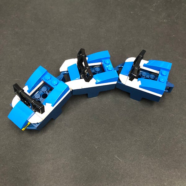
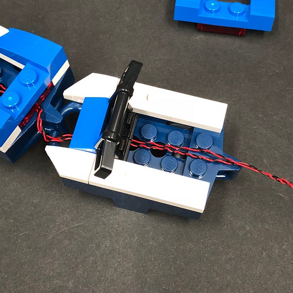
4.) Reconnect the middle carriage and then disconnect the following pieces from it.
Position both carriages as per below so that the cables are stretched out before reconnecting the front rail to the middle carriage. This is to ensure there is enough cable slack for the carriages to turn smoothly on the tracks.
5.) Lay the cables down the middle in between studs before reconnecting remaining sections to the back of the middle carriage.
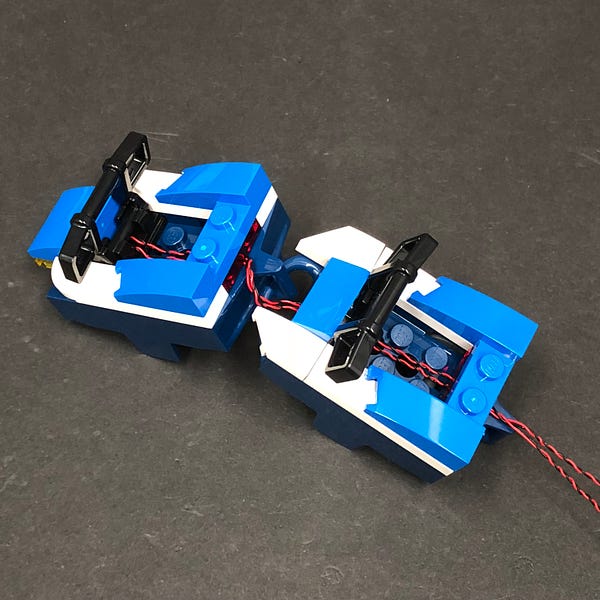
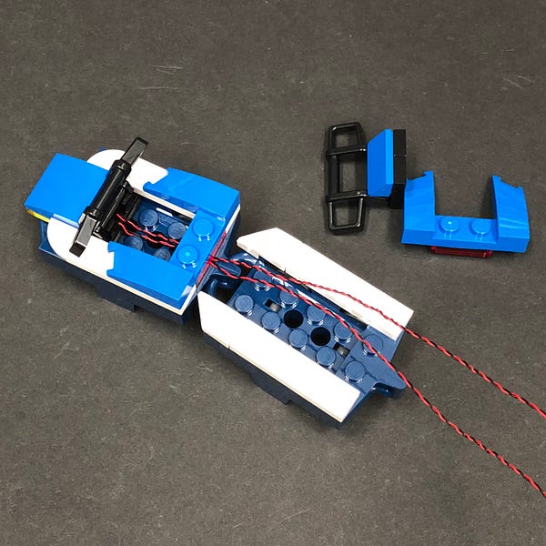
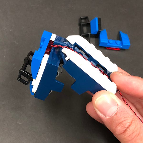
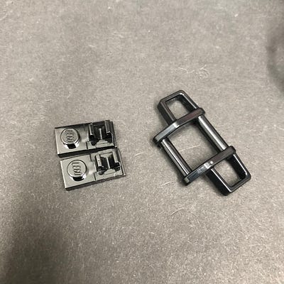
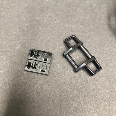
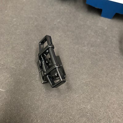
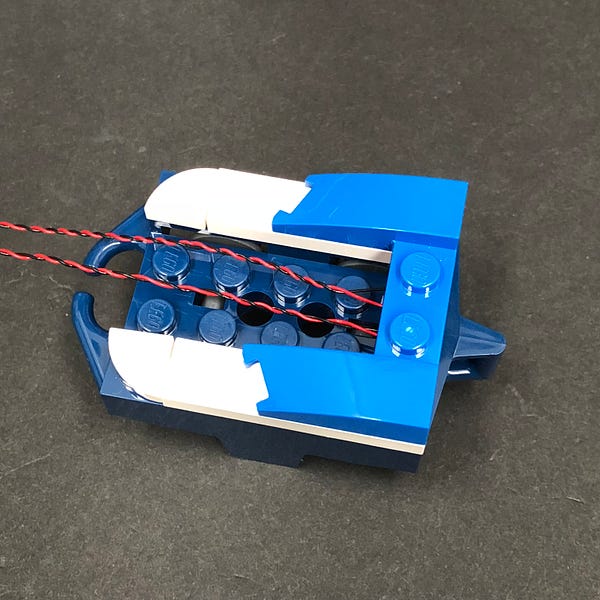
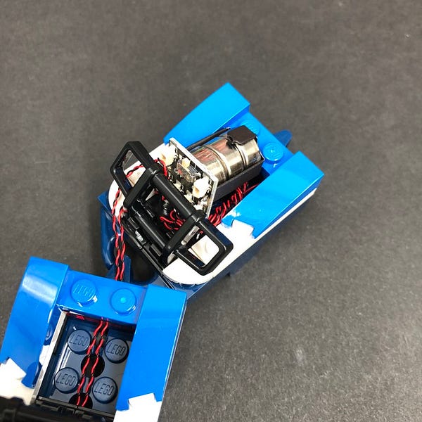
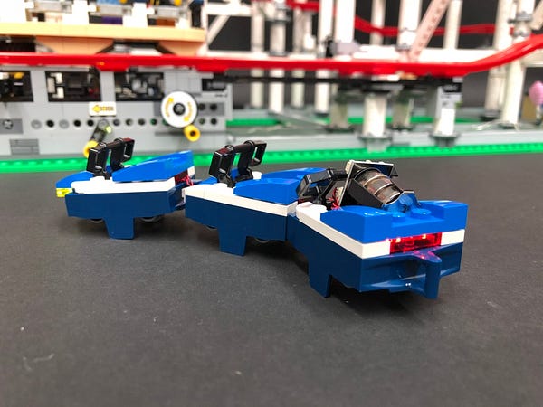
6.) Take the back carriage and disassemble pieces as per below
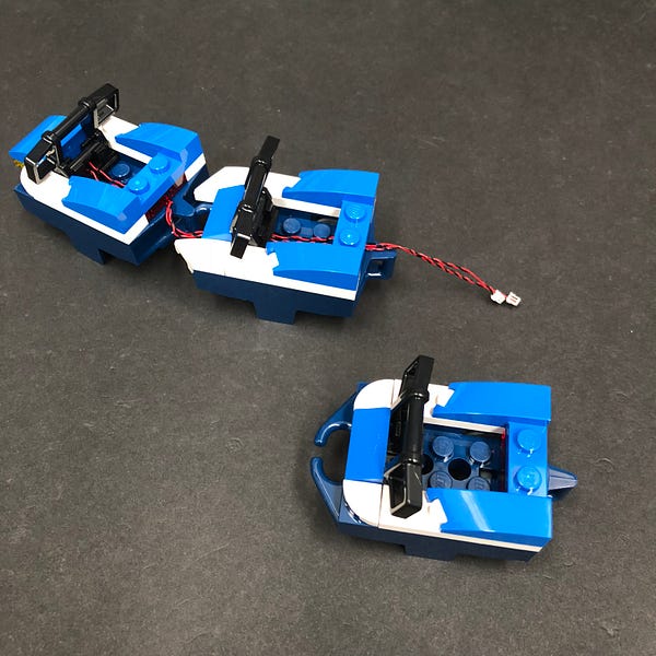
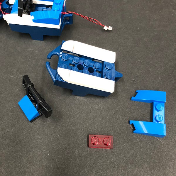
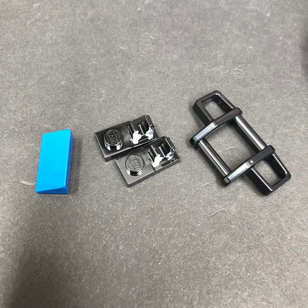
Rebuild the rail for the back carriage as per below. (Ensure 1×2 plates with clips are flipped around)
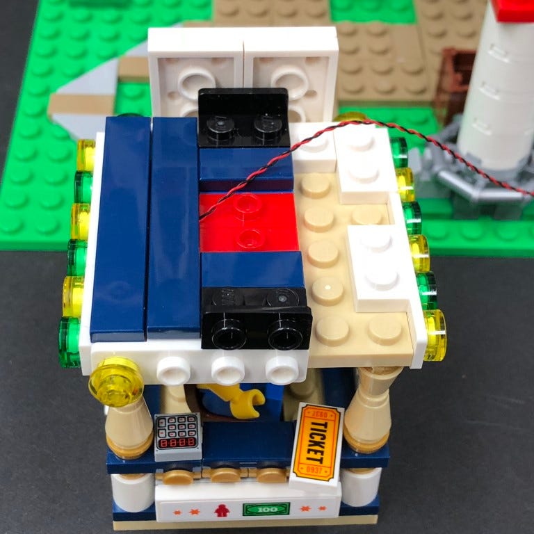
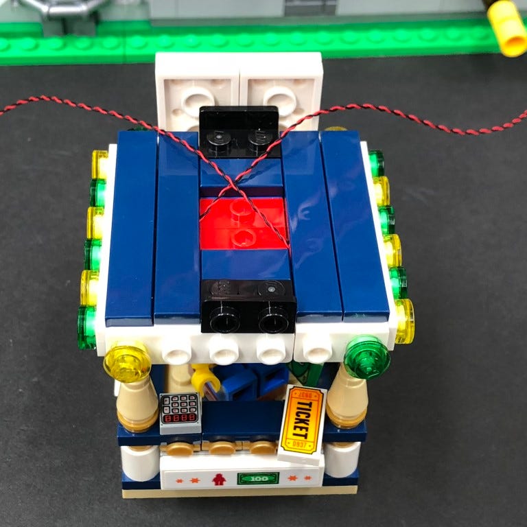
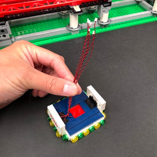
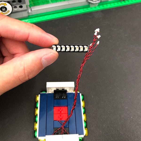
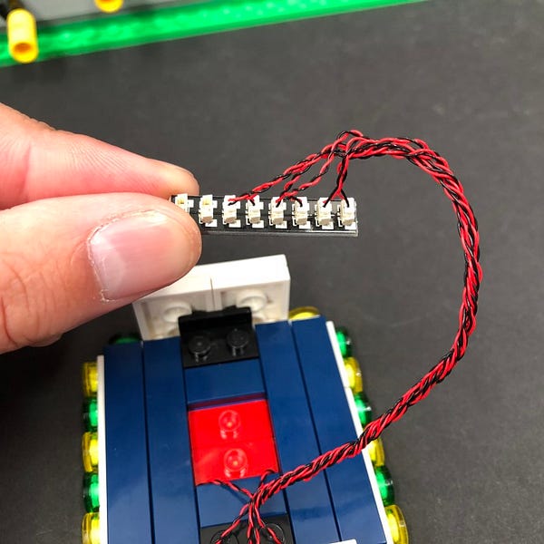
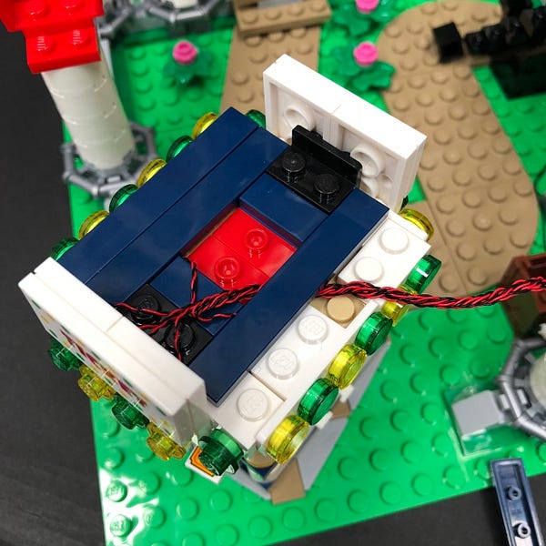
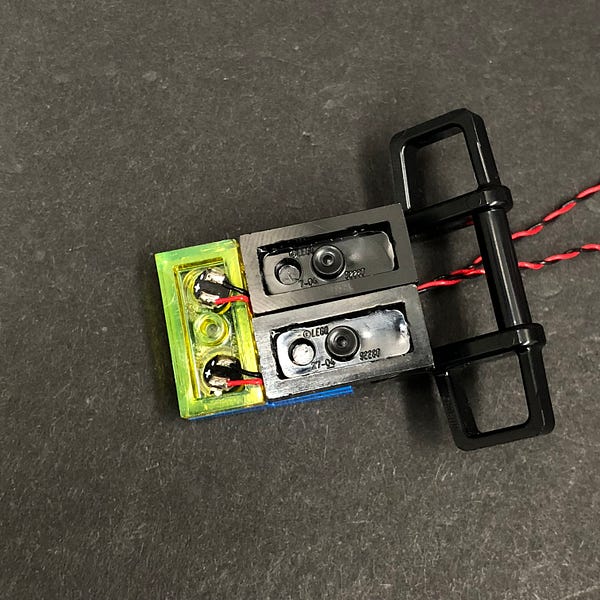
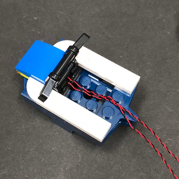
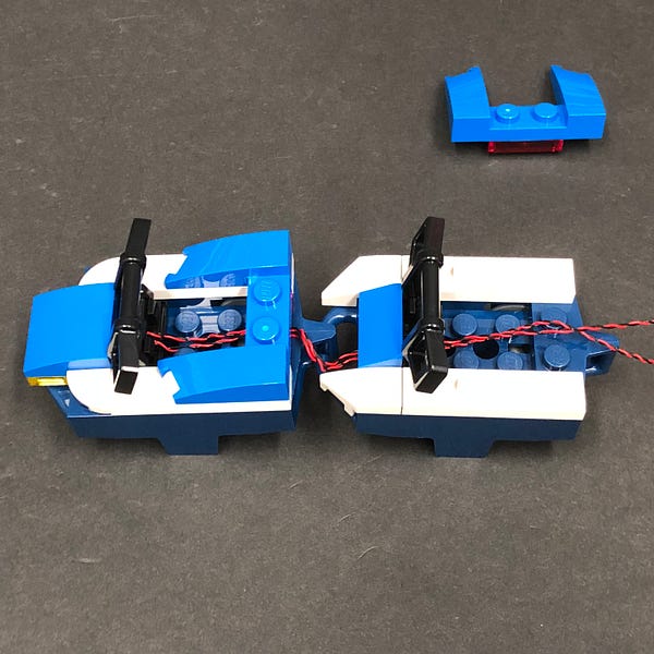
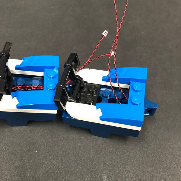
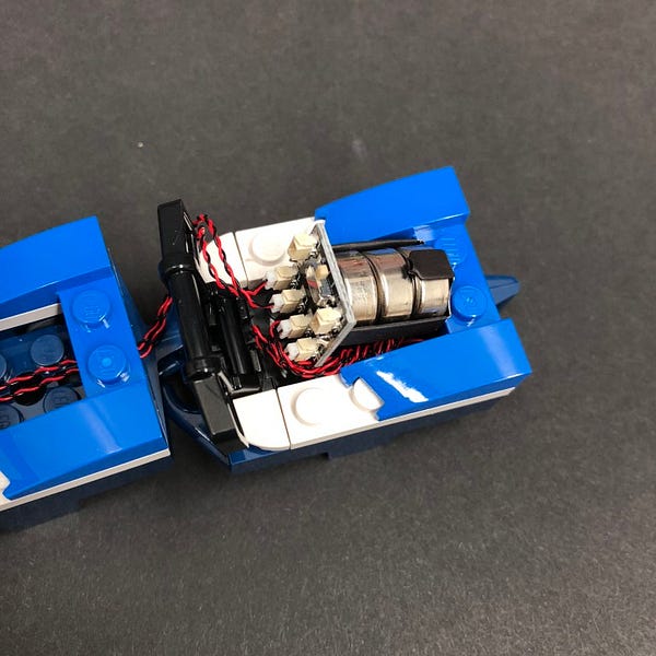
7.) Take 2x Flashing White 15cm Bit Lights and hold them together.
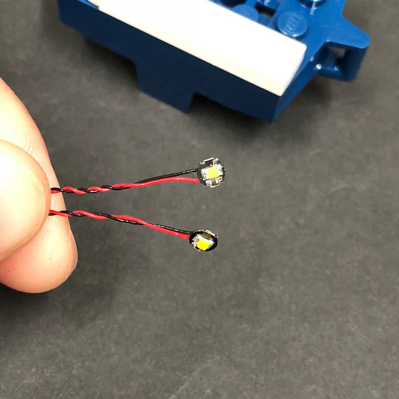
With the cables facing the front, place them over the two studs along the back.
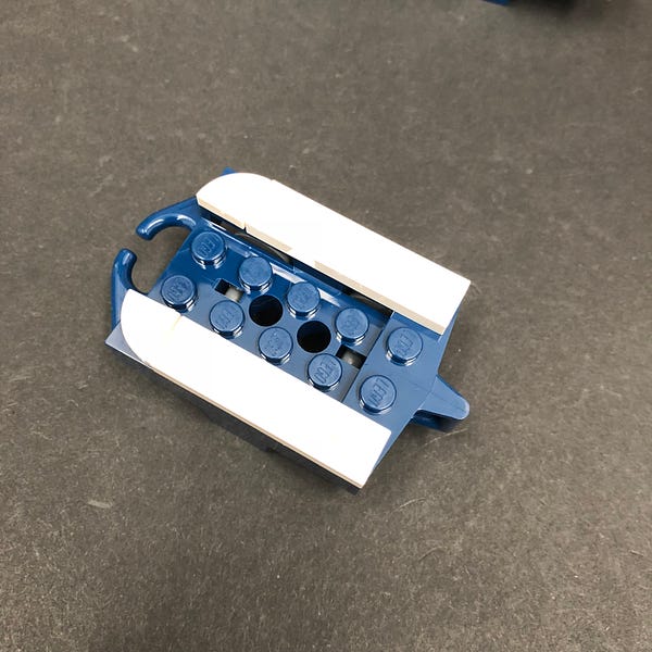
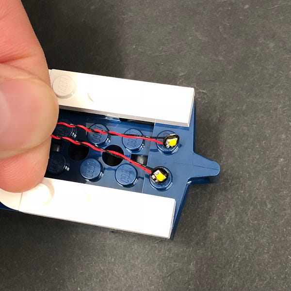
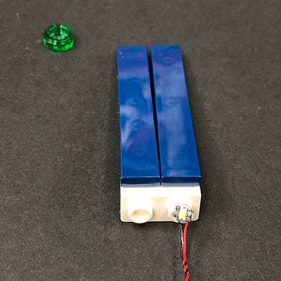
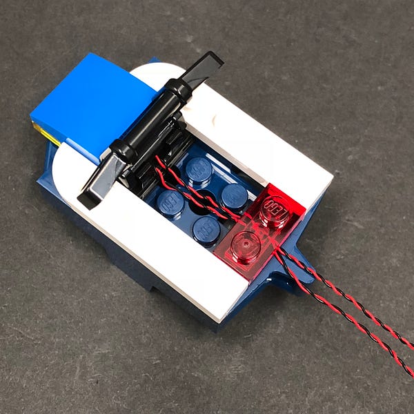
Secure the Bit Lights in place by reconnecting the Trans Red 1×2 plate over the top followed by the blue section on top.
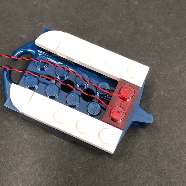
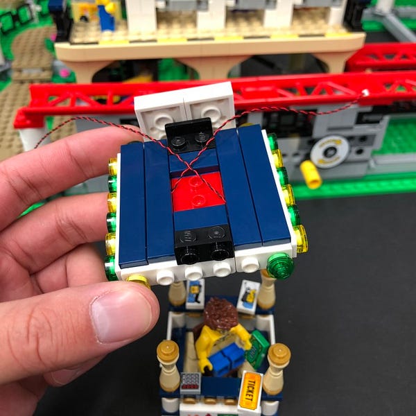
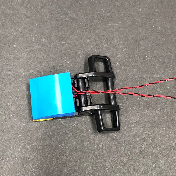
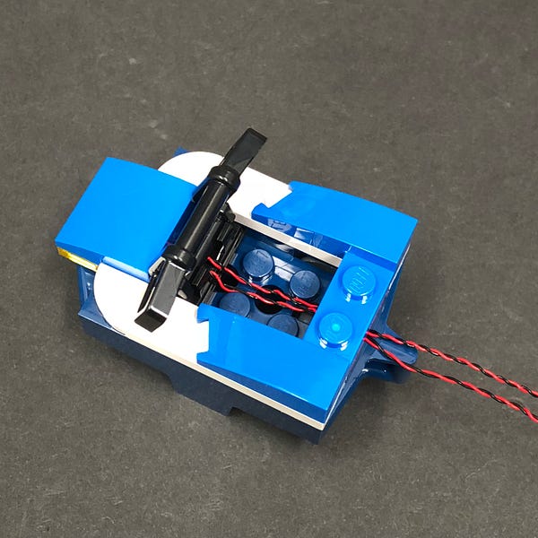
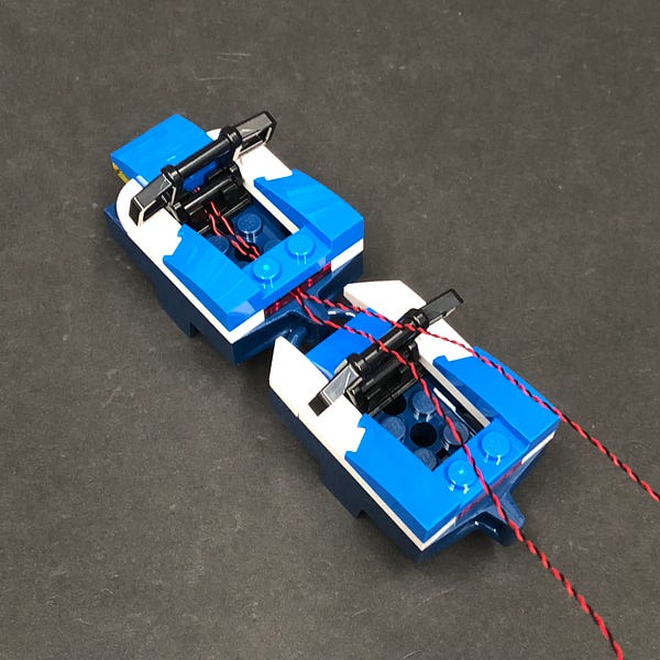
8.) Reconnect the back carriage to the remaining carriages and then reconnect the black rail.
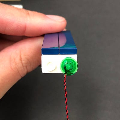
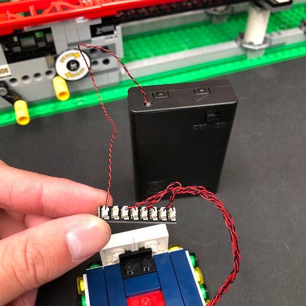
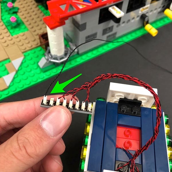
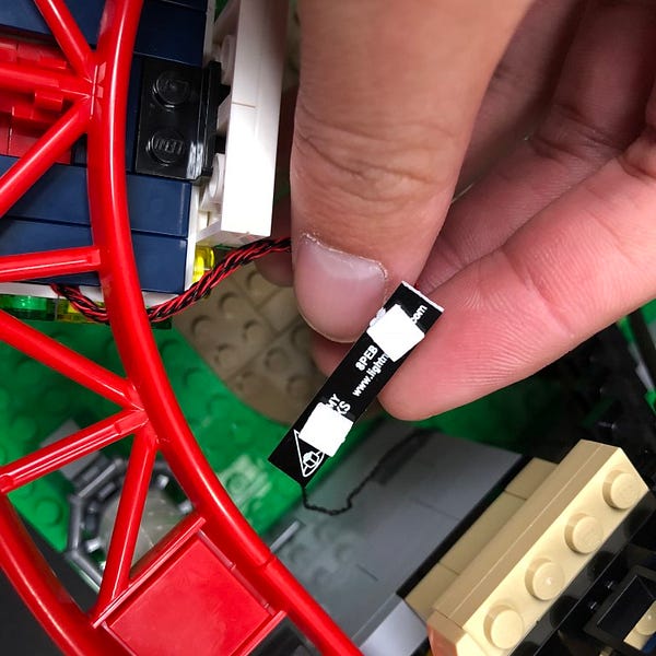
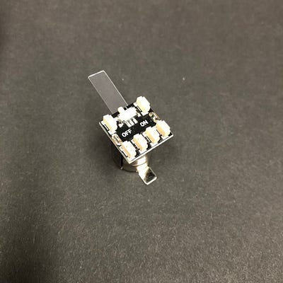
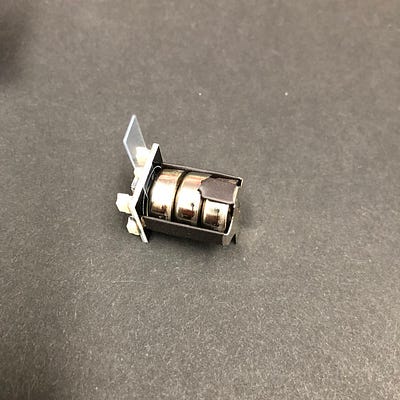
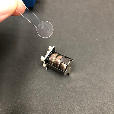
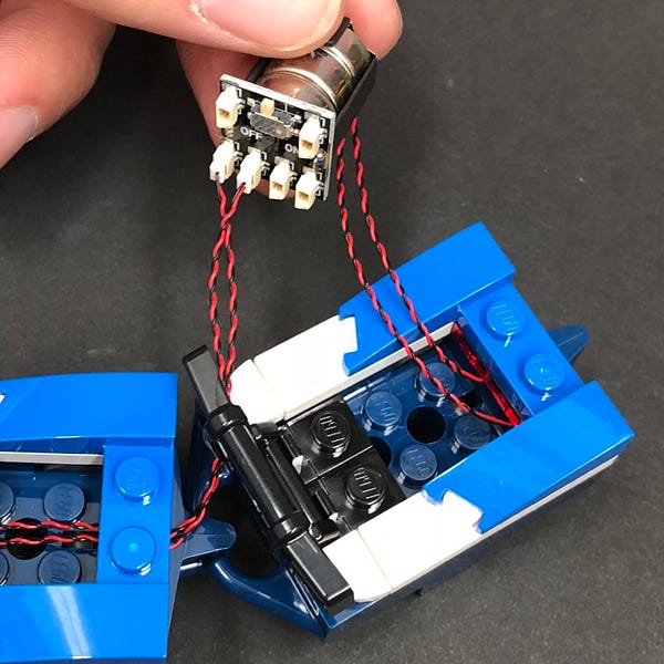
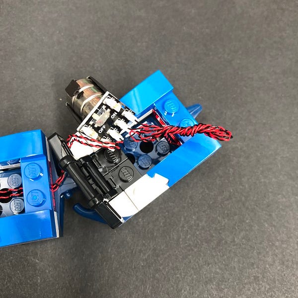
Take out the Micro Battery Pack and then remove the plastic slip to activate the LR44 button batteries connected inside.
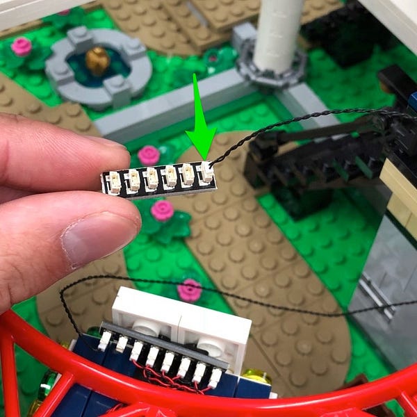
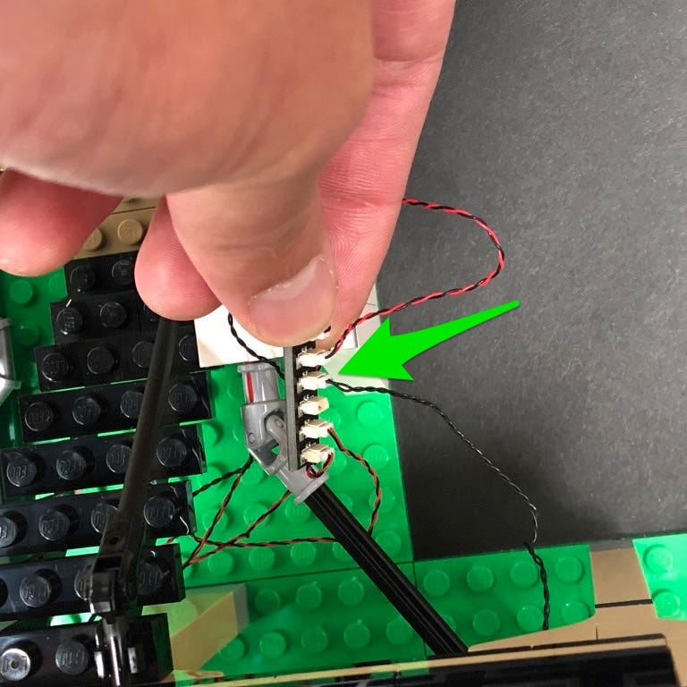
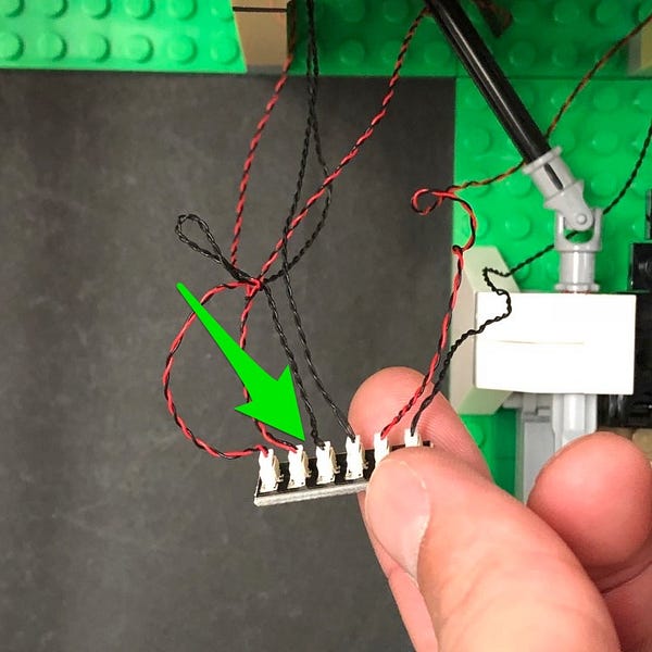
Connect all four bit light cables to the ports on the bottom starting with the two front lights (shorter cables).
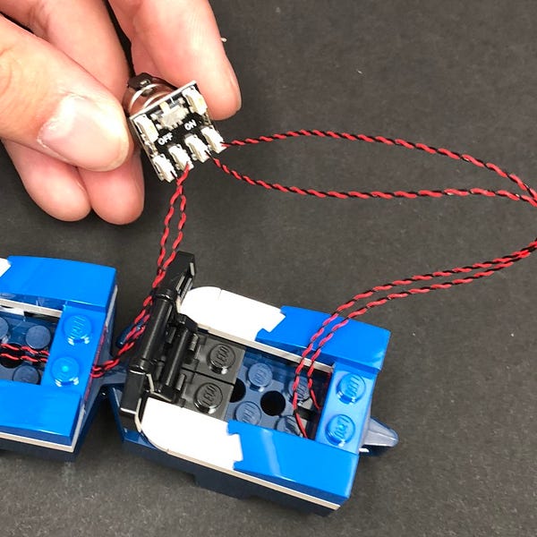
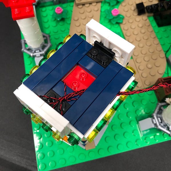
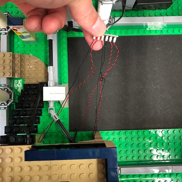
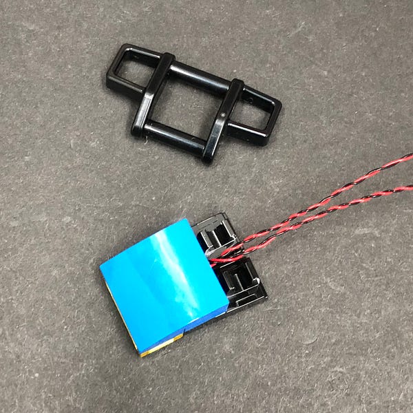
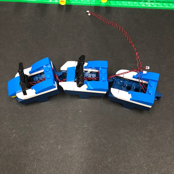
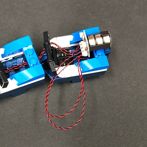
9.) Eliminate excess cables from the back lights by grouping the two cables together and then twisting them around each other as per below
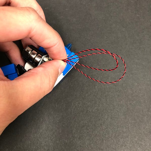
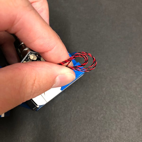
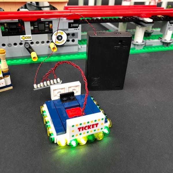
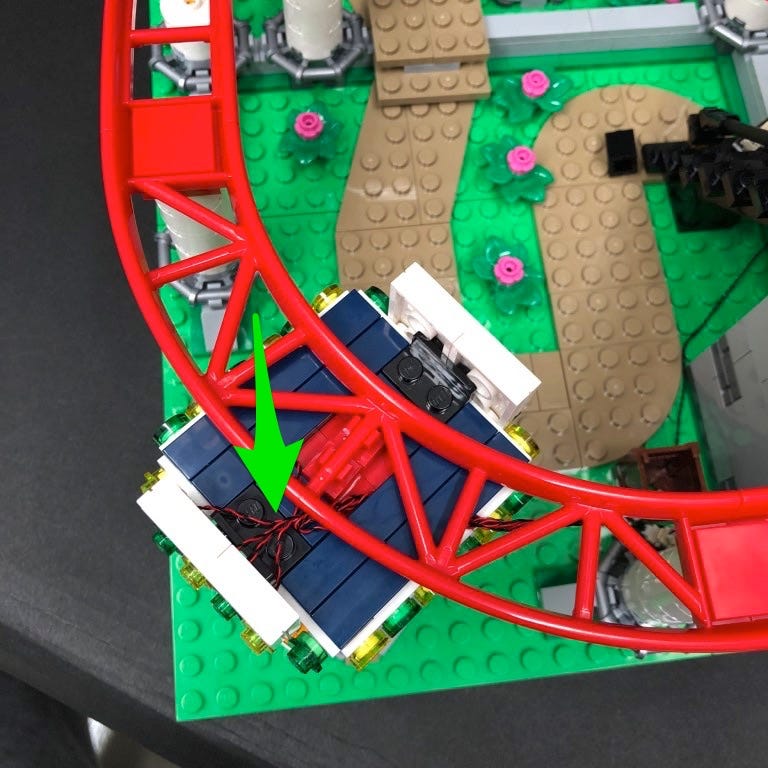
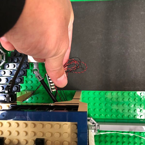
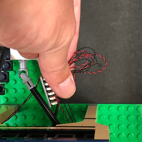
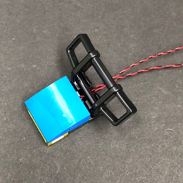
Place the battery pack neatly in the back carriage and tuck the cables in underneath. Push back the black rail to secure the battery pack in place.
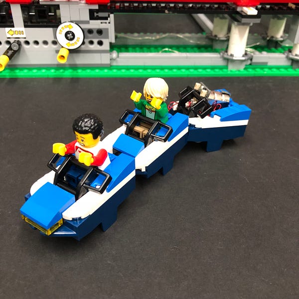
10.) Turn the battery pack ON to test that all four flashing lights are working OK.
Place the minifigs inside the front two carriages and then reconnect it back to the Roller coaster tracks.
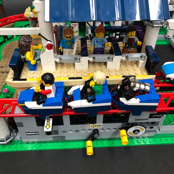
Follow the above steps to install lights to the second carriage using the remaining components:
4x Flashing White 15cm Bit Lights
1x Micro Battery Pack
This finally completes installation of the Roller Coaster 10261 Light Kit. We hope you enjoy your light kit.
Thank YOU for purchasing this Light Kit!