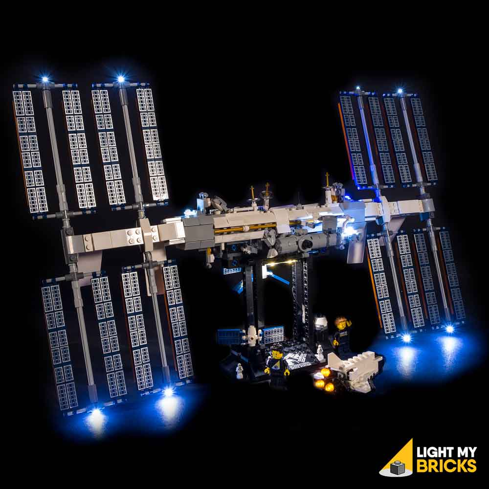
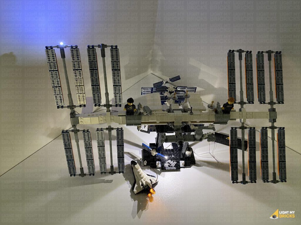
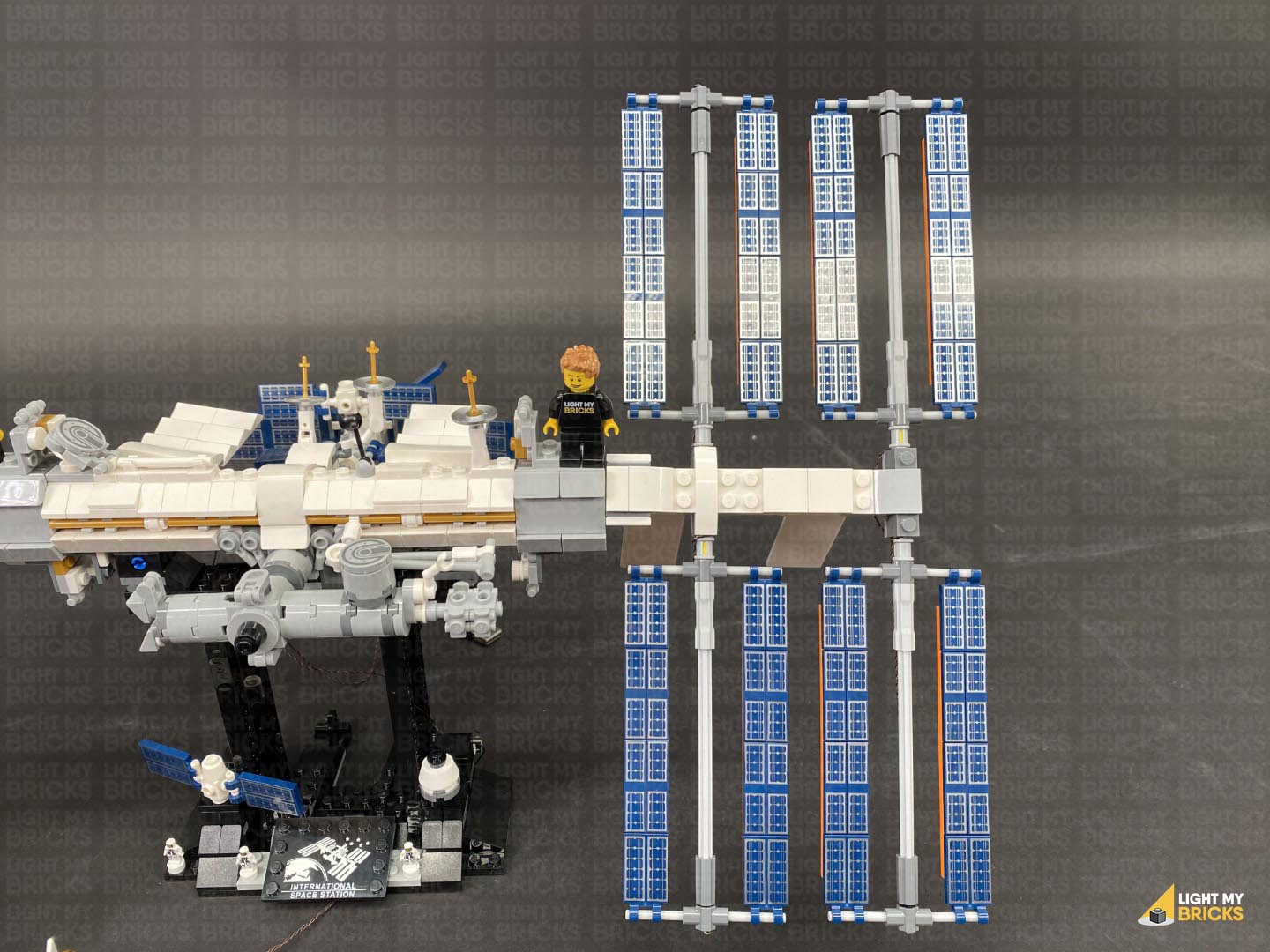
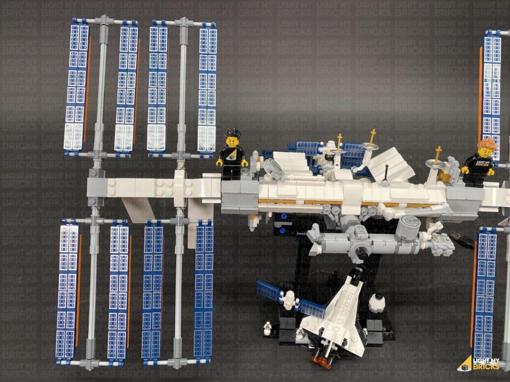
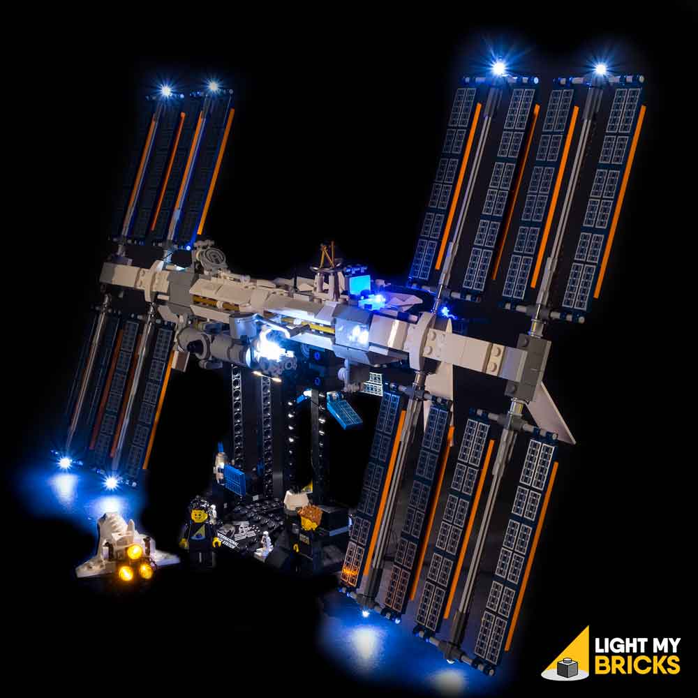
The following page is the instructions for the Light My Bricks International Space Station (21321) LED light kit.
If you run into any issues, please refer to the online troubleshooting guide.
To ensure a trouble-free installation of your light kit, please read and follow each step carefully. These instructions can be downloaded in PDF format here
Please note: This page lists instructions for the LED light kit only. If you are wishing to purchase the Light My Bricks LEGO International Space Station (21321) LED light kit , please click here to view the product page
Package Contents:
- 9x Cool White 30cm Bit Lights
- 2x Blue 30cm Bit Light
- 1x Flashing White 15cm Bit Light
- 3x White 30cm Micro Bit Lights
- 1x White Strip Light
- 3x 6-Port Expansion Board
- 1x 8-Port Expansion Board
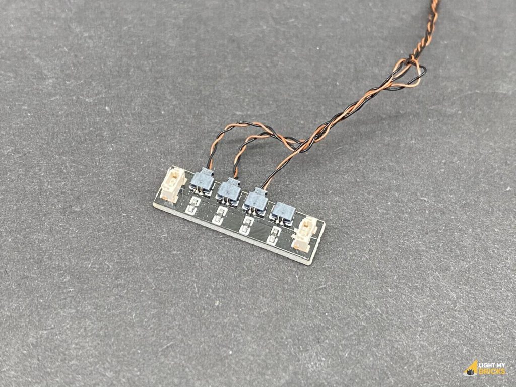
- 1x Micro 2-4 Port Expansion Board
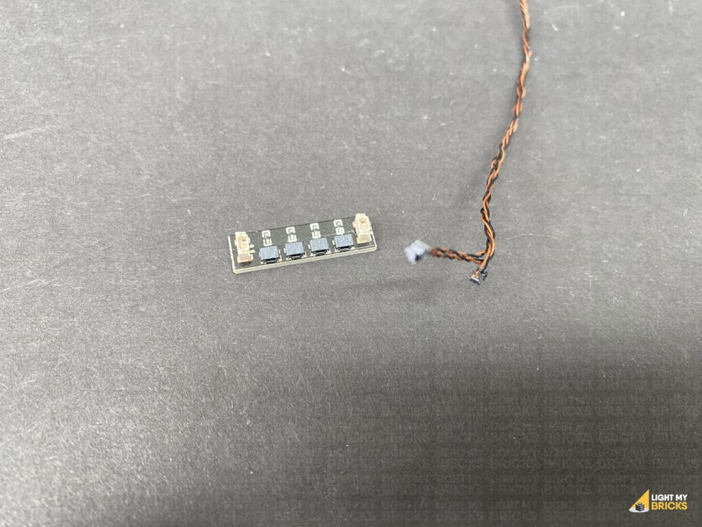
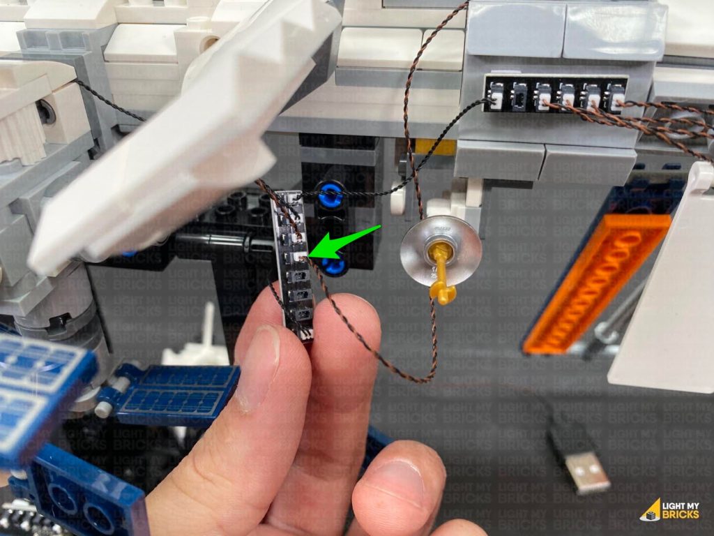
- 1x Flicker Effects Board
- 4x 5cm Connecting Cables
- 2x 15cm Connecting Cables
- 1x USB Power Cable
- 12x Ahdesive Squares
- 4x Trans Clear Round Plate 1×1
- 3x Trans Orange Round Plate 1×1
Important things to note:
Laying cables in between and underneath bricks
Cables can fit in between and underneath LEGO® bricks, plates, and tiles providing they are laid correctly between the LEGO® studs. Do NOT forcefully join LEGO® together around cables; instead ensure they are laying comfortably in between each stud.
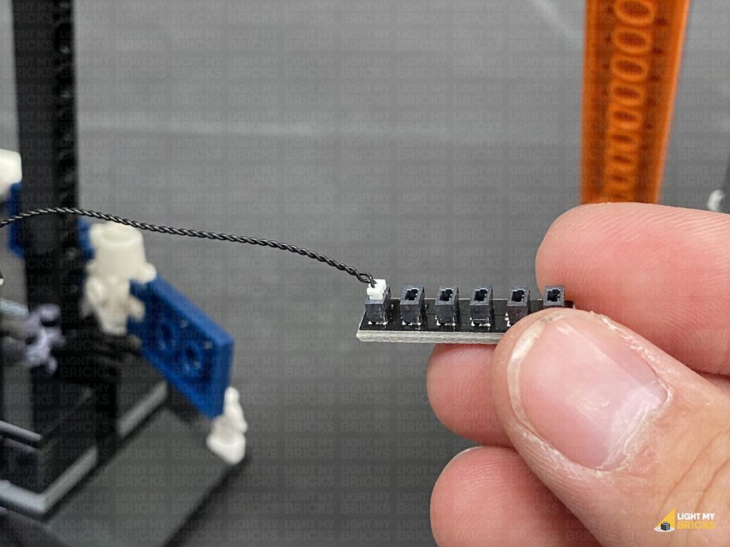
Connecting cable connectors to Expansion Boards
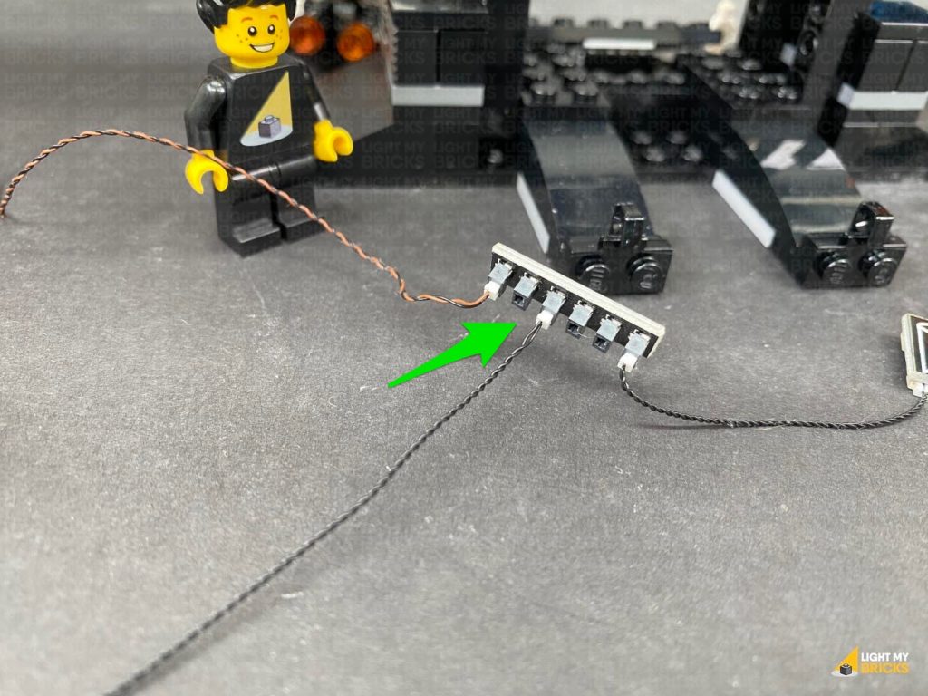
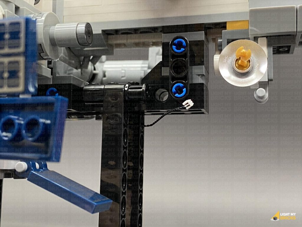
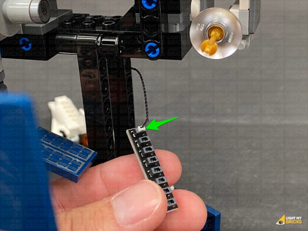
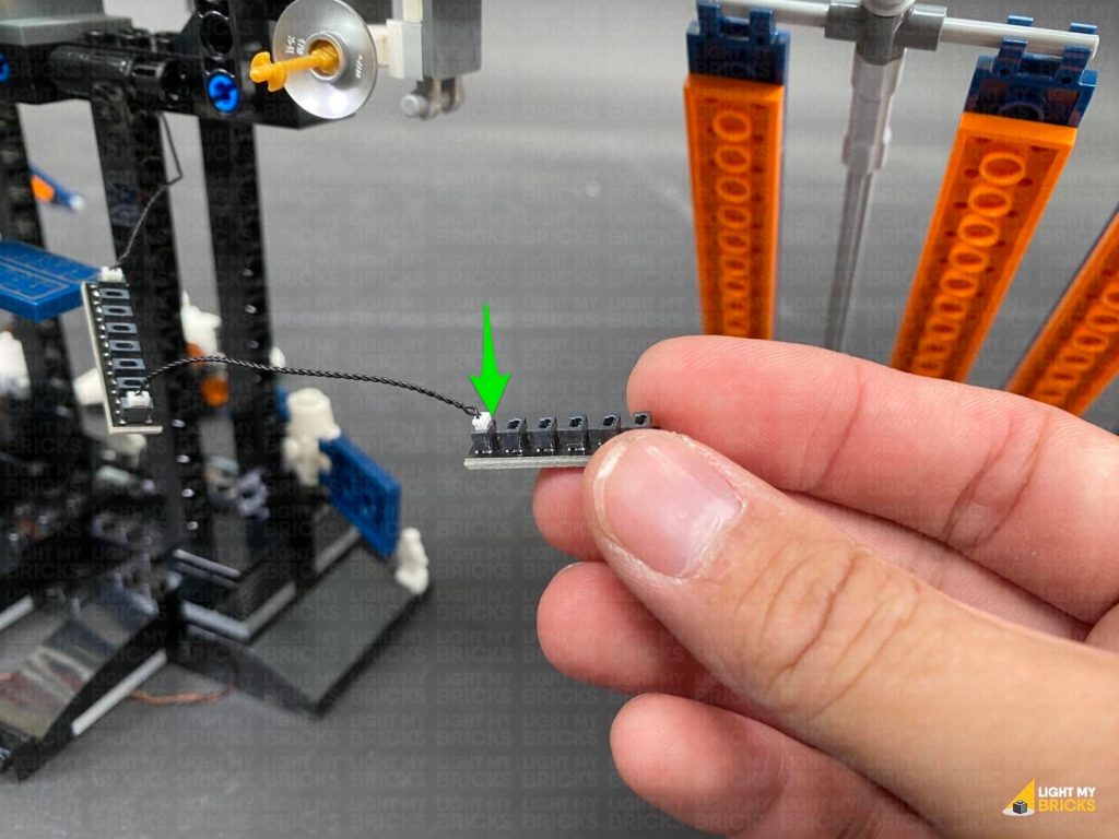
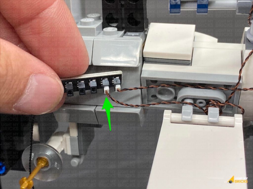
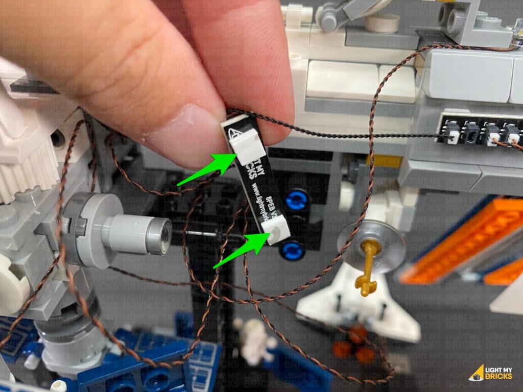
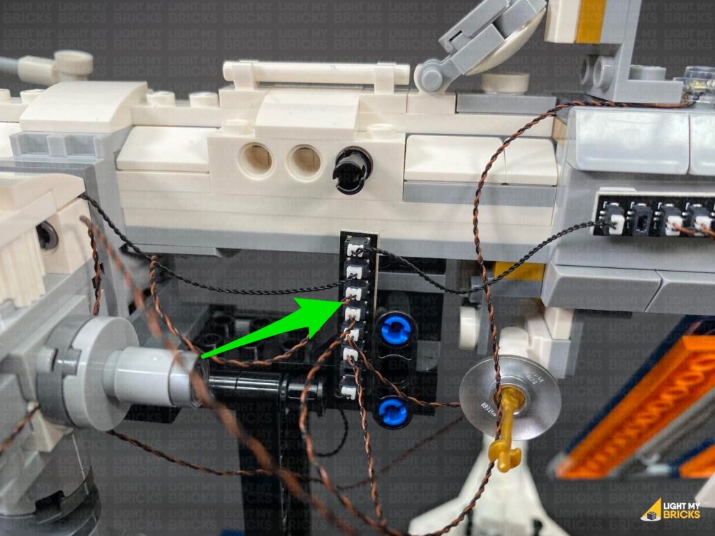
Take extra care when inserting connectors to ports of Expansion Boards. Connectors can be inserted only one way. With the expansion board facing up, look for the soldered “=” symbol on the left side of the port. The connector side with the wires exposed should be facing toward the soldered “=” symbol as you insert into the port. If a plug won’t fit easily into a port connector, do not force it.
Connecting cable connectors to Strip Lights
Take extra care when inserting connectors to ports on the Strip Lights. Connectors can be inserted only one way. With the Strip Light facing up, ensure the side of the connector with the wires exposed is facing down. If a plug won’t fit easily into a port connector, don’t force it. Doing so will damage the plug and the connector.
Connecting Micro Cable connectors to Micro Expansion Board Ports
Take extra care when inserting the micro connectors to micro ports of Micro Expansion Boards. Connecting Micro Bit Lights to Micro Expansion Boards is similar to connecting lights and cables to Strip Lights. With the expansion board facing up, ensure the side of the connector with the wires exposed is facing down. If a plug won’t fit easily into a port connector, do not force it. Use your fingernail to push the plastic part of the connector to the micro port.
Installing Bit Lights under LEGO® bricks and plates.
When installing Bit Lights under LEGO® pieces, ensure they are placed the correct way up (Yellow LED component exposed). You can either place them directly on top of LEGO® studs or in between.
OK, Let’s Begin!
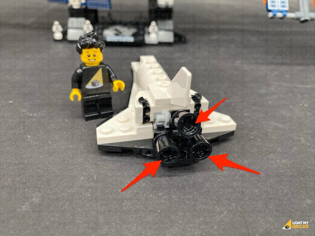
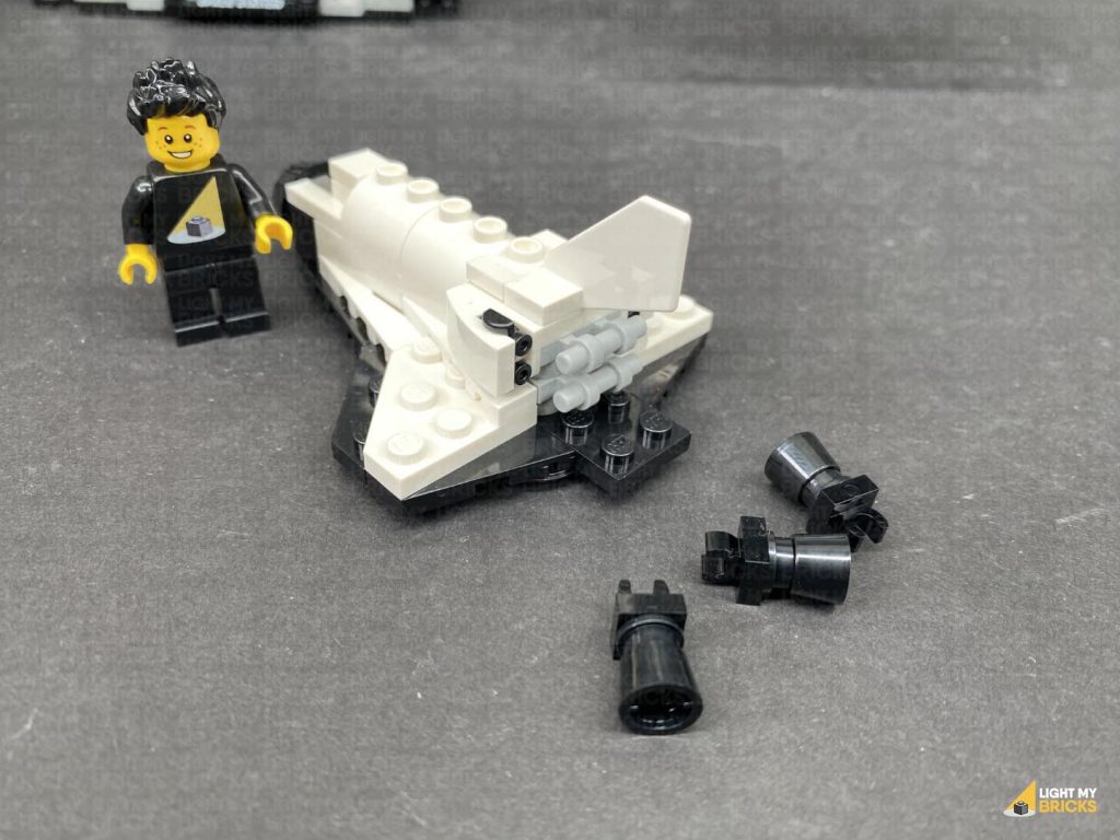
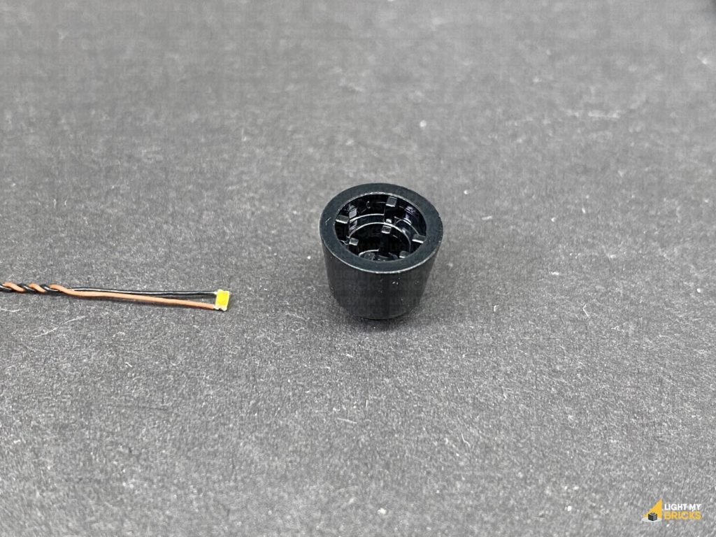
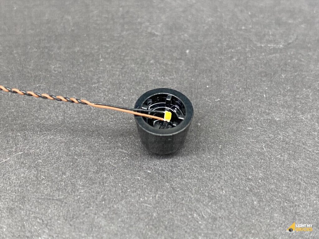
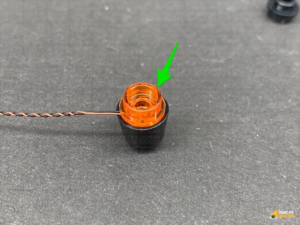
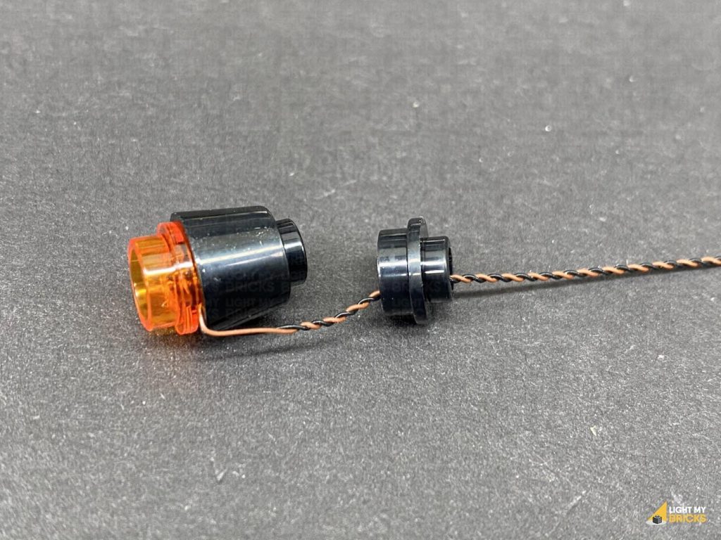
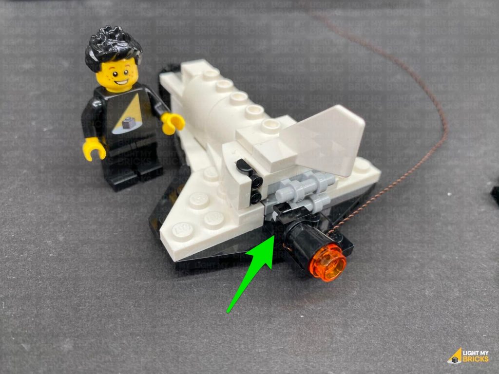
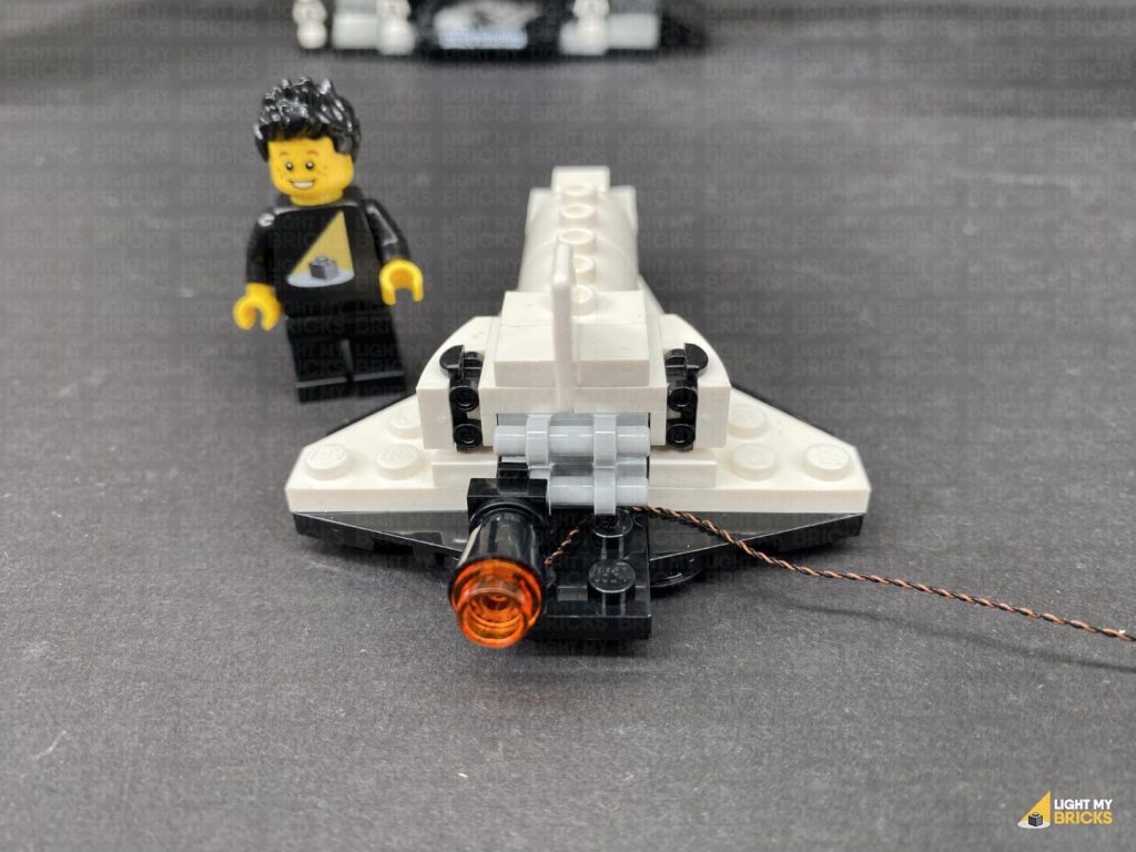
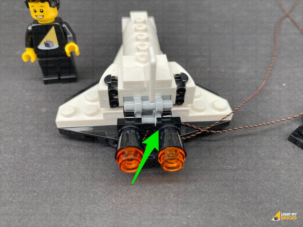
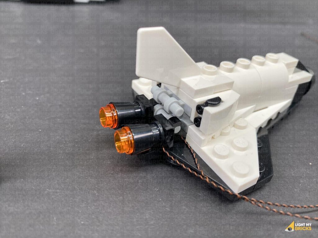
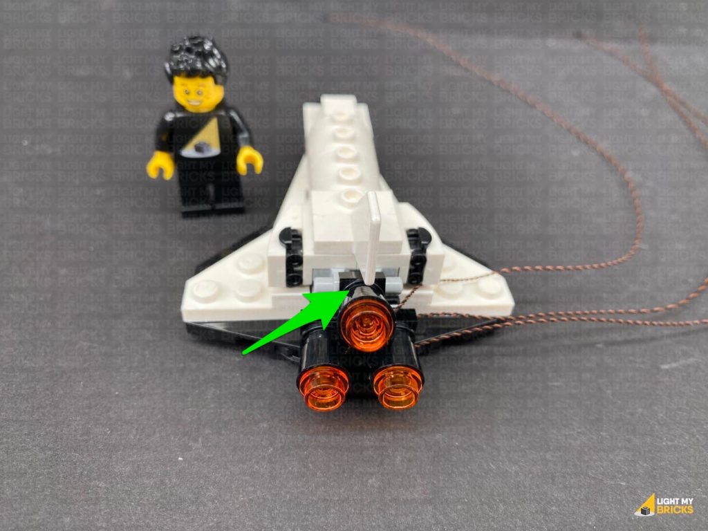
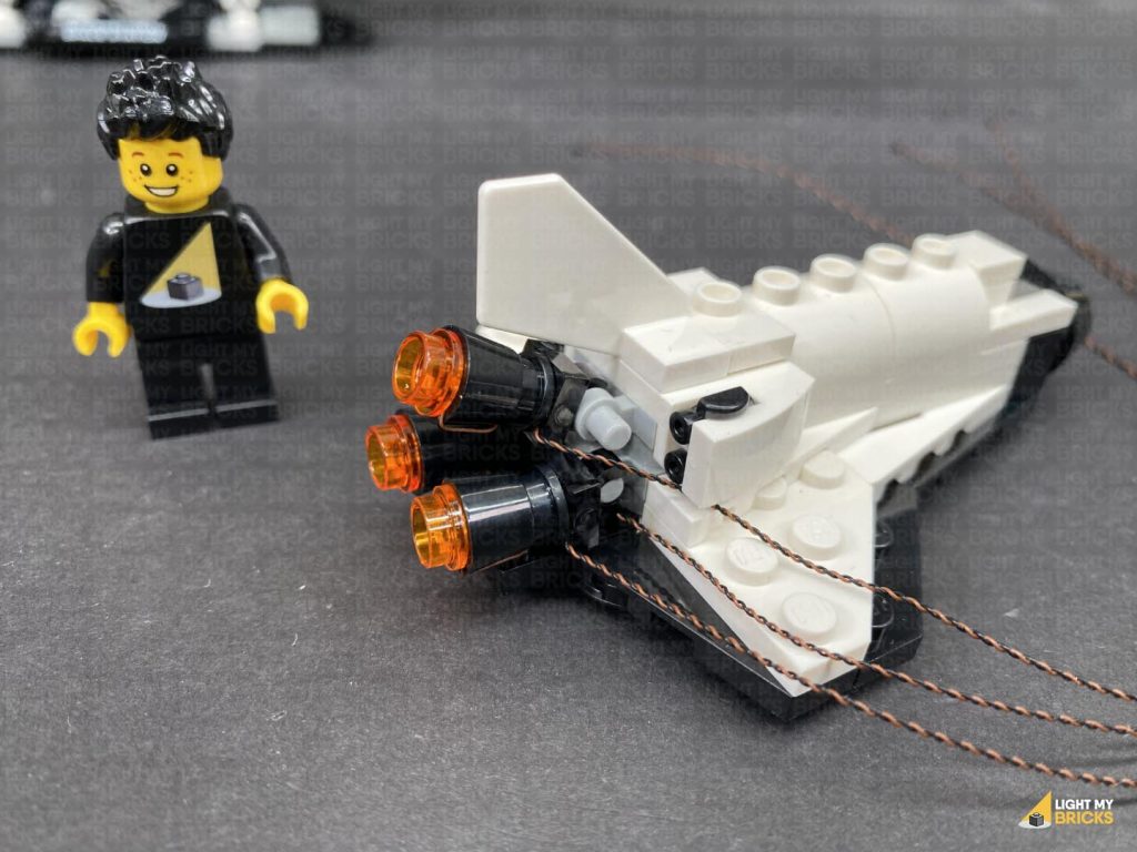
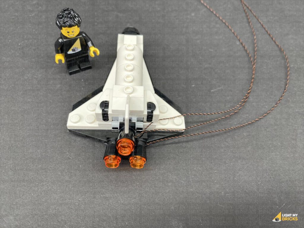
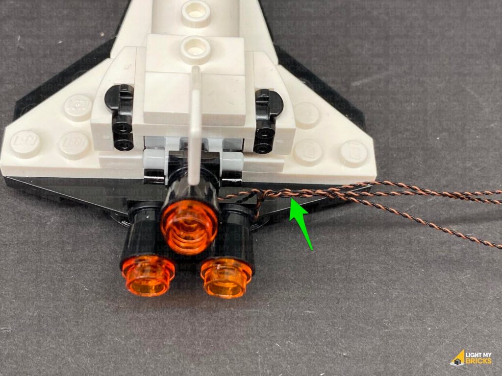
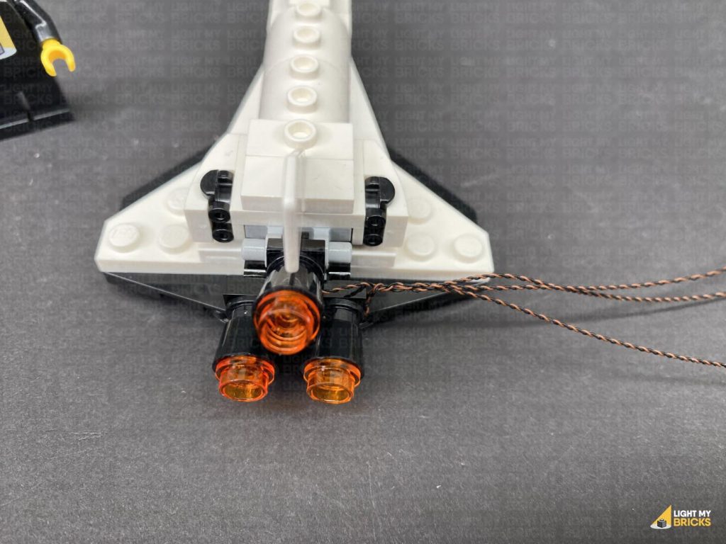
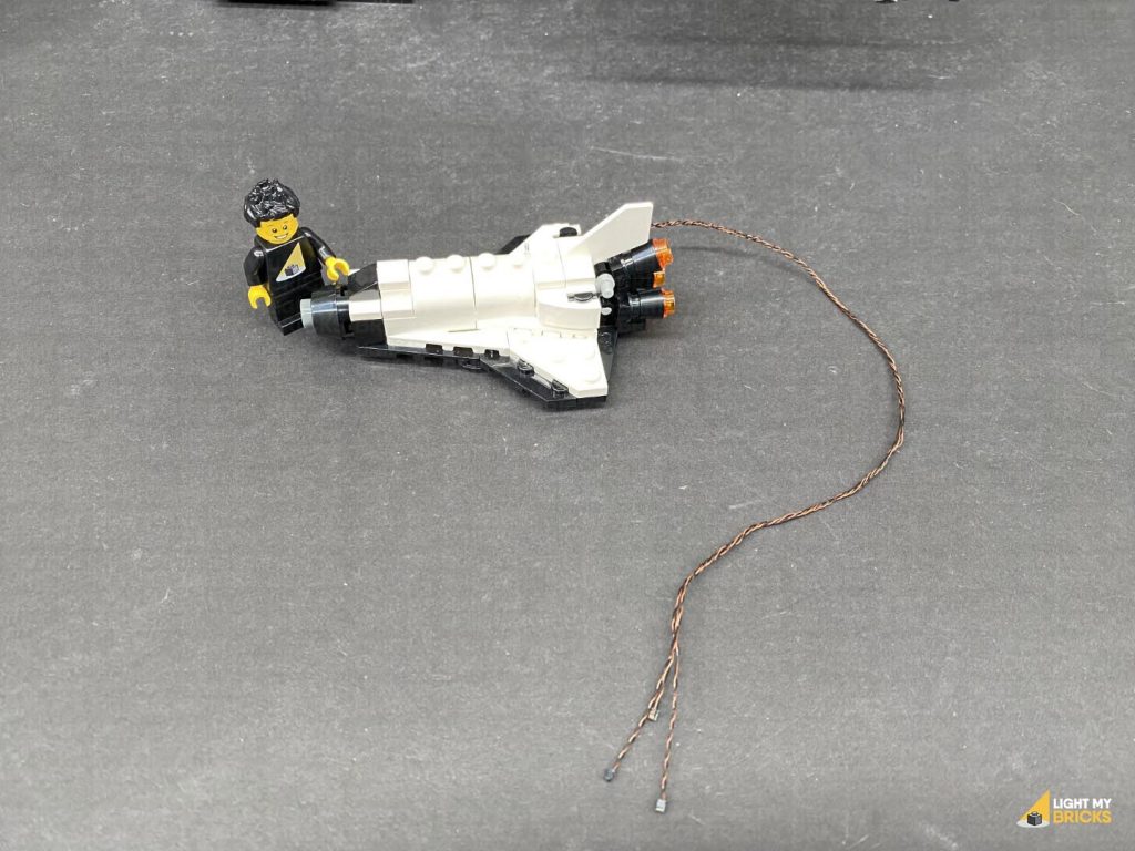
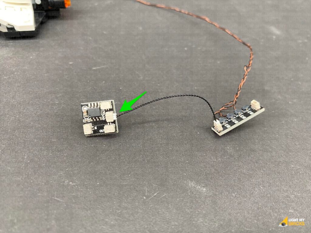
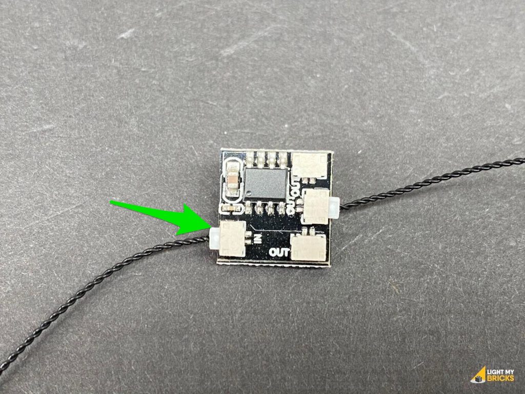
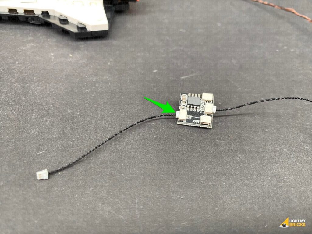
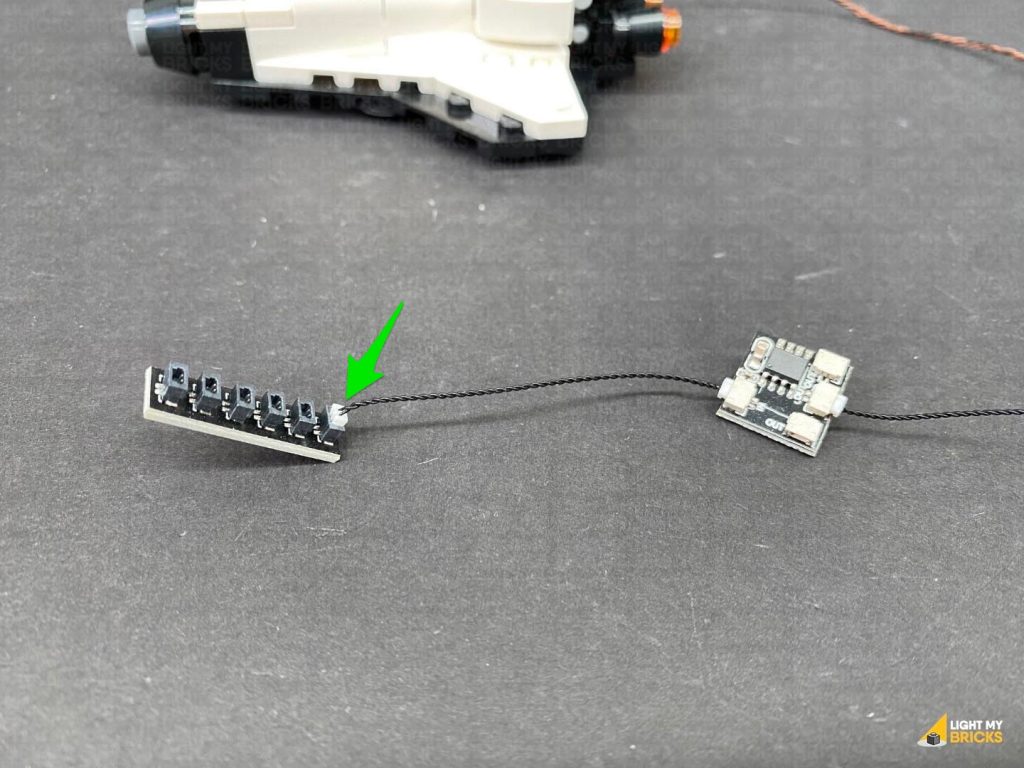
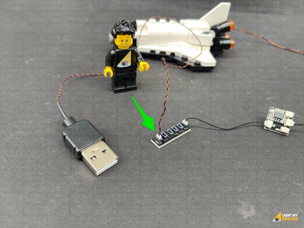
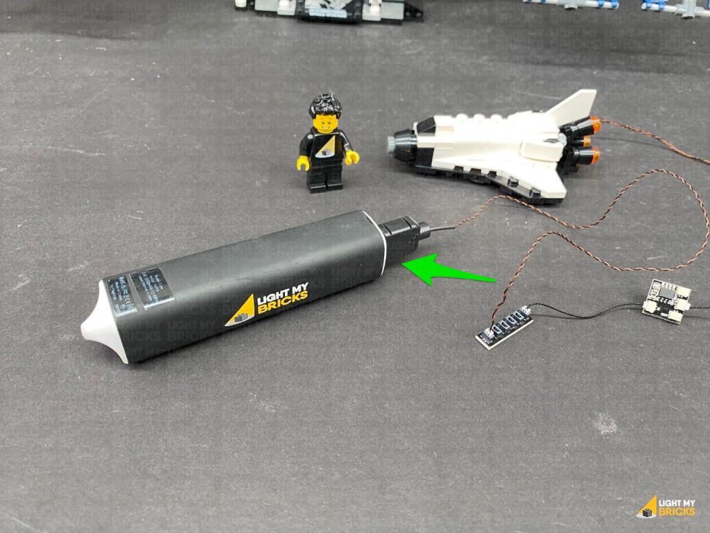
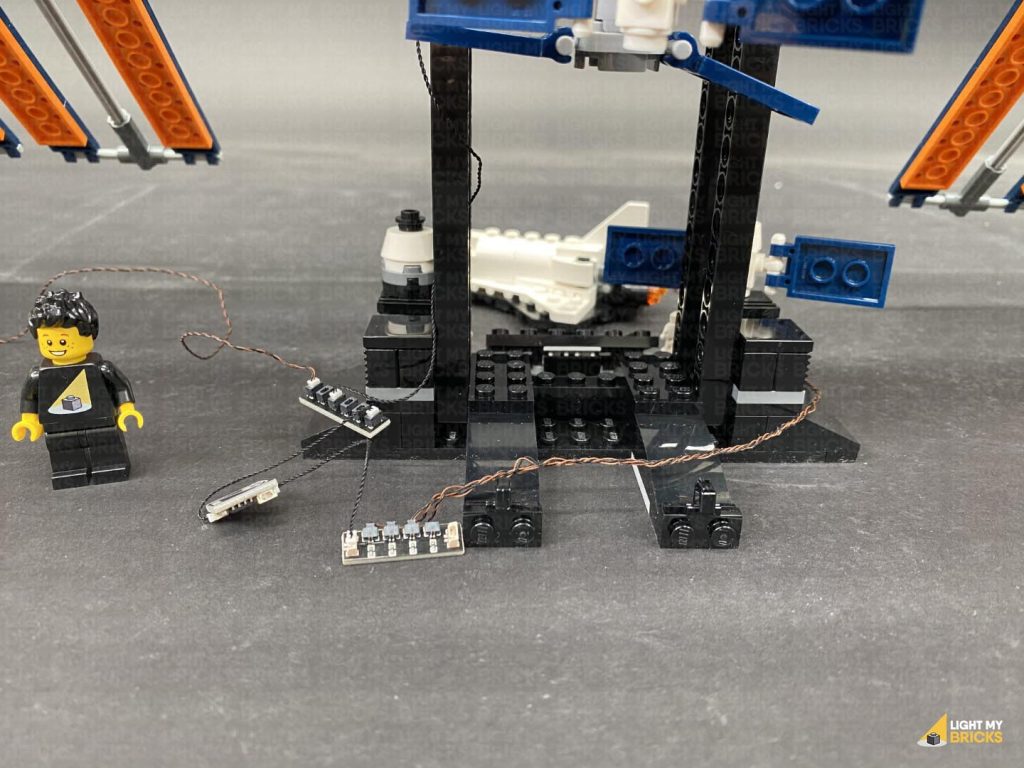
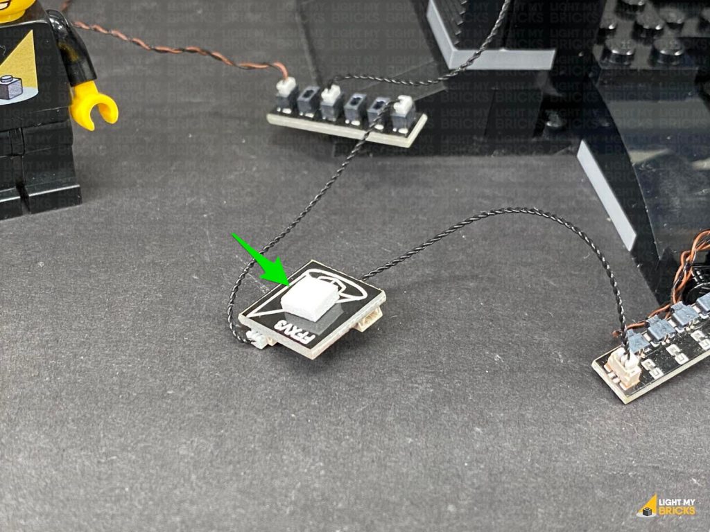
1.) We will first light up the space shuttle. Disconnect and disassemble the three jet pieces from the shuttle as shown below: Take out a White 30cm Micro Bit Light and with the LED facing up, place it inside one of the black rounded bricks. Secure the light by connecting a provided Trans Orange Round Plate 1×1 over the top. Thread the connector end of the cable through the bottom of the black round plate with open stud, then reconnect this along with the clip tile to the back as shown below: Reconnect this section to the back of the shuttle ensuring the cable is facing the same way as shown in the below images. 2.) Repeat the previous step to install another 2x White 30cm Micro Bit Lights to the two other jet sections (using the provided Trans Orange Round Plate 1×1 to secure the lights in place). Reconnect each jet section to the back of the shuttle with the cable facing the same way. 3.) Group the three cables together toward the shuttle and twist them around each other a few times. Continue to twist the cables around each other all the way to the end to form one larger cable. Connect the three Micro Bit Lights to the Micro 2-4 Port Expansion Board (smaller ports). 4.) Connect a 5cm Connecting Cable to the larger port on this expansion board, then connect the other end of the cable to one of the OUT ports on the Flicker Effects Board Connect another 5cm Connecting Cable to the IN port on the Flicker Effects Board, then connect the other end of this cable to a 6-Port Expansion Board. Connect the USB Power Cable to the 6-Port Expansion Board, then connect the other end of the USB cable to your USB Power Bank or wall adaptor (sold separately) to test the space shuttle lights are working OK with the flickering effect.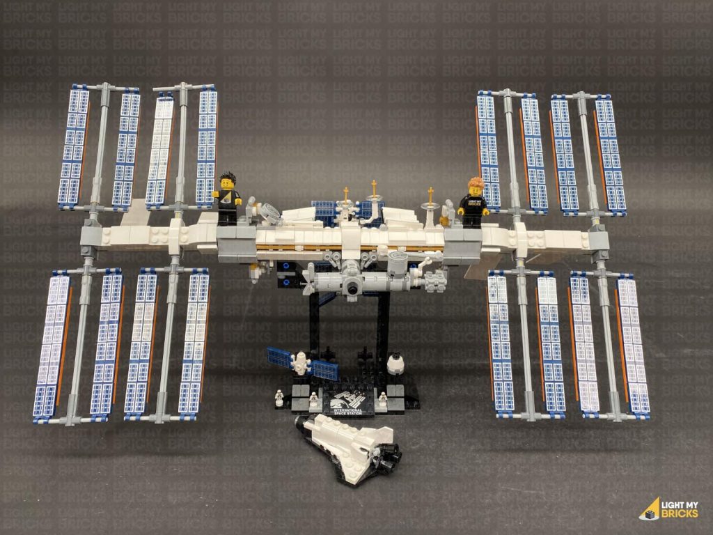
 Note: If you experience any issues with the lights not working and suspect an issue with a component, please try a different port on the expansion board to verify where the fault lies (with the light, expansion board or effects board). To correct any issues with expansion board ports, please view the section addressing expansion board issues on our online troubleshooting guide.
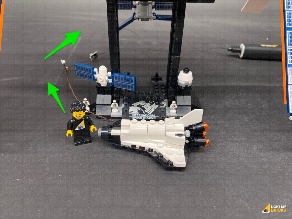
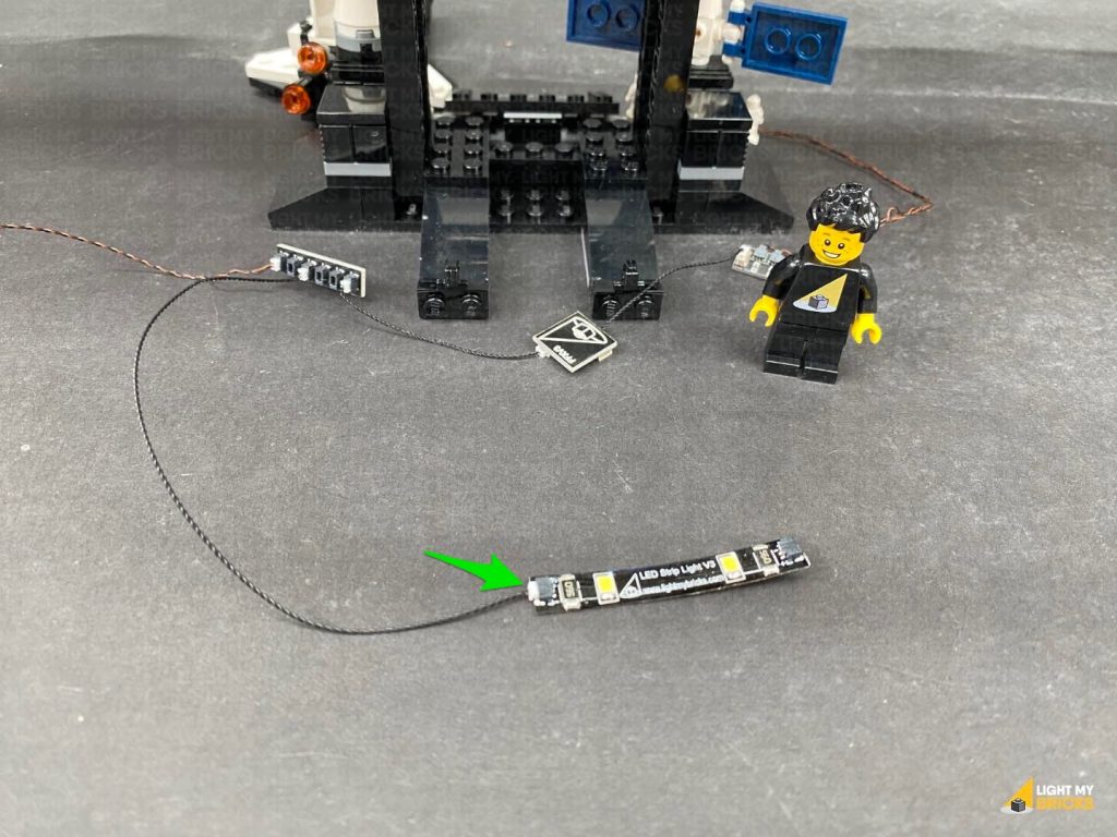
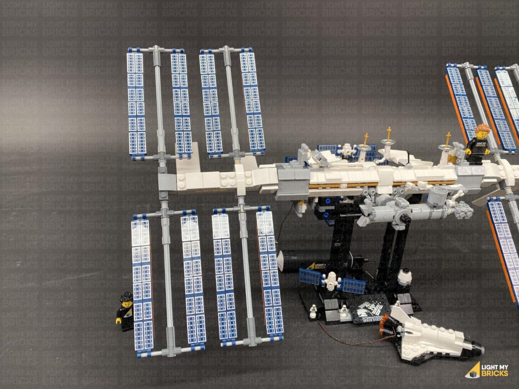
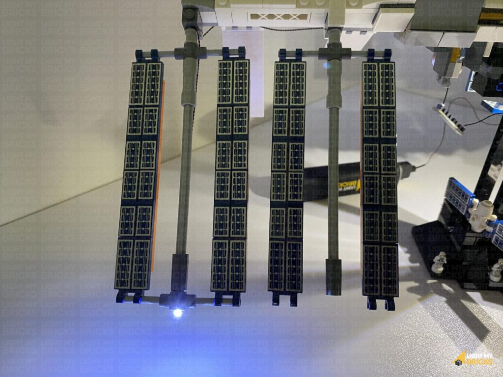
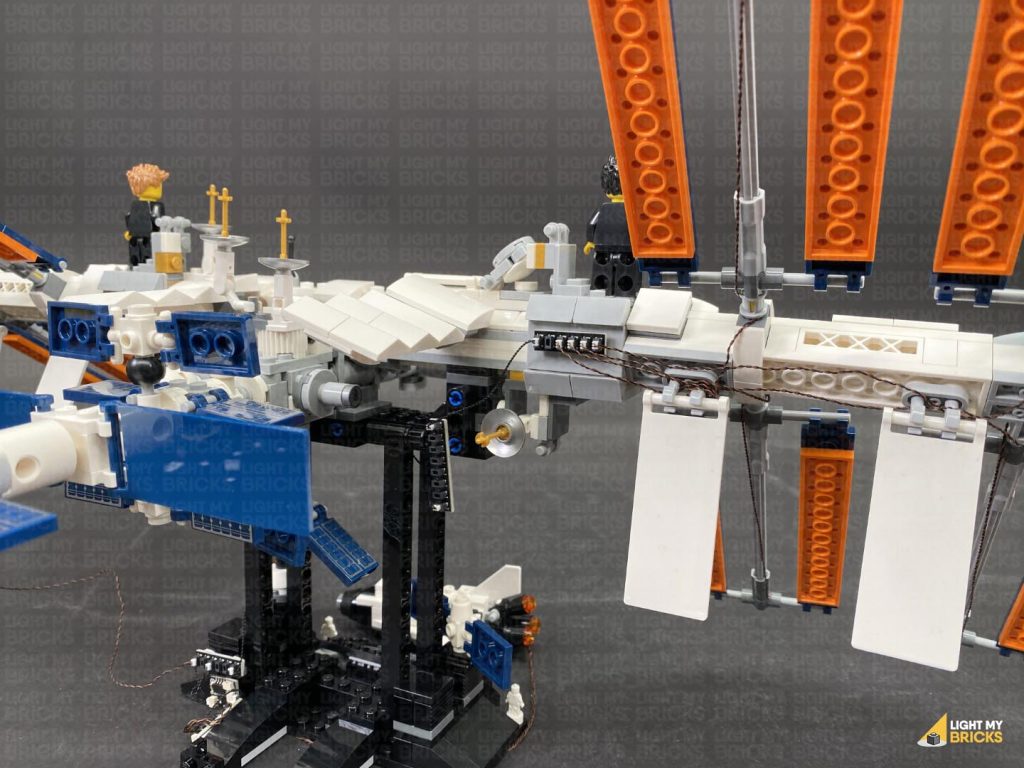
5.) Place the Space Shuttle in front of the space station set and bring the cables and components around the left side of the stand. Turn the set around and connect a 15cm Connecting Cable to the 6-Port Expansion Board. Connect the other end of the cable to a White Strip Light
Note: If you experience any issues with the lights not working and suspect an issue with a component, please try a different port on the expansion board to verify where the fault lies (with the light, expansion board or effects board). To correct any issues with expansion board ports, please view the section addressing expansion board issues on our online troubleshooting guide.
5.) Place the Space Shuttle in front of the space station set and bring the cables and components around the left side of the stand. Turn the set around and connect a 15cm Connecting Cable to the 6-Port Expansion Board. Connect the other end of the cable to a White Strip Light
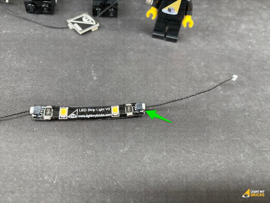
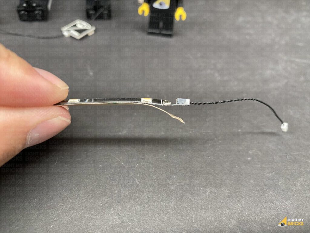
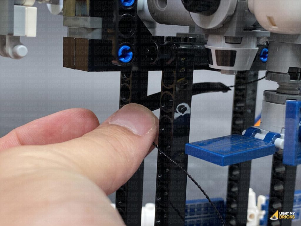
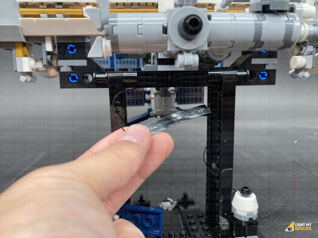
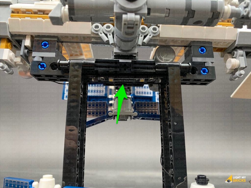
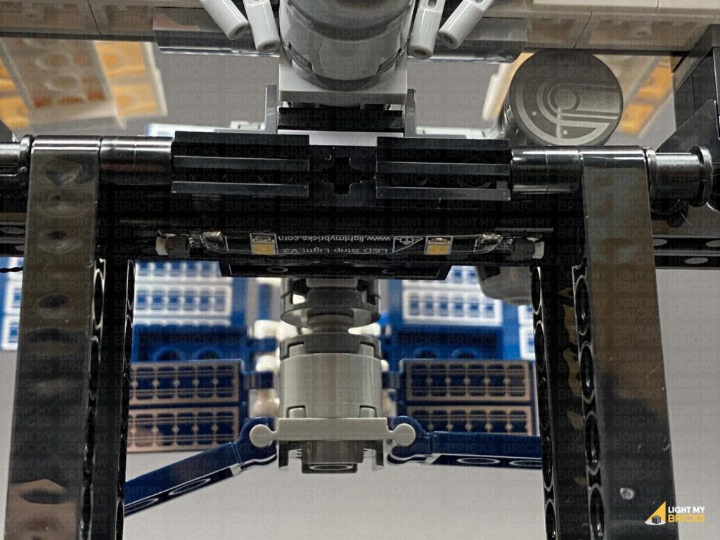
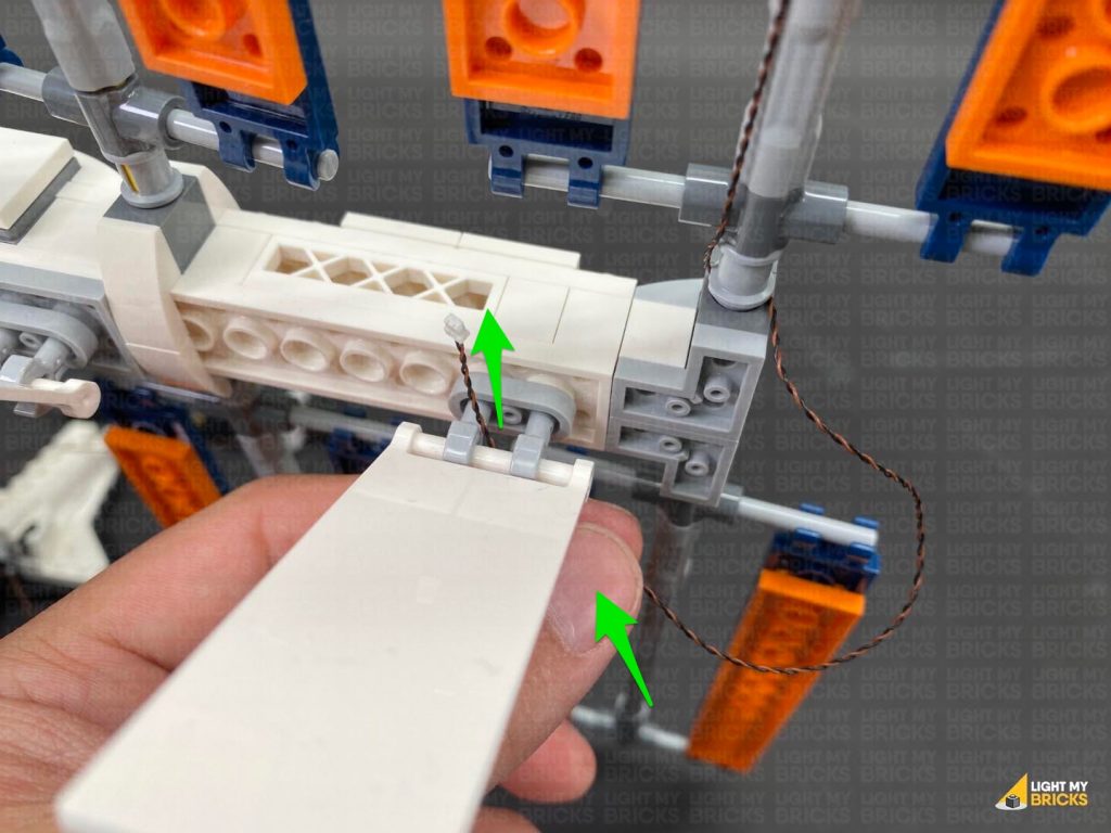
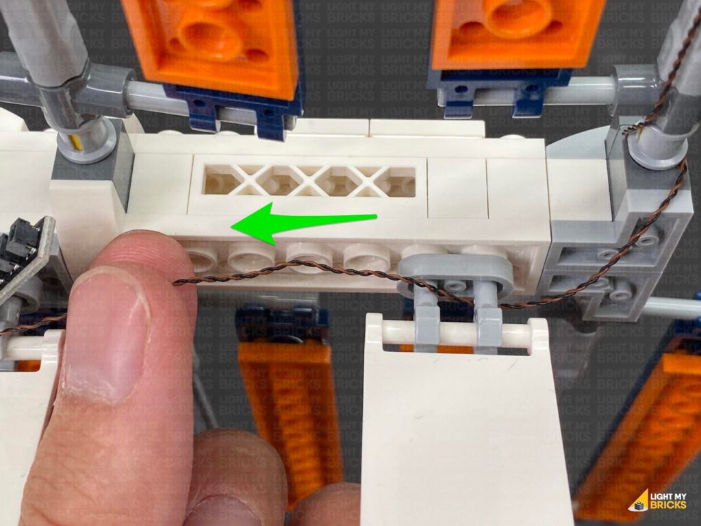
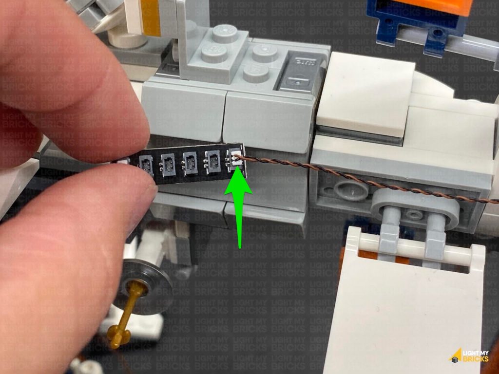
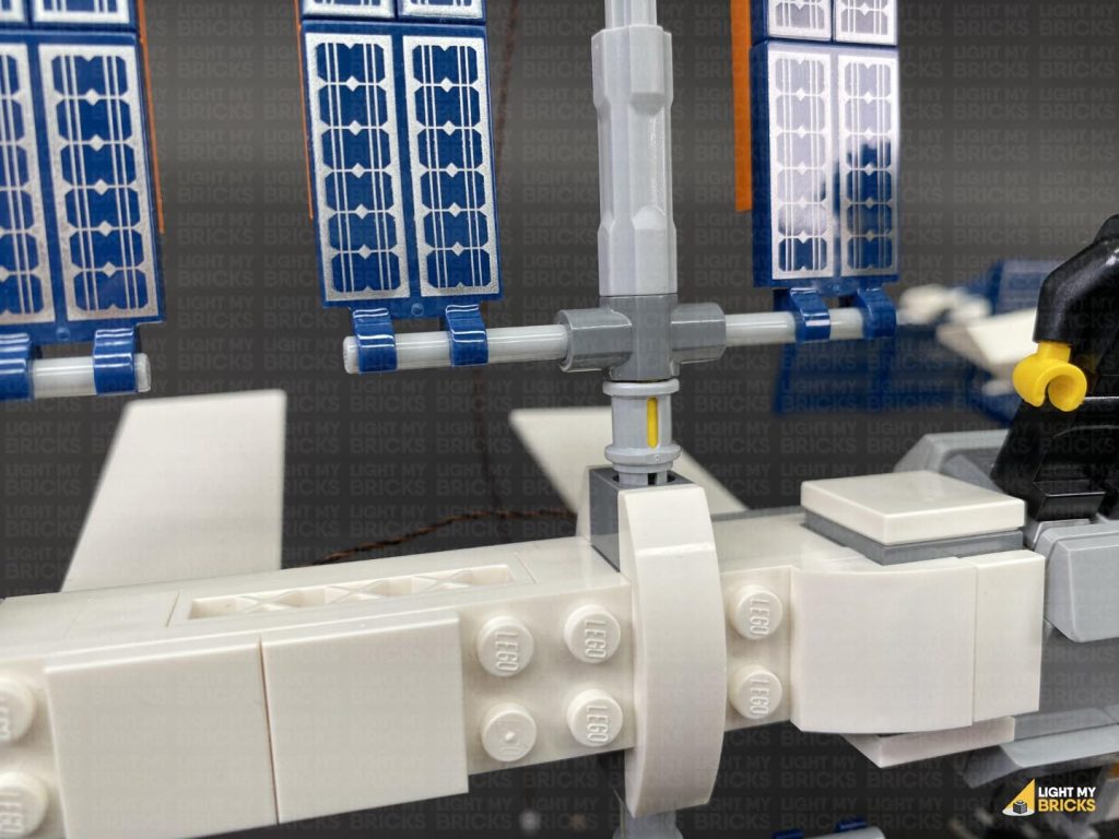
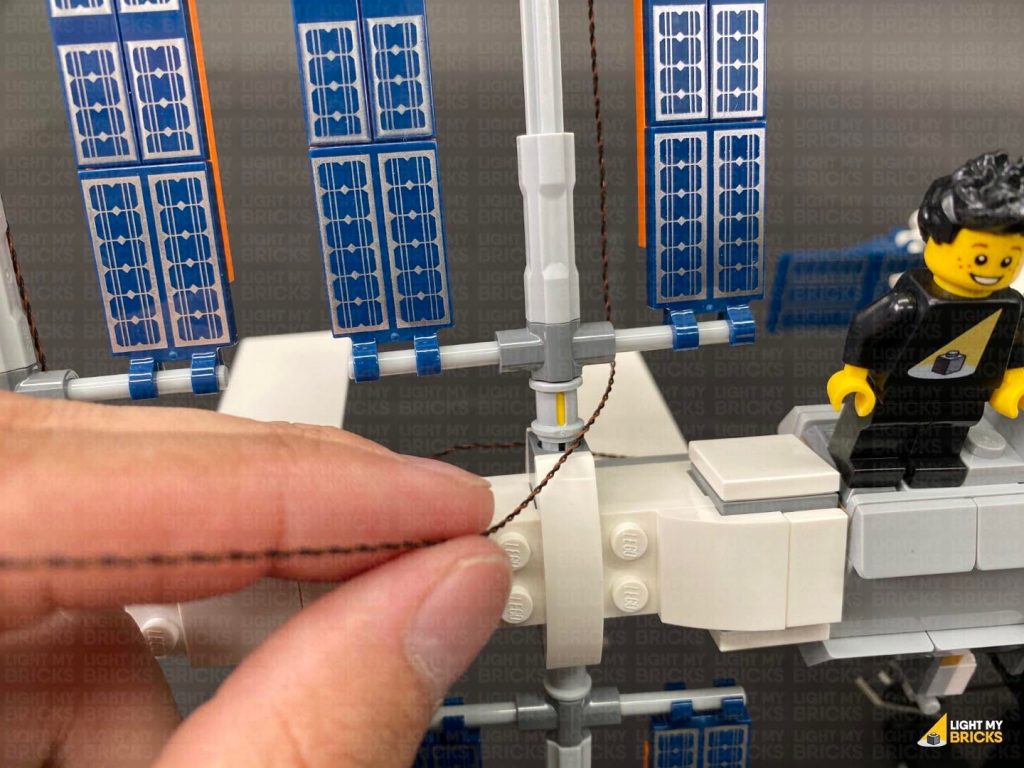
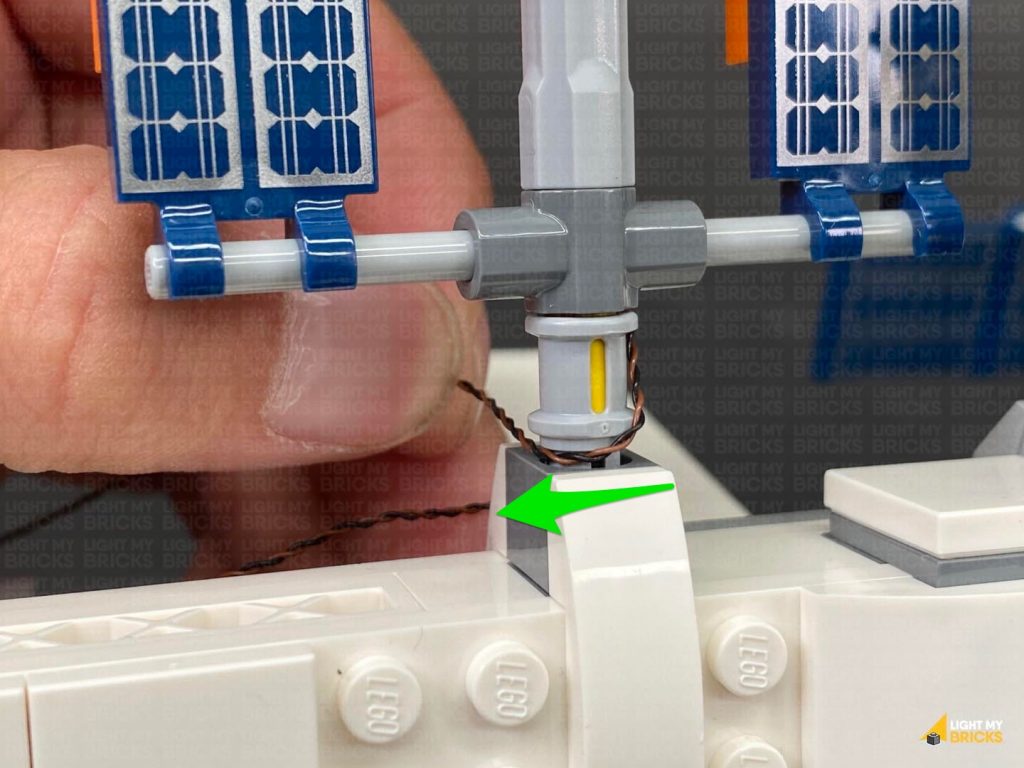
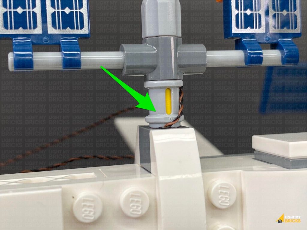
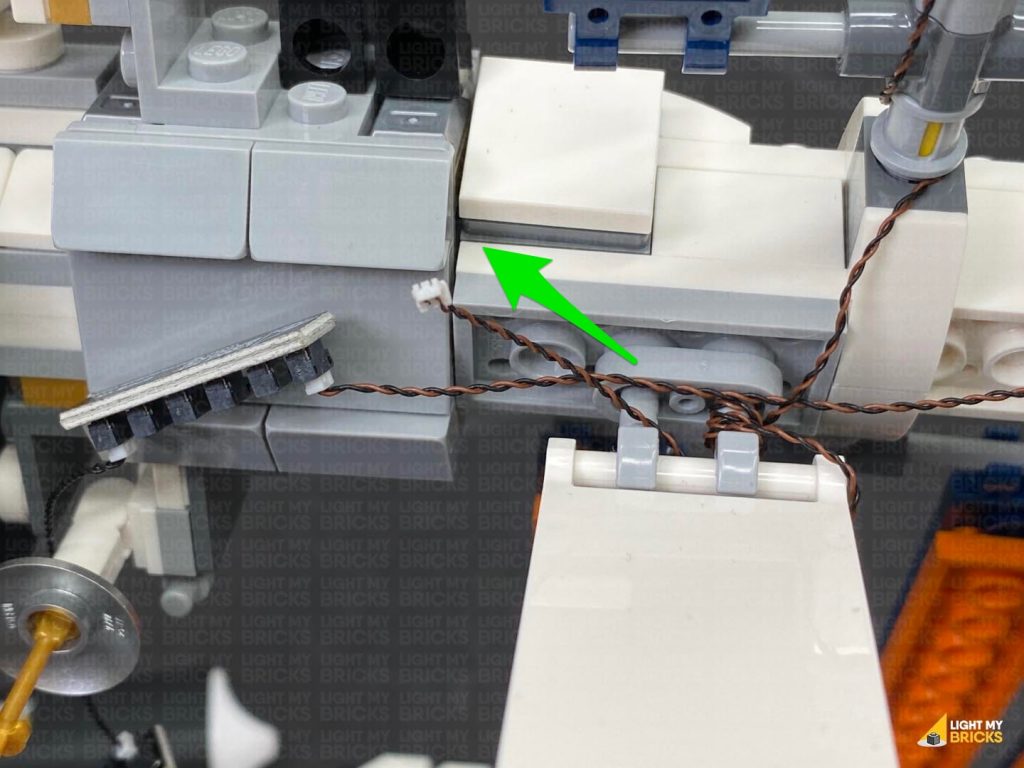
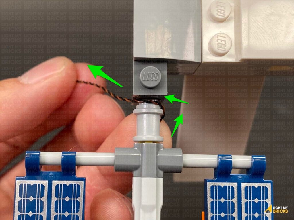
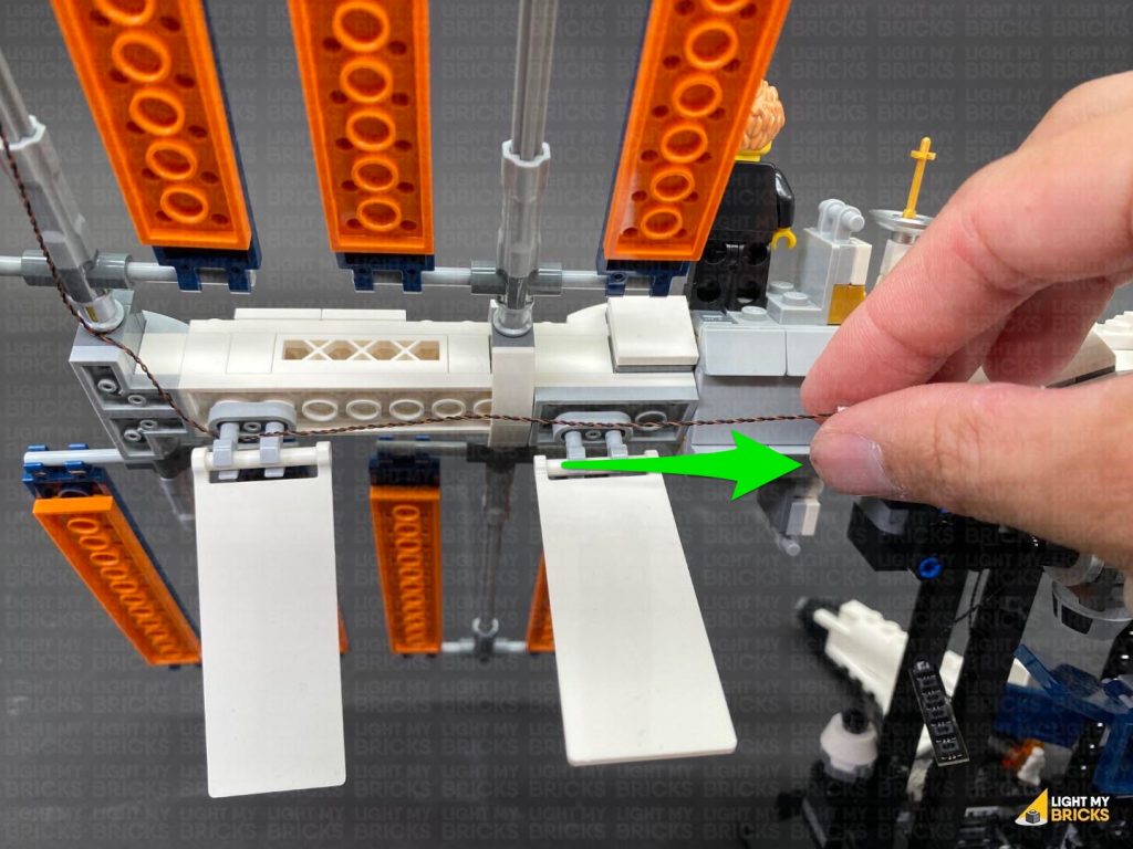
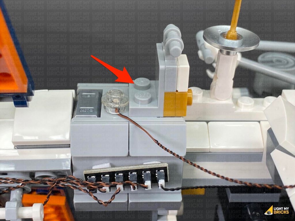
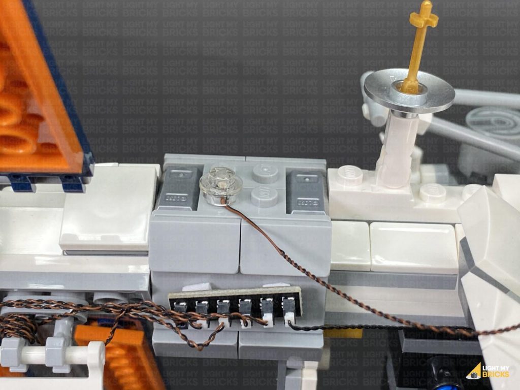
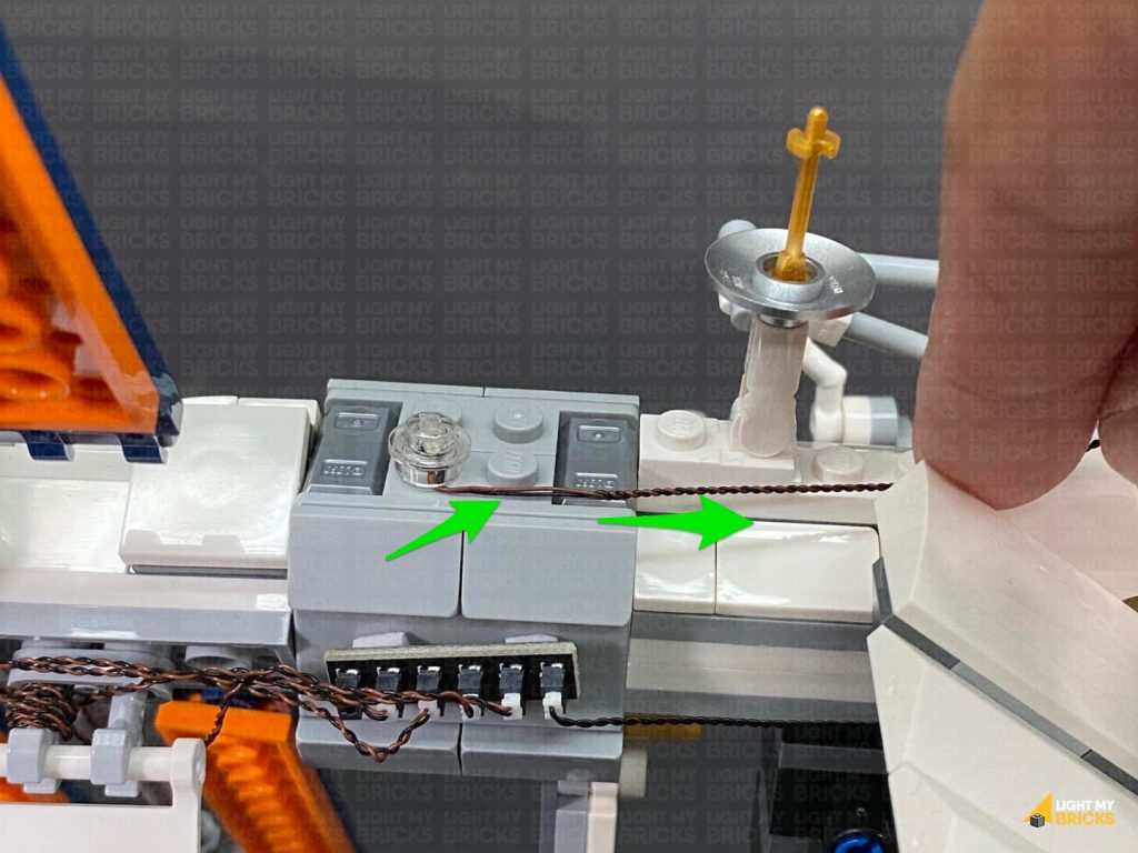
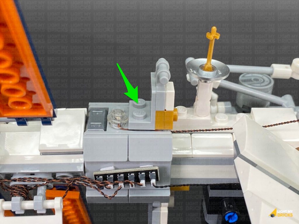
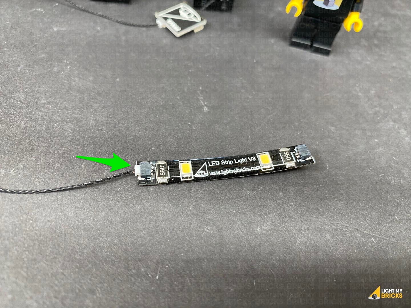 Connect a new 5cm Connecting Cable to the other end of the Strip Light, then peel off the adhesive backing protective paper on the back of the Strip Light.
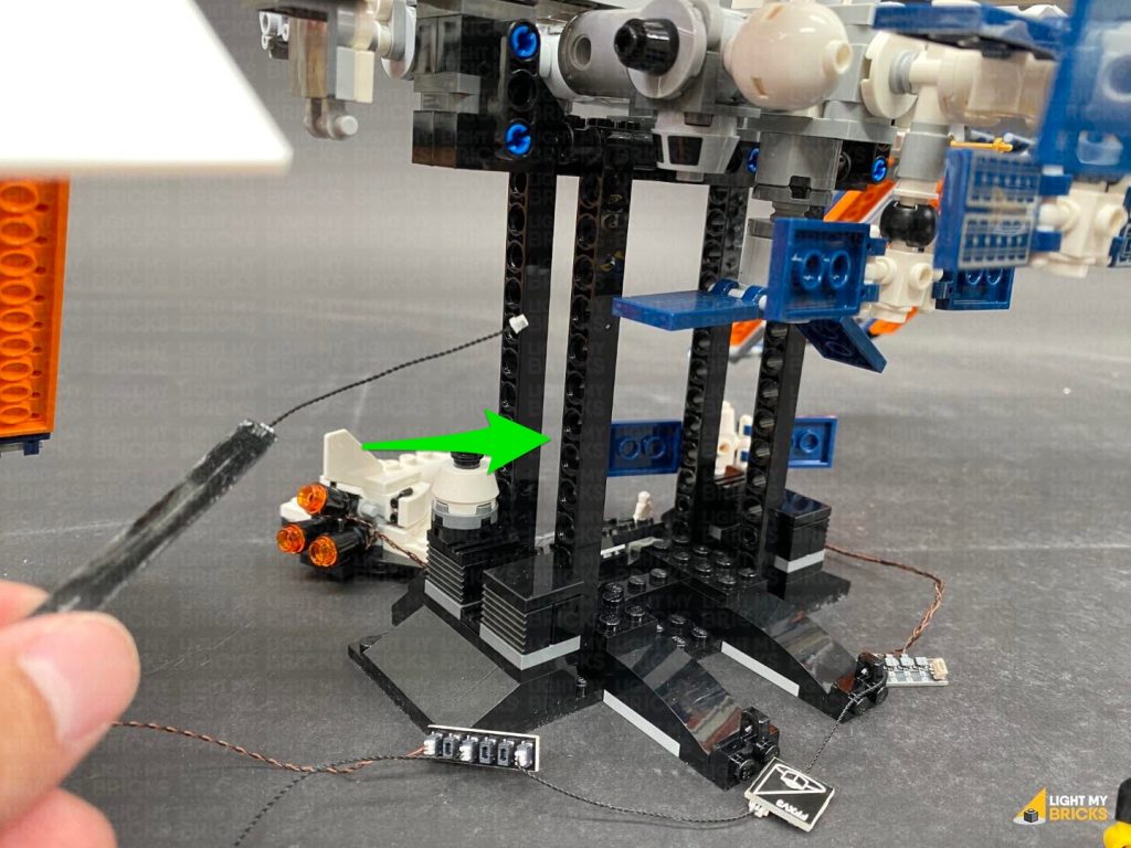
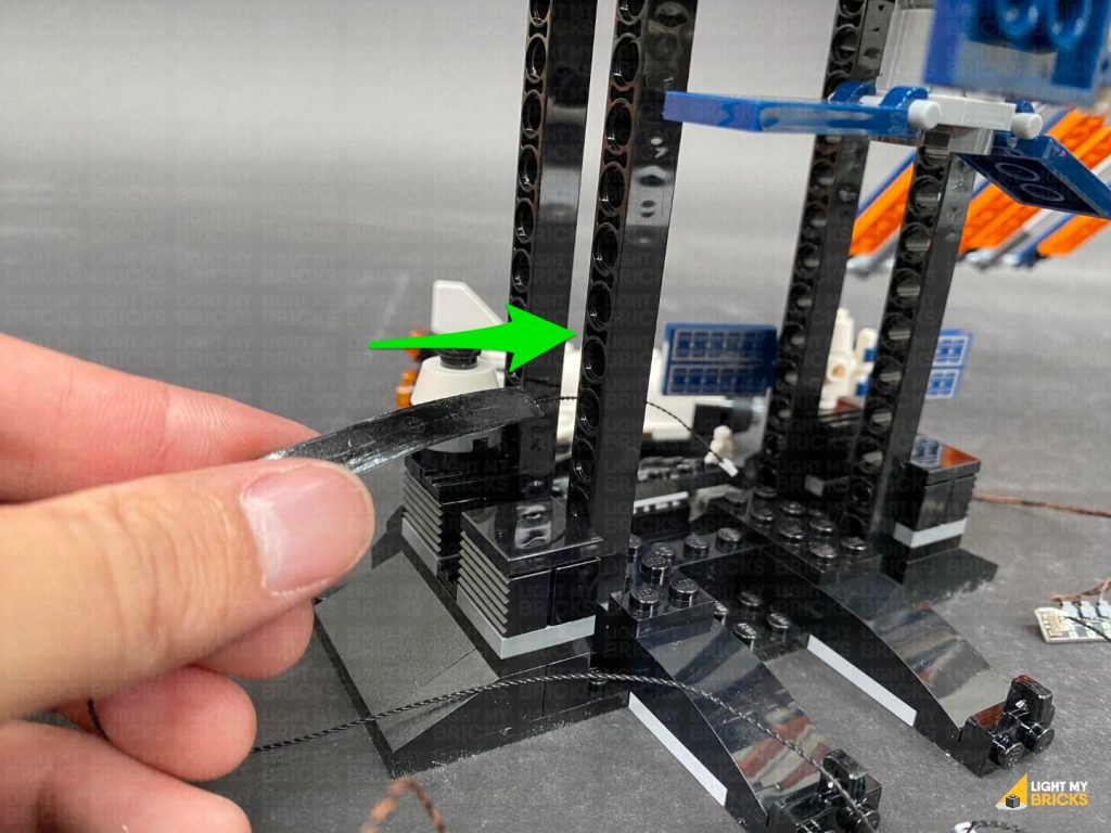
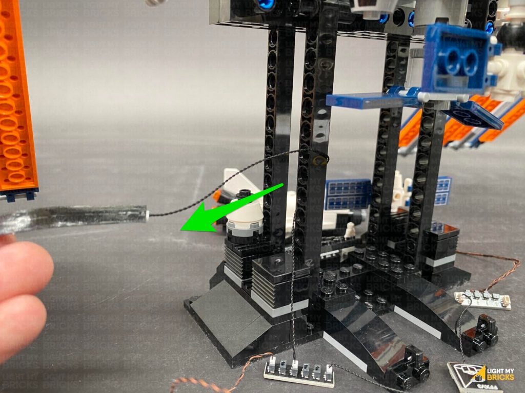
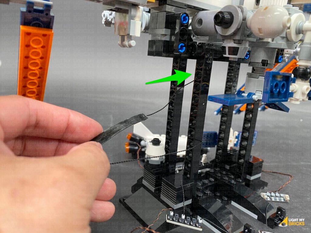
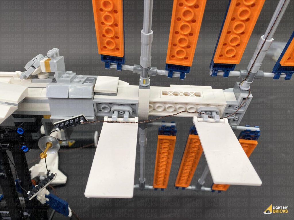
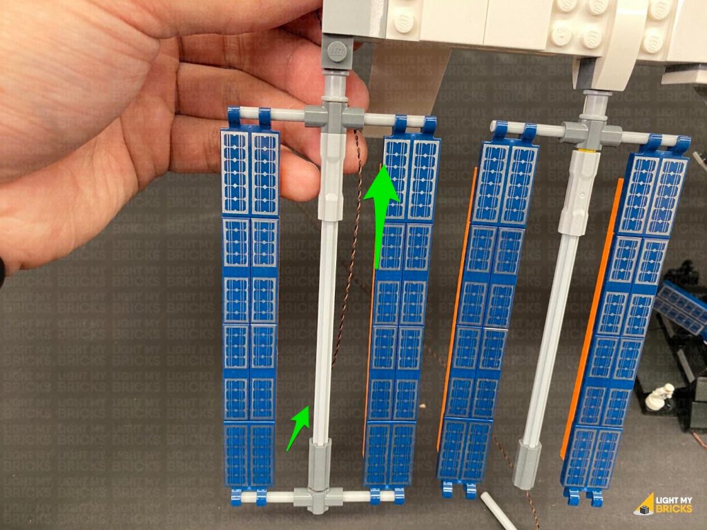
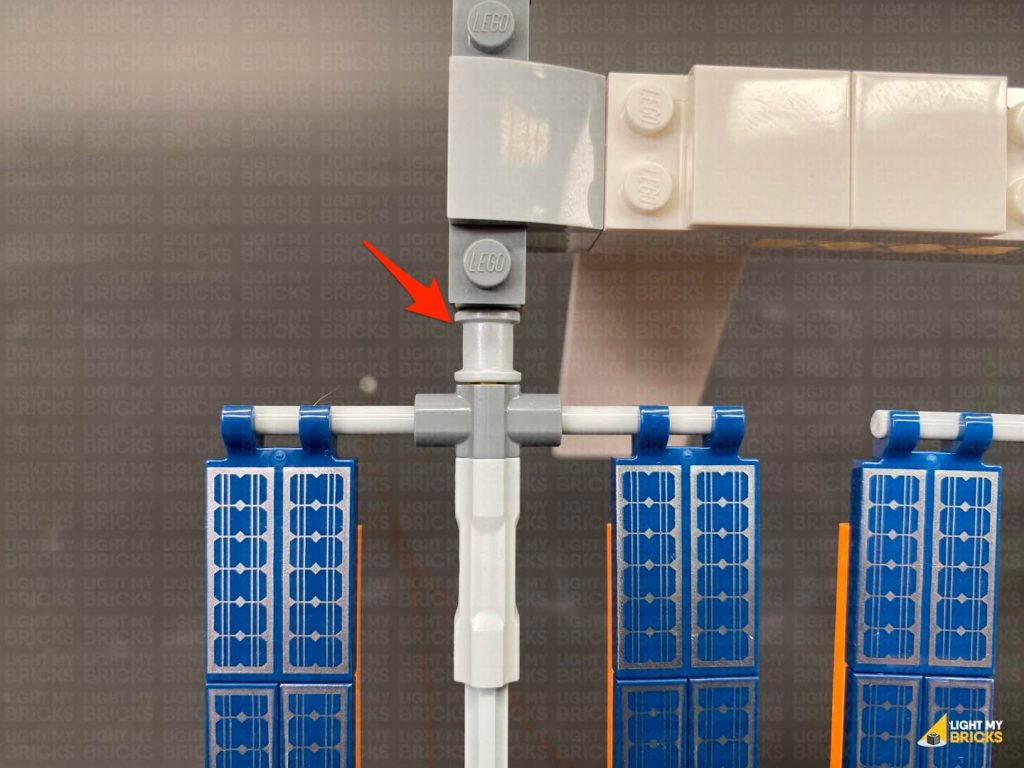
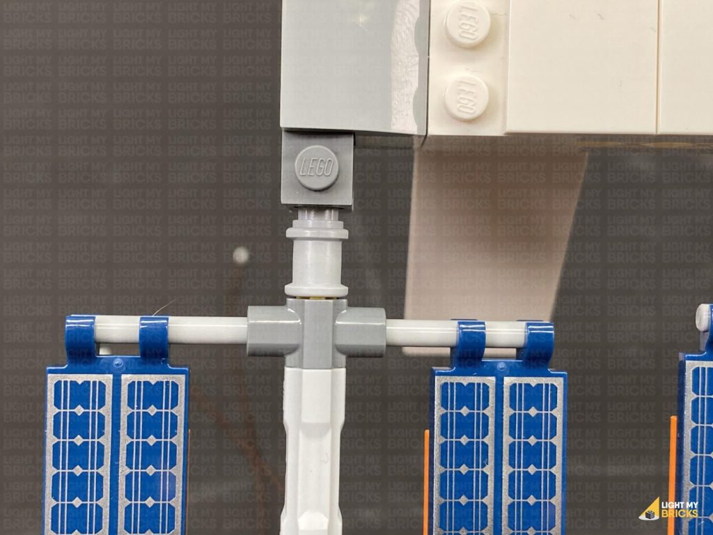
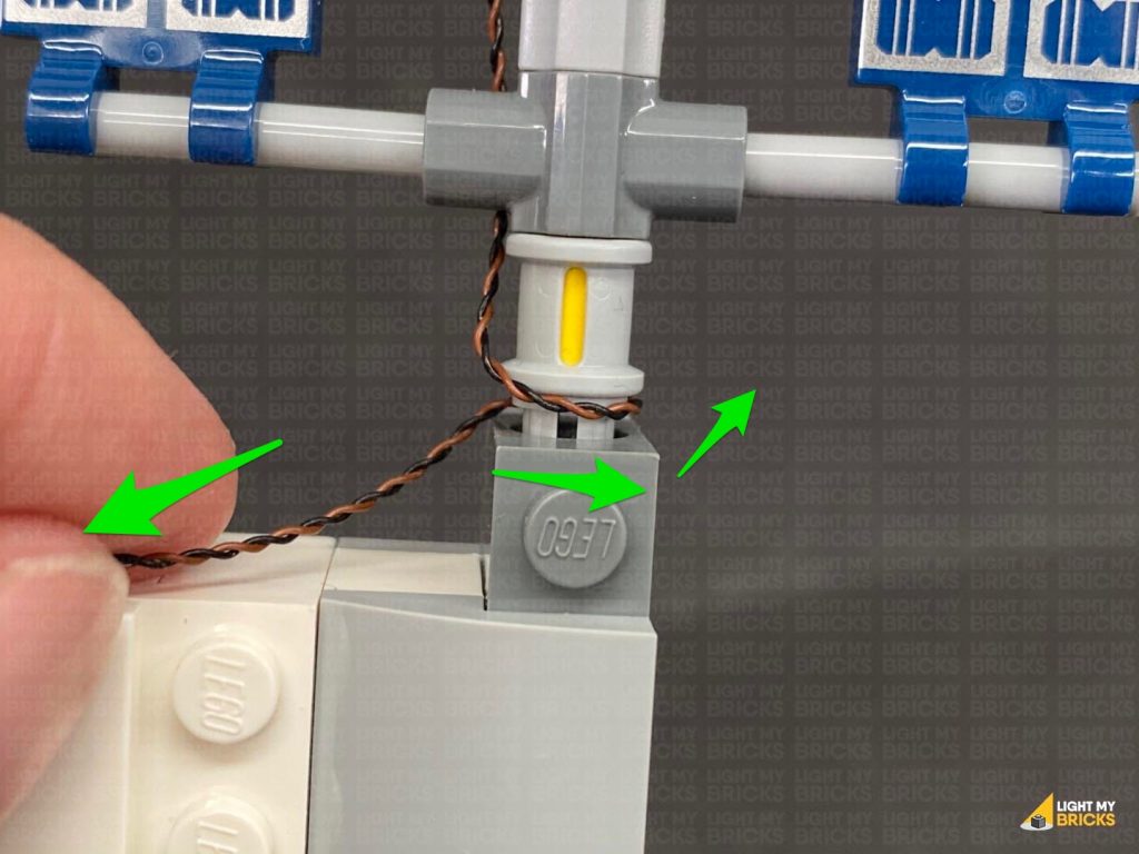
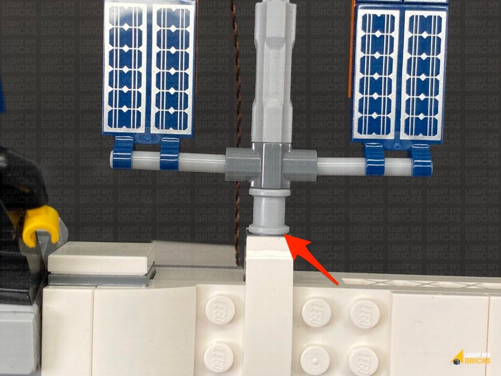
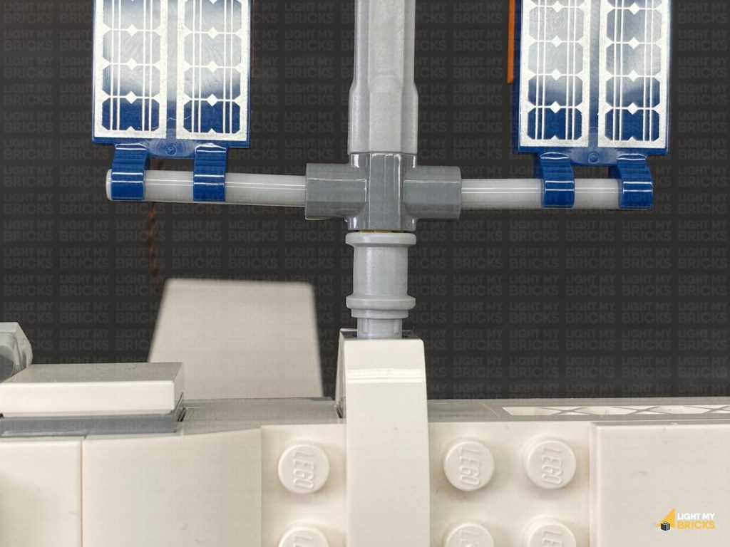
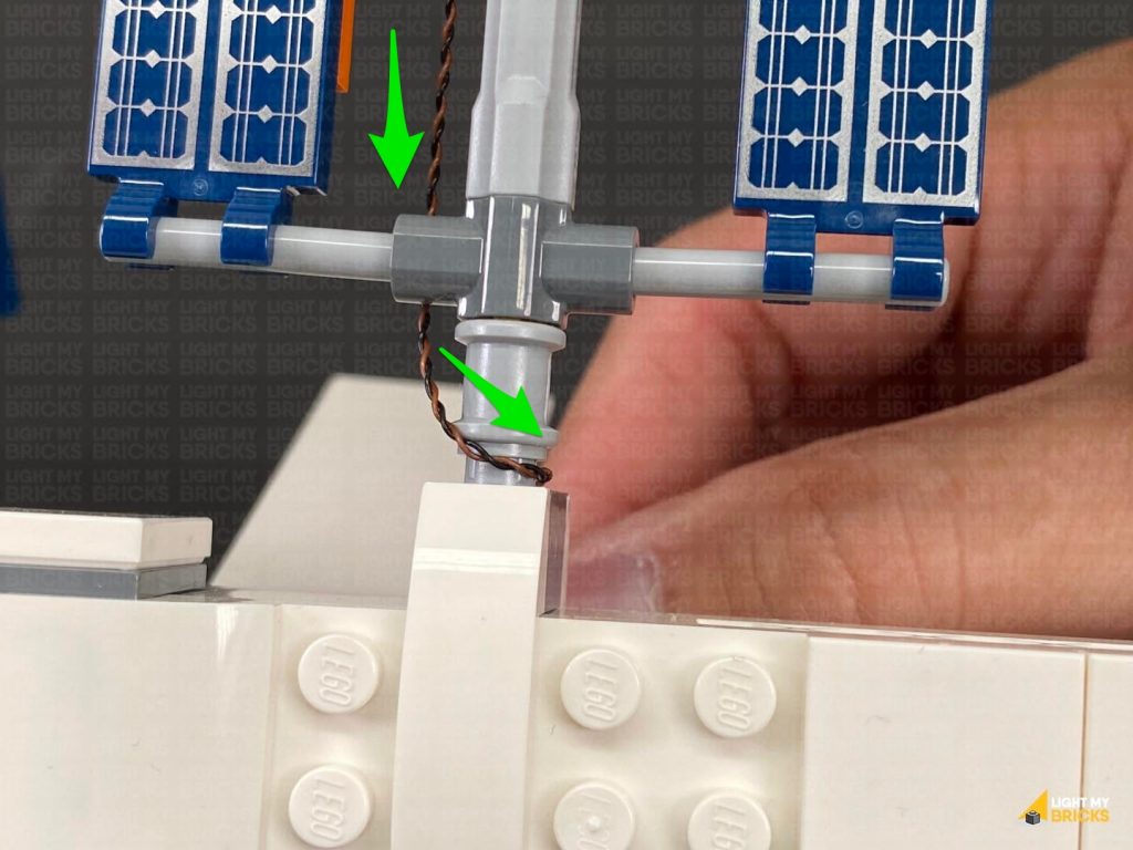
6.) Thread the strip light through in between the stand’s vertical technic stand pieces, then wind the cable around the back stand leg and thread it back through in between. Turn the set around to the front, then stick the Strip Light underneath the top of the stand in the below position.
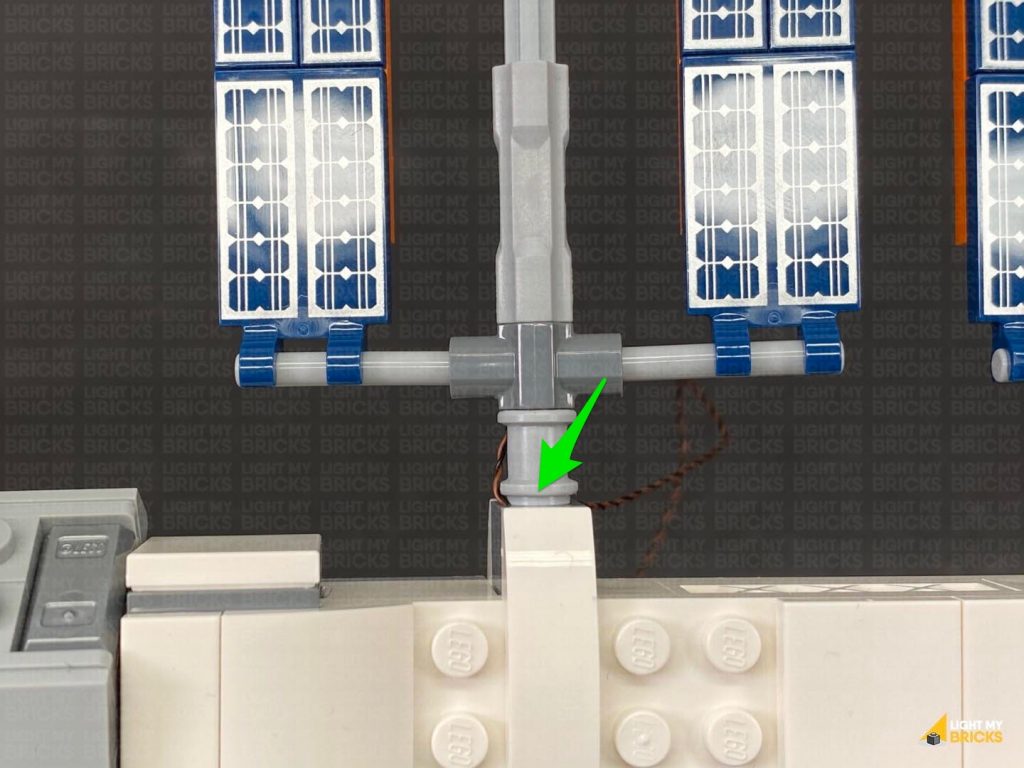
Turn the Power ON to test the strip light is working OK.
Connect a new 5cm Connecting Cable to the other end of the Strip Light, then peel off the adhesive backing protective paper on the back of the Strip Light.
6.) Thread the strip light through in between the stand’s vertical technic stand pieces, then wind the cable around the back stand leg and thread it back through in between. Turn the set around to the front, then stick the Strip Light underneath the top of the stand in the below position.
Turn the Power ON to test the strip light is working OK.
 Note: If you experience any issues with the lights not working and suspect an issue with a component, please try a different port on the expansion board to verify where the fault lies (with the light, expansion board or effects board). To correct any issues with expansion board ports, please view the section addressing expansion board issues on our online troubleshooting guide.
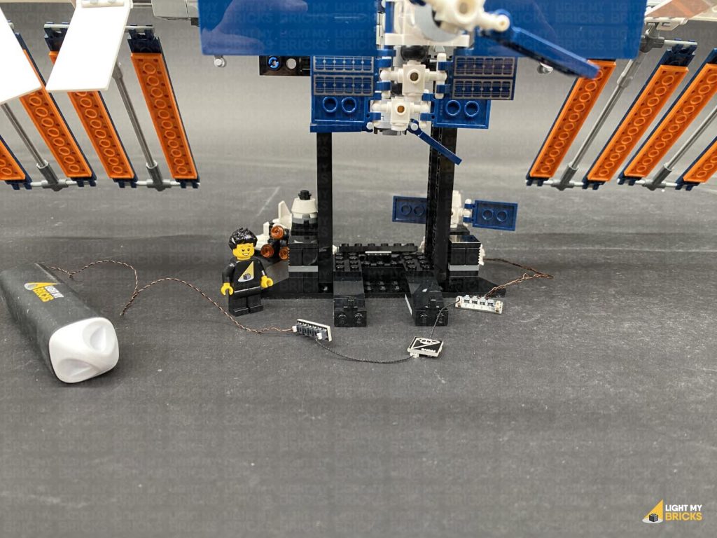
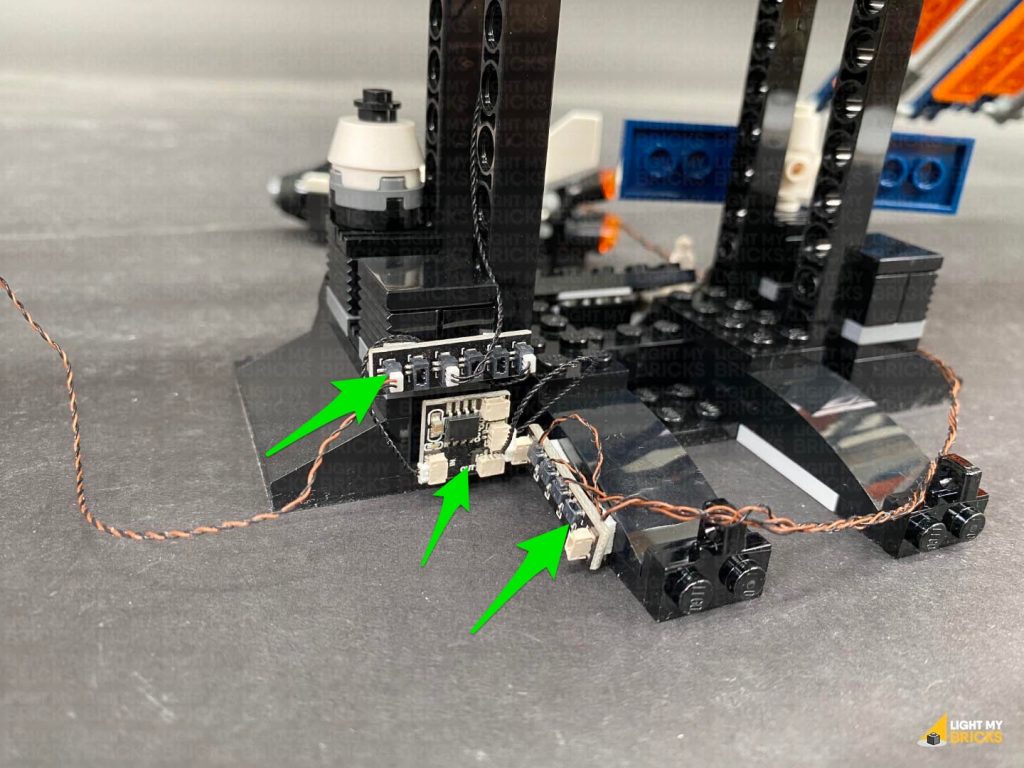
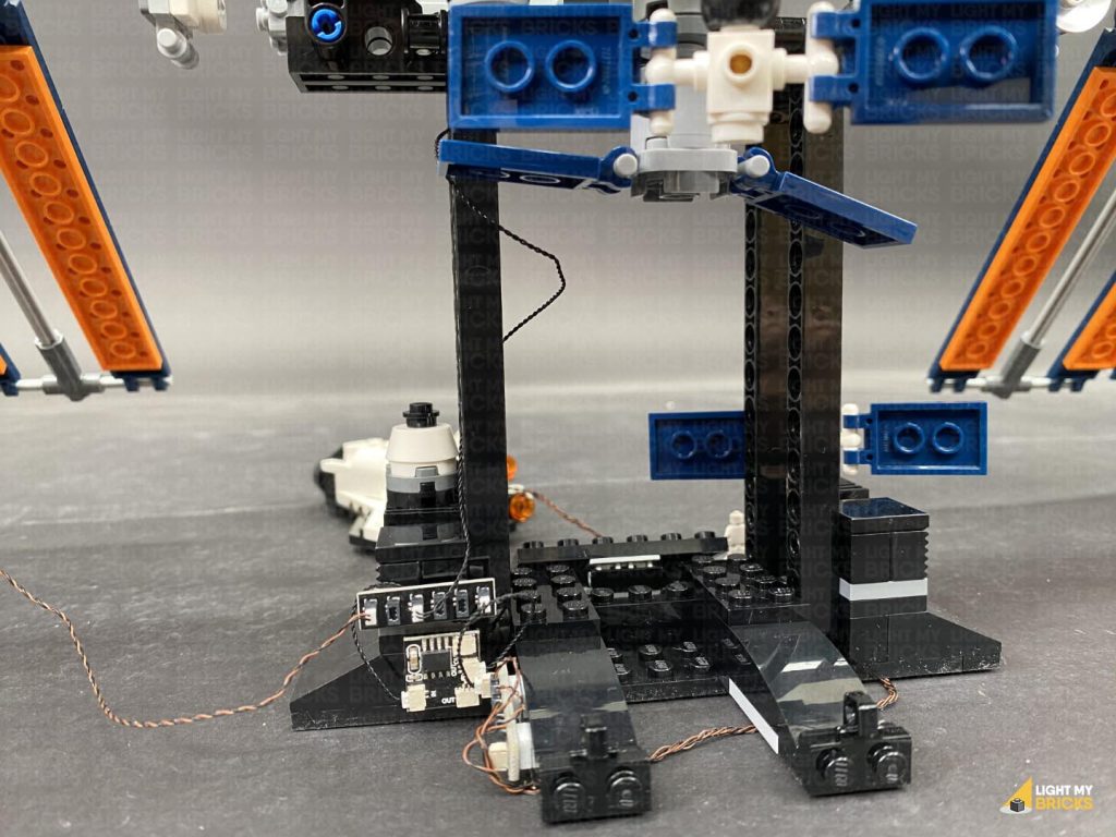
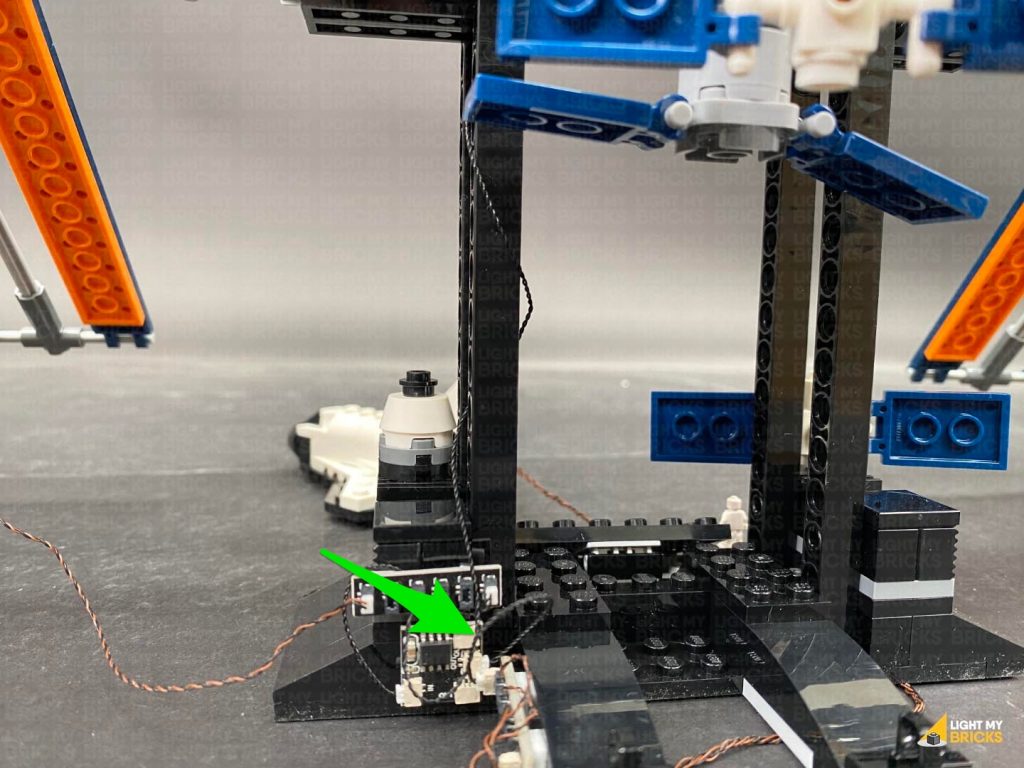
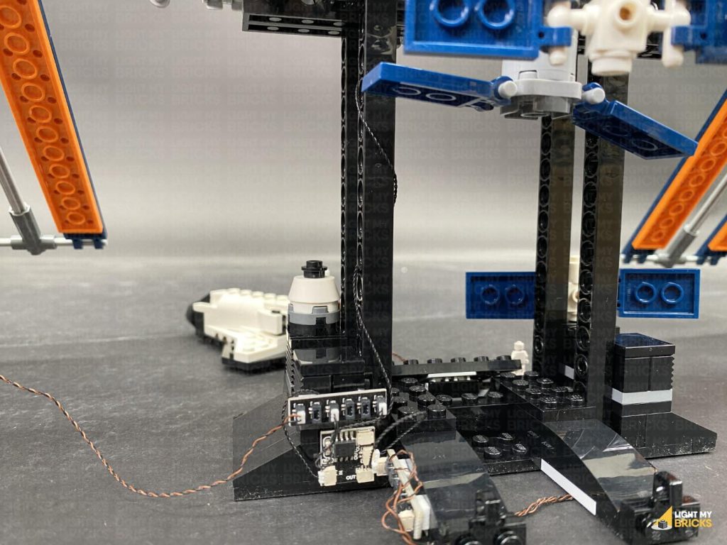
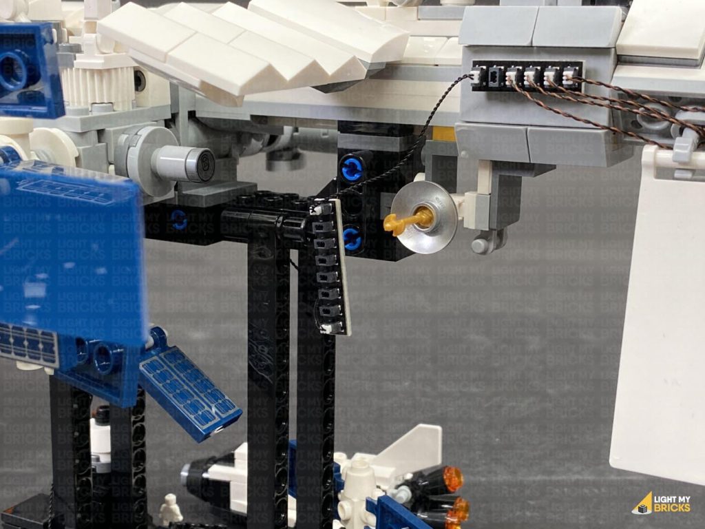
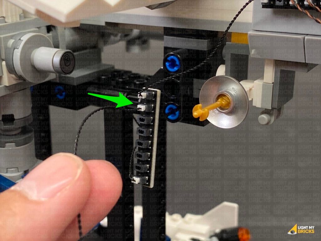
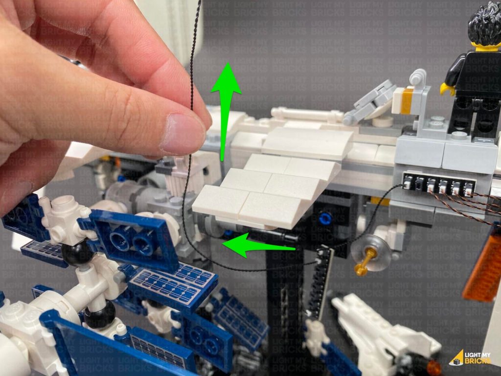
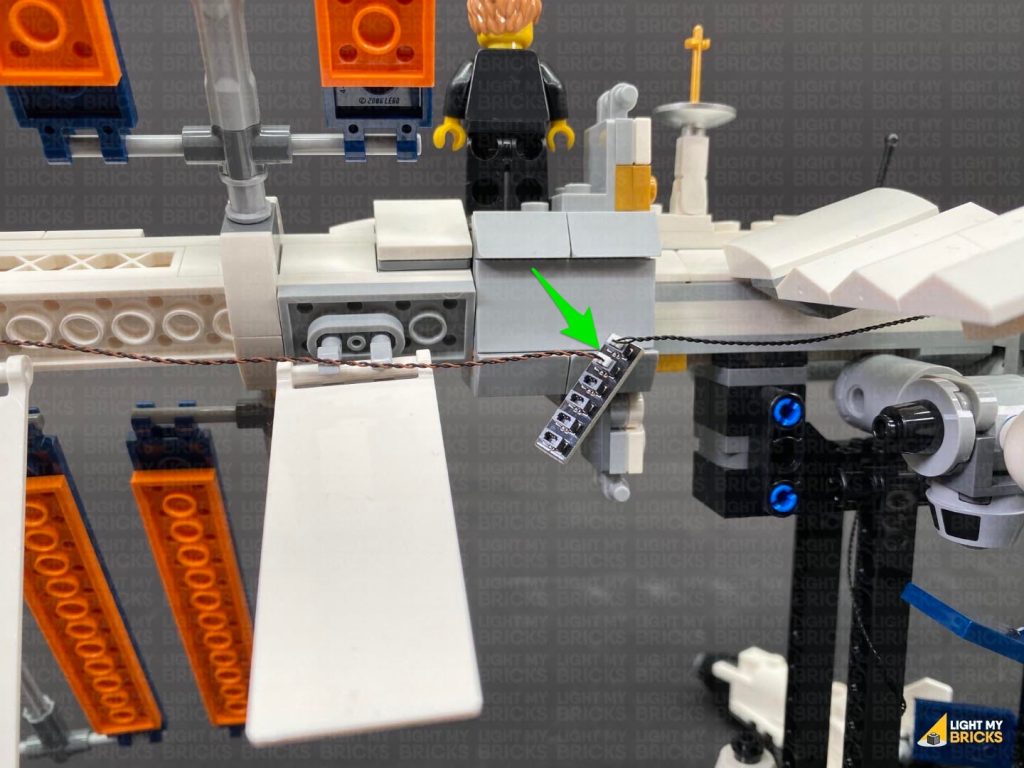
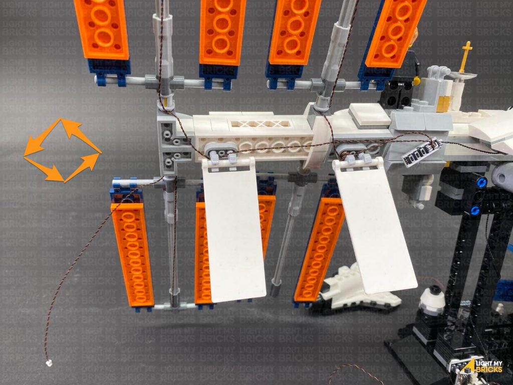
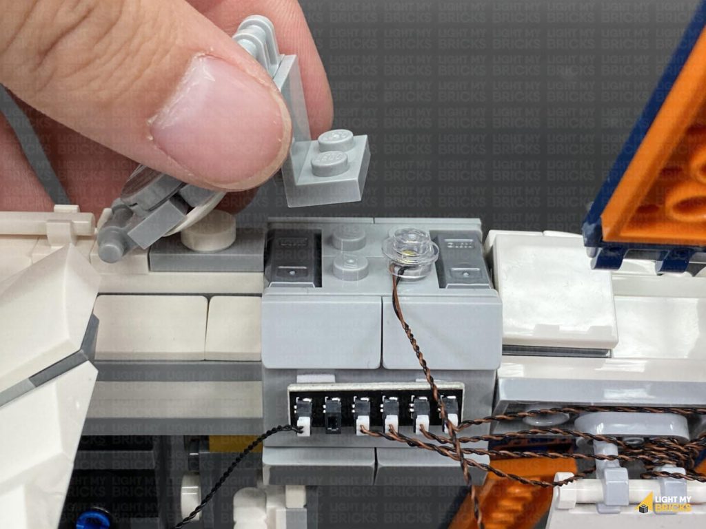
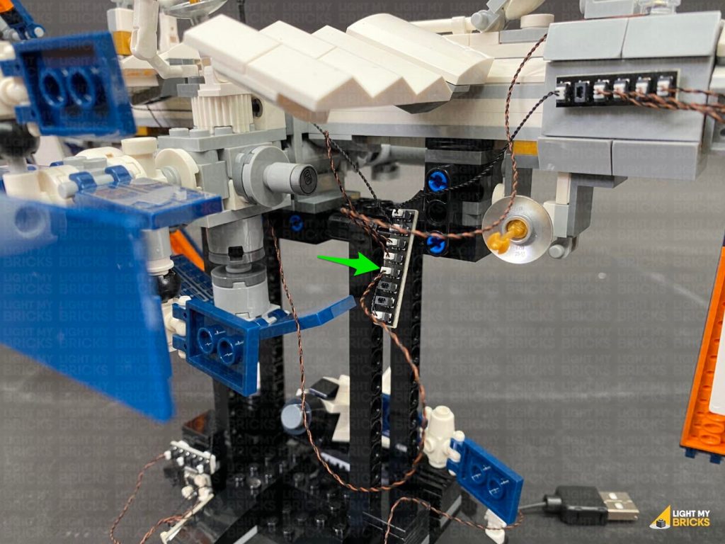
7.) Turn the set around to the back again and stick adhesive squares onto the back of the two expansion boards and effects board. Mount them behind the bottom of the stand in the below positions. Neaten up cables by twisting excess cables into a bunch (to tighten the cable around the stand) as well as hiding the larger cable underneath the stand base as shown below.
Note: If you experience any issues with the lights not working and suspect an issue with a component, please try a different port on the expansion board to verify where the fault lies (with the light, expansion board or effects board). To correct any issues with expansion board ports, please view the section addressing expansion board issues on our online troubleshooting guide.
7.) Turn the set around to the back again and stick adhesive squares onto the back of the two expansion boards and effects board. Mount them behind the bottom of the stand in the below positions. Neaten up cables by twisting excess cables into a bunch (to tighten the cable around the stand) as well as hiding the larger cable underneath the stand base as shown below.
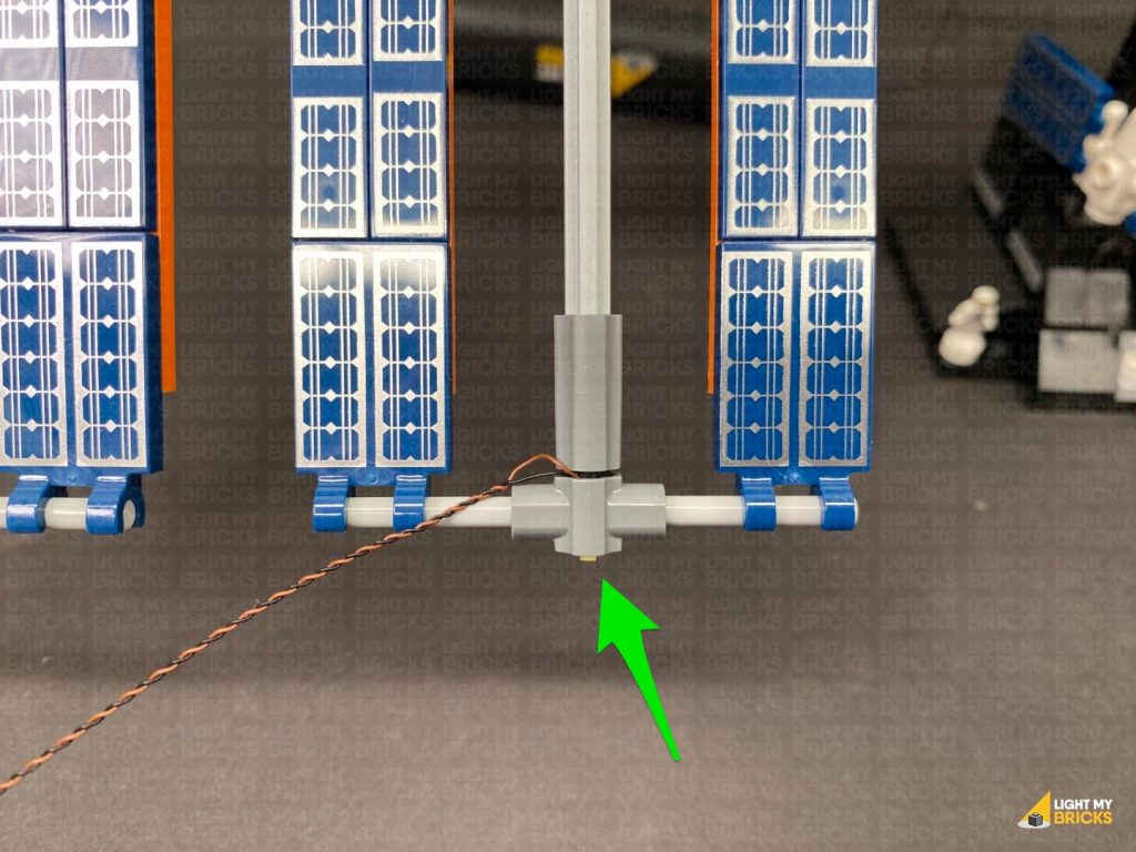
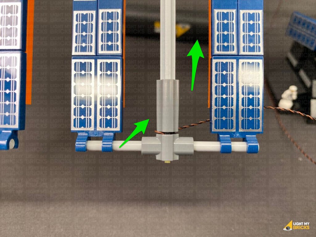
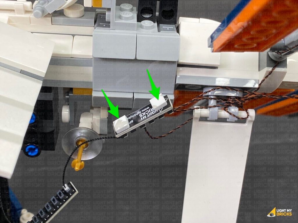
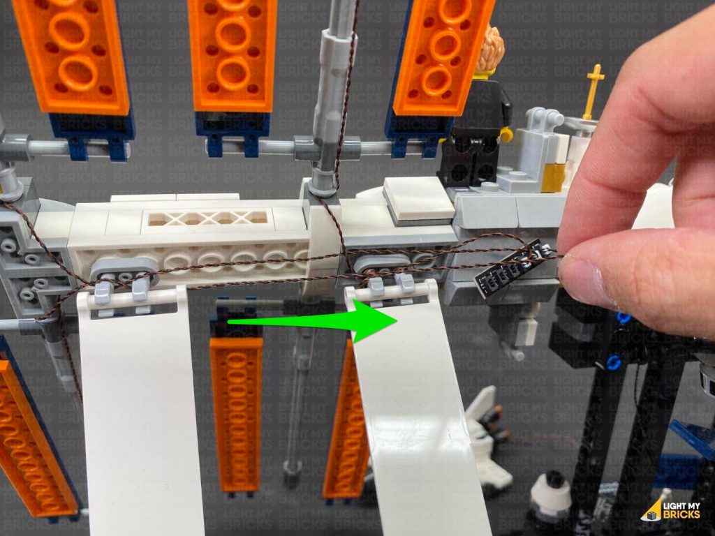
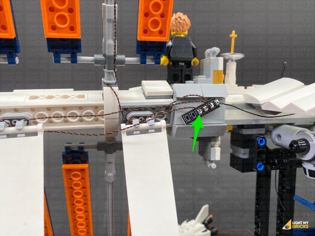
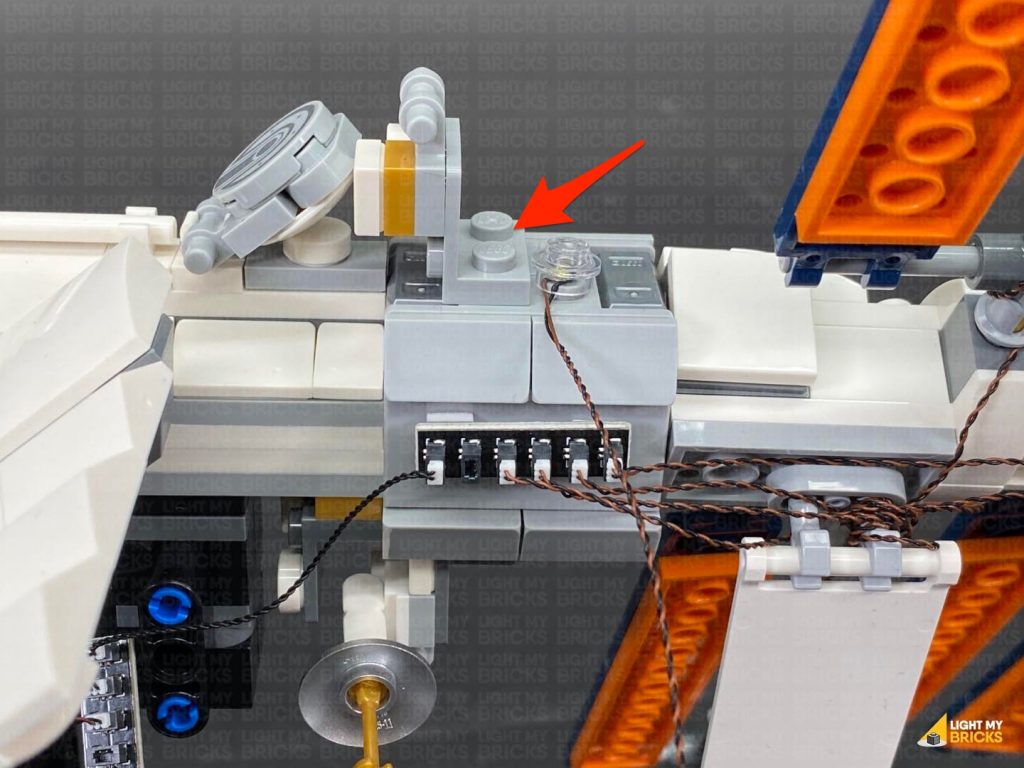
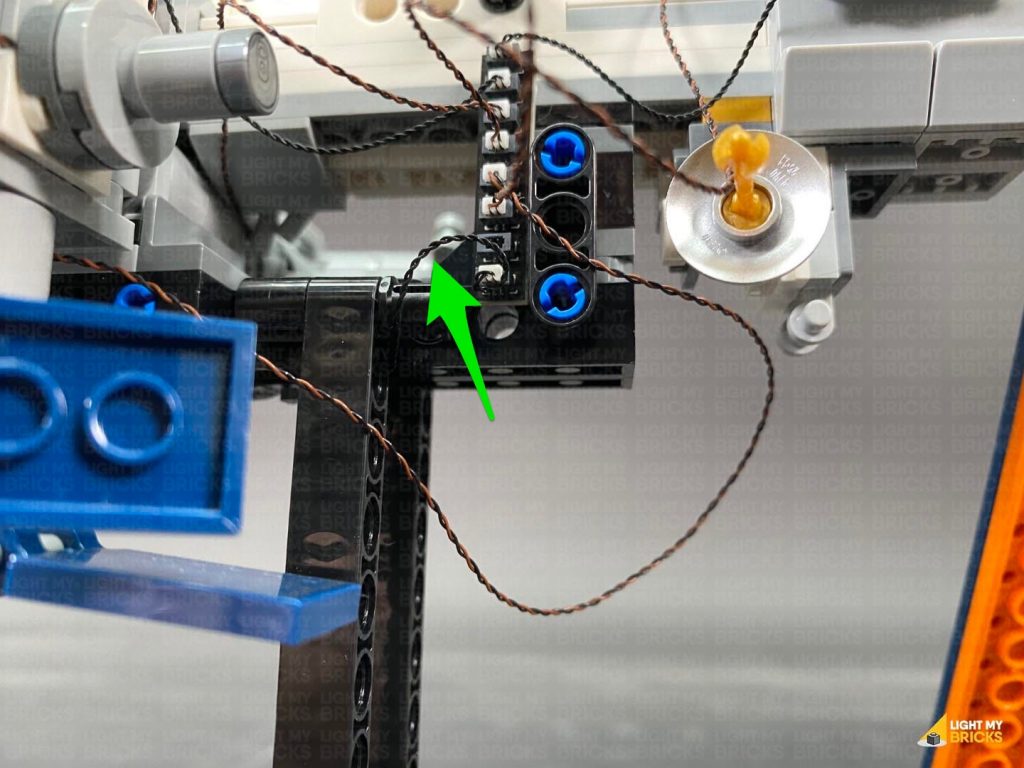
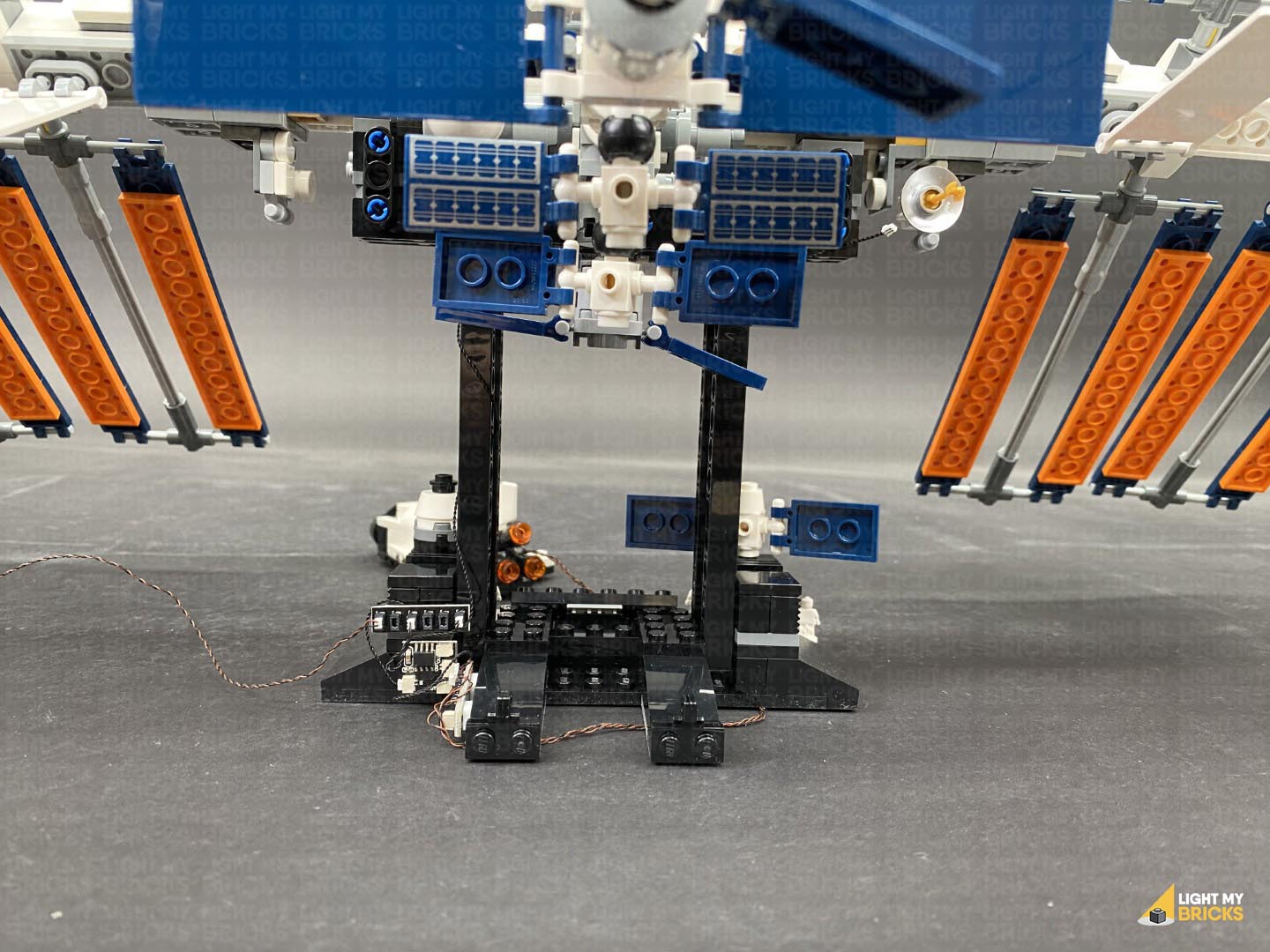 Locate the spare end of the 5cm Connecting Cable from the Strip Light and connect it to an 8-Port Expansion Board. Connect a new 5cm Connecting Cable to the 8-port Expansion Board, then connect the other end of the cable to a new 6-Port Expansion Board.
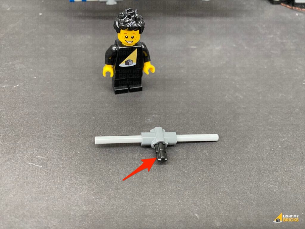
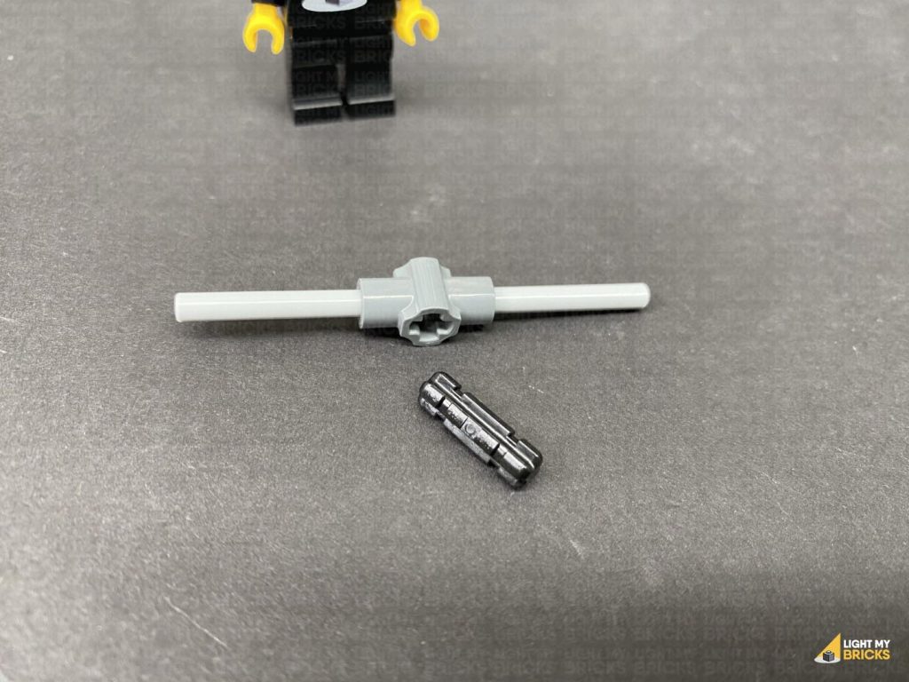
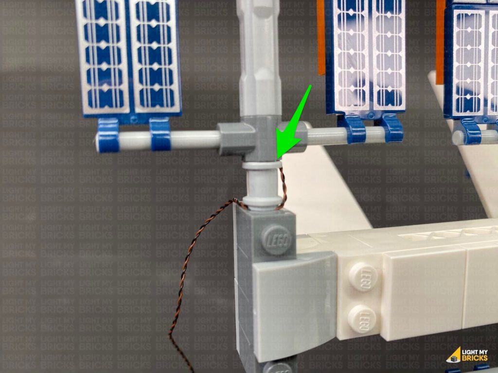
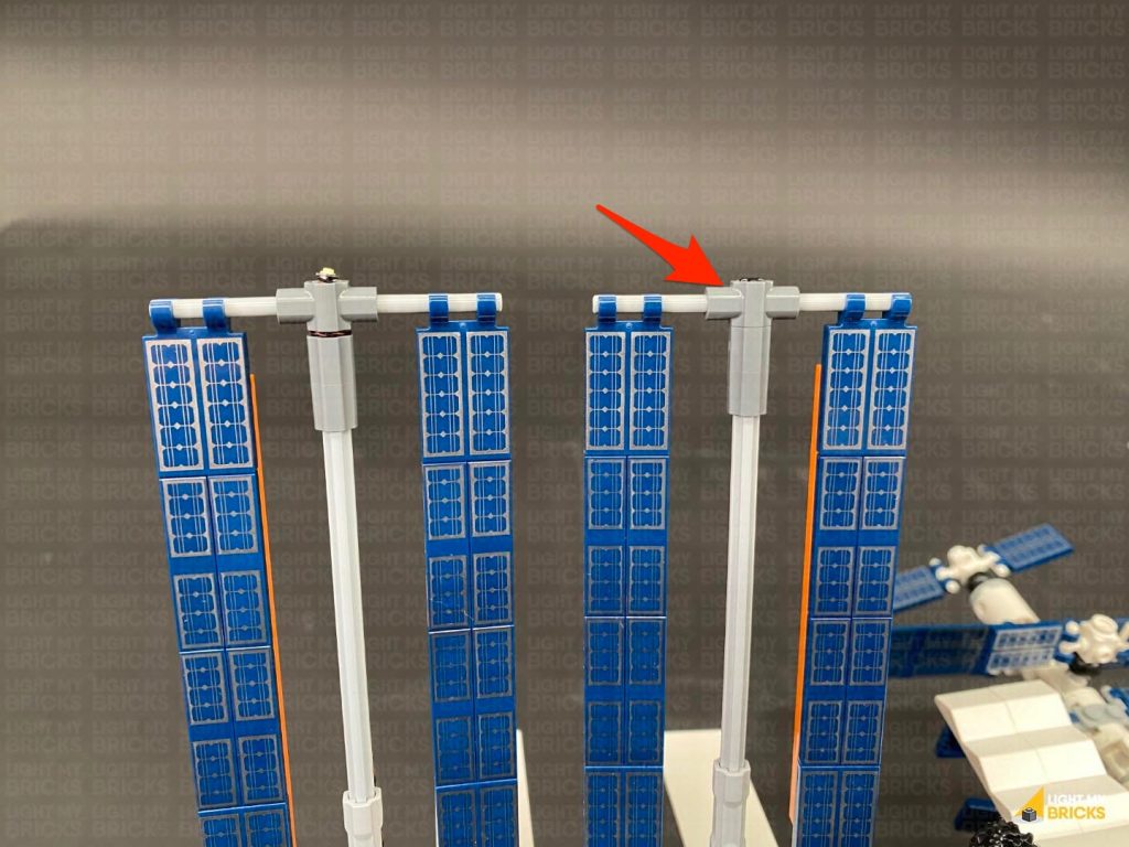
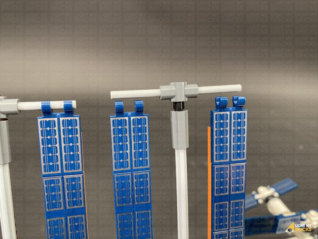
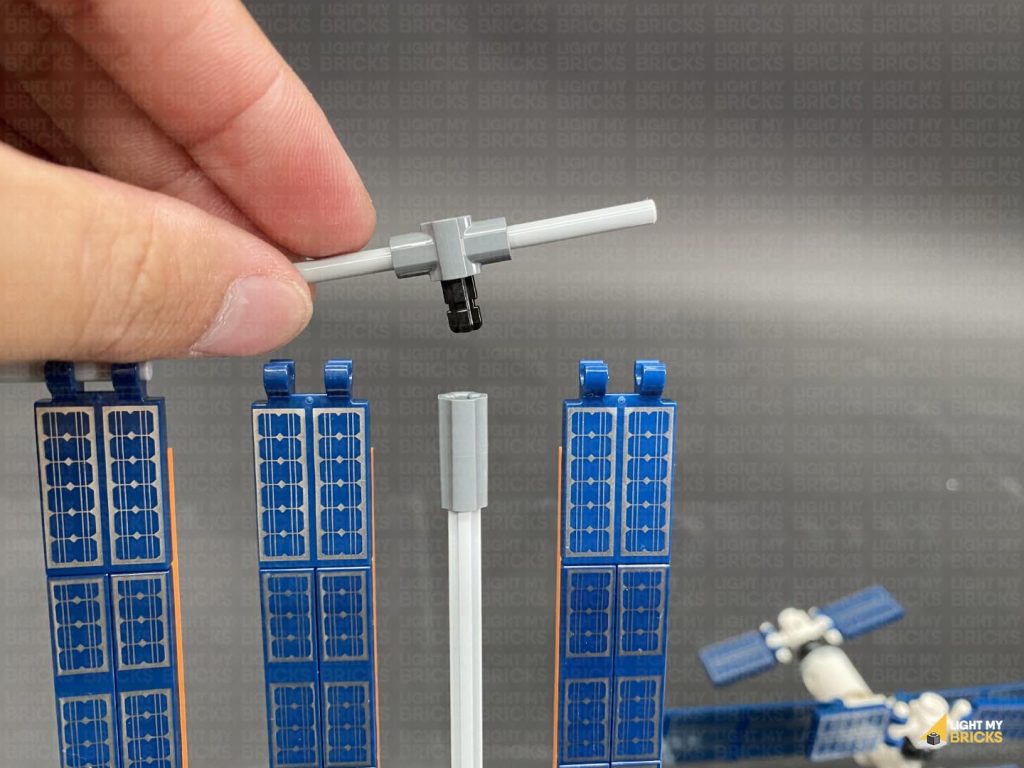
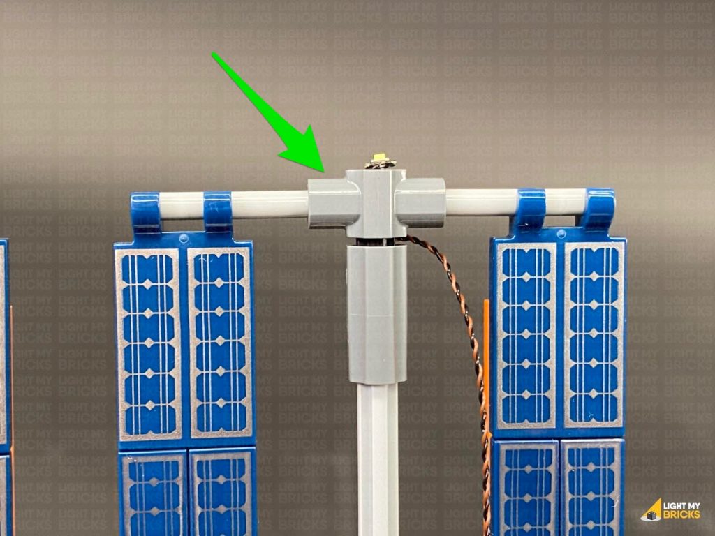
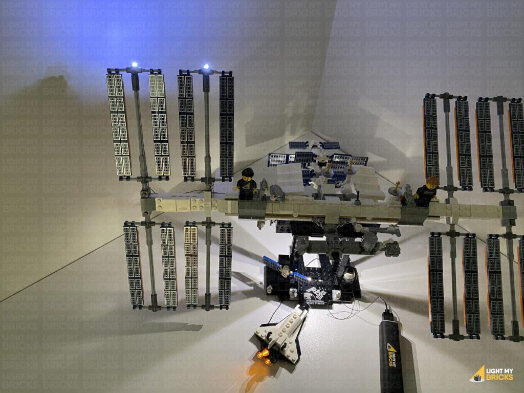
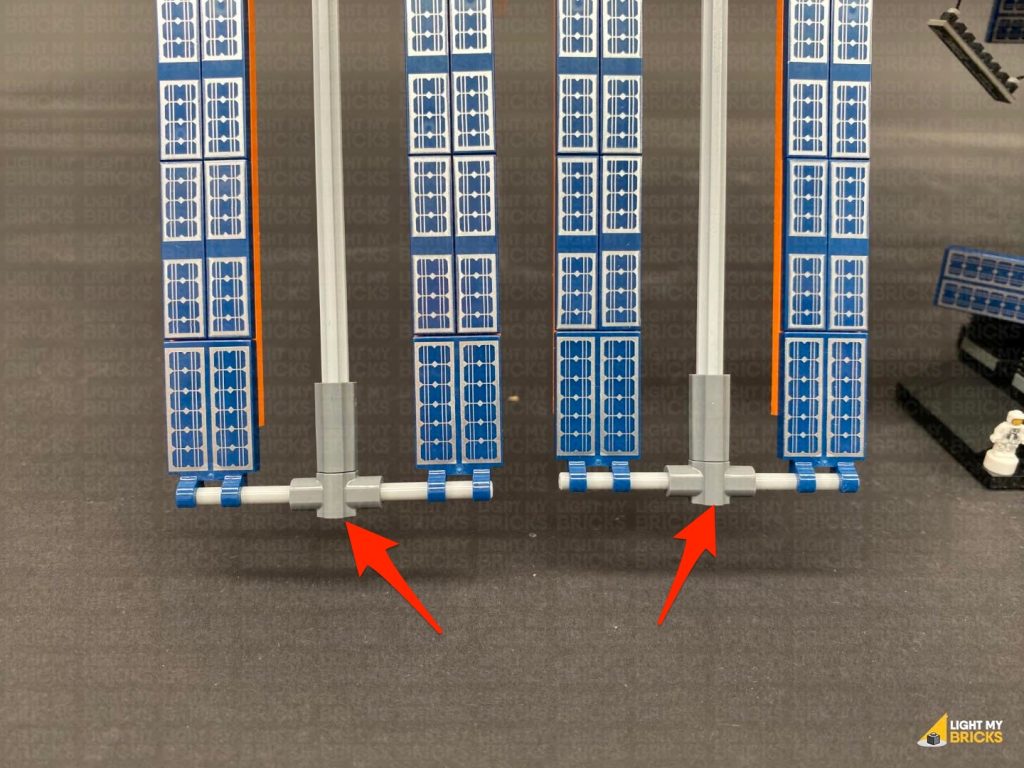
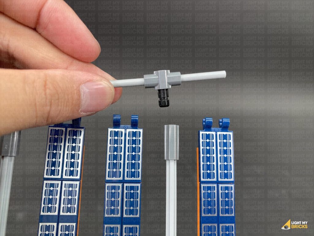
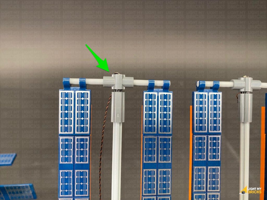
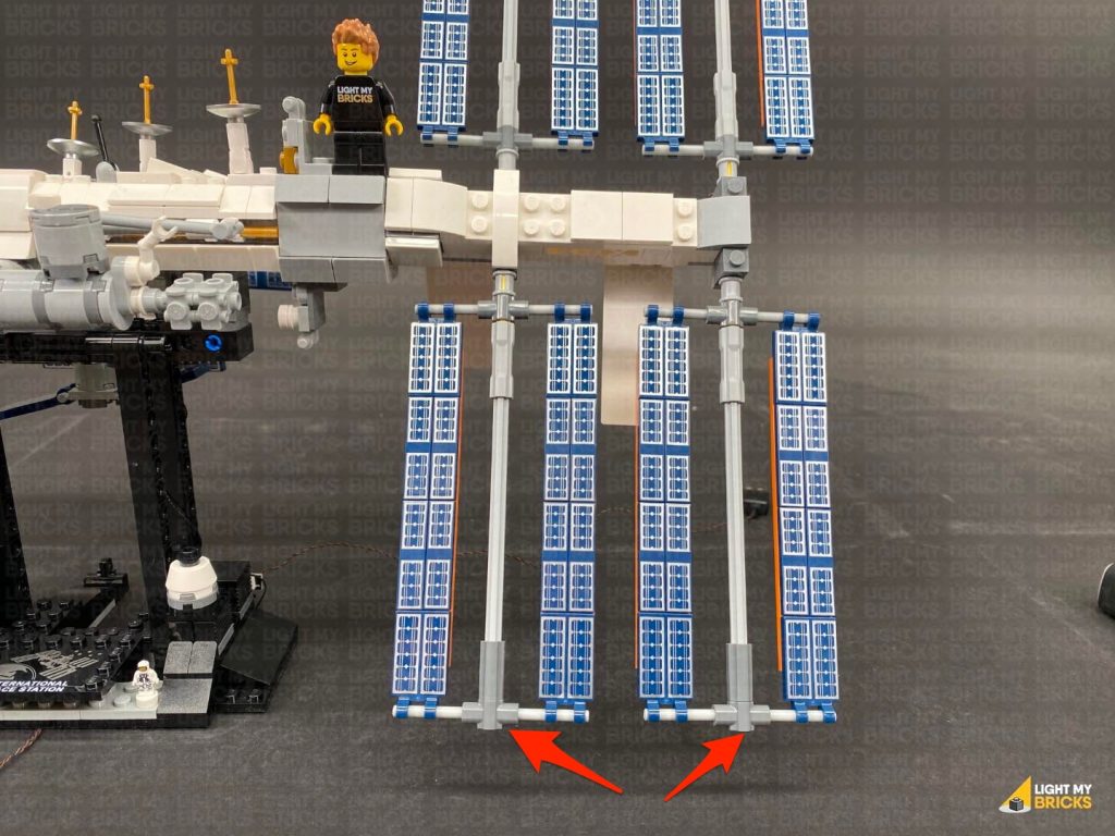
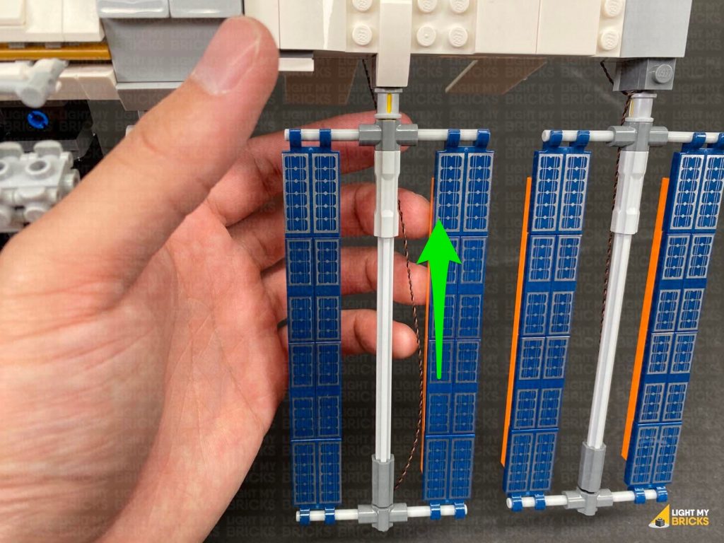
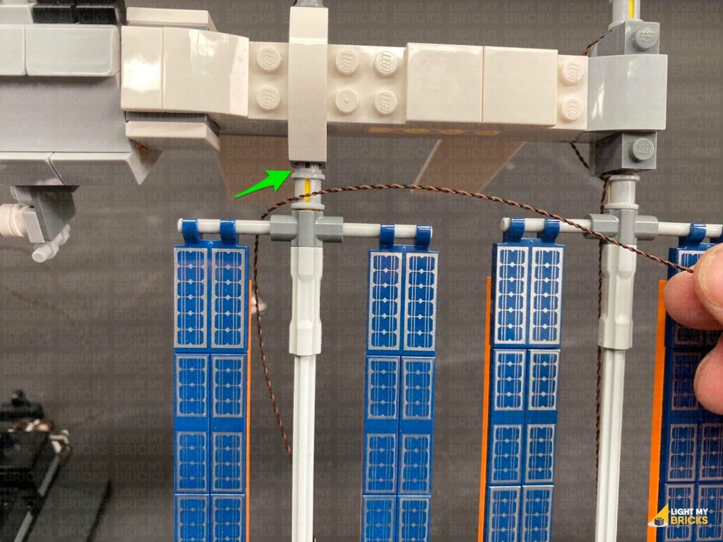
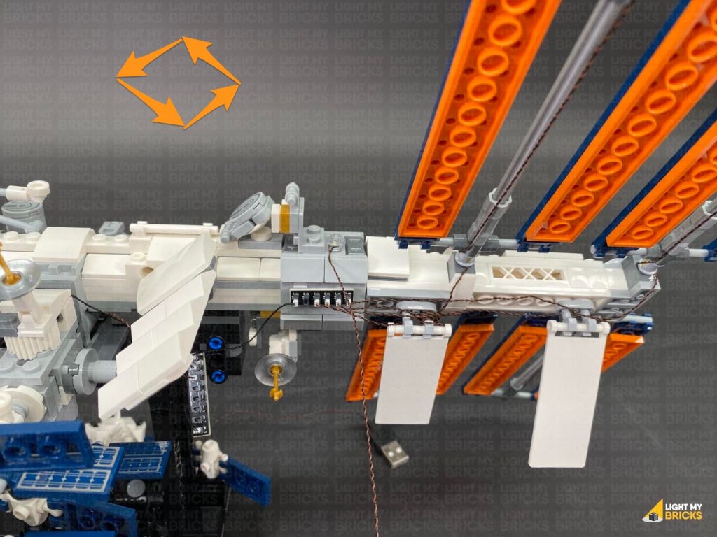
8.) Turn the set back around to the front and disconnect the horizontal bar that connects over the two upper panels on the left side.
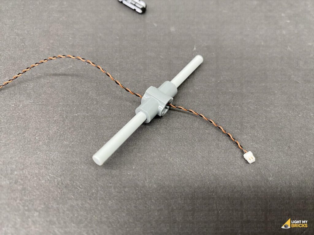
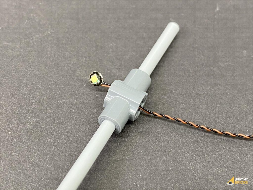
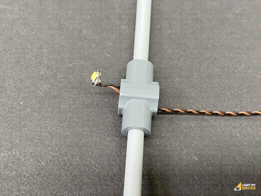
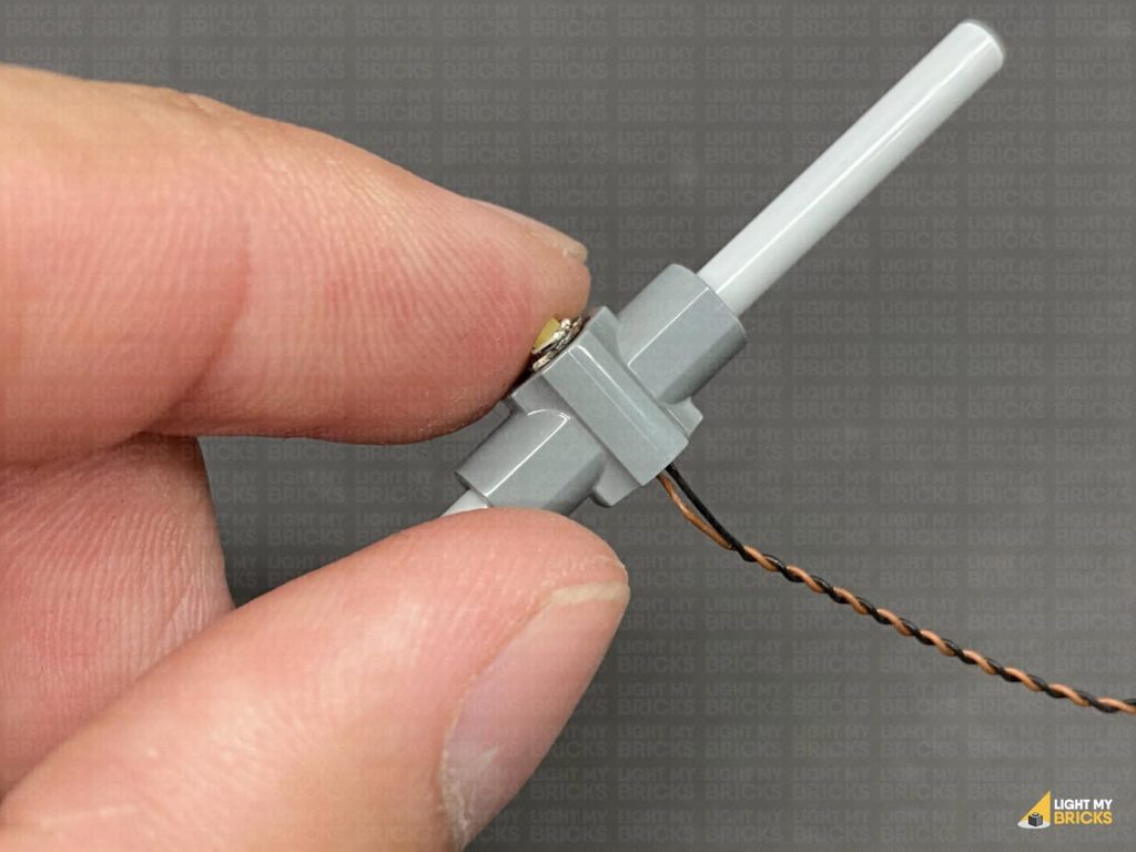
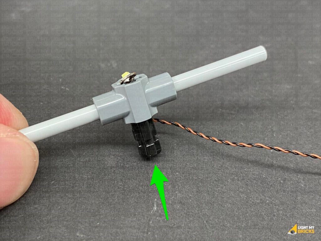
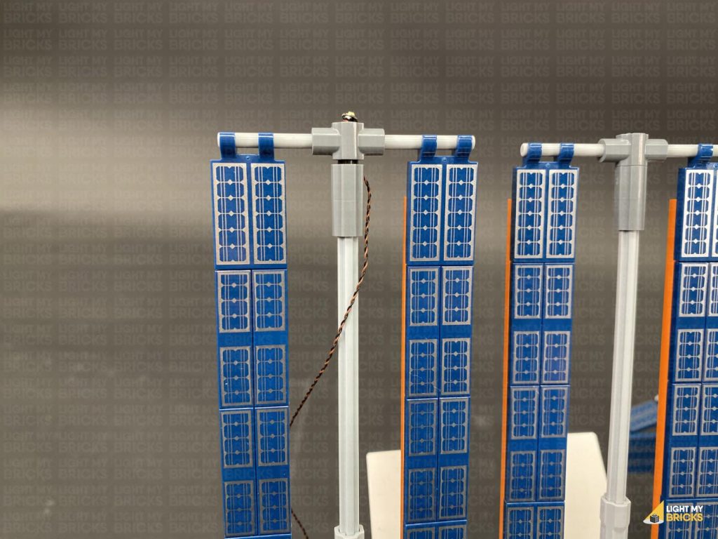
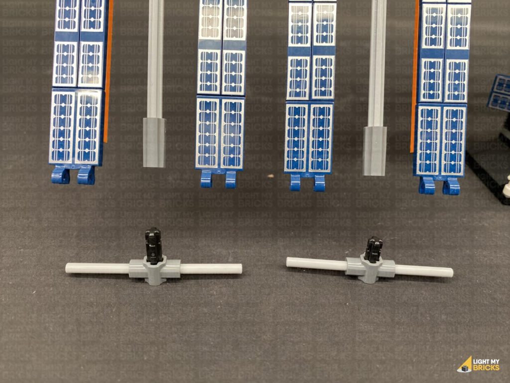
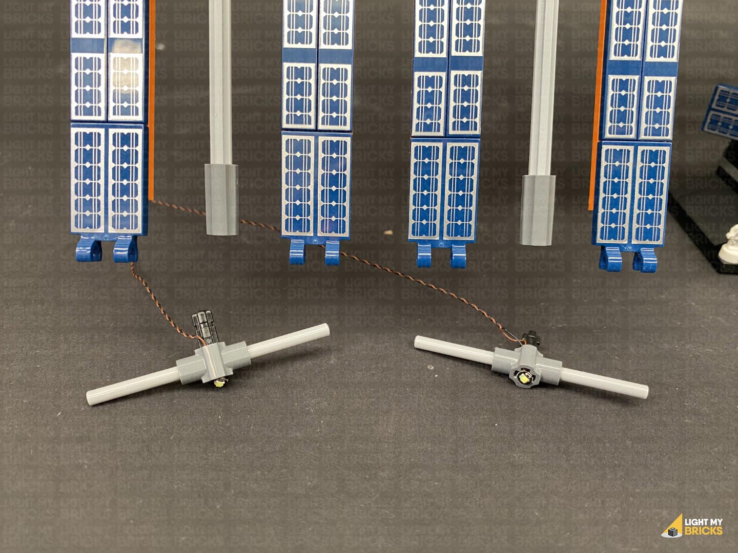
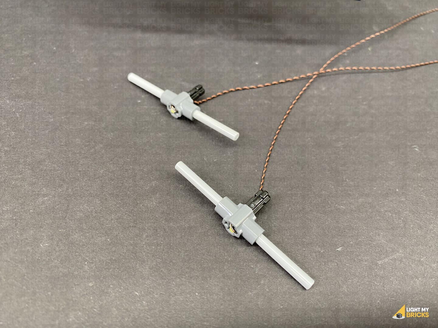
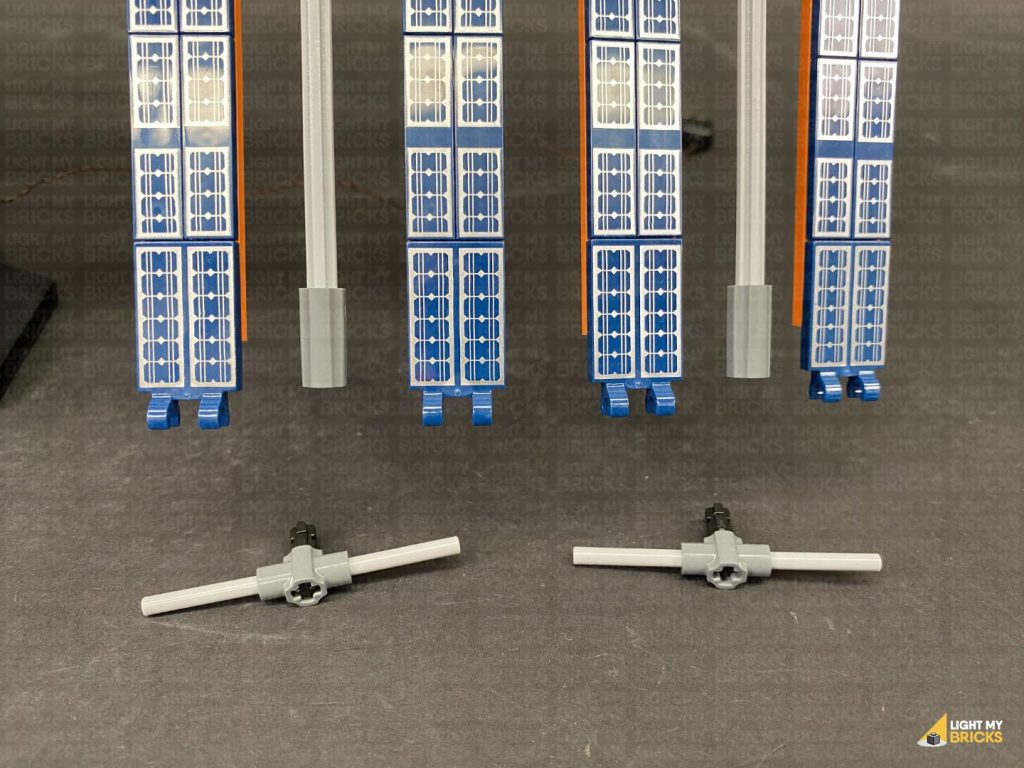
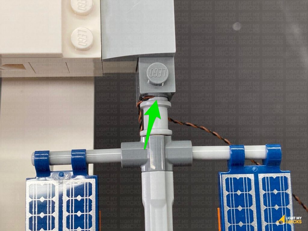
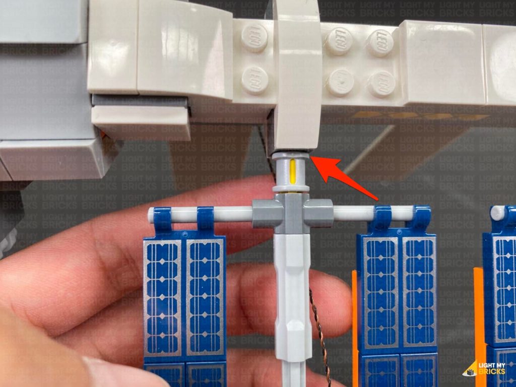
Disconnect the technic axle pin from the middle of the bar, then take a Cool White 30cm Bit Light and thread the connector end of it through the top of the bar. Pull the cable all the way out from the bottom then, carefully bend the LED component so that it is facing directly up. Hold the Bit Light together on top of the bar, then ensuring the cable is laid inside one of the grooves, carefully re-insert the technic axle pin.
CAUTION: Do not forcefully reconnect the pin all the way through, as this may break the cable. It is important that the cable is laid inside one of the technic axle grooves before inserting the pin.
Note – with the Bit Light installed, the technic axle pin will not re-insert the whole way through.
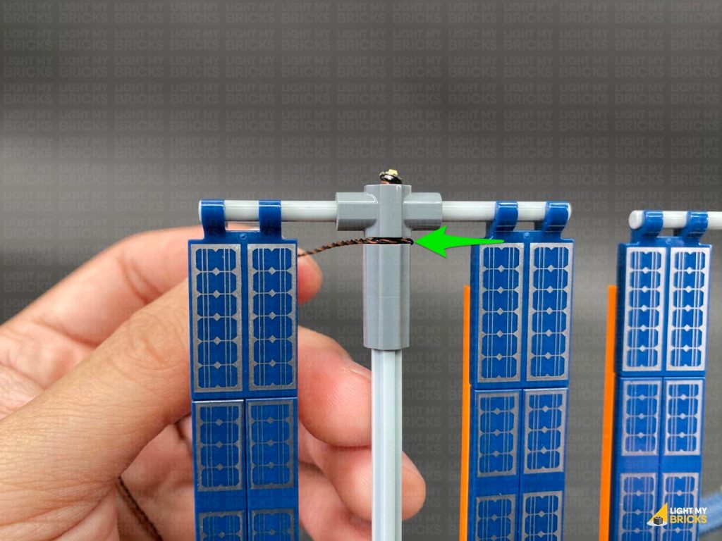
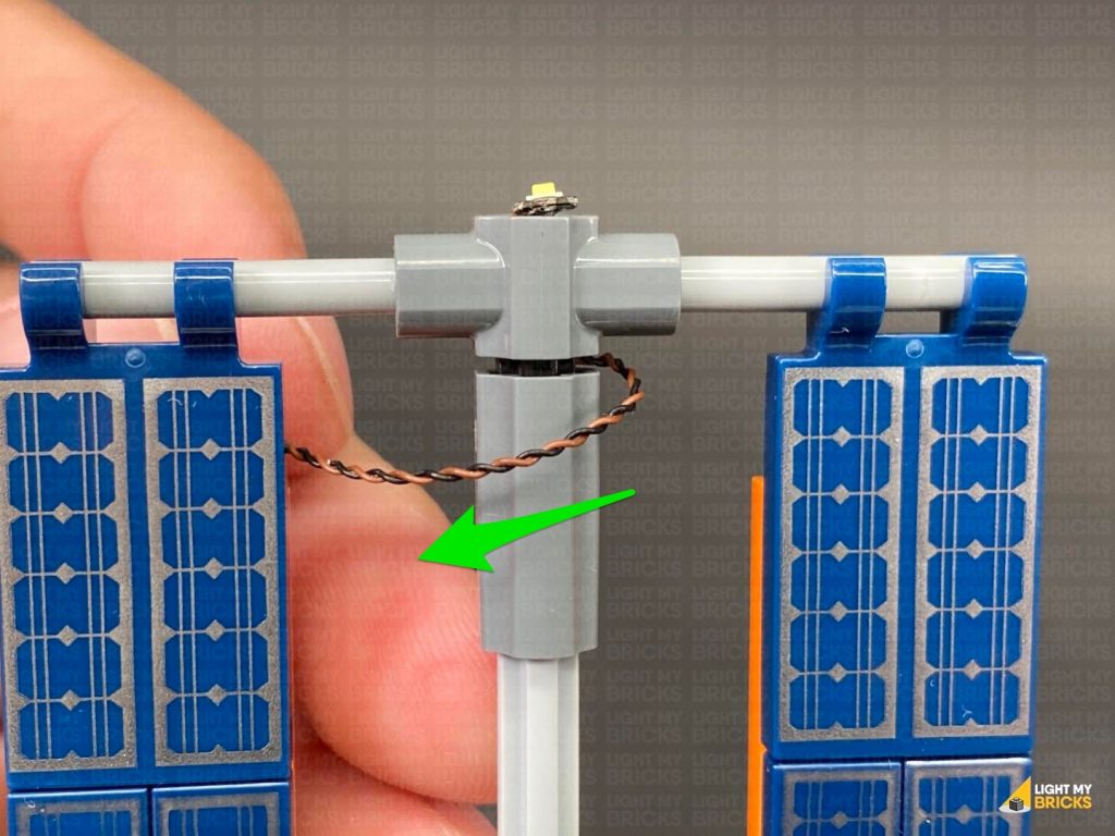
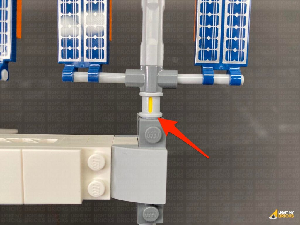
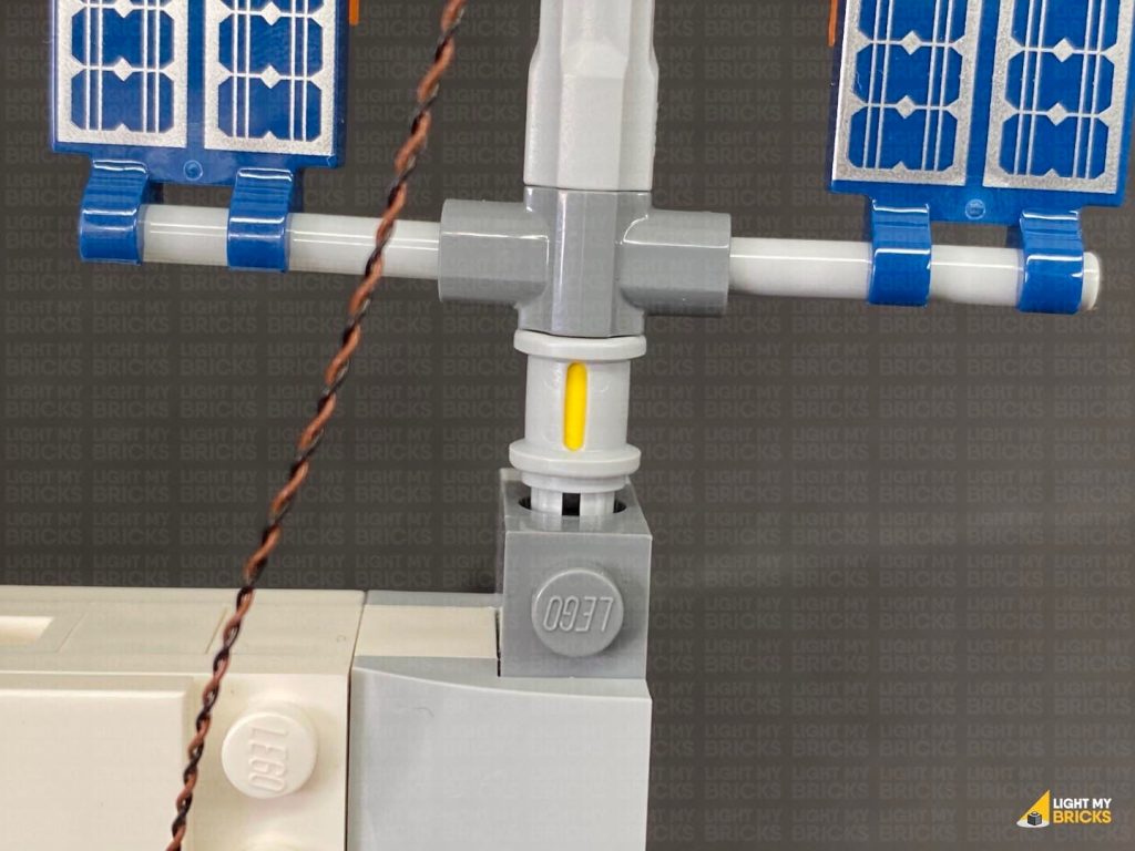
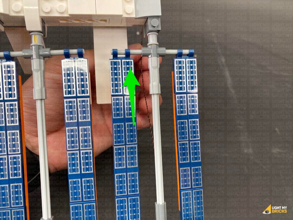
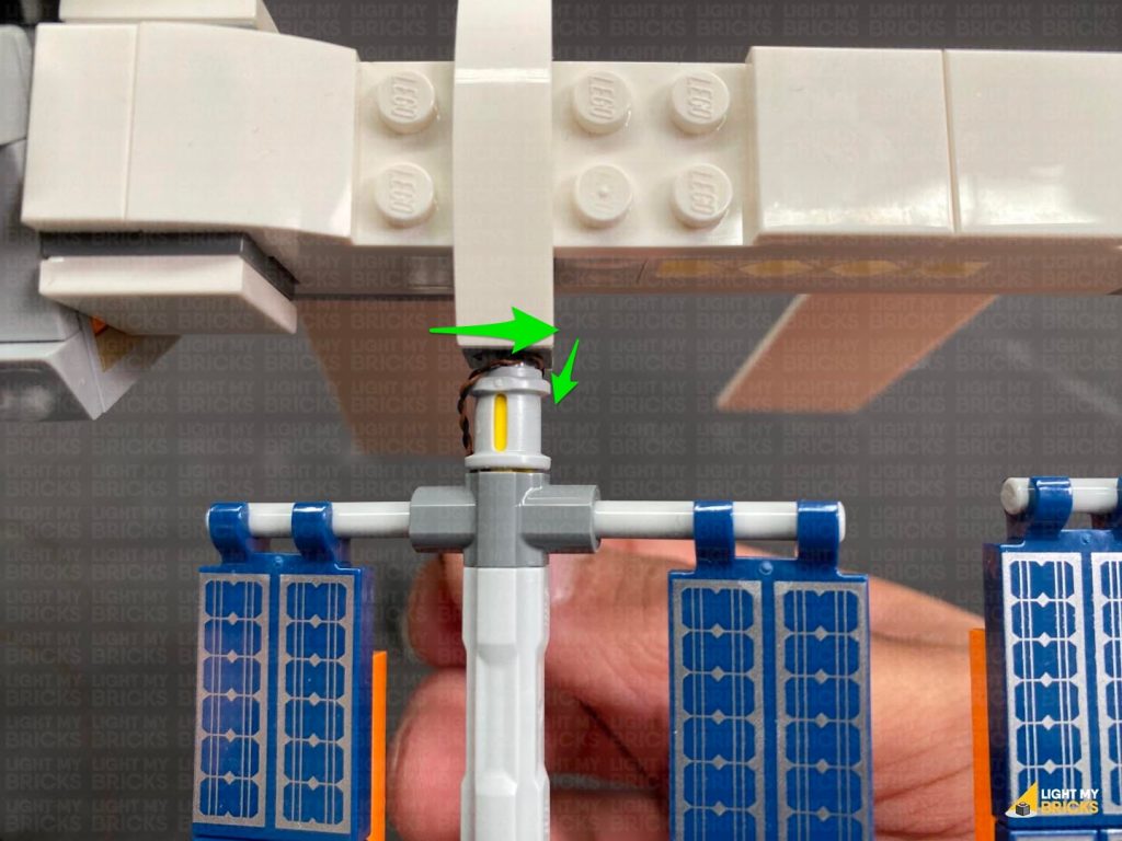
9.) Reconnect the horizontal bar to the top of the panels, then loop the cable across the front toward the left. Slot the cable in between the space created. This will secure the cable, then bring the cable down the centre behind the long technic axle pin. Ensure the cable is brought down behind, so that it isn’t visible from the front of the set.
Slightly disconnect the light grey technic pin from the dark grey 1×1 brick, then bring the cable around and across the front to the left. Reconnect the light grey technic pin so that it slightly pushes the cable inside the dark grey 1×1 brick hole. This will secure the cable in place.
Locate the spare end of the 5cm Connecting Cable from the Strip Light and connect it to an 8-Port Expansion Board. Connect a new 5cm Connecting Cable to the 8-port Expansion Board, then connect the other end of the cable to a new 6-Port Expansion Board.
8.) Turn the set back around to the front and disconnect the horizontal bar that connects over the two upper panels on the left side.
Disconnect the technic axle pin from the middle of the bar, then take a Cool White 30cm Bit Light and thread the connector end of it through the top of the bar. Pull the cable all the way out from the bottom then, carefully bend the LED component so that it is facing directly up. Hold the Bit Light together on top of the bar, then ensuring the cable is laid inside one of the grooves, carefully re-insert the technic axle pin.
CAUTION: Do not forcefully reconnect the pin all the way through, as this may break the cable. It is important that the cable is laid inside one of the technic axle grooves before inserting the pin.
Note – with the Bit Light installed, the technic axle pin will not re-insert the whole way through.
9.) Reconnect the horizontal bar to the top of the panels, then loop the cable across the front toward the left. Slot the cable in between the space created. This will secure the cable, then bring the cable down the centre behind the long technic axle pin. Ensure the cable is brought down behind, so that it isn’t visible from the front of the set.
Slightly disconnect the light grey technic pin from the dark grey 1×1 brick, then bring the cable around and across the front to the left. Reconnect the light grey technic pin so that it slightly pushes the cable inside the dark grey 1×1 brick hole. This will secure the cable in place.
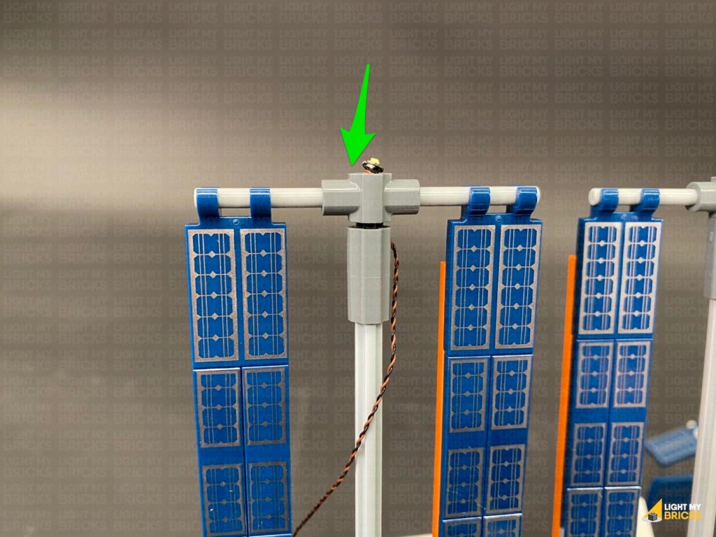
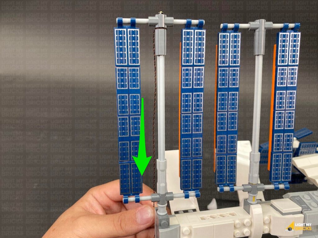
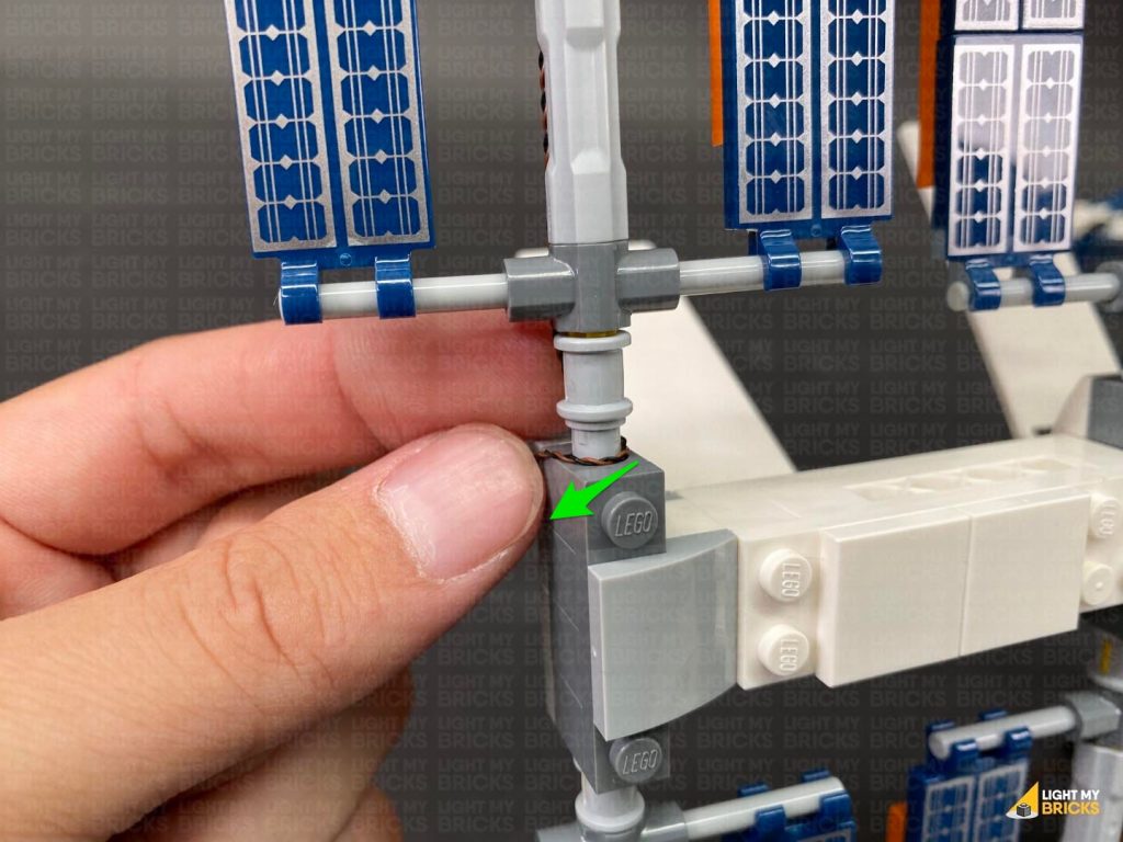
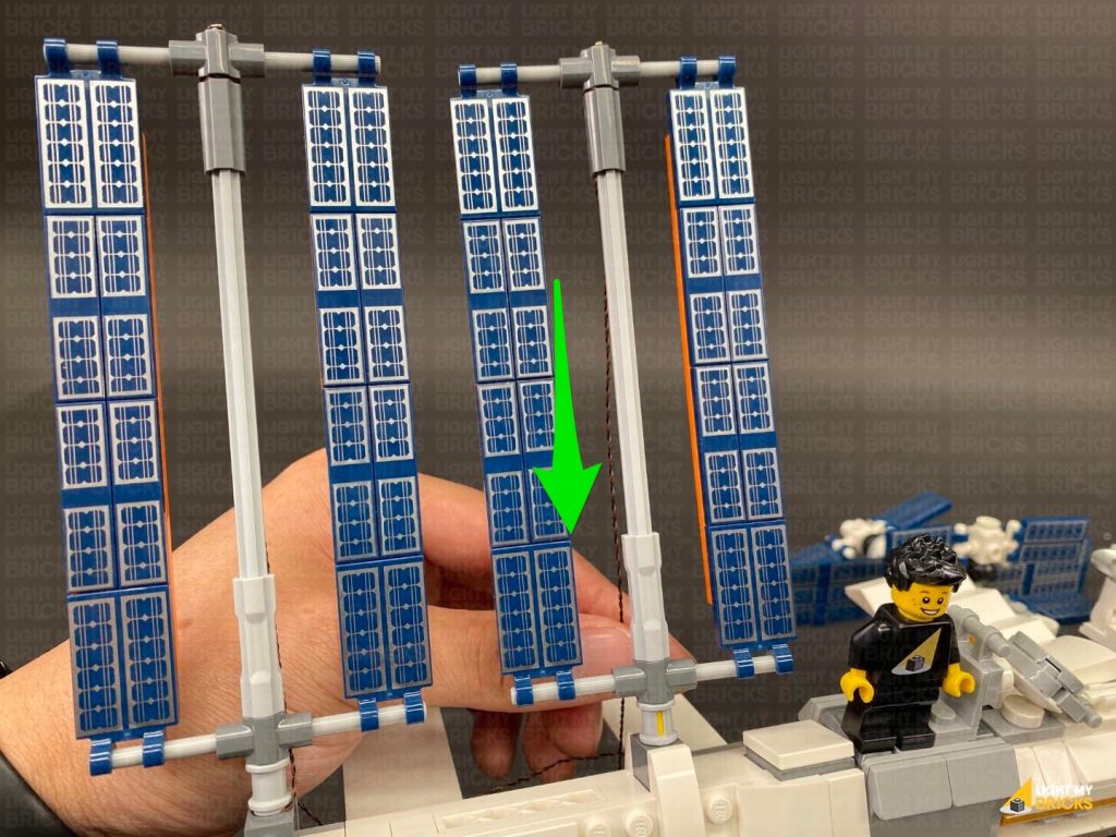
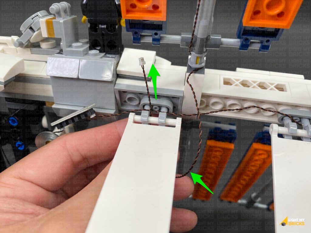
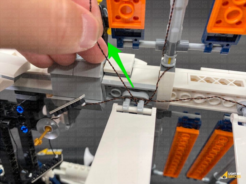
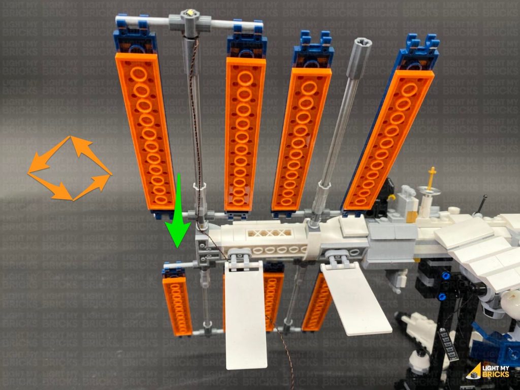
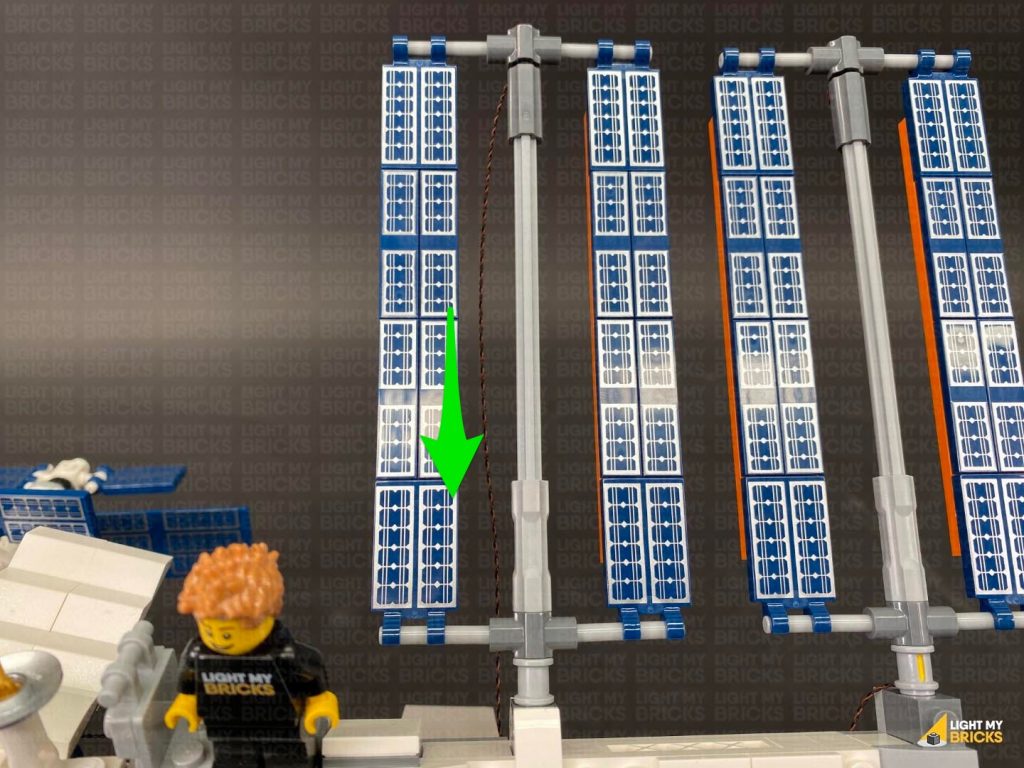
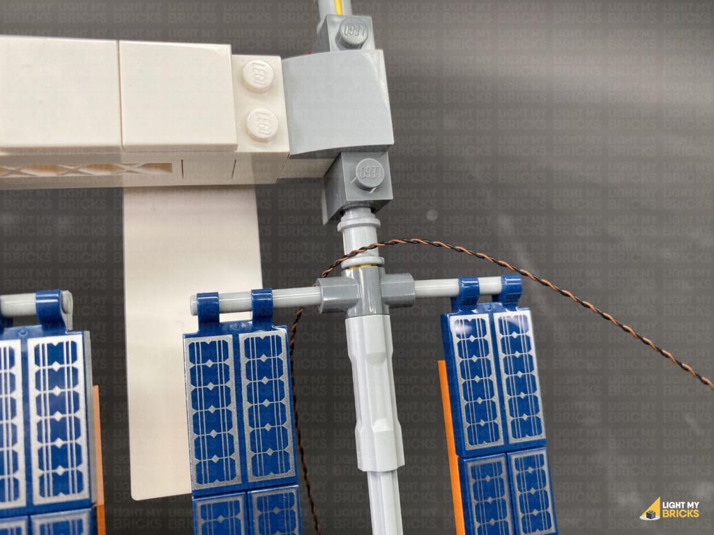
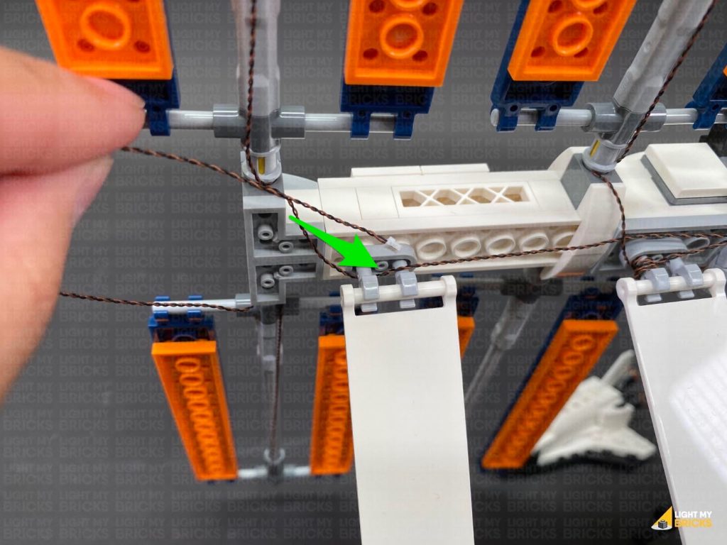
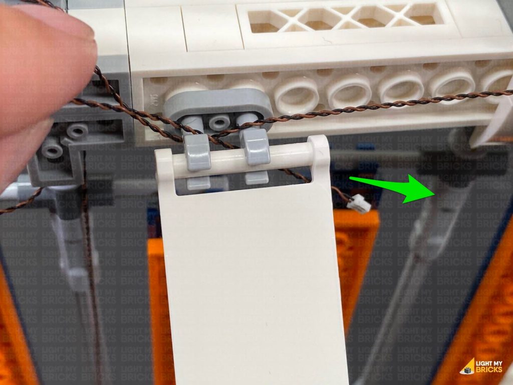
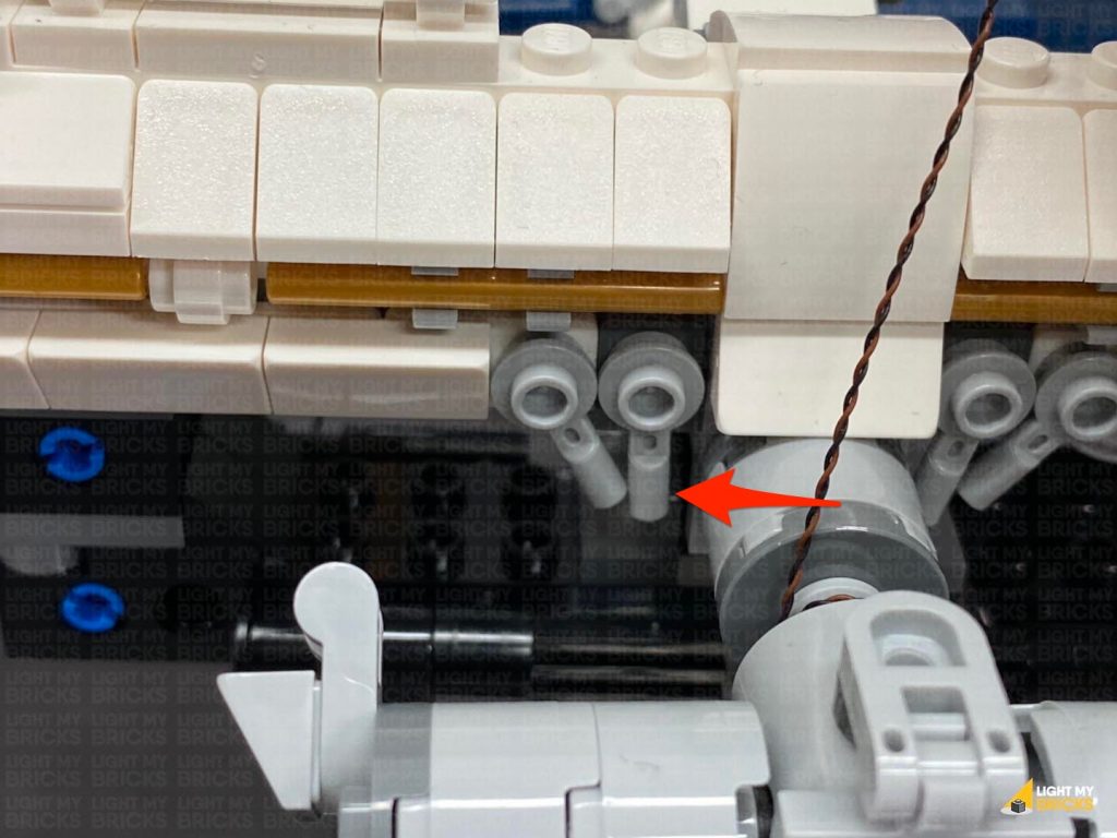
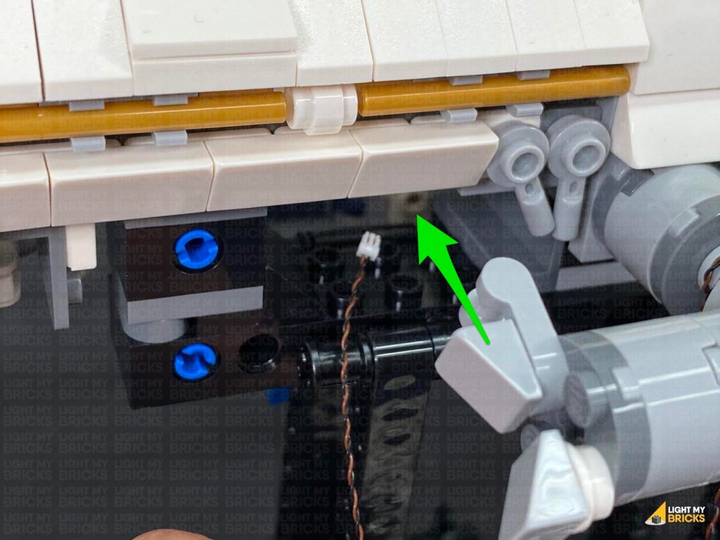
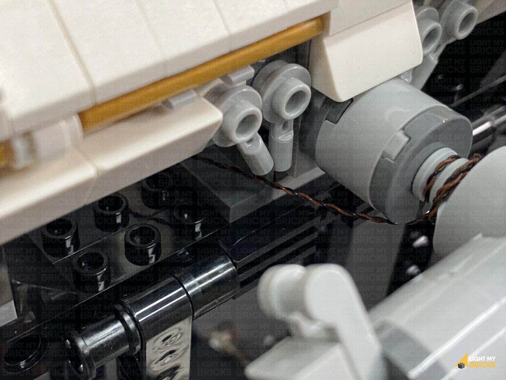
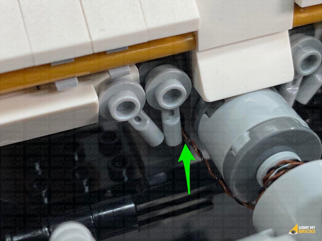
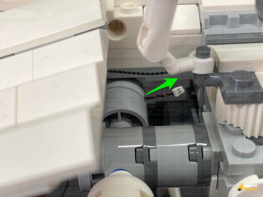
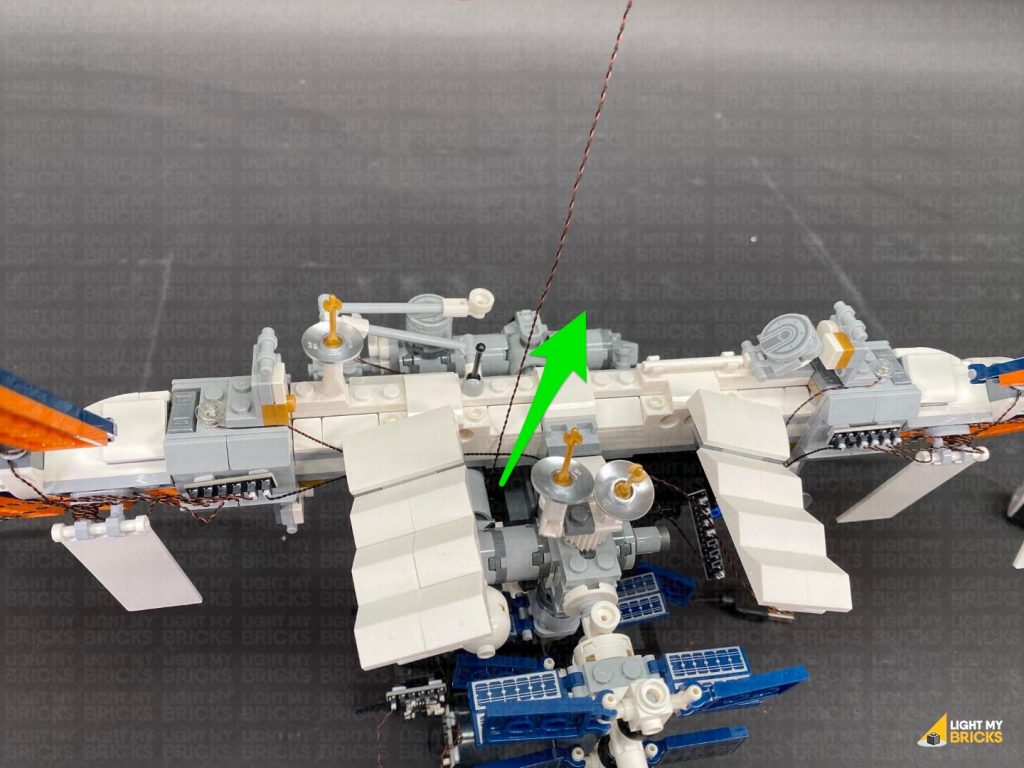
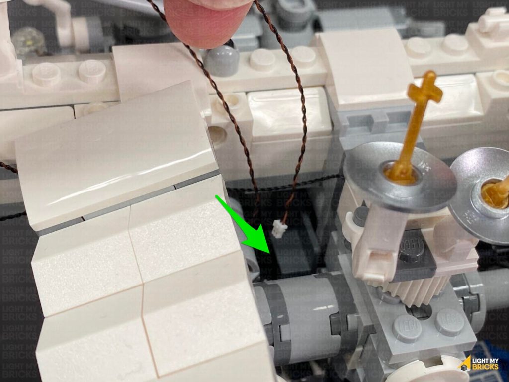
 10.) From the back of the set, thread the Bit Light cable underneath and up in between the following light grey clips. Pull the cable out from the top and bring it to the left to connect to the 6-Port Expansion Board nearby.
Turn the Power On to test the Bit Light we installed to the panel is working OK.
Note: If you experience any issues with the lights not working and suspect an issue with a component, please try a different port on the expansion board to verify where the fault lies (with the light, expansion board or effects board). To correct any issues with expansion board ports, please view the section addressing expansion board issues on our online troubleshooting guide.
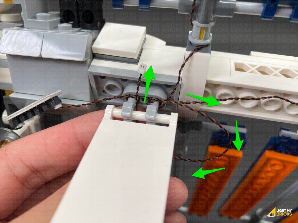
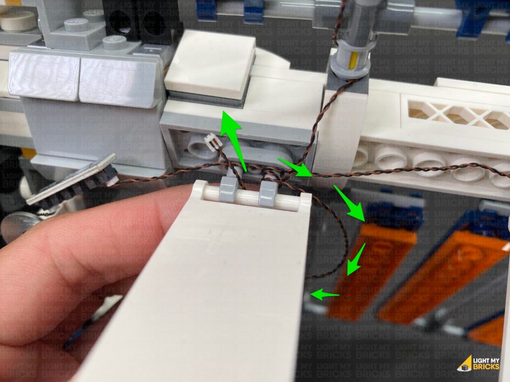
11.) Repeat steps 8 and 9 to install another Cool White 30cm Bit Light to the other top panel on the left side.
12.) From the back of the set, thread the Bit Light cable up in between the light grey clips, then loop the cable around and up in between 3-4 times to eliminate excess cable. Connect the Bit Light to the 6-Port Expansion Board, then turn the Power ON to test the panel lights are working OK.
Note: If you experience any issues with the lights not working and suspect an issue with a component, please try a different port on the expansion board to verify where the fault lies (with the light, expansion board or effects board). To correct any issues with expansion board ports, please view the section addressing expansion board issues on our online troubleshooting guide.
13.) Using the same methods used to install the top panel lights, install another 2x Cool White 30cm Bit Lights to the bottom left panels.
CAUTION: Do not forcefully reconnect the pin all the way through, as this may break the cable. It is important that the cable is laid inside one of the technic axle grooves before inserting the pin.
Note – with the Bit Light installed, the technic axle pin will not re-insert the whole way through.
10.) From the back of the set, thread the Bit Light cable underneath and up in between the following light grey clips. Pull the cable out from the top and bring it to the left to connect to the 6-Port Expansion Board nearby.
Turn the Power On to test the Bit Light we installed to the panel is working OK.
Note: If you experience any issues with the lights not working and suspect an issue with a component, please try a different port on the expansion board to verify where the fault lies (with the light, expansion board or effects board). To correct any issues with expansion board ports, please view the section addressing expansion board issues on our online troubleshooting guide.
11.) Repeat steps 8 and 9 to install another Cool White 30cm Bit Light to the other top panel on the left side.
12.) From the back of the set, thread the Bit Light cable up in between the light grey clips, then loop the cable around and up in between 3-4 times to eliminate excess cable. Connect the Bit Light to the 6-Port Expansion Board, then turn the Power ON to test the panel lights are working OK.
Note: If you experience any issues with the lights not working and suspect an issue with a component, please try a different port on the expansion board to verify where the fault lies (with the light, expansion board or effects board). To correct any issues with expansion board ports, please view the section addressing expansion board issues on our online troubleshooting guide.
13.) Using the same methods used to install the top panel lights, install another 2x Cool White 30cm Bit Lights to the bottom left panels.
CAUTION: Do not forcefully reconnect the pin all the way through, as this may break the cable. It is important that the cable is laid inside one of the technic axle grooves before inserting the pin.
Note – with the Bit Light installed, the technic axle pin will not re-insert the whole way through.
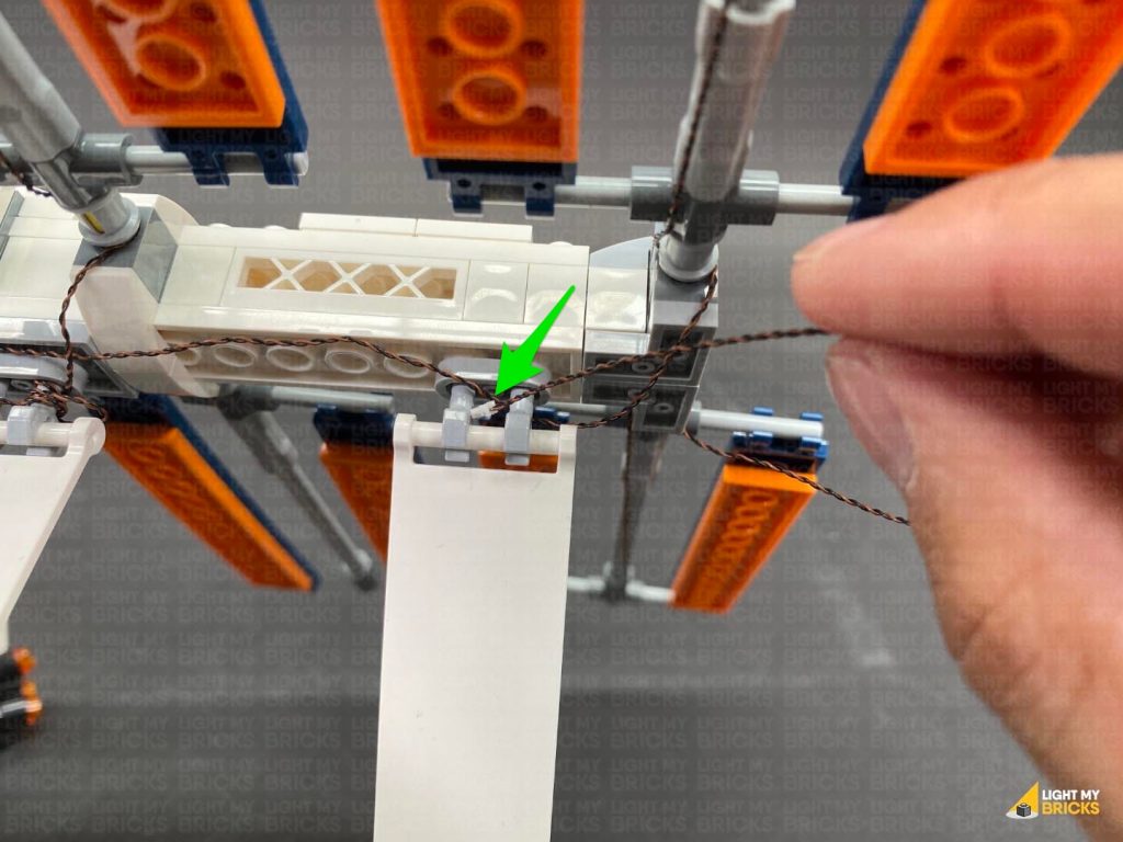
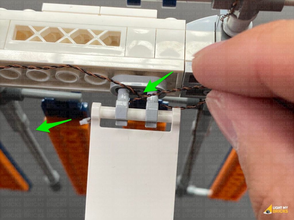
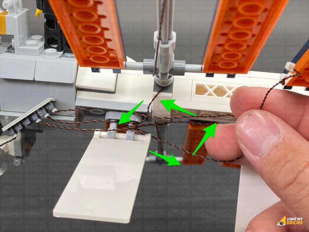
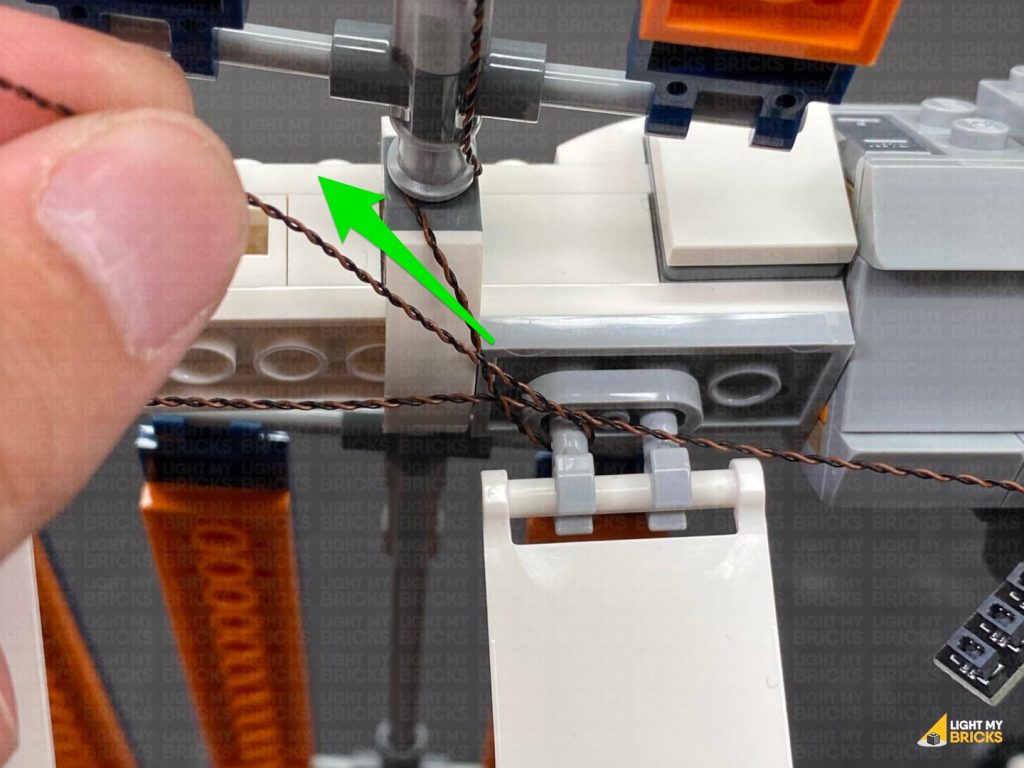
 Turn the set around to the back and this time, thread the Bit Light cable down in between the light grey clips before connecting it to the 6-Port Expansion Board.
Turn the Power ON to test
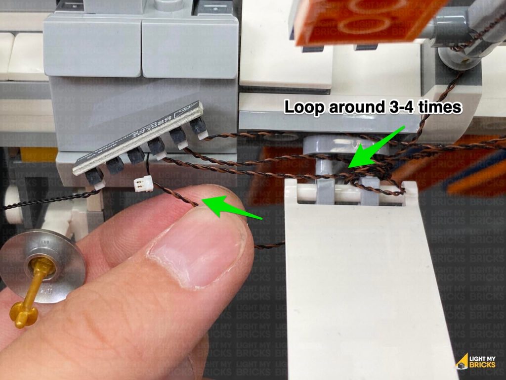
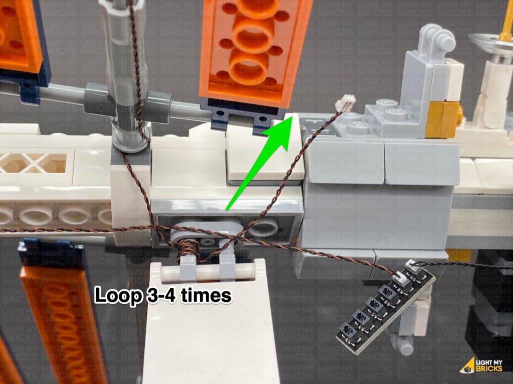
13.) Connect the second bottom panel light.
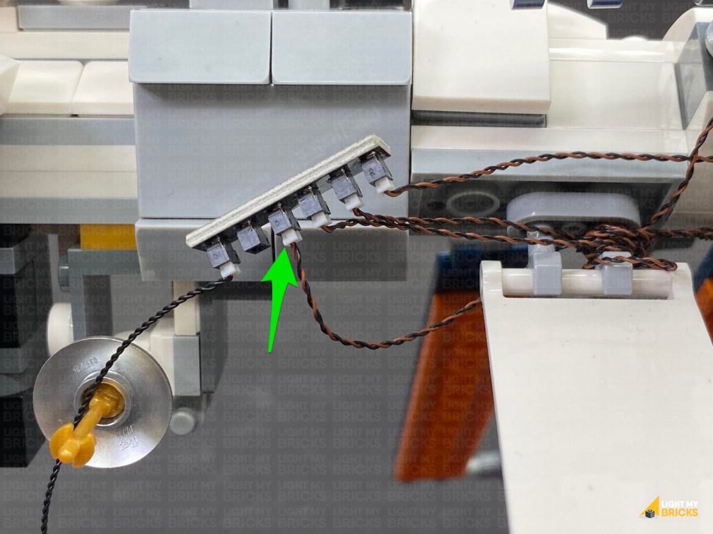
Thread the cable through the top of the light grey clips, then loop it around 3-4 times before connecting to the next spare port on the 6-Port Expansion Board.
Turn the Power ON to test
Note: If you experience any issues with the lights not working and suspect an issue with a component, please try a different port on the expansion board to verify where the fault lies (with the light, expansion board or effects board). To correct any issues with expansion board ports, please view the section addressing expansion board issues on our online troubleshooting guide.
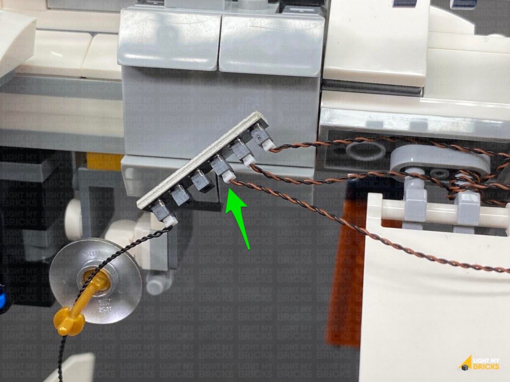
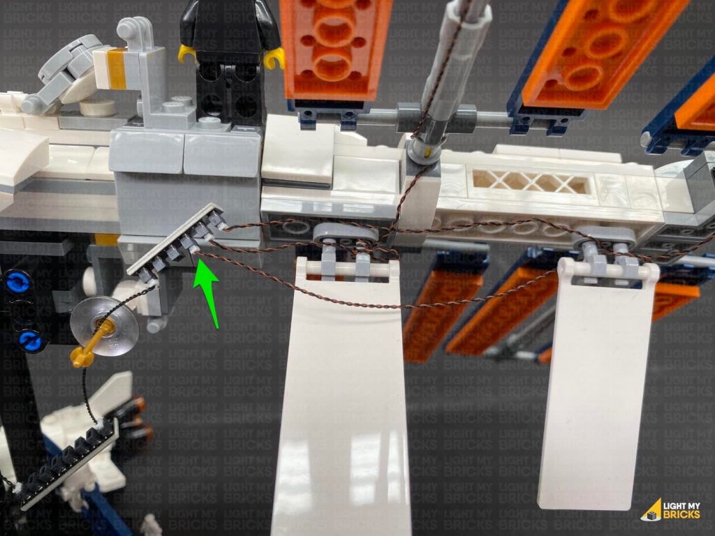
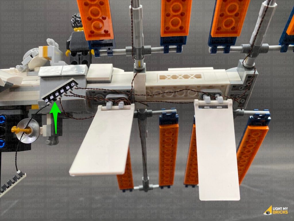
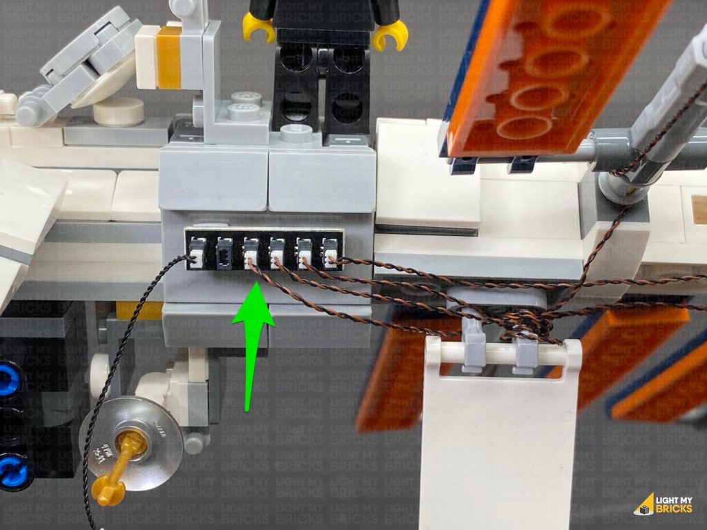
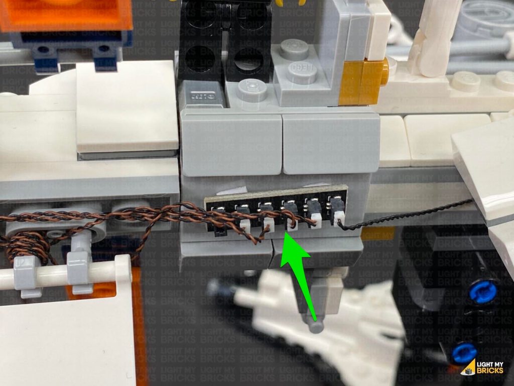
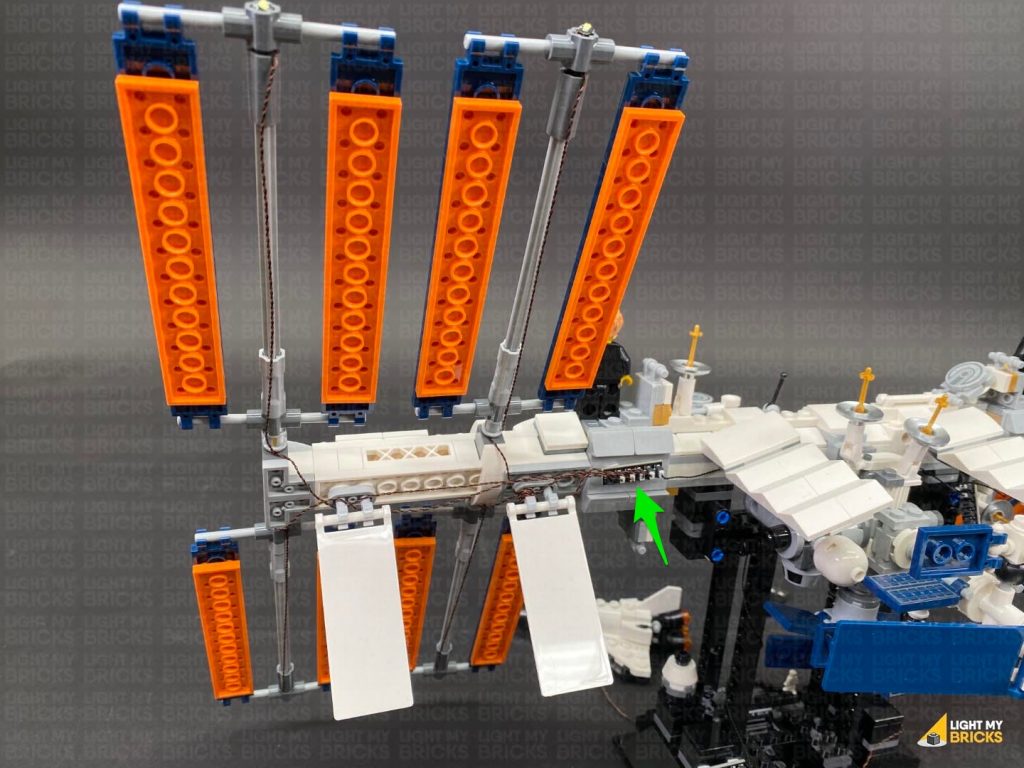
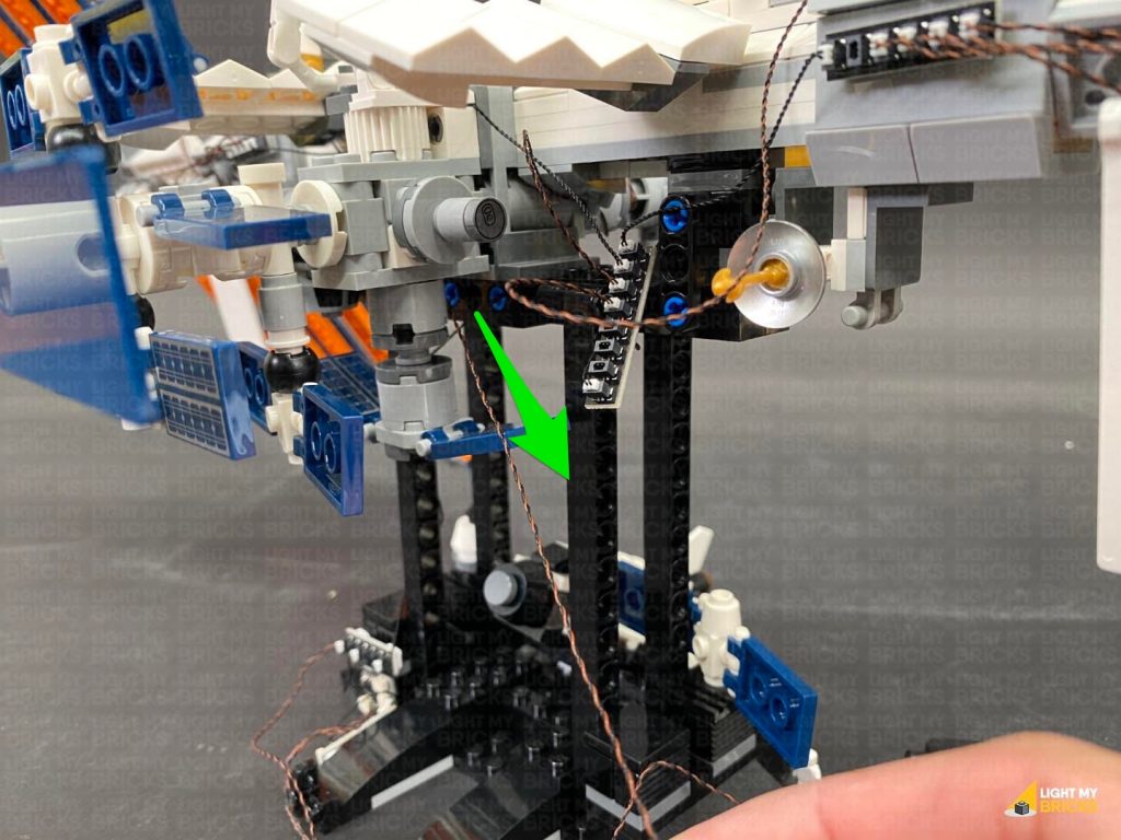
14.) Use 2x Adhesive Squares to mount the 6-port Expansion Board behind the space station in the following position. Then neaten up cabling to ensure there are no cables sticking out and visible from the front side.
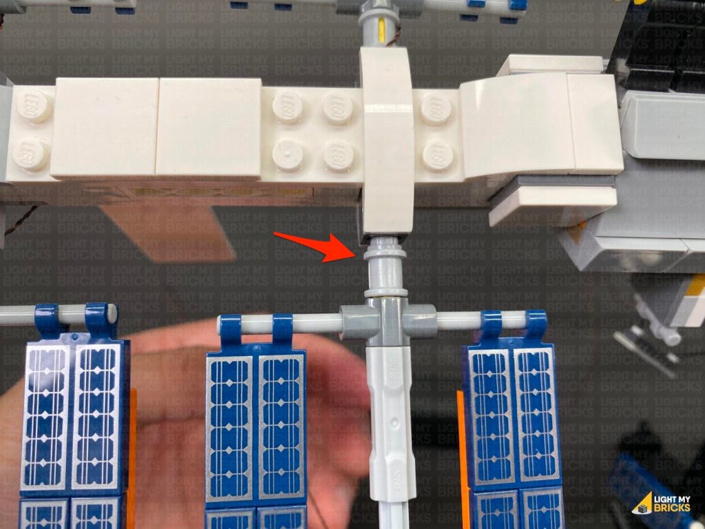
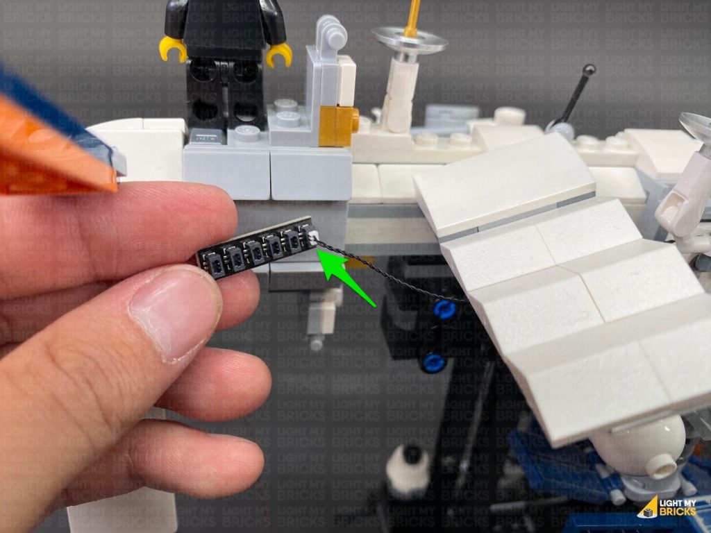
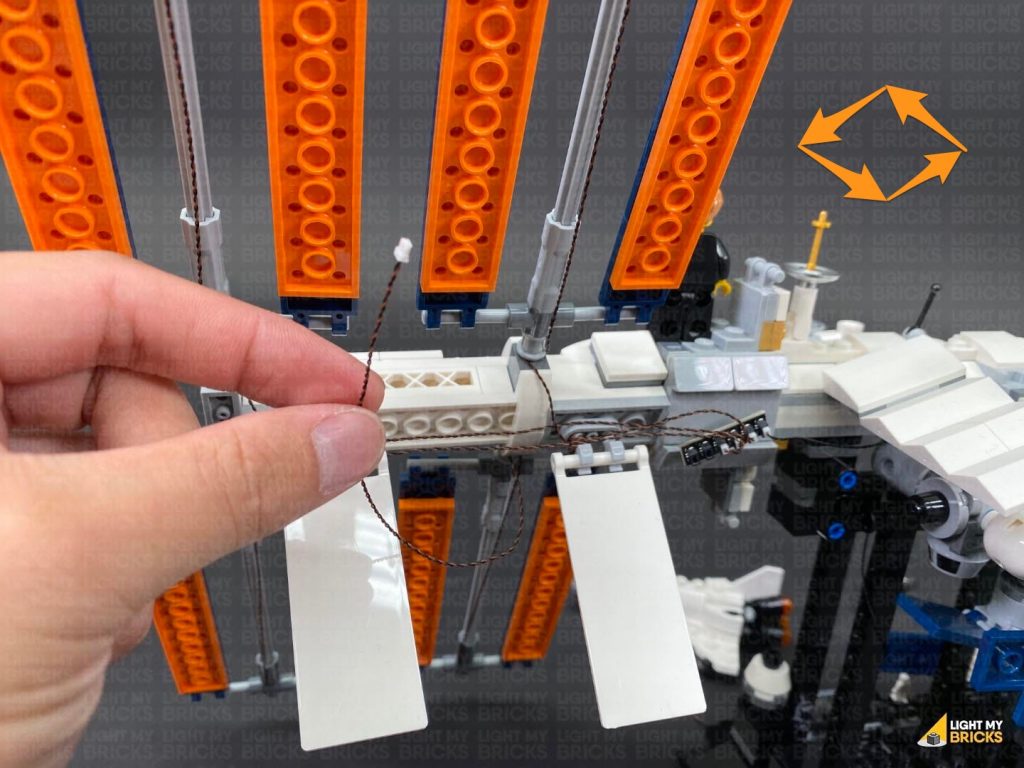
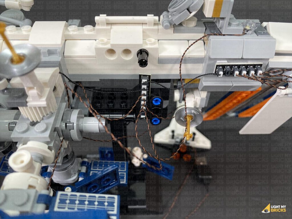
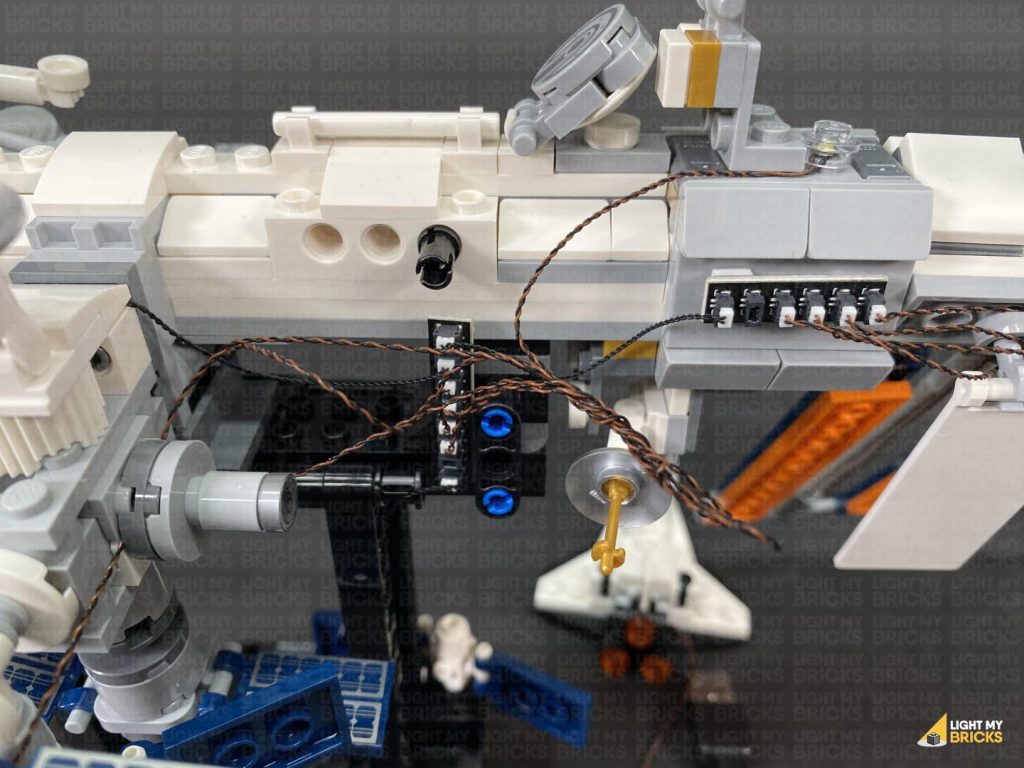
15.) Take the remaining 15cm Connecting Cable and connect it to the 8-Port Expansion Board at the back of the space station. Bring the cable above the middle and across to the left side laying it around sections as shown below, then connect it to the remaining 6-Port Expansion Board.
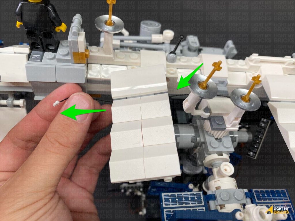
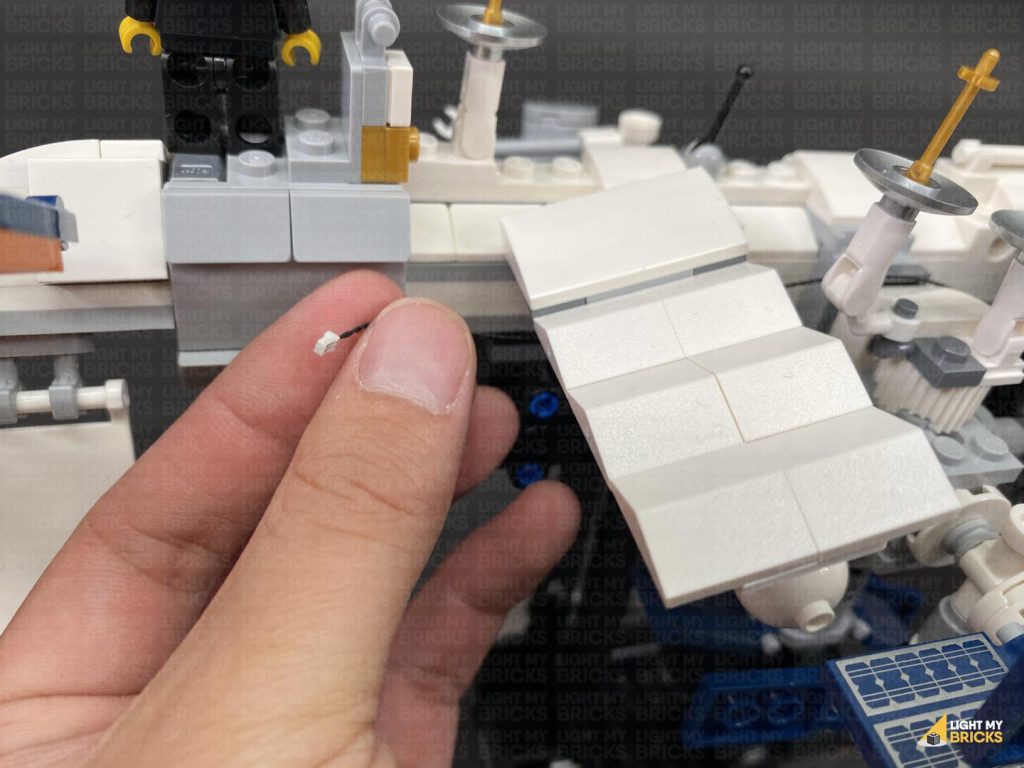
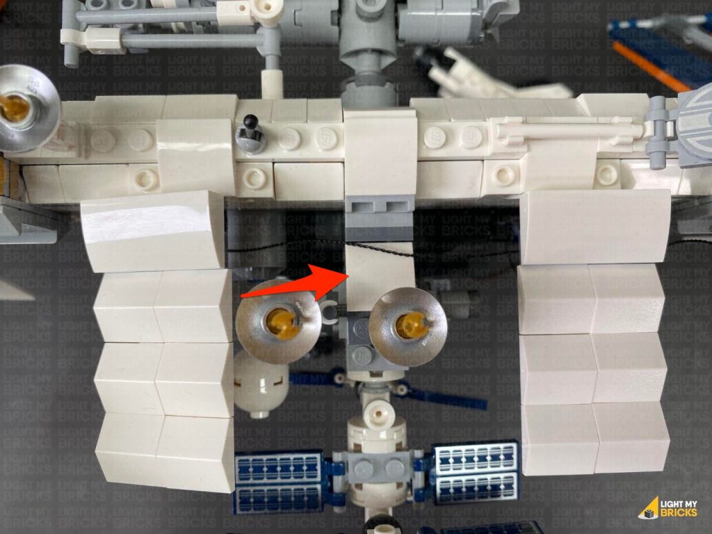
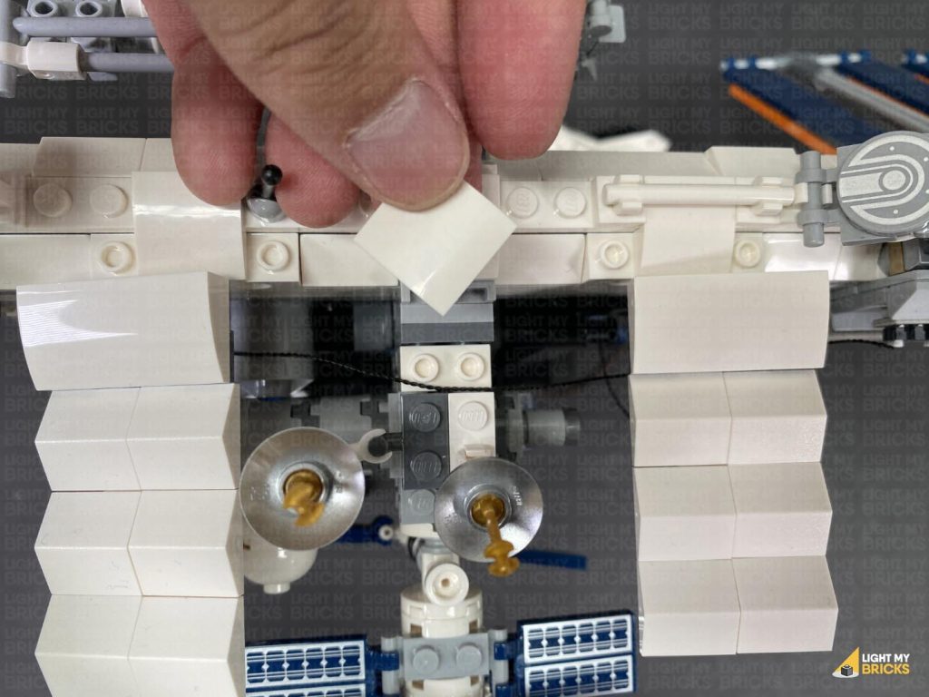
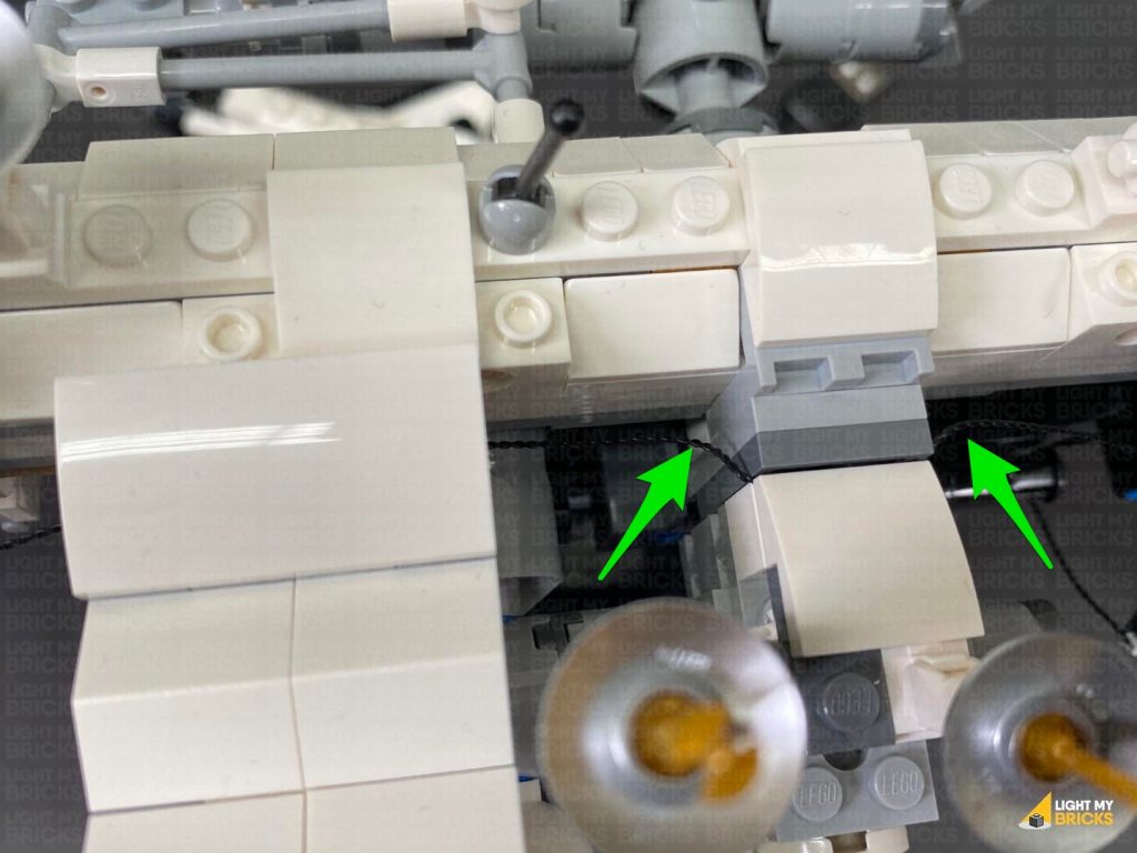
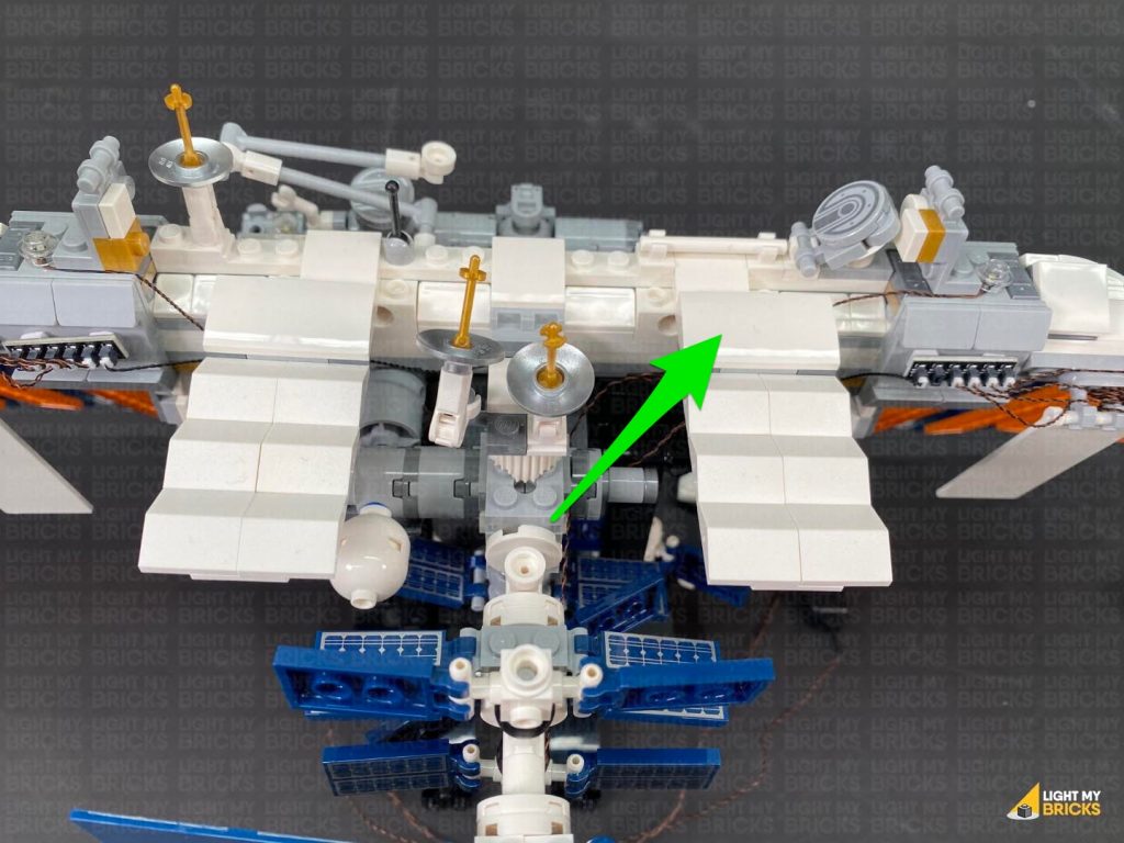
Disconnect the following white curved plate in the middle and lay the cable underneath in between studs. Reconnect the curved plate over the top.
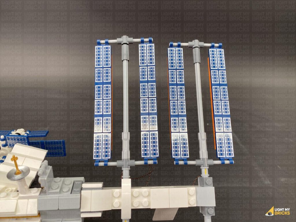
16.) We will now install lights to the panels on the right side. Follow the same methods used for the left panel lights to install lights to this side, starting with the top two panels. Install 2x Cool White 30cm Bit Lights as per below:
CAUTION: Do not forcefully reconnect the pin all the way through, as this may break the cable. It is important that the cable is laid inside one of the technic axle grooves before inserting the pin.
Note – with the Bit Light installed, the technic axle pin will not re-insert the whole way through.
Turn the set around to the back and this time, thread the Bit Light cable down in between the light grey clips before connecting it to the 6-Port Expansion Board.
Turn the Power ON to test
13.) Connect the second bottom panel light.
Thread the cable through the top of the light grey clips, then loop it around 3-4 times before connecting to the next spare port on the 6-Port Expansion Board.
Turn the Power ON to test
Note: If you experience any issues with the lights not working and suspect an issue with a component, please try a different port on the expansion board to verify where the fault lies (with the light, expansion board or effects board). To correct any issues with expansion board ports, please view the section addressing expansion board issues on our online troubleshooting guide.
14.) Use 2x Adhesive Squares to mount the 6-port Expansion Board behind the space station in the following position. Then neaten up cabling to ensure there are no cables sticking out and visible from the front side.
15.) Take the remaining 15cm Connecting Cable and connect it to the 8-Port Expansion Board at the back of the space station. Bring the cable above the middle and across to the left side laying it around sections as shown below, then connect it to the remaining 6-Port Expansion Board.
Disconnect the following white curved plate in the middle and lay the cable underneath in between studs. Reconnect the curved plate over the top.
16.) We will now install lights to the panels on the right side. Follow the same methods used for the left panel lights to install lights to this side, starting with the top two panels. Install 2x Cool White 30cm Bit Lights as per below:
CAUTION: Do not forcefully reconnect the pin all the way through, as this may break the cable. It is important that the cable is laid inside one of the technic axle grooves before inserting the pin.
Note – with the Bit Light installed, the technic axle pin will not re-insert the whole way through.
 Connect Light 1:
Connect Light 2:
Turn On the Power to test!
Note: If you experience any issues with the lights not working and suspect an issue with a component, please try a different port on the expansion board to verify where the fault lies (with the light, expansion board or effects board). To correct any issues with expansion board ports, please view the section addressing expansion board issues on our online troubleshooting guide.
17.) Install another 2x Cool White 30cm Bit Lights to the bottom panels as shown below:
CAUTION: Do not forcefully reconnect the pin all the way through, as this may break the cable. It is important that the cable is laid inside one of the technic axle grooves before inserting the pin.
Note – with the Bit Light installed, the technic axle pin will not re-insert the whole way through.
Connect Light 1:
Connect Light 2:
18.) Stick 2x Adhesive Squares to the back of the 6-Port Expansion Board. Stick the expansion board to the back of the space station in the following position, then push in any excess 15cm connecting cable sticking out.
Connect Light 1:
Connect Light 2:
Turn On the Power to test!
Note: If you experience any issues with the lights not working and suspect an issue with a component, please try a different port on the expansion board to verify where the fault lies (with the light, expansion board or effects board). To correct any issues with expansion board ports, please view the section addressing expansion board issues on our online troubleshooting guide.
17.) Install another 2x Cool White 30cm Bit Lights to the bottom panels as shown below:
CAUTION: Do not forcefully reconnect the pin all the way through, as this may break the cable. It is important that the cable is laid inside one of the technic axle grooves before inserting the pin.
Note – with the Bit Light installed, the technic axle pin will not re-insert the whole way through.
Connect Light 1:
Connect Light 2:
18.) Stick 2x Adhesive Squares to the back of the 6-Port Expansion Board. Stick the expansion board to the back of the space station in the following position, then push in any excess 15cm connecting cable sticking out.
 Turn ON the power to test the lights on the right panel of the ISS are working OK.
Note: If you experience any issues with the lights not working and suspect an issue with a component, please try a different port on the expansion board to verify where the fault lies (with the light, expansion board or effects board). To correct any issues with expansion board ports, please view the section addressing expansion board issues on our online troubleshooting guide.
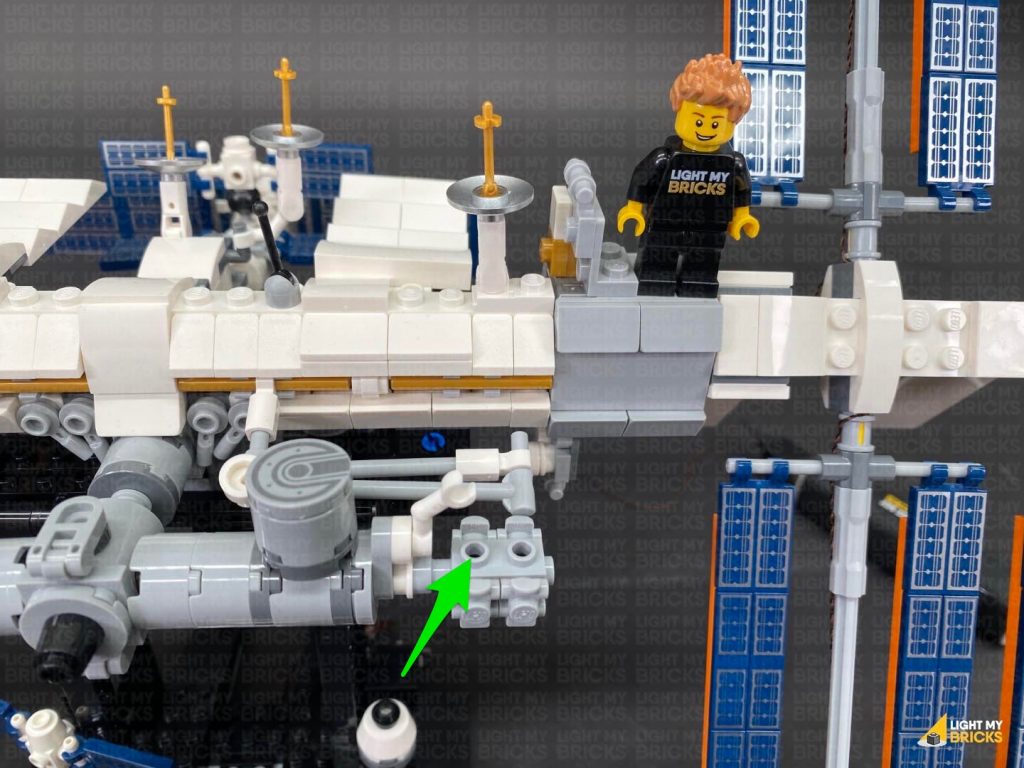
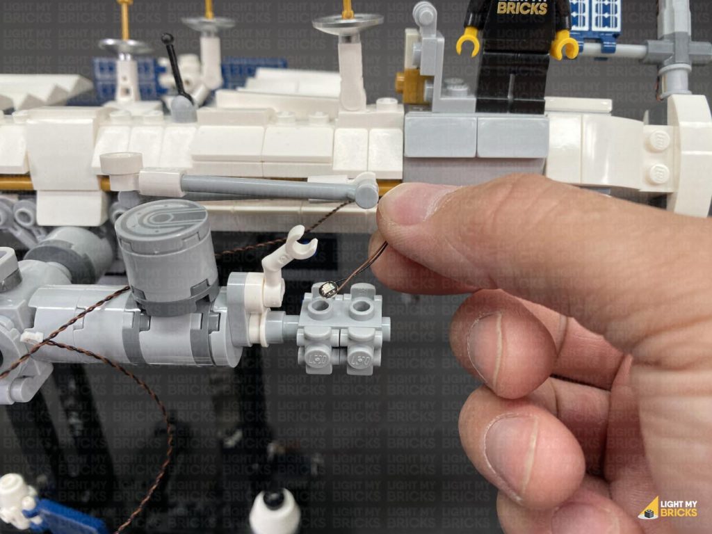
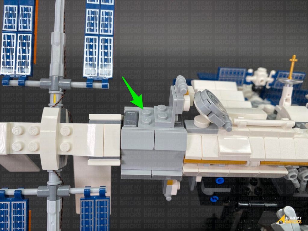
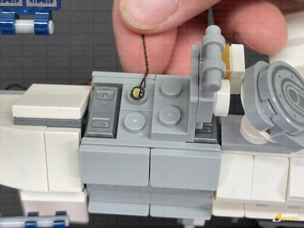
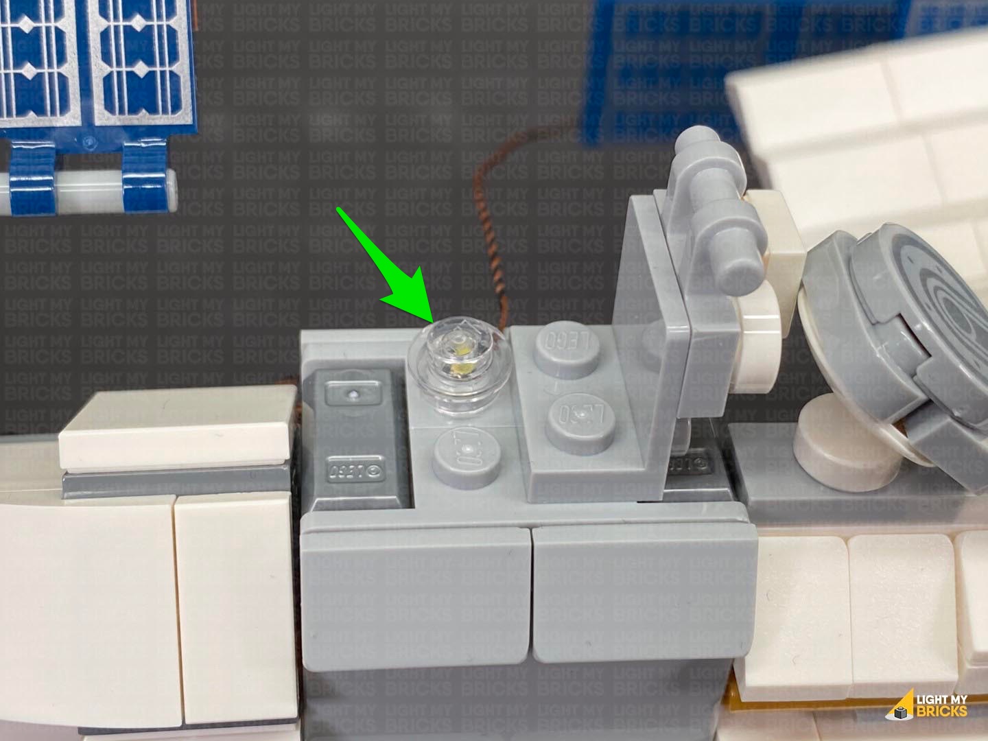
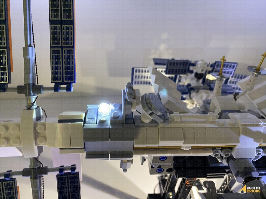
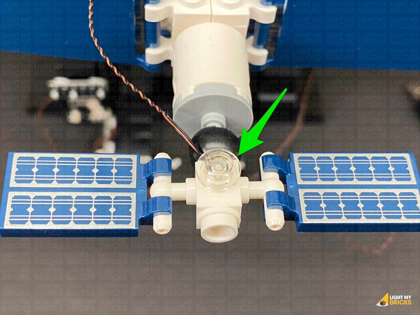
19.) We will now install light to the front right of the ISS. Take out the remaining Cool White 30cm Bit Light and with the cable facing the back, place the Bit Light over the following stud. Secure the Bit Light in place by connecting a provided Trans Clear Round Plate 1×1 over the top.
Turn ON the power to test the lights on the right panel of the ISS are working OK.
Note: If you experience any issues with the lights not working and suspect an issue with a component, please try a different port on the expansion board to verify where the fault lies (with the light, expansion board or effects board). To correct any issues with expansion board ports, please view the section addressing expansion board issues on our online troubleshooting guide.
19.) We will now install light to the front right of the ISS. Take out the remaining Cool White 30cm Bit Light and with the cable facing the back, place the Bit Light over the following stud. Secure the Bit Light in place by connecting a provided Trans Clear Round Plate 1×1 over the top.
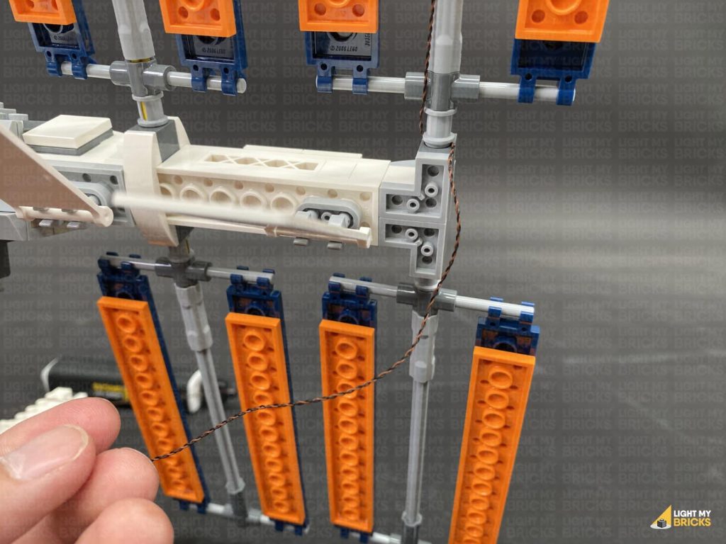
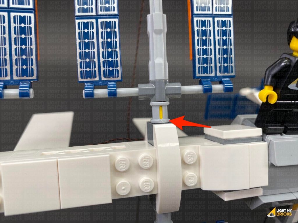
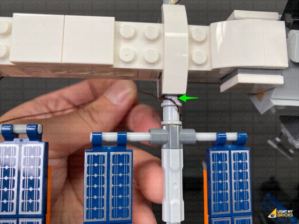
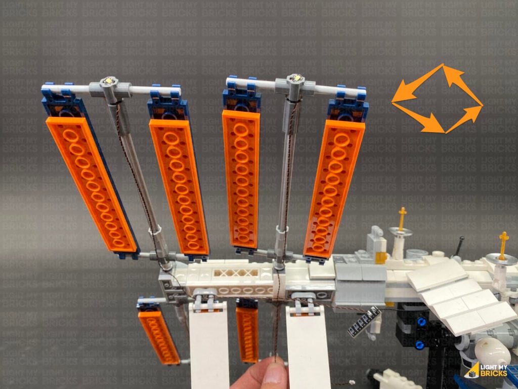
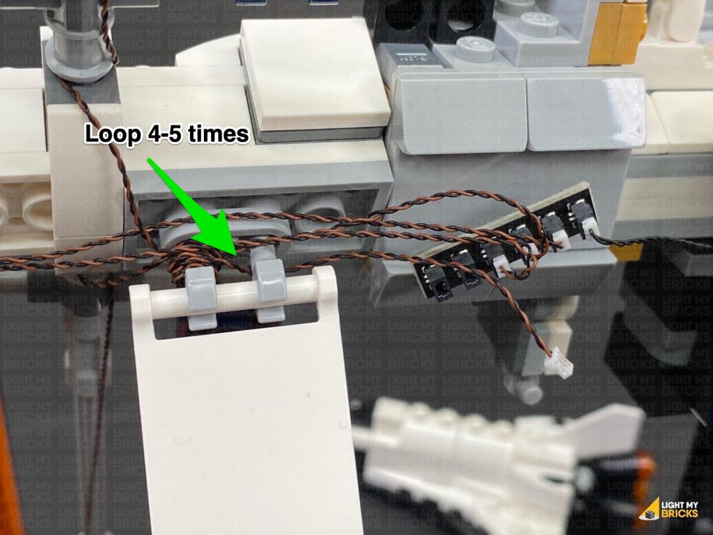
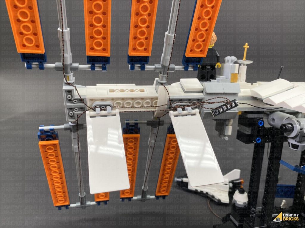
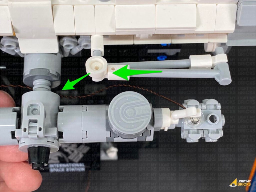
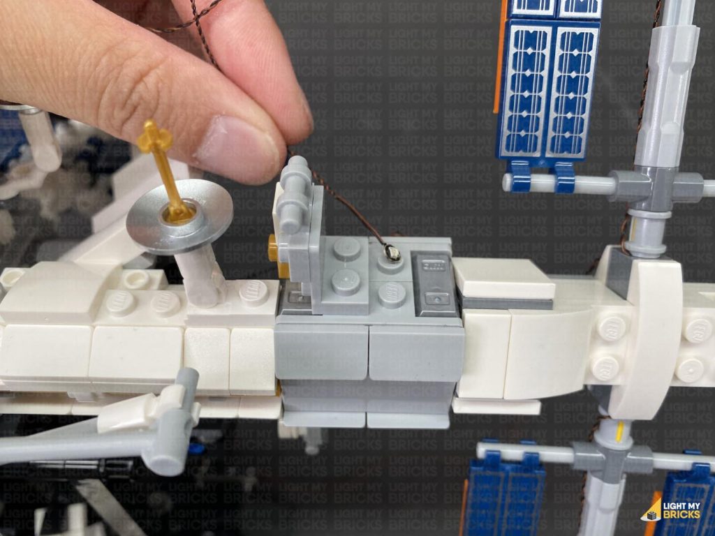
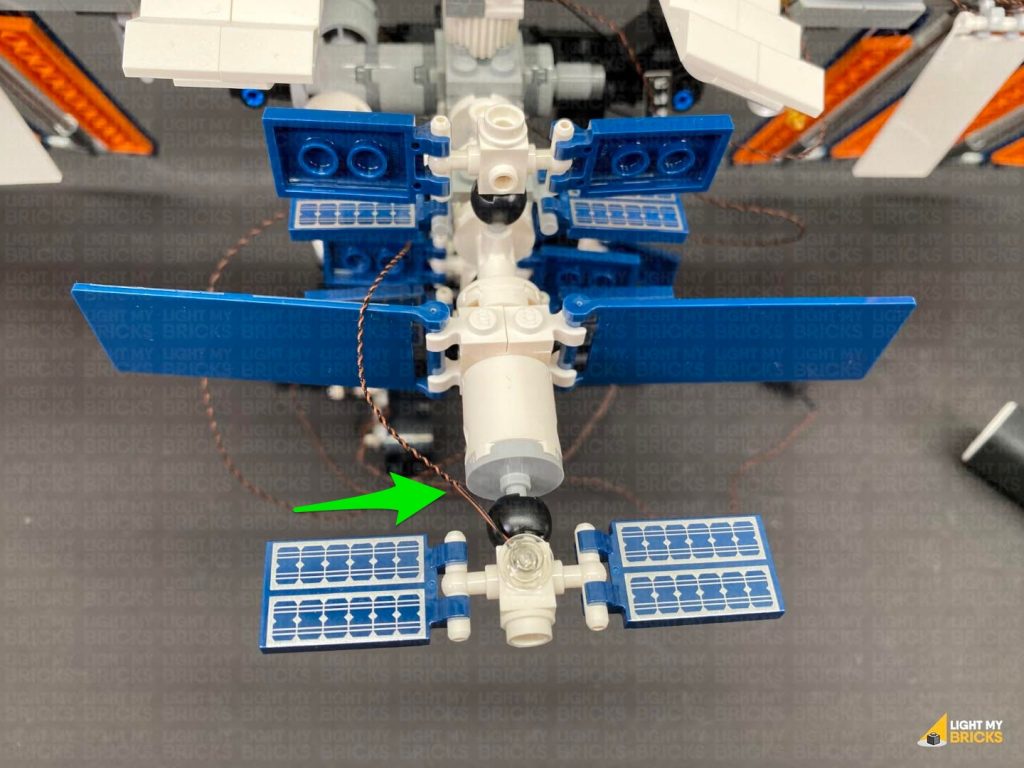
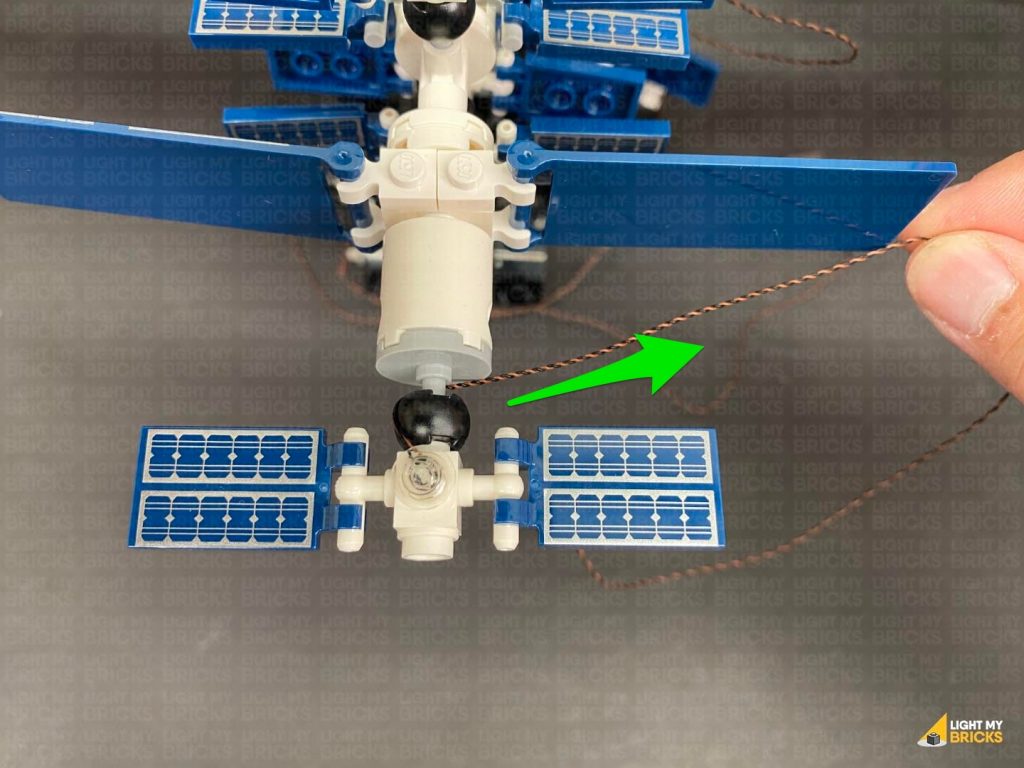
 Bring the cable across to the left and thread it underneath the centre. Loop it around this centre section 4-5 times
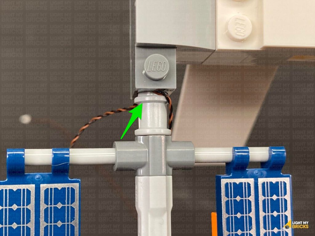
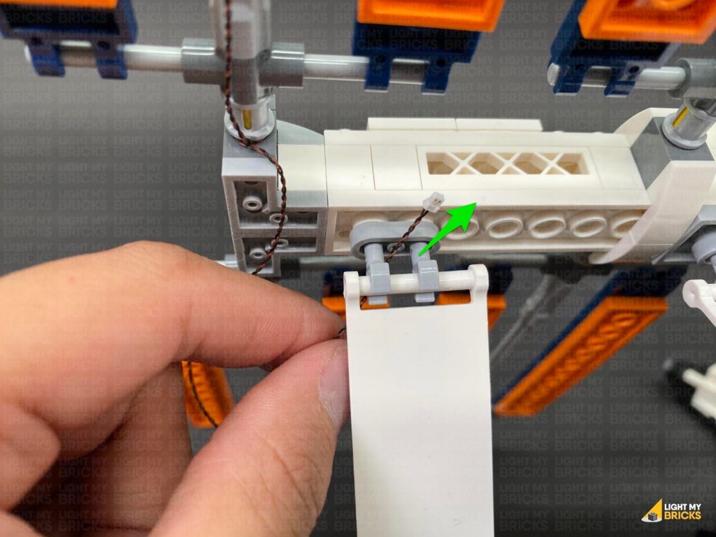
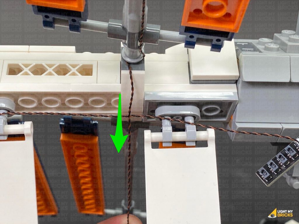
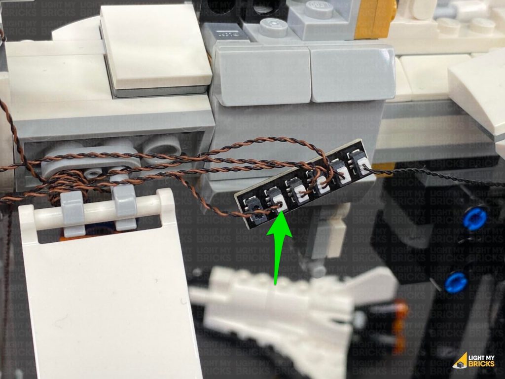
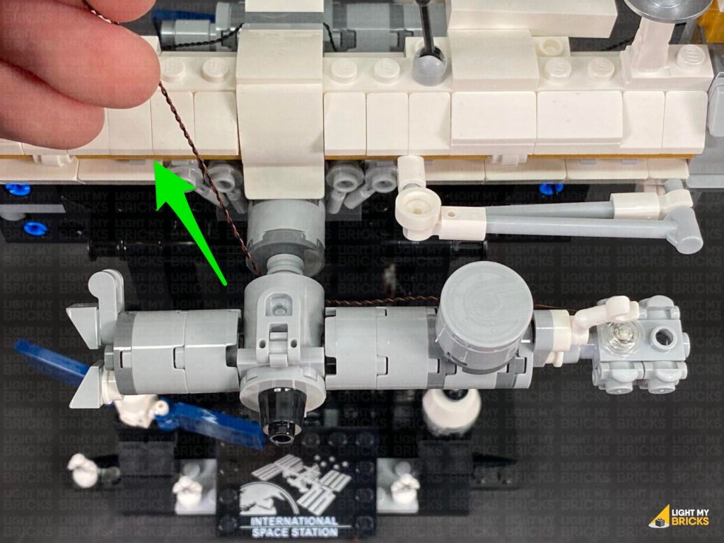
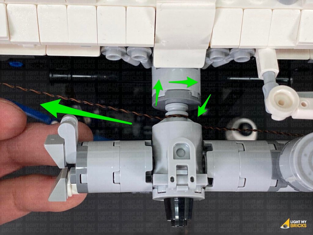
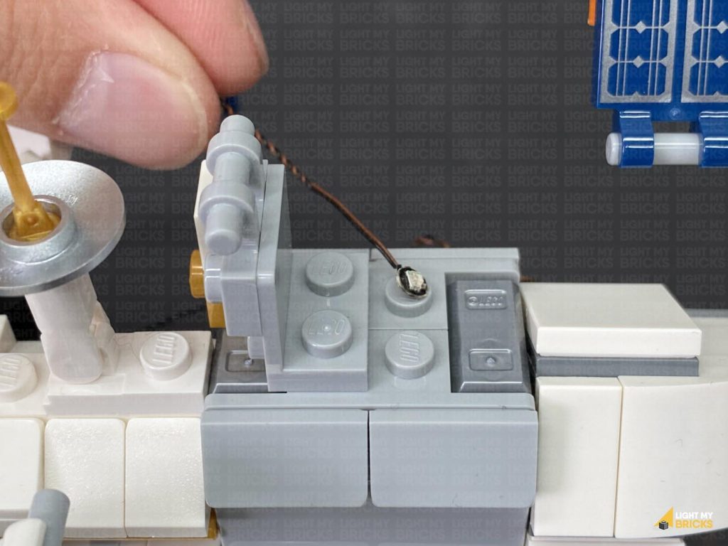
 Push out the light grey lever piece toward the left, then thread the cable through the space which leads to the other side. Slip the cable in between the lever and centre section, then push back the lever to secure the cable in place.
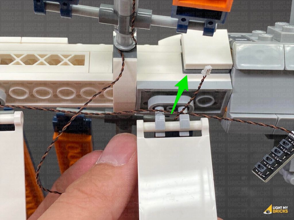
From the back of the set, pull the cable out and connect it to the 8-Port Expansion Board nearby. Turn ON the power to test this light is working OK.
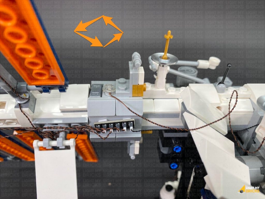
20.) We will now install a flashing light to the left side. Take a Flashing White 15cm Bit Light and with the cable facing the back, place it over the following stud. Secure the light in place using another provided Trans Clear Round Plate 1×1.
Push out the light grey lever piece toward the left, then thread the cable through the space which leads to the other side. Slip the cable in between the lever and centre section, then push back the lever to secure the cable in place.
From the back of the set, pull the cable out and connect it to the 8-Port Expansion Board nearby. Turn ON the power to test this light is working OK.
20.) We will now install a flashing light to the left side. Take a Flashing White 15cm Bit Light and with the cable facing the back, place it over the following stud. Secure the light in place using another provided Trans Clear Round Plate 1×1.
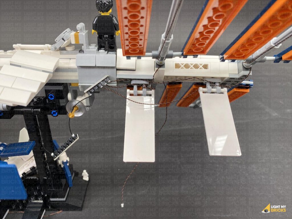
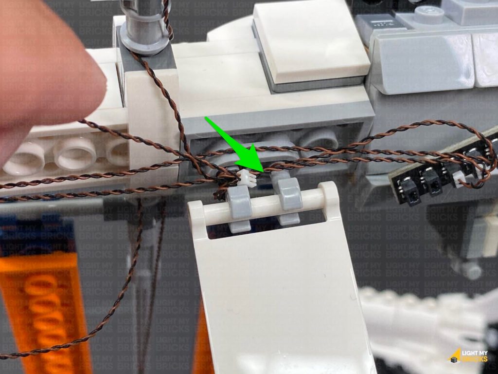
 Turn the set around to the back and disconnect the following section. Lay the cable down toward the left side in between studs, then reconnect the section over the top of the cable.
Connect the cable to a spare port on the 8-Port Expansion Board, then turn ON the power to test the flashing white light is working OK.
Turn the set around to the back and disconnect the following section. Lay the cable down toward the left side in between studs, then reconnect the section over the top of the cable.
Connect the cable to a spare port on the 8-Port Expansion Board, then turn ON the power to test the flashing white light is working OK.
 Note: If you experience any issues with the lights not working and suspect an issue with a component, please try a different port on the expansion board to verify where the fault lies (with the light, expansion board or effects board). To correct any issues with expansion board ports, please view the section addressing expansion board issues on our online troubleshooting guide.
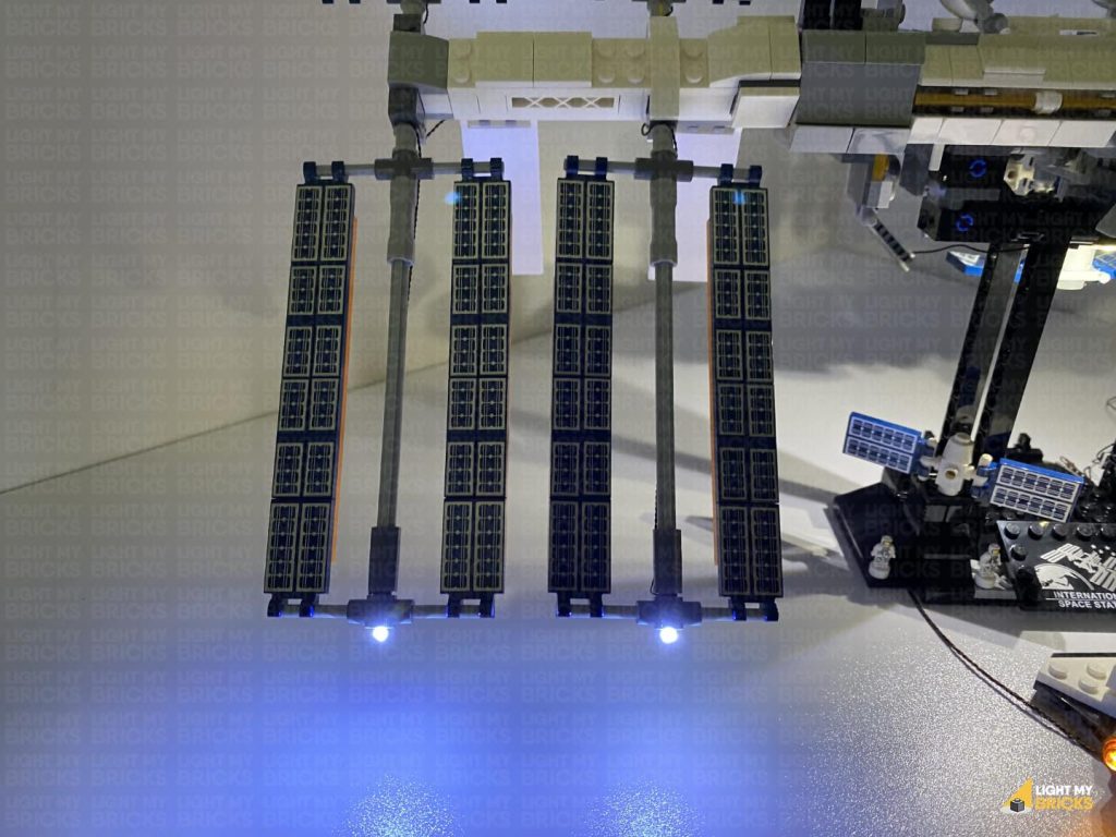
21.) We will now install a Blue light to the right side. Take out a Blue 30cm Bit Light and with the cable facing the back, place it over the following stud. Secure the light in place by connecting a provided Trans Clear Round Plate 1×1 over the top as shown below:
Note: If you experience any issues with the lights not working and suspect an issue with a component, please try a different port on the expansion board to verify where the fault lies (with the light, expansion board or effects board). To correct any issues with expansion board ports, please view the section addressing expansion board issues on our online troubleshooting guide.
21.) We will now install a Blue light to the right side. Take out a Blue 30cm Bit Light and with the cable facing the back, place it over the following stud. Secure the light in place by connecting a provided Trans Clear Round Plate 1×1 over the top as shown below:
 Turn the set around to the back and disconnect the following section. Lay the cable down toward the right, in between studs, then reconnect the section over the top of the cable.
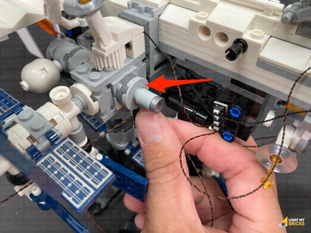
Bring the cable down and thread it through the hole of the technic brick underneath the white wing. Pull the cable all the way out from the other side of the technic brick, then thread it back underneath toward the right side. Pull the cable out from the other side and connect it to a spare port on the 8-Port Expansion Board. Turn ON the power to test the Blue Light is working OK.
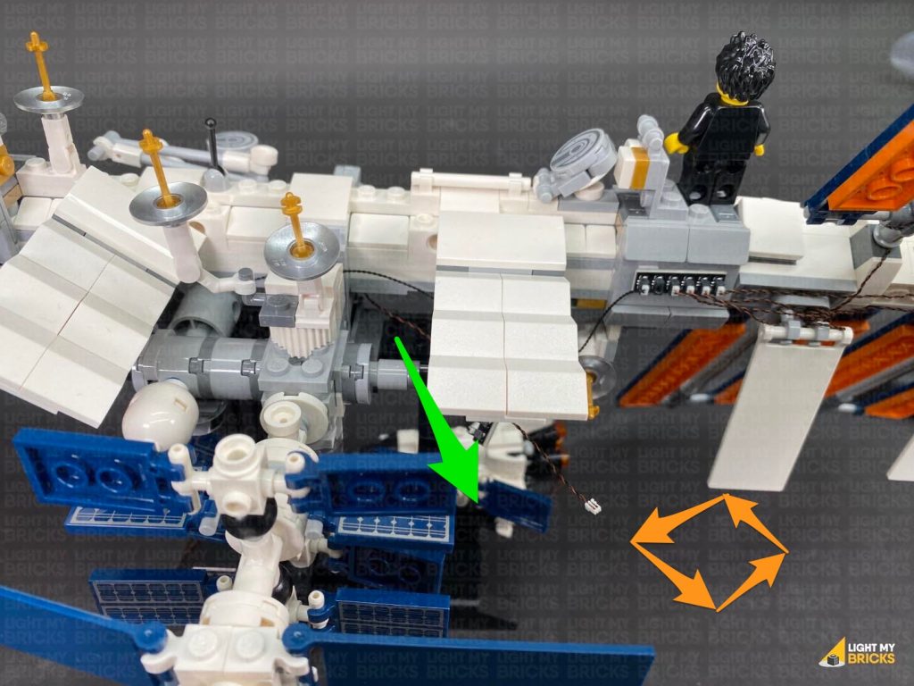
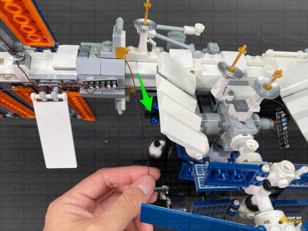
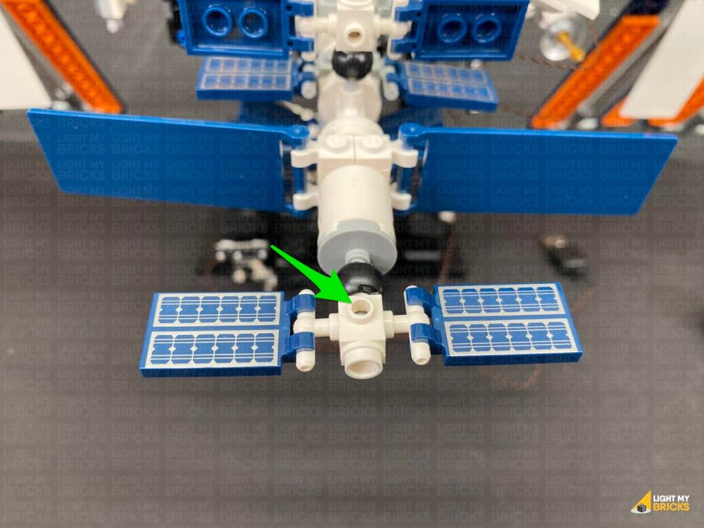
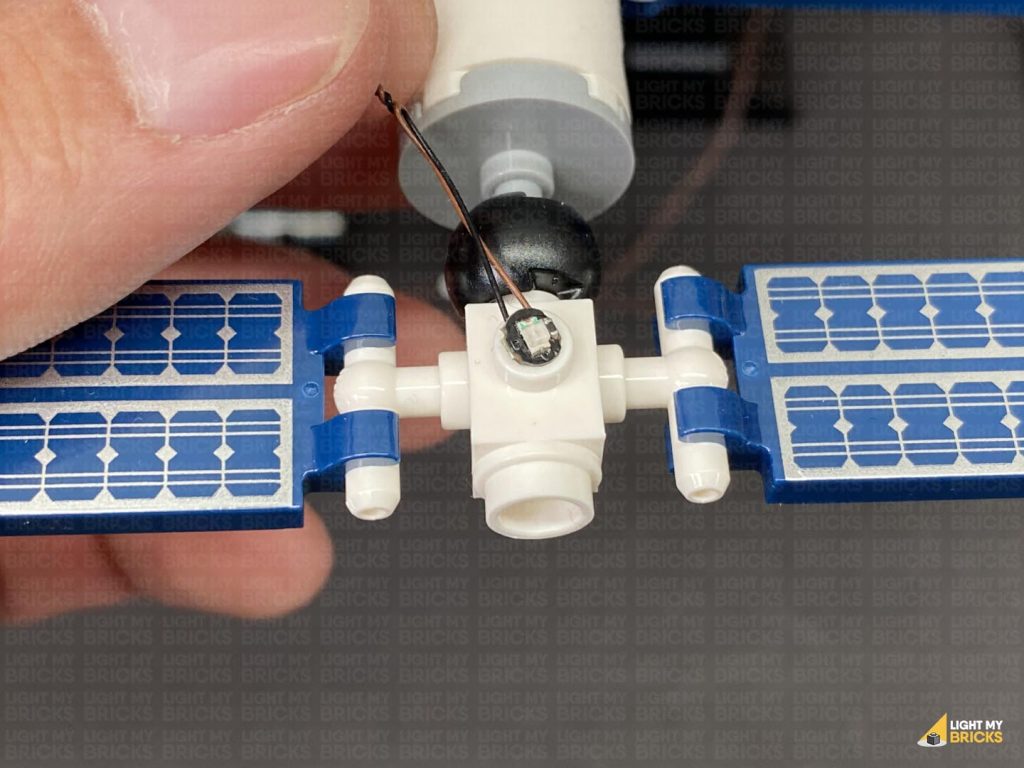
22.) Turn the set around to the back and take out the remaining Blue 30cm Bit Light. With the cable facing the back (front of the ISS), place the Bit Light over the following stud. Secure the Bit Light in place by connecting the remaining provided Trans Clear Round Plate 1×1 over the top.
Turn the set around to the back and disconnect the following section. Lay the cable down toward the right, in between studs, then reconnect the section over the top of the cable.
Bring the cable down and thread it through the hole of the technic brick underneath the white wing. Pull the cable all the way out from the other side of the technic brick, then thread it back underneath toward the right side. Pull the cable out from the other side and connect it to a spare port on the 8-Port Expansion Board. Turn ON the power to test the Blue Light is working OK.
22.) Turn the set around to the back and take out the remaining Blue 30cm Bit Light. With the cable facing the back (front of the ISS), place the Bit Light over the following stud. Secure the Bit Light in place by connecting the remaining provided Trans Clear Round Plate 1×1 over the top.
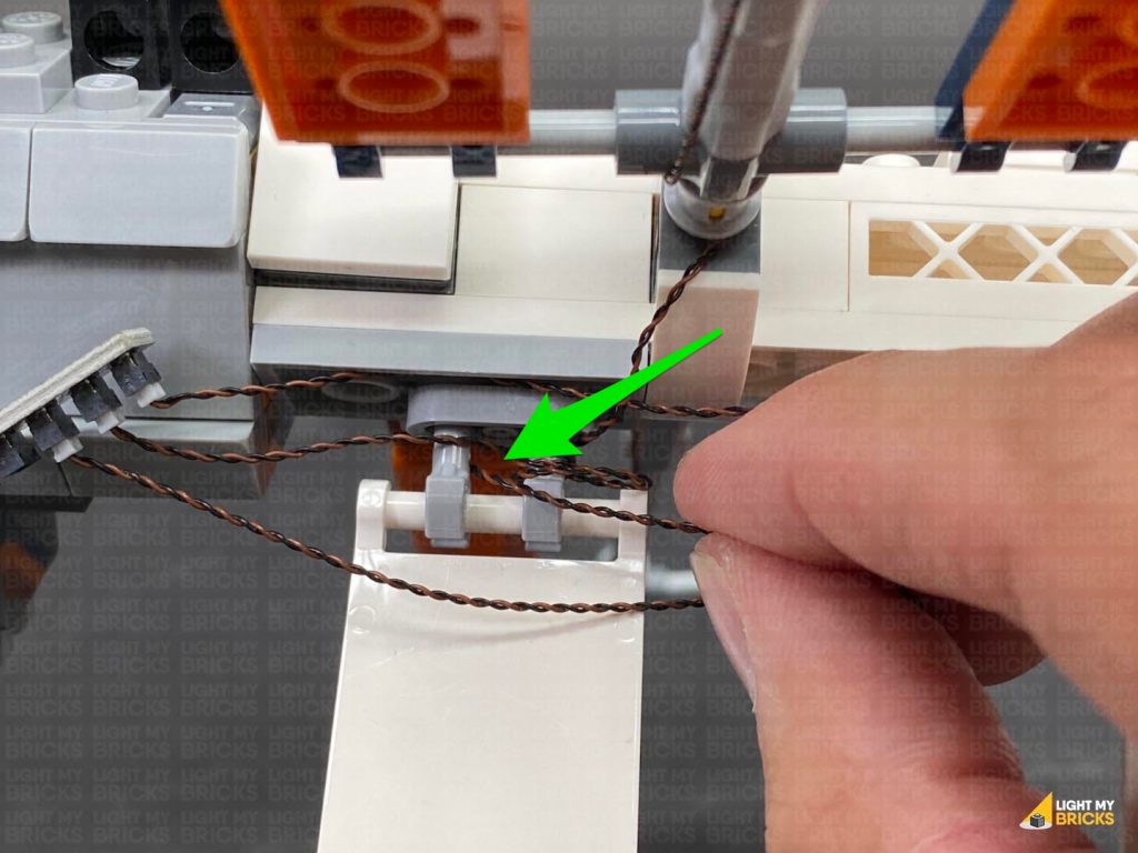
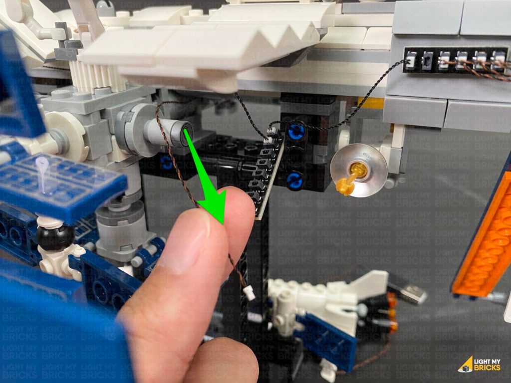
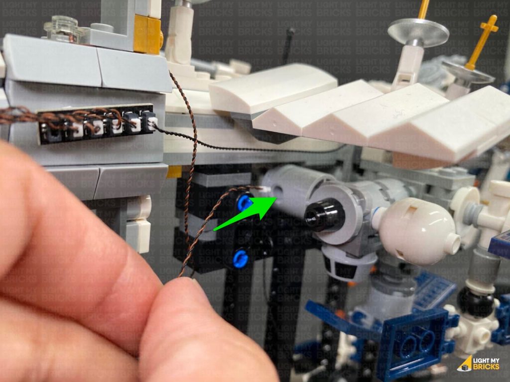
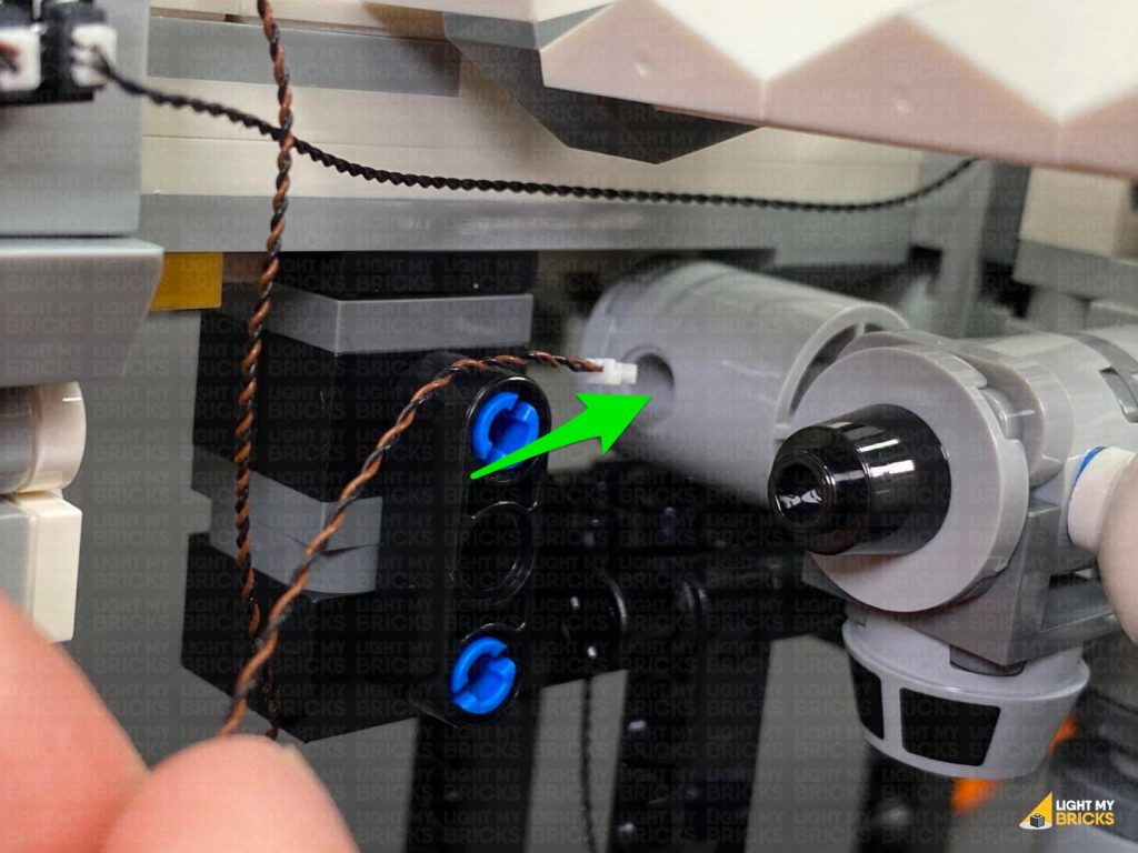
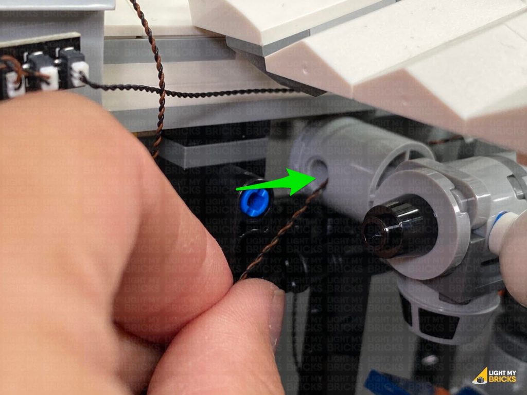
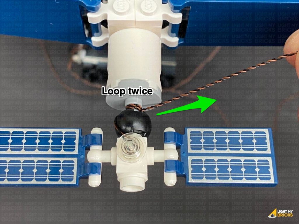
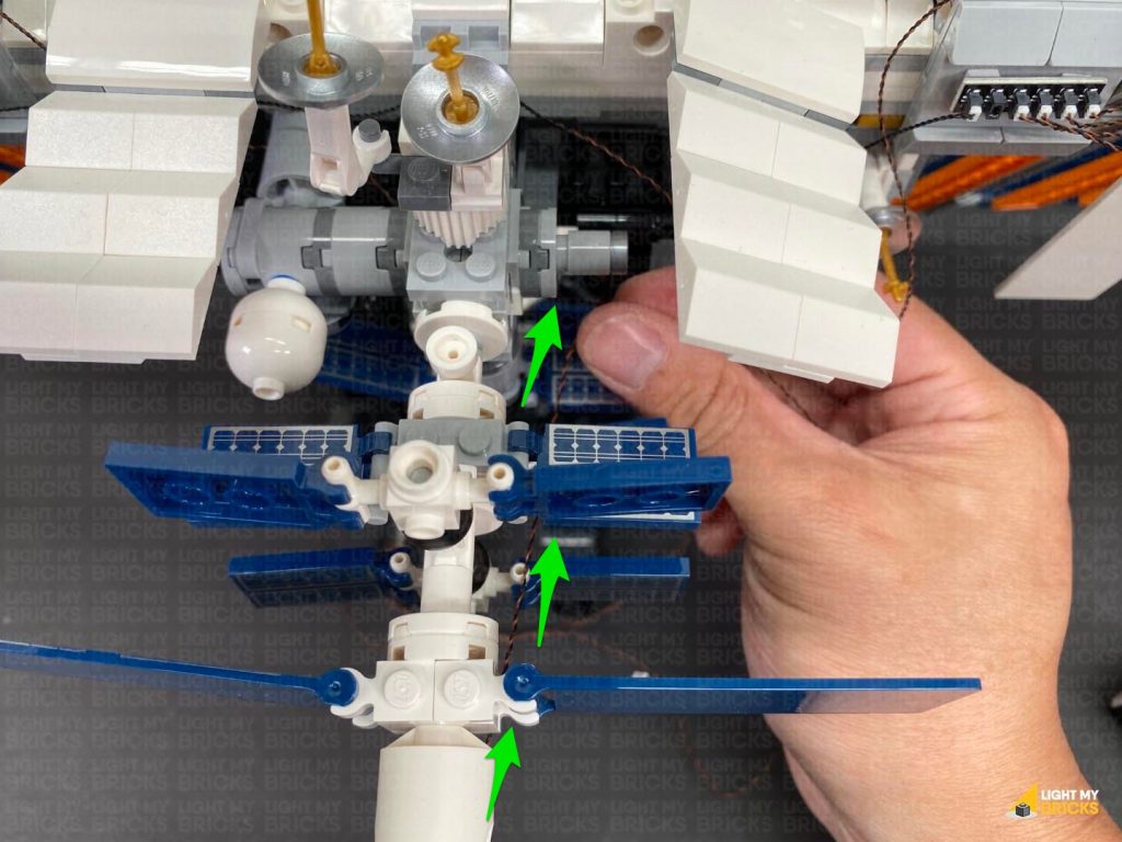
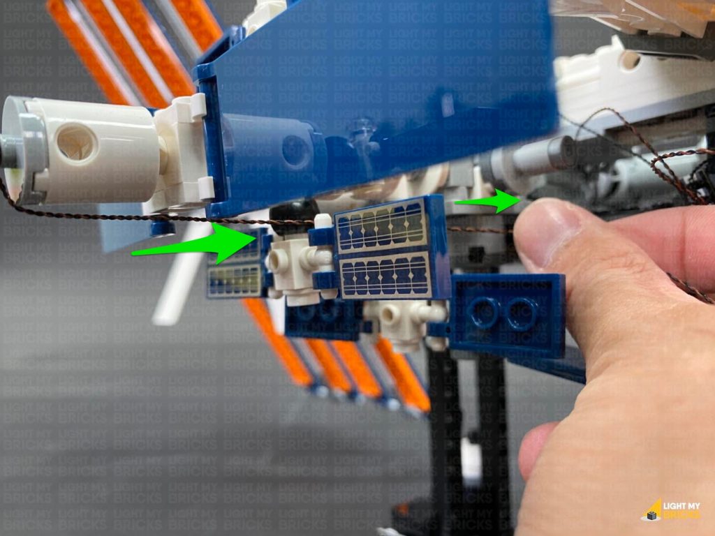
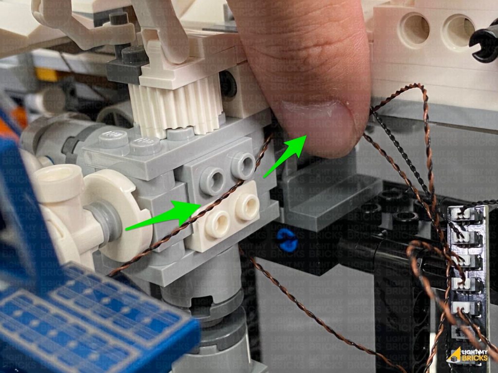
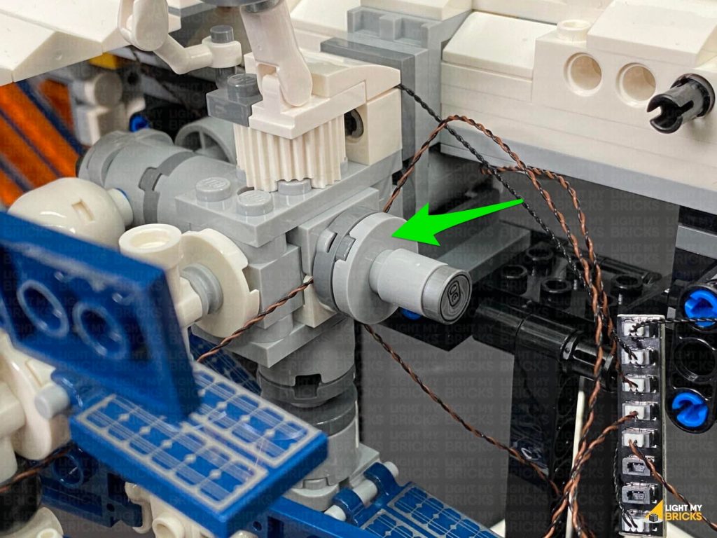
 Bring the cable behind, then underneath and loop it around this section twice (behind the black ball piece), then continue to thread it towards the middle section.
Disconnect the white wing section, as well as the following round piece, and lay the cable in between studs. Reconnect this piece over the top, then connect the Bit Light to the 8-Port Expansion Board.
Bring the cable behind, then underneath and loop it around this section twice (behind the black ball piece), then continue to thread it towards the middle section.
Disconnect the white wing section, as well as the following round piece, and lay the cable in between studs. Reconnect this piece over the top, then connect the Bit Light to the 8-Port Expansion Board.
 Turn ON the power to test the rear Blue light is working OK.
Note: If you experience any issues with the lights not working and suspect an issue with a component, please try a different port on the expansion board to verify where the fault lies (with the light, expansion board or effects board). To correct any issues with expansion board ports, please view the section addressing expansion board issues on our online troubleshooting guide.
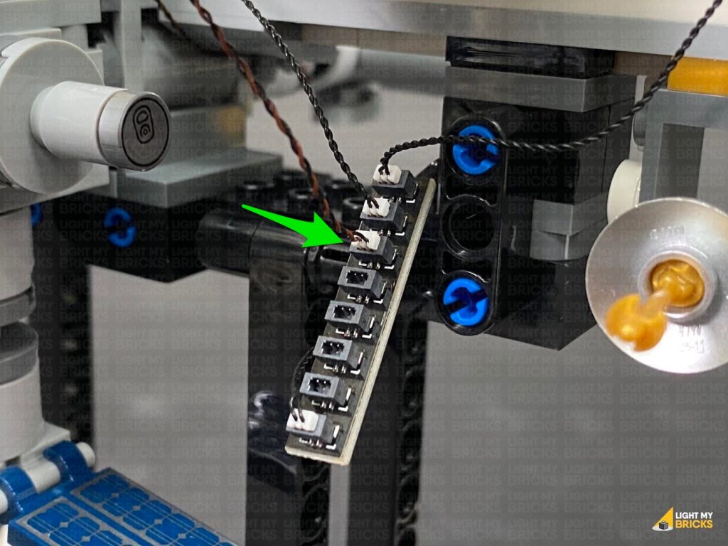
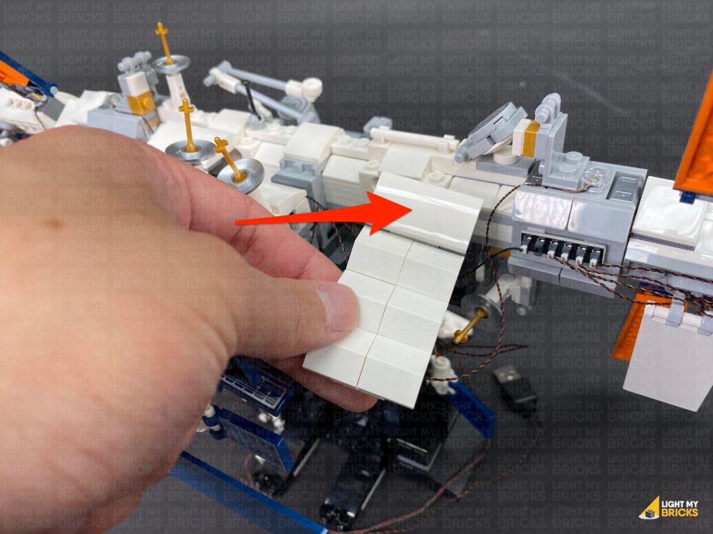
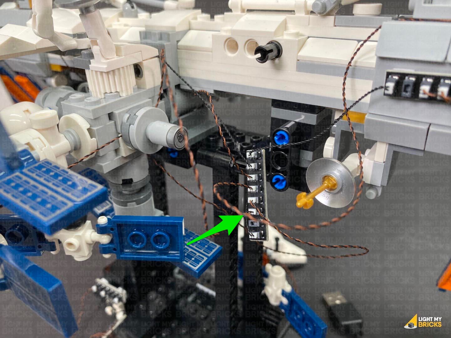
23.) The final step is to mount the 8-port expansion board and neaten up cables. Stick 2x Adhesive squares to the back of the 8-Port Expansion Board, then stick it vertically in the following position on the back of the ISS.
Pull up the excess connecting cable from the strip light, then twist and fold up all the Bit Light cables into a neat bunch. Reconnect the white wing section, then hide the bunched up cables underneath.
Turn ON the power to test the rear Blue light is working OK.
Note: If you experience any issues with the lights not working and suspect an issue with a component, please try a different port on the expansion board to verify where the fault lies (with the light, expansion board or effects board). To correct any issues with expansion board ports, please view the section addressing expansion board issues on our online troubleshooting guide.
23.) The final step is to mount the 8-port expansion board and neaten up cables. Stick 2x Adhesive squares to the back of the 8-Port Expansion Board, then stick it vertically in the following position on the back of the ISS.
Pull up the excess connecting cable from the strip light, then twist and fold up all the Bit Light cables into a neat bunch. Reconnect the white wing section, then hide the bunched up cables underneath.
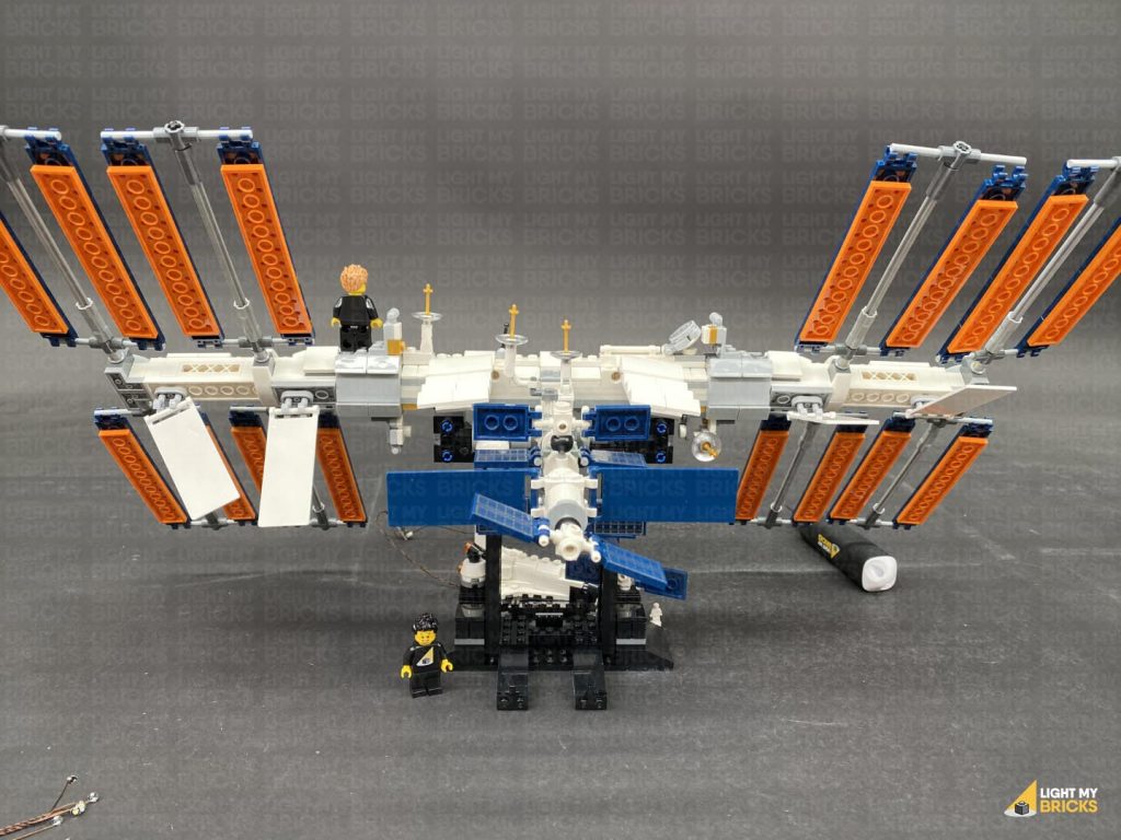
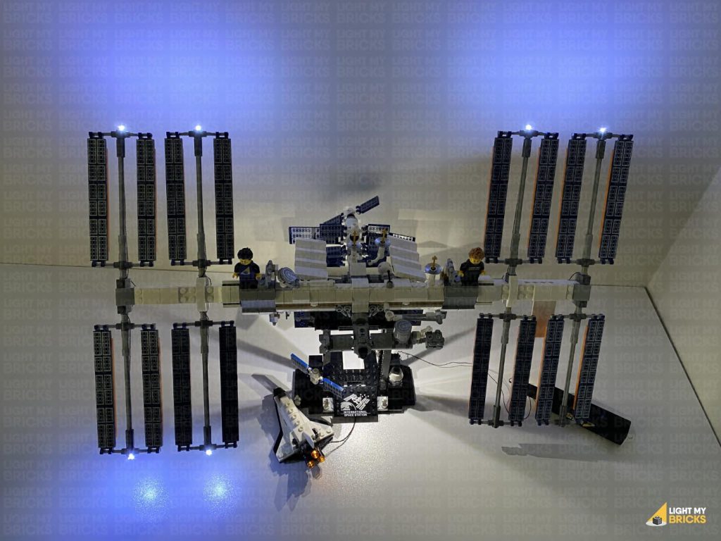
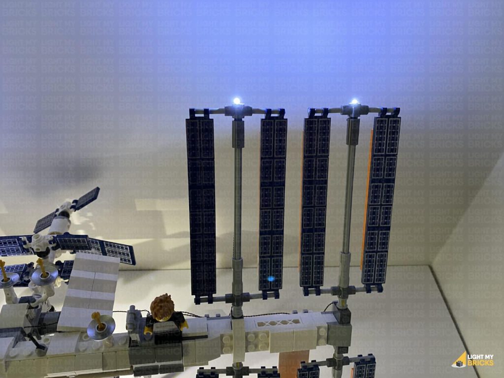
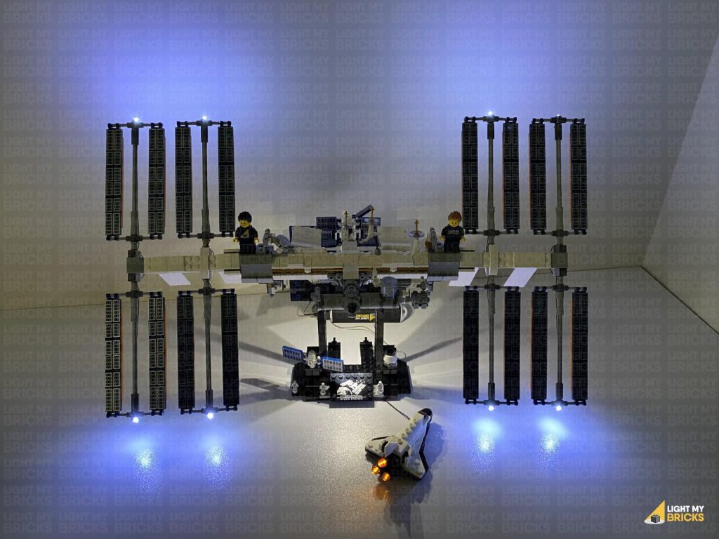
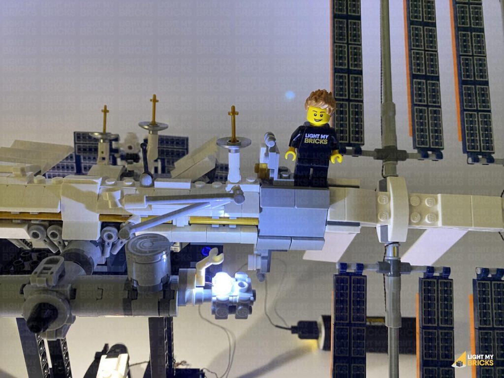
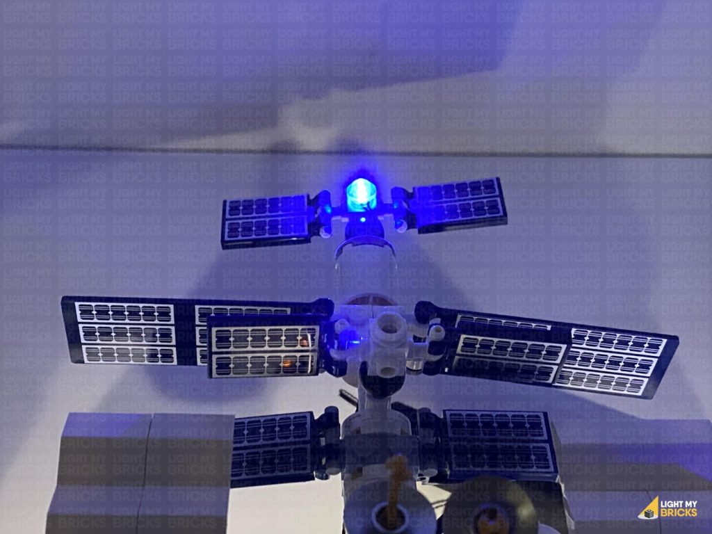
This finally completes installation of the Light My Bricks International Space Station 21321 Light Kit.
We thank you for purchasing this product and hope you ENJOY!