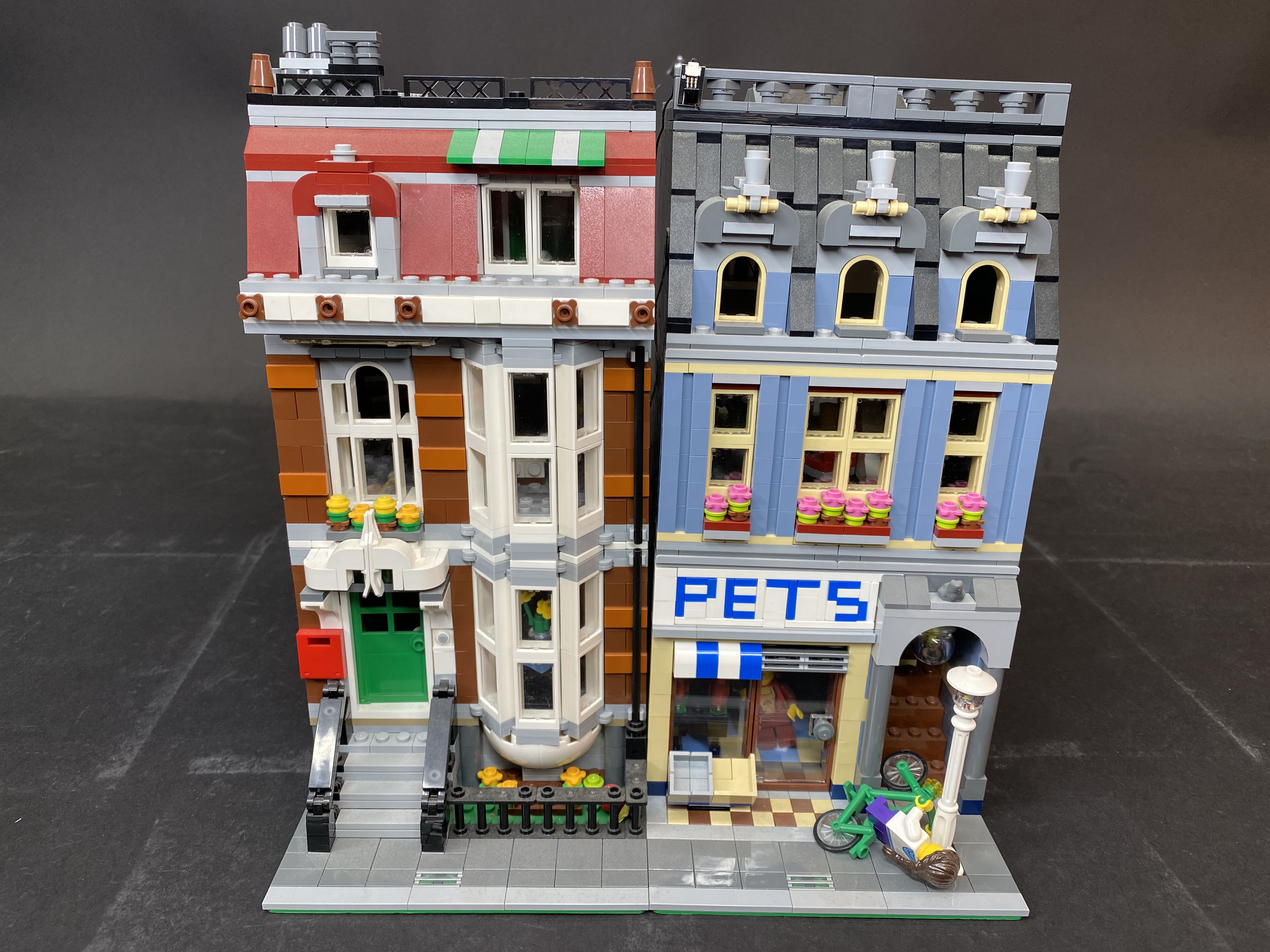
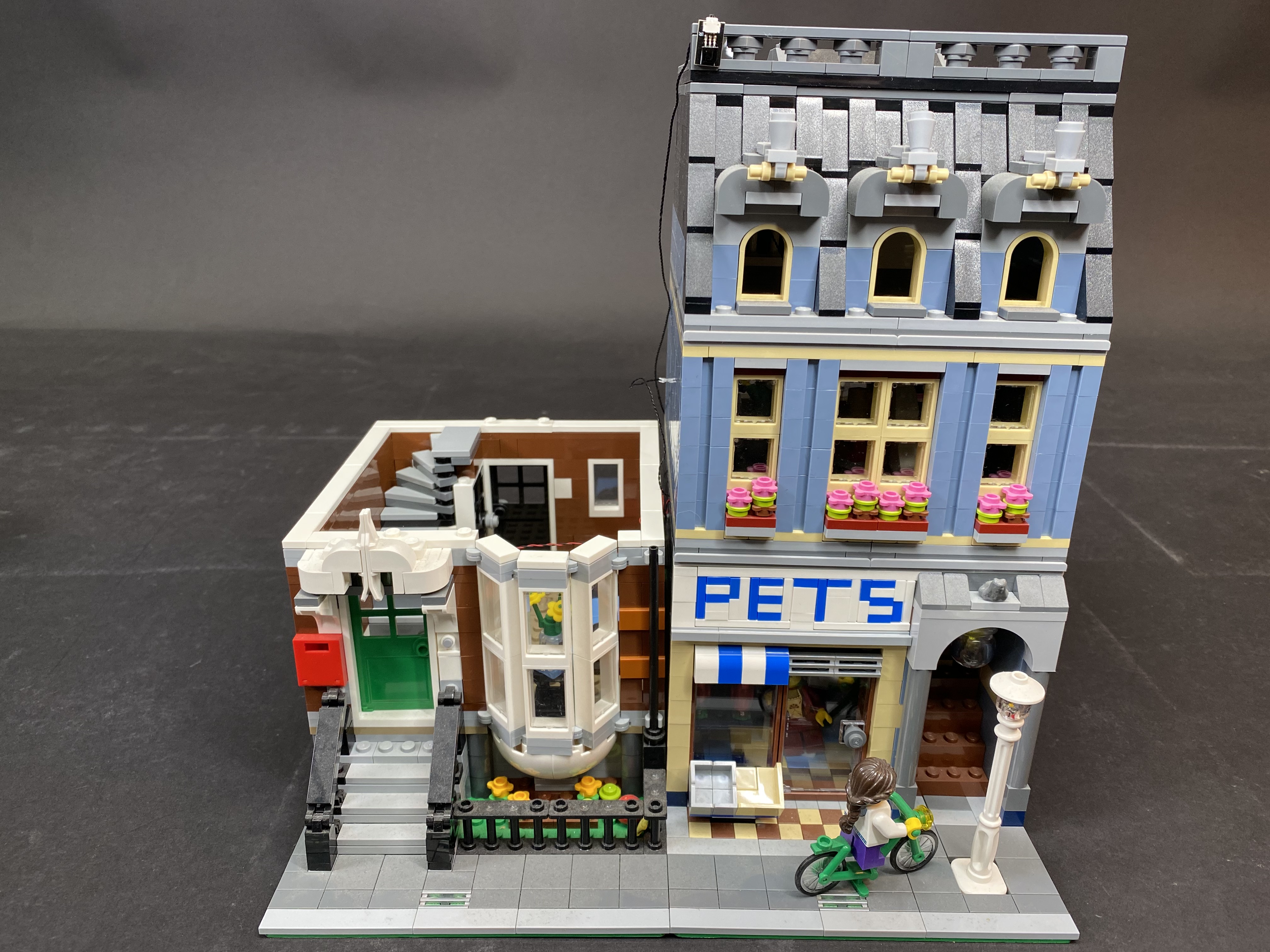
Here is the instructions document for the Light My Bricks Pet Shop LED lighting kit.
To ensure a trouble-free installation of your light kit, please read and follow each step carefully. These instructions can be downloaded in PDF format here
Package contents:
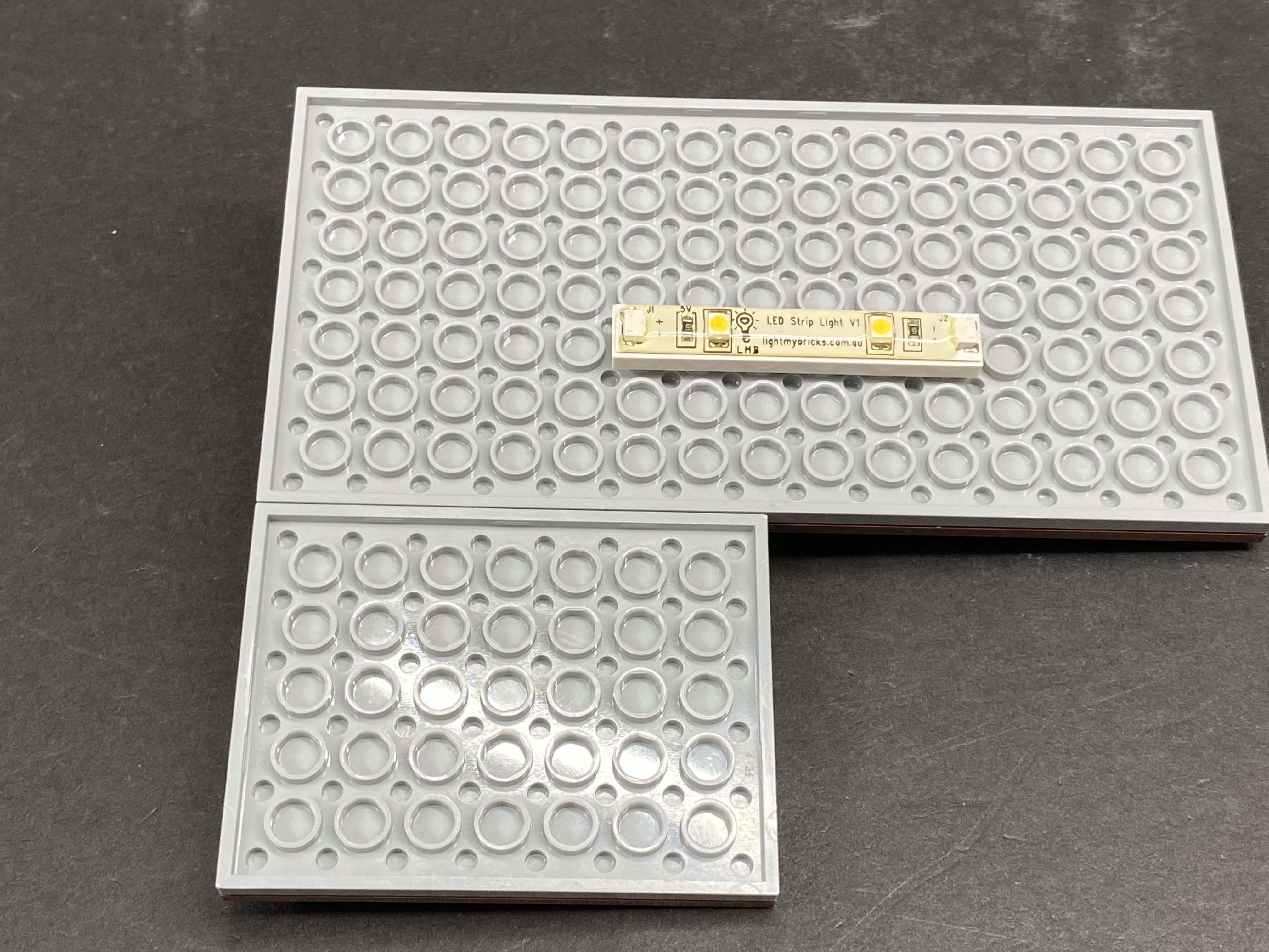
- 7x White Strip Lights
- 3x White 30cm Bit Lights
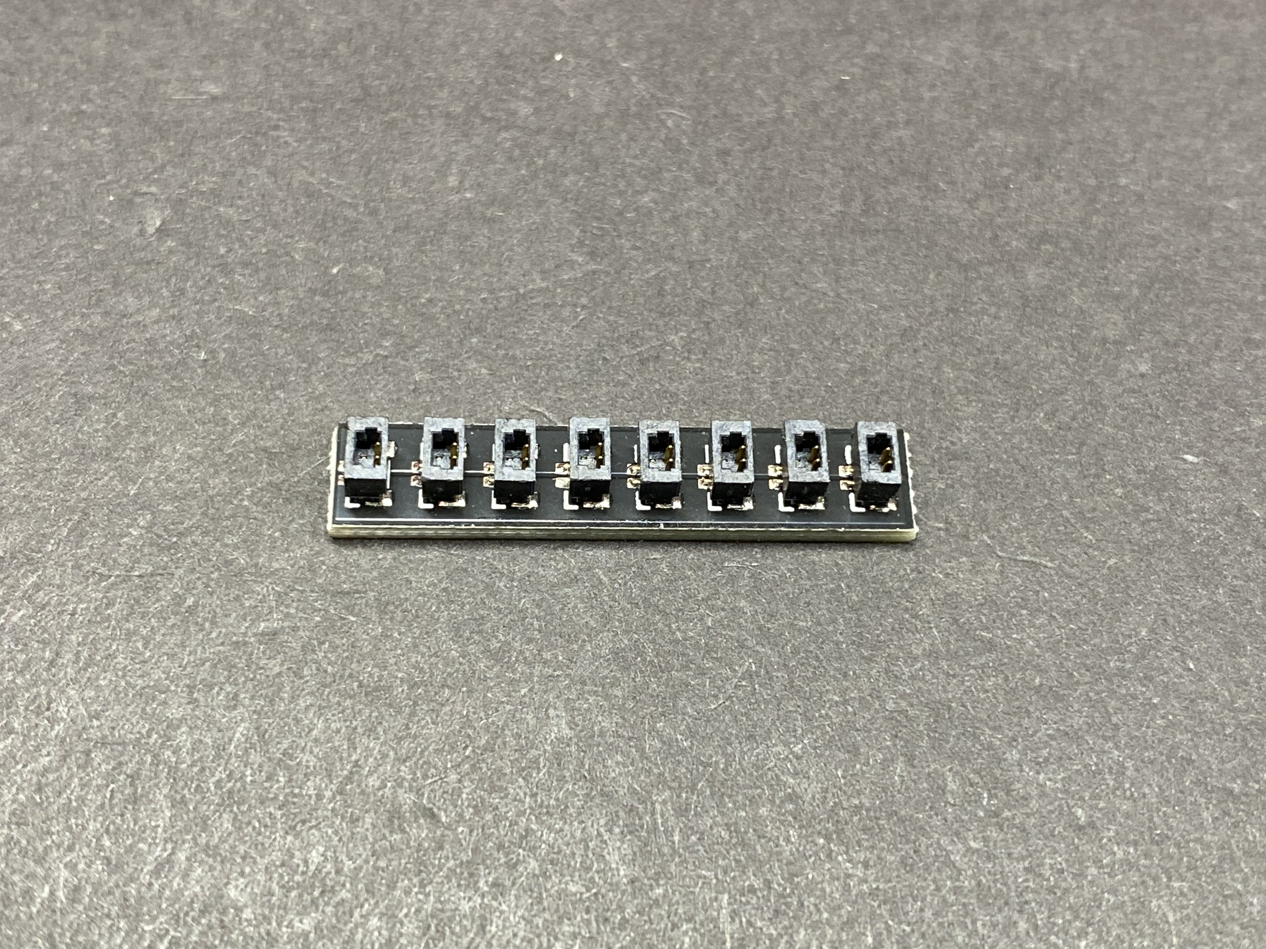
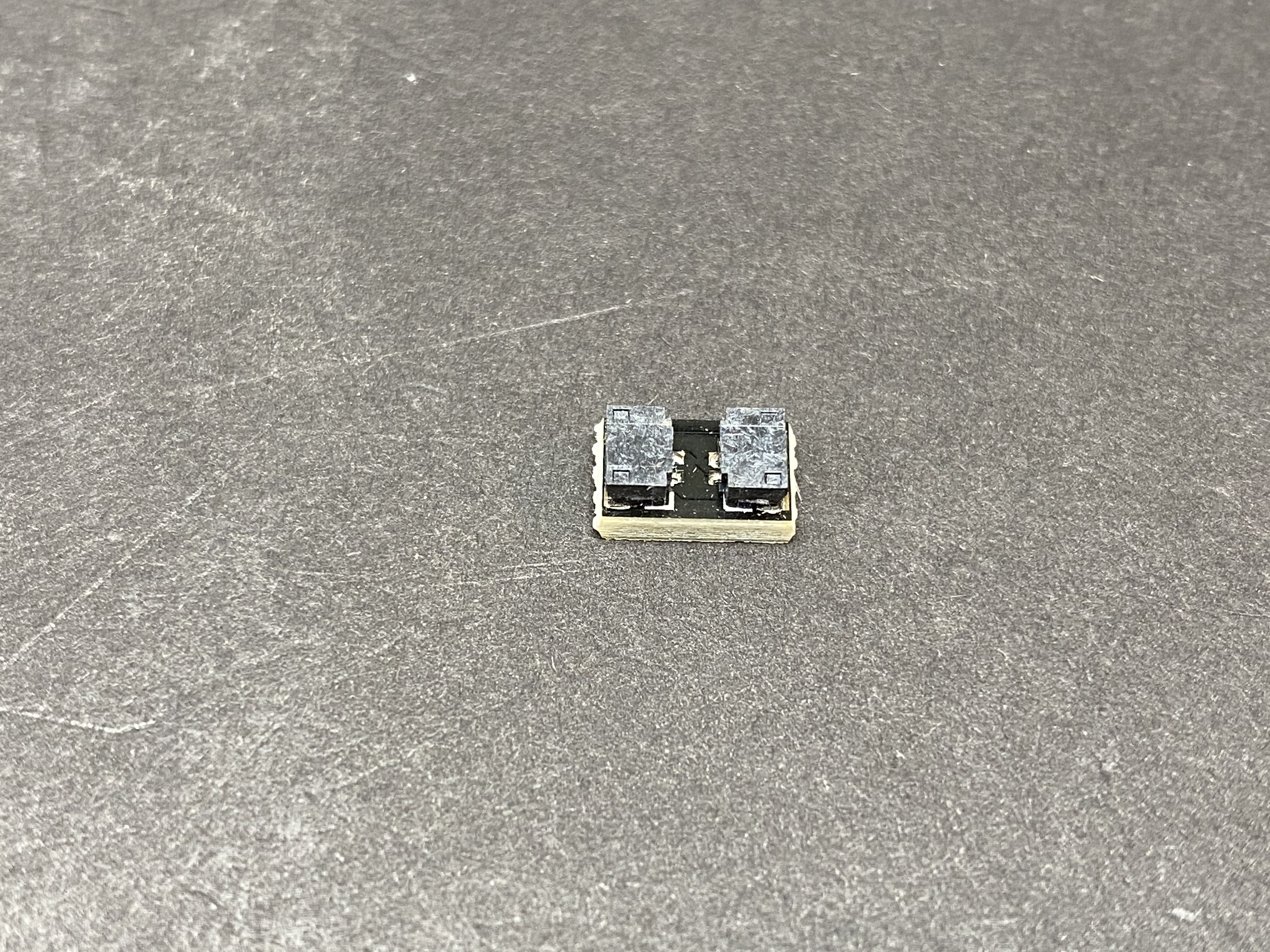
- 1x 6-port Expansion Board
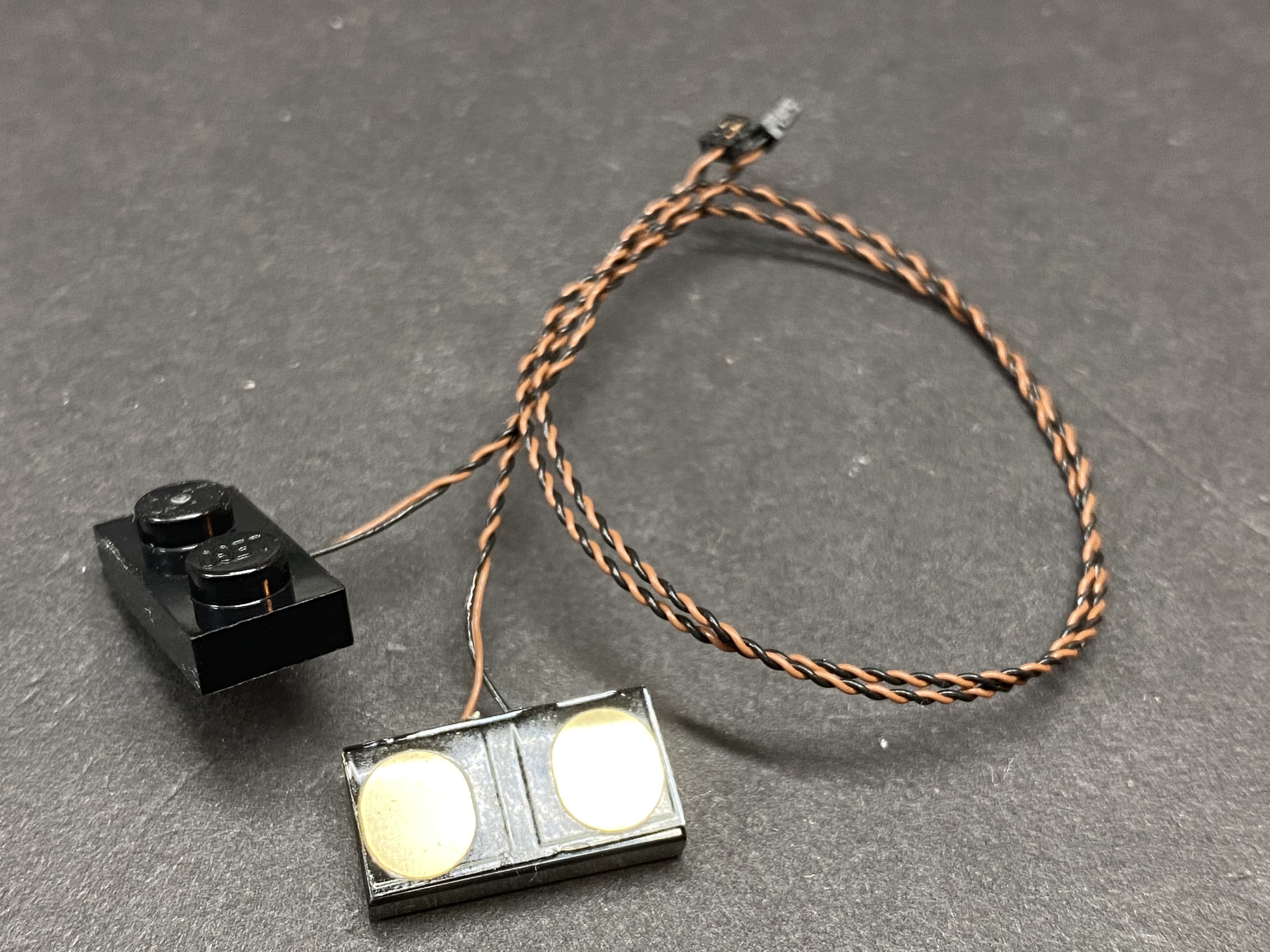
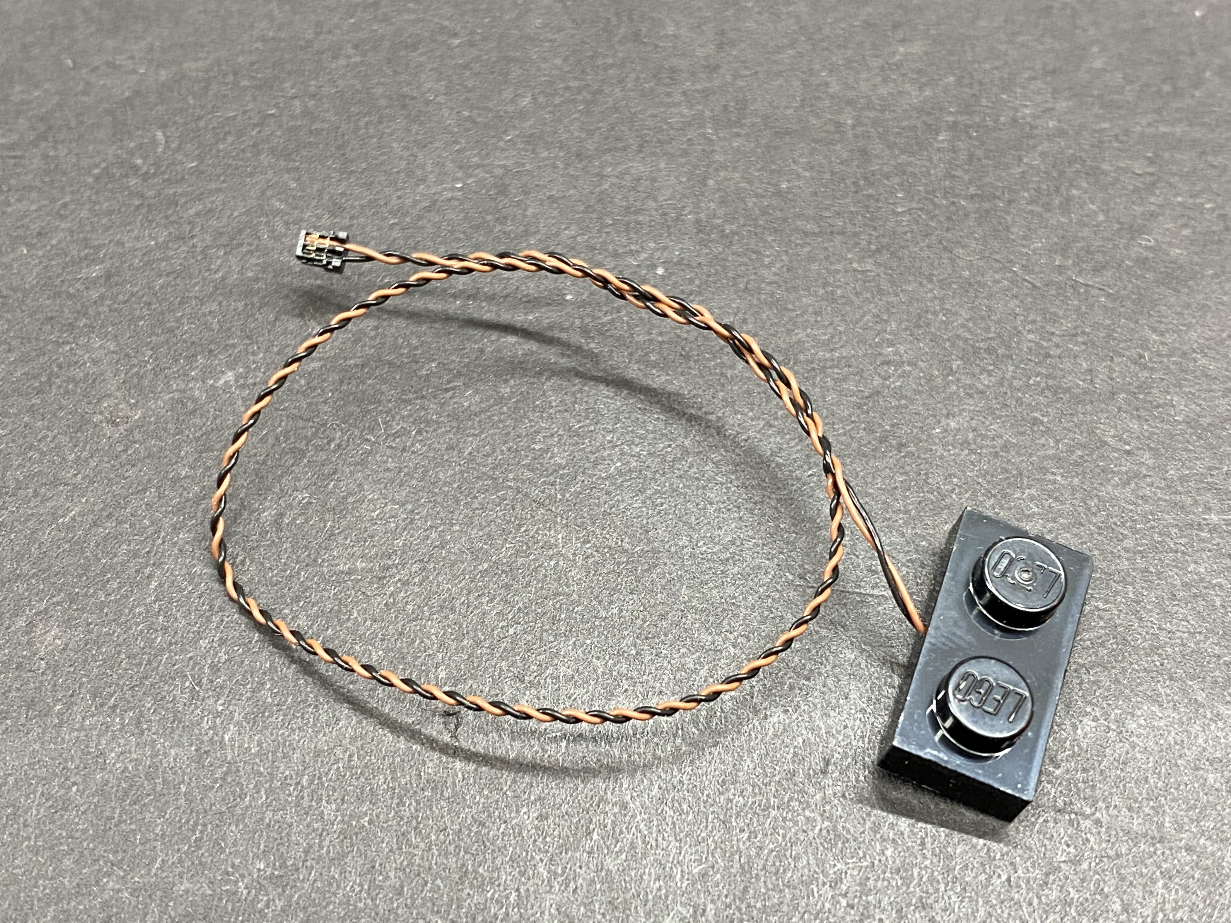
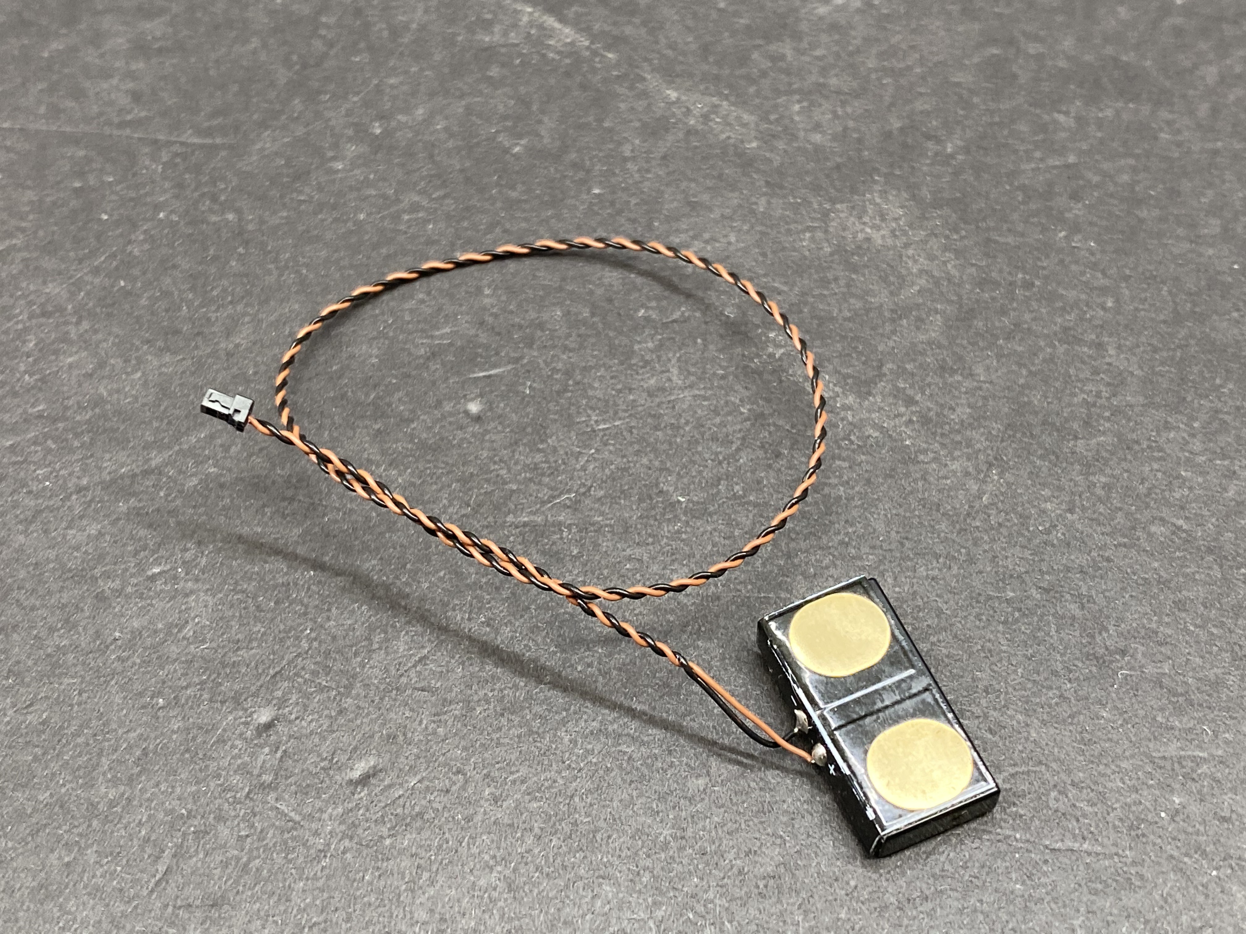
- 1x Lamp Post with LED and cable attached
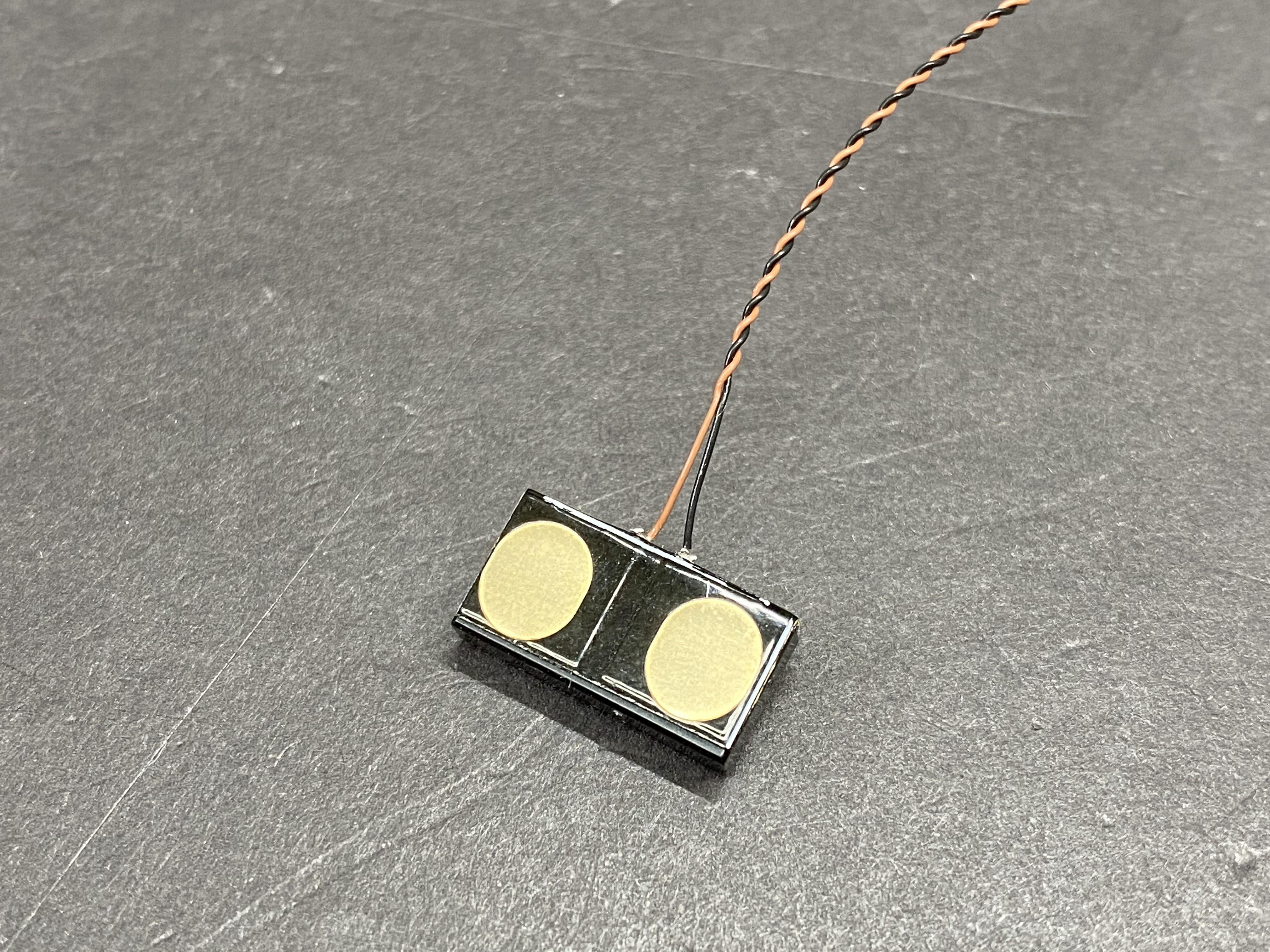
- 2x Adhesive squares
- 7x Lego Plates 1×6 for mounting Strip Lights
- 1x USB Power Cable
Connecting Cables
- 1x 5cm cable
- 5x 15cm cable
- 1x 30cm cable
Wireless Power Connectors:
If you wish to use Light My Bricks Wireless Power Connectors in between floors (sold separately), please scroll to the bottom of the page to view the instructions.
You will require the following extra parts (available for purchase through our DIY range)
- 6x Wireless Power Connectors sets (available to purchase in a 2pk)
- 4x 2-Port Expansion Board (available to purchase in a 4pk)
- 1x 8-Port Expansion Board (available to purchase in a 2pk)
- 3x 1×6 Plate (Any Colour) (Available to Purchase)
- 2 1×2 Plate (Any Colour) (Not sold but it is a common LEGO piece)
- 1x 1×4 Tile (Any Colour) (Not sold but it is a common LEGO piece)The LEGO pieces are interchangeable as long as the replacements can fulfil the same role/purpose.
Important things to note:
Laying cables in between and underneath bricks
Cables can fit in between and underneath LEGO® bricks, plates, and tiles providing they are laid correctly between the LEGO® studs. Do NOT forcefully join LEGO® together around cables; instead ensure they are laying comfortably in between each stud.


CAUTION: Forcing LEGO® to connect over a cable can result in damaging the cable and light.
Connecting cable connectors to Strip Lights
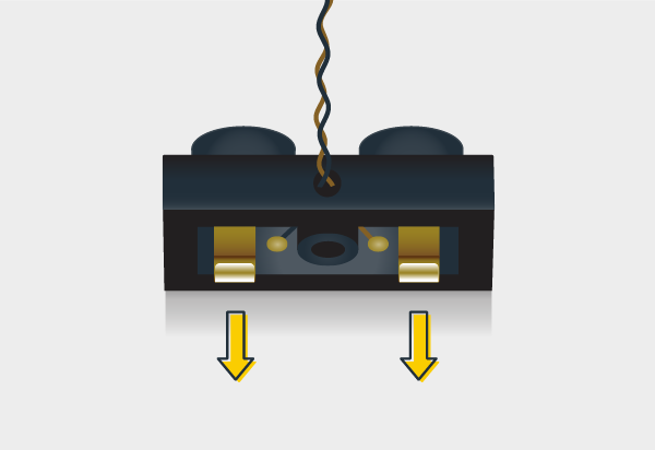
Take extra care when inserting connectors to ports on the Strip Lights. Connectors can be inserted only one way. With the Strip Light facing up, ensure the side of the connector with the wires exposed is facing down. If a plug won’t fit easily into a port connector, don’t force it. Doing so will damage the plug and the connector.


Connecting cable connectors to Expansion Boards
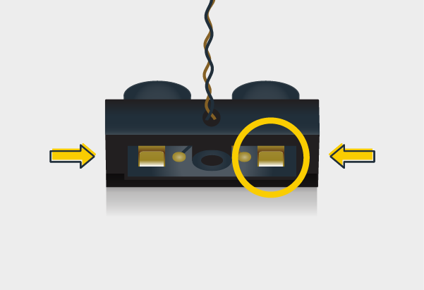
Take extra care when inserting connectors to ports of Expansion Boards. Connectors can be inserted only one way. With the expansion board facing up, look for the soldered “=” symbol on the left side of the port. The connector side with the wires exposed should be facing toward the soldered “=” symbol as you insert into the port. If a plug won’t fit easily into a port connector, do not force it.


WARNING: Incorrectly inserting the connector can result in bent pins inside the port or possible overheating of the expansion board when connected.
Installing Bit Lights under LEGO® bricks and plates.
When installing Bit Lights under LEGO® pieces, ensure they are placed the correct way up (Yellow LED component exposed). You can either place them directly on top of LEGO® studs or in between.


OK, Let’s Begin!
Instructions for installing this kit
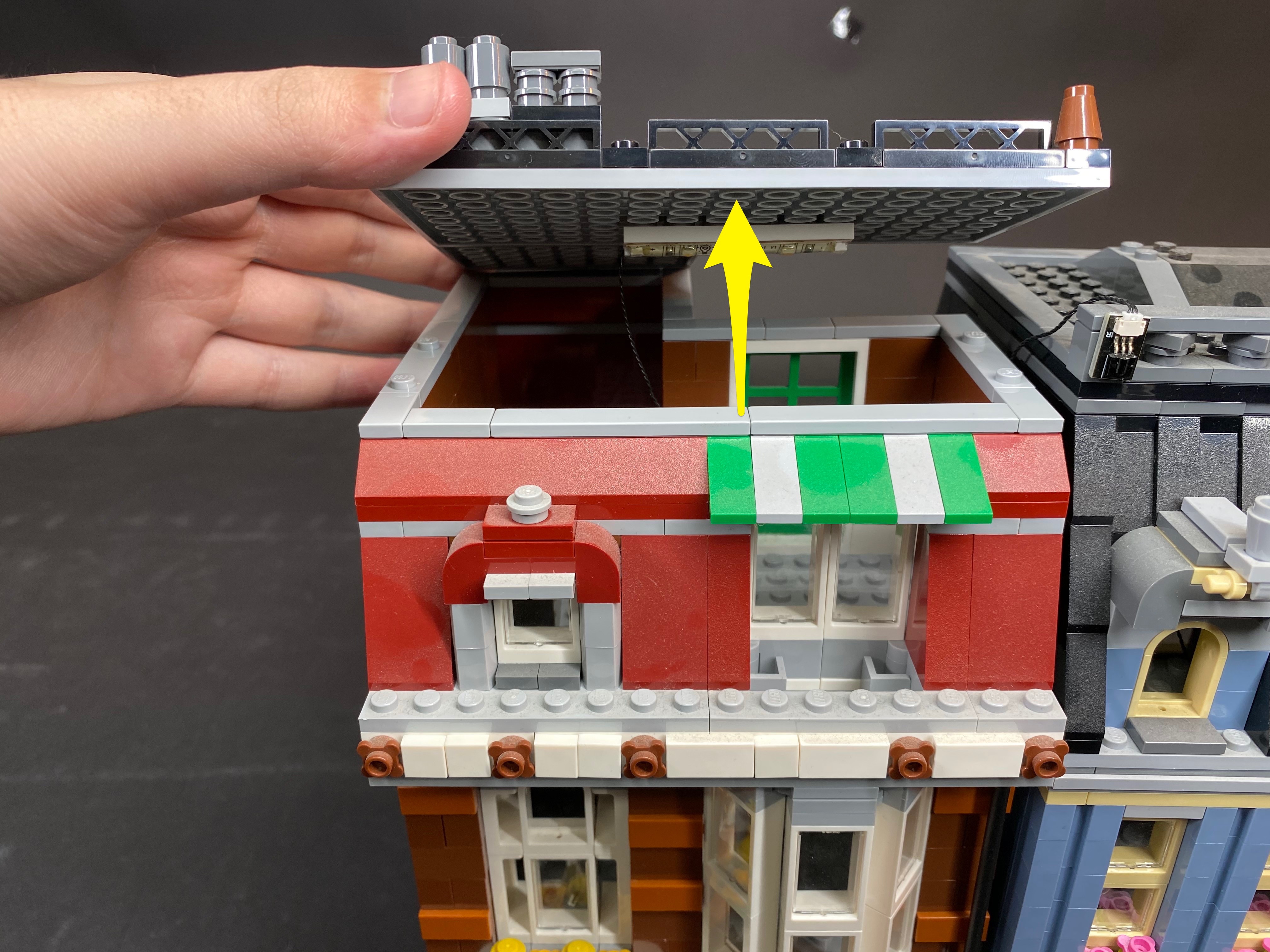
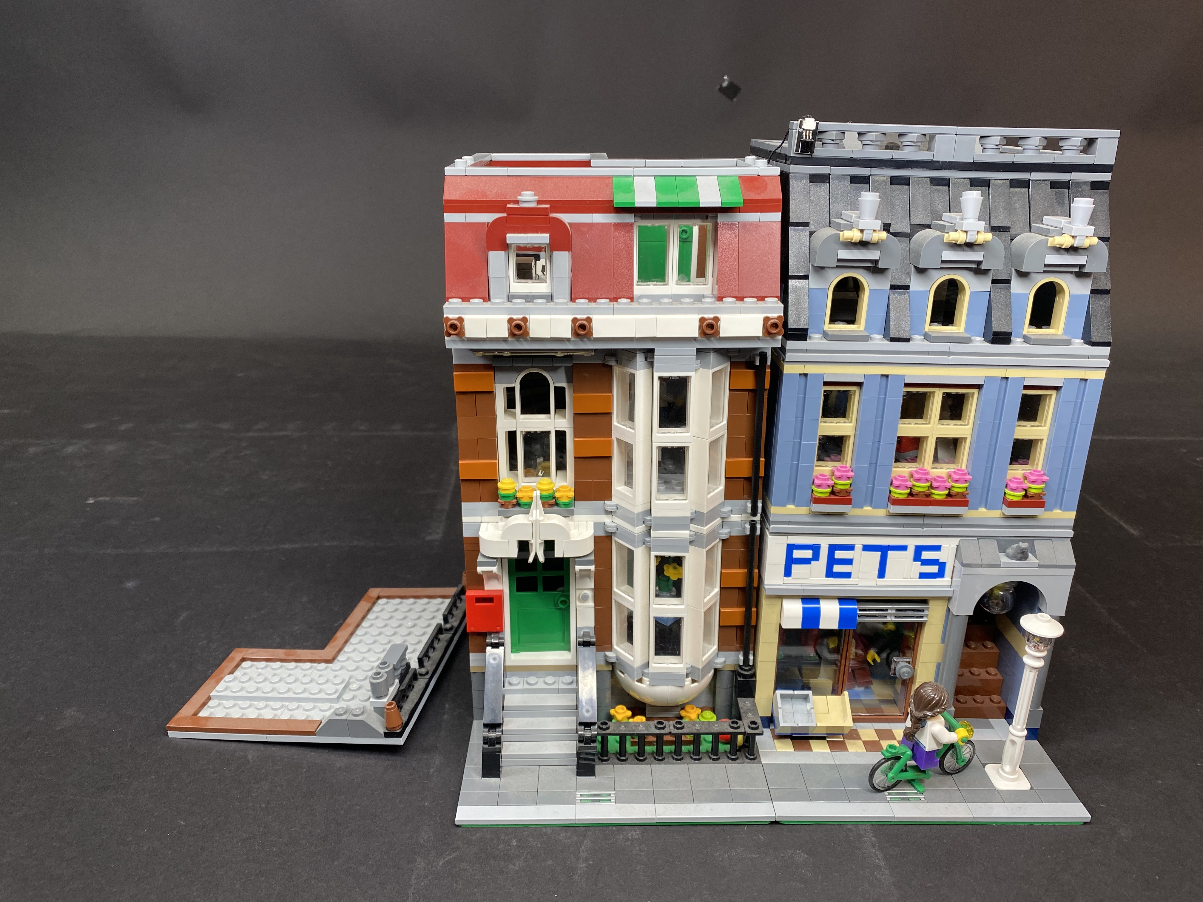
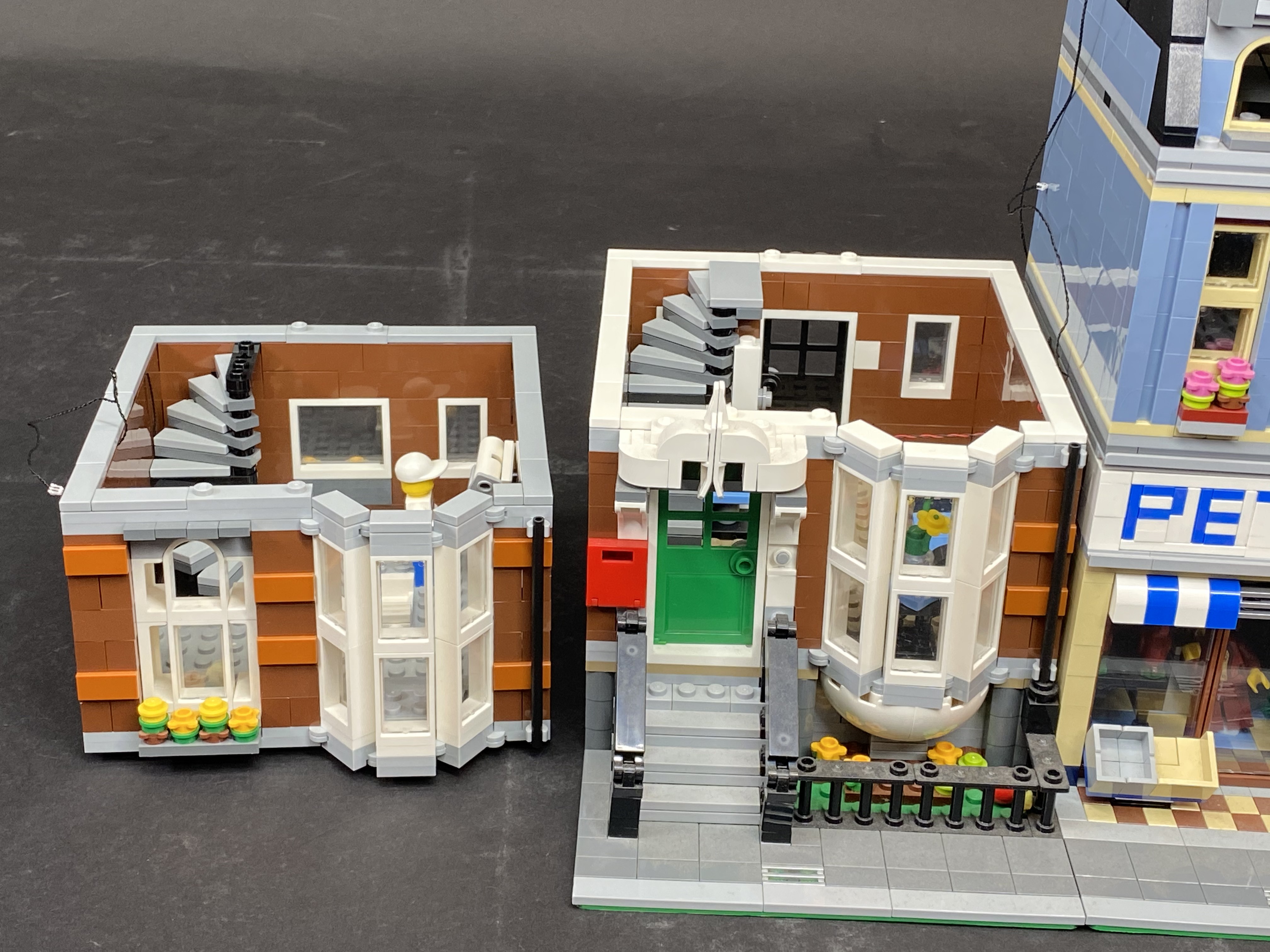
1.) Start by separating the 2 buildings and then remove the 2nd and top levels from the Red building as we will install lights to this section first.


2.) Remove the following pieces which make up the top frame of the front door. Save the last section as we will install a bit light to it.


3.) Turn this section over so that we can see the bottom of it. Take 1 bit light and place it in the middle of the plate as per below. Ensure that the LED component part is facing the correct way up.


Reconnect this section back to original position but first place your thumb over the bit light so that it does not fall out of place when we turn the Lego section over. Ensure the cable for the bit light is on the inside of the building and laid in between Lego studs. When you look from underneath, you should be able to just see the LED component peeping through.


Reconnect the Lego pieces we removed in previous steps.

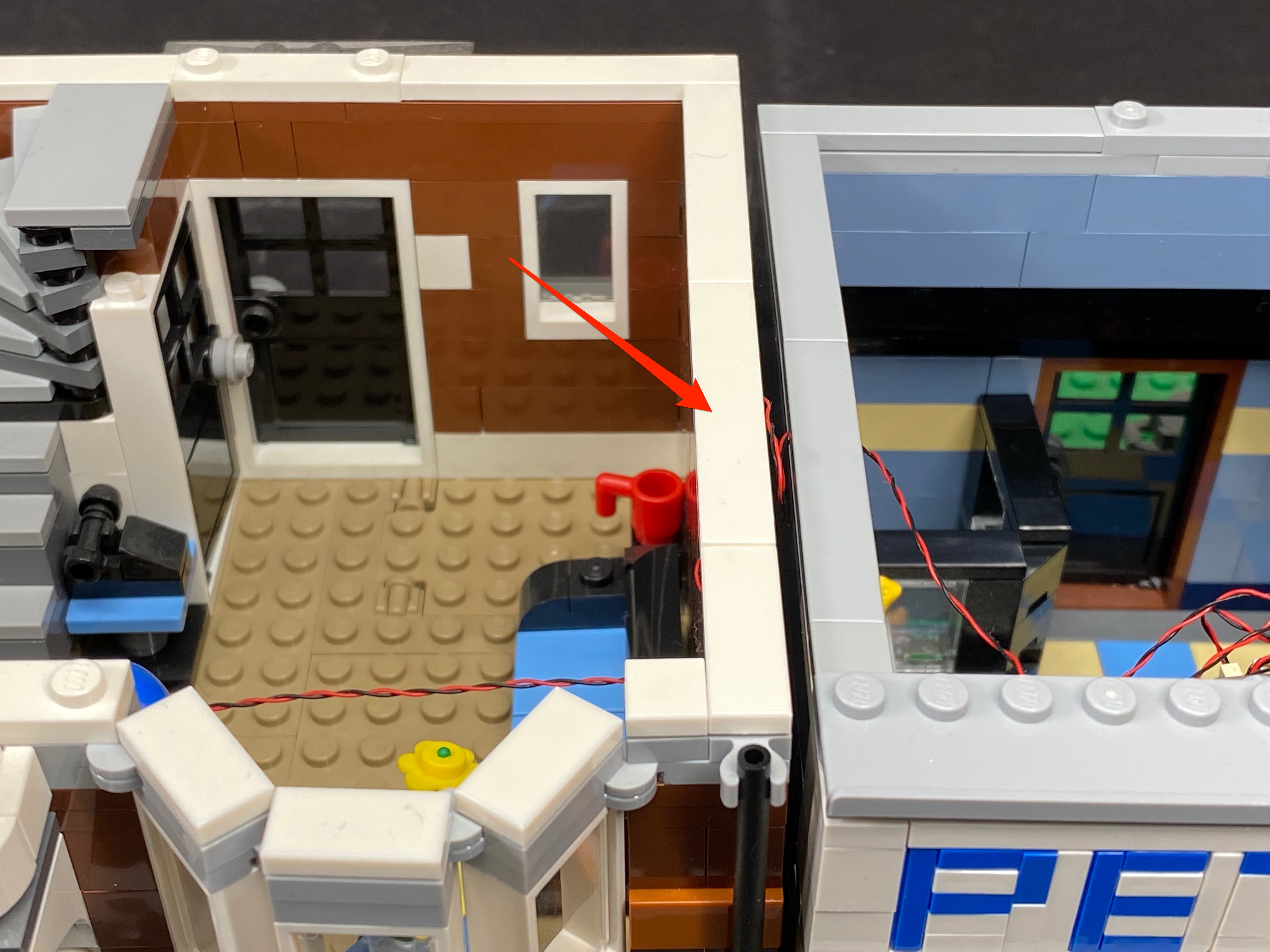
4.) Pull the excess cable toward the right and then lay it in between the brown studs underneath the white Lego plate as per below. This helps hide excess cable and secures it in place. The cable should be now secured and there should be roughly 12–15cm in length between the wall and connector. Leave this end of the cable for now as We will connect this to the other side of the Pet Shop later on.


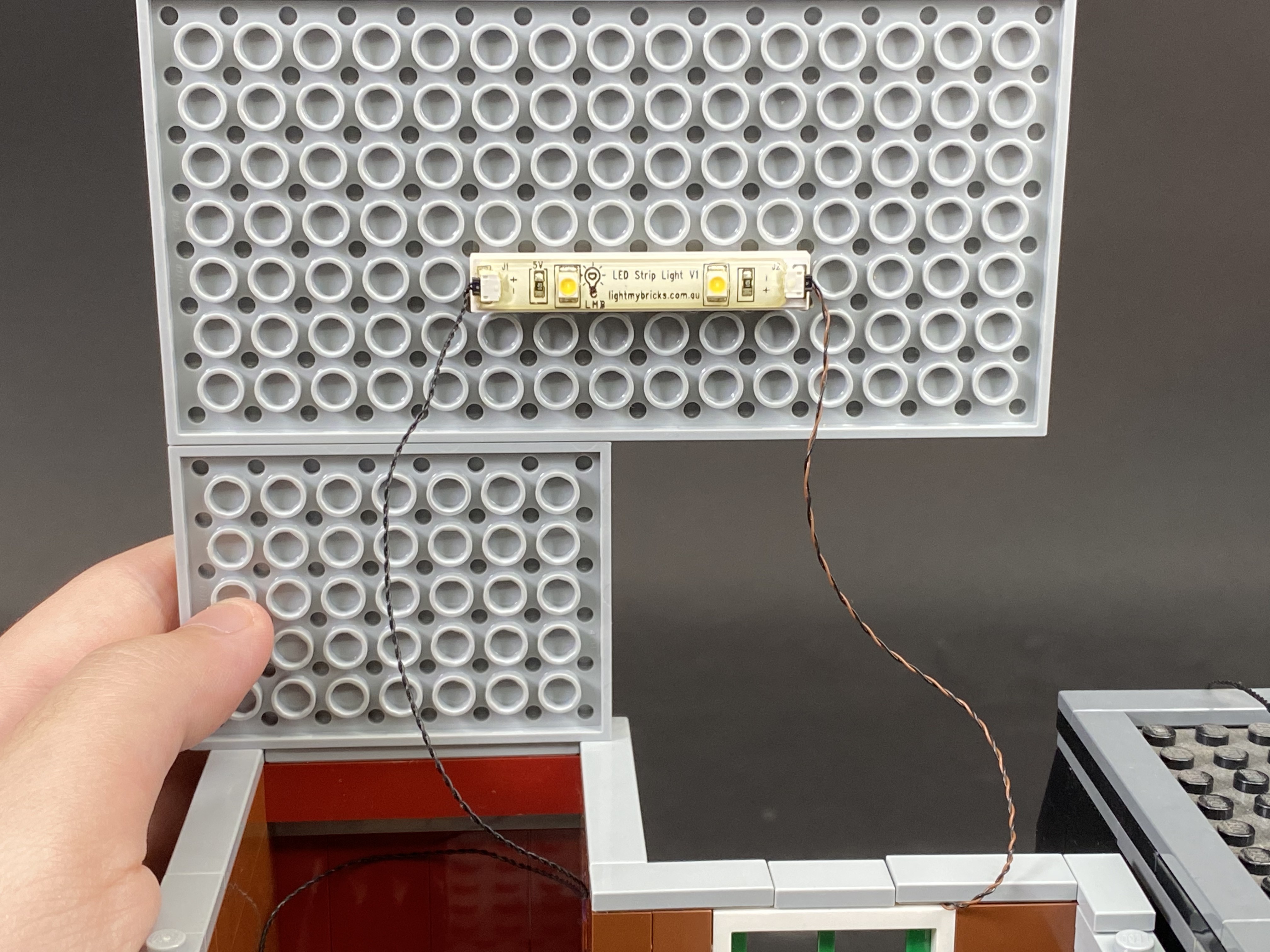
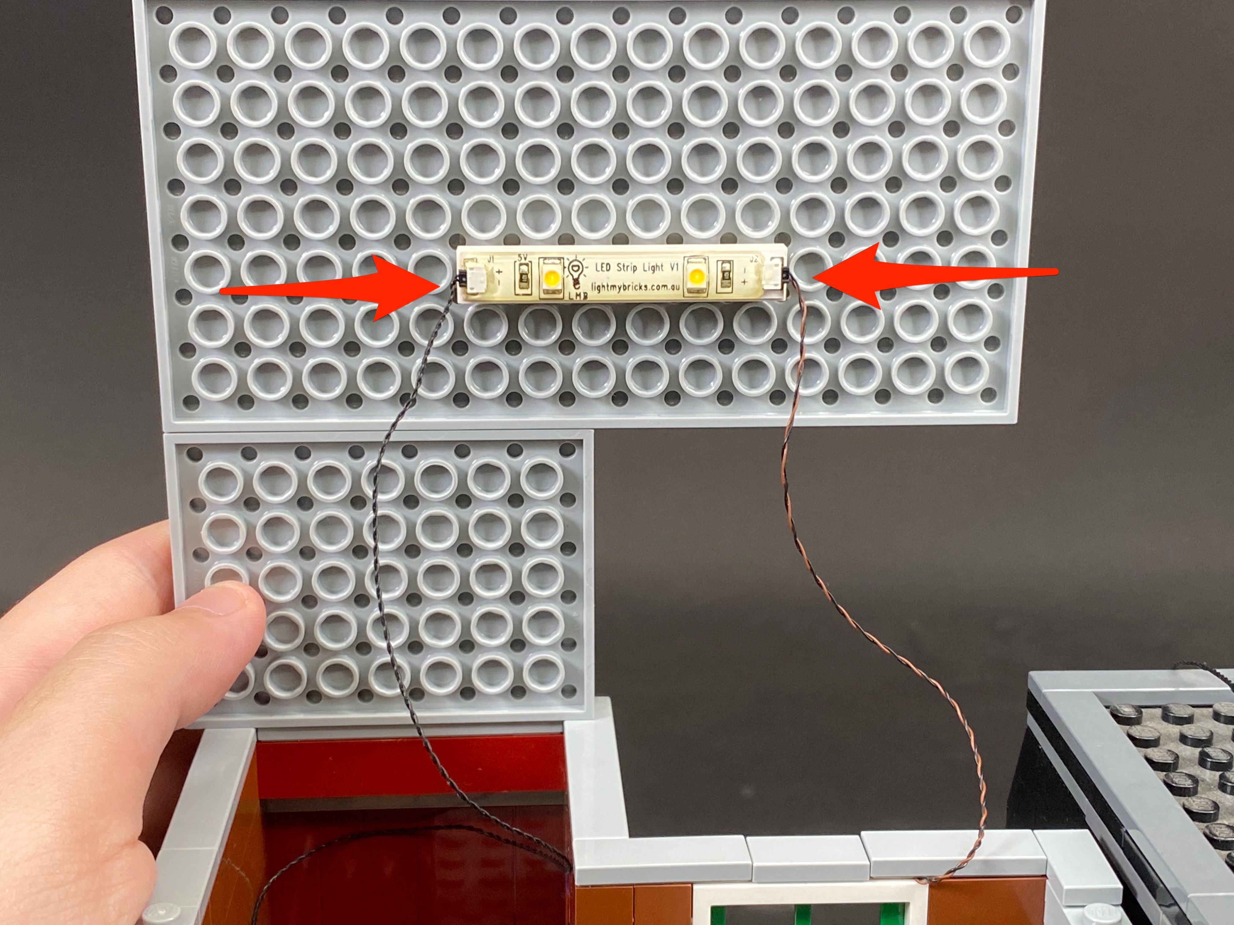
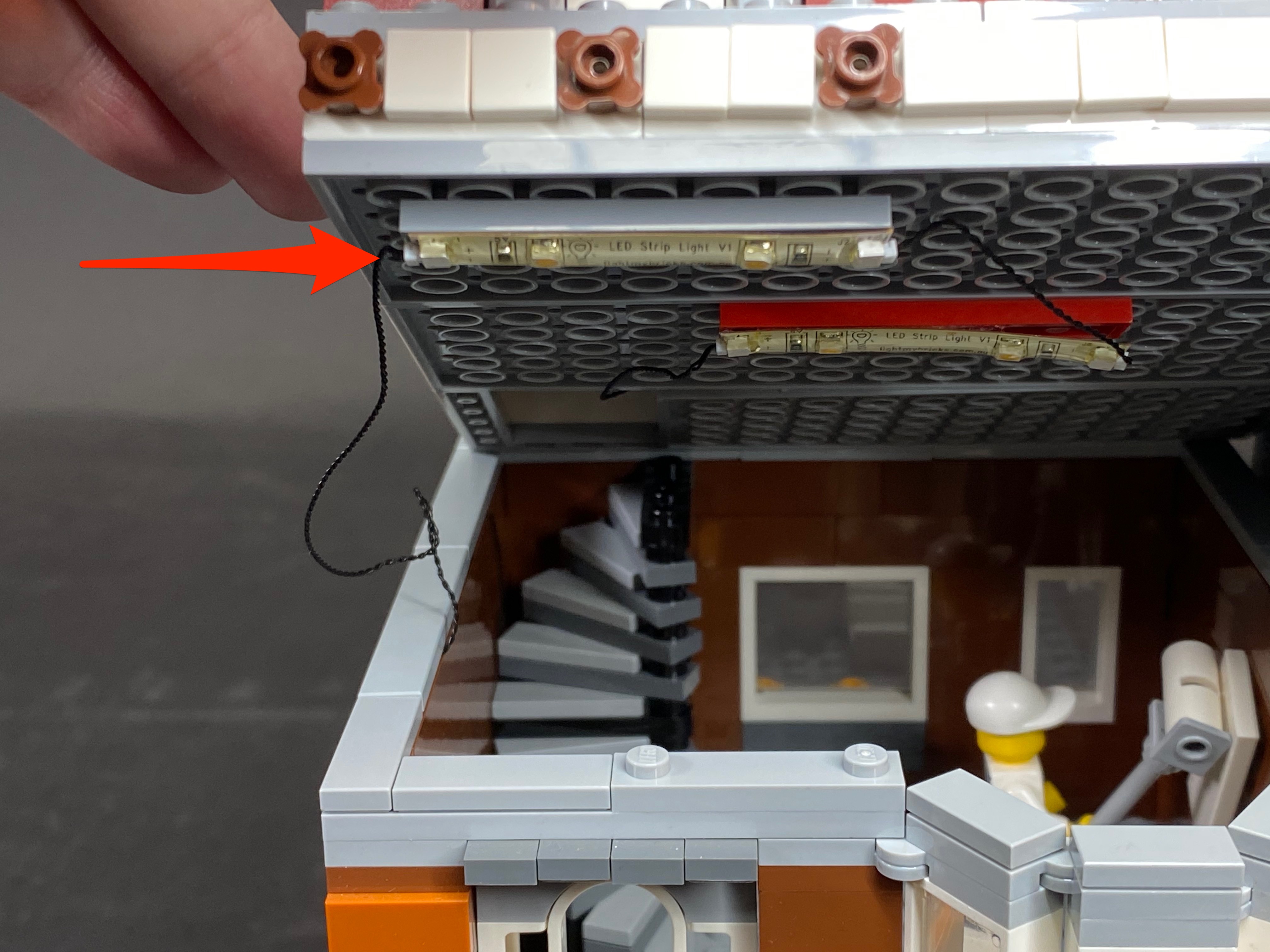
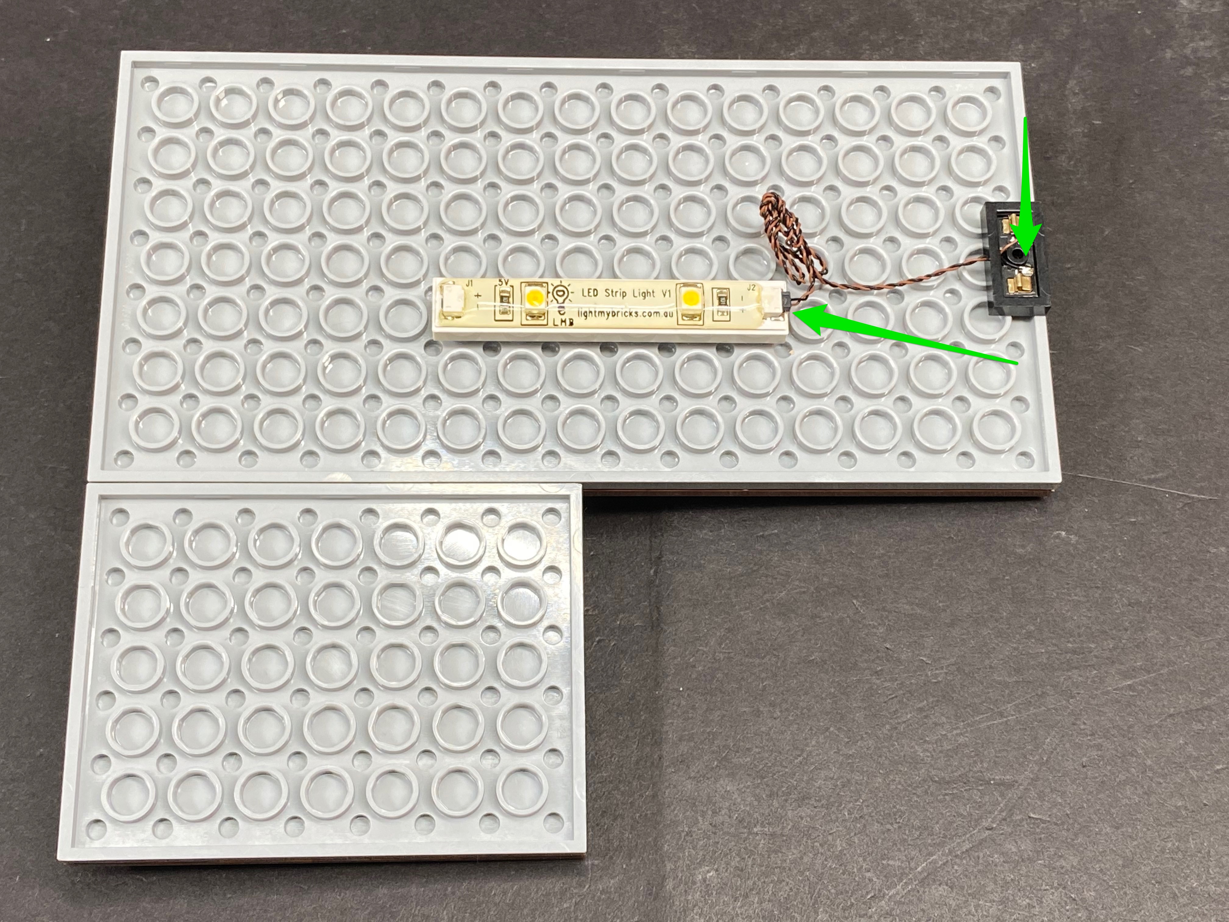
5.) Take the entire 2nd floor and then turn if over on its back so that we can see the bottom of it. Take 1 strip light and connect or stick it (depending on which option you choose) in the following position. We will refer to this as striplight#1. Take a 30cm connecting cable and plug it into the left port of the strip light.


6.) Take another 15cm cable and connect it to the right port of the strip light. Secure this cable by reconnecting the white lego plate over it.


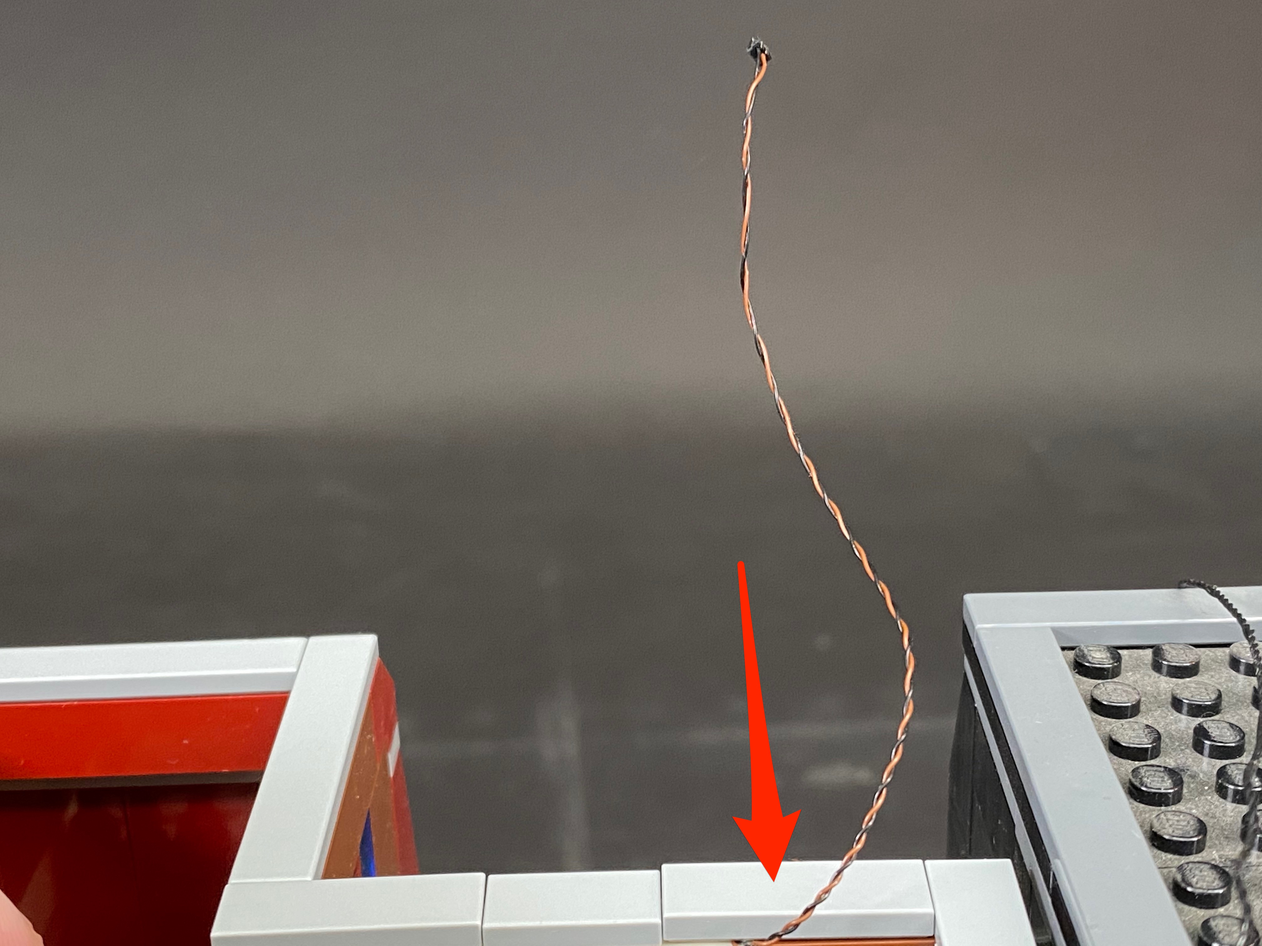
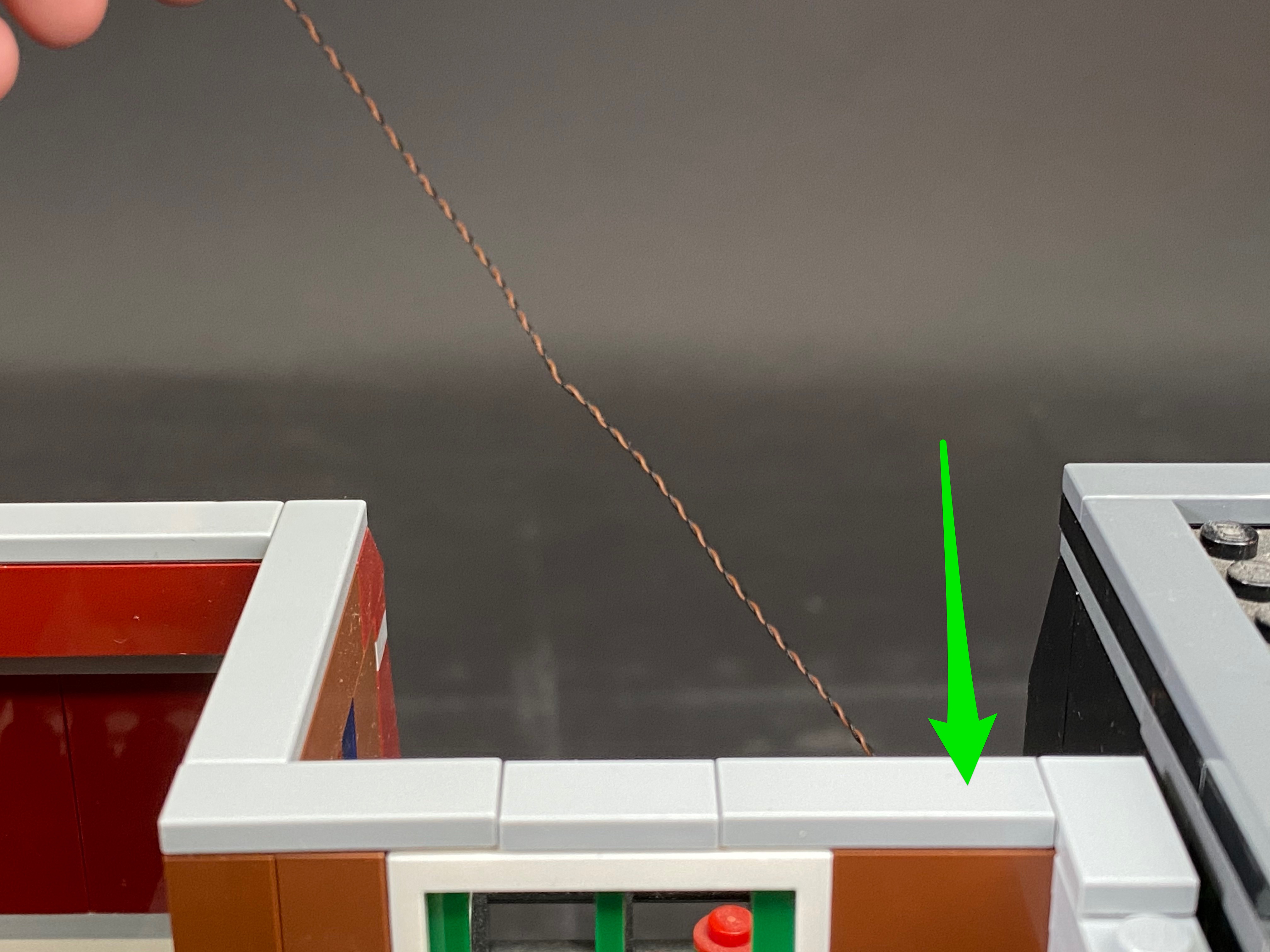
7.) Thread the other side of the cable we connected into the left port up the space which leads to the level above. Flip the 2nd floor over and then reconnect it in place. Locate the cable we threaded up earlier and pull it up. Secure it in place by pulling it in between the 4th & 5th step from the top. This should lock the cable in place as it is a tight gap between the step and wall.


8.) Take the 3rd level and then turn it on its back so that we can see underneath. Take another 2 strip lights and connect them together using a 5cm connecting cable, then connect/stick them in the following positions. These will be identified as striplight#2 and striplight#3.


9.) Take the 30cm cable that we pulled up from underneath and connect this into the left port of striplight#2.

Lay access cable toward the front of the building underneath the grey Lego tiles as per below.

10.) Take a 15cm cable and connect it into the left port of striplight#3 then thread this up to the level above.

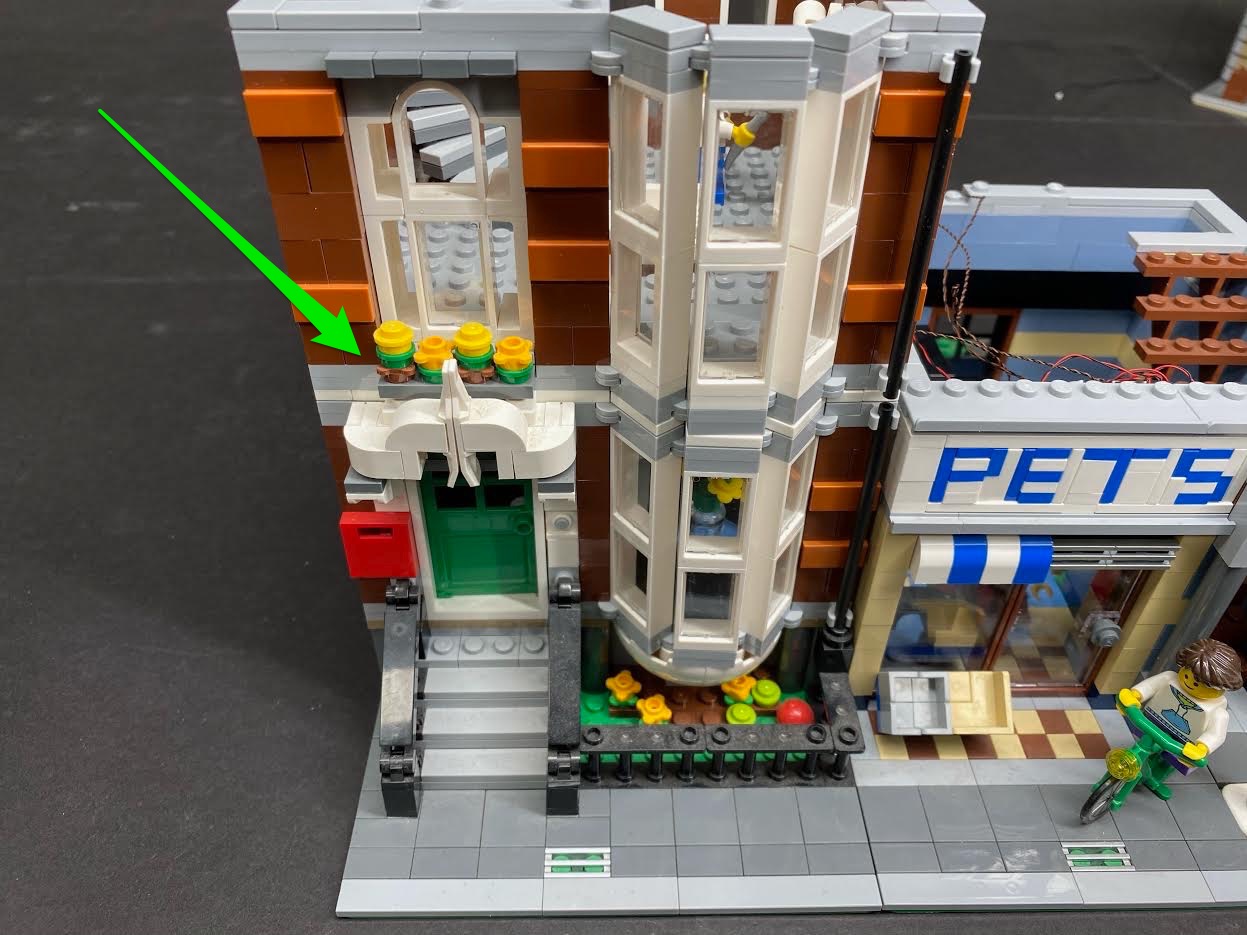
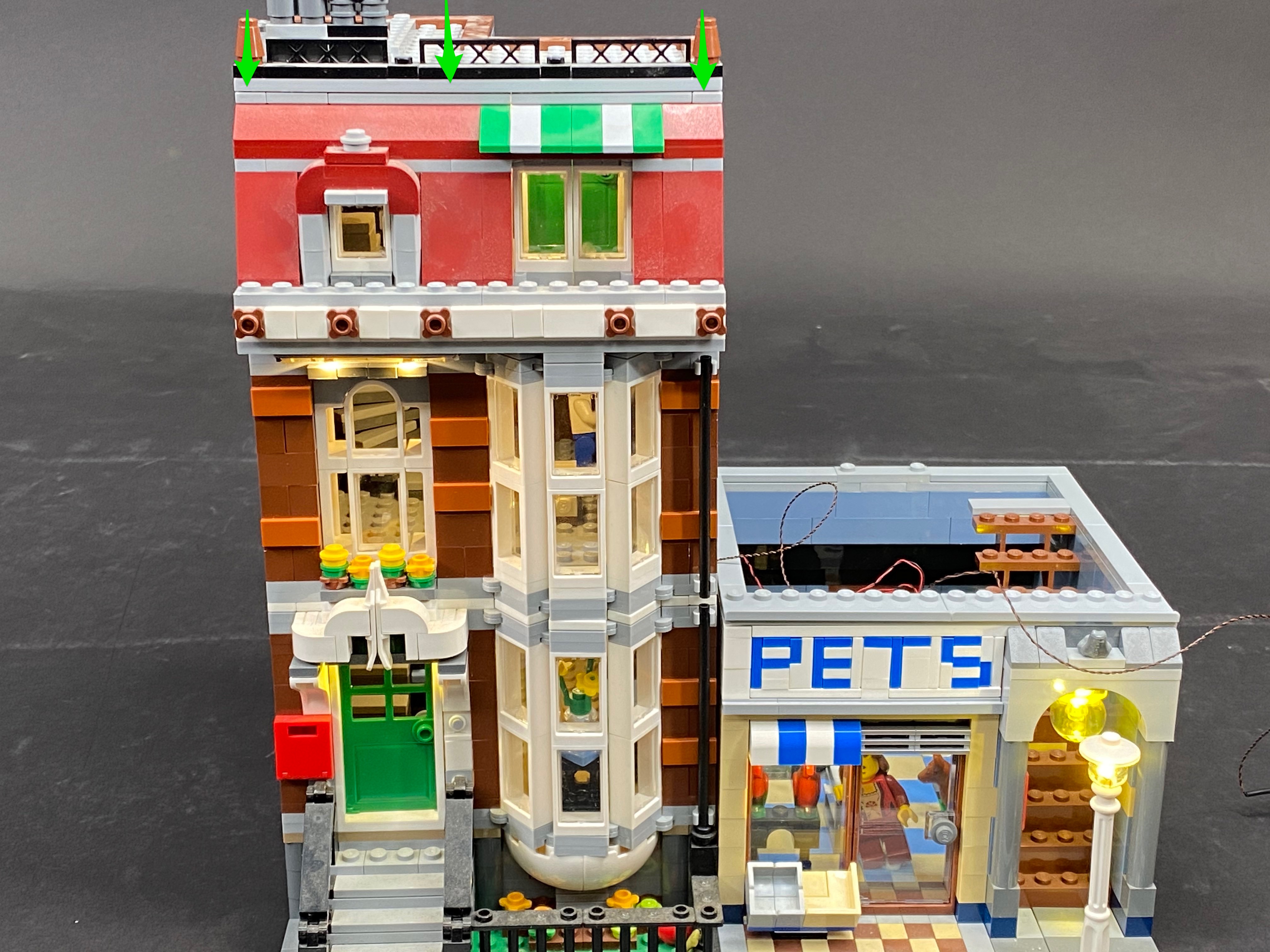
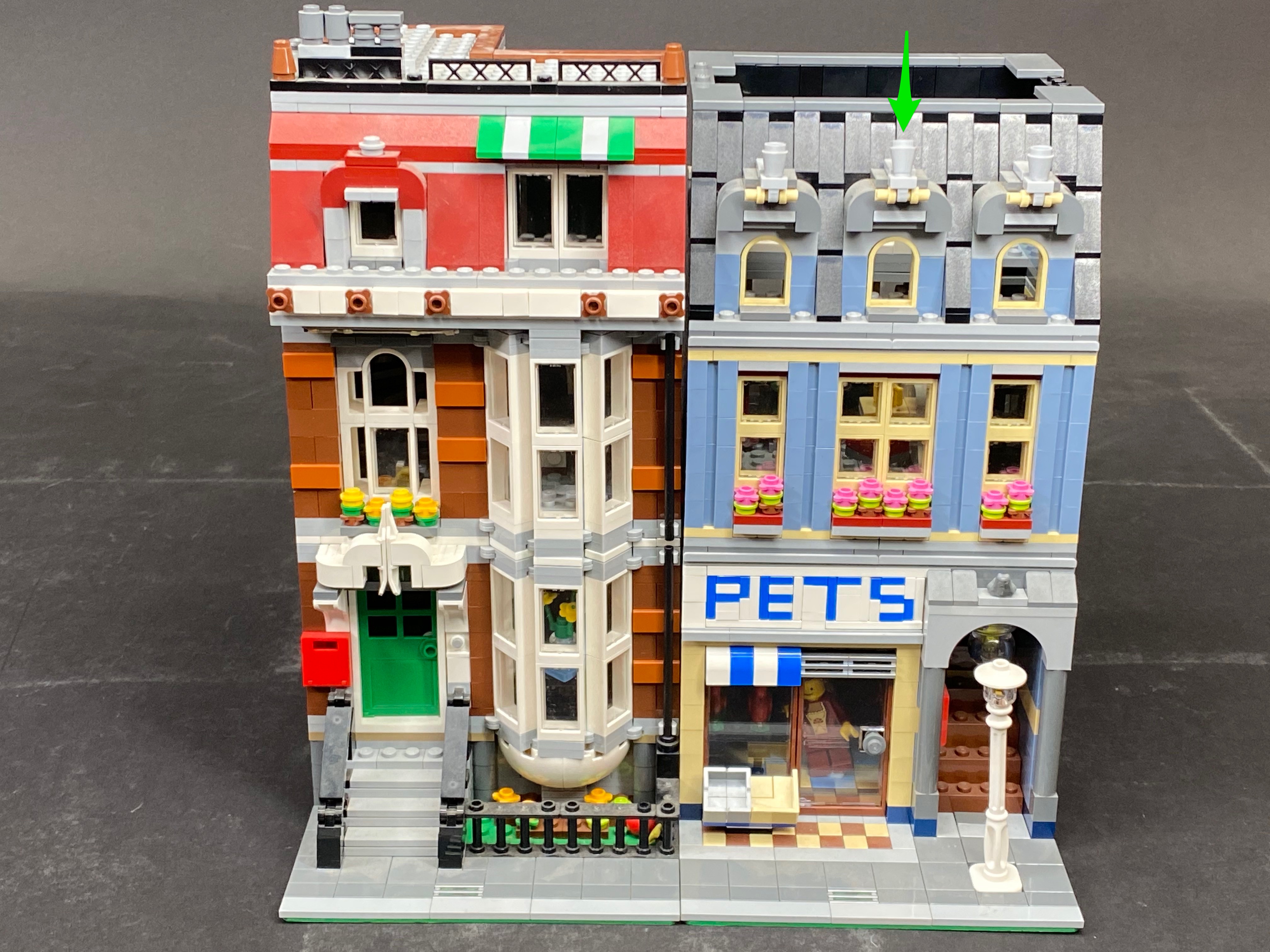
Place the entire 3rd level back into the correct position ensuring that striplight#3 is clearly visible from the front of the building just above the window of the 2nd floor.

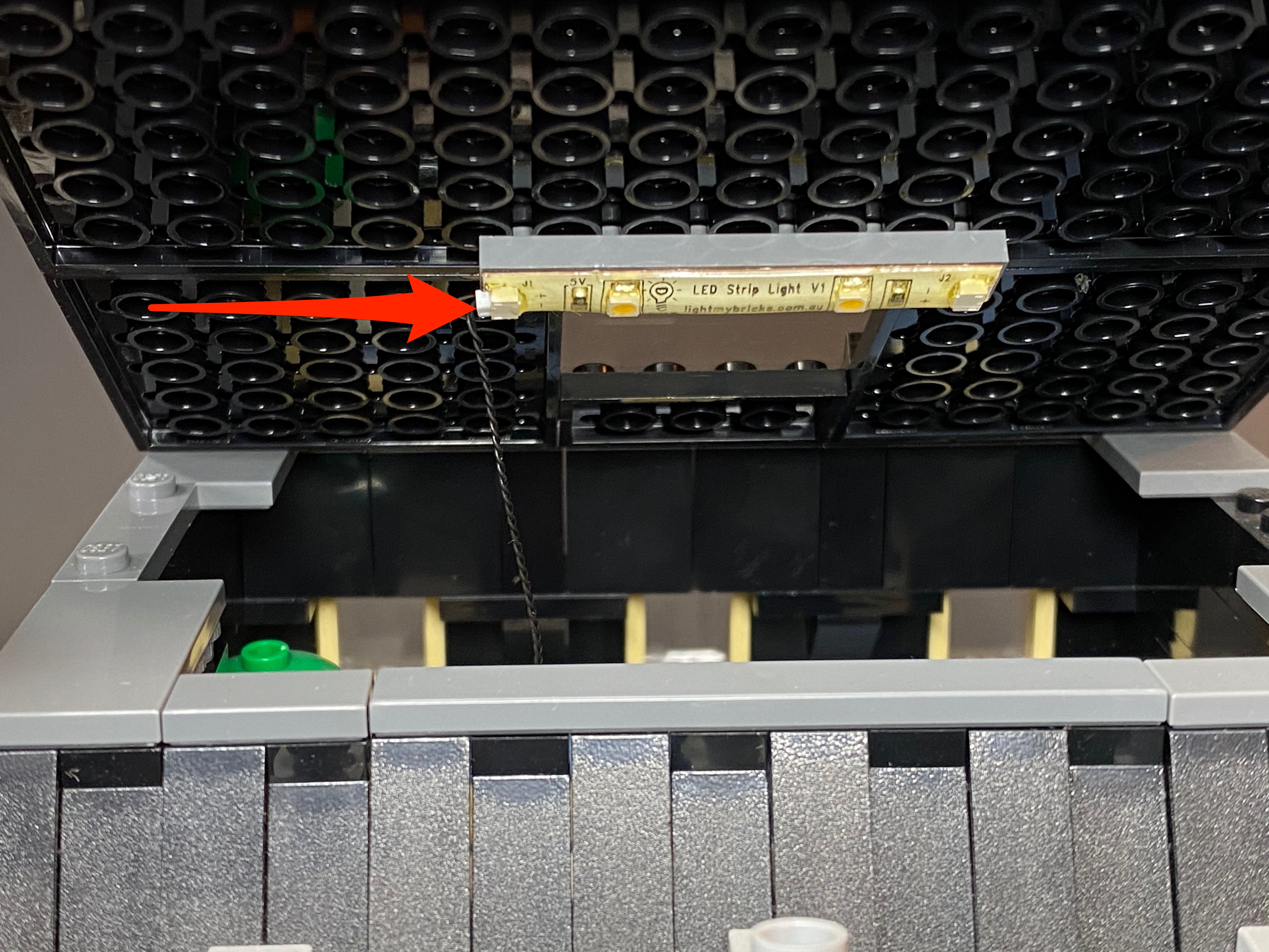
11.) Take the roof of the red building and then connect/stick another strip light (striplight#4) in the following position underneath. Connect the 15cm cable which we pulled up from the lower level into the left port of the strip light.

12.) Using the USB Power Cable, connect it to the strip light.

You can secure the USB power bank/battery pack in place and prevent it from moving around by using a few spare Lego bricks which is what I have done as per below.

13.) Reconnect the roof on and connect the USB power cable to a USB Power Bank or wall adaptor (sold separately) and turn it ON to test the front lights are working OK.
You should have 2 cables sticking out through the right of the building (connecting cable and bit light cable)


Note: that the front door light will not be working as we have yet to connect this to any expansion board.
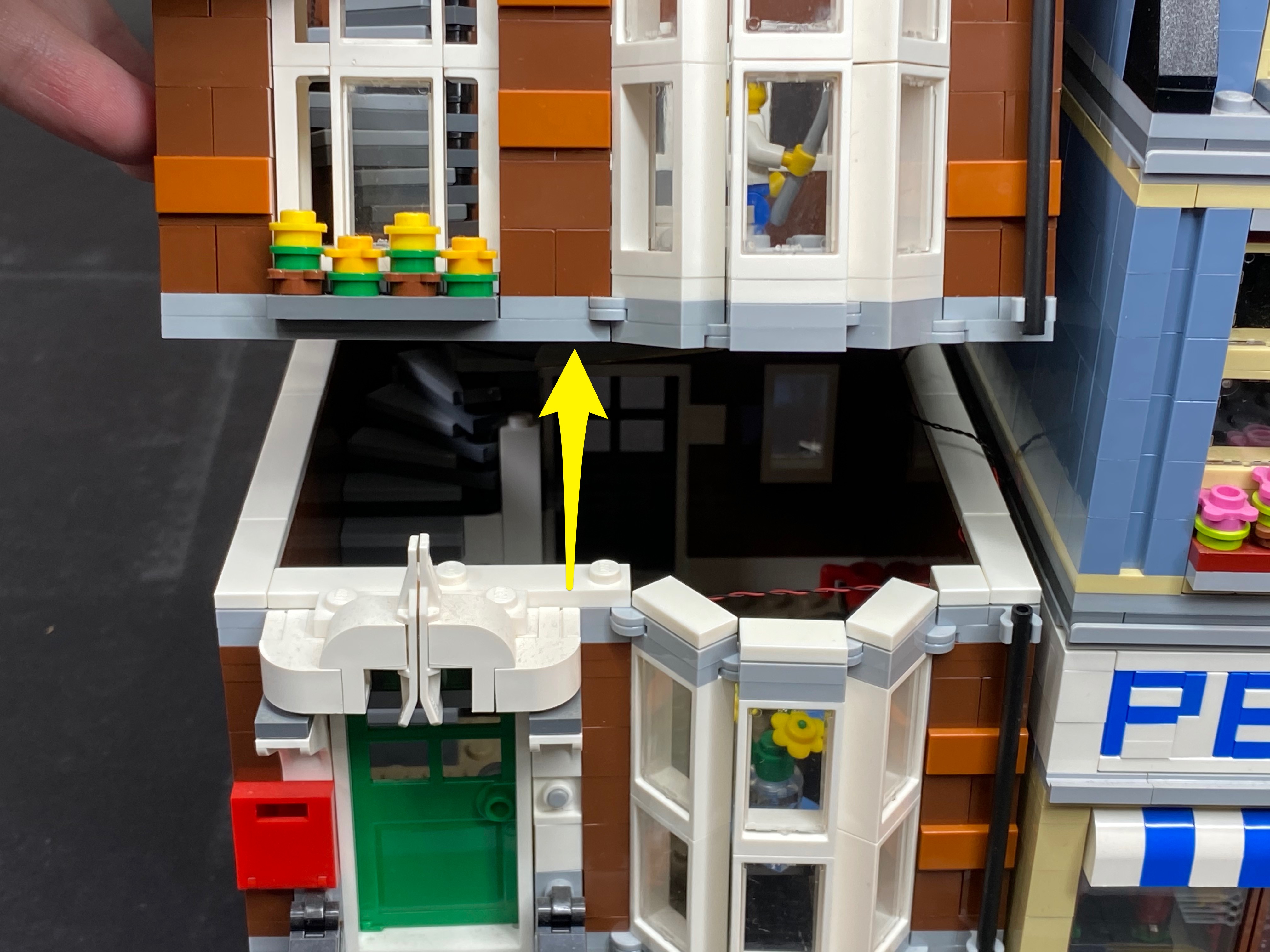
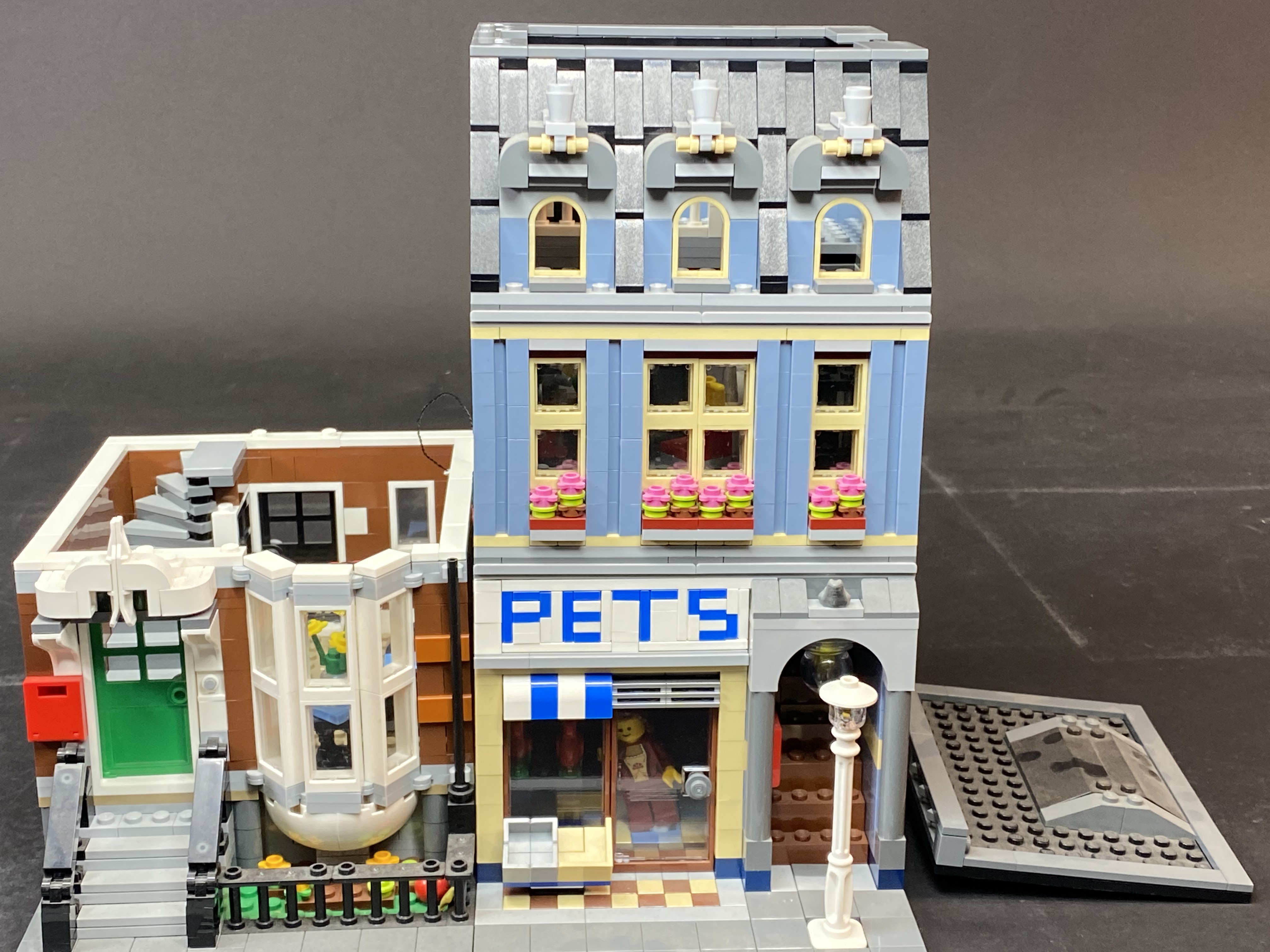
14.) We will now move on to the “pet shop” side of the building. First remove the 2nd and 3rd levels.


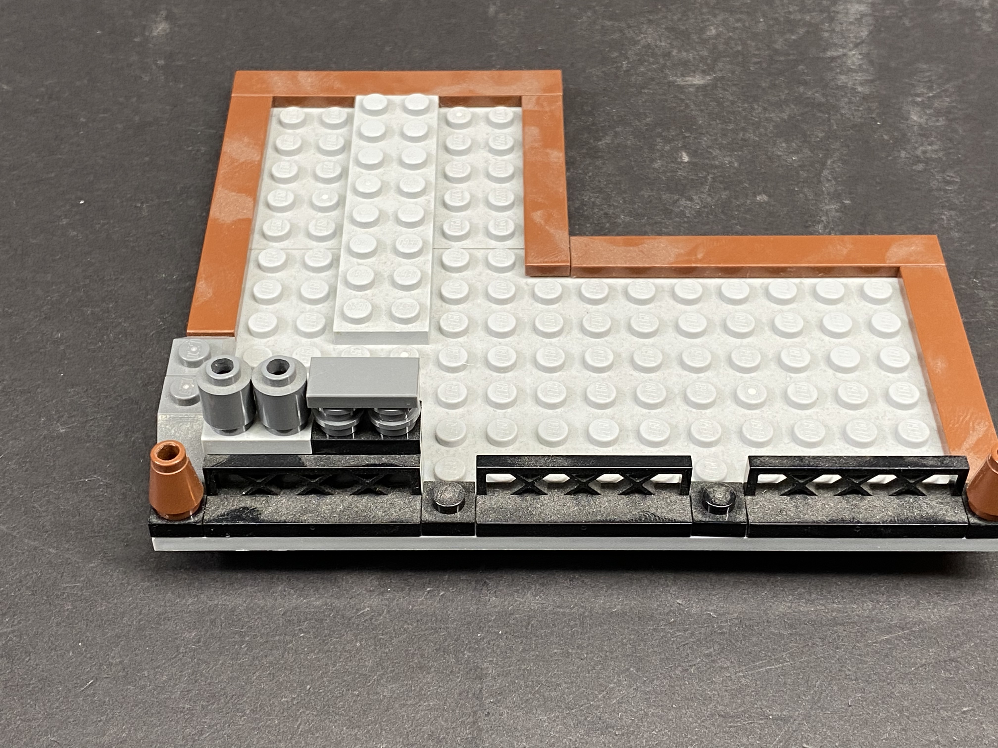
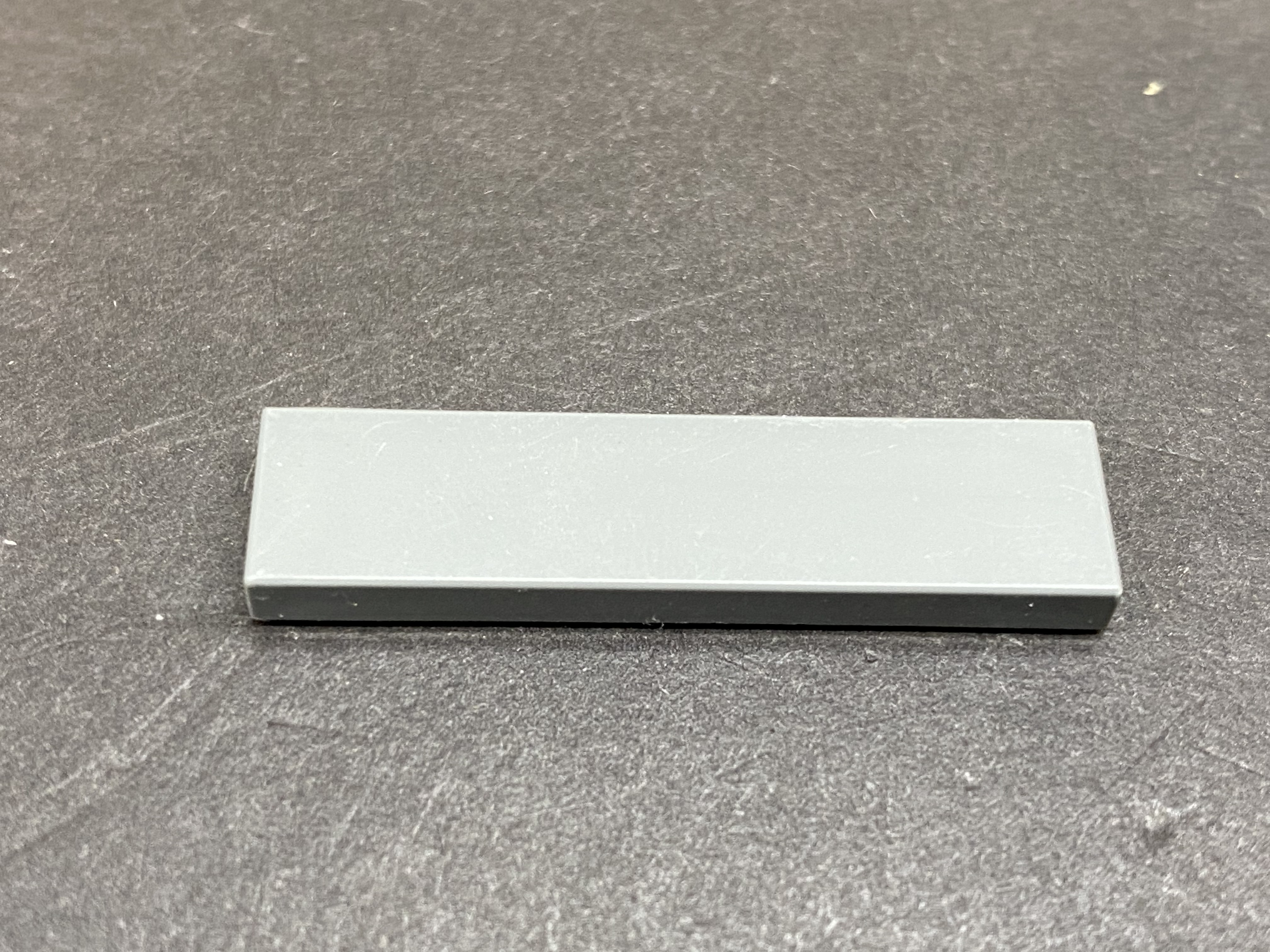
Remove the lamp post as well as the following Lego tiles.


Remove the set of brown steps.
Note: You can tilt the base plate down a little to help easily disconnect the steps.


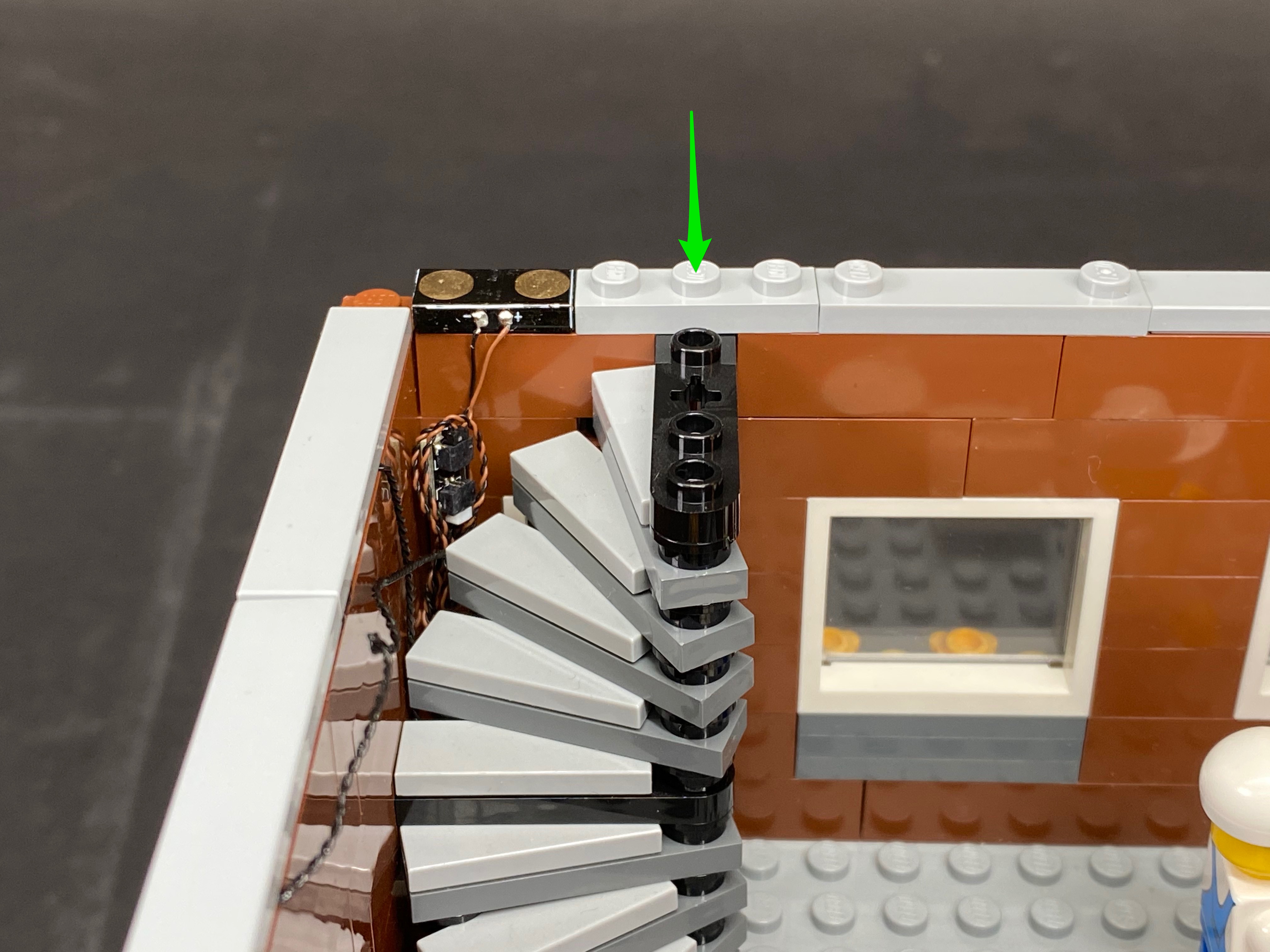
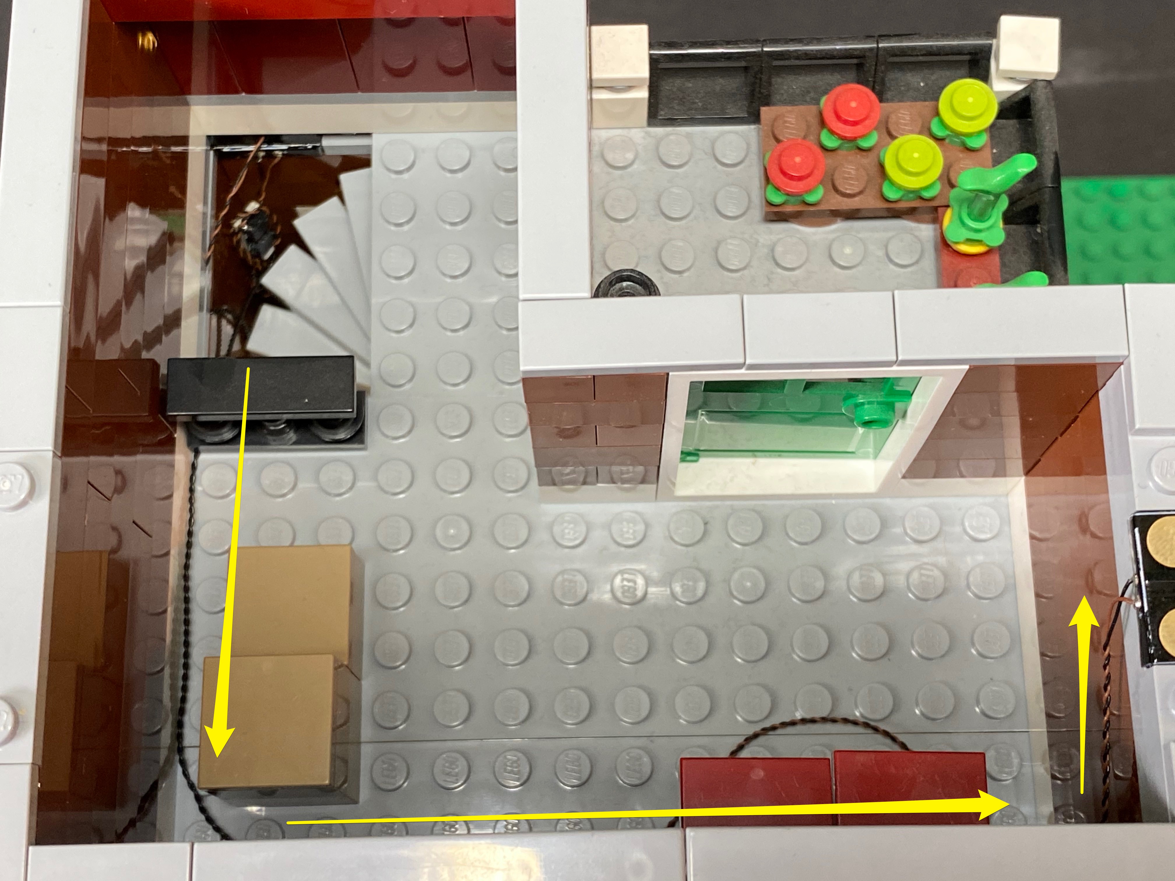
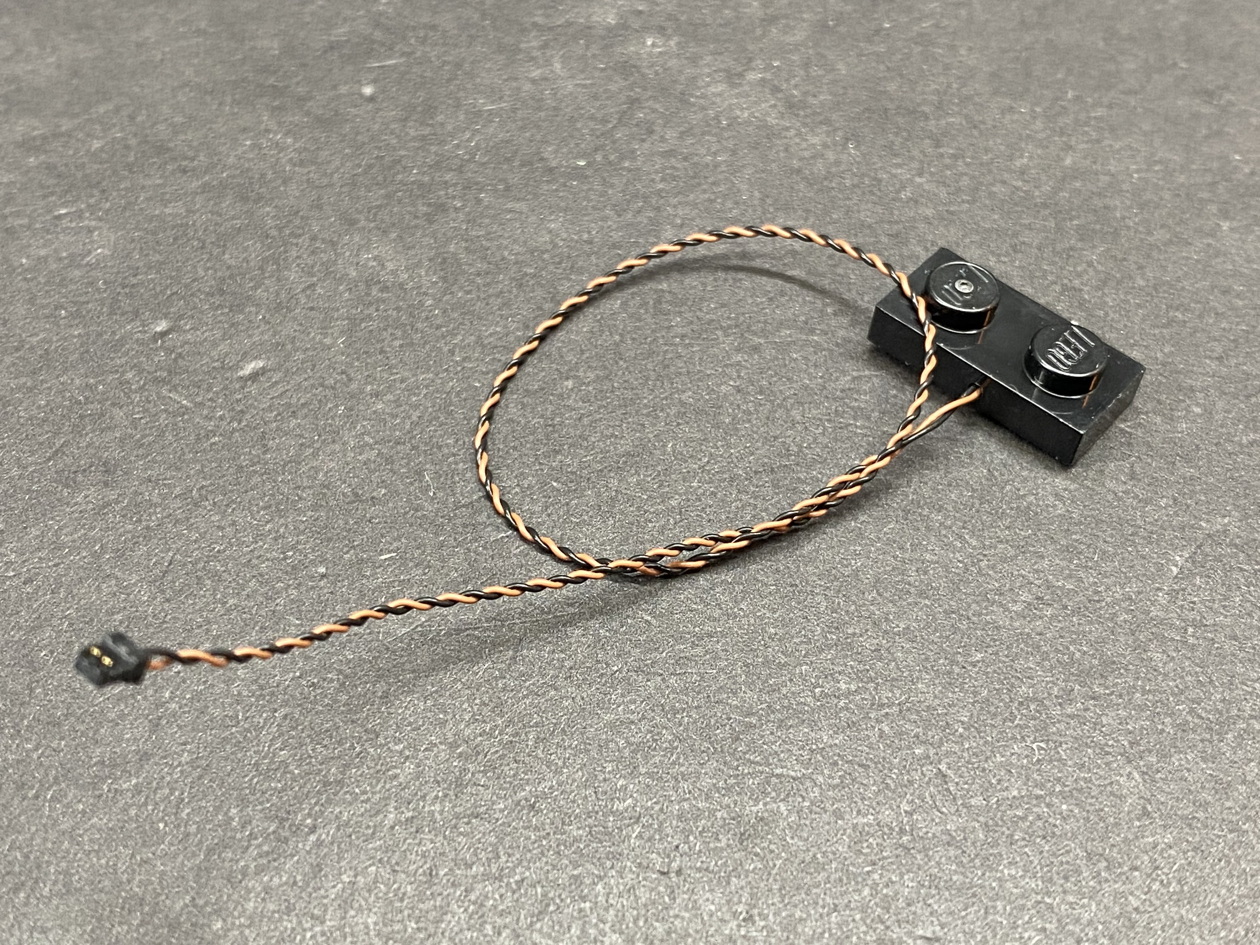
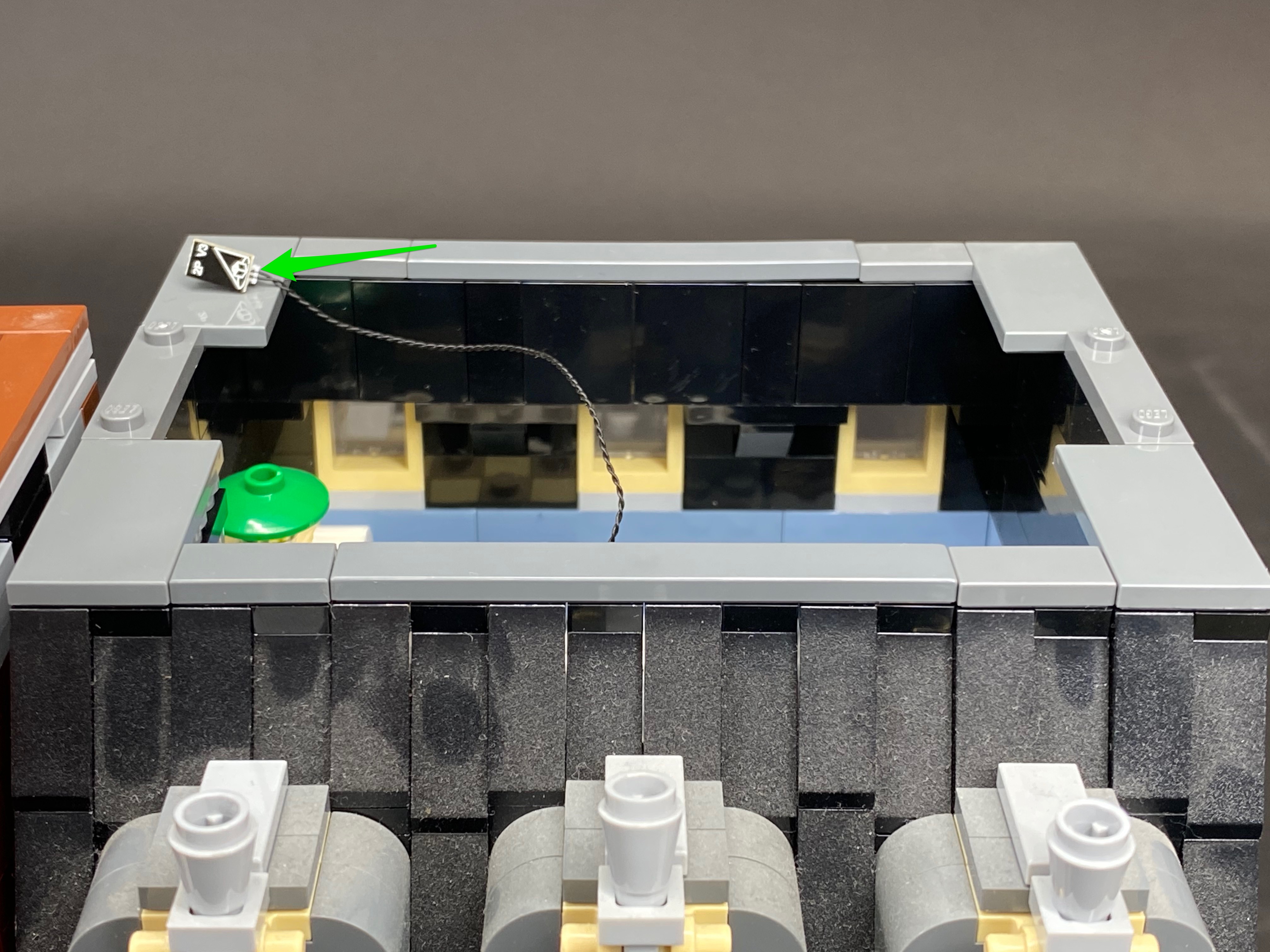
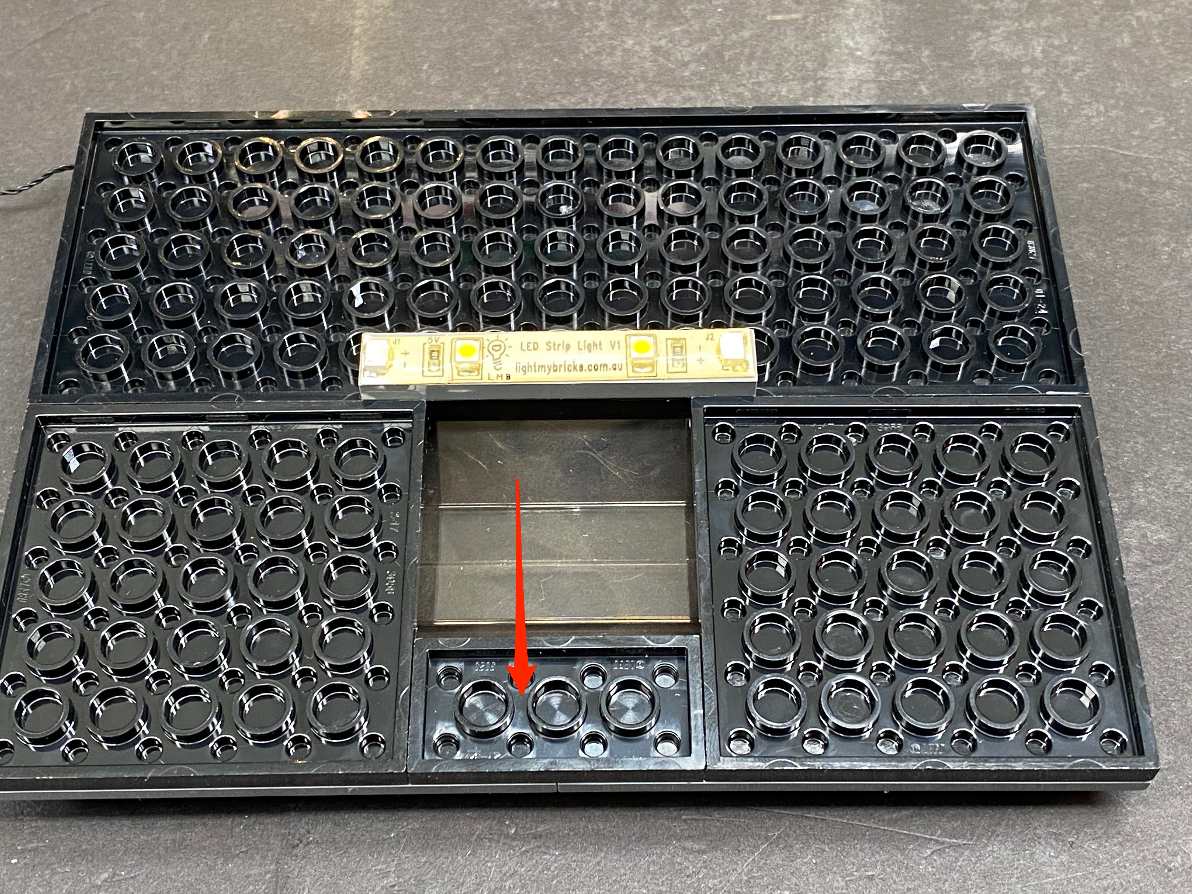
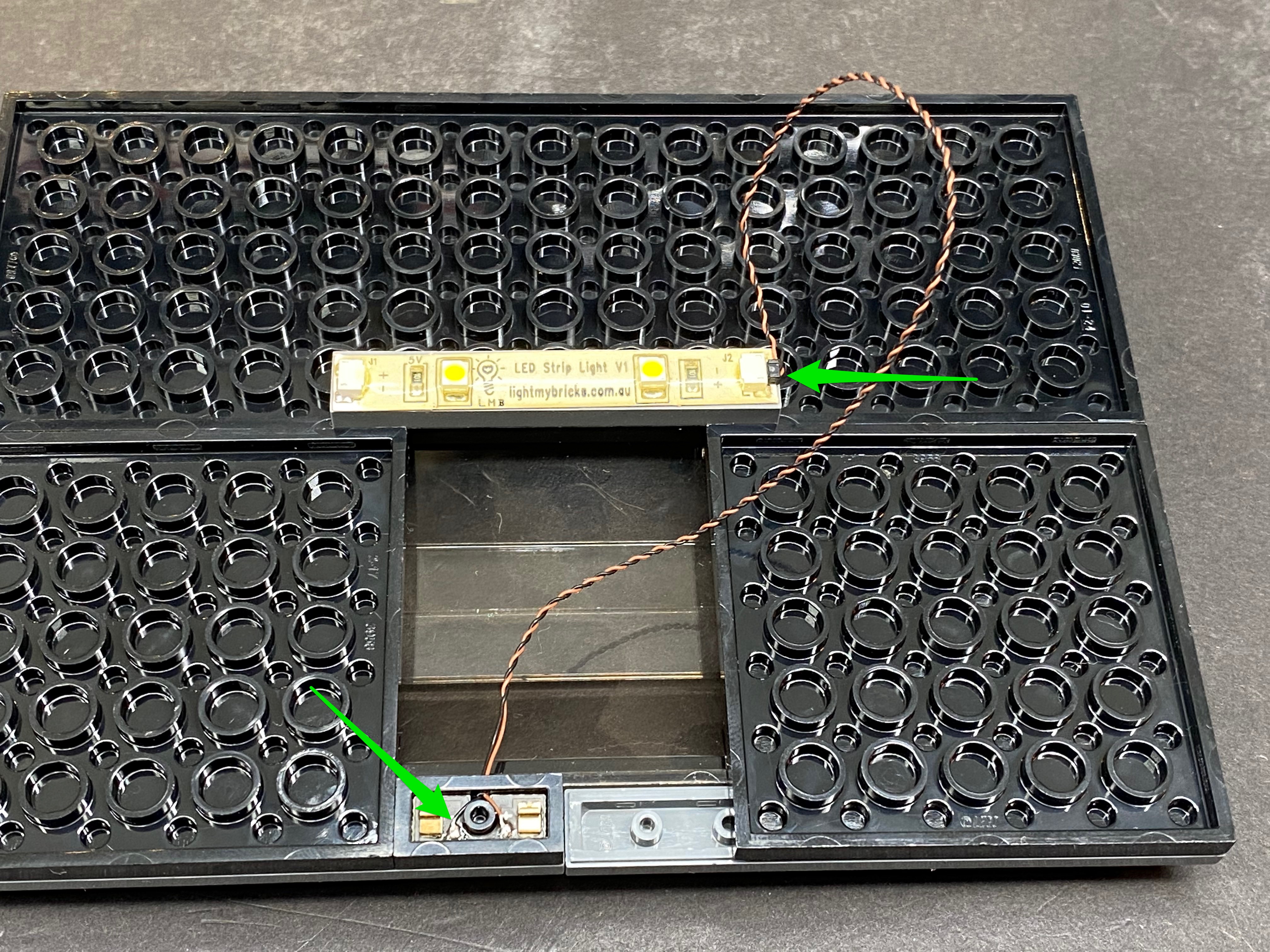
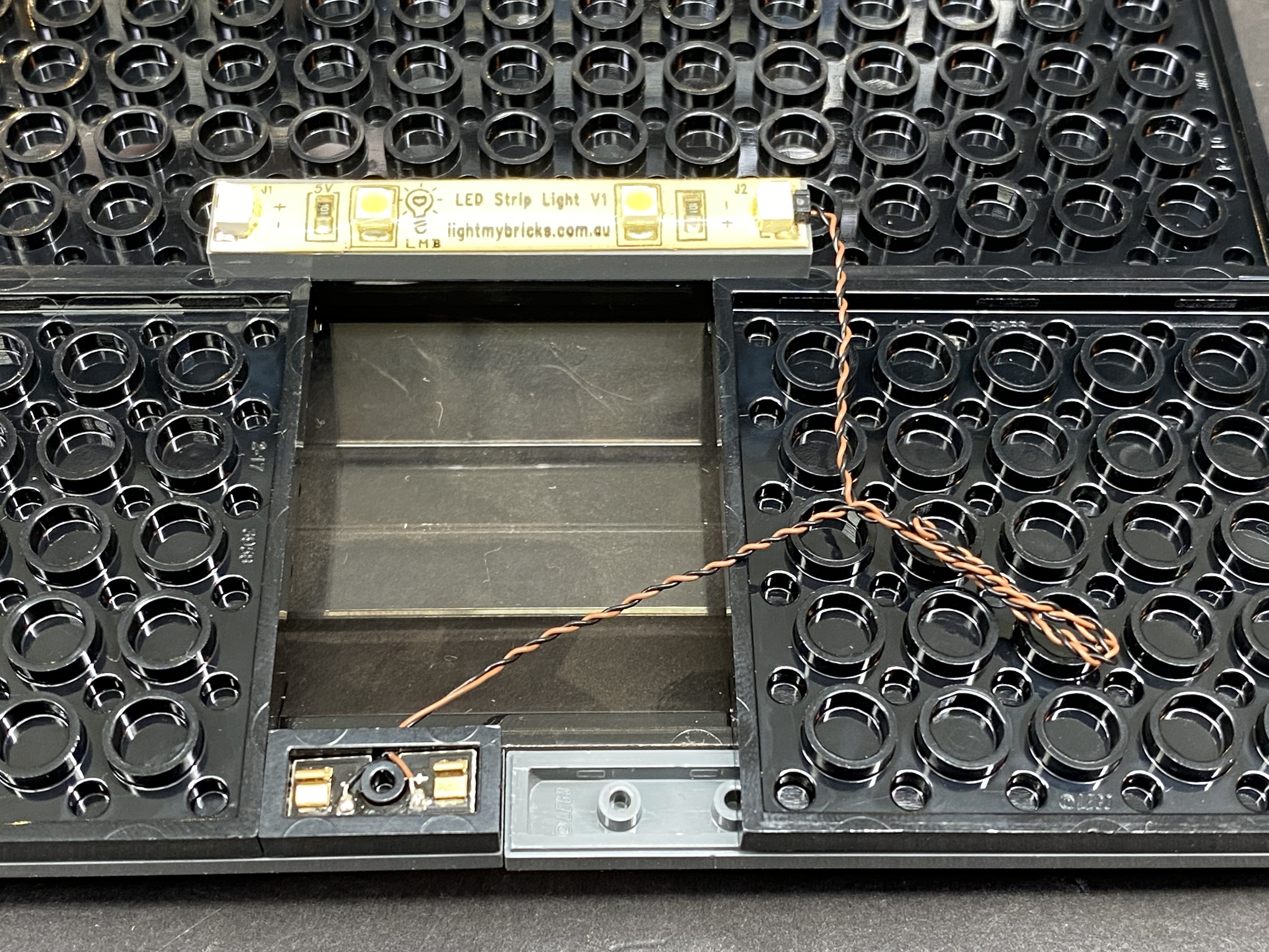
Take the Light My Bricks lamp post with LED and cable attached and connect this to the base plate ensuring the cable is facing toward the shop. Thread the cable through the doorway and pull the other end of this cable up from the inside of the shop.


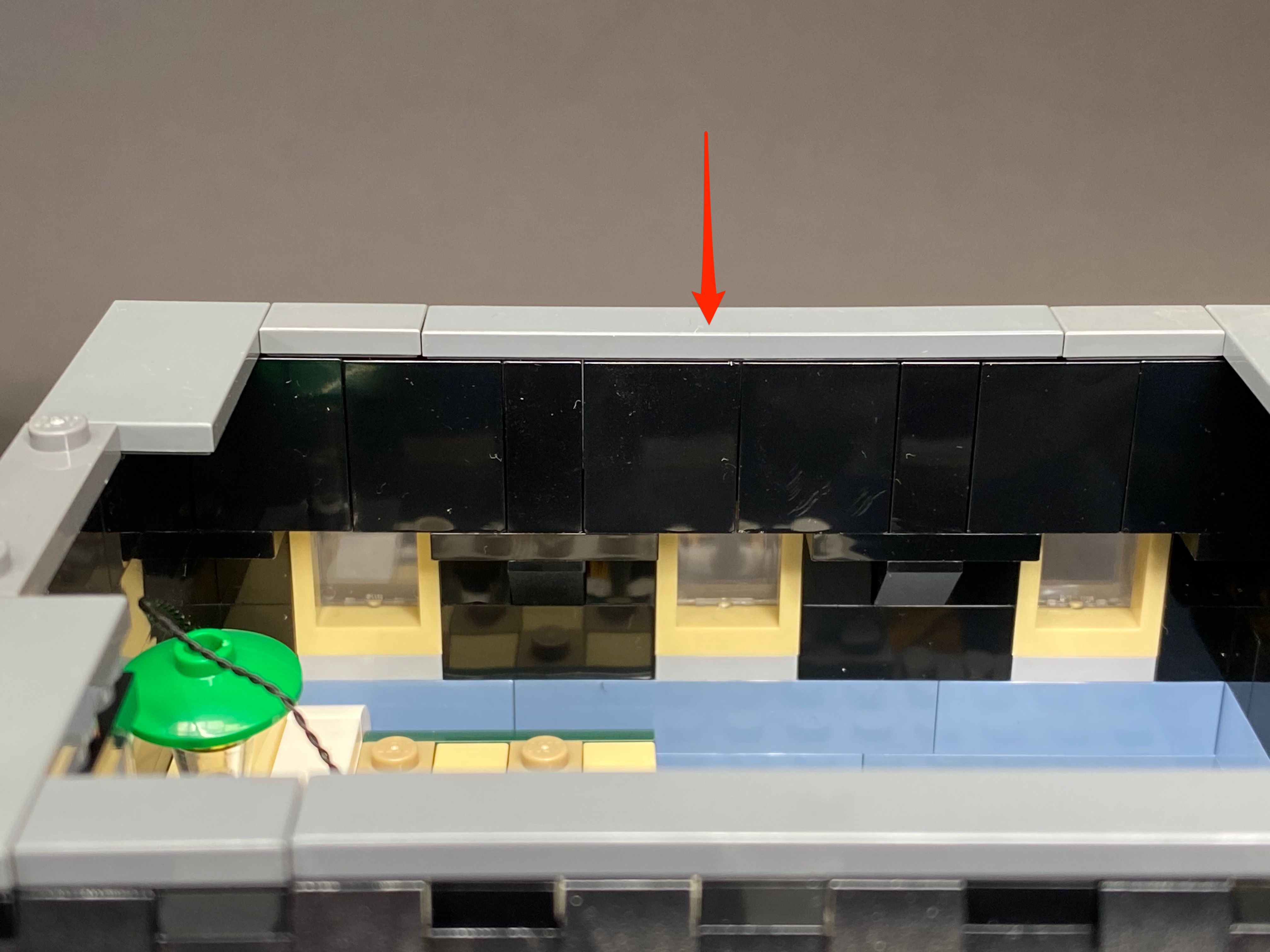
Lay the cable in between the green studs as pictured below before reconnecting the set of brown steps as well as the grey tiles we removed earlier.


15.) Push the porch light back and then disassemble the following pieces as per below.


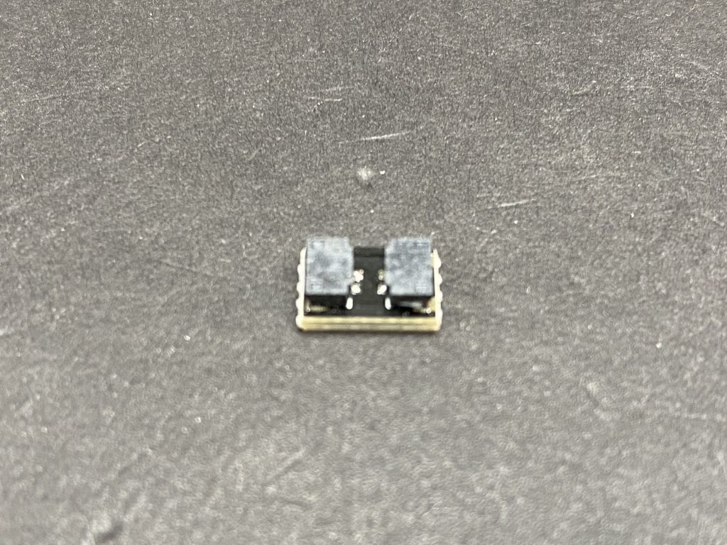
16.) Take a bit light and place it in the middle of the 4 grey studs ensuring the LED component part is facing the correct way up. Secure this bit light in place by reconnecting the transparent yellow Lego light piece directly over the top. Ensure that the cable is facing the same way as per below. The bit light should sit comfortably in the middle of the light piece. Once this is done, reconnect the transparent globe piece over the top.


Turn the porch light back toward the original position.

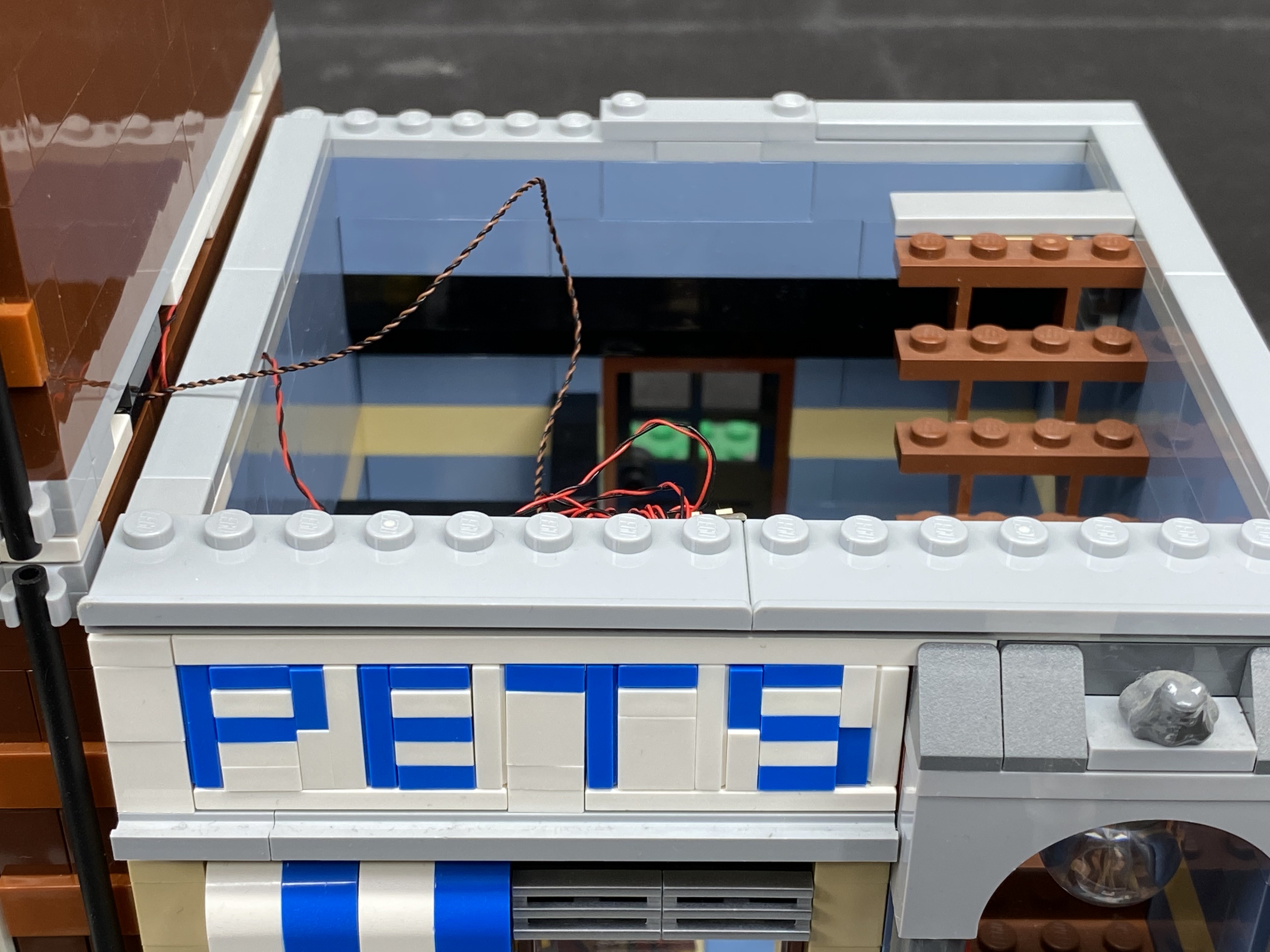
17.) Remove the following Lego pieces which surround the front windows of the Pet shop.


Take the below pieces and then install another bit light to the bottom of the blue and white roof. Secure the bit light in place by reconnecting the brown window underneath ensuring that the bit light cable is facing the inside of the building and laying in between the brown studs. The LED component should be visible if you look from underneath.


Reconnect the windows and surrounding pieces to original positions.


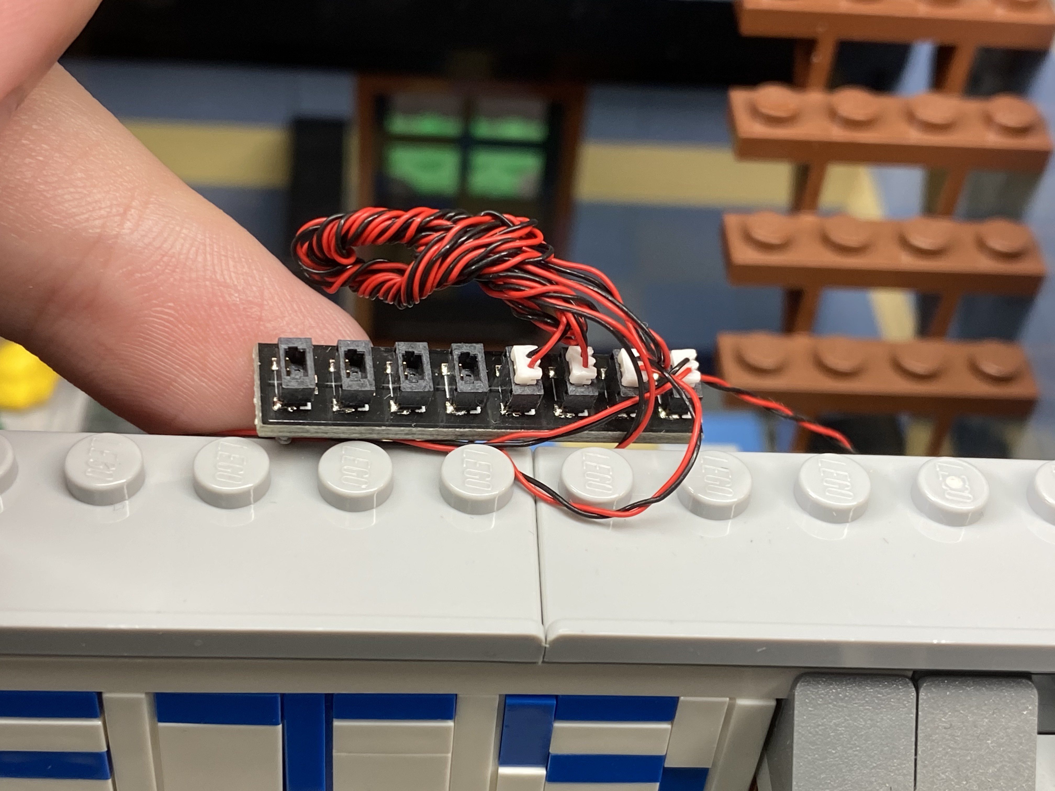
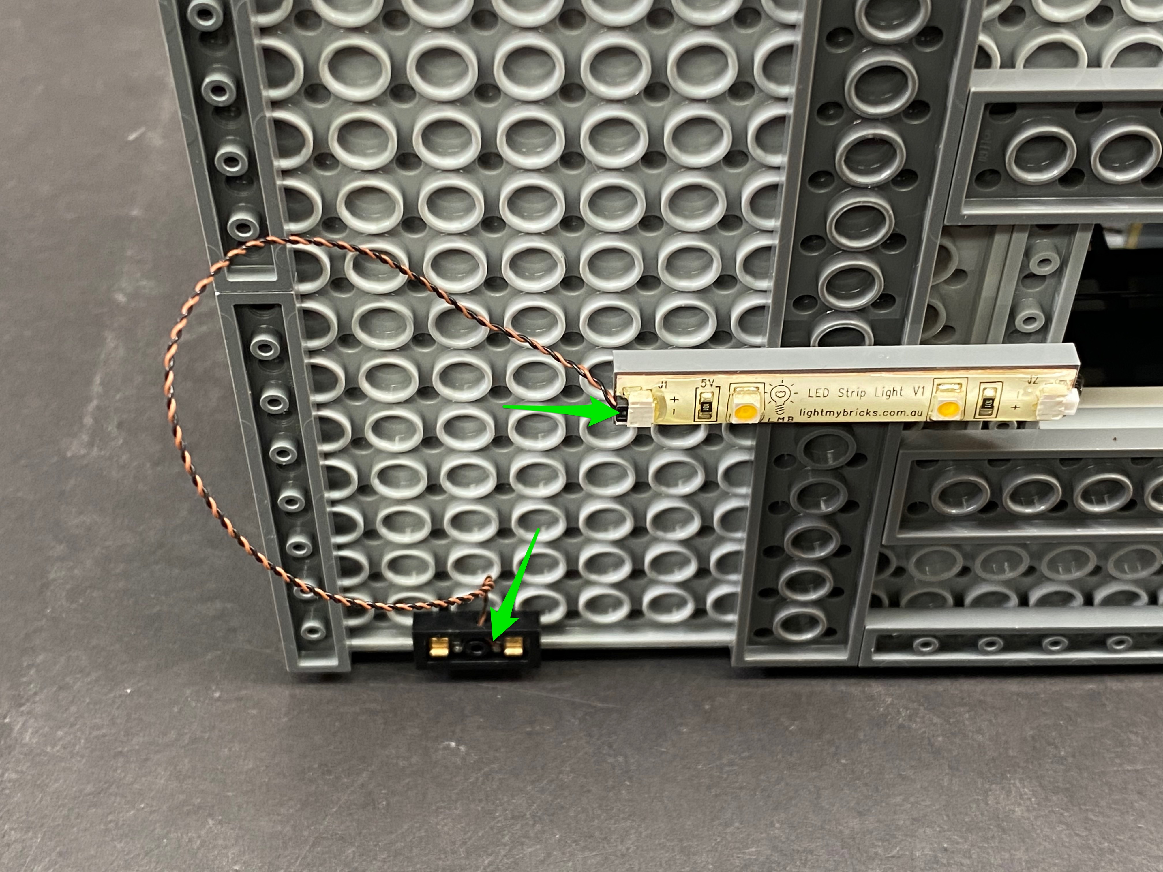
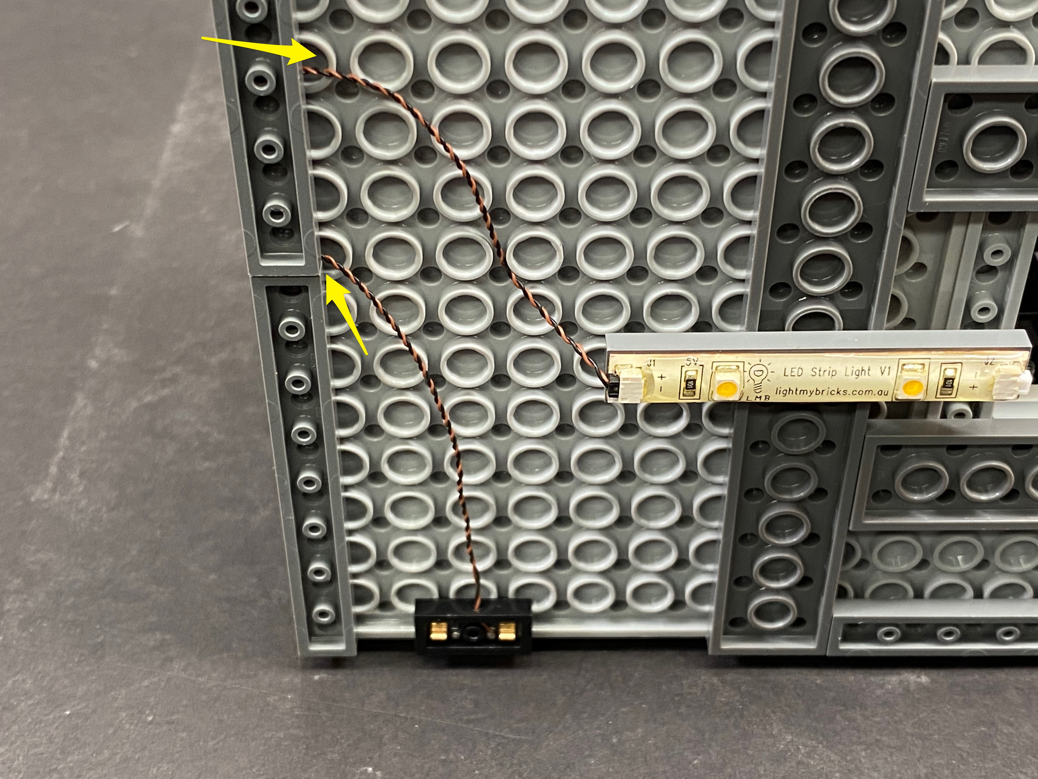
18.) Take the cable from the bit light we just installed as well as porch bit light and twist/wind them together.


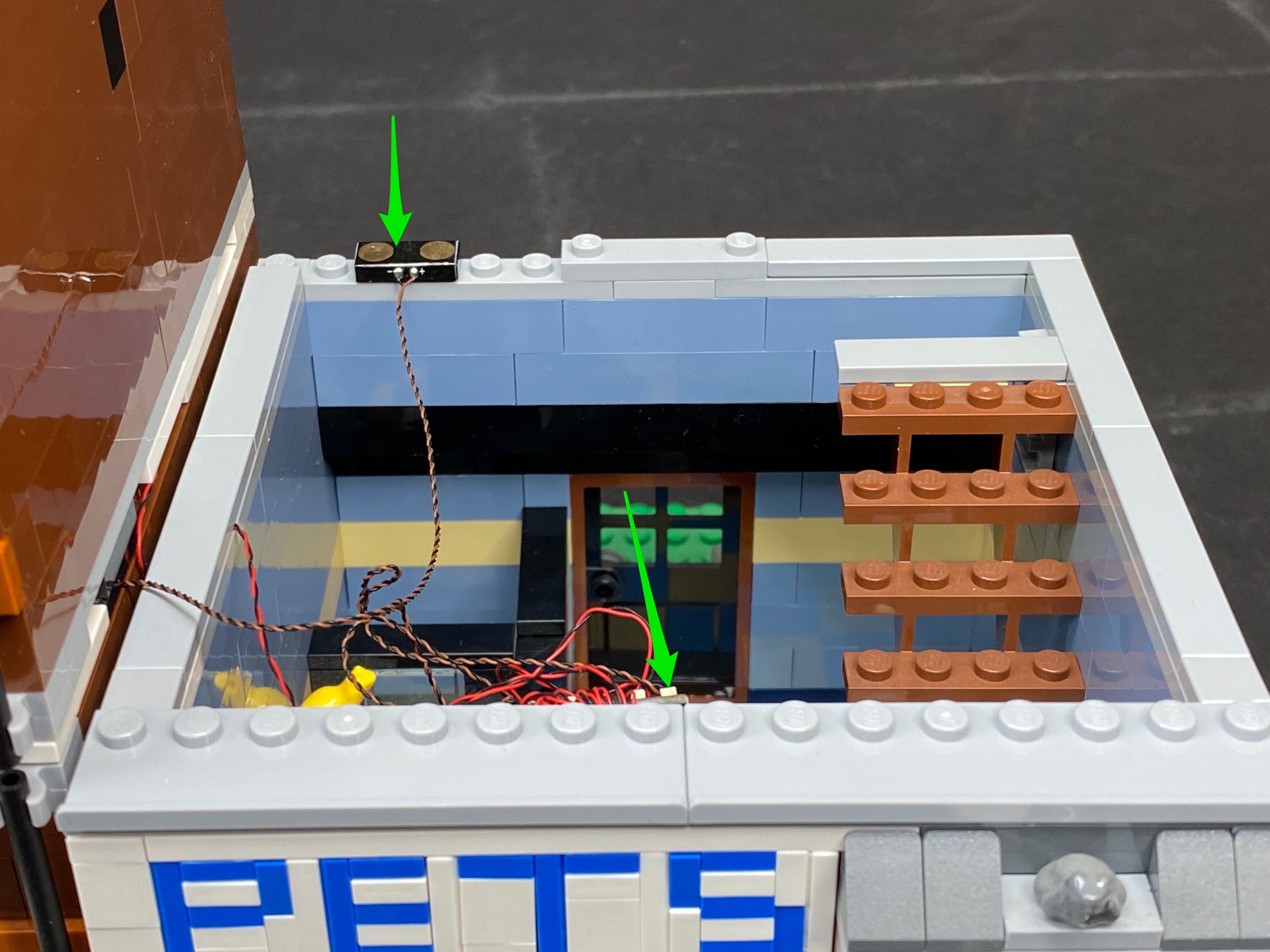
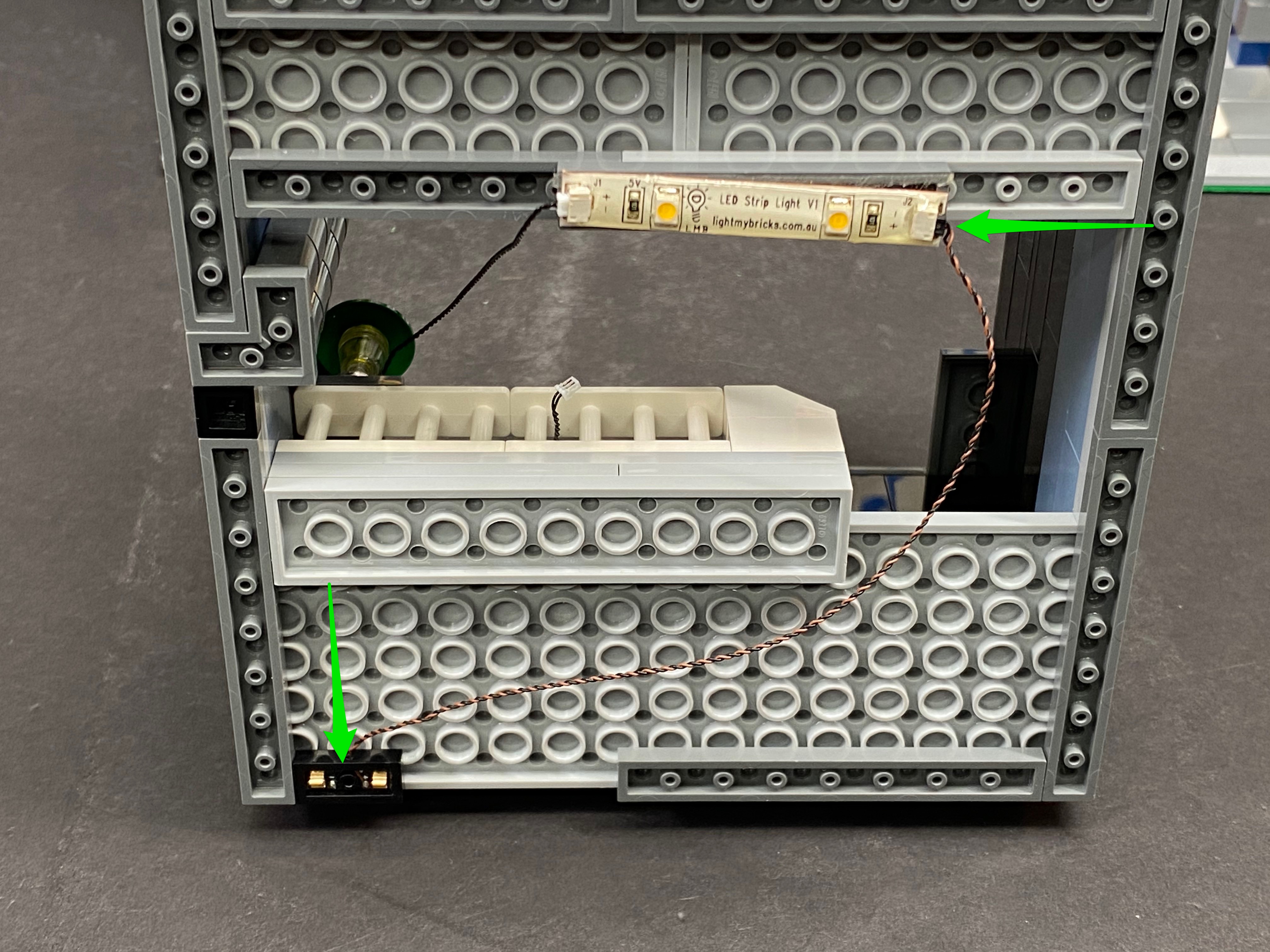
Take the 6-port expansion board from this kit and connect the 2 cables we twisted together into the the spare ports of the expansion board. Wind the 2 cables around the expansion board to free up the excess cable as per below.


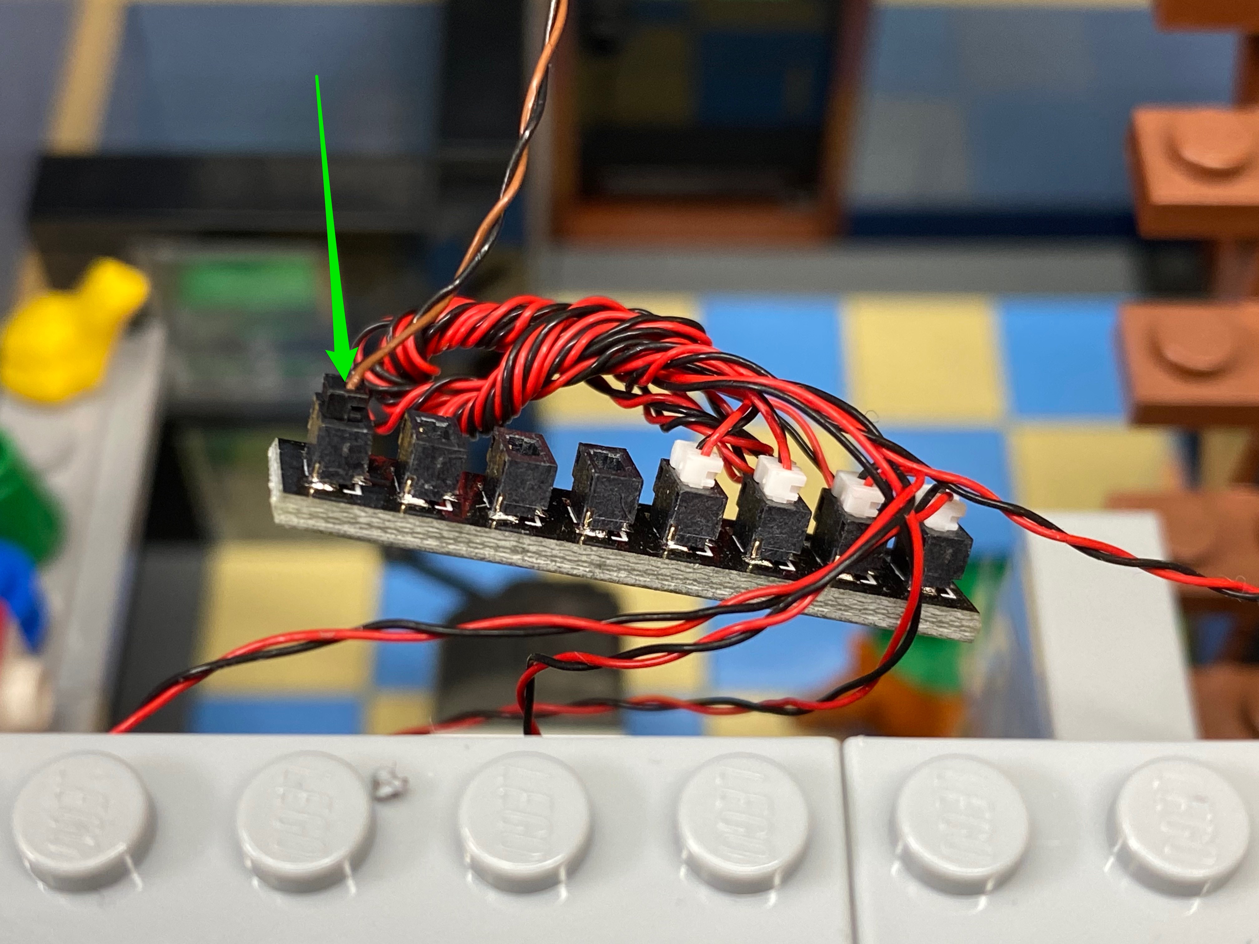
19.) Take the cables from the lamp post as well as the front door bit light from the red building and plug them into the next available ports on the expansion


Before you connect the cable from the front door of the red building, lay this cable underneath one of the grey tiles as per below.


20.) Connect the 15cm cable we connected to striplight#1 from the red building into a spare port of the expansion board then take another 15cm cable and connect it into the final port on the expansion board.

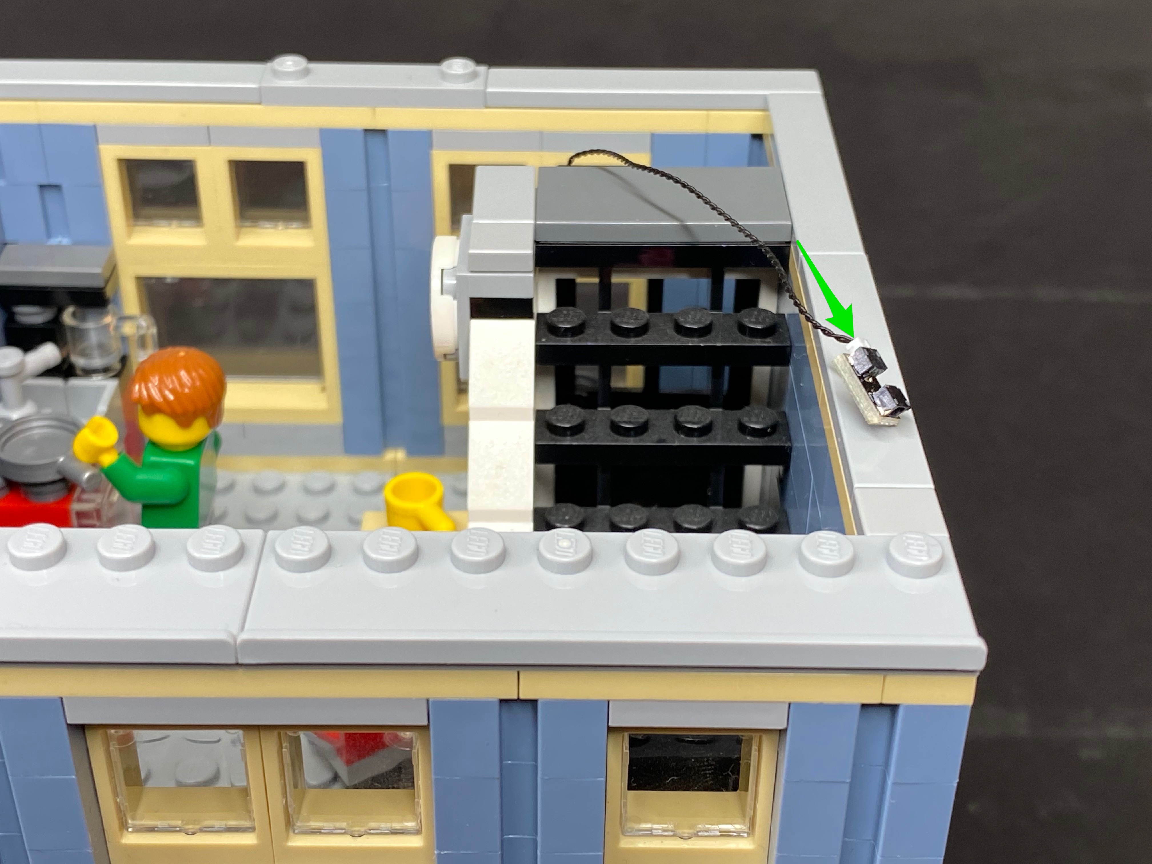
Secure the expansion board to the top of the building using a self adhesive square like I have done below. We need to keep the cables from being obviously seen from the outside front of the building so do your best to hide these cables.

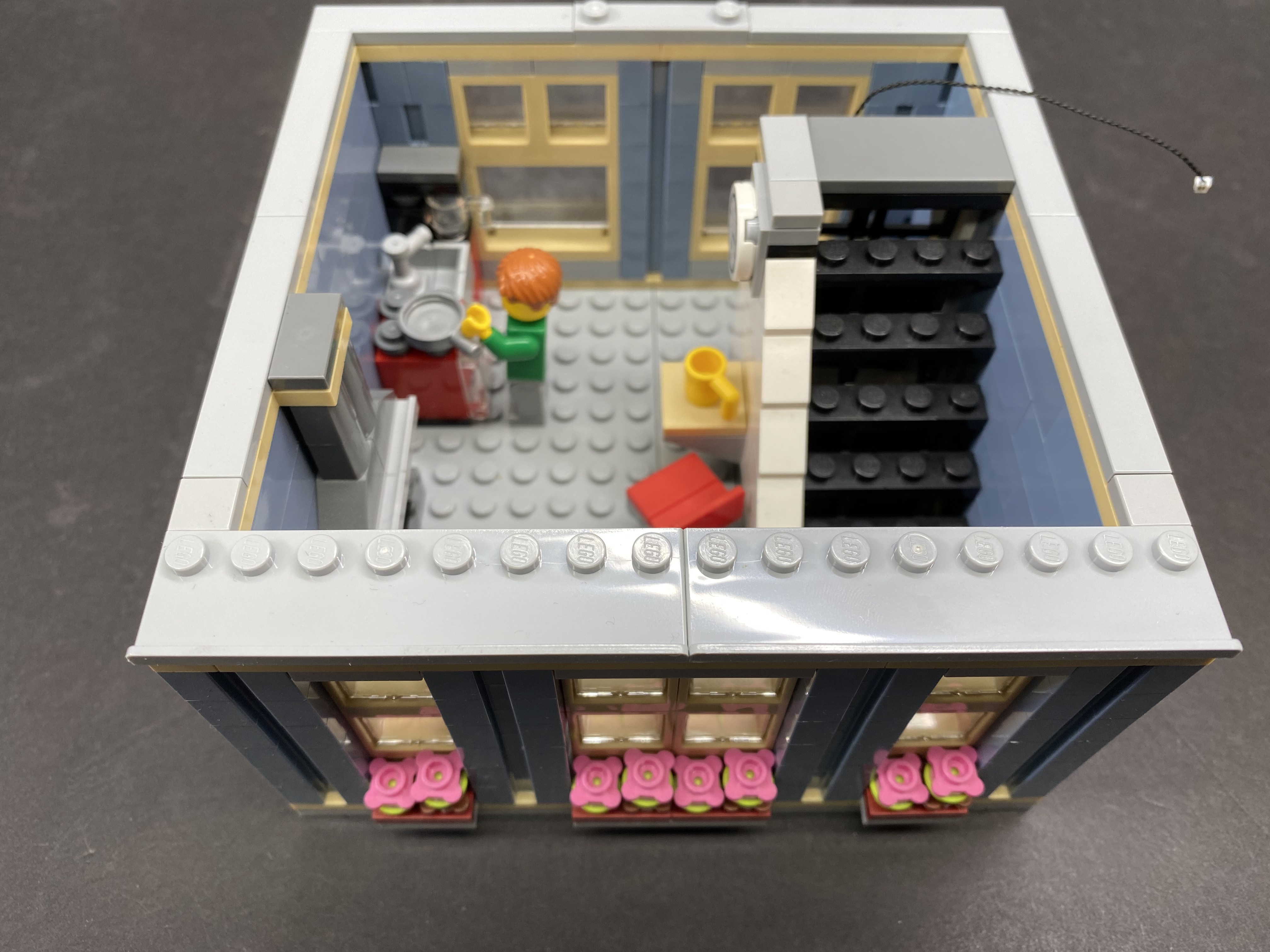
You will notice that the cable from the lamp post is dangling down. You can hide this by simply using a little bit of sticky tape to stick the cable to the wall as shown below.


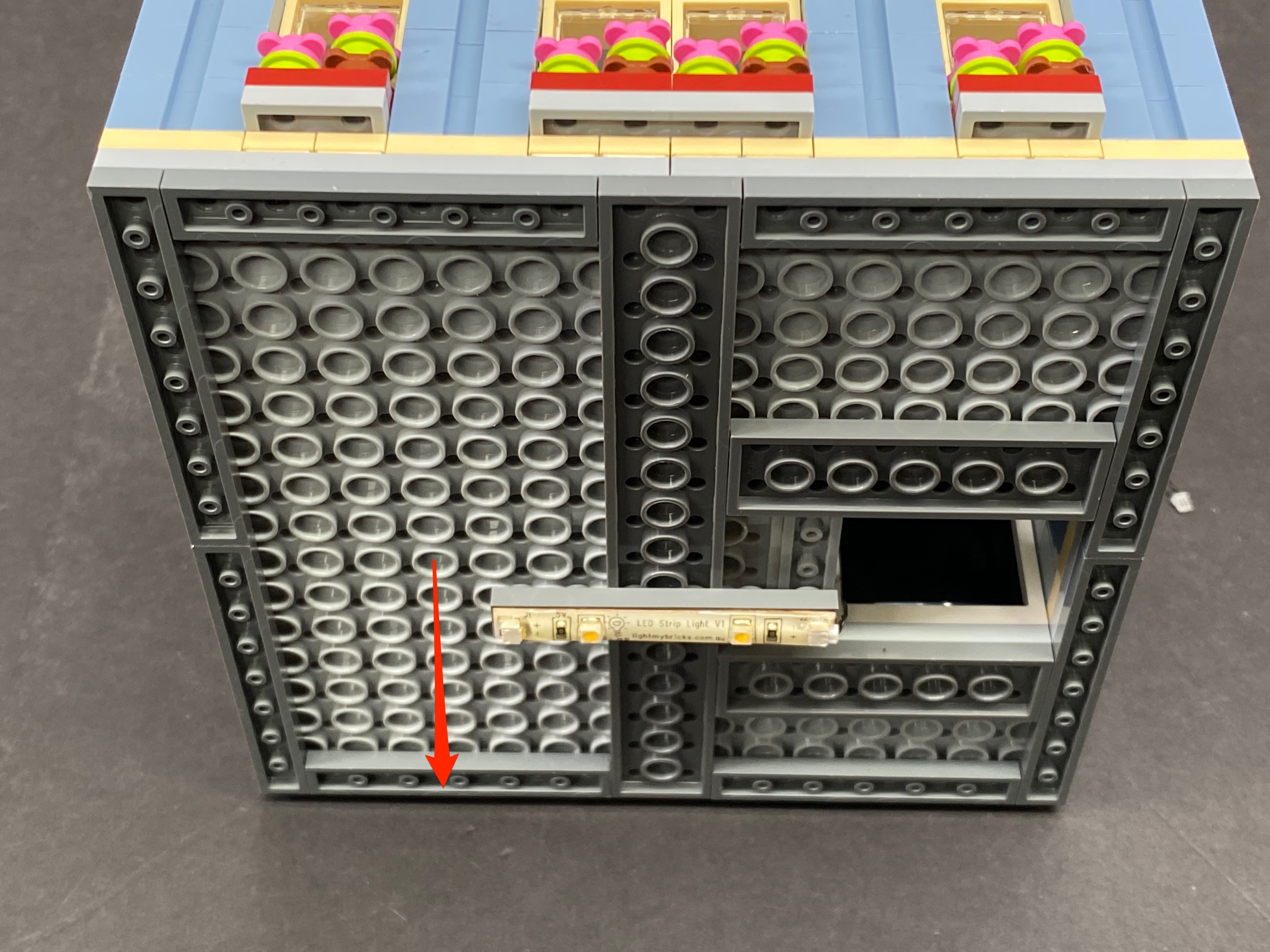
21.) Take the 2nd level and place it on top of the ground floor. Tip it on its back and connect/stick a strip light (Striplight#5) to the bottom of it in the following position. Connect the other end of the 15cm cable we connected earlier to the expansion board into the left port of the strip light.


22.) Take another 15cm cable and connect it to the right port of striplight#5. Thread the other end of the cable up the spacing which leads to the 2nd level. Reconnect the entire 2nd level back to original position and then pull the 15cm cable up from underneath.
Note: You will need to open the door on the 2nd level to do this and when you close the door after the cable has been threaded through, it will secure it it place. Leave this cable aside for now and ensure it does to drop back down below.


23.) Place the 3rd level (first remove roof) on top and then turn it over to connect/stick another strip light(Striplight#6) in the following position.


Take another 15cm cable and connect this to the left port of striplight#6. Thread this up and pull it up from the top of the floor and set aside ensuring it does not drop back down below. Locate the 15cm cable we pulled up from the door on the level below and connect this to the right port of striplight#6. Reconnect the entire 3rd floor back in place.

24.) Pull the 15cm cable up from the below 2nd floor and connect it to the final strip light (striplight#7). Take the roof of the building and connect/stick the strip light in the below position.


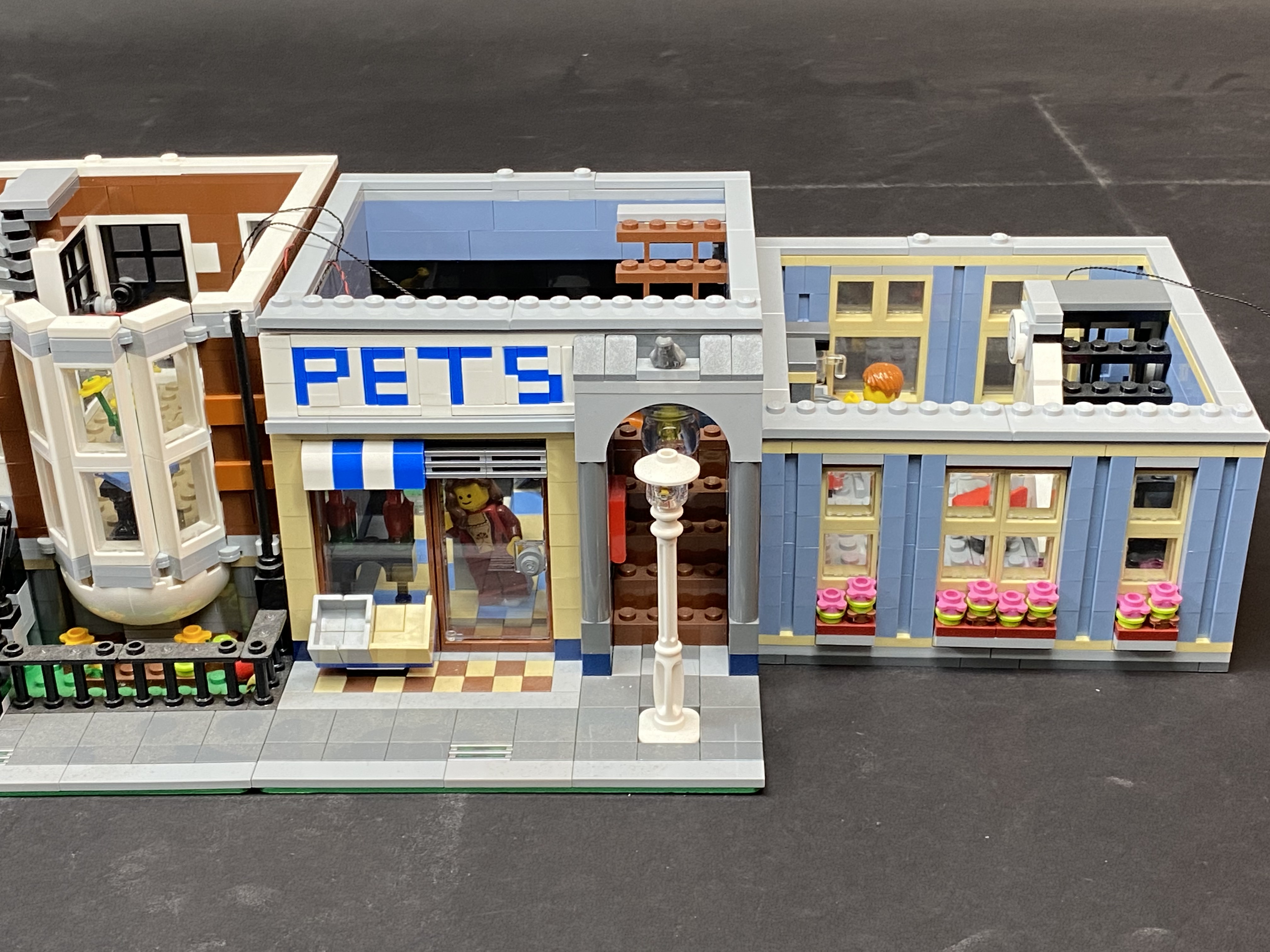
Reconnect the roof to the original position and and then connect the 2 buildings back together.


This now completes installation of the Pet Shop lighting kit.
Turn the battery pack to “on” and enjoy!

Wireless Power Connectors:
If you wish to use Light My Bricks Wireless Power Connectors in between floors (sold separately), you will require the following extra parts (available for purchase through our DIY range)
- 6x Wireless Power Connectors sets (available to purchase in a 2pk)
- 4x 2-Port Expansion Board (available to purchase in a 4pk)
- 1x 8-Port Expansion Board (available to purchase in a 2pk)
- 3x 1×6 Plate (Any Colour) (Available to Purchase)
- 2x 1×2 Plate (Any Colour) (Not sold but it is a common LEGO piece)
- 1x 1×4 Tile (Any Colour) (Not sold but it is a common LEGO piece)The LEGO pieces are interchangeable as long as the replacements can fulfil the same role/purpose.
1.) Lift up the roof of the left building before disconnecting the USB Power Cable and the Connecting Cable.
Disconnect the following tile to remove the secured USB Power Cable as we will connect it to a different spot later on. Reconnect the tile once the cable is free/loose.
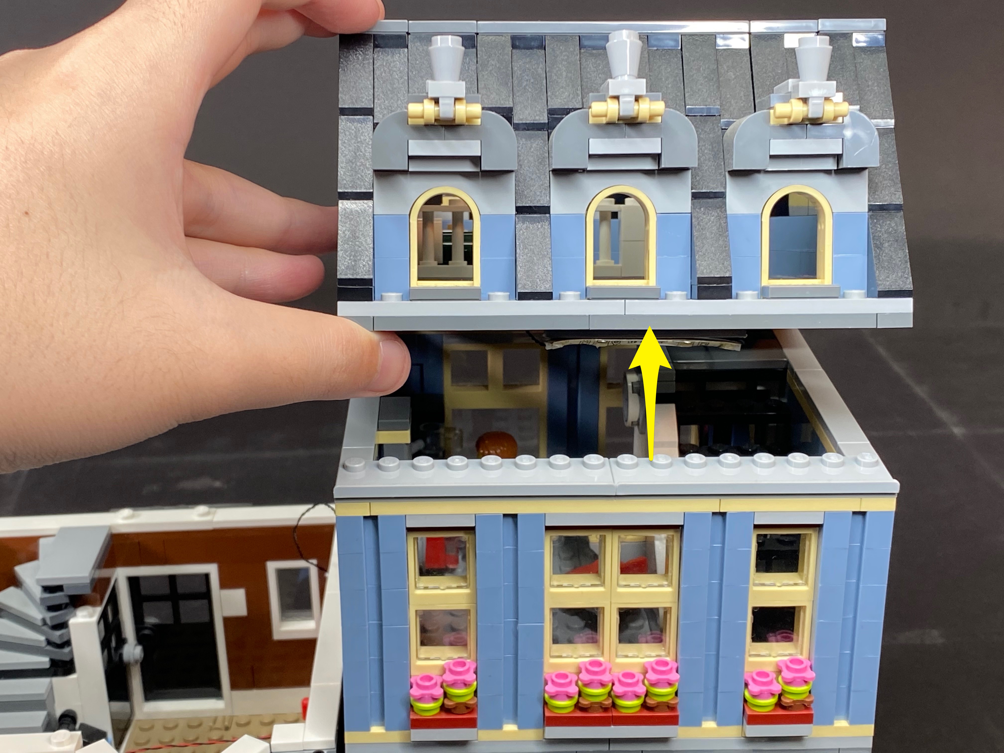
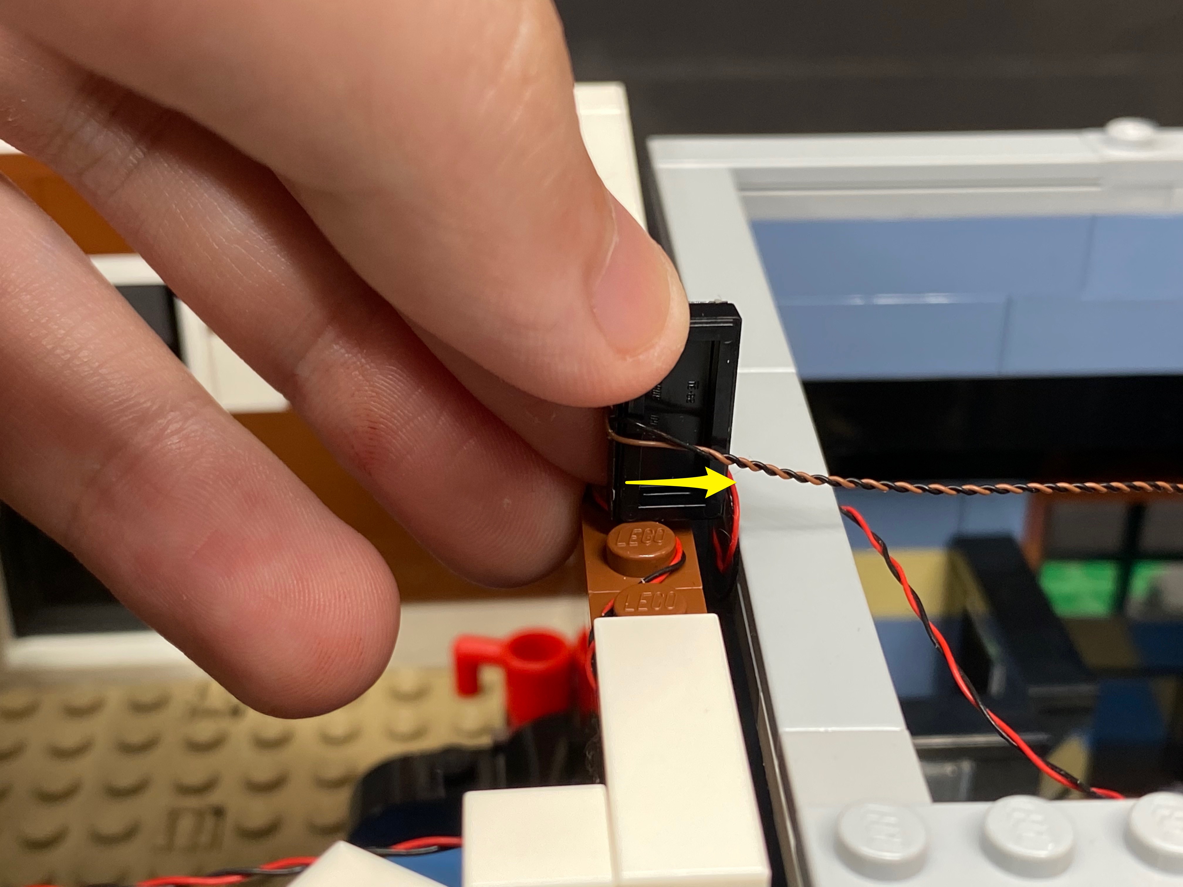
2.) Lift up the 2nd floor before disconnecting the Connecting Cable as shown. Once disconnected, remove the 2nd floor of the left building.


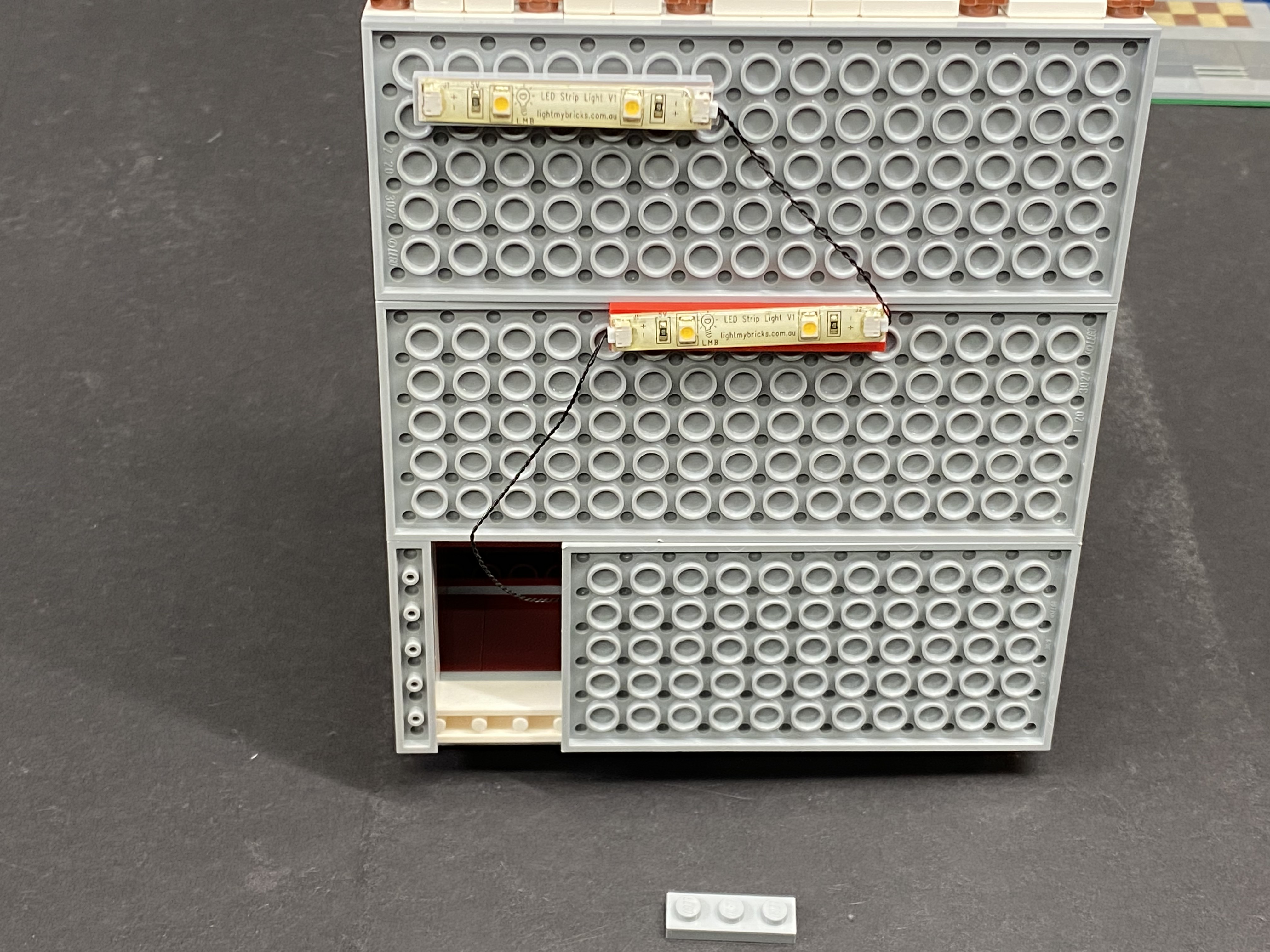
3.) Lift up the 1st floor before disconnecting the Connecting Cable and White LEGO Plate from underneath as shown. Once the cable/wire is free, reconnect the White LEGO Plate, then remove the 1st floor of the left building.


4.) Lift up the roof of the right building before disconnecting the Connecting Cable from the strip light as shown. Once disconnected, remove the roof.

5.) Lift up the 2nd floor before disconnecting the following Connecting Cable from the strip light as shown. Once disconnected, remove the 2nd floo.r


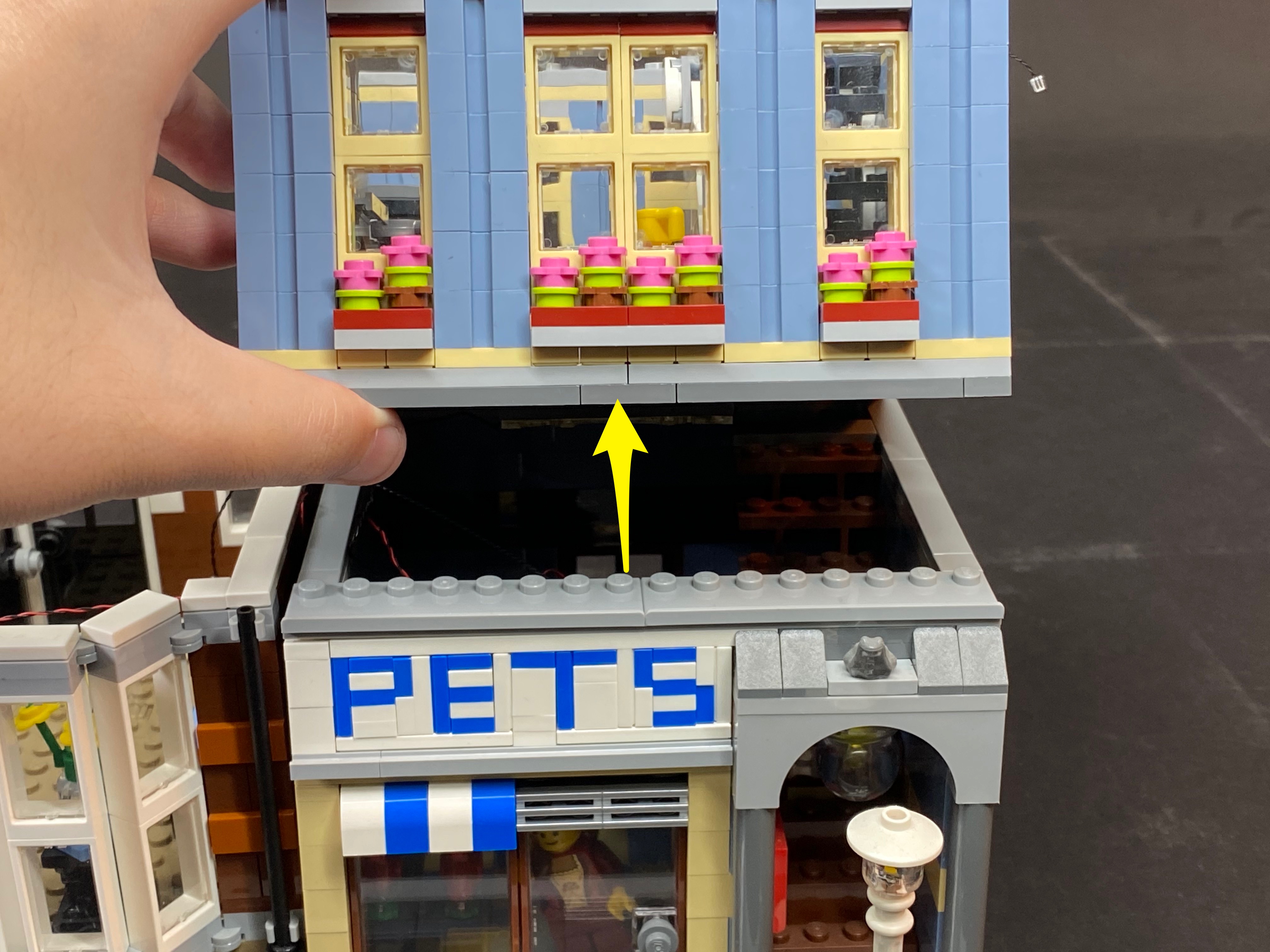
6.) Lift up the 1st floor, before disconnecting the Connecting Cable from the strip light as shown. Once disconnected, remove the 1st floor.

7.) Disconnect all the bit lights from the 6-Port Expansion Board. We will also now permanently remove the connecting cables from our build, then remove the expansion board from the wall.

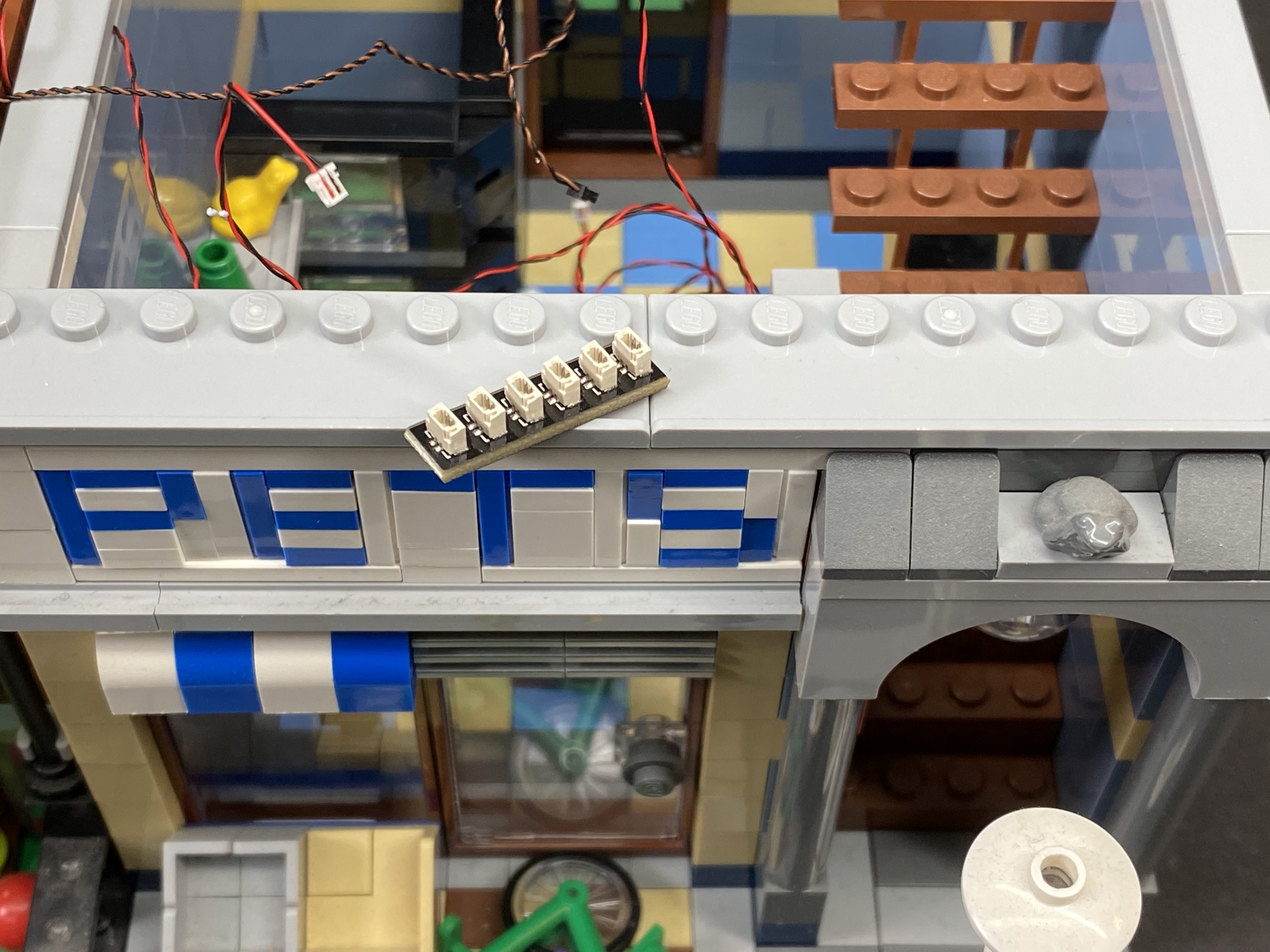
8.) Swap out the 6-Port Expansion Board for a new 8-Port Expansion Board. Reconnect the Bit Lights to the 8-Port Expansion Board. Twist/braid the wires to ensure a cleaner look. Take the USB Power Cable we removed from the left building and connect it to a spare port on the expansion board.


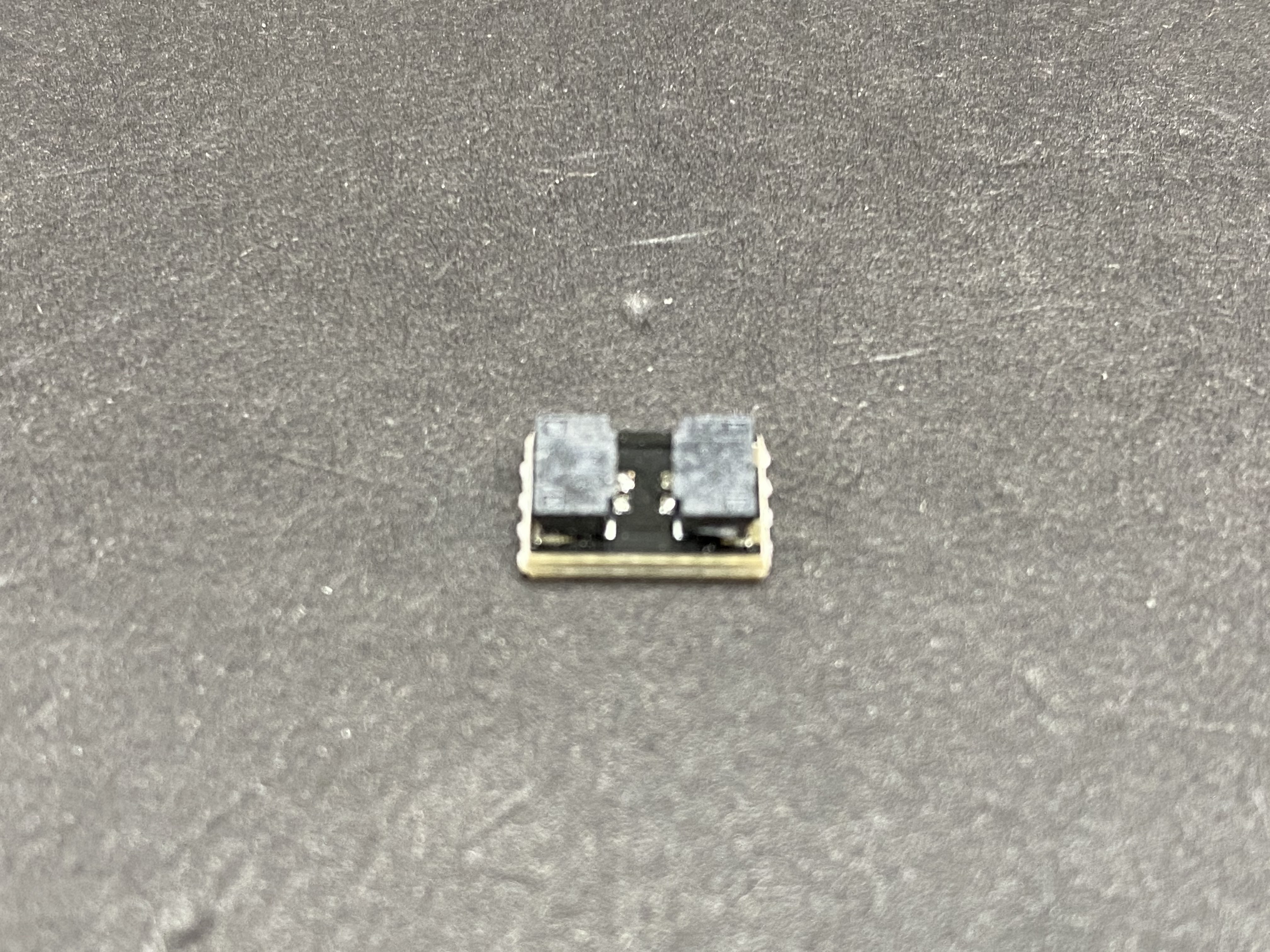
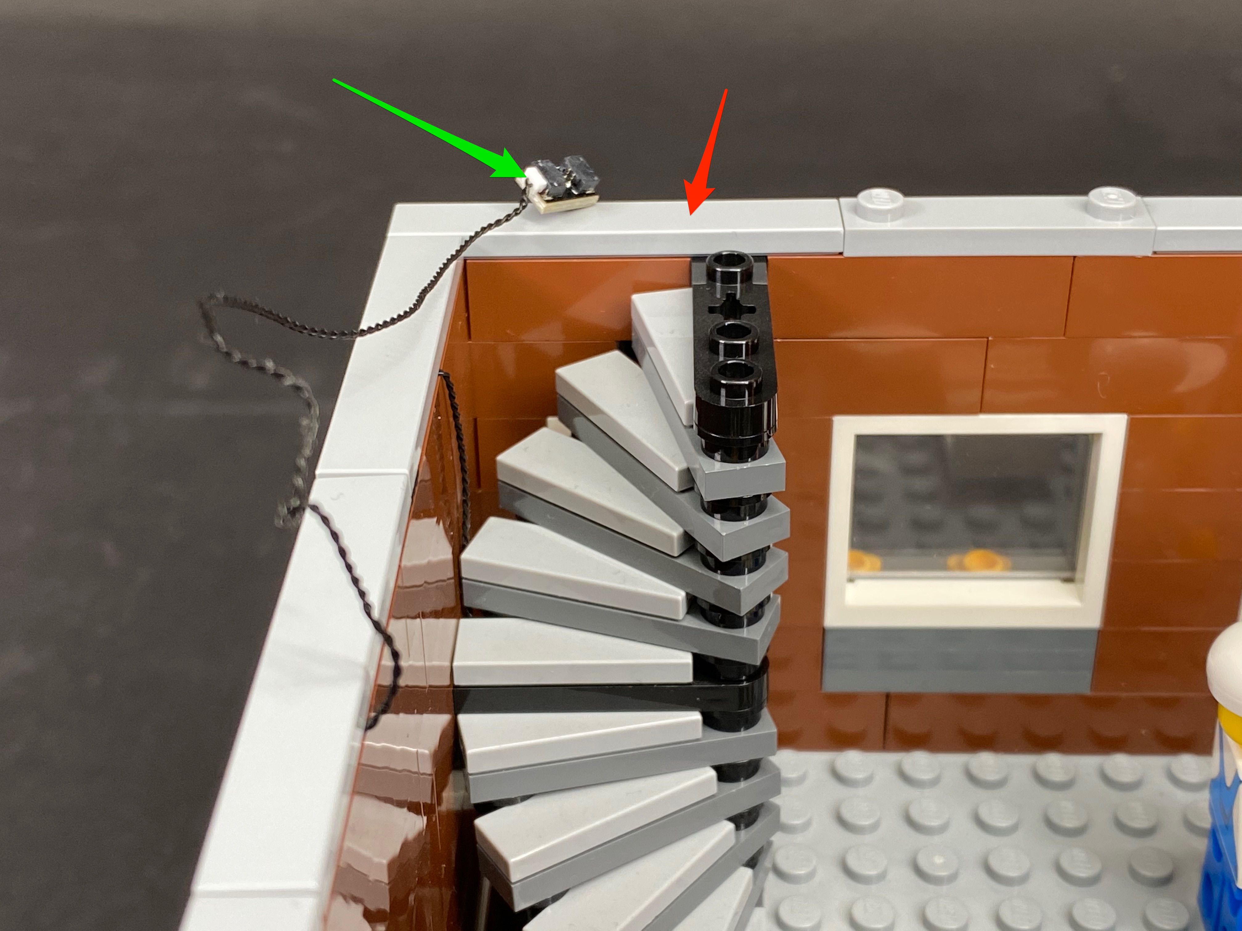
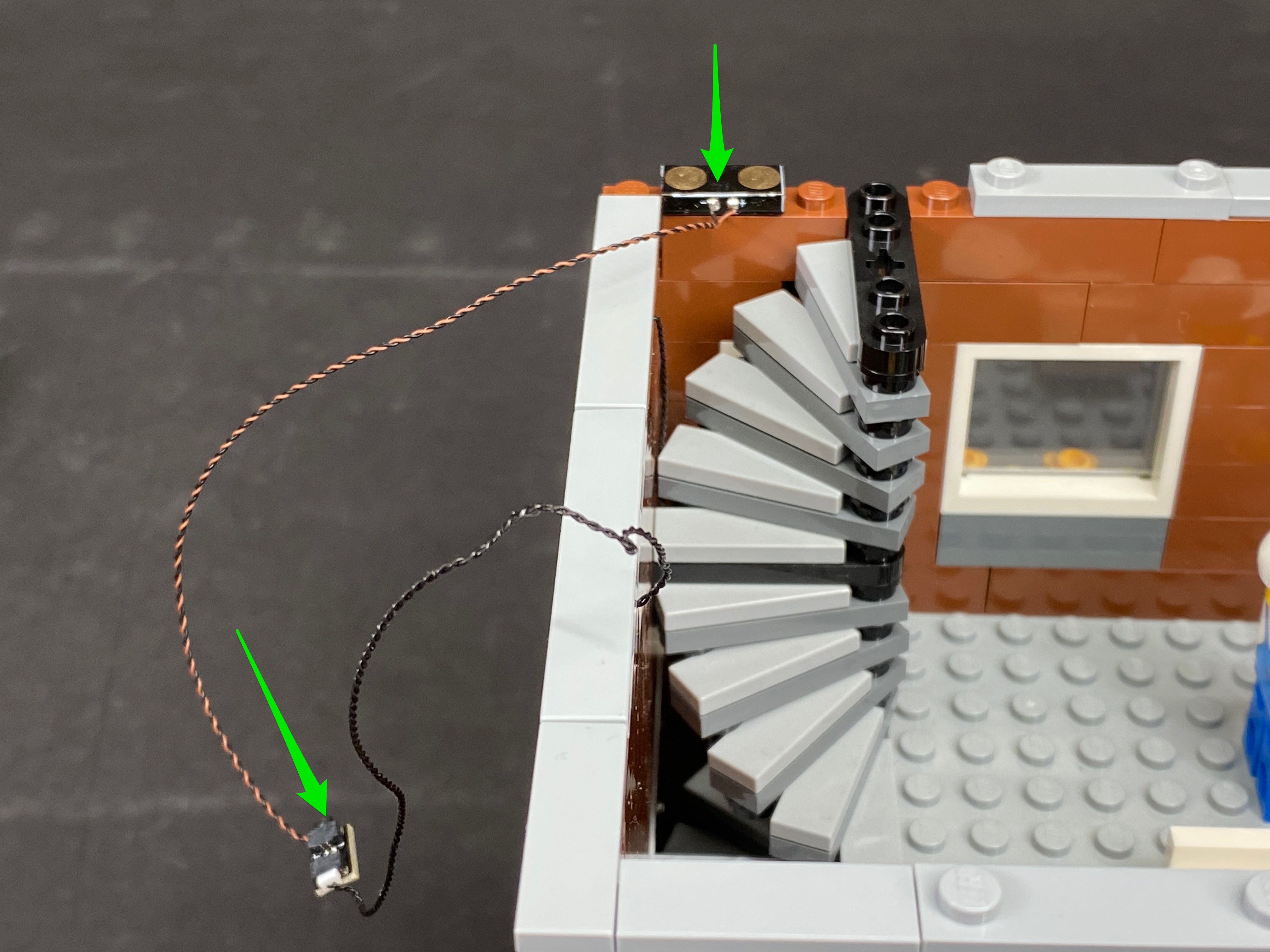
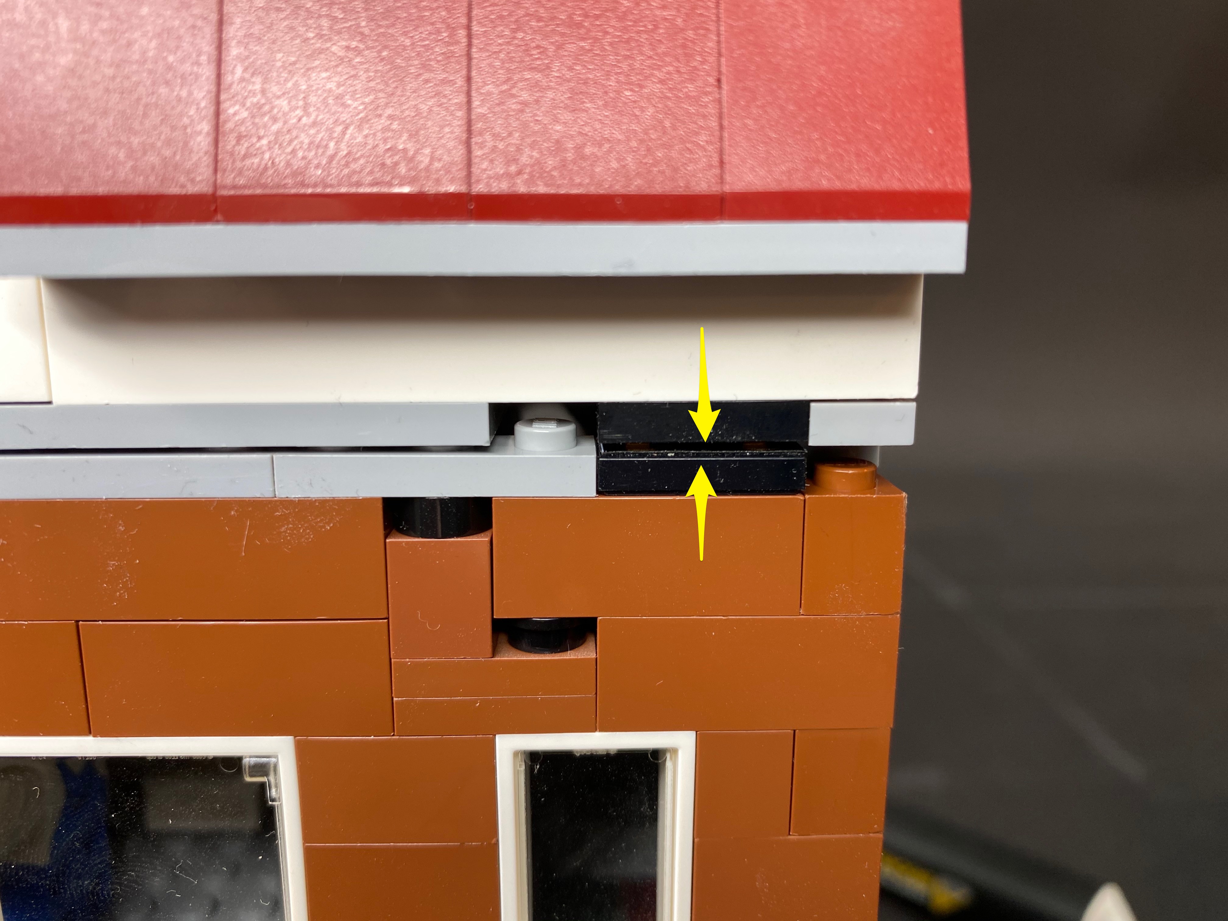
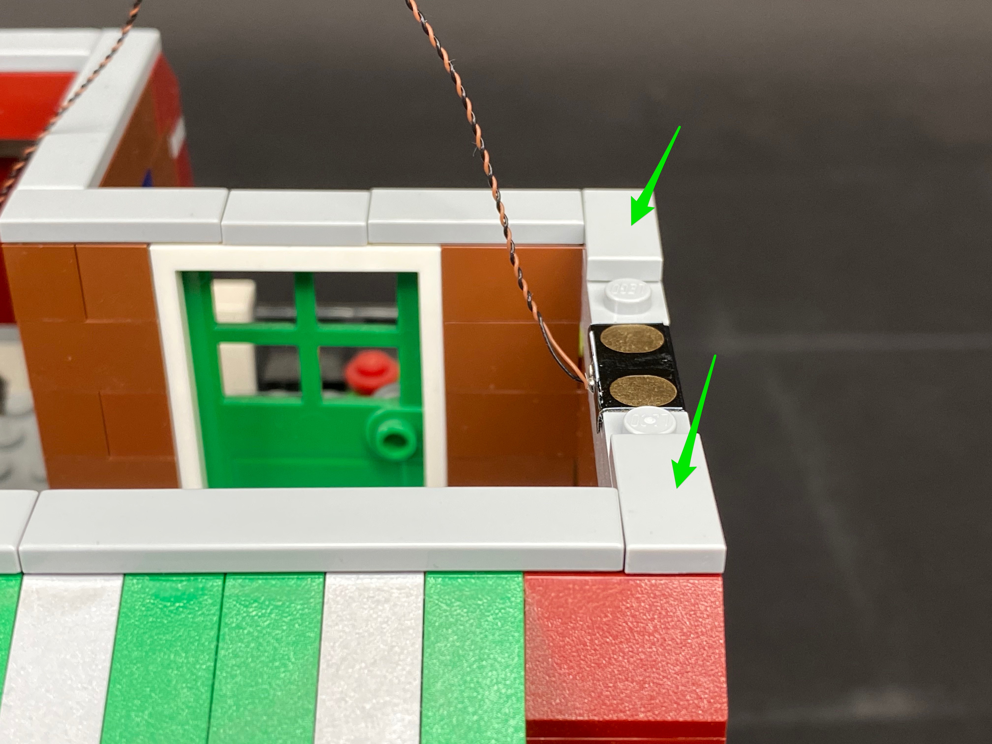
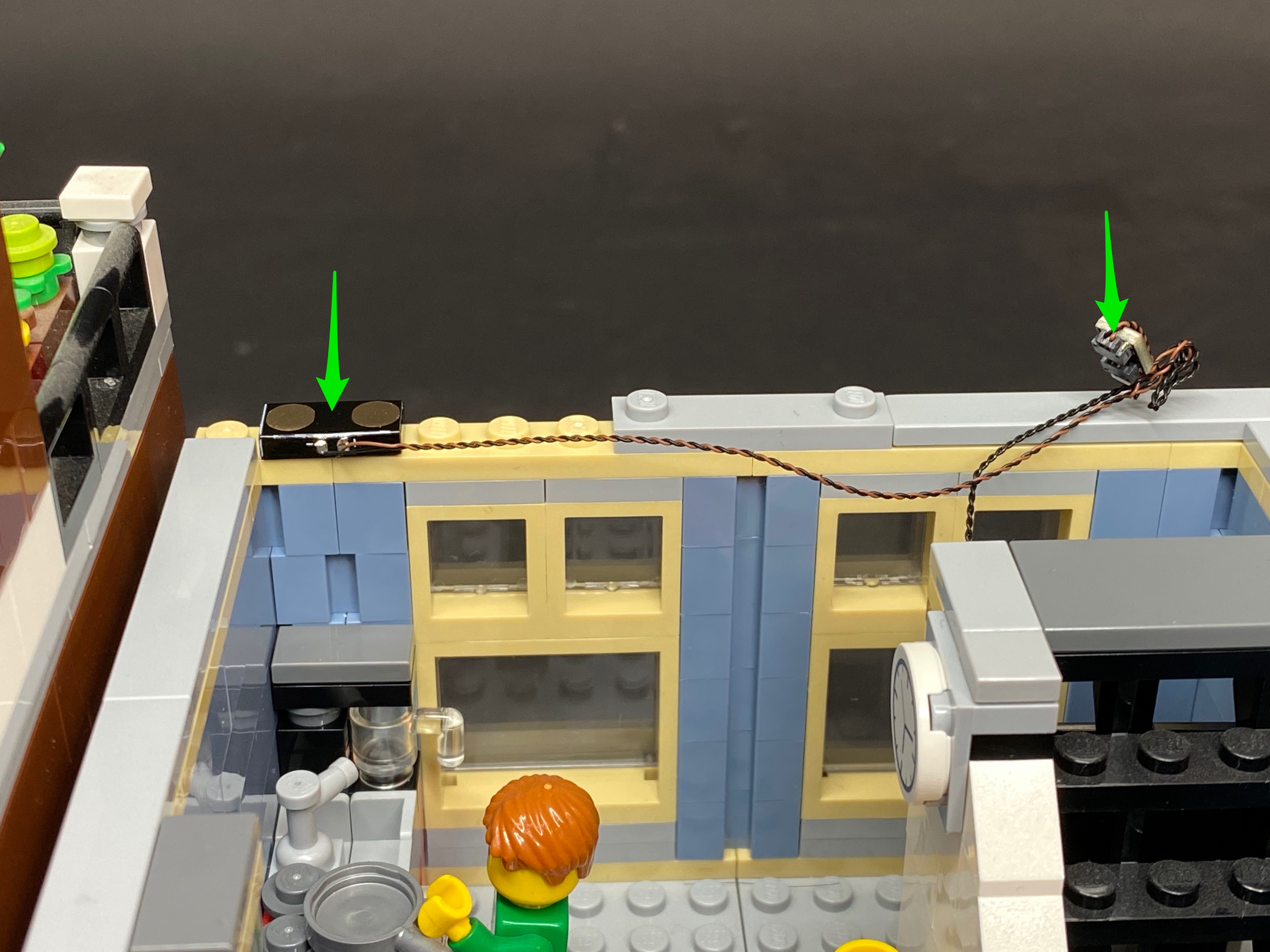
9.) Disconnect the following LEGO tile from the left building, then take a tile side wireless power connector (from a Wireless Power Connector Set) and fold the wire underneath the tile. With the wire now facing the outside of the building, connect it to the below position.


Connect the wireless power connector on the ground floor of the left building to the 8-Port Expansion Board

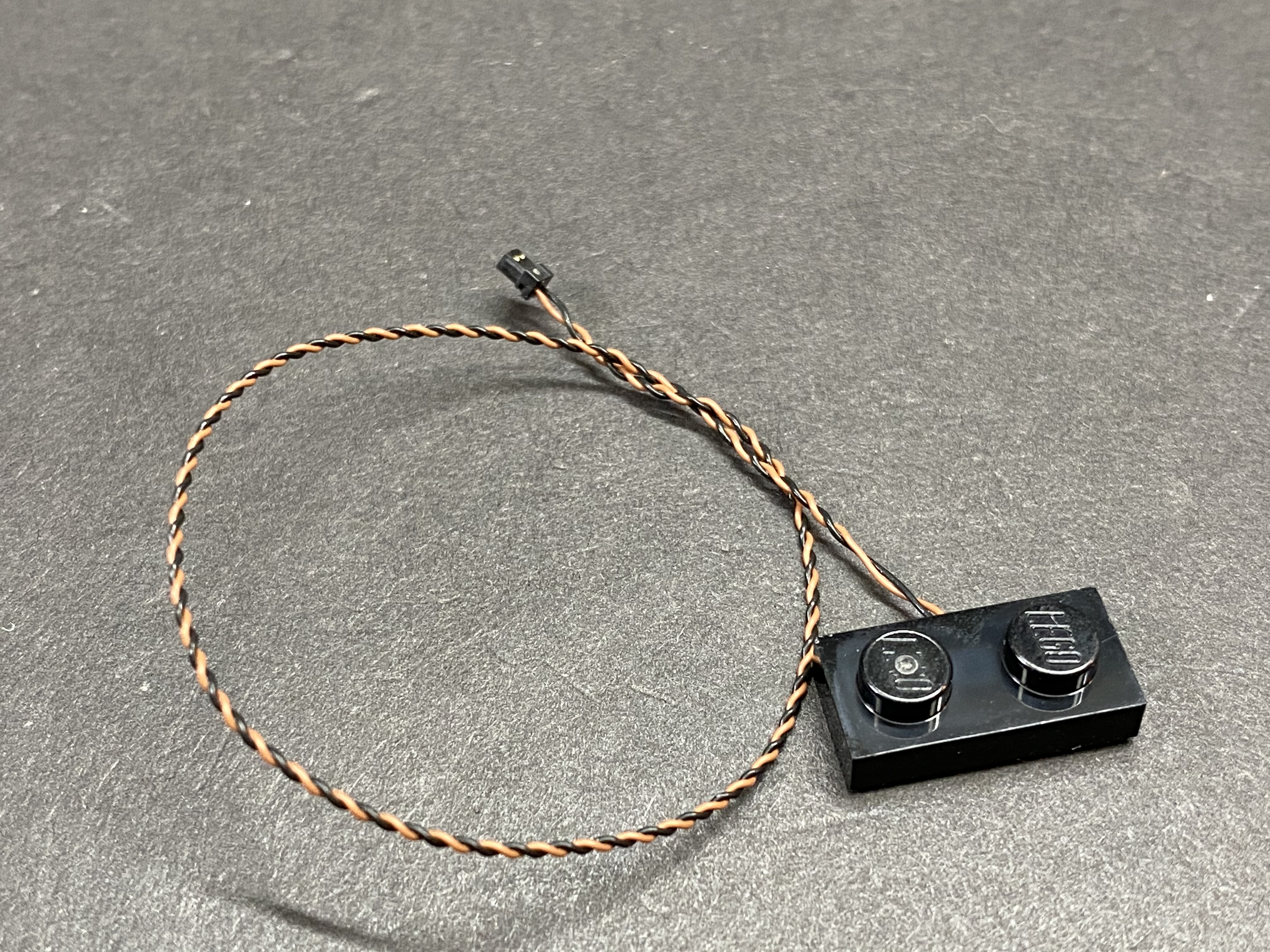
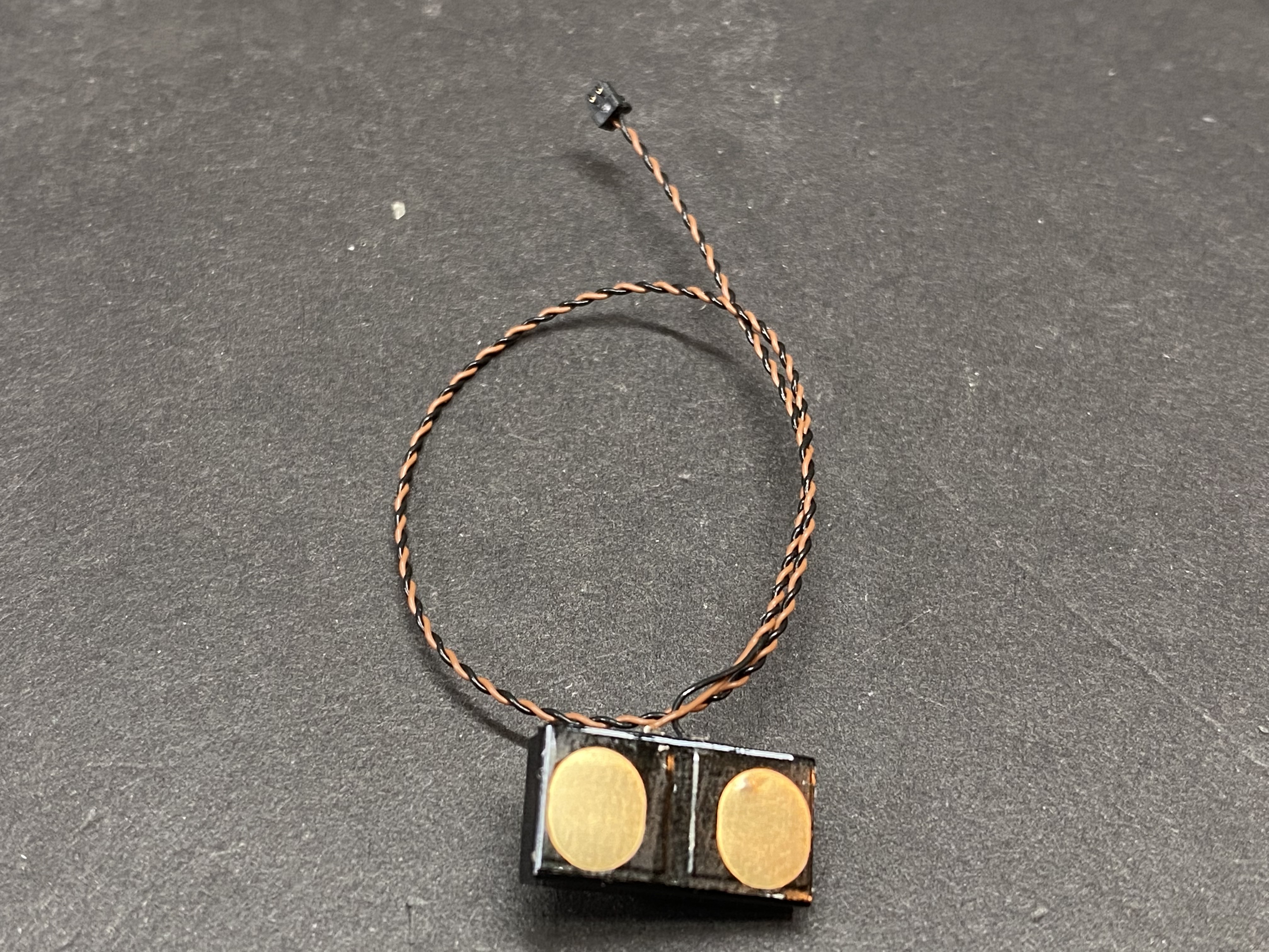
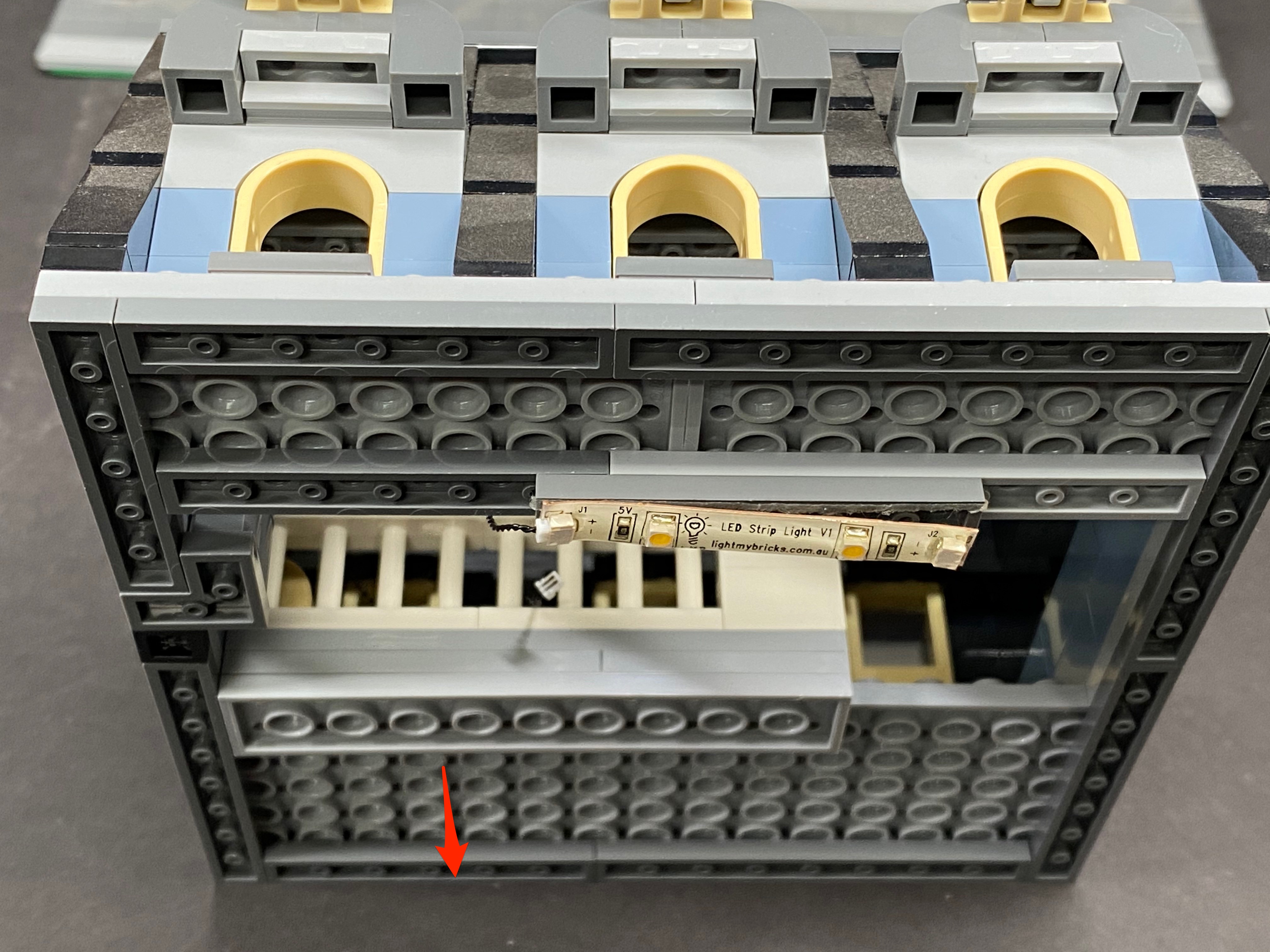
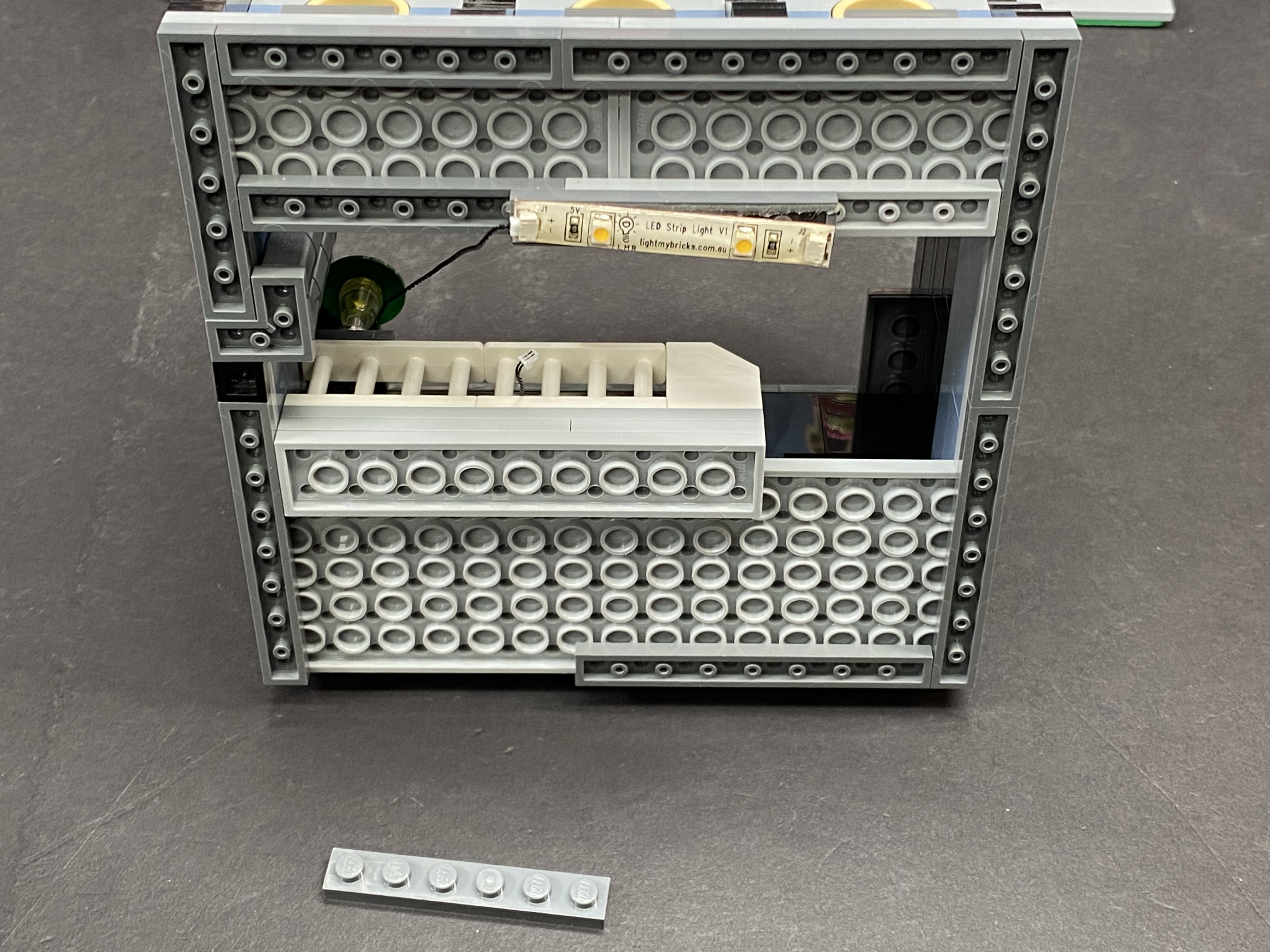
10.) Take the 1st floor of the left building and turn it onto it’s back so we can access underneath. Take the plate side of the wireless power connector from your first set, and connect it underneath the floor in the below position. Connect the cable to the Strip Light. Use a spare 1×6 Plate (any colour) to secure the wire in place, then flip the floor over and reconnect it to the ground floor ensuring the two wireless connectors are correctly aligned on top of each other.

11.) Connect the Connecting Cable on the 1st floor (of the left building) to a 2-Port Expansion Board. Remove the following tile piece as shown, then take a tile side of a wireless power connector (of a 2nd set) and with the wire facing the inside of the building, connect it to the below position. Connect the wire to the 2-Port Expansion board, then twist/braid the wires to provide a cleaner look.

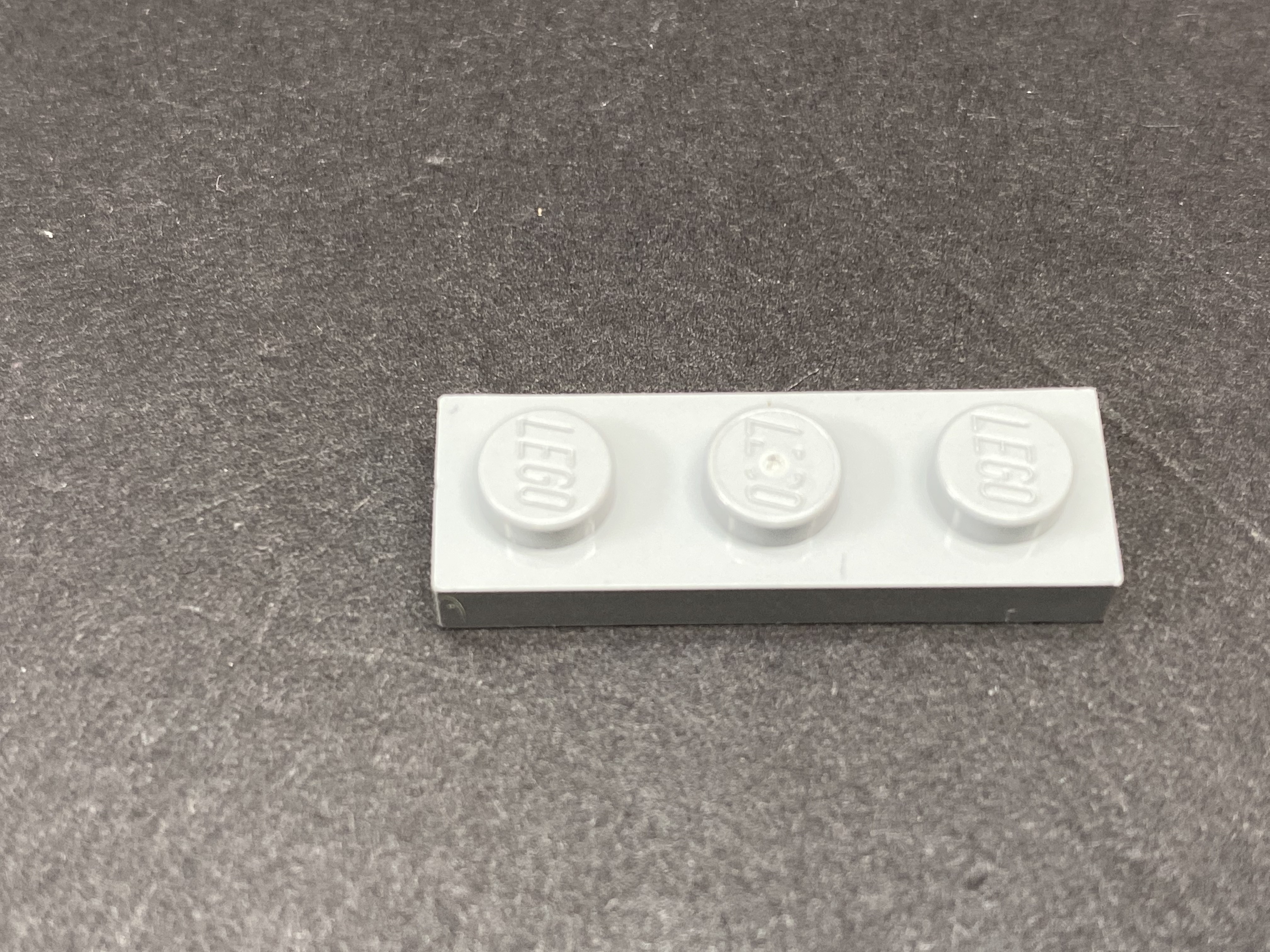
12.) Take the 2nd floor and turn it onto it’s back so we can access underneath. Remove the LEGO 1×3 Plate from underneath connect it to the 1st floor in the following position.

13.) Going back to the 2nd floor, take a plate side of a wireless power connector (from your 2nd set) and with the wire facing the inside of the building, connect it to where you removed the 1×3 Plate. Connect the wire to the Strip Light, then turn the floor over and reconnect it to the first floor ensuring the wireless power connectors correctly align.


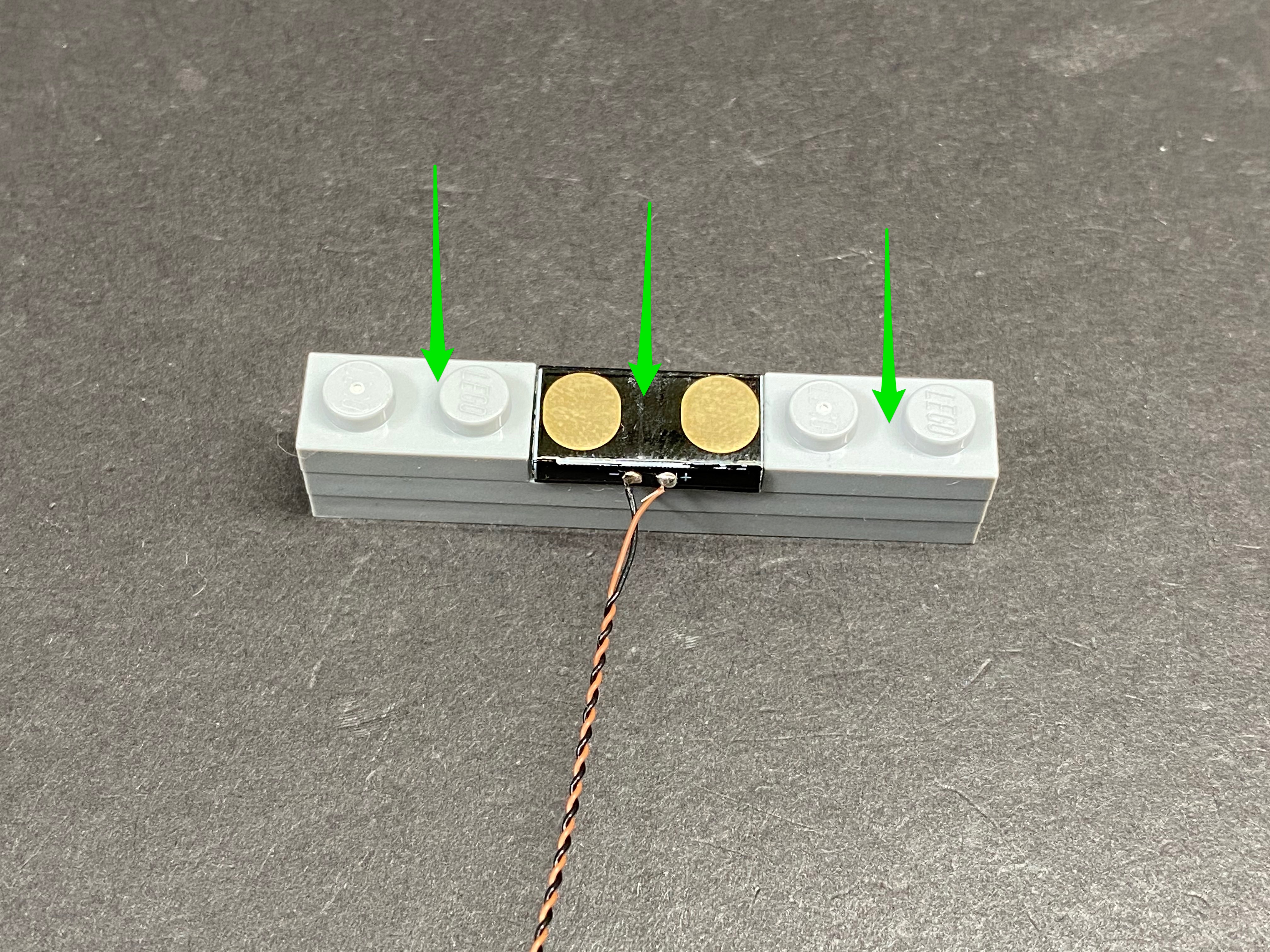
14.) Take 2x Plates 1×6 and 2x Plates 1×2 and connect them together as shown below. Take a tile side of another wireless power connector and with the wire facing toward you, connect it in between.


15.) Disconnect the following LEGO pieces before placing the LEGO pieces with the wireless power connector in its place ensuring the wire is facing the inside of the building. Once in position, connect the Wireless Power Connector to the 2-Port Expansion Board.
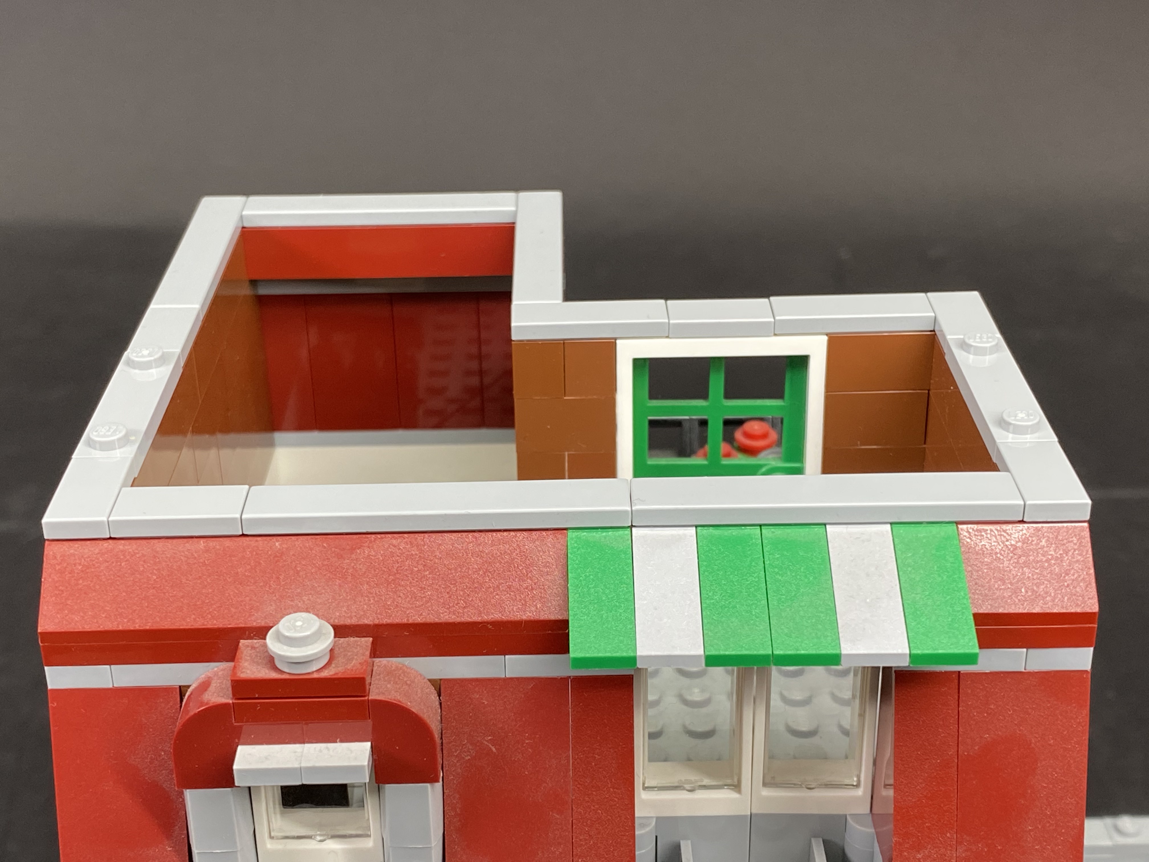


16.) From the LEGO pieces you just removed, disconnect the two 1×2 tiles connect them to the 2nd floor as shown below. Tuck the wires around the room.
17.) Take the roof and flip it over. Take a plate side of a wireless power connector and with the wire facing the inside, connect it underneath as shown. Twist/braid the wire to neaten them up, then reconnect the roof ensuring the wireless power connectors align.

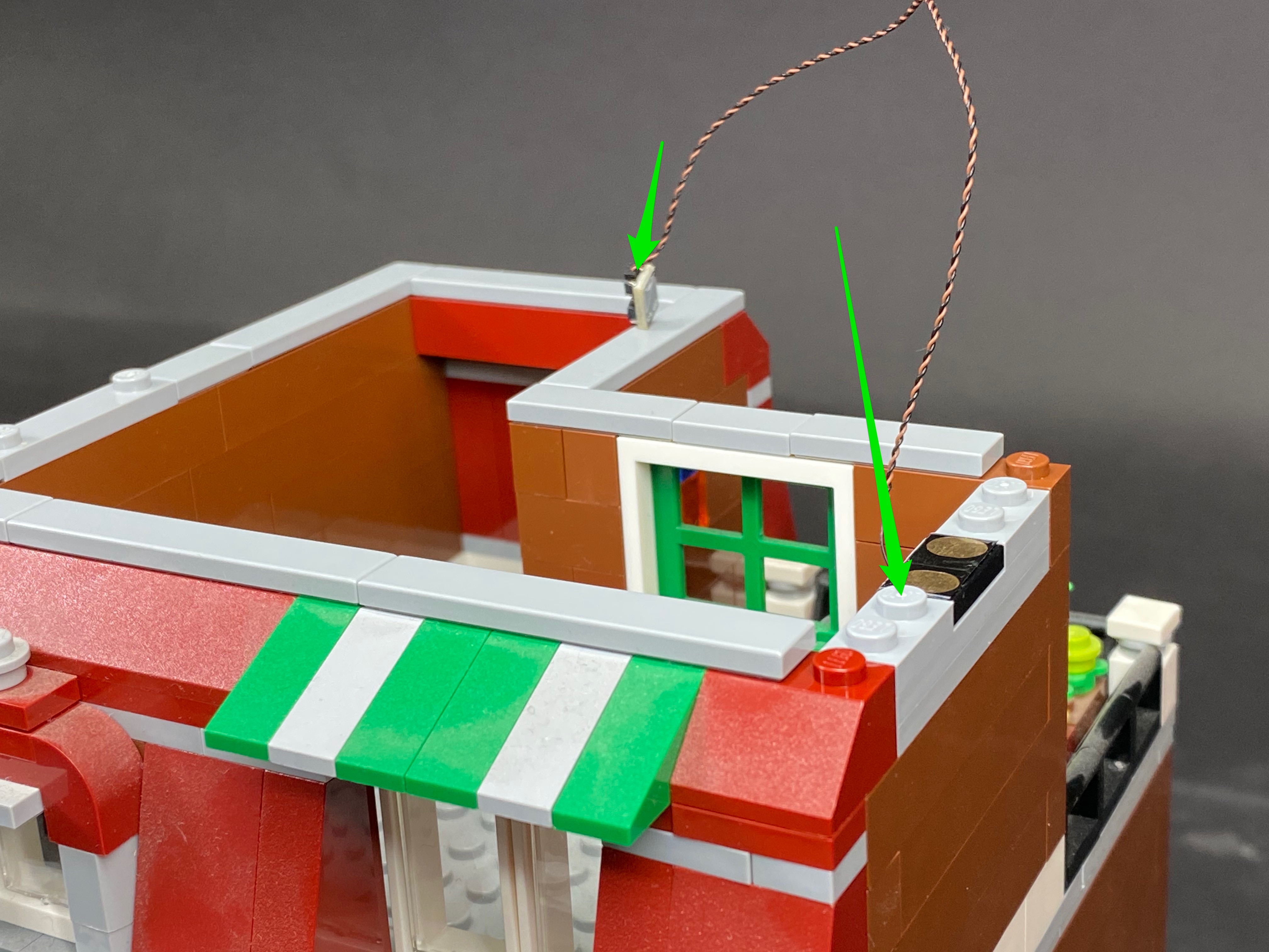
18.) Disconnect the following tile piece from the right ground floor as shown. Take another tile side of a wireless power connector and with the wire facing the inside, connect it to the below position.

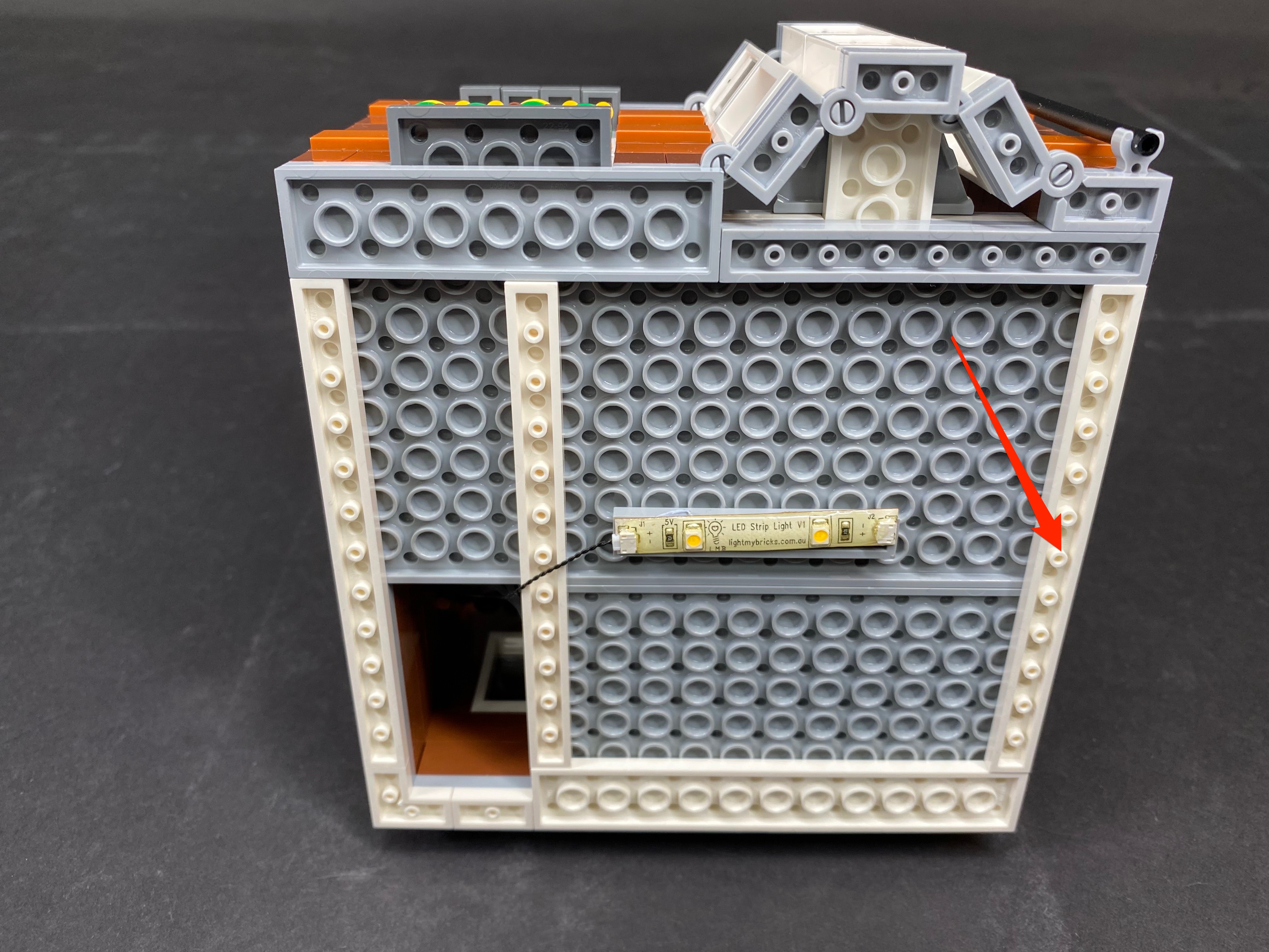
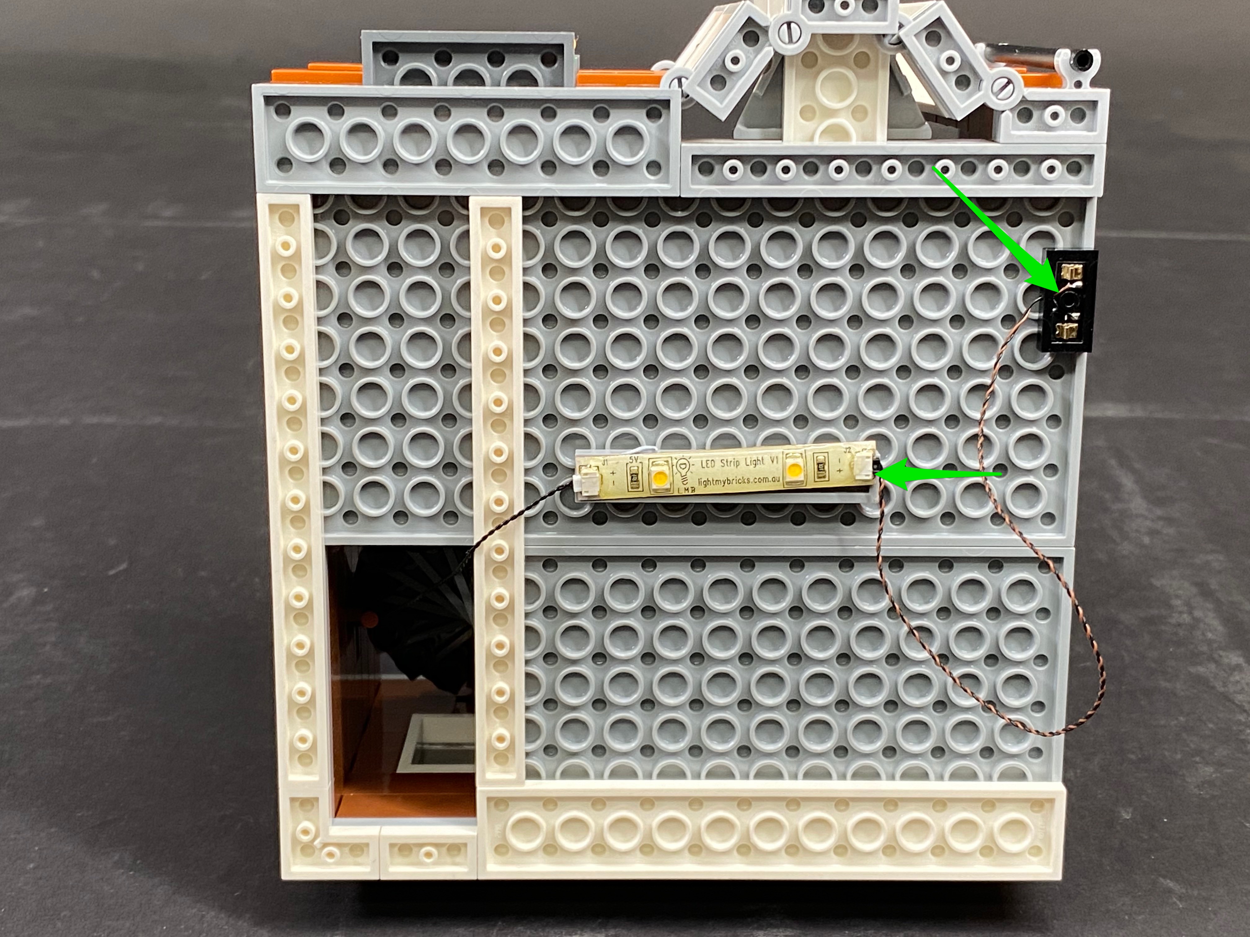
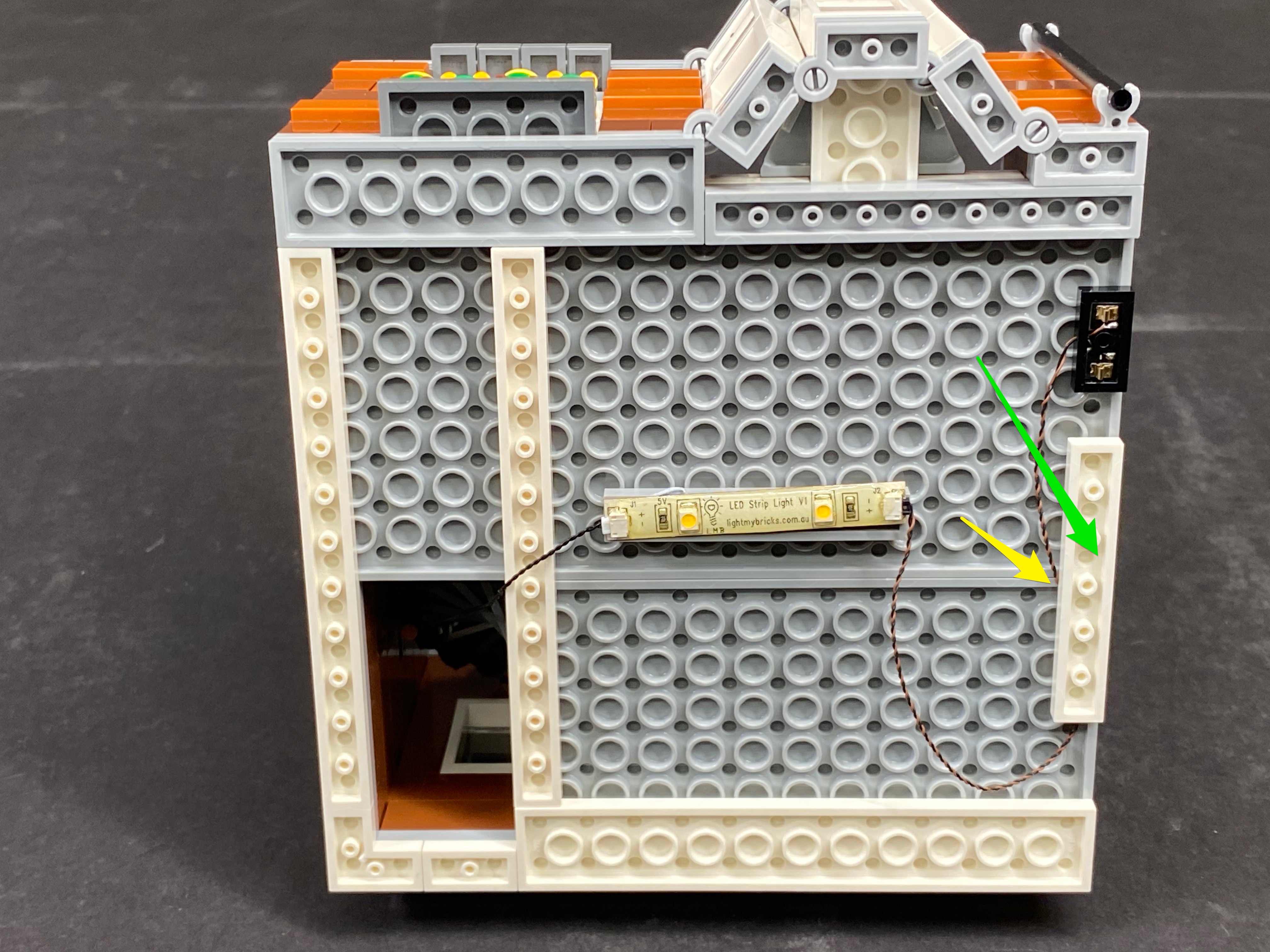
19.) Take the 1st floor (of the right building) and disconnect the following LEGO plate from underneath. Take a plate side of a wireless power connector and with the wire facing the inside, connect it underneath, then connect the wire to the strip light. Tuck in the wires underneath the plates, then re-connect the 1st floor ensuring the wireless power connectors correctly align.


20.) Connect the Connecting Cable from the 1st floor to a 2-Port Expansion Board. Disconnect the following tile, then take a tile side of a wireless power connector and with the wire facing the inside, connect it to the below position. Connect the wire to the 2-Port Expansion Board. Twist/Braid the excess cables into a neat bunch.

21.) Take the 2nd floor of the right building and disconnect the following LEGO plate from underneath as shown below. Take a plate side of a wireless power connector and with the wire facing the inside, connect underneath the floor in the following position. Connect the wire to the Strip Light, then re-connect the 2nd floor ensuring the wireless connectors correctly align.


22.) Connect the Connecting Cable on the 2nd floor to another 2-Port Expansion Board.

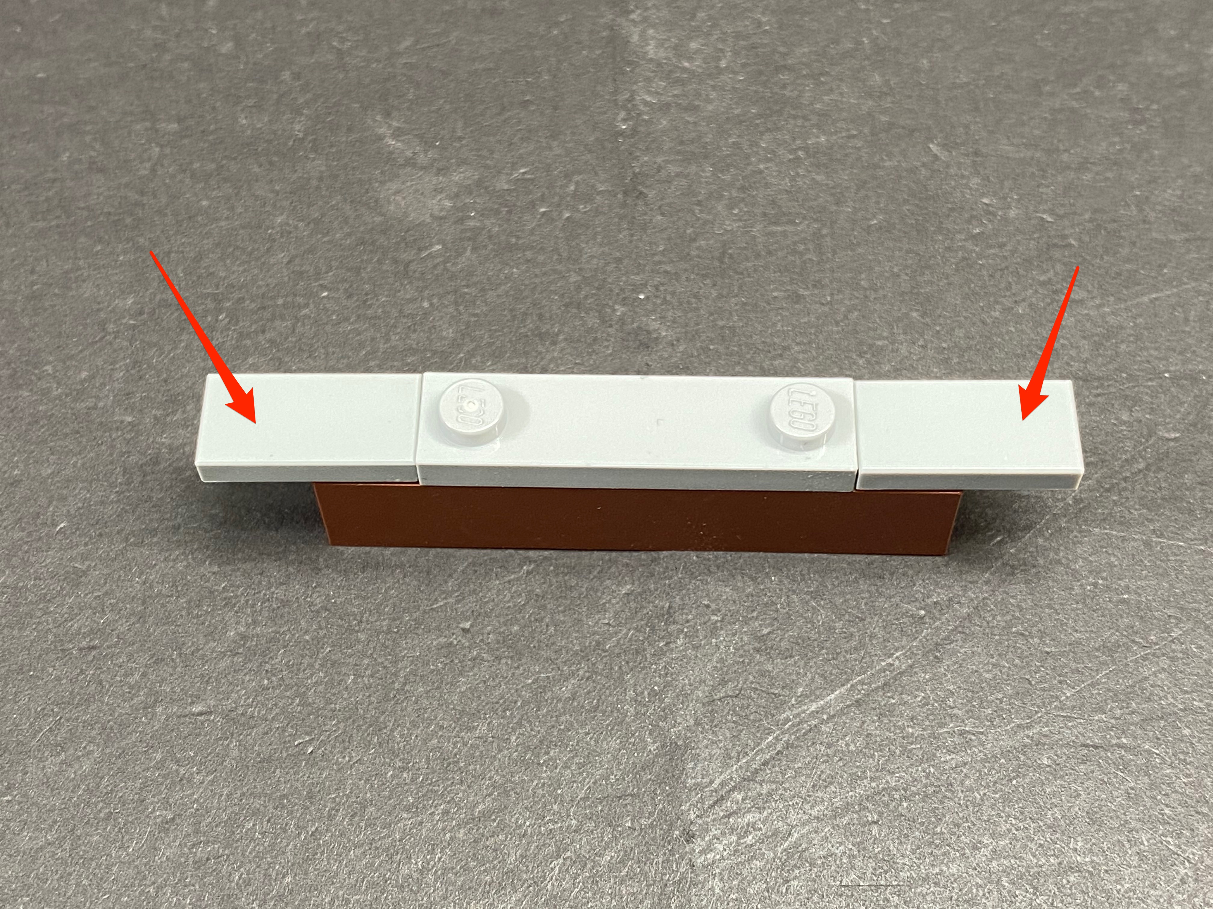
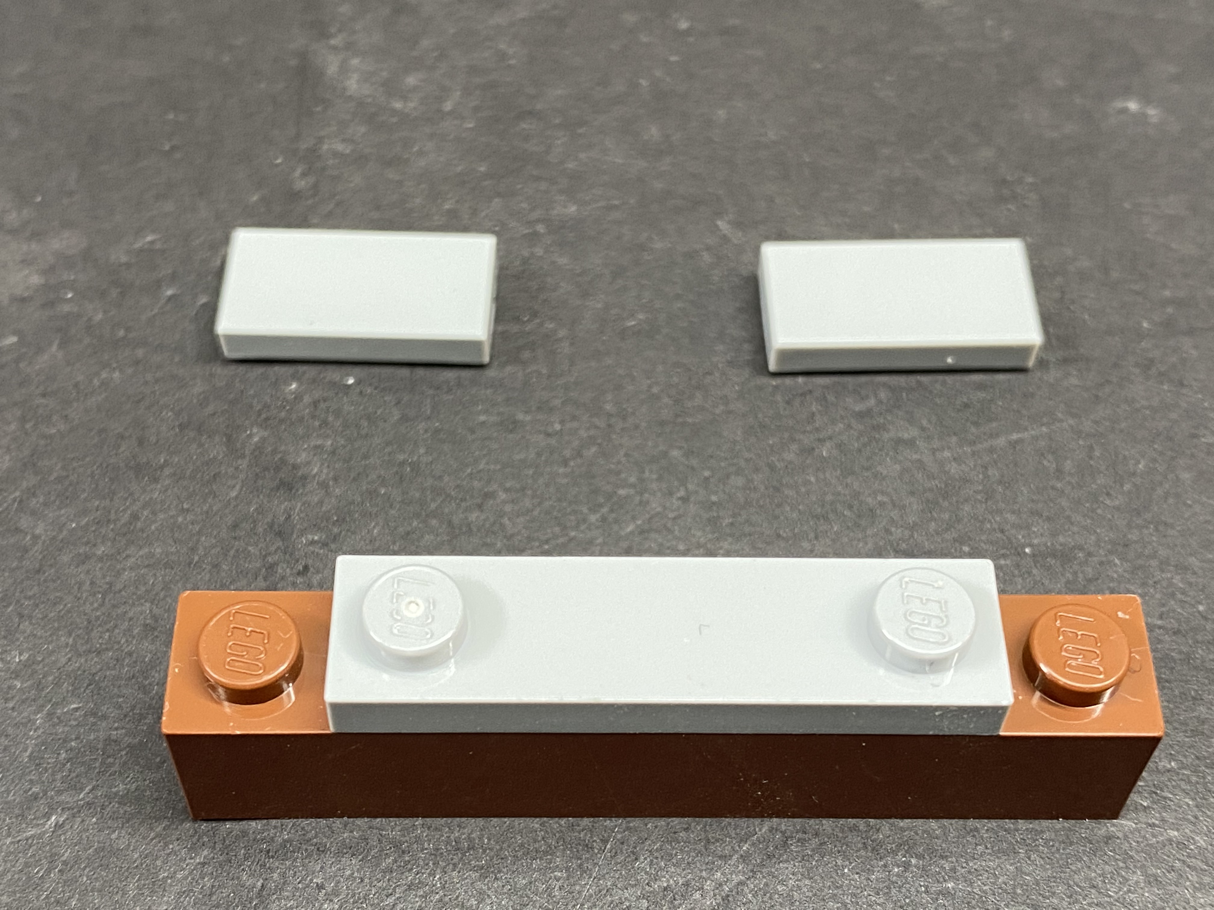
Disconnect the following LEGO tile piece, then take a tile side of a wireless connector and with the wire facing the wire facing the inside, connect it to the below position. Take your spare Tile 1×4 and connect to the right of the Wireless Power Connector.


23.) Take the roof and disconnect the following plate from underneath. Take the remaining plate side of a wireless power connector and with the wire facing the inside, connect it underneath the roof in the following position. Connect the wire to the strip light, then twist/braid the wire into a neat bunch.


Finally, re-connect the roof back to the set ensuring the wireless power connectors correctly align.

And… you’re done!

Wireless Power Connectors Install Tip
If you’re having connectivity / contact issues with the Wireless Power Connectors, try the following tip to help resolve the issue:
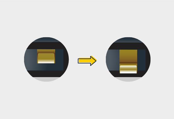
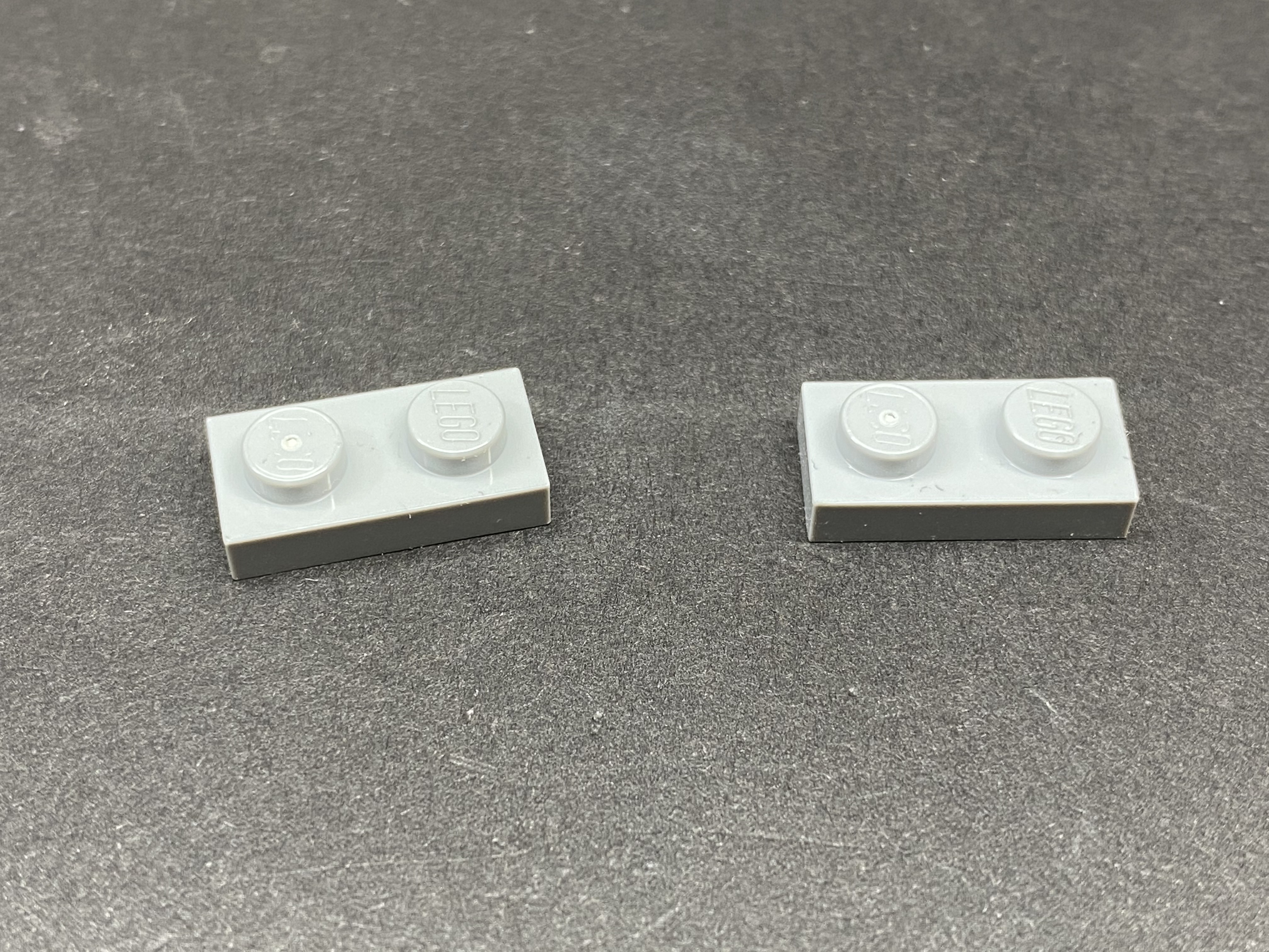
Pull the terminal contacts further out. Use a pair of tweezers to gently pull out both terminal contacts from the plate.
This will ensure that both plate and tile connectors are can easily make contact.