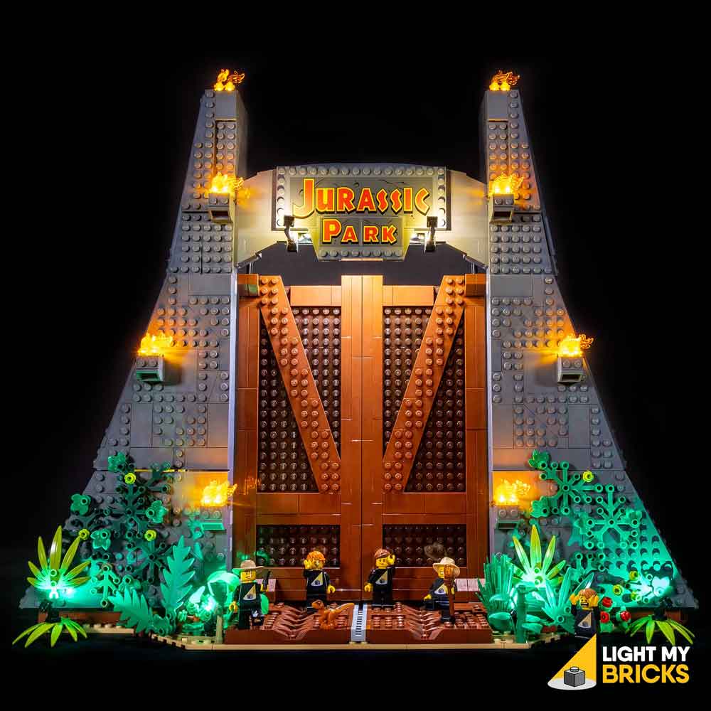

The following page is the instructions for the Light My Bricks LEGO Jurassic Park – T.Rex Rampage (75936) LED light kit.
If you run into any issues, please refer to the online troubleshooting guide.
To ensure a trouble-free installation of your light kit, please read and follow each step carefully. These instructions can be downloaded in PDF format here
Please note: This page lists instructions for the LED light kit only. If you are wishing to purchase the Light My Bricks LEGO Jurassic Park – T.Rex Rampage (75936) LED light kit , please click here to view the product page
Package Contents:
- 12x White 30cm Bit Lights
- 27x White 15cm Bit Lights (26 required, includes 1 extra)
- 5x Green 30cm Bit Lights
- 2x Flashing White 15cm Bit Lights
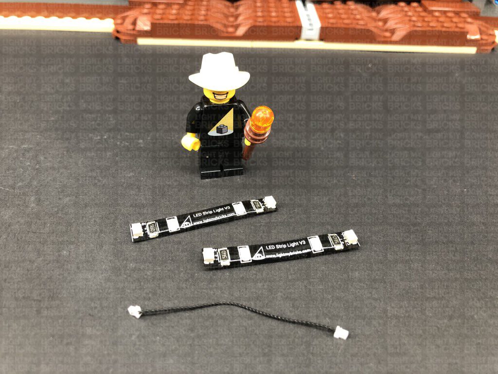
- 2x White Strip Lights
- 4x 6-Port Expansion Boards
- 5x 8-Port Expansion Boards
- 2x Flicker Effects Boards
- 5x 5cm Connecting Cables
- 3x 15cm Connecting Cables
- 3x 30cm Connecting Cables
- 1x 50cm Connecting Cable
- 18x Adhesive Squares
- 1x USB Power Cable
LEGO Pieces:
- 7x Black Tile 1×1 with Clip
- 4x Black 1×1 Modified Plate Rounded with Handle
- 4x Black Round Plate 1×1 with open stud
- 3x Technic Brick 1×1 with hole (Black or Grey)
- 3x Black Technic Pin with Friction Ridges Lengthwise with Centre
- 3x Black Speargun Minifig Weapon
- 1x Trans Clear Plate w Rounded Bottom 2×2
Important things to note:
Laying cables in between and underneath bricks
Cables can fit in between and underneath LEGO® bricks, plates, and tiles providing they are laid correctly between the LEGO® studs. Do NOT forcefully join LEGO® together around cables; instead ensure they are laying comfortably in between each stud.
Connecting cable connectors to Expansion Boards
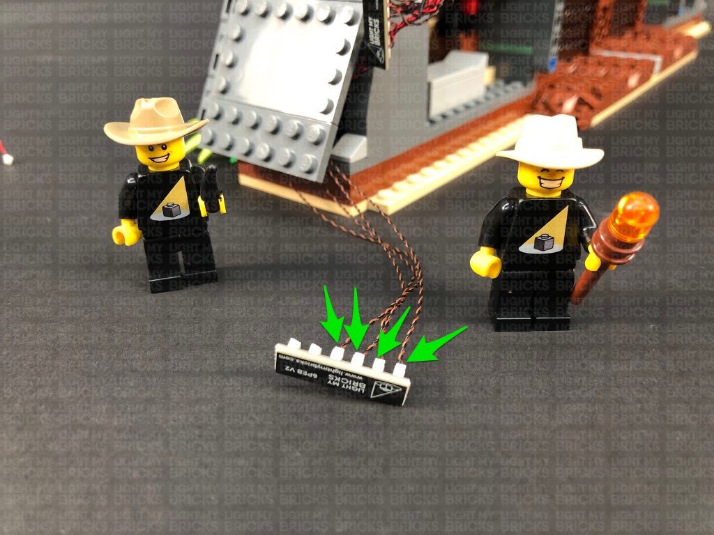
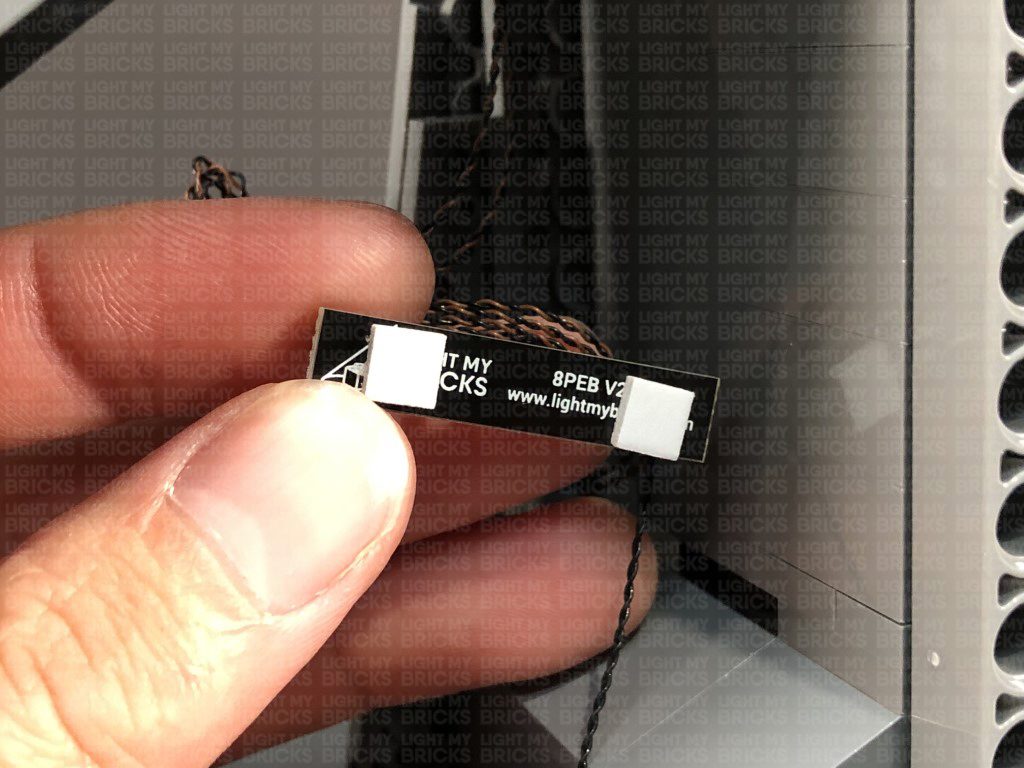
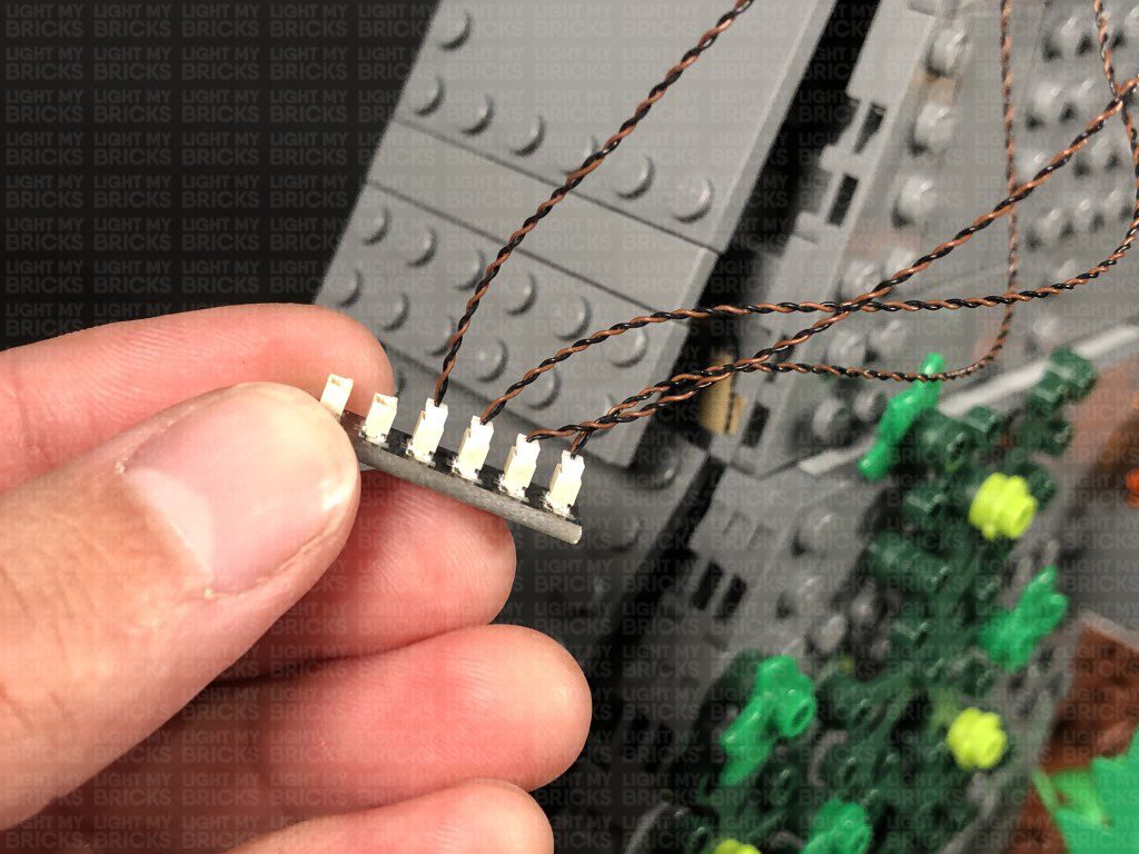
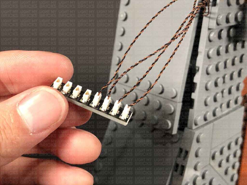
Take extra care when inserting connectors to ports of Expansion Boards. Connectors can be inserted only one way. With the expansion board facing up, look for the soldered “=” symbol on the left side of the port. The connector side with the wires exposed should be facing toward the soldered “=” symbol as you insert into the port. If a plug won’t fit easily into a port connector, do not force it.
Connecting cable connectors to Strip Lights
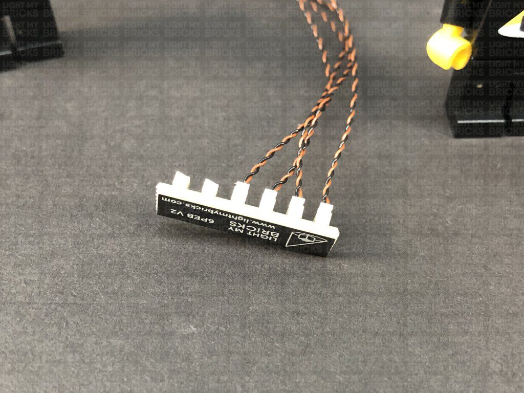
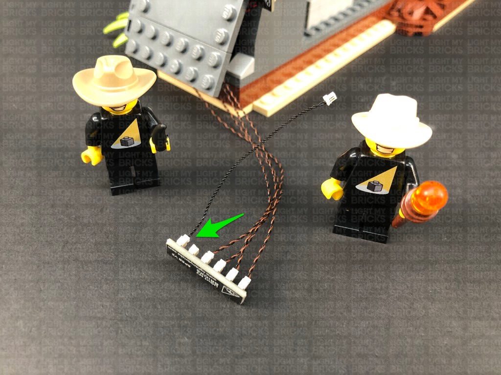
Take extra care when inserting connectors to ports on the Strip Lights. Connectors can be inserted only one way. With the Strip Light facing up, ensure the side of the connector with the wires exposed is facing down. If a plug won’t fit easily into a port connector, don’t force it. Doing so will damage the plug and the connector.
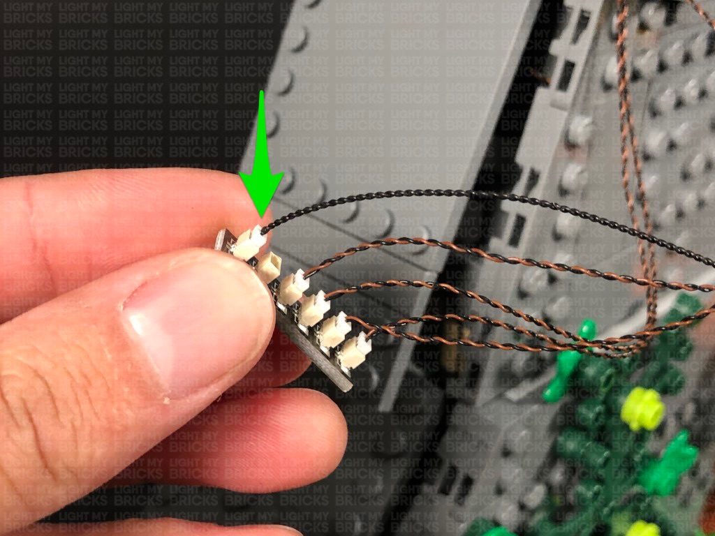
Connecting Micro Cable connectors to Micro Expansion Board Ports
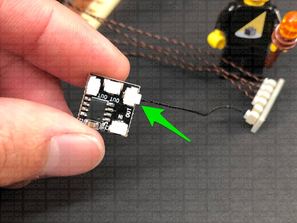
Take extra care when inserting the micro connectors to micro ports of Micro Expansion Boards. Connecting Micro Bit Lights to Micro Expansion Boards is similar to connecting lights and cables to Strip Lights. With the expansion board facing up, ensure the side of the connector with the wires exposed is facing down. If a plug won’t fit easily into a port connector, do not force it. Use your fingernail to push the plastic part of the connector to the micro port.
Installing Bit Lights under LEGO® bricks and plates.
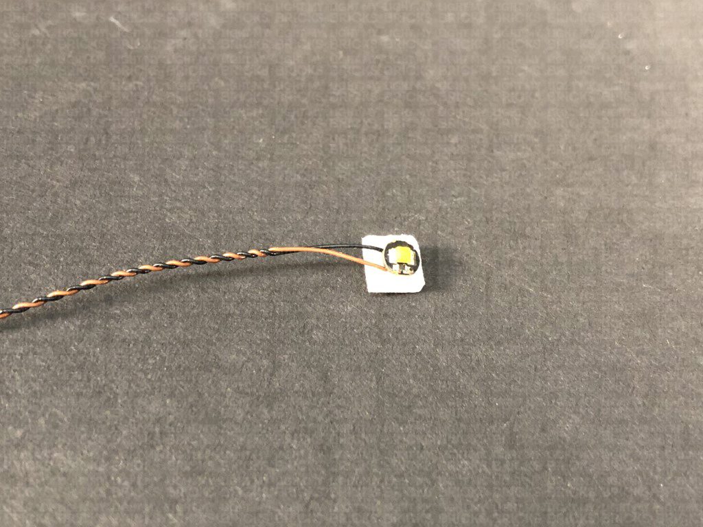
When installing Bit Lights under LEGO® pieces, ensure they are placed the correct way up (Yellow LED component exposed). You can either place them directly on top of LEGO® studs or in between.
OK, Let’s Begin!
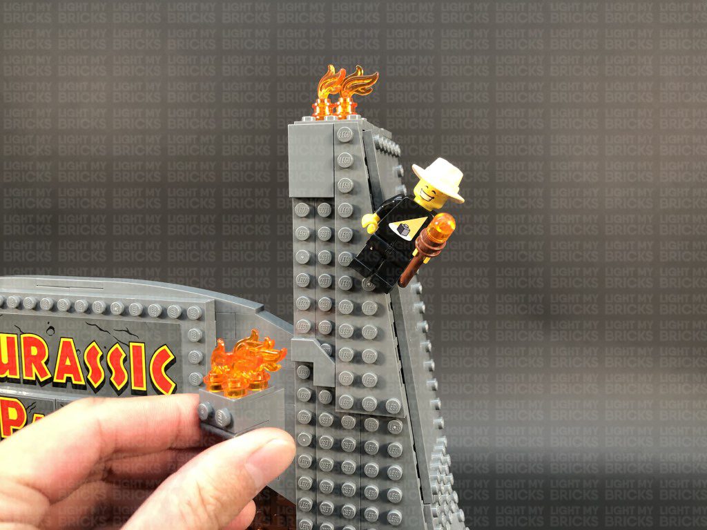
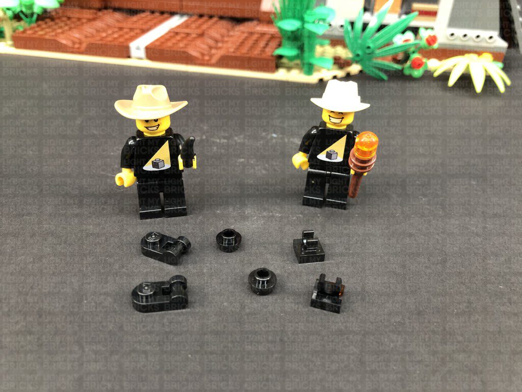
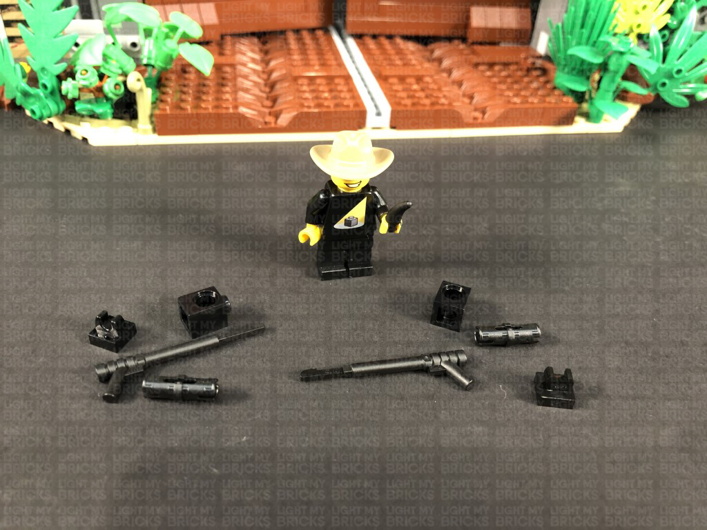
1.) First disconnect the front wall panels as well as the fire sections from the right side of the entrance. Next, take out the following provided LEGO pieces shown below:
- 2x Black Tile 1×1 with Clip
- 2x Black 1×1 Modified Plate Rounded with Handle
- 2x Black Round Plate 1×1 with open stud
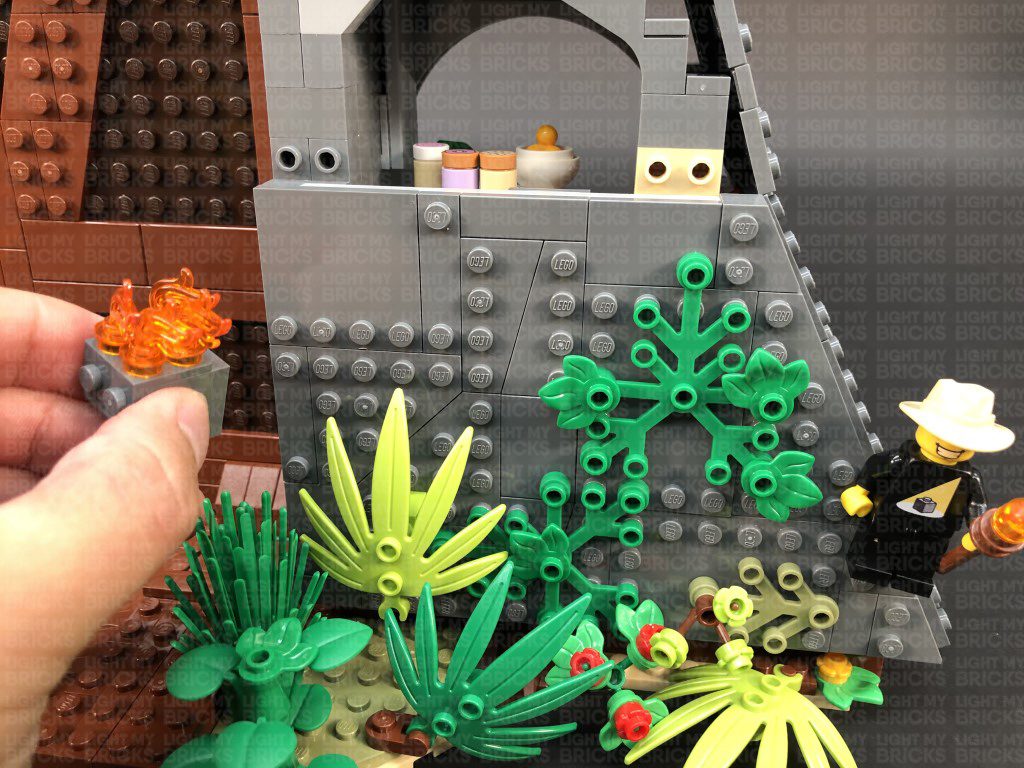
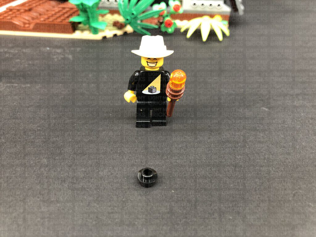
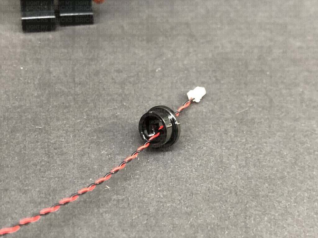
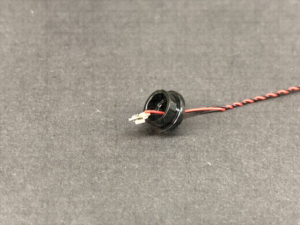
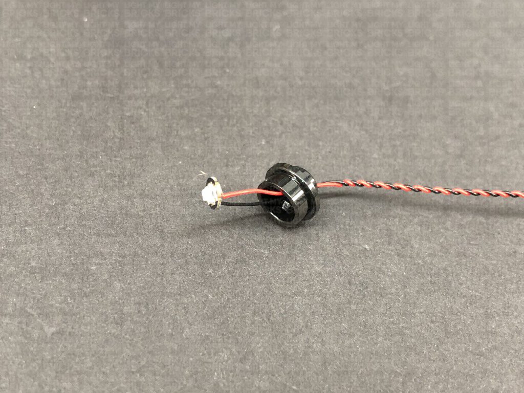
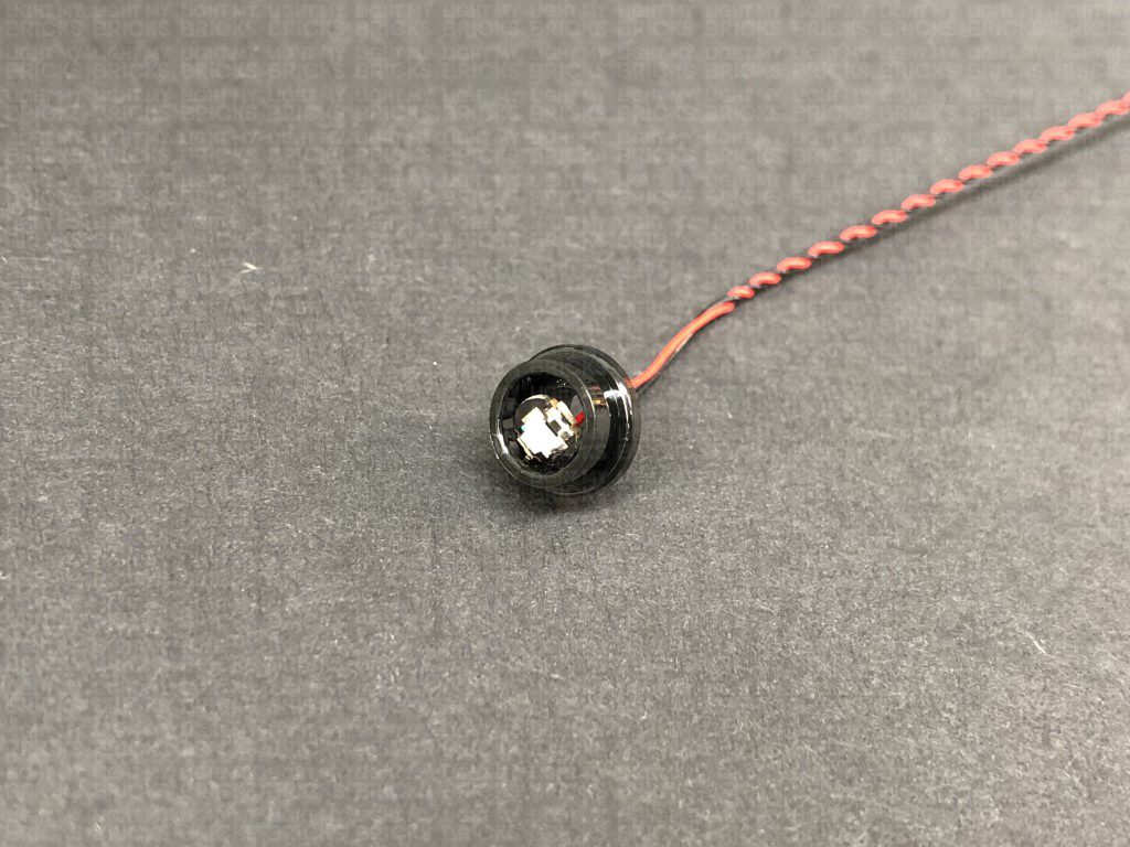
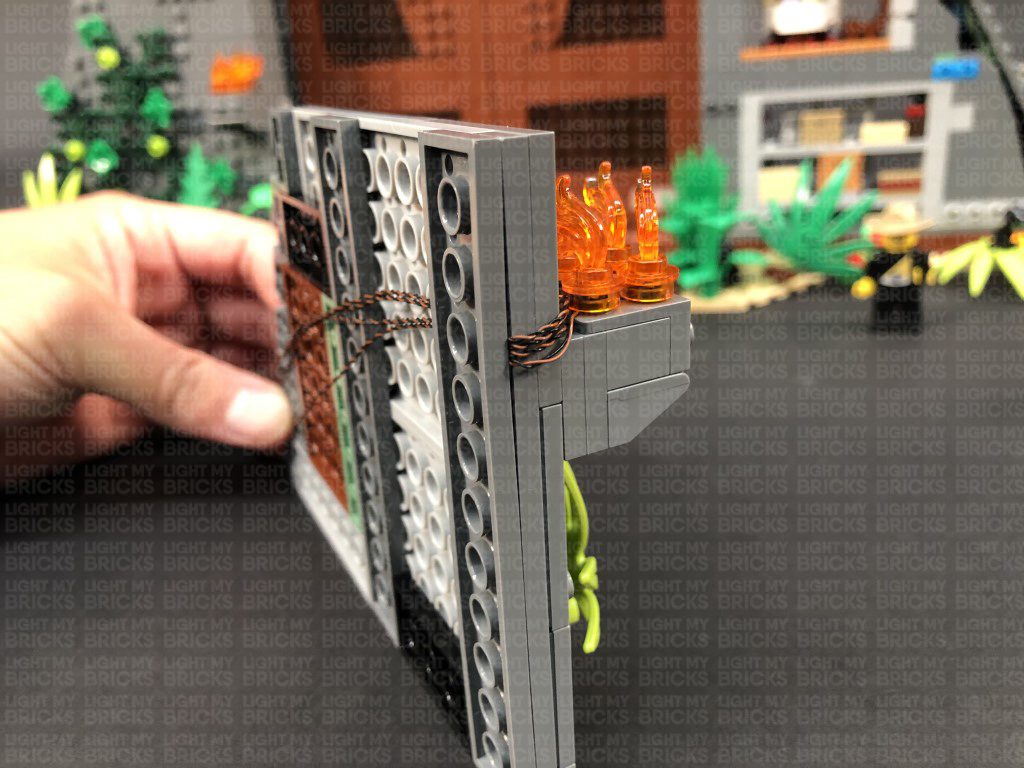
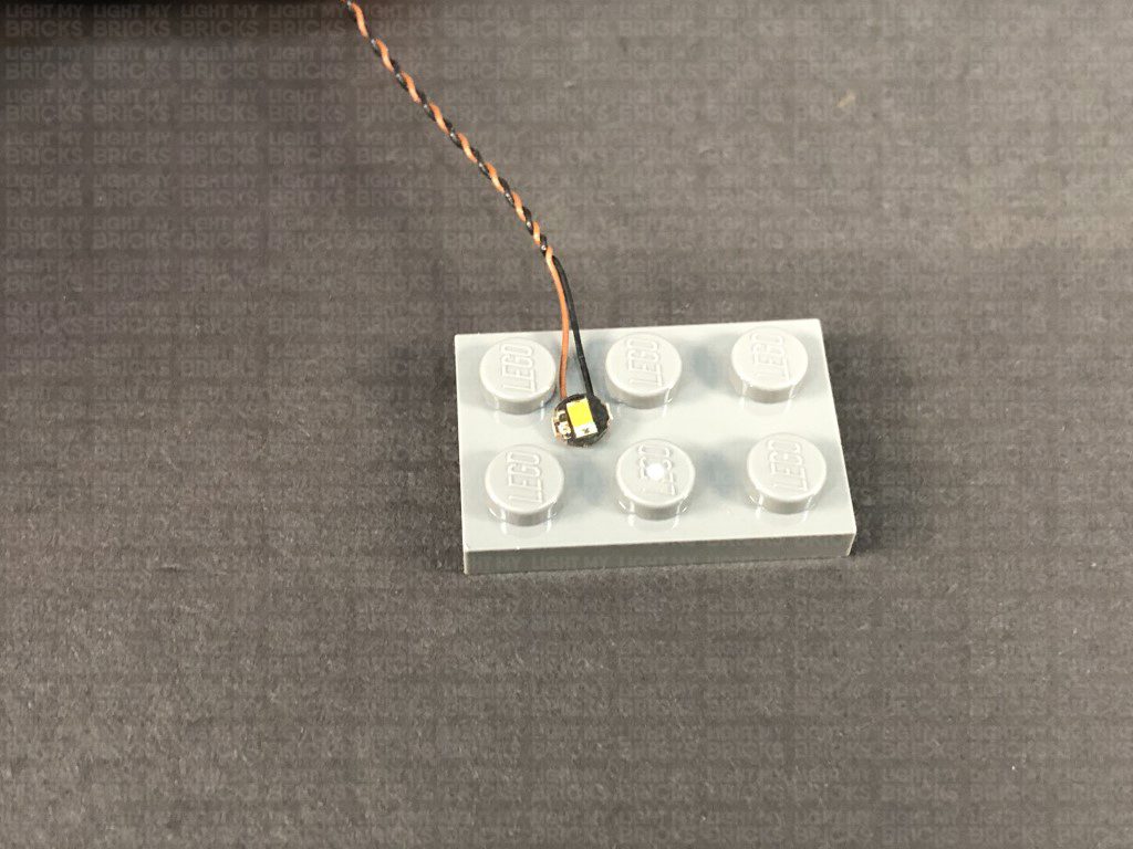
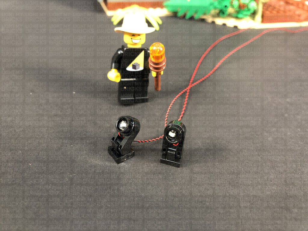
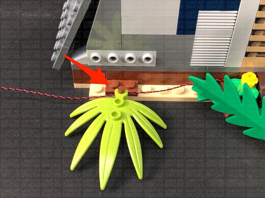
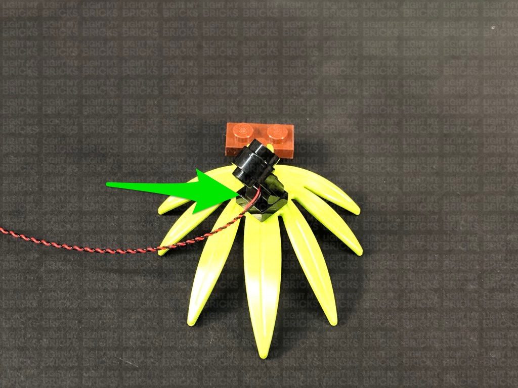
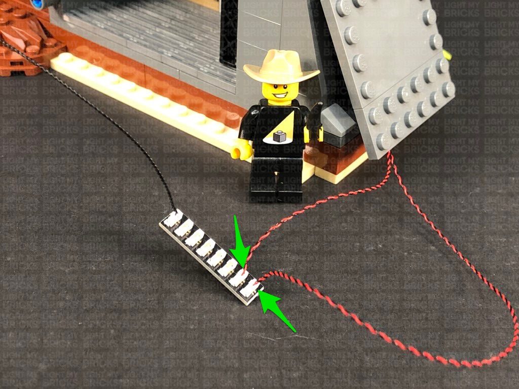
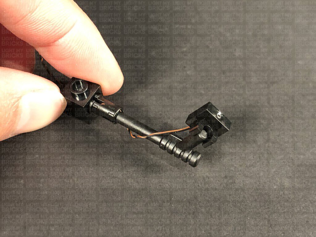
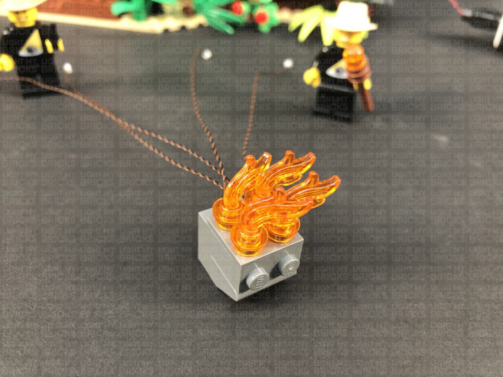
 2.) Take one of the black round plates with open stud and thread the connector end of a Green 30cm Bit Light through the bottom of the black plate. Thread it all the way through, then slightly bend the Bit Light on a 90 degree angle so that it can sit flat against the bottom of the black round plate as per below:
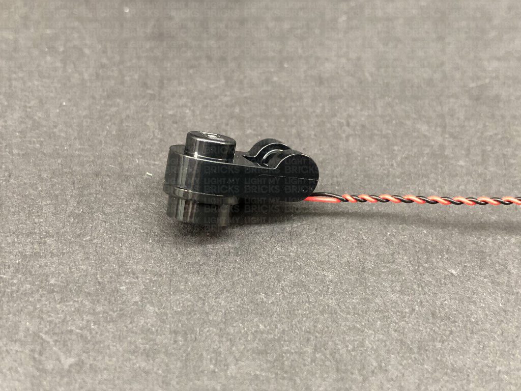
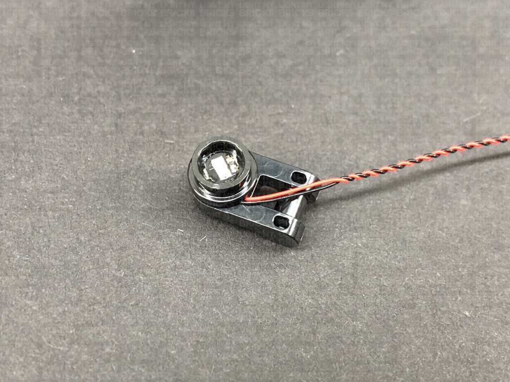
Connect this piece to one of the Black 1×1 Modified Plate Rounded with Handle pieces, then thread the connector side of the cable through the space just above the handle. Pull the cable all the way out from the other side, then attach the plate with clip at the bottom.
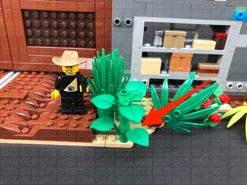
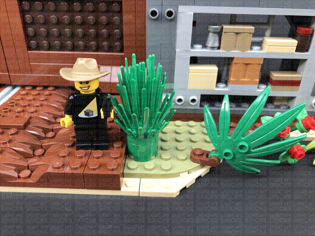
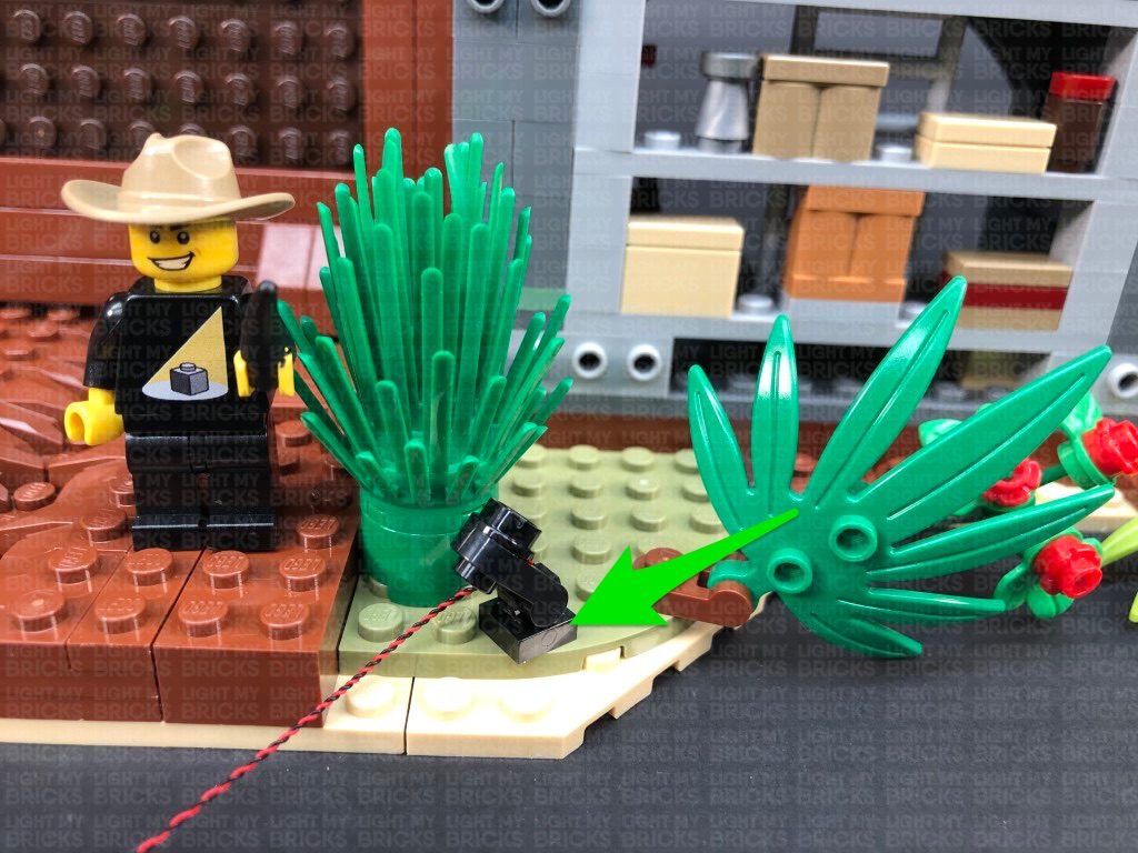
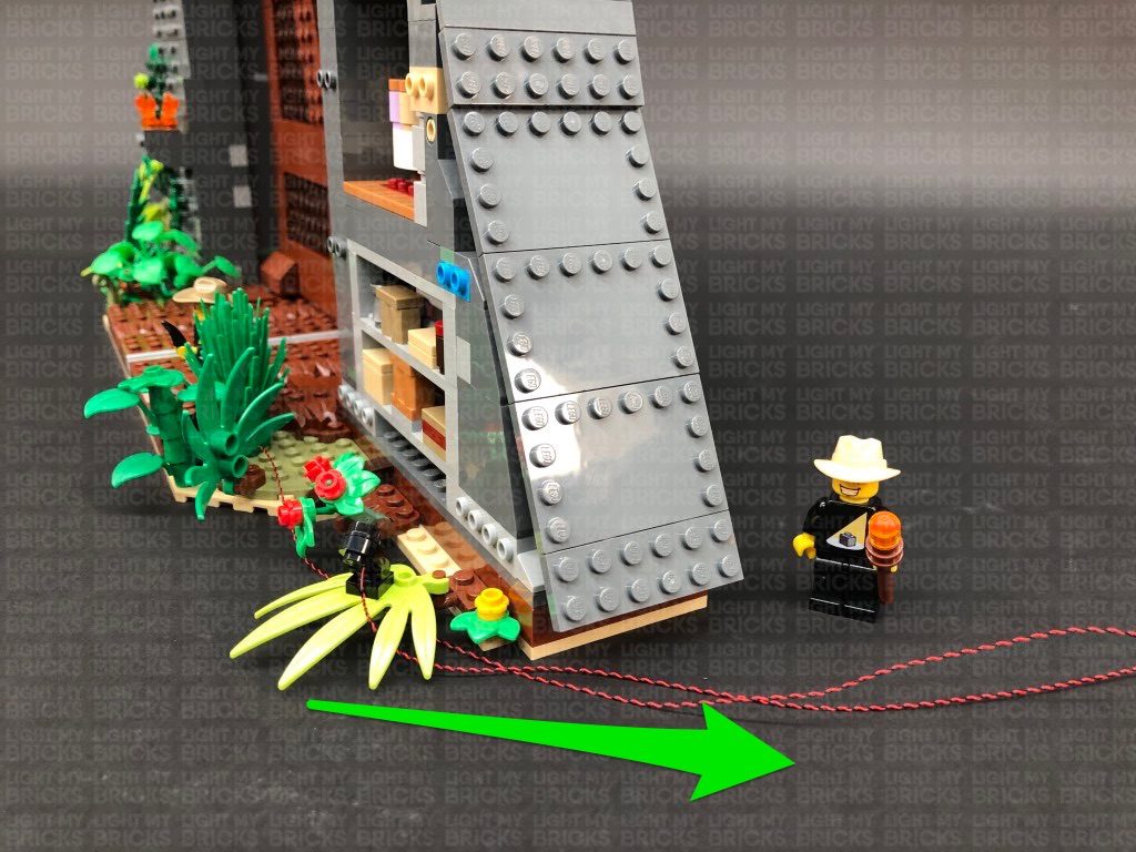
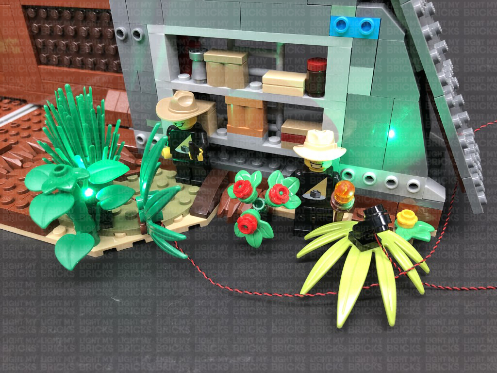
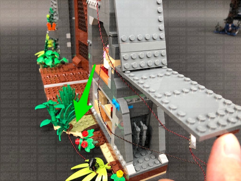
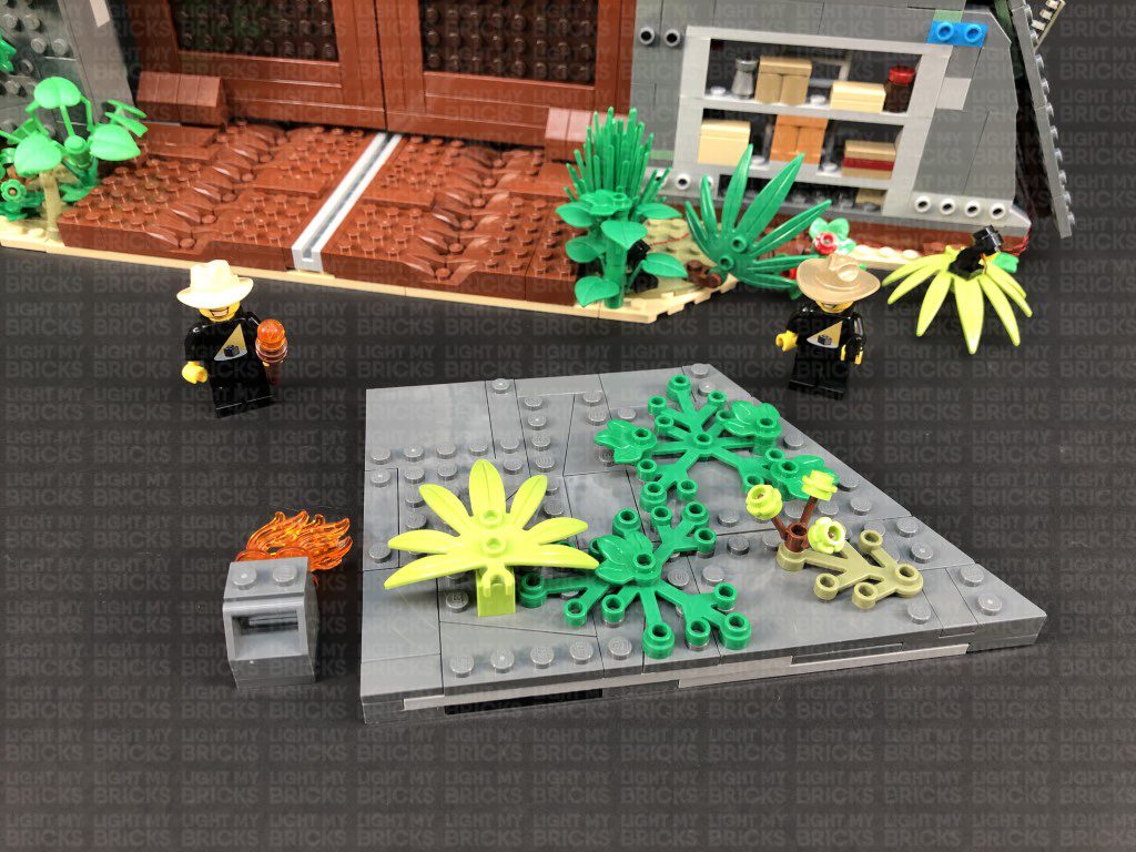
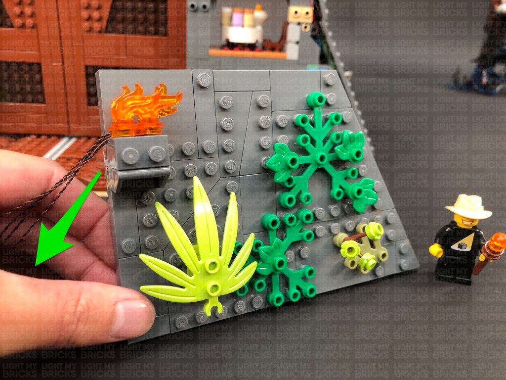
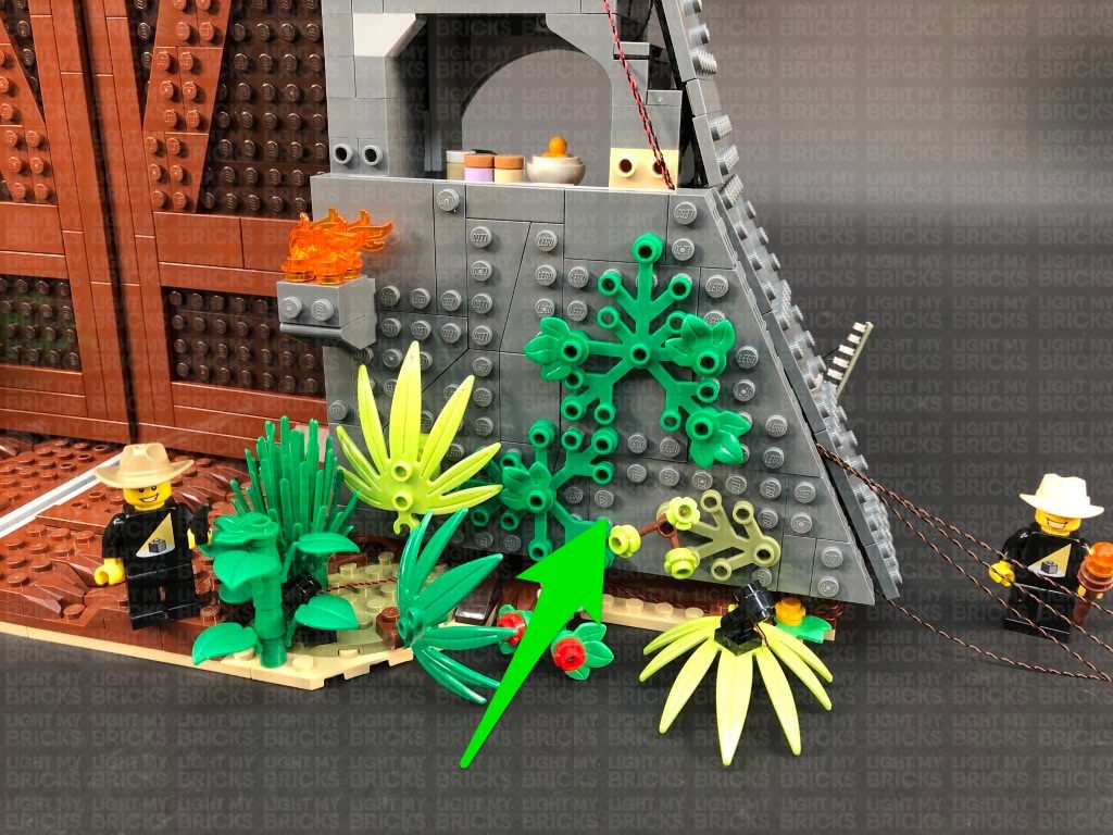
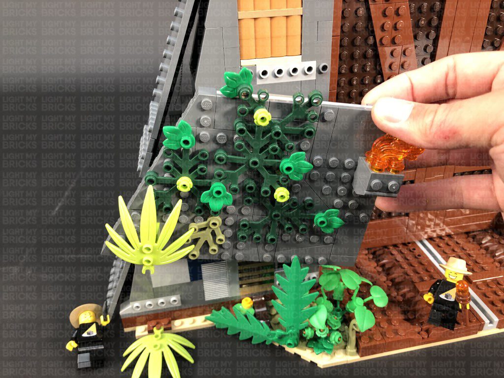
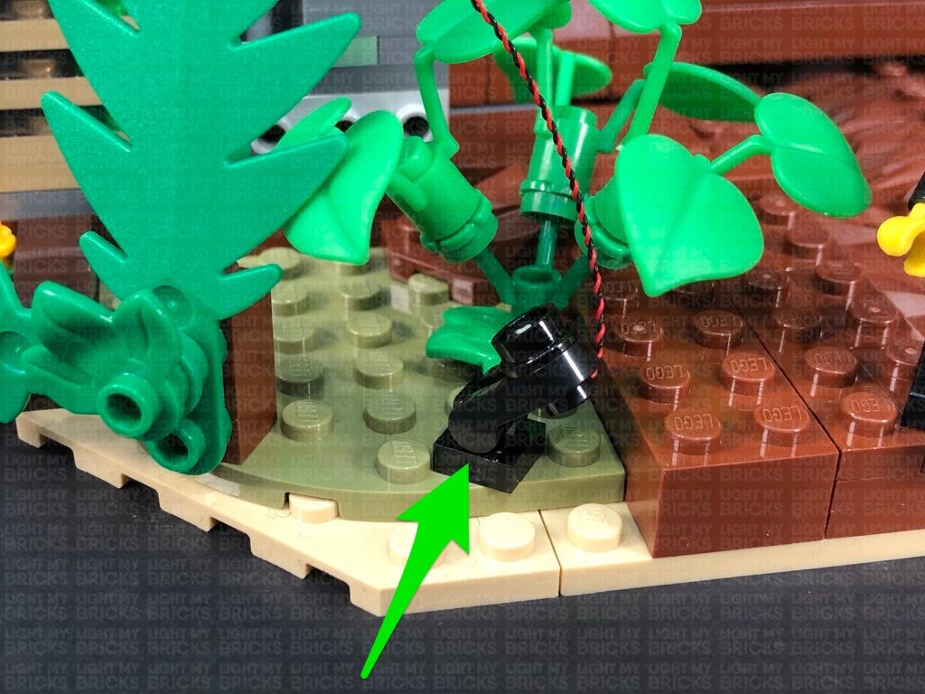
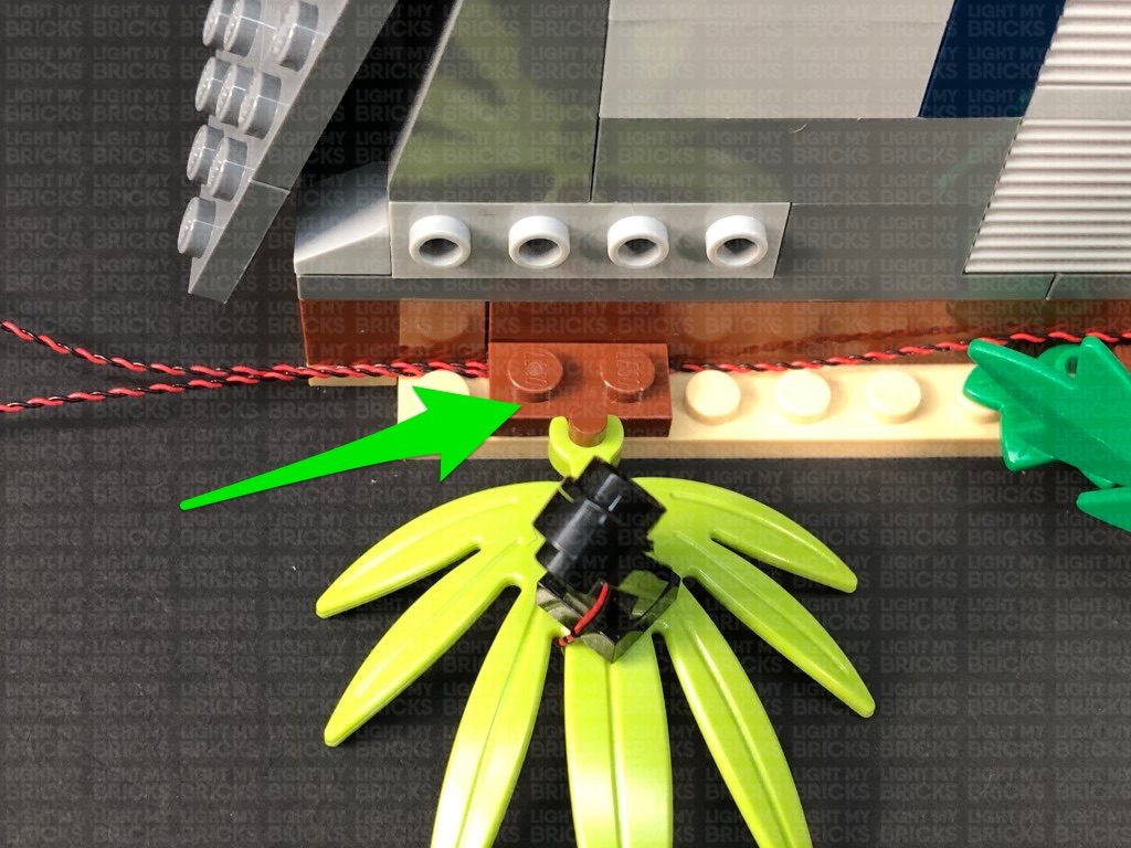
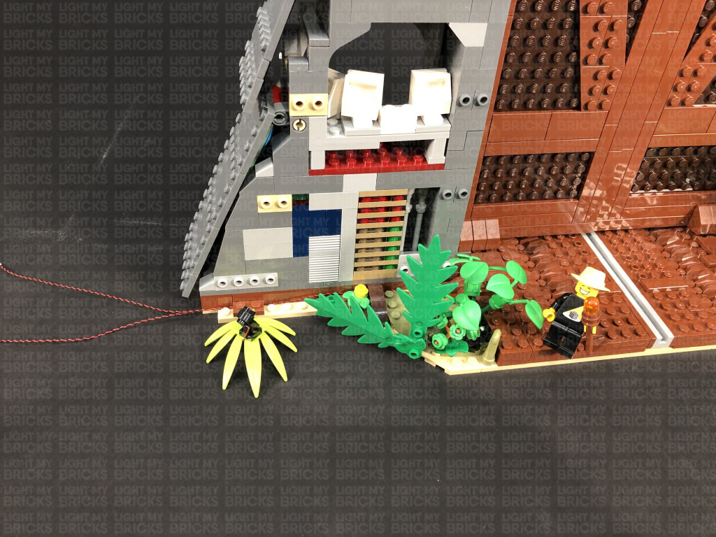
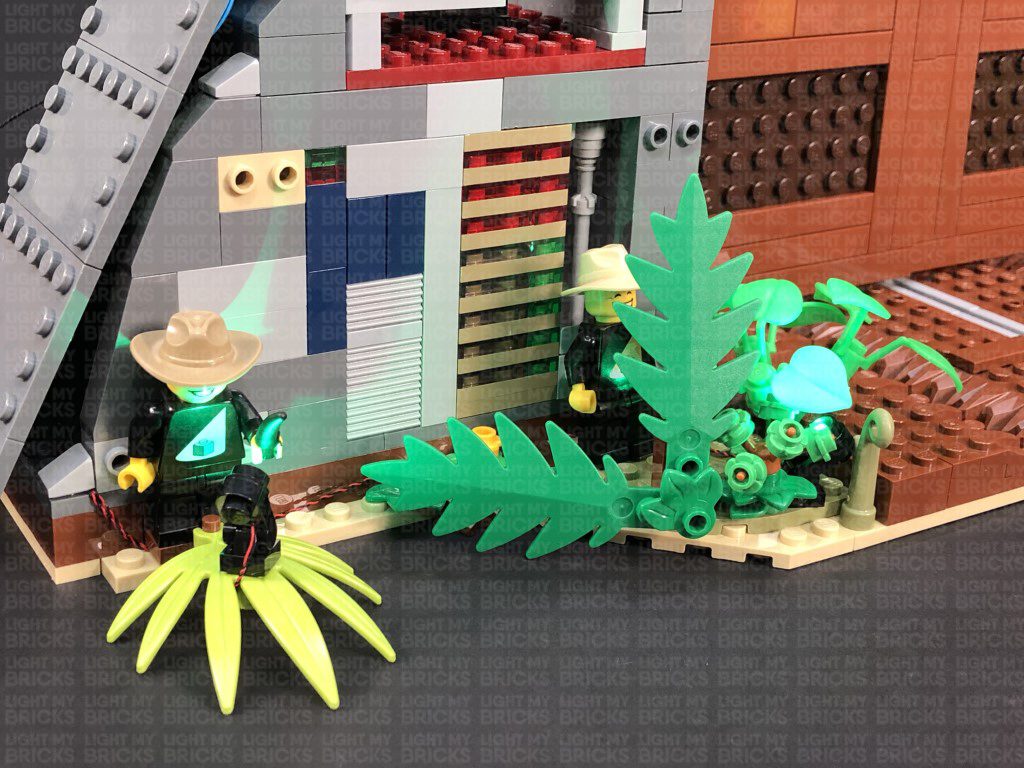
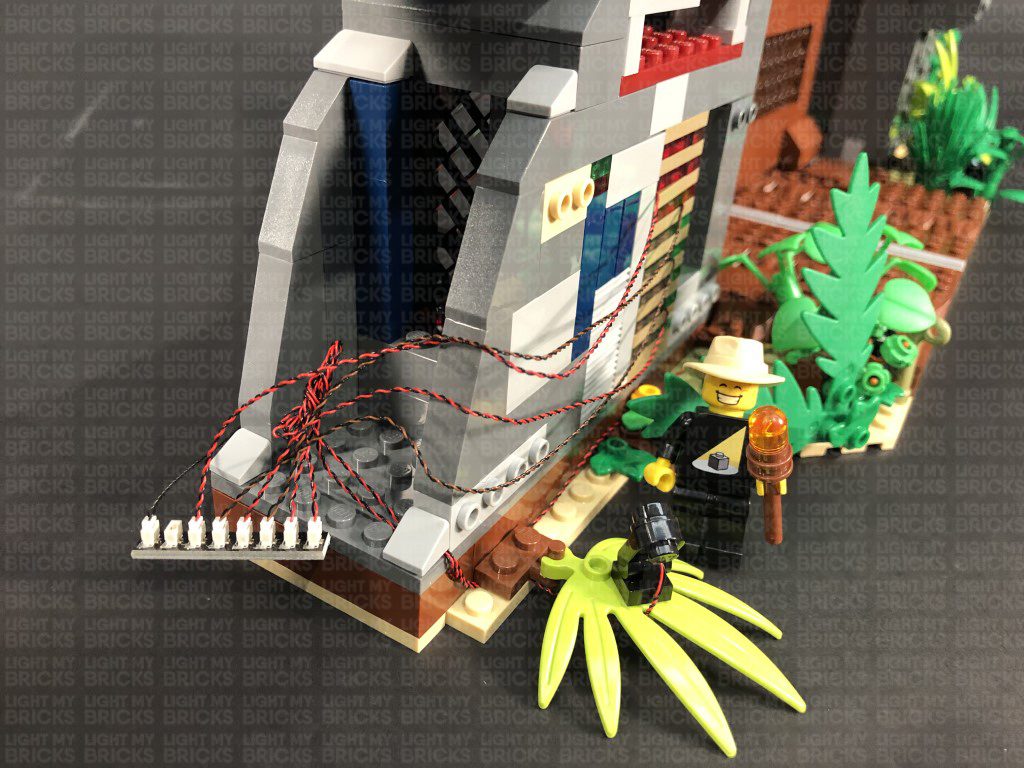
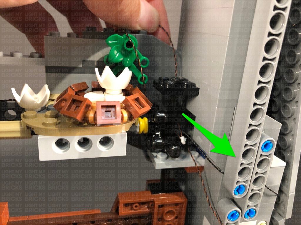
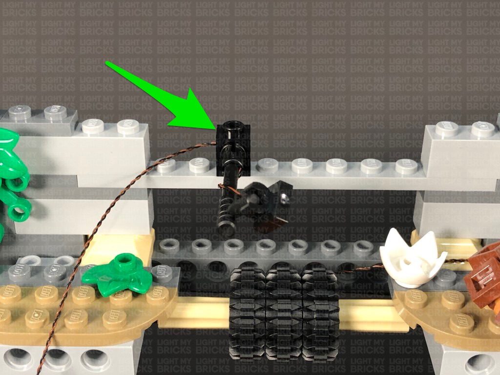
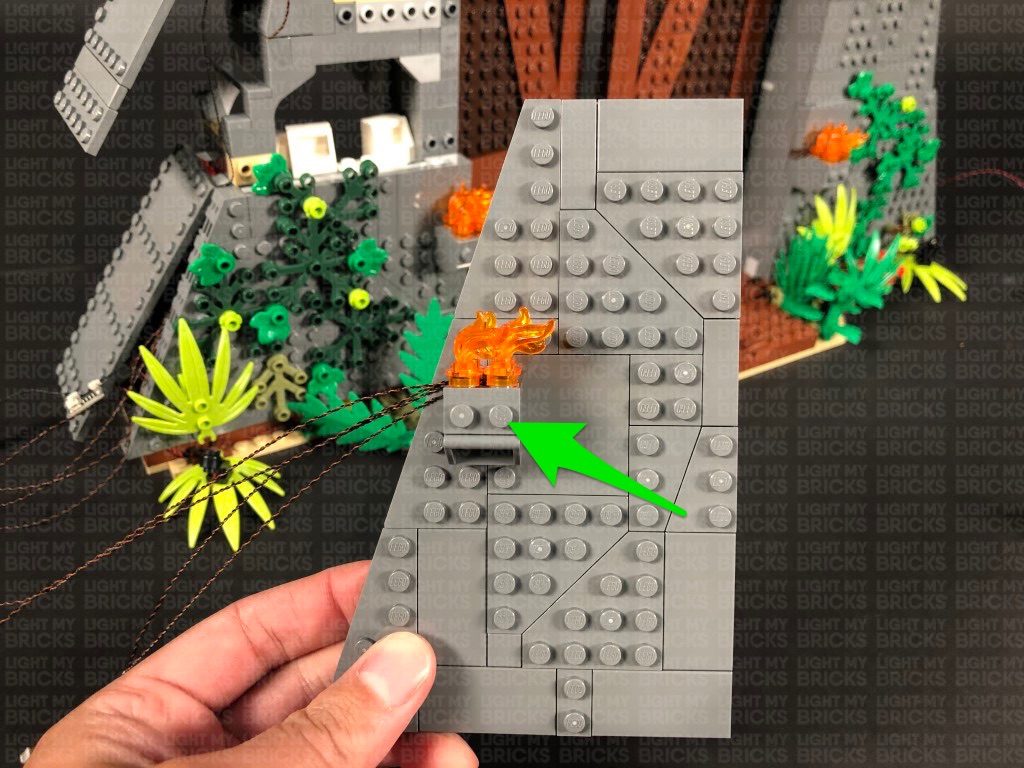
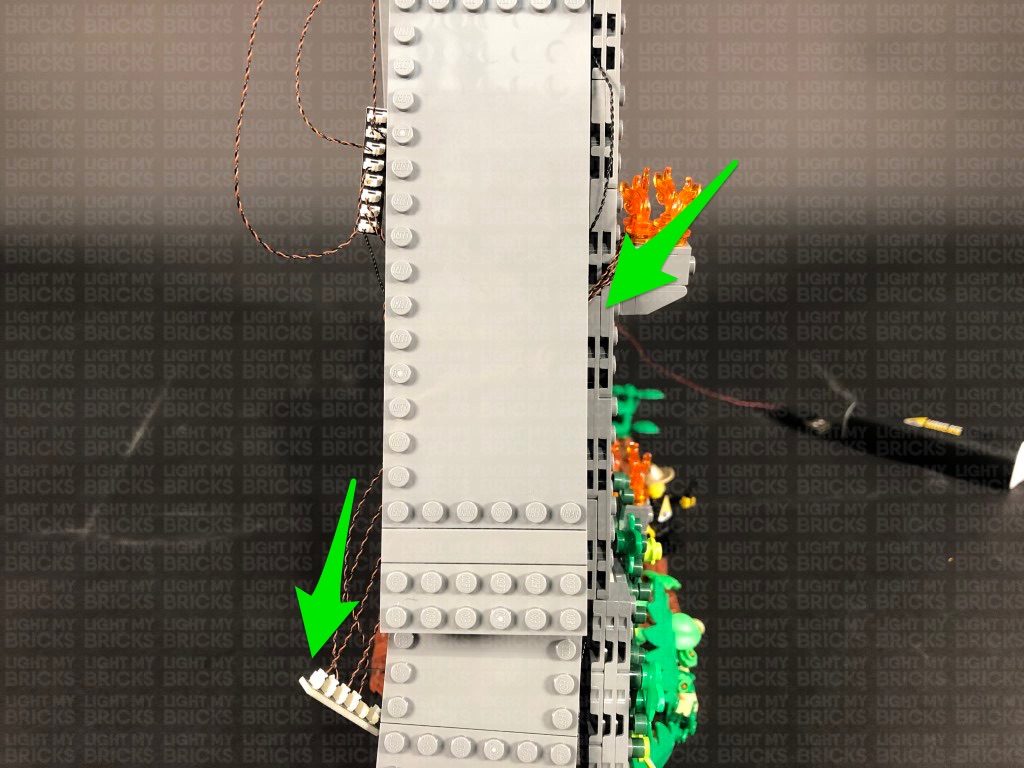
3.) Attach the assembled spot light facing up, to the bottom of the set in the following position(facing diagonally up left), then disconnect the the plant from the left. Repeat the previous step to assemble another spot light and install another Green 30cm Bit Light.
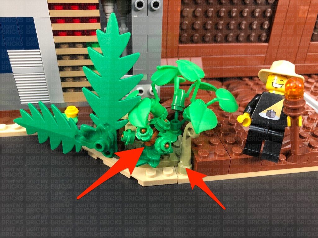
Connect the assembled spot light to the following position, facing the wall. Bring the cable behind and to the right side
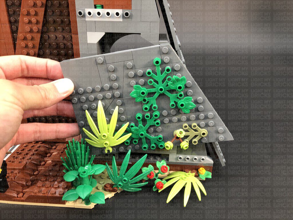
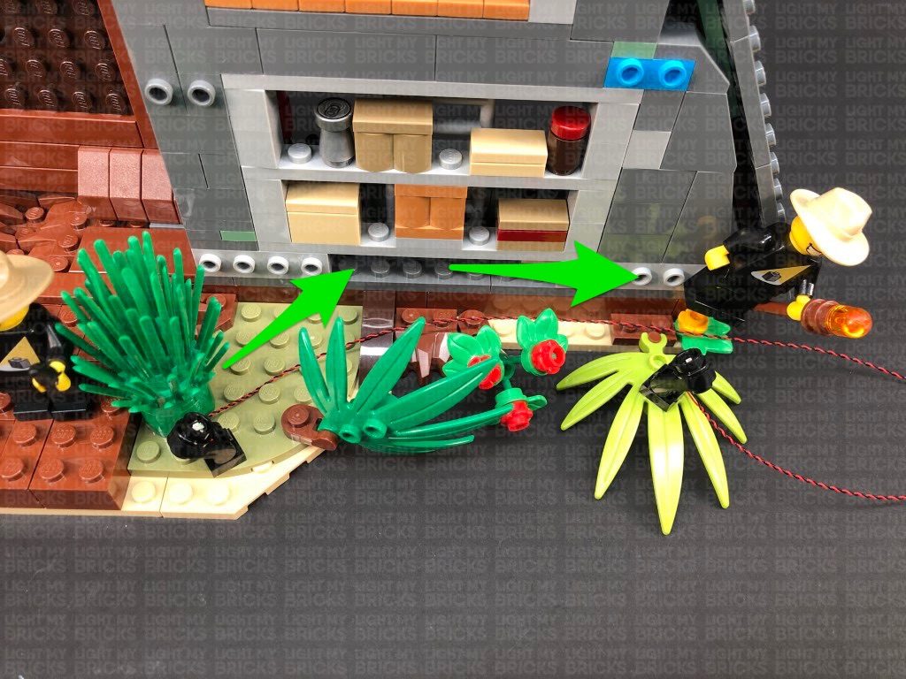
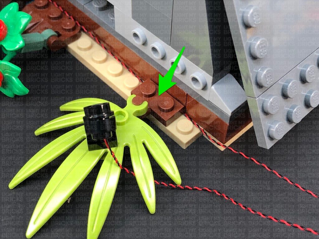
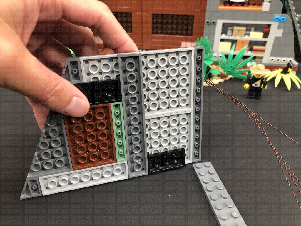
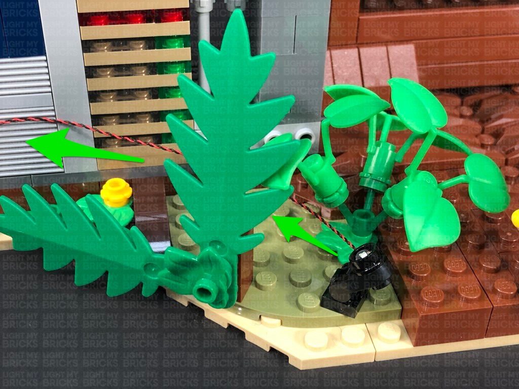
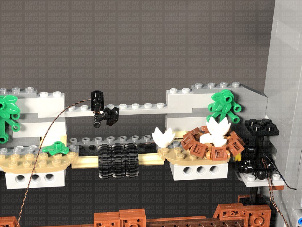
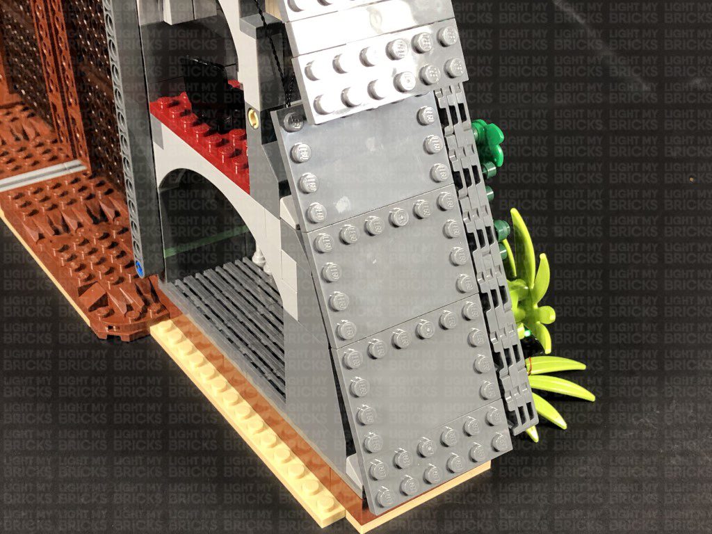
Disconnect the following brown piece and lay the cable from the left spot light along the wall in between studs, then reconnect the piece over the top.
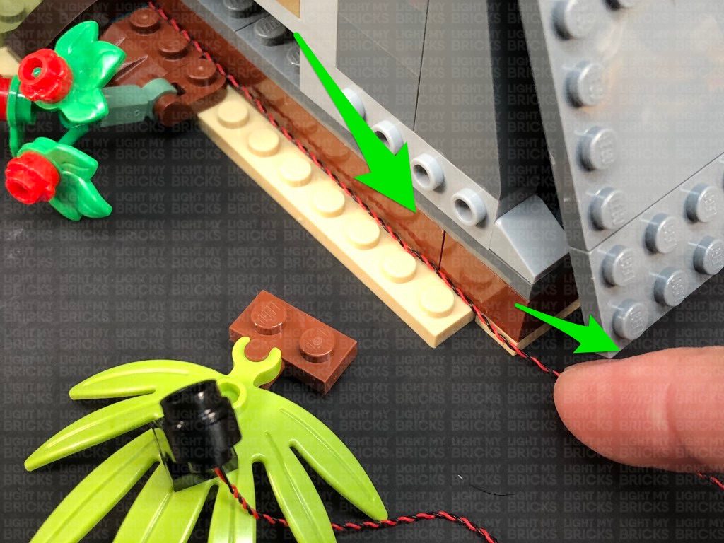
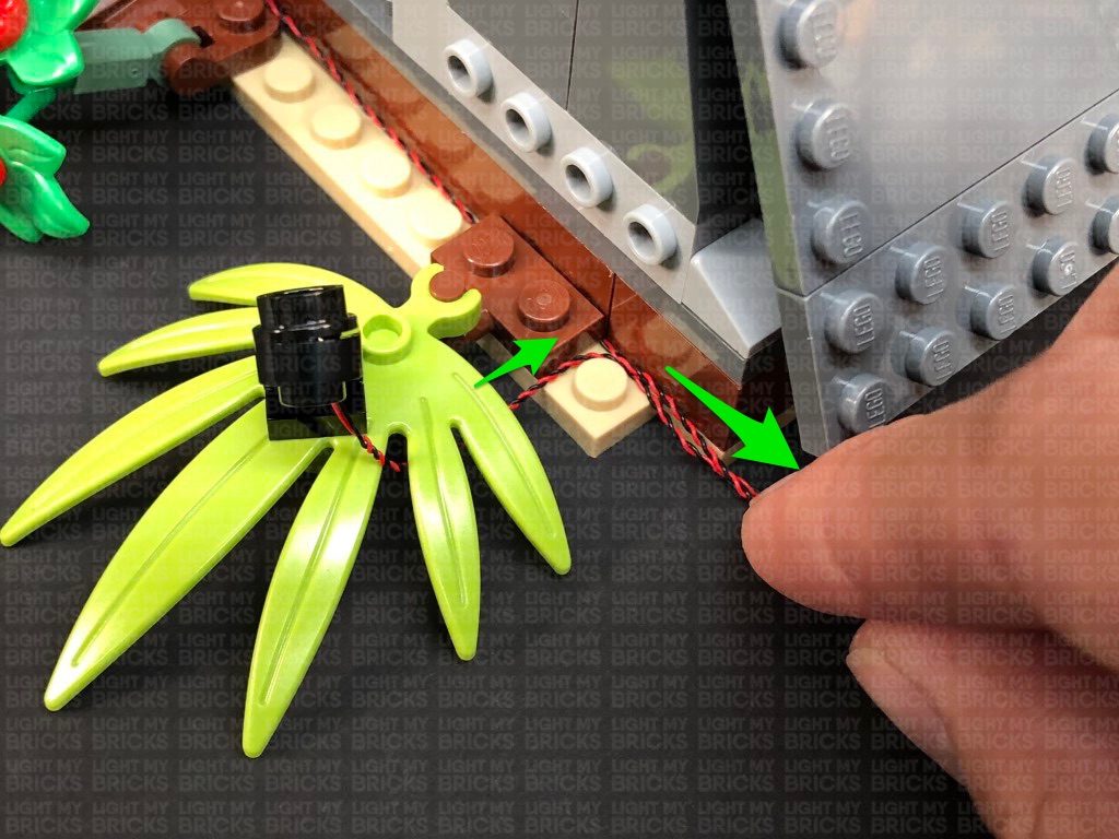
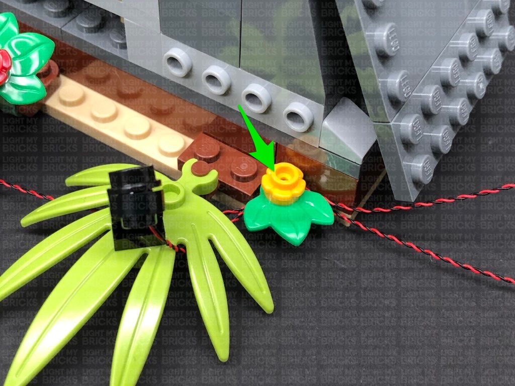
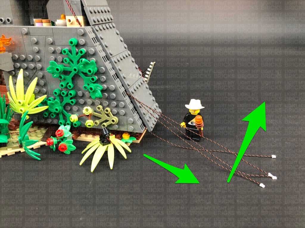
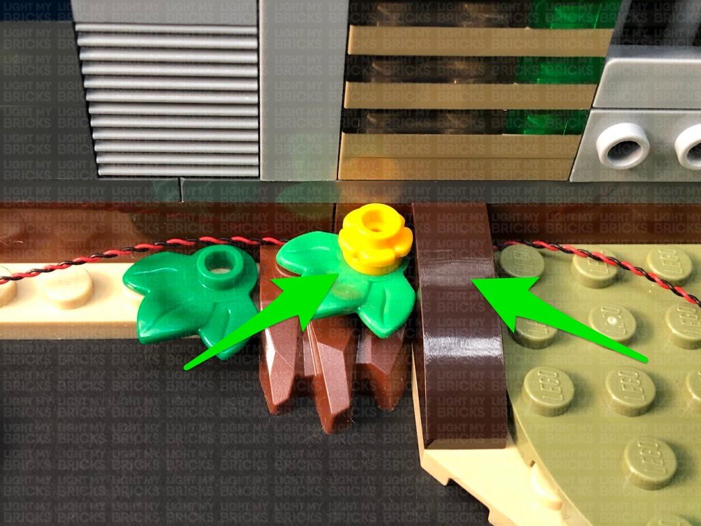
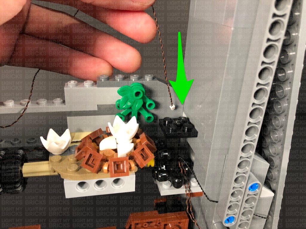
Disconnect the following two sections, then lay the cable from the left spot light along the wall in between studs. Reconnect the first section, then lay the cable from the right spot light underneath the leaves, then around the right corner stud before reconnecting the flower section over the top.
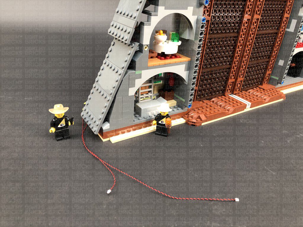
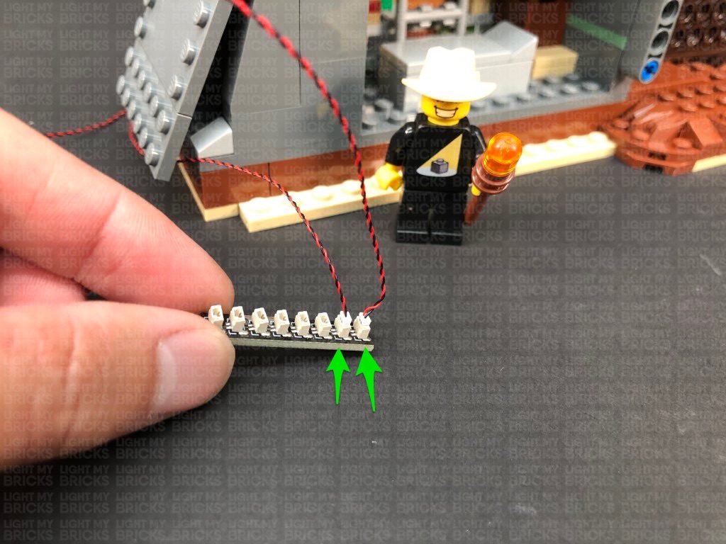
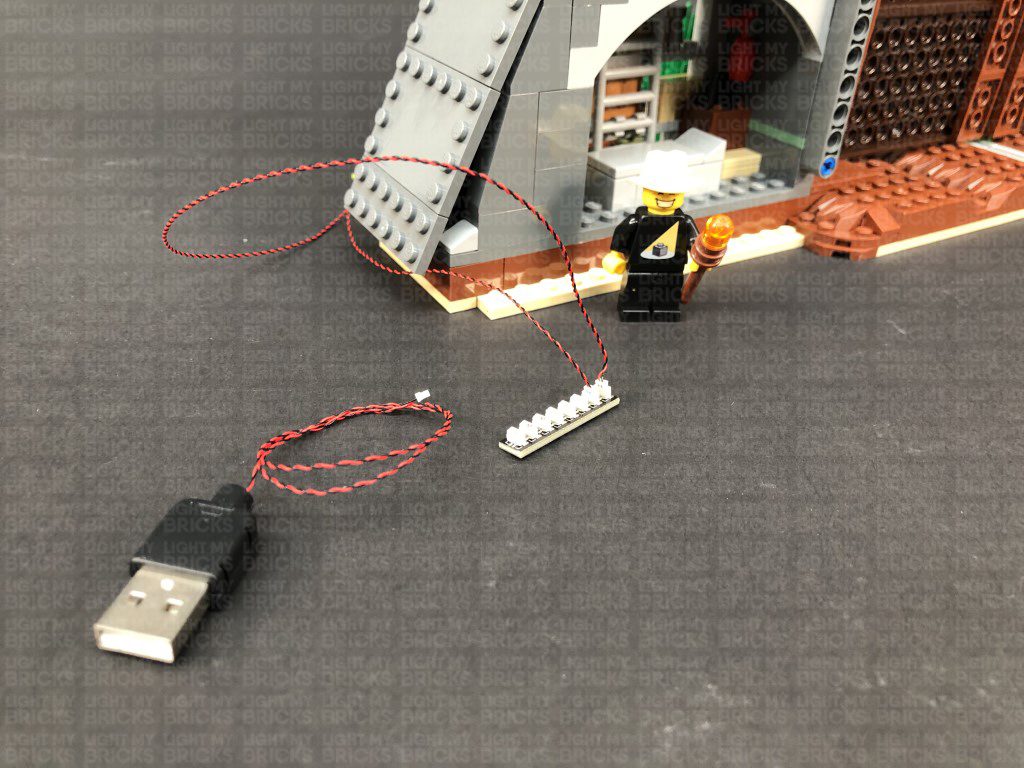
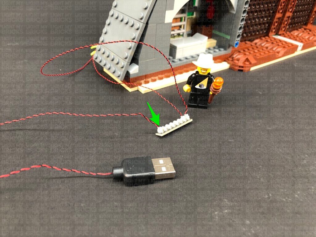
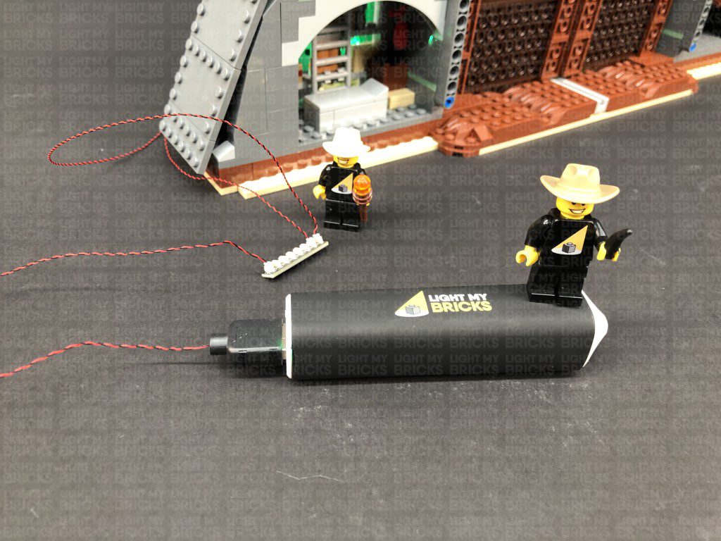
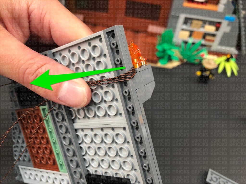
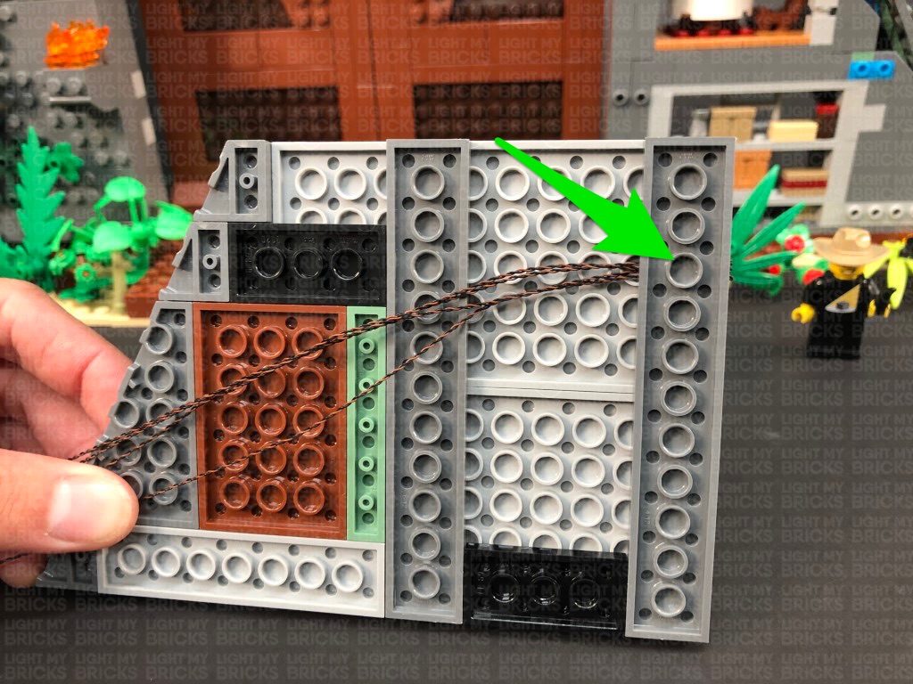
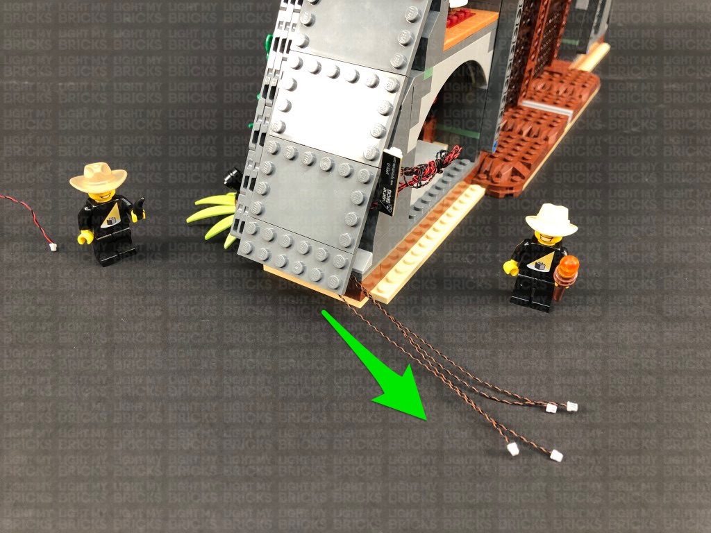
4.) Bring both the cables around the corner to the back side of the set, then connect them to an 8-Port Expansion Board. Take out the USB Power Cable and connect it to expansion board. Connect the other end to a USB Power Bank or wall adaptor (sold separately) and turn it ON to test the green lights are working OK.
2.) Take one of the black round plates with open stud and thread the connector end of a Green 30cm Bit Light through the bottom of the black plate. Thread it all the way through, then slightly bend the Bit Light on a 90 degree angle so that it can sit flat against the bottom of the black round plate as per below:
Connect this piece to one of the Black 1×1 Modified Plate Rounded with Handle pieces, then thread the connector side of the cable through the space just above the handle. Pull the cable all the way out from the other side, then attach the plate with clip at the bottom.
3.) Attach the assembled spot light facing up, to the bottom of the set in the following position(facing diagonally up left), then disconnect the the plant from the left. Repeat the previous step to assemble another spot light and install another Green 30cm Bit Light.
Connect the assembled spot light to the following position, facing the wall. Bring the cable behind and to the right side
Disconnect the following brown piece and lay the cable from the left spot light along the wall in between studs, then reconnect the piece over the top.
Disconnect the following two sections, then lay the cable from the left spot light along the wall in between studs. Reconnect the first section, then lay the cable from the right spot light underneath the leaves, then around the right corner stud before reconnecting the flower section over the top.
4.) Bring both the cables around the corner to the back side of the set, then connect them to an 8-Port Expansion Board. Take out the USB Power Cable and connect it to expansion board. Connect the other end to a USB Power Bank or wall adaptor (sold separately) and turn it ON to test the green lights are working OK.
 Note: If you experience any issues with the lights not working and suspect an issue with a component, please try a different port on the expansion board to verify where the fault lies (with the light or expansion board). To correct any issues with expansion board ports, please view the section addressing expansion board issues on our online troubleshooting guide.
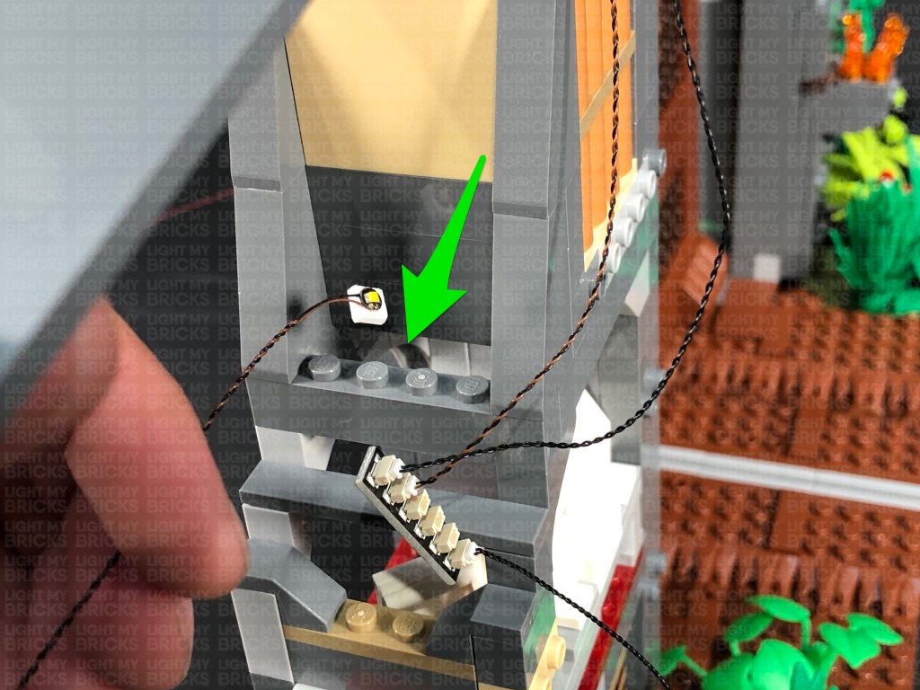
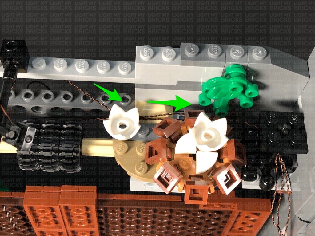
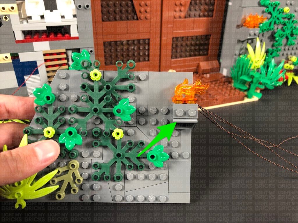
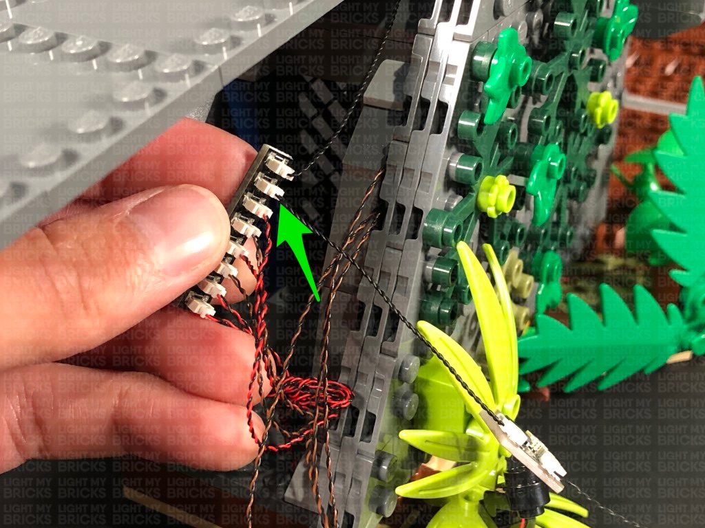
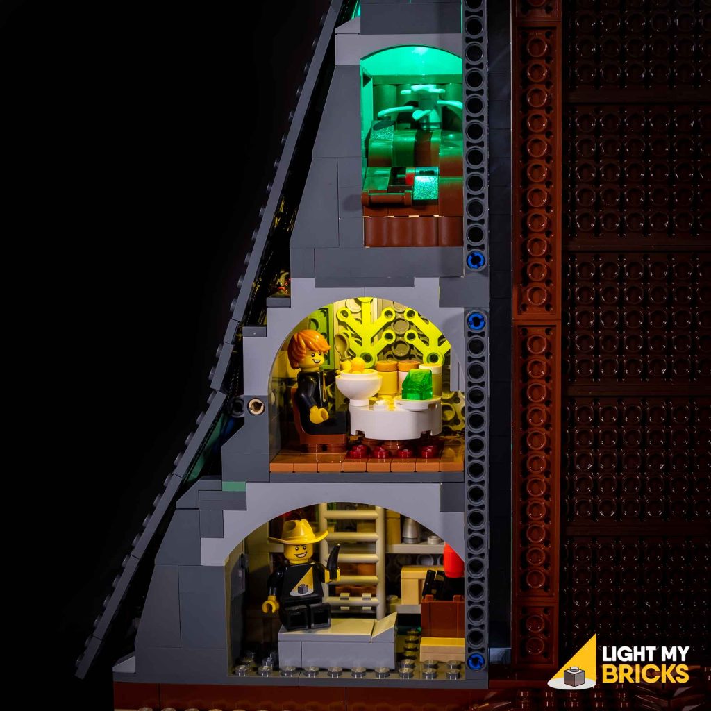
5.) We will now install another Green light to the Mud room at the top of the back side. Take a Green 30cm Bit Light and stick it to an Adhesive Square. Lift up the middle side flap and thread the Bit Light through to stick it to the front of the top inside this section as shown below.
Disconnect the following angled tile toward the back, then lay the cable in between studs before reconnecting the angled tile over the top. This will help secure the cable.
Bring the other end of the cable out, then bring it around the front and down towards the bottom to connect to the 8-Port Expansion Board underneath. Turn the USB Power Bank ON to test the light is working OK.
6.) We will now light up the restaurant room underneath. Take out a White 30cm Bit Light and stick it to another Adhesive Square. Lift up the side flap and thread the Bit Light down the following space on the side. Stick the Bit Light to the the front of the top section inside this room as shown below.
Note: If you experience any issues with the lights not working and suspect an issue with a component, please try a different port on the expansion board to verify where the fault lies (with the light or expansion board). To correct any issues with expansion board ports, please view the section addressing expansion board issues on our online troubleshooting guide.
5.) We will now install another Green light to the Mud room at the top of the back side. Take a Green 30cm Bit Light and stick it to an Adhesive Square. Lift up the middle side flap and thread the Bit Light through to stick it to the front of the top inside this section as shown below.
Disconnect the following angled tile toward the back, then lay the cable in between studs before reconnecting the angled tile over the top. This will help secure the cable.
Bring the other end of the cable out, then bring it around the front and down towards the bottom to connect to the 8-Port Expansion Board underneath. Turn the USB Power Bank ON to test the light is working OK.
6.) We will now light up the restaurant room underneath. Take out a White 30cm Bit Light and stick it to another Adhesive Square. Lift up the side flap and thread the Bit Light down the following space on the side. Stick the Bit Light to the the front of the top section inside this room as shown below.
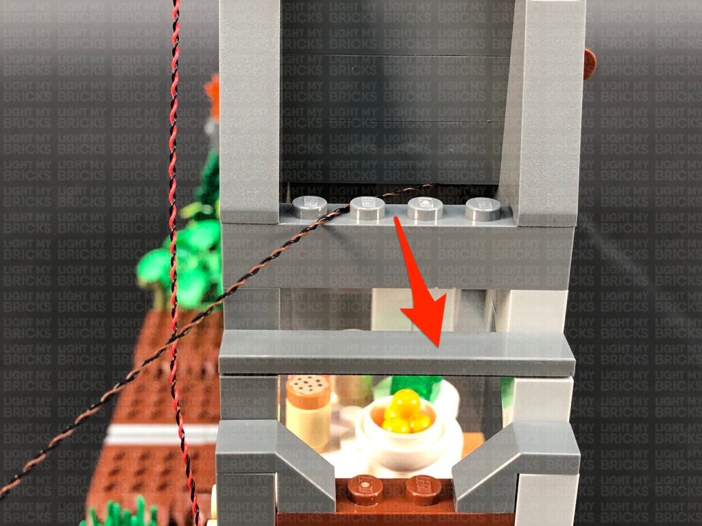
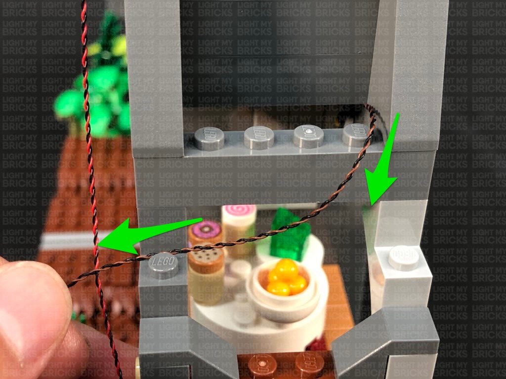
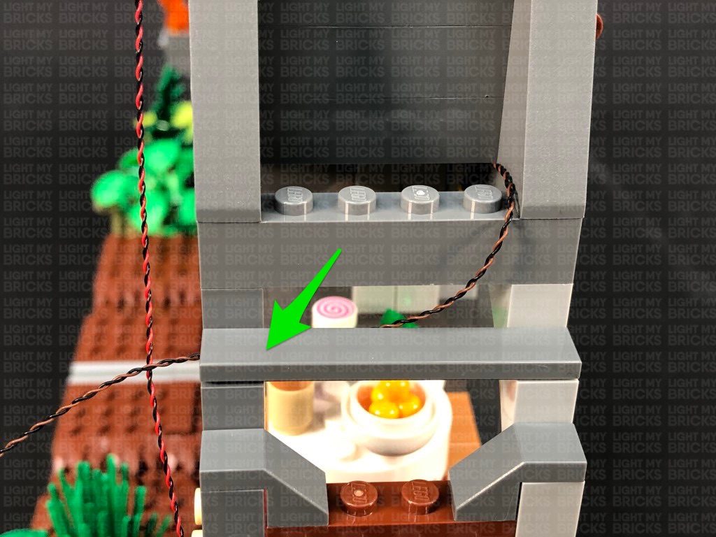
 Disconnect the following tile, then bring the cable down and lay it across toward the front of the set in between studs, before reconnecting the tile over the top. This will help secure the cable.
Bring the other end of the cable out, then bring it down underneath the bottom side flap, to connect to the 8-Port Expansion Board underneath. Turn the USB Power Bank ON to test the light is working OK.
Note: If you experience any issues with the lights not working and suspect an issue with a component, please try a different port on the expansion board to verify where the fault lies (with the light or expansion board). To correct any issues with expansion board ports, please view the section addressing expansion board issues on our online troubleshooting guide.
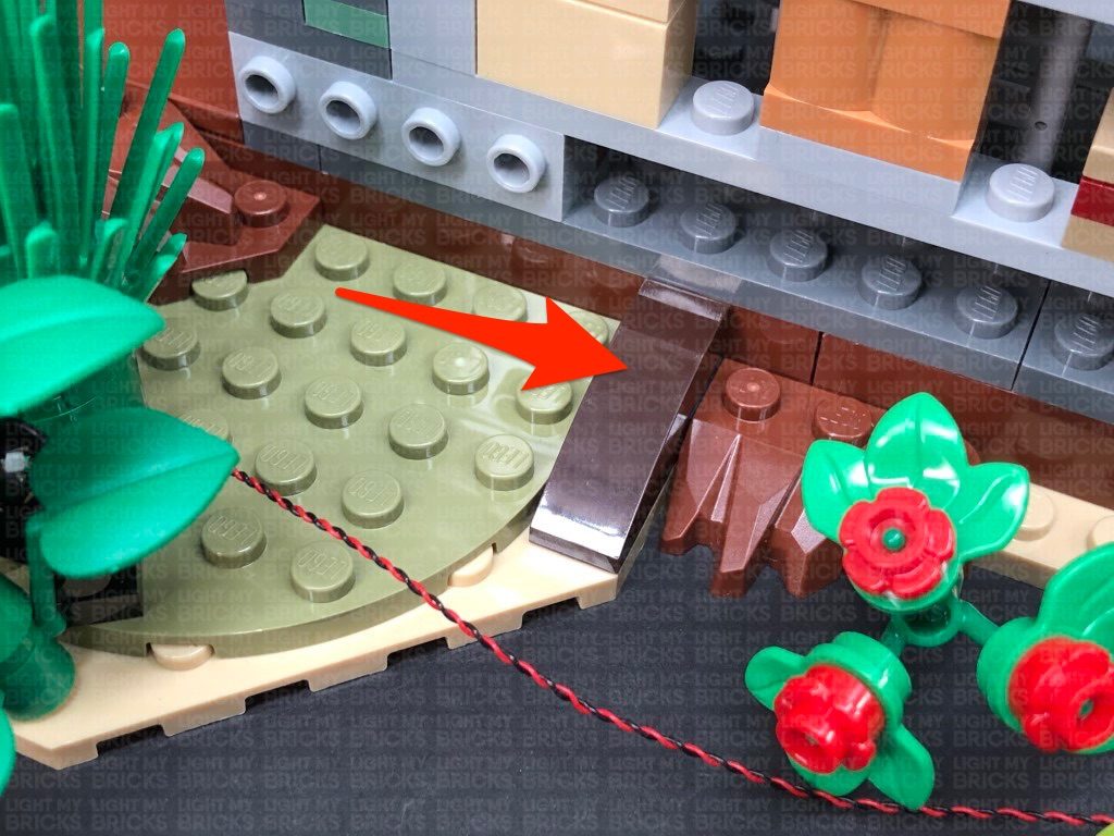
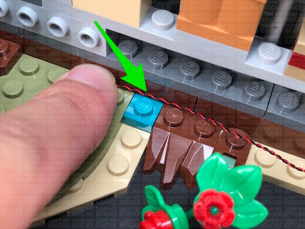
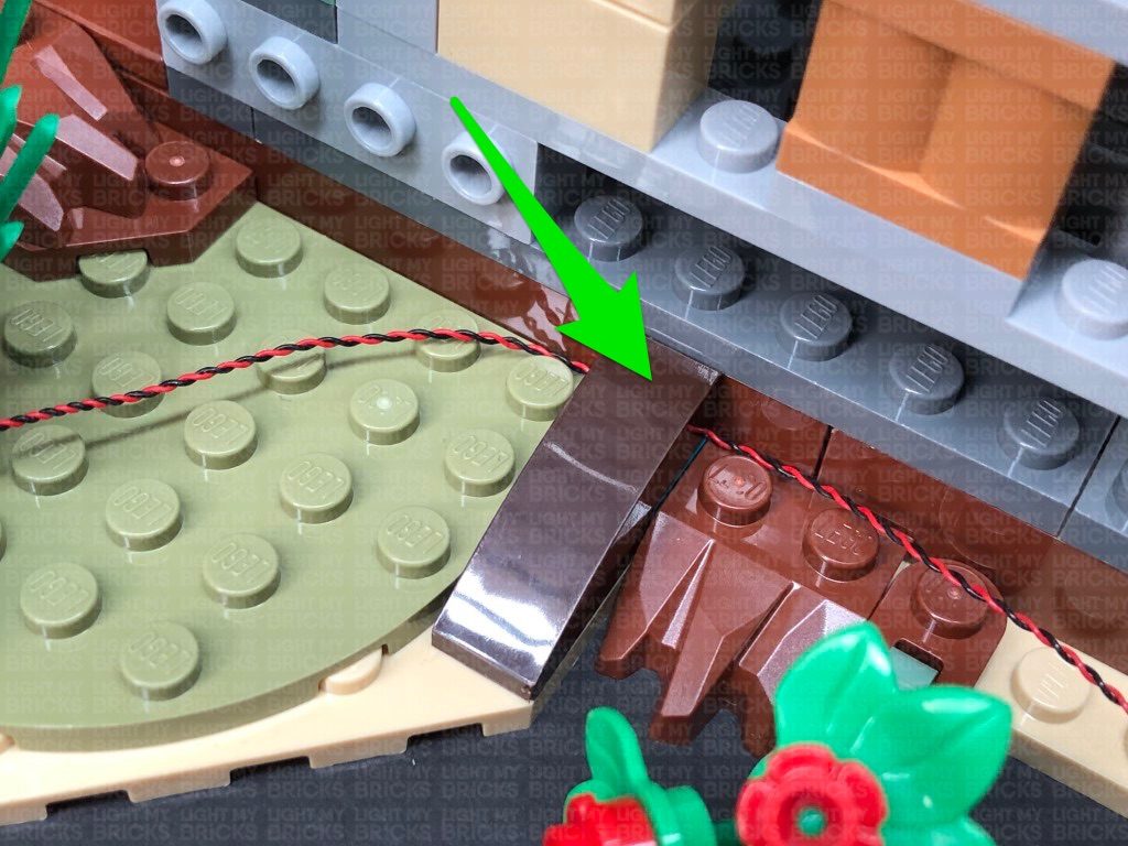
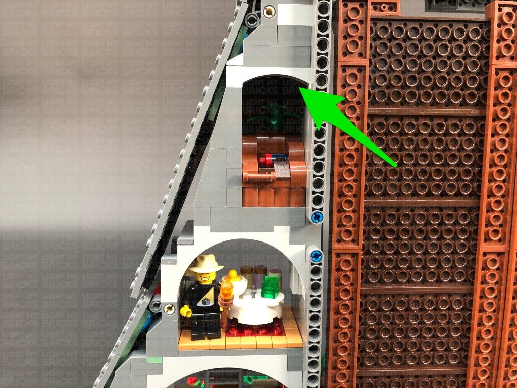
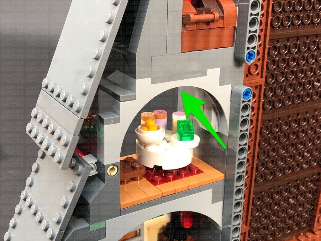
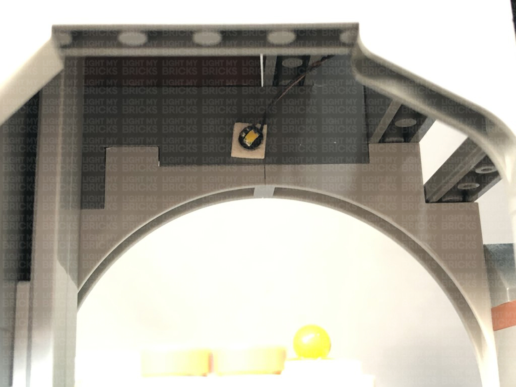
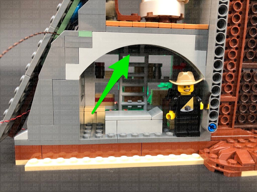
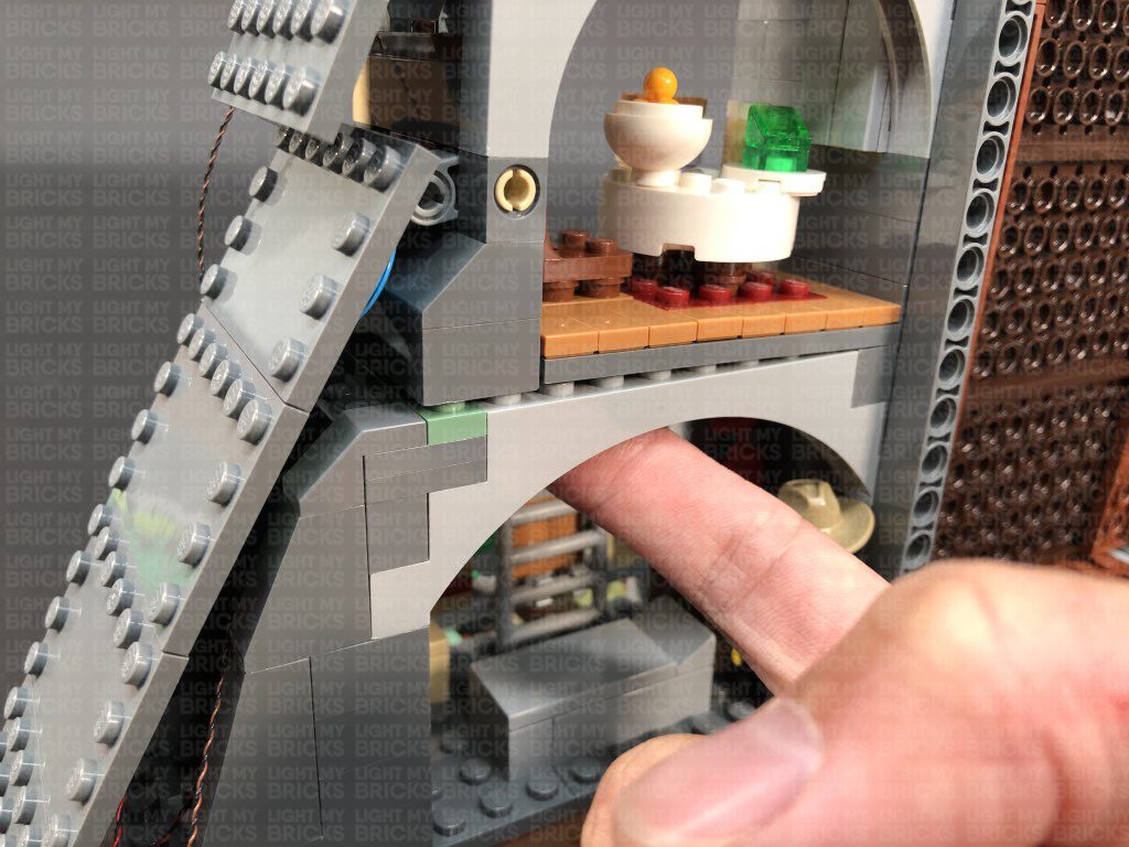
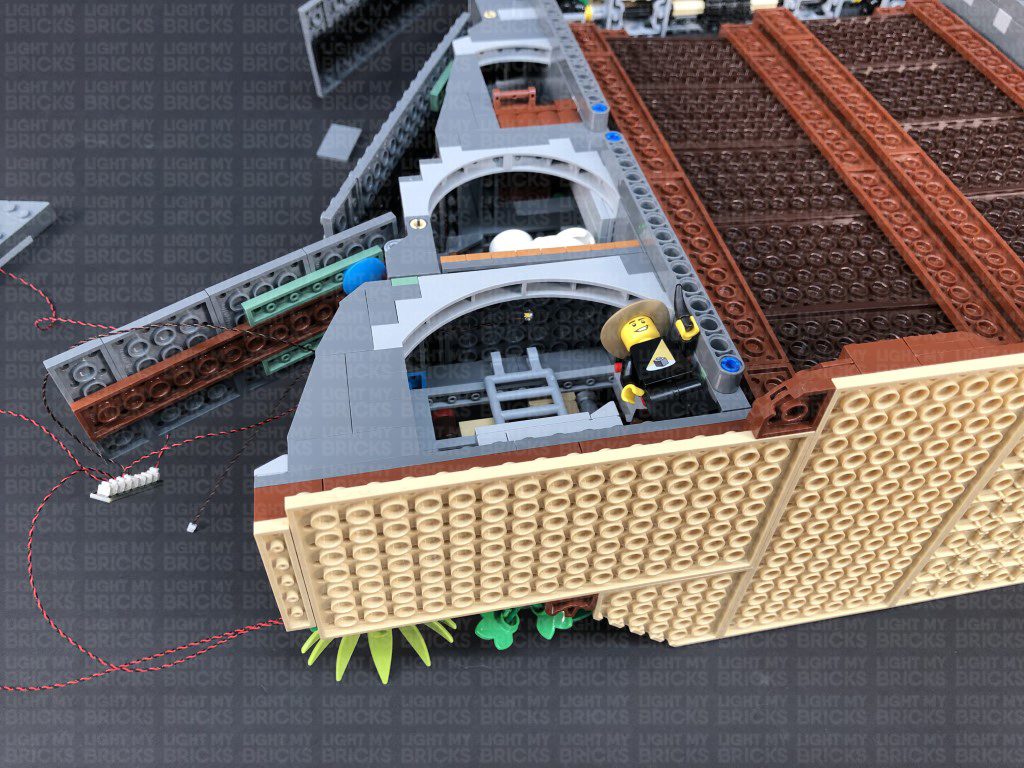
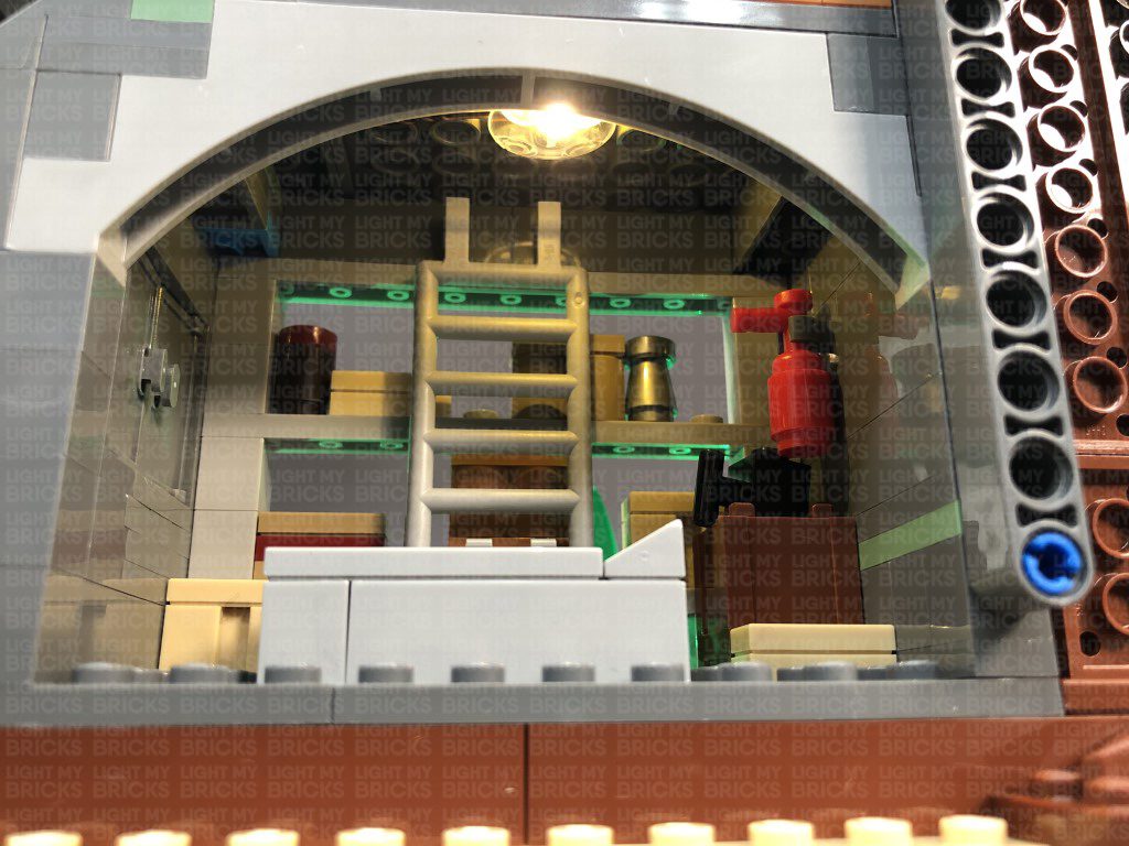
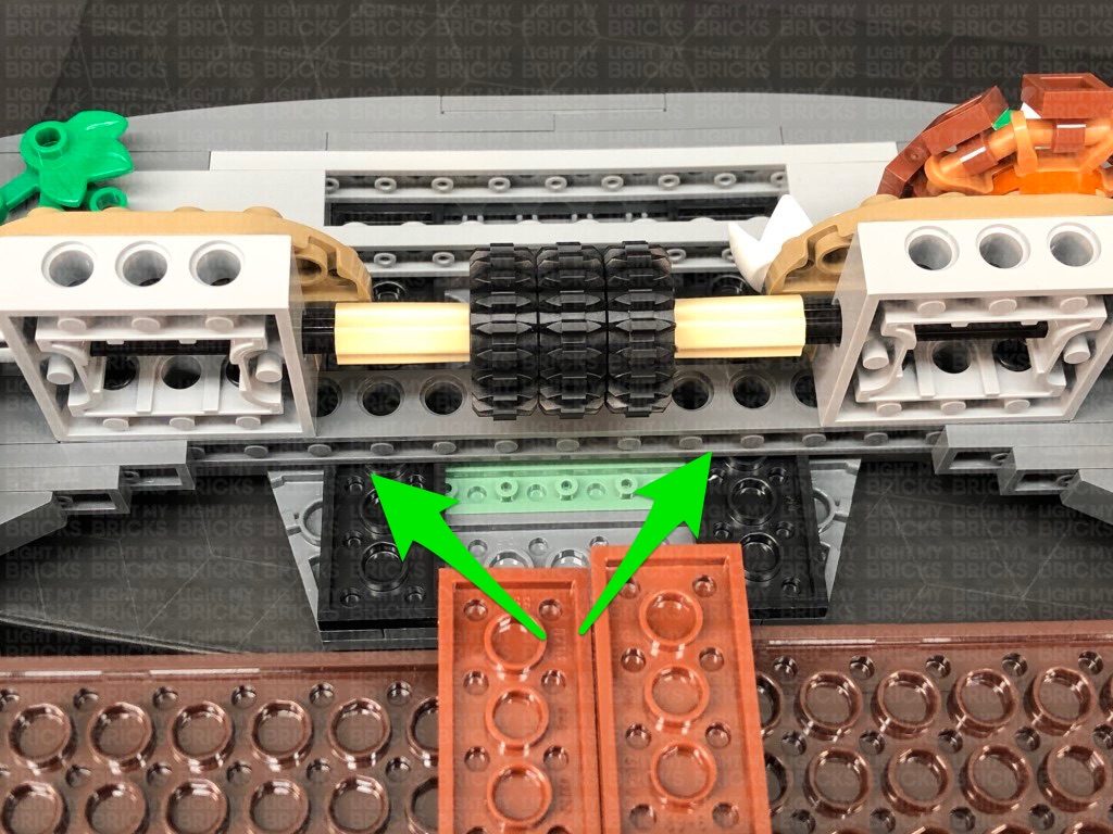
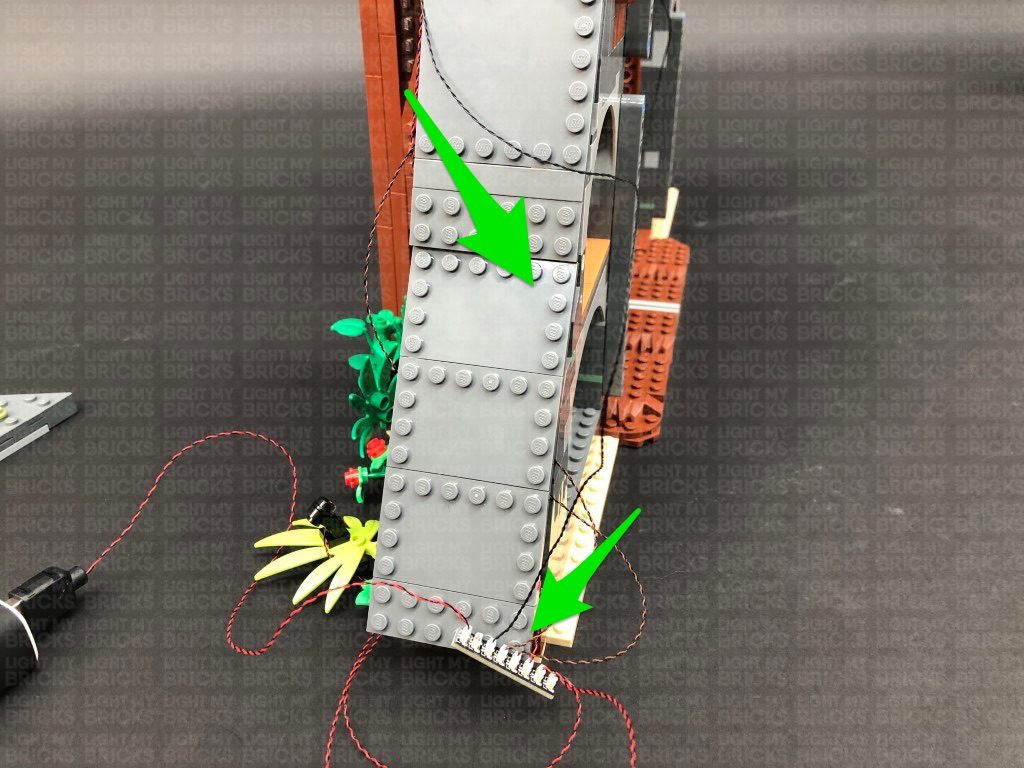
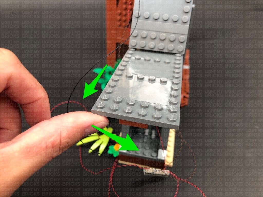
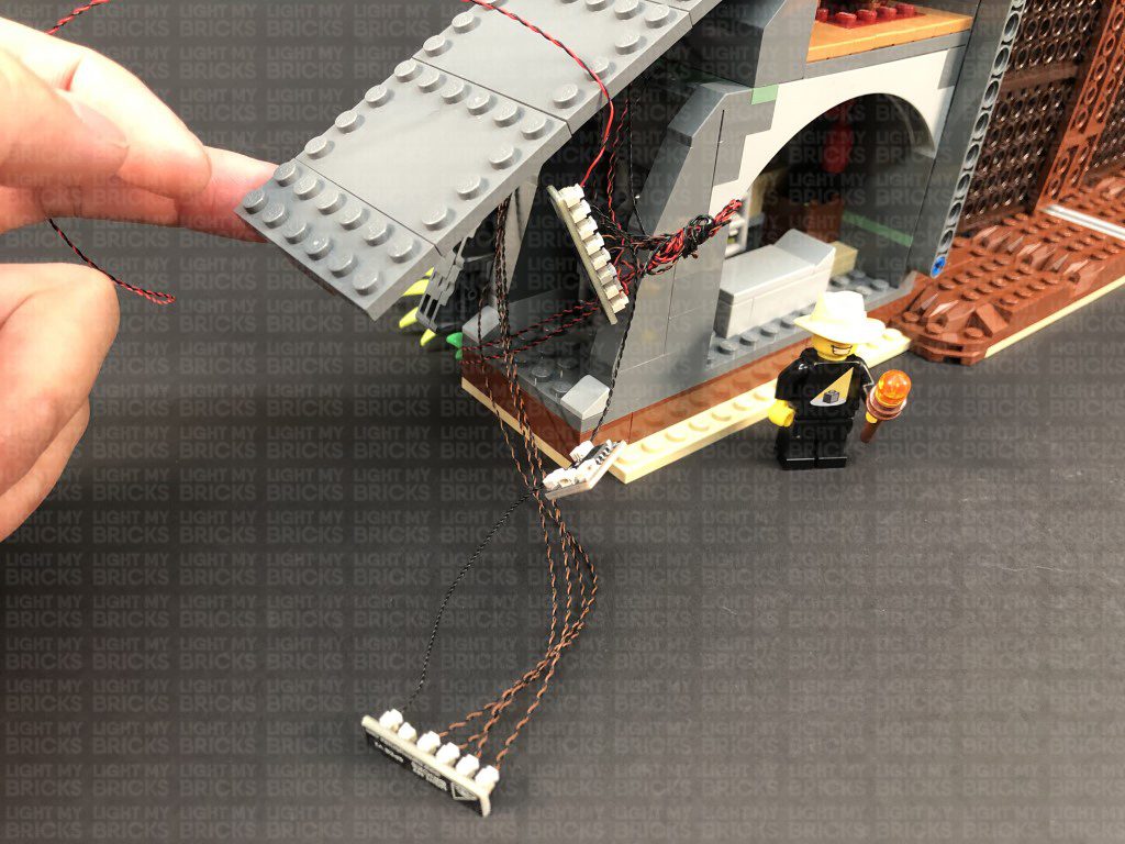
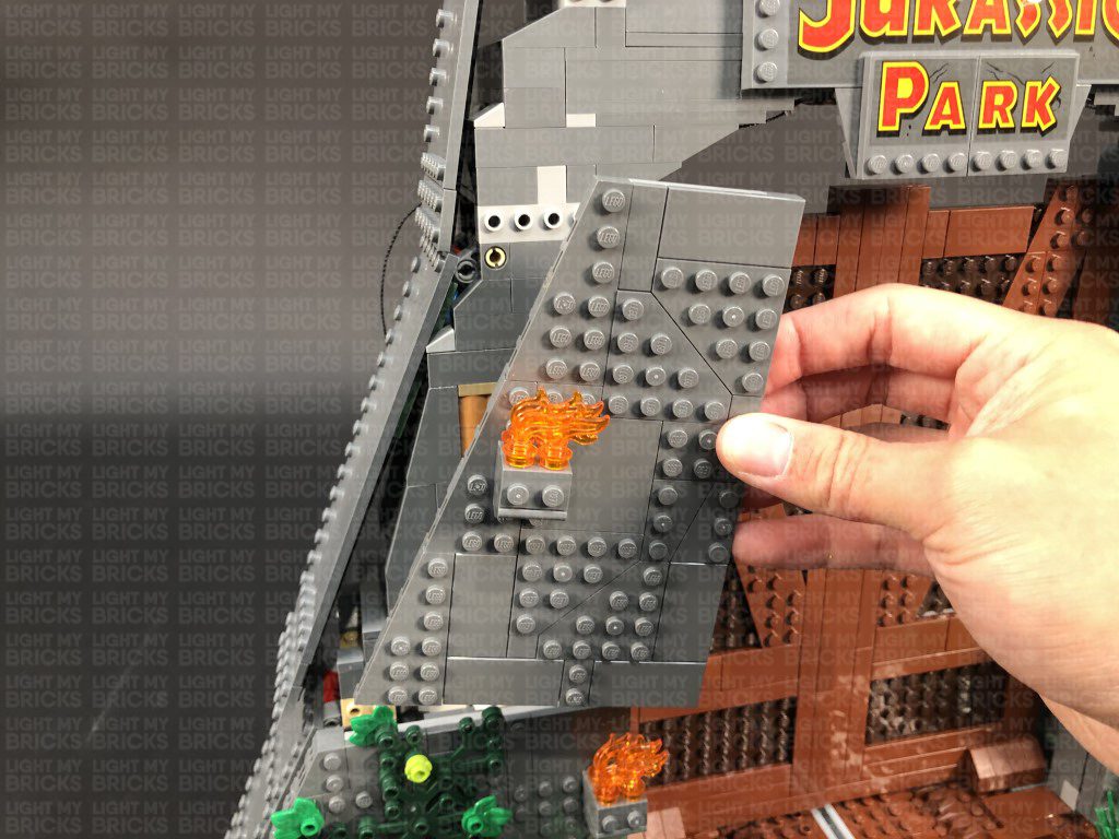
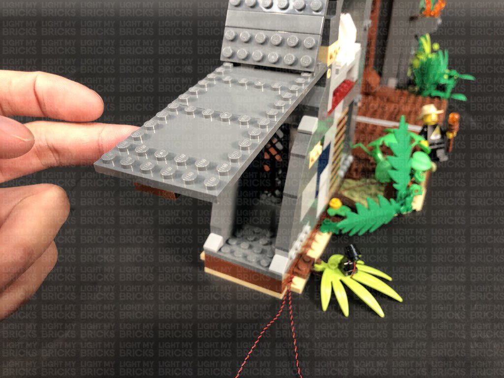
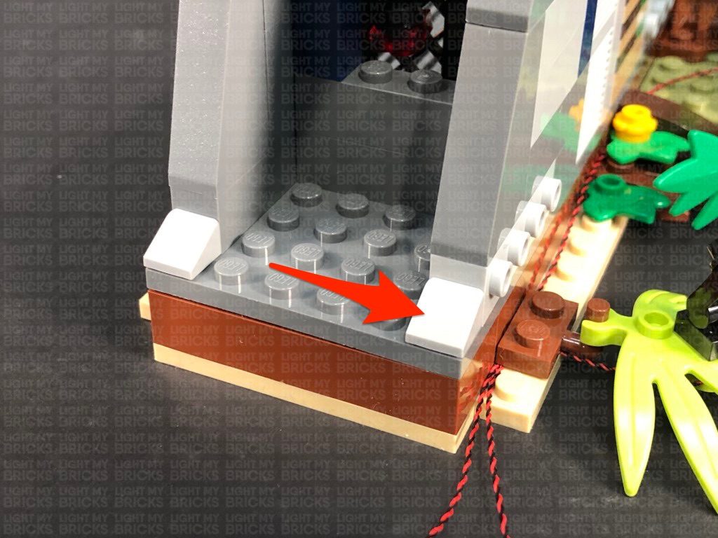
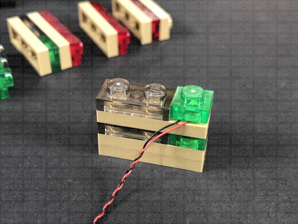
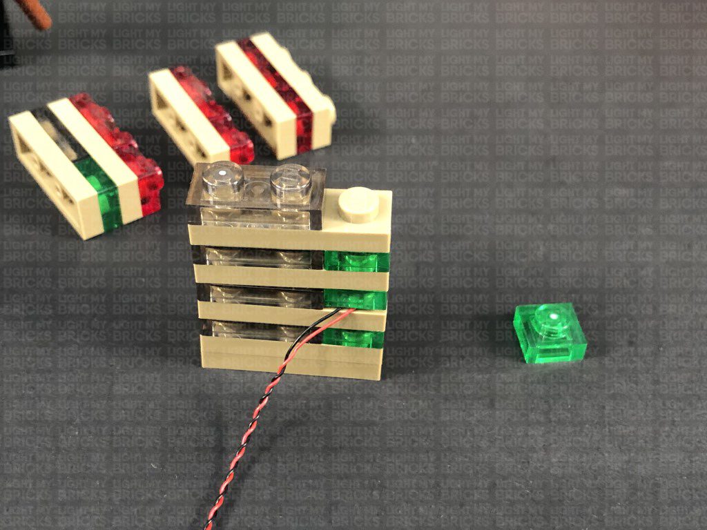
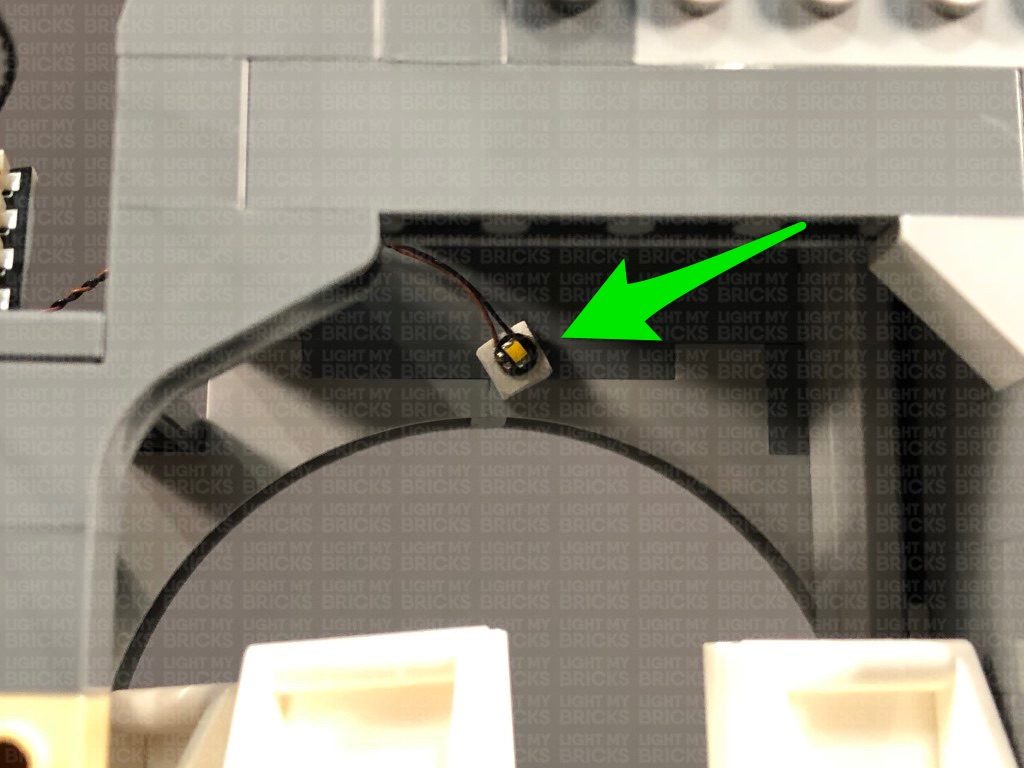
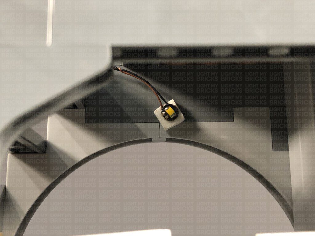
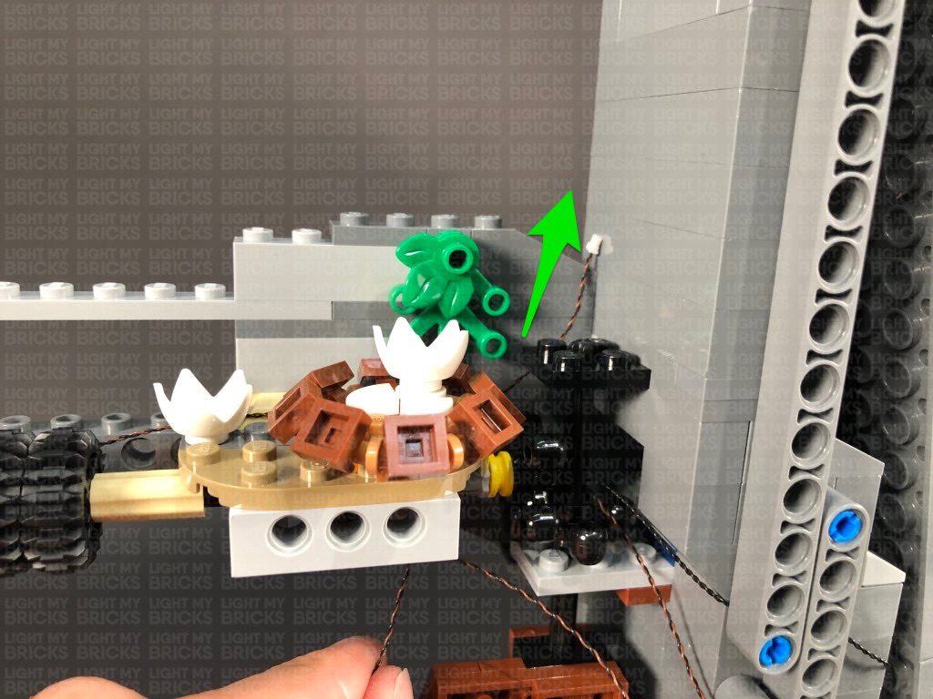
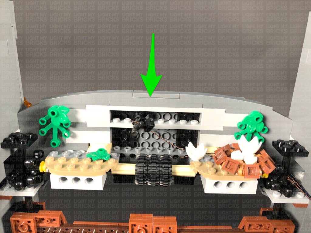
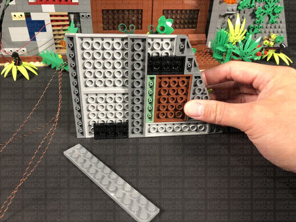
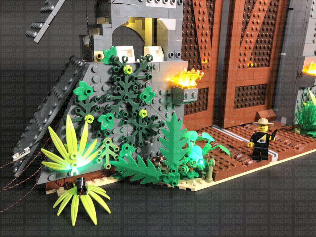
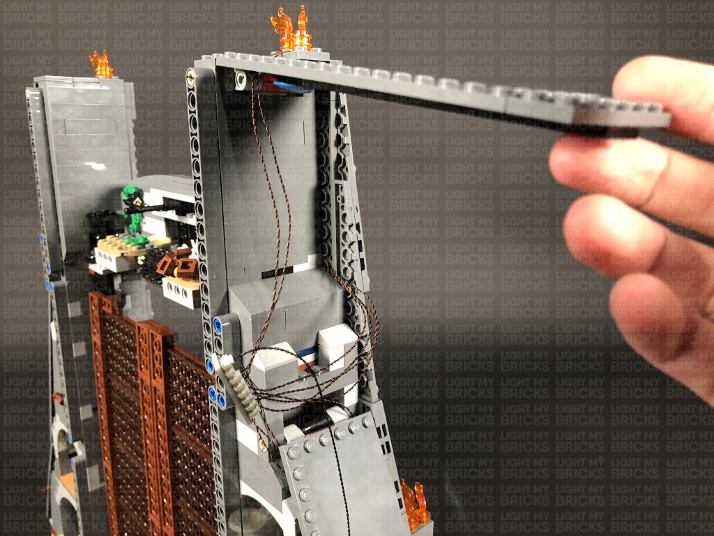
7.) We will now light up the underground bunker at the bottom floor. First, we want to create a gap just above the room (above the green plate). To create this gap, gently push your finger up the roof plate of this room to slightly disconnect this section on the top left side as shown below.
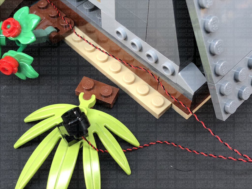
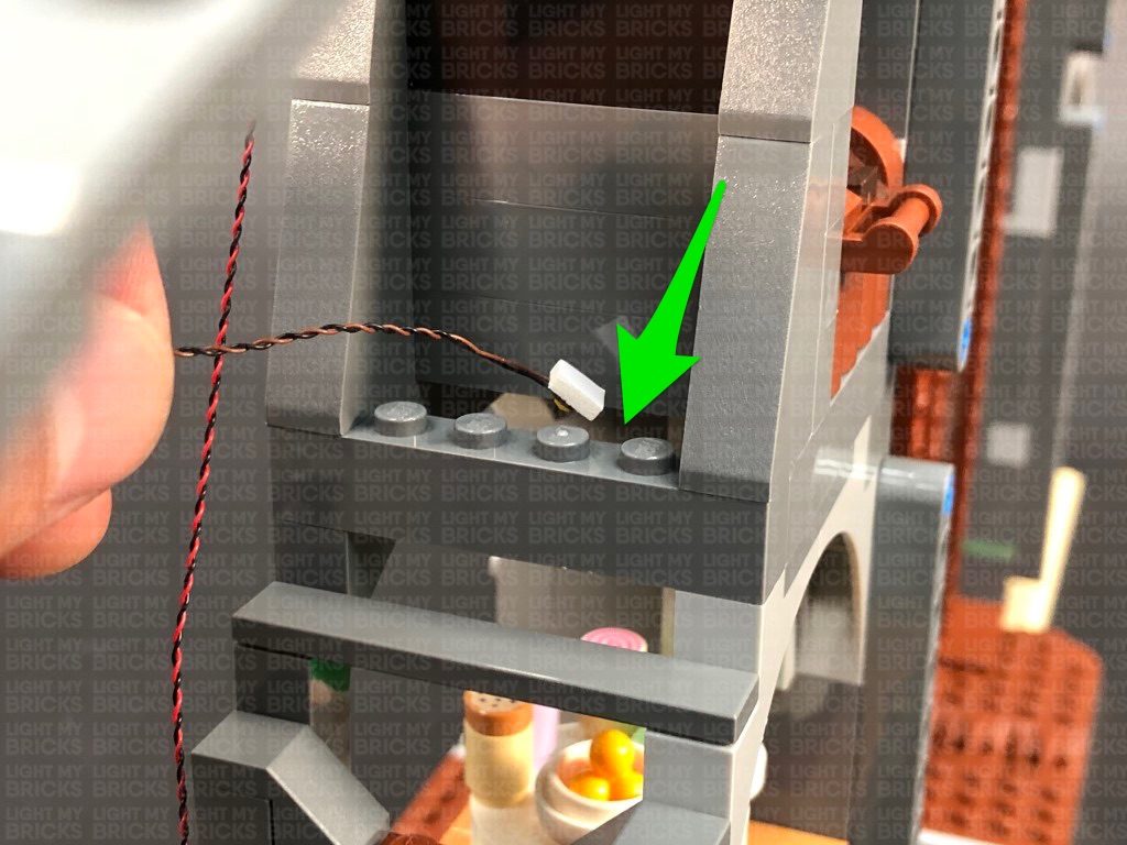
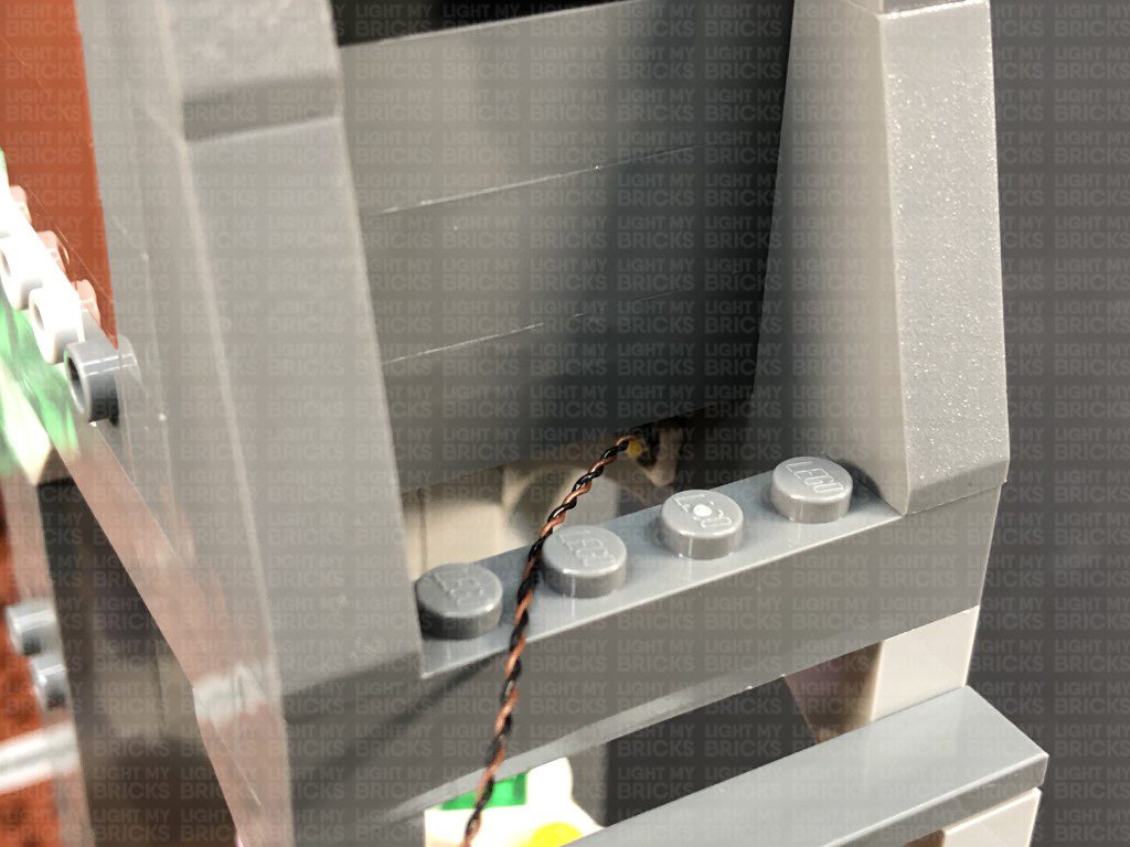
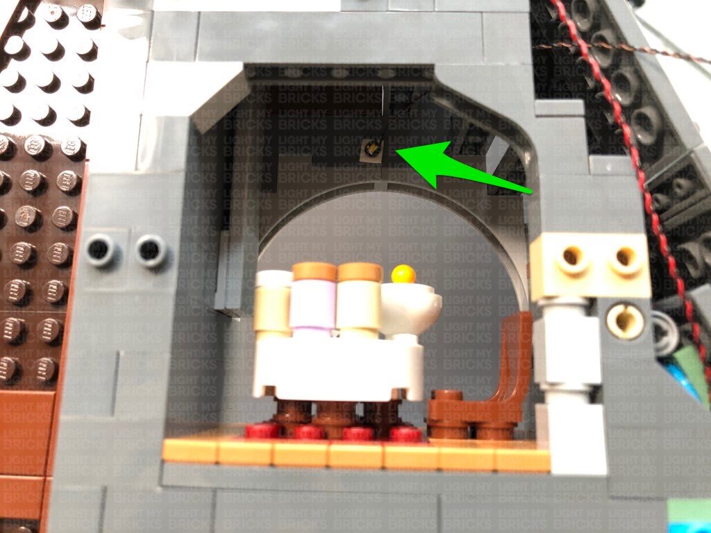
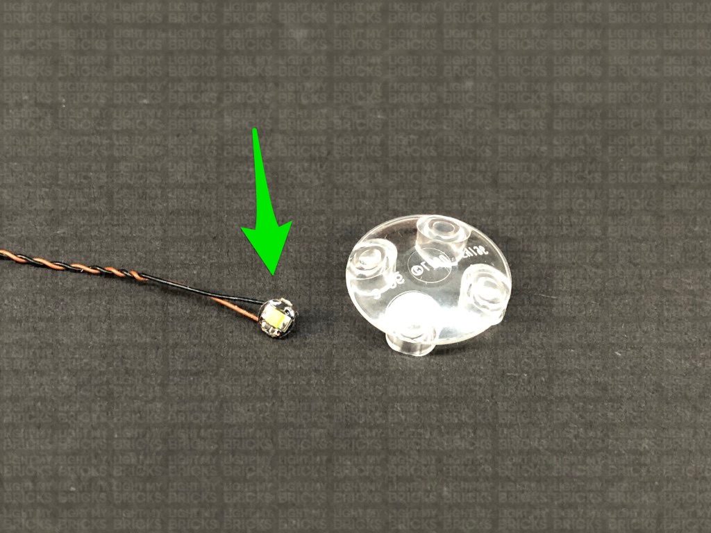
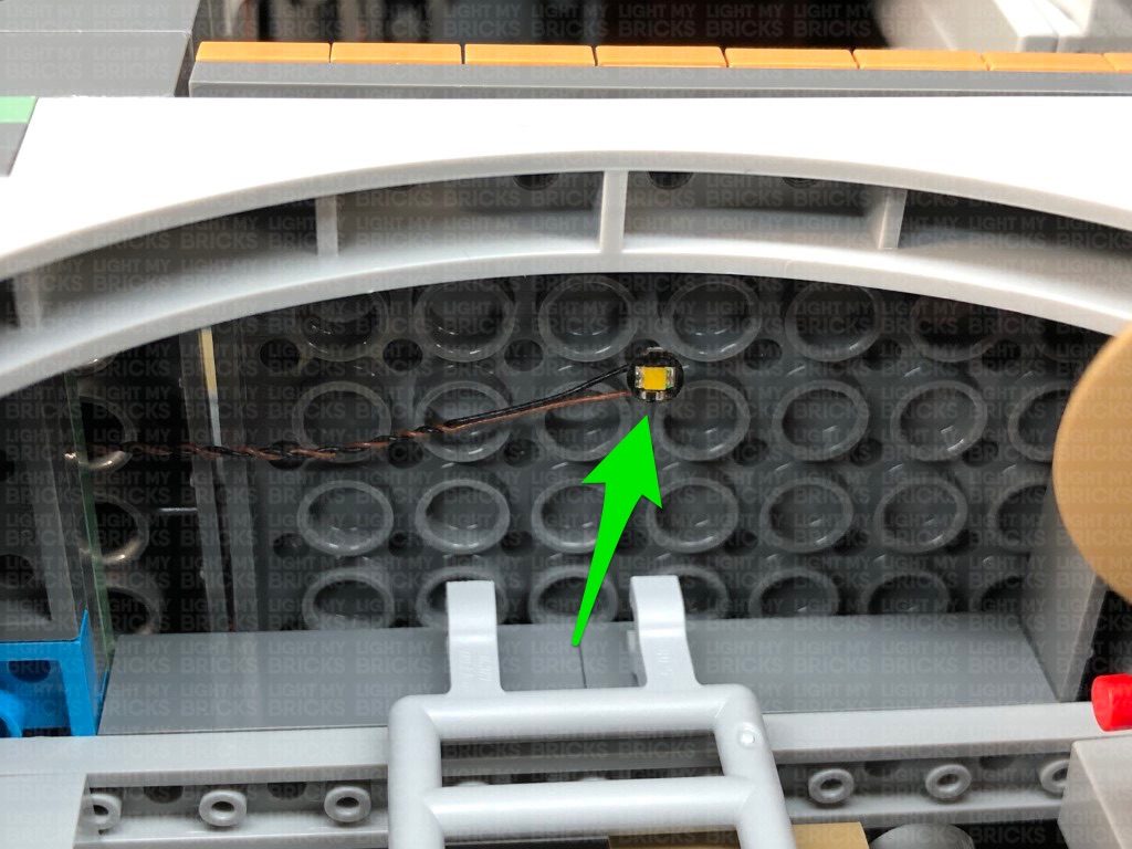
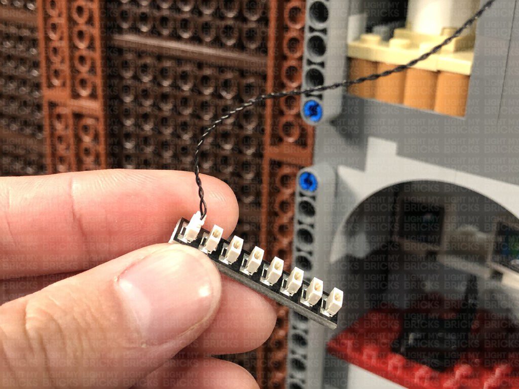
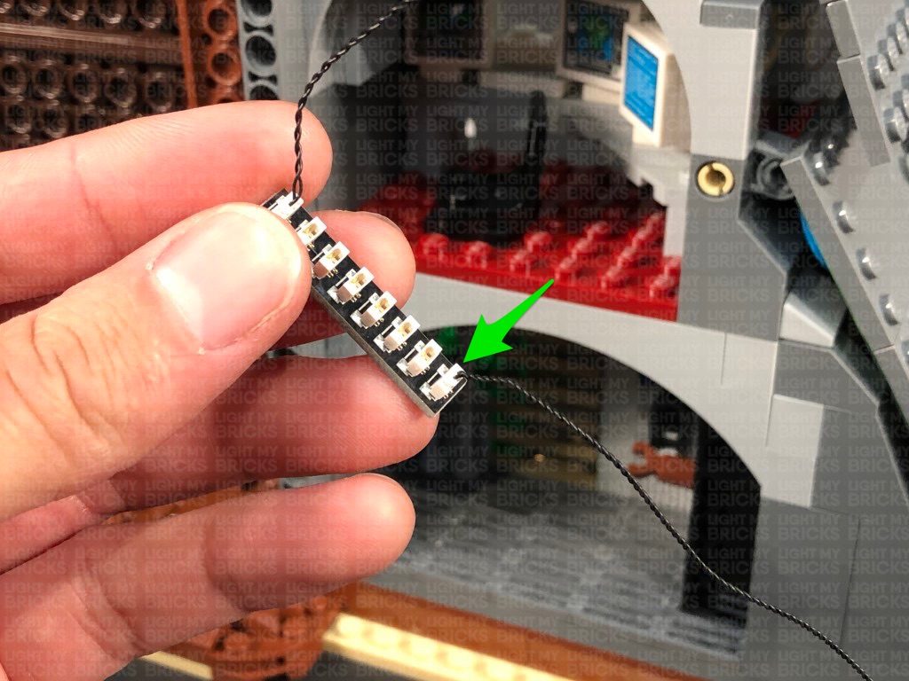
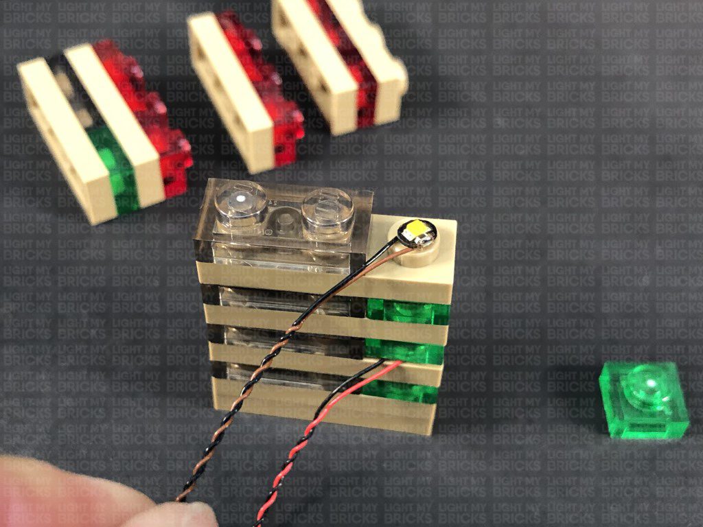
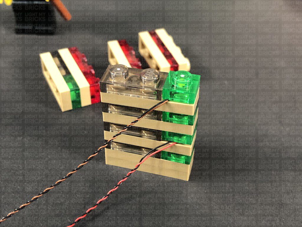
Take a White 15cm Bit Light and thread it through this gap. Carefully place the entire set onto it’s front side so we can neatly position the Bit Light in the centre underneath the roof plate as shown below. Ensuring the Bit Light is facing down, secure it in place by connecting a provided Trans Clear Plate w Rounded Bottom 2×2 over it.
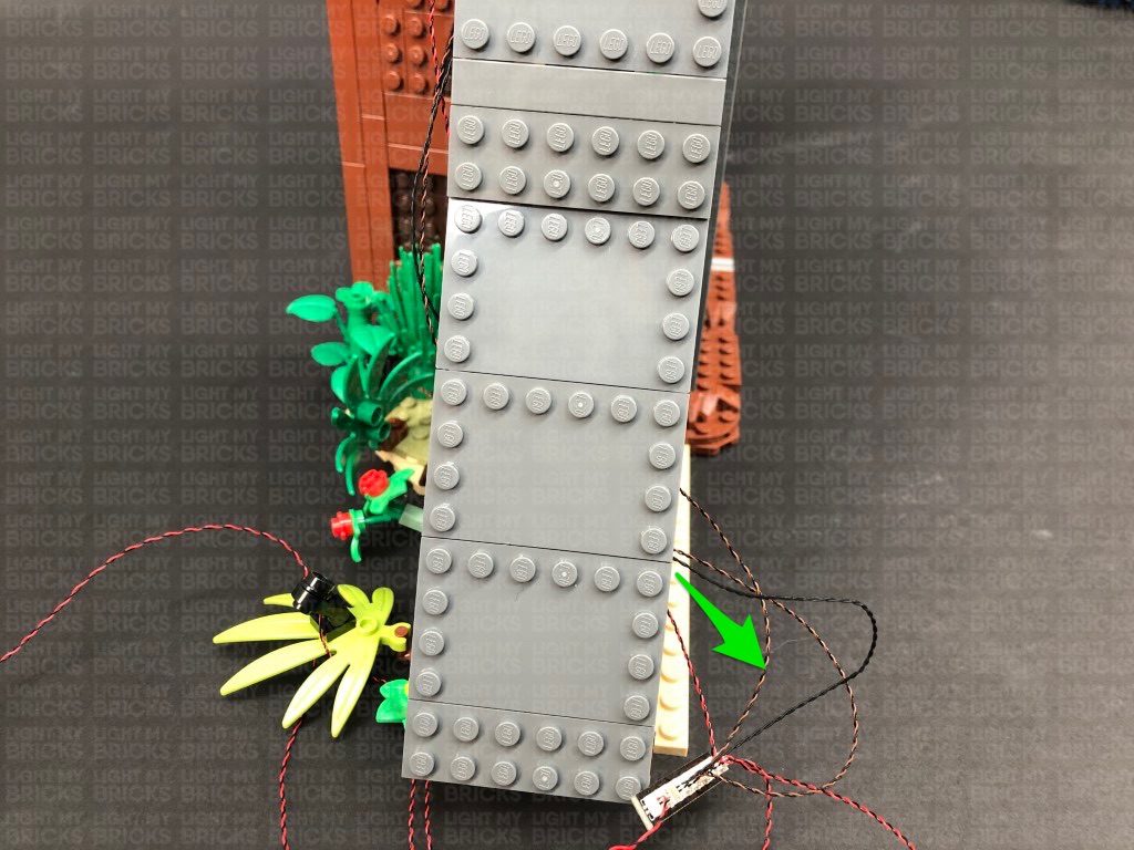
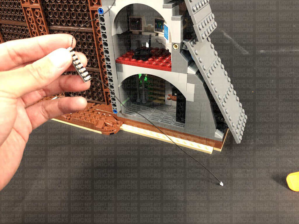
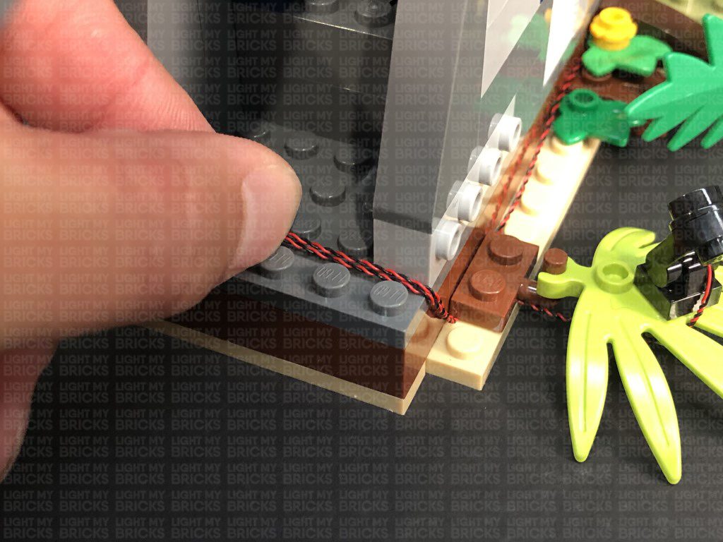
Bring the set back to it’s upright position and push down the section above the bunker room to close up the gap we created earlier. Bring the Bit Light cable down and connect it to the 8-Port Expansion Board underneath, then turn ON the USB Power Bank to test the light is working OK.
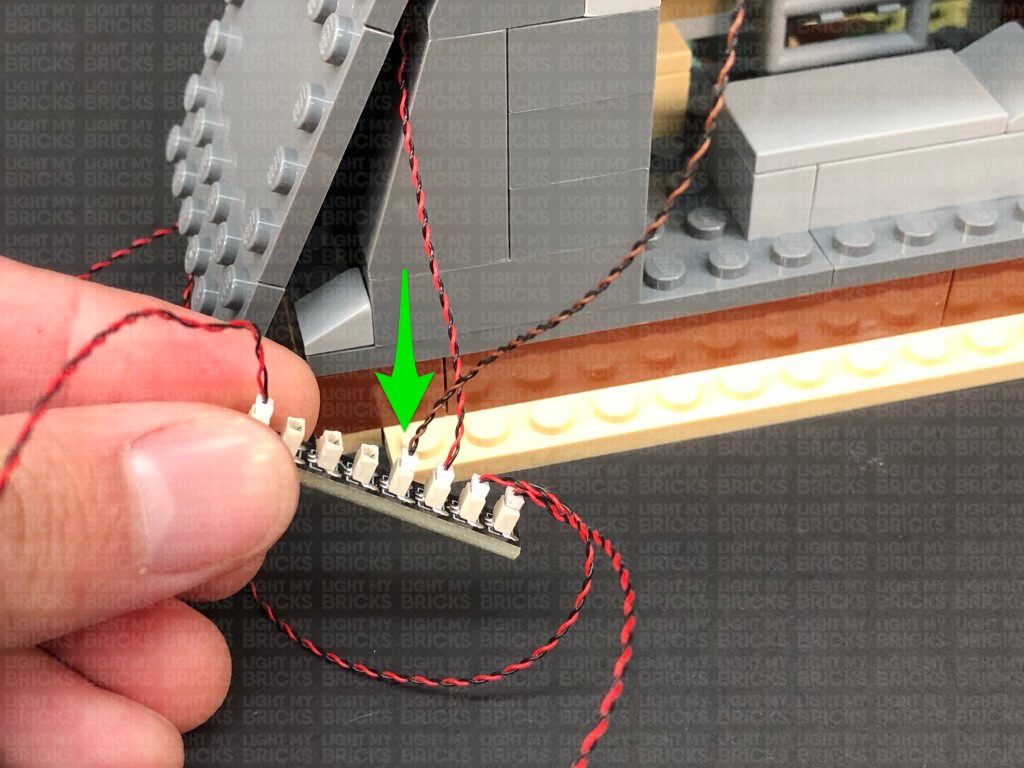
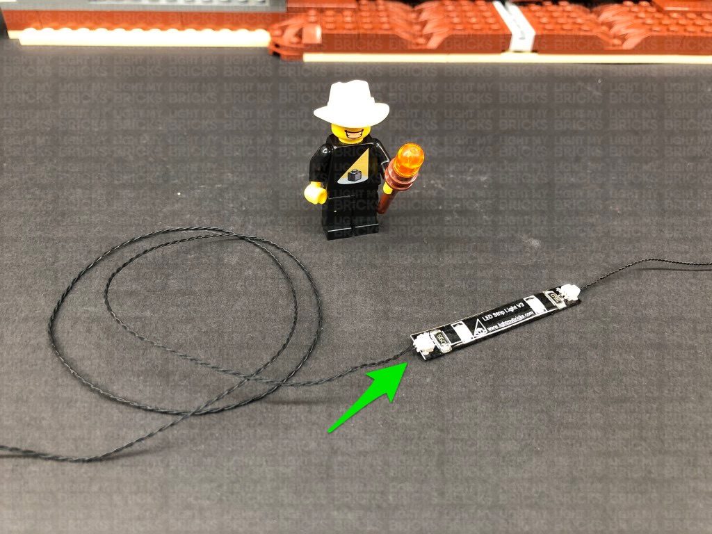
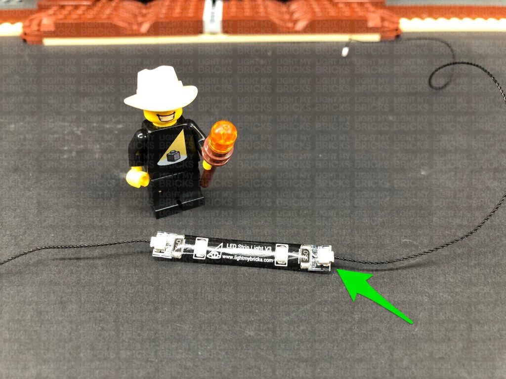
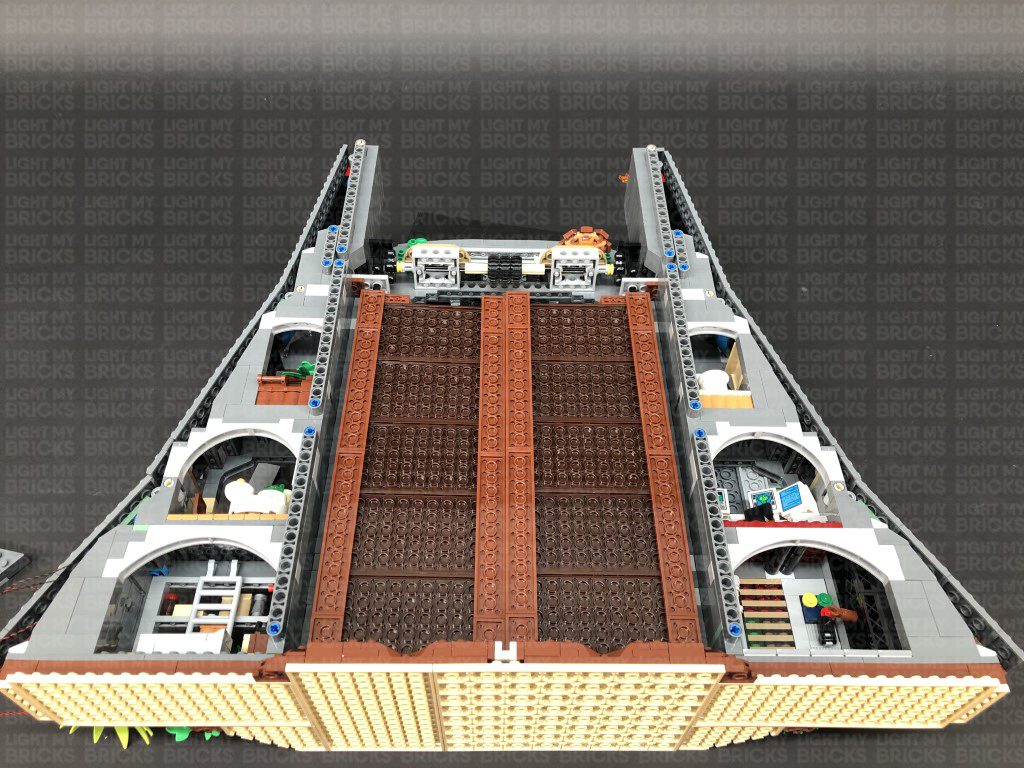
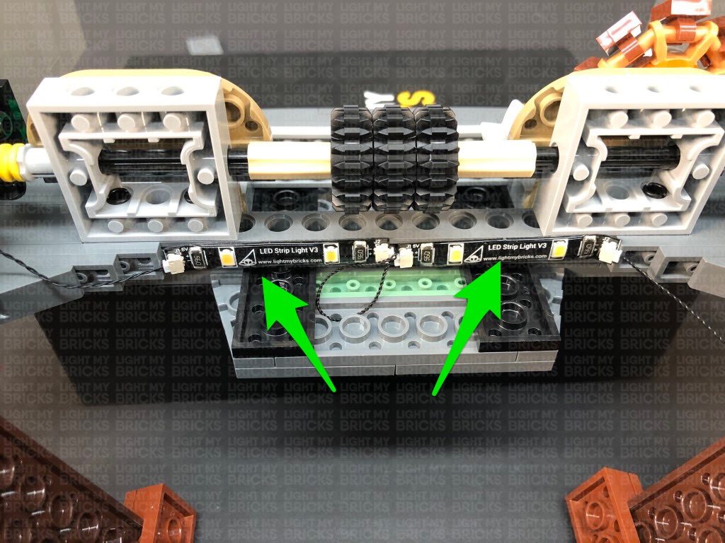
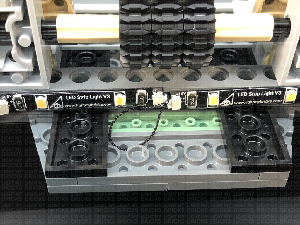
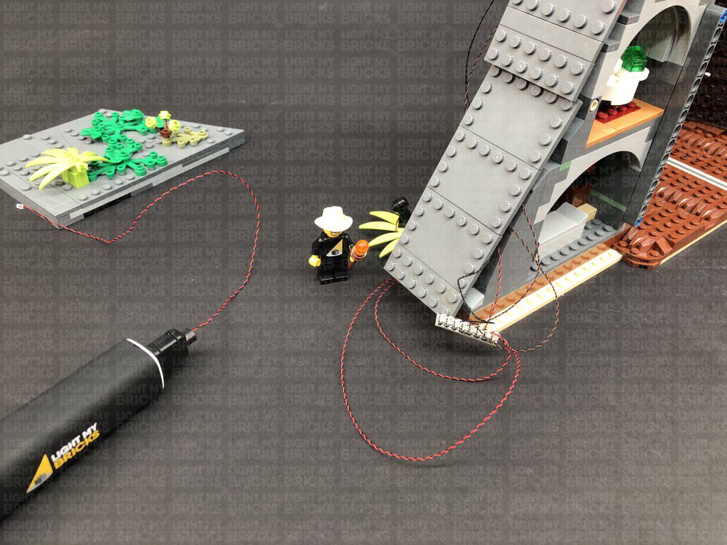
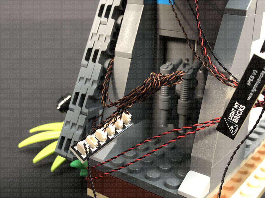
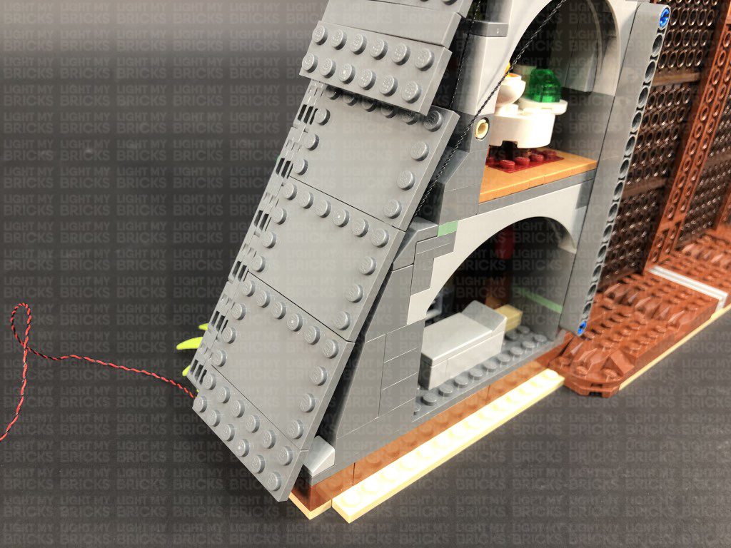
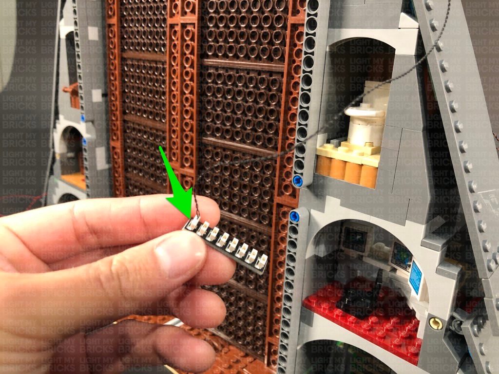
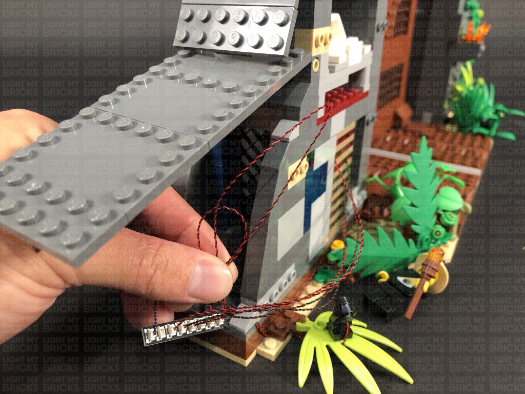
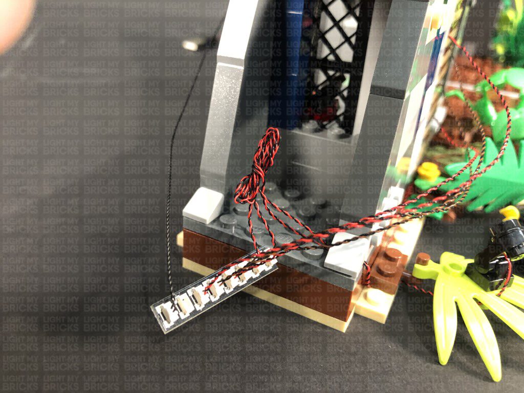
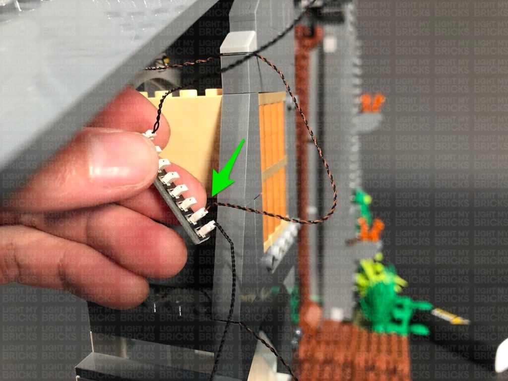
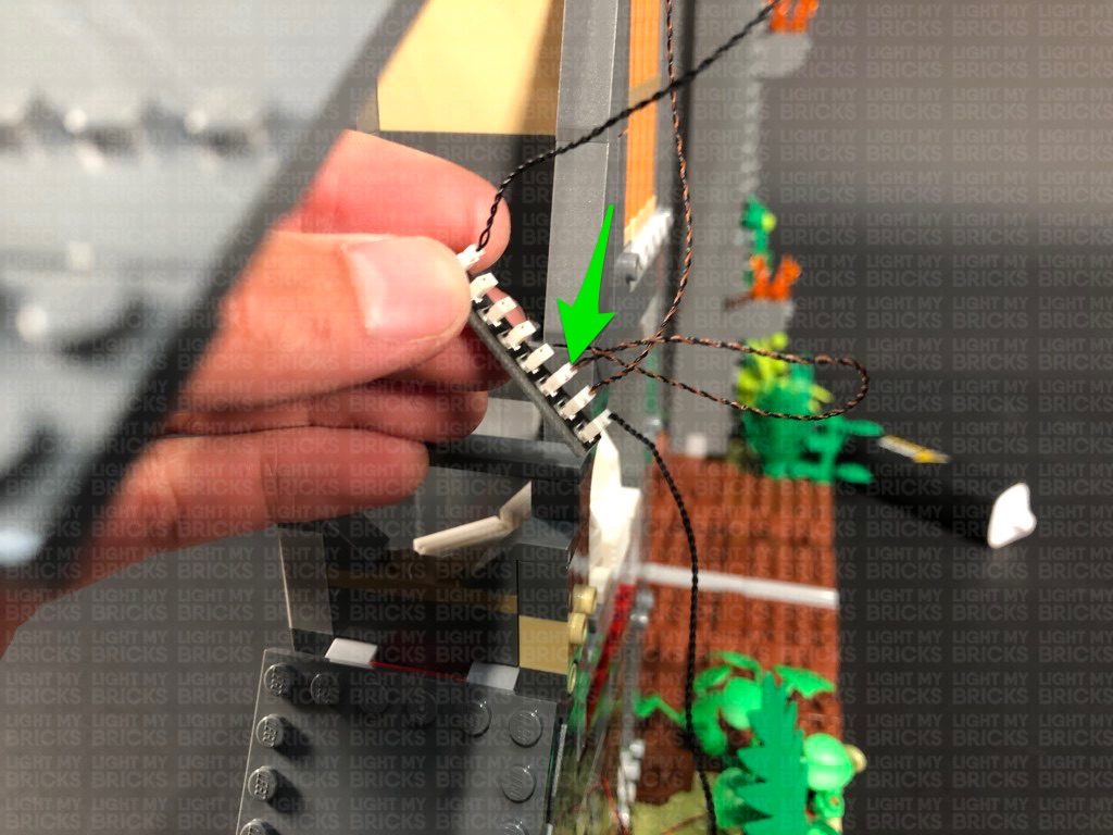
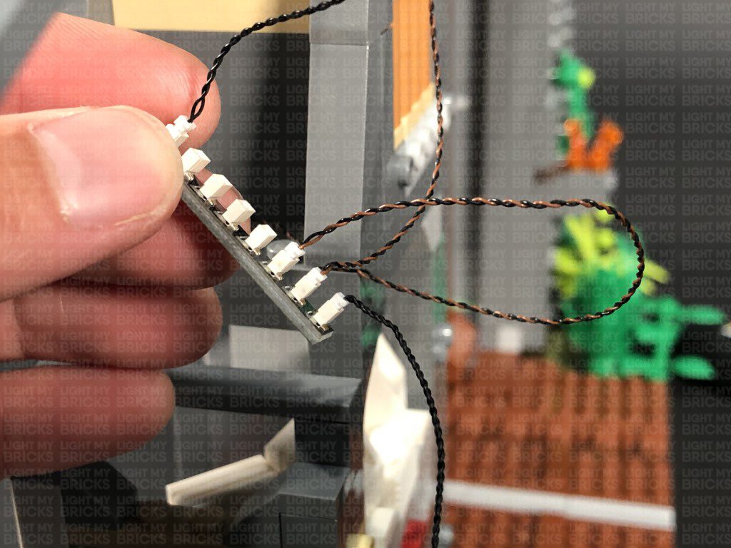
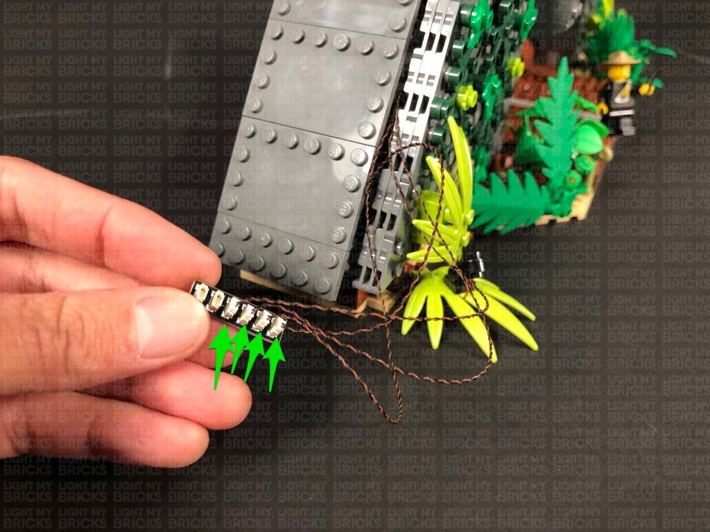
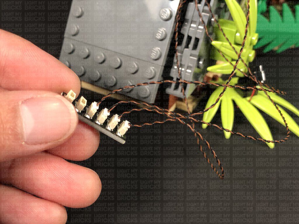
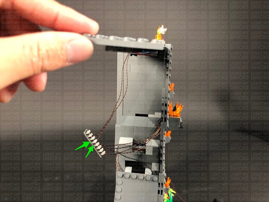
8.) Take the 2x White Strip Lights and connect them together using a 5cm Connecting Cable. Take a 50cm Connecting Cable and connect one end it to the left strip light. Take a 30cm Connecting Cable and connect one end to the right strip light.
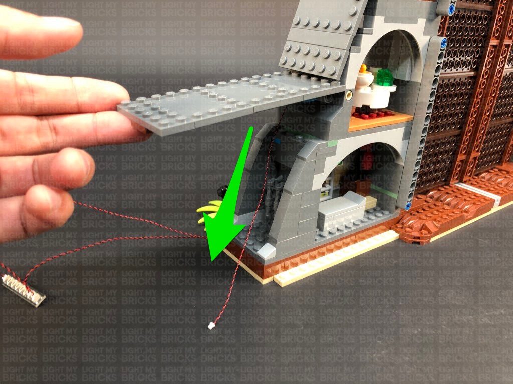
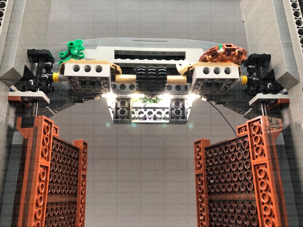
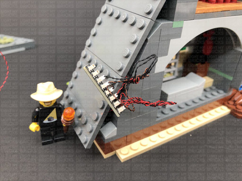
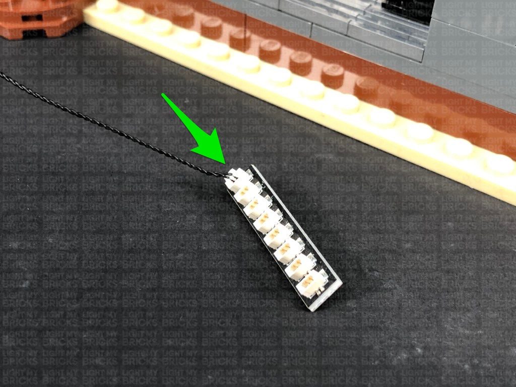
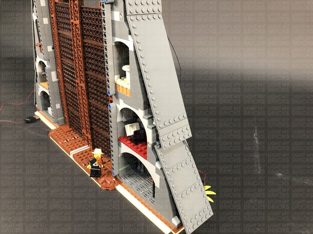
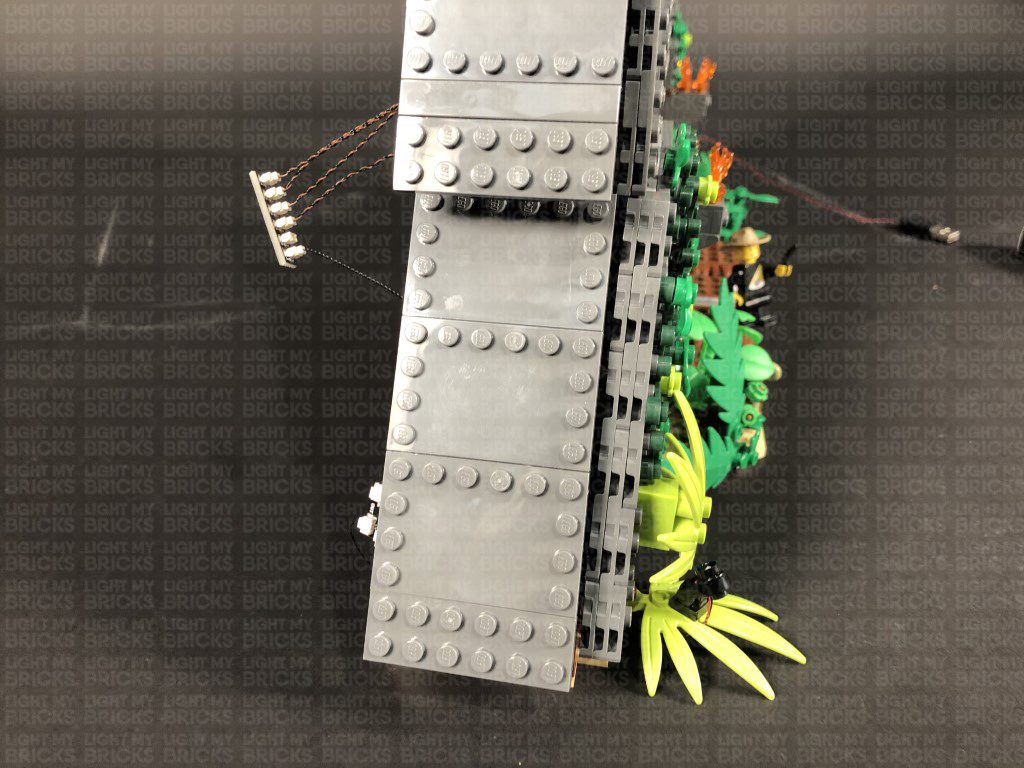
Carefully place the entire set back over onto it’s front, then using their adhesive backings, stick the two strip lights underneath the following section as shown below: Do your best to stick them as closely as possible next to one another.
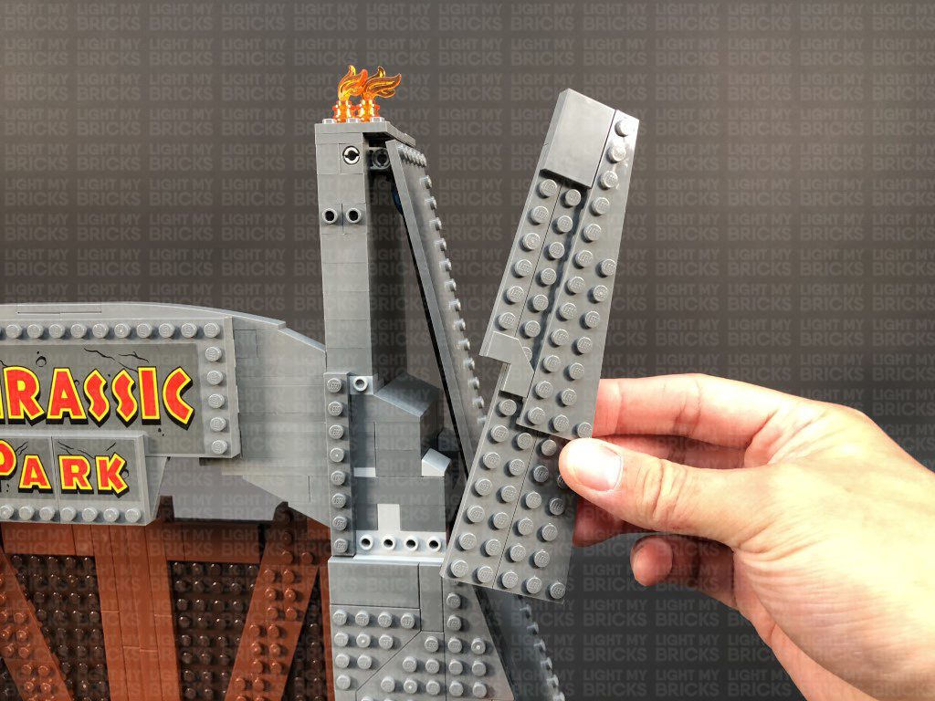
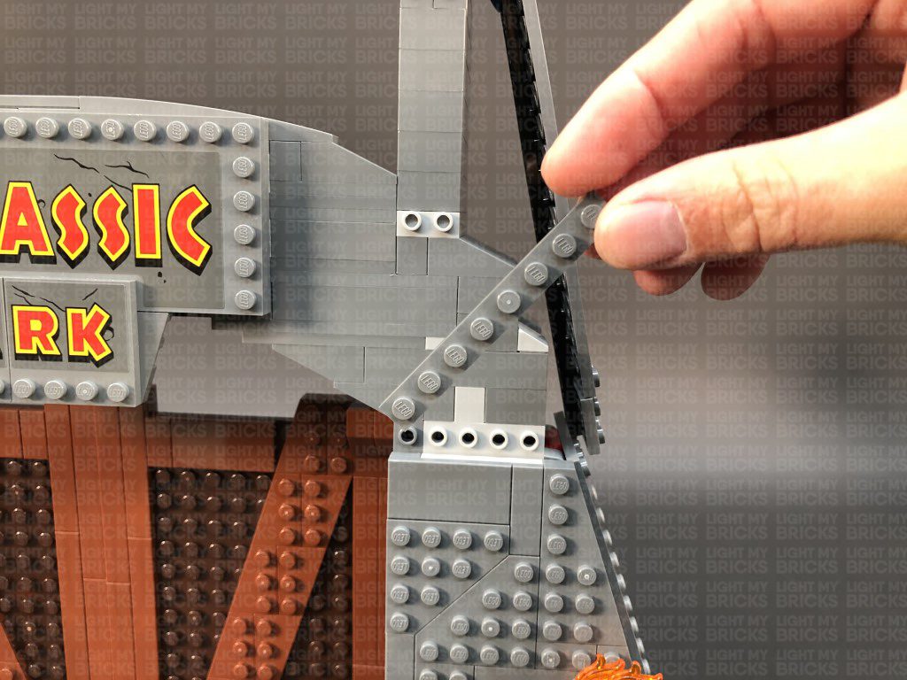
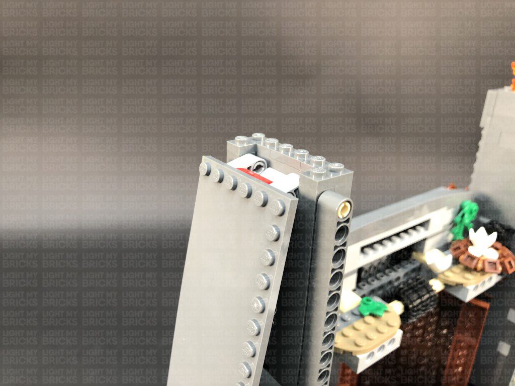
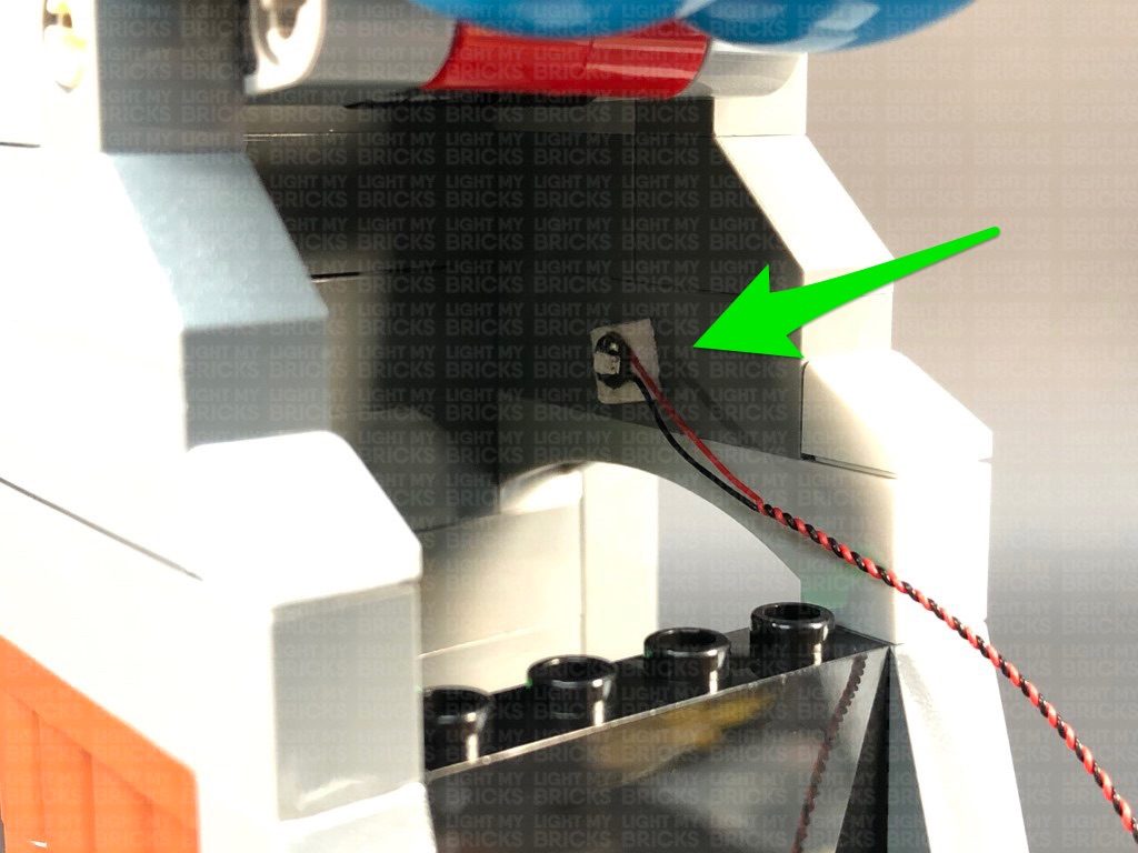
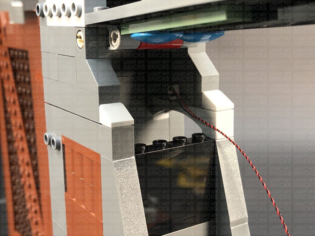
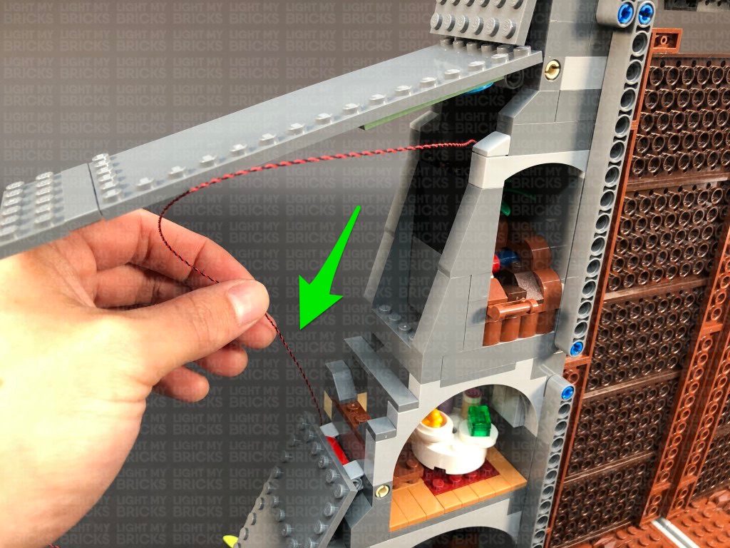
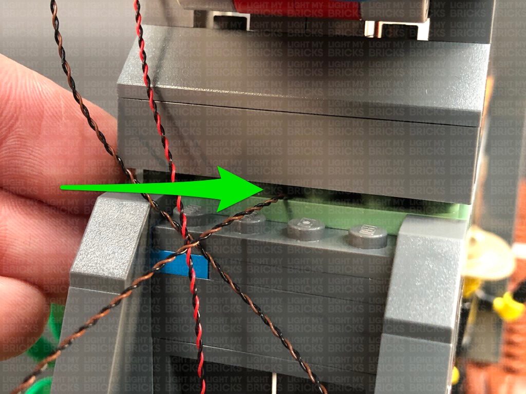
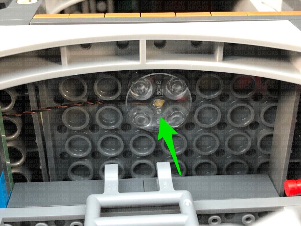
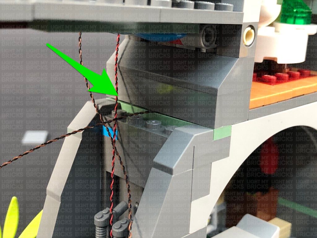
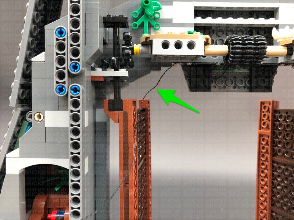
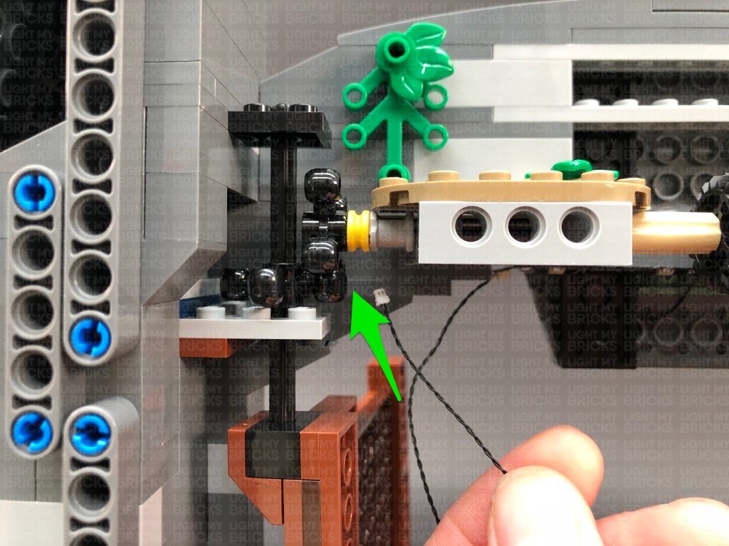
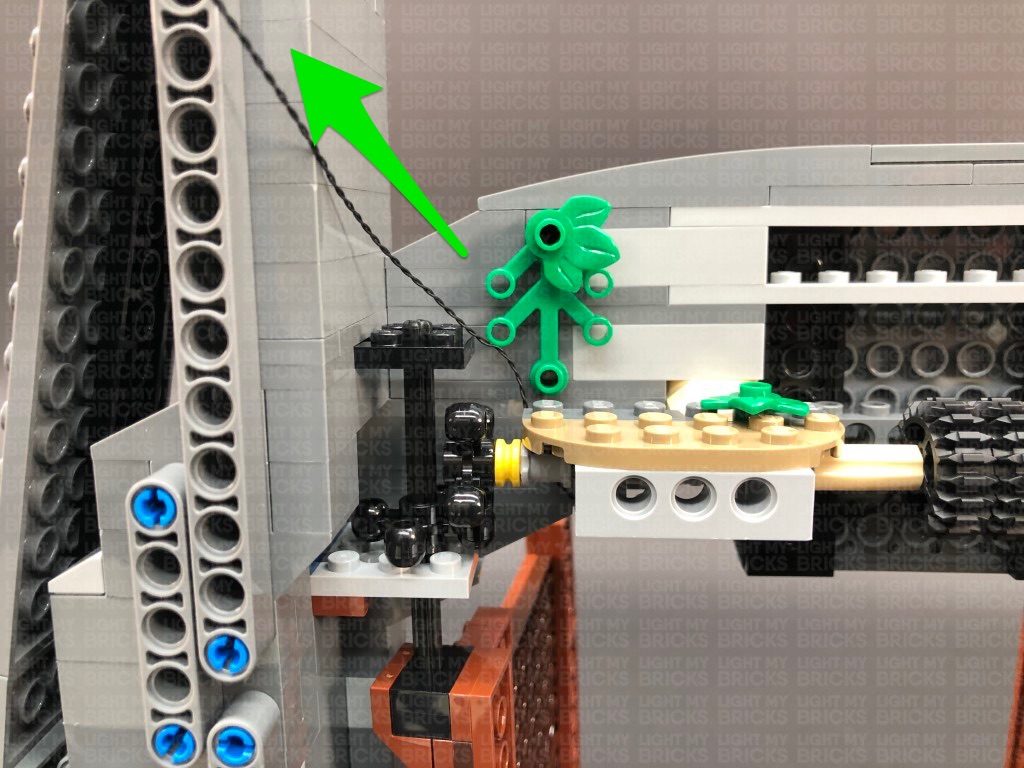
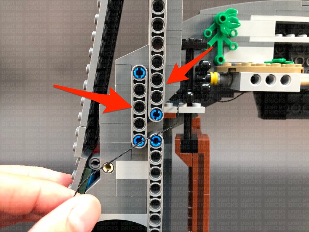
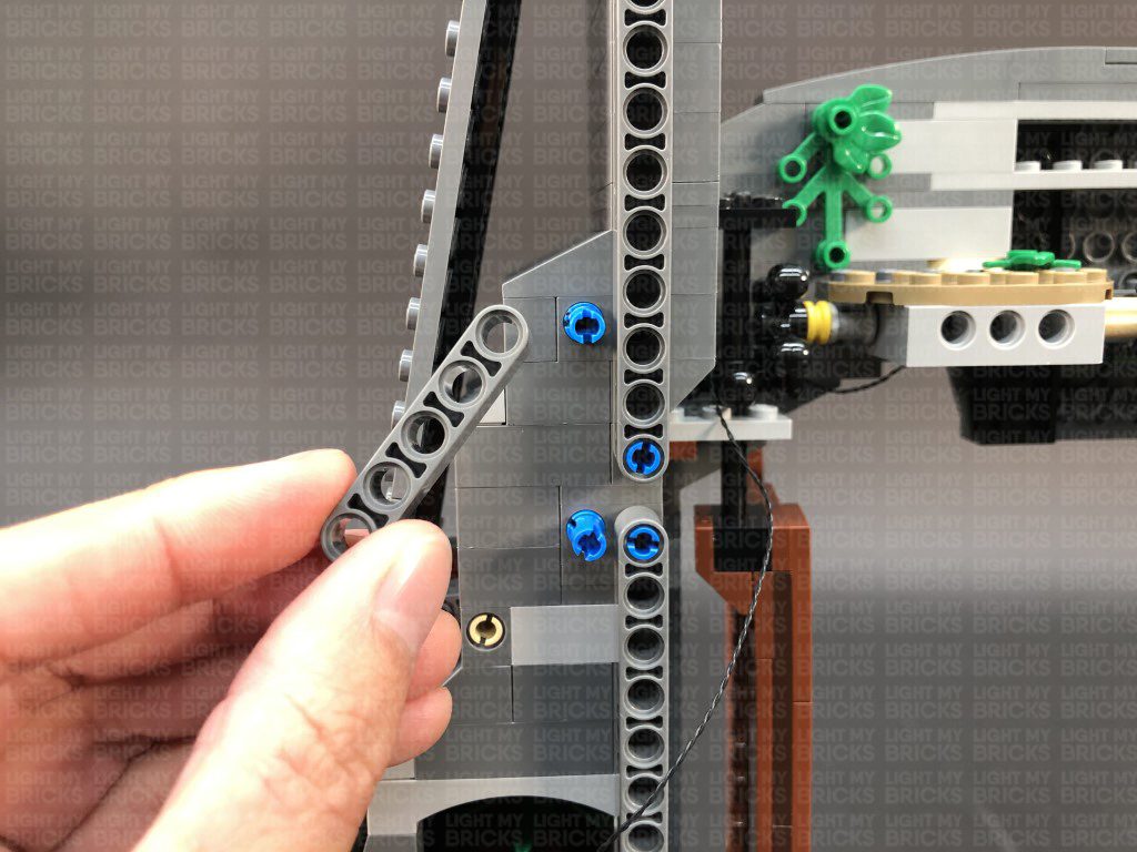
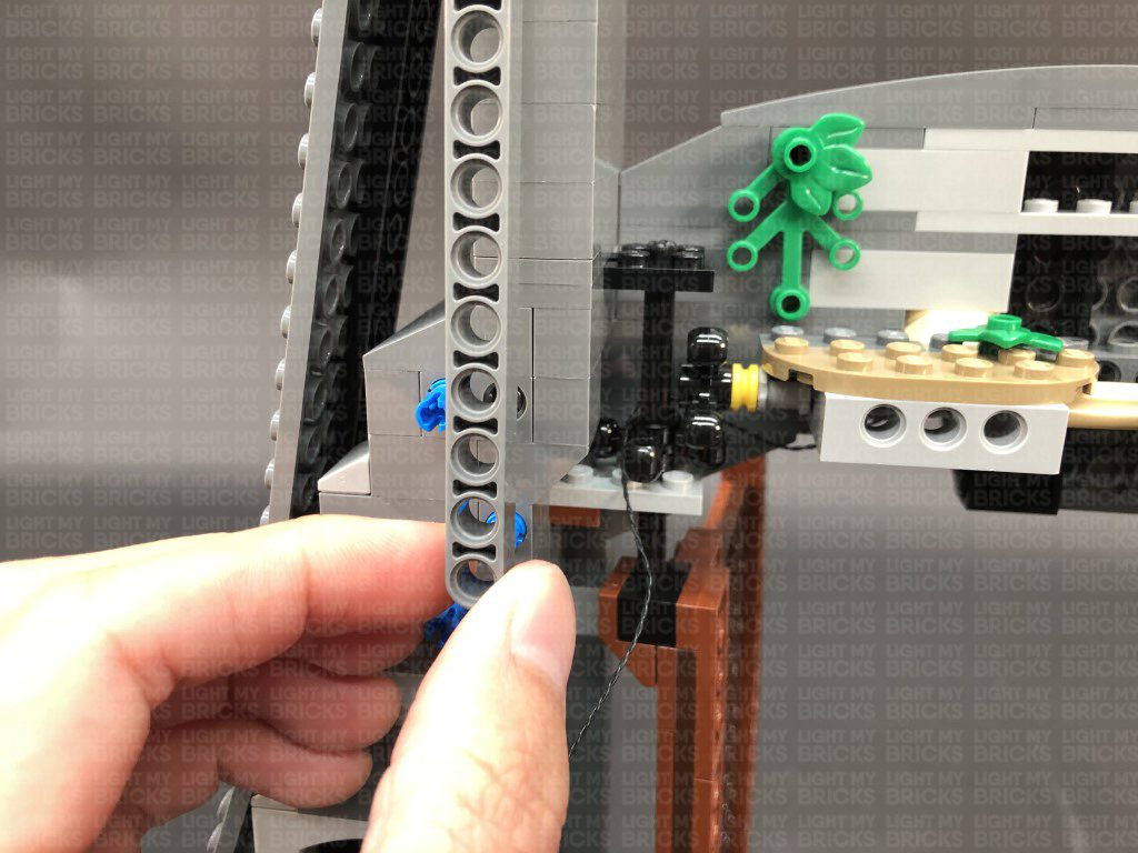
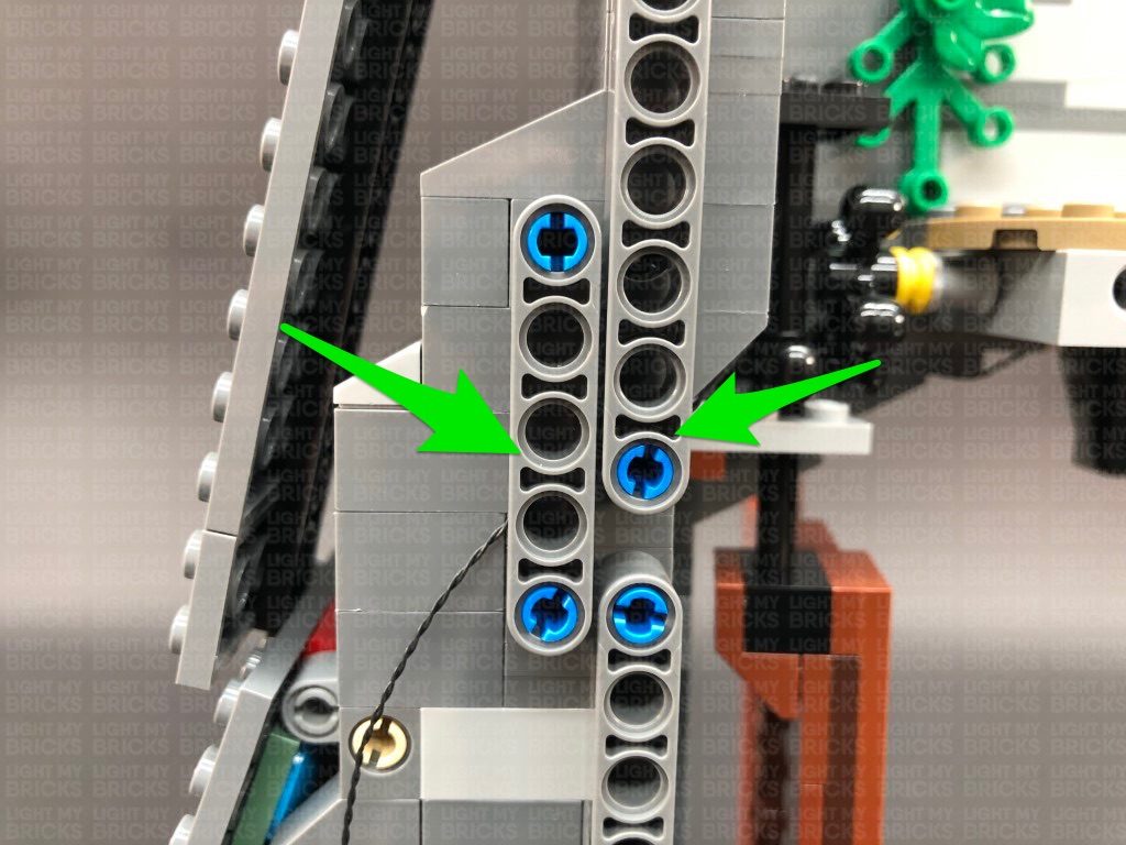
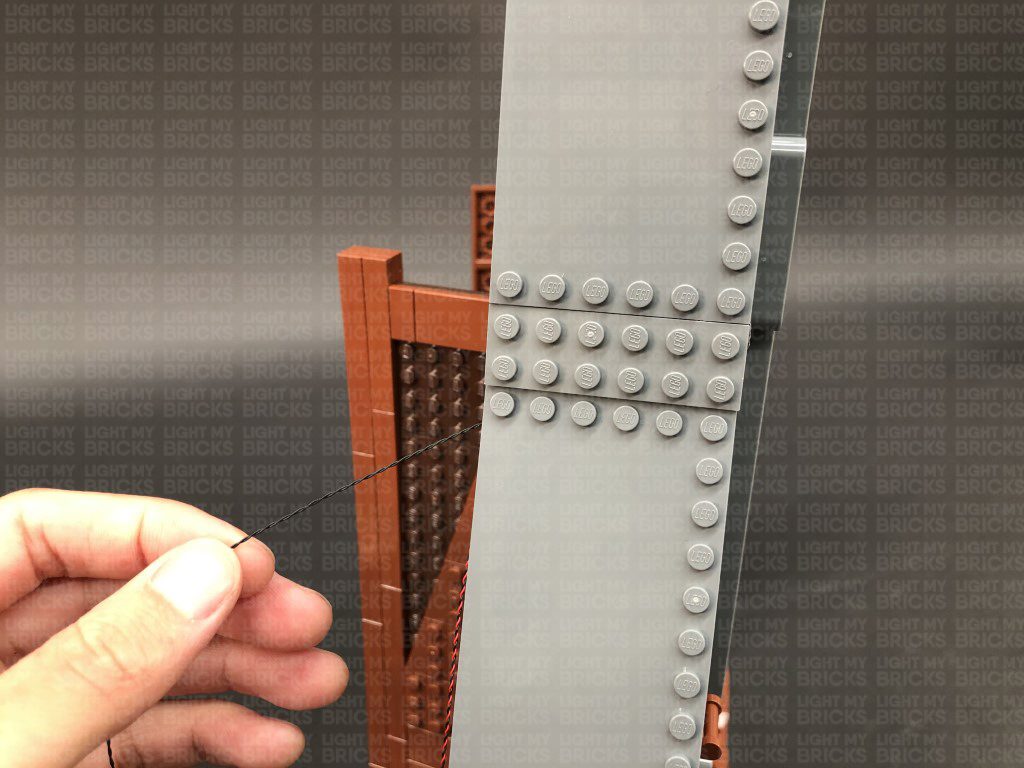
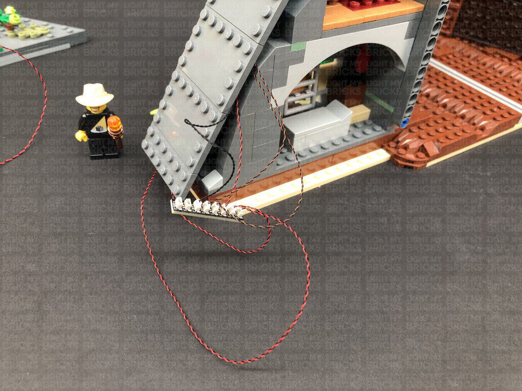
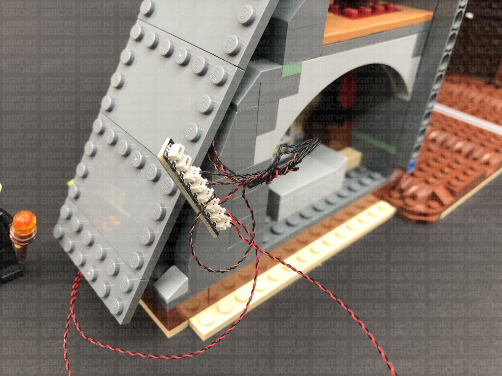
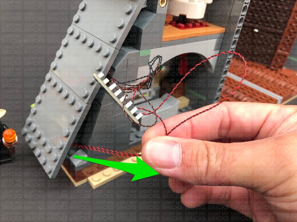
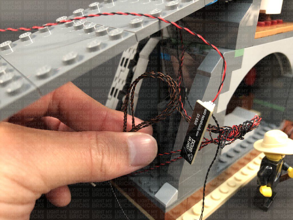
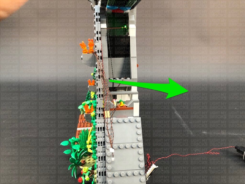
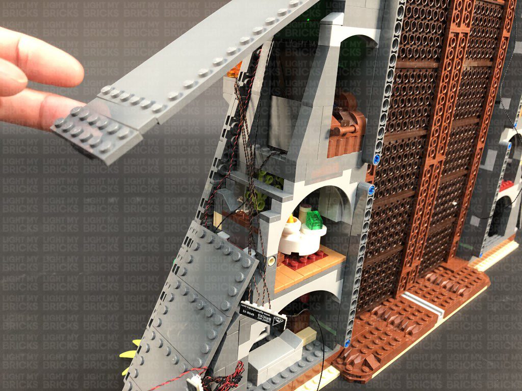
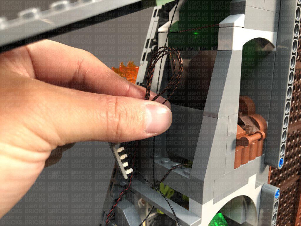
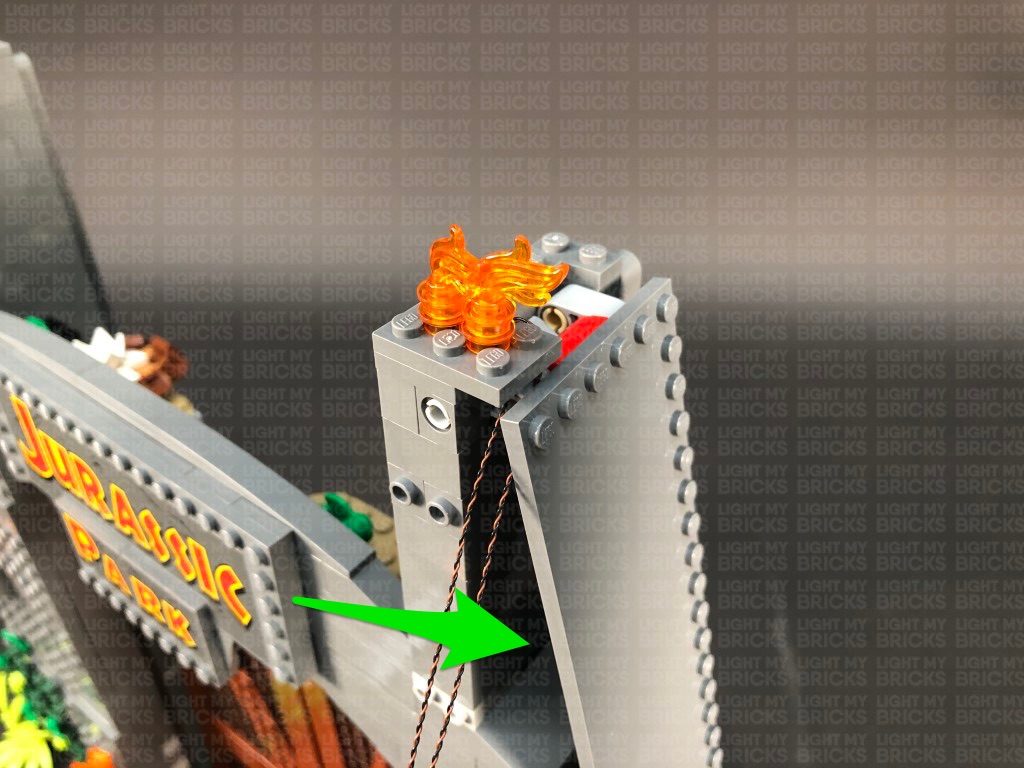
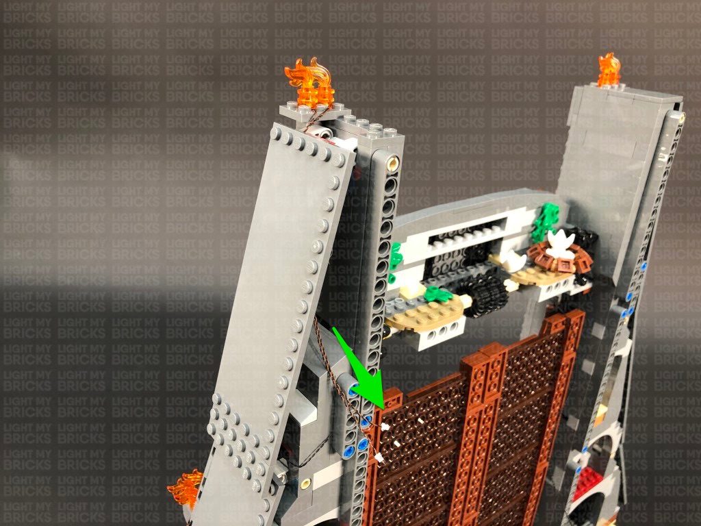
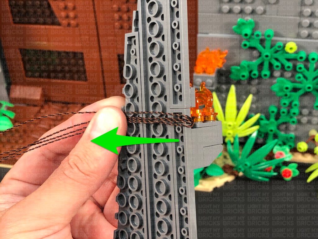
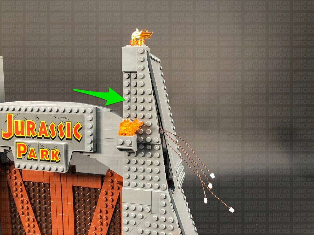
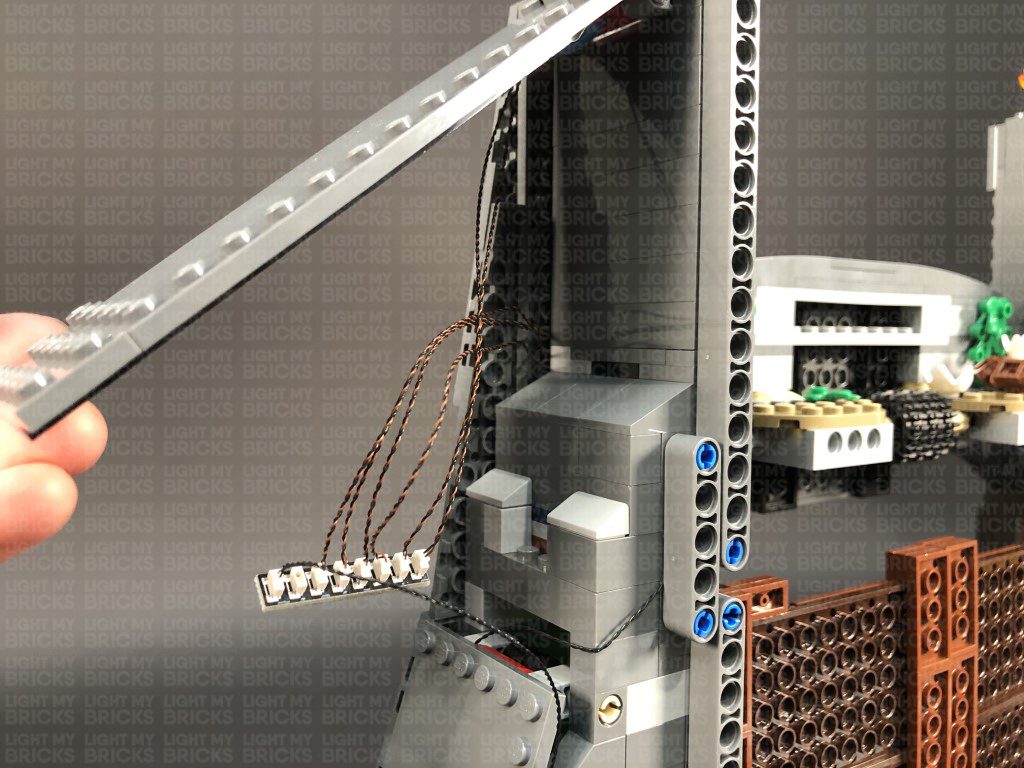
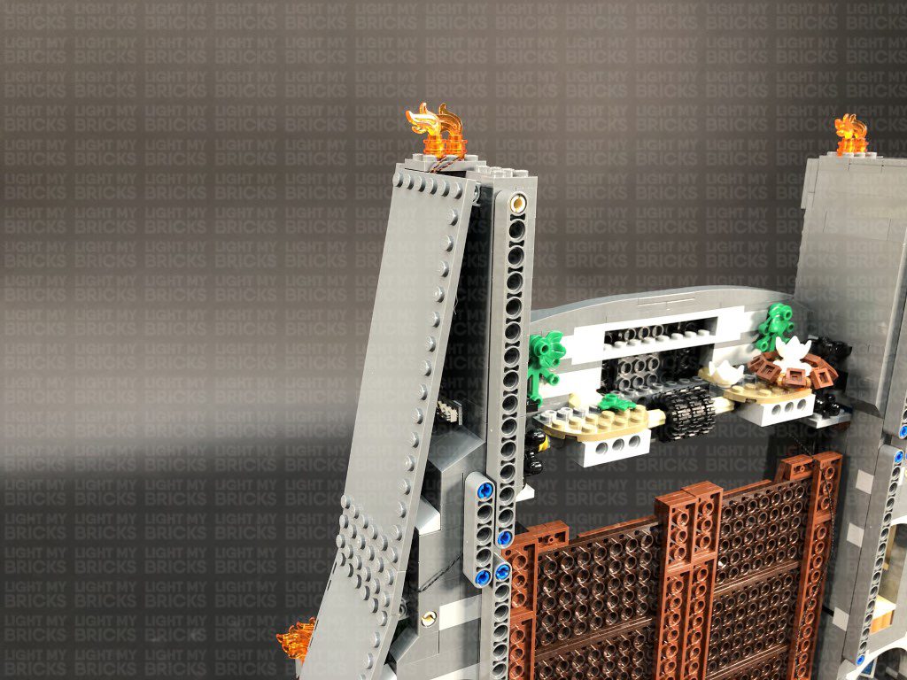
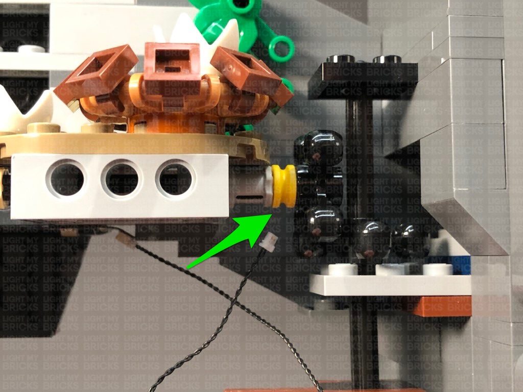
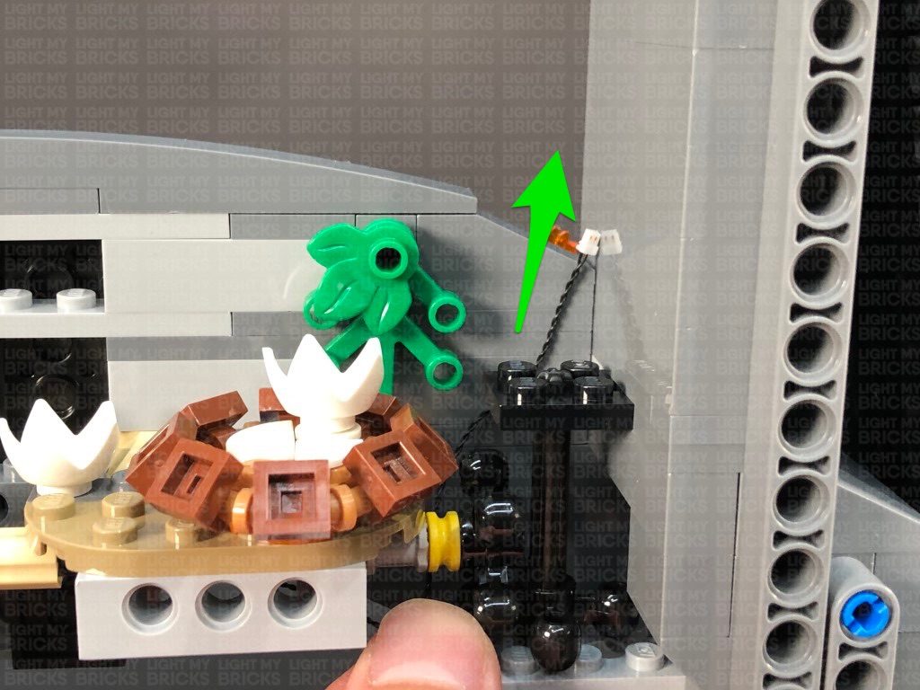
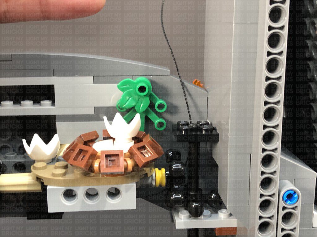
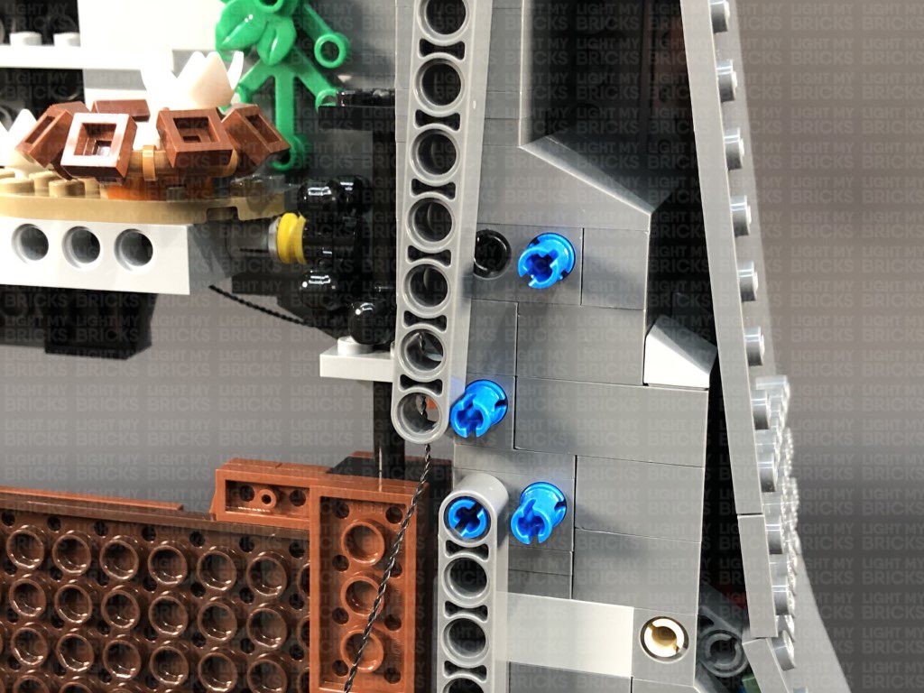
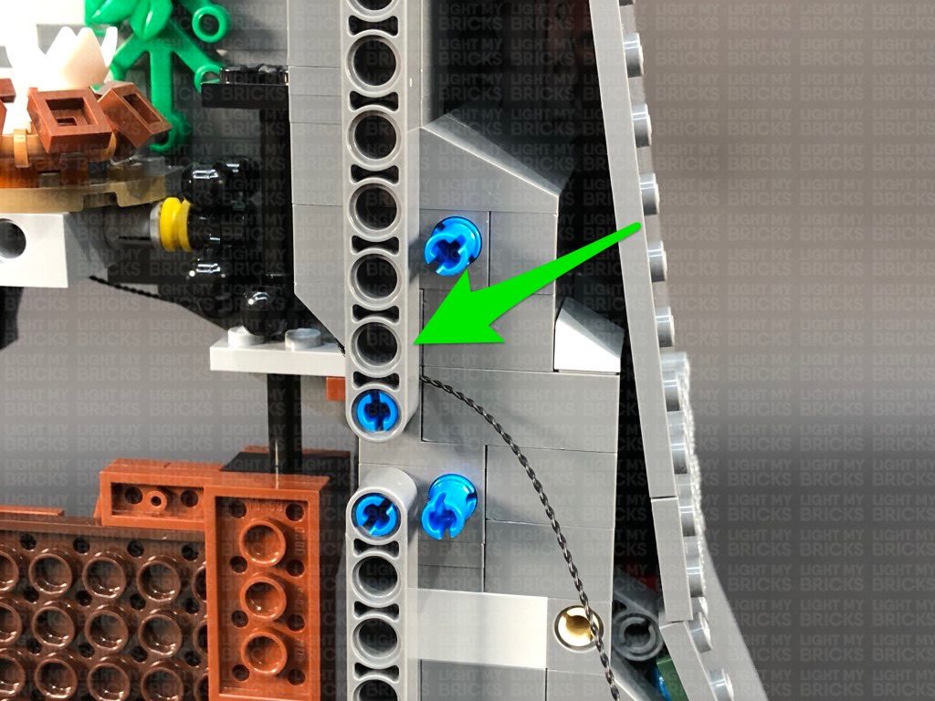
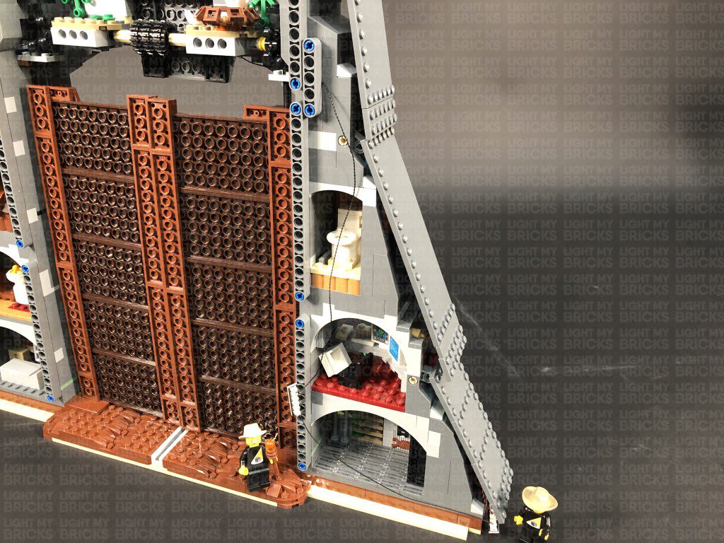
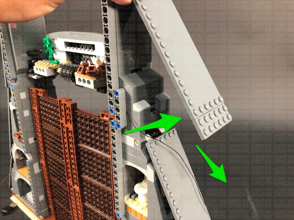
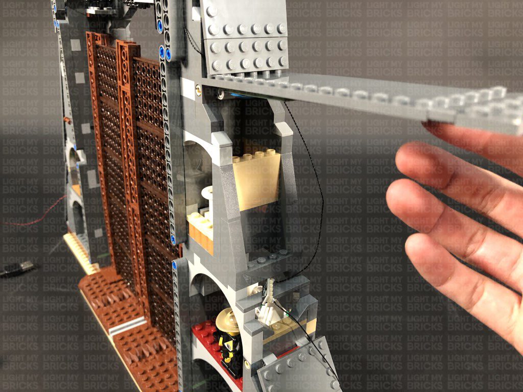
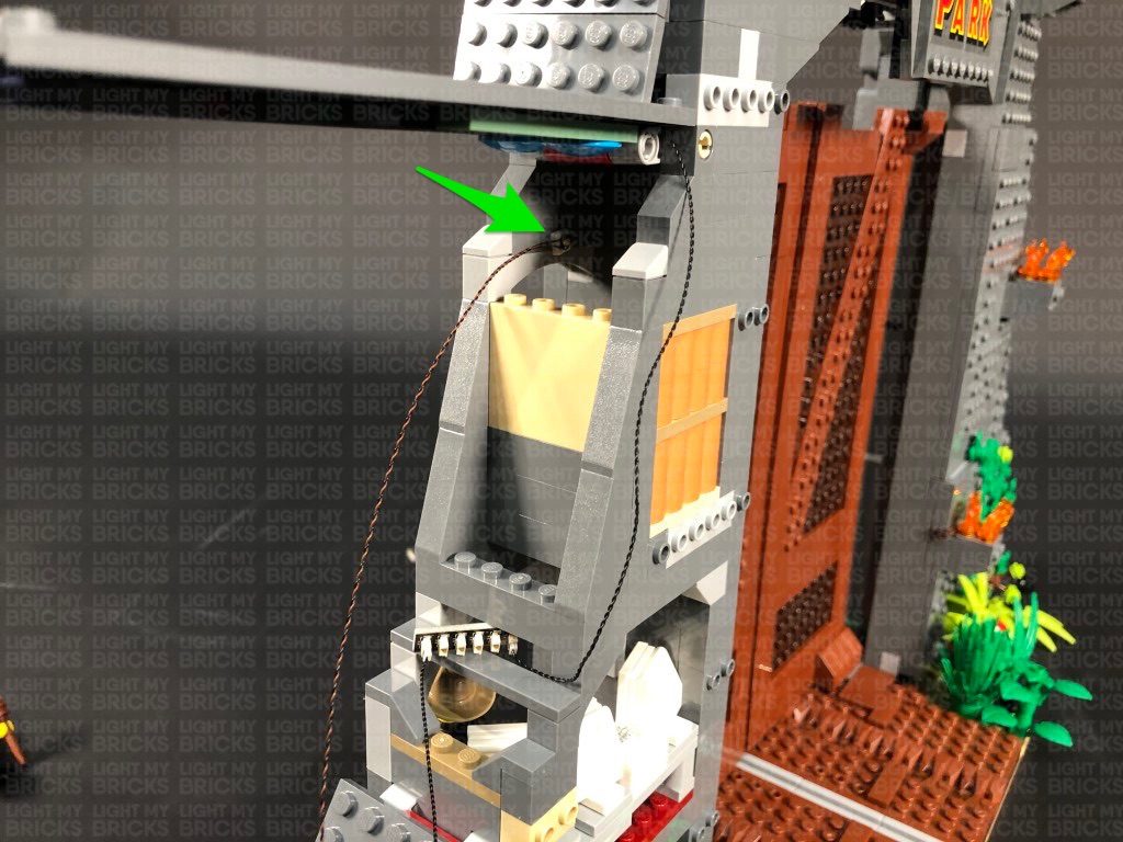
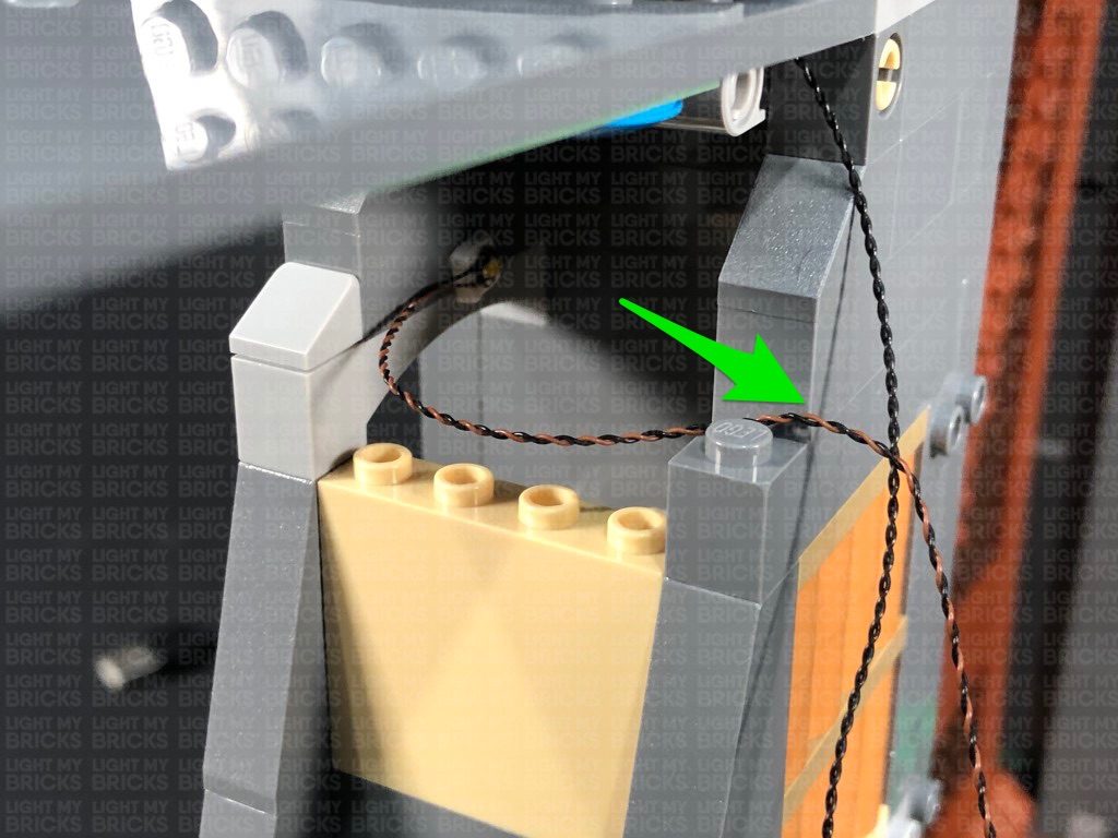
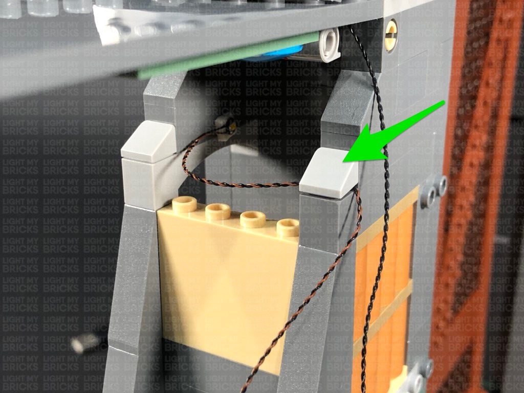
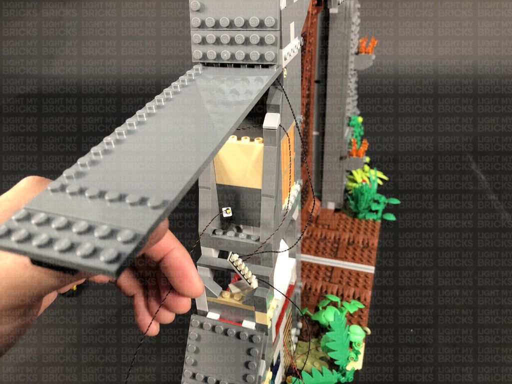
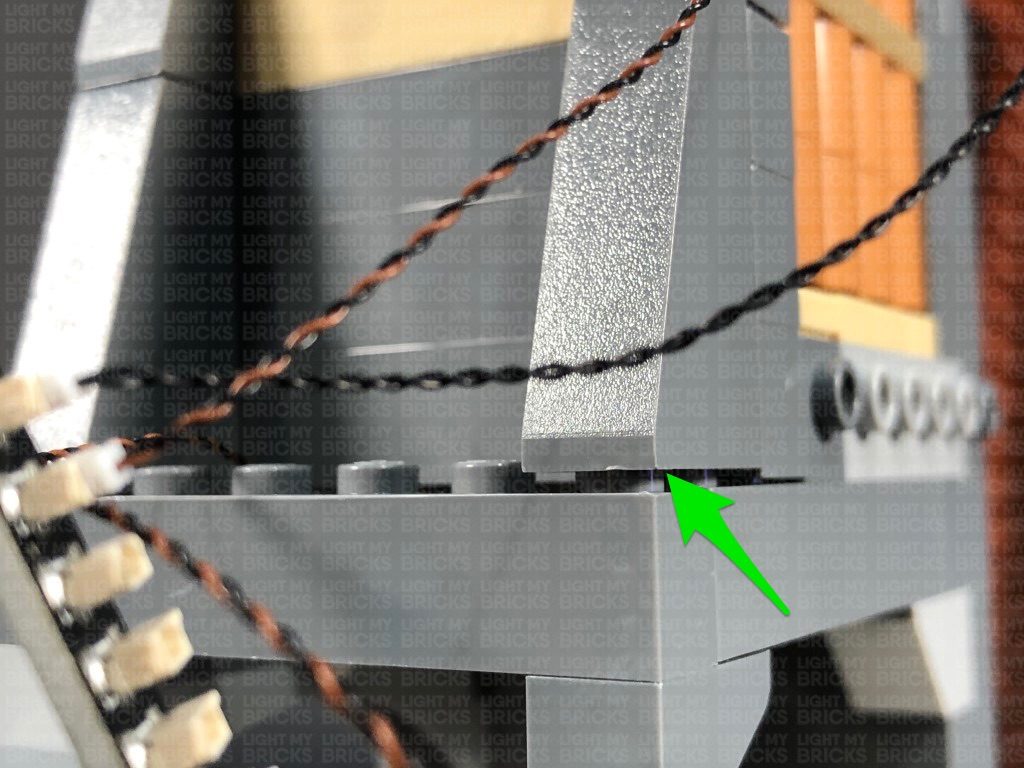
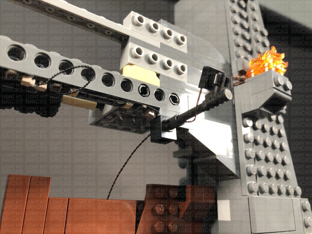
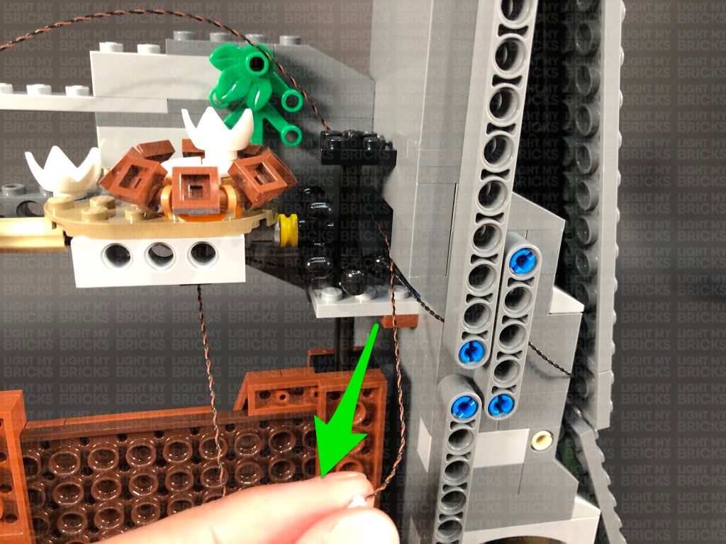
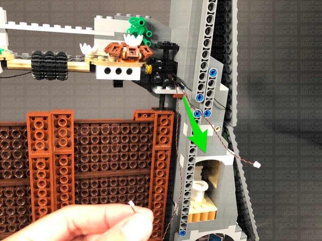
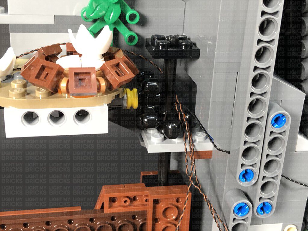
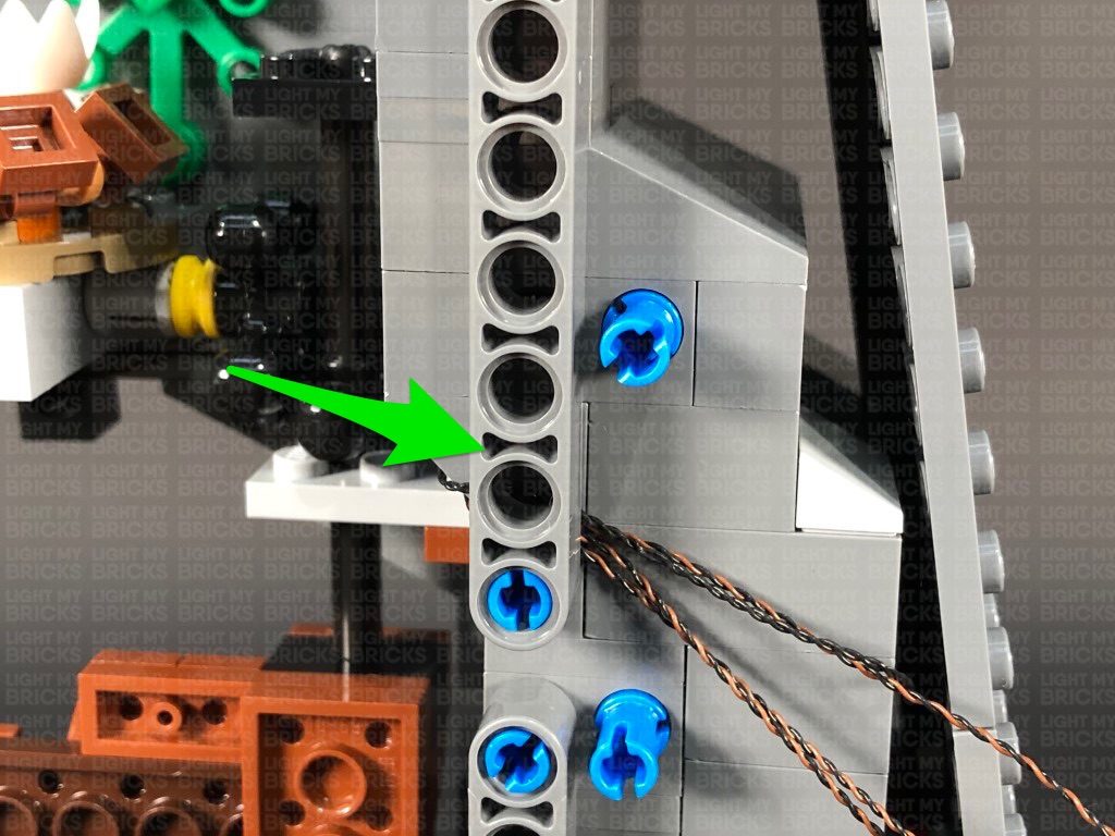
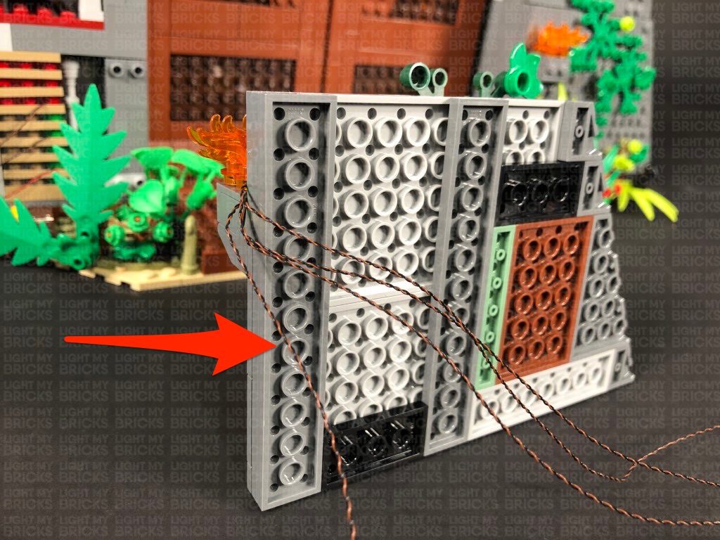
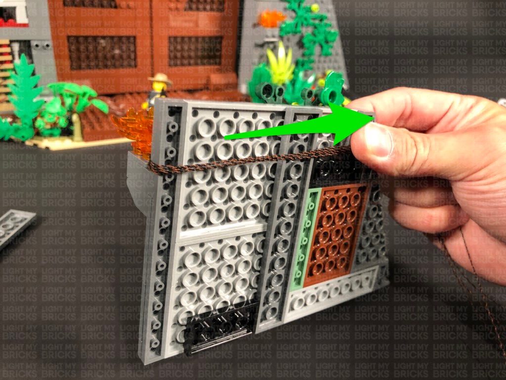
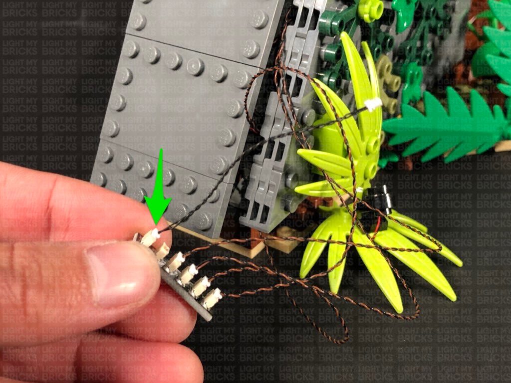
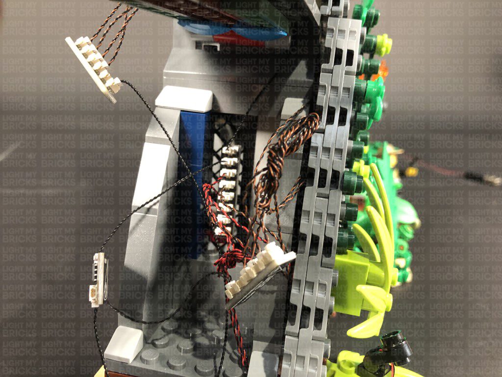
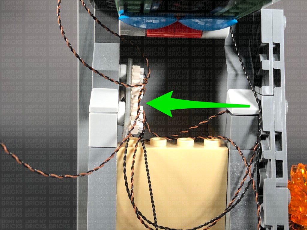
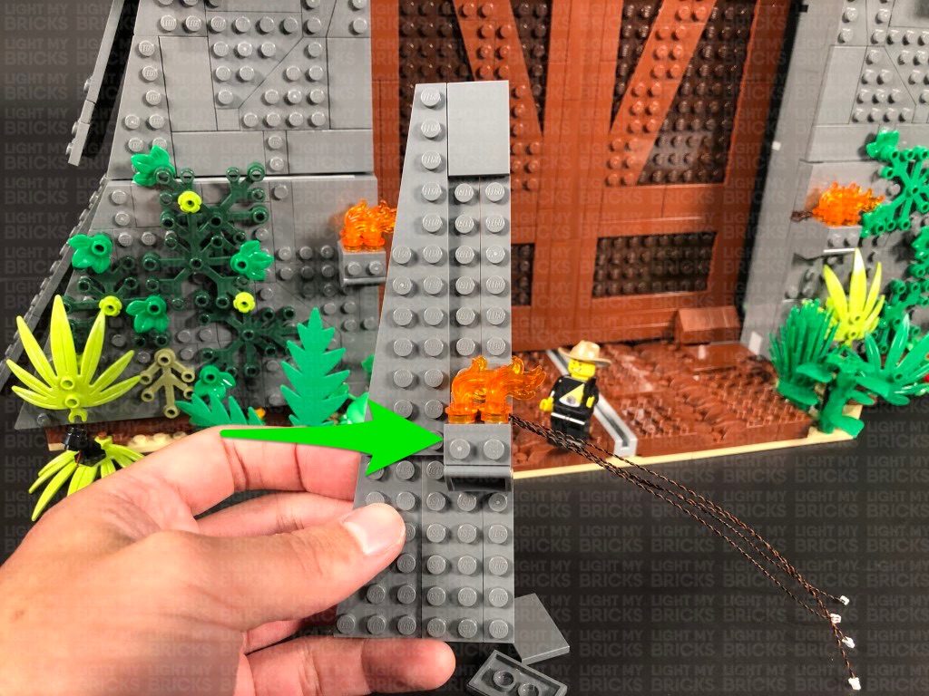
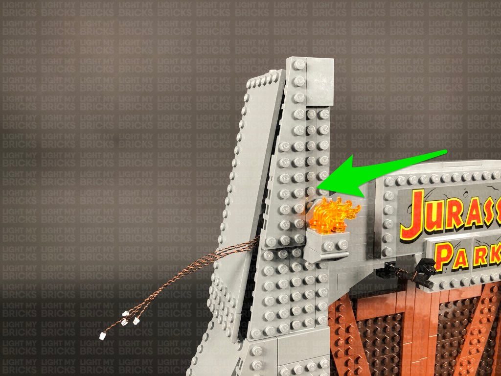
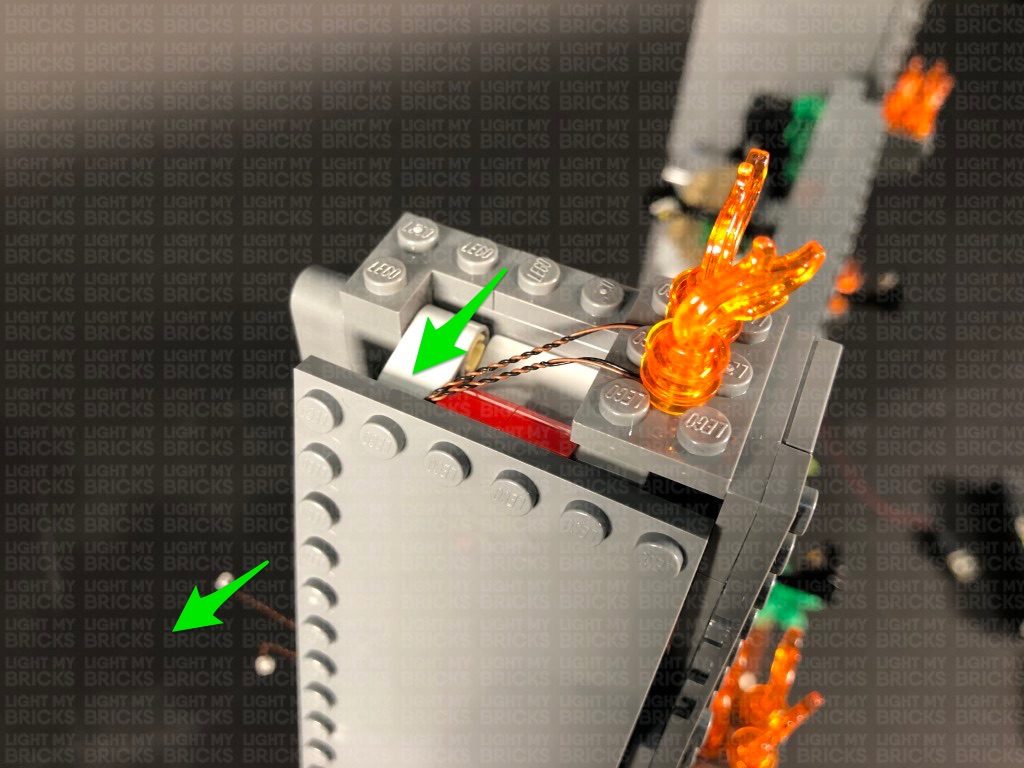
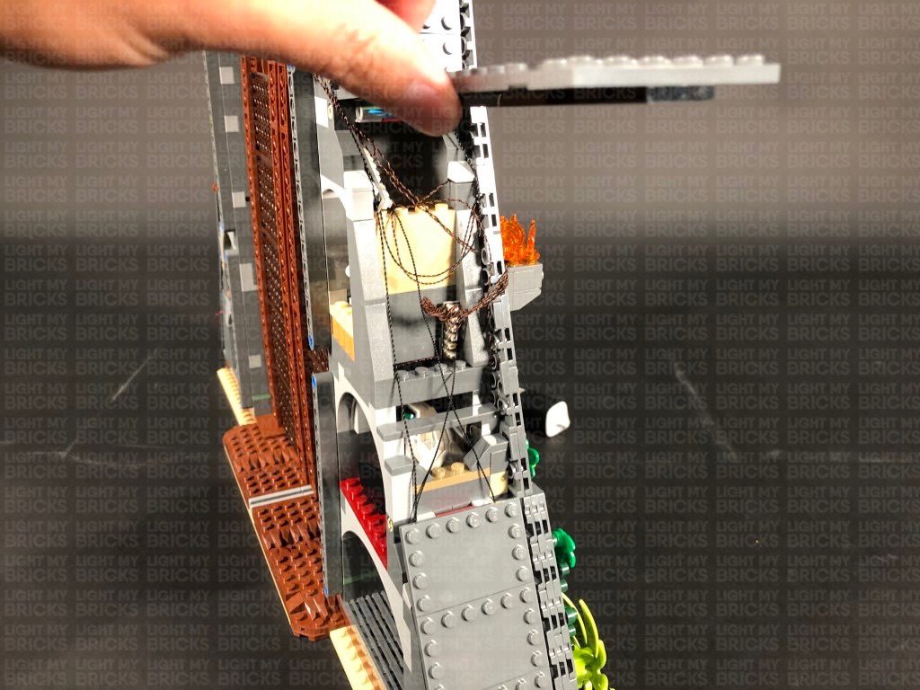
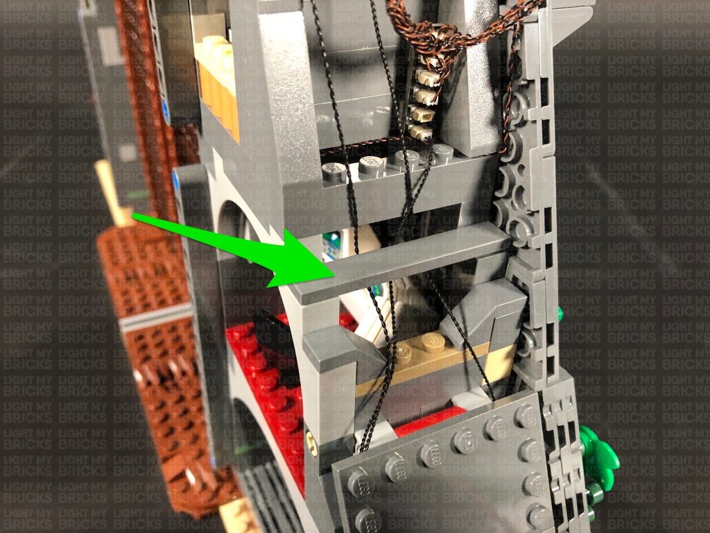
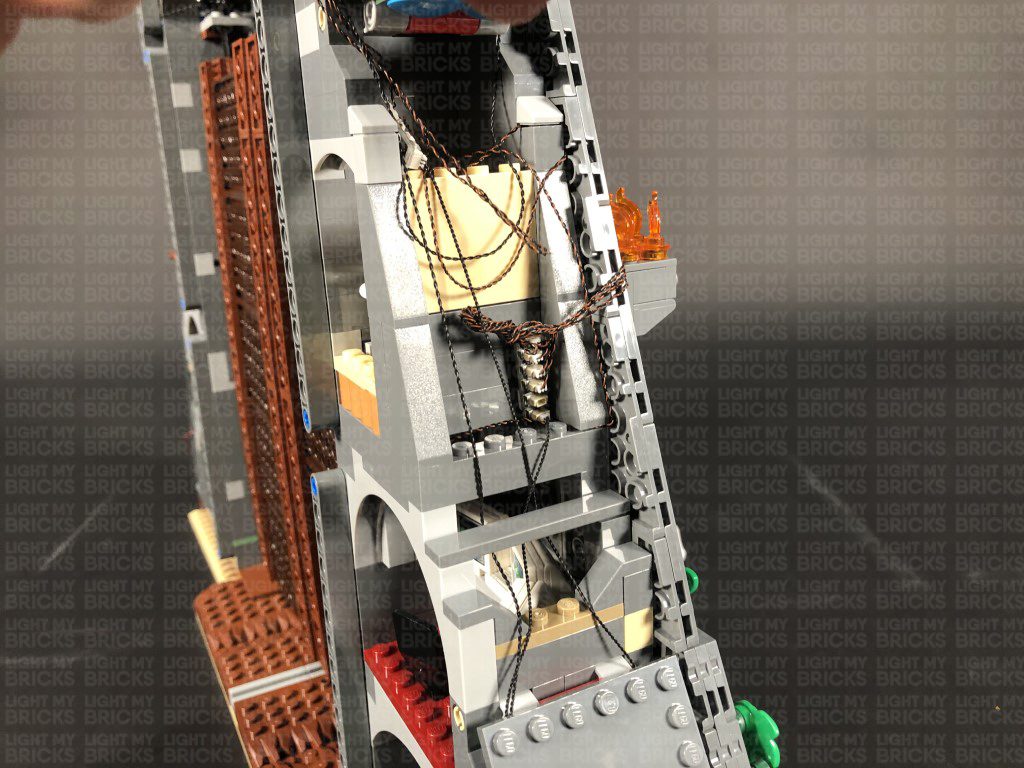
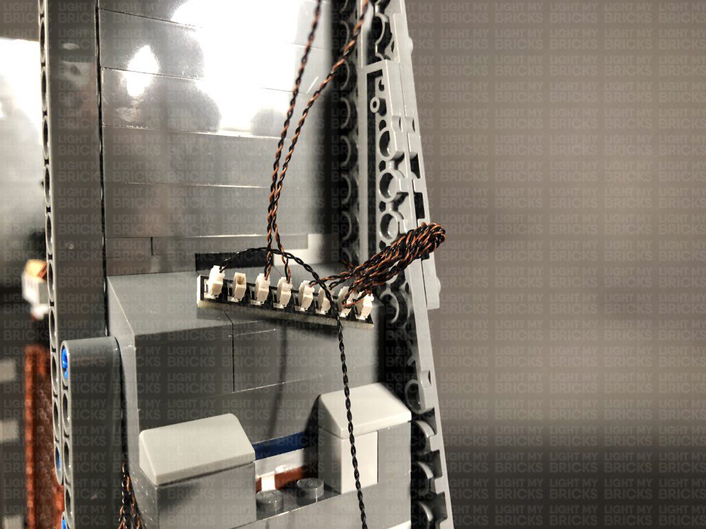
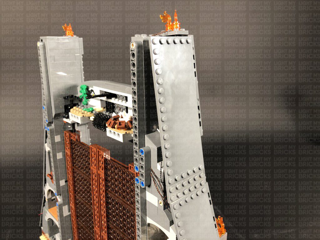
9.) Carefully bring the set back to it’s upright position, then take the 50cm connecting cable from the left side and thread it all the way up the top left corner behind the gears. Thread the cable back down in between the wall and the black bar and pull it out over the top of the light grey plate as show below:
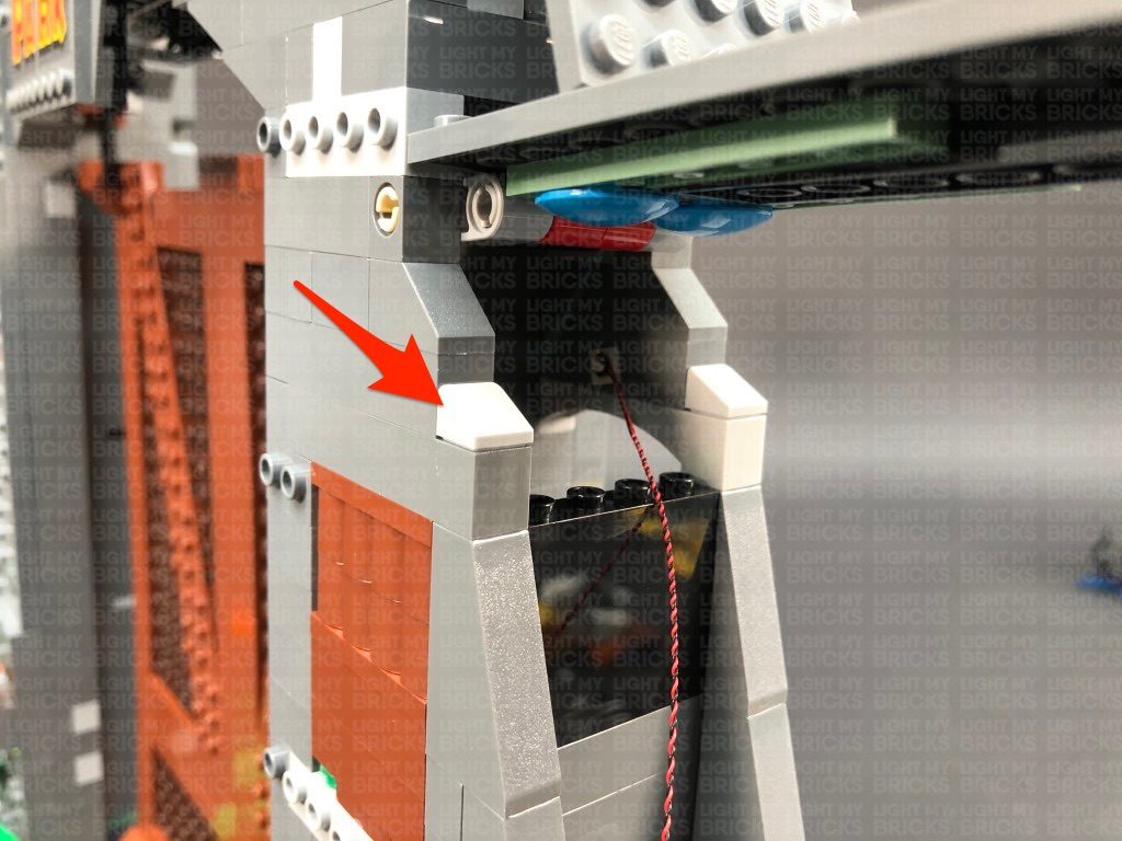
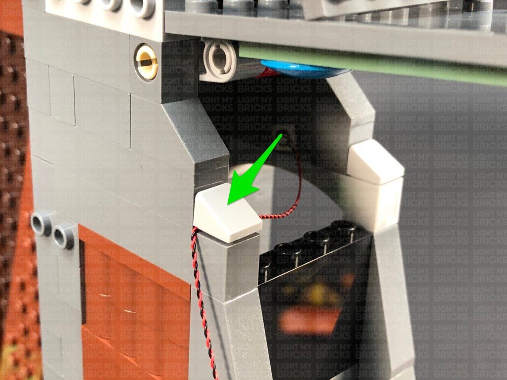
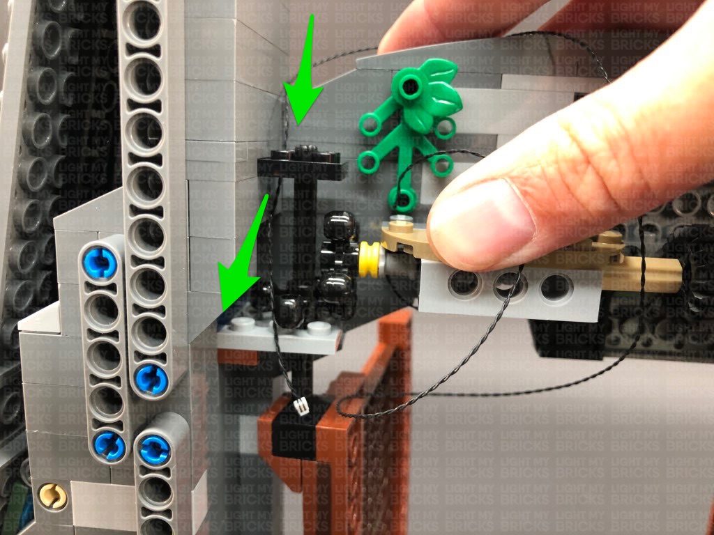
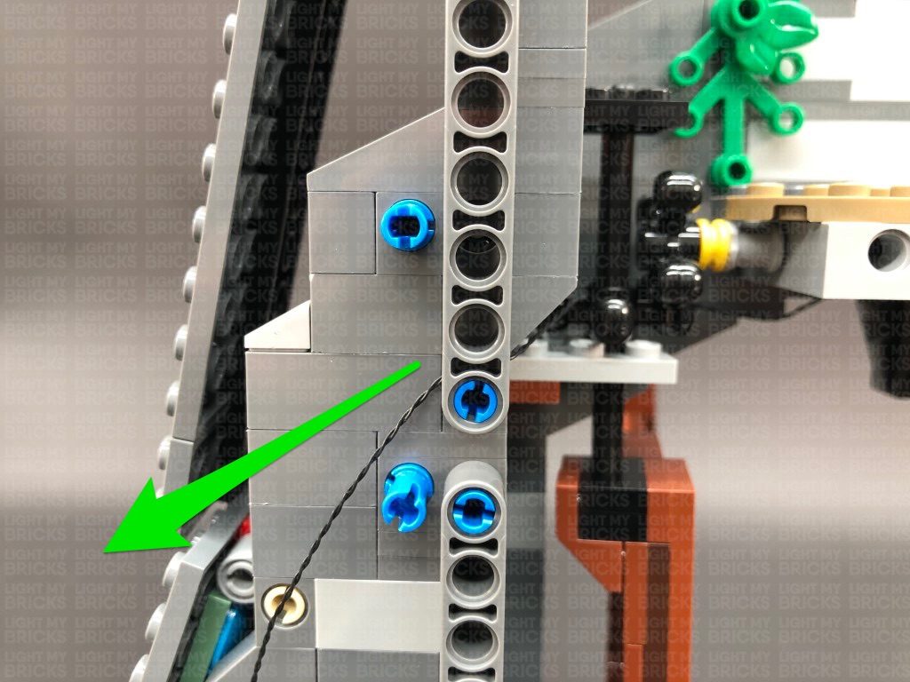
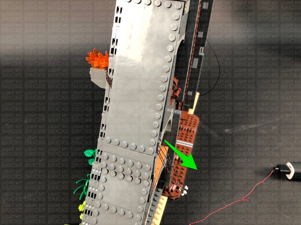
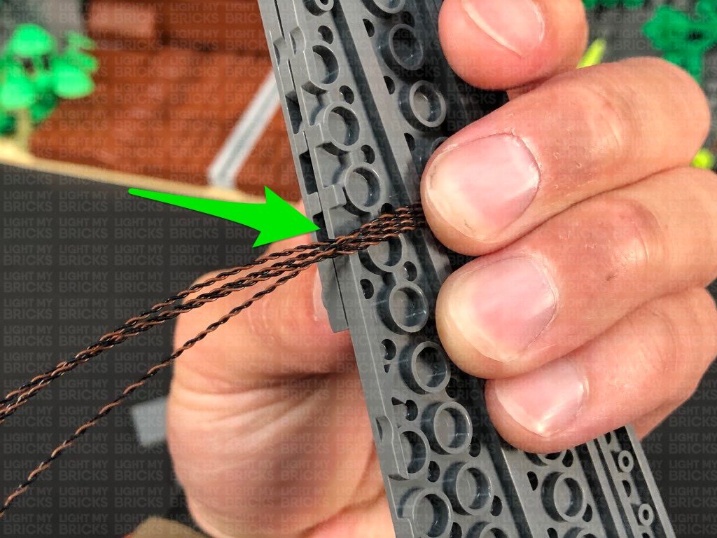
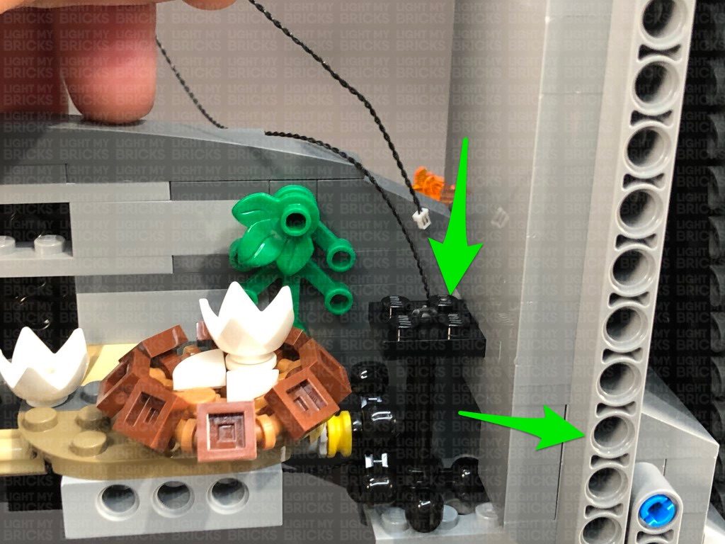
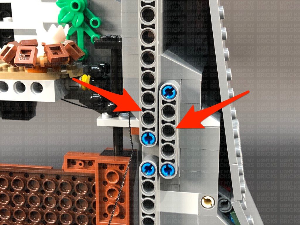
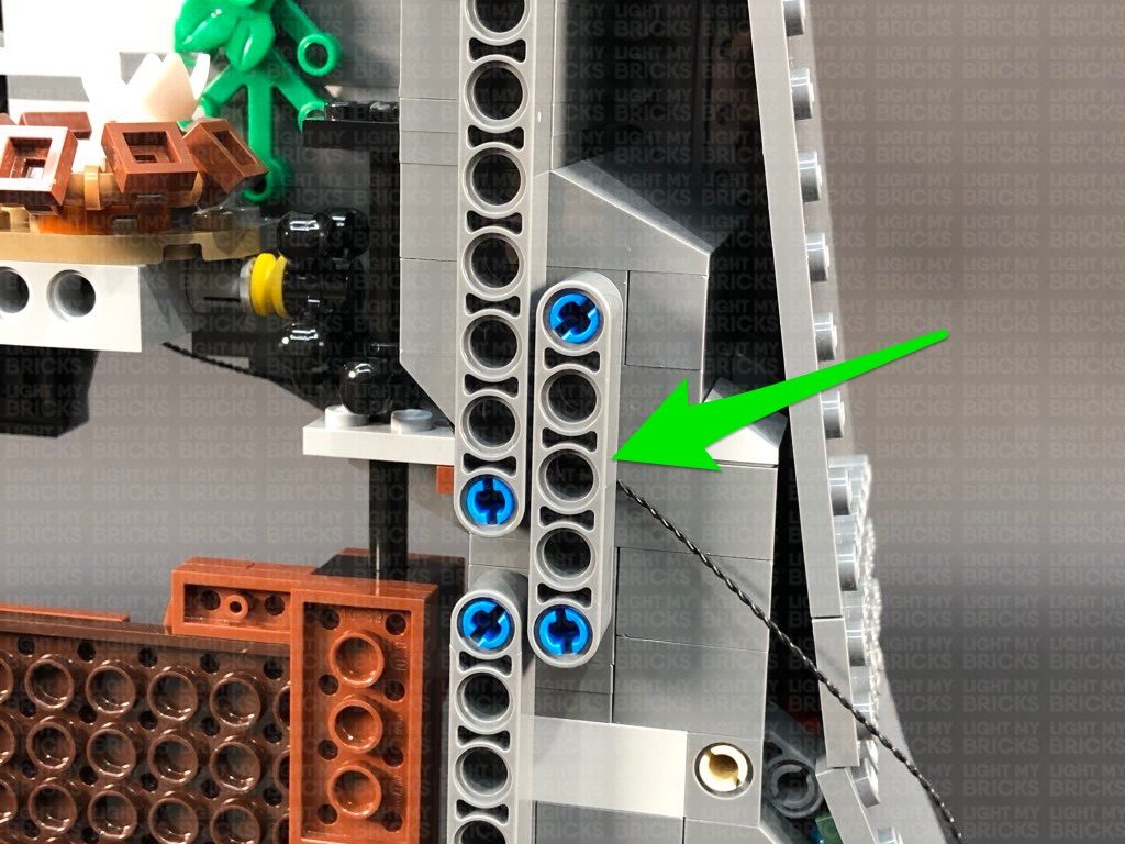
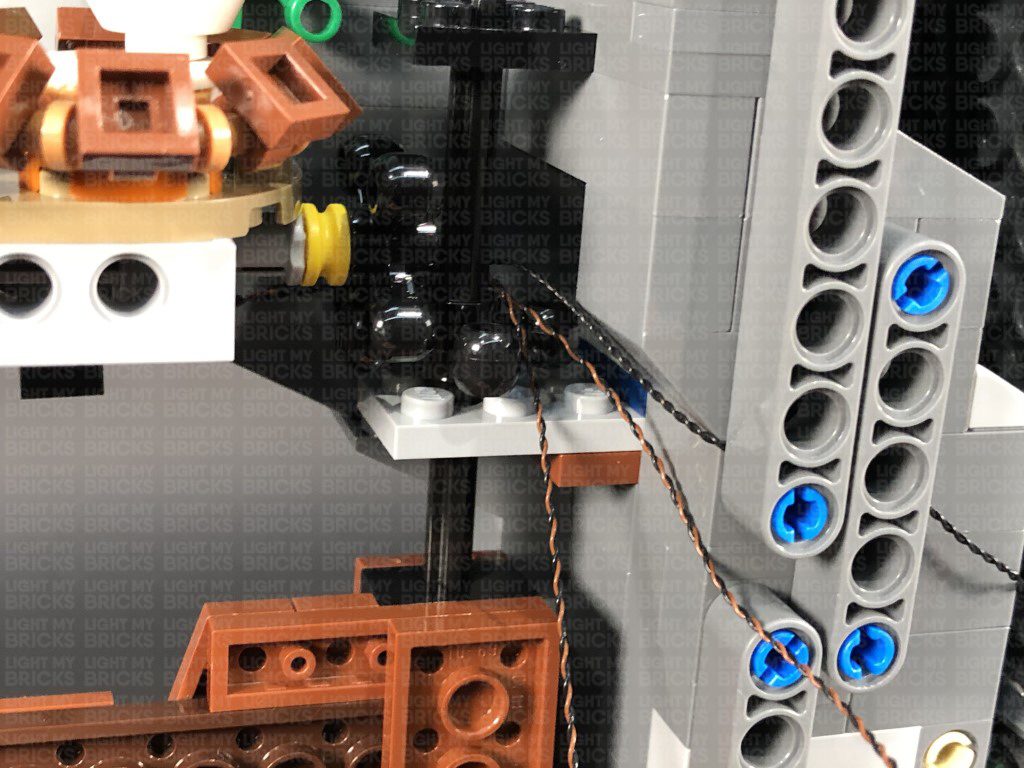
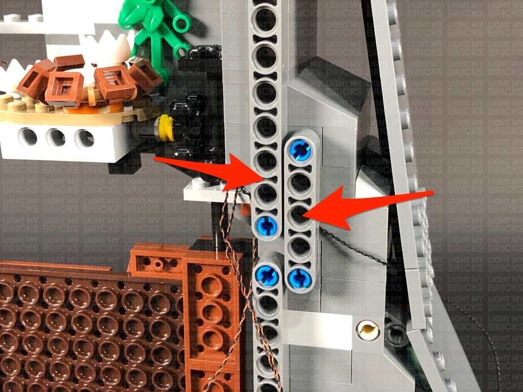
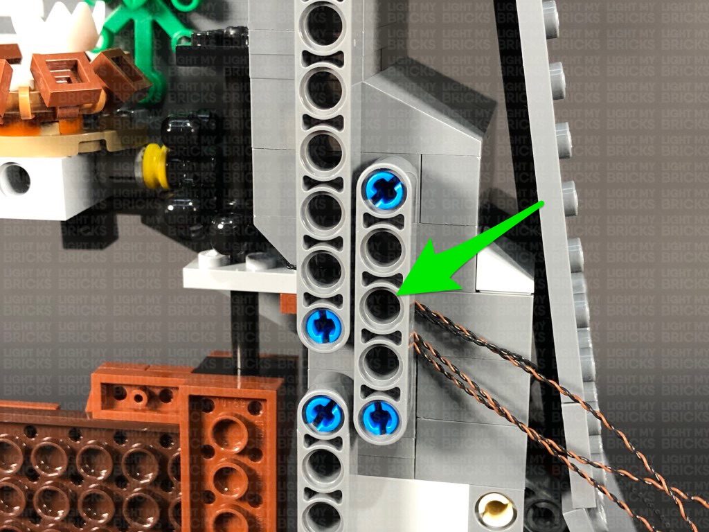
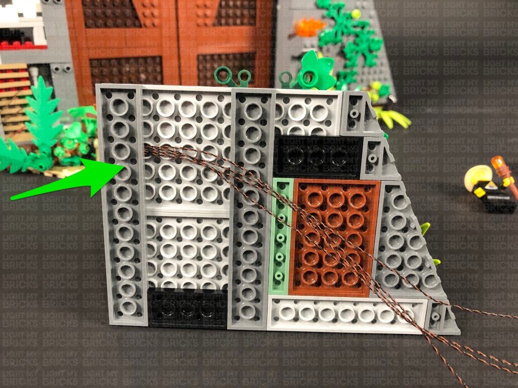
Completely disconnect the smaller technic bar, then disconnect just the bottom section of the longer technic bar. Bring the cable over to the left, then reconnect both technic bars, securing the cable in place.
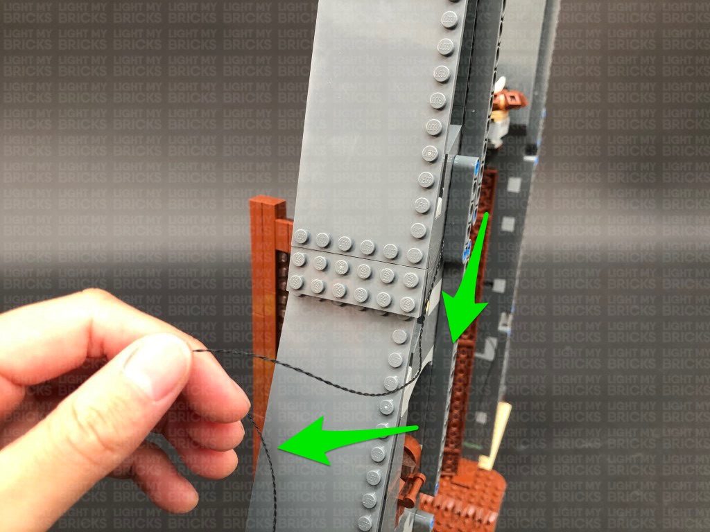
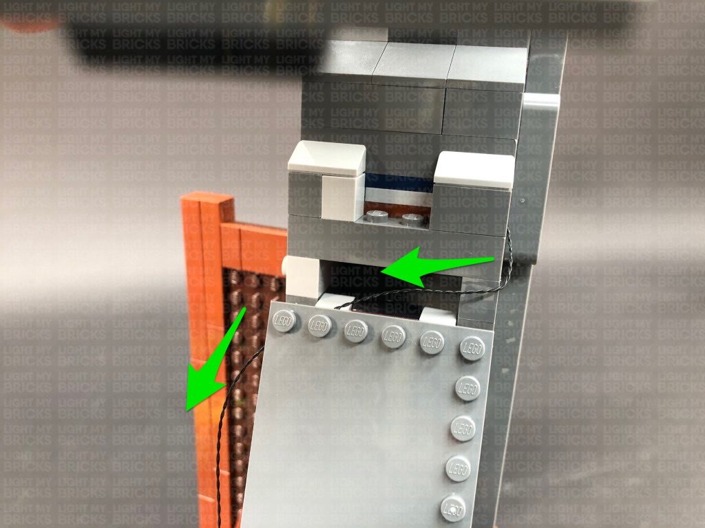
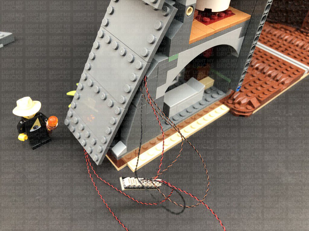
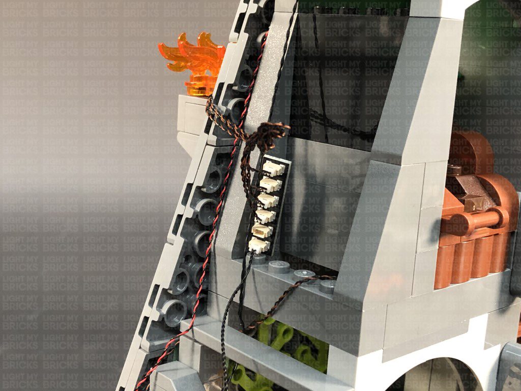
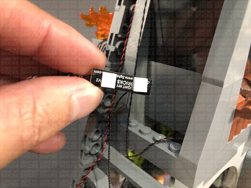
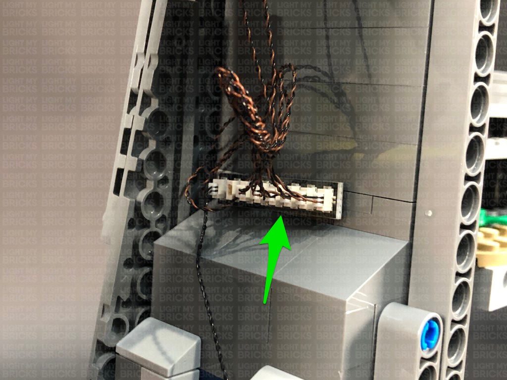
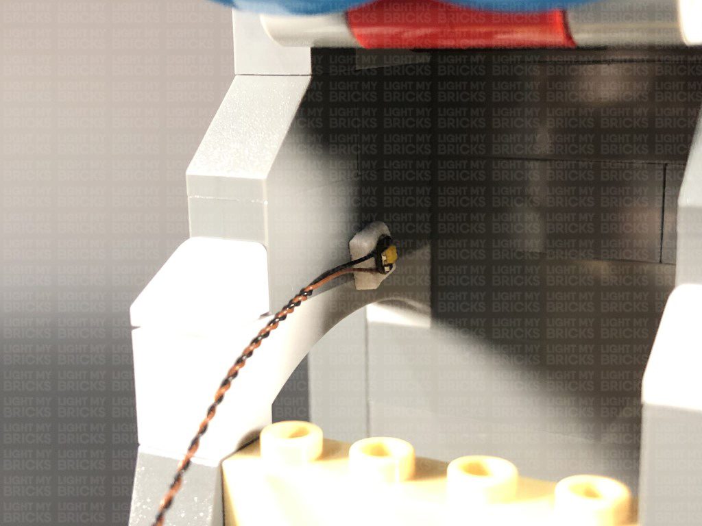
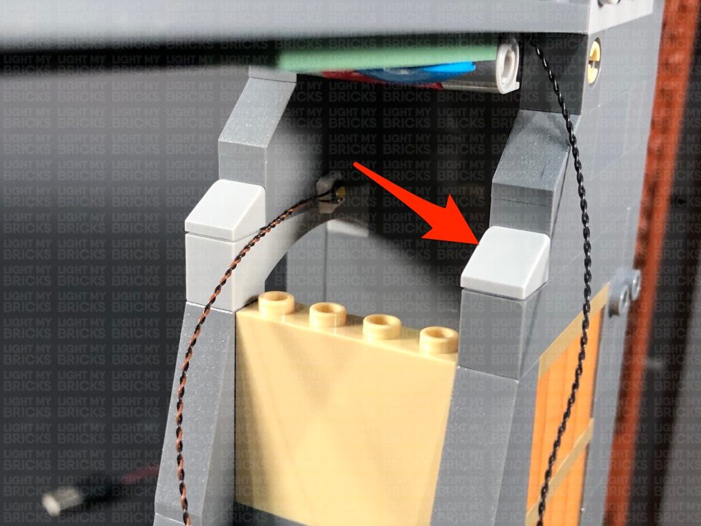
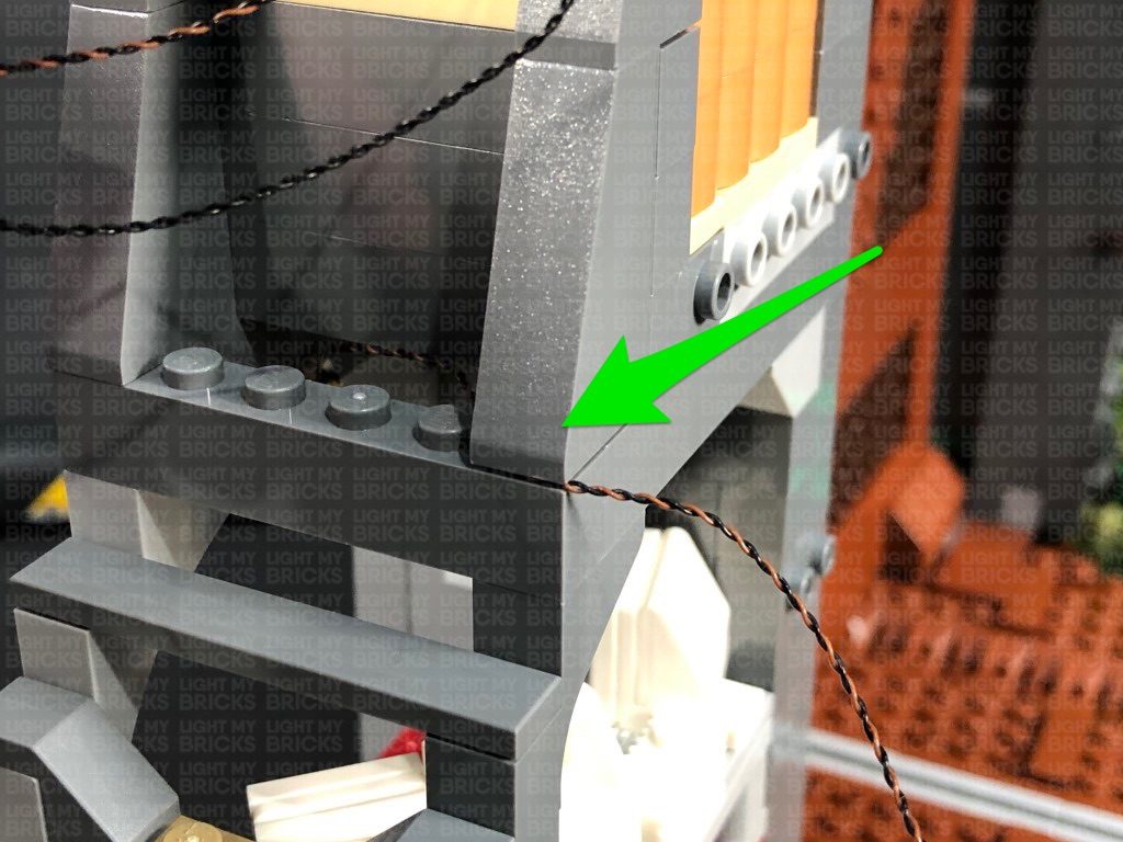
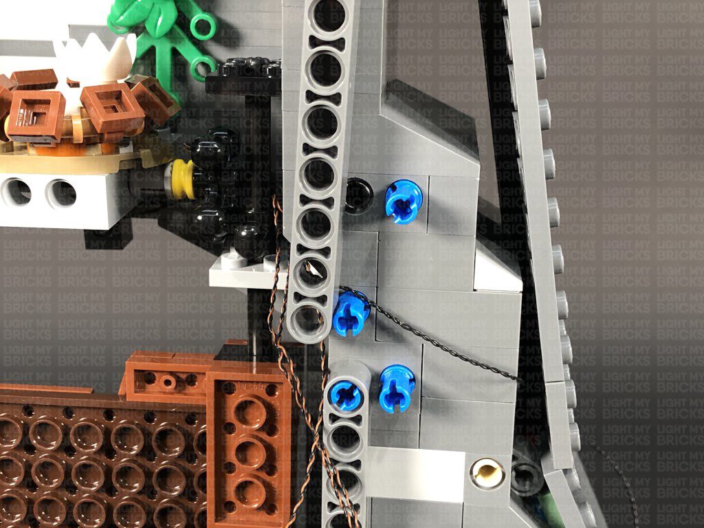
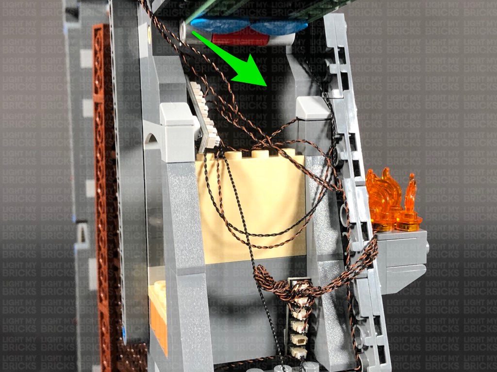
Bring the cable down and then across toward the front, then tuck it in underneath the top side flap.
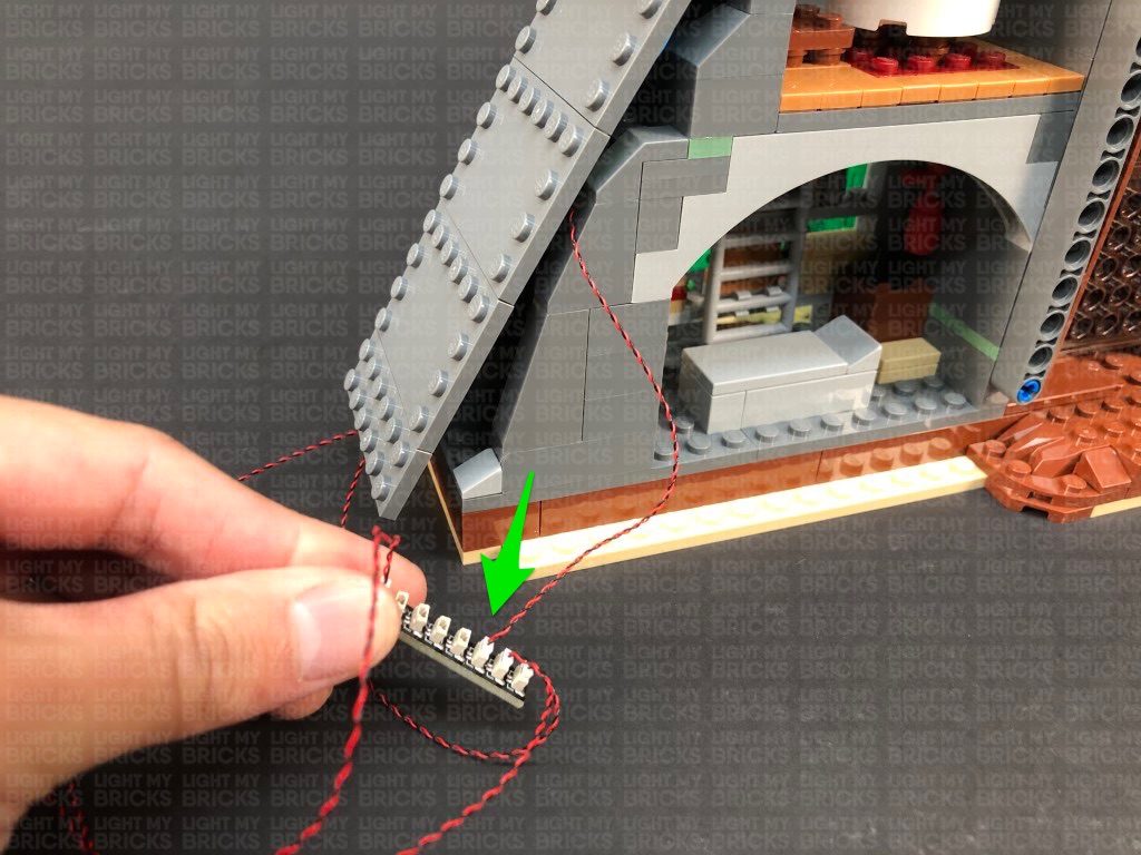
Bring the cable down toward the bottom and connect it to the 8-Port Expansion Board. Lift up the bottom side flap and bring the connecting cable underneath it. Turn the USB Power Bank ON to test the strip lights are working OK.
Note: If you experience any issues with the lights not working and suspect an issue with a component, please try a different port on the expansion board to verify where the fault lies (with the light or expansion board). To correct any issues with expansion board ports, please view the section addressing expansion board issues on our online troubleshooting guide.
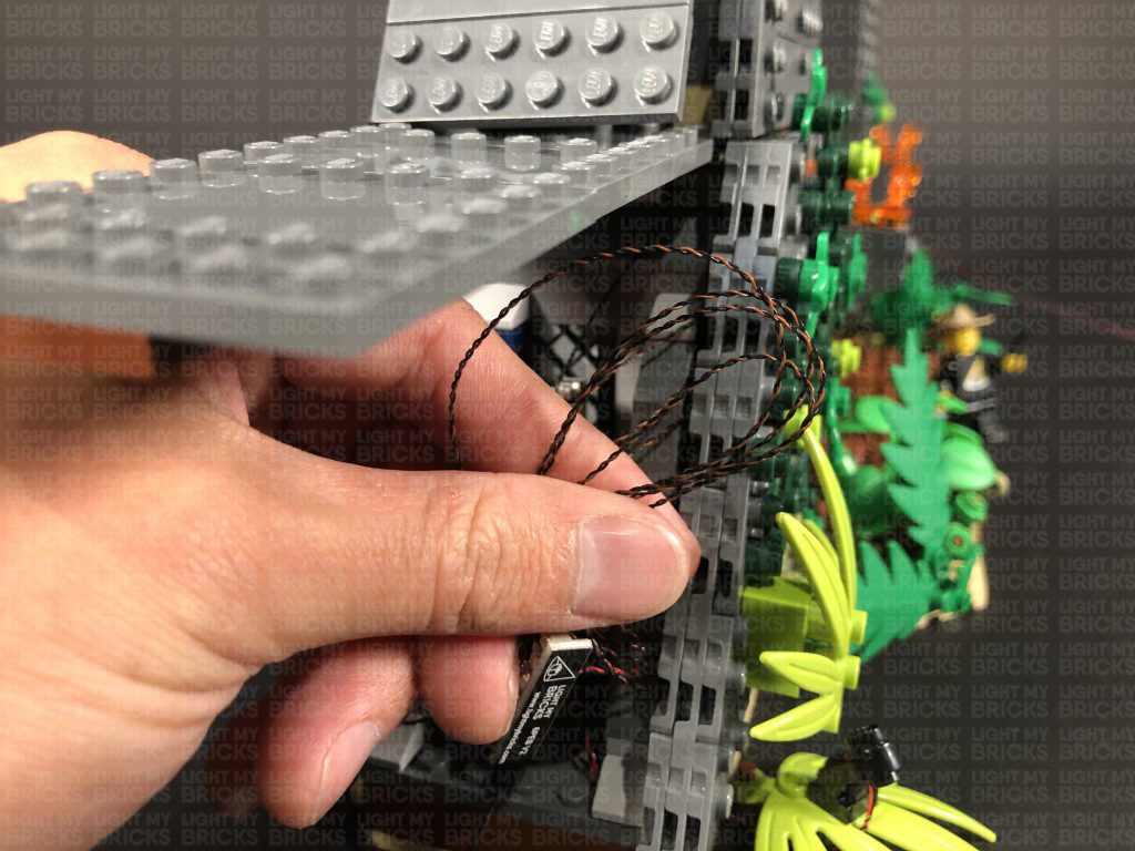
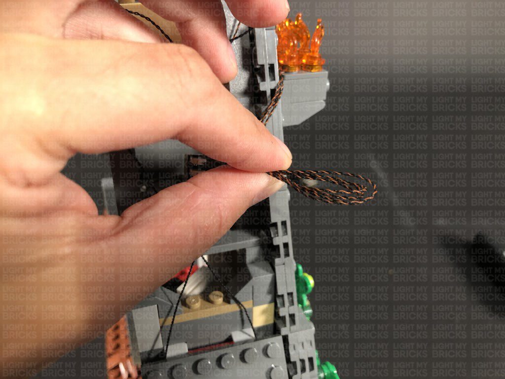
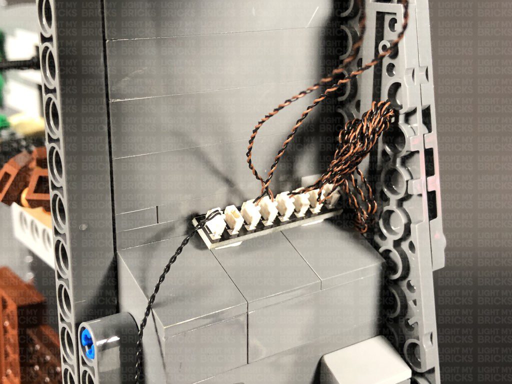
10.) Disconnect the USB Power Cable from the expansion board, then neaten up all the cables (Except the two spot light cables) by grouping them altogether, then folding and twisting them around each other to form a neat bunch.
Pull the two spot light cables out the back side, then twist and fold them around each other into a neat bunch. Twist the two bunched up cables together into one larger bunch.
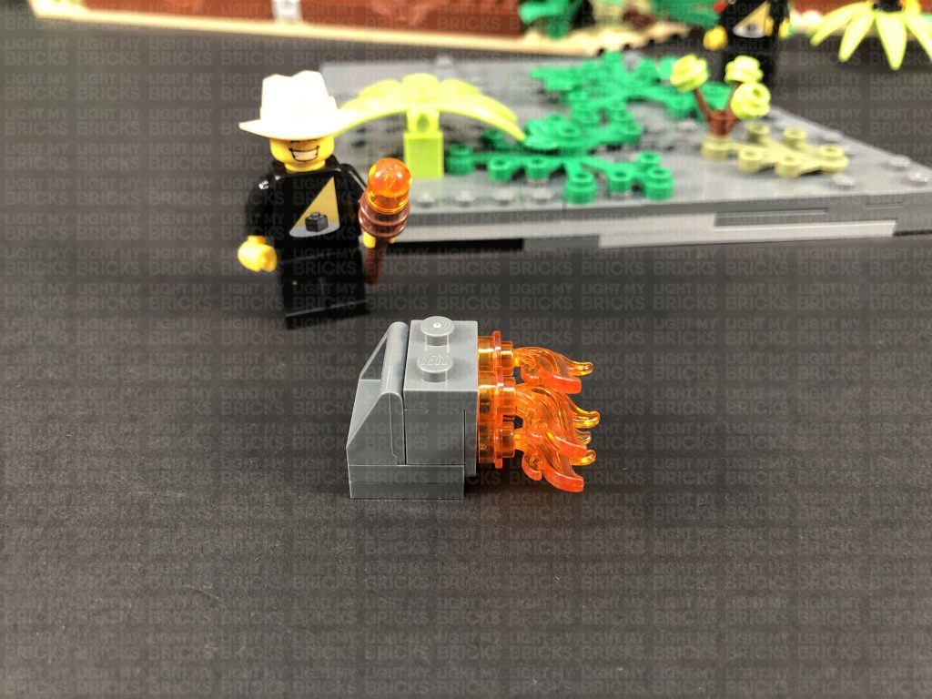
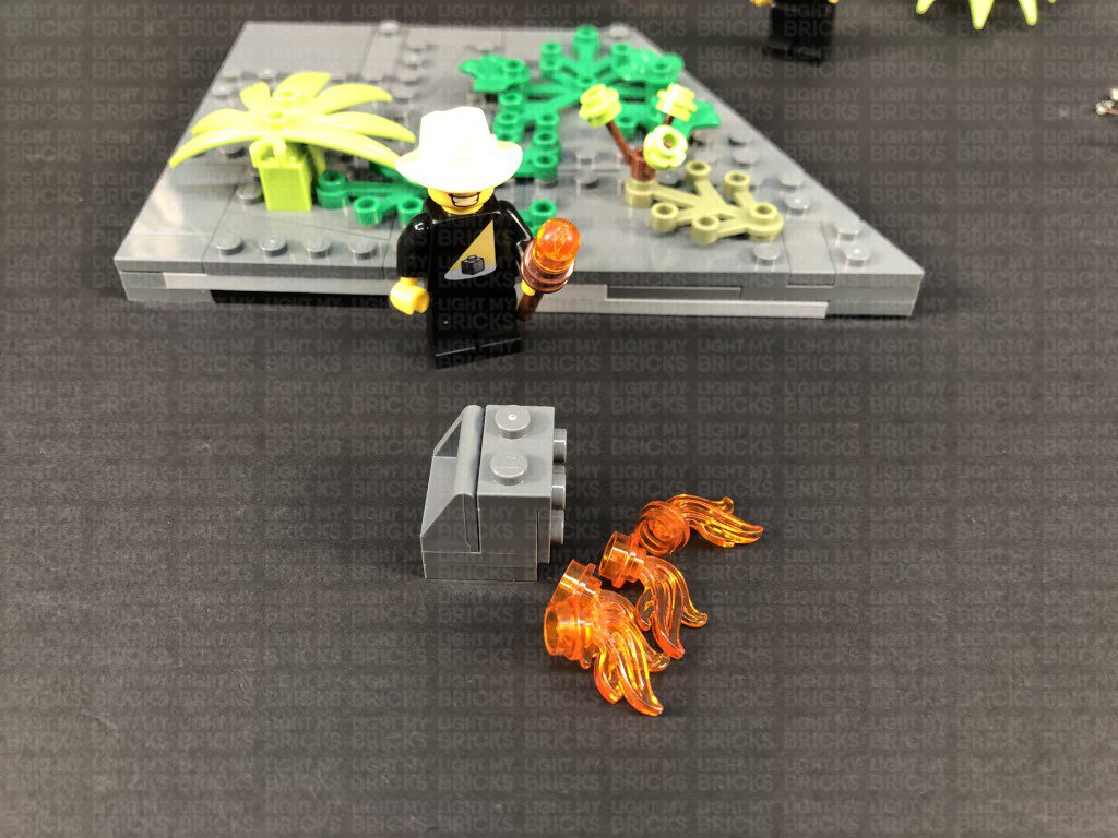
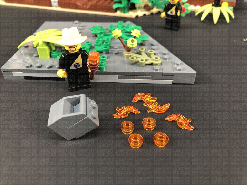
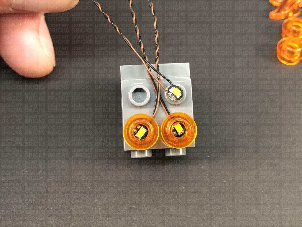
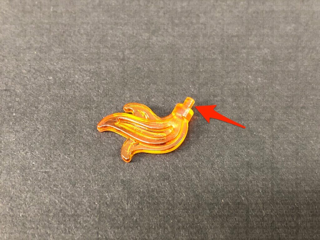
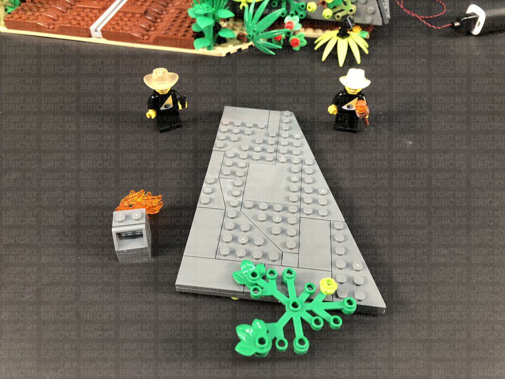
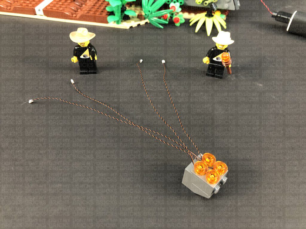
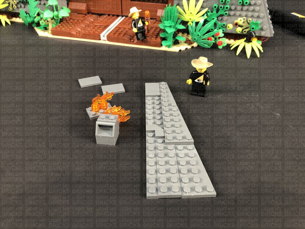
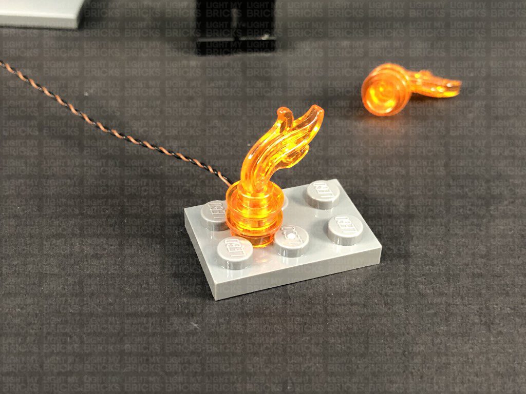
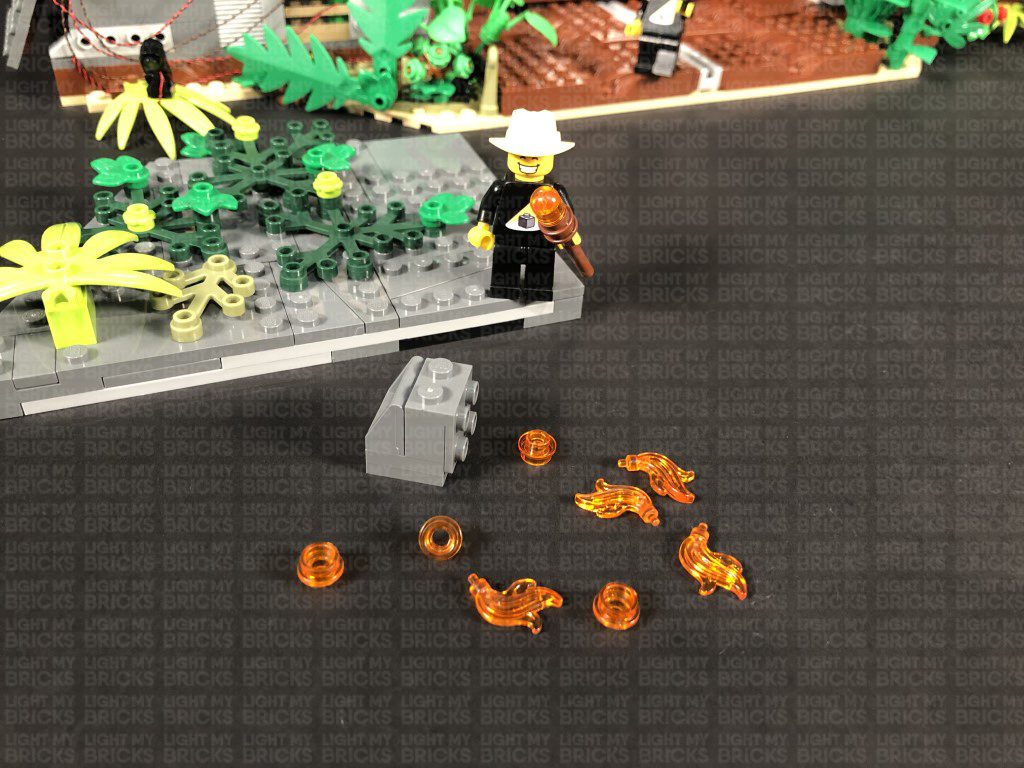
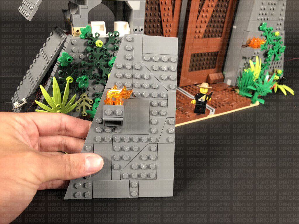
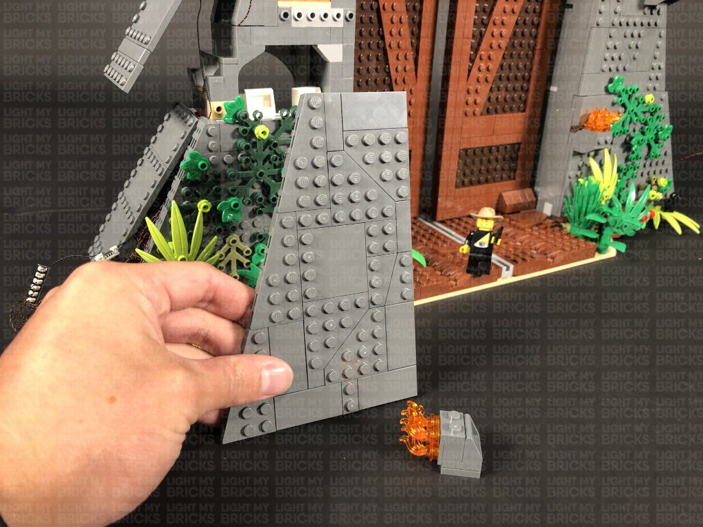
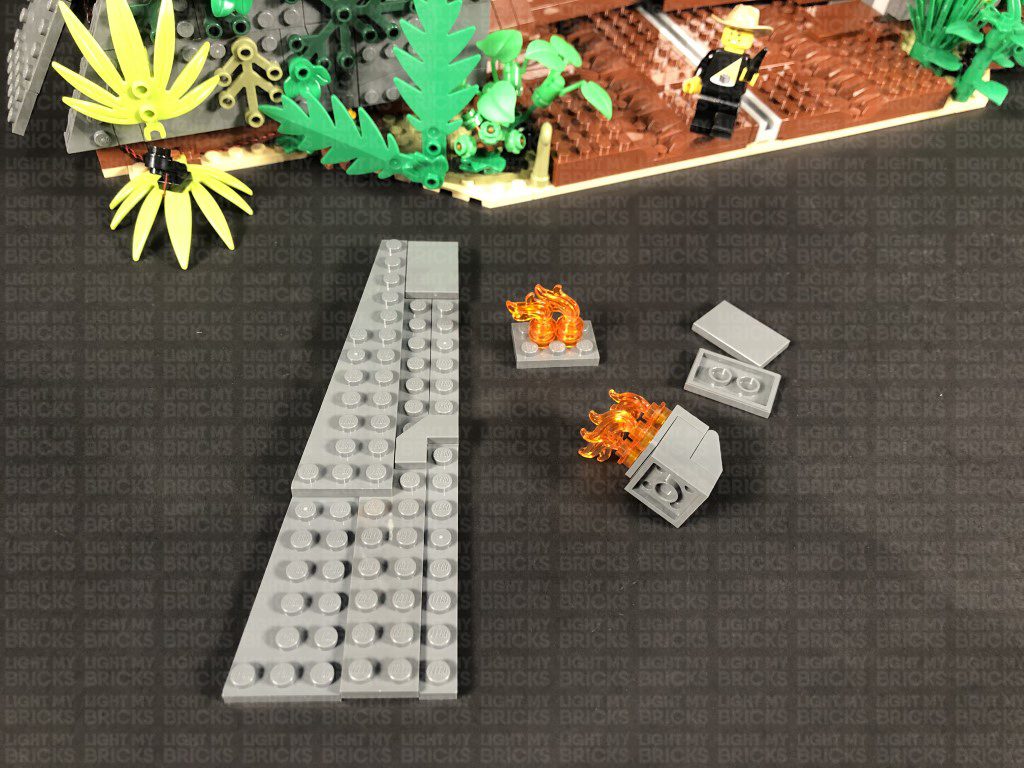
11.) Turn the set around to the front side as we will now light up the fire sections on the right. Take the bottom wall plate as well as the fire section. Disconnect and disassemble to trans orange flame pieces as shown below:
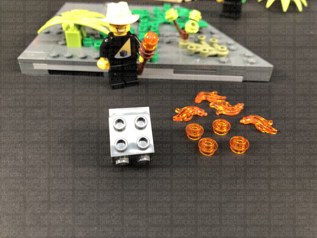
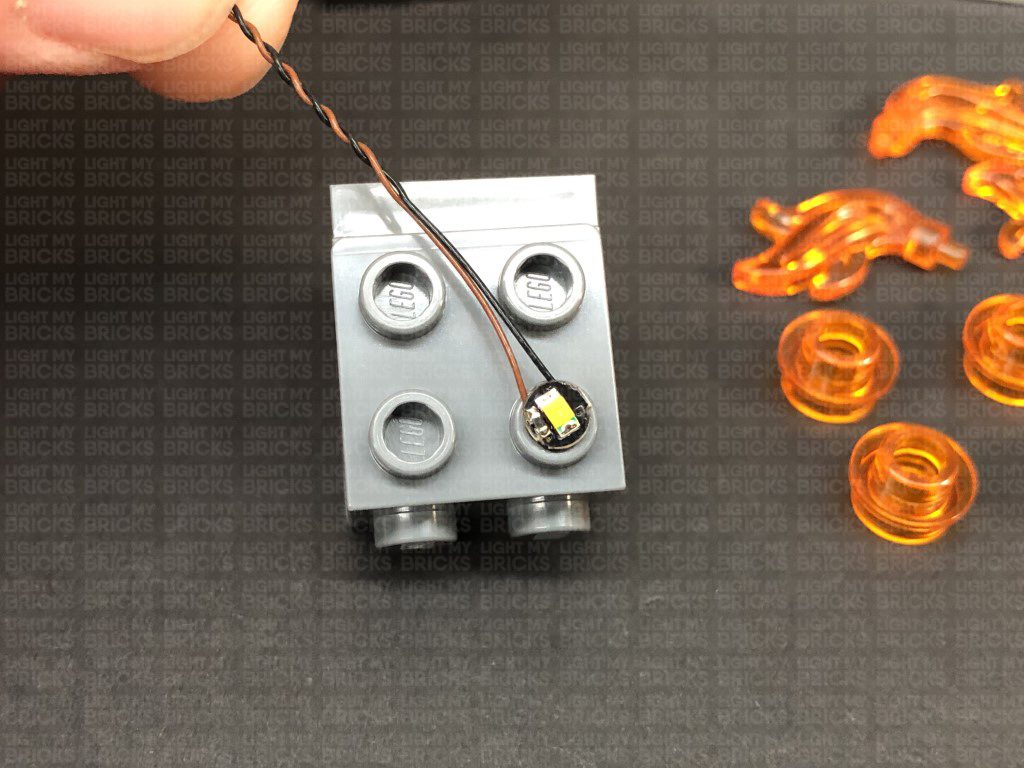
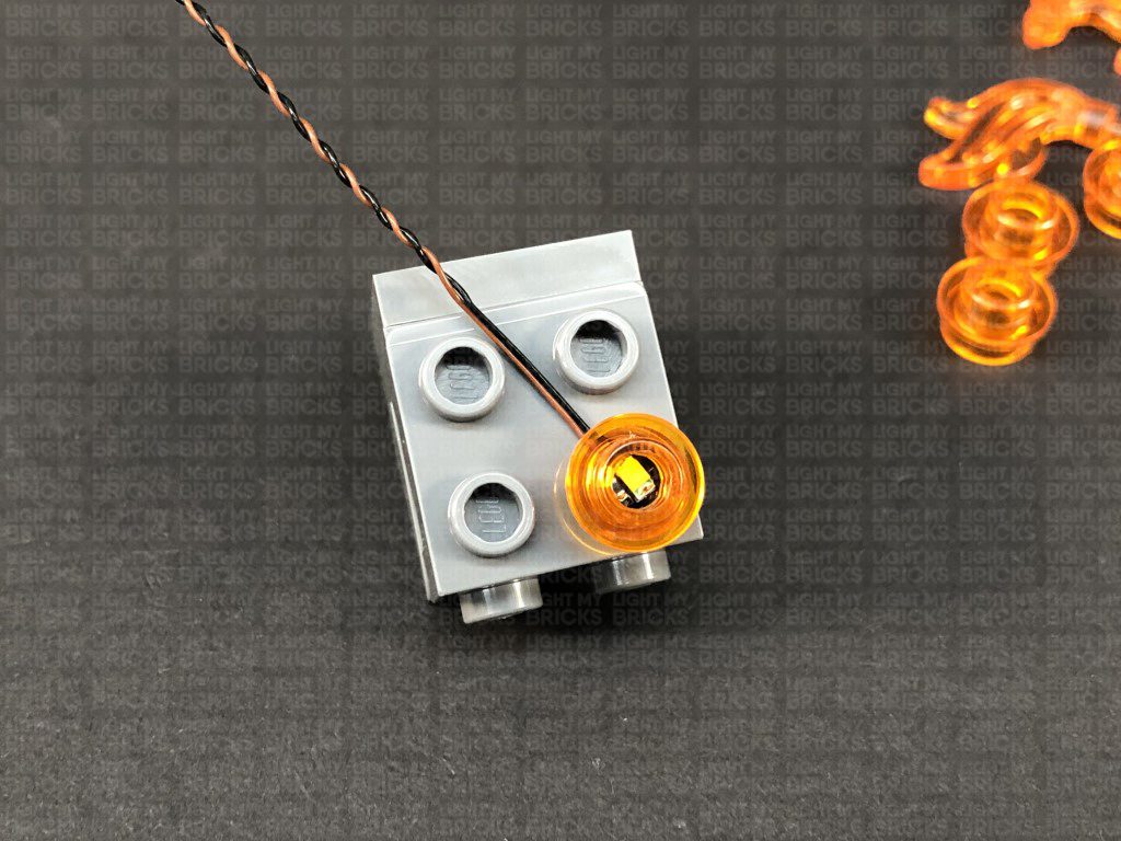
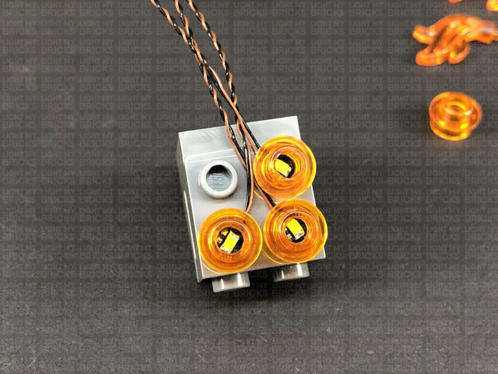
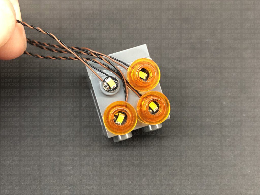
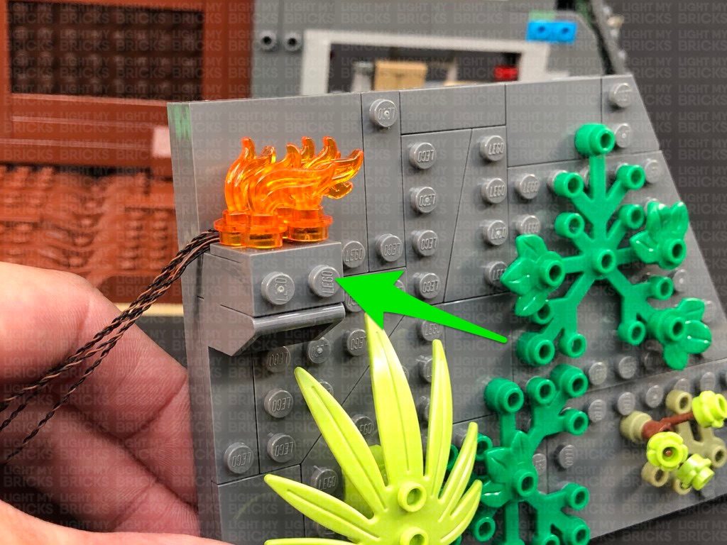
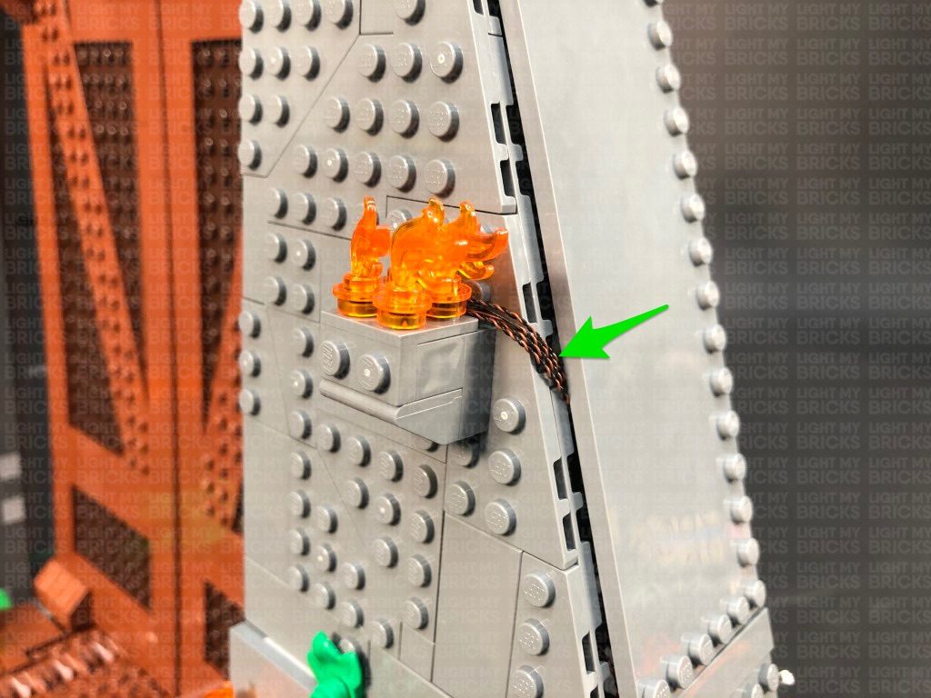
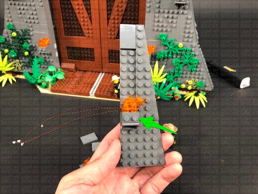
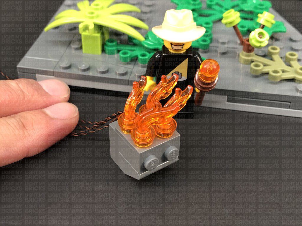
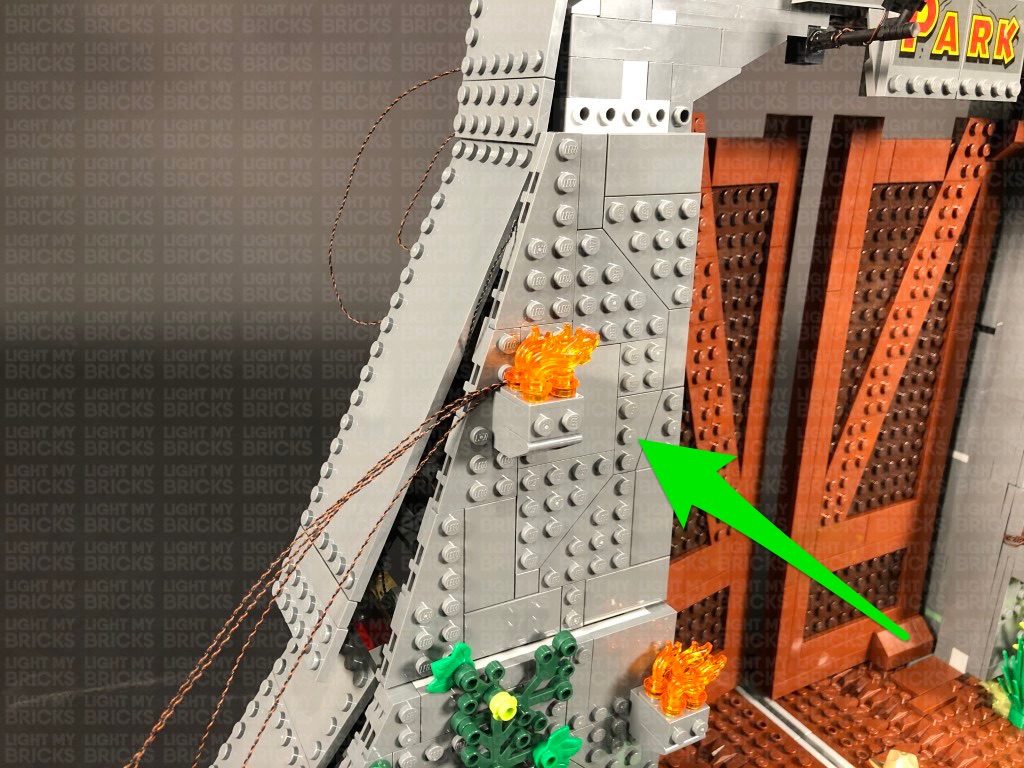
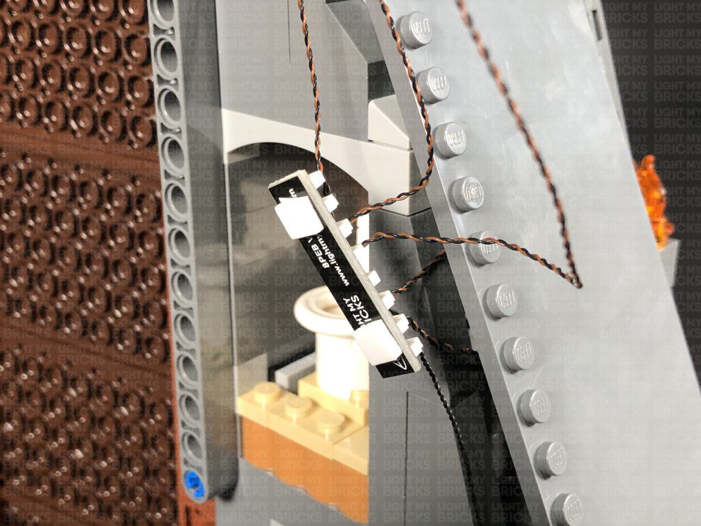
Take a White 30cm Bit Light and with the cable facing the back and in between studs, place it over the front right stud of the grey brick section as shown below. Secure the Bit Light in place by reconnecting one of the trans orange round plates over the top.
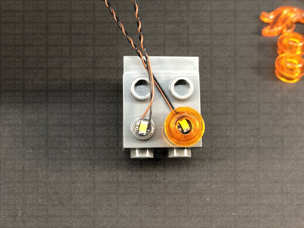
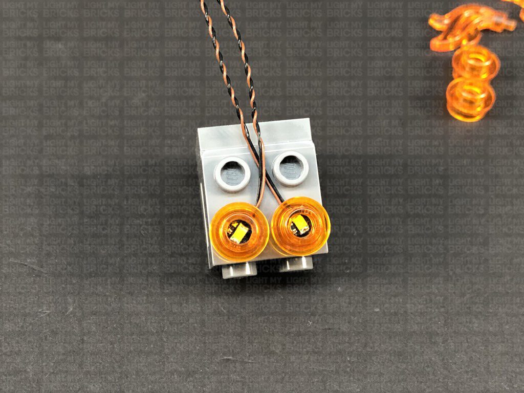
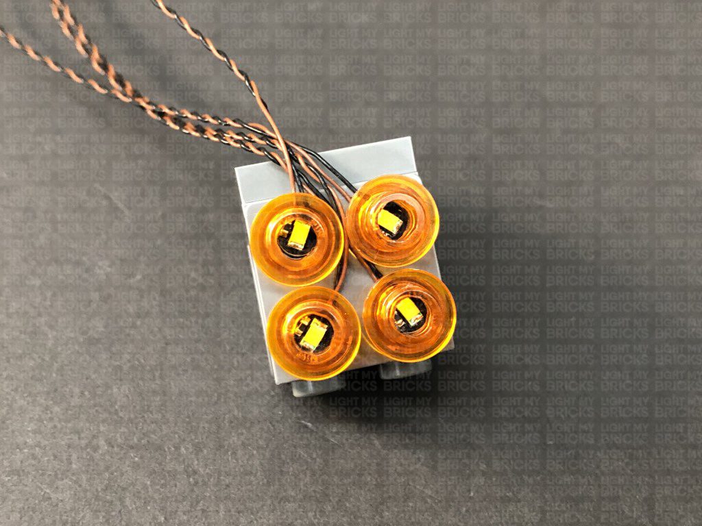
Repeat this step to install another 3x White 30cm Bit Lights to this section ensuring all cables are facing the back and laid in between studs as shown below:
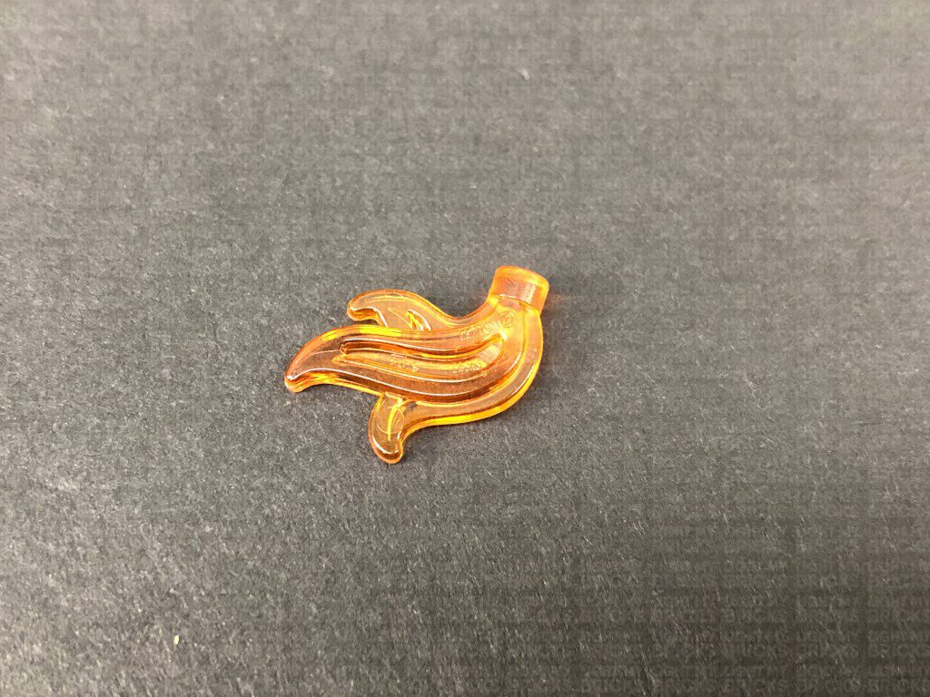
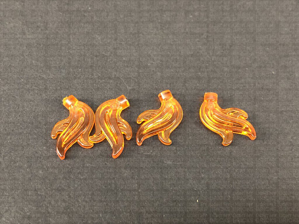
12.) Take the four trans orange flame pieces and carefully snip off the tips using a pair of scissors.
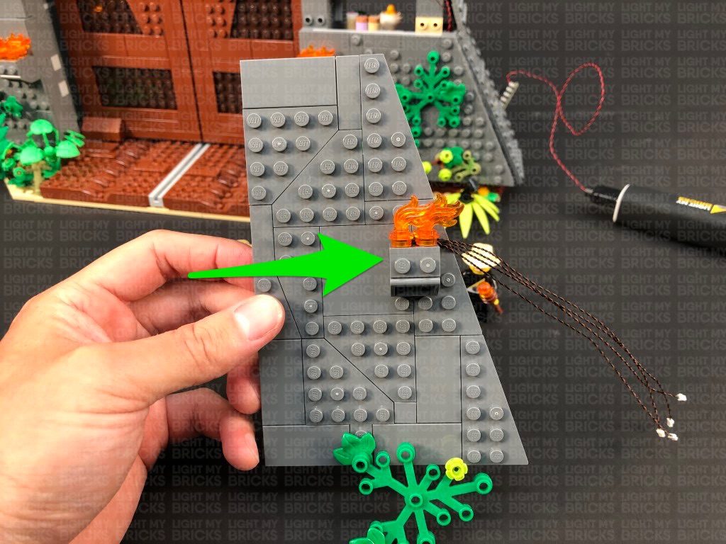
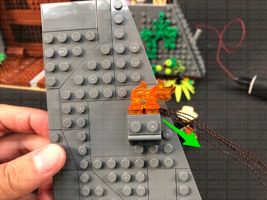
Reconnect the flames pieces to the trans orange round plates over the bit lights before reconnecting this section back to the wall. Ensure the cables are laid out toward the left side.
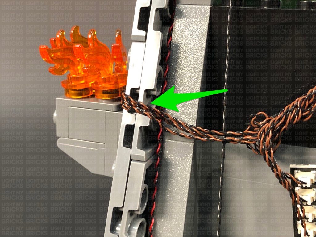
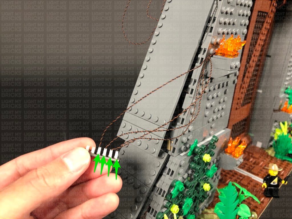
Turn the wall section around and disconnect the large dark grey plate on the right side. Bring the three cables together and lay them across to the left, then reconnect the dark grey plate ensuring the cables are laid in between the studs of the dark grey plate. Also ensure the cables are side by side rather than on top of each other underneath the plate.
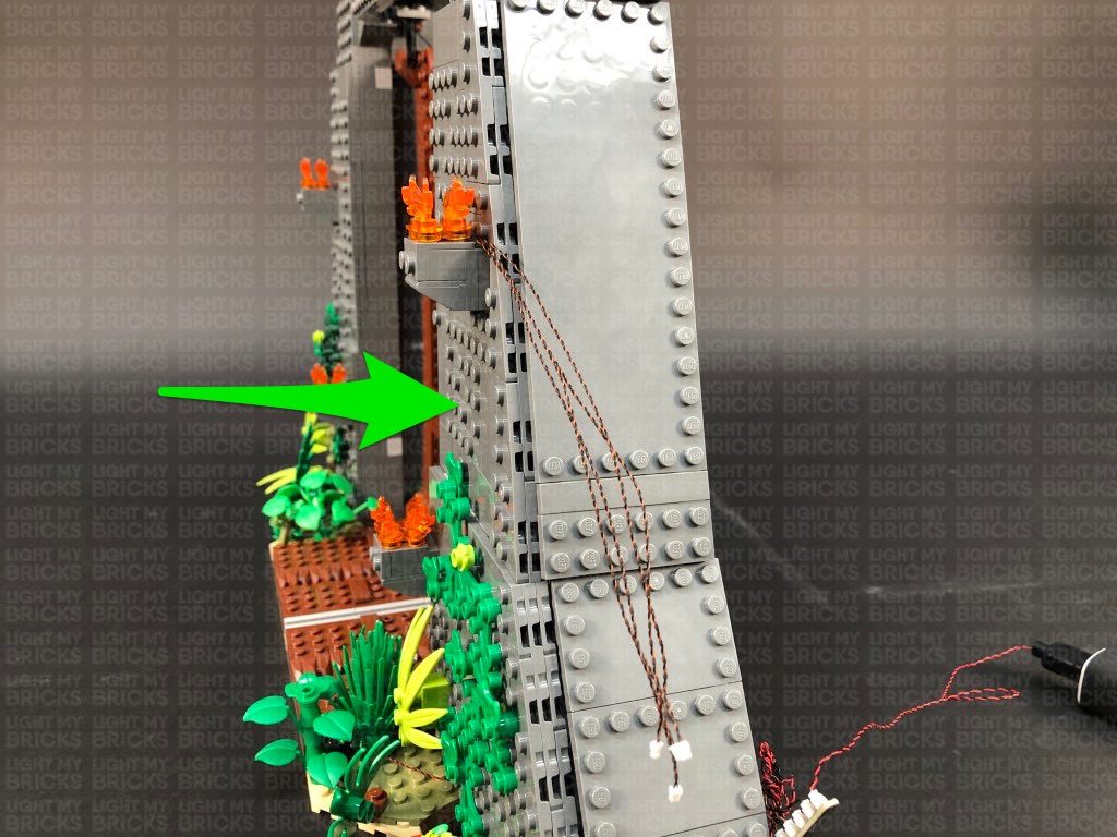
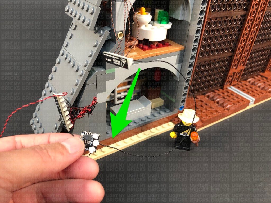
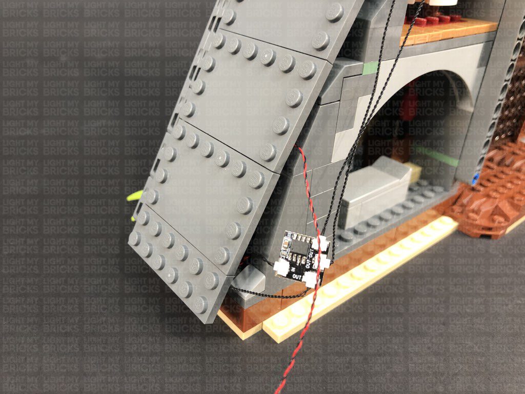
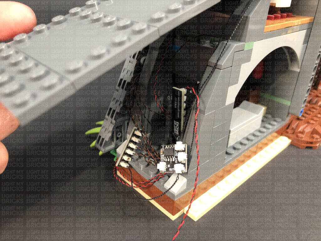
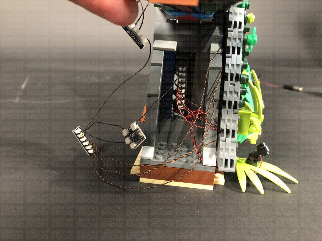
13.) Reconnect this bottom wall section, then bring the cables out toward the back, underneath the bottom side flap. Connect the four cables to a 6-Port Expansion Board.
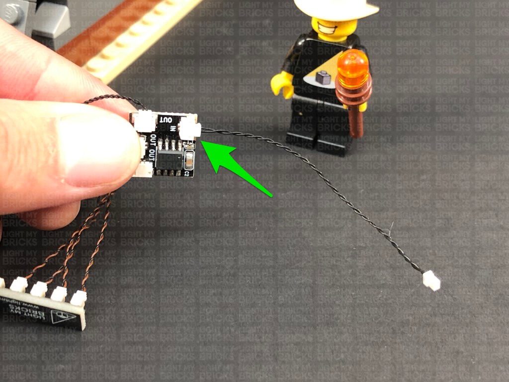
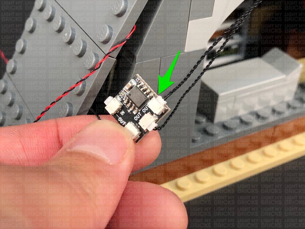
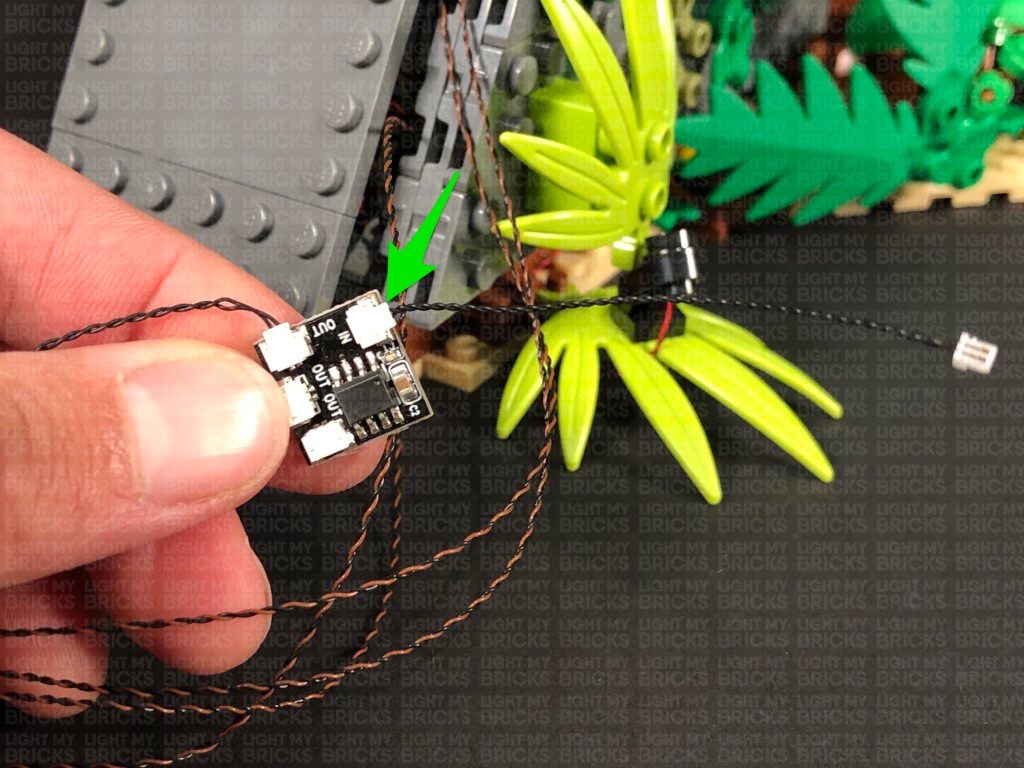
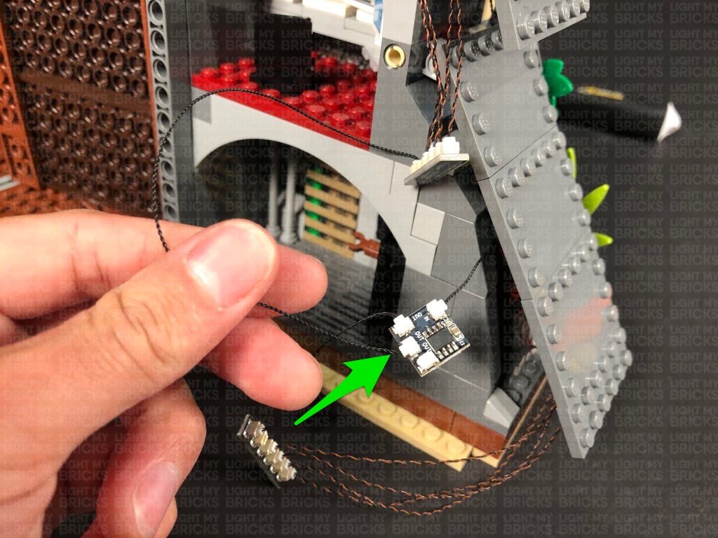
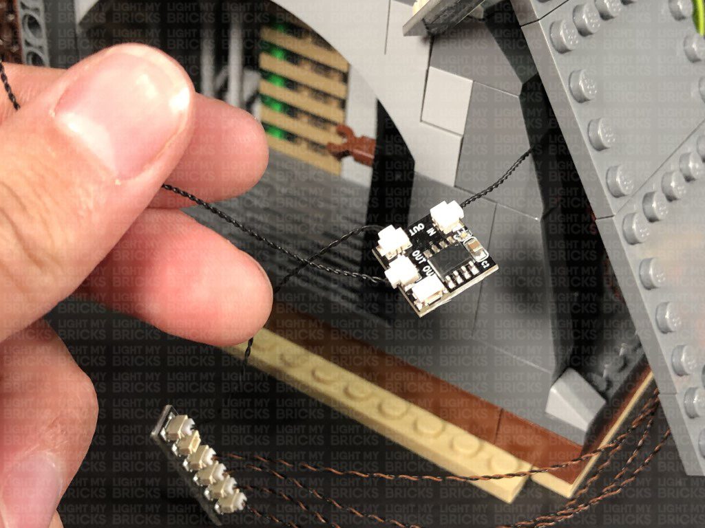
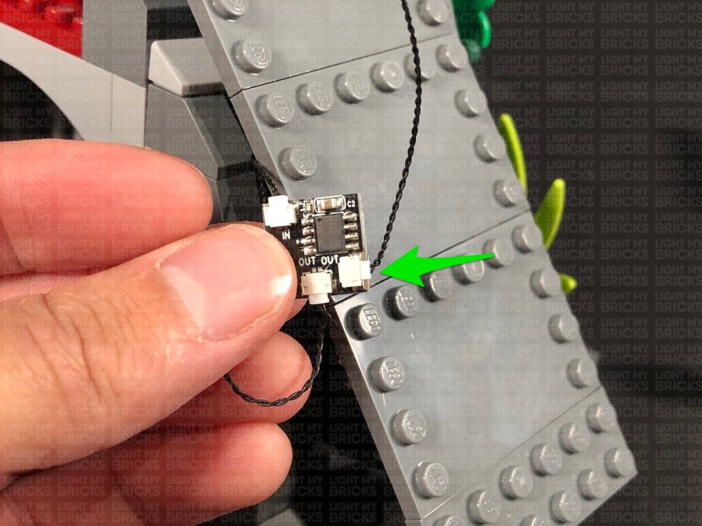
Take a 5cm Connecting Cable and connect it to the 6-Port Expansion Board. Connect the other end of the cable to one of the OUT ports on a Flicker Effects Board.
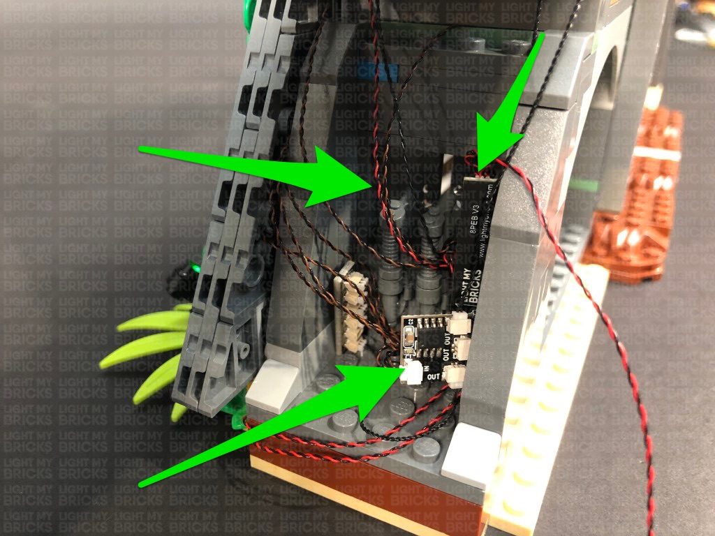
Take another 5cm Connecting Cable and connect it to the IN port on the Flicker Effects Board. Connect the other end of the cable to the 8-Port Expansion Board from previous steps.
Reconnect the USB power Cable to the remaining port on the 8-Port Expansion Board. Turn your USB Power Bank ON to test the fire section from the front wall are working and flickering OK.
Note: If you experience any issues with the lights not working and suspect an issue with a component, please try a different port on the expansion board to verify where the fault lies (with the light or expansion board). To correct any issues with expansion board ports, please view the section addressing expansion board issues on our online troubleshooting guide.
Neaten up the cables from the bottom fire section by grouping them together and folding and twisting around each other into a neat bunch
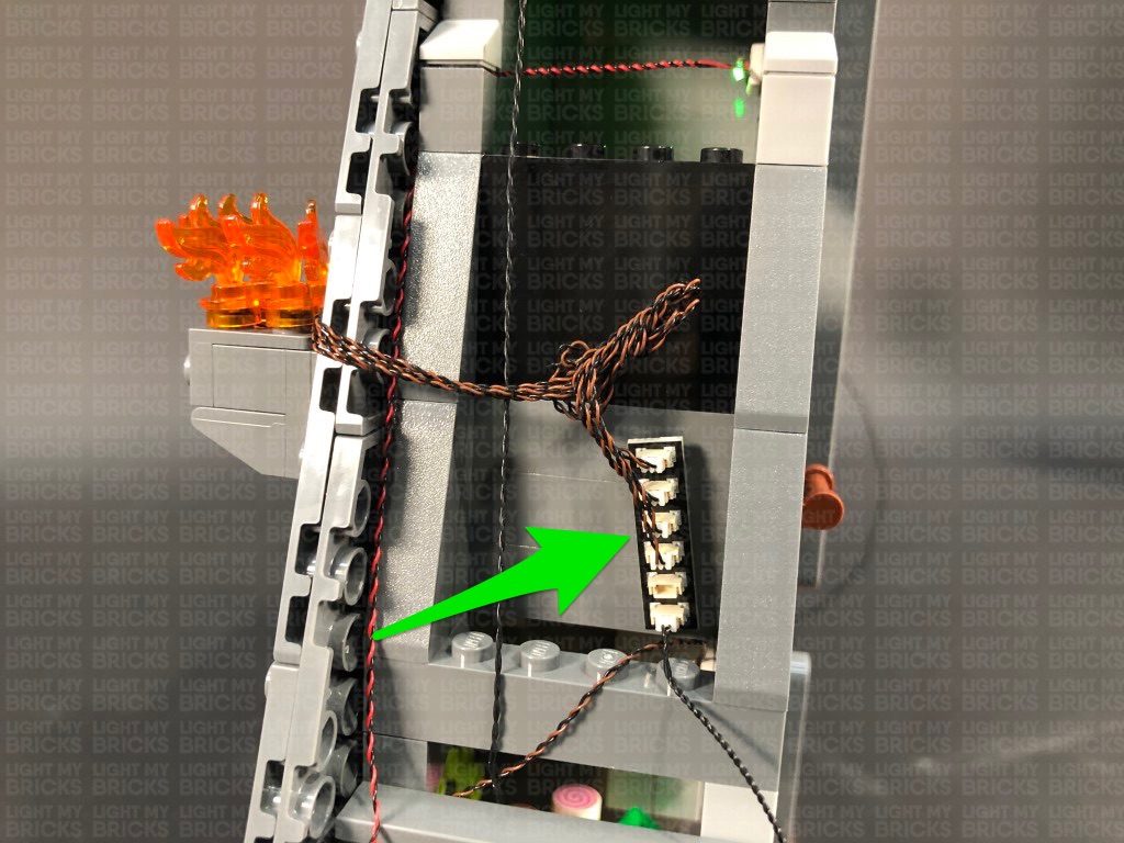
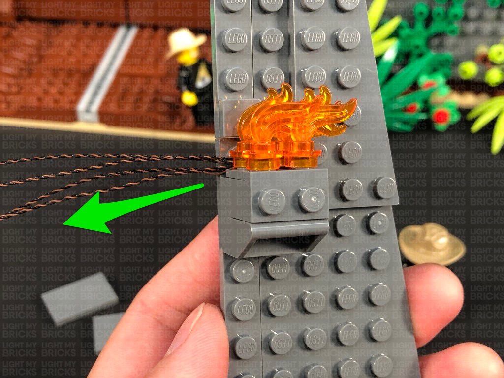
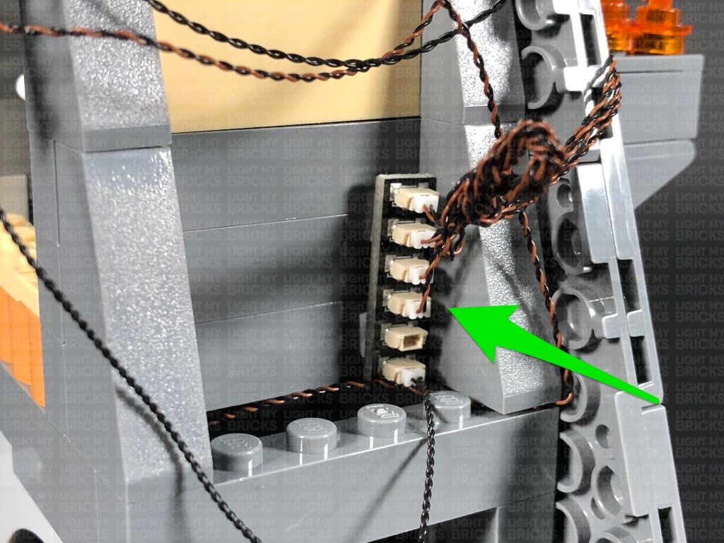
14.) We will now light the torches on the middle wall section. First disassemble the pieces from the flame section, then using the same method used to install lights to the bottom fire section, install 4x White 15cm Bit Lights to this middle fire section.
Disconnect the following tile, then bring the cable down and lay it across toward the front of the set in between studs, before reconnecting the tile over the top. This will help secure the cable.
Bring the other end of the cable out, then bring it down underneath the bottom side flap, to connect to the 8-Port Expansion Board underneath. Turn the USB Power Bank ON to test the light is working OK.
Note: If you experience any issues with the lights not working and suspect an issue with a component, please try a different port on the expansion board to verify where the fault lies (with the light or expansion board). To correct any issues with expansion board ports, please view the section addressing expansion board issues on our online troubleshooting guide.
7.) We will now light up the underground bunker at the bottom floor. First, we want to create a gap just above the room (above the green plate). To create this gap, gently push your finger up the roof plate of this room to slightly disconnect this section on the top left side as shown below.
Take a White 15cm Bit Light and thread it through this gap. Carefully place the entire set onto it’s front side so we can neatly position the Bit Light in the centre underneath the roof plate as shown below. Ensuring the Bit Light is facing down, secure it in place by connecting a provided Trans Clear Plate w Rounded Bottom 2×2 over it.
Bring the set back to it’s upright position and push down the section above the bunker room to close up the gap we created earlier. Bring the Bit Light cable down and connect it to the 8-Port Expansion Board underneath, then turn ON the USB Power Bank to test the light is working OK.
8.) Take the 2x White Strip Lights and connect them together using a 5cm Connecting Cable. Take a 50cm Connecting Cable and connect one end it to the left strip light. Take a 30cm Connecting Cable and connect one end to the right strip light.
Carefully place the entire set back over onto it’s front, then using their adhesive backings, stick the two strip lights underneath the following section as shown below: Do your best to stick them as closely as possible next to one another.
9.) Carefully bring the set back to it’s upright position, then take the 50cm connecting cable from the left side and thread it all the way up the top left corner behind the gears. Thread the cable back down in between the wall and the black bar and pull it out over the top of the light grey plate as show below:
Completely disconnect the smaller technic bar, then disconnect just the bottom section of the longer technic bar. Bring the cable over to the left, then reconnect both technic bars, securing the cable in place.
Bring the cable down and then across toward the front, then tuck it in underneath the top side flap.
Bring the cable down toward the bottom and connect it to the 8-Port Expansion Board. Lift up the bottom side flap and bring the connecting cable underneath it. Turn the USB Power Bank ON to test the strip lights are working OK.
Note: If you experience any issues with the lights not working and suspect an issue with a component, please try a different port on the expansion board to verify where the fault lies (with the light or expansion board). To correct any issues with expansion board ports, please view the section addressing expansion board issues on our online troubleshooting guide.
10.) Disconnect the USB Power Cable from the expansion board, then neaten up all the cables (Except the two spot light cables) by grouping them altogether, then folding and twisting them around each other to form a neat bunch.
Pull the two spot light cables out the back side, then twist and fold them around each other into a neat bunch. Twist the two bunched up cables together into one larger bunch.
11.) Turn the set around to the front side as we will now light up the fire sections on the right. Take the bottom wall plate as well as the fire section. Disconnect and disassemble to trans orange flame pieces as shown below:
Take a White 30cm Bit Light and with the cable facing the back and in between studs, place it over the front right stud of the grey brick section as shown below. Secure the Bit Light in place by reconnecting one of the trans orange round plates over the top.
Repeat this step to install another 3x White 30cm Bit Lights to this section ensuring all cables are facing the back and laid in between studs as shown below:
12.) Take the four trans orange flame pieces and carefully snip off the tips using a pair of scissors.
Reconnect the flames pieces to the trans orange round plates over the bit lights before reconnecting this section back to the wall. Ensure the cables are laid out toward the left side.
Turn the wall section around and disconnect the large dark grey plate on the right side. Bring the three cables together and lay them across to the left, then reconnect the dark grey plate ensuring the cables are laid in between the studs of the dark grey plate. Also ensure the cables are side by side rather than on top of each other underneath the plate.
13.) Reconnect this bottom wall section, then bring the cables out toward the back, underneath the bottom side flap. Connect the four cables to a 6-Port Expansion Board.
Take a 5cm Connecting Cable and connect it to the 6-Port Expansion Board. Connect the other end of the cable to one of the OUT ports on a Flicker Effects Board.
Take another 5cm Connecting Cable and connect it to the IN port on the Flicker Effects Board. Connect the other end of the cable to the 8-Port Expansion Board from previous steps.
Reconnect the USB power Cable to the remaining port on the 8-Port Expansion Board. Turn your USB Power Bank ON to test the fire section from the front wall are working and flickering OK.
Note: If you experience any issues with the lights not working and suspect an issue with a component, please try a different port on the expansion board to verify where the fault lies (with the light or expansion board). To correct any issues with expansion board ports, please view the section addressing expansion board issues on our online troubleshooting guide.
Neaten up the cables from the bottom fire section by grouping them together and folding and twisting around each other into a neat bunch
14.) We will now light the torches on the middle wall section. First disassemble the pieces from the flame section, then using the same method used to install lights to the bottom fire section, install 4x White 15cm Bit Lights to this middle fire section.
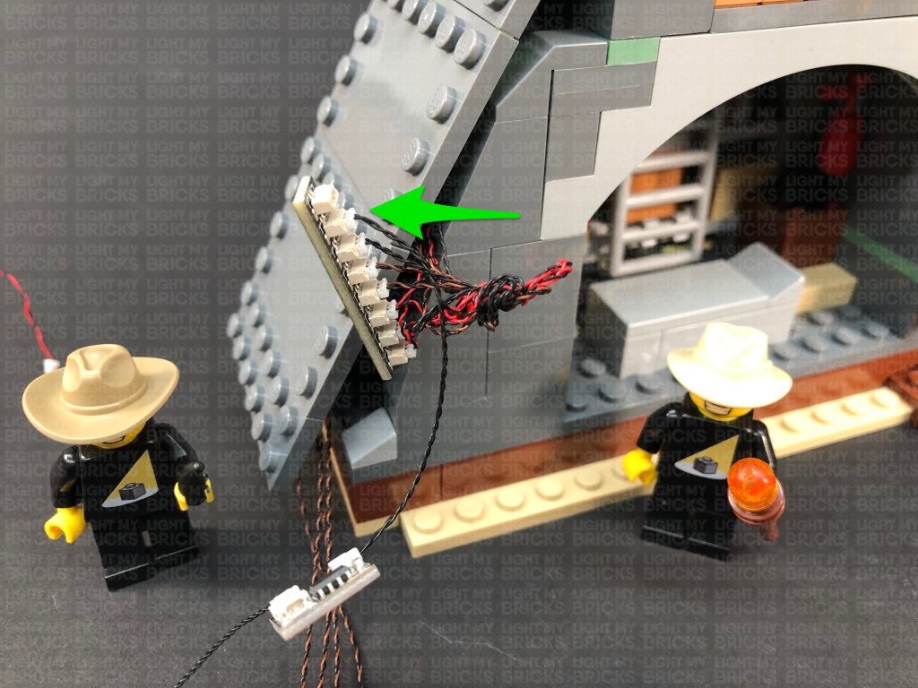
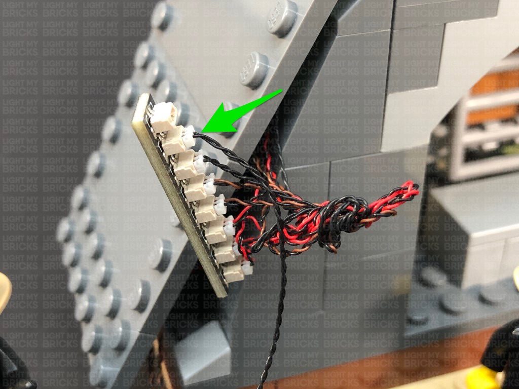
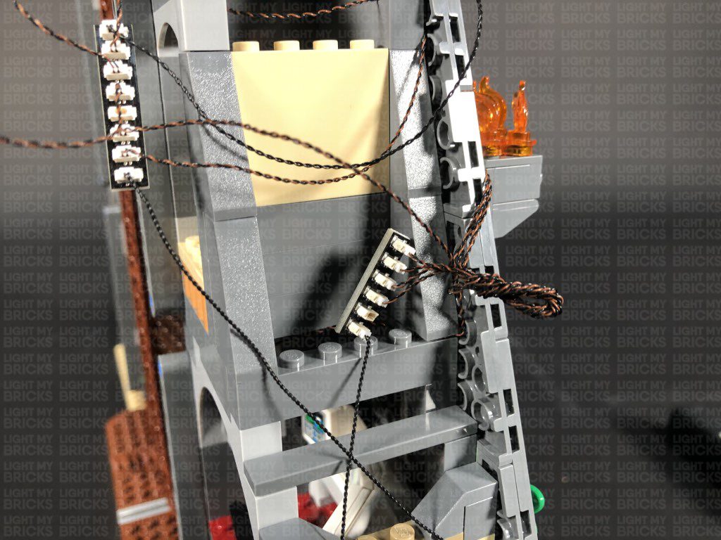
 15.) Reconnect the fire section to the middle wall section ensuring the cables are laid behind to the right side. Reconnect the middle wall section to the gate, then bring the cables to the right side underneath the middle side flap. The four cables should fit nicely into the gaps of the bottom of the wall plate.
Connect the four cables to a new 6-Port Expansion Board. Take a 15cm Connecting Cable and connect it to the 6-Port Expansion Board. Bring the other end of the cable down to the bottom to connect to a different OUT port on the Flicker Effects Board. Turn ON the USB Power Bank to test the fire torches in the middle wall section are working and flickering OK.
Note: If you experience any issues with the lights not working and suspect an issue with a component, please try a different port on the expansion board to verify where the fault lies (with the light or expansion board). To correct any issues with expansion board ports, please view the section addressing expansion board issues on our online troubleshooting guide.
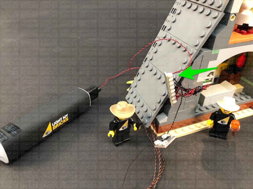
Neaten up the cables from the middle fire section by grouping them together and folding and twisting around each other into a neat bunch. Take 2x Adhesive Squares and stick them to the back of the expansion board. Mount the expansion board to the dark grey wall plate on the side, then ensure the four cables are neatly laid and tucked into the space behind the wall plate.
16.) Take the top wall section along with the fire torch section on the very top, then disassemble the flame pieces. Install another 4x White 15cm Bit Lights to this section (same way we did for previous fire sections).
15.) Reconnect the fire section to the middle wall section ensuring the cables are laid behind to the right side. Reconnect the middle wall section to the gate, then bring the cables to the right side underneath the middle side flap. The four cables should fit nicely into the gaps of the bottom of the wall plate.
Connect the four cables to a new 6-Port Expansion Board. Take a 15cm Connecting Cable and connect it to the 6-Port Expansion Board. Bring the other end of the cable down to the bottom to connect to a different OUT port on the Flicker Effects Board. Turn ON the USB Power Bank to test the fire torches in the middle wall section are working and flickering OK.
Note: If you experience any issues with the lights not working and suspect an issue with a component, please try a different port on the expansion board to verify where the fault lies (with the light or expansion board). To correct any issues with expansion board ports, please view the section addressing expansion board issues on our online troubleshooting guide.
Neaten up the cables from the middle fire section by grouping them together and folding and twisting around each other into a neat bunch. Take 2x Adhesive Squares and stick them to the back of the expansion board. Mount the expansion board to the dark grey wall plate on the side, then ensure the four cables are neatly laid and tucked into the space behind the wall plate.
16.) Take the top wall section along with the fire torch section on the very top, then disassemble the flame pieces. Install another 4x White 15cm Bit Lights to this section (same way we did for previous fire sections).
 Reconnect the fire section to the top wall panel ensuring the cables are this time, laid behind toward the left.
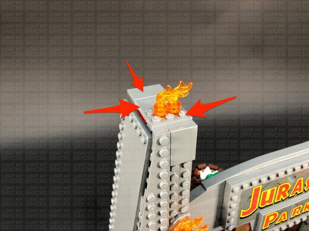
17.) Before we reconnect the wall section, take the fire section on the very top of the gate and disconnect the flame sections as per below:
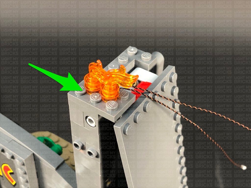
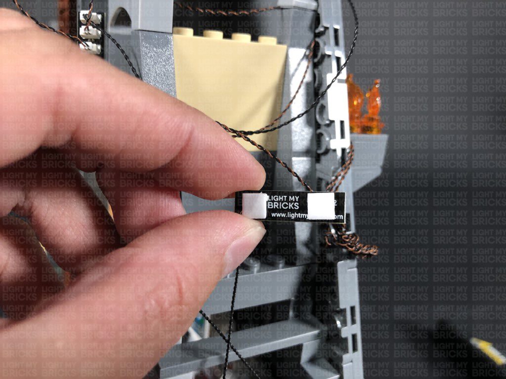
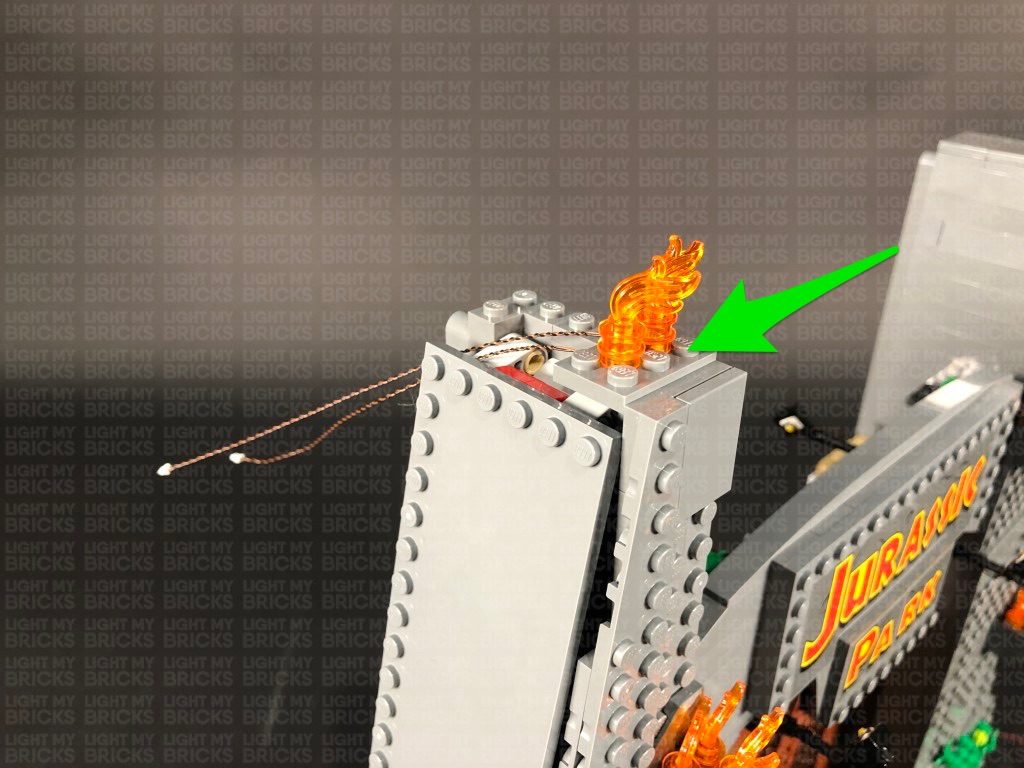
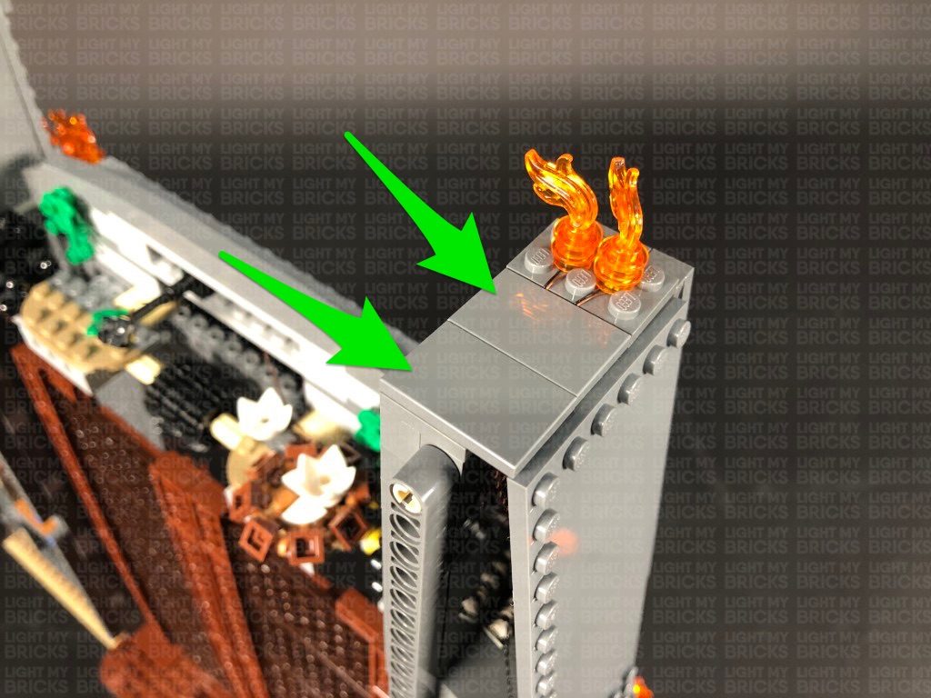
Take a White 15cm Bit Light and with the cable facing behind, place it in between studs in the following position. Secure the Bit Light in place by reconnecting one of the flame pieces directly over the top, then repeat this step to install another White 15cm Bit Light to the other flame.
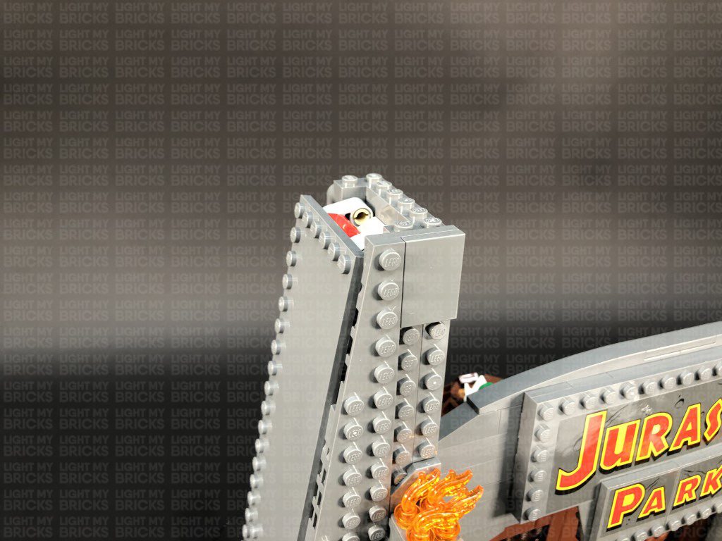
Reconnect the plate with flame pieces to the top of the gate, then tuck both of the cables underneath. Bring the cables underneath the side flap section to the back as shown below:
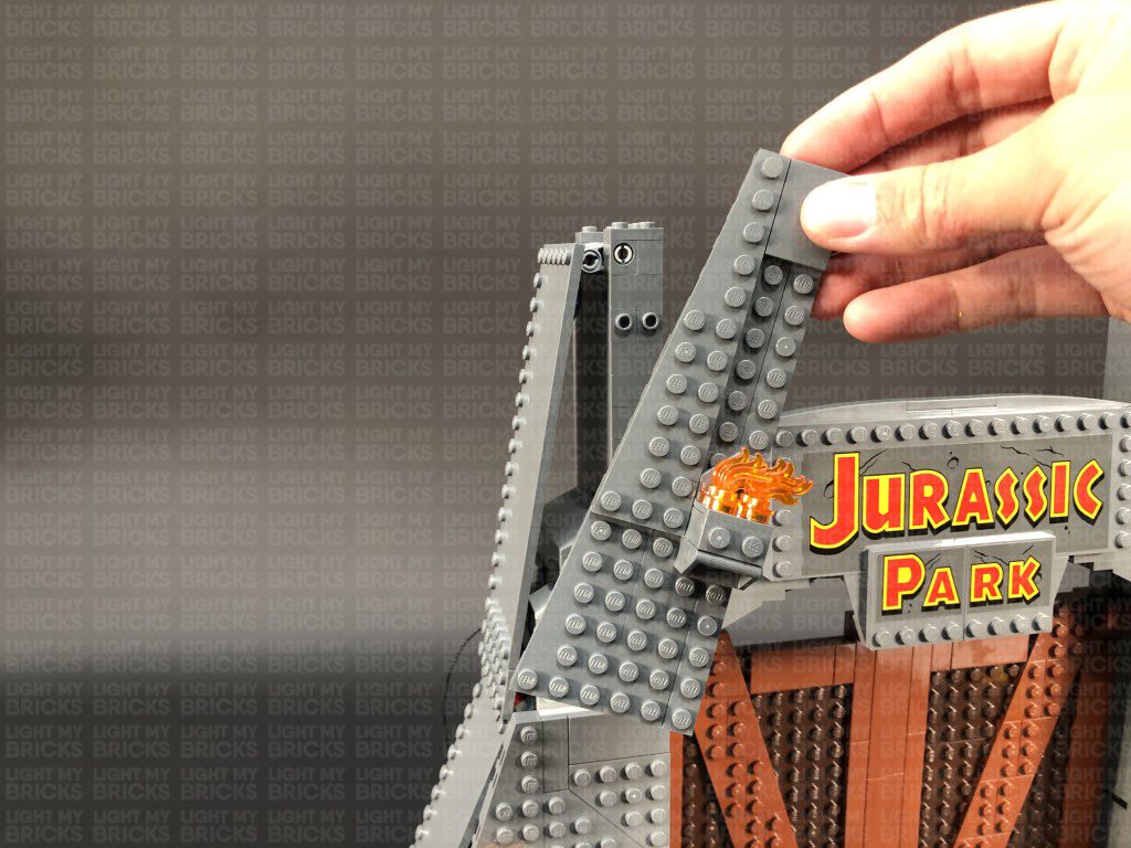
18.) Take the top wall section and fold the cables behind and across the left section. Ensure the cables are laid in the following space underneath the wall plate before reconnecting this section to the front of the set.
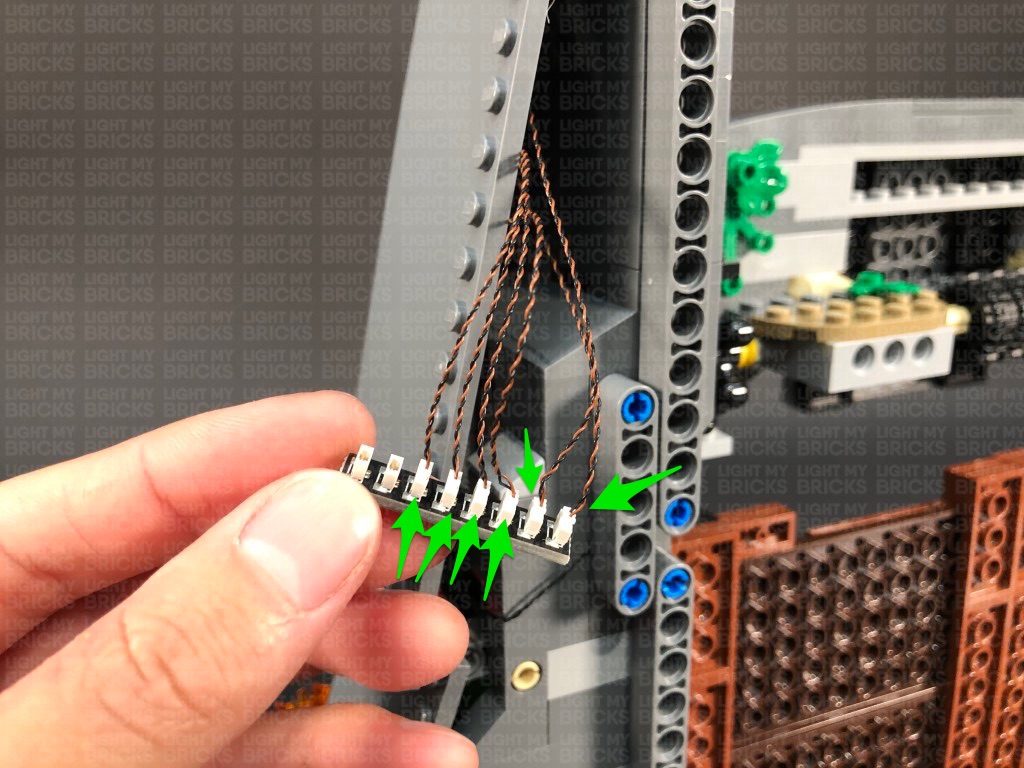
Bring the cables to the back, underneath the top flap section, then connect them along with the two bit light cables from the top to a new 8-Port Expansion Board.
Take a 30cm Connecting Cable and connect it to a spare port on the 8-port expansion board. Bring the other end of the cable all the way down and connect it to the remaining OUT port on the Flicker Effects Board. Turn ON the USB Power Bank to test the top fire torches are all working and flickering OK.
Reconnect the fire section to the top wall panel ensuring the cables are this time, laid behind toward the left.
17.) Before we reconnect the wall section, take the fire section on the very top of the gate and disconnect the flame sections as per below:
Take a White 15cm Bit Light and with the cable facing behind, place it in between studs in the following position. Secure the Bit Light in place by reconnecting one of the flame pieces directly over the top, then repeat this step to install another White 15cm Bit Light to the other flame.
Reconnect the plate with flame pieces to the top of the gate, then tuck both of the cables underneath. Bring the cables underneath the side flap section to the back as shown below:
18.) Take the top wall section and fold the cables behind and across the left section. Ensure the cables are laid in the following space underneath the wall plate before reconnecting this section to the front of the set.
Bring the cables to the back, underneath the top flap section, then connect them along with the two bit light cables from the top to a new 8-Port Expansion Board.
Take a 30cm Connecting Cable and connect it to a spare port on the 8-port expansion board. Bring the other end of the cable all the way down and connect it to the remaining OUT port on the Flicker Effects Board. Turn ON the USB Power Bank to test the top fire torches are all working and flickering OK.
 19.) Now that we have completed installation of all the lights on the right side of the gate, take the time to neaten up cables and components. Starting with the bottom section, neatly tuck in all the components and cables (leaving the USB cable out). Ensure the bottom side flap can completely close.
Moving up to the middle section, neatly tuck the 30cm Connecting Cable into the side section.
19.) Now that we have completed installation of all the lights on the right side of the gate, take the time to neaten up cables and components. Starting with the bottom section, neatly tuck in all the components and cables (leaving the USB cable out). Ensure the bottom side flap can completely close.
Moving up to the middle section, neatly tuck the 30cm Connecting Cable into the side section.
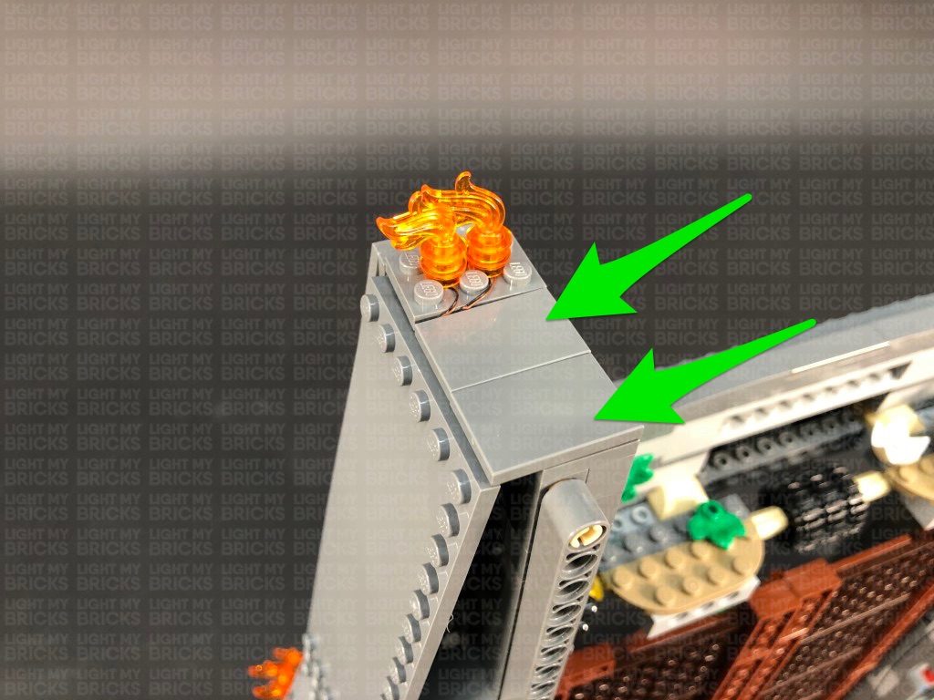
 Lift up the top side flap and group the cables together into a neat bunch by twisting and folding them around each other. Stick 2x Adhesive Squares to the back of the 8-Port Expansion Board. Mount the expansion board to the following position on the side of the set, then securely reconnect the top side flap.
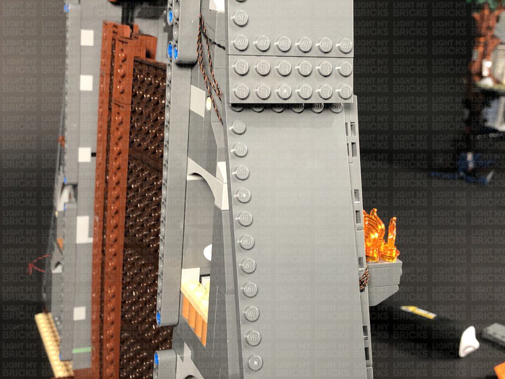
Reconnect the remaining two tiles at the very top. The back of the set should look like below, without any cables visible.
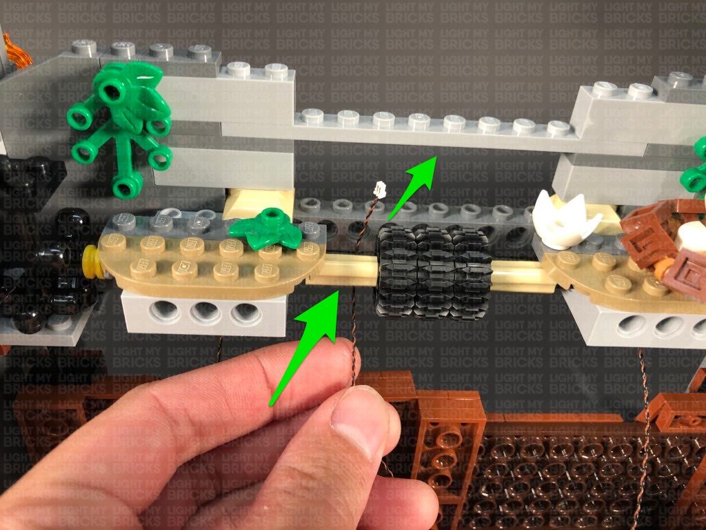
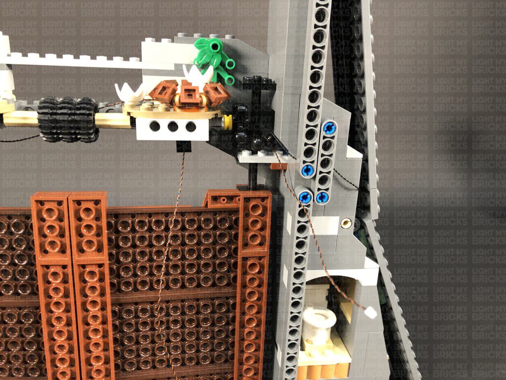
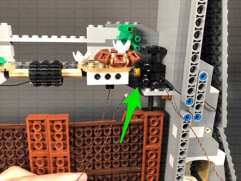
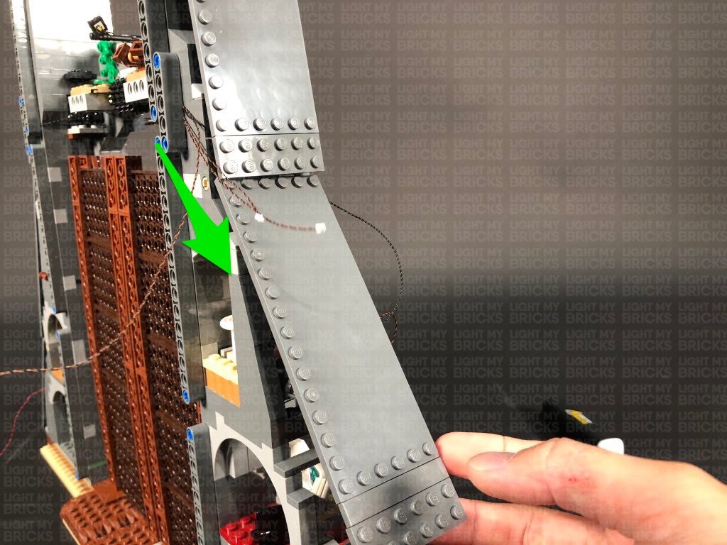
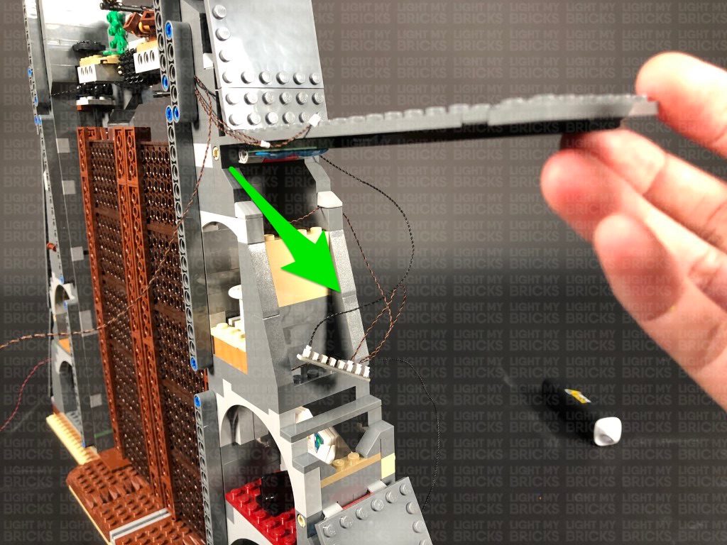
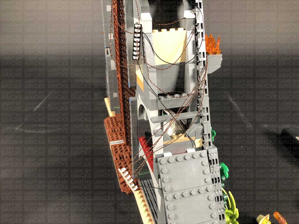
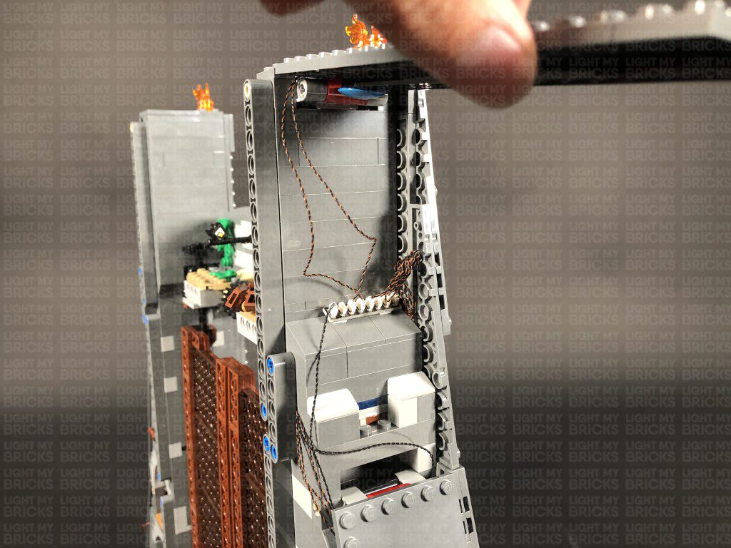
20.) Turn the set to the back, then take the other end of the 30cm Connecting Cable from the White strip Light on the right side and thread it all the way up the top right corner. Thread the cable back down and then pull it out from the front in between the wall and black technic bar. Pull the cable all the way out as shown below.
Lift up the top side flap and group the cables together into a neat bunch by twisting and folding them around each other. Stick 2x Adhesive Squares to the back of the 8-Port Expansion Board. Mount the expansion board to the following position on the side of the set, then securely reconnect the top side flap.
Reconnect the remaining two tiles at the very top. The back of the set should look like below, without any cables visible.
20.) Turn the set to the back, then take the other end of the 30cm Connecting Cable from the White strip Light on the right side and thread it all the way up the top right corner. Thread the cable back down and then pull it out from the front in between the wall and black technic bar. Pull the cable all the way out as shown below.
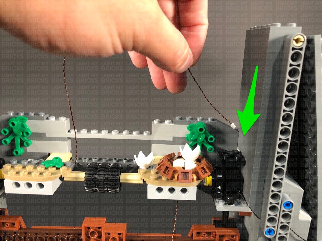
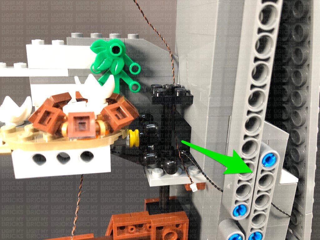
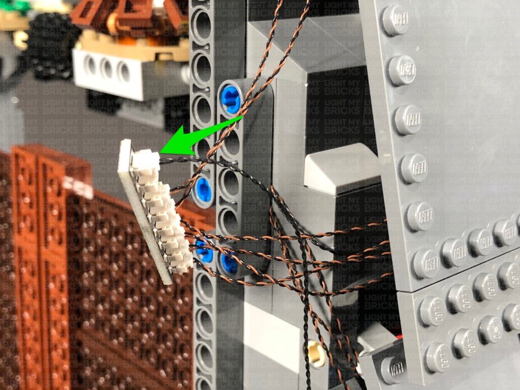
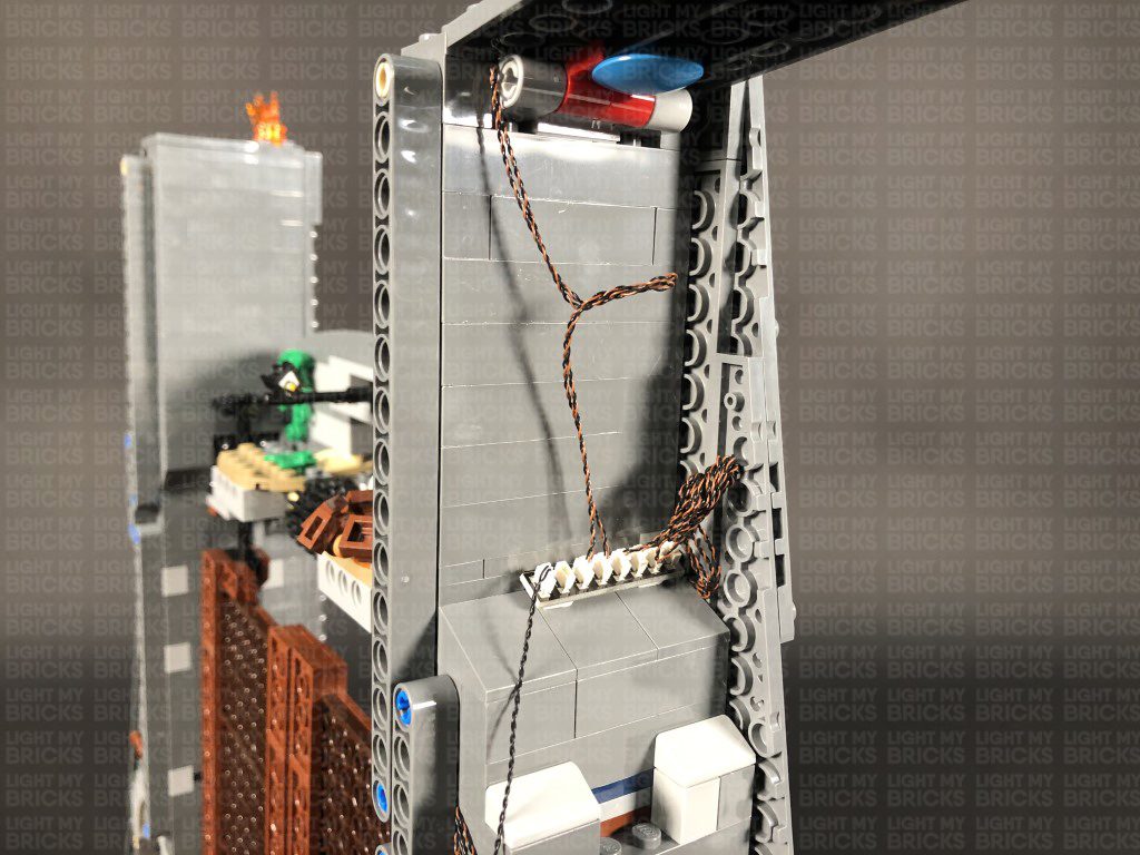
 Disconnect the smaller technic bar as well as the bottom part of the larger technic bar. Pull the cable across to the right as per below, then reconnect the technic bars to secure the cable in place.
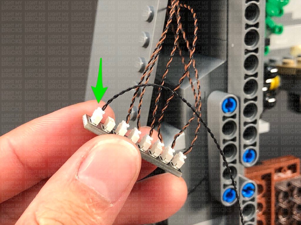
Bring the 30cm Connecting Cable down and connect it to the first available port on a new 8-Port Expansion Board. Take a 15cm Connecting Cable and connect it to the end port on that expansion board, then connect the other end of the 15cm cable to another 8-Port Expansion Board.
21.) Turn the set around to the front side, then disconnect the wall sections as well as all the fire torch sections.
Disconnect the smaller technic bar as well as the bottom part of the larger technic bar. Pull the cable across to the right as per below, then reconnect the technic bars to secure the cable in place.
Bring the 30cm Connecting Cable down and connect it to the first available port on a new 8-Port Expansion Board. Take a 15cm Connecting Cable and connect it to the end port on that expansion board, then connect the other end of the 15cm cable to another 8-Port Expansion Board.
21.) Turn the set around to the front side, then disconnect the wall sections as well as all the fire torch sections.
 Repeat step 2 to install another 2x Green 30cm Bit Lights to another two assembled LEGO spot lights using the provided LEGO pieces.
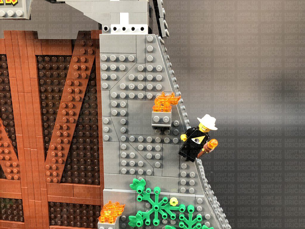
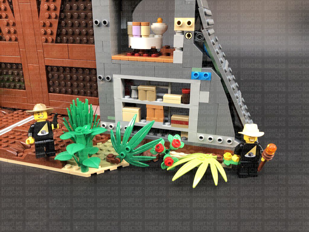
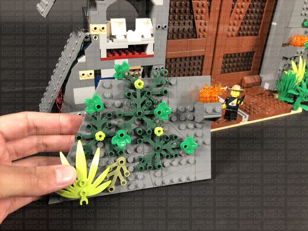
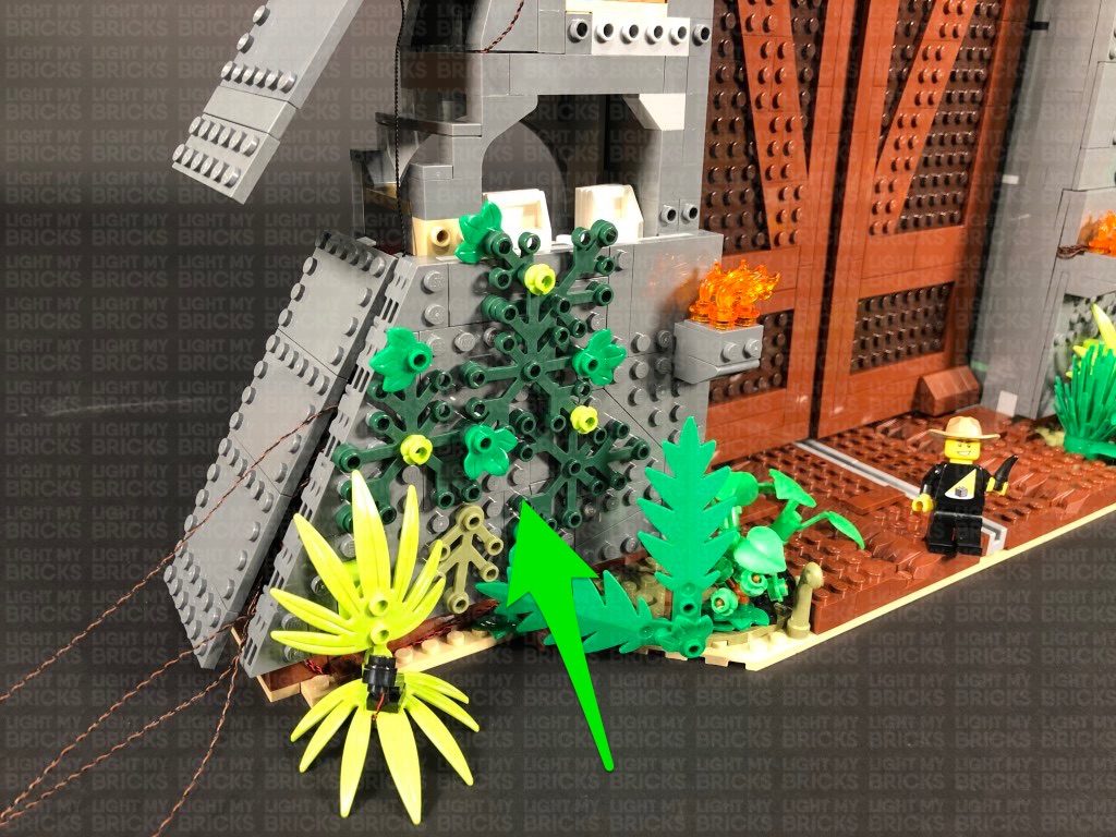
 22.) Disconnect the following two plants from the left side of the set, then connect one of the spot lights in the below position (facing diagonally up to the left):
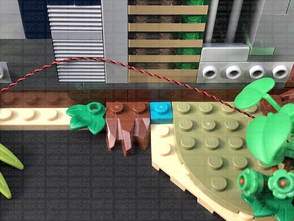
Bring the cable behind and to the left side before reconnecting the two plants we disconnected earlier.
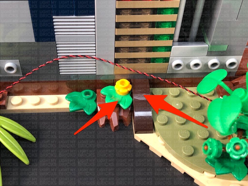
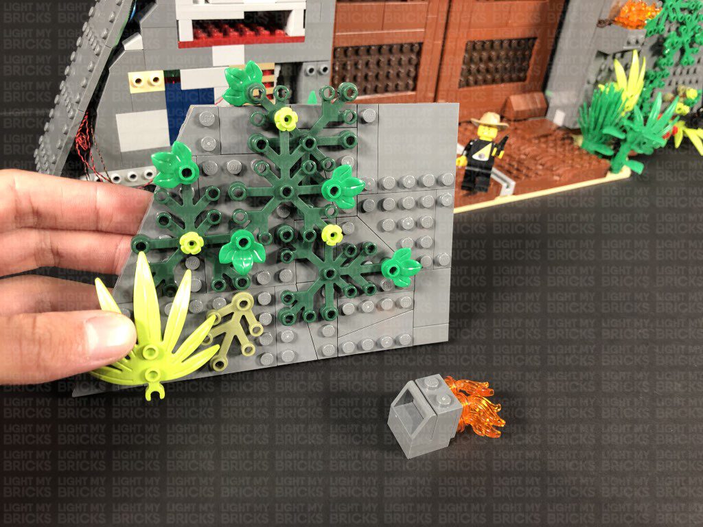
Disconnect the following plant section and flower pieces behind it, then lay the cable in between studs against the wall before reconnecting the flower pieces over it.
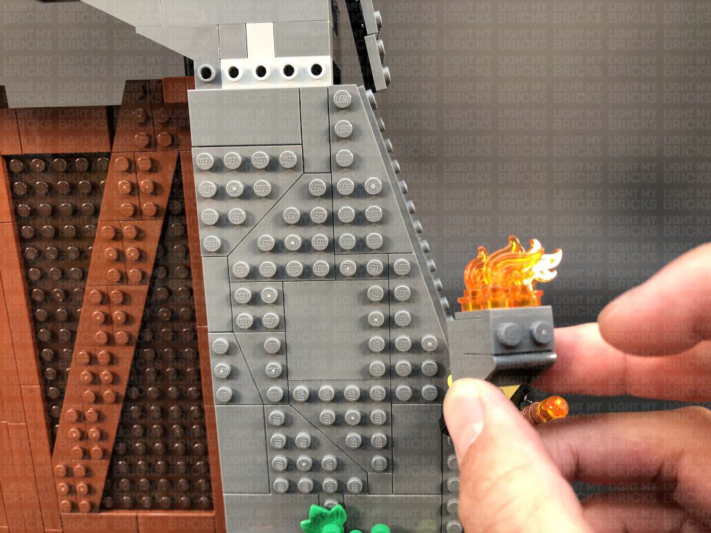
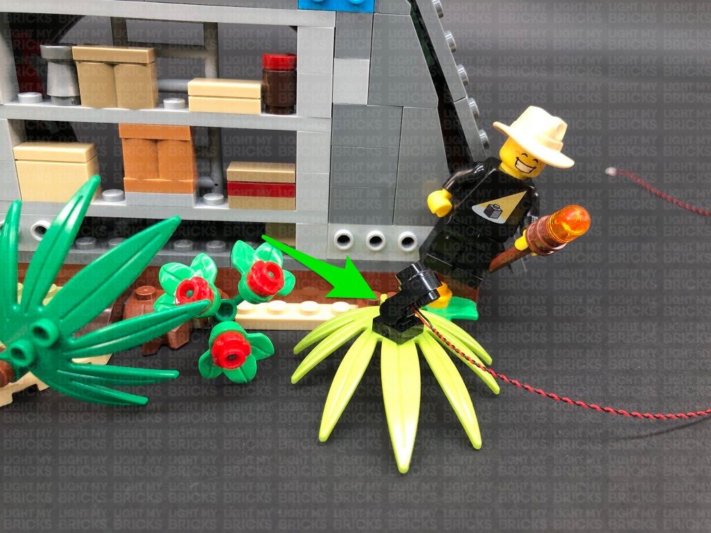
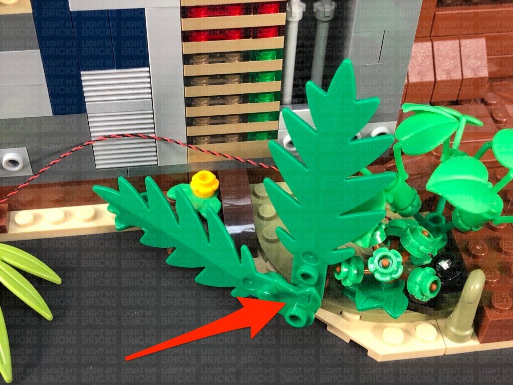
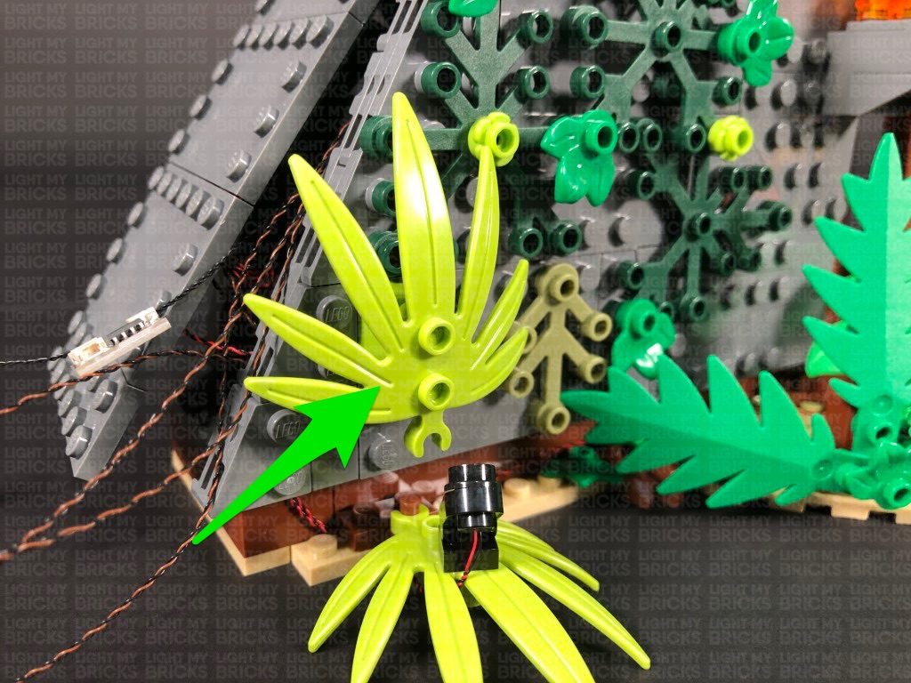
23.) Disconnect the following plant at the brown plate, then connect the second spot light to the top of it ensuring the it is angled to the right as shown below. Tuck the cable underneath the leaves toward the back right. Lay the cable along with the cable from the right spotlight over to the left in between studs before reconnecting this section over the top.
22.) Disconnect the following two plants from the left side of the set, then connect one of the spot lights in the below position (facing diagonally up to the left):
Bring the cable behind and to the left side before reconnecting the two plants we disconnected earlier.
Disconnect the following plant section and flower pieces behind it, then lay the cable in between studs against the wall before reconnecting the flower pieces over it.
23.) Disconnect the following plant at the brown plate, then connect the second spot light to the top of it ensuring the it is angled to the right as shown below. Tuck the cable underneath the leaves toward the back right. Lay the cable along with the cable from the right spotlight over to the left in between studs before reconnecting this section over the top.
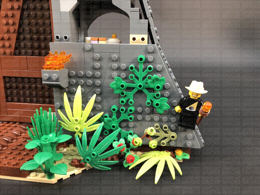
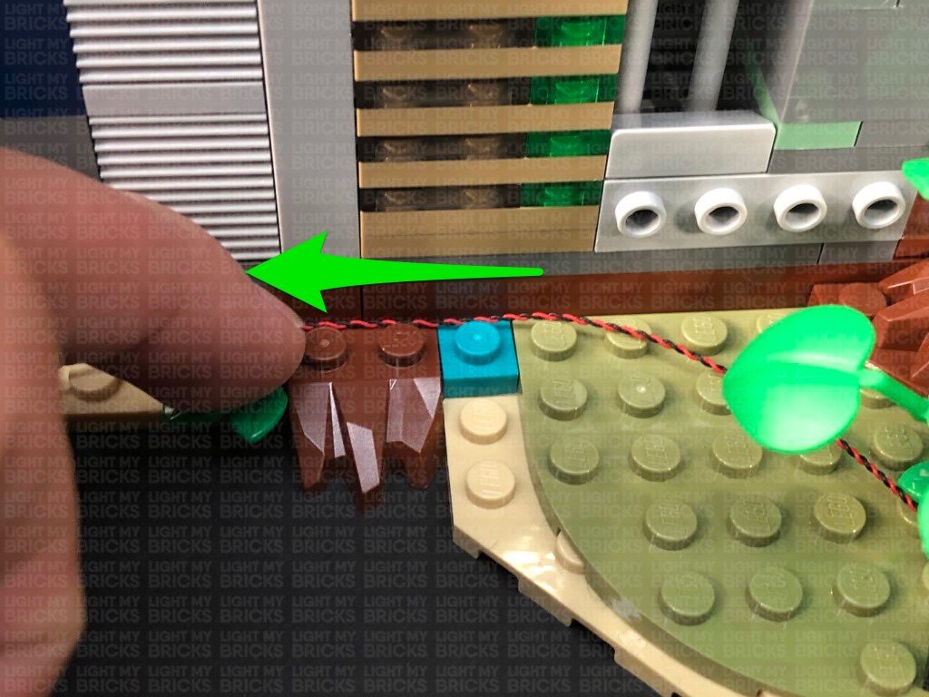
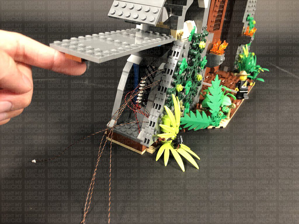
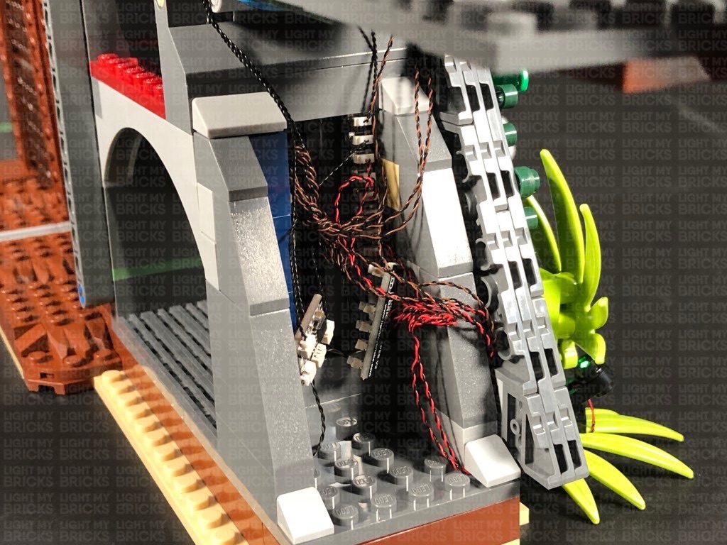
 Bring the two cables around to the back and secure them underneath the following angled tile. Connect the two bit light cables to the lower 8-Port Expansion Board from previous step. Turn the USB Power Bank ON to test the spot lights on this side are working OK.
Note: If you experience any issues with the lights not working and suspect an issue with a component, please try a different port on the expansion board to verify where the fault lies (with the light or expansion board). To correct any issues with expansion board ports, please view the section addressing expansion board issues on our online troubleshooting guide.
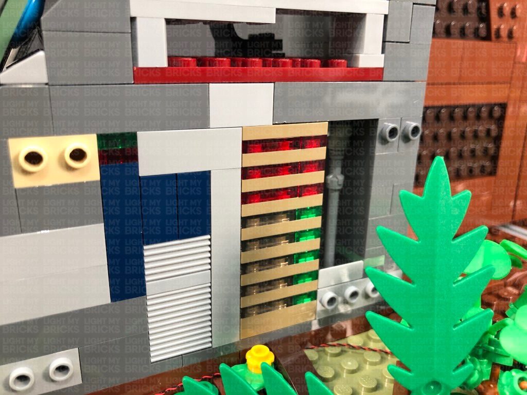
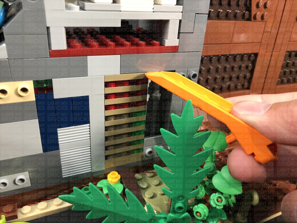
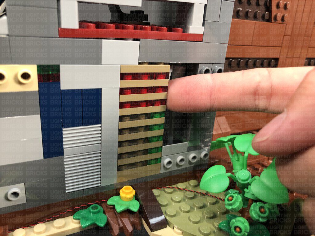
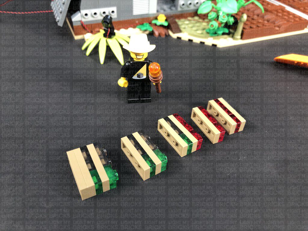
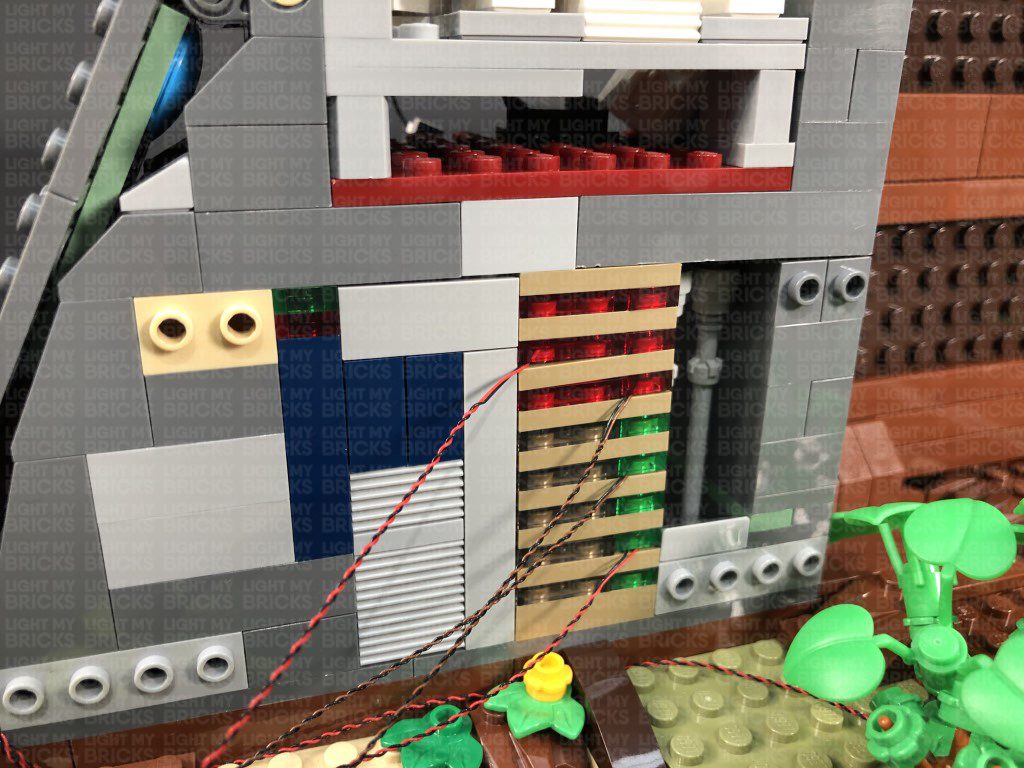
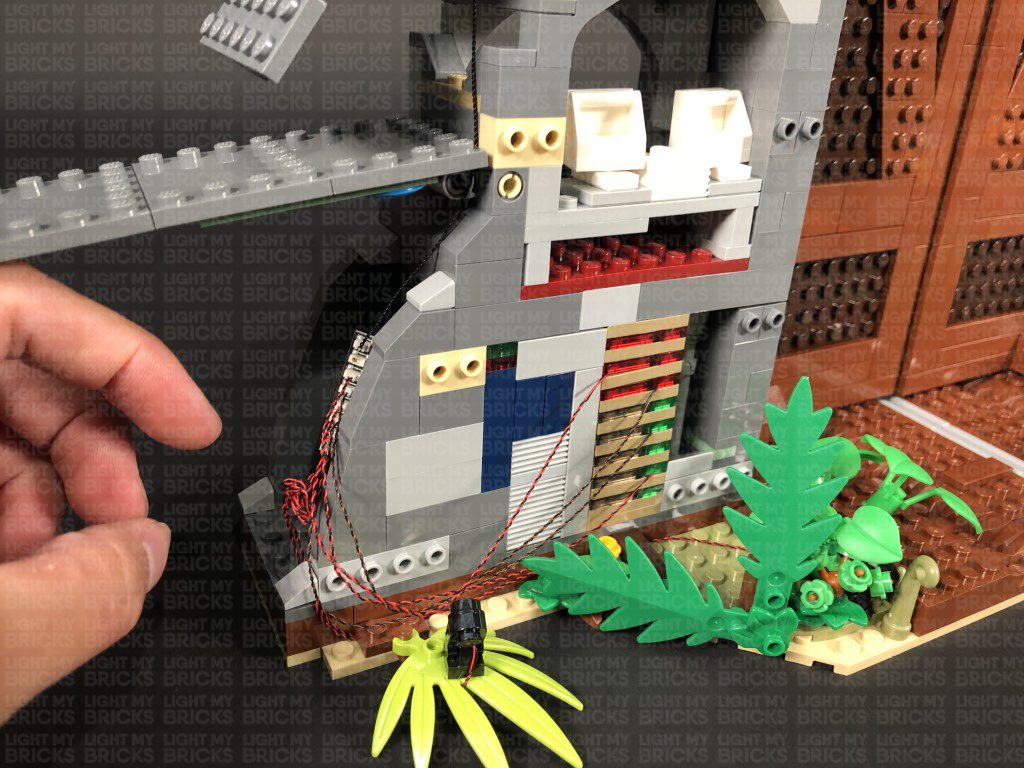
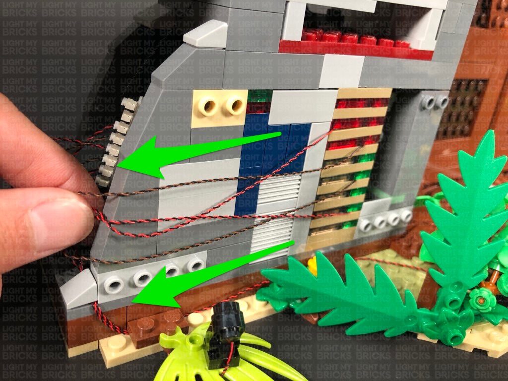
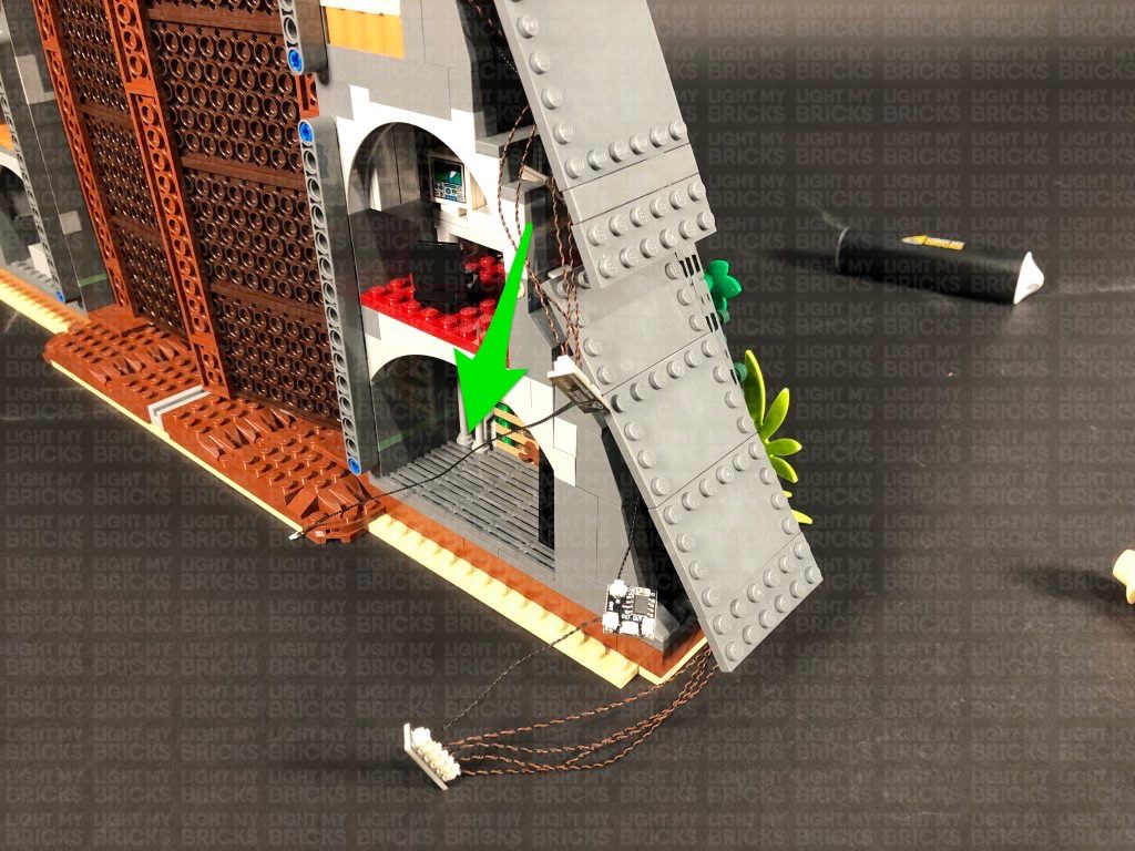
24.) We will now install some lights to the ground control room on the back side. We need to create a gap just above the brown plate so that we can pull the entire wall section out. Use the LEGO Removal tool to create the gap, then using your finger, pull the control panel section out as shown below.
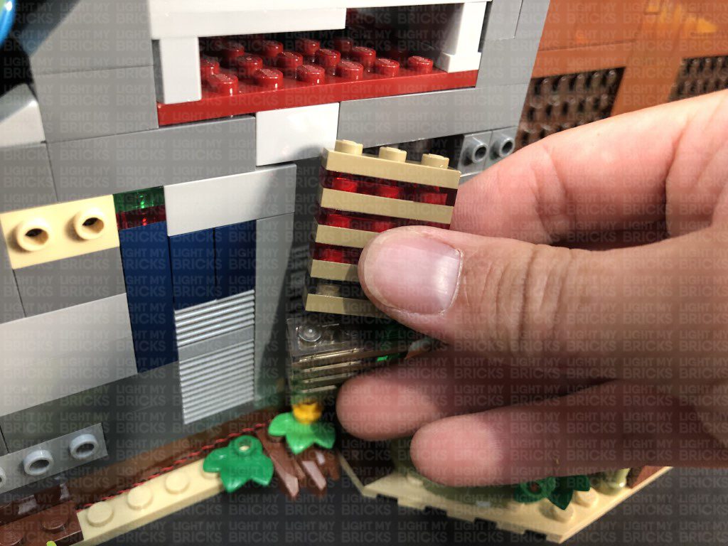
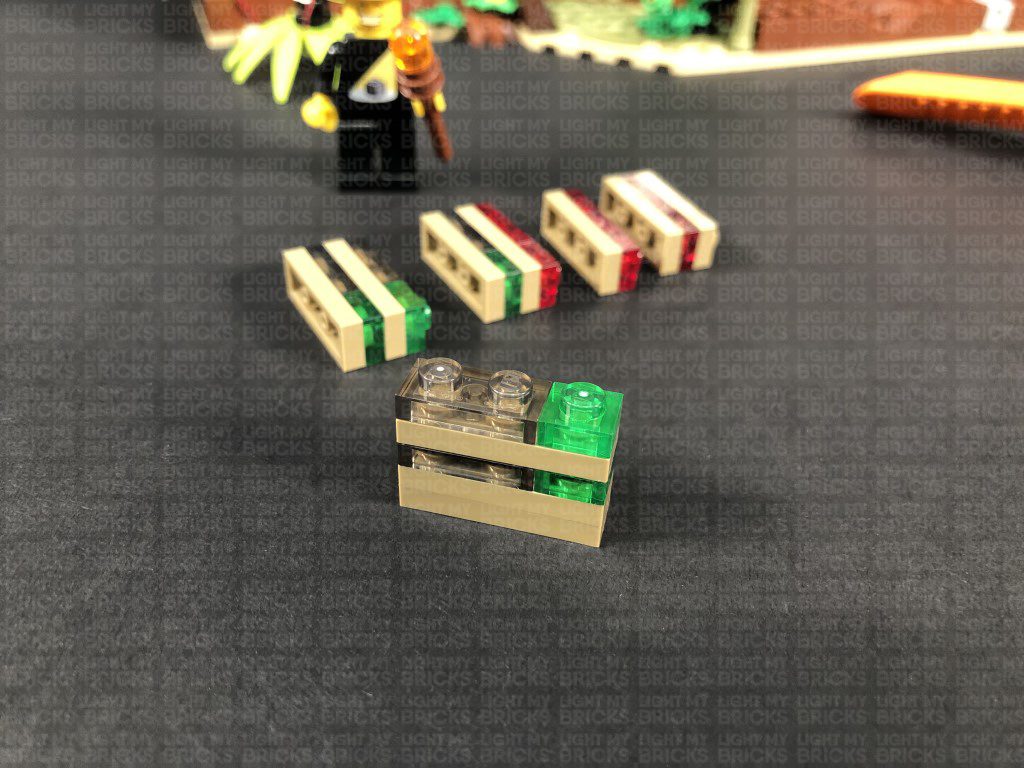
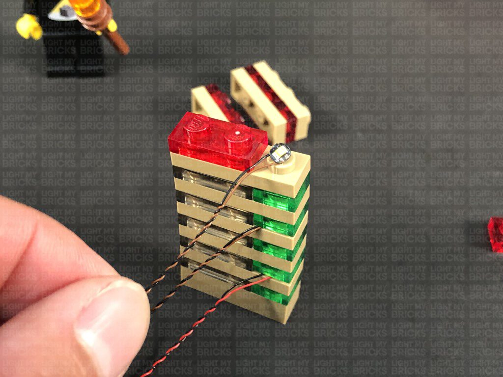
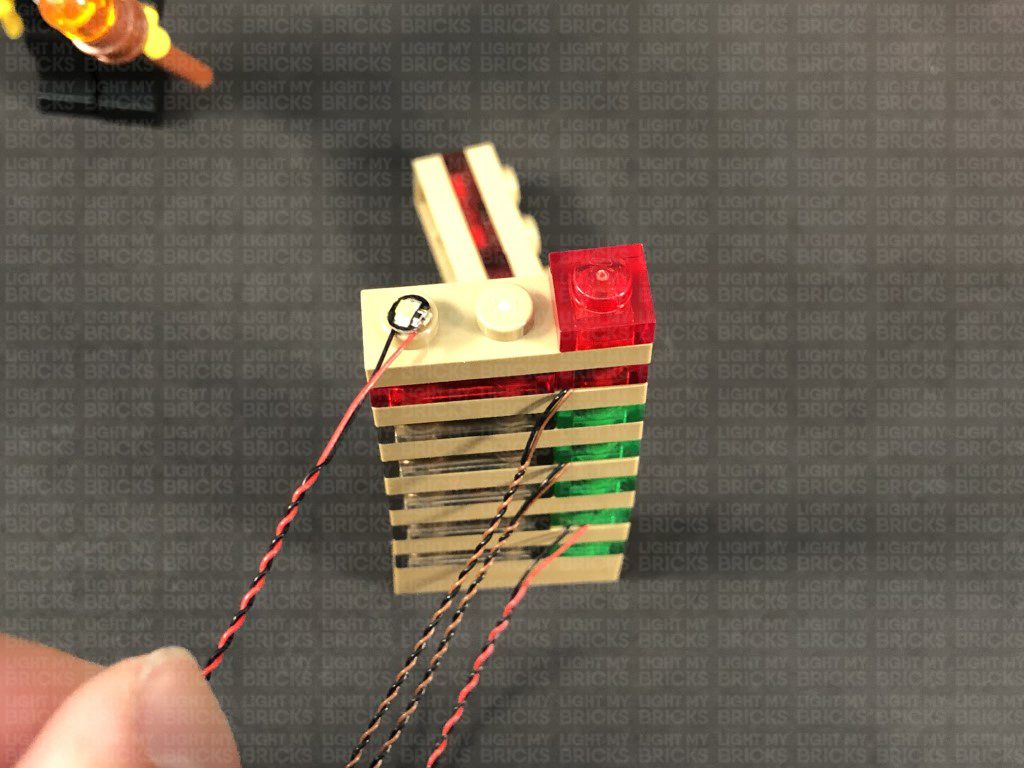
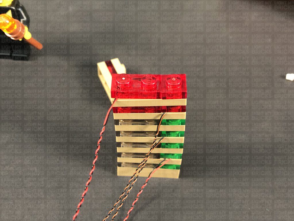
Disassemble the control panel light section as per below, then take the bottom section and disconnect the trans green plate.
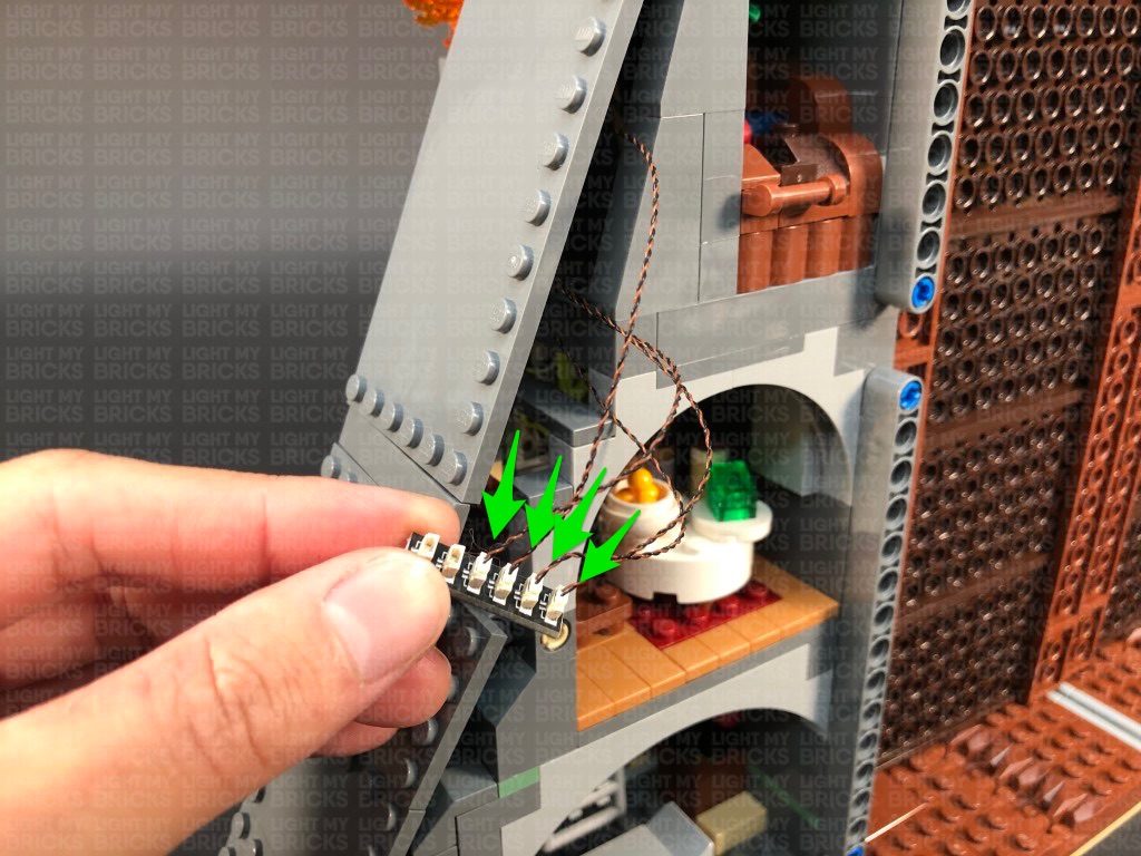
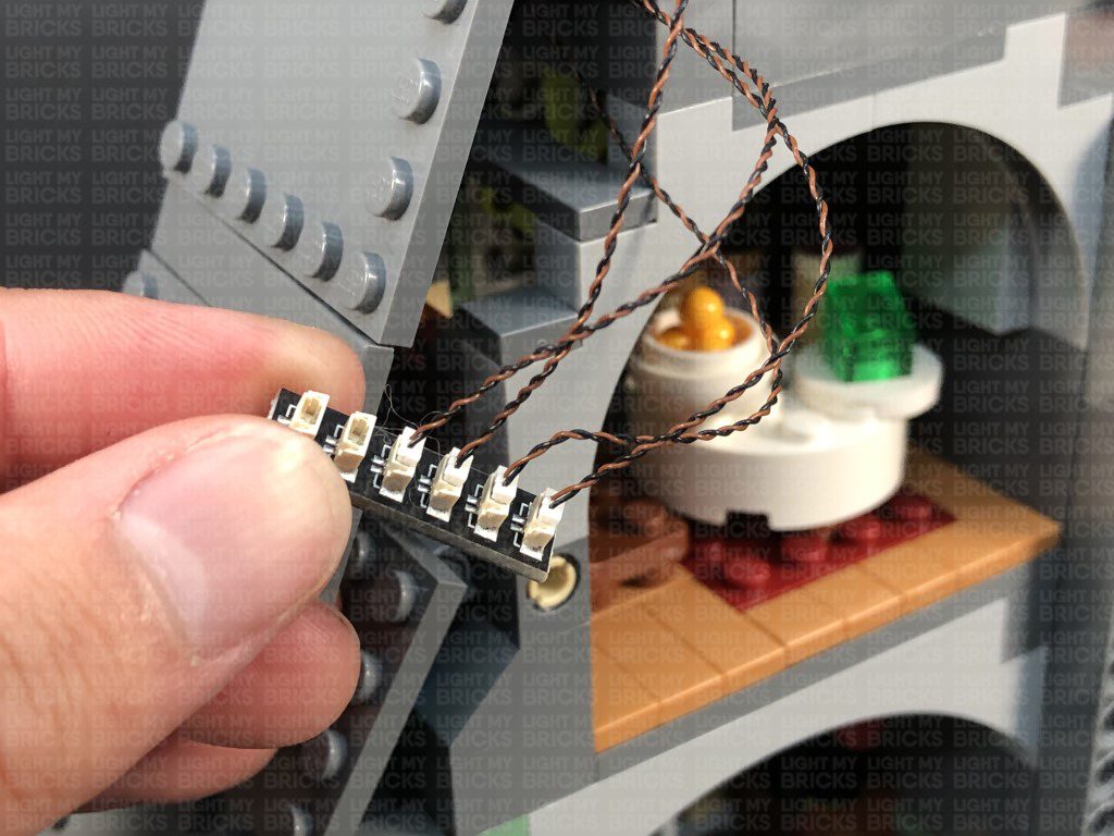
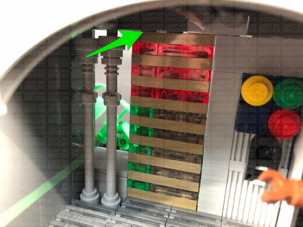
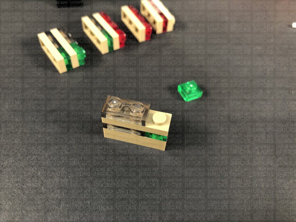
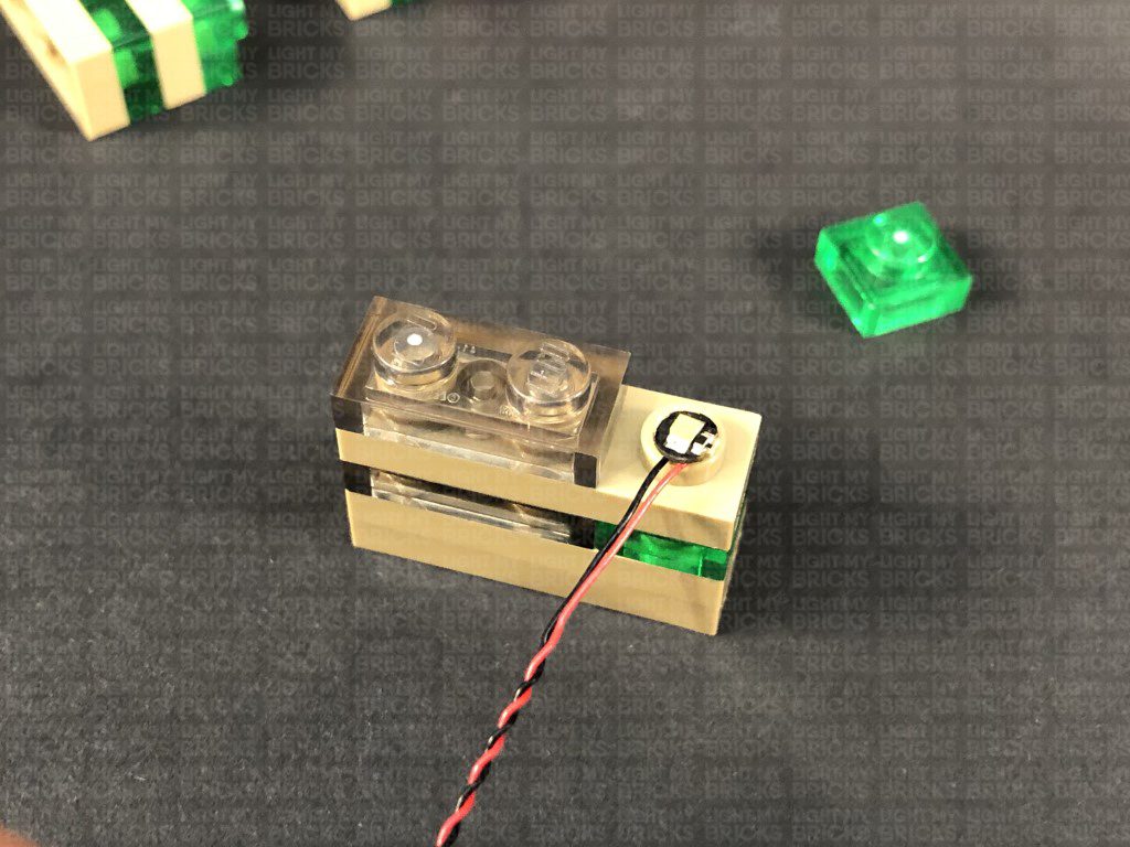
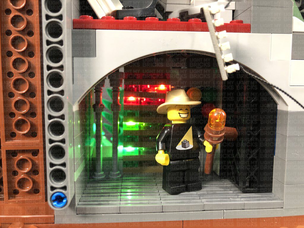
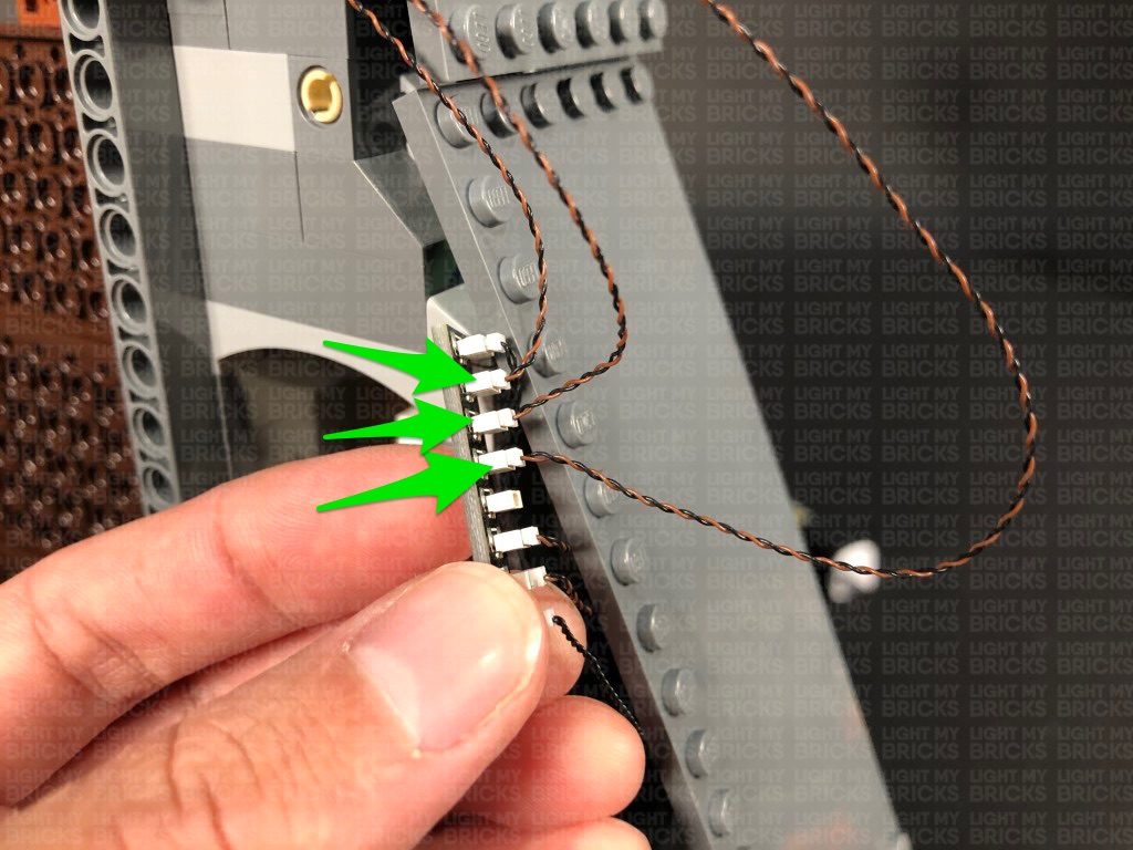
25.) Take a Flashing White 15cm Bit Light and with the cable facing toward you, place it over the stud on the right. Secure the light in place by reconnecting the trans green plate over the top. Reconnect the second section, then disconnect the trans green plate from the top of it as per below:
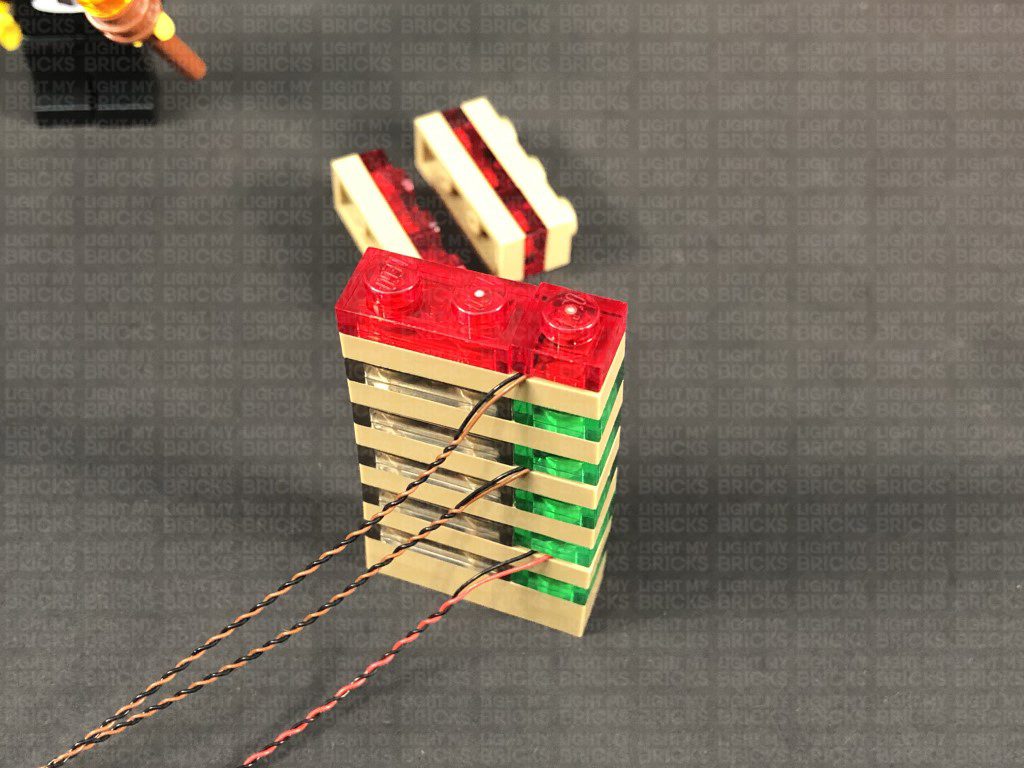
Take a White 15cm Bit Light and with the cable facing toward you, place it over the stud on the right. Secure the light in place by reconnecting the trans green plate over the top. Reconnect the next section, then disconnect the trans red 1×1 plate from the top right of it as per below:
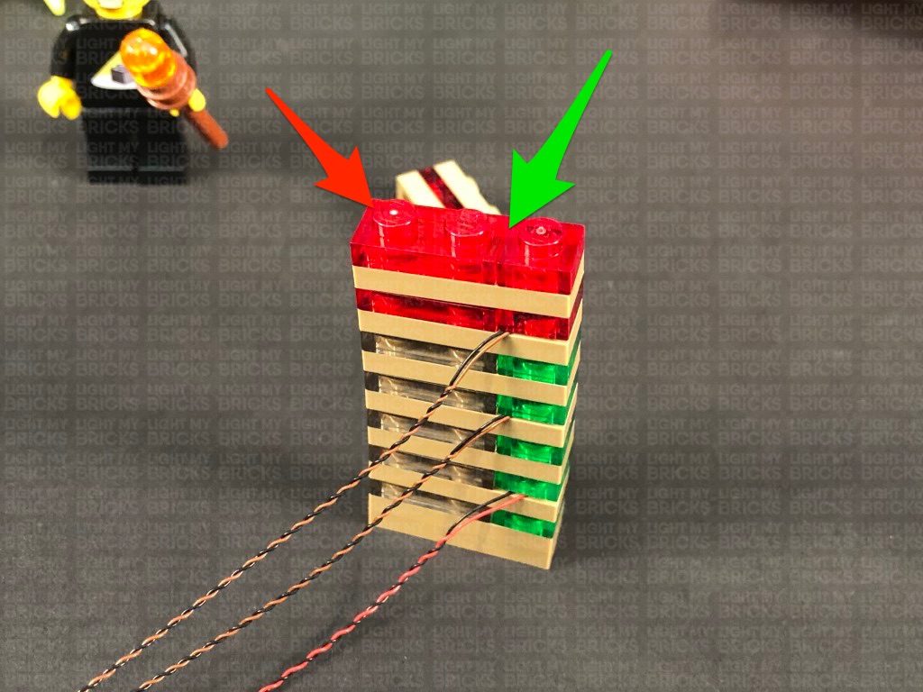
Take another White 15cm Bit Light and with the cable facing toward you, place it over the stud on the right. Secure the light in place by reconnecting the trans red plate over the top. Reconnect the next section, then disconnect the trans red 2×2 plate from the top of it as per below:
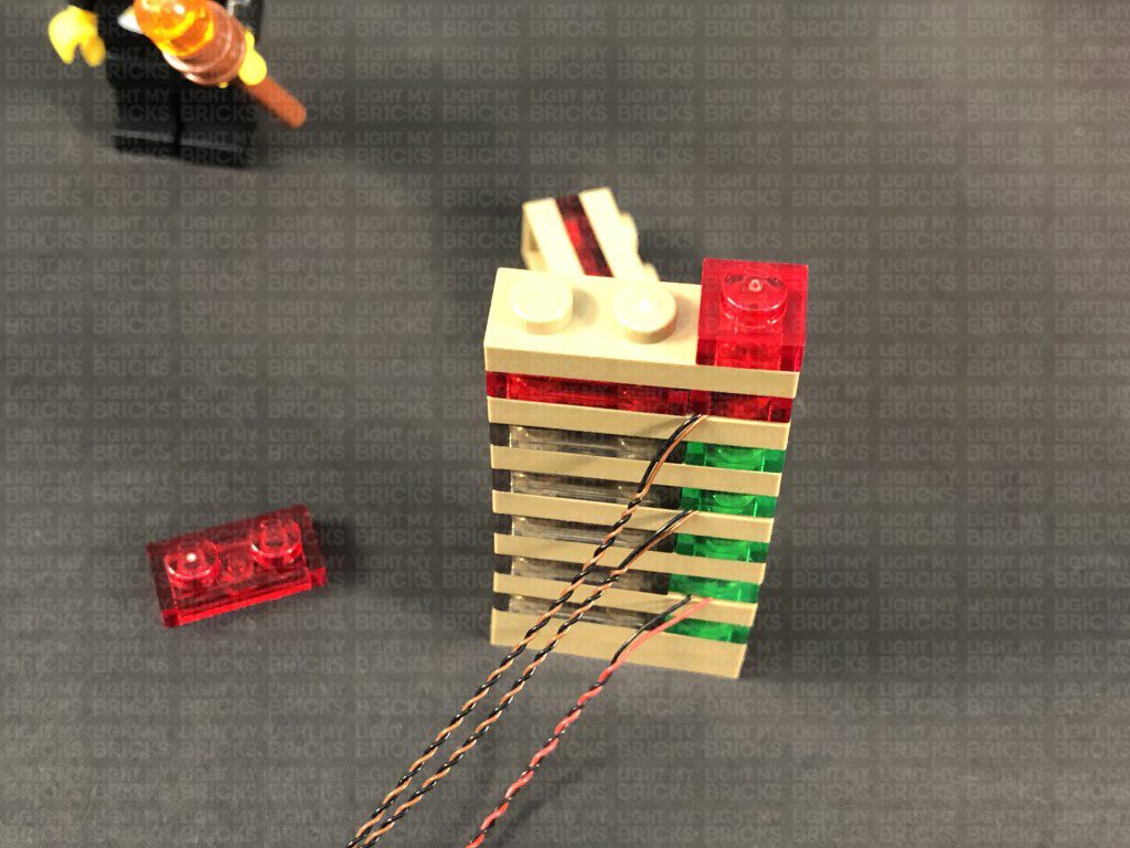
Take Flashing White 15cm Bit Light and with the cable facing toward you, place it over the left stud. Secure the Bit Light in place by reconnecting the trans red 2×2 plate, then reconnect the top section
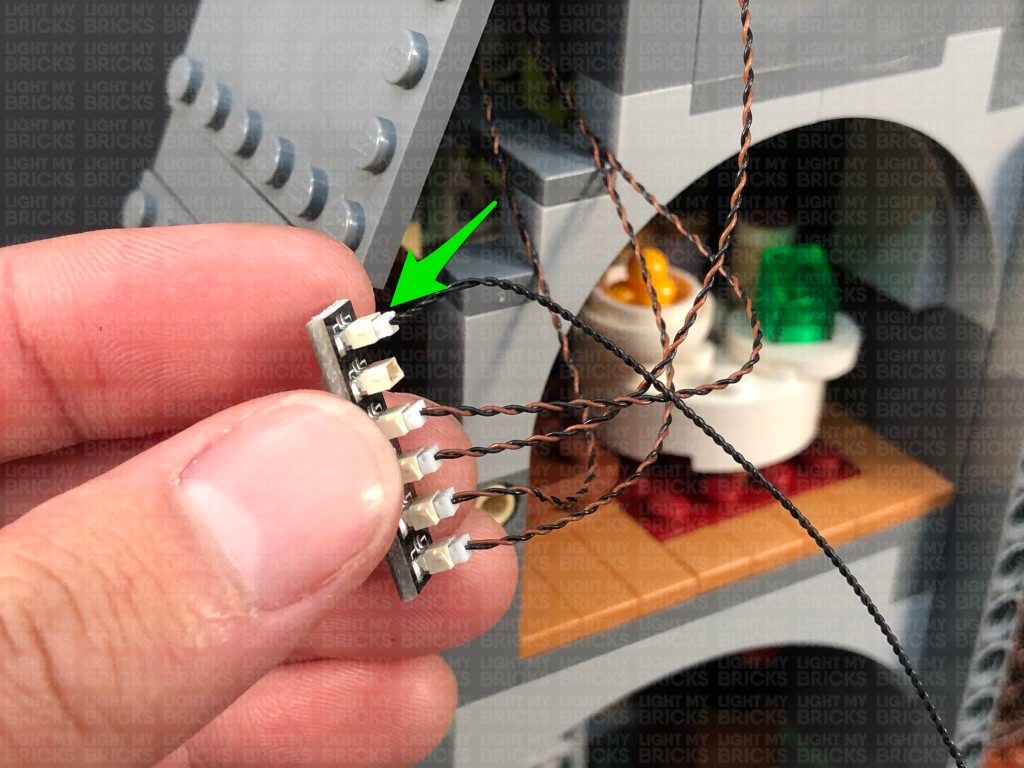
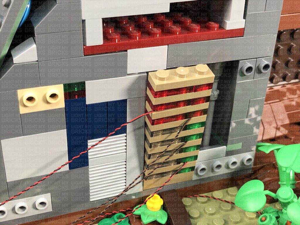
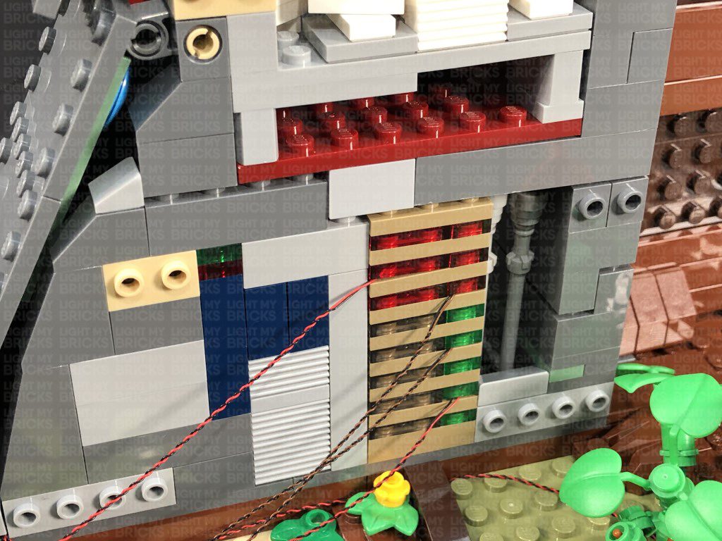
26.) Reconnect the control panel wall section back to the control room by connecting the bottom first, then slightly lifting up the upper section in order to tuck in the top of the control panel. Close up the gap by pushing down and reconnecting all the sections above.
Bring all four cables to the left and around the side to connect to the 8-Port Expansion Board. Turn ON the USB Power Bank to test all the lights in the ground control room are working OK.
Note: If you experience any issues with the lights not working and suspect an issue with a component, please try a different port on the expansion board to verify where the fault lies (with the light or expansion board). To correct any issues with expansion board ports, please view the section addressing expansion board issues on our online troubleshooting guide.
Take the two cables from the green spot lights and twist and fold them together a few times to form a neat bunch.
Turn the set around to the back and bring the 30cm Connecting Cable from above, underneath the top side flap, toward the front.
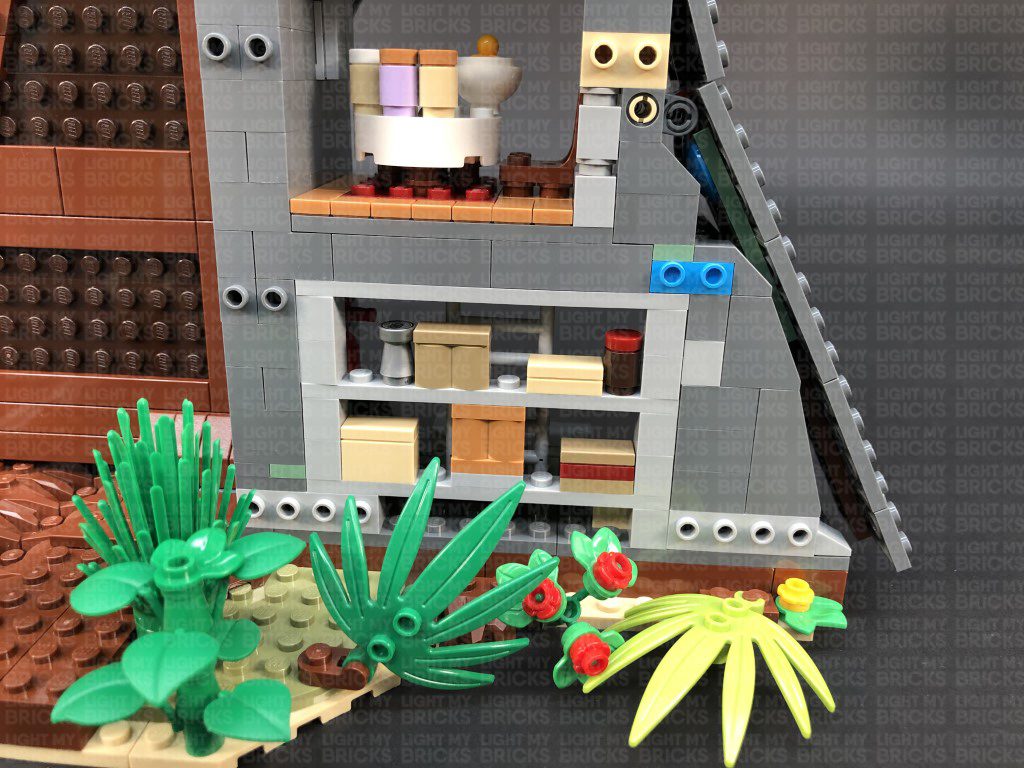
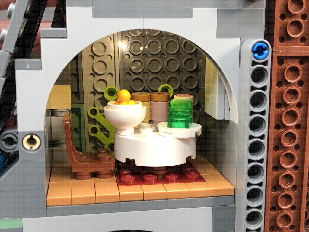
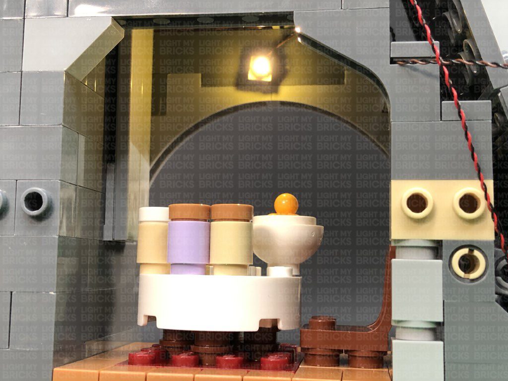
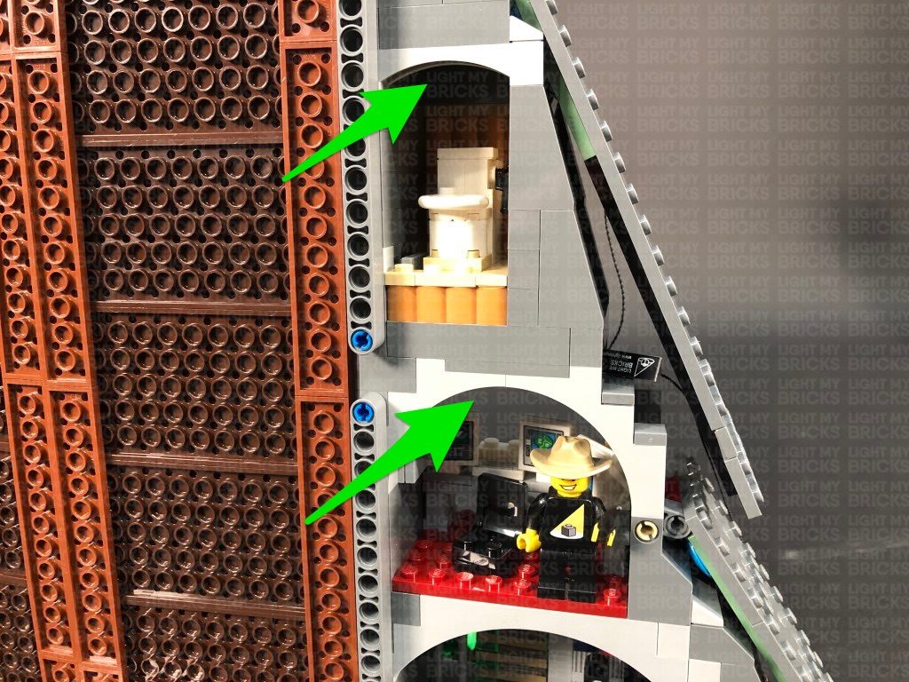
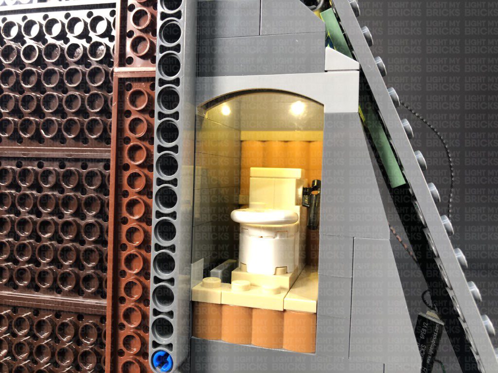
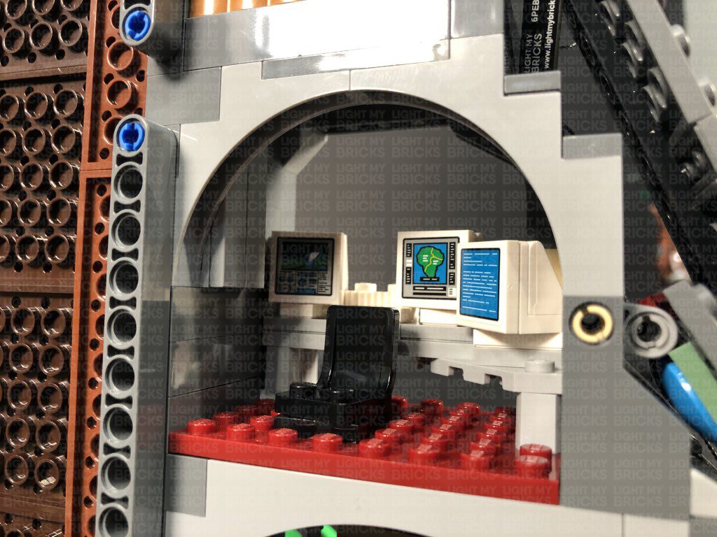
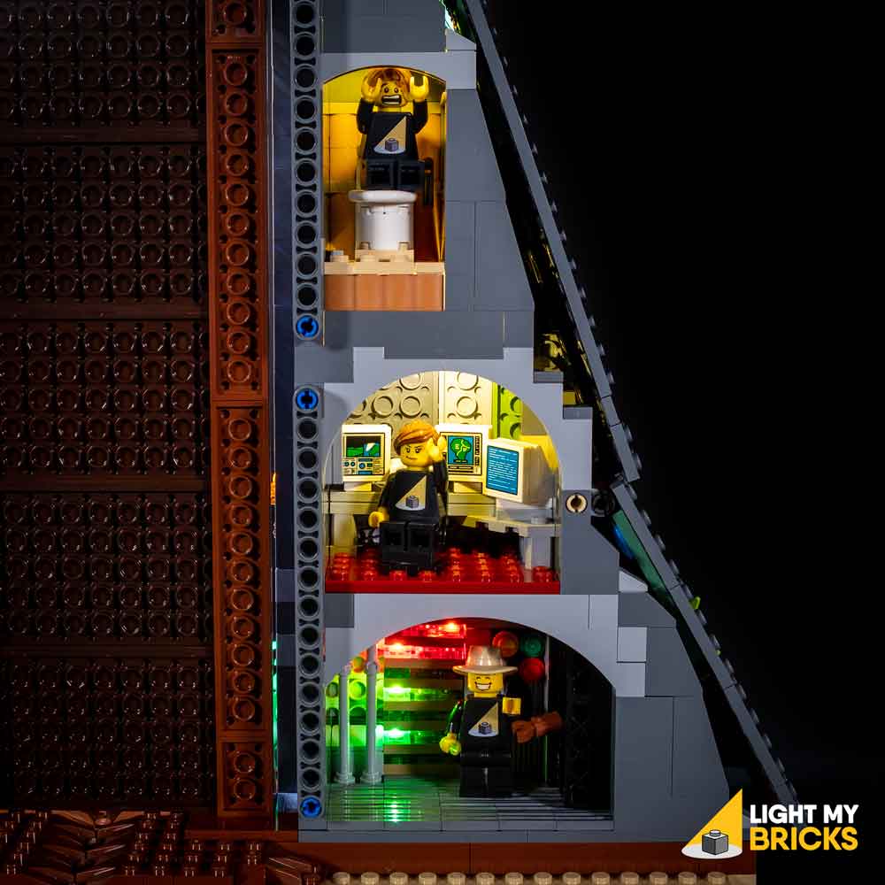
27.) We will now light up the toilet and the computer room. First take a White 15cm Bit Light and stick it to an Adhesive Square. Lift up the middle side flap and stick the Bit Light above the toilet on the inside of the top section as shown below:
Secure the Bit Light cable underneath the following angled tile towards the front of the set, then connect the cable to the 8-Port Expansion Board nearby. Turn ON the USB Power Bank to test the toilet light is working OK.
28.) Take another White 15cm Bit Light and stick it to an Adhesive Square. Lift up the middle side flap again and stick the Bit Light above the computer room on the inside of the top section as shown below:
Secure the Bit Light cable underneath the following angled brick towards the front of the set by slightly lifting up this section, laying the cable underneath, then reconnecting the angled brick over the top. Connect the cable to the 8-Port Expansion Board nearby, then turn ON the USB Power Bank to test the computer room light is working OK.
Note: If you experience any issues with the lights not working and suspect an issue with a component, please try a different port on the expansion board to verify where the fault lies (with the light or expansion board). To correct any issues with expansion board ports, please view the section addressing expansion board issues on our online troubleshooting guide.
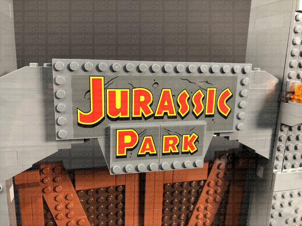
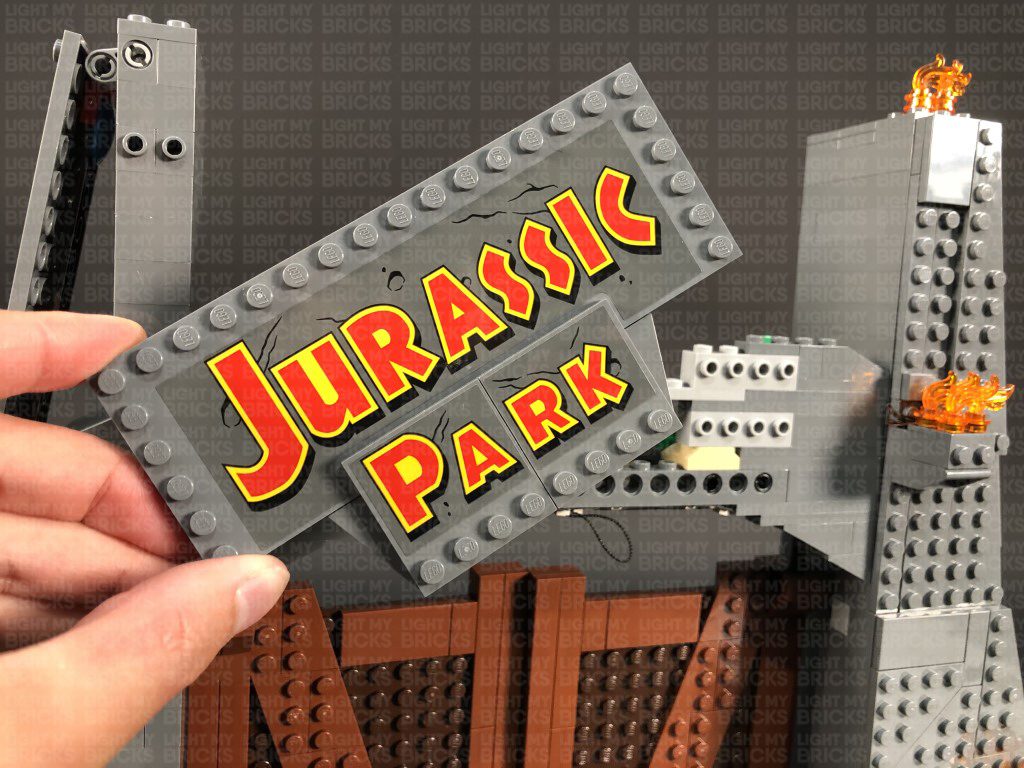
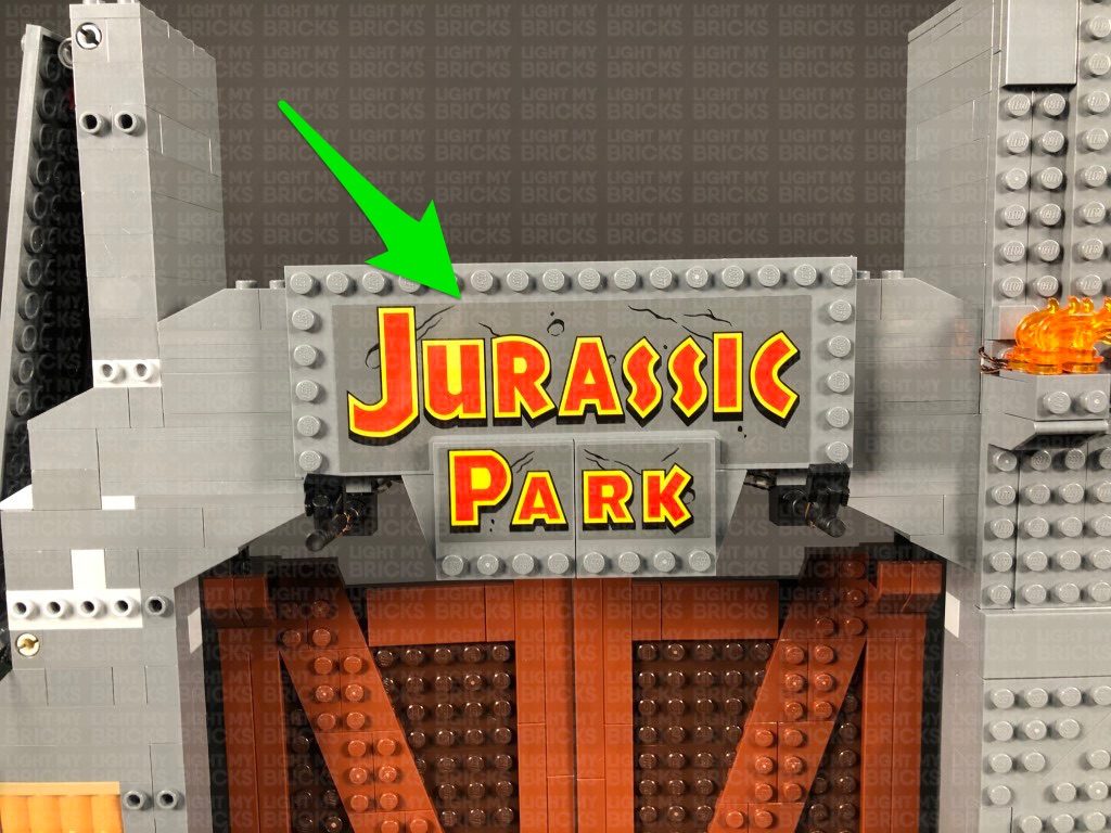
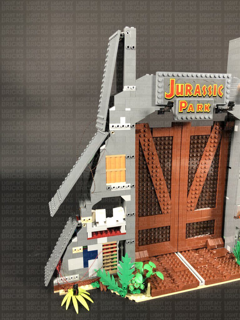
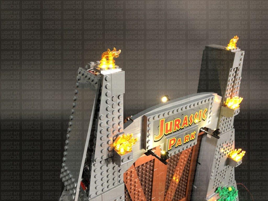
29.) We will now install some spotlights to shine up on the “Jurassic Park” sign. First disconnect the following section from the top, then turn the set around to the front and disconnect the Jurassic Park Sign plates.
Take out the following provided LEGO pieces for us to assemble 2x spot lights:
Bring the two cables around to the back and secure them underneath the following angled tile. Connect the two bit light cables to the lower 8-Port Expansion Board from previous step. Turn the USB Power Bank ON to test the spot lights on this side are working OK.
Note: If you experience any issues with the lights not working and suspect an issue with a component, please try a different port on the expansion board to verify where the fault lies (with the light or expansion board). To correct any issues with expansion board ports, please view the section addressing expansion board issues on our online troubleshooting guide.
24.) We will now install some lights to the ground control room on the back side. We need to create a gap just above the brown plate so that we can pull the entire wall section out. Use the LEGO Removal tool to create the gap, then using your finger, pull the control panel section out as shown below.
Disassemble the control panel light section as per below, then take the bottom section and disconnect the trans green plate.
25.) Take a Flashing White 15cm Bit Light and with the cable facing toward you, place it over the stud on the right. Secure the light in place by reconnecting the trans green plate over the top. Reconnect the second section, then disconnect the trans green plate from the top of it as per below:
Take a White 15cm Bit Light and with the cable facing toward you, place it over the stud on the right. Secure the light in place by reconnecting the trans green plate over the top. Reconnect the next section, then disconnect the trans red 1×1 plate from the top right of it as per below:
Take another White 15cm Bit Light and with the cable facing toward you, place it over the stud on the right. Secure the light in place by reconnecting the trans red plate over the top. Reconnect the next section, then disconnect the trans red 2×2 plate from the top of it as per below:
Take Flashing White 15cm Bit Light and with the cable facing toward you, place it over the left stud. Secure the Bit Light in place by reconnecting the trans red 2×2 plate, then reconnect the top section
26.) Reconnect the control panel wall section back to the control room by connecting the bottom first, then slightly lifting up the upper section in order to tuck in the top of the control panel. Close up the gap by pushing down and reconnecting all the sections above.
Bring all four cables to the left and around the side to connect to the 8-Port Expansion Board. Turn ON the USB Power Bank to test all the lights in the ground control room are working OK.
Note: If you experience any issues with the lights not working and suspect an issue with a component, please try a different port on the expansion board to verify where the fault lies (with the light or expansion board). To correct any issues with expansion board ports, please view the section addressing expansion board issues on our online troubleshooting guide.
Take the two cables from the green spot lights and twist and fold them together a few times to form a neat bunch.
Turn the set around to the back and bring the 30cm Connecting Cable from above, underneath the top side flap, toward the front.
27.) We will now light up the toilet and the computer room. First take a White 15cm Bit Light and stick it to an Adhesive Square. Lift up the middle side flap and stick the Bit Light above the toilet on the inside of the top section as shown below:
Secure the Bit Light cable underneath the following angled tile towards the front of the set, then connect the cable to the 8-Port Expansion Board nearby. Turn ON the USB Power Bank to test the toilet light is working OK.
28.) Take another White 15cm Bit Light and stick it to an Adhesive Square. Lift up the middle side flap again and stick the Bit Light above the computer room on the inside of the top section as shown below:
Secure the Bit Light cable underneath the following angled brick towards the front of the set by slightly lifting up this section, laying the cable underneath, then reconnecting the angled brick over the top. Connect the cable to the 8-Port Expansion Board nearby, then turn ON the USB Power Bank to test the computer room light is working OK.
Note: If you experience any issues with the lights not working and suspect an issue with a component, please try a different port on the expansion board to verify where the fault lies (with the light or expansion board). To correct any issues with expansion board ports, please view the section addressing expansion board issues on our online troubleshooting guide.
29.) We will now install some spotlights to shine up on the “Jurassic Park” sign. First disconnect the following section from the top, then turn the set around to the front and disconnect the Jurassic Park Sign plates.
Take out the following provided LEGO pieces for us to assemble 2x spot lights:
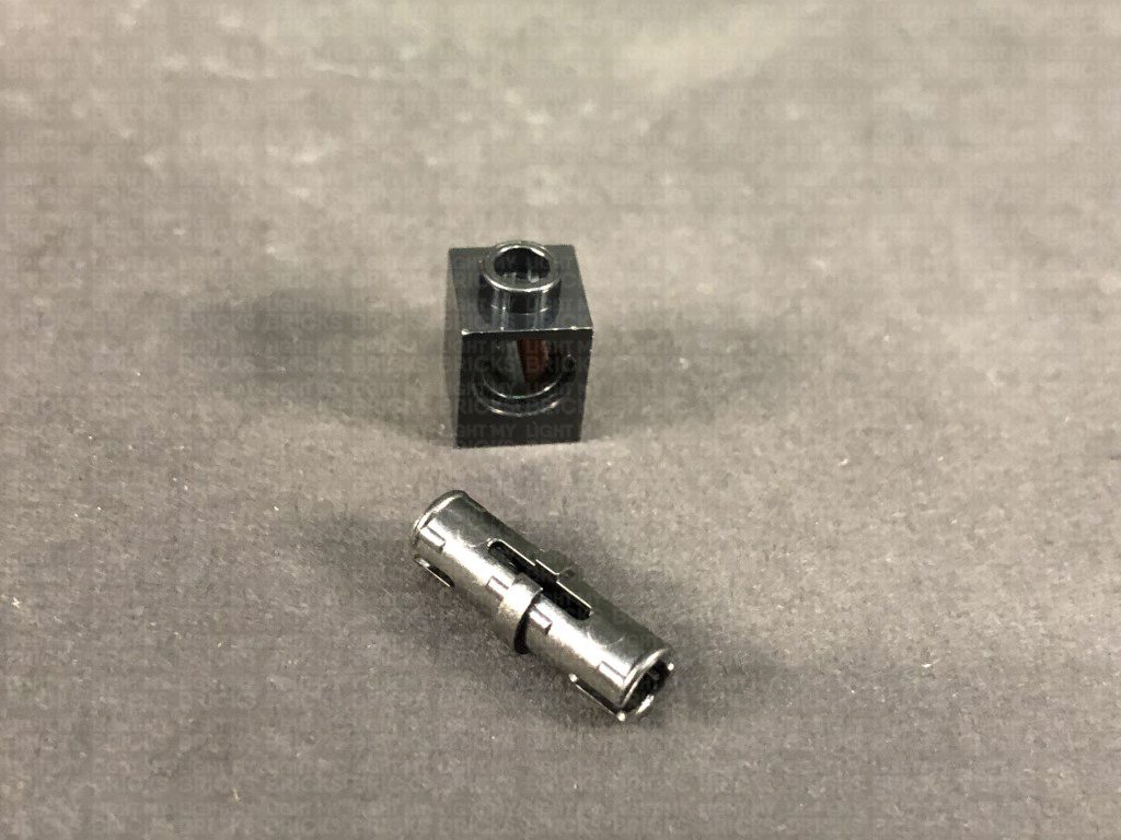
- 2x Black Tile 1×1 with Clip
- 2x Technic Brick 1×1 with hole (Black or Grey)
- 2x Black Technic Pin with Friction Ridges Lengthwise with Centre
- 2x Black Speargun Minifig Weapon
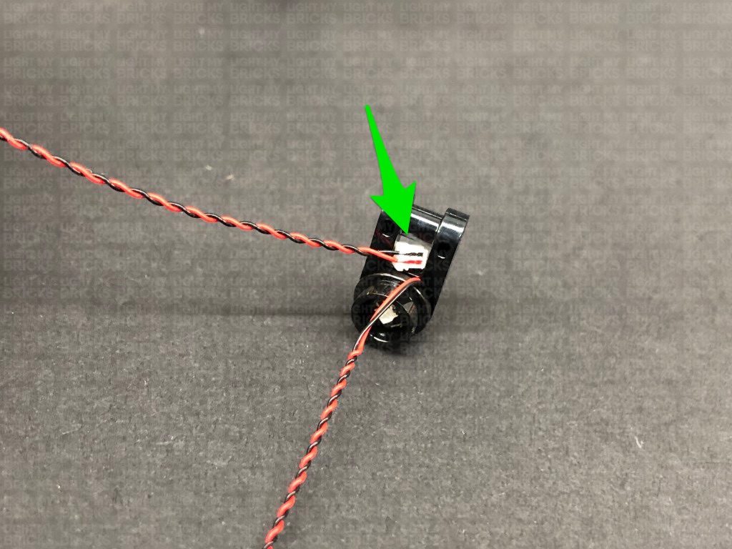
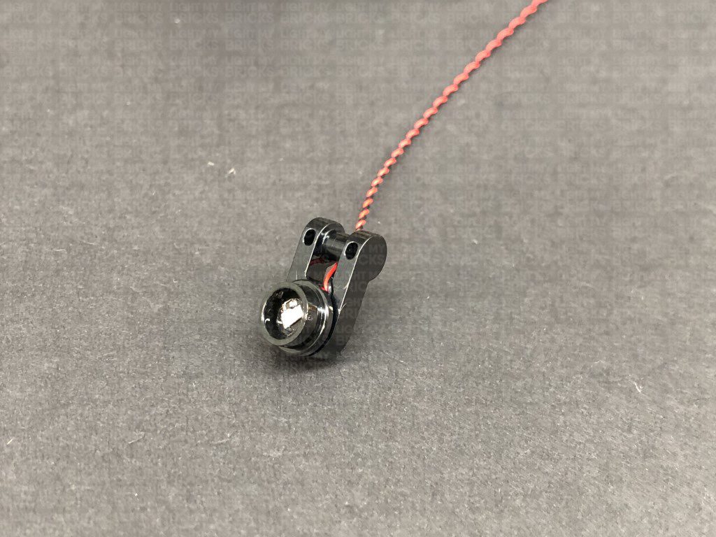
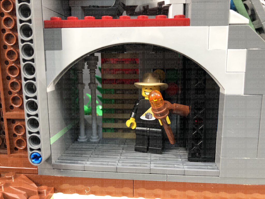
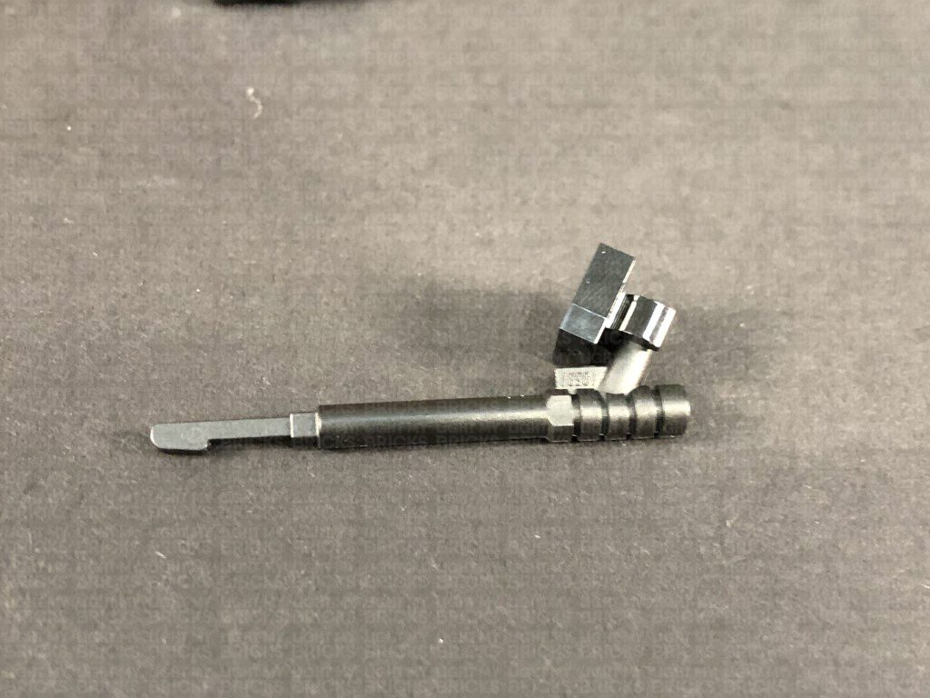
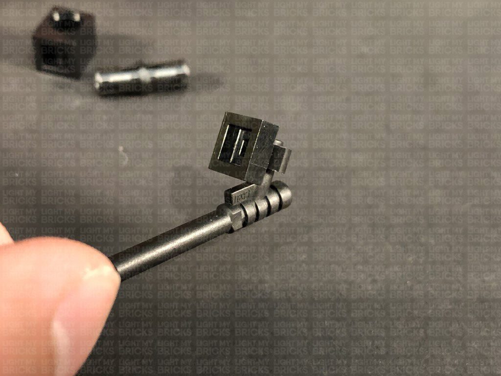
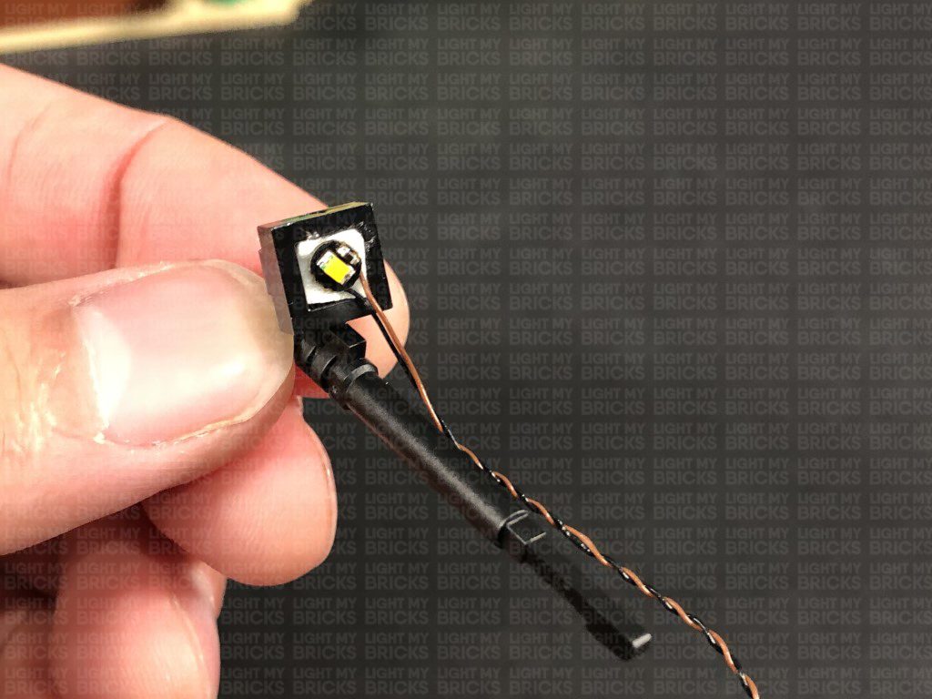
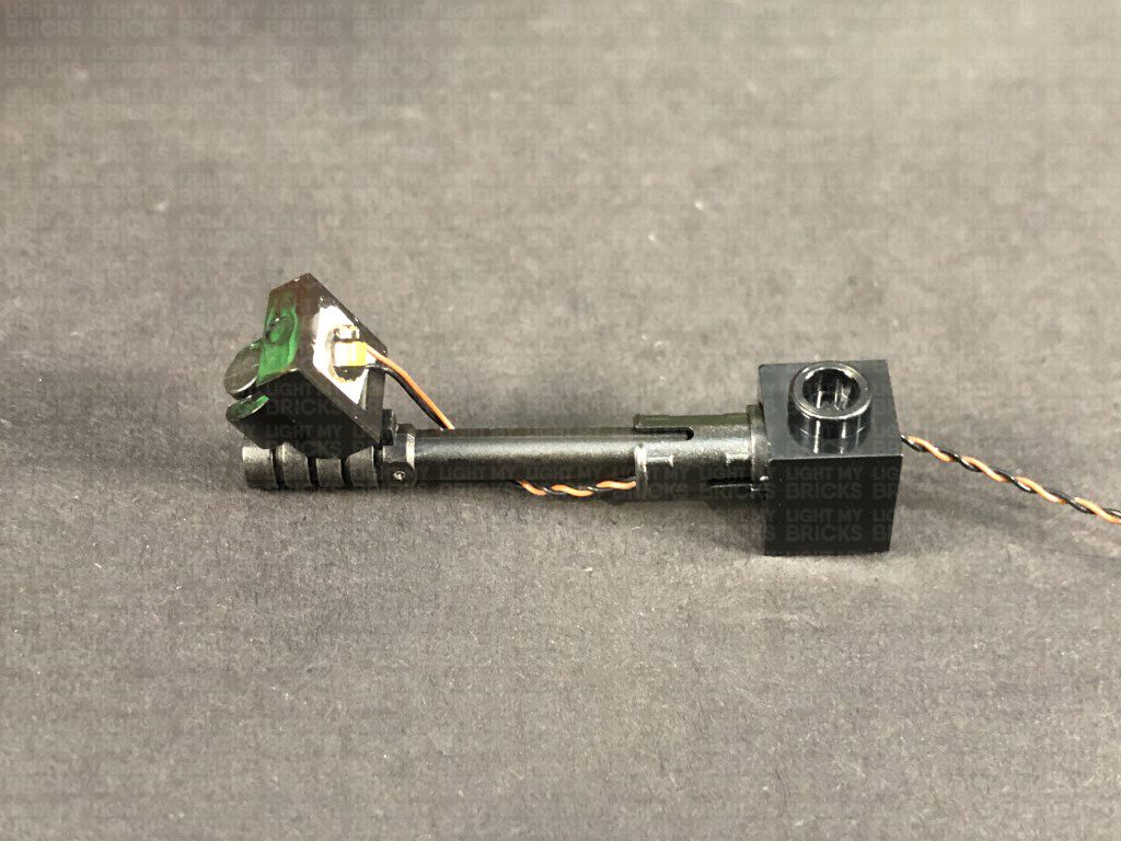
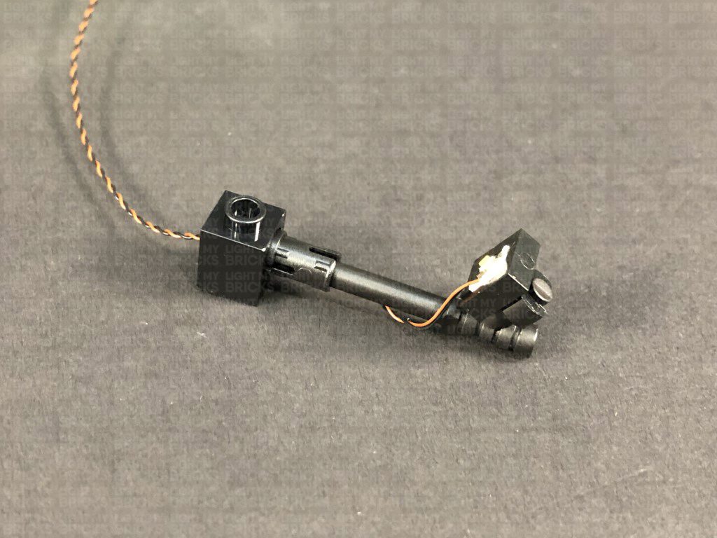
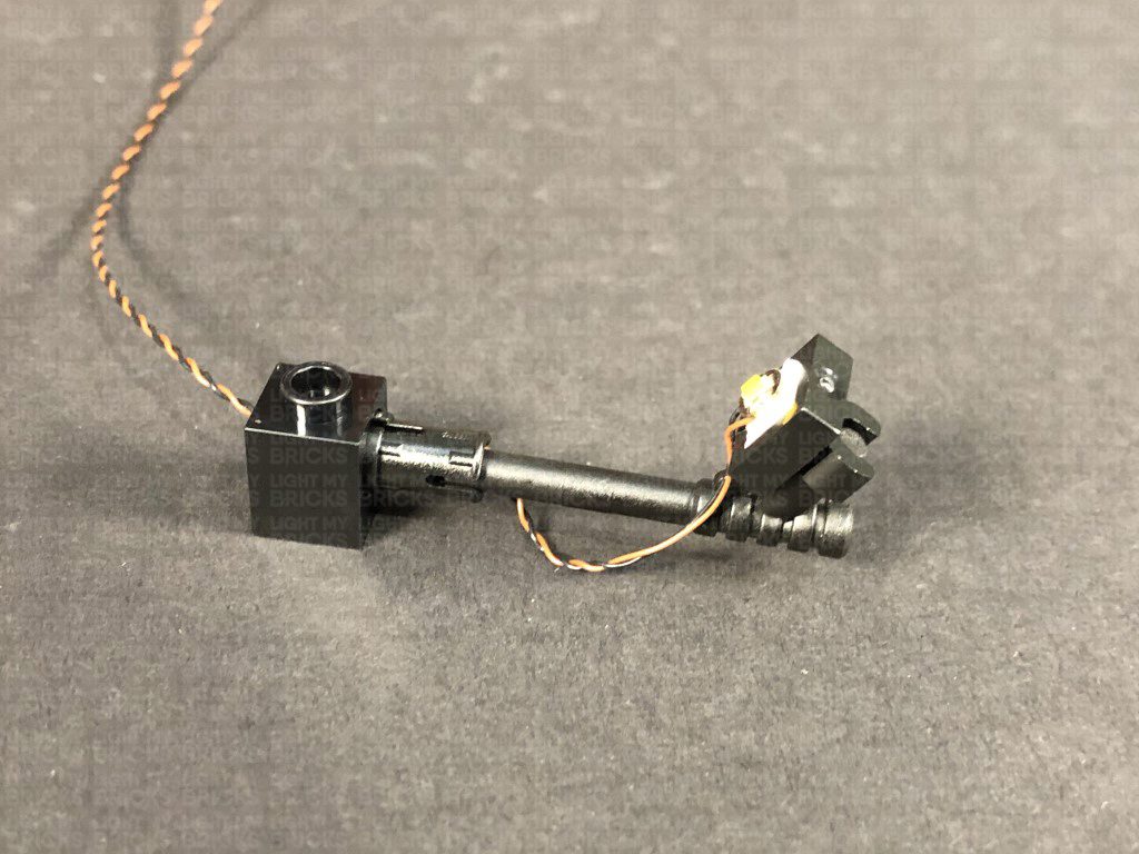
 Connect the Black Tile 1×1 with Clip to the Spear Gun Minifig weapon as shown below, then stick an Adhesive Square inside the Black Tile. Take a White 30cm Bit Light and with the cable facing down, stick the Bit Light to the adhesive square. Push the Adhesive Square down so that it fits inside the square plate completely. Wind the cable around the speargun toward the tip as shown below:
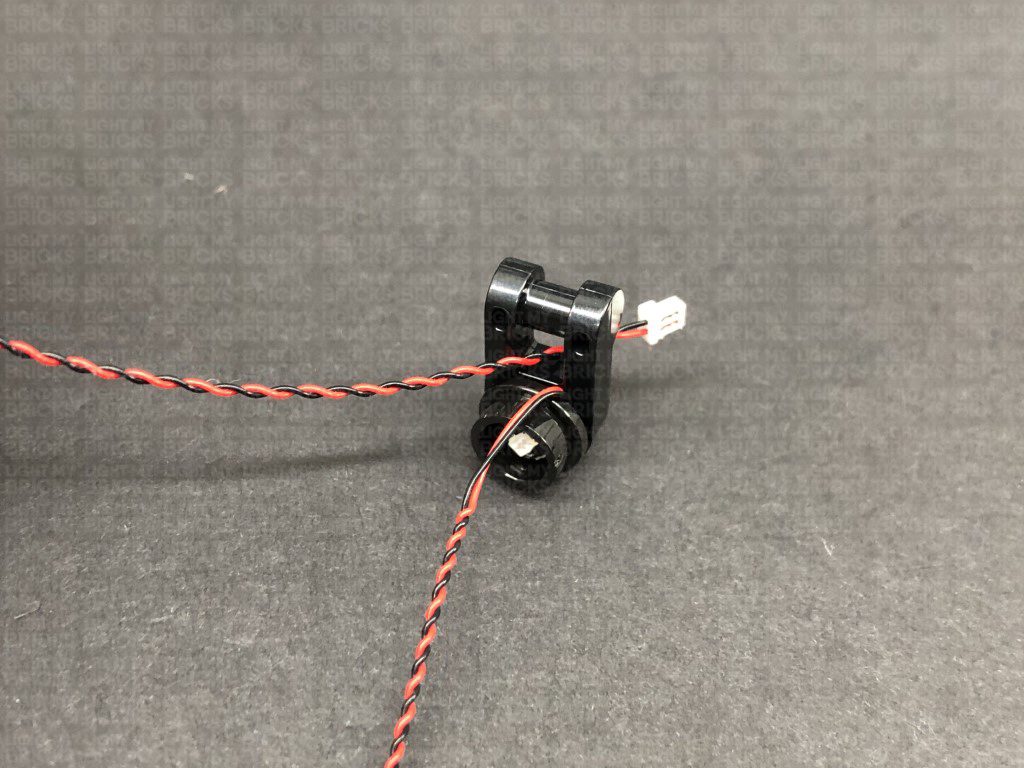
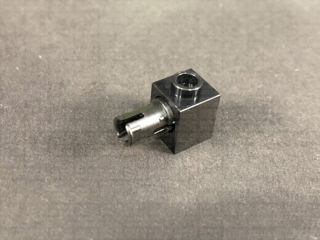
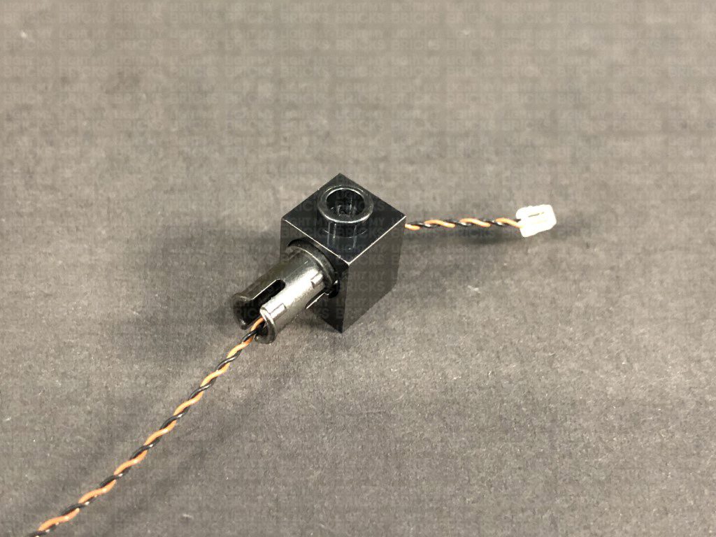
Connect the Technic Pin to the Technic Brick, then thread the Bit Light cable through the technic pin. Pull the cable all the way out from the other side of the technic brick and ensure there is no excess cable, by pulling the cable all the way out before connecting the speargun to the technic pin.
Repeat this step to install another White 30cm Bit Light to another assembled spotlight using another Adhesive Square.
Connect the Black Tile 1×1 with Clip to the Spear Gun Minifig weapon as shown below, then stick an Adhesive Square inside the Black Tile. Take a White 30cm Bit Light and with the cable facing down, stick the Bit Light to the adhesive square. Push the Adhesive Square down so that it fits inside the square plate completely. Wind the cable around the speargun toward the tip as shown below:
Connect the Technic Pin to the Technic Brick, then thread the Bit Light cable through the technic pin. Pull the cable all the way out from the other side of the technic brick and ensure there is no excess cable, by pulling the cable all the way out before connecting the speargun to the technic pin.
Repeat this step to install another White 30cm Bit Light to another assembled spotlight using another Adhesive Square.
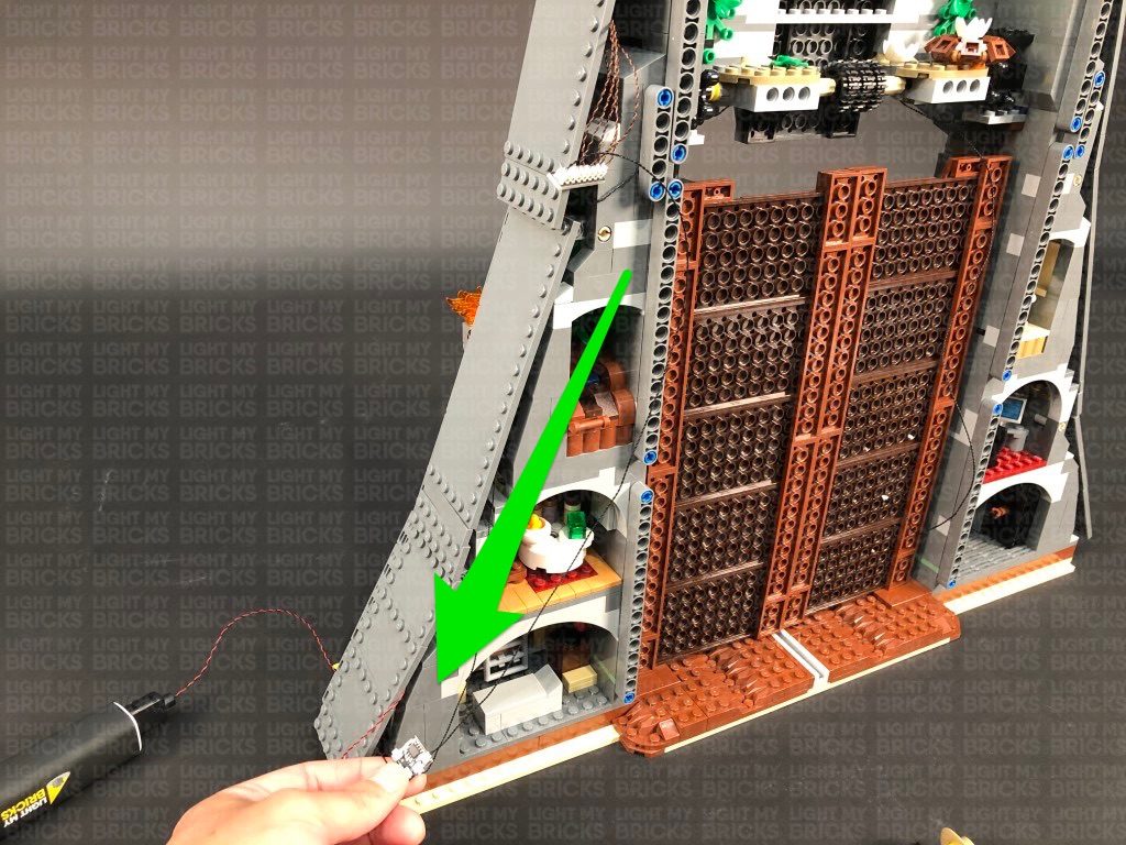
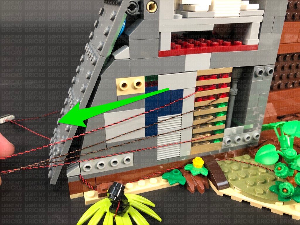
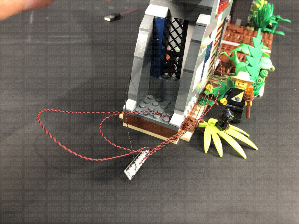
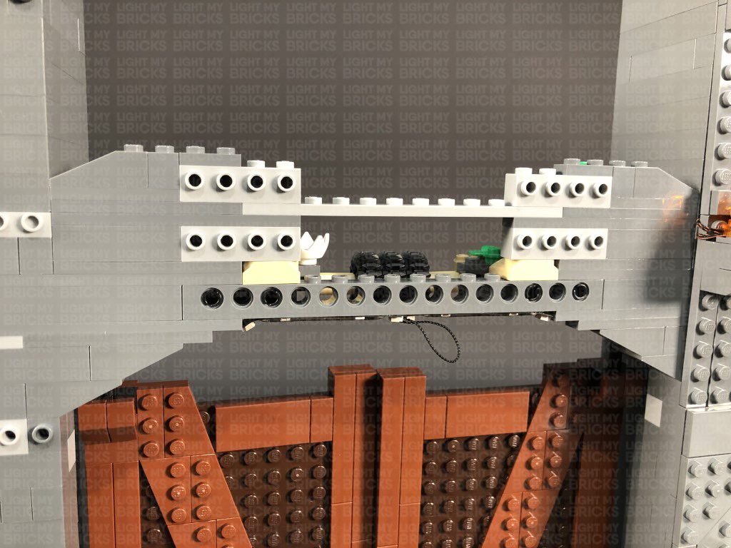
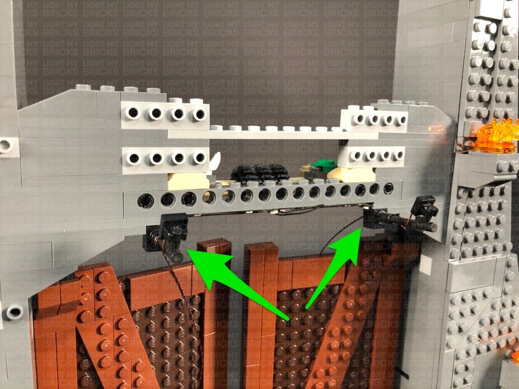
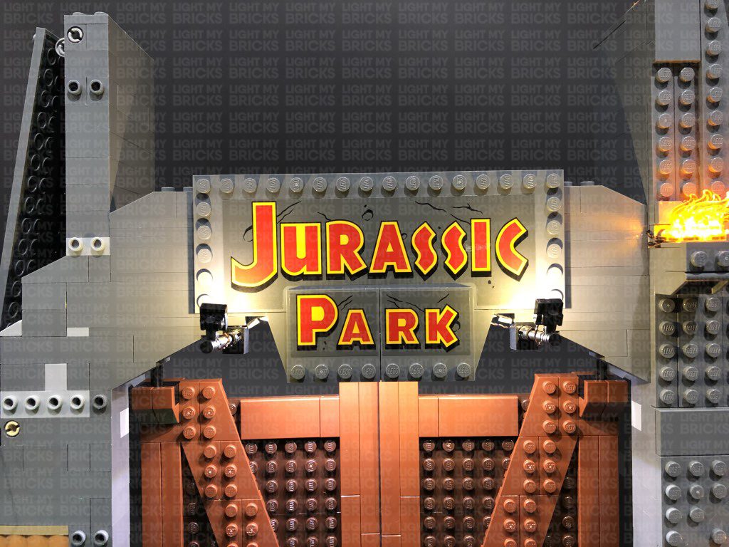
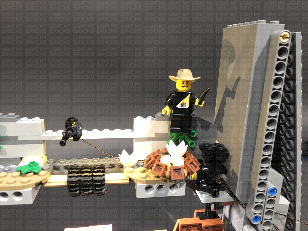
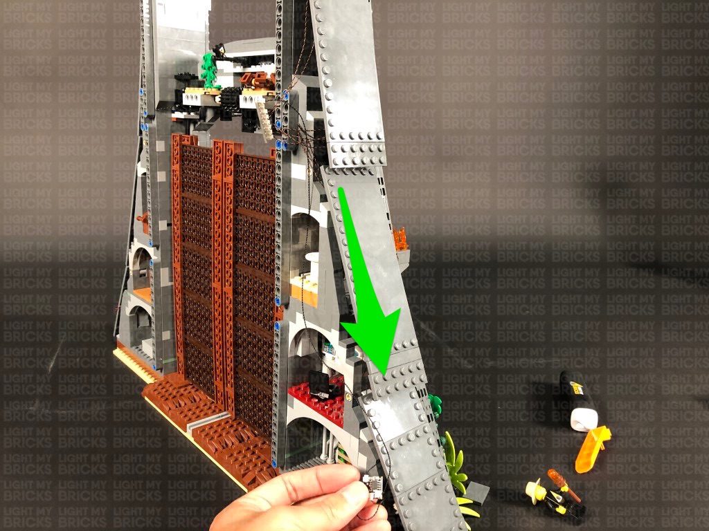
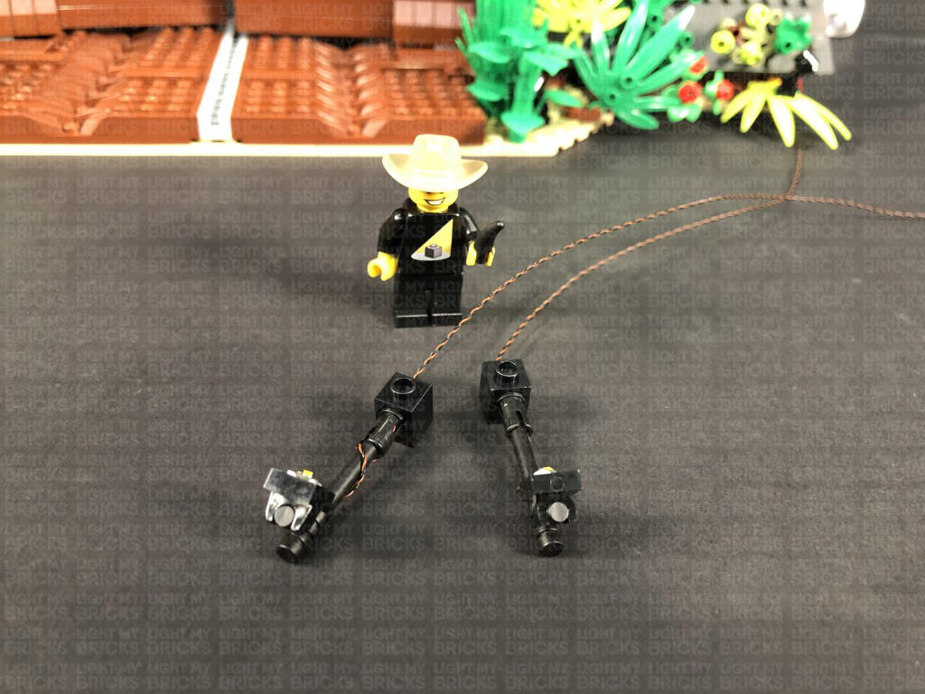 30.) Connect both spotlights underneath the light grey horizontal brick in the following positions, then turn the set around and pull both cables out.
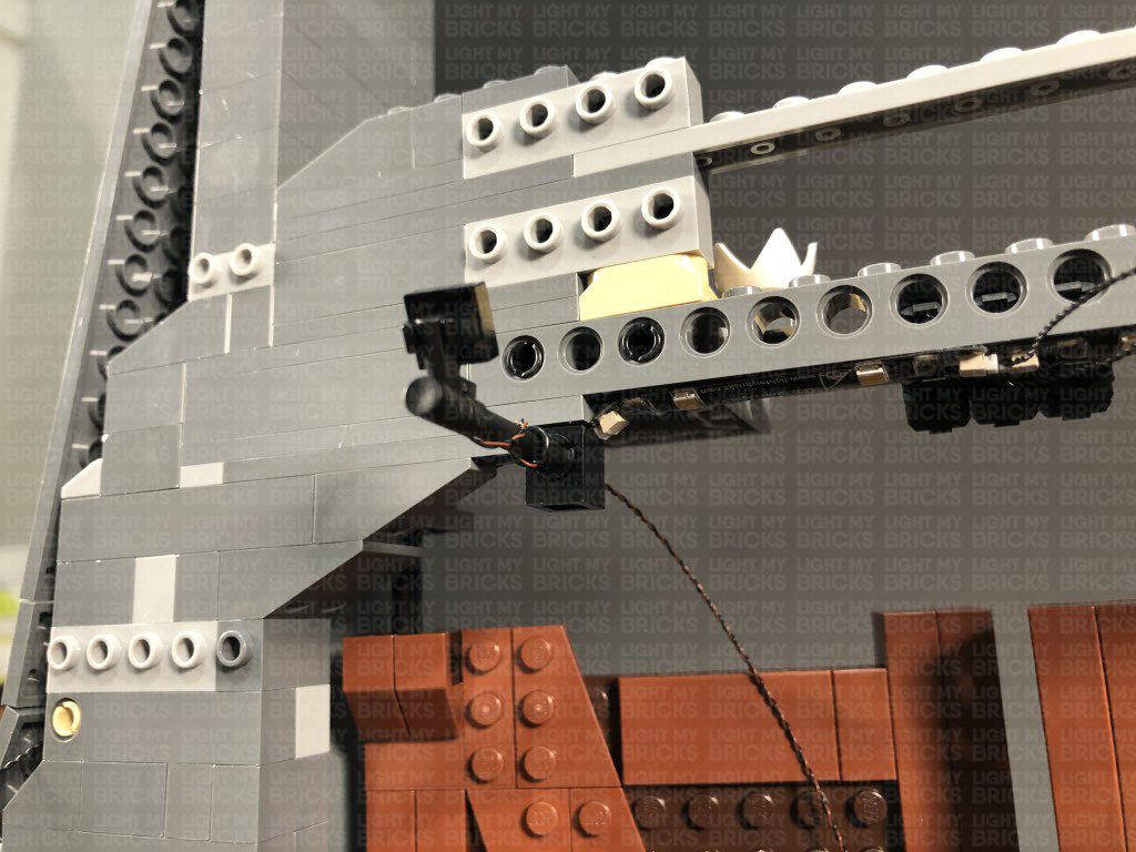
Take the cable from the left and thread it up the following space in the middle, then thread it back down the right corner. Pull the cable out from underneath, the same way we threaded the 30cm Connecting Cable from the Strip Light in step 20
Take the Bit Light cable from the right side and thread it up the following space that leads up to the right corner, then thread the cable back down and pull it out the front, the same way we did for the Bit Light cable from the left side.
31.) Assemble another spotlight using the below provided pieces, then Install another White 30cm Bit Light to it using an Adhesive Square.
30.) Connect both spotlights underneath the light grey horizontal brick in the following positions, then turn the set around and pull both cables out.
Take the cable from the left and thread it up the following space in the middle, then thread it back down the right corner. Pull the cable out from underneath, the same way we threaded the 30cm Connecting Cable from the Strip Light in step 20
Take the Bit Light cable from the right side and thread it up the following space that leads up to the right corner, then thread the cable back down and pull it out the front, the same way we did for the Bit Light cable from the left side.
31.) Assemble another spotlight using the below provided pieces, then Install another White 30cm Bit Light to it using an Adhesive Square.
- 1x Black Tile 1×1 with Clip
- 1x Technic Brick 1×1 with hole (Black or Grey)
- 1x Black Technic Pin with Friction Ridges Lengthwise with Centre
- 1x Black Speargun Minifig Weapon
 Note: If you experience any issues with the lights not working and suspect an issue with a component, please try a different port on the expansion board to verify where the fault lies (with the light or expansion board). To correct any issues with expansion board ports, please view the section addressing expansion board issues on our online troubleshooting guide.
37.) Neaten up cables toward the bottom by grouping them and folding twisting them together into a neat bunch. Neatly tuck them in to the side compartment, leaving the Flicker Effects board out.
Neaten up cables in the middle side area by grouping the four cables from the middle fire torches and folding and twisting them around each other to form a neat bunch. Take 2x Adhesive Squares and stick them to the back of the 6-Port Expansion Board, then stick the expansion board to the dark grey wall piece in the following position:
Take another 2x Adhesive Squares and stick them to the back of the 8-Port Expansion Board, then mount the expansion board to the inside of the wall facing the back. Pull the cables connected to the expansion board inside before closing the flap.
38.) We will now light up the top part of the gate. First disconnect and disassemble to torches connected to the top wall section, then install another 4x White 15cm Bit Lights to it as shown below:
39.) Reconnect the fire torch section to the wall ensuring the cables are laid behind to the right, then turn the wall plate around and pull the cables across to the right side. Ensure the cables are laying in between the spaces of the bottom of the angled plate studs, before reconnecting the top wall section to the front of the gate.
Connect the four Bit Lights to the remaining 8-Port Expansion Board.
40.) Disassemble the top torch section as shown below, then install the remaining 2x White 15cm Bit Lights (the same way we did for the top fire torches on the right side – step 17)
Reconnect the top fire torches ensuring you tuck the two cables underneath and out toward the back, then connect them to the 8-Port Expansion Board.
Take a 30cm Connecting Cable and connect one end to the 8-Port Expansion Board. Bring the other end of the cable down and connect it to the remaining OUT port on the Flicker Effects Board. Turn the USB Power Bank ON to test all the fire torches are working and flickering OK.
41.) Starting from the very bottom, tuck all the components and cables into the bottom compartment before securely connecting the bottom side flap.
Move up to the middle section, and hide the connecting cables running down by securing them underneath the following dark grey tile. Ensure all components and cables are neatly tucked in and hidden inside before securely reconnecting the middle side flap.
Move up to the top section and neaten up cabling by grouping the four cables from the top wall fire section and folding and twisting them around each other into a neat bunch. Use 2x Adhesive Squares to mount the 8-Port Expansion Board to the top of the angled pieces as shown below.
Twist and fold up the two cables from the top fire section into a neat bunch, then tuck everything inside before securely closing the top side flap and reconnecting the two flat tiles on the very top.
Note: If you experience any issues with the lights not working and suspect an issue with a component, please try a different port on the expansion board to verify where the fault lies (with the light or expansion board). To correct any issues with expansion board ports, please view the section addressing expansion board issues on our online troubleshooting guide.
37.) Neaten up cables toward the bottom by grouping them and folding twisting them together into a neat bunch. Neatly tuck them in to the side compartment, leaving the Flicker Effects board out.
Neaten up cables in the middle side area by grouping the four cables from the middle fire torches and folding and twisting them around each other to form a neat bunch. Take 2x Adhesive Squares and stick them to the back of the 6-Port Expansion Board, then stick the expansion board to the dark grey wall piece in the following position:
Take another 2x Adhesive Squares and stick them to the back of the 8-Port Expansion Board, then mount the expansion board to the inside of the wall facing the back. Pull the cables connected to the expansion board inside before closing the flap.
38.) We will now light up the top part of the gate. First disconnect and disassemble to torches connected to the top wall section, then install another 4x White 15cm Bit Lights to it as shown below:
39.) Reconnect the fire torch section to the wall ensuring the cables are laid behind to the right, then turn the wall plate around and pull the cables across to the right side. Ensure the cables are laying in between the spaces of the bottom of the angled plate studs, before reconnecting the top wall section to the front of the gate.
Connect the four Bit Lights to the remaining 8-Port Expansion Board.
40.) Disassemble the top torch section as shown below, then install the remaining 2x White 15cm Bit Lights (the same way we did for the top fire torches on the right side – step 17)
Reconnect the top fire torches ensuring you tuck the two cables underneath and out toward the back, then connect them to the 8-Port Expansion Board.
Take a 30cm Connecting Cable and connect one end to the 8-Port Expansion Board. Bring the other end of the cable down and connect it to the remaining OUT port on the Flicker Effects Board. Turn the USB Power Bank ON to test all the fire torches are working and flickering OK.
41.) Starting from the very bottom, tuck all the components and cables into the bottom compartment before securely connecting the bottom side flap.
Move up to the middle section, and hide the connecting cables running down by securing them underneath the following dark grey tile. Ensure all components and cables are neatly tucked in and hidden inside before securely reconnecting the middle side flap.
Move up to the top section and neaten up cabling by grouping the four cables from the top wall fire section and folding and twisting them around each other into a neat bunch. Use 2x Adhesive Squares to mount the 8-Port Expansion Board to the top of the angled pieces as shown below.
Twist and fold up the two cables from the top fire section into a neat bunch, then tuck everything inside before securely closing the top side flap and reconnecting the two flat tiles on the very top.
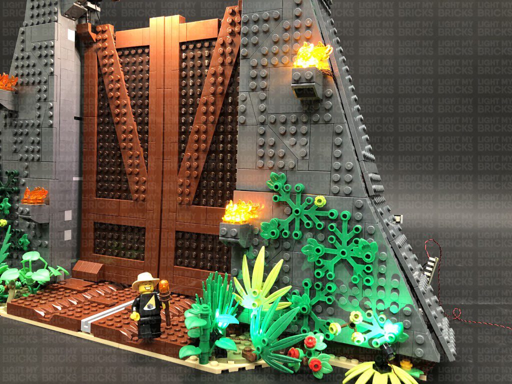
This finally completes installation of the Light My Bricks LEGO Jurassic Park T.Rex Rampage set for 75936.
f you experience any issues during this installation, please refer to our online troubleshooting guide. If you have any other issues or questions please email the customer service team: info@lightmybricks.com
We Thank YOU for purchasing this product and hope you enjoy!