The Light My Bricks Bit Light can be installed in a number of different ways. This page will go through the several different methods you can use to install our Bit Lights to your LEGO Creation.
The Bit Light measures approximately 3.2mm and is connected to either a 15cm connecting cable or 30cm cable. The width of our cables are approximately .5mm. The tiny size of our Bit Lights enable our customers to install them under any 1×1 LEGO brick or plate. These can be purchased in a 4pack on our website and are also available in a number of different colours as well as a flashing effect.
Installing Bit Lights underneath 1×1 Plates
The simplest method to install our Bit Lights is by installing them underneath LEGO Plates or Bricks either directly underneath or in between studs.
To install them directly underneath, place the Bit Light over a LEGO stud facing up. Take a 1×1 LEGO plate and then connect it over the top. The LED component will easily fit inside of the LEGO stud.
Installing Bit Lights in between studs underneath Tiles
You can install Bit Lights in between studs as long as they are underneath a LEGO tile rather than a plate. This reason being is that a LEGO plate has a part that connects in between the stud leaving no room for the Bit Light. To install them in between studs, simply place the Bit Light in between two studs and then connect a 1×2 Tile over the top. Note that
Installing Bit Lights to lamps (feeding cable all the way through).
There are several different methods to install Bit Lights to a variety of lamps depending on how they are assembled.
The below examples will demonstrate how to install Bit Lights to pieces which have holes to pass the cable all the way through. These two examples are extracted from our instructions from the Parisian Restaurant Light Kit.
Example 1
Disconnect the 2 transparent yellow Lego pieces from the lamp sections
Take a White Bit Light and thread the connector side of the cable down through the larger hole of the transparent yellow Lego piece. Thread this all the way until the LED part is up against the inside Lego piece.
Reconnect this piece with Bit Light installed back to the lamp shade
ensure cable is facing toward the back and the LED component is facing the correct way down
Example 2
Start by removing the Lego pieces which make up the 2 lamps. You only need to remove the yellow transparent pieces.
Using a White Bit Light, thread the connector side of the cable through the larger hole of the yellow Lego piece. Thread this all the way through until the LED part is sitting comfortably inside the Lego piece, then connect the top of the lamp post (black Lego pieces) back on top of the yellow piece.
Pull the cable all the way through
Connect the lamp back to the lamp post. The cable should be able to fit comfortable in between the lamp and lamp post like below.
Installing Bit Lights to lamps (using pieces without holes to pass cable through).
The below examples will demonstrate how to install Bit Lights to pieces which do NOT have holes to pass the cable all the way through.
Example 1
This example shows how to install our Bit Lights to the lanterns in the Ninjago City set. The lanterns are assembled using Trans Bright Orange coloured Minifig Heads. These pieces only have an opening at the base so we need to use a different method to install our lights.
First disconnect the three lantern pieces from the bottom.
Disconnect the black and gold pieces from the top of the lanterns and then take out 3x White 15cm Bit Lights.
Install the first White 15cm Bit Light by inserting the led component inside the lantern piece. Take the black and gold pieces and then reconnect them over the top. Ensure the led component is facing the front (of where you will be positioning the lantern) and that the cable is pulled to the back of the lantern.
Repeat this process to install Bit Lights to all three lanterns.
Reconnect the lantern pieces to the bottom of the second floor section ensuring the cables are facing behind each lantern.
Example 2
This example shows how to install our Bit Lights to the lamps in the Assembly Square set. These lamps are installed using 1×1 trans yellow round plates which only have an opening at the base.
Remove the 2 lamp sections at the front.
Take a Bit Light with 15cm cable and then bend the cable up in 90 degree angle where the LED component is.
Place the LED component facing upward inside the middle of the trans yellow LEGO piece of one of the lamps. Pull the cable over the top of the lamp and then pull it right toward the black brick. Reconnect this lamp section back to the front wall ensuring the cable is tight and in between the 2 black bricks.
Reconnect the 1×2 black brick over the top to secure it in place.
Repeat the same process to install another Bit Light with 15cm cable to the lamp on the right side of the front of the cafe.
Reconnect surrounding LEGO bricks and pieces we removed earlier.
Example 3
This example shows how to install our Bit Lights to the lamps in the Old Fishing Store set. These lamps are installed using trans clear minifig head with only the opening at the base of the piece.
Remove the lamp from the right side of the building and then disconnect the black round stud from underneath.
Take a White 15cm Bit Light and thread the connector side through the top of the black round plate. Thread it all the way through until the LED is flat against the top of the plate then reconnect the top section of the lamp.
You may need bend the LED slightly so that it sits flat against the top of the LEGO piece
Reconnect lamp with Bit Light installed to the front of the building
Installing Bit Lights without the use of any LEGO bricks
It is not mandatory to install our Bit Lights underneath or in between LEGO bricks and pieces. There may be instances where there are no sections within your MOC to connect a LEGO piece to. It may be a flat surface such as a tile, window or arch way. Luckily, our Bit Lights can be used together with our Adhesive Squares to mount onto any flat surface.
Below are examples to show how easy it is to install our Bit Lights using our double sided Adhesive Squares.
The above examples can be followed as guides to install Bit Lights to your LEGO creations. We encourage all our customers to be creative as possible as there are endless possibilities in lighting your LEGO creations. Head over to our DIY section on our website and grab a 4pack of Bit Lights now.
To download this instructions guide in PDF format please click here.
Please note: This page lists instructions for the LED light kit only. If you are wishing to purchase the Light My Bricks LEGO Mercedes-Benz Arocs (42043) LED light kit , please click here to view the product page
Package Contents:
18x White 15cm Bit Lights
2x Flashing White 15cm Bit Lights
2x White 30cm Bit Lights
2x Rotating 30cm Bit Lights
4x 8-Port Expansion Boards
1x 5cm Connecting Cables
1x 15cm Connecting Cables
1x 50cm Connecting Cable
8x Adhesive Squares
1x Power Functions Cable
LEGO Pieces:
6x Trans Clear Round Plate 1×1
4x Trans Orange Round Plate 1×1
2x Trans Red Round Plate 1×1
Important things to note:
Laying cables in between and underneath bricks
Cables can fit in between and underneath LEGO® bricks, plates, and tiles providing they are laid correctly between the LEGO® studs. Do NOT forcefully join LEGO® together around cables; instead ensure they are laying comfortably in between each stud.
CAUTION: Forcing LEGO® to connect over a cable can result in damaging the cable and light.
Connecting cable connectors to Expansion Boards
Take extra care when inserting connectors to ports of Expansion Boards. Connectors can be inserted only one way. With the expansion board facing up, look for the soldered “=” symbol on the left side of the port. The connector side with the wires exposed should be facing toward the soldered “=” symbol as you insert into the port. If a plug won’t fit easily into a port connector, do not force it.
Incorrectly inserting the connector can can result in bent pins inside the port or possible overheating of the expansion board when connected.
Connecting cable connectors to Strip Lights
Take extra care when inserting connectors to ports on the Strip Lights. Connectors can be inserted only one way. With the Strip Light facing up, ensure the side of the connector with the wires exposed is facing down. If a plug won’t fit easily into a port connector, don’t force it. Doing so will damage the plug and the connector.
Installing Bit Lights under LEGO® bricks and plates.
When installing Bit Lights under LEGO® pieces, ensure they are placed the correct way up (Yellow LED component exposed). You can either place them directly on top of LEGO® studs or in between.
OK, Let’s Begin!
1.) Start by disconnecting the head light pieces as well as surrounding pieces as per below.
2.) Starting with the left side of the truck, carefully split the section as per below by creating a gap in between sections, then take a White 15cm Bit Light and thread the connector side of the cable through the gap we have created.
Thread the cable all the way through until the LED component is up against the edge on the left of the black stud. Reconnect the following LEGO section ensuring the Bit Light is right up against Trans Orange Plate, then reconnect sections to close up the gap and secure the light in place.
3.) Repeat previous step to install another White 15cm Bit Light to the right side
Pull both cables out from underneath
4.) Take the following two pieces and remove the trans clear tiles from each side.
Take a White 15cm Bit Light and place it over one of the pieces over the light grey stud. Secure the Bit Light in place by connecting a provided Trans Clear Round Plate 1×1.
Repeat this process to install another White 15cm Bit Light to the other piece using another provided Trans Clear Round Plate 1×1
5.) Take one of the pieces and then recreate the same gap we created in step 2 to allow us to thread the cable through the left side of the truck. Thread it all the way through and then reconnect this section over the black stud as per below:
Close up the gap.
Repeat this process to reconnect the other piece to the right side.
6.) Take the two headlight pieces and then disconnect the trans clear 2×2 plates.
Take 4x White 15cm Bit Lights and then place each one over each hole of the light grey round 2×2 plate as per below:
Reconnect the trans clear 2×2 plate over the top to secure the bit lights in place.
Turn the headlight section over and then group the four cables together and then twist them around each other to form one large cable.
Repeat this process to install another 4x White 15cm Bit Lights to the other headlight section.
7.) Take one of the headlight cables and then thread it through the following gap on the right side of the truck. Thread it all the way through and then pull it out from underneath. Reconnect the headlight to original position.
Repeat this process to reconnect the headlight on the left side of the truck.
8.) Take 2x 8-Port Expansion Boards and connect them together using a 5cm Connecting Cable. Connect the cable to the end ports.
Connect all six Bit Light cables from the left side of the truck to one of the expansion boards and then connect all six Bit Light cables from the right side of the truck to the other expansion board.
9.) Test the lights we have installed so far are working OK by taking out the LEGO Power Functions Cable and connecting it to a spare port on the expansion board. Connect the other side to your Power Functions Battery Pack and then turn on to verify all is working OK.
Disconnect the Power Functions Cable from the expansion board and proceed to the next step.
10.) Disconnect the trans orange round tiles from both sides of the truck.
Take a Flashing White 15cm Bit Light and thread the connector side of the cable through the hole where you disconnected the trans orange round tile from. Thread the cable all the way through until the Bit Light is sitting right against the edge of the hole.
Press the Bit Light down so that it sits flat against the edge and the secure it in place by connecting a provided Trans Orange Round Plate 1×1 over the top.
11.) Repeat previous step to install another Flashing White 15cm Bit Light to the left side of the truck using another provided Trans Orange Round Plate 1×1
12.) Turn the truck on it’s side so we can access underneath of it and then pull down both cables from the two Bit Lights we just installed.
Take another 8-Port Expansion Board and connect both lights to the first two ports.
13.) We will now install lights over the top front of the truck. First disconnect the trans clear round tiles from each side.
Starting with the left side, seperate the following sections by pulling the front piece forward.
Take a White 30cm Bit Light and thread the connector side through the following hole and then in between white and black sections as per below:
Pull the cable all the way back and then thread it through the second hole of the white piece as per below and then down in between black and grey sections:
Press the Bit Light flat against the edge of the light grey piece and then secure it in place by connecting a provided Trans Clear Round Plate 1×1 over the top.
Close up all the sections we separated.
14.) Pull the cable down the back and then thread down through the following space. Pull it down from underneath (above the wheel) and then connect it to the third port along the 8-port Expansion Board from step 12.
15.) Repeat steps 13 to install another White 30cm Bit Light to the top right front of the truck using another Trans Clear Round Plate 1×1.
16.) Pull the cable back and then pull it down over the back white section as per below then thread the cable down through the following space. Pull it down from underneath (above the wheel) and then turn the truck over so that we can bring the 8-port Expansion Board from step 12 across. Connect the Bit Light to the next port along this expansion board.
17.) Take a 15cm Connecting Cable and connect it to the remaining port on one of the 8-port expansion boards from step 8.
Thread the other end of the 15cm connecting cable through the following space (over the light grey piece) and then connect it to the next port along the 8-port expansion board (from step 12)
18.) Take 4x Adhesive Squares and stick two on each 8-port expansion board at the front. Mount the two expansion boards underneath the truck in the below positions.
19.) Neaten up excess cable from the Bit Lights at the front by pulling them all the way out and then twisting them around each other and then tucking them up the sections closest to each expansion board.
20.) Connect the Power Functions Cable to the Power Functions Battery pack and then pull the cable over the back and then thread it down the space below the cream coloured cog wheel. Pull it down from underneath the truck and then turn the truck on it’s side to allow you to connect the power functions cable to a spare port on the 8-port expansion board.
Turn on the power functions battery pack again to test all the lights are working OK.
21.) We will now install our Rotating Bit Lights inside the two beacons. First disconnect both beacon light sections and then disconnect the black round plates 2×2 from underneath each.
22.) Take 1x Rotating 30cm Bit Light and place the component upside down (flat side up) over the top of the middle of the trans orange round brick 2×2. Reconnect the black round plate 2×2 directly over the top then flip the beacon over to the correct side.
Repeat this process to install another Rotating 30cm Bit Light to the other beacon.
23.) Reconnect both beacons to the top of the truck ensuring the cables are facing toward the back. Because we have installed Rotating Bit Lights inside trans orange round brick, we will not be able to push this brick all the way down the technic pin.
Ensure that you do NOT forcefully push the Beacon all the way down otherwise this may damage the Rotating Bit Light
The base of the Rotating Bit Light should be sitting on top of the technic bar coming up from underneath
Take the left beacon cable and thread it down the following space:
Pull it out from underneath and then thread it through the space below. Pull it out from underneath the truck.
Take the right beacon light and thread it down the following space:
Pull it down from underneath and then thread it down through the next space below:
24.) Turn the truck over and pull both beacon light cables out from underneath and connect them to the two remaining ports on the 8-port expansion board.
Turn the truck back to its correct side up and then Turn ‘ON’ the Power Functions Battery Pack to test the Rotating Bit Lights are working OK
25.) Turn the Truck back over and then mount the 8-port Expansion Board underneath in the following position using 2x Adhesive Squares.
Neaten up excess cable from all the Bit Lights by pulling them all the way out and then twisting them around each other and then tucking them up one of the spaces closest to the expansion board.
26.) Take a 50cm Connecting Cable and connect it to the remaining port on the 8-port Expansion Board at the front of the truck.
Follow the below images to thread the other end of the cable through towards the back underneath the truck through the following holes and gaps.
27.) Connect the other end of the 50cm Connecting Cable to the first port on the remaining 8-Port Expansion Board.
28.) Turn the truck over to the back and then remove the three trans coloured round tiles (orange, red, clear) from each side.
We will installing another 6x White 15cm Bit Lights and replacing the round tiles with the provided trans coloured plates.
29.) Take the first White 15cm Bit Light and thread it through the first hole on the left side. Thread it all the way through and then push the Bit Light flat down against the edge of the technic pin before securing it in place with one Trans Orange Round Plate 1×1.
Using the same method, install another 2x White 15cm Bit Lights for the left side of the truck using a provided Trans Red Round Plate 1×1 and Trans Clear Round Plate 1×1 to secure them in place.
30.) Take the three cables from the left side and then twist them around each other to form one large cable.
Thread the cable up through the following space underneath and then pull it all the way out from the back as per below
31.) Repeat previous steps to install another 3x White 15cm Bit Lights to the right side of the truck using the remaining provided trans coloured round plates 1×1
32.) Thread the cable up through the following space underneath and then pull it all the way out the left side (same with the left side cable). Then bring all cables together and pull them down behind the wheel.
33.) Turn the truck over and then connect all six lights to the 8-port Expansion Board.
34.) Remove the back left wheel and then disconnect the 50cm connecting cable from the expansion board and thread the expansion board through the following space. Then pull it over the wheel axle and reconnect the 50cm connecting cable
Mount the expansion board to the side frame in the following position using another 2x Adhesive Squares.
Pull the excess cable from the two sides back and them twist them around each other to secure them from dangling down and being seen from the back of the truck. Tuck them in close the expansion board.
35.) Eliminate excess cable from the 50cm connecting cable by pulling it back towards the back expansion board and then twisting any remaining cable around the the six bit light cables as per below
36.) Reconnect the back wheel and then turn ON the power pack to confirm the back lights are working OK.
This finally completes installation of the Mercedes Benz Arocs Light Kit. We hope you enjoy your light kit.
The following page is instructions for the Light My Bricks LEGO Kessel Run Millennium Falcon (75212) LED lighting kit. You purchase this kit on our official website.
To ensure a trouble-free installation of your light kit, please read and follow each step carefully.
Cables can fit in between and underneath LEGO® bricks, plates, and tiles providing they are laid correctly between the LEGO® studs. Do NOT forcefully join LEGO® together around cables; instead ensure they are laying comfortably in between each stud.
CAUTION: Forcing LEGO® to connect over a cable can result in damaging the cable and light.
Connecting cable connectors to Expansion Boards
Take extra care when inserting connectors to ports of Expansion Boards. Connectors can be inserted only one way. With the expansion board facing up, look for the soldered “=” symbol on the left side of the port. The connector side with the wires exposed should be facing toward the soldered “=” symbol as you insert into the port. If a plug won’t fit easily into a port connector, do not force it.
Incorrectly inserting the connector can can result in bent pins inside the port or possible overheating of the expansion board when connected.
Connecting cable connectors to Strip Lights
Take extra care when inserting connectors to ports on the Strip Lights. Connectors can be inserted only one way. With the Strip Light facing up, ensure the side of the connector with the wires exposed is facing down. If a plug won’t fit easily into a port connector, don’t force it. Doing so will damage the plug and the connector.
Installing Bit Lights under LEGO® bricks and plates.
When installing Bit Lights under LEGO® pieces, ensure they are placed the correct way up (Yellow LED component exposed). You can either place them directly on top of LEGO® studs or in between.
OK, Let’s Begin!
Lighting the Escape Pod
1.) The first section we will light up will be the escape pod. To start, disconnect this from the main ship and then disconnect the following pieces from the front left.
Disconnect the 1×2 technic brick and then disconnect the trans-light blue tile from the back of it.
2.) Take a White 15cm Bit Light and then thread the connector side through the blue technic pin. Thread it all the way through until the Bit Light is right up against the technic pin, then bend the Bit Light slightly so that it sits flat.
Secure the Bit Light in place by connecting a provided LEGO Trans Light Blue plate 1×1 over the top.
3.) Reconnect the 1×2 Technic brick back to the escape pod and then reconnect pieces we removed earlier.
4.) Repeat previous steps to install another White 15cm Bit Light to the right side of the escape pod.
5.) Take a 6-Port Expansion Board and connect both bit lights to the available ports.
6.) Disconnect the following white 2×2 tile from the centre of the main door then use a LEGO removal tool to disconnect the Trans Clear 1×2 Plate.
7.) Take 2x White 15cm Bit Lights and then hold them together as shown below.
With the cables facing toward the back, place both lights over the following studs (underneath where the trans clear 1×2 plate was) and then reconnect the Trans Clear 1×2 Plate over the top.
Reconnect the white LEGO 2×2 tile over on top.
8.) Disconnect the 2×4 tile toward the back and then carefully slip the cables in between the two long LEGO plates as shown below.
Reconnect the 2×4 tile over the top.
9.) From underneath the main door, take the two cables and connect them to spare ports on the expansion board.
10.) Disconnect the following sections from the back of the escape pod:
Disconnect and disassemble the middle section from the back piece as per below:
11.) Take another 2x White 15cm Bit Lights and place each in between studs with each cable facing outward.
Reconnect the trans light blue 2×2 round brick
12.) Bend both cables down before reconnecting this to the back piece.
13.) Take the Flat Battery Pack and insert 2x CR2032 Batteries to it. Thread the battery pack cable through the back of the escape pod in the space at the bottom left corner.
Pull it all the way through and then connect it to a spare port on the 6-port expansion board.
14.) Take the back piece and then thread each bit light cable through the corner space on each side, then reconnect this back piece as per below
15.) Reconnect surrounding pieces we removed earlier.
16.) Take the Flicker Effects Board and then connect the two cables from the back light to the OUT ports
17.) Take a 5cm Connecting Cable and connect this to the IN port on the flicker effects board. Connect the other side of the cable to the remaining port on the 6-port expansion board.
Turn the battery pack ON to test all lights are working OK (including the flicker effect for the back jet)
18.) Neatly place all the cables and boards inside the escape pod and then close the door.
19.) Tuck the flat battery pack in underneath the escape pod in between the grey plates.
Pull in any excess cable from the battery pack.
This completes installation of the lights for the Escape Pod.
Lighting the Kessel Run
1.) Open up the Kessel Run and then disconnect the following pieces from the left side of the ship.
Disconnect the two white arch pieces and then take a White Strip Light.
2.) Connect a 30cm Connecting Cable to the left port of the strip light and then connect a 15cm Connecting Cable to the right port .
3.) Using it’s adhesive backing, stick the strip light underneath the two white arch pieces in the following position. Ensure the 30cm Connecting cable is facing the left and the 15cm Connecting cable is facing the right.
Reconnect the arch piece section ensuring the cables underneath are laid in between studs.
4.) Pull the 30cm connecting cable across and around the side of the ship toward the back.
Reconnect surrounding pieces we removed earlier from the middle.
5.) Disconnect the long section from the back of the ship as per below:
6.) Take 3x White Strip Lights and 2x 5cm Connecting Cables. Connect them all together as per below:
7.) Take the other end of the 30cm Connecting Cable from previous steps and then connect this to the end of one of the Strip Lights.
8.) Take a Flashing White 15cm Bit Light and connect it to the end of the Strip Light on the other side.
9.) Using the strip light’s adhesive backing, stick each one to the following sections starting from the left side. You can disconnect surrounding sections to make it easier to stick down the strip lights.
10.) Disconnect the hyperdrive section and then remove the trans light green brick.
11.) Place the Flashing White 15cm Bit Light over the top of the trans light green brick (with LED facing down) then reconnect the hyperdrive section over the top to secure the light in place.
You will notice that the Bit Light is slightly bent up. Use a thin LEGO bar to push the component down so that the light is facing directly down.
12.) Reconnect the hyperdrive with bit light installed back to the kessel run and then neatly lay excess cable behind the unit.
13.) Pull excess cable from the first strip light back inside the kessel run then lay the cable in between studs underneath the following section.
14.) Reconnect the back long section over the strip lights and then push down any excess connecting cables in between strip lights.
15.) Take the AA Battery Pack and insert 3x AA Batteries to it. Place the Battery Pack inside the Kessel Run towards the back in the following position (with battery pack cable at the top)
Disconnect the following sections to allow us to lay the battery pack cable down towards the centre of the Kessel Run underneath these sections before reconnecting them.
16.) Take a 6-port Expansion Board and then connect the other end of the connecting cable from the very first Strip Light we installed as well as the Battery Pack cable to the available ports.
Turn the Battery Pack On to test that all lights we have installed so far are working OK.
17.) Turn the Kessel Run over to the other side and then disconnect the following sections to allow us to remove the two white arched pieces.
18.) Take another White Strip Light and connect a new 15cm Connecting Cable to the left port. Take a Blue 30cm Bit Light and connect it to the Strip Light’s right port.
19.) Using it’s adhesive backing, mount the strip light underneath the two white arch pieces in the following position
Reconnect this section back ensuring the Blue Bit Light is facing down and 15cm Connecting Cable is facing up and laid in between studs.
Connect the other end of the 15cm Connecting Cable to a spare port on the 6-port Expansion Board in the middle.
17.) Disconnect the following section that leads to the cockpit as well as the cockpit cover section.
18.) Thread the end of the Blue 30cm Bit Light through the space that leads to the back of the cockpit.
Pull the Bit Light out from the front and then lay it on top of the following stud:
Secure the Bit Light in place by connecting the provided Trans Clear Round Plate 1×1 over the top.
19.) Pull the excess cable out through to the front and then secure the cables underneath the following LEGO piece.
Disconnect the following pieces from the front of the cockpit, pull the cable out to the left in between studs and then reconnect the pieces over the top.
Tuck the excess cable down underneath the cockpit and then place Han Solo inside.
Reconnect the cockpit window and then turn the Battery Pack ON to verify everything you have installed so far is working OK
20.) Reconnect the roof that leads to the cockpit as well as pieces around the centre of the ship we removed earlier.
21.) We will now install flashing lights to the control panel at the front of the vehicle. Disconnect the following pieces to give us access inside.
Disconnect the two trans red 1×2 plates as well as the 1×4 plate behind.
22.) Take a Flashing White 15cm Bit Light and with the cable facing toward the back, place it on top of the following stud. Secure the light in place by reconnecting one of the trans red 1×2 plates over the top.
Repeat this step to install another Flashing White 15cm Bit Light to the other side.
23.) Reconnect some of the surrounding pieces we removed earlier.
Take the two Flashing Bit Lights and connect them to the 6-port Expansion Board
Turn the Battery Pack ON to verify everything you have installed so far is working OK
Reconnect the top cannon section.
24.) Carefully turn the entire Kessel Run over to access underneath. Place your hands over the top of the back section to ensure the AA Battery Pack doesn’t fall out.
Disconnect the lower cannon section as and then disconnect the dark grey cone piece from the front of the canon as per below:
25.) Take a Red 30cm Bit Light and thread the connector end of the cable through the base of the cone. Thread the cable all the way through and then slightly bend the LED component on a 90 degree angle so that it sits flat against the edge of the cone piece.
Reconnect the cone piece to the cannon bar and then pull the cable down and secure underneath the following dark grey 2×2 tile. Ensure the cable is laid in between studs
26.) Thread the cable down (up through to the top side) through the centre of the Kessel Run before securely reconnecting the lower cannon section.
Carefully turn the entire Kessel Run over and pull the Bit Light cable from the lower canon up from the centre.
27.) Take the Multi Effects Board and connect the other end of the Red 30cm Bit Light to one of the output ports (side with two ports). Set this effects board aside for now and proceed to next step.
28.) Disconnect the upper canon section and then disconnect the dark grey cone piece from the front of the canon as per below:
29.) Take the remaining Red 30cm Bit Light and thread the connector end of the cable through the base of the cone. Thread the cable all the way through and then slightly bend the LED component on a 90 degree angle so that it sits flat against the edge of the cone piece.
Reconnect the cone piece to the cannon bar and then pull the cable down and secure underneath the following dark grey 2×2 tile. Ensure the cable is laid in between studs
30.) Reconnect the upper canon section to the top of the kessell run and then connect the other end of the Red 30cm Bit Light to the other output port on the multi effects board.
31.) Take a 5cm Connecting Cable and connect one end to the input port of the Multi Effects Board and then connect the other end to the remaining port on the 6-port expansion board.
32.) Configure the effects board but turning the switch to the middle channel for “emergency” effect and then turn the speed wheel all the way to the left for the slowest effect. This setting will set the “firing canon” effect.
Turn the battery pack ON to verify.
33.) Neatly tuck all the components and cables down through centre hole and then close up the upper cannon door.
Reconnect the escape pod to the front of the ship.
This finally completes installation of the Kessel Run Millennium Falcon Light Kit. Now turn on the light kit using both battery packs and ENJOY!
This user guide is also available to download in PDF format here.
Package contents:
3x White 30cm Bit Lights
3x Red 30cm Bit Lights
2x Blue 30cm Bit Lights
1x Flashing White 30cm Bit Light
2x 6-Port Expansion Boards
1x Fire Effects Board
2x 5cm Connecting Cables
1x USB Power Cable
* USB Power Cable has replaced Flat Battery Pack as of June 2022 due to child safety regulations
LEGO Pieces
2x Plate 1×1 (Trans Red)
1x Plate 1×1 (Trans Light Blue)
1x Round Plate 1×1 (Trans Dark Blue)
1x Round Plate 1×1 (Trans Clear)
1x Round Plate 1×1 with open stud (Light Grey)
1x Plate 2×2 with Rounded Bottom (Trans Clear)
Important things to note:
Laying cables in between and underneath bricks
Cables can fit in between and underneath LEGO® bricks, plates, and tiles providing they are laid correctly between the LEGO® studs. Do NOT forcefully join LEGO® together around cables; instead ensure they are laying comfortably in between each stud.
CAUTION: Forcing LEGO® to connect over a cable can result in damaging the cable and light.
Connecting cable connectors to Expansion Boards
Take extra care when inserting connectors to ports of Expansion Boards. Connectors can be inserted only one way. With the expansion board facing up, look for the soldered “=” symbol on the left side of the port. The connector side with the wires exposed should be facing toward the soldered “=” symbol as you insert into the port. If a plug won’t fit easily into a port connector, do not force it.
Incorrectly inserting the connector can can result in bent pins inside the port or possible overheating of the expansion board when connected.
Connecting cable connectors to Strip Lights
Take extra care when inserting connectors to ports on the Strip Lights. Connectors can be inserted only one way. With the Strip Light facing up, ensure the side of the connector with the wires exposed is facing down. If a plug won’t fit easily into a port connector, don’t force it. Doing so will damage the plug and the connector.
Installing Bit Lights under LEGO® bricks and plates.
When installing Bit Lights under LEGO® pieces, ensure they are placed the correct way up (Yellow LED component exposed). You can either place them directly on top of LEGO® studs or in between.
OK, Let’s Begin!
Instructions for this Kit
1.) Start by removing BB-8’s head and then turn the body around and using the LEGO removal tool, remove the back section.
2.) Disconnect BB-8’s eye section and then disassemble pieces as per below.
Take a Red 30cm Bit Light and then place the LED component in the centre of the round plate with stud. Take the provided LEGO Plate 2×2 with rounded bottom (Trans Clear) and connect it over the top securing the bit light in place.
Ensure the LED component is facing up
Turn this section over and then pull the cable across before reconnecting this section back to the light grey dish piece. The cable should be neatly laid underneath in between the eye section.
Reconnect the bar section underneath as per below.
3.) Take BB-8’s head and then turn it over to disconnect the following sections underneath.
Disconnect the following section from the top of BB’8’s head.
4.) Disconnect the dark grey dish from the front right and then disconnect the trans dark blue tile from the top.
Take a Blue 30cm Bit Light and thread the connector side of the cable through the top of the dark grey dish. Thread it all the way through until the LED component is right up against the top of the dish.
Secure the light in place by connecting a provided LEGO Round Plate 1×1 (Trans Dark Blue) over the top.
5.) Thread the other side of the Blue 30cm Bit Light through the space on the corner and then pull the cable all the way out from the top to allow you to then reconnect the blue light section.
Thread the cable down through to the top of the head using the following hole and then pull it all the way through from underneath.
6.) We will now install lights for the following sections of BB-8’s head.
From underneath of the head section, disconnect the top left section and then disconnect and disassemble the following pieces as per below:
7.) Take a White 30cm Bit Light and then place it over the orange stud. Ensuring the cable is facing up, secure it in place by reconnecting the Trans Light Blue 1×1 Plate, then reconnect this section back to the rest.
Ensure the cable is laid neatly in between studs before reconnecting this section back underneath the head. The cable should be laid out in between the red and grey pieces as shown below.
8.) Disconnect the section on the top right underneath the head and then disconnect and disassemble the following pieces as per below:
Take a White 30cm Bit Light and then place it over the orange stud with the cable facing diagonally to the top left. Secure it in place by reconnecting the two Trans coloured 1×1 Plates.
Reconnect this section back ensuring the cable is top left and laid neatly in between bricks then reconnect this section back underneath the head.
9.) From the top of the head, push the following section down by pressing down the yellow 2×2 brick. The middle section underneath should come down slightly. Thread the cable from the top right section in through the space as per below:
Pull the cable all the way through and then push the middle section up to secure it back into place.
Both cables should now be laid out in between the red and grey pieces as shown below.
10.) Reconnect BB-8’s eye section ensuring the cable from the eye light is facing down.
11.) Take the following section we removed earlier and then disconnect the following pieces as per below:
12.) Take the Flashing White 30cm Bit Light and then place it over the hole of the white technic brick with cable facing up. Push the Bit Light inside the whole and then secure it in place by connecting the provided LEGO Round Plate 1×1 (Trans Clear).
13.) Reconnect the triangular white plate and then thread the end of the cable all the way down through the following hole of the dark grey technic plate.
14.) Thread the end of the cable from BB-8’s eye down through the same hole in the previous step.
15.) Group the three other cables from BB-8’s head and thread them through the following hole of the dark grey technic plate.
16.) With all the cables thread through the holes, bring the bottom section up and then reconnect it underneath the head section.
If you look directly at the front of BB-8’s head, you will notice that the front plate section does not connect all the way up. This is perfectly fine given the cables underneath and will not impact the final design.
Reconnect the section back on top of BB-8’s head
17.) Group all 5 cables together and then twist them around each other to neaten and form one large cable.
18.) Take a 6-Port Expansion Board and then connect all 5 cables to it.
Test the lights we have installed so far by taking the Flat Battery Pack and inserting 2x CR2032 Batteries to it. Connect the battery pack cable to the spare port on the expansion board and then turn on the battery pack.
Important Note:USB Power Cable has replaced Flat & Round Battery Packs (CR2032) as of June 2022 due to child safety regulations. Please use the USB Power Cable in place of the Battery Pack.
Once you have confirmed all is working OK, disconnect the battery pack and then reconnect the middle shaft section we disconnected at the start.
19.) Take the head section over the top of the body and then thread the expansion board and cables down through the top of the body. Pull everything all the way down from the inside and then reconnect BB-8’s head.
20.) We will now install lights to the left side. Using the LEGO removal tool, disconnect the left side section as per below.
21.) Disconnect the top off the side section and then disassemble the following pieces.
22.) Take a Blue 30cm Bit Light and with the cable facing toward the left, place it directly over the following stud. Secure it in place by connecting a provided LEGO Plate 1×1 (Trans Light Blue) over the top.
23.) Take a Red 30cm Bit Light and with the cable facing toward the left, place it directly over the following stud. Secure it in place by connecting a provided LEGO Plate 1×1 (Trans Red) over the top.
24.) Ensure both cables are laid in between studs, then reconnect the following LEGO piece.
Turn this section over and reconnect the white 2×2 plate.
Ensure the two cables are laid underneath before reconnecting this section back to the top section. Ensure cables are neatly laid in between studs as per below:
25.) Thread the two cables from the lights we just installed through the corner space of the side section. Pull the cables all the way through from the other side before reconnecting the top section.
26.) Reconnect this whole side section back to the body but before doing so, ensure that the black technic wheel is in correct position (neatly seated at the correct hole in between light grey technic bricks).
Before completely securing the side section in place, ensure you pull out all the cables so that they are being laid out the back of BB-8’s body.
27.) Take a new 6-Port Expansion Board and connect the two cables from the side to spare ports.
28.) Take a 5cm Connecting Cable and connect it to the last port on the expansion board. Connect the other end of the cable to the remaining port on the first expansion board.
29.) Take the Flat Battery Pack and connect the cable into one of the spare ports on the second expansion board. Turn on the battery pack to confirm all lights are working OK.
* USB Power Cable has replaced Flat Battery Pack as of June 2022 due to child safety regulations
Caution: Now that we have wired lights inside BB8’s body, this will remove the ability to completely turn the head around 360 degrees. Given the cables, BB8’s head should be limited to only turning left and right 90 degrees each way. Do NOT forcefully turn it’s head otherwise this will damage the cables.
Once you have confirmed all the lights are working OK, disconnect the battery pack and proceed to the next step.
30.) We will now light up the front door panel. First disconnect the front panel section and then disconnect the trans red tile.
Take the remaining Red 30cm Bit Light and then place it over the top of the stud with the cable facing the left. Secure it by connecting the provided LEGO Plate 1×1 (Trans Red) over the top of bit light.
Thread the cable through the middle of the body and then pull the cable all the way through from the other side of the body. Connect it to the spare port on the second expansion board.
31.) Take the remaining 5cm Connecting Cable and connect it to the input port on Fire Effect Board . Connect the other side of the 5cm connecting cable to a spare port on the second expansion board.
32.) Disconnect the trans blue fire piece as well as the the light grey round tile to the left of it.
Use the LEGO Removal tool to remove the technic light grey 1/2L pin underneath and then find the provided Round Plate 1×1 with open stud (Light Grey) which came in this light kit.
33.) Take the White 30cm Bit Light and thread the connector side of the cable through the top of the technic light grey 1/2L Pin. Thread the cable all the way through until the LED is right up against to the edge of technic 1/2L pin. Bend the LED so that it is sitting flat against the technic pin and then connect the provided Round Plate 1×1 with open stud (light grey) over the top.
Connect the trans blue fire piece over the top and then thread the connector side of the cable through the top of the following black technic hole.
Thread it all the way through and then connect the fire piece section on top as per below.
34.) Remove and discard the following pieces toward the left side of the flame section.
35.) Thread the other end of fire bit light through BB-8’s body toward the left side and then pull it out from the back.
Pull the cable all the way out and then connect it to one of the the output ports on the Fire Effects Board.
36.) Take the Flat Battery Pack and thread the battery pack cable through the hole of the back section of the body. Thread the cable all the way through and connect it to a spare port on the second expansion board.
* USB Power Cable has replaced Flat Battery Pack as of June 2022 due to child safety regulations
Neaten all the cables by grouping them all together and place them inside the body of BB-8 before reconnecting the back wall.
This finally completes installation of the BB-8 Light Kit. Now turn on your battery pack and ENJOY!
This user guide is also available to download in PDF format here.
Package contents:
11x White Strip Lights
2x Blue Strip Lights
3x White 30cm Bit Lights
13x White 15cm Bit Lights
3x Flashing White 30cm Bit Lights
4x Pink 30cm Bit Lights
2x 12-Port Expansion Board
2x 6-Port Expansion Boards
3x 30cm Connecting Cables
11x 15cm Connecting Cables
2x 5cm Connecting Cables
8x Adhesive Squares
1x Battery Pack (requires 3x AA Batteries)
OR
1x USB Power Cable
Note – Battery Pack will be replaced with USB Power Cables from mid April 2020
LEGO Pieces
10x LEGO Plate 1×6 (any colour)
1x LEGO Plate 1×8 (Dark Bluish Grey)
Important things to note:
Laying cables in between and underneath bricks
Cables can fit in between and underneath LEGO® bricks, plates, and tiles providing they are laid correctly between the LEGO® studs. Do NOT forcefully join LEGO® together around cables; instead ensure they are laying comfortably in between each stud.
CAUTION: Forcing LEGO® to connect over a cable can result in damaging the cable and light.
Connecting cable connectors to Expansion Boards
Take extra care when inserting connectors to ports of Expansion Boards. Connectors can be inserted only one way. With the expansion board facing up, look for the soldered “=” symbol on the left side of the port. The connector side with the wires exposed should be facing toward the soldered “=” symbol as you insert into the port. If a plug won’t fit easily into a port connector, do not force it.
Incorrectly inserting the connector can can result in bent pins inside the port or possible overheating of the expansion board when connected.
Connecting cable connectors to Strip Lights
Take extra care when inserting connectors to ports on the Strip Lights. Connectors can be inserted only one way. With the Strip Light facing up, ensure the side of the connector with the wires exposed is facing down. If a plug won’t fit easily into a port connector, don’t force it. Doing so will damage the plug and the connector.
Installing Bit Lights under LEGO® bricks and plates.
When installing Bit Lights under LEGO® pieces, ensure they are placed the correct way up (Yellow LED component exposed). You can either place them directly on top of LEGO® studs or in between.
OK, Let’s Begin!
Instructions for this Kit
1.) Start by removing the roof, third, and fourth floors.
2.) We will first install blue lights under the bridge.
Take the AA Battery Pack (or USB Cable) and insert 3x AA batteries into it. Take 1x Blue Strip Light, 1x LEGO 1×6 Plate and 1x 15cm Connecting Cable.
Stick the Blue Strip Light to the base of the LEGO plate using it’s adhesive backing. Then connect the 15cm Connecting Cable to one end of the strip light and then connect the Battery Pack /USB cable to the other end.
Mount the strip light underneath the bridge in the following position. Ensure the Battery pack /usb cable is facing toward the left end of the building before laying it neatly against the back.
Hide the battery pack/usb cable underneath the Lego pieces as shown below.
Turn on the battery pack to test the lights are working
If you’re using the USB Power Cable, connect this to a USB Power Bank or wall adaptor (sold separately) and turn it ON to test the front lights are working OK.
3.) Pull the other end of the 15cm Connecting Cable out to ensure that it is not dangling down and visible from under the bridge.
4.) Remove the second floor section and then disconnect the three lantern pieces from the bottom.
Disconnect the black and gold pieces from the top of the lanterns and then take out 3x White 15cm Bit Lights.
Install the first White 15cm Bit Light by inserting the led component inside the lantern piece. Take the black and gold pieces and then reconnect them over the top. Ensure the led component is facing the front (of where you will be positioning the lantern) and that the cable is pulled to the back of the lantern.
Repeat this process to install Bit Lights to all three lanterns.
5.) Reconnect the lantern pieces to the bottom of the second floor section ensuring the cables are facing behind each lantern.
Disconnect the brown plates from underneath and then lay the lantern cables underneath before reconnecting the plates. Ensure the cables are laid in between studs.
6.) Take a 6-Port Expansion Board and then connect the Bit Lights from the lanterns to spare ports.
7.) Take a 15cm Connecting Cable and connect one end to a spare port then mount the expansion board underneath the second floor using 2x Adhesive Squares.
Secure the Bit Light Cables neatly and push them up against the base to prevent them from dangling down and being visible.
8.) Locate the other end of the connecting cable from under the bridge and then connect this to the 6-port expansion board then securely reconnect the second floor on top ensuring the other end of the second 15cm connecting cable is pulled out.
Turn on the battery pack to test the lights we have installed so far.
9.) Take the entire third floor and then disconnect the four lanterns above the crab restaurant.
10.) Take 4x White 15cm Bit Lights and install one to each lantern following the same method used to install lights to the lanterns above the first floor.
11.) Reconnect each lantern back to the top of the restaurant ensuring each cable is pulled up behind the grey bars.
Lay each Bit Light Cable underneath the brown tiles on the top of this section
12.) We will now install lights above the window features of the restaurant. First disconnect the following pieces
Lift the bricks above and then carefully disconnect the brown 2×2 plate above the window feature section.
Take a White 15cm Bit Light and then place the LED Component in the centre of the 4 studs. Ensure the Bit Light is facing down and cable is facing the inside of the restaurant.
Secure the Bit Light in place by reconnecting the brown 2×2 plate over the top followed by the surrounding pieces we removed earlier.
13.) Install another White 15cm Bit Light to the window feature on the other side of the restaurant following the same method used in previous step.
14.) Before reconnecting the corner bricks and tiles, we will install a light above the ATM. First disconnect the top section of the ATM and then disconnect the trans black tile.
Take a White 15cm Bit Light and then place it in between the two studs (facing up). Secure the bit light in place by reconnecting the trans black tile over the top.
Lay the cable to the left side of this section and then carefully reconnect this section back to the ATM.
Lay the cable in between studs before reconnecting the corner bricks and tiles from the restaurant.
15.) Take a 12-Port Expansion Board and then connect all seven of the bit light cables to it.
Remove the following LEGO piece.
Mount the expansion board to the following position inside the restaurant using 2x Adhesive Squares.
26.) Take a 15cm Connecting Cable and connect one end to a spare port closest to the right side.
27.) Eliminate excess cables by laying them underneath the brown tiles on top of the restaurant.
28.) Take the entire third floor and place it on it’s back and then disconnect the six lantern pieces from underneath.
Take the three lantern sections from the left side and then take 3x White 15cm Bit Lights and install one to each lantern following the same method used to light up the previous lanterns.
29.) Reconnect the lanterns back to the left side of the third floor and then hide the cables by disconnecting the plates underneath, laying the cables in between studs, and then reconnecting the plates.
30.) Take 3x White 30cm Bit Lights and install one to each of the three lantern sections on the right side.
Reconnect the lanterns back to the right side of the third floor and then hide the cables by disconnecting the plates underneath, laying the cables in between studs, and then reconnecting the plates.
31.) Take the remaining 12-Port Expansion Board and then connect all the cables from the lanterns to the spare ports (closest ports to the left side).
Mount the expansion board underneath the third floor in the following position using 2x Adhesive Squares.
32.) Neaten up messy cables by grouping them together, twisting them around each other and then tucking them into spaces underneath the third floor.
You can also secure dangling cables by laying them underneath LEGO plates.
33.) Take 3x White Strip Lights and stick them to 3x LEGO 1×6 Plates.
Take a 5cm Connecting Cable and connect it to the end of one strip light (strip light 1) then take a 30cm Connecting Cable and connect it to the other end of the strip light and connect the other end of the 30cm cable to another strip light (Strip light 2).
Take a 15cm Connecting Cable and connect it the other end of strip light 2 and then connect the other end of the cable to strip light 3.
Take the another 30cm Connecting Cable and connect it to the end of strip light 3.
34.) Connect the other end of the 5cm Connecting Cable to a spare port on the 12-port Expansion board and then mount strip light 1 to the following position underneath the third floor.
Mount strip light 2 and 3 to the following positions on the right side ensuring the other end of the 30cm connecting cable from strip light 3 is facing right.
To eliminate excess cable, loop and lay the cables under plates and expansion boards
35.) Pull the other end of the 30cm Connecting Cable from strip light 3 out the back and then pull it up and bring it over the wall behind the following section below.
Secure the cable underneath the following brown tile and then connect it to a spare port on the 12-port expansion board inside the restaurant.
Use your hand to lift all the cables up from underneath them so they are not dangling down and seen from the outside windows.
36.) We will now install flashing lights to one of the billboards at the front. First disconnect the following sections to allow us to disconnect the two dark grey plates with trans green pieces.
37.) Disconnect the trans green pieces from the grey plates and then starting with the left plate, take a Flashing White 30cm Bit Light and with the cable facing down, place the led component over the left stud. Secure it in place by reconnecting the trans green piece over it.
Repeat this step to install another Flashing White 30cm Bit Light to the right side.
38.) Reconnect both plates to the sign poles and then thread both cables behind and then down through in between the grey bar and base plate.
Reconnect the sign
39.) Pull both cables down underneath and then connect them to the spare ports on the 12-port expansion board.
Lay both cables underneath the 2 plates underneath as shown below.
Group the remaining excess cables together, twist them around each other and then tuck them into the space underneath.
40.) Bring the entire third floor above the building and then locate the other end of the 15cm Connecting Cable from underneath. Connect this cable into a spare port on the 12-port expansion board mounted underneath the 3rd level.
Securely reconnect the entire third floor on top and then turn the battery pack to test all the lights are working OK
41.) We will now install some lights to the cherry blossom tree on the fourth floor.
Take out the 4x Pink 30cm Bit Lights and bend the tip of the of each light on a 90 degree angle as per below:
Thread the connector end of the first bit light down through the following hole of the tree piece. Pull the cable all the way down from underneath until the LED is sitting face up against the round hole.
Bit Light should be sitting flat against the white piece facing up
Thread the connector end of the cable through the window underneath the branch piece and then pull it out from the inside as shown below.
42.) Take another Pink 30cm Bit Light and then thread the connector end down through the following hole to the left of the previous light.
Thread the connector end of the cable through the window underneath the branch piece and then pull it out from the inside as shown below.
Tilt this tree section back to original position
43.) Install another 2x Pink 30cm Bit Lights to the tree section toward the left following the images below to ensure you thread the lights through the correct holes.
Tilt this tree section back to original position
Both tree sections should be neatly positioned so that all four lights are shining up against the tree sections and branches above.
44.) Take the remaining 6-Port Expansion Board and then connect the four pink light cables to it.
Group all cables and loop them around each other, then twist them around each other to eliminate excess cable.
45.) Turn the entire fourth floor onto its back so we can access underneath.
Take 2x White Strip Lights, 2x LEGO 1×6 Plates and 2x 15cm Connecting Cables.
Stick each strip light to the lego plate provided and then connect one of the connecting cables in between each strip light, and the other on the end of one of the strip lights.
Ensuring the spare end of the 15cm connecting cable is facing right, mount the strip lights underneath the fourth floor in the below position:
To prevent cables from dangling down, loop one side underneath the strip light plate as shown below:
46.) Take the other end of the 15cm connecting cable and thread it through the doorway above that leads into the room with the tree branch. Pull the cable up from underneath and then connect it to a spare port on the 6-port expansion board.
47.) Take the entire fourth floor above the rest of the building and then locate the other end of the 15cm connecting cable from the 12-port expansion board in the crab restaurant. Connect this into the other end of the strip light underneath the fourth floor.
Securely reconnect the fourth floor to the rest of the building and then reconnect the level above the tree room.
Turn on the battery pack to test all the lights are working OK.
48.) We will now move onto lighting the rooftop and tower. First take the entire rooftop and disconnect the tower. Turn the rooftop onto it’s back so that we can access underneath.
Take 2x White Strip Lights and then stick them both onto 2x LEGO 1×6 Plates. Join the two strip lights together using a 5cm Connecting Cable
Take another White Strip Light (strip light 3)and stick it onto another LEGO 1×6 Plate. Take a 15cm Connecting Cable and connect it to strip light 3.
Connect the other end of the 15cm Connecting Cable to the other end of strip light 2 and then take another 15cm Connecting Cable and connect it to the other end of the strip light 3.
Take another 15cm Connecting Cable and connect this to the other end of strip light 1
49.) Mount the three strip lights underneath the rooftop in the following positions.
Lay the cable between strip light 2 and 3 underneath the following plate.
50.) Pull the other end of the 15cm connecting cable from strip light 3 across to the left and then lay it in between the following bricks.
Take the entire roof top section over the rest of the building and then connect the other end of the 15cm connecting cable from strip light 1 into the remaining spare port on the 6-port expansion board inside the cherry blossom tree room.
Turn on the battery pack to verify all the lights are working ok
51.) Take another White Strip Light and connect a 30cm Connecting Cable to one end of it.
Locate the other end of the 15cm Connecting Cable from strip light 3 in step 50 and connect it to the other side of the strip light then using it’s adhesive backing, stick the strip light to the top of the balcony rail as per below:
Eliminate excess cable (15cm cable) by pulling it over the wall and then securing underneath the black tile.
Turn the battery pack on to verify that the strip light is shining directly up underneath the puffer fish.
52.) Remove the following tile from the base of the tower and replace it with the provided LEGO 1×7 Dark Grey Plate. This will better secure the tower to the roof as we found that it was quite flimsy without the extra studded plate.
53.) Take another White Strip Light and connect another 15cm Connecting Cable to one side.
Locate the other end of the 30cm Connecting Cable from the strip light on the rail and then connect this to the other end of the new Strip Light.
Stick the strip light to the wall underneath the sushi train table as per below
54.) Hide the large 30cm cable by laying it in between the rail tables and chairs on the roof top.
Turn on the battery pack to test the strip lights on the roof top are working OK.
55.) Take the tower and then remove the middle and bottom sections.
Disconnect the trans orange cone piece from the top of the tower and then take a Flashing White 30cm Bit Light and place it over the stud below (with cable facing the back). Secure the light in place by reconnecting the trans orange cone piece.
56.) Turn the tower to the back and then disconnect the left wall section
Disconnect the beacon section from the dark grey round brick and then lay the cable underneath it. Reconnect this section to secure the cable.
57.) Take a Blue Strip Light and connect the remaining 15cm Connecting Cable to one side.
Take the top section of the tower above the middle section and then thread the cable from the Flashing White 30cm Bit Light down one of the spaces of the round feature underneath.
Pull the cable down from above and then connect it to the other end of the blue strip light.
58.) Using it’s adhesive backing, stick the blue strip light to the center of the roof of the round feature as per below.
Tuck the excess cable from the flashing white bit light up into the space above.
59.) Reconnect the wall section we disconnected on back of the top section of the tower and then eliminate excess cable from the flashing white bit light by tucking it down in between wall sections.
60.) Take the other end of the 15cm connecting cable from the blue strip light and then thread it behind to the back. Secure the cable underneath the dark grey brick on the side.
61.) Take the remaining White Strip Light and stick it onto the LEGO 1×6 plate. Connect the other end of the 15cm connecting cable from the blue strip light to the White Strip Light.
Mount the White Strip Light underneath the middle tower section in the below position. Loop the cable and secure it underneath the plate to eliminate excess cable.
62.) Reconnect the bottom section of the tower and then locate the other end of the 15cm connecting cable from the strip light underneath the sushi train table and then connect this to the other end of the White Strip Light underneath the middle section of the tower.
63.) Securely reconnect the upper levels of the tower to the bottom section.
Turn on the battery pack and confirm all the lights on the roof top and tower are working OK.
This finally completes installation of the Ninjago City Light Kit. ENJOY!
This user guide is also available to download in PDF format here.
Package contents:
8x White 30cm Bit Lights
9x White Strip Lights
2x Multi Colour Strip Lights
1x 8-Port Expansion Board
6x 6-Port Expansion Boards
7x 30cm Connecting Cables
10x 15cm Connecting Cables
1x USB Power Cable 30cm
6x Adhesive Squares
LEGO Pieces
9x LEGO Plate 1×6 (any colour)
4x Plate 1×2 (any colour)
Important things to note:
Laying cables in between and underneath bricks
Cables can fit in between and underneath LEGO® bricks, plates, and tiles providing they are laid correctly between the LEGO® studs. Do NOT forcefully join LEGO® together around cables; instead ensure they are laying comfortably in between each stud.
CAUTION: Forcing LEGO® to connect over a cable can result in damaging the cable and light.
Connecting cable connectors to Expansion Boards
Take extra care when inserting connectors to ports of Expansion Boards. Connectors can be inserted only one way. With the expansion board facing up, look for the soldered “=” symbol on the left side of the port. The connector side with the wires exposed should be facing toward the soldered “=” symbol as you insert into the port. If a plug won’t fit easily into a port connector, do not force it.
Incorrectly inserting the connector can can result in bent pins inside the port or possible overheating of the expansion board when connected.
Connecting cable connectors to Strip Lights
Take extra care when inserting connectors to ports on the Strip Lights. Connectors can be inserted only one way. With the Strip Light facing up, ensure the side of the connector with the wires exposed is facing down. If a plug won’t fit easily into a port connector, don’t force it. Doing so will damage the plug and the connector.
Installing Bit Lights under LEGO® bricks and plates.
When installing Bit Lights under LEGO® pieces, ensure they are placed the correct way up (Yellow LED component exposed). You can either place them directly on top of LEGO® studs or in between.
OK, Let’s Begin!
Instructions for this Kit
1.) Start by removing the center tower as well as the second level of the Taj Mahal.
2.) Disconnect the four towers.
3.) Take one of the towers and disconnect the roof as per below:
Take a White 30cm Bit Light and stick it underneath the roof in the centre using an Adhesive Square.
4.) Reconnect the roof ensuring the cable from the Bit Light is facing one of the corners, then disconnect the bottom of the tower from the below position:
5.) Take the top of the tower and then disconnect the following pieces from the bottom:
Gently pull apart the two upper round wall sections and then slip the Bit Light cable inside.
Lay the cable down the middle of the wall sections and then close them up.
Reconnect the two lower wall sections ensuring the Bit Light cable is laid down the middle.
Thread the end of the Bit Light Cable down the top of the round plate below and then thread the cable down the bottom of the white dish.
Reconnect both pieces to the bottom of the top section of the tower.
6.) Take the bottom half of the tower and then disconnect sections and pieces as per below:
7.) Insert the black rod with red pieces attached back to the top half of the tower.
Thread the Bit Light Cable down the top of the section below before reconnecting both round wall pieces as well as the round plate below ensuring the Bit Light cable is threaded down the middle.
8.) Take the lower section of the tower and then disconnect the black rod with round red piece attached.
9.) Thread the Bit Light cable through the white dish below and then reconnect the black rod with red piece attached.
10.) Take the lower section of the tower and disconnect the white 3×3 plate as well as one of the wall pieces.
Reconnect the lower section by threading it up the rod and securing to the bottom of the tower while ensuring the cable is threaded down the middle.
11.) Take a 6-port Expansion Board and connect a 30cm Connecting Cable to a spare port. Connect the end of the Bit Light Cable from the tower to the expansion board and then tuck both components inside the wall section of the tower while ensuring the 30cm connecting cable is laid down the middle of the wall piece.
Reconnect the other wall piece as well as the 3×3 plate.
12.) Repeat steps 3 through to 11 to install another 3x White 30cm Bit Lights to the remaining 3 towers using 3x Adhesive Squares,3x 30cm Connecting Cables and 3x 6-Port Expansion Boards.
13.) Reconnect all four towers to the base of the Taj Mahal ensuring that the cables from each tower is facing towards the centre of the base.
14.) Take 2x 6-Port Expansion Boards and connect them together using 1x 15cm Connecting Cable.
Connect the other end of the cables from the front two towers into one of the expansion boards and then connect the other end of the cable from the back two towers into the other expansion board.
15.) Take the USB Power Cable and thread the connector side through one of windows on the back side (near the steps). Pull the cable through from the inside and then connect it to the closest 6-port expansion board.
Connect the USB Power Cable into your USB power Bank or wall connector. Verify the lights for the four towers are working OK.
16.) We will now thread the cables from the towers underneath the white plates to prevent them from being too visible. First disconnect the cable from each tower from the expansion board and then disconnect the 6×10 plate closest to each tower. Thread the cable down through the space and pull the cable out from the inside to then reconnect it to the expansion board.
Place your finger down on the cable close to the tower to ensure there is enough excess cable then carefully reconnect the 6×10 plate over the top.
Repeat this step for all four corner cables.
17.) We will now install strip lights to light up the ground floor of the Taj Mahal. Take 8x White Strip Lights and 7x 15cm Connecting Cables.
Connect them all together using the connecting cables.
Take a 30cm Connecting Cable and connect it to one of the end strip lights.
18.) Stick each strip light to provided LEGO 1×6 Plates using the adhesive backing.
19.) Starting from the front right corner, remove the following two white plates and then turn them over to mount the first strip light (with the 30cm connecting cable) in the following position. Ensure the end with the 30cm connecting cable is facing the right.
Thread the other end of the 30cm connecting cable down the space and then pull it out from the inside.
Thread all the strip lights through the space and pull them all out from the inside toward the left before reconnecting the two white plates.
20.) Pull the other end of the 30cm connecting cable from the first strip light out and then connect it to the spare port on the 6-port expansion board closest to it.
1.) Moving along to the front left corner, disconnect the following two white plates.
Pull the strip lights all the way out from underneath and then stick the second strip light to the base of the two white plates we removed in the following position:
Thread the remaining strip lights back down the space toward the left to allow us to easily pull them out later.
Reconnect the two plates.
22.) Disconnect the two plates on the left side of the base (above the tower) and then pull the strip lights out from underneath.
Mount the third strip light to the bottom of the two plates we disconnected in the following position:
23.) Disconnect the following plate to allow us to thread the rest of the strip lights under and then out the space which has been created.
Reconnect the two plates we disconnected earlier
24.) Mount the fourth strip light underneath the plate we removed in step 23 then thread the remaining strip lights down the space below before reconnecting the plate.
25.) Disconnect the following two plates from the top left of the base as per below:
Pull the strip lights out from the left side and then mount the fifth strip light underneath the two plates in the following position:
You can disconnect extra plates to make it easier to pull the strip lights through
Thread the remaining strip lights down through the space toward the right before reconnecting the two plates.
26.) Disconnect the next two plates toward the top right corner of the base. Pull the strip lights out towards the right from underneath before mounting the sixth strip light to the following position underneath the two plates.
Thread the remaining strip lights down through the space toward the right before reconnecting the two plates.
27.) Disconnect the following two plates underneath the top right corner of the base as per below:
Pull the strip lights out from the left side and then mount the seventh strip light underneath the two plates in the following position:
Thread the remaining strip light down through the space before reconnecting the two plates.
28.) Disconnect the following two plates toward the bottom right corner of the base as per below:
Pull the remaining strip light out and then mount it underneath the two plates in the following position:
Reconnect the two plates.
We have now completed installation of all the strip lights to light the entire base. Check that all the strip lights and tower lights are working ok by turning on your USB power bank.
29.) We will now light the middle section of the Taj Mahal starting with the four towers on the top. Disconnect the roof off the first tower from the below position:
Take a White 30cm Bit Light and place it in underneath the roof directly in the centre. Take a provided LEGO 1×2 Plate and connect it underneath the roof to secure the Bit Light in place as per below:
30.) Reconnect this section back to the tower ensuring the cable is facing toward the back. Run the cable down one corner of the tower and along the base. Secure the cable in between studs under the following LEGO tile:
31.) Install another White 30cm Bit Light to the other front tower using the same method as we used to light the other tower.
32.) Take the cables from both front towers and then thread them down the middle space.
33.) Install another 2x White 30cm Bit Lights to the remaining two towers in the back and then secure cables down by laying them in between studs under tiles.
34.) Thread both cables from the back two towers down the middle space.
35.) Turn the entire middle section of the Taj Mahal onto it’s back. Pull the four cables down from above and then connect them into a 8-port Expansion Board
36.) Take 2x Multi-Colour Strip Lights and connect a 15cm Connecting Cable to each strip light (total 2x 15cm connecting cables)
Connect the other end of each connecting cable to the 8-port expansion board.
37.) Take a 30cm Connecting Cable and connect it to a spare port on the expansion board.
38.) Mount the expansion board to the following position inside the tower using 2x Adhesive Squares.
39.) Mount the 2x Multi-Colour Strip Lights to the back wall using each strip light’s adhesive backing.
40.) Take the entire middle section of the Taj Mahal over the ground floor and then locate the other end of the 30cm connecting cable from the 8-port expansion board and then connect it to one of the 6-port expansion boards on the ground floor below.
Secure the middle section of the Taj Mahal in place and then test all the lights installed so far are working OK by turning on your USB power bank.
41.) We will now light up the top tower of the Taj Mahal. Take this tower and then disconnect the following section from the base:
Take the remaining White Strip Light and then stick it to the remaining provided LEGO 1×6 Plate.
42.) Connect the remaining 30cm Connecting Cable to the strip light and then mount the strip light to the inside of the tower in the following position
43.) Reconnect the section we removed to the base of the tower ensuring the cable is threaded through.
Take the entire section over the Taj Mahal and then connect the other side of the 30cm connecting cable to the 8-port expansion board below.
Securely reconnect the main tower.
This finally completes installation of the Light My Bricks Taj Mahal Light Kit. Now turn on your light kit and ENJOY!
This user guide is also available to download in PDF format here.
Package contents:
6x Flashing White 15cm Bit Lights
10x White 15cm Bit Lights
1x Multi Effects Board
1x 8-Port Expansion Board
3x 6-Port Expansion Boards
4x 5cm Connecting Cables
1x Flat Battery Pack (Requires 2x CR2032)
LEGO Pieces
1x White Plate 1×6
Important things to note:
Laying cables in between and underneath bricks
Cables can fit in between and underneath LEGO® bricks, plates, and tiles providing they are laid correctly between the LEGO® studs. Do NOT forcefully join LEGO® together around cables; instead ensure they are laying comfortably in between each stud.
CAUTION: Forcing LEGO® to connect over a cable can result in damaging the cable and light.
Connecting cable connectors to Expansion Boards
Take extra care when inserting connectors to ports of Expansion Boards. Connectors can be inserted only one way. With the expansion board facing up, look for the soldered “=” symbol on the left side of the port. The connector side with the wires exposed should be facing toward the soldered “=” symbol as you insert into the port. If a plug won’t fit easily into a port connector, do not force it.
Incorrectly inserting the connector can can result in bent pins inside the port or possible overheating of the expansion board when connected.
Connecting cable connectors to Strip Lights
Take extra care when inserting connectors to ports on the Strip Lights. Connectors can be inserted only one way. With the Strip Light facing up, ensure the side of the connector with the wires exposed is facing down. If a plug won’t fit easily into a port connector, don’t force it. Doing so will damage the plug and the connector.
Installing Bit Lights under LEGO® bricks and plates.
When installing Bit Lights under LEGO® pieces, ensure they are placed the correct way up (Yellow LED component exposed). You can either place them directly on top of LEGO® studs or in between.
OK, Let’s Begin!
Instructions for this Kit
1.) Start by disconnecting the following pieces from the front of the vehicle
2.) Take 1x White 15cm Bit Light and place it over the top corner stud ensuring the cable is facing down as per below. Reconnect the trans yellow plate over the top to secure the light in place.
Repeat this step to install another 1x White 15cm Bit Light to the other headlight.
3.) Reconnect pieces we removed earlier ensuring the cables underneath are laid in between studs.
Reconnect this front section back to the vehicle.
4.) Thread each cable up the space behind the front wheels. Pull the cables up from the top and then tuck the cable in over the wheel.
5.) Open up the roof door and then disconnect the following pieces behind the front seat.
6.) Lay the front Bit Light cables along each side (in between studs) before reconnecting the middle wall section over the top.
7.) Take one of the 6-port Expansion Boards and connect the Bit Light cables to spare ports.
8.) Reconnect the window.
9.) Disconnect the red and blue plates from underneath the top roof section and then reconnect them on top of the middle wall.
10.) Take the top roof section and disconnect the trans blue 1×2 tiles from each side.
Take a 1x White 15cm Bit Light and with the cable facing up, place the Bit Light in between studs on one side. Reconnect the trans blue 1×2 tile over the top to secure it in place.
Repeat this step to install another White 15cm Bit Light to the other side.
11.) Take the front roof section and disconnect the trans blue plates from each side.
Install another 2x White 15cm Bit Lights using the same method as above ensuring the cables are facing up.
12.) Reconnect the front roof section back to the vehicle.
Lay each bit light cable in between studs before reconnecting the top roof section.
13.) Connect the two cable from the left into a 6-port Expansion Board and then connect the two cables from the right into another 6-port Expansion Board.
14.) Turn the Ambulance to the back and then disconnect the back door.
Disconnect the bottom section of the door and disconnect the two trans red pieces as per below
15.) Install another 2x White 15cm Bit Lights to the bottom section ensuring the cables for each light is facing up. Secure the lights in place by reconnecting the trans red plates over the top.
Reconnect the bottom section back to the door.
16.) Disconnect the following sections from the top of the door and then disassemble pieces underneath
17.) Take 1x Flashing White 15cm Bit Light and place it on top of the first stud on the the first white plate as per below.
Secure the light in place by reconnecting the trans red plate over the top.
Repeat this step to install the remaining 5x Flashing White 15cm Bit Lights ensuring you follow the correct order of colours.
19.) Reconnect the 3x White Plates back to the top of the door and then lay the cables in between studs (2 cables between each of the studs) as shown below.
20.) Take the provided LEGO Plate 1×6 and connect it over the top of the cables then reconnect the white 1×6 tile at the front.
21.) From the other side of the door, Take the two Bit Light cables from the bottom and thread each cable up the space of each red 1×2 plate with handle, as shown below.
22.) From the top of the door, take the three cables toward the right and thread them down the space of the red 1×2 plate with handle.
Repeat this step to thread down the three cables on the left, down the space of the other red 1×2 plate with handle.
23.) Take each group of three cables which have been threaded down from the top and then twist them around each other forming one thicker cable for each side.
24.) Take the 8-port Expansion Board and connect both groups of cables (Total of 6) to the spare ports.
25.) Take 1x 5cm Connecting Cable and connect it to the next port along the 8-port expansion board.
26.) Take this time to test the flashing lights we have just installed. To do this take the Flat Battery Pack and insert 2x CR2032 batteries to it. Connect the battery pack to the spare port on the expansion board and then turn it on to ensure flashing lights are working OK.
27.) Disconnect the following sections and pieces from the back of the vehicle.
Remove the red 1×2 plate and the trans blue 1×2 plate attached to it. We will be threading the light cables from the back door through the space these pieces were originally connected to therefor, we will not be reconnecting these pieces.
28.) We will now install the remaining two lights to the top of the back door. First reconnect the middle trans blue 1×2 tile.
29.) Install the remaining 2x White 15cm Bit Lights to the top of the back door ensuring the cables are facing up. Secure them in place by reconnecting the trans blue 1×2 tiles on either side.
30.) Thread one of the bit light cables we just installed down the space of the red 1×2 plate with handle closest to it, then thread the other bit light cable down the space of the other red 1×2 plate with handle.
31.) Take the door and all the cables, expansion board, and connected battery pack and place them inside the top of the ambulance before reconnecting the back door.
Pull the cables, expansion board, and connected battery pack out the back door way.
32.) Locate the 6-port expansion board with the headlights connected to it and then bring the tail lights back in from the back of the ambulance and connect them to it.
Locate the other end of the 5cm connecting cable from the 8-port expansion board and bring this back in and connect it to the 6-port expansion board inside (where the head and tail lights are connected to)
33.) Turn on the battery pack to verify the head lights, tail lights, and flashing lights on the back door are all working OK.
34.) We will now connect the 2 remaining lights from the top of the back door to the expansion boards where the front roof lights are connected to. Turn the ambulance to the backside and then take the bit light on the right side and connect it to the 6-port expansion board on the left side.
Take the bit light on the left side and connect it to the 6-port expansion board on the right side.
35.) Take the 2x 5cm Connecting Cables and connect each one to each of the 6-port expansion boards on each side.
36.) Take the Multi Effects Board and then connect the remaining 5cm Connecting Cable to the input port of the effects board (side with 1 port).
Connect the other end of the 5cm connecting cable from the effects board to the remaining port on the 6-port expansion board (where the head and tail lights are connected to)
37.) Take the spare ends of the 2x 5cm Connecting Cables from the expansion boards (where the roof lights are connected to) and connect each one to the output ports of the multi effects board (side with 2 ports)
38.) Program the effects board by flicking the switch to the middle (emergency effect) and then turn the battery pack on to verify the effect of the roof lights.Turn the wheel on the effects board to adjust the speed of the flashing effect.
39.) Once you have configured the effect to your desired speed, neatly tuck all the components inside the back of the ambulance.
40.) Reconnect the roof of the ambulance and then reconnect the white 1×6 plate to cover the wires.
Neatly tuck in the battery pack and then close the back door.
This finally completes installation of your LEGO City Ambulance lighting kit. Now turn on the light kit and ENJOY!
You will require the following extra parts (available for purchase through our DIY range):
3x Wireless Power Connectors sets (available to purchase in a 2pk)
1x 6-Port Expansion Board (available to purchase in a 2pk)
1x 2-Port Expansion Board (available to purchase in a 4pk)
2x Adhesive Squares (available to purchase in a 10pk)
Important things to note:
Laying cables in between and underneath bricks
Cables can fit in between and underneath LEGO® bricks, plates, and tiles providing they are laid correctly between the LEGO® studs. Do NOT forcefully join LEGO® together around cables; instead ensure they are laying comfortably in between each stud.
CAUTION: Forcing LEGO® to connect over a cable can result in damaging the cable and light.
Connecting cable connectors to Expansion Boards
Take extra care when inserting connectors to ports of Expansion Boards. Connectors can be inserted only one way. With the expansion board facing up, look for the soldered “=” symbol on the left side of the port. The connector side with the wires exposed should be facing toward the soldered “=” symbol as you insert into the port. If a plug won’t fit easily into a port connector, do not force it.
Incorrectly inserting the connector can can result in bent pins inside the port or possible overheating of the expansion board when connected.
Connecting cable connectors to Strip Lights
Take extra care when inserting connectors to ports on the Strip Lights. Connectors can be inserted only one way. With the Strip Light facing up, ensure the side of the connector with the wires exposed is facing down. If a plug won’t fit easily into a port connector, don’t force it. Doing so will damage the plug and the connector.
Installing Bit Lights under LEGO® bricks and plates.
When installing Bit Lights under LEGO® pieces, ensure they are placed the correct way up (Yellow LED component exposed). You can either place them directly on top of LEGO® studs or in between.
OK, Let’s Begin!
Lighting the Car
1.) Start by disconnecting the following sections of the front and bottom of the car (trans clear tiles, 1×12 plates, and front bumper section).
2.) Take a White 15cm Bit Light and with the cable facing down, place it directly over one of the front grey studs. Take a provided Trans Clear Round Plate 1×1 and connect it over the top to secure the Bit Light in place.
Install another White 15cm Bit Light to the other headlight using the same method as above.
3.) Lay both Bit Light cables down the side of the White 2×4 plate and then reconnect the front bumper section over the top.
Bring both cables down the base of the car and then thread each cable through the spacing in between the back wheel and side of car.
Pull each cable up from the inside of the car.
4.) Reconnect the two 1×12 plates ensuring you secure each cable in between studs of each plate.
5.) We will now install the tail lights. First disconnect the whole section as well as the 2 curved pieces as per below:
Continue to disconnect pieces from the back of the car.
6.) Disconnect and disassemble the four tail light sections as per below:
7.) Take another White 15cm Bit Light and then thread the connector side through the top of one of the Light Grey Round Plates. Thread it all the way through and then slightly bend the Bit Light so that it sits flat against the top of the plate.
Take one of the provided Trans Red Round Plates 1×1 and then connect it over the top to secure the Bit Light in place. Reconnect this plate to the back section ensuring the cable is facing toward the middle of the car.
8.) Repeat previous step to install another 3x White 15cm Bit Lights to the back of the car.
9.) Reconnect the back section to the car and then take the two Bit Light cables from each side and lay them in between studs before reconnecting each curved white piece on top.
Continue to reconnect surrounding pieces to the back of the car.
10.) Take an 8-port Expansion Board and then connect the four Bit Light cables from the back of the car to the inside ports.
Wind the four cables around the expansion board 3–4 times until the board is close enough to the top of the car seat then connect the two Bit Light cables from the front of the car to the out side ports.
11.) Take the 50cm Connecting Cable and then thread one side underneath the car and then up the spacing in between the back wheel and side of the car. Pull it up from the top of the car and then connect it to one of the spare ports on the expansion board.
Neatly place the expansion board on top of the back seat then add the guitar and minifigure.
Test the lights we have installed so far by connecting the other end of the 50cm connecting cable to a spare expansion board and then connect the USB Power Cable to a USB Power Power Bank, USB to AA Battery Pack, or USB Wall Adaptor(each sold separately) and turn it ON to test the front lights are working OK.
This completes the installation of lights for the car and we are now ready to move on to lighting the Downtown Diner.
Lighting the Downtown Diner
1.) First remove the top two levels of the Downtown Diner then disconnect the lamp post and 2×4 plate underneath.
Disconnect the following two grey tiles above where the lamp post was connected to.
2.) Take the LEGO Lamp Post with Bit Light installed and then connect it to the base plate ensuring the cable is facing toward the building. Gently bend the corner of the base plate down so that the bottom right corner of building disconnects and provides a gap underneath. Thread the lamp post cable in between this spacing and then pull the cable up from the inside.
Pull the cable all the way up eliminating excess cable between the lamp post and building and then reconnect the bottom right corner of the building to the base plate. Ensuring the lamp post cable is laid in between studs, reconnect the tiles we removed earlier
3.) We will now install flashing lights to the jukebox. First disconnect the jukebox and then disassemble pieces as per below:
4.) Take a Flashing White 30cm Bit Light and then place it (with cable facing toward the back) directly over the top of the stud toward the front of the jukebox. Reconnect one the angled trans clear tiles over the top securing the Bit Light in place.
Repeat this step to install another Flashing White 30cm Bit Light to the right side then reconnect surrounding pieces of the jukebox.
5.) Reconnect the jukebox to the inside of the diner and then remove the following sections which make up the bench in the corner, side tables and extra seats.
Lay the two cables from the jukebox down and around the bottom corners of the diner. Secure them in place by first reconnecting the bottom of the corner seat, followed by the table, then the remaining chairs.
6.) Take the 8-Port Expansion Board and then connect the two cables from the jukebox as well as the lamp post cable to the inside ports.
Pull the three cables up the corner of the diner and then use tape to secure them down.
Using 2x Adhesive Squares, mount the expansion board to the inside of the diner in the following position.
3.) To prevent cables from dangling down you can secure them underneath the top tiles by laying them in between studs.
4.) Take the USB Power Cable and then place it behind the Downtown Diner as per below. Bring the cable over the wall and then connect it to a spare port on the 8-port Expansion Board.
Secure the USB Power cable by laying it underneath the tile on the top.
5.) Take the other end of the 50cm Connecting Cable from the Car and then connect it to a spare port on the expansion board. Secure the cable in place by laying it underneath one of the tiles on the top of by building.
Turn ON the power and ensure the lights we have installed so far are working OK.
6.) We will now slightly modify the ‘Diner’ sign on top of the first floor so that it sits slightly back from original position. We need to create this little gap in order for us to install strip lights to shine on the sign. To start, first disconnect both sections of the sign.
Separate the letters ‘n’, ‘e’, and ‘r’ and then disconnect the light grey 1×1 plate from the section in between ‘e’ and ‘r’. Hold onto this 1×1 plate as we will bring this over and use this to connect to the section in between ‘D’ and ‘I’.
Disconnect the 2 sections in between letters ‘D’ and ‘I’ and then remove and discard the light grey 1×2 plate from the bottom of letter ‘D’. Take the light grey 1×1 plate we disconnected earlier and then connect it to the pink stud at the lower front of the ‘D’.
There were two sections that were in between ‘D’ and ‘I’. Discard the front section and then replace it with just the back section to connect ‘D’ and ‘I’ together.
Take the ‘R’ and then reconnect the section in between ‘R’ and ‘E’ to the bottom left of ‘R’(section we removed the 1×1 plate from).
Take the ‘E’ and then disconnect and discard the section connected to the bottom right then reconnect ‘E’ to the new section next to the ‘R’
Take the ’n’ and then remove the light grey 1×1 plate from the bottom right. Reconnect the ’n’ to the ‘E’.
Place the two sections of the ‘Diner’ sign together and it should now look like below:
You should also have the same excluded pieces shown underneath. Set this ‘Diner’ sign aside for now and proceed to the next step.
7.) Take 5x White Strip Lights and 5x 5cm Connecting Cables and connect all the strip lights together leaving one side of a 5cm connecting cable disconnected.
8.) First disconnect the following tile on the front right section of the Diner and then lift up the top section to create a gap underneath as per below:
9.) Insert the end of the 5cm connecting cable through this space and then pull the cable up from the inside of the Diner. Connect this cable to the 8-port expansion board inside.
10.) Pull the first Strip Light all the way out from the front of the Diner and then using it’s adhesive backing, stick it underneath the top section on the eave right above the front door.
Reconnect the top section and tile we removed in step 8.
11.) Using the adhesive backings, stick the next two strip lights in the following positions along the eaves of the roof .
12.) We will now need to thread the remaining two strip lights up the left corner of the roof. First disconnect the top white section followed by the round corner section as per below:
13.) Thread the two strip lights up through the space in the corner and then pull them all the way up from above.
Carefully reconnect the round corner section ensuring the cable is laid on the right side as per below:
Reconnect the top white section.
14.) Turn the building around and then using the adhesive backings, stick the two strip lights to the following positions. These will be used to shine on the newly positioned ‘Diner’ sign.
15.) Reconnect the two sections of the Diner sign and then turn the power ON to test and confirm the lights we have installed so far are working OK.
16.) We will now install a light to the lamp post on the left corner of the second floor. First disconnect the rails on each side, followed by the lamp post.
Disconnect the trans clear minifigure head as well as the dish above.
17.) Take a White 30cm Bit Light and then thread the connector side through the bottom of the dish piece.
Place the other end of the Bit Light inside the bottom of the trans clear minifigure head and then from the top of the dish, pull the cable all the way up and then reconnect the two together. This should secure the bit light in place and look similar to below:
18.) Reconnect the dish to the lamp post and then reconnect the lamp post and rails back to the second floor.
We will leave this section for now as we will connect the lamp post cable to the top floor later.
19.) Take the entire second floor and the place it on it’s side as per below:
Take 2x White Strip Lights and then stick them to 2x provided LEGO Plates 1×6.
Take a 15cm Connecting Cable and connect the two strip lights together. Take another 15cm Connecting Cable and connect it to other end of one of the strip lights and then connect a 30cm Connecting Cable to the end of the other strip light.
20.) Mount the two Strip Lights underneath the second floor in the following positions. Ensure the strip light with the 30cm connecting cable is positioned on top and the strip light with 15cm connecting cable is positioned below. Also ensure the cables are facing the exact way as below.
Secure the 30cm Connecting cable by laying it underneath the 2×3 plate.
Secure the 15cm Connecting Cable that connects the two strip lights underneath the 2×6 plate. Securing these connecting cables will also prevent them from dangling down and being seen from the outside looking in.
21.) Thread the other end of the 30cm connecting cable through the space in between the base and first step of the staircase.
Pull the cable all the way up from above the second floor and then lay it across toward the inside of the building. Secure it in place by laying it under the 1×2 tile on the top of the second floor.
22.) Take the entire second floor above the first floor and then connect the other end of the 15cm connecting cable from the strip light underneath to a spare port on the expansion board below.
Securely connect the second floor in place and then turn the power ON to test all the lights we have installed so far are working OK.
23.) Take the entire third floor and then place it on it’s back so we can access underneath.
Take another 2x White Strip Lights and then stick them to another 2x LEGO Plates 1×6.
Connect the two strip lights together using a 15cm Connecting Cable and then connect another 30cm Connecting Cable to the end of one of the strip lights.
Mount the two strip lights underneath the 3rd floor in the below position ensuring the strip light with the 30cm connecting cable is positioned on the left.
Secure the 15cm connecting cable which conencts the two strip lights together underneath the 2×14 plate:
Take the 30cm Connecting cable and then secure it underneath the 2×6 plate at the bottom as per below:
24.) Turn the third floor over to the top side and then pull the other end of the 30cm connecting cable up from the back of the third floor. Thread the cable through the space in between the rail and then up the ladder. Secure the cable in place by laying underneath the 1×4 tile on the top of the floor.
25.) Take the entire third floor above the second floor and then locate the other end of the 30cm connecting cable from underneath (second floor). Connect this cable to the spare port on the right strip light underneath the third floor.
Securely connect the third floor to the second floor and then turn the power ON to confirm all the lights are working OK.
26.) Turn the building around to the back and then locate the Bit Light cable from the lamp post on the second floor.
Pull the cable across toward the building and then thread it through the top of the stair case.
Pull the cable up the the side of the building and then thread it through the top of the ladder. Pull the cable over the wall and then secure it underneath the 1×4 tile on the top of the third floor.
27.) We will now install a strip light to shine down to the top of the arc of the face of the building. Remove the two pieces which make up the arc.
Take a White Strip Light and then connect a 15cm Connecting cable to the left port.
Place the two arc pieces together and then using the adhesive backing, stick the strip light underneath ensuring the strip light is stuck directly on the centre of the two pieces.
28.) Reconnect the two arc pieces to the face of the building and then pull the 15cm connecting cable across and then toward the inside of the building. Secure the cable underneath the 1×3 tile on the top of the third floor.
29.) Take the roof of the building and then disconnect the antenna section at the top red round 1×1 plate. Remove the red round plate from the bottom.
Take the remaining Flashing White 30cm Bit Light and place it on top of the white round stud on the roof ensuing the cable is facing toward the back. Secure the Bit Light in place by connecting a provided Trans Red round plate in lieu of the original red round plate.
Reconnect the rest of the antenna section.
30.) Disconnect the main white roof section and then disconnect the back sections as per below:
Lay the cable down in between studs and then reconnect the middle section over the top of the cable (ensuring the cable is laid in between studs). Reconnect the back section.
Reconnect the white roof section back to the rest of the roof.
31.) Place the roof on its back so we can access the inside. We will be installing a Bit Light to light the recording studio. First disconnect the trans clear dish and then take the remaining White 15cm Bit Light and place it (facing down) at the top of the black dish.
With the cable facing toward the left, reconnect the trans clear dish to secure the bit light in place.
32.) Disconnect the 2×10 dark grey plate and then lay the two bit light cables toward the left. Reconnect the 2×10 plate over the top ensuring each cable is laid in between studs.
33.) Take the remaining White Strip Light and stick it to the remaining LEGO plate 1×6. Connect the last 15cm Connecting Cable to the right port on the strip light.
Connect the other end of the White 15cm Bit Light to the left port on the strip light and then mount the strip light to the bottom of the roof in the following position:
34.) Take the 6-port Expansion Board and then to the spare ports, the connect the 30cm connecting cable from the third floor, the lamp post cable from second floor, and the 15cm connecting cable from the strip light on the front arc.
35.) Mount the strip light to the inside of the building in the following position using the remaining 2x Adhesive Squares.
36.) Take the roof directly above the building and then connect the Flashing White 30cm Bit Light cable as well as the 15cm Connecting cable from the strip light to the spare ports on the 6-port expansion board.
Securely reconnect the roof to the third floor.
This finally completes installation of the Light My Bricks Downtown Diner Lighting Kit. Turn on your light kit and ENJOY!
Wireless Power Connectors (sold separately)
Follow the below instructions if you wish to install theIf you wish to use Light My Bricks Wireless Power Connectors in between floors. You will require the following extra parts (sold separately)
3x Wireless Power Connectors sets
1x 6-Port Expansion Board
1x 2-Port Expansion Board
2x Adhesive Squares
1.) Lift up the roof and remove the 2 bit light cables as well as connecting cable connected to the strip light from the ceiling.
2.) Disconnect the connecting cable between the first floor and 2nd floor (connected via strip light) so that the 2nd floor can be removed freely. Remove the 2nd floor.
3.) Disconnect the connecting cable between the ground floor and first floor (connected via strip light). Once disconnected, you can remove the 1st floor from the set.
Remove the following tile piece as shown.
4.) Connect the bit light from the lamp post to the 8-Port Expansion Board then reconnect the tile over the cable. Ensure the cable is laid in between studs.
5.) Connect the tile side of one of your wireless power connectors as shown, then connect it to the 8-Port Expansion Board.
6.) Twist/braid the wire to shorten it as shown.
7.) Disconnect the following plate from underneath the first floor, then connect the other plate side of the wireless power connector underneath this floor. Connect the cable end to the strip light as shown below.
8.) Place the first floor above the ground floor, ensuring both wireless connectors are correctly aligned directly on top of each other. Connect the connecting cable to the 2-Port Expansion Board and remove the following tile piece as shown.
9.) Connect the tile end of another wireless power connector (from your 2nd set) to the 2-Port Expansion Board, then connect it to the top of this floor as shown below.
Tighten the wires, then twist/braid the wires as shown.
10.) Remove the following plate from underneath the second floor, so that we can attach the plate side of the other wireless power connector.
Connect the wireless power connector to the strip light (and place in between other bricks to secure the wire).
11.) Place the 2nd floor on top ensuring both wireless connectors are correctly aligned directly on top of each other. Disconnect the following tile with stud.
12.) Connect the tile side of your remaining wireless power connector as shown, then connect it to the expansion board.
13.) Remove the following 2 plates from underneath the roof.
14.) Connect the plate side of the wireless connector underneath the roof in the following position, then disconnect the following plate from the centre.
Reconnect the Brown LEGO plate.
15.) Connect the other Wireless Power Connector, Connecting Cable (from the strip light) and Bit Light (from underneath the roof) to the 6-Port Expansion Board.
Reconnect the following plate ensuring the wires are secured underneath.
16.) Twist/braid the wires to shorten the length as shown, then mount the expansion board underneath the roof using adhesive squares.
17.) Reconnect the roof to the Downtown Diner set, ensuring both wireless connectors are correctly aligned directly on top of each other
Ensure the lights are lit on every level.
Wireless Power Connectors Install Tip
If you’re having connectivity / contact issues with the Wireless Power Connectors, try the following tip to help resolve the issue:
Pull the terminal contacts further out. Use a pair of tweezers to gently pull out both terminal contacts from the plate.
This will ensure that both plate and tile connectors are can easily make contact.
The following page is instructions for the Light My Bricks LEGO UCS Millennium Falcon (75192) LED light kit. You purchase this kit on our official website.
To ensure a trouble-free installation of your light kit, please read and follow each step carefully.
This user guide is also available to download in PDF format here.
Package contents:
10x White 30cm Bit Lights
8x Red 30cm Bit Lights
2x Blue 30cm Bit Lights
2x Flashing White 30cm Bit Lights
6x White Strip Lights
1x Multi Effects Board
5x 6-Port Expansion Boards
1x 12-Port Expansion Board
4x 30cm Connecting Cables
8x 5cm Connecting Cables
8x Adhesive Squares
1x USB Power Cable
LEGO Pieces:
10x Trans Red Round Plate 1×1
1x Trans Clear Round Plate 1×1
Important things to note:
Laying cables in between and underneath bricks
Cables can fit in between and underneath LEGO® bricks, plates, and tiles providing they are laid correctly between the LEGO® studs. Do NOT forcefully join LEGO® together around cables; instead ensure they are laying comfortably in between each stud.
CAUTION: Forcing LEGO® to connect over a cable can result in damaging the cable and light.
Connecting cable connectors to Expansion Boards
Take extra care when inserting connectors to ports of Expansion Boards. Connectors can be inserted only one way. With the expansion board facing up, look for the soldered “=” symbol on the left side of the port. The connector side with the wires exposed should be facing toward the soldered “=” symbol as you insert into the port. If a plug won’t fit easily into a port connector, do not force it.
Incorrectly inserting the connector can can result in bent pins inside the port or possible overheating of the expansion board when connected.
Connecting cable connectors to Strip Lights
Take extra care when inserting connectors to ports on the Strip Lights. Connectors can be inserted only one way. With the Strip Light facing up, ensure the side of the connector with the wires exposed is facing down. If a plug won’t fit easily into a port connector, don’t force it. Doing so will damage the plug and the connector.
Installing Bit Lights under LEGO® bricks and plates.
When installing Bit Lights under LEGO® pieces, ensure they are placed the correct way up (Yellow LED component exposed). You can either place them directly on top of LEGO® studs or in between.
OK, Let’s Begin!
1.) Start by removing the top sections of the back half of the Falcon as per below:
2.) Take 6x White Strip Lights and 6x 5cm Connecting Cables and then connect them all together. Leave one end of the connecting cables spare as shown below:
3.) Take the 12-port Expansion Board and connect the connecting cable with the spare end to the port furthest to the right.
4.) Disconnect the outer section of the back jets(left side) and then stick the first strip light (closest to the expansion board) down using it’s adhesive backing. Pull the cable and expansion board over the left side so that it is sitting inside the falcon then reconnect the outer section of the back jets(left side).
Reconnect the outer section of the back jets.
5.) Stick the second strip light (using it’s adhesive backing) to the section as per below image.
6.) Stick the third strip light to the same positions as in the below images. Note that we will only be sticking down about .5cm of the strip light.
7.) Disconnect the middle section of the back jets and then lay the cable that leads to the fourth strip light in between studs. Stick the fourth strip light in the below position (again using only .5cm of the left side of the strip light) and then reconnect the middle section to secure the cable in place.
8.) Stick the fifth and sixth strip lights down to the following positions ensuring you disconnect the back jet at the right side before sticking down the sixth strip light.
Reconnect the back jet at the right side.
9.) Take the USB Power Cable and connect this to the 12- Port Expansion Board. Connect the other end of the USB Cable to a USB Power Bank or wall adaptor (sold separately) and turn it ON to test the back jet lights are working OK.
10.) We will now light the interior cabin section closest to the back. Start by disconnecting the corridor section to the left.
Take an Adhesive Square and stick it underneath this section. Take White 30cm Bit Light and stick it down to the adhesive square with the cable facing down as per below.
Reconnect this corridor section ensuring the cable is facing behind then pull the cable behind and then down the centre of the falcon.
11.) Disconnect the corridor section in the middle and then take an Adhesive Square and stick it underneath this section. Take a White 30cm Bit Light and stick it down to the adhesive square with the cable facing down as per below.
Reconnect this corridor section ensuring the cable is facing behind. Secure the cable by laying in between studs underneath the dark grey 2×2 plate.
12.) Remove the control panel section toward the right of the middle corridor and then disassemble this section as per below
Take a Flashing White 30cm Bit Light and the place it directly over the stud on top of the brick. Reconnect the top section and ensure the cable is facing the back of the brick as per below
Thread the connector side of the flashing bit light behind in the space between the technic bricks before reconnecting this control panel section.
13.) Pull both cables (from the middle corridor and control panel) behind and toward the right. Lay them in between studs and secure them down underneath the light grey 2×4 plate.
Thread the two cables behind and through the left hole of the lower black technic brick as per below
Connect the two cables to the 12-port expansion board.
14.) We will now install an LED inside the hyperdrive. First disconnect the top section as shown below.
Take a White 30cm Bit Light and thread the connector side through the hole of the black technic brick in the corner. Pull the cable all the way through from the other side and then stick the Bit Light down (LED facing up) in the following position using an adhesive square.
Reconnect the top section of the hyperdrive.
Thread the cable from the hyperdrive bit light through the black Technic hole (to the right of the hole we threaded the 2 bit light cables earlier). Pull the cable all the way through and then connect it to the 12 port expansion board.
15.) We will now install a flashing light in the corridor and another light to the cabin corridor above. First remove the following section as shown below:
Take a White 30cm Bit Light and stick it underneath the roof of the corridor (with cable facing the same way as below) using an adhesive square.
Place the corridor section down and then disconnect the wall section followed by the trans green plate.
16.) Take a Flashing White 30cm Bit Light and place the LED over the grey stud before reconnecting the trans green plate to secure the Bit Light in place. Ensure the cable is facing the same way as the example below
17.) Reconnect the section back to the rest of the corridor then thread the Flashing Bit Light cable through the technic pin hole to the right. Reconnect the corridor section back to it’s original position.
Thread the cable from the corridor roof down in between sections and then thread underneath spacing as shown below
Connect the both Flashing White 30cm Bit Light and White 30cm Bit Lights into the 12 port expansion board.
18.) Locate the end of the White 30cm Bit Light from the left corridor (from step 10) and pull it down the centre behind sections and then across to the right to connect to the 12-port expansion board.
Turn the Power ON to test all the lights we have installed so far are working correctly
19.) Take 2x 30cm Connecting Cables and connect them to spare ports on the 12 port Expansion board and then pull both cables across to the left toward the middle of the Falcon.
20.) Remove the roof off the middle section as well as the section toward the left as shown below:
21.) Take a 6-Port Expansion Board and connect one of the 30cm connecting cables we pulled across to one of the ports on the board.
Take the Multi-Effects Board and connect the other 30cm connecting cable we pulled across to the input port on the board (side with only one port)
Place the multi-effects board down the middle section as shown below
22.) Remove the following section and lay the 2 connecting cables as well as the cable from the left corridor underneath in between studs. Reconnect the section we removed.
Tuck in the 12-port expansion board in to the space in between sections and tuck in any access cables from the bit lights ensuring they are not visible from the outside
Reconnect roof sections of the back of the falcon
23.) Remove the light grey 2×8 plate in the middle section. Thread the 6-port expansion board underneath through the space in between before reconnecting the light grey 2×8 plate over the top
24.) We will now light up the corridor in this section. First remove the top section and then take a White 30cm Bit Light and stick underneath the corridor roof using an adhesive square.
Reconnect the corridor section ensuring the cable is laid neatly behind. Connect this Bit Light into the 6-port expansion board and then neatly lay the cable behind before securing it underneath the following LEGO piece.
25.) Remove the following section toward the side of the ship. Place it upside down and then disconnect the two light grey 2×4 bricks connected underneath.
Take a White 30cm Bit Light and place it (facing up) directly in the centre of the round plate. Carefully reconnect one of the 2×4 bricks ensuring the cable is laid in between studs. You should be able to see the Bit Light peaking out.
Reconnect the second 2×4 brick ensuring the cable is laid in the middle, before reconnecting this section to the side of the ship. The Bit Light should now be facing down to shine down on this part of the cabin.
26.) Pull the cable behind and toward the right. Thread it thought the space which leads to the other side and then thread it underneath, up toward the middle before reconnecting it to the 6-port expansion board.
27.) Take another White 30cm Bit Light and this time connect the connector side first into the next available port on the 6-port expansion board. Leave the Bit Light end as is for now as we will stick this end to the roof of the middle section later.
28.) Take another 30cm Connecting Cable and connect this to the next available port on the 6-port expansion board.
Thread the other end of the cable down the middle of the falcon toward the left. Feed the cable through the technic holes as shown below:
29.) Take the roof of the middle section and before we reconnect this section, turn it over and then using another adhesive square, stick the White 30cm Bit Light from step 27 to the following position. This bit light will be used to shine down and light up this section of the cabin.
Reconnect the middle section securely.
Turn the Power ON to test the lights we have installed to this cabin section.
30.) Take another 6-port Expansion Board and connect the other end of the 30cm connecting cable from step 28 to the first available port on the expansion board. Bring the expansion board over to the left
31.) We will now install lights to the front of the Millennium Falcon. First remove the front plate sections from each side as shown below.
Remove the following pieces from each plate.
Starting with the left plate, take a White 30cm Bit Light and place it directly over the stud shown below ensuring the cable is laid the same way. Take one of the provided 1×1 Round Plates (trans red) and connect it over the top securing the Bit Light in place.
Reconnect the remaining piece ensuring the cable is laid underneath and then reconnect this section back to the front left of the ship.
32.) Repeat the previous step for the front right side using another White 30cm Bit Light and provided 1×1 Round Plate (trans red)
33.) Pull the cable from the front left side across to the right toward the inside and secure it underneath the dark grey bar as shown below before connecting the Bit Light into the 6-port expansion board.
Secure the cable underneath the light grey tap pieces as shown below:
34.) Repeat this process for the front right side.
Turn on the Power ON to test the front lights are working OK
35.) Take the remaining 30cm Connecting Cable and connect it to the 6-port expansion board. Leave the other end as is as we will connect this later.
Neatly place the expansion board in between sections as per below
36.) Remove the entire roof sections that leads to the cockpit.
Remove the cockpit window, as well as the section underneath.
Remove the right section of the cockpit as well as the following section underneath.
37.) Take the remaining White 30cm Bit Light and place it directly over the middle stud at the front ensuring the cable is facing out. Connect the provided 1×1 Round Plate (trans clear) over the top of the bit light, securing it in place.
Pull the bit light cable underneath the cockpit and secure it in the space in between the side and middle section.
28.) Take the section underneath the cockpit and then stick 2x adhesive squares in the following positions.
Take the 2x Blue 30cm Bit Lights and then stick them on the adhesive squares with cable facing the same way as shown below.
Reconnect the section underneath the cockpit and thread all cables underneath and then along the right side.
29.) Reconnect the section underneath the right section of the cockpit we removed earlier and then connect the lower section of the cockpit underneath securely.
Reconnect the right section of the cockpit ensuring all cables are neatly hidden underneath.
Reconnect the cockpit window.
30.) Group the 3x Bit Light cables together and then thread them underneath the white bar that leads inside the falcon. Take a 6-Port Expansion Board and then connect the bit light cables to available ports.
Locate the other end of the 30cm connecting cable from the expansion board earlier (step 35) and connect this to an available port.
Neatly place the expansion board inside the middle compartment and then turn the Power ON to test all lights are working so far.
31.) Reconnect corridor roof sections that lead to the cockpit as well as the front half roof sections of the ship ensuring all cables and components are neatly hidden underneath.
32.) We will now install lights for the top and bottom cannons. First remove the main round roof section above and then disconnect the cannon section at the technic blue pin.
Disassemble pieces from the 4 cannon sections as per below.
33.) Take one of the Red 30cm Bit Lights and thread the connector side through the top of the 1/2L technic pin. Thread the bit light all the way through and then bend the LED component slightly so that it sits flat against the top of the pin.
Take one of the provided Trans Red 1×1 Round Plate and connect it directly over the top of the Bit Light to secure it in place.
34.) Reconnect the 1/2L technic pin to the section below and then thread the bit light cable through the technic ring.
Bring the ring up and then reconnect it to the pole section ensuring you eliminate excess cable by pulling the end of the cable down as you bring the ring up.
Reconnect the dark grey 1×1 round brick underneath.
Repeat the previous 2 steps to install another Red 30cm Bit Light to another cannon.
35.) Reconnect the 2 cannons with lights to the cannon base. Connect one on the top left and the other on the bottom right ensuring the cables are facing the same way as per below.
Take the 2 cables and then wind them around each other from top to the bottom so they become one larger cable.
36.) Repeat steps 34 and 35 to install lights to the other 2 remaining top cannons using another 2x Red 30cm Bit Lights and provided Trans Red 1×1 Round Plates.
37.) Reconnect the 2 cannons with lights back to the cannon base (this time top right and bottom left) and then wind the 2 cables around each other just like we did for the previous 2 cables.
38.) Take 2x 6-Port Expansion Boards and 2x 5cm Connecting Cables. Connect a 5cm cable to each expansion board and then connect 2 bit lights from each cannon to each expansion board as shown below.
39.) Wind all the cables around each other from top to bottom forming one larger cable.
Take the round roof section, open the window and then thread the expansion boards and rest of the cable through the top. Thread the cable all the way through.
Before reconnecting the cannon section, disconnect one of the side pieces and then neatly place the large cable inside before reconnecting this section.
Note: if you decide that it is more visually appealing to leave the trans red pieces off, you can simply remove them so they look more like the original set.
40.) Place the upper cannon section on the roof of the falcon but do not reconnect it just yet.
Connect the ends of each 5cm cable from the each expansion board into each output port of the Multi Effects Board we connected in step 21.
42.) We now need to setup the chosen effect on the Multi Effects Board. First turn on the power and then set the switch on the multi effects board to the middle (we will be using the emergency effect to display as the shooting canon effect). Turn the effect dial all the way to the left for the slowest effect. You should now see the upper cannons firing away in sequence.
43.) We will now install lights to the cannons below the ship. First disconnect the canon section at the technic blue pin and then disassemble pieces from the 4 cannon sections as per below.
Repeat steps 32–37 to install another 4x Red 30cm Bit Lights to the 4 lower canons using the provided Trans Red 1×1 Round Plates.
Wind all the cables around each other from top to bottom forming one larger cable and then thread the cable into the space in the middle of the canon base.
44.) From the top of the Millennium Falcon use a long stick/straw/pen to push down to open the round LEGO glass piece then feed up from underneath the large cable of Bit Light cables.
Pull the cables up from the below opened window and then connect 2 of the cables to each 6-port expansion board. We need to ensure that 2 cables from the top left and bottom right cannons are connected to one expansion board and the other cables from the top right and bottom left cannons are connected to the other expansion board. Turn the power on to verify/adjust accordingly.
Reconnect the bottom cannons at the technic blue pin and pull up (from above) any excess cable before closing (pushing up) the LEGO glass piece.
Before reconnecting the main round roof section above, neatly tuck the expansion boards, effects board, and any excess cabling into the middle section.
This finally completes installation of your UCS Millennium Falcon Lighting Kit. Now turn ON your light kit and ENJOY!
Here is the instructions document for the LEGO Winter Village Market LED lighting kit. Please read and follow the steps carefully to ensure this lighting kit is installed properly.
This user guide is also available to download in PDF format here.
Package contents:
8x Flashing White 15cm Bit Lights
3x White 15cm Bit Lights
3x White 30cm Bit Lights
4x White Strip Lights
1x Multi Colour Light Strings
1x 8-Port Expansion Board
1x 12-Port Expansion Board
1x 30cm Connecting Cable
3x 5cm Connecting Cables
1x 50cm Connecting Cable
4x Adhesive Squares
1x AABattery Pack
IMPORTANT NOTE: Flat and Round Battery Packs (CR2032) have been removed as of June 2022 due to child safety regulations. Please use the 50cm Connecting Cable in place of the Battery Packs.
LEGO Pieces
2x Trans Clear Plates 2×2 w Rounded Bottom
2x Plate 1×2 (any colour)
Important things to note:
Laying cables in between and underneath bricks
Cables can fit in between and underneath LEGO® bricks, plates, and tiles providing they are laid correctly between the LEGO® studs. Do NOT forcefully join LEGO® together around cables; instead ensure they are laying comfortably in between each stud.
CAUTION: Forcing LEGO® to connect over a cable can result in damaging the cable and light.
Connecting cable connectors to Expansion Boards
Take extra care when inserting connectors to ports of Expansion Boards. Connectors can be inserted only one way. With the expansion board facing up, look for the soldered “=” symbol on the left side of the port. The connector side with the wires exposed should be facing toward the soldered “=” symbol as you insert into the port. If a plug won’t fit easily into a port connector, do not force it.
Incorrectly inserting the connector can can result in bent pins inside the port or possible overheating of the expansion board when connected.
Connecting cable connectors to Strip Lights
Take extra care when inserting connectors to ports on the Strip Lights. Connectors can be inserted only one way. With the Strip Light facing up, ensure the side of the connector with the wires exposed is facing down. If a plug won’t fit easily into a port connector, don’t force it. Doing so will damage the plug and the connector.
Installing Bit Lights under LEGO® bricks and plates.
When installing Bit Lights under LEGO® pieces, ensure they are placed the correct way up (Yellow LED component exposed). You can either place them directly on top of LEGO® studs or in between.
OK, Let’s Begin!
1.) We will start by installing lights to the two left sections (candy stand and chicken stand). Bring both forward and then take the candy stand and turn it around to the back side.
2.) Take a White 15cm Bit Light and place it under the roof of this section in the following position. Secure the Bit Light in place using one of the provided Trans Clear 2×2 Plate w Rounded Bottom. Ensure the LED is facing downward and placed in the middle of the LEGO plate.
Pull the cable toward the left so that it is no obviously seen from the front.
3.) Take the chicken stand and turn it around to the back side.
Take another White 15cm Bit Light and bend the cable on an angle as shown below.
Secure the Bit Light to the top using a provided LEGO 1×2 Plate and then pull the cable toward the left so that it is not obviously seen from the front.
Hide the cable underneath bricks as shown below
4.) Turn this section over to the front and then remove the 1×4 plate with round coloured light pieces.
5.) Disconnect all the round coloured light pieces and then take a Flashing White 15cm Bit Light and place it directly over the far left stud. Secure the Bit Light in place by reconnecting the Trans Green Round Plate over the top as shown below.
6.) Repeat the previous step to install another 3x Flashing White 15cm Bit Lights to the remaining studs on the 1×4 plate.
7.) Take all 4 cables from the Flashing Bit Lights and then twist them around each other forming one large cable.
8.) Connect this section back to the roof and then lift up the roof to thread the large cable in through the spacing behind. Thread it all the way through and then reconnect this light section to the roof with cables facing down as per below.
9.) Turn the stand over to the back side again and the pull the large cable towards the left then connect all cables from this stand to the 8-Port Expansion Board
10.) Take the 30cm Connecting Cable and connect this to one of the spare ports.
Turn the Candy Stand around and place it to the right of the Chicken Stand. Connect the Bit Light from the Candy Stand to the expansion board
Using 2x Adhesive Squares, mount the expansion board to the base of the Chicken Stand as positioned below:
Use tape to secure cables to the back of the chicken stand.
Test your current lighting circuit so far by taking the AA Battery Pack and inserting 3x AA Batteries inside. Connect the battery pack cable to the expansion board and turn it ON to verify all is OK
Once you have confirmed all the lights are working OK, disconnect the AA Battery Pack and proceed to the next step
11.) We will now install lights to the two right sections of the Winter Village Market. Starting with the pastry stand, turn it around and then take a White 30cm Bit Light and place it underneath the roof in the below position. Secure it in place using a provided LEGO 1×2 Plate.
12.) Take the section with the bench and lamp post and disconnect and disassemble to lamp post as per below:
Take a White 30cm Bit Light and thread the connector side through the base of the trans yellow brick (larger hole) and out through the smaller hole. Thread it all the way through until the LED component is right inside the brick.
Reconnect the trans yellow brick to the lamp post and then reconnect the outer trans clear bulb pieces.
Wind the Bit Light cable around lamp post pole toward the bottom and then secure underneath the base of the lamp post as per below:
Ensure the cable is laid in between LEGO studs.
13.) Turn both sections around and then take the 12-port Expansion Board and connect both cables to spare ports.
Re-position the two sections as per below.
14.) We will now install a light to the lamp post in front of the hot chocolate/ticket stand. Remove this lamp post and the follow the process used in step 12 to install another White 30cm Bit Light.
Ensure the cable is laid in between LEGO studs
15.) Pull the lamp post cable toward the back and ensure it is laid in between studs. Secure it down by reconnecting the Tree over the top.
16.) We will now install flashing lights to the roof of the hot chocolate/ticket stand. First disconnect the round pieces (both white and trans coloured) and then dissemble them as per below:
17.) Take a Flashing White 15cm Bit Light and place it directly over the stud of one of the white round plates. Secure the Bit Light in place by reconnecting a trans coloured plate over the top.
Repeat this process to install another 3x Flashing White 15cm Bit Lights.
18.) Remove the top section of the roof and then reconnect the round pieces (with flashing bit lights installed) in the following order (and with the cables facing up).
19.) Lift the roof of this stand up and then group the 2x Flashing Bit Light cables from each side together before threading through the inside space that leads to the back side. Thread the cables all the way through and then reconnect the top section.
20.) Take a White 15cm Bit Light and then thread it through the space inside the roof that leads to the back side. Thread the cable all the way through and then place the LED component in the below position:
Secure the Bit Light in place using the remaining provided Trans Clear 2×2 Plate with Rounded Bottom then close up the roof.
21.) Turn this section over to the back and then place the Pastry Stand and Park Bench/Lamp Post section to the left as per below. Connect the lights from the hot chocolate stand and lamp post to the 12-port Expansion Board.
22.) Pull the 30cm Connecting Cable from the right side over and connect this to the 12-port Expansion Board.
23.) Take the AA Battery Pack and connect it to one of the spare ports on the 12-port expansion board.
24.) Stick 2x Adhesive Squares to the base of the back of the hot chocolate and then mount the 12-port expansion board as per below:
Neaten up cabling as best you can to prevent it from looking messy from the front, then test your current lighting circuit by turning the AA Battery Pack ‘On’ and ensure all is working OK.
25.) We will now proceed to lighting the carousel. First remove the blue and white roof flaps as per below.
26.) Take 4x White Strip Lights and then connect them all together using 3x 5cm Connecting Cables
27.) Using the adhesive backing on the strip lights, mount each one (but leave the 4th one unmounted for now) underneath the roof of the carousel in the below positions.
28.) Take the Flat Battery Pack and insert 2x CR2032 batteries. Thread the battery pack cable down the top of the roof and then pull the cable out from underneath. Connect this cable to the end port of the strip light we left unmounted.
IMPORTANT NOTE: Flat and Round Battery Packs (CR2032) have been removed as of June 2022 due to child safety regulations. Please use the 50cm Connecting Cable in place of the Battery Packs. This cable will tether the Carousel to the 12-Port Expansion Board from step 24.
Please note that this will remove the ability for the Carousel to spin due to this change.
Mount the final strip light
From the top of the carousel, pull the battery pack up to remove excess cable from dangling down and then wind the cable around the middle pole. Place the Battery Pack neatly on top.
If using the 50cm Connecting Cable instead of the Battery Pack, Connect the other end to the 12-Port Expansion Board from step 24.
Turn the battery pack on to test the strip lights are all working OK.
29.) Take the Multi-Colour Changing Light String and then connect it to the end port of the other outside strip light.
Pull the connector end of the Multi-Colour Changing Light String cable up slightly from the top to prevent excess cable from dangling. Secure it down underneath the below LEGO white tile.
30.) Pull the rest of the Light String around the outside carousel securing them underneath the mirror pieces and 1×2 plates as pictured below. The length of the light string should cover the whole outside of the carousel.
31.) Turn on the battery pack to test all lights in the carousel are working OK.
32.) Reconnect the roof flap pieces in order from left to right.
To access the battery pack, simply lift the flap closest to the battery pack up.
This finally completes installation of the Light My Bricks Winter Village Market Light Kit. Now turn ‘ON’ your light kit at both battery packs and ENJOY!
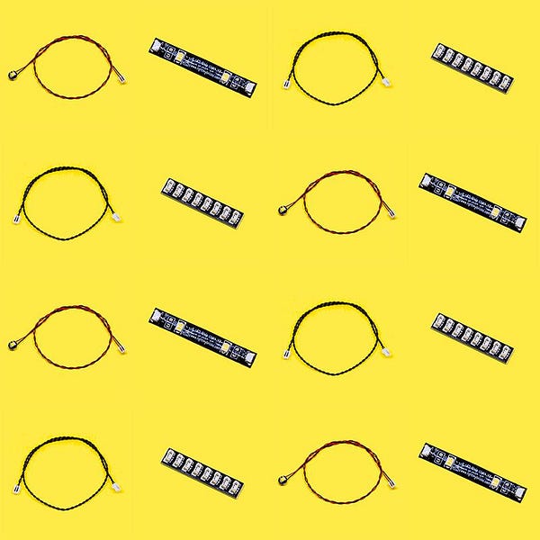
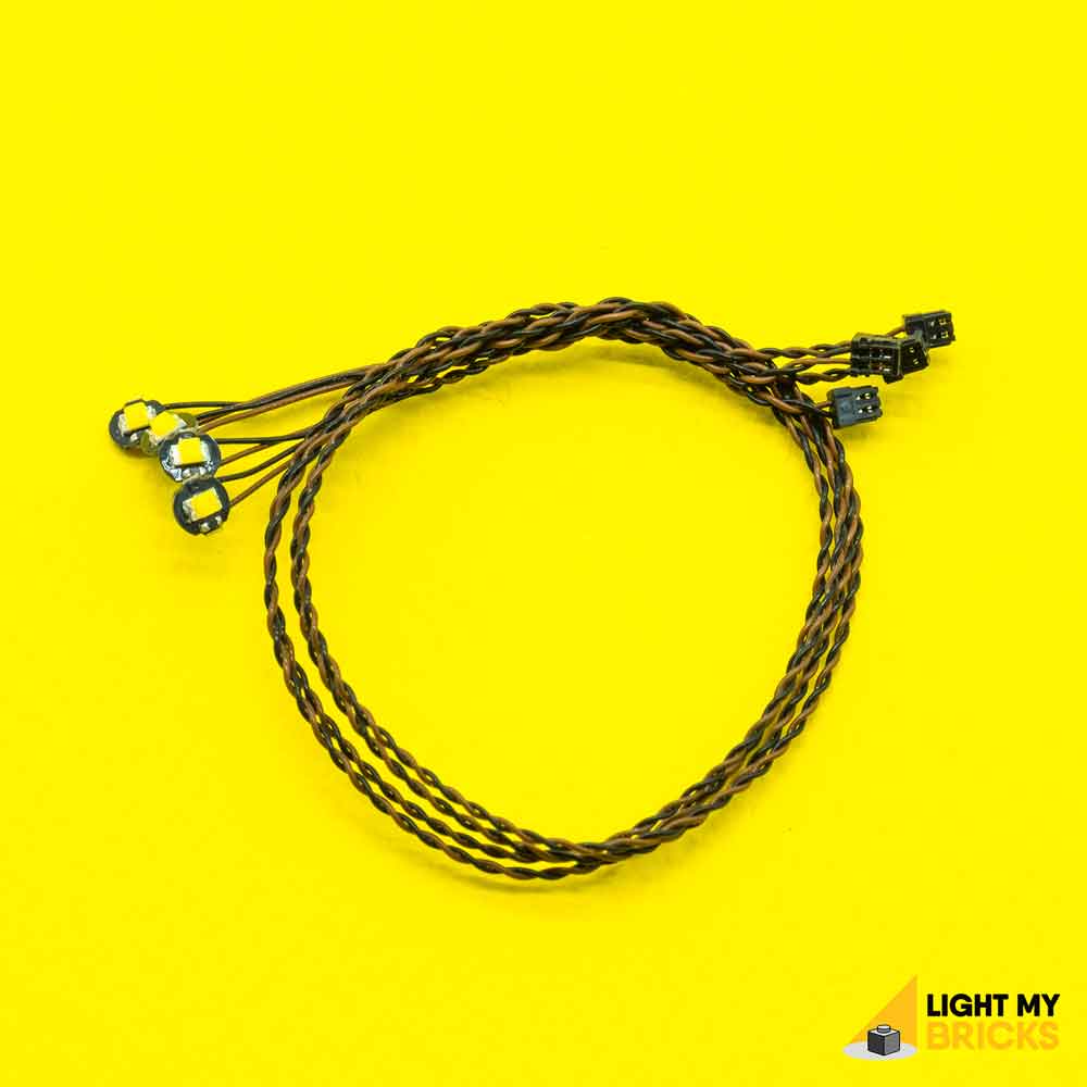
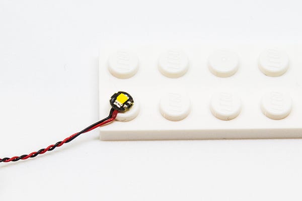
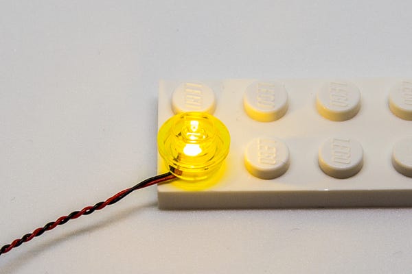
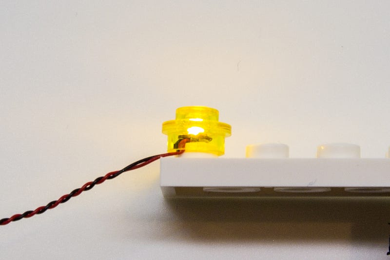
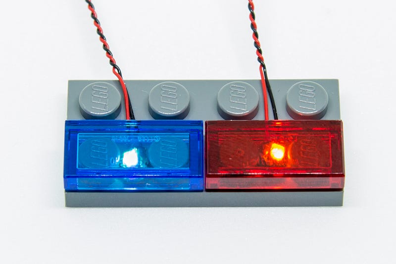
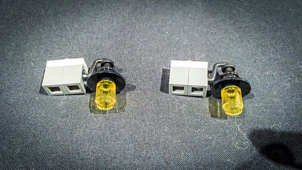
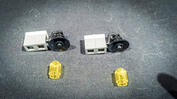
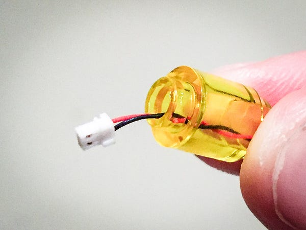
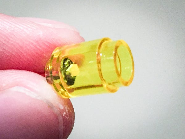
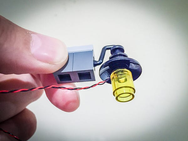
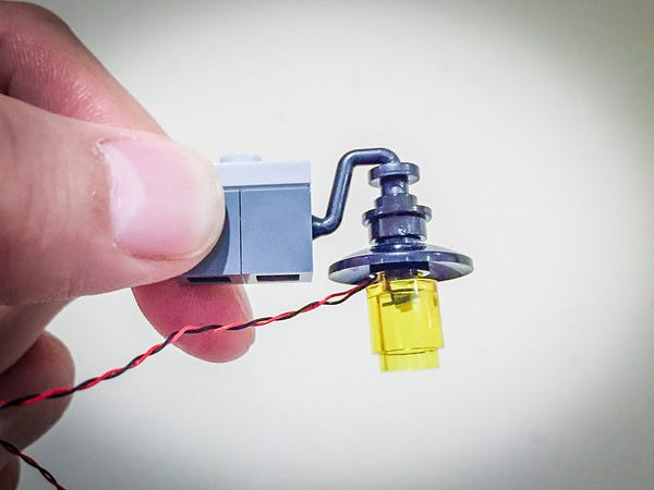
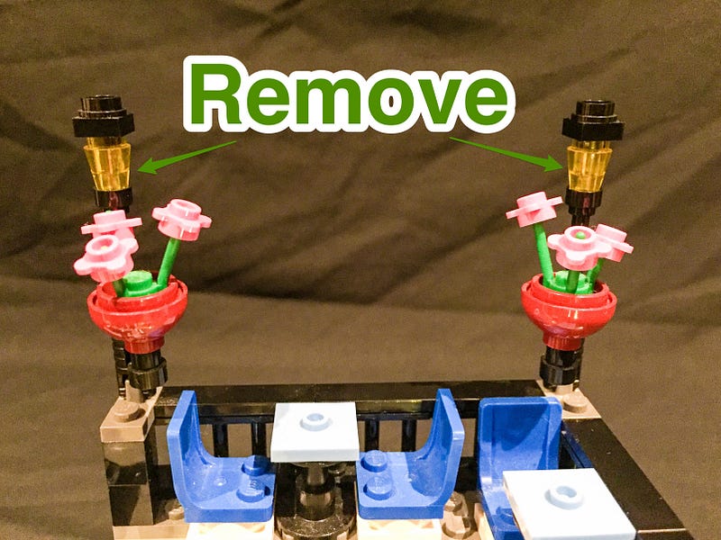
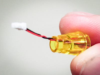
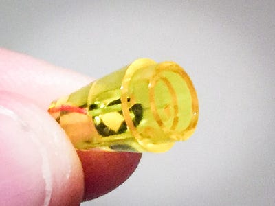
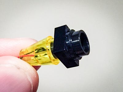
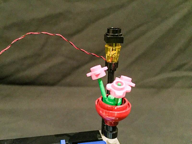
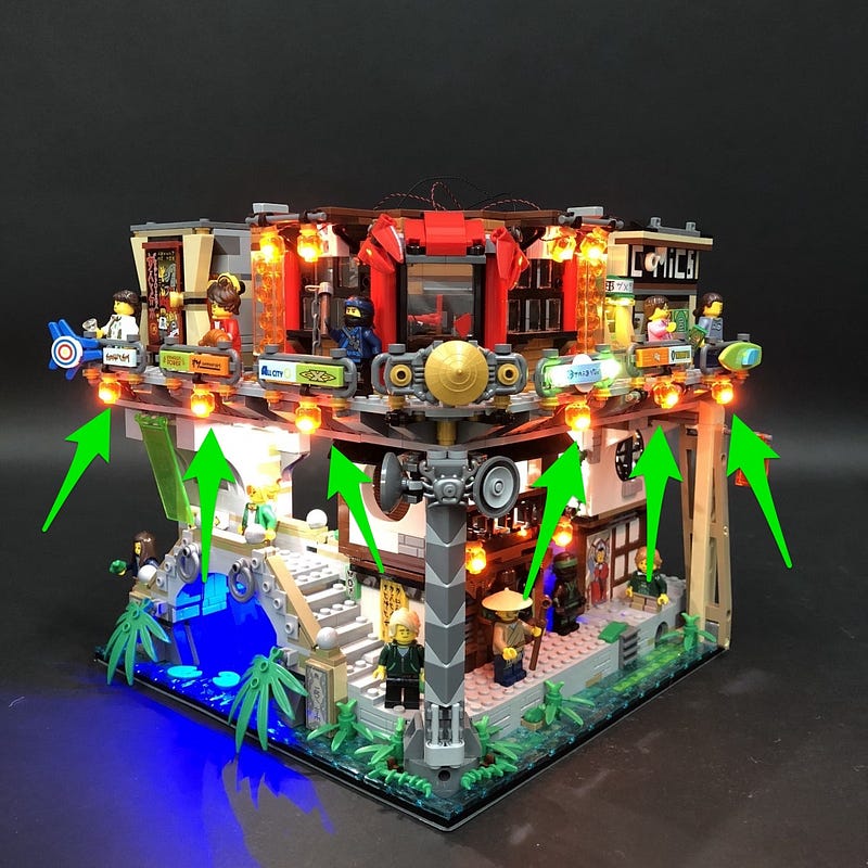
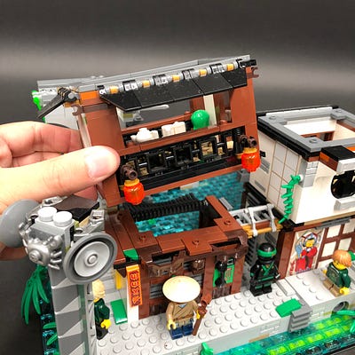
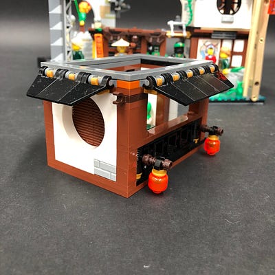
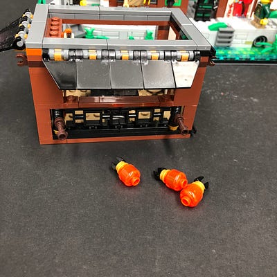
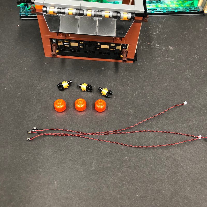
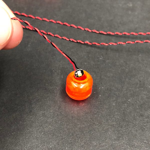
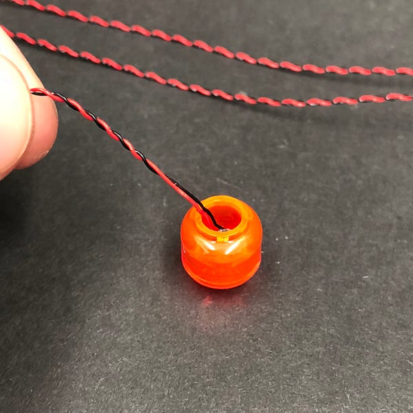
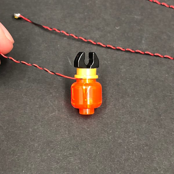
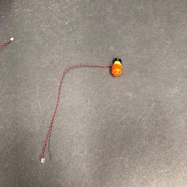
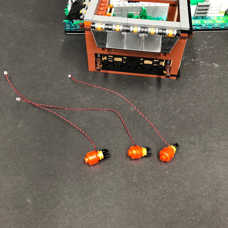
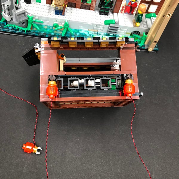
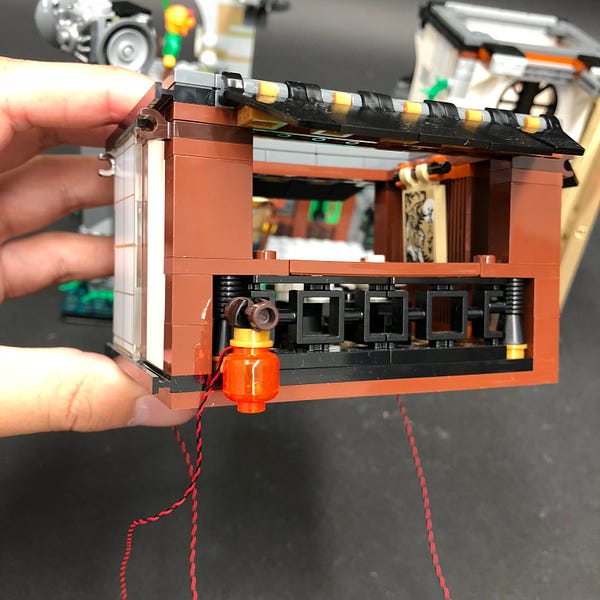
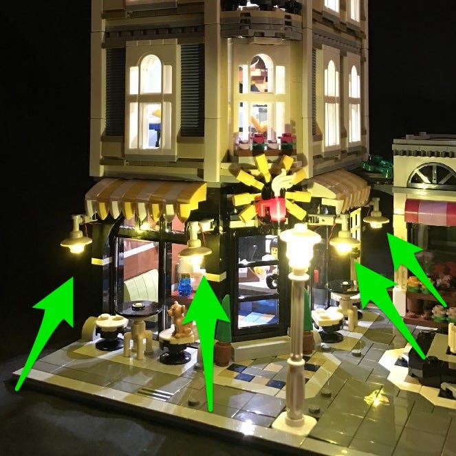
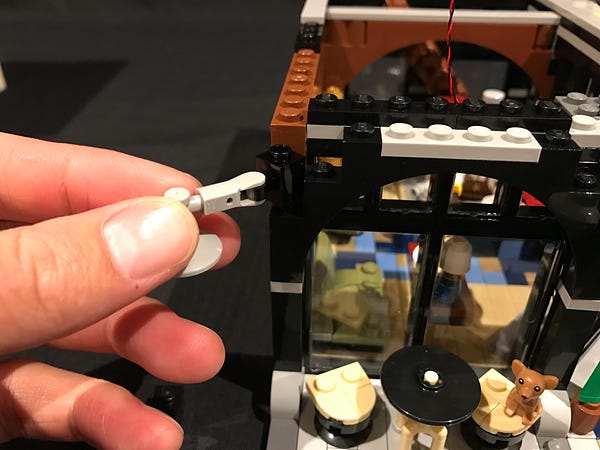
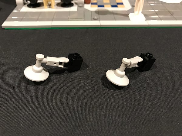
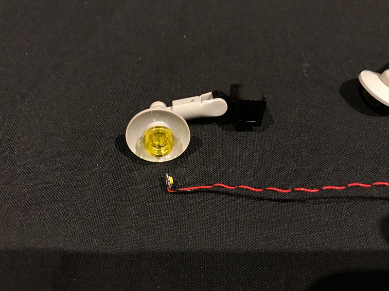
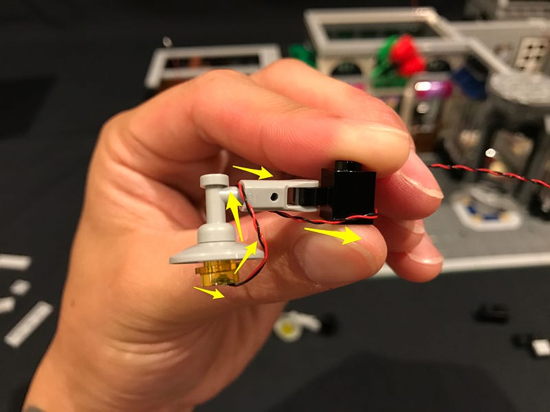
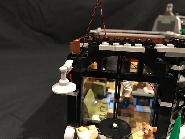
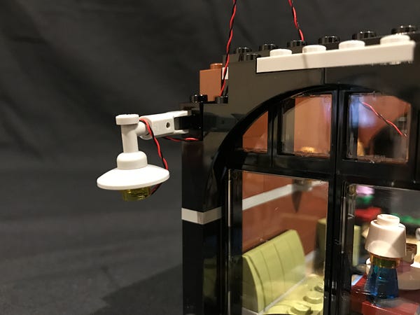
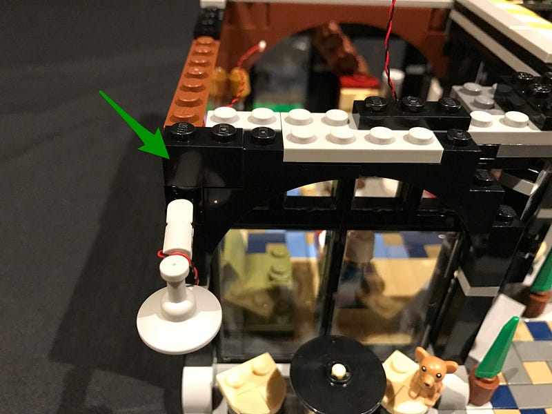
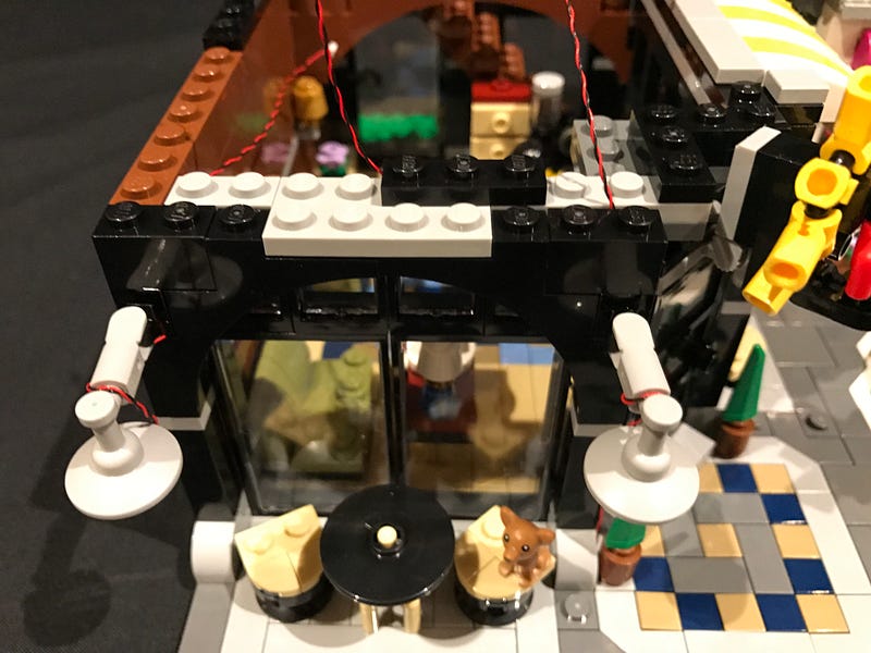
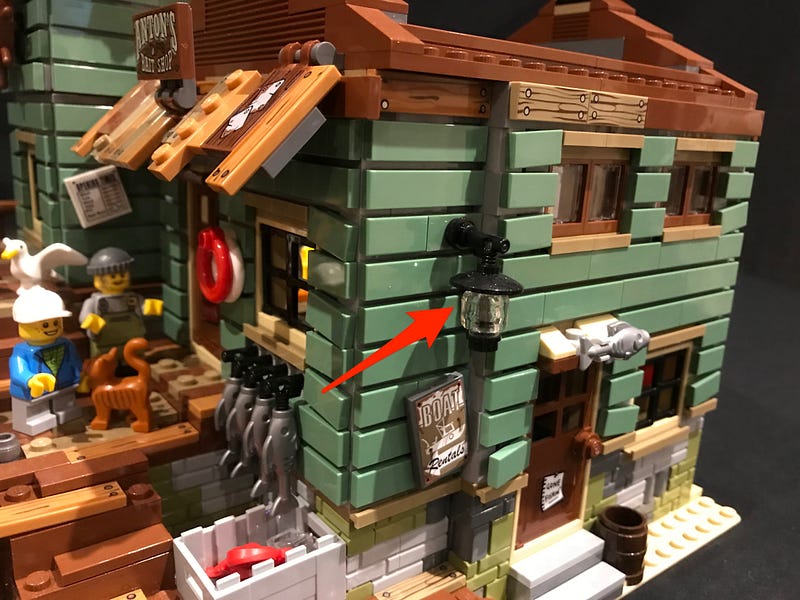
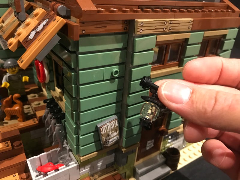
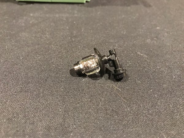
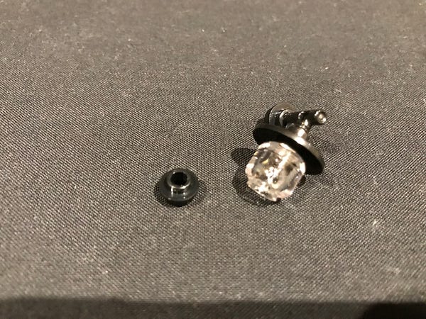
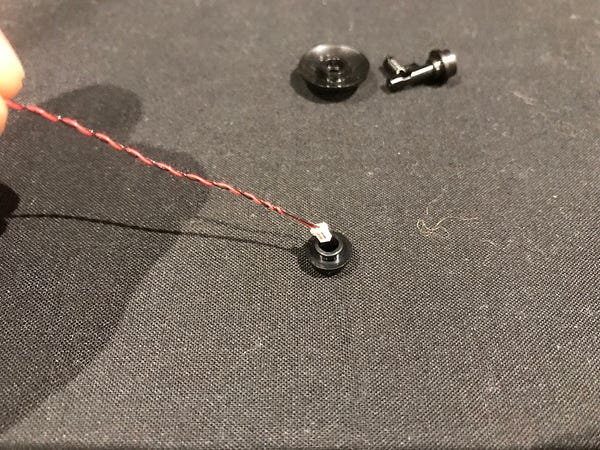

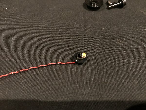
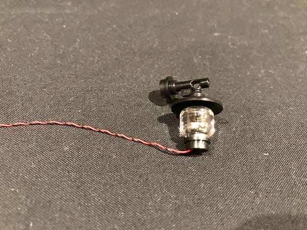
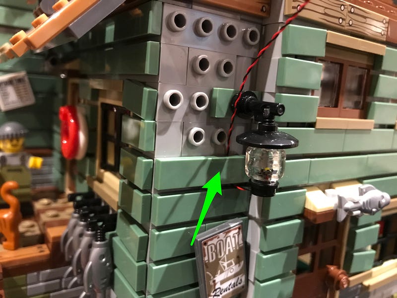
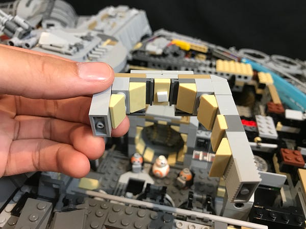
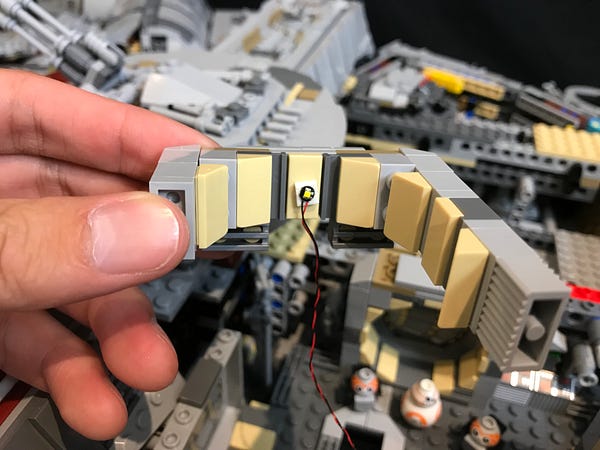
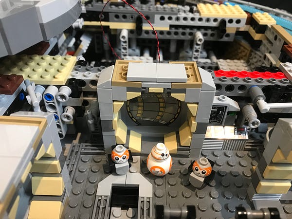
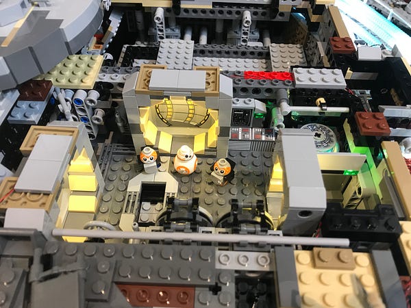
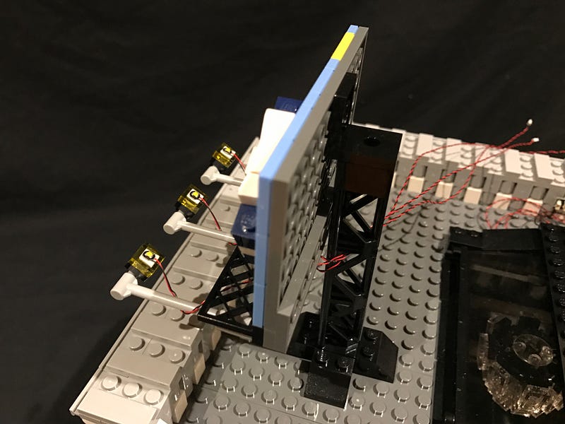
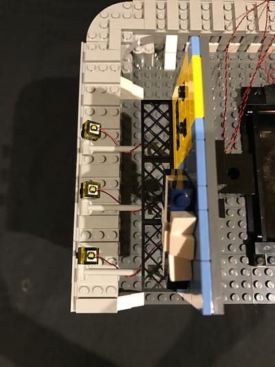
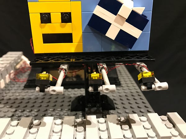
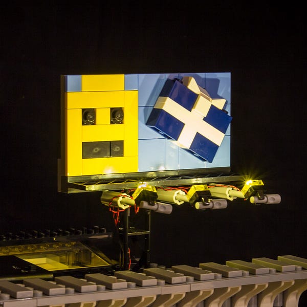
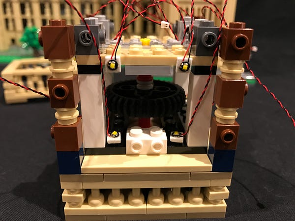
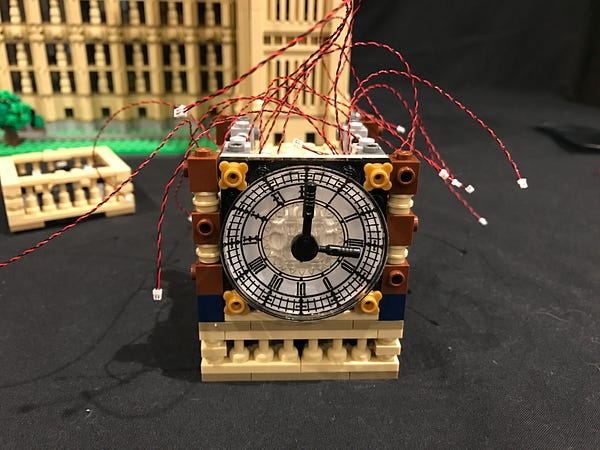
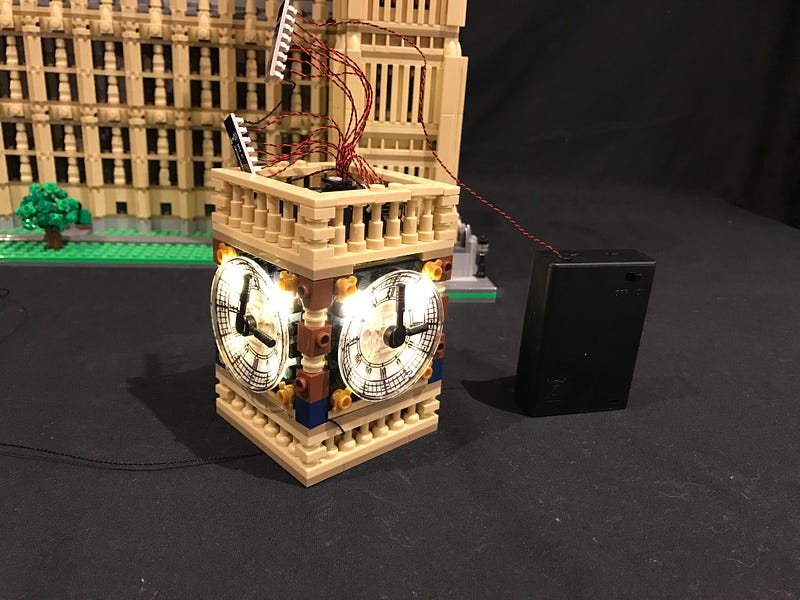


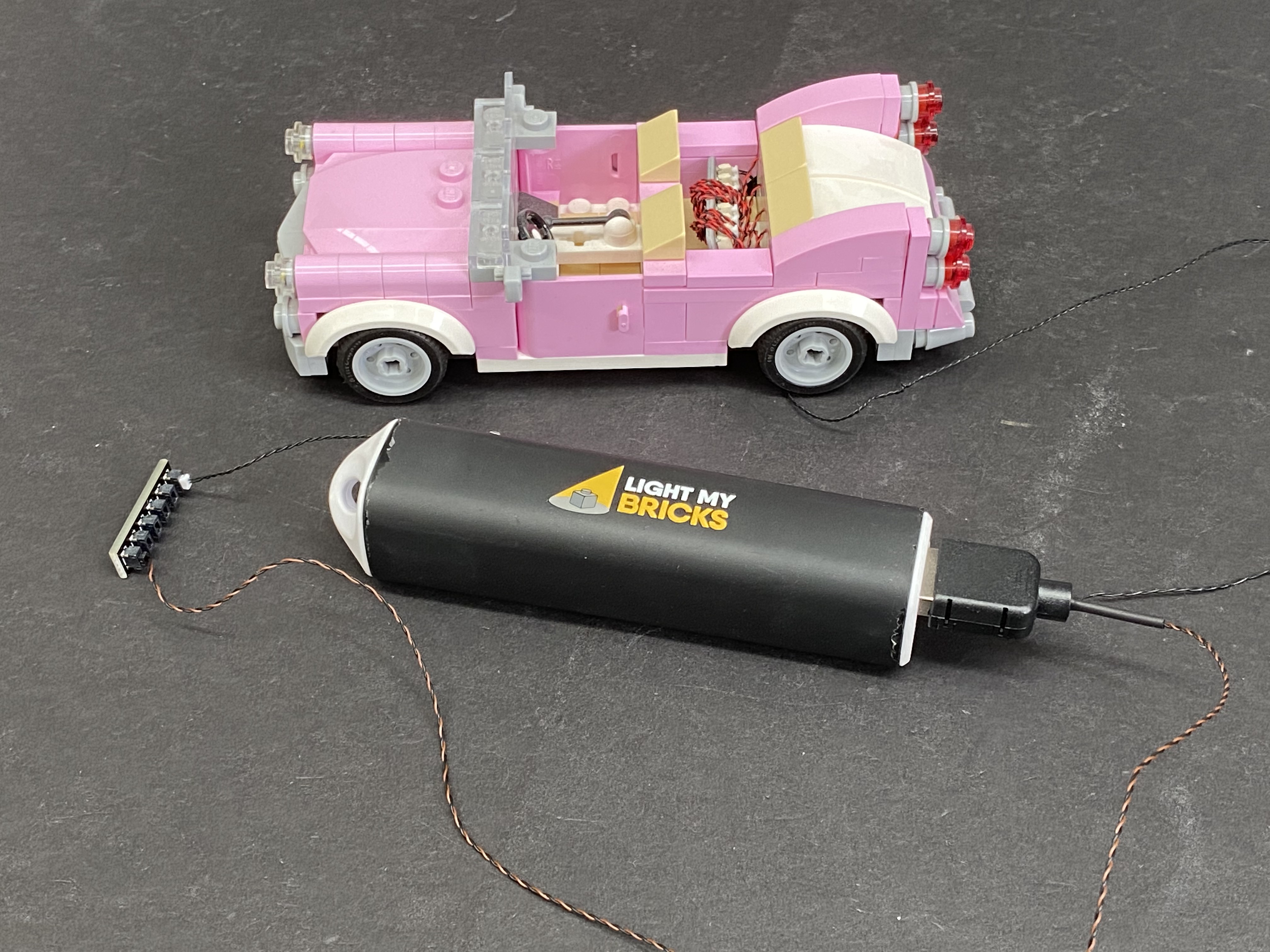


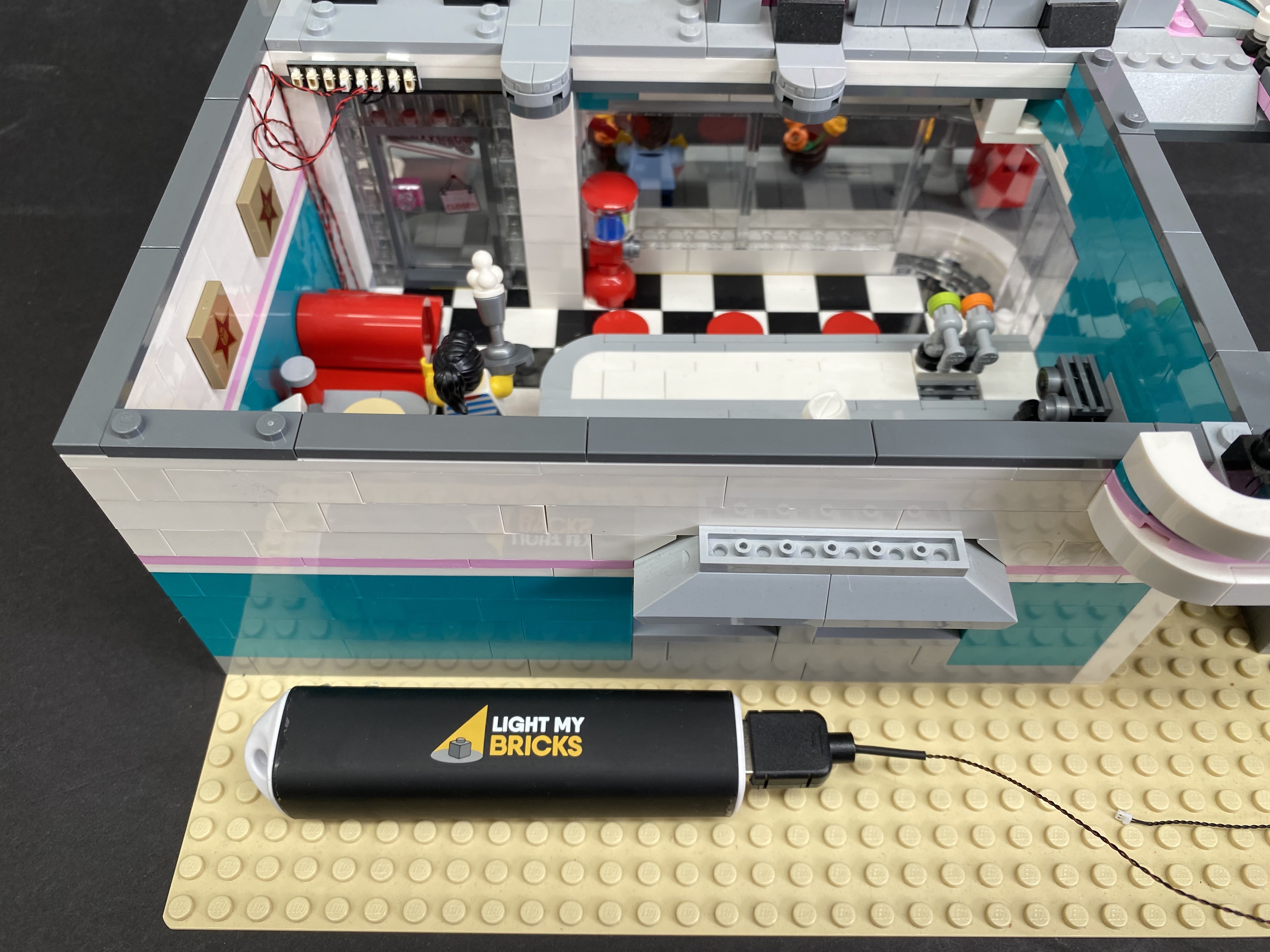

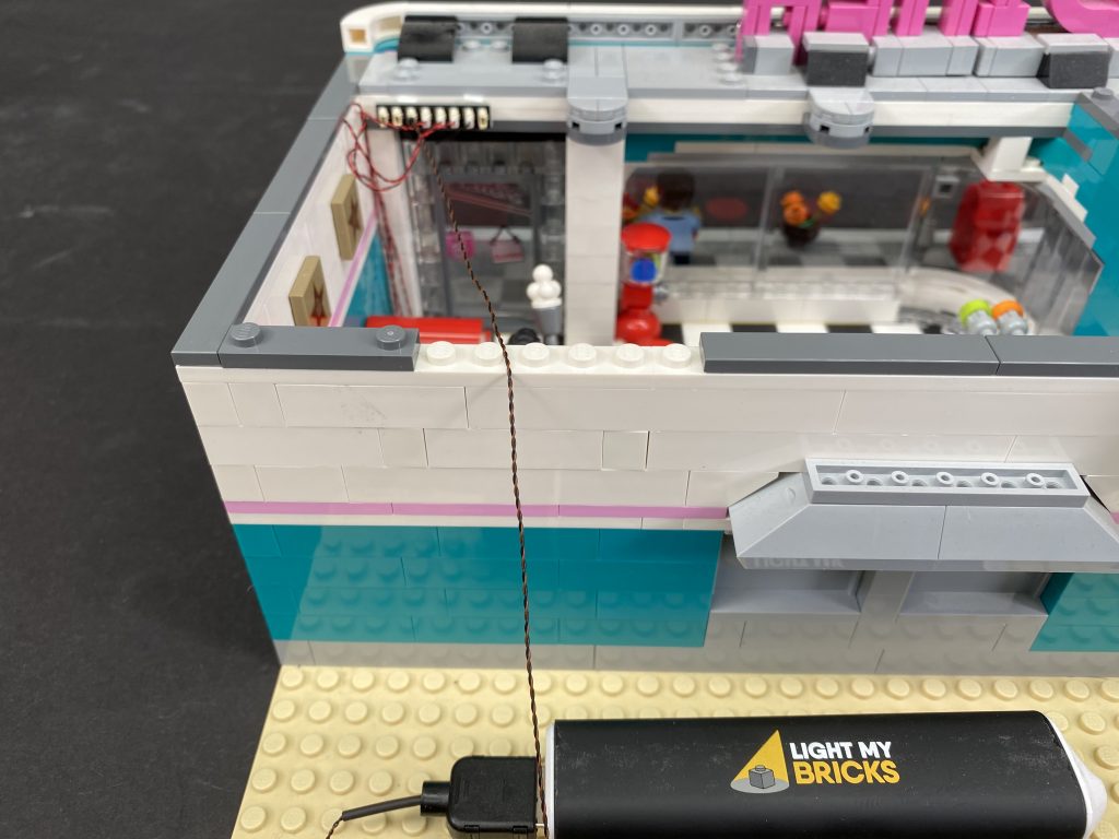


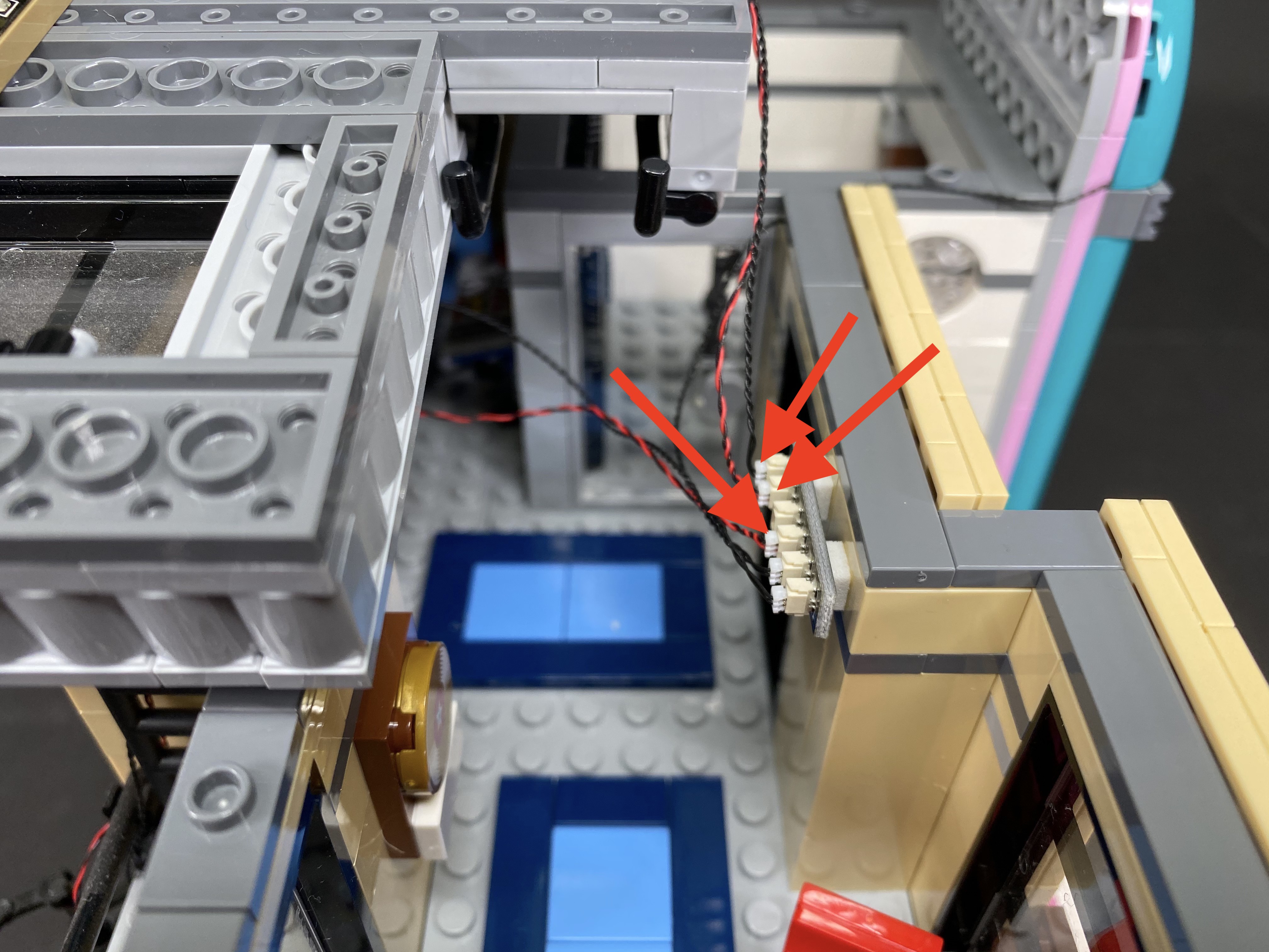


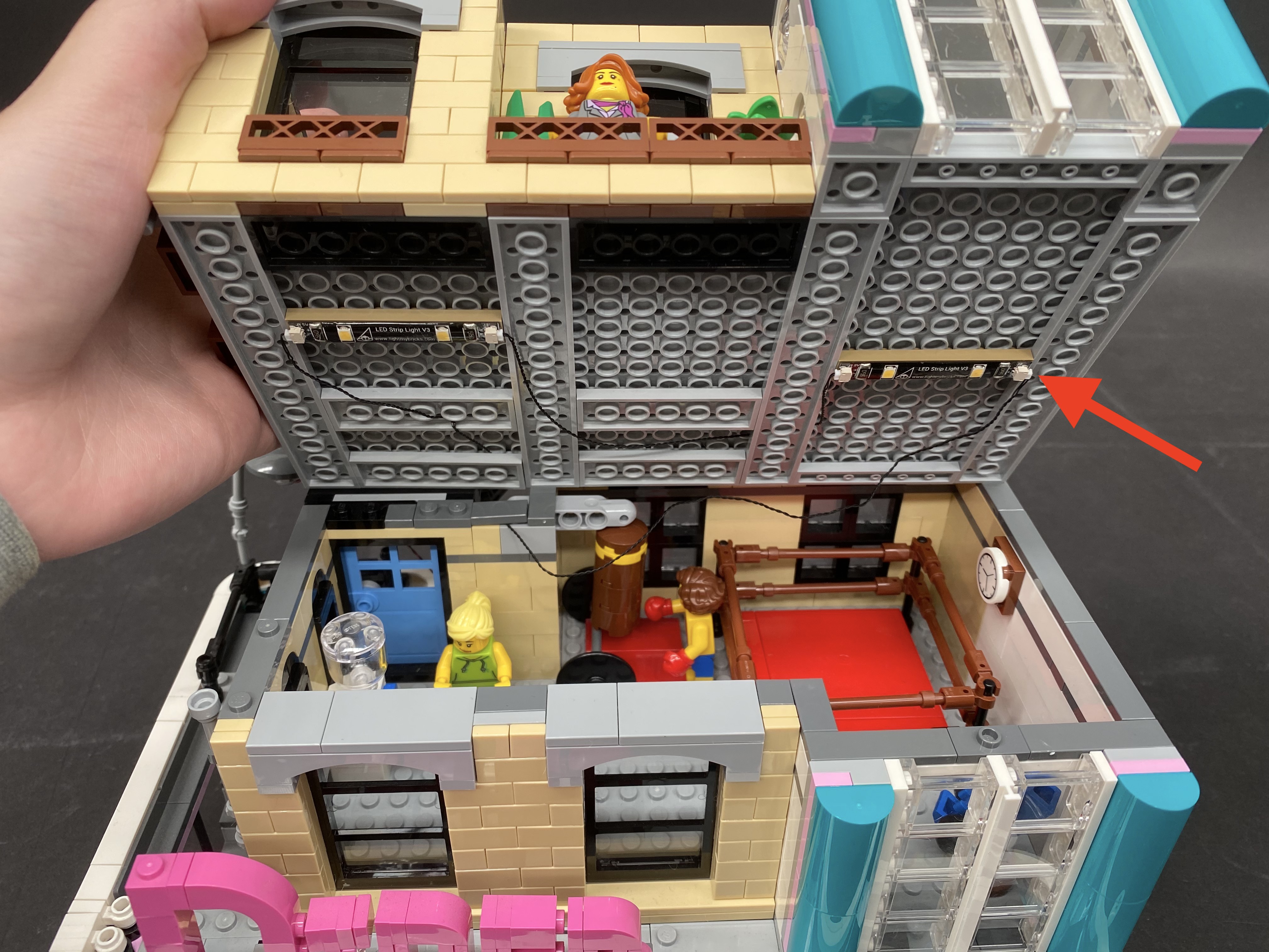
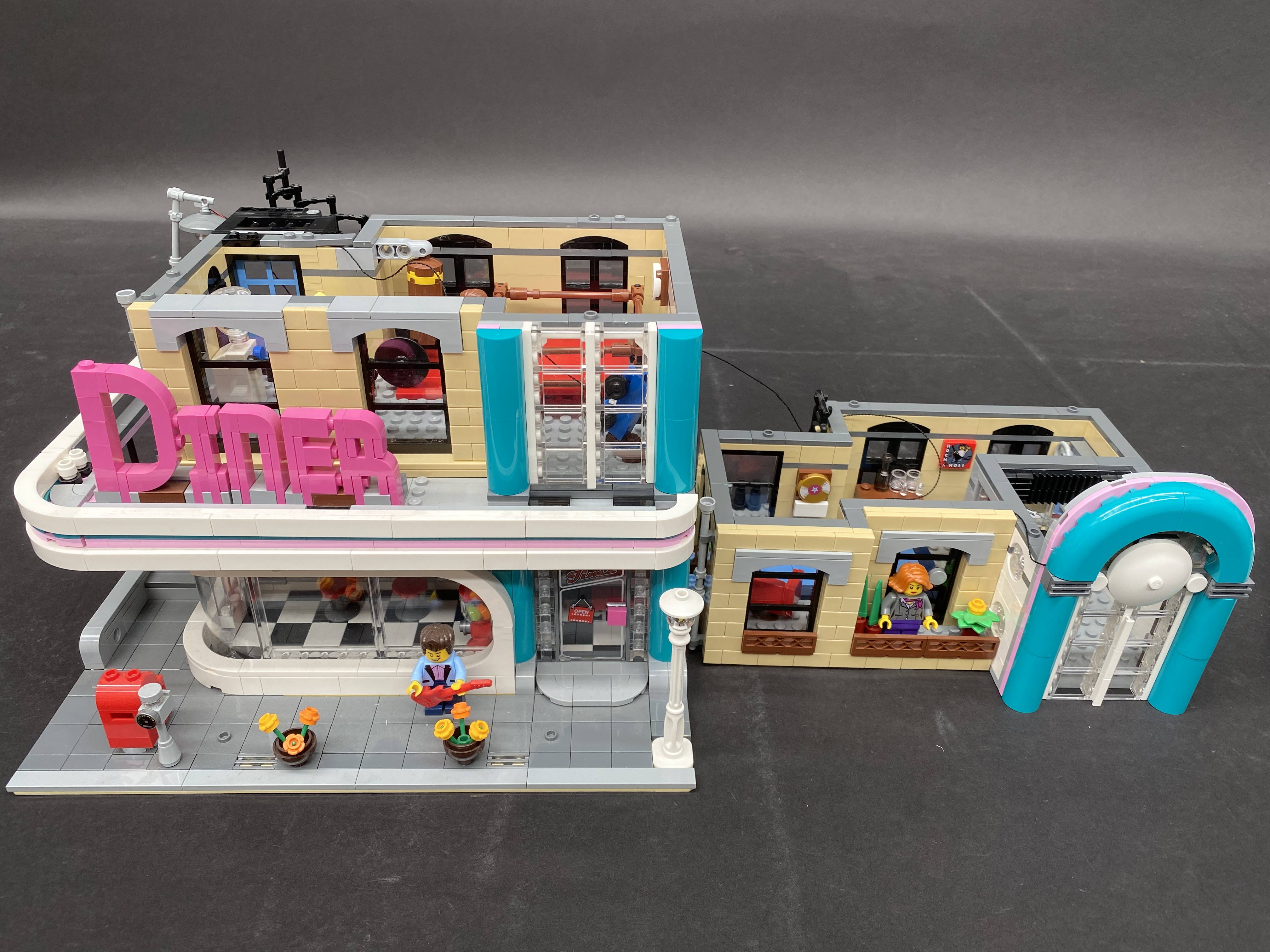
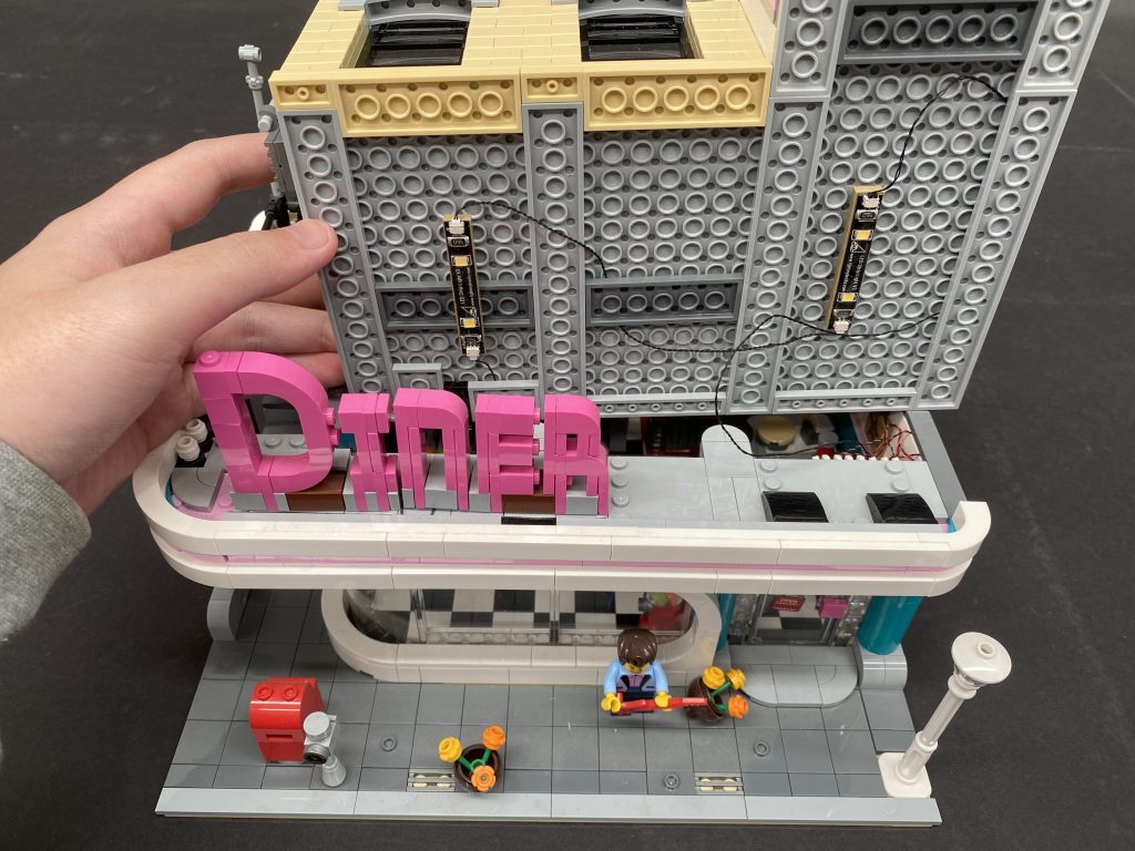
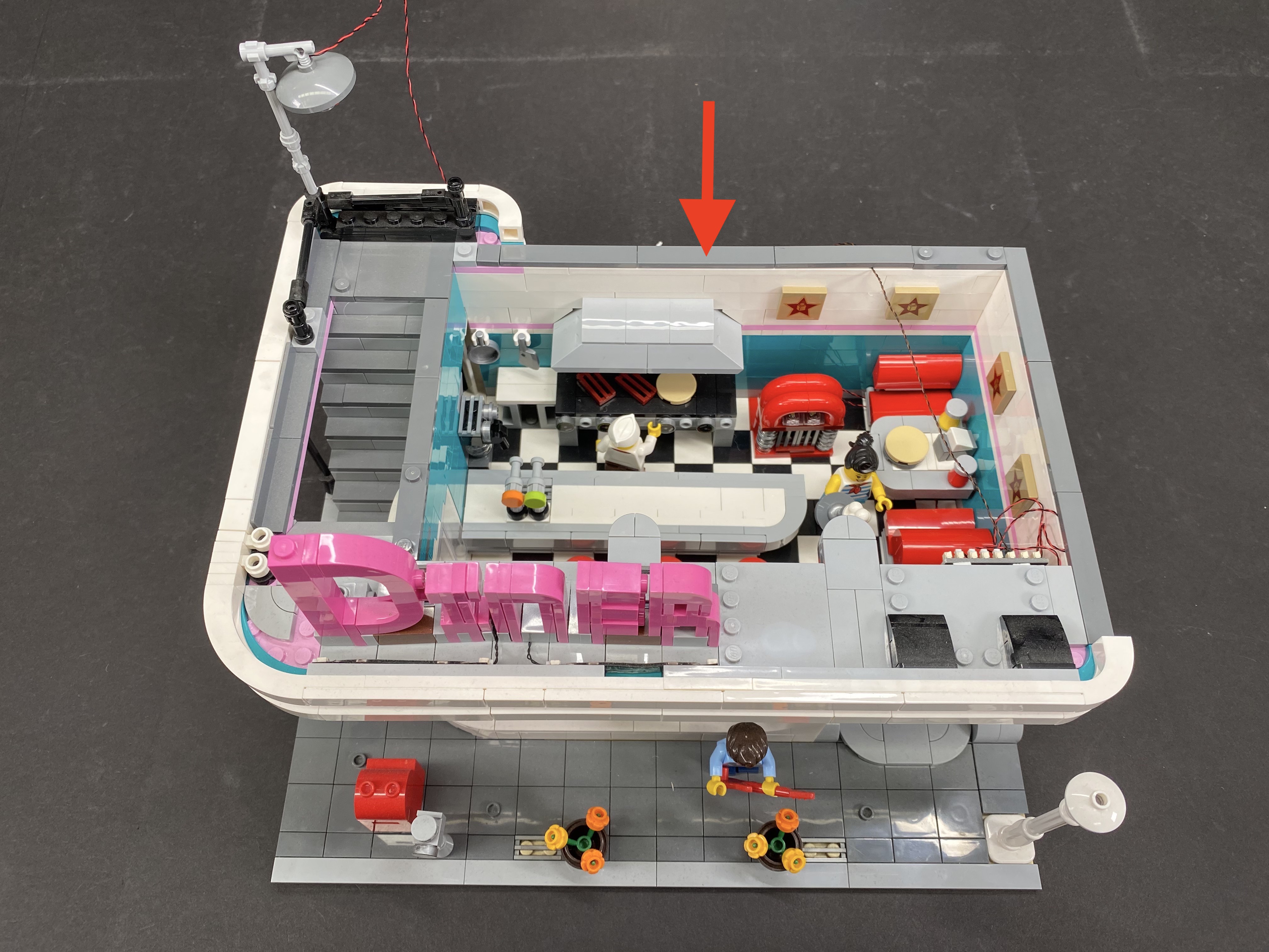
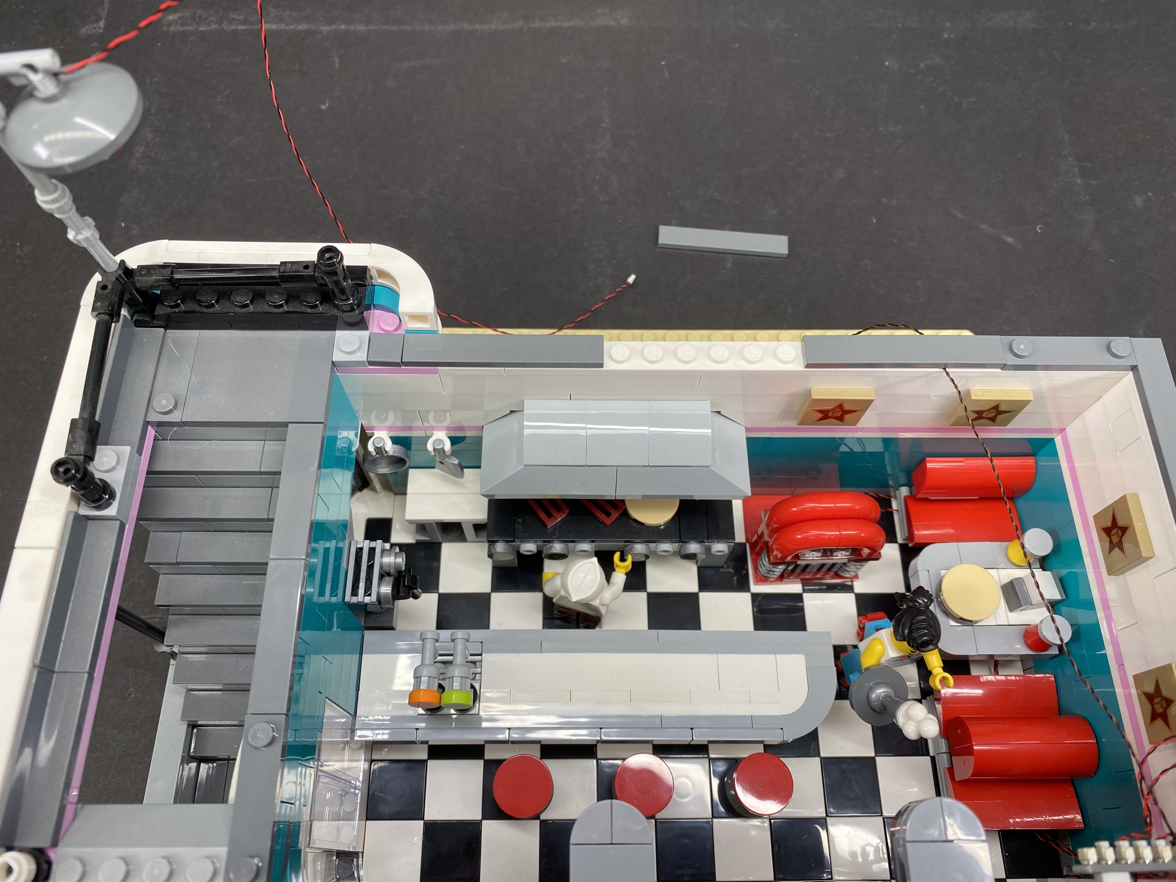
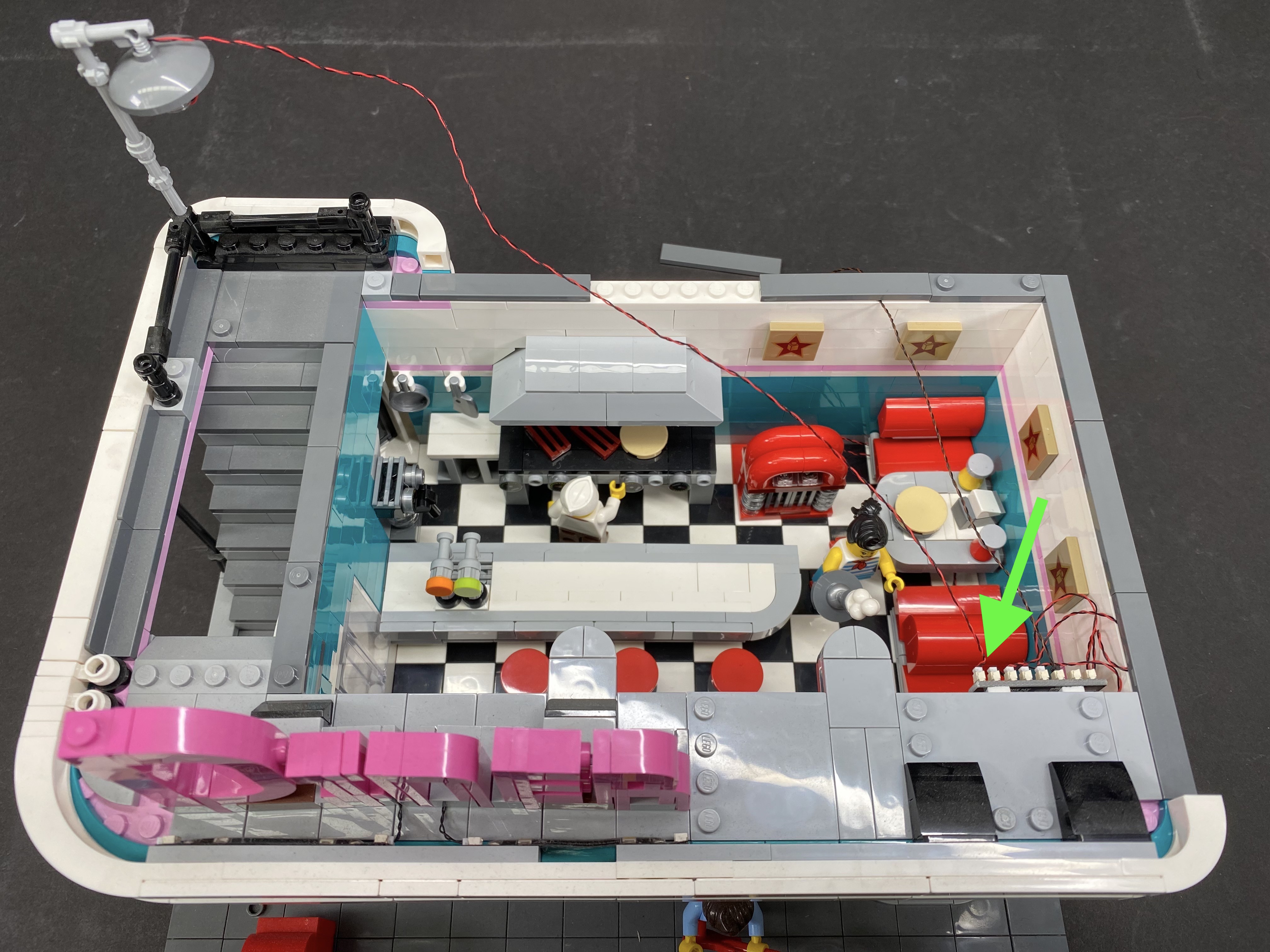


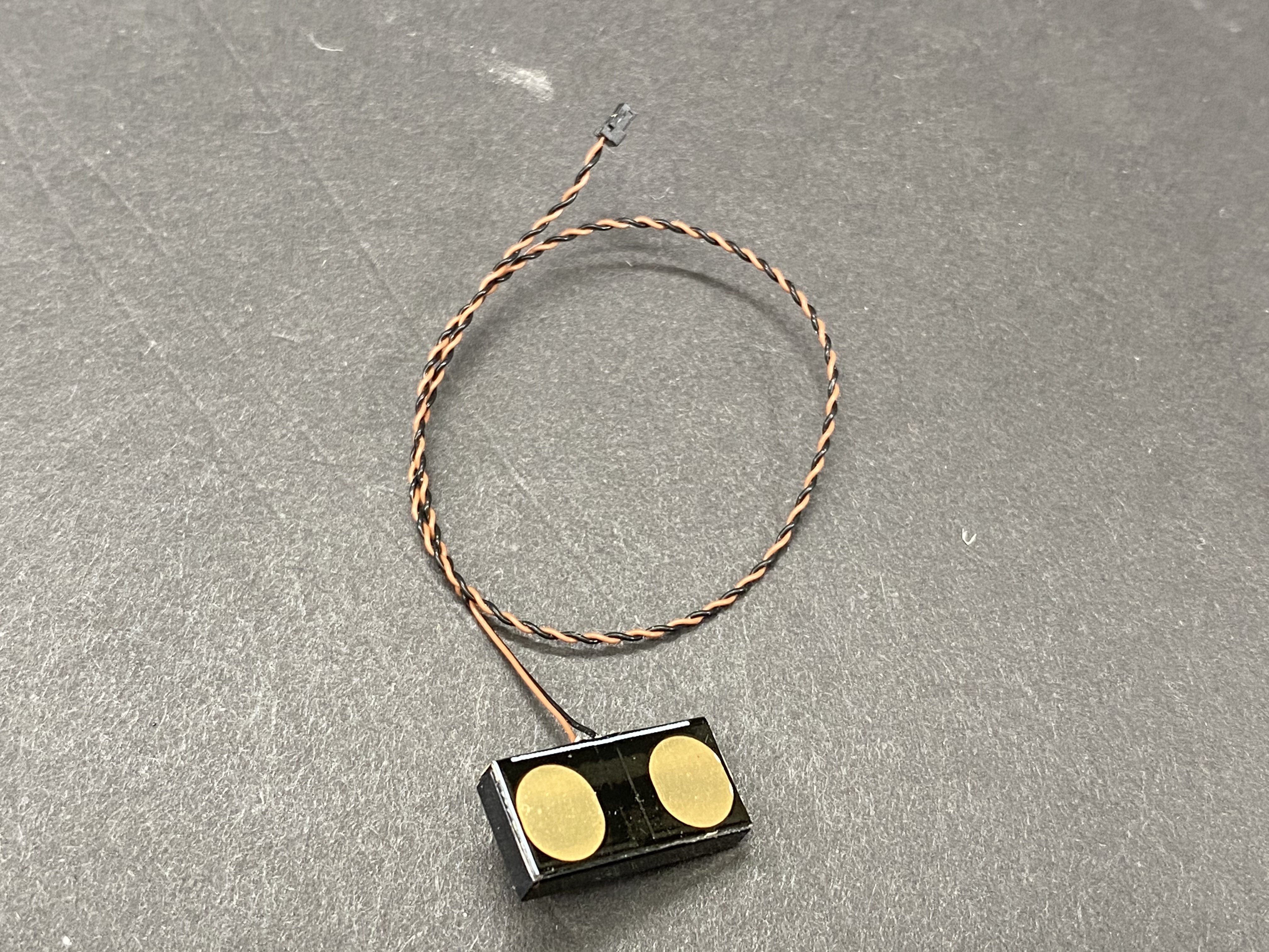

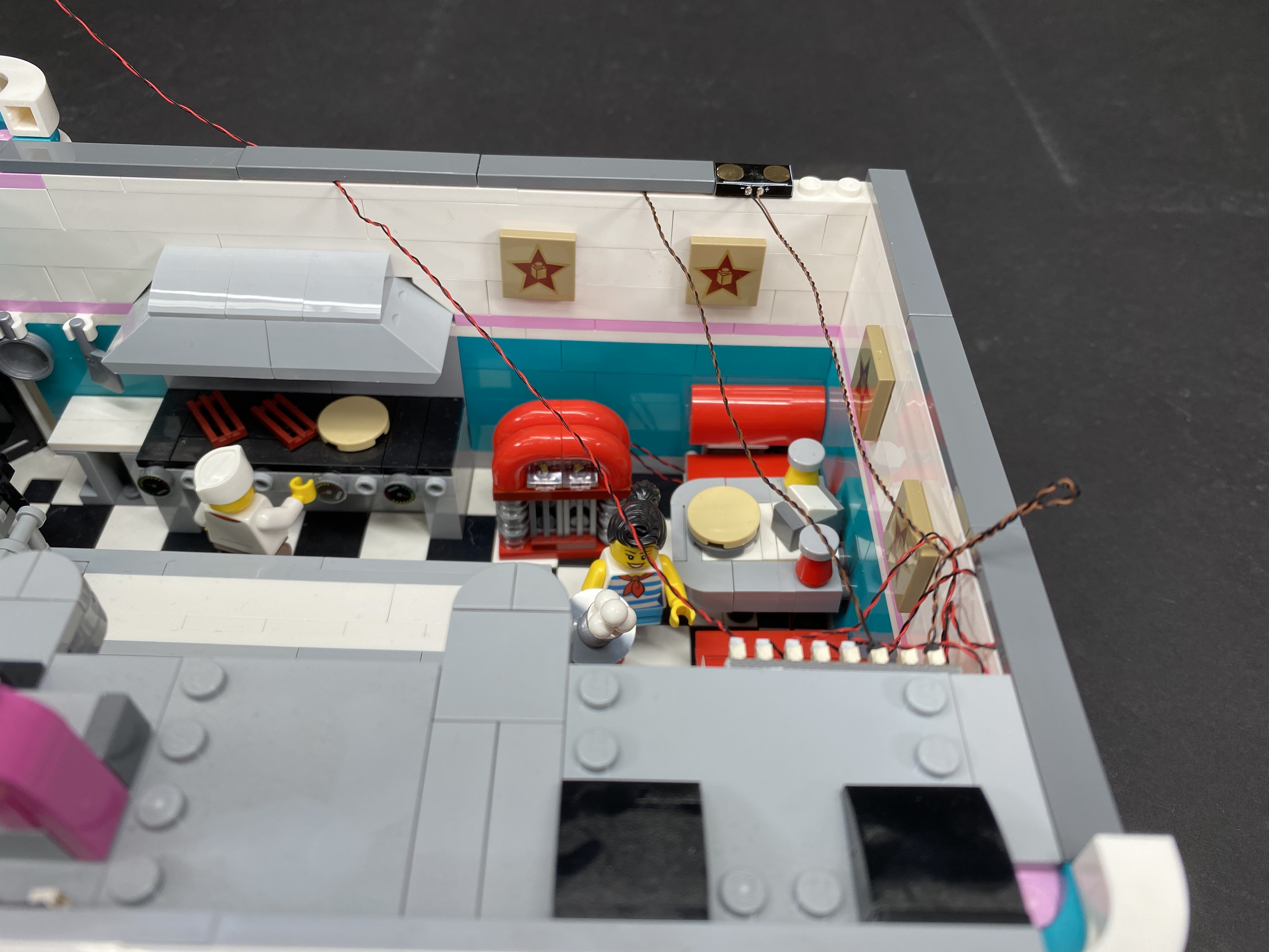
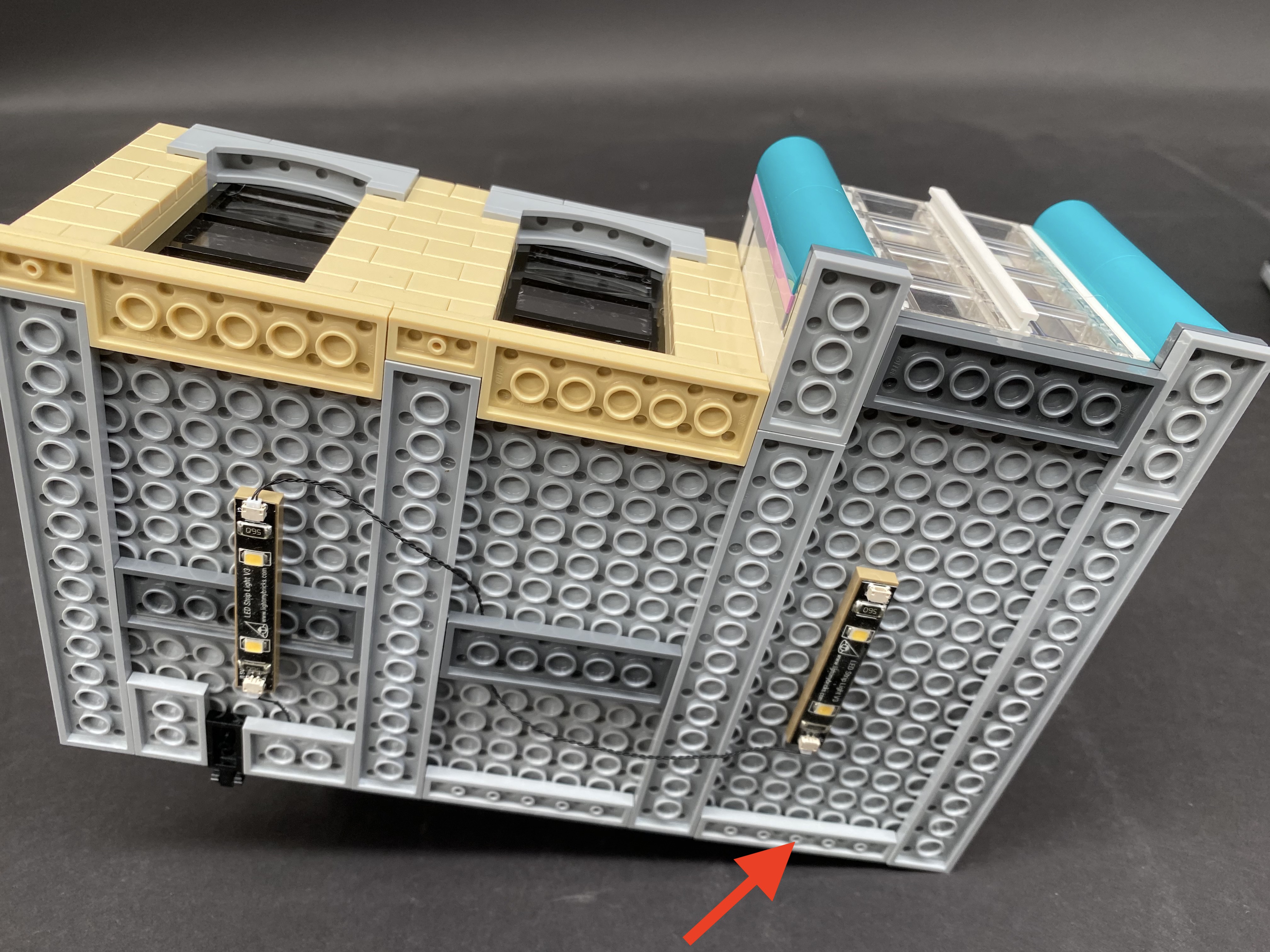
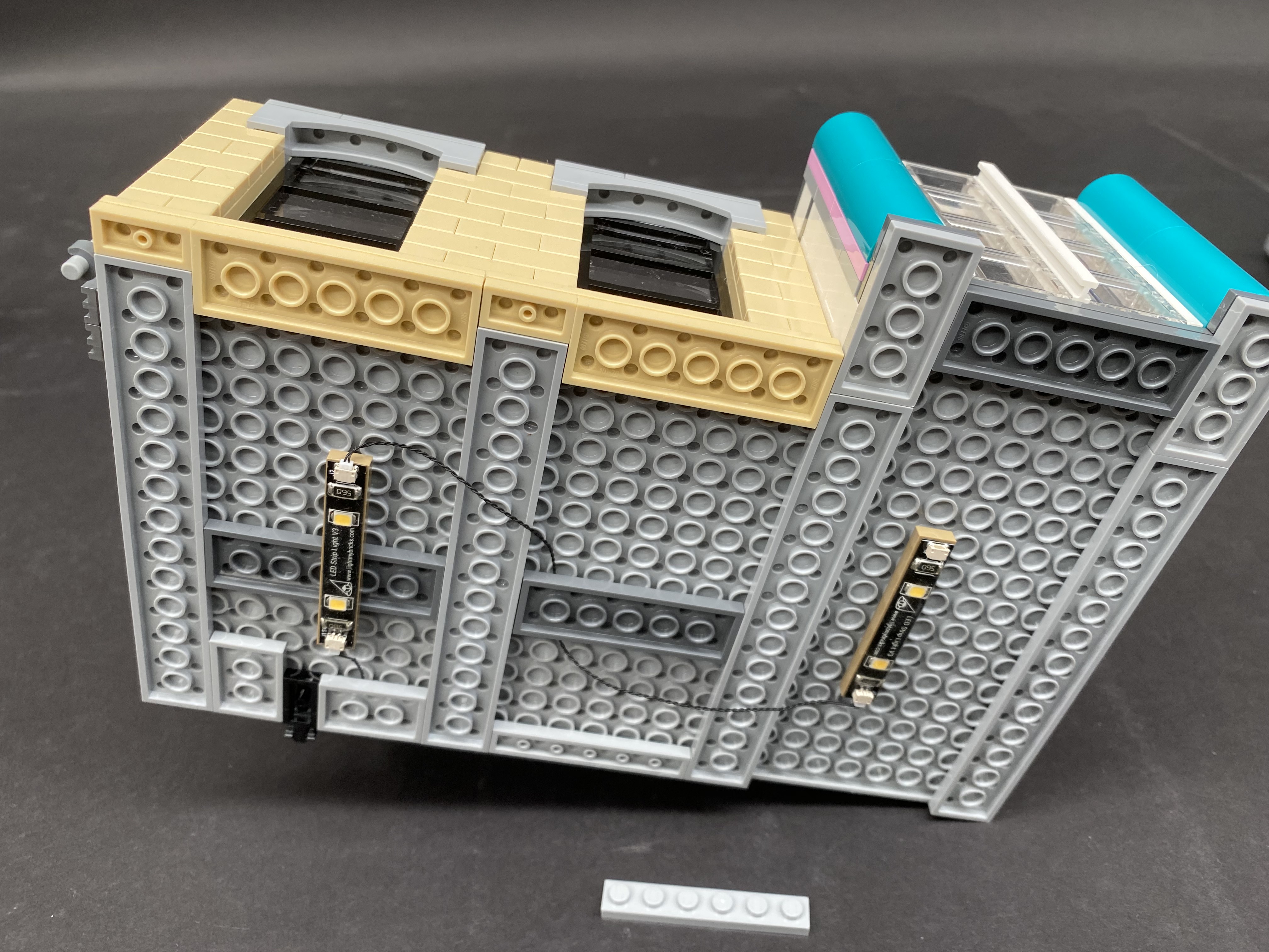

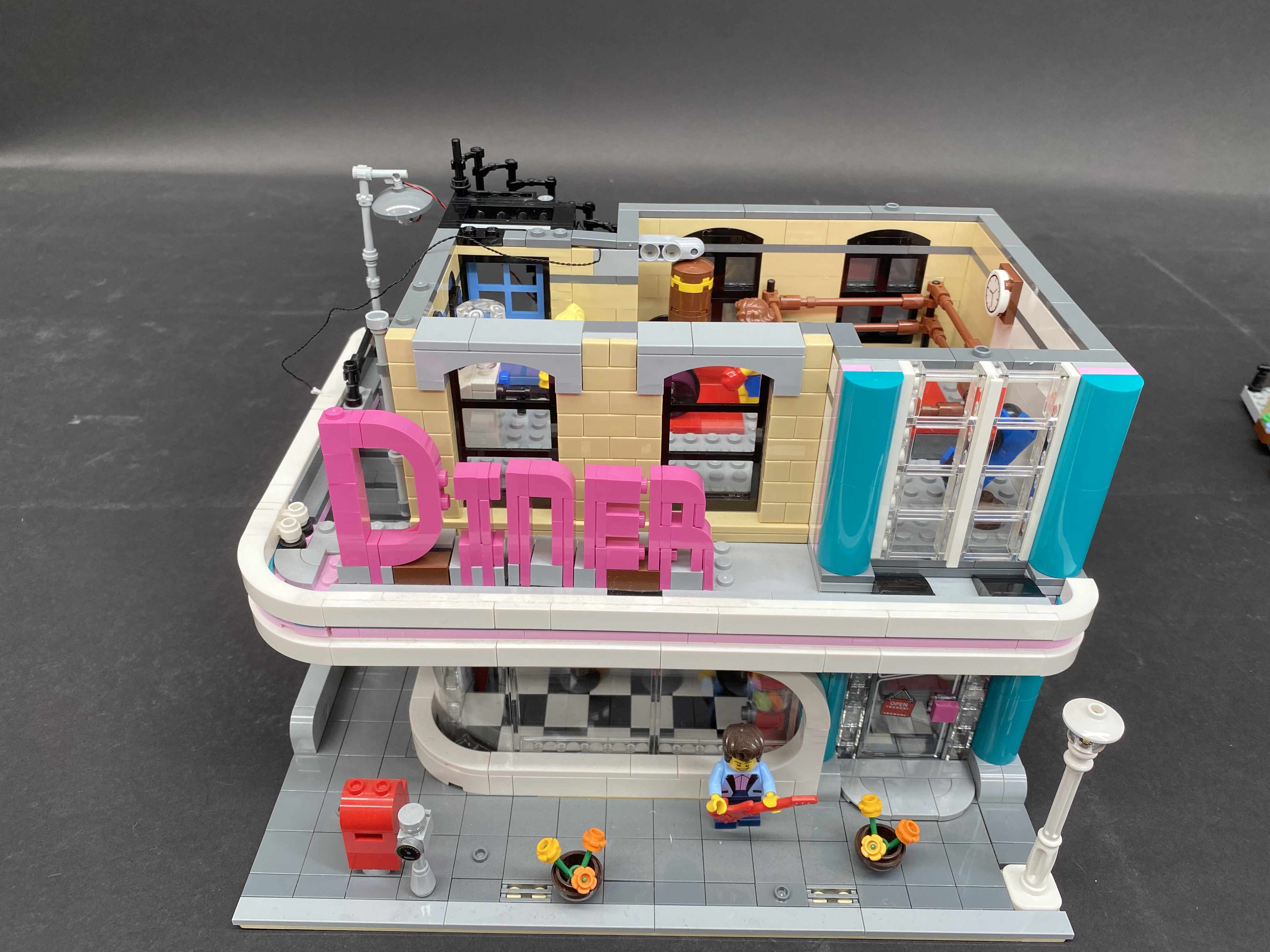
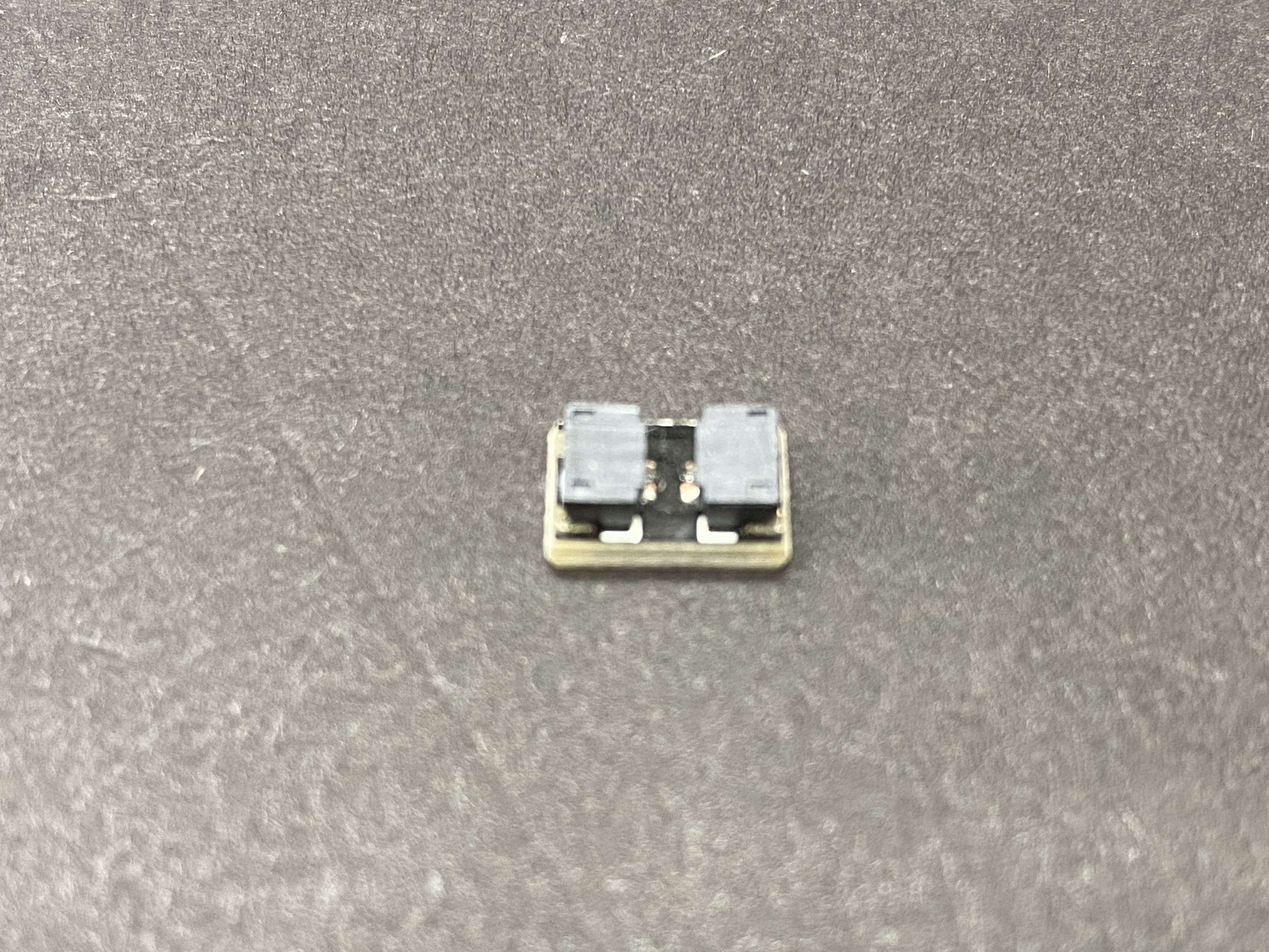
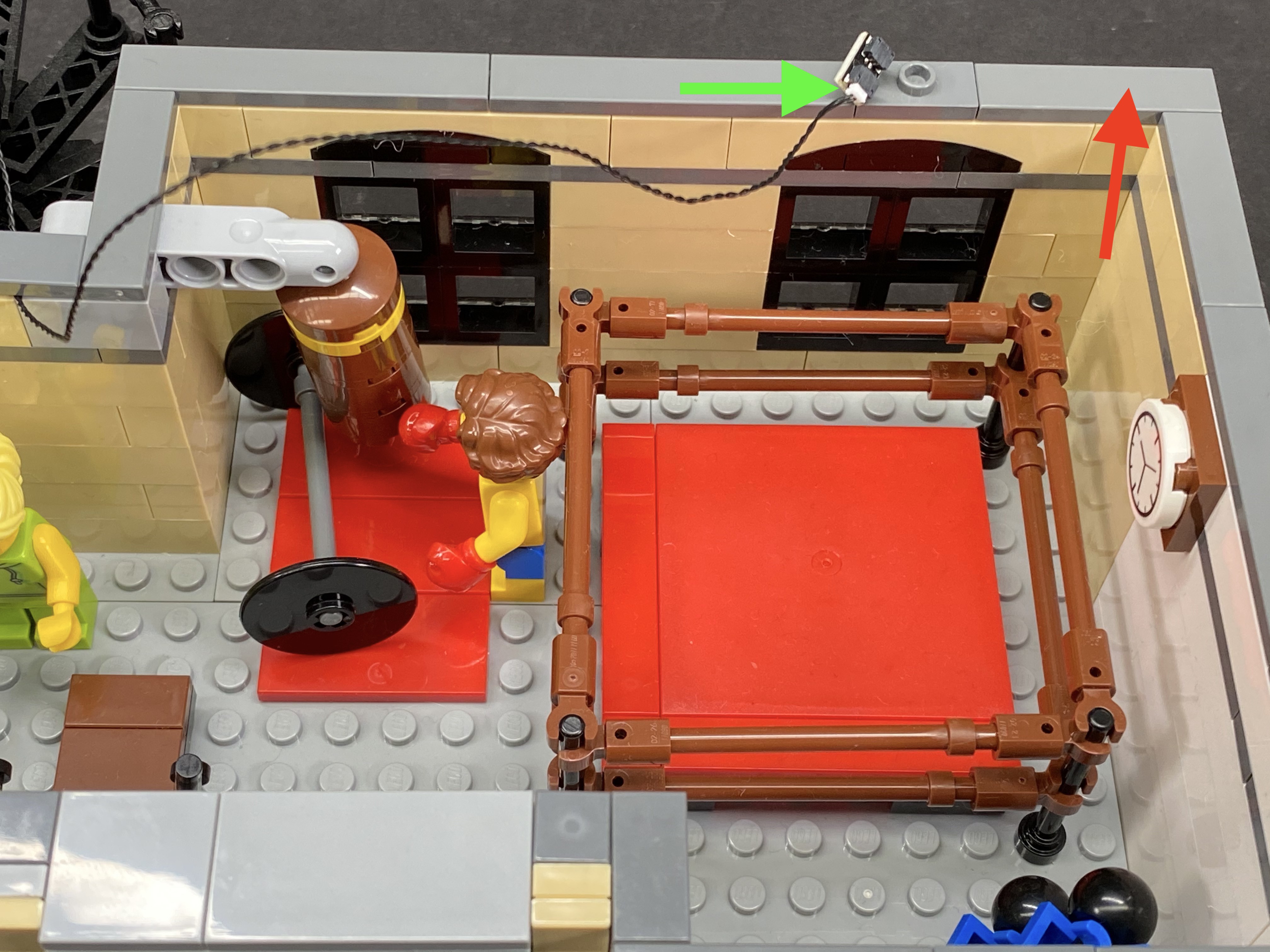
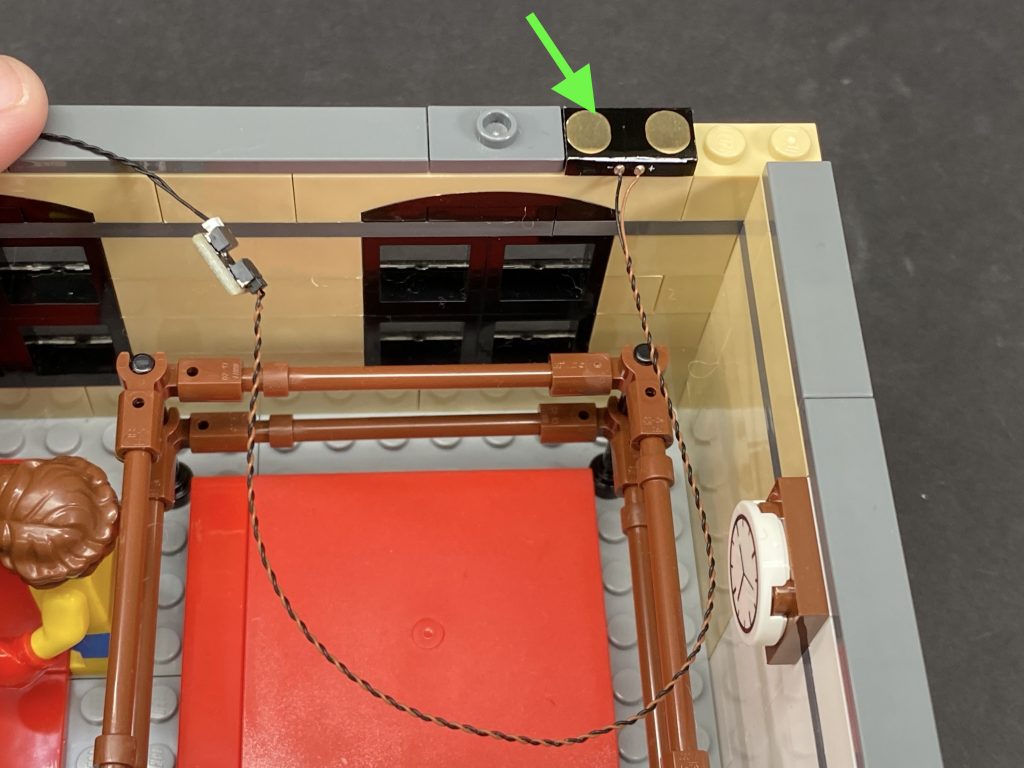
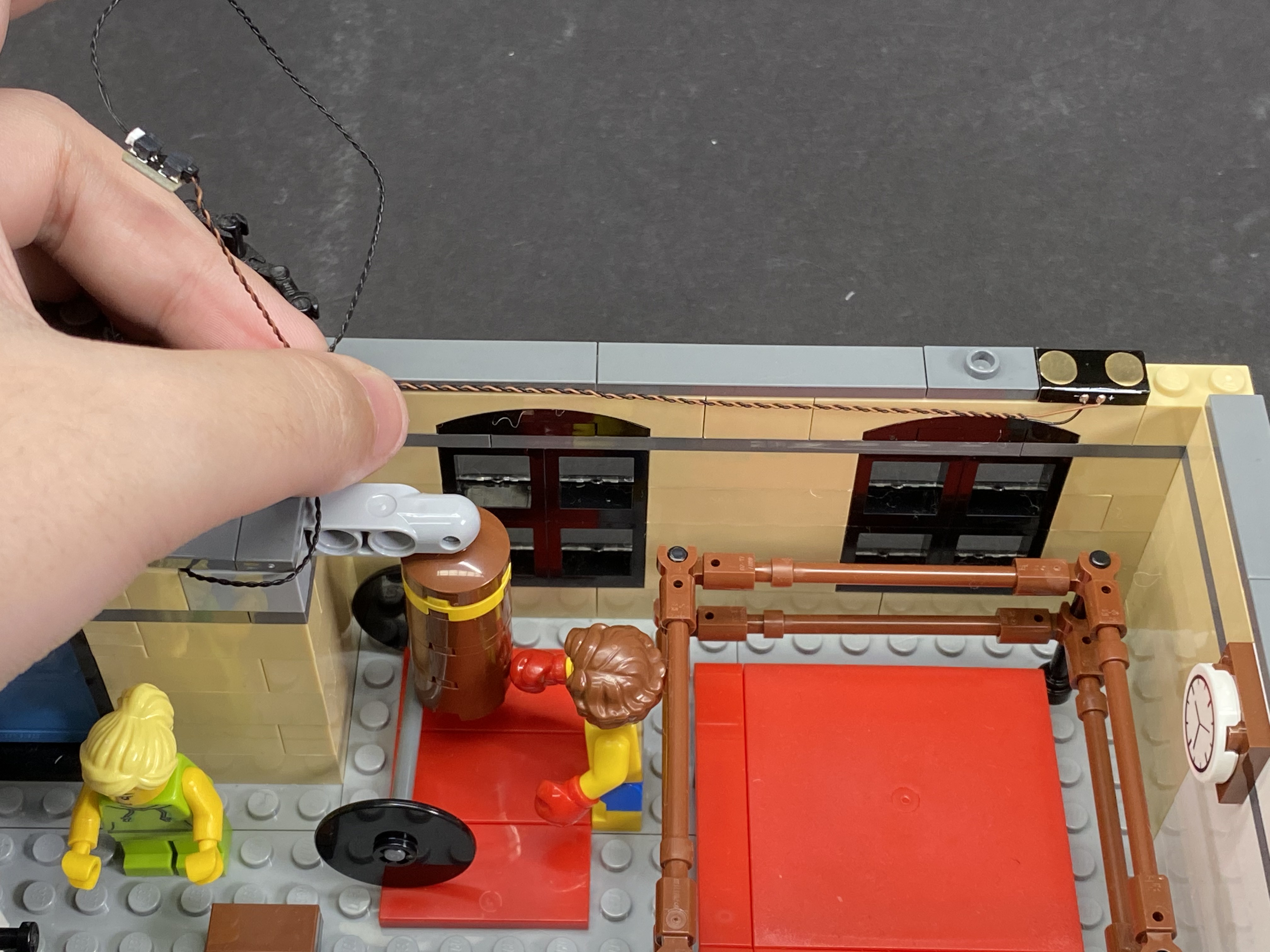
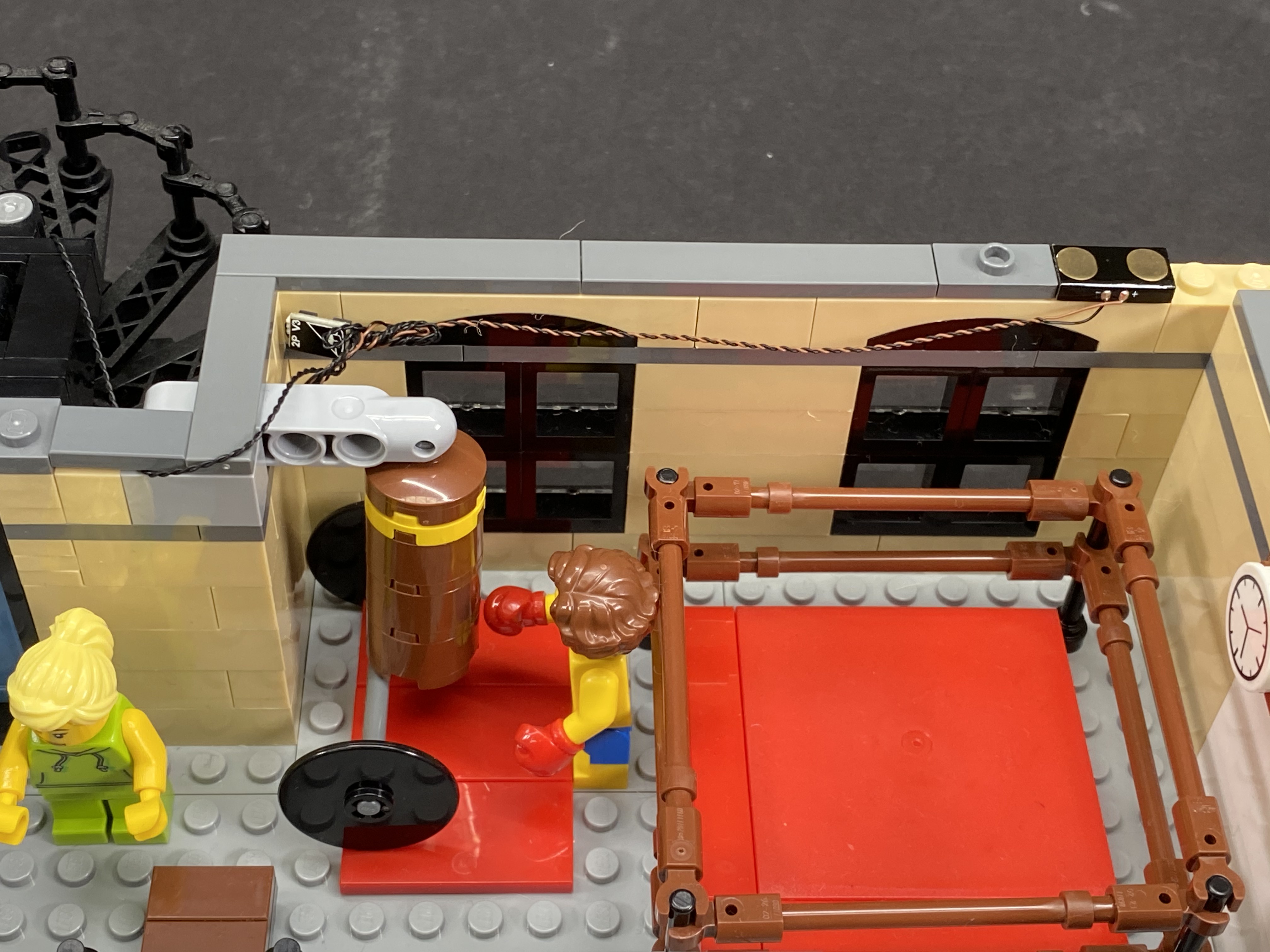


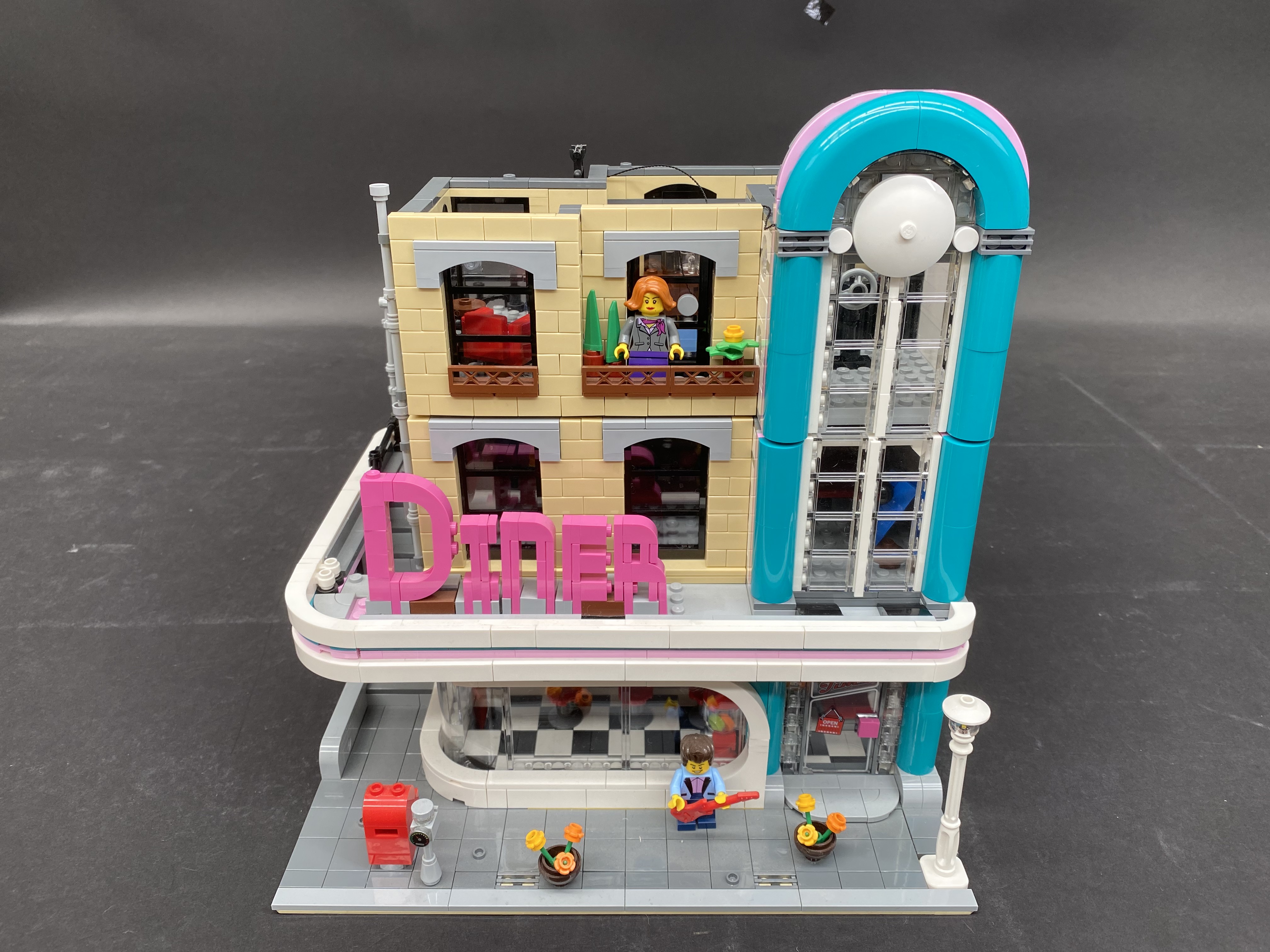
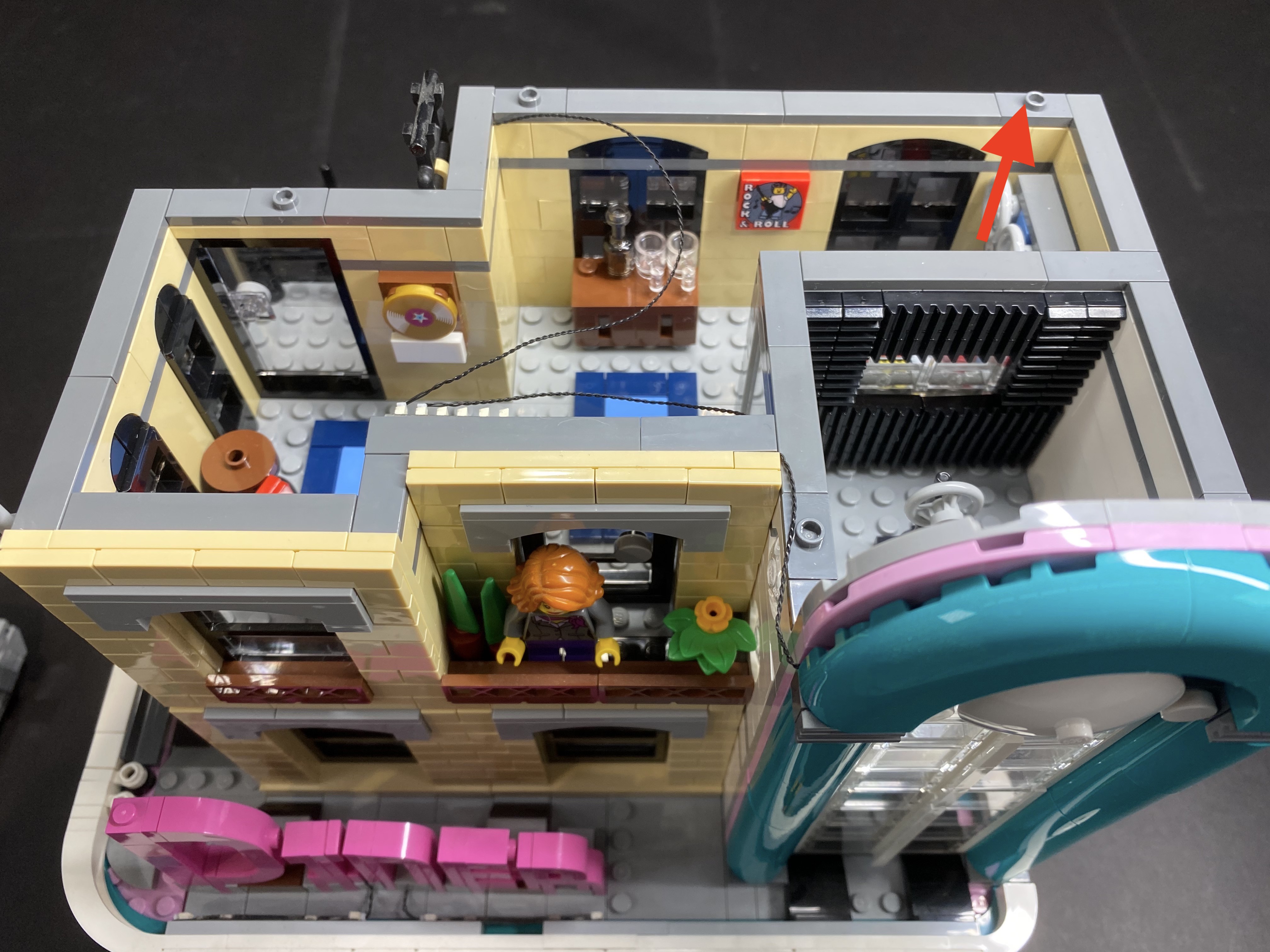


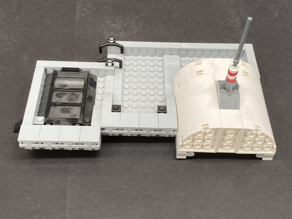
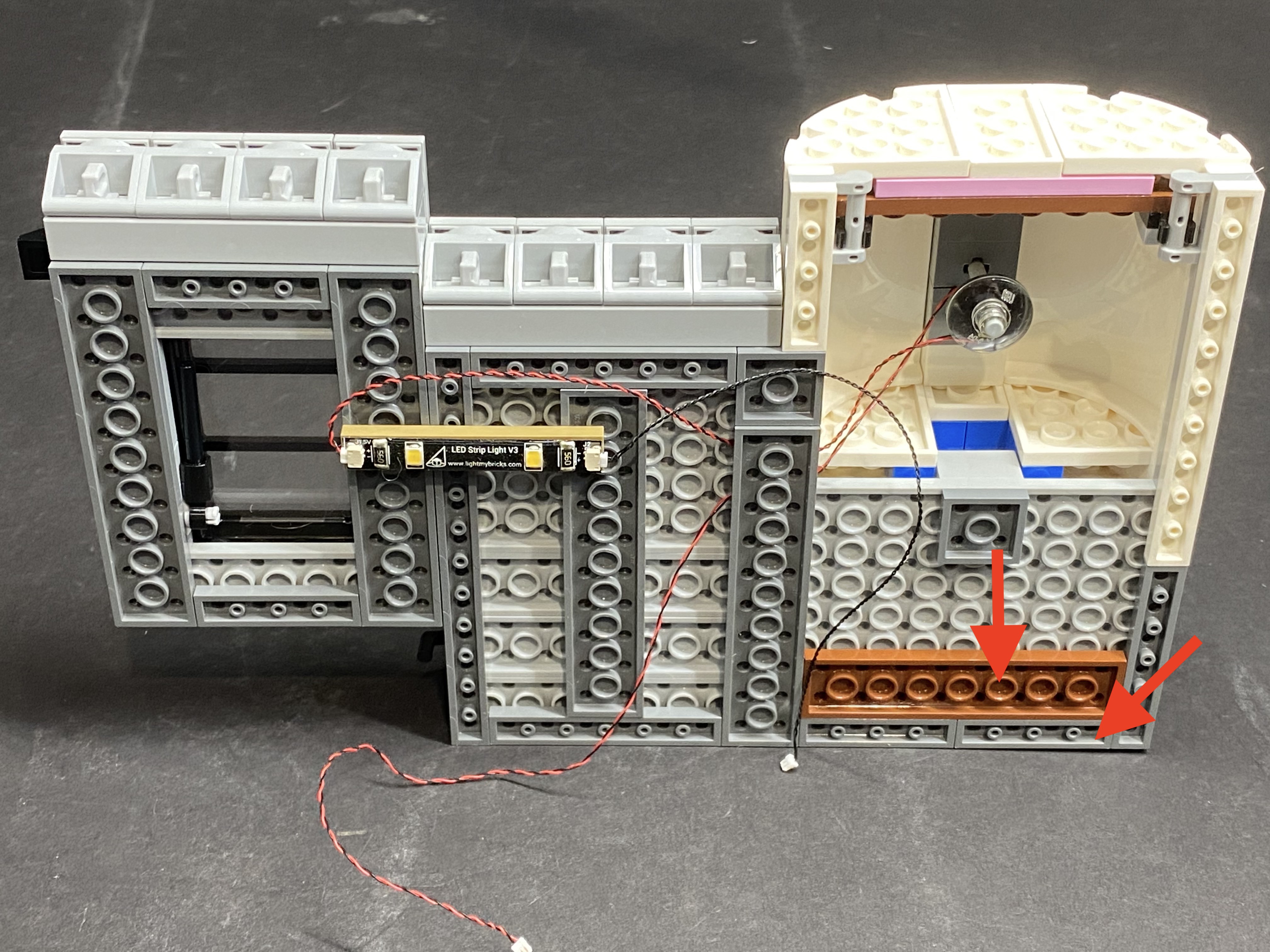


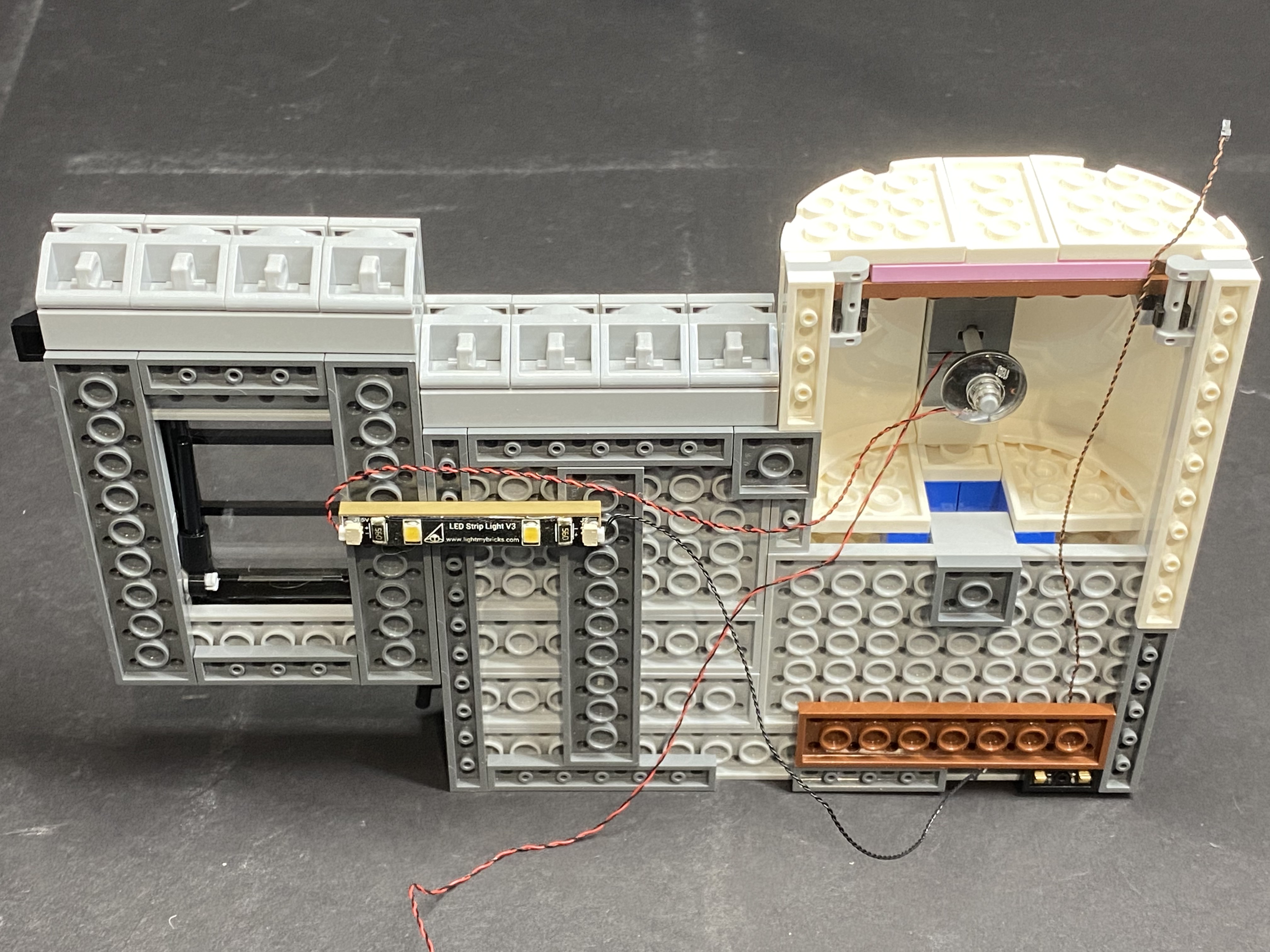
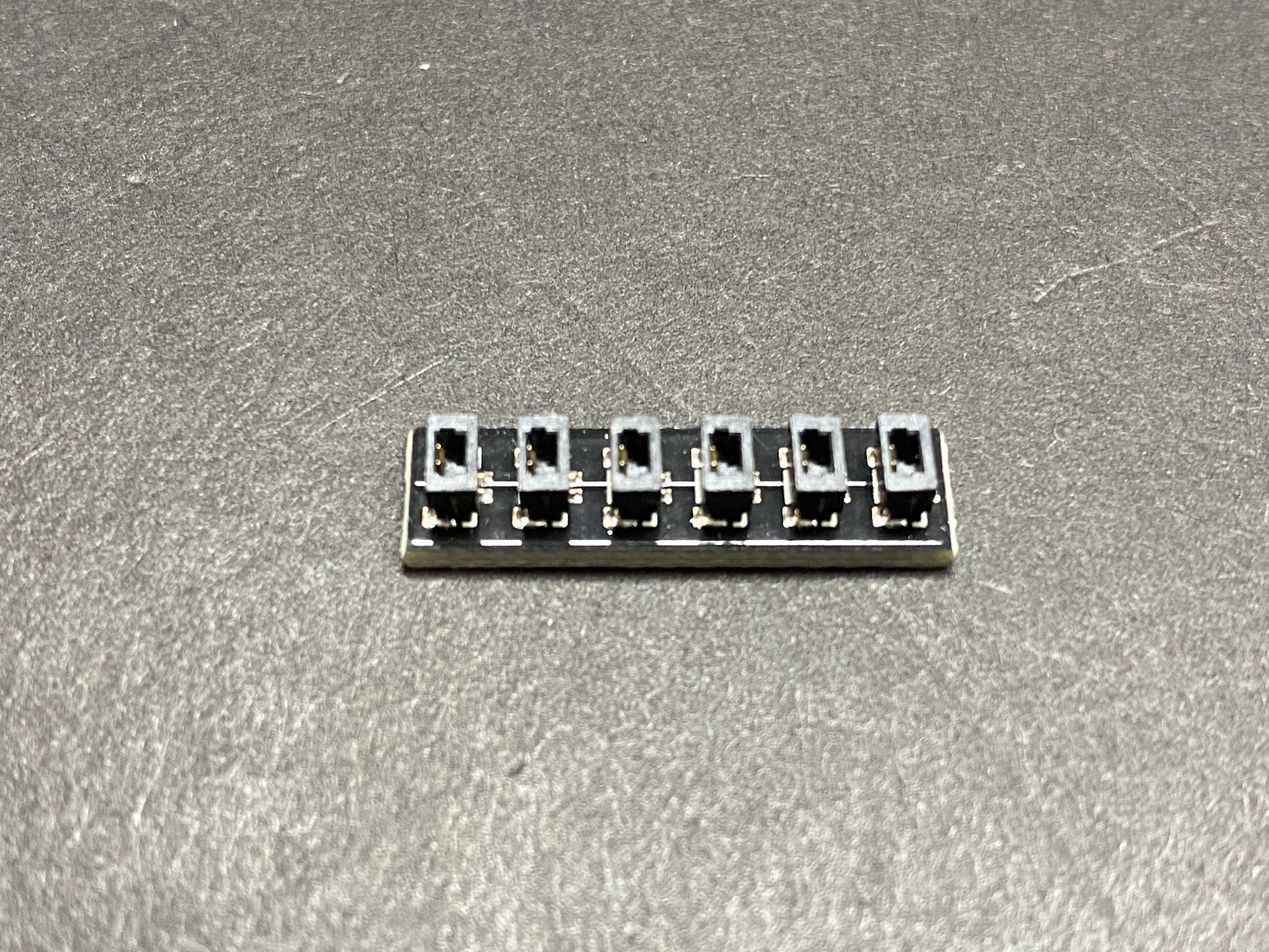
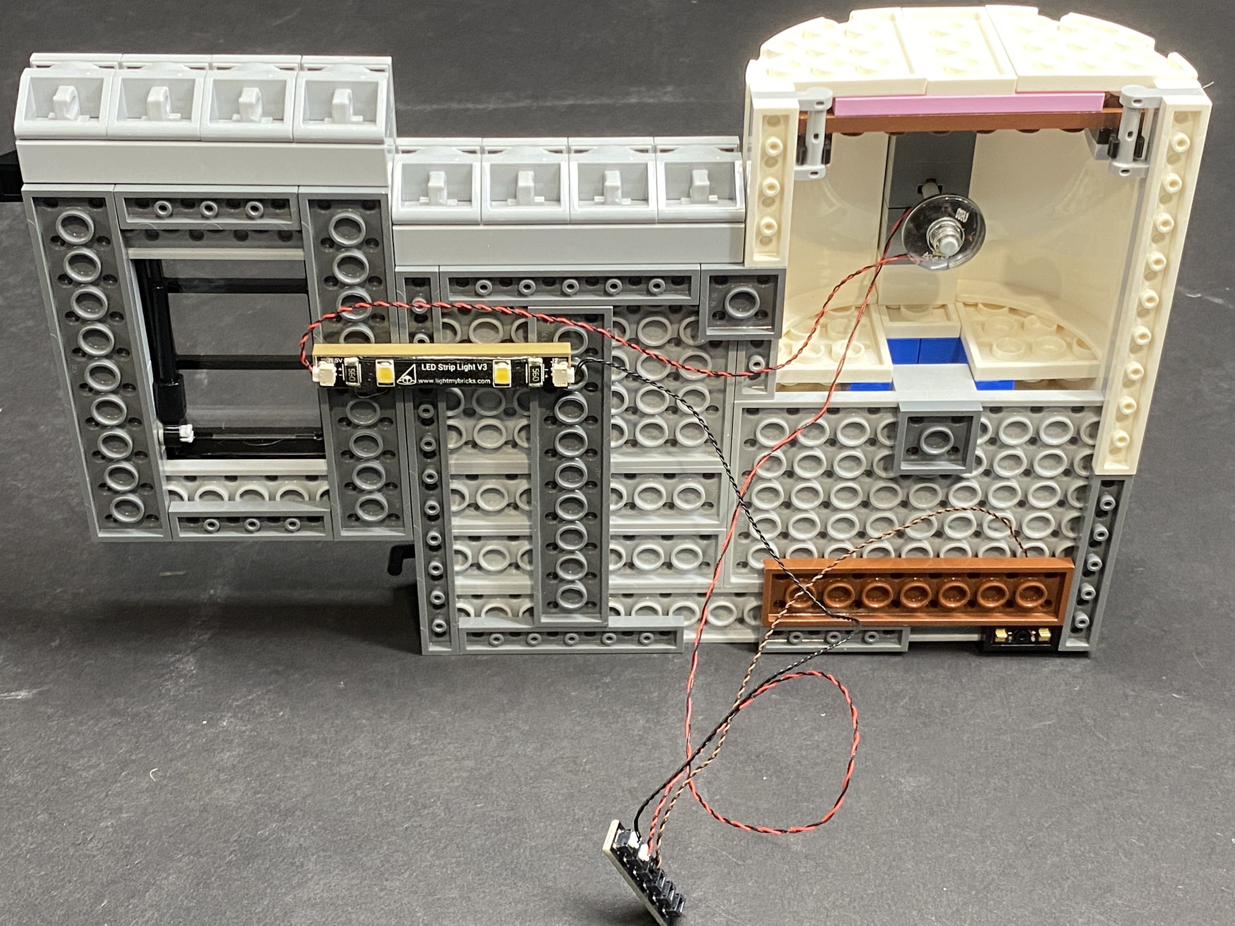
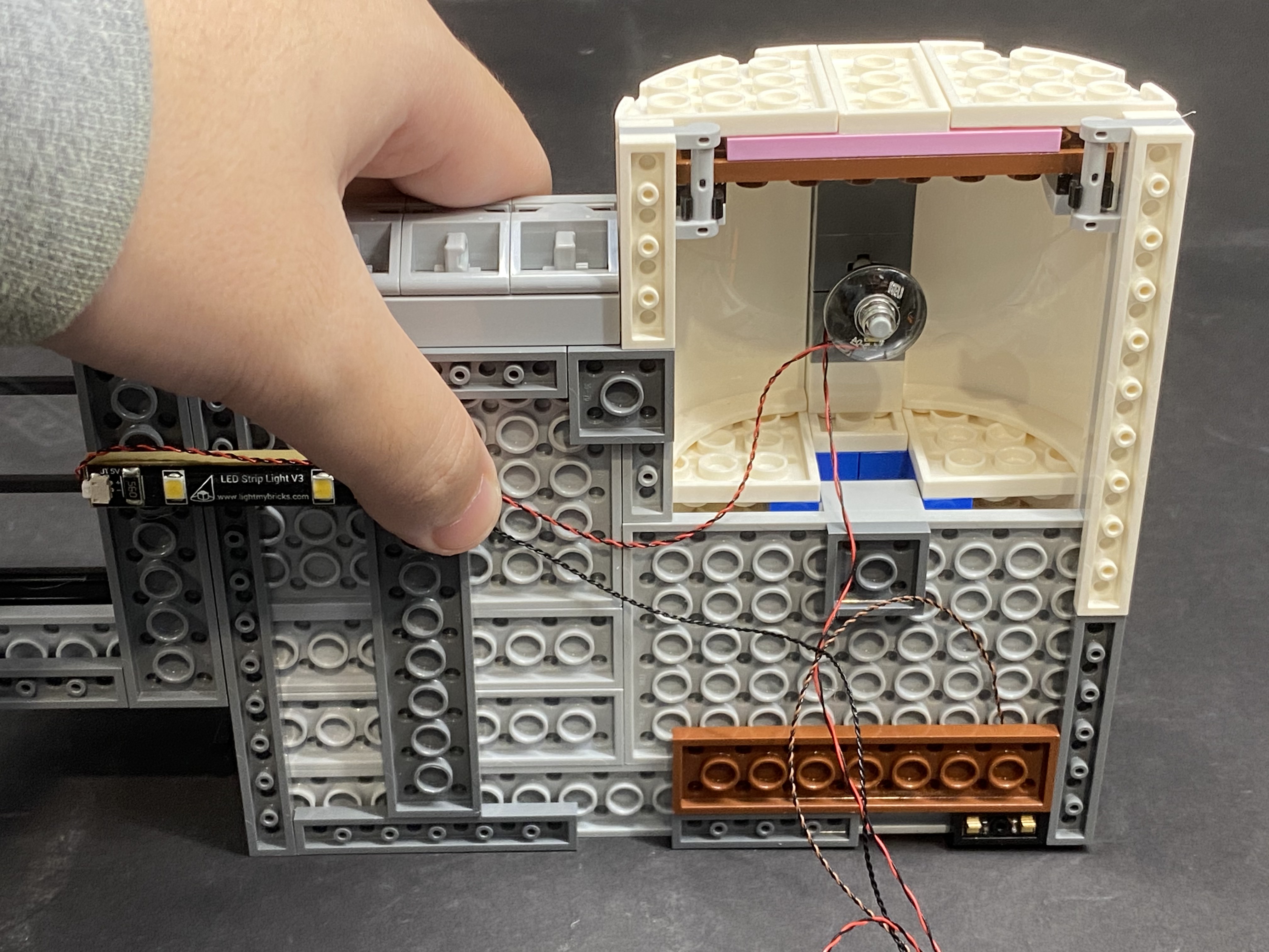

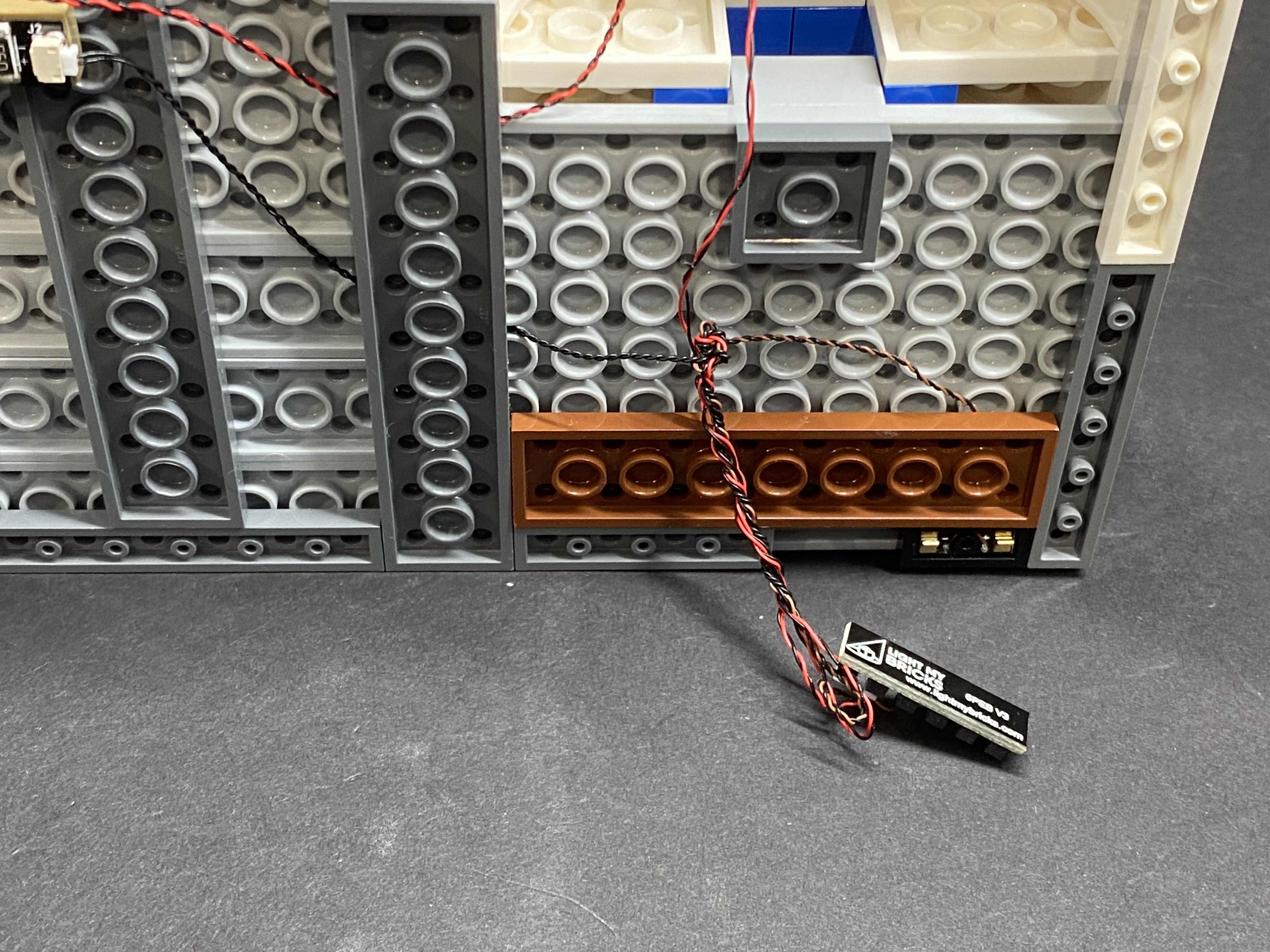
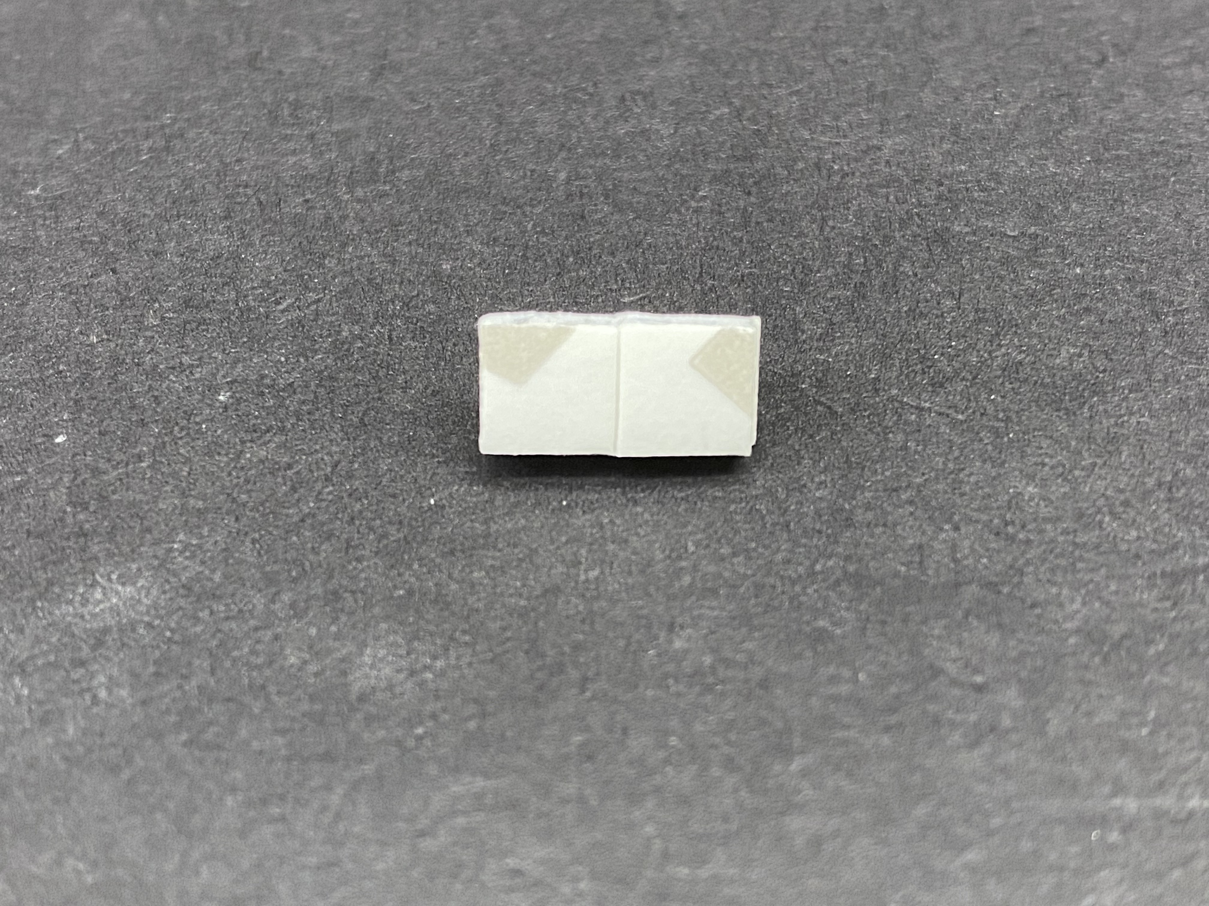

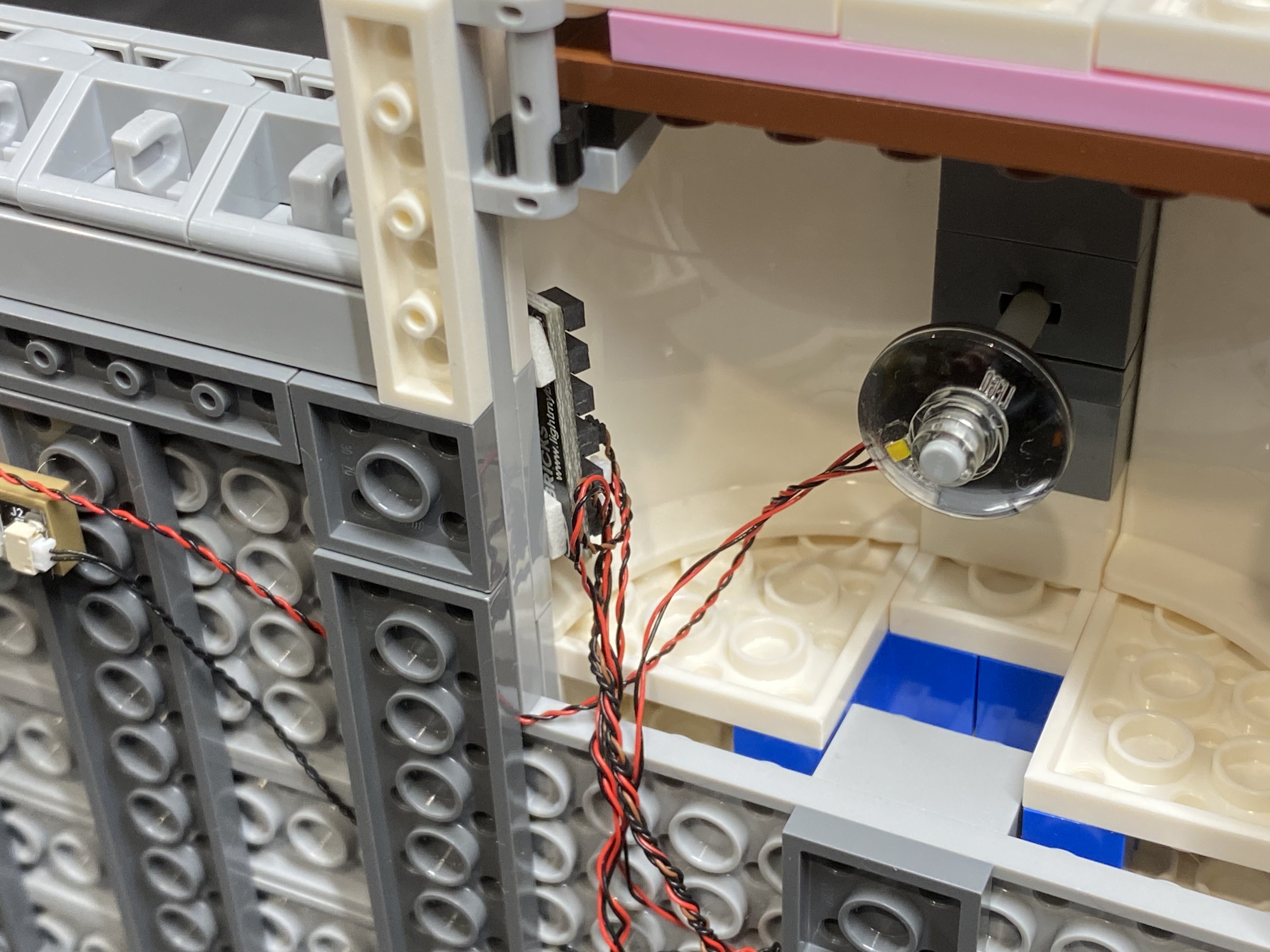

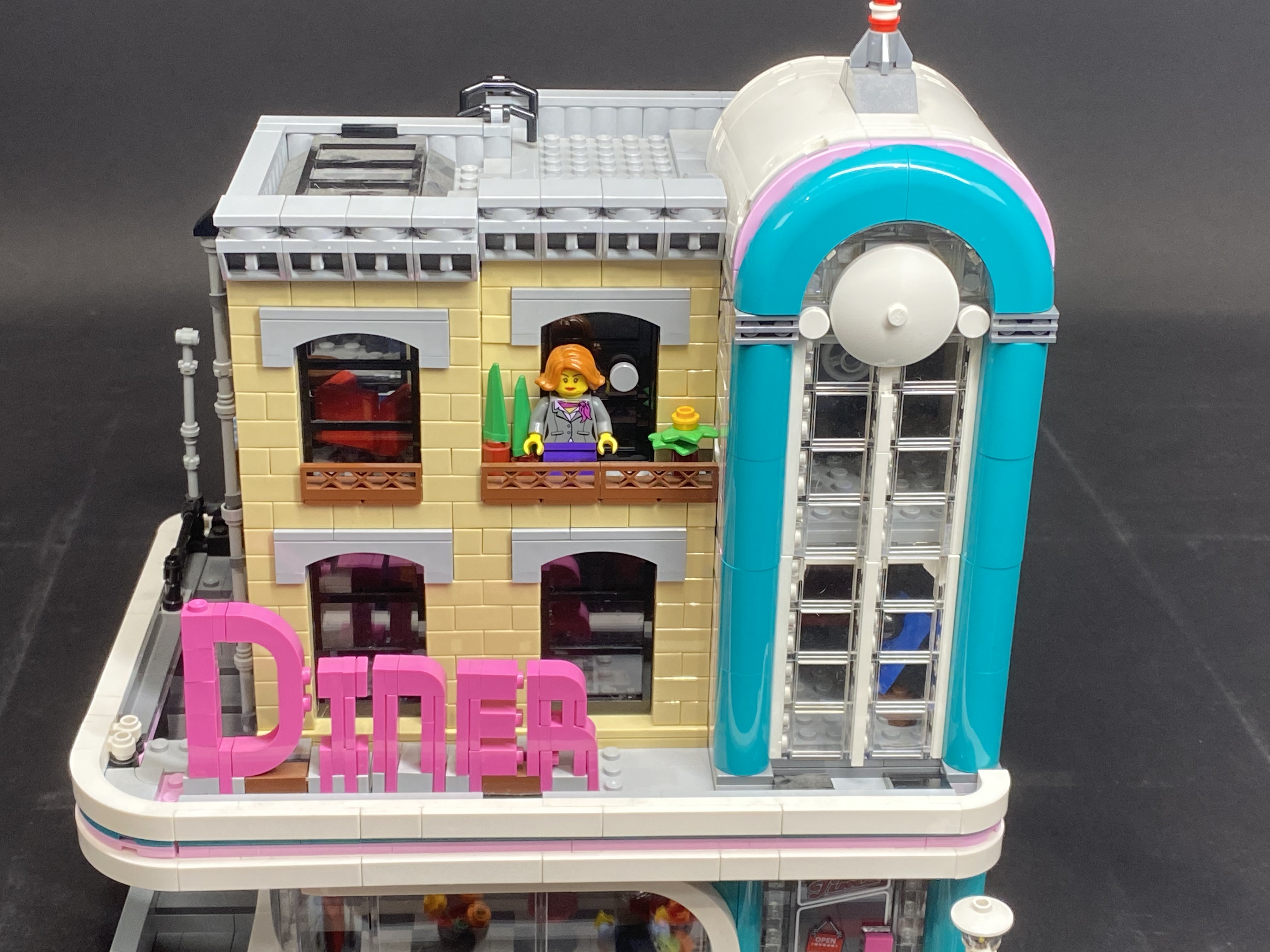

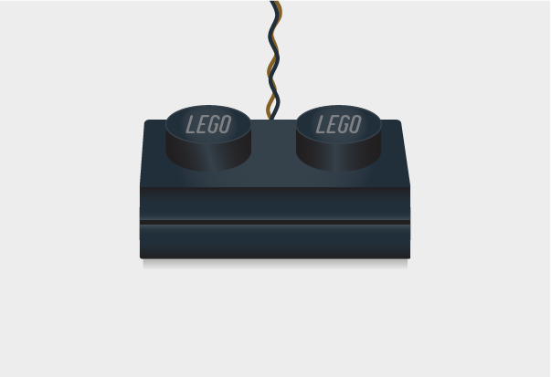
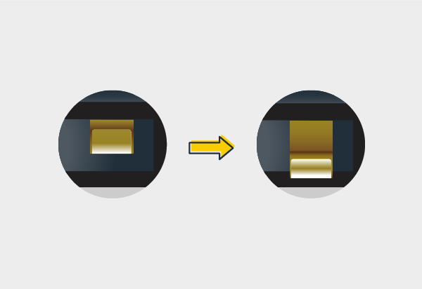


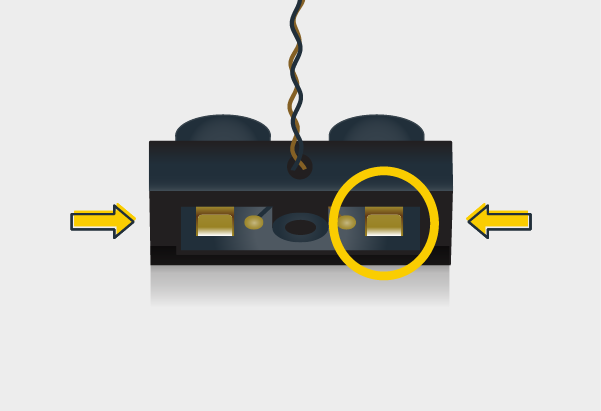
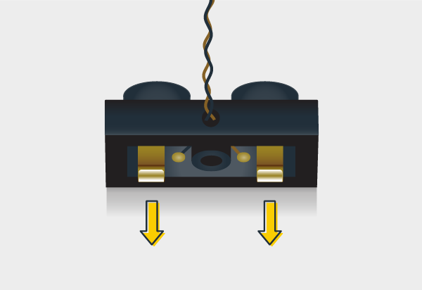