
The following page is the instructions for the Light My Bricks LEGO Corner Garage (10264) LED light kit.
If you run into any issues, please refer to the online troubleshooting guide.
To ensure a trouble-free installation of your light kit, please read and follow each step carefully. These instructions can be downloaded in PDF format here
Please note: This page lists instructions for the LED light kit only. If you are wishing to purchase the Light My Bricks LEGO Corner Garage (10264) LED light kit , please click here to view the product page
Package Contents:
- 10x White 15cm Bit Lights
- 4x White 30cm Bit Lights
- 3x Pink 30cm Bit Lights
- 1x Blue 30cm Bit Light
- 1x LEGO Lamp Post with Bit Light installed
- 8x White Strip Lights
- 1x 6-Port Expansion Board
- 1x 8-Port Expansion Board
- 1x 12-Port Expansion Board
- 7x 15cm Connecting Cable
- 3x 30cm Connecting Cables
- 1x USB Power Cable
- 1x Micro Battery Pack (requires 3x LR44 Batteries)
- 6x Adhesive Squares
LEGO Pieces:
- 2x Trans Clear Round Plate 1×1
- 2x Trans Red Round Plate 1×1
- 6x Plate 1×6 (Any Colour)
- 2x Black Round Plate 1×1 with Open Stud
- 2x Black Tile 1×1 with Clip Rounded Edges
- 2x Black 1×1 Modified Plate Rounded with Handle
Important things to note:
Laying cables in between and underneath bricks
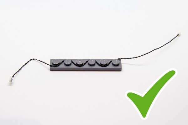
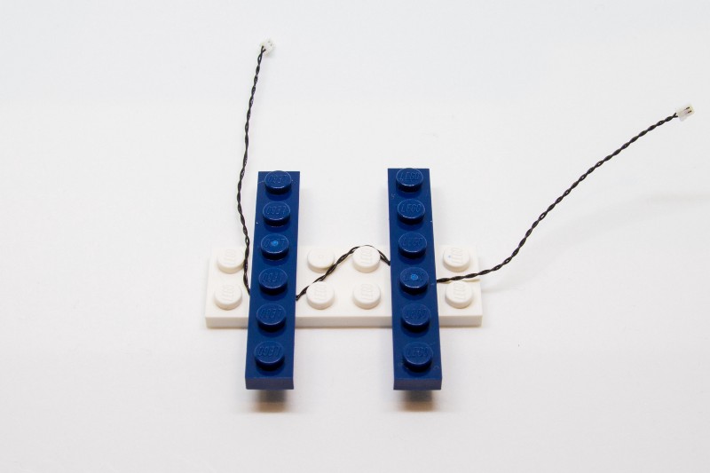
Cables can fit in between and underneath LEGO® bricks, plates, and tiles providing they are laid correctly between the LEGO® studs. Do NOT forcefully join LEGO® together around cables; instead ensure they are laying comfortably in between each stud.
Connecting cable connectors to Expansion Boards
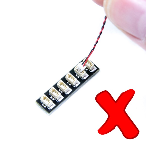
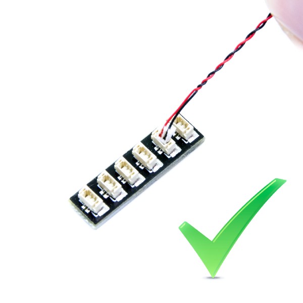
Take extra care when inserting connectors to ports of Expansion Boards. Connectors can be inserted only one way. With the expansion board facing up, look for the soldered “=” symbol on the left side of the port. The connector side with the wires exposed should be facing toward the soldered “=” symbol as you insert into the port. If a plug won’t fit easily into a port connector, do not force it.
Connecting cable connectors to Strip Lights
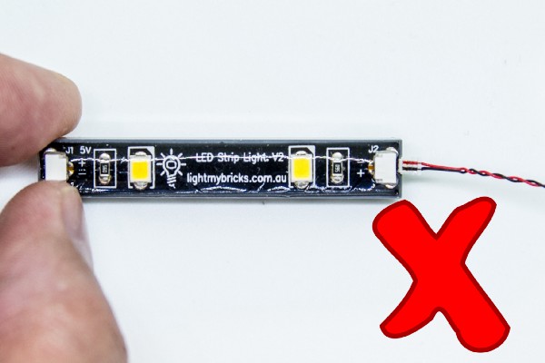
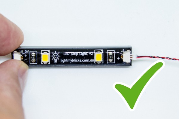
Take extra care when inserting connectors to ports on the Strip Lights. Connectors can be inserted only one way. With the Strip Light facing up, ensure the side of the connector with the wires exposed is facing down. If a plug won’t fit easily into a port connector, don’t force it. Doing so will damage the plug and the connector.
Installing Bit Lights under LEGO® bricks and plates.
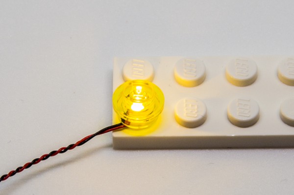
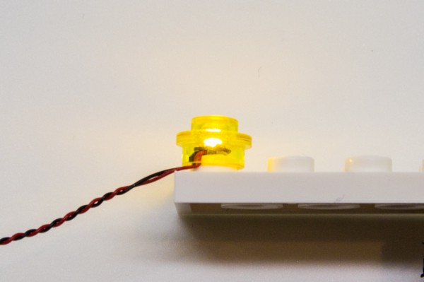
When installing Bit Lights under LEGO® pieces, ensure they are placed the correct way up (Yellow LED component exposed). You can either place them directly on top of LEGO® studs or in between.
OK, Let’s Begin!
Lighting up the Truck
1.) The first thing we will do is light up the truck. First take this vehicle and remove the following pieces from the front, then disassemble as per below: 2.) Take a White 15cm Bit Light and thread the connector side of the cable through the front of the light grey technic pin. Thread it all the way through, then carefully bend the Bit Light on a 90 degree angle so that it is sitting flat against the edge of the pin. Take a provided Trans Clear Round Plate 1×1 and connect it over the top. Repeat this step to install another White 15cm Bit Light to the other technic pin, securing it in place using another provided Trans Clear Round Plate 1×1. 3.) Remove the following sections from the front of the truck,then thread one of the Bit Light cables through the front of the below piece allowing you to reconnect the left headlight.
Disconnect the wheel, then reconnect the left headlight section ensuring the cable is passed through over the wheel axis, before reconnecting the wheel over the top.
4.) Repeat previous step to reconnect the right headlight to the truck then reconnect the remaining sections we removed earlier.
5.) Turn the truck around and disconnect the back section as well as rear right wheel, then thread the cable from the right headlight up the space in front of the rear right wheel (which leads to the back of the truck). Ensure the cable is pulled up inside the black side rail as per below images.
Repeat this process to thread the cable from the left headlight up the space in front of the left rear wheel.
6.) Take out the Micro Battery Pack and pull out and discard the clear tag to activate the batteries. Connect the two cables to the bottom ports (ensuring the battery switch side is facing up), then turn the battery pack ON to verify the headlights are working OK.
7.) Disconnect the two trans red tiles from the back panel, then take a White 15cm Bit Light and with the cable facing toward the centre, place it over the right stud as shown below. Secure the Bit Light in place by connecting a provided Trans Red Round Plate 1×1 over the top.
Repeat this process to install another White 15cm Bit Light to the left side, securing it in place using another provided Trans Red Round Plate 1×1. Reconnect this panel back to the truck ensuring both cables are laid in between studs underneath.
8.) Remove the rear left wheel then thread the left tail light cable up the space in front of the left wheel axis and pull it up from the top on the inside of the black bars (same way we did for the headlight cables).
Reconnect the wheel, then connect the cable to the next port along the micro battery pack.
Repeat this process to thread the right tail light cable up to the top and connect it to the next port on the Micro Battery Pack.
9.) Neaten up excess cables by grouping them all together and twisting/folding them around each other a few times. Tuck the bunched up cables underneath the battery pack then lower the hook section so that it secures the battery pack in place.
This completes installation of the lights for the Corner Garage Truck. Turn ON the battery pack to test the tail lights are working OK.
3.) Remove the following sections from the front of the truck,then thread one of the Bit Light cables through the front of the below piece allowing you to reconnect the left headlight.
Disconnect the wheel, then reconnect the left headlight section ensuring the cable is passed through over the wheel axis, before reconnecting the wheel over the top.
4.) Repeat previous step to reconnect the right headlight to the truck then reconnect the remaining sections we removed earlier.
5.) Turn the truck around and disconnect the back section as well as rear right wheel, then thread the cable from the right headlight up the space in front of the rear right wheel (which leads to the back of the truck). Ensure the cable is pulled up inside the black side rail as per below images.
Repeat this process to thread the cable from the left headlight up the space in front of the left rear wheel.
6.) Take out the Micro Battery Pack and pull out and discard the clear tag to activate the batteries. Connect the two cables to the bottom ports (ensuring the battery switch side is facing up), then turn the battery pack ON to verify the headlights are working OK.
7.) Disconnect the two trans red tiles from the back panel, then take a White 15cm Bit Light and with the cable facing toward the centre, place it over the right stud as shown below. Secure the Bit Light in place by connecting a provided Trans Red Round Plate 1×1 over the top.
Repeat this process to install another White 15cm Bit Light to the left side, securing it in place using another provided Trans Red Round Plate 1×1. Reconnect this panel back to the truck ensuring both cables are laid in between studs underneath.
8.) Remove the rear left wheel then thread the left tail light cable up the space in front of the left wheel axis and pull it up from the top on the inside of the black bars (same way we did for the headlight cables).
Reconnect the wheel, then connect the cable to the next port along the micro battery pack.
Repeat this process to thread the right tail light cable up to the top and connect it to the next port on the Micro Battery Pack.
9.) Neaten up excess cables by grouping them all together and twisting/folding them around each other a few times. Tuck the bunched up cables underneath the battery pack then lower the hook section so that it secures the battery pack in place.
This completes installation of the lights for the Corner Garage Truck. Turn ON the battery pack to test the tail lights are working OK.
Lighting up the Corner Garage
1.) The Corner Garage lights are installed from the bottom up. First remove the second and third floors, then disconnect the gas station roof, gas pump, followed by the lamp post. 2.) Use your LEGO removal tool to disconnect the following tiles as well as the trolley from the building leading to the gas pump. Remove the upper section of the gas pump then take out a Blue 30cm Bit Light and with the cable facing the back of the pump, place it in the centre, in between the white studs. Reconnect the upper section of the gas pump on top, ensuring the Bit Light is neatly secured in the middle. Turn the Gas Pump around to the back and secure the bit light cable underneath the following light grey tile. 3.) Reconnect the following tile before reconnecting the Gas Pump section over the top, back onto the base plate. Bring the front corner of the base plate over the edge of your table and bend it down slightly so that the dark green wall comes apart at the following section: Feed the wire from the Blue Bit Light through the following space, then pull it all the way out from the inside of the wall. 4.) Neatly lay the cable in between the following studs, then reconnect the following tiles and pieces we disconnected earlier, starting with the grey tile with stud on top. 5.) Take a 12-Port Expansion Board and connect the Blue Bit Light to the first port on the left. Take your USB Power Cable and connect it to the far right port. Connect the other side to your USB Power Bank (sold separately) and turn it on to test the blue light is working OK. Note: If you experience any issues with the lights not working and suspect an issue with a component, please try a different port on the expansion board to verify where the fault lies (with the light or expansion board). To correct any issues with expansion board ports, please view the section addressing expansion board issues on our online troubleshooting guide. 6.) Disconnect the following pieces in front of the garage door, then take out the provided LEGO Lamp Post with Bit Light installed. Bring this side of the base plate over the edge of the table and slightly bend it down to create a gap underneath the right side of the garage door. 7.) Thread the Lamp Post cable through this gap and then pull it out from the inside of the garage before connecting the lamp post to the base plate. Ensure the cable is neatly laid in between the following studs and is pulled all the way out from the inside of the garage before closing up the gap in between base plate and wall. Connect the lamp post cable to the next port on the left of the 12-port Expansion Board, then turn on your USB Power Bank to test the lamp post light is working OK. Reconnect the tiles and pieces we disconnected earlier (discard the black 2×2 plate). Note: If you experience any issues with the lights not working and suspect an issue with a component, please try a different port on the expansion board to verify where the fault lies (with the light or expansion board). To correct any issues with expansion board ports, please view the section addressing expansion board issues on our online troubleshooting guide. 8.) Take the roof section of the gas station and disconnect the following sections. Take the following provided LEGO pieces and assemble two of the pieces to make two spot lights as per below: 2x Black Round Plate 1×1 with Open Stud 2x Black Tile 1×1 with Clip Rounded Edges 2x Black 1×1 Modified Plate Rounded with Handle 9.) Take a White 30cm Bit Light and thread the connector side of the cable through the base (large hole) of the round plate with open stud. Thread the cable all the way through and then carefully bend the Bit Light on a 90 degree angle so that it sits flat against the inside of the round plate. Connect the round plate to the back of the Black 1×1 Modified Plate Rounded with Handle ensuring the cable is facing the bottom then repeat this process to install another White 30cm Bit Light to the other spot light section. 10.) Connect both spot lights to the front of the gas station roof section in the following positions. Ensure that both cables are neatly laid in between studs before securing the cables underneath the white 1×6 tile at the back. Reconnect the roof top with the ‘Jo’s Garage’ sign followed by the dark grey corner sections. 11.) Take 2x White Strip Lights and connect them together using a 15cm Connecting Cable. Take another 15cm Connecting Cable and connect it to the other side of one of the Strip Lights. Using it’s adhesive backing, stick the Strip Lights underneath the gas station roof section in the following positions. Ensure the Strip Light with the spare end of the 15cm connecting cable is toward the back of the roof as shown below: Secure the excess cable from the 15cm Connecting Cable (in between the strip lights) underneath the green plates along the side. Bunch up any remaining excess and tuck it in to the inside of the roof, then secure the spare end of the 15cm connecting cable (towards the back), underneath the following green plate. 12.) Reconnect the pillars underneath the roof section before reconnecting this whole section back to the base plate and top of the first floor ensuring the 15cm connecting cable and 2x White 30cm Bit Lights are laid out toward the inside of the building. Connect the 2x White 30cm Bit Lights and 15cm Connecting Cable to the next ports along the 12-port Expansion Board (next to the USB Power Cable). Turn ON the USB Power Bank to test the spot lights and strip lights are working OK. Note: If you experience any issues with the lights not working and suspect an issue with a component, please try a different port on the expansion board to verify where the fault lies (with the light or expansion board). To correct any issues with expansion board ports, please view the section addressing expansion board issues on our online troubleshooting guide. 13.) We will now install some lights to the lamps above the garage door. Using your LEGO Removal tool, disconnect the following sections, then disassemble the pieces from the lamps. Take a White 15cm Bit Light and thread the connector side of the cable through the base of the black round plate with open stud (large hole). Thread the cable all the way through and then carefully bend the Bit Light on a 90 degree angle so that it sits flat against the inside of the round plate. Reconnect this section to the black dish with trans yellow round plate. Carefully reconnect this section back to the black tap piece ensuring you do NOT Forcefully push it all the way in. *CAUTION – This section cannot be pushed all the way in as doing so may break the wire.
14.) Repeat the previous step to install another White 15cm Bit Light to the other lamp, then reconnect this section back to the top of the garage.
Reconnect the top section above the garage door, then connect the two Bit Light Cables to the next ports along the 12-Port Expansion Board (next to the lamp post cable). Turn the USB Power Bank ON to confirm the lamp lights are working OK.
Note: If you experience any issues with the lights not working and suspect an issue with a component, please try a different port on the expansion board to verify where the fault lies (with the light or expansion board). To correct any issues with expansion board ports, please view the section addressing expansion board issues on our online troubleshooting guide.
15.) We will now install a light to the door lamp on the other side of the building. First disconnect the following pieces to allow us to remove and disassemble the lamp section.
Take a White 15cm Bit Light and thread the connector side of the cable through the base of the black round plate with open stud (large hole). Thread the cable all the way through and then carefully bend the Bit Light on a 90 degree angle so that it sits flat against the inside of the round plate.
Reconnect this section to the trans yellow cone piece then with the cable facing the back, carefully reconnect this to the black bar ensuring you do NOT Forcefully push it all the way in.
*CAUTION – This section cannot be pushed all the way in as doing so may break the wire.
16.) Reconnect this section back to the top of the building, then connect the Bit Light to the next port along the 12-Port Expansion Board (next to the 15cm connecting cable). Turn ON the USB Power Bank to confirm the light is working OK, then reconnect the pieces we removed surrounding the top of this section.
Note: If you experience any issues with the lights not working and suspect an issue with a component, please try a different port on the expansion board to verify where the fault lies (with the light or expansion board). To correct any issues with expansion board ports, please view the section addressing expansion board issues on our online troubleshooting guide.
17.) We will now secure down the 12-port expansion board and neaten up cables. Take 3x Adhesive Squares and stick them to the back of the 12-Port Expansion, then turn the set around to the back and mount the expansion board to the inside of the building as shown below
Disconnect the 1×8 tile from the top of the back wall and secure the USB Power Cable in between studs underneath.
18.) Neaten up all the excess cable and prevent them from being too visible from the outside. Starting with the the cables on the left near the garage door (except for the lamp post cable), bring them together and twist/fold them around each other in a neat bunch.
For the lamp post cable, use some tape to secure it up the side of the wall.
*CAUTION – This section cannot be pushed all the way in as doing so may break the wire.
14.) Repeat the previous step to install another White 15cm Bit Light to the other lamp, then reconnect this section back to the top of the garage.
Reconnect the top section above the garage door, then connect the two Bit Light Cables to the next ports along the 12-Port Expansion Board (next to the lamp post cable). Turn the USB Power Bank ON to confirm the lamp lights are working OK.
Note: If you experience any issues with the lights not working and suspect an issue with a component, please try a different port on the expansion board to verify where the fault lies (with the light or expansion board). To correct any issues with expansion board ports, please view the section addressing expansion board issues on our online troubleshooting guide.
15.) We will now install a light to the door lamp on the other side of the building. First disconnect the following pieces to allow us to remove and disassemble the lamp section.
Take a White 15cm Bit Light and thread the connector side of the cable through the base of the black round plate with open stud (large hole). Thread the cable all the way through and then carefully bend the Bit Light on a 90 degree angle so that it sits flat against the inside of the round plate.
Reconnect this section to the trans yellow cone piece then with the cable facing the back, carefully reconnect this to the black bar ensuring you do NOT Forcefully push it all the way in.
*CAUTION – This section cannot be pushed all the way in as doing so may break the wire.
16.) Reconnect this section back to the top of the building, then connect the Bit Light to the next port along the 12-Port Expansion Board (next to the 15cm connecting cable). Turn ON the USB Power Bank to confirm the light is working OK, then reconnect the pieces we removed surrounding the top of this section.
Note: If you experience any issues with the lights not working and suspect an issue with a component, please try a different port on the expansion board to verify where the fault lies (with the light or expansion board). To correct any issues with expansion board ports, please view the section addressing expansion board issues on our online troubleshooting guide.
17.) We will now secure down the 12-port expansion board and neaten up cables. Take 3x Adhesive Squares and stick them to the back of the 12-Port Expansion, then turn the set around to the back and mount the expansion board to the inside of the building as shown below
Disconnect the 1×8 tile from the top of the back wall and secure the USB Power Cable in between studs underneath.
18.) Neaten up all the excess cable and prevent them from being too visible from the outside. Starting with the the cables on the left near the garage door (except for the lamp post cable), bring them together and twist/fold them around each other in a neat bunch.
For the lamp post cable, use some tape to secure it up the side of the wall.
 Secure the two cables from the spot lights underneath the light grey 1×4 tile, then group the two cables as well as the connecting cable and twist/fold them around each other in a neat bunch.
Secure the door lamp cable underneath the dark grey 1×8 tile.
All cables should be neatly hidden and tidied up looking similar to the below. Now Turn on the USB Power Bank again to test all lights are working OK.
19.) Take the entire second floor and turn it onto it’s back so we can access underneath. Take 2x White Strip Lights and using their adhesive backings, stick them to the provided 2x LEGO Plates 1×6.
Connect the two strip lights together using a 15cm Connecting Cable, then take another 15cm Connecting Cable and connect it to one of the strip light’s other port. Take a 30cm Connecting Cable and connect it to the other strip light’s port.
20.) Mount the two strip lights underneath the second floor in the below positions ensuring the other end of the 15cm Connecting cable is facing the right and the other end of the 30cm Connecting Cable is facing the space that leads up to the second level.
Take the end of the 30cm Connecting Cable and thread the cable up the space that leads to the second level. Flip the second level back over and pull the cable all the way up.
21.) Disconnect the following two pieces then secure the cable underneath in the left corner of the top of the staircase. Reconnect the brown brick over the top, then bring the cable over the top corner and secure it down by reconnecting the light grey plate over the top.
Bring the cable over toward the right and secure it underneath the light grey 1×4 tile.
Secure the two cables from the spot lights underneath the light grey 1×4 tile, then group the two cables as well as the connecting cable and twist/fold them around each other in a neat bunch.
Secure the door lamp cable underneath the dark grey 1×8 tile.
All cables should be neatly hidden and tidied up looking similar to the below. Now Turn on the USB Power Bank again to test all lights are working OK.
19.) Take the entire second floor and turn it onto it’s back so we can access underneath. Take 2x White Strip Lights and using their adhesive backings, stick them to the provided 2x LEGO Plates 1×6.
Connect the two strip lights together using a 15cm Connecting Cable, then take another 15cm Connecting Cable and connect it to one of the strip light’s other port. Take a 30cm Connecting Cable and connect it to the other strip light’s port.
20.) Mount the two strip lights underneath the second floor in the below positions ensuring the other end of the 15cm Connecting cable is facing the right and the other end of the 30cm Connecting Cable is facing the space that leads up to the second level.
Take the end of the 30cm Connecting Cable and thread the cable up the space that leads to the second level. Flip the second level back over and pull the cable all the way up.
21.) Disconnect the following two pieces then secure the cable underneath in the left corner of the top of the staircase. Reconnect the brown brick over the top, then bring the cable over the top corner and secure it down by reconnecting the light grey plate over the top.
Bring the cable over toward the right and secure it underneath the light grey 1×4 tile.
 Turn the set around to the back and bring the second level over the ground level. Connect the other side of the 15cm Connecting Cable (from the strip light) to a spare port on the 12-port Expansion Board underneath.
Secure the excess cable from the 15cm Connecting Cable by looping it around the stud underneath on top of the ground level. Securely reconnect the second level then turn ON the USB Power Bank to test all the strip lights on the ground floor are working OK.
22.) Take the entire third level and place it onto it’s back so we can access underneath. Take another 2x White Strip Lights and stick them onto the provided 2x LEGO Plates 1×6.
Connect the two strip lights together using another 15cm Connecting Cable. Take a 30cm Connecting Cable and connect it to one of the strip light’s spare ports.
Turn the set around to the back and bring the second level over the ground level. Connect the other side of the 15cm Connecting Cable (from the strip light) to a spare port on the 12-port Expansion Board underneath.
Secure the excess cable from the 15cm Connecting Cable by looping it around the stud underneath on top of the ground level. Securely reconnect the second level then turn ON the USB Power Bank to test all the strip lights on the ground floor are working OK.
22.) Take the entire third level and place it onto it’s back so we can access underneath. Take another 2x White Strip Lights and stick them onto the provided 2x LEGO Plates 1×6.
Connect the two strip lights together using another 15cm Connecting Cable. Take a 30cm Connecting Cable and connect it to one of the strip light’s spare ports.
 Mount the two strip lights underneath the third floor in the below positions. Ensure the other end of the 30cm Connecting Cable is closest to the space which leads up to the third floor.
23.) Take the end of the 30cm Connecting Cable and thread the cable up the space that leads to the third level. Flip the third level back over and pull the cable all the way up.
Disconnect the light grey plate as well as the staircase. Lay the connecting cable down toward the front of the building, then secure it down by reconnecting the staircase over it (ensuring the cable neatly laid in between studs). Reconnect the brown brick as well as the light grey plate.
From the front of the level looking down, lay the cable across to the right in between studs and behind the TV. Connect the cable to the first port on the 8-Port Expansion Board.
24.) We will now install some lights underneath the flowers outside the windows. Disconnect the following pieces to allow us to remove the windows and window ledge section.
Create a gap underneath the flower section by lifting up the tan plate, then take a White 30cm Bit Light and thread the connector side through the gap.
25.) Take the window ledge section and with the back of it facing down, place the bit light (facing down) flat against the bottom of the ledge in the centre. While holding the wire with you finger/thumb, reconnect this section to the front of the building ensuring the Bit Light is secured in place (cable laid in between studs and led facing down). If you look from underneath you should be able to see the Bit Light peaking out underneath the window ledge.
Close up the gap underneath the flowers by reconnecting this section over the top of the wire (ensuring it’s laid in between studs).
Mount the two strip lights underneath the third floor in the below positions. Ensure the other end of the 30cm Connecting Cable is closest to the space which leads up to the third floor.
23.) Take the end of the 30cm Connecting Cable and thread the cable up the space that leads to the third level. Flip the third level back over and pull the cable all the way up.
Disconnect the light grey plate as well as the staircase. Lay the connecting cable down toward the front of the building, then secure it down by reconnecting the staircase over it (ensuring the cable neatly laid in between studs). Reconnect the brown brick as well as the light grey plate.
From the front of the level looking down, lay the cable across to the right in between studs and behind the TV. Connect the cable to the first port on the 8-Port Expansion Board.
24.) We will now install some lights underneath the flowers outside the windows. Disconnect the following pieces to allow us to remove the windows and window ledge section.
Create a gap underneath the flower section by lifting up the tan plate, then take a White 30cm Bit Light and thread the connector side through the gap.
25.) Take the window ledge section and with the back of it facing down, place the bit light (facing down) flat against the bottom of the ledge in the centre. While holding the wire with you finger/thumb, reconnect this section to the front of the building ensuring the Bit Light is secured in place (cable laid in between studs and led facing down). If you look from underneath you should be able to see the Bit Light peaking out underneath the window ledge.
Close up the gap underneath the flowers by reconnecting this section over the top of the wire (ensuring it’s laid in between studs).
 26.) Disconnect the pink flower and leaf piece and disassemble as shown below:
Take a Pink 30cm Bit Light and thread the connector side through the top of the leaf piece. Thread it all the way through, then carefully bend the Bit Light so that it sits flat against the top of the hole. Secure it in place by reconnecting the pink flower over the top, then reconnect it back to the window (ensuring the cable is facing the inside of the building).
Reconnect the windows and surrounding pieces we removed earlier.
Group both Bit Light cables together and lay them along the front of the room behind the TV.
26.) Disconnect the pink flower and leaf piece and disassemble as shown below:
Take a Pink 30cm Bit Light and thread the connector side through the top of the leaf piece. Thread it all the way through, then carefully bend the Bit Light so that it sits flat against the top of the hole. Secure it in place by reconnecting the pink flower over the top, then reconnect it back to the window (ensuring the cable is facing the inside of the building).
Reconnect the windows and surrounding pieces we removed earlier.
Group both Bit Light cables together and lay them along the front of the room behind the TV.
 27.) We will now install a few more pink lights to the flowers on the front corner. First disconnect the following pieces to allow us to remove the centre windows as well as the purple and pink flowers in the middle.
Disassemble the two flowers, then using the same method as previous step, install another 2x Pink 30cm Bit Lights to them.
28.) Reconnect the two flowers ensuring the cables are facing inside and laid in between studs before reconnecting the windows and surrounding pieces we removed earlier.
Lay both cables along the front of the room behind the TV, then connect these along with the two cables from previous step to the 8-port expansion board.
29.) We will now install another light underneath the window ledge on the right side of this floor. First disconnect the following pieces to allow us to disconnect the windows and window ledge section.
Take the window ledge section and with the back of it facing down, take a White 15cm Bit Light and place it (facing down) flat against the bottom of the ledge in the centre. While holding the cable in place with your thumb/finger, reconnect this section to the front of the building ensuring the Bit Light cable is in between studs. If you look from underneath you should be able to see the Bit Light peaking out underneath the window ledge.
Reconnect the light tan plate over the top followed by the window section and surrounding pieces we disconnected earlier.
30.) We now need to clean up excess cables and prevent them from being too obvious from the outside looking in. First disconnect the TV and reconnect it over the top of the cables to secure them down then turn the third level around to the back for better access.
Group all the cables on the left (except for the White 15cm Bit Light cable) and fold/twist them around each other to form a neat bunch. Neatly tuck the bunched up cables and expansion board down next to the TV, then connect the White 15cm Bit Light to a spare port on the expansion board.
31.) Disconnect the bed, then take out a new 30cm Connecting Cable and connect it to a spare port on the 8-port Expansion Board.
Neatly lay the 30cm connecting cable down along the floor toward the left corner, then up the wall. Neatly bunch up the white 15cm bit light cable before reconnecting the bed over the two cables to secure them in place.
Pull the cable up along the right side of the wall then secure it underneath the light grey 1×4 tile on the top.
32.) Bring the entire third level above the building then take the spare end of the 30cm Connecting Cable from the second level underneath and connect it to the Strip Light underneath the 3rd level. Securely reconnect the third level on top, then turn ON the USB Power Bank to test all the lights we installed so far are working OK.
Note: If you experience any issues with the lights not working and suspect an issue with a component, please try a different port on the expansion board to verify where the fault lies (with the light or expansion board). To correct any issues with expansion board ports, please view the section addressing expansion board issues on our online troubleshooting guide.
33.) Take the entire roof section and turn it onto it’s back so we can access underneath. Take out the remaining 2x White Strip Lights and stick them to the provided 2x LEGO Plates 1×6.
Connect the two strip lights together using a 15cm Connecting Cable, then take a new 15cm Connecting Cable and connect it to one of the strip light’s spare port.
27.) We will now install a few more pink lights to the flowers on the front corner. First disconnect the following pieces to allow us to remove the centre windows as well as the purple and pink flowers in the middle.
Disassemble the two flowers, then using the same method as previous step, install another 2x Pink 30cm Bit Lights to them.
28.) Reconnect the two flowers ensuring the cables are facing inside and laid in between studs before reconnecting the windows and surrounding pieces we removed earlier.
Lay both cables along the front of the room behind the TV, then connect these along with the two cables from previous step to the 8-port expansion board.
29.) We will now install another light underneath the window ledge on the right side of this floor. First disconnect the following pieces to allow us to disconnect the windows and window ledge section.
Take the window ledge section and with the back of it facing down, take a White 15cm Bit Light and place it (facing down) flat against the bottom of the ledge in the centre. While holding the cable in place with your thumb/finger, reconnect this section to the front of the building ensuring the Bit Light cable is in between studs. If you look from underneath you should be able to see the Bit Light peaking out underneath the window ledge.
Reconnect the light tan plate over the top followed by the window section and surrounding pieces we disconnected earlier.
30.) We now need to clean up excess cables and prevent them from being too obvious from the outside looking in. First disconnect the TV and reconnect it over the top of the cables to secure them down then turn the third level around to the back for better access.
Group all the cables on the left (except for the White 15cm Bit Light cable) and fold/twist them around each other to form a neat bunch. Neatly tuck the bunched up cables and expansion board down next to the TV, then connect the White 15cm Bit Light to a spare port on the expansion board.
31.) Disconnect the bed, then take out a new 30cm Connecting Cable and connect it to a spare port on the 8-port Expansion Board.
Neatly lay the 30cm connecting cable down along the floor toward the left corner, then up the wall. Neatly bunch up the white 15cm bit light cable before reconnecting the bed over the two cables to secure them in place.
Pull the cable up along the right side of the wall then secure it underneath the light grey 1×4 tile on the top.
32.) Bring the entire third level above the building then take the spare end of the 30cm Connecting Cable from the second level underneath and connect it to the Strip Light underneath the 3rd level. Securely reconnect the third level on top, then turn ON the USB Power Bank to test all the lights we installed so far are working OK.
Note: If you experience any issues with the lights not working and suspect an issue with a component, please try a different port on the expansion board to verify where the fault lies (with the light or expansion board). To correct any issues with expansion board ports, please view the section addressing expansion board issues on our online troubleshooting guide.
33.) Take the entire roof section and turn it onto it’s back so we can access underneath. Take out the remaining 2x White Strip Lights and stick them to the provided 2x LEGO Plates 1×6.
Connect the two strip lights together using a 15cm Connecting Cable, then take a new 15cm Connecting Cable and connect it to one of the strip light’s spare port.
 34.) Mount the two strip lights underneath the roof section in the below positions, ensuring the spare end of the 15cm Connecting Cable is closest to the door way that leads to the rooftop.
Open the doors and thread the other end of the 15cm Connecting Cable up to the rooftop. Flip the roof section back over and pull the cable up. Secure the cable by closing the doors, then connect the cable to the 6-port Expansion Board
35.) Disconnect the following piece from the left corner of the roof, then take a White 15cm Bit Light and with the LED facing down, place it over the centre of the brown piece. Secure it in place by reconnecting the light grey piece over the top, then pull the bit light cable back so the LED is just peaking out the top of the roof piece.
Connect the Bit Light to the 6-port Expansion Board.
34.) Mount the two strip lights underneath the roof section in the below positions, ensuring the spare end of the 15cm Connecting Cable is closest to the door way that leads to the rooftop.
Open the doors and thread the other end of the 15cm Connecting Cable up to the rooftop. Flip the roof section back over and pull the cable up. Secure the cable by closing the doors, then connect the cable to the 6-port Expansion Board
35.) Disconnect the following piece from the left corner of the roof, then take a White 15cm Bit Light and with the LED facing down, place it over the centre of the brown piece. Secure it in place by reconnecting the light grey piece over the top, then pull the bit light cable back so the LED is just peaking out the top of the roof piece.
Connect the Bit Light to the 6-port Expansion Board.
 36.) Remove the following section from the front corner of the roof. Take out another White 15cm Bit Light and with the LED facing down, place it over the centre of the brown piece underneath. Secure it in place by reconnecting the light grey piece over the top, then pull the bit light cable back so the LED is just peaking out the top of the roof piece.
Connect the Bit Light to the 6-port Expansion Board.
36.) Remove the following section from the front corner of the roof. Take out another White 15cm Bit Light and with the LED facing down, place it over the centre of the brown piece underneath. Secure it in place by reconnecting the light grey piece over the top, then pull the bit light cable back so the LED is just peaking out the top of the roof piece.
Connect the Bit Light to the 6-port Expansion Board.
 37.) Remove the following section from the right corner of the roof. Take out the remaining White 30cm Bit Light and with the LED facing down, place it over the centre of the brown piece underneath. Secure it in place by reconnecting the light grey piece over the top, then pull the bit light cable back so the LED is just peaking out the top of the roof piece.
Connect the Bit Light to the 6-port Expansion Board.
37.) Remove the following section from the right corner of the roof. Take out the remaining White 30cm Bit Light and with the LED facing down, place it over the centre of the brown piece underneath. Secure it in place by reconnecting the light grey piece over the top, then pull the bit light cable back so the LED is just peaking out the top of the roof piece.
Connect the Bit Light to the 6-port Expansion Board.
 38.) Group the three bit light cables together and twist/fold them around each other to form a neat bunch.
Take 2x Adhesive Squares and stick them on the back of the 6-Port Expansion Board. Mount the expansion board to the inside of the left corner of the roof, then secure the bunch of cables by tucking them in underneath it.
39.) Take the rooftop section over the rest of the building and locate the spare end of the 30cm Connecting Cable from underneath. Connect the cable to the strip light underneath the rooftop section.
Securely reconnect the rooftop, then turn ON the USB Power Bank to confirm that all the lights installed are working OK.
Note: If you experience any issues with the lights not working and suspect an issue with a component, please try a different port on the expansion board to verify where the fault lies (with the light or expansion board). To correct any issues with expansion board ports, please view the section addressing expansion board issues on our online troubleshooting guide.
38.) Group the three bit light cables together and twist/fold them around each other to form a neat bunch.
Take 2x Adhesive Squares and stick them on the back of the 6-Port Expansion Board. Mount the expansion board to the inside of the left corner of the roof, then secure the bunch of cables by tucking them in underneath it.
39.) Take the rooftop section over the rest of the building and locate the spare end of the 30cm Connecting Cable from underneath. Connect the cable to the strip light underneath the rooftop section.
Securely reconnect the rooftop, then turn ON the USB Power Bank to confirm that all the lights installed are working OK.
Note: If you experience any issues with the lights not working and suspect an issue with a component, please try a different port on the expansion board to verify where the fault lies (with the light or expansion board). To correct any issues with expansion board ports, please view the section addressing expansion board issues on our online troubleshooting guide.
This finally completes installation of the Light My Bricks Corner Garage Light Kit. We thank you for purchasing this product!