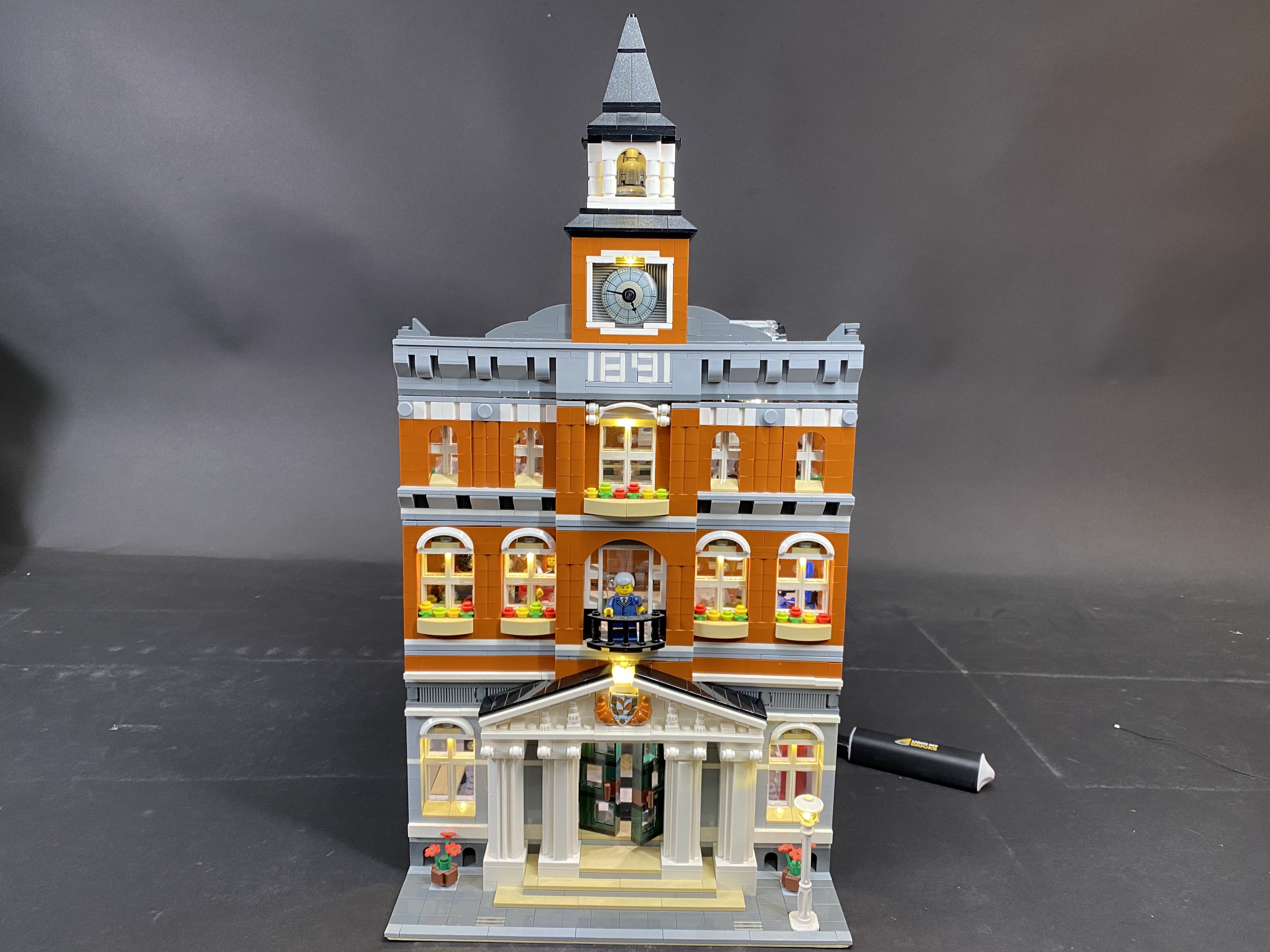
Here is the instructions document for the LEGO Cafe Corner LED lighting kit. Please read and follow the steps carefully to ensure this lighting kit is installed properly.
These instructions can be downloaded in PDF format here
Package contents:
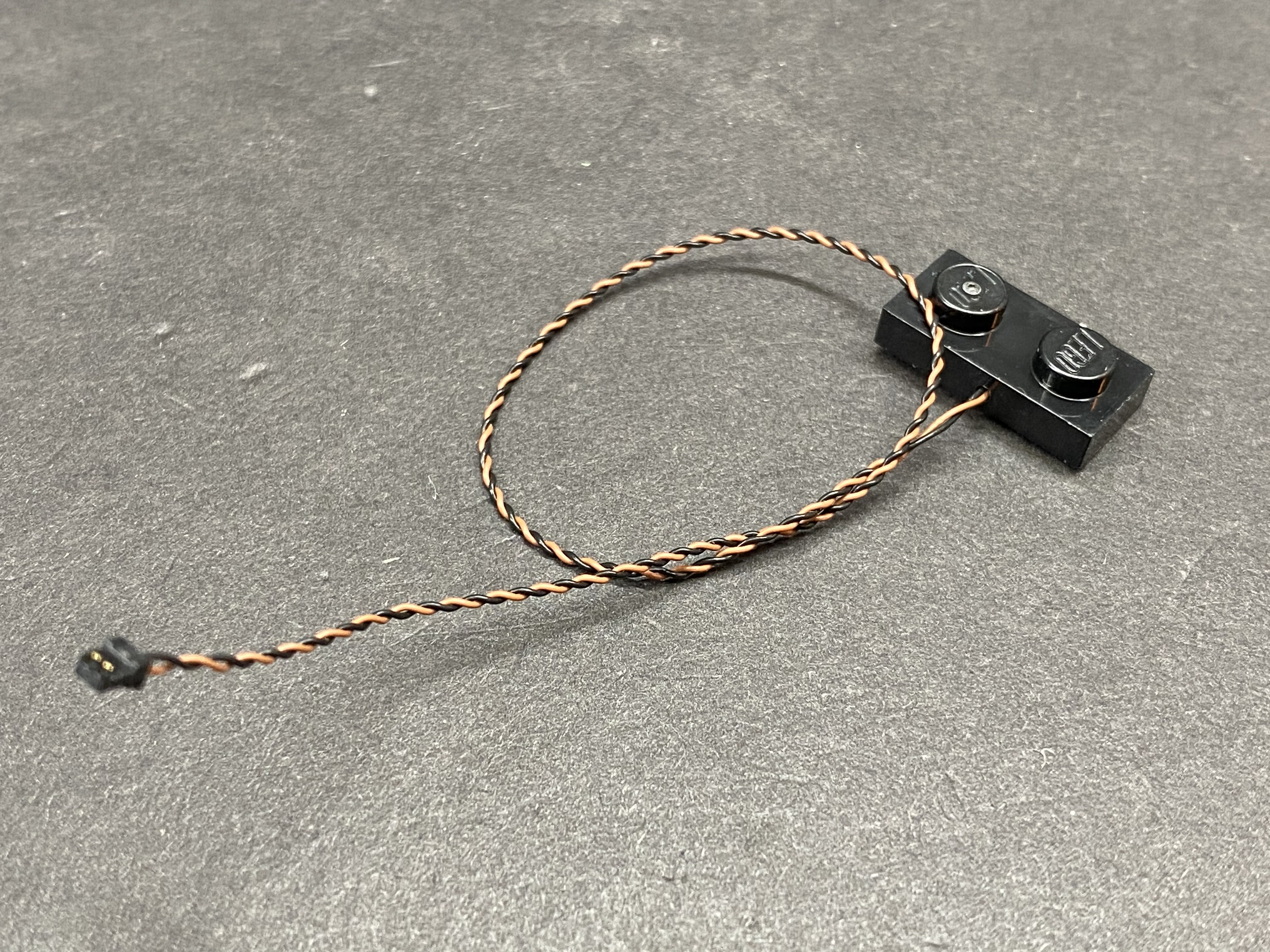
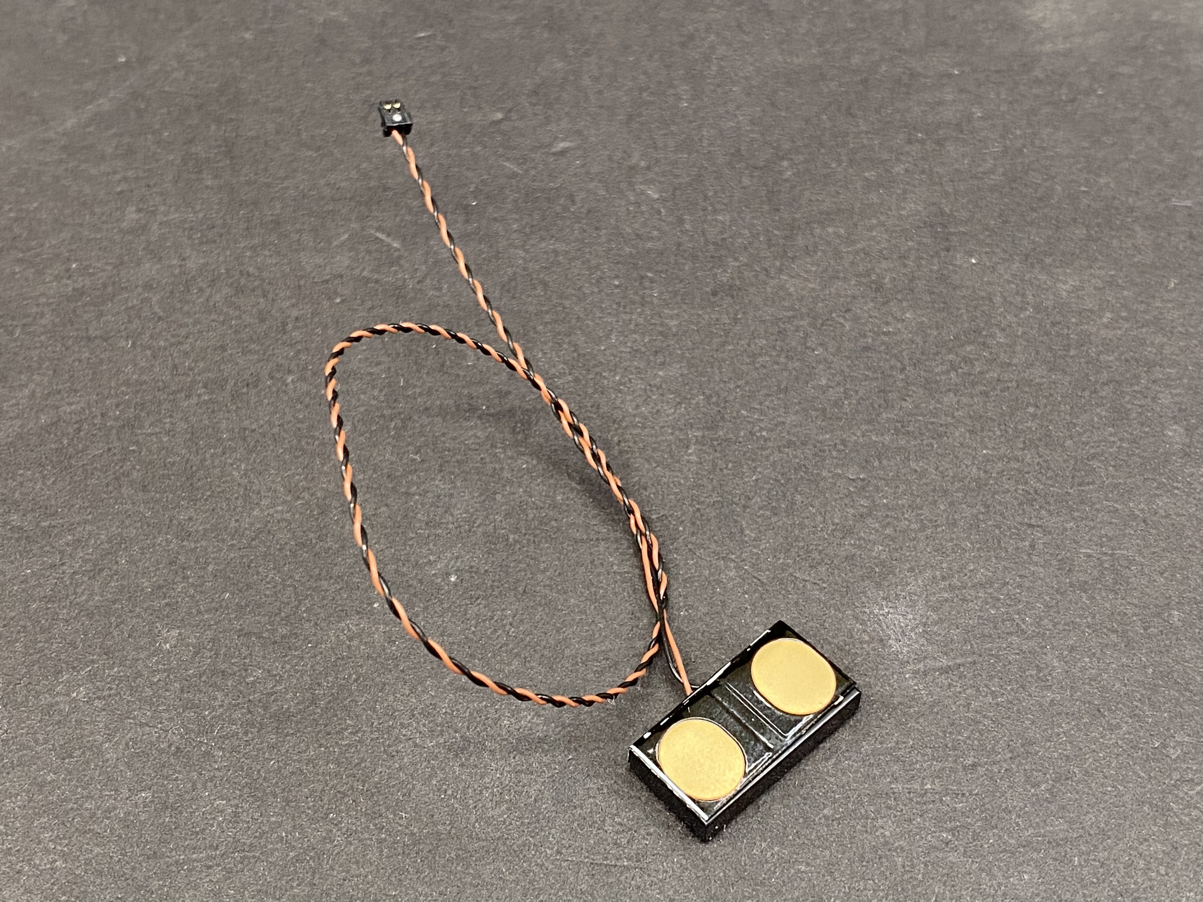
- 1x LEGO Lamp Post with 30cm Bit Light installed
- 6x White 30cm Bit Lights
- 10x White 15cm Bit Lights
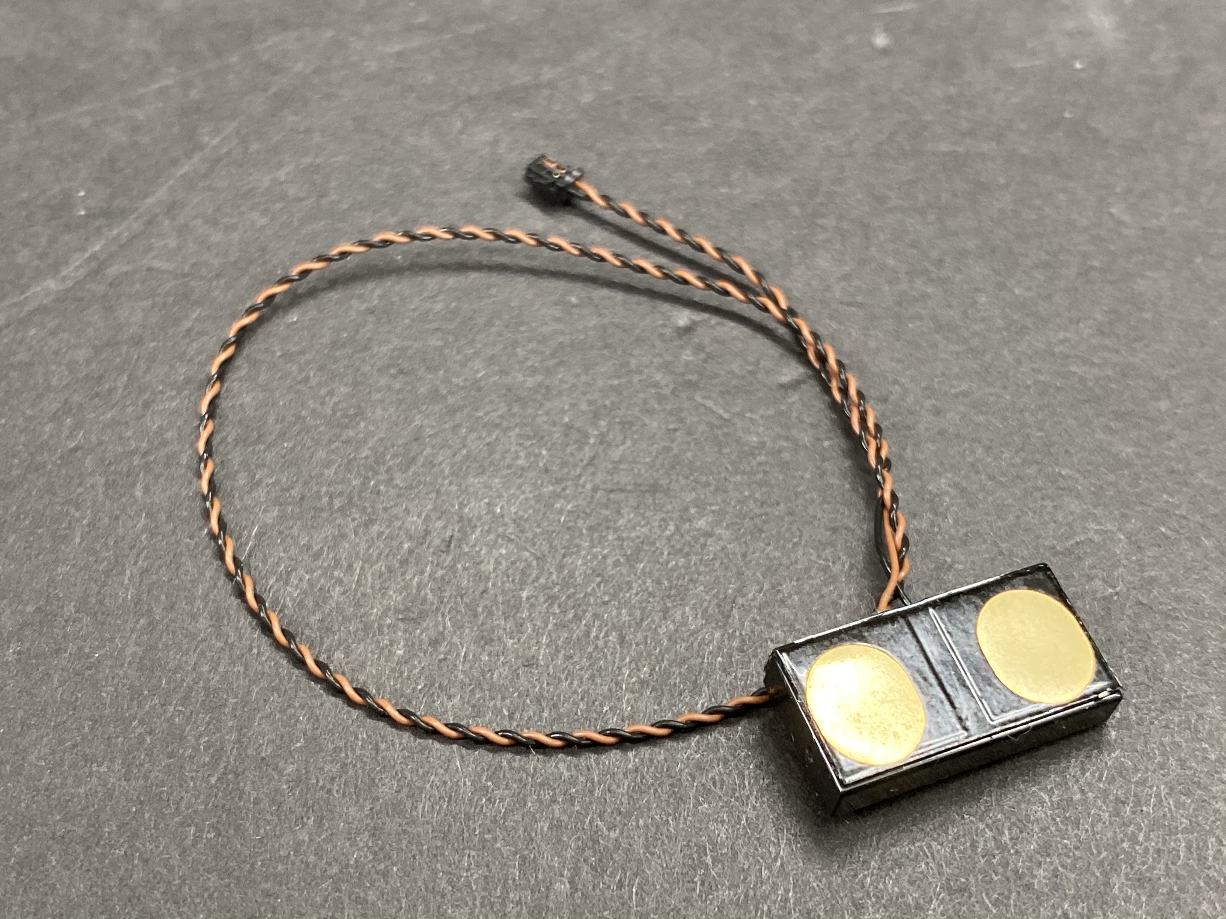
- 8x White Strip Lights
- 2x 5cm Connecting Cables
- 7x 15cm Connecting Cables
- 1x 30cm Connecting Cable
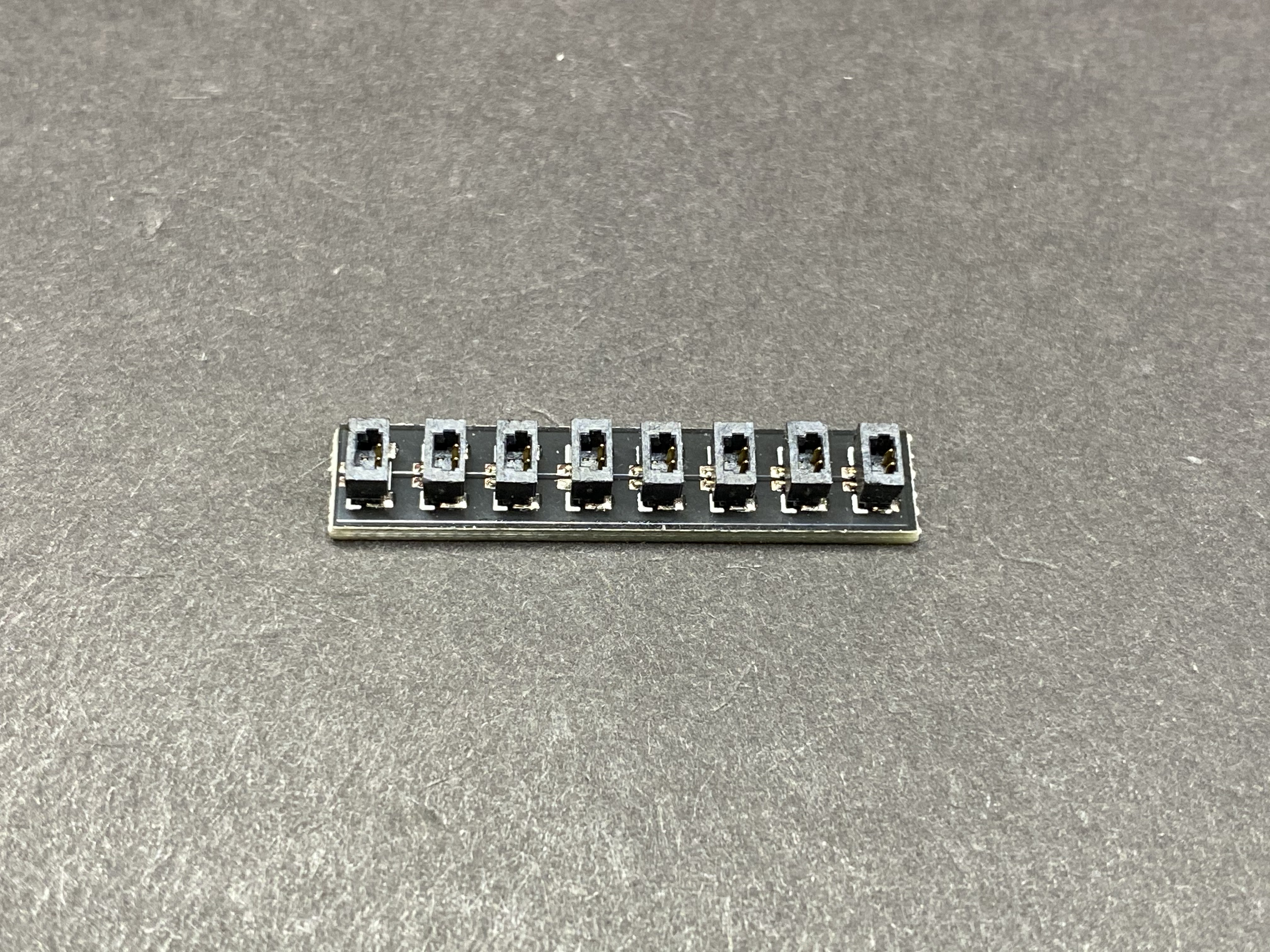
- 3x 8-Port Expansion Boards
- 14x Adhesive Squares
- 1x USB Power Cable
Extra LEGO pieces
- 5x Plate 1×6
Important things to note:
Laying cables in between and underneath bricks
Cables can fit in between and underneath LEGO® bricks, plates, and tiles providing they are laid correctly between the LEGO® studs. Do NOT forcefully join LEGO® together around cables; instead ensure they are laying comfortably in between each stud.


CAUTION: Forcing LEGO® to connect over a cable can result in damaging the cable and light.
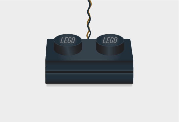
Connecting cable connectors to Strip Lights
Take extra care when inserting connectors to ports on the Strip Lights. Connectors can be inserted only one way. With the Strip Light facing up, ensure the side of the connector with the wires exposed is facing down. If a plug won’t fit easily into a port connector, don’t force it. Doing so will damage the plug and the connector.


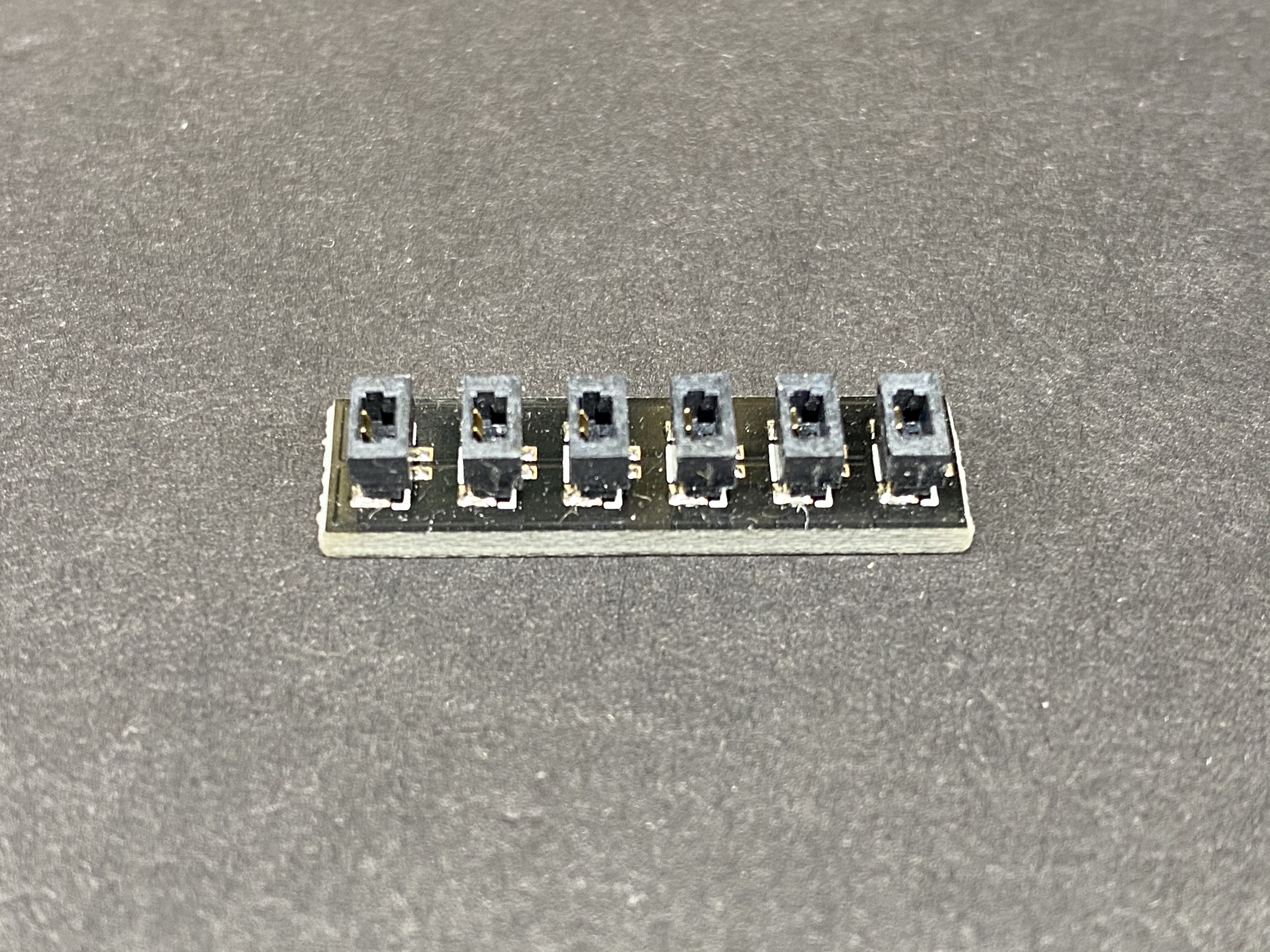
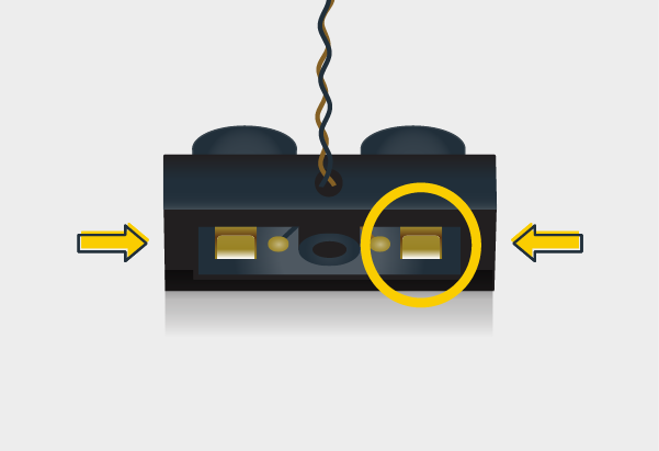
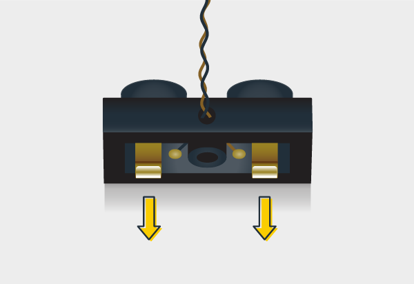
Connecting cable connectors to Expansion Boards
Take extra care when inserting connectors to ports of Expansion Boards. Connectors can be inserted only one way. With the expansion board facing up, look for the soldered “=” symbol on the left side of the port. The connector side with the wires exposed should be facing toward the soldered “=” symbol as you insert into the port. If a plug won’t fit easily into a port connector, do not force it.


WARNING: Incorrectly inserting the connector can result in bent pins inside the port or possible overheating of the expansion board when connected.
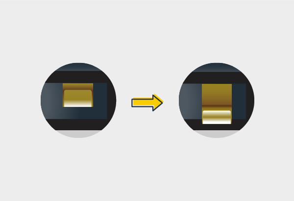
Installing Bit Lights under LEGO® bricks and plates.
When installing Bit Lights under LEGO® pieces, ensure they are placed the correct way up (Yellow LED component exposed). You can either place them directly on top of LEGO® studs or in between.


OK, Let’s Begin!
Instructions for installing this kit
1.) This lighting kit is installed from ground up so start by removing the second and third floor, followed by the lamp post.


Remove the following tiles in front of the building.


2.) Replace the stock lamp post with the Light My Bricks lamp post with Bit Light installed and ensure the cable is facing toward the building.

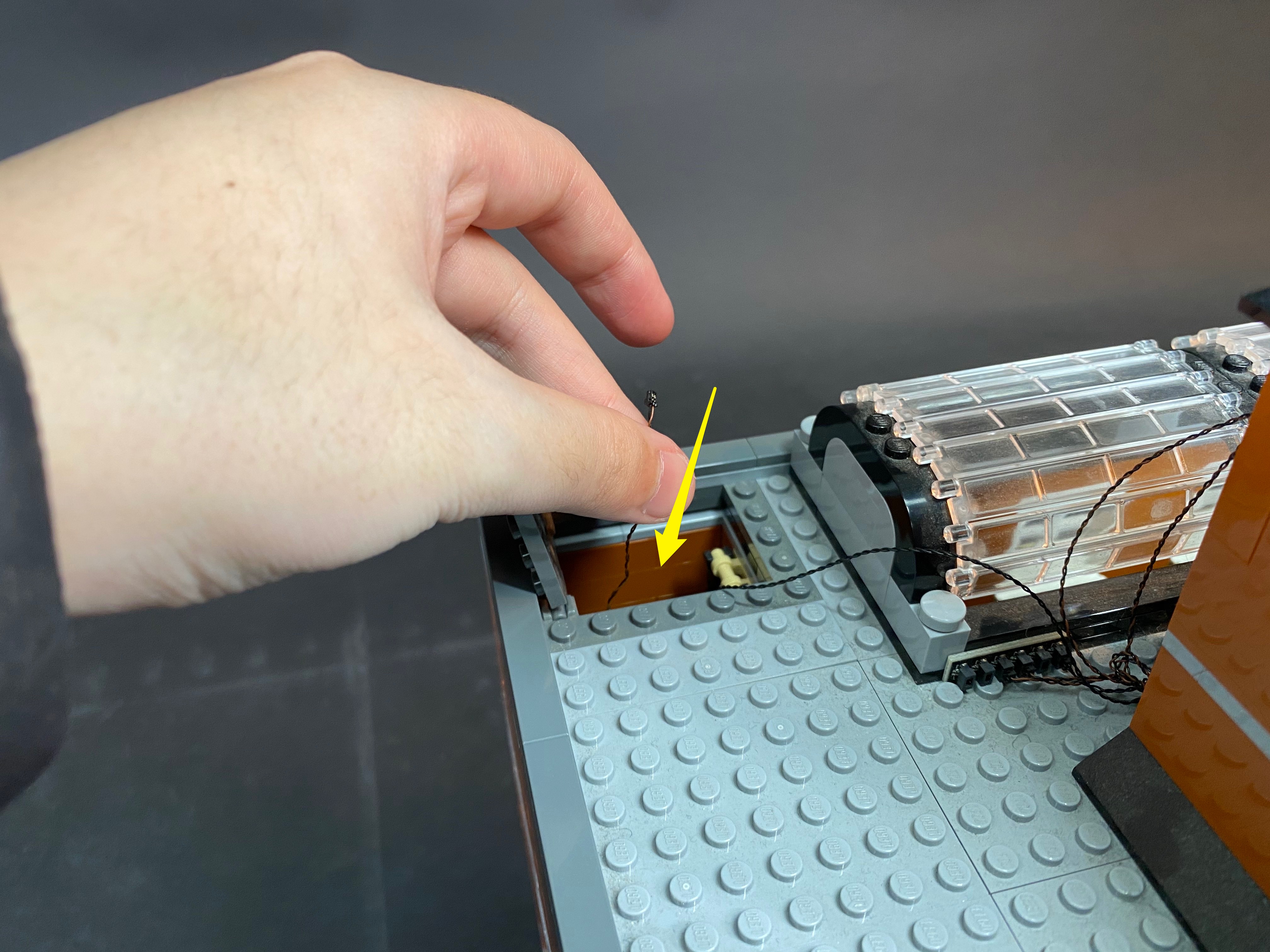
Gently bend the corner of the base plate down so that the building slightly disconnects from the base plate creating a gap in between allowing you to thread the lamp post cable underneath the wall.


Pull the lamp post cable up from inside of the building.


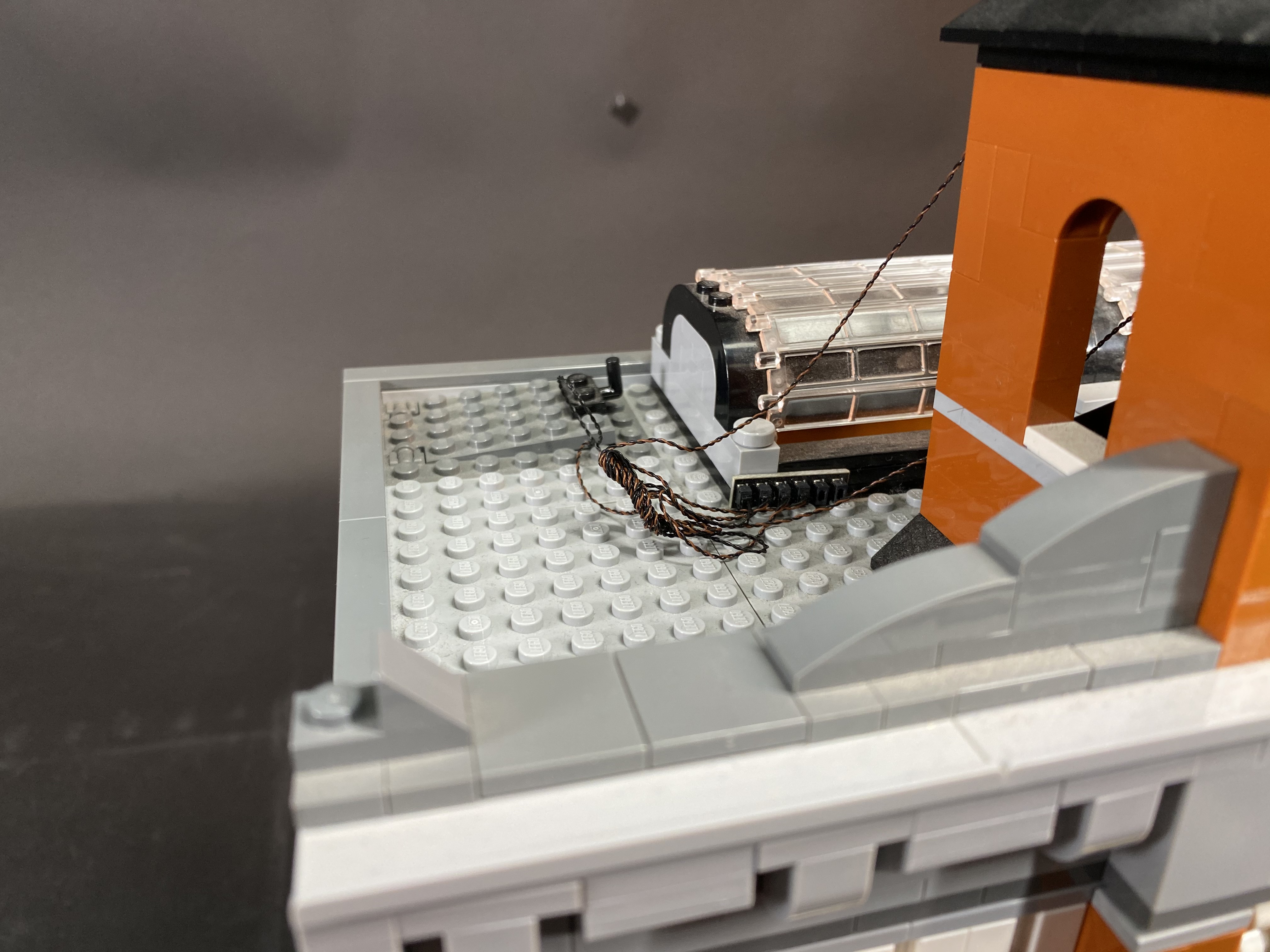
Ensure the lamp post cable is neatly laid straight and in between the studs of the base plate then reconnect the building and base plate back together. Reconnect the LEGO tiles we removed earlier.


3.) We will now install lights to the 2 door lamps on the right side. First disconnect the Hotel sign as well as the lamp sections as per below


Take your LEGO removal tool and use this to create a gap just above where the right lamp was connected to, then remove the light grey 1×1 brick with hole.


Remove the left pillar to allow us to then use the LEGO removal tool to create another gap above where the left lamp was connected to. Remove the 1×1 brick with hole.


4.) Disassemble sections of the lamps as per below and then take a White 30cm Bit Light and then thread the connector side through the large hole of the trans yellow round brick.


Before we thread the bit light all the way through, bend the LED component on a 90 degree angle ensuring the component is facing up.


Reconnect pieces ensuring the cable is facing toward the back of the lamp.


Thread the connector side of the bit light through the front of the light grey 1×1 brick with hole. Thread all the way through and then reconnect the lamp section to the brick as per below.


Thread the connector side of the bit light through the gap on the right side of the door before reconnecting this lamp section.


5.) Repeat the previous step to install another White 30cm Bit Light to the left lamp and then reconnect to the front of the building.


Once both lamps are reconnected, reconnect sections to close up the gaps and secure everything in place.


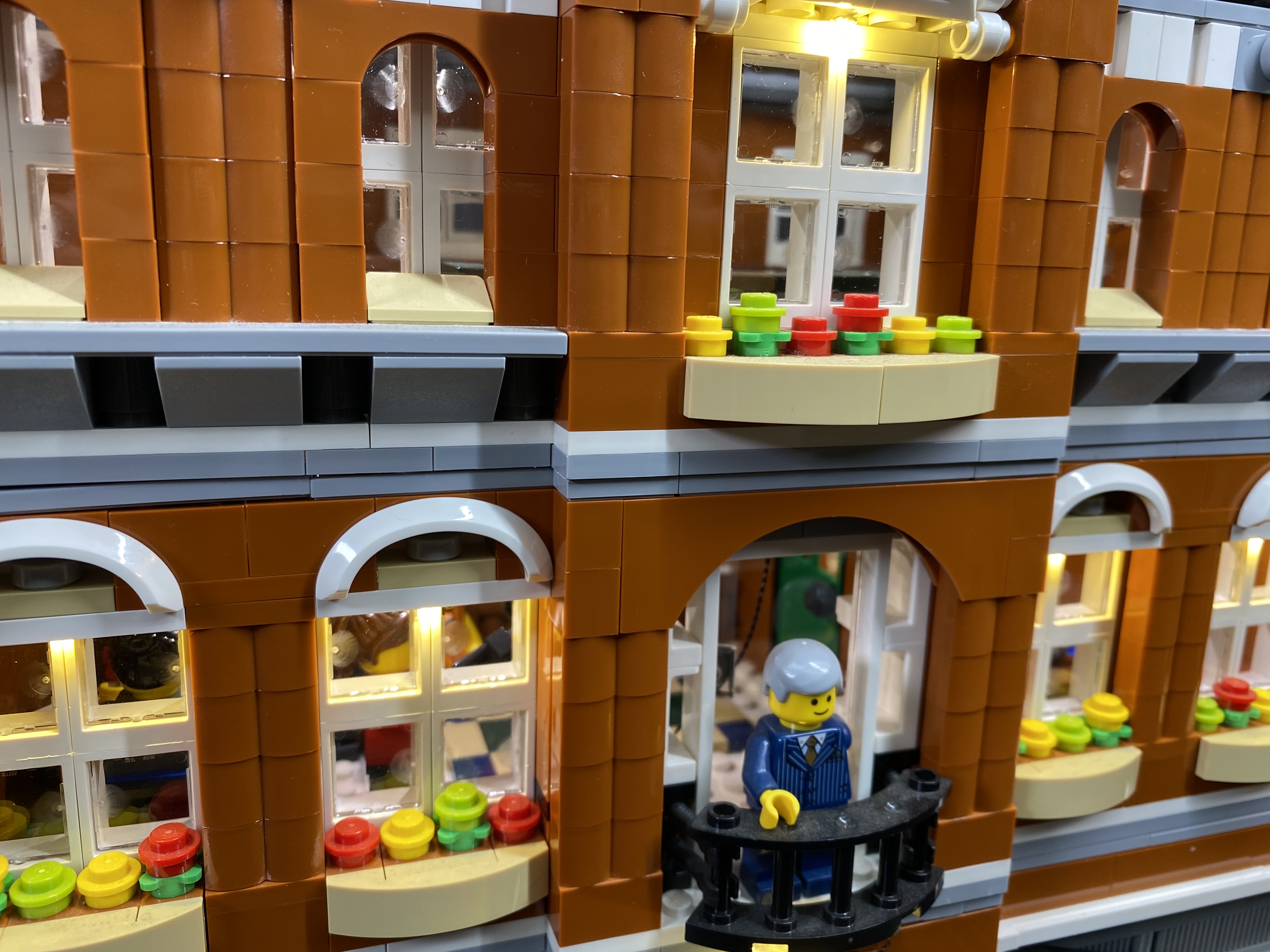
6.) We will now move onto installing lights to the lamps beside the corner entrance. First remove both sections and disassemble as per below


Take a White 15cm Bit Light and thread the connector side of the cable through the large hole of the trans yellow round brick. Thread all the way through until the LED component is in the middle of inside the brick.


Take the black bar and then carefully thread this through the trans yellow round brick ensuring the LED component inside stays in the centre. The LED should sit in between the bar and the inside of the brick.

Reconnect the bottom section of the lamp as per below

Before we can connect back the top section, thread the connector side of the cable through the base of the black dish and then through the hole of the arm above. Then reconnect them back to the bar.


Thread the cable through the bottom corner of the right side and then pull the cable up from the top as per below.


Reconnect the lamp with bit light installed ensuring the cable is neatly hidden behind.

7.) Repeat the previous step to install another White 15cm Bit Light to the lamp on the left side. Once installed, thread the cable through to the inside of the building as per previous step before reconnecting.


8.) Take a 8-Port Expansion Board and then connect the 2 lights we just installed as well as the other 2 lights and lamp post cable into the available ports.


We can take this time to test the lights we have installed so far. Take the Battery Pack and insert 3x AA batteries to it. Connect the battery pack cable into a spare port of the expansion board and then turn on to verify all is working ok.
If you’re using the USB Power Cable, connect this to the board this instead of the battery pack, and connect the other end to a USB Power Bank or wall adaptor (sold separately) and turn it ON to test the front lights are working OK.


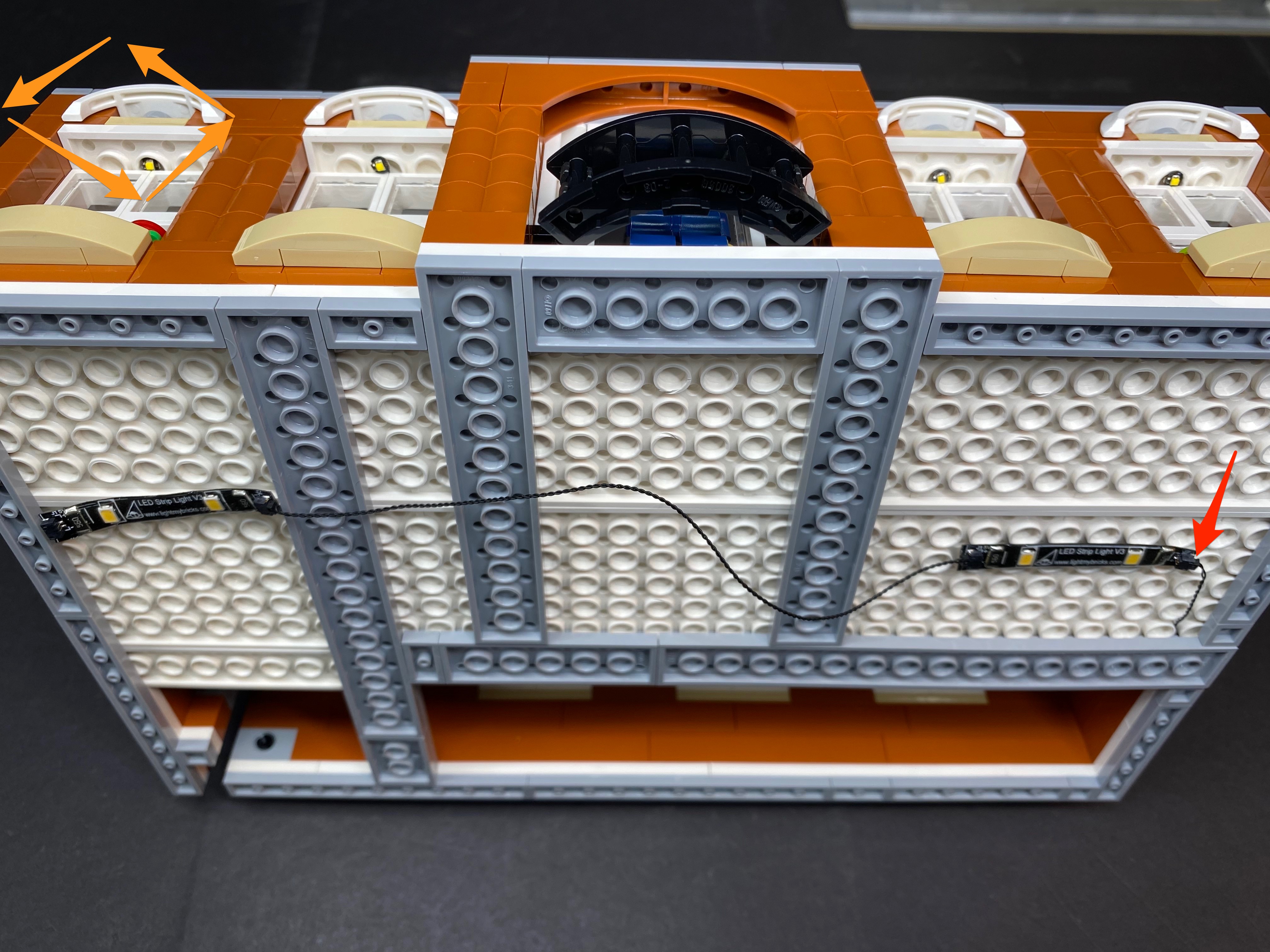
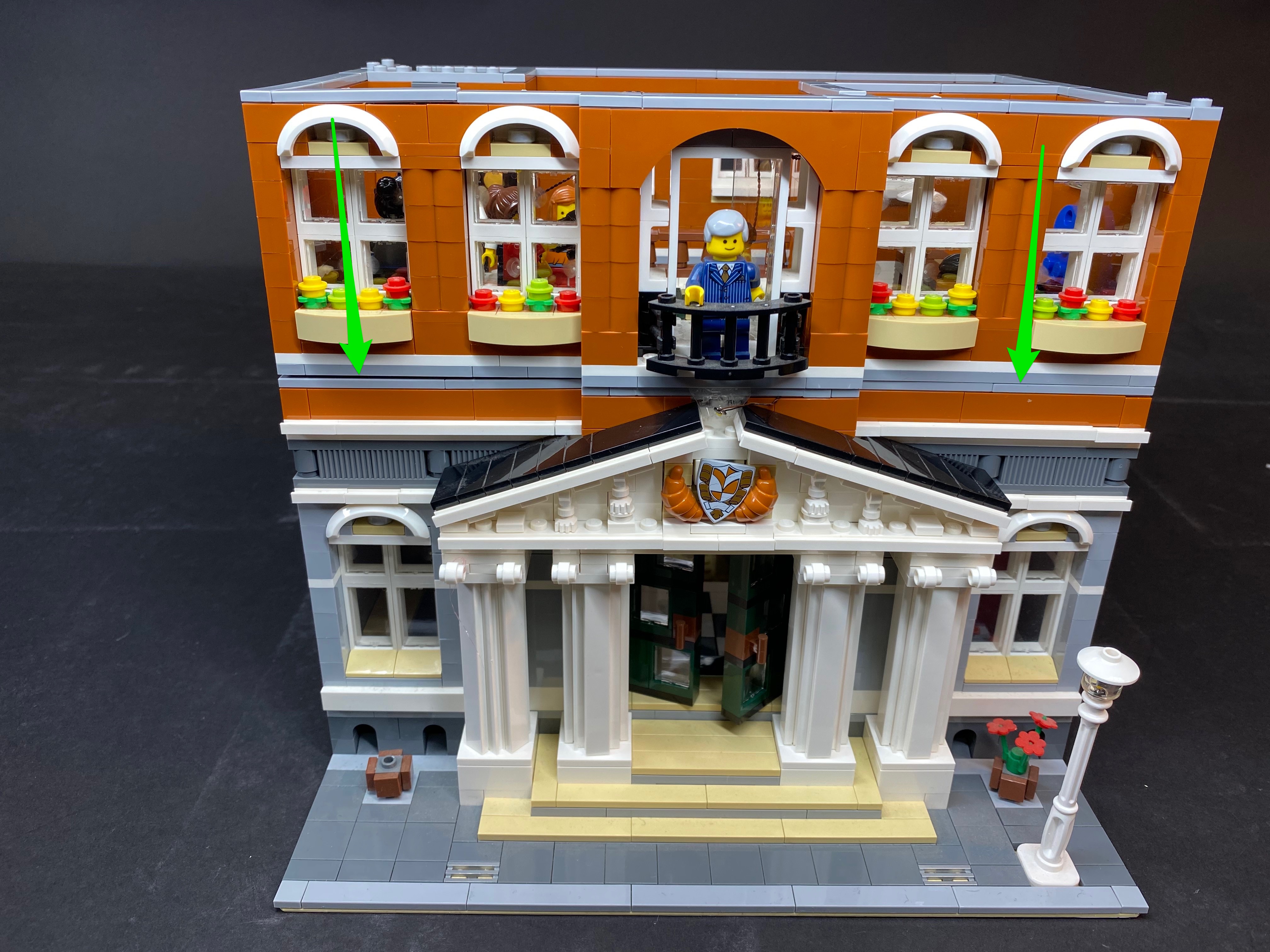
9.) We will now install strip lights underneath the window awnings on each side starting with the larger side. First remove this section and then turn over to lay on its front.


Take 2x LED Strip Lights and then connect a 5cm connecting cable between them and then connect a 15cm connecting cable to the striplight on the right. Because we are using several strip lights in this kit, we will identify these two as striplight#1 and striplight#2

Peel off the adhesive backing paper behind the strip lights to allow you to stick them to the following positions. Tuck the 5cm cable underneath the lego pieces.


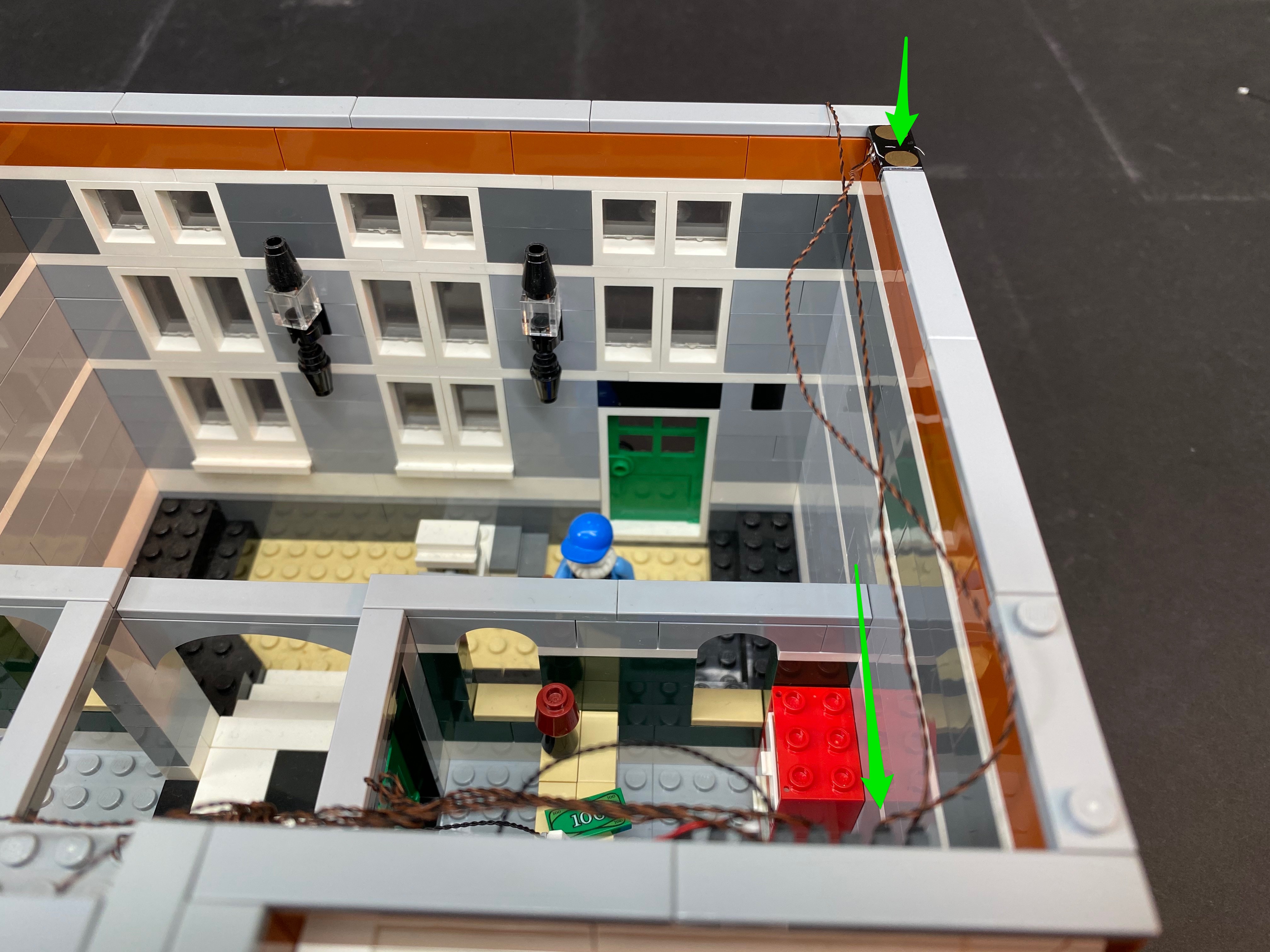
Before we reconnect the awning back to the building, thread the 15cm cable from striplight#2 through to the inside of the building as per below. Then reconnect the awning


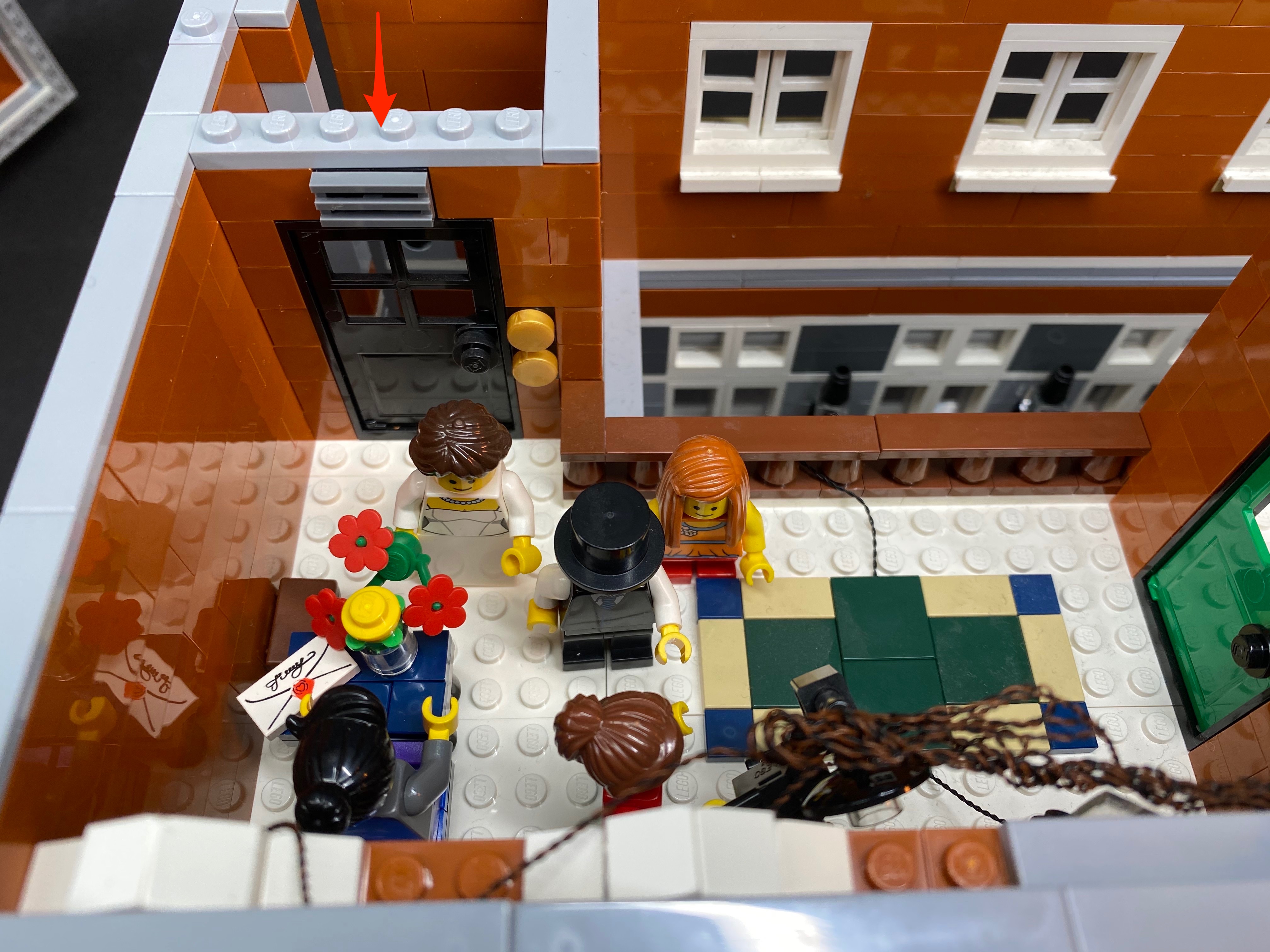
Take the 15cm cable we threaded inside and then pull this over to the right section and then thread down through the gap which leads to the right side as per below


9.) Let’s move onto the awning on the other side. Remove this section and then turn it over so we can access the back of it.

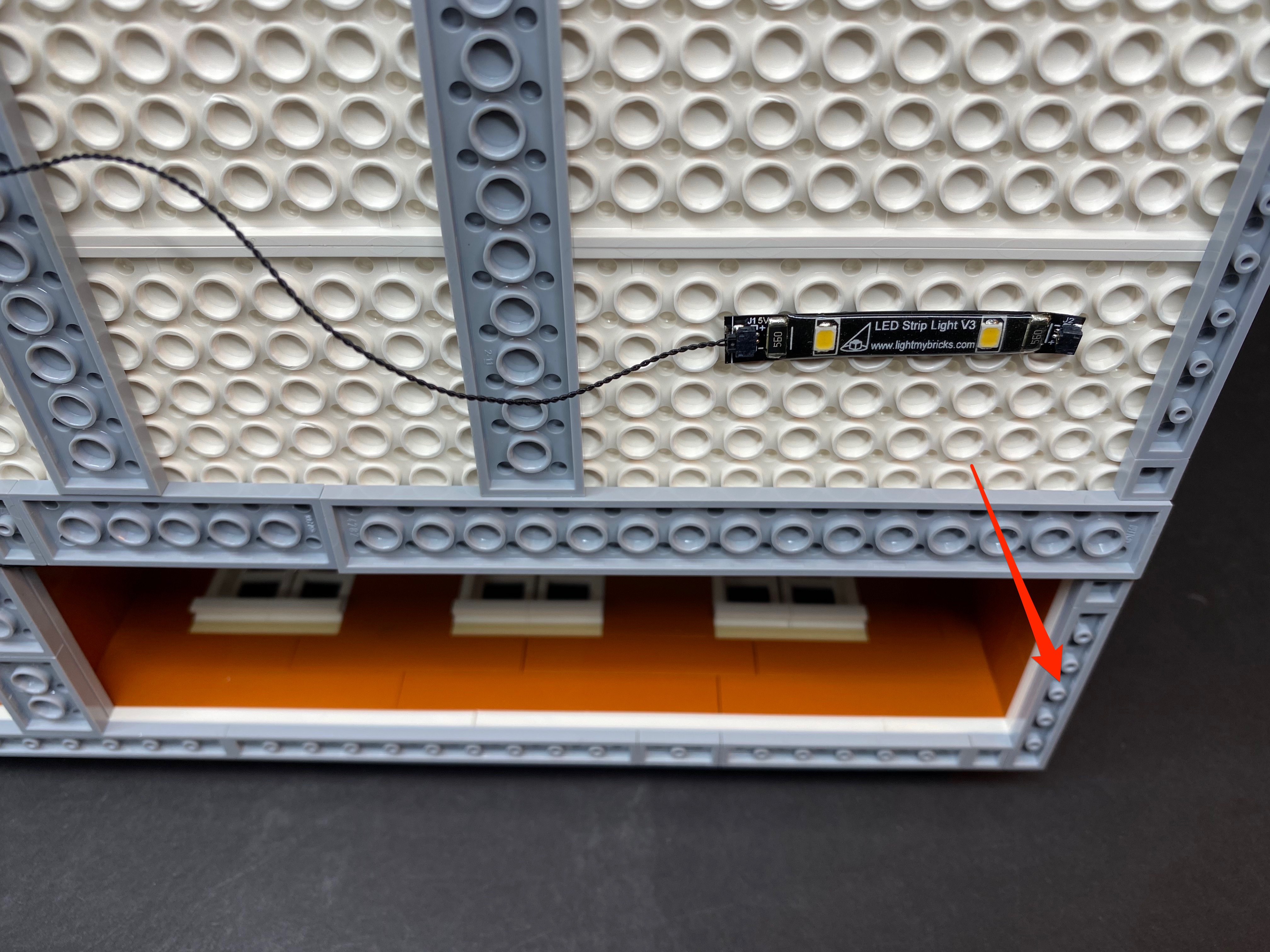
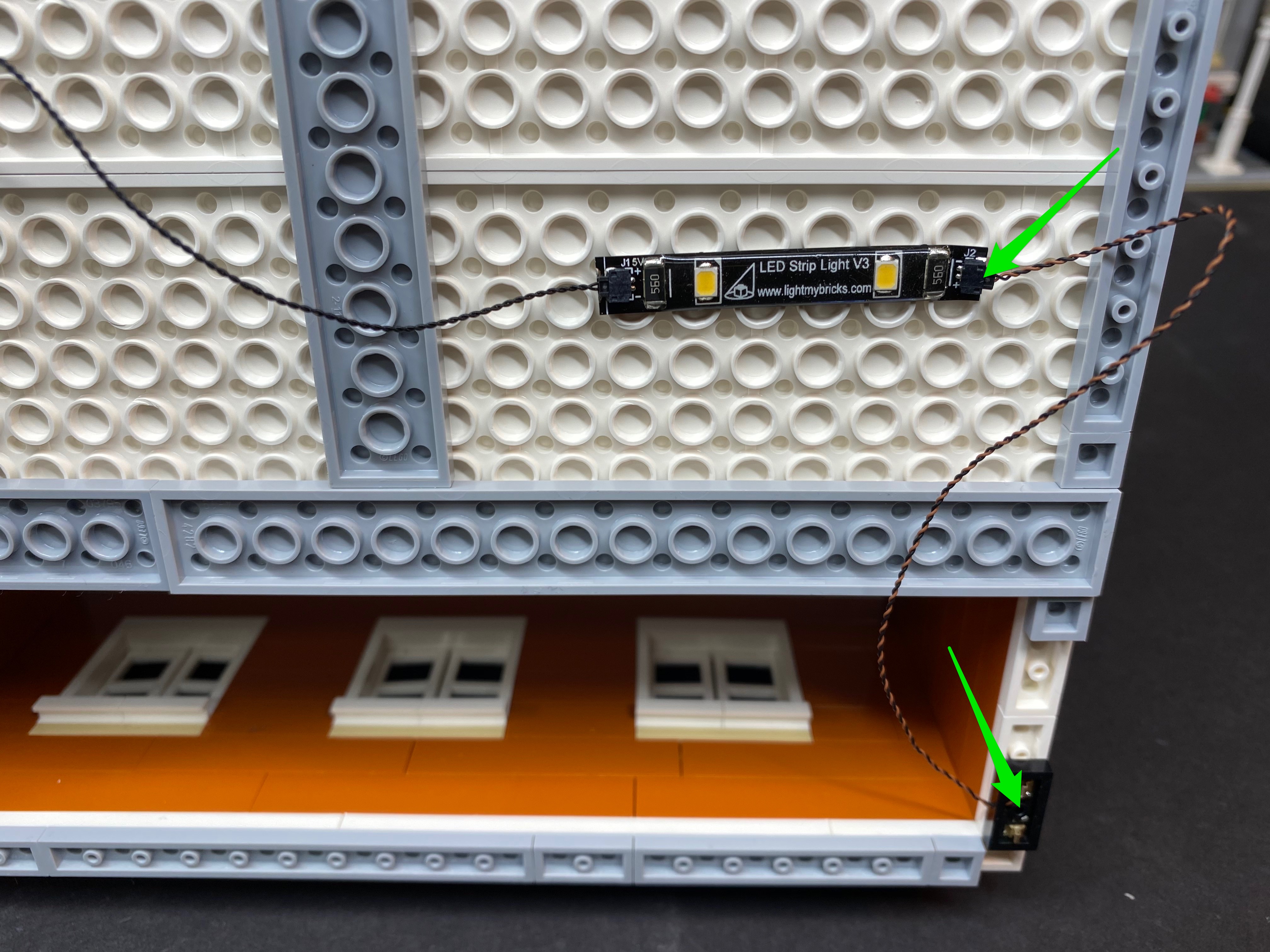
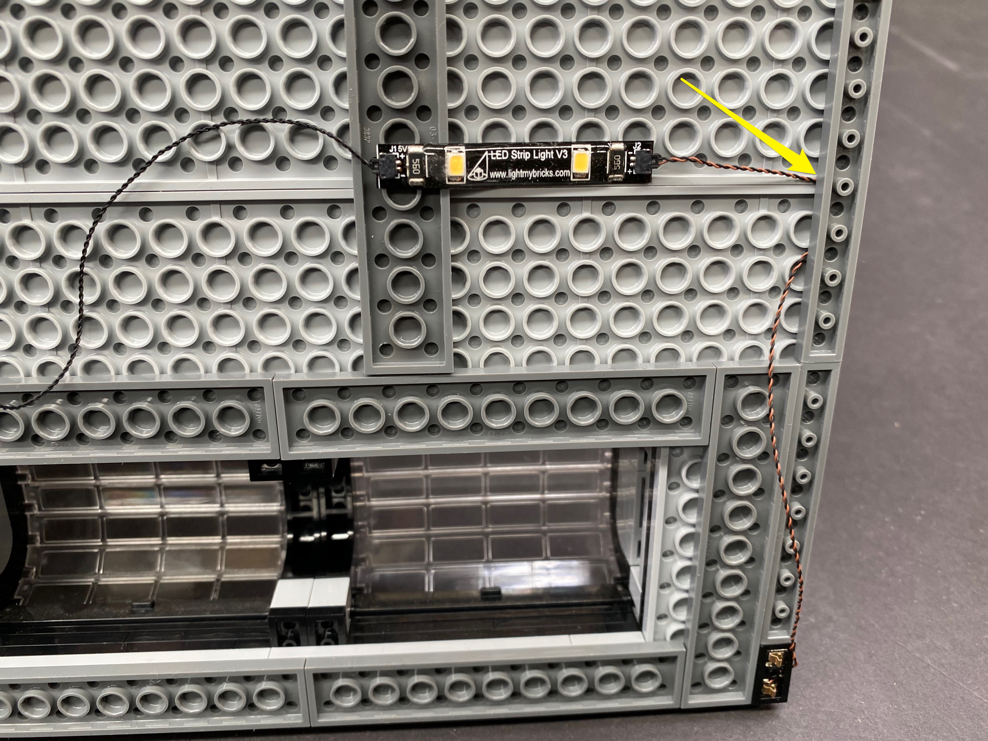
Take 1x LED Strip Light (striplight#3) and connect a 15cm connecting cable to the right port before sticking the strip light onto the back of the awning to the below position.


Locate the 15cm cable that is hanging down from the top and then connect this to the left port on striplight#3. Reconnect the awning back to the building ensuring the cables are neatly hidden behind.


Hide the cable from the right underneath the LEGO plates on the top of this floor by first disconnecting, and then reconnecting over the cable.


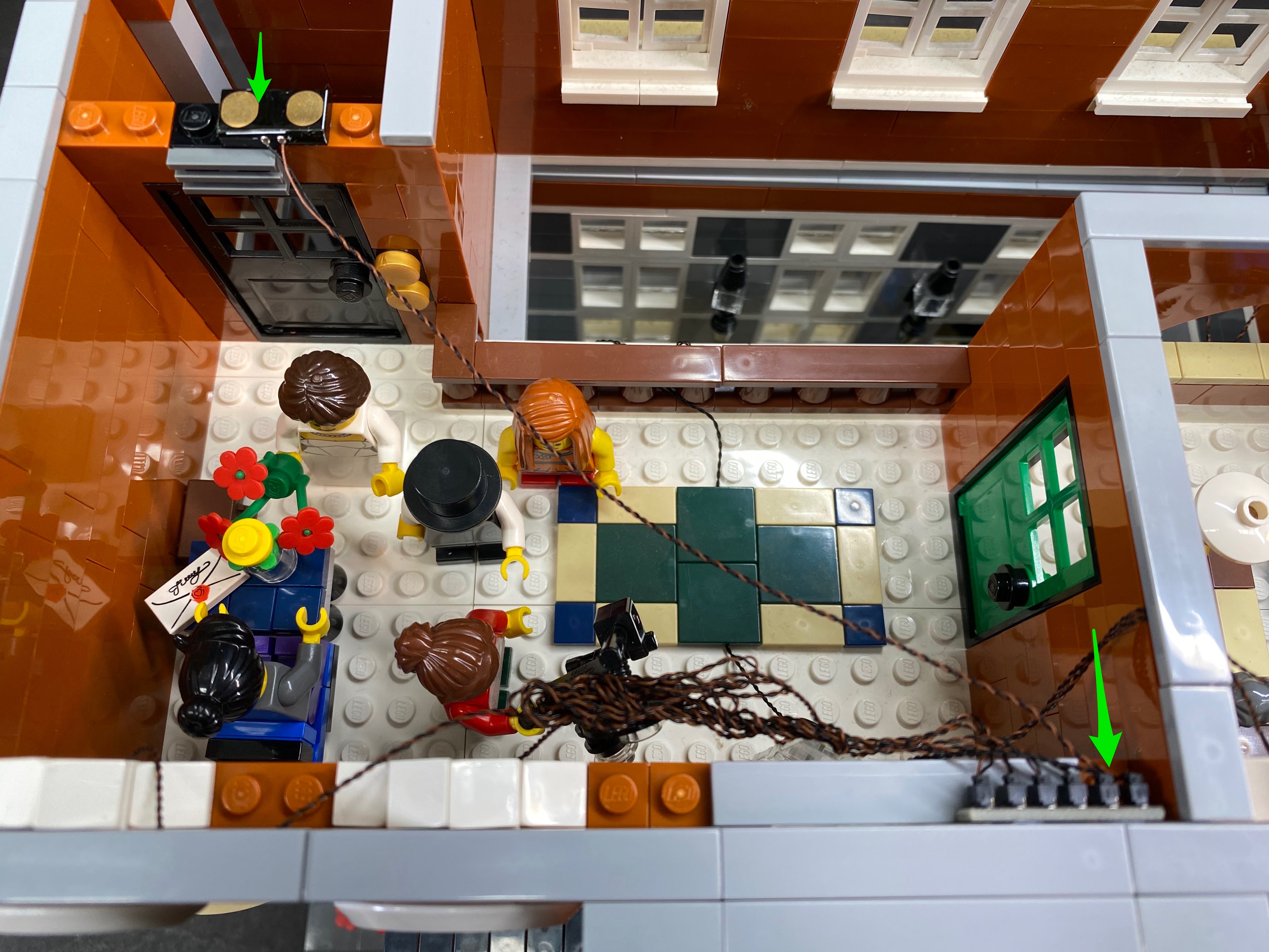
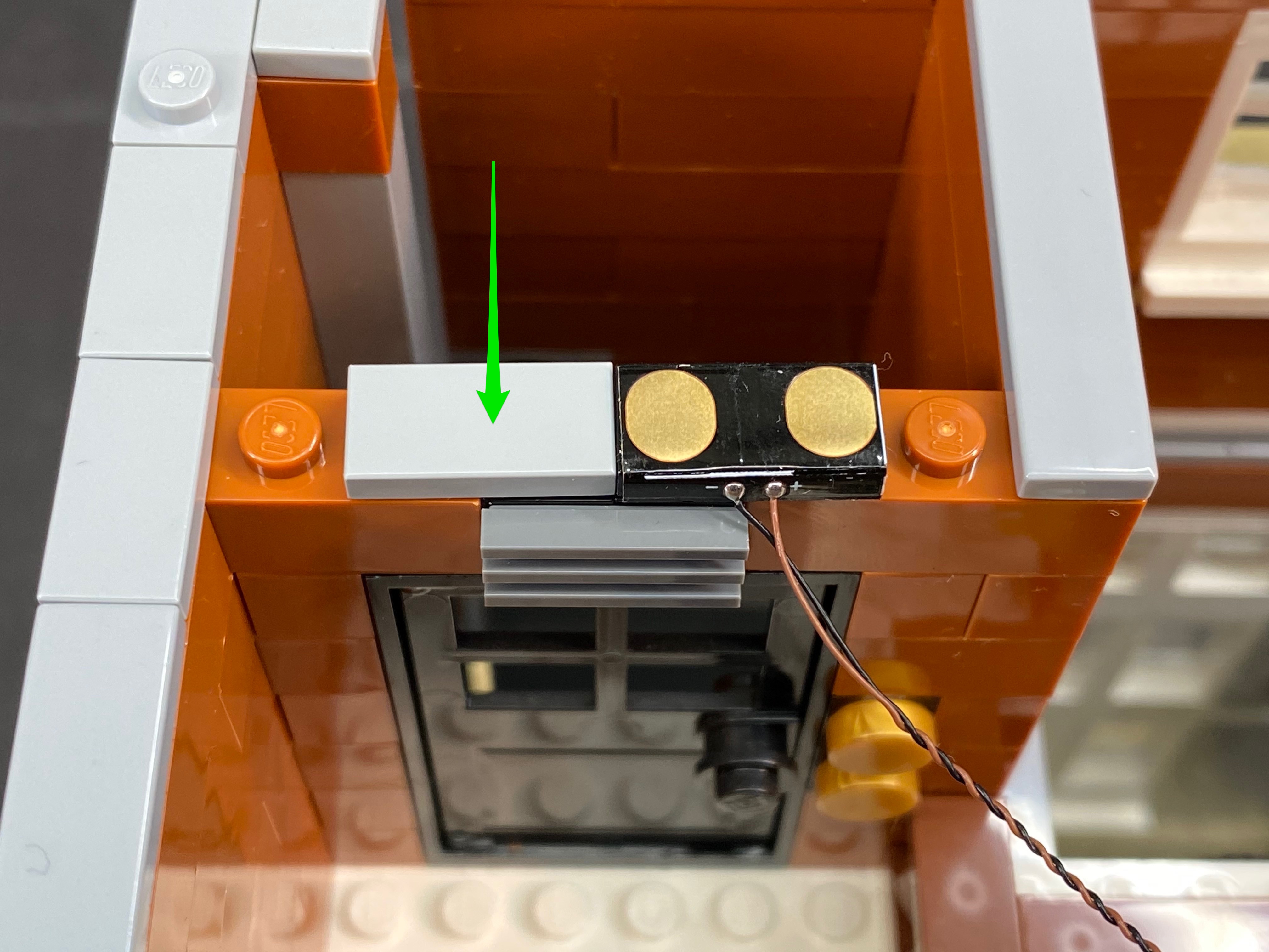
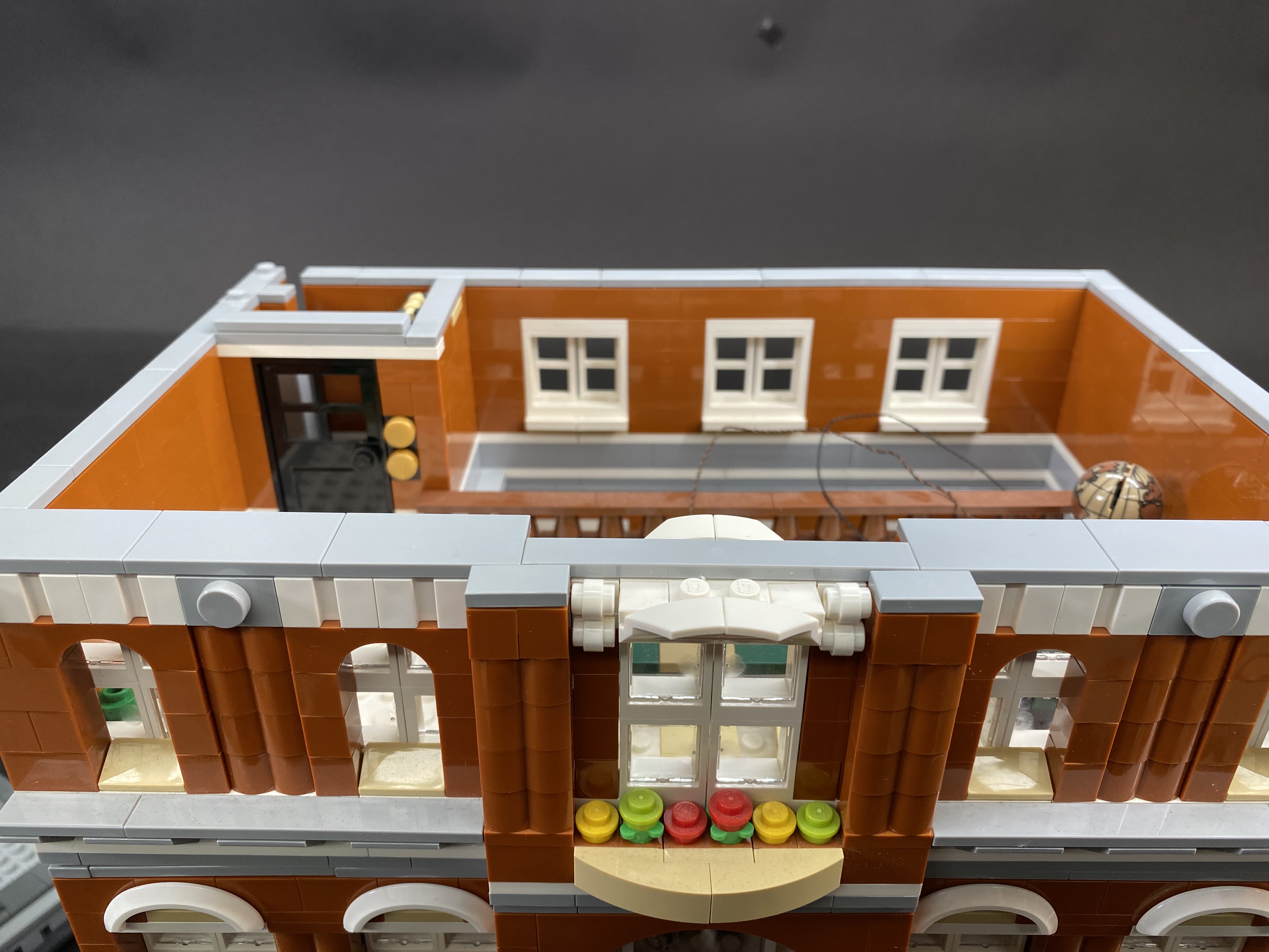
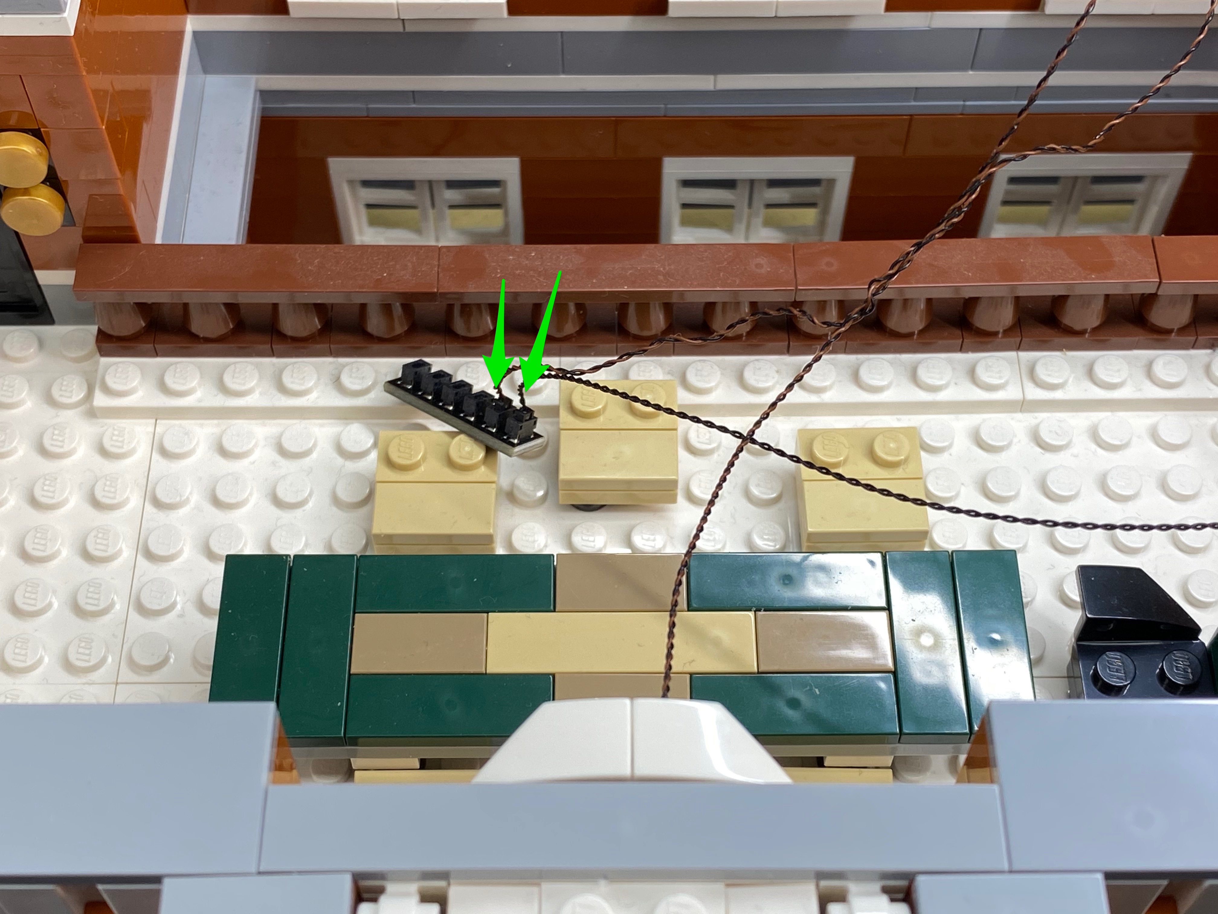
10.) Connect the other side of the 15cm cable from striplight#3 to the next available port on the 8-port expansion board.

Use 2x adhesive squares to stick on the back of the expansion board to allow us to mount it to the inside of the building in the below position


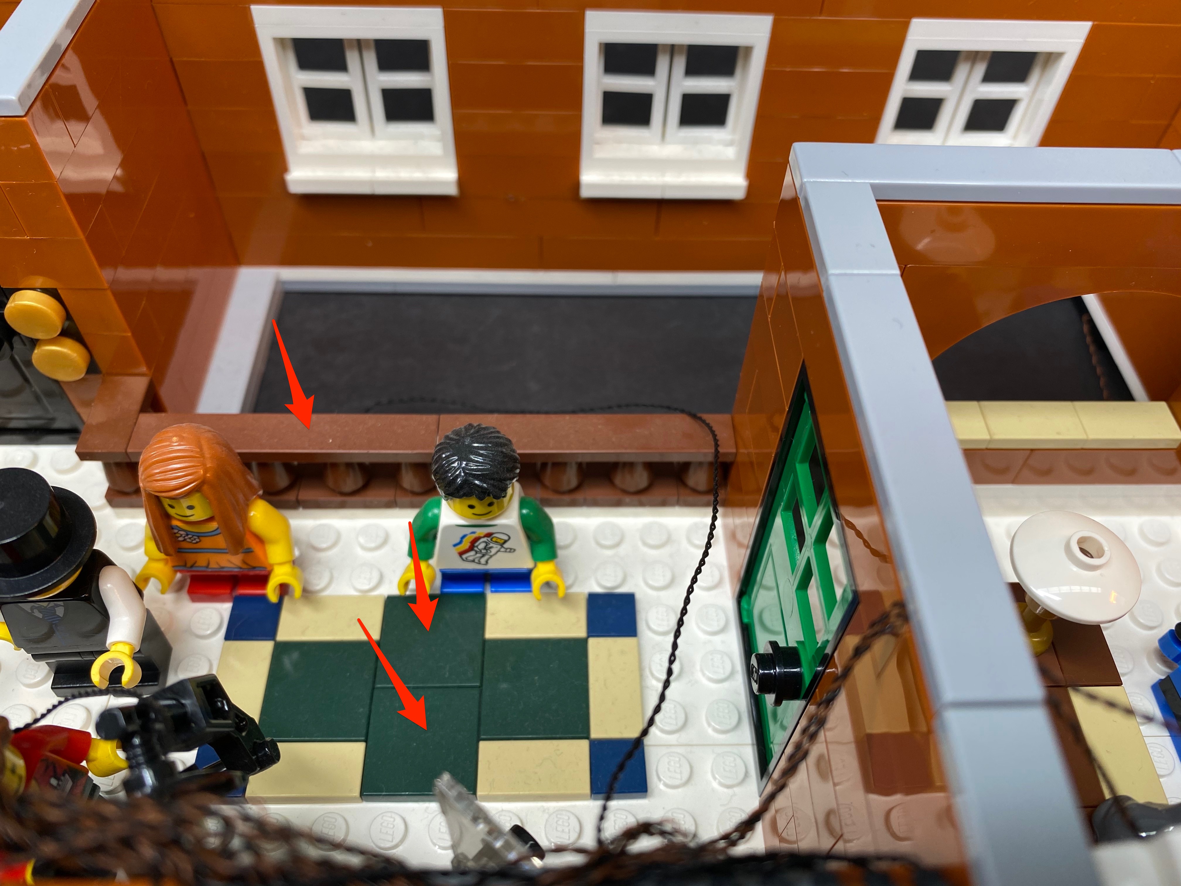
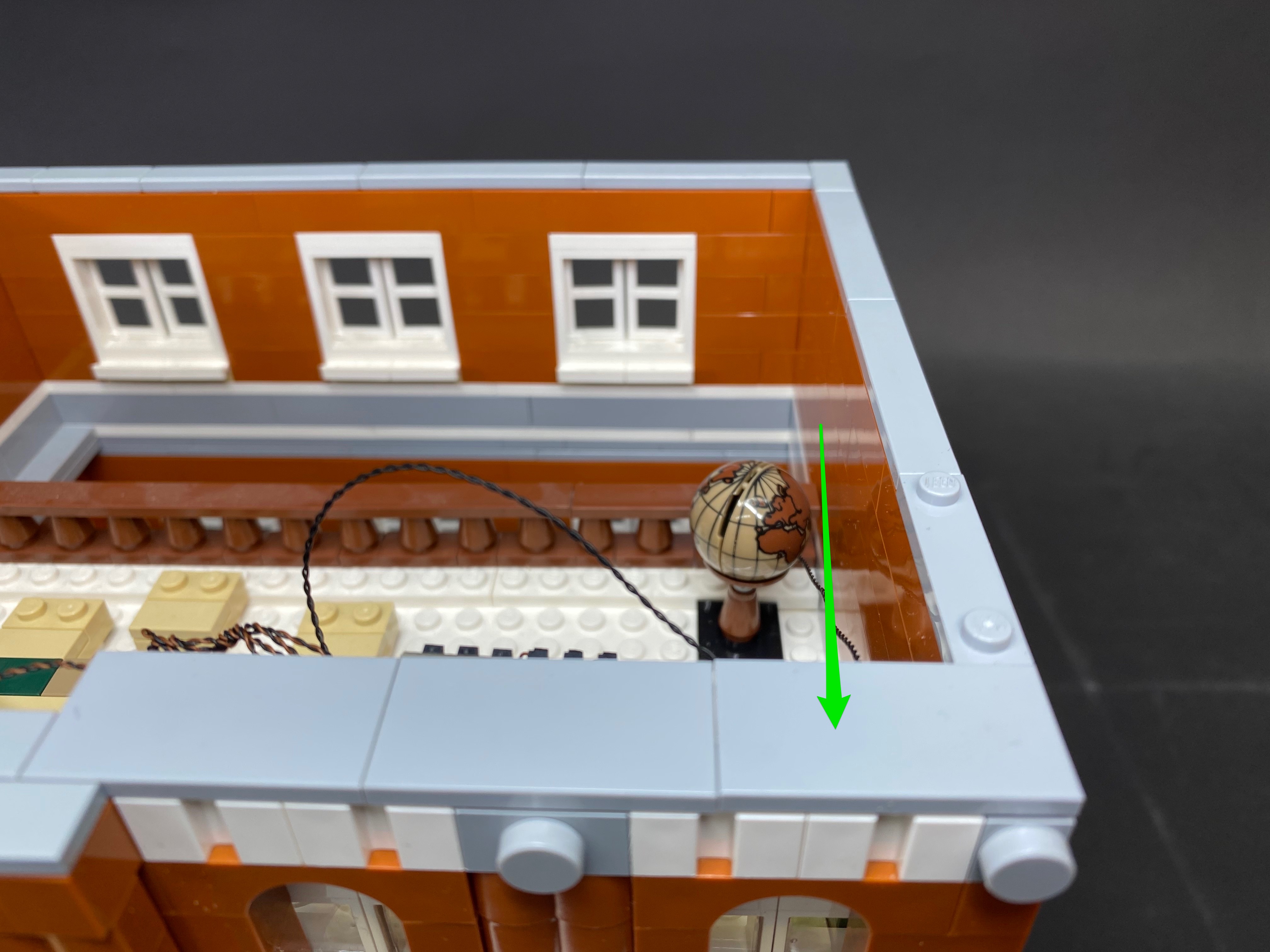
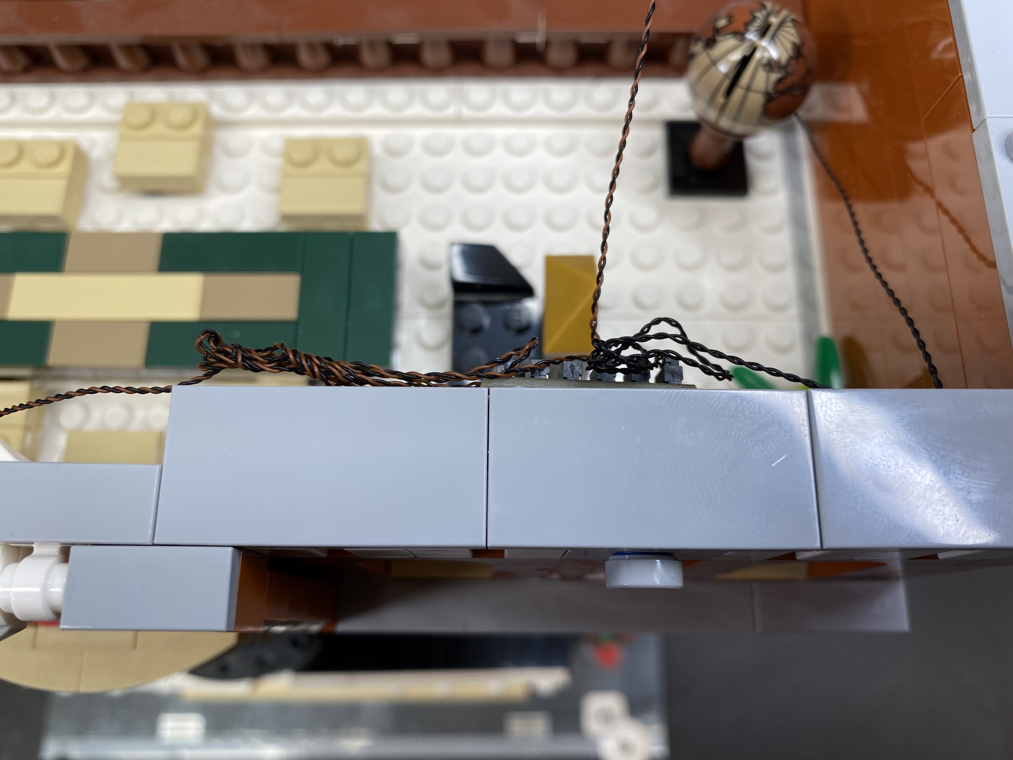
Neaten up cabling by hiding the 2x 30cm bit light cables underneath the tiles on the top of this floor. Lay the cables in between studs as shown below before reconnecting the tiles directly over them.


We can test the lights again by connecting the battery pack/usb cable to the last port on the expansion board. Turn on to verify all is looking ok so far.

11.) We will now install lights to the Hotel sign. First disconnect the following pieces from the back of the sign.


Remove the following pieces.

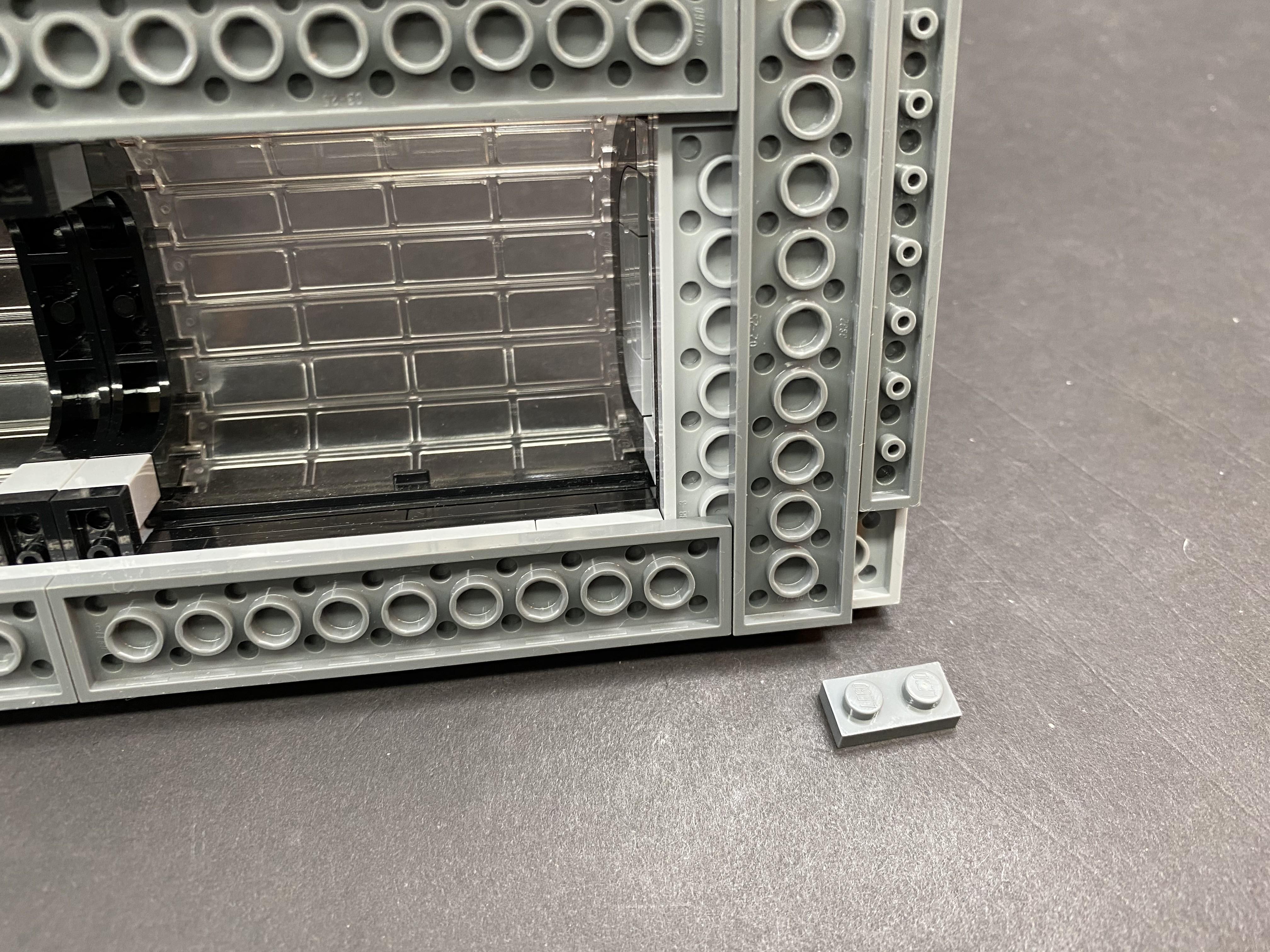
Take the white 1×10 plate and then place a White 30cm Bit Light over the top of the stud on the far left. With the cable facing down, reconnect the 1×2 trans red plate over the top, the same way as shown below.


Take another White 30cm Bit Light and place it over the 4th stud from the left. Reconnect another 1×2 trans red plate over the top, securing it in place.


Take another White 30cm Bit Light and place it on the white stud on the right of the trans ref plate. Reconnect a 1×1 trans red plate over the top to secure in place.


Take another White 30cm Bit Light and then place it directly over the stud 3rd from the right. Reconnect the 1×1 trans red plate over the top to secure in place.


Reconnect the White 1×10 plate back to rest of the Hotel sign.

12.) Disconnect the sections which make up the ‘E’ and the ‘L’.


Remove the white 1×2 plate from underneath the ‘E’ and then take a White 15cm Bit Light and place it directly over the bottom stud. With the cable facing down, reconnect the ‘E’ section directly over the top to secure the bit light in place.


13.) Remove the top part of the ‘L’ section and then take another White 15cm Bit Light and place it directly over the stud on the right side. Reconnect the top part of the ‘L’ section to secure the bit light in place.


Connect both sections back together

14.) Reconnect the white 1×8 plate and then reconnect the ‘E’ and ‘L’ sections back to the Hotel sign.


Turn the Hotel sign over and then hold all the cables down toward the bottom. Twist all the cables around each other toward the bottom so they all come together forming one larger cable.


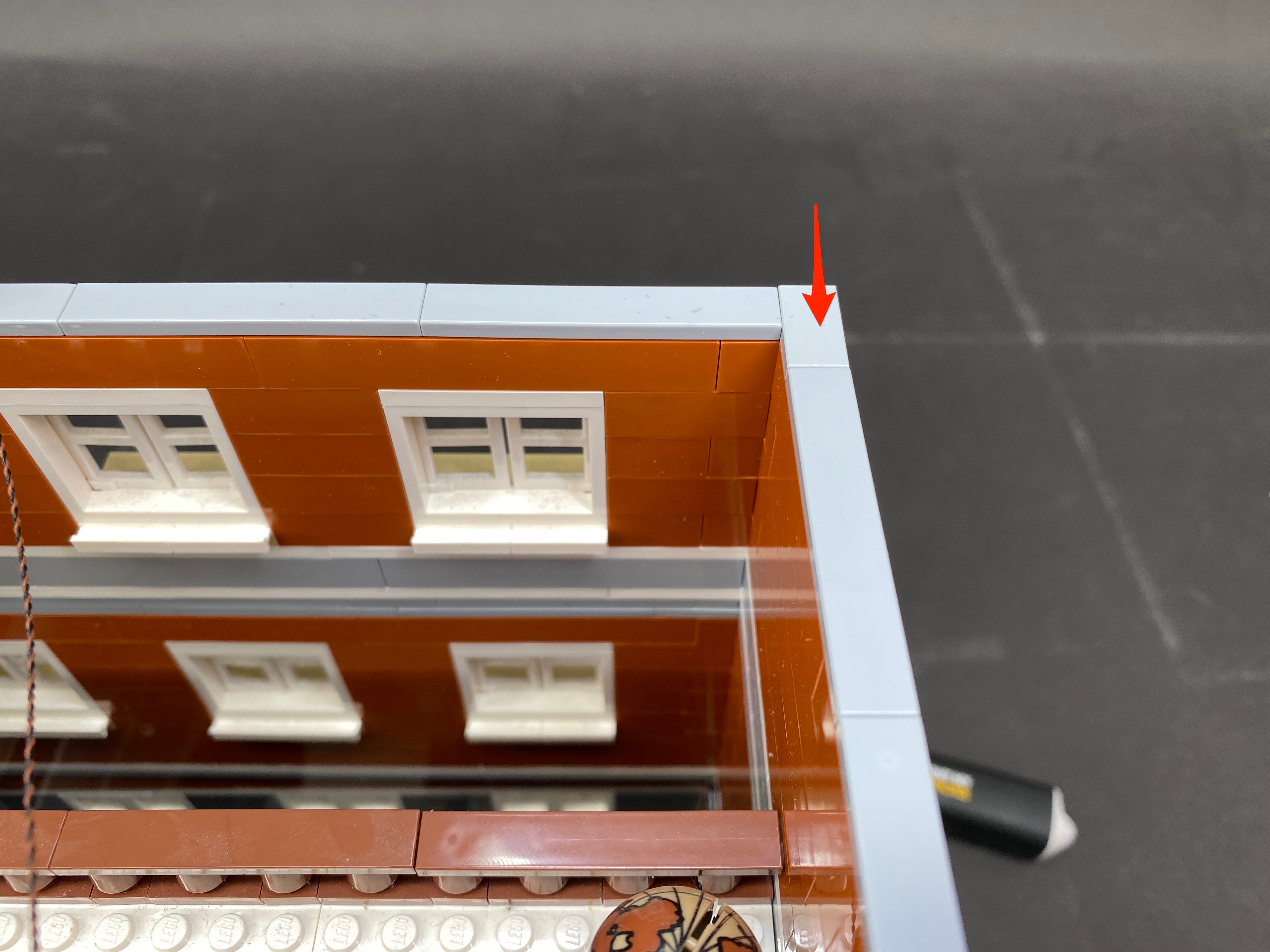
Reconnect the Hotel sign to the building ensuring the cables are facing toward the right side as shown below.


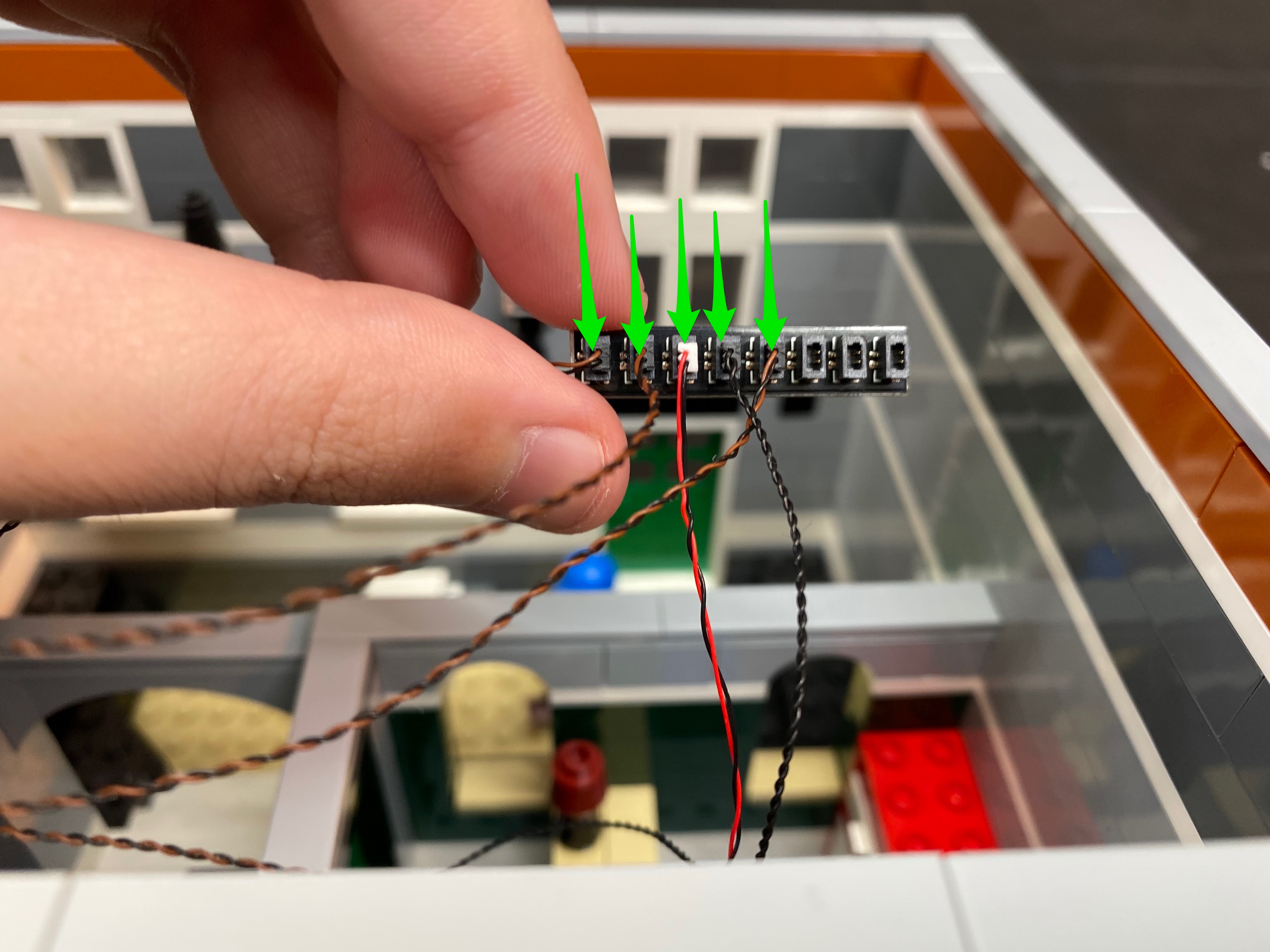
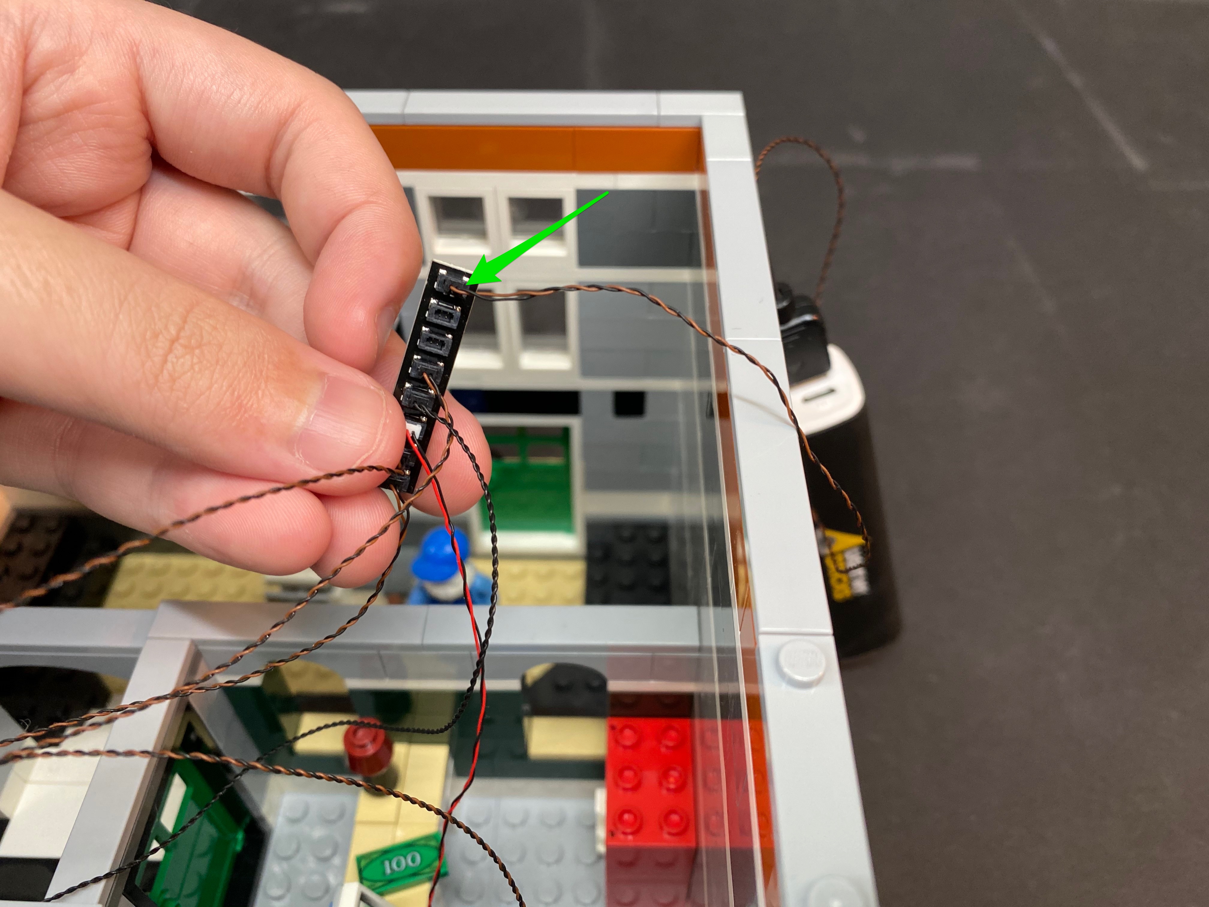
15.) Take a 8-Port Expansion Board and then connect all the cables from the Hotel sign into spare ports. Take another 15cm connecting cable and connecting it to the next available port on the expansion board


Use another 2x adhesive squares to mount this expansion board to the inside of the building in the following position.


16.) Take a 5cm connecting cable and then connect this to the final port of the 8-port expansion board we just mounted and then connect the other side to the expansion board on the right, joining the two together.


You can now take this time to test the light kit so far. Take the last 8-port expansion board and battery pack/usb cable and connect them to the other end of the loose 15cm cable. Verify all is working ok.


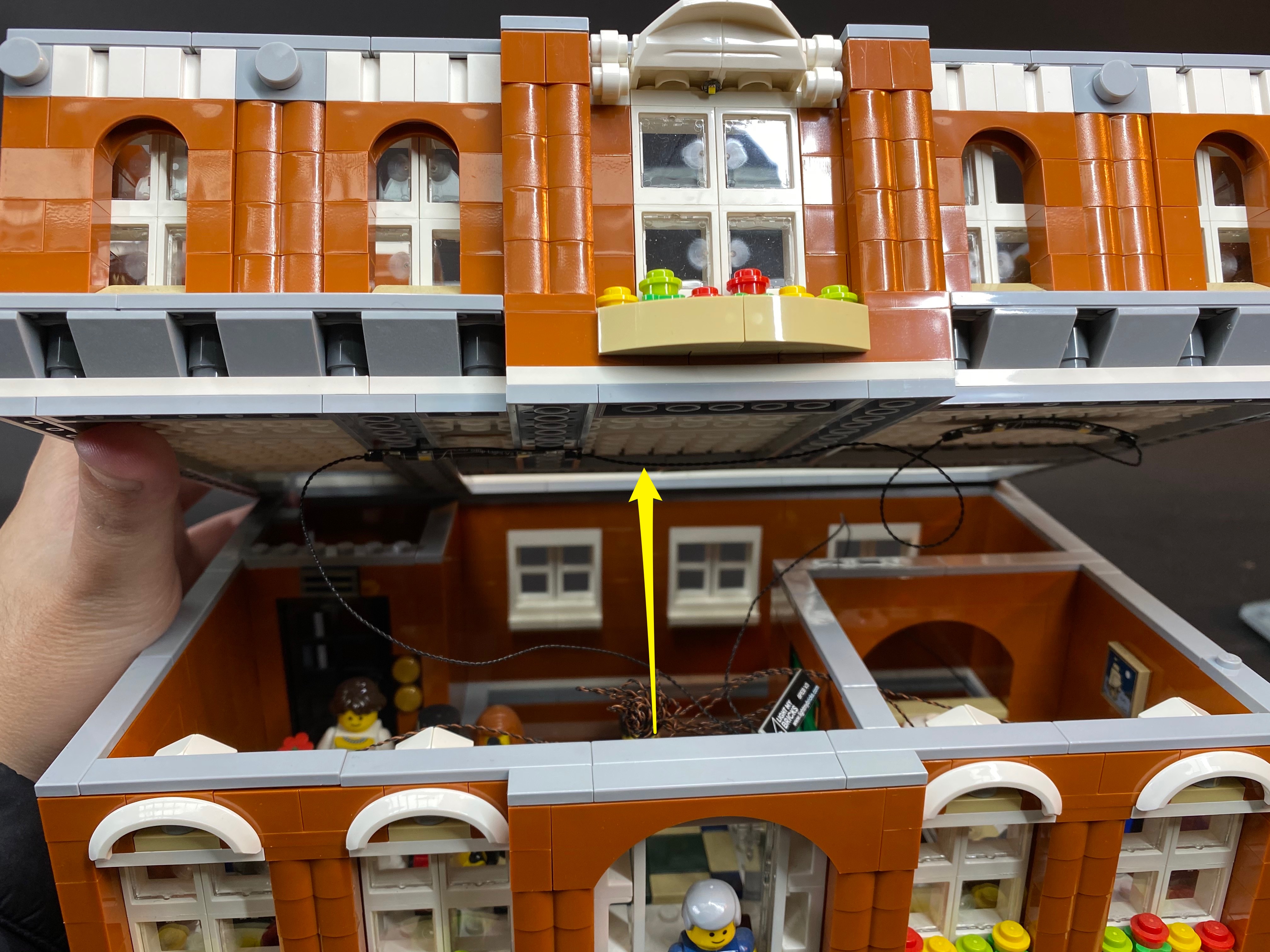
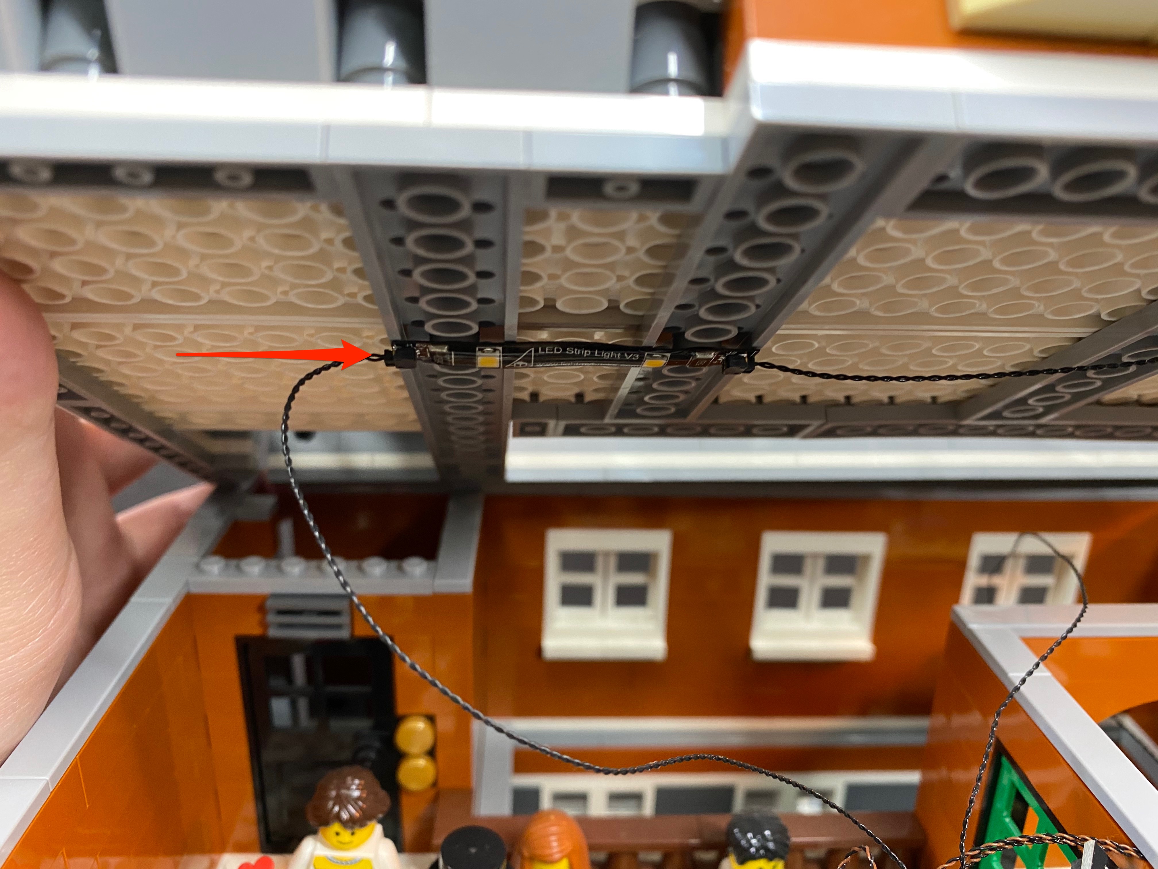
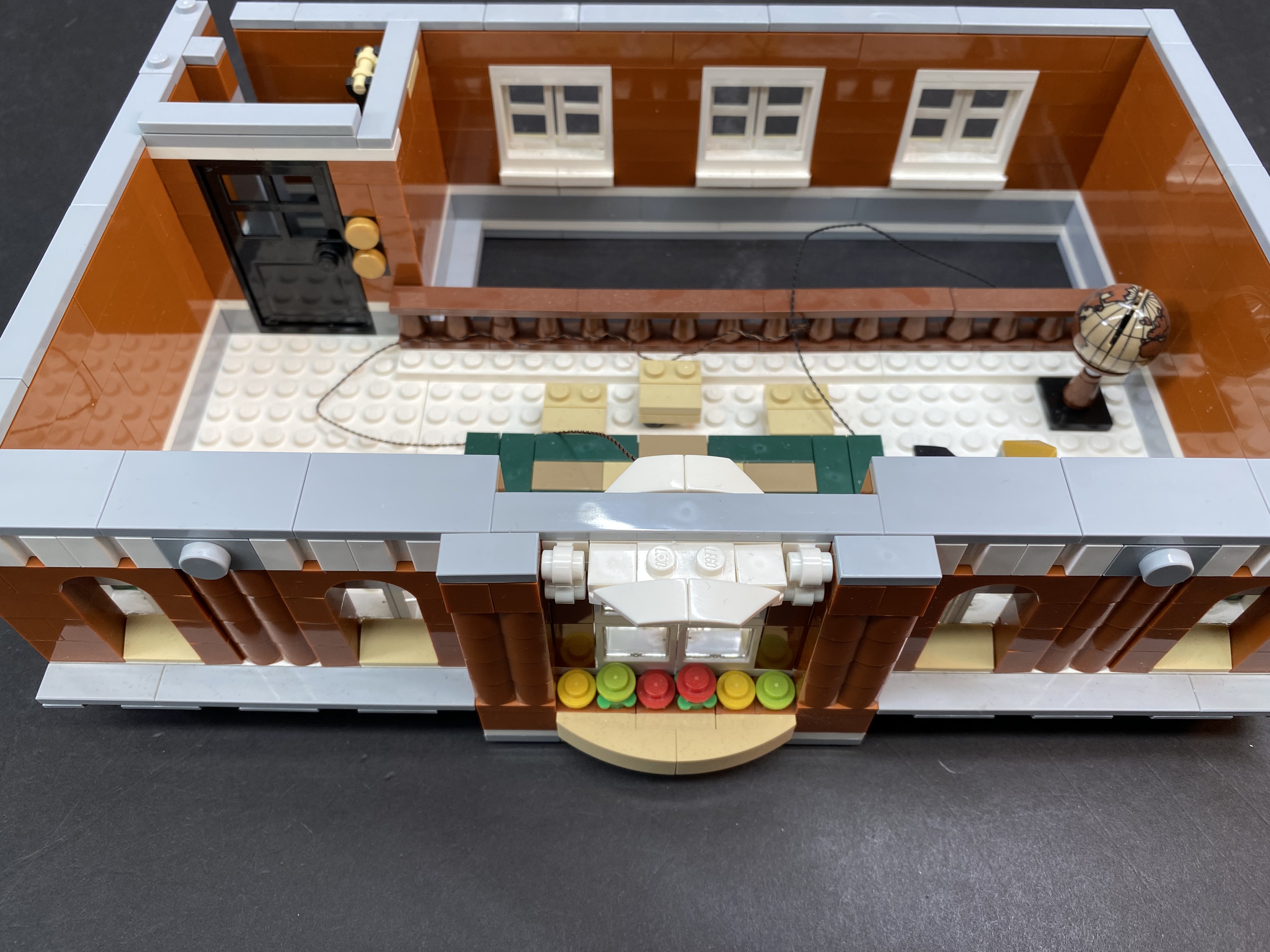
17.) Take the entire second level and then turn if over so that we can access the bottom of it.


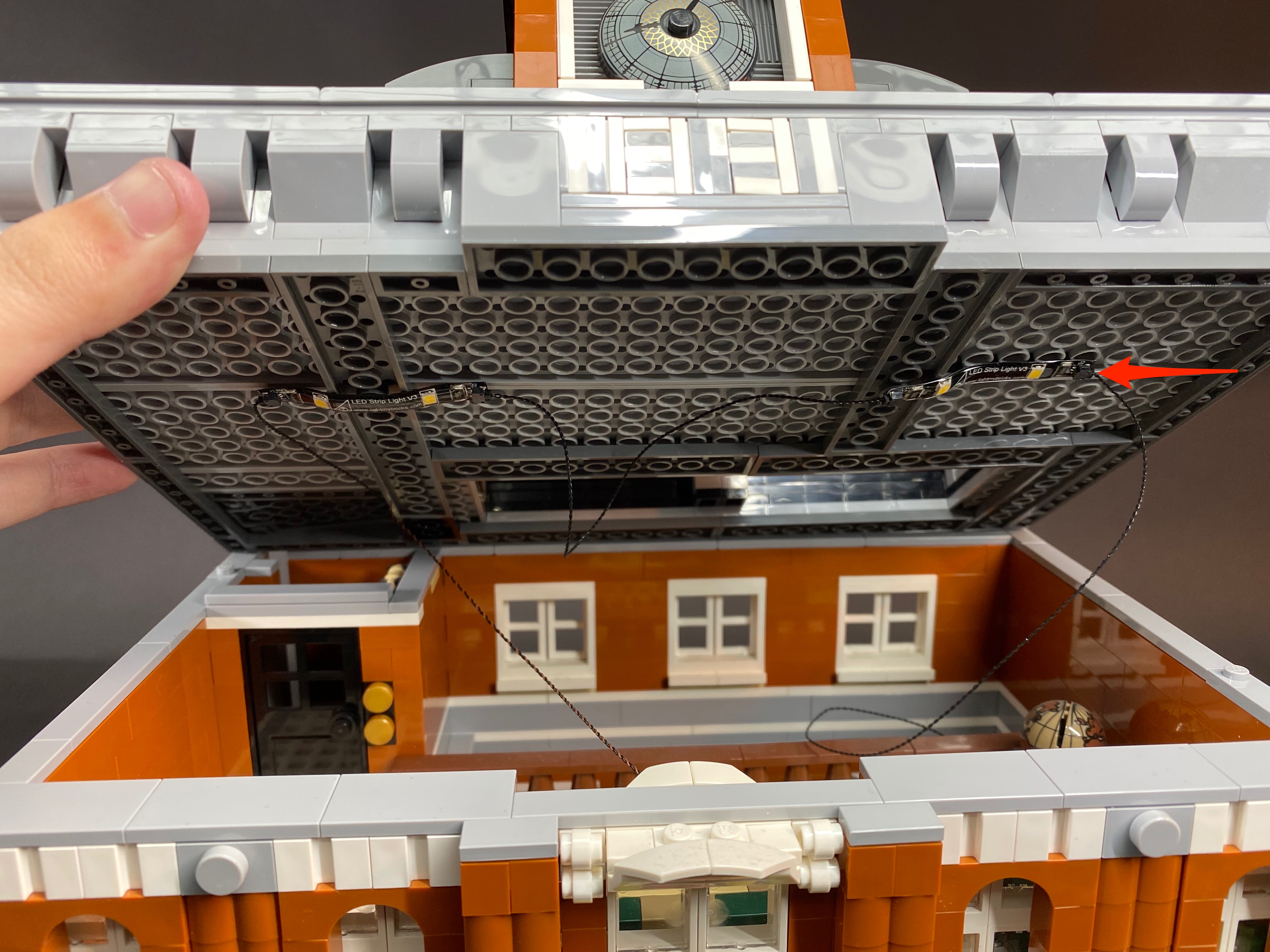
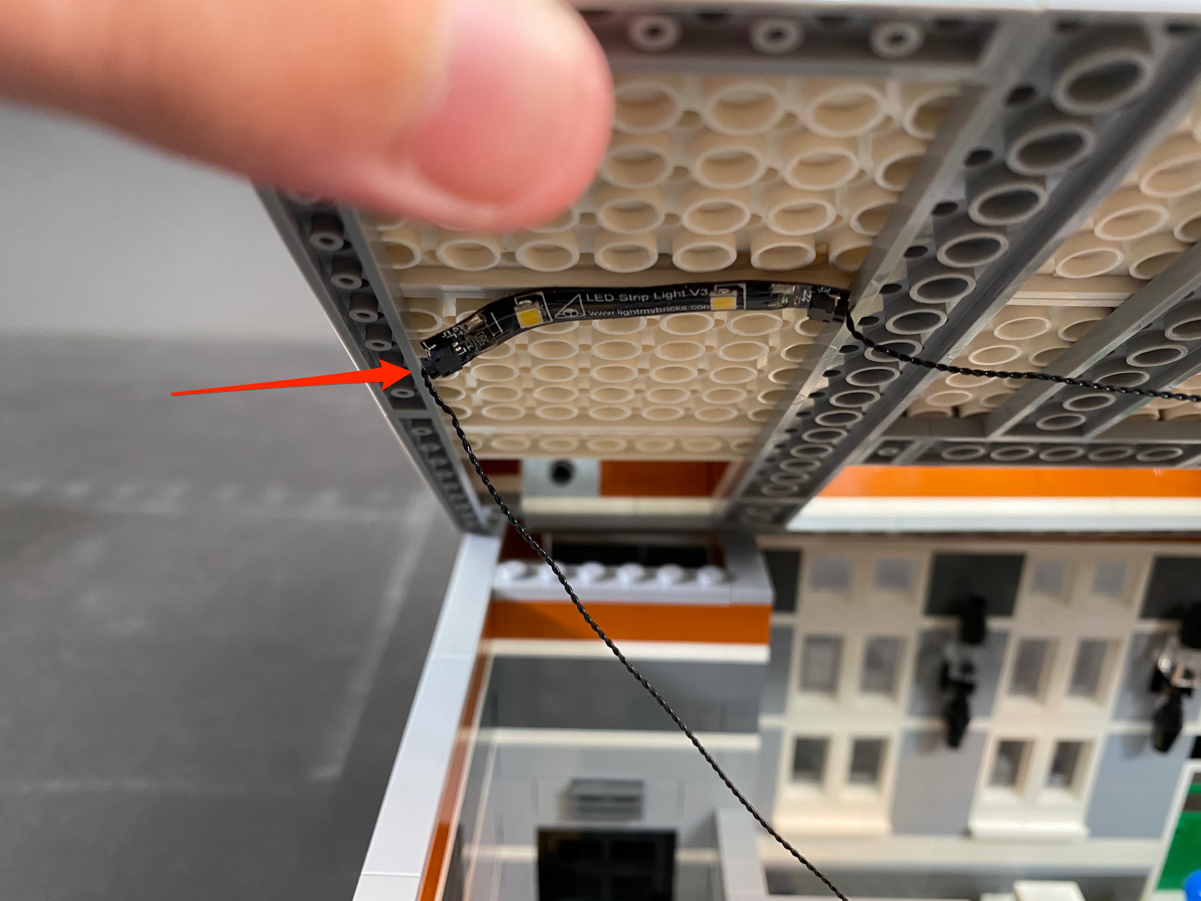
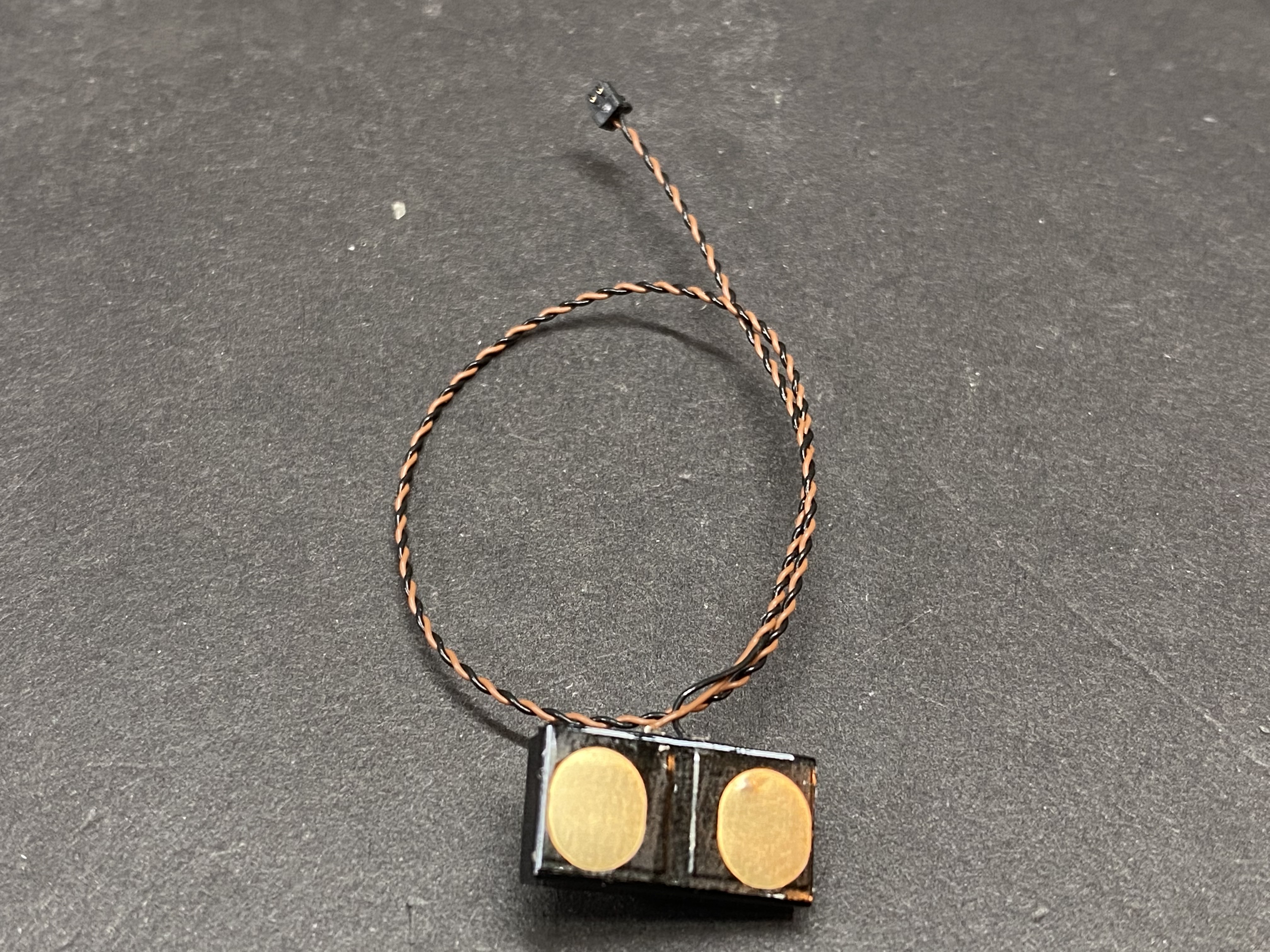
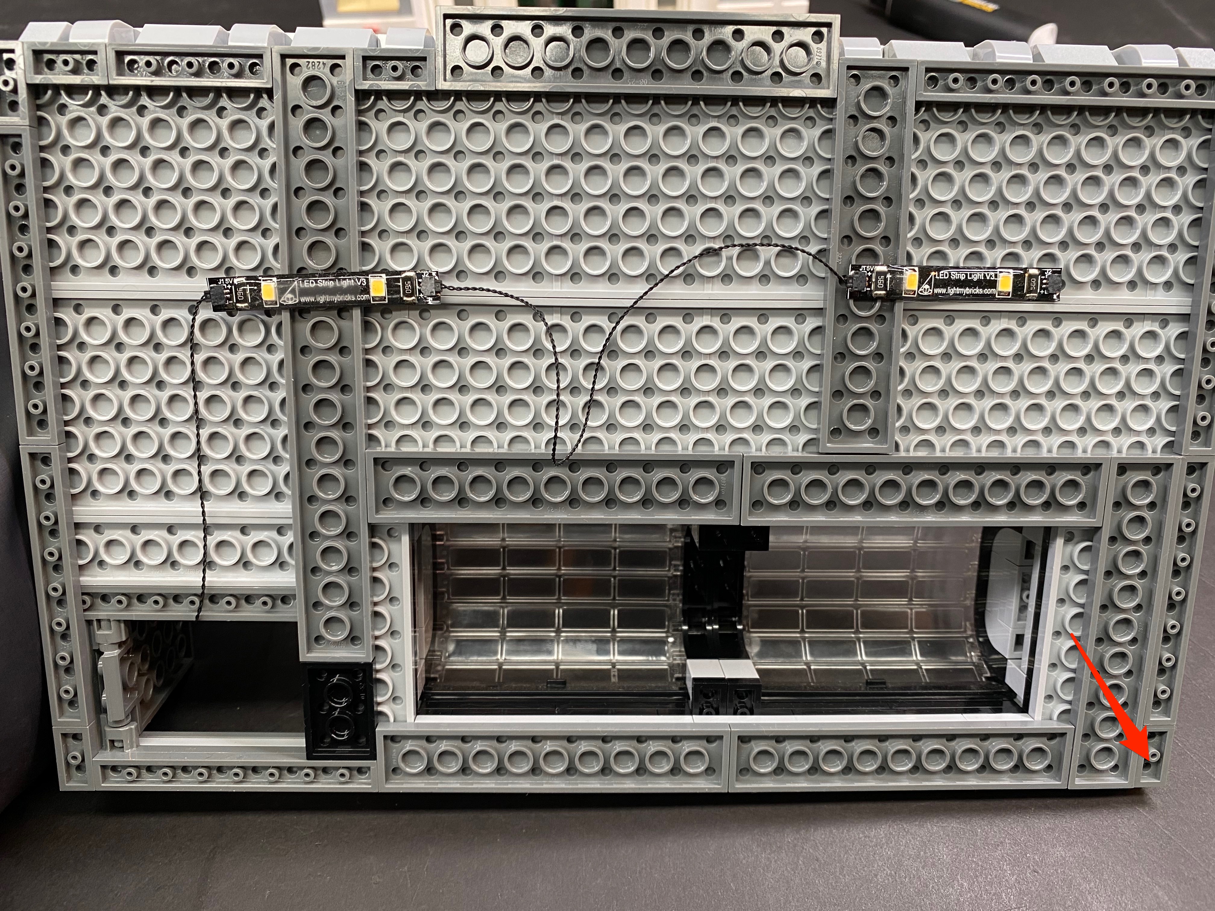
Take two LED Strip Lights (striplight#4 and striplight#5) and stick them to provided 1×6 LEGO plates using the adhesive backing on each strip light. Connect a 15cm connecting cable between the two and then mount them underneath this level to the following position.


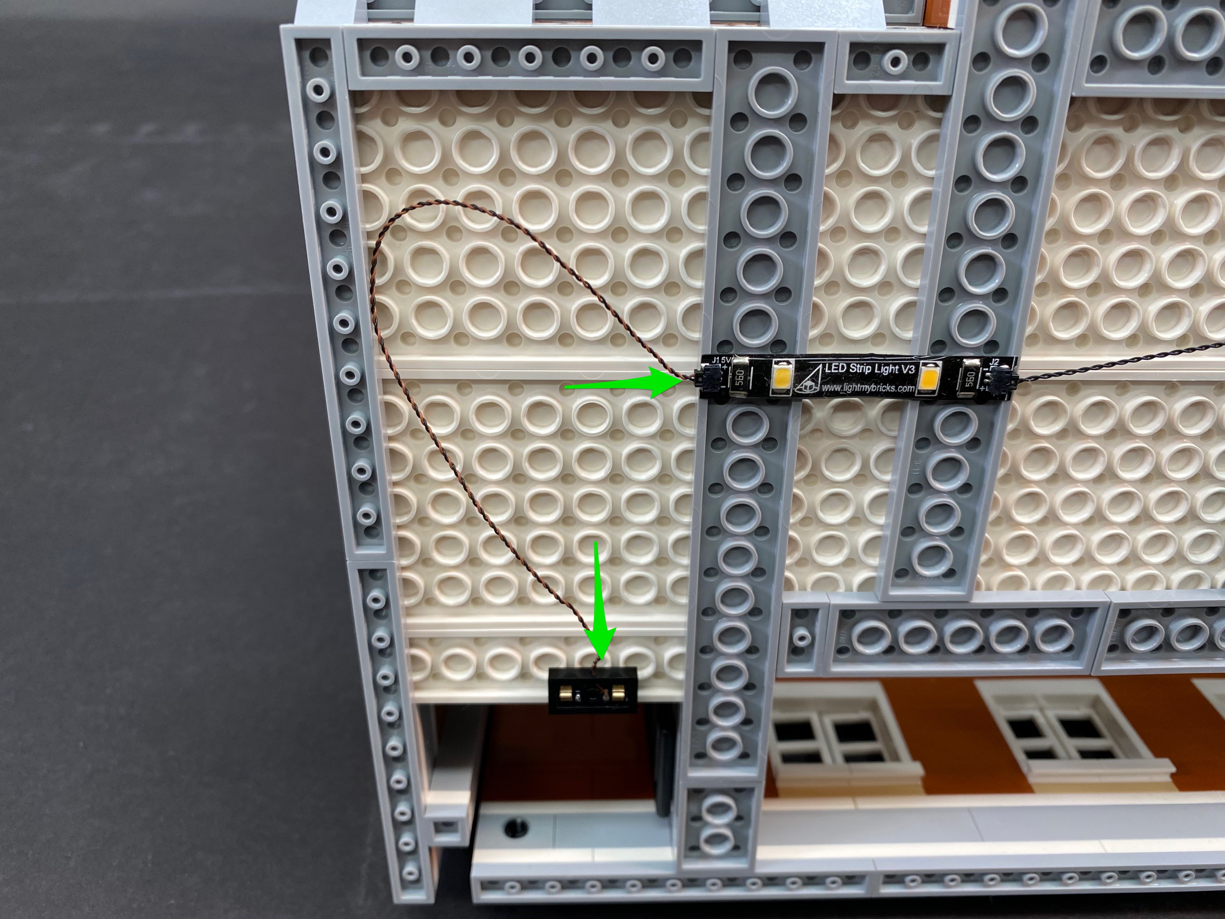
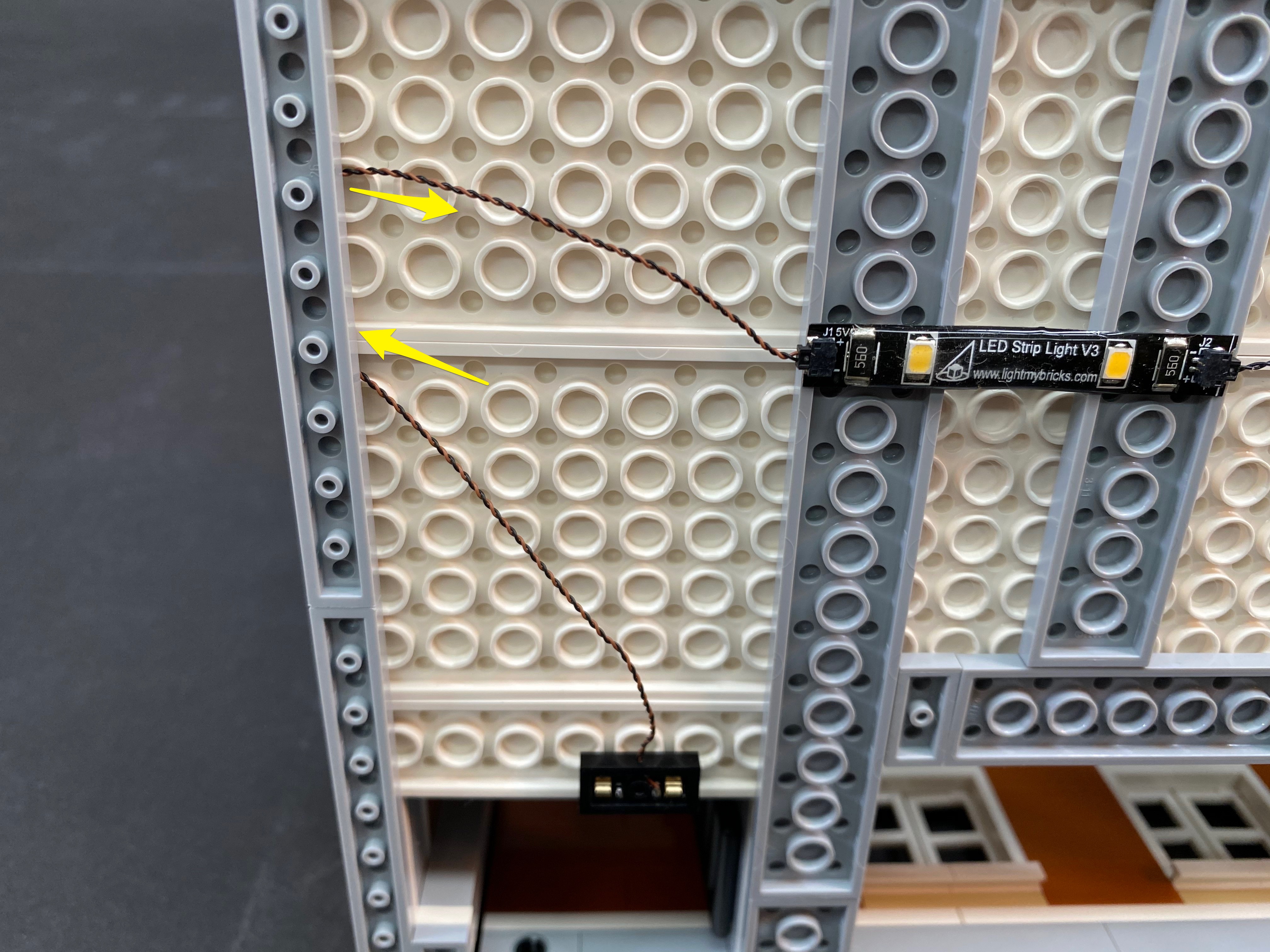
Take a 30cm connecting cable and connect it to the other end of striplight#5 and then thread the other end of the cable up the space which leads to the level above. Turn the second level over and then pull the cable up from underneath and the set aside.


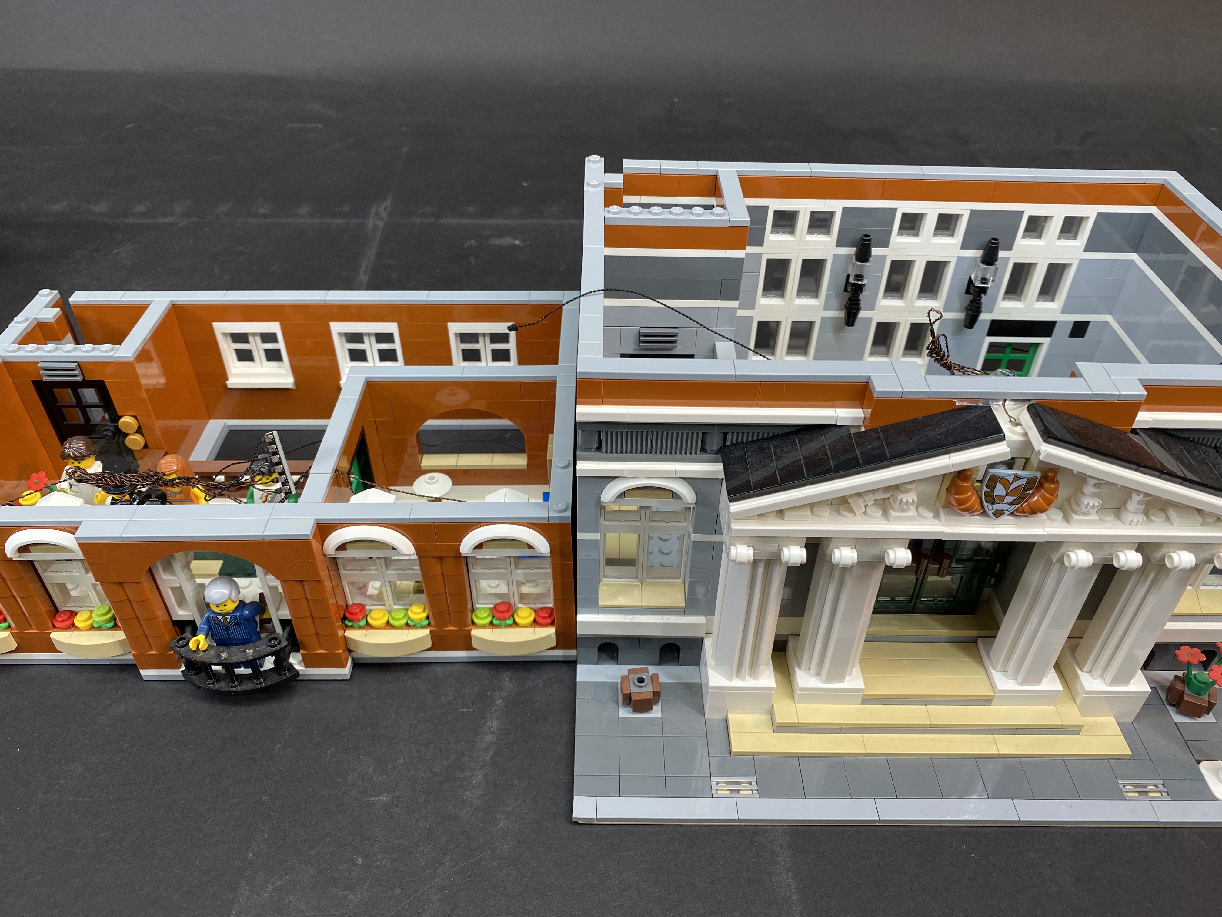
Take the second floor above the ground floor and then connect the other end of the 15cm cable from expansion board below and connect this to the spare port on striplight#4 before securely connecting the second floor in place.


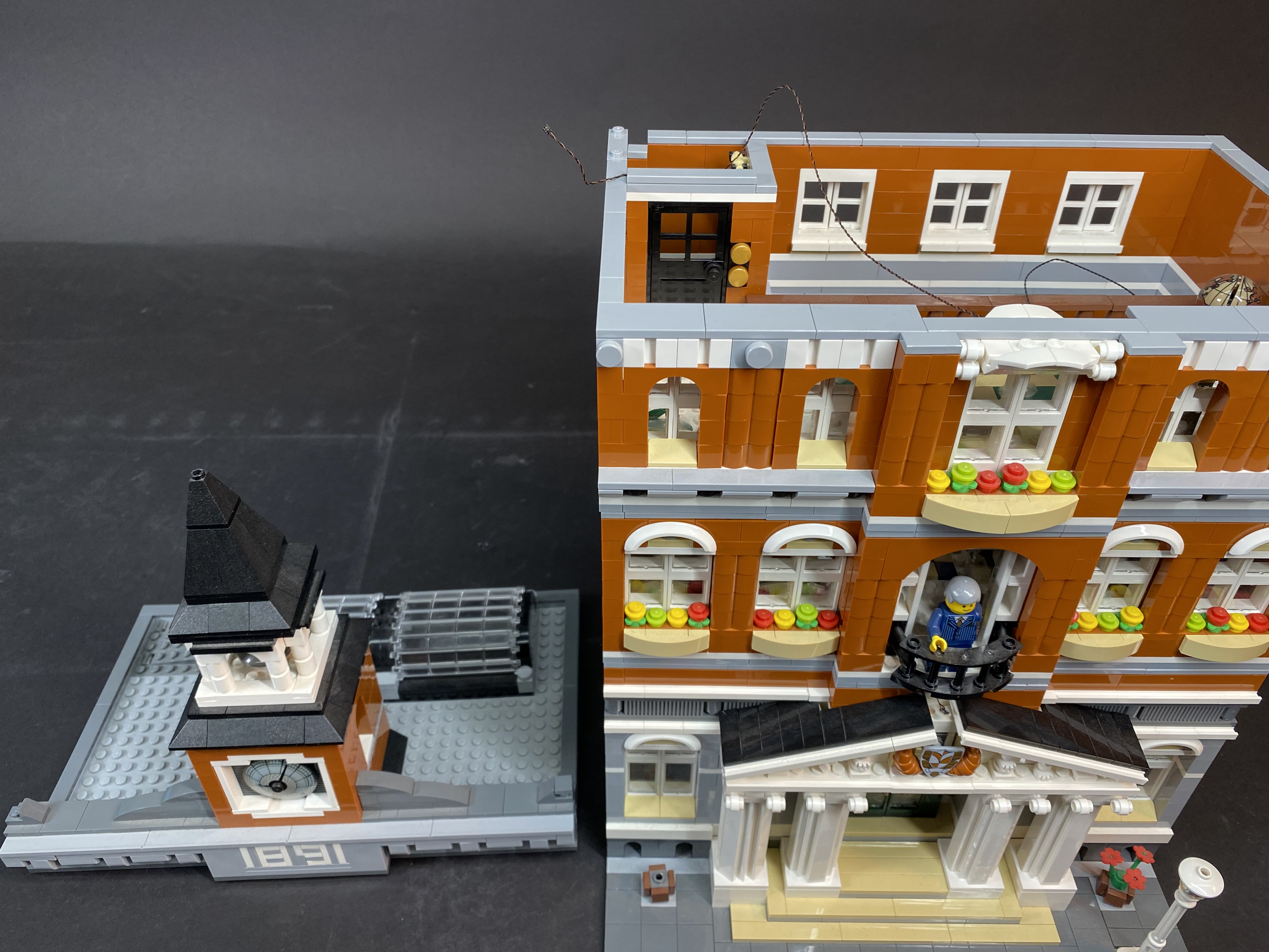
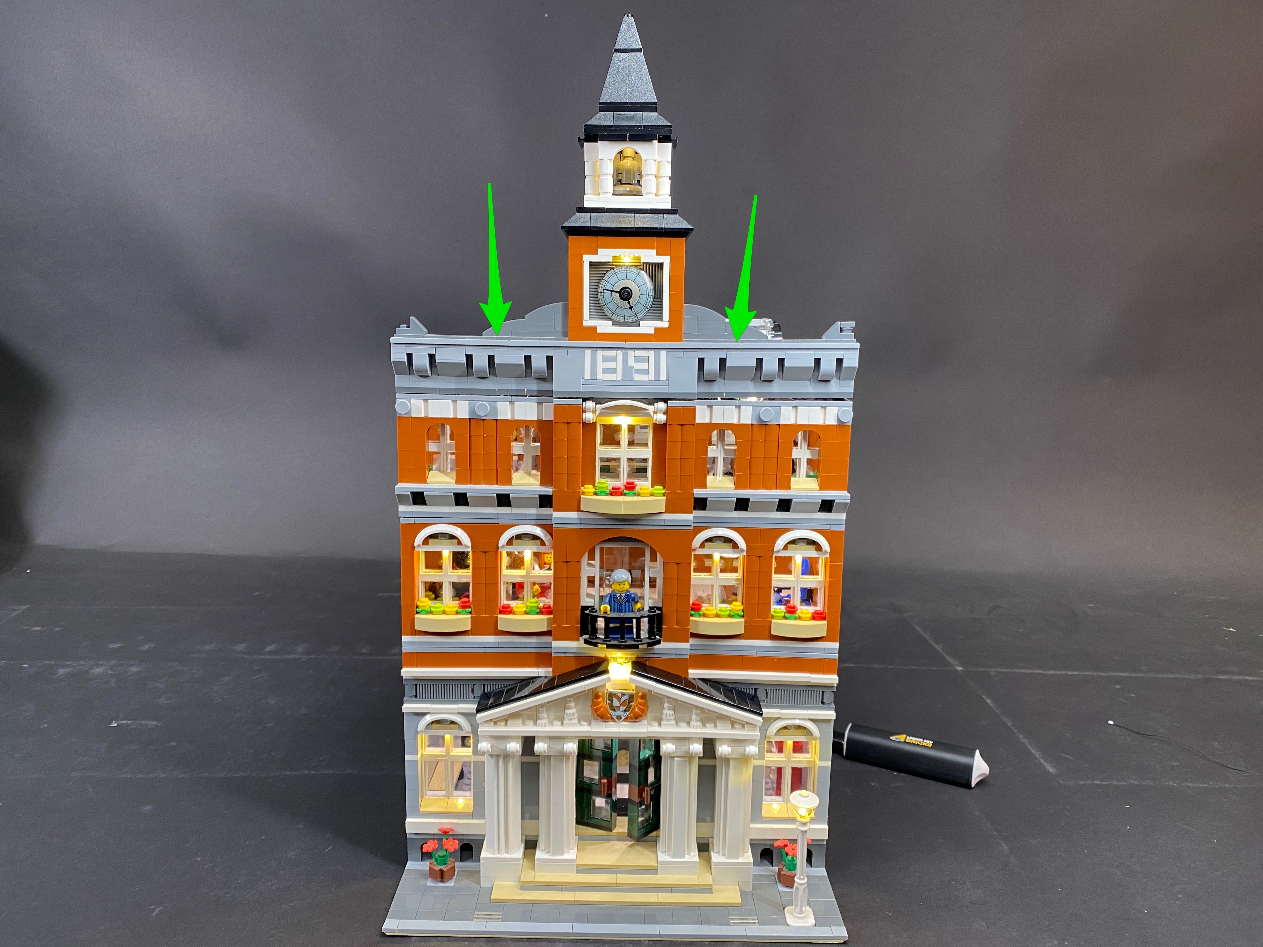
18.) We will now install lights to the outside of the top floor. Take the top floor and then remove the roof from behind as well as the centre tower section as per below.


Lights will be installed above each window so start with the left side of the building by firs removing the below LEGO sections.


19.) Remove each of the two window sections and then disassemble sections as per below


Take a White 15cm Bit Light and then bend the LED component part down on a 90 degree angle ensuring the LED component is facing down. Use an adhesive square to stick the bit light under the top window section so that it will directly shine down behind where the dark grey frog piece will be. Reconnect the two sections together ensuring the cable is laid behind.


20.) Repeat the process in the previous step to install another White 15cm Bit Light to the other window section.


Reconnect both window sections to the building

21.) Remove sections surrounding the middle window to allow you to remove the middle window section as per below.


Remove the top half of the window and then take another White 15cm Bit Light and mount it underneath the top using an adhesive square and following the same process we used to install lights to the left side.


Reconnect the two sections ensuring the cable is laid behind and then reconnect the window section back to the building.


22.) Repeat the process used in previous steps to install another 2x White 15cm Bit Lights to the two windows on the right side of the building.


Reconnect LEGO sections above each of the windows.


23.) Take the last 8-Port Expansion Board and then connect all 5 bit light cables to spare ports.


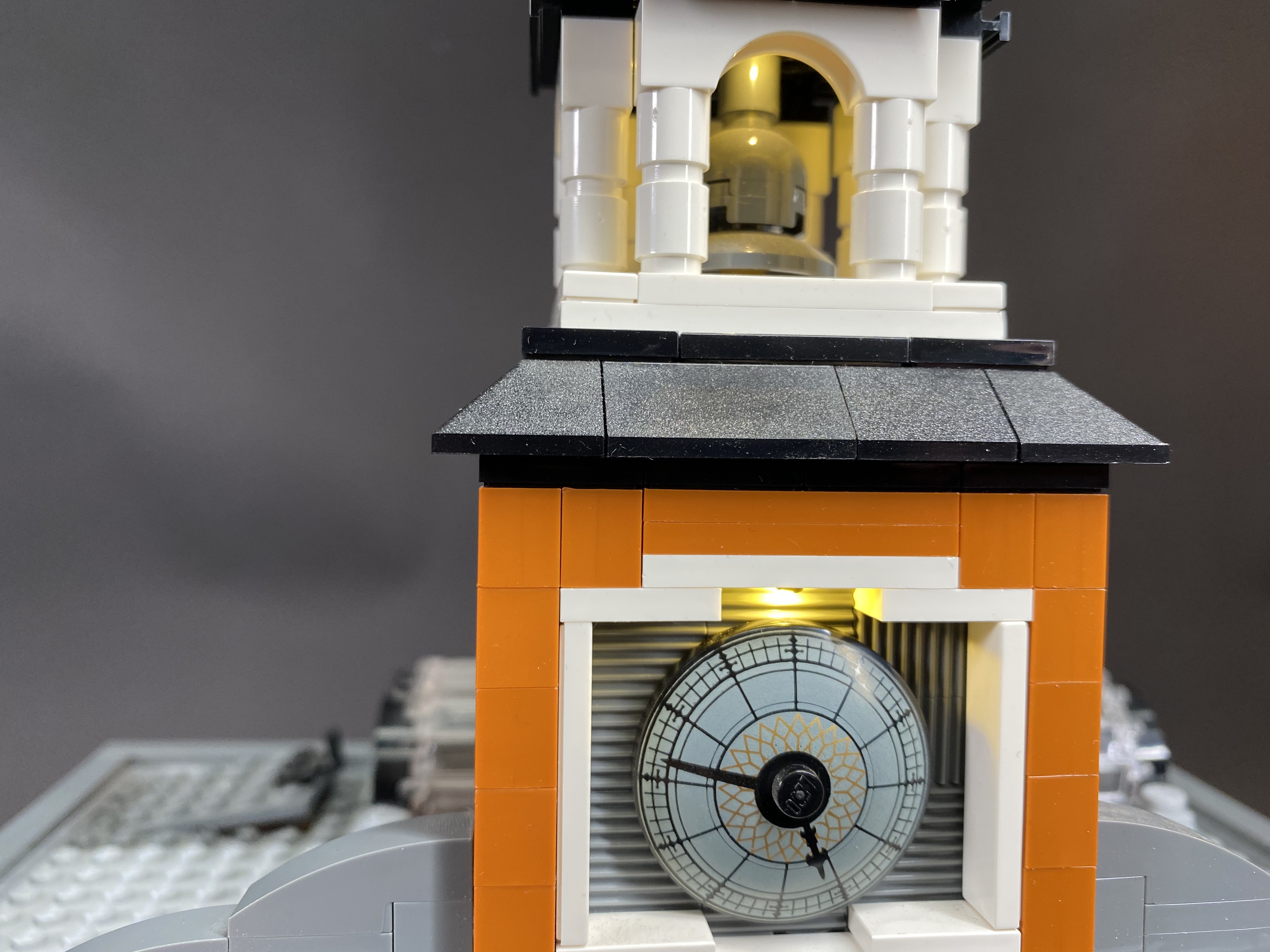
24.) We will now install a light to the centre tower section. First remove the entire roof off ensuring the roof is all kept in one piece.


Take a White 15cm Bit Light and then stick it underneath the roof in the centre using an adhesive square. Ensure the cable is facing down toward the back.

Before we reconnect the roof, remove the dark grey 1×6 plate from the back of the section below.

Reconnect the roof to the section below and then reconnect the 1×6 plate on the back to secure the bit light in place ensuring the cable is laid in between studs.


Reconnect this whole section back to the building and then reconnect the ‘tap’ piece we removed earlier to secure in place.


Connect the Bit Light cable into the next available port on the 8-port expansion board.

From the back of the building, hide the bit light cable by pulling it down and then laying it between studs underneath the 1×2 tile as shown below


Test the lights we have just installed by connecting the battery cable/usb cable to the spare port on the expansion board. Verify all is working OK.


25.) Turn the entire top section onto it’s back so that we can access underneath.


Take another 2x LED Strip Lights (striplight#6 and stripligiht#7) and then stick them to provided LEGO 1×6 plates. Connect a 15cm connecting cable between them before mounting them to the below positions underneath the top floor.


26.) Take a 15cm connecting cable and connect it to the right side of striplight#7. Thread the other end of the cable up the space which leads to the level above. Turn the entire floor back up and then pull the cable up from underneath and then connect it to a spare port on the expansion board.


27.) Take another 15cm connecting cable and connect it to the remaining port on the expansion board then mount the expansion board using (2x adhesive squares) underneath the top of the level on the left side as per below.


You will notice all the cables from the bit lights are hanging down. Use your fingers to lift them up from underneath. Because of the shorter length of the cables, they should stay up and not be visible from the outside looking in through the windows.


28.) Take the entire top floor above the rest of the building. Locate the other end of the 30cm connecting cable from the level below and then connect this to the left side of striplight#6. Reconnect the entire top level to the rest of the building and secure in place.


29.) Take the top roof of the Cafe Corner and turn it onto it’s back to allow us to then mount (using the last LED Strip Light and 2×6 plate) underneath in the below position.


Turn the roof over and then place the Battery Pack/usb cable on top in the below position with the cable facing toward the back. You can secure the Battery Pack to the roof top by either using 2x adhesive squares or you can use any spare LEGO bricks you may have.


With the battery pack secured, pull the cable behind and underneath to connect to the left port of striplight#8

Take the roof top above the rest of the building and then locate the other end of the 15cm connecting cable from the level below. Connect this to the right port of striplight#8. Securely reconnect the roof top to the rest of the building.


This now completes installation of the Cafe Corner LED Lighting Kit. Turn on via the Battery Pack and ENJOY!