Light My Bricks: Winter Holiday Train 10254 Lighting Kit
Here is the instructions document for the LEGO Winter Holiday Train 10254 LED lighting kit. Please read and follow the steps carefully to ensure this lighting kit is installed properly.
This user guide is also available to download in PDF format here.
Package contents:
5x White 15cm Bit Lights
7x Flashing White 15cm Bit Lights
2x Multi Colour Light Strings
2x 6-Port Expansion Board
1x 12-Port Expansion Board
1x 30cm Connecting Cable
1x 15cm Connecting Cables
10x Adhesive Squares
Light My Bricks Power Functions Cable (Power Functions 1.0)or
Light My Bricks Powered Up Cable (Power Functions 2.0)
This light kit is powered using the compatible Power Functions Cable option, which can be connected and powered by your existing power functions battery pack. The lights cannot be powered unless your Winter Holiday Train set is motorised.
Important things to note:
Laying cables in between and underneath bricks
Cables can fit in between and underneath LEGO® bricks, plates, and tiles providing they are laid correctly between the LEGO® studs. Do NOT forcefully join LEGO® together around cables; instead ensure they are laying comfortably in between each stud.
CAUTION: Forcing LEGO® to connect over a cable can result in damaging the cable and light.
Connecting cable connectors to Expansion Boards
Take extra care when inserting connectors to ports of Expansion Boards. Connectors can be inserted only one way. With the expansion board facing up, look for the soldered “=” symbol on the left side of the port. The connector side with the wires exposed should be facing toward the soldered “=” symbol as you insert into the port. If a plug won’t fit easily into a port connector, do not force it.
Incorrectly inserting the connector can can result in bent pins inside the port or possible overheating of the expansion board when connected.
Connecting cable connectors to Strip Lights
Take extra care when inserting connectors to ports on the Strip Lights. Connectors can be inserted only one way. With the Strip Light facing up, ensure the side of the connector with the wires exposed is facing down. If a plug won’t fit easily into a port connector, don’t force it. Doing so will damage the plug and the connector.
Installing Bit Lights under LEGO® bricks and plates.
When installing Bit Lights under LEGO® pieces, ensure they are placed the correct way up (Yellow LED component exposed). You can either place them directly on top of LEGO® studs or in between.
OK, Let’s Begin!
1.) Start by removing the front sections of the train as per below in order for us to install the front lights.
2.) Remove the trans clear plate and then take a White 15cm Bit Light and place it directly over the stud of the black piece. Reconnect the trans clear plate over the top to secure it in place.
Disassemble pieces of the light section that sits above.
Take another White 15cm Bit Light and thread the connector side through the hole of the black dish piece. Thread the cable all the way through until the LED is right up against the hole as per below.
Reconnect pieces which make up this front light
3.) Reconnect both light sections back to the front of the train starting with the top light and ensure both cables are facing down.
4.) Take a 6-port Expansion Board and connect the two lights to the ports.
Take the 2x Multi Colour Light Strings and connect these to the next available ports on the expansion board
Take a 30cm Connecting Cable and connect one end to the next available port on the expansion board.
Take the Light My Bricks Power Functions Cable or Light My Bricks Powered Up Cable and connect the connector end to the remaining port on the expansion board
5.) Reconnect the front wheels of the train ensuring the cables for the two front lights are neatly laid in between as per below
Using 2x Adhesive Squares, stick the expansion board underneath the train in the below position. Neaten all the cables and secure them underneath the back wheels section.
Thread the Power functions cable (LEGO connector side) up through the inside of the train before mounting the expansion board.
Connect the power functions cable to power pack and turn the power ON test that all lights connected are working OK.
*If you are using the Light My Bricks Powered Up cable (LEGO power functions 2.0), read the below two options on connecting to the Powered Up battery box.
Option 1 – If you’re using the hand controller to control the train motor, Leave the train motor cable connected to port A and connect the Light My Bricks Powered Up cable to port B. This will allow you to turn the lights on if the train is stationary. Press the “+” or “-” button on the controller (on the B side) to test the lights are turning ON and working OK.
Option 2- If you’re using the smartphone app to control the train motor, pull out the train motor cable from the battery box and connect it to the spare socket on the Light My Bricks Compatible Powered Up Cable. If you connect the motor cable to socket B on the battery box, it will cause potential issues with being able to run the motor.
Launch the Powered Up App on your smart phone and ensure the battery box is paired to the phone. Press the “+” or “-
button on the app to test the lights are turning ON and working OK.
Important Note: If using the smartphone App to control the lights and motor, the lights will only turn on when the train is in “accelerate or reverse mode )+ or -)”. The lights will automatically turn off when the motor is turned off or when “STOP” on the controller/app is pressed. Note: If you experience any issues with the lights not working and suspect an issue with a component, please try a different port on the expansion board to verify where the fault lies (with the light or expansion board). To correct any issues with expansion board ports, please view the section addressing expansion board issues on our online troubleshooting guide.6.) Take the next carriage and then remove the top section as well as the inside section as per below.
7.) Pull the 30cm connecting cable all the way across from the front carriage and neatly lay it in between studs before reconnecting the top section over the top. Try not to leave too much cable slack between the first and second carriage as we need as much cable length as possible in order to reach to the remaining carriages.
Hook the second carriage up and then connect the Power Functions Cable onto the power pack and then neaten cables by tucking them into the inside of the front carriage.
Feed the two Multi Colour Light Strings through and behind the white and gold LEGO pieces on each side of the carriage. Tuck the ends of the light strings into the first carriage.
8.) Take the third carriage and then remove the loose pieces from the front before removing the Christmas tree section.
Turn the carriage over and then remove the technic bar from underneath.
The Christmas tree will be unable to spin with this light kit installed therefore, we need to remove and discard the cog piece from the technic bar to prevent the tree from turning.
9.) Disconnect the top and sides of the Christmas tree then disassemble pieces as per below
Take a Flashing White 15cm Bit Light and thread the connector side through the top of the green dish. Thread the cable all the way through and then bend the LED on a 90 degree angle so that the LED is facing up.. Place the top section over the LED and then push down and connect it to secure it in place.
Reconnect the top section to the structure of the Christmas tree ensuring the cable is laid in between studs as per below.
10.) Disconnect the trans coloured round plates from all four sides of the tree.
Remove the top plate from the first side (as per below) and then take a Flashing White 15cm Bit Light and place it directly over the top stud (with cable facing down). Secure the LED in place by reconnecting the trans blue round plate over the top followed by top plate we removed earlier ensuring the cable is laid in on the outside of the studs.
Take another Flashing White 15cm Bit Light and place it directly over the bottom right stud. Secure it in place by reconnecting the trans red round plate over the top as per below
11.) Take another Flashing White 15cm Bit Light and place it directly over the bottom stud on the next plate. Secure it in place by reconnecting the trans yellow round plate over the top.
12.) Repeat this process to install another 3x Flashing White 15cm Bit Lights over the next 2 sides.
13.) Reconnect each side back to the structure of the tree ensuring the cable from the top light is laid in between pieces as per below
14.) Take all 7 cables and then twist them around each other at the base of the tree so that they all come together forming one larger cable.
15.) Re-insert the technic bar we removed earlier underneath the carriage and then reconnect the tree on top of the carriage ensuring the cable is facing toward the back.
16.) Turn the carriage over again and then slightly remove the left side of the wheel section. Locate the other end of the 30cm connecting cable from the front carriage and then pull it across and thread it through the middle of the carriage. Pull it all the way out from the other side and then reconnect the wheel section back to the carriage to secure the cable in place. Before doing so, ensure the cable is laid in between studs.
17.) Take a 12-port Expansion Board and connect the 30cm connecting cable to the first port (from the right) then connect all the cables from the Christmas tree to the other spare ports.
18.) Take a 15cm Connecting Cable and connect it to the next available port along the expansion board then mount the expansion board underneath the carriage in the below position using 4x Adhesive Squares. Neatly tuck in all the cables by pushing them up to prevent them from hanging down and dragging along the tracks. Turn the carriage back over and connect it to the second carriage.
Use your controller or remote app to press ‘accelerate’ to test all the lights installed so far are working OK.
Note: If you experience any issues with the lights not working and suspect an issue with a component, please try a different port on the expansion board to verify where the fault lies (with the light or expansion board). To correct any issues with expansion board ports, please view the section addressing expansion board issues on our online troubleshooting guide.19.) Take the last carriage and remove the roof as well as side window sections as per below
20.) Remove the lamp and then disassemble it as per below
Take a White 15cm Bit Light and place it directly over the blue stud. Reconnect the top section of the lamp to secure it in place and then reconnect the lamp to the inside of the carriage as well as the side window sections.
21.) Remove the two lamps from the roof and then disassemble pieces as per below
Take a White 15cm Bit light and then place it (Facing down) directly over the trans clear round brick. Ensure the Bit Light is facing down before reconnecting the top plate with clip on top to secure it in place.
Repeat this step to install another White 15cm Bit Light to the other roof lamp ensuring the bit light is facing down over the trans clear round brick.
22.) Thread the cable for each light through the top of the roof in between gold bar and side of the roof. Pull the cable all the way down from underneath before reconnecting the lamp back in place to each side.
23.) Reconnect the roof to the carriage then pull each roof lamp cable down behind the gold bars and then thread them back through to the outside as per below
24.) Turn the carriage over and then connect the lamp cable from the inside of the carriage to one of the middle ports of the 6-port Expansion Board.
Wind the cable around the expansion board a few times to eliminate excess cable. When the board is roughly at the same length of the remaining two cables, connect them to the expansion board.
Reconnect the white LEGO pieces ensuring the cables from the lights are laid neatly behind.
25.) Take the 15cm Connecting cable from the carriage in front and connect this to a spare port on the 6-port expansion board.
Use 2x Adhesive Squares to mount the expansion board underneath the back carriage in the below position
Turn the carriage over and then connect it to the rest of the train.
26.) Follow the below images to thread the remaining length of the two multi colour light strings along each side of the carriage.
Loop each light string behind the gold bars on the back carriage and then pull each string to the back before threading them back through to the front of the carriage. Thread and secure each light string around sections of the carriage as you see fit.
Use your controller or remote app to press ‘accelerate’ to test all the lights installed so far are working OK.
Note: If you experience any issues with the lights not working and suspect an issue with a component, please try a different port on the expansion board to verify where the fault lies (with the light or expansion board). To correct any issues with expansion board ports, please view the section addressing expansion board issues on our online troubleshooting guide.
This finally completes installation of the Light My Bricks Winter Holiday Train Light Kit.
We thank you for purchasing this product and hope you ENJOY!
For all questions or issues please follow the troubleshooting guide or contact our customer support team at info@lightmybricks.com


 Option 2- If you’re using the smartphone app to control the train motor, pull out the train motor cable from the battery box and connect it to the spare socket on the Light My Bricks Compatible Powered Up Cable. If you connect the motor cable to socket B on the battery box, it will cause potential issues with being able to run the motor.
Launch the Powered Up App on your smart phone and ensure the battery box is paired to the phone. Press the “+” or “-
button on the app to test the lights are turning ON and working OK.
Option 2- If you’re using the smartphone app to control the train motor, pull out the train motor cable from the battery box and connect it to the spare socket on the Light My Bricks Compatible Powered Up Cable. If you connect the motor cable to socket B on the battery box, it will cause potential issues with being able to run the motor.
Launch the Powered Up App on your smart phone and ensure the battery box is paired to the phone. Press the “+” or “-
button on the app to test the lights are turning ON and working OK.
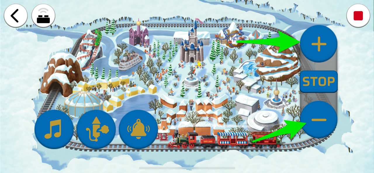 Important Note: If using the smartphone App to control the lights and motor, the lights will only turn on when the train is in “accelerate or reverse mode )+ or -)”. The lights will automatically turn off when the motor is turned off or when “STOP” on the controller/app is pressed.
Note: If you experience any issues with the lights not working and suspect an issue with a component, please try a different port on the expansion board to verify where the fault lies (with the light or expansion board). To correct any issues with expansion board ports, please view the section addressing expansion board issues on our online troubleshooting guide.
6.) Take the next carriage and then remove the top section as well as the inside section as per below.
Important Note: If using the smartphone App to control the lights and motor, the lights will only turn on when the train is in “accelerate or reverse mode )+ or -)”. The lights will automatically turn off when the motor is turned off or when “STOP” on the controller/app is pressed.
Note: If you experience any issues with the lights not working and suspect an issue with a component, please try a different port on the expansion board to verify where the fault lies (with the light or expansion board). To correct any issues with expansion board ports, please view the section addressing expansion board issues on our online troubleshooting guide.
6.) Take the next carriage and then remove the top section as well as the inside section as per below.


