
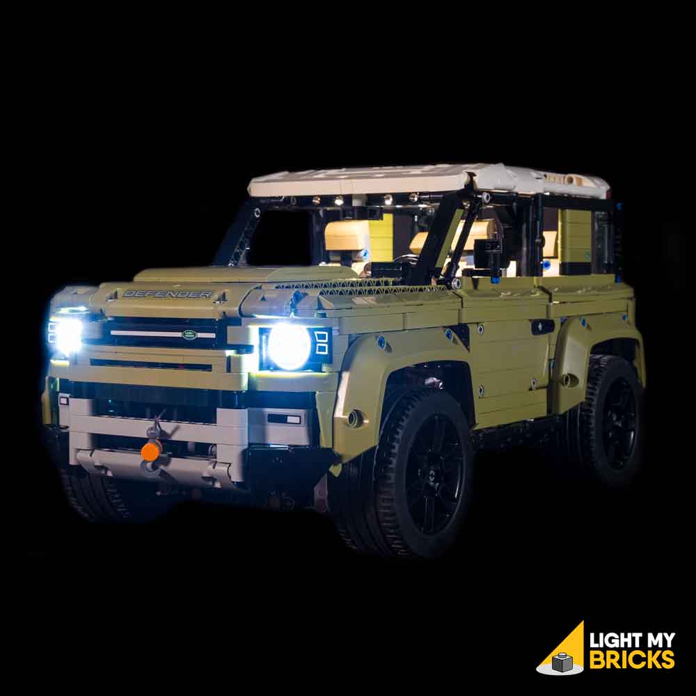
The following page is the instructions for the Light My Bricks LEGO Land Rover Defender (42110) LED light kit.
If you run into any issues, please refer to the online troubleshooting guide.
To ensure a trouble-free installation of your light kit, please read and follow each step carefully. These instructions can be downloaded in PDF format here
Please note: This page lists instructions for the LED light kit only. If you are wishing to purchase the Light My Bricks LEGO Land Rover Defender (42110) LED light kit , please click here to view the product page
Package Contents:
- 8x Cool White 30cm Bit Lights
- 4x Red 30cm Bit Lights
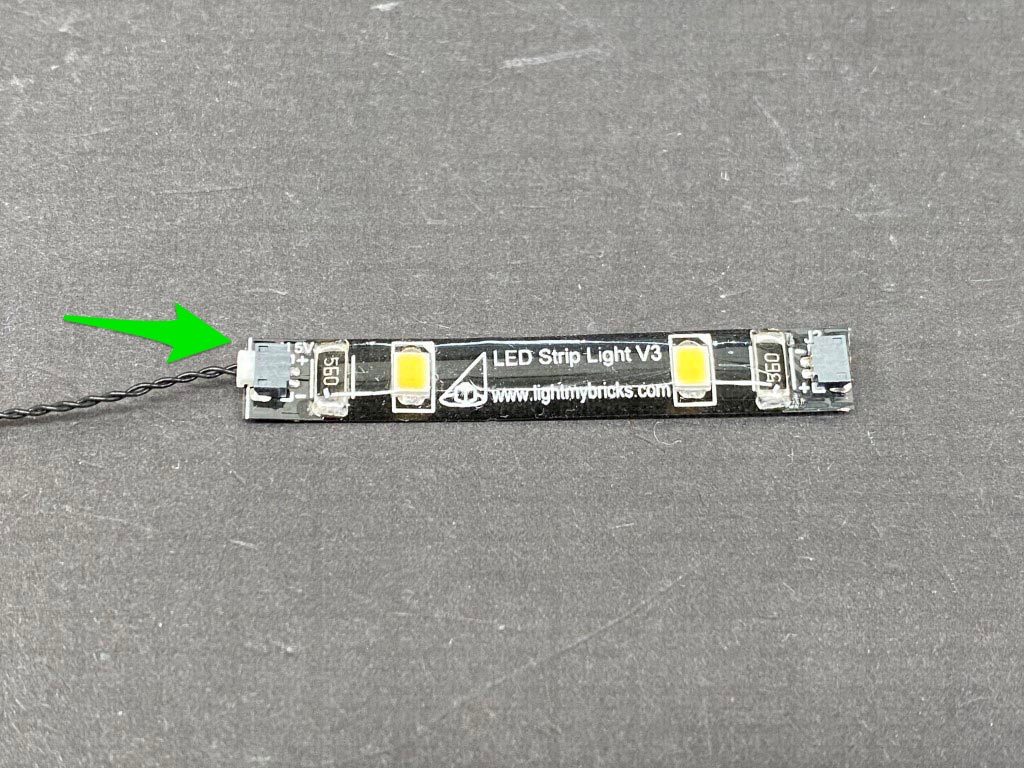
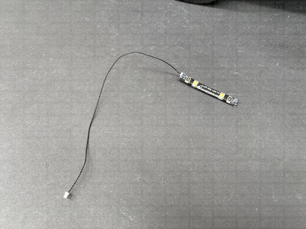
- 2x White Strip Lights
- 1x 6-Port Expansion Board
- 1x 12-Port Expansion Board
- 1x 15cm Connecting Cables
- 2x 30cm Connecting Cables
- 6x Adhesive Squares
- 1x AA Battery Pack
- 4x Round Plate 1×1 with Open Stud (Black)
Important things to note:
Laying cables in between and underneath bricks
Cables can fit in between and underneath LEGO® bricks, plates, and tiles providing they are laid correctly between the LEGO® studs. Do NOT forcefully join LEGO® together around cables; instead ensure they are laying comfortably in between each stud.
Connecting cable connectors to Expansion Boards
Take extra care when inserting connectors to ports of Expansion Boards. Connectors can be inserted only one way. With the expansion board facing up, look for the soldered “=” symbol on the left side of the port. The connector side with the wires exposed should be facing toward the soldered “=” symbol as you insert into the port. If a plug won’t fit easily into a port connector, do not force it.
Connecting cable connectors to Strip Lights
Take extra care when inserting connectors to ports on the Strip Lights. Connectors can be inserted only one way. With the Strip Light facing up, ensure the side of the connector with the wires exposed is facing down. If a plug won’t fit easily into a port connector, don’t force it. Doing so will damage the plug and the connector.
Connecting Micro Cable connectors to Micro Expansion Board Ports
Take extra care when inserting the micro connectors to micro ports of Micro Expansion Boards. Connecting Micro Bit Lights to Micro Expansion Boards is similar to connecting lights and cables to Strip Lights. With the expansion board facing up, ensure the side of the connector with the wires exposed is facing down. If a plug won’t fit easily into a port connector, do not force it. Use your fingernail to push the plastic part of the connector to the micro port.
Installing Bit Lights under LEGO® bricks and plates.
When installing Bit Lights under LEGO® pieces, ensure they are placed the correct way up (Yellow LED component exposed). You can either place them directly on top of LEGO® studs or in between.
OK, Let’s Begin!
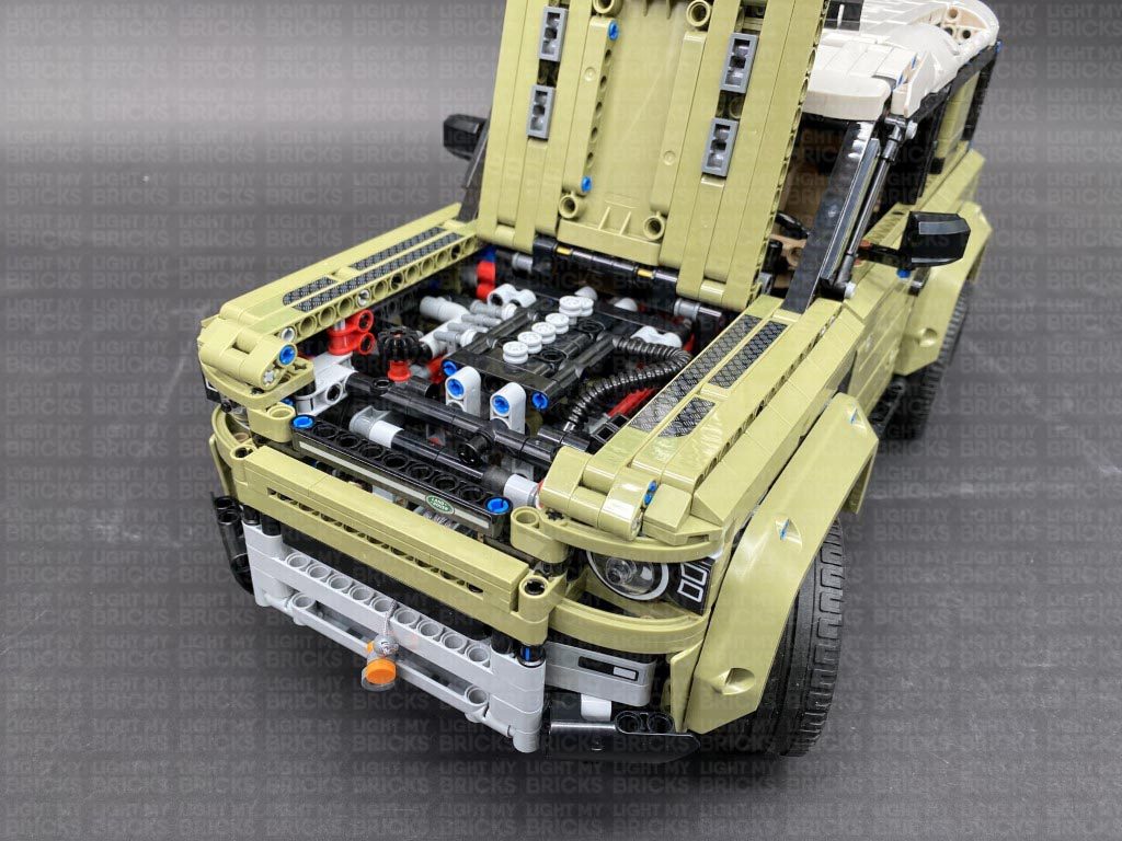
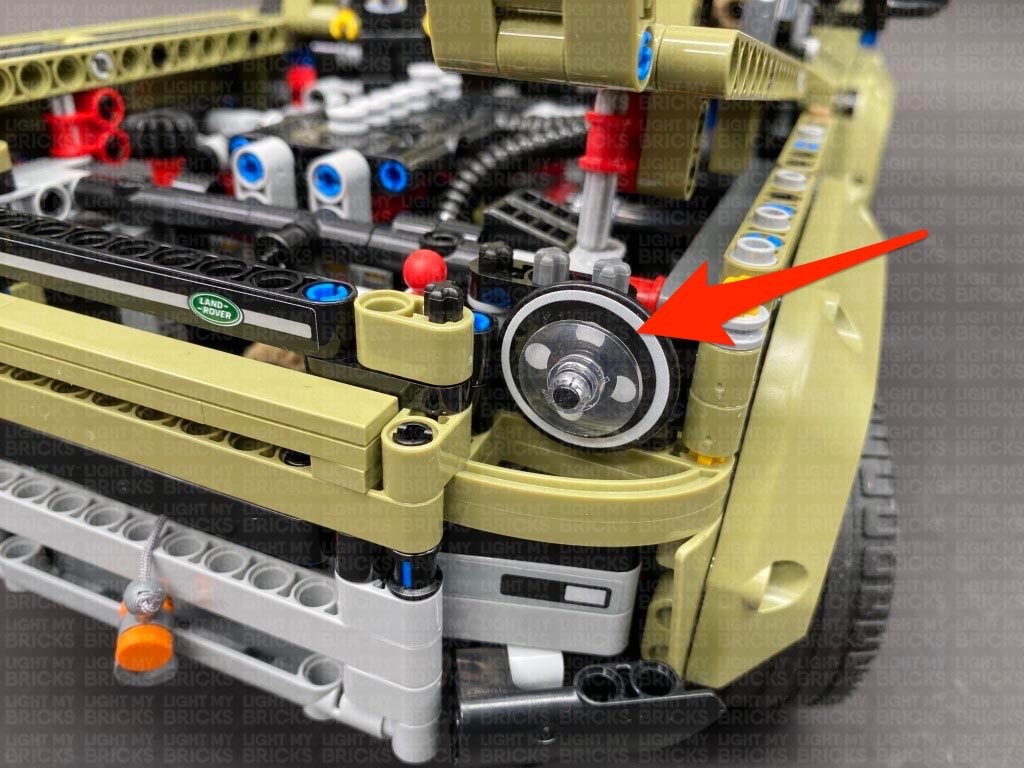
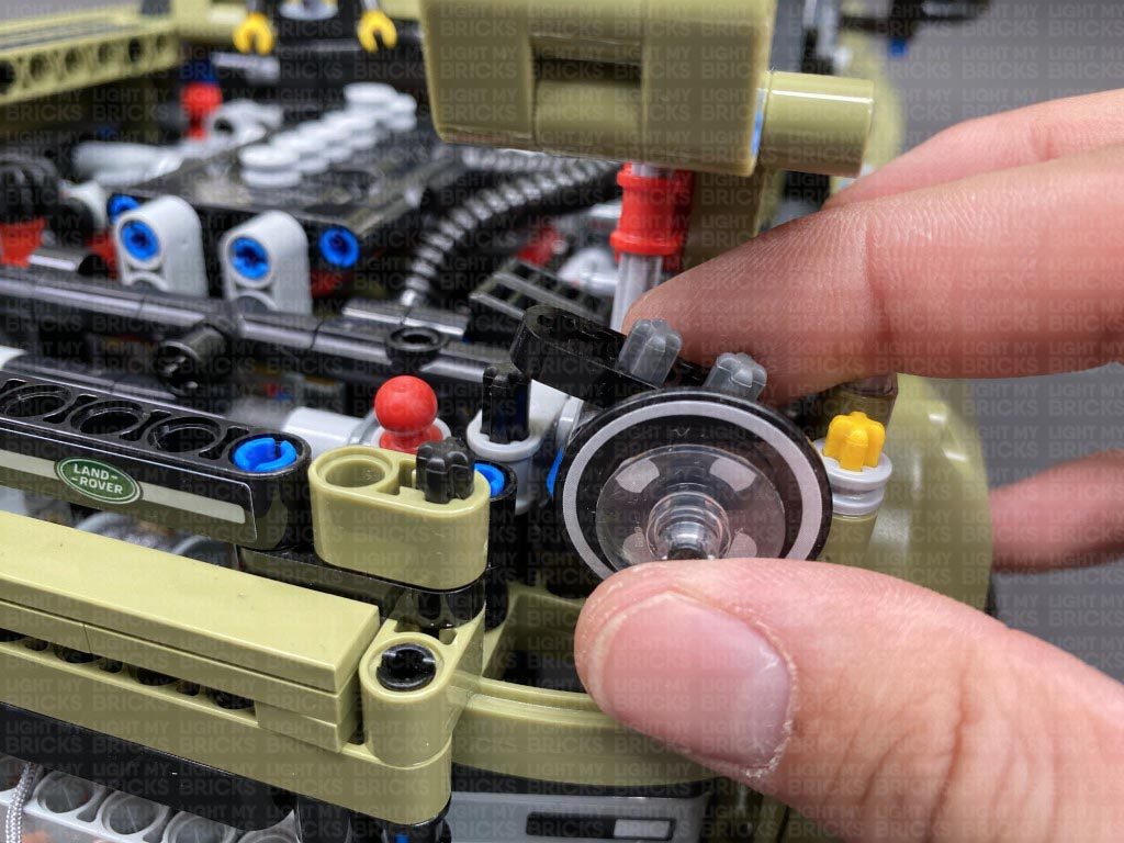
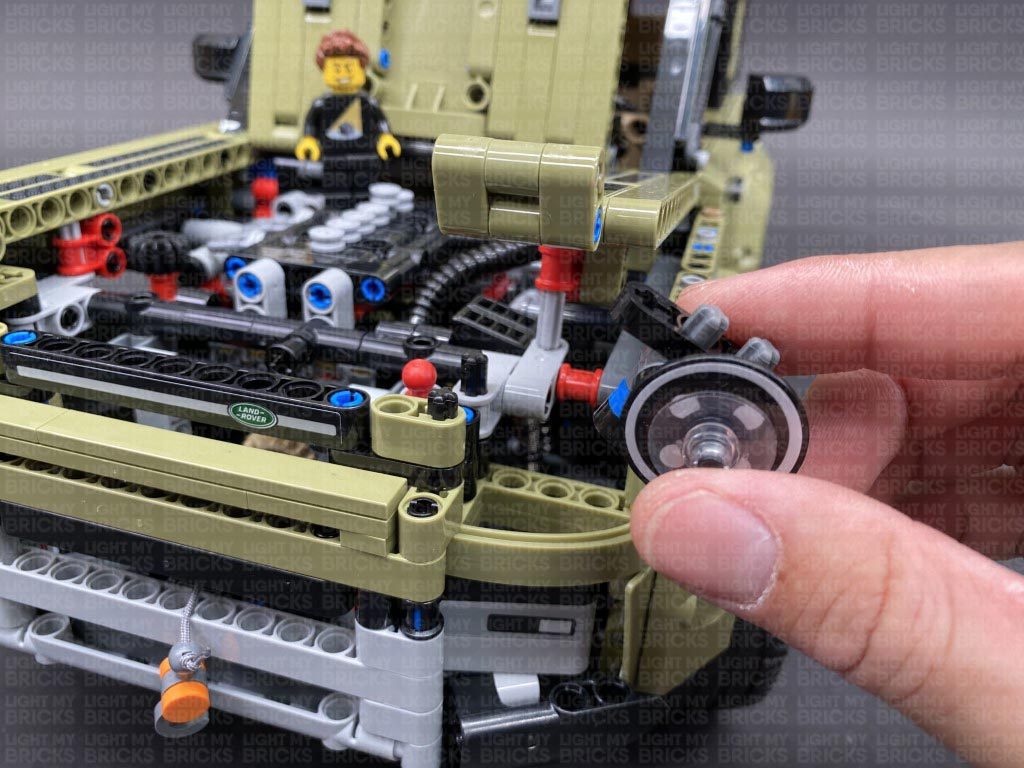
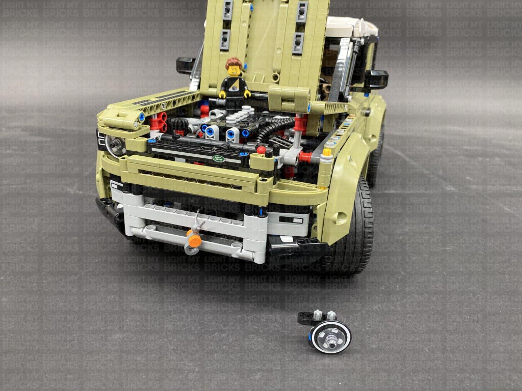
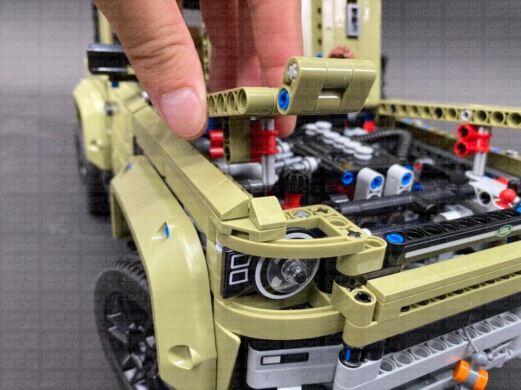
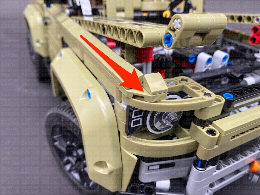
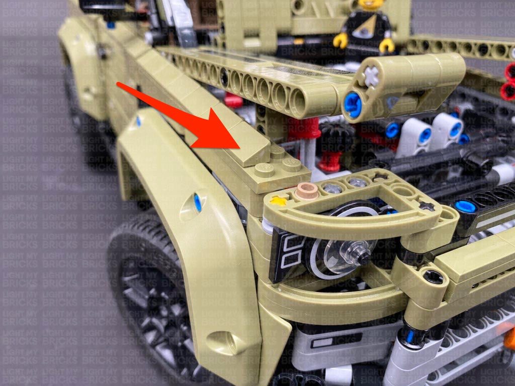
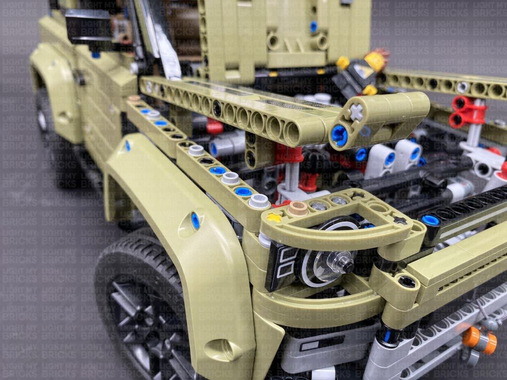
1.) Lift up the bonnet, then remove the following sections in order for us to remove the two headlight sections as shown below.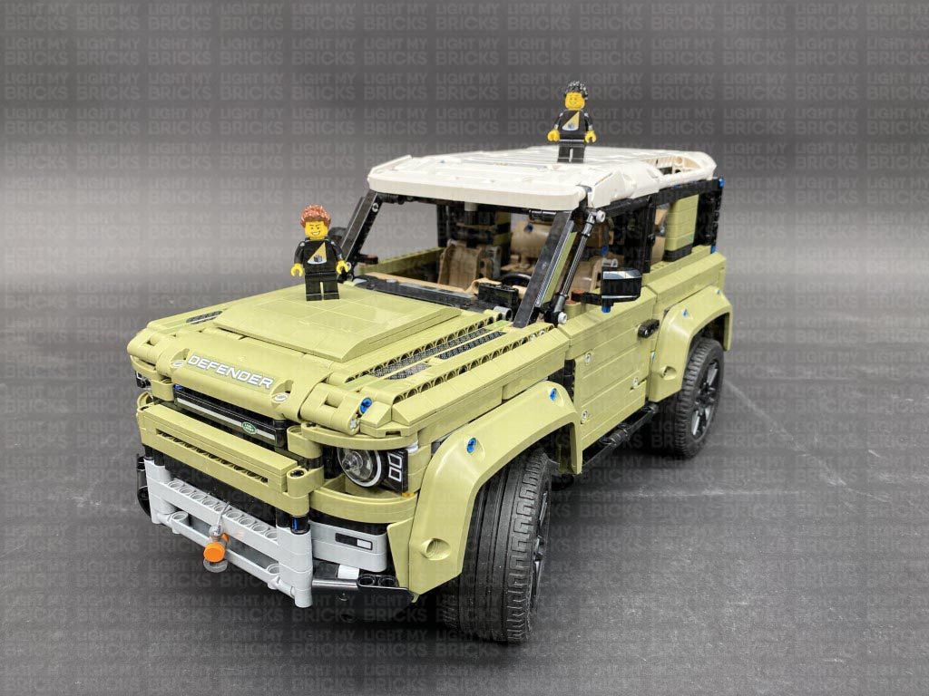
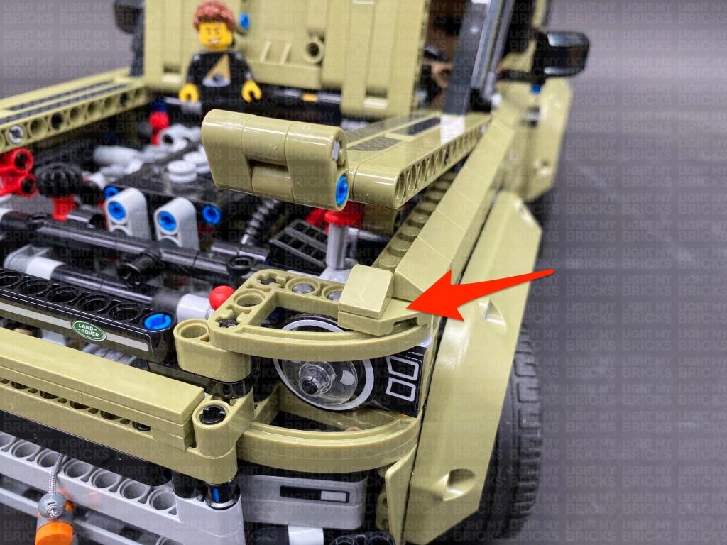
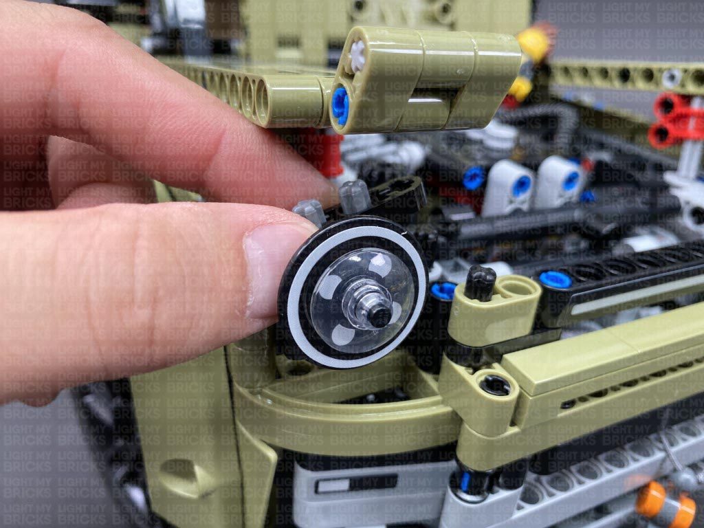
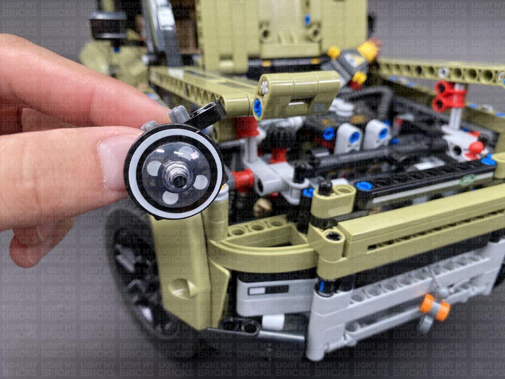
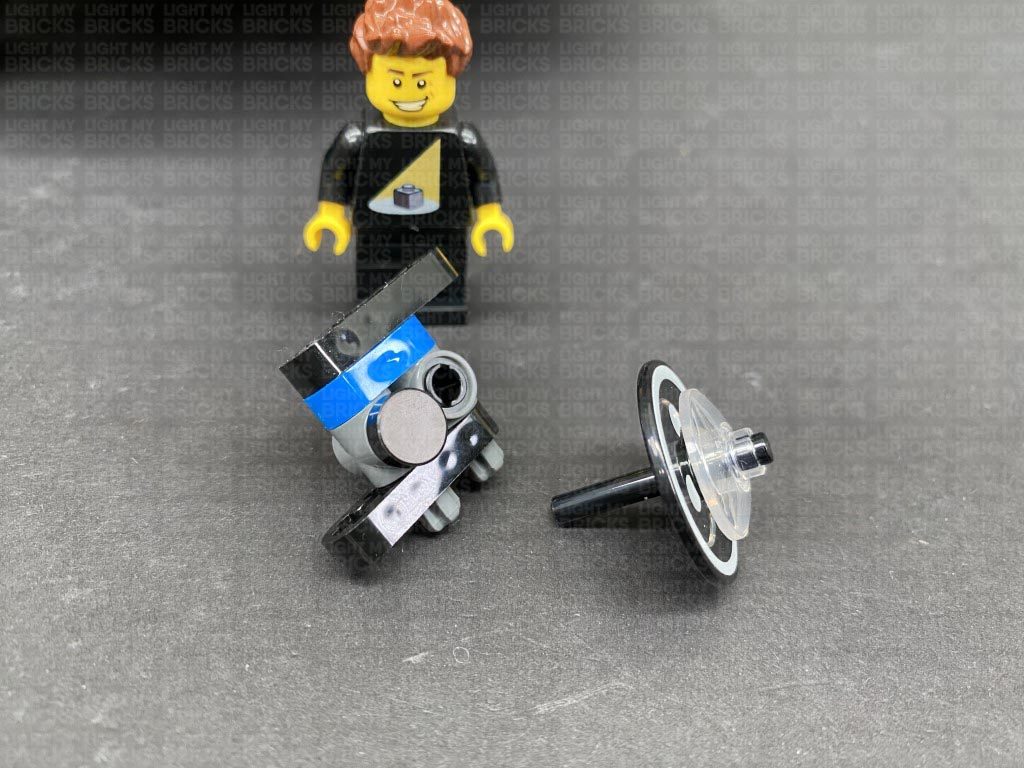
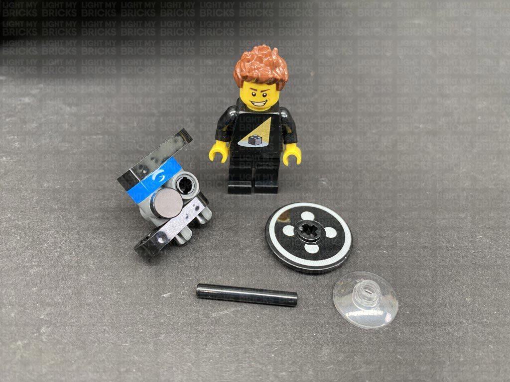
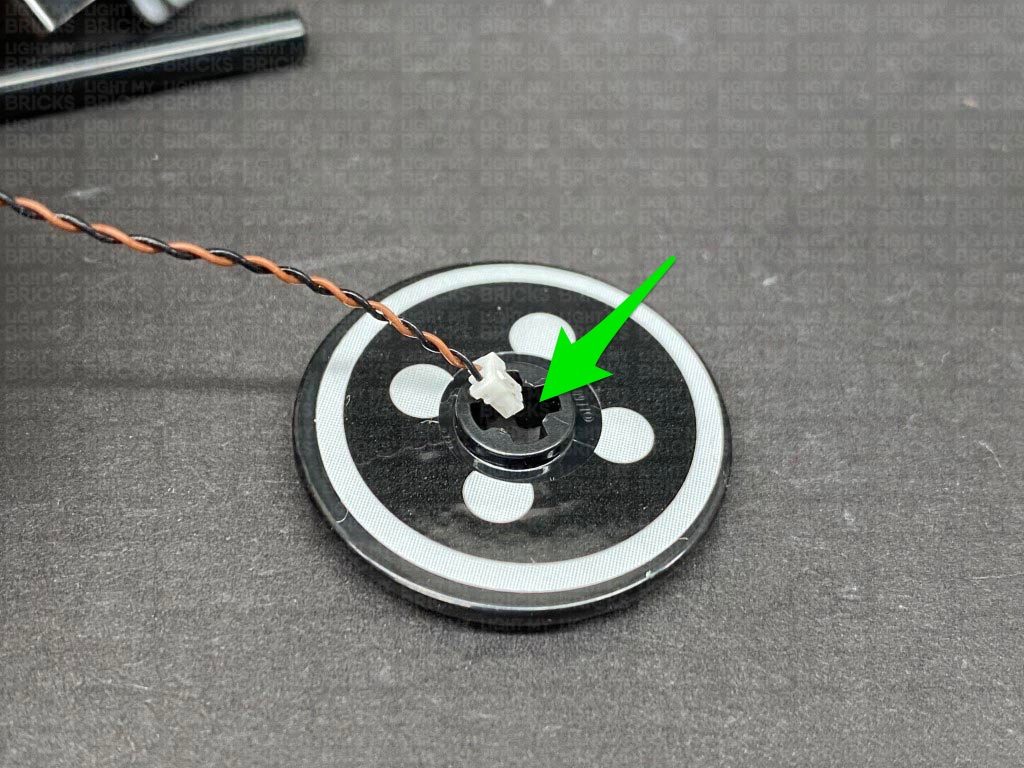
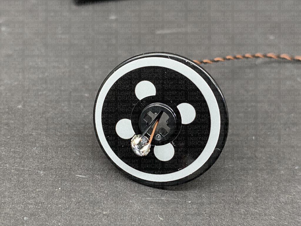
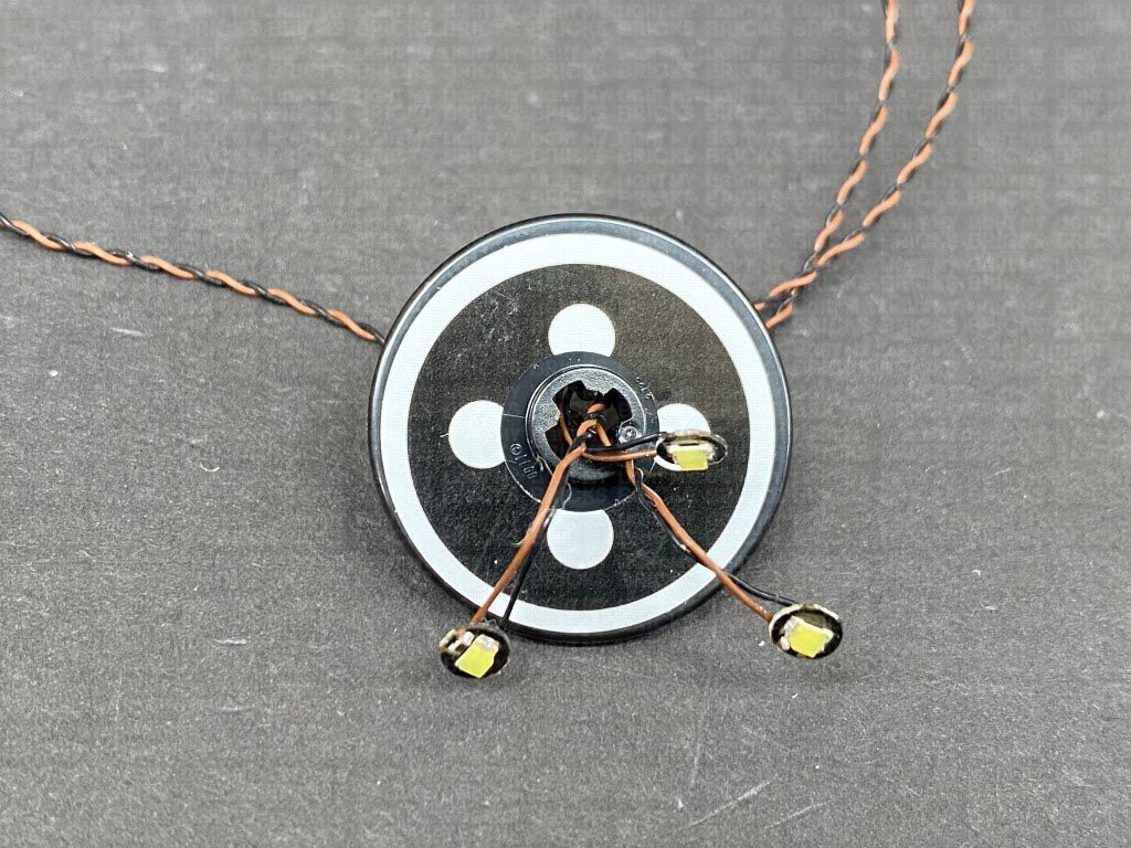
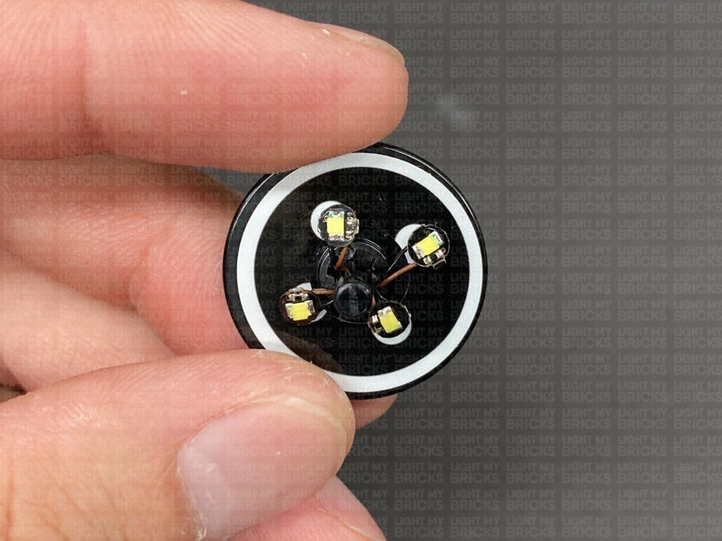
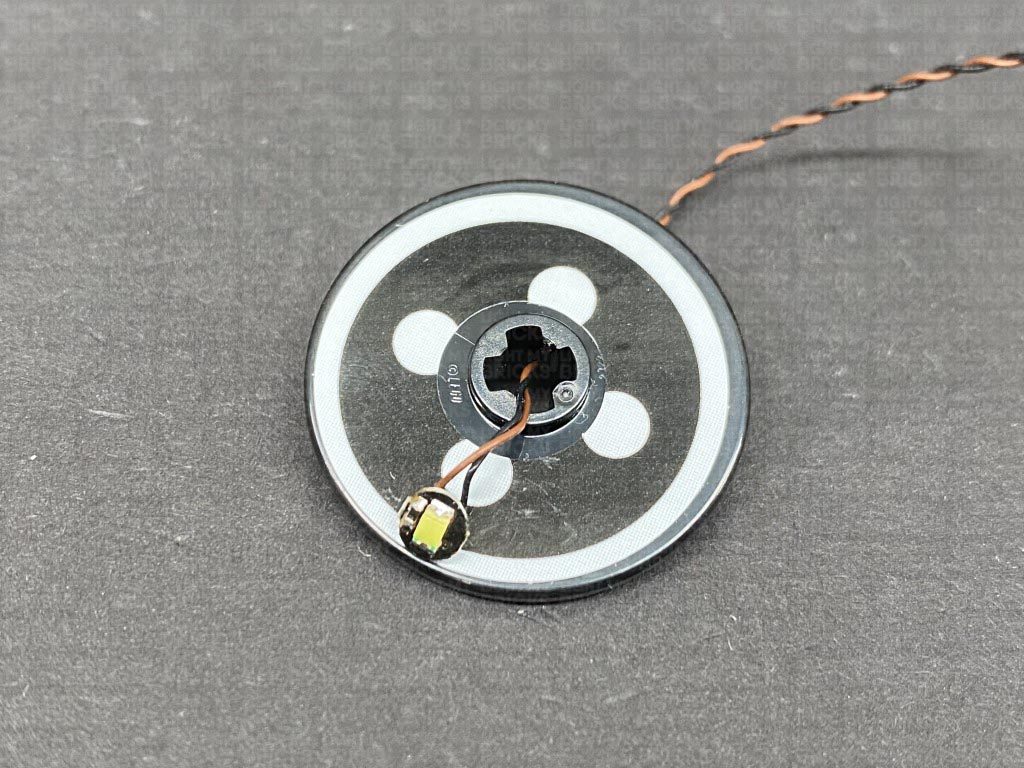
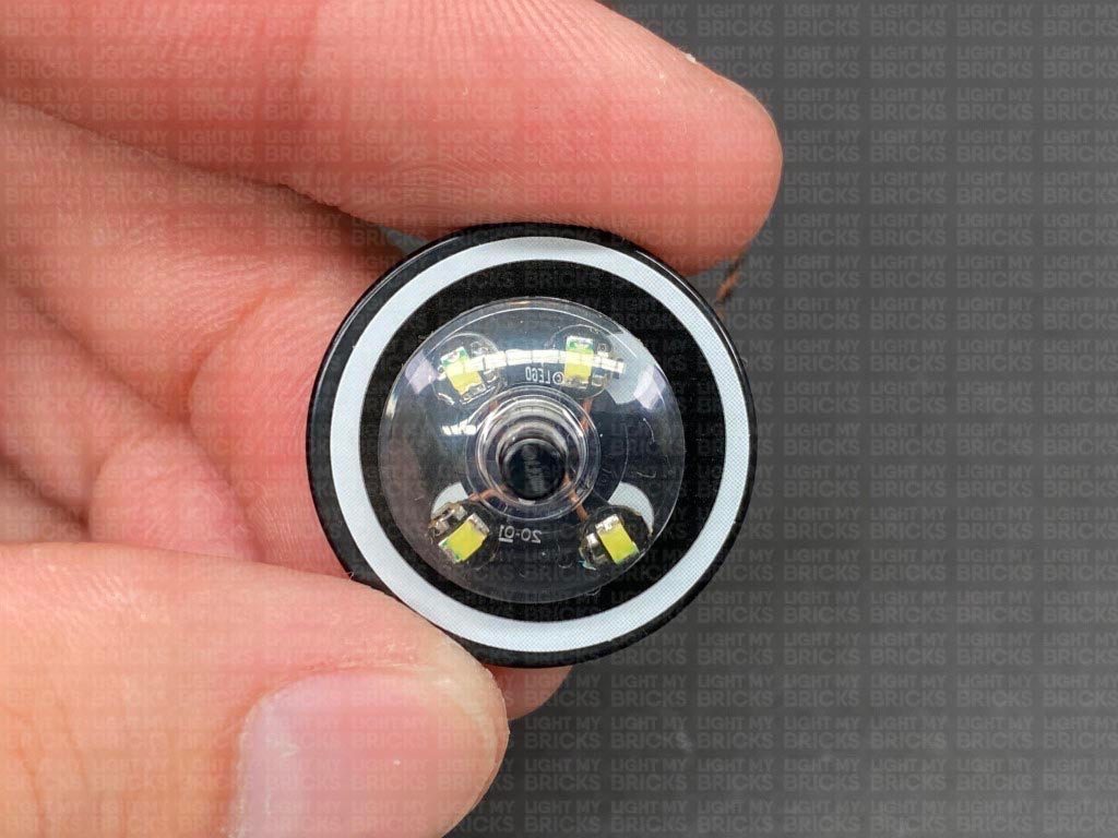
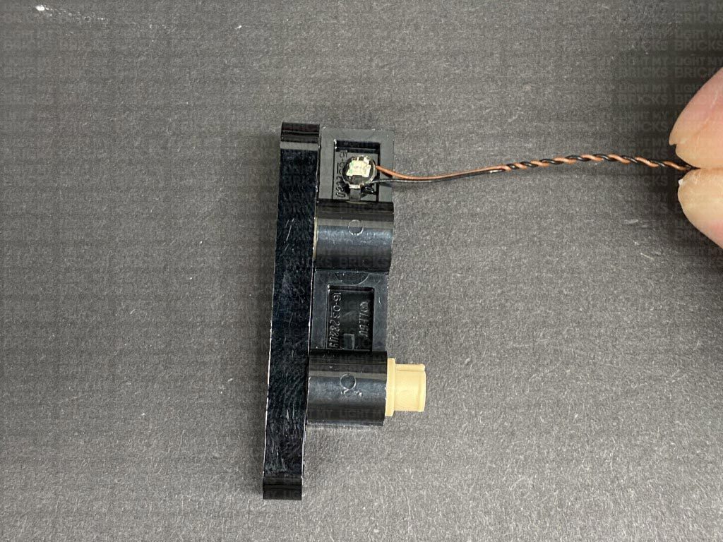
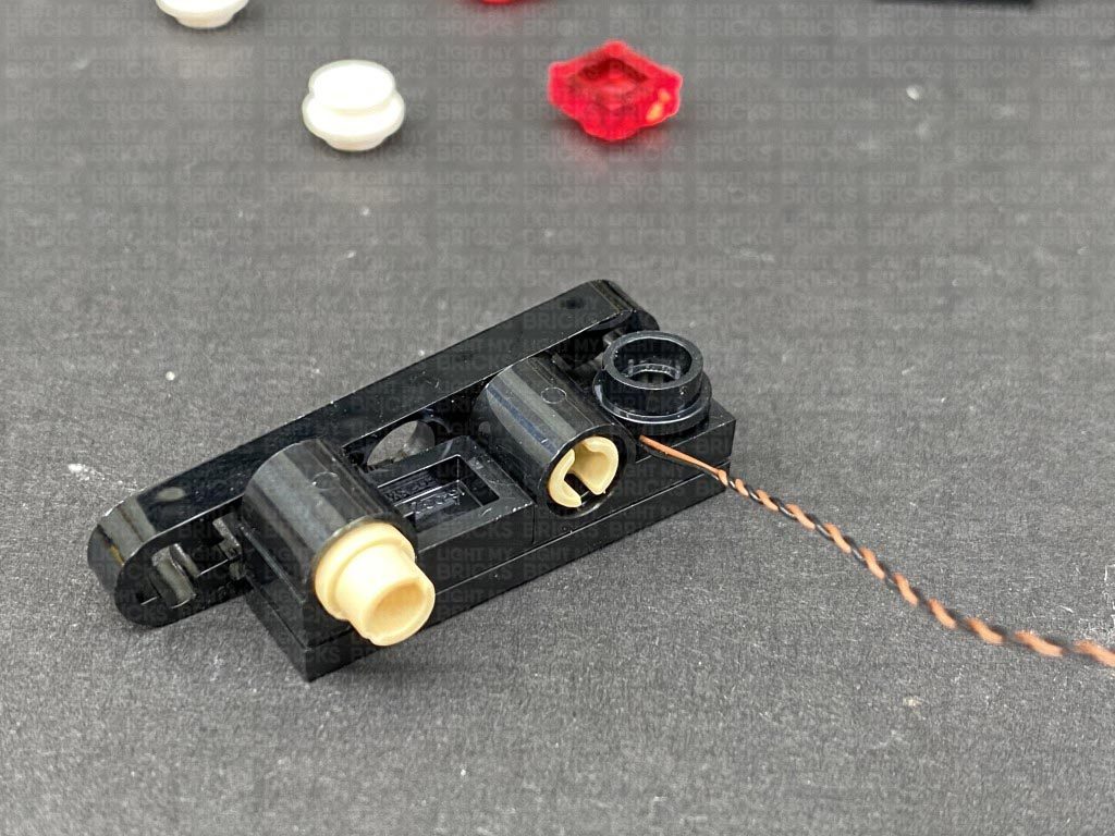
 2.) Take the right headlight section (passenger side) and disassemble it as per below, then take a Cool White 30cm Bit Light and thread the connector end of it through the front of the round dish. Thread the cable all the way through until the LED is about 1cm away from the front of the dish. Turn the LED over so that it is facing forward.
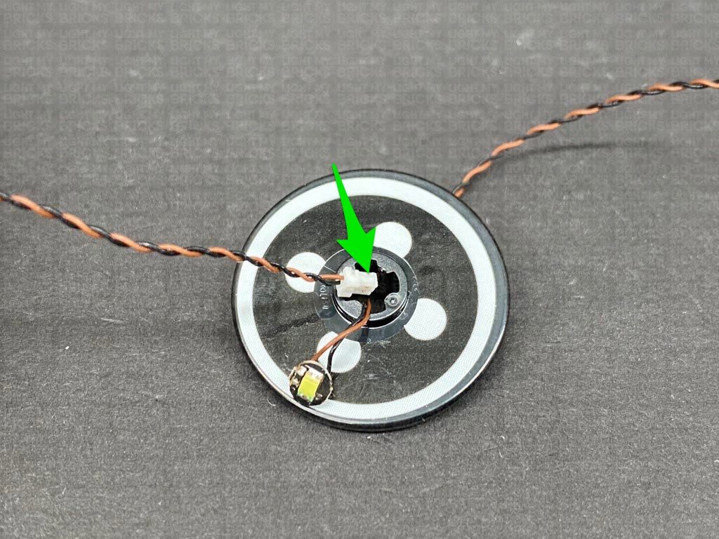
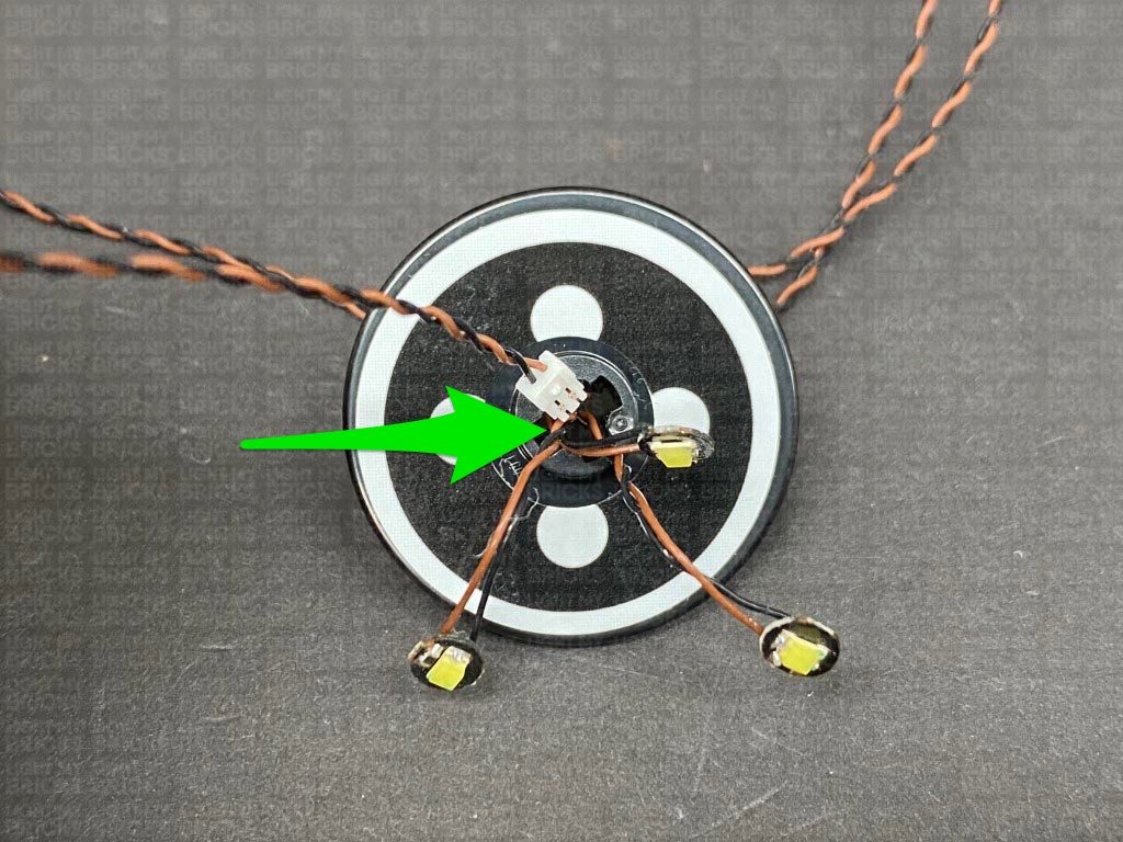
 Take another Cool White 30cm Bit Light and thread it through the front of the dish, same way we did for the first light.
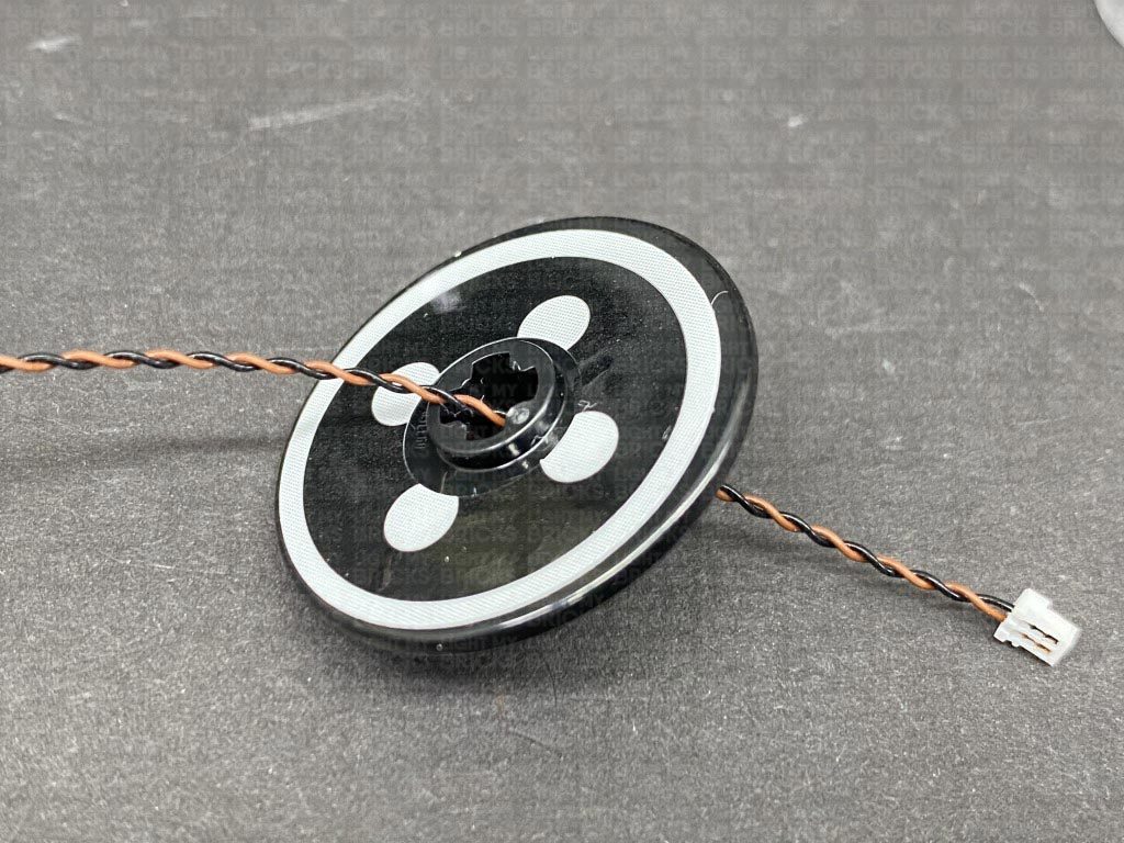
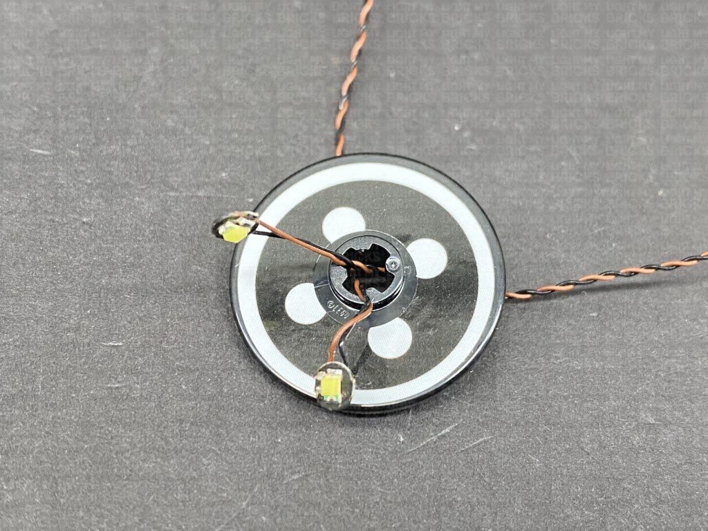
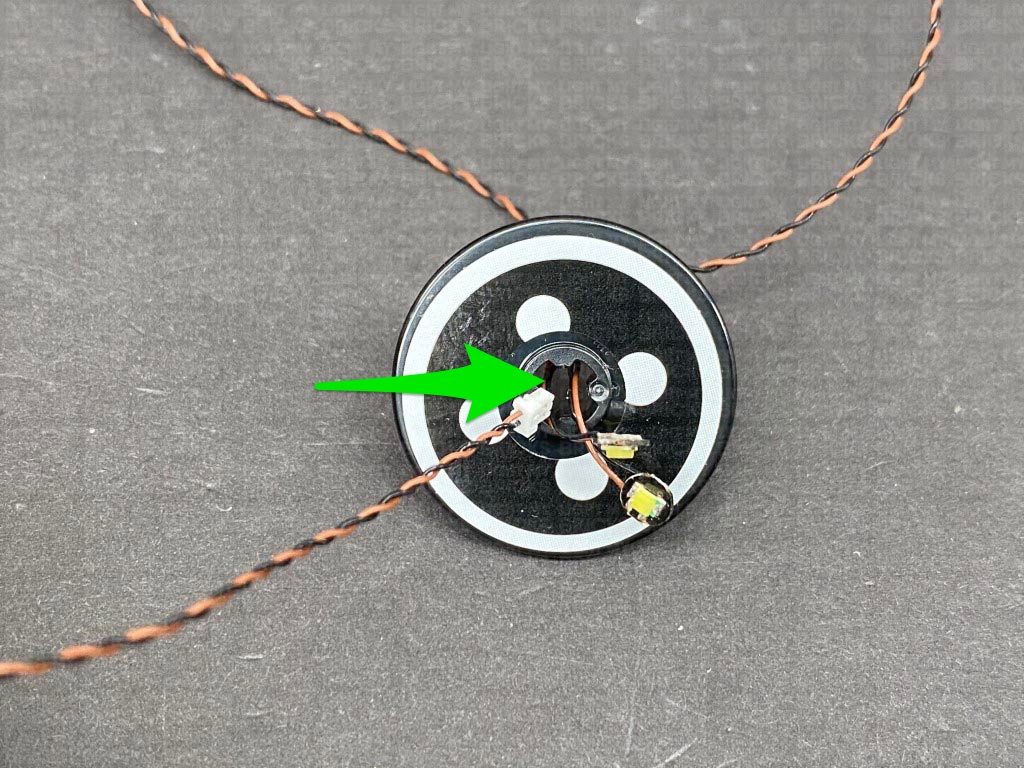
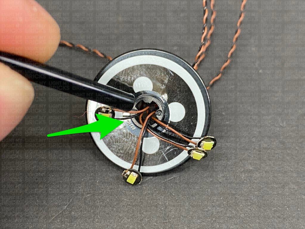
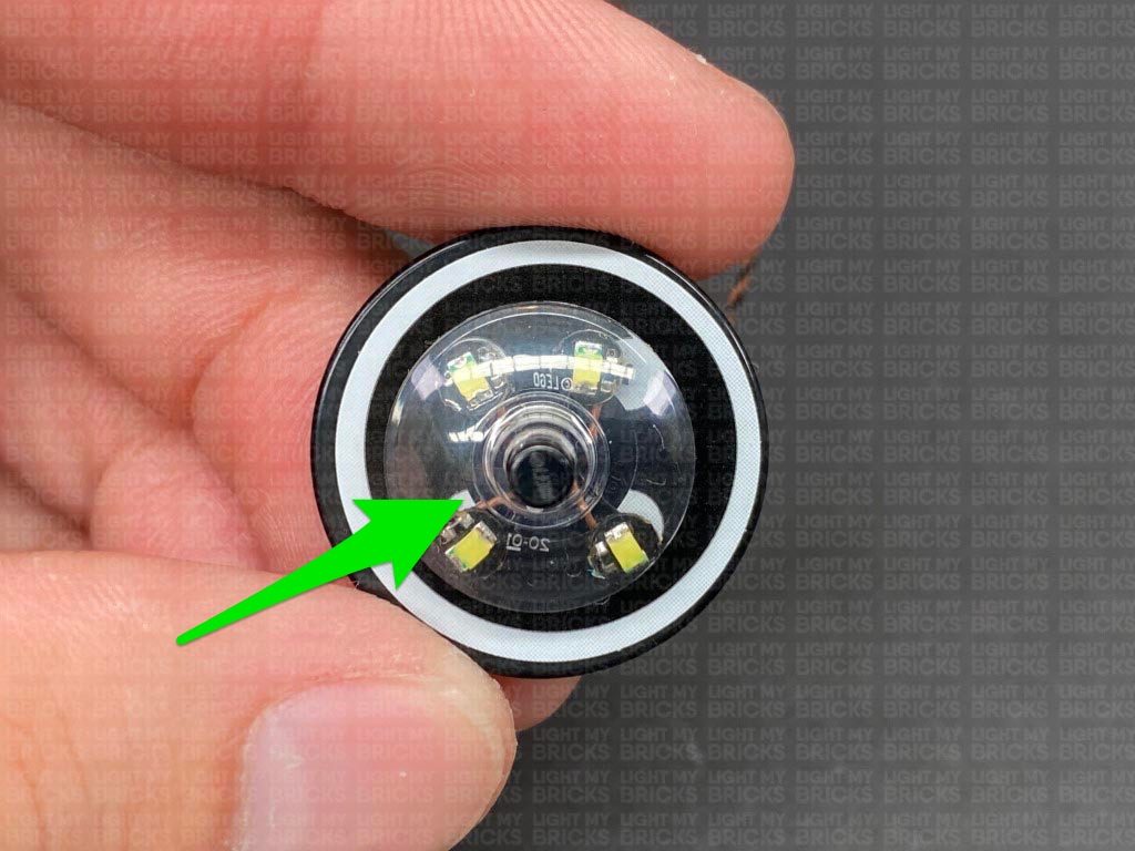
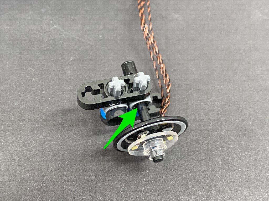
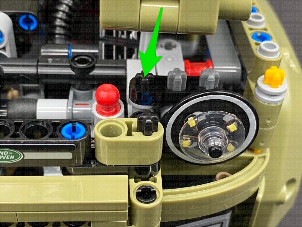
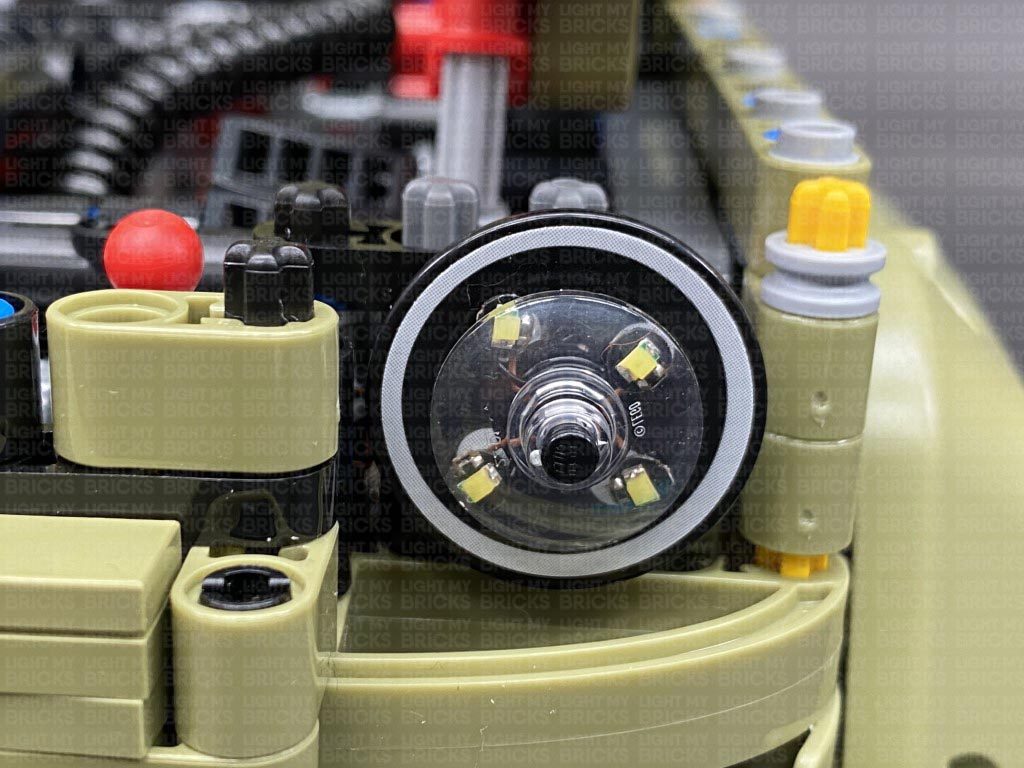
3.) Continue threading another 2x Cool White 30cm Bit Lights through the dish, then take LEGO Bar we removed earlier and insert it through the technic axle hole. Ensure the cables are laid in the technic axle spaces, to prevent them from being damaged when inserting the bar.
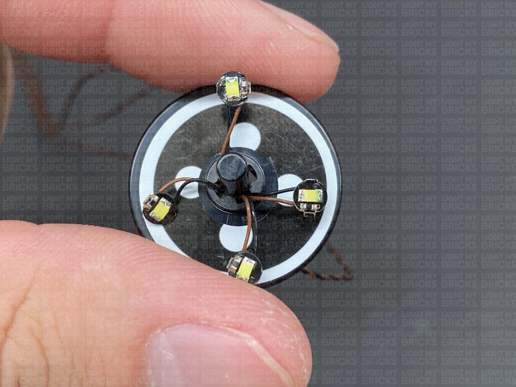
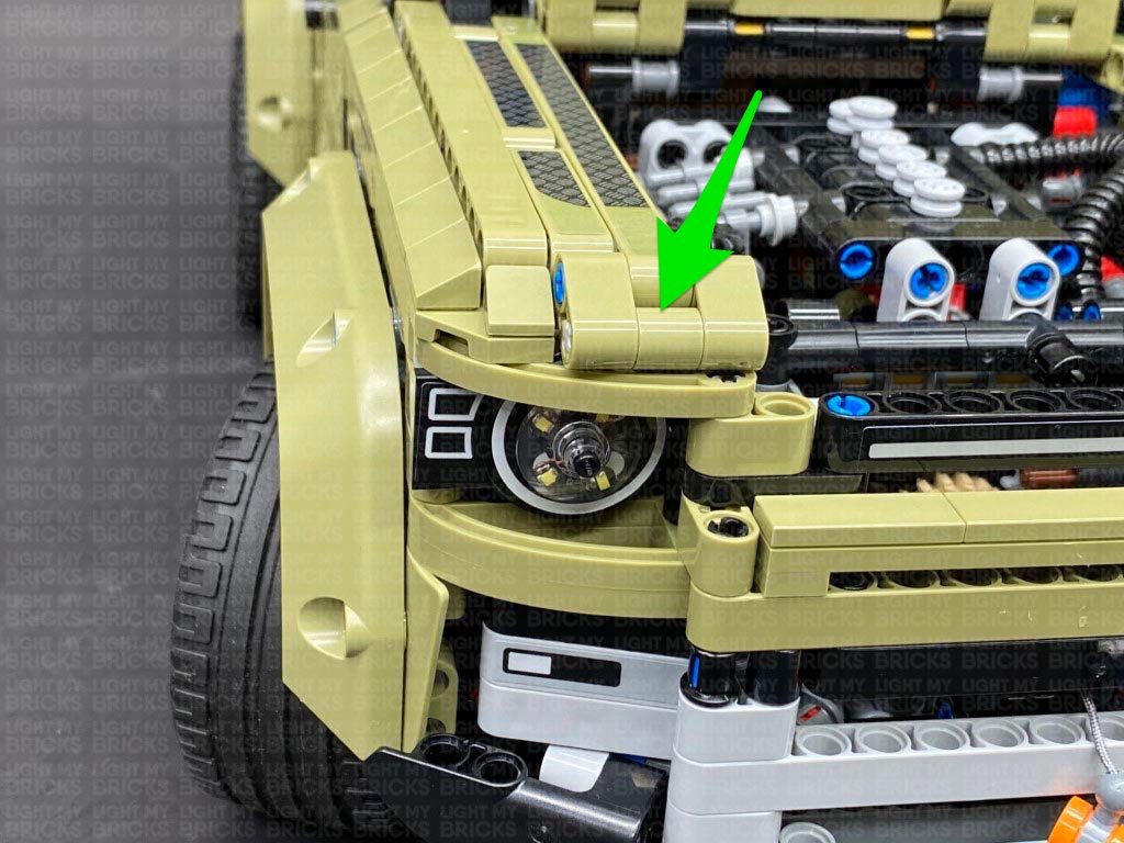
Reposition the 4 LEDs so they are evenly spaced out and positioned over the circles on the stickers behind, then reconnect the trans clear dish over the top. Reconnect the headlight to the rest of this section via the technic bar.
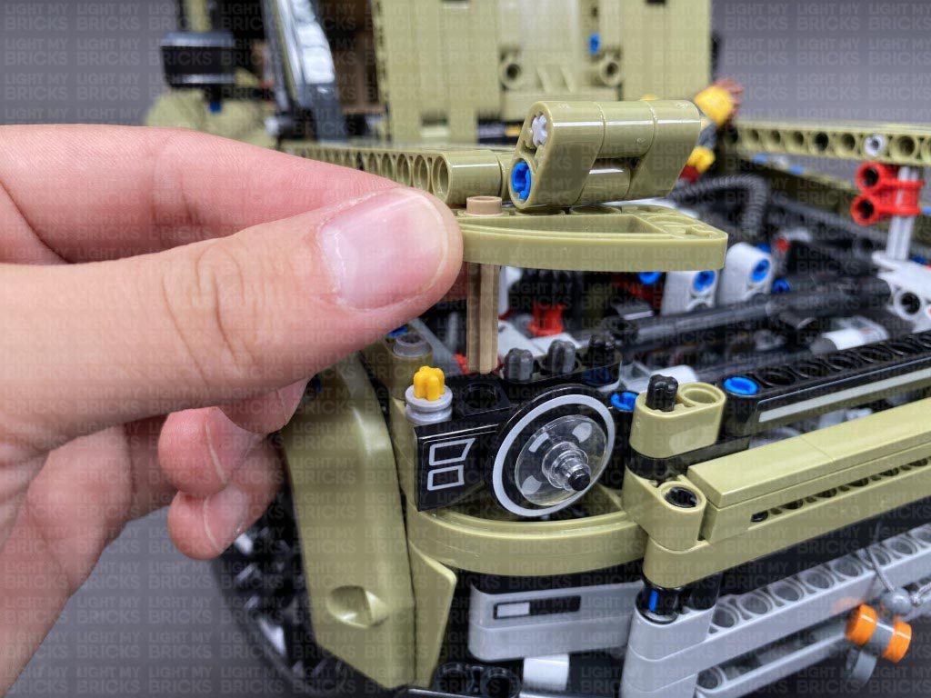
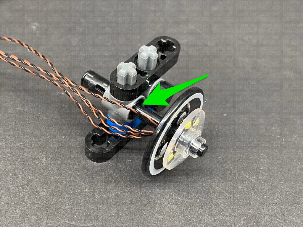
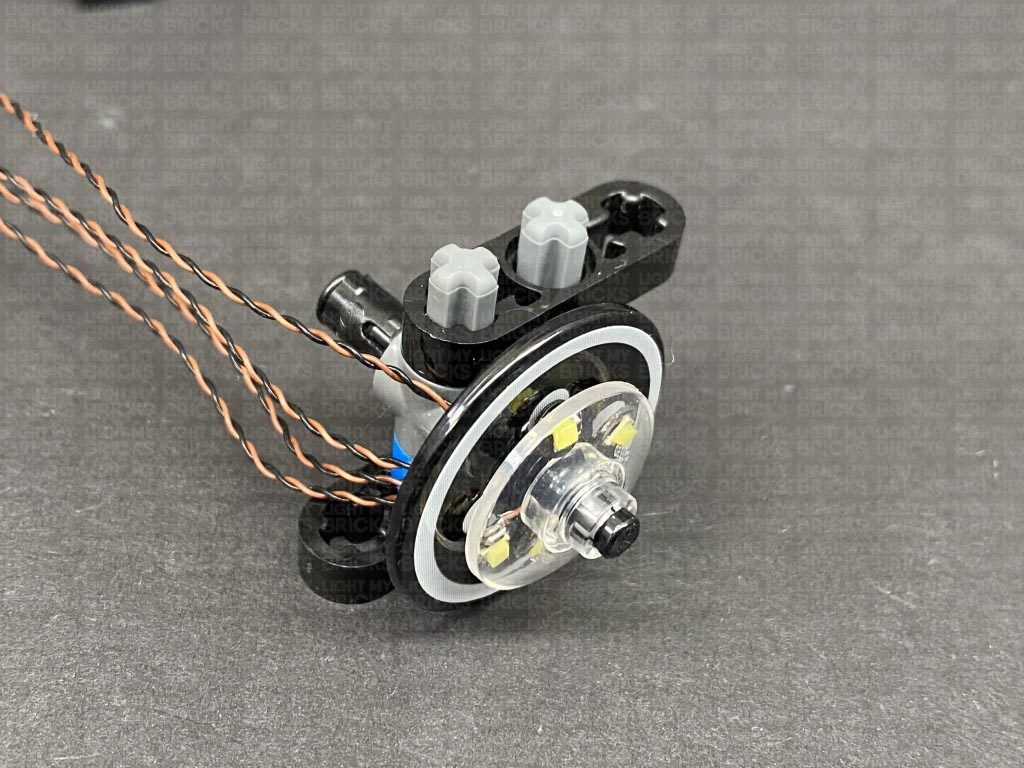
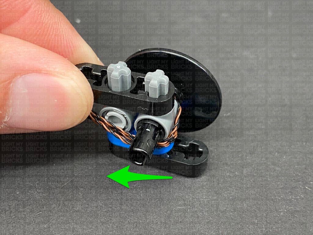
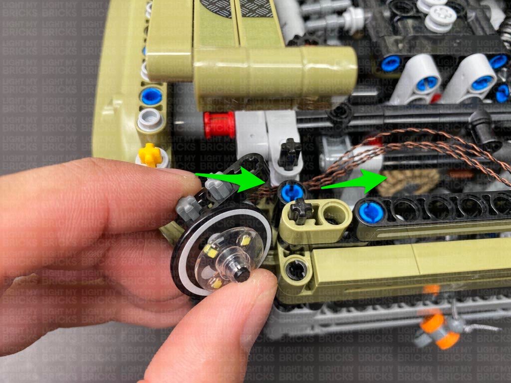
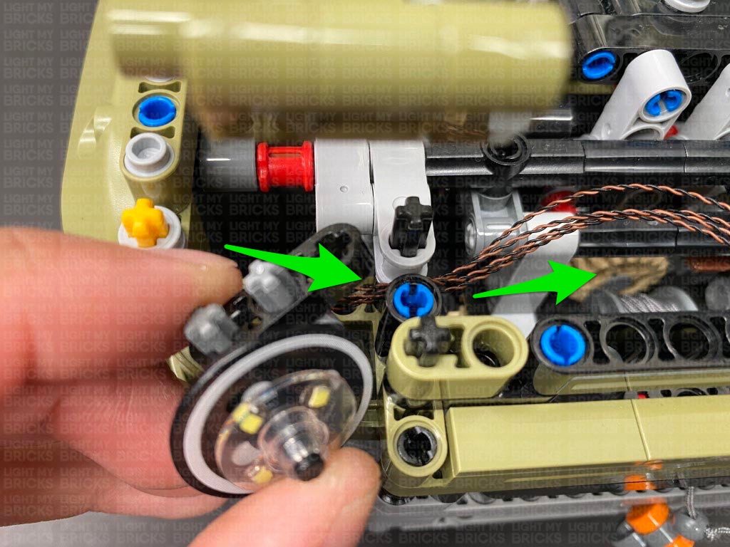
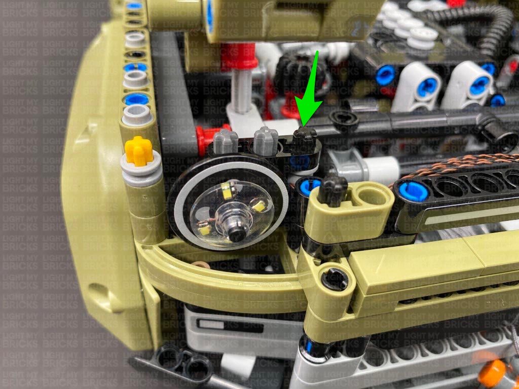
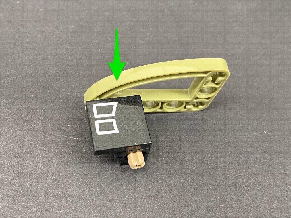
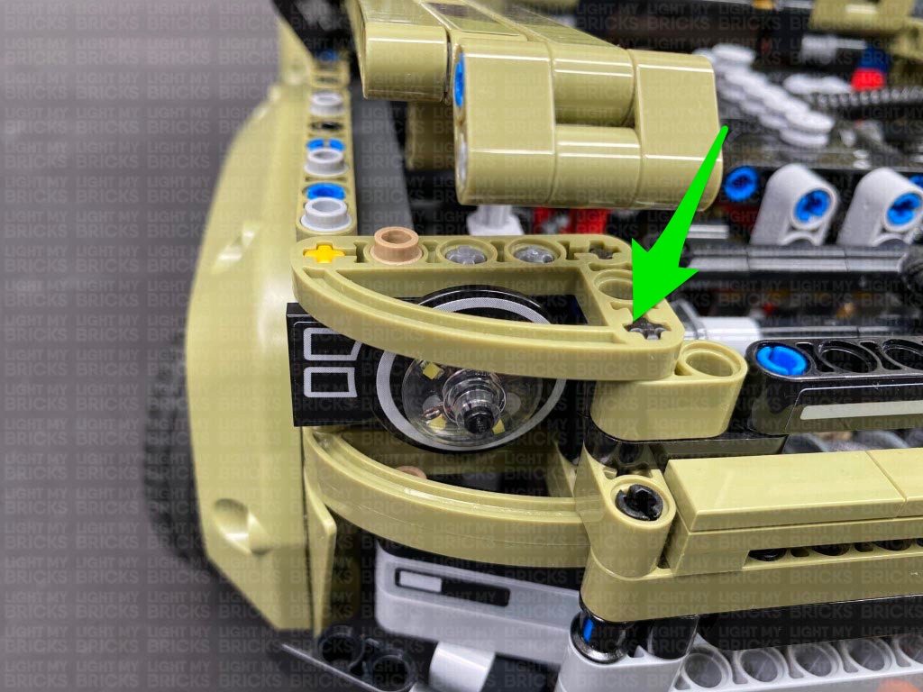
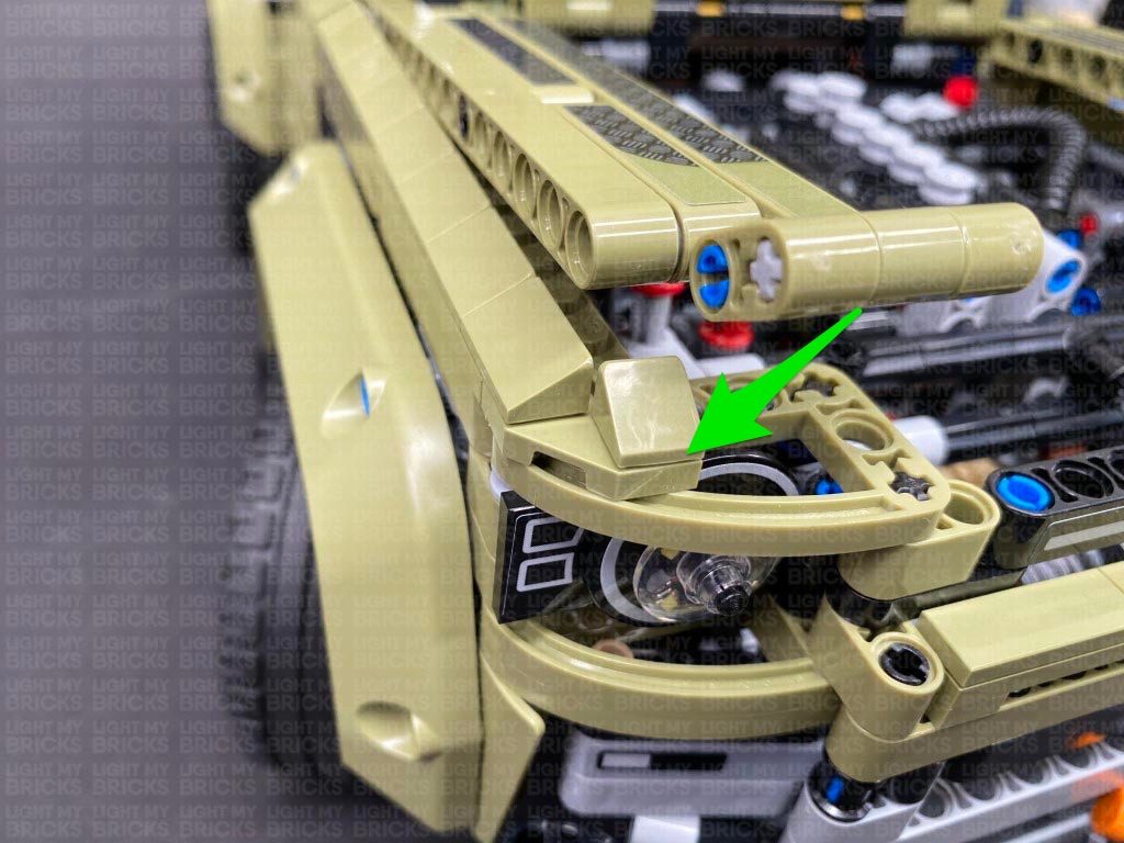
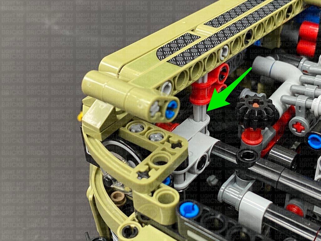
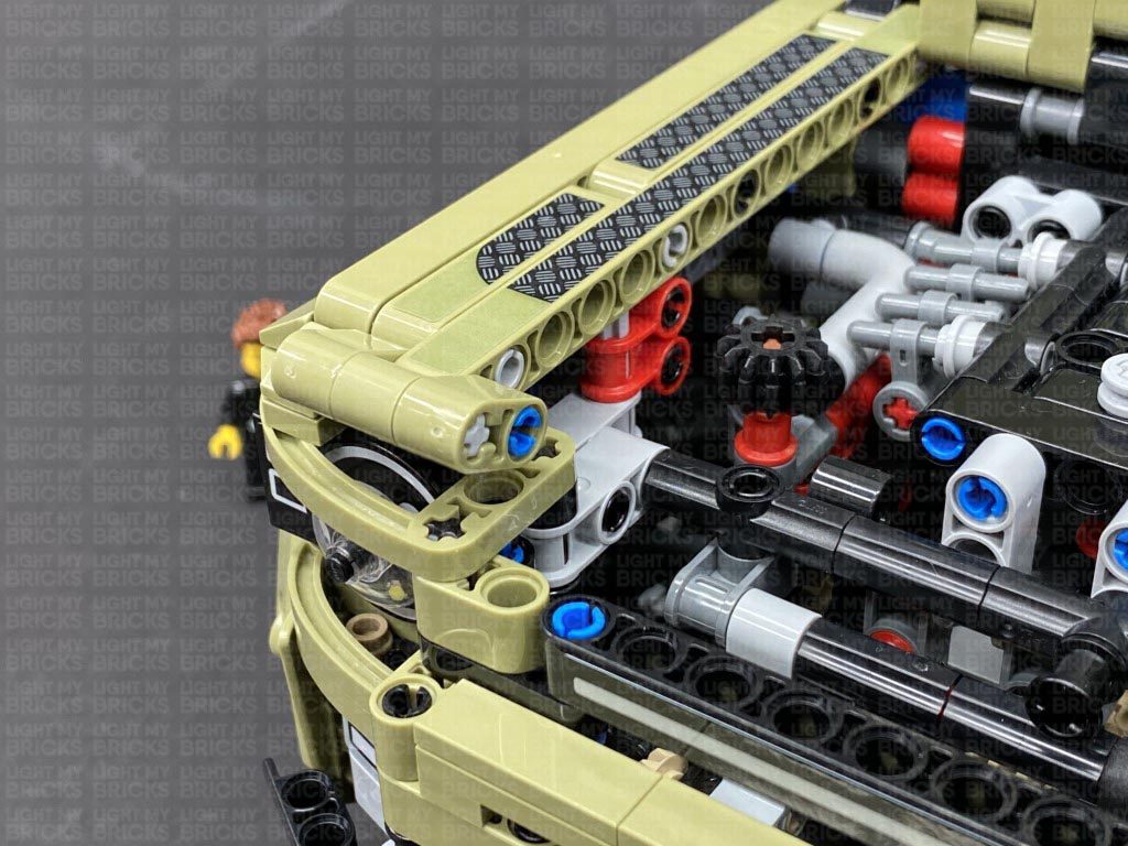
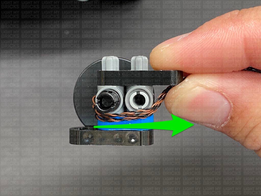
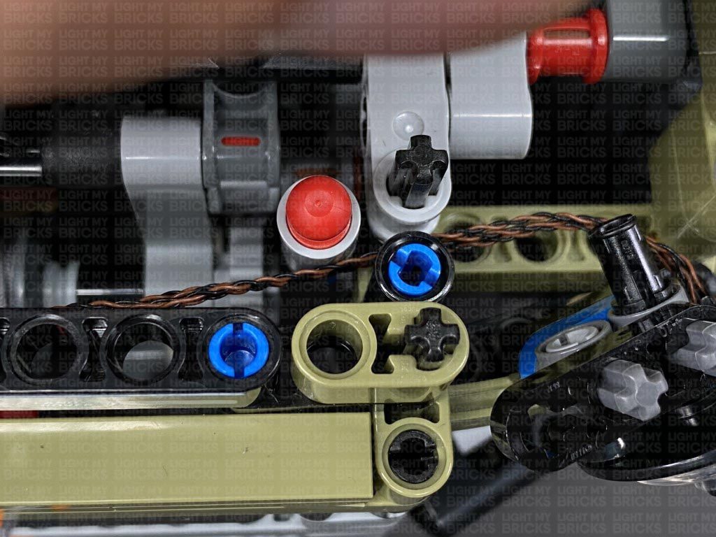
4.) Turn this section around and bring the 4 cables across to the right side underneath the technic pin. Bring this section over to the left side of the vehicle and thread the cables in between the two sections as shown below. Reconnect the headlight via the technic vertical axle.
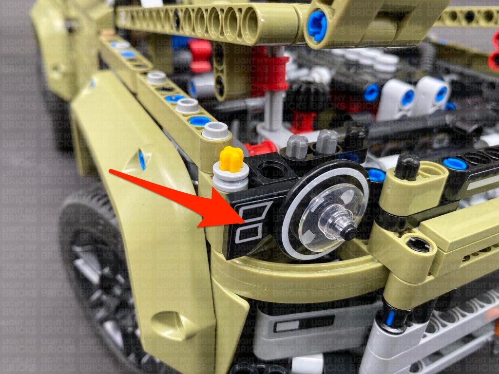
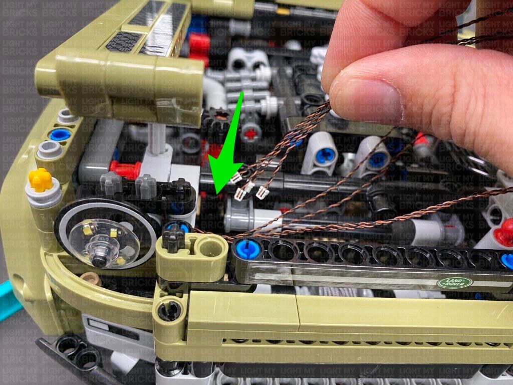
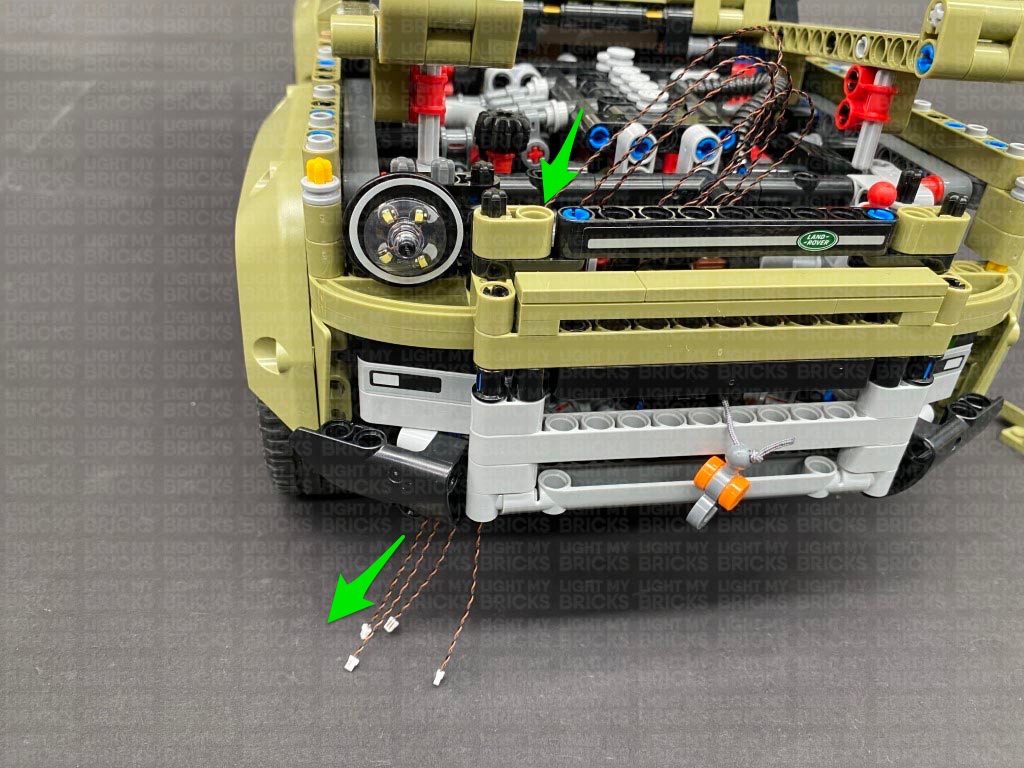
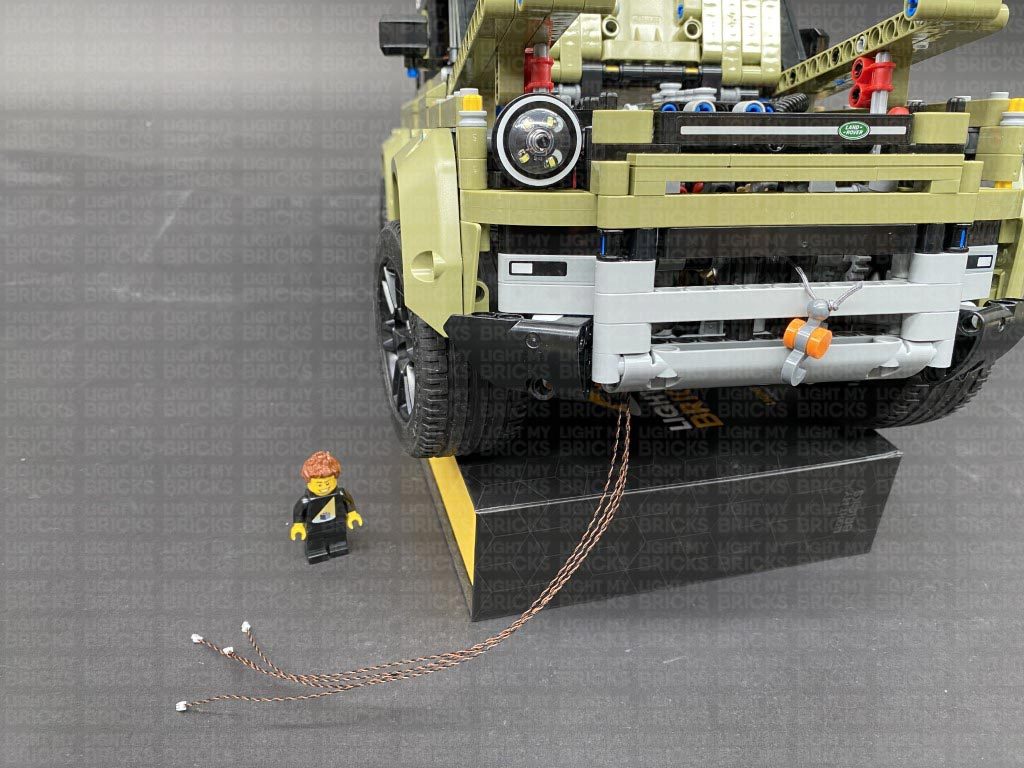
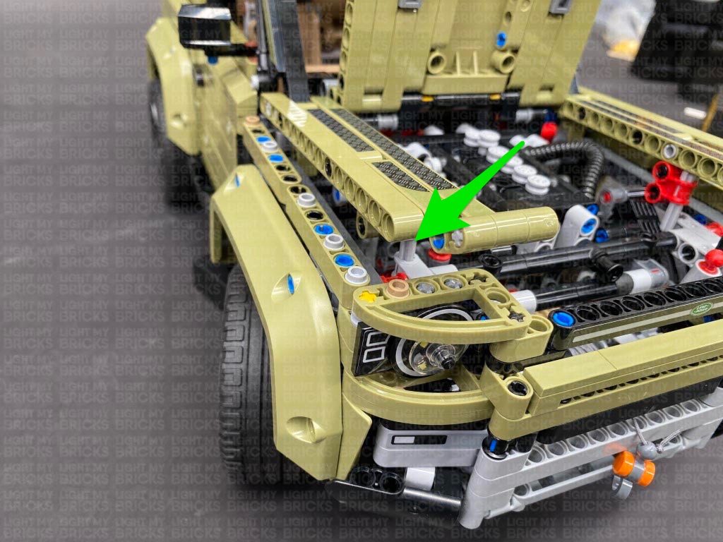
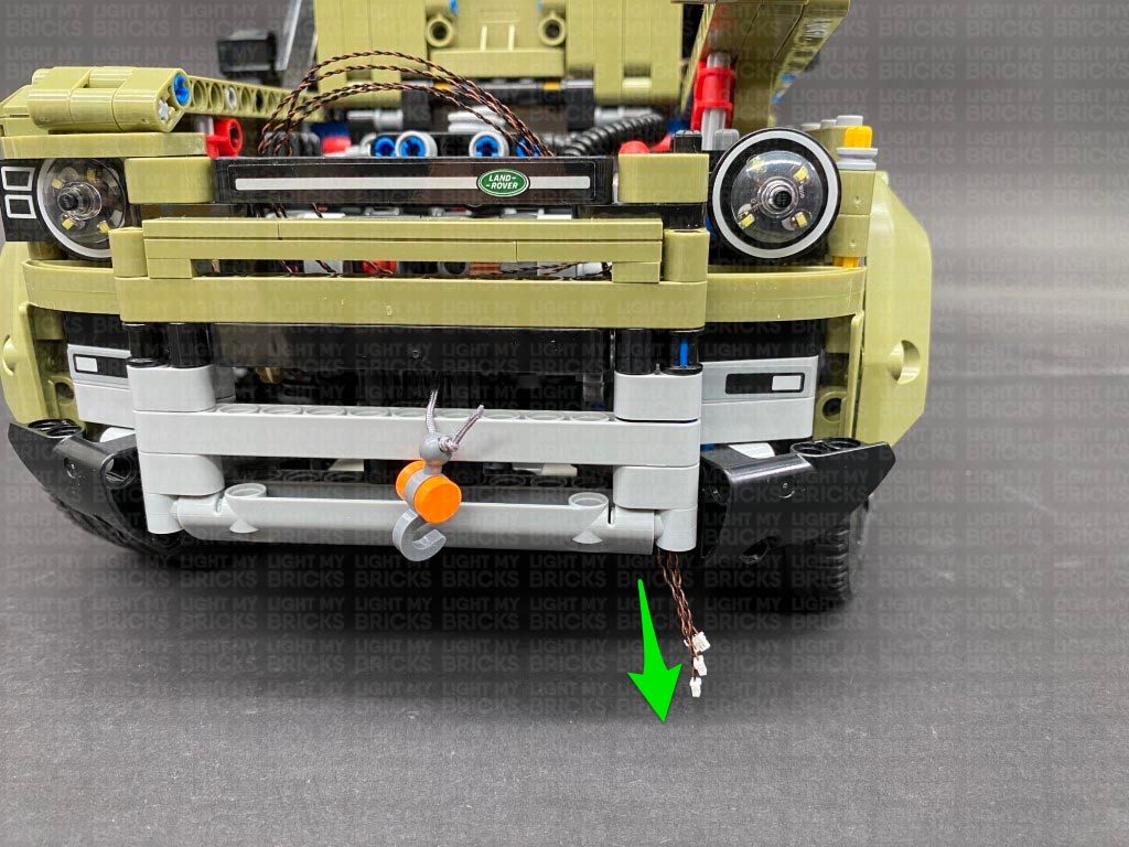
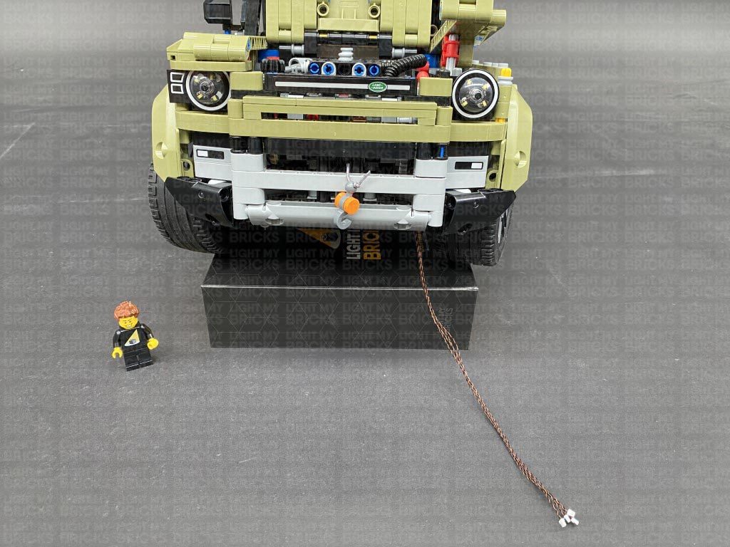
Group the 4 cables together and thread them down the following space behind the front grill. Prop the vehicle up using your light kit box, then pull the cables down from underneath as shown below.
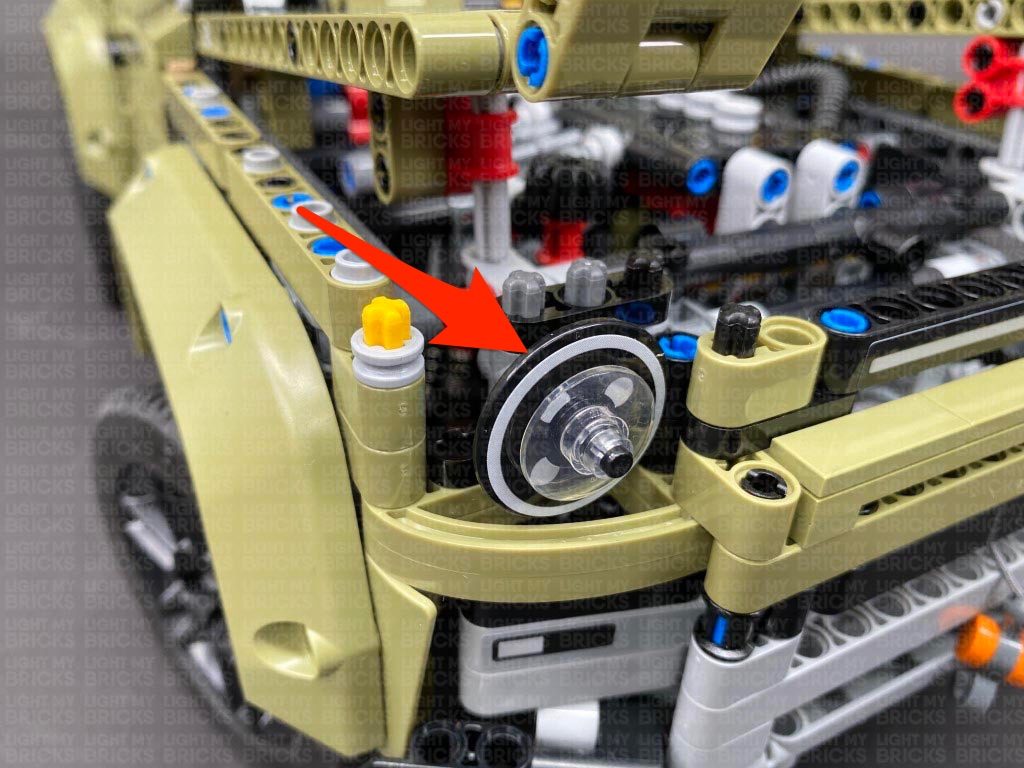
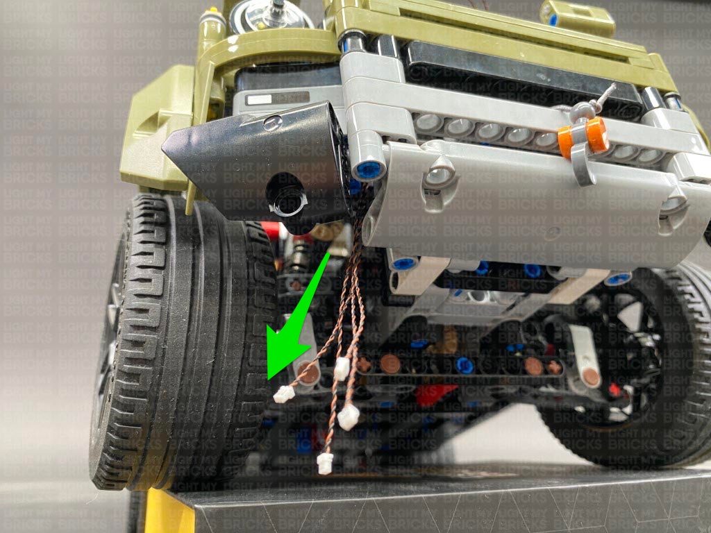
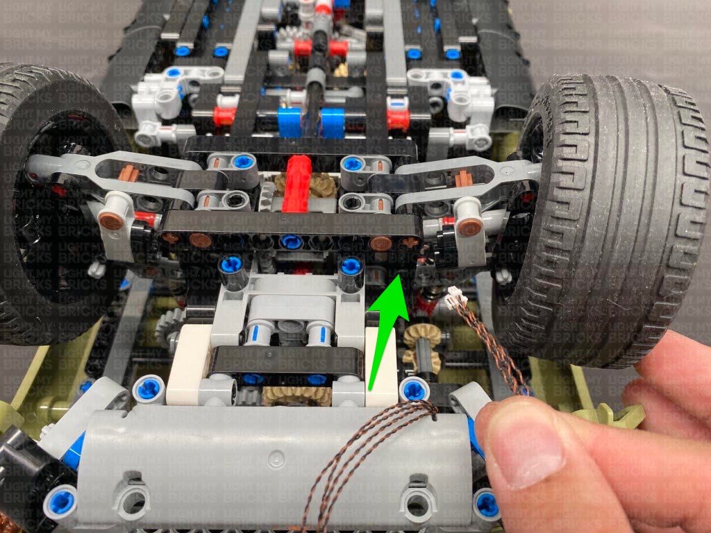
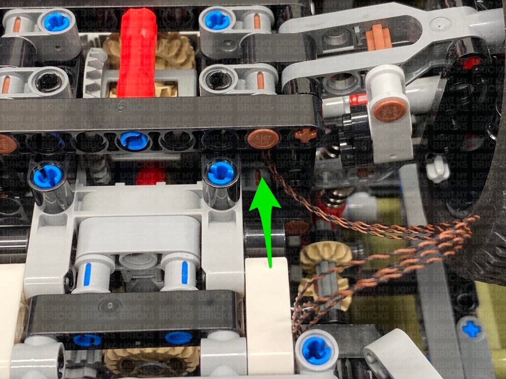
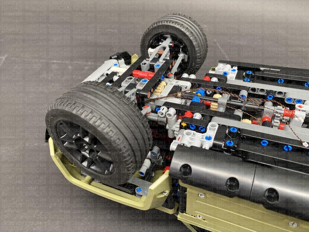
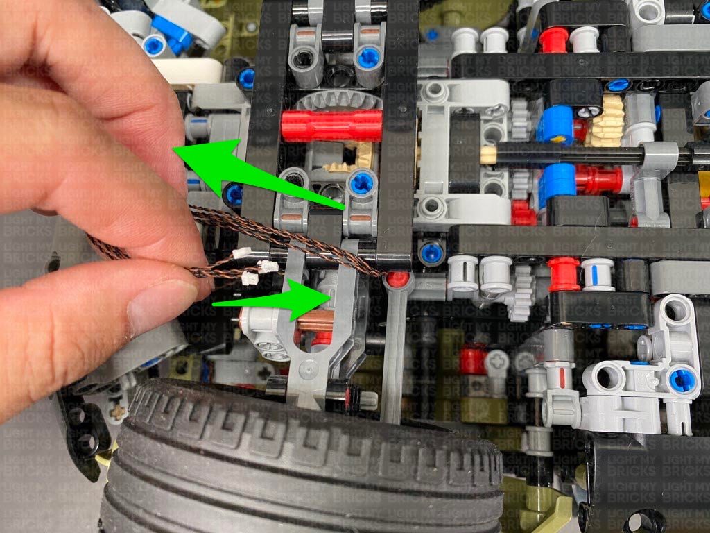
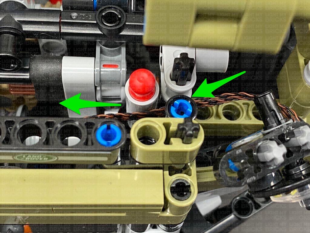
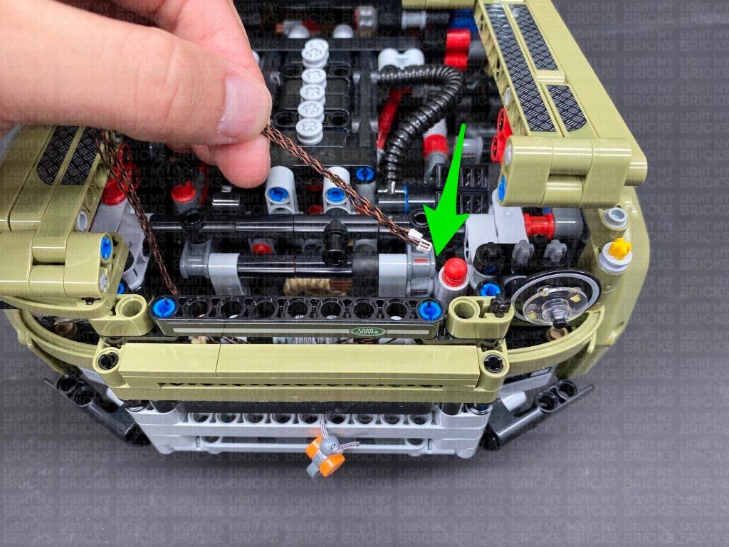
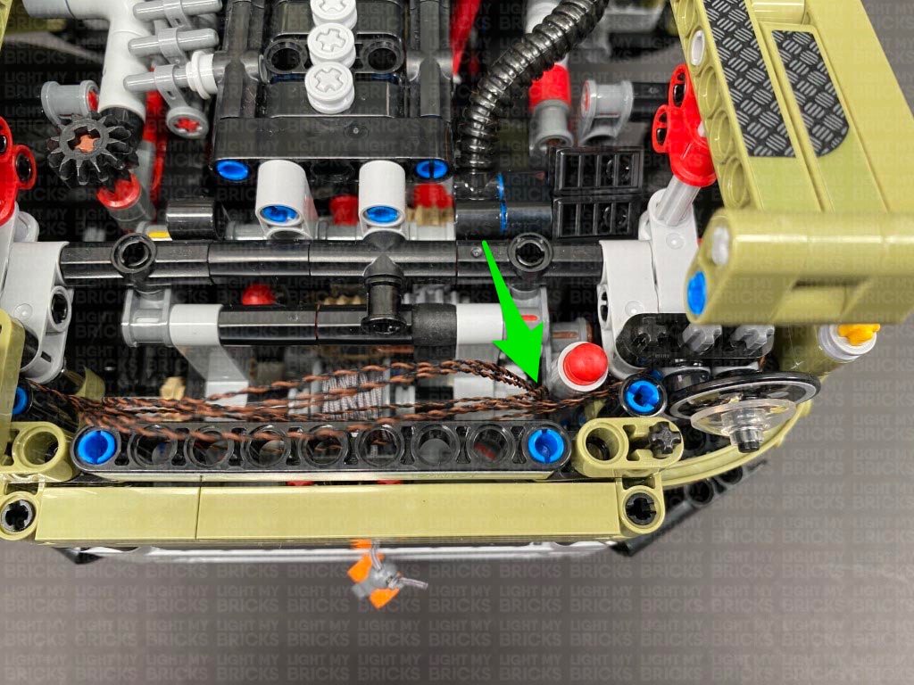
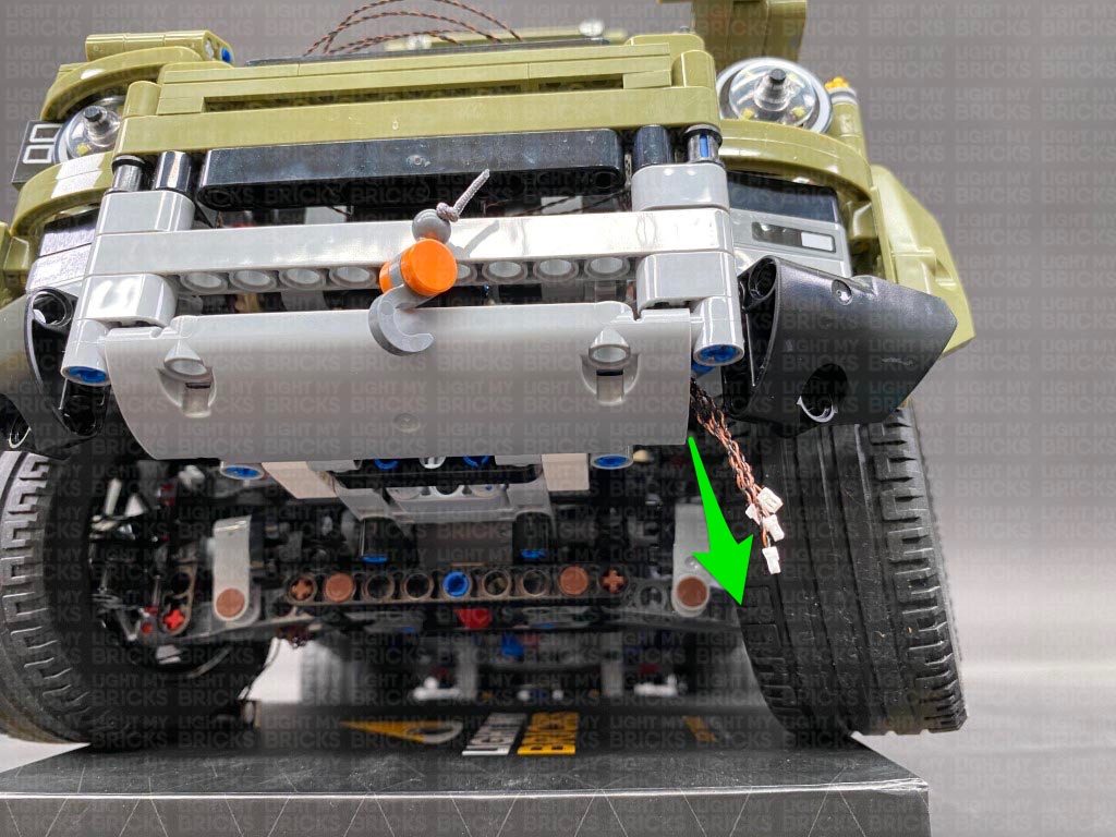
5.) Flip the vehicle over and thread the four cables through the following space underneath the technic bars, pulling them all the way out from the other side as shown below.
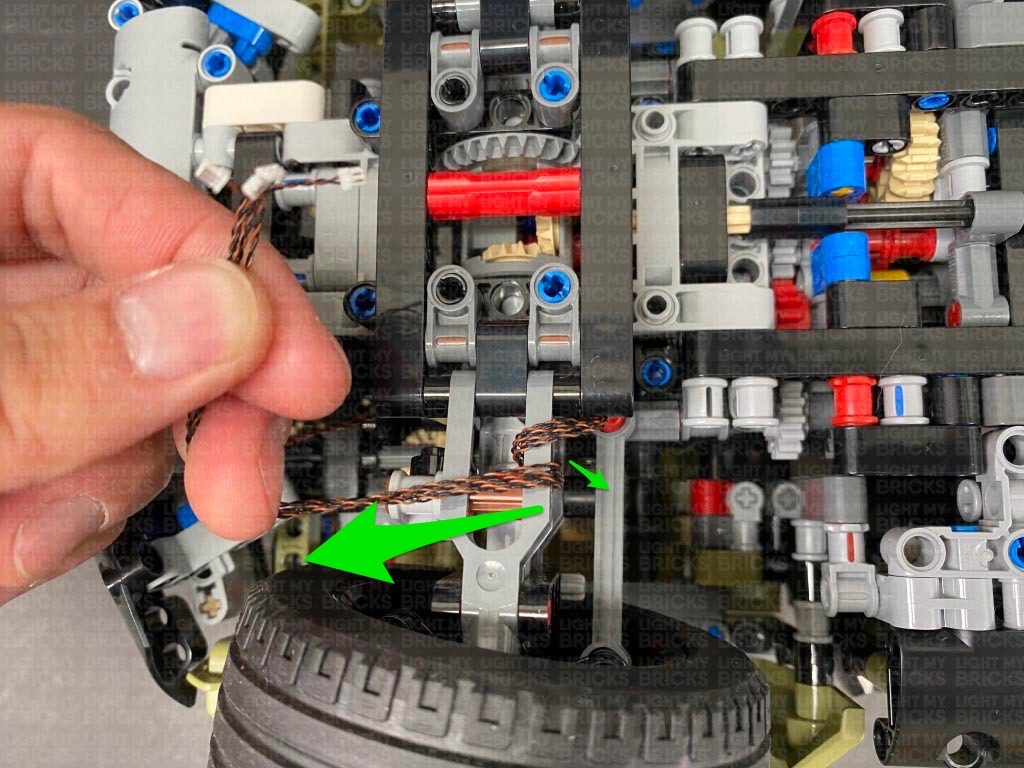
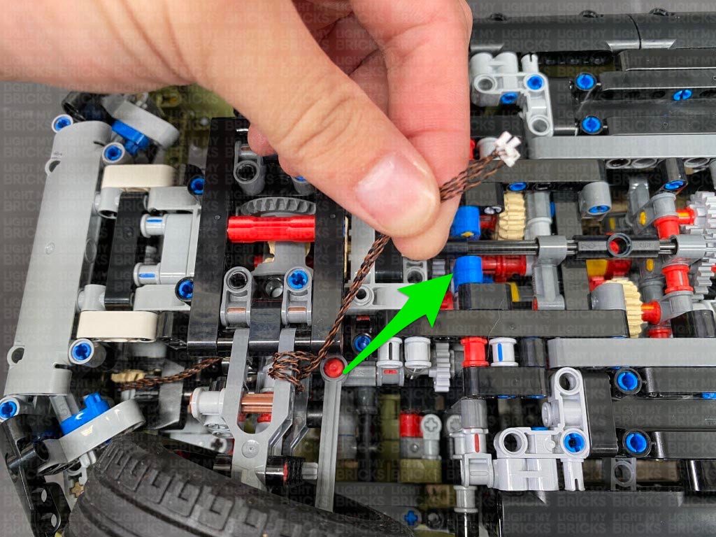
Turn the vehicle around to the side, and bring the cables back over and loop them around the wheel axis 3-4 times to eliminate excess cables, then connect them to the 12-Port Expansion Board
Take another Cool White 30cm Bit Light and thread it through the front of the dish, same way we did for the first light.
3.) Continue threading another 2x Cool White 30cm Bit Lights through the dish, then take LEGO Bar we removed earlier and insert it through the technic axle hole. Ensure the cables are laid in the technic axle spaces, to prevent them from being damaged when inserting the bar.
Reposition the 4 LEDs so they are evenly spaced out and positioned over the circles on the stickers behind, then reconnect the trans clear dish over the top. Reconnect the headlight to the rest of this section via the technic bar.
4.) Turn this section around and bring the 4 cables across to the right side underneath the technic pin. Bring this section over to the left side of the vehicle and thread the cables in between the two sections as shown below. Reconnect the headlight via the technic vertical axle.
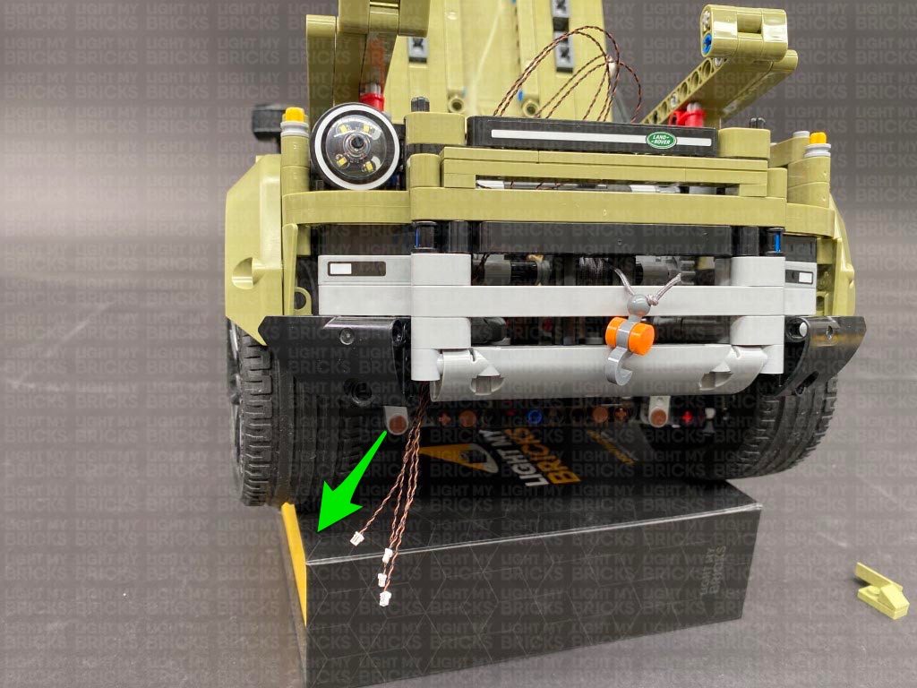
Group the 4 cables together and thread them down the following space behind the front grill. Prop the vehicle up using your light kit box, then pull the cables down from underneath as shown below.
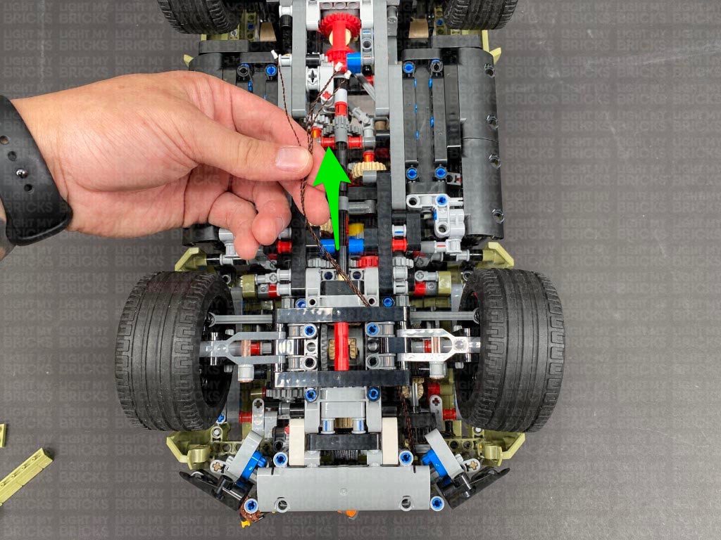
5.) Flip the vehicle over and thread the four cables through the following space underneath the technic bars, pulling them all the way out from the other side as shown below.
Turn the vehicle around to the side, and bring the cables back over and loop them around the wheel axis 3-4 times to eliminate excess cables, then connect them to the 12-Port Expansion Board
 Take the AA Battery Pack and insert 3x new AA batteries to it. Connect the battery pack cable to a spare port on the 12-port expansion board then turn it ON to test the right headlights are working OK.
Note: If you experience any issues with the lights not working and suspect an issue with a component, please try a different port on the expansion board to verify where the fault lies (with the light, expansion board or effects board). To correct any issues with expansion board ports, please view the section addressing expansion board issues on our online troubleshooting guide.
6.) Take the following remaining head light sections and reassemble and connect them back to the front of the vehicle. Reconnect all the sections we disconnected earlier from the right side.
7.) Repeat steps 2 – 6 to install another 4x Cool White 30cm Bit Lights to the left headlight section.
8.) Reconnect this section to the rest via the black technic bar, then turn this section over and bring the cables across to the right side, underneath the technic pin.
Bring this section over to the left side of the vehicle and thread the cables in between the two sections as shown below. Reconnect the headlight via the technic vertical axle.
9.) Group the 4 cables together and thread them down the following space behind the front grill. Prop the vehicle up using your light kit box, then pull the cables down from underneath as shown below.
Flip the vehicle over and bring the four cables across to the right side, then thread them underneath the following technic pieces, pulling them all the way out from the other side.
Take the AA Battery Pack and insert 3x new AA batteries to it. Connect the battery pack cable to a spare port on the 12-port expansion board then turn it ON to test the right headlights are working OK.
Note: If you experience any issues with the lights not working and suspect an issue with a component, please try a different port on the expansion board to verify where the fault lies (with the light, expansion board or effects board). To correct any issues with expansion board ports, please view the section addressing expansion board issues on our online troubleshooting guide.
6.) Take the following remaining head light sections and reassemble and connect them back to the front of the vehicle. Reconnect all the sections we disconnected earlier from the right side.
7.) Repeat steps 2 – 6 to install another 4x Cool White 30cm Bit Lights to the left headlight section.
8.) Reconnect this section to the rest via the black technic bar, then turn this section over and bring the cables across to the right side, underneath the technic pin.
Bring this section over to the left side of the vehicle and thread the cables in between the two sections as shown below. Reconnect the headlight via the technic vertical axle.
9.) Group the 4 cables together and thread them down the following space behind the front grill. Prop the vehicle up using your light kit box, then pull the cables down from underneath as shown below.
Flip the vehicle over and bring the four cables across to the right side, then thread them underneath the following technic pieces, pulling them all the way out from the other side.
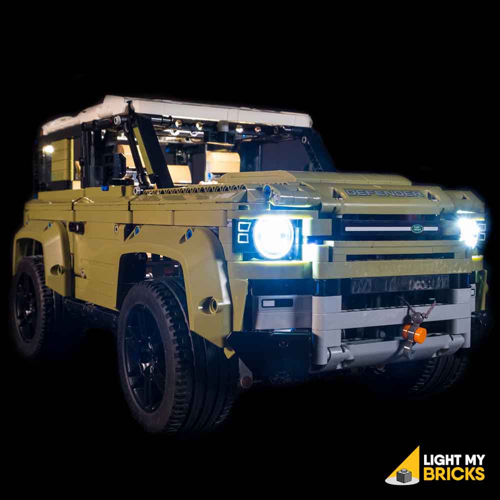
 Ensure the cables are laid around the following section, then connect them to the left ports on the 12-port expansion board. Turn the power ON to test the left headlights are working OK.
Note: If you experience any issues with the lights not working and suspect an issue with a component, please try a different port on the expansion board to verify where the fault lies (with the light, expansion board or effects board). To correct any issues with expansion board ports, please view the section addressing expansion board issues on our online troubleshooting guide.
10.) Take the following remaining head light sections and reassemble and connect them back to the front of the vehicle. Reconnect all the sections we disconnected earlier surrounding the left side.
11.) Flip the vehicle back over again and disconnect the AA Battery Pack from the expansion board. Pull the four cables from the left headlight all the way out near the expansion board to eliminate any excess cable, then twist them around each other to form a neat bunch.
Turn the vehicle over to the side, then tuck the bunched up cables through one of the technic plate holes as shown below. Take 3x Adhesive Squares and stick them to the back of the 12-port expansion board, then stick the expansion board to the following position.
Ensure the cables are laid around the following section, then connect them to the left ports on the 12-port expansion board. Turn the power ON to test the left headlights are working OK.
Note: If you experience any issues with the lights not working and suspect an issue with a component, please try a different port on the expansion board to verify where the fault lies (with the light, expansion board or effects board). To correct any issues with expansion board ports, please view the section addressing expansion board issues on our online troubleshooting guide.
10.) Take the following remaining head light sections and reassemble and connect them back to the front of the vehicle. Reconnect all the sections we disconnected earlier surrounding the left side.
11.) Flip the vehicle back over again and disconnect the AA Battery Pack from the expansion board. Pull the four cables from the left headlight all the way out near the expansion board to eliminate any excess cable, then twist them around each other to form a neat bunch.
Turn the vehicle over to the side, then tuck the bunched up cables through one of the technic plate holes as shown below. Take 3x Adhesive Squares and stick them to the back of the 12-port expansion board, then stick the expansion board to the following position.
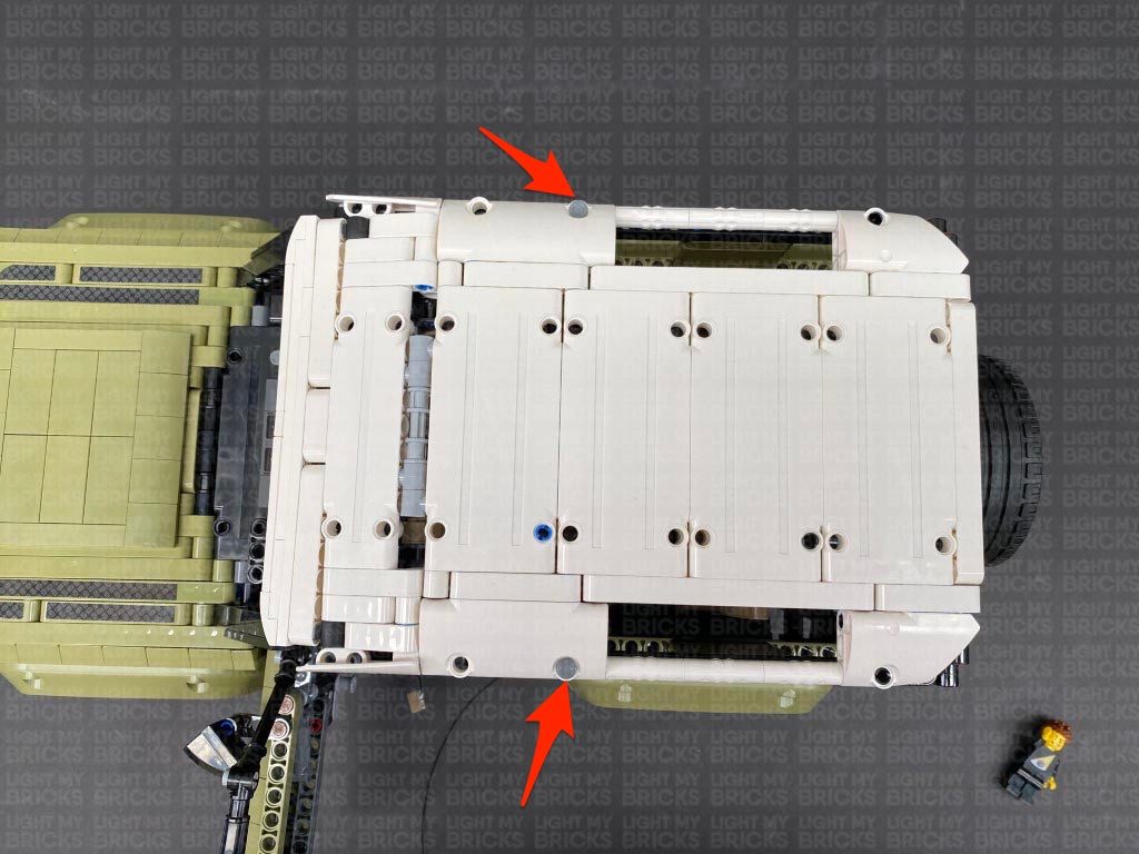
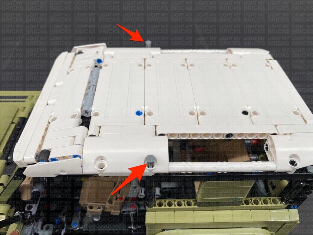
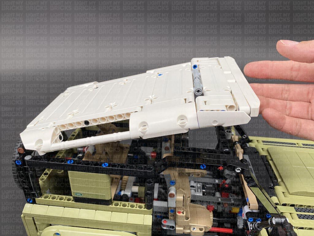
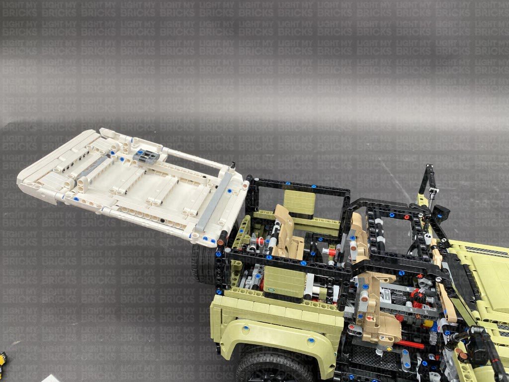
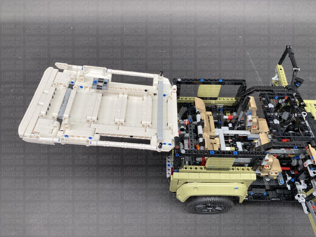
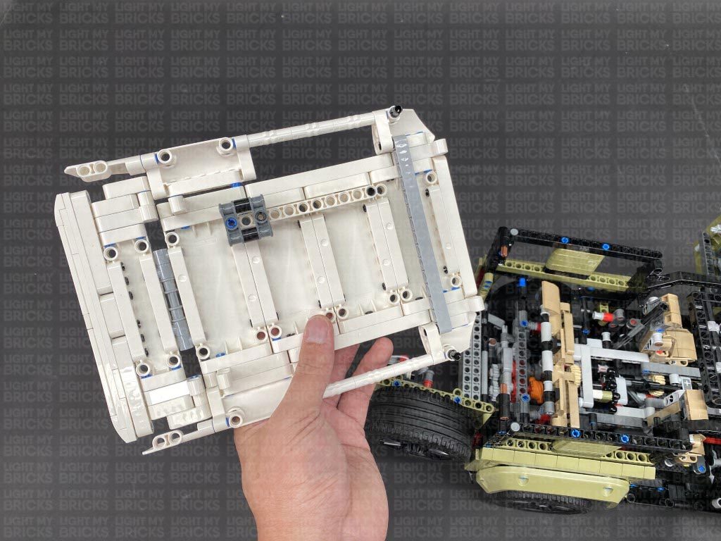
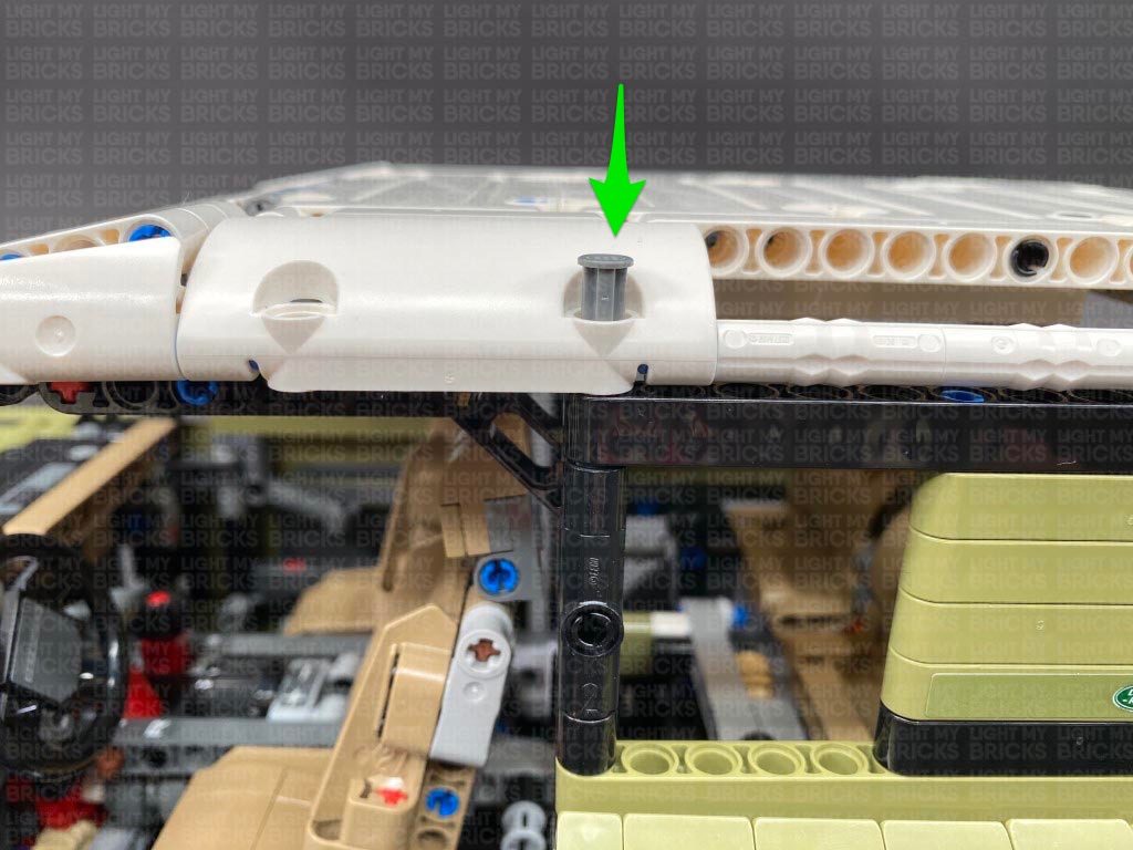
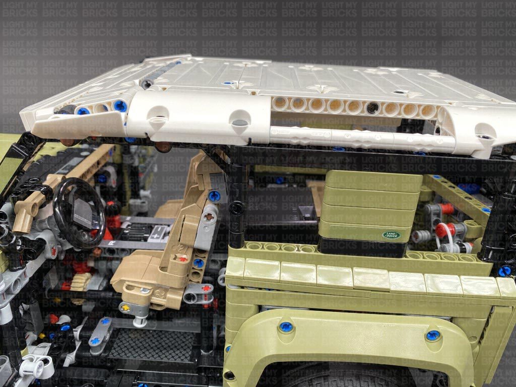
 12.) Flip the vehicle back over and disconnect the roof by first removing the following two technic pins from the top as well as the two from each side.
Lift up the roof, then disconnect the back of it from the technic pins.
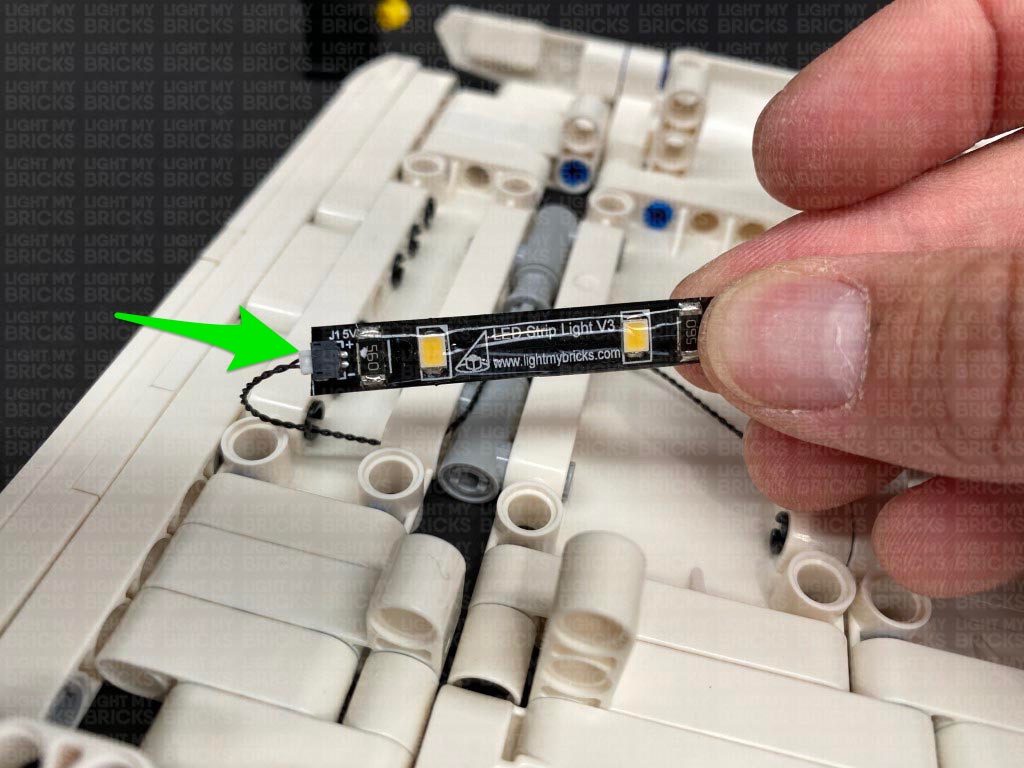
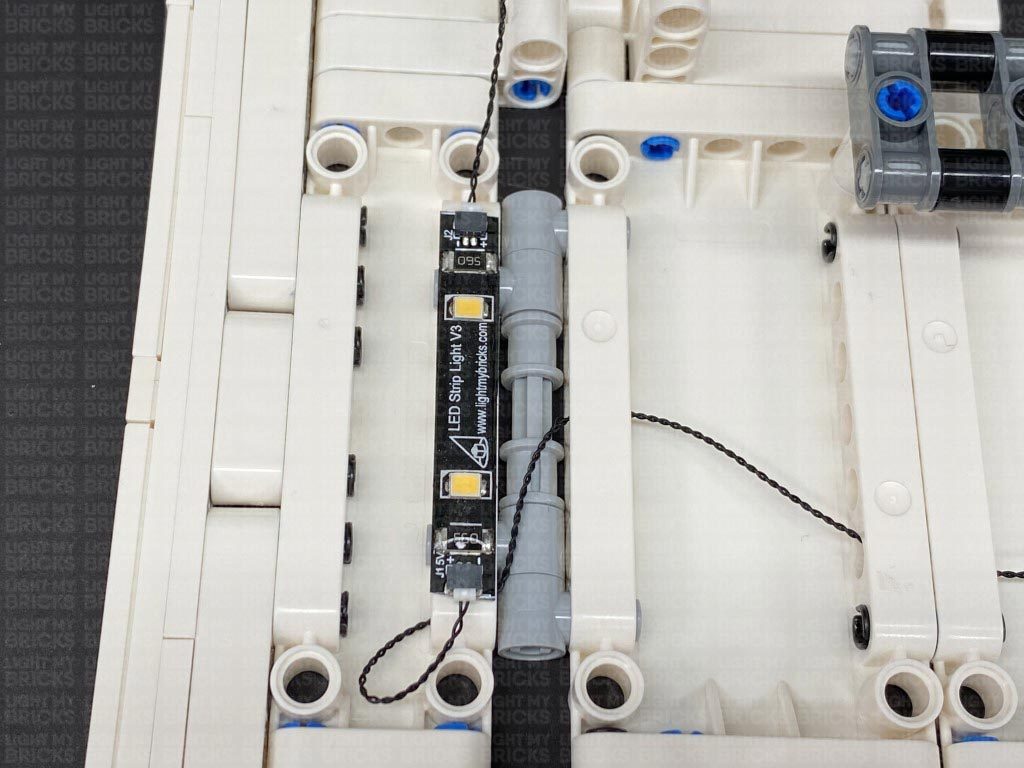
13.) Take out a White Strip Light and connect a 15cm Connecting Cable to it, then using it’s adhesive backing, stick the strip light underneath the roof in the following position. Ensure the 15cm cable is facing down as per below.
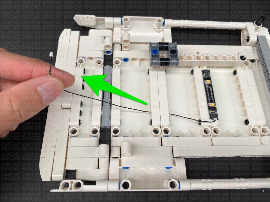
Thread the other end of the connecting cable through the following technic brick holes. Pull the cable all the way out from the other side.
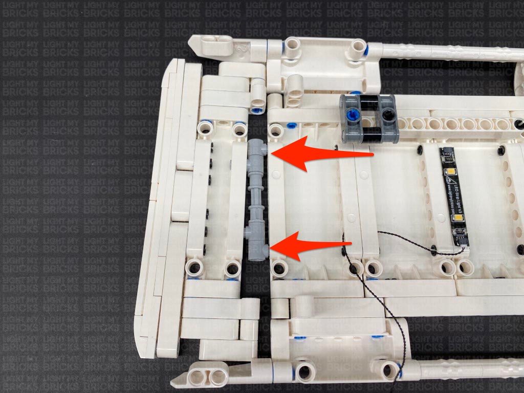
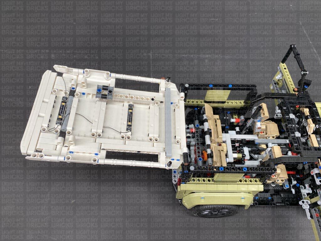
14.) Disconnect the following group of technic pieces from the main section of the roof then continue to thread the connecting cable through the middle hole.
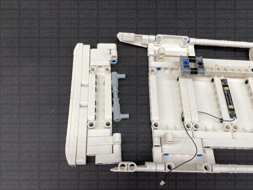
Disconnect the grey technic pieces from the back of the section we removed earlier, then reconnect it to the main roof section, ensuring the cable is laid out underneath of it.
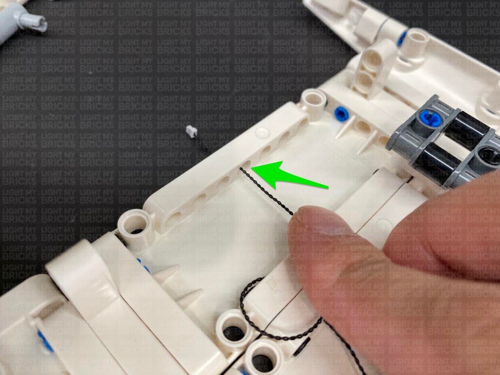
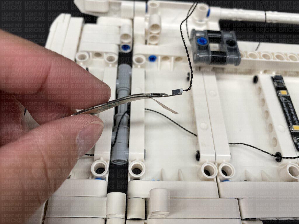
Fold the tip of the connecting cable into a “hook” shape, then hook the cable through the following hole on the technic pieces, then reconnect them to the grey technic pins, while pulling the cable out from the other side.
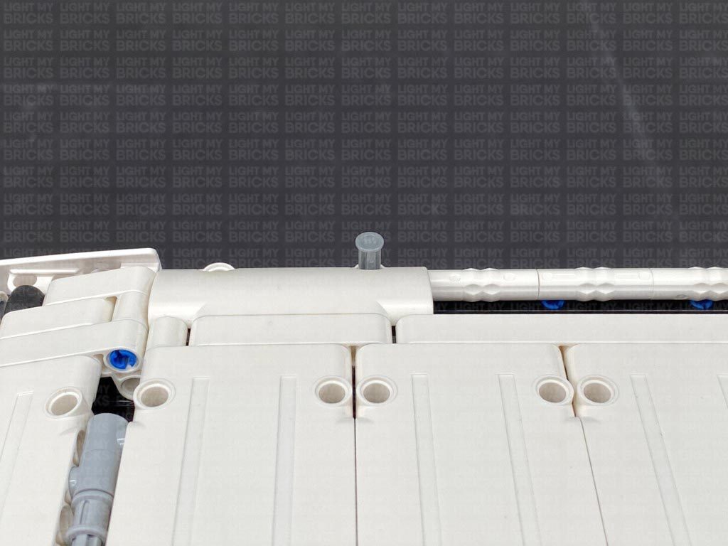
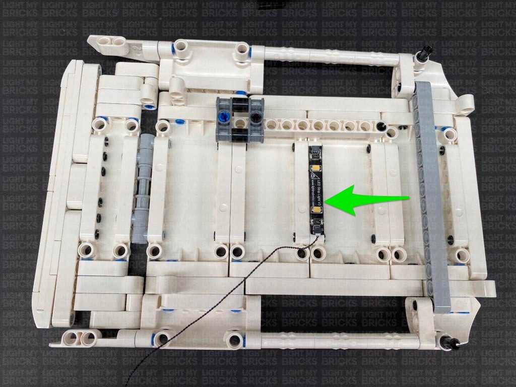
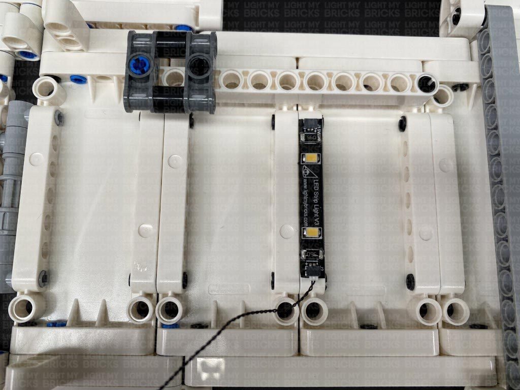
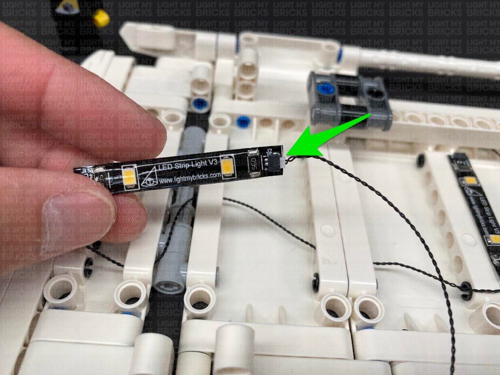
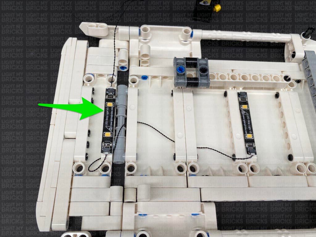
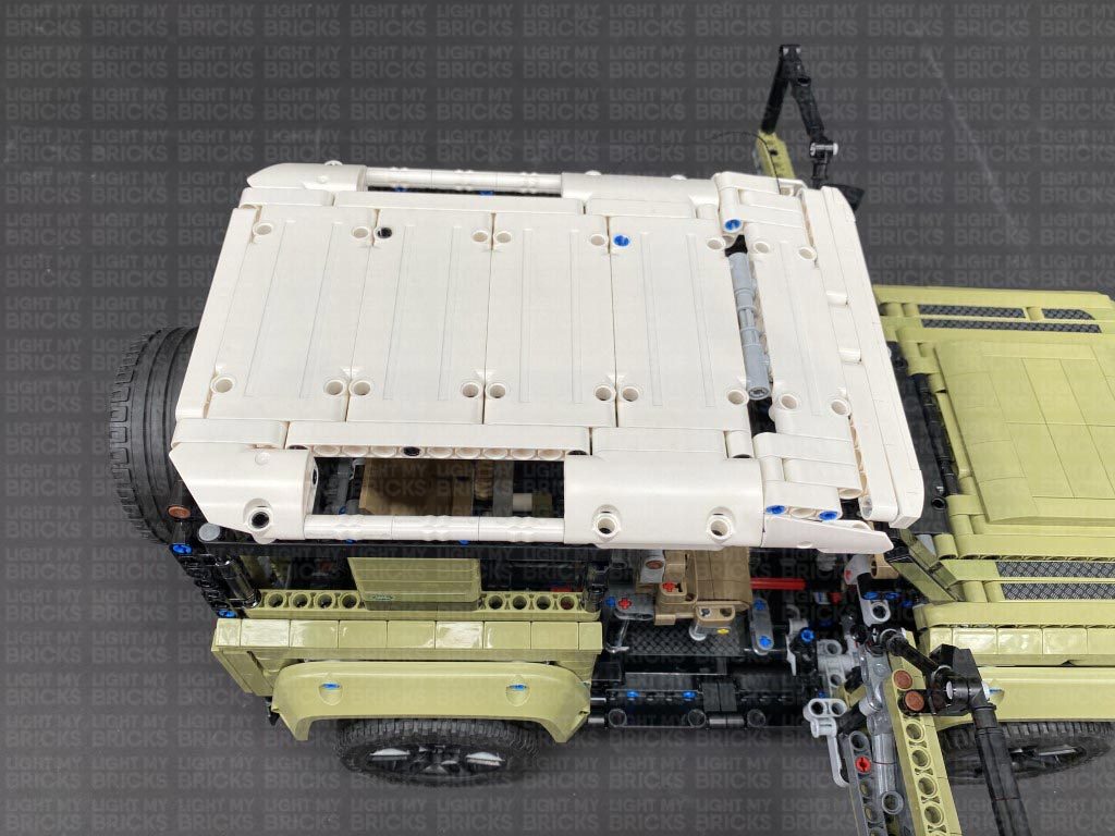
15.) Connect the cable to a new White Strip Light, then take a 30cm Connecting Cable and connect it to the strip light’s right port. Using it’s adhesive backing, stick the strip light to the roof in the following position. Ensure the 30cm cable is facing up as shown below
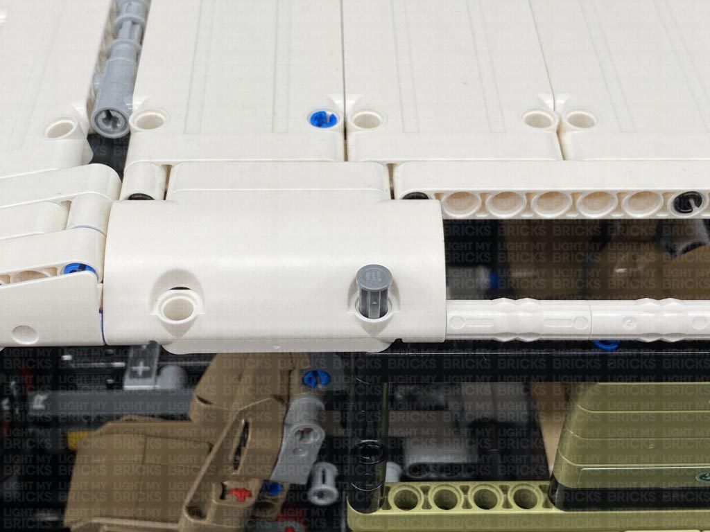
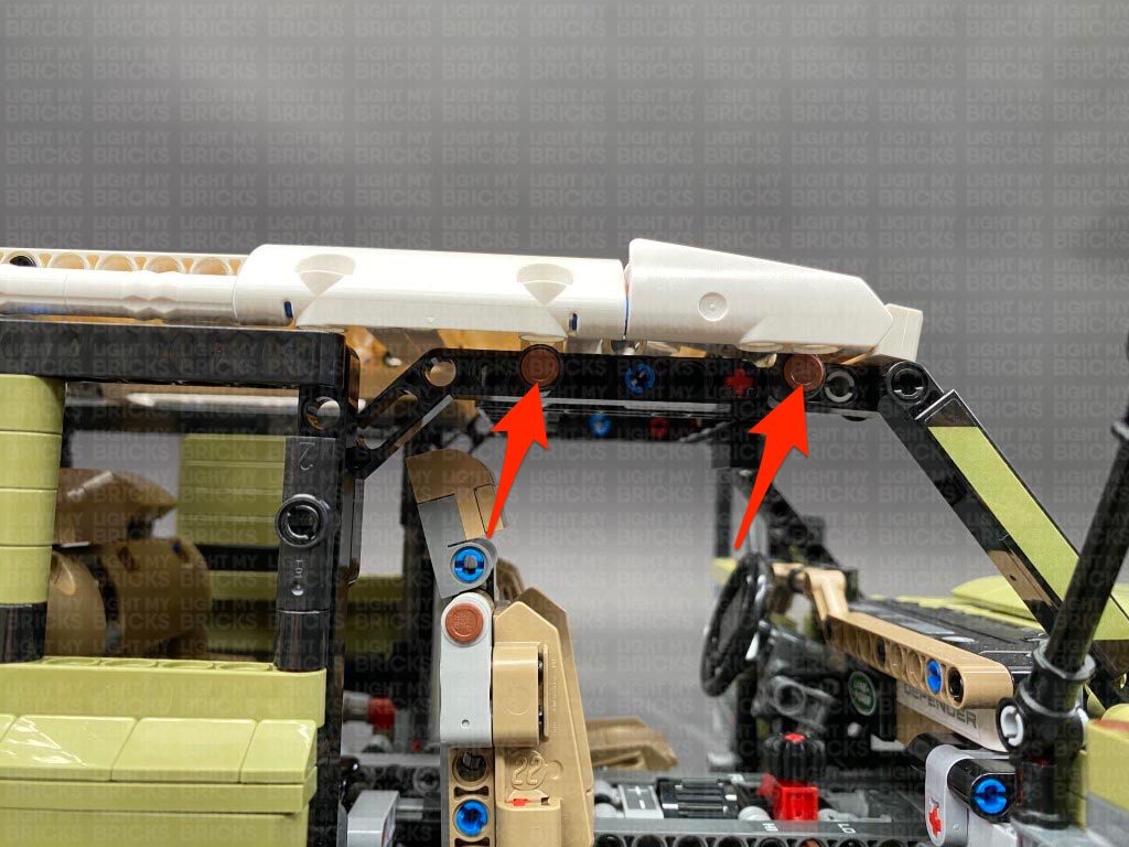
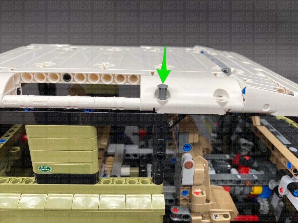
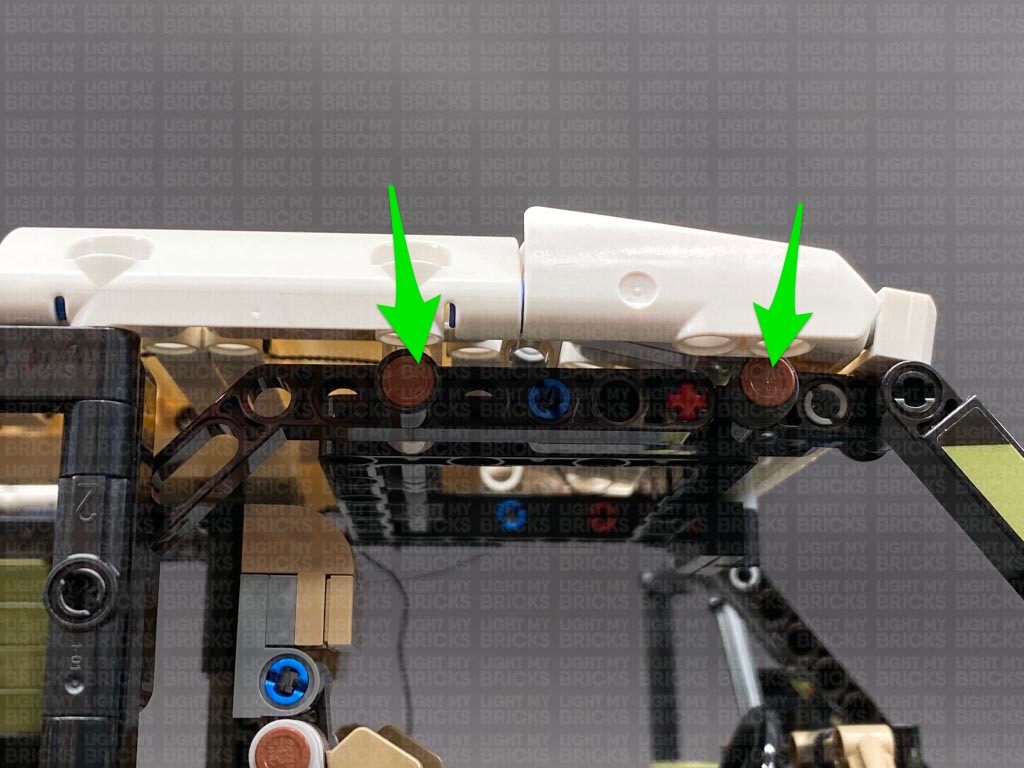
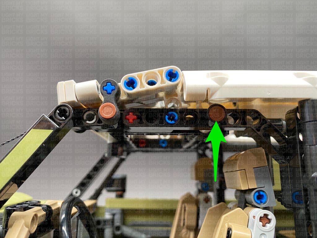
Reconnect the roof to the vehicle, then secure it down by reconnecting the two grey technic pins on the top, as well as the two brown technic pins to the right side.
Turn the vehicle over to it’s left side and reconnect the grey technic pin on the top. Leave the two brown technic pins from the left side disconnected for now.
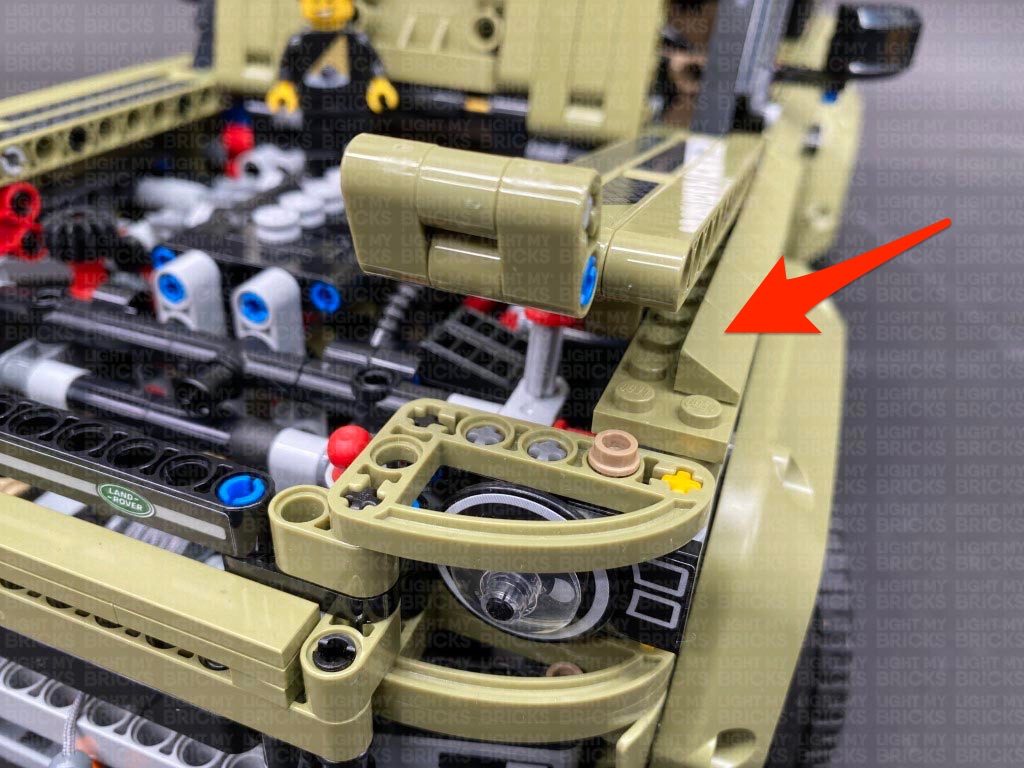
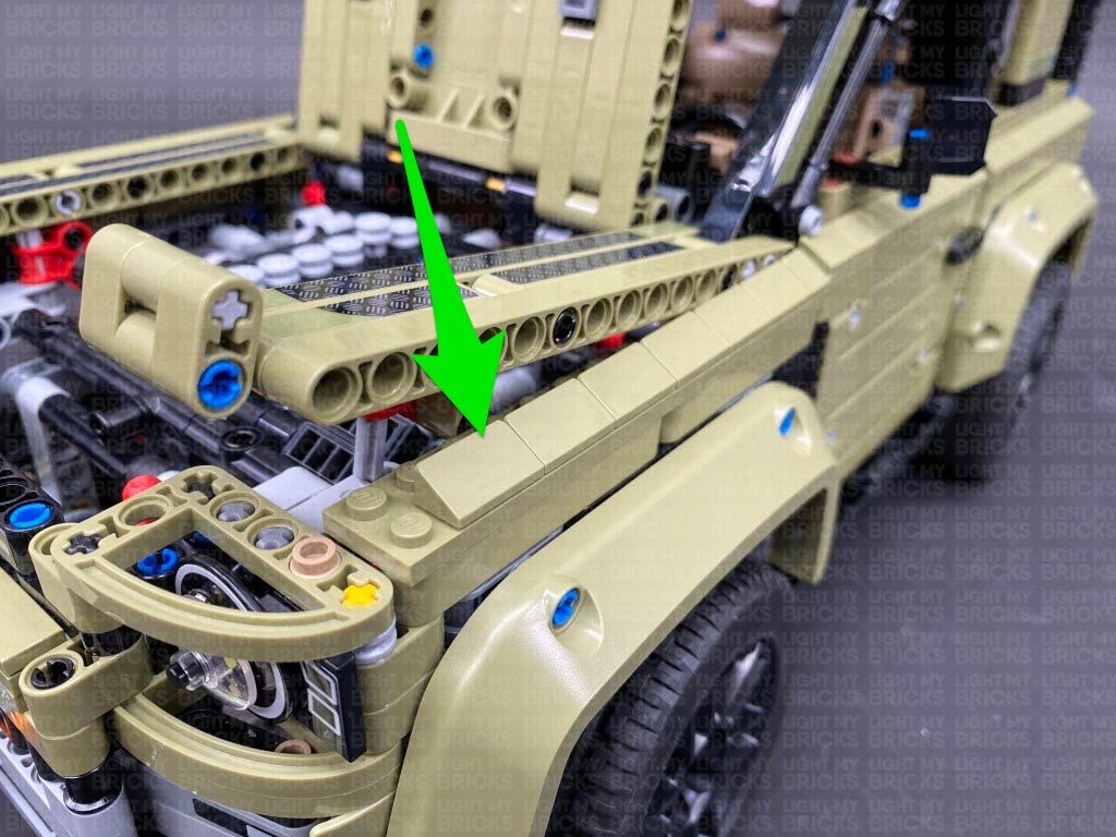
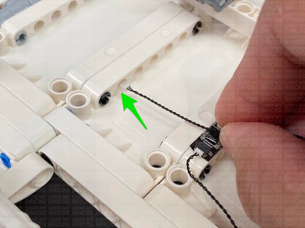
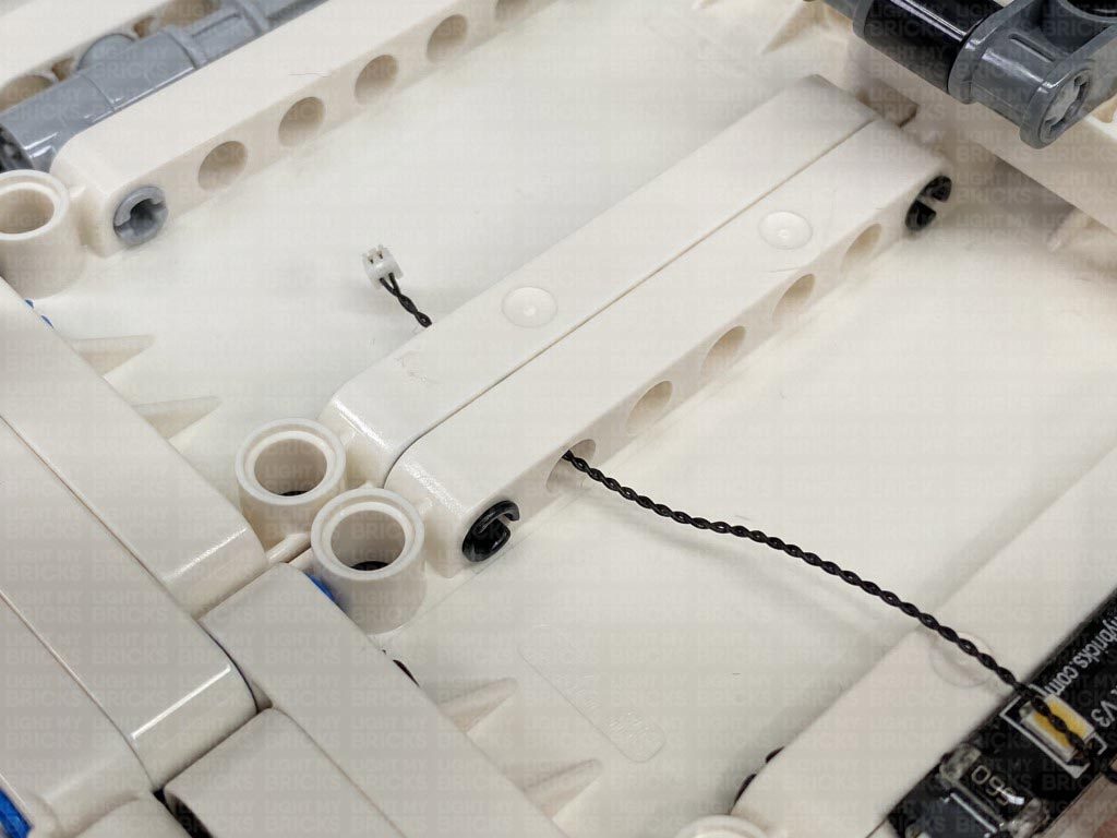
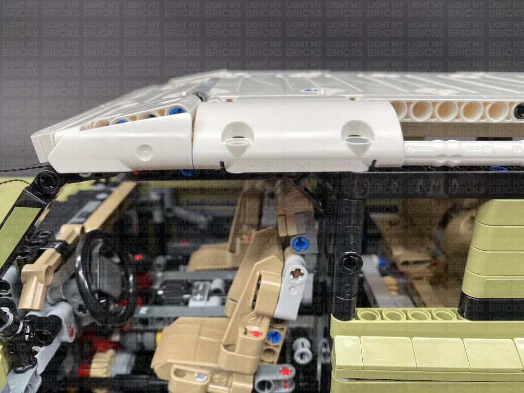
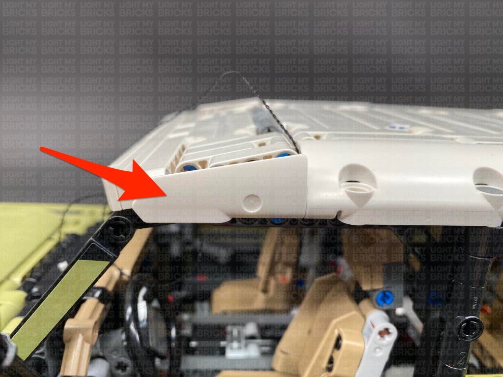
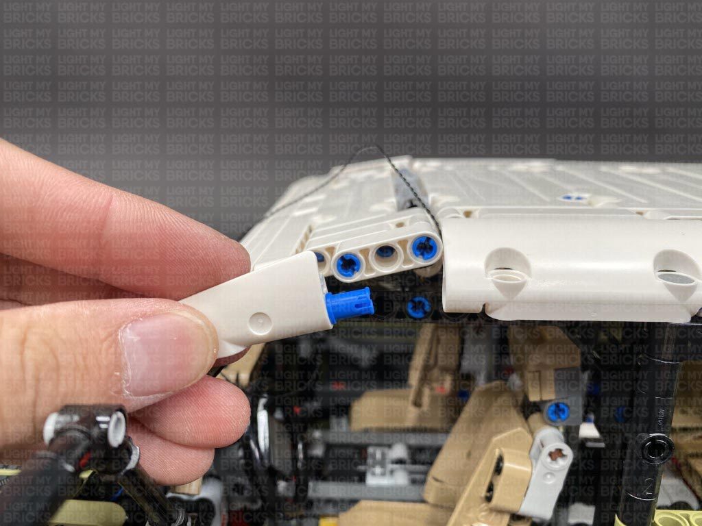
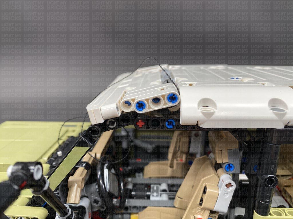
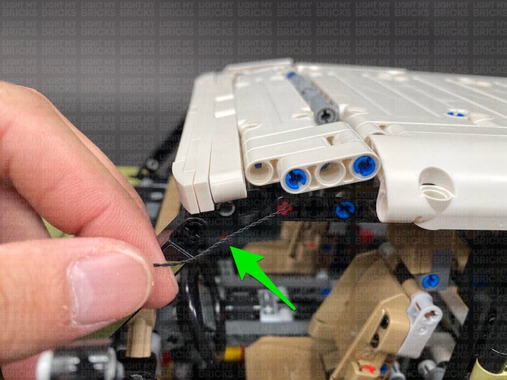
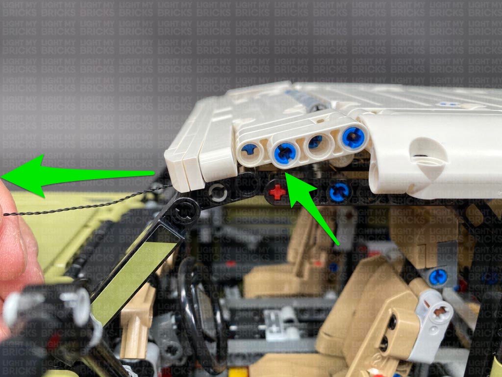
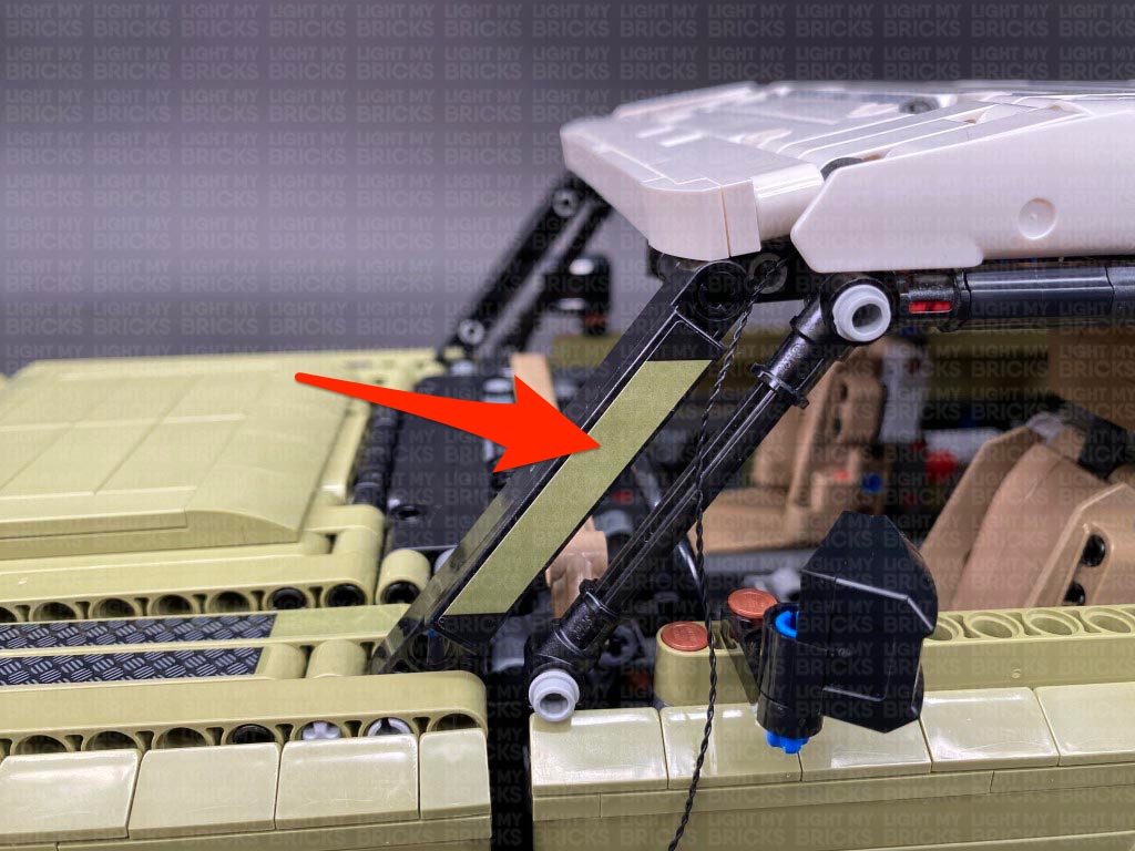
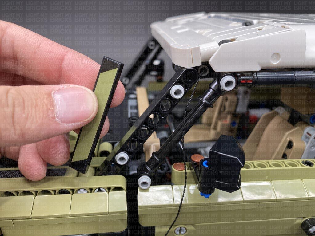
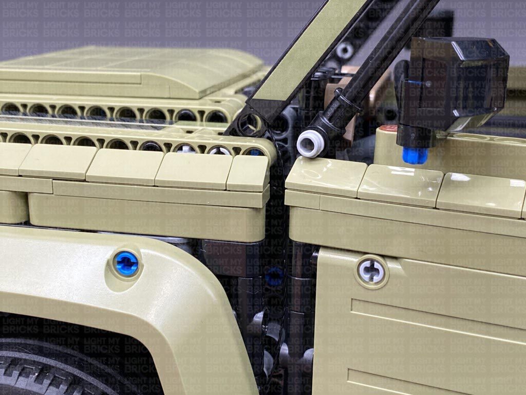
16.) Disconnect the following white technic piece, then take the 30cm connecting cable from the roof and bring it towards the front. Slip the cable in between the white and black technic pieces.
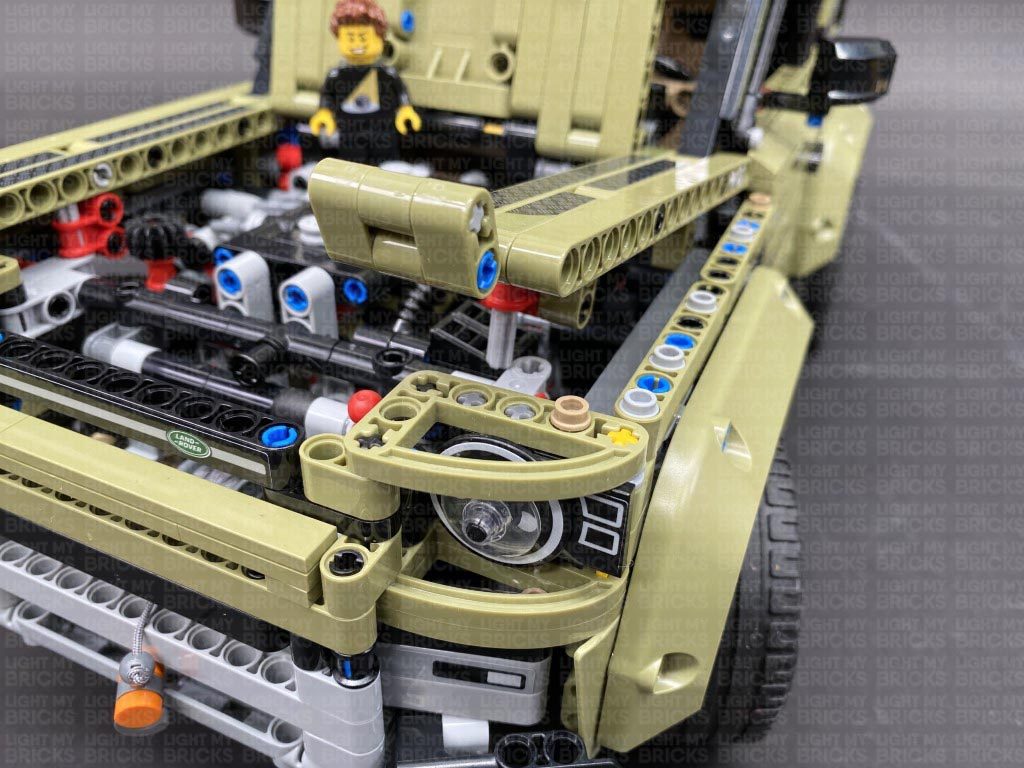
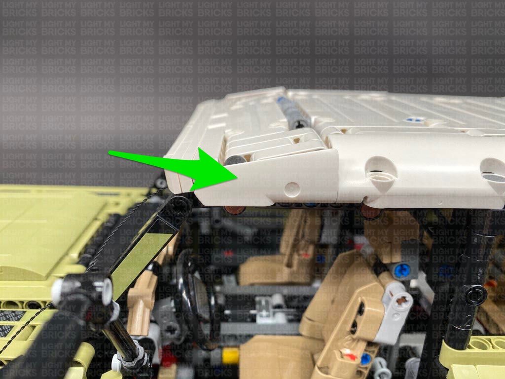
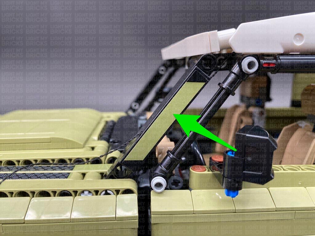
Reconnect the two brown technic pins to the side to secure the roof, then reconnect the white technic piece we removed earlier.
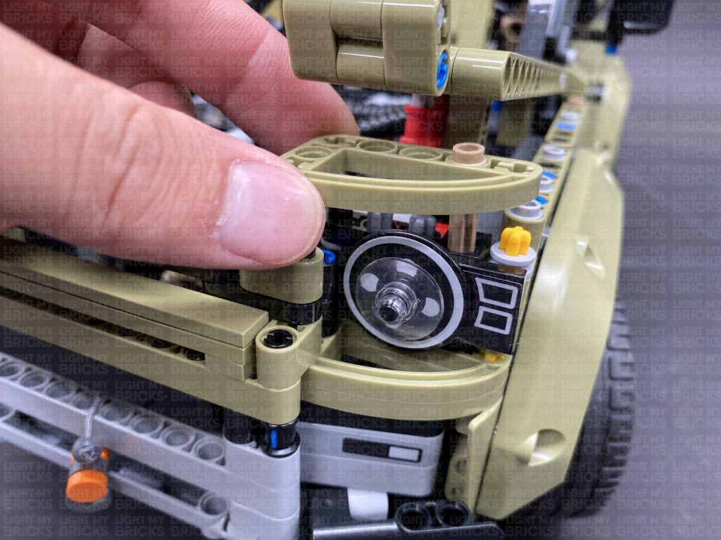
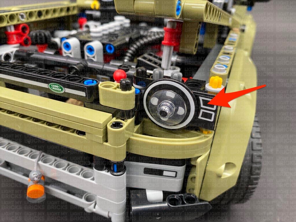
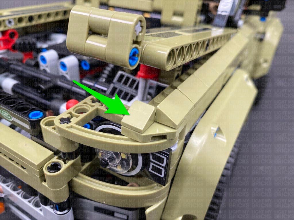
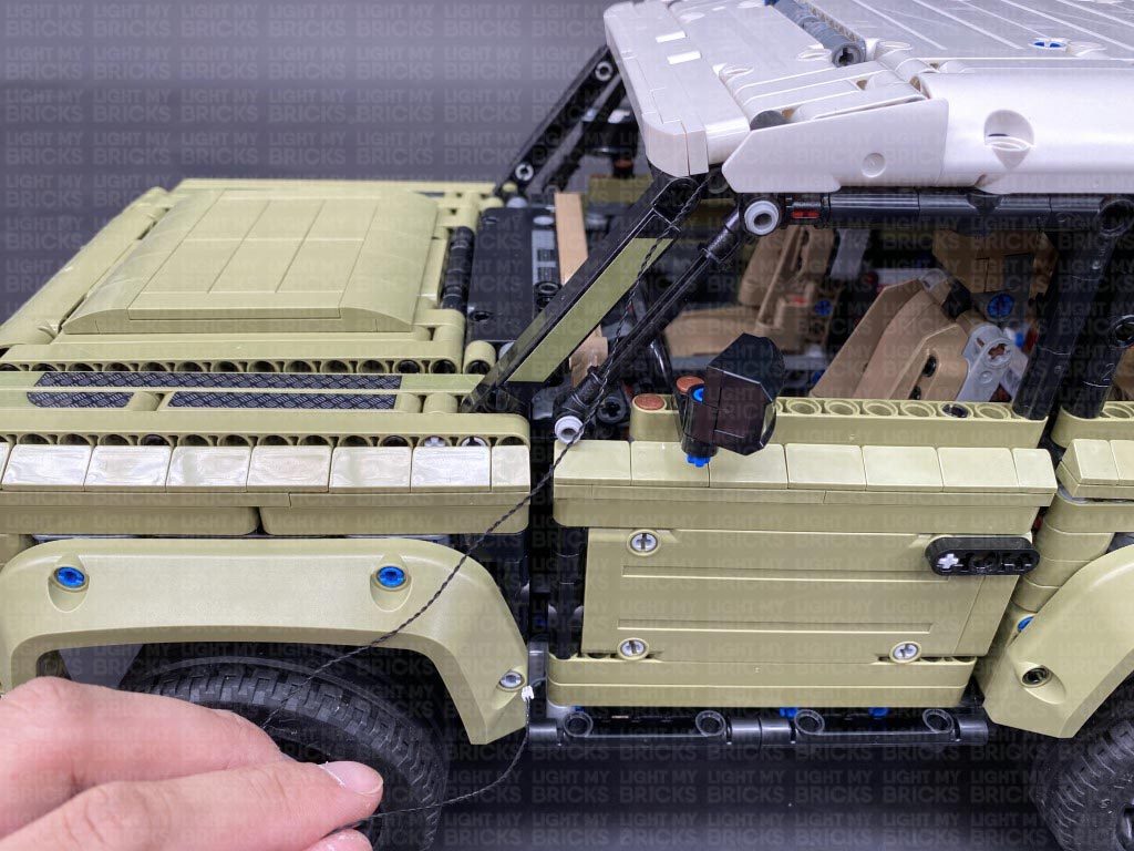
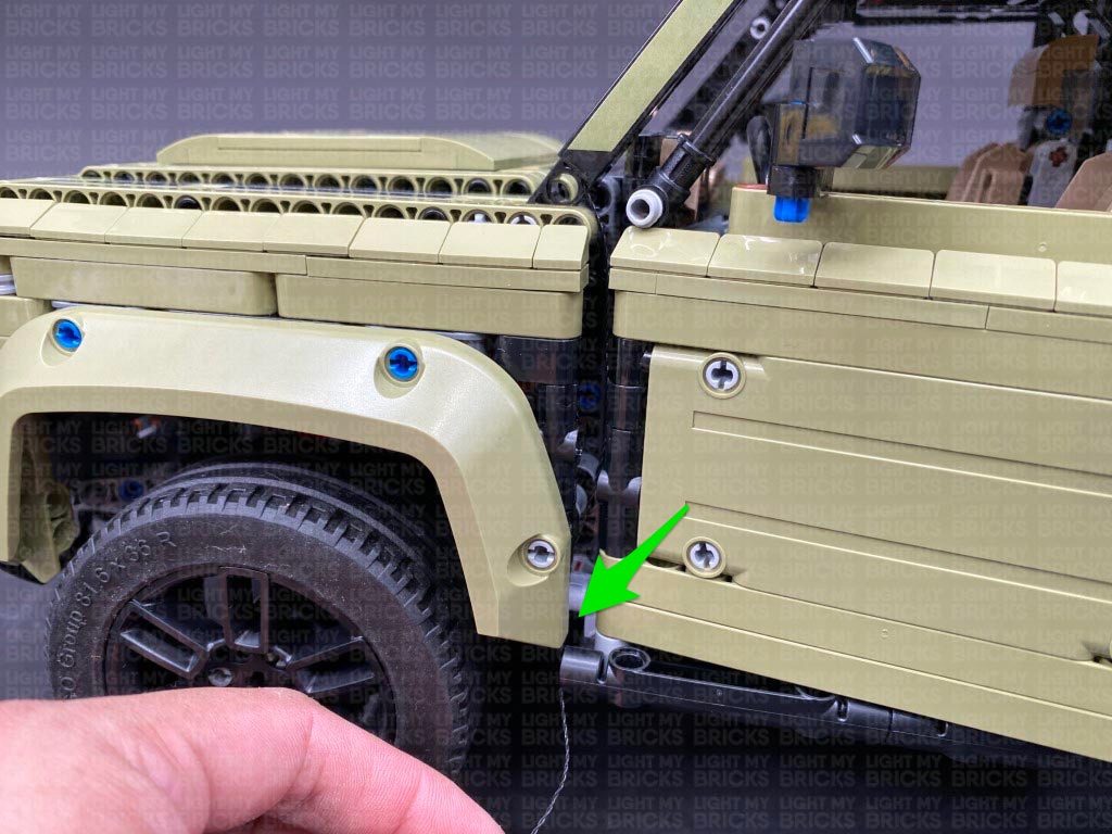
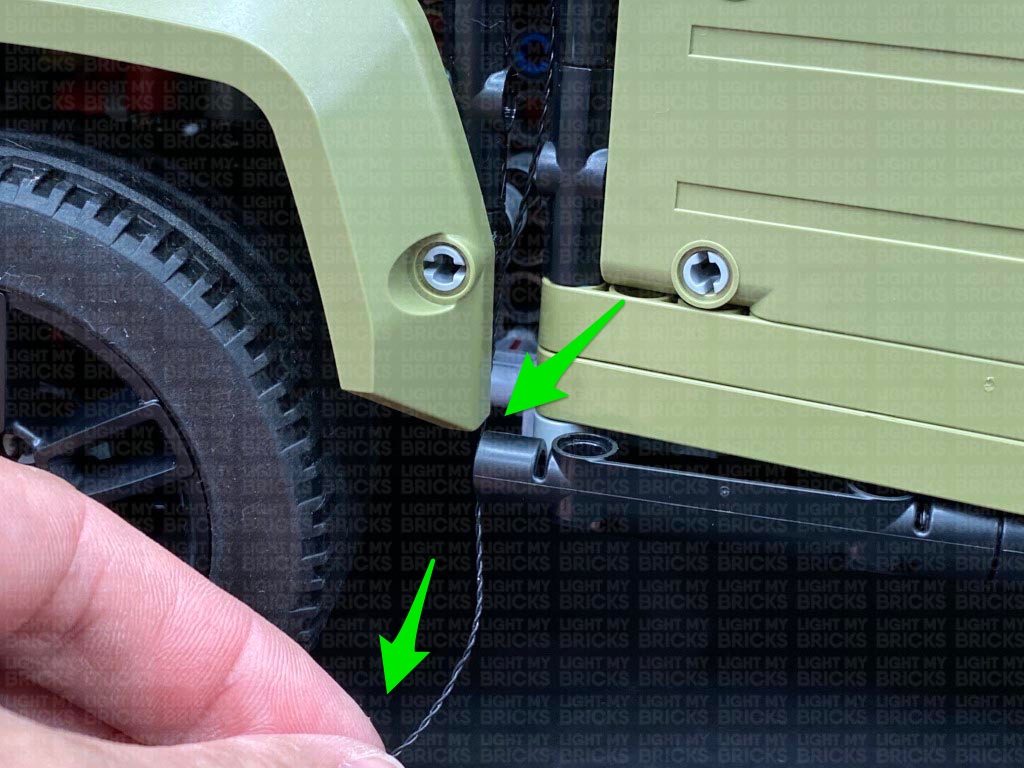
Bring the connecting cable down the left side of the windscreen, then disconnect the following tile and lay the cable under the light grey stud before reconnecting the tile over the top.
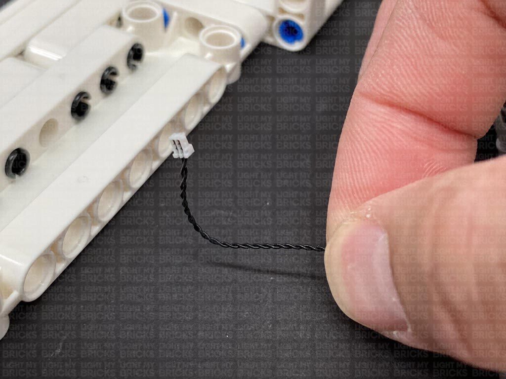
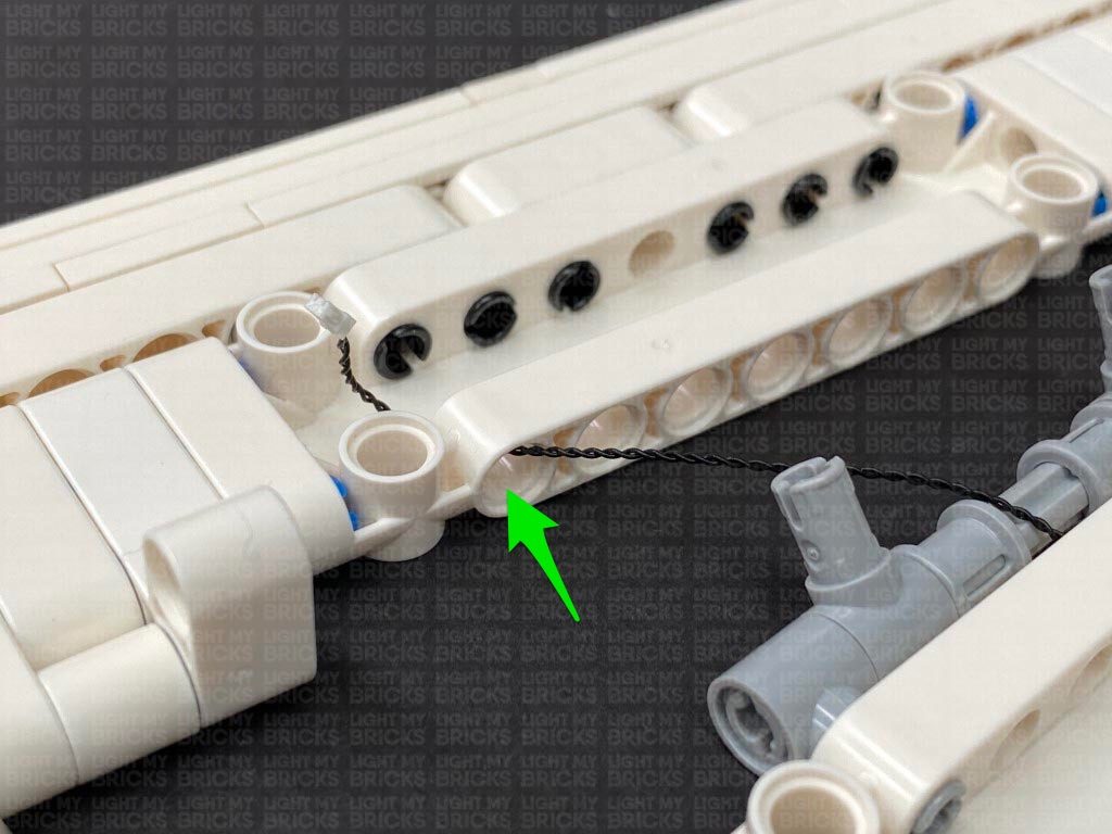
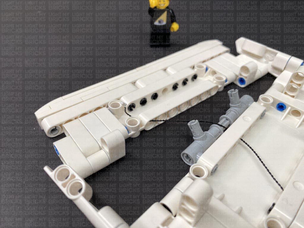
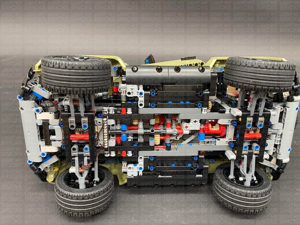
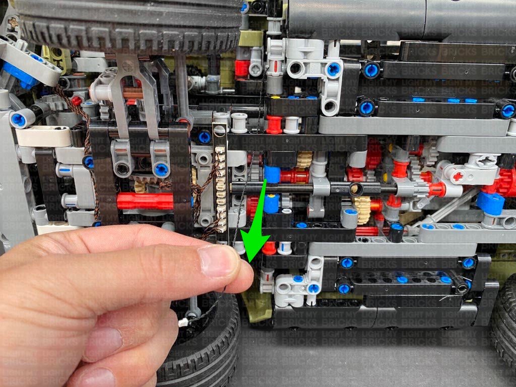
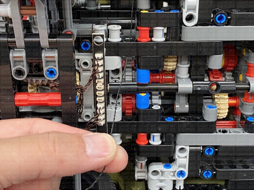
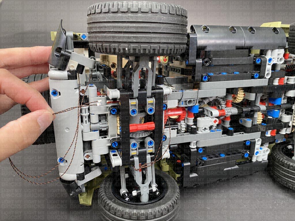
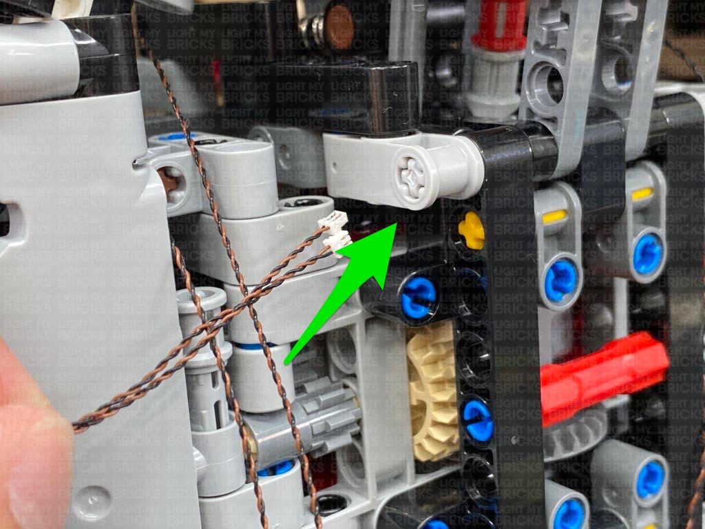
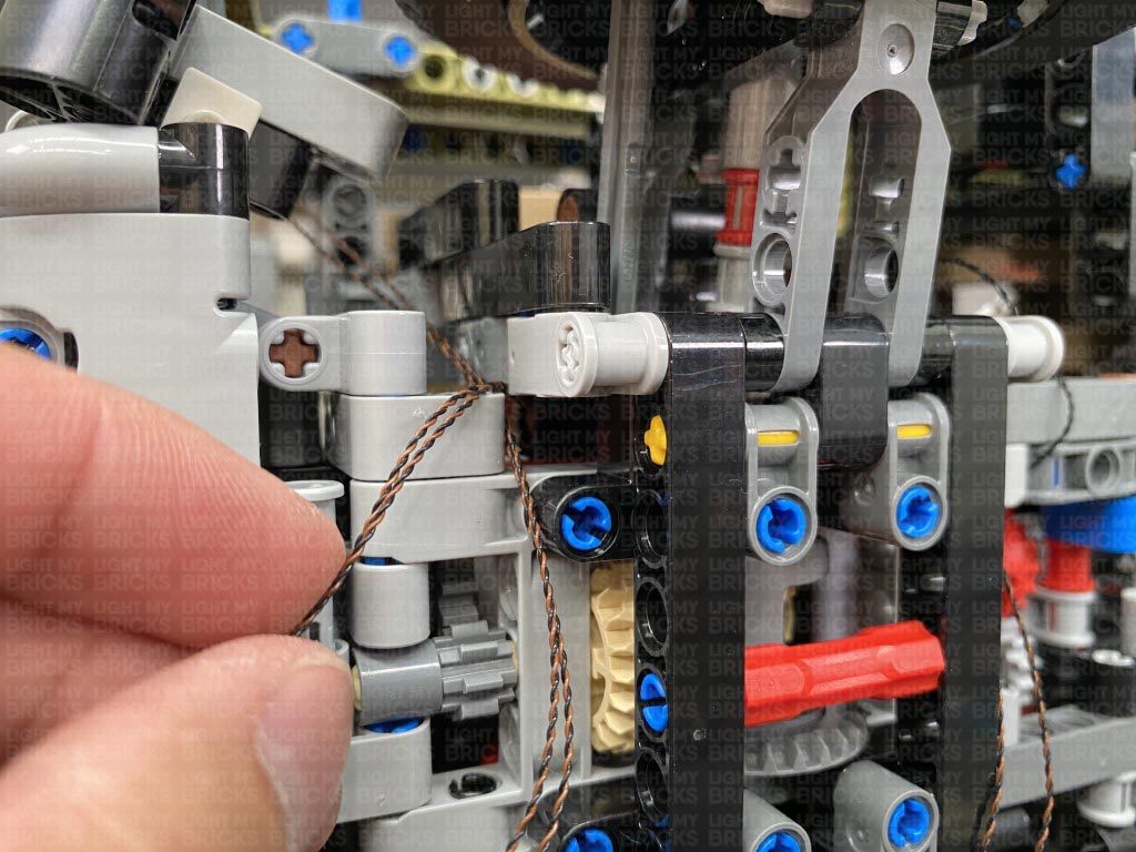
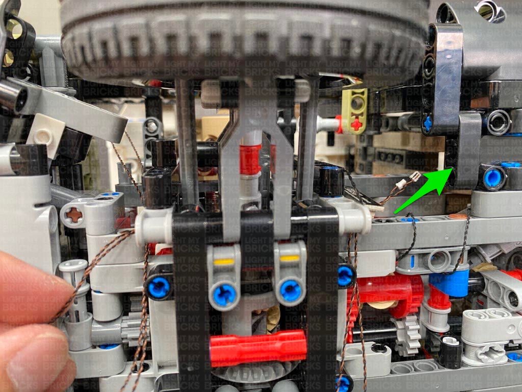
17.) Bring the connecting cable down and thread it through the following space behind the front wheel, then turn the vehicle onto it’s side so we can access underneath.
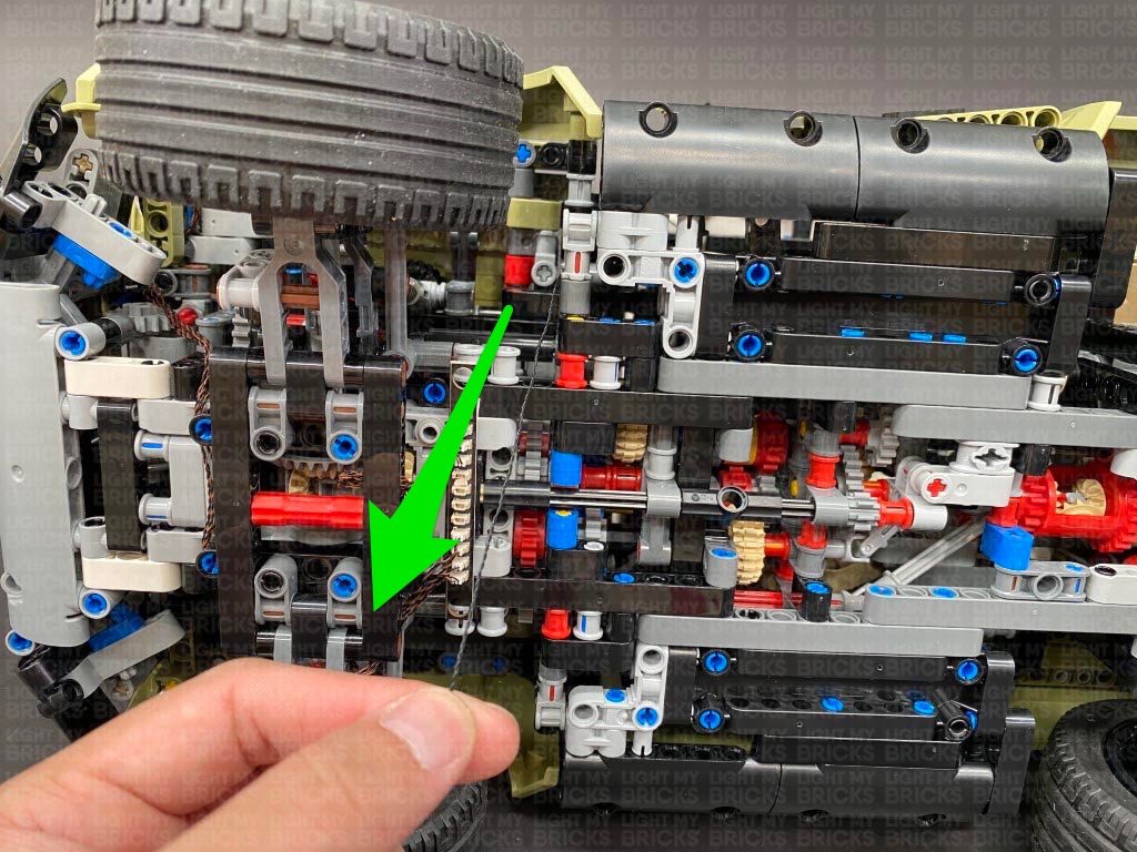
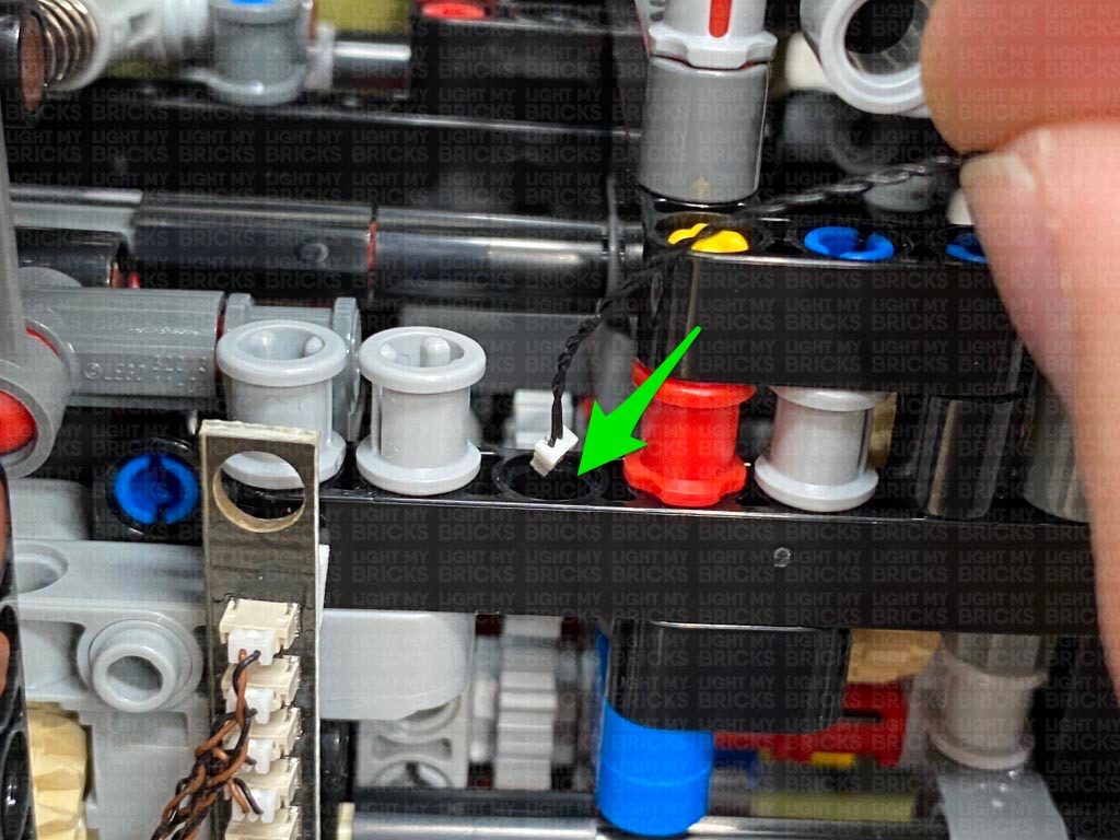
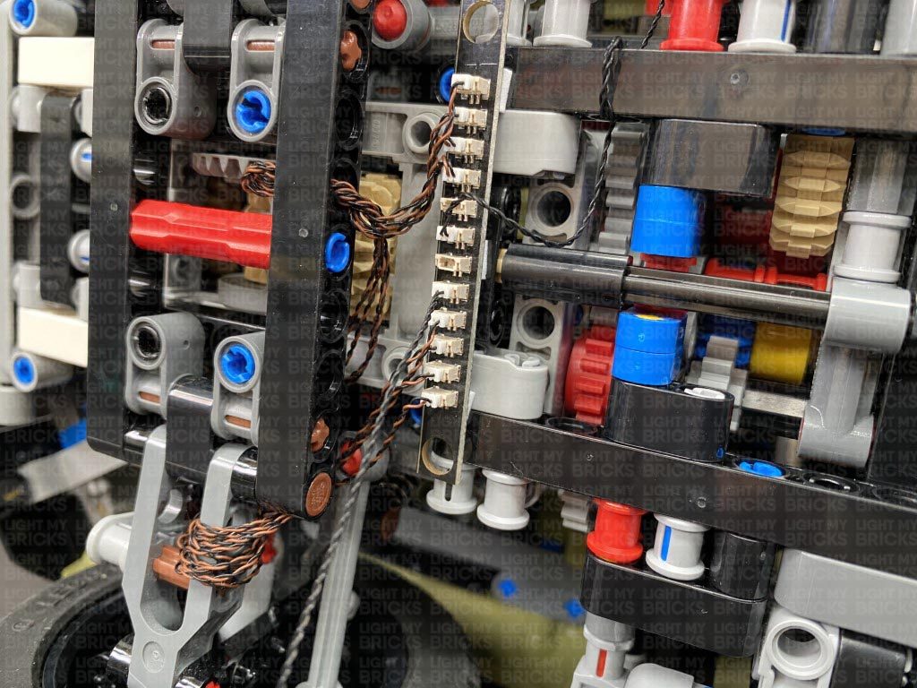
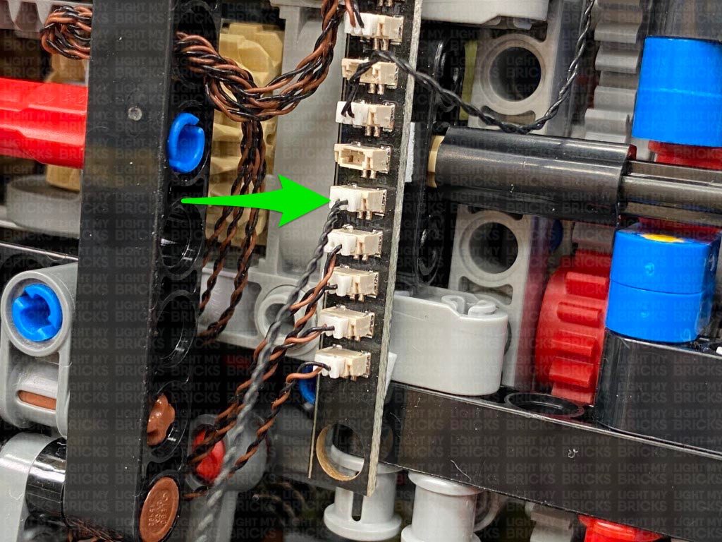
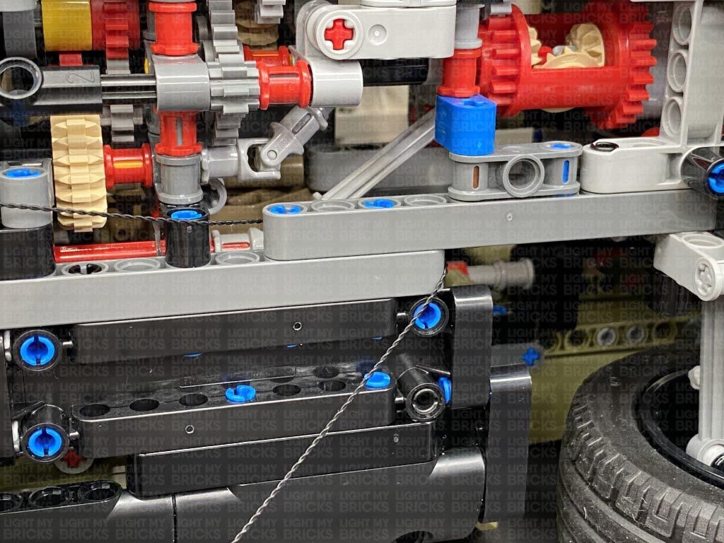
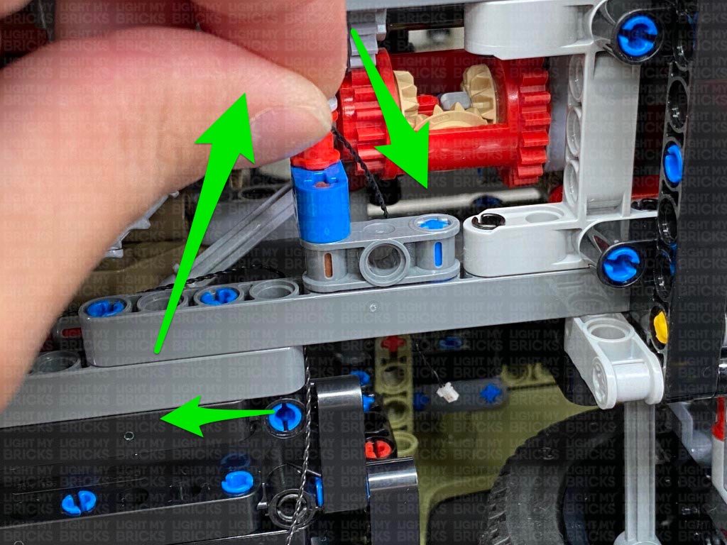
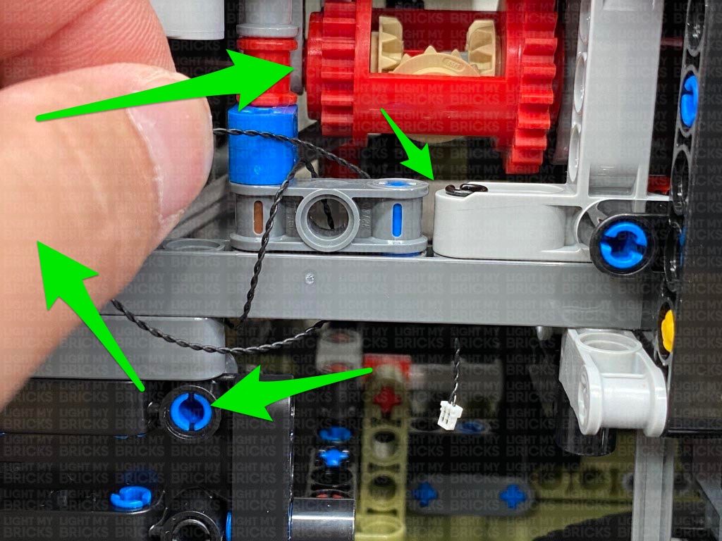
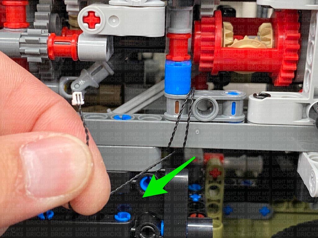
Pull the connecting cable down and thread it through the following technic hole near the expansion board. Pull the cable all the way out from below, then loop the cable and thread it back through the same hole. Repeat this to loop the cable through the hole twice (to eliminate excess cable), then connect the cable to a spare port on the 12-Port Expansion Board.
12.) Flip the vehicle back over and disconnect the roof by first removing the following two technic pins from the top as well as the two from each side.
Lift up the roof, then disconnect the back of it from the technic pins.
13.) Take out a White Strip Light and connect a 15cm Connecting Cable to it, then using it’s adhesive backing, stick the strip light underneath the roof in the following position. Ensure the 15cm cable is facing down as per below.
Thread the other end of the connecting cable through the following technic brick holes. Pull the cable all the way out from the other side.
14.) Disconnect the following group of technic pieces from the main section of the roof then continue to thread the connecting cable through the middle hole.
Disconnect the grey technic pieces from the back of the section we removed earlier, then reconnect it to the main roof section, ensuring the cable is laid out underneath of it.
Fold the tip of the connecting cable into a “hook” shape, then hook the cable through the following hole on the technic pieces, then reconnect them to the grey technic pins, while pulling the cable out from the other side.
15.) Connect the cable to a new White Strip Light, then take a 30cm Connecting Cable and connect it to the strip light’s right port. Using it’s adhesive backing, stick the strip light to the roof in the following position. Ensure the 30cm cable is facing up as shown below
Reconnect the roof to the vehicle, then secure it down by reconnecting the two grey technic pins on the top, as well as the two brown technic pins to the right side.
Turn the vehicle over to it’s left side and reconnect the grey technic pin on the top. Leave the two brown technic pins from the left side disconnected for now.
16.) Disconnect the following white technic piece, then take the 30cm connecting cable from the roof and bring it towards the front. Slip the cable in between the white and black technic pieces.
Reconnect the two brown technic pins to the side to secure the roof, then reconnect the white technic piece we removed earlier.
Bring the connecting cable down the left side of the windscreen, then disconnect the following tile and lay the cable under the light grey stud before reconnecting the tile over the top.
17.) Bring the connecting cable down and thread it through the following space behind the front wheel, then turn the vehicle onto it’s side so we can access underneath.
Pull the connecting cable down and thread it through the following technic hole near the expansion board. Pull the cable all the way out from below, then loop the cable and thread it back through the same hole. Repeat this to loop the cable through the hole twice (to eliminate excess cable), then connect the cable to a spare port on the 12-Port Expansion Board.
 Take the AA Battery Pack and connect it to a spare port on the expansion board, then turn it ON to test the internal strip lights are working OK.
Note: If you experience any issues with the lights not working and suspect an issue with a component, please try a different port on the expansion board to verify where the fault lies (with the light, expansion board or effects board). To correct any issues with expansion board ports, please view the section addressing expansion board issues on our online troubleshooting guide.
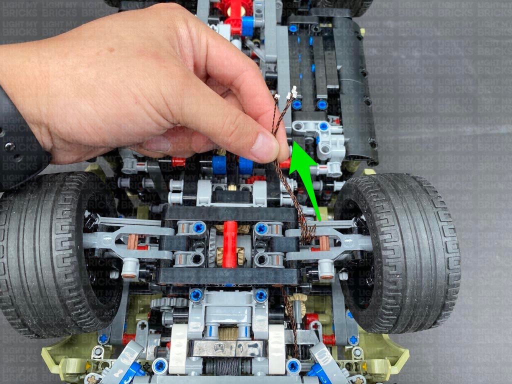
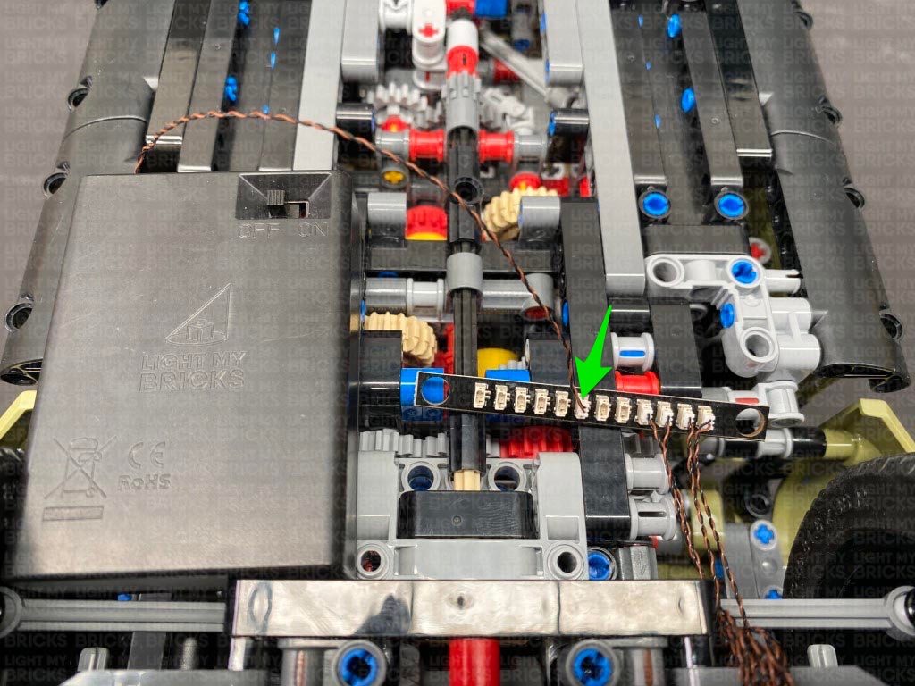
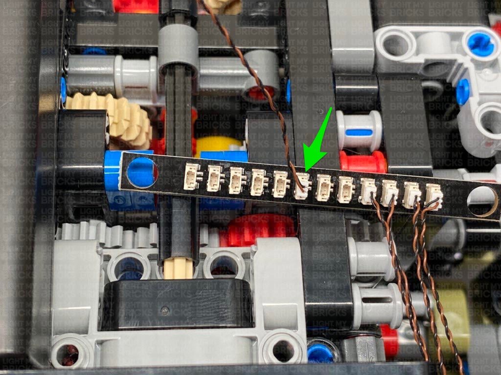
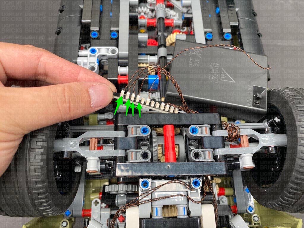
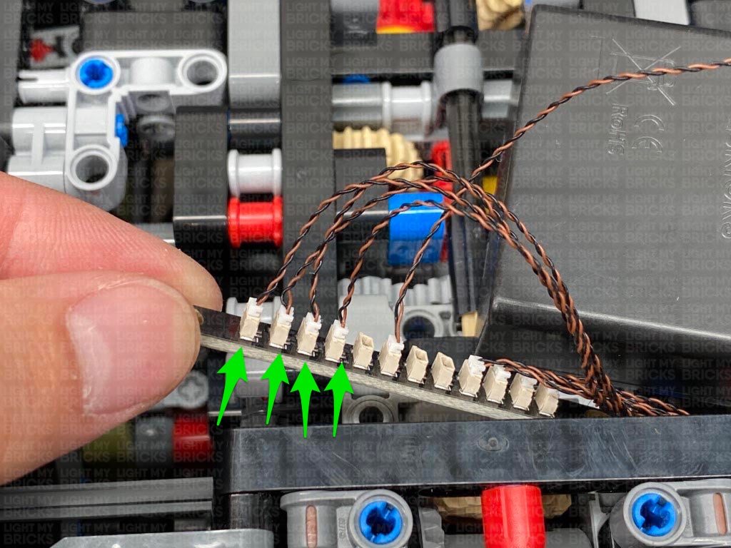
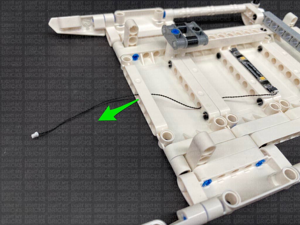
18.) Disconnect the AA battery Pack from the expansion board again, then take out a new 30cm Connecting Cable and connect it to a spare port.
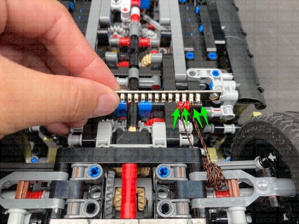
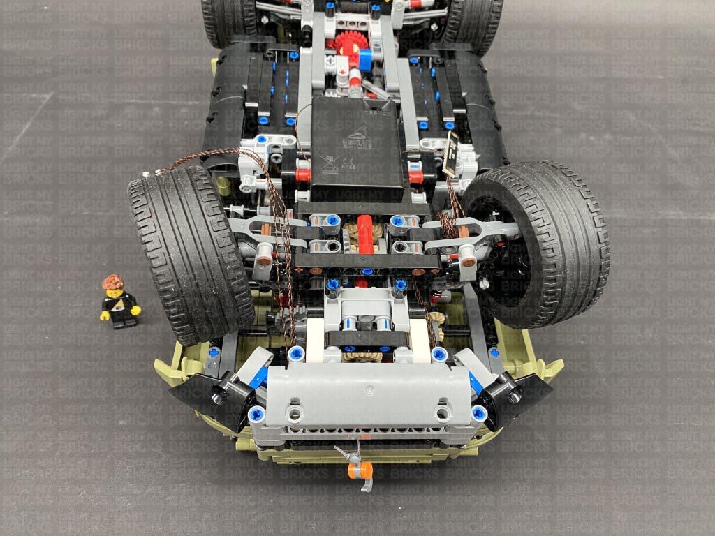
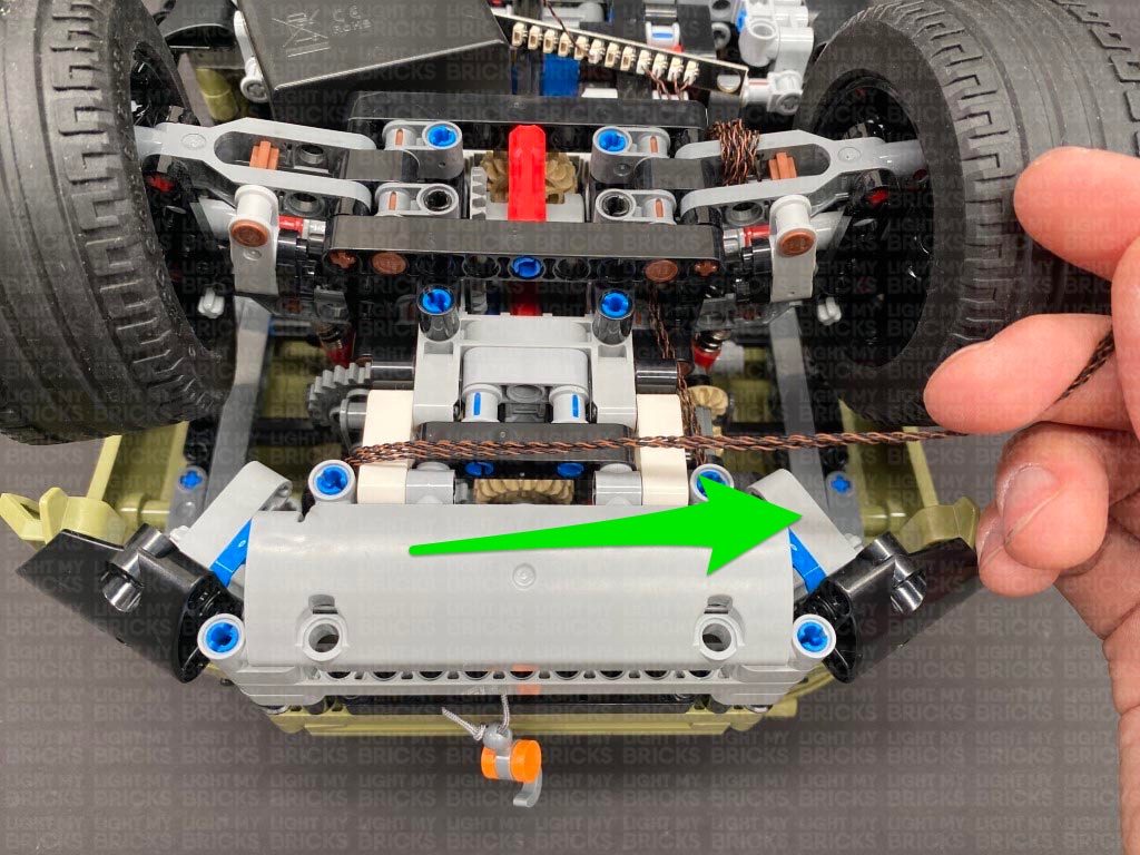
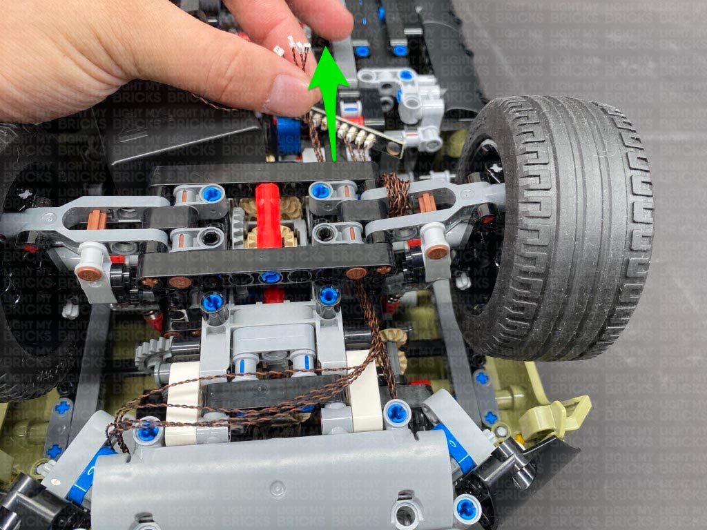
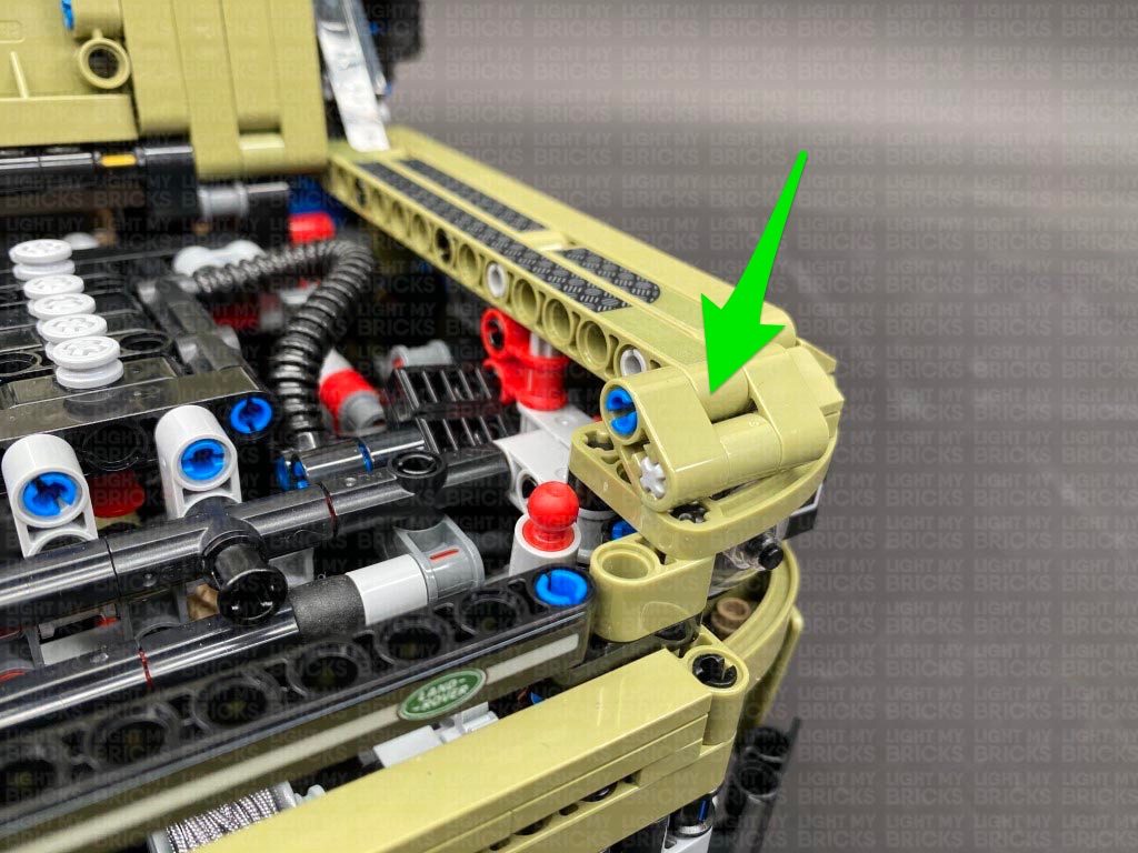
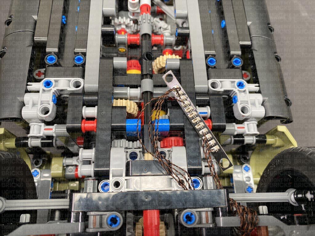
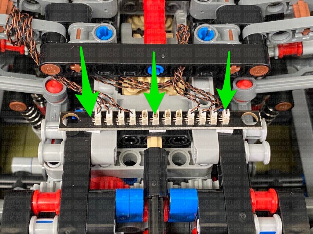
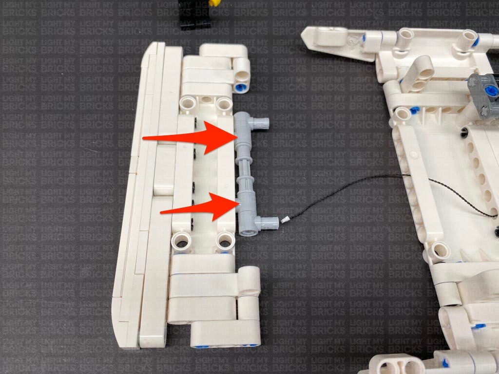
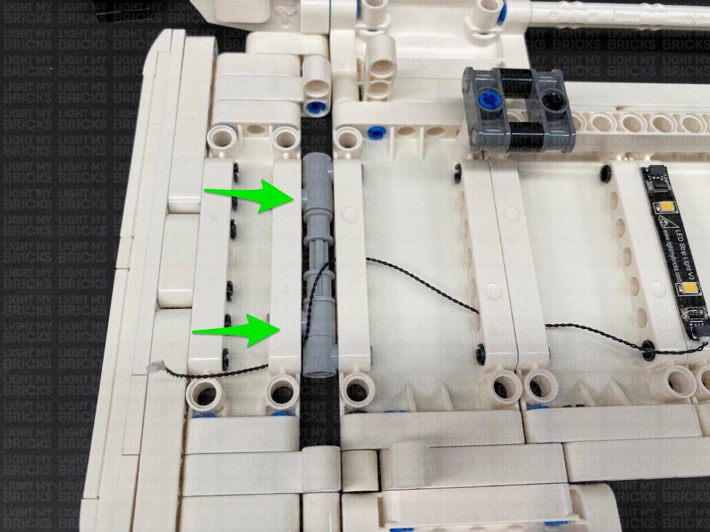
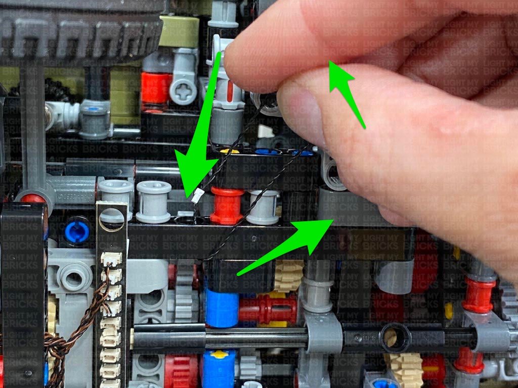
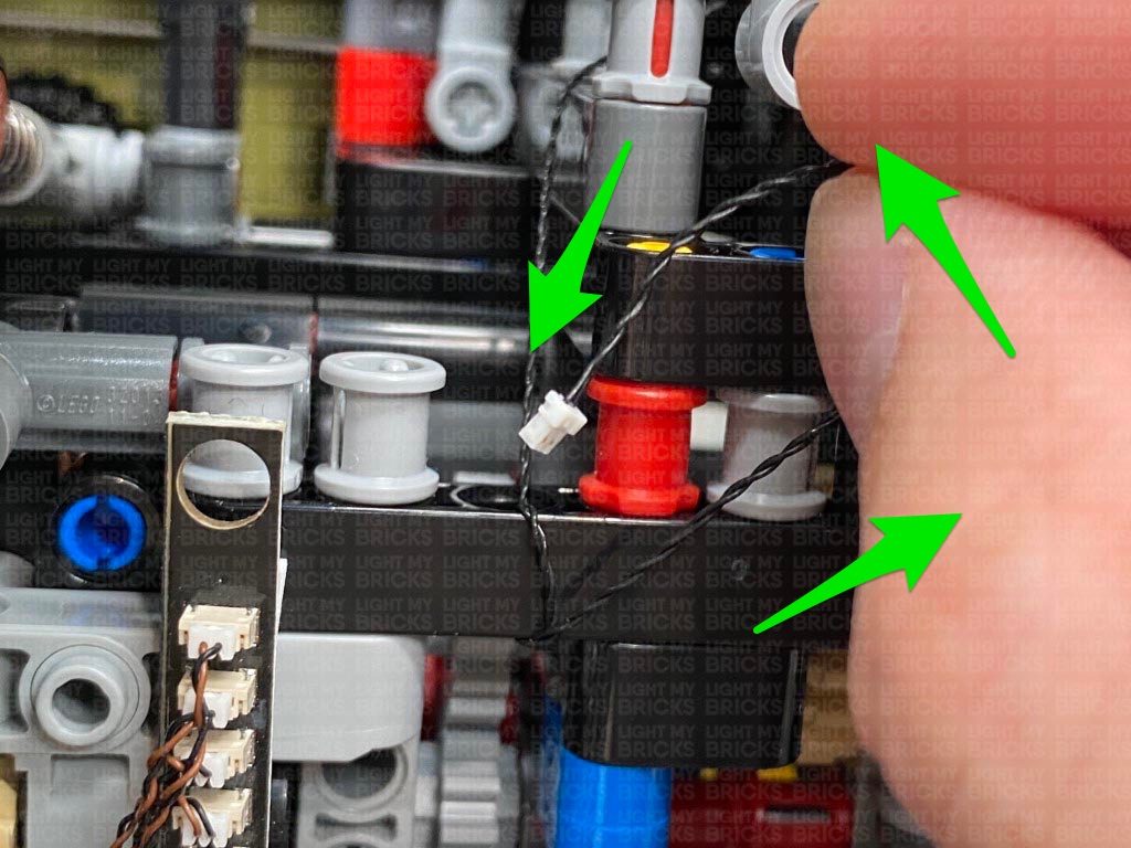
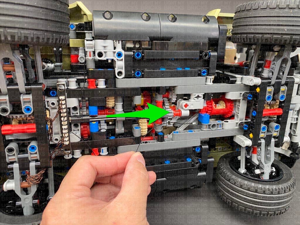
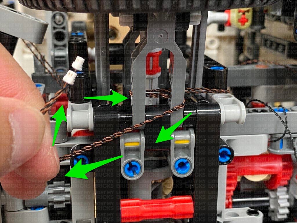
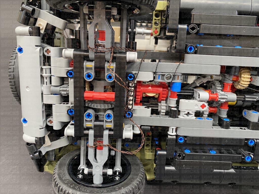
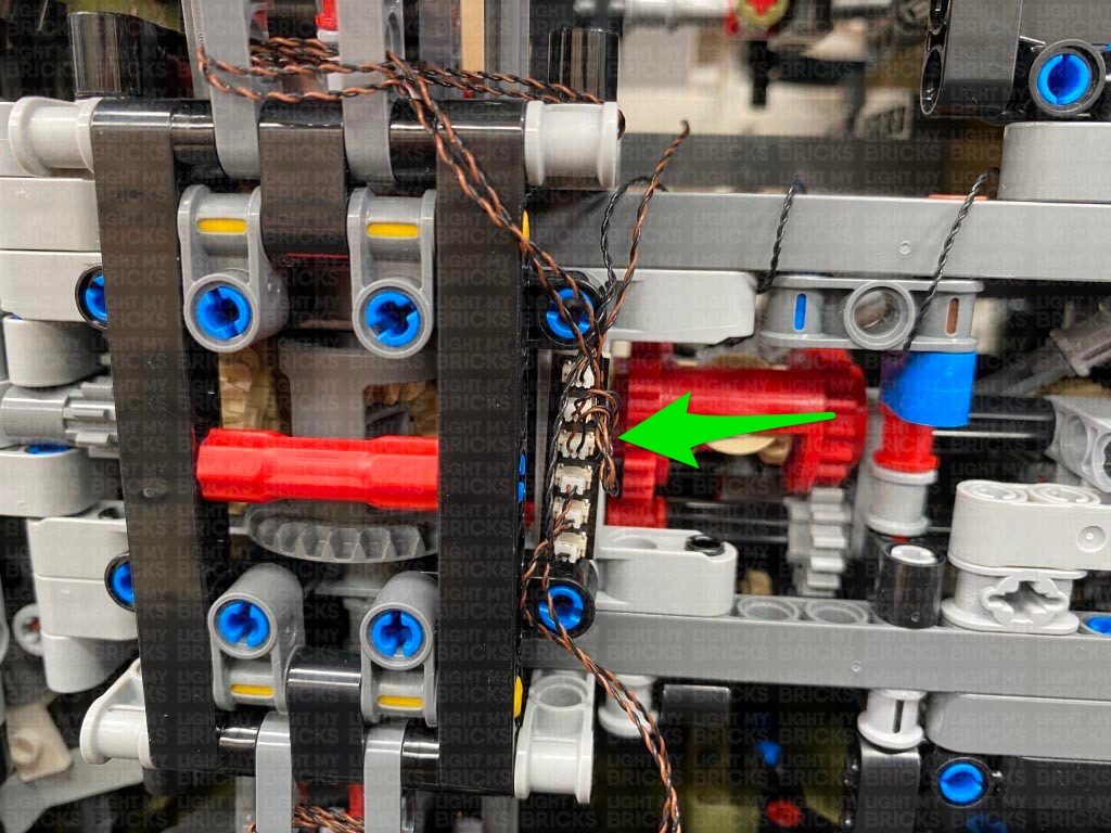
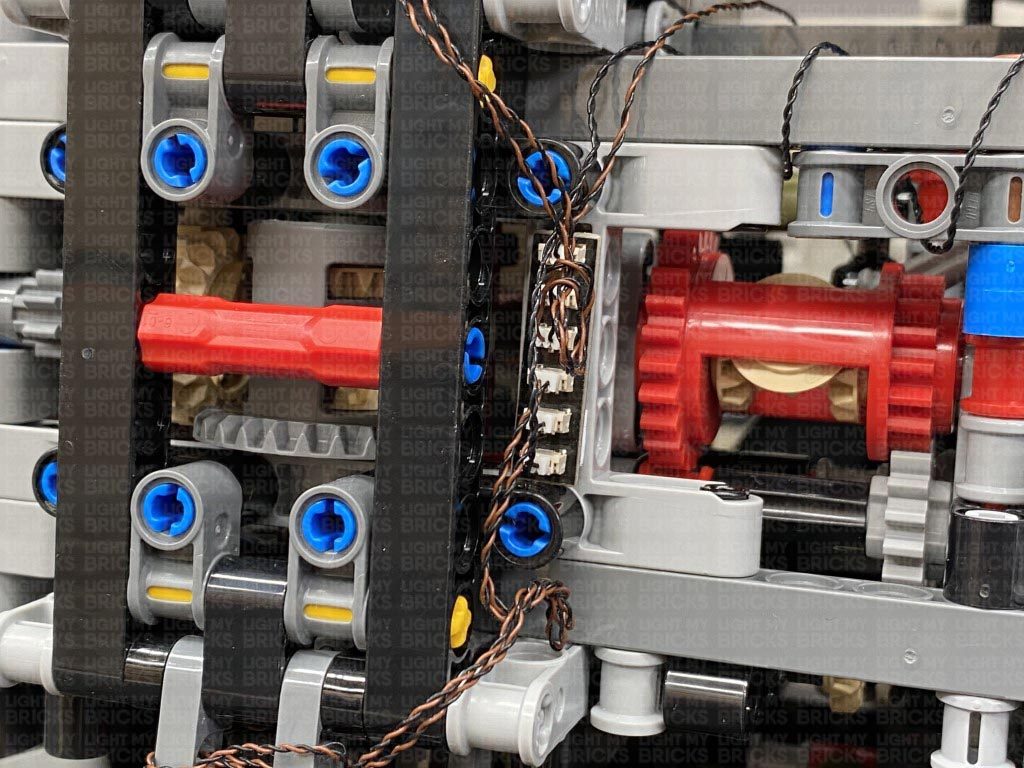
Bring the 30cm cable toward the back of the vehicle and thread it underneath the following grey technic pieces. Pull the cable all the way down from below, then loop the cable over the technic pieces above.
Take the AA Battery Pack and connect it to a spare port on the expansion board, then turn it ON to test the internal strip lights are working OK.
Note: If you experience any issues with the lights not working and suspect an issue with a component, please try a different port on the expansion board to verify where the fault lies (with the light, expansion board or effects board). To correct any issues with expansion board ports, please view the section addressing expansion board issues on our online troubleshooting guide.
18.) Disconnect the AA battery Pack from the expansion board again, then take out a new 30cm Connecting Cable and connect it to a spare port.
Bring the 30cm cable toward the back of the vehicle and thread it underneath the following grey technic pieces. Pull the cable all the way down from below, then loop the cable over the technic pieces above.
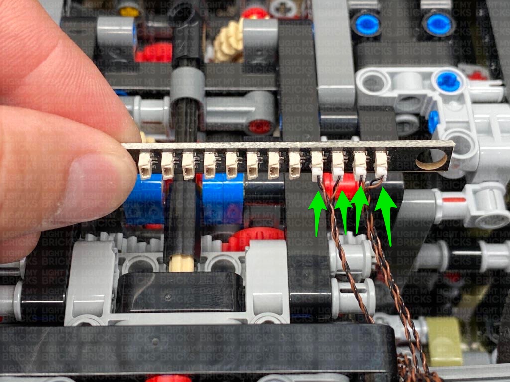
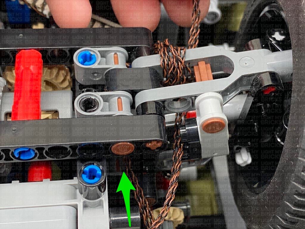
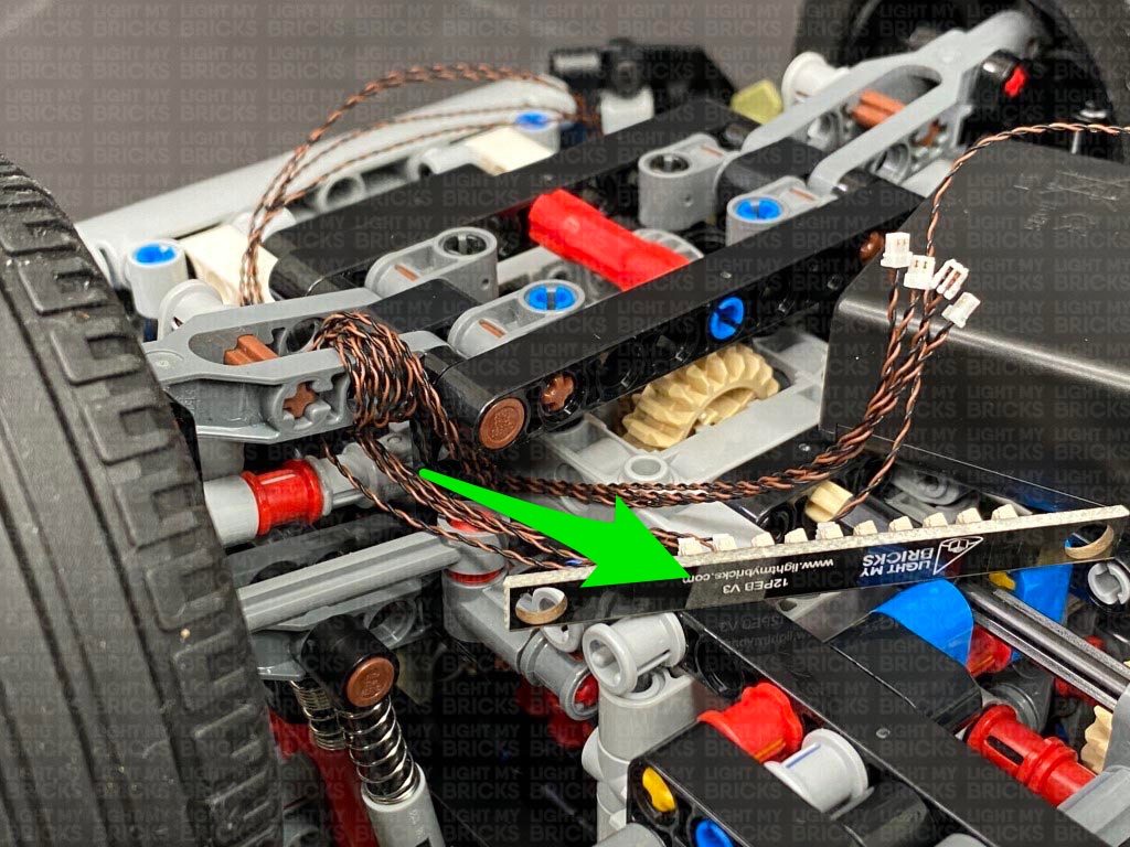
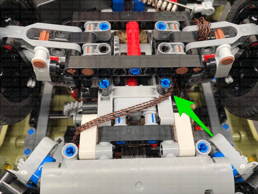
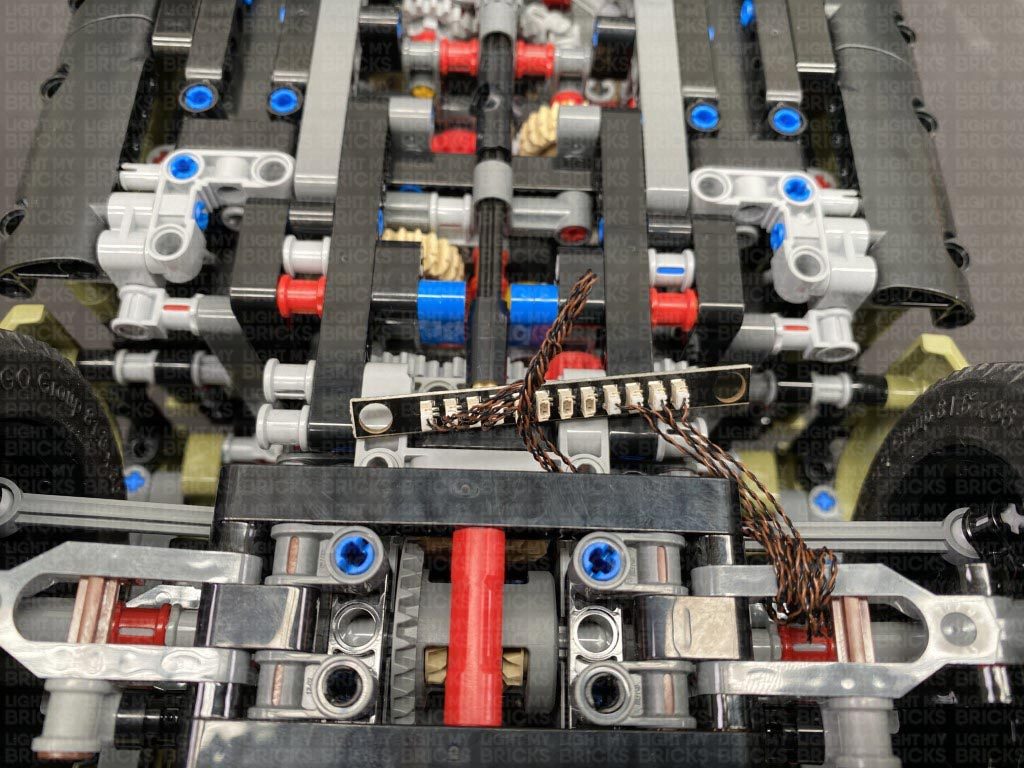
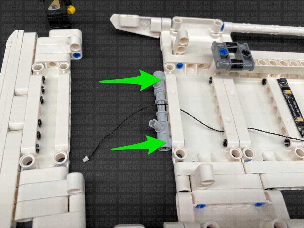
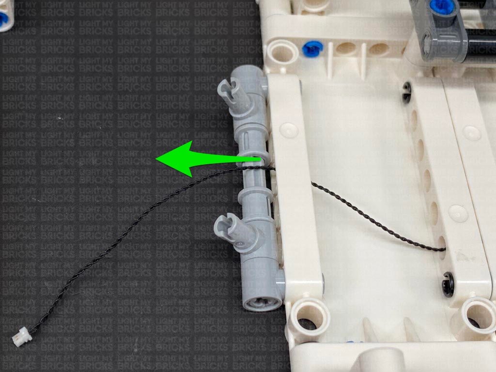
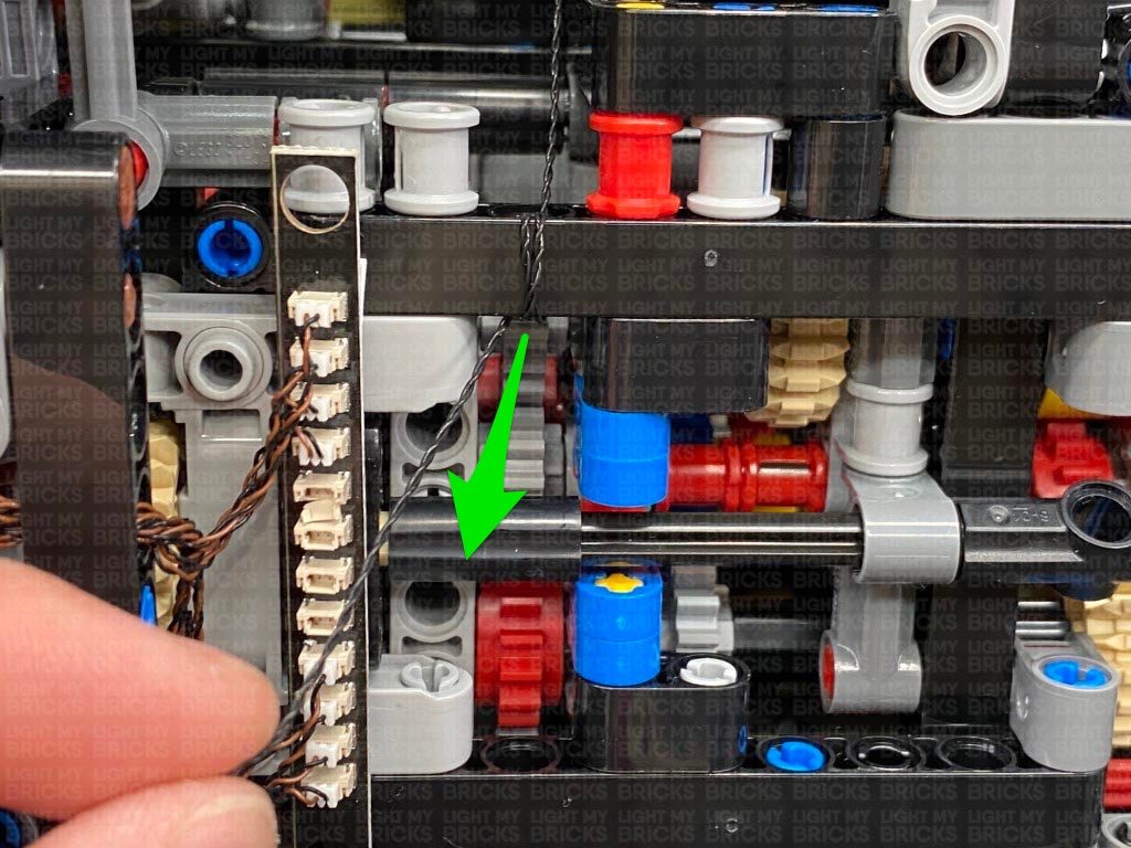
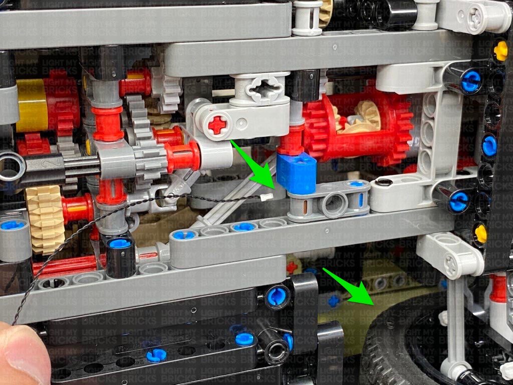
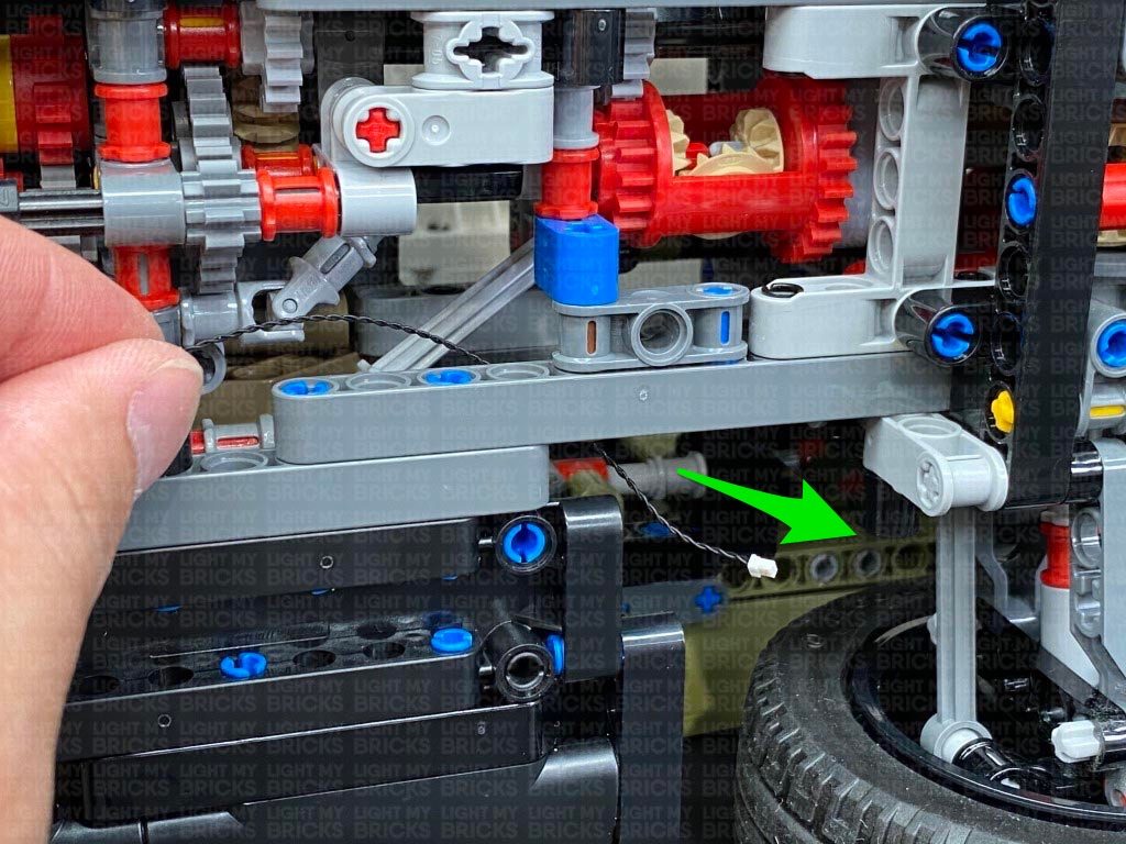
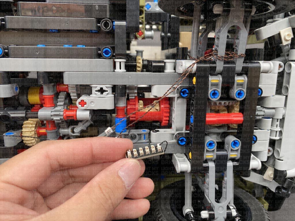
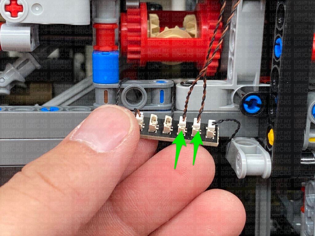
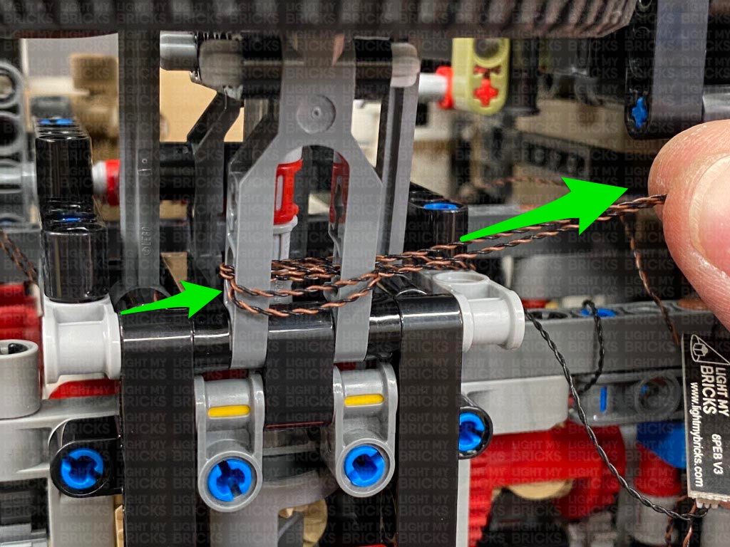
 Loop the cable around these pieces a second time, then connect it to a 6-Port Expansion Board.
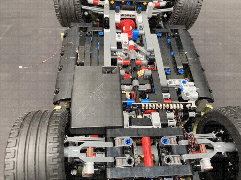
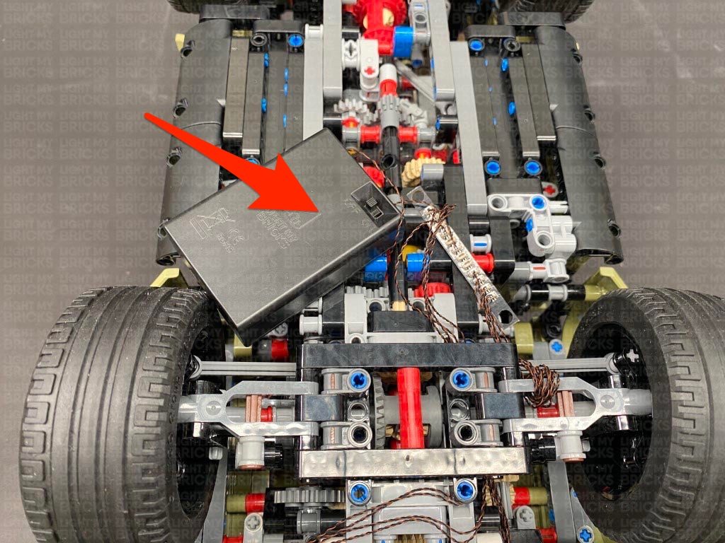
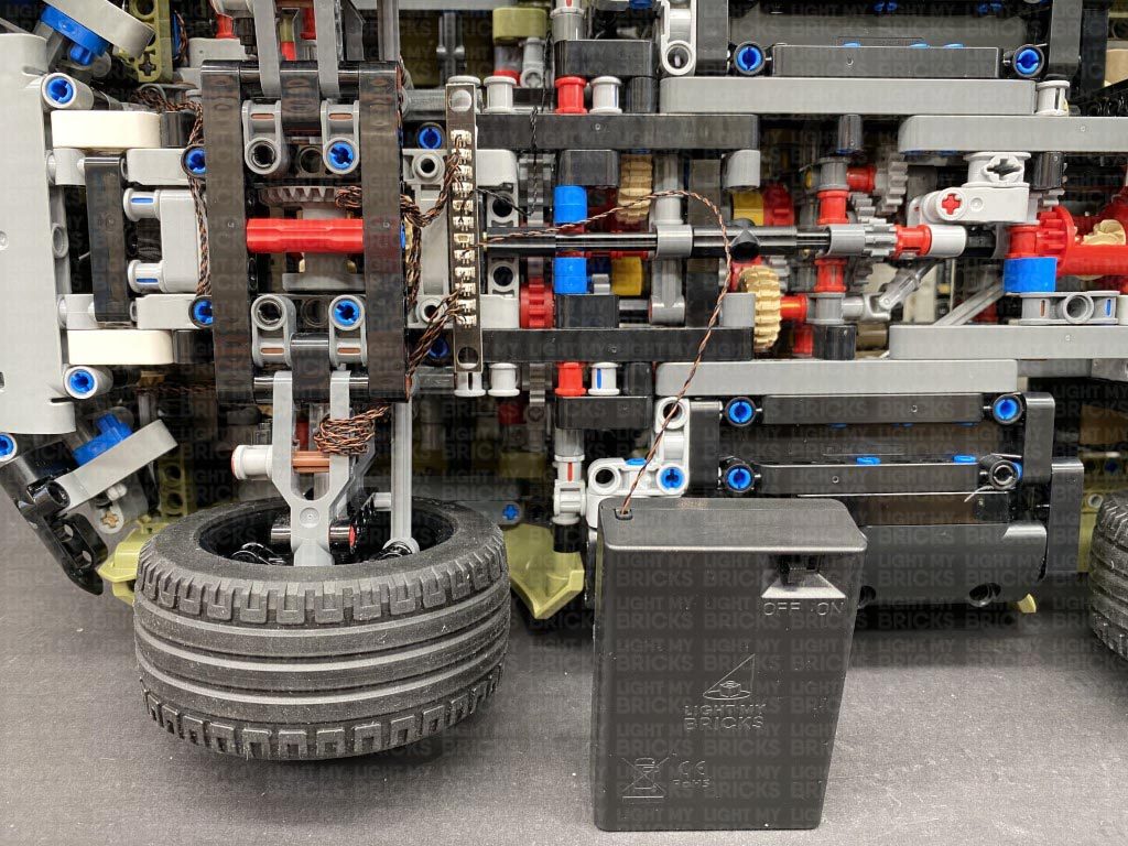
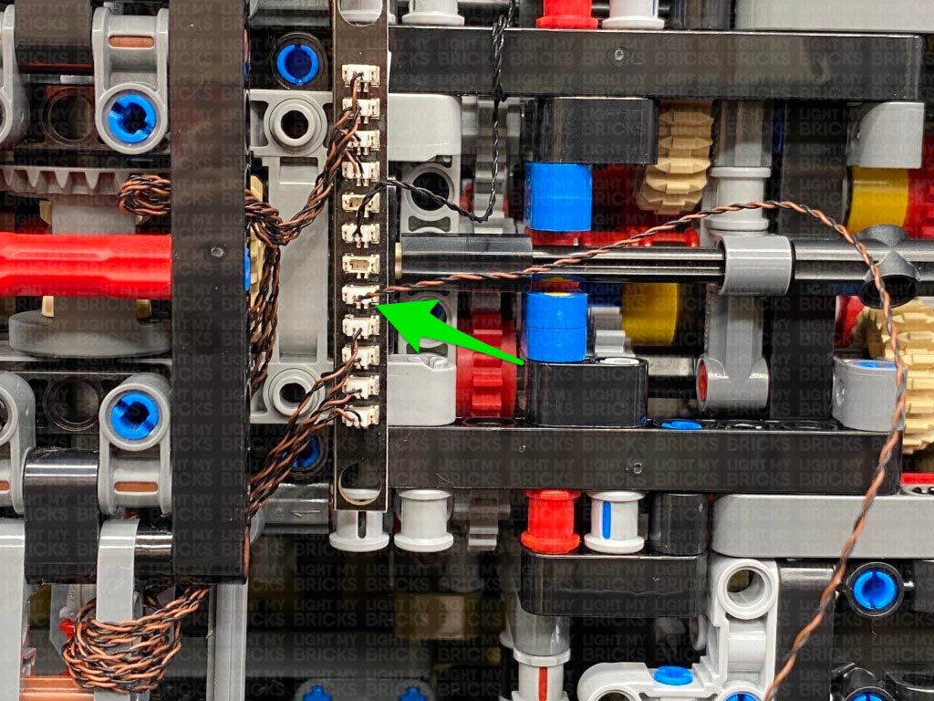
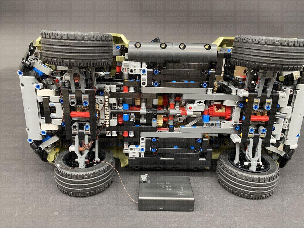
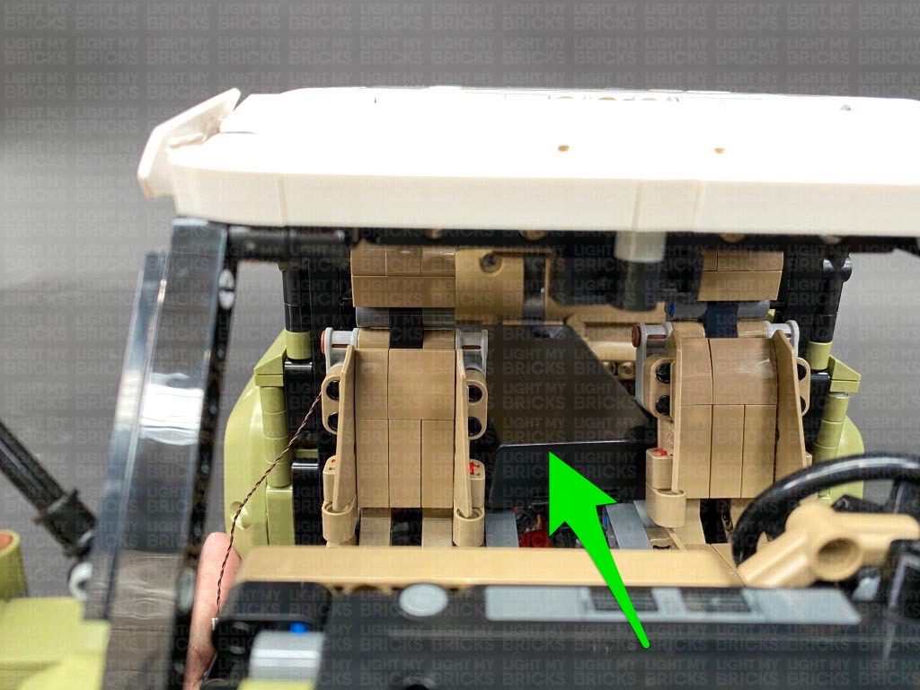
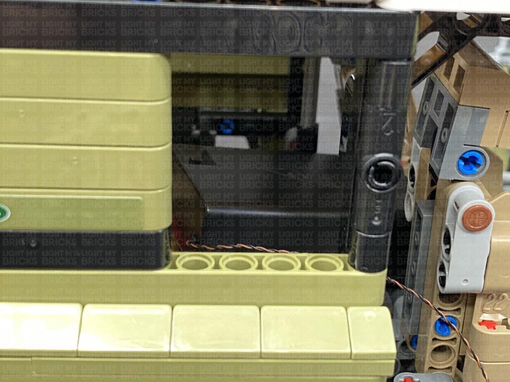
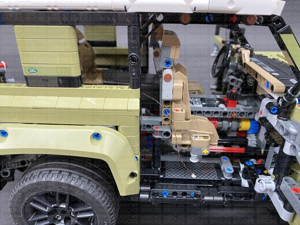
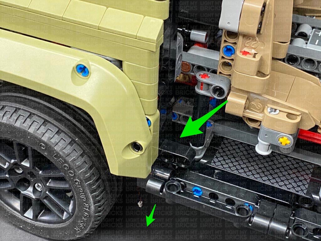
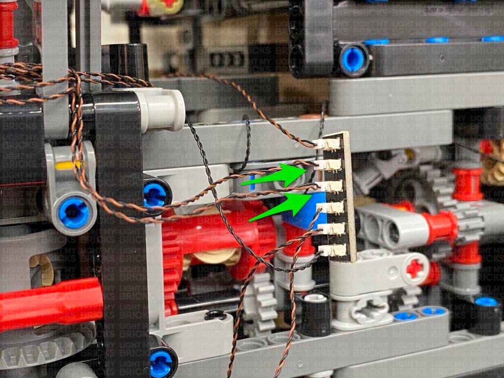
19.) Place the AA Battery Pack inside the vehicle in the back seat, then thread the battery pack cable down the following space on the right side of the vehicle. Pull the battery pack cable down from underneath the vehicle and connect it to a spare port on the 6-port Expansion Board.
Loop the cable around these pieces a second time, then connect it to a 6-Port Expansion Board.
19.) Place the AA Battery Pack inside the vehicle in the back seat, then thread the battery pack cable down the following space on the right side of the vehicle. Pull the battery pack cable down from underneath the vehicle and connect it to a spare port on the 6-port Expansion Board.
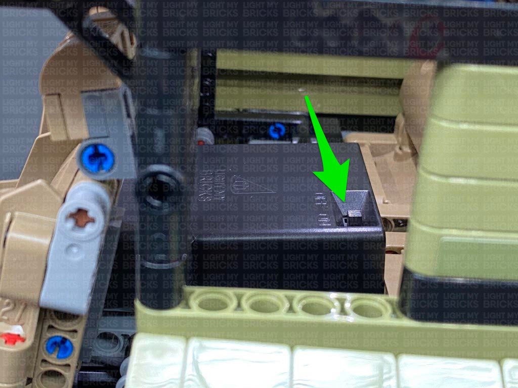
 Ensure you position the battery pack so that the switch is accessible.
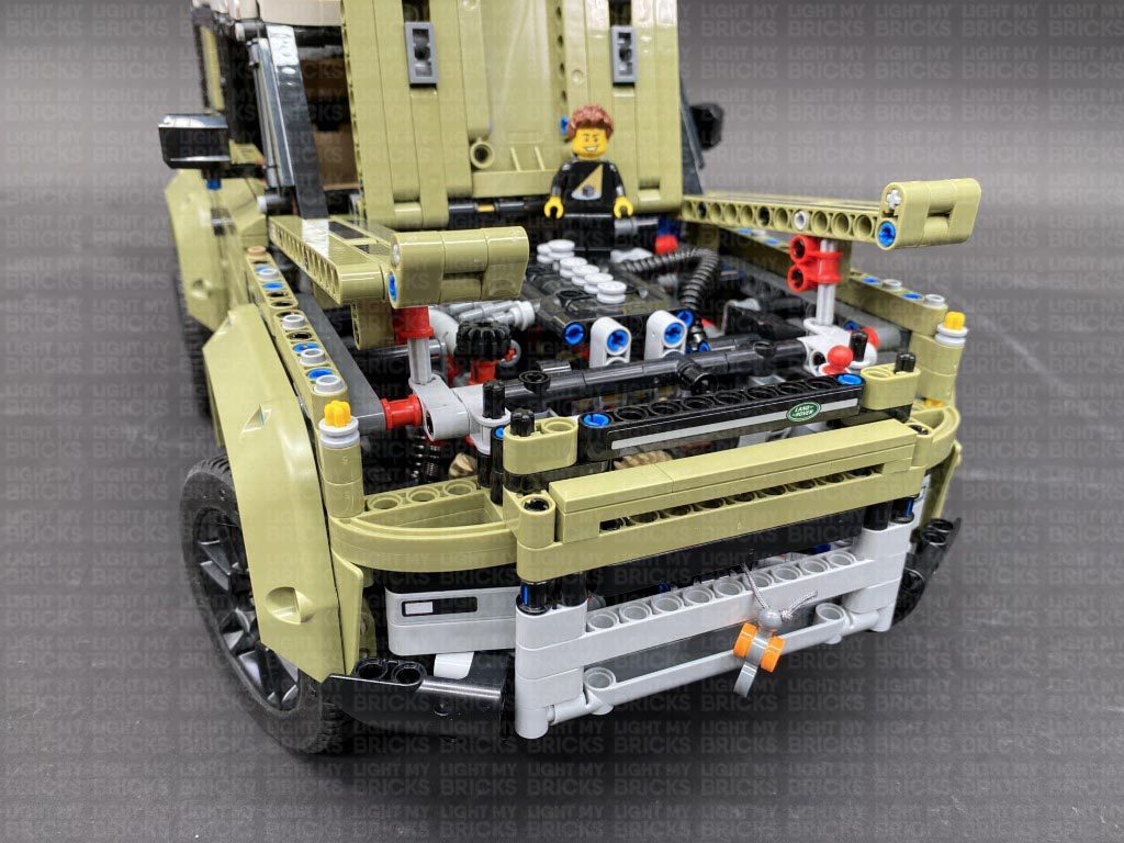
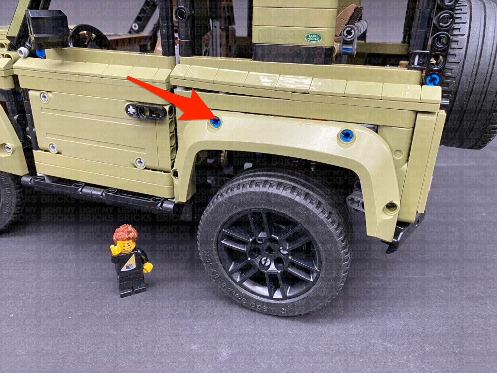
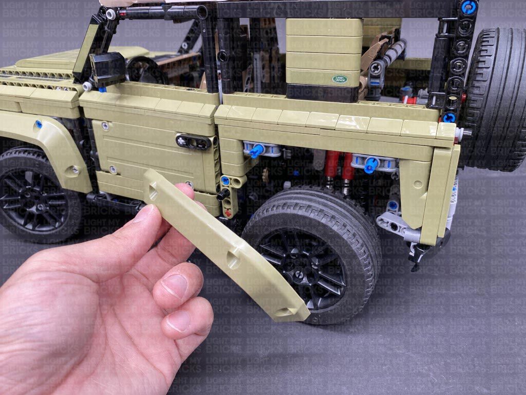
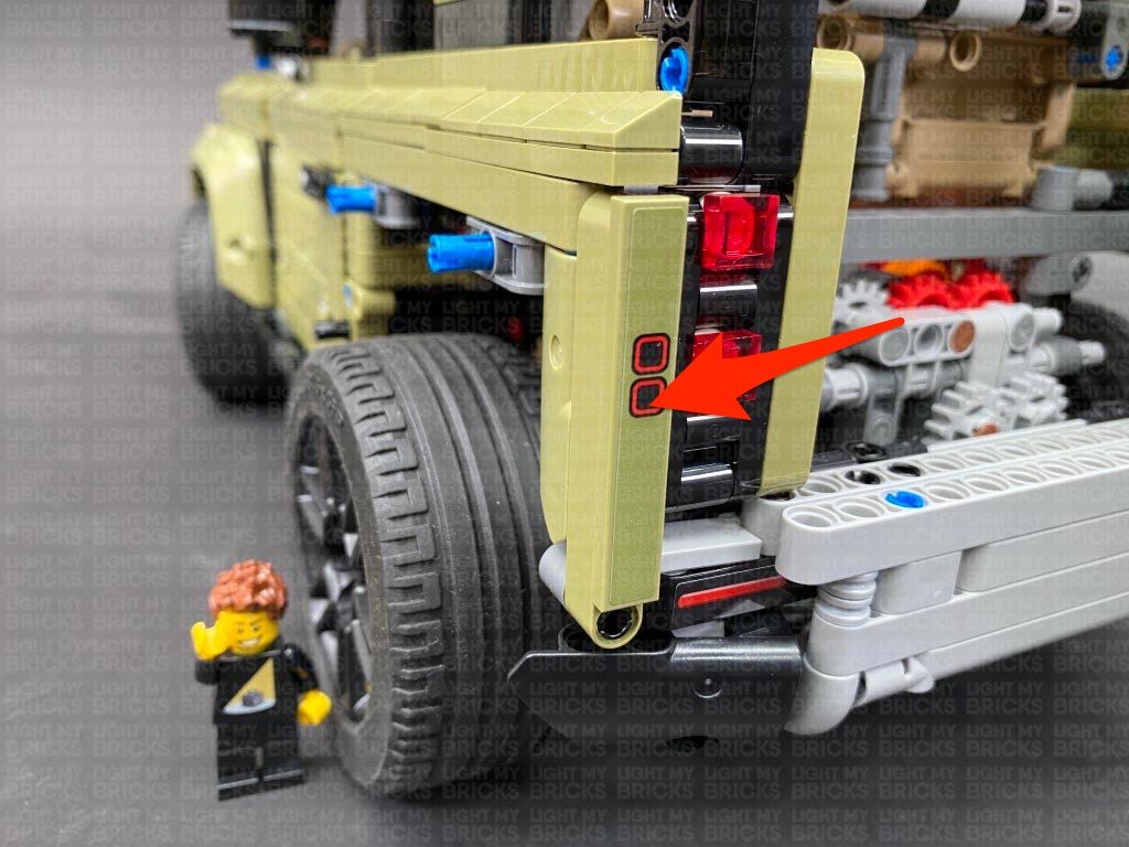
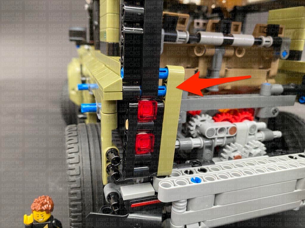
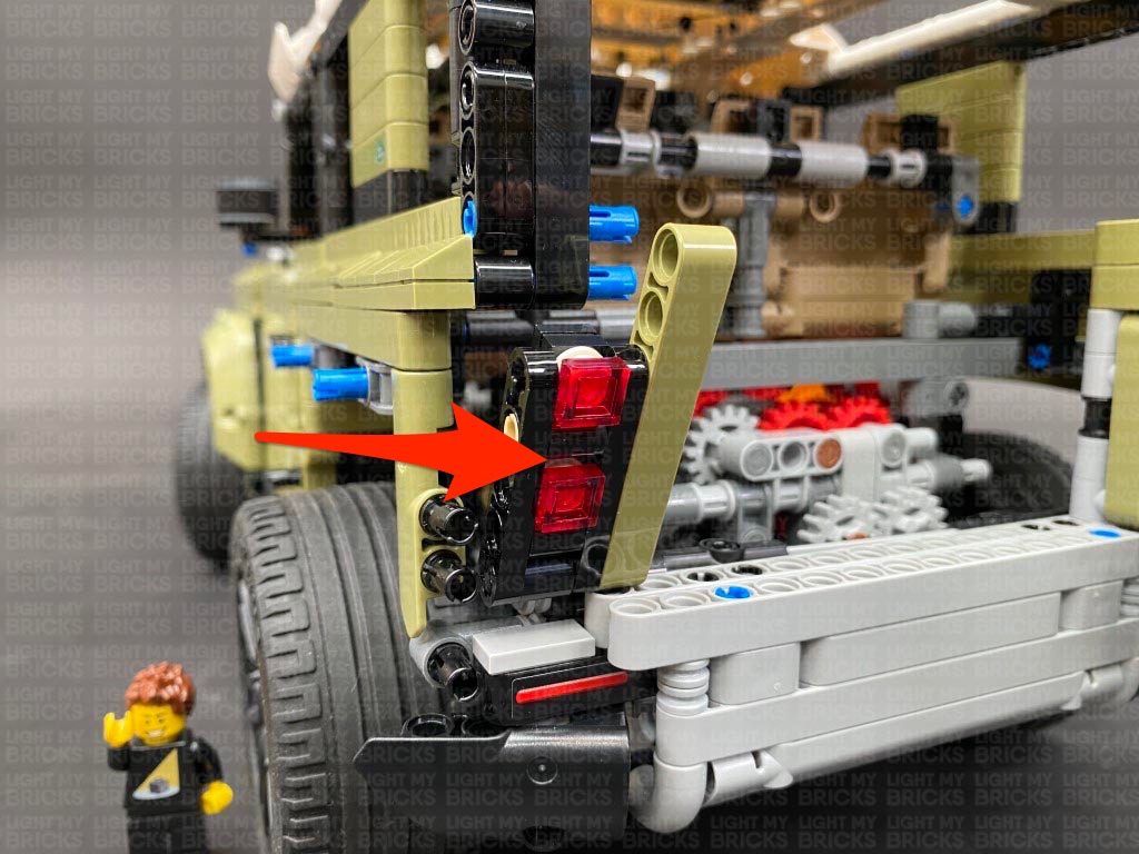
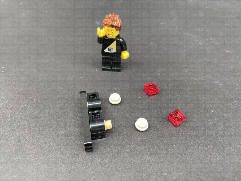
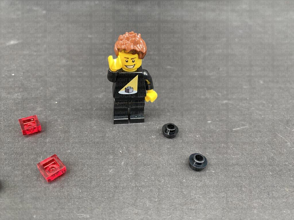
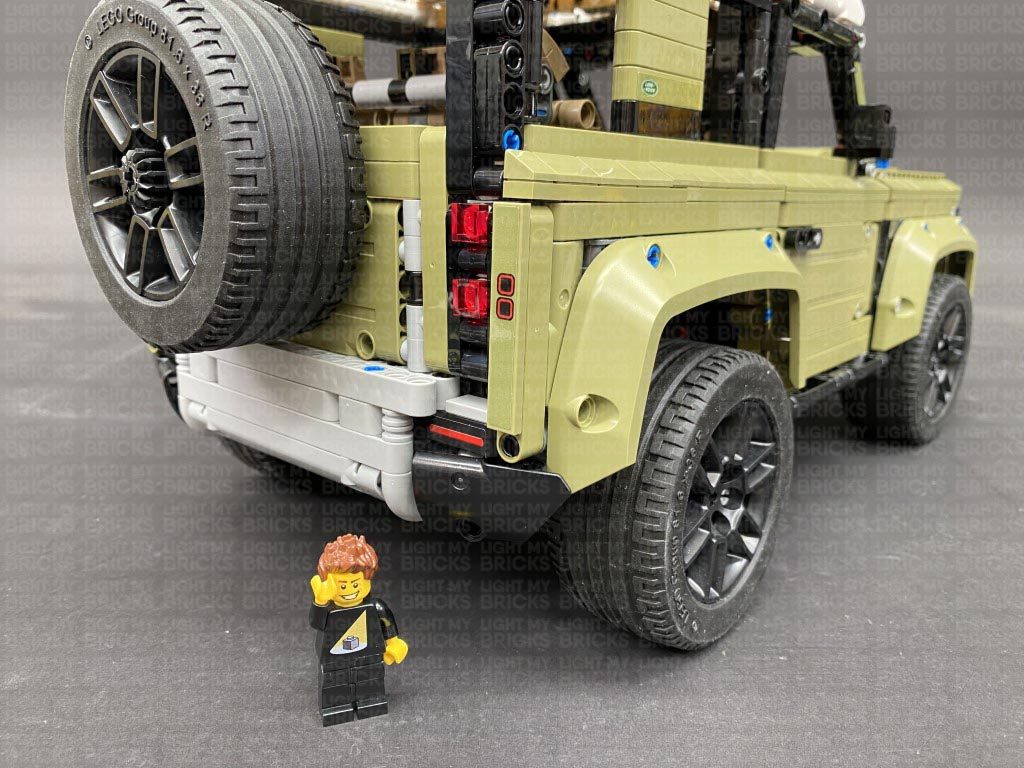
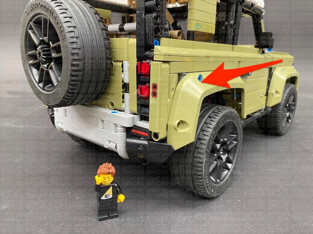
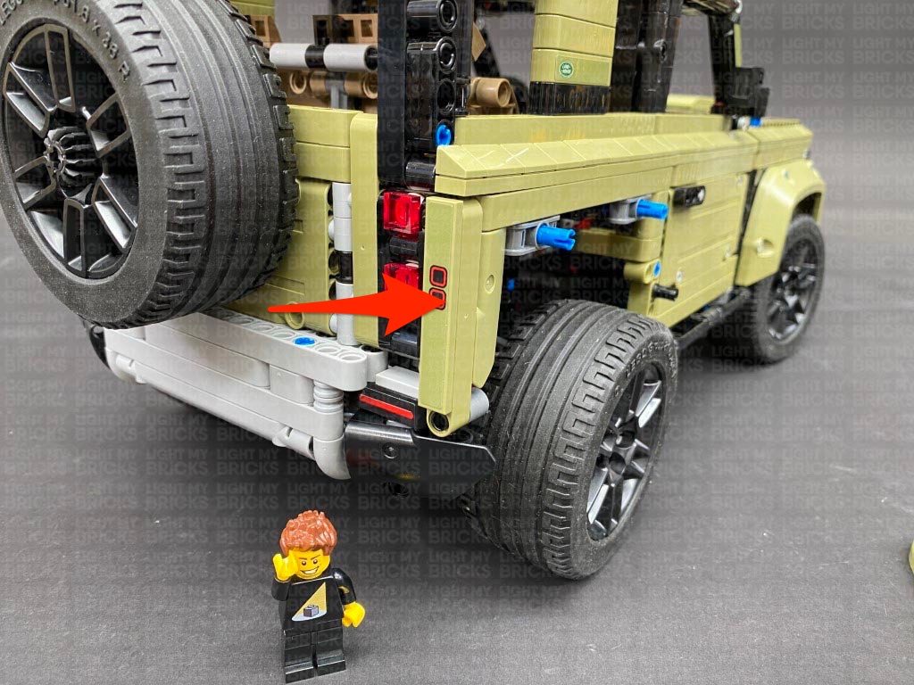
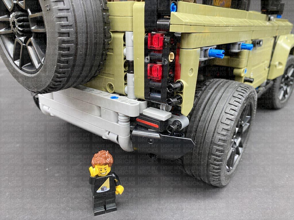
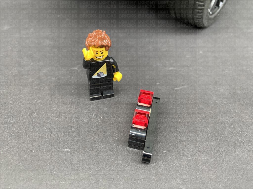
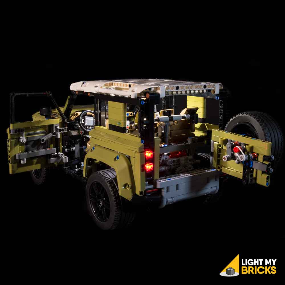
20.) We will now install the tail lights starting from the left side. Disconnect the panel above the wheel, then open the back door and disconnect the following pieces in order for us to remove the left tail light section as shown below:
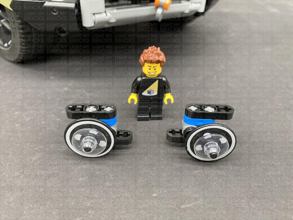
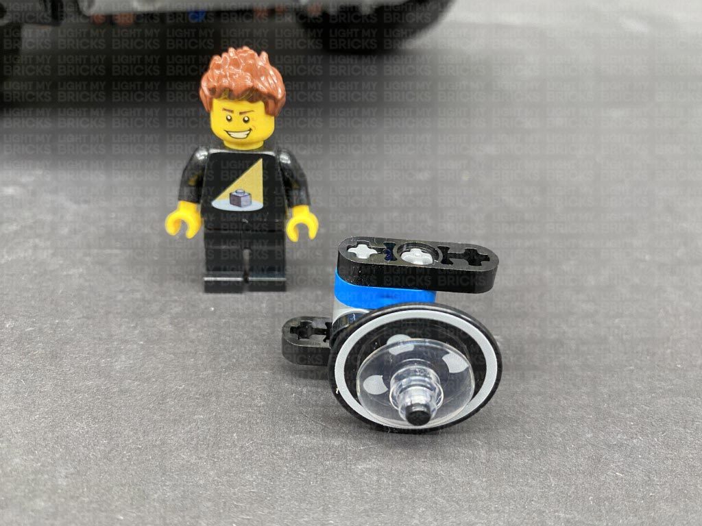
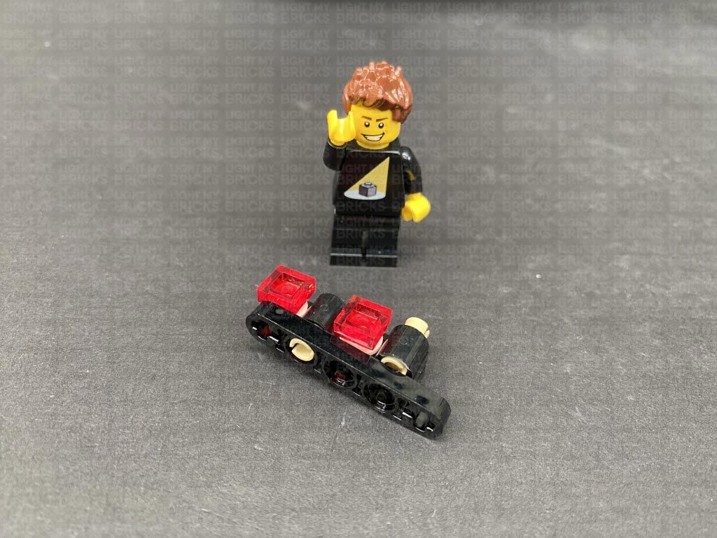
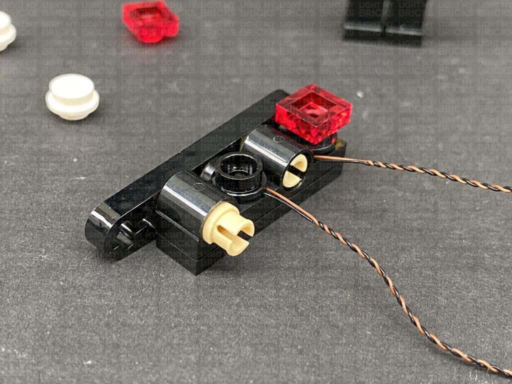
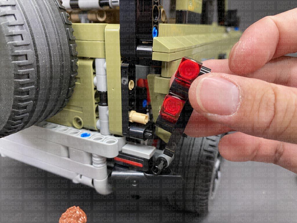
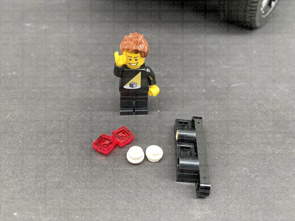
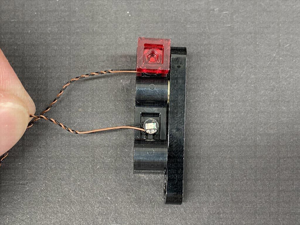
Disassemble the tail light section as per below and discard the two white round plates. Take out the provided LEGO pieces, 2x Round Plate 1×1 with Open Stud (Black).
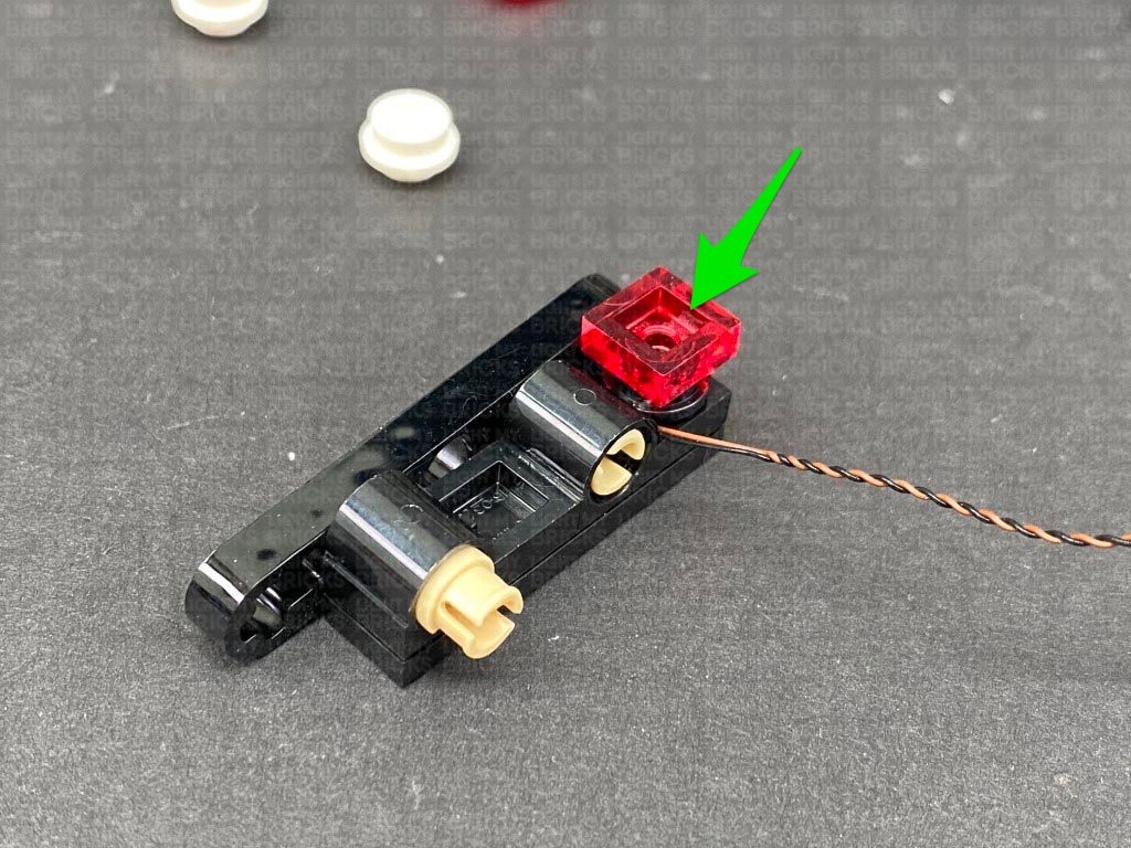
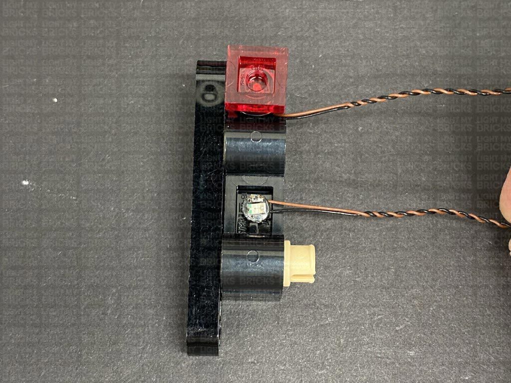
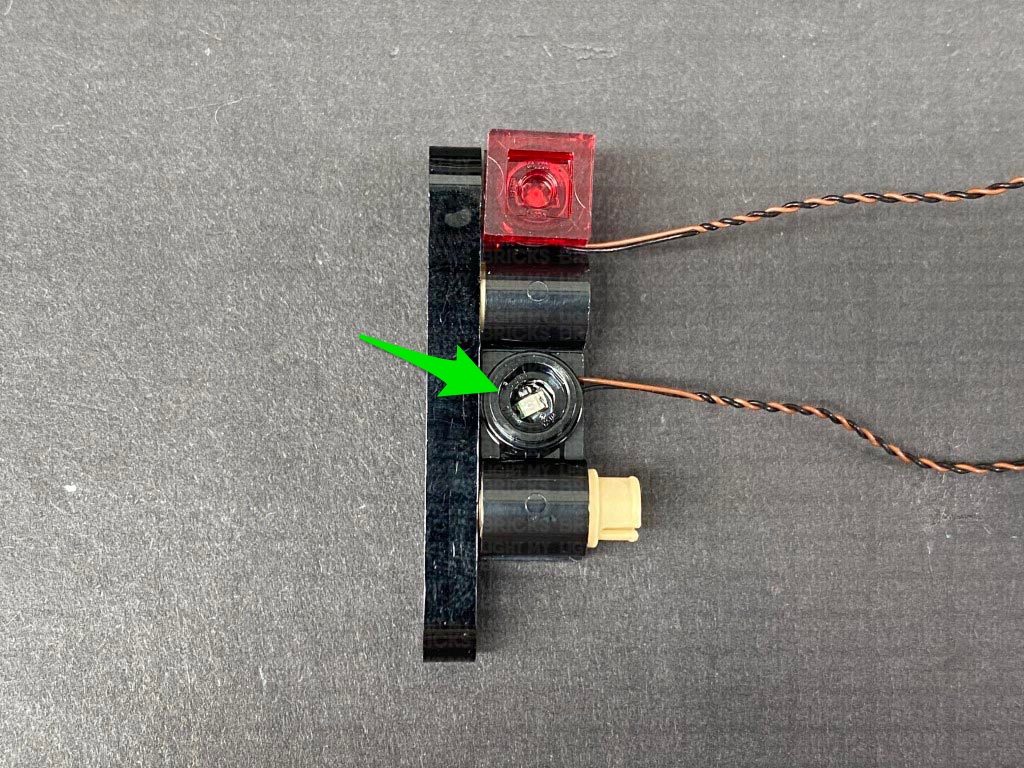
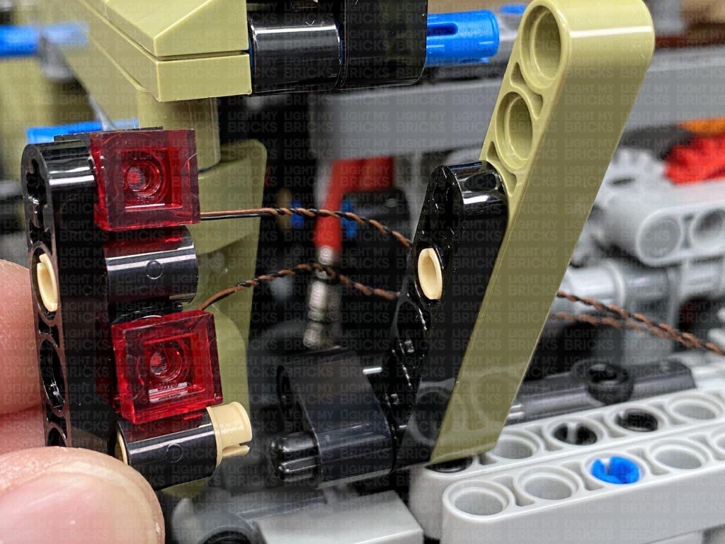
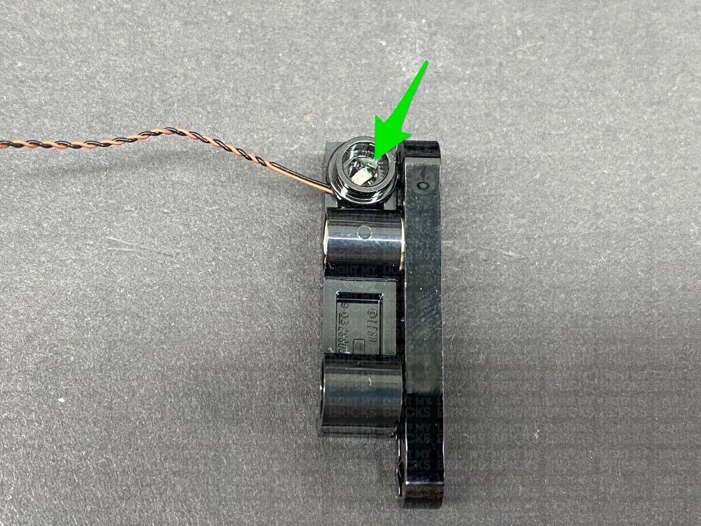
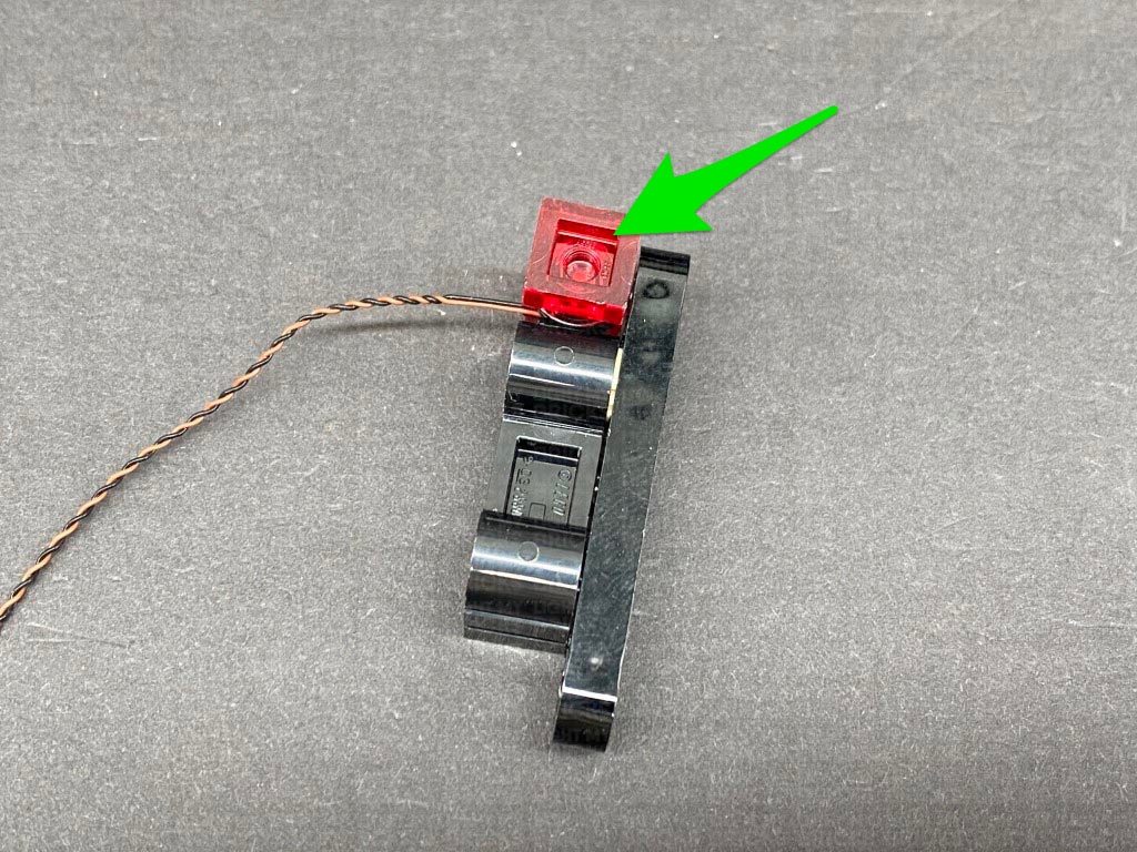
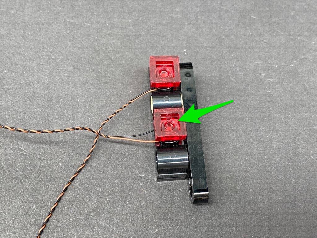
21.) Take a Red 30cm Bit Light and with the LED facing up and cable to the right, place it over the inside of the following plate. Secure the Bit Light in place by connecting one of the provided Round Plate 1×1 with open stud over the top, then reconnect one of the trans red plates.
Repeat this step to install another Red 30cm Bit Light to this tail light section.
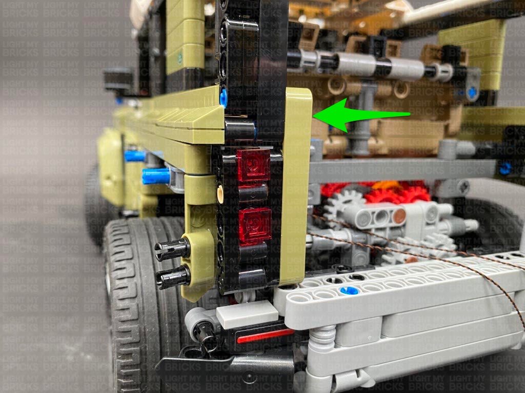
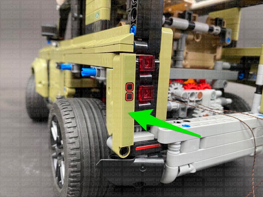
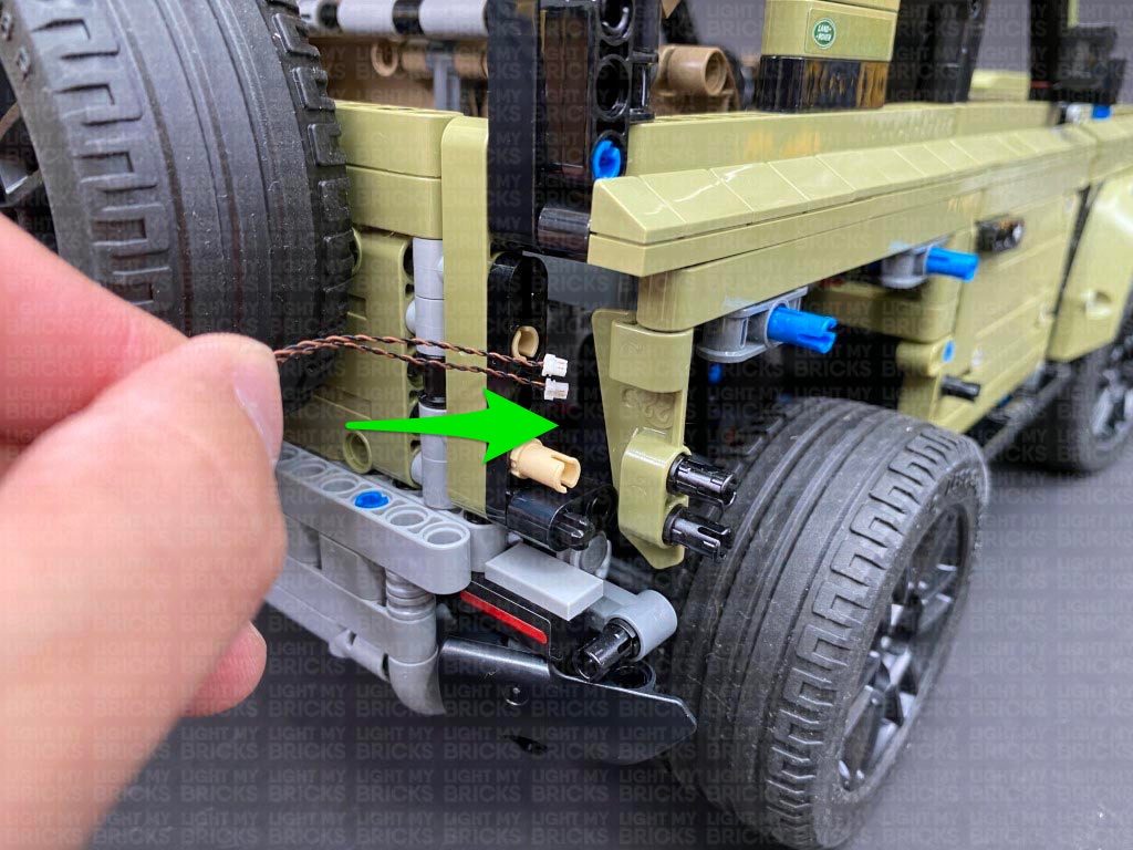
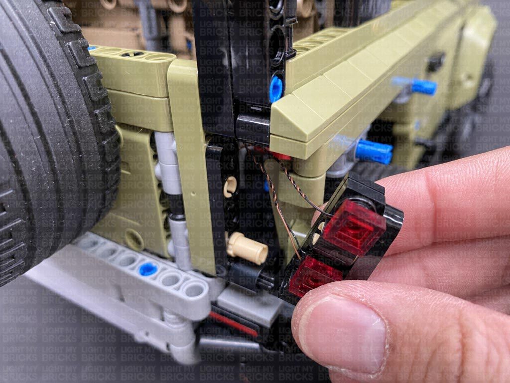
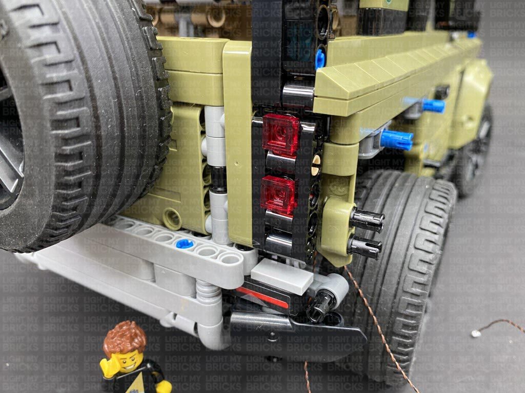
22.) Reconnect the tail light section to the back of the vehicle ensuring you first thread both cables through the back, then reconnect some of the pieces we disconnected earlier.
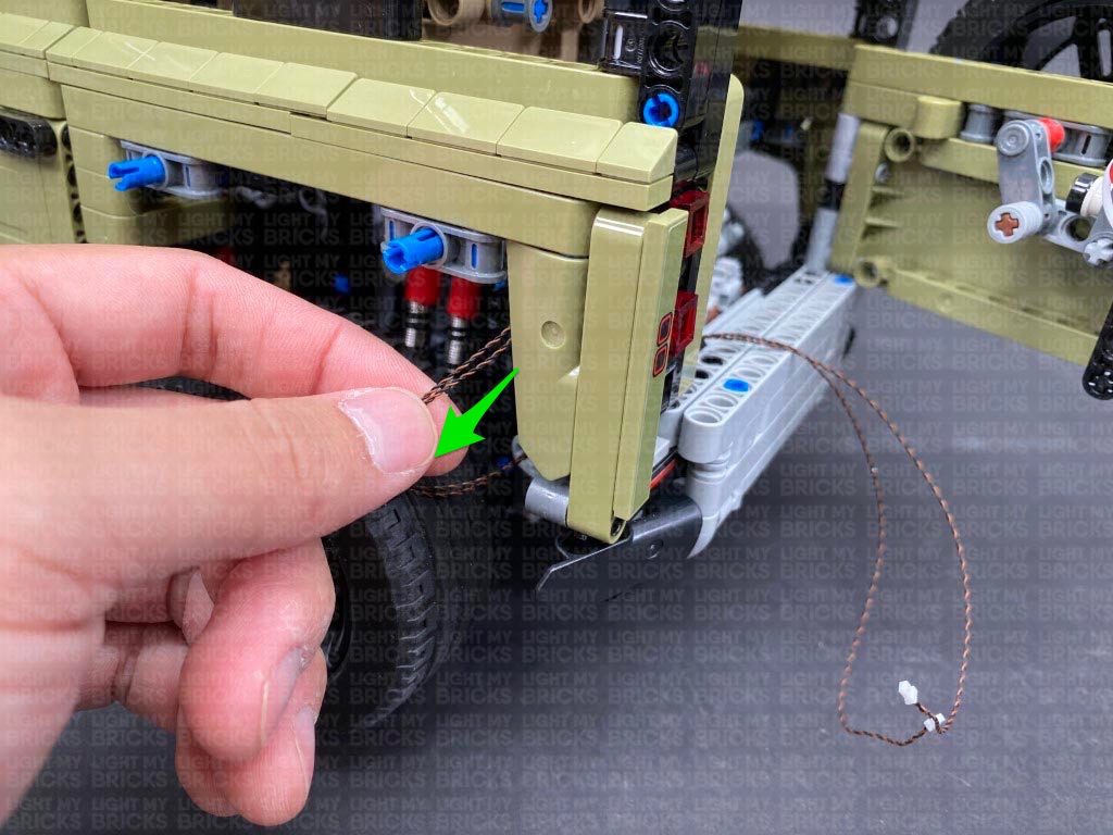
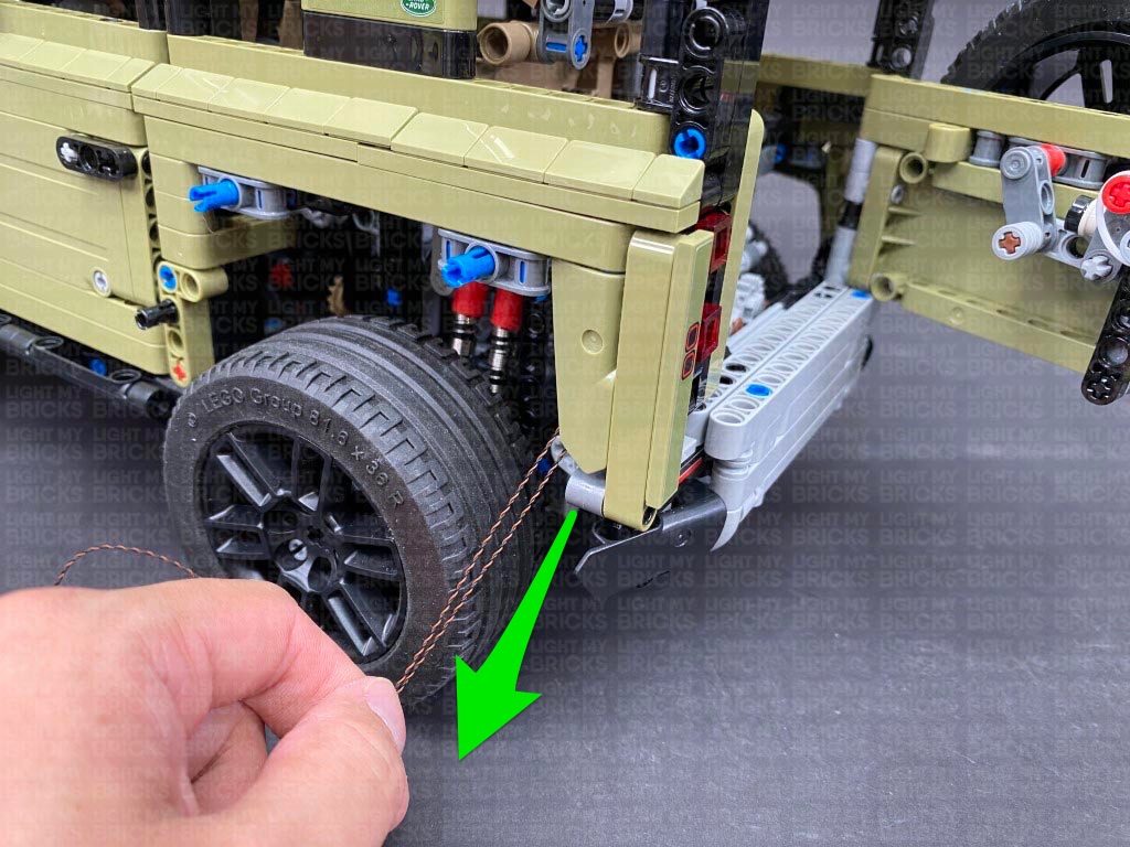
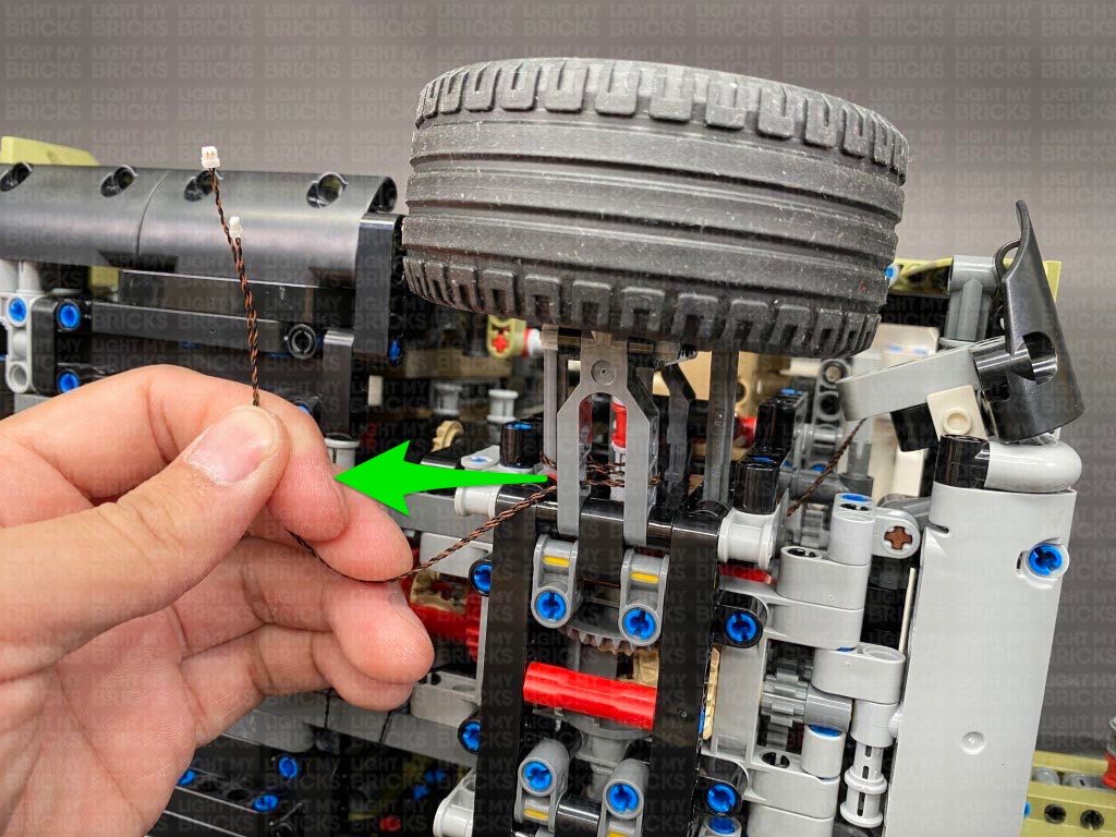
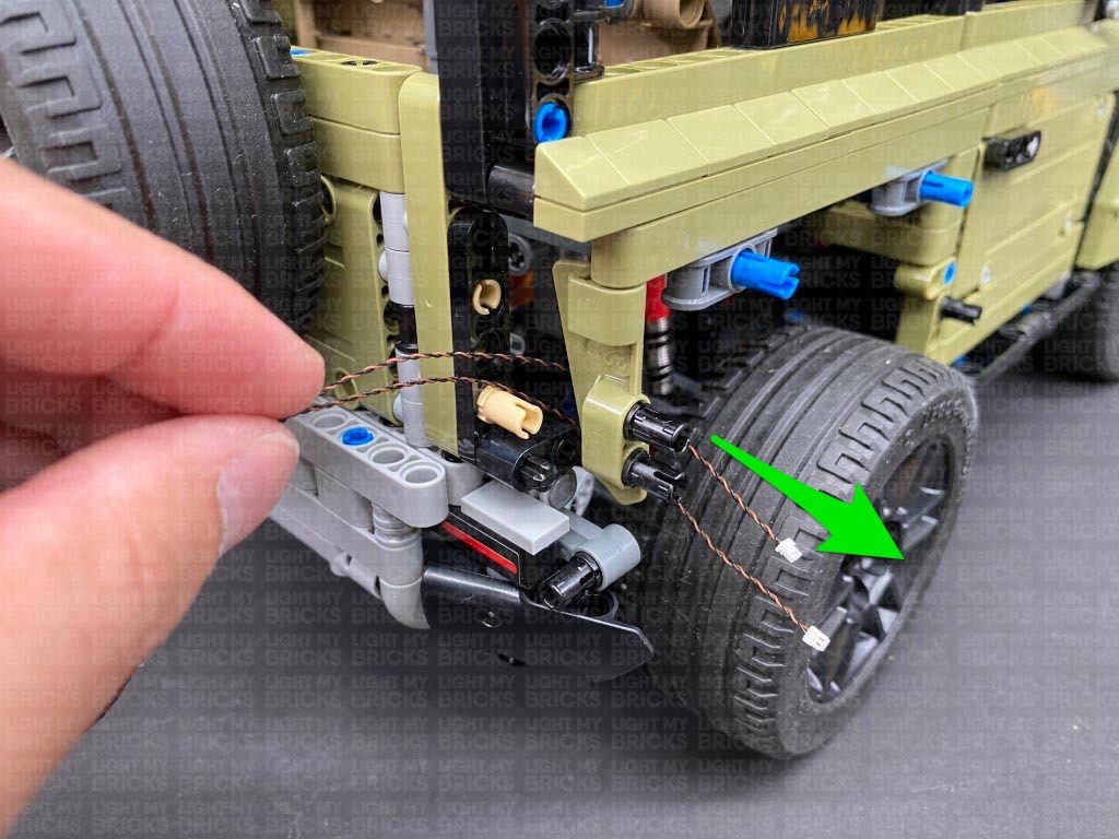
Pull out both Red Bit Light cables from behind the back wheel.
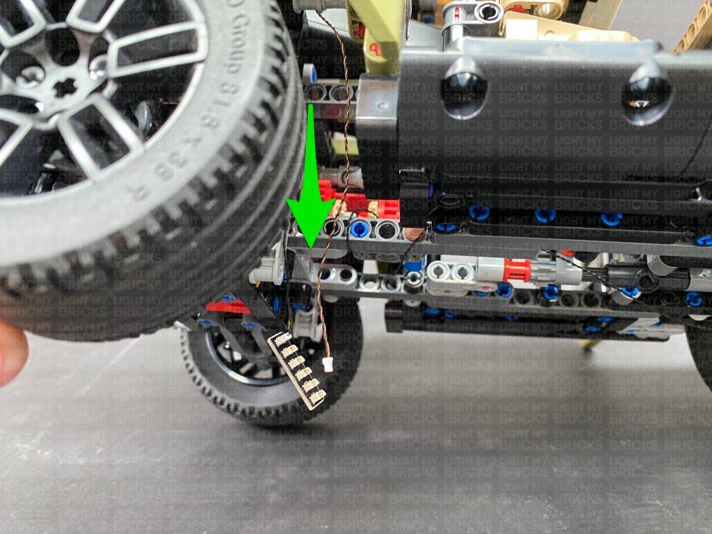
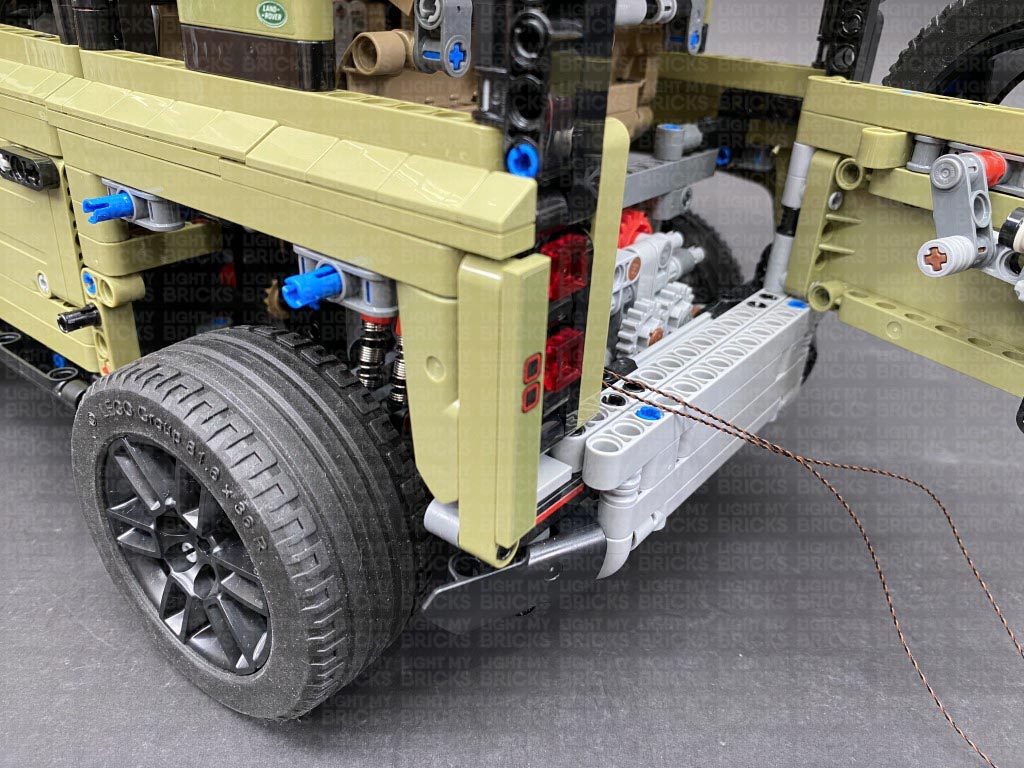
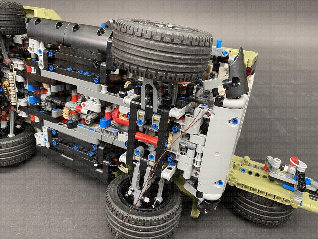
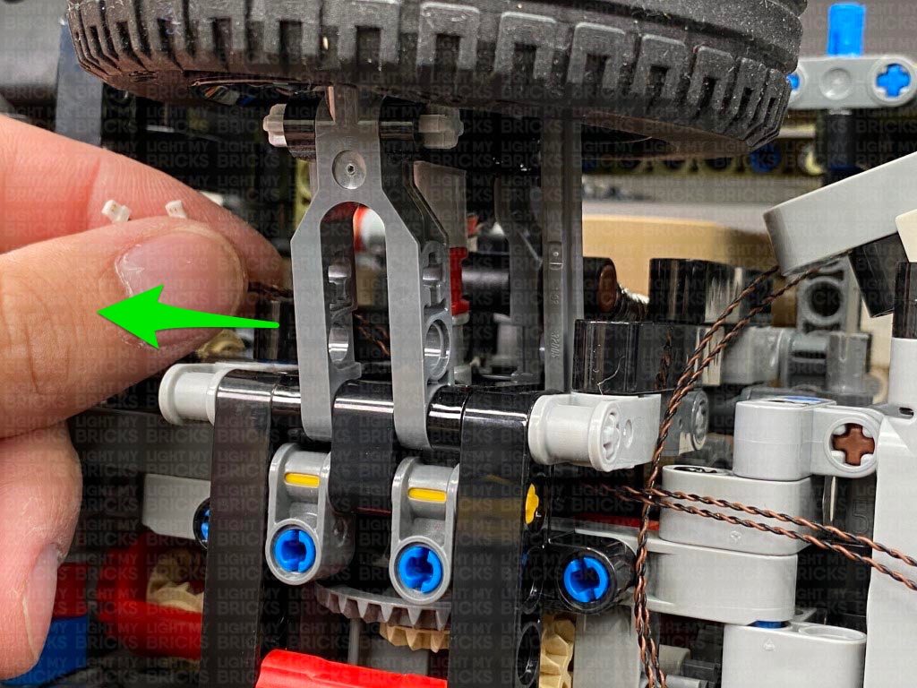
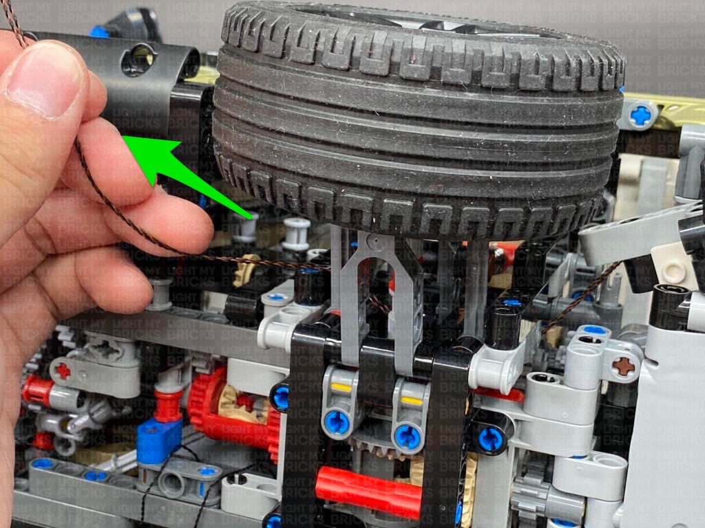
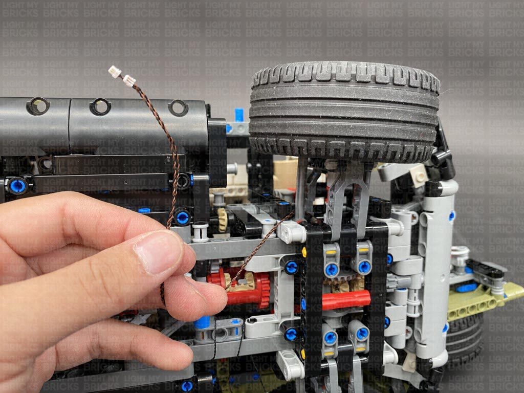
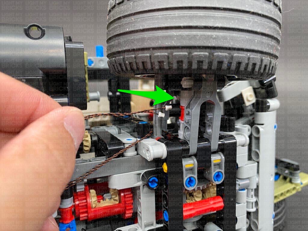
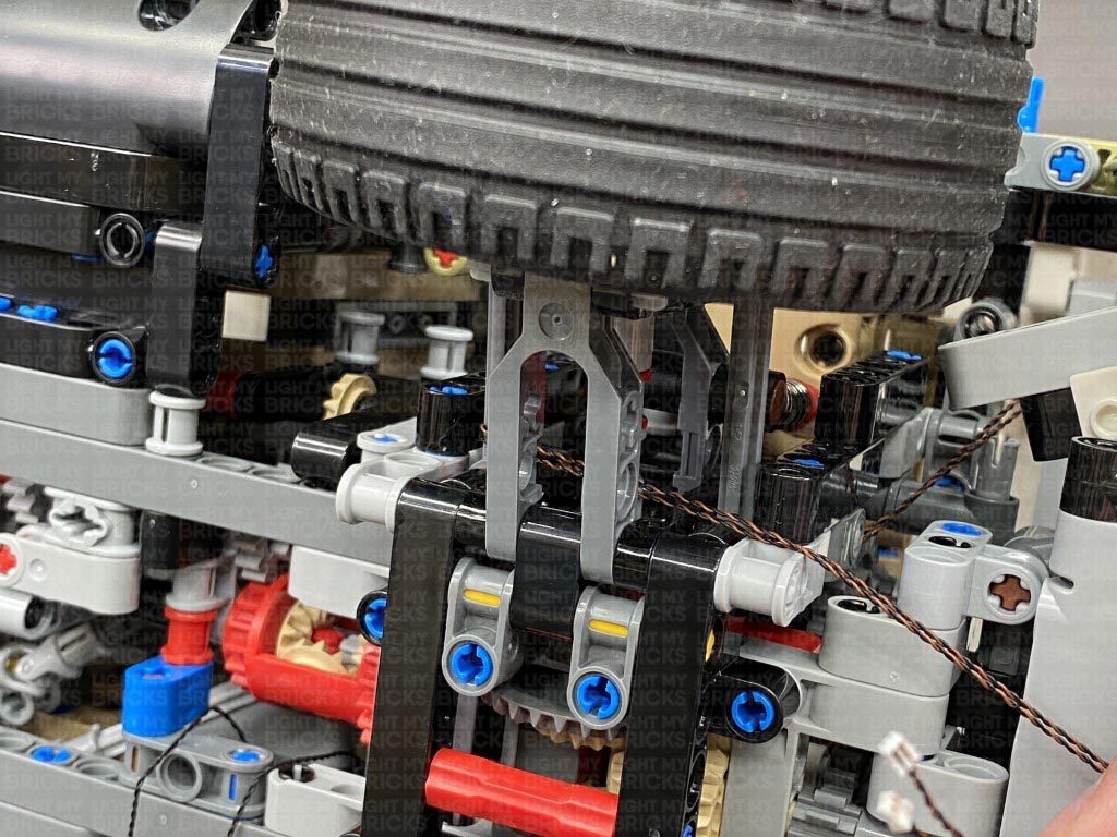
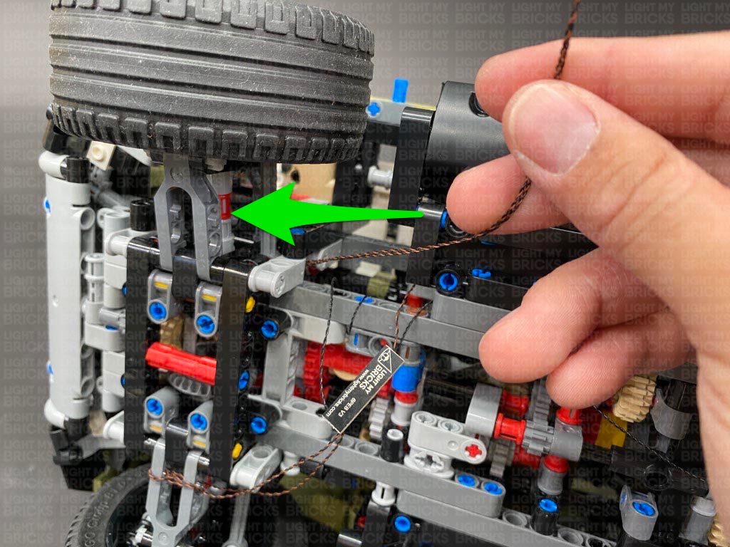
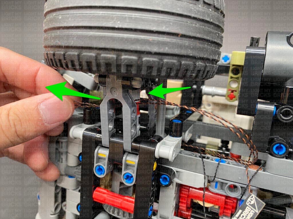
23.) Turn the vehicle onto it’s right side so we can access underneath, then pull the cable down and thread it underneath the wheel axle. Pull the cables all the way out from the other side.
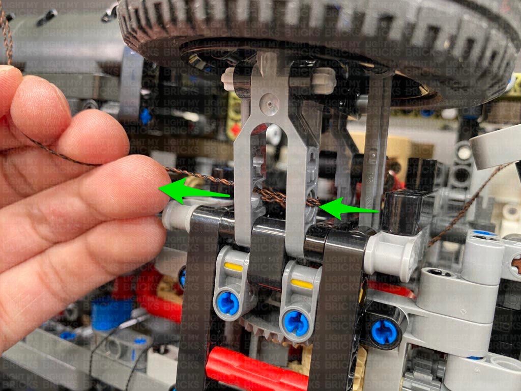
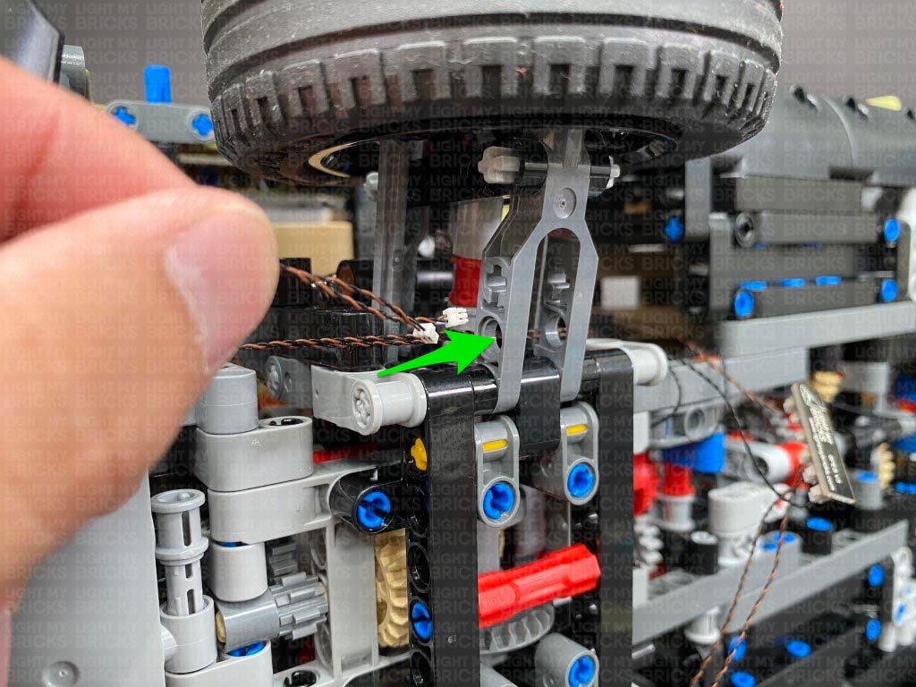
Thread the cable through the middle of the wheel axle and pull it all the way out from the back side.
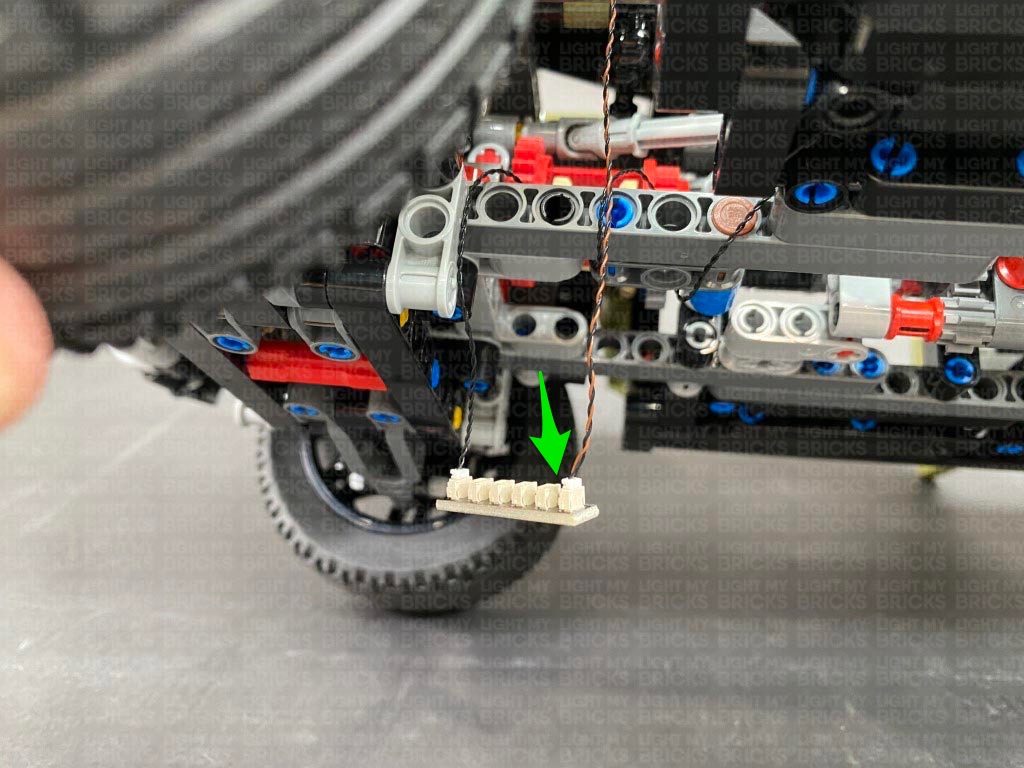
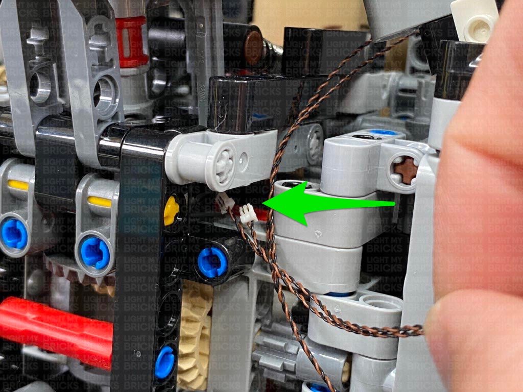
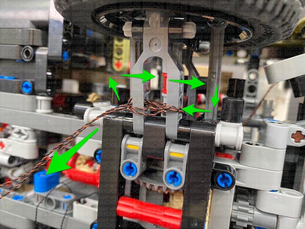
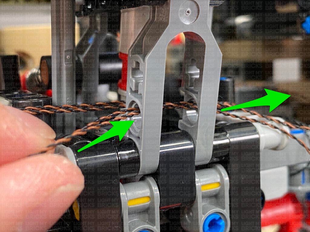
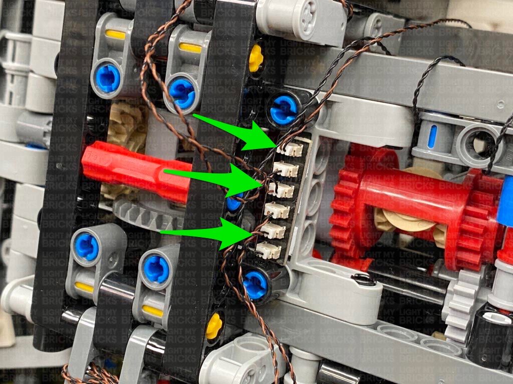
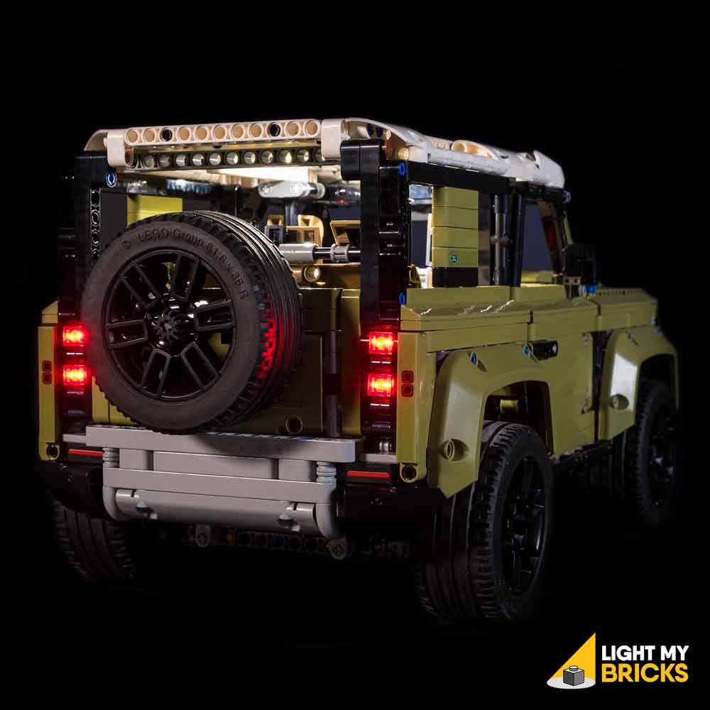
Thread the cables through the following technic hole in the axle. Loop the cables through a second time to secure and eliminate excess cabling. Connect both cables to the 6-Port Expansion Board, then turn the Battery Pack ON to test the tail lights are working OK.
Note: If you experience any issues with the lights not working and suspect an issue with a component, please try a different port on the expansion board to verify where the fault lies (with the light, expansion board or effects board). To correct any issues with expansion board ports, please view the section addressing expansion board issues on our online troubleshooting guide.
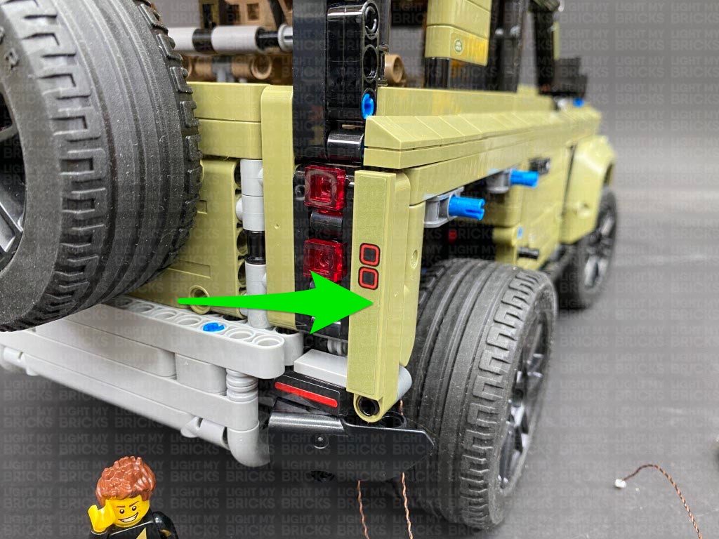
Reconnect the panel above the rear left wheel.
Ensure you position the battery pack so that the switch is accessible.
20.) We will now install the tail lights starting from the left side. Disconnect the panel above the wheel, then open the back door and disconnect the following pieces in order for us to remove the left tail light section as shown below:
Disassemble the tail light section as per below and discard the two white round plates. Take out the provided LEGO pieces, 2x Round Plate 1×1 with Open Stud (Black).
21.) Take a Red 30cm Bit Light and with the LED facing up and cable to the right, place it over the inside of the following plate. Secure the Bit Light in place by connecting one of the provided Round Plate 1×1 with open stud over the top, then reconnect one of the trans red plates.
Repeat this step to install another Red 30cm Bit Light to this tail light section.
22.) Reconnect the tail light section to the back of the vehicle ensuring you first thread both cables through the back, then reconnect some of the pieces we disconnected earlier.
Pull out both Red Bit Light cables from behind the back wheel.
23.) Turn the vehicle onto it’s right side so we can access underneath, then pull the cable down and thread it underneath the wheel axle. Pull the cables all the way out from the other side.
Thread the cable through the middle of the wheel axle and pull it all the way out from the back side.
Thread the cables through the following technic hole in the axle. Loop the cables through a second time to secure and eliminate excess cabling. Connect both cables to the 6-Port Expansion Board, then turn the Battery Pack ON to test the tail lights are working OK.
Note: If you experience any issues with the lights not working and suspect an issue with a component, please try a different port on the expansion board to verify where the fault lies (with the light, expansion board or effects board). To correct any issues with expansion board ports, please view the section addressing expansion board issues on our online troubleshooting guide.
Reconnect the panel above the rear left wheel.
 24.) Repeat steps 20-22. to install another 2x Red 30cm Bit Lights to the right tail light section using another provided 2x Round Plate 1×1 with Open Stud (Black). Ensure this time, the two bit light cables are laid in the opposite direction as we did for the left tail light section lights.
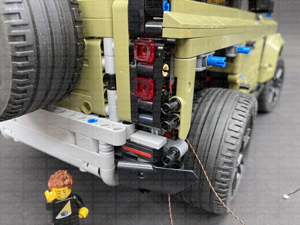
25.) Thread both Bit Light cables from the right tail light section through the back of the vehicle, then pull them out from behind the rear wheel. Reconnect the tail light section as well as some of the sections we removed earlier.
Turn the vehicle onto it’s left side so that we can access underneath, then thread both Bit Light cables underneath the wheel axle as shown below. Pull the cables all the way out from the other side.
Thread the cables through the middle of the wheel axle, pulling it all the way out from the back side.
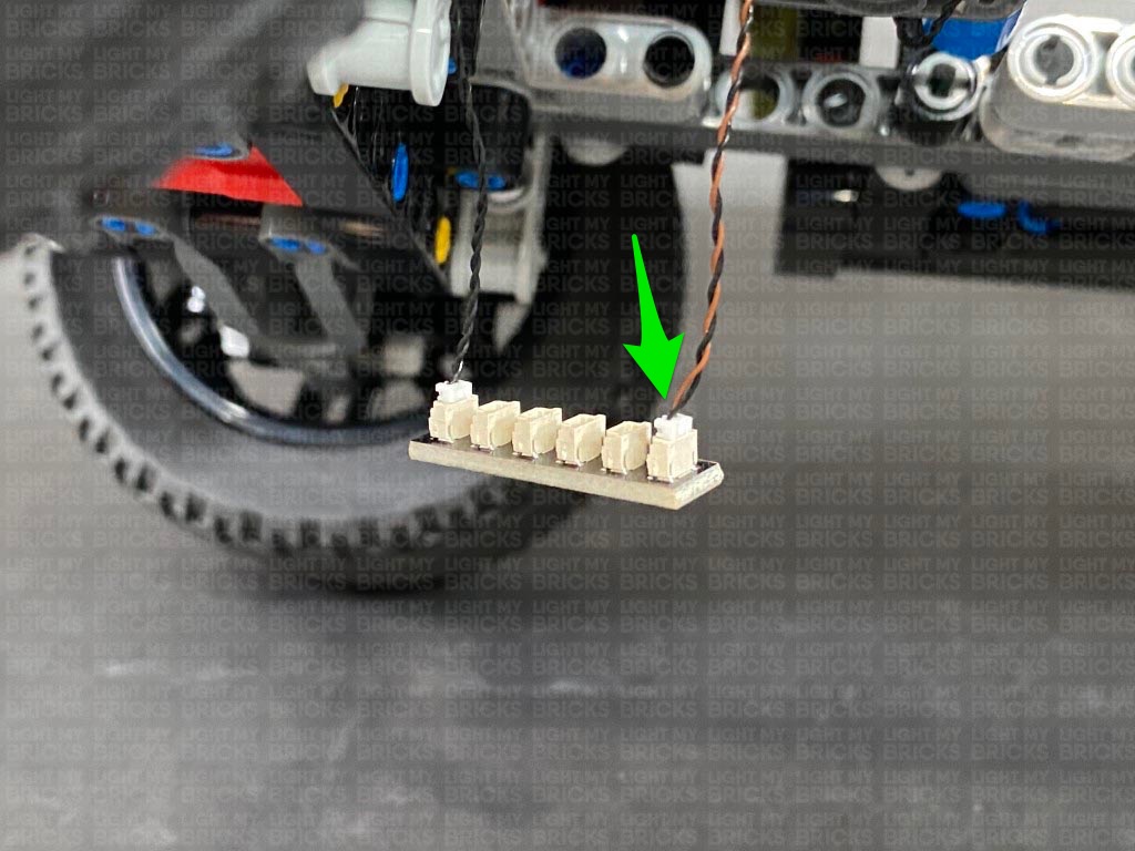
Thread the cables through the following technic hole, then loop it through the same hole again to secure and eliminate excess cabling. Connect the two cables to the 6-Port Expansion Board.
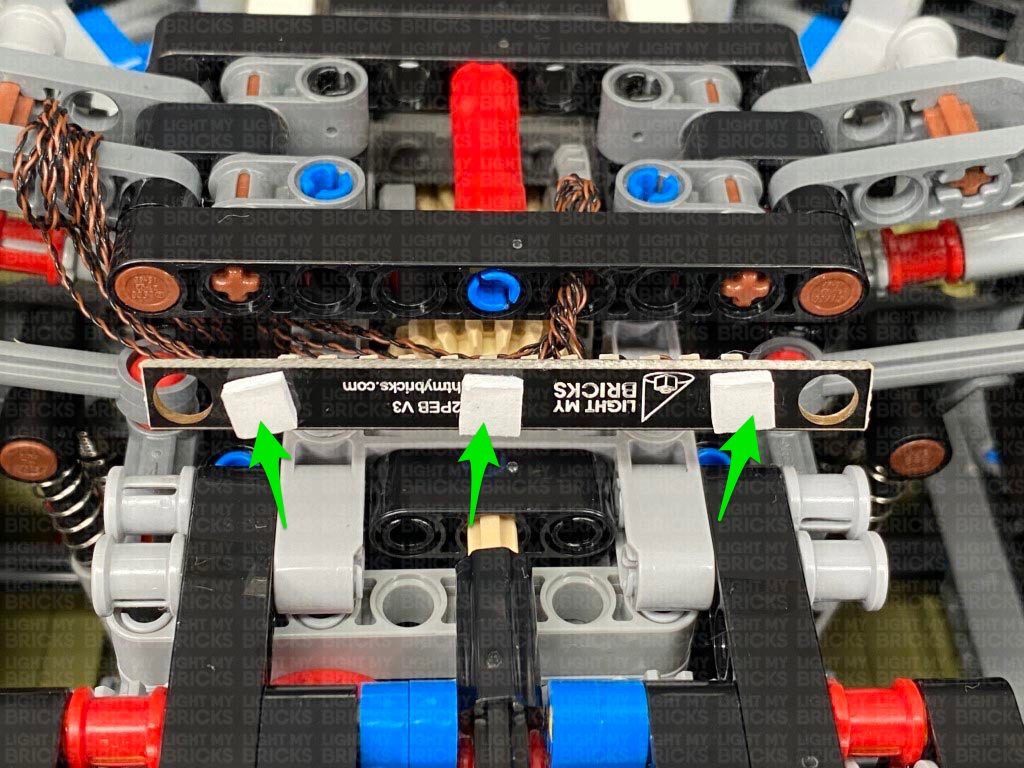
26.) Take 3x Adhesive Squares and stick them to the back of the 6-Port Expansion Board. Mount the expansion board underneath the vehicle to the following position.
24.) Repeat steps 20-22. to install another 2x Red 30cm Bit Lights to the right tail light section using another provided 2x Round Plate 1×1 with Open Stud (Black). Ensure this time, the two bit light cables are laid in the opposite direction as we did for the left tail light section lights.
25.) Thread both Bit Light cables from the right tail light section through the back of the vehicle, then pull them out from behind the rear wheel. Reconnect the tail light section as well as some of the sections we removed earlier.
Turn the vehicle onto it’s left side so that we can access underneath, then thread both Bit Light cables underneath the wheel axle as shown below. Pull the cables all the way out from the other side.
Thread the cables through the middle of the wheel axle, pulling it all the way out from the back side.
Thread the cables through the following technic hole, then loop it through the same hole again to secure and eliminate excess cabling. Connect the two cables to the 6-Port Expansion Board.
26.) Take 3x Adhesive Squares and stick them to the back of the 6-Port Expansion Board. Mount the expansion board underneath the vehicle to the following position.
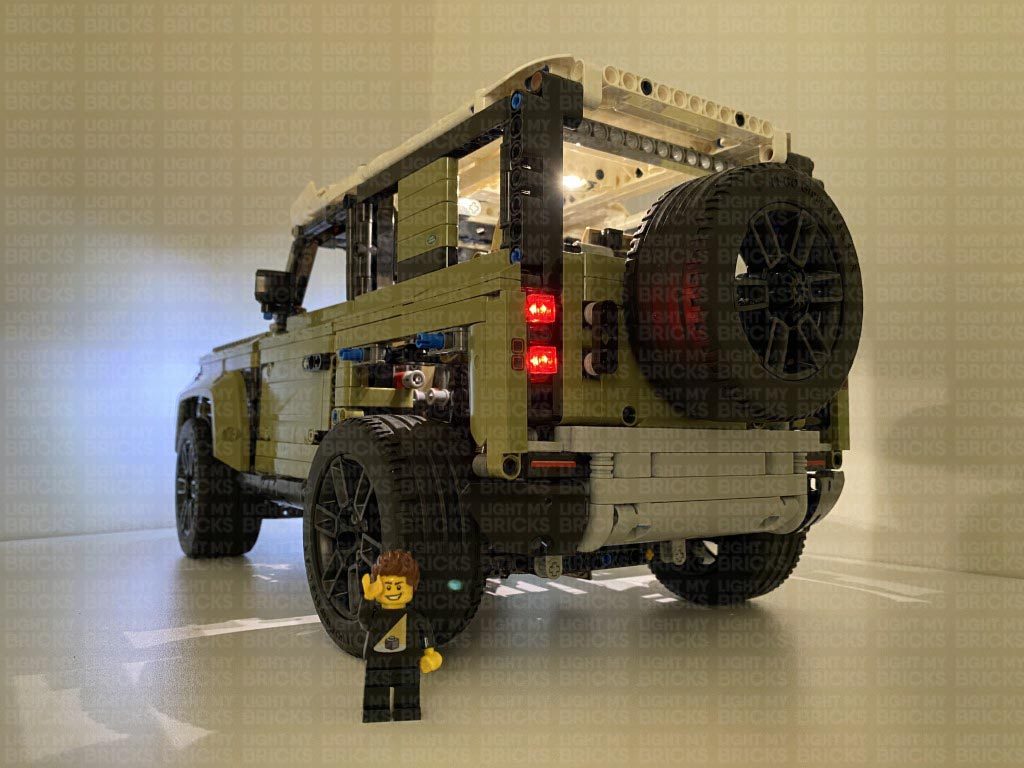
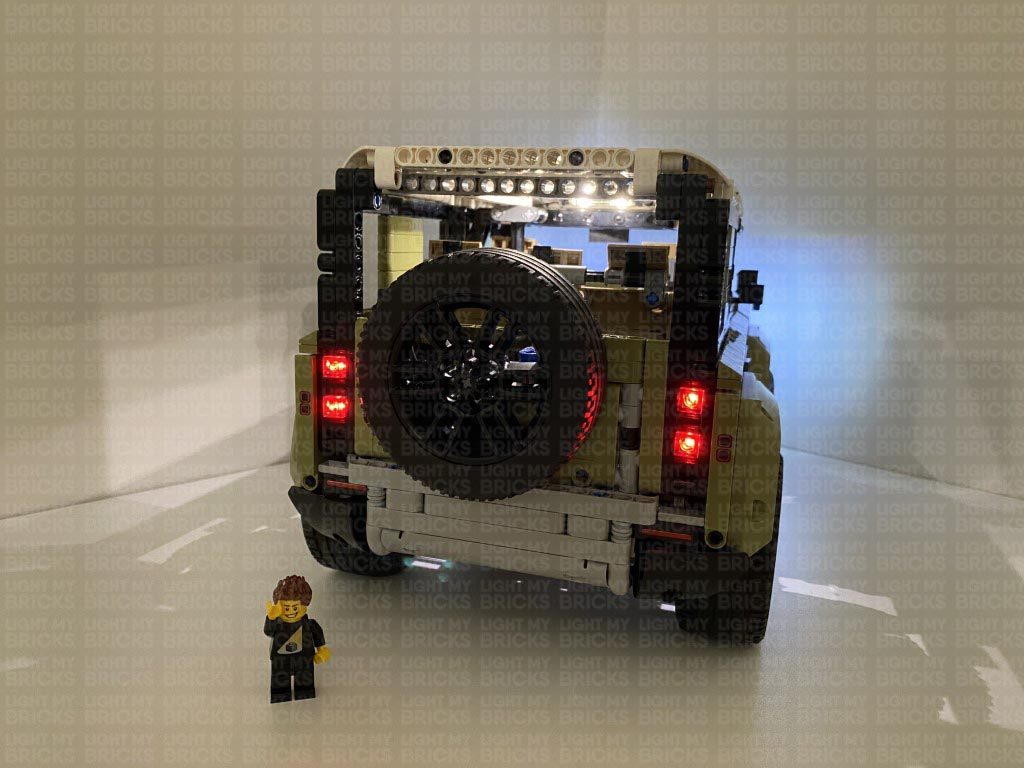
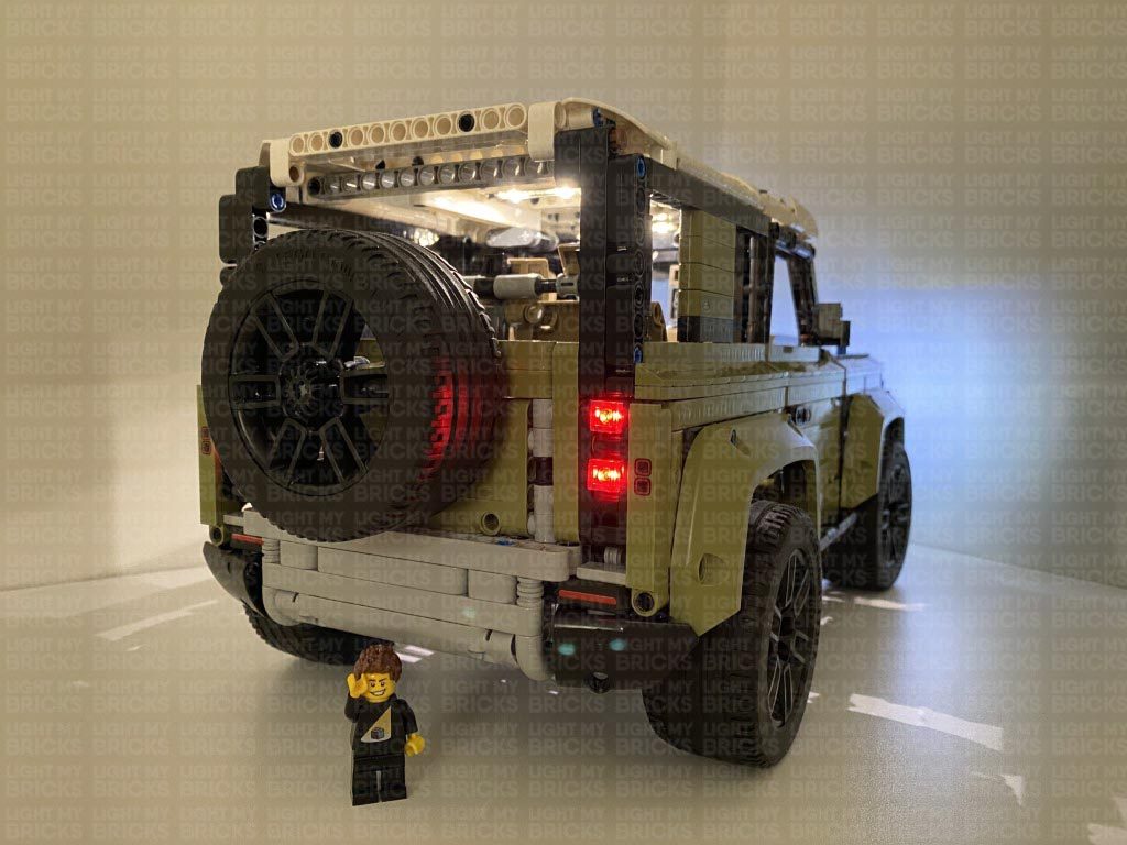
 Eliminate any excess cables by twisting and folding them around each other into a neat bunch. Ensure that the wheels can still turn left and right.
Flip the Defender over and reconnect the Technic piece above the rear wheel. Turn the AA Battery Pack ON to test all the lights are working OK.
Eliminate any excess cables by twisting and folding them around each other into a neat bunch. Ensure that the wheels can still turn left and right.
Flip the Defender over and reconnect the Technic piece above the rear wheel. Turn the AA Battery Pack ON to test all the lights are working OK.
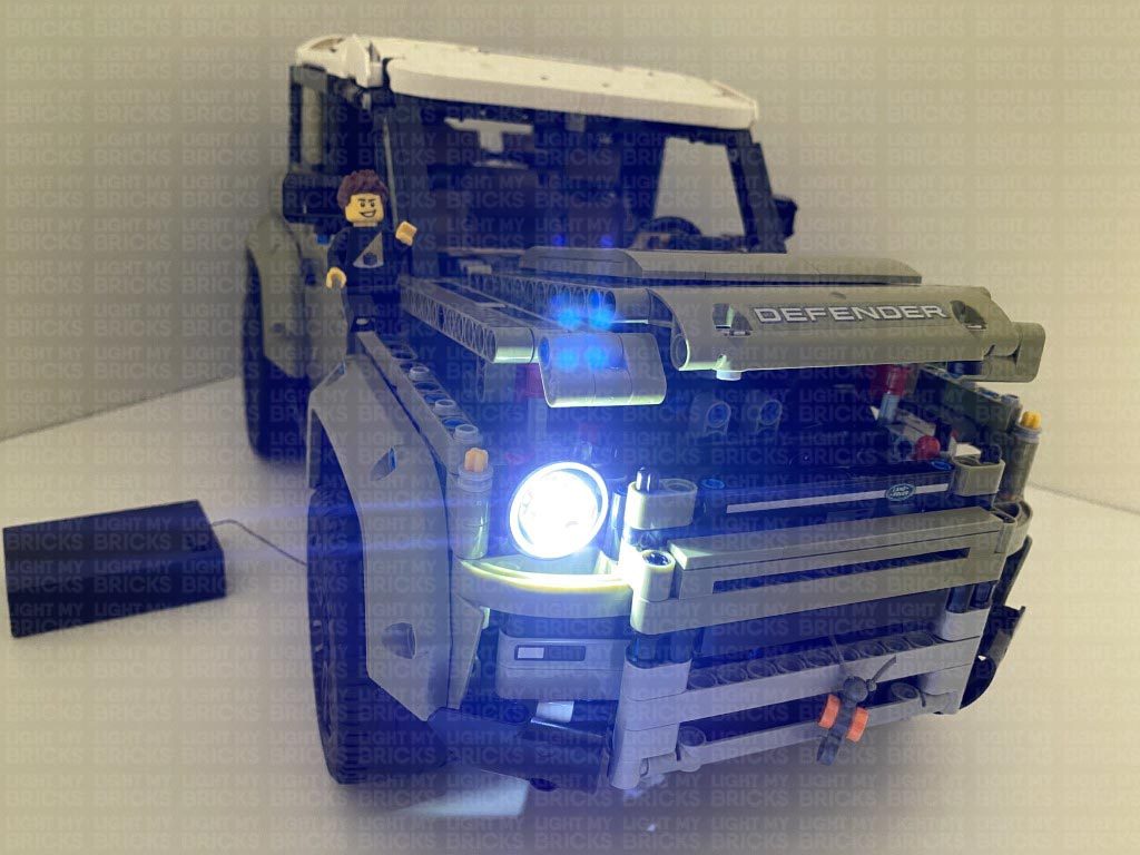
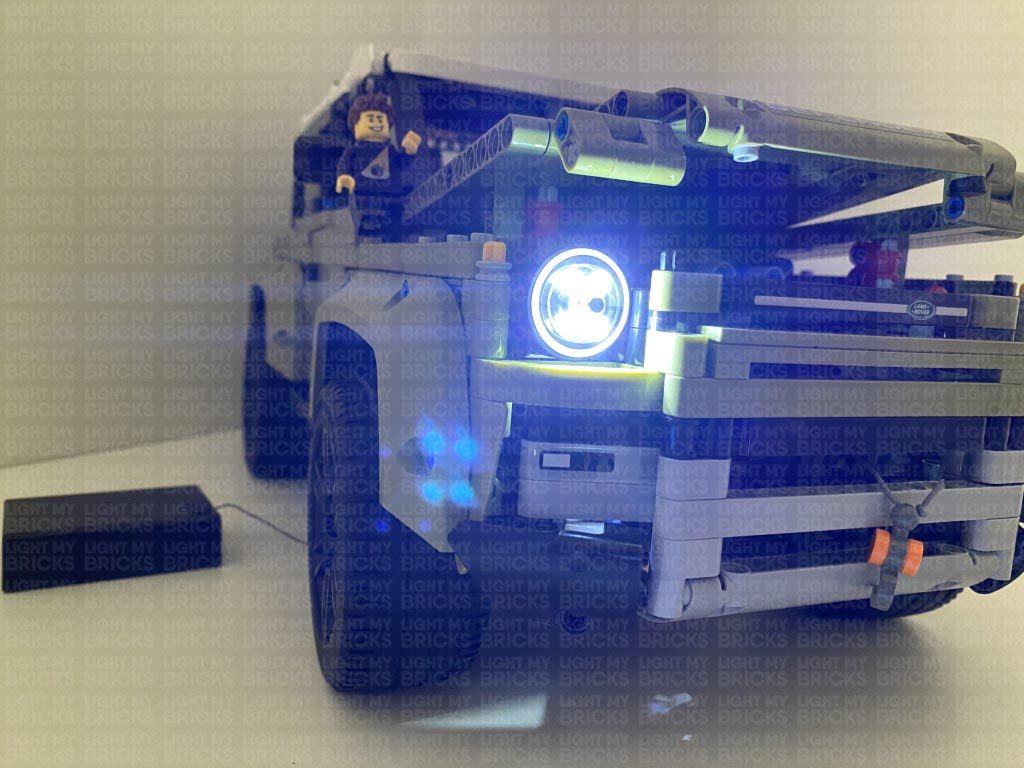
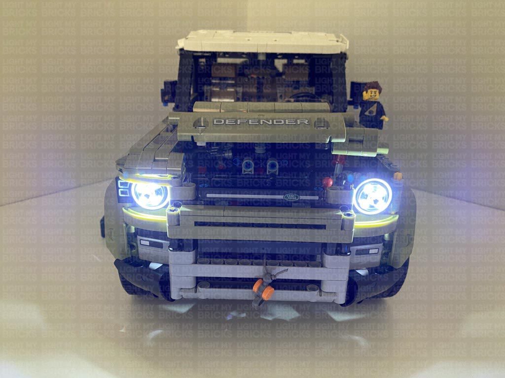
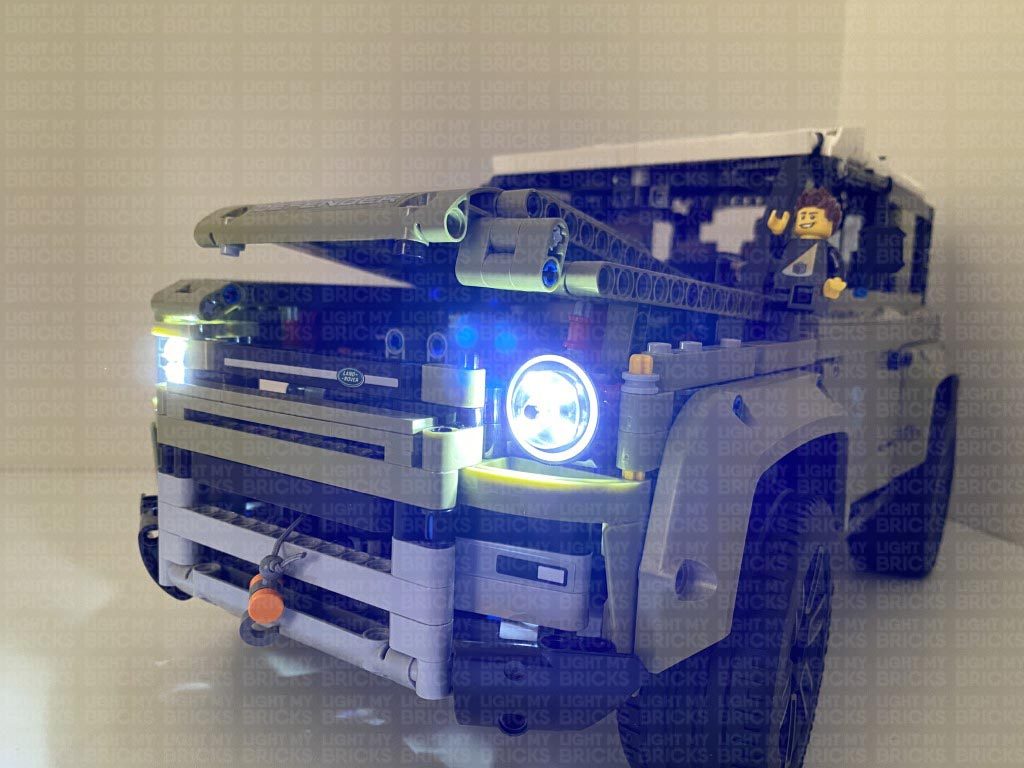
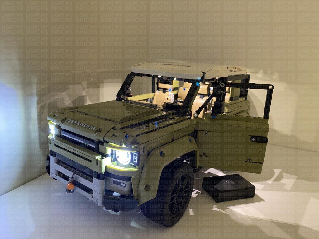
This finally completes installation of the Light My Bricks Land Rover Defender 42110 Light Kit.
We thank you for purchasing this product and hope you ENJOY!