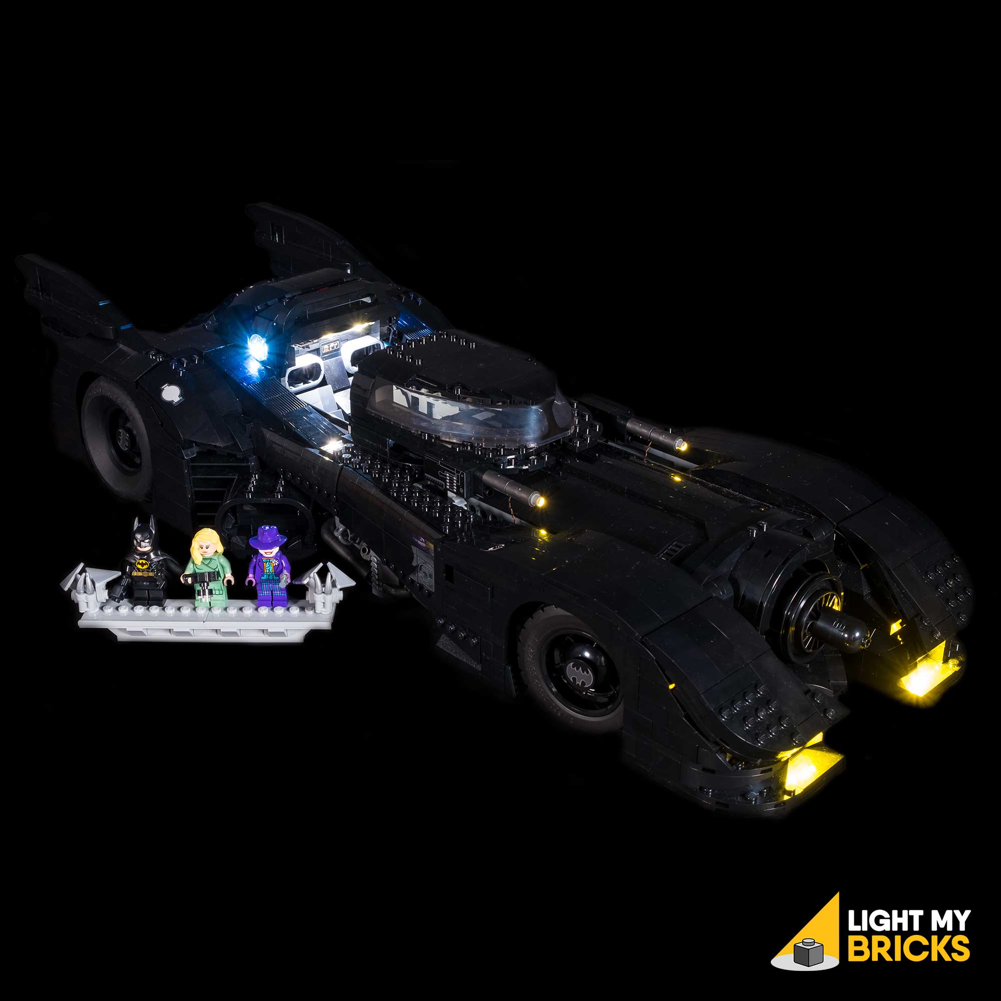

The following page is the instructions for the Light My Bricks LEGO 1989 Batmobile (76139) LED light kit.
If you run into any issues, please refer to the online troubleshooting guide.
To ensure a trouble-free installation of your light kit, please read and follow each step carefully. These instructions can be downloaded in PDF format here
Please note: This page lists instructions for the LED light kit only. If you are wishing to purchase the Light My Bricks LEGO 1989 Batmobile (76139) LED light kit , please click here to view the product page
Package Contents:
- 8x White 15cm Bit Lights
- 6x Warm White 30cm Large Bit Lights
- 2x Cool White 30cm Bit Lights
- 4x Red 30cm Bit Lights
- 1x Rotating White 30cm Bit Light
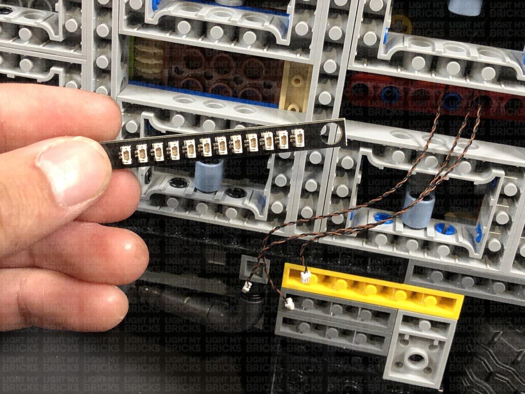
- 1x White Strip Light
- 1x Flicker Effects Board
- 1x Gun Effects Board
- 1x NC Push Board
- 1x 6-Port Expansion Board
- 2x 8-Port Expansion Boards
- 1x 12-Port Expansion Board
- 3x 5cm Connecting Cables
- 3x 15cm Connecting Cables
- 1x 50cm Connecting Cable
- 8x Adhesive Squares
- 1x AA Battery Pack
- 2x Black Round Plate 1×1 with open stud
Important things to note:
Laying cables in between and underneath bricks
Cables can fit in between and underneath LEGO® bricks, plates, and tiles providing they are laid correctly between the LEGO® studs. Do NOT forcefully join LEGO® together around cables; instead ensure they are laying comfortably in between each stud.
Connecting cable connectors to Expansion Boards
Take extra care when inserting connectors to ports of Expansion Boards. Connectors can be inserted only one way. With the expansion board facing up, look for the soldered “=” symbol on the left side of the port. The connector side with the wires exposed should be facing toward the soldered “=” symbol as you insert into the port. If a plug won’t fit easily into a port connector, do not force it.
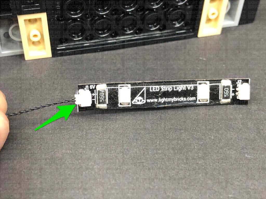
Connecting cable connectors to Strip Lights
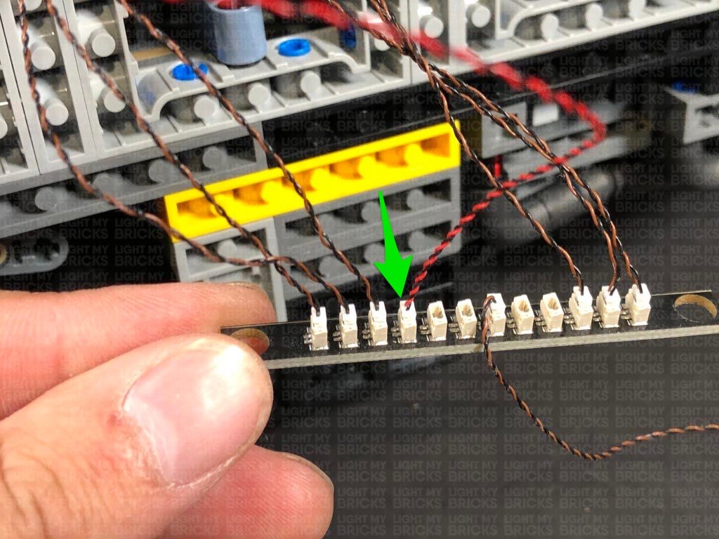
Take extra care when inserting connectors to ports on the Strip Lights. Connectors can be inserted only one way. With the Strip Light facing up, ensure the side of the connector with the wires exposed is facing down. If a plug won’t fit easily into a port connector, don’t force it. Doing so will damage the plug and the connector.
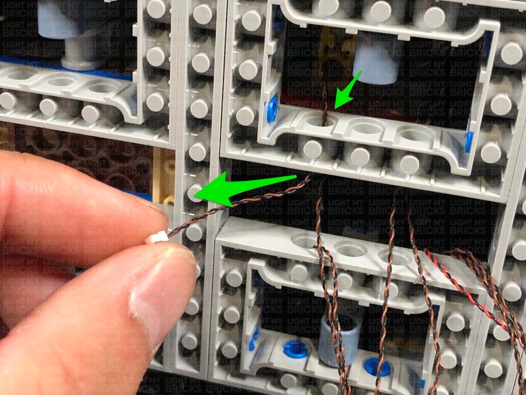
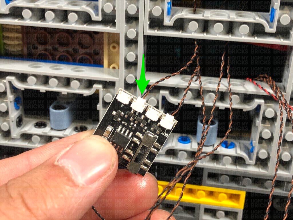
Connecting Micro Cable connectors to Micro Expansion Board Ports
Take extra care when inserting the micro connectors to micro ports of Micro Expansion Boards. Connecting Micro Bit Lights to Micro Expansion Boards is similar to connecting lights and cables to Strip Lights. With the expansion board facing up, ensure the side of the connector with the wires exposed is facing down. If a plug won’t fit easily into a port connector, do not force it. Use your fingernail to push the plastic part of the connector to the micro port.
Installing Bit Lights under LEGO® bricks and plates.
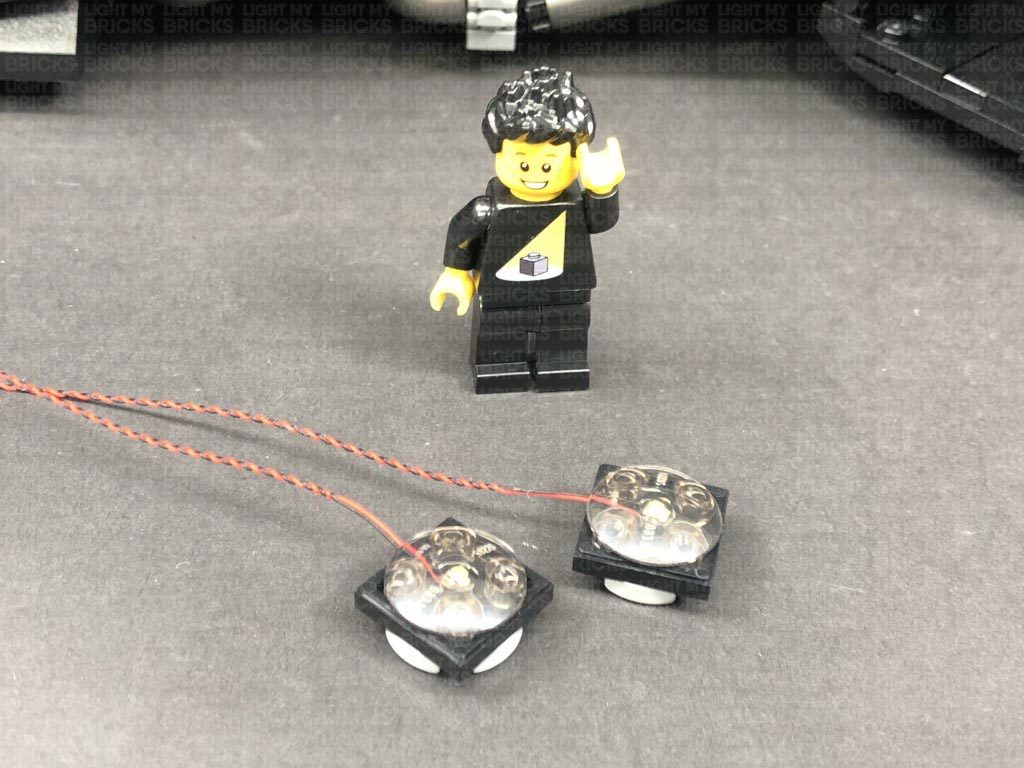
When installing Bit Lights under LEGO® pieces, ensure they are placed the correct way up (Yellow LED component exposed). You can either place them directly on top of LEGO® studs or in between.
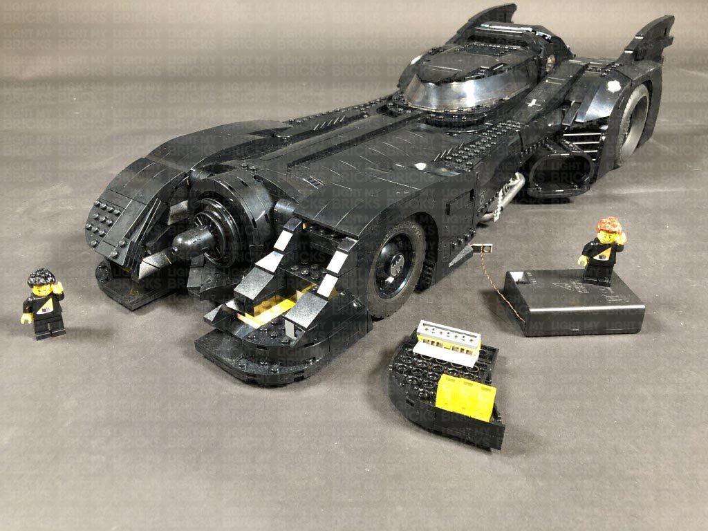
OK, Let’s Begin!
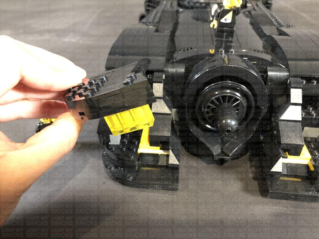
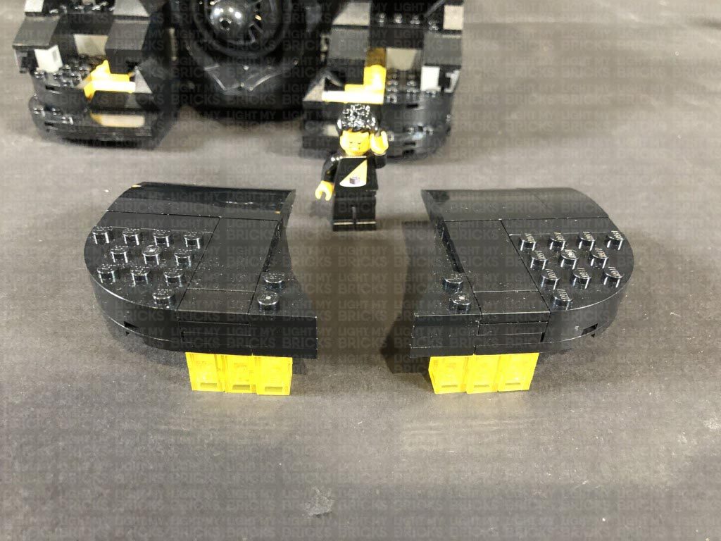
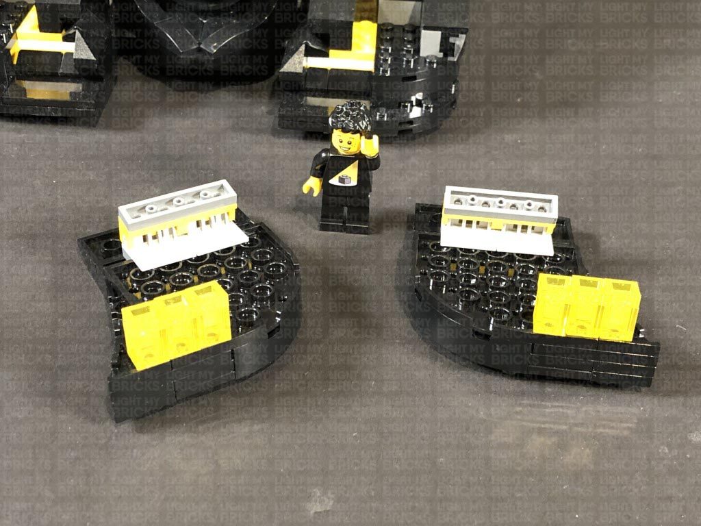
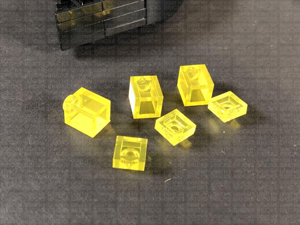
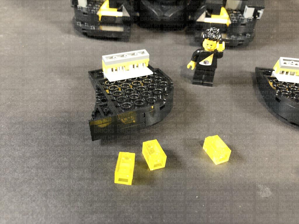
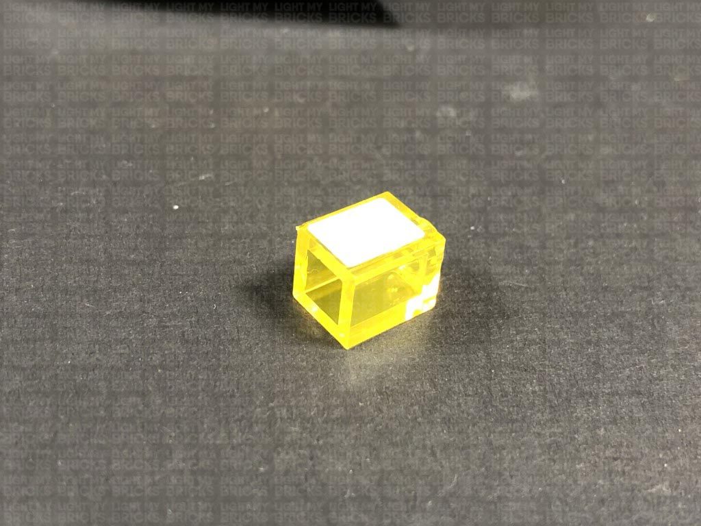
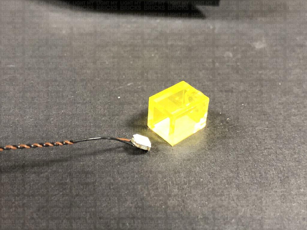
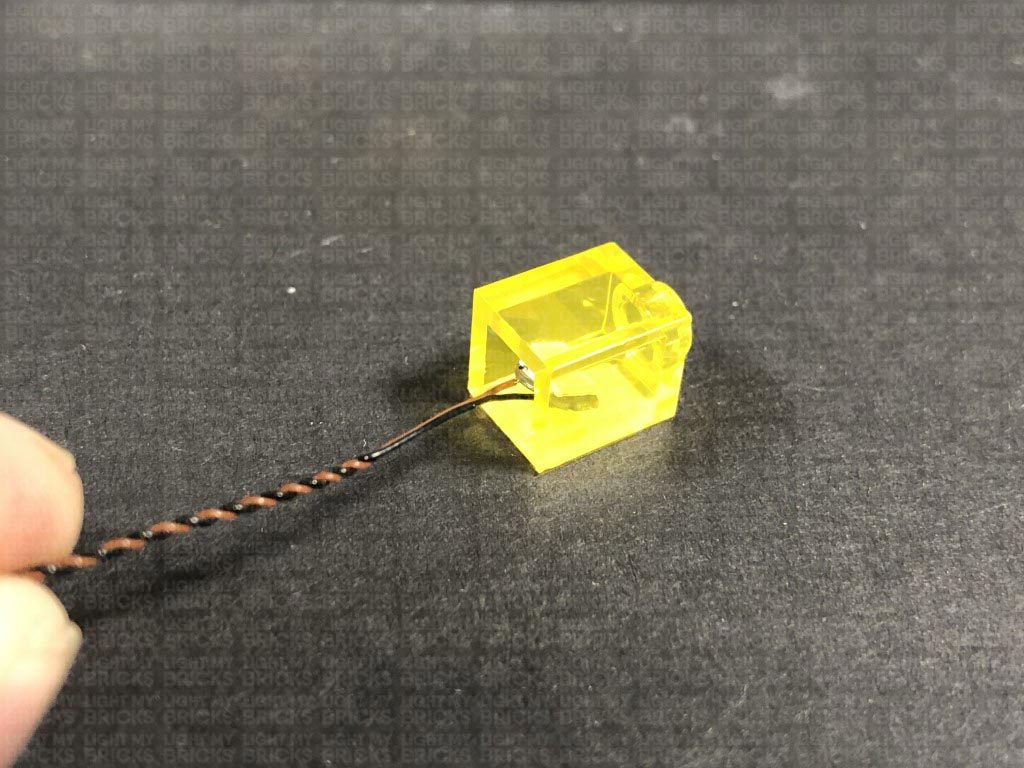
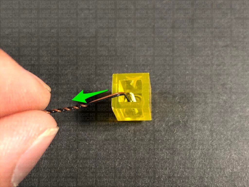
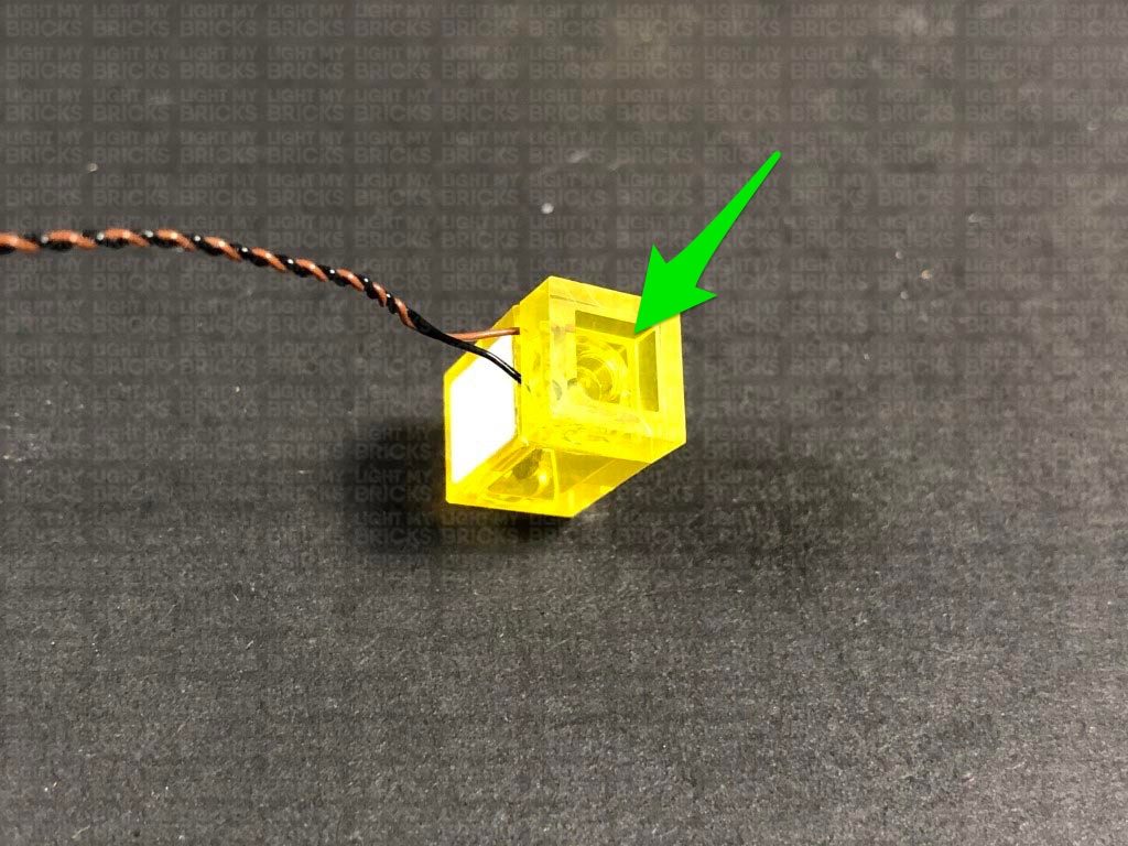
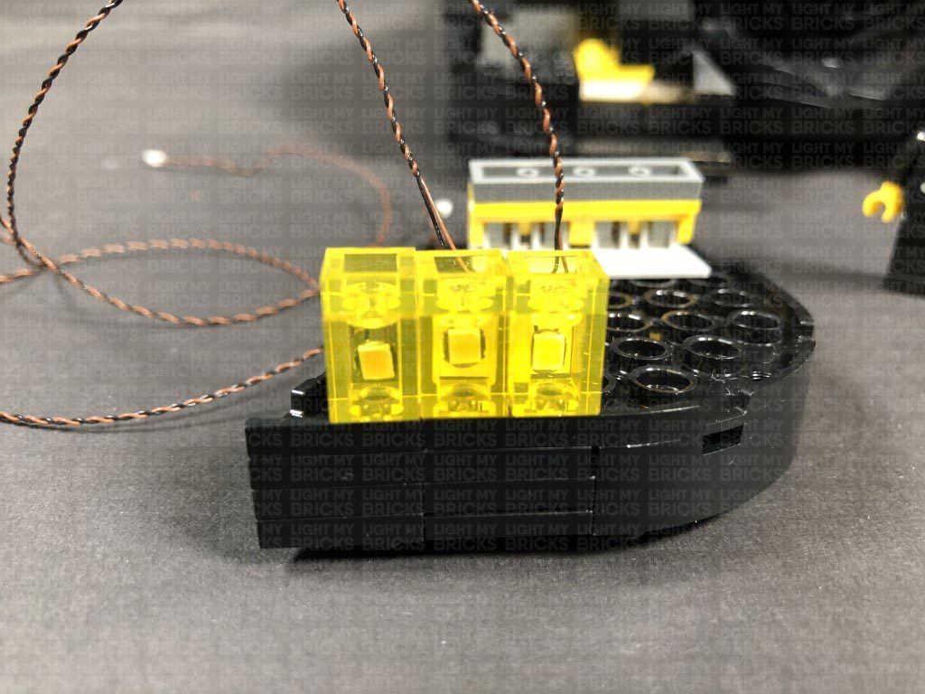
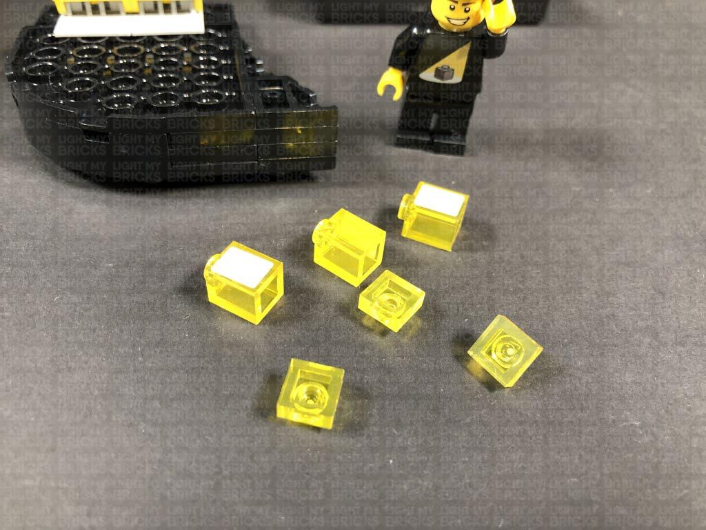
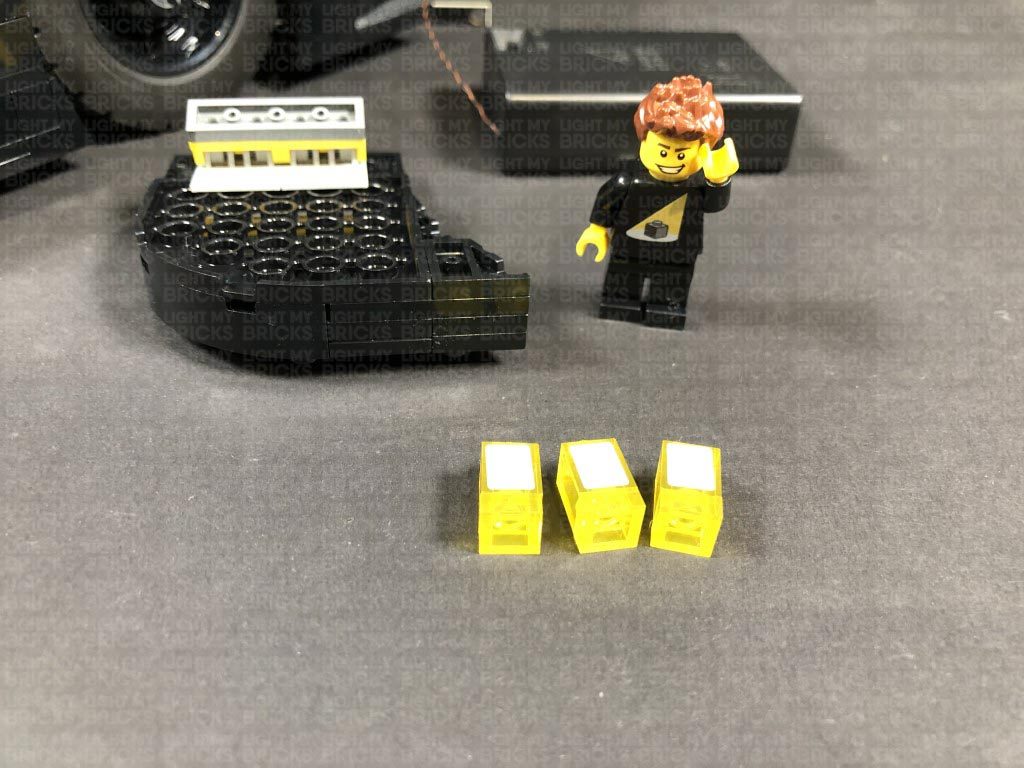
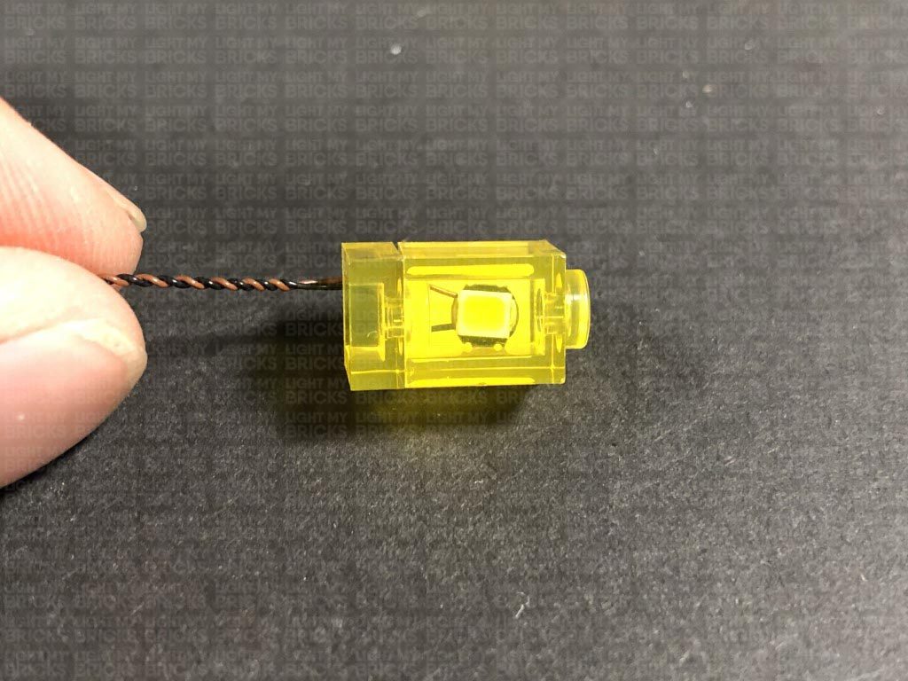
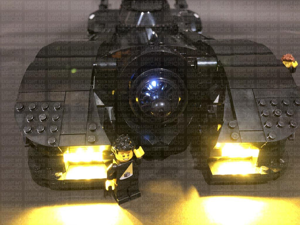
1.) We will first install the headlights to the batmobile. Carefully remove the two headlight sections, then flip them over and disassemble the right headlight section as shown below. Take a Warm White 30cm Large Bit Light and with the LED facing the opposite side to the sticker, place it inside the trans yellow brick. Bring the cable down the side where the sticker is, then secure the Bit Light in place by reconnecting the trans yellow plate over the top.
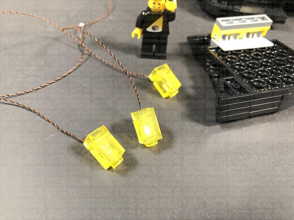
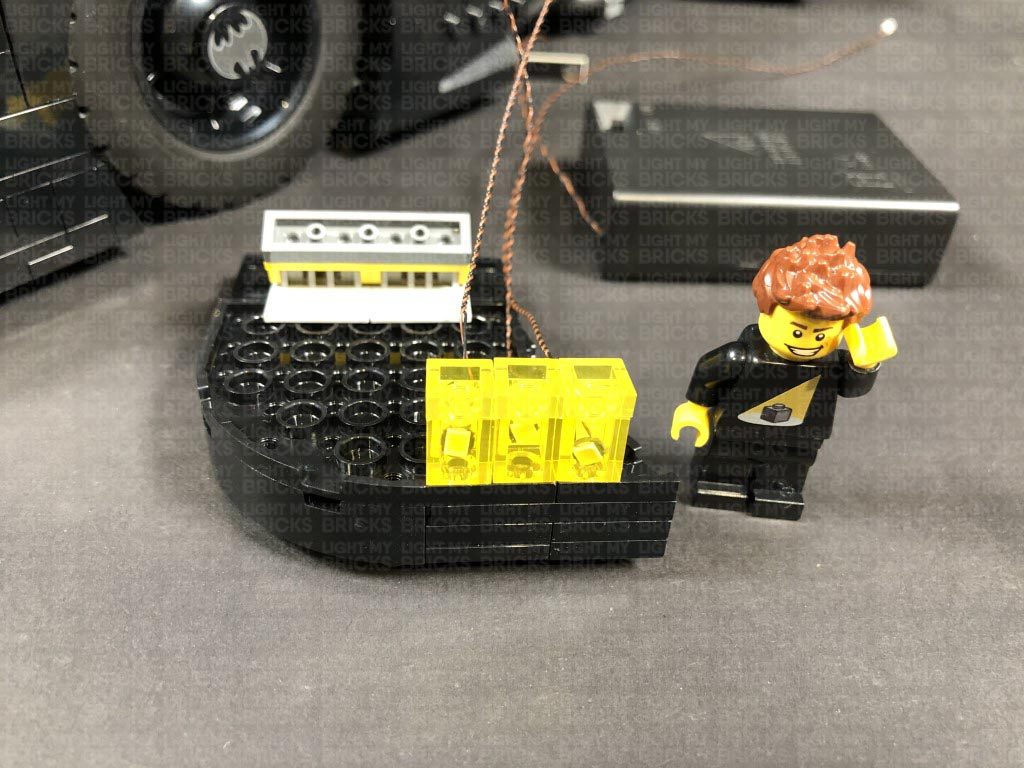
 Repeat this step to install another 2x Warm White 30cm Large Bit Lights to the other two headlight pieces, then reconnect each one to the right headlight ensuring the LEDS are facing to the front.
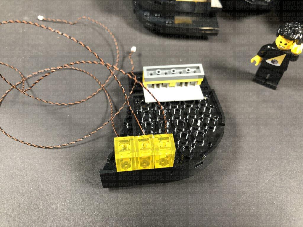
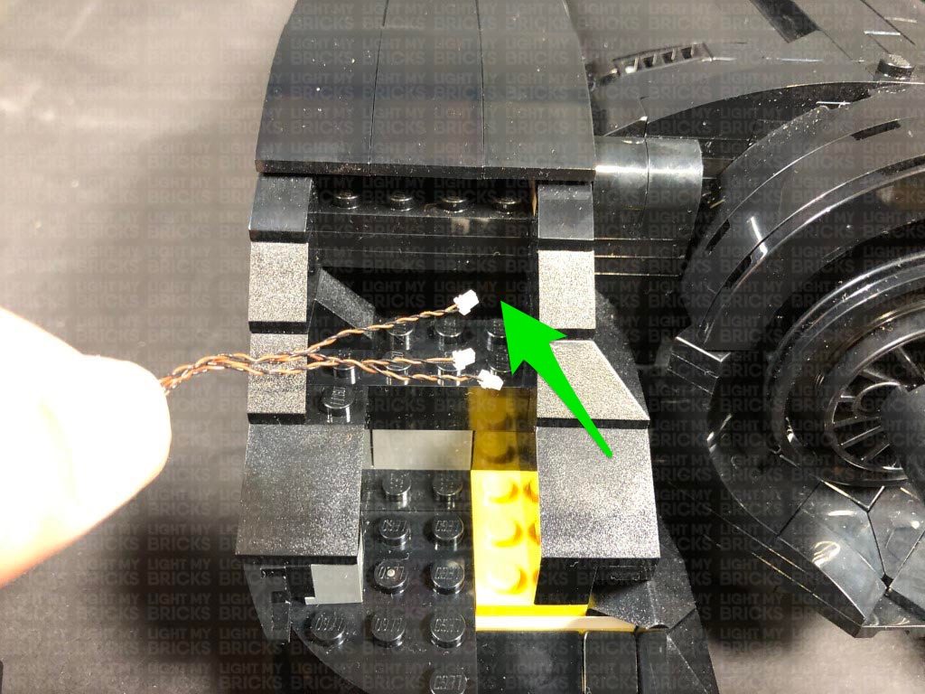
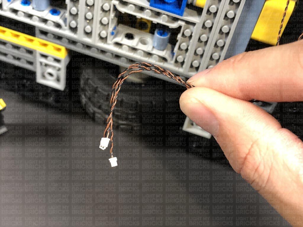
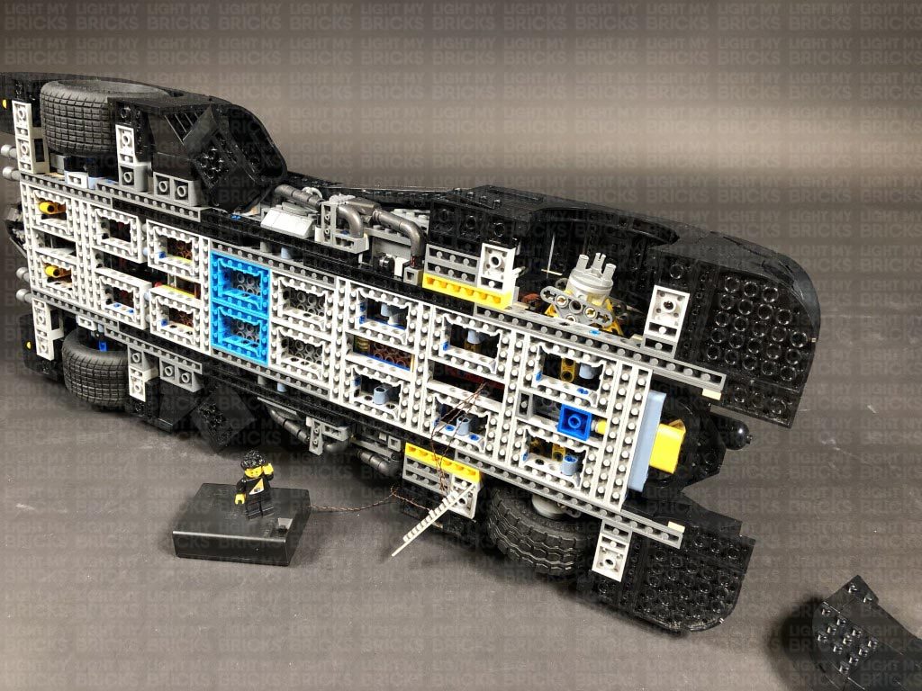
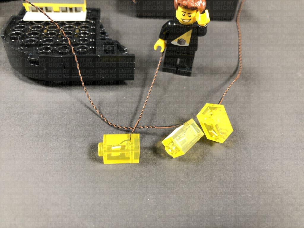
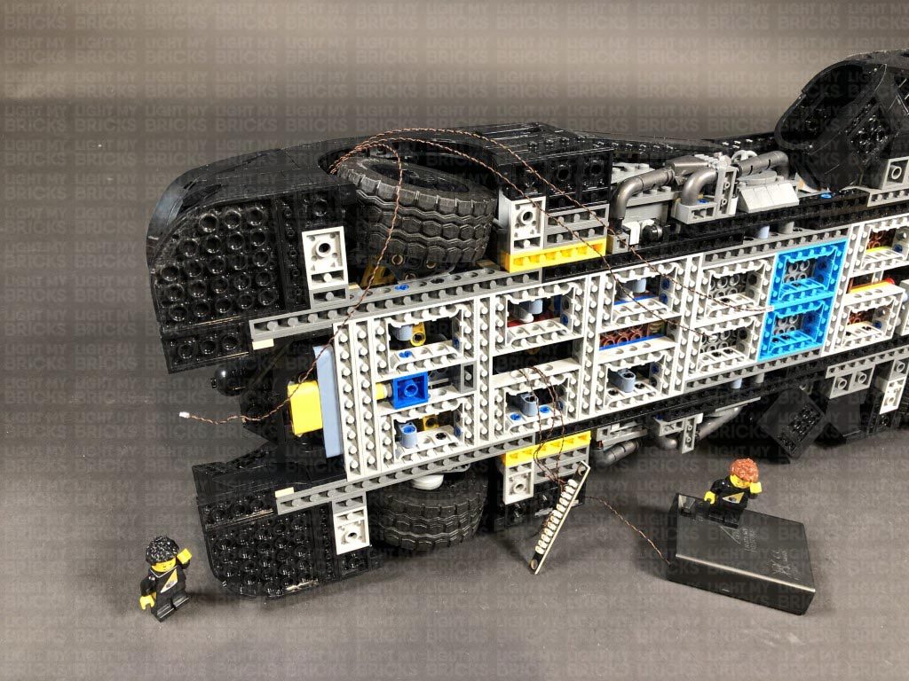
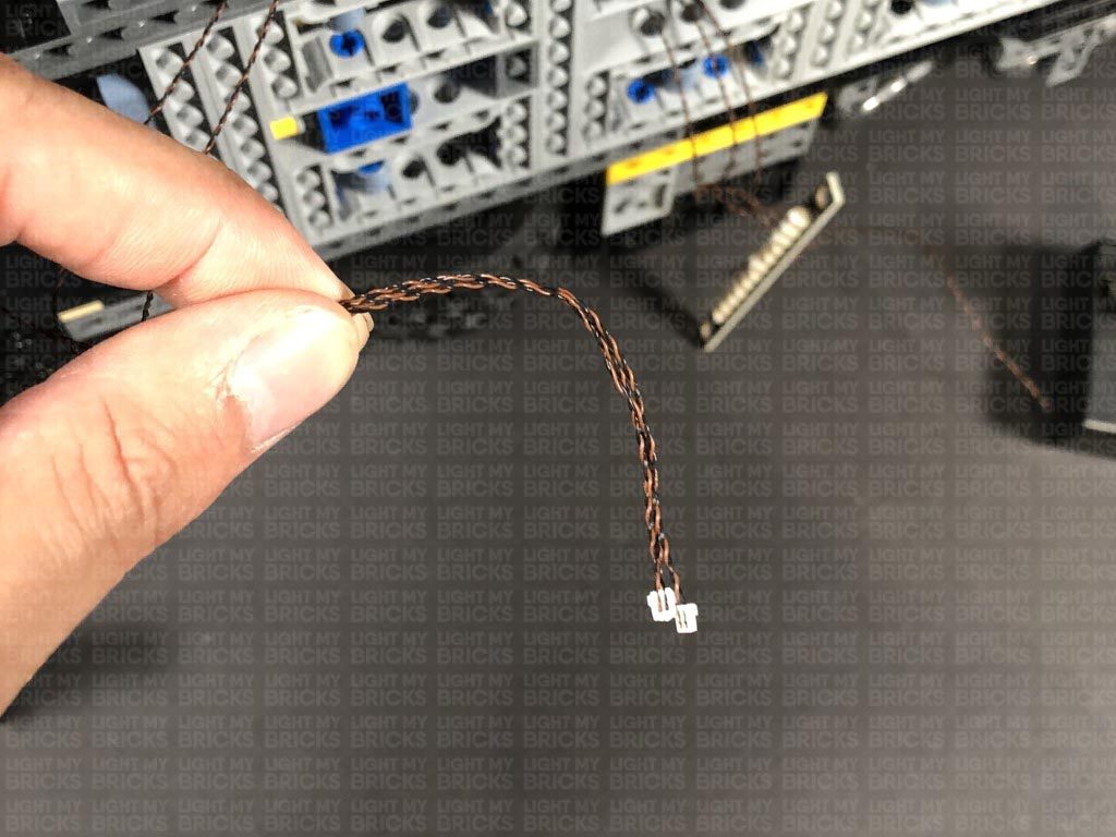
2.) Bring the ends of the three bit light cables together and thread them through the space behind the headlights. Turn the batmobile onto it’s left side so we can access underneath. Find the three cables we threaded through behind the headlight and pull them all the way out at the front of the wheel.
Turn the vehicle back over and reconnect the right headlight ensuring the cables underneath are laid in between studs.
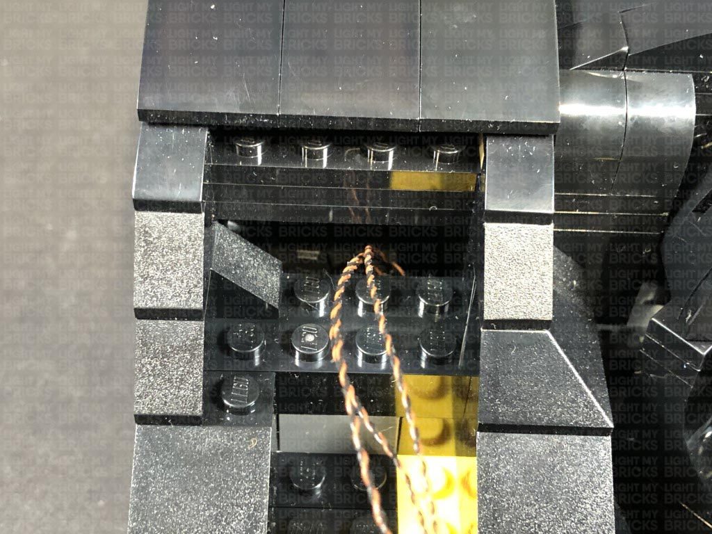
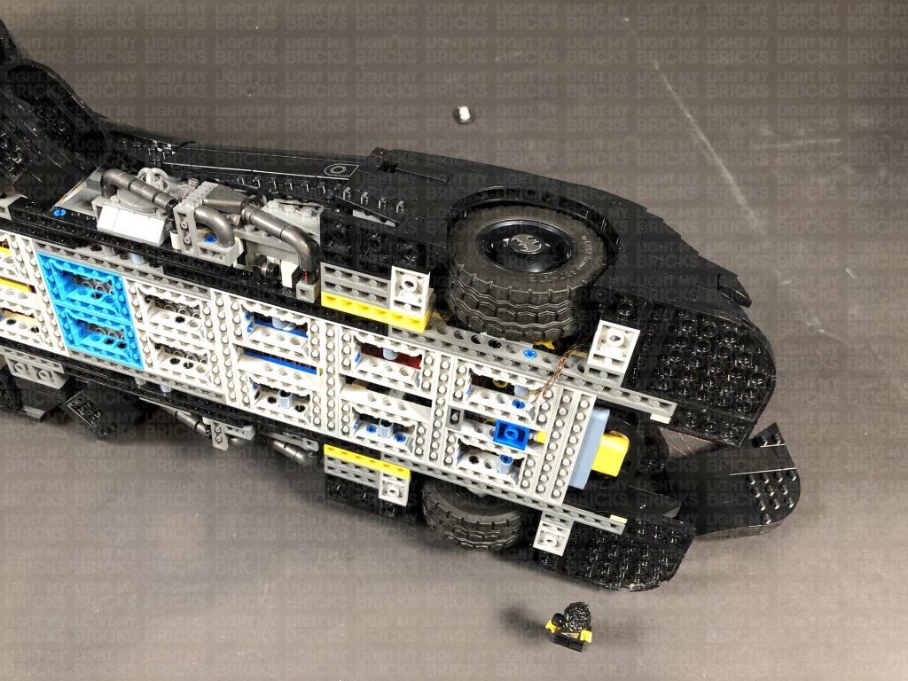
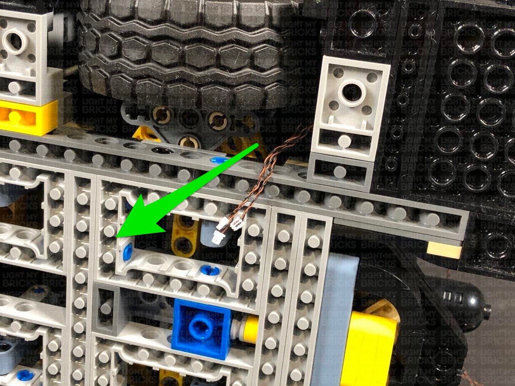
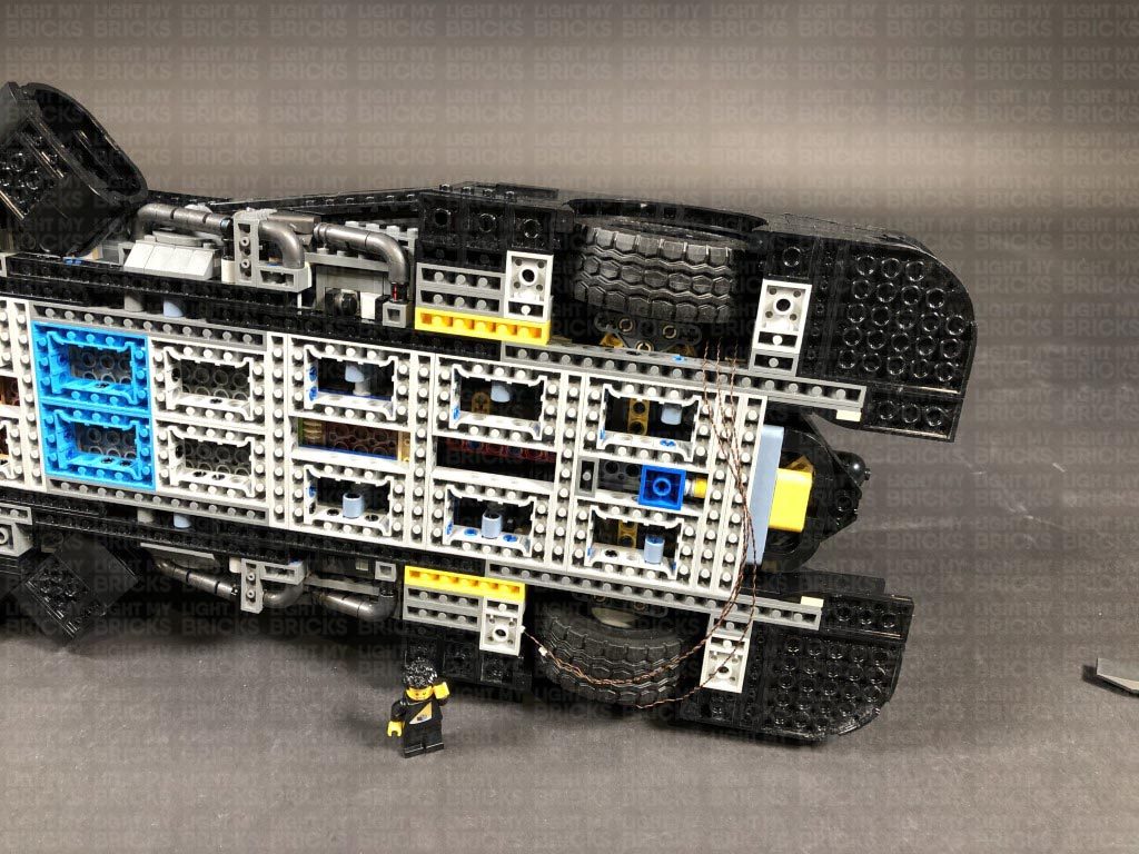
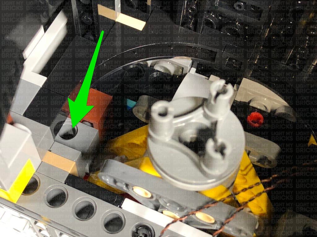
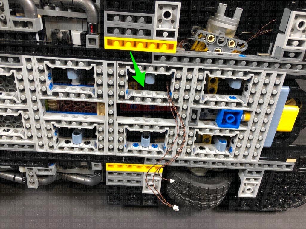
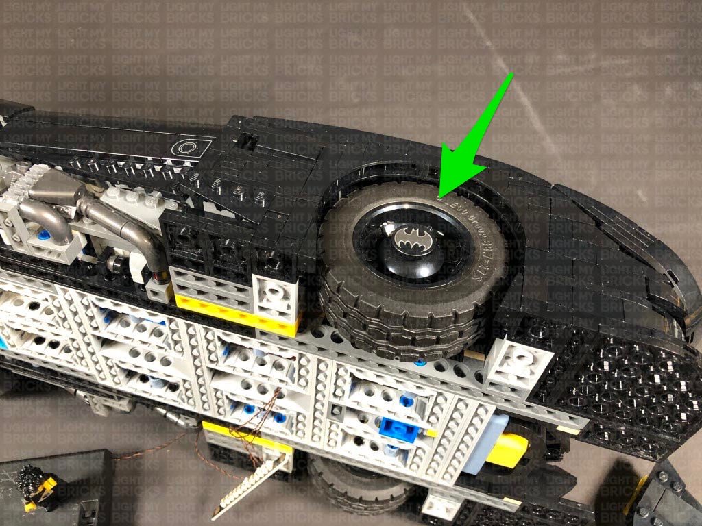
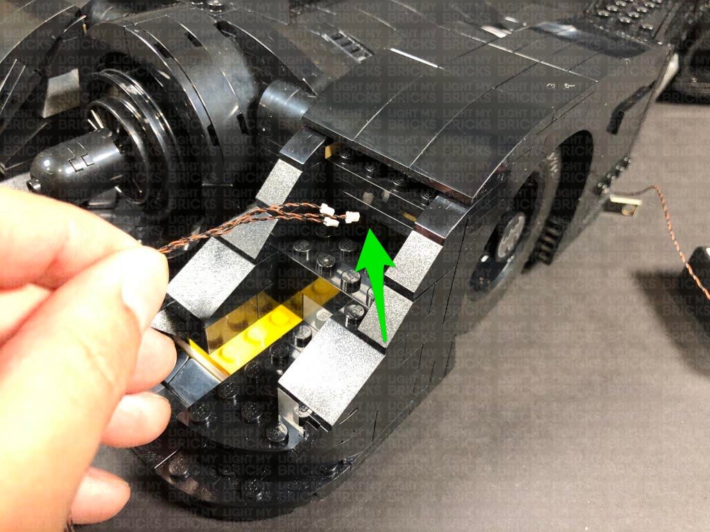
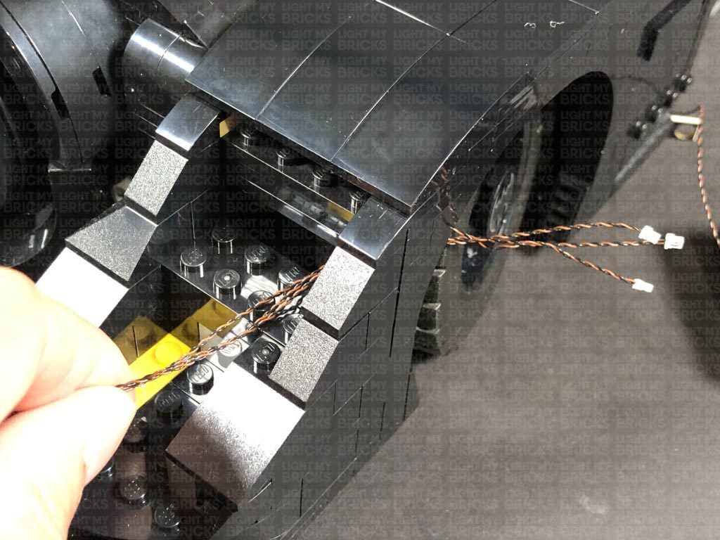
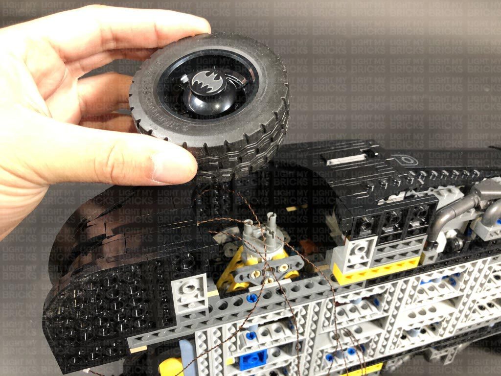
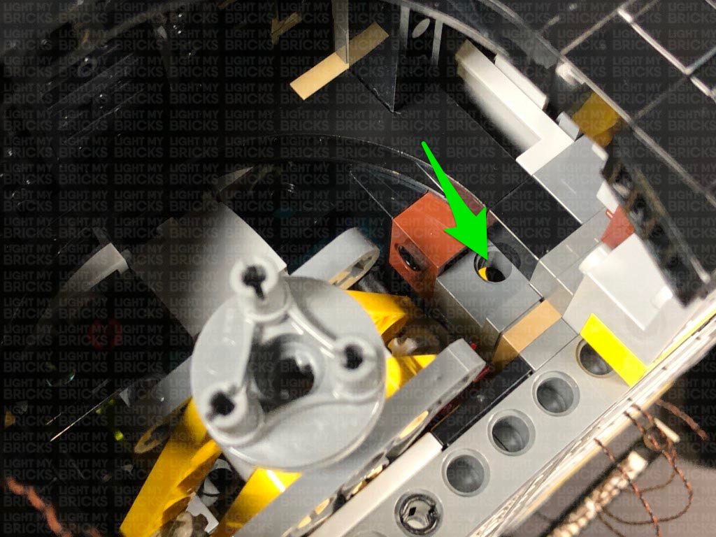
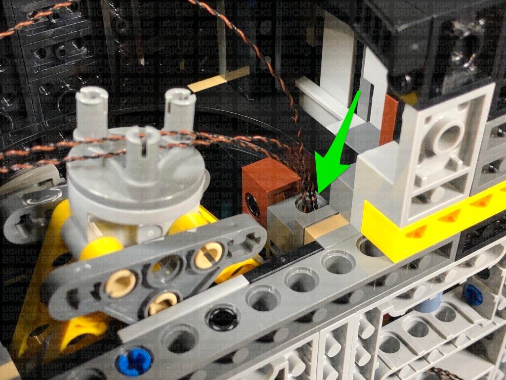
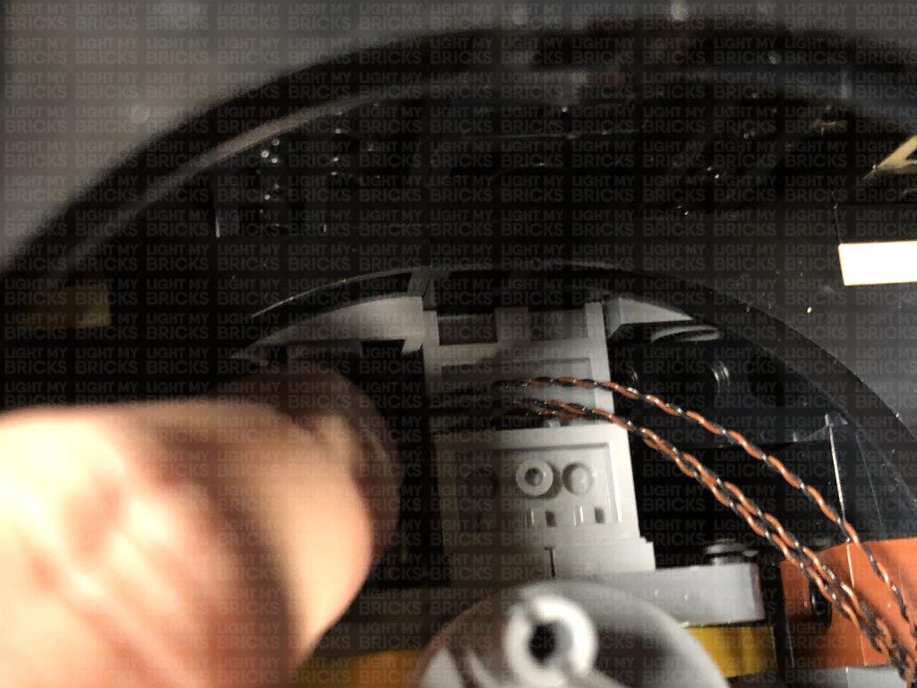
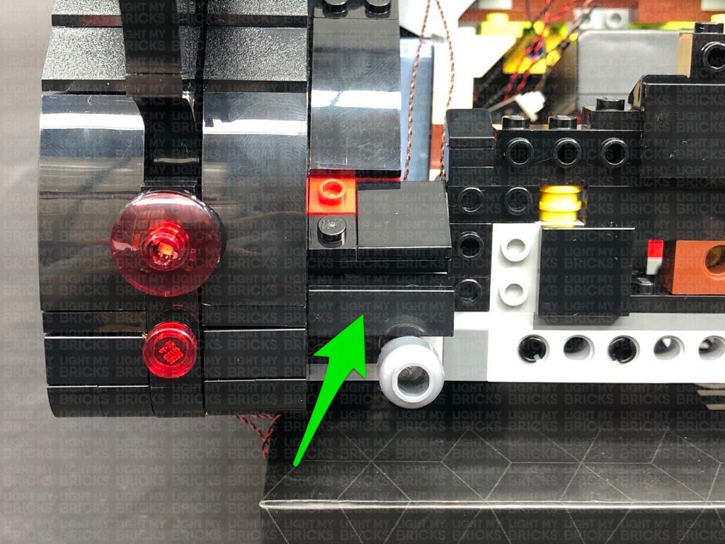
Turn the vehicle back onto it’s left side again and disconnect the front right wheel, then slightly bend the three cables into a hook shape and thread the cables through the following dark grey technic brick hole behind the wheel. Thread the cables through and pull them all the way out at the following space below.
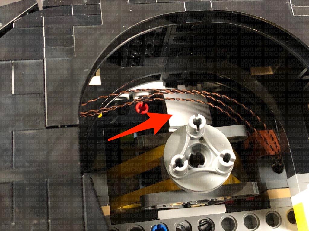
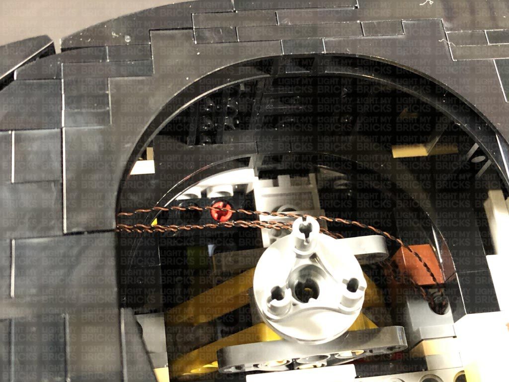
Secure the cables around the top of the wheel axis by disconnecting the following light grey plate, laying the cables underneath in between studs, then reconnecting the plate over the top. It is important to ensure there is enough cable slack for the wheel to still be able to turn all the way left and right, so test this out to ensure all is ok.
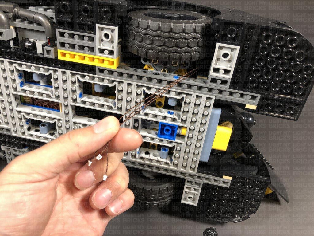
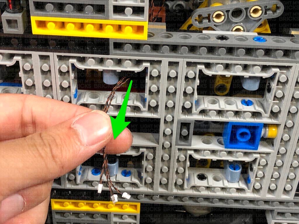
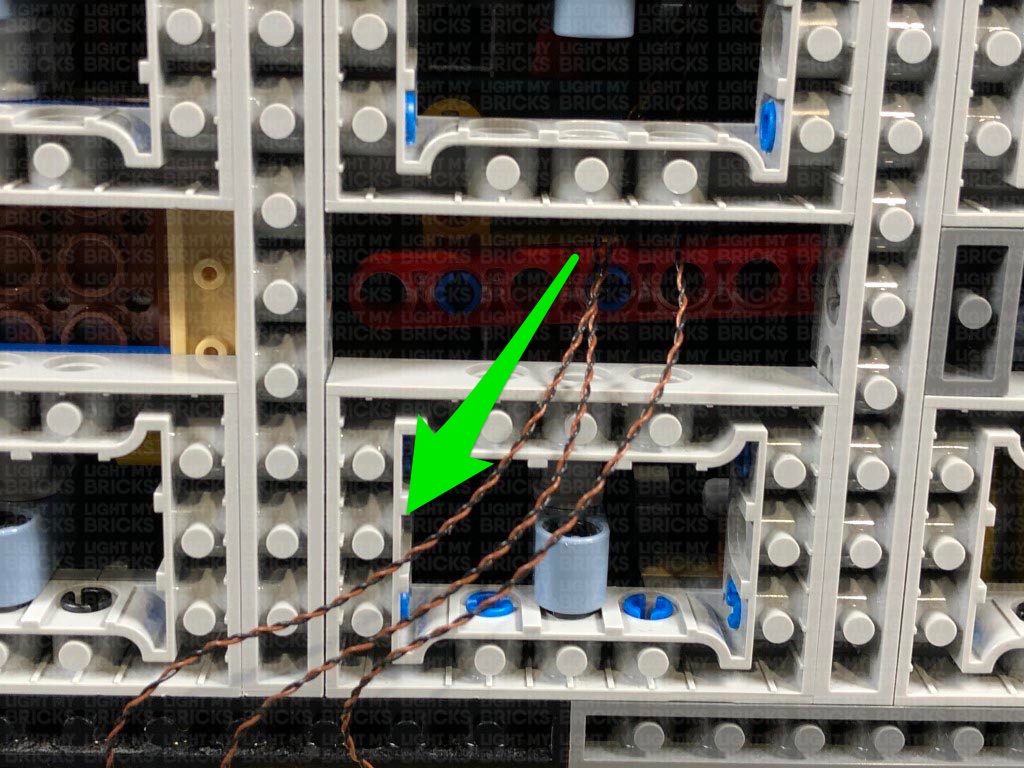
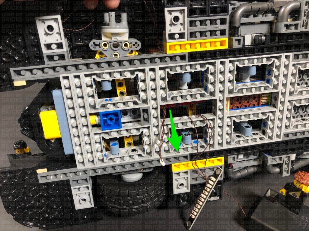
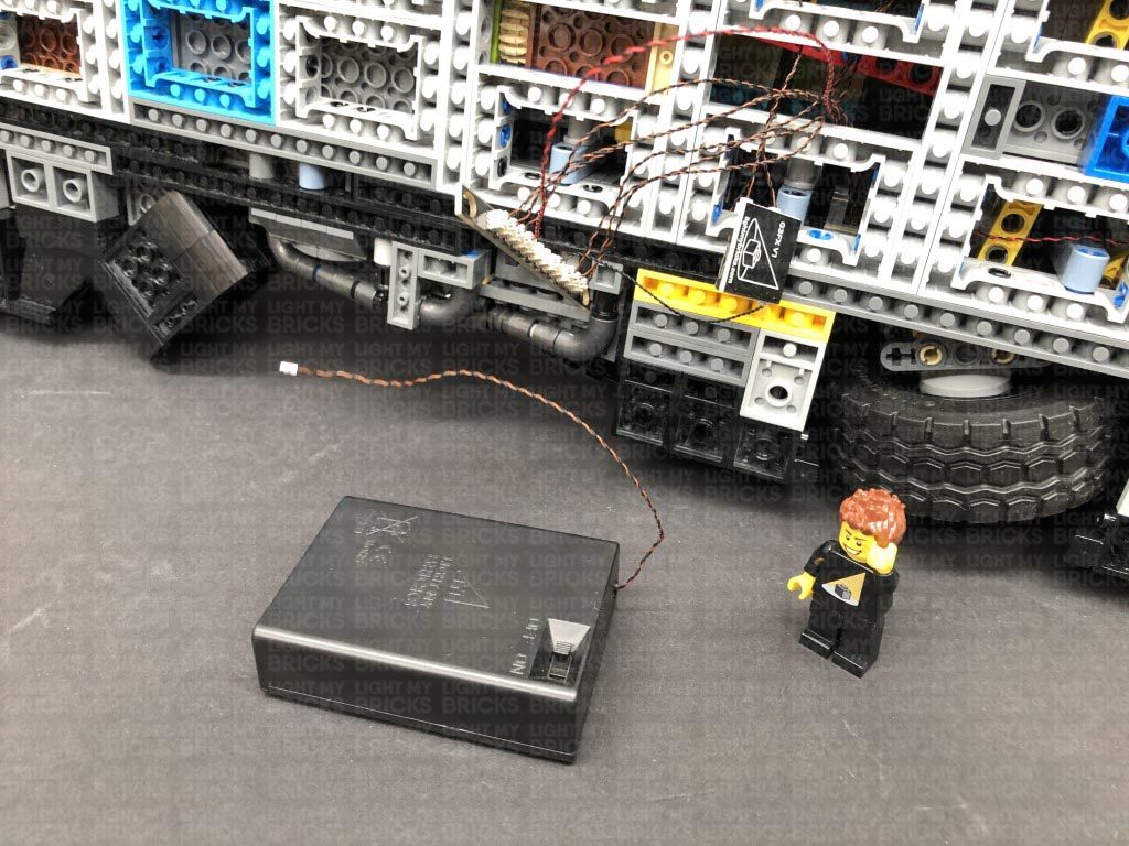
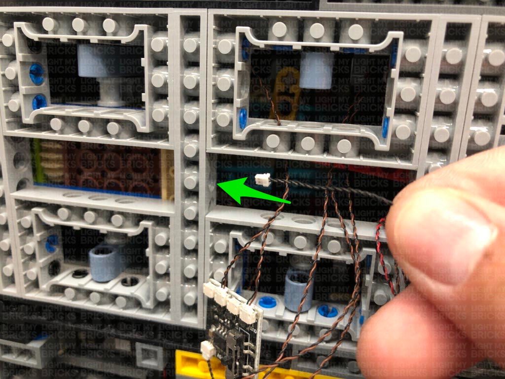
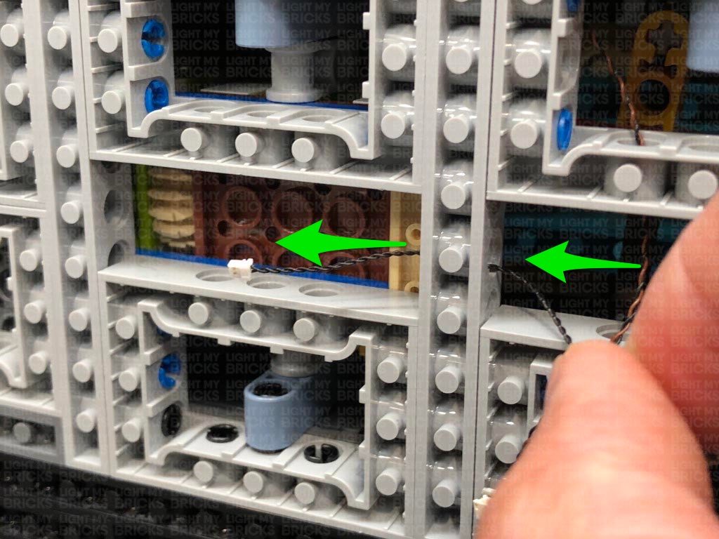
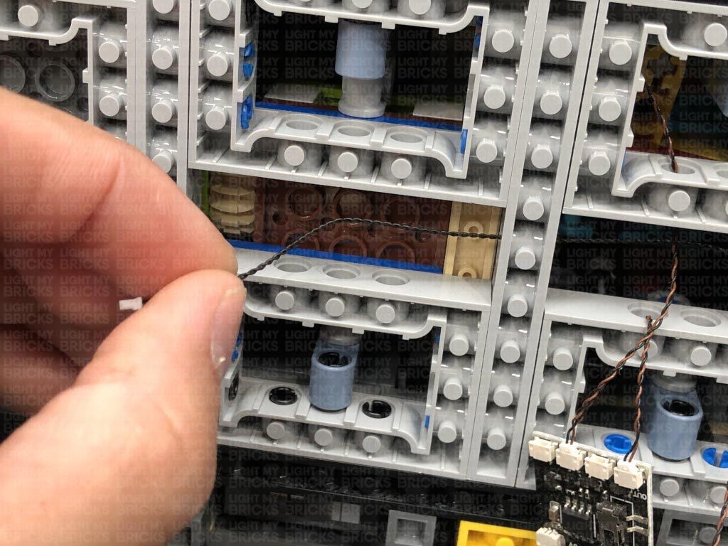
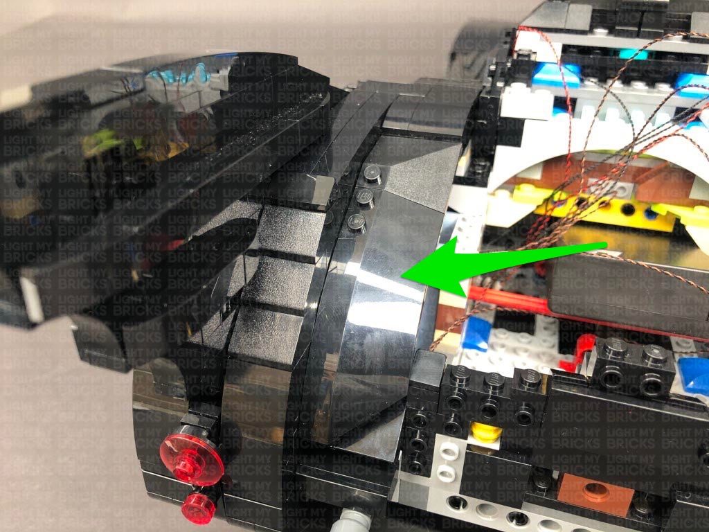
3.) Thread the three cables through to the next space in the centre, then pull them all the way out.
Connect the three bit lights to a 12-Port Expansion Board. Take the AA Battery Pack and insert 3x new AA Batteries to it. Connect the Battery Pack cable to a spare port on the expansion board, then turn it on to test the right headlights are working OK
Note: If you experience any issues with the lights not working and suspect an issue with a component, please try a different port on the expansion board to verify where the fault lies (with the light or expansion board). To correct any issues with expansion board ports, please view the section addressing expansion board issues on our online troubleshooting guide.
Reconnect the wheel we removed earlier, then flip the batmobile back over and continue to the next step.
4.) Disassemble the left headlight section, then repeat step 1 and 2 to install another 3x Warm White 30cm Large Bit Lights and reconnect the headlight section.
Repeat this step to install another 2x Warm White 30cm Large Bit Lights to the other two headlight pieces, then reconnect each one to the right headlight ensuring the LEDS are facing to the front.
2.) Bring the ends of the three bit light cables together and thread them through the space behind the headlights. Turn the batmobile onto it’s left side so we can access underneath. Find the three cables we threaded through behind the headlight and pull them all the way out at the front of the wheel.
Turn the vehicle back over and reconnect the right headlight ensuring the cables underneath are laid in between studs.
Turn the vehicle back onto it’s left side again and disconnect the front right wheel, then slightly bend the three cables into a hook shape and thread the cables through the following dark grey technic brick hole behind the wheel. Thread the cables through and pull them all the way out at the following space below.
Secure the cables around the top of the wheel axis by disconnecting the following light grey plate, laying the cables underneath in between studs, then reconnecting the plate over the top. It is important to ensure there is enough cable slack for the wheel to still be able to turn all the way left and right, so test this out to ensure all is ok.
3.) Thread the three cables through to the next space in the centre, then pull them all the way out.
Connect the three bit lights to a 12-Port Expansion Board. Take the AA Battery Pack and insert 3x new AA Batteries to it. Connect the Battery Pack cable to a spare port on the expansion board, then turn it on to test the right headlights are working OK
Note: If you experience any issues with the lights not working and suspect an issue with a component, please try a different port on the expansion board to verify where the fault lies (with the light or expansion board). To correct any issues with expansion board ports, please view the section addressing expansion board issues on our online troubleshooting guide.
Reconnect the wheel we removed earlier, then flip the batmobile back over and continue to the next step.
4.) Disassemble the left headlight section, then repeat step 1 and 2 to install another 3x Warm White 30cm Large Bit Lights and reconnect the headlight section.
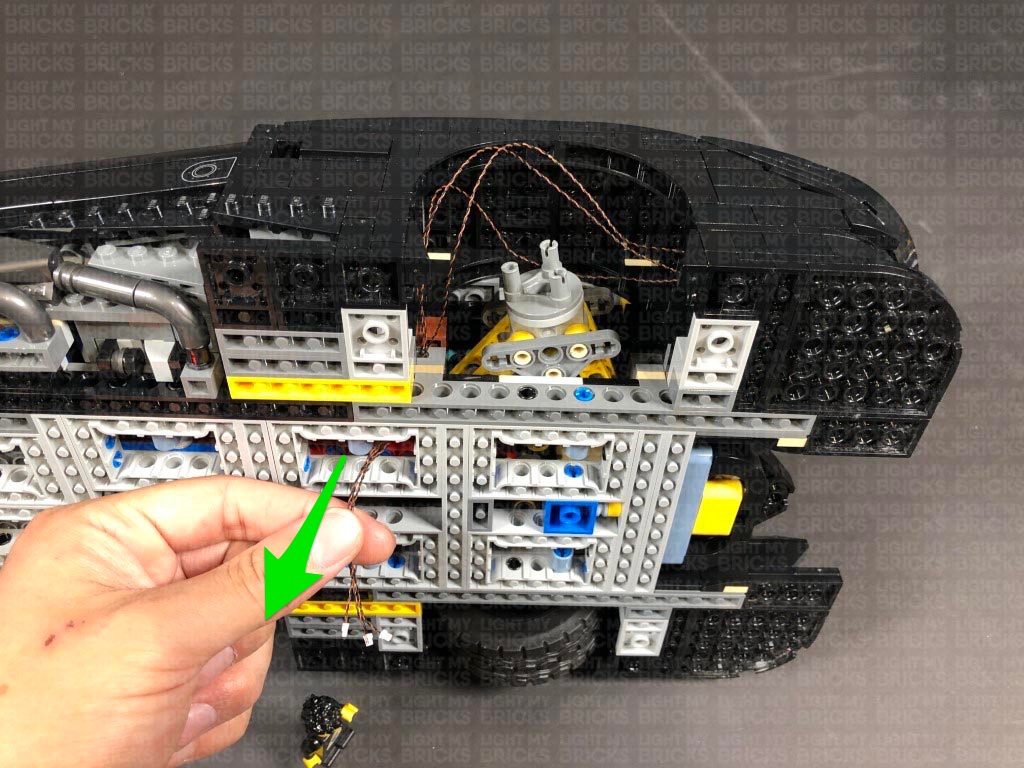
 Turn the vehicle back onto it’s right side and disconnect the front left wheel, then slightly bend the three cables into a hook shape and thread the cables through the following hole behind the wheel. Thread the cables through and pull them all the way out at the middle space as shown below.
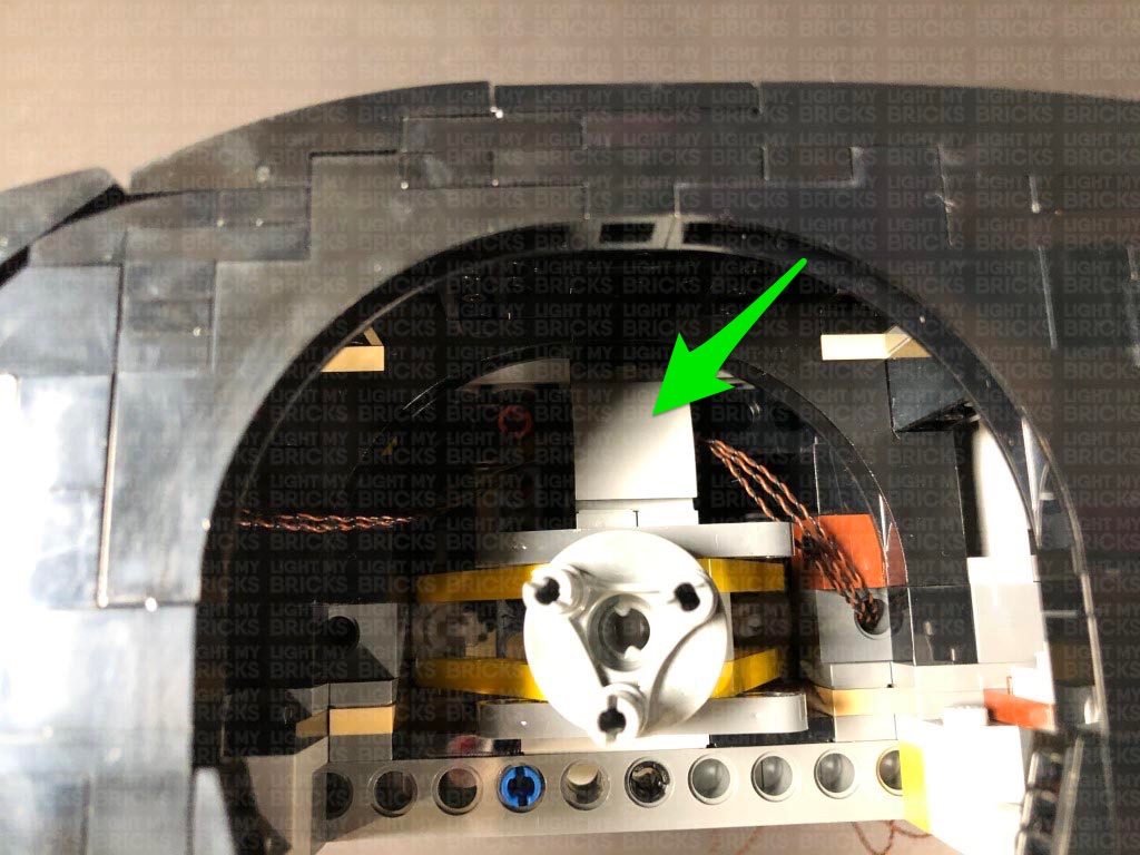
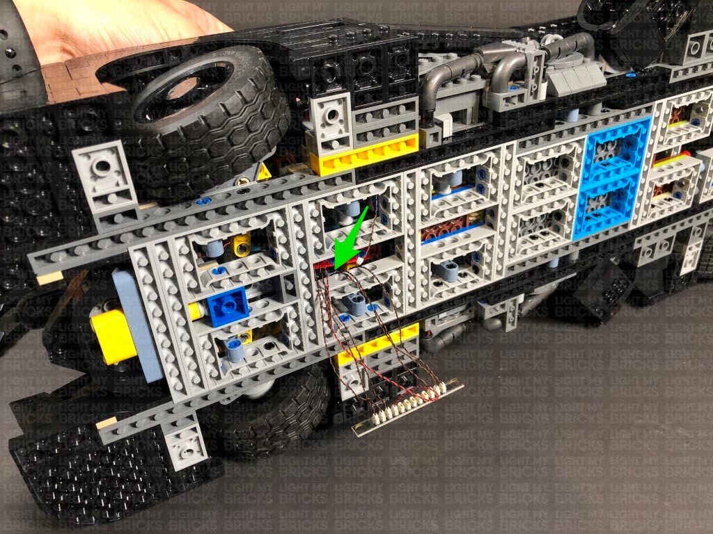
 5.) Secure the cables around the top of the wheel axis by disconnecting the following grey plate, laying the cables underneath in between studs, then reconnecting the plate over the top. It is important to ensure there is enough cable slack for the wheel to turn all the way left and right.
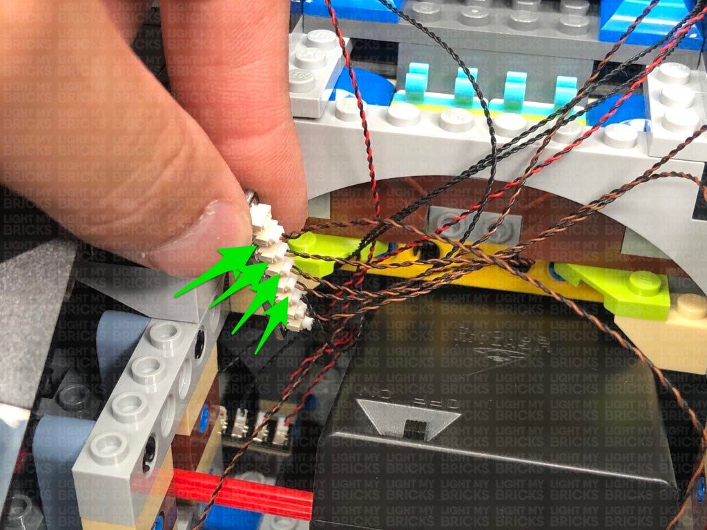
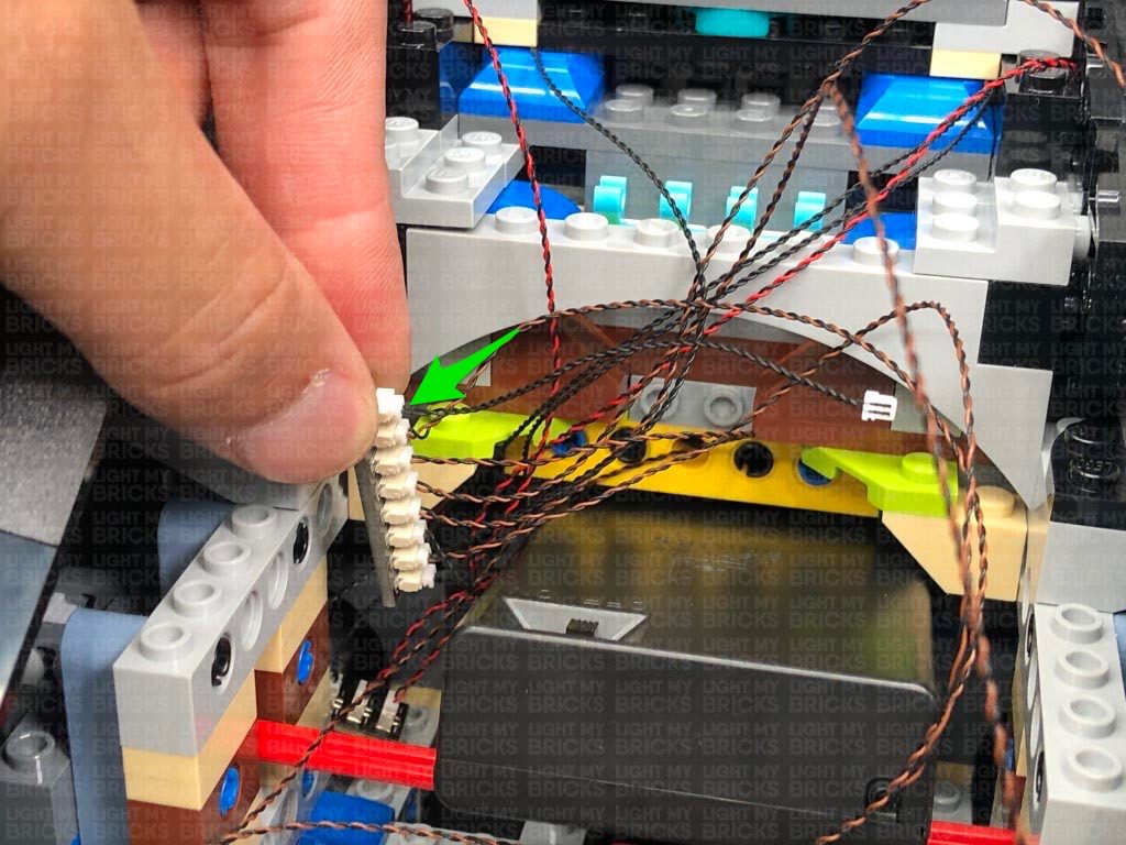
Pull the three cables all the way out the middle section and connect them to the 12-Port Expansion Board. Turn the AA Battery Pack ON to test both headlights are working OK.
5.) Secure the cables around the top of the wheel axis by disconnecting the following grey plate, laying the cables underneath in between studs, then reconnecting the plate over the top. It is important to ensure there is enough cable slack for the wheel to turn all the way left and right.
Pull the three cables all the way out the middle section and connect them to the 12-Port Expansion Board. Turn the AA Battery Pack ON to test both headlights are working OK.
 Note: If you experience any issues with the lights not working and suspect an issue with a component, please try a different port on the expansion board to verify where the fault lies (with the light or expansion board). To correct any issues with expansion board ports, please view the section addressing expansion board issues on our online troubleshooting guide.
Reconnect the left wheel and turn the set back over.
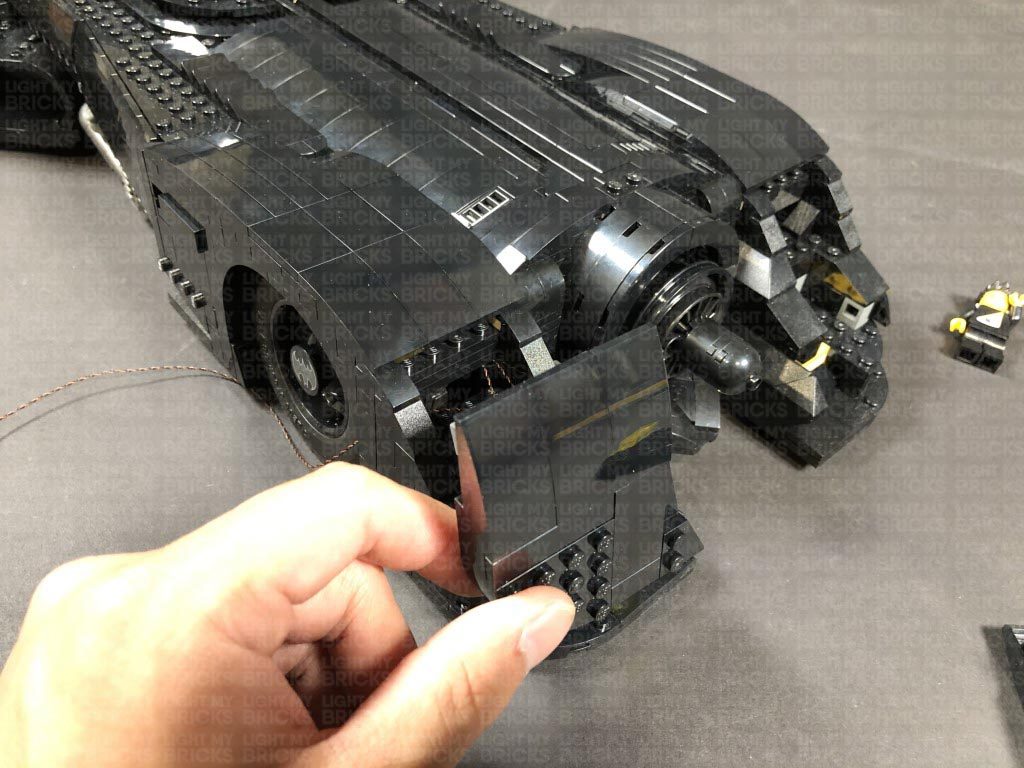
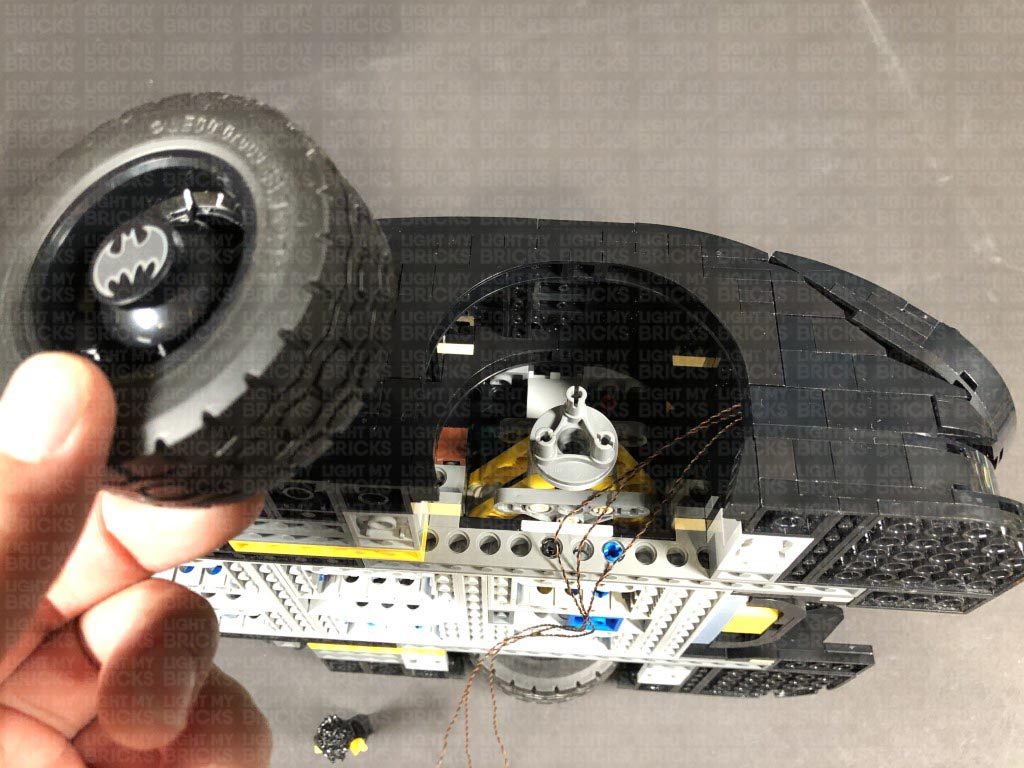
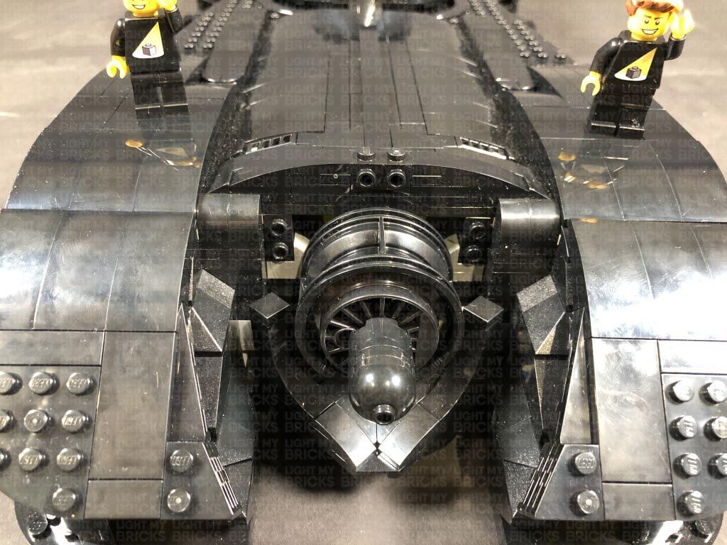
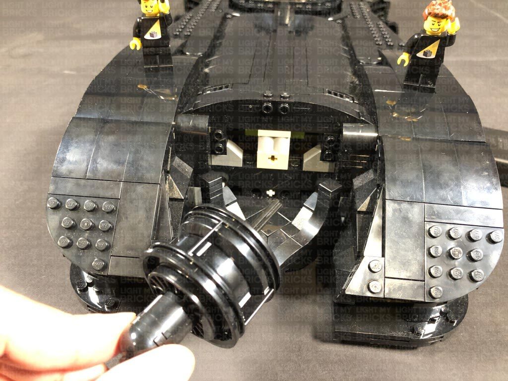
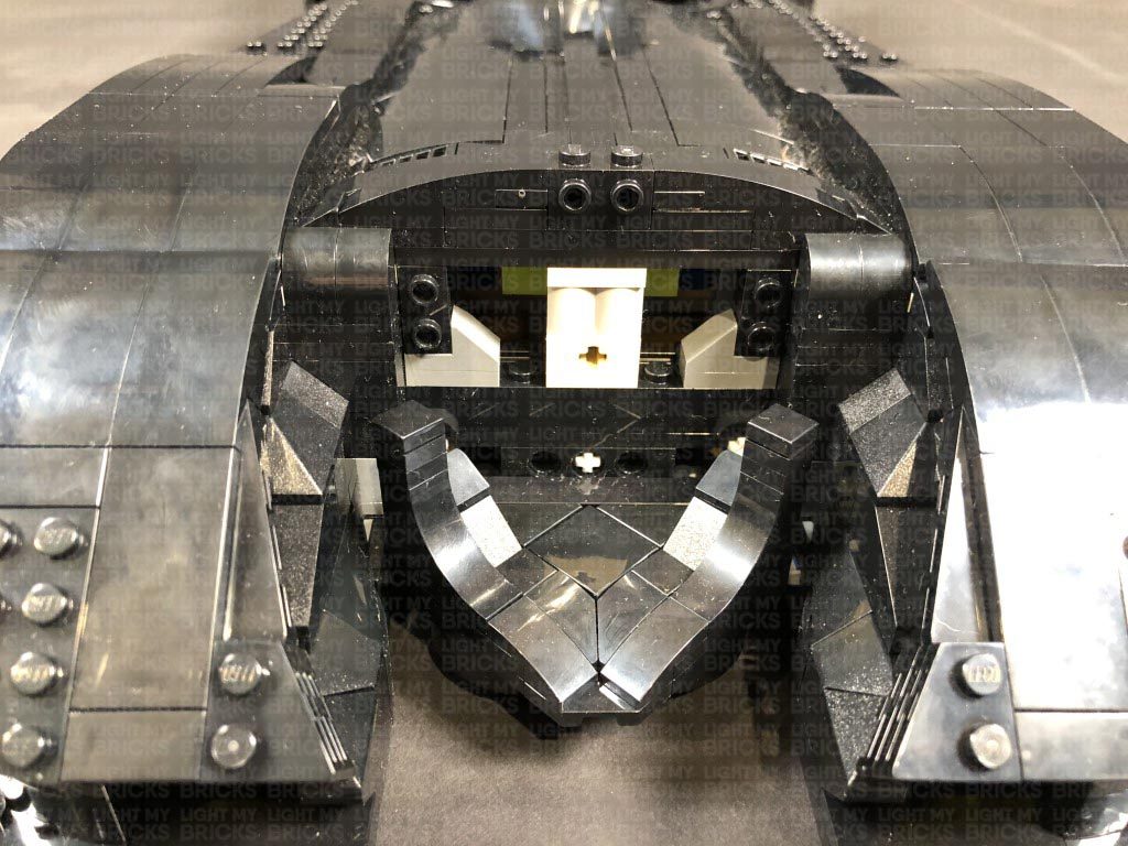
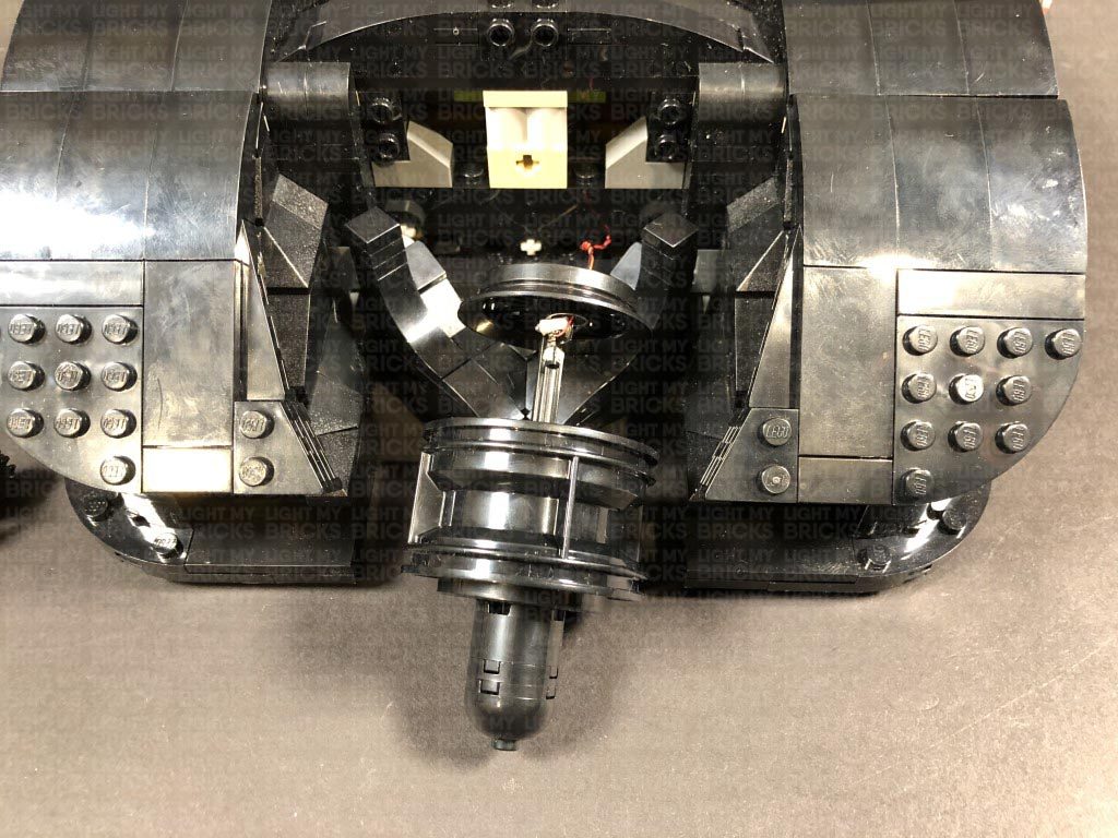
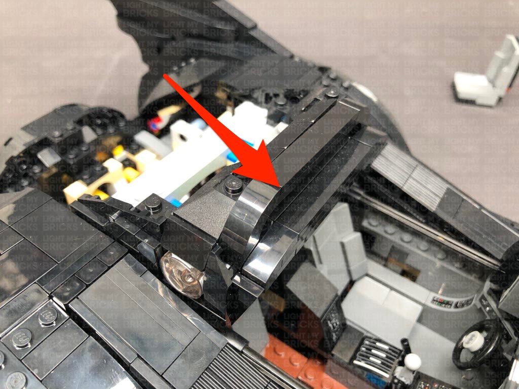
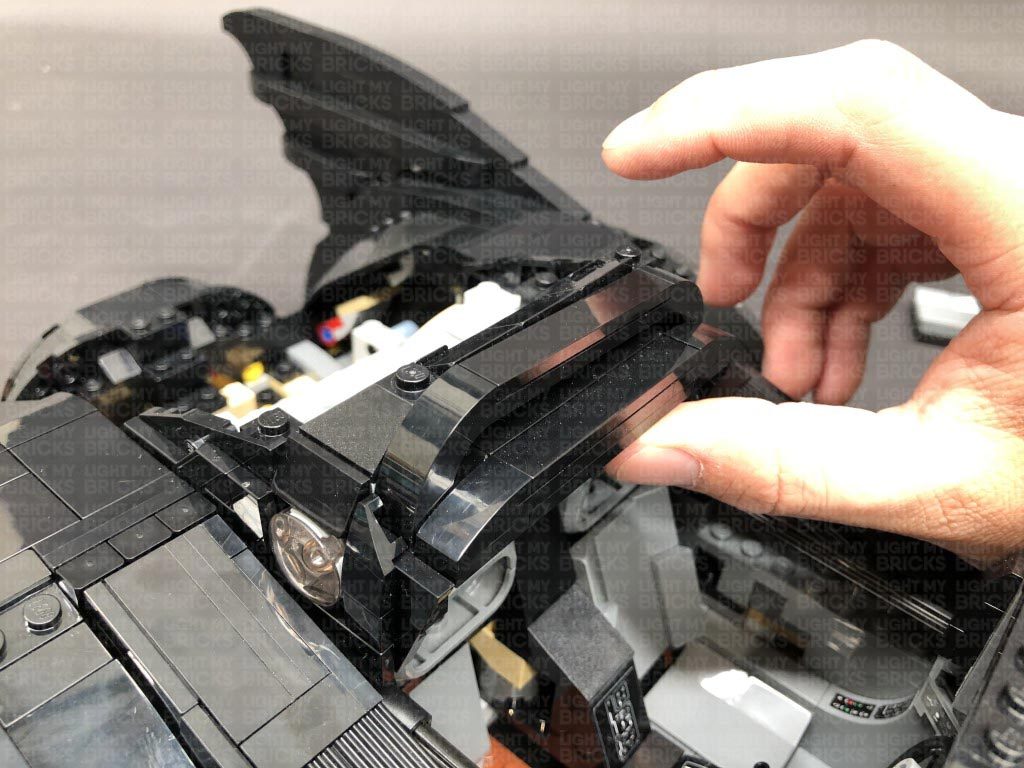
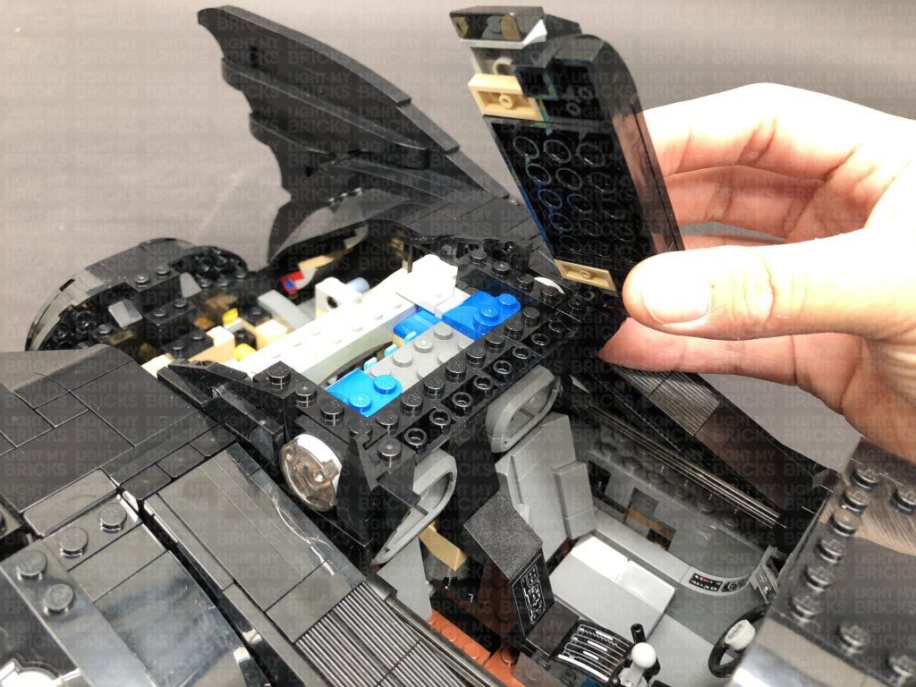
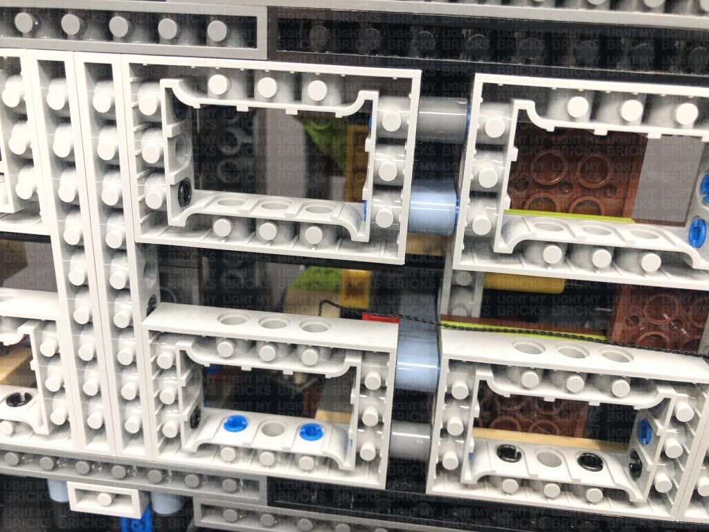
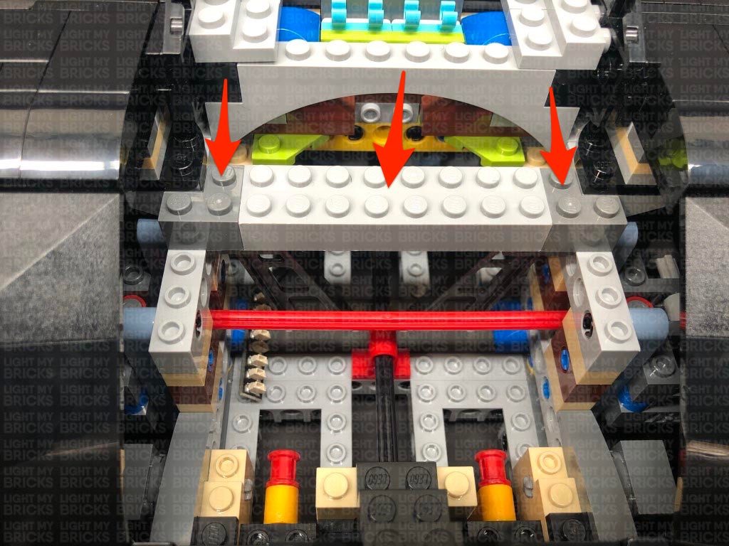
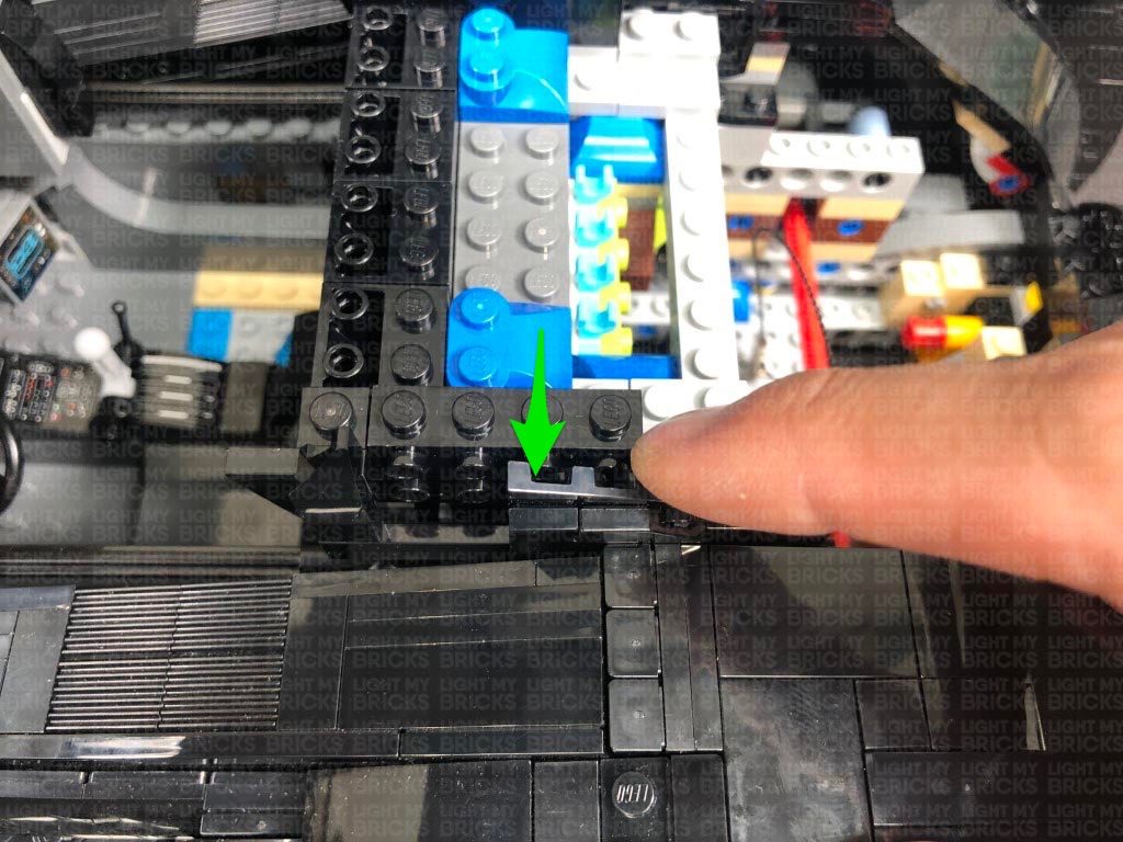
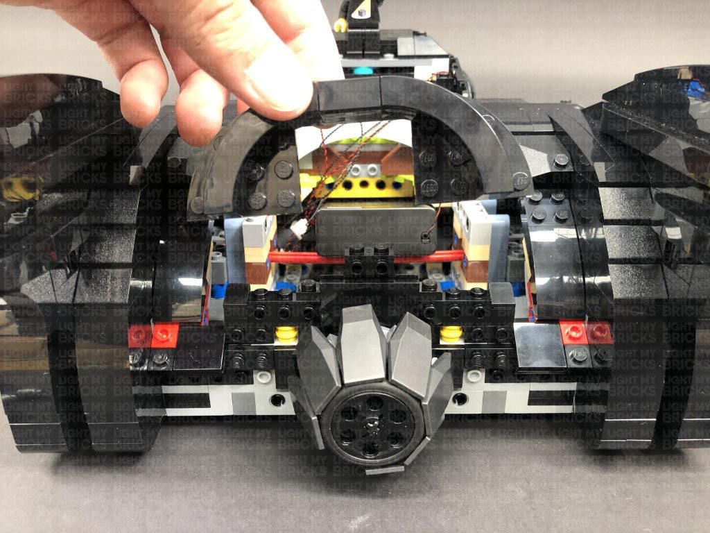
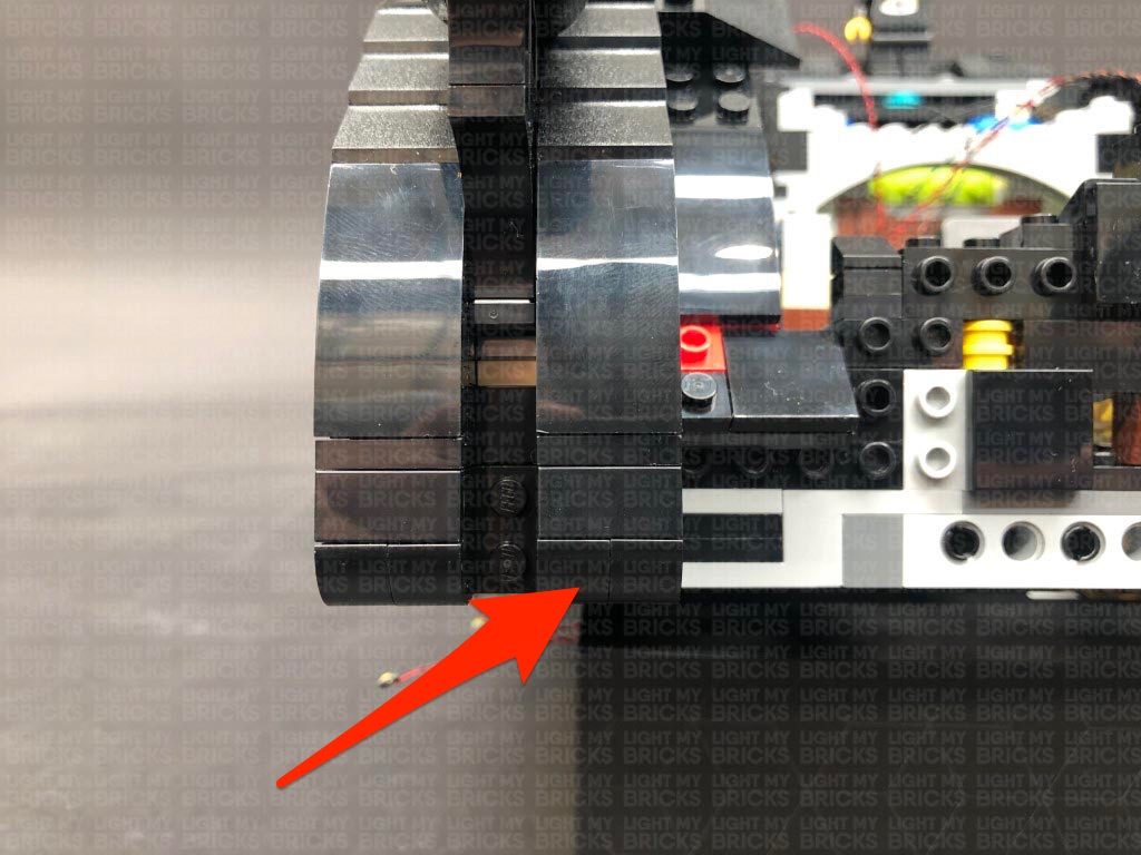
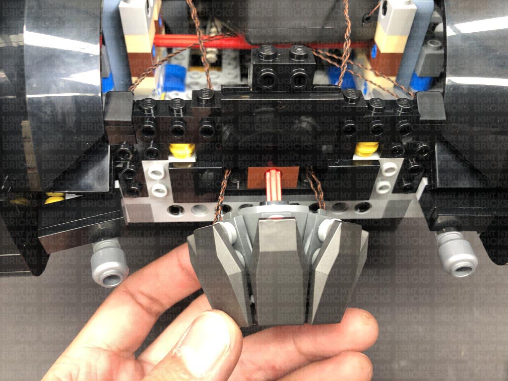
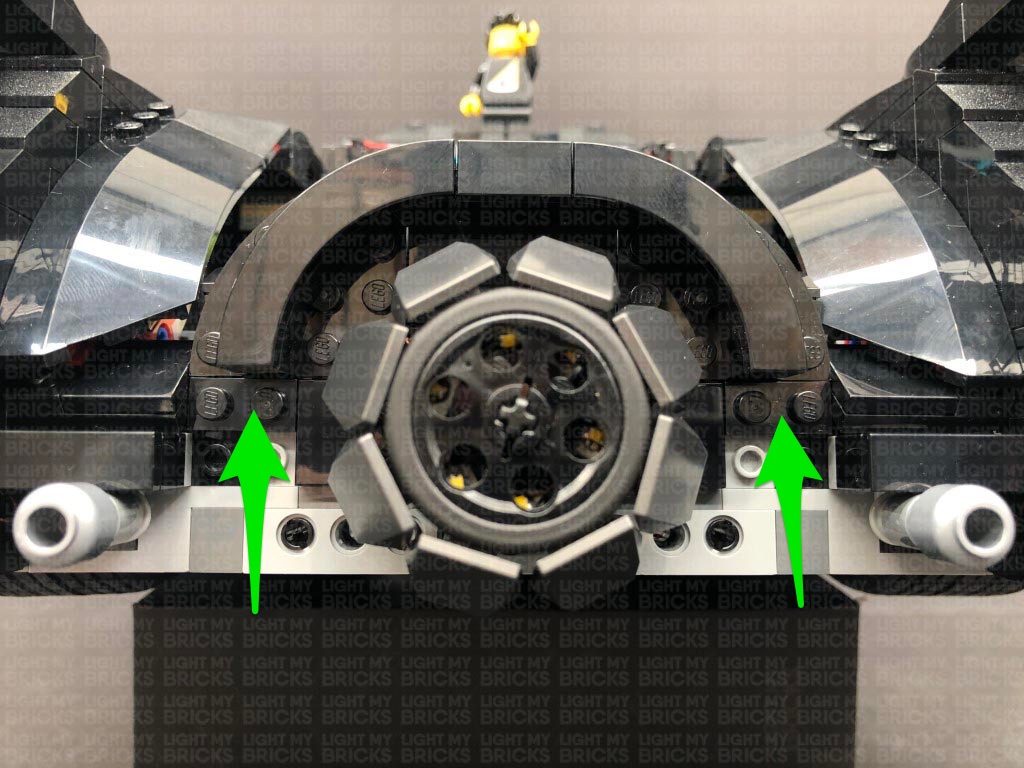
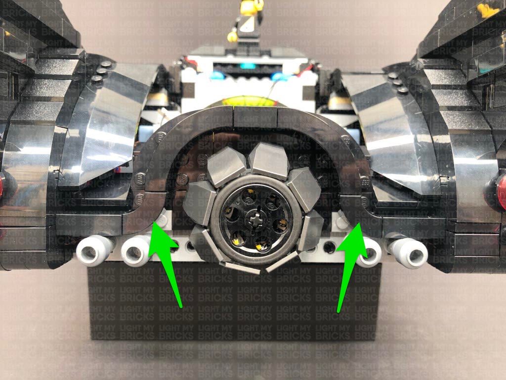
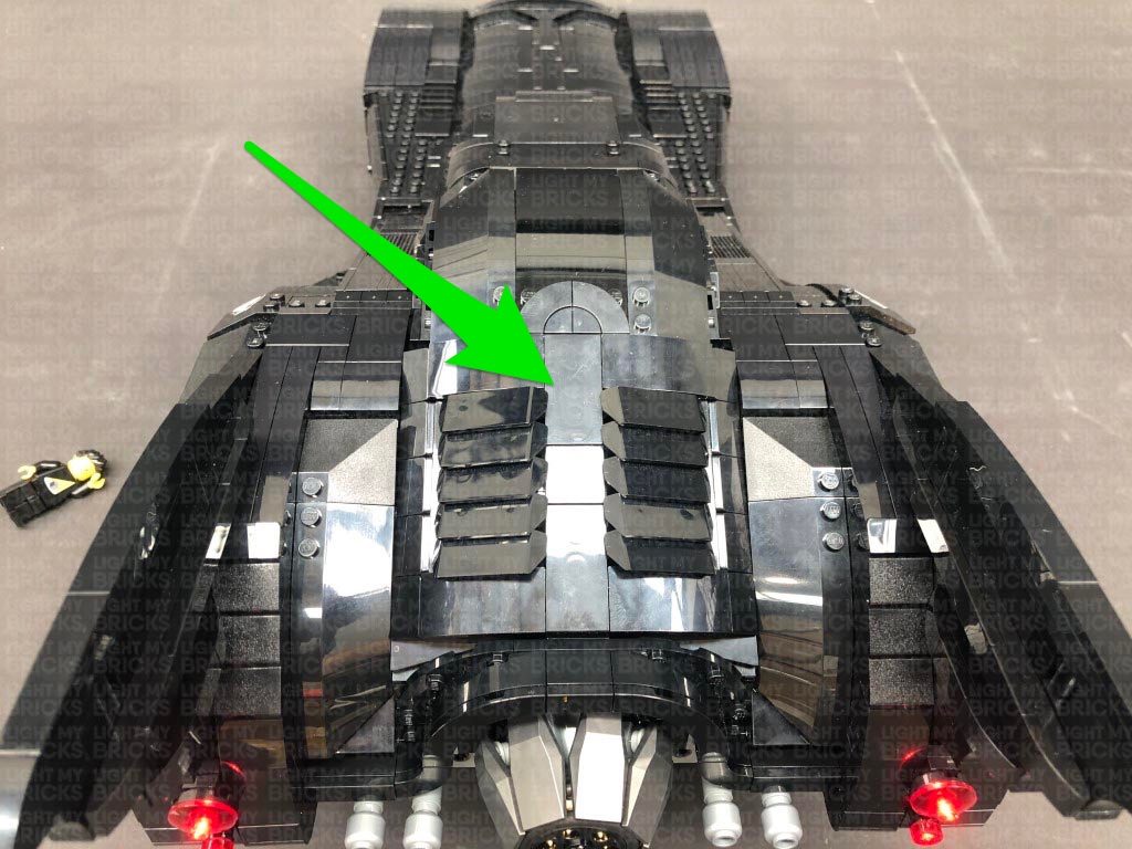
6.) We will now install a light effect behind the front grill. First disconnect the top two sections surrounding it, then pull the grill section all the way out.
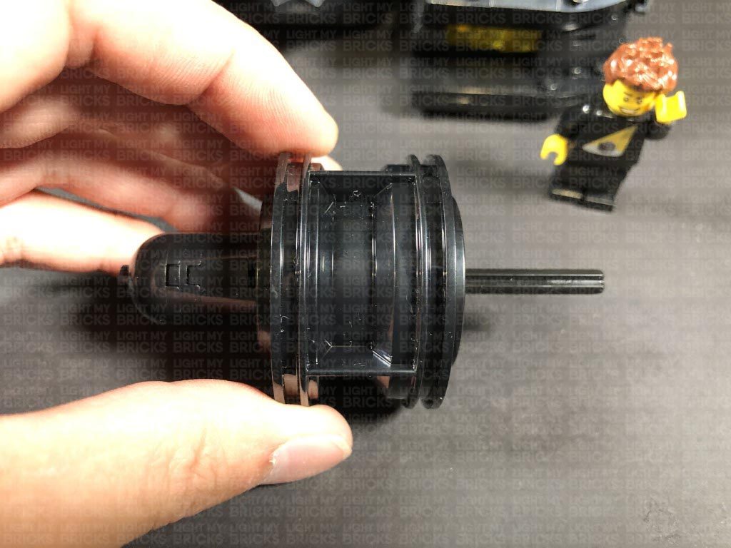
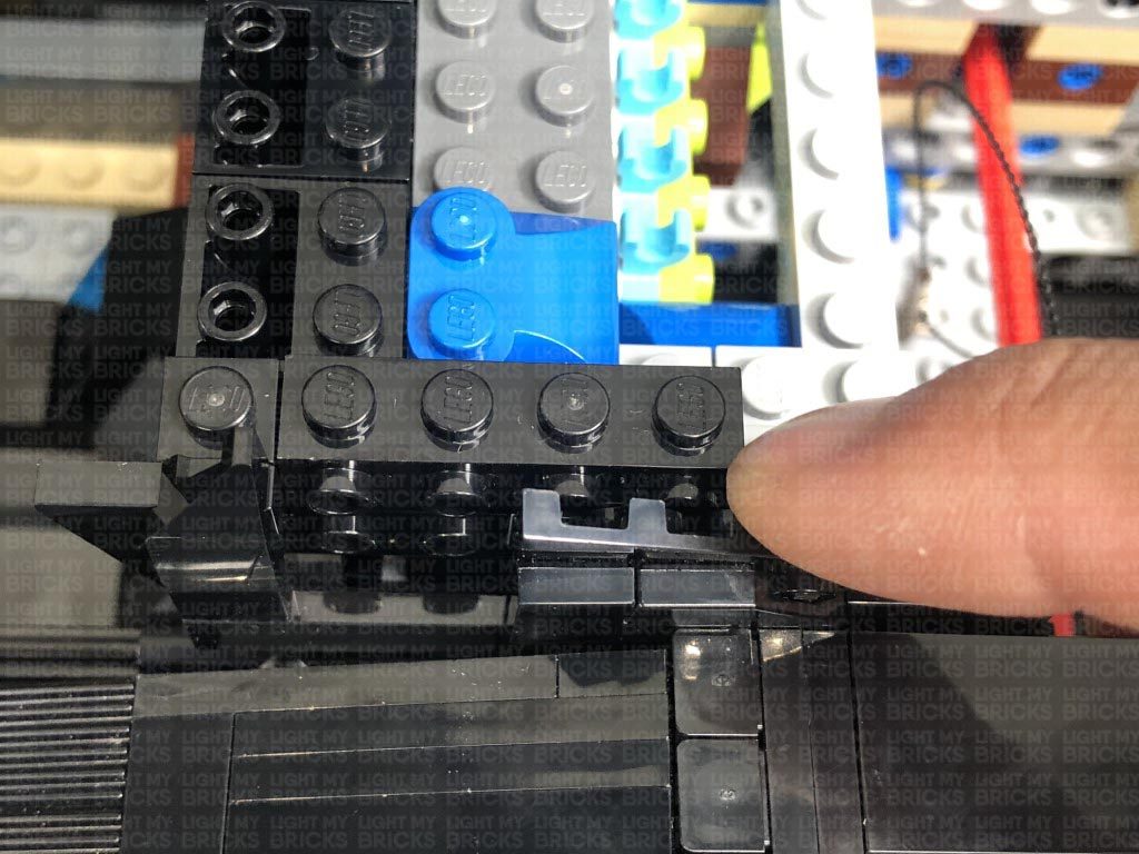
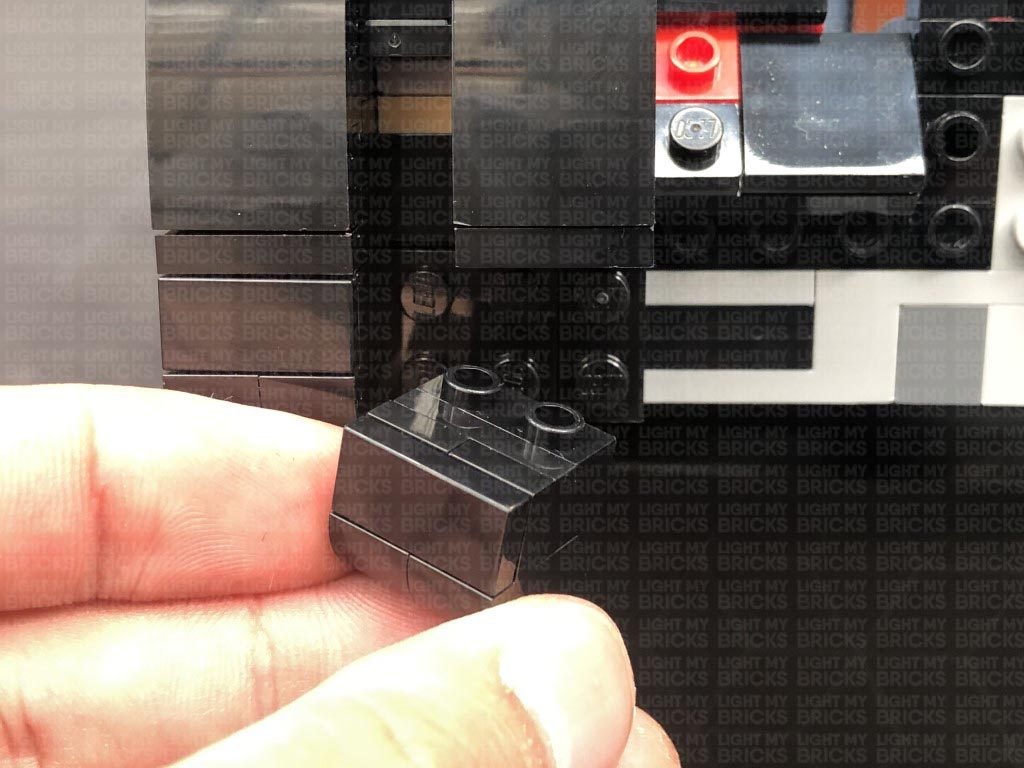
Pull back the rear wheel plate as shown below.
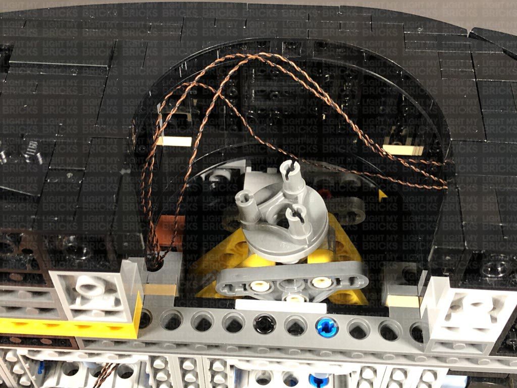
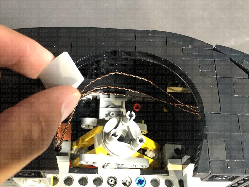
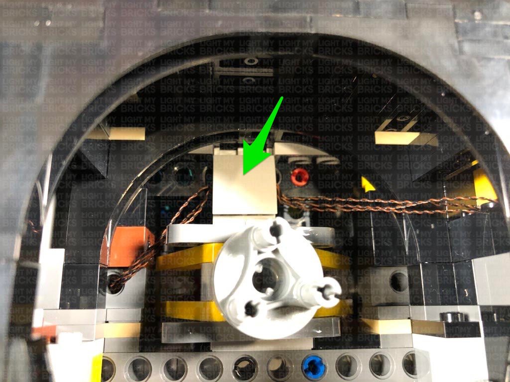
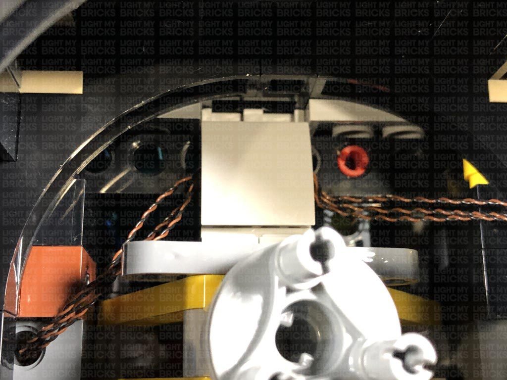
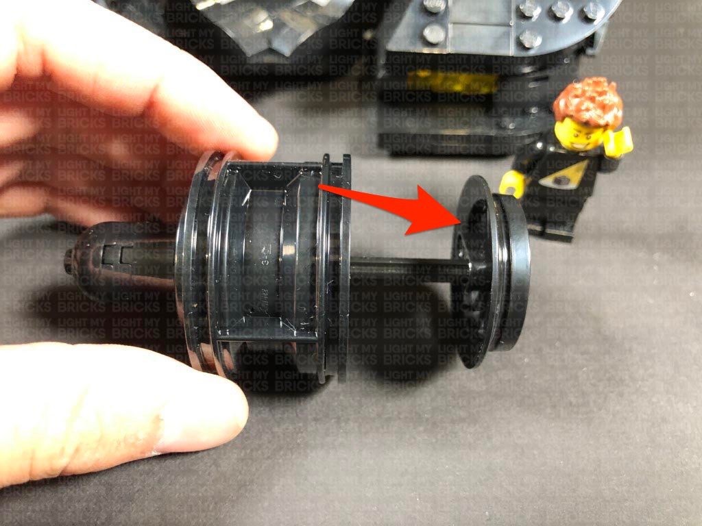
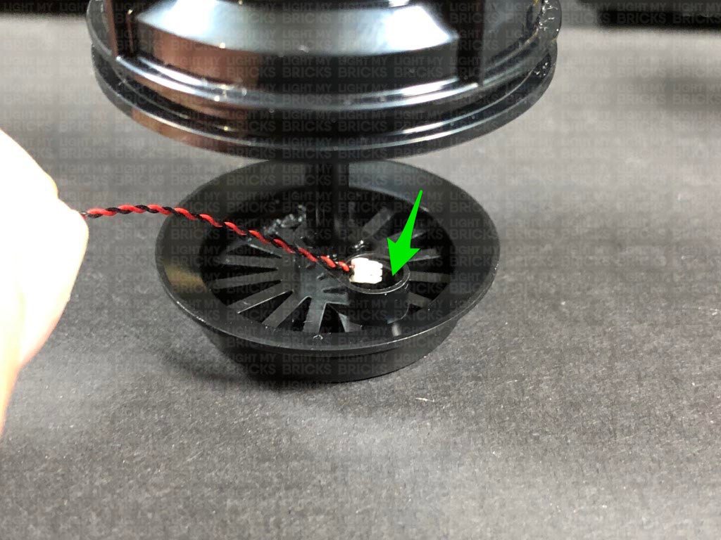
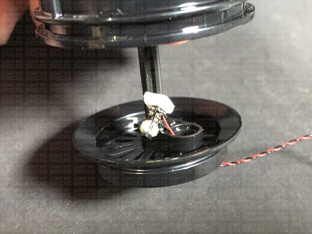
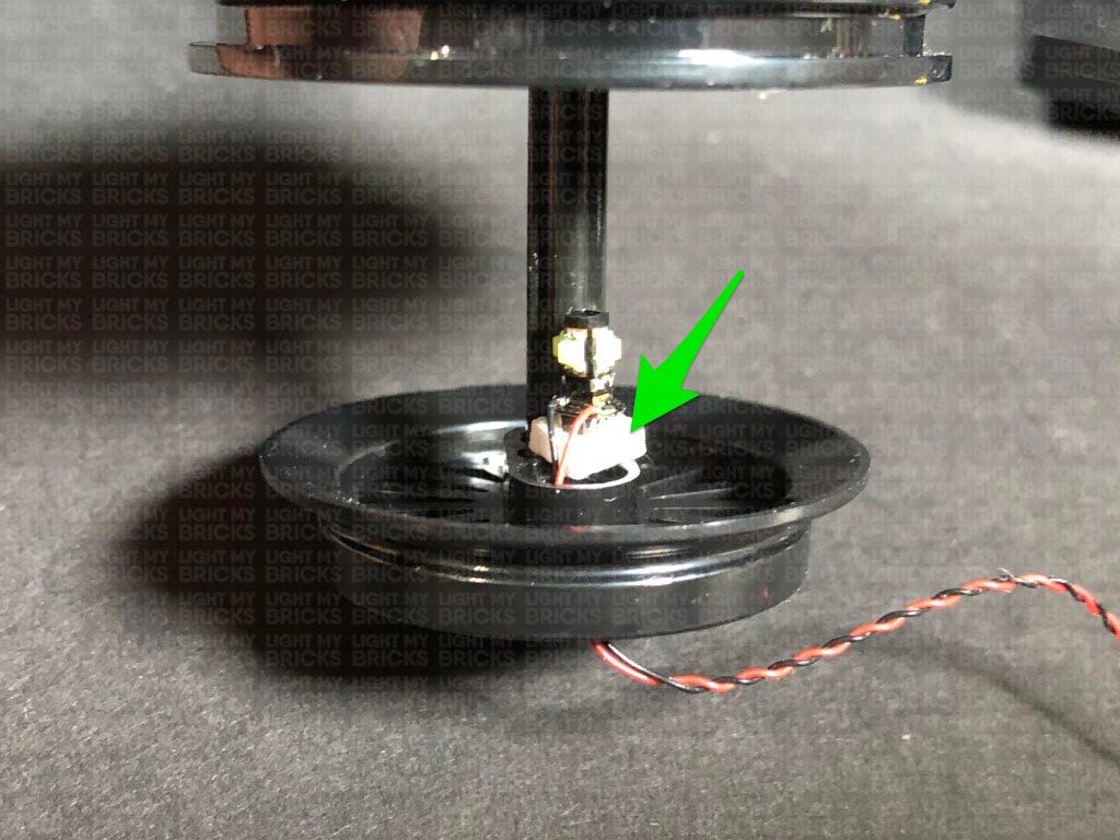
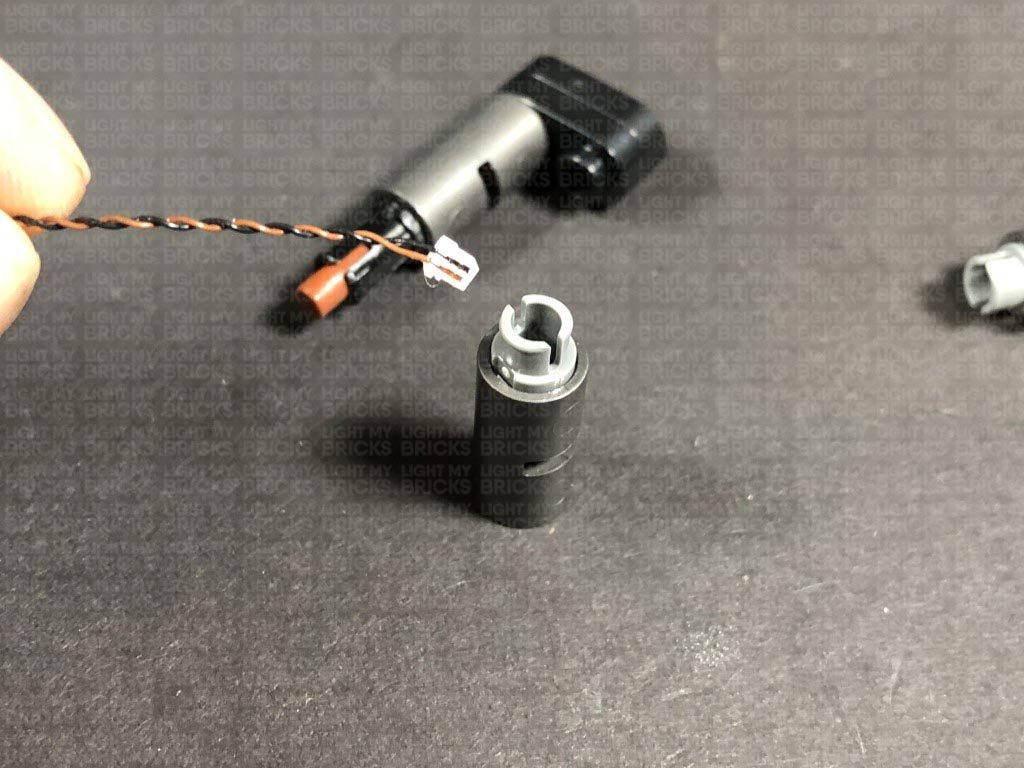
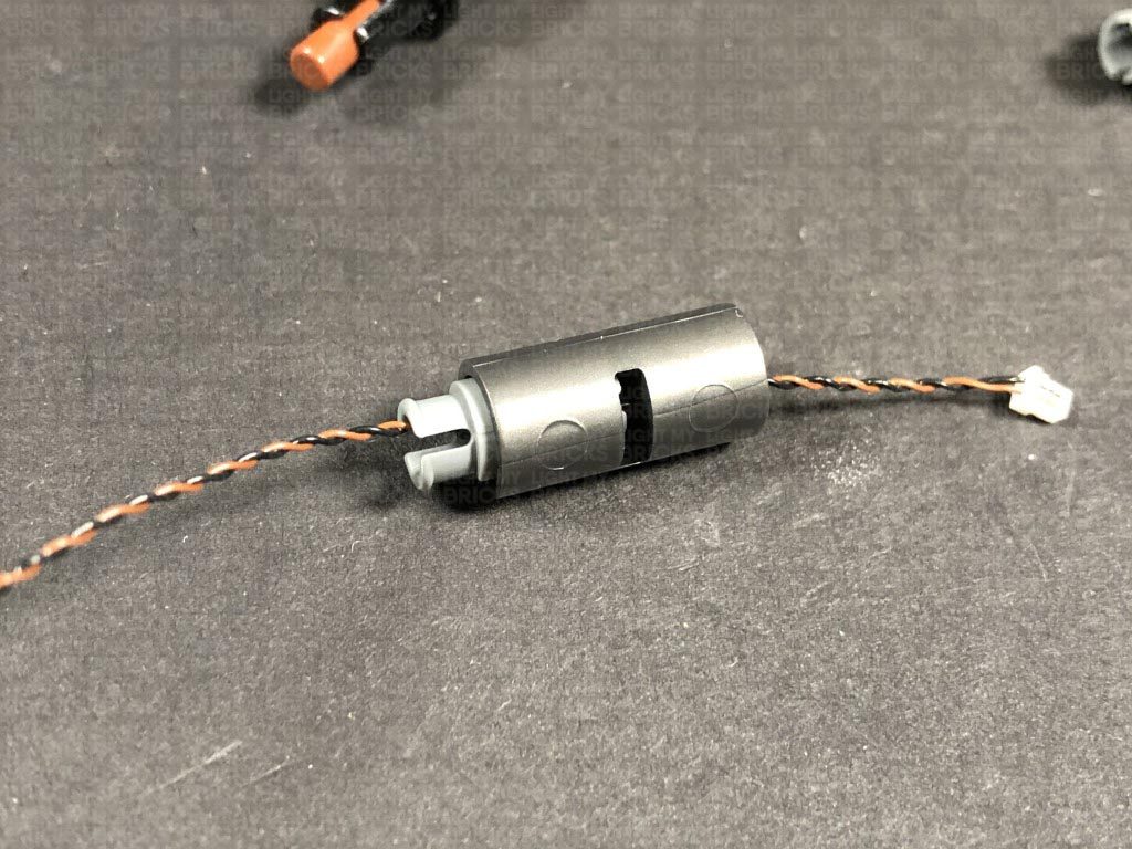
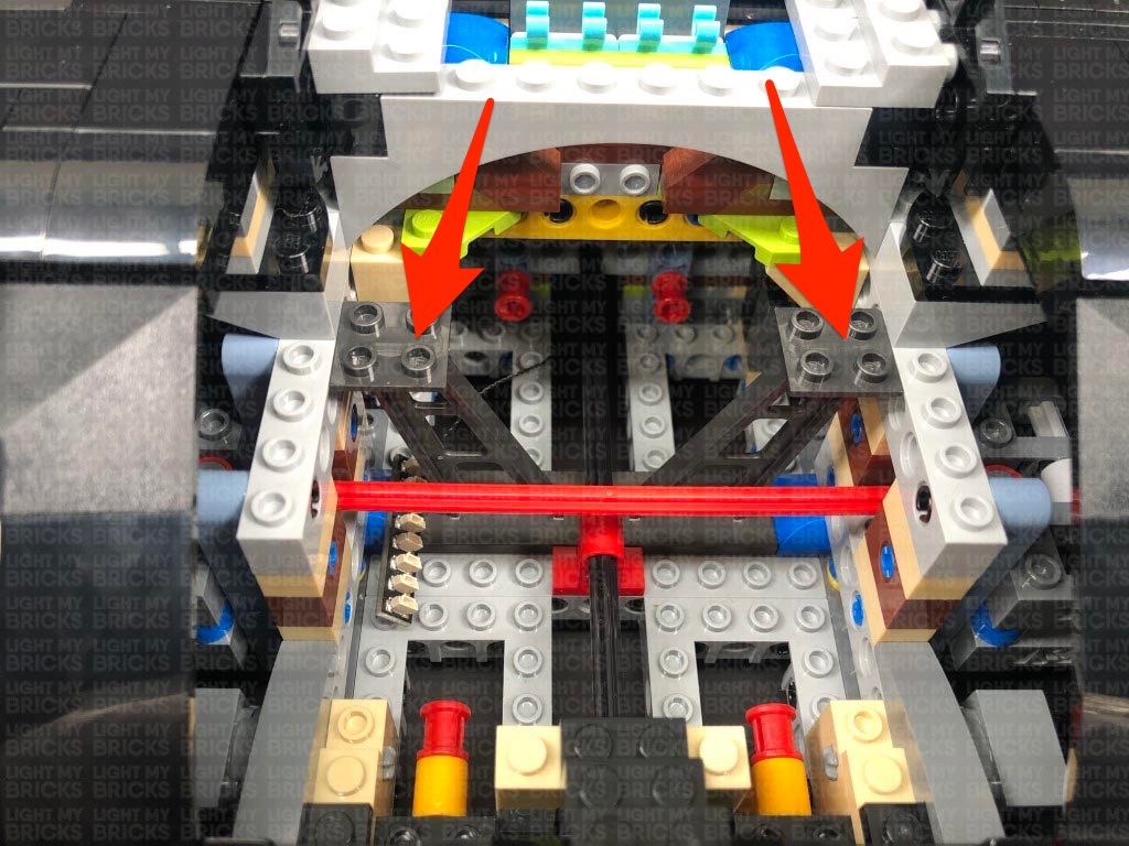
Take the Rotating White 30cm Bit Light and thread the connector side of the cable through the top of the rear wheel plate through the following hole.
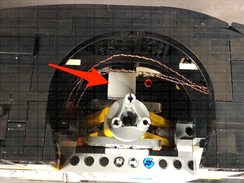
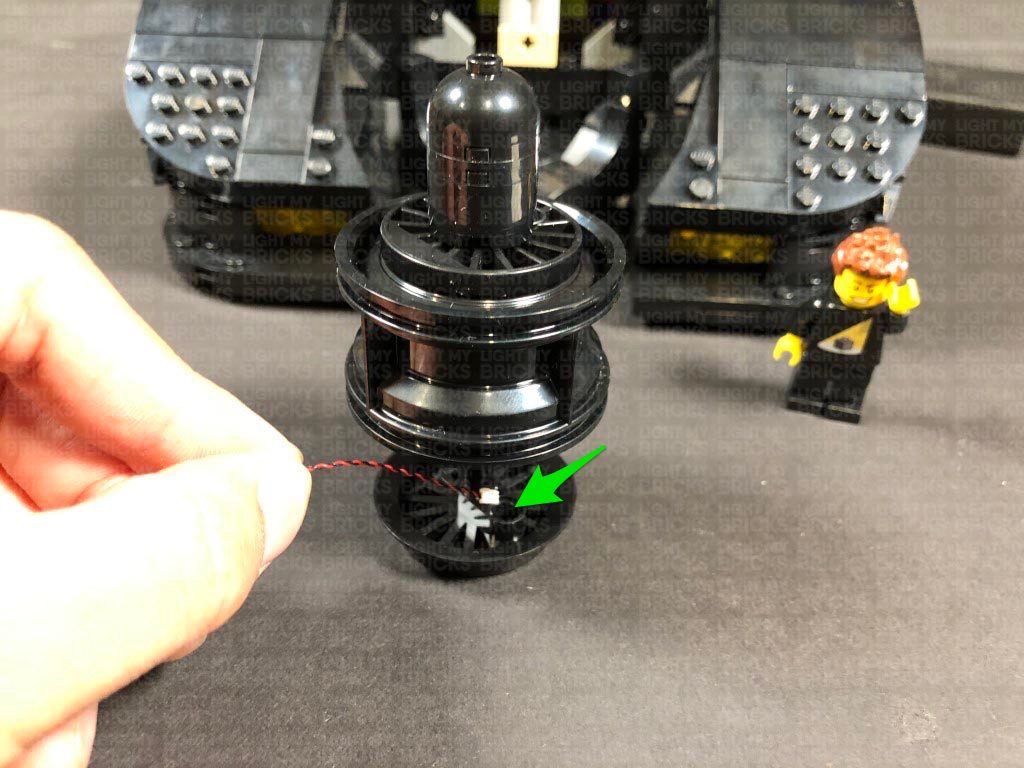
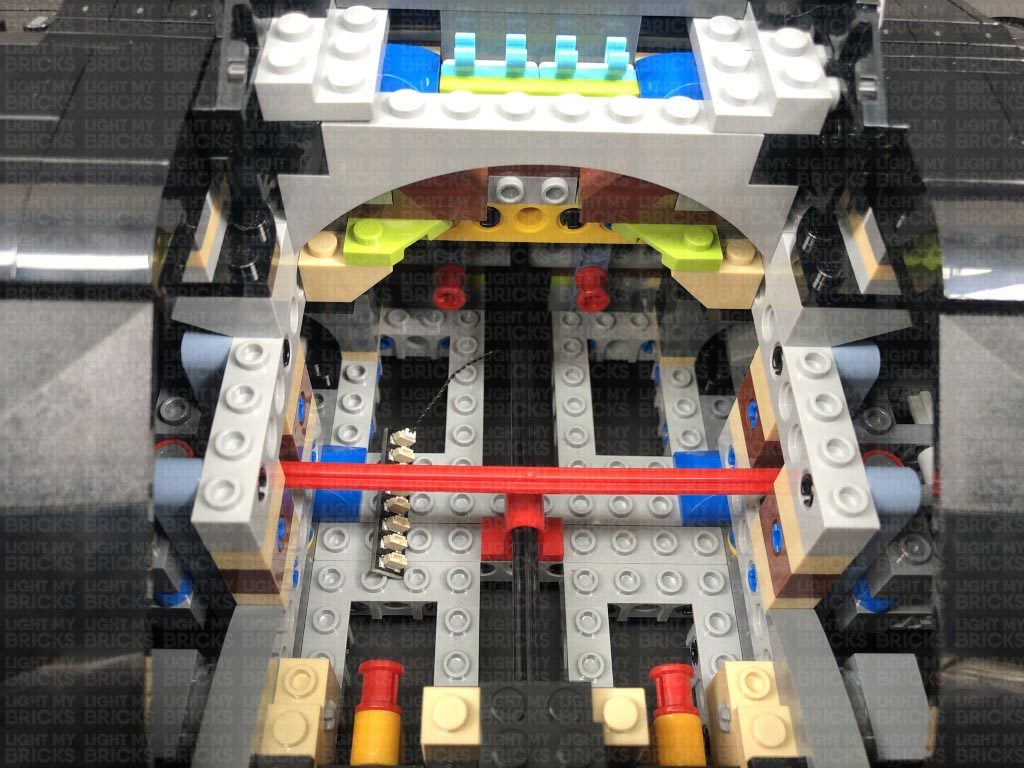
Take an Adhesive Square and stick it to the bottom of the Rotating Bit Light, then stick the bit light to the top of the hole inside the rear wheel plate as shown below:
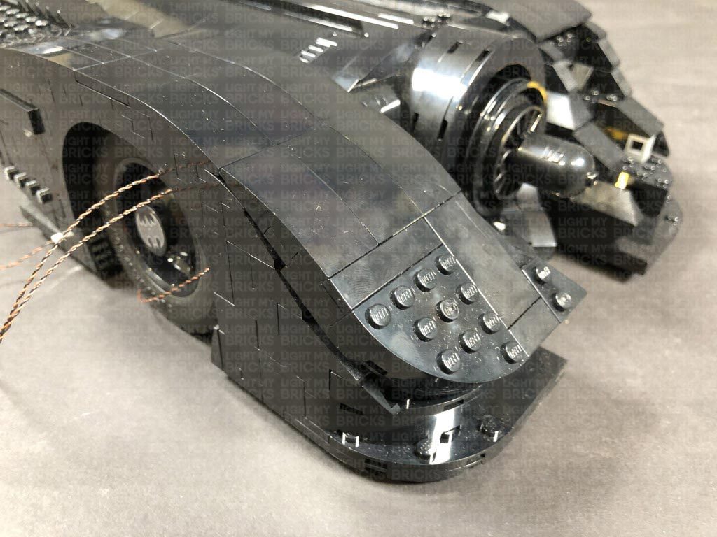
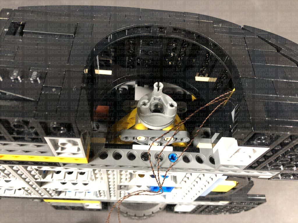
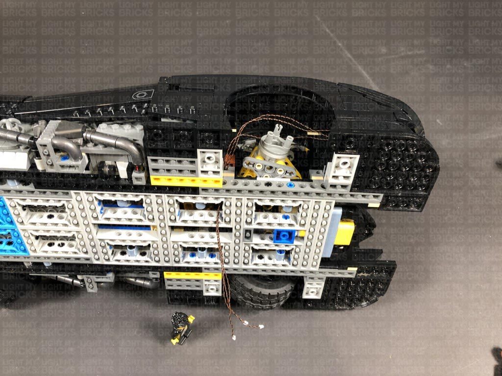
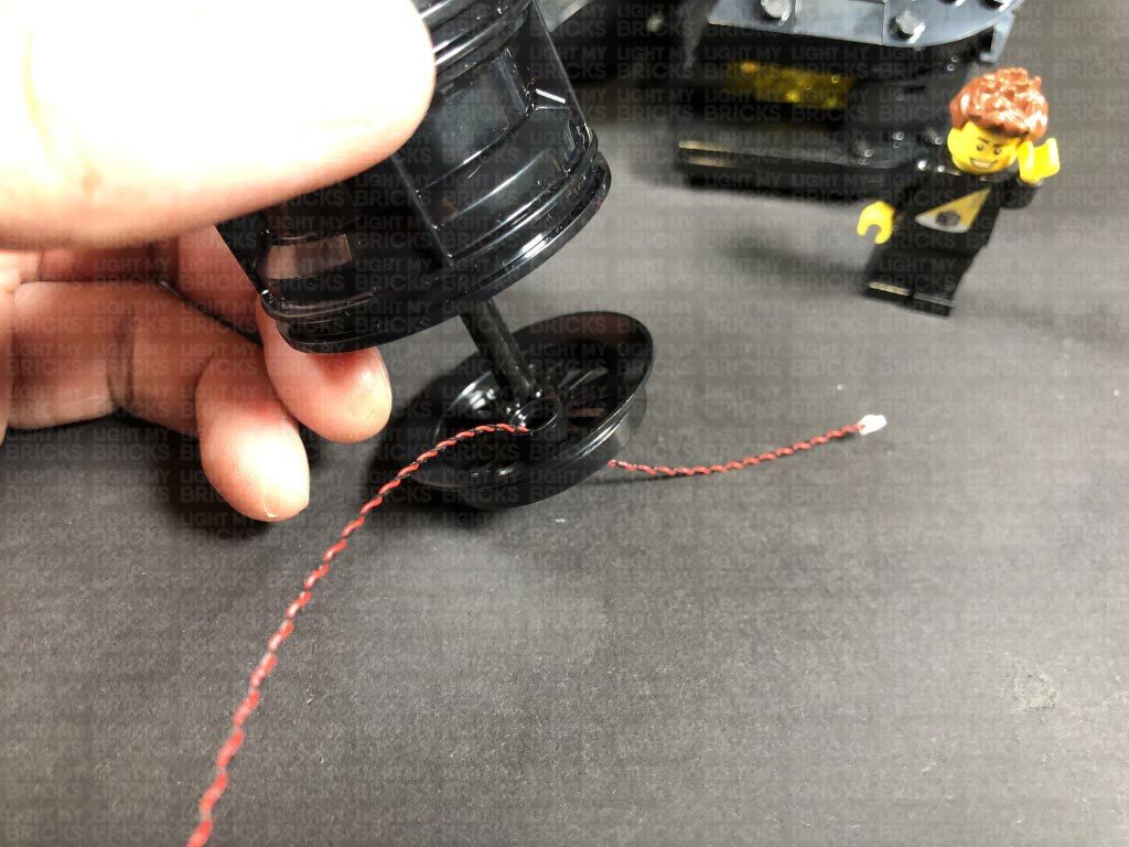
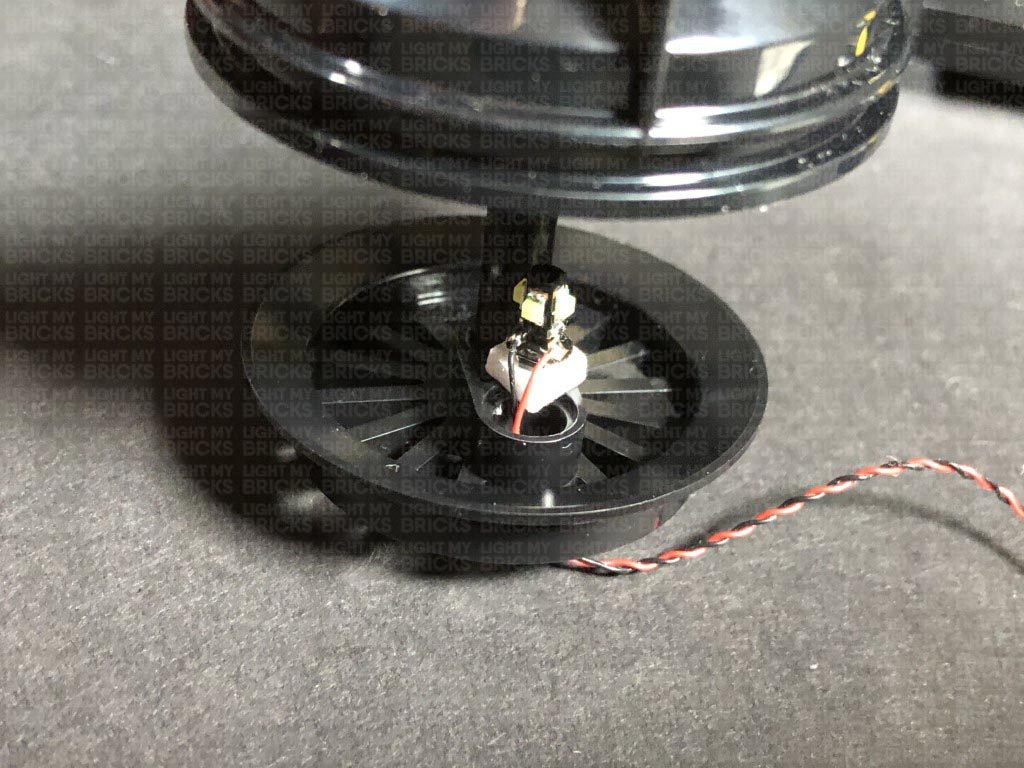
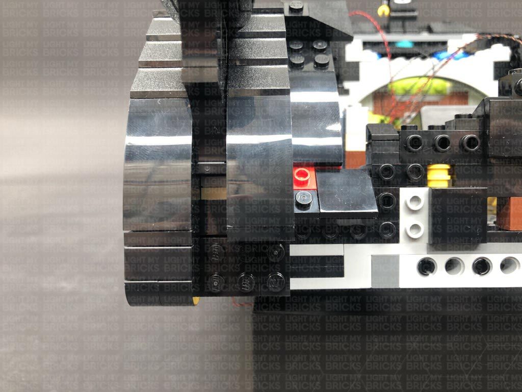
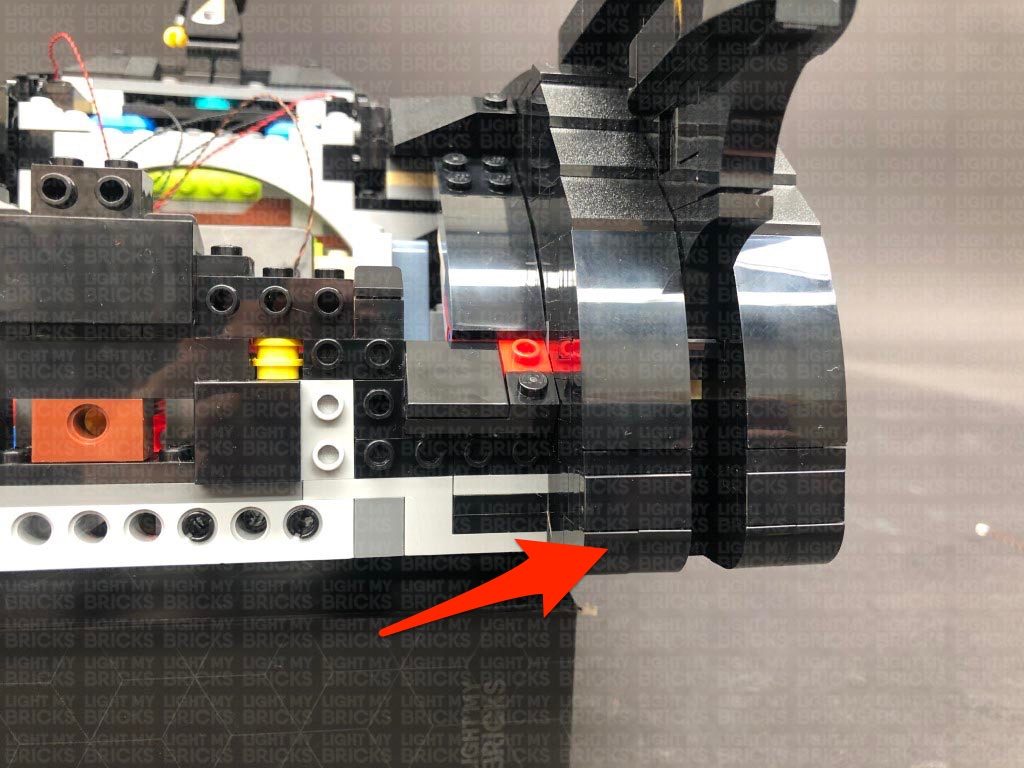
7.) Thread the Rotating Bit Light cable through the bottom space behind where the grill connects to, then turn the vehicle over and pull the cable all the way out from underneath as per below:
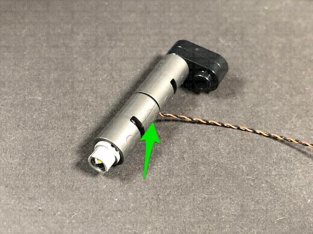
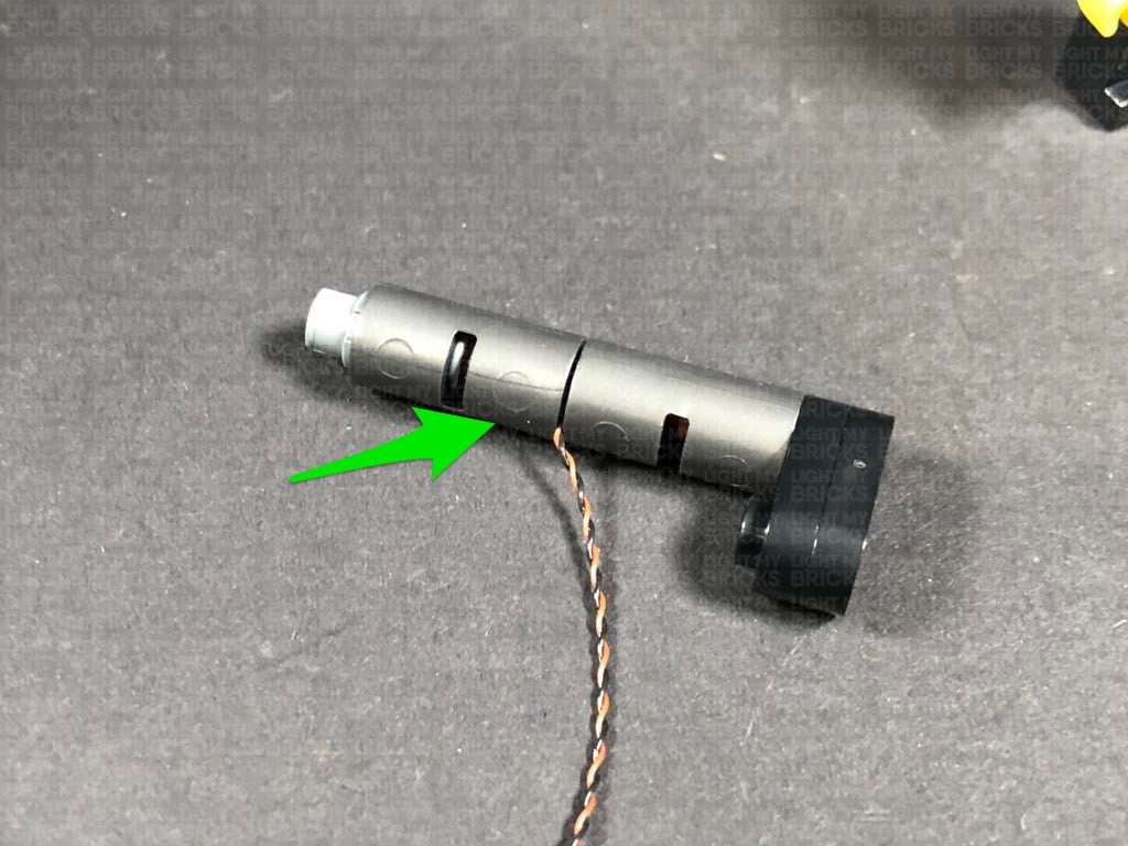
Before we reconnect the front grill, push the rear wheel plate back up but ensure you Do NOT push the technic pin the whole way back otherwise it will crush the rotating bit light inside. Push the rear wheel plate up so that you can still see the ridge that runs along the side of the wheel plate.
Note: If you experience any issues with the lights not working and suspect an issue with a component, please try a different port on the expansion board to verify where the fault lies (with the light or expansion board). To correct any issues with expansion board ports, please view the section addressing expansion board issues on our online troubleshooting guide.
Reconnect the left wheel and turn the set back over.
6.) We will now install a light effect behind the front grill. First disconnect the top two sections surrounding it, then pull the grill section all the way out.
Pull back the rear wheel plate as shown below.
Take the Rotating White 30cm Bit Light and thread the connector side of the cable through the top of the rear wheel plate through the following hole.
Take an Adhesive Square and stick it to the bottom of the Rotating Bit Light, then stick the bit light to the top of the hole inside the rear wheel plate as shown below:
7.) Thread the Rotating Bit Light cable through the bottom space behind where the grill connects to, then turn the vehicle over and pull the cable all the way out from underneath as per below:
Before we reconnect the front grill, push the rear wheel plate back up but ensure you Do NOT push the technic pin the whole way back otherwise it will crush the rotating bit light inside. Push the rear wheel plate up so that you can still see the ridge that runs along the side of the wheel plate.
 Ensure the Rotating Bit Light cable is facing up, then reconnect the grill section as well as the two arched sections above.
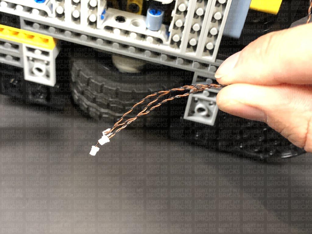
8.) From underneath the vehicle, thread the Rotating Bit Light cable under and pull it out the space where all the headlight cables are located.
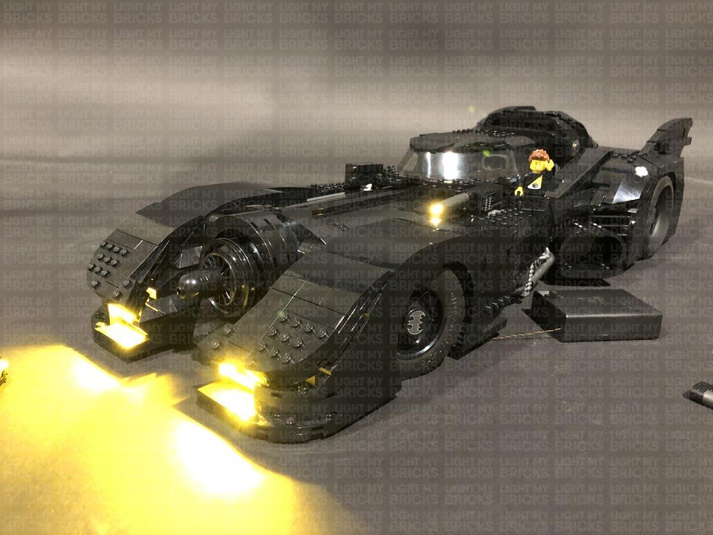
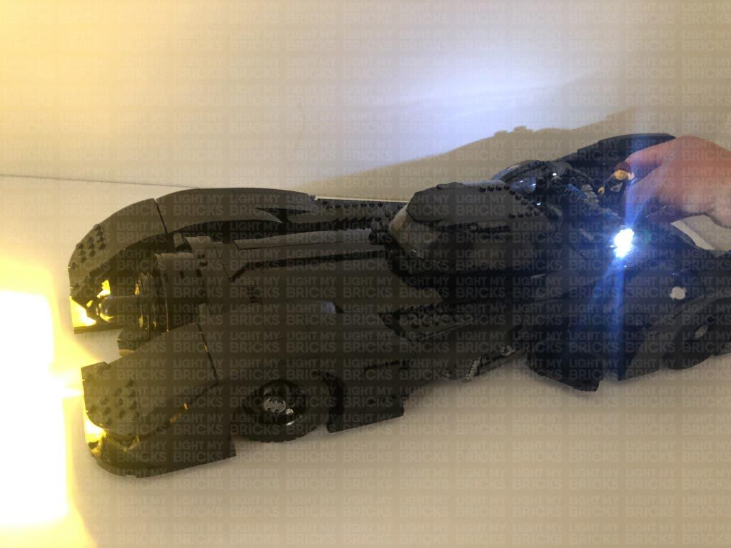
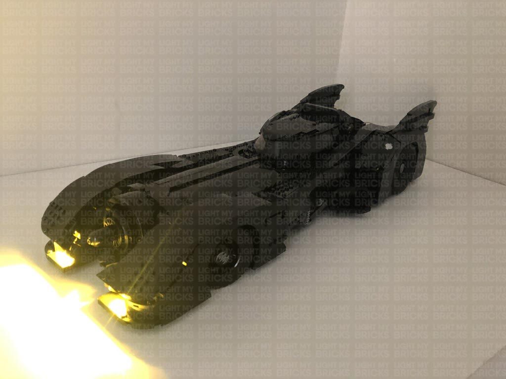
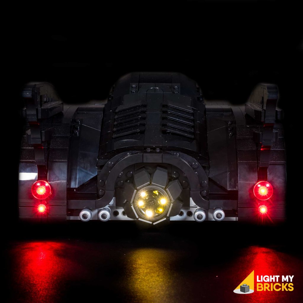
Pull the cable all the way out, then connect it to a spare port on the 12-Port Expansion Board. Turn the Battery Pack ON to test the Rotating Bit Light inside the grill is working OK. The LEDs should be illuminating in a rotating sequence to give a nice “engine rev” effect inside the grill.
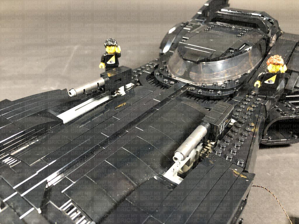
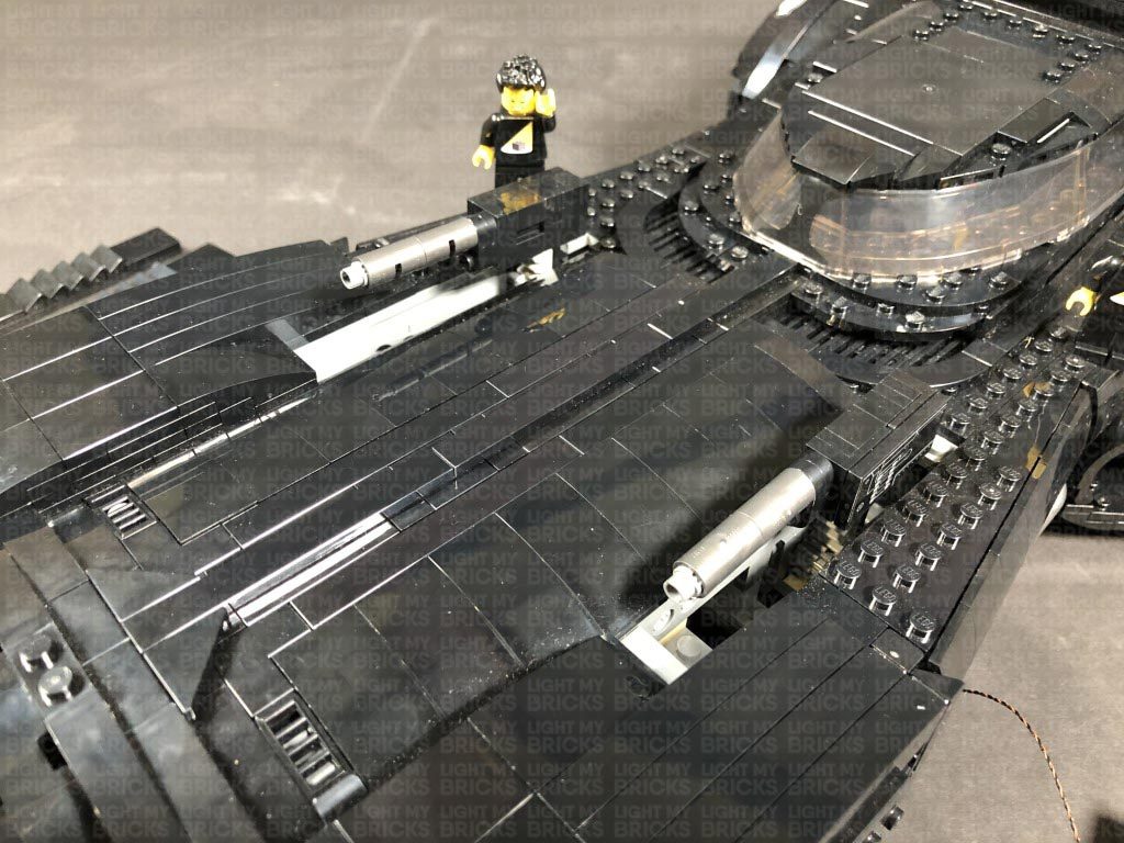
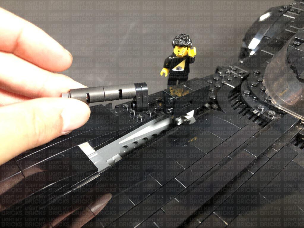
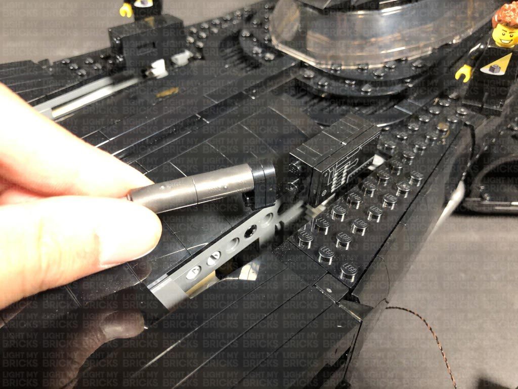
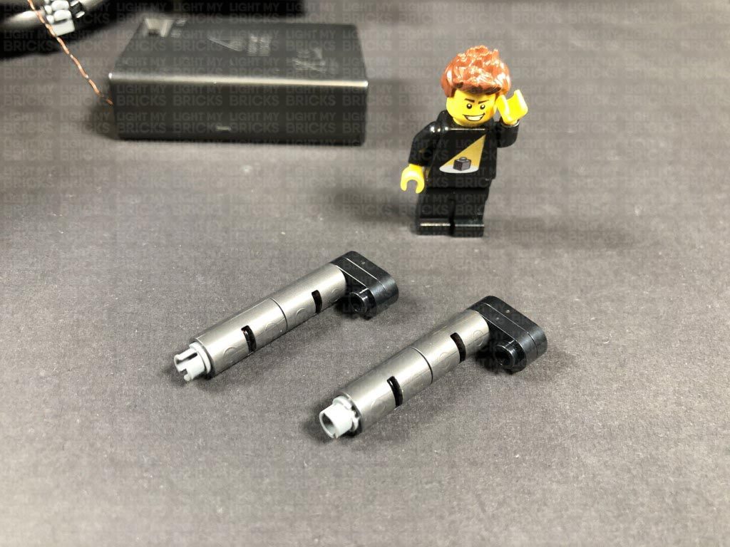
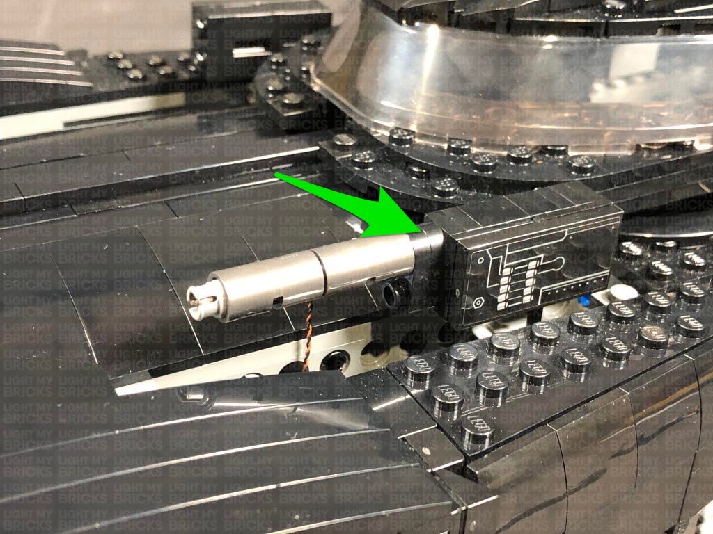
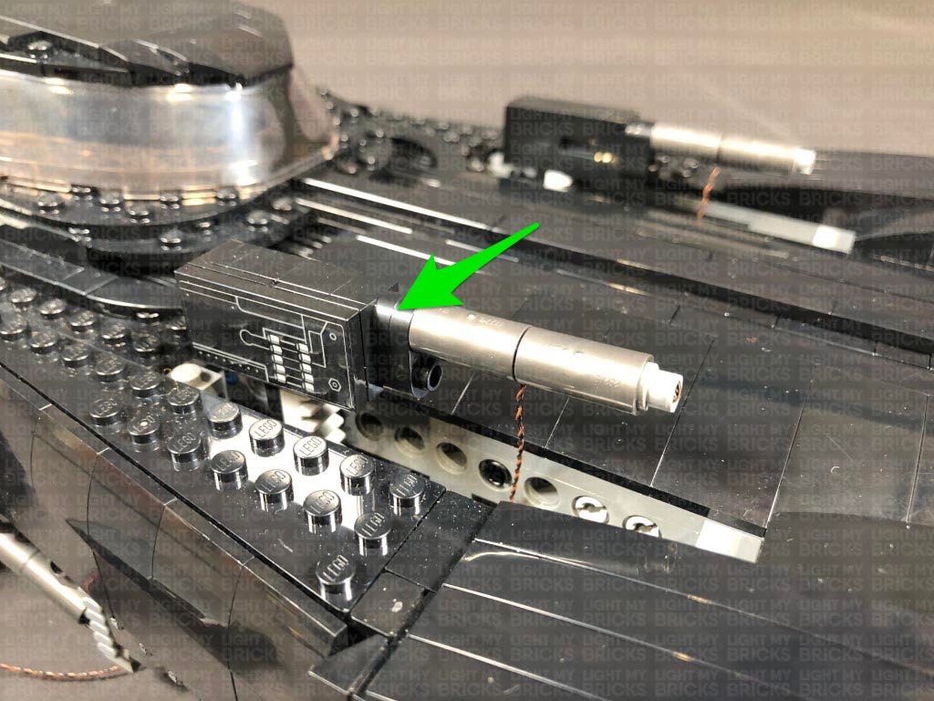
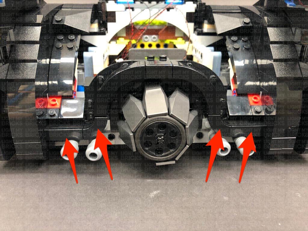
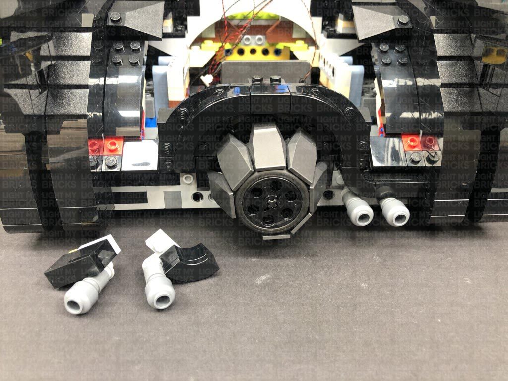
9.) We will now install some lights and effects for the machine guns. First, lift this section up and remove the front half from each gun section.
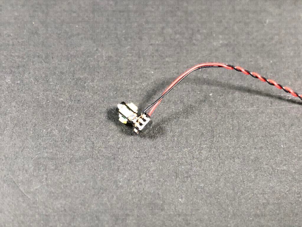
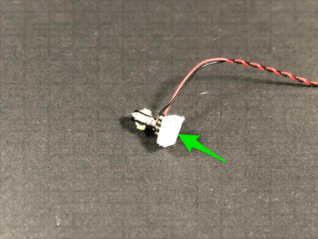
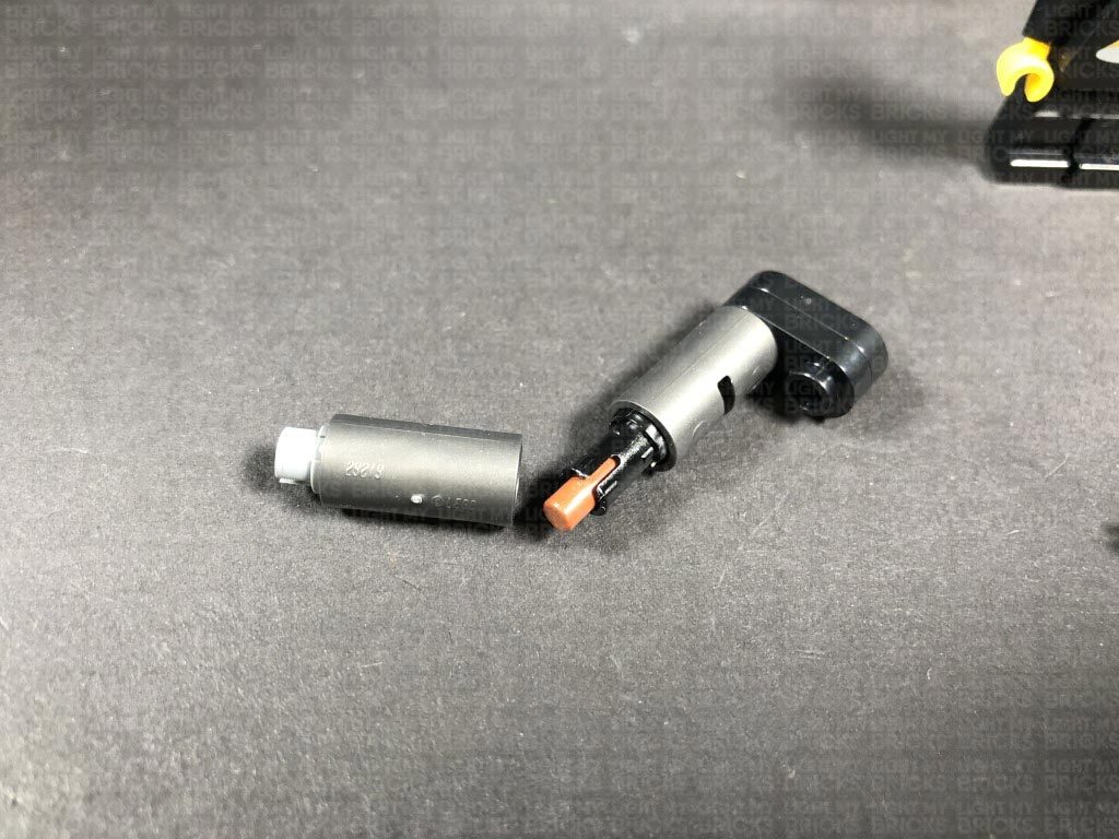
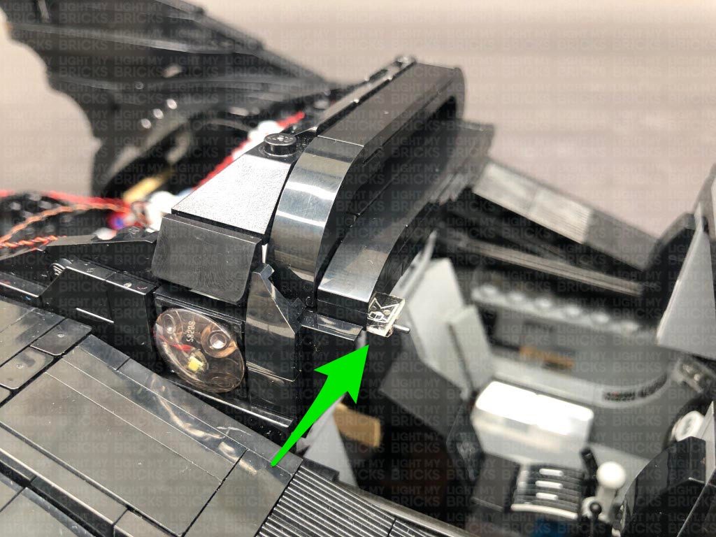
Disassemble one of the guns as shown below then take a White 15cm Bit Light and thread the connector end of the cable down the front of the barrel. Thread it all the way through. The LED should fit snug inside the top of the barrel, with the led facing sideways. Reconnect this section to the bottom half of the gun ensuring the cable is facing the bottom.
Repeat this step to install another White 15cm Bit Light to the other gun section.
Ensure the Rotating Bit Light cable is facing up, then reconnect the grill section as well as the two arched sections above.
8.) From underneath the vehicle, thread the Rotating Bit Light cable under and pull it out the space where all the headlight cables are located.
Pull the cable all the way out, then connect it to a spare port on the 12-Port Expansion Board. Turn the Battery Pack ON to test the Rotating Bit Light inside the grill is working OK. The LEDs should be illuminating in a rotating sequence to give a nice “engine rev” effect inside the grill.
9.) We will now install some lights and effects for the machine guns. First, lift this section up and remove the front half from each gun section.
Disassemble one of the guns as shown below then take a White 15cm Bit Light and thread the connector end of the cable down the front of the barrel. Thread it all the way through. The LED should fit snug inside the top of the barrel, with the led facing sideways. Reconnect this section to the bottom half of the gun ensuring the cable is facing the bottom.
Repeat this step to install another White 15cm Bit Light to the other gun section.
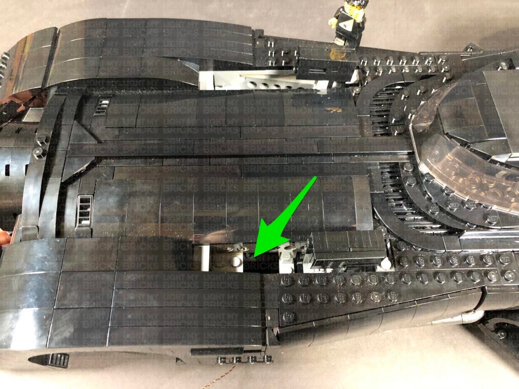
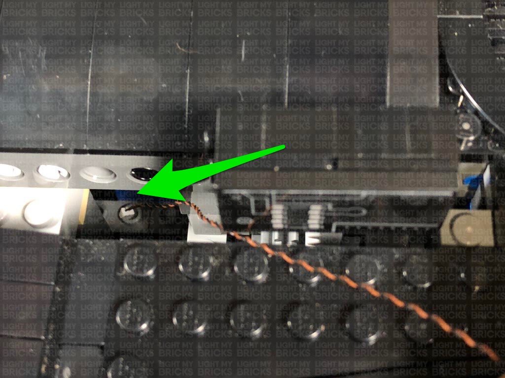
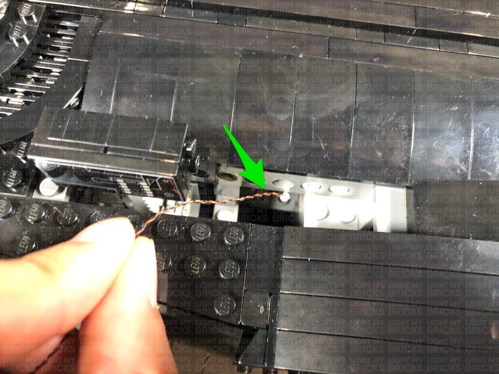
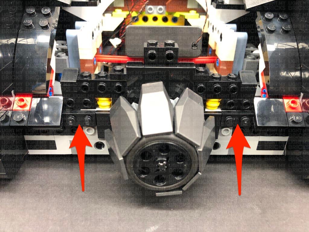
 10.) Take the left gun section and thread the cable down the space underneath where it pops out of. Reconnect the gun to the base section, then turn the vehicle onto it’s right side and pull the cable out at the following position.
Pull the cable all the way down, then thread it through the technic brick hole underneath and pull it out of the space where the rest of the cables are.
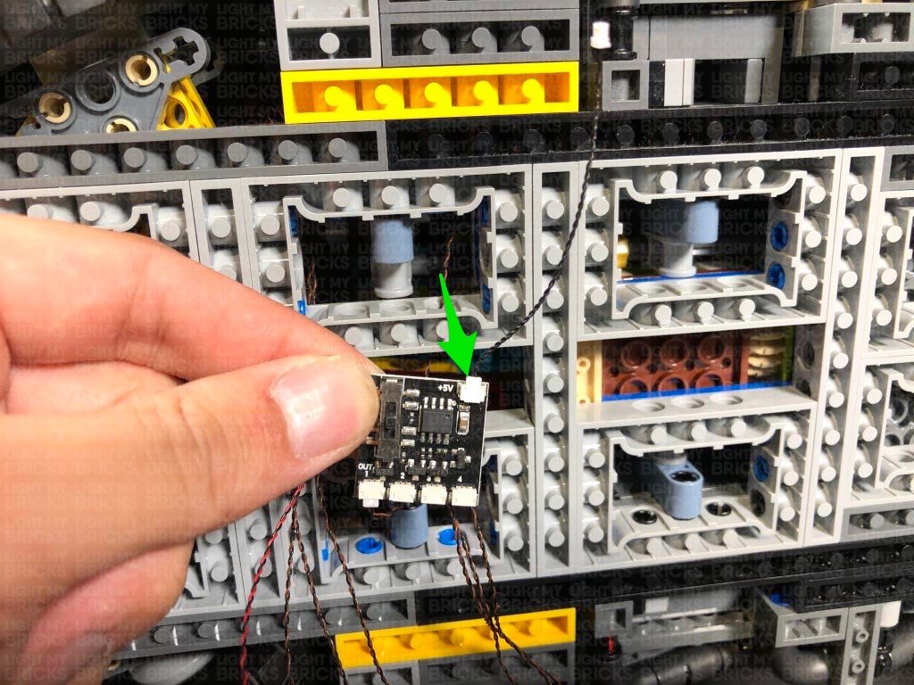
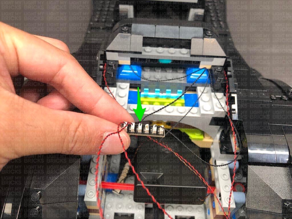
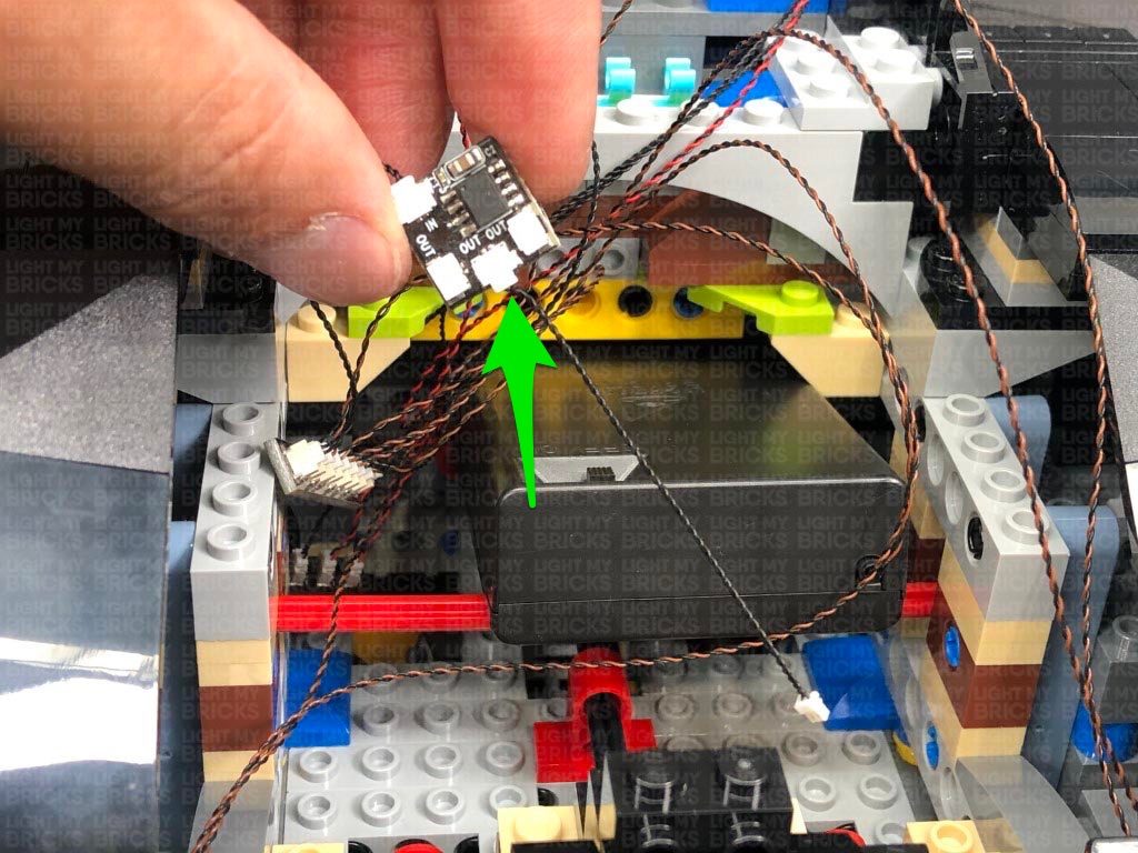
Take the Gun Effects Board (GFX) , and connect the Bit Light cable to the channel 1 port. Ensure the channel switch is set to the middle for the “machine gun” effect. Alternatively, you can choose from one of the other gun effects.
Take a 5cm Connecting Cable and connect it to the IN port (+5V) on the Gun Effects Board. Connect the other end of the connecting cable to a spare port on the 12-Port Expansion Board. Turn the AA Battery Pack ON again, to test the machine gun light is working along with the machine gun effect.
Note: If you experience any issues with the lights not working and suspect an issue with a component, please try a different port on the expansion board to verify where the fault lies (with the light or expansion board or effects board). To correct any issues with expansion board ports, please view the section addressing expansion board issues on our online troubleshooting guide.
22.) Take the right gun section and repeat the previous step to reconnect and thread the bit light cable down underneath the vehicle. Connect the cable to Channel 3 on the Gun Effects Board.
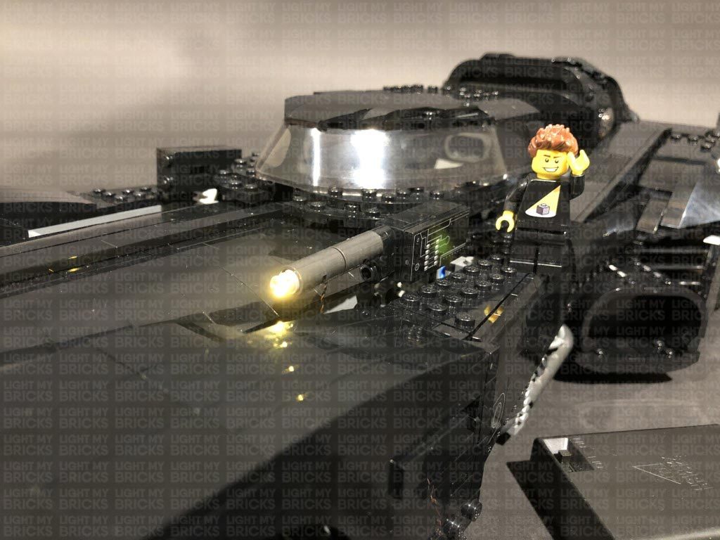
Turn the Power ON to test both Machine Guns lights are working OK. They should be both firing at random rates.
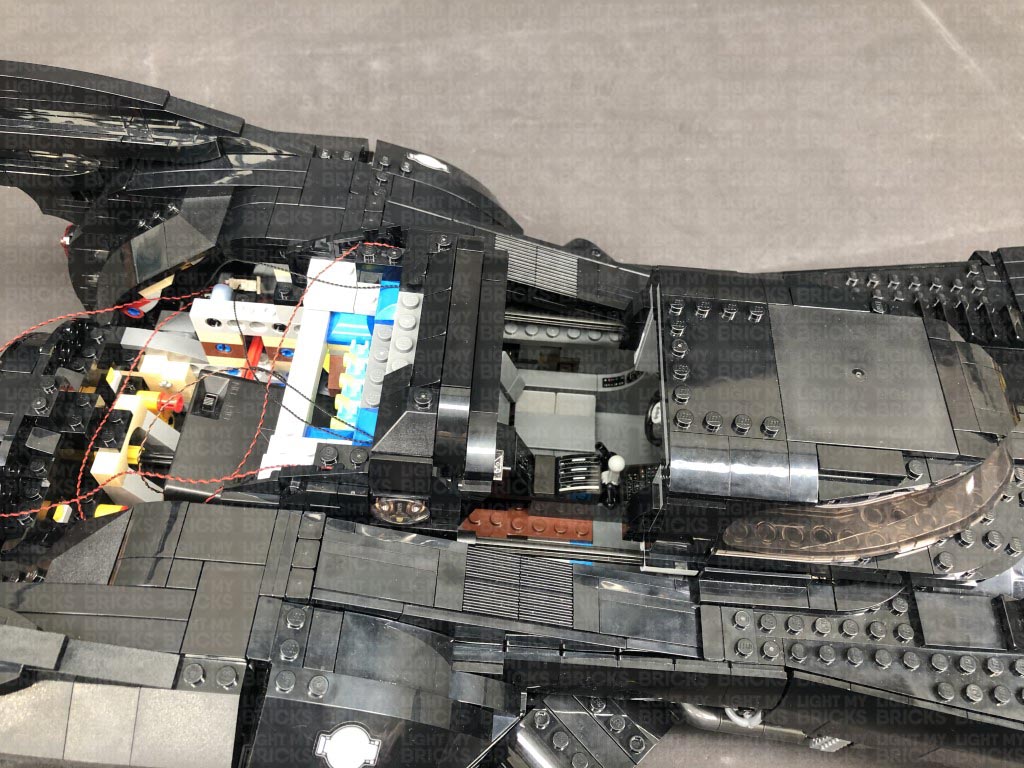
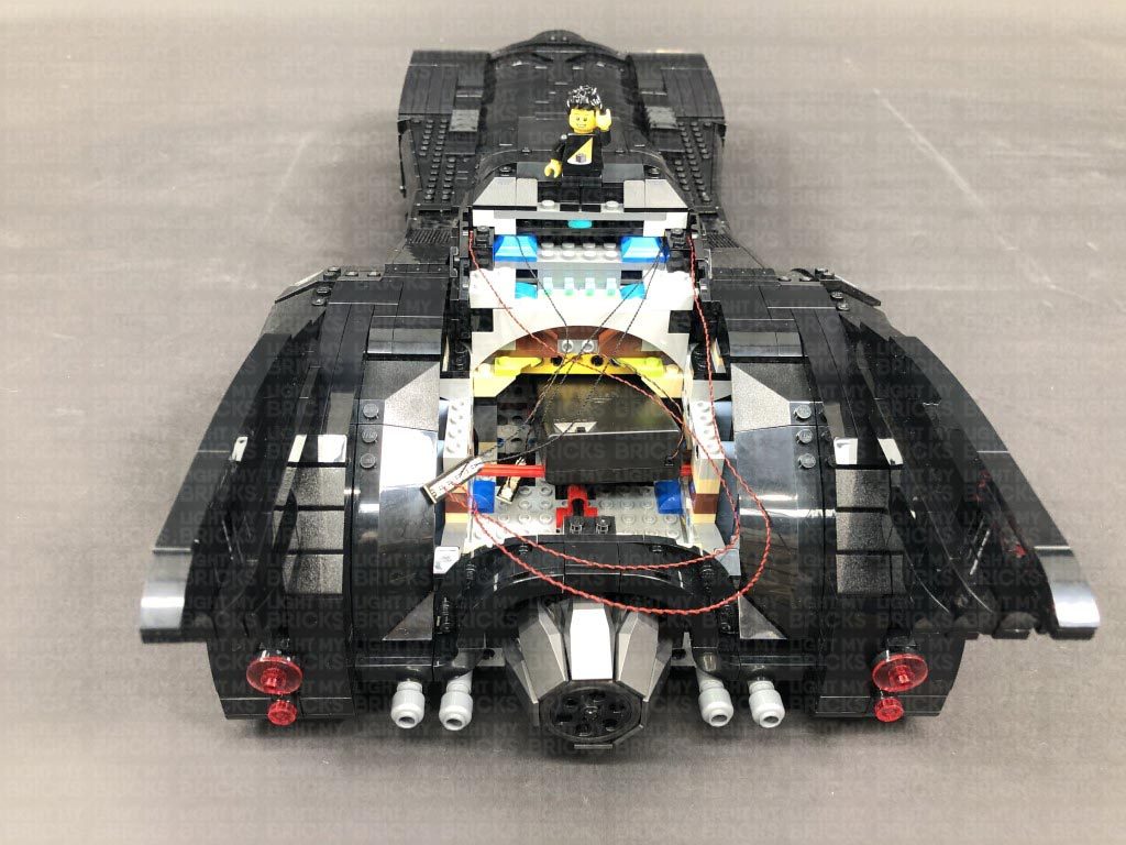
23.) Turn the Batmobile around and remove the following sections from the back of the vehicle and from the back of the cabin.
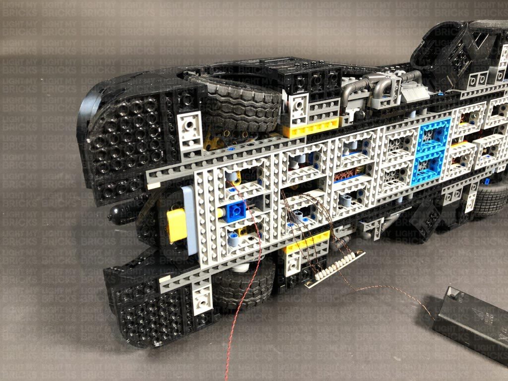
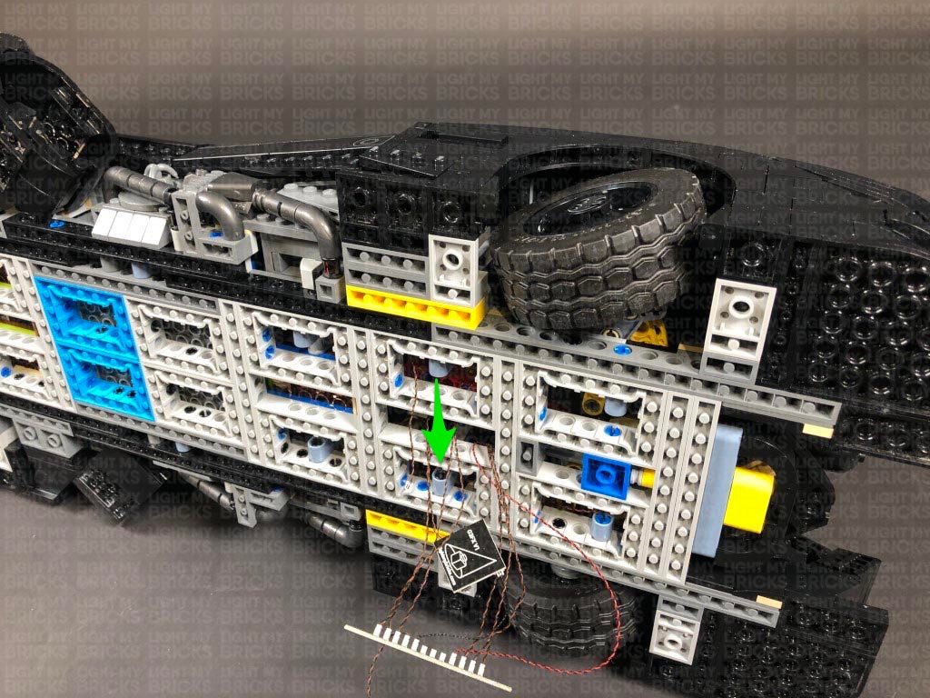
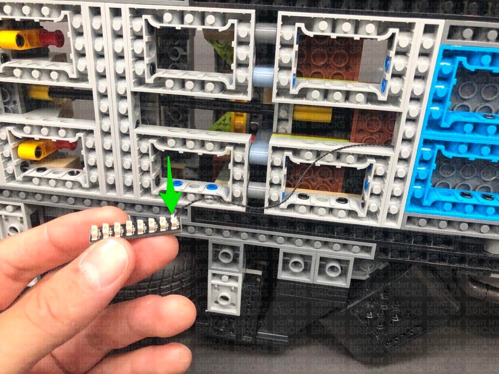
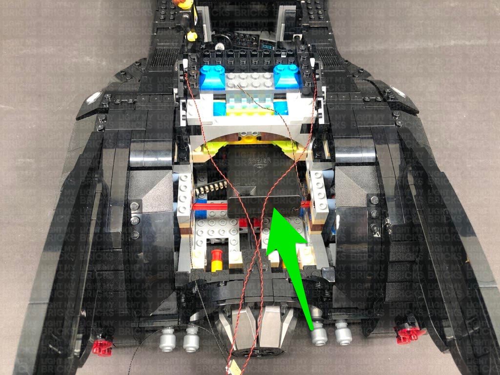
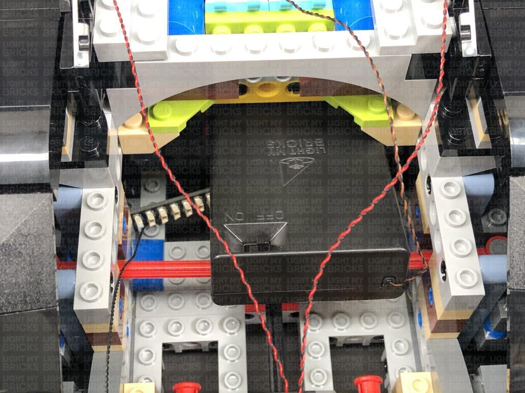
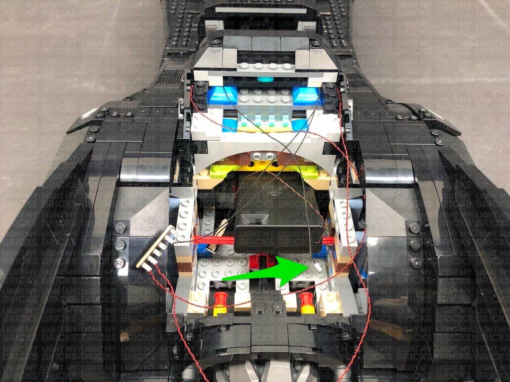
24.) Disconnect the AA Battery Pack from the 12-Port Expansion Board underneath the Batmobile, then take a 50cm Connecting Cable and connect it to a spare port on the 12-Port Expansion Board.
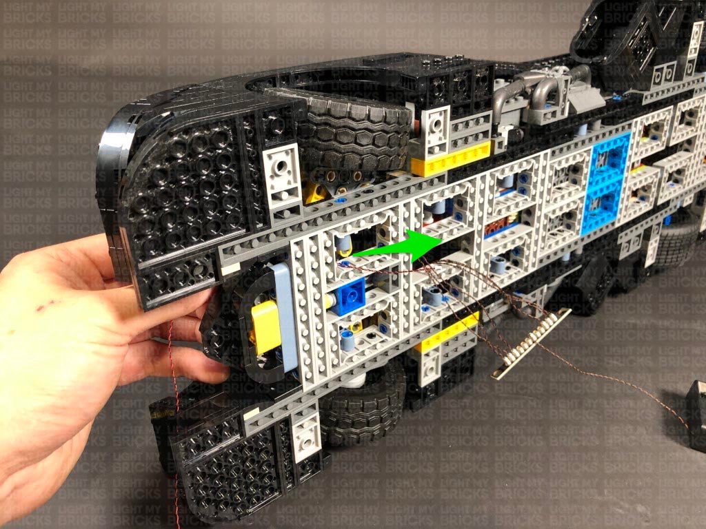
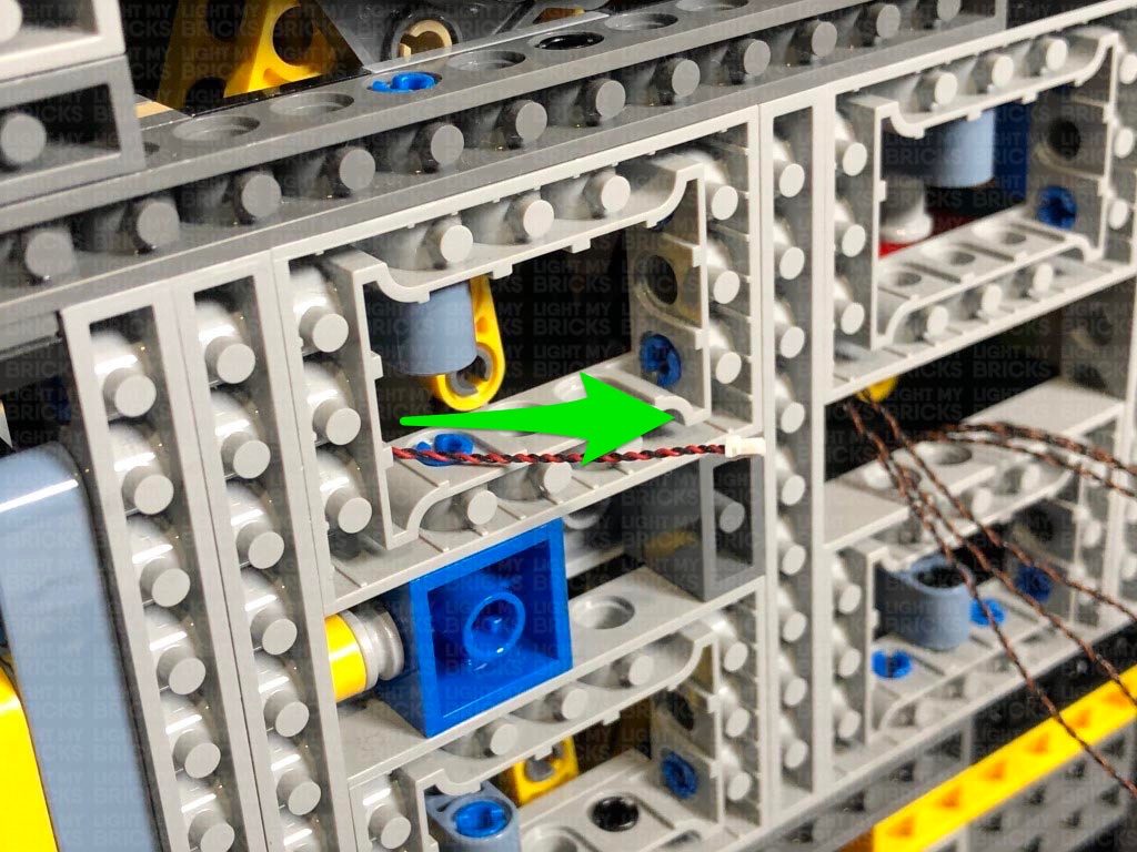
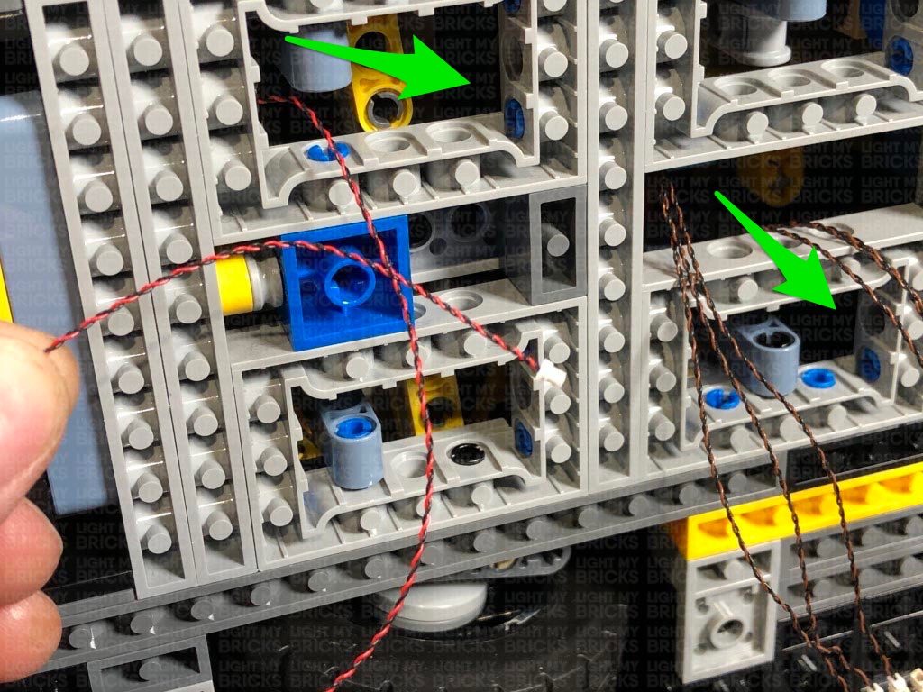
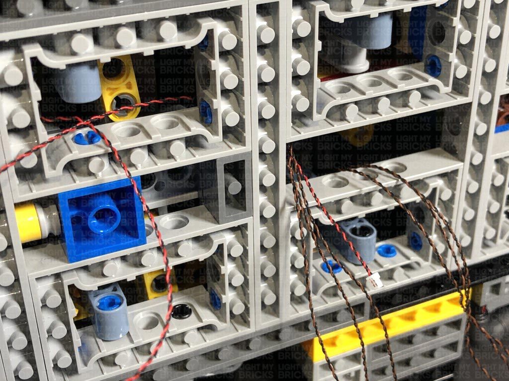
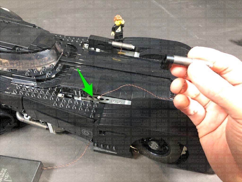
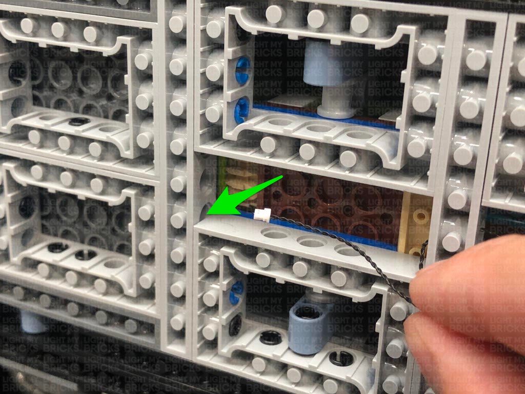
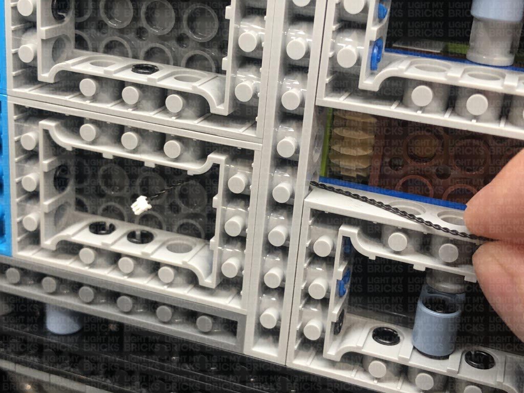
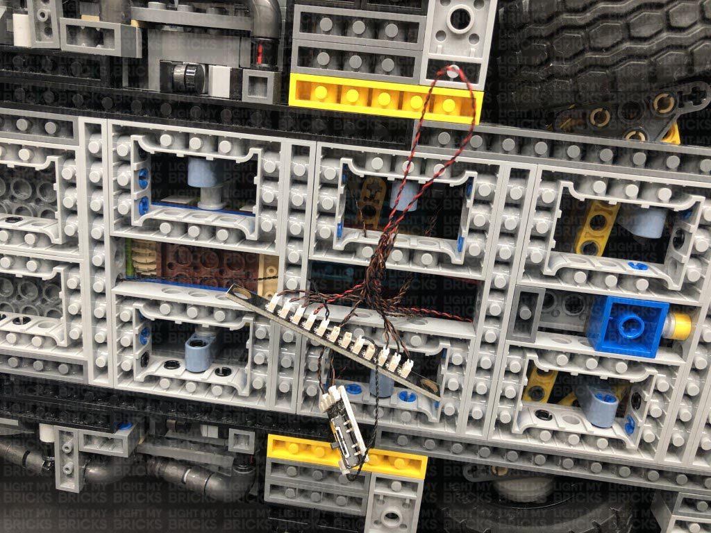
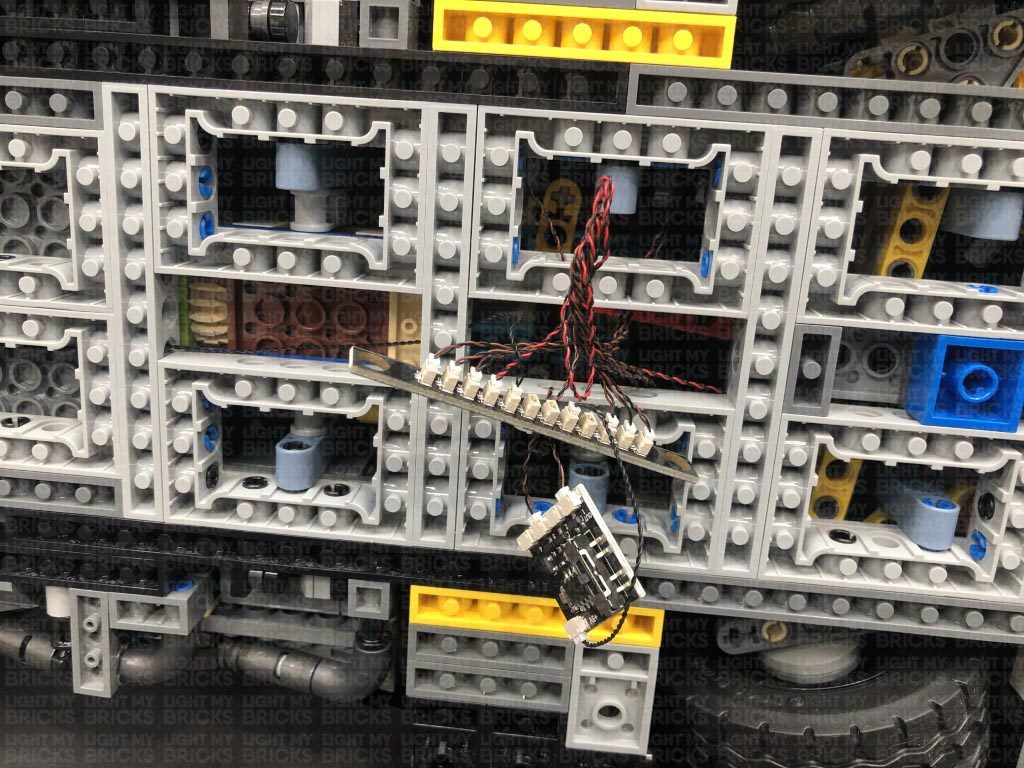
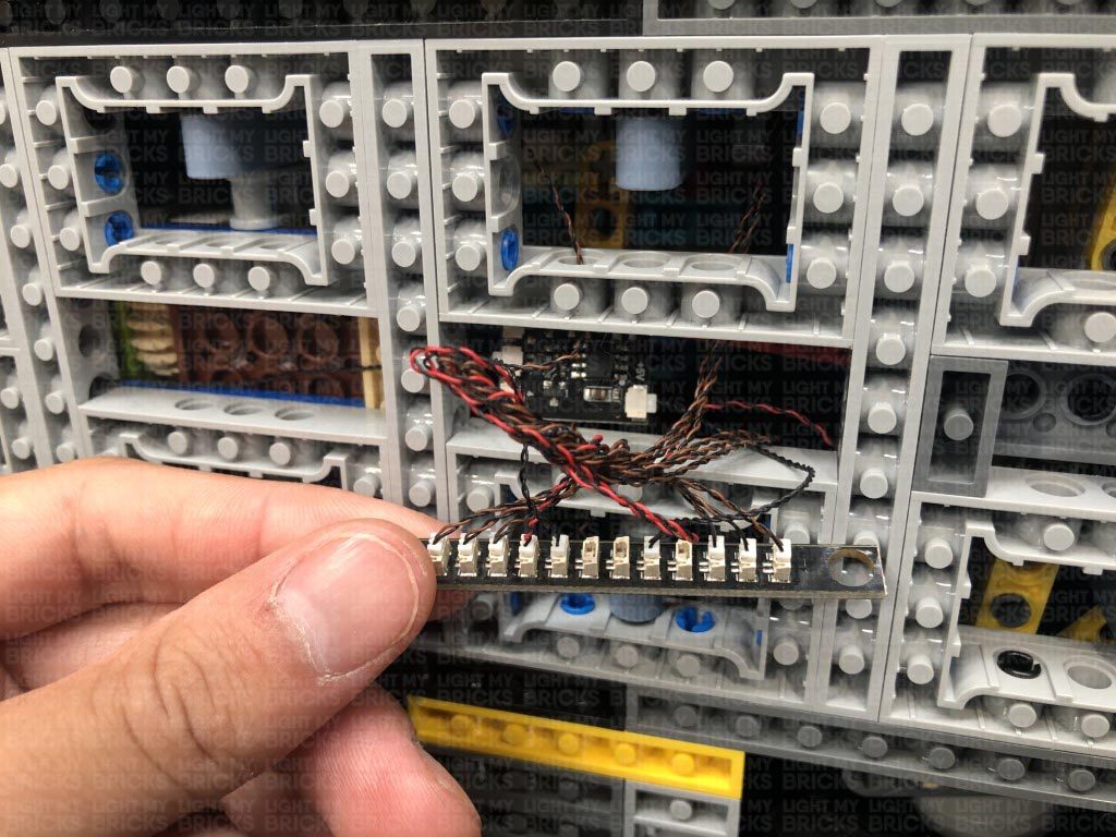
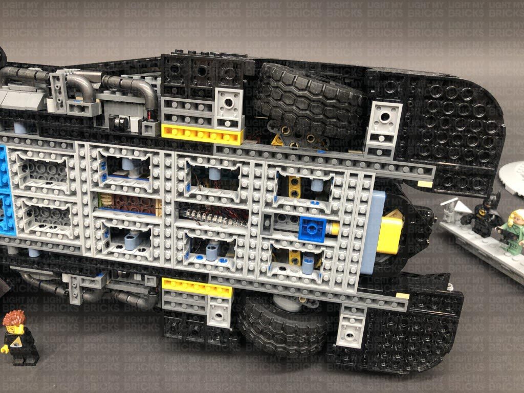
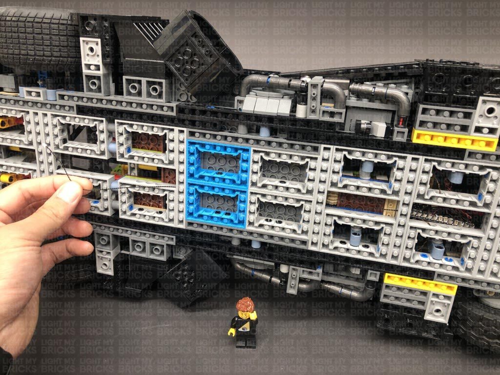
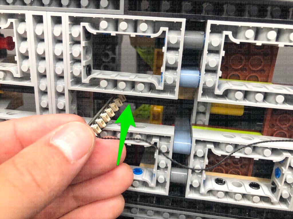
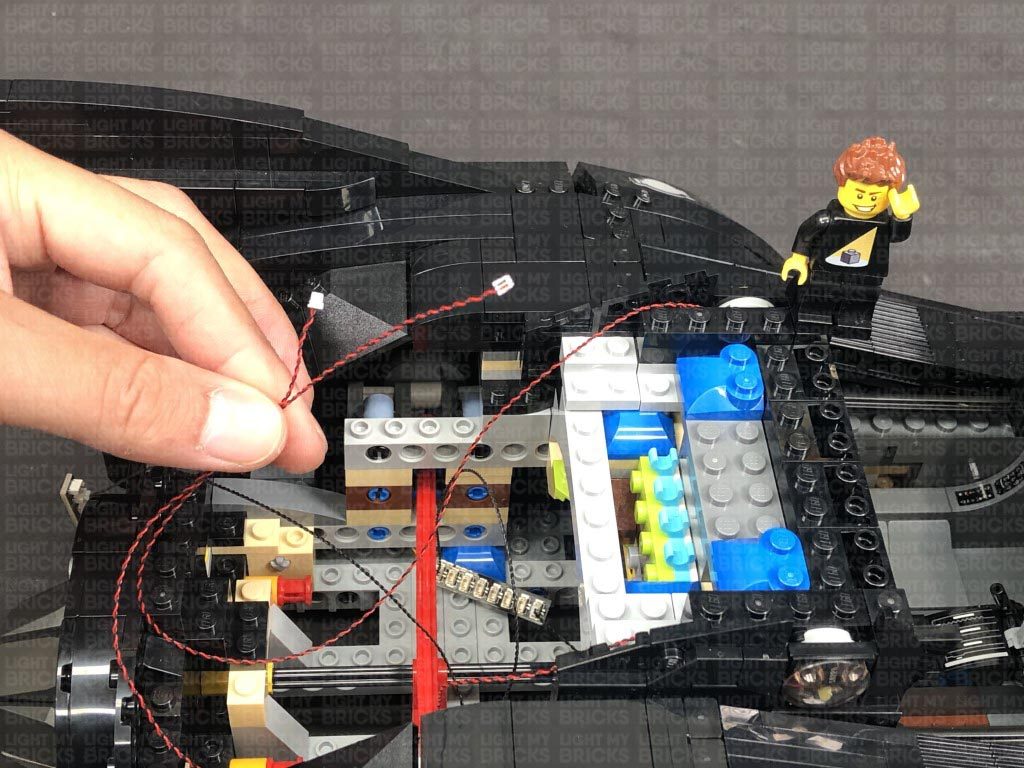
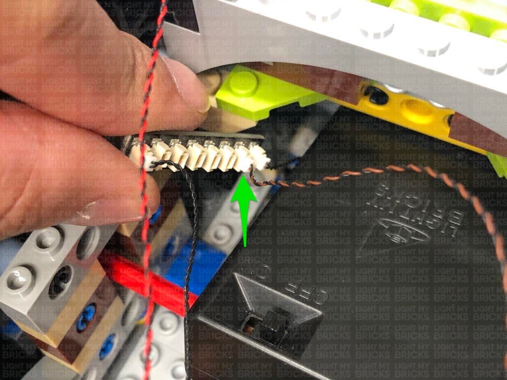
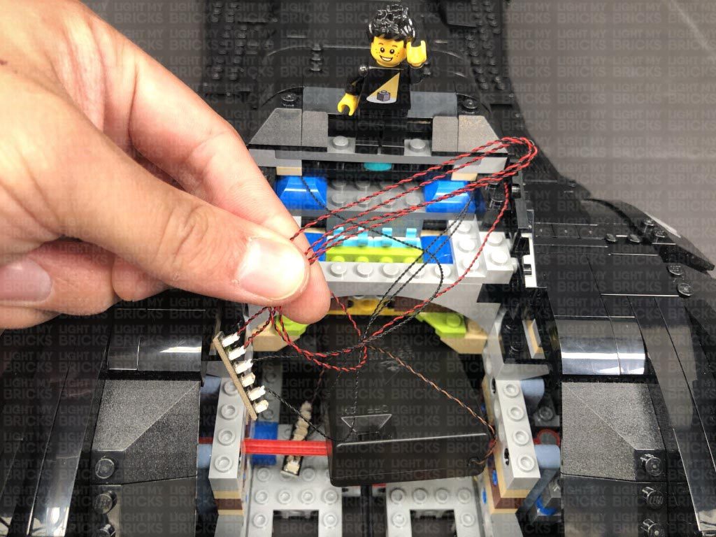
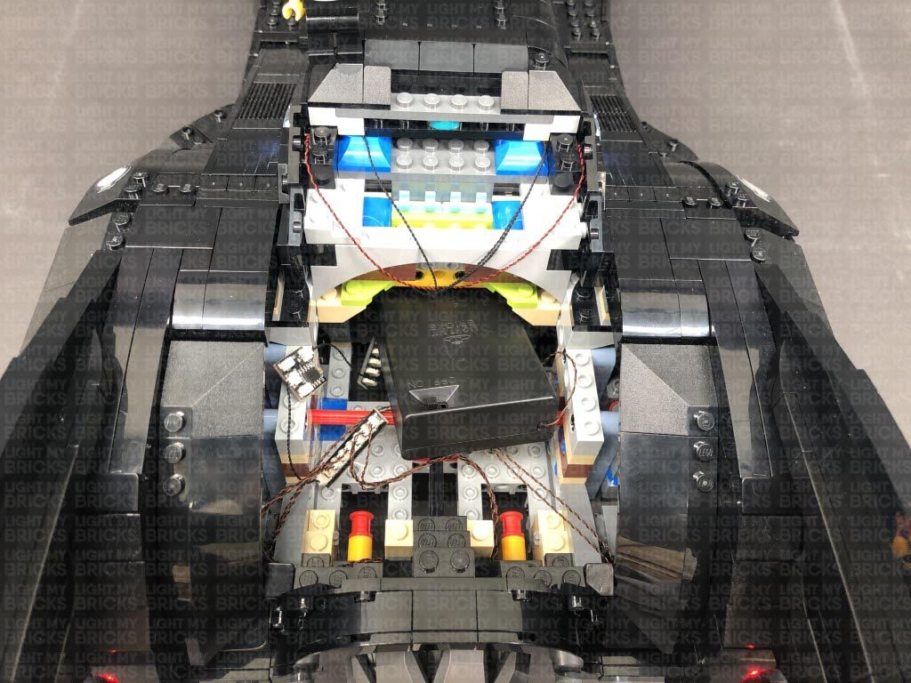
Follow the below images to thread the other end of the 50cm Cable through the following technic brick holes in the middle to lead it toward the back of the vehicle.
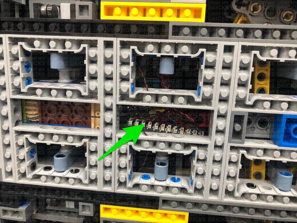
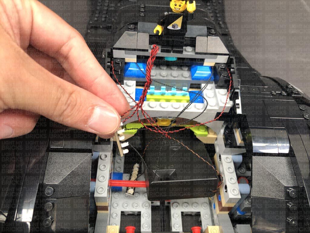
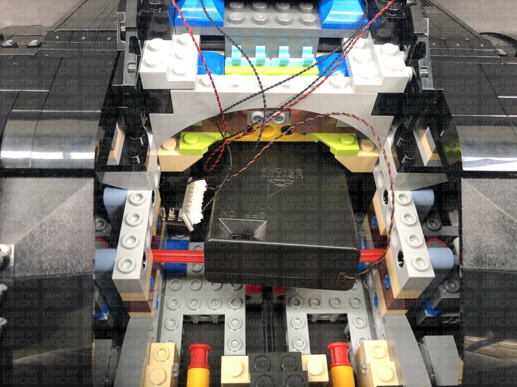
Neaten up cables from the components toward the front of the vehicle by grouping them together and twisting and folding them into a neat bunch. Tuck both effects board and expansion board inside the centre spaces as shown below:
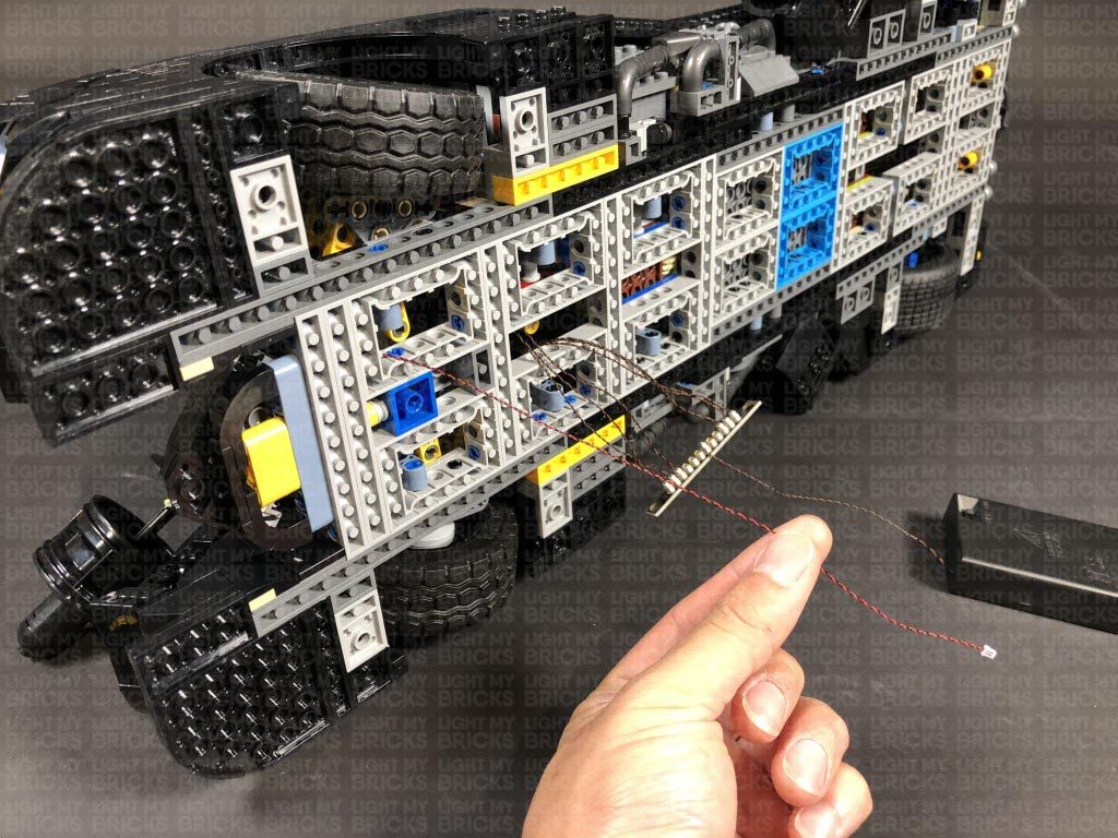
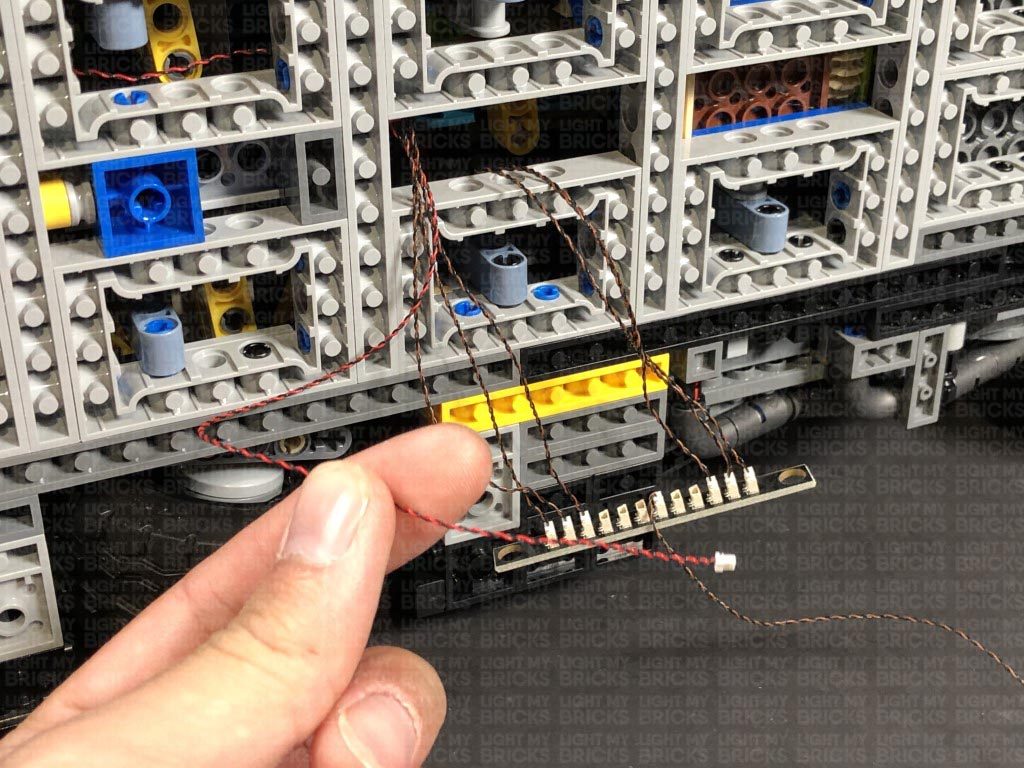
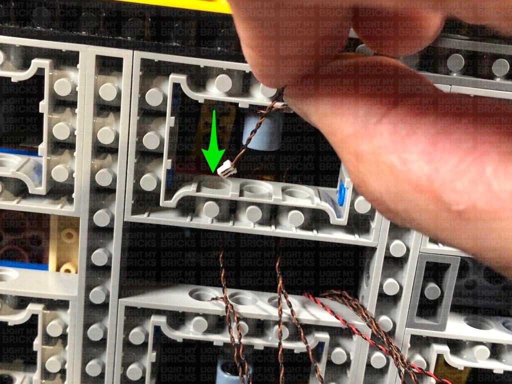
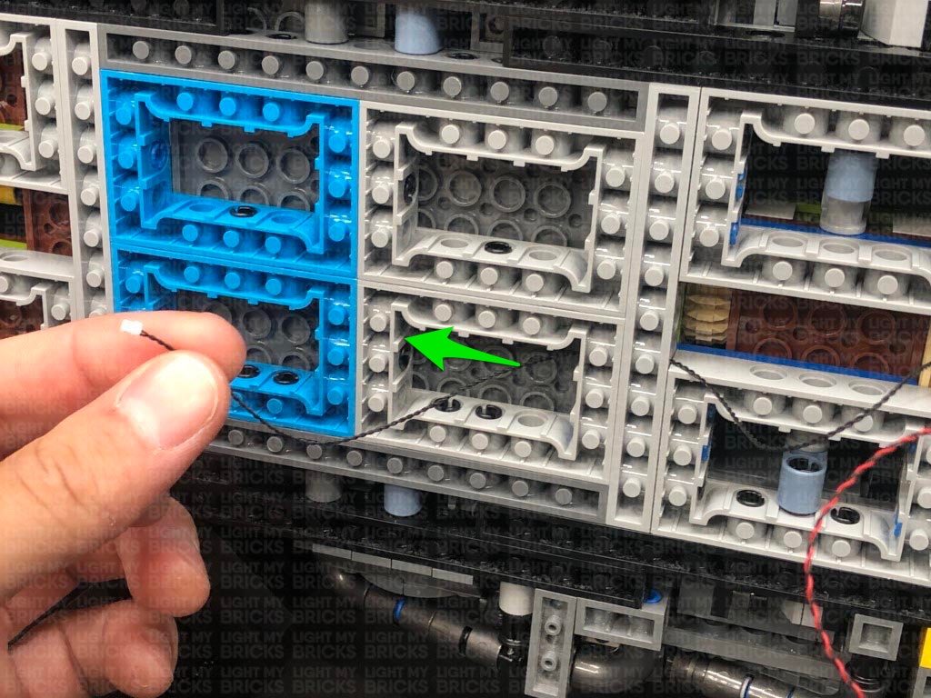
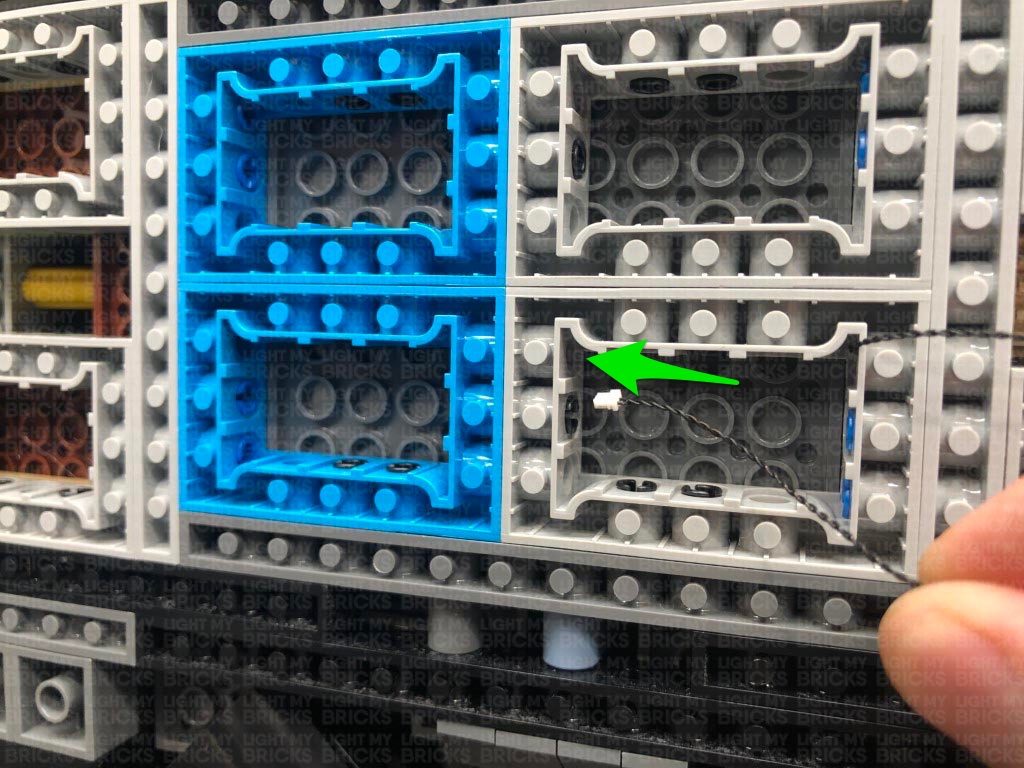
25.) Pull remaining excess of the 50cm Connecting Cable all the way out from the rear side, then connect it to an 8-Port Expansion Board. Tuck the expansion board up the following space which leads to the inside of the trunk.
Turn the vehicle back around and you should be able to easily access the expansion board inside the trunk of the vehicle.
10.) Take the left gun section and thread the cable down the space underneath where it pops out of. Reconnect the gun to the base section, then turn the vehicle onto it’s right side and pull the cable out at the following position.
Pull the cable all the way down, then thread it through the technic brick hole underneath and pull it out of the space where the rest of the cables are.
Take the Gun Effects Board (GFX) , and connect the Bit Light cable to the channel 1 port. Ensure the channel switch is set to the middle for the “machine gun” effect. Alternatively, you can choose from one of the other gun effects.
Take a 5cm Connecting Cable and connect it to the IN port (+5V) on the Gun Effects Board. Connect the other end of the connecting cable to a spare port on the 12-Port Expansion Board. Turn the AA Battery Pack ON again, to test the machine gun light is working along with the machine gun effect.
Note: If you experience any issues with the lights not working and suspect an issue with a component, please try a different port on the expansion board to verify where the fault lies (with the light or expansion board or effects board). To correct any issues with expansion board ports, please view the section addressing expansion board issues on our online troubleshooting guide.
22.) Take the right gun section and repeat the previous step to reconnect and thread the bit light cable down underneath the vehicle. Connect the cable to Channel 3 on the Gun Effects Board.
Turn the Power ON to test both Machine Guns lights are working OK. They should be both firing at random rates.
23.) Turn the Batmobile around and remove the following sections from the back of the vehicle and from the back of the cabin.
24.) Disconnect the AA Battery Pack from the 12-Port Expansion Board underneath the Batmobile, then take a 50cm Connecting Cable and connect it to a spare port on the 12-Port Expansion Board.
Follow the below images to thread the other end of the 50cm Cable through the following technic brick holes in the middle to lead it toward the back of the vehicle.
Neaten up cables from the components toward the front of the vehicle by grouping them together and twisting and folding them into a neat bunch. Tuck both effects board and expansion board inside the centre spaces as shown below:
25.) Pull remaining excess of the 50cm Connecting Cable all the way out from the rear side, then connect it to an 8-Port Expansion Board. Tuck the expansion board up the following space which leads to the inside of the trunk.
Turn the vehicle back around and you should be able to easily access the expansion board inside the trunk of the vehicle.
 26.) Disconnect the following pieces from the inside of the trunk. We will be discarding these pieces as we require this space to house the AA Battery Pack.
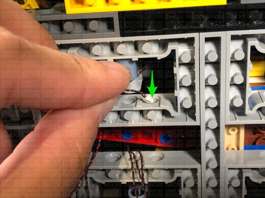
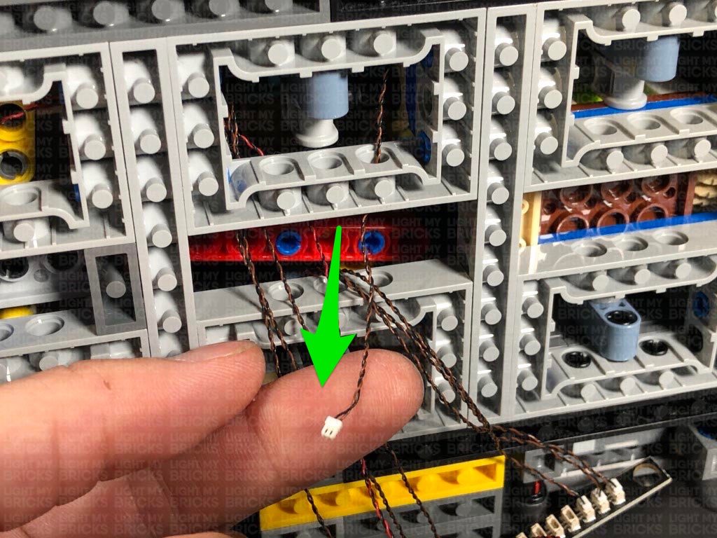
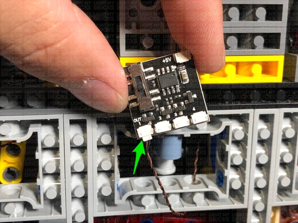
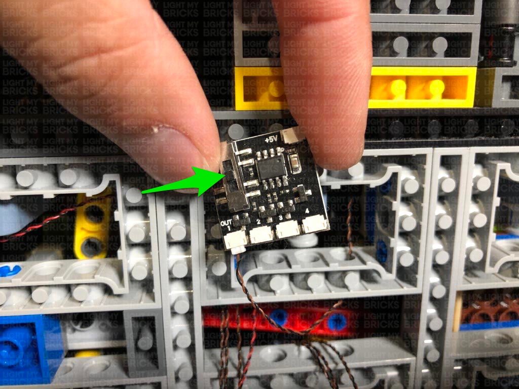
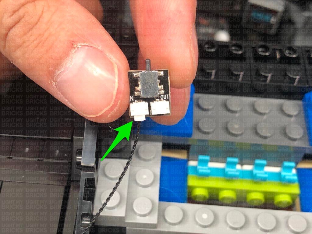
Take a 15cm Connecting Cable and connect one end to the 8-Port Expansion Board underneath. Connect the other end of the cable to the IN port on the NC Push Board.
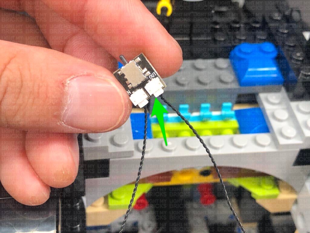
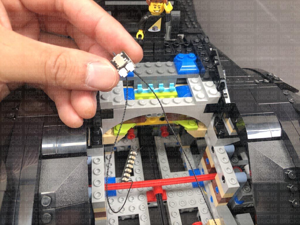
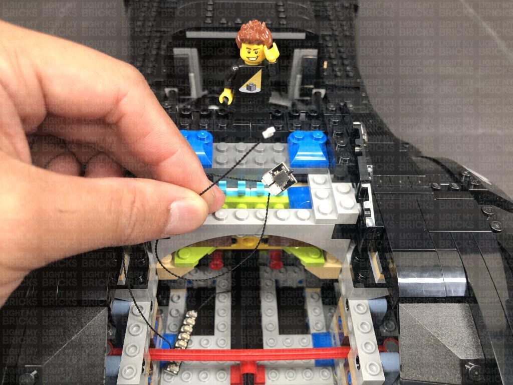
Take another 15cm Connecting Cable and connect one end to the OUT port on the NC Push Board. Connect the other end of the cable to a 6-Port Expansion Board. Set all of these components inside the rear section of the vehicle for now.
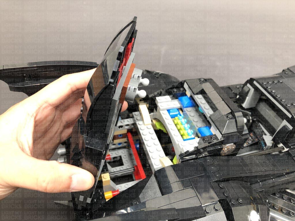
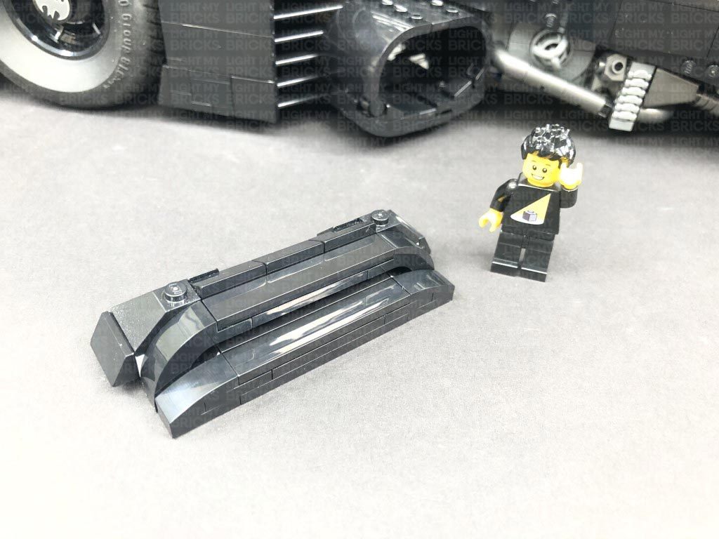
27.) Disconnect the following section from both sides of the cabin.
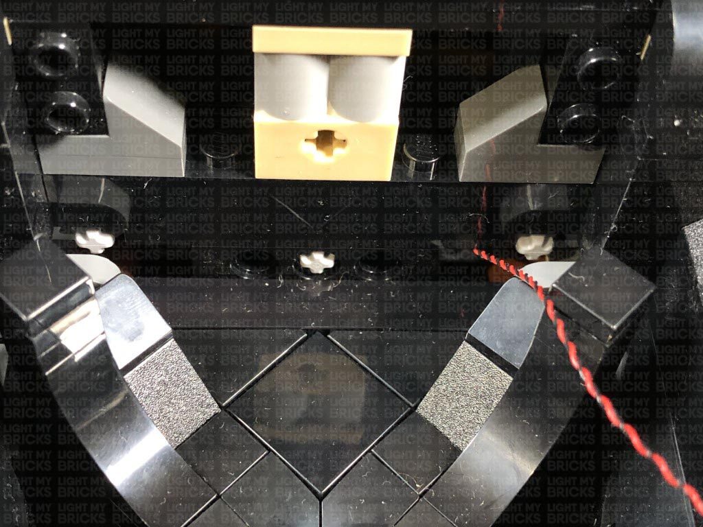
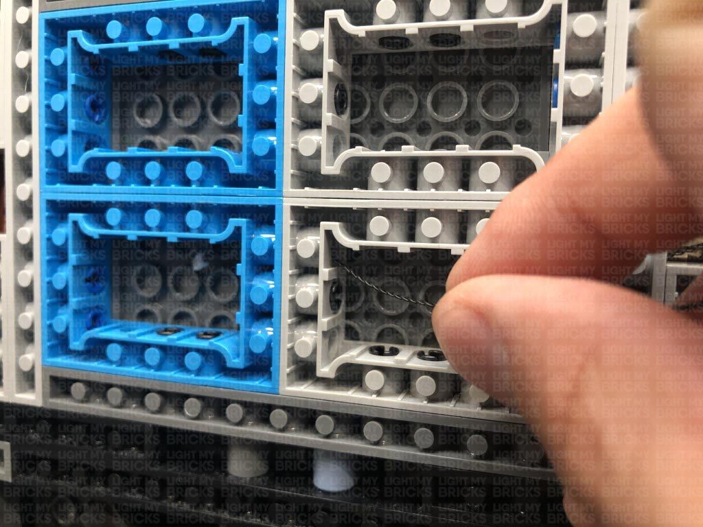
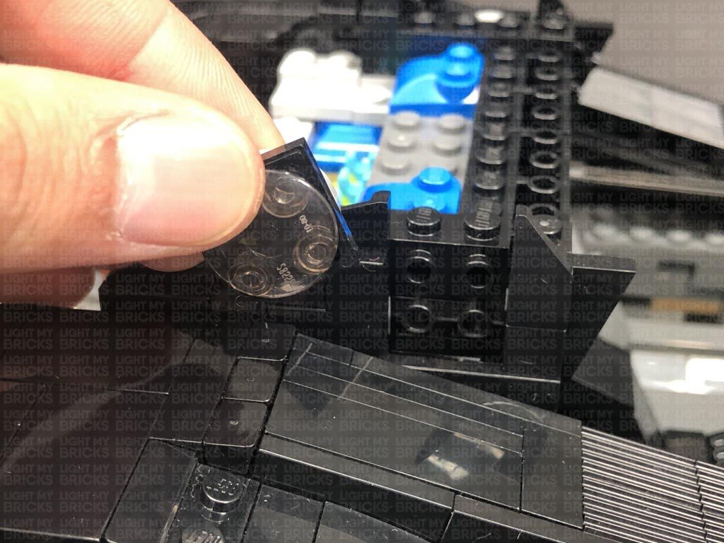
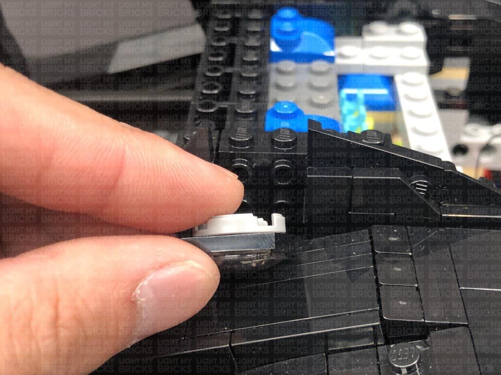
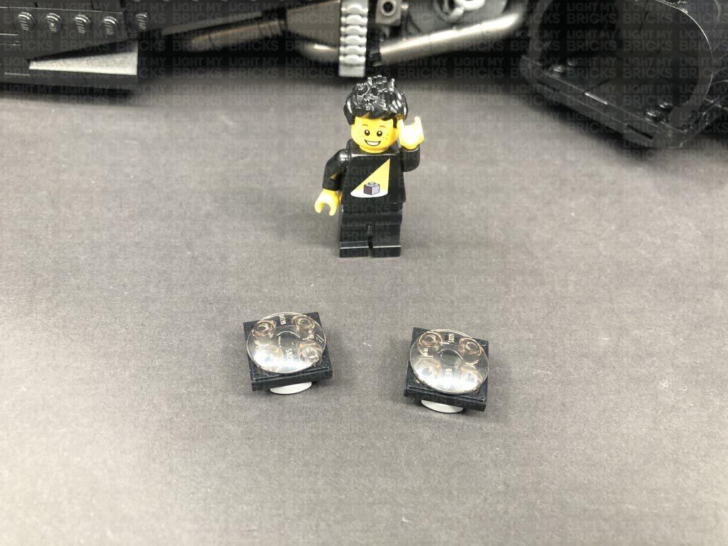
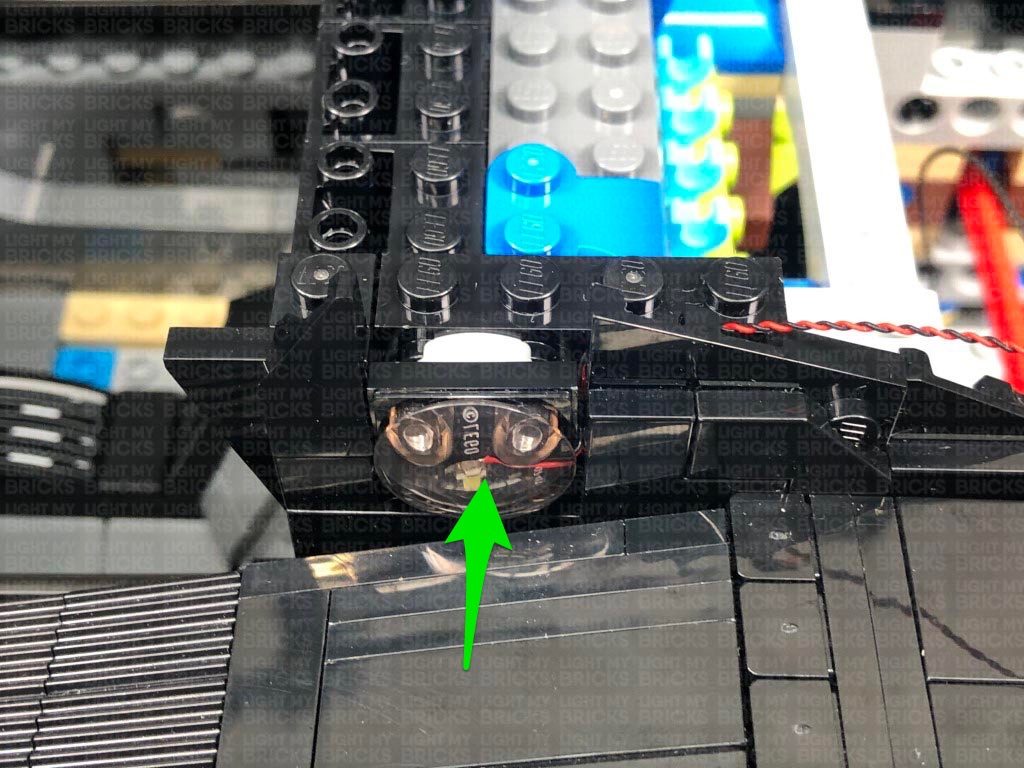
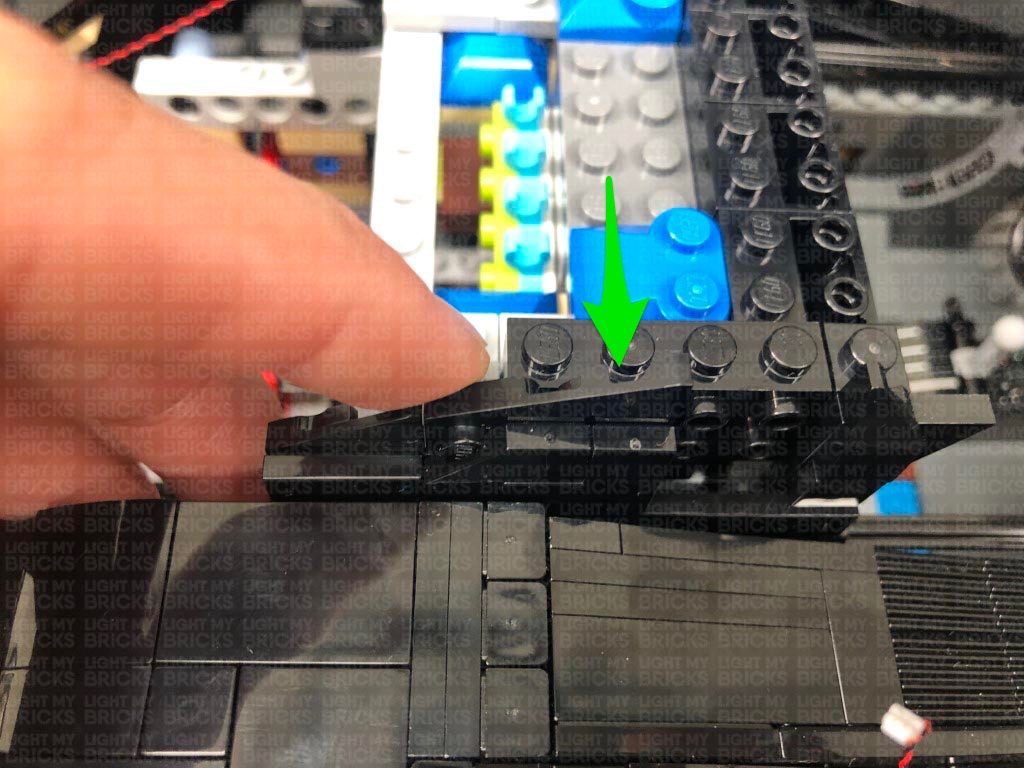
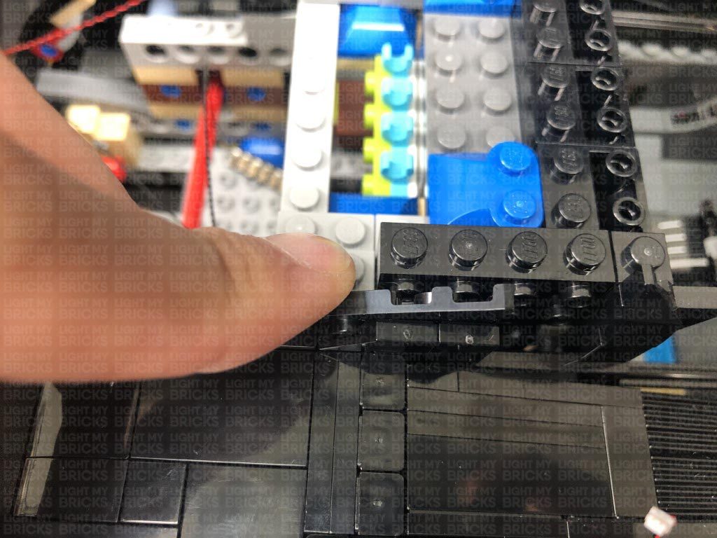
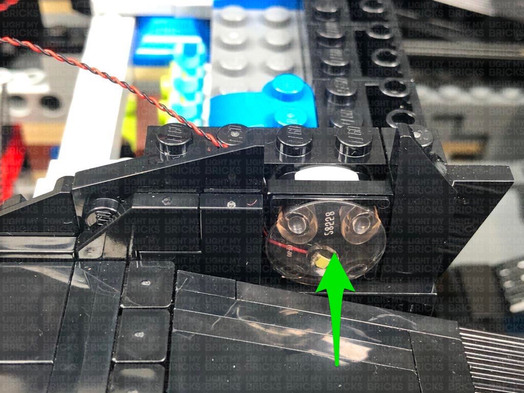
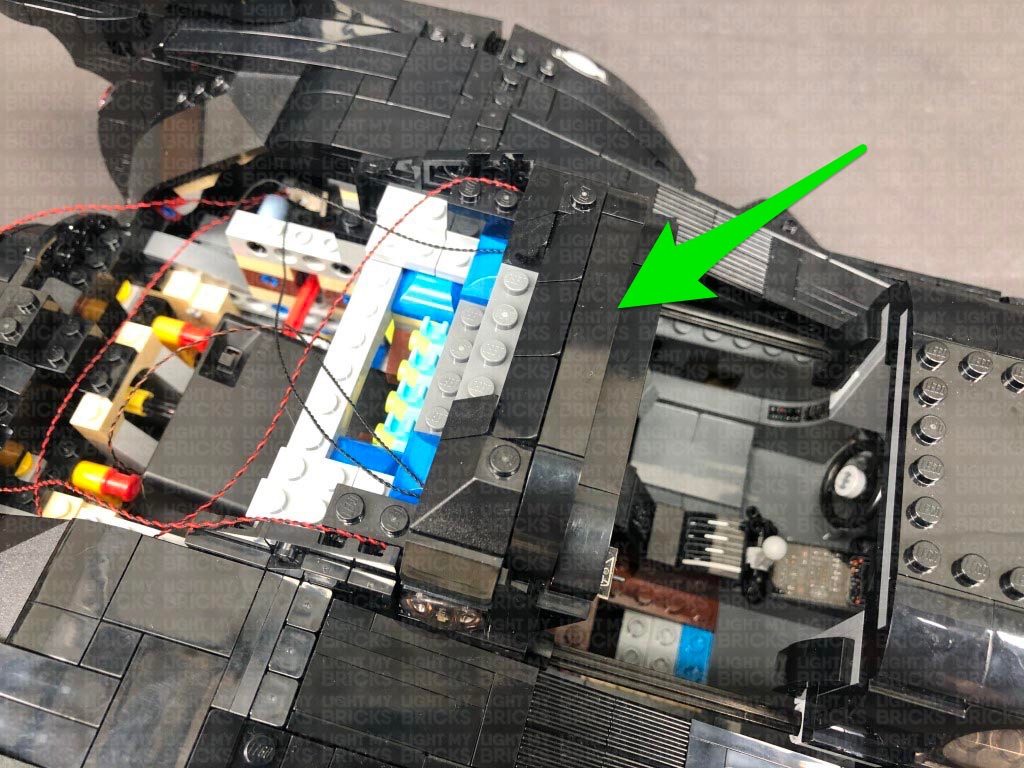
Disconnect the trans black 2×2 rounded bottom plate from one of the sections, then place a Cool White 30cm Bit Light in the middle (led facing up). Reconnect the trans black 2×2 rounded bottom plate over the top, then repeat this step to install another Cool White 30cm Bit Light to the other section.
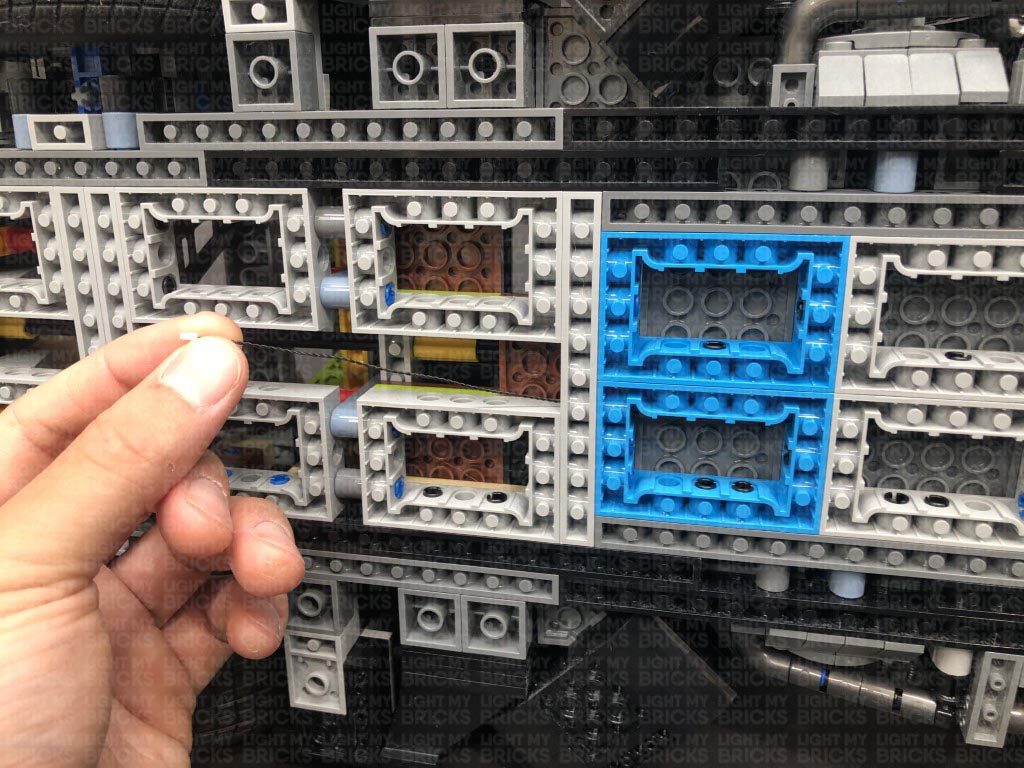
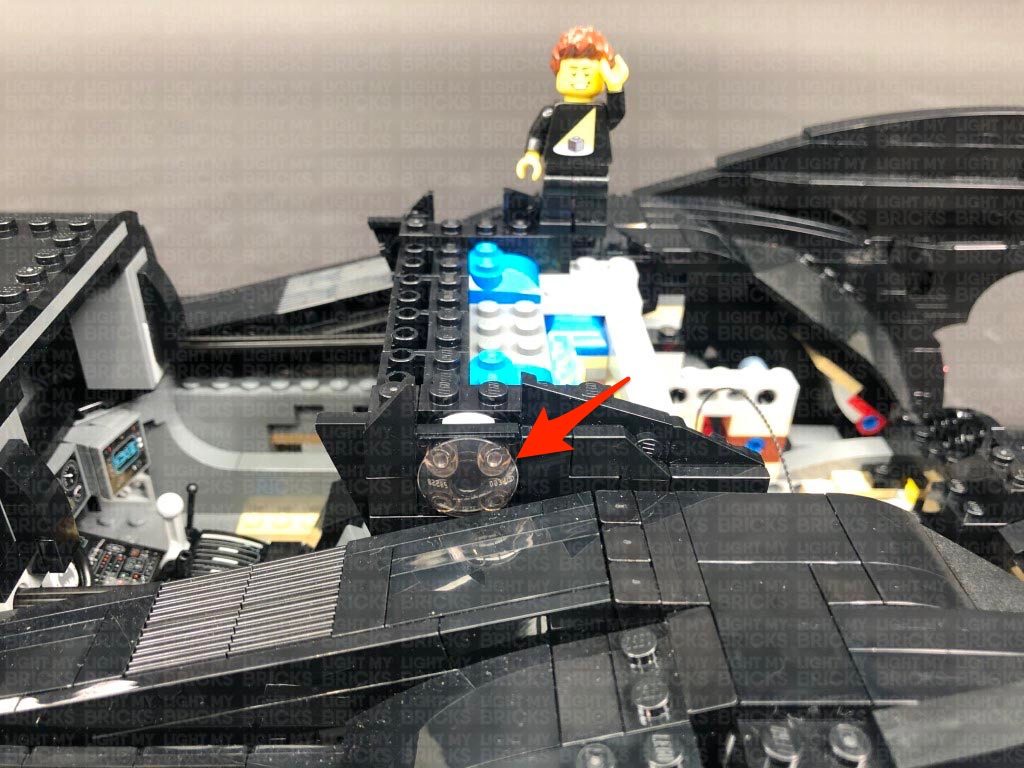
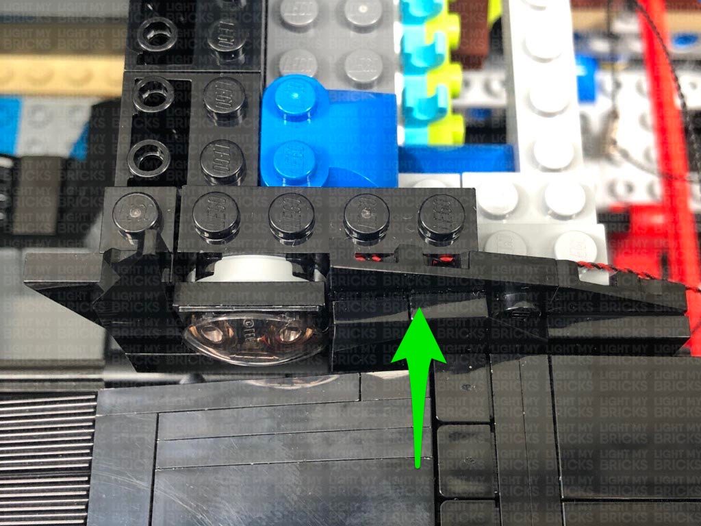
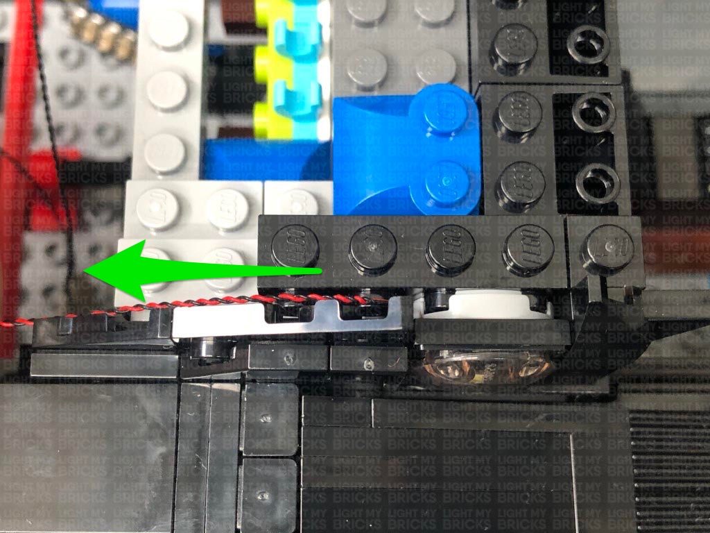
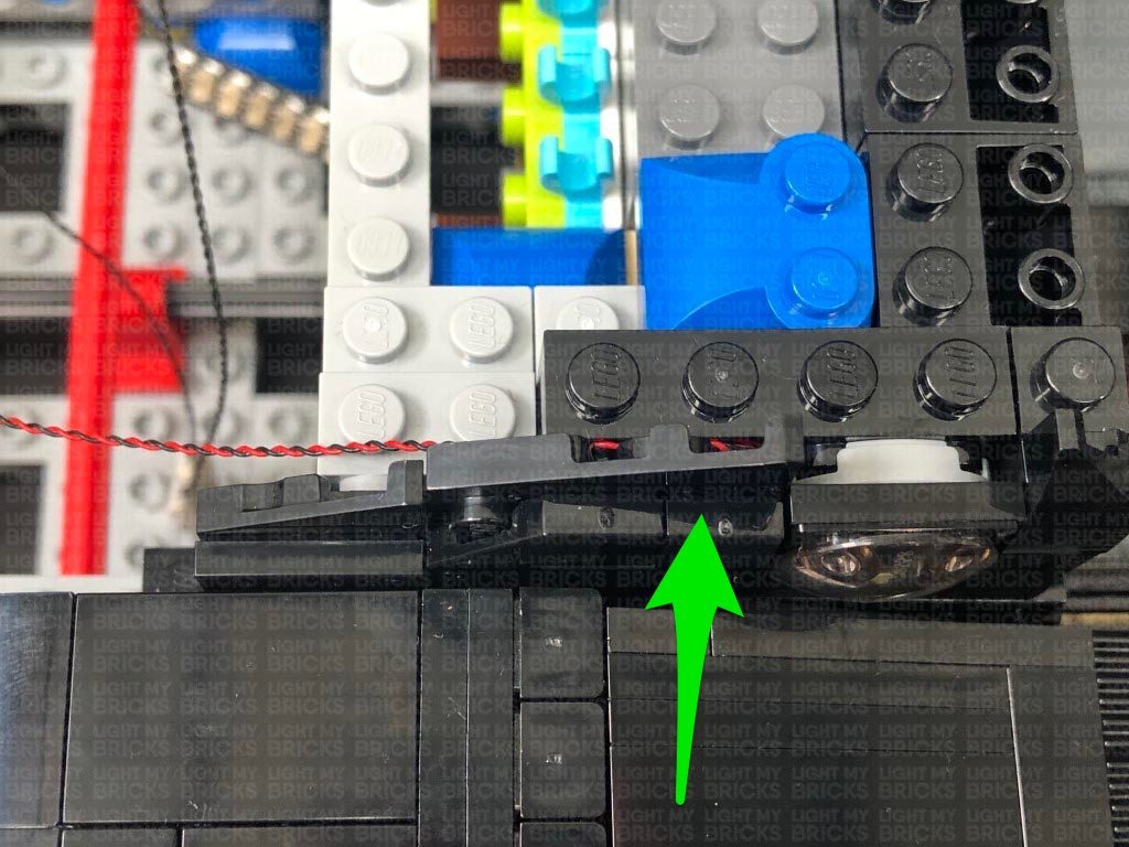
Reconnect each section to the vehicle ensuring the cable is facing toward the back. Pull down the angled plate behind it so we can neatly lay the cable behind and in between studs. Reconnect the plate to conceal the wiring as shown below.
26.) Disconnect the following pieces from the inside of the trunk. We will be discarding these pieces as we require this space to house the AA Battery Pack.
Take a 15cm Connecting Cable and connect one end to the 8-Port Expansion Board underneath. Connect the other end of the cable to the IN port on the NC Push Board.
Take another 15cm Connecting Cable and connect one end to the OUT port on the NC Push Board. Connect the other end of the cable to a 6-Port Expansion Board. Set all of these components inside the rear section of the vehicle for now.
27.) Disconnect the following section from both sides of the cabin.
Disconnect the trans black 2×2 rounded bottom plate from one of the sections, then place a Cool White 30cm Bit Light in the middle (led facing up). Reconnect the trans black 2×2 rounded bottom plate over the top, then repeat this step to install another Cool White 30cm Bit Light to the other section.
Reconnect each section to the vehicle ensuring the cable is facing toward the back. Pull down the angled plate behind it so we can neatly lay the cable behind and in between studs. Reconnect the plate to conceal the wiring as shown below.
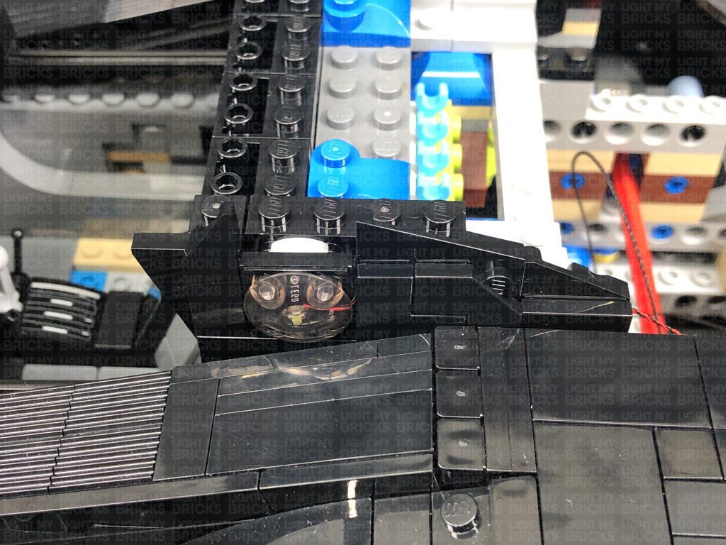 Repeat this step to reconnect the other section to the right side.
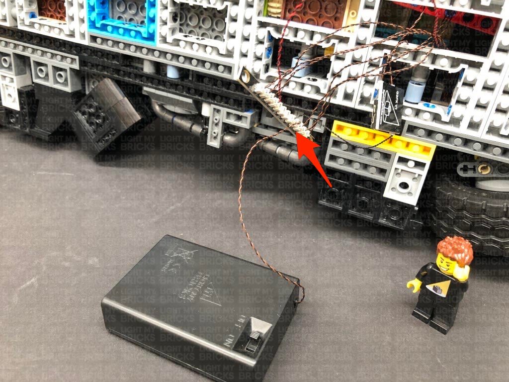
28.) Connect both Bit Light cables we just installed to the 6-Port Expansion Board from step 26, then take the AA Battery Pack and place it inside the back of the Batmobile ensuring the switch is facing up and closest to the back. Connect the Battery Pack cable to the 8-Port Expansion Board (Do NOT connect the battery pack to the 6-port Expansion Board.)
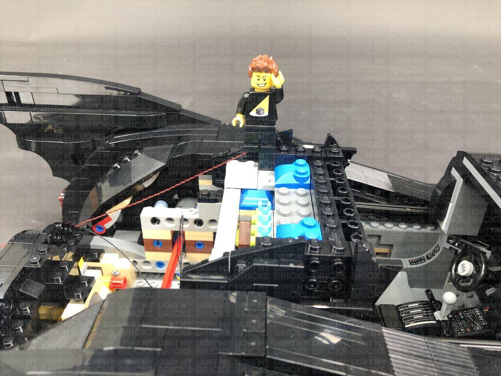
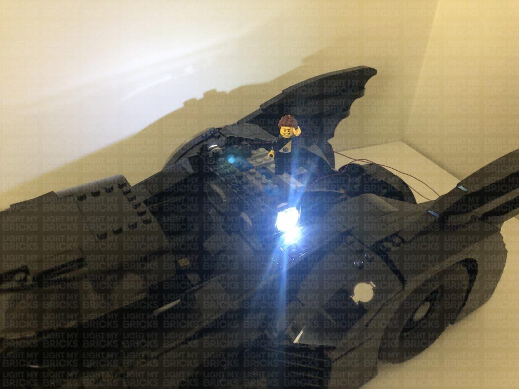
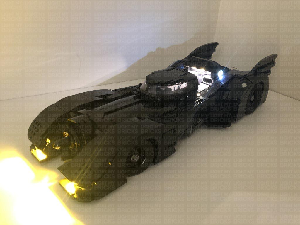
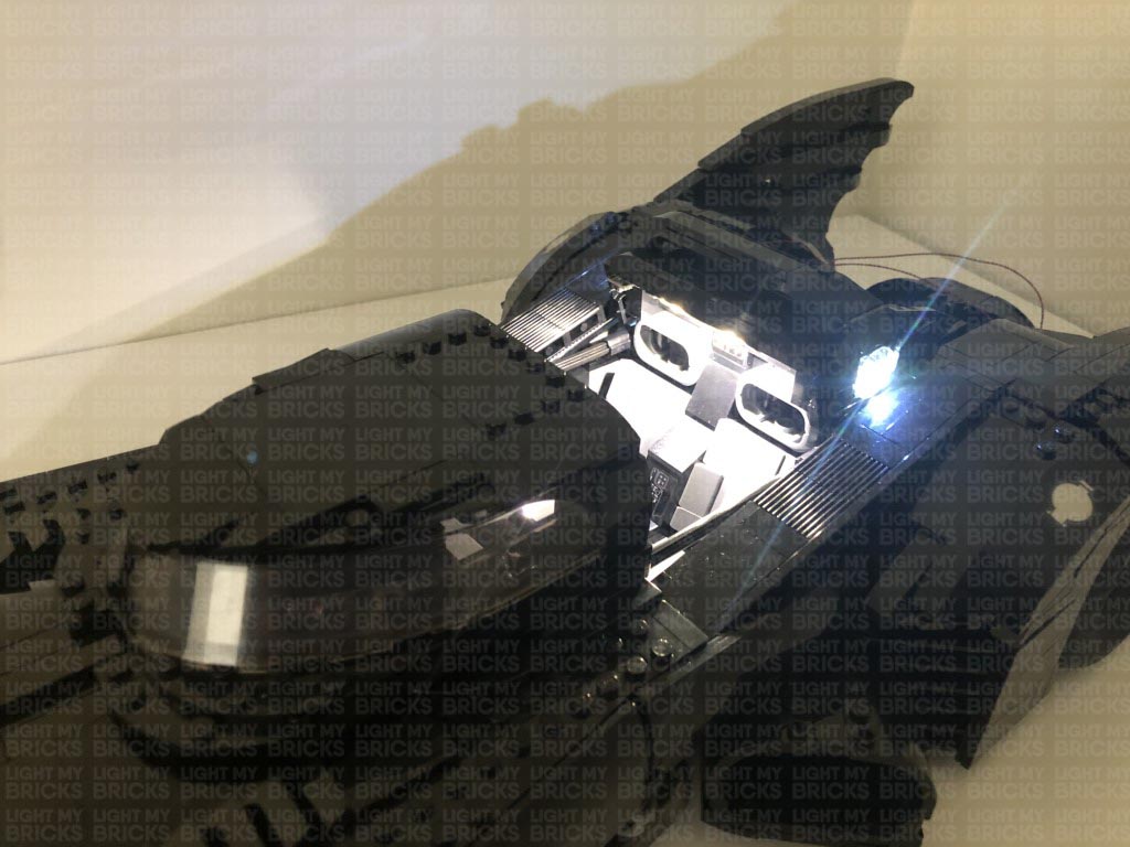
Turn the AA Battery Pack ON to test all the lights are working OK. Test the NC push board is also working OK. Push the lever to test the the outside cabin lights we just installed turn OFF. The lights should re-activate when the push lever is released.
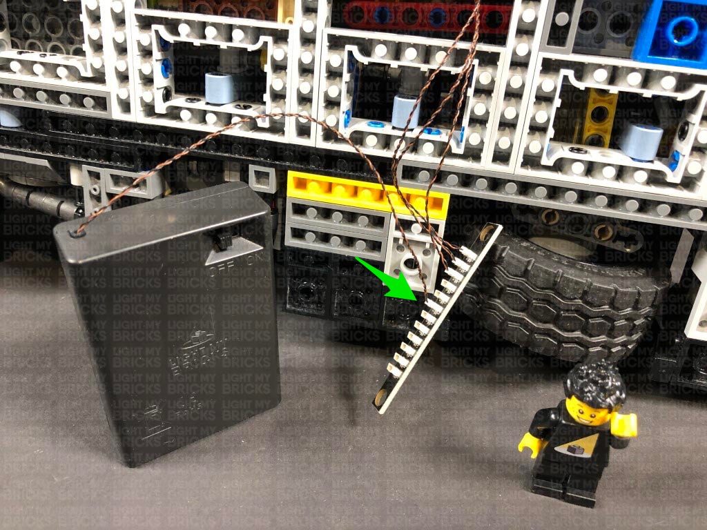
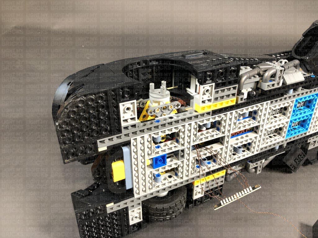
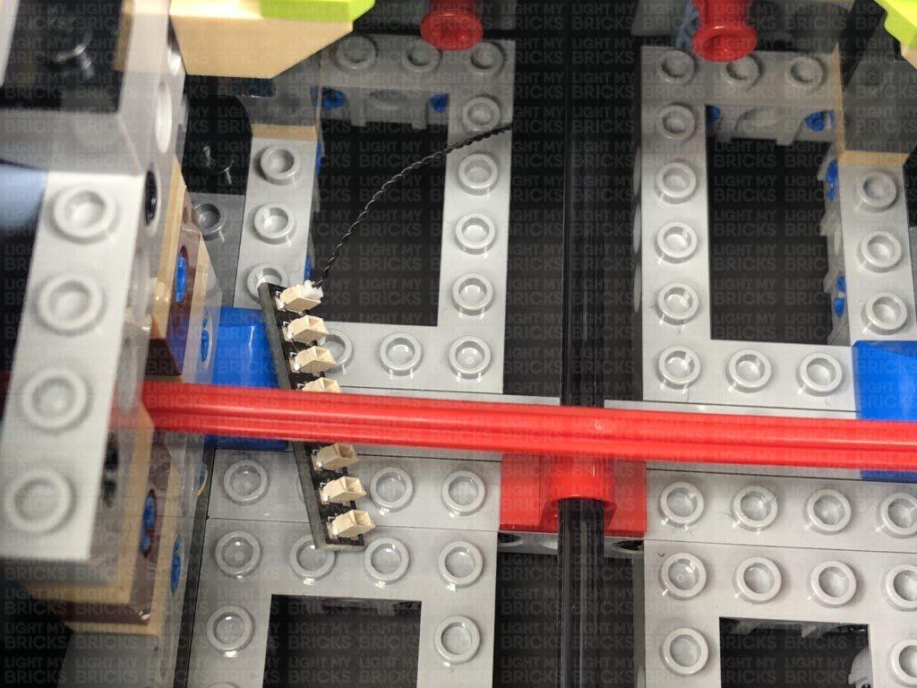
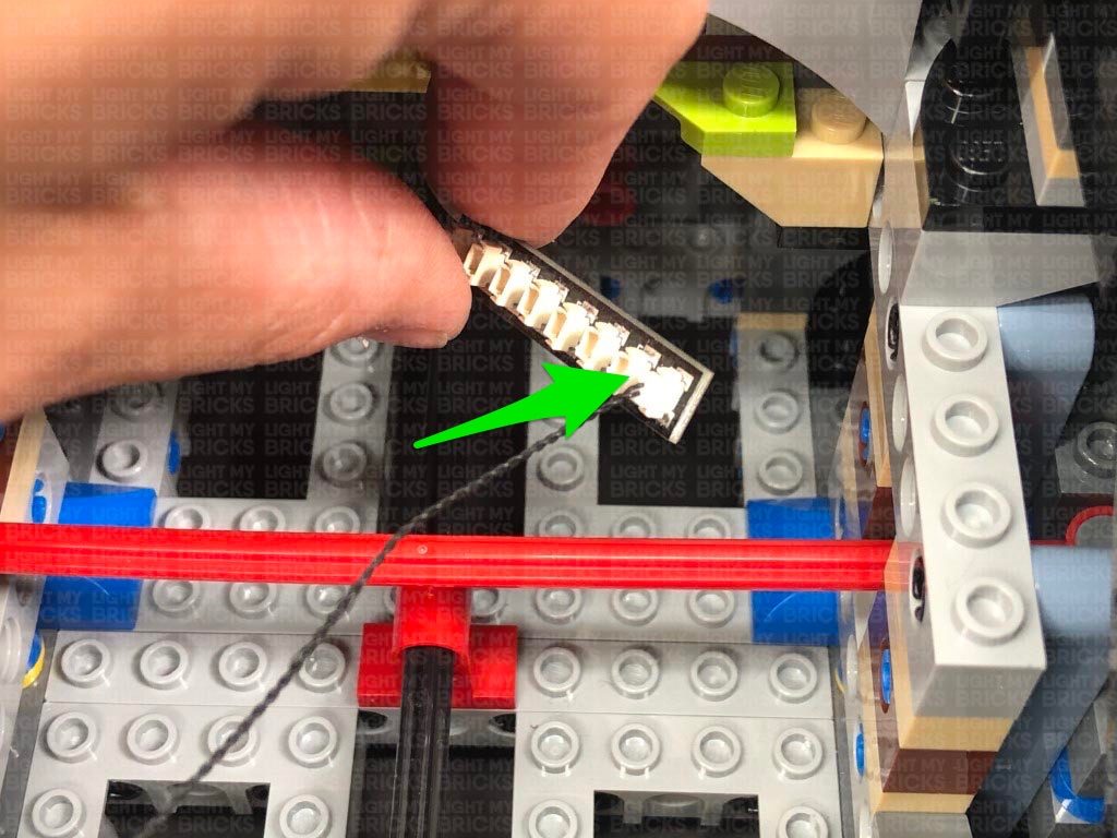
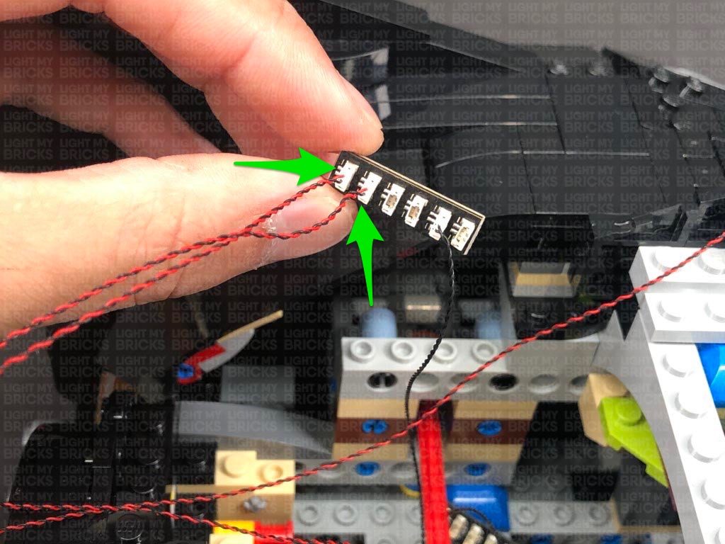
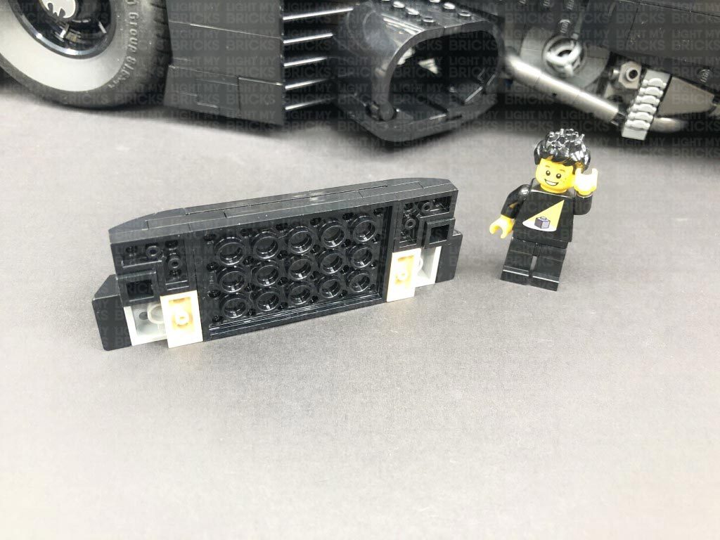
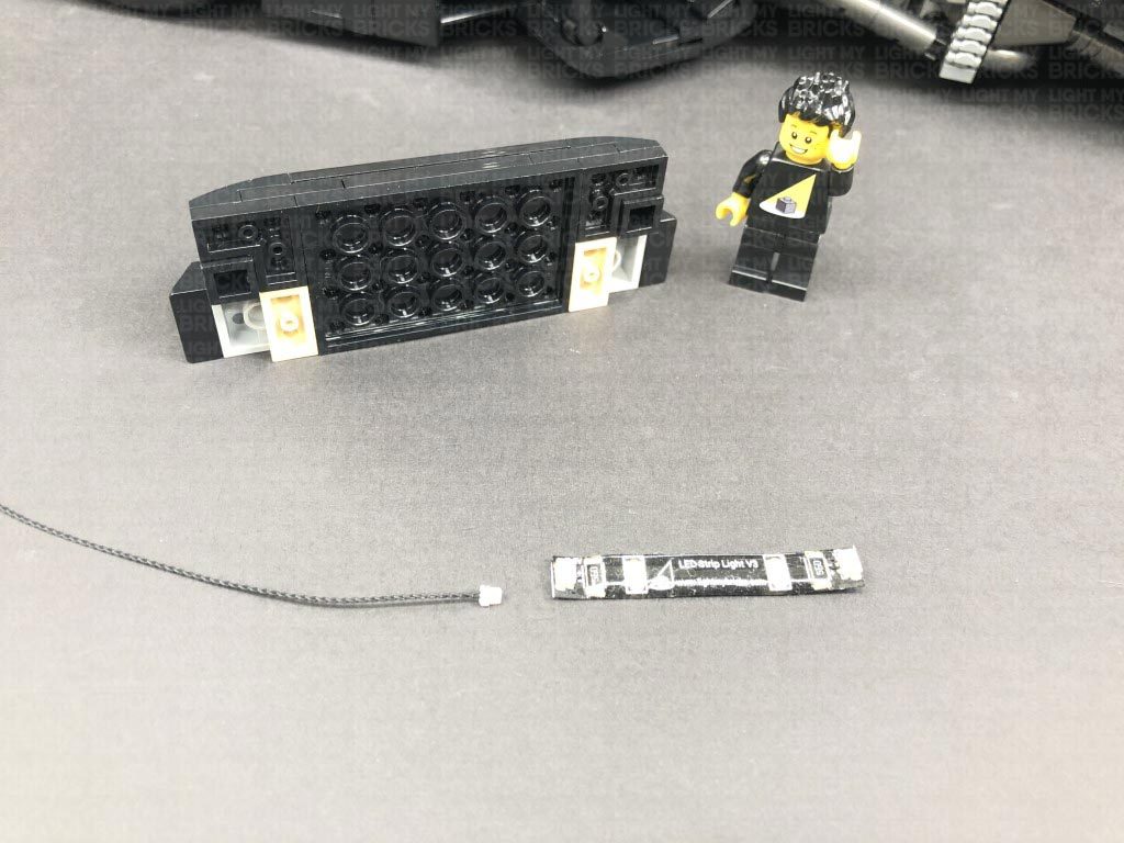
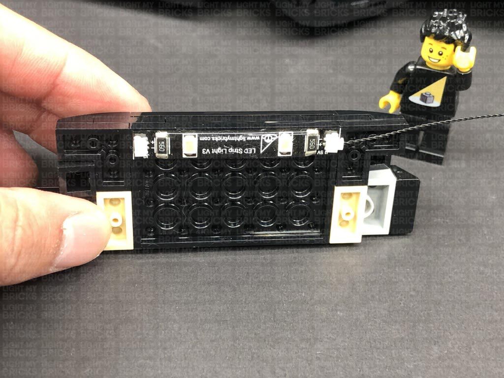
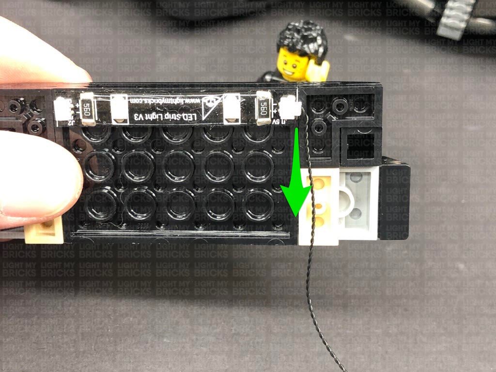
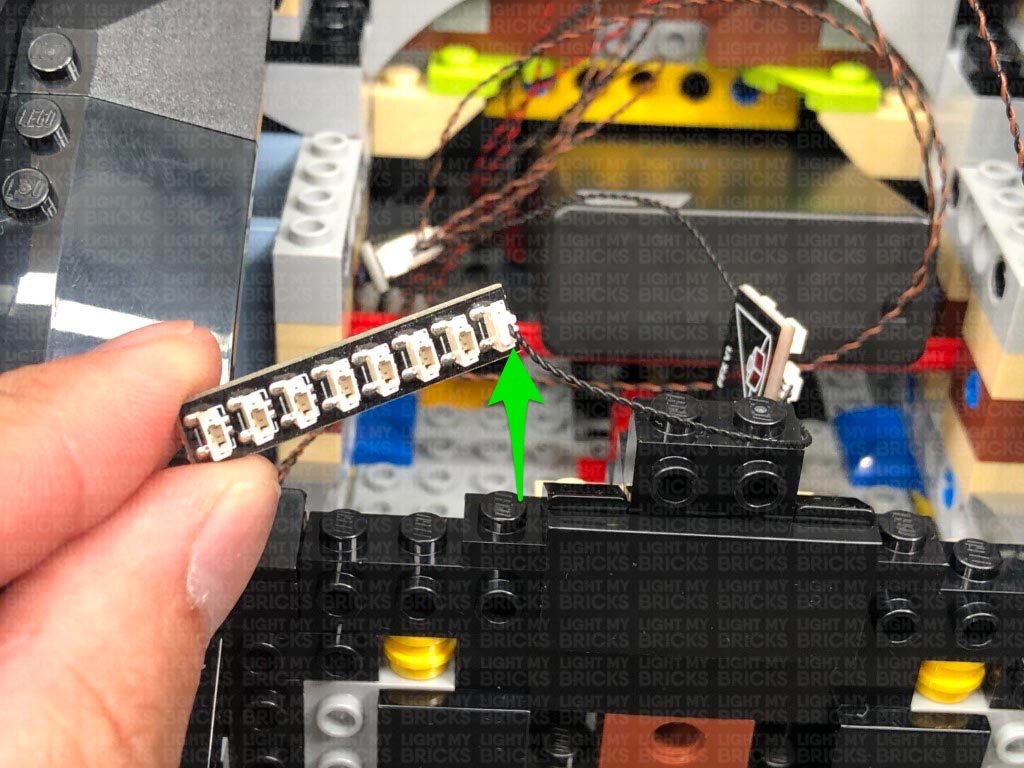
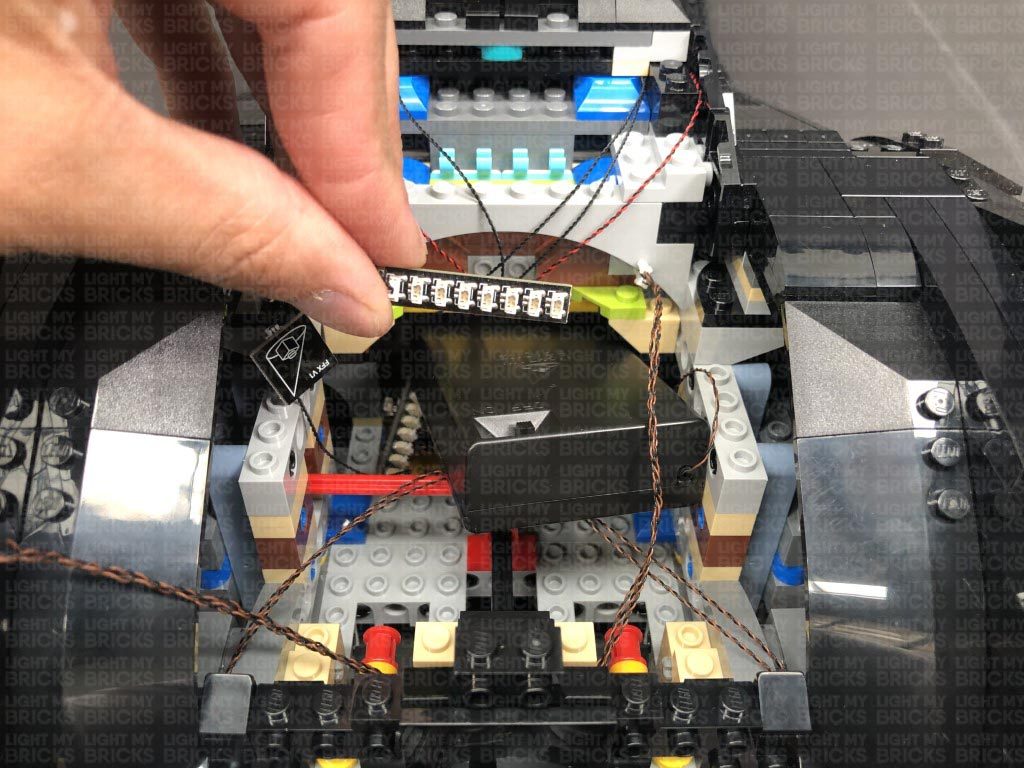
29.) Take the following section we moved just behind the cabin and turn it over so we can access underneath. Take a White Strip Light and connect a 15cm Connecting Cable to it.
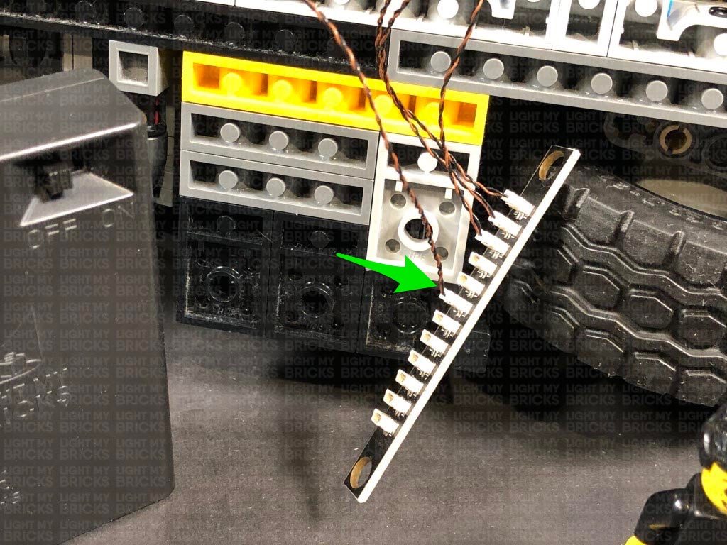
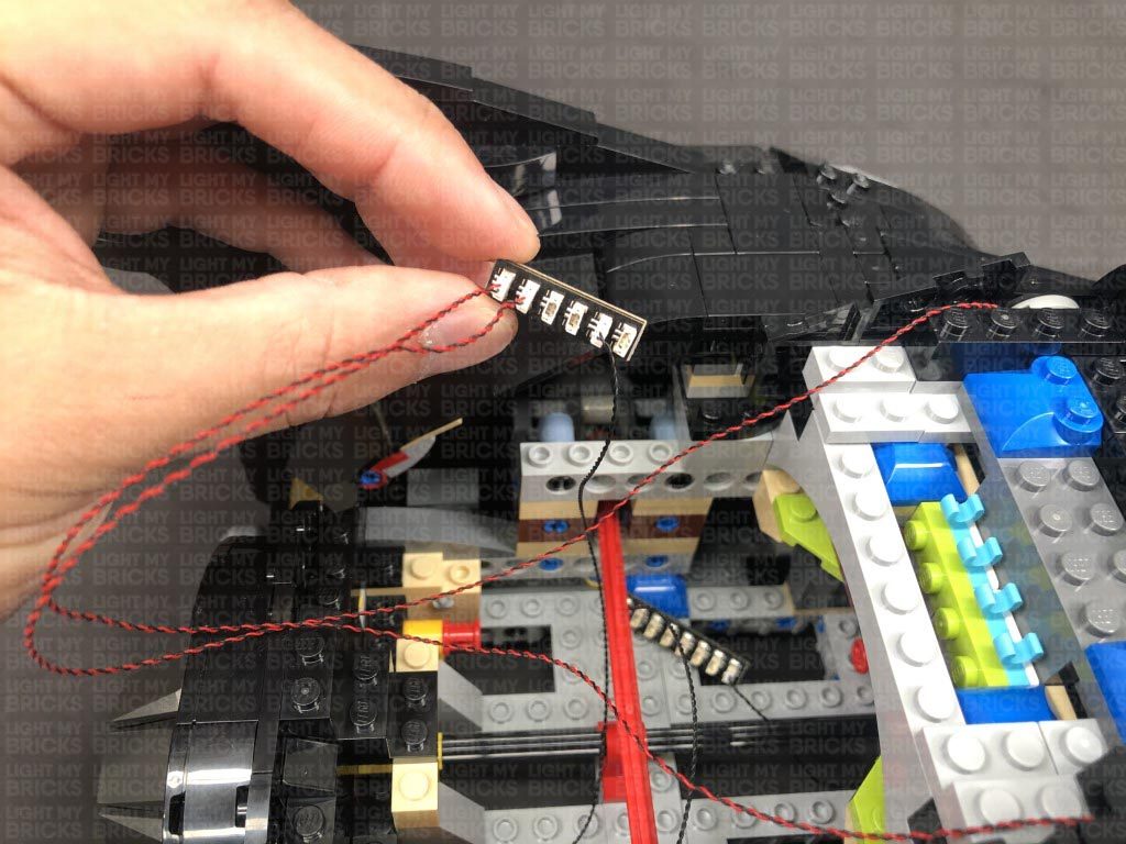
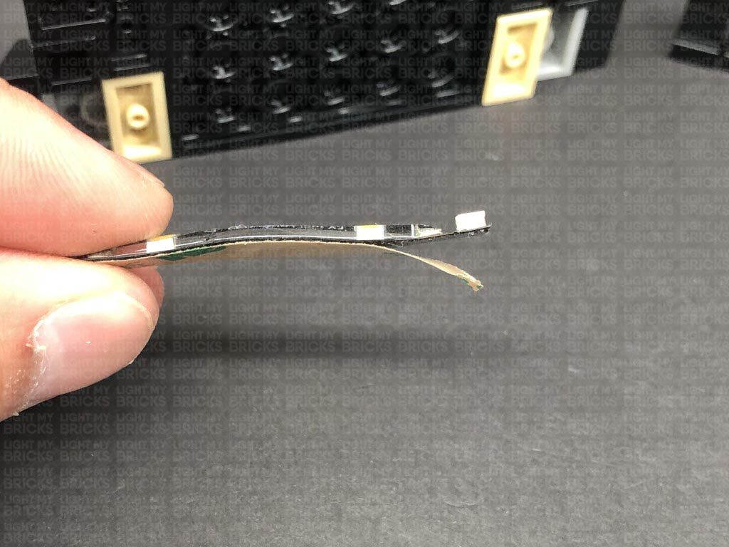
Using it’s adhesive backing, stick the strip light underneath this section in the following position. Ensure the cable is facing the right, then bend the cable down so that it is facing the back of this section, as shown below.
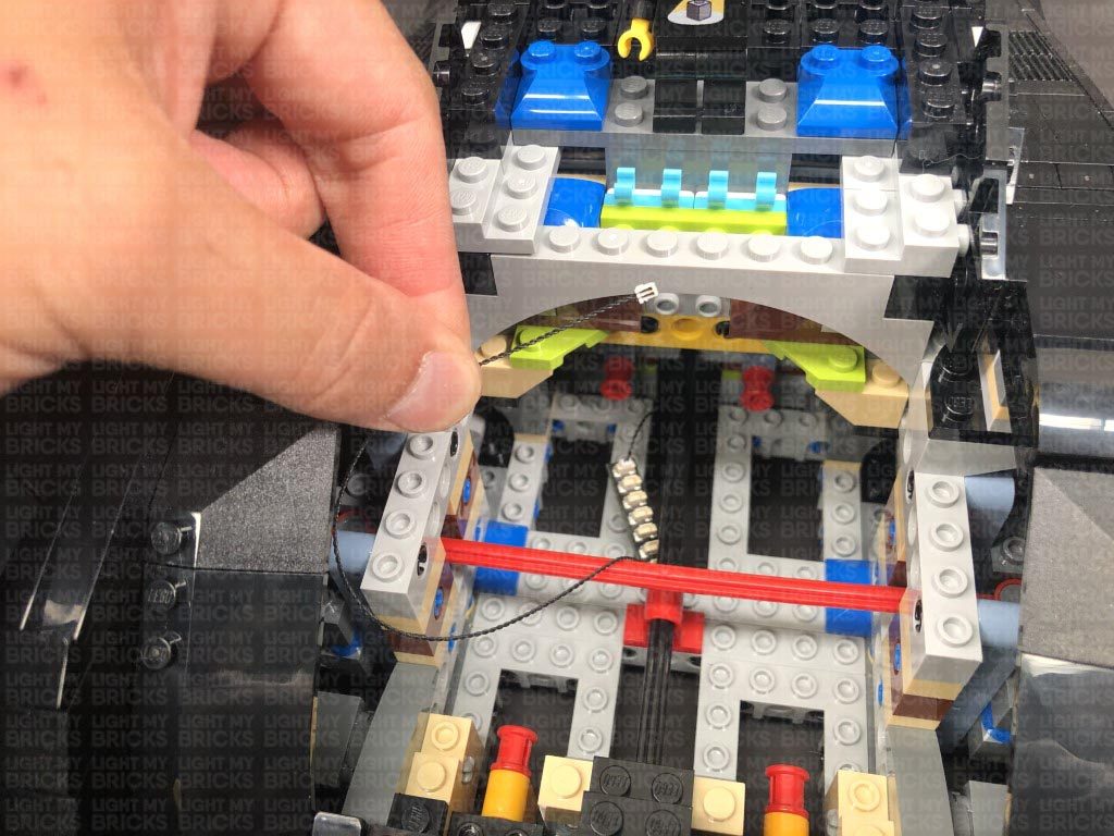
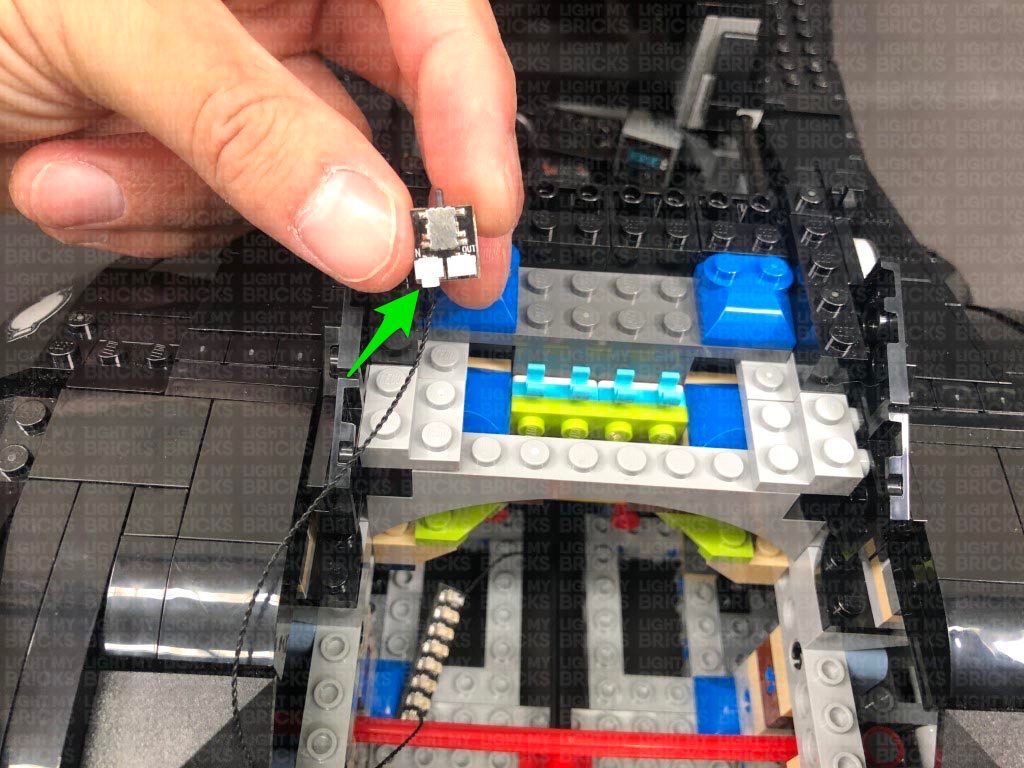
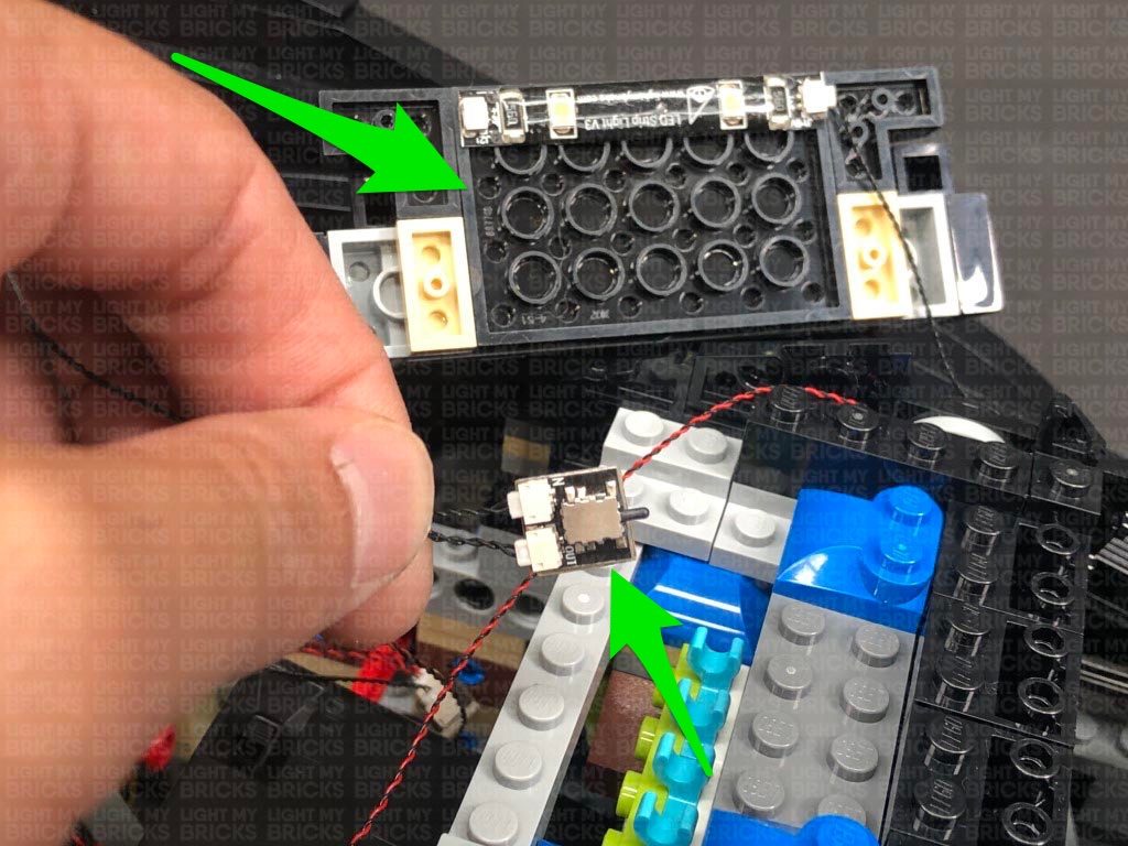
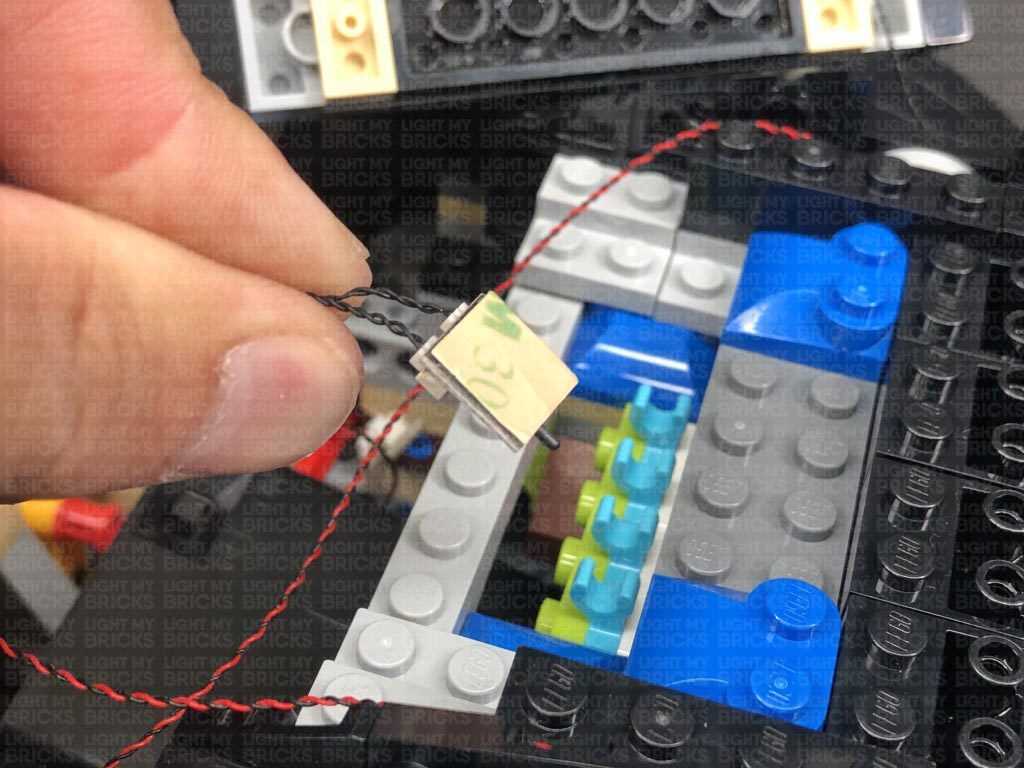
30.) Bring this section above the batmobile, then locate the NC Push Board and remove the protective paper on the back of it to expose the adhesive. With the push button facing the front, stick the NC Push Board underneath the top cabin section in the following position. Ensure that the NC push board is mounted exactly as shown below and aligned exactly so that we do not have any issues reconnecting this section later.
Repeat this step to reconnect the other section to the right side.
28.) Connect both Bit Light cables we just installed to the 6-Port Expansion Board from step 26, then take the AA Battery Pack and place it inside the back of the Batmobile ensuring the switch is facing up and closest to the back. Connect the Battery Pack cable to the 8-Port Expansion Board (Do NOT connect the battery pack to the 6-port Expansion Board.)
Turn the AA Battery Pack ON to test all the lights are working OK. Test the NC push board is also working OK. Push the lever to test the the outside cabin lights we just installed turn OFF. The lights should re-activate when the push lever is released.
29.) Take the following section we moved just behind the cabin and turn it over so we can access underneath. Take a White Strip Light and connect a 15cm Connecting Cable to it.
Using it’s adhesive backing, stick the strip light underneath this section in the following position. Ensure the cable is facing the right, then bend the cable down so that it is facing the back of this section, as shown below.
30.) Bring this section above the batmobile, then locate the NC Push Board and remove the protective paper on the back of it to expose the adhesive. With the push button facing the front, stick the NC Push Board underneath the top cabin section in the following position. Ensure that the NC push board is mounted exactly as shown below and aligned exactly so that we do not have any issues reconnecting this section later.
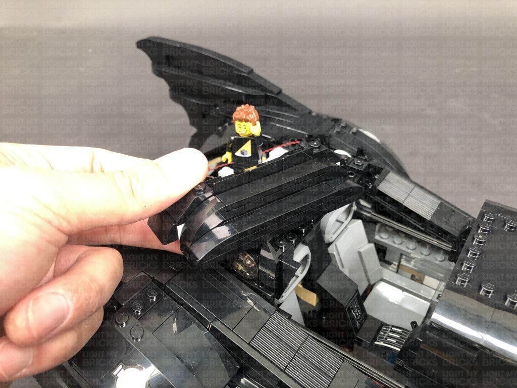
 Turn this section over and reconnect it to the back of the Batmobile while ensuring all cables are laid neatly in between studs underneath. The NC Push Board button should be peaking out slightly so that it pushes in when the cabin door is closed.
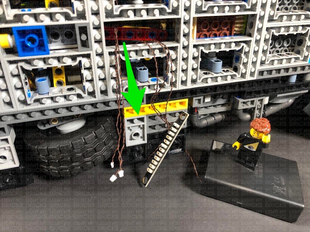
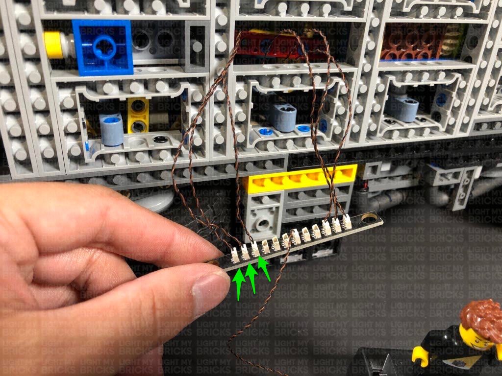
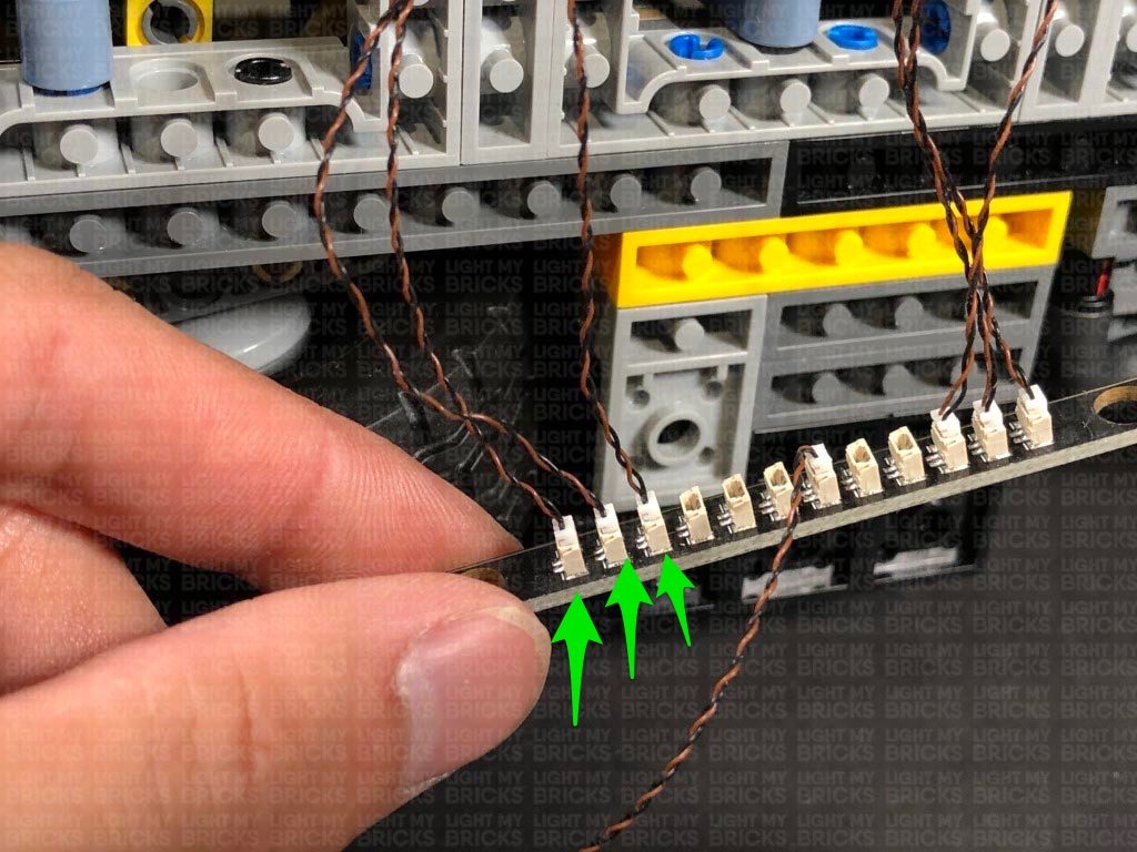
 Locate the other end of the 15cm Connecting Cable from the White Strip Light and connect it to a spare port on the 6-Port Expansion Board at the back of the vehicle. Turn ON the Battery Pack to test all internal and external cabin lights are working OK. The lights should activate when the cabin door is open, and deactivate when the cabin door is closed.
 Note: If you experience any issues with the lights not working and suspect an issue with a component, please try a different port on the expansion board to verify where the fault lies (with the light or expansion board or effects board). To correct any issues with expansion board ports, please view the section addressing expansion board issues on our online troubleshooting guide.
Neaten up cabling from the cool white bit lights by folding and twisting them into a neat bunch. Tuck the bunched up cables underneath the AA Battery Pack.
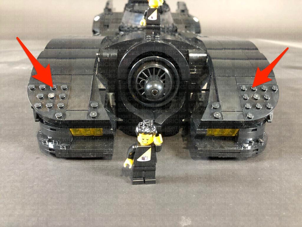
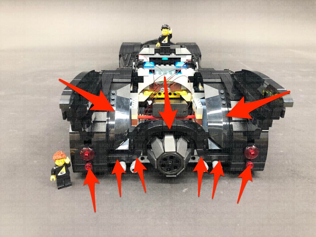
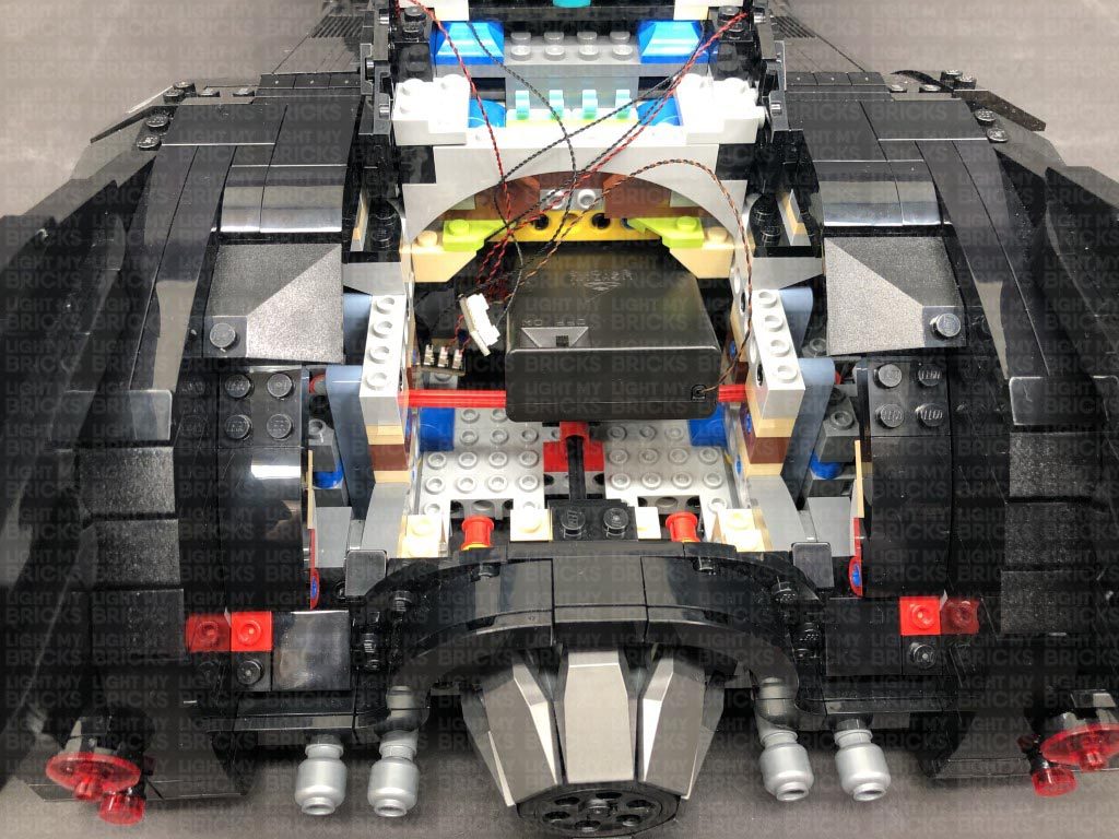
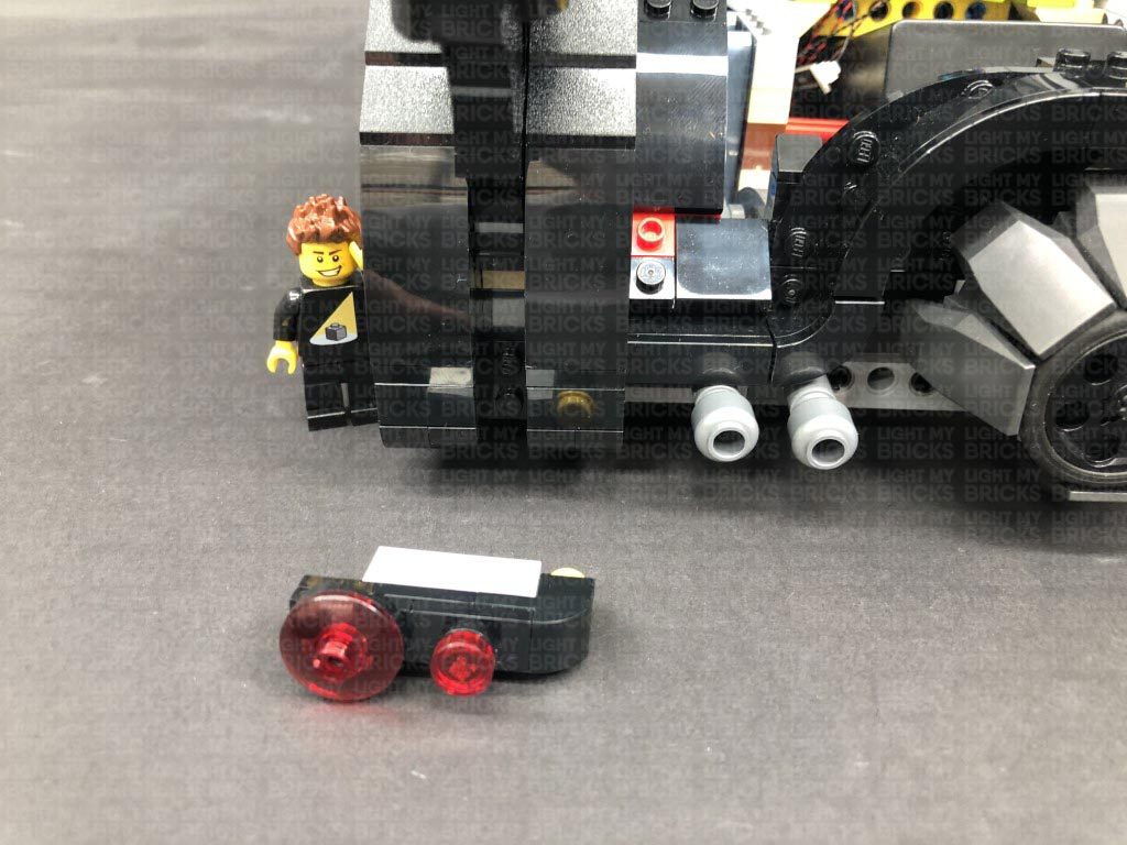
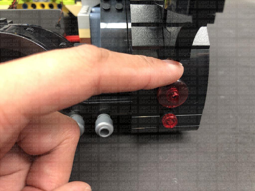
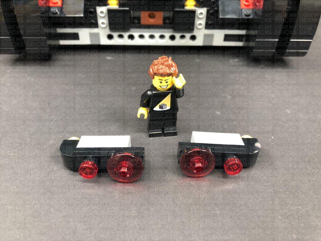
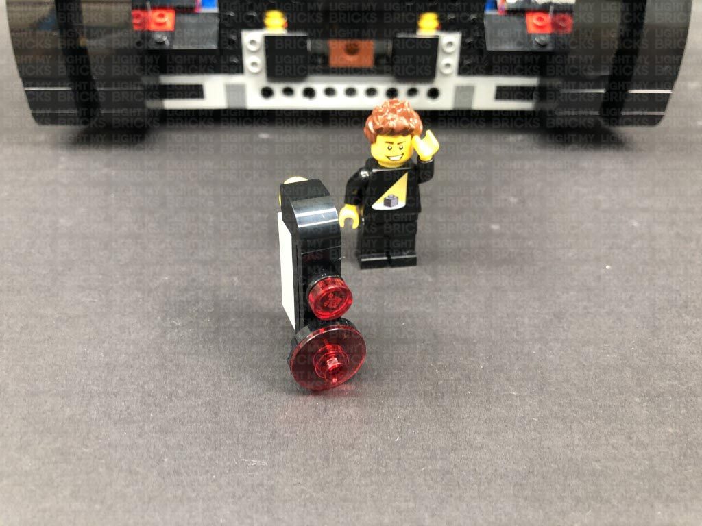
31.) We will now install the tail lights. First disconnect all of the following sections from the back of the vehicle as shown below.
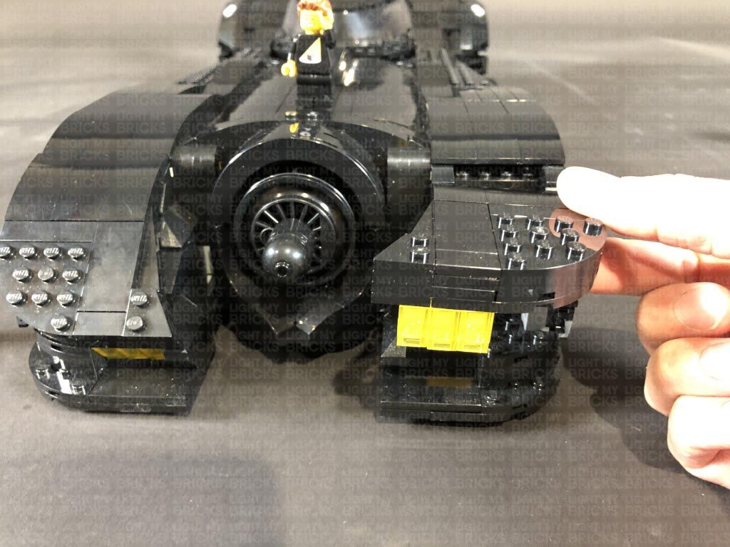
Prop a large object like a book or the light kit box underneath the back of the Batmobile so that you can easily access underneath of the rear side, then disconnect the following section from each side of the tail light.
Note: If you experience any issues with the lights not working and suspect an issue with a component, please try a different port on the expansion board to verify where the fault lies (with the light or expansion board or effects board). To correct any issues with expansion board ports, please view the section addressing expansion board issues on our online troubleshooting guide.
Neaten up cabling from the cool white bit lights by folding and twisting them into a neat bunch. Tuck the bunched up cables underneath the AA Battery Pack.
31.) We will now install the tail lights. First disconnect all of the following sections from the back of the vehicle as shown below.
Prop a large object like a book or the light kit box underneath the back of the Batmobile so that you can easily access underneath of the rear side, then disconnect the following section from each side of the tail light.
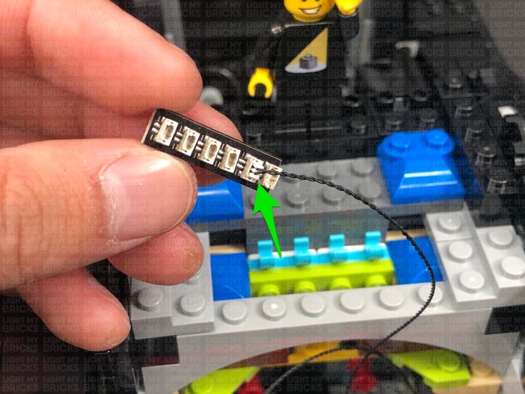
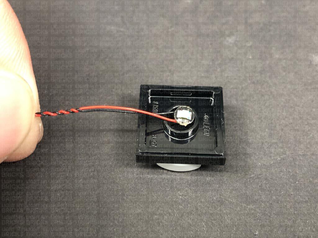
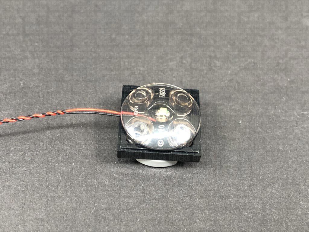
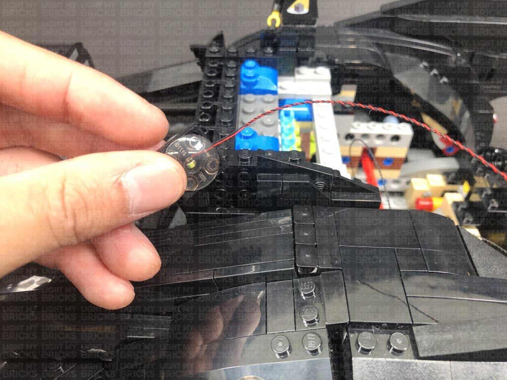
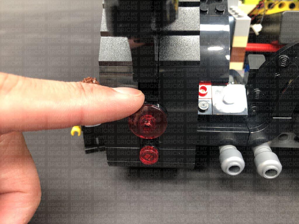
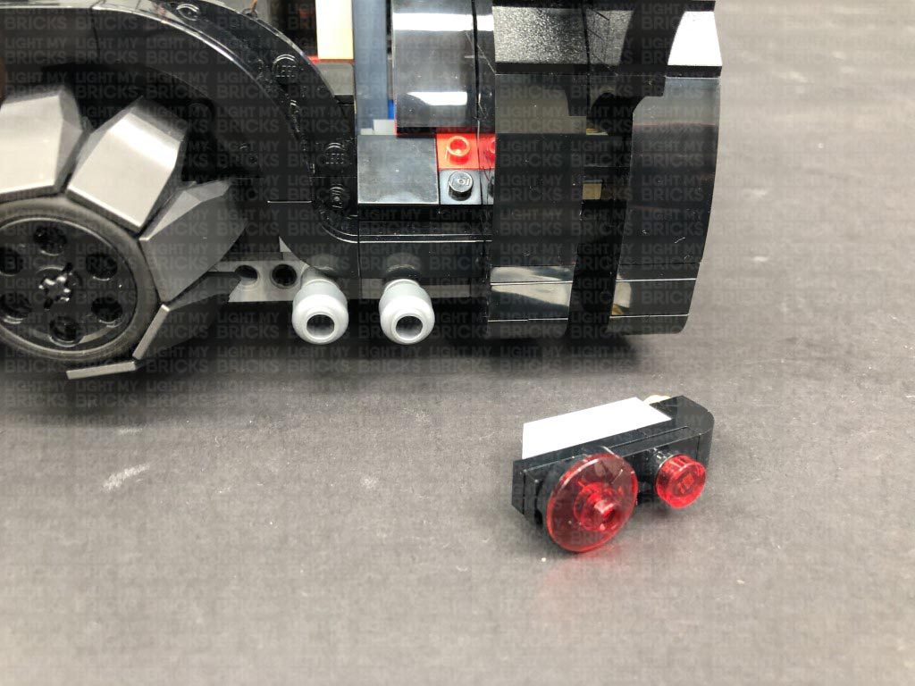
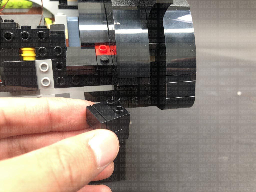
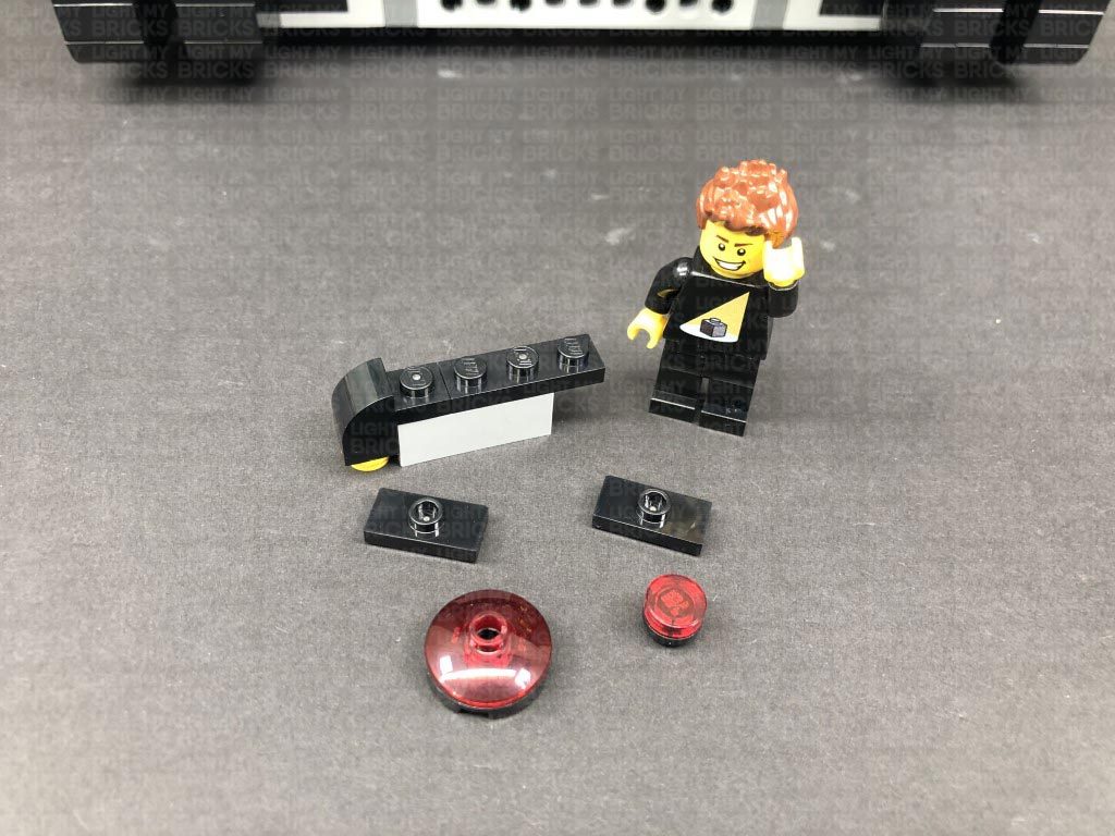
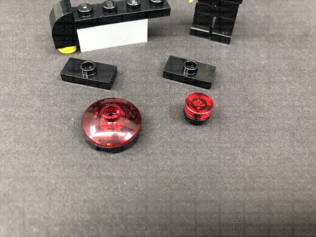
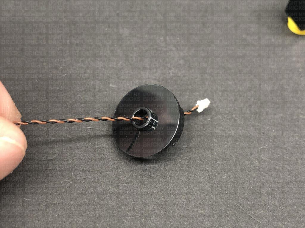
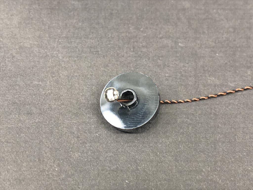
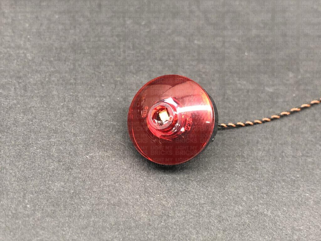
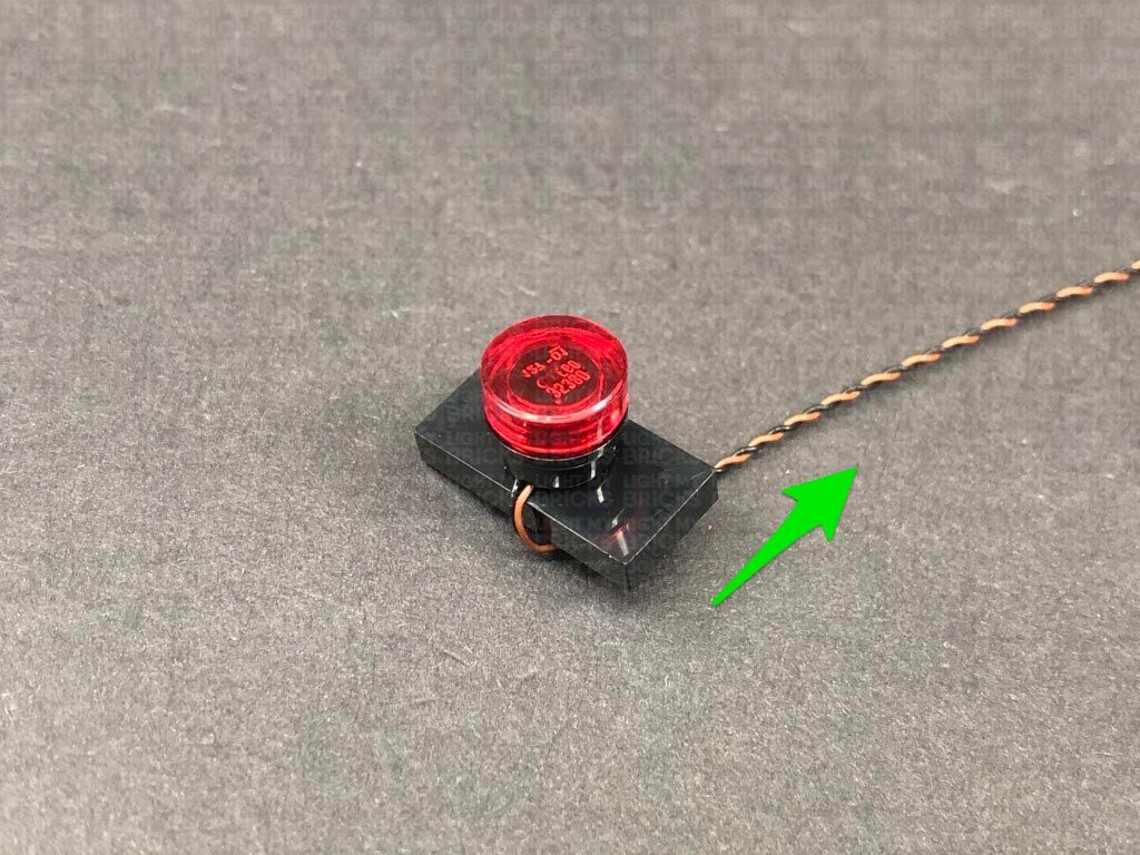
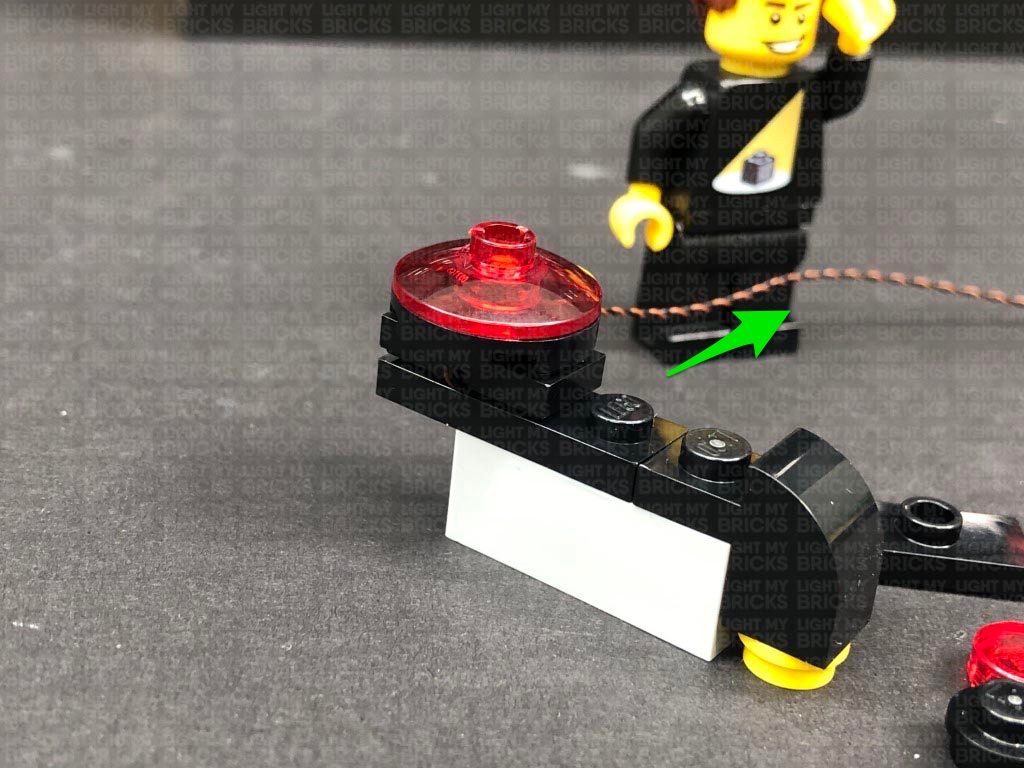
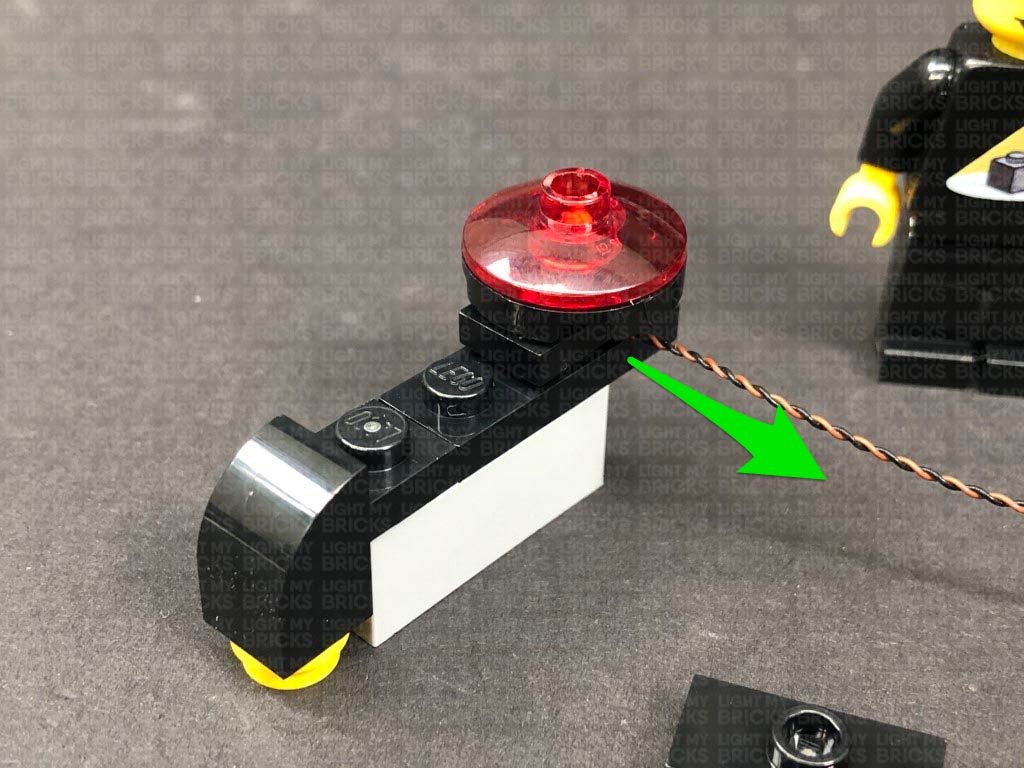
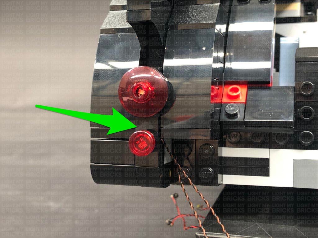
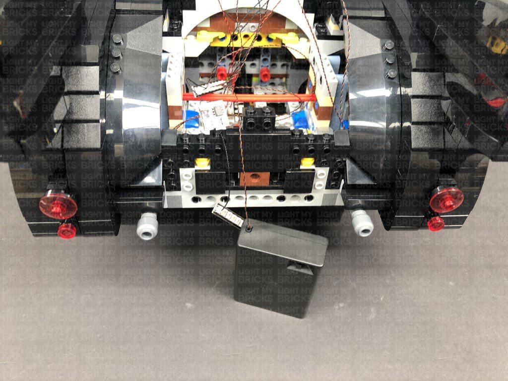
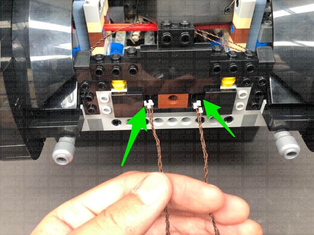
 32.) Take the two tail light sections and disassemble the right tail light as per below. Take a Red 30cm Bit Light and thread the connector end of the cable through the top of the black round plate with centre open stud. Thread the Bit Light all the way through then carefully bend it so that the LED sits flat against the top of the plate. Secure the Bit Light in place by reconnecting the trans red dish over the top.
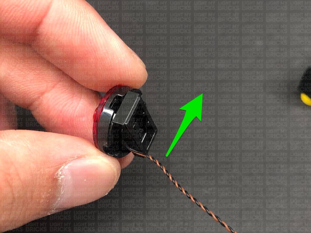
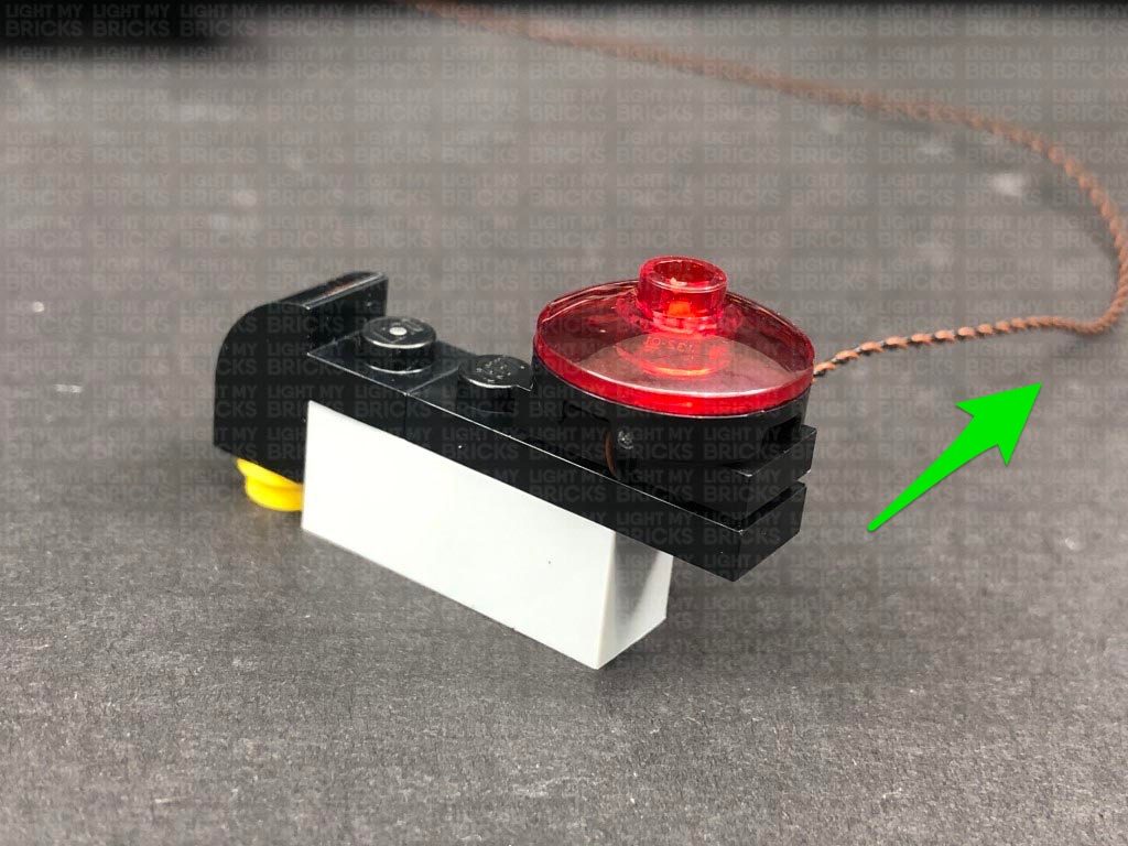
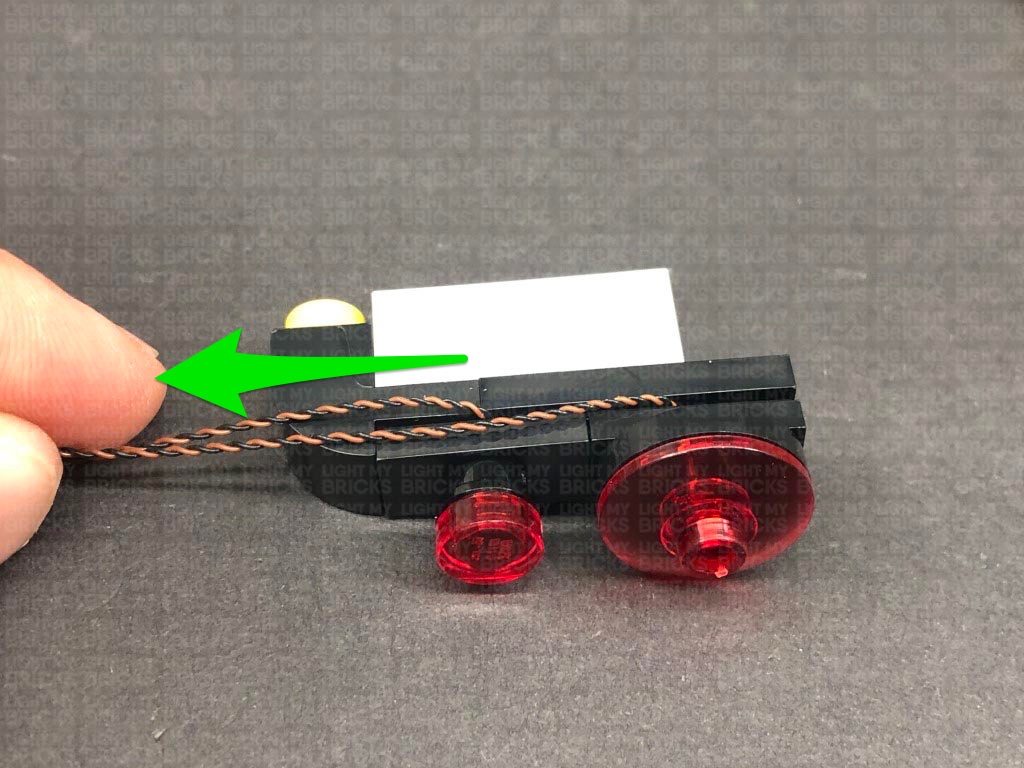
Reconnect the black tile underneath, then fold the cable underneath before reconnecting it to the tail light section. Ensure the cable is facing toward the left side as shown below:
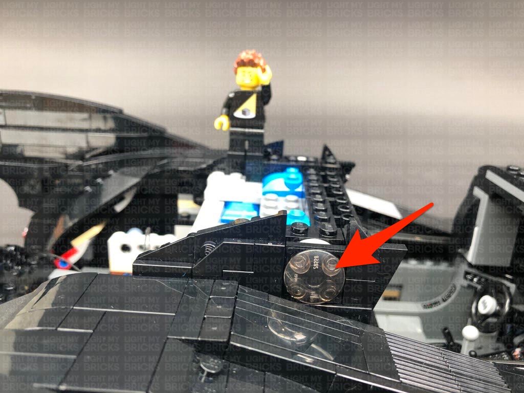
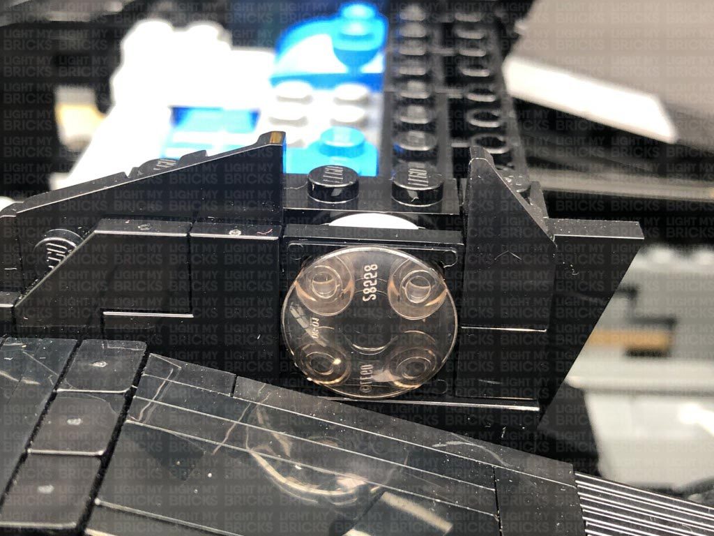
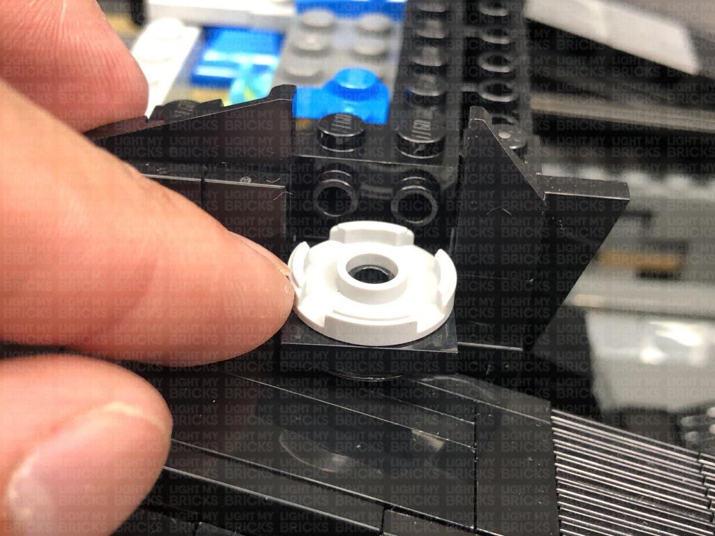
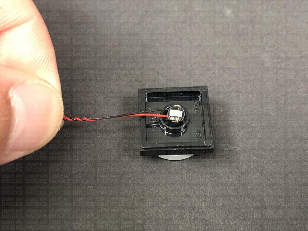
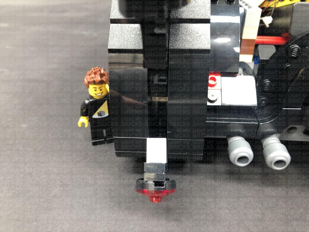
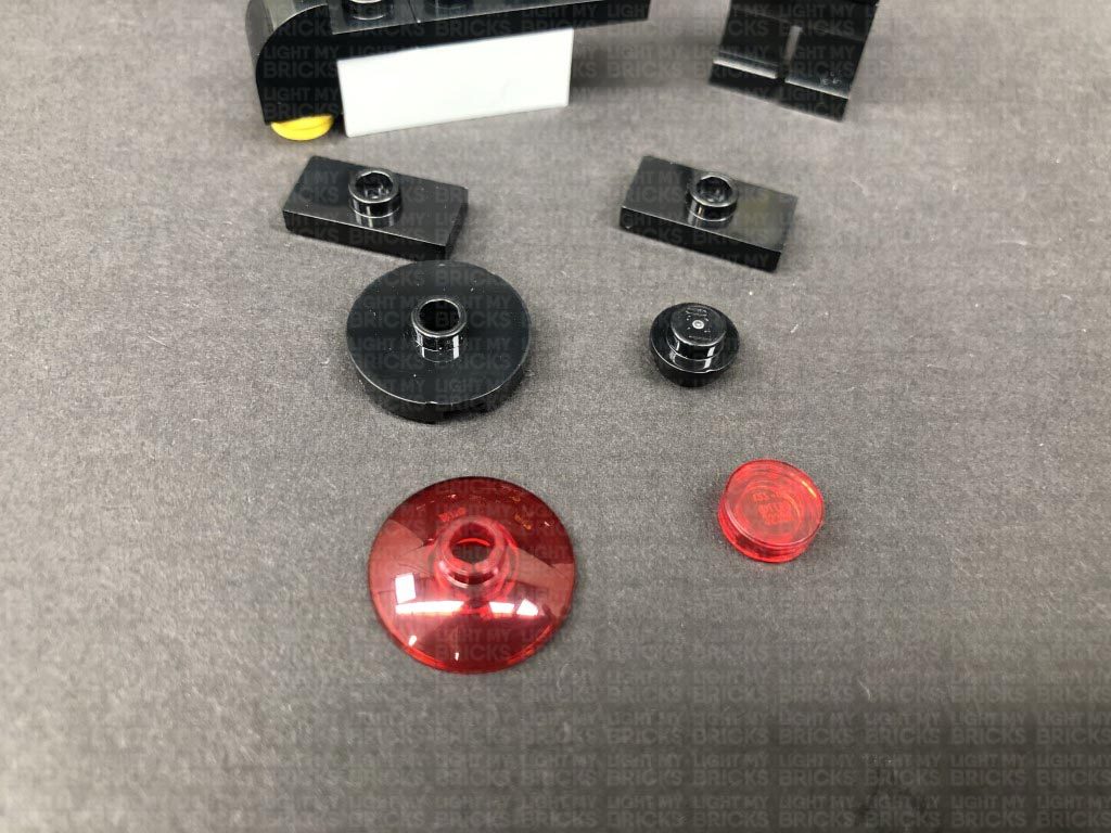
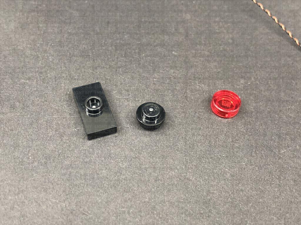
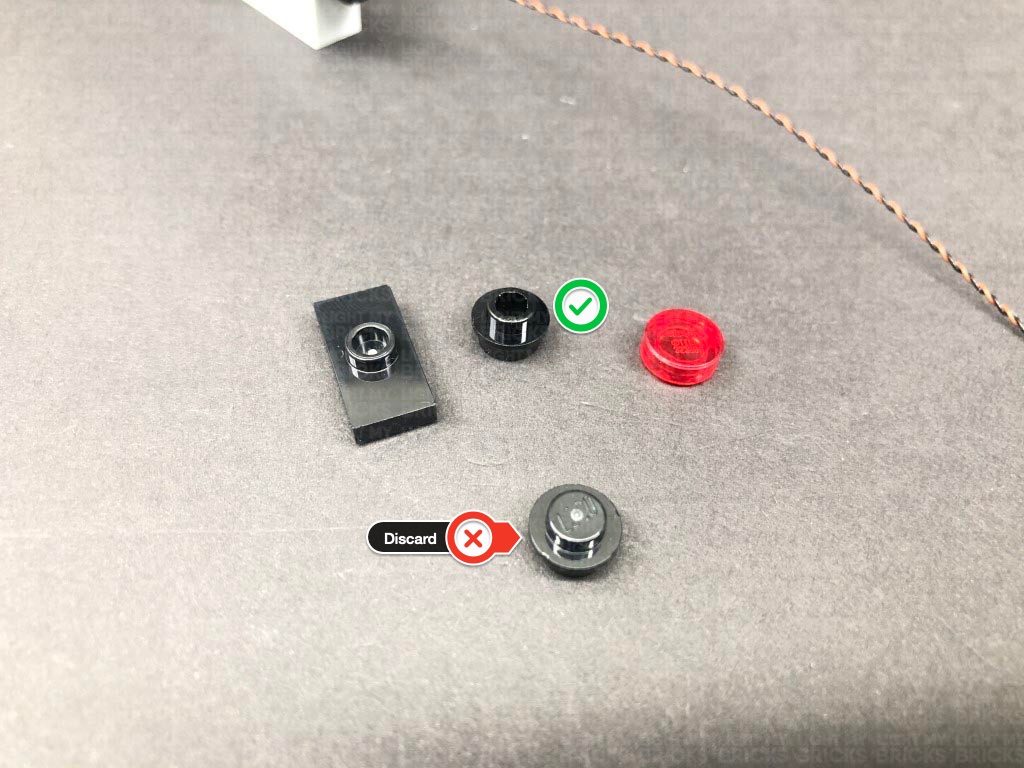
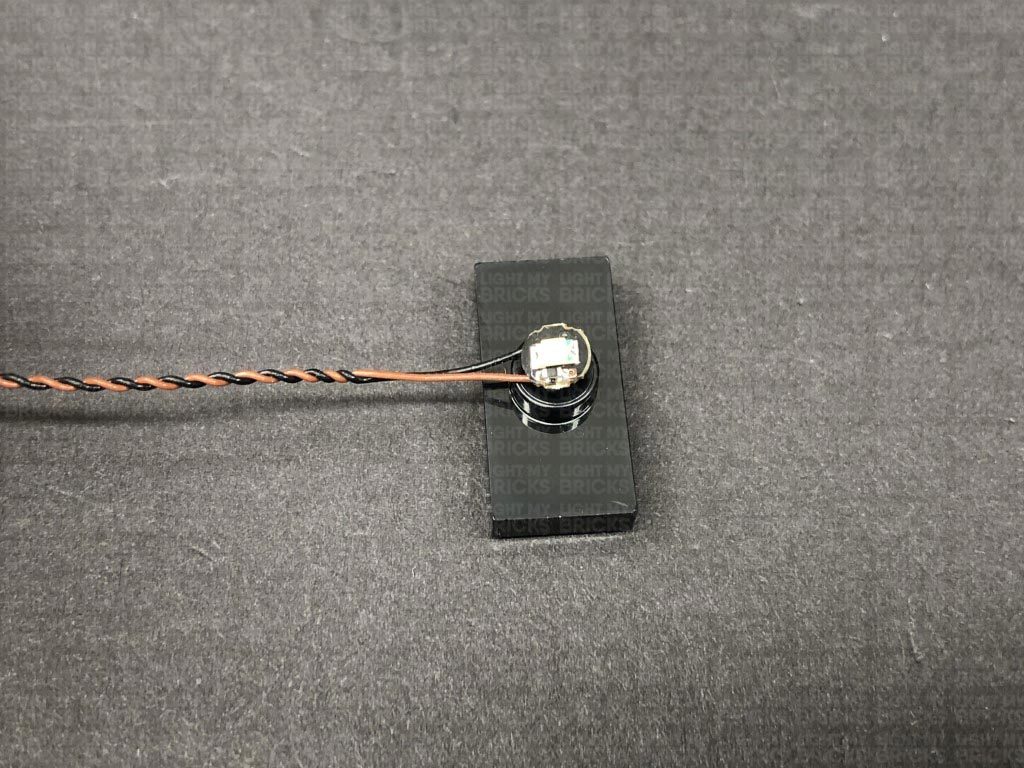
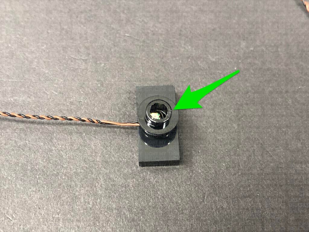
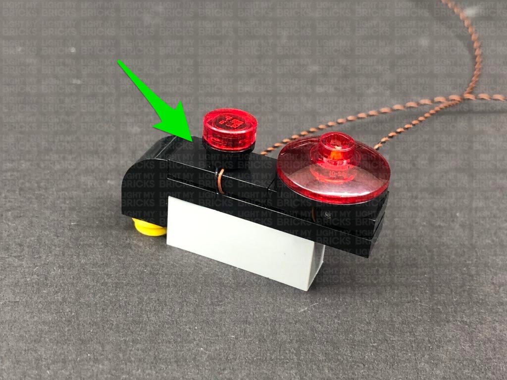
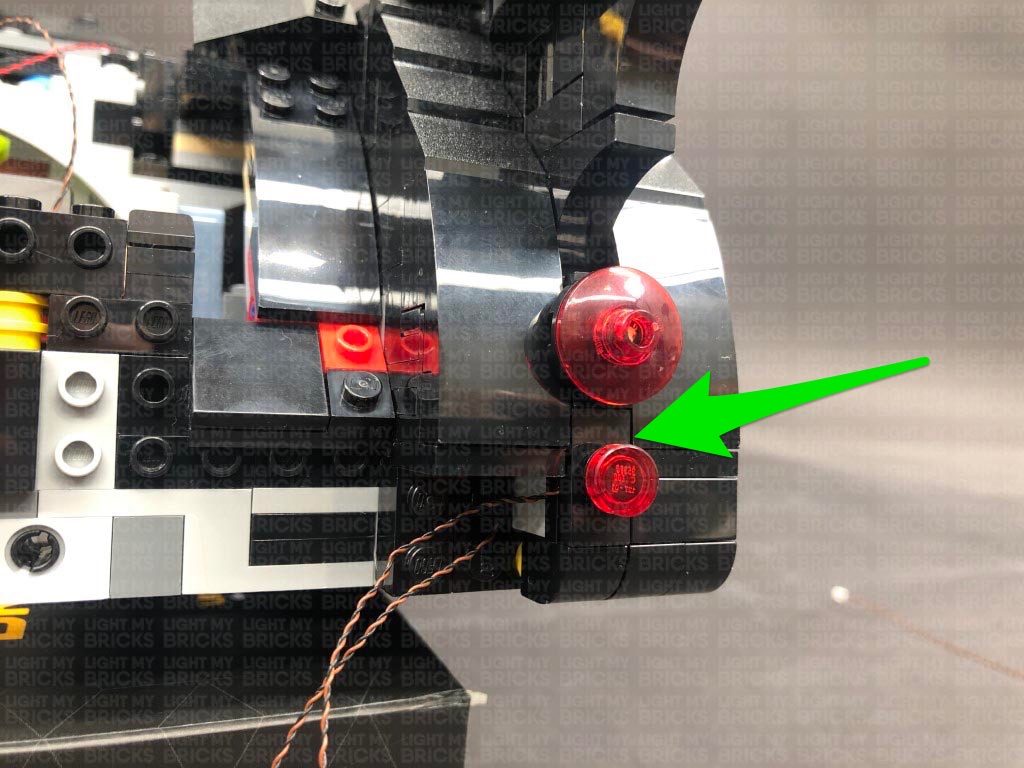
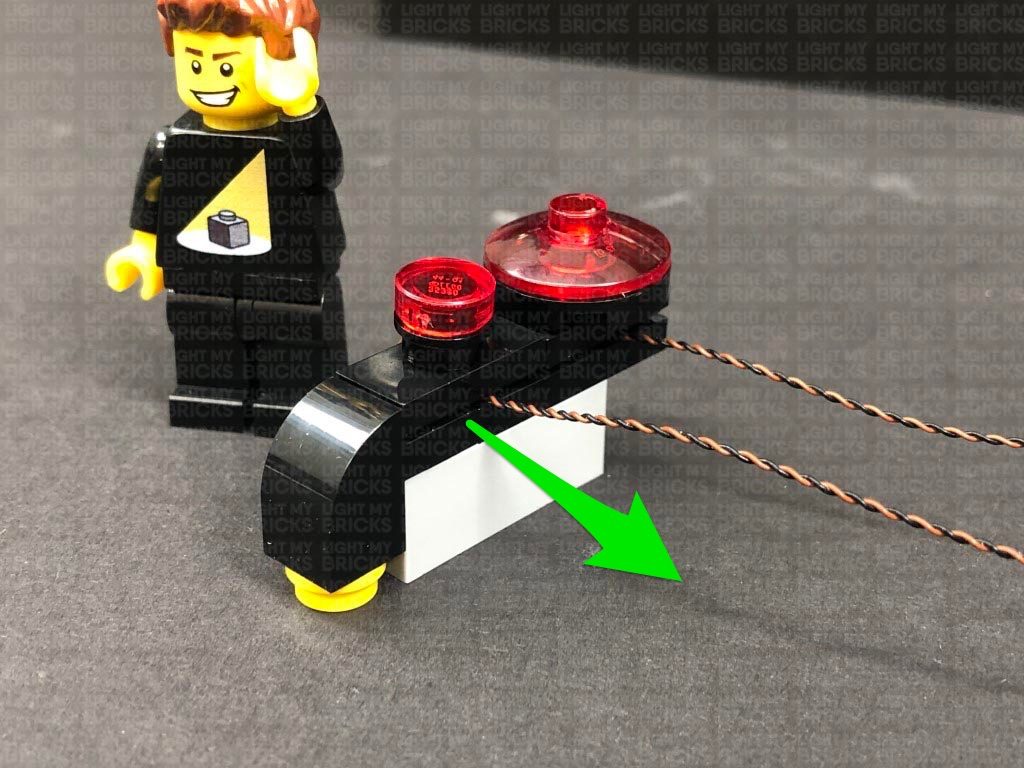
33.) Take the following three pieces and swap out the black round plate 1×1 with a provided Black Round Plate 1×1 with open stud. Take another Red 30cm Bit Light and place it directly over the black tile’s stud. Secure it in place by connecting the provided black round plate with open stud over the top. Reconnect the trans red round tile.
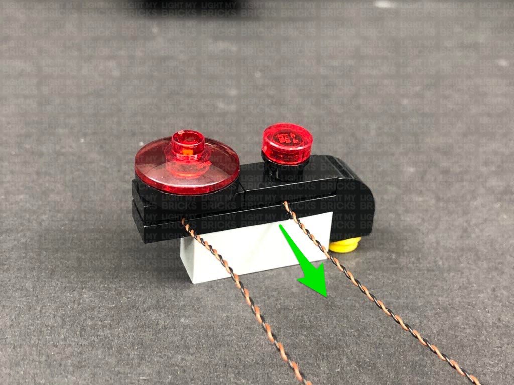
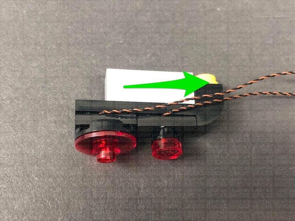
Fold the bit light cable underneath the black tile before reconnecting it to the tail light section. Ensure the cable is facing the left side.
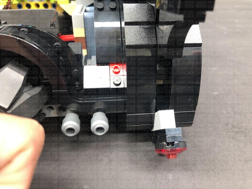
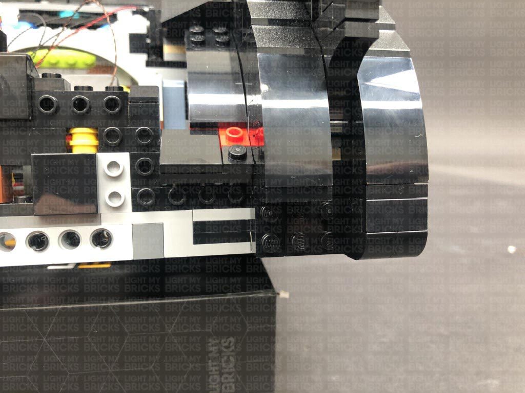
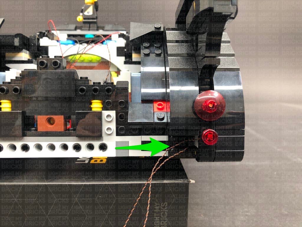
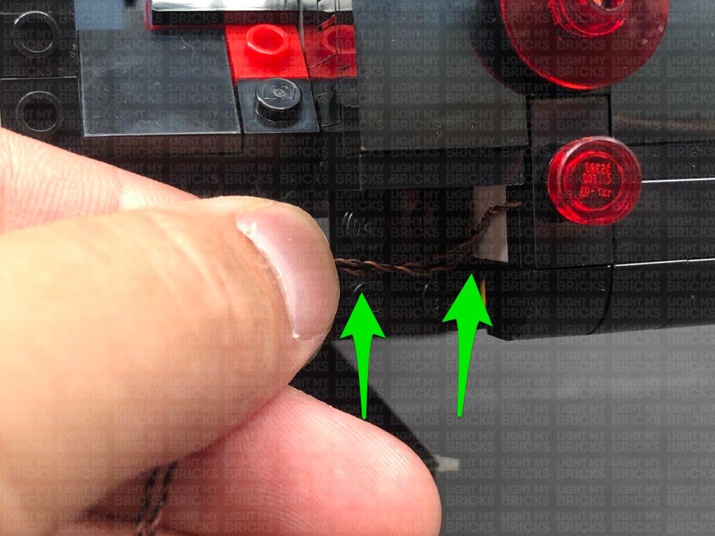
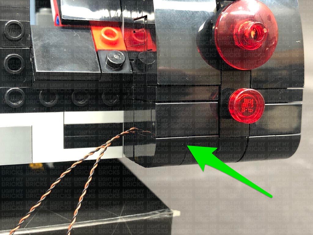
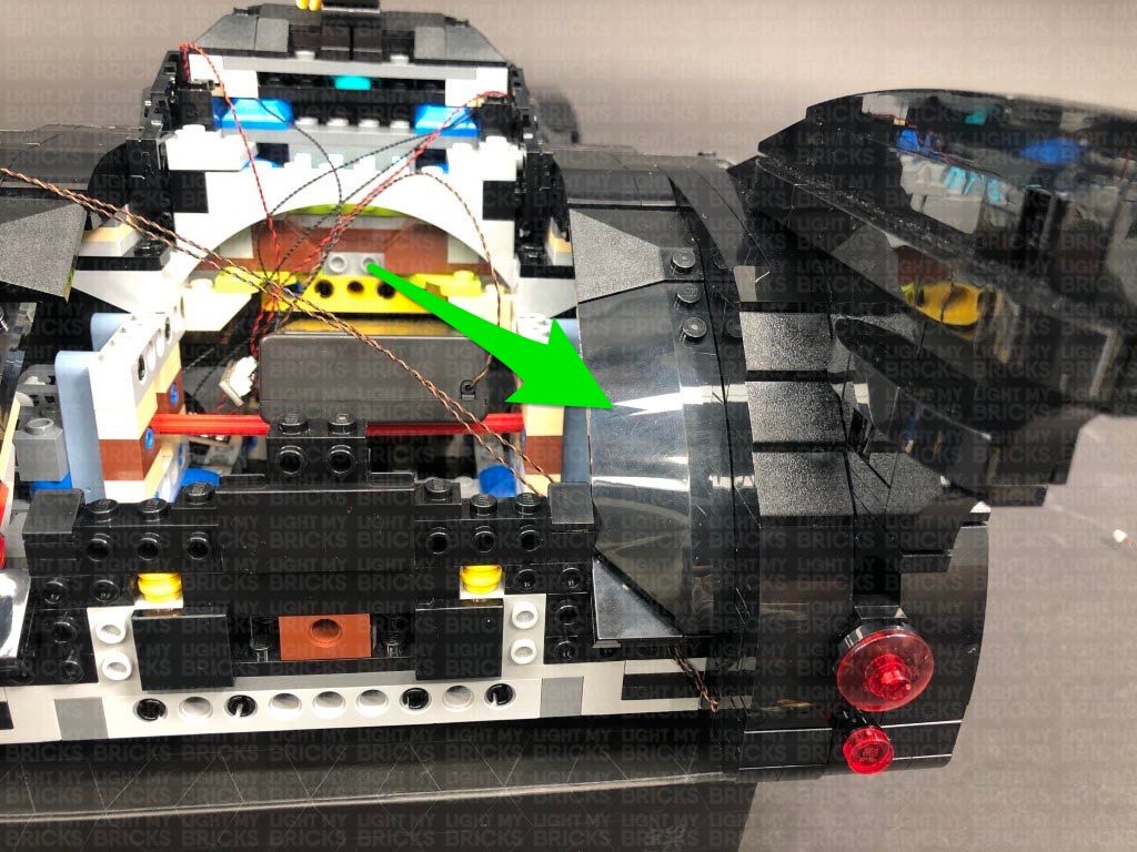
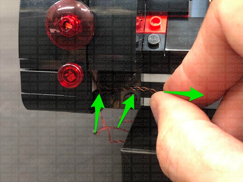
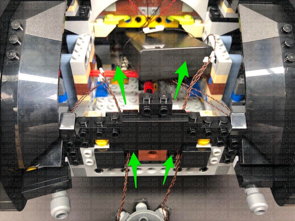
Fold both cables down the left side of the tail light, then reconnect this section to the back of the Batmobile. Ensuring both cables are folded down into the corner and laid in between studs before reconnecting the section we removed earlier over the top.
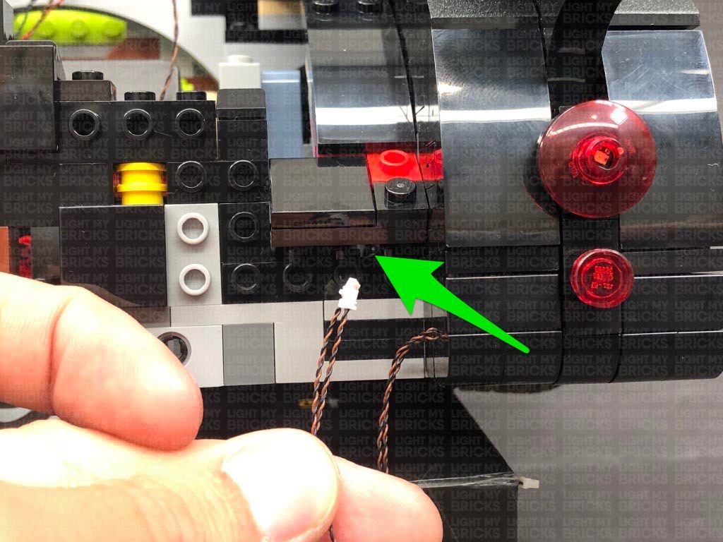
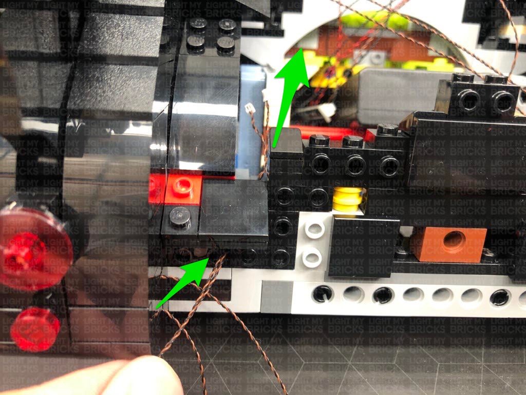
Thread both cables up the following section which leads to the inside of the trunk, then pull them all the way out from the inside. Reconnect the two sections we removed earlier to the right side.
34.) Repeat steps 32 and 33 to install another 2x Red 30cm Bit Lights to the left tail light section, this time, laying the cables toward the right side.
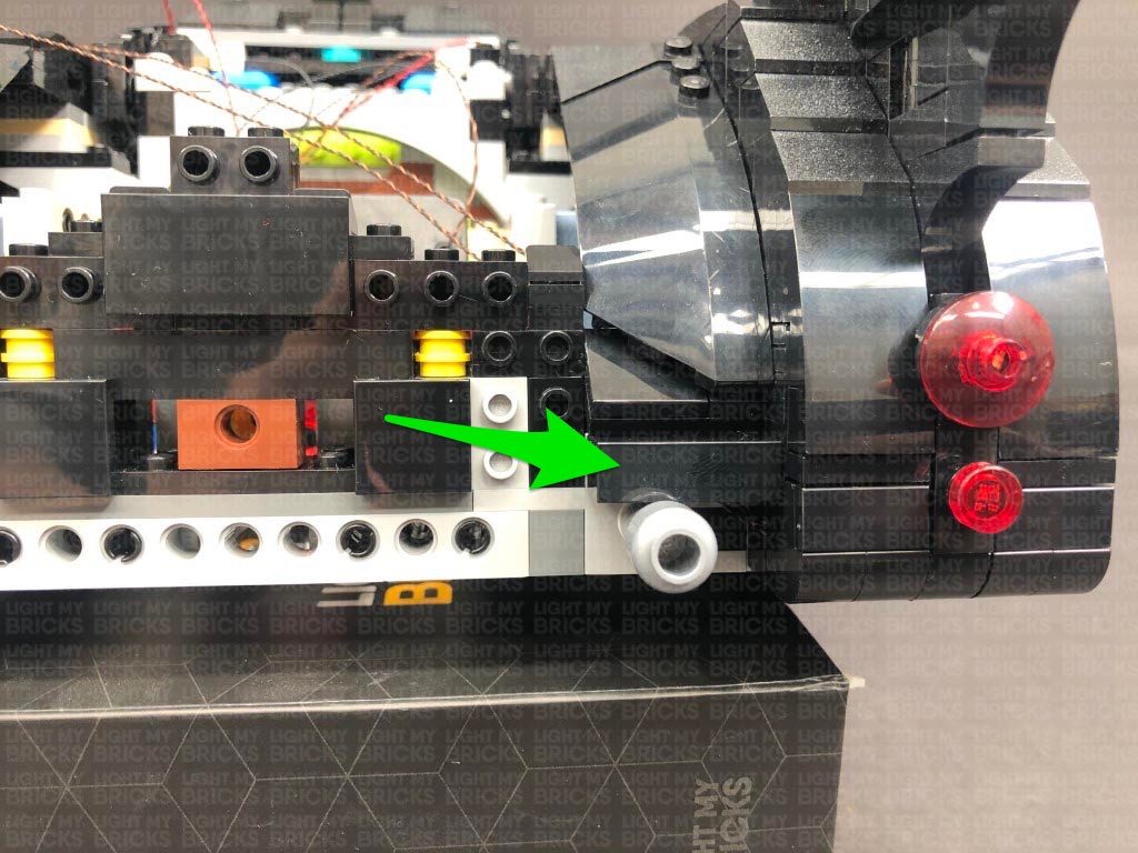
Fold the cables down the right side of the tail light, then reconnect it to the left side of the vehicle. Ensure you carefully lay the cables down in the corner before reconnecting the section we removed earlier over the top.
32.) Take the two tail light sections and disassemble the right tail light as per below. Take a Red 30cm Bit Light and thread the connector end of the cable through the top of the black round plate with centre open stud. Thread the Bit Light all the way through then carefully bend it so that the LED sits flat against the top of the plate. Secure the Bit Light in place by reconnecting the trans red dish over the top.
Reconnect the black tile underneath, then fold the cable underneath before reconnecting it to the tail light section. Ensure the cable is facing toward the left side as shown below:
33.) Take the following three pieces and swap out the black round plate 1×1 with a provided Black Round Plate 1×1 with open stud. Take another Red 30cm Bit Light and place it directly over the black tile’s stud. Secure it in place by connecting the provided black round plate with open stud over the top. Reconnect the trans red round tile.
Fold the bit light cable underneath the black tile before reconnecting it to the tail light section. Ensure the cable is facing the left side.
Fold both cables down the left side of the tail light, then reconnect this section to the back of the Batmobile. Ensuring both cables are folded down into the corner and laid in between studs before reconnecting the section we removed earlier over the top.
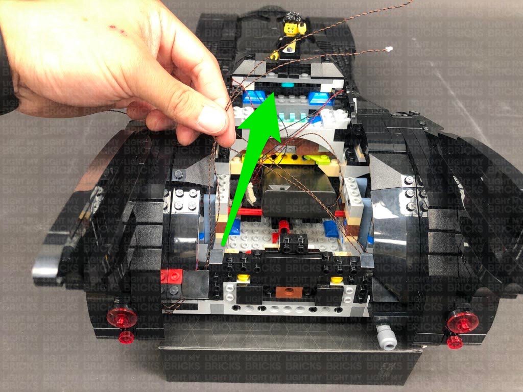
Thread both cables up the following section which leads to the inside of the trunk, then pull them all the way out from the inside. Reconnect the two sections we removed earlier to the right side.
34.) Repeat steps 32 and 33 to install another 2x Red 30cm Bit Lights to the left tail light section, this time, laying the cables toward the right side.
Fold the cables down the right side of the tail light, then reconnect it to the left side of the vehicle. Ensure you carefully lay the cables down in the corner before reconnecting the section we removed earlier over the top.
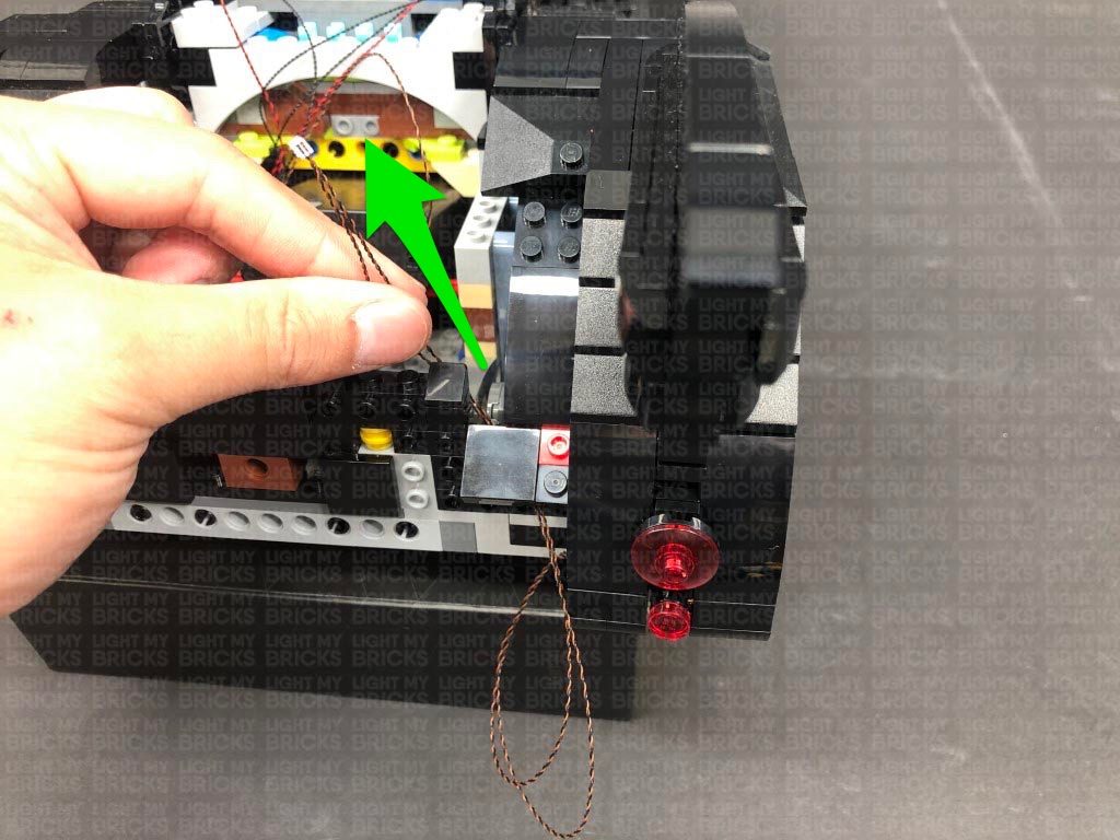
 Thread the cables through to the inside of the trunk, then reconnect the following two sections to the left side.
Connect all four Red Bit Light cables to the 8-Port Expansion Board in the rear of the vehicle, then turn ON the Batter Pack to test the tail lights are all working OK.
Note: If you experience any issues with the lights not working and suspect an issue with a component, please try a different port on the expansion board to verify where the fault lies (with the light or expansion board or effects board). To correct any issues with expansion board ports, please view the section addressing expansion board issues on our online troubleshooting guide.
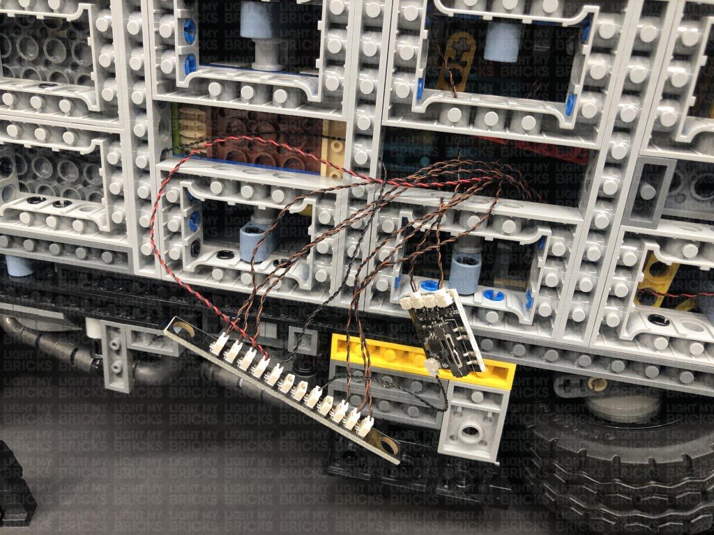
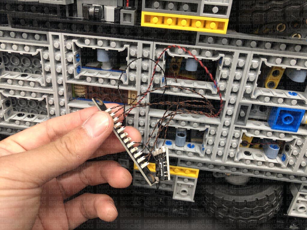
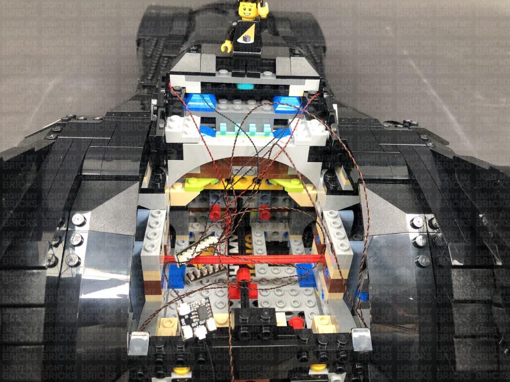
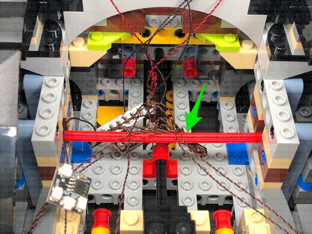
35.) Take a 5cm Connecting Cable and connect it a spare port on the 8-Port Expansion Board. Connect the other end of the cable to the IN port on the Flicker Effects Board (FFX).
Take a new 5cm Connecting Cable and connect it to one of the OUT ports on the Flicker Effects Board, then connect the other end of the cable to the remaining 8-Port Expansion Board in this kit.
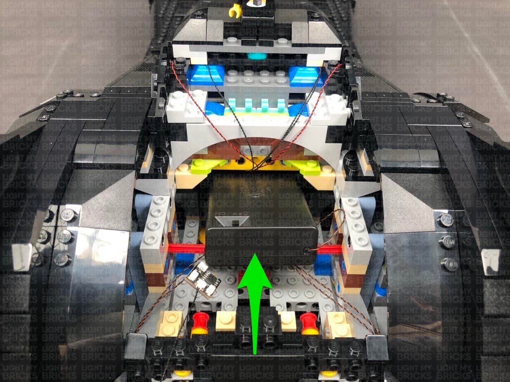
Slide the AA Battery Pack out from the rear of the vehicle, then neaten up cabling by folding and twisting the tail light cables into a neat bunch. Tuck the bunched up cables underneath the red technic bar, then slide the AA Battery Pack back in ensuring the new 8-port expansion board from this step is still accessible.
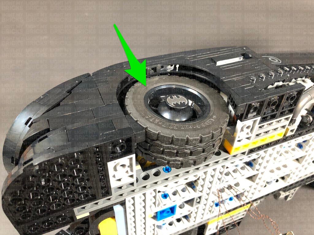
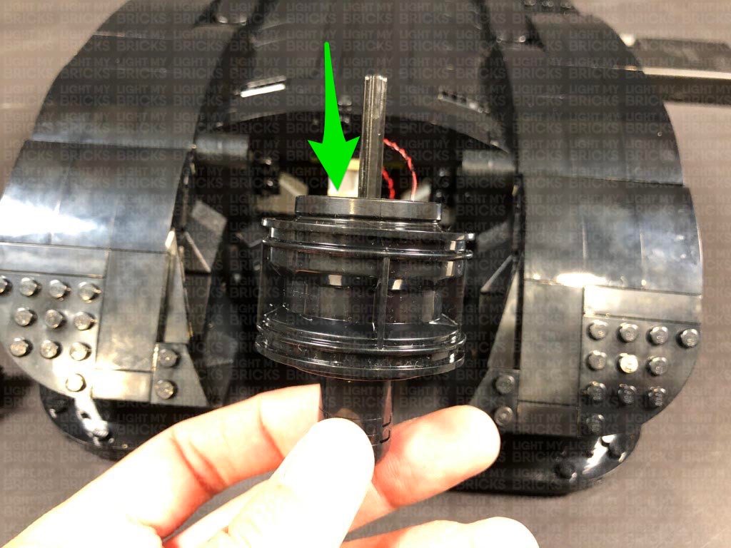
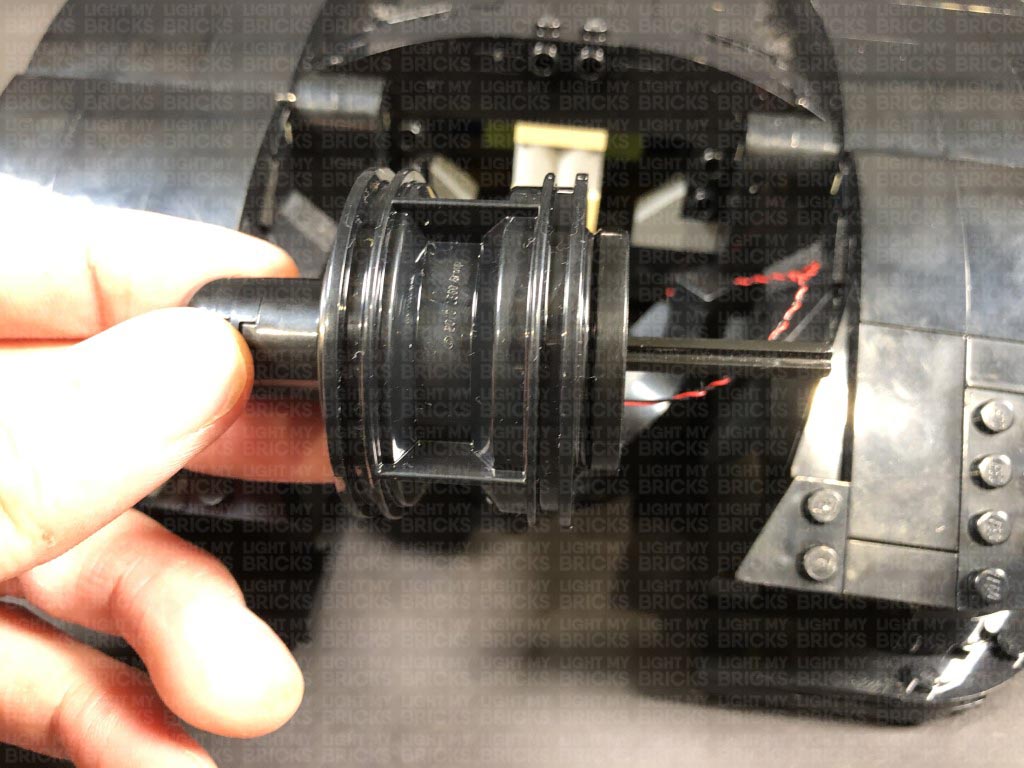
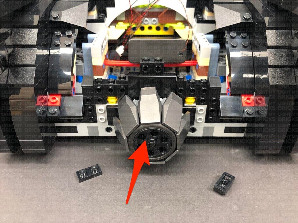
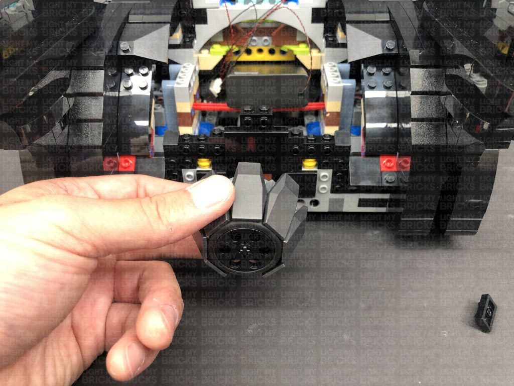
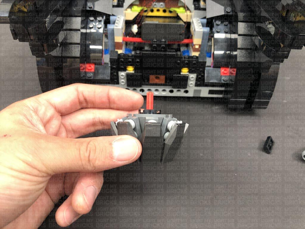
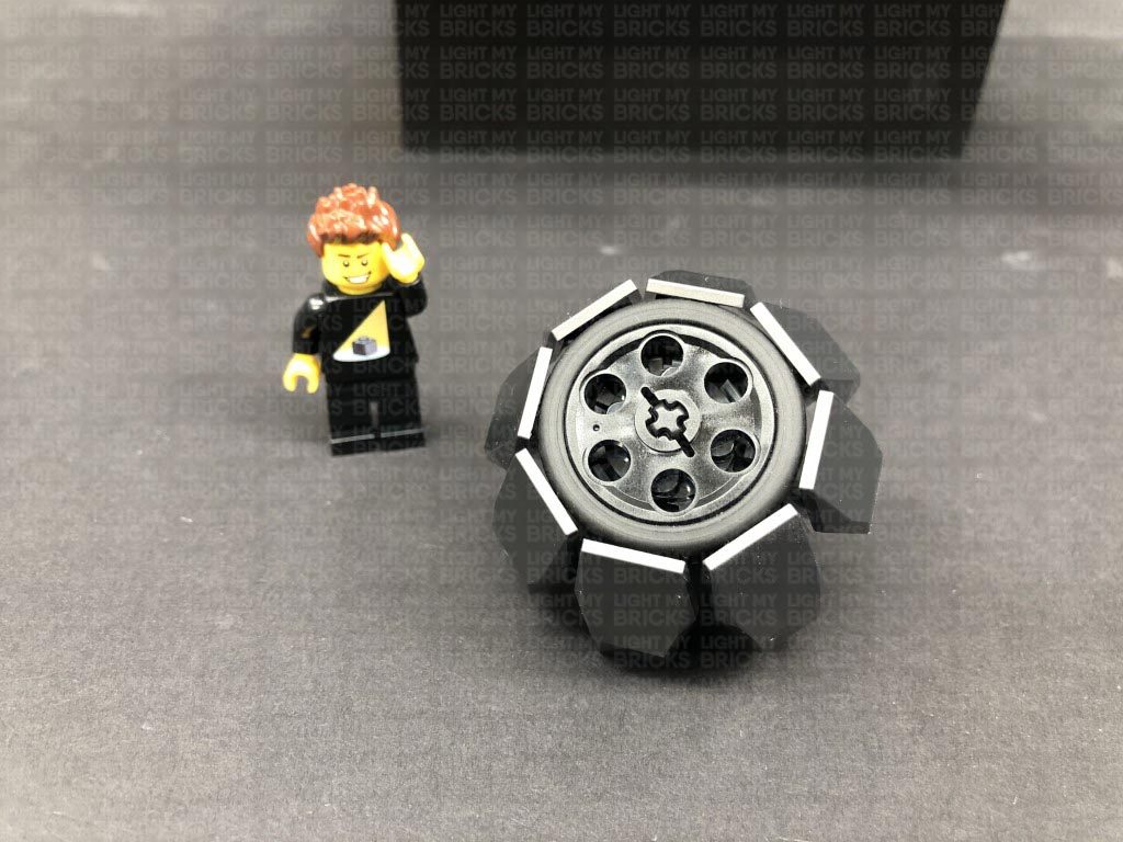
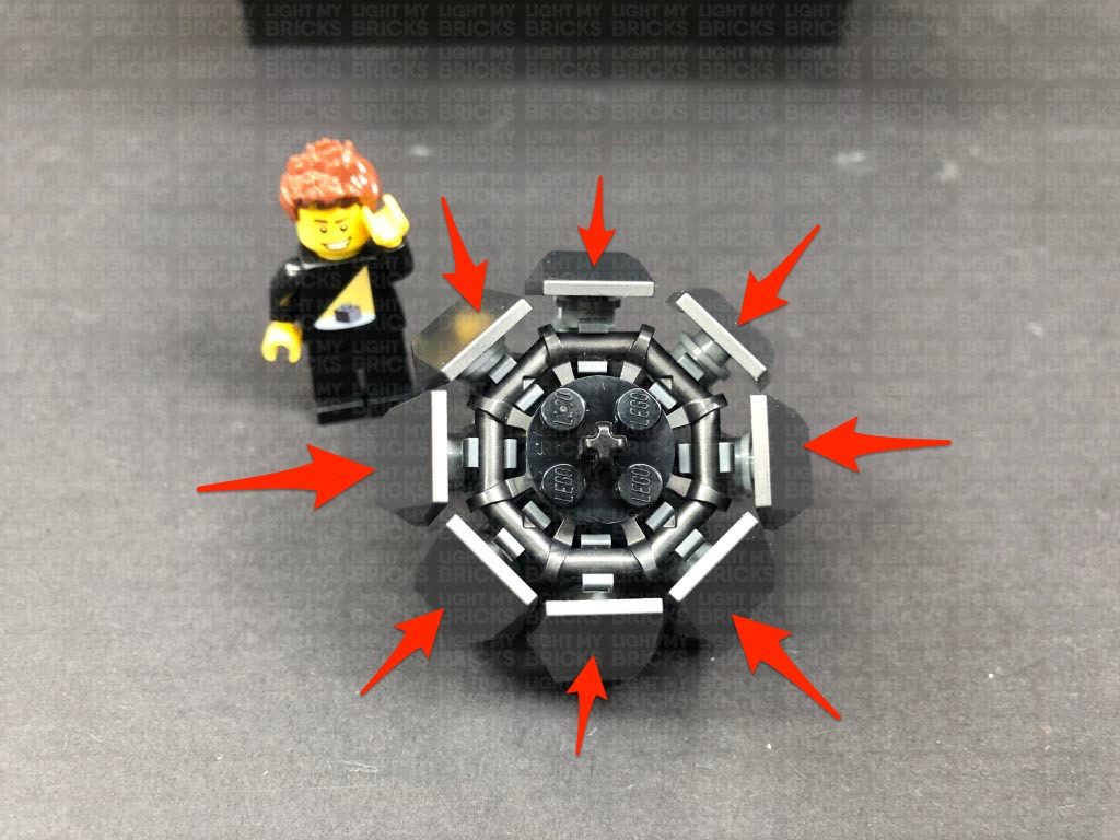
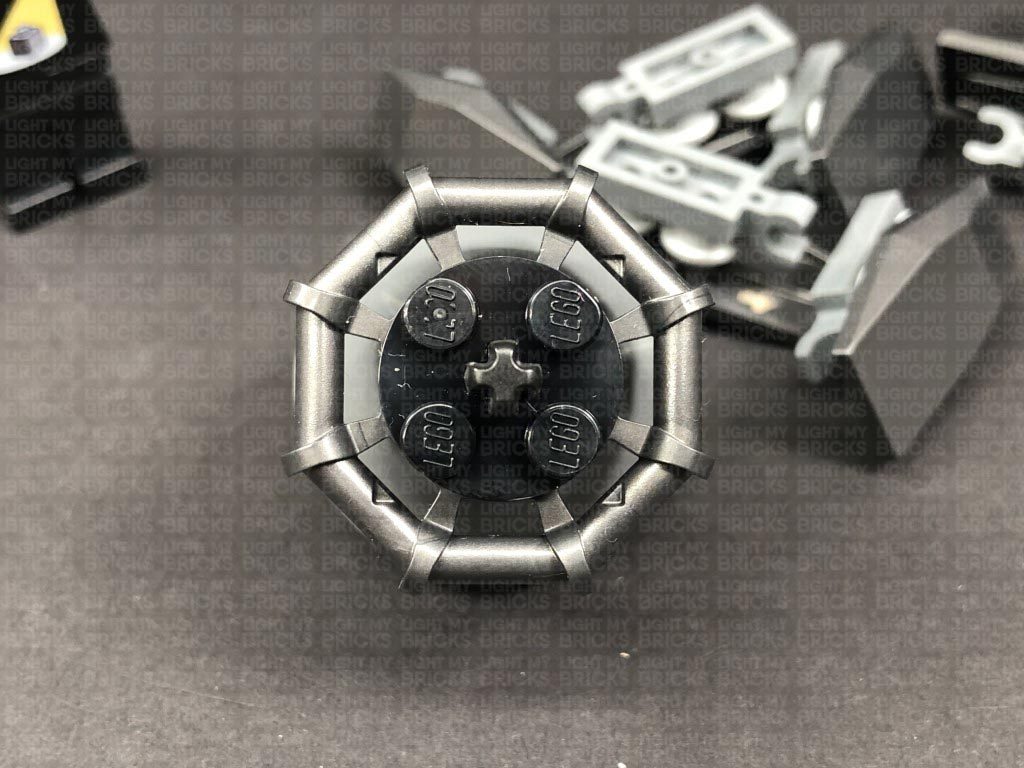
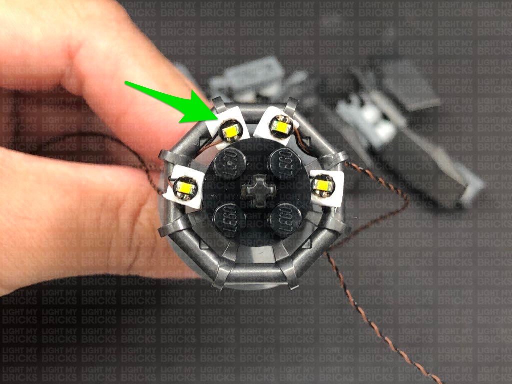
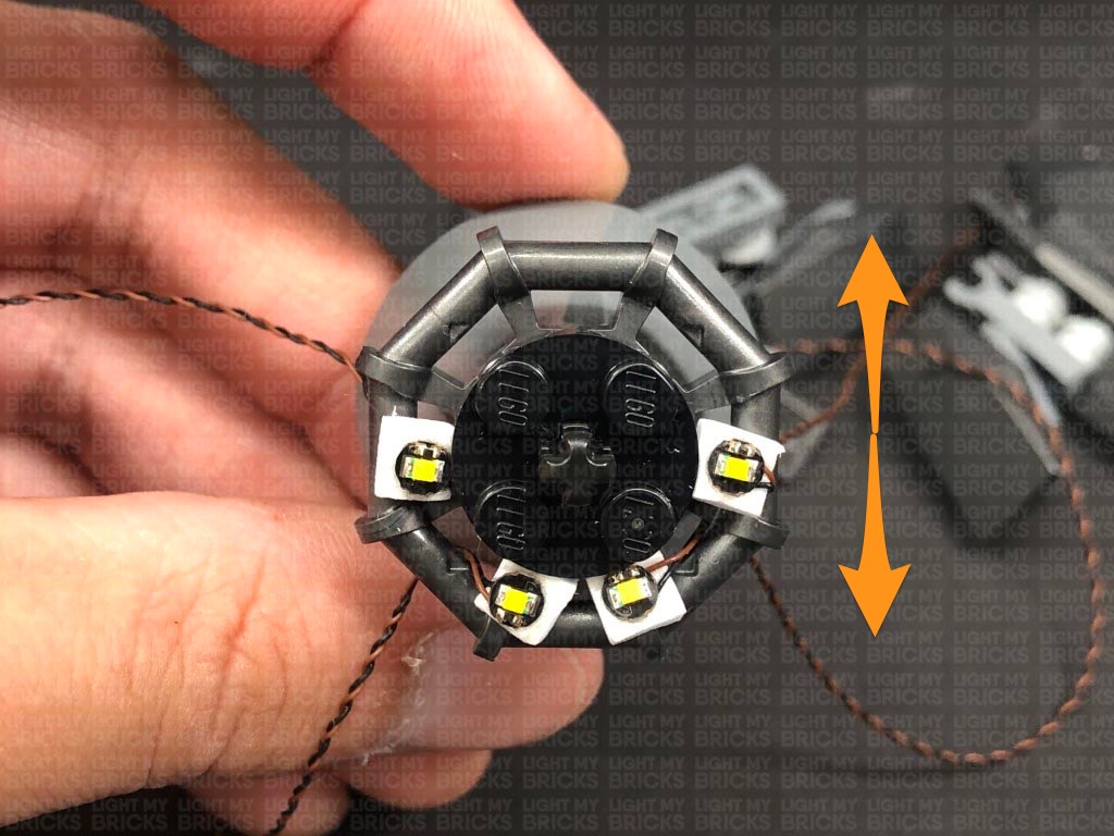
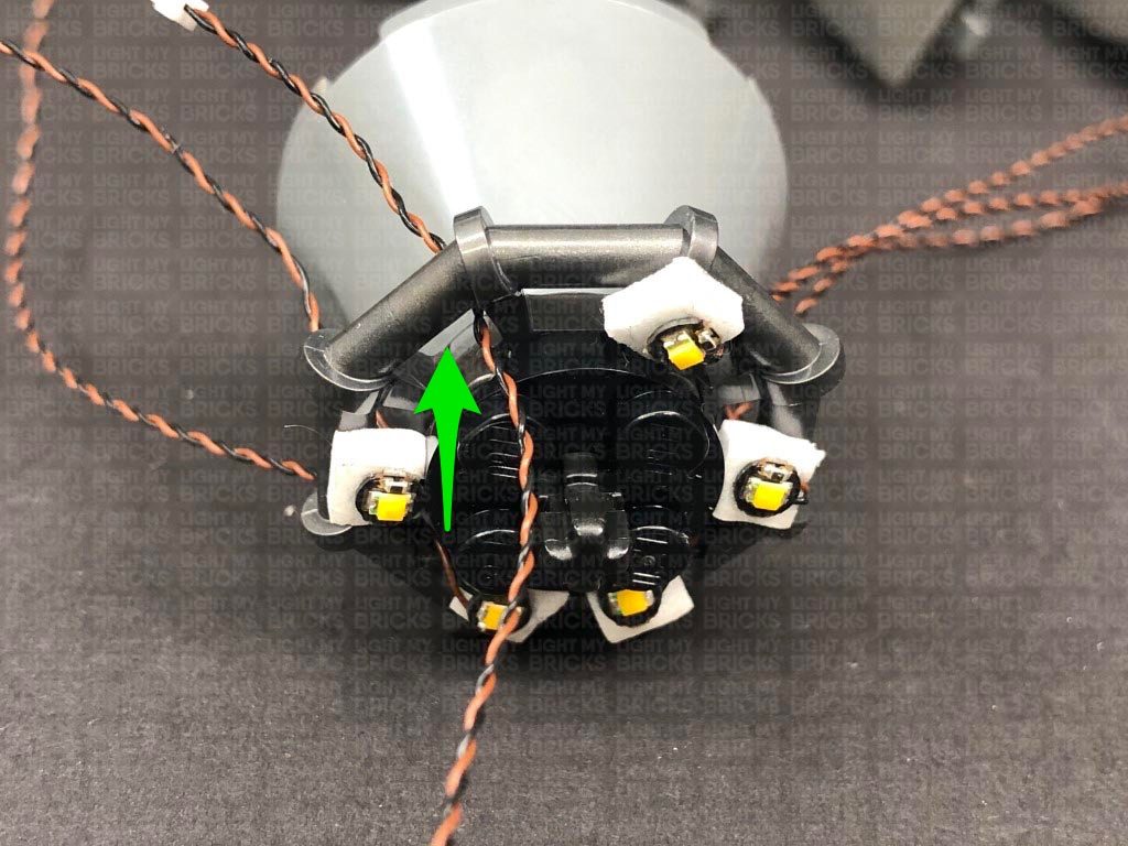
36.) Take the jet section and remove the top technic wheel, then remove the 8 plates from the outside.
We will be sticking Bit Lights to the following 6 positions. Take note of the below image as a reference.
Thread the cables through to the inside of the trunk, then reconnect the following two sections to the left side.
Connect all four Red Bit Light cables to the 8-Port Expansion Board in the rear of the vehicle, then turn ON the Batter Pack to test the tail lights are all working OK.
Note: If you experience any issues with the lights not working and suspect an issue with a component, please try a different port on the expansion board to verify where the fault lies (with the light or expansion board or effects board). To correct any issues with expansion board ports, please view the section addressing expansion board issues on our online troubleshooting guide.
35.) Take a 5cm Connecting Cable and connect it a spare port on the 8-Port Expansion Board. Connect the other end of the cable to the IN port on the Flicker Effects Board (FFX).
Take a new 5cm Connecting Cable and connect it to one of the OUT ports on the Flicker Effects Board, then connect the other end of the cable to the remaining 8-Port Expansion Board in this kit.
Slide the AA Battery Pack out from the rear of the vehicle, then neaten up cabling by folding and twisting the tail light cables into a neat bunch. Tuck the bunched up cables underneath the red technic bar, then slide the AA Battery Pack back in ensuring the new 8-port expansion board from this step is still accessible.
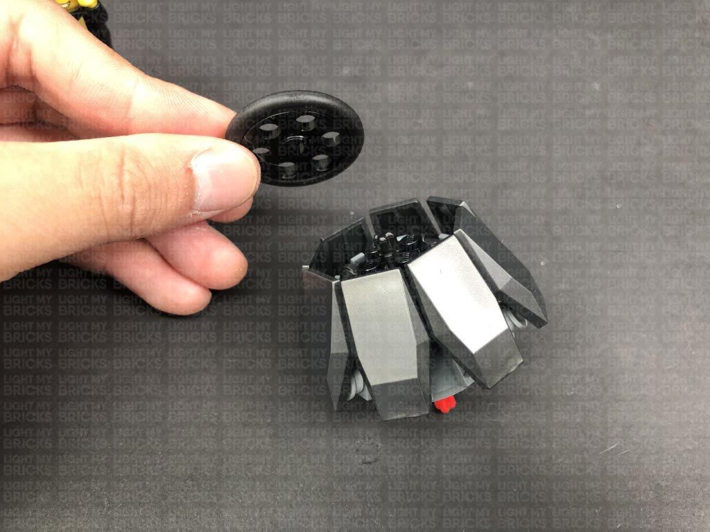
36.) Take the jet section and remove the top technic wheel, then remove the 8 plates from the outside.
We will be sticking Bit Lights to the following 6 positions. Take note of the below image as a reference.
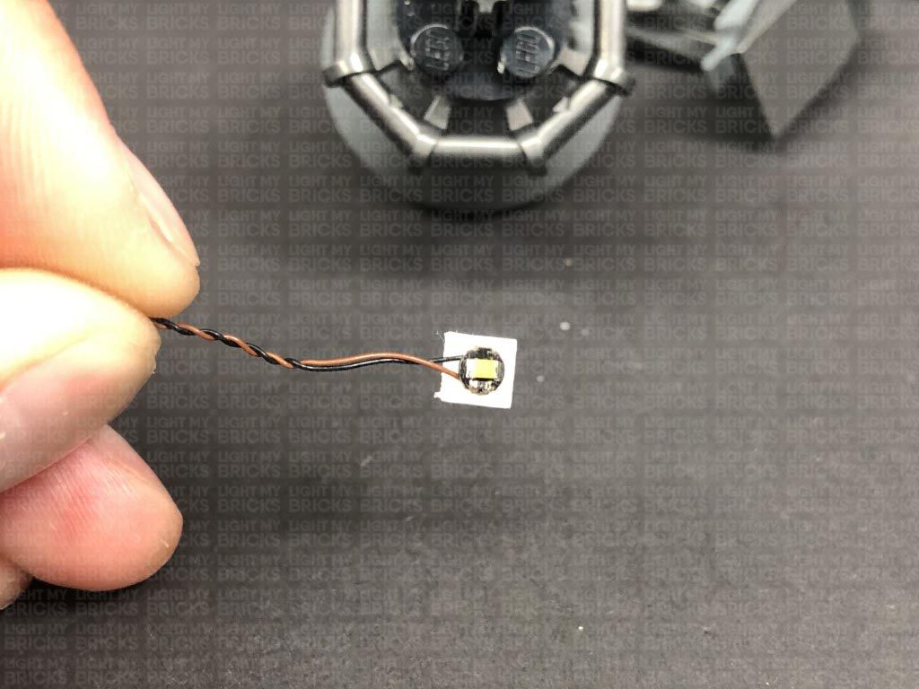
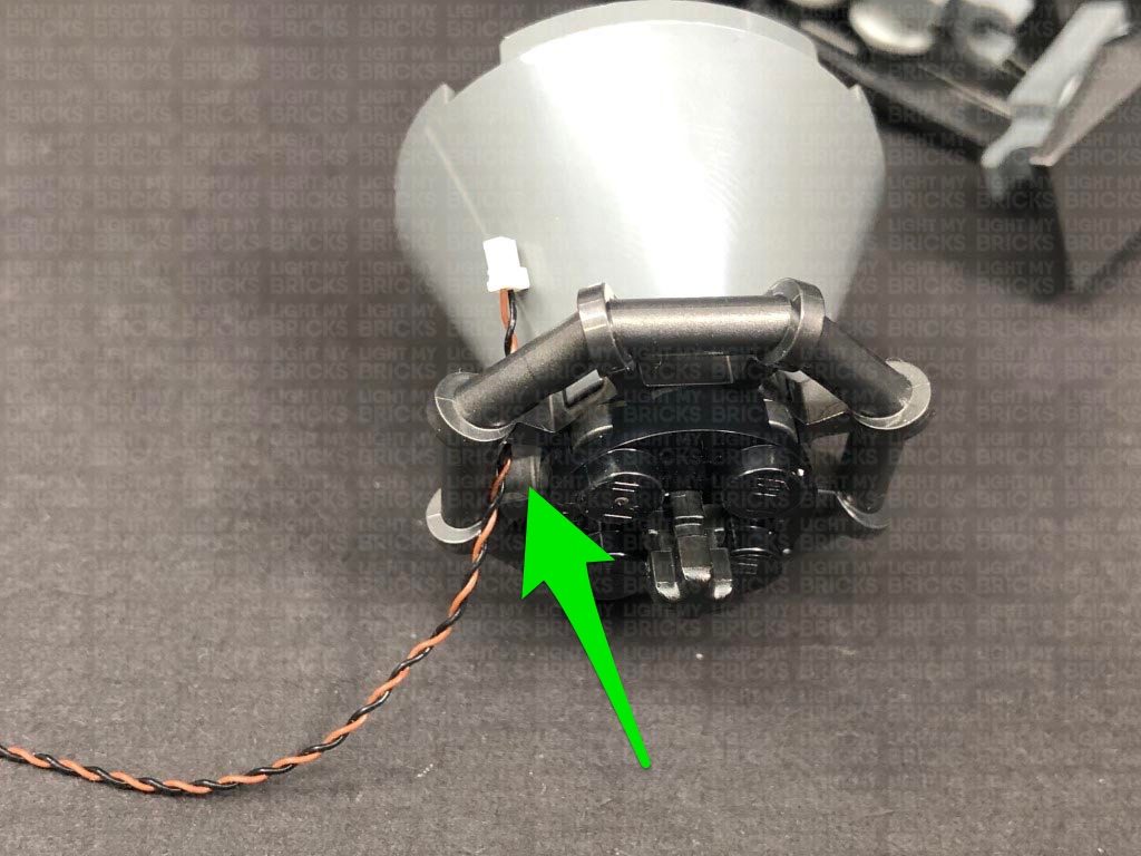
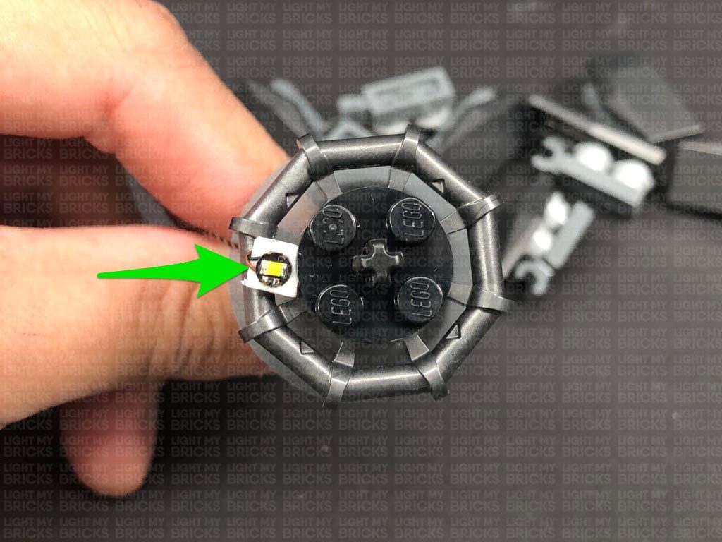
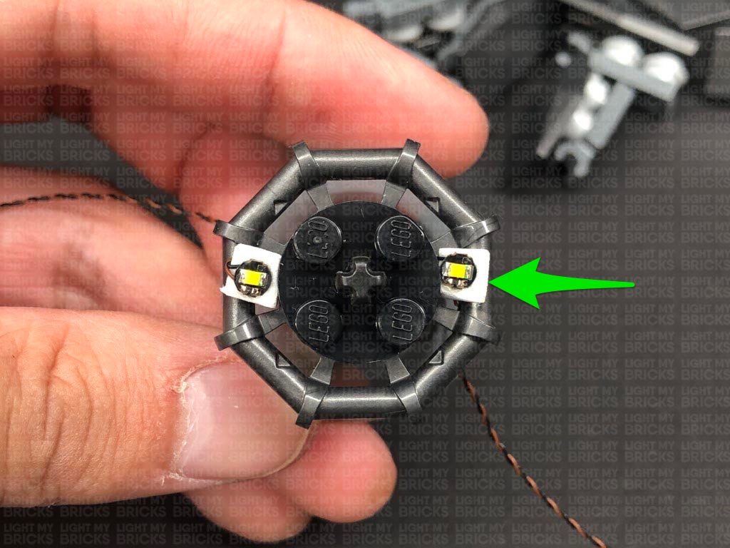
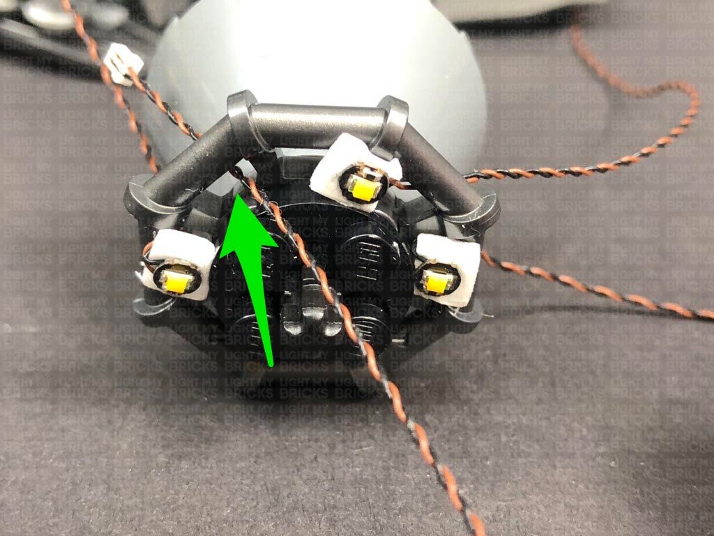
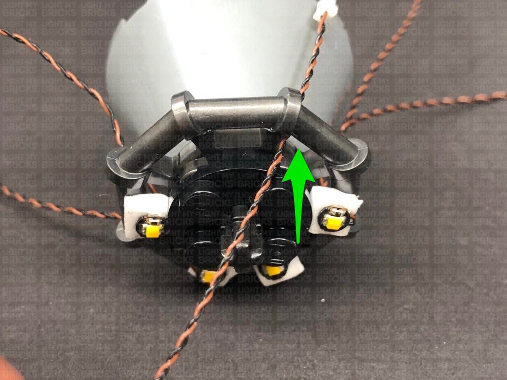
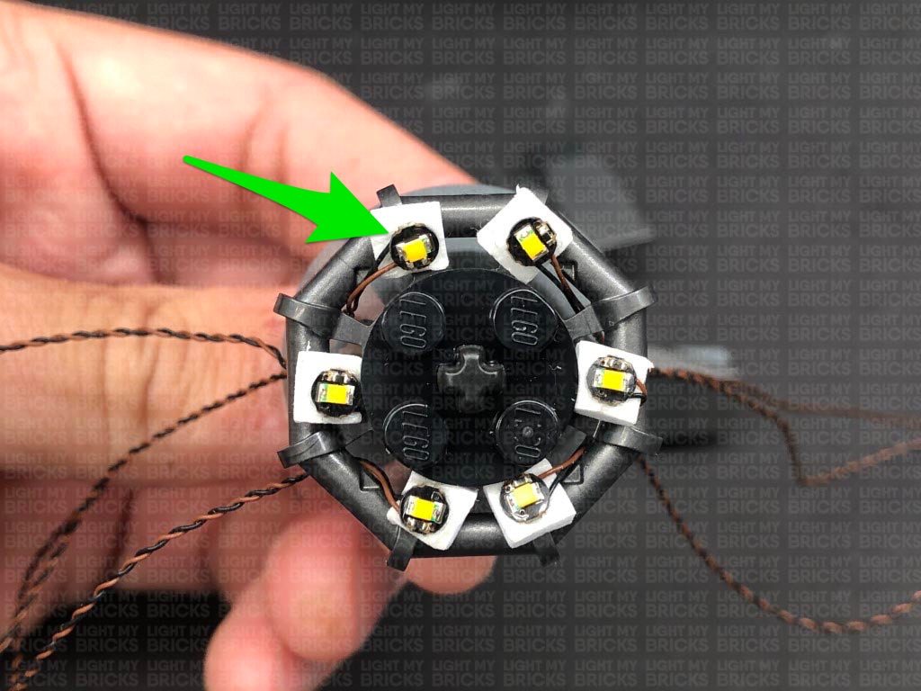
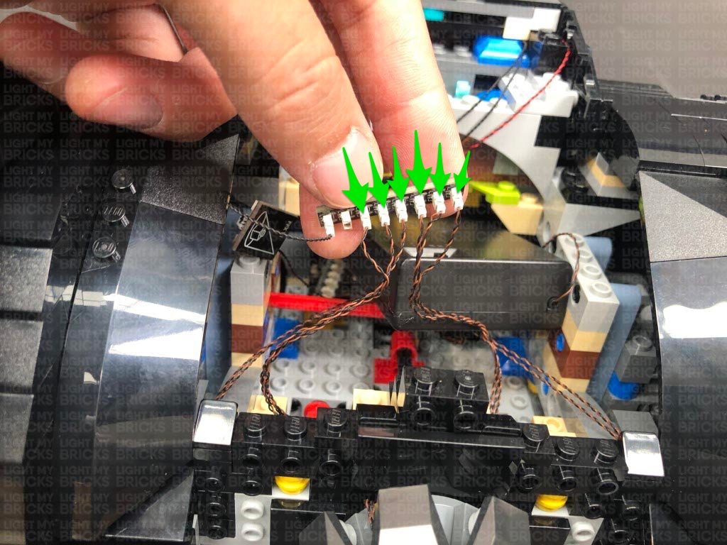
 Take a White 15cm Bit Light and stick it to an Adhesive Square. Thread the connector end of the cable through the following space, then stick the Bit Light to the first location as shown below.
37.) Using the same method as in previous step, install another 5x White 15cm Bit Lights to this jet sections ensuring you stick the Bit Lights to the correct locations as shown below:
Turn this section around and continue.
Take a White 15cm Bit Light and stick it to an Adhesive Square. Thread the connector end of the cable through the following space, then stick the Bit Light to the first location as shown below.
37.) Using the same method as in previous step, install another 5x White 15cm Bit Lights to this jet sections ensuring you stick the Bit Lights to the correct locations as shown below:
Turn this section around and continue.
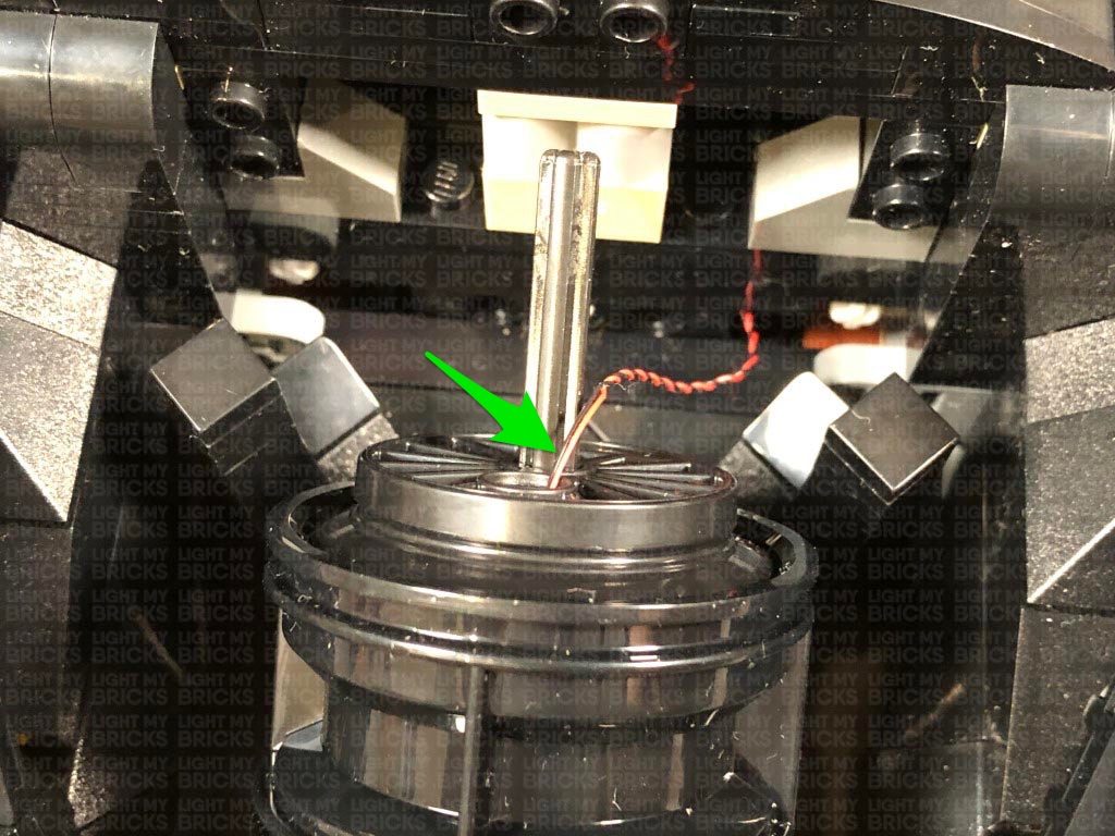
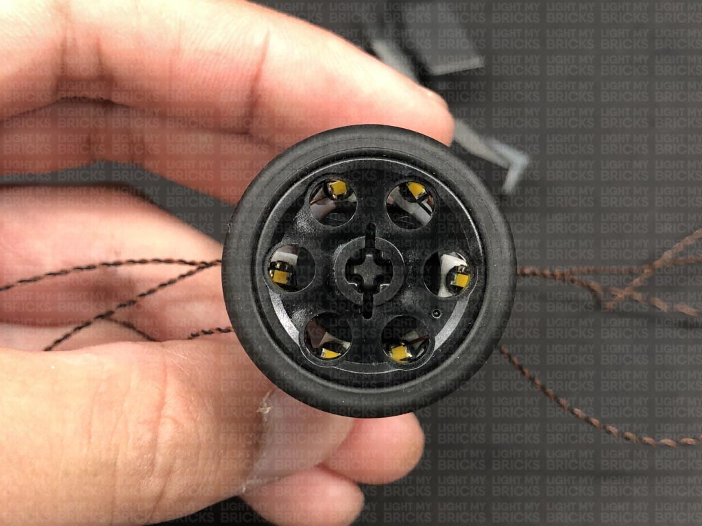
 38.) Reconnect the technic wheel to the top ensuring you the wheel holes align up to where the Bit Lights are installed underneath.
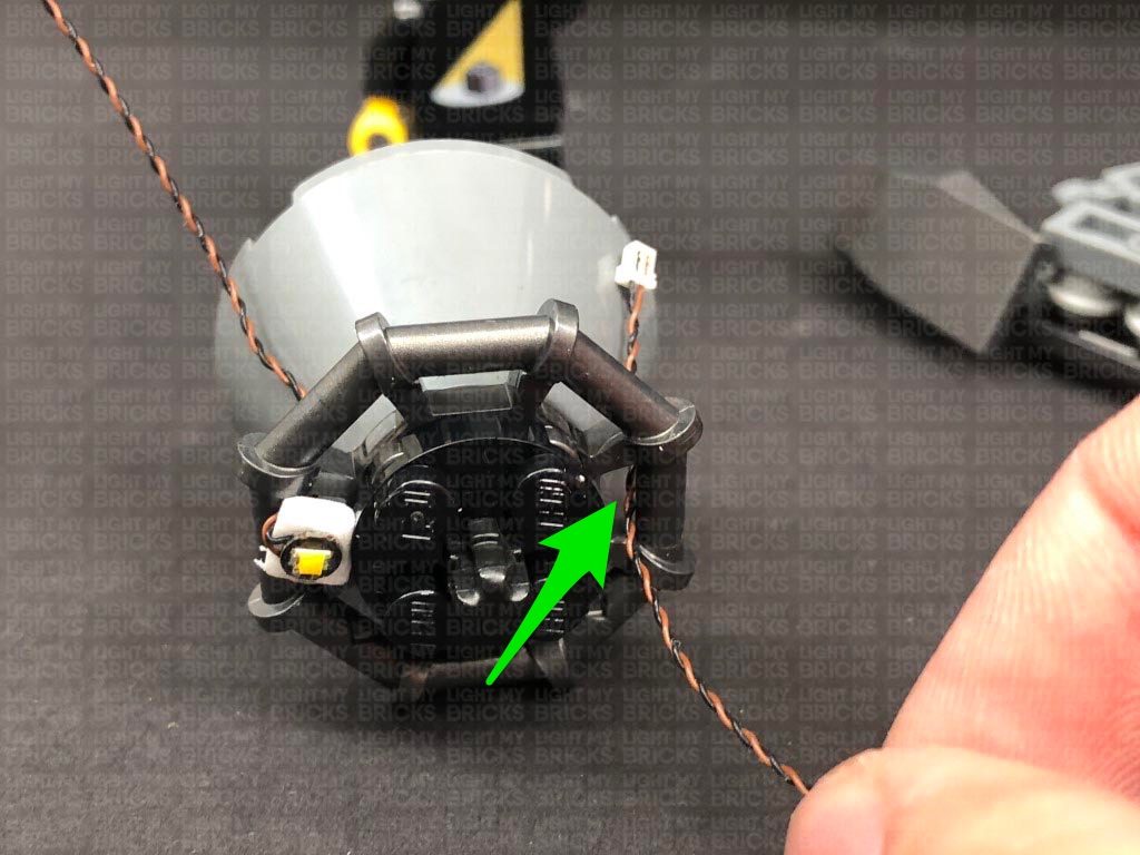
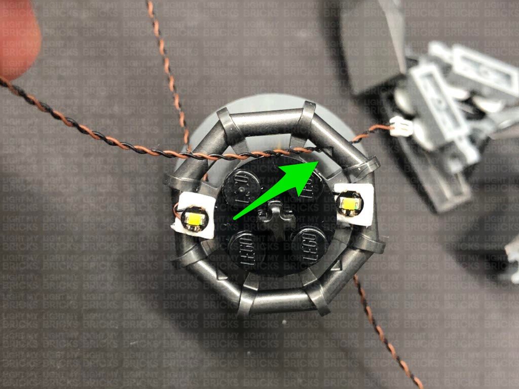
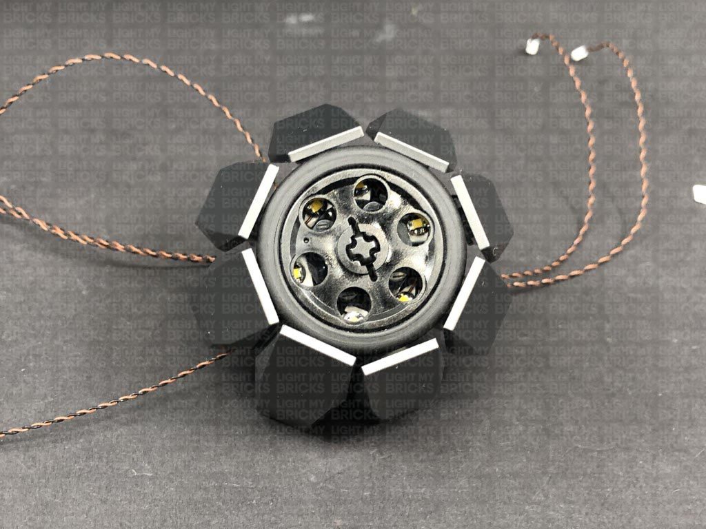
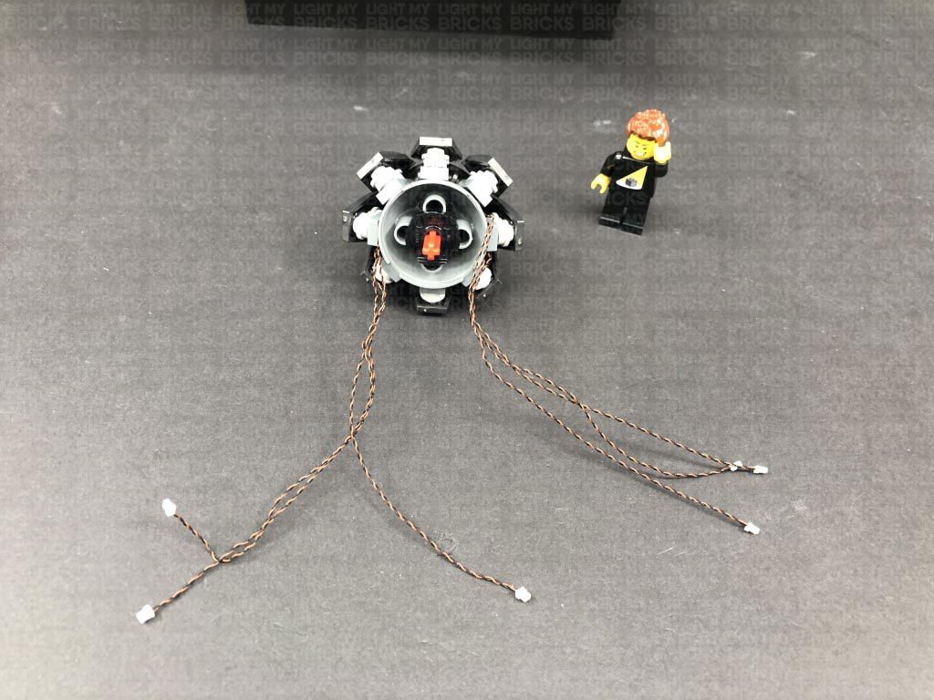
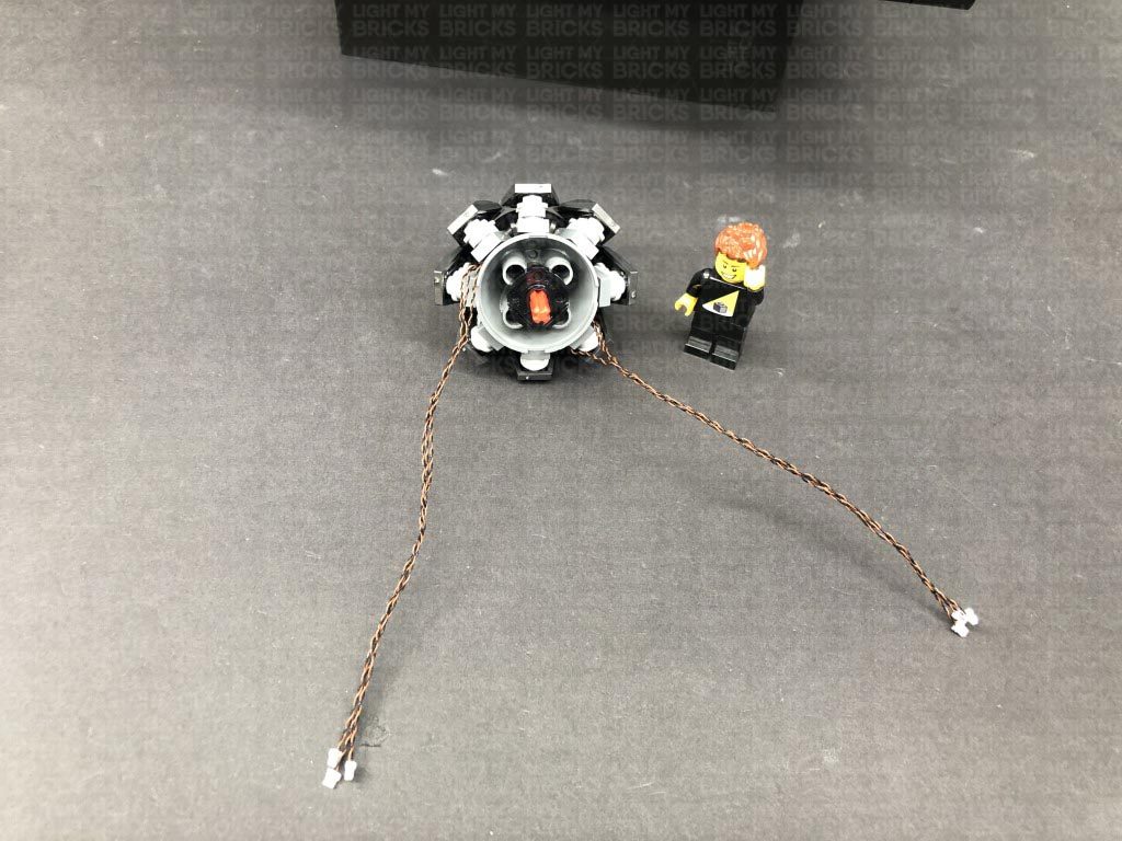
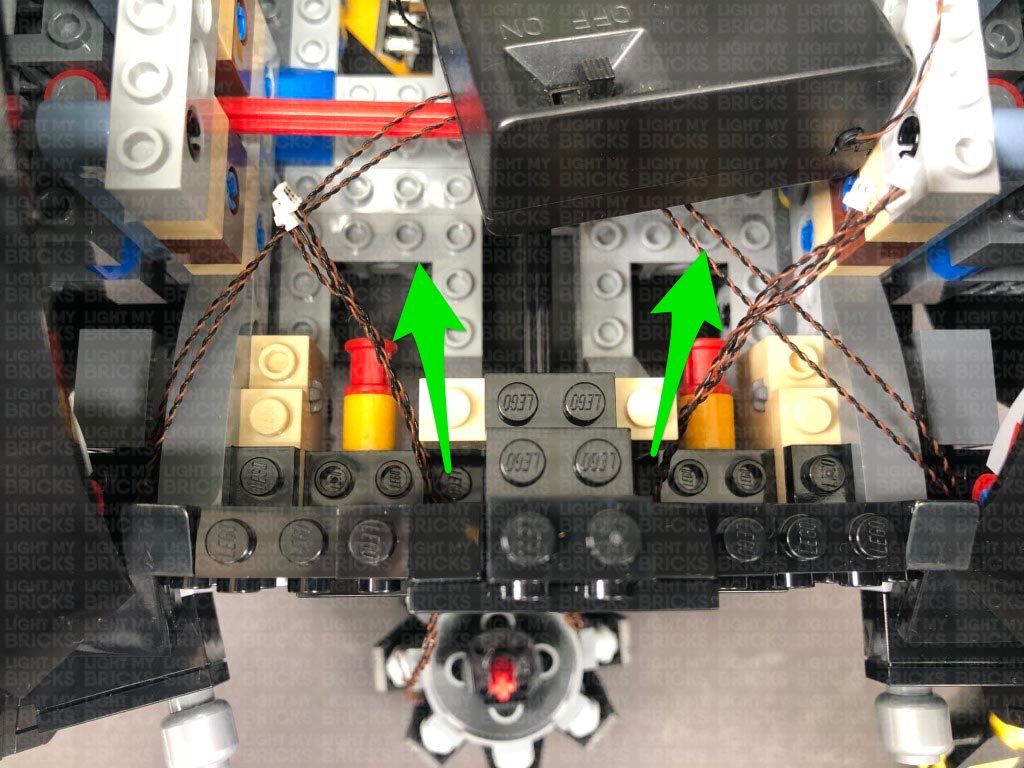
 Reconnect the 8 plates to the outside of the Jet section, then from the back, seperate the cables into two groups. Twist or Braid the cables together as shown below.
Thread the two groups of cables all the way through the following two spaces, then reconnect the Jet section ensuring the two groups of cables are directly to each side.
Reconnect the 8 plates to the outside of the Jet section, then from the back, seperate the cables into two groups. Twist or Braid the cables together as shown below.
Thread the two groups of cables all the way through the following two spaces, then reconnect the Jet section ensuring the two groups of cables are directly to each side.
 Connect all six cables to the 8-Port Expansion Board, then turn on the AA Battery Pack to test the jet lights are working and flickering OK.
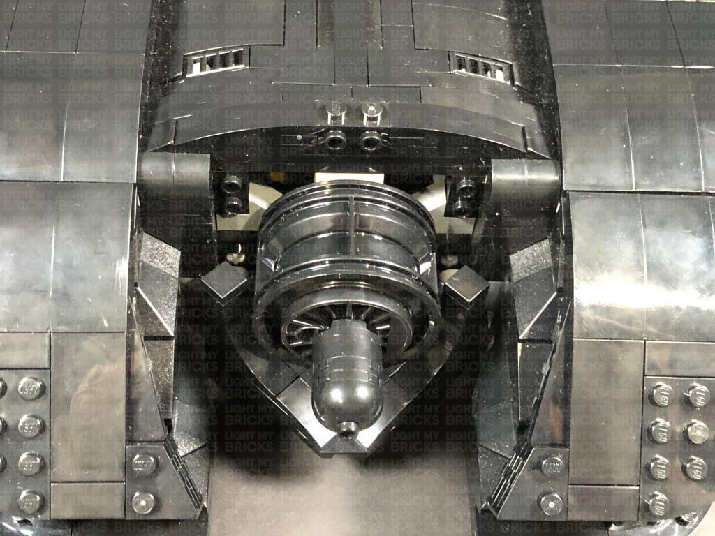
Test the machine guns can still be hoisted up and down by turning the Jet section. If you run into any issues, check the two group of bit light cables from the jet are neatly separated and installed exactly as shown in previous steps.
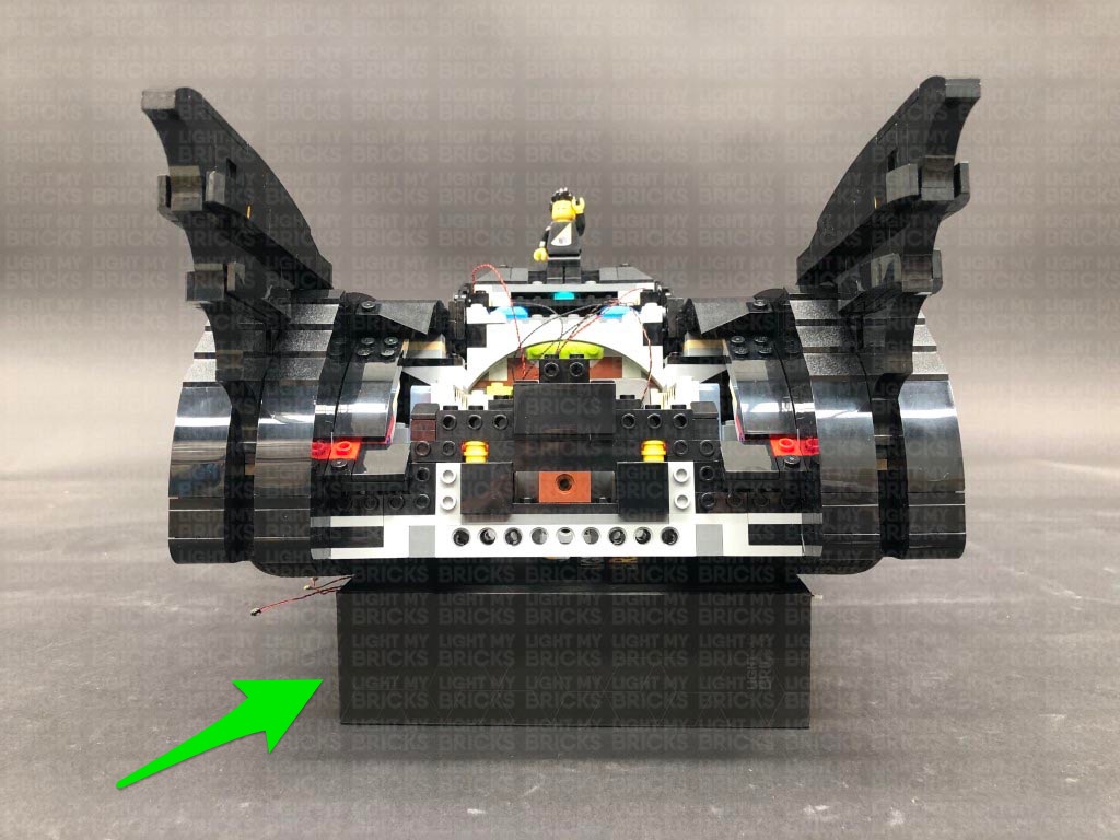
39.) Reconnect all the sections surrounding the back of the vehicle.
To access the battery, simply remove the backing.
Connect all six cables to the 8-Port Expansion Board, then turn on the AA Battery Pack to test the jet lights are working and flickering OK.
Test the machine guns can still be hoisted up and down by turning the Jet section. If you run into any issues, check the two group of bit light cables from the jet are neatly separated and installed exactly as shown in previous steps.
39.) Reconnect all the sections surrounding the back of the vehicle.
To access the battery, simply remove the backing.
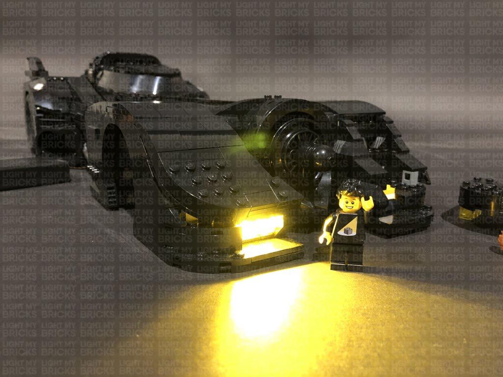
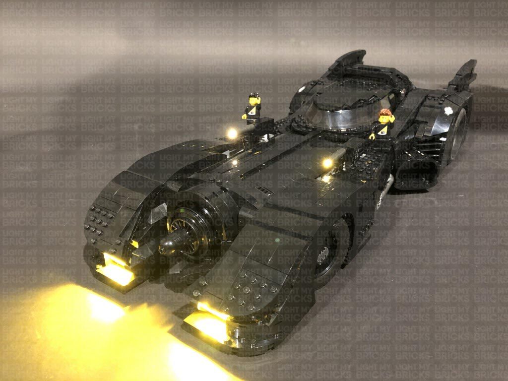
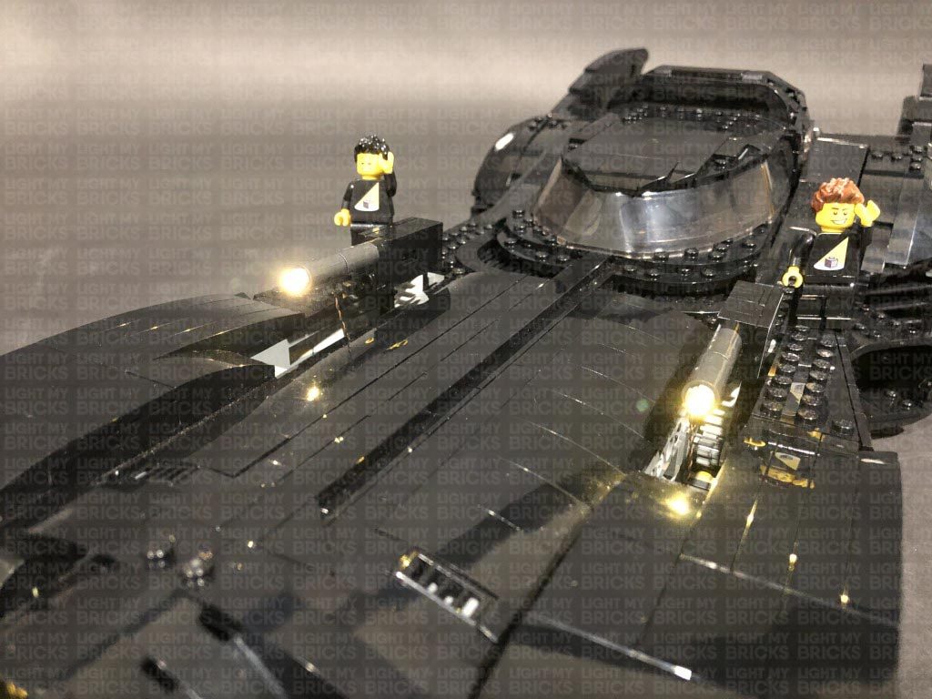
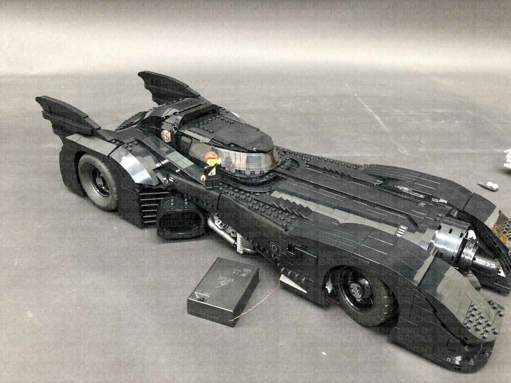
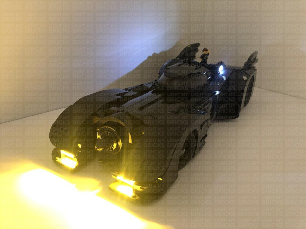
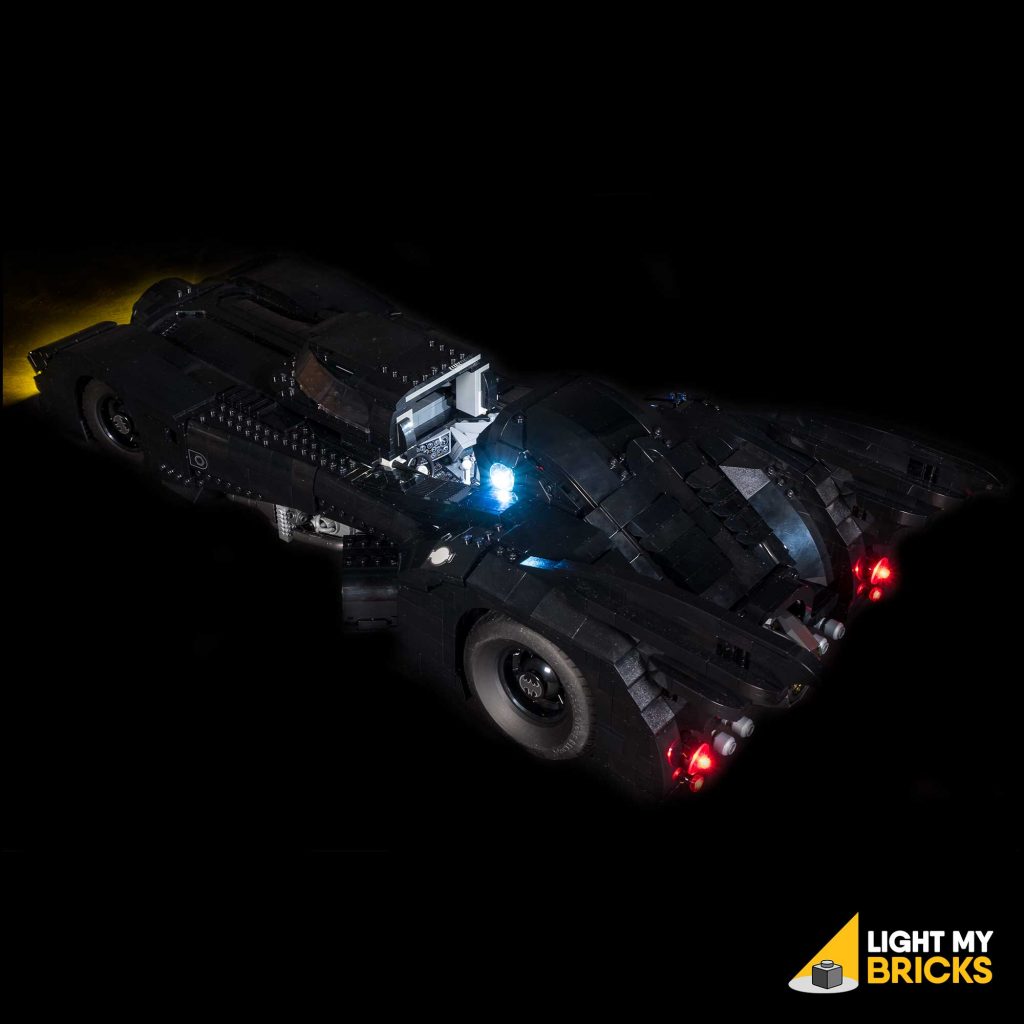
This finally completes installation of the Light My Bricks Star Wars 1989 Batmobile Light Kit.
We thank you for purchasing this product and hope you ENJOY!