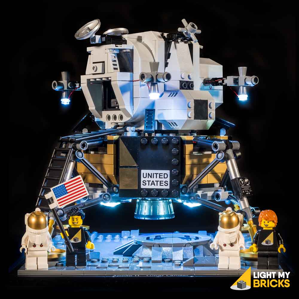

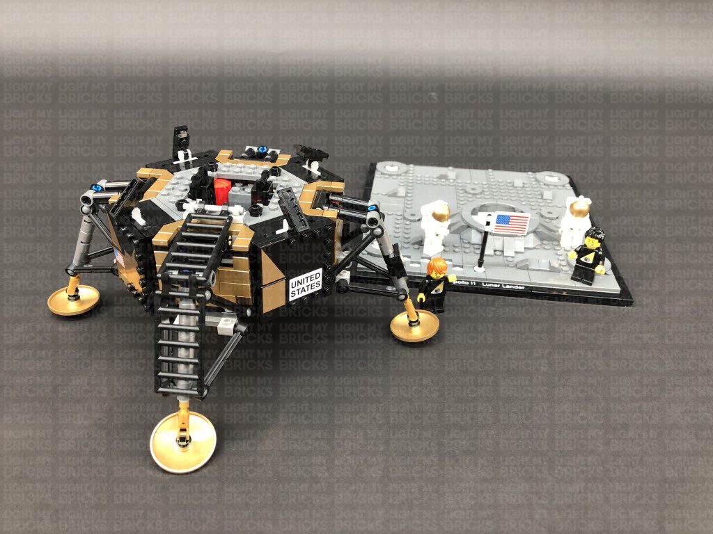
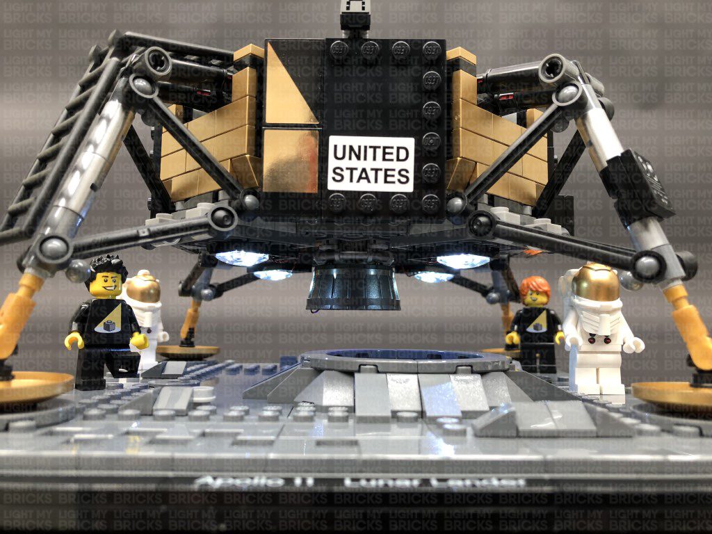
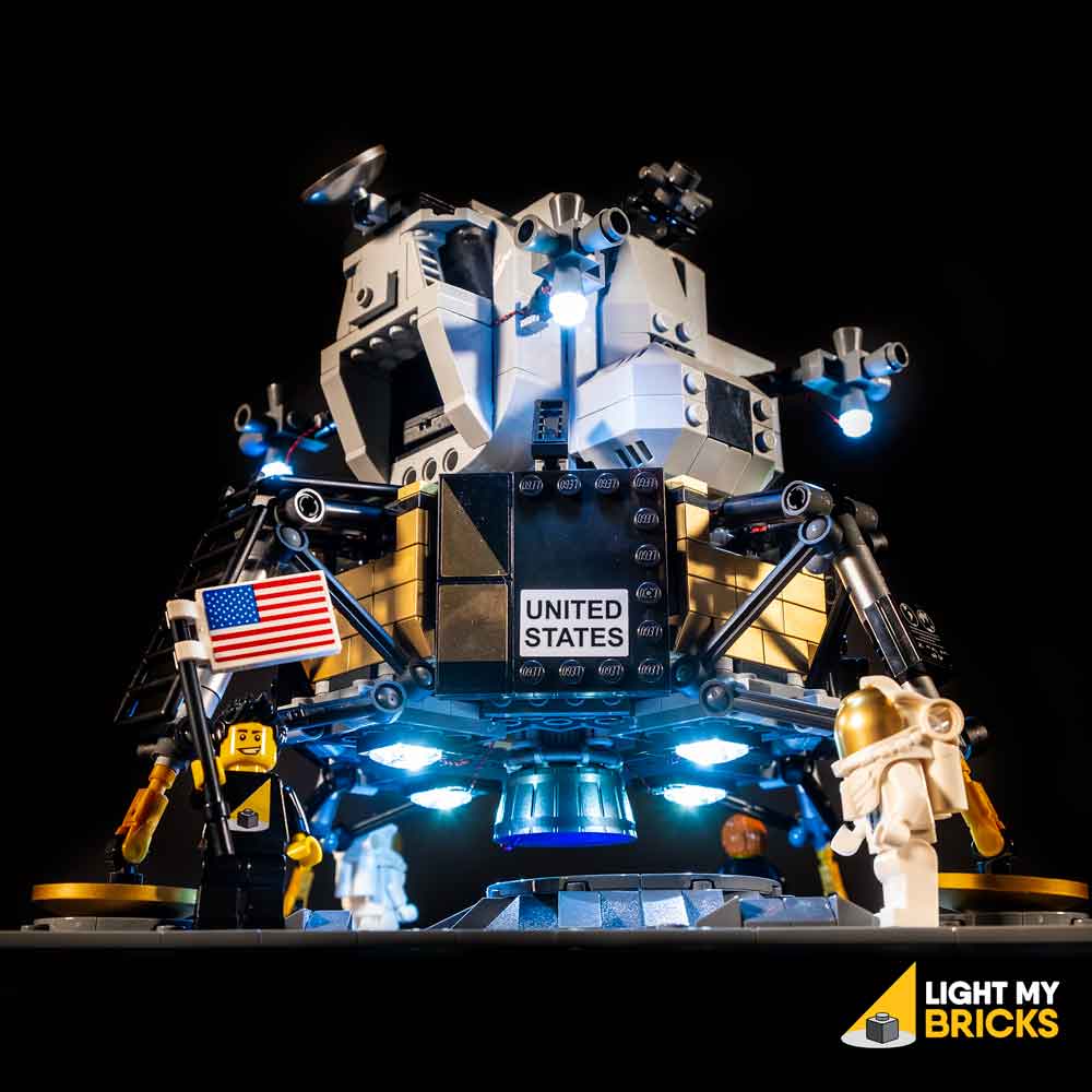
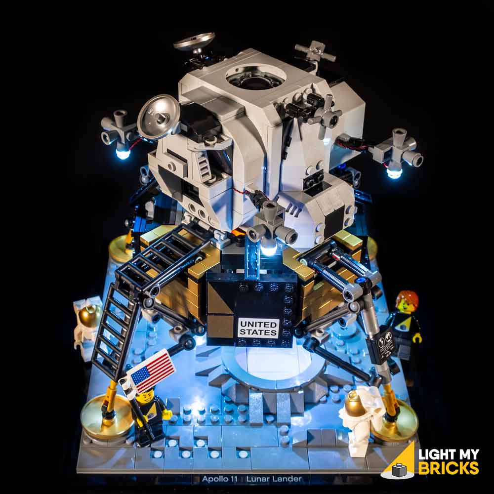
The following page is the instructions for the Light My Bricks LEGO NASA Apollo 11 Lunar Lander (10266) LED light kit.
If you run into any issues, please refer to the online troubleshooting guide.
To ensure a trouble-free installation of your light kit, please read and follow each step carefully. These instructions can be downloaded in PDF format here
Please note: This page lists instructions for the LED light kit only. If you are wishing to purchase the Light My Bricks LEGO NASA Apollo 11 Lunar Lander (10266) LED light kit , please click here to view the product page
Package Contents:
- 8x Cool White 30cm Bit Lights
- 1x Blue 30cm Bit Light
- 1x Orange 30cm Bit Light
- 2x 6-Port Expansion Boards
- 2x Flicker Effects Boards
- 2x 5cm Connecting Cables
- 2x Flat Battery Packs (requires 2x CR2032 Batteries each)
- 2x 3M Adhesive Squares
LEGO Pieces:
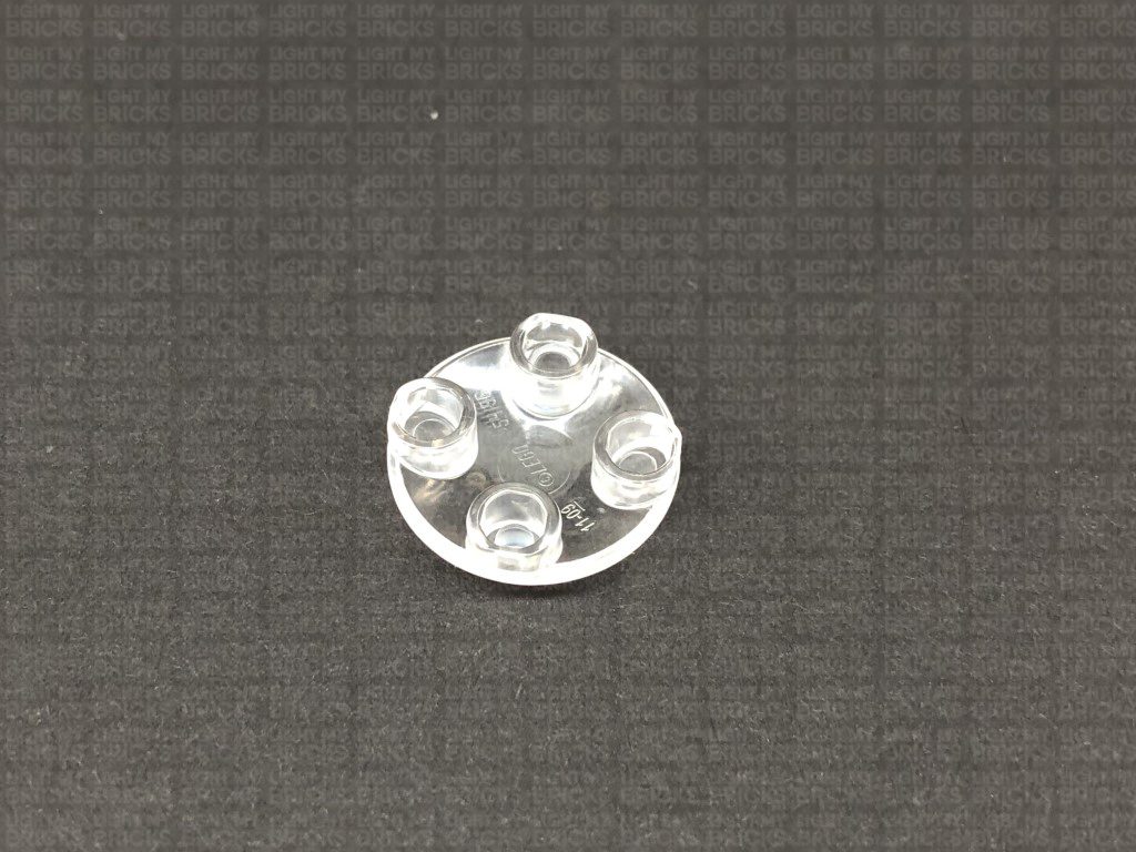
- 5x Trans Clear Plate w Rounded Bottom 2×2
- 4x Trans Clear Round Plate 1×1
Important things to note:
Laying cables in between and underneath bricks
Cables can fit in between and underneath LEGO® bricks, plates, and tiles providing they are laid correctly between the LEGO® studs. Do NOT forcefully join LEGO® together around cables; instead ensure they are laying comfortably in between each stud.
Connecting cable connectors to Expansion Boards
Take extra care when inserting connectors to ports of Expansion Boards. Connectors can be inserted only one way. With the expansion board facing up, look for the soldered “=” symbol on the left side of the port. The connector side with the wires exposed should be facing toward the soldered “=” symbol as you insert into the port. If a plug won’t fit easily into a port connector, do not force it.
Connecting cable connectors to Strip Lights
Take extra care when inserting connectors to ports on the Strip Lights. Connectors can be inserted only one way. With the Strip Light facing up, ensure the side of the connector with the wires exposed is facing down. If a plug won’t fit easily into a port connector, don’t force it. Doing so will damage the plug and the connector.
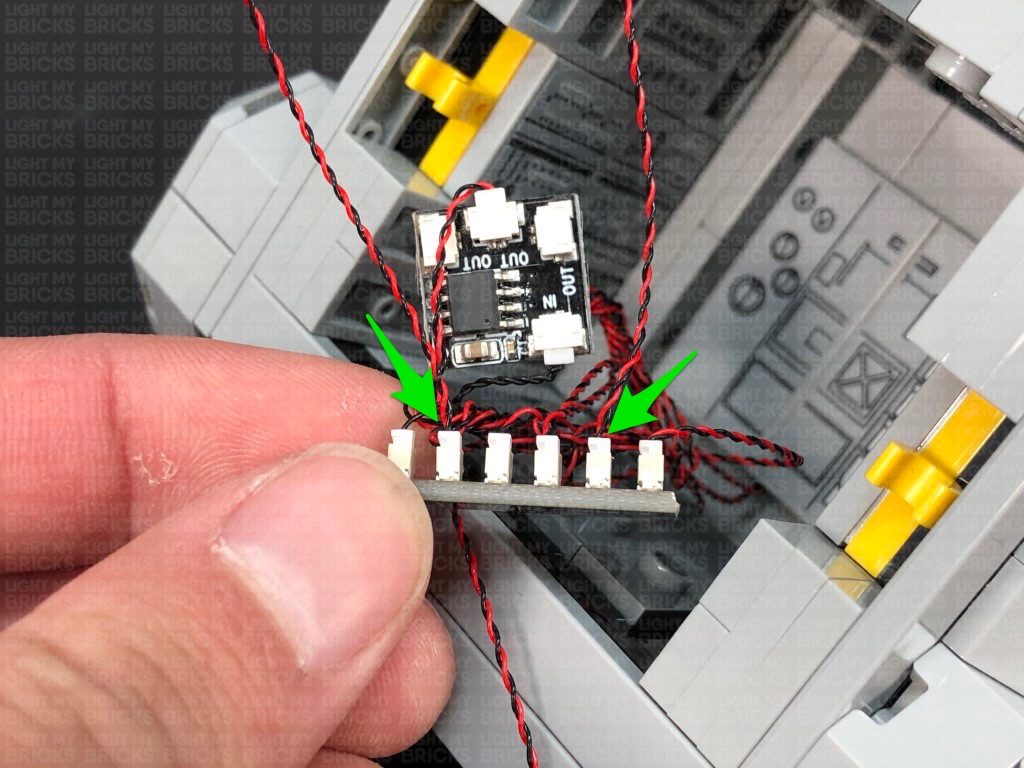
Connecting Micro Cable connectors to Micro Expansion Board Ports
Take extra care when inserting the micro connectors to micro ports of Micro Expansion Boards. Connecting Micro Bit Lights to Micro Expansion Boards is similar to connecting lights and cables to Strip Lights. With the expansion board facing up, ensure the side of the connector with the wires exposed is facing down. If a plug won’t fit easily into a port connector, do not force it. Use your fingernail to push the plastic part of the connector to the micro port.
Installing Bit Lights under LEGO® bricks and plates.
When installing Bit Lights under LEGO® pieces, ensure they are placed the correct way up (Yellow LED component exposed). You can either place them directly on top of LEGO® studs or in between.
OK, Let’s Begin!
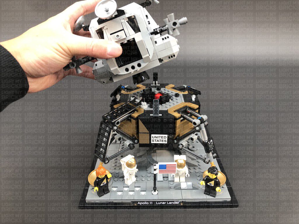
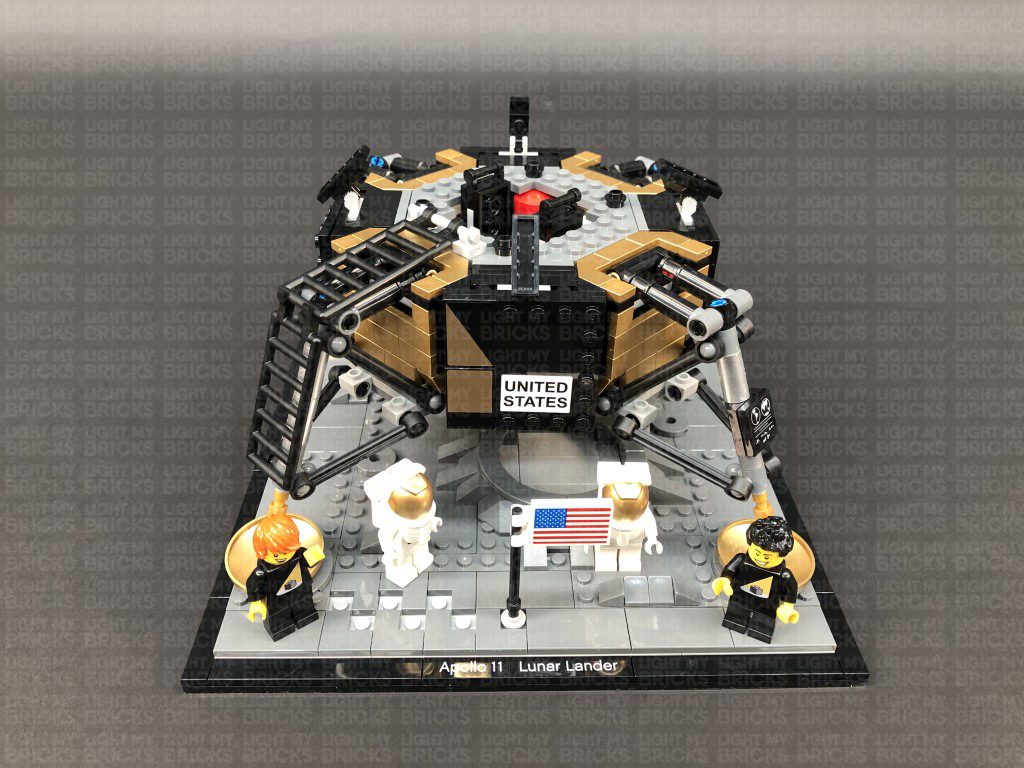
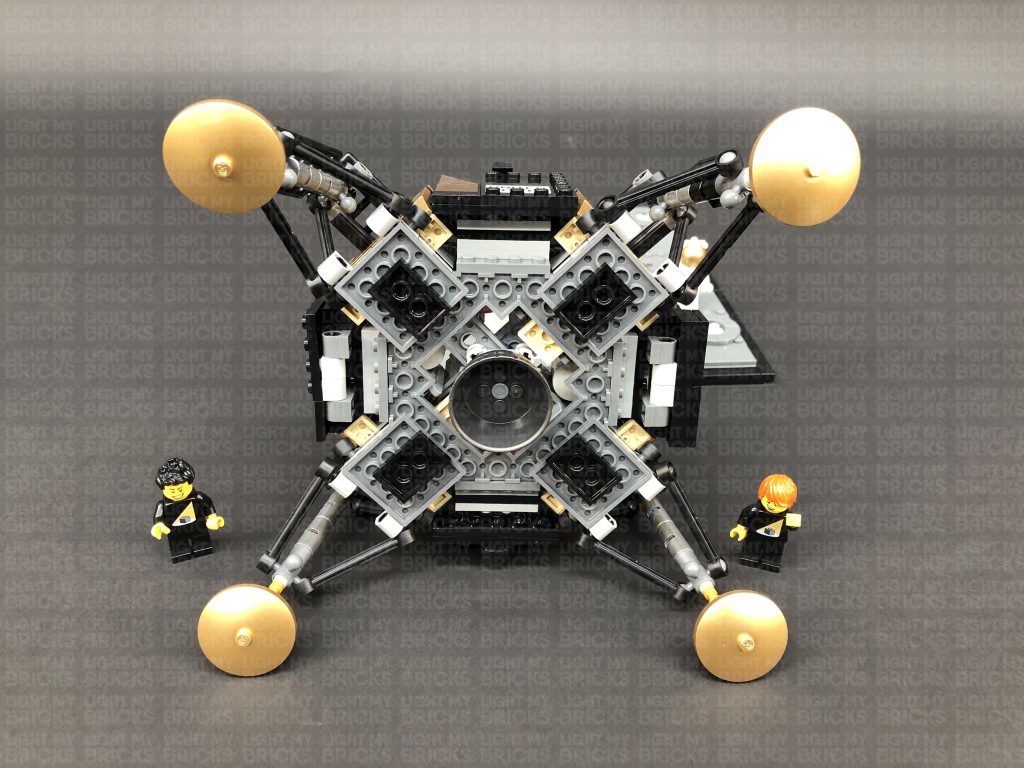
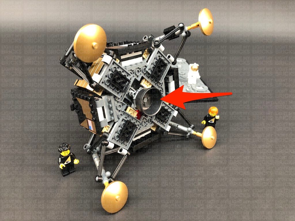
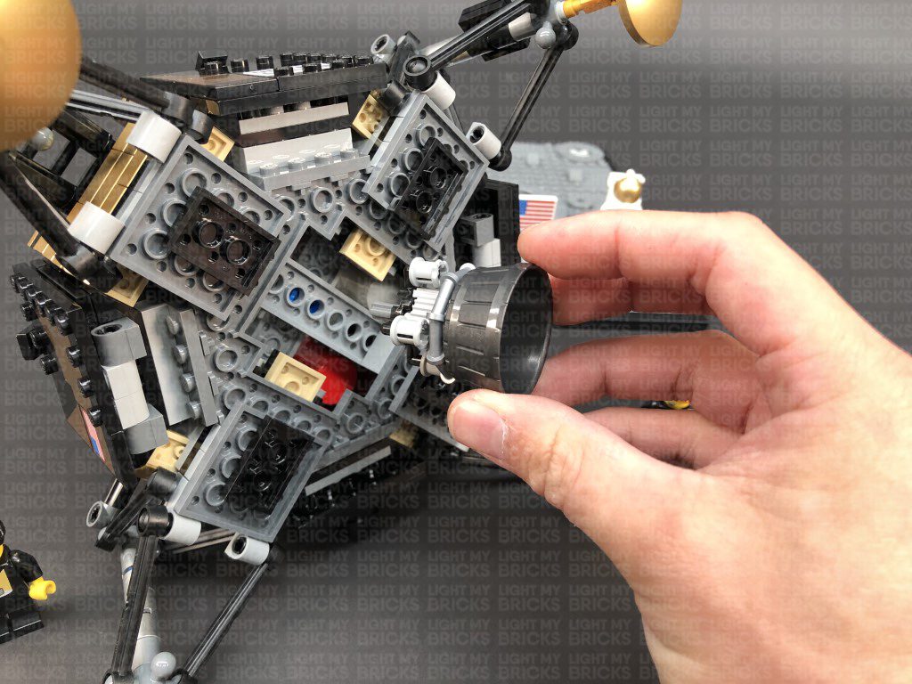
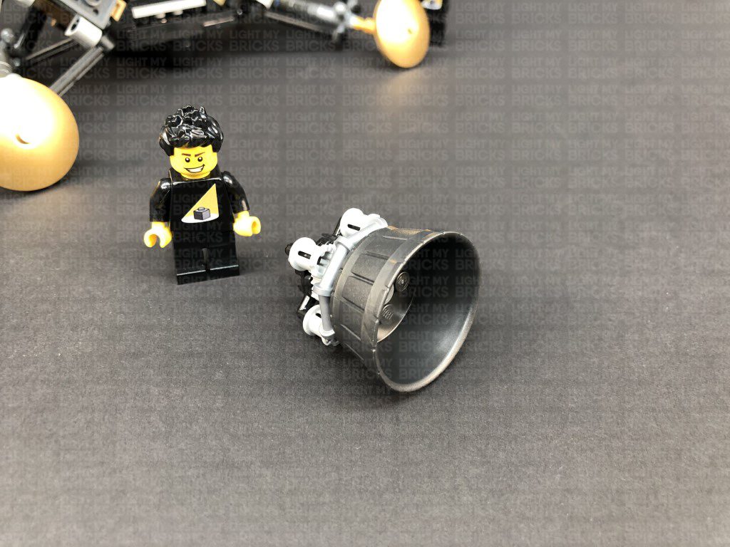
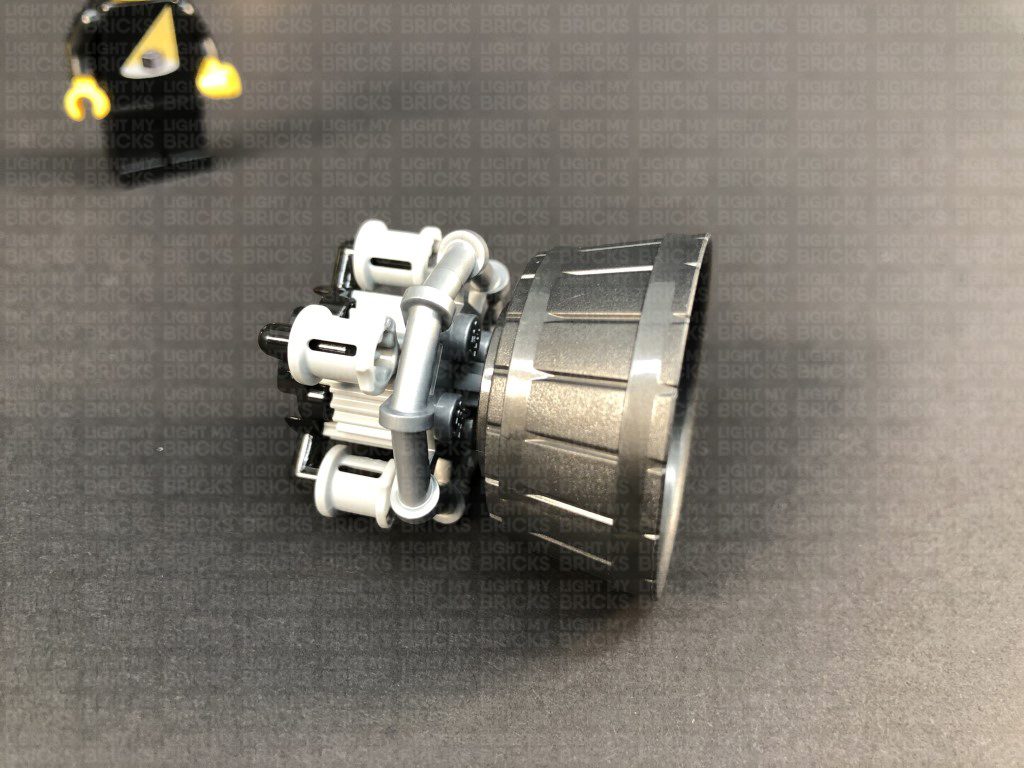
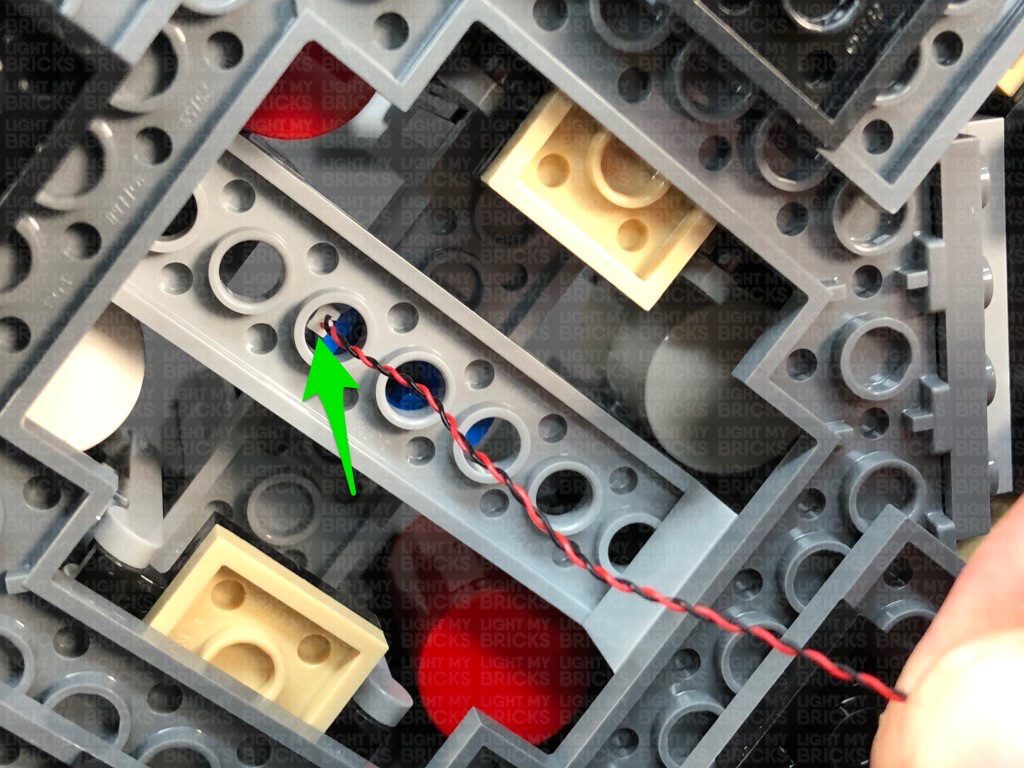
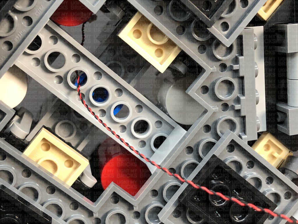
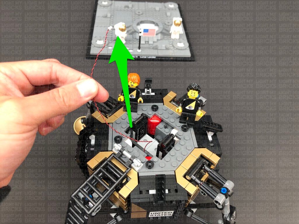
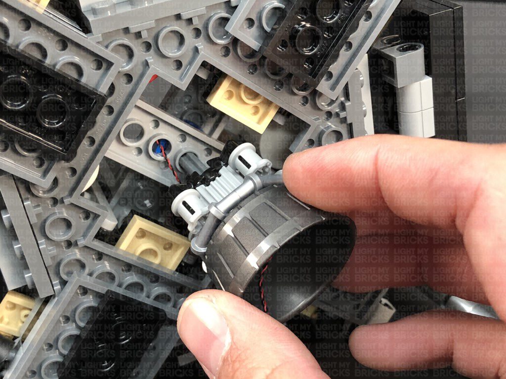
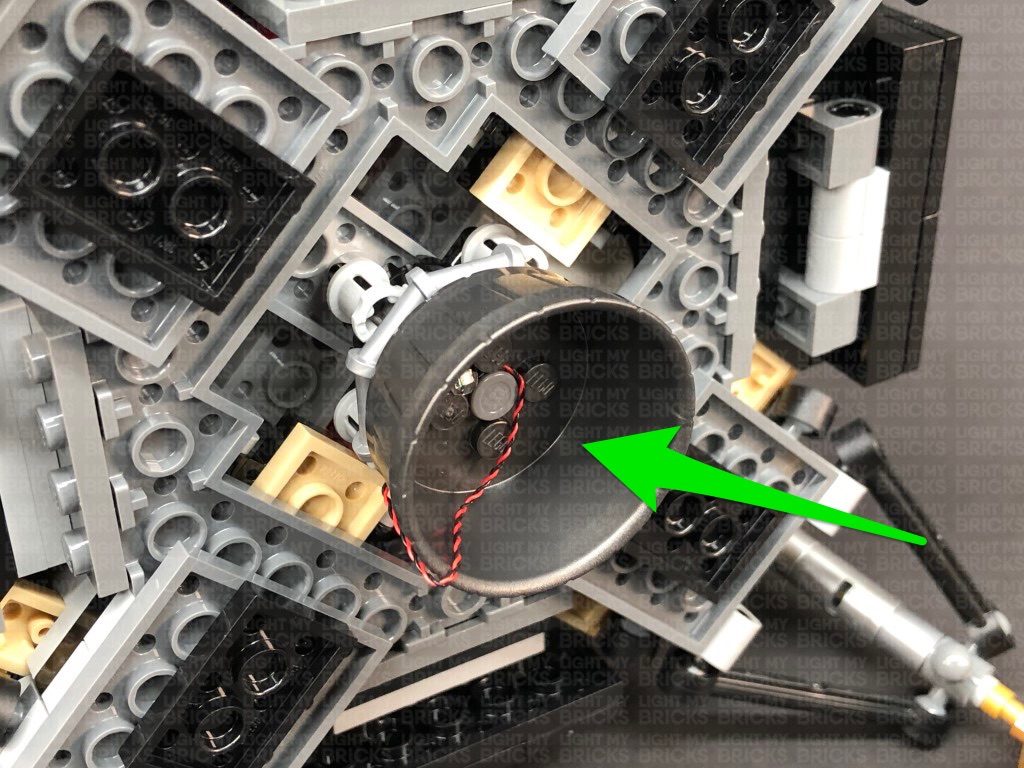
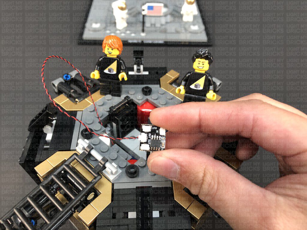
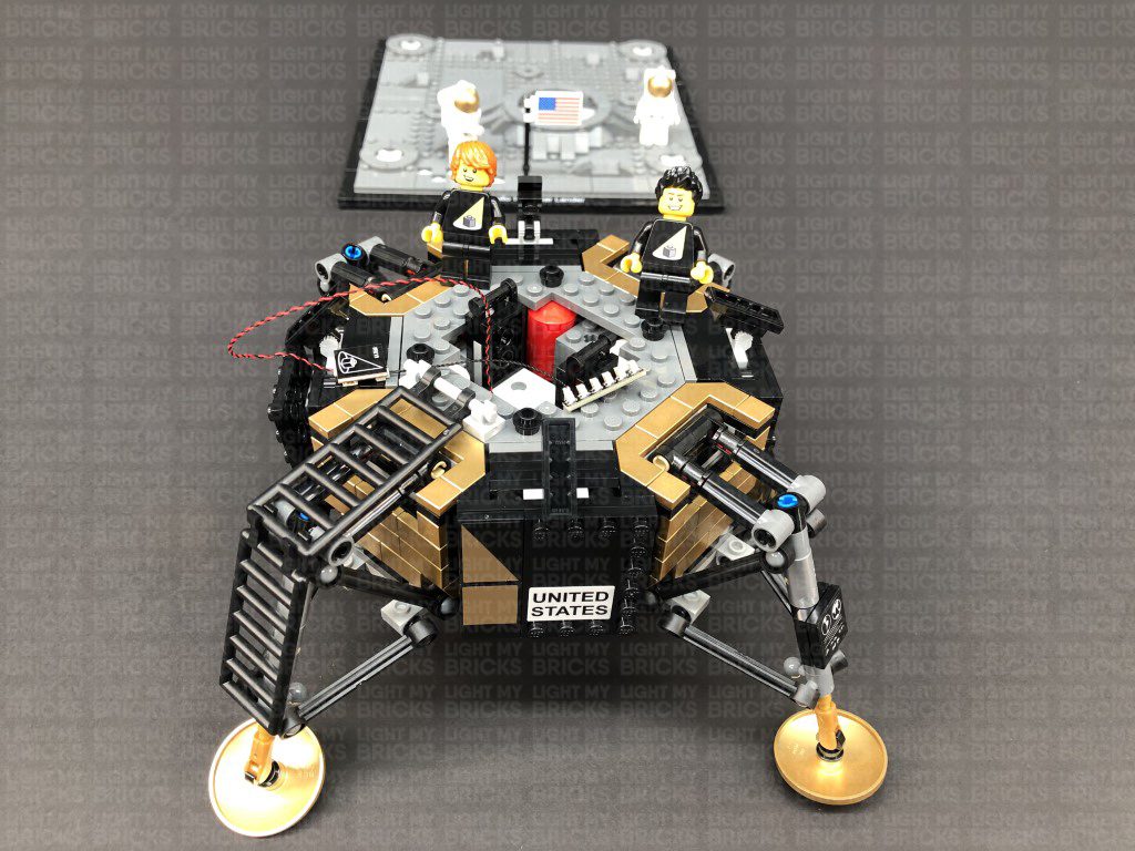
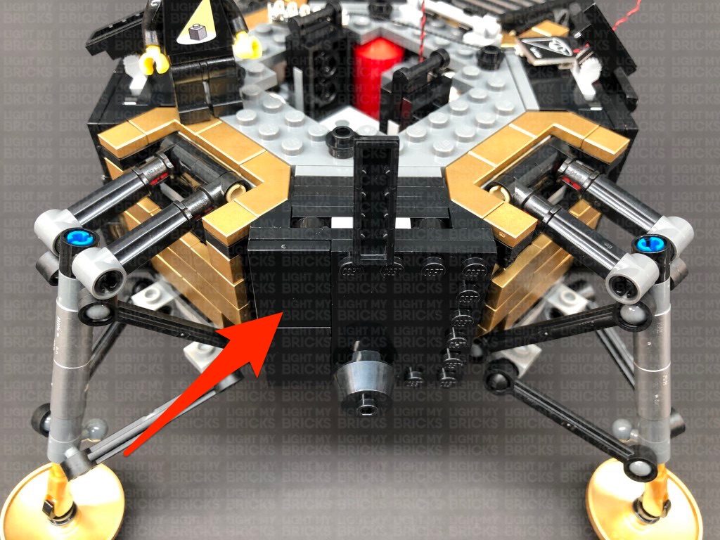
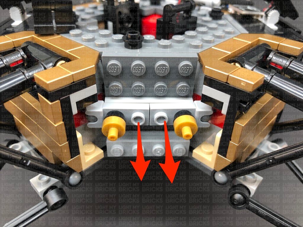
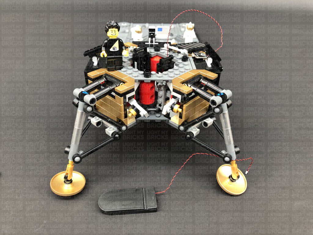
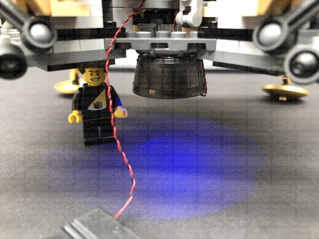
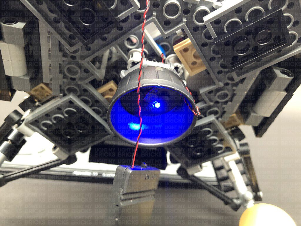
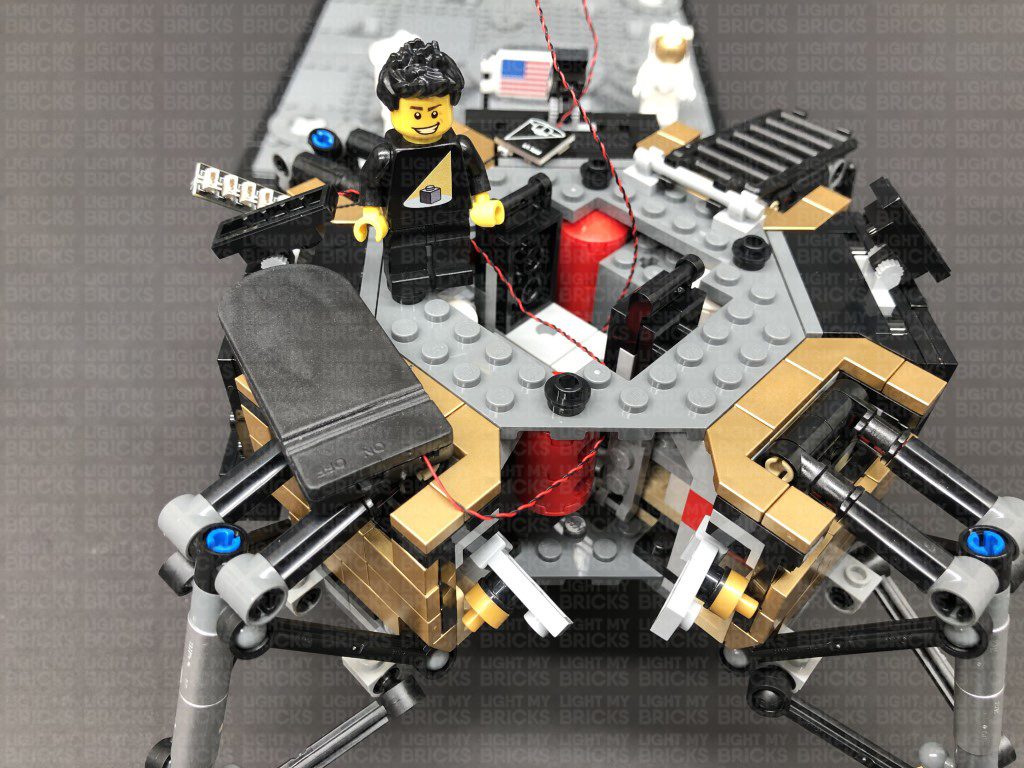
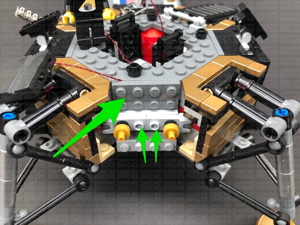
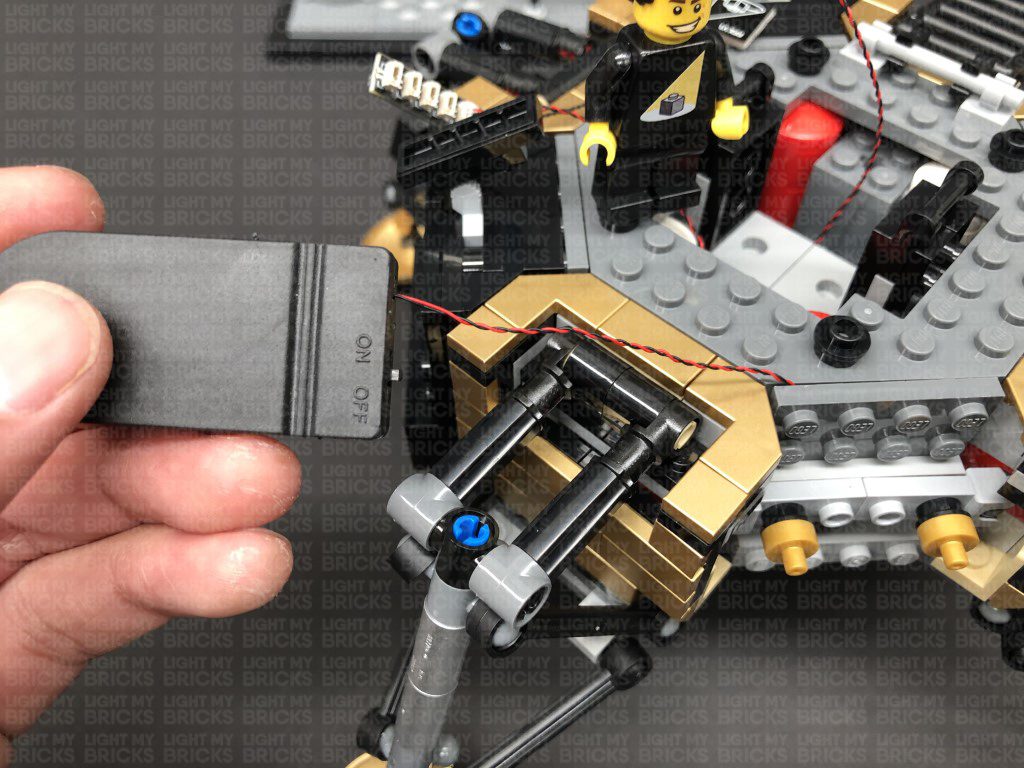
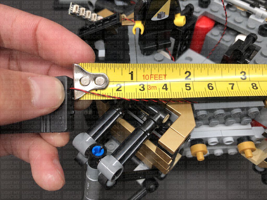
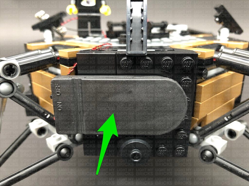
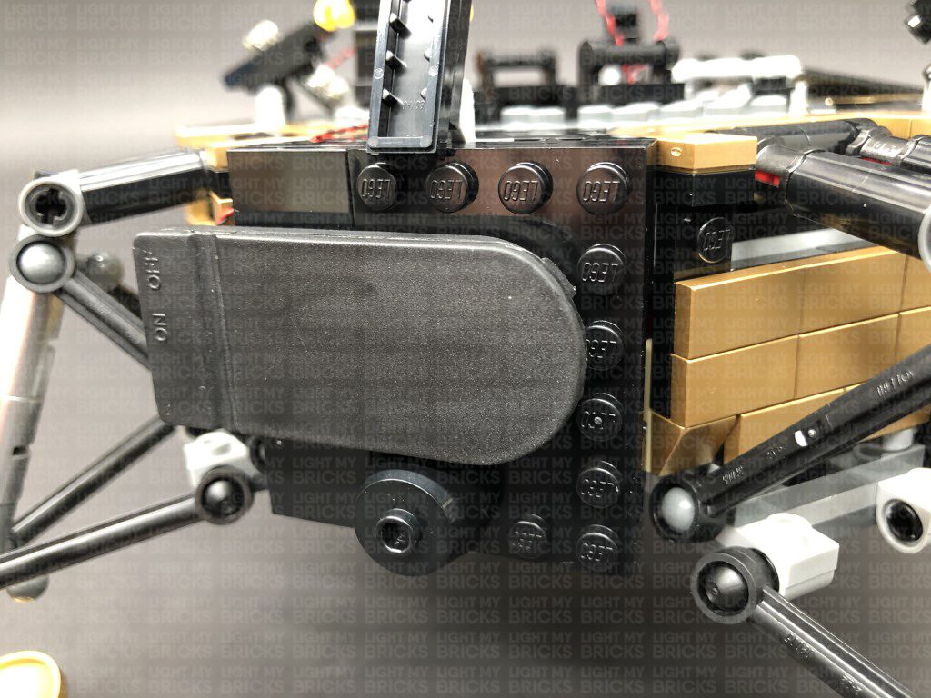
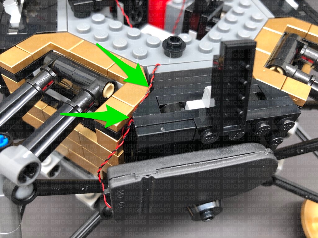
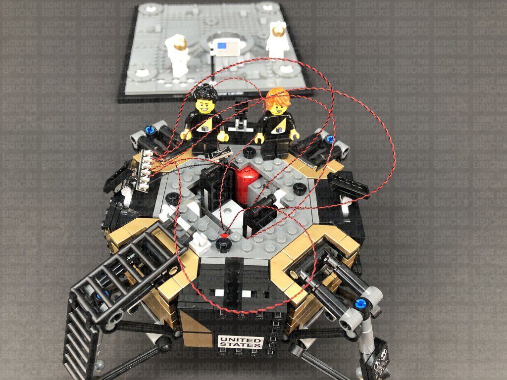
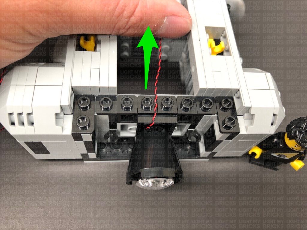
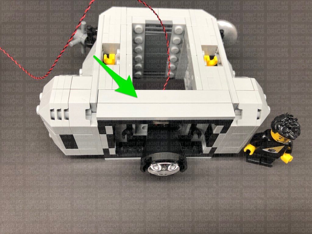
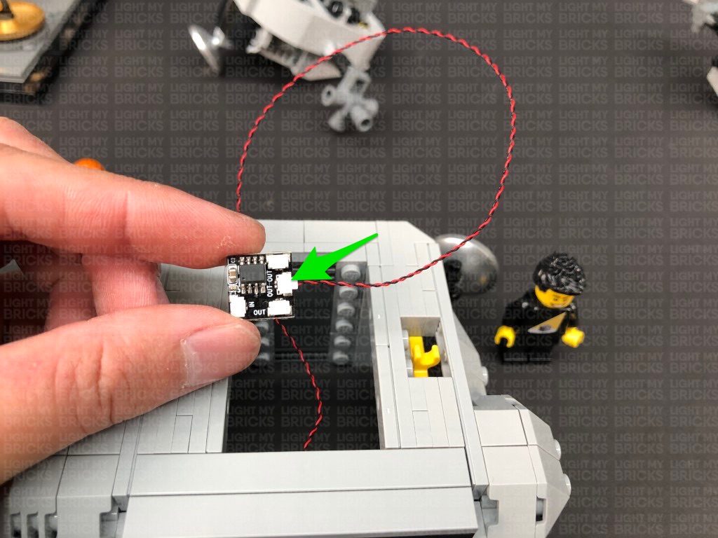
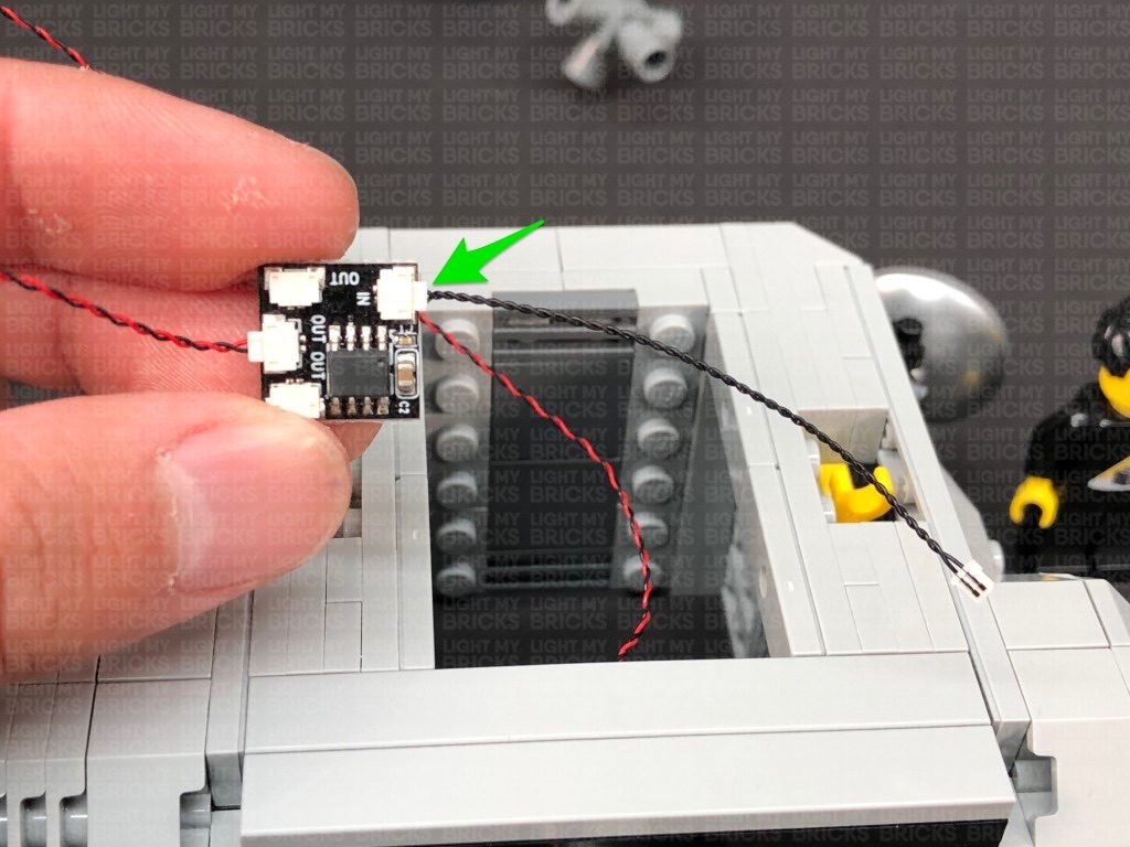
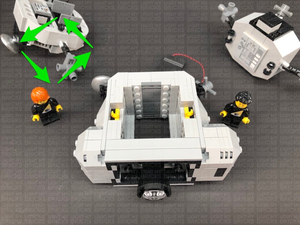
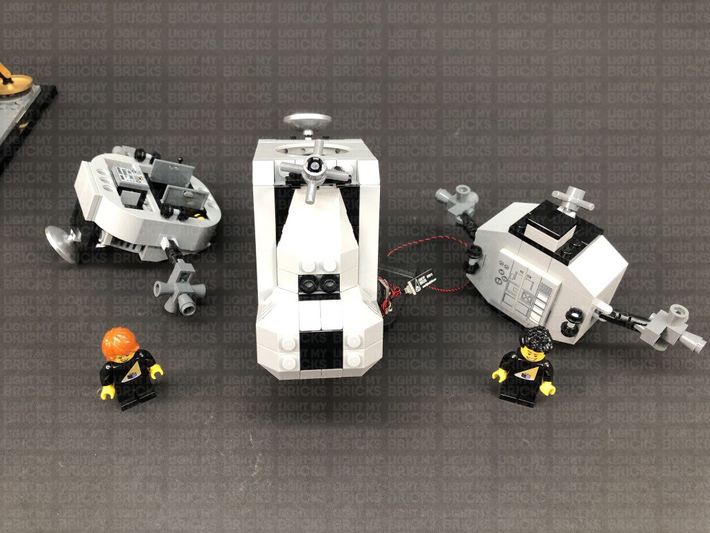
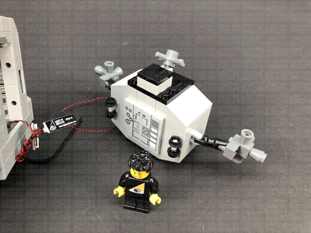
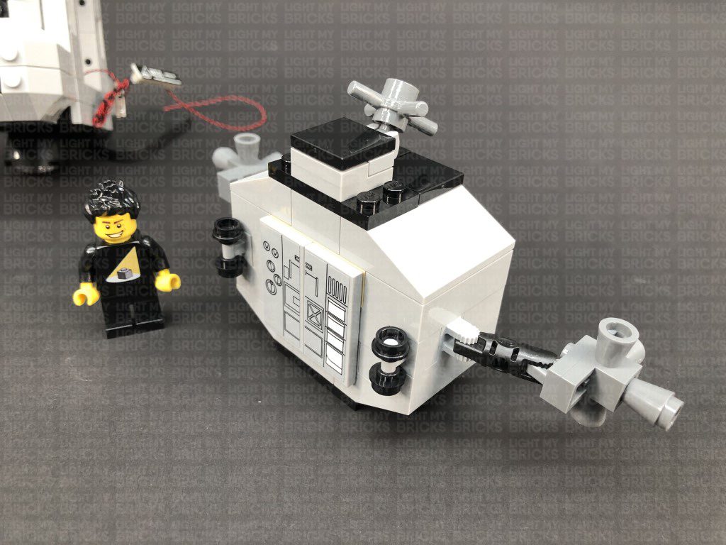
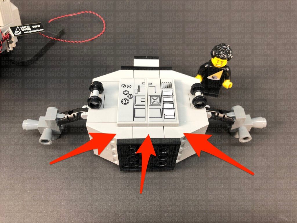
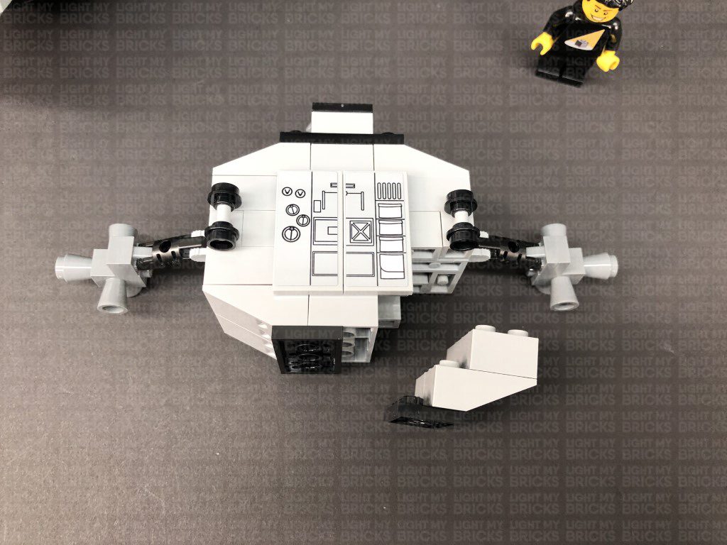
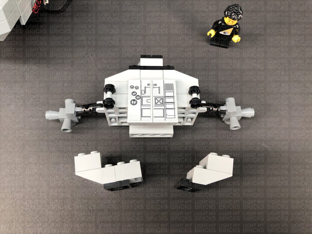
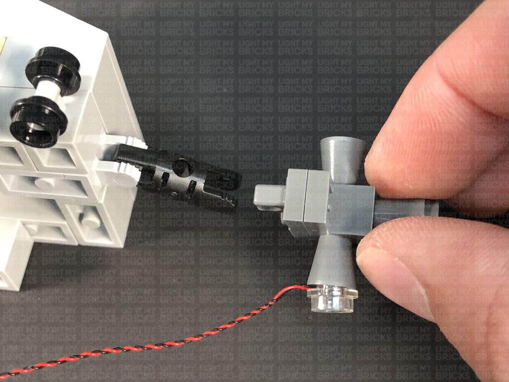
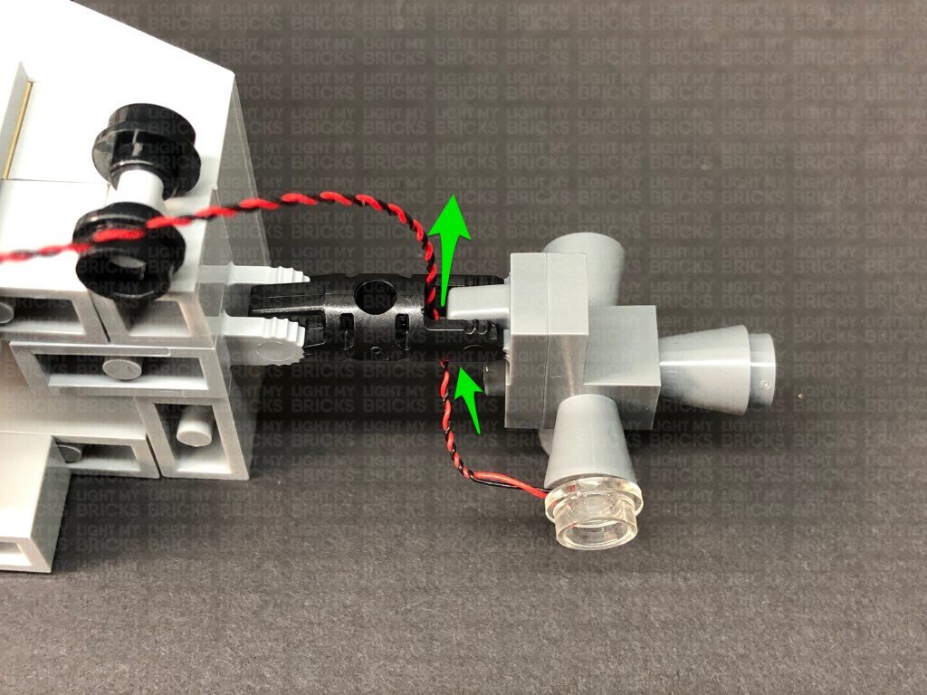
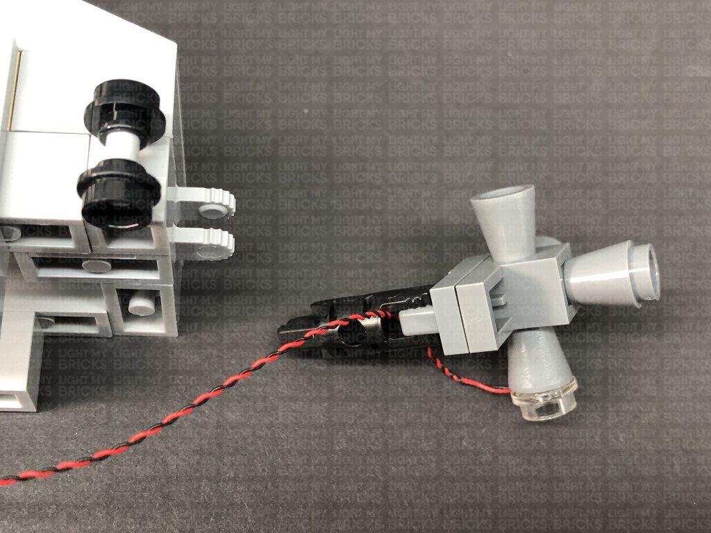
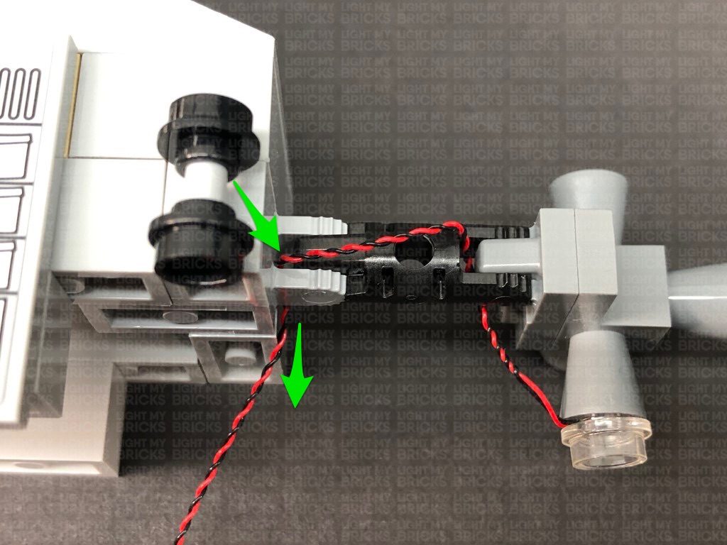
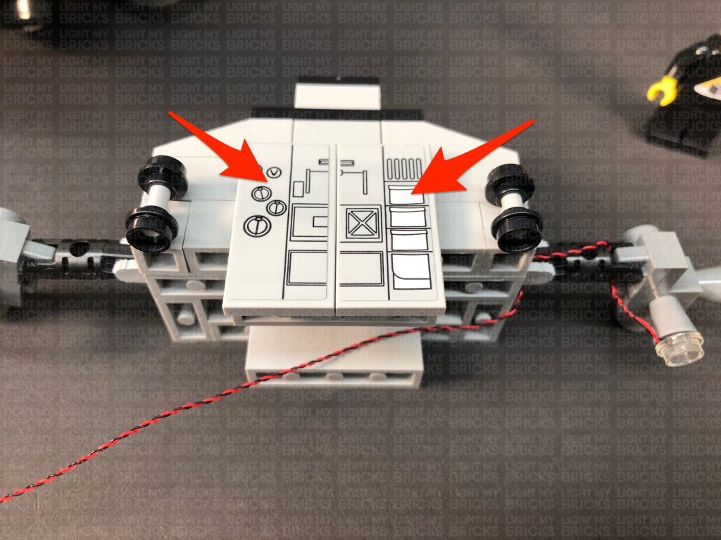
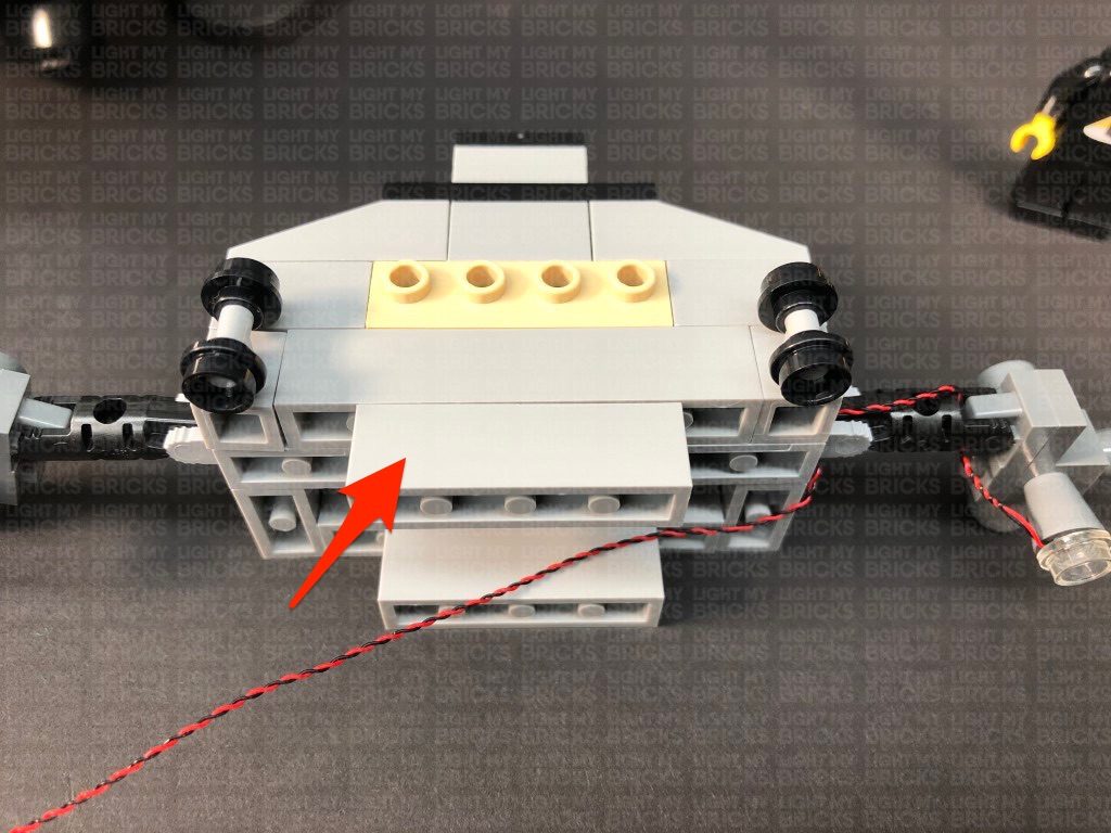
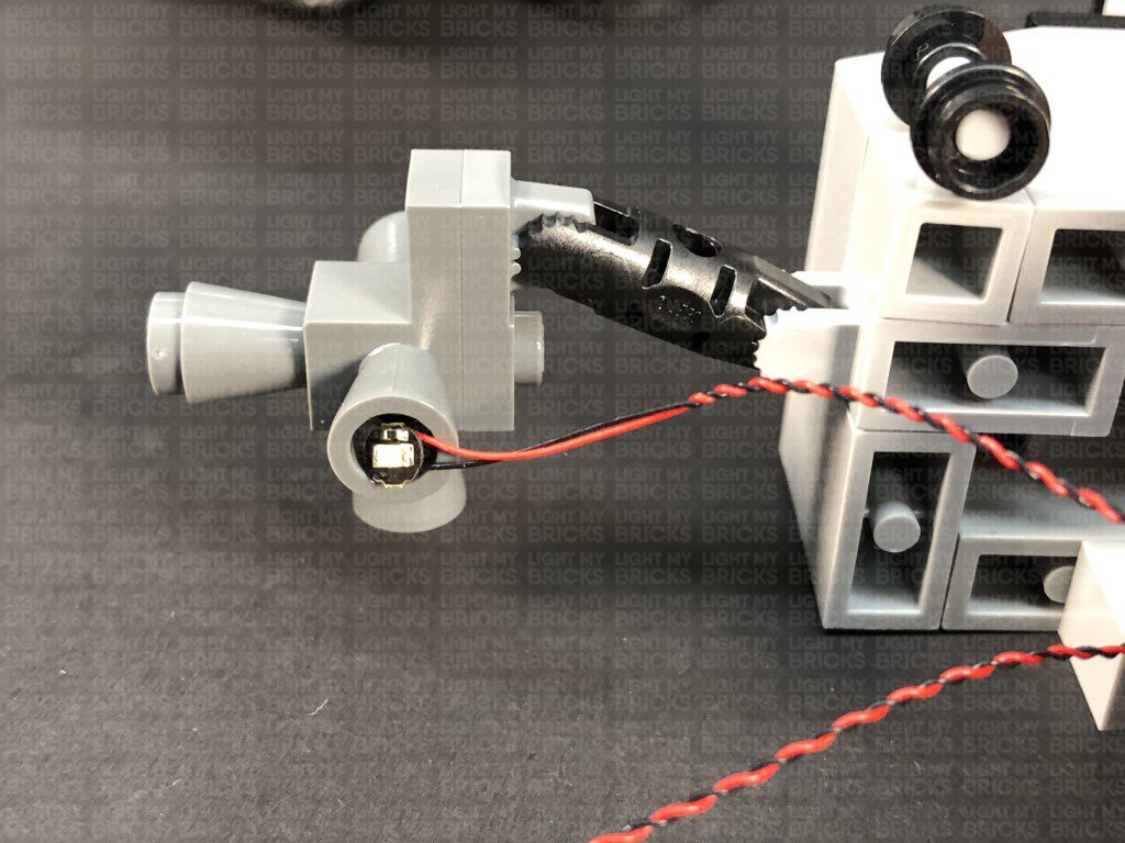
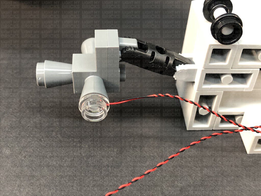
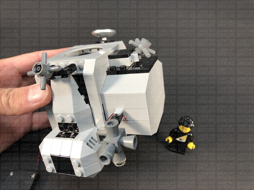
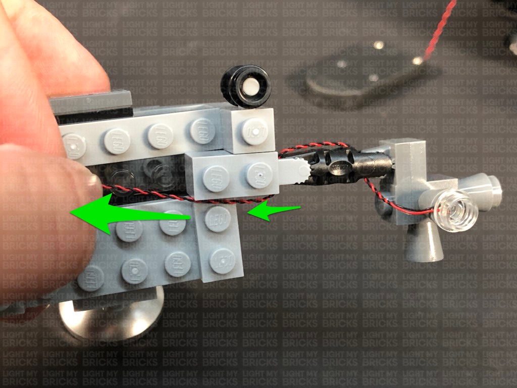
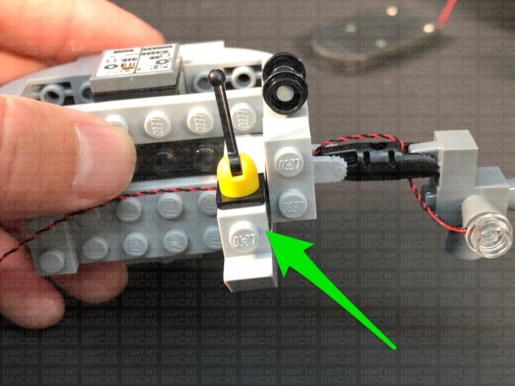
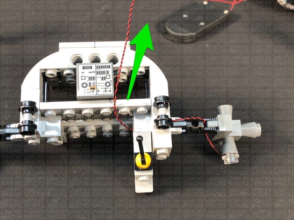
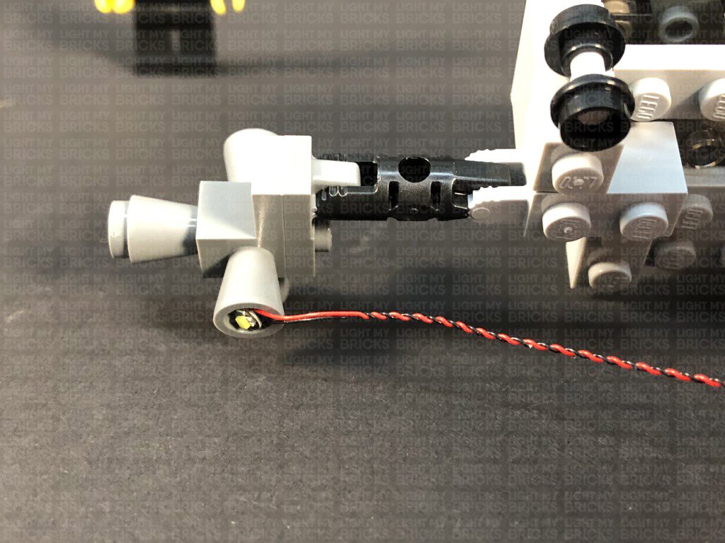
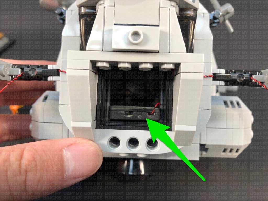
1.) We will start with lighting the bottom section of the Lander. First disconnect the upper shuttle, then remove the bottom section from the base and turn it onto it’s side. Disconnect the Jet section as per below: Take the Jet section and slightly disconnect the part above by pulling it up, then push the technic pin out slightly by approx. 5mm. 2.) Take the Blue 30cm Bit Light and loop the cable as shown below: Place the loop of the cable around the technic bar’s head, then pull the other end of the cable so that the cable tightens the loop securely around the technic bar. Push the bar back in to secure the cable in between. Thread the other end of the cable through the following space of the frame above, then pull the cable all the way out from the other side. Push the section above back down, then push the cable down into the corner of the inside of the Jet section. Fold down the cable on the outside. 3.) Thread the Bit Light cable through the technic plate hole underneath the lower section of the Lander, pull the cable all the way out from above, then reconnect the Jet section. Connect the Blue Bit Light to one of the OUT ports on a Flicker Effects Board. Take a 5cm Connecting Cable and connect it to the IN port on the Flicker Effects Board, then connect the other end of the cable to a 6-Port Expansion Board. 4.) Turn the Lander around to the back and disconnect the following section in the middle. Pull the two grey plates out to allow us to disconnect the dark grey plate behind. Take a Flat Battery Pack and insert 2x new CR2032 batteries to it. Thread the battery pack cable through the following space that leads inside the Lander and pull it out from the inside, then connect it to the 6-Port Expansion Board. Turn the Battery Pack ON to test the blue jet light is working OK and flickering! Note: If you experience any issues with the lights not working and suspect an issue with a component, please try a different port on the expansion board to verify where the fault lies (with the light or expansion board). To correct any issues with expansion board ports, please view the section addressing expansion board issues on our online troubleshooting guide. 5.) Place the Battery Pack on top of the lander, then pull the cable inside until there is approx. 5cm of cable left between the battery pack and left corner of the middle section. Reconnect the dark grey plate and push in the two light grey plates to secure the battery pack cable. Reconnect the black wall section, then take 2x Adhesive Squares and stick them to the back of the Battery Pack. Mount the battery pack to the outside of the Lander in the below position (mount to the flat surface of the black plates): Secure the battery pack cable in between pieces as shown below: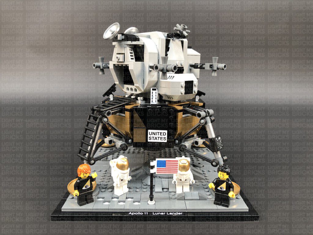
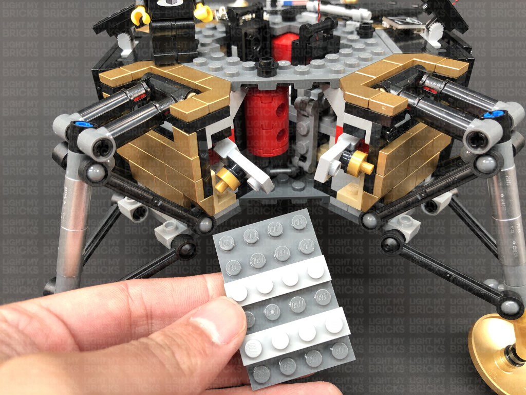
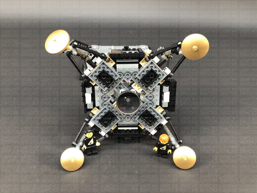
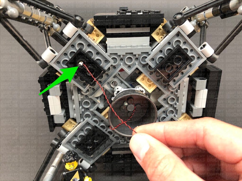
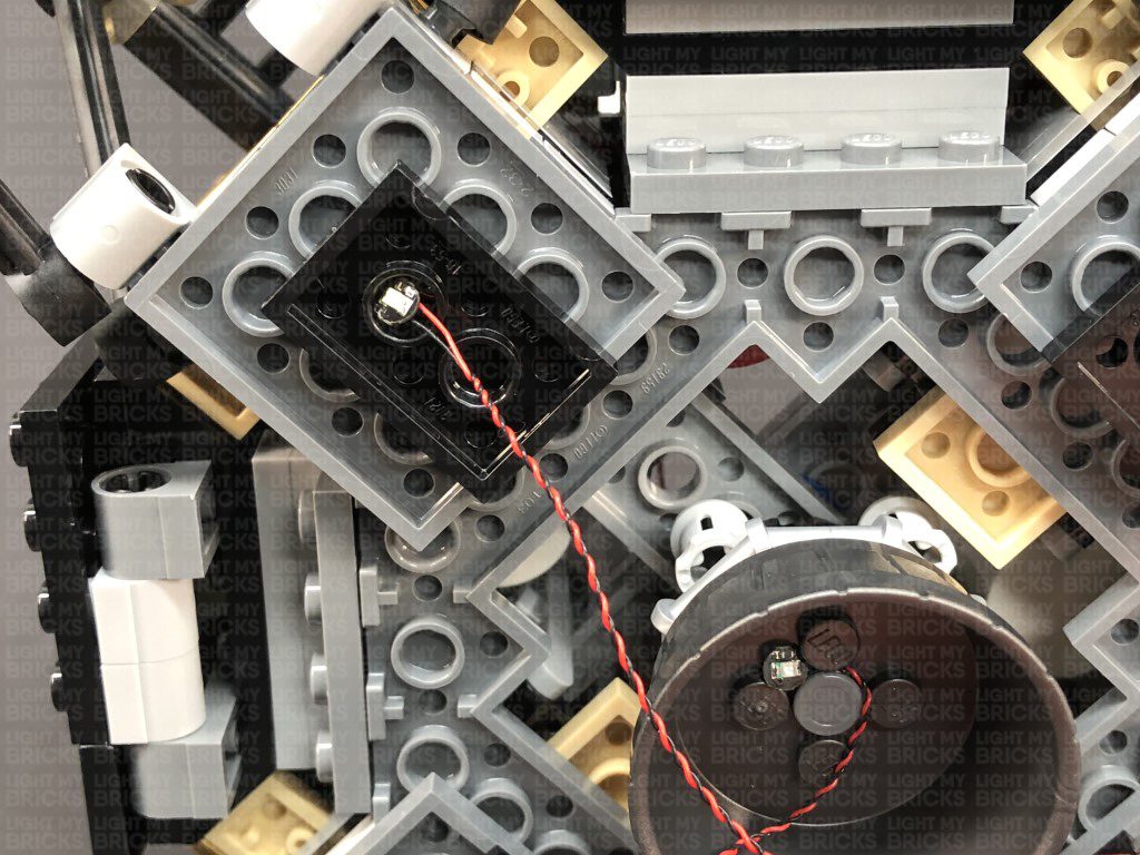
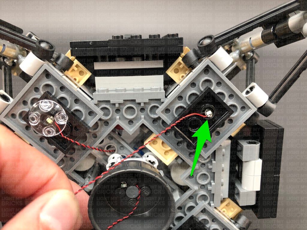
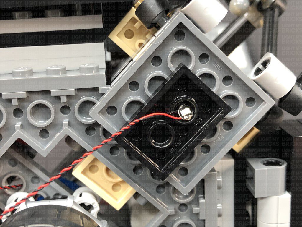
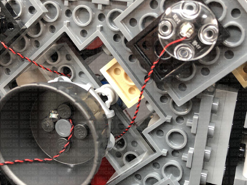
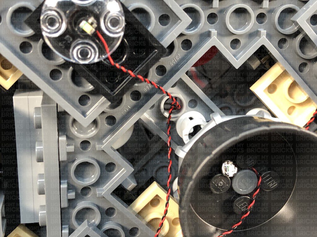
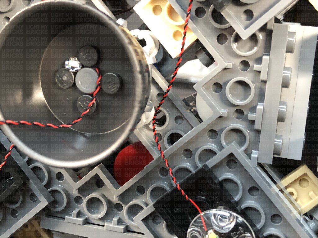
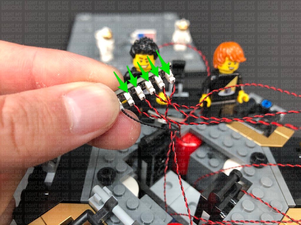
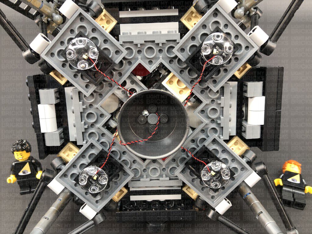
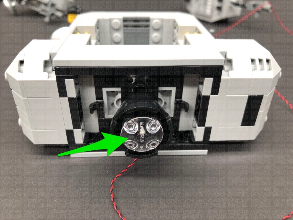
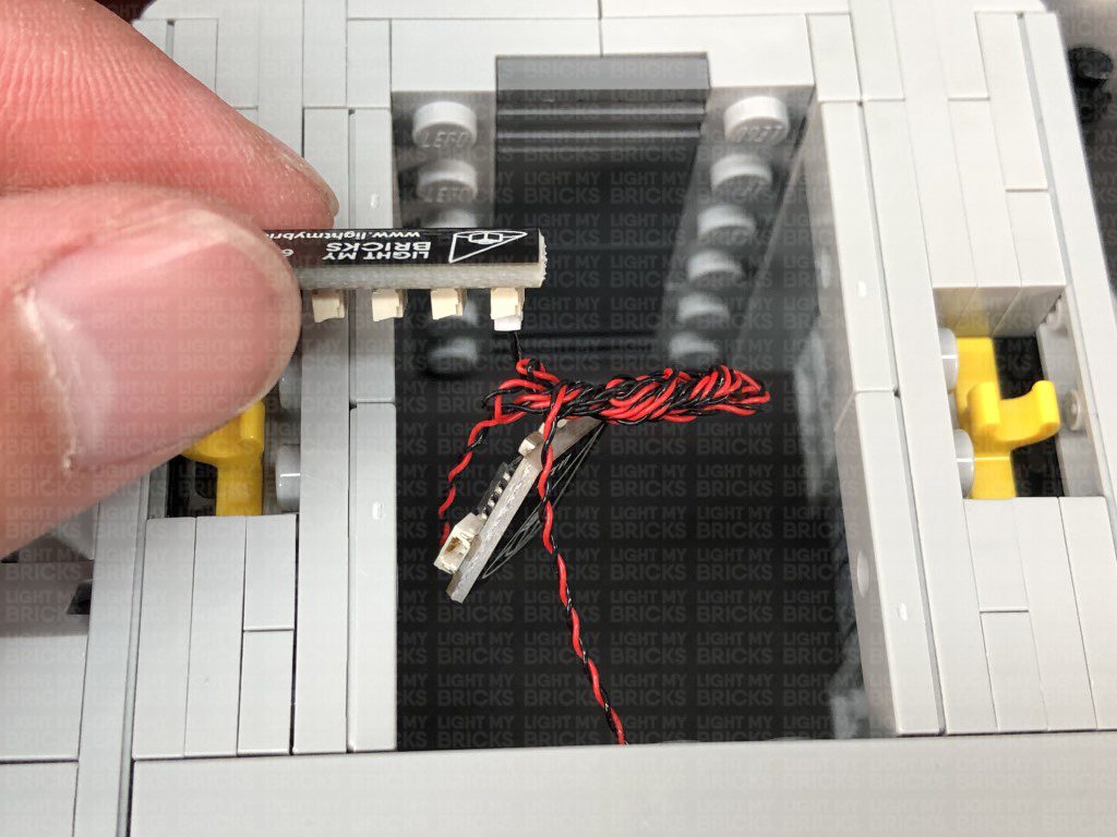
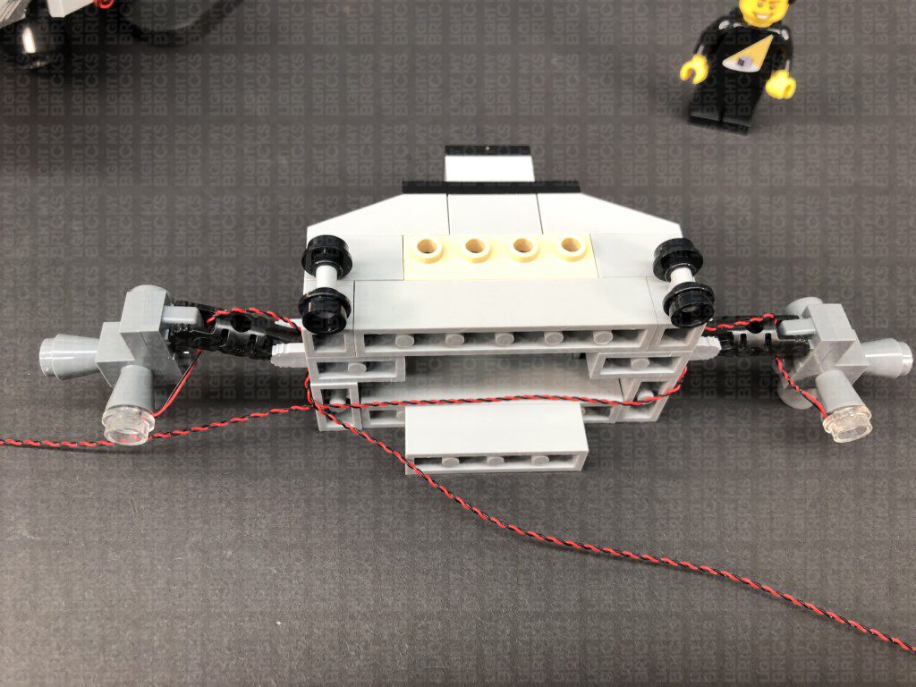
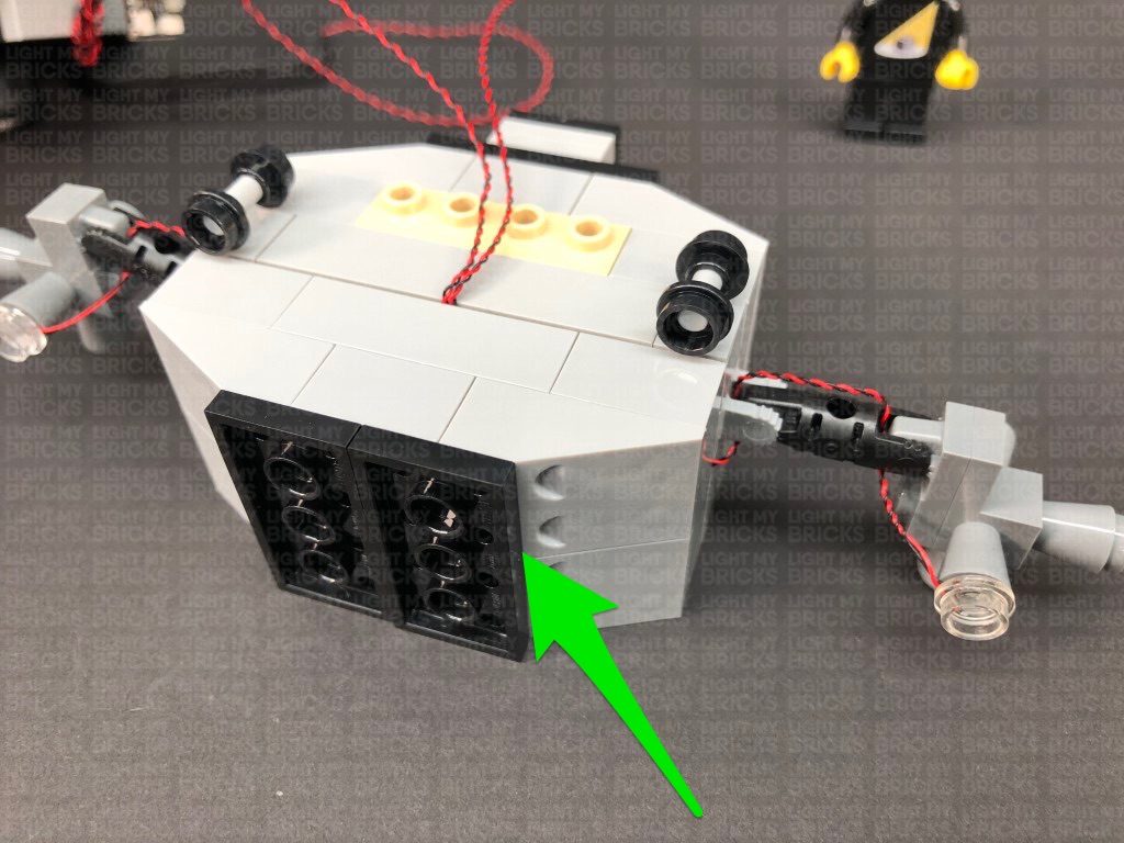
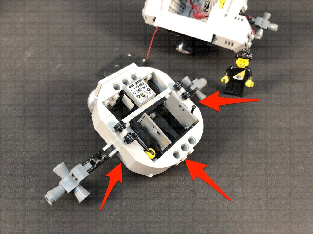
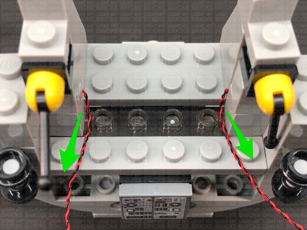
 6.) Turn the bottom section of the Lander around to the front, then onto it’s back side so we can access underneath. Take a Cool White 30cm Bit Light, and with the cable facing down, place the Bit Light underneath the Lander inside the hole underneath the black 2×3 plate, as per below. Secure the Bit Light in place by connecting a provided Trans Clear Plate w Rounded Bottom 2×2 over the top.
Thread the other end of the Bit Light up the following hole of the technic plate, then pull the cable all the way out from the other side.
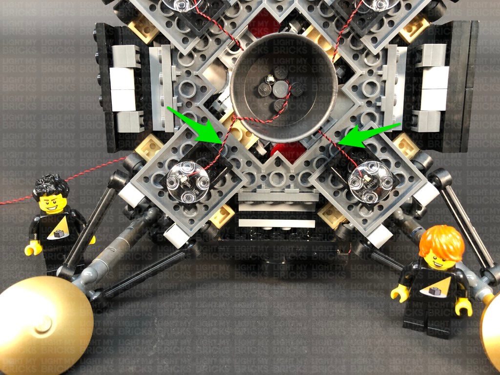
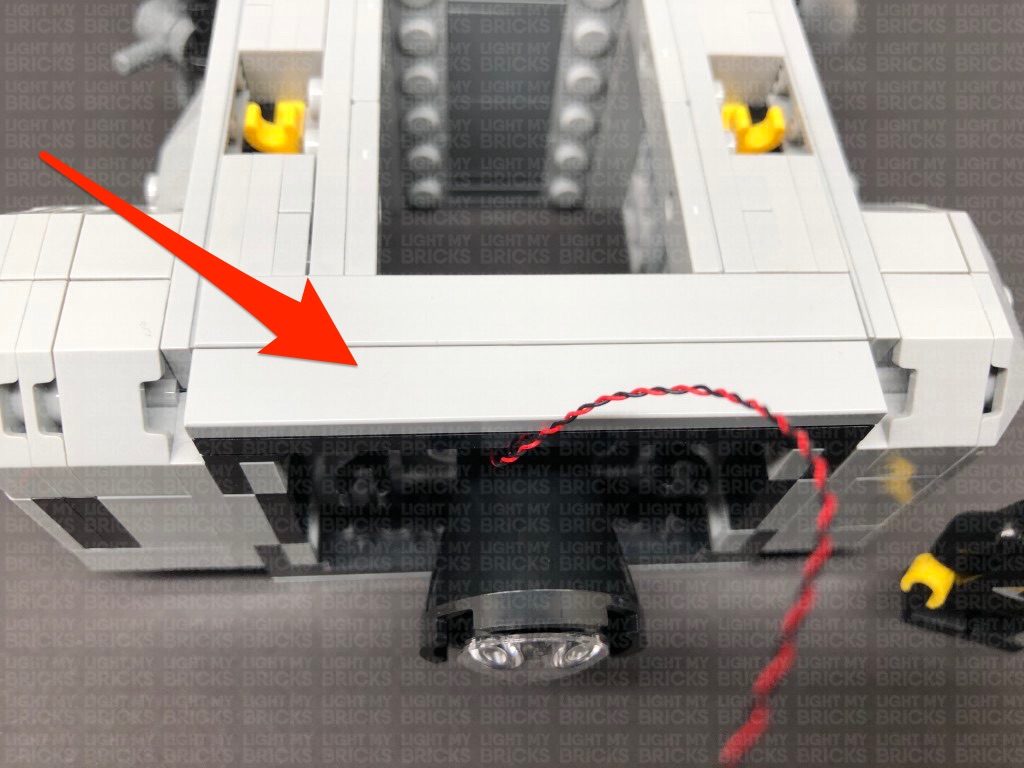
Using this same method, install another Cool White 30cm Bit Light to the right side, securing it in place by connecting another Trans Clear Plate w Rounded Bottom 2×2 over the top. Thread the Bit Light cable through a different hole as shown below:
Push both cables down behind the edge of the black 2×3 plate to prevent them from dangling later on.
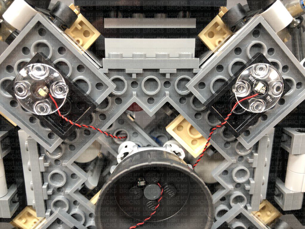
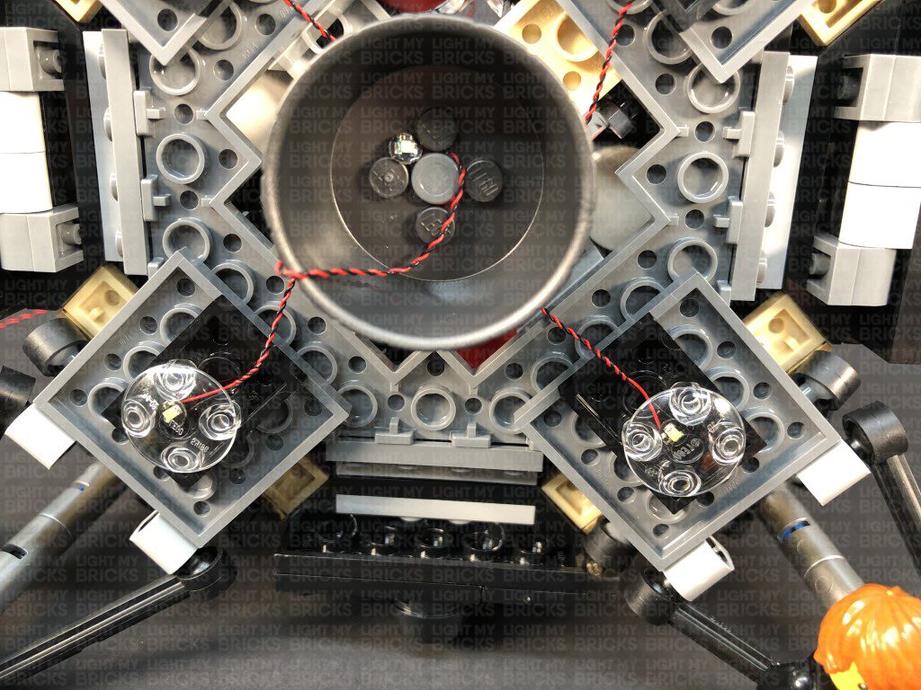
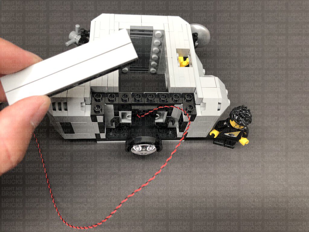
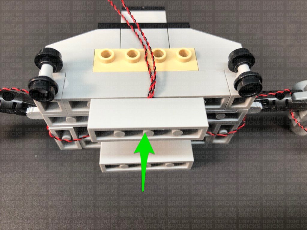
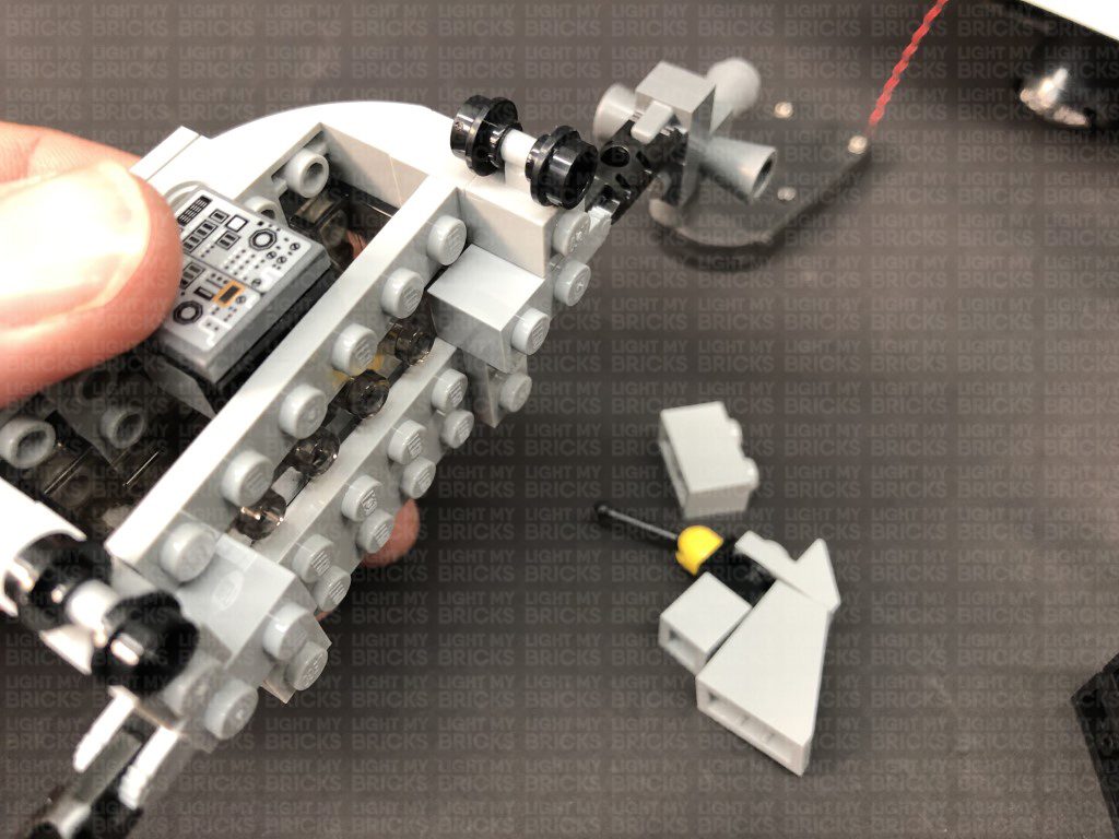
7.) Take another Cool White 30cm Bit Light and with the cable facing up, place it over the lower hole underneath the black 2×3 plate on the bottom left, as per below. Secure the Bit Light in place by connecting another provided Trans Clear Plate w Rounded Bottom 2×2 over the top. Thread the cable all the way through the same hole we threaded the first Cool White Bit Light through.
Repeat this process to install another Cool White 30cm Bit Light to the bottom right side, securing it in place by connecting another Trans Clear Plate w Rounded Bottom 2×2 over the top. Thread the Bit Light cable all the way through the same hole we did for the second Cool White Bit Light we installed in previous step.
Push both cables down behind the edge of the black 2×3 plate to prevent them from dangling later on.
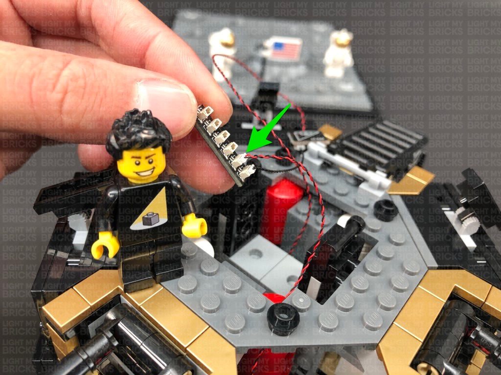
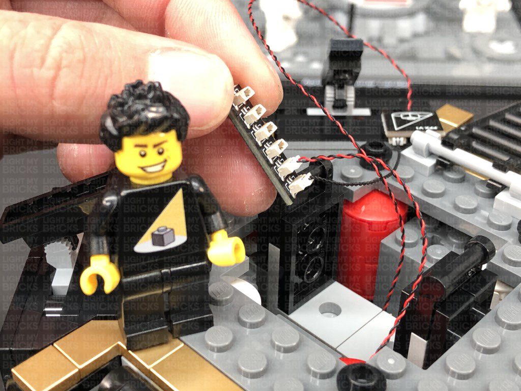
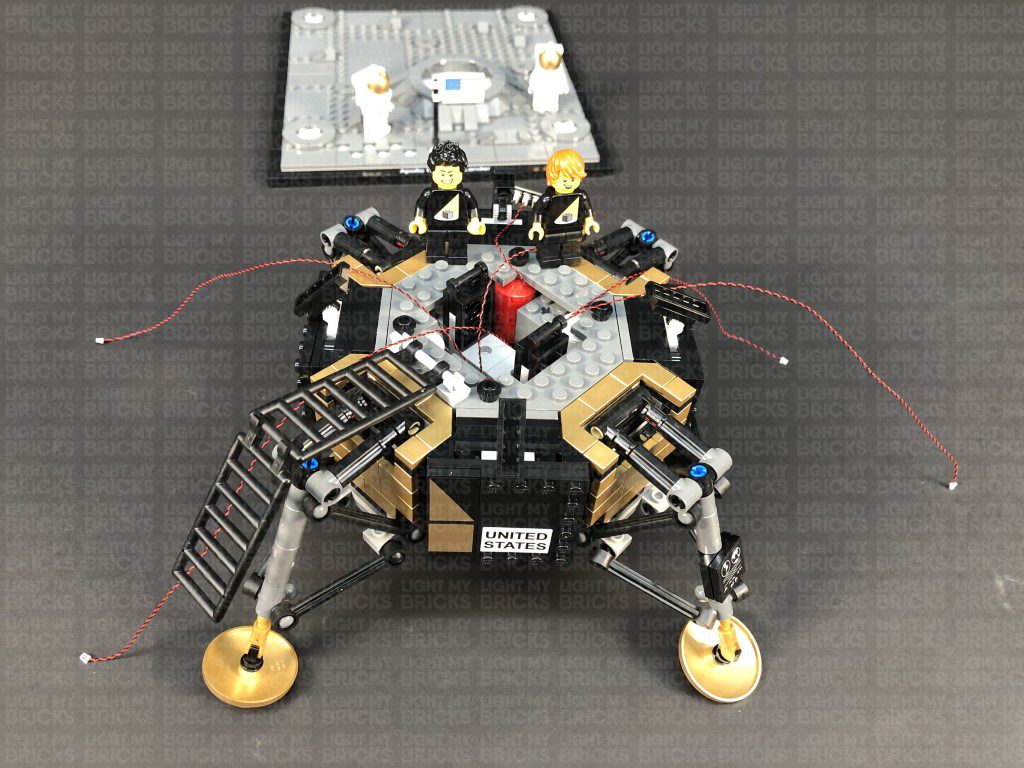
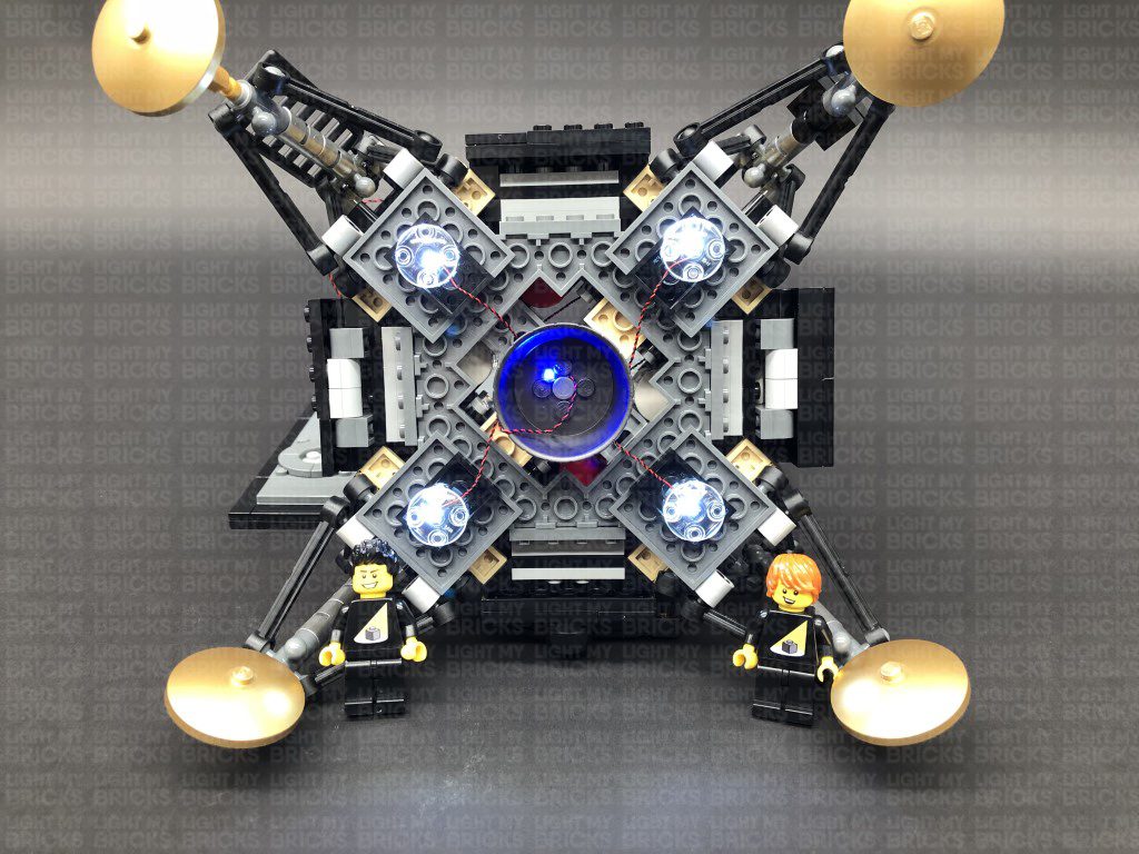
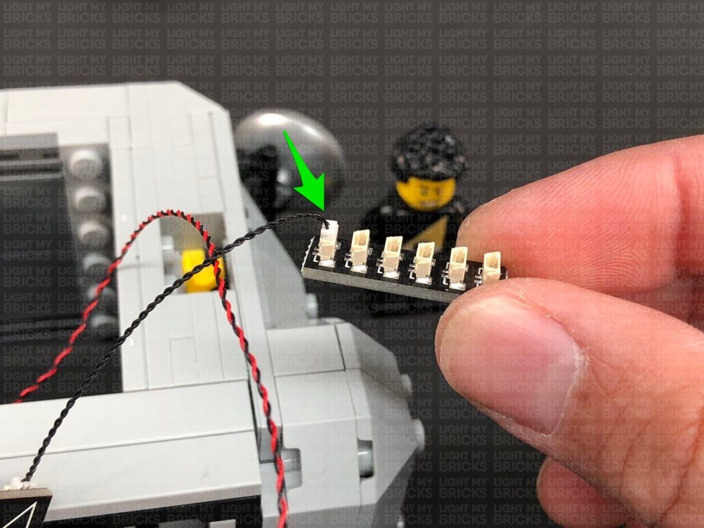
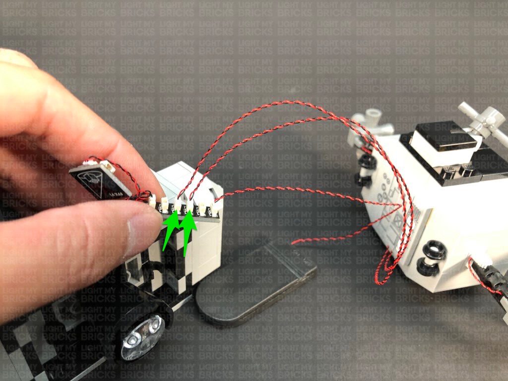
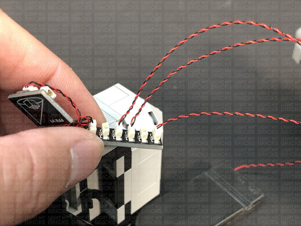
8.) Turn the Lander back over, then connect all four Bit Light cables to the 6-Port Expansion Board. Turn the Flat Battery Pack located on the back ON to test the lights are all working OK, then place the Lander back onto the base plate.
Note: If you experience any issues with the lights not working and suspect an issue with a component, please try a different port on the expansion board to verify where the fault lies (with the light or expansion board). To correct any issues with expansion board ports, please view the section addressing expansion board issues on our online troubleshooting guide.
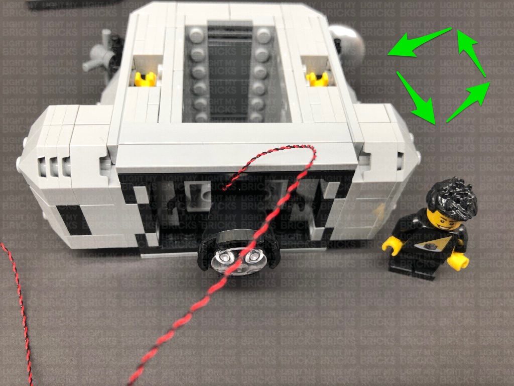
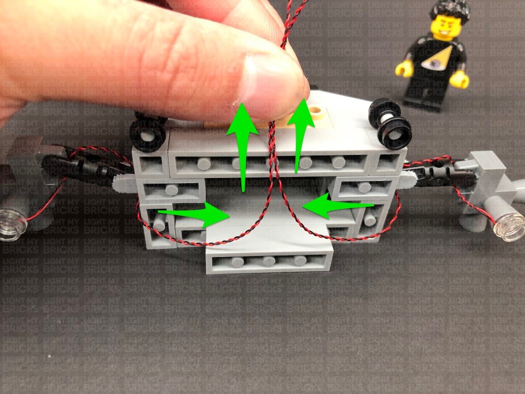
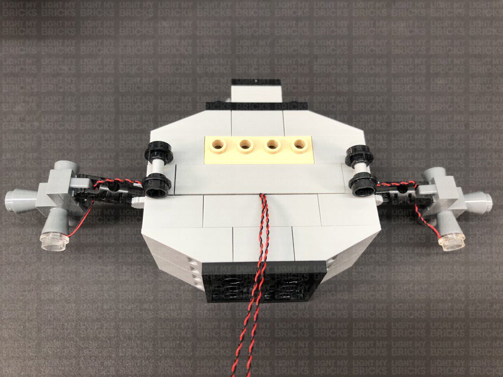
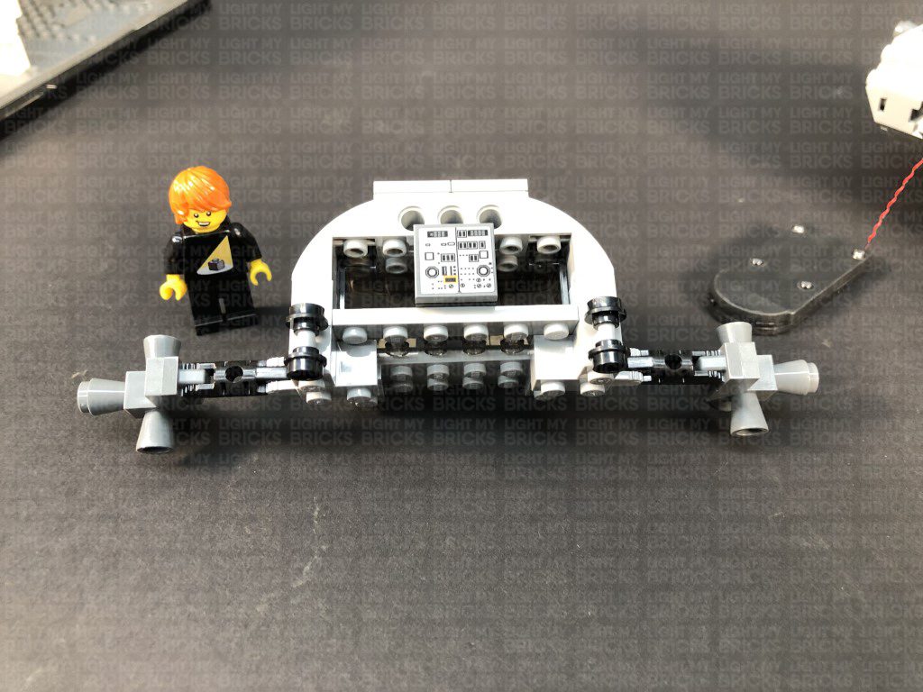
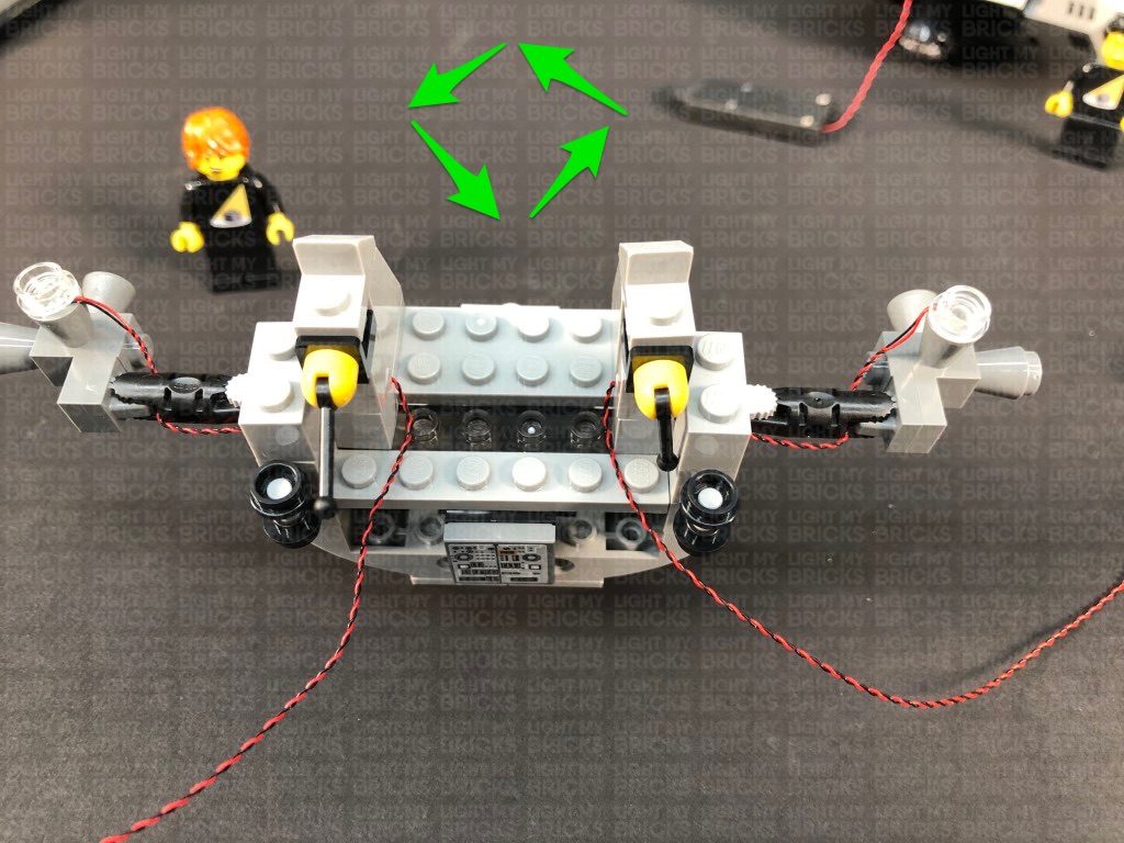
9.) Neaten up cabling by grouping all the cables together, then folding and twisting them around each other into a neat bunch as shown below:
Take the four cables from the Cool White Bit Lights and pull them up and twist them around each other. This will help prevent them from dangling down underneath.
Neatly tuck the bunched up cables into the spaces on the side, then tuck the expansion board and flicker effects board into the far sides as shown below:
6.) Turn the bottom section of the Lander around to the front, then onto it’s back side so we can access underneath. Take a Cool White 30cm Bit Light, and with the cable facing down, place the Bit Light underneath the Lander inside the hole underneath the black 2×3 plate, as per below. Secure the Bit Light in place by connecting a provided Trans Clear Plate w Rounded Bottom 2×2 over the top.
Thread the other end of the Bit Light up the following hole of the technic plate, then pull the cable all the way out from the other side.
Using this same method, install another Cool White 30cm Bit Light to the right side, securing it in place by connecting another Trans Clear Plate w Rounded Bottom 2×2 over the top. Thread the Bit Light cable through a different hole as shown below:
Push both cables down behind the edge of the black 2×3 plate to prevent them from dangling later on.
7.) Take another Cool White 30cm Bit Light and with the cable facing up, place it over the lower hole underneath the black 2×3 plate on the bottom left, as per below. Secure the Bit Light in place by connecting another provided Trans Clear Plate w Rounded Bottom 2×2 over the top. Thread the cable all the way through the same hole we threaded the first Cool White Bit Light through.
Repeat this process to install another Cool White 30cm Bit Light to the bottom right side, securing it in place by connecting another Trans Clear Plate w Rounded Bottom 2×2 over the top. Thread the Bit Light cable all the way through the same hole we did for the second Cool White Bit Light we installed in previous step.
Push both cables down behind the edge of the black 2×3 plate to prevent them from dangling later on.
8.) Turn the Lander back over, then connect all four Bit Light cables to the 6-Port Expansion Board. Turn the Flat Battery Pack located on the back ON to test the lights are all working OK, then place the Lander back onto the base plate.
Note: If you experience any issues with the lights not working and suspect an issue with a component, please try a different port on the expansion board to verify where the fault lies (with the light or expansion board). To correct any issues with expansion board ports, please view the section addressing expansion board issues on our online troubleshooting guide.
9.) Neaten up cabling by grouping all the cables together, then folding and twisting them around each other into a neat bunch as shown below:
Take the four cables from the Cool White Bit Lights and pull them up and twist them around each other. This will help prevent them from dangling down underneath.
Neatly tuck the bunched up cables into the spaces on the side, then tuck the expansion board and flicker effects board into the far sides as shown below:
 Ensure there are not dangling cables visible from underneath.
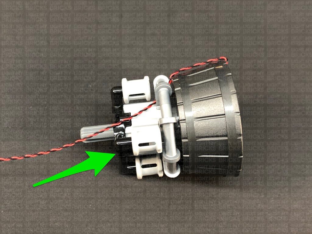
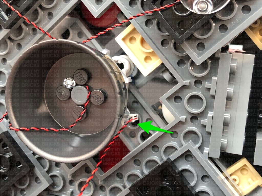
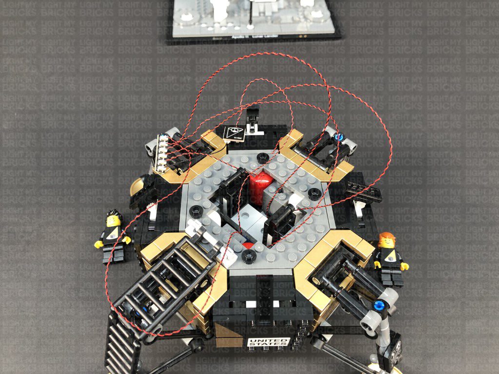
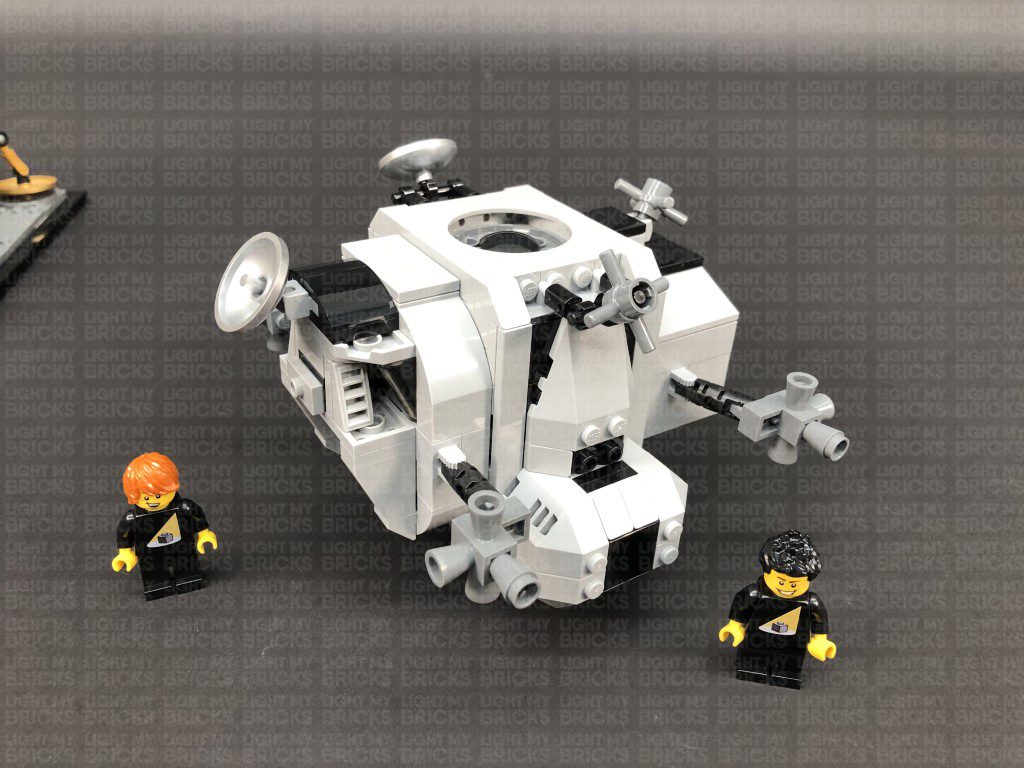
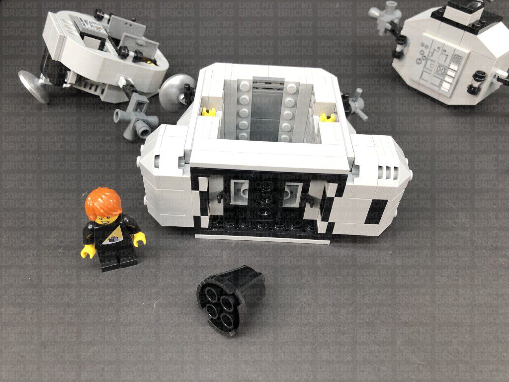
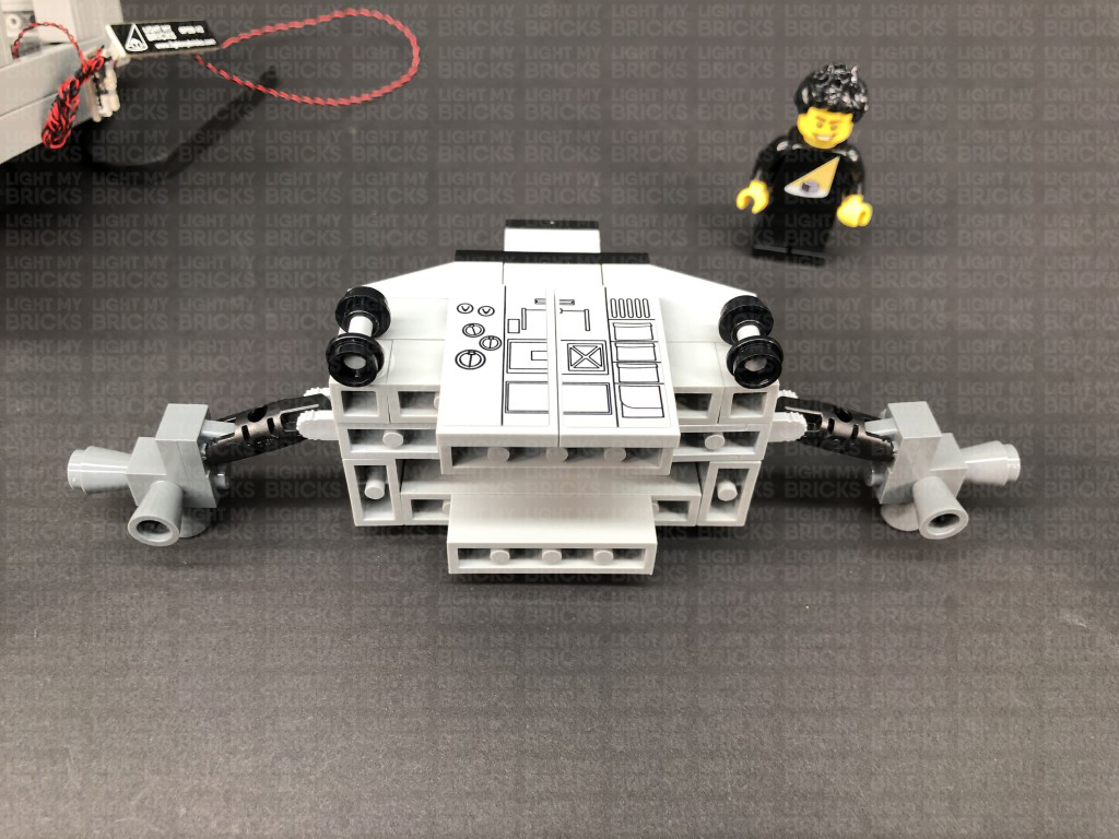
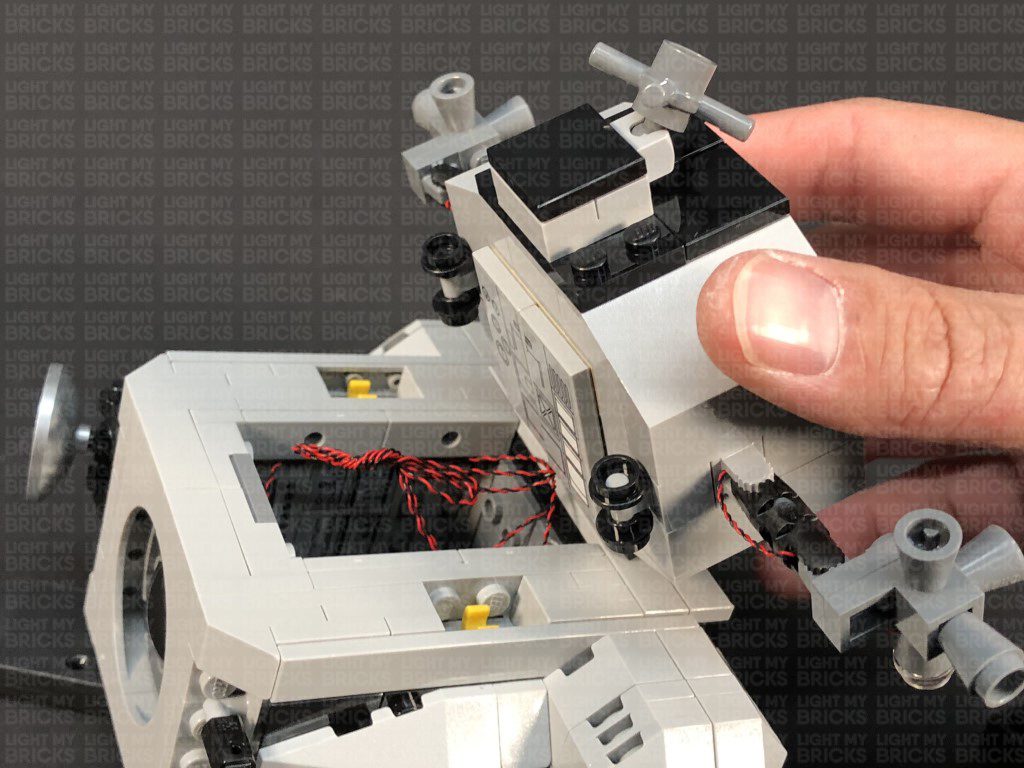
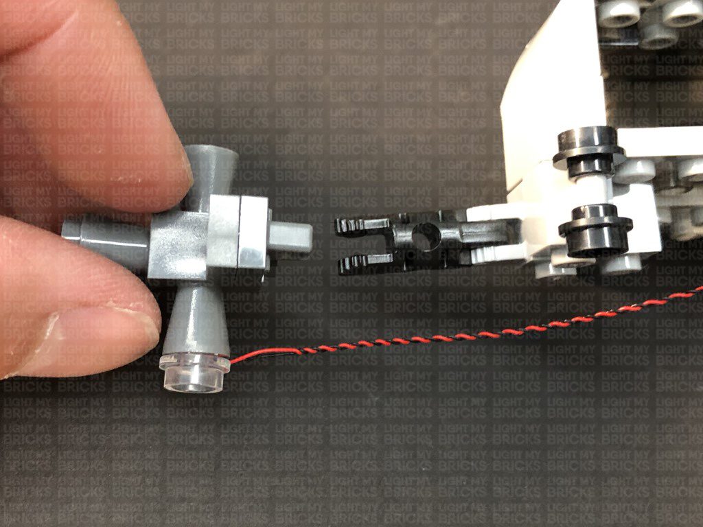
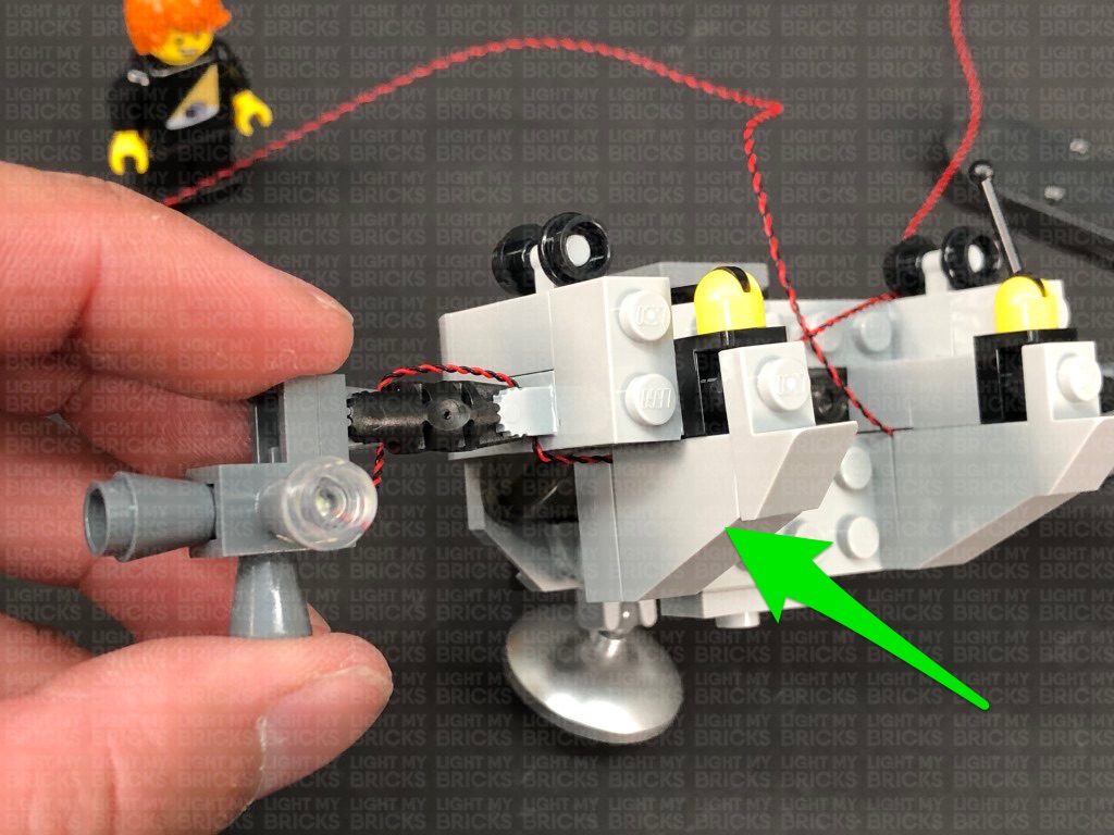
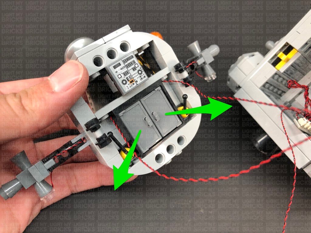
10.) We will now install lights to the upper shuttle of the Lander. First disconnect the side sections, then disconnect the Jet piece from underneath as shown below:
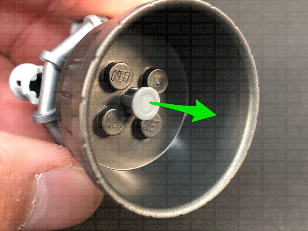
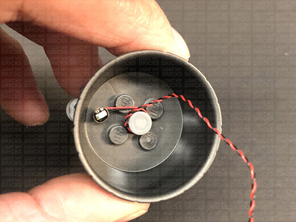
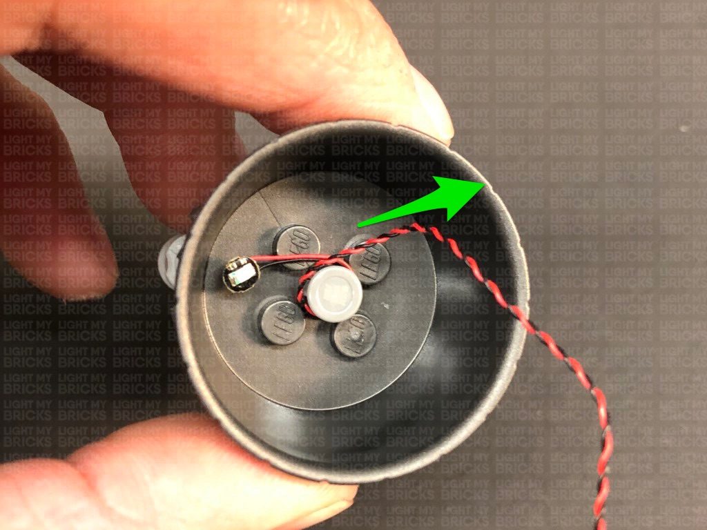
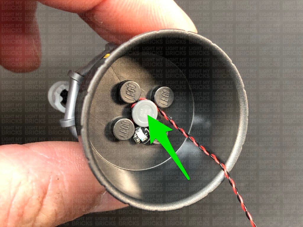
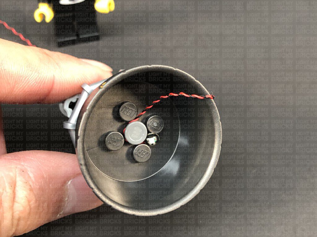
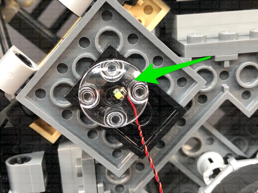
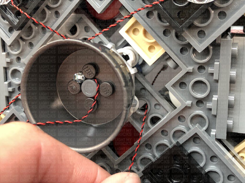
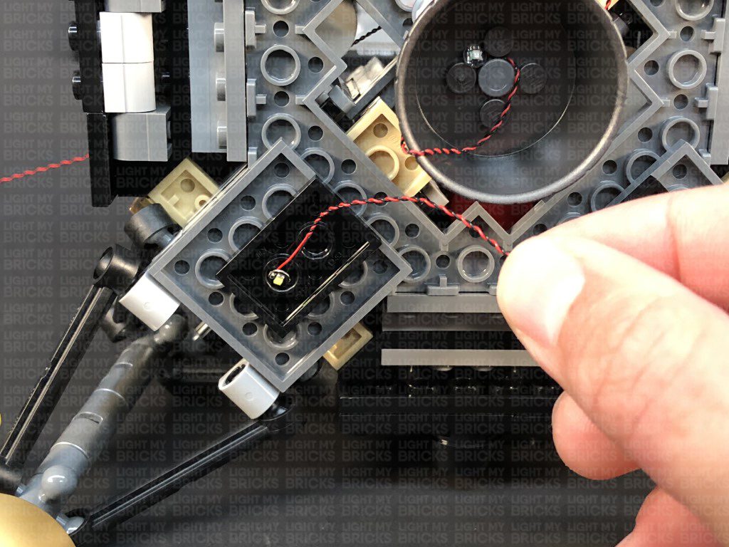
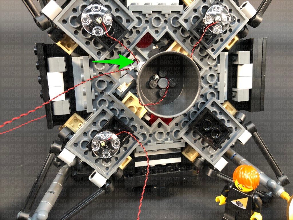
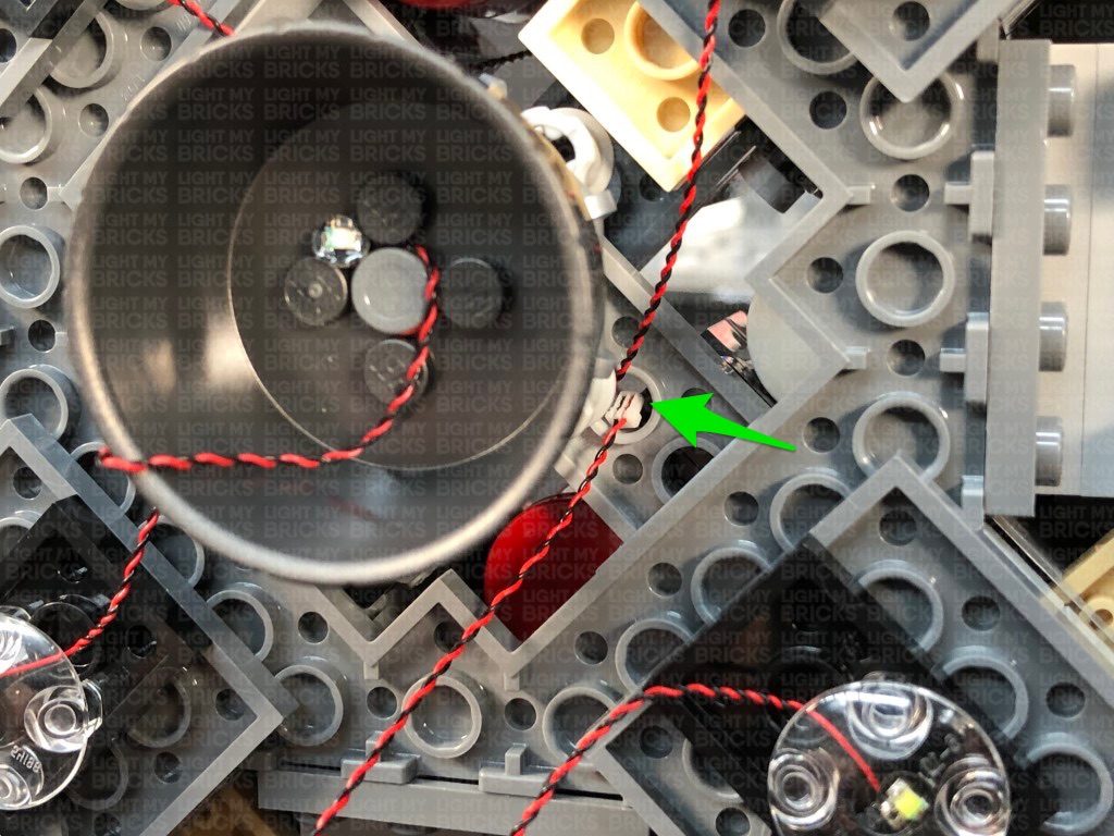
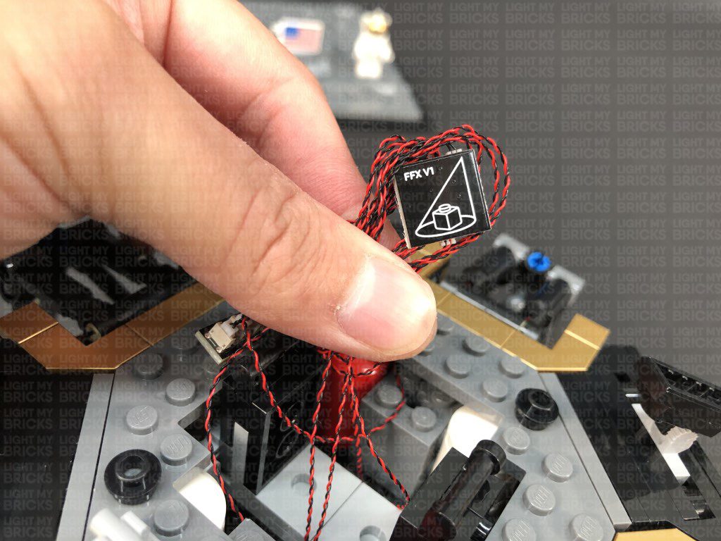
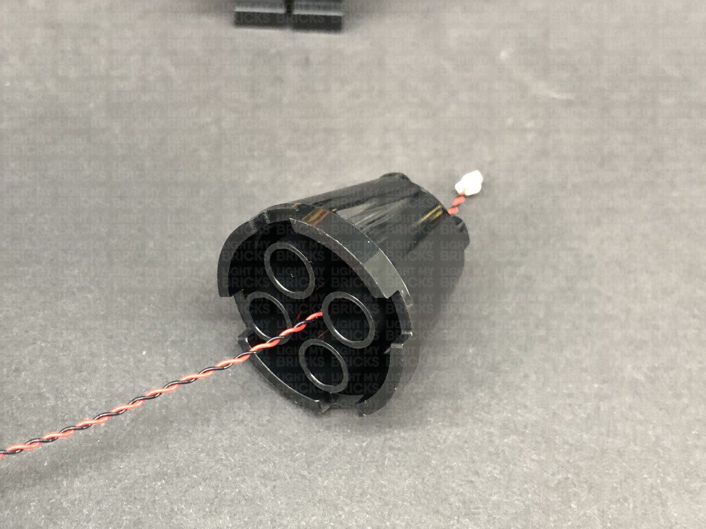
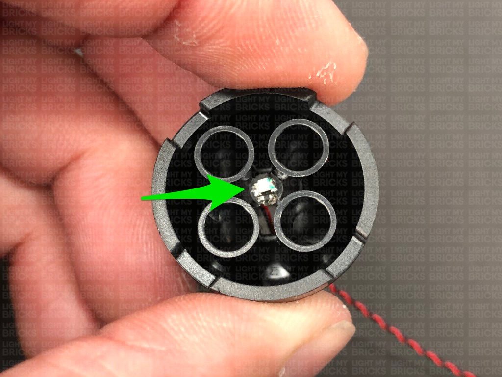
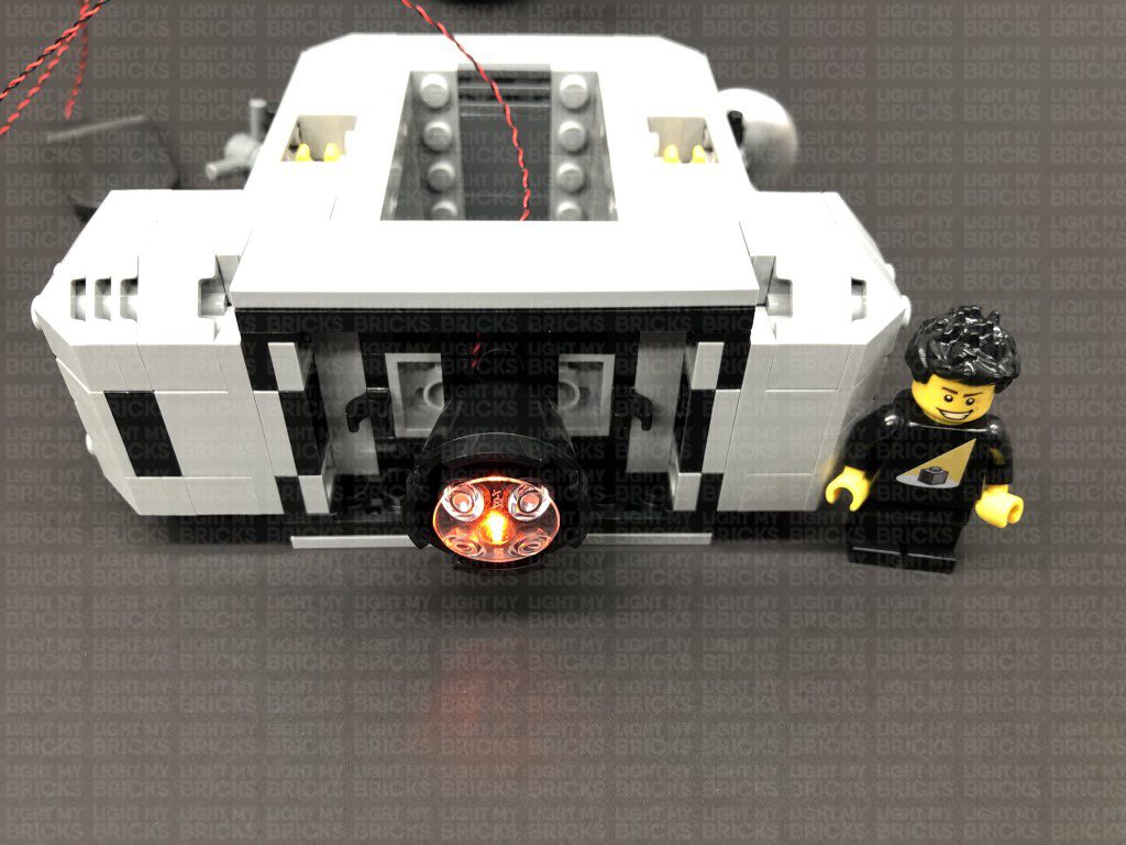
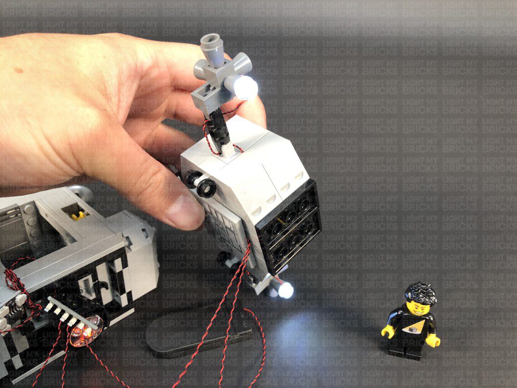
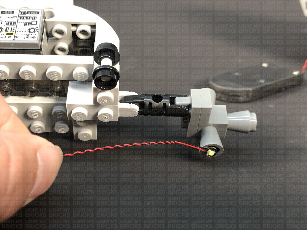
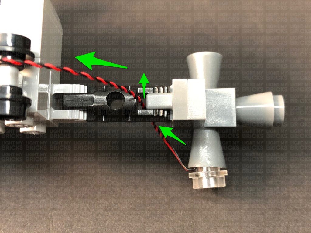
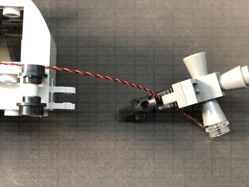
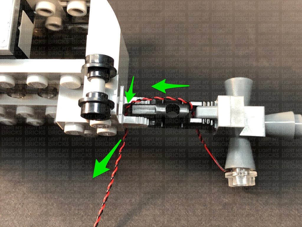
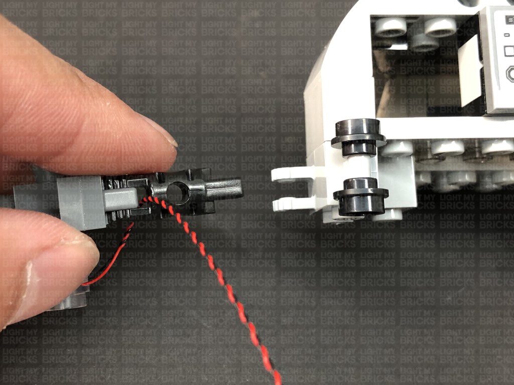
Take a Orange 30cm Bit Light and thread the connector side of the cable through the centre hole underneath of the Jet piece. Pull the cable out from the top of the piece, then carefully bend the Bit Light onto a 90 degree angle so that the LED is facing the same way as the cable.
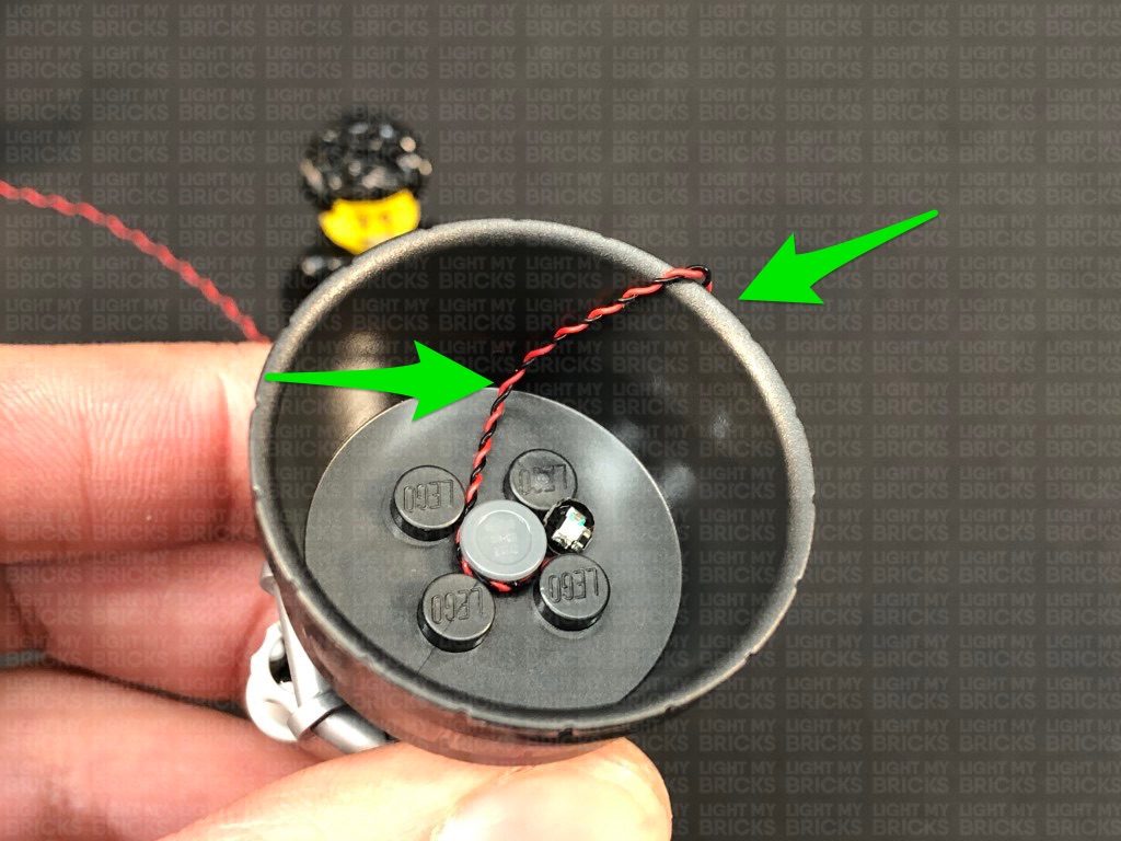
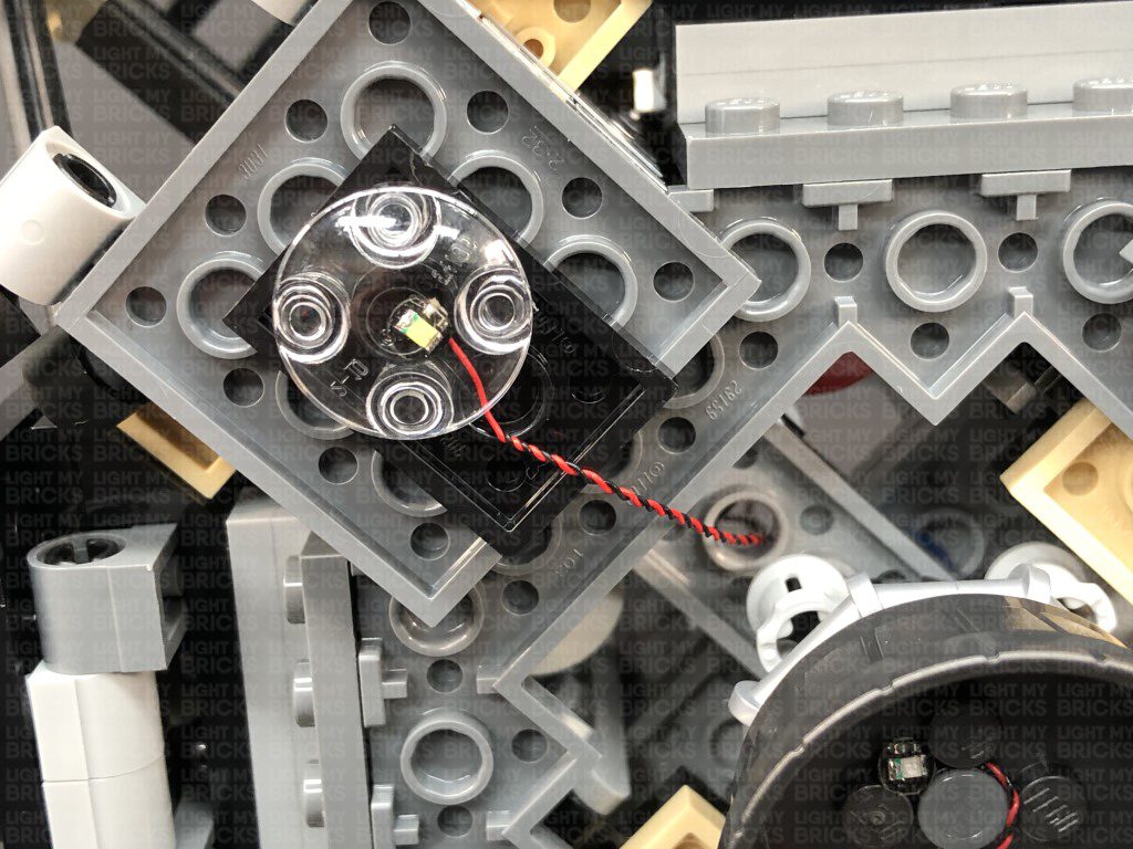
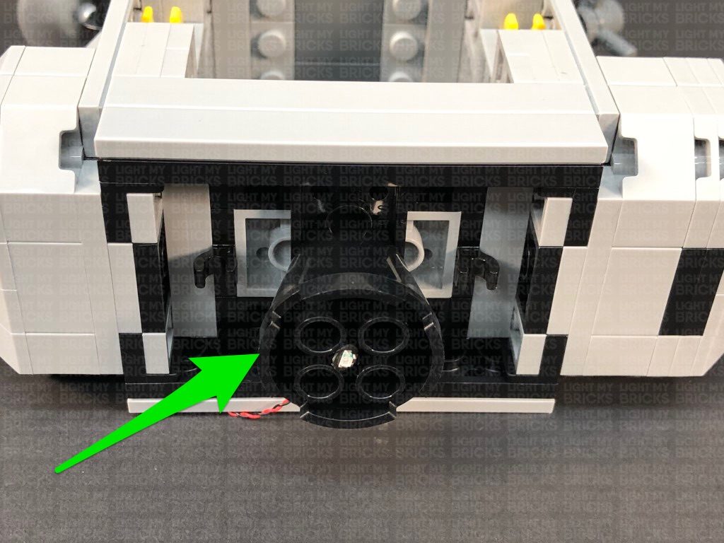
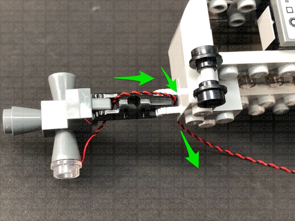
Place the LED in the centre of the 4 studs, then reconnect the Jet piece underneath the upper section of the Lander. Ensure the other end of the cable is facing down and in between the two studs of the Jet section. Take the remaining Trans Clear Plate w Rounded Bottom 2×2 and connect it over the Bit Light as shown below. The trans clear piece will help distribute the light underneath the shuttle.
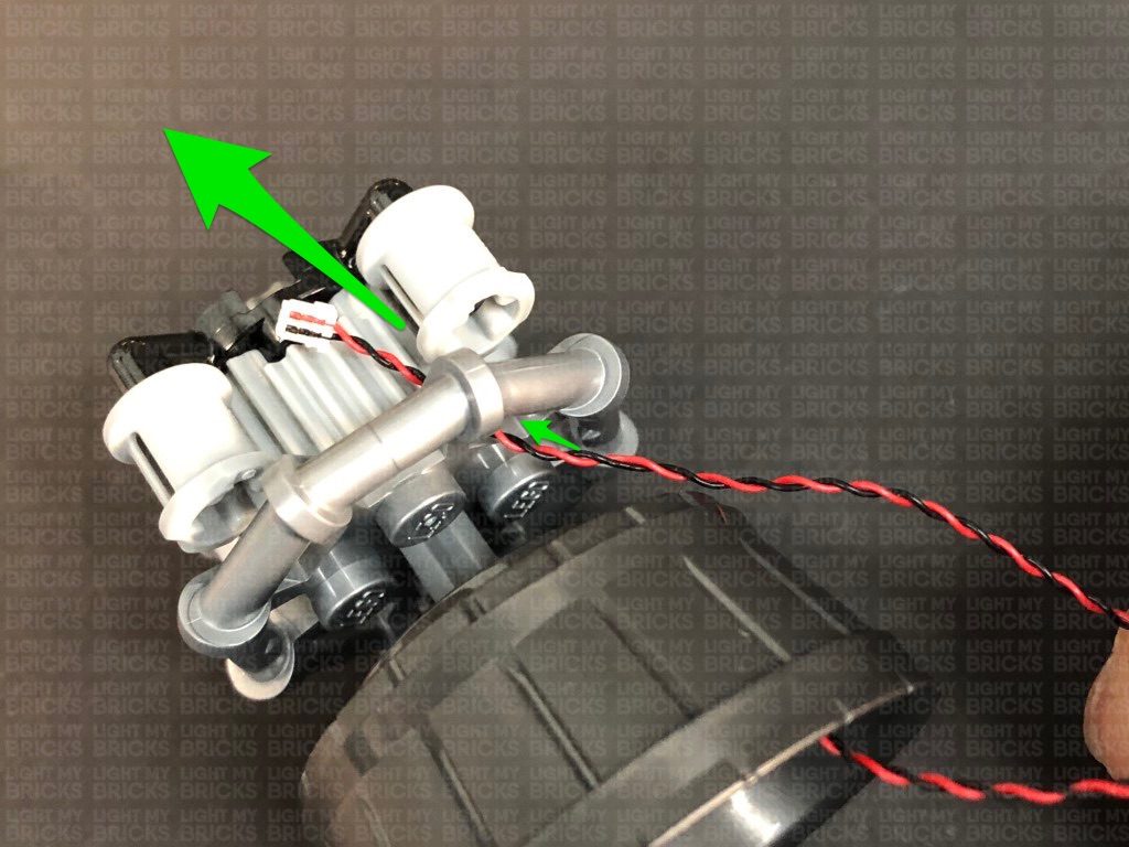
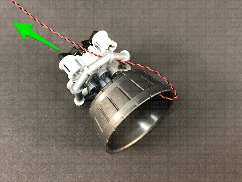
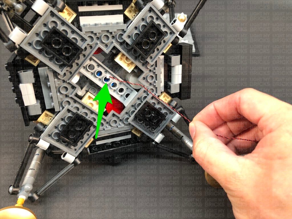
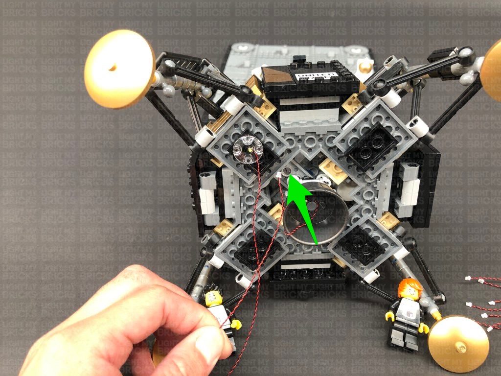
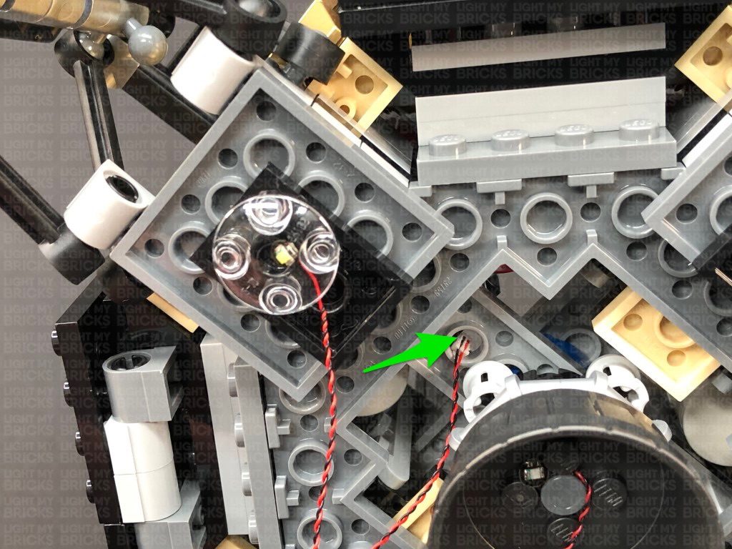
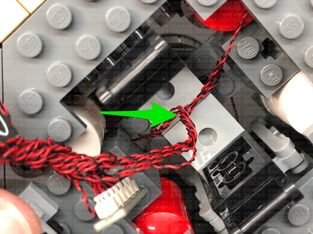
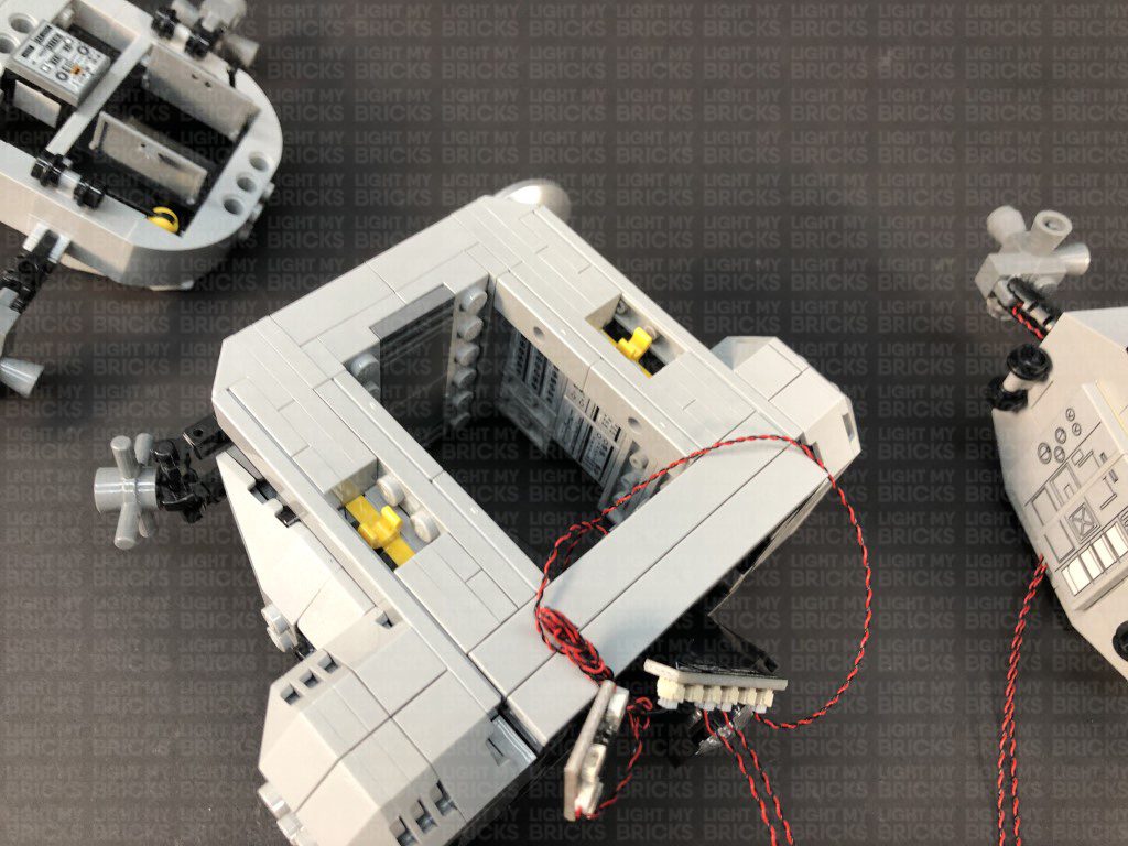
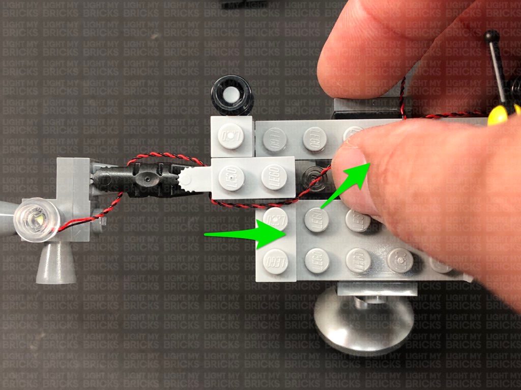
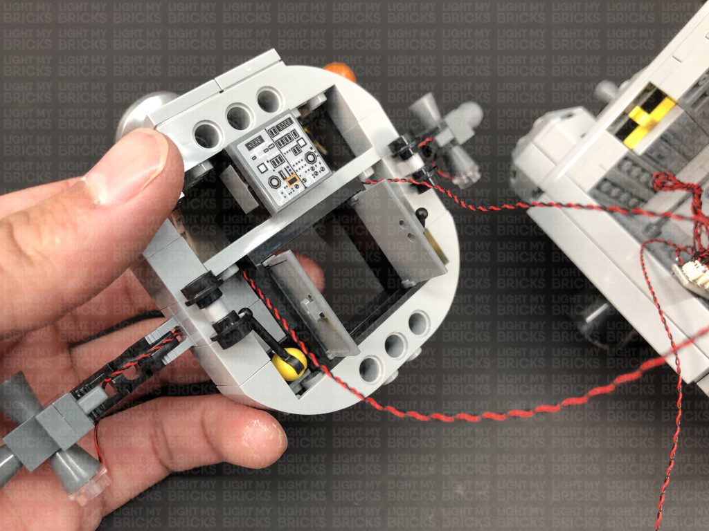
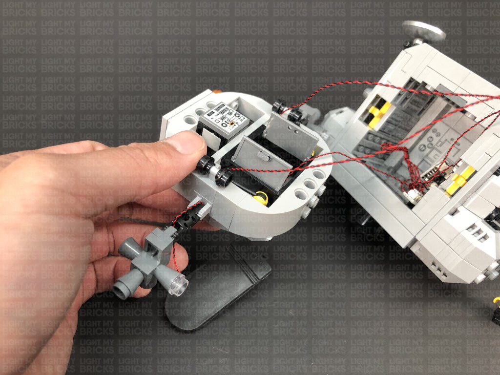
11.) Turn this middle section around to the other side, then disconnect the section with the two grey tiles running horizontally. Pull the Bit Light cable up and lay them in between studs before reconnecting the section with the grey tiles over it.
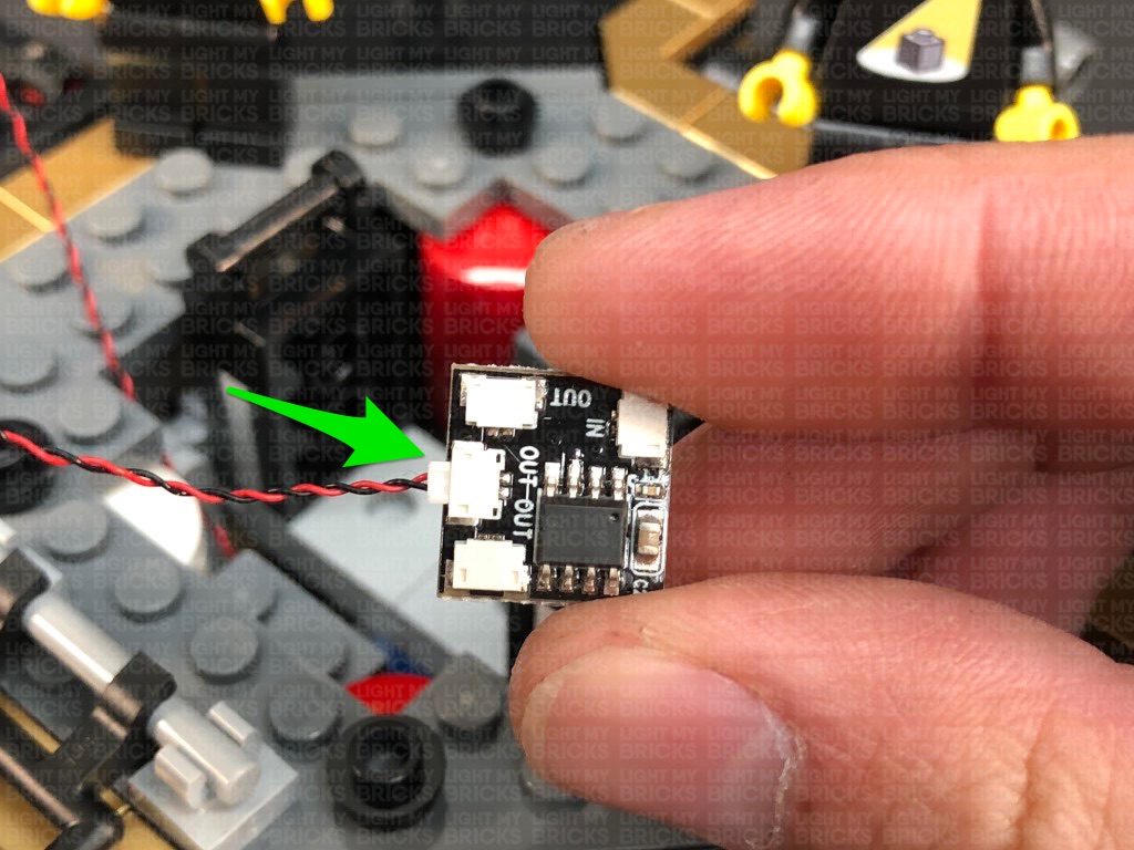
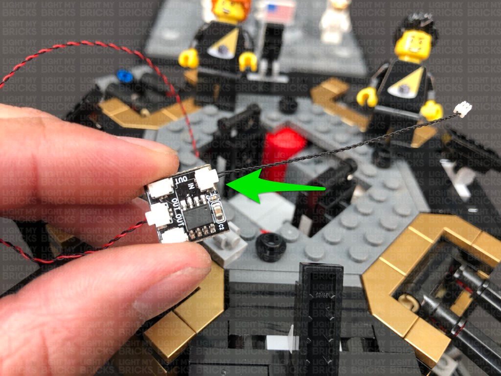
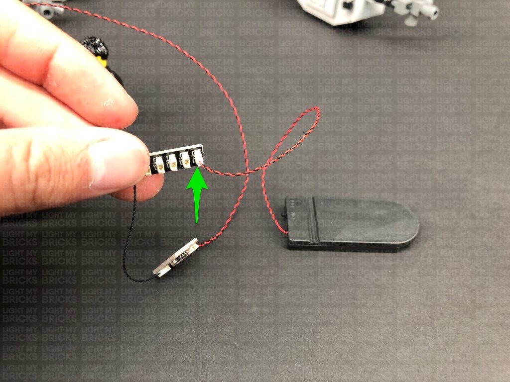
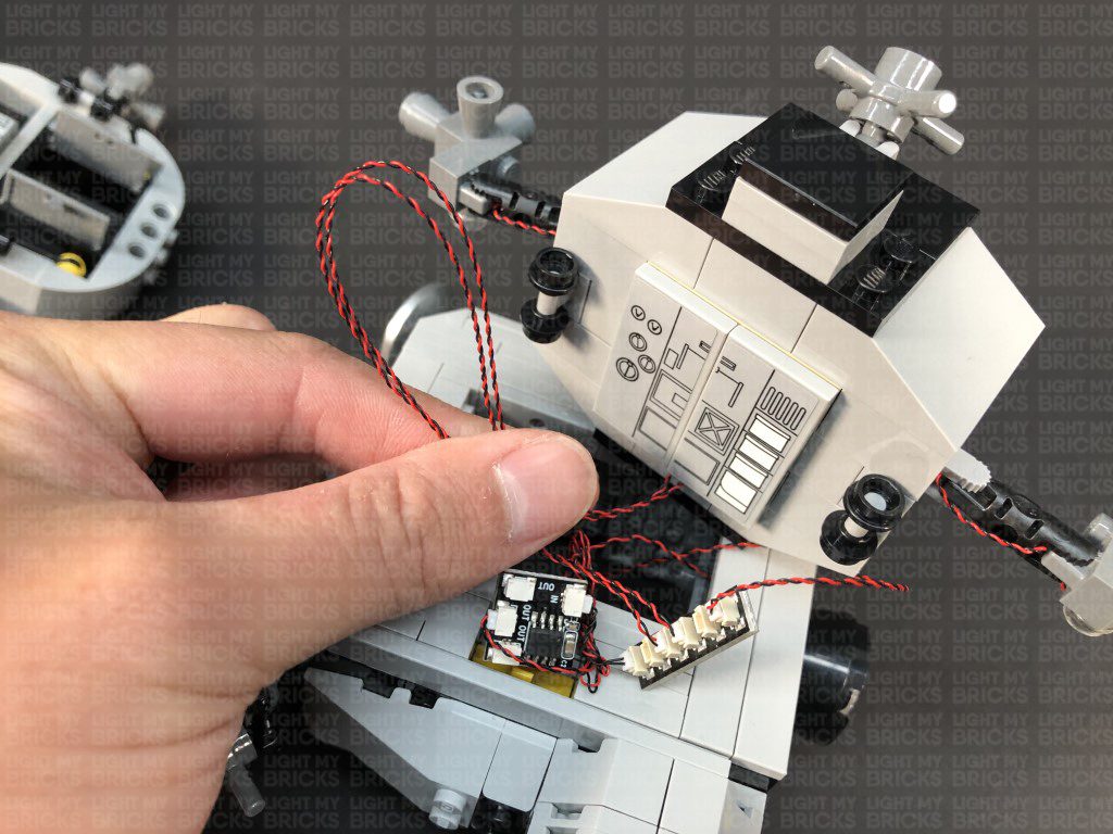
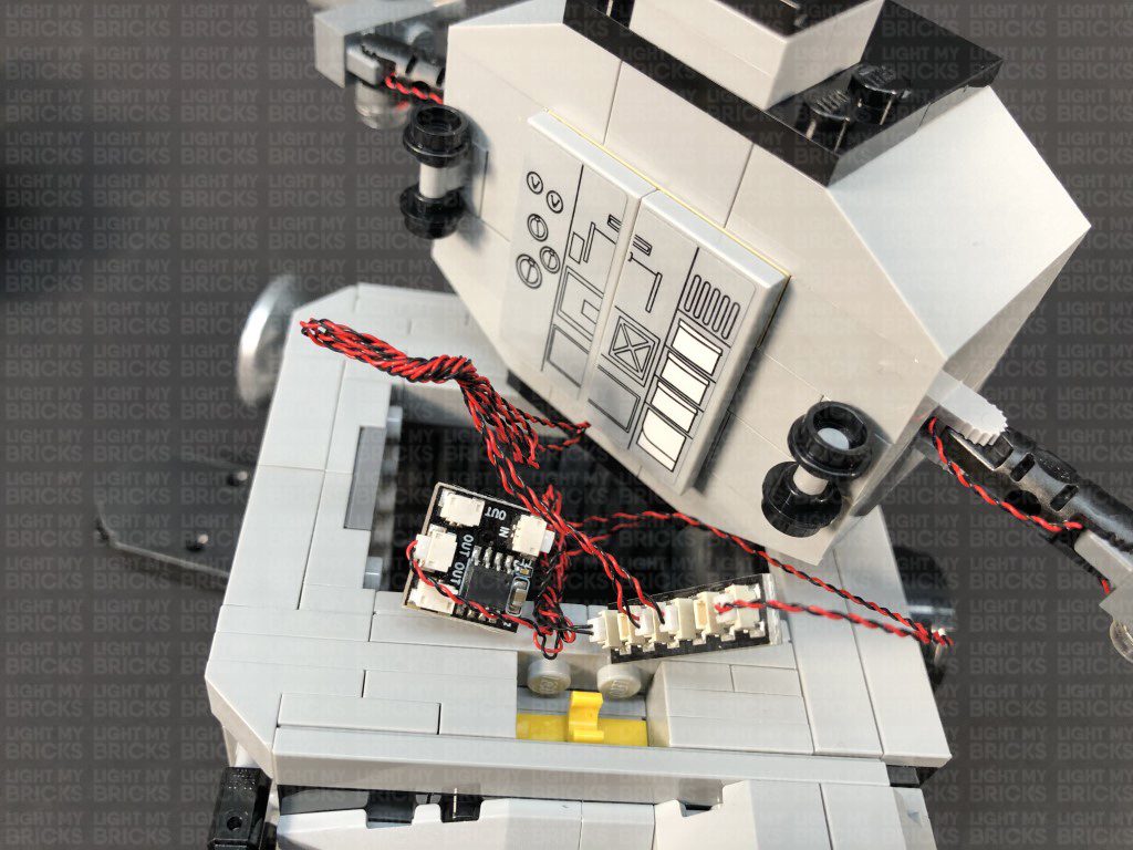
Connect the Orange Bit Light to one of the OUT ports on a new Flicker Effects Board. Take a 5cm Connecting Cable and connect it to the IN port on the Flicker Effects Board, then connect the other end of the cable to a new 6-Port Expansion Board.
Take another Flat Battery Pack and insert 2x new CR2032 batteries to it. Connect the battery pack cable to the 6-Port Expansion Board, then turn the battery pack ON to test the Jet light is on and flickering OK.
Note: If you experience any issues with the lights not working and suspect an issue with a component, please try a different port on the expansion board to verify where the fault lies (with the light or expansion board). To correct any issues with expansion board ports, please view the section addressing expansion board issues on our online troubleshooting guide.
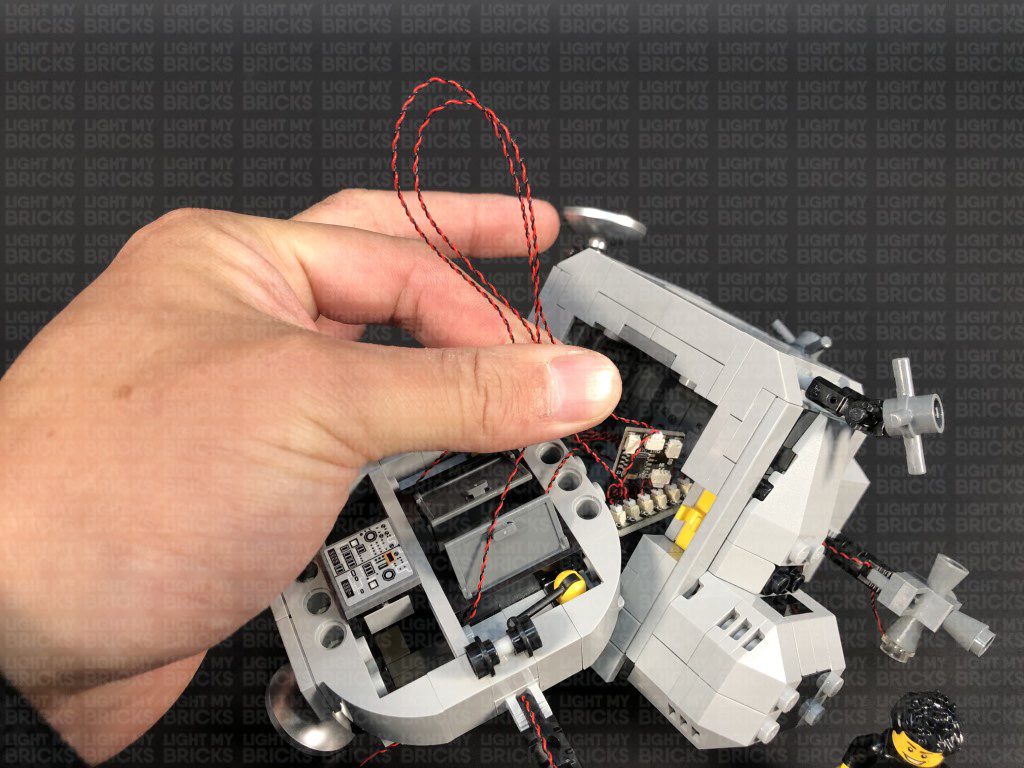
Neaten up excess cabling by folding and twisting the Orange Bit Light Cable and 5cm Connecting Cable around each other into a neat bunch, then turn the middle section around again.
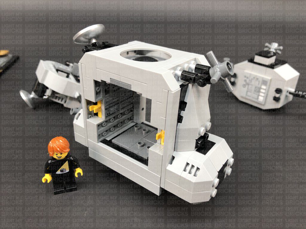
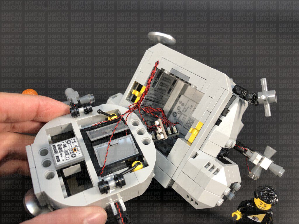
12.) Take the right section of the upper shuttle and place it onto it’s back. Disconnect the sections from underneath as shown below:
Ensure there are not dangling cables visible from underneath.
10.) We will now install lights to the upper shuttle of the Lander. First disconnect the side sections, then disconnect the Jet piece from underneath as shown below:
Take a Orange 30cm Bit Light and thread the connector side of the cable through the centre hole underneath of the Jet piece. Pull the cable out from the top of the piece, then carefully bend the Bit Light onto a 90 degree angle so that the LED is facing the same way as the cable.
Place the LED in the centre of the 4 studs, then reconnect the Jet piece underneath the upper section of the Lander. Ensure the other end of the cable is facing down and in between the two studs of the Jet section. Take the remaining Trans Clear Plate w Rounded Bottom 2×2 and connect it over the Bit Light as shown below. The trans clear piece will help distribute the light underneath the shuttle.
11.) Turn this middle section around to the other side, then disconnect the section with the two grey tiles running horizontally. Pull the Bit Light cable up and lay them in between studs before reconnecting the section with the grey tiles over it.
Connect the Orange Bit Light to one of the OUT ports on a new Flicker Effects Board. Take a 5cm Connecting Cable and connect it to the IN port on the Flicker Effects Board, then connect the other end of the cable to a new 6-Port Expansion Board.
Take another Flat Battery Pack and insert 2x new CR2032 batteries to it. Connect the battery pack cable to the 6-Port Expansion Board, then turn the battery pack ON to test the Jet light is on and flickering OK.
Note: If you experience any issues with the lights not working and suspect an issue with a component, please try a different port on the expansion board to verify where the fault lies (with the light or expansion board). To correct any issues with expansion board ports, please view the section addressing expansion board issues on our online troubleshooting guide.
Neaten up excess cabling by folding and twisting the Orange Bit Light Cable and 5cm Connecting Cable around each other into a neat bunch, then turn the middle section around again.
12.) Take the right section of the upper shuttle and place it onto it’s back. Disconnect the sections from underneath as shown below:
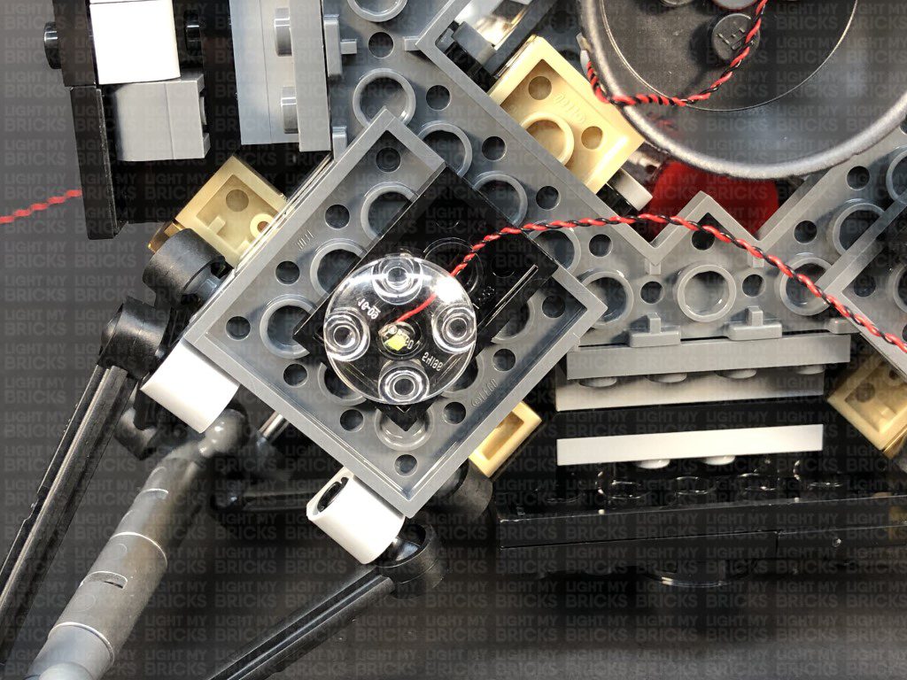
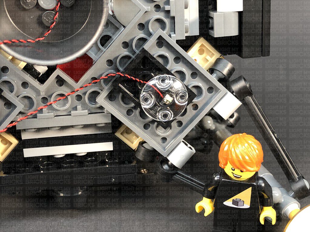
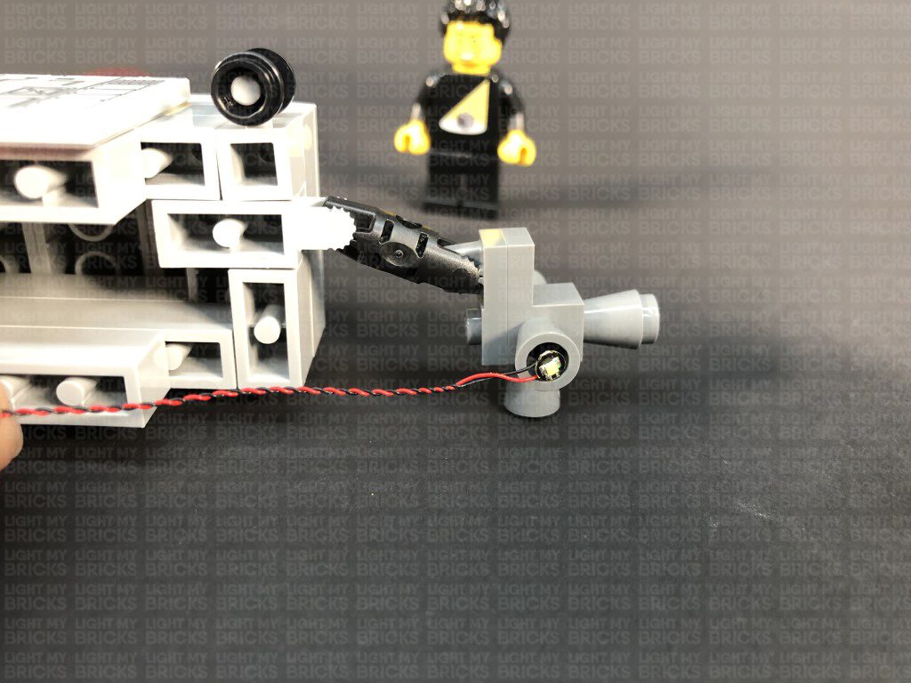
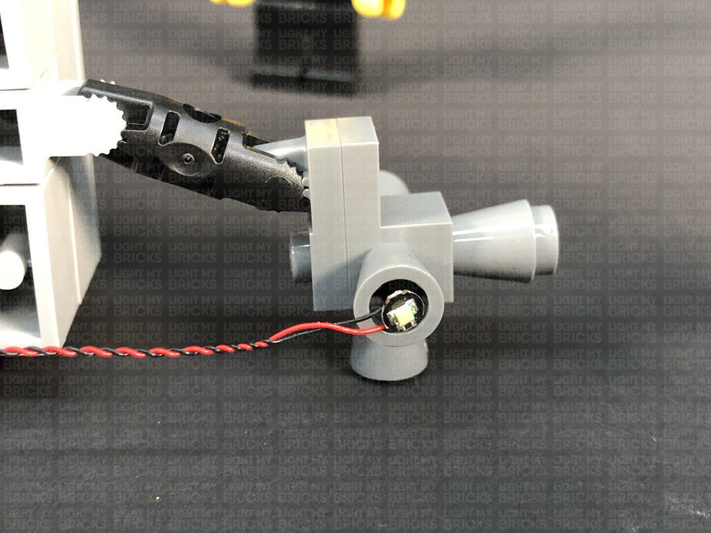
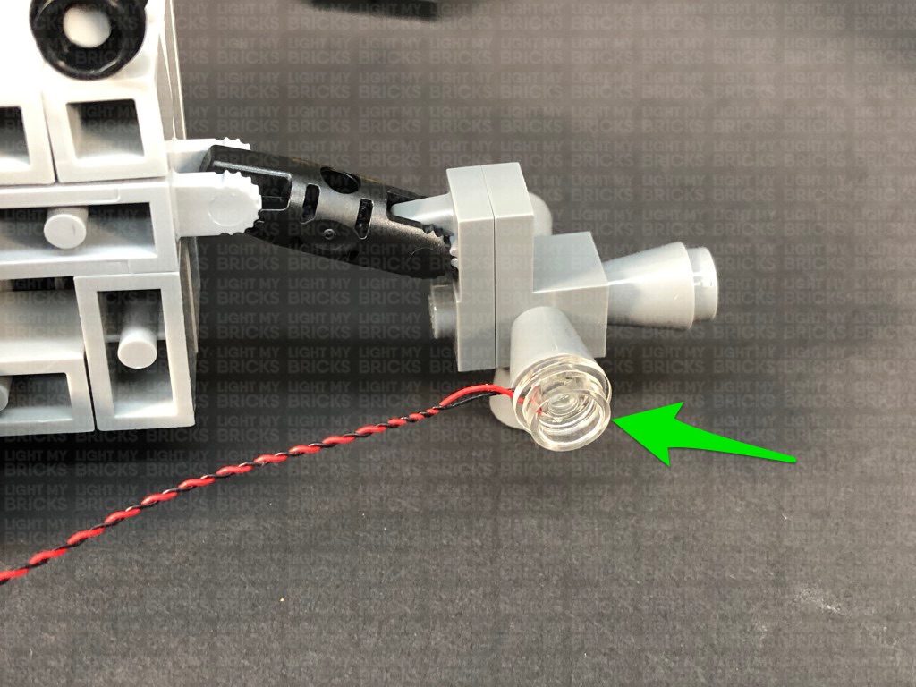
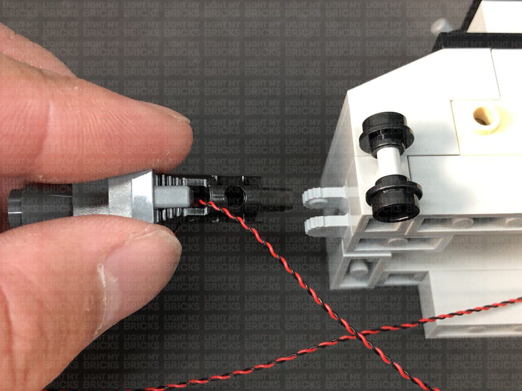
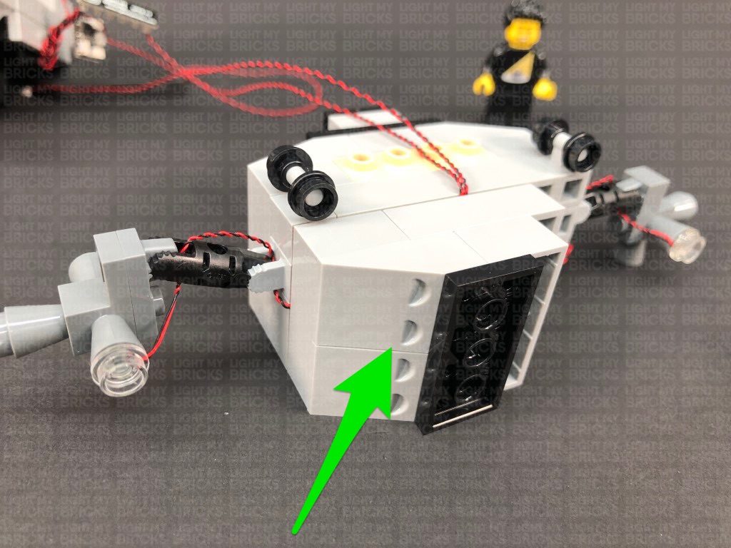
 13.) Take a Cool White 30cm Bit Light and with the cable facing the left, place it underneath the the following piece. Secure the Bit Light in place by connecting a provided Trans Clear Round Plate 1×1 over the top (Connecting the stud side of the plate inside the piece above)
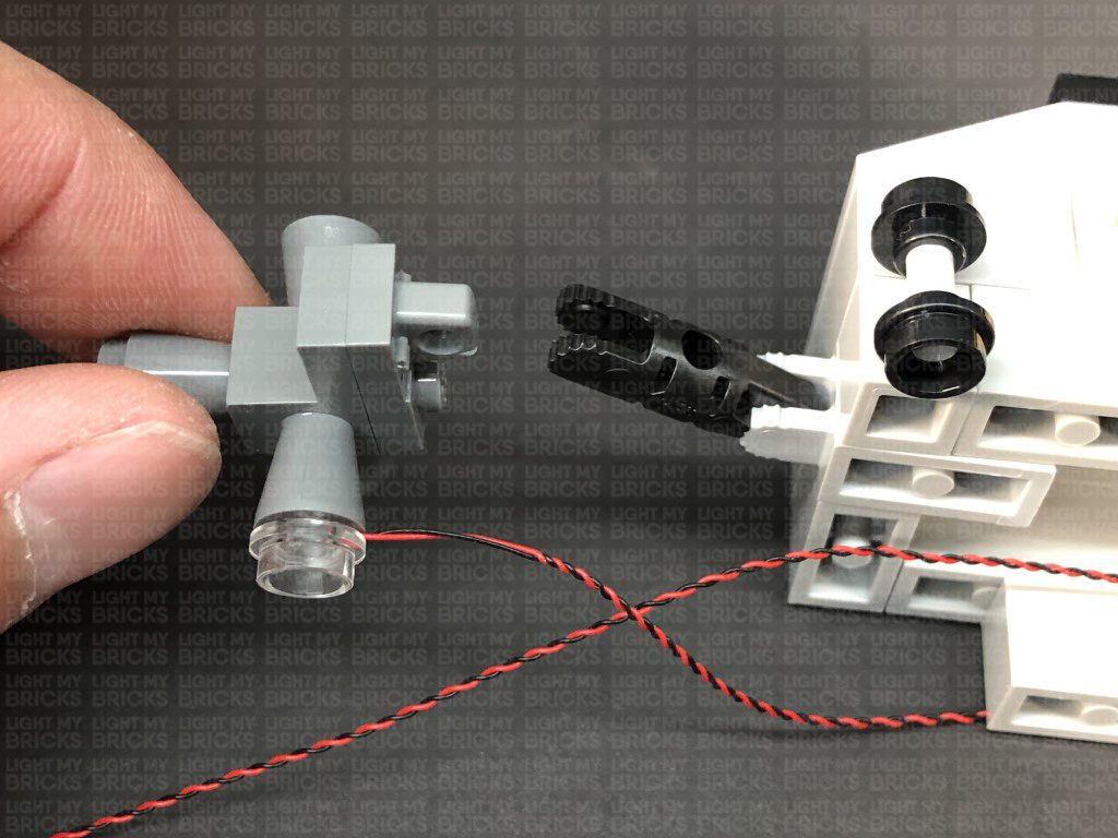
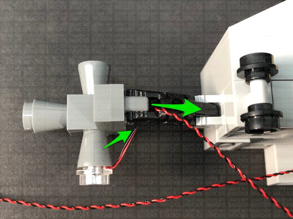
Disconnect the grey pieces from the black technic clip, then reconnect them ensuring you feed the cable underneath and out the front as shown below:
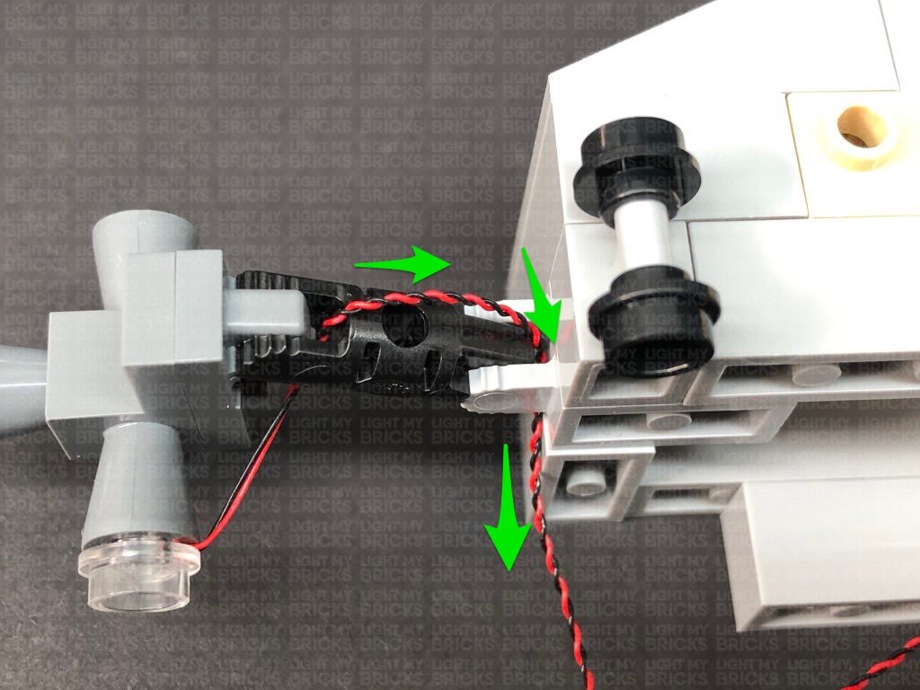
Disconnect the black technic clip from the grey clip, then reconnect it ensuring the cable is fed through and out underneath as shown below:
Disconnect the following pieces from the front:
14.) Follow the previous step to Install another Cool White 30cm Bit Light to the left side, securing it in place with another provided Trans Clear Round Plate 1×1. Disconnect and Reconnect the arm sections in order to feed and secure the cables through the gaps.
13.) Take a Cool White 30cm Bit Light and with the cable facing the left, place it underneath the the following piece. Secure the Bit Light in place by connecting a provided Trans Clear Round Plate 1×1 over the top (Connecting the stud side of the plate inside the piece above)
Disconnect the grey pieces from the black technic clip, then reconnect them ensuring you feed the cable underneath and out the front as shown below:
Disconnect the black technic clip from the grey clip, then reconnect it ensuring the cable is fed through and out underneath as shown below:
Disconnect the following pieces from the front:
14.) Follow the previous step to Install another Cool White 30cm Bit Light to the left side, securing it in place with another provided Trans Clear Round Plate 1×1. Disconnect and Reconnect the arm sections in order to feed and secure the cables through the gaps.
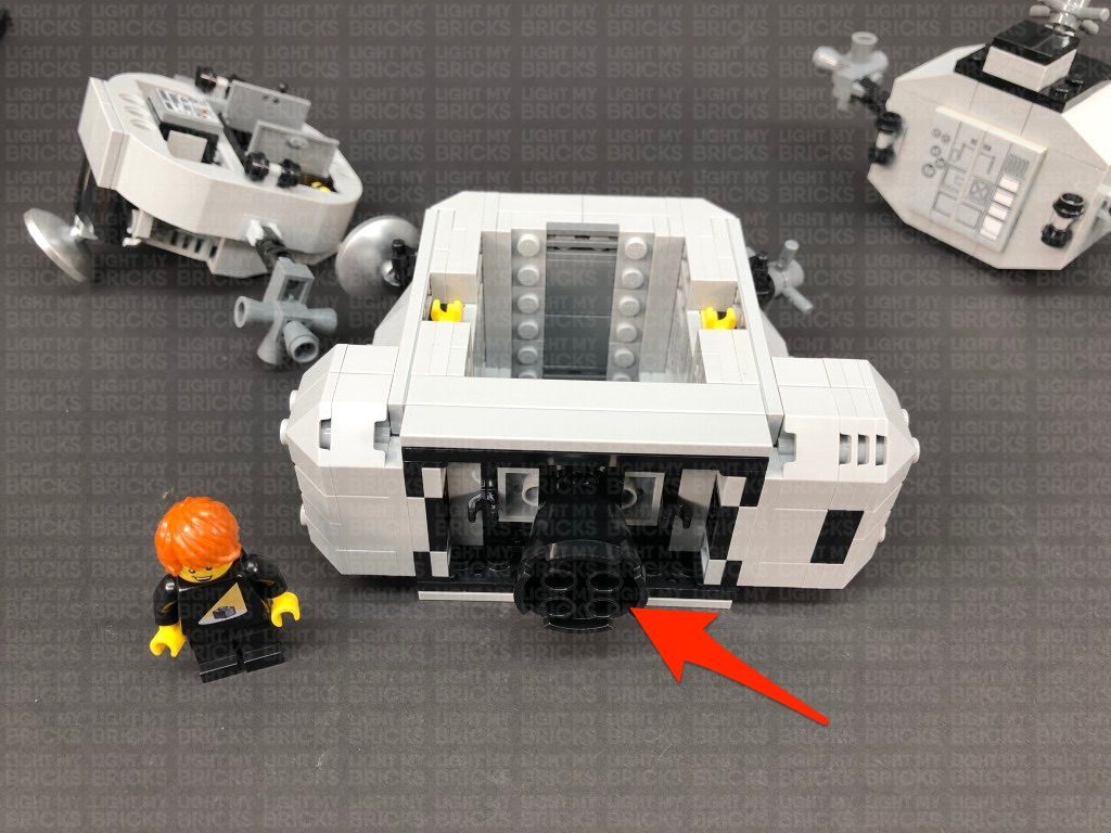
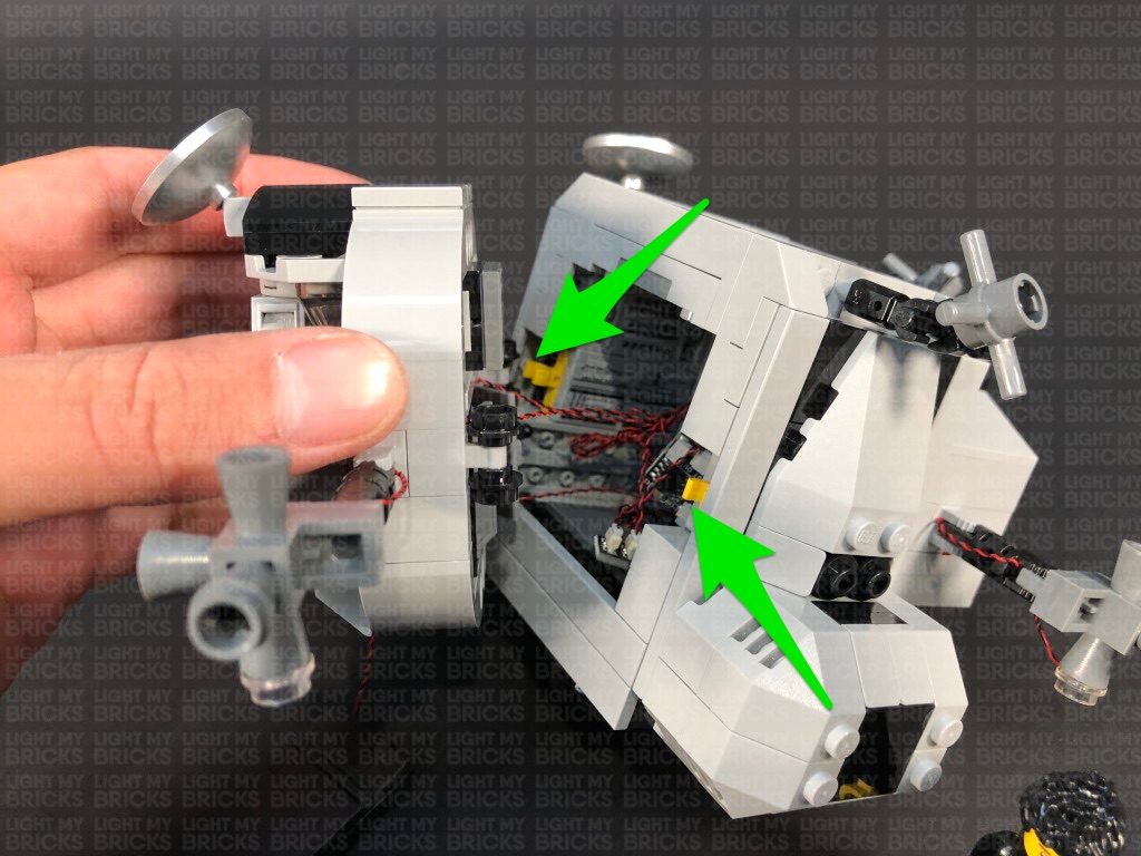
 15.) Lay both cables toward the middle then up before reconnecting the following 1×4 brick over the top of the cables ensuring both cables are in between studs. Tuck the middle section of the cables up the inside of the shuttle as per below:
Reconnect the sections underneath as well as the two tiles on the top.
16.) Bring this right section closer to the middle section, then connect the two Bit Light cables to the 6-Port Expansion Board in the middle section. Turn the Battery Pack ON to test the two lights are working OK.
Note: If you experience any issues with the lights not working and suspect an issue with a component, please try a different port on the expansion board to verify where the fault lies (with the light or expansion board). To correct any issues with expansion board ports, please view the section addressing expansion board issues on our online troubleshooting guide.
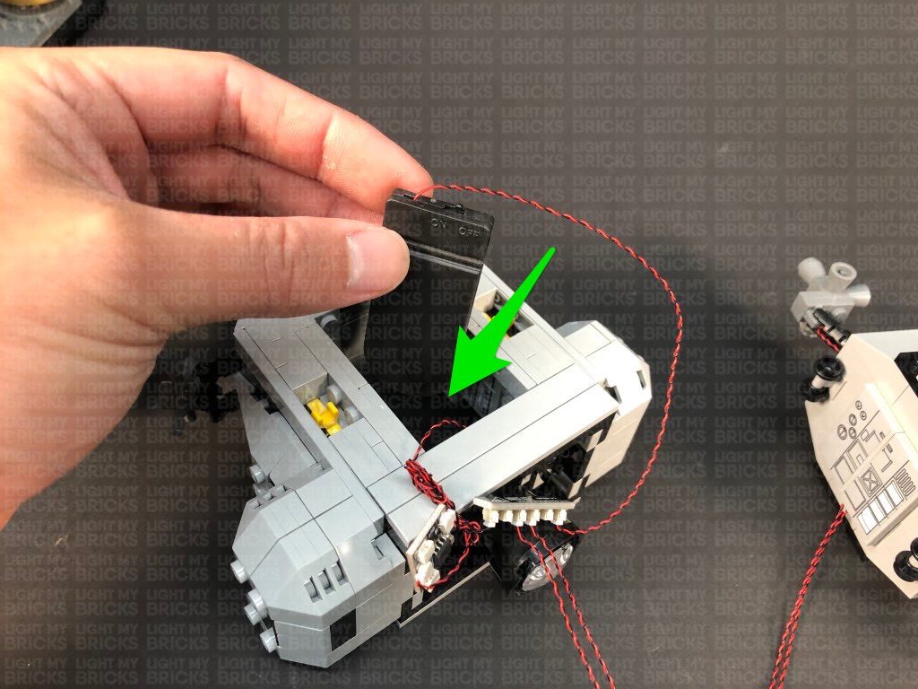
Take the Flat Battery Pack and tuck it inside the cabin so that it comes through to the other side, then twist and fold the cables from the Orange and Cool White Bit Lights together into a neat bunch. Reconnect the right section to the middle section via the two side clips.
15.) Lay both cables toward the middle then up before reconnecting the following 1×4 brick over the top of the cables ensuring both cables are in between studs. Tuck the middle section of the cables up the inside of the shuttle as per below:
Reconnect the sections underneath as well as the two tiles on the top.
16.) Bring this right section closer to the middle section, then connect the two Bit Light cables to the 6-Port Expansion Board in the middle section. Turn the Battery Pack ON to test the two lights are working OK.
Note: If you experience any issues with the lights not working and suspect an issue with a component, please try a different port on the expansion board to verify where the fault lies (with the light or expansion board). To correct any issues with expansion board ports, please view the section addressing expansion board issues on our online troubleshooting guide.
Take the Flat Battery Pack and tuck it inside the cabin so that it comes through to the other side, then twist and fold the cables from the Orange and Cool White Bit Lights together into a neat bunch. Reconnect the right section to the middle section via the two side clips.
 17.) Take the left side of the upper shuttle and disconnect the bottom sections as shown below:
With the front of this section facing up, take a Cool White 30cm Bit Light and following the same method used to install lights to the right section (step 13), install it to the right side of this section. Use a provided Trans Clear Round Plate 1×1 to secure the Bit Light in place.
18.) Continue following step 13 to disconnect the arm sections to feed and secure the cable through the clips toward the middle.
Lay the cable underneath this section in between studs, before reconnecting the lower right section. Bring the the cable out toward the front of this section.
19.) Repeat the previous two steps to install the remaining Cool White 30cm Bit Light to the left side, securing it in place with the remaining provided Trans Clear Round Plate 1×1.
Lay the cable underneath this section in between studs before reconnecting the lower left section over the top.
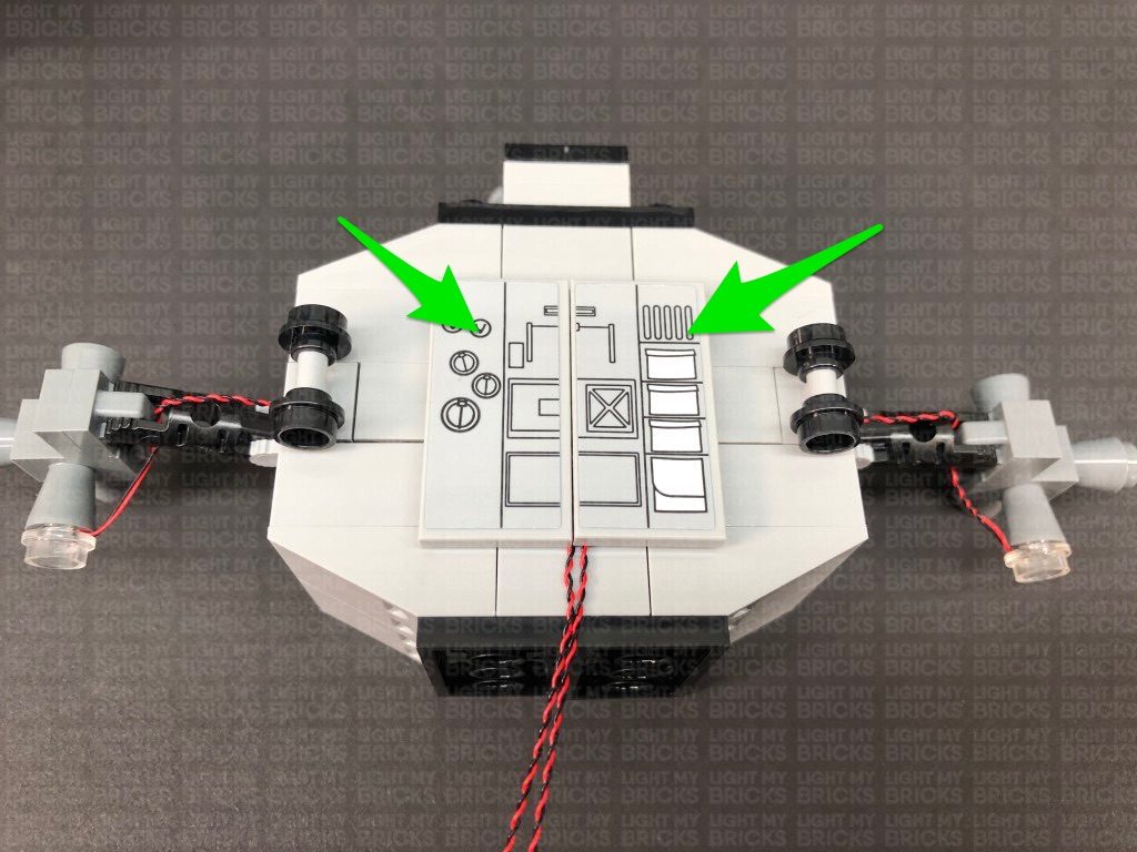
20.) With the front of this section still facing toward you, flip this section upside down (so the yellow control handles are facing you). Lay both cables in between studs in each corner before reconnecting the middle lower section.
17.) Take the left side of the upper shuttle and disconnect the bottom sections as shown below:
With the front of this section facing up, take a Cool White 30cm Bit Light and following the same method used to install lights to the right section (step 13), install it to the right side of this section. Use a provided Trans Clear Round Plate 1×1 to secure the Bit Light in place.
18.) Continue following step 13 to disconnect the arm sections to feed and secure the cable through the clips toward the middle.
Lay the cable underneath this section in between studs, before reconnecting the lower right section. Bring the the cable out toward the front of this section.
19.) Repeat the previous two steps to install the remaining Cool White 30cm Bit Light to the left side, securing it in place with the remaining provided Trans Clear Round Plate 1×1.
Lay the cable underneath this section in between studs before reconnecting the lower left section over the top.
20.) With the front of this section still facing toward you, flip this section upside down (so the yellow control handles are facing you). Lay both cables in between studs in each corner before reconnecting the middle lower section.
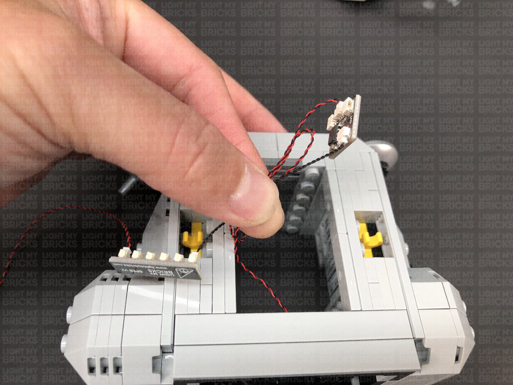
 Take the two Bit Light cables and connect them to the remaining ports on the 6-Port Expansion Board inside the middle compartment. Turn the Flat Battery Pack ON to test all lights in the upper shuttle are working OK.
Note: If you experience any issues with the lights not working and suspect an issue with a component, please try a different port on the expansion board to verify where the fault lies (with the light or expansion board). To correct any issues with expansion board ports, please view the section addressing expansion board issues on our online troubleshooting guide.
21.) Open the doors of the left side section, then group the two bit light cables together and twist and fold them into a neat bunch. Place the bunch of cable inside the cabin, before reconnecting the left section via the clips on each side.
Take the two Bit Light cables and connect them to the remaining ports on the 6-Port Expansion Board inside the middle compartment. Turn the Flat Battery Pack ON to test all lights in the upper shuttle are working OK.
Note: If you experience any issues with the lights not working and suspect an issue with a component, please try a different port on the expansion board to verify where the fault lies (with the light or expansion board). To correct any issues with expansion board ports, please view the section addressing expansion board issues on our online troubleshooting guide.
21.) Open the doors of the left side section, then group the two bit light cables together and twist and fold them into a neat bunch. Place the bunch of cable inside the cabin, before reconnecting the left section via the clips on each side.
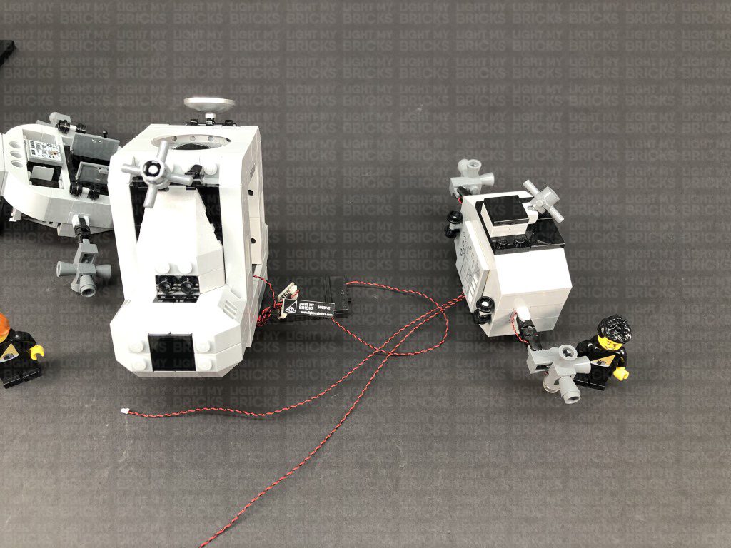
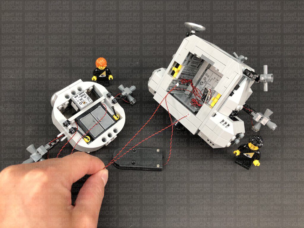
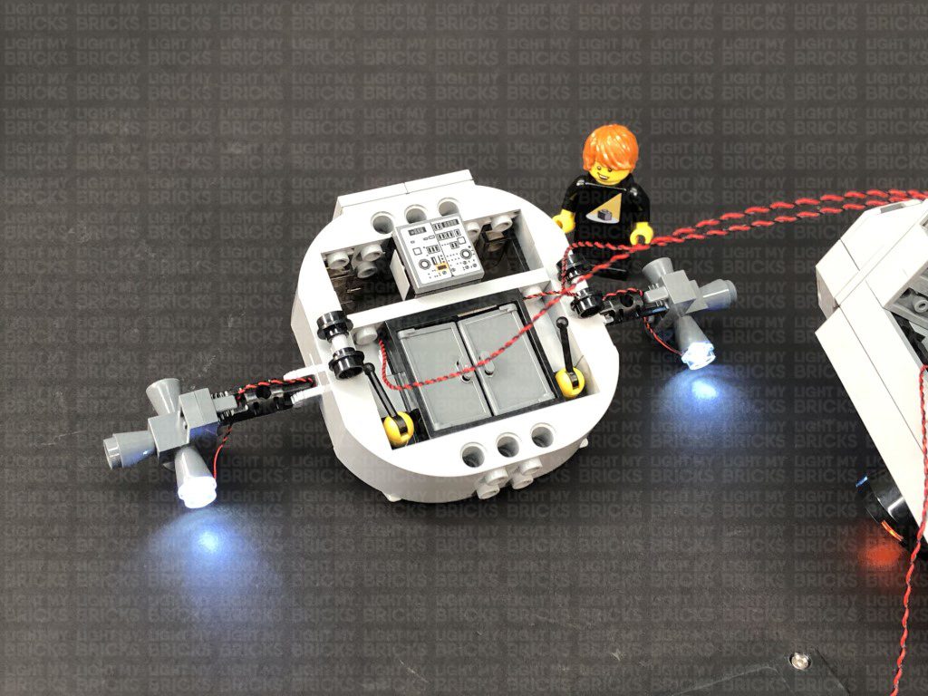
 Place the battery pack inside the cabin ensuring the cable is neatly placed underneath and the battery pack switch is facing out.
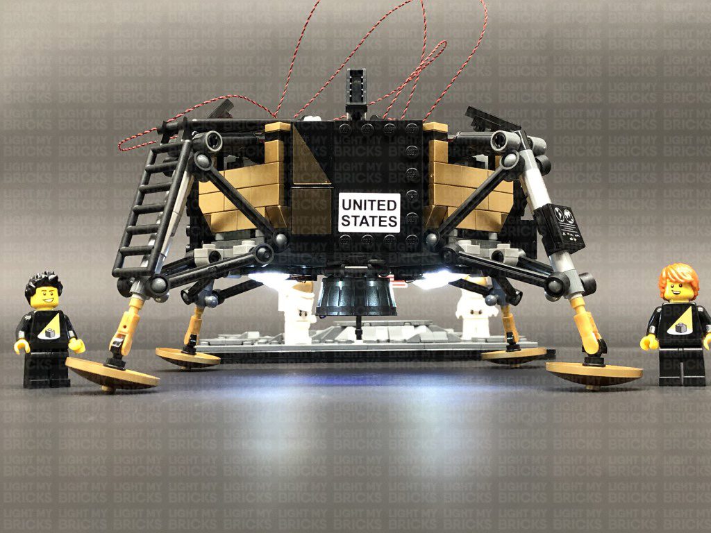
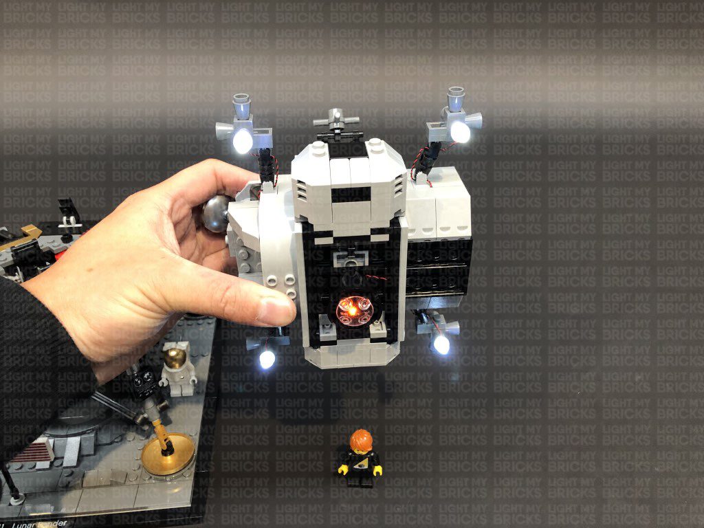
22.) Ensure all the lights are working OK before placing the upper shuttle on top of the lower section.
Place the battery pack inside the cabin ensuring the cable is neatly placed underneath and the battery pack switch is facing out.
22.) Ensure all the lights are working OK before placing the upper shuttle on top of the lower section.
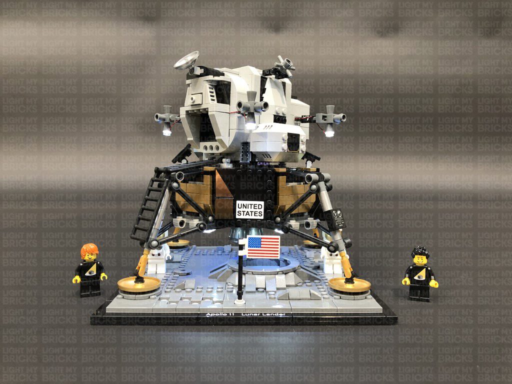
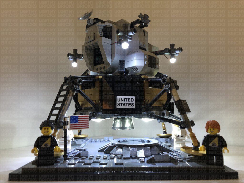
This finally completes installation of the Light My Bricks NASA Apollo 11 Lunar Lander Light Kit. We thank you for purchasing this product and hope you ENJOY!