

The following page is the instructions for the Light My Bricks LEGO Porsche 911 RSR (42096) LED light kit.
If you run into any issues, please refer to the online troubleshooting guide.
To ensure a trouble-free installation of your light kit, please read and follow each step carefully. These instructions can be downloaded in PDF format here
Please note: This page lists instructions for the LED light kit only. If you are wishing to purchase the Light My Bricks LEGO Porsche 911 RSR (42096) LED light kit , please click here to view the product page
Package Contents:
- 12x White 15cm Bit Lights
- 6x Red Strip Lights
- 1x White Strip Lights
- 1x 8-Port Expansion Boards
- 1x 12-Port Expansion Boards
- 1x NC Push Board
- 2x 5cm Connecting Cables
- 4x 15cm Connecting Cables
- 3x 30cm Connecting Cable
- 1x AA Battery Pack (requires 3x AA Batteries)
Important things to note:
Laying cables in between and underneath bricks
Cables can fit in between and underneath LEGO® bricks, plates, and tiles providing they are laid correctly between the LEGO® studs. Do NOT forcefully join LEGO® together around cables; instead ensure they are laying comfortably in between each stud.
Connecting cable connectors to Expansion Boards
Take extra care when inserting connectors to ports of Expansion Boards. Connectors can be inserted only one way. With the expansion board facing up, look for the soldered “=” symbol on the left side of the port. The connector side with the wires exposed should be facing toward the soldered “=” symbol as you insert into the port. If a plug won’t fit easily into a port connector, do not force it.
Connecting cable connectors to Strip Lights
Take extra care when inserting connectors to ports on the Strip Lights. Connectors can be inserted only one way. With the Strip Light facing up, ensure the side of the connector with the wires exposed is facing down. If a plug won’t fit easily into a port connector, don’t force it. Doing so will damage the plug and the connector.
Installing Bit Lights under LEGO® bricks and plates.
When installing Bit Lights under LEGO® pieces, ensure they are placed the correct way up (Yellow LED component exposed). You can either place them directly on top of LEGO® studs or in between.
OK, Let’s Begin!
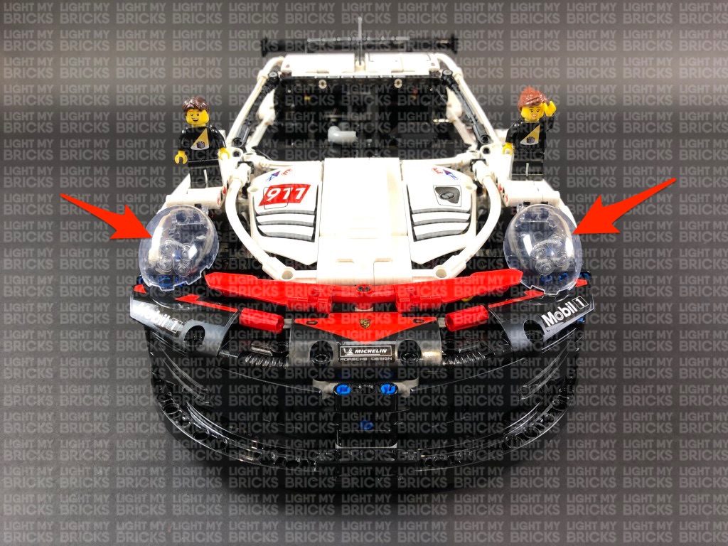
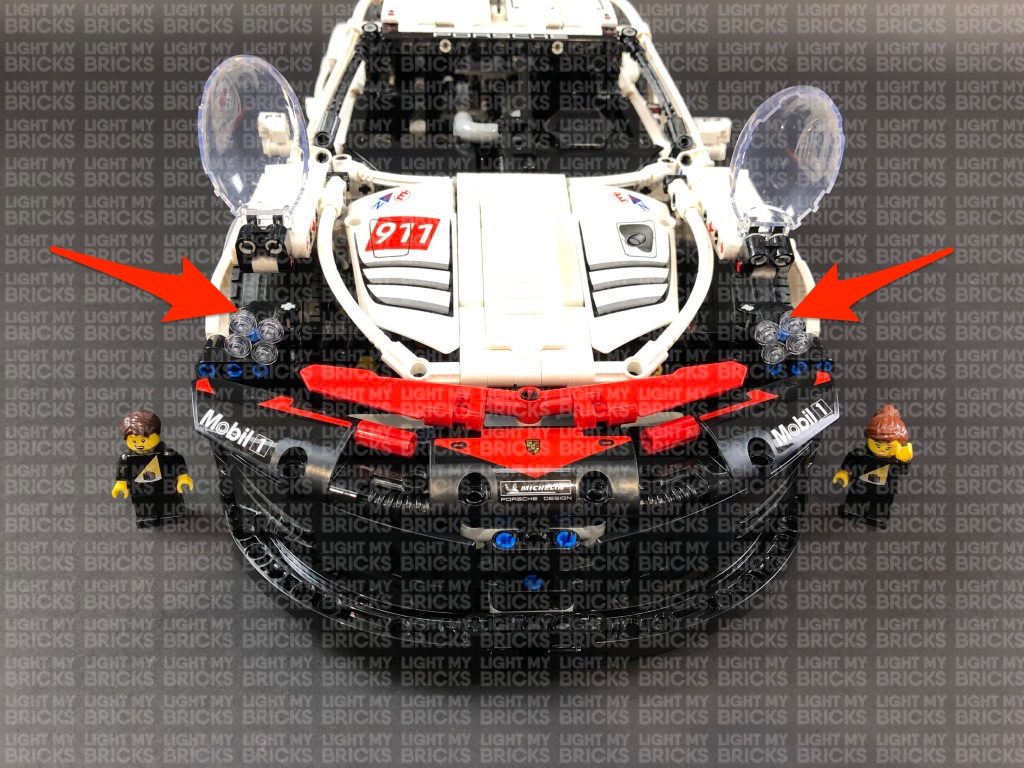
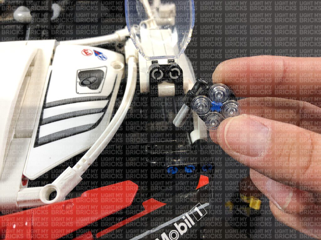
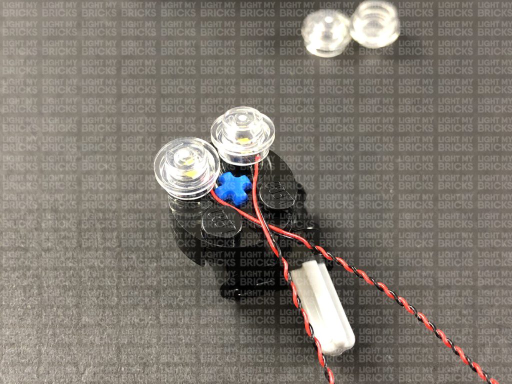
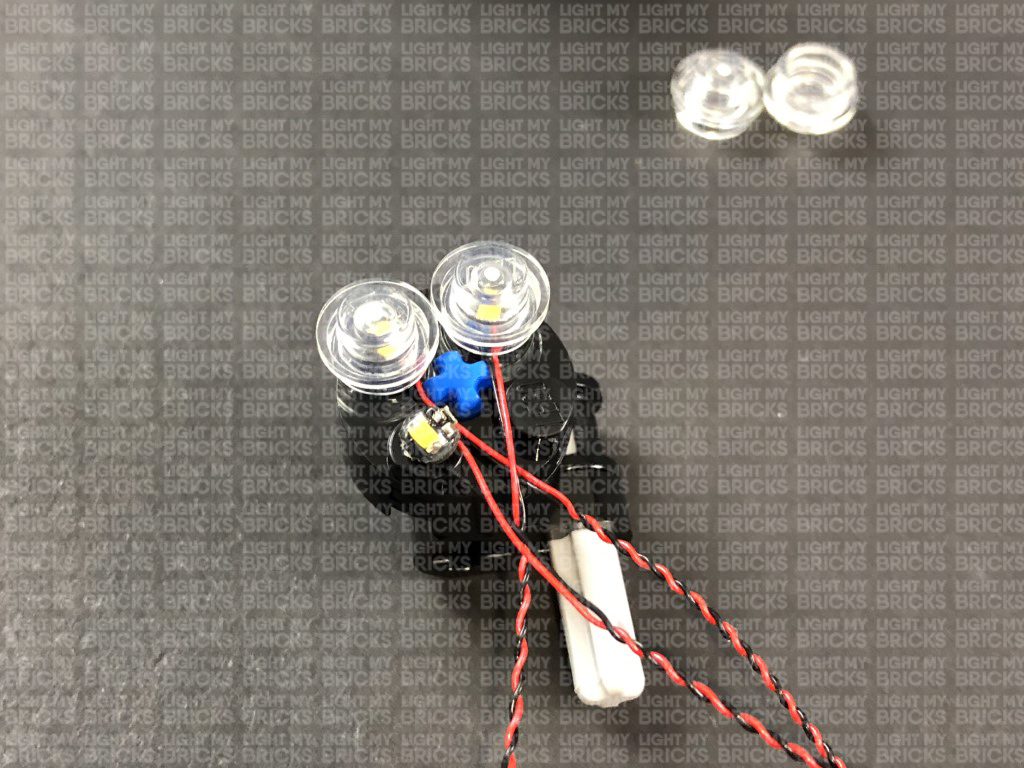
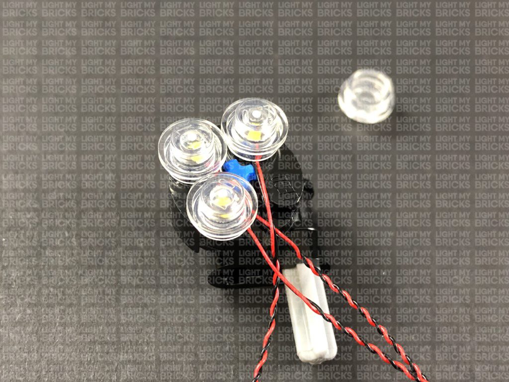
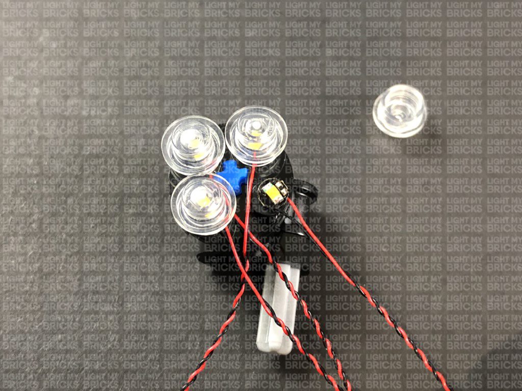
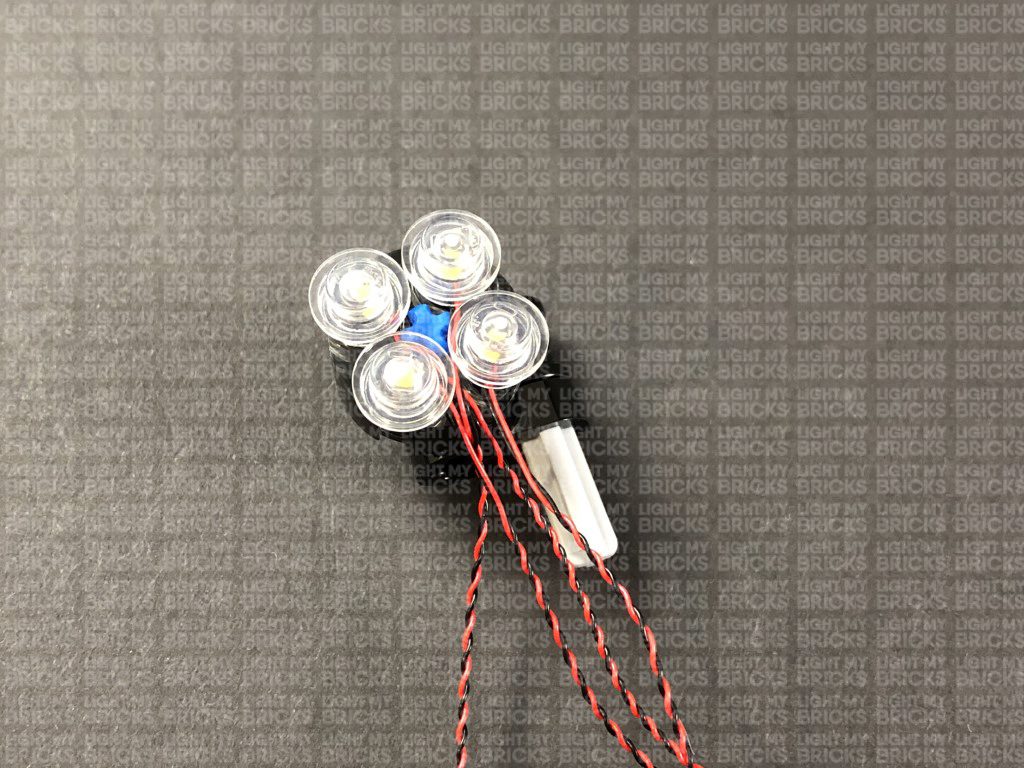
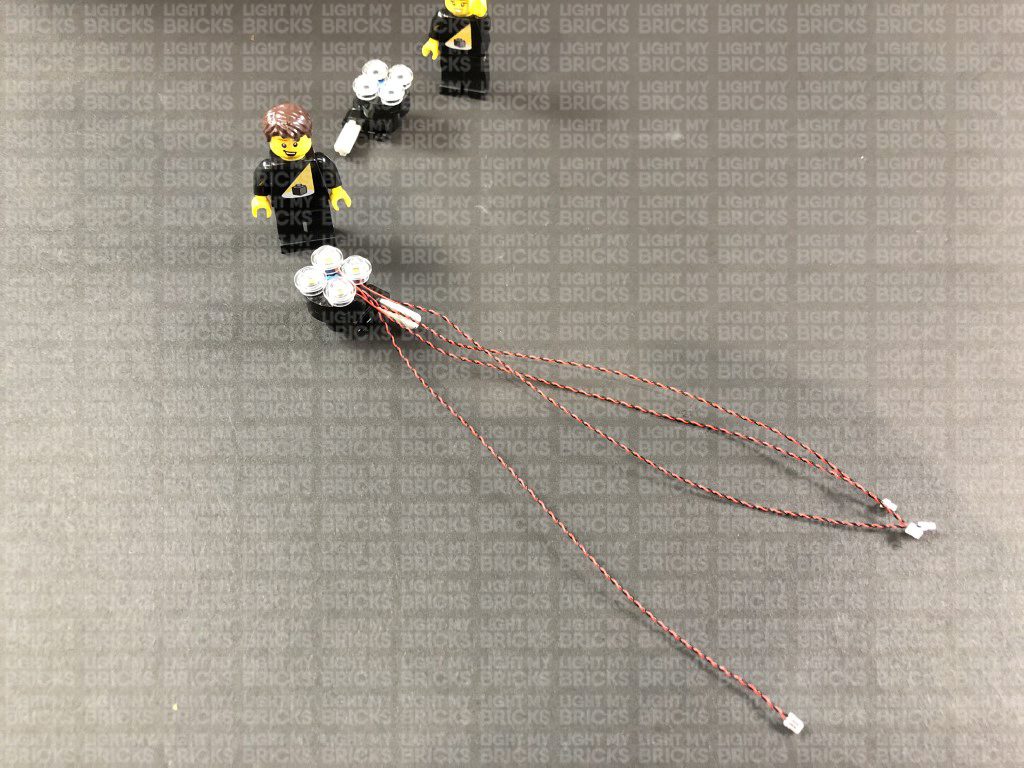
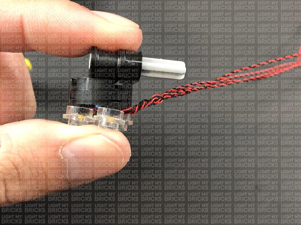
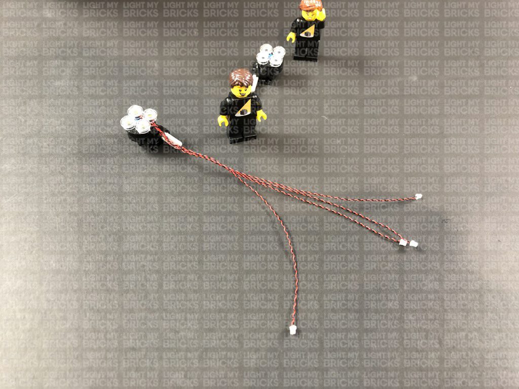
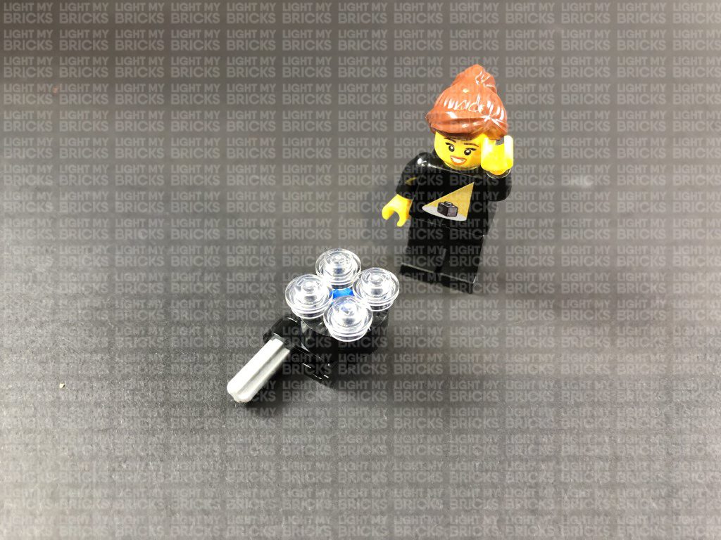
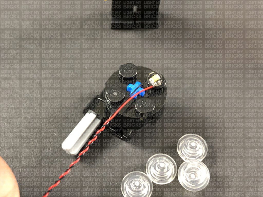
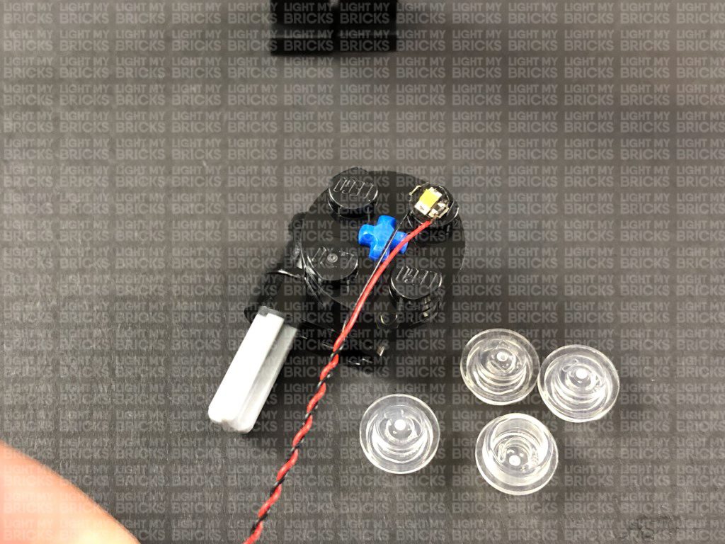
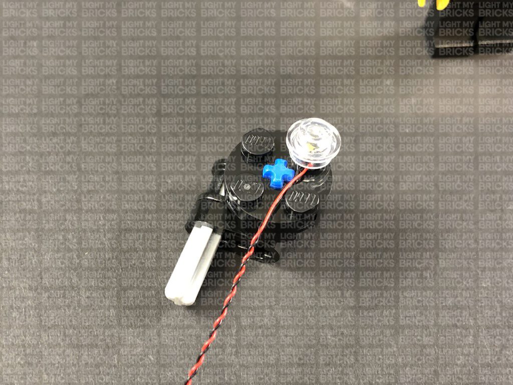
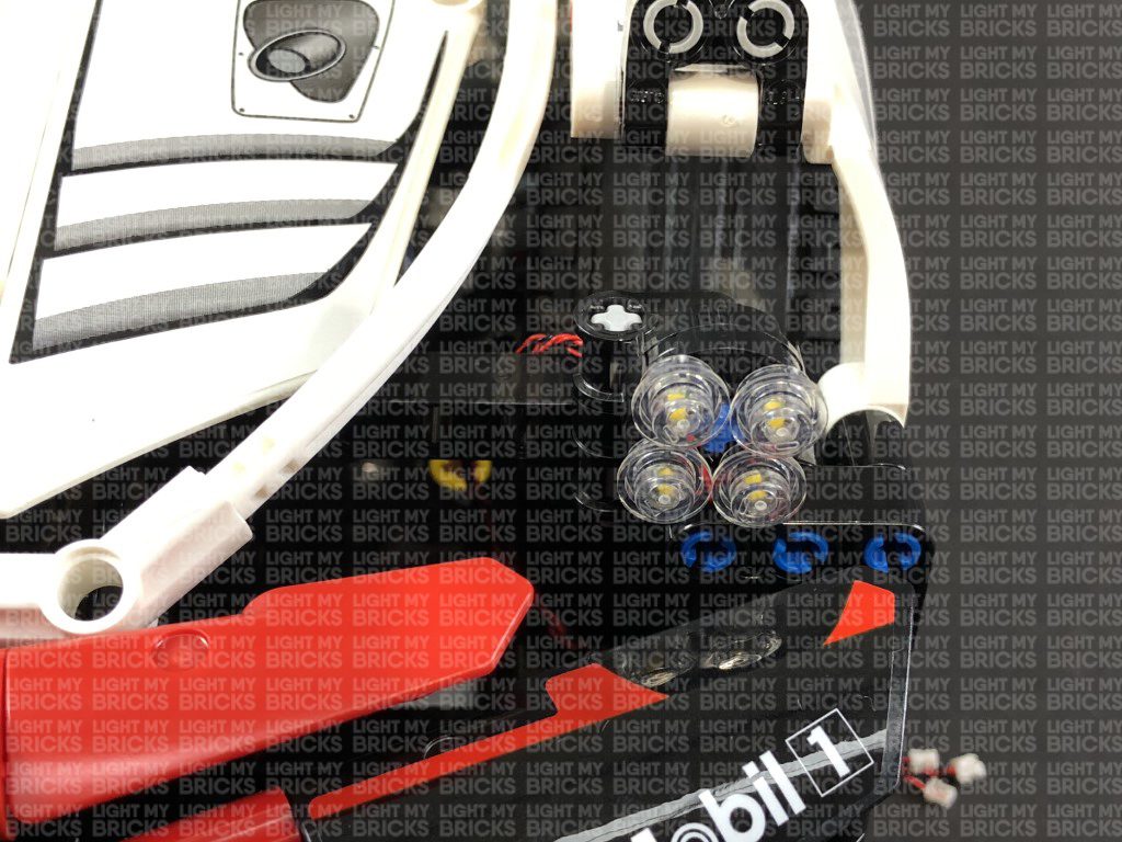
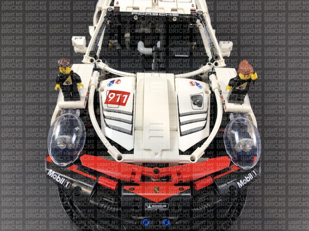
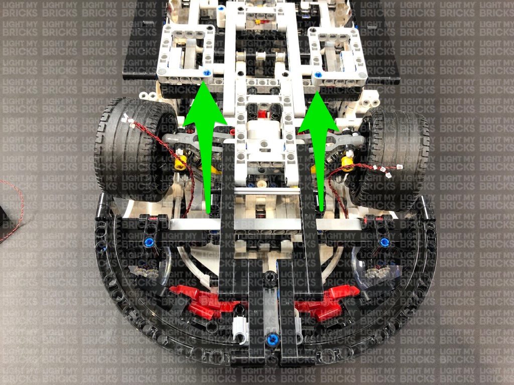
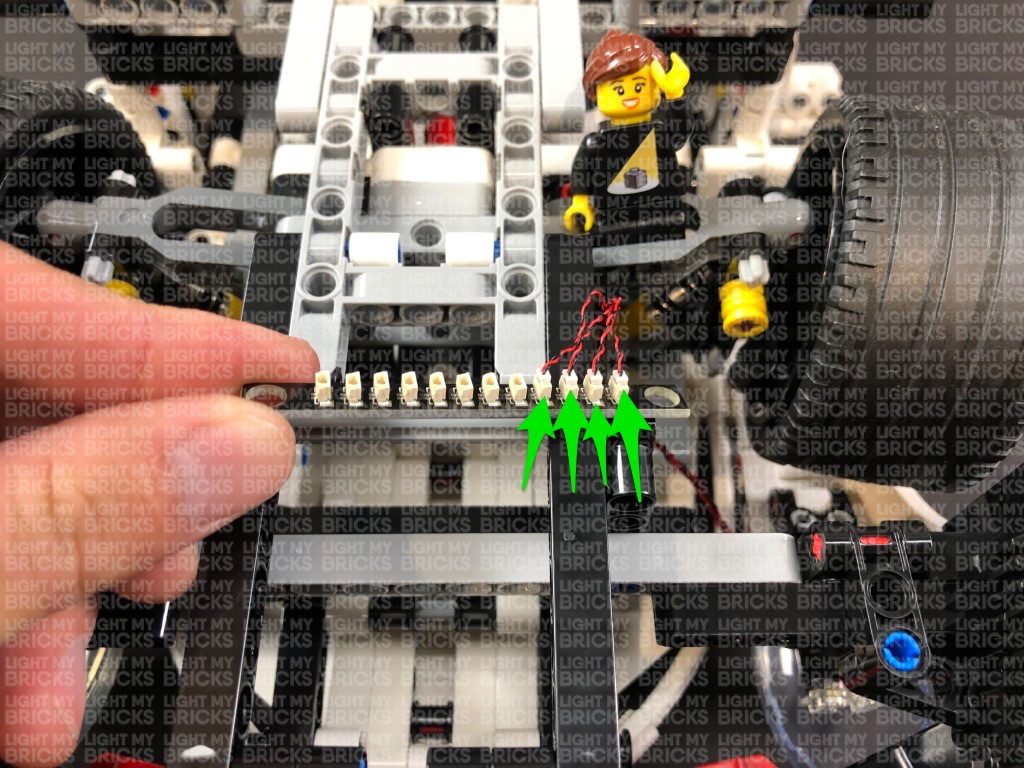
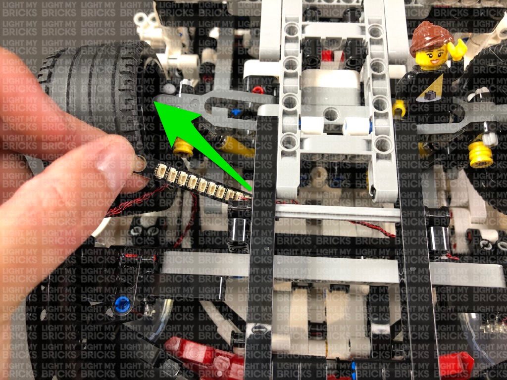
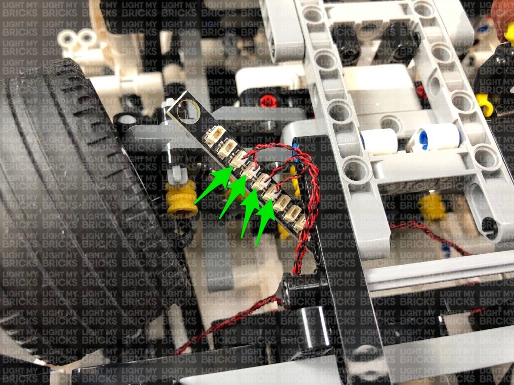
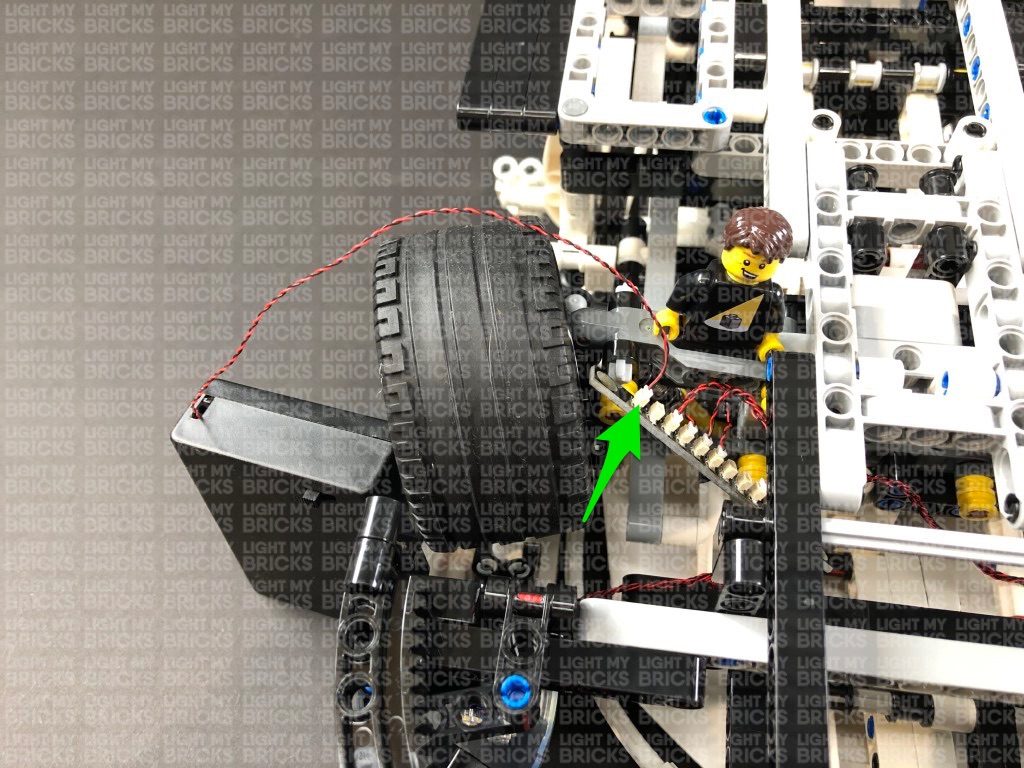
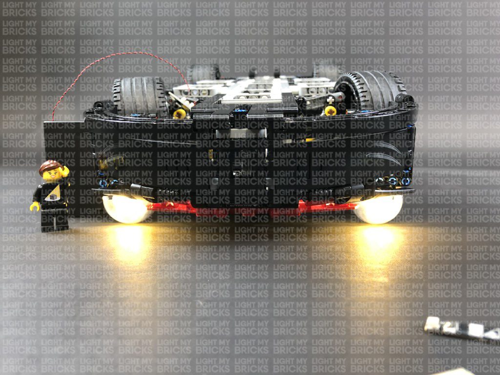
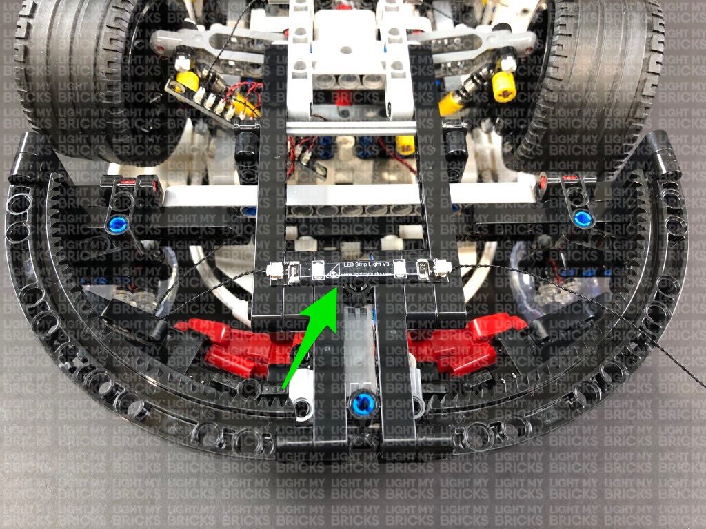
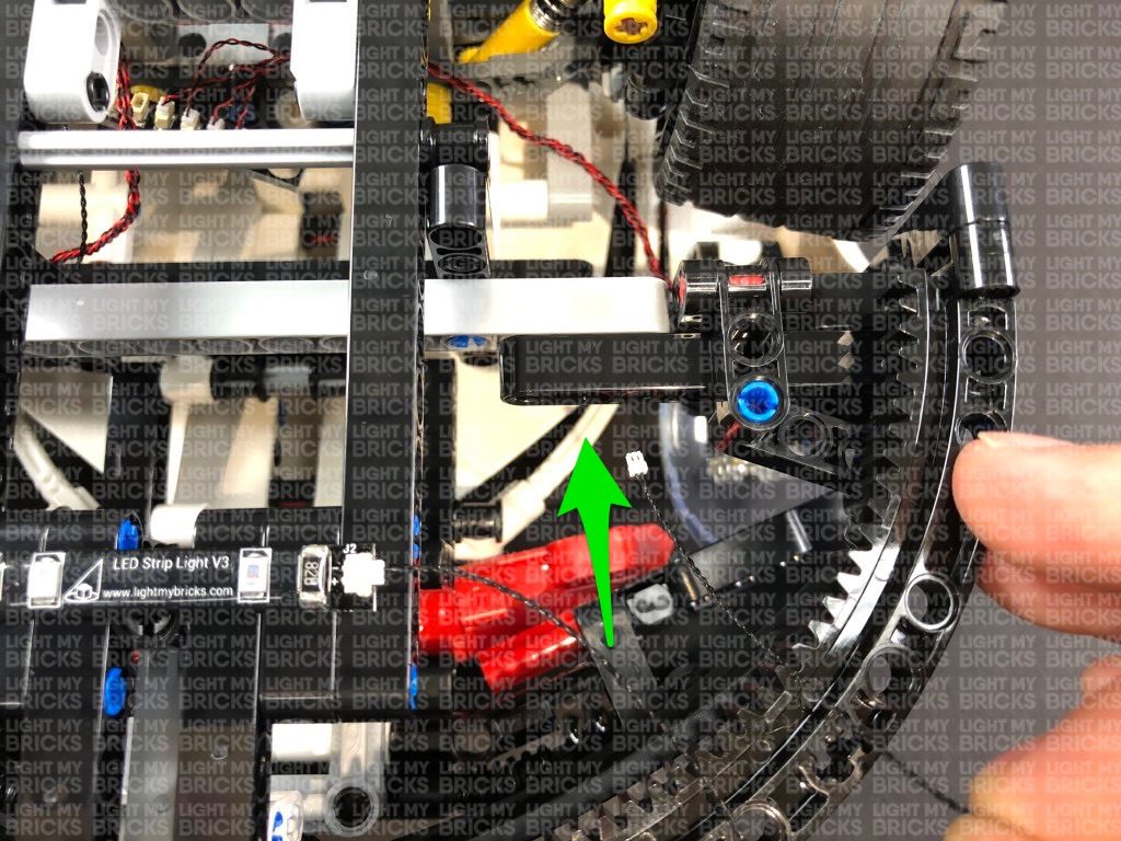
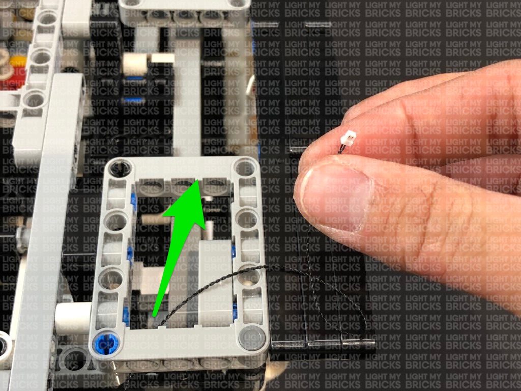
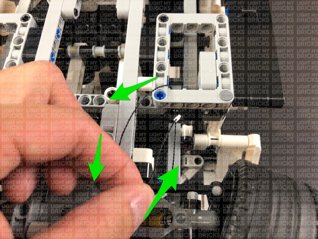
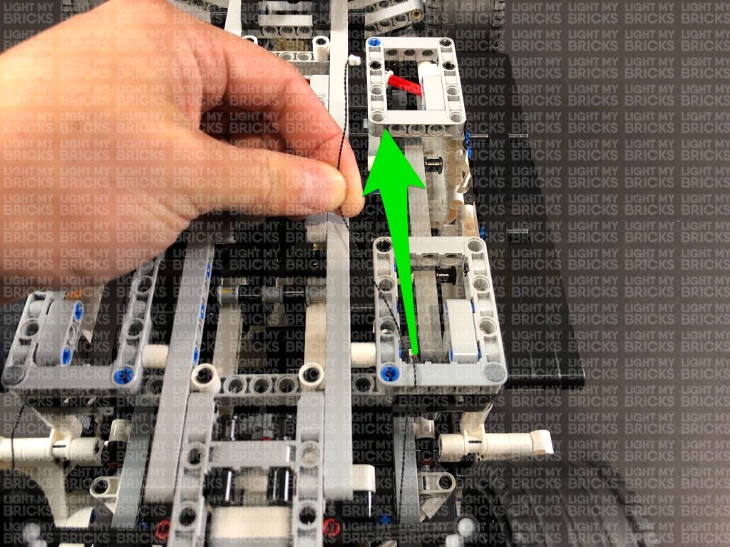
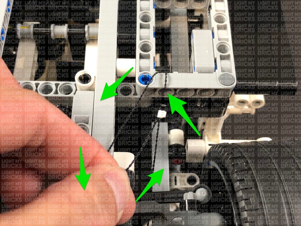
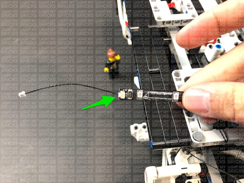
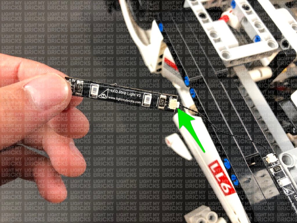
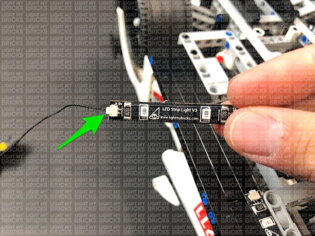
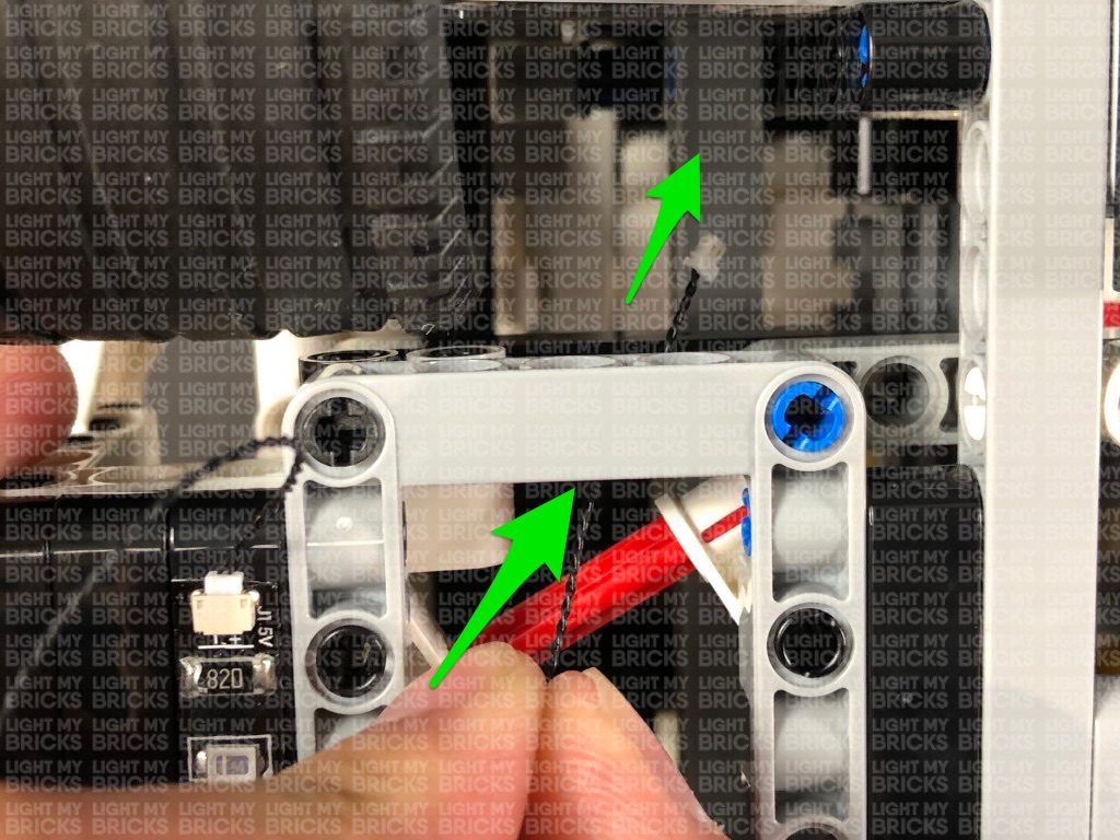
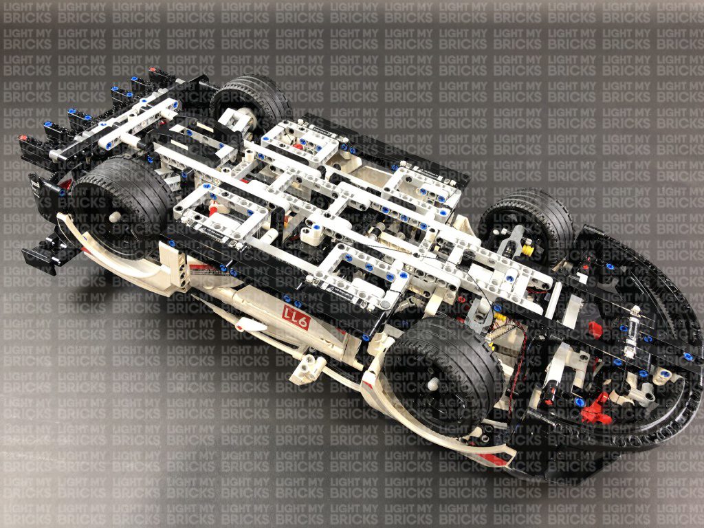
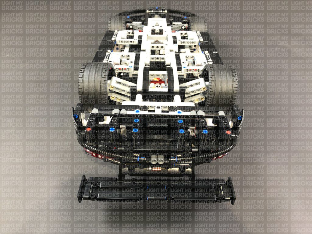
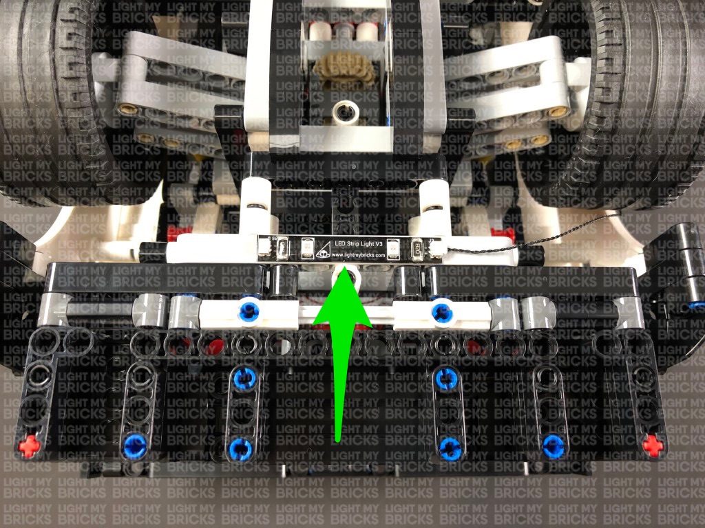
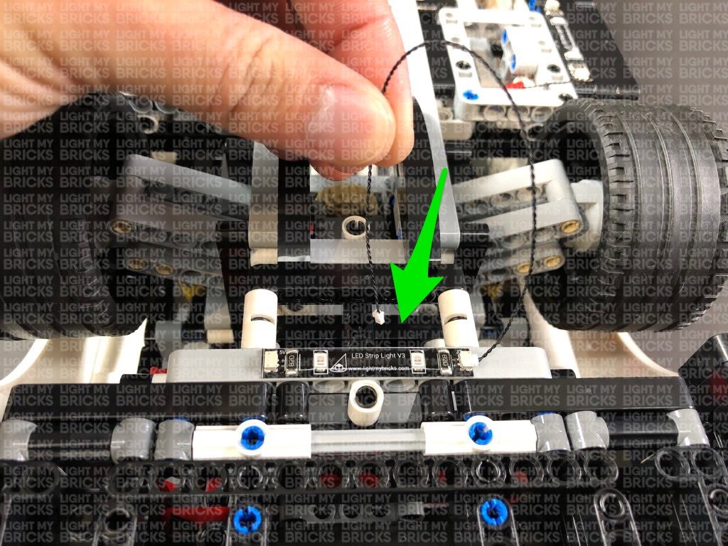
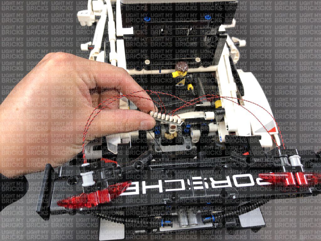
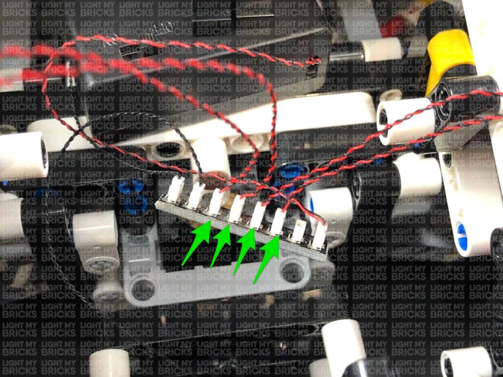
1.) Lift up the headlight covers and remove the two headlight sections as shown below. Take the left headlight and disconnect the trans clear round plates then take a White 15cm Bit Light and with the cable facing down, place it over the top left stud as shown below, with the cable laid in between studs. Secure it in place by reconnecting one of the trans clear round plates over the top. 2.) Take another White 15cm Bit Light and using the same method as in previous step, install it to the top right stud. Install another 2x White 15cm Bit Lights to the two bottom studs as shown below: 3.) Bring the four Bit Light cables together at the bottom of the headlight section, then twist/wind them around each other 2-3 times to secure the cables together. Ensure you hold the headlights in between your thumb and index finger when twisting the cables to prevent the trans round plates from popping off. 4.) Repeat the above steps to install 4x White 15cm Bit Lights to the right headlight section. 5.) Take the 12-Port Expansion Board and connect all the lights from the two headlight sections to it. Take your AA Battery Pack and insert 3x new AA Batteries to it. Connect the battery pack cable to the expansion board, then turn it ON to test the 8 lights from the headlights are working OK. Note: If you experience any issues with the lights not working and suspect an issue with a component, please try a different port on the expansion board to verify where the fault lies (with the light or expansion board). To correct any issues with expansion board ports, please view the section addressing expansion board issues on our online troubleshooting guide. Disconnect the lights and battery pack from the expansion board, then continue to twist wind the cables from each headlight around each other so that the four cables from each headlight become one larger cable. 6.) Take the left headlight section and feed the cables through the space behind it (over the black horizontal technic bar) before securely reconnecting the headlight in place. Repeat this step to reconnect the right headlight section. 7.) Turn the car over and pull both groups of cables out. Connect the right group of cables to the 12-Port Expansion Board, then feed the expansion board underneath the following middle section. Pull the expansion board out from the other side, then reconnect the left group of cables to it. Reconnect the AA Battery Pack to the expansion board and turn it ON to test the headlights are all working OK. Note: If you experience any issues with the lights not working and suspect an issue with a component, please try a different port on the expansion board to verify where the fault lies (with the light or expansion board). To correct any issues with expansion board ports, please view the section addressing expansion board issues on our online troubleshooting guide. 8.) Disconnect the AA Battery Pack and take 2x 15cm Connecting Cables and connect each one to the 12-Port Expansion Board. Take one of the connecting cables and thread it through the same space where the expansion board is, then bring the cable down and thread it back out to the left side. Connect the connecting cable to a Red Strip Light. Take a 30cm Connecting Cable and connect it to the other port on the Red Strip Light. Using the Strip Light’s adhesive backing, stick the Strip Light underneath the car in the following position. 9.) Take the other end of the 30cm Connecting Cable and thread it underneath the technic bars. Continue to thread it in between the wheel axis, pulling it out from the other side. Thread the cable underneath the light grey technic bar, then bring it back over again and thread it through the technic bar hole towards the left. Ensure you tighten the cable as you pull it out from the other side. Continue to loop the cable back around, threading it through the same hole as before. Ensure you tighten the cable each time you pull it out from the other side. Loop the cable back through a few more times to eliminate excess cable until you have about 4-5cm of cable left, then connect it to a new Red Strip Light. 10.) Take a 5cm Connecting Cable and connect it to the other side of the Red Strip Light, then using it’s adhesive backing, stick the strip light down vertically on the black technic bar in the below position. Connect the other end of the 5cm Connecting Cable to a new Red Strip Light, then connect a new 30cm Connecting Cable to the strip light’s other port. Using it’s adhesive backing, stick the Red Strip Light vertically onto the black technic bar in the below position. Ensure the 5cm Connecting Cable in between is stretched out to prevent it from dangling down. 11.) Take the other end of the 30cm Connecting Cable and thread it through the hole on top of the technic grey bar, then pull it all the way from the other side out as shown below: Bring the cable back over the technic bar and thread it through the same hole as before to secure the cable in place. Thread the cable underneath the following technic bars and pull the cable all the way out from from the middle area as shown below: Bring the cable toward the left, underneath the centre bars, then thread the cable through the technic bar hole as shown below. Pull the cable out from the bottom, then bring the cable back over the technic bar and thread it back through the same hole. Connect the cable to a new Red Strip Light.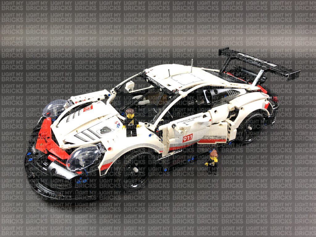
 12.) Take a 5cm Connecting Cable and connect it to the other end of the Red Strip Light from previous step, then using it’s adhesive backing, stick the strip light vertically to the below position.
Connect the other end of the 5cm Connecting Cable to a new Red Strip Light. Take a new 15cm Connecting Cable and connect it to the strip light’s other port, then using it’s adhesive backing, stick the strip light vertically to the below position close to the rear wheel.
12.) Take a 5cm Connecting Cable and connect it to the other end of the Red Strip Light from previous step, then using it’s adhesive backing, stick the strip light vertically to the below position.
Connect the other end of the 5cm Connecting Cable to a new Red Strip Light. Take a new 15cm Connecting Cable and connect it to the strip light’s other port, then using it’s adhesive backing, stick the strip light vertically to the below position close to the rear wheel.
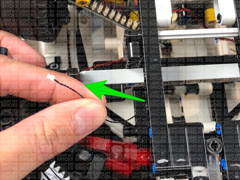
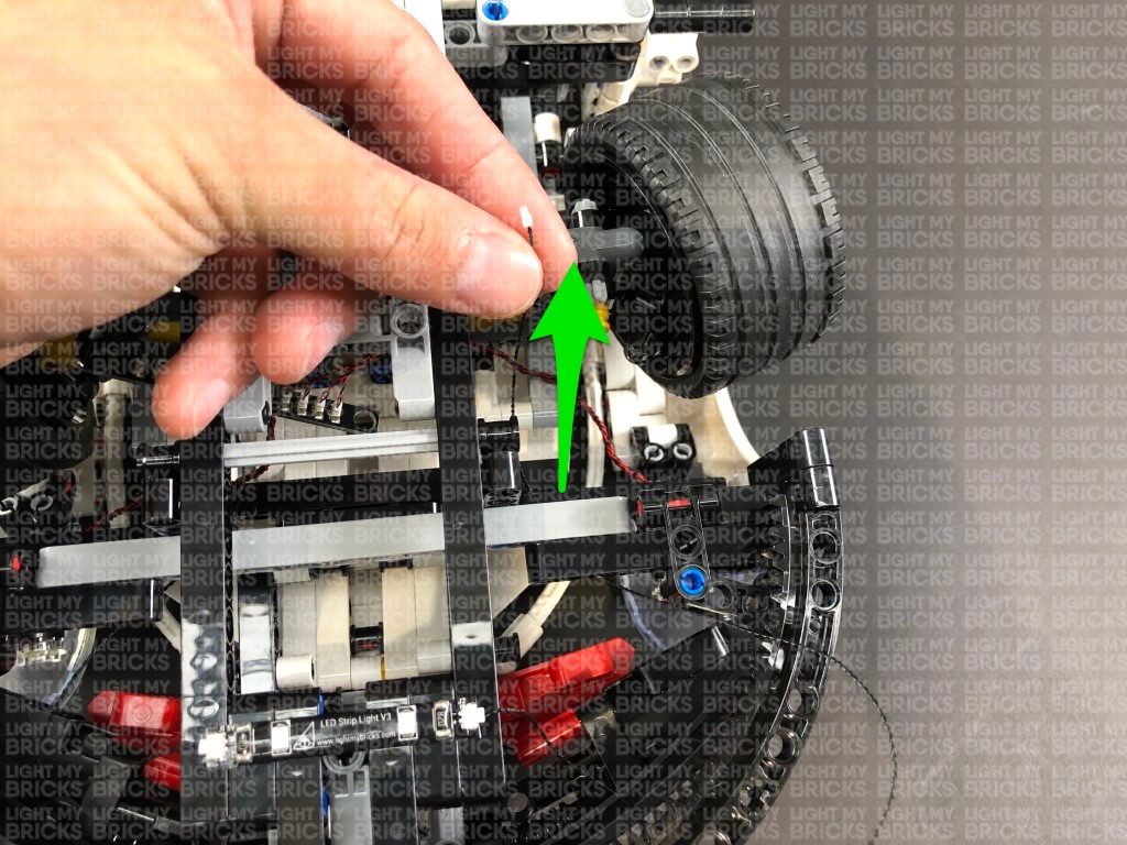
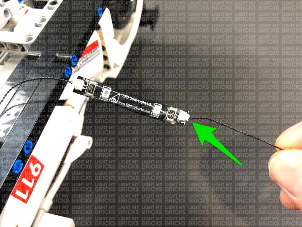
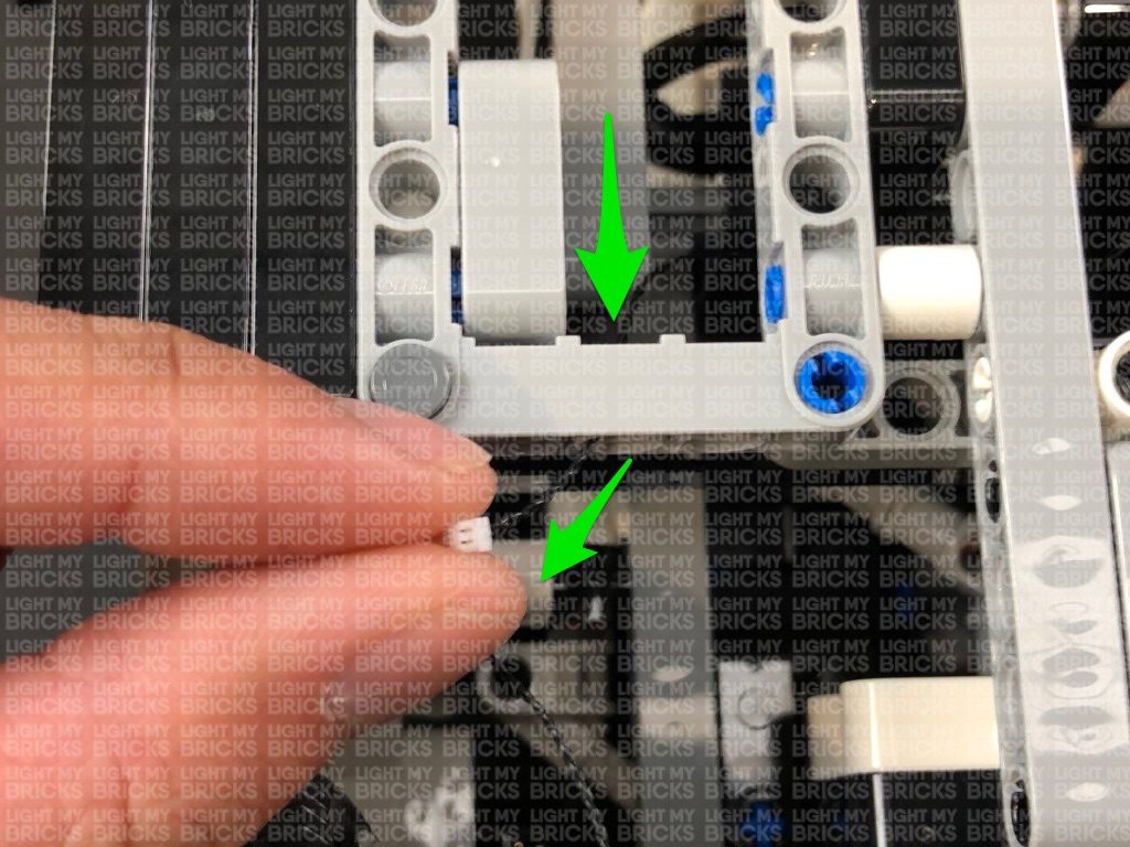
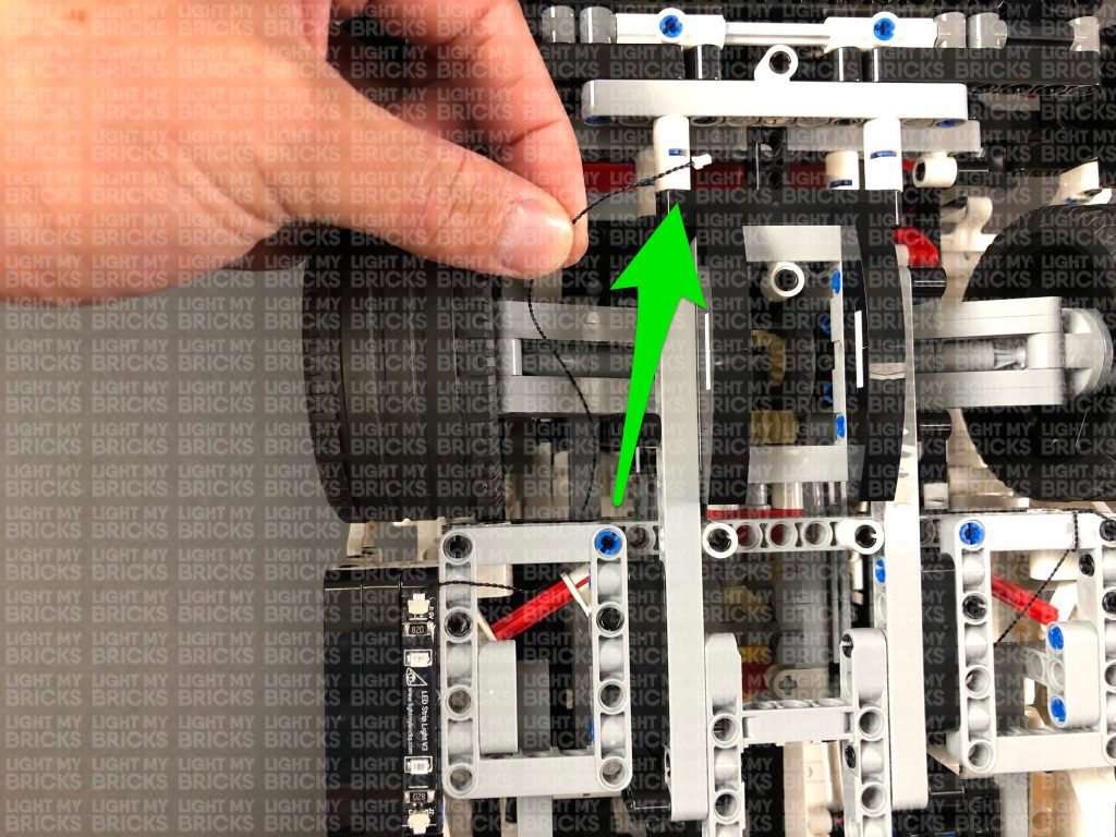
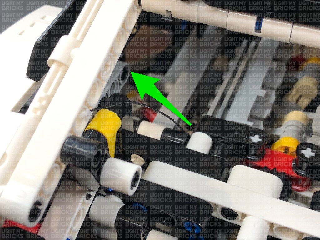
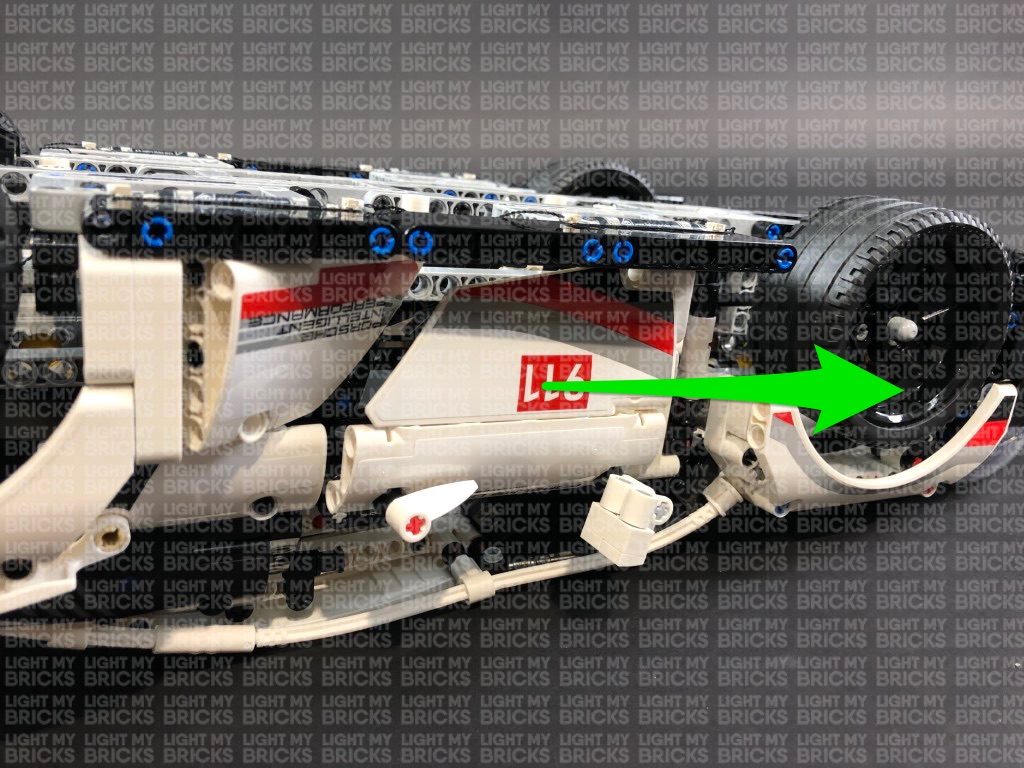
 13.) Take the other end of the 15cm Connecting Cable from previous step and thread it underneath the grey technic piece, then pull it all the way out from the other side. Thread the cable down the space on the right of the wheel that leads to the inside of the trunk.
Flip the Porsche back around and open the trunk and locate the other end of the connecting cable. Pull the cable all the way up and connect it to an 8-Port Expansion Board.
Take the AA Battery Pack and connect the battery pack cable to the 8-Port Expansion Board, then place it inside the trunk. Turn it ON to test all the red strip lights are working OK.
Note: If you experience any issues with the lights not working and suspect an issue with a component, please try a different port on the expansion board to verify where the fault lies (with the light or expansion board). To correct any issues with expansion board ports, please view the section addressing expansion board issues on our online troubleshooting guide.
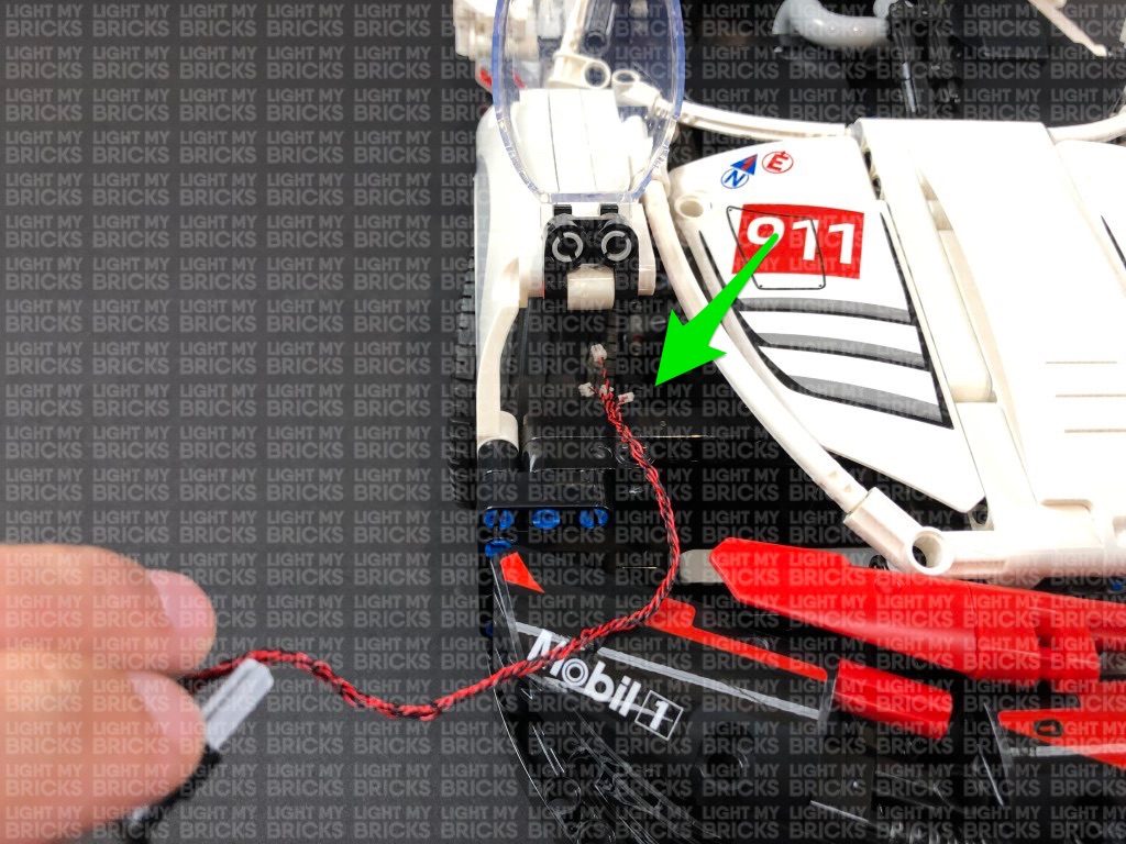
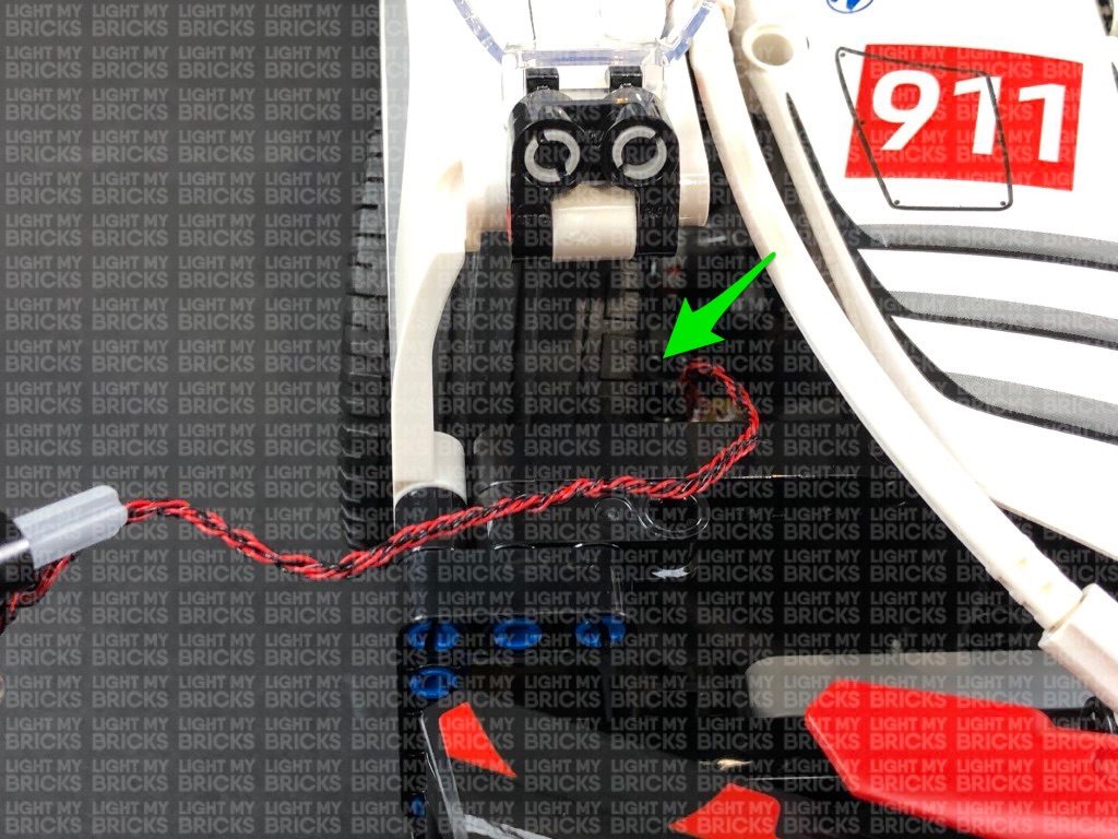
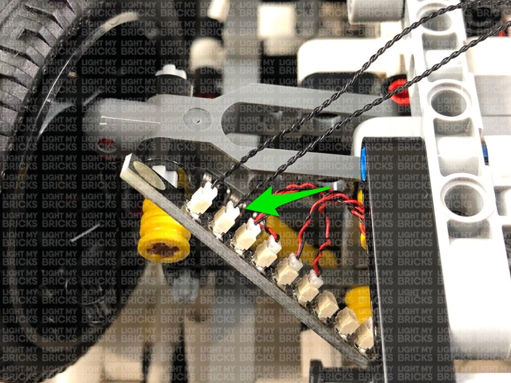
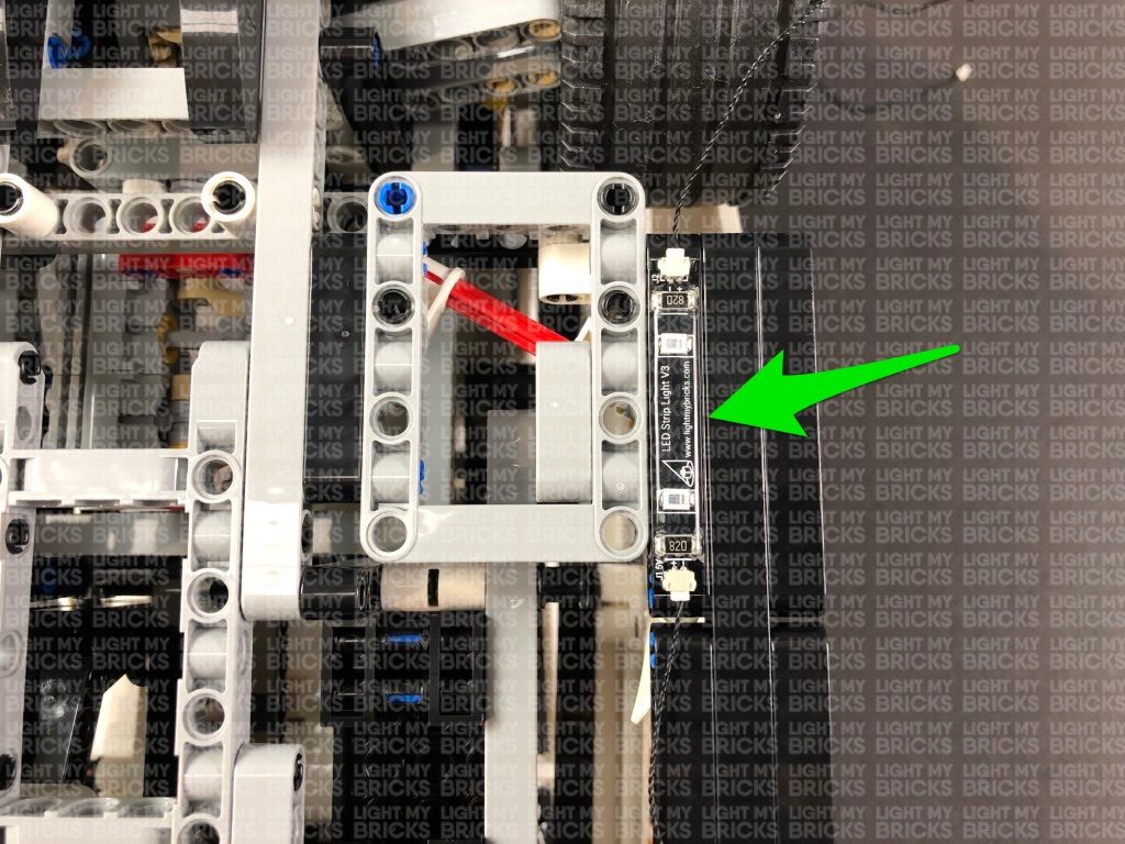
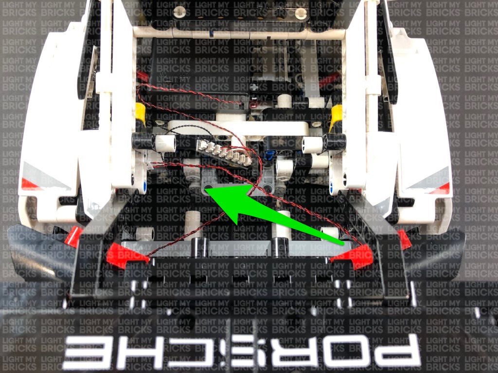
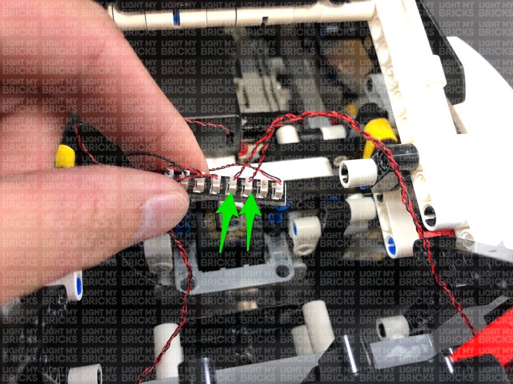
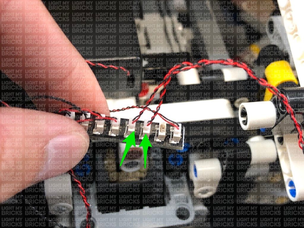
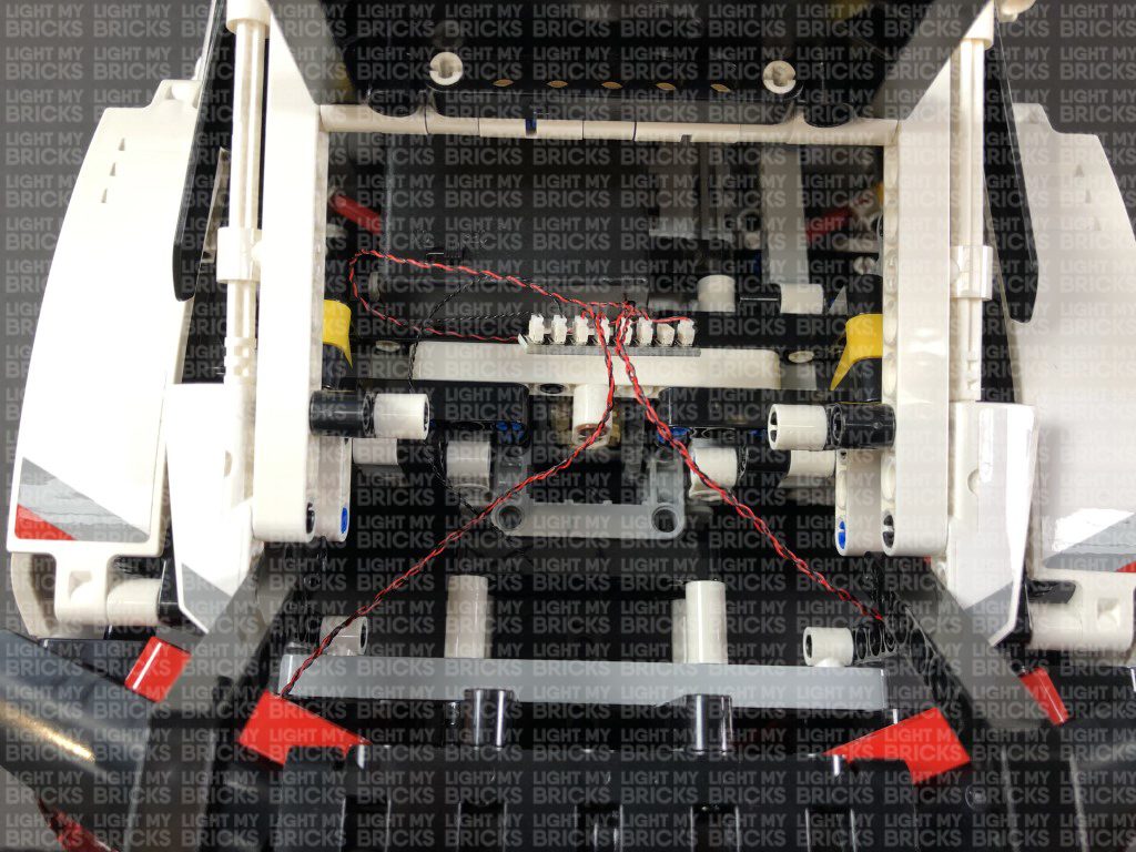
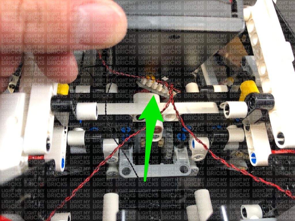
14.) Close the trunk, then flip the car back over again and locate the other end of the second 15cm Connecting Cable we connected to the 12-Port Expansion Board (step. 8).
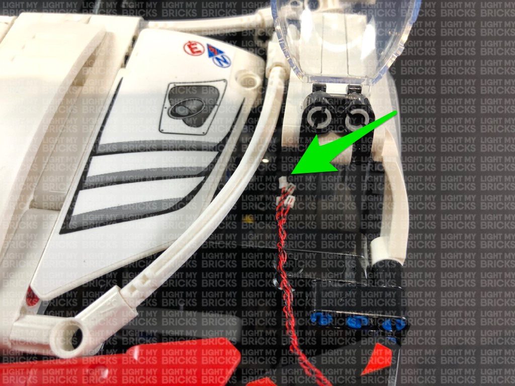
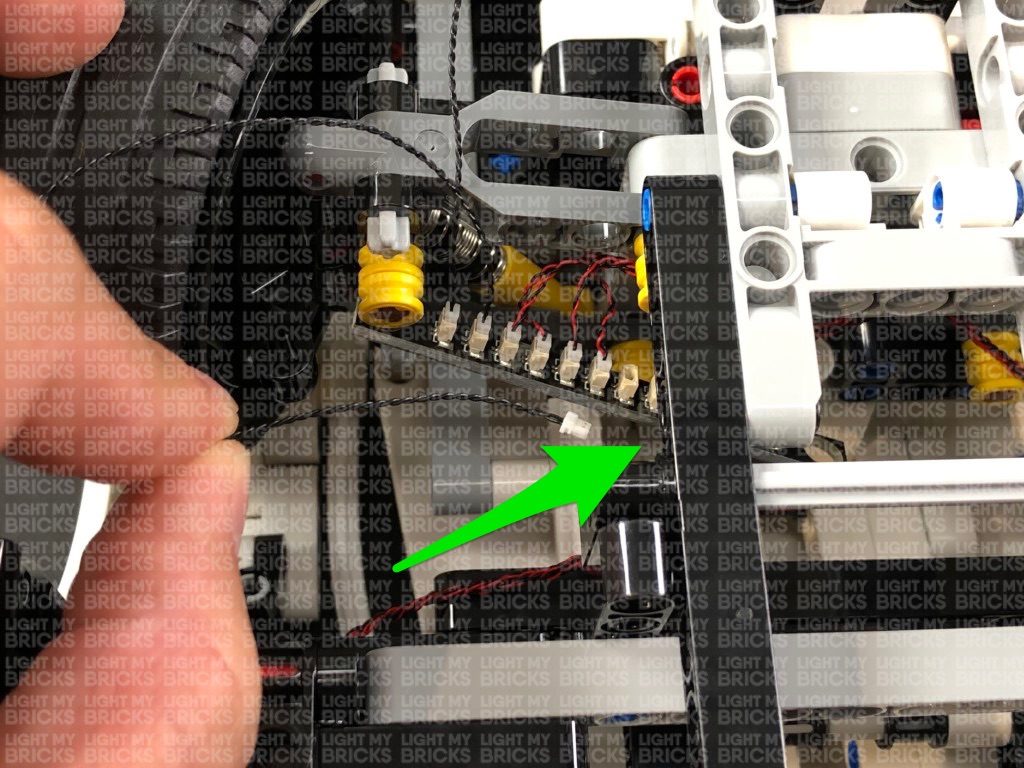
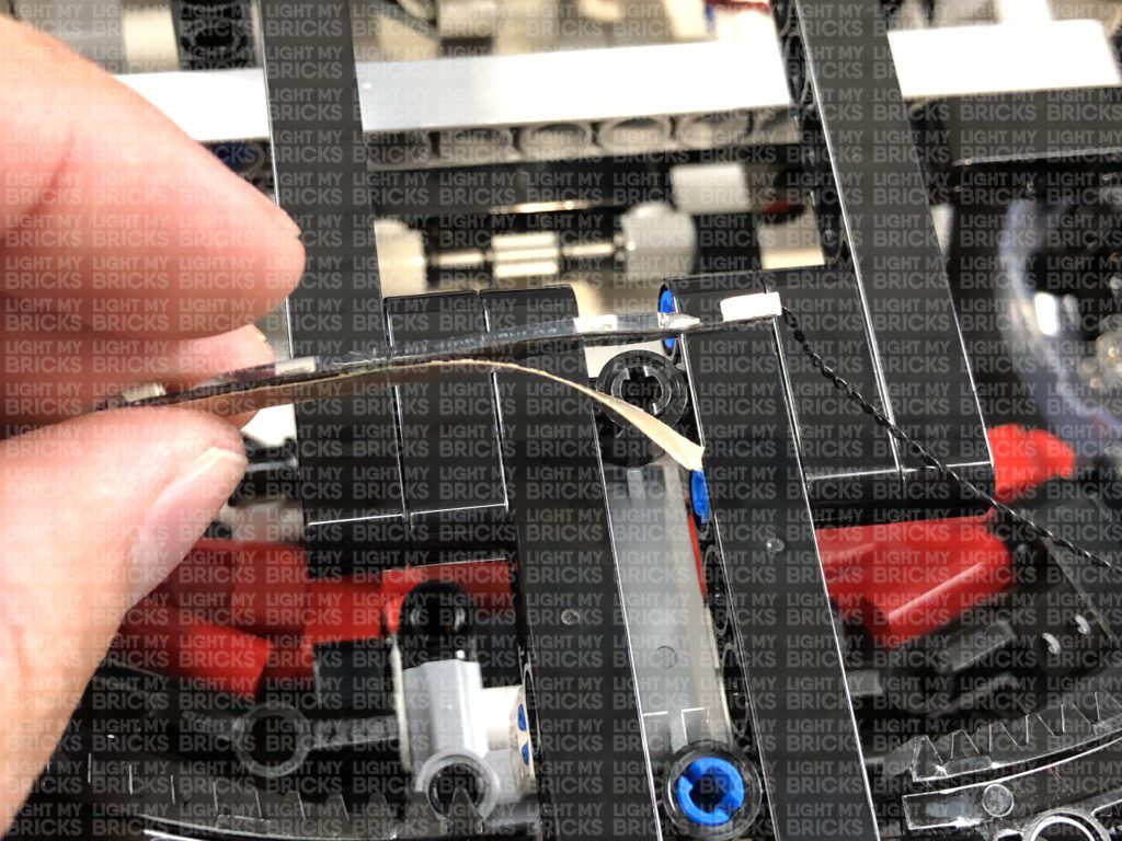
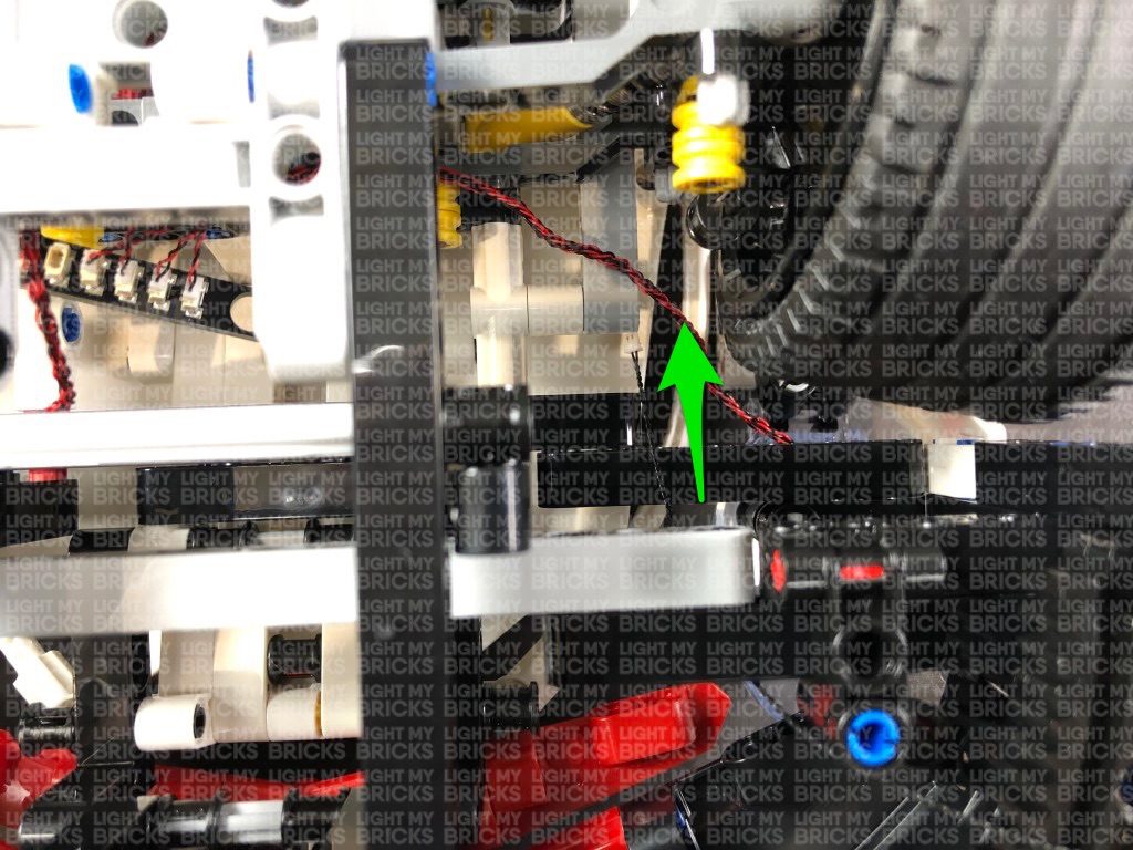
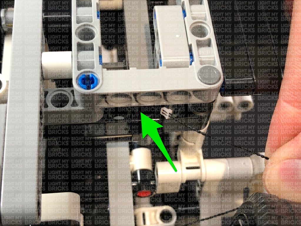
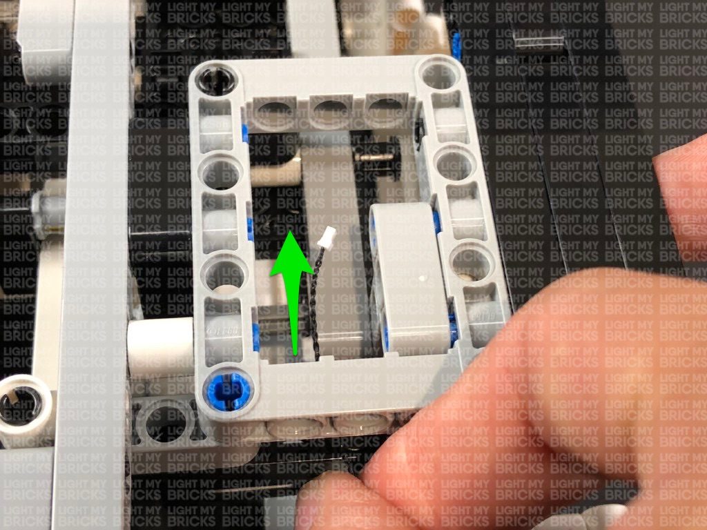
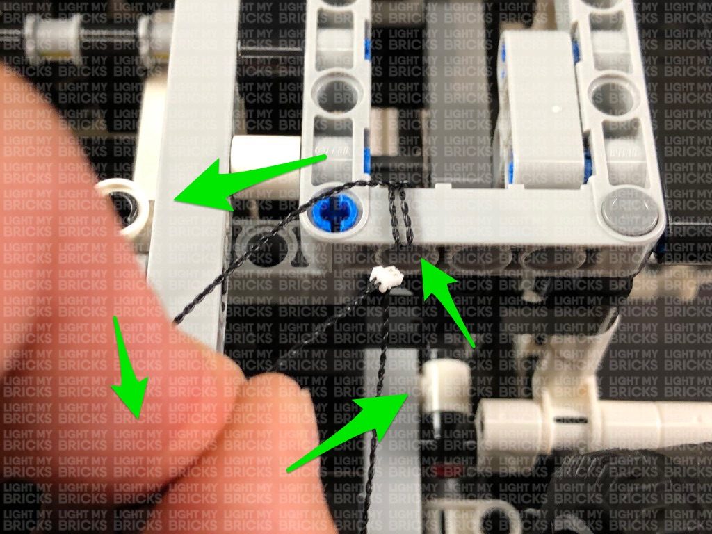
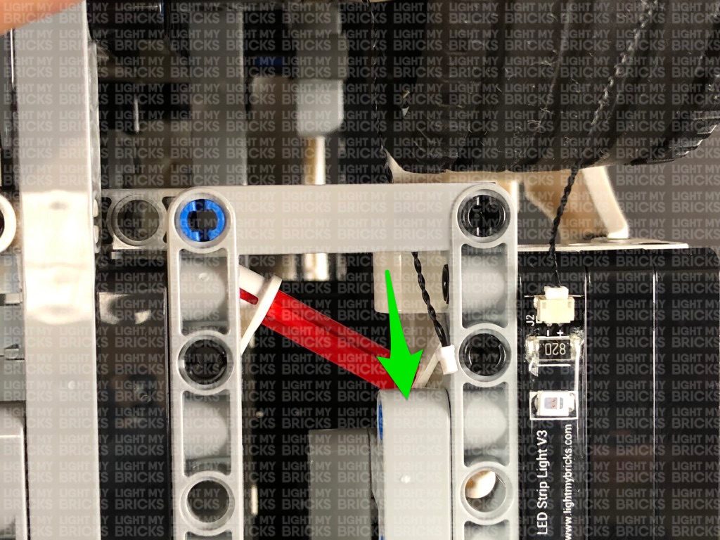
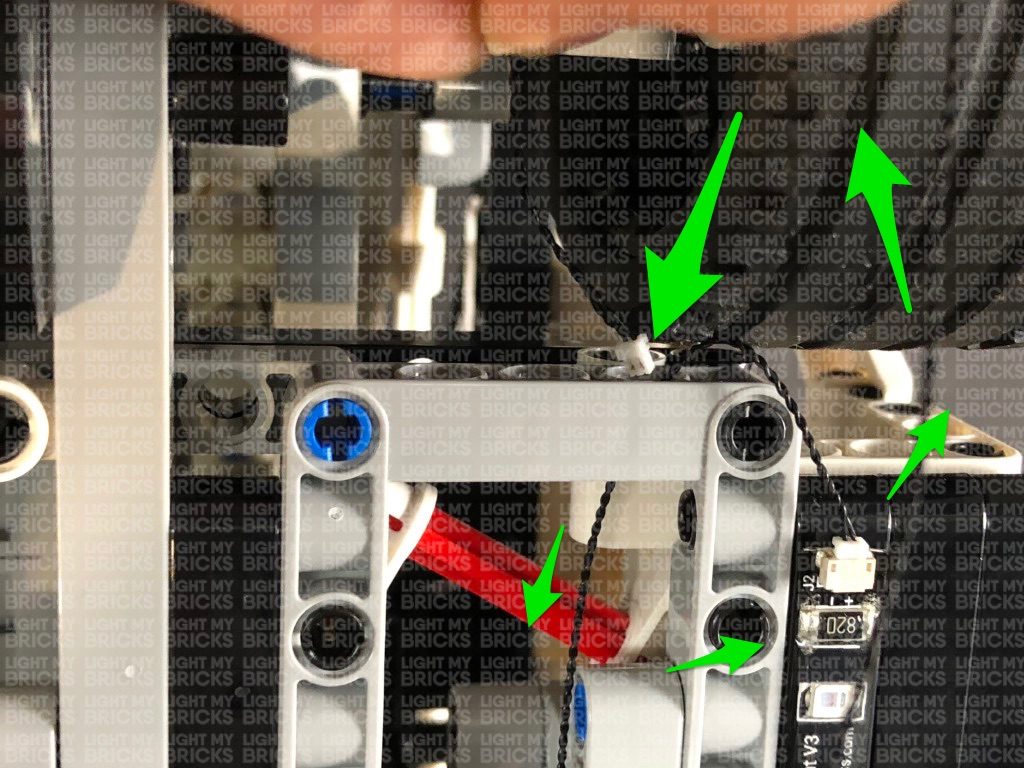
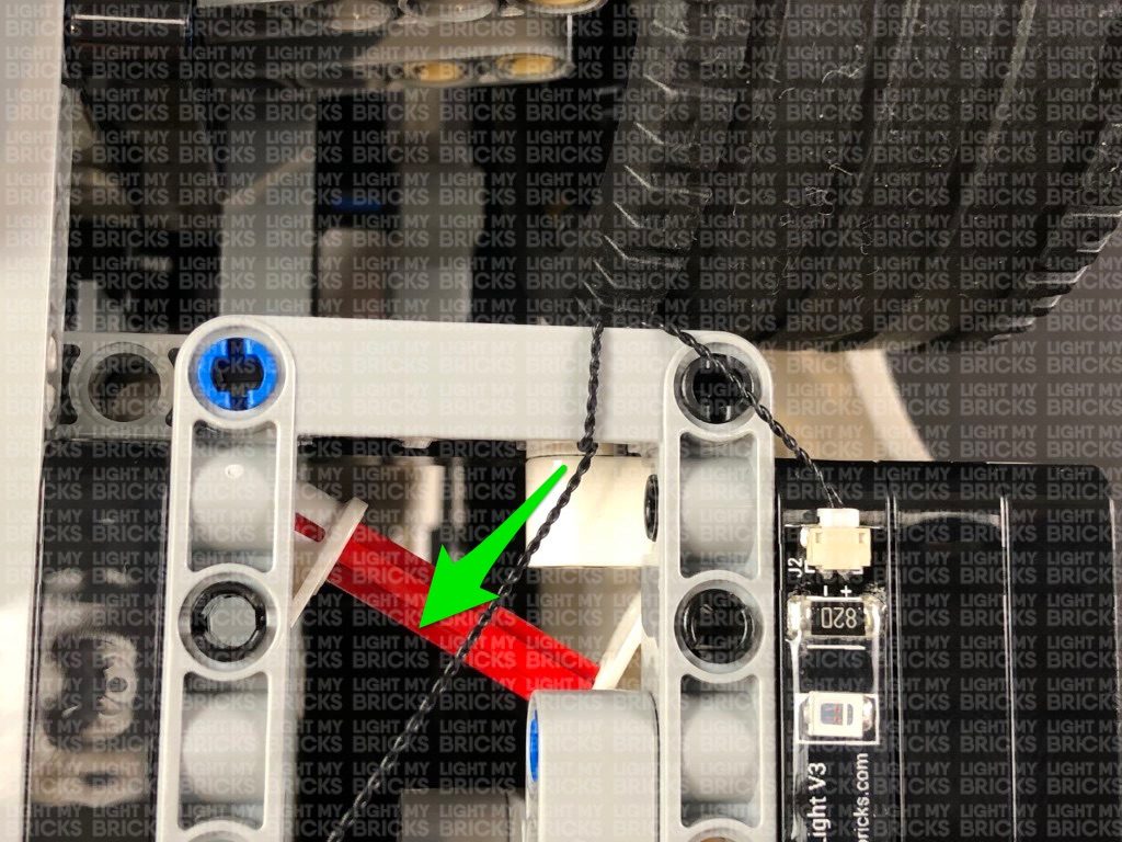
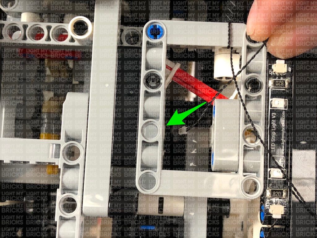
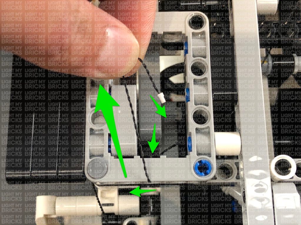
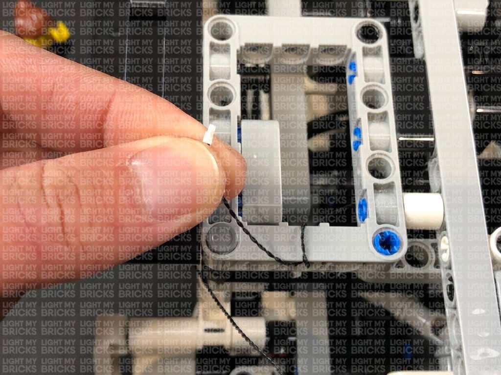
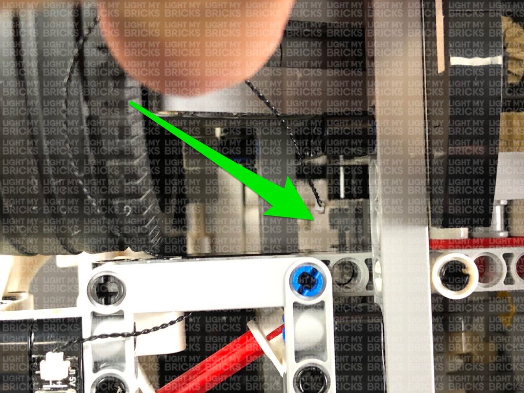
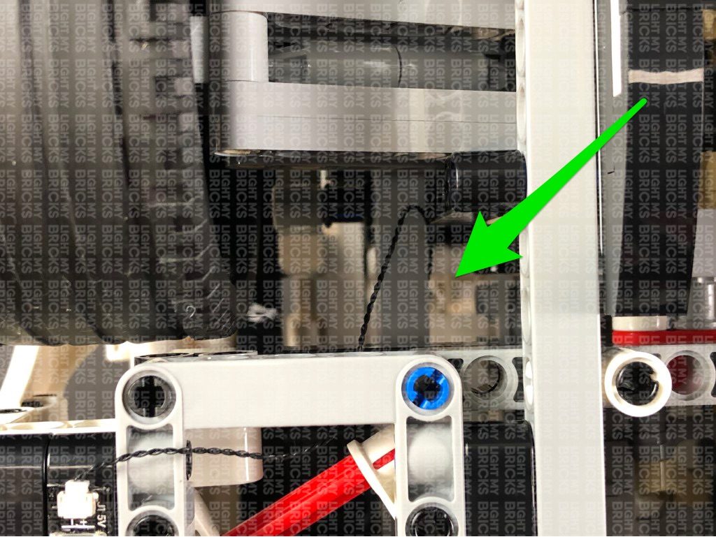
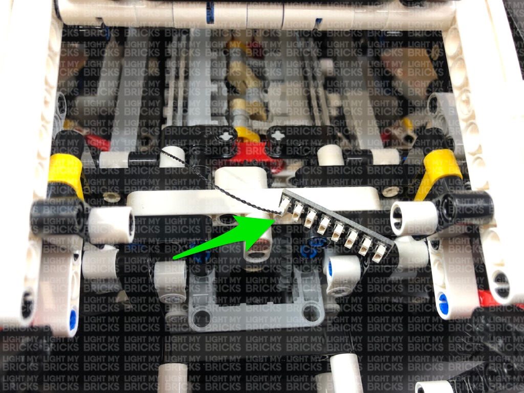
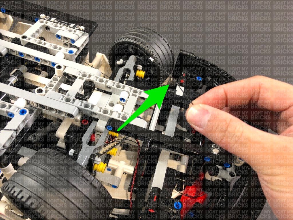
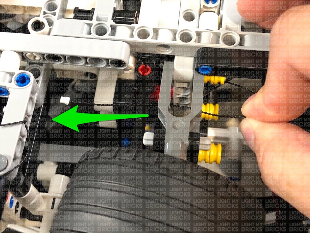
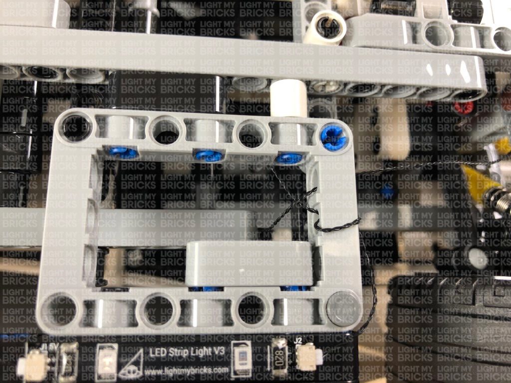
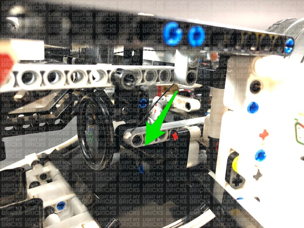
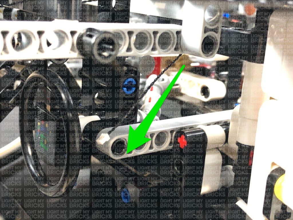
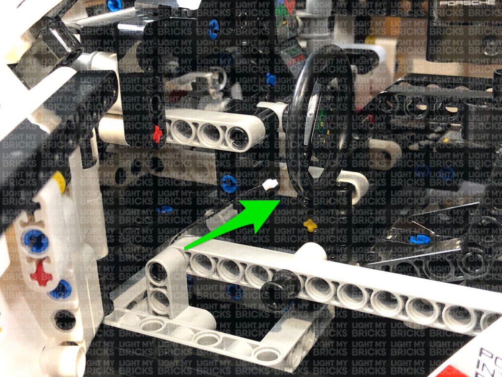
Thread the cable underneath the wheel axis, then through the hole of the grey technic piece as shown below:
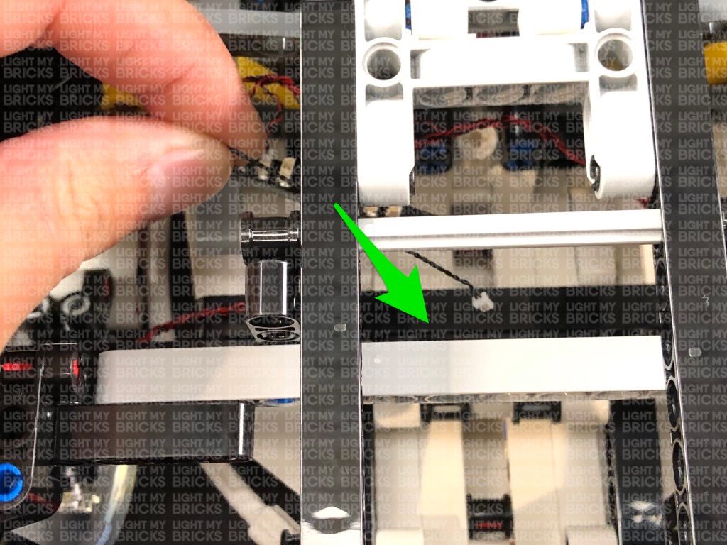
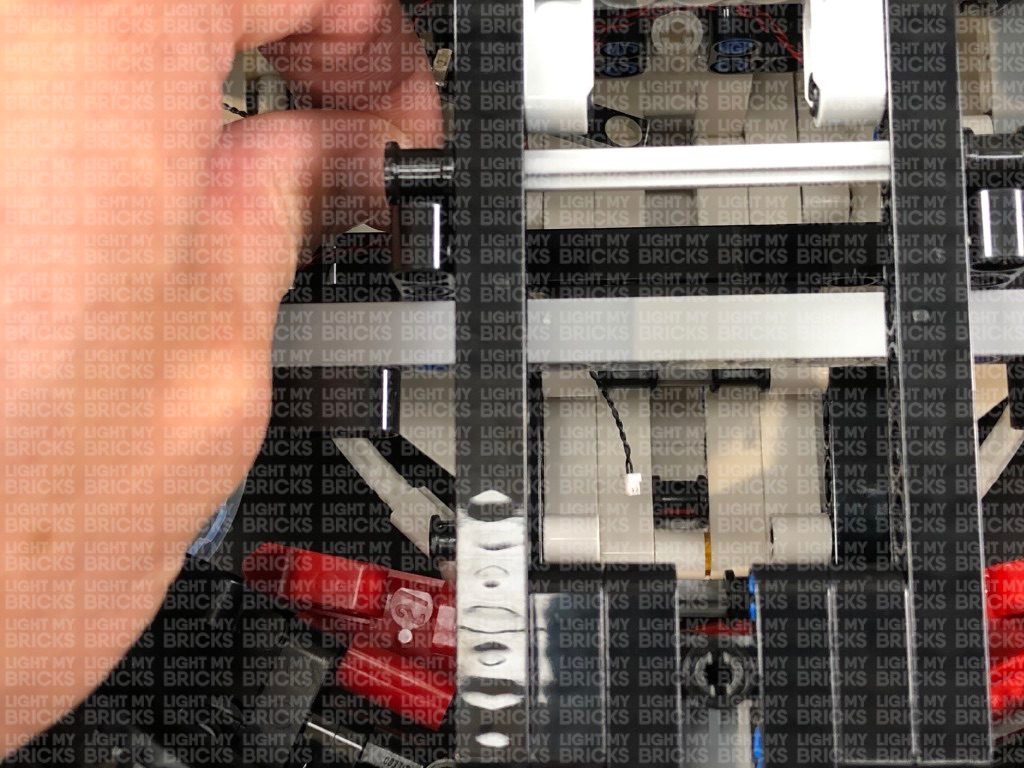
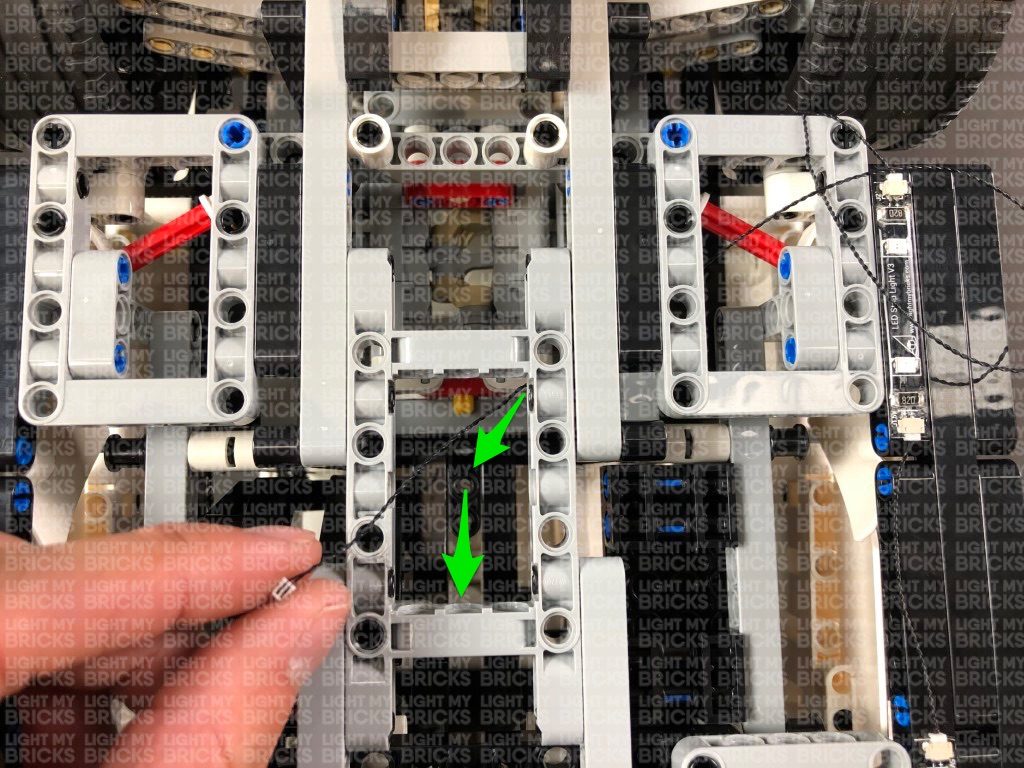
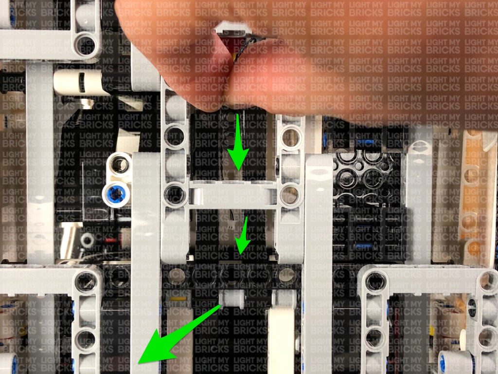
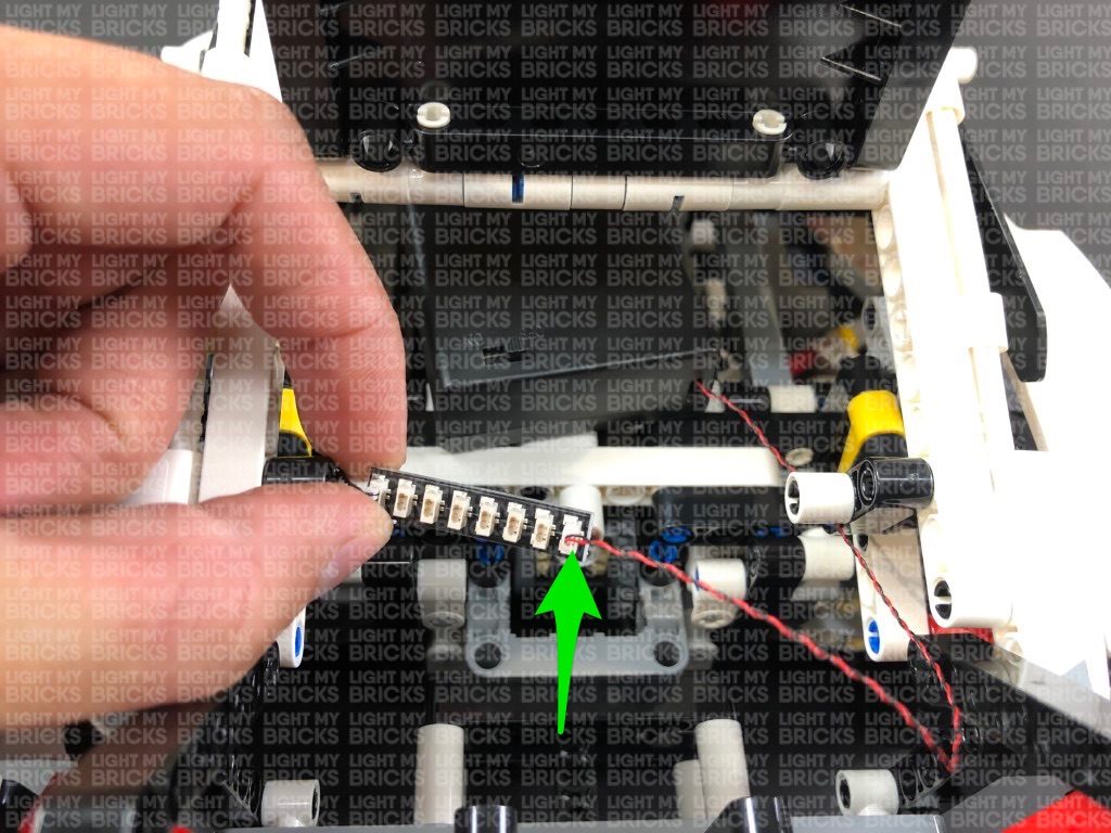
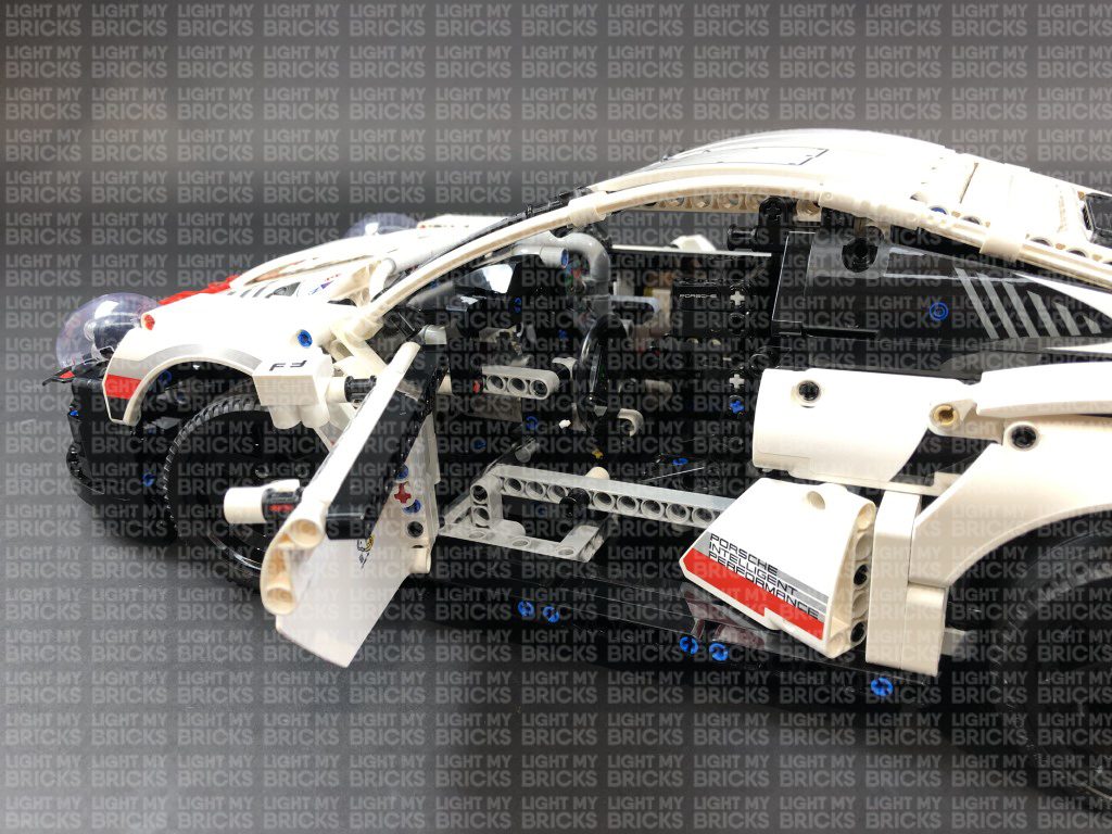
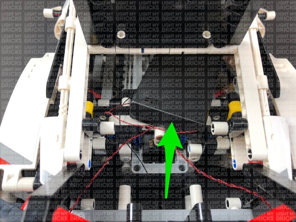
Thread the cable down the following space which leads to the inside of the driver side. Open the driver door and pull the cable all the way out.
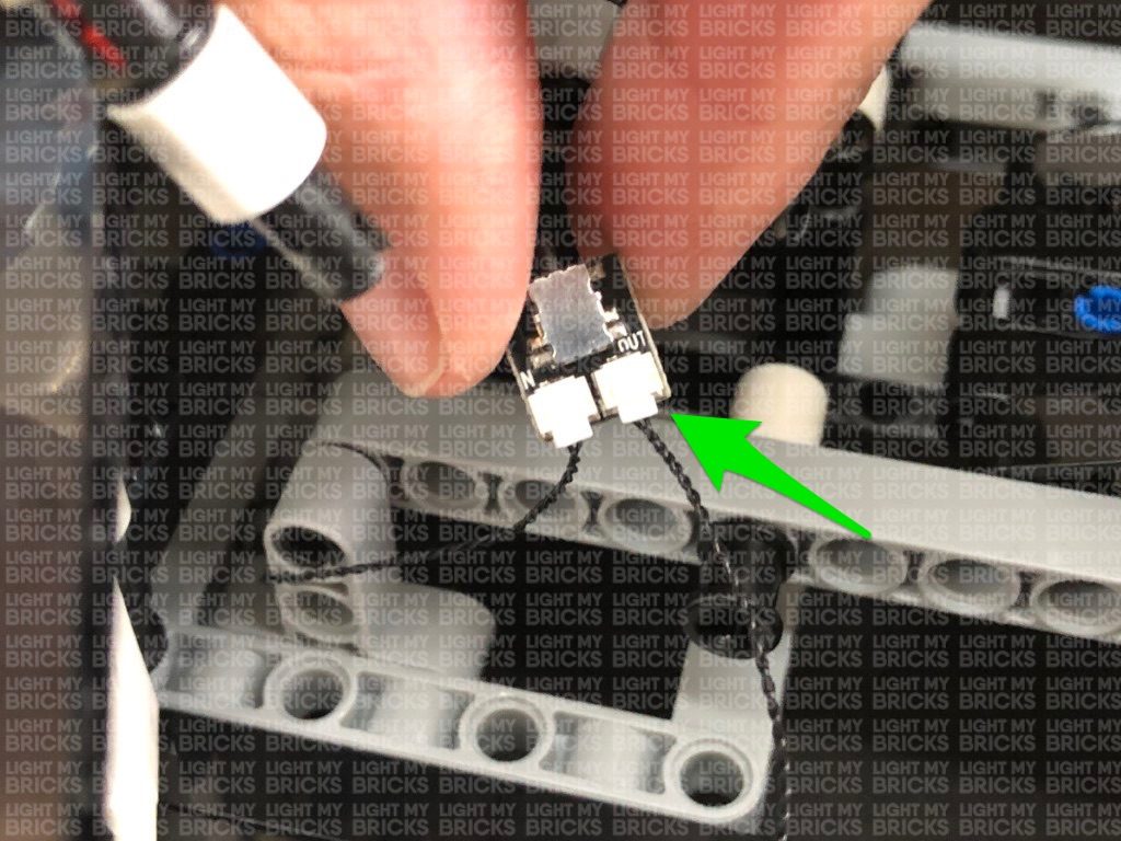
Flip the car back over and connect the other end of the cable to the IN port on the NC Push Board.
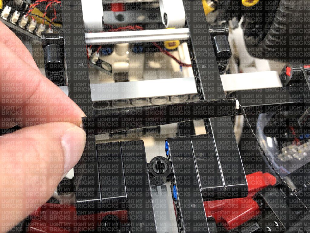
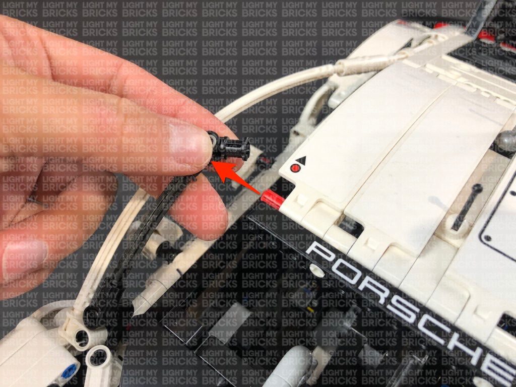
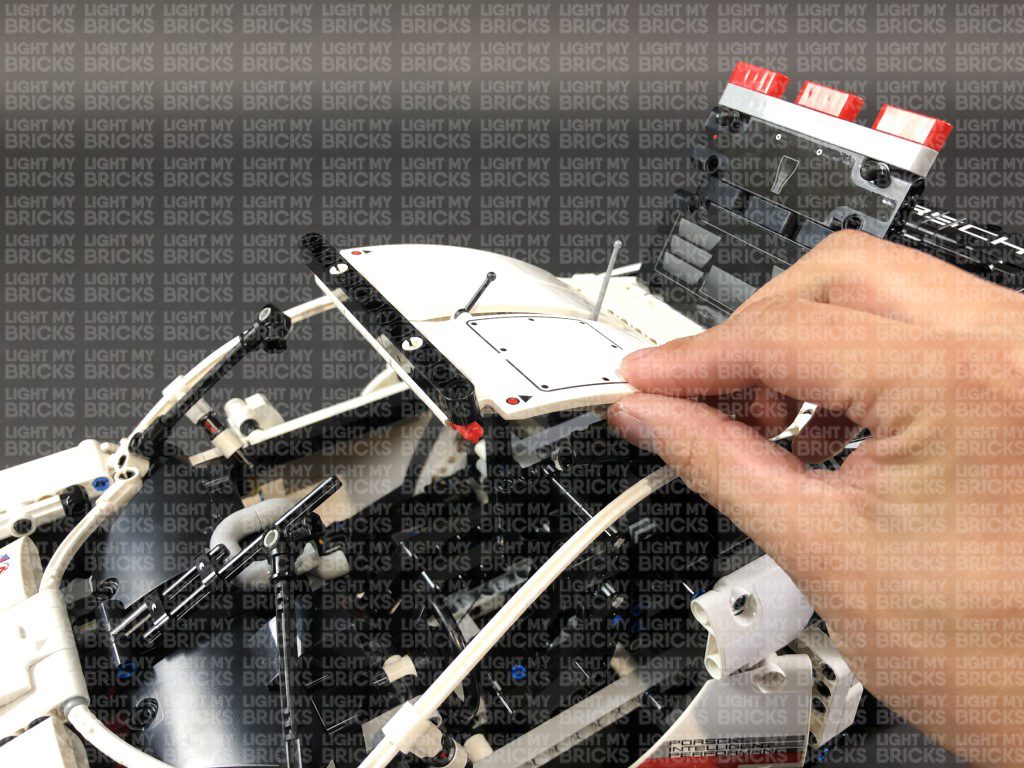
15.) We will now disconnect the roof at the following sections.
13.) Take the other end of the 15cm Connecting Cable from previous step and thread it underneath the grey technic piece, then pull it all the way out from the other side. Thread the cable down the space on the right of the wheel that leads to the inside of the trunk.
Flip the Porsche back around and open the trunk and locate the other end of the connecting cable. Pull the cable all the way up and connect it to an 8-Port Expansion Board.
Take the AA Battery Pack and connect the battery pack cable to the 8-Port Expansion Board, then place it inside the trunk. Turn it ON to test all the red strip lights are working OK.
Note: If you experience any issues with the lights not working and suspect an issue with a component, please try a different port on the expansion board to verify where the fault lies (with the light or expansion board). To correct any issues with expansion board ports, please view the section addressing expansion board issues on our online troubleshooting guide.
14.) Close the trunk, then flip the car back over again and locate the other end of the second 15cm Connecting Cable we connected to the 12-Port Expansion Board (step. 8).
Thread the cable underneath the wheel axis, then through the hole of the grey technic piece as shown below:
Thread the cable down the following space which leads to the inside of the driver side. Open the driver door and pull the cable all the way out.
Flip the car back over and connect the other end of the cable to the IN port on the NC Push Board.
15.) We will now disconnect the roof at the following sections.
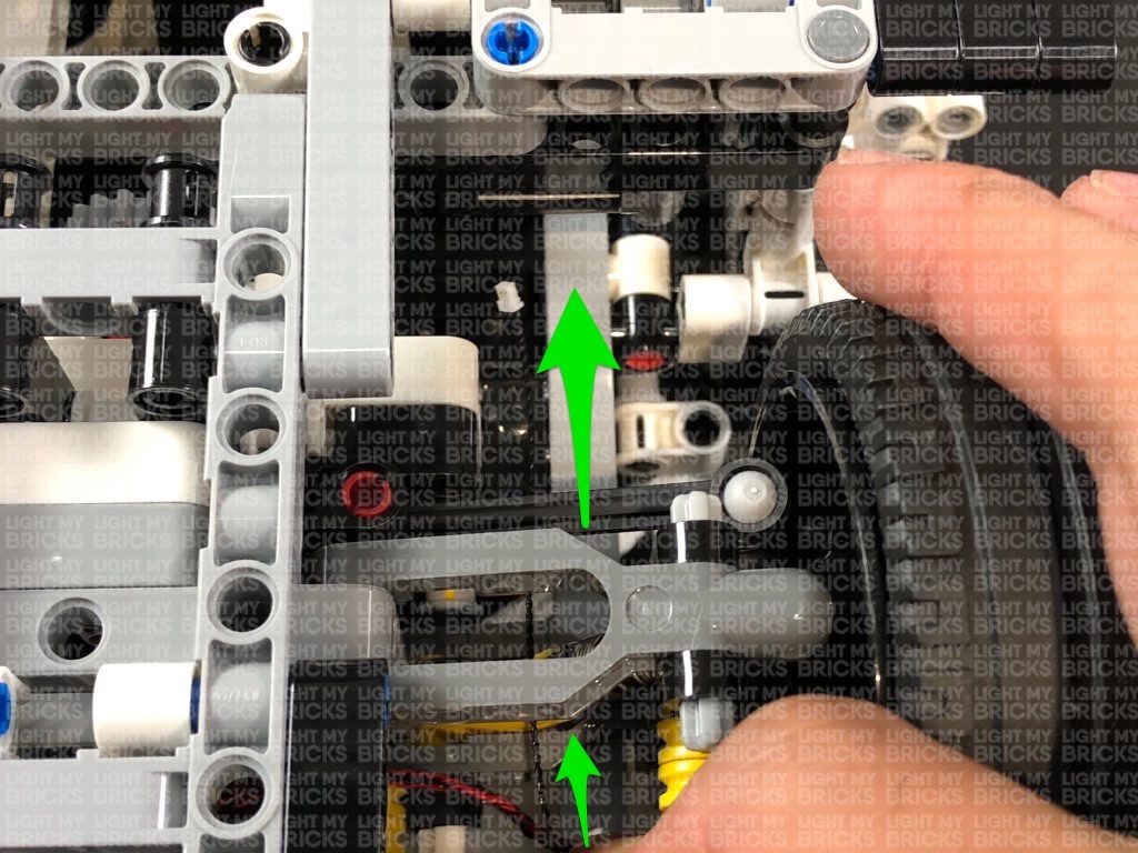
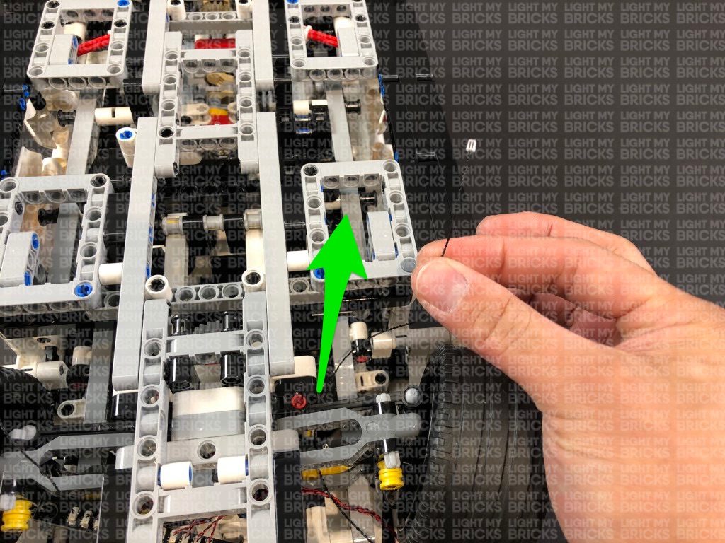
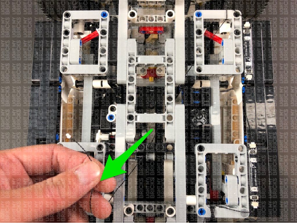
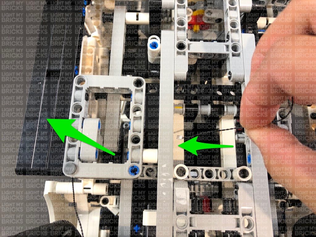
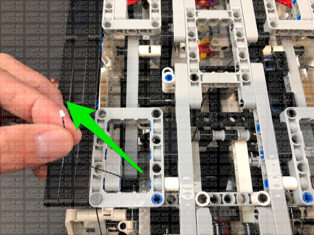
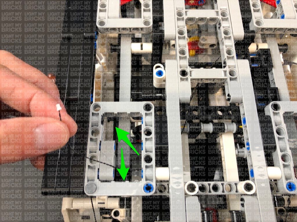
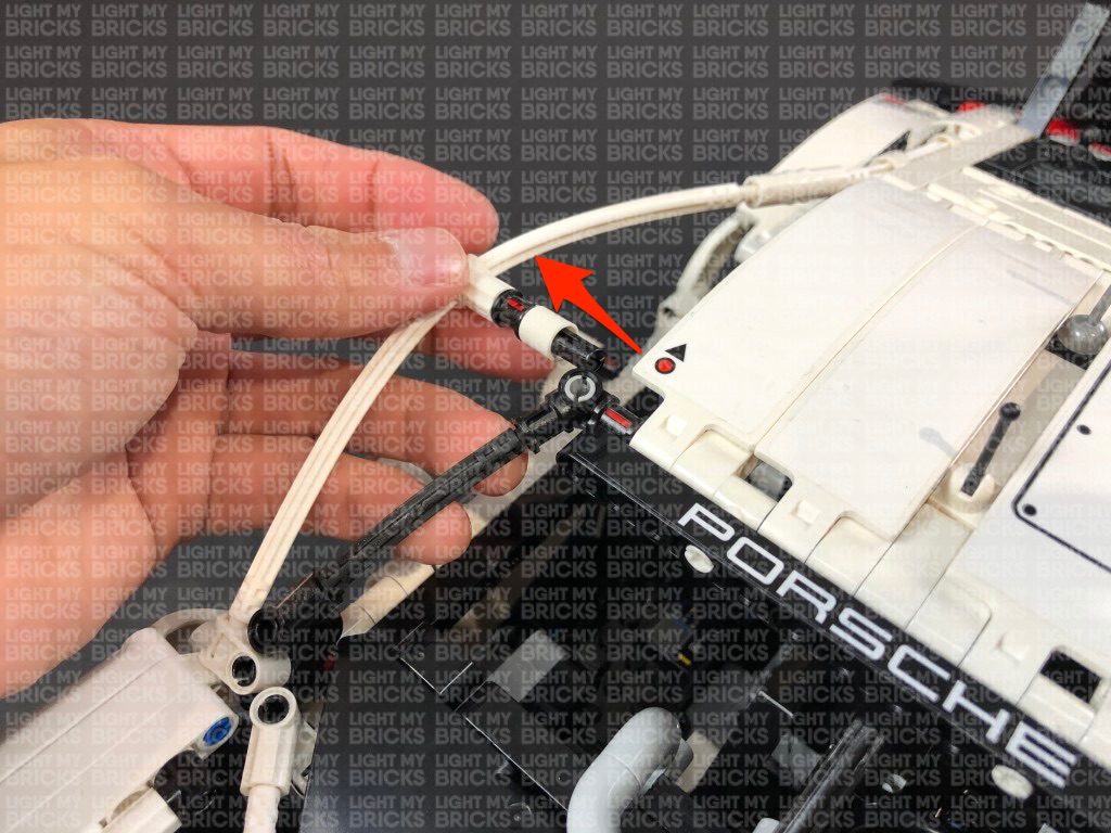
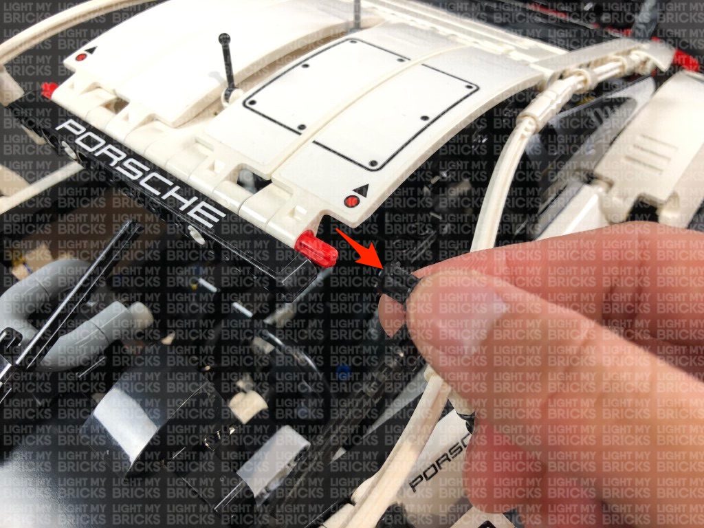
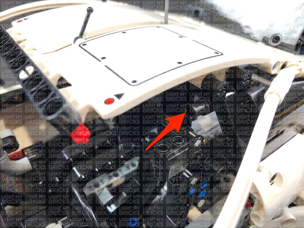
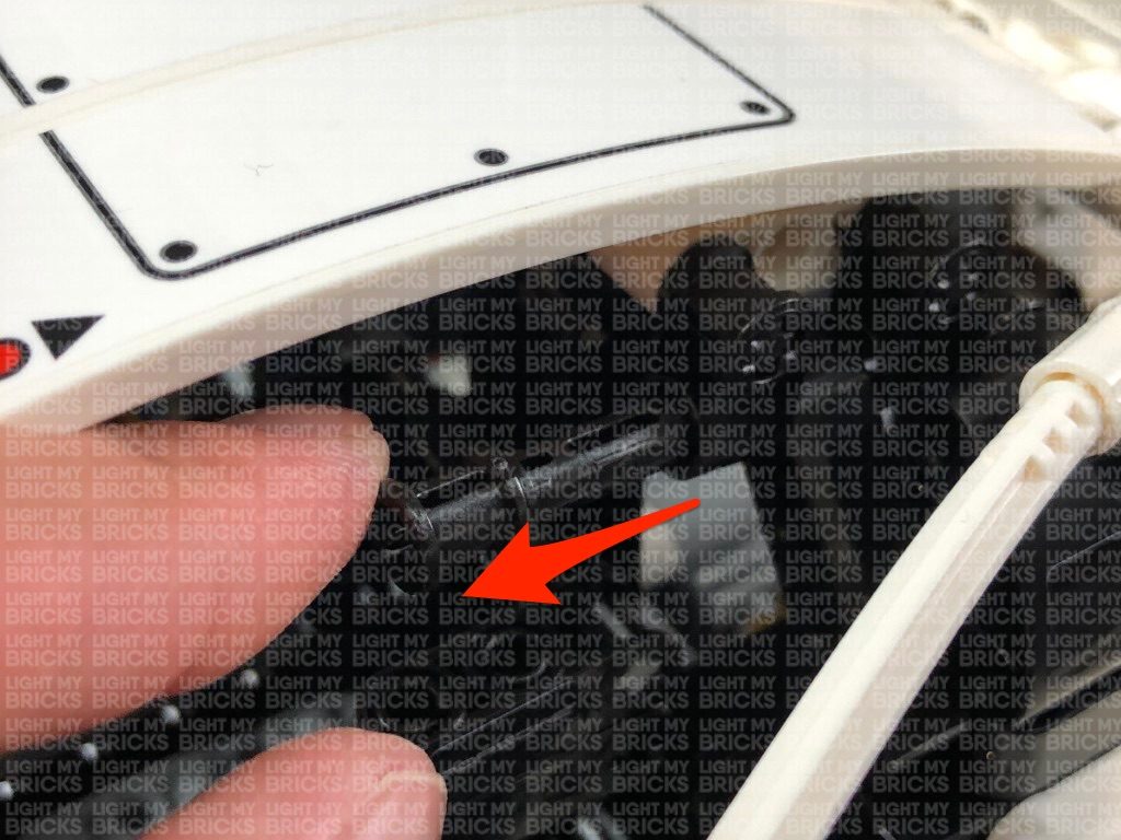
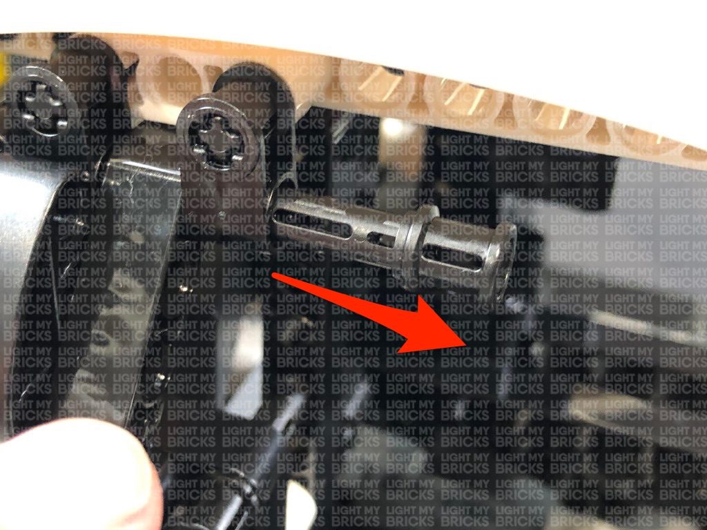
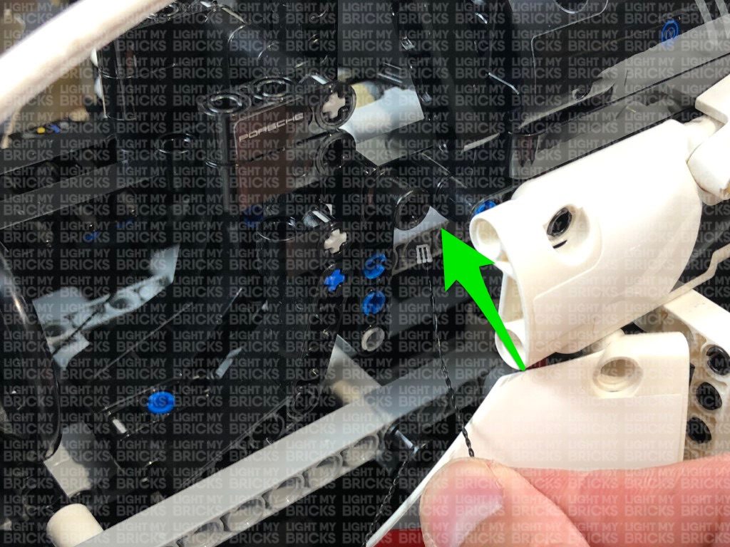
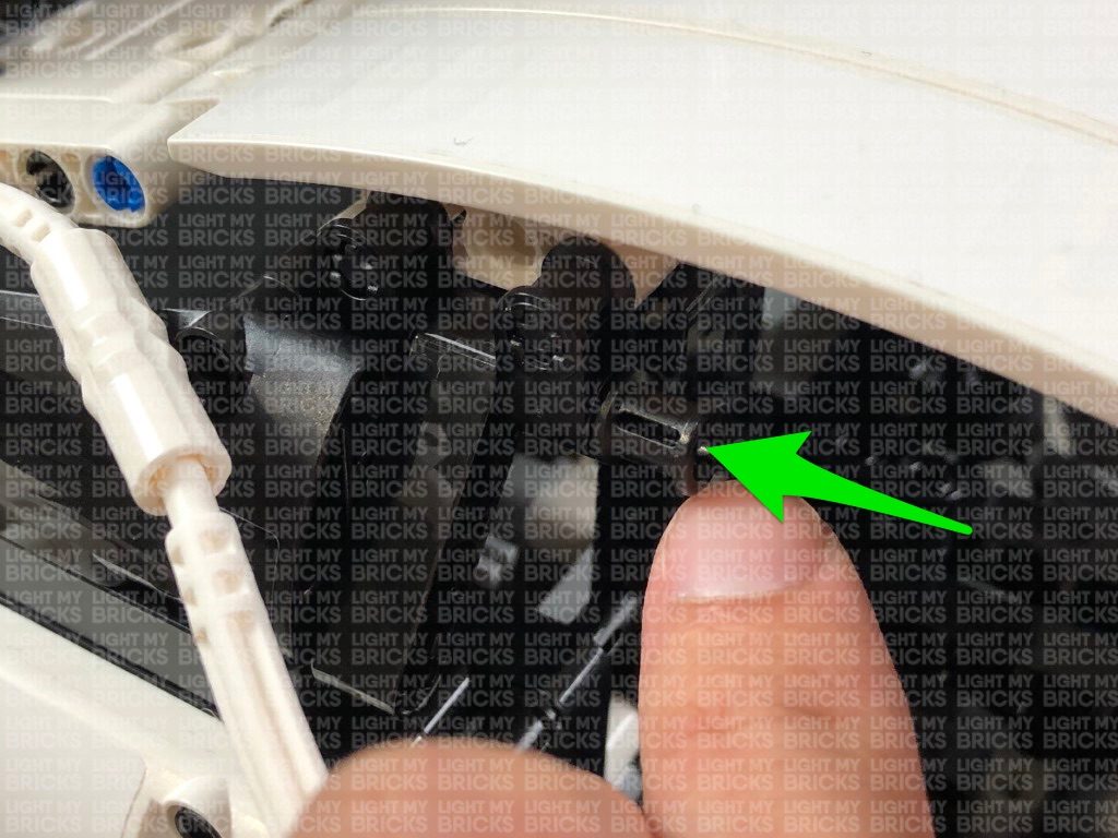
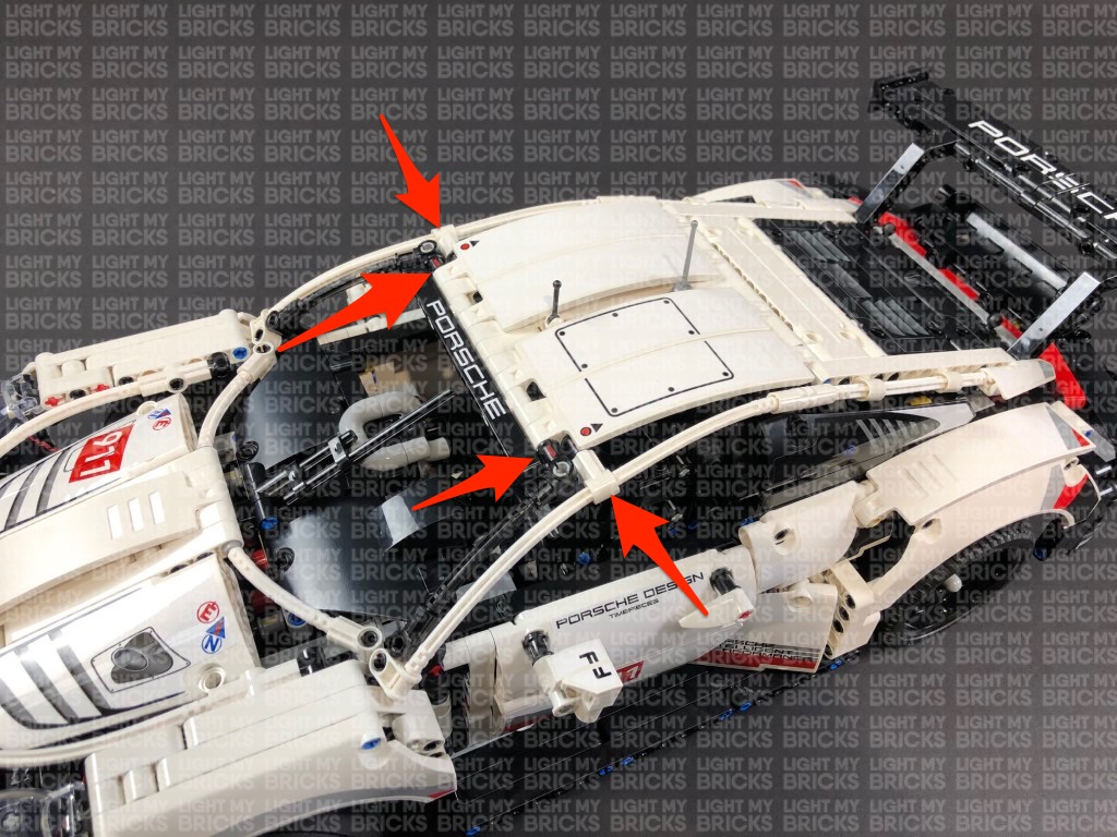 Follow the below images to disconnect technic pins in order for us to lift up the roof.
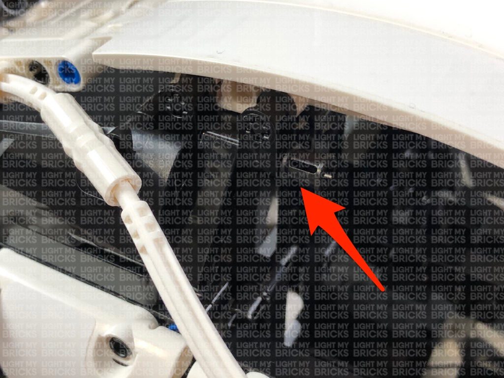
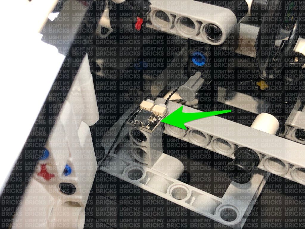
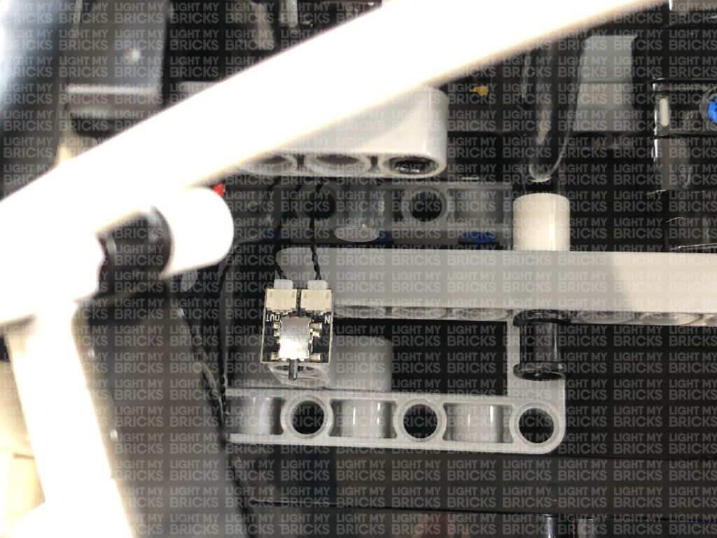
16.) Take a 30cm Connecting Cable and connect it to the OUT port on the NC Push Board. Using it’s adhesive backing, stick the NC Push Board to the following position of the driver doorway. We need to ensure that when we close the driver door, it will push in the trigger on the NC Push Board.
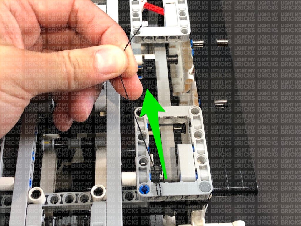
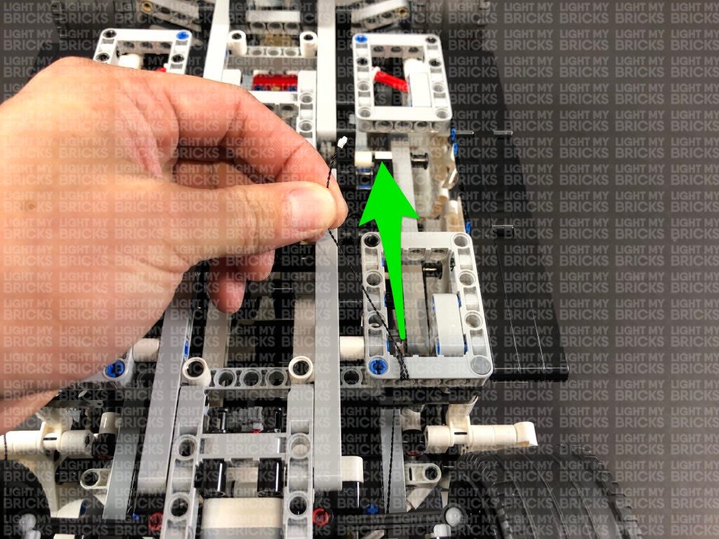
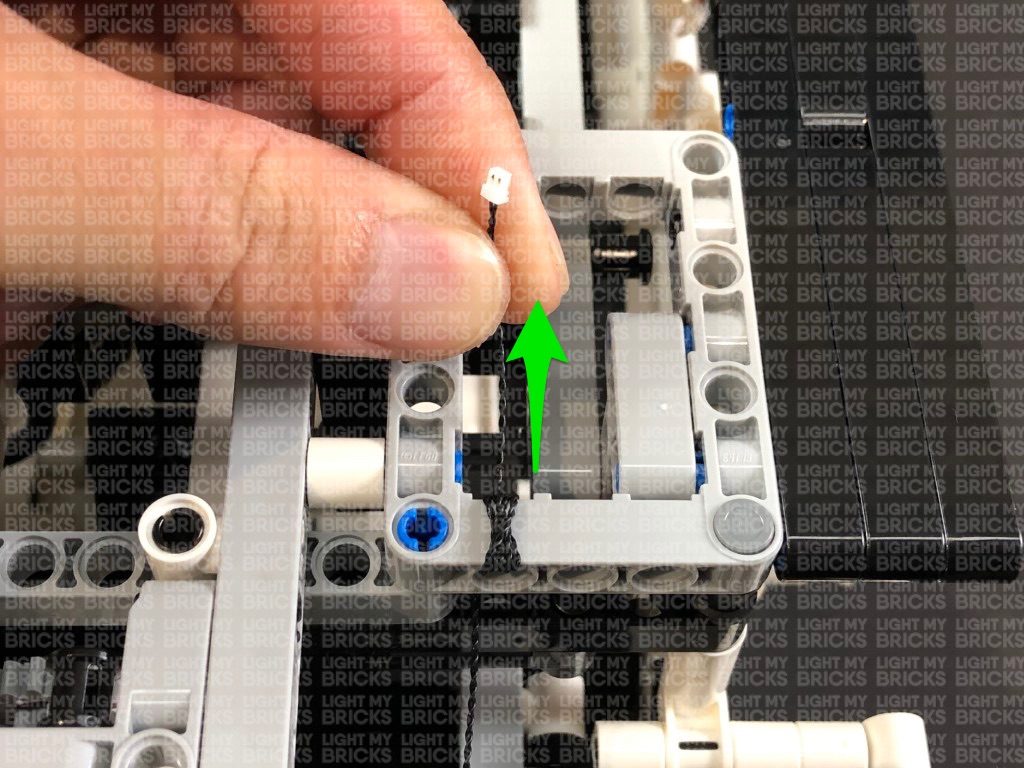
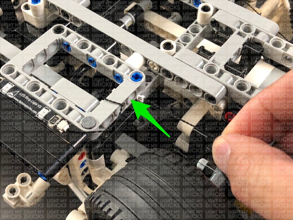
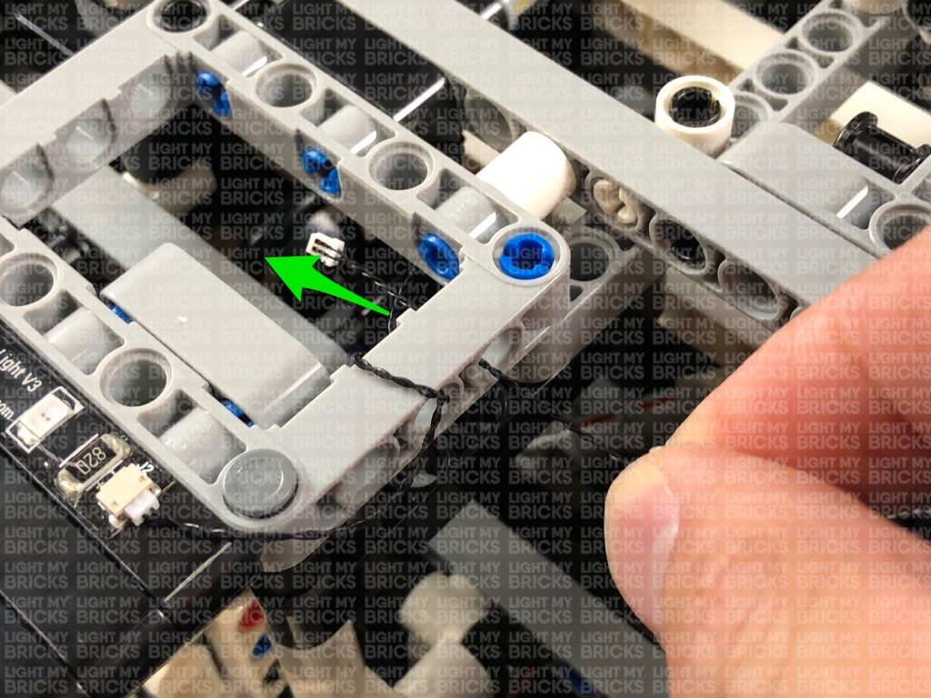
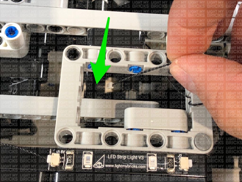
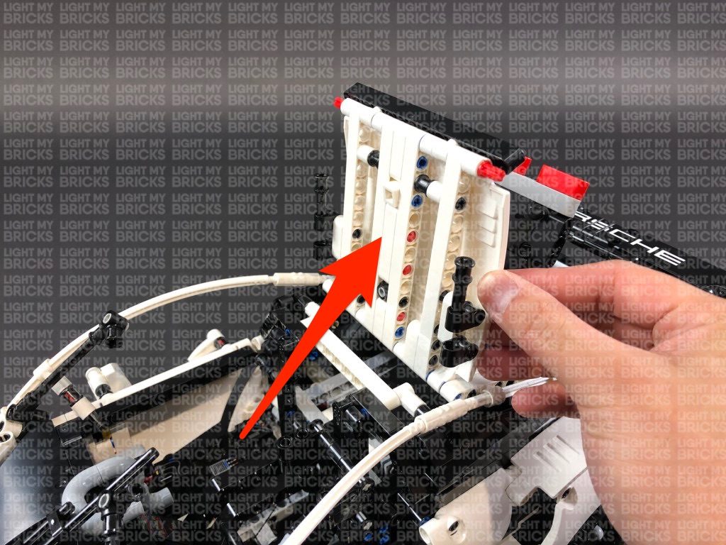
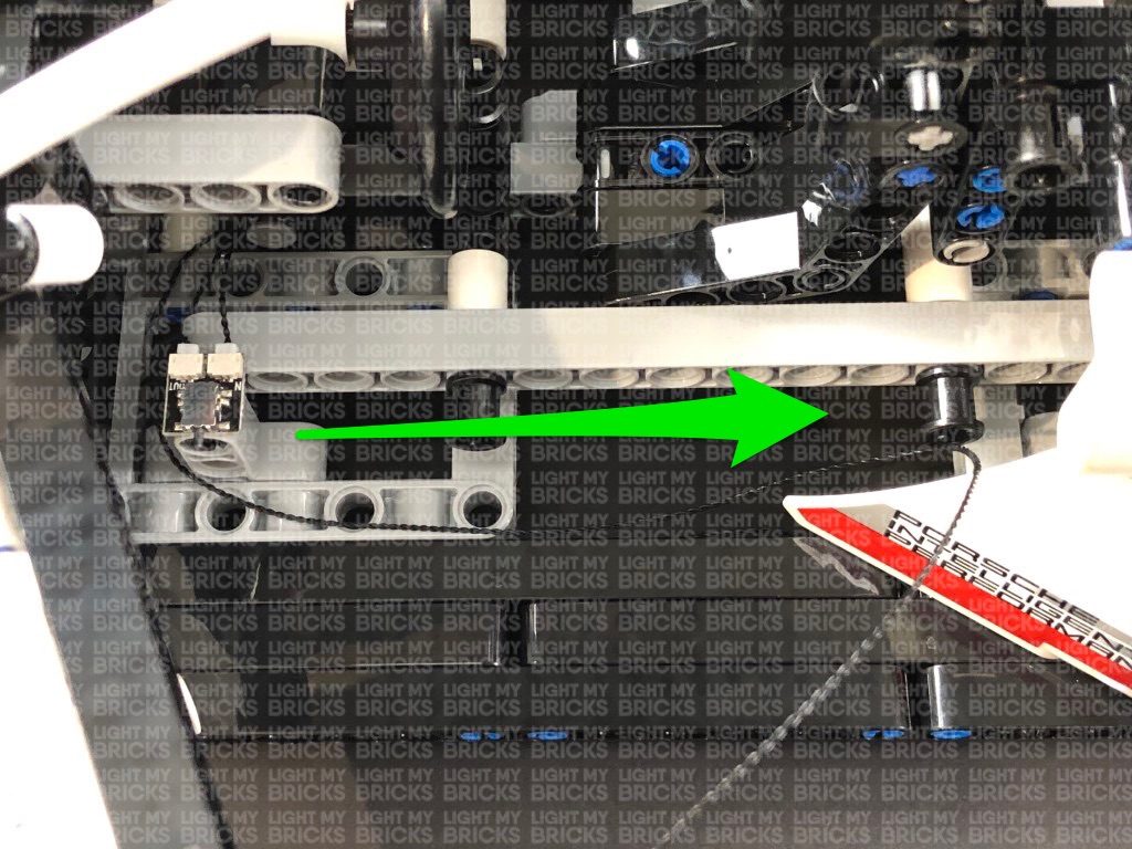
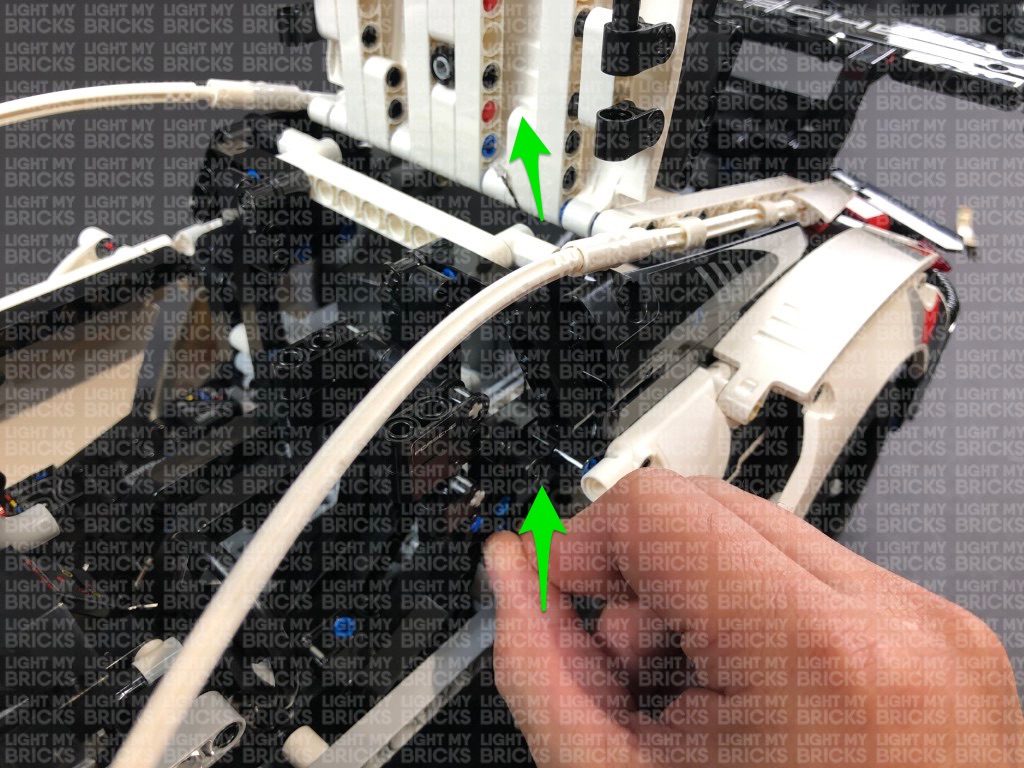
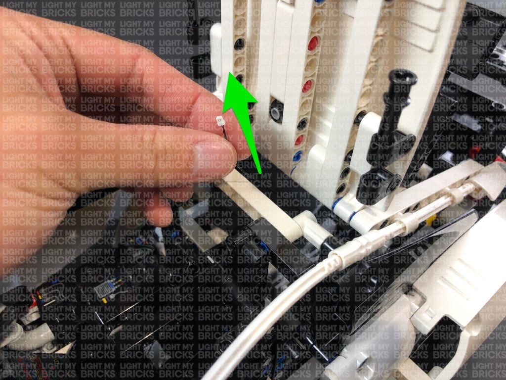
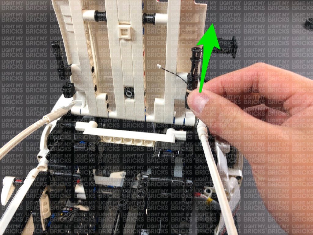
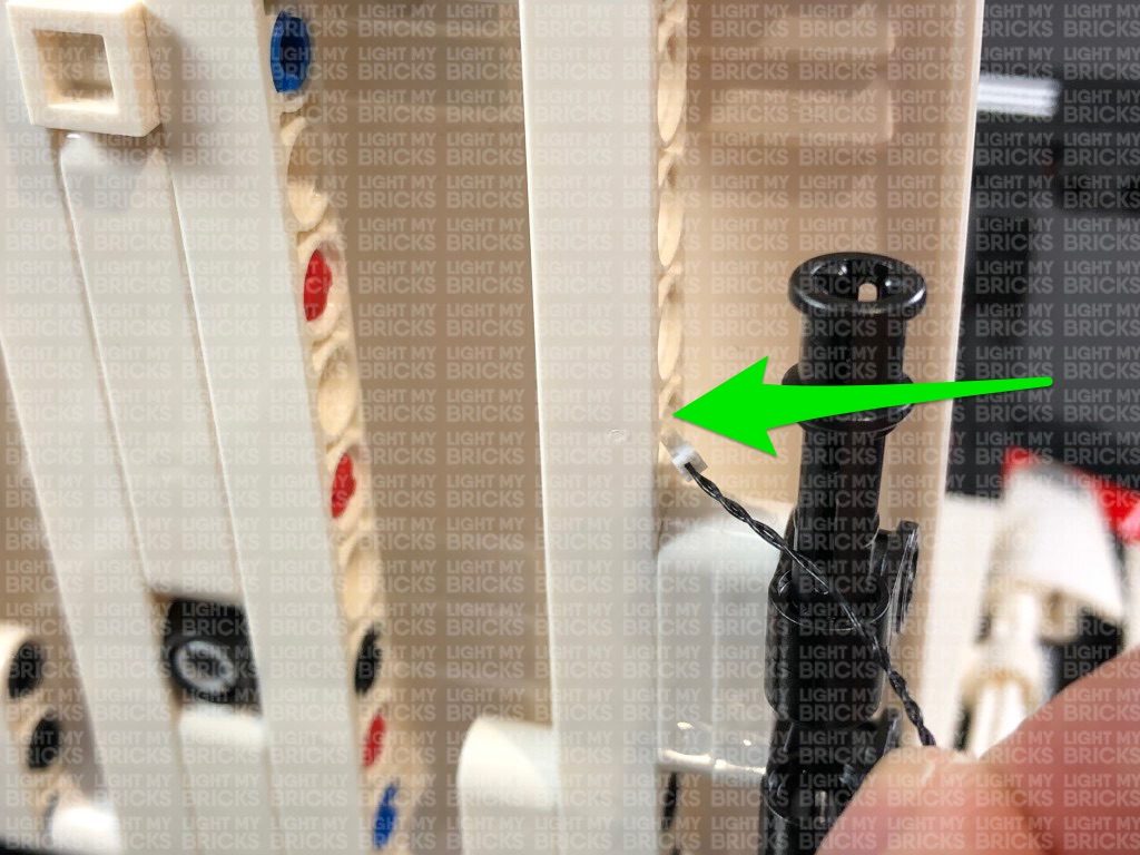
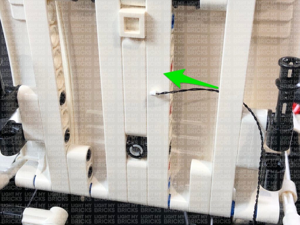
Lay the other end of the 30cm Connecting Cable across the right, then thread it up behind the driver’s seat and up in between the white horizontal bar. Pull the cable out from the top, then thread it through the following hole on the side of the roof as show below:
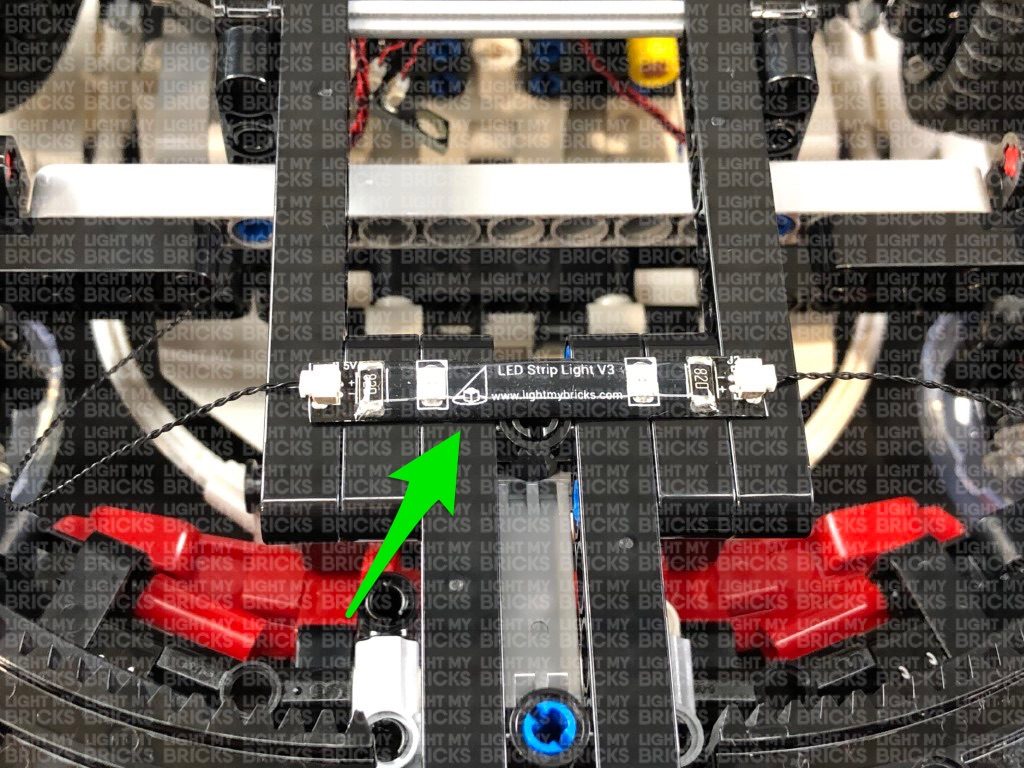
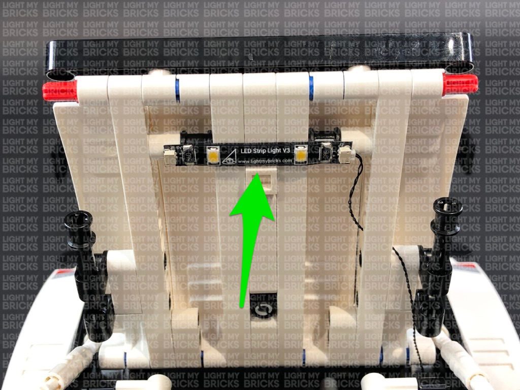
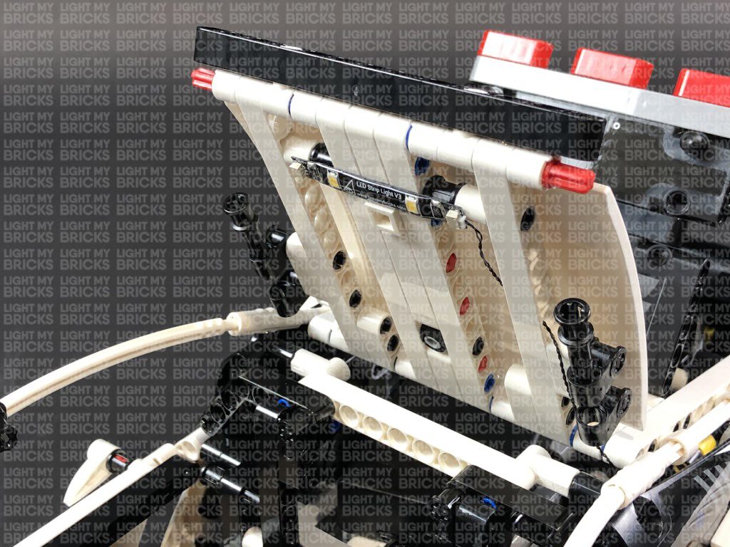
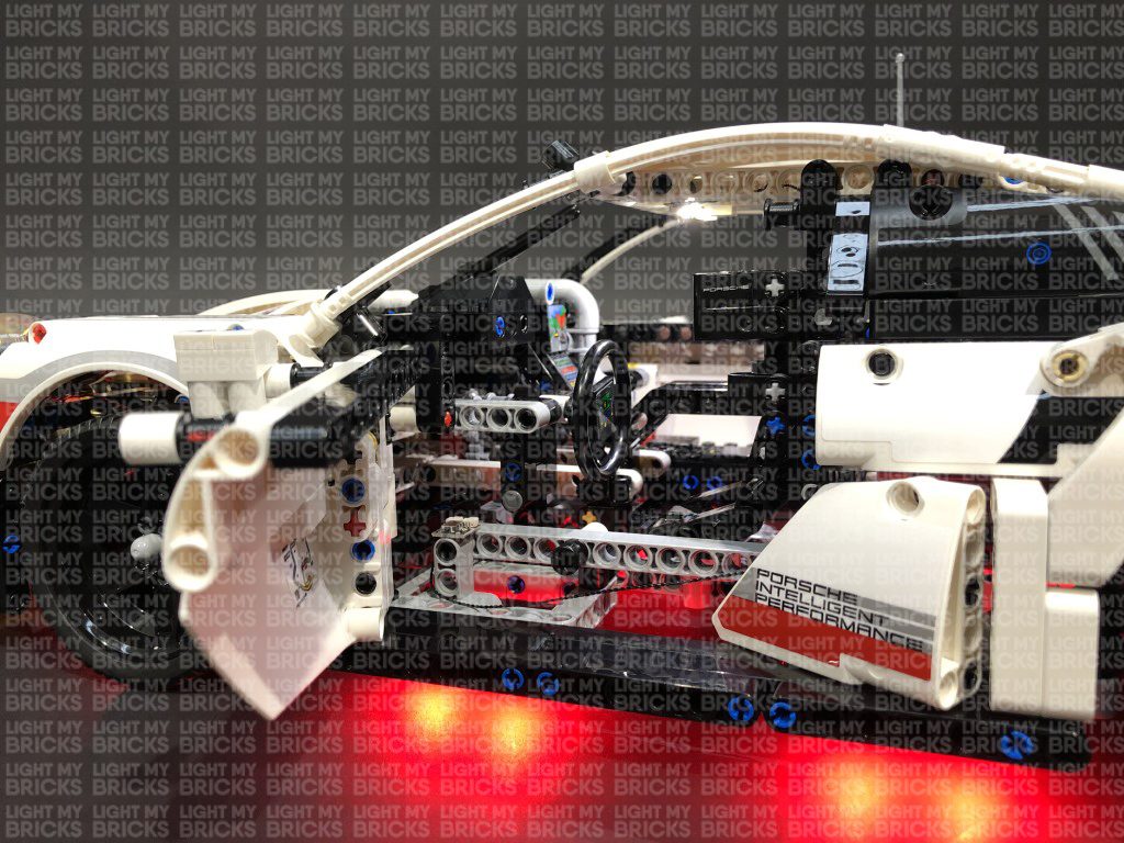
Connect the cable to a White Strip Light, then using it’s adhesive backing, stick the strip light underneath the roof in the following position:
17.) Push the roof back down, then reconnect everything back in place by pushing in the pins we pulled out earlier.
Turn ON the Battery Pack and test the NC Push Board function. When you open the driver door, the interior light should turn activate. When closing the door, the interior light should deactivate.
Troubleshooting step: If you’re interior light is not functioning correctly, check that the NC Push Board is correctly mounted so that the trigger is pushed when the door is closed. You may need to adjust the positioning of the Board.
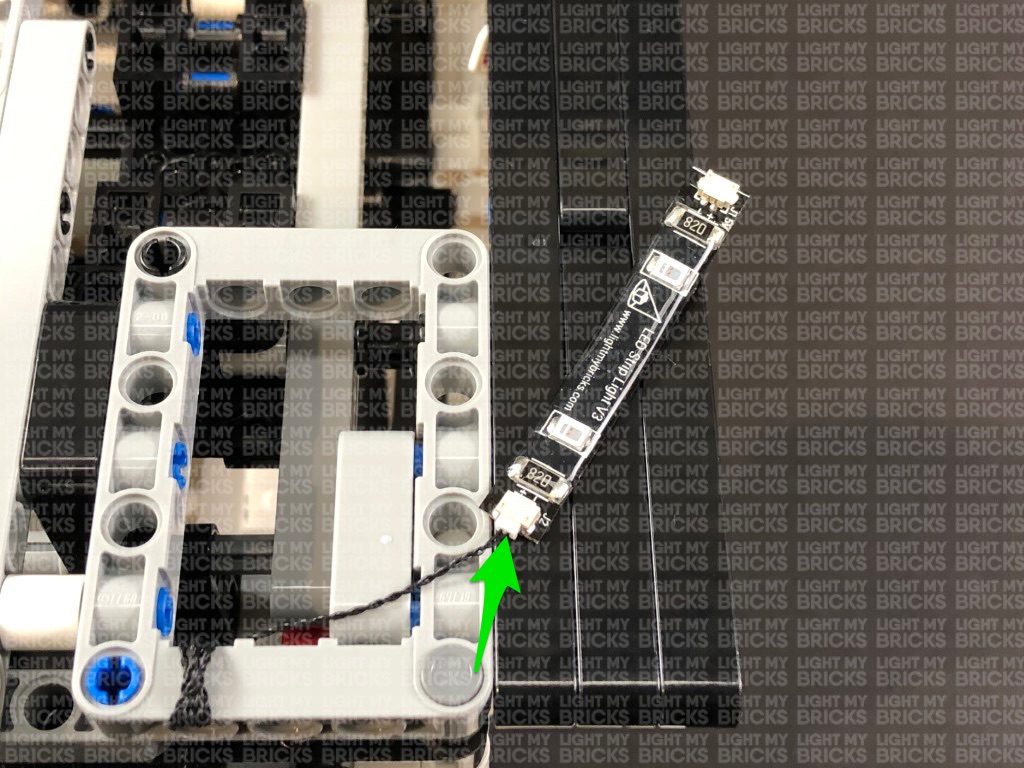
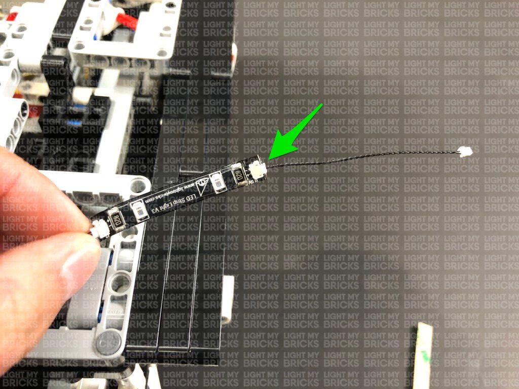
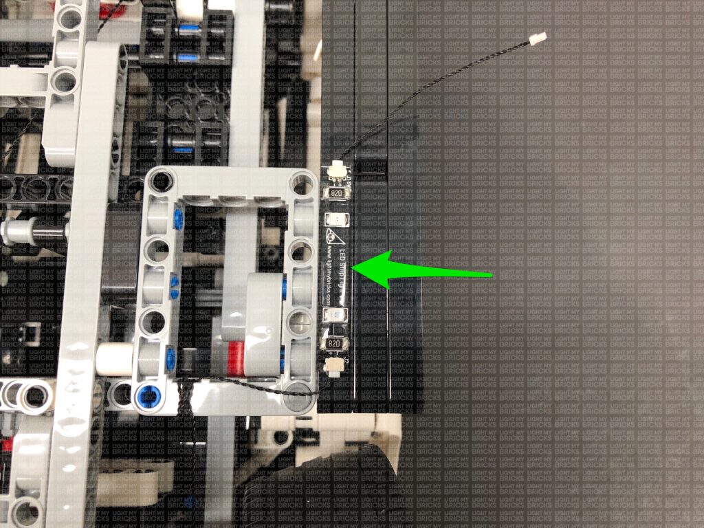
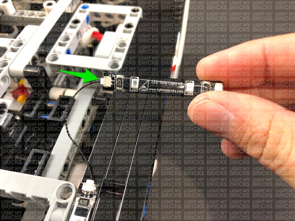
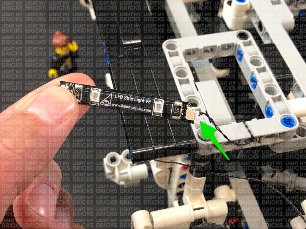
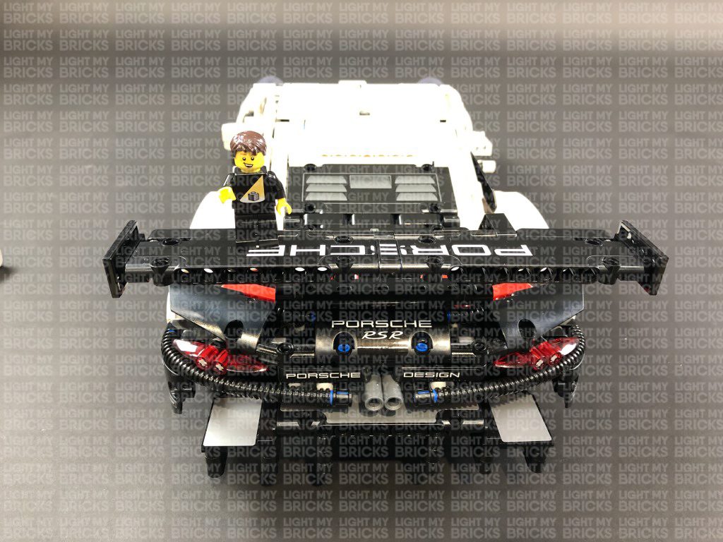
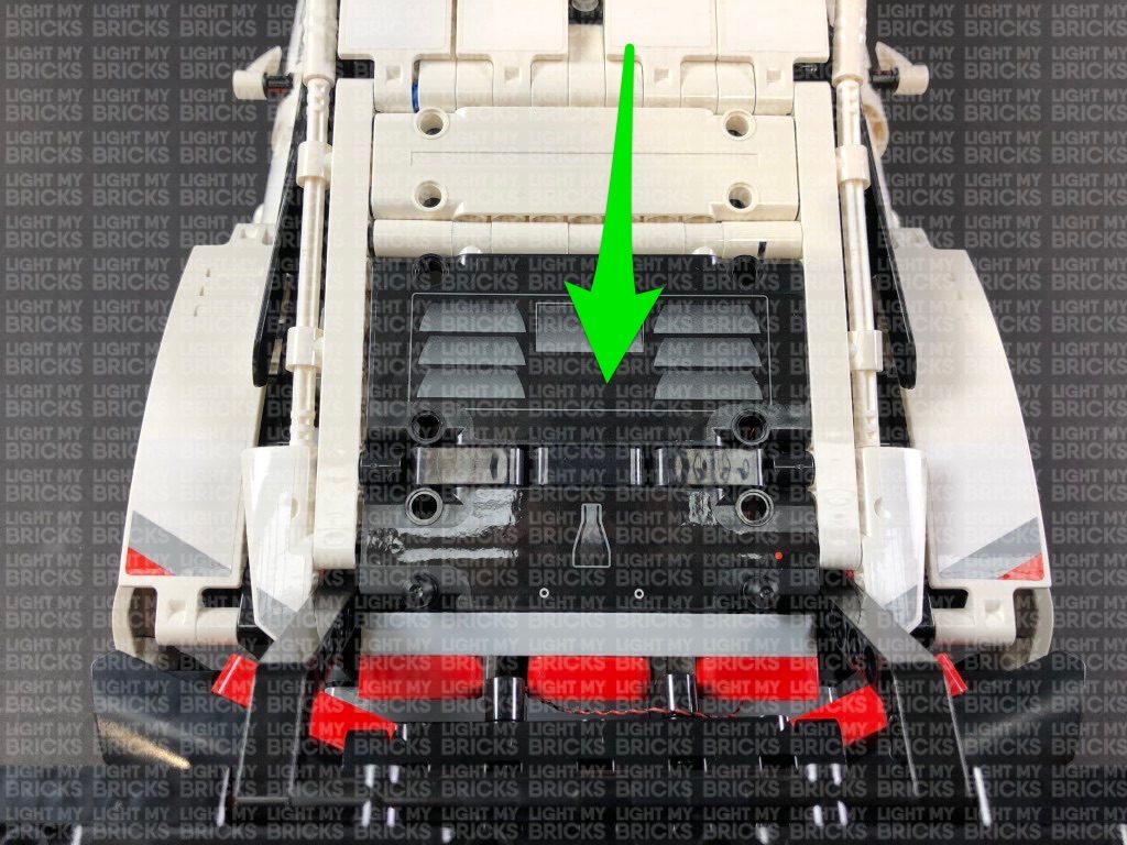
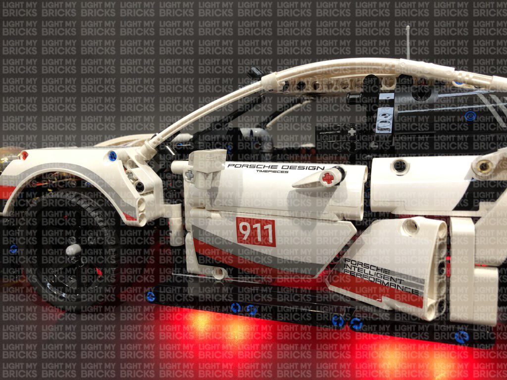
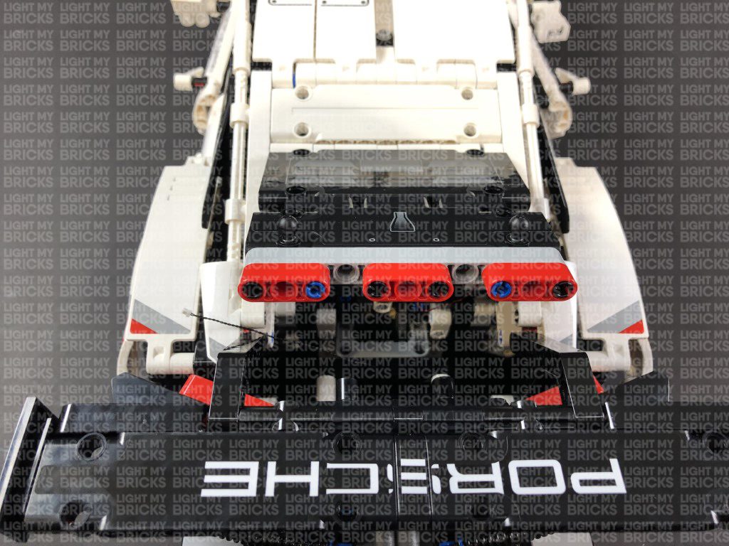
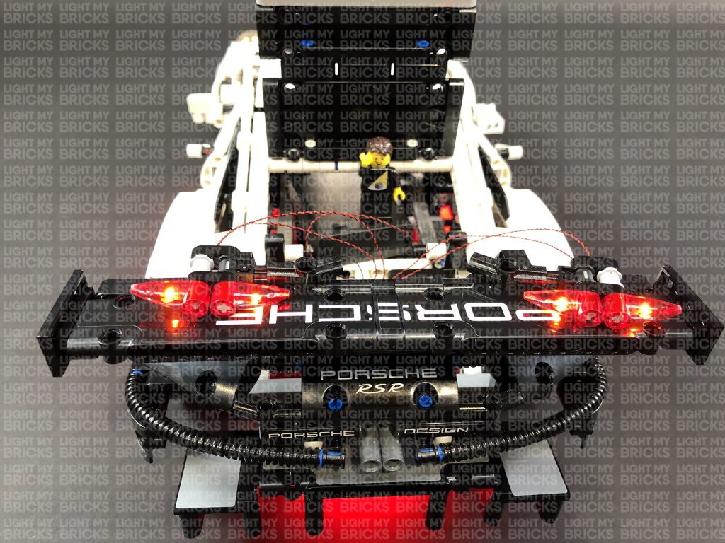
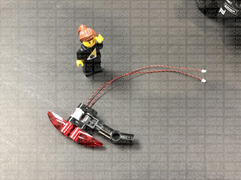
18.) Flip the car back over with the rear of the car facing toward you. Take the remaining Red Strip Light and connect a 15cm Connecting Cable to it. Using it’s adhesive backing, stick the Strip Light horizontally underneath the car in the following position.
Thread the other end of the 15cm Connecting Cable down the space behind which leads to the inside of the trunk of the car.
Flip the Porsche back around, open the trunk. Locate the other end of the connecting cable, then pull it all the way out and connect it to the 8-port Expansion Board.
Turn the Battery Pack ON to test the rear Red Strip Light is working OK.
Follow the below images to disconnect technic pins in order for us to lift up the roof.
16.) Take a 30cm Connecting Cable and connect it to the OUT port on the NC Push Board. Using it’s adhesive backing, stick the NC Push Board to the following position of the driver doorway. We need to ensure that when we close the driver door, it will push in the trigger on the NC Push Board.
Lay the other end of the 30cm Connecting Cable across the right, then thread it up behind the driver’s seat and up in between the white horizontal bar. Pull the cable out from the top, then thread it through the following hole on the side of the roof as show below:
Connect the cable to a White Strip Light, then using it’s adhesive backing, stick the strip light underneath the roof in the following position:
17.) Push the roof back down, then reconnect everything back in place by pushing in the pins we pulled out earlier.
Turn ON the Battery Pack and test the NC Push Board function. When you open the driver door, the interior light should turn activate. When closing the door, the interior light should deactivate.
Troubleshooting step: If you’re interior light is not functioning correctly, check that the NC Push Board is correctly mounted so that the trigger is pushed when the door is closed. You may need to adjust the positioning of the Board.
18.) Flip the car back over with the rear of the car facing toward you. Take the remaining Red Strip Light and connect a 15cm Connecting Cable to it. Using it’s adhesive backing, stick the Strip Light horizontally underneath the car in the following position.
Thread the other end of the 15cm Connecting Cable down the space behind which leads to the inside of the trunk of the car.
Flip the Porsche back around, open the trunk. Locate the other end of the connecting cable, then pull it all the way out and connect it to the 8-port Expansion Board.
Turn the Battery Pack ON to test the rear Red Strip Light is working OK.
 Note: If you experience any issues with the lights not working and suspect an issue with a component, please try a different port on the expansion board to verify where the fault lies (with the light or expansion board). To correct any issues with expansion board ports, please view the section addressing expansion board issues on our online troubleshooting guide.
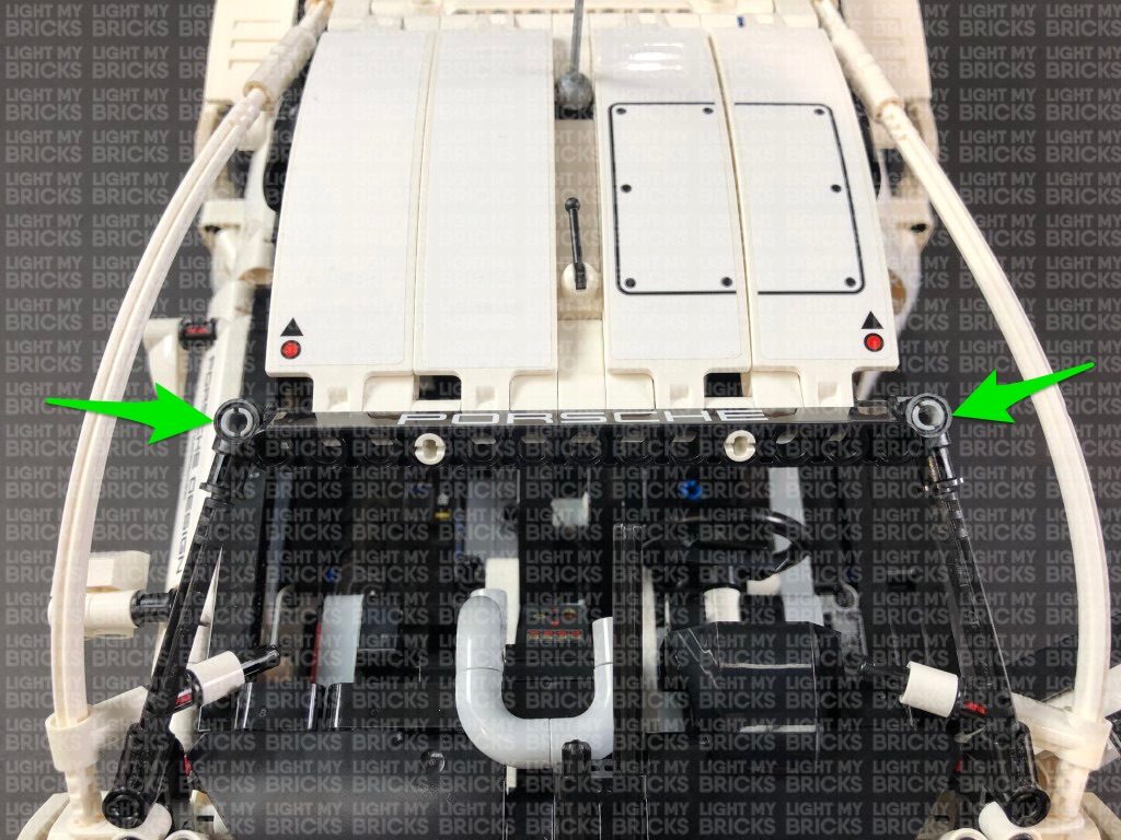
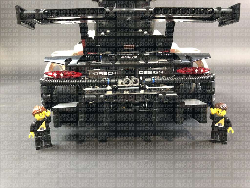
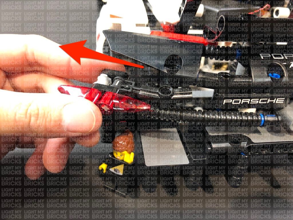
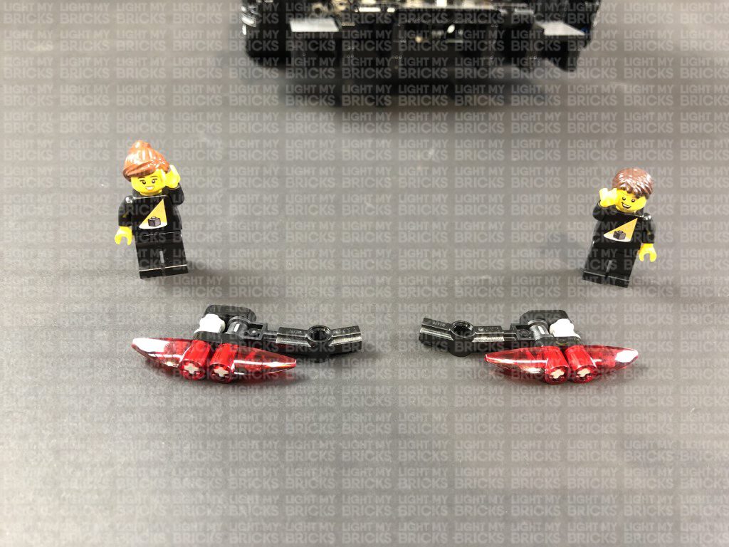
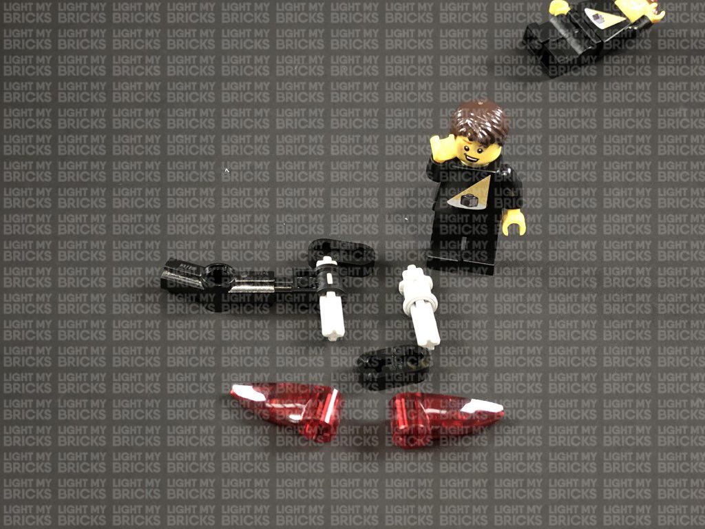
19.) We will now install the tail lights. First disconnect each tail light section by pulling it out at the technic pin as shown below.
Note: If you experience any issues with the lights not working and suspect an issue with a component, please try a different port on the expansion board to verify where the fault lies (with the light or expansion board). To correct any issues with expansion board ports, please view the section addressing expansion board issues on our online troubleshooting guide.
19.) We will now install the tail lights. First disconnect each tail light section by pulling it out at the technic pin as shown below.
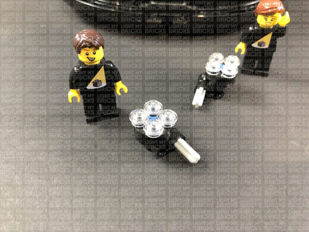
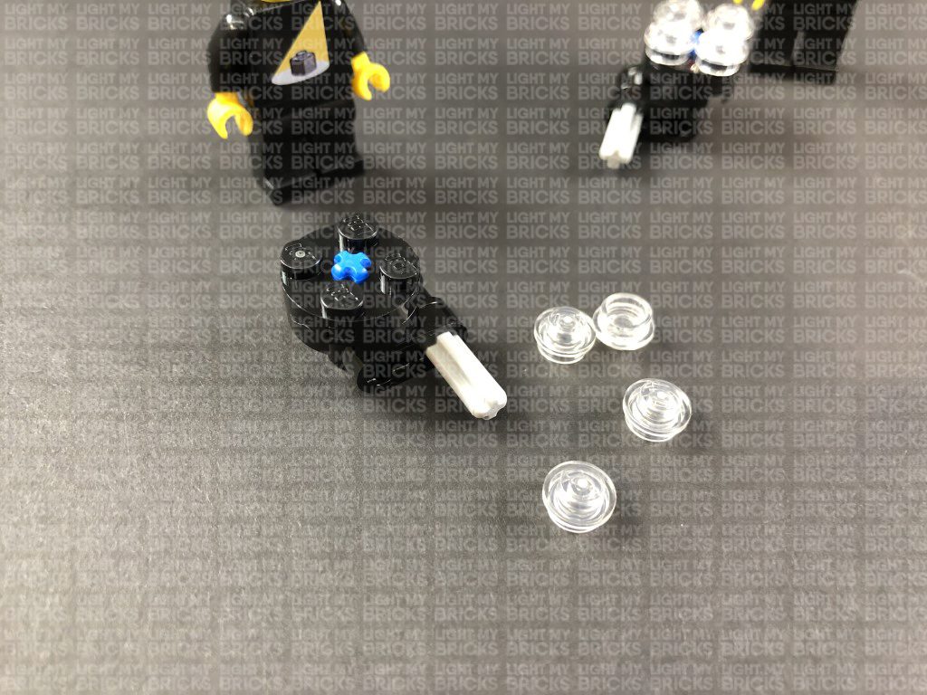
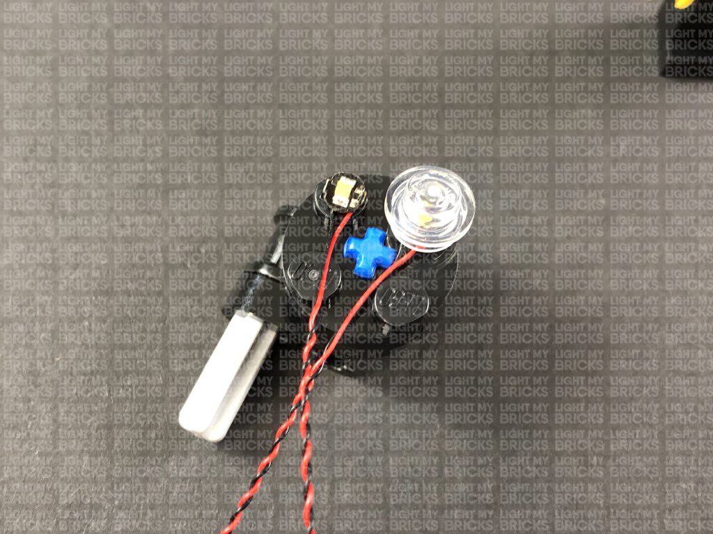
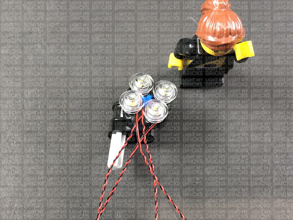
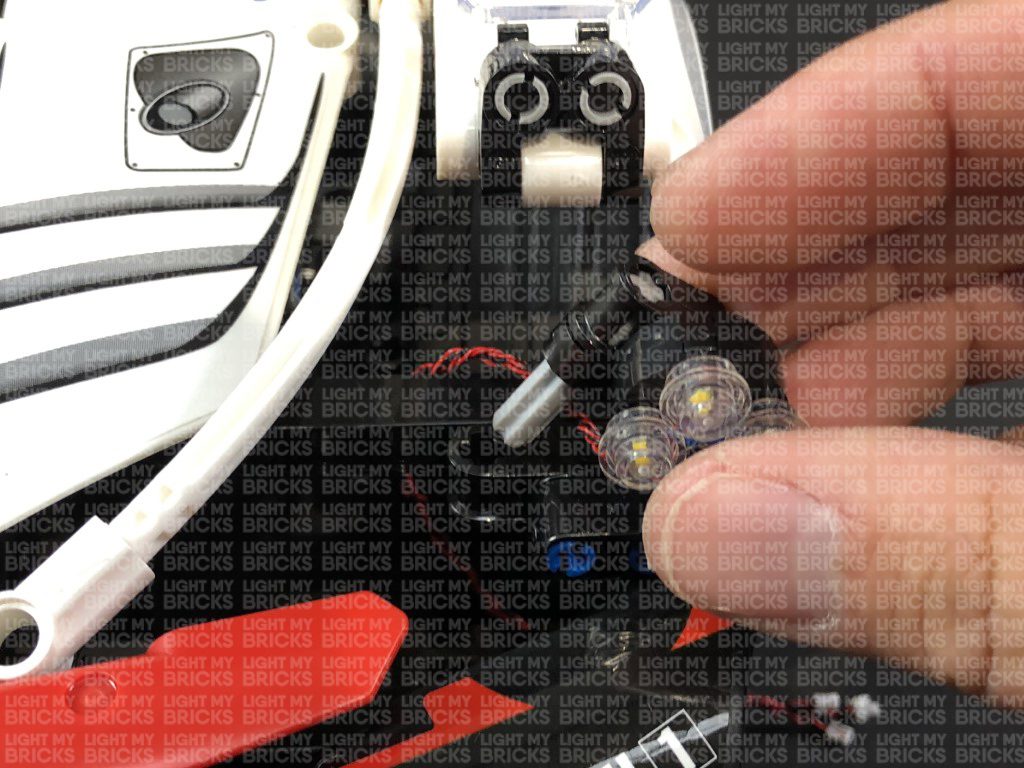
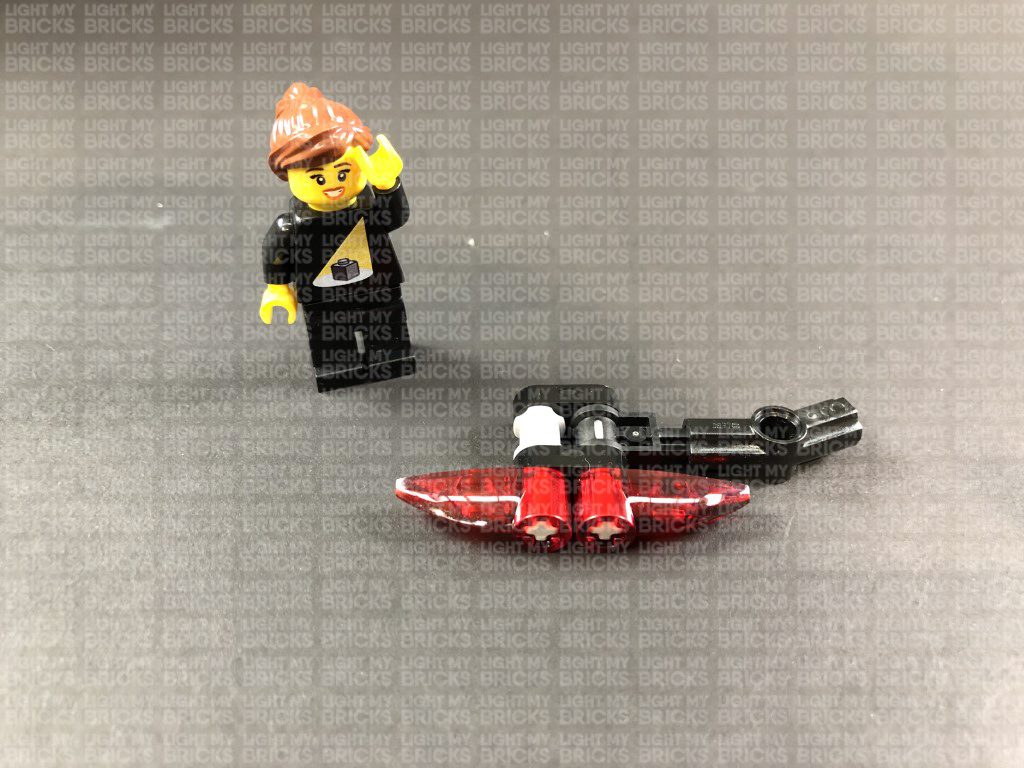
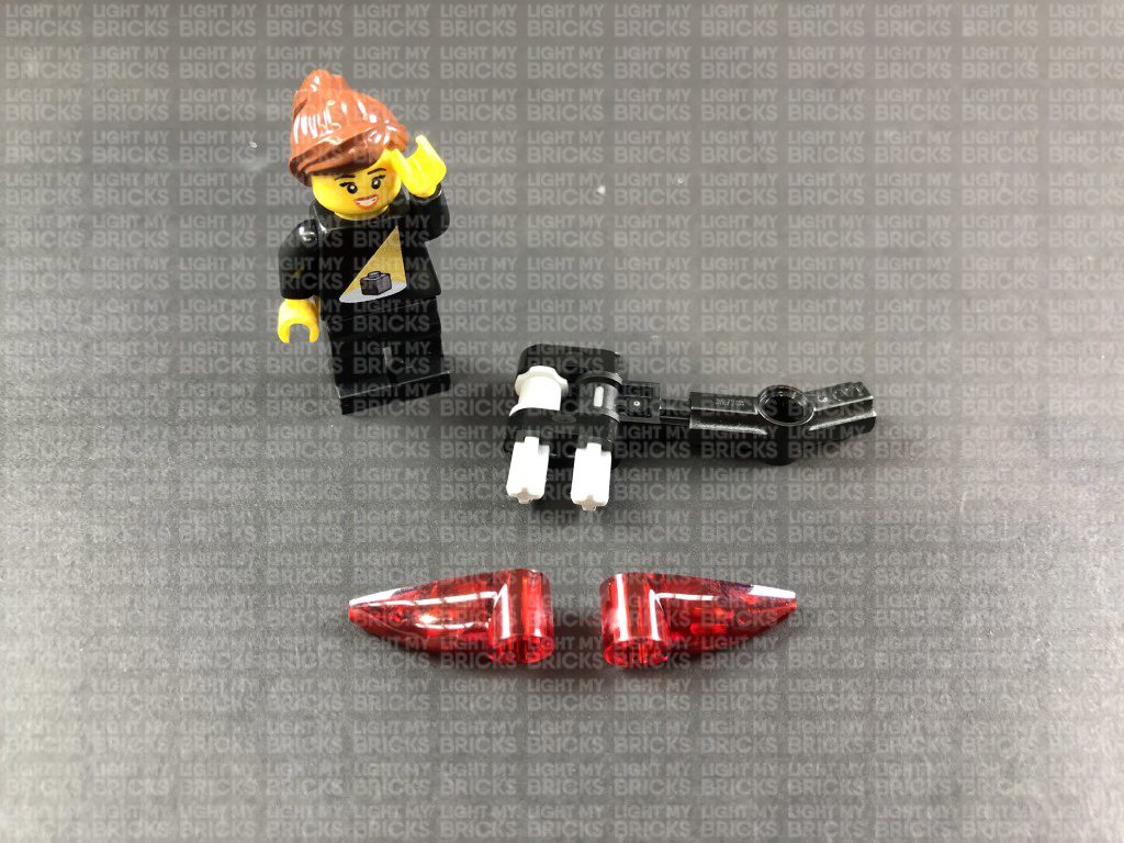
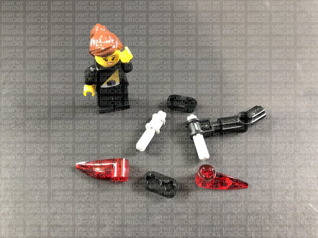
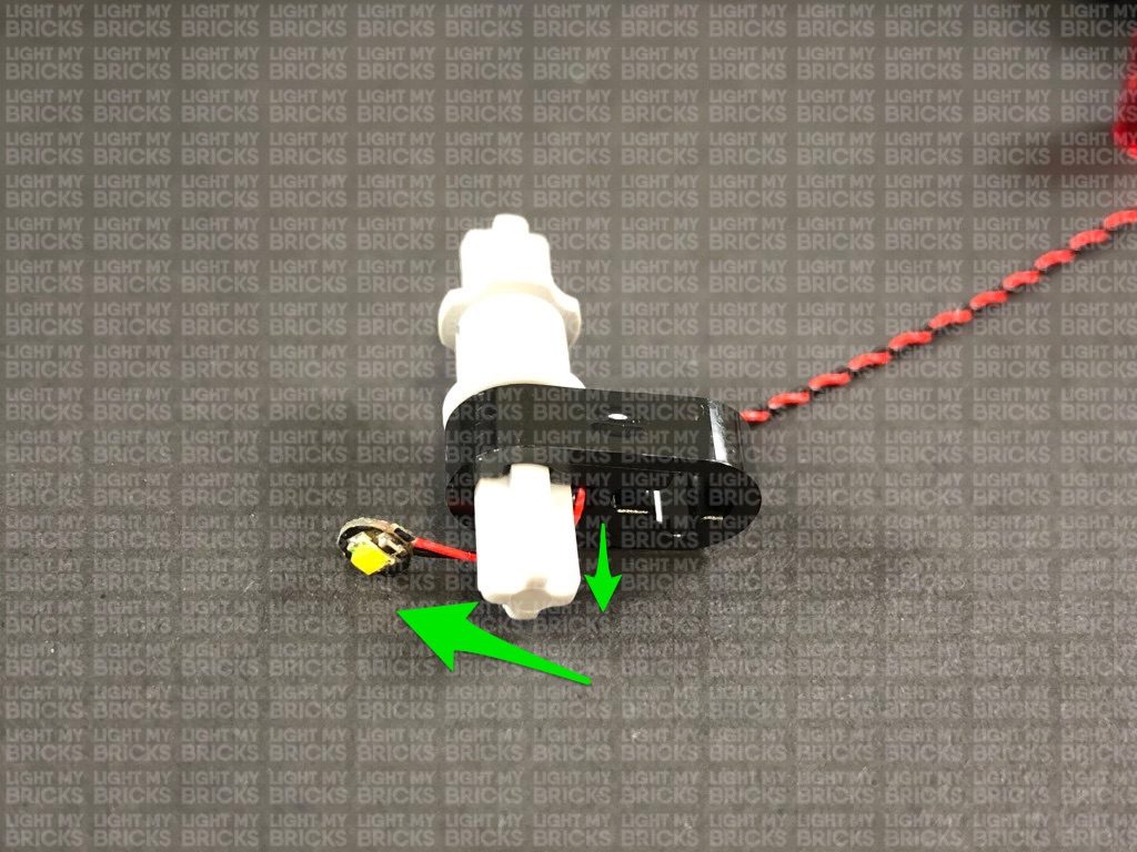
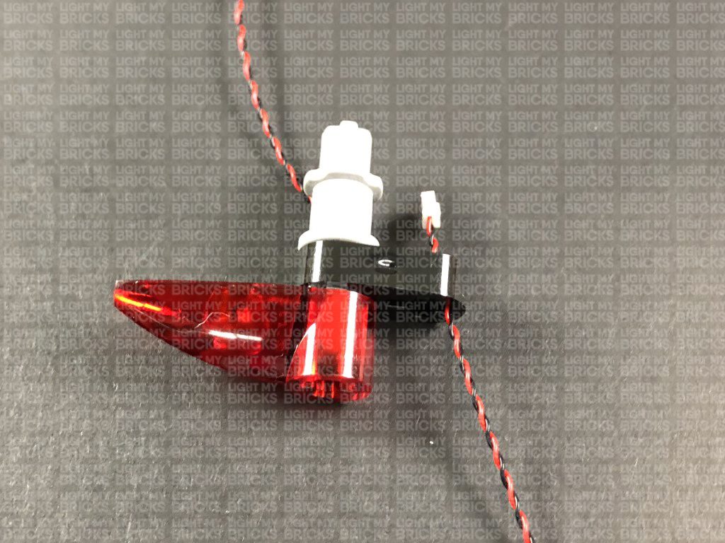
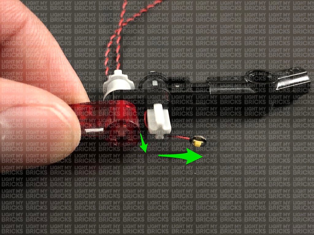
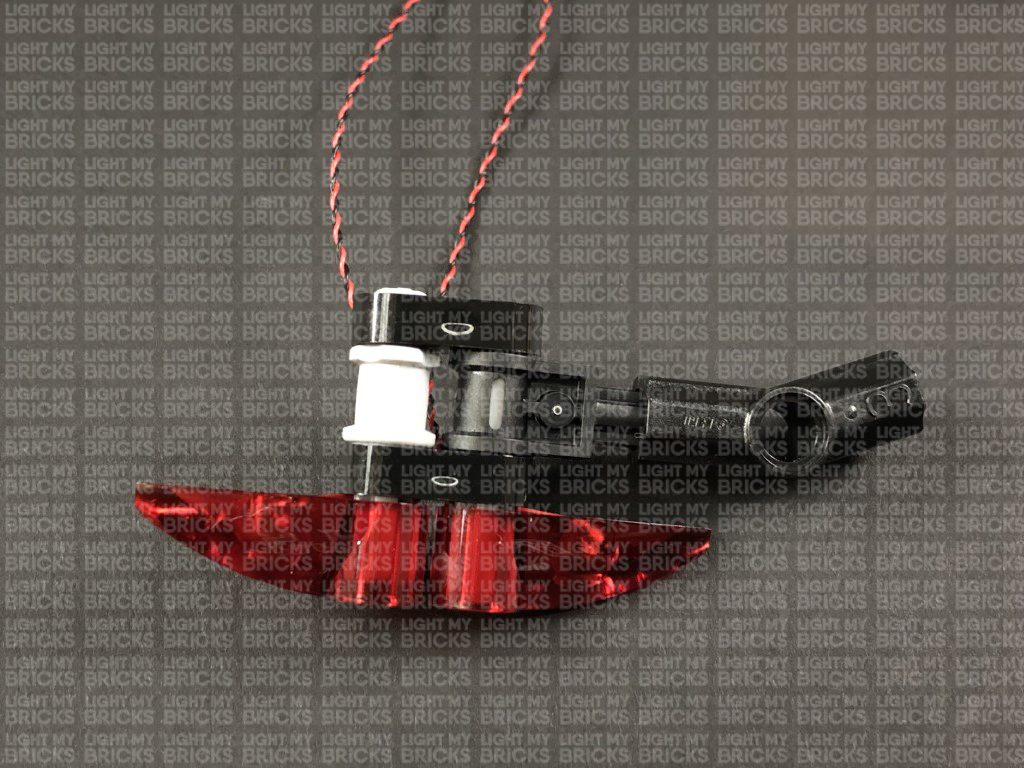
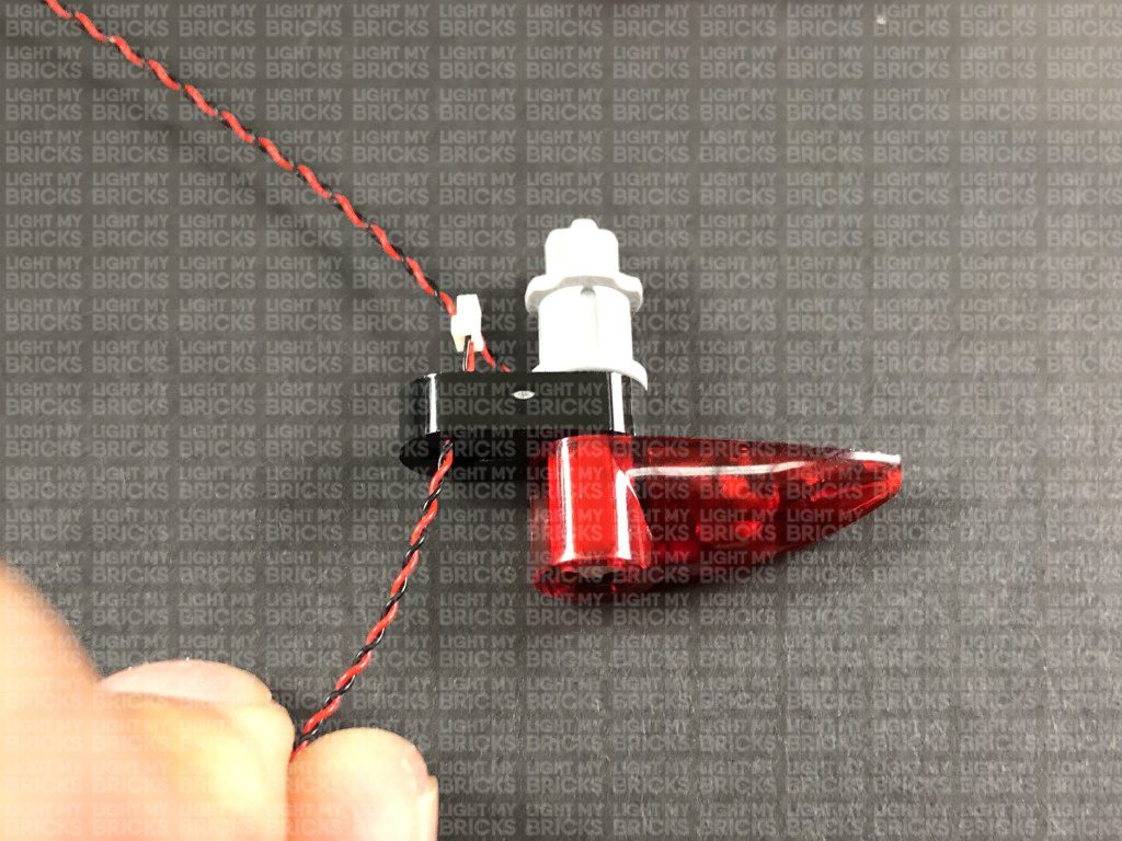
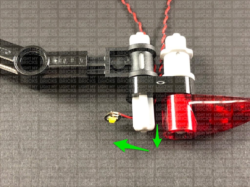
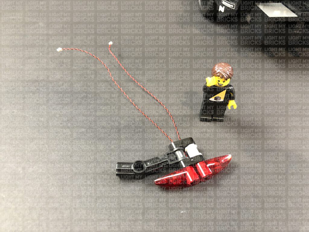
 Take left tail light section and disassemble it as shown below
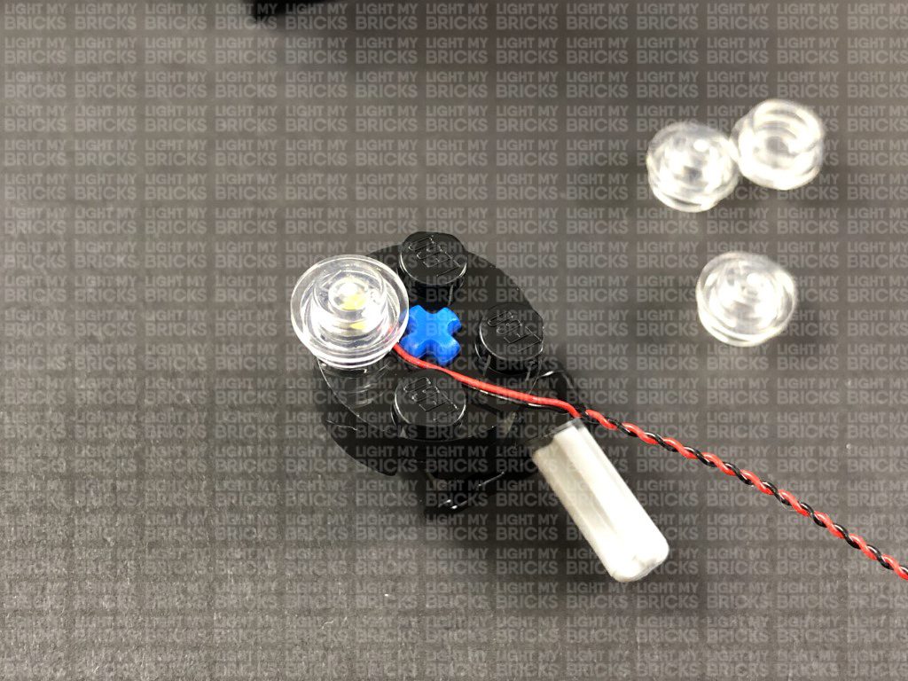
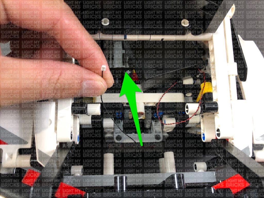
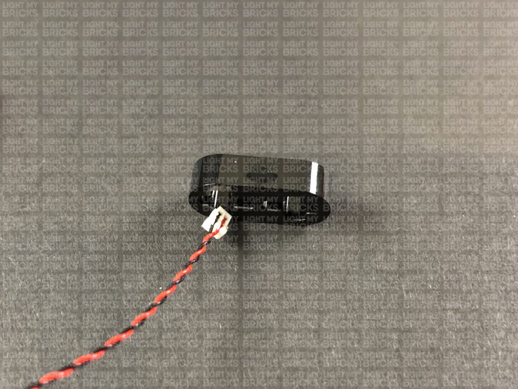
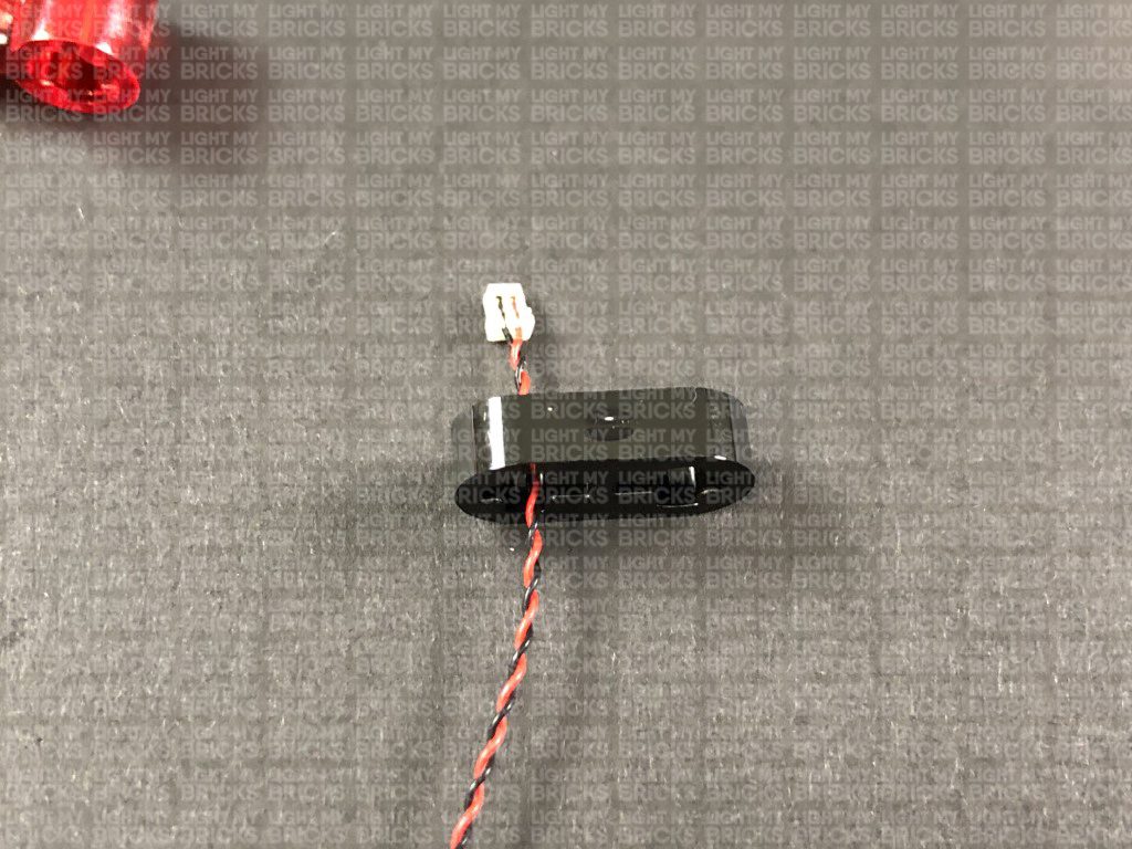
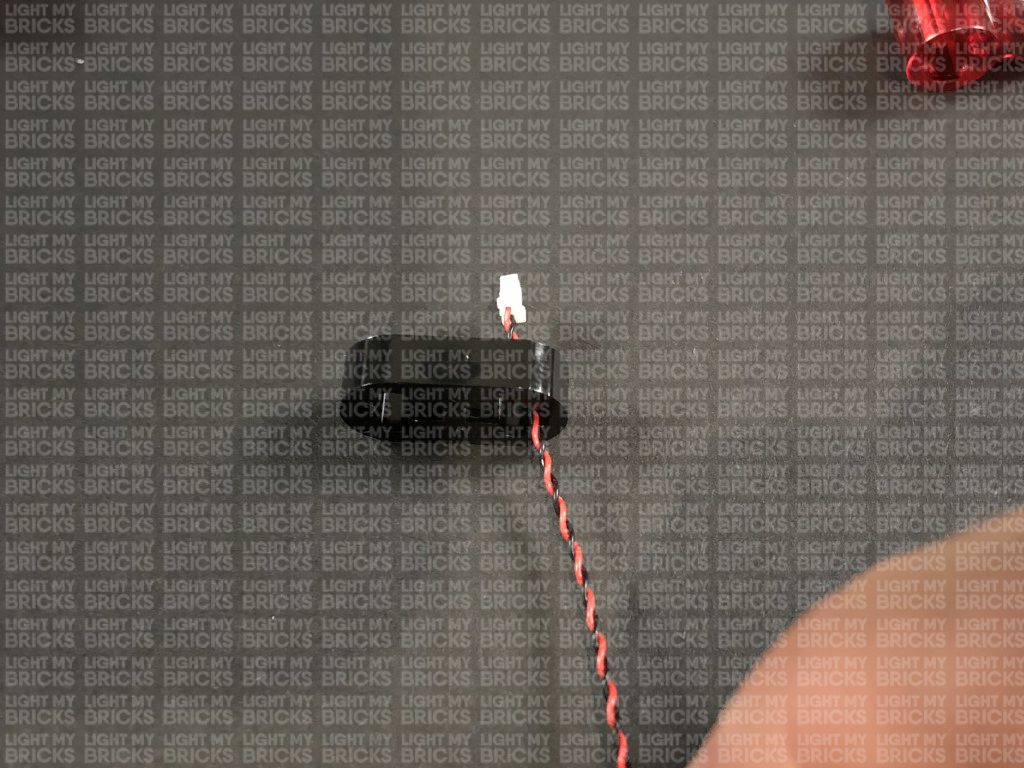
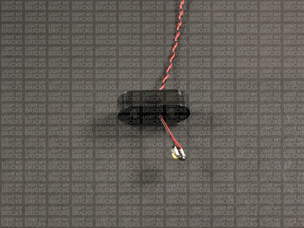
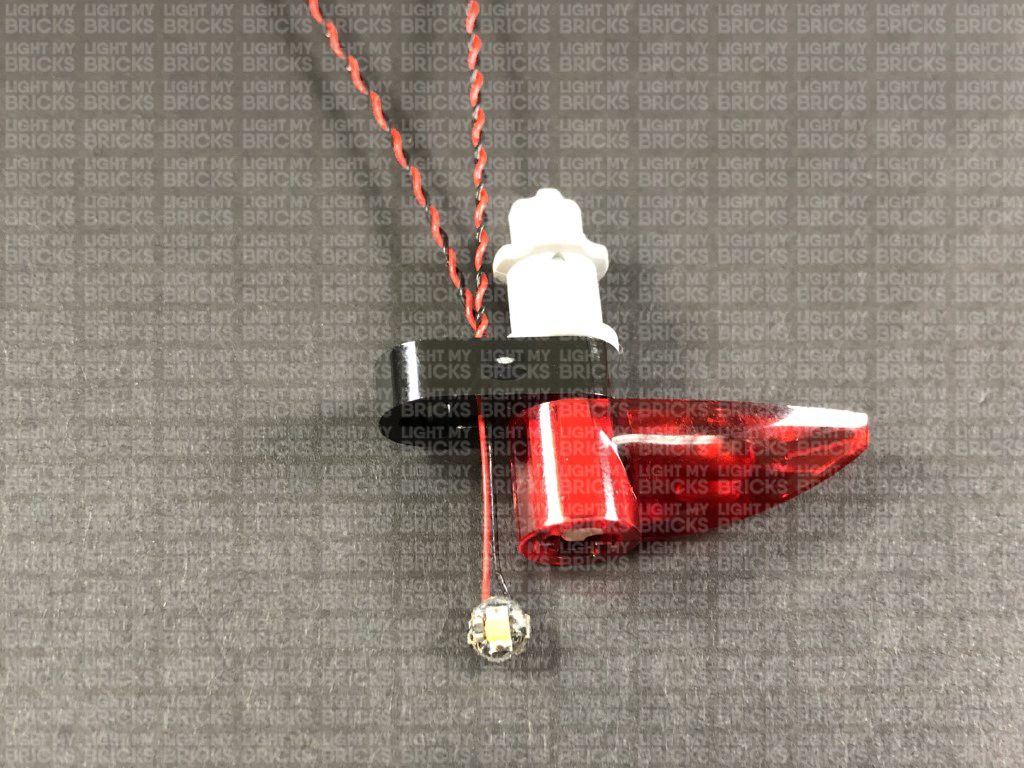
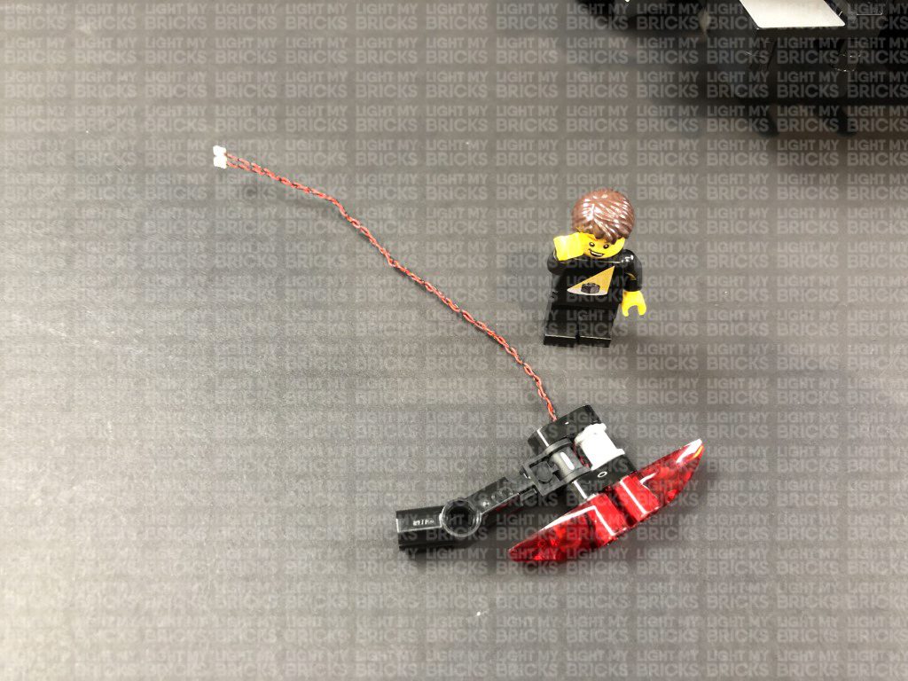
Take a White 15cm Bit Light and thread the connector end through the left hole on the black technic plate. Thread the cable all the way through until you have approx. 2cm from the Bit Light to the edge of the plate.
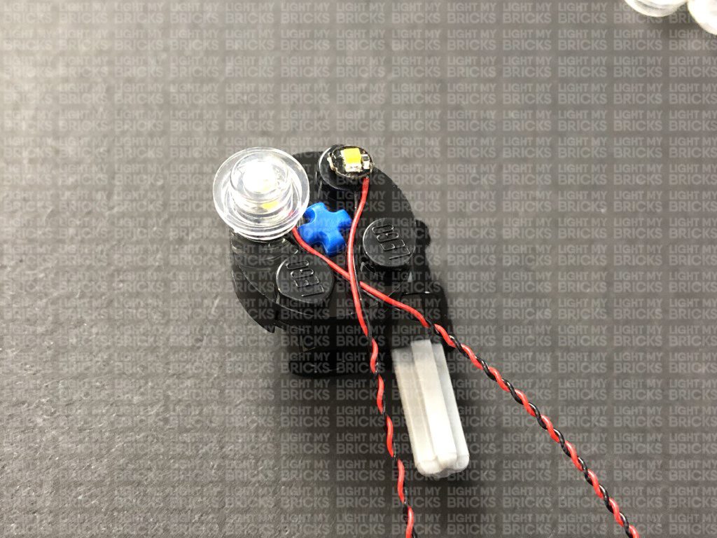
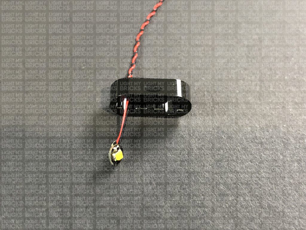
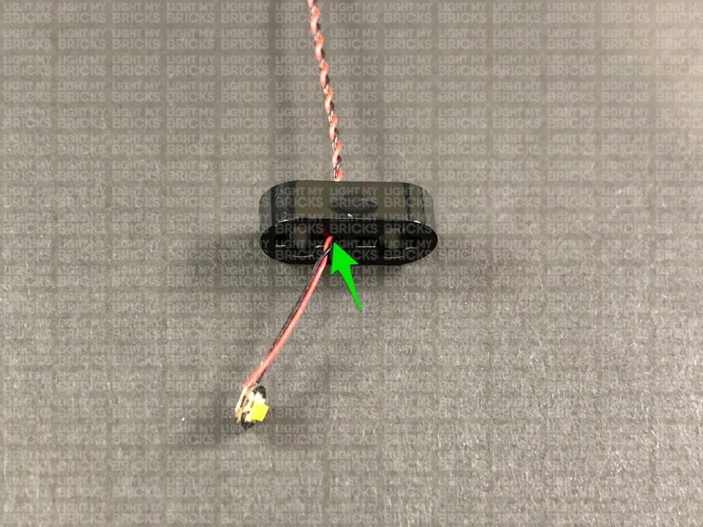
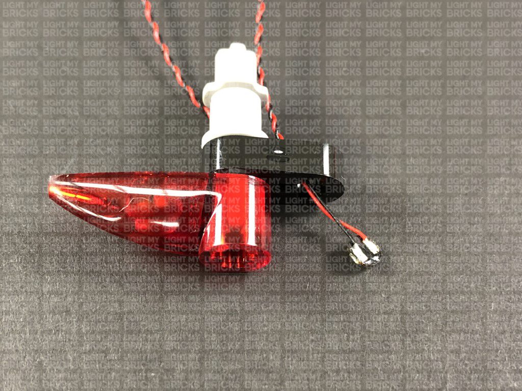
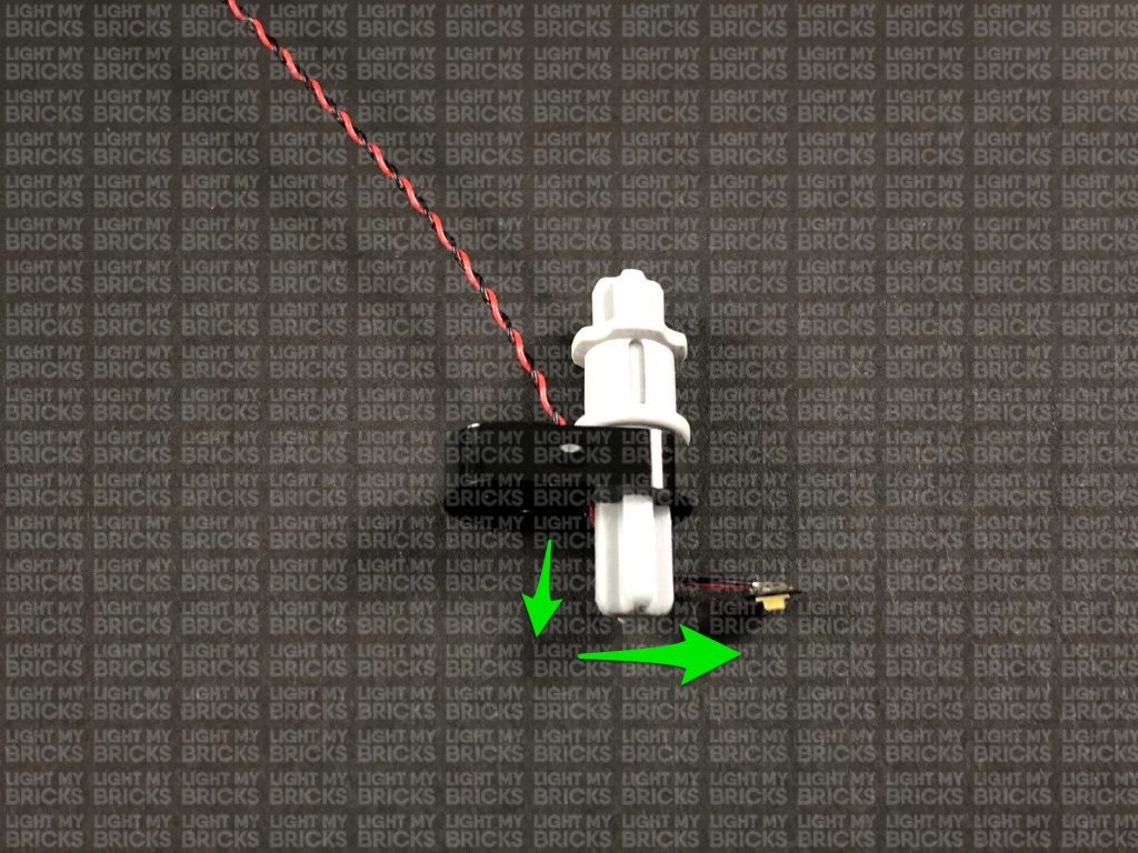
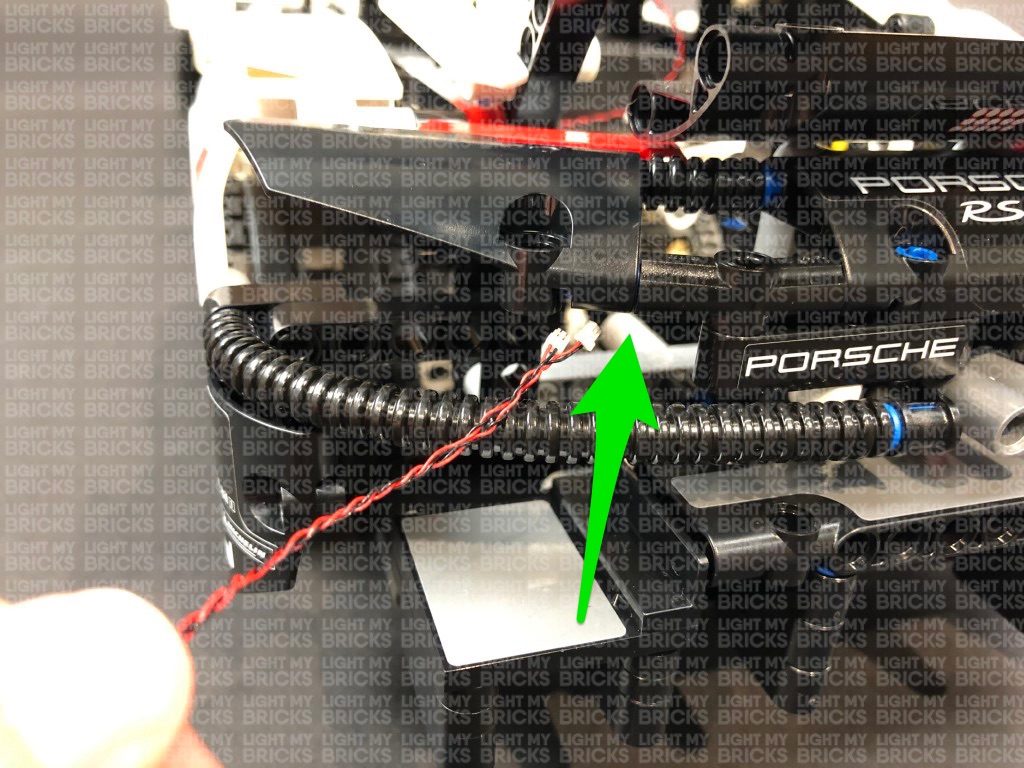
Ensuring the cable is placed to the side of the + hole, reconnect the light grey technic pin. Bring the Bit Light underneath the pin toward the left side as shown below:
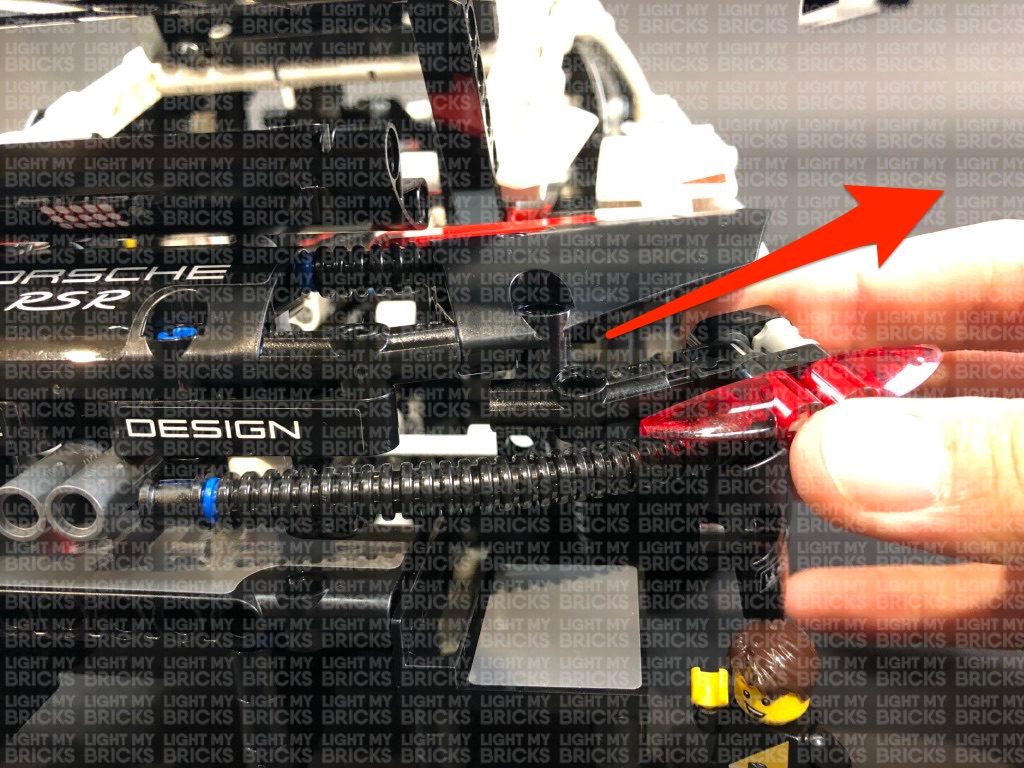
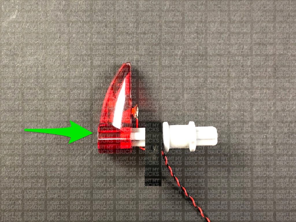
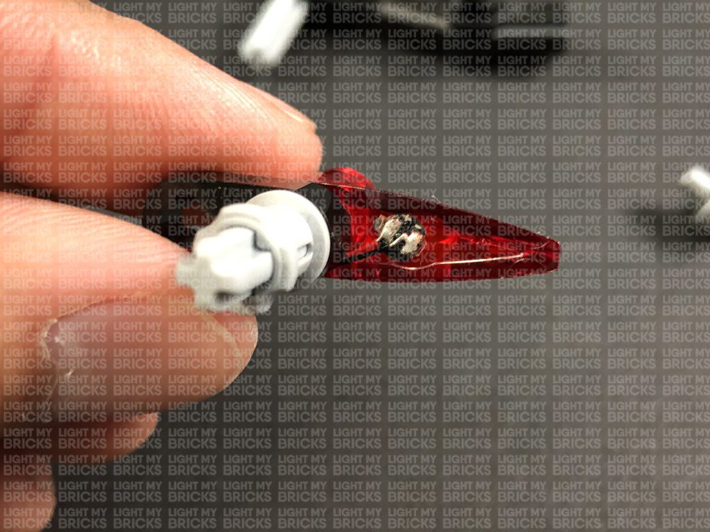
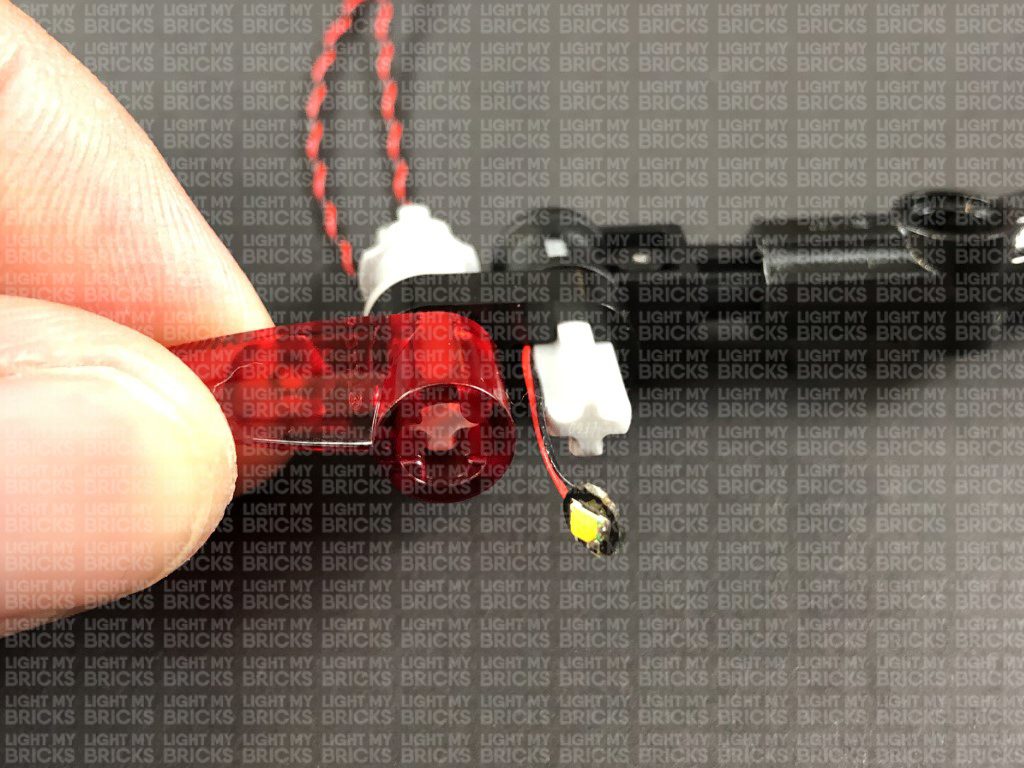
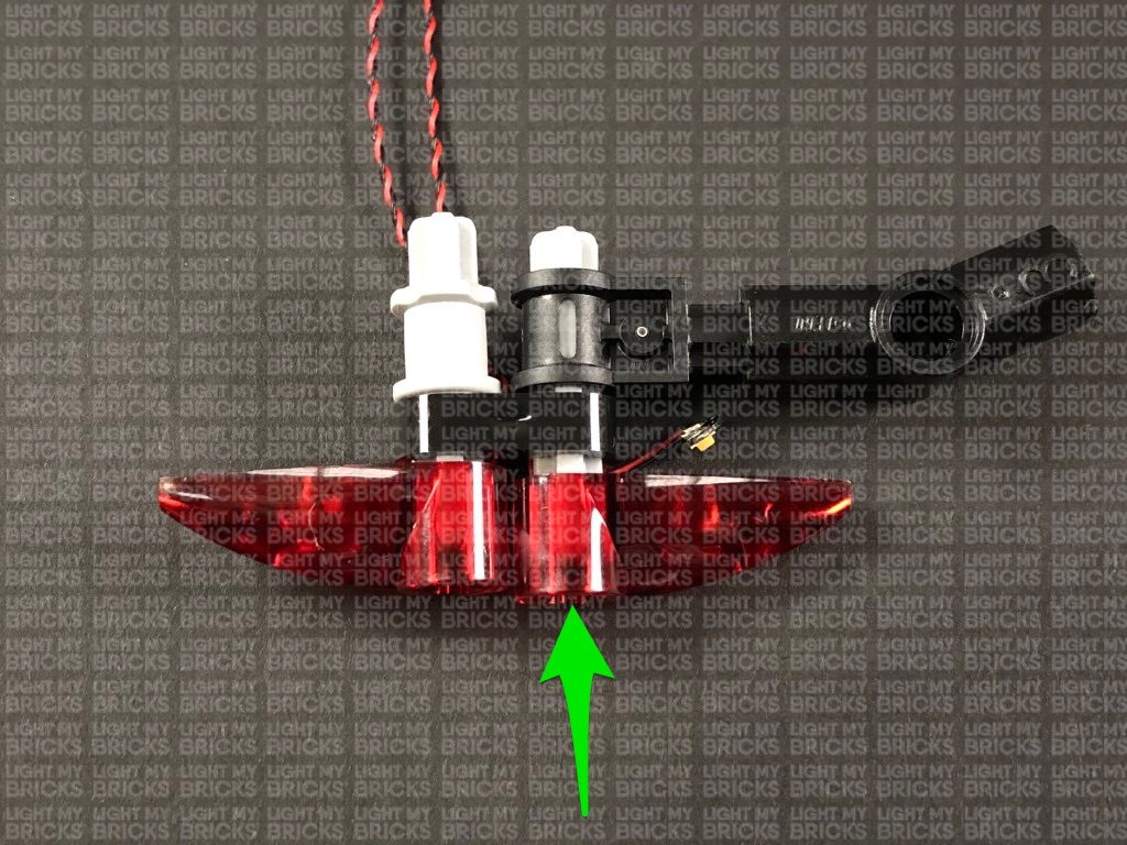
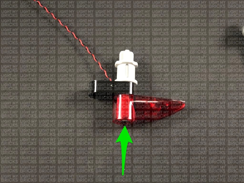
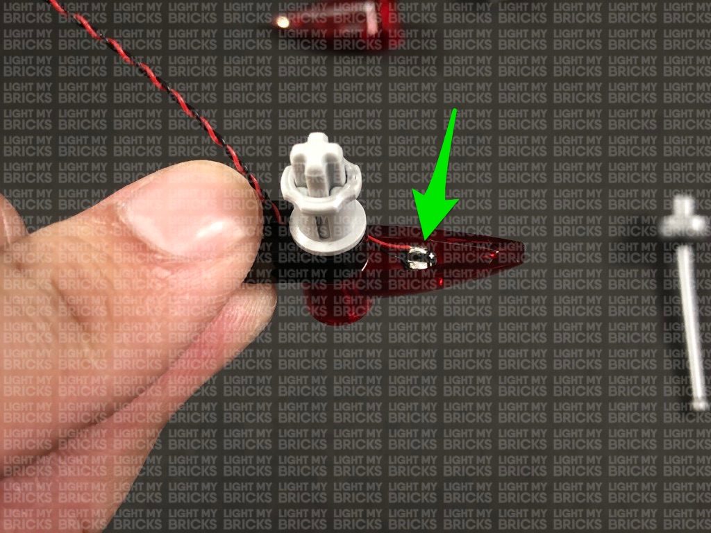
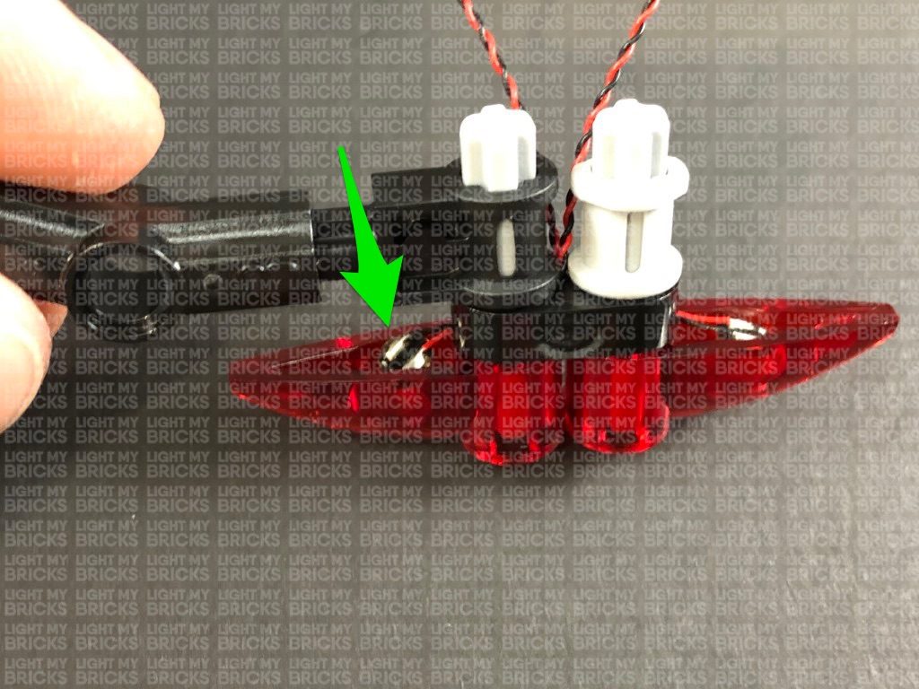
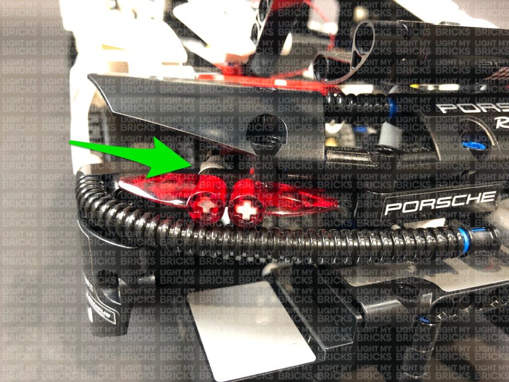
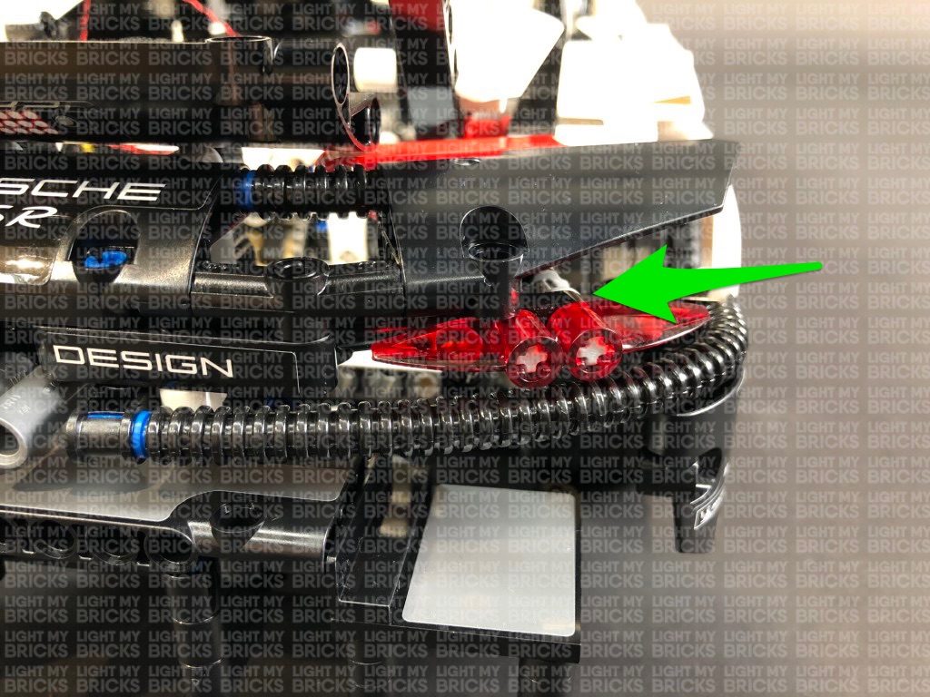
Reconnect the trans red piece, then from the back of this section, push the Bit Light in so that it securely fits inside the trans red plate.
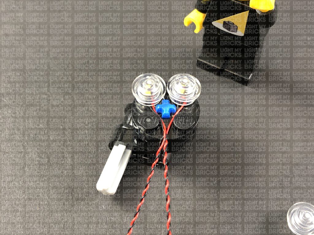
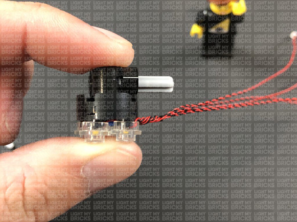
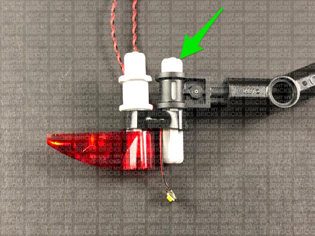
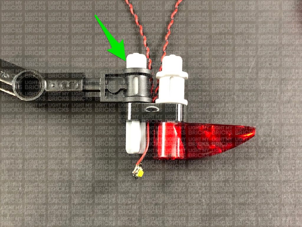
20.) Take another White 15cm Bit Light and thread the connector end through the right + hole on the black technic plate. Thread it all the way through leaving approx. 2cm from the Bit Light to the edge of the plate. With the cable on the left side of the + hole, reconnect the light grey technic pin with black section connected.
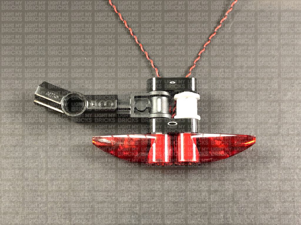
Bring the Bit Light underneath the light grey technic pin to the right side, then reconnect the trans red plate. From the back of this section, push the Bit Light in so that it securely fits inside the trans red plate.
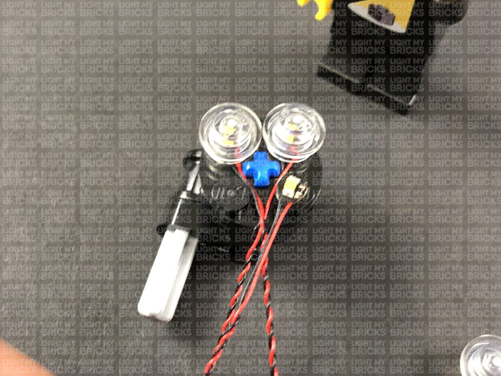
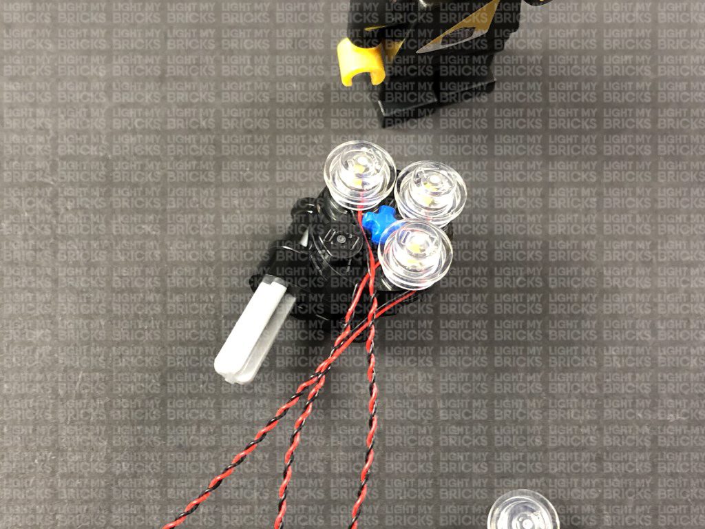
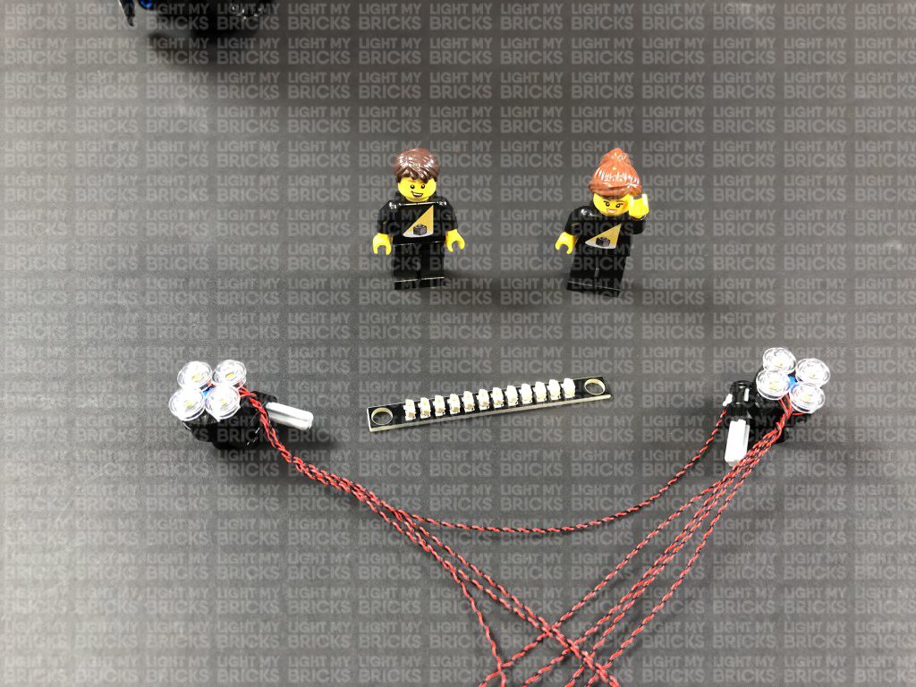
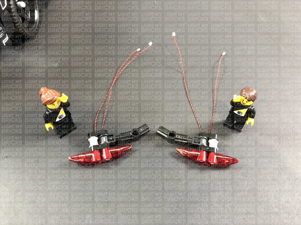
21.) Install another 2x White 15cm Bit Lights to the right tail light section, using the same method used to install lights to the left tail light section.
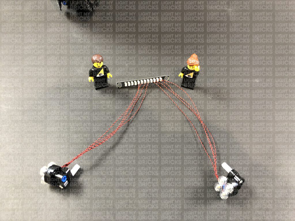
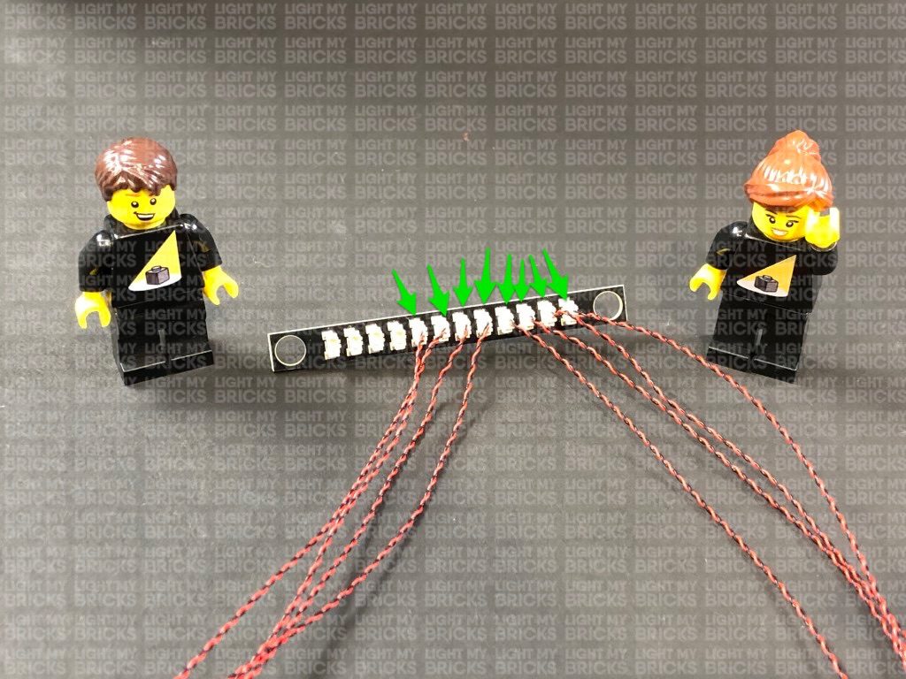
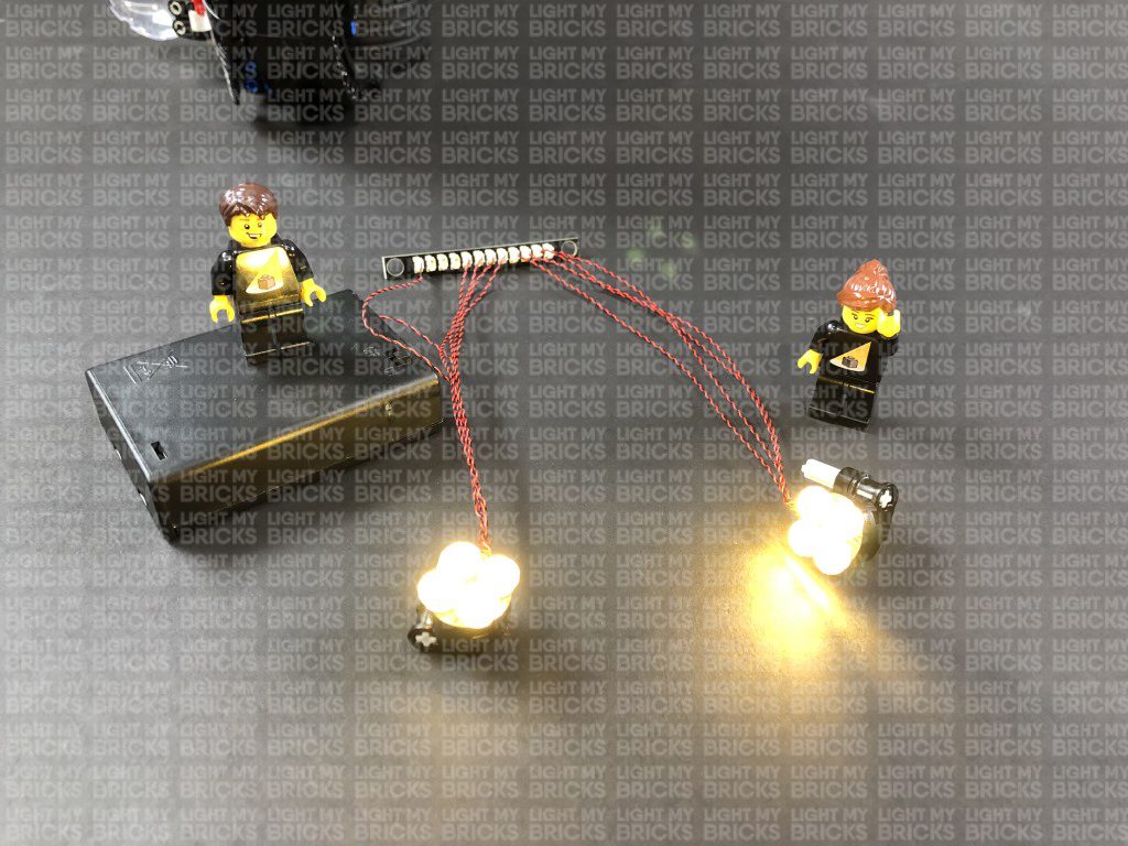
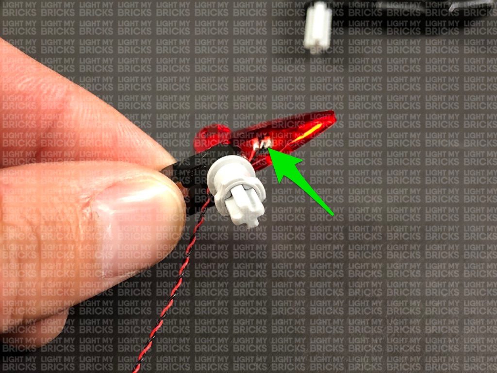
22.) Take both tail light sections and connect all four bit light cables to the 8-Port Expansion Board inside the trunk of the car. Turn the Battery Pack ON to test the tail lights are all working OK.
Note: If you experience any issues with the lights not working and suspect an issue with a component, please try a different port on the expansion board to verify where the fault lies (with the light or expansion board). To correct any issues with expansion board ports, please view the section addressing expansion board issues on our online troubleshooting guide.
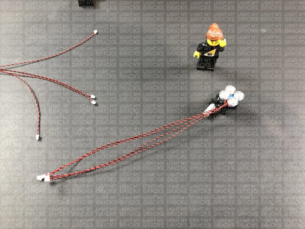
23.) Disconnect the tail lights, then twist the two cables from each tail light section around each other all the way to the ends to form one larger cable.
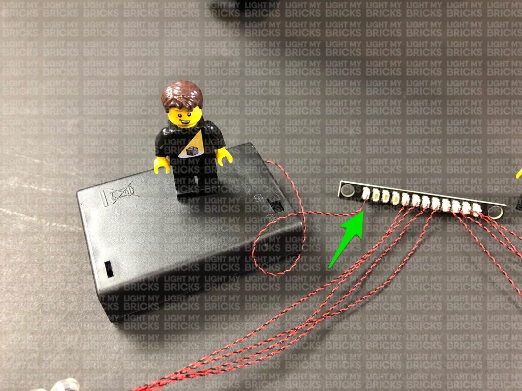
Take the left tail light section and thread the cable through the rear left side of the car before reconnecting the tail light section at the technic pin.
Pull the other end of the cable all the way up from the inside of the trunk and connect them to the 8-Port Expansion Board.
Repeat this step for the right tail light section.
24.) Neaten up cables inside the trunk, then place the expansion board and cables underneath the Battery Pack before closing the trunk door.
Take left tail light section and disassemble it as shown below
Take a White 15cm Bit Light and thread the connector end through the left hole on the black technic plate. Thread the cable all the way through until you have approx. 2cm from the Bit Light to the edge of the plate.
Ensuring the cable is placed to the side of the + hole, reconnect the light grey technic pin. Bring the Bit Light underneath the pin toward the left side as shown below:
Reconnect the trans red piece, then from the back of this section, push the Bit Light in so that it securely fits inside the trans red plate.
20.) Take another White 15cm Bit Light and thread the connector end through the right + hole on the black technic plate. Thread it all the way through leaving approx. 2cm from the Bit Light to the edge of the plate. With the cable on the left side of the + hole, reconnect the light grey technic pin with black section connected.
Bring the Bit Light underneath the light grey technic pin to the right side, then reconnect the trans red plate. From the back of this section, push the Bit Light in so that it securely fits inside the trans red plate.
21.) Install another 2x White 15cm Bit Lights to the right tail light section, using the same method used to install lights to the left tail light section.
22.) Take both tail light sections and connect all four bit light cables to the 8-Port Expansion Board inside the trunk of the car. Turn the Battery Pack ON to test the tail lights are all working OK.
Note: If you experience any issues with the lights not working and suspect an issue with a component, please try a different port on the expansion board to verify where the fault lies (with the light or expansion board). To correct any issues with expansion board ports, please view the section addressing expansion board issues on our online troubleshooting guide.
23.) Disconnect the tail lights, then twist the two cables from each tail light section around each other all the way to the ends to form one larger cable.
Take the left tail light section and thread the cable through the rear left side of the car before reconnecting the tail light section at the technic pin.
Pull the other end of the cable all the way up from the inside of the trunk and connect them to the 8-Port Expansion Board.
Repeat this step for the right tail light section.
24.) Neaten up cables inside the trunk, then place the expansion board and cables underneath the Battery Pack before closing the trunk door.
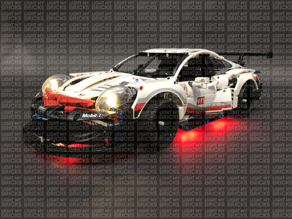
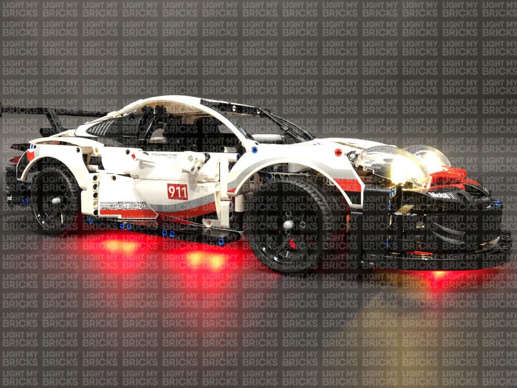
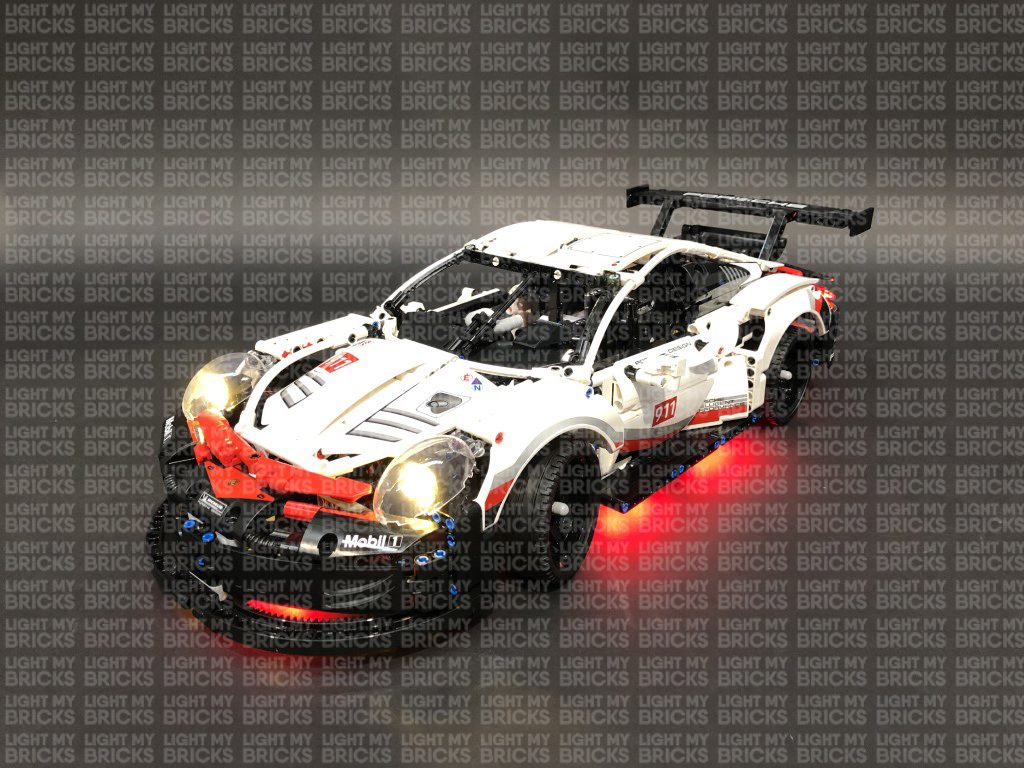
This finally completes installation of your Light My Bricks Porsche 911 RSR Light Kit!
We thank you for purchasing this product and hope you enjoy!