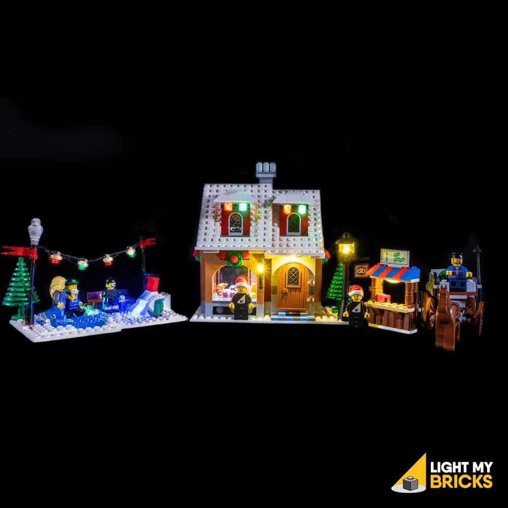

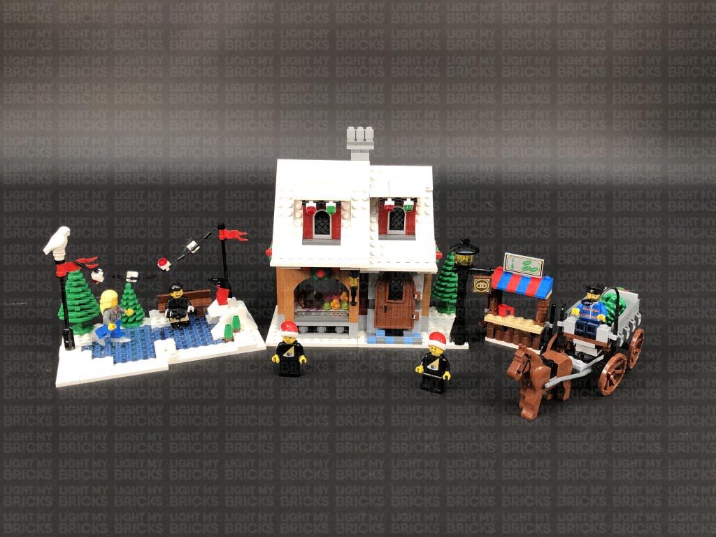
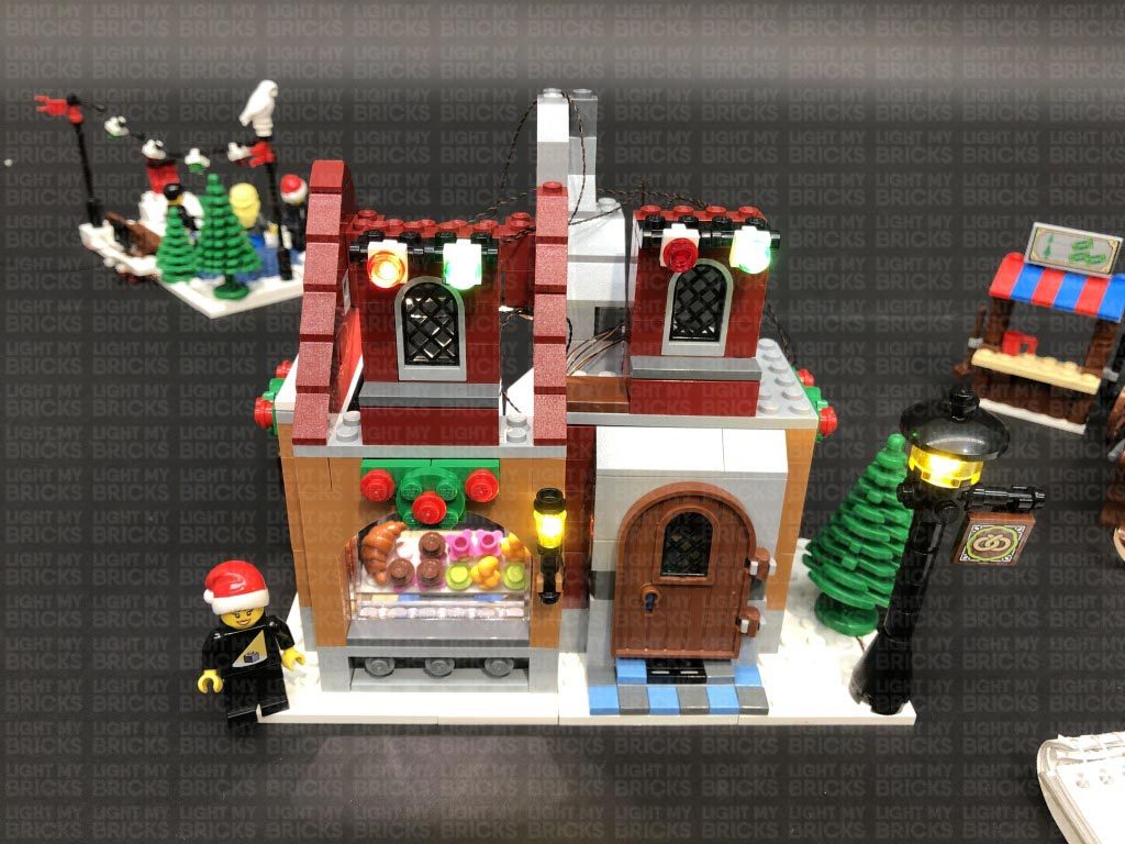
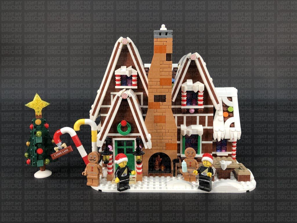
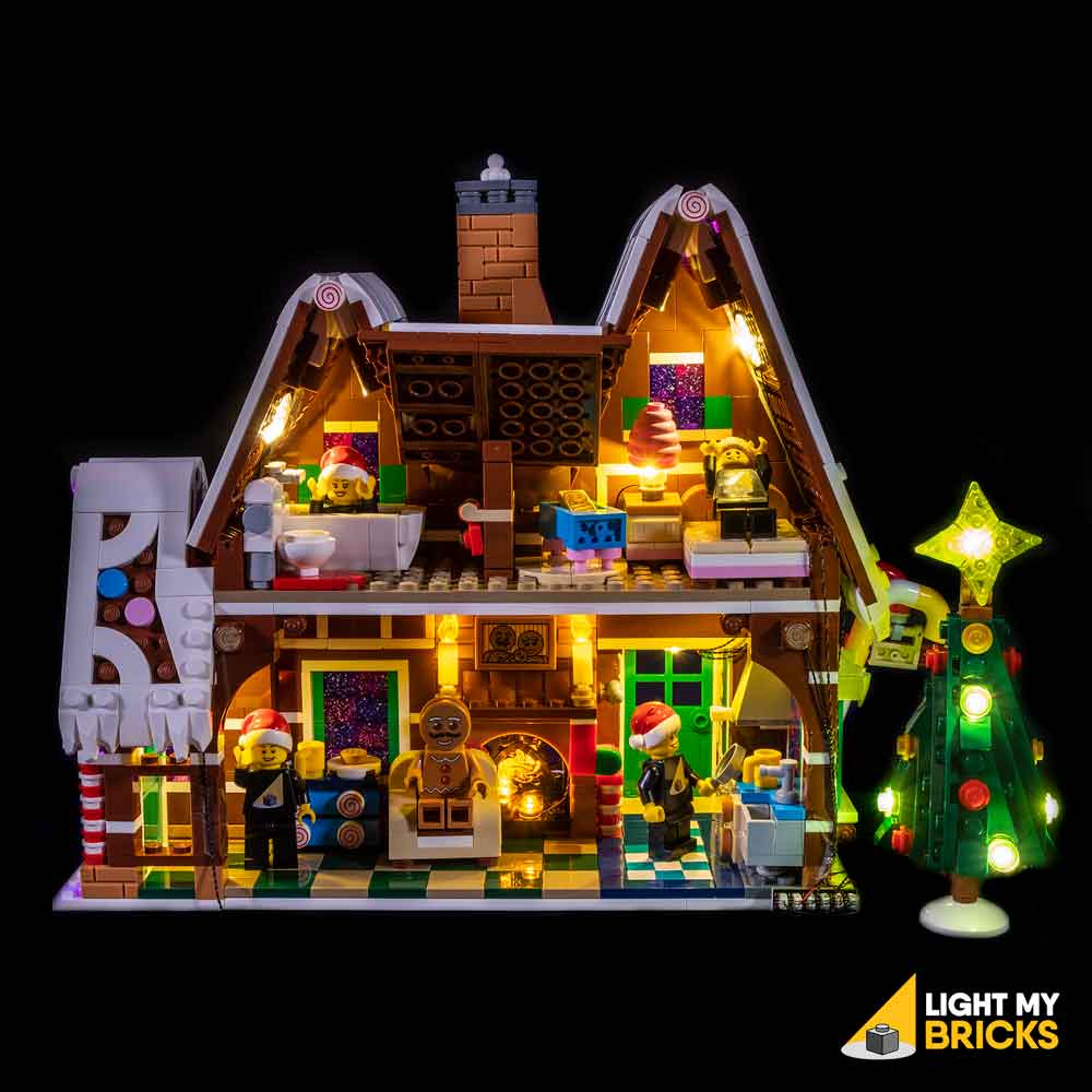
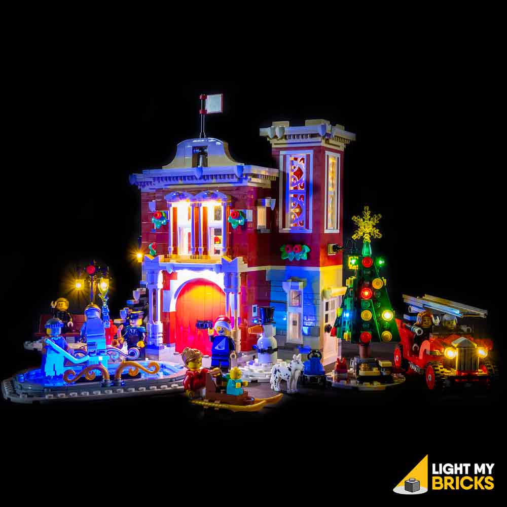
The following page is the instructions for the Light My Bricks LEGO Winter Village Bakery (10216) LED light kit.
If you run into any issues, please refer to the online troubleshooting guide.
To ensure a trouble-free installation of your light kit, please read and follow each step carefully.
Please note: This page lists instructions for the LED light kit only. If you are wishing to purchase the Light My Bricks LEGO Winter Village Bakery (10216) LED light kit , please click here to view the product page
Package Contents:
- 2x White 30cm Bit Lights
- 3x White 15cm Bit Lights
- 1x Blue 30cm Bit Light
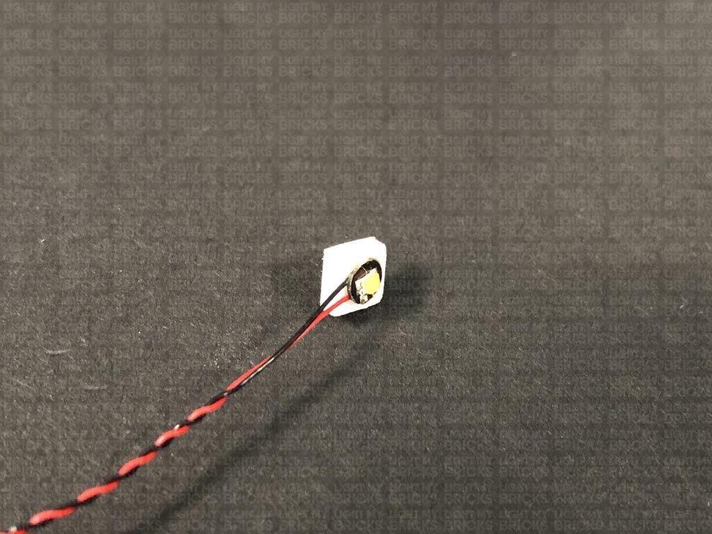
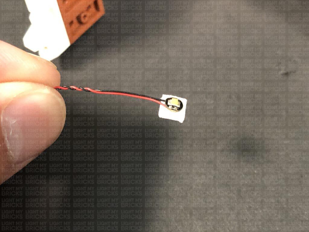
- 4x White 15cm Micro Bit Lights
- 4x Flashing White 30cm Micro Bit Lights
- 4x Flashing White 15cm Micro Bit Lights
- 1x White Strip Light
- 3x Micro 2 to 4-Port Expansion Boards
- 1x 8-Port Expansion Board
- 1x Flicker Effects Board
- 2x 5cm Connecting Cables
- 1x 15cm Connecting Cables
- 2x 30cm Connecting Cable
- 1x AA Battery Pack
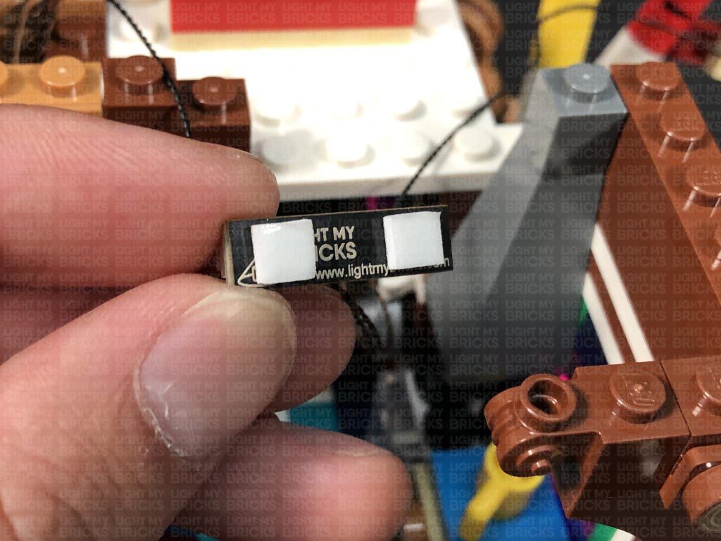
- 6x 3M Adhesive Squares
LEGO Pieces:
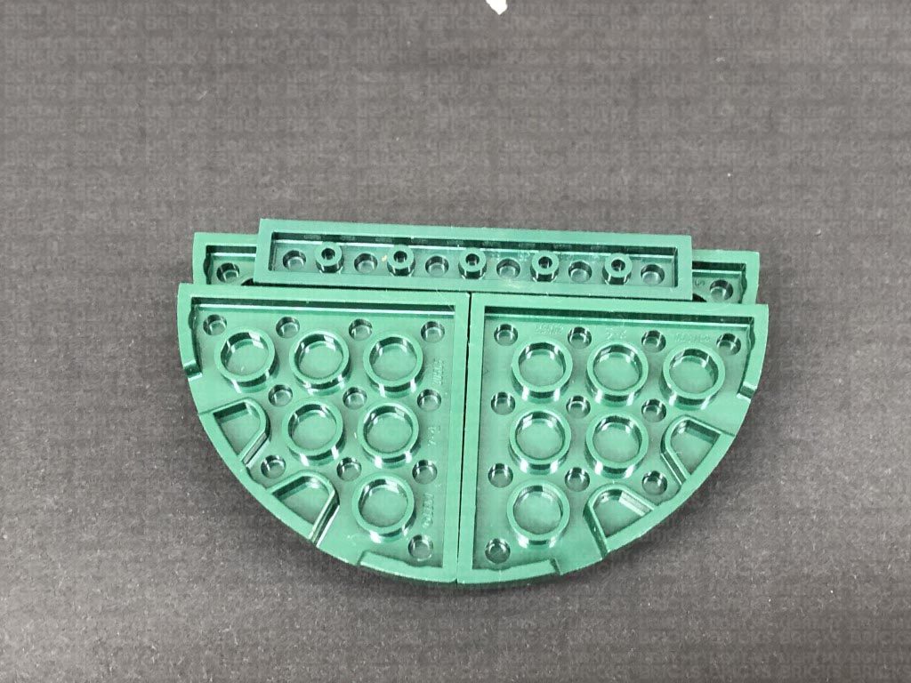
- 2x Trans Clear Plate w Rounded Bottom 2×2
Important things to note:
Laying cables in between and underneath bricks
Cables can fit in between and underneath LEGO® bricks, plates, and tiles providing they are laid correctly between the LEGO® studs. Do NOT forcefully join LEGO® together around cables; instead ensure they are laying comfortably in between each stud.
Connecting cable connectors to Expansion Boards
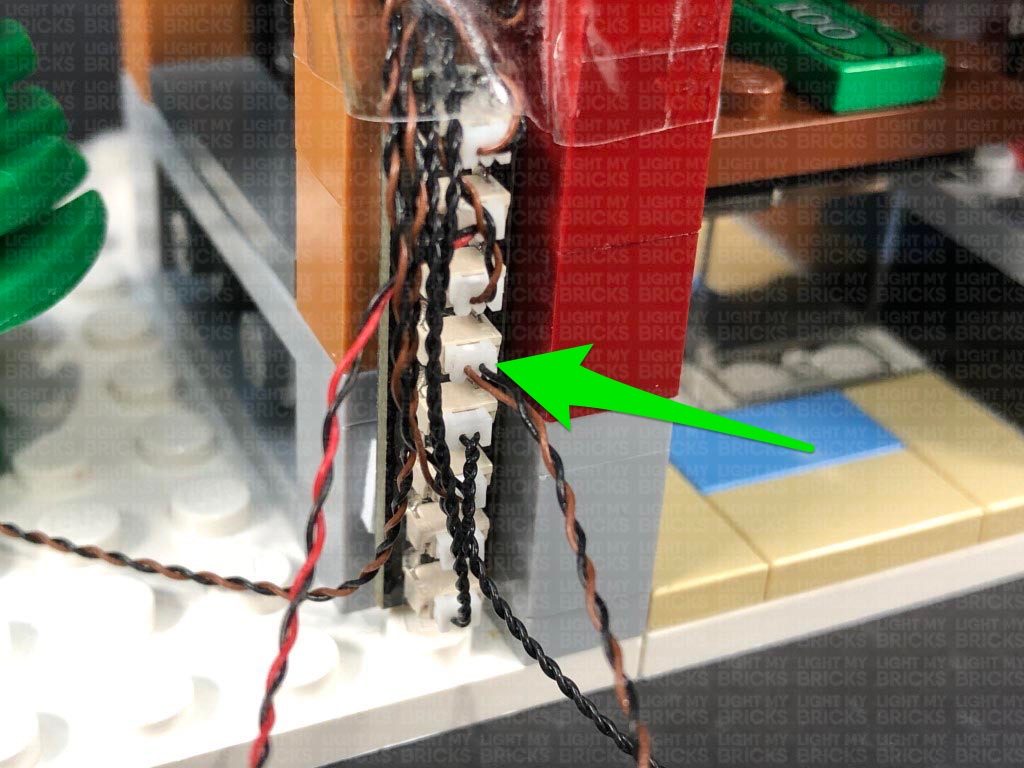
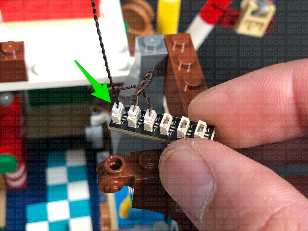
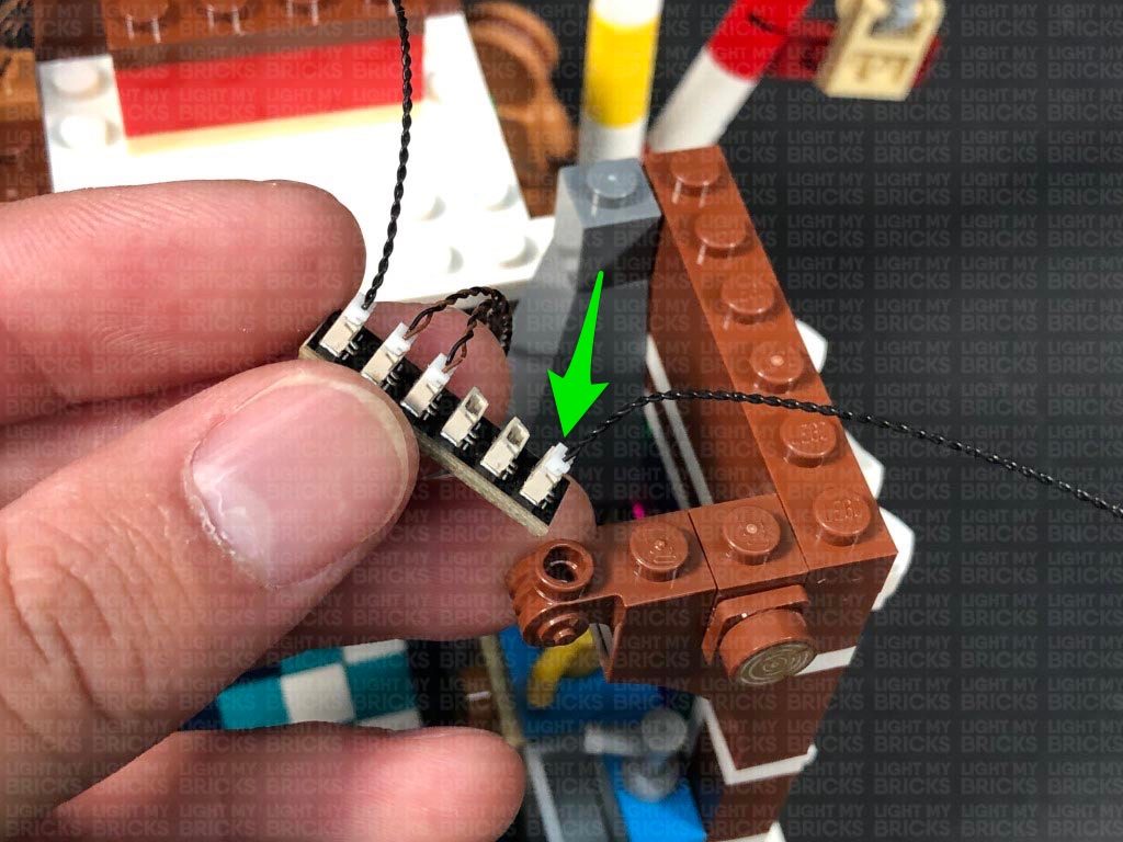
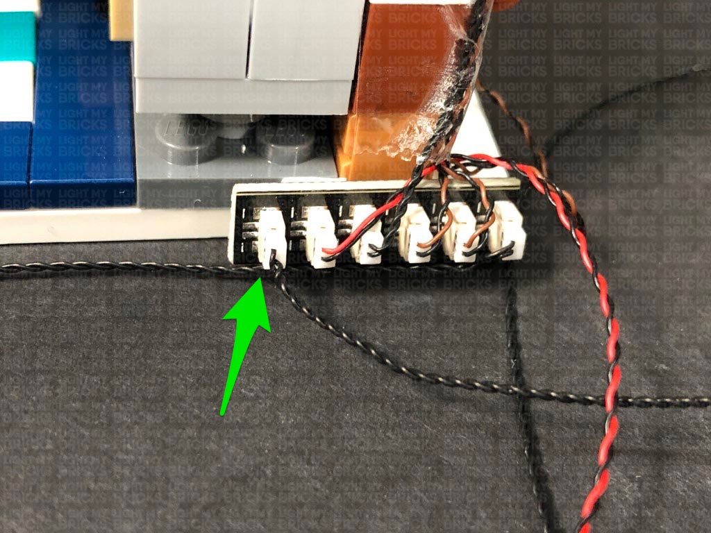
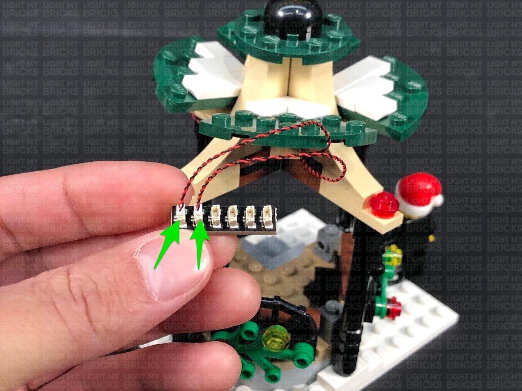
Take extra care when inserting connectors to ports of Expansion Boards. Connectors can be inserted only one way. With the expansion board facing up, look for the soldered “=” symbol on the left side of the port. The connector side with the wires exposed should be facing toward the soldered “=” symbol as you insert into the port. If a plug won’t fit easily into a port connector, do not force it.
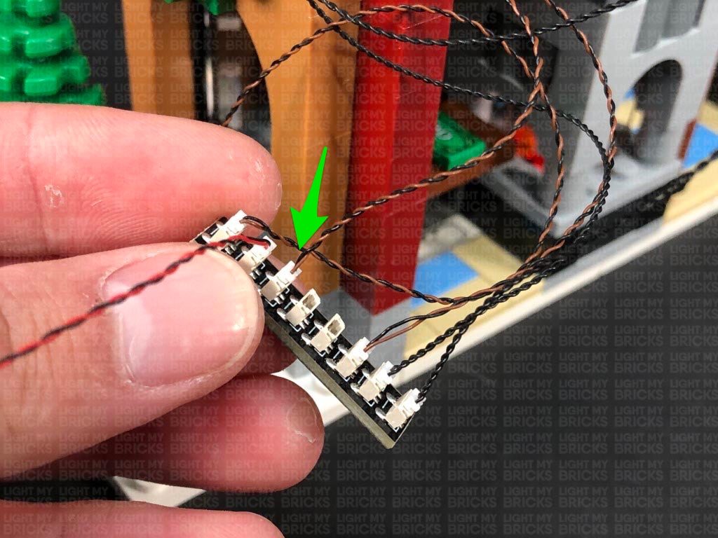
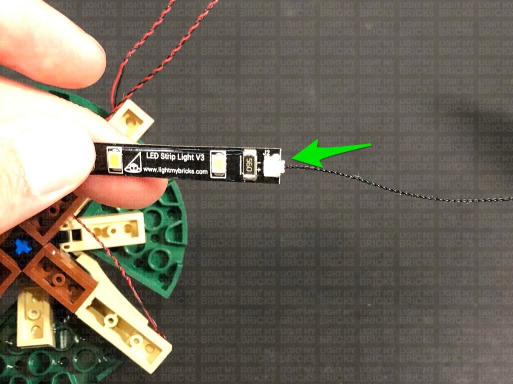
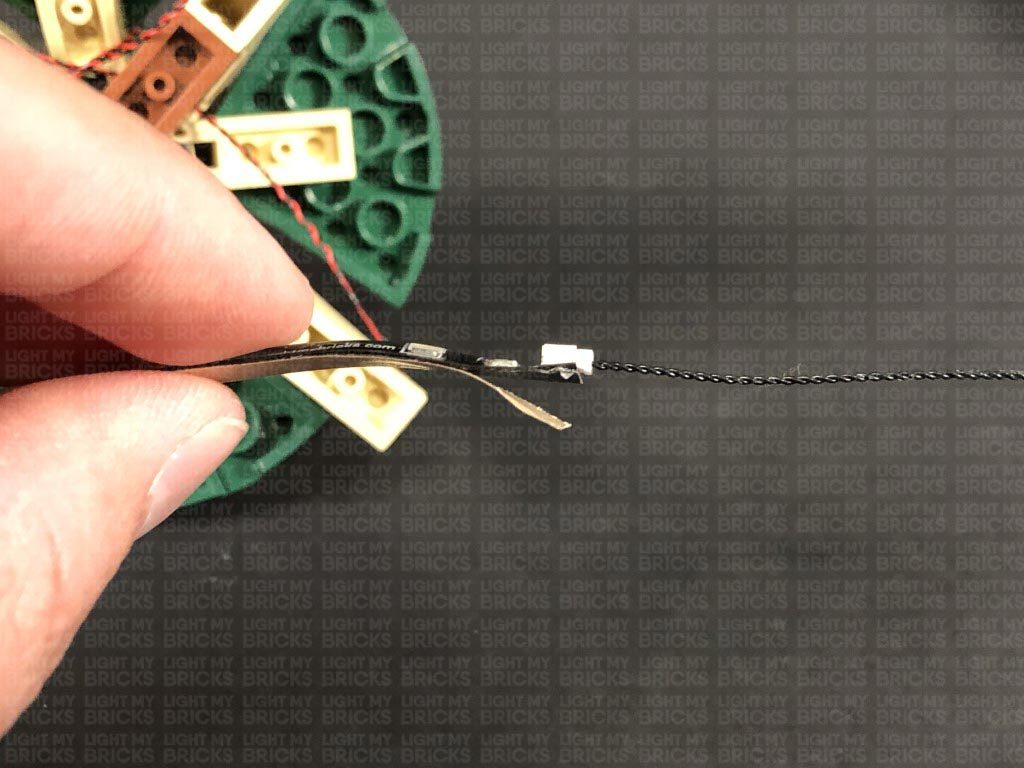
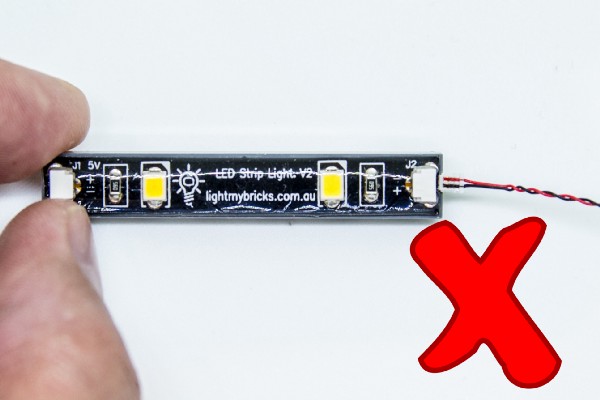
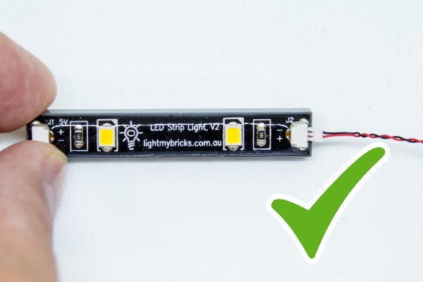
Connecting cable connectors to Strip Lights
Take extra care when inserting connectors to ports on the Strip Lights. Connectors can be inserted only one way. With the Strip Light facing up, ensure the side of the connector with the wires exposed is facing down. If a plug won’t fit easily into a port connector, don’t force it. Doing so will damage the plug and the connector.
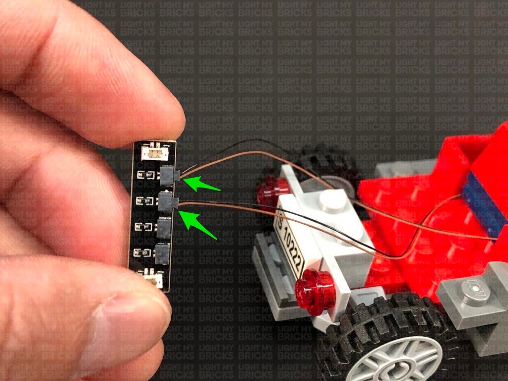
Connecting Micro Cable connectors to Micro Expansion Board Ports
Take extra care when inserting the micro connectors to micro ports of Micro Expansion Boards. Connecting Micro Bit Lights to Micro Expansion Boards is similar to connecting lights and cables to Strip Lights. With the expansion board facing up, ensure the side of the connector with the wires exposed is facing down. If a plug won’t fit easily into a port connector, do not force it. Use your fingernail to push the plastic part of the connector to the micro port.Installing Bit Lights under LEGO® bricks and plates.
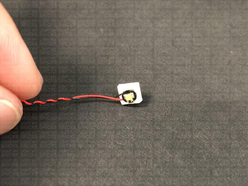
When installing Bit Lights under LEGO® pieces, ensure they are placed the correct way up (Yellow LED component exposed). You can either place them directly on top of LEGO® studs or in between.
OK, Let’s Begin!
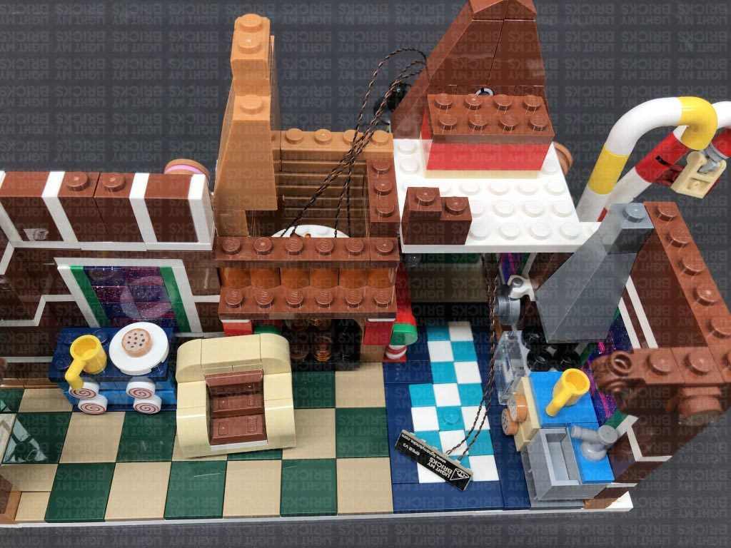
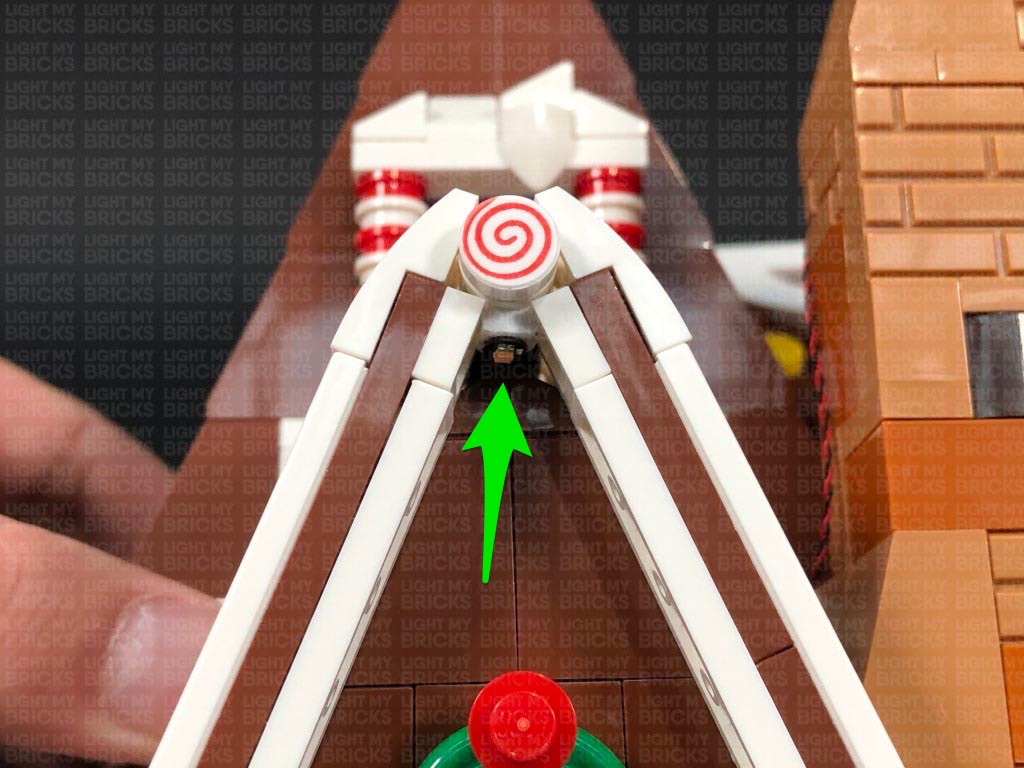
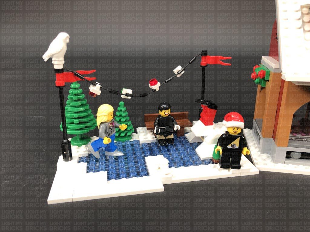
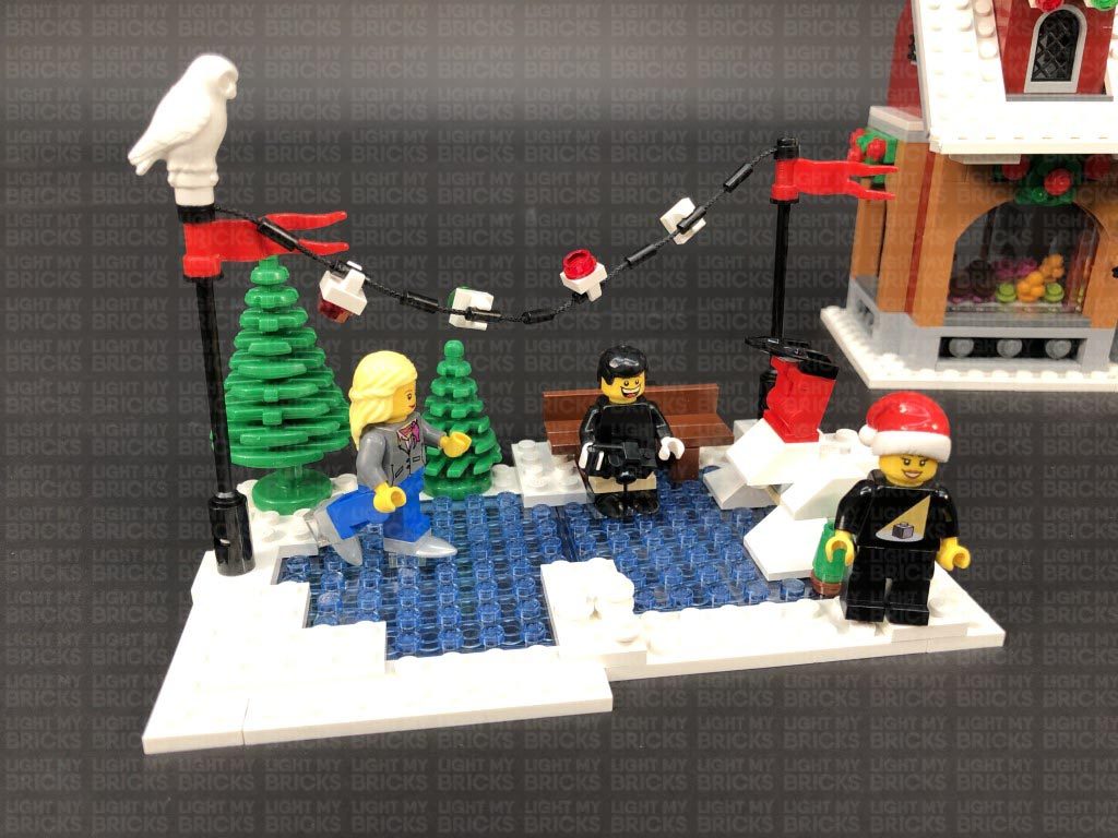
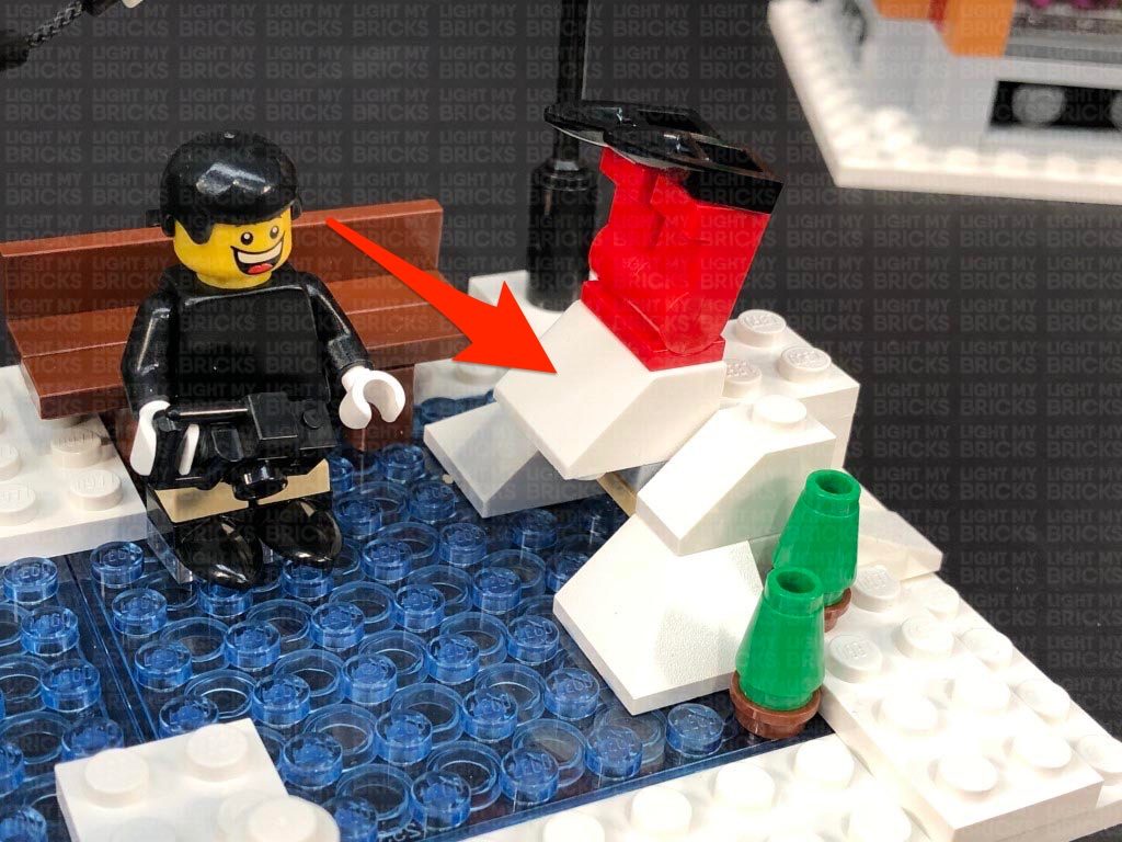
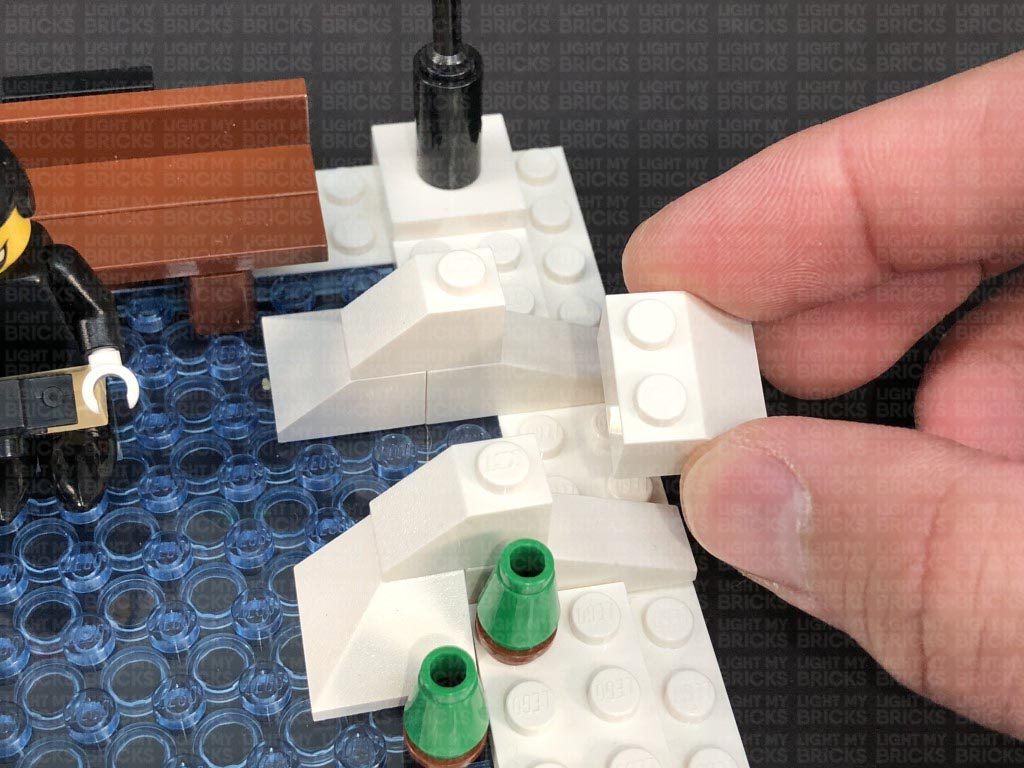
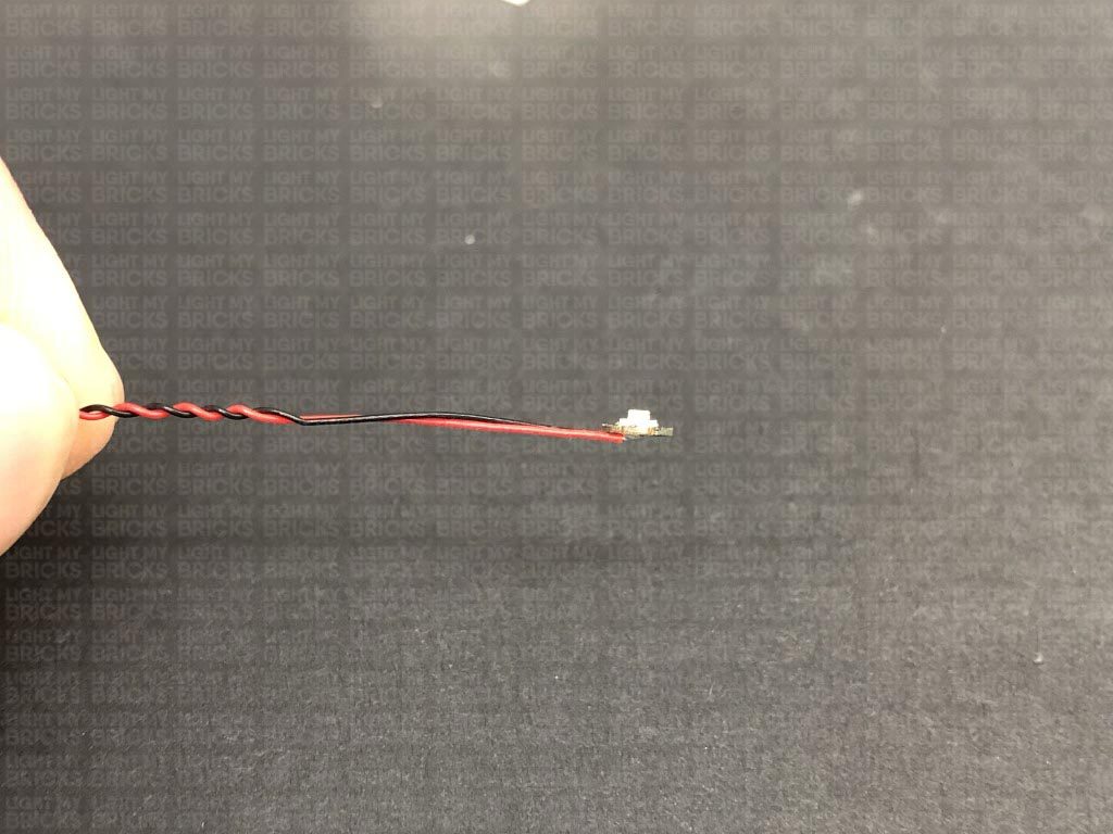
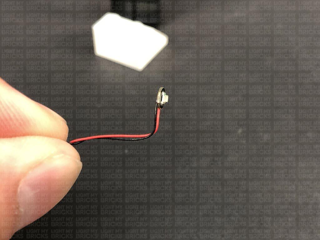
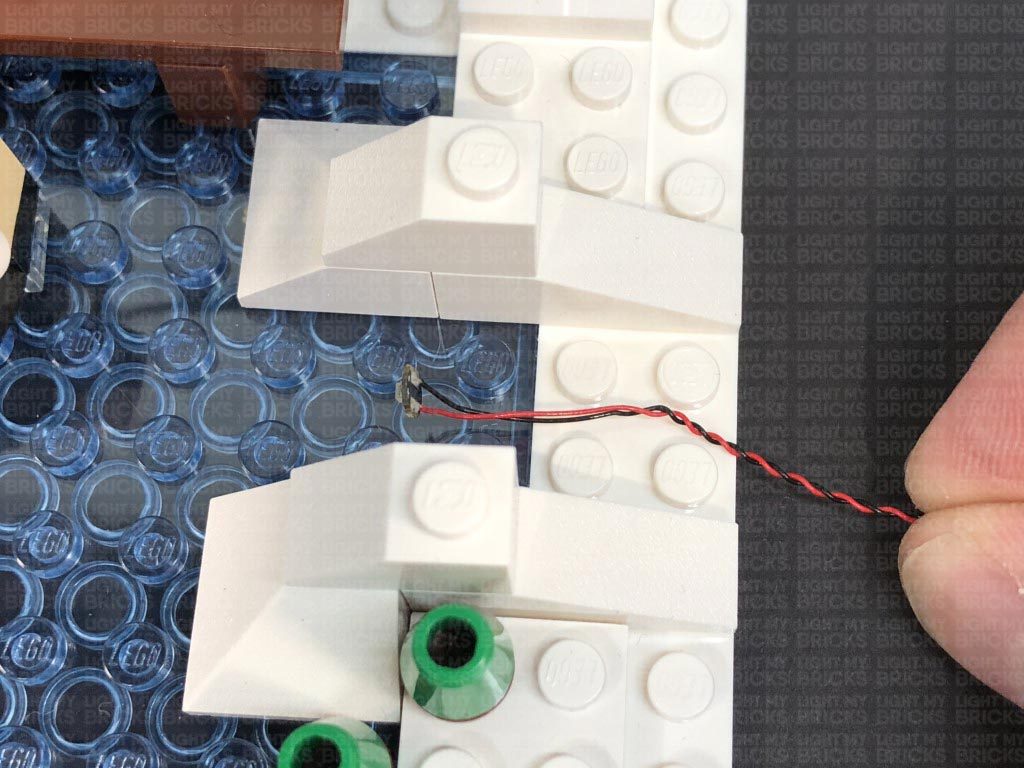
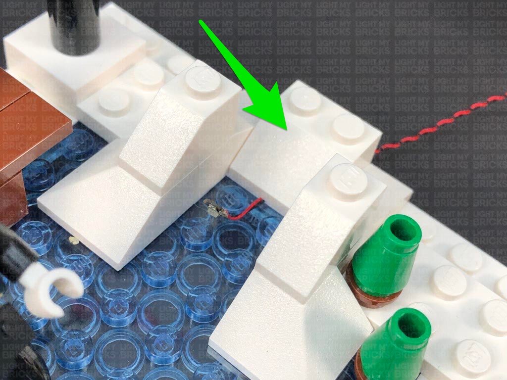
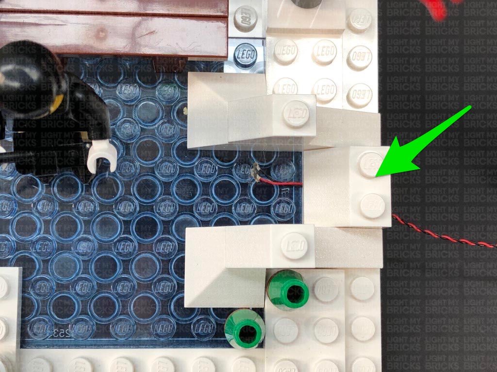
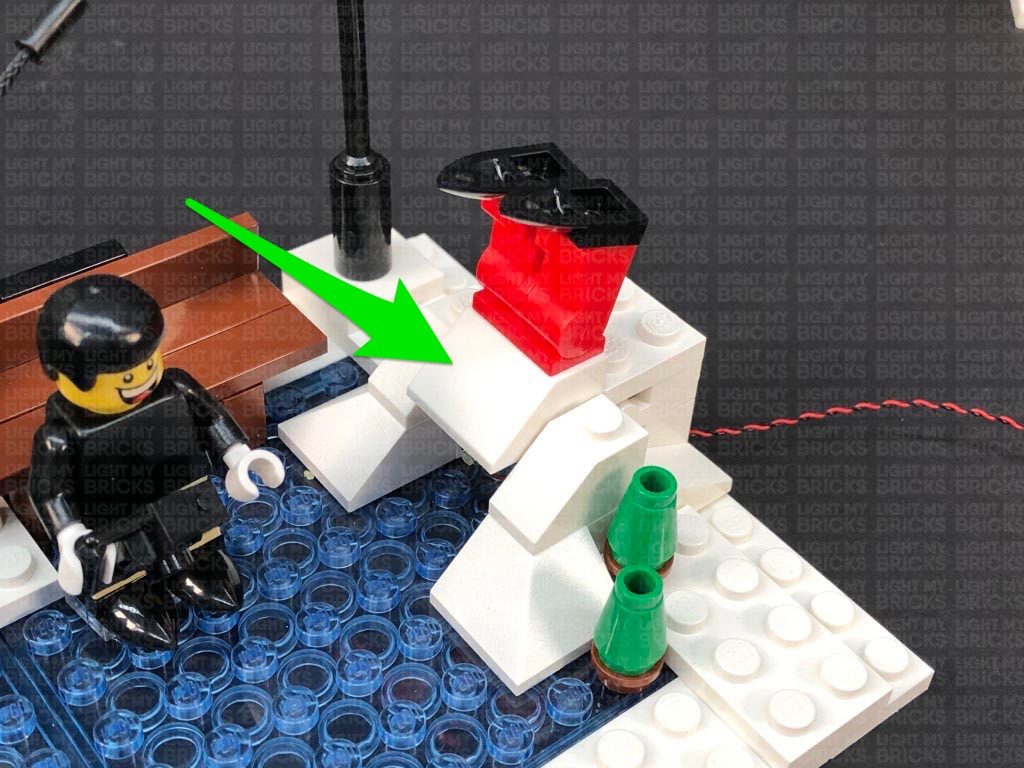
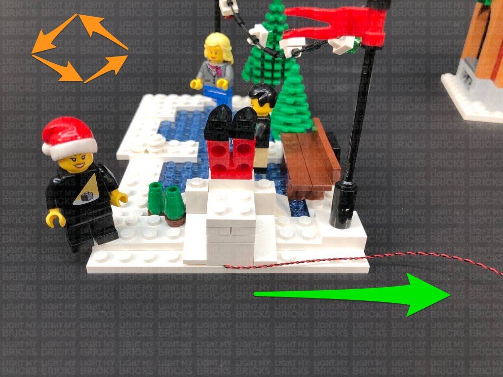
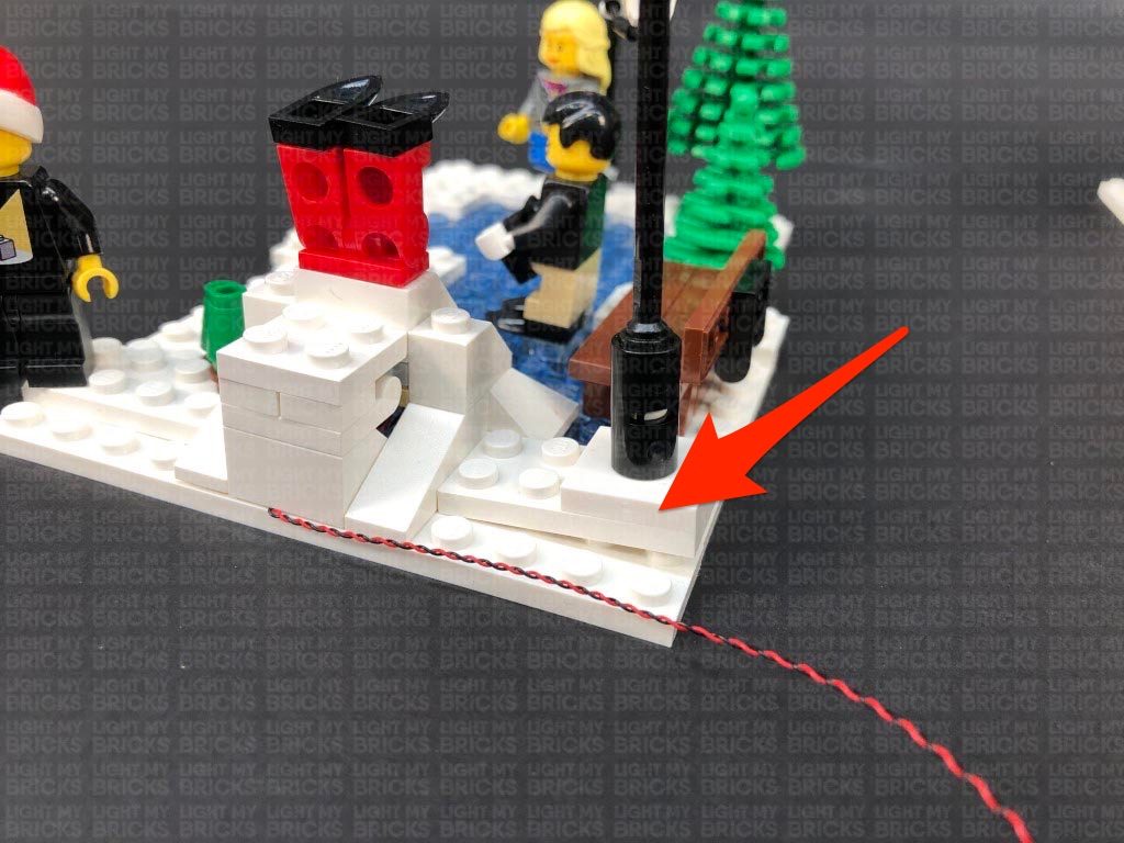
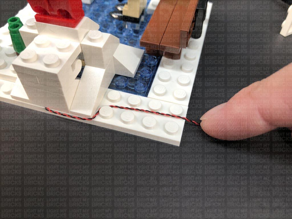
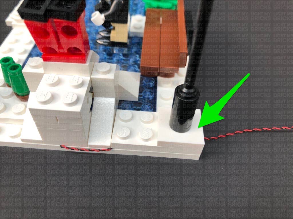
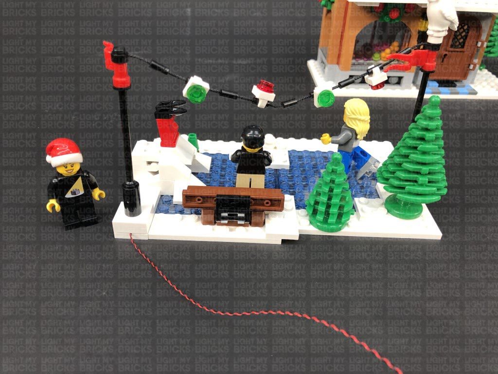
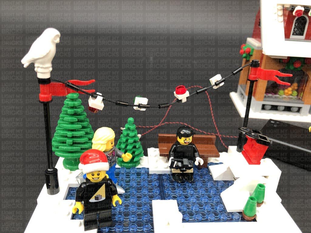
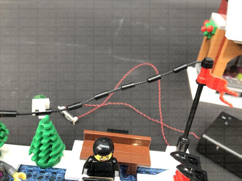
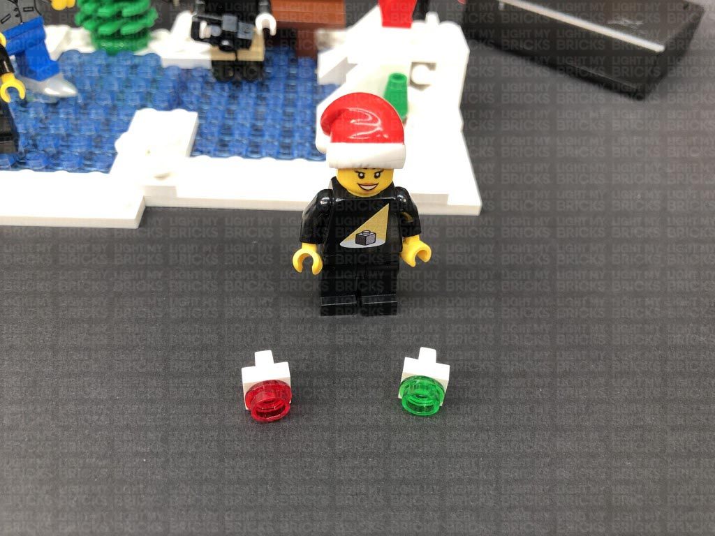
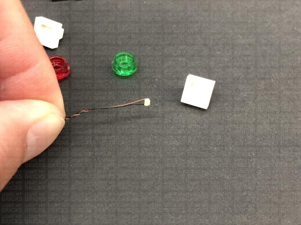
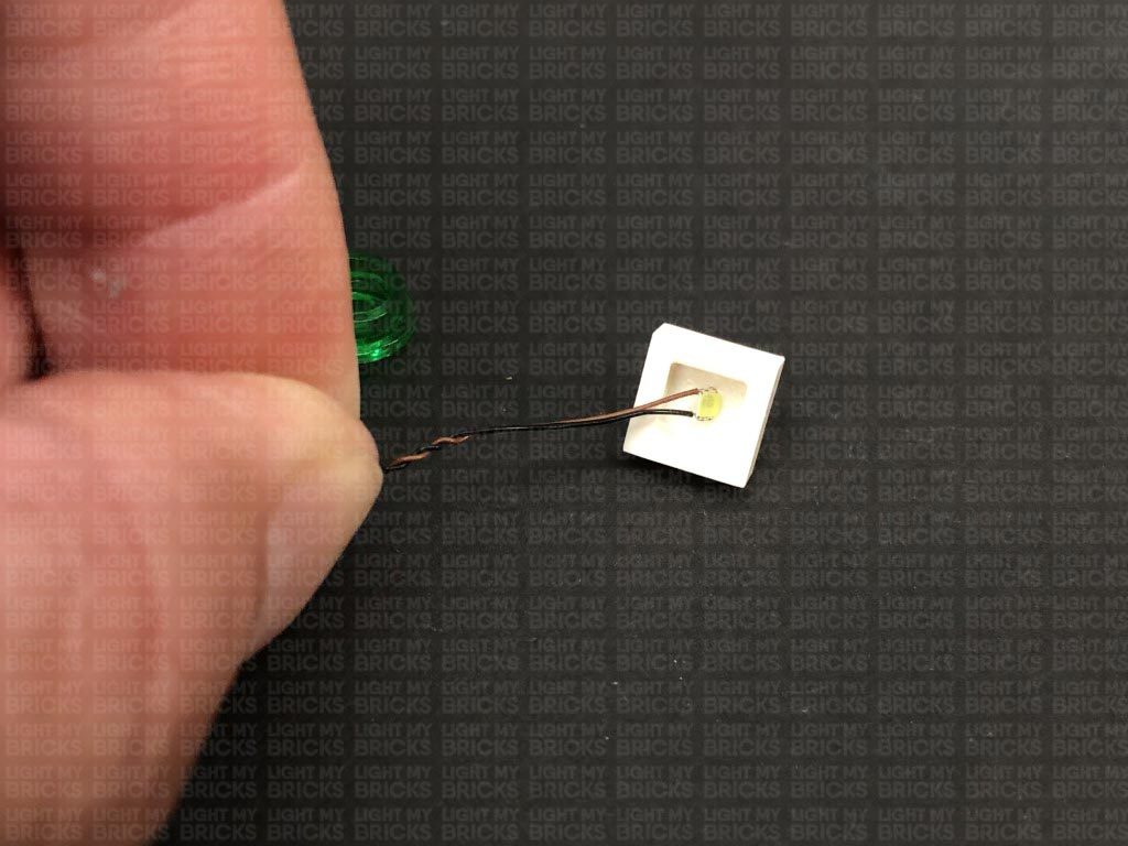
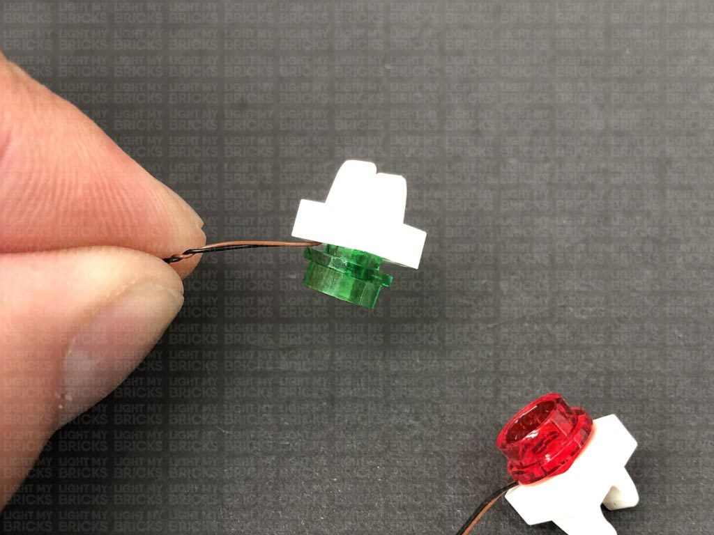
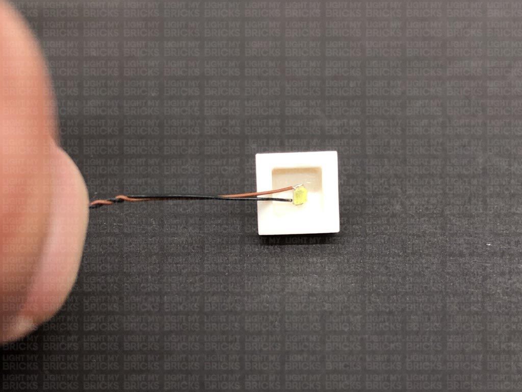
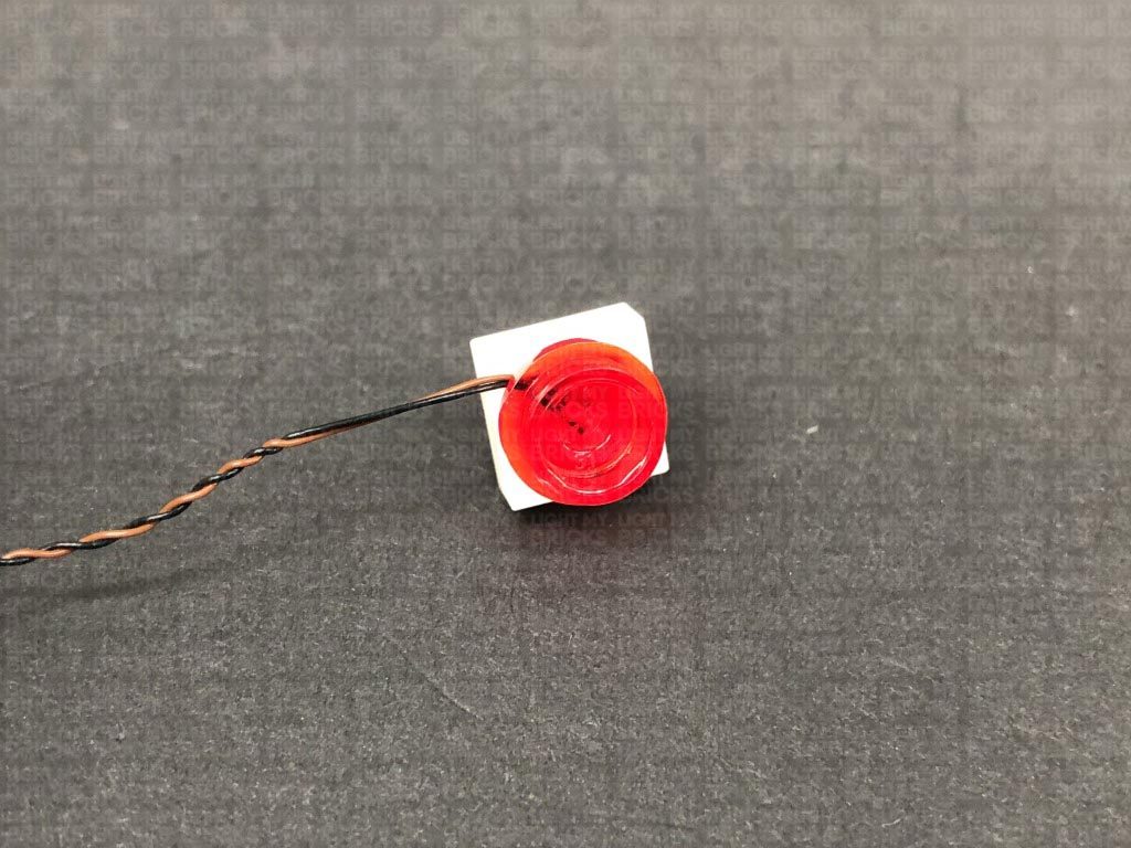
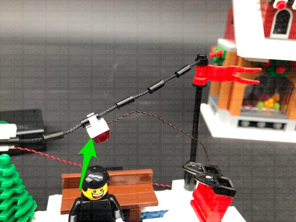
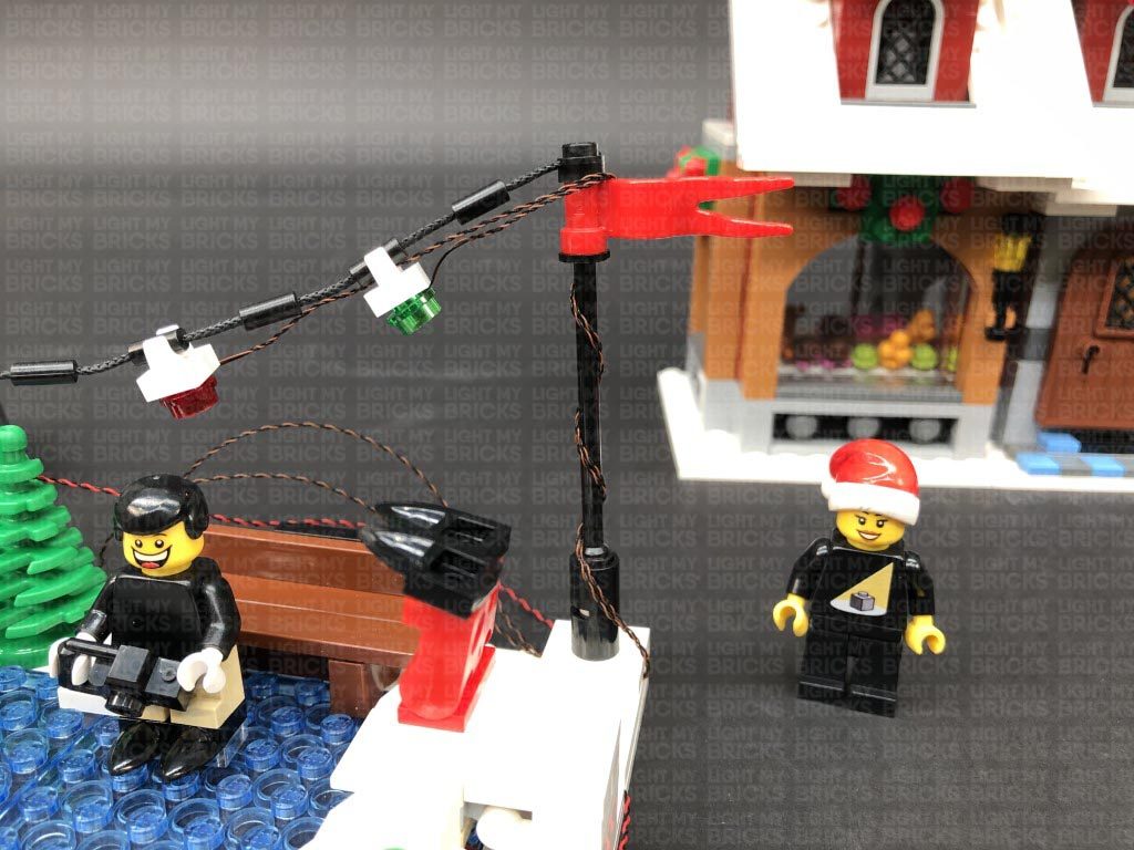
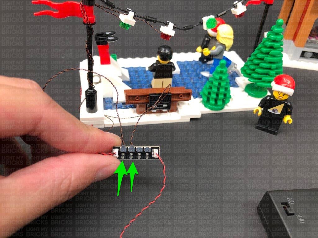
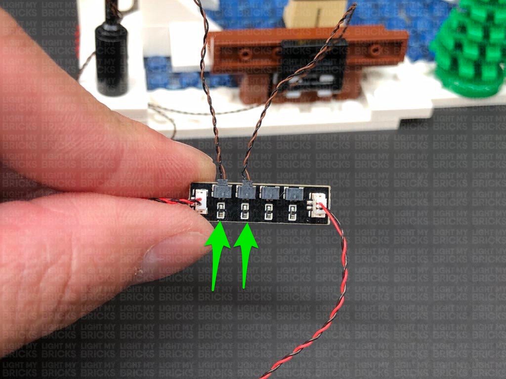
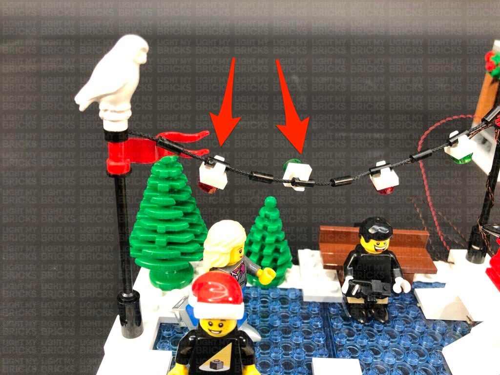
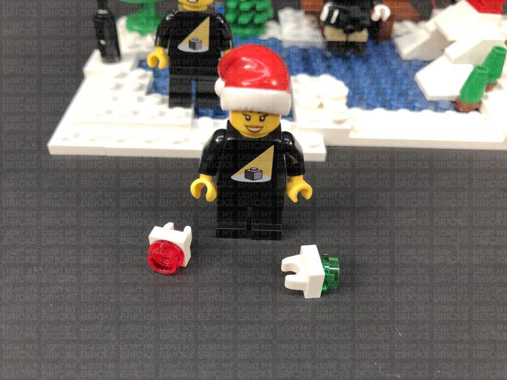
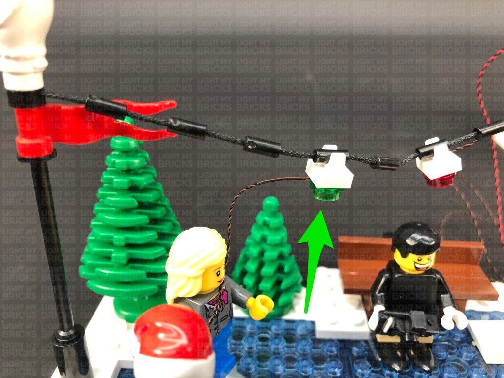
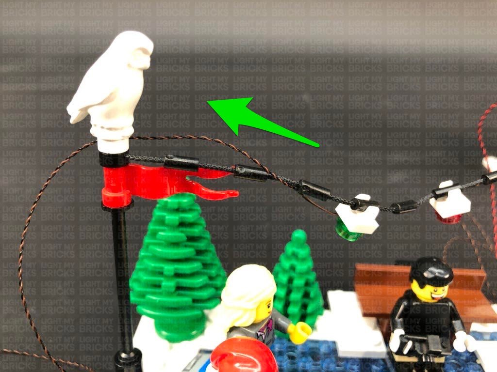
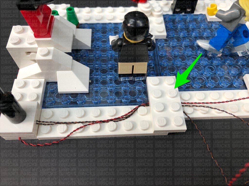
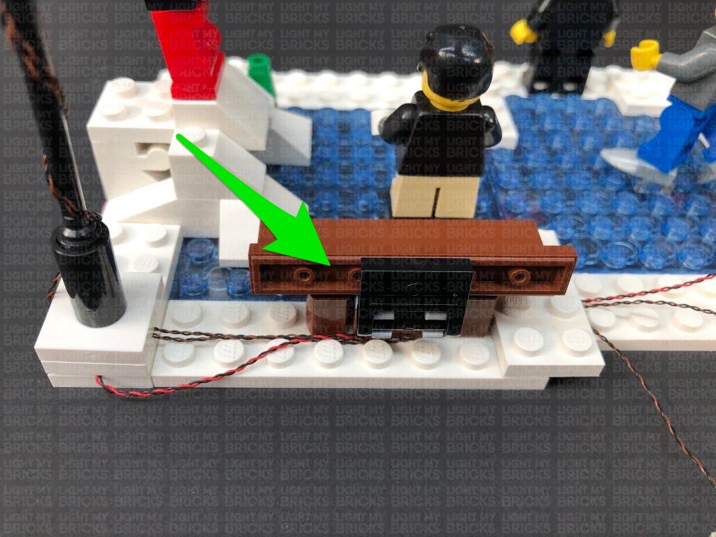
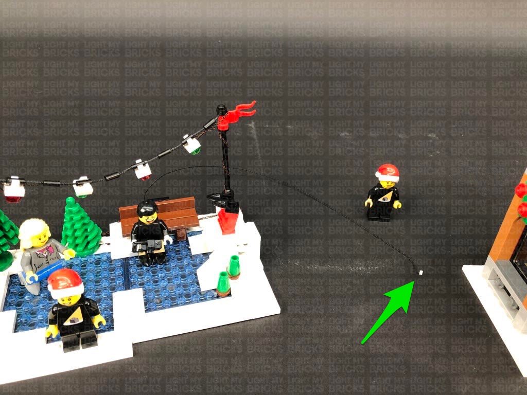
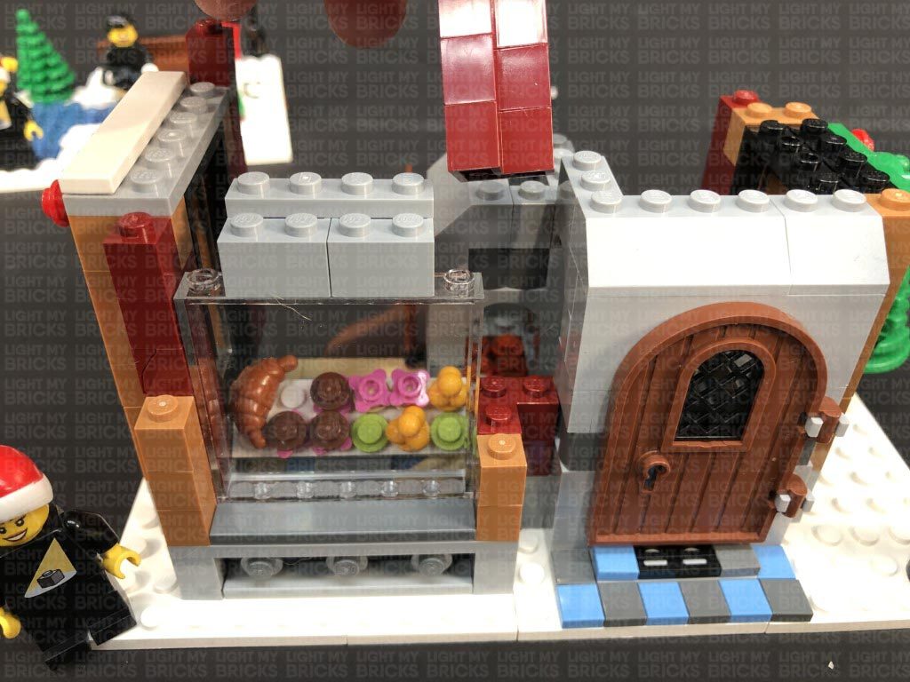
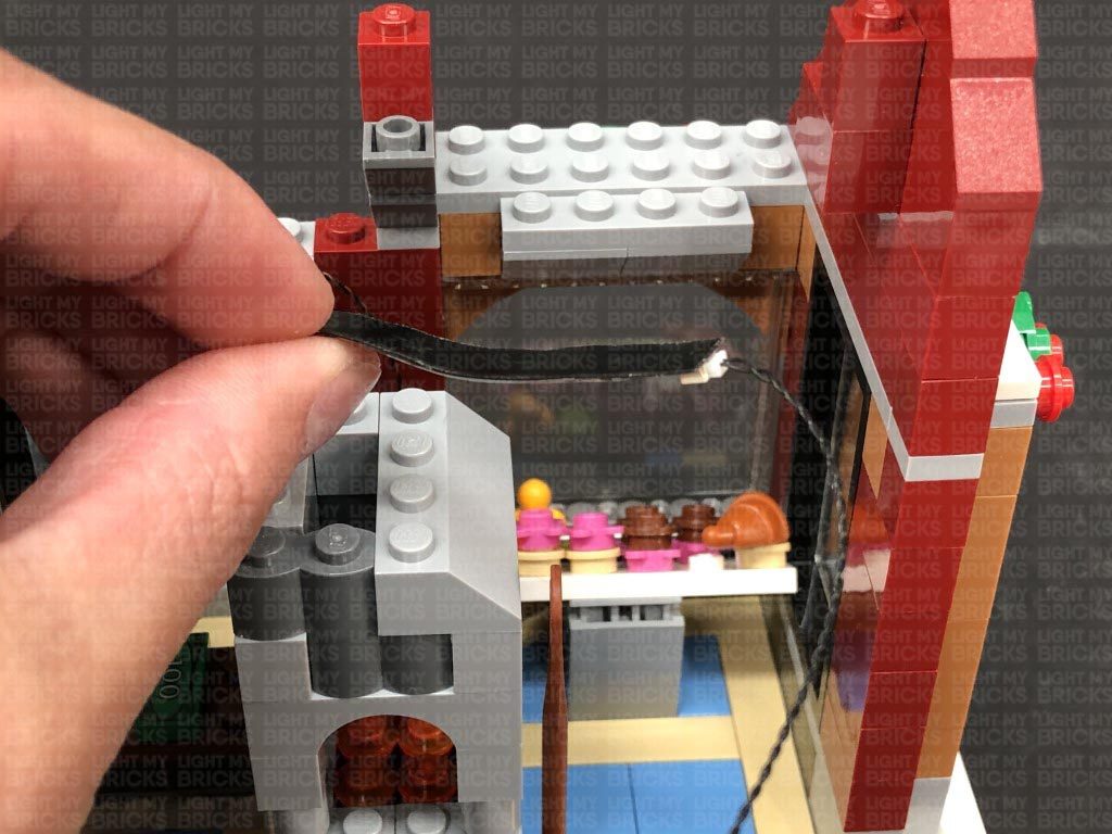
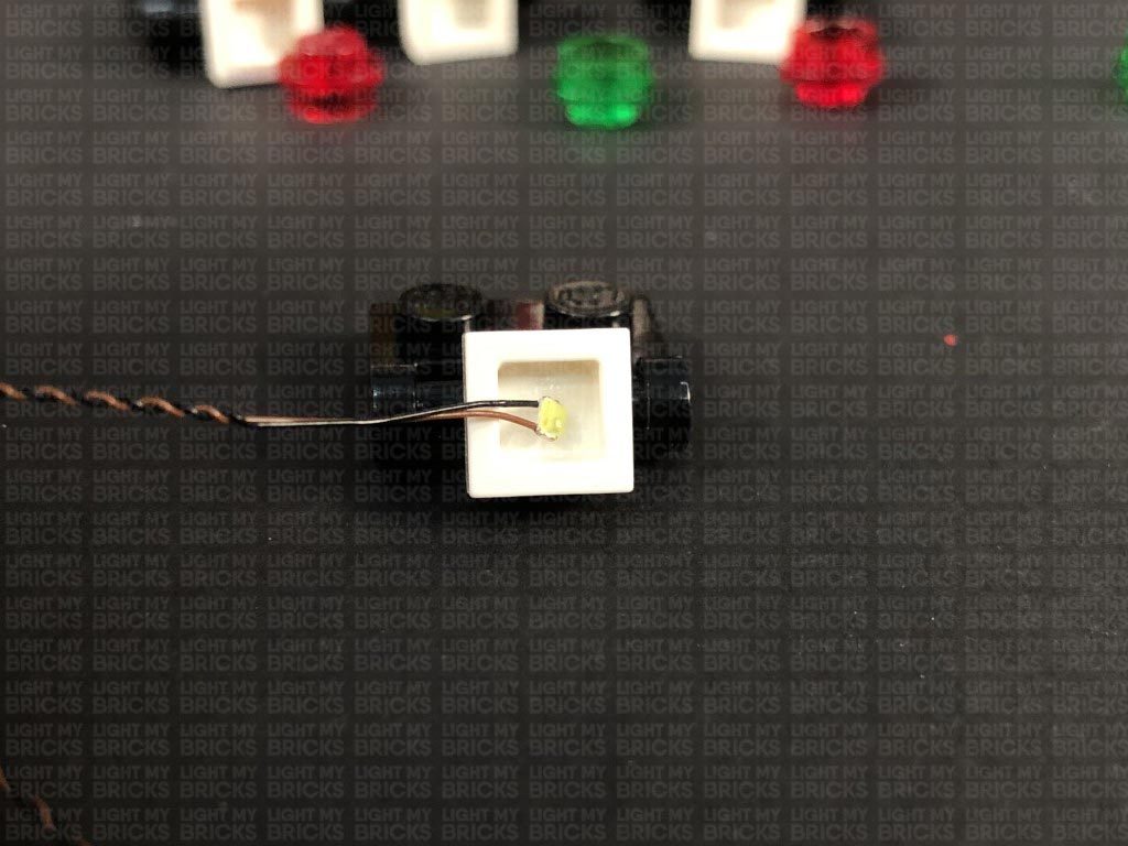
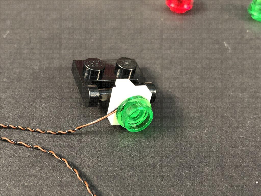
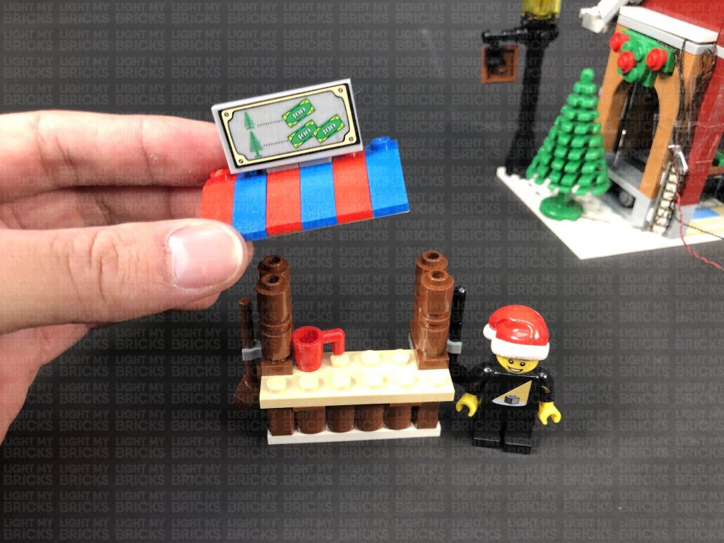
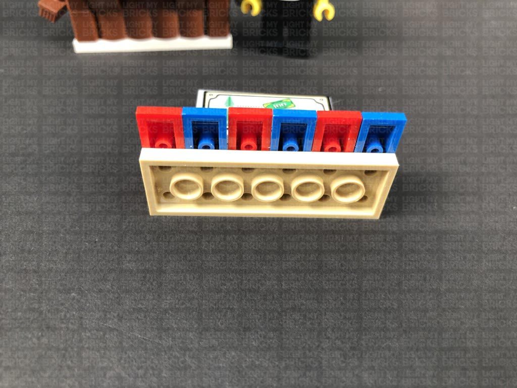
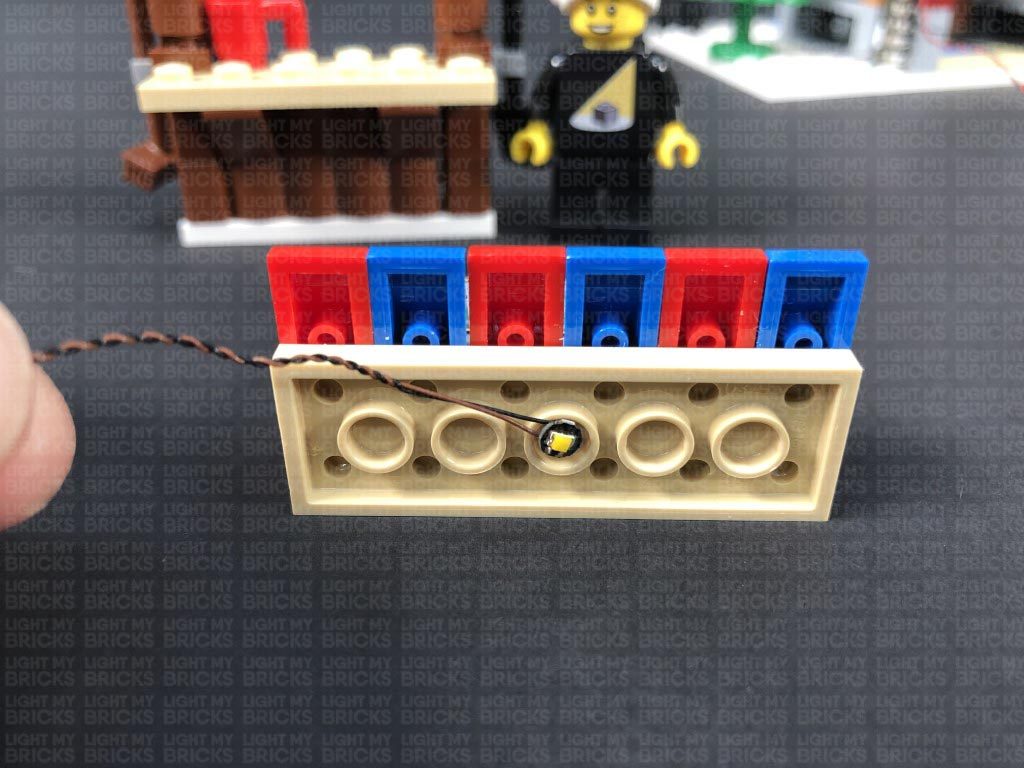
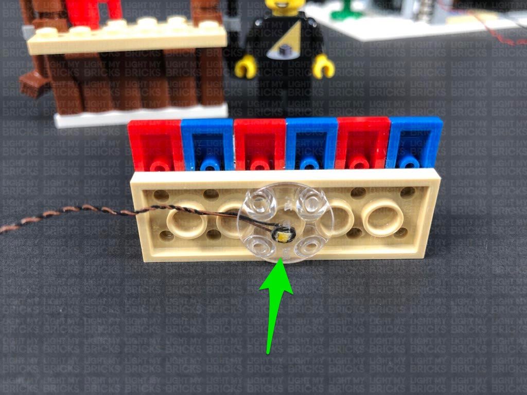
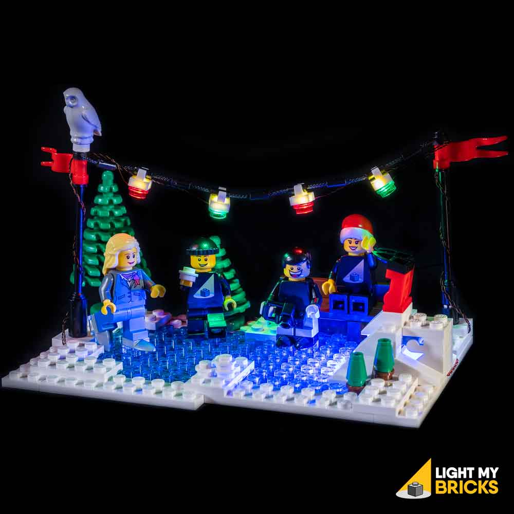
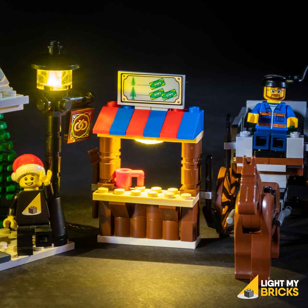
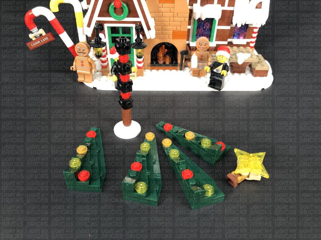
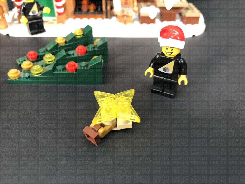
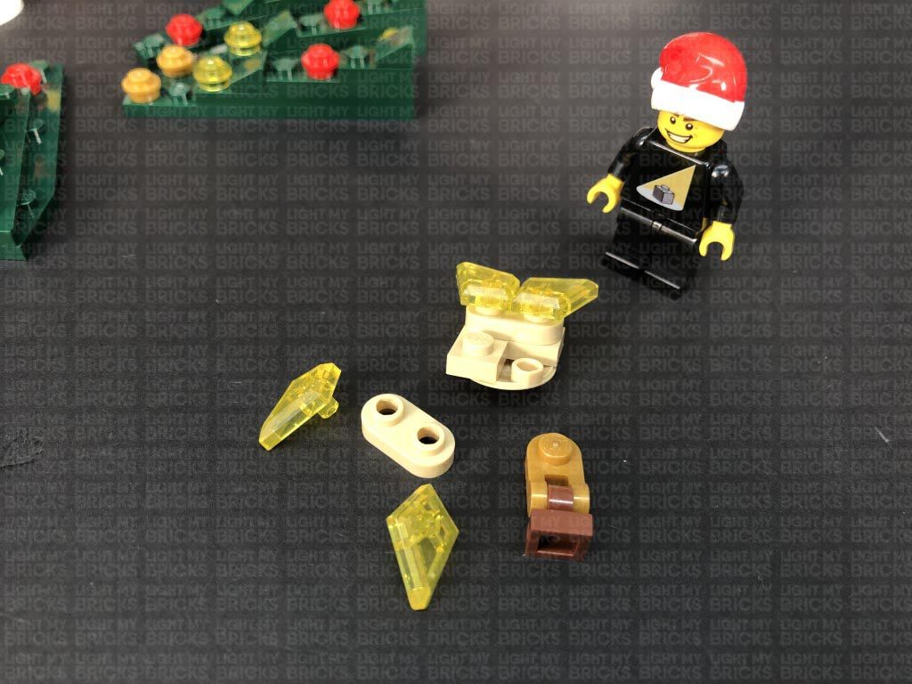
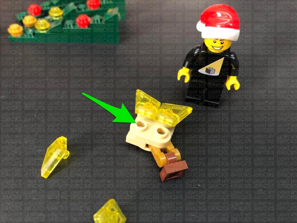
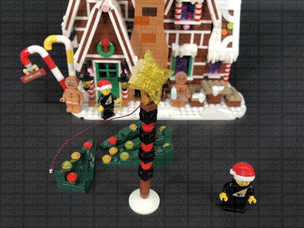
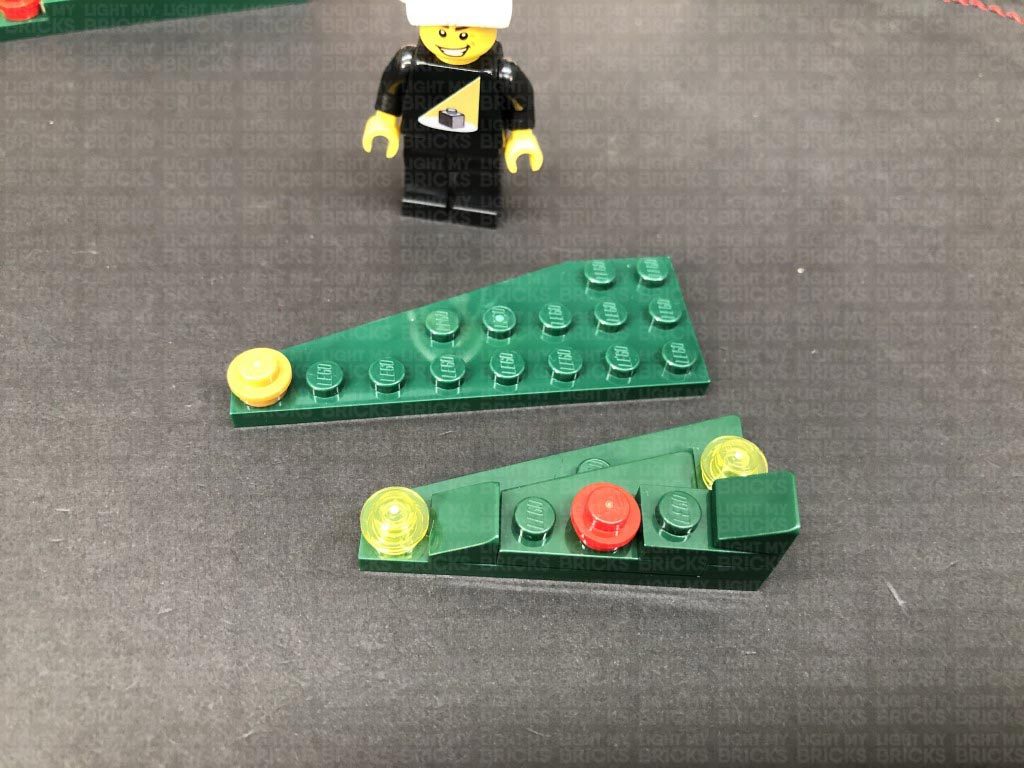
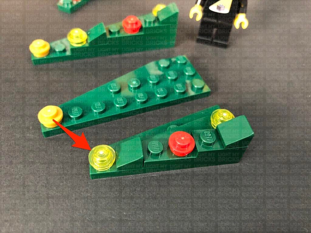
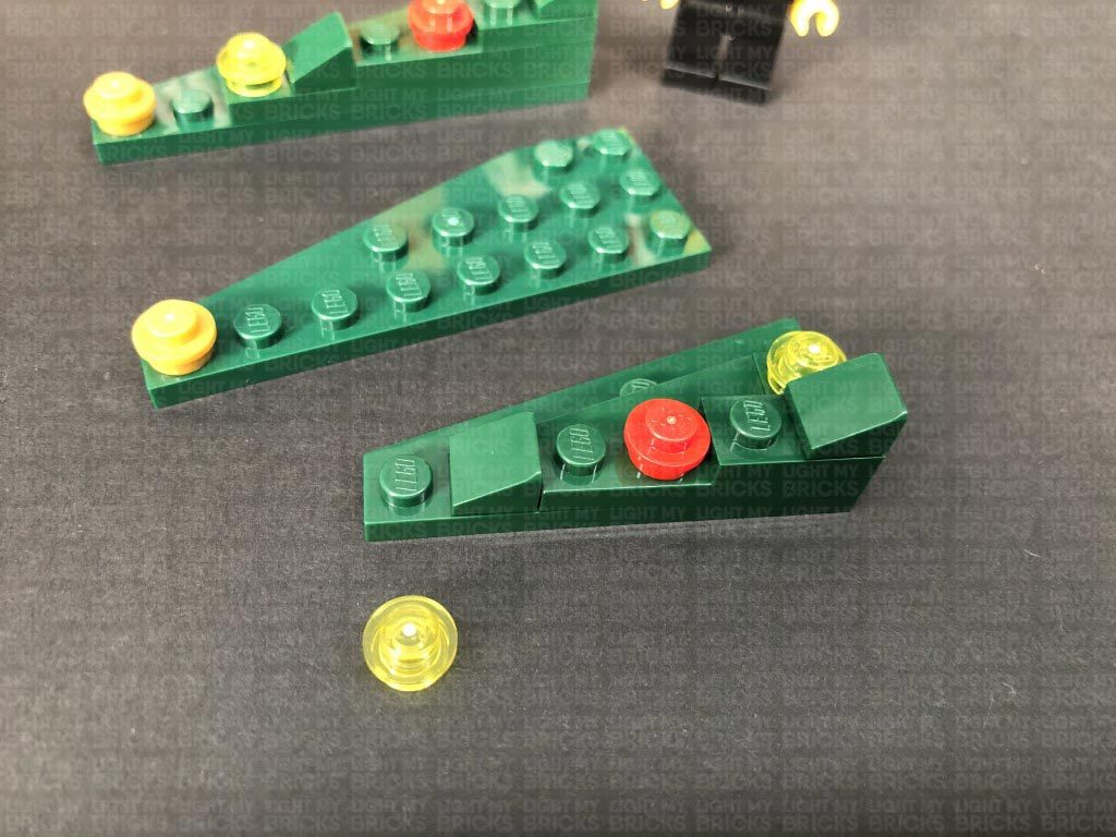
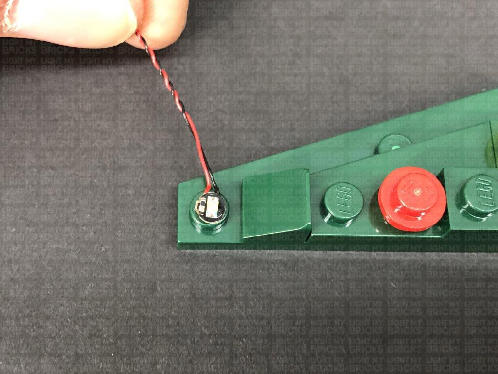
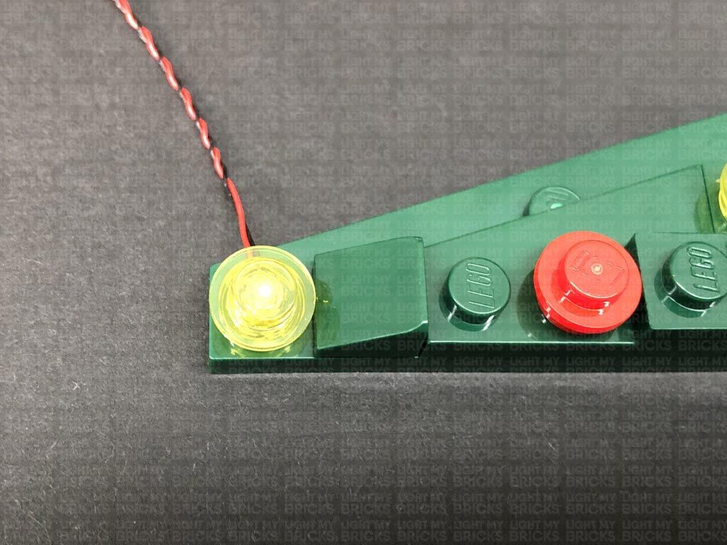
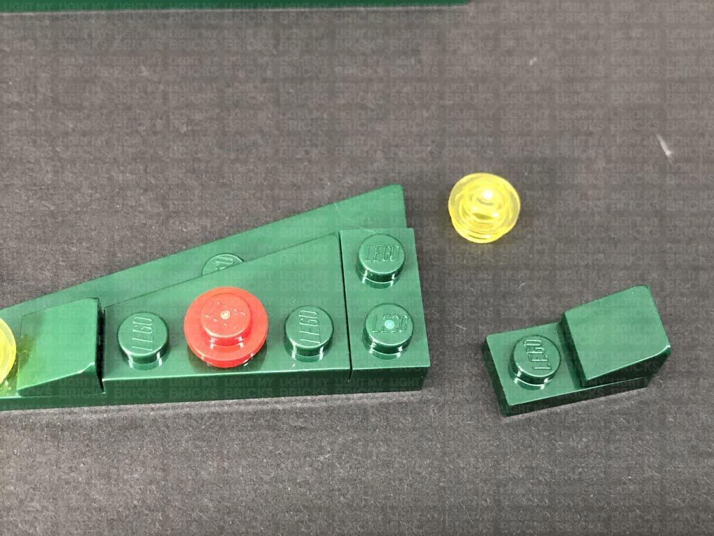
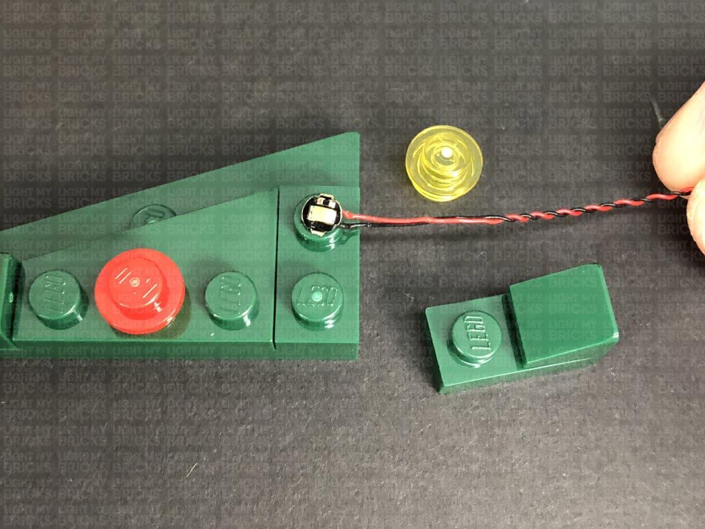
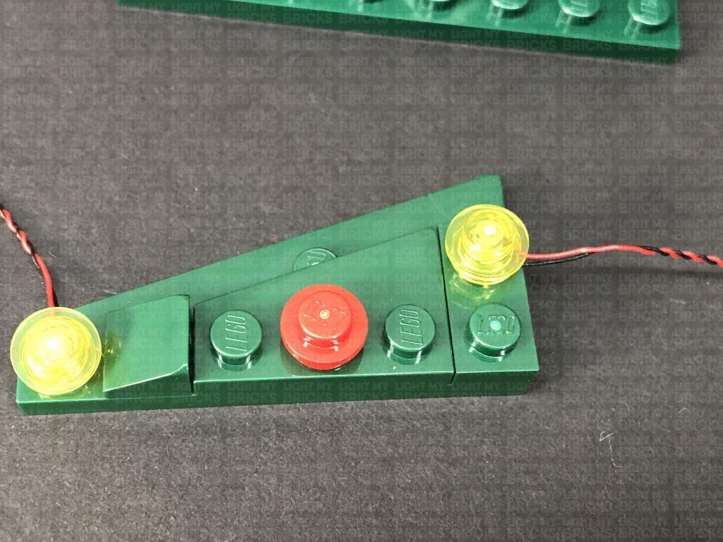
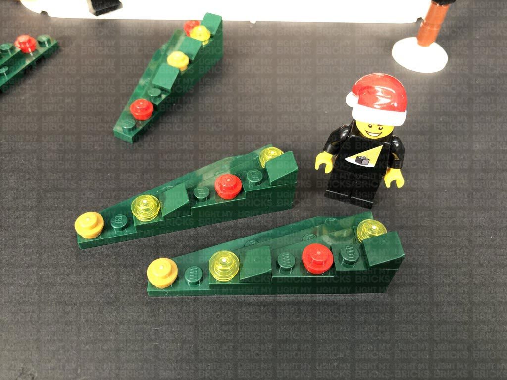
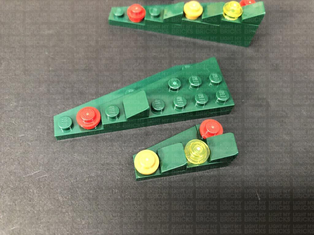
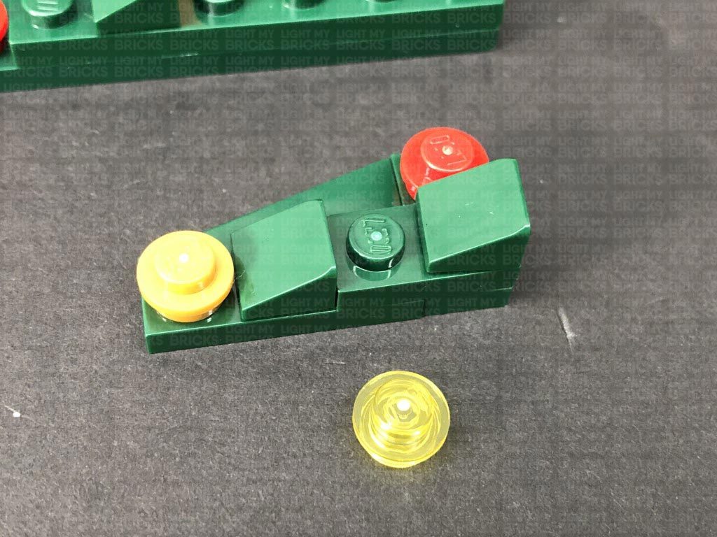
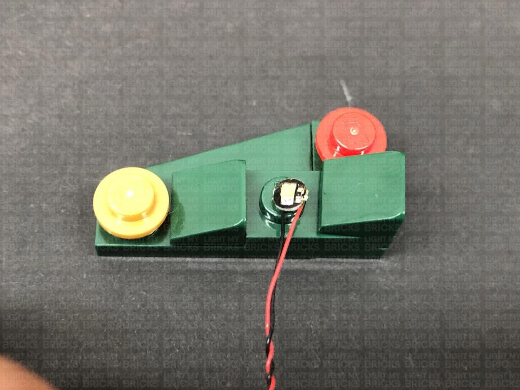
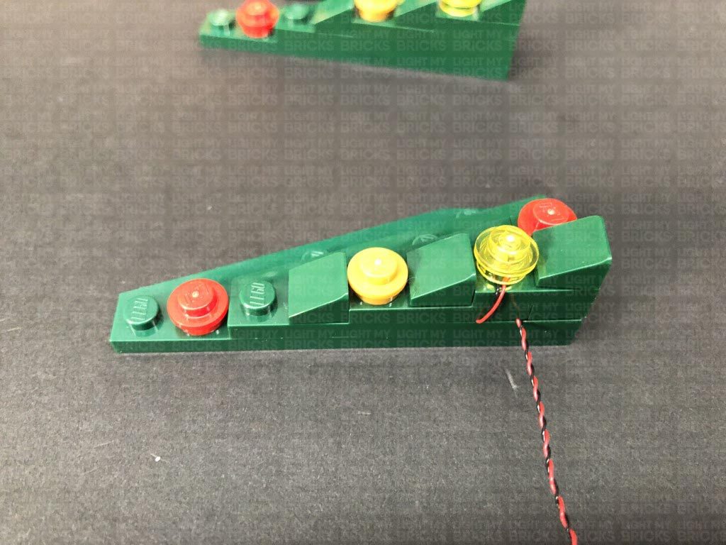
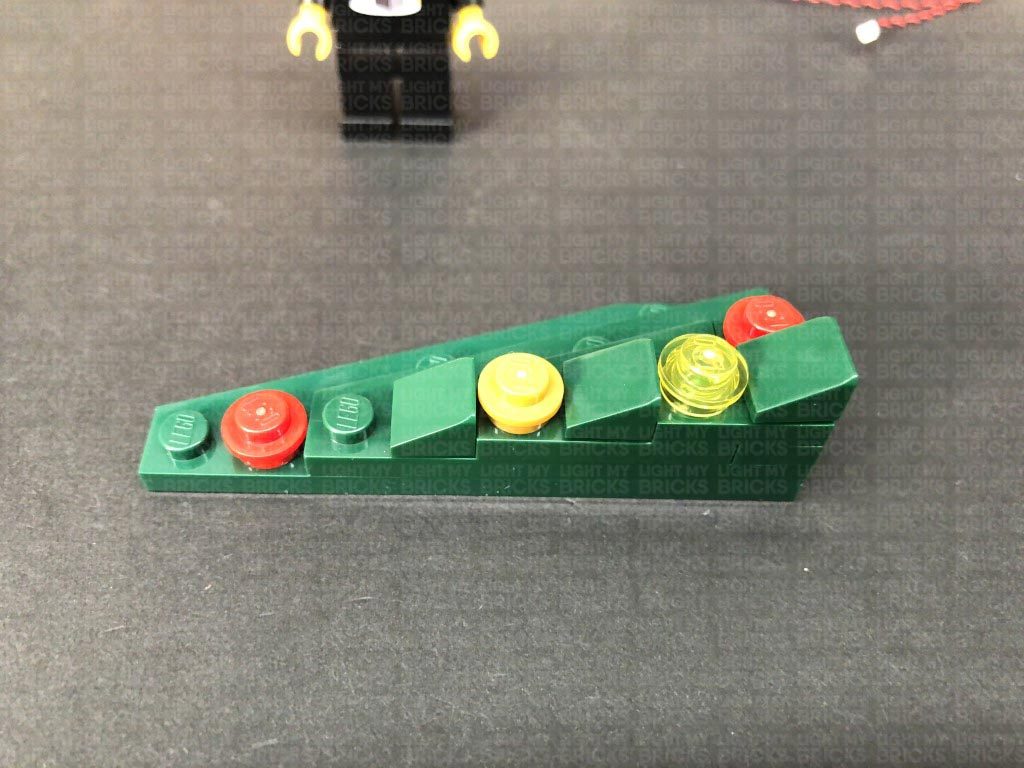
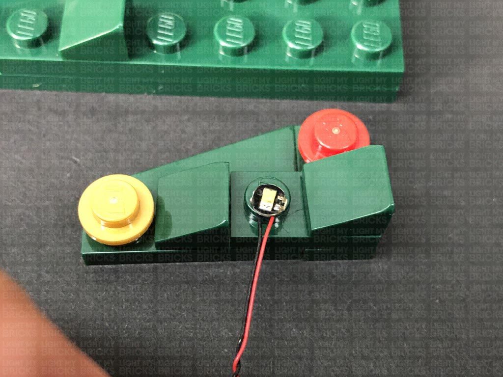
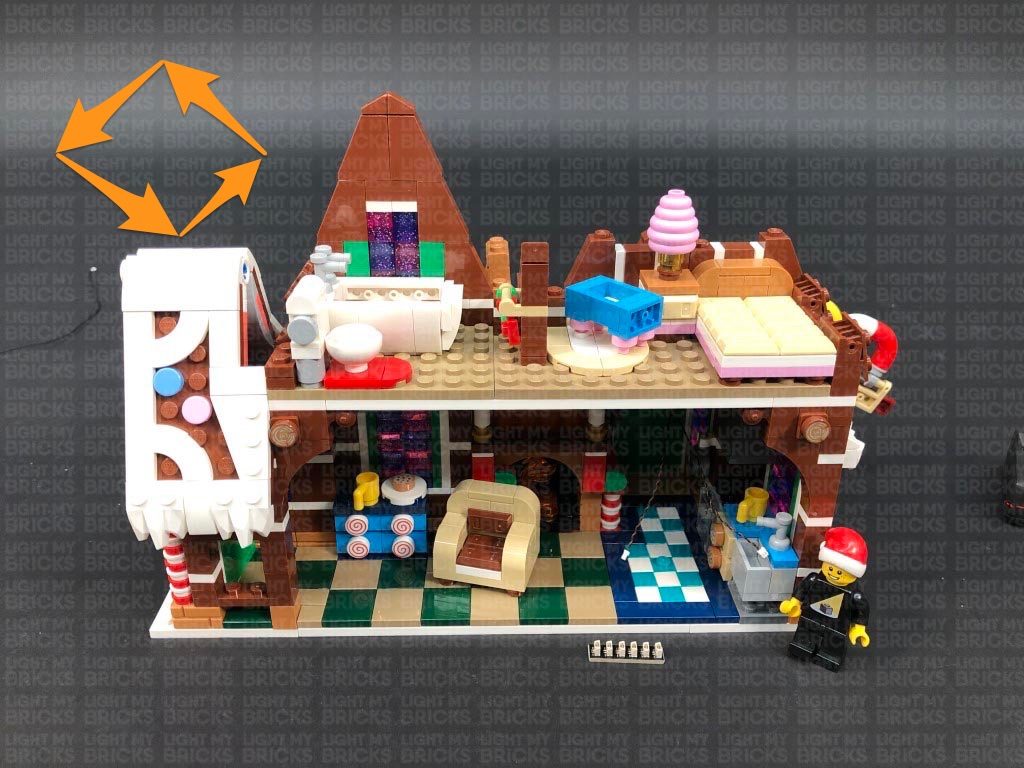
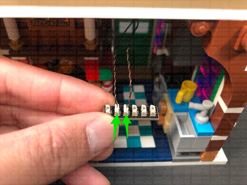
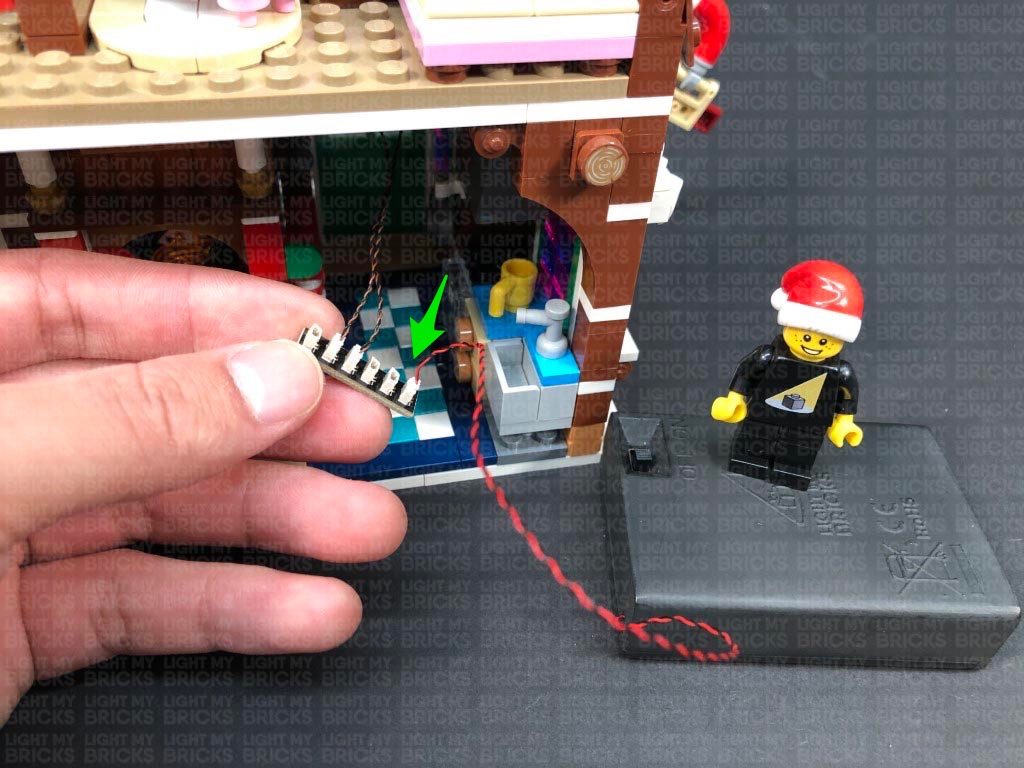
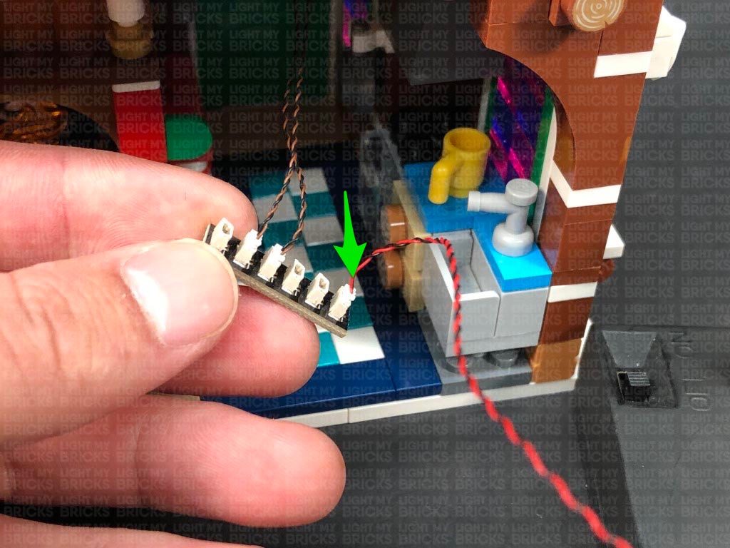
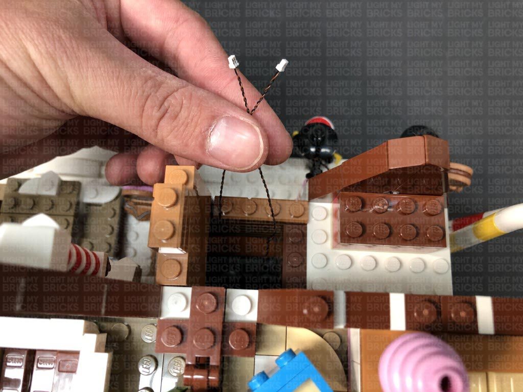
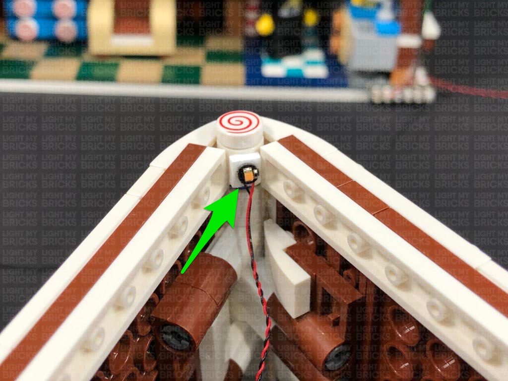
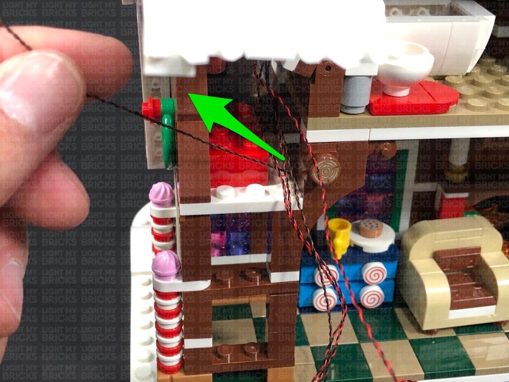
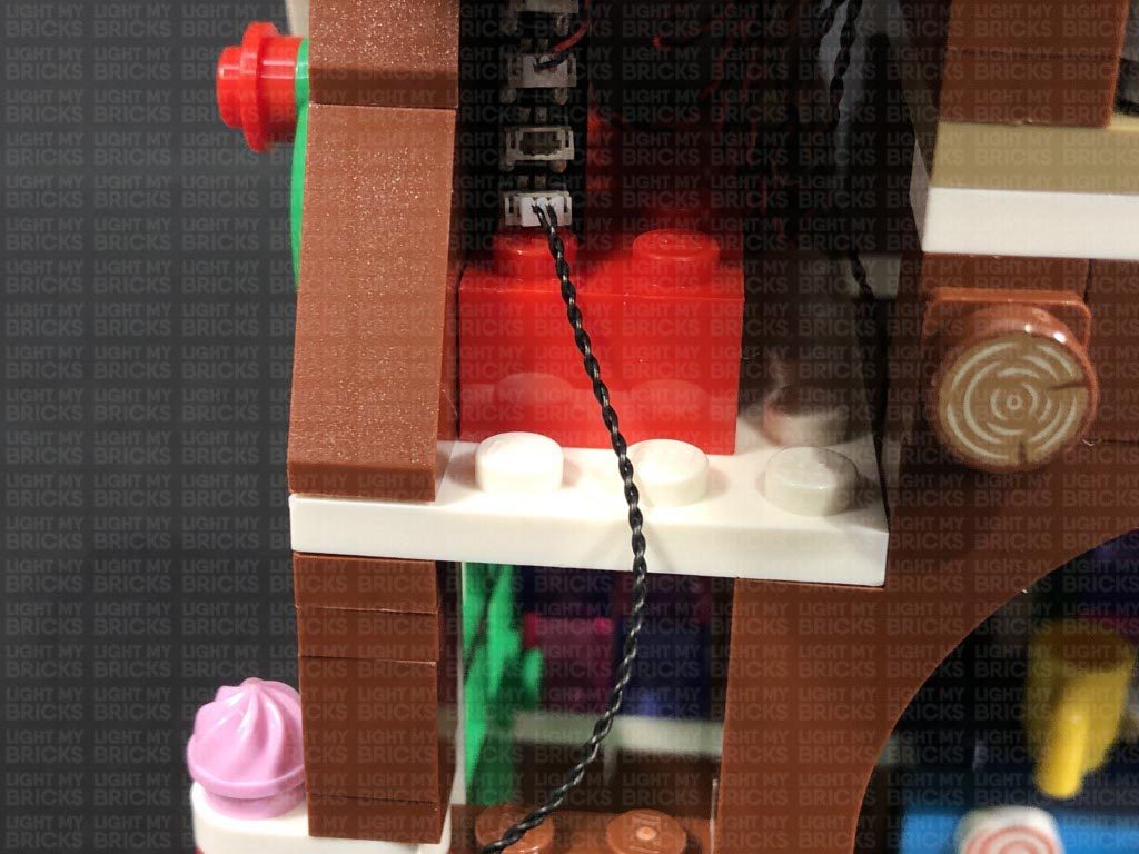
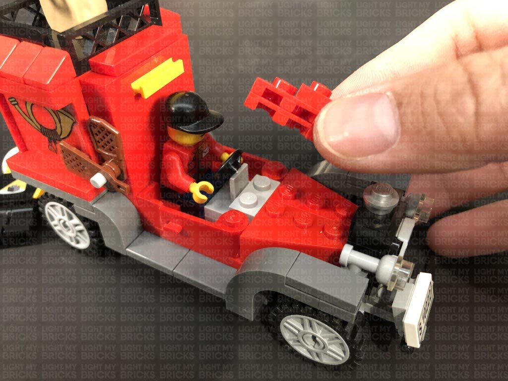
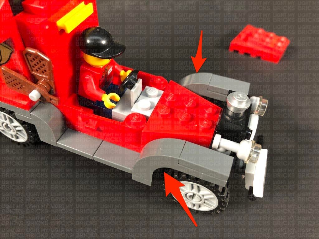
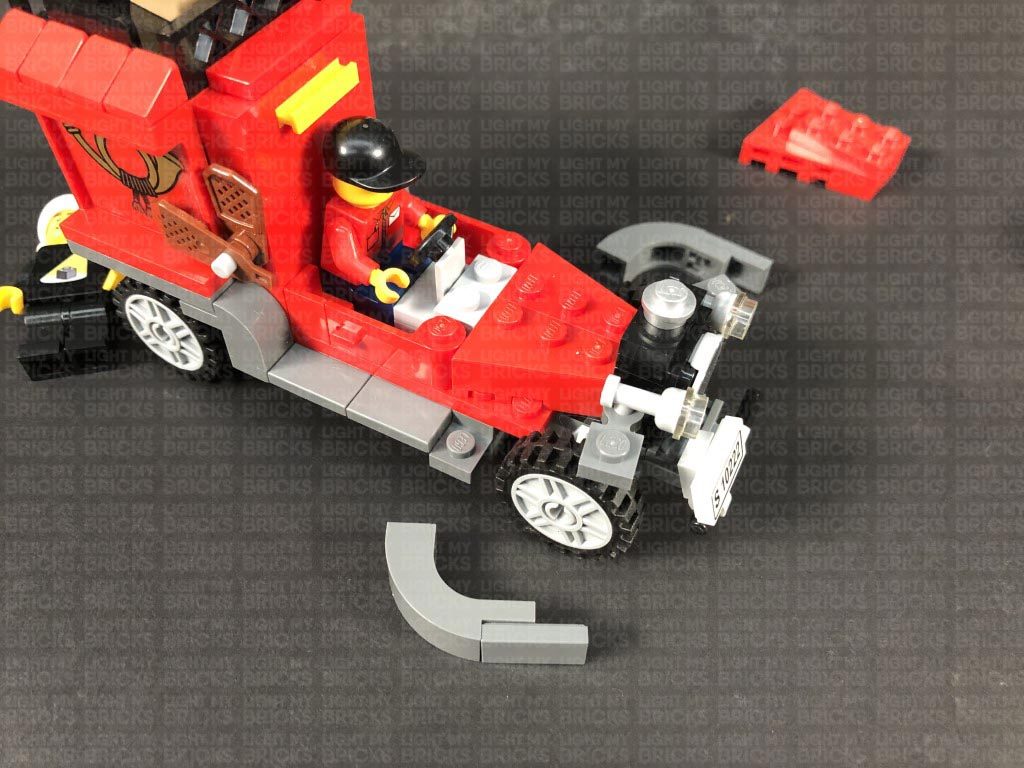
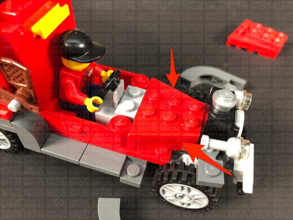
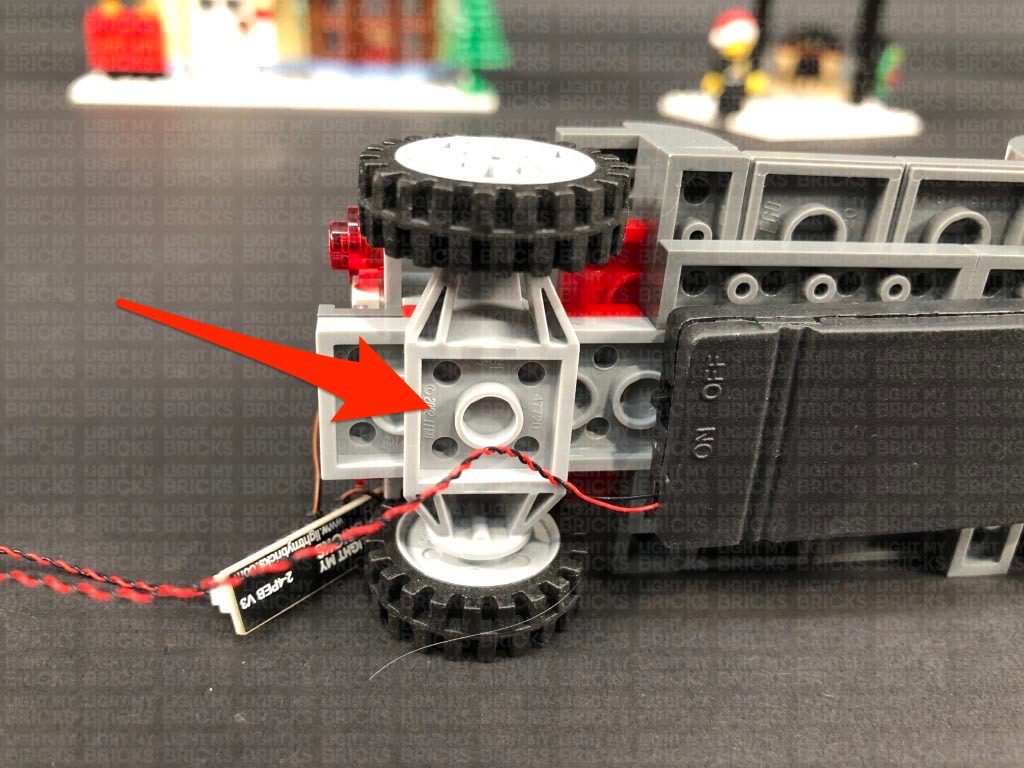
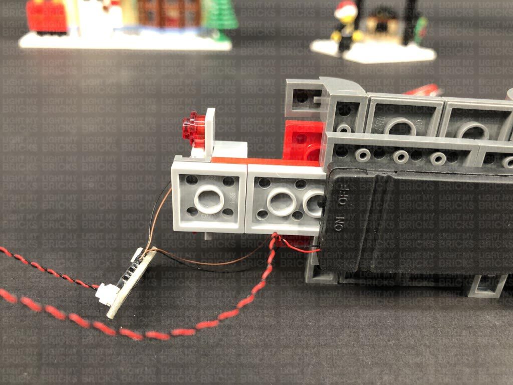
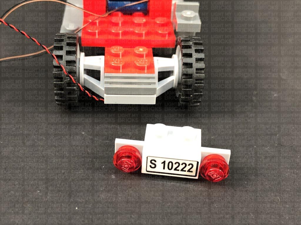
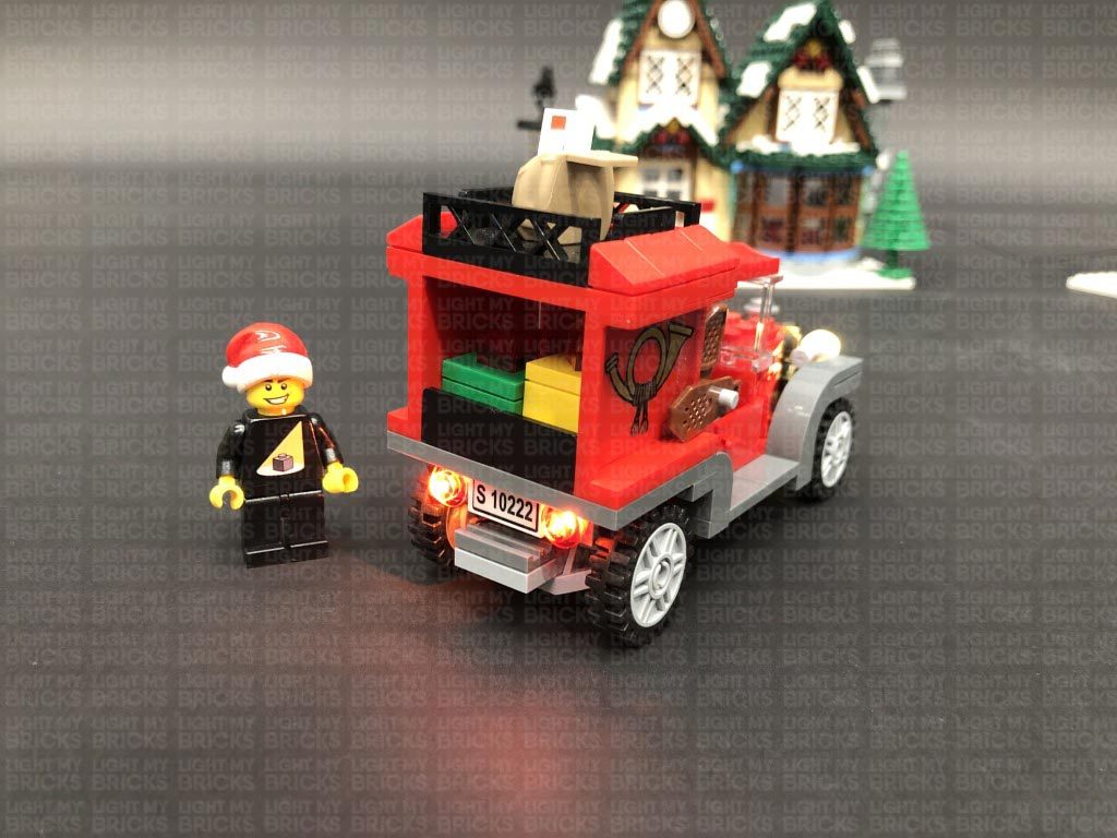
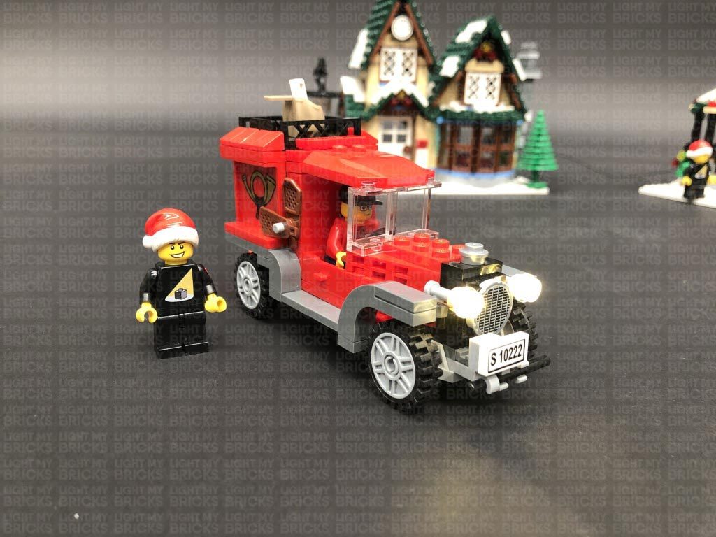
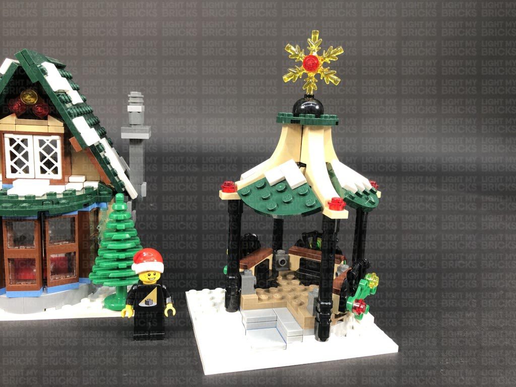
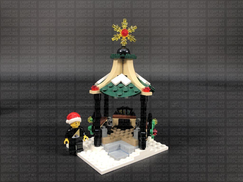
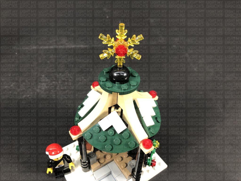
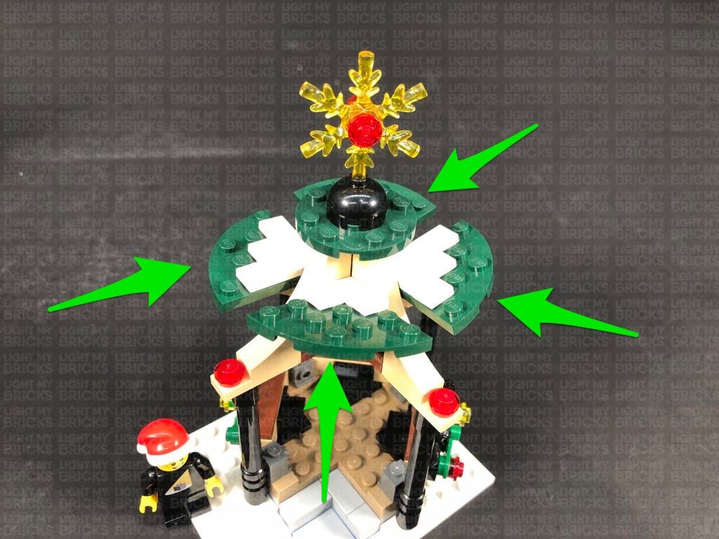
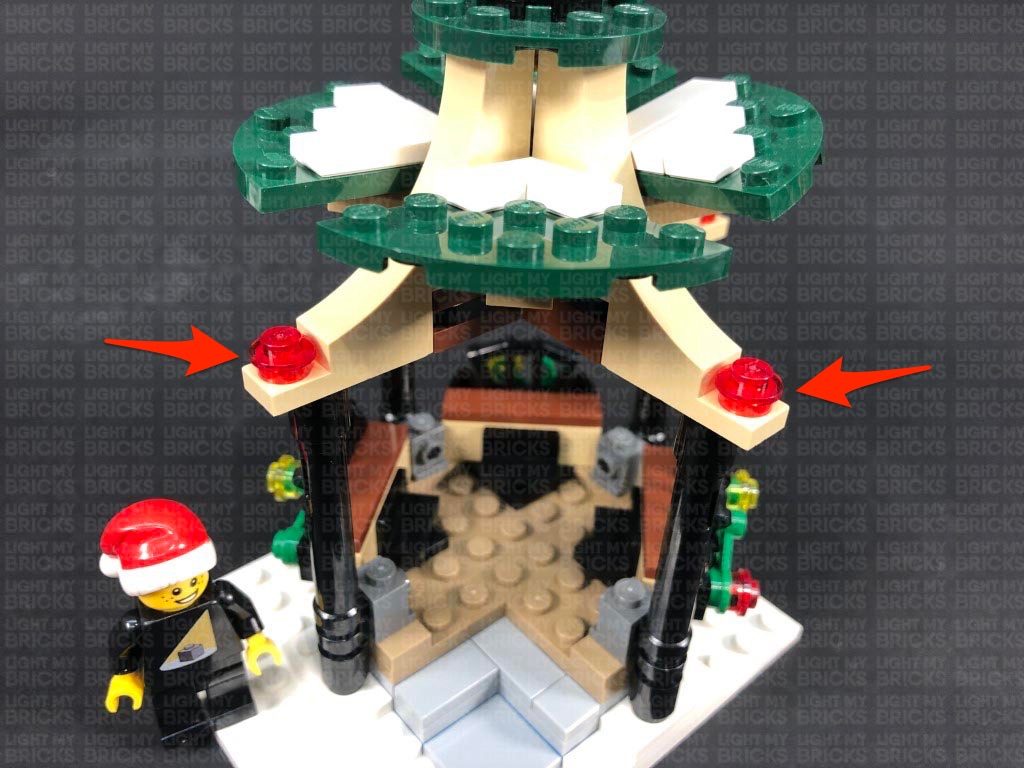
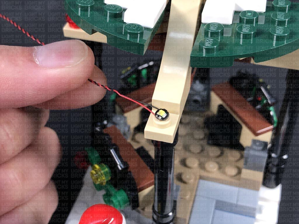
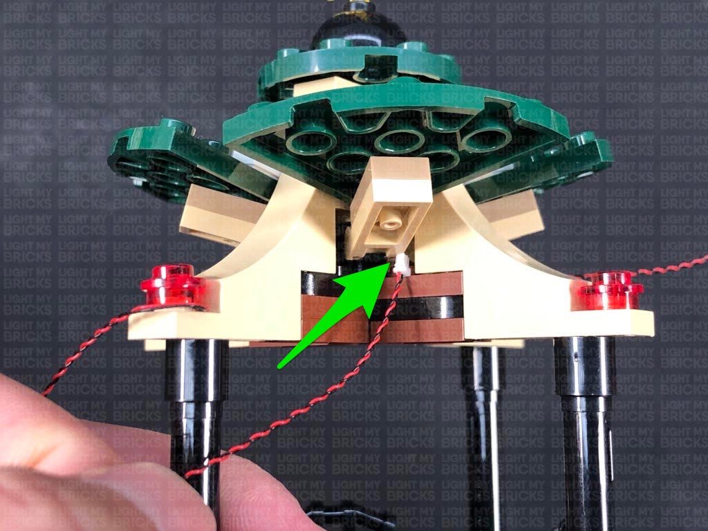
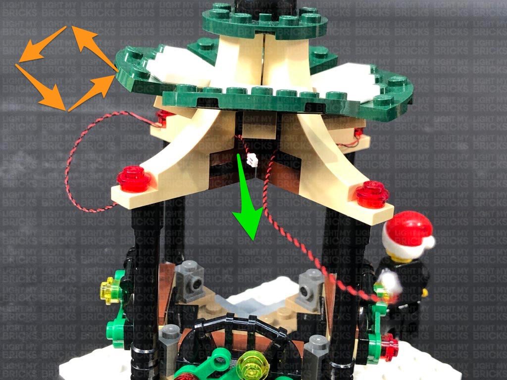
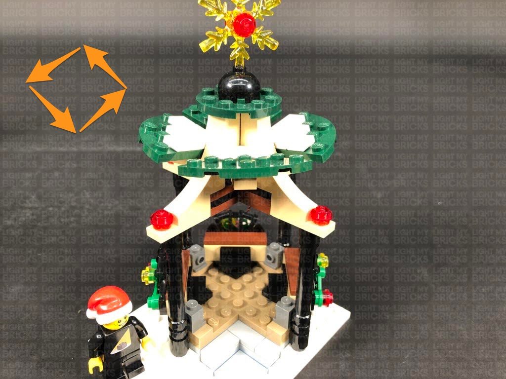
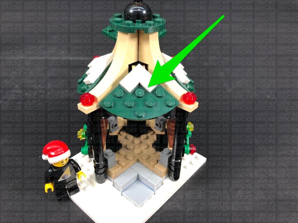
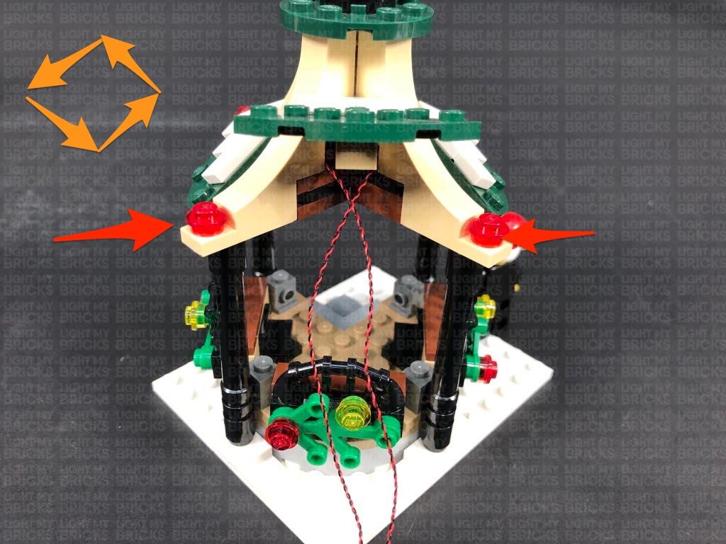
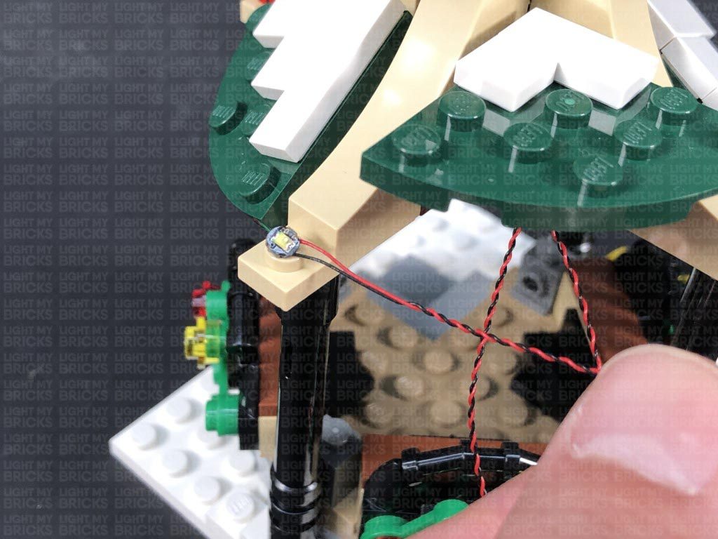
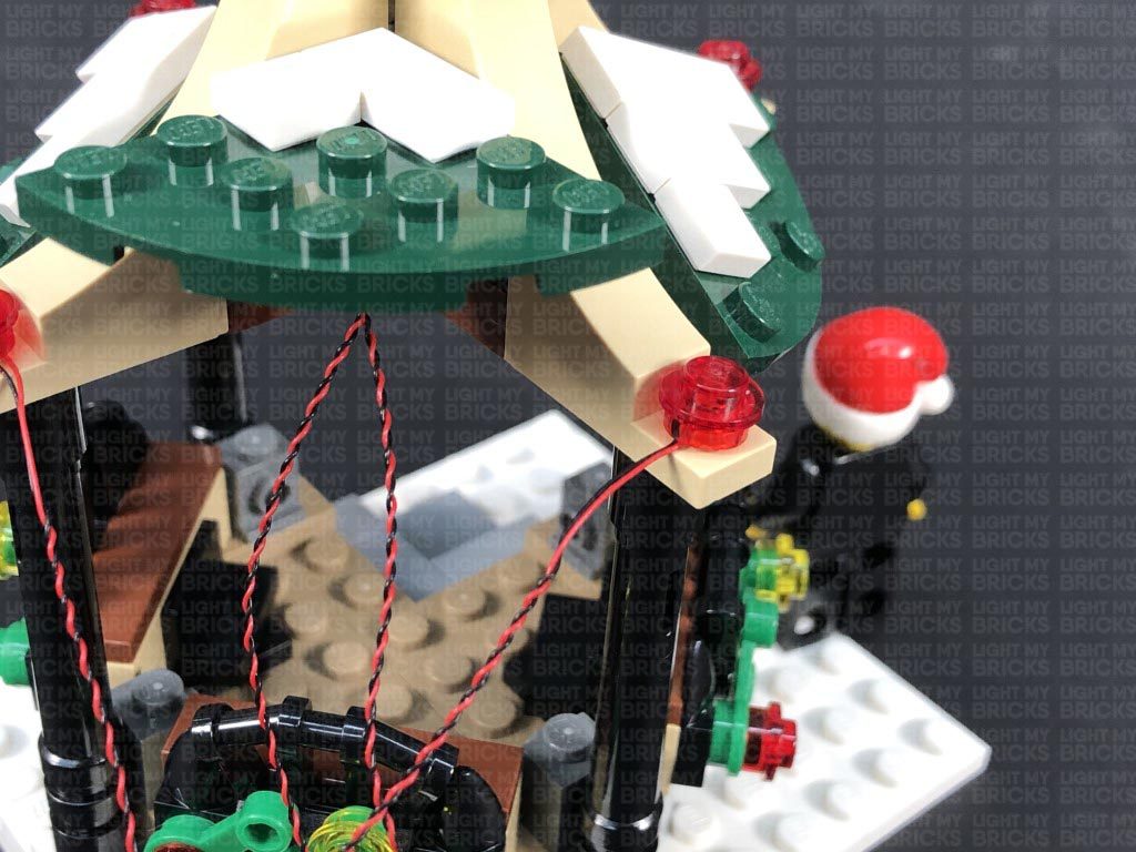
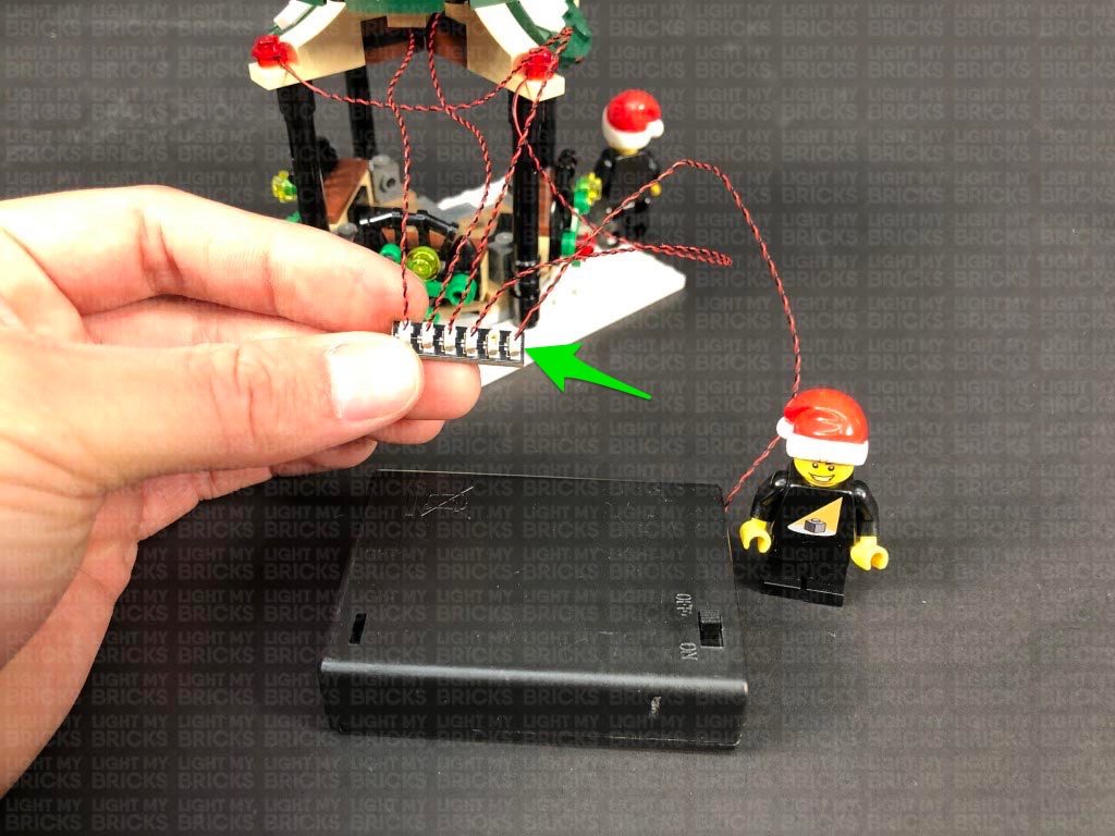
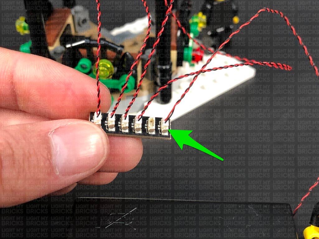
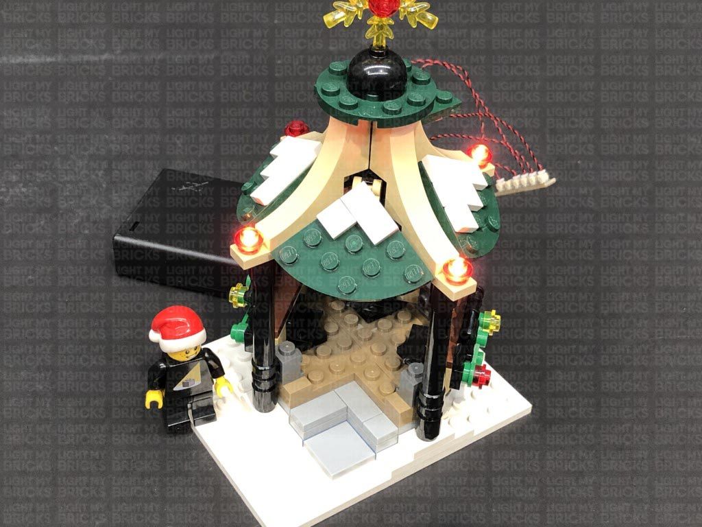
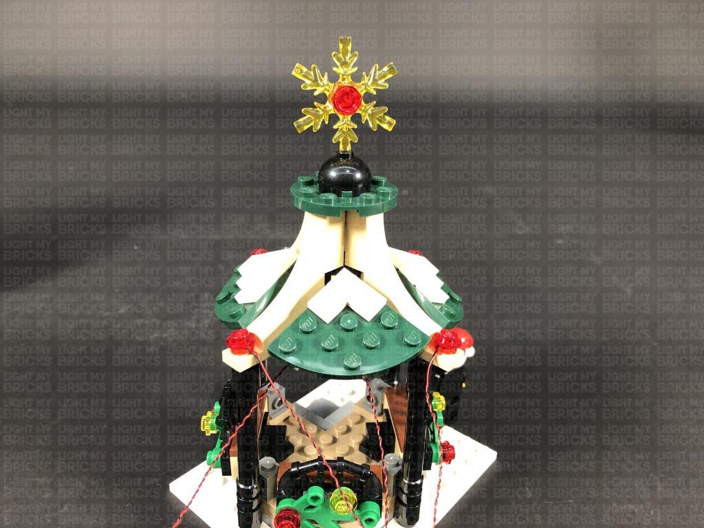
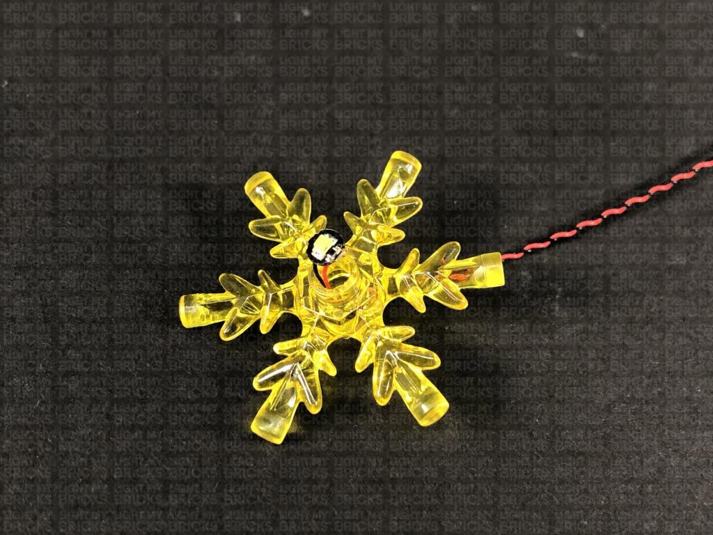
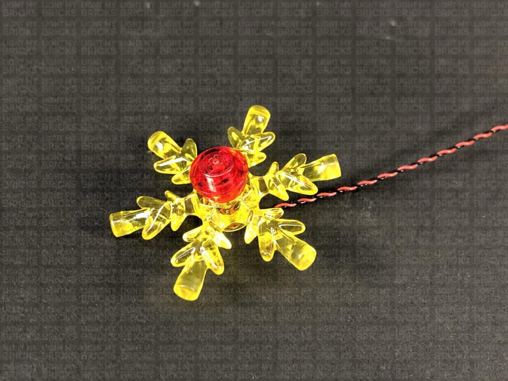
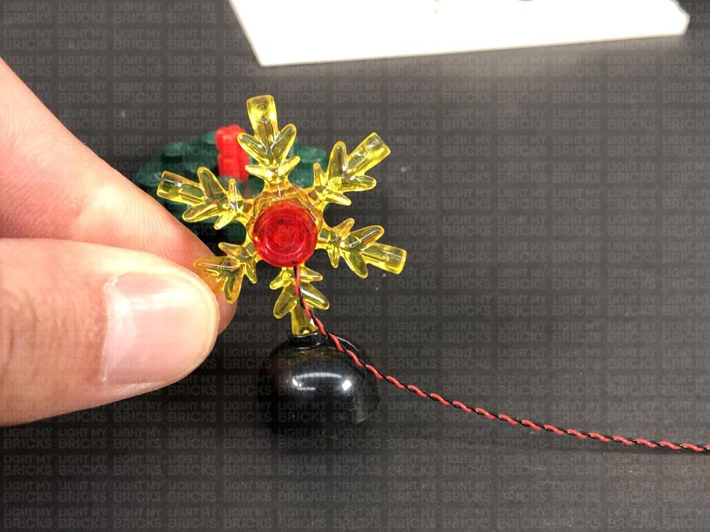
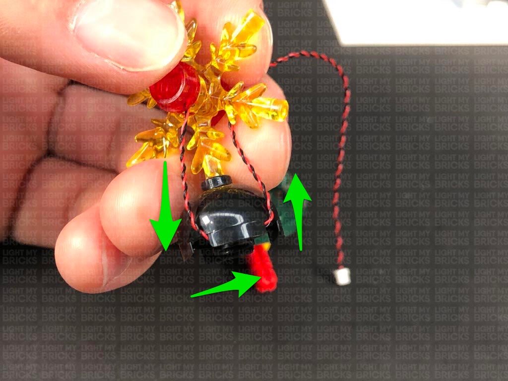
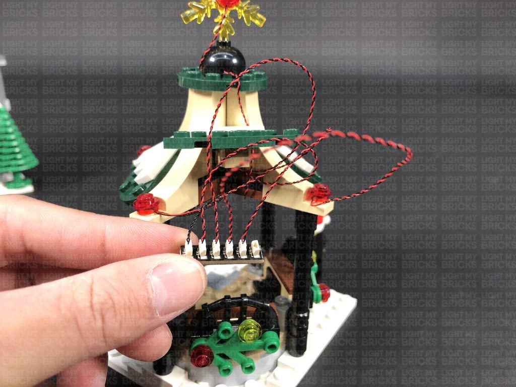
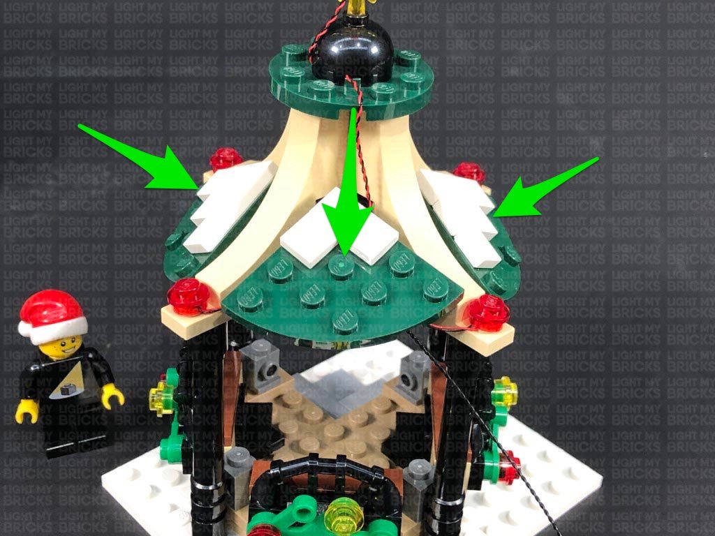
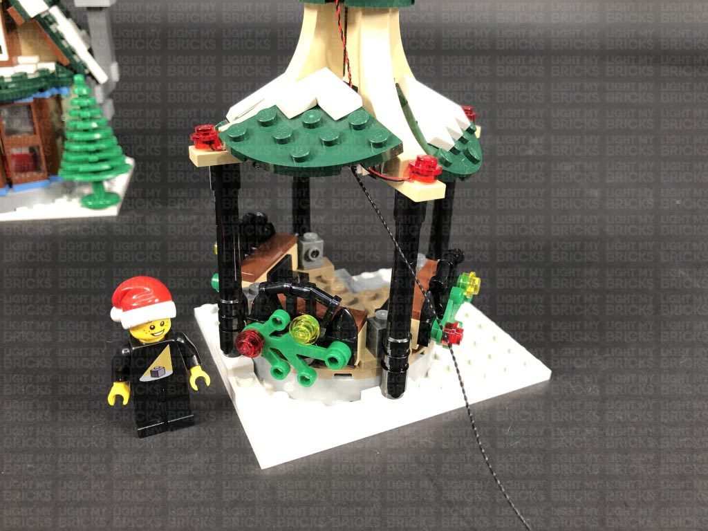
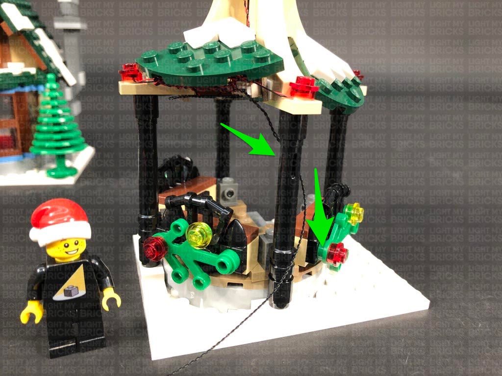
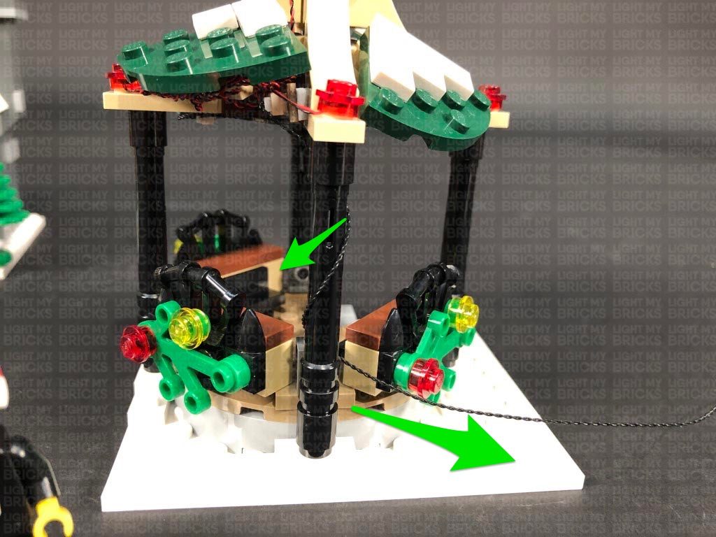
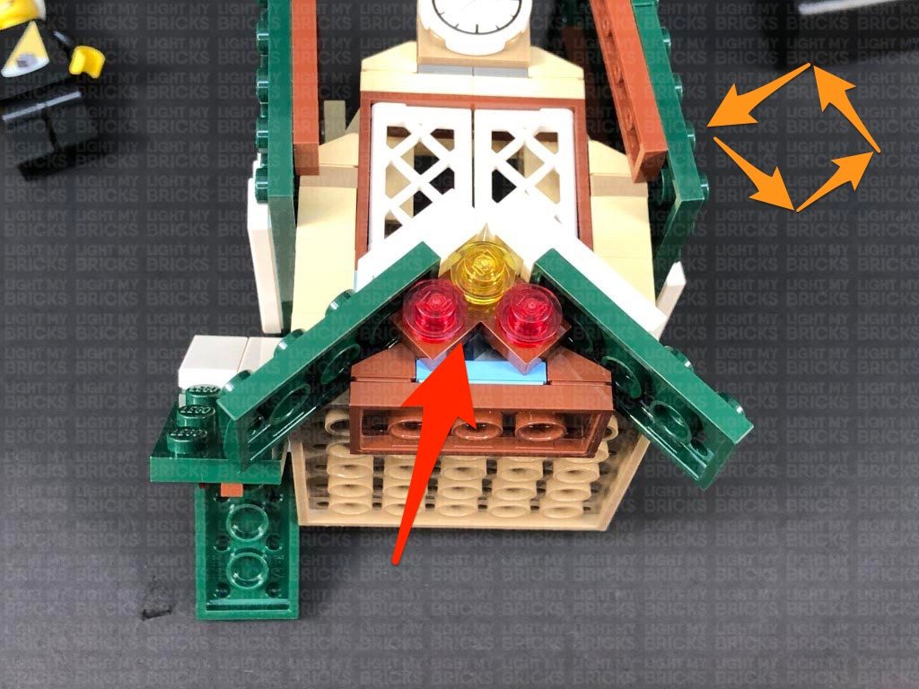
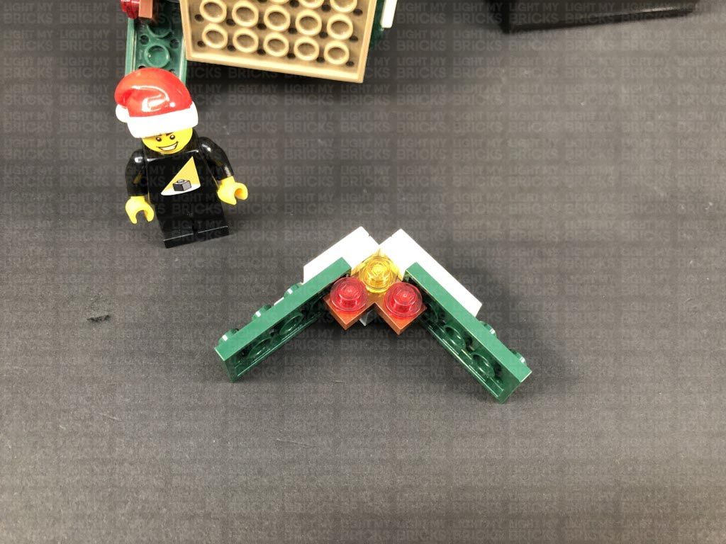
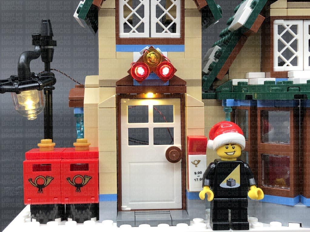
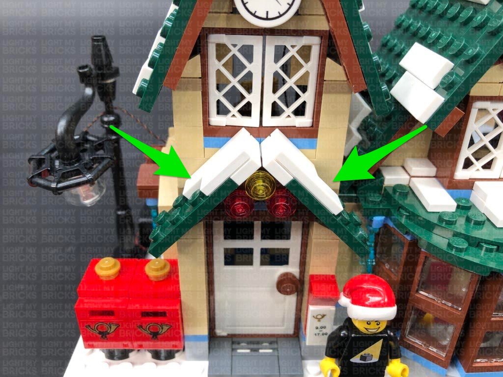
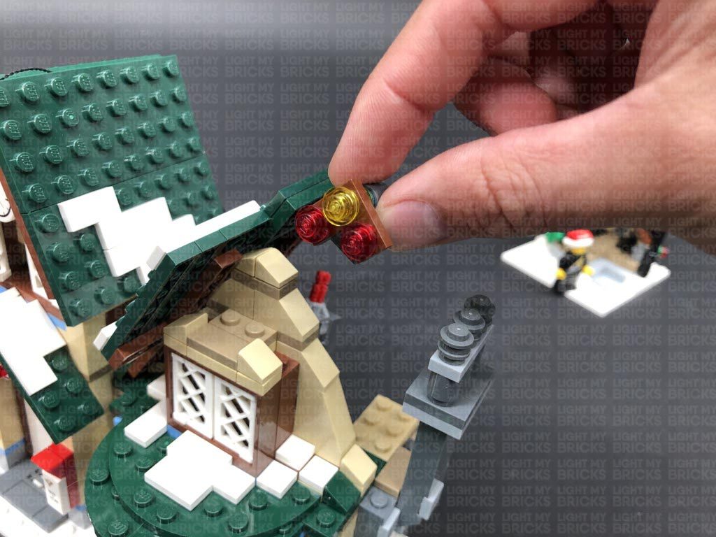
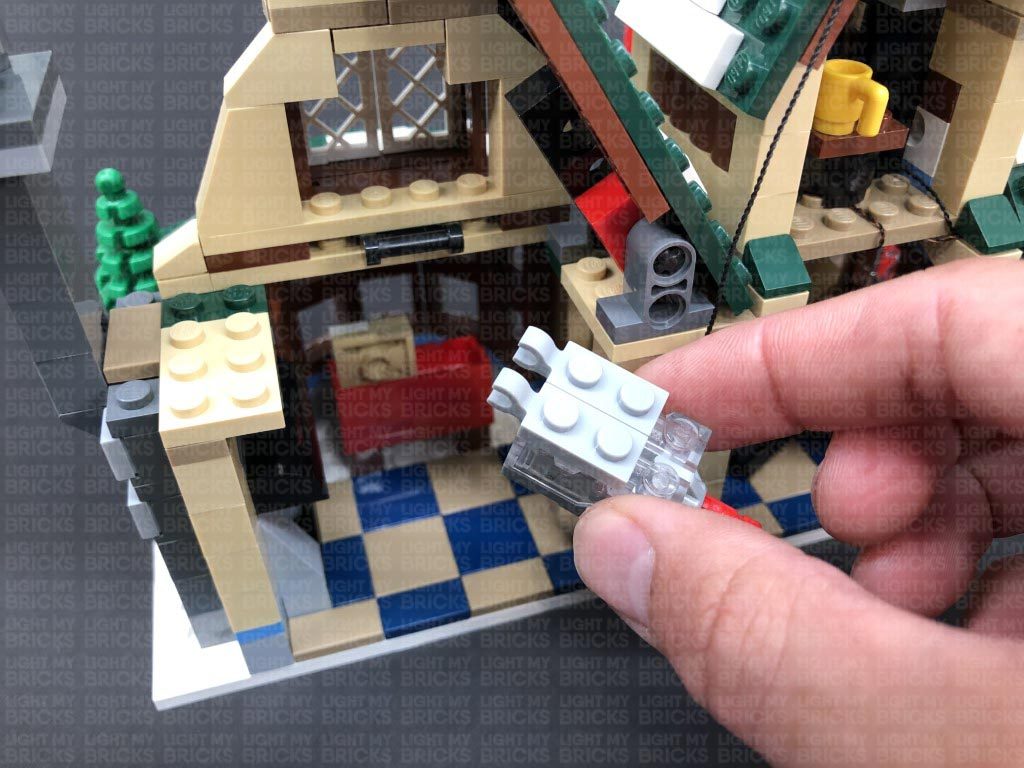
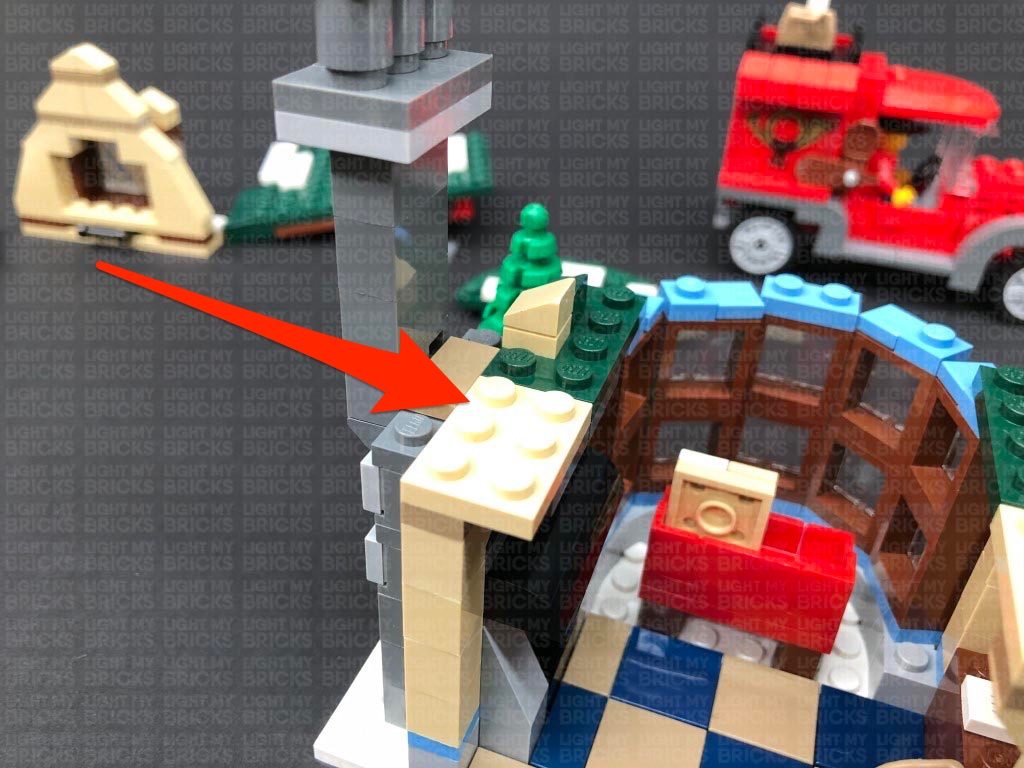
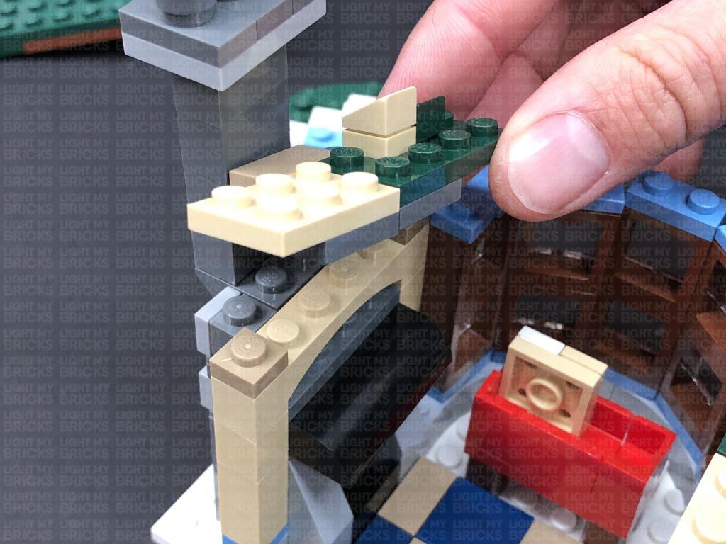
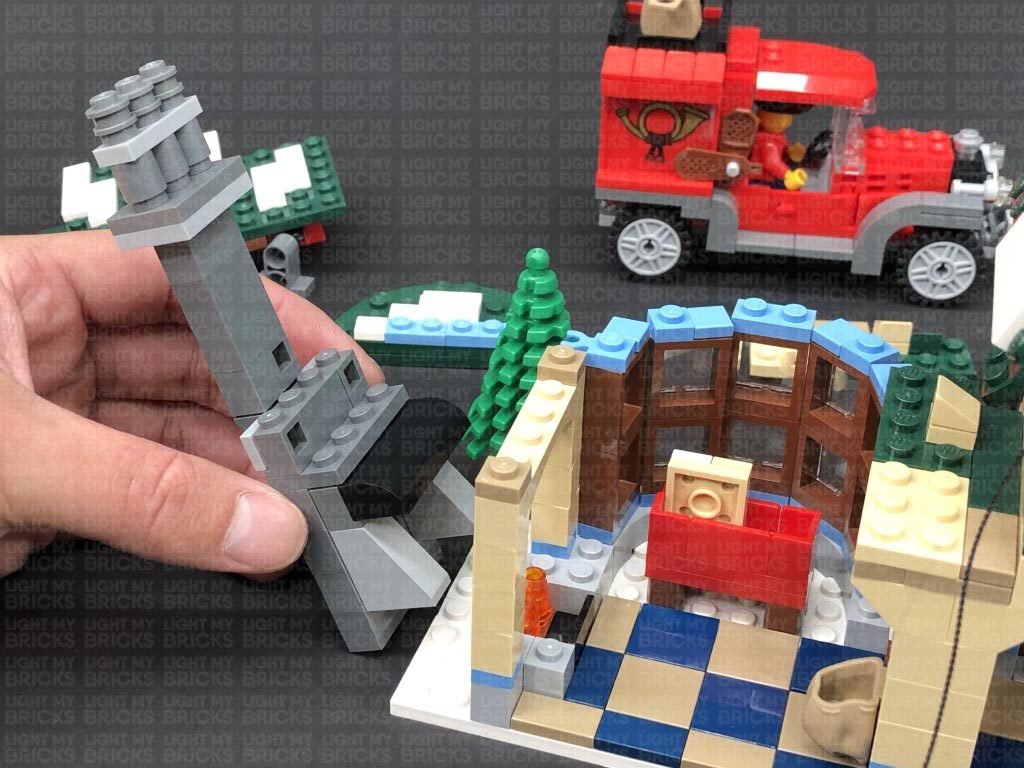
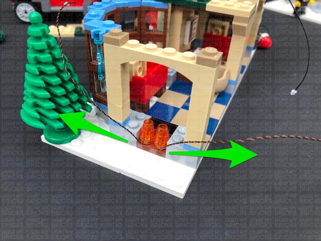
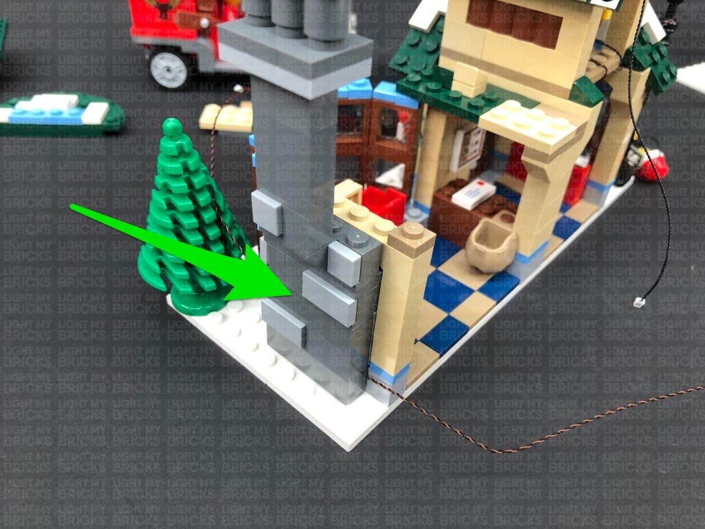
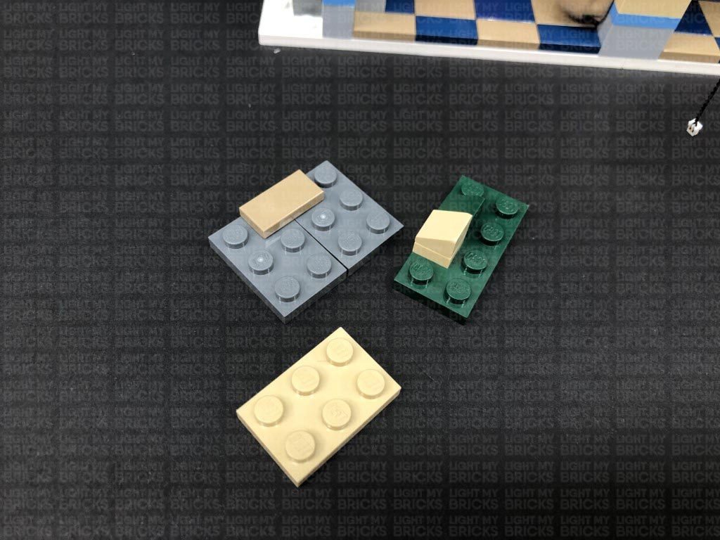
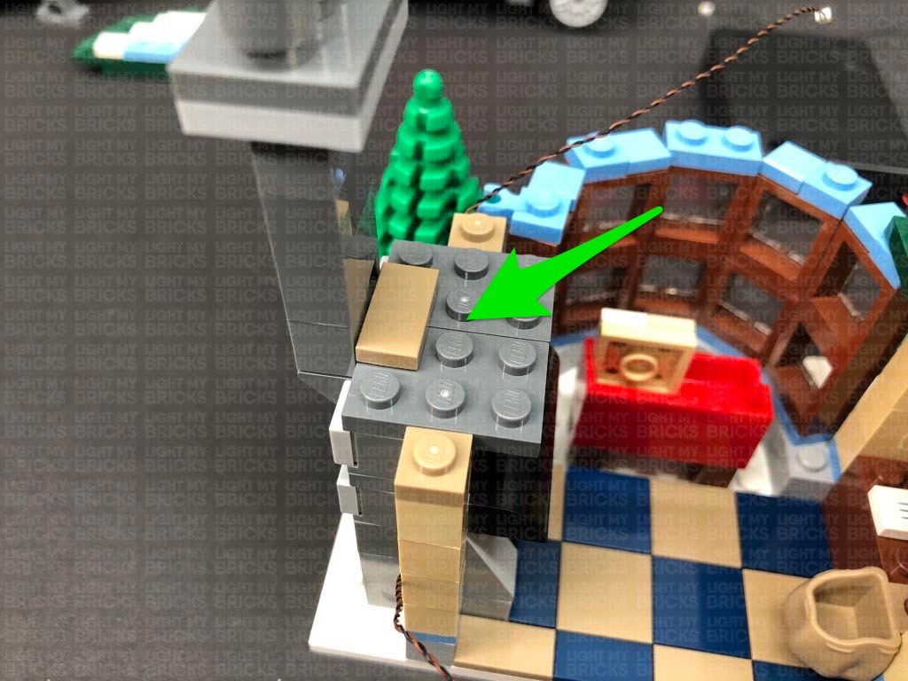
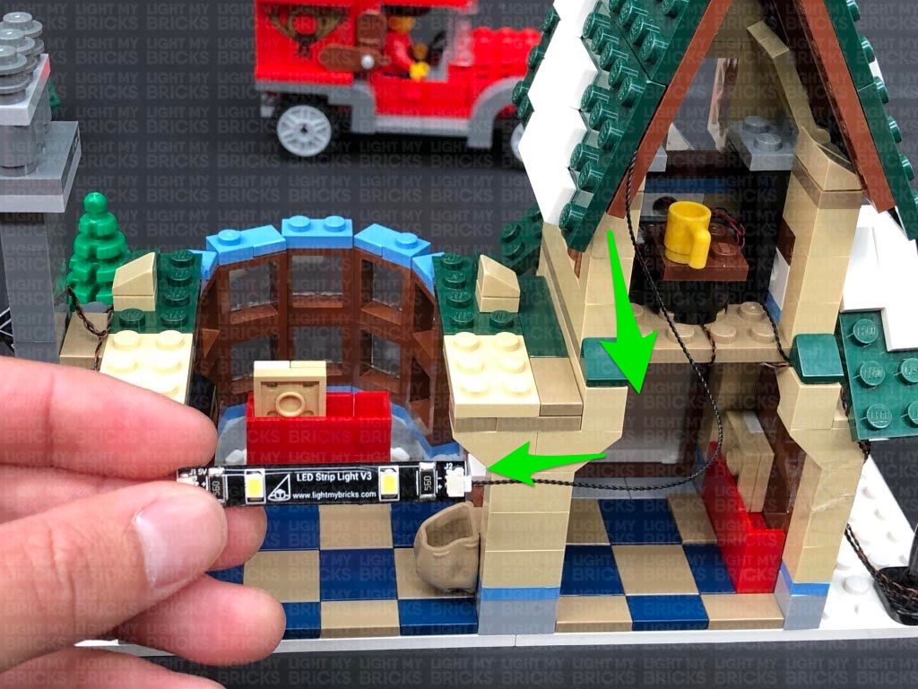
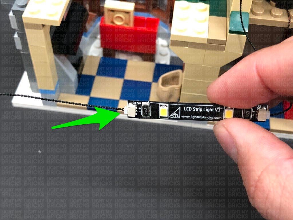
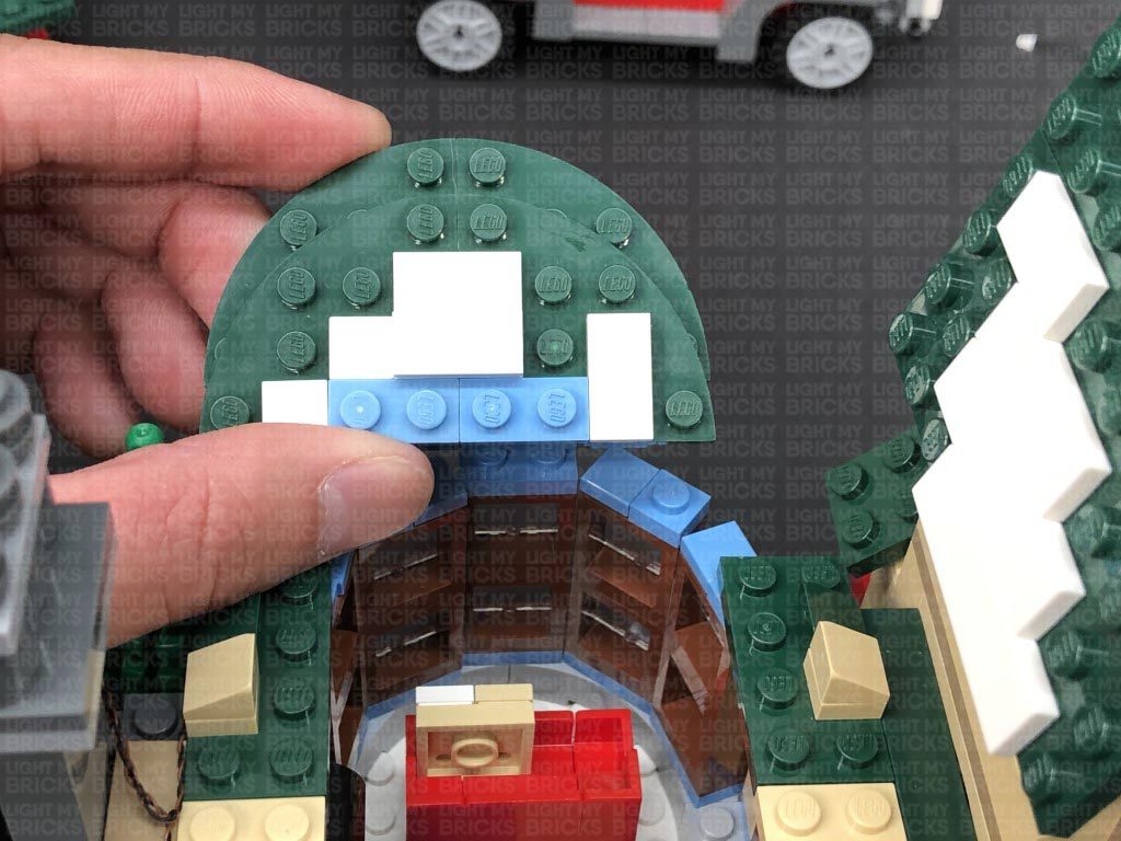
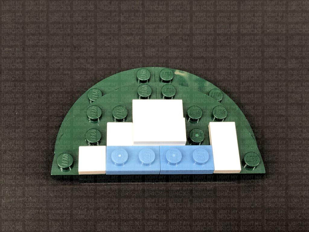
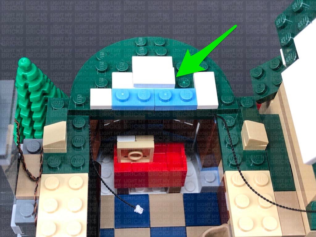
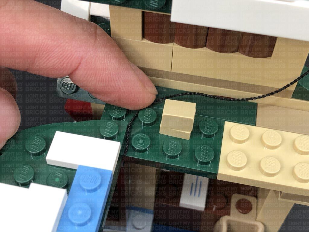
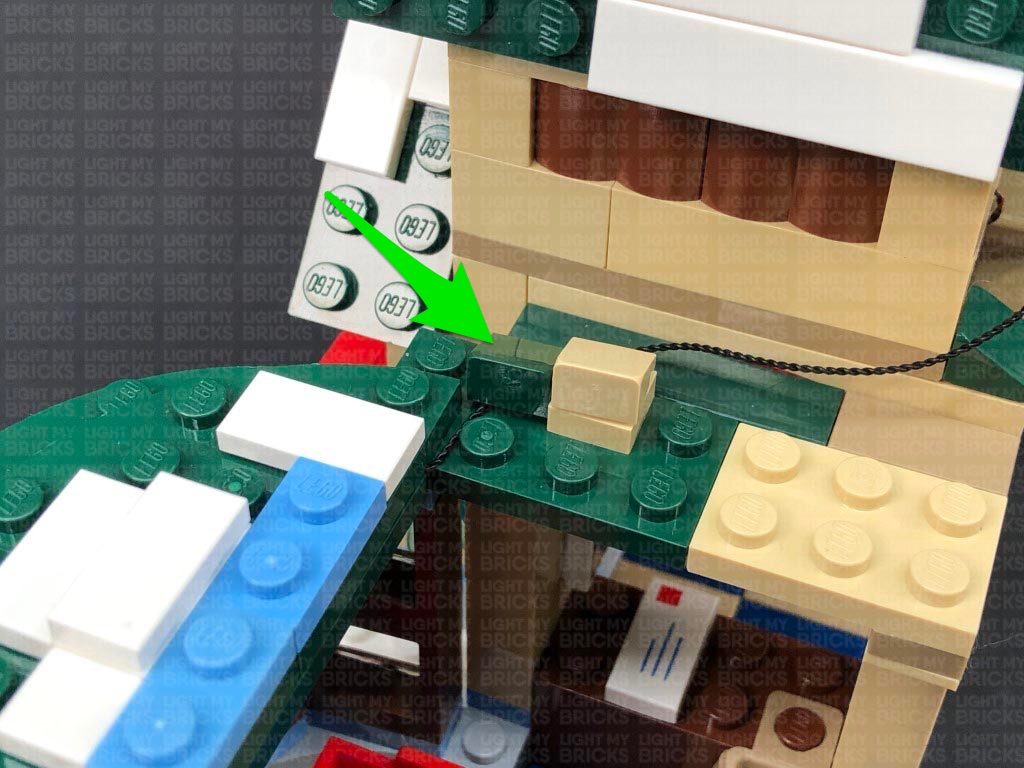
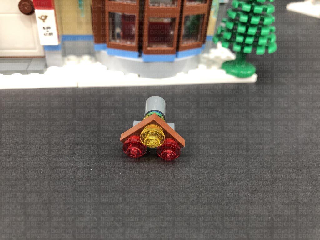
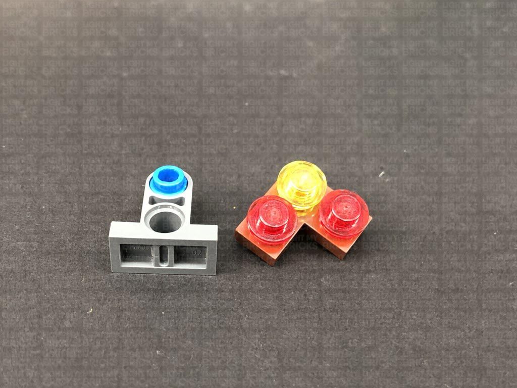
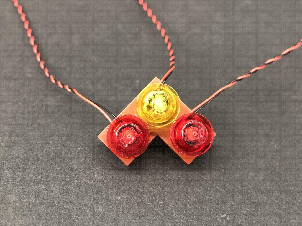
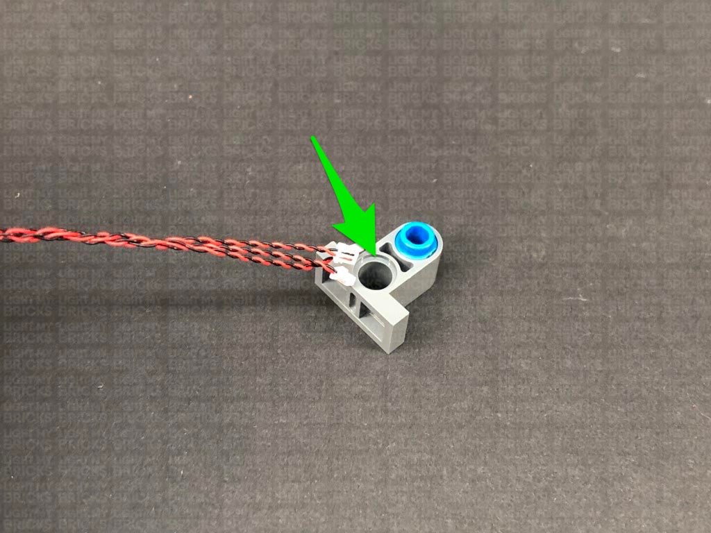
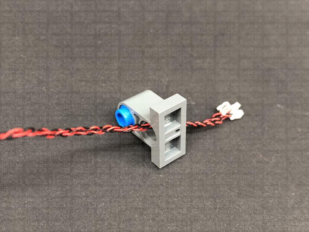
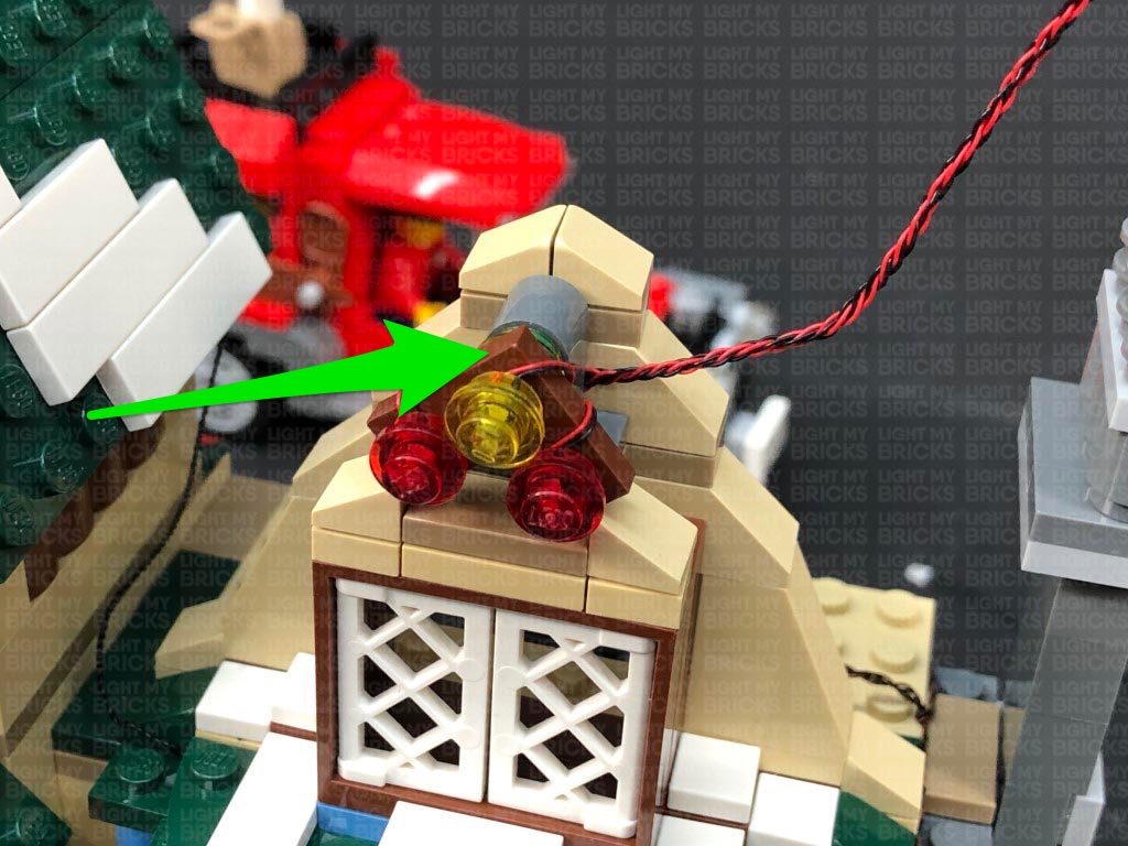
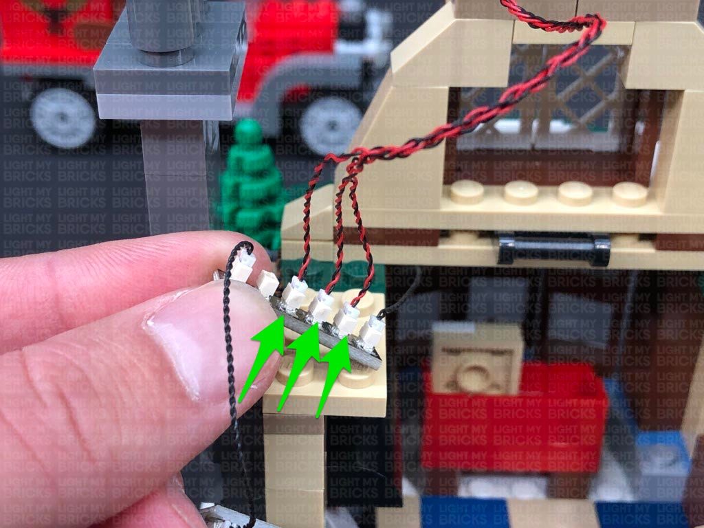
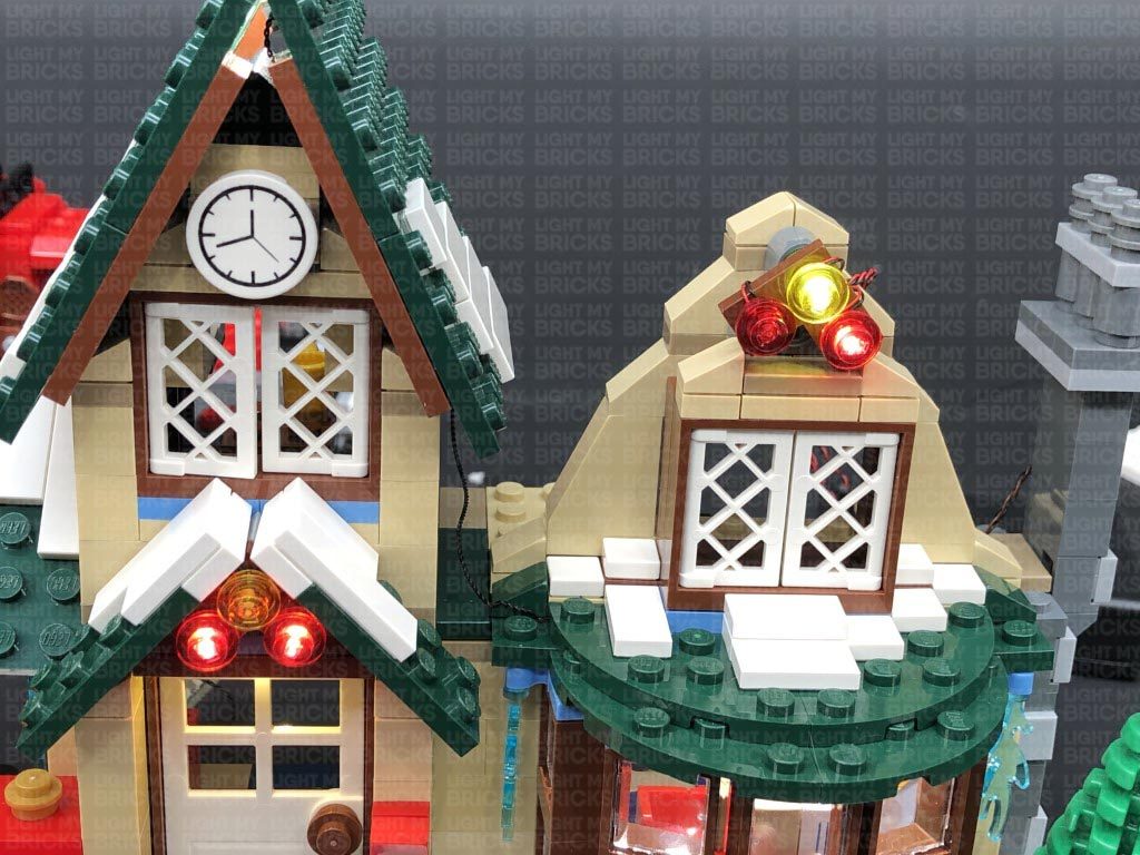
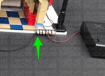
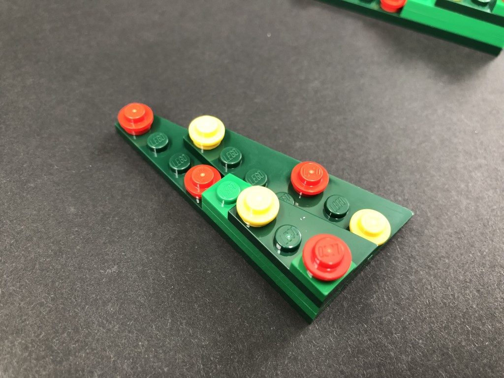
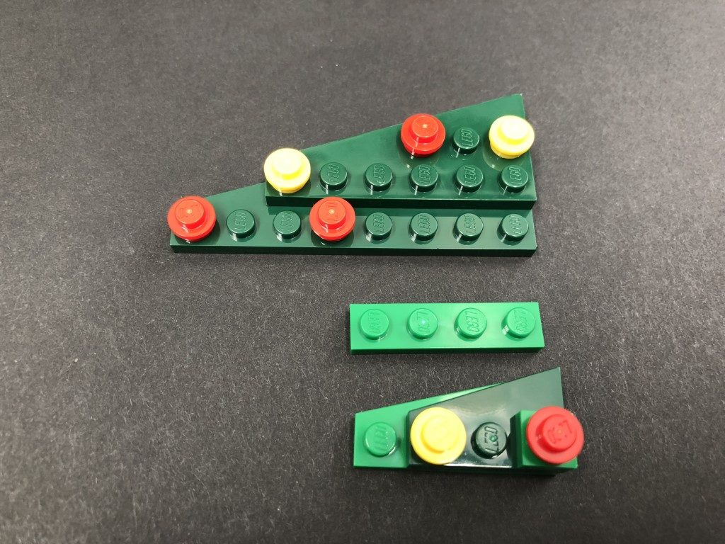
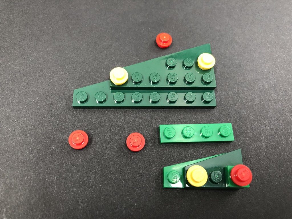
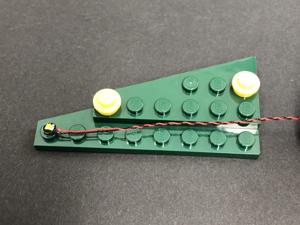
1.) We will first install lights to the Ice rink. Disconnect the following sections surrounding the snow pile on the right side as shown below: Take a Blue 30cm Bit Light and bend the LED up at approximately 1cm from the end. With the LED facing the Ice rink, place the cable in between the white studs, then secure it in place by reconnecting the white angled brick as shown below: 2.) Reconnect the surrounding pieces, then turn this section around to the side and bring the cable towards the back. Disconnect the light post section and lay the cable in between studs underneath it. Reconnect the light post to secure the cable in place. Turn the set around to the back and connect the Blue Bit Light into a large port on a Micro 4-Port Expansion Board. Take the AA Battery Pack and insert 3x NEW AA Batteries to it. Connect the Battery Pack cable to the other large port on the Micro Expansion Board, then turn ON the power to test the blue light is working OK. Note: If you experience any issues with the lights not working and suspect an issue with a component, please try a different port on the expansion board to verify where the fault lies (with the light or expansion board). To correct any issues with expansion board ports, please view the section addressing expansion board issues on our online troubleshooting guide. 3.) We will now install flashing lights to the lights hanging over the ice rink. Disconnect the two light sections on the right, then disassemble them as shown below. Take a Flashing White 30cm Micro Bit Light and place the LED inside one of the white plates with clips. Secure the Bit Light in place by reconnecting the trans green round plate over the top. Warning – Do not forcefully connect the LEGO plate back inside the white plate. Because of the size of the micro LED, the plate will not fully connect inside. Forcing the plate to fully reconnect may cause the wire to break. Repeat this step to install another Flashing White 30cm Micro Bit Light to the other light section. 4.) Reconnect the red light to the overhead string, ensuring the trans red plate is facing down. Bring the cable across and over the flag, then reconnect the green light ensuring the cable from the red light is laid inside the white clip of the green light. Bring both cables over the flag, then disconnect the pole and wind both cables around it three times. Secure the two cables underneath the white 2×2 plate underneath the pole as shown below. Ensure the two cables are laid in between studs underneath and towards the back of this section. Turn the set around to the back and connect both Micro Bit Light cables to the Micro Expansion Board (smaller ports). Turn the AA Battery Pack ON to test the flashing lights are working OK. 5.) We will now install the other two flashing lights above the rink. Disconnect the two light sections on the left side, then following the same process used in previous steps, install another 2x Flashing White 30cm Micro Bit Lights to these lights.
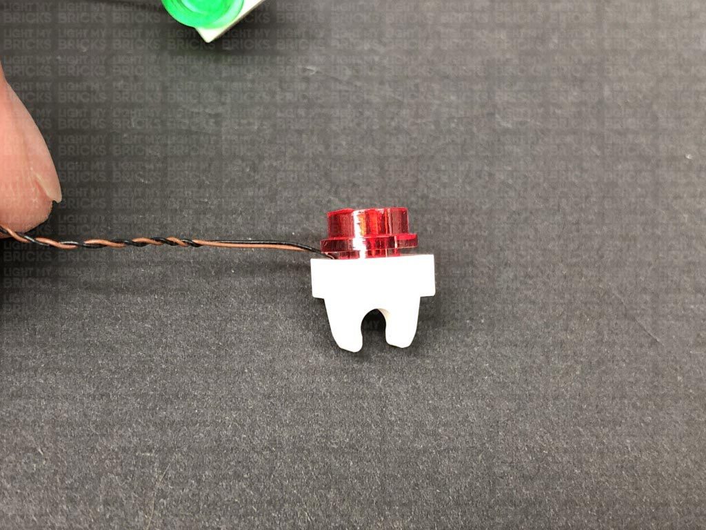
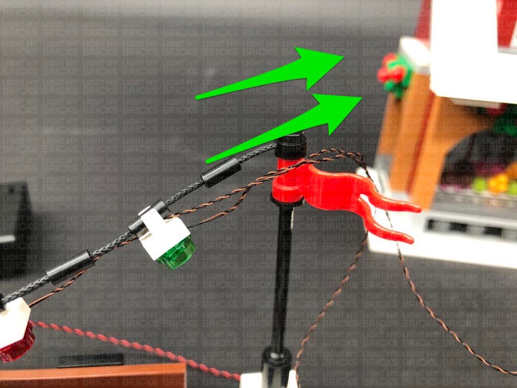
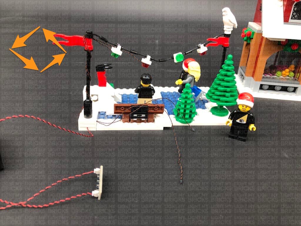
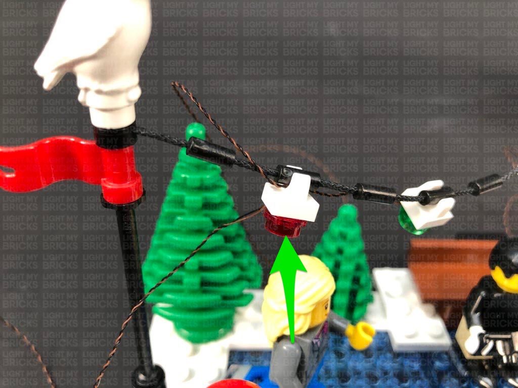
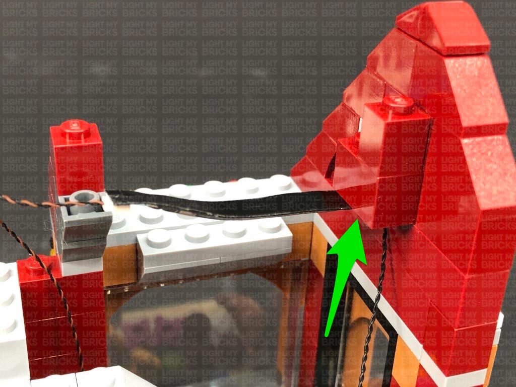
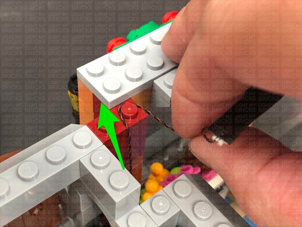
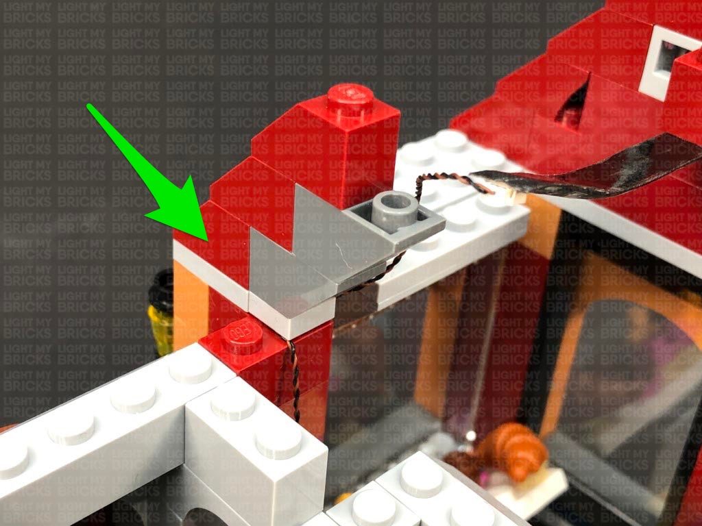
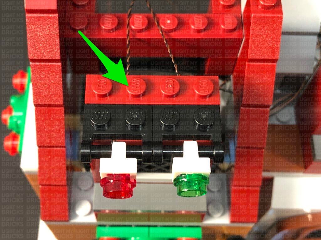
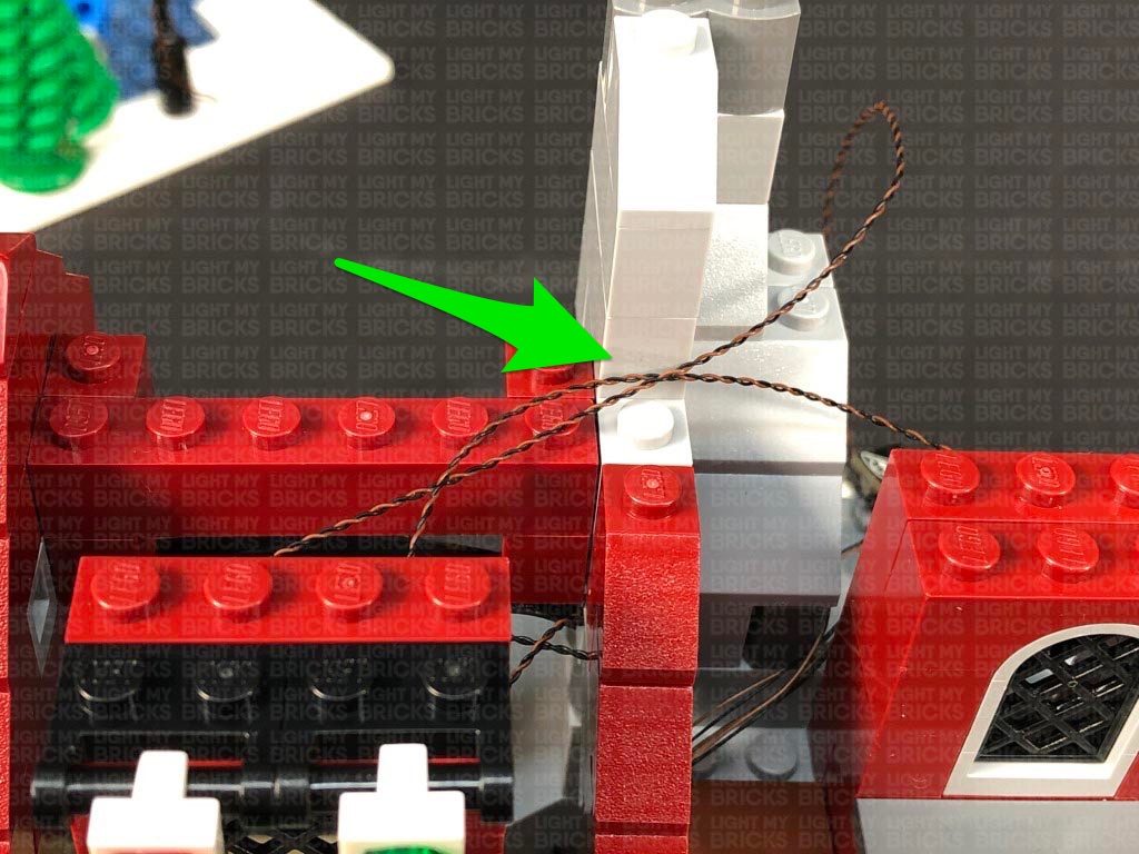
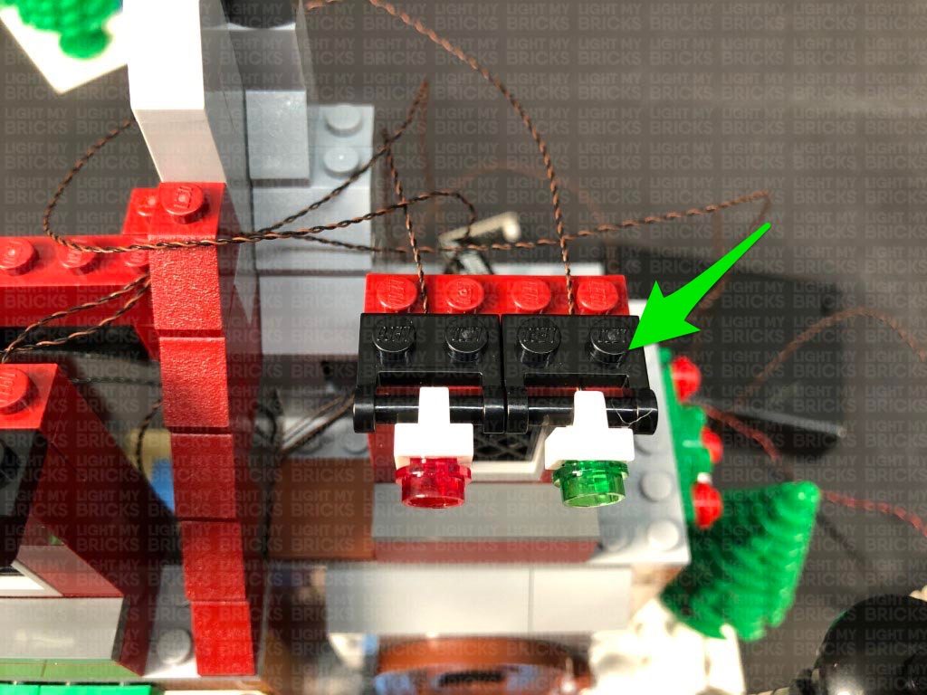
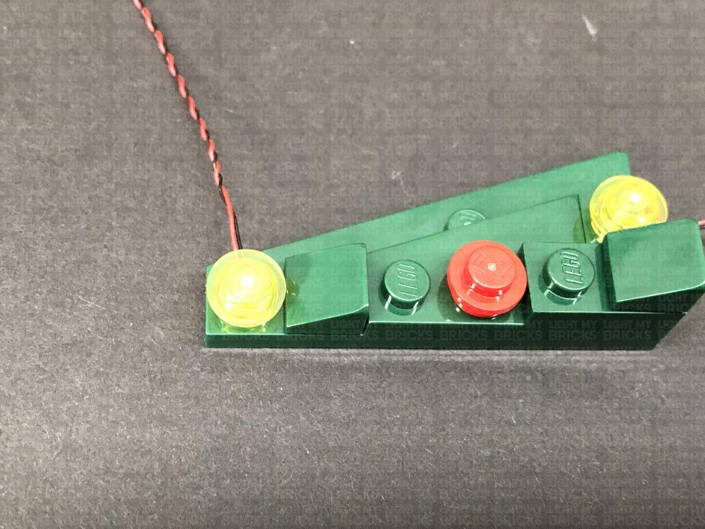
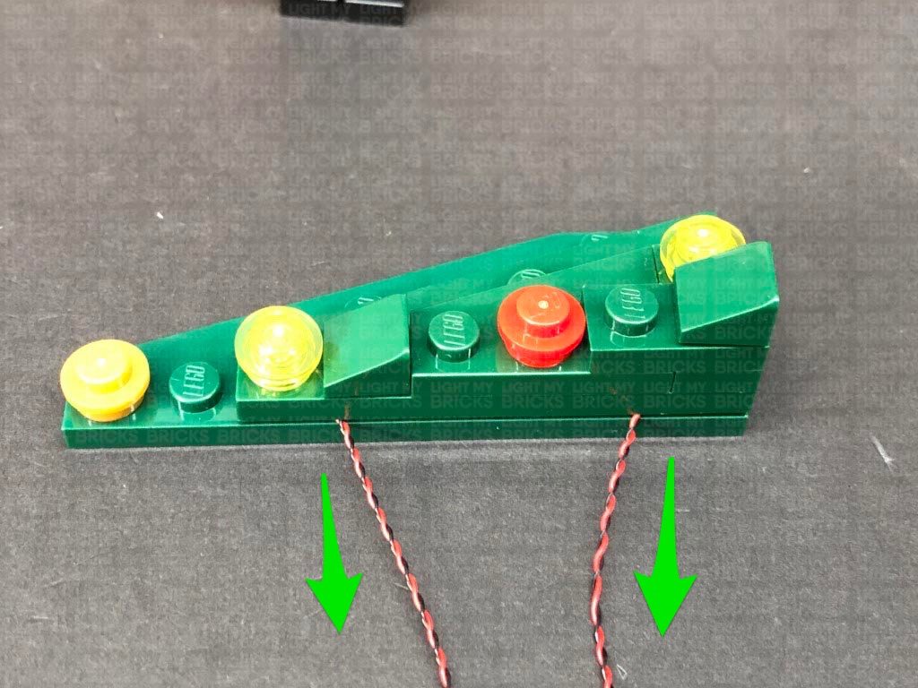
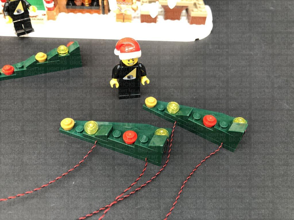
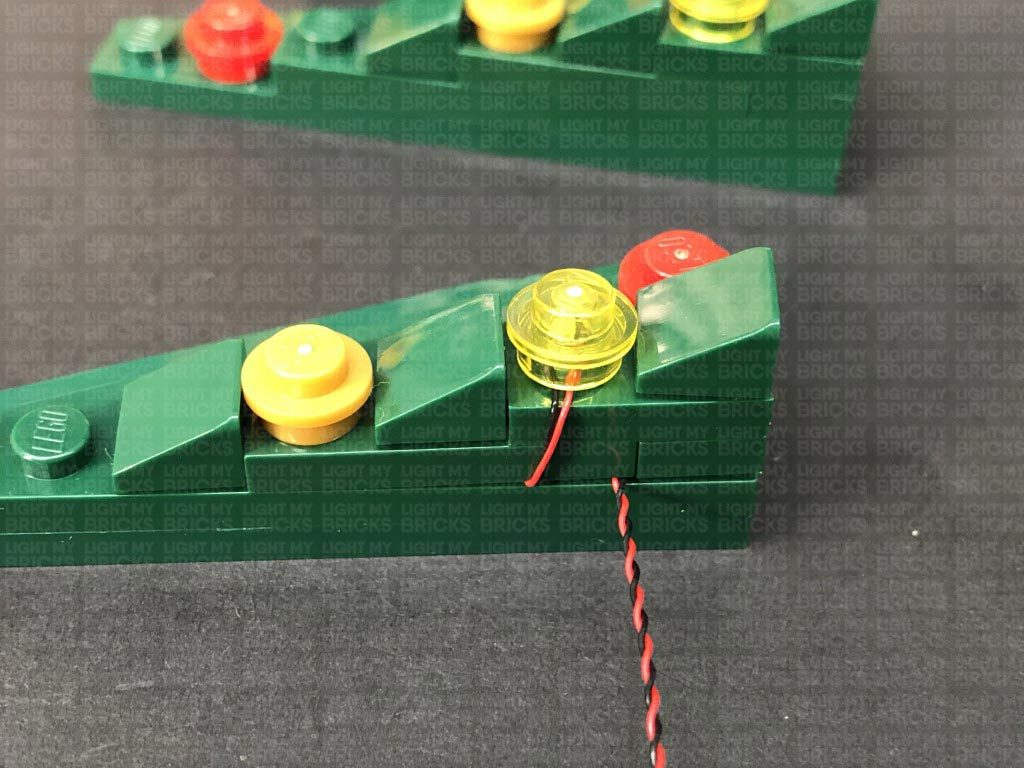
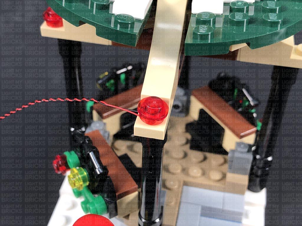
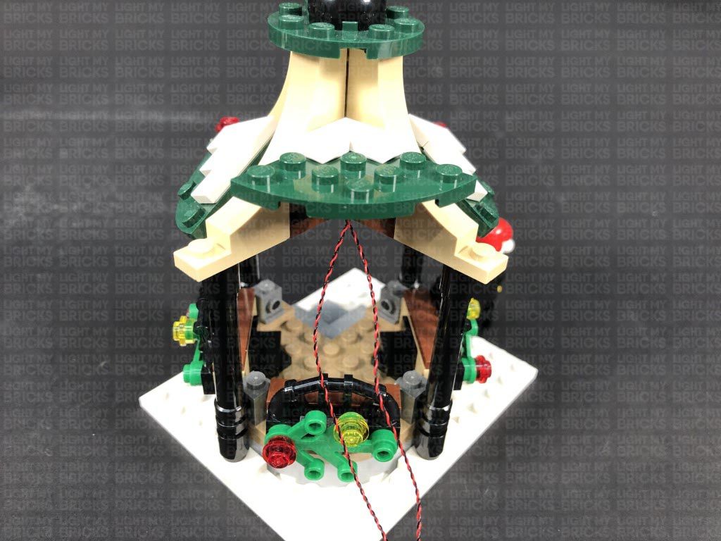
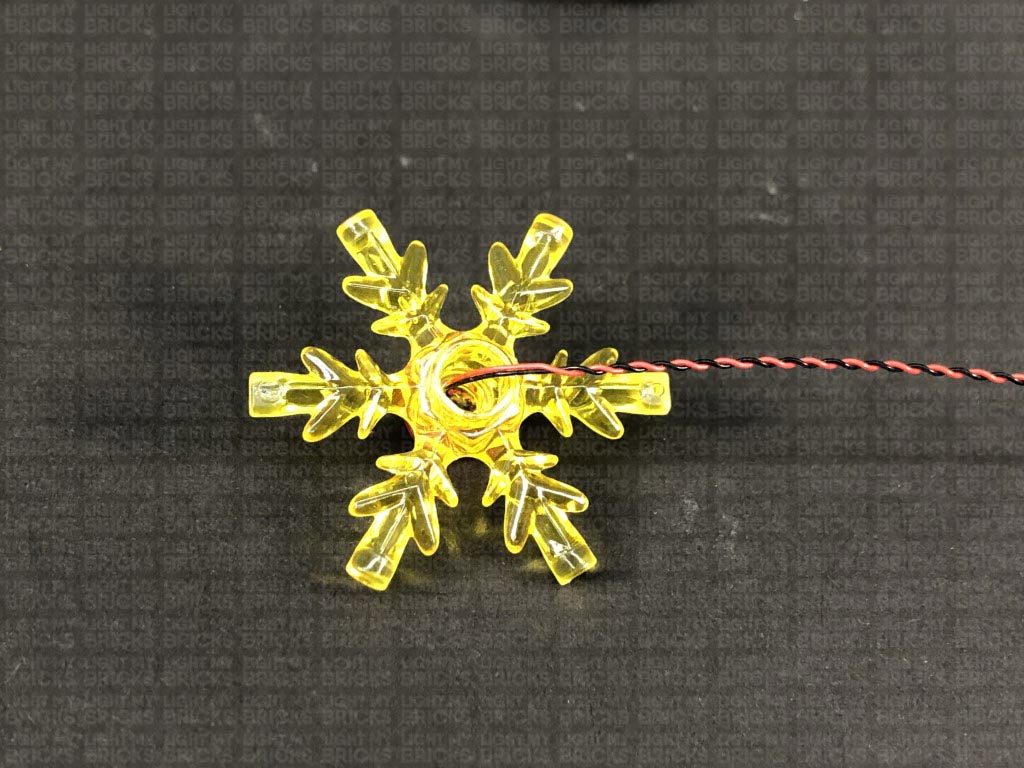
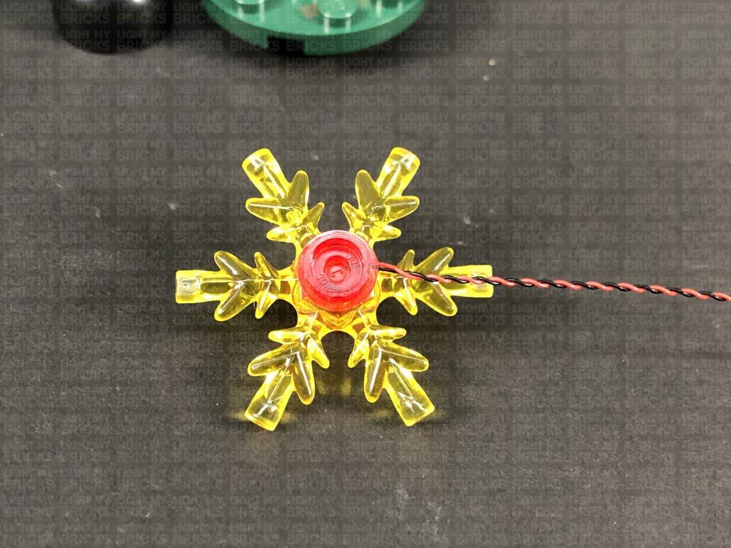
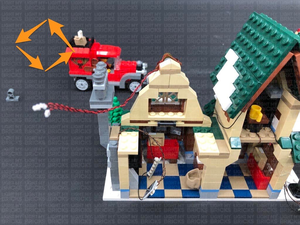
6.) Reconnect the green light first, ensuring the trans green plate is facing down, then bring the cable over the flag. Reconnect the red light ensuring the cable from the green light is clipped inside the white clip of the red light. Bring both cables over the flag.
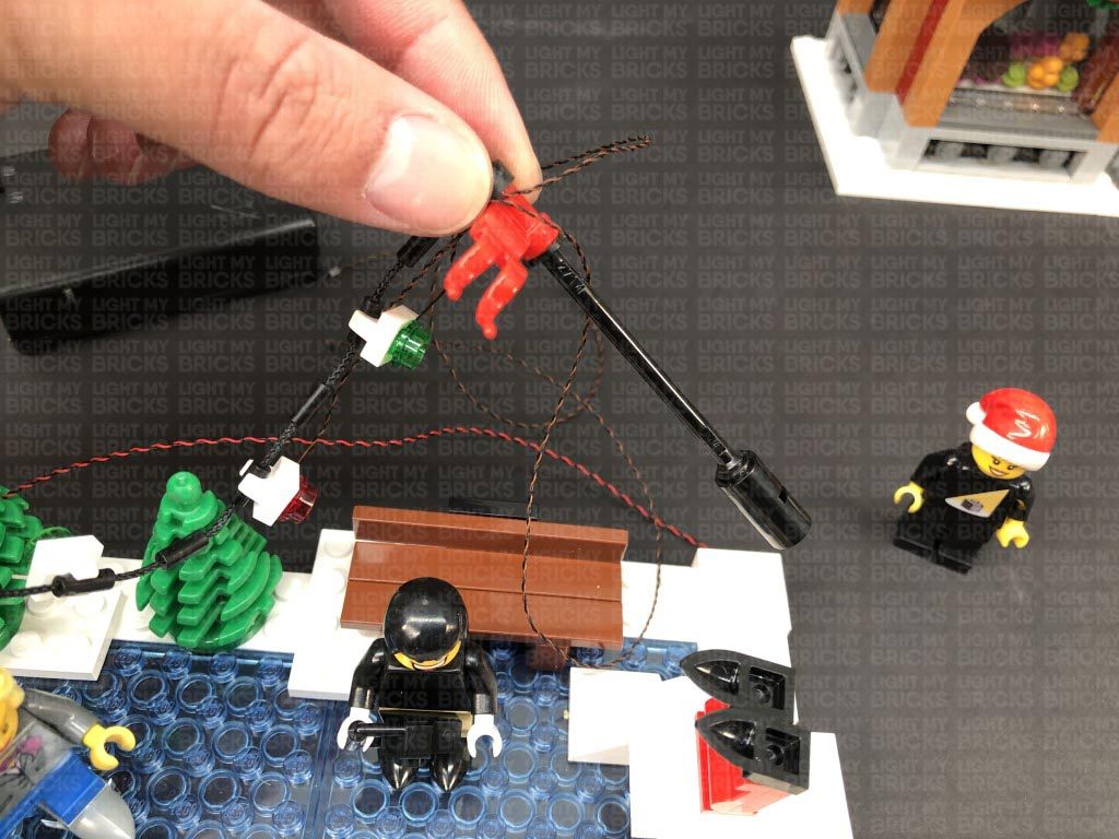
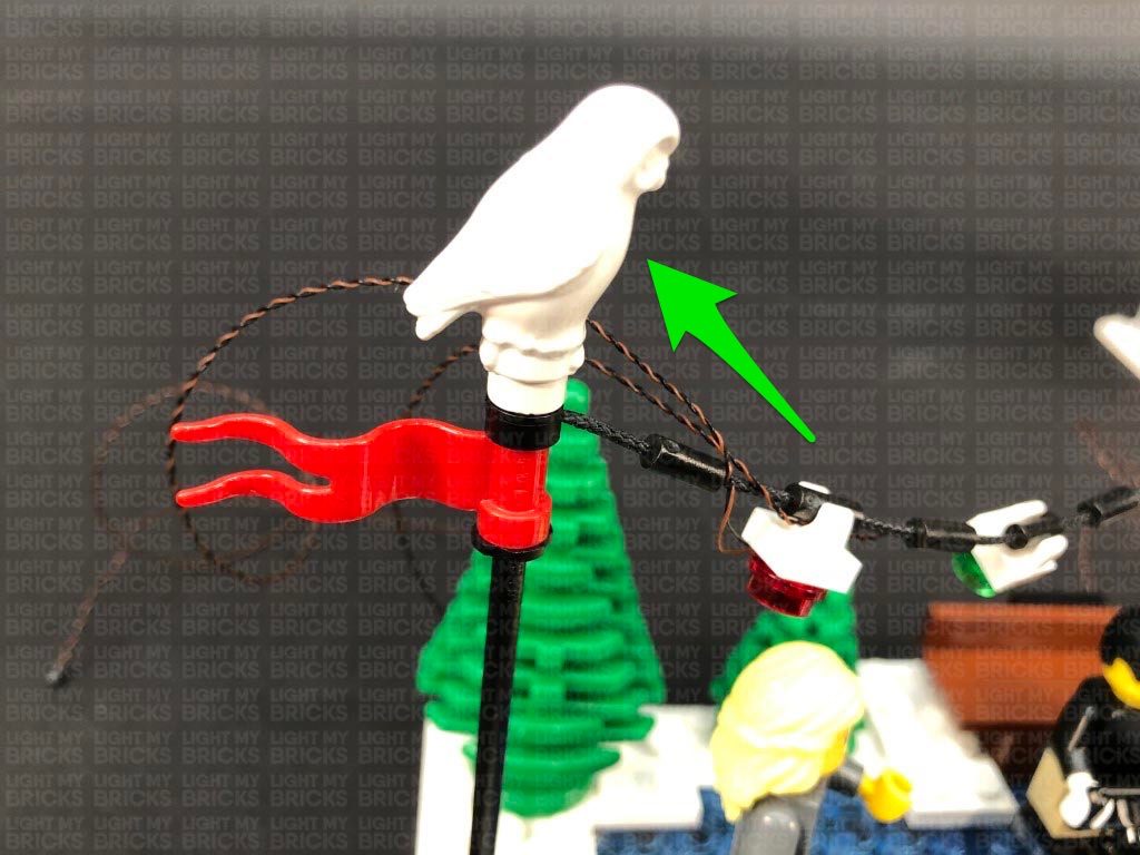
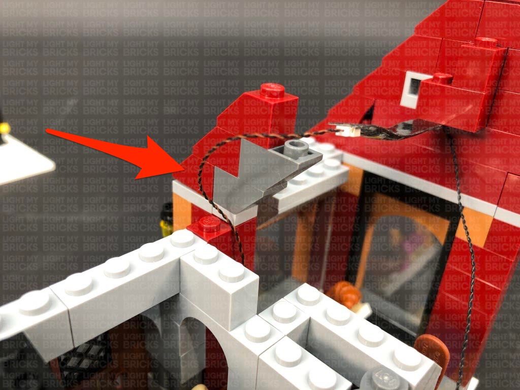
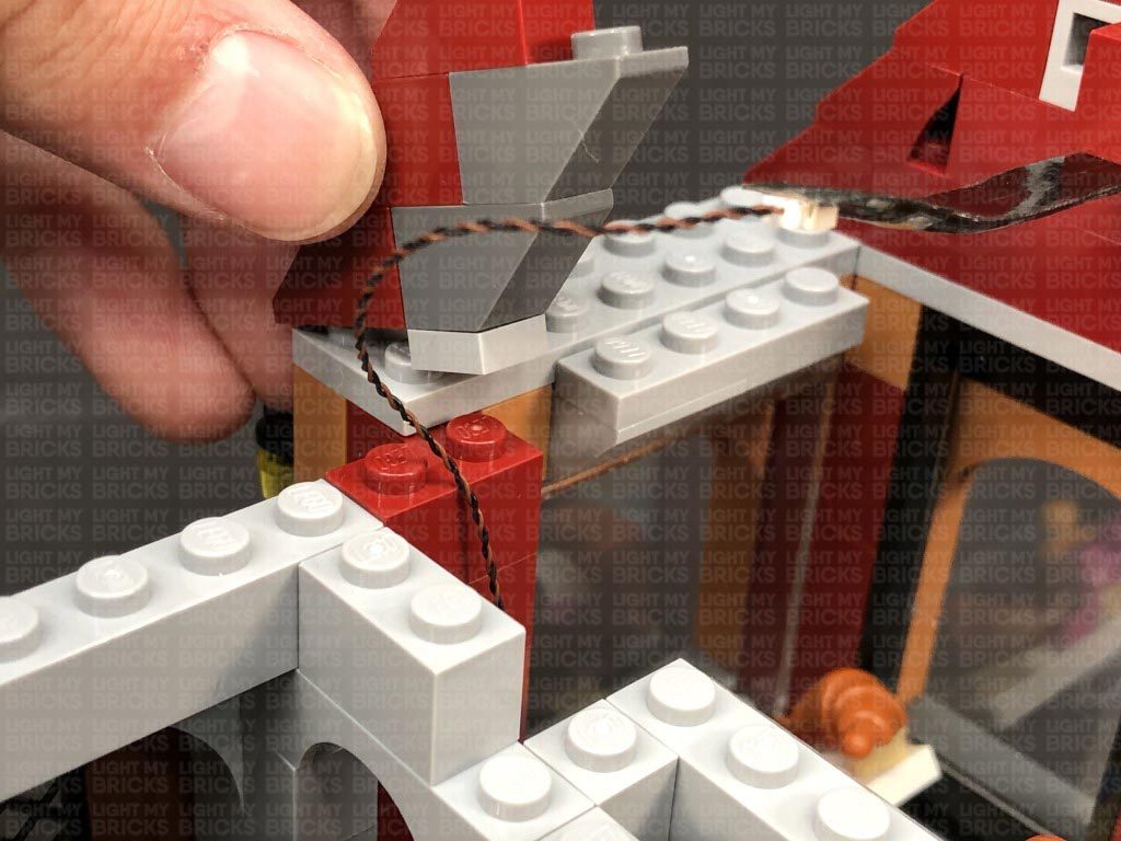
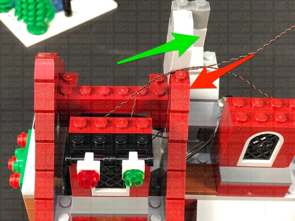
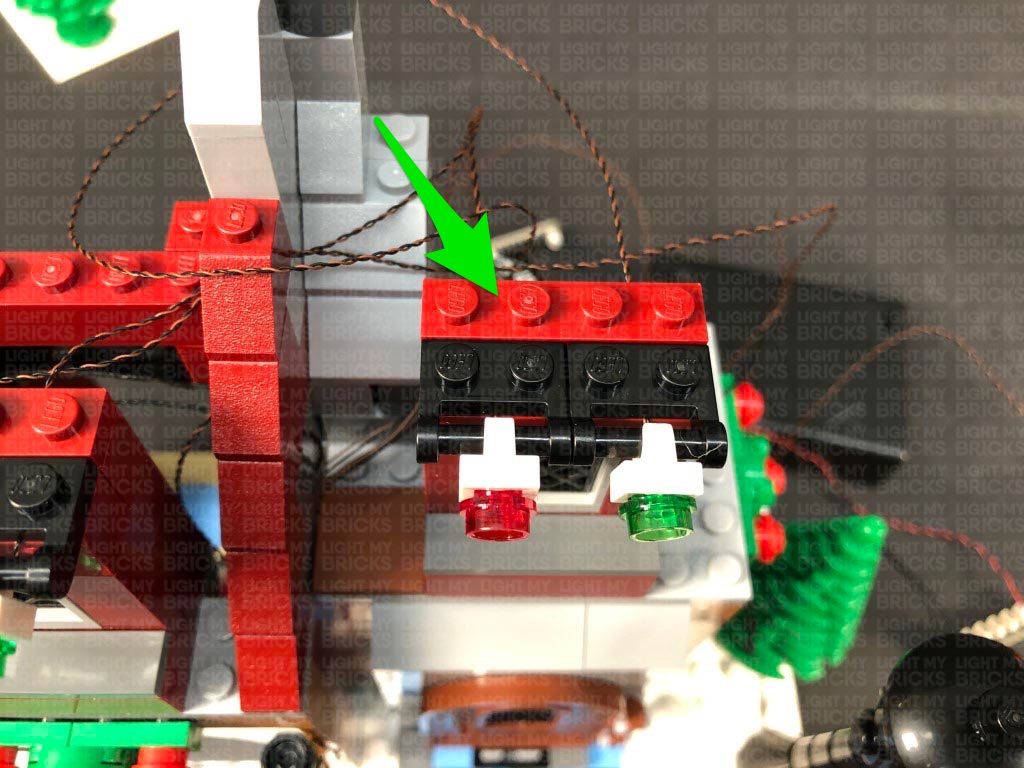
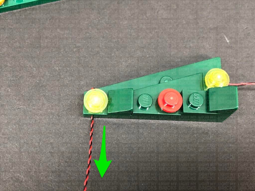
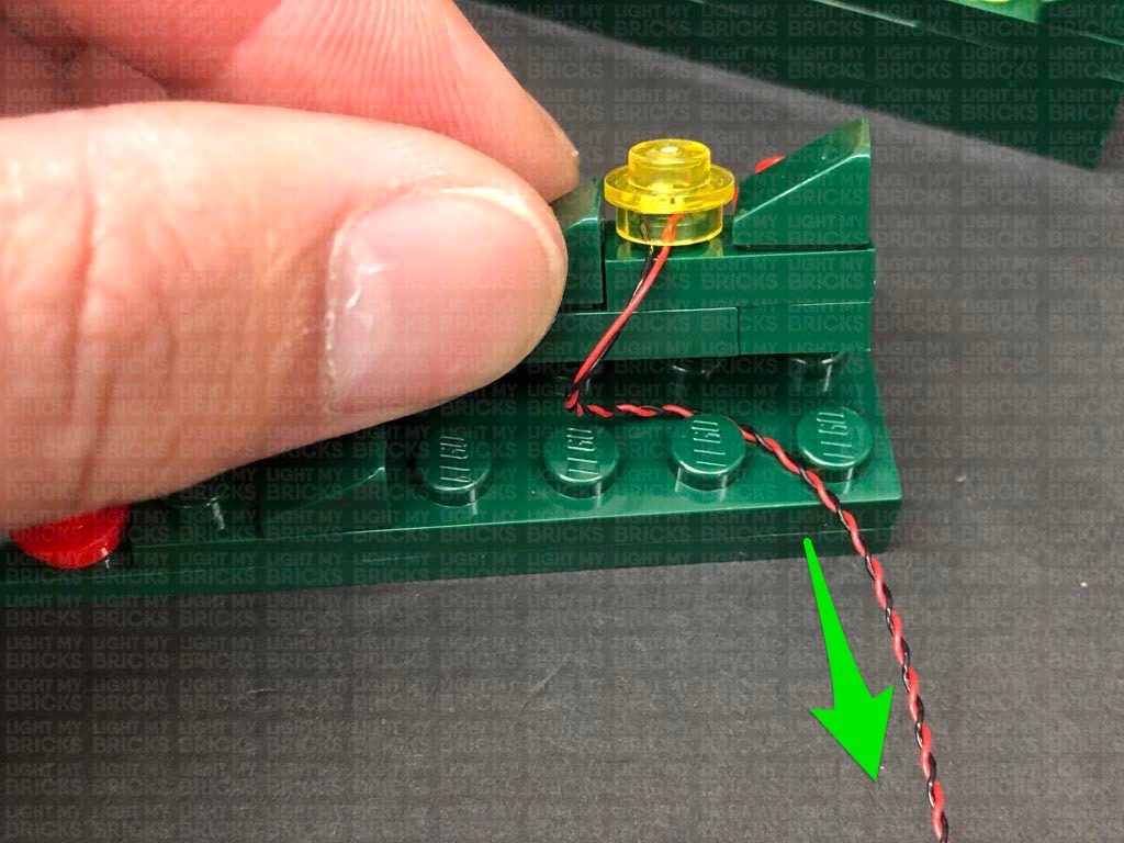
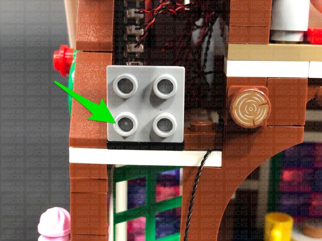
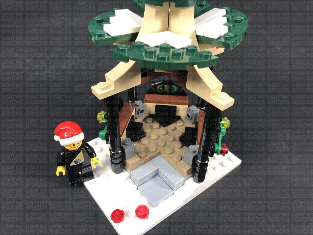
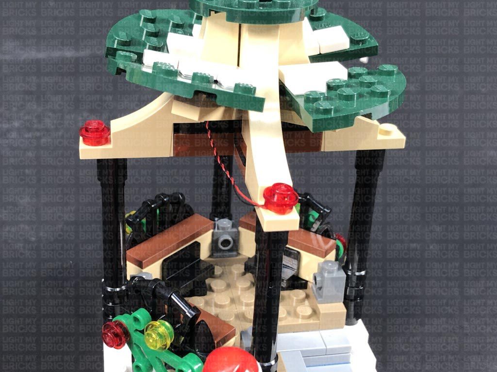
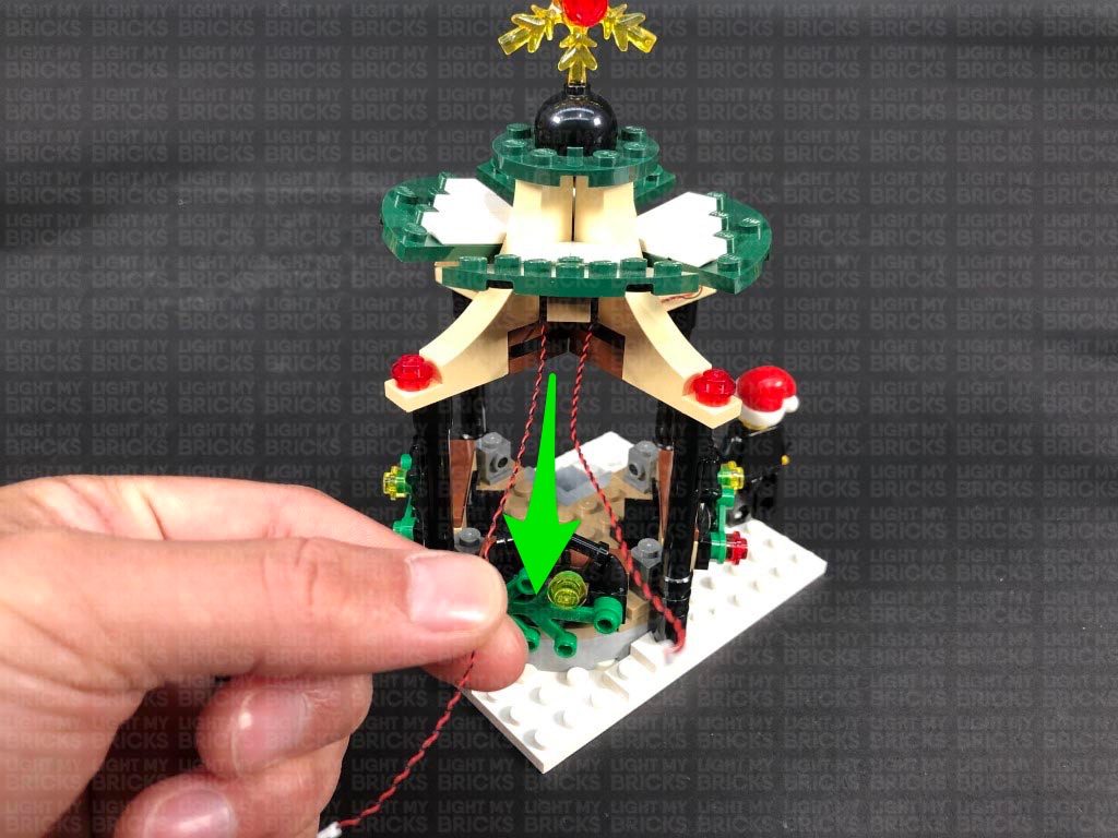
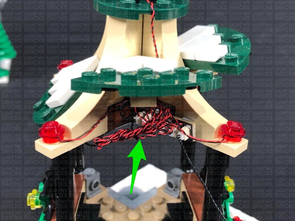
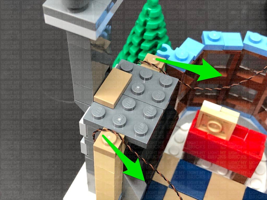
Wind both cables around the pole twice, then secure the cables underneath the white plate on the bottom of the pole. Ensure the cables are laid together in between studs underneath and that they are facing toward the back of this section.
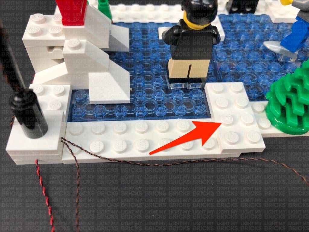
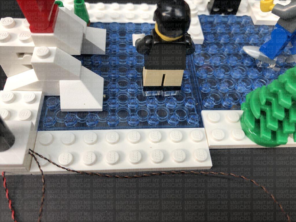
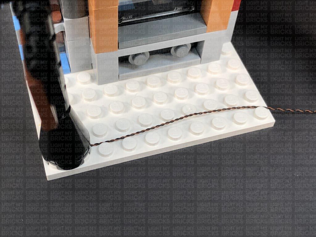
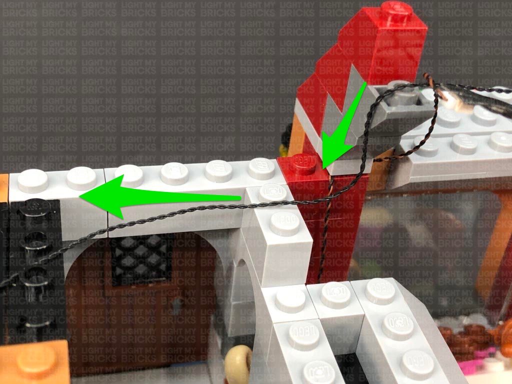
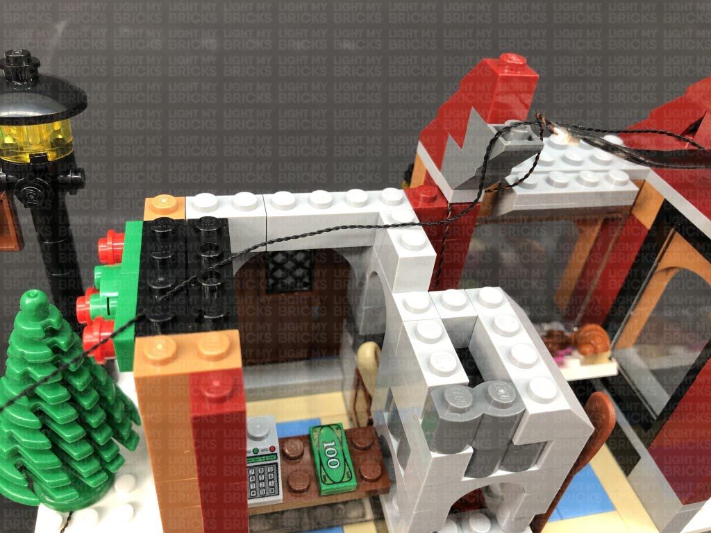
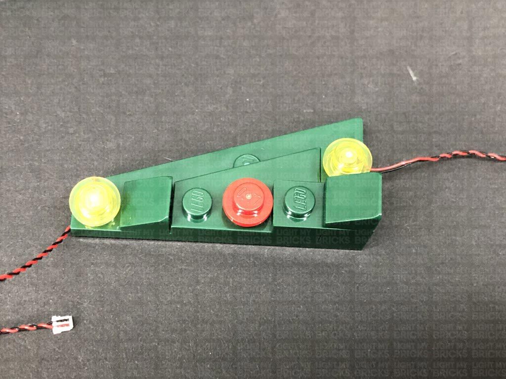
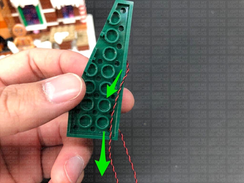
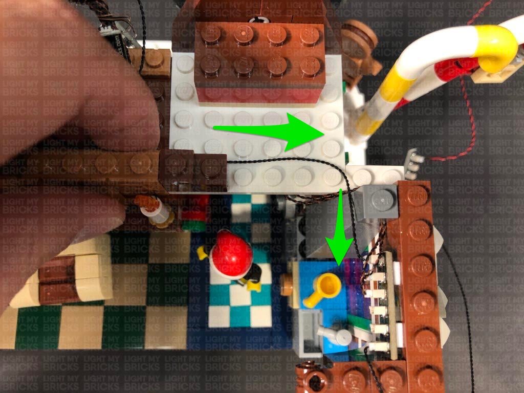
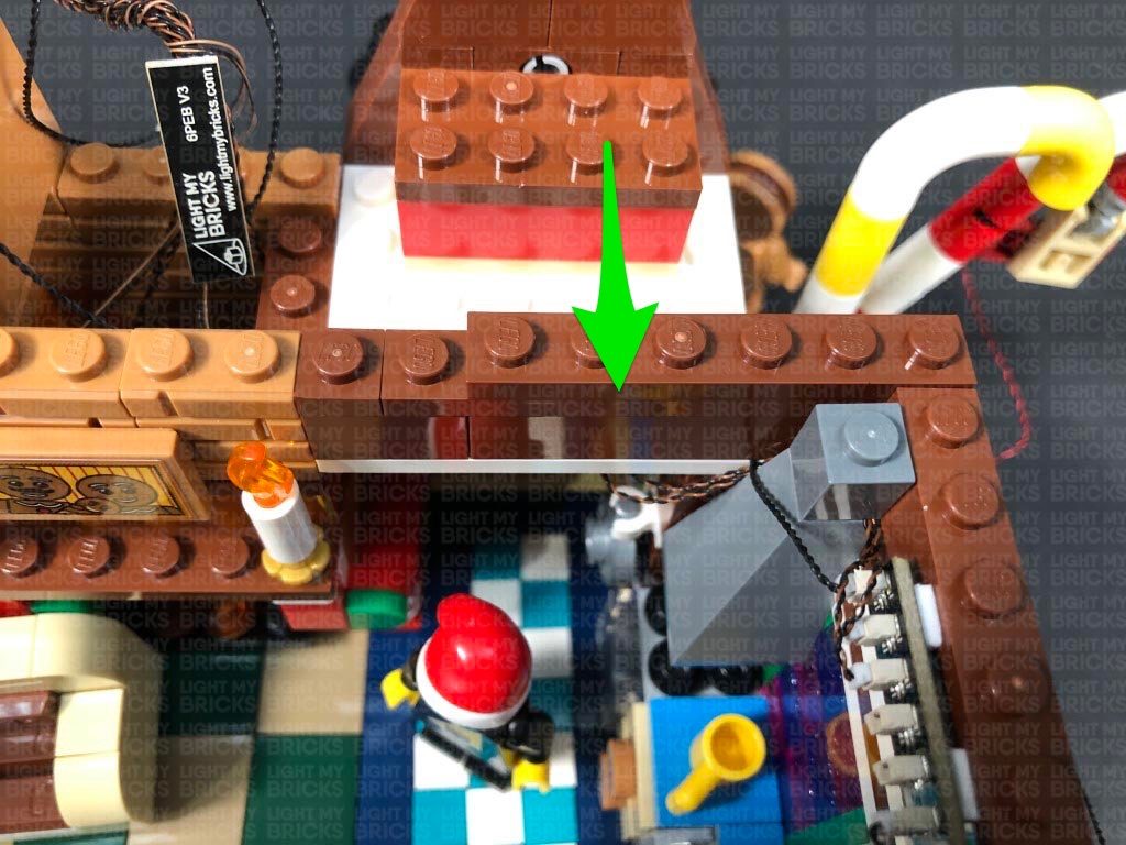
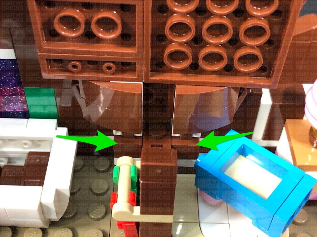
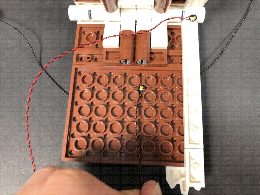
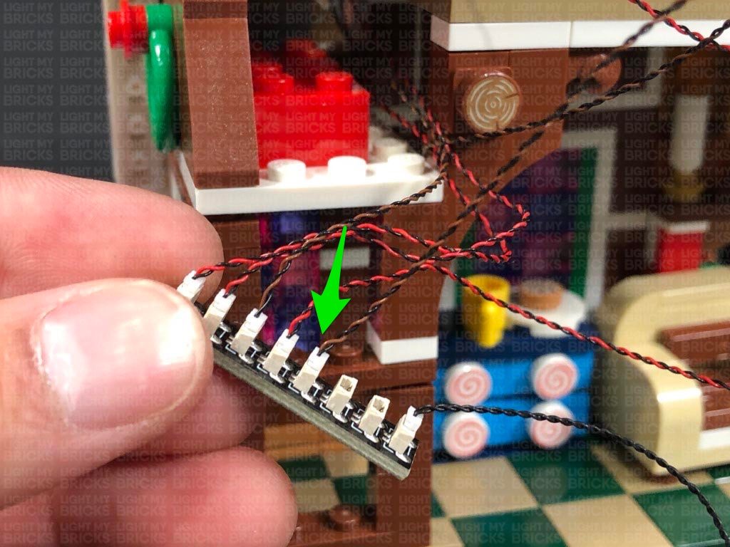
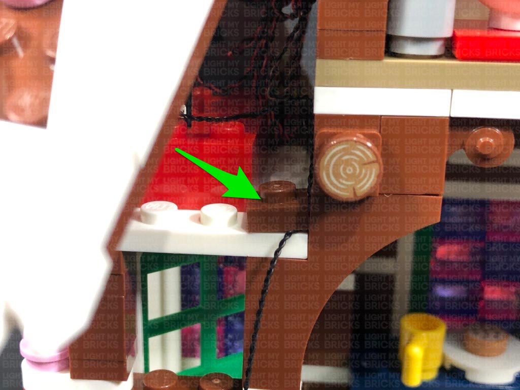
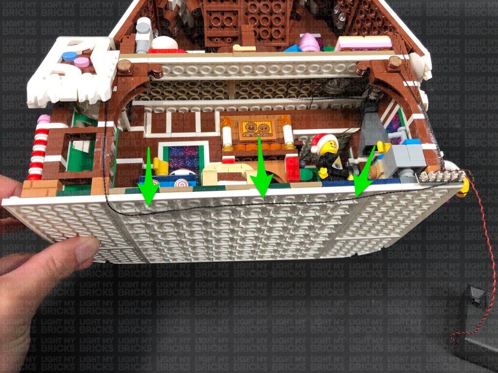
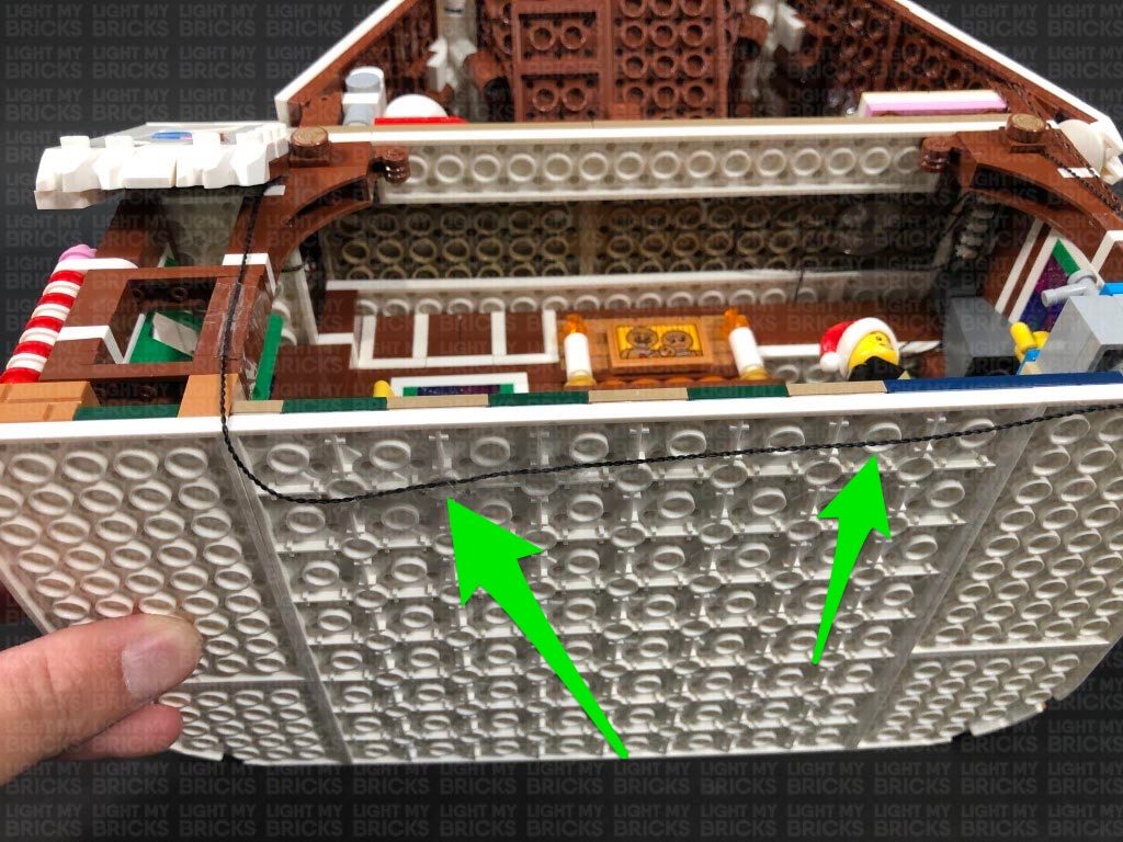
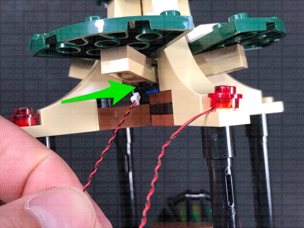
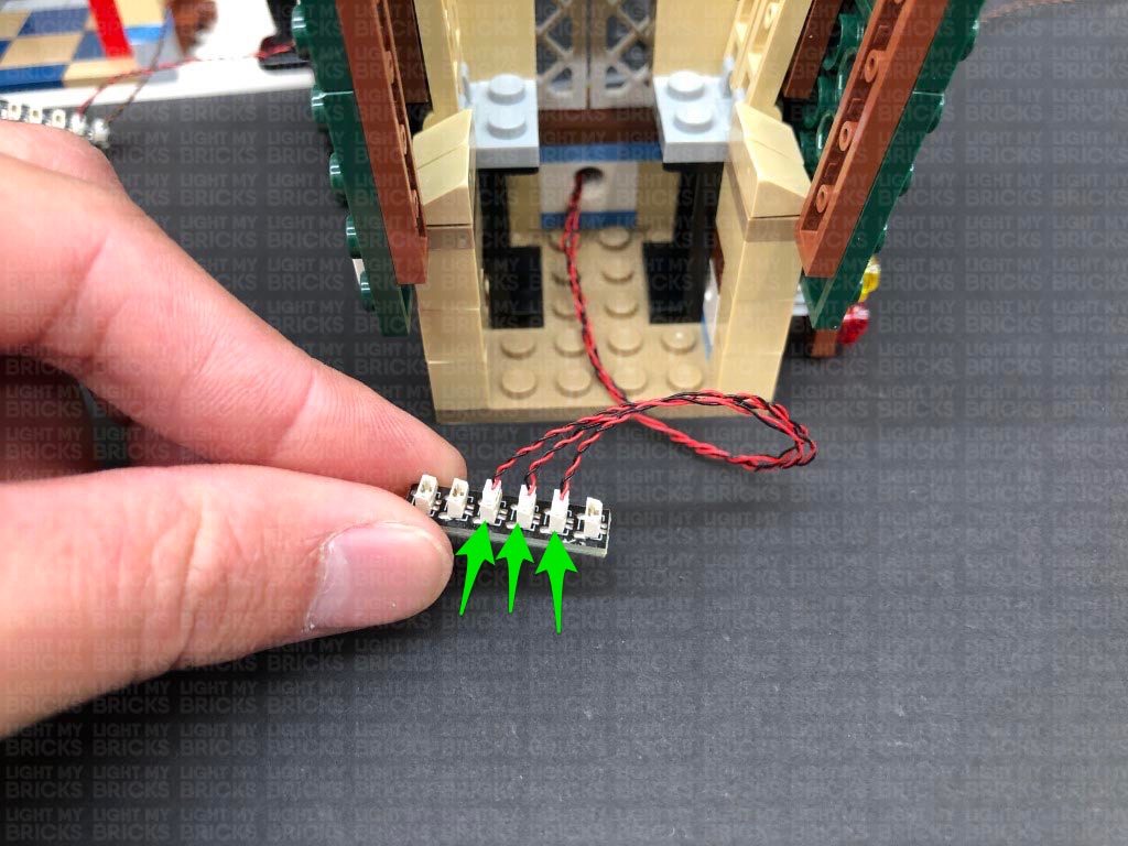
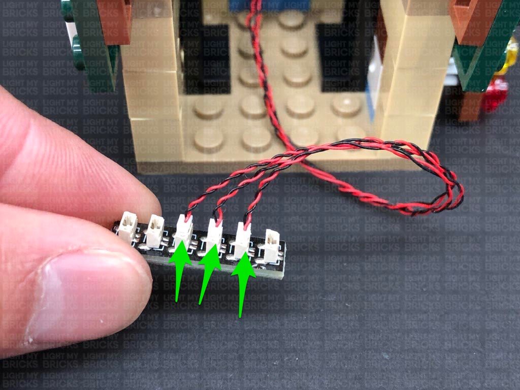
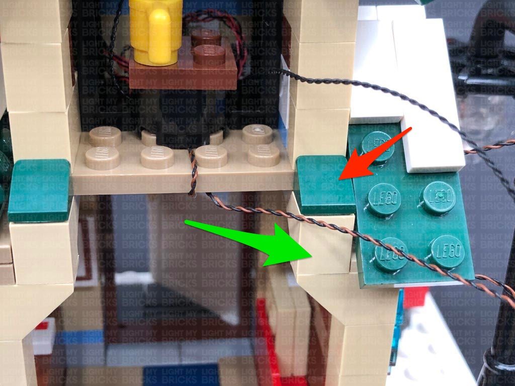
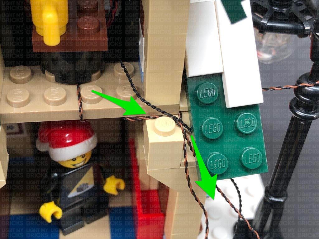
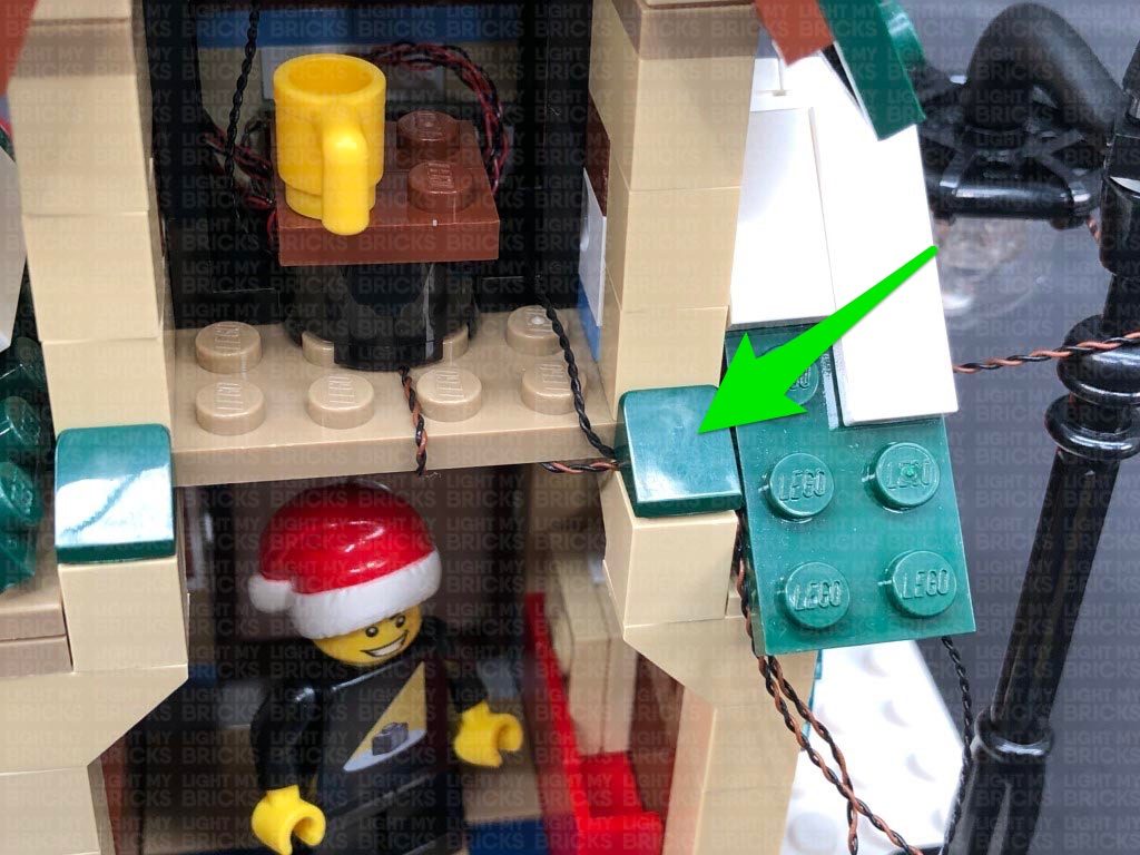
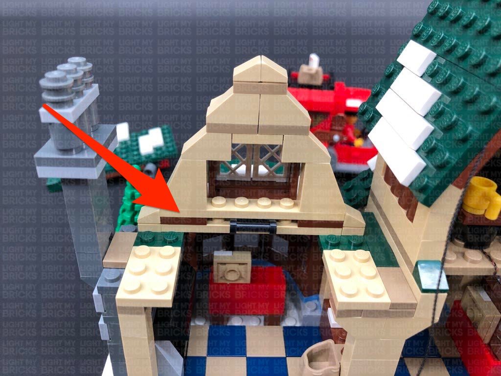
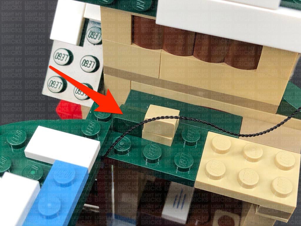
7.) Turn the set around to the back and disconnect the white 2×4 plate underneath the larger tree on the right. Lay the two cables down in between studs as shown below, then reconnect the white plate as well as the larger tree.
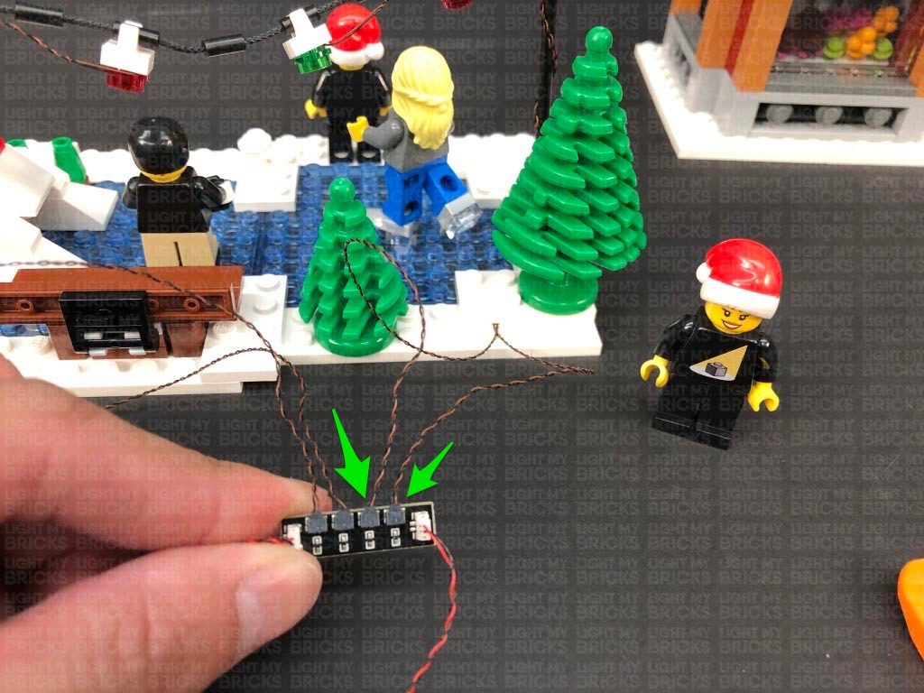
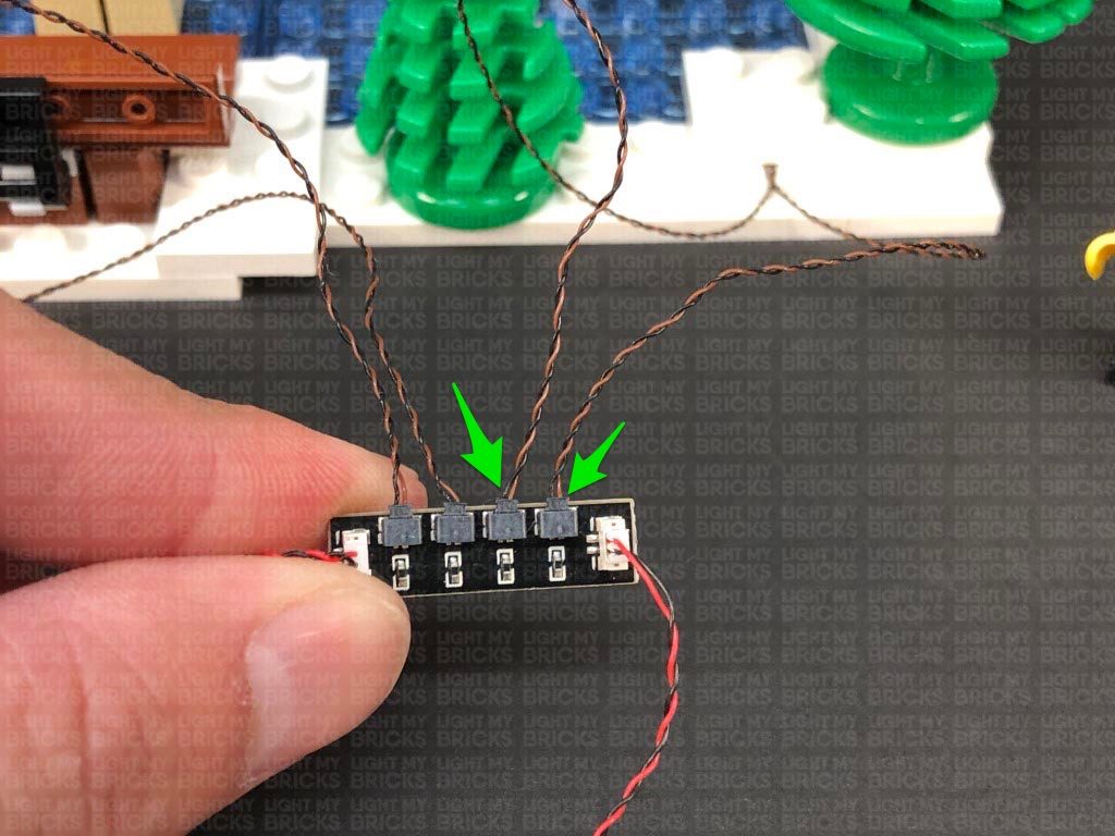
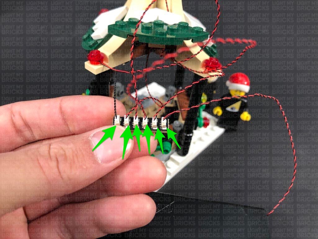
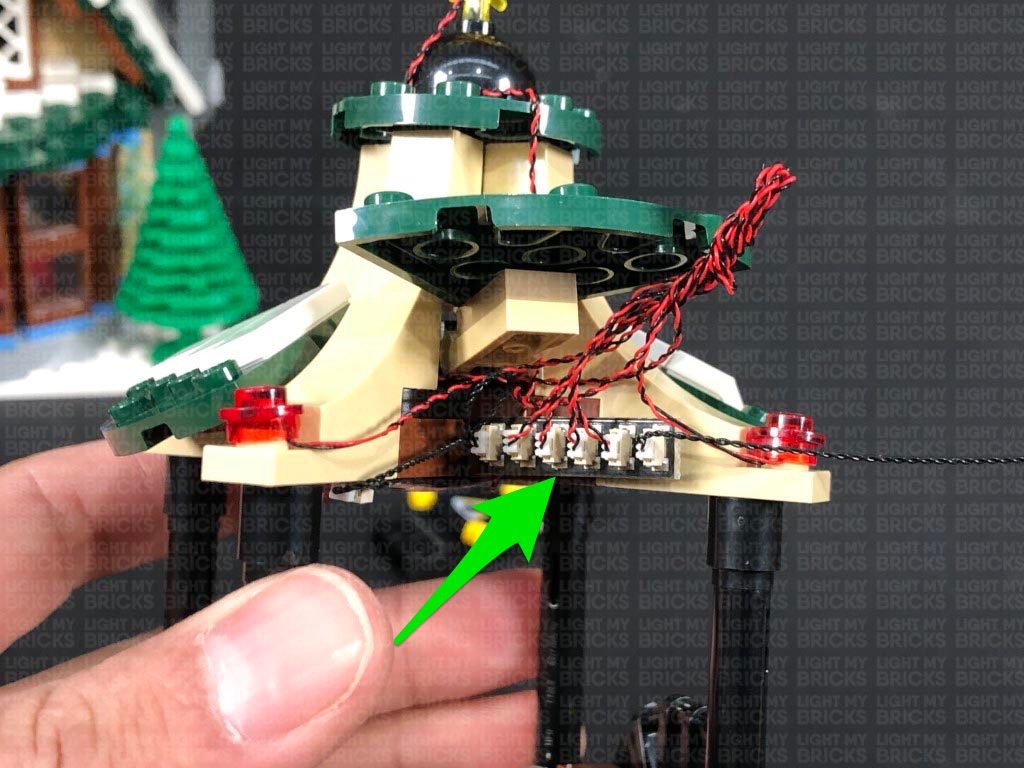
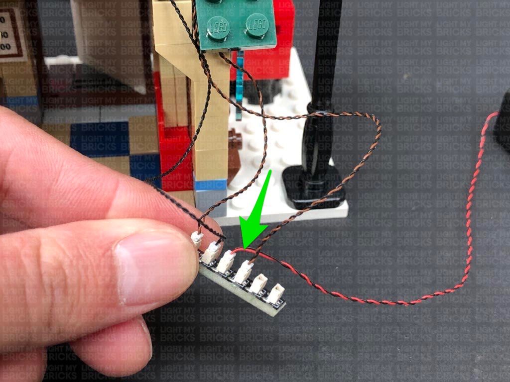
Connect the two Micro Bit Lights to the remaining ports on the Micro Expansion Board. Turn ON the Battery Pack to test the flashing lights are all working OK.
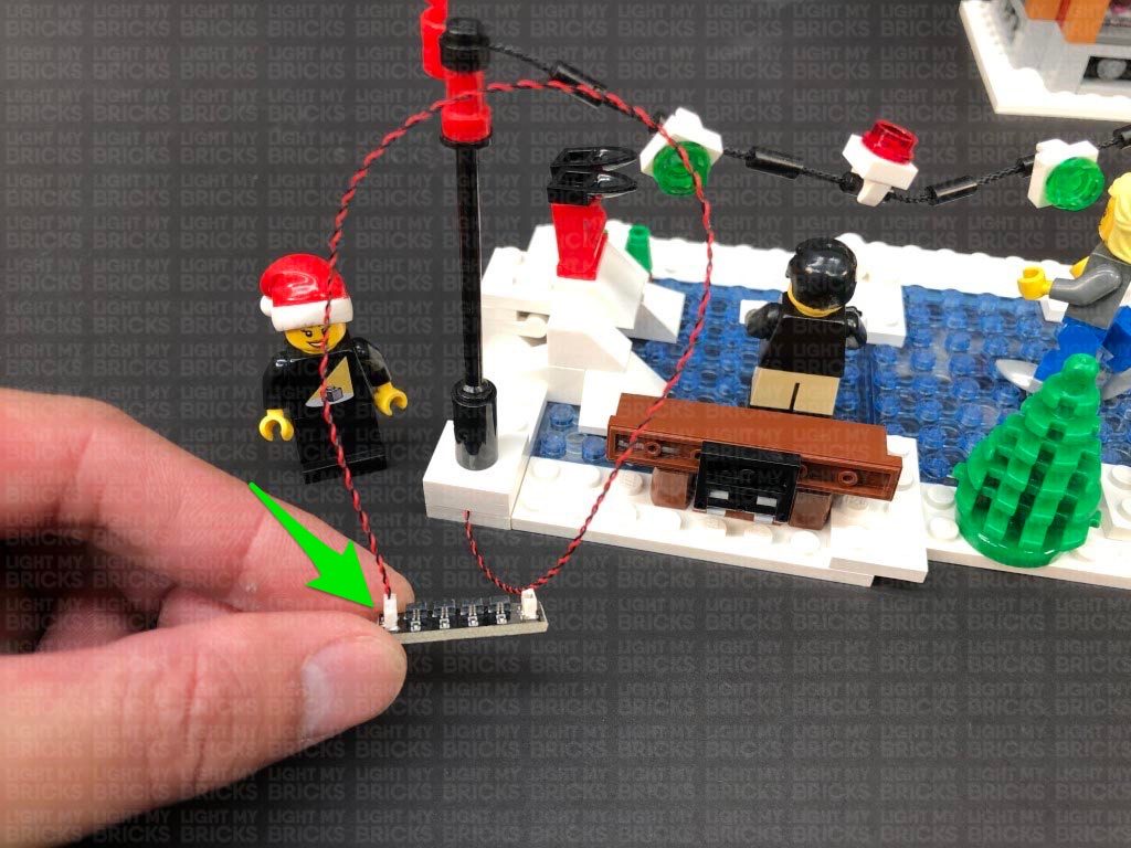
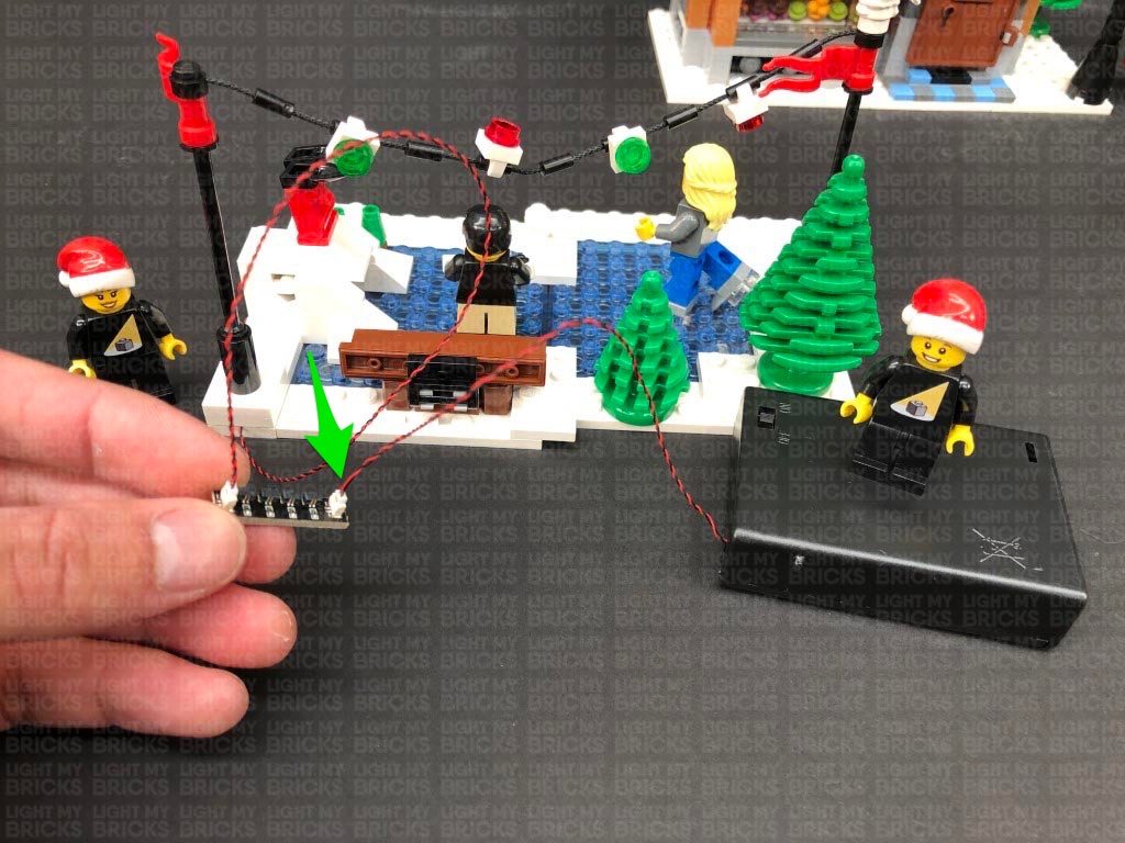
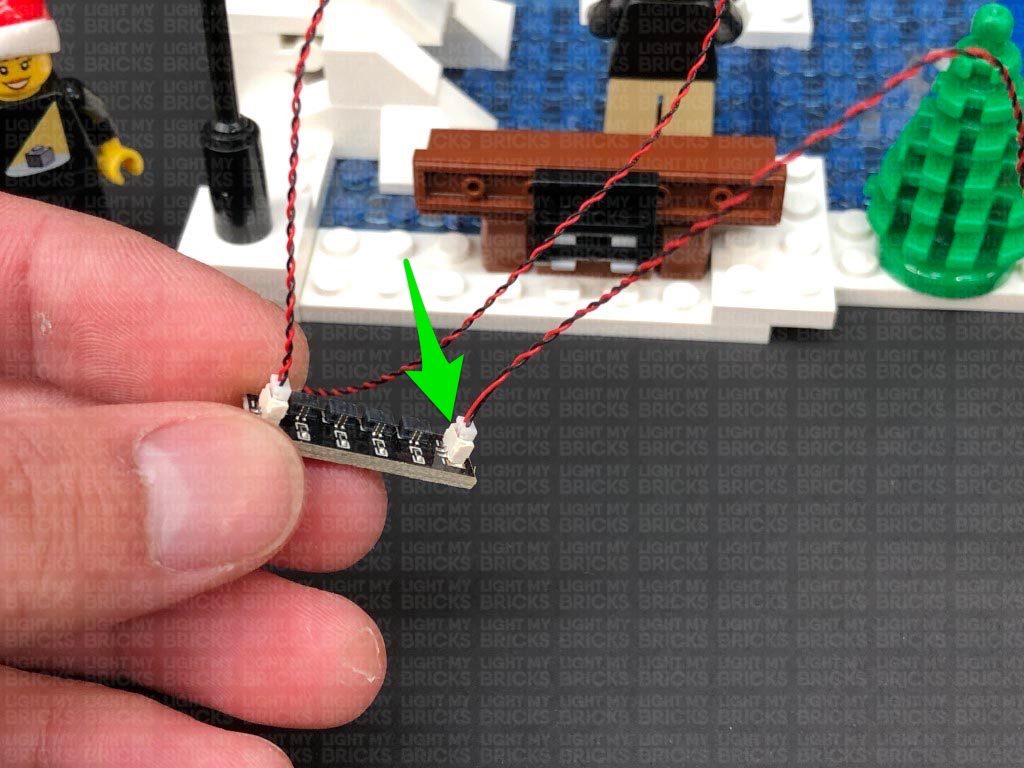
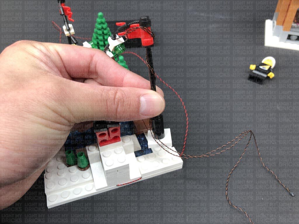
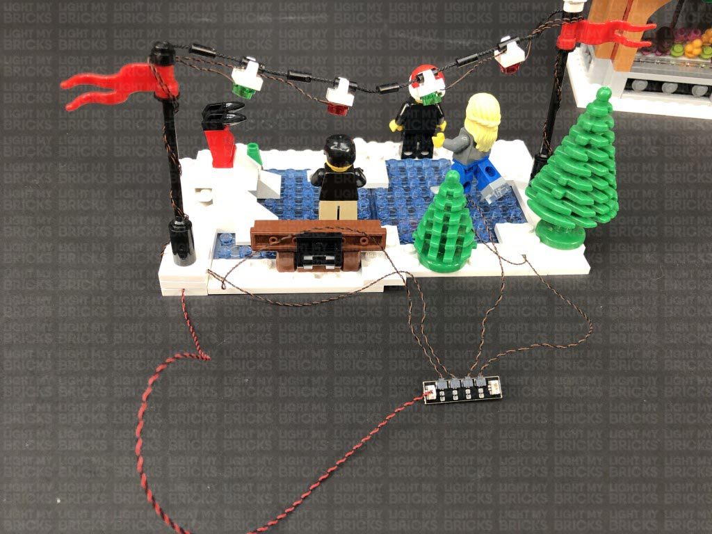
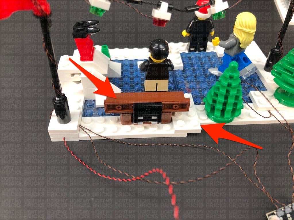
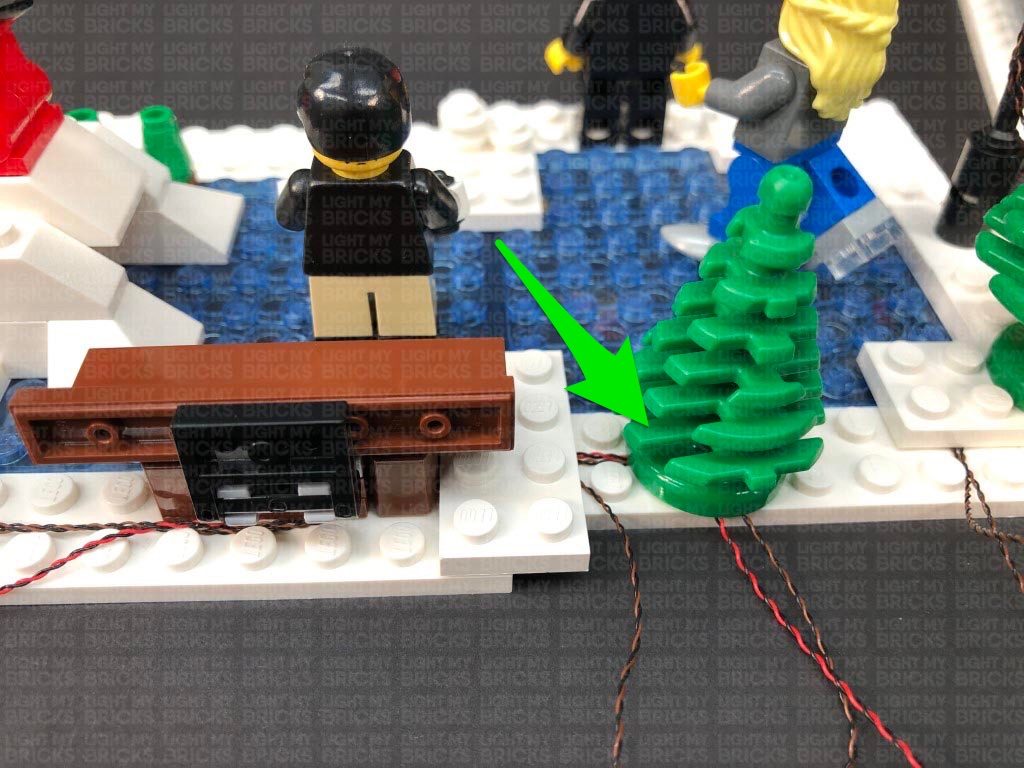
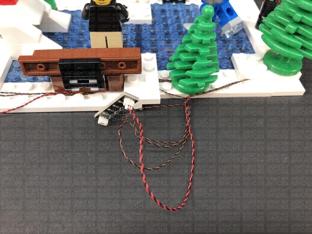
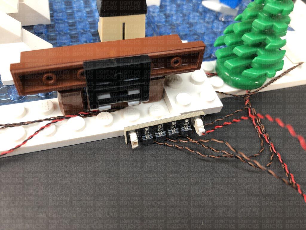
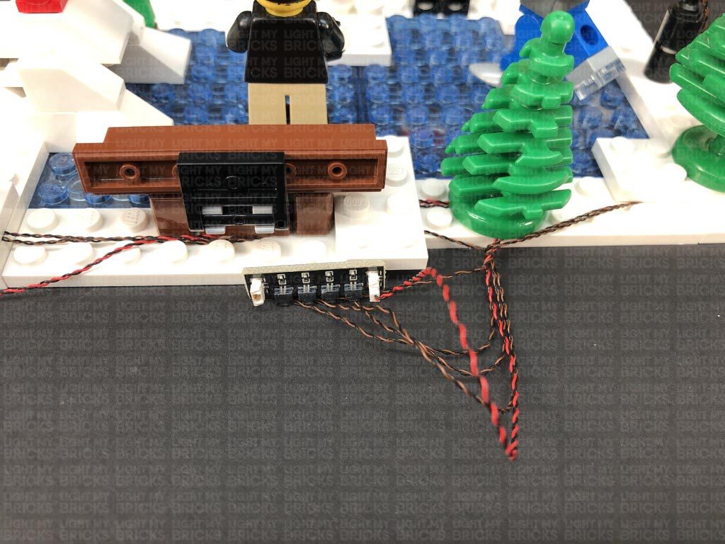
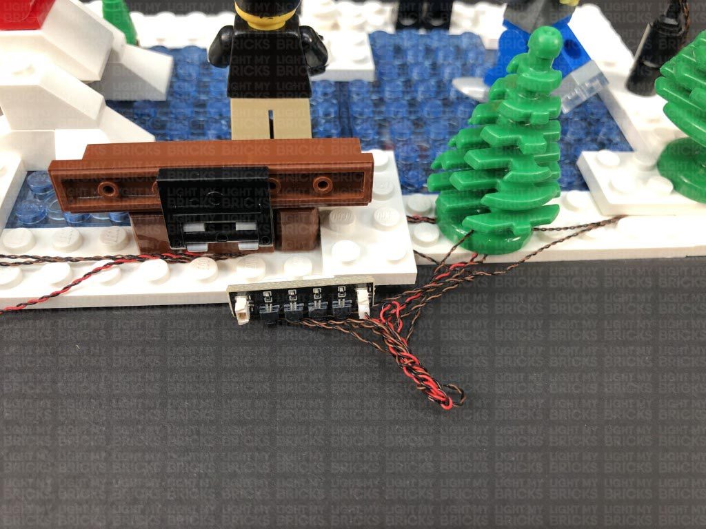
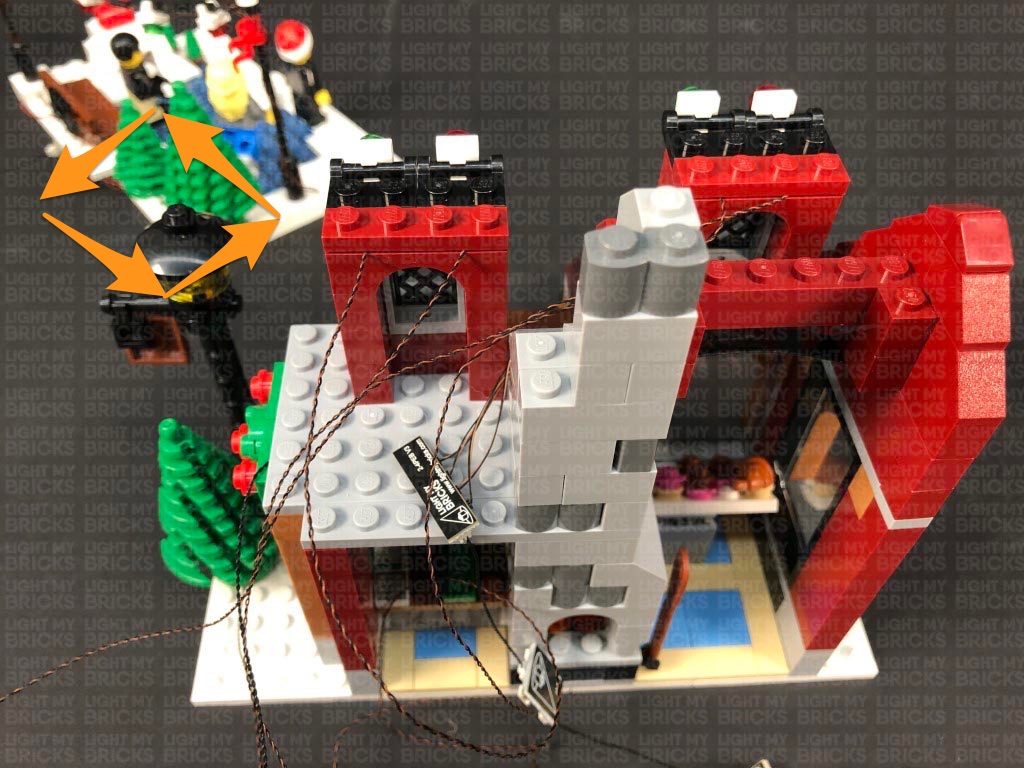
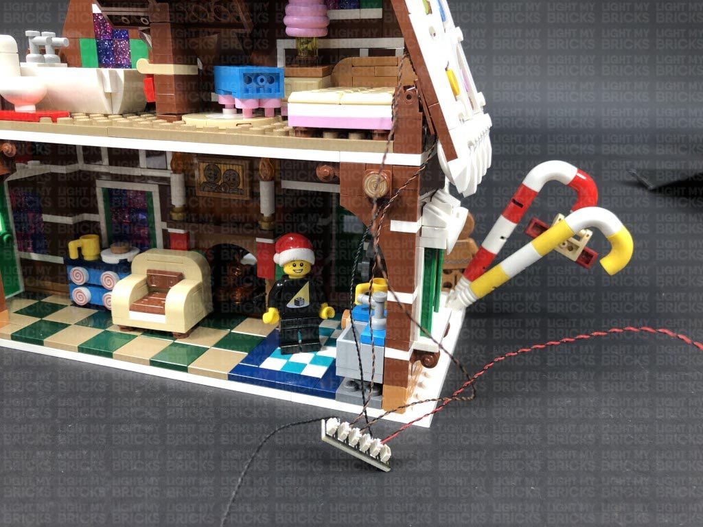
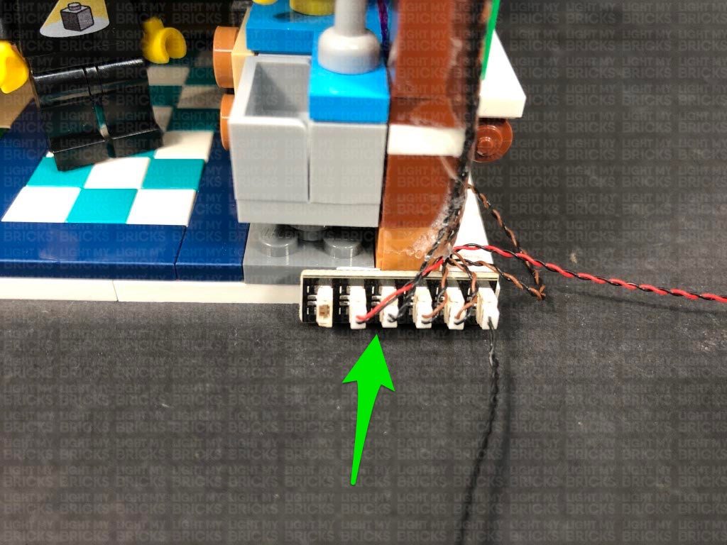
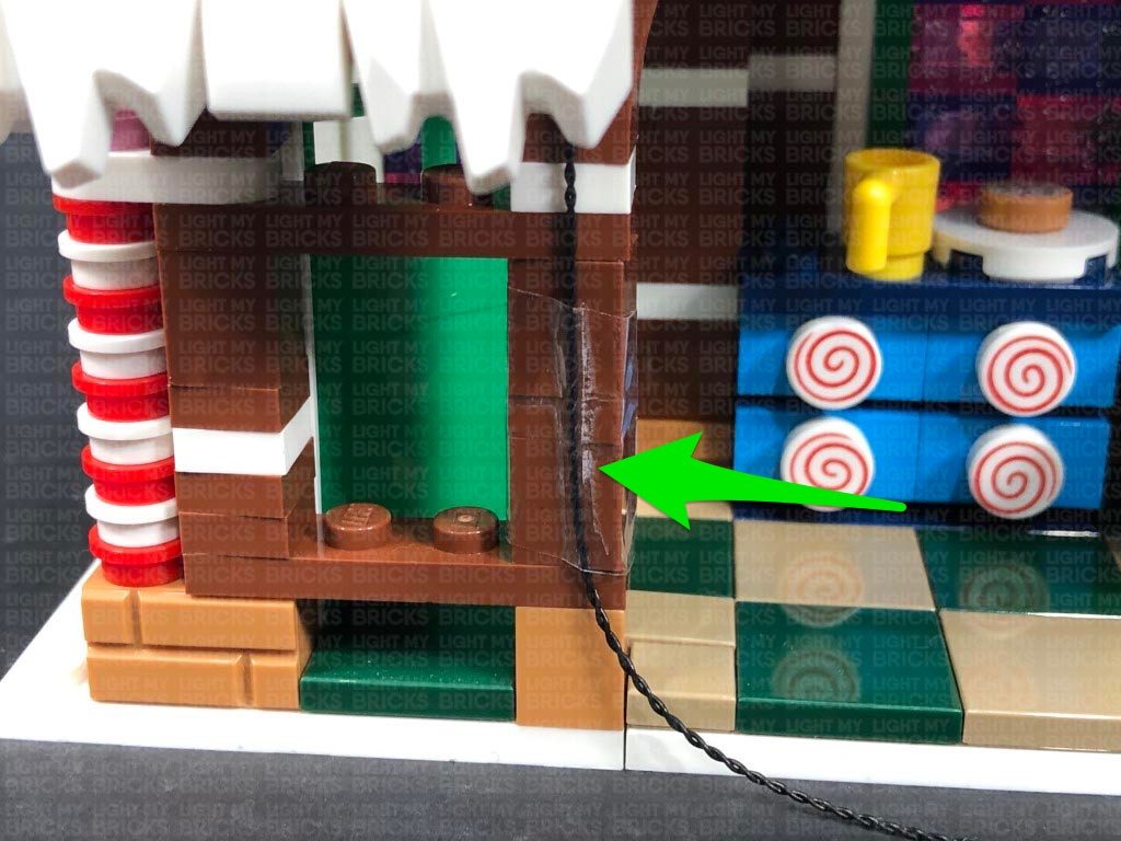
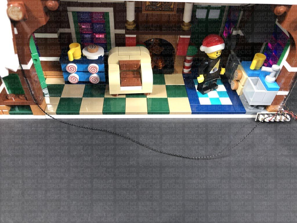
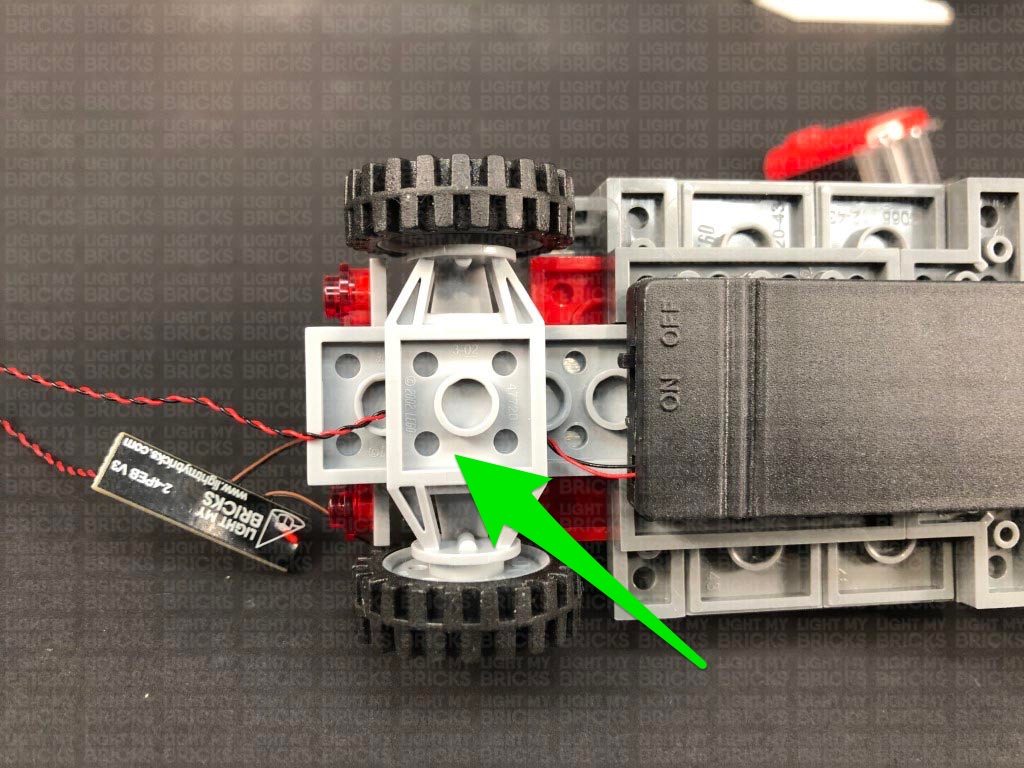
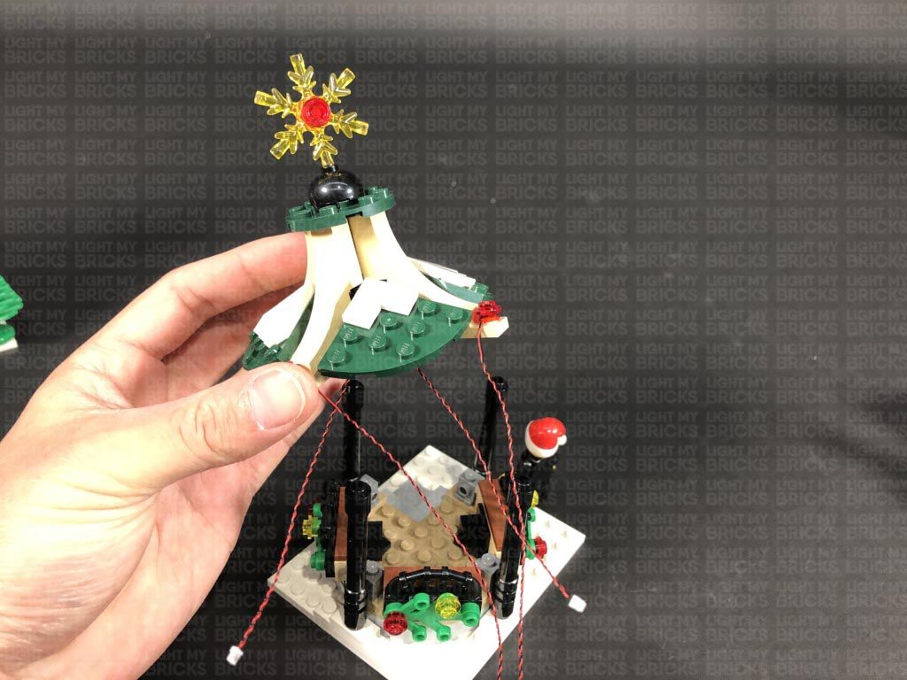
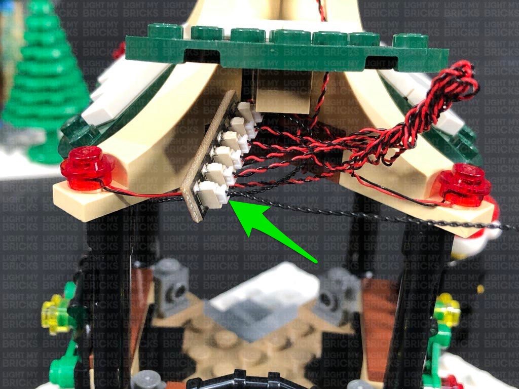
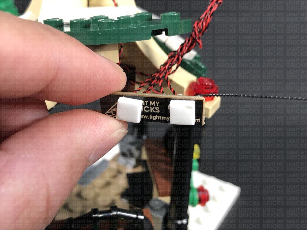
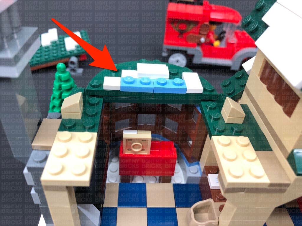
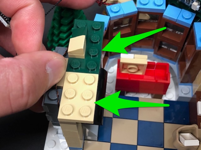
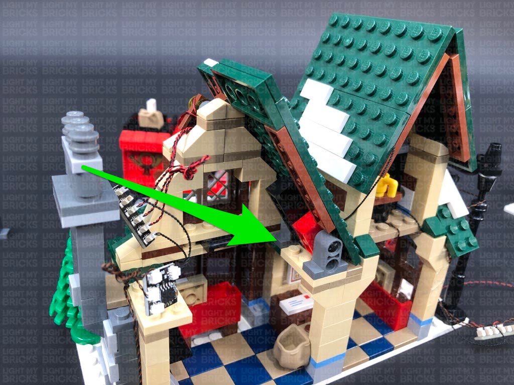
8.) Disconnect the AA Battery Pack from the expansion board, then disconnect the bench as well as the white 2×4 plate to the right of it. Lay the cables from the Blue Bit Light and the two Flashing Micro Bit Lights toward the centre of this section in between studs. Reconnect the 2×4 plate over the top followed by the bench.
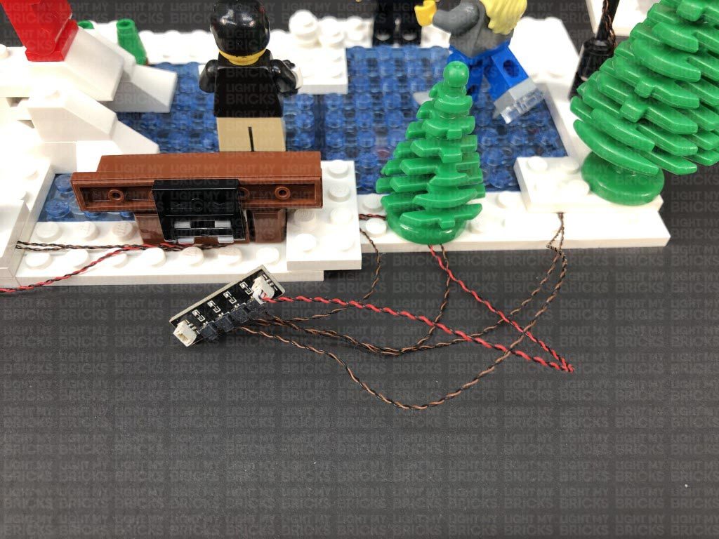
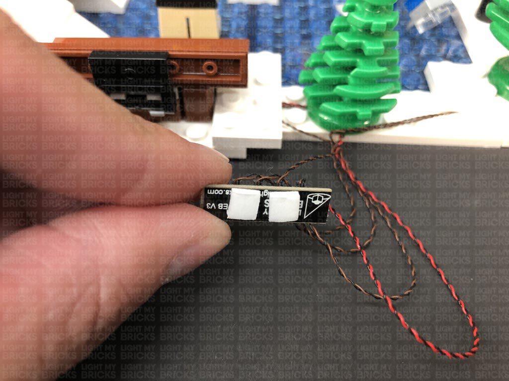
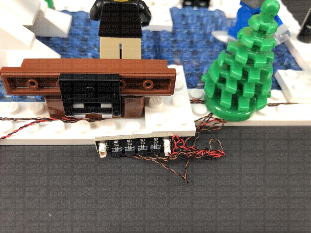
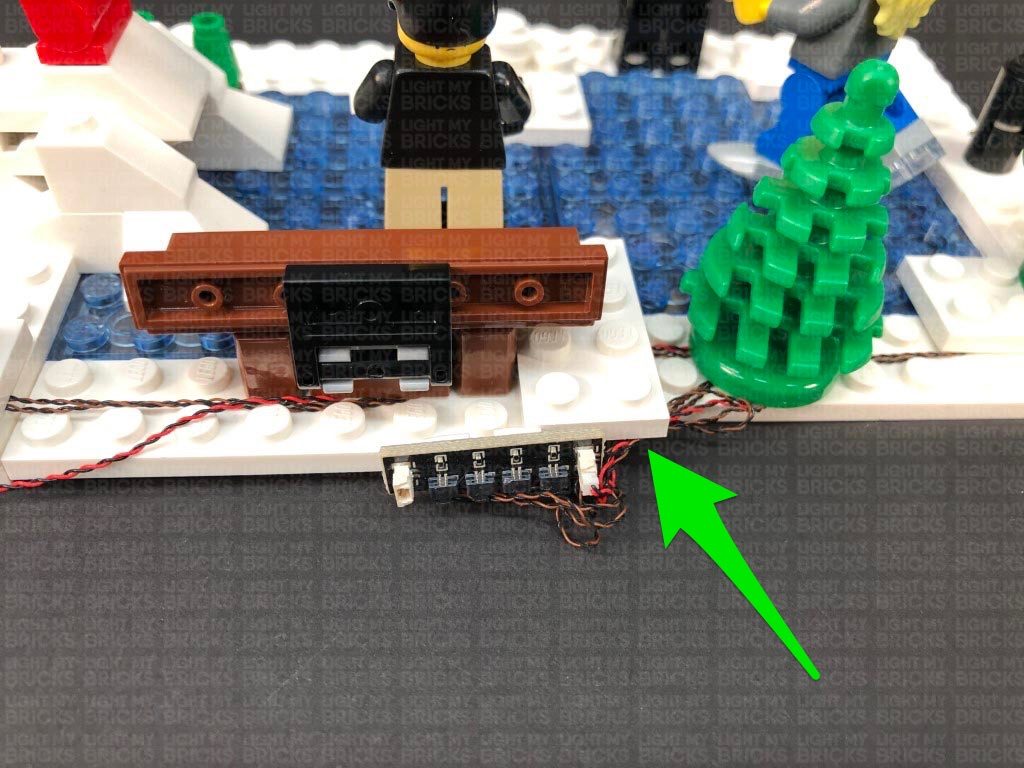
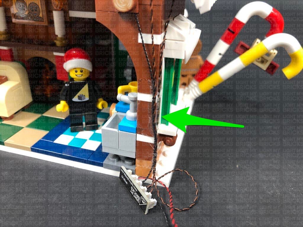
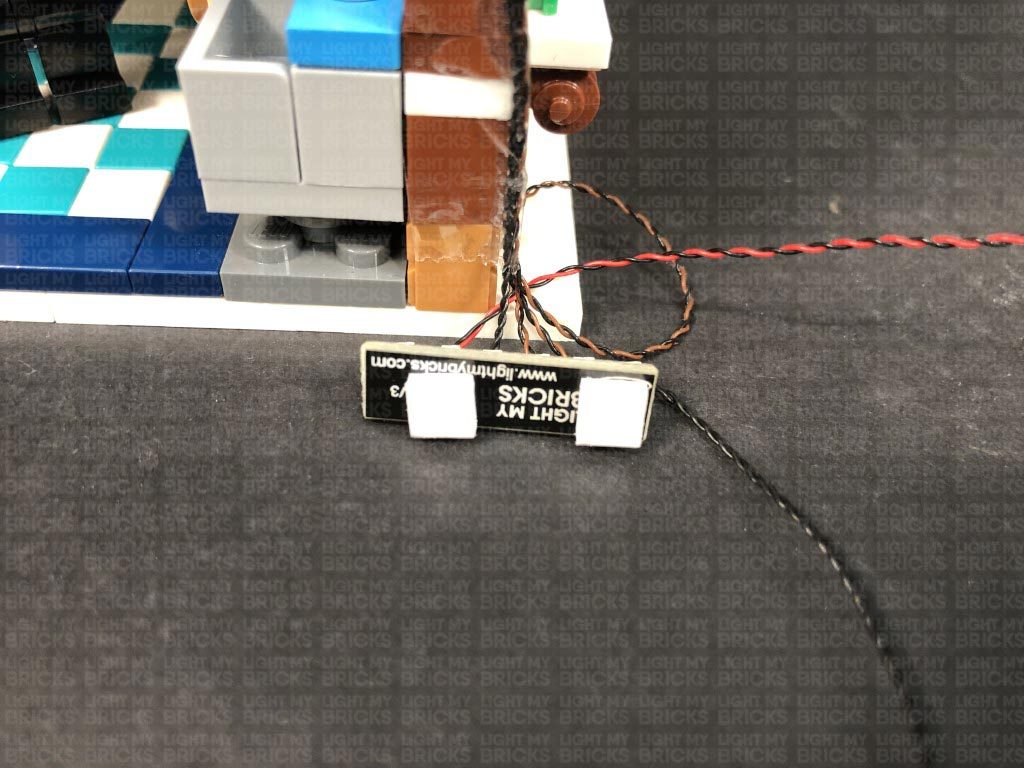
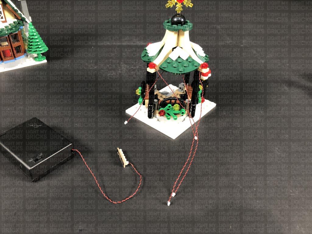
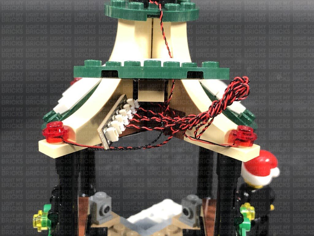
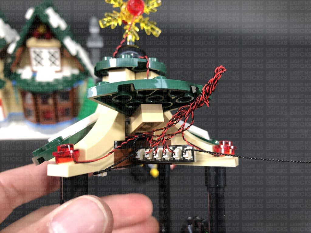
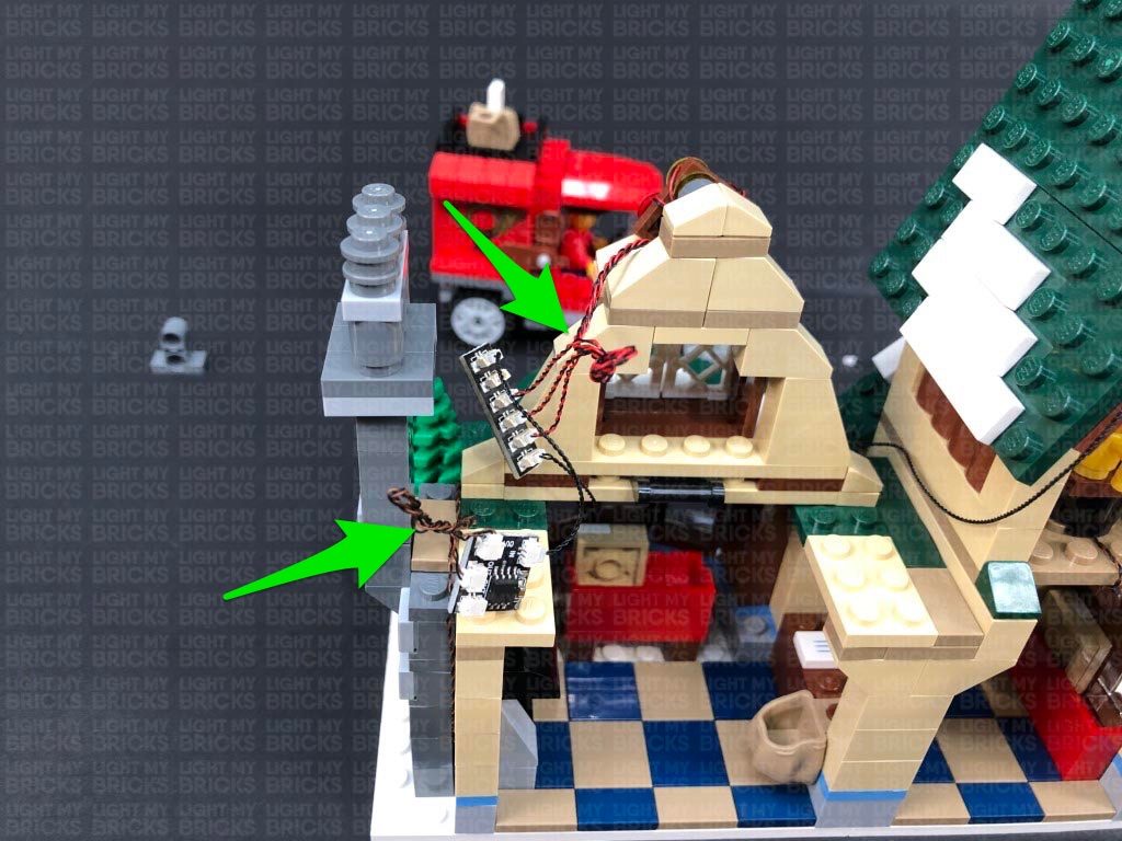
Secure the cables underneath the smaller tree, then twist the cables around each other a few times just behind the smaller tree. Take 2x Adhesive Squares and stick them to the back of the expansion board, then stick the expansion board on the back of the white plates behind the bench.
Continue to twist and fold up the cables into a neat bunch, then tuck any remaining cable underneath the plates.
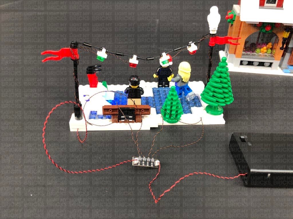
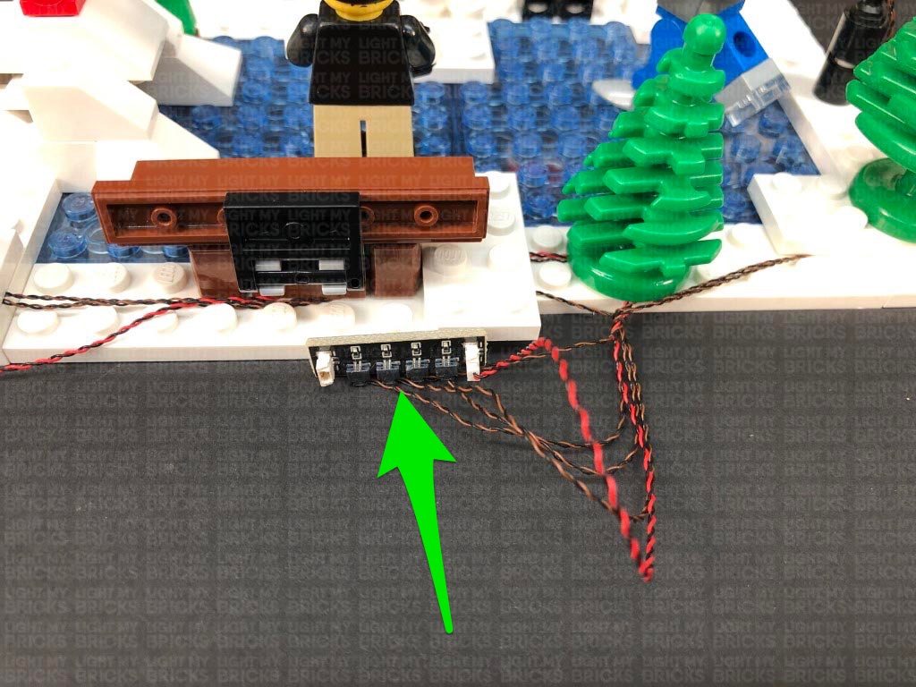
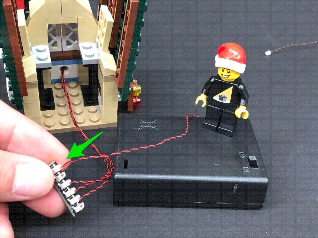
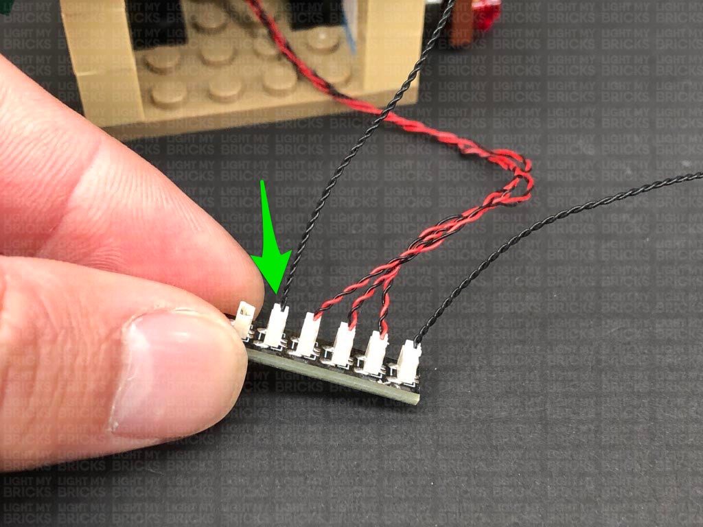
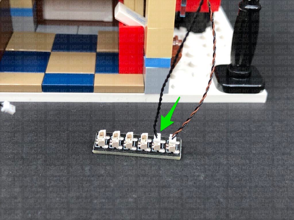
Take a 30cm Connecting Cable and connect it to the larger port on the Micro Expansion Board. Leave the other end of the cable disconnected for now as this will be used to connect to an expansion board on the back of the bakery later on.
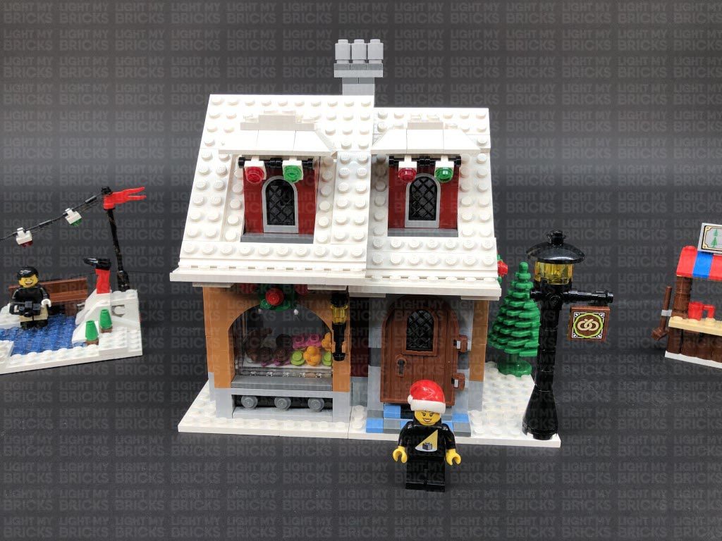
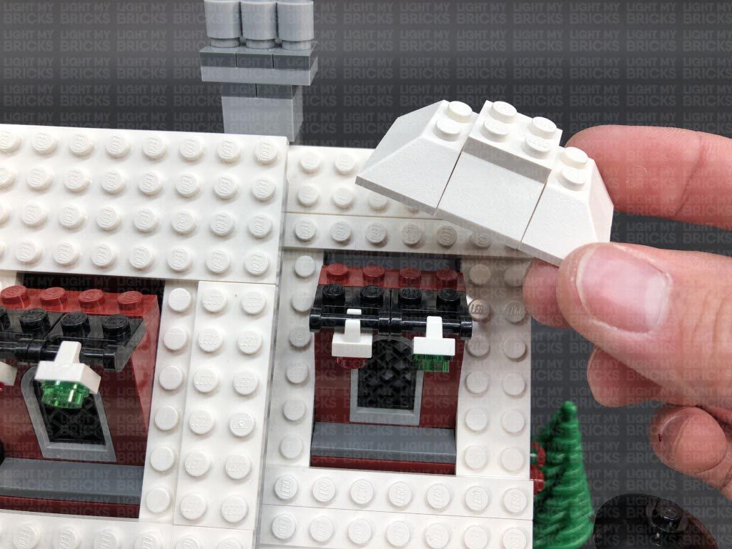
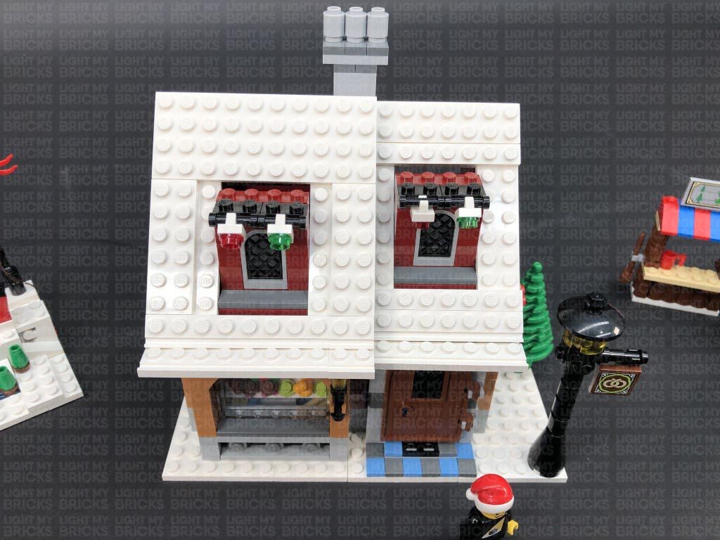
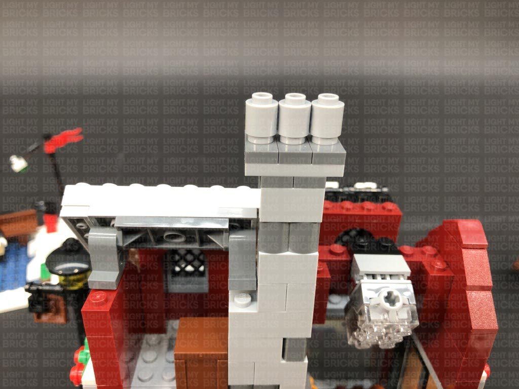
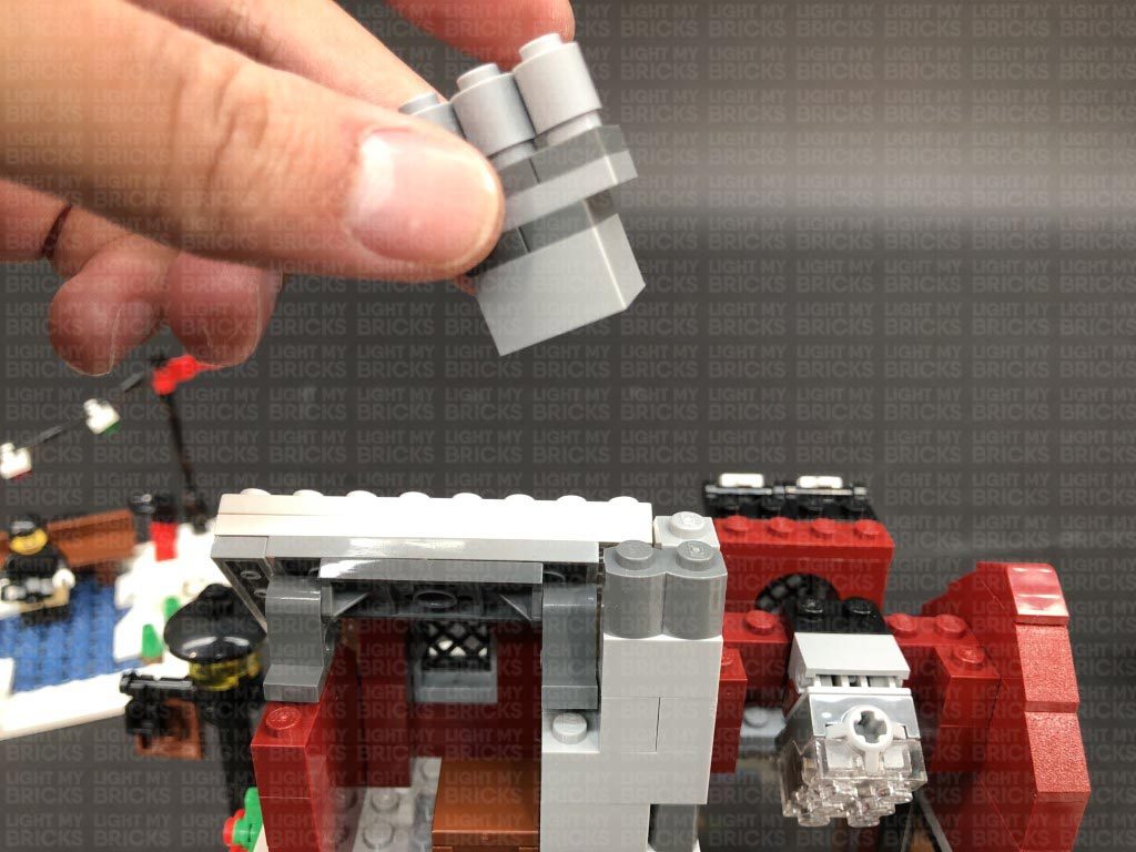
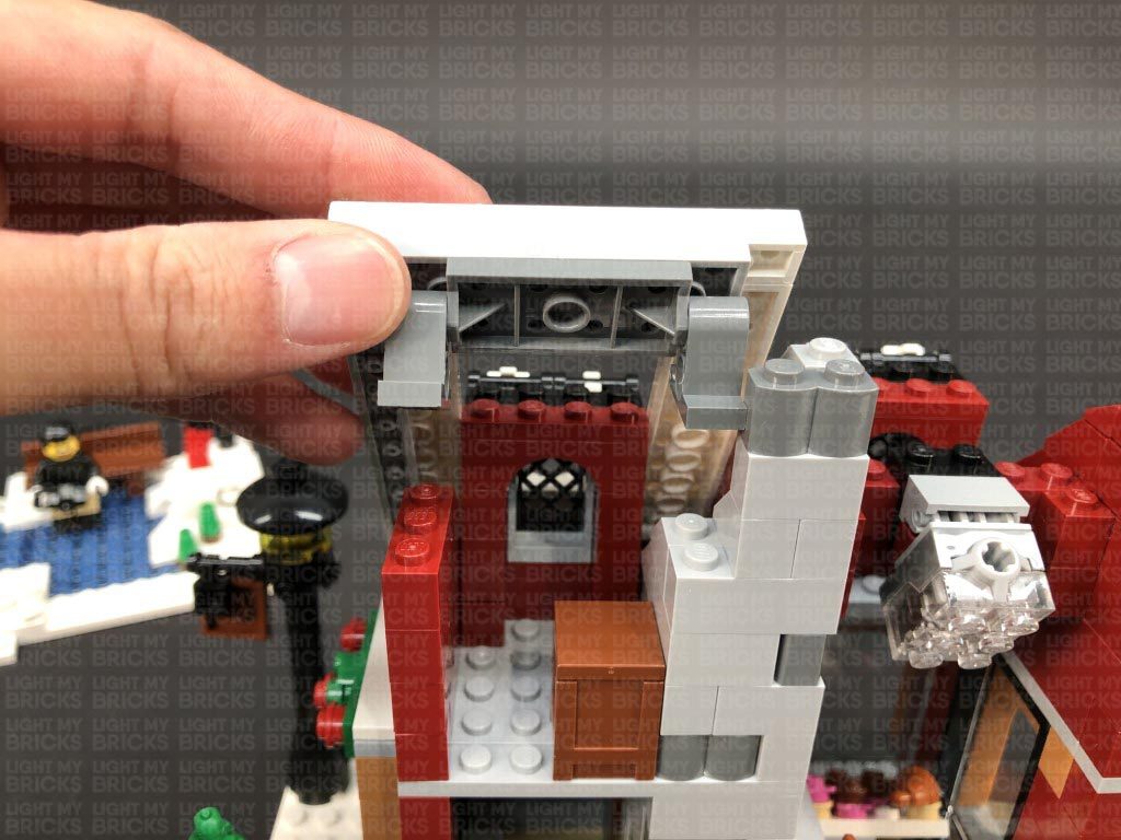
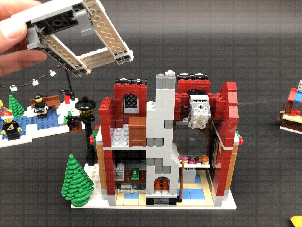
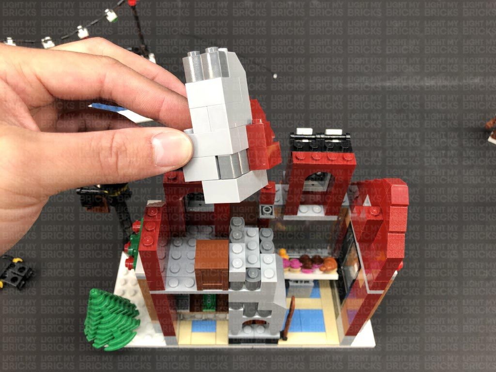
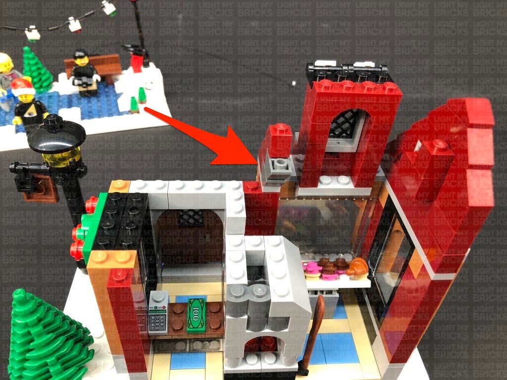
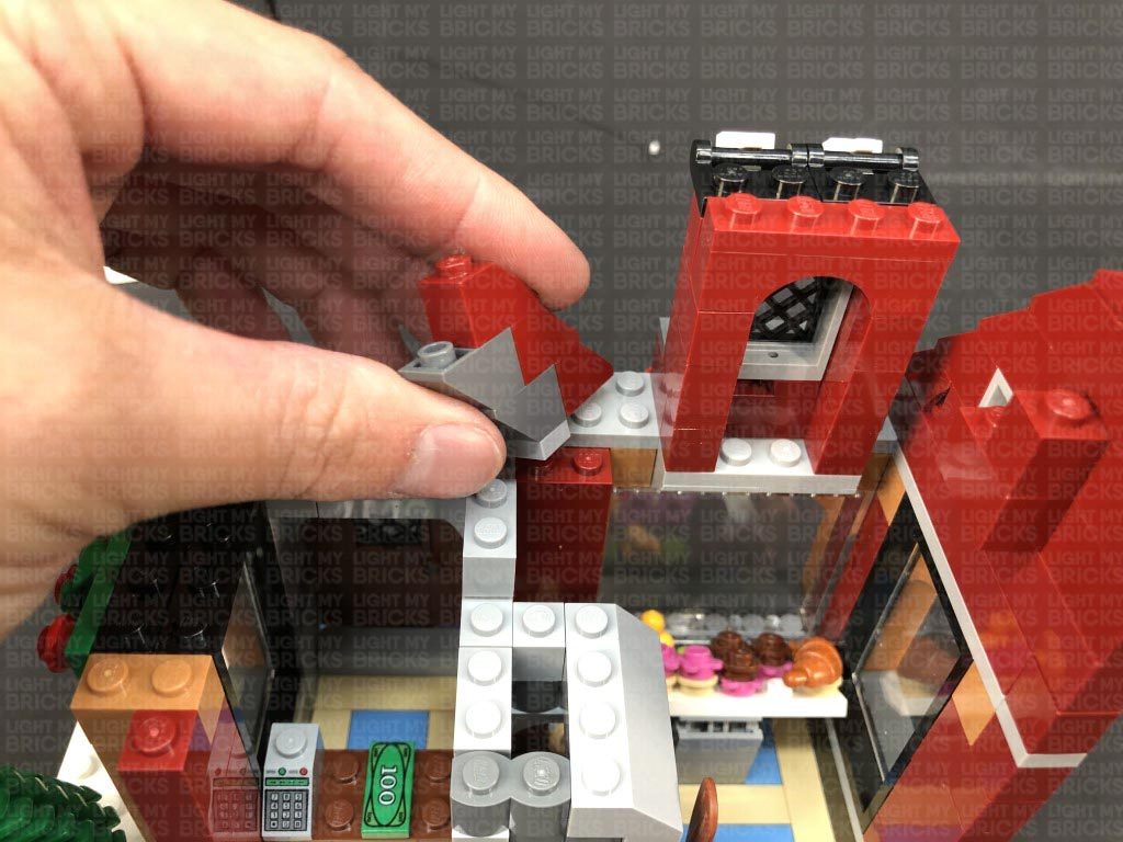
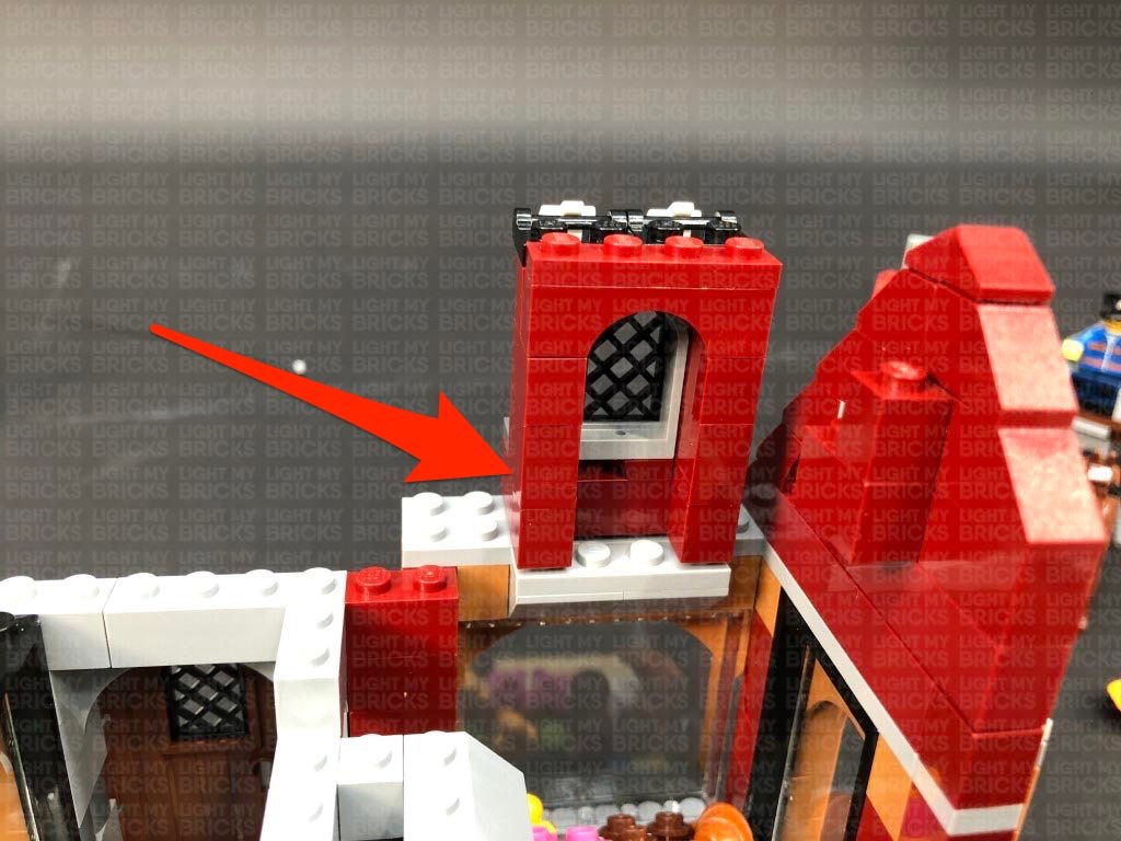
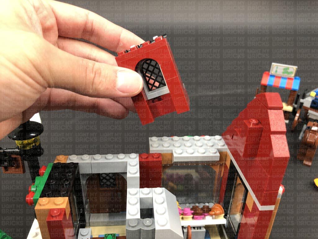
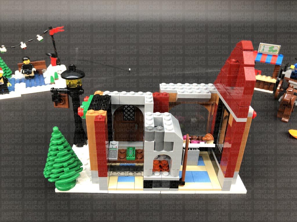
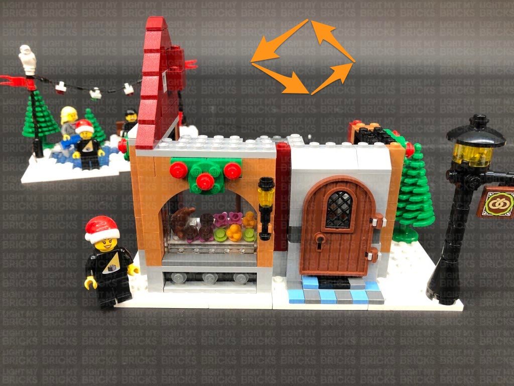
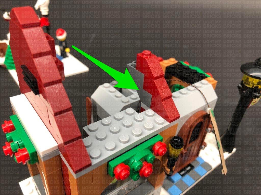
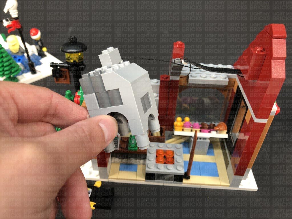
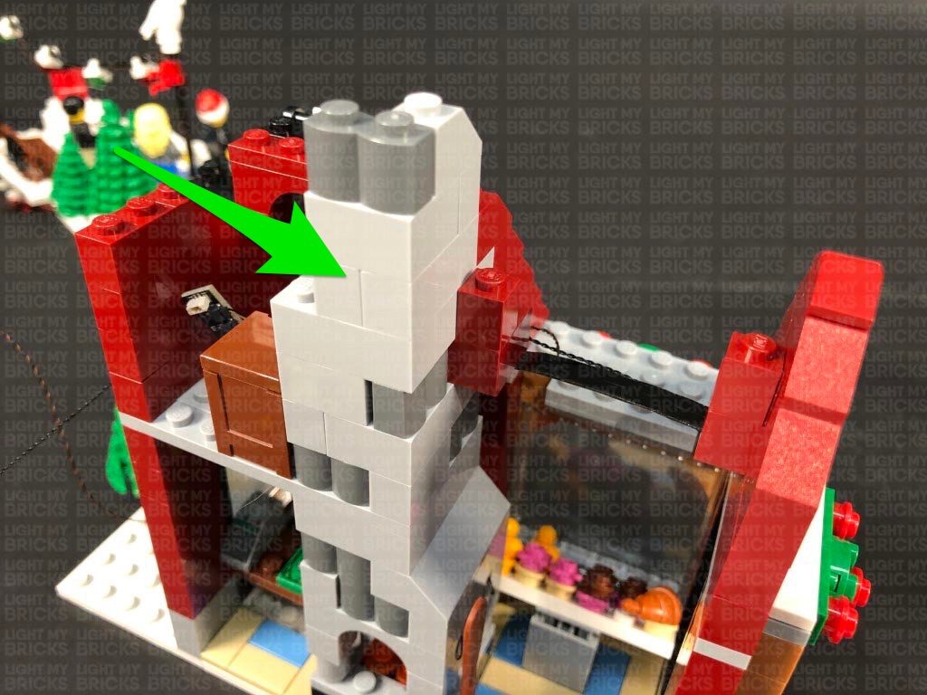
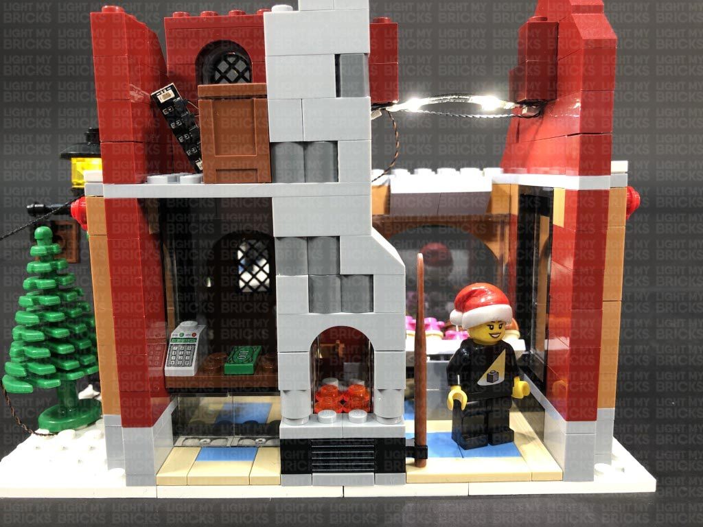
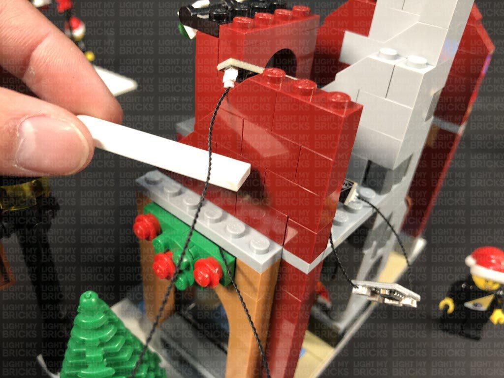
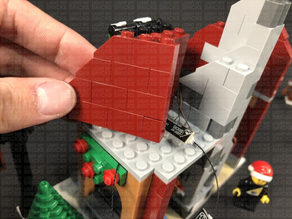
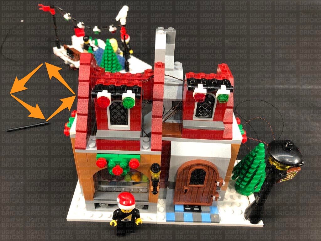
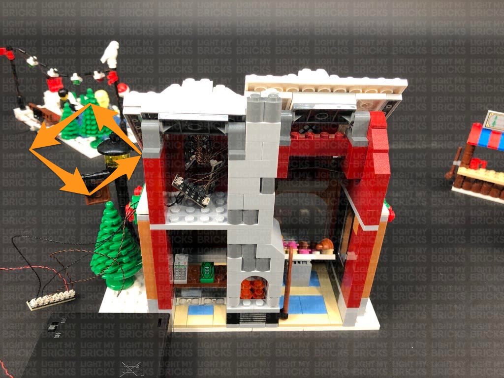
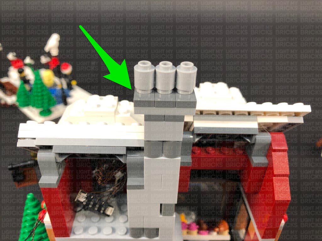
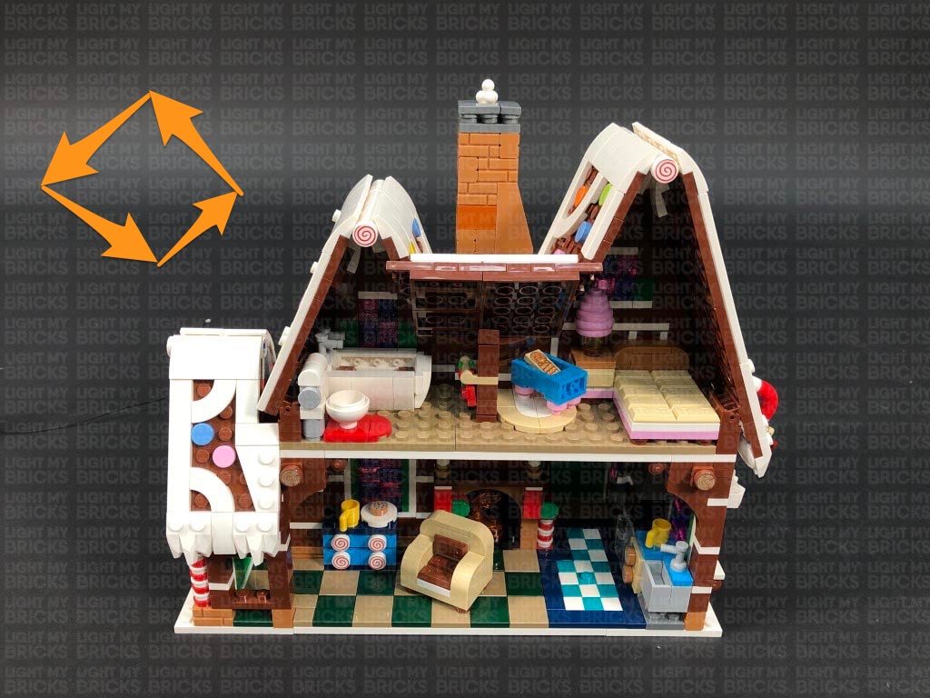
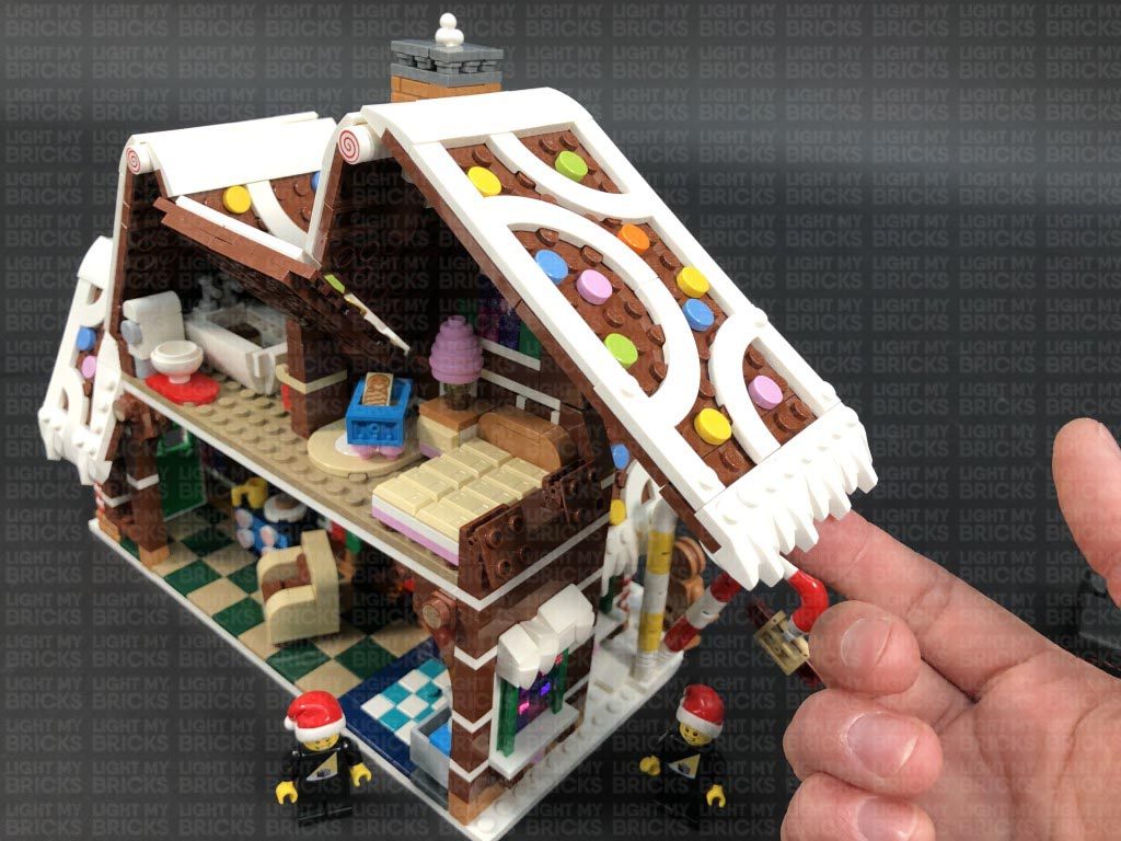
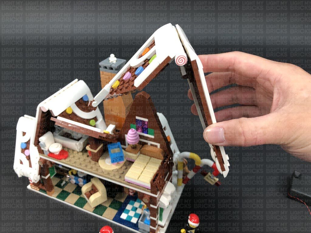
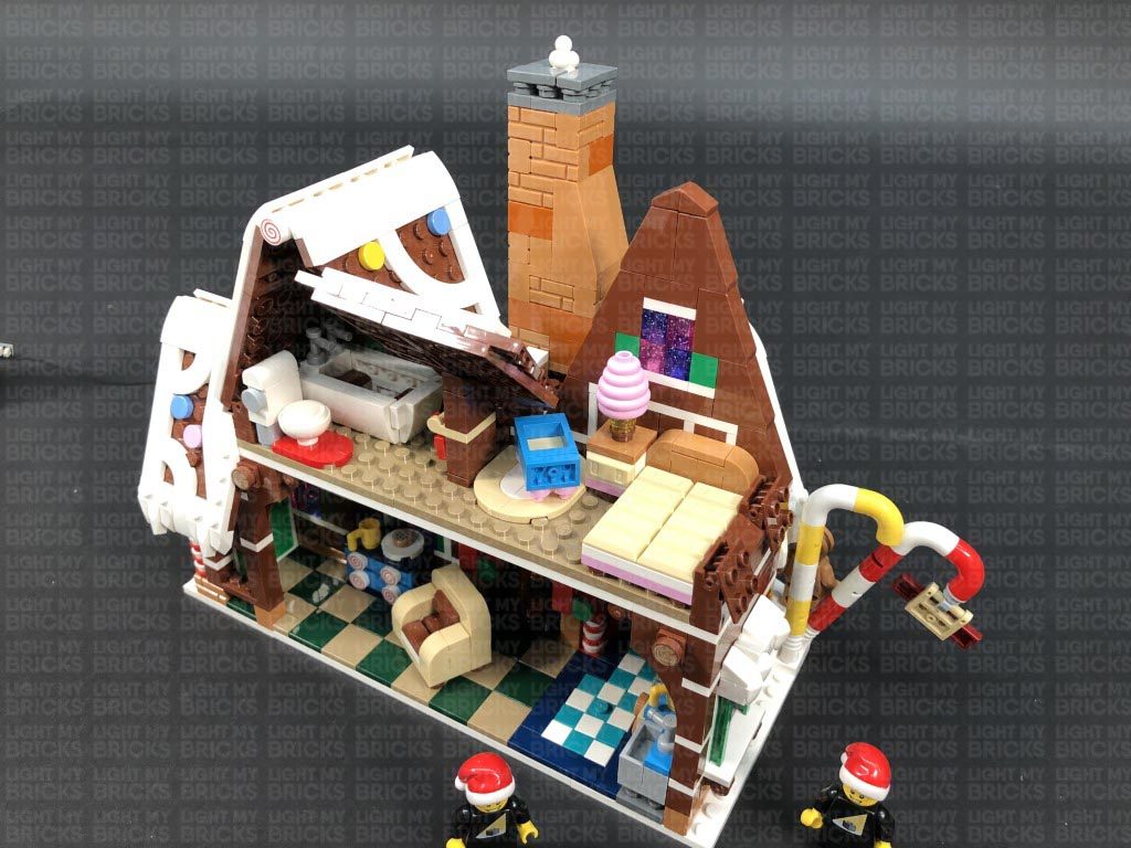
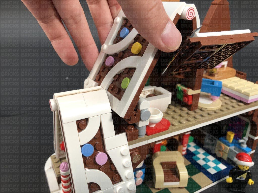
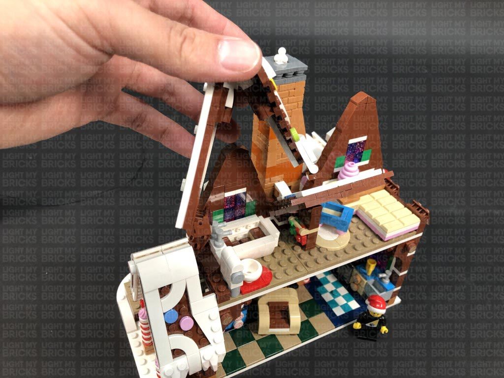
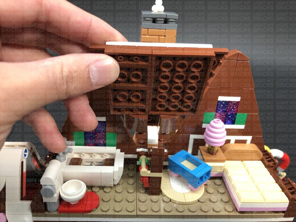
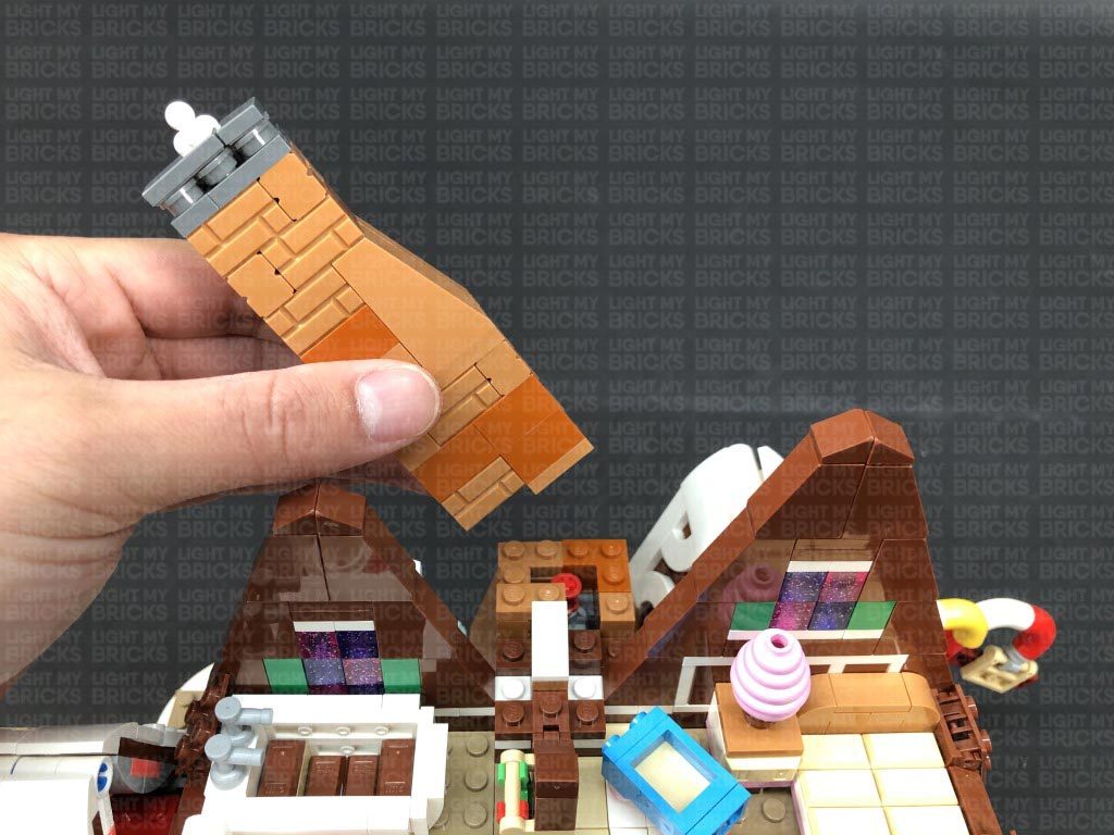
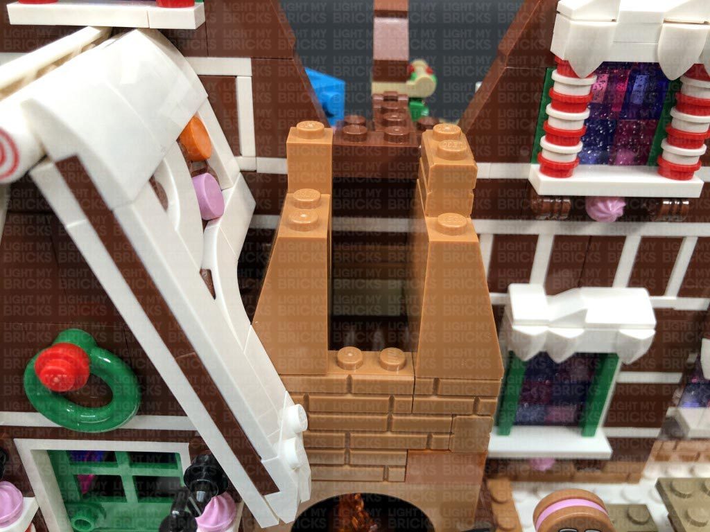
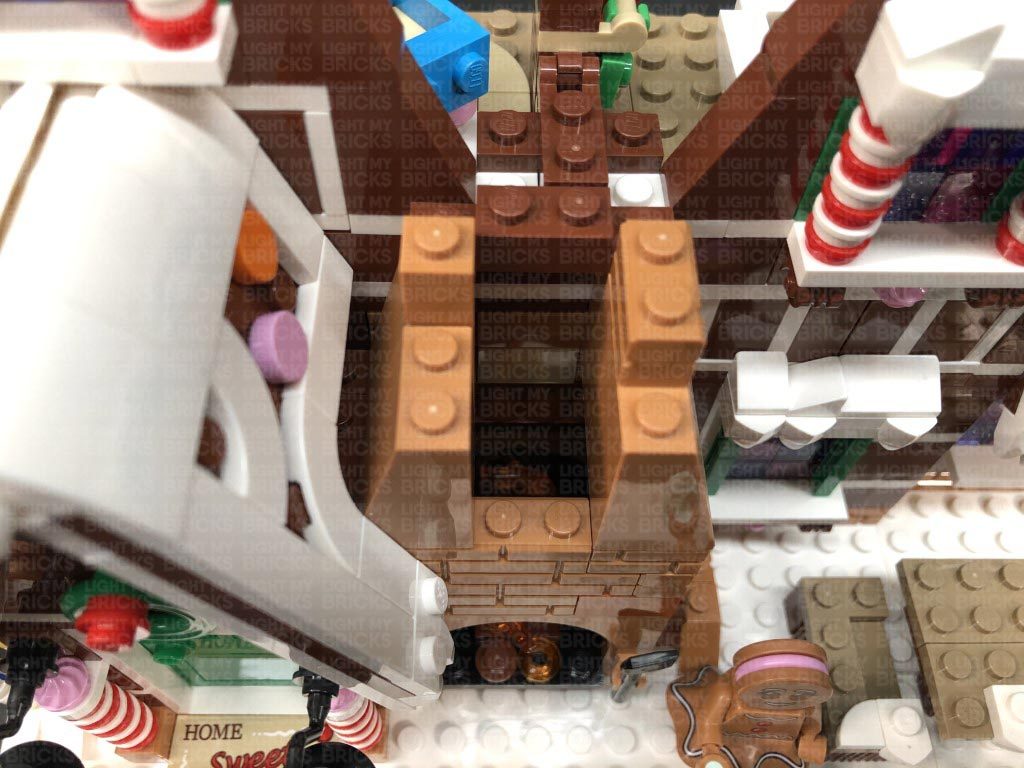
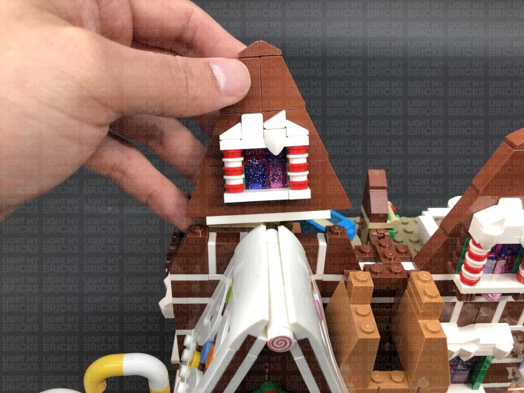
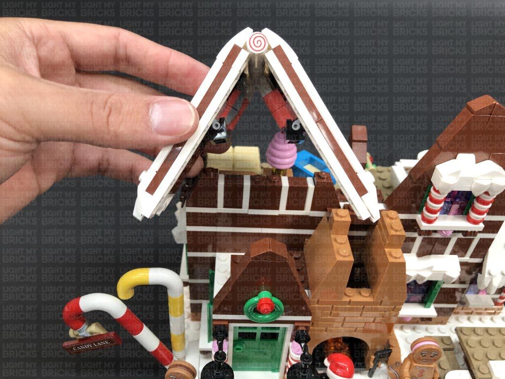
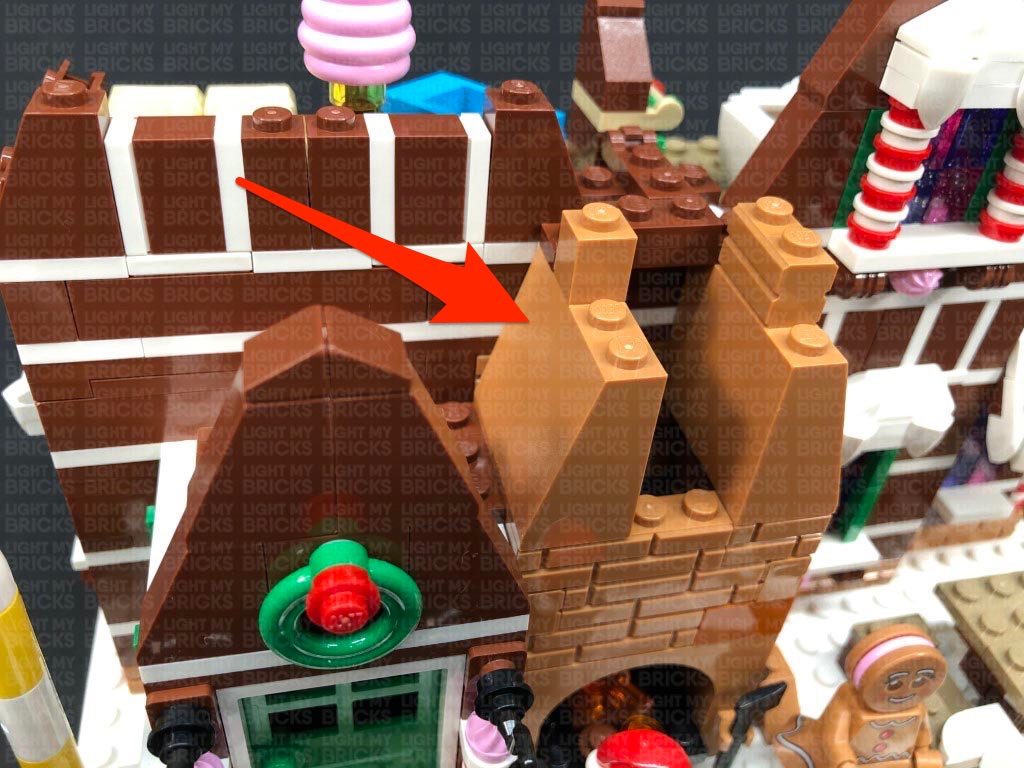
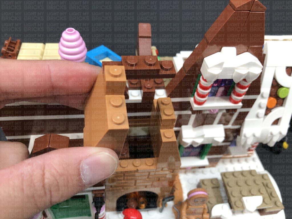
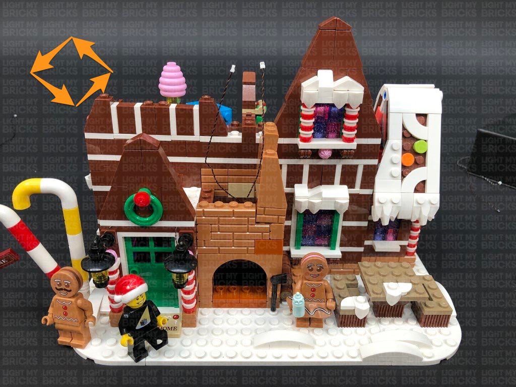
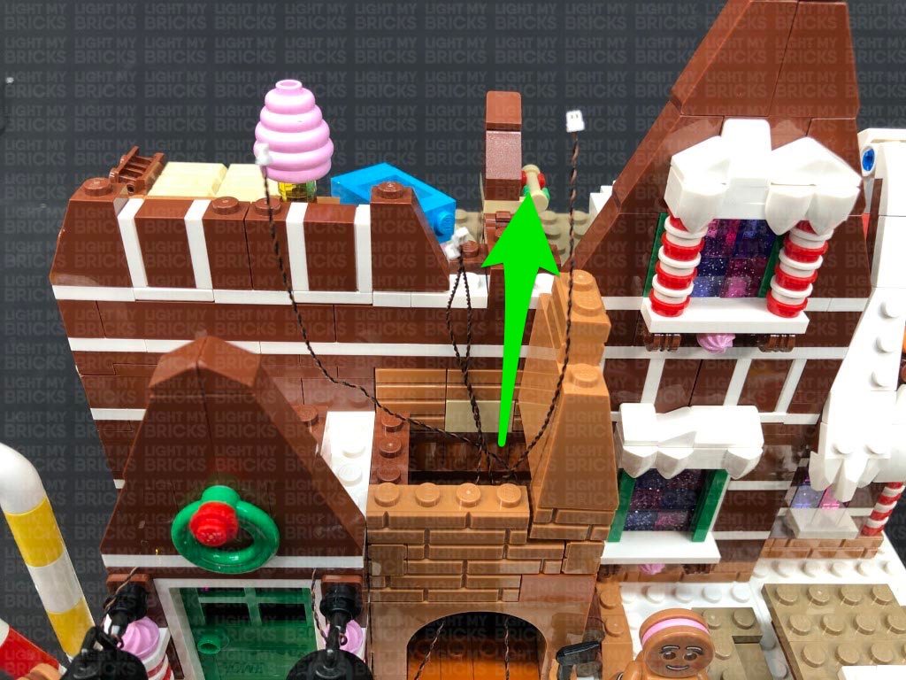
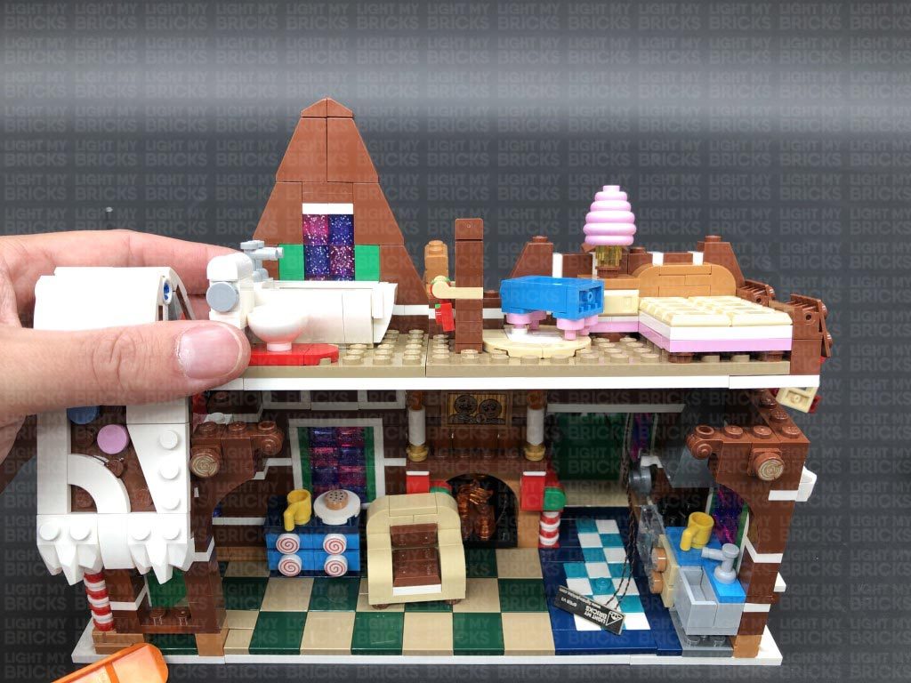
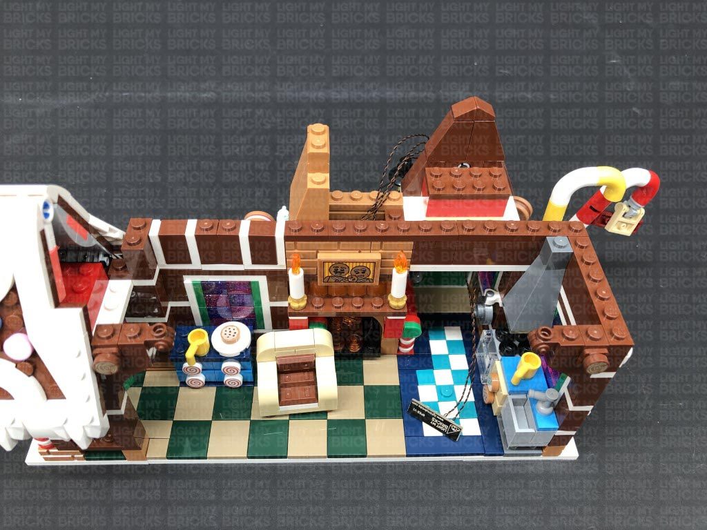
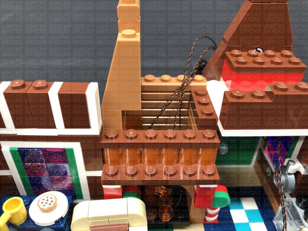
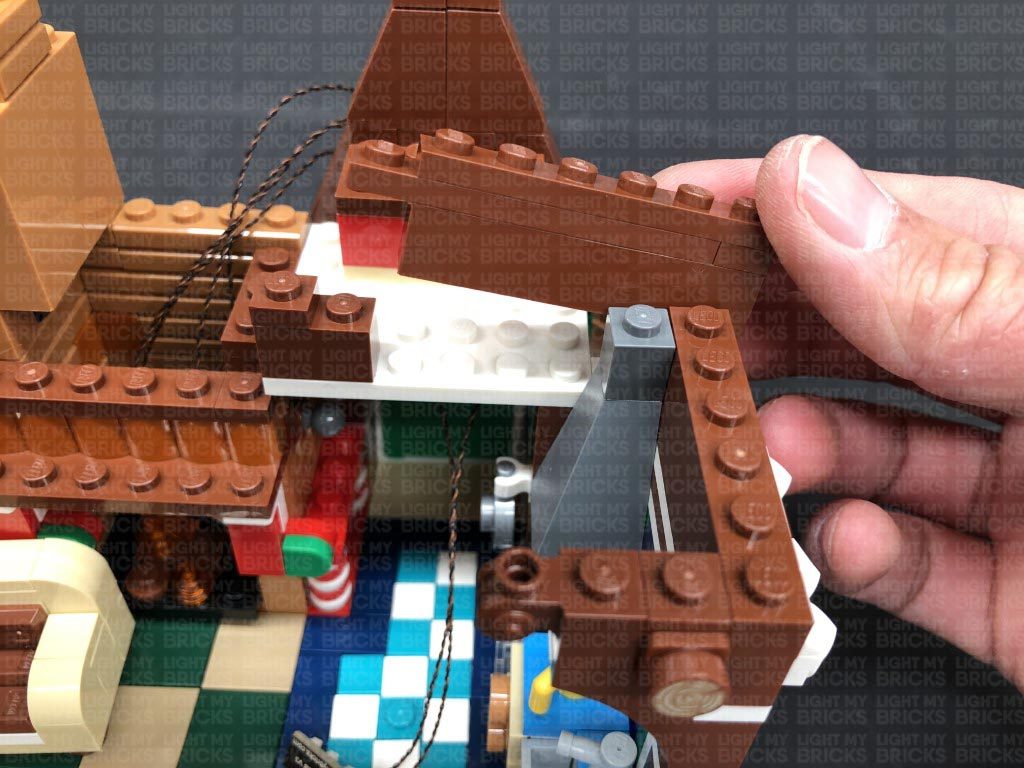
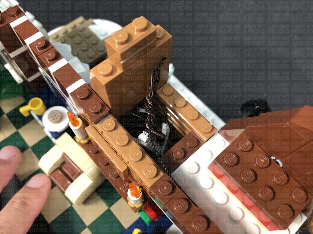
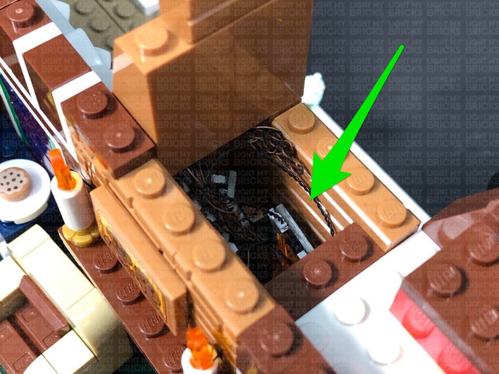
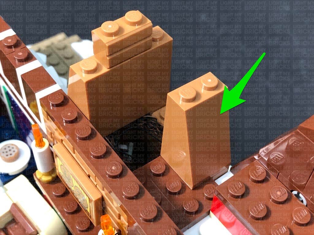
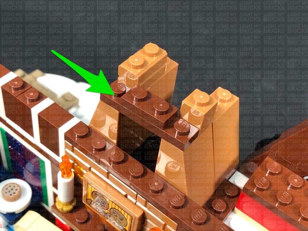
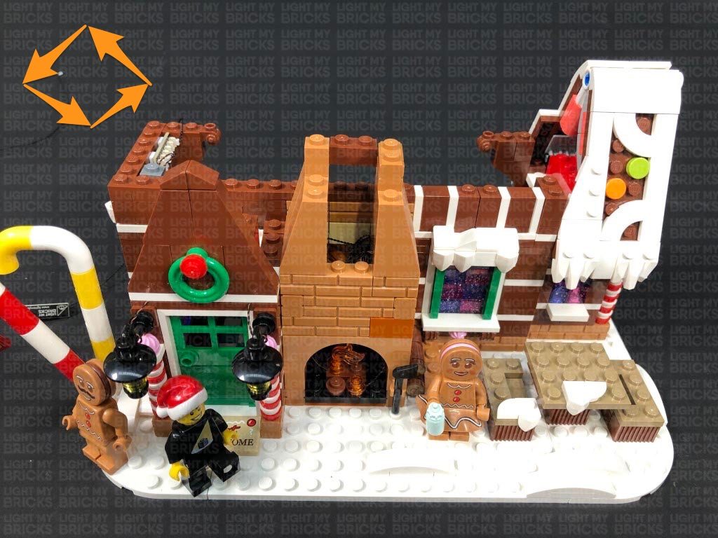
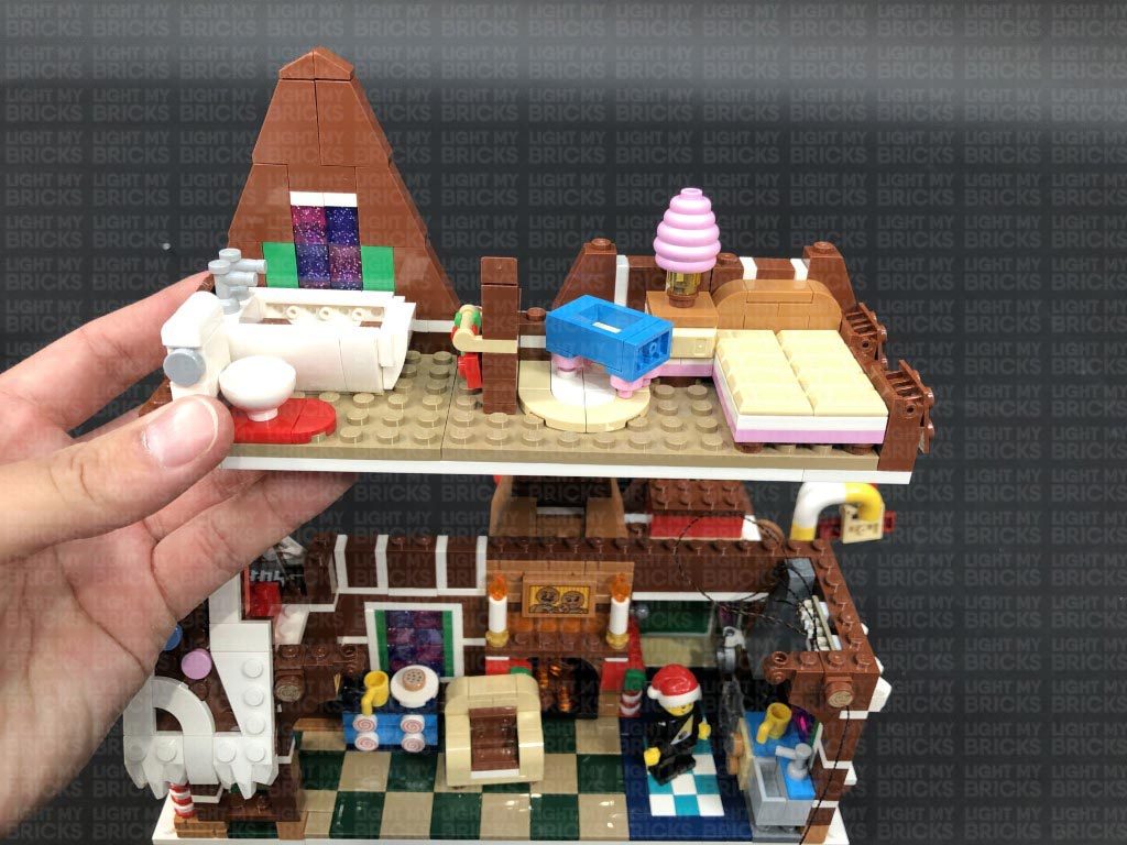
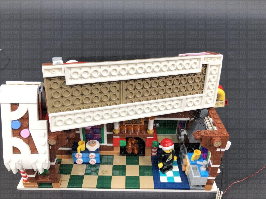
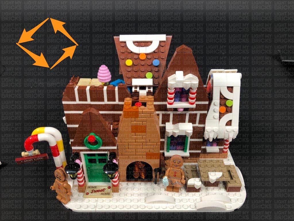
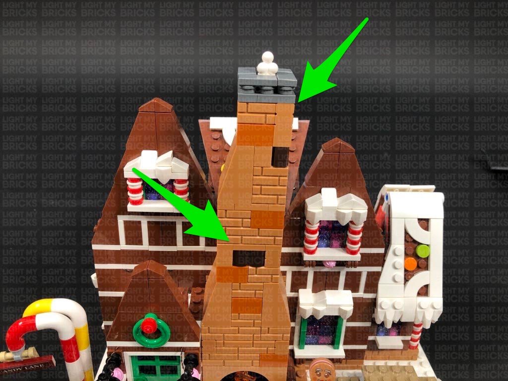
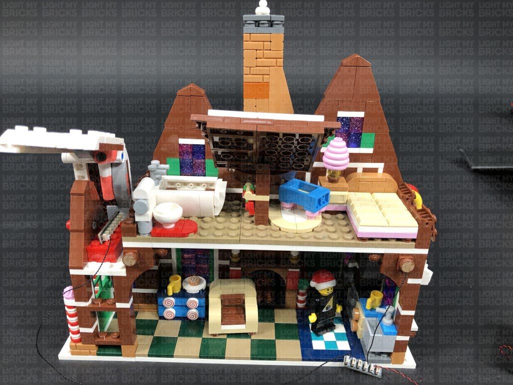
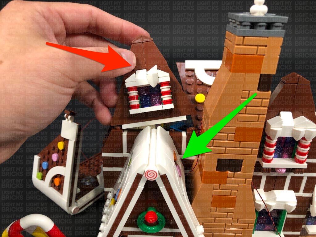
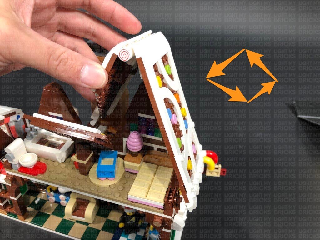
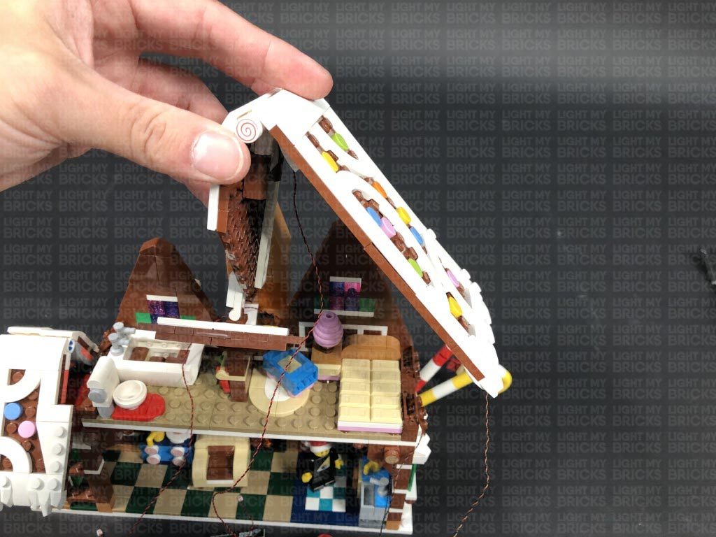
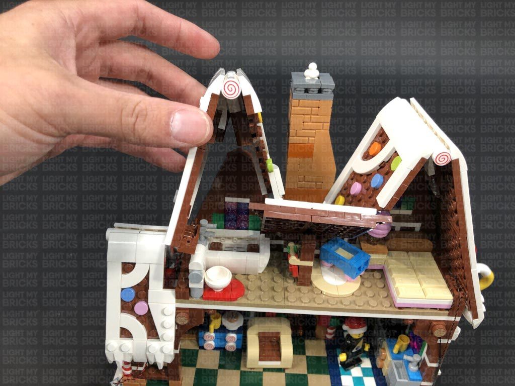
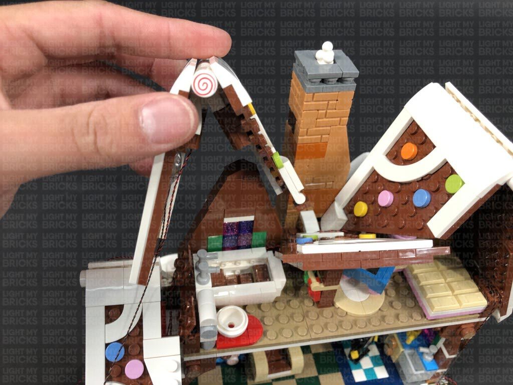
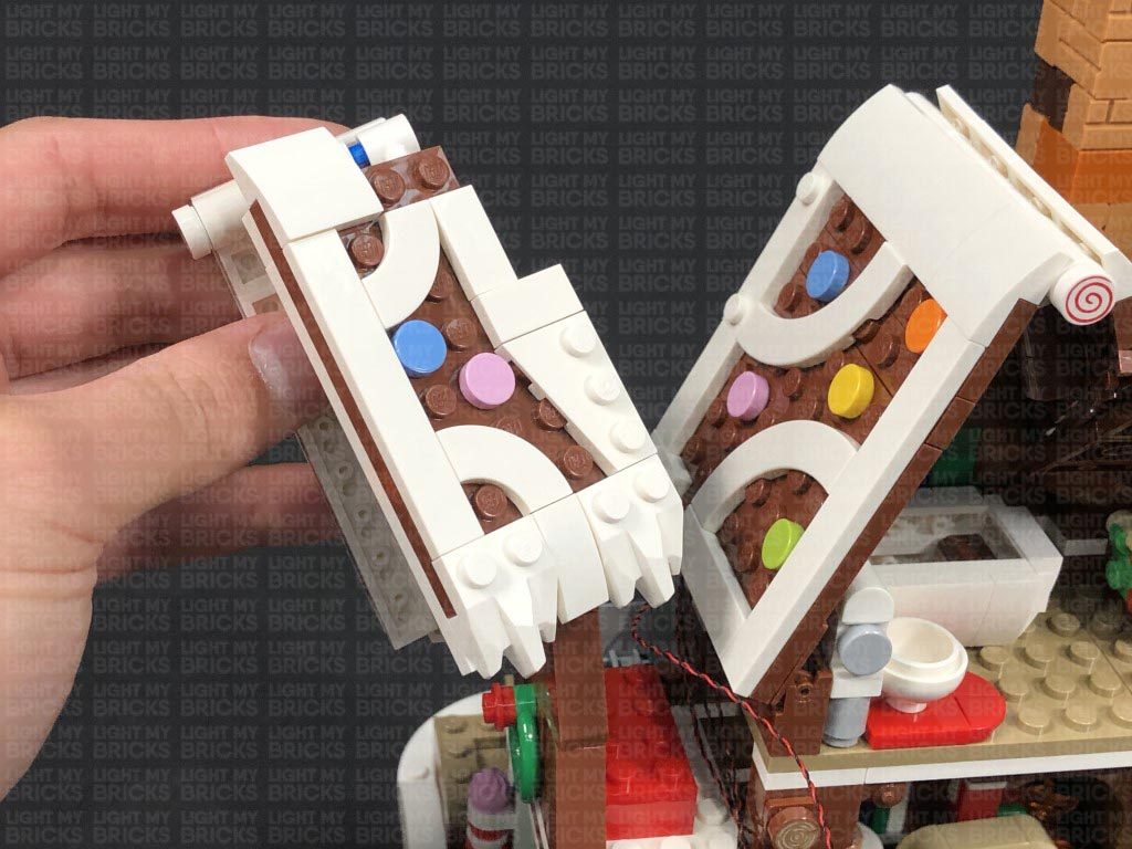
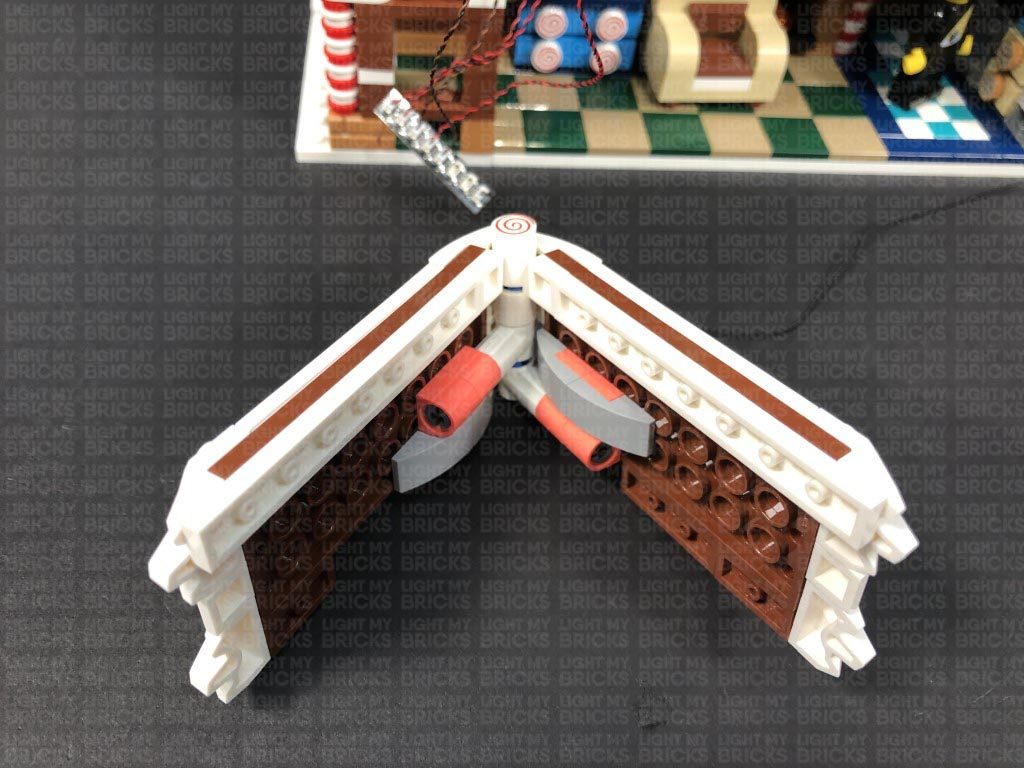
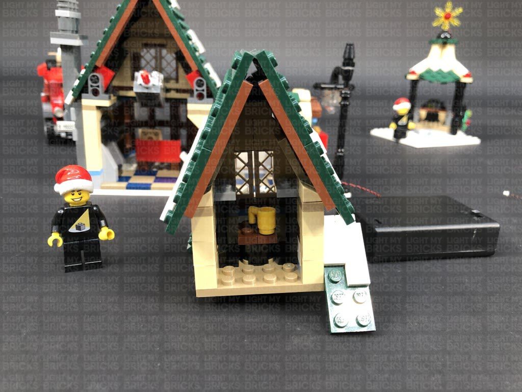
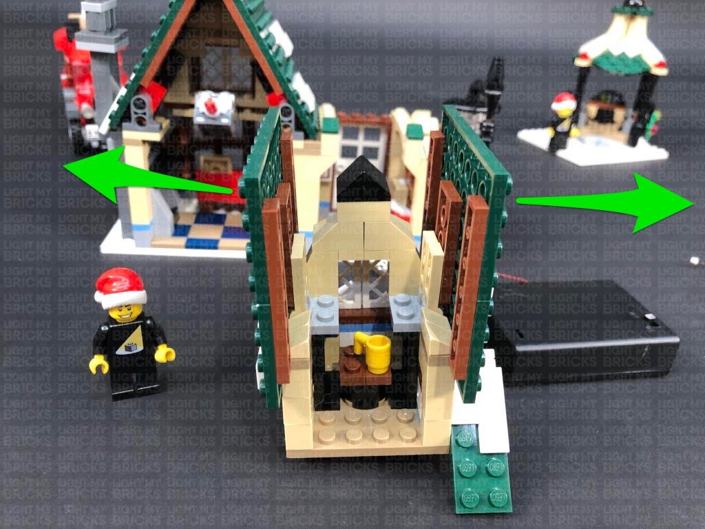
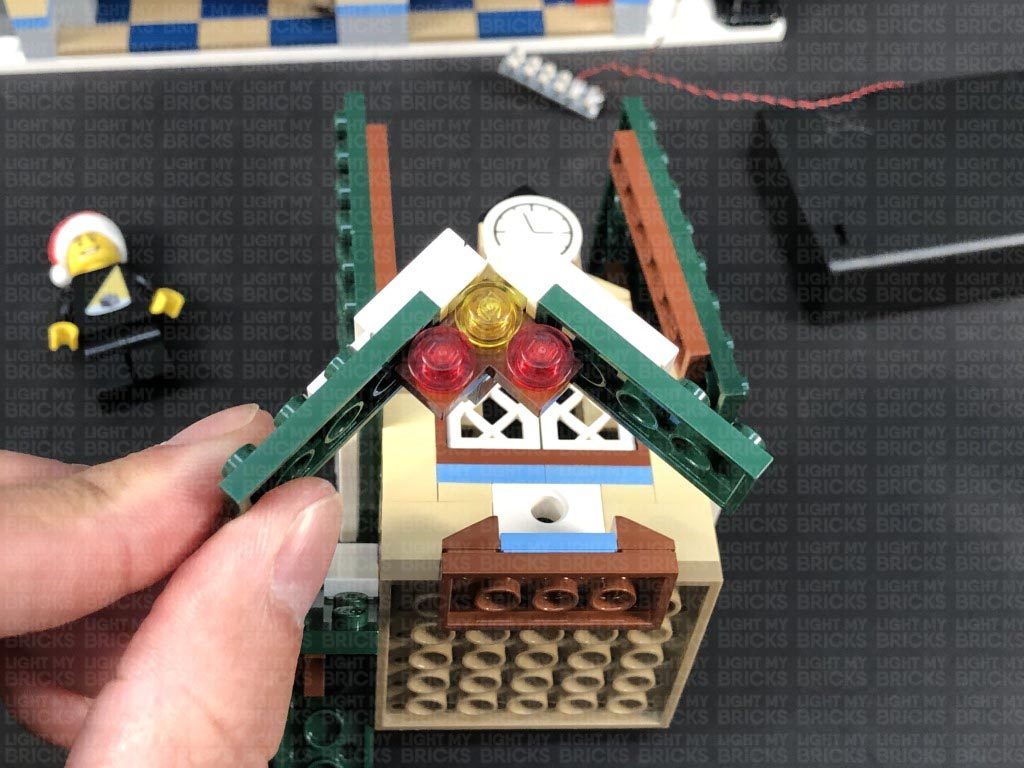
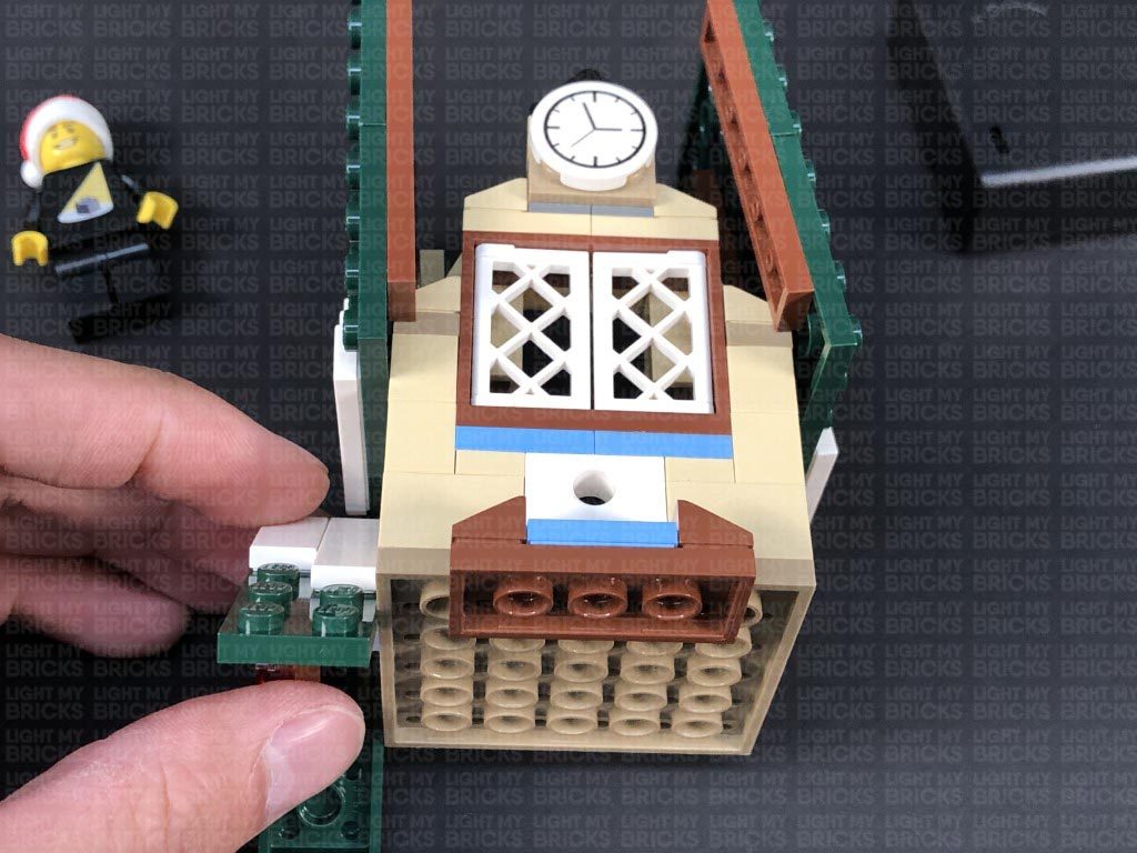
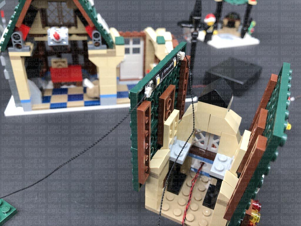
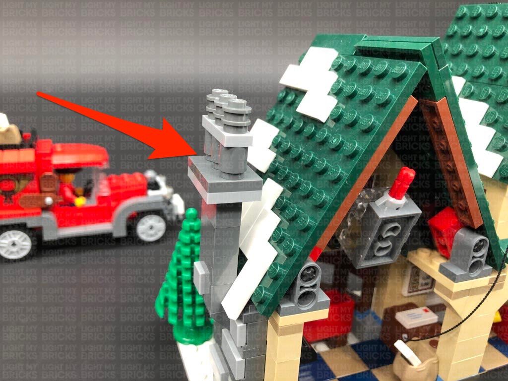
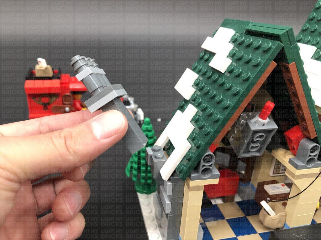
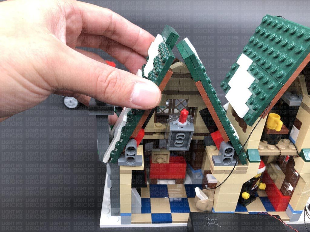
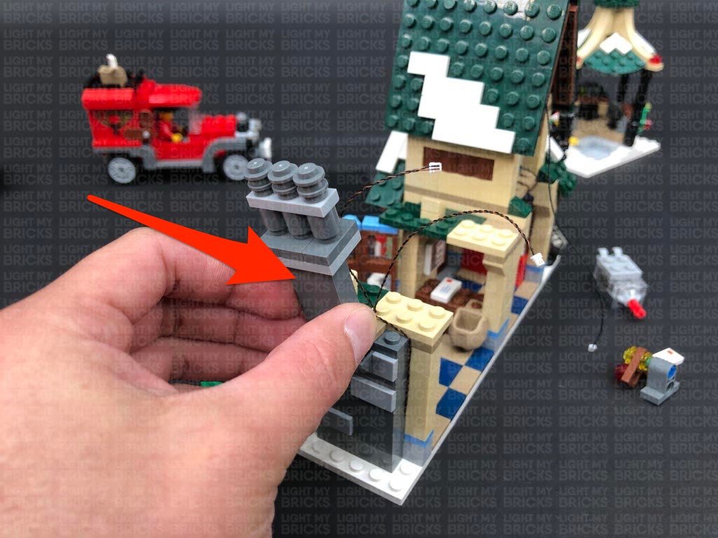
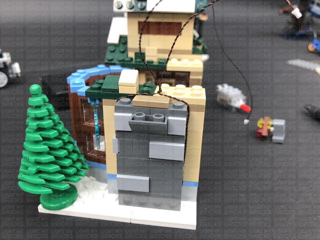
9.) We will now install lights to the bakery. First disconnect the sections just above the windows, then turn the set around and remove the roof and chimney sections as shown below.
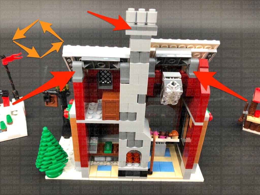
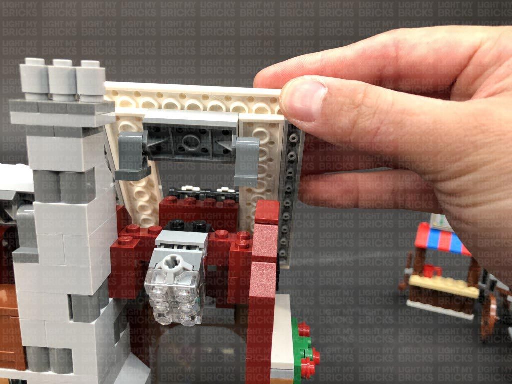
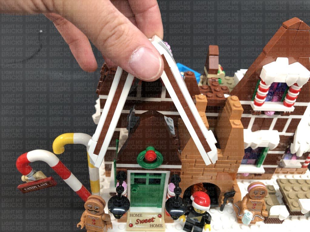
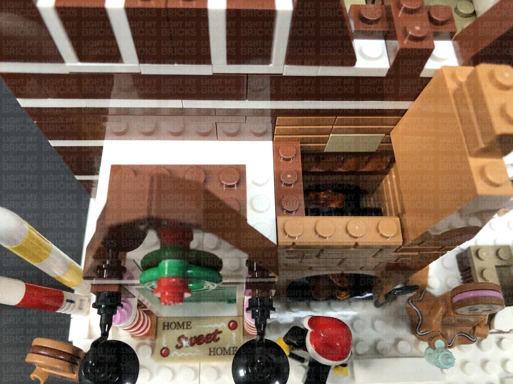
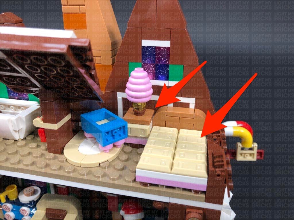
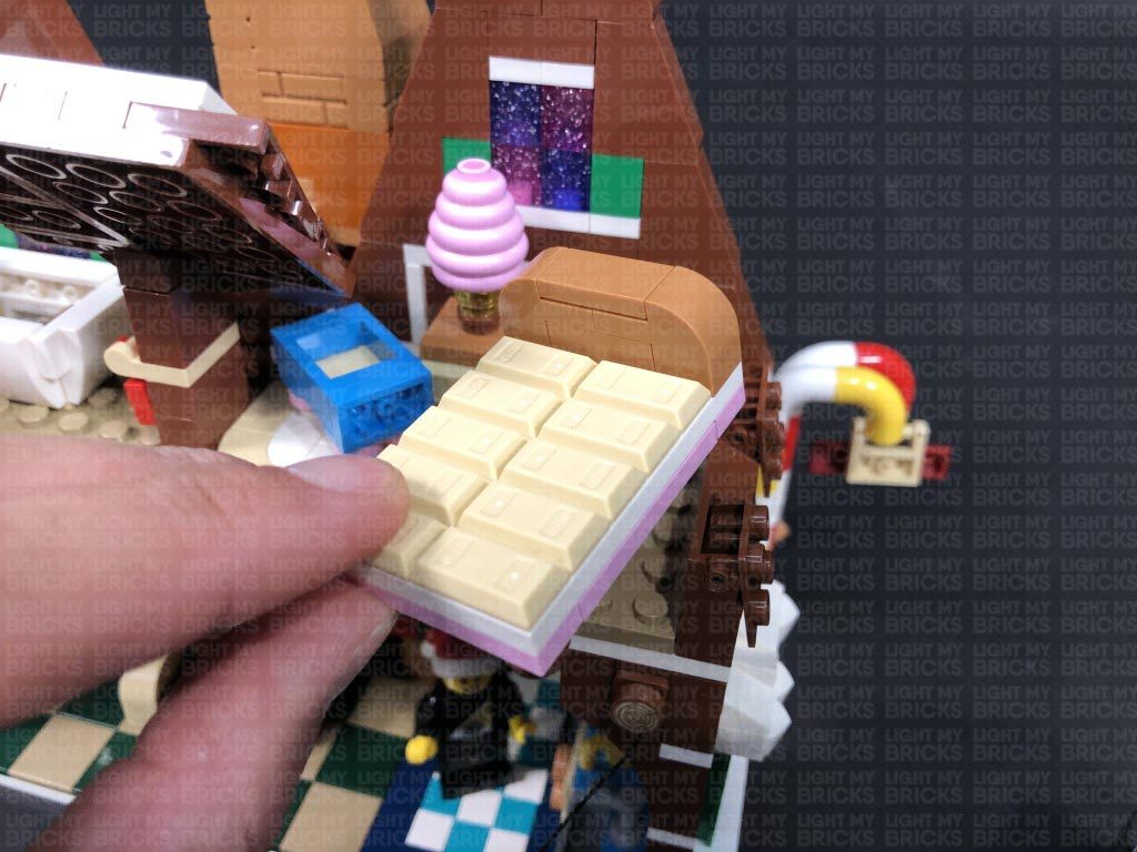
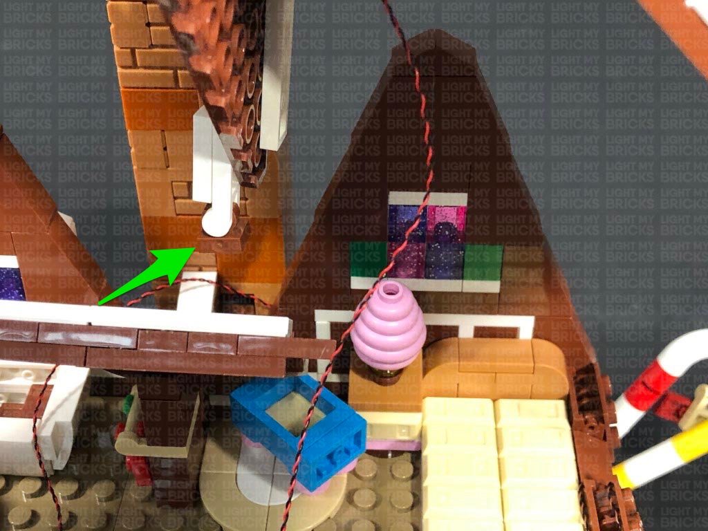
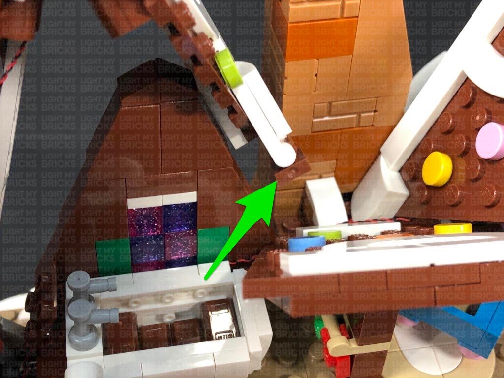
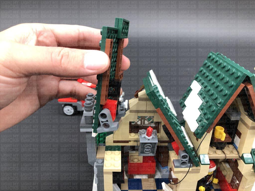
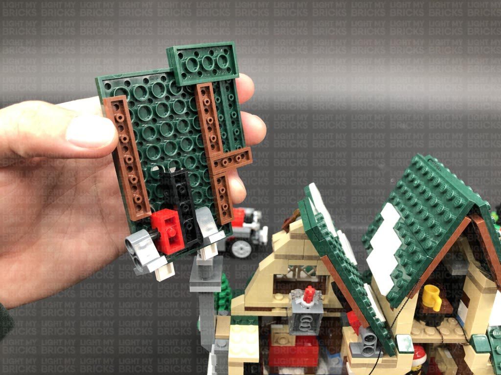
Follow the below images to continue to disconnect sections from the top half of the bakery.
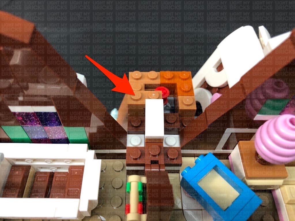
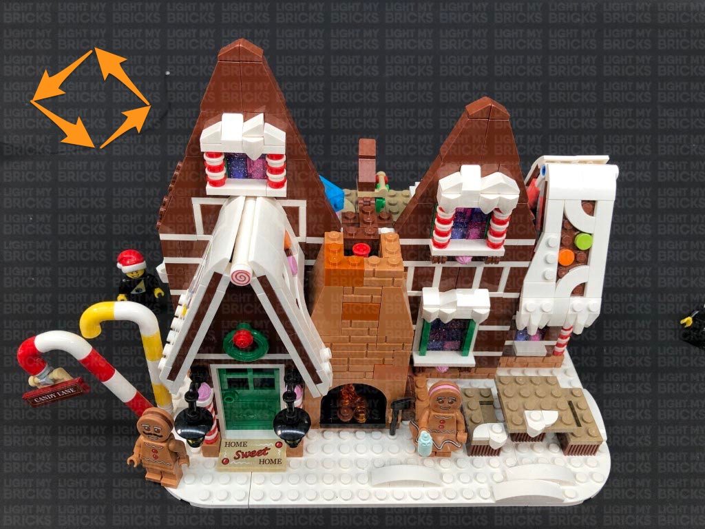
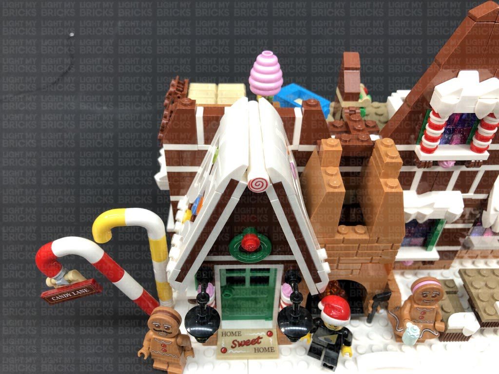
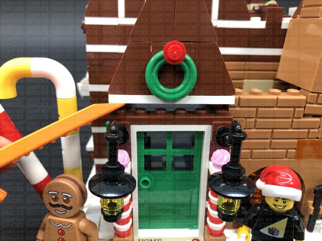
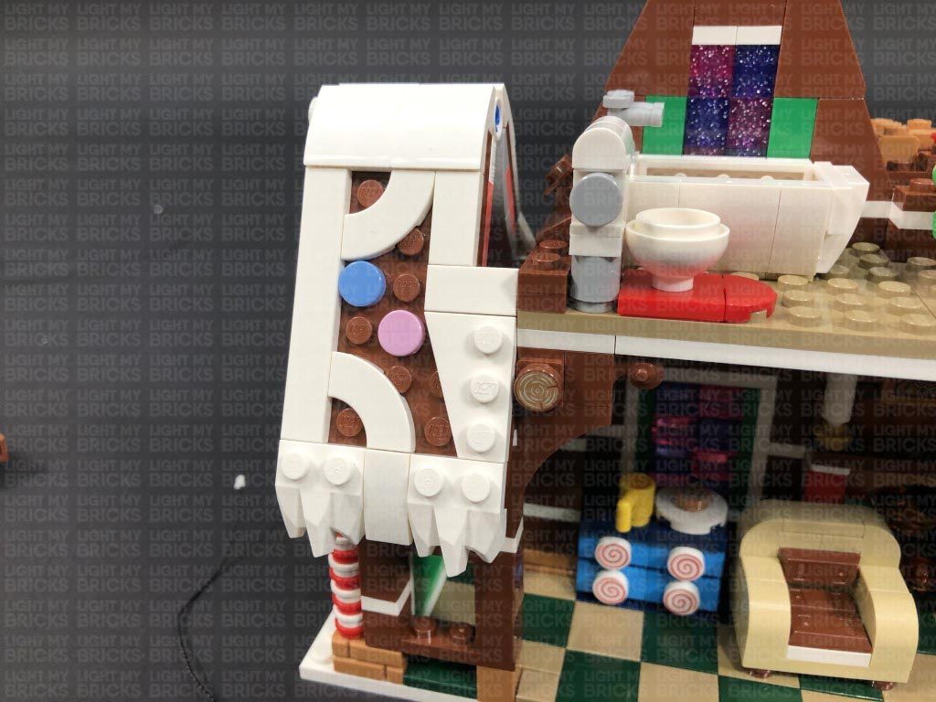
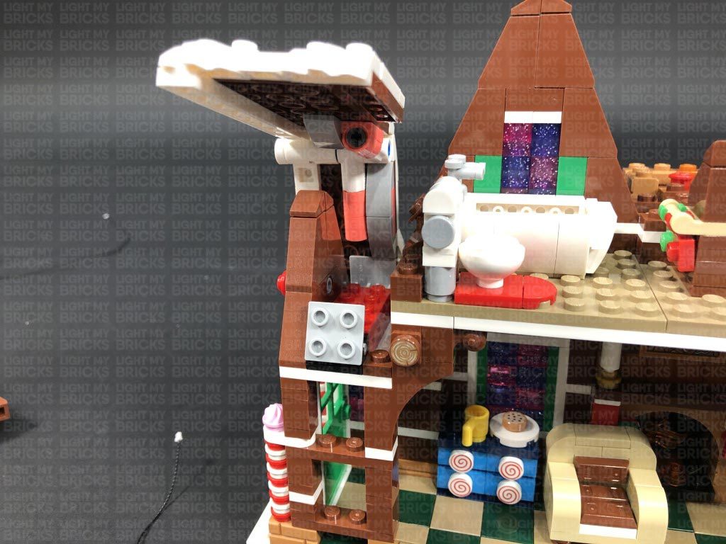
Turn the set around to the front and disconnect the following sections surrounding the front window.
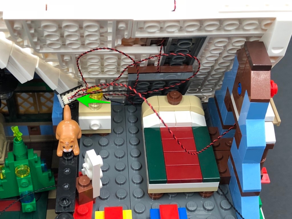
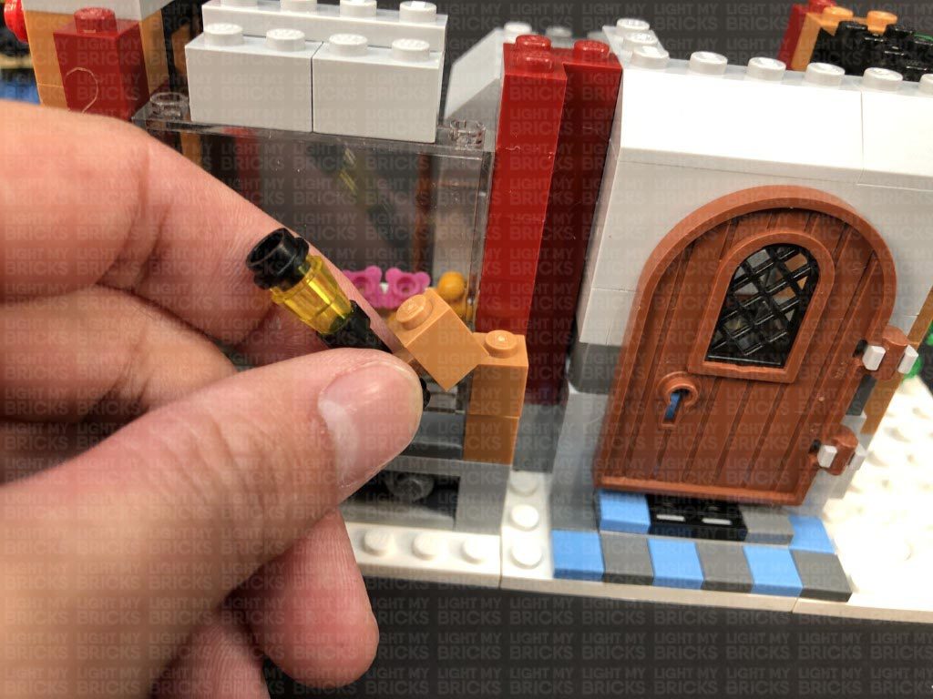
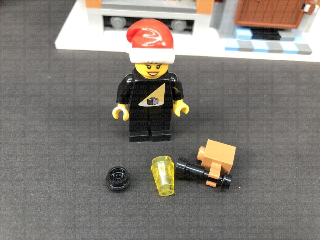
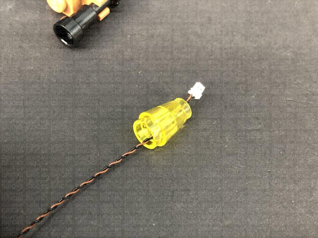
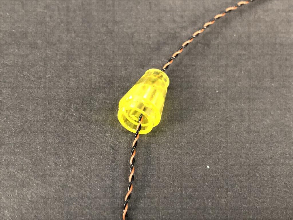
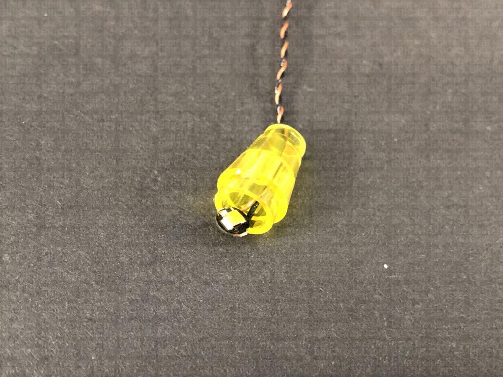
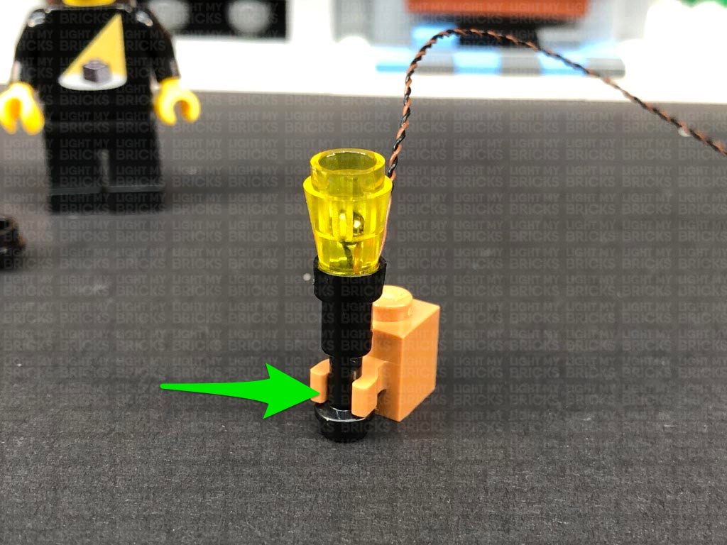
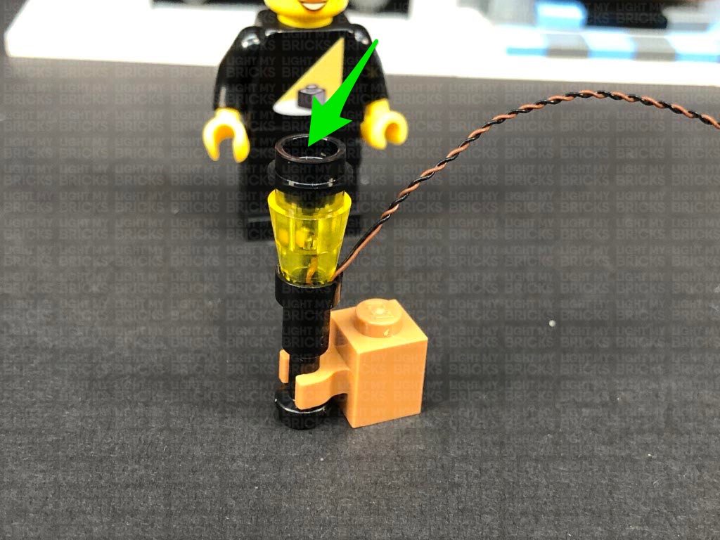
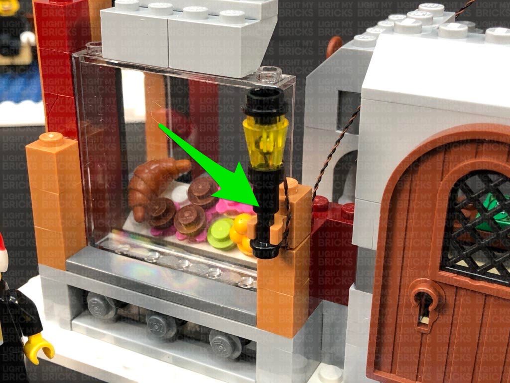
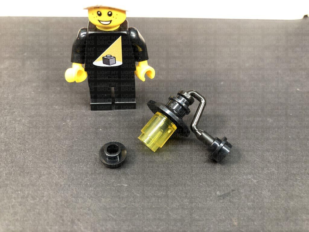
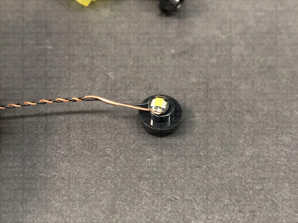
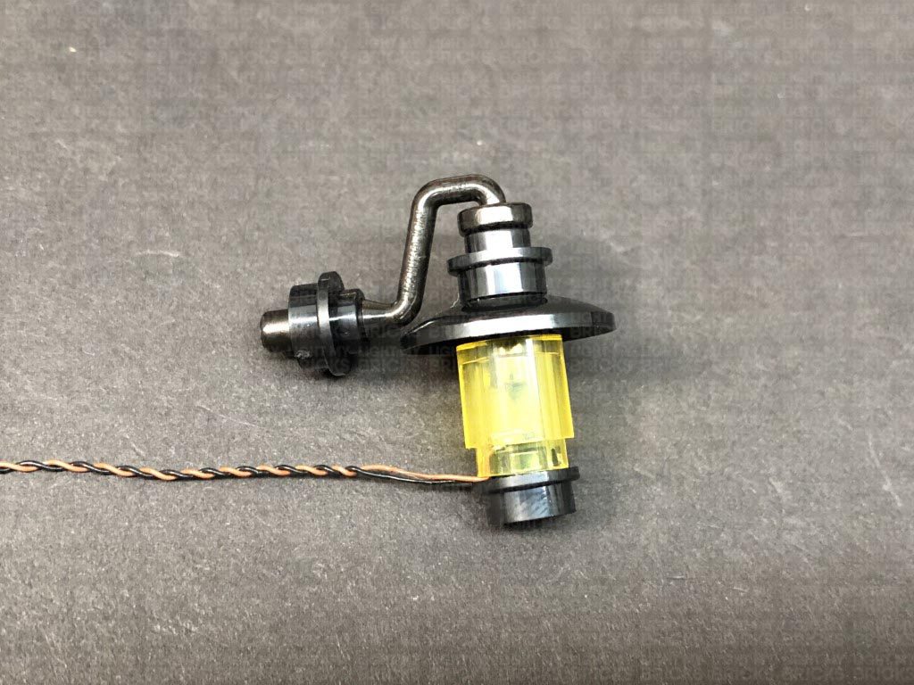
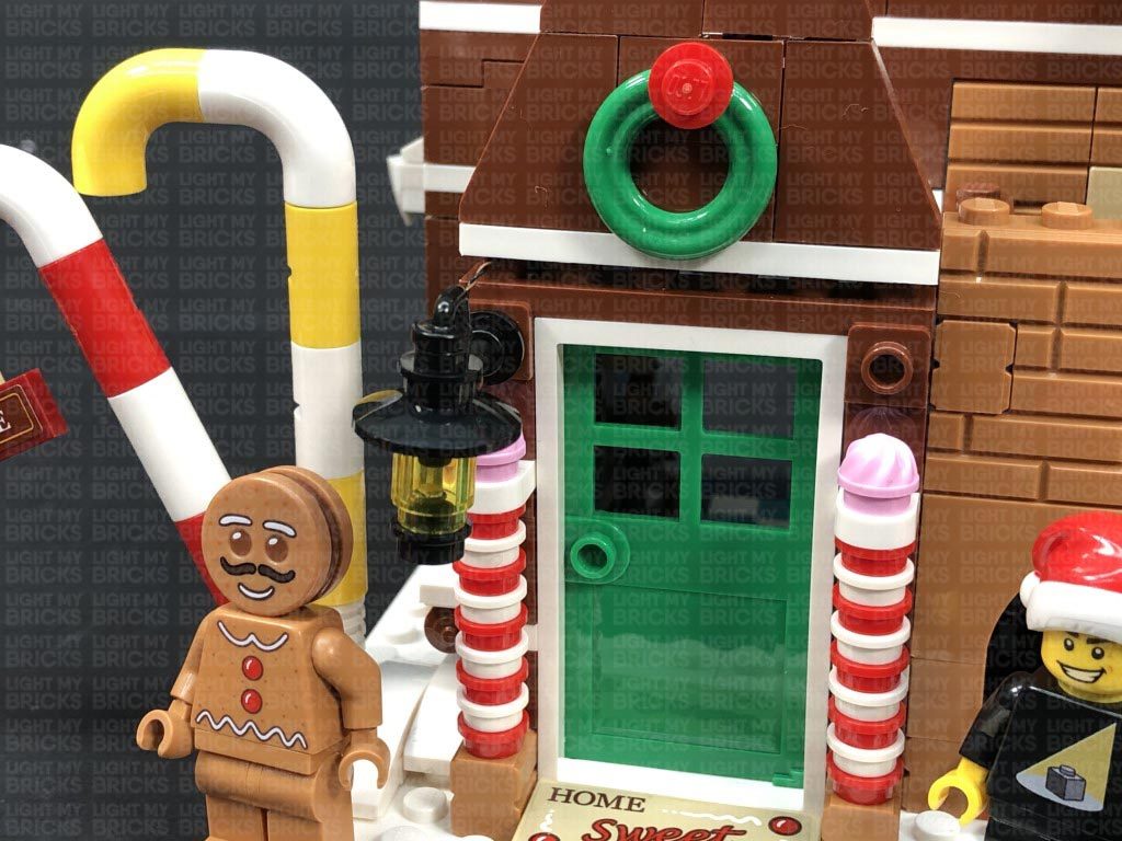
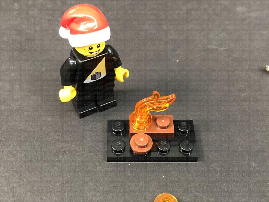
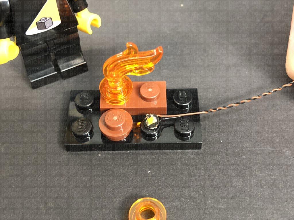
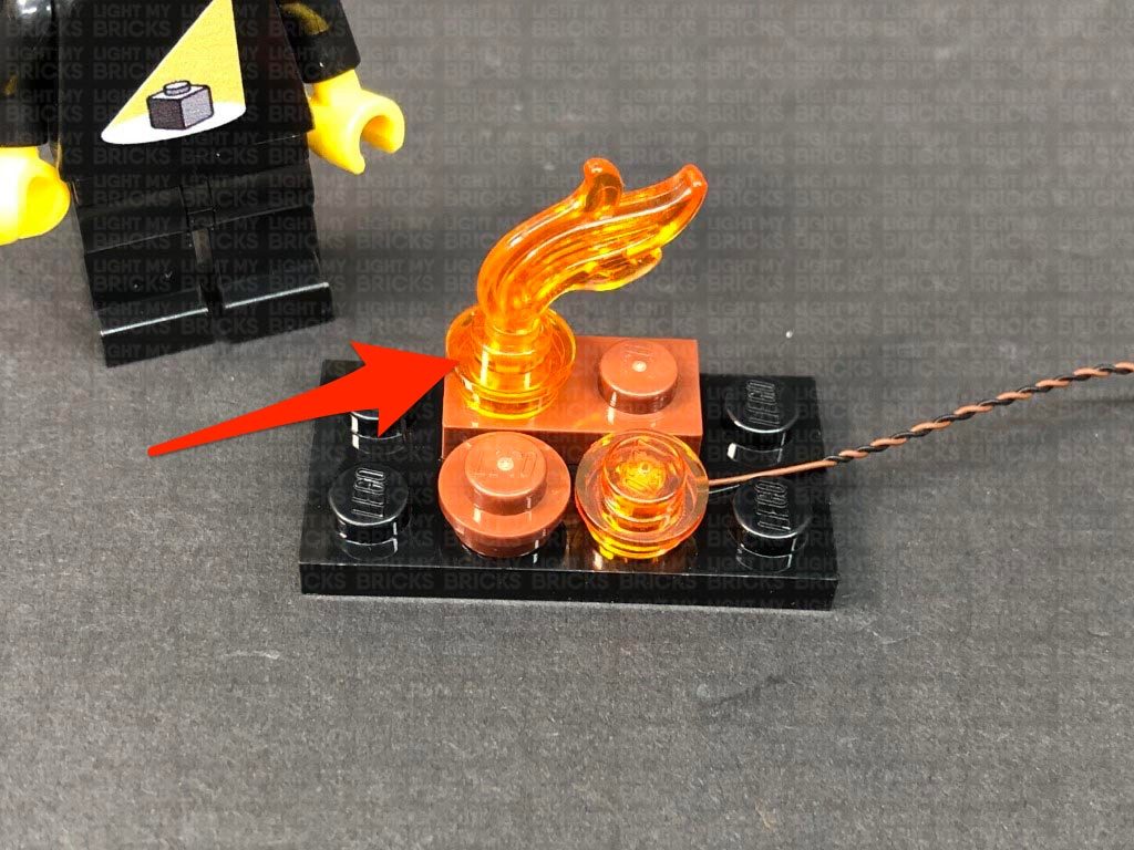
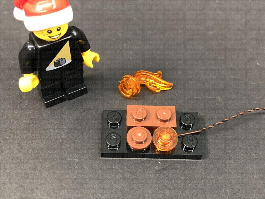
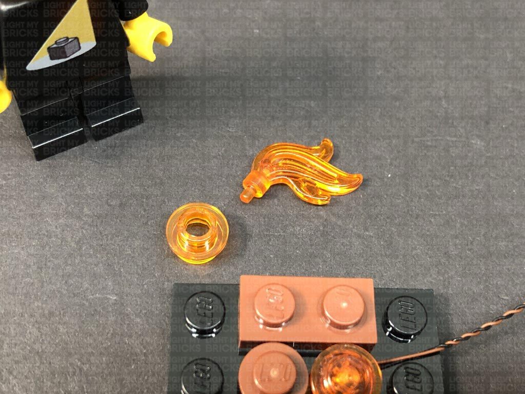
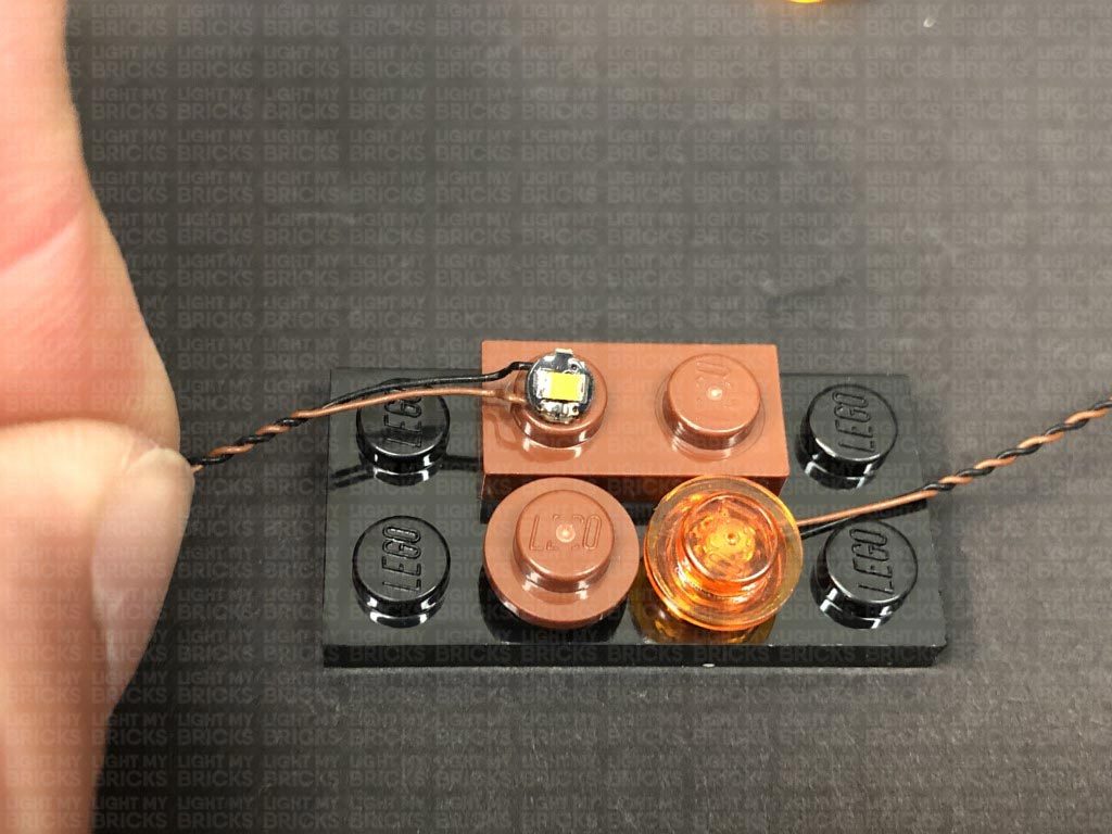
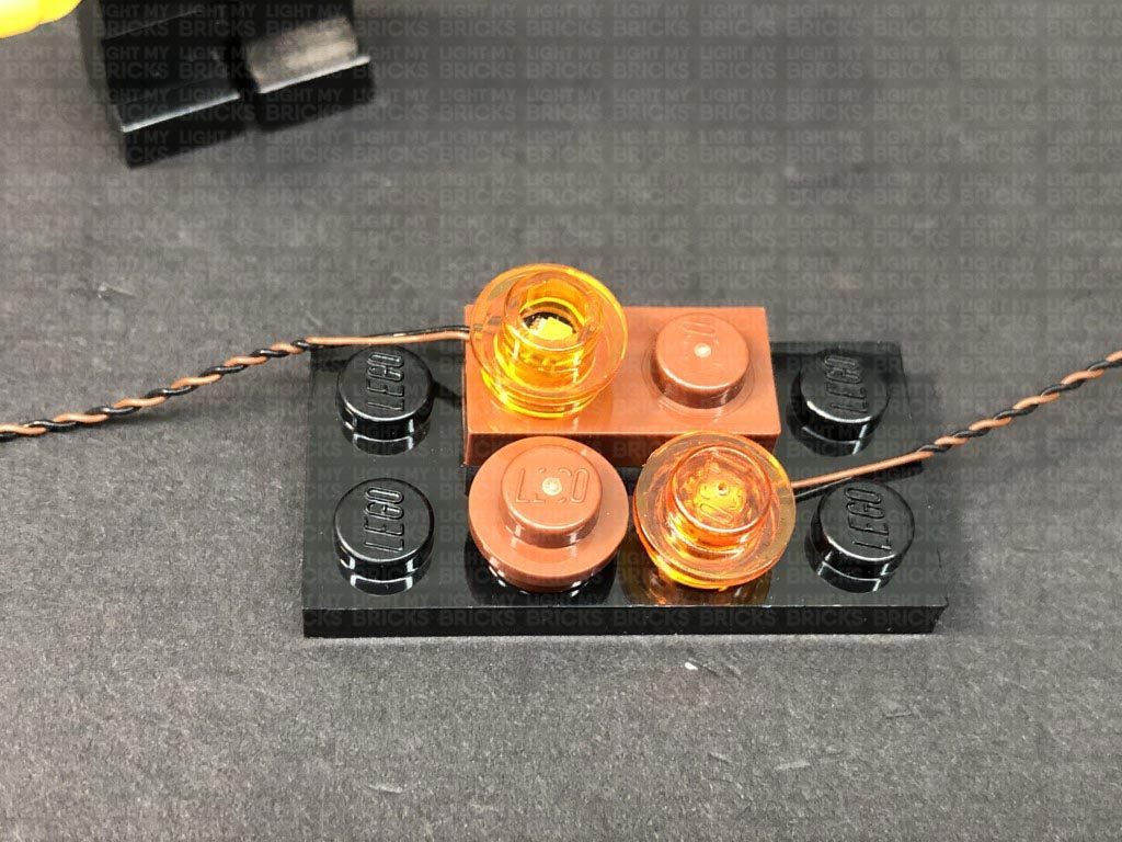
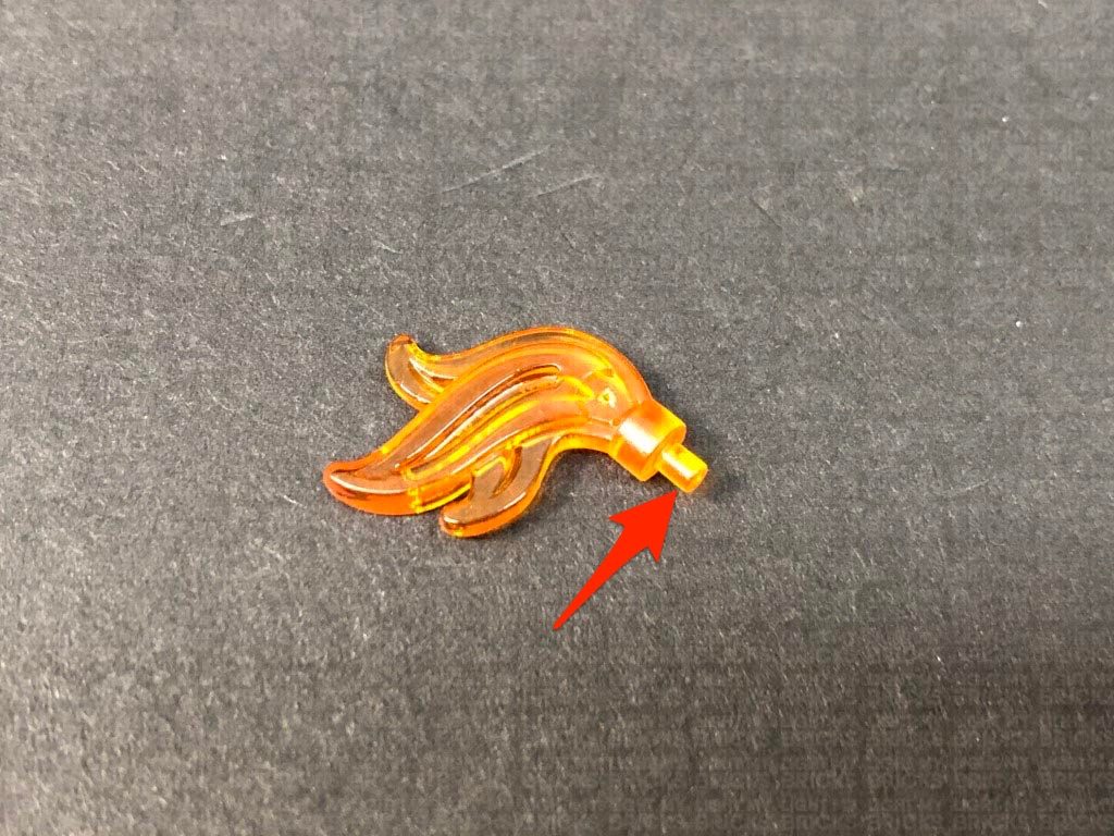
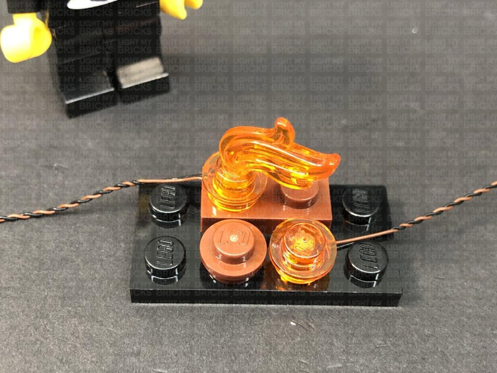
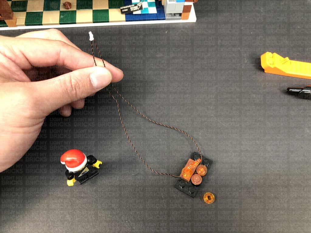
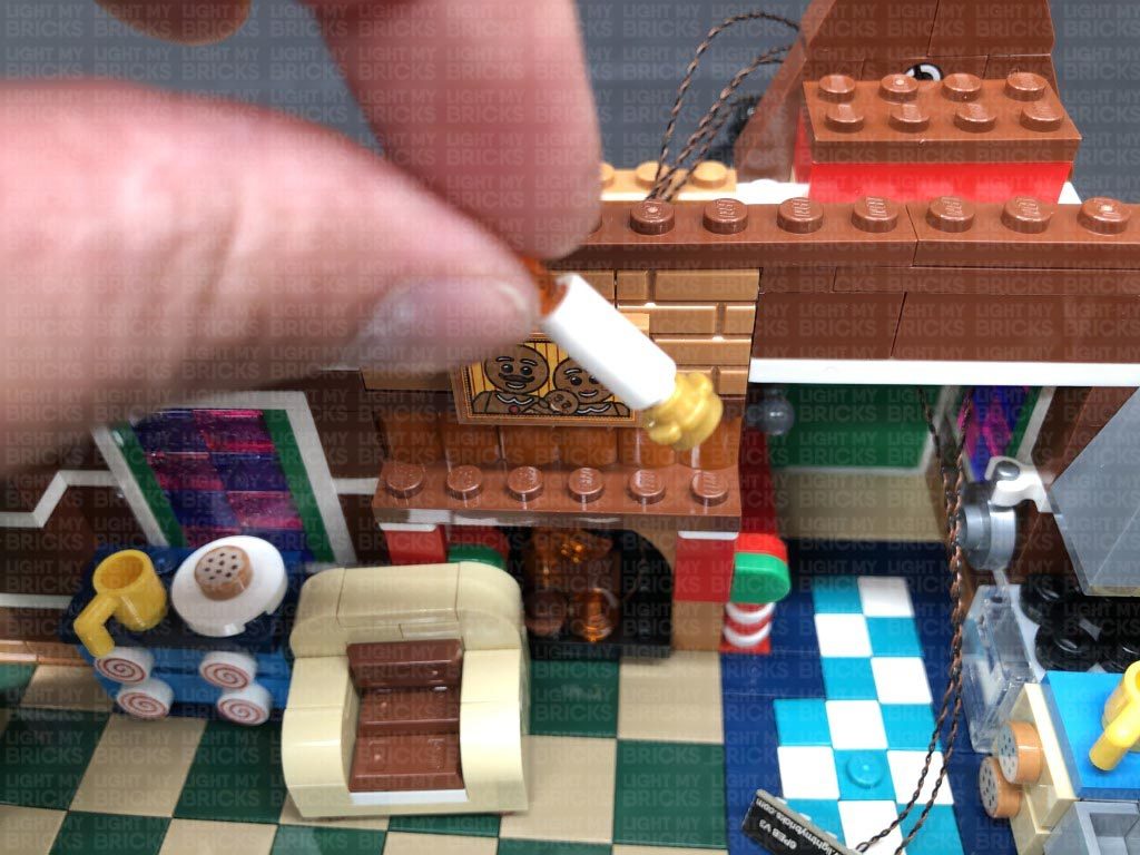
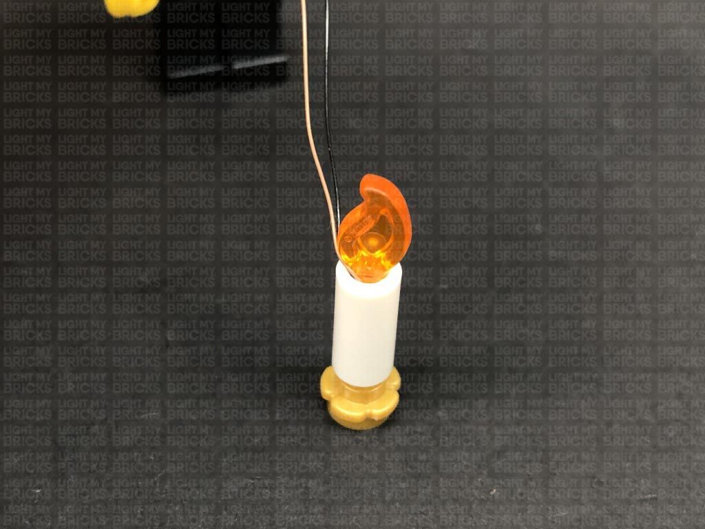
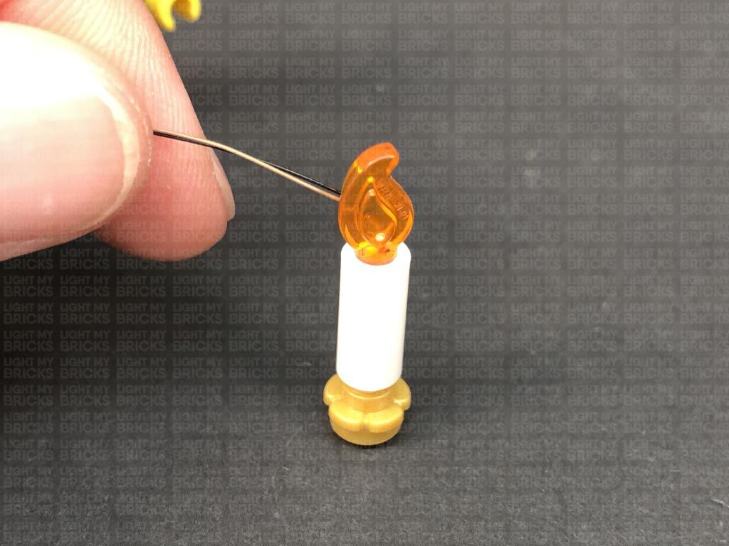
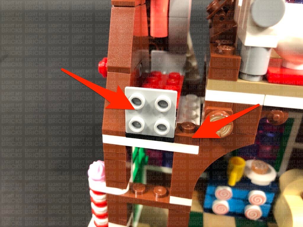
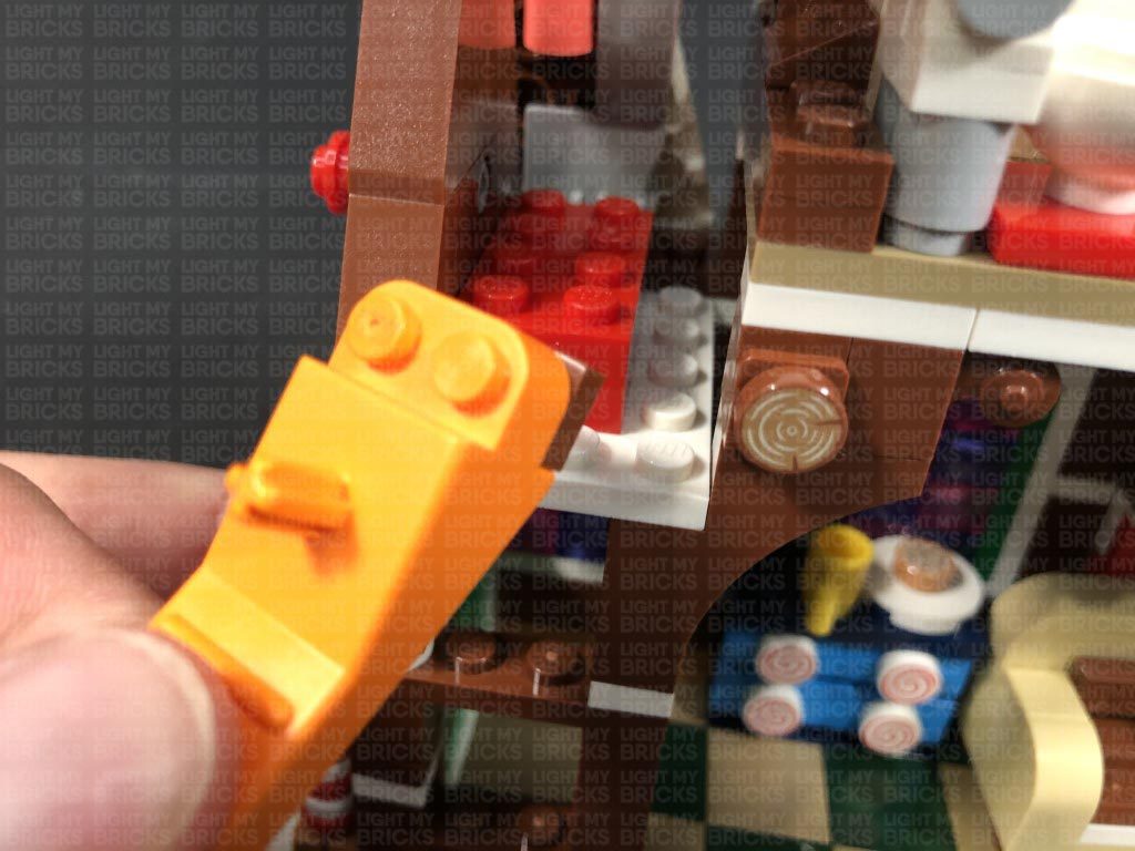
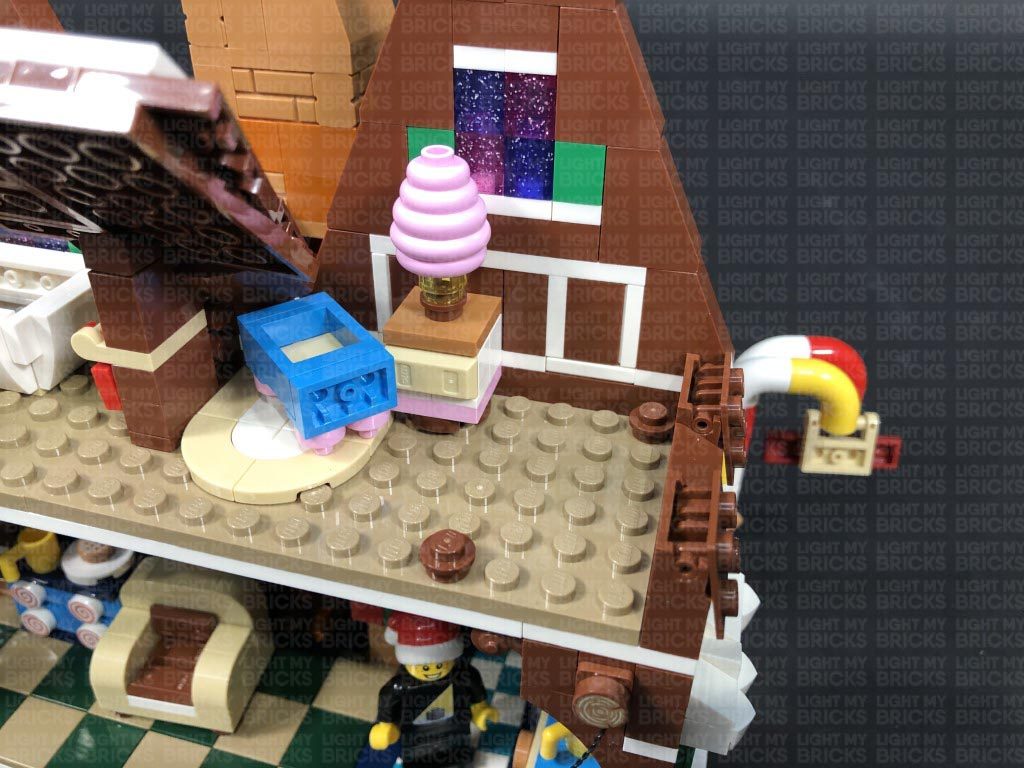
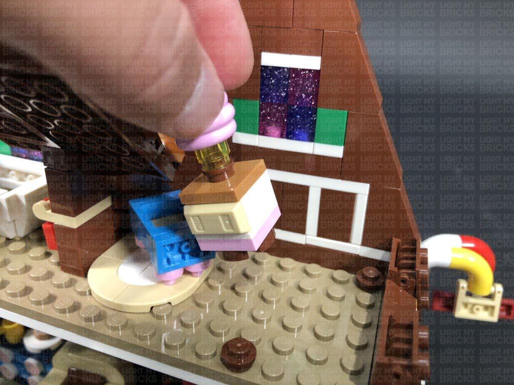
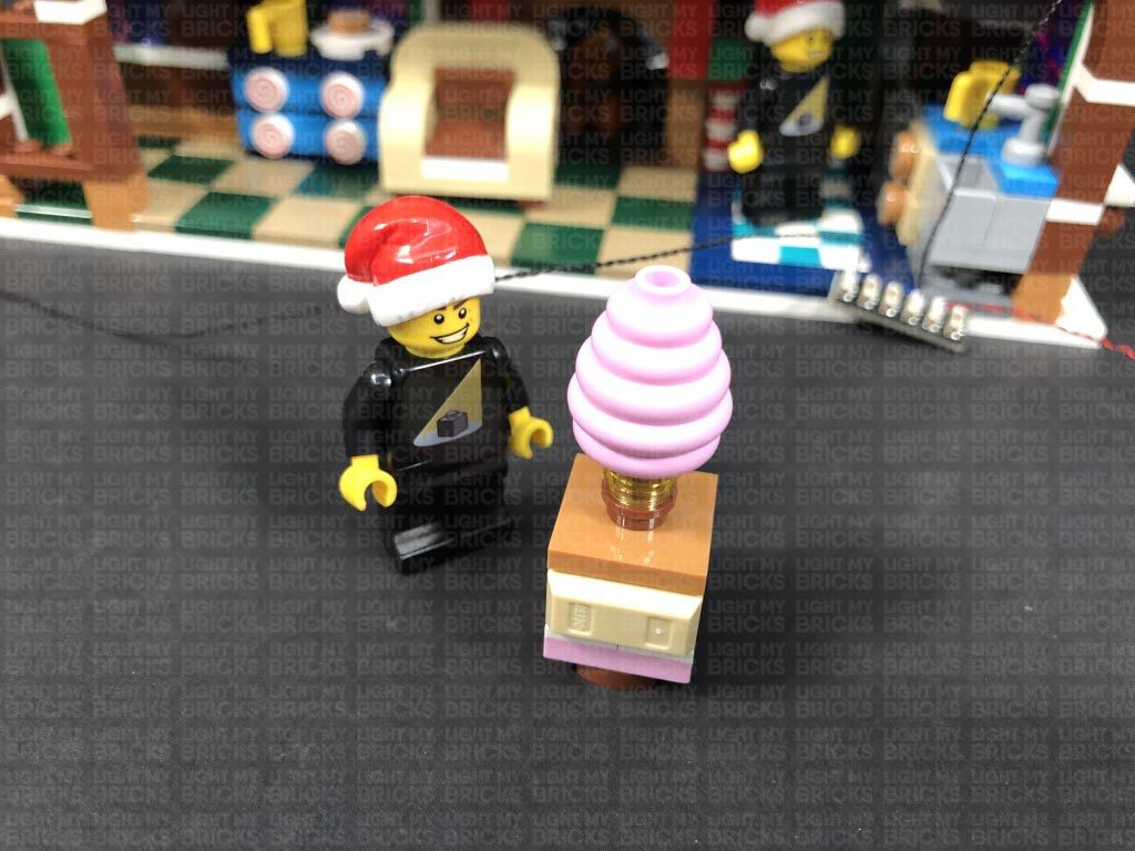
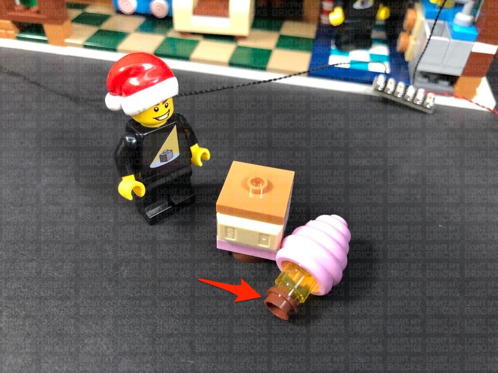
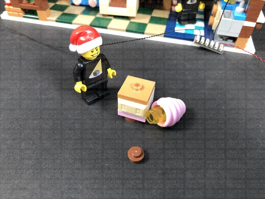
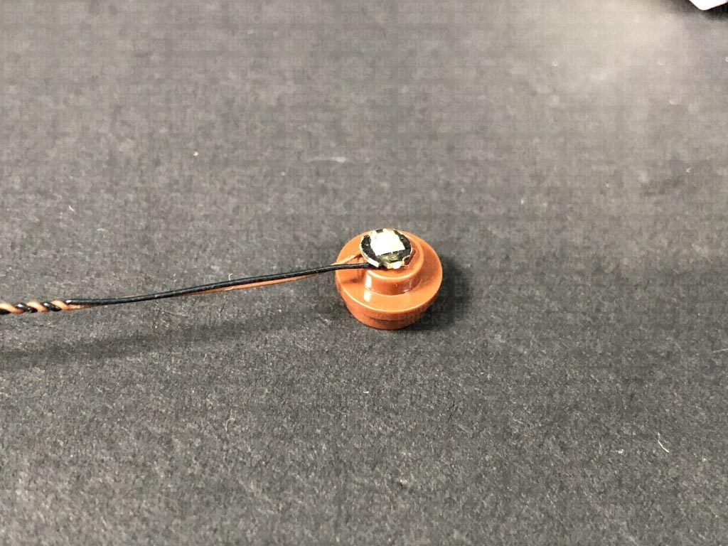
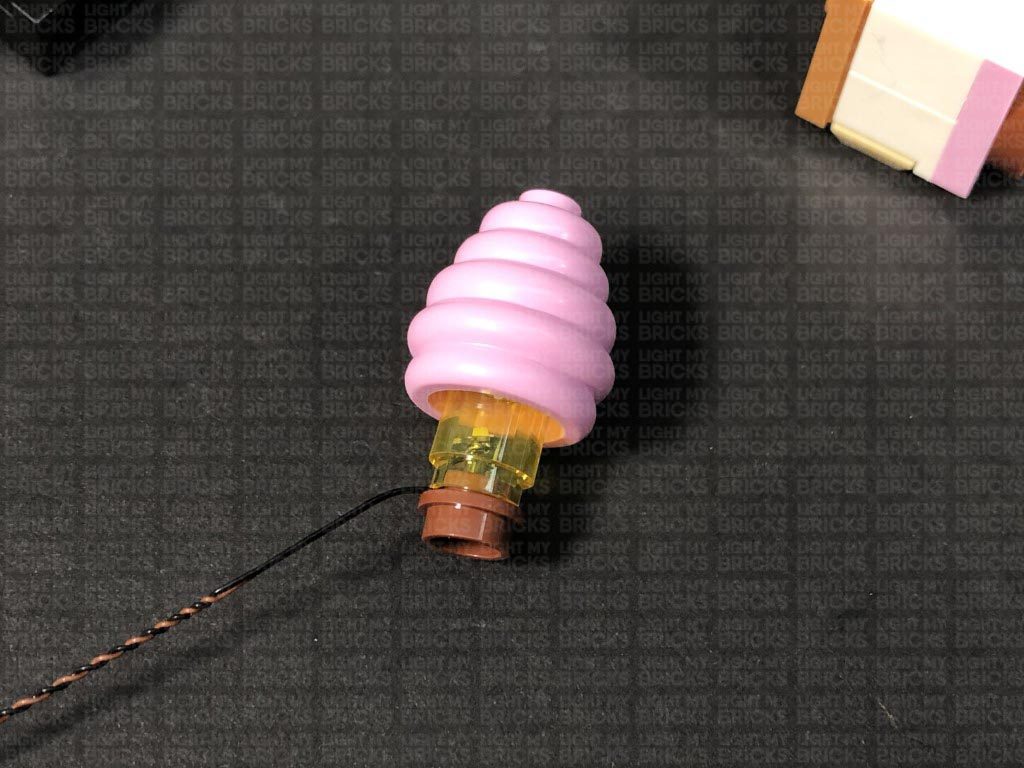
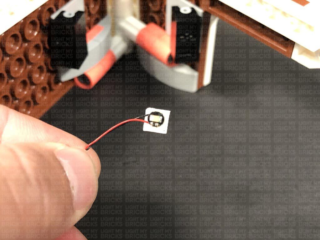
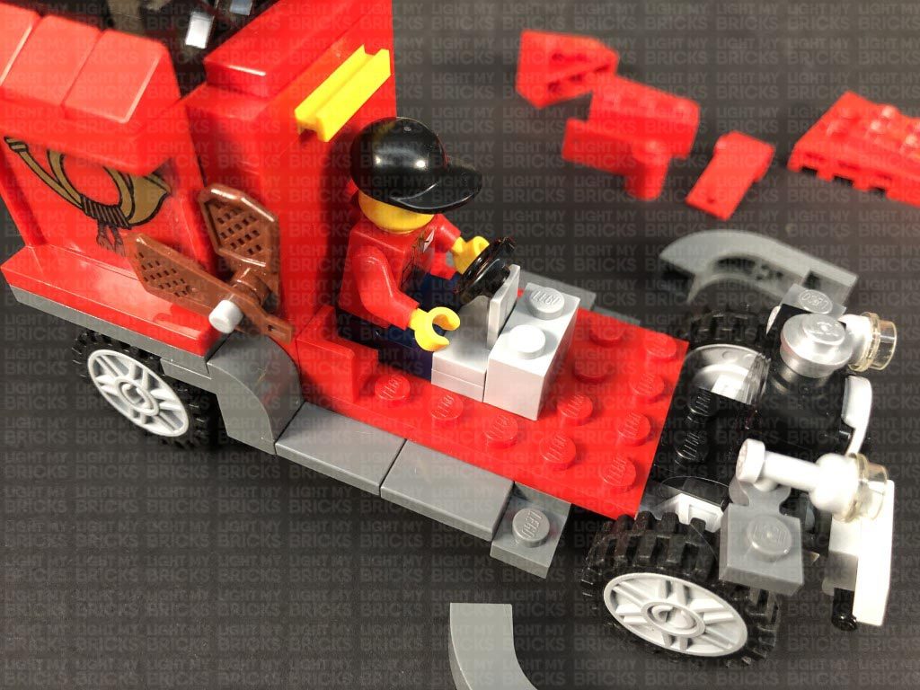
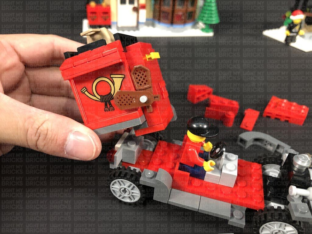
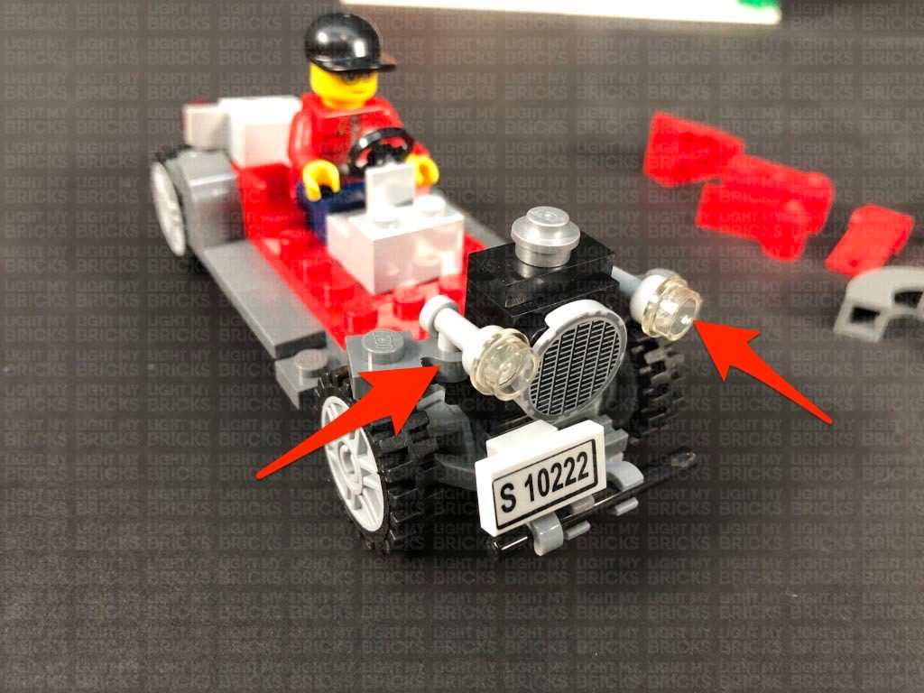
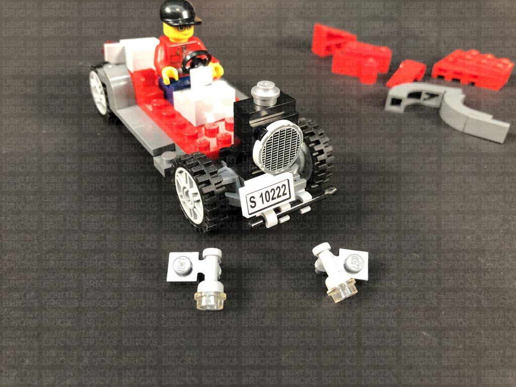
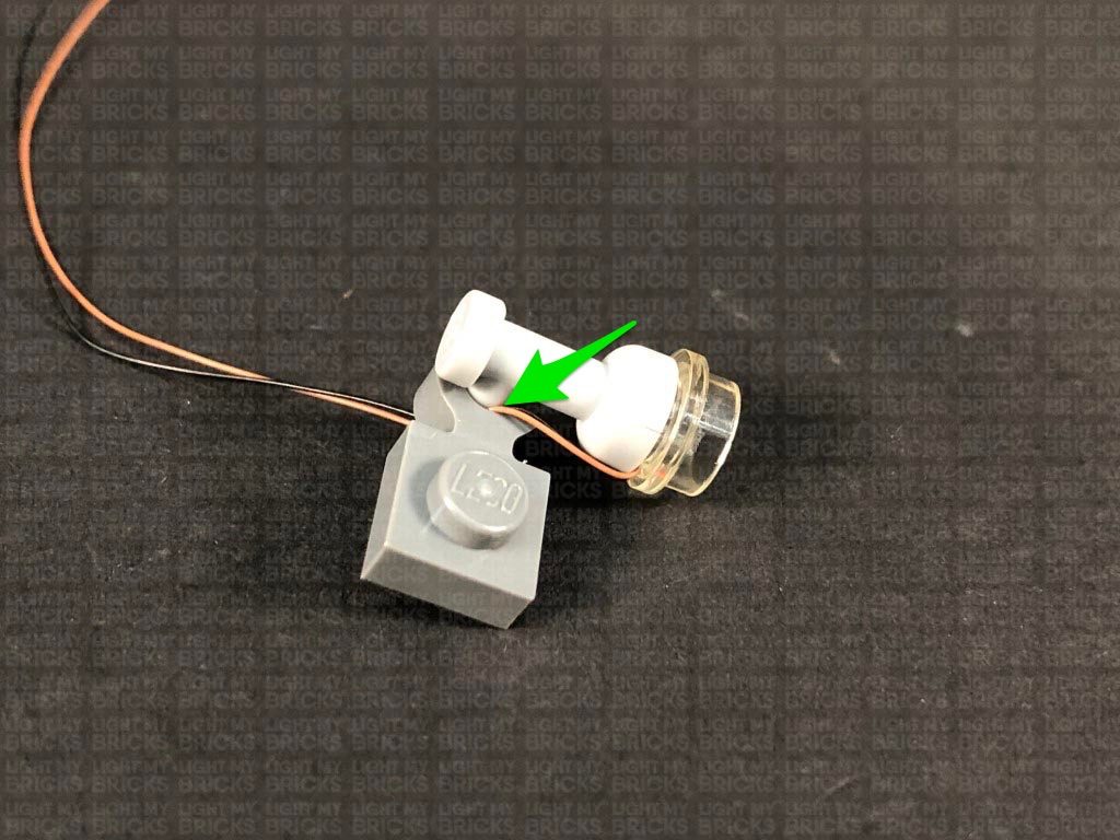
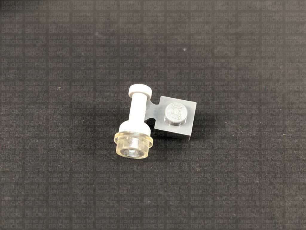
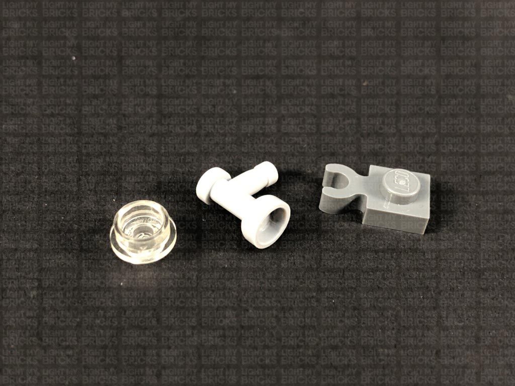
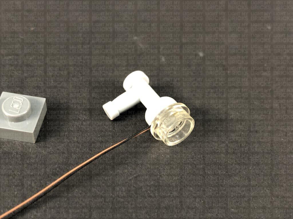
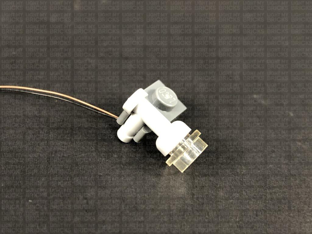
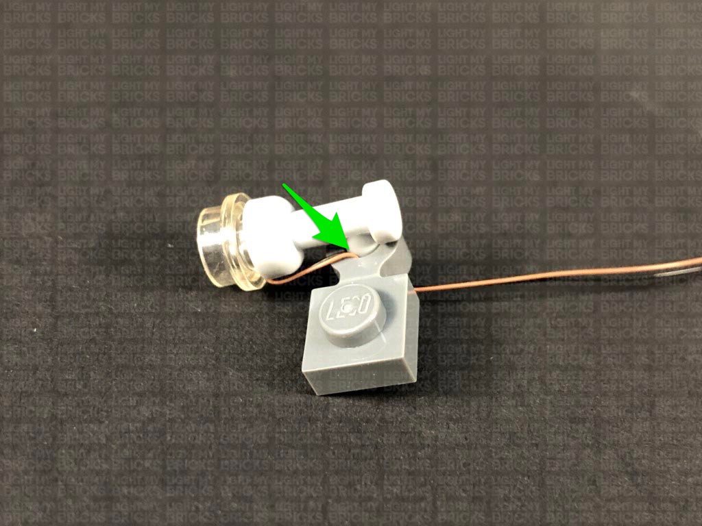
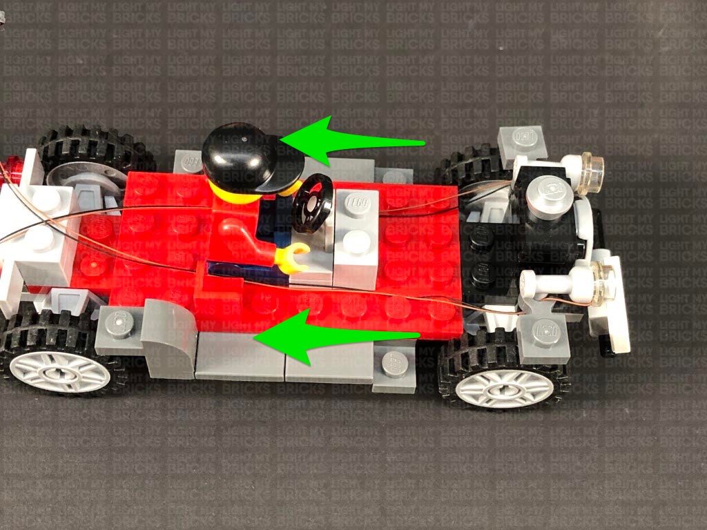
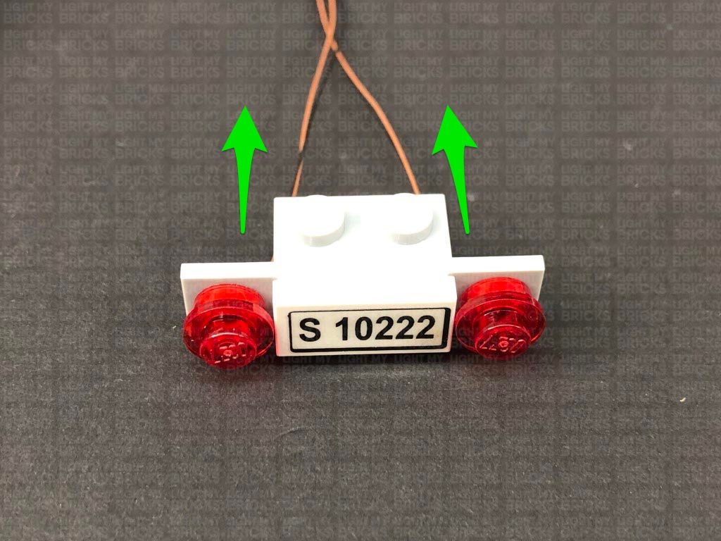
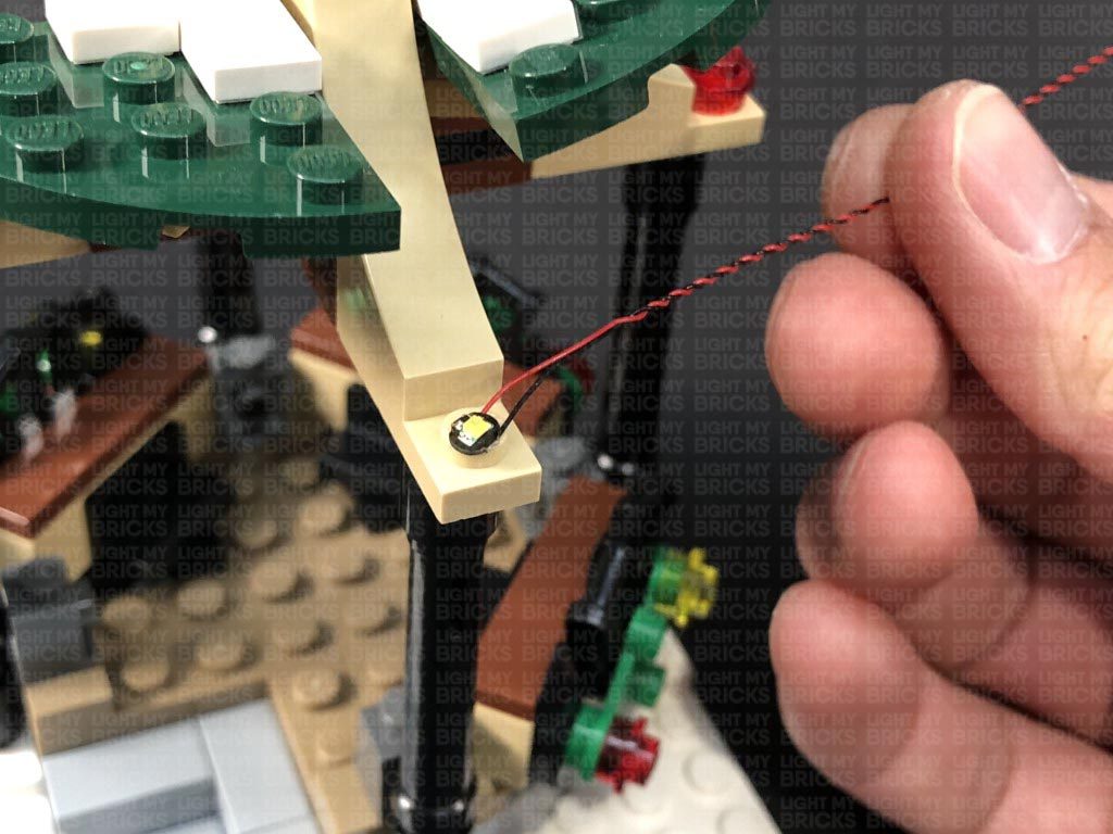
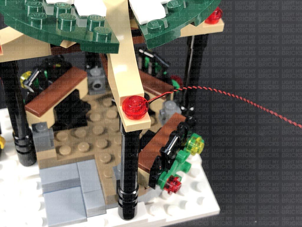
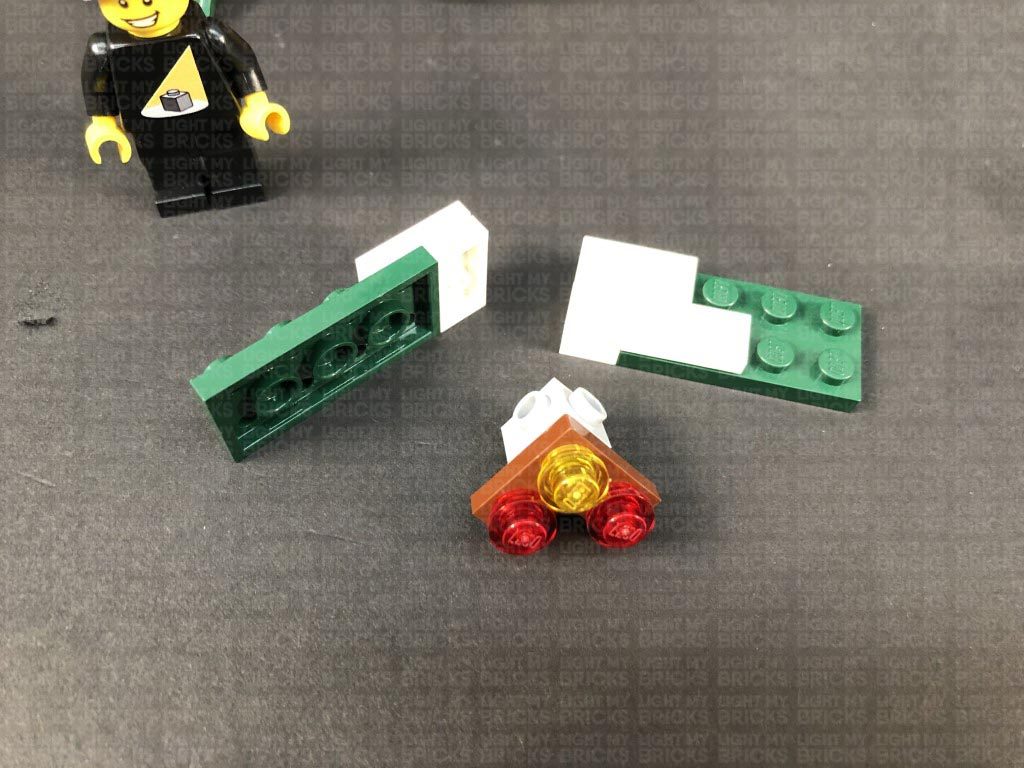
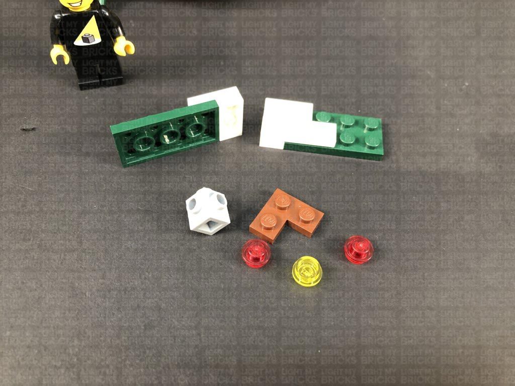
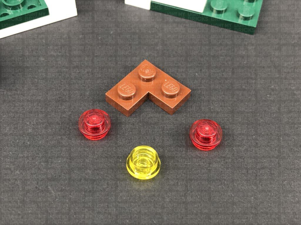
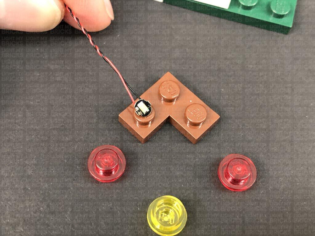
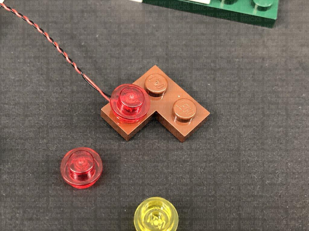
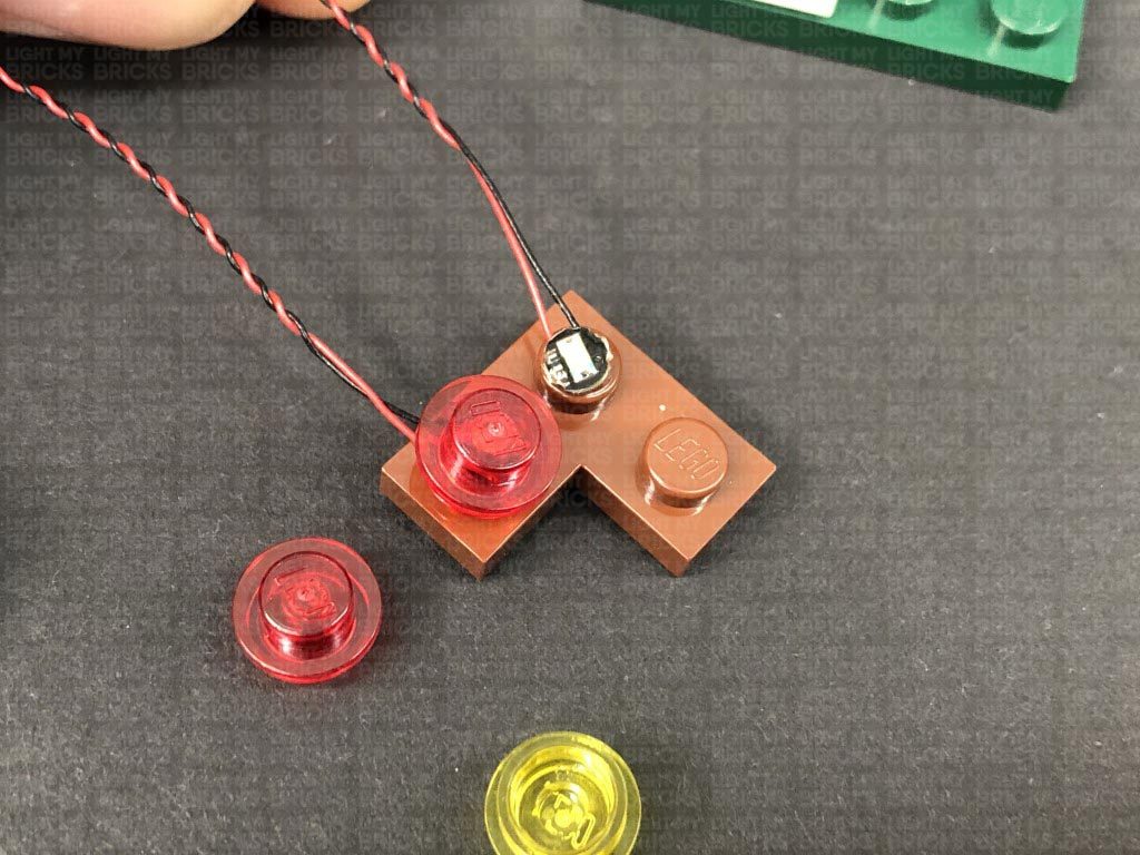
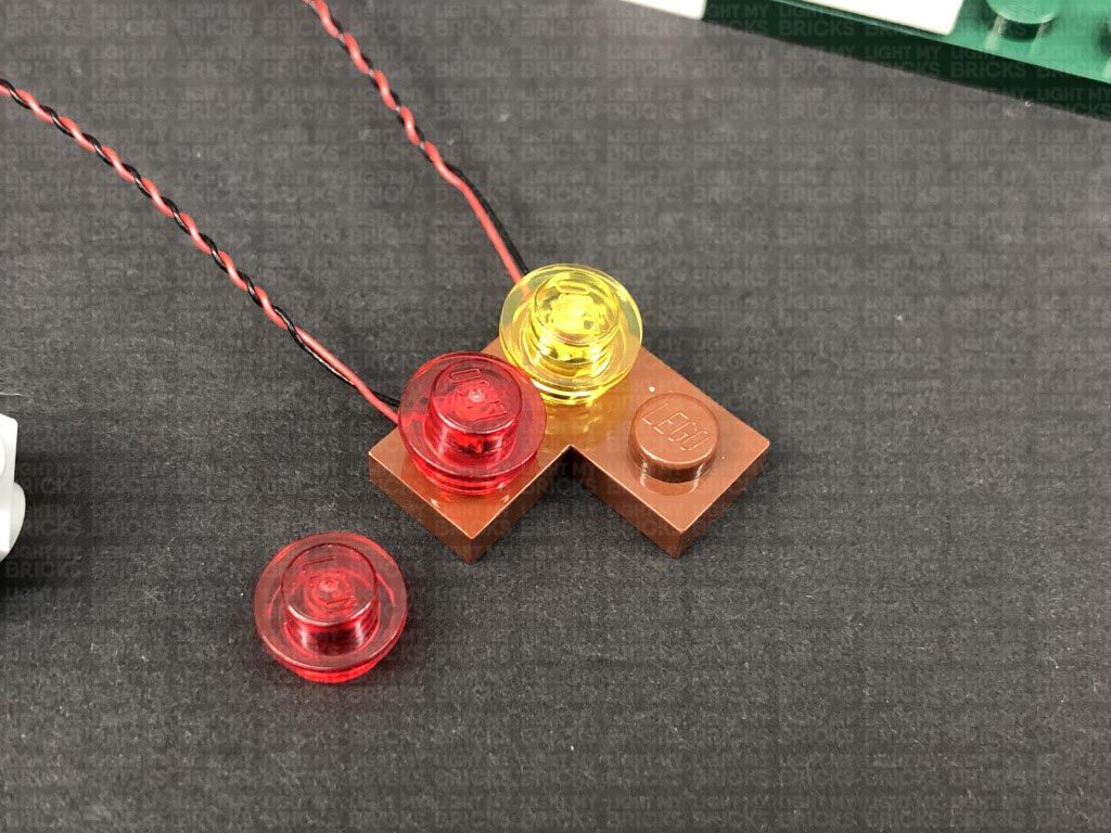
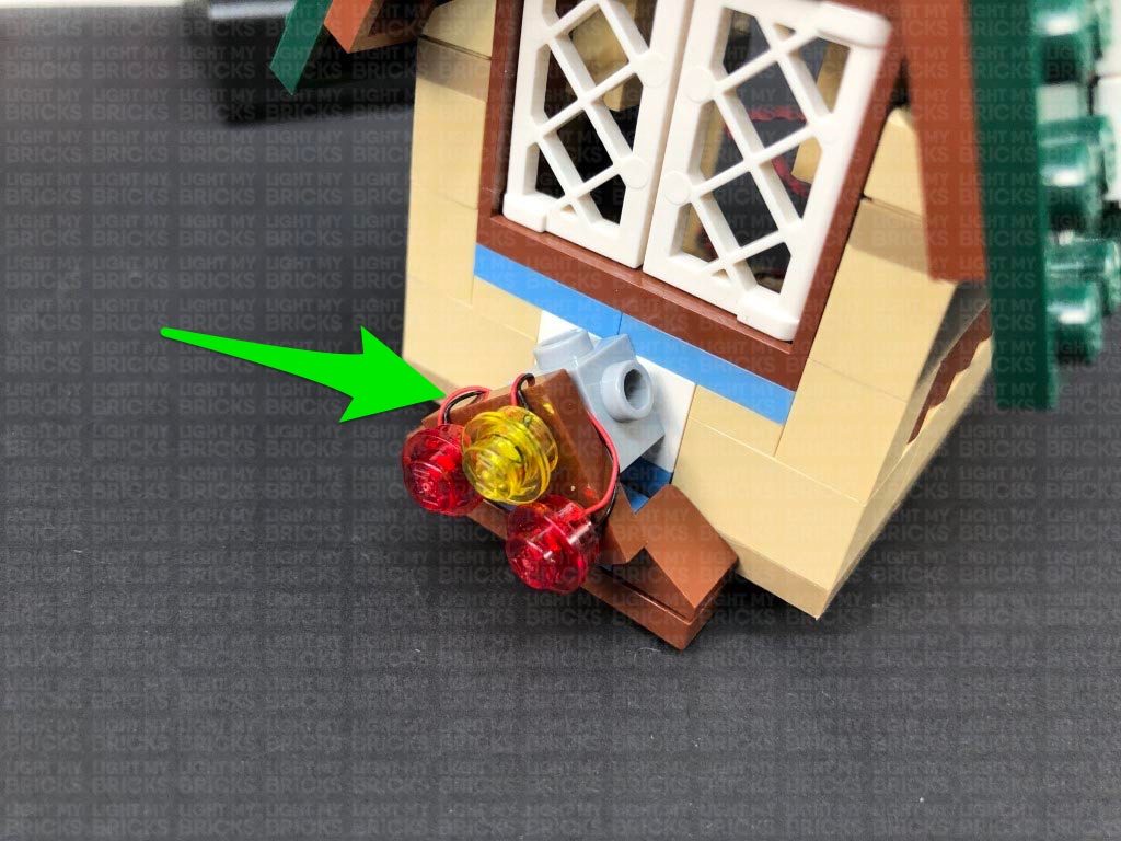
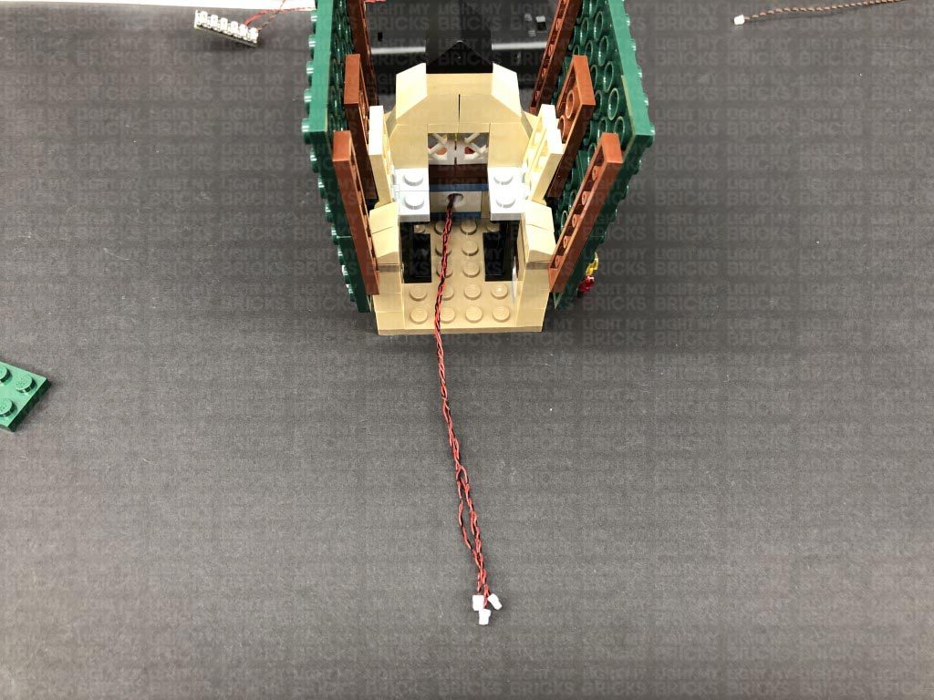
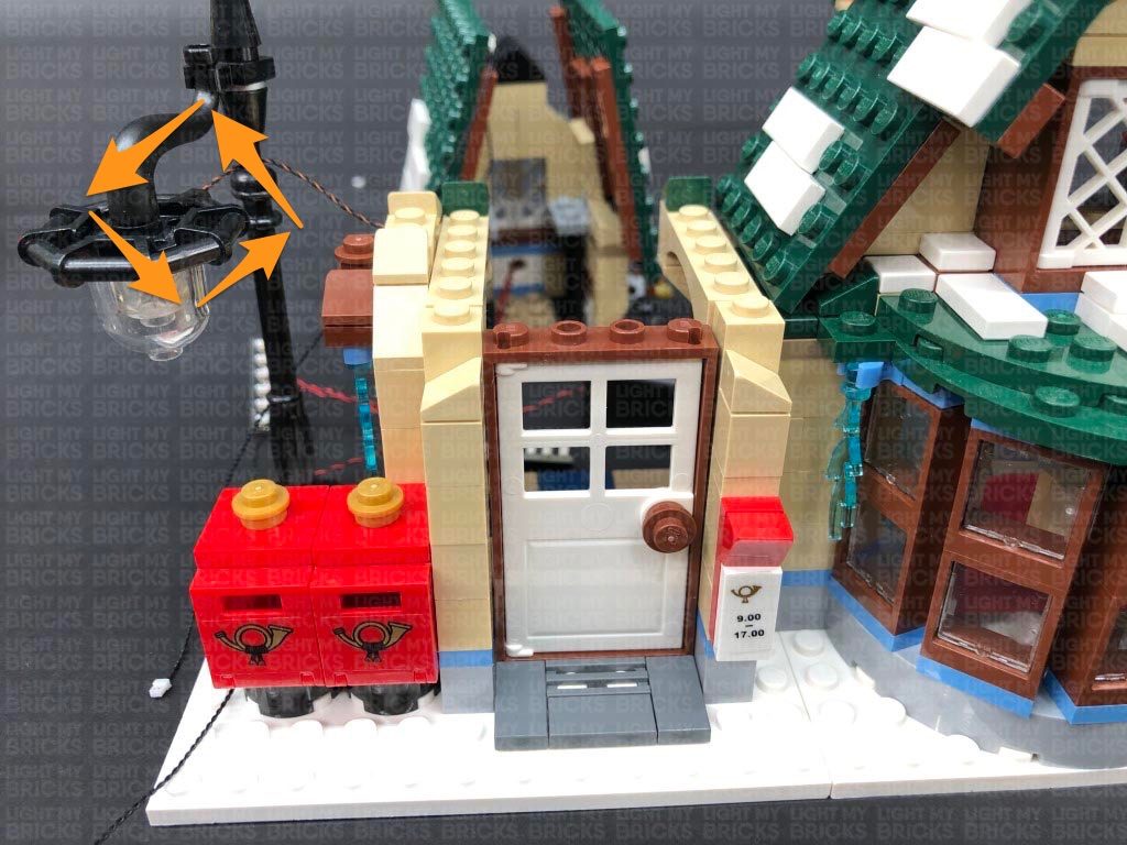
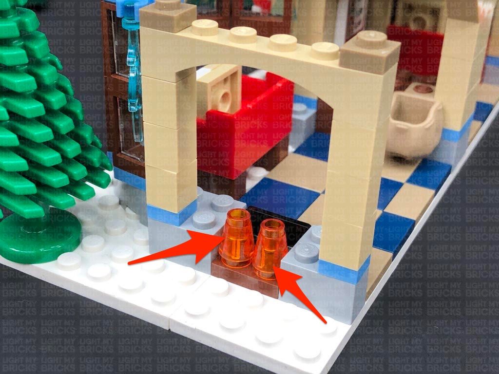
10.) Take the front lamp section and disassemble it as shown below, then take a White 15cm Bit Light and thread the connector end of the cable through the bottom of the trans yellow cone piece. Thread the cable all the way through then, with the LED facing the front, reconnect the black post piece and re-clip it back to the orange brick. Reconnect the black round plate to the top.
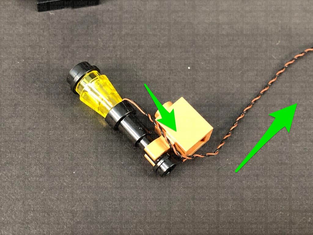
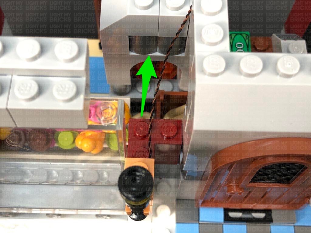
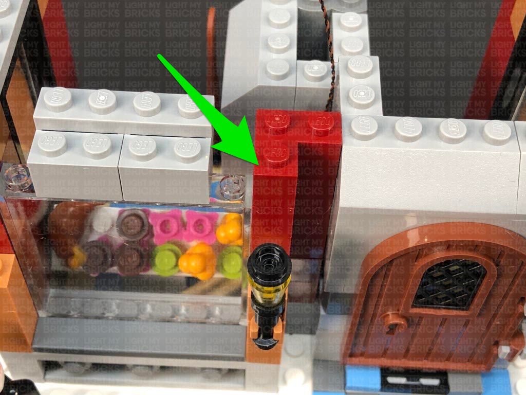
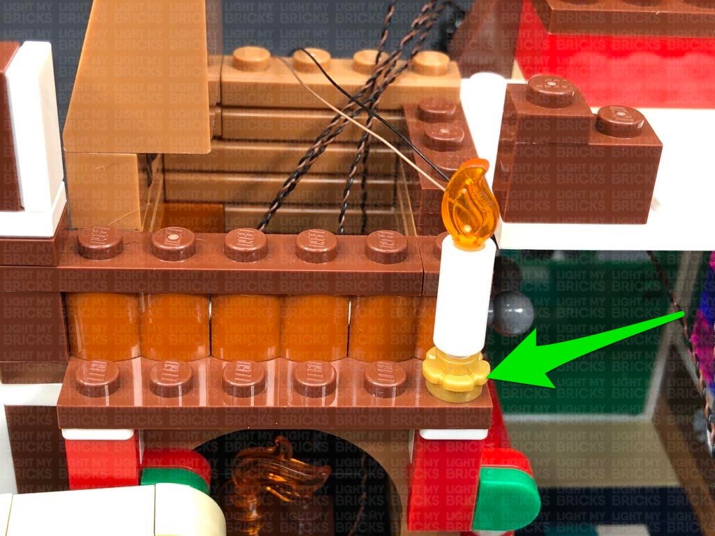
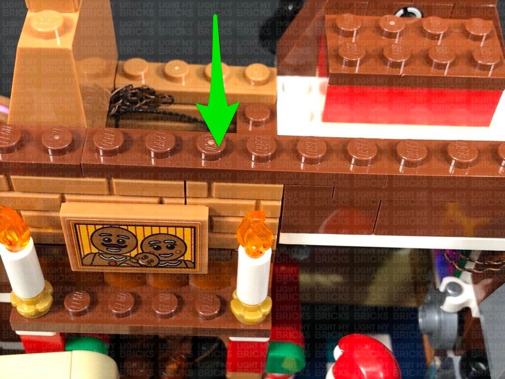
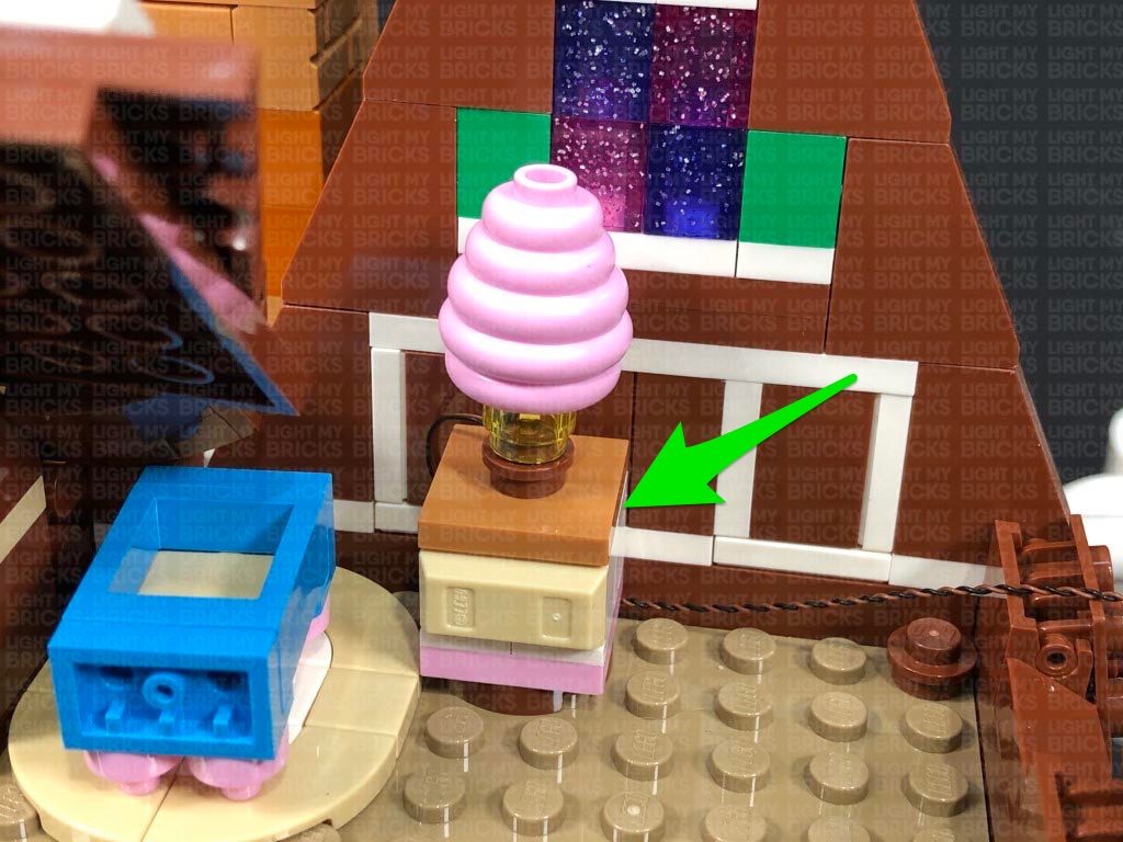
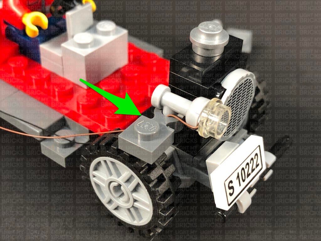
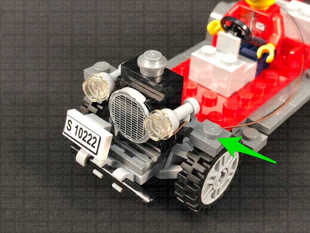
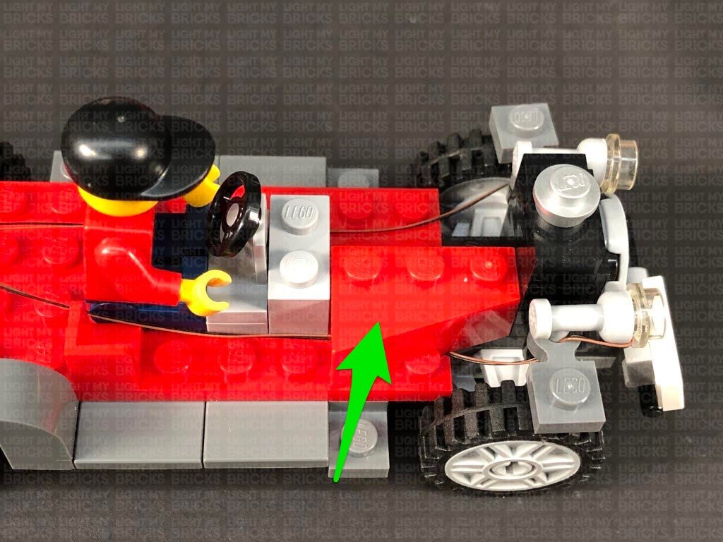
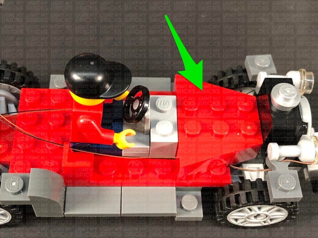
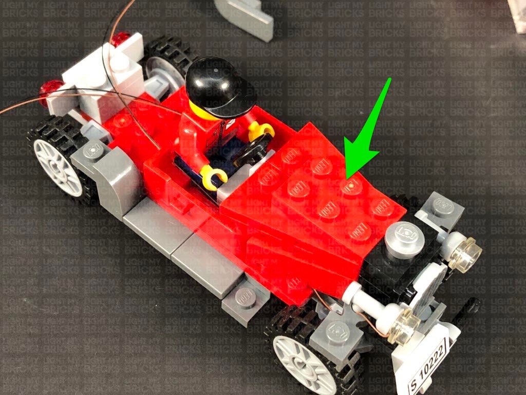
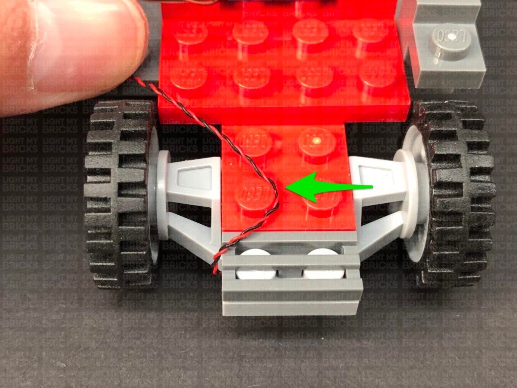
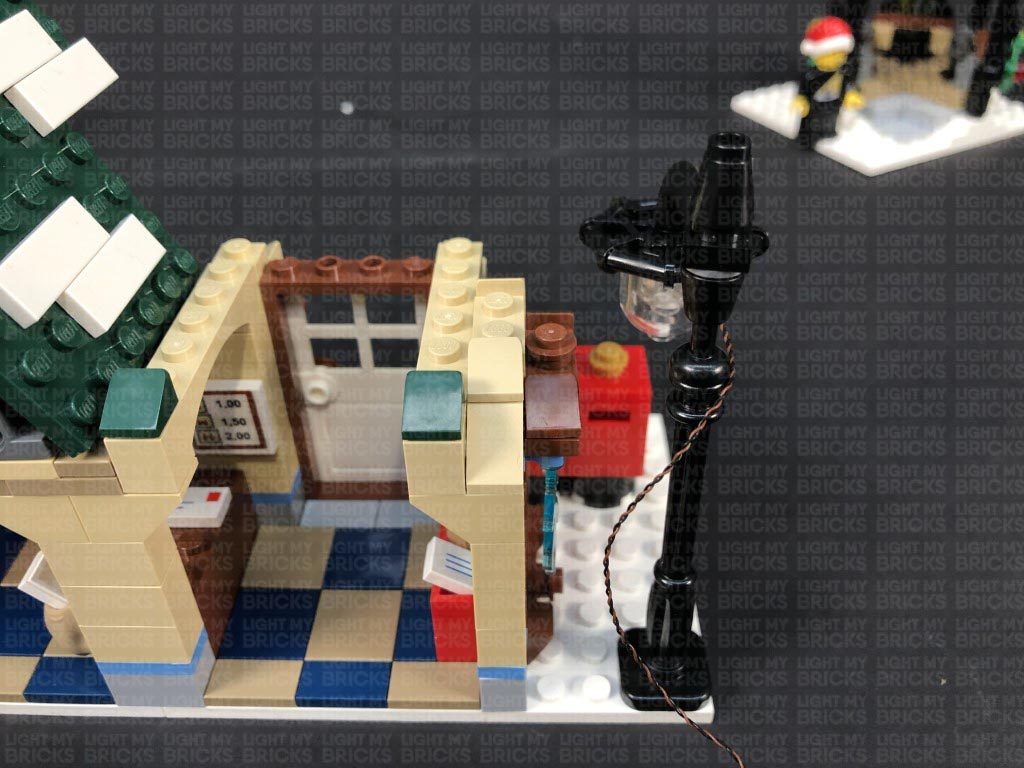
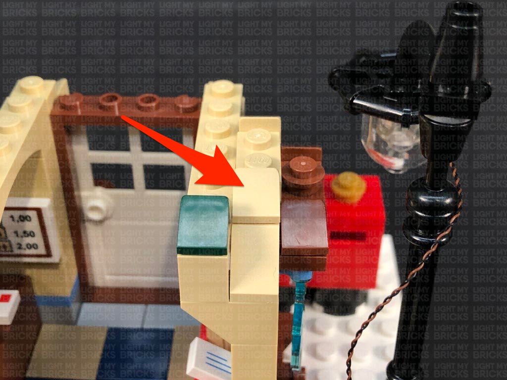
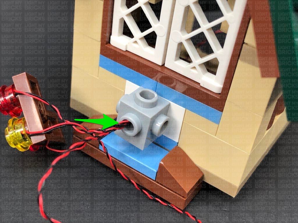
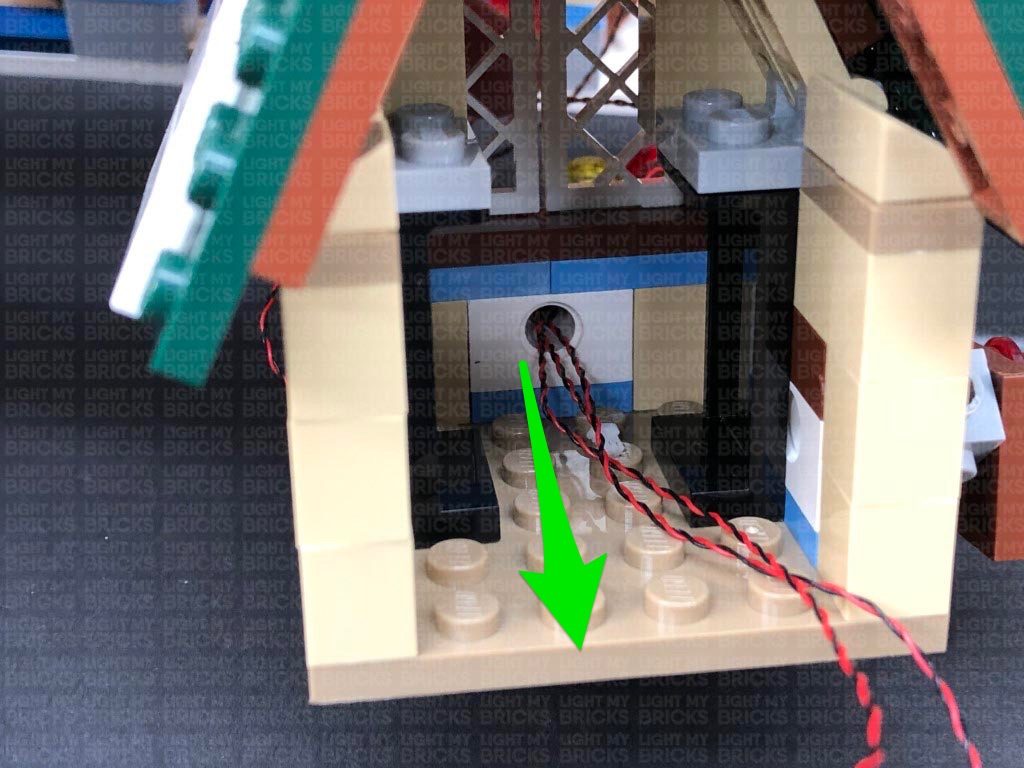
Bring the cable down behind the black post, then underneath the brown brick before reconnecting it to the front of the Bakery. Ensuring the cable is laid in between studs, reconnect the red ‘L’ bricks over the top.
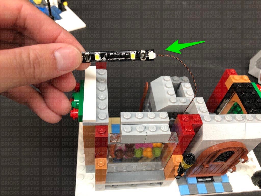
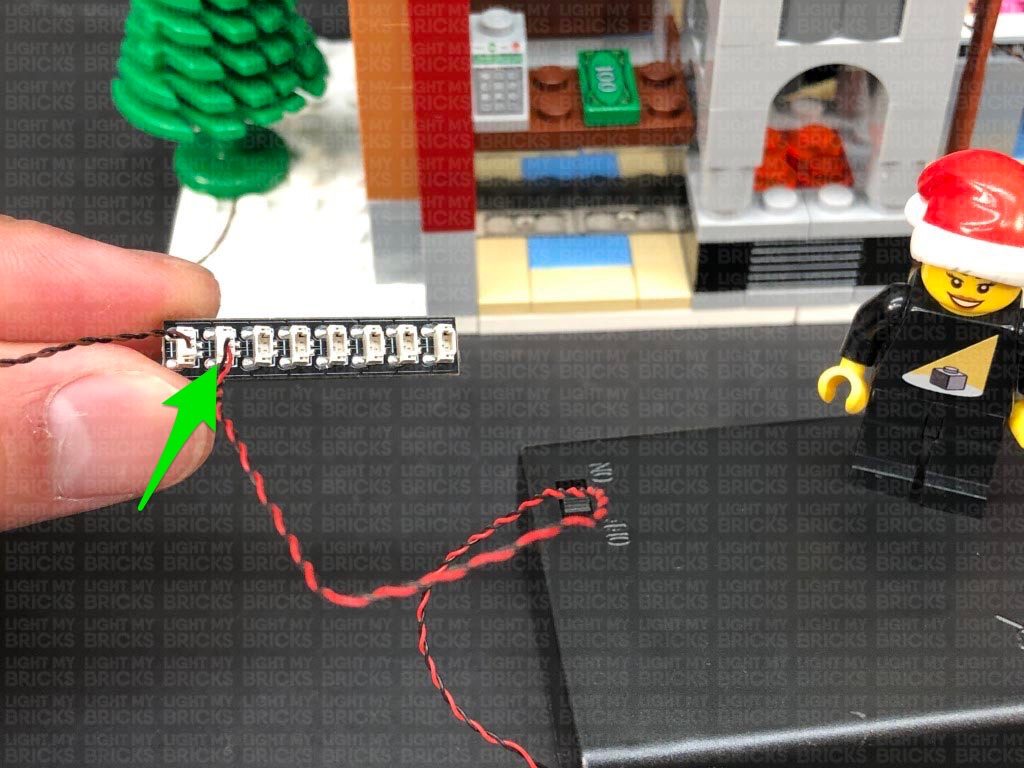
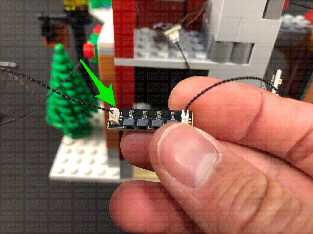
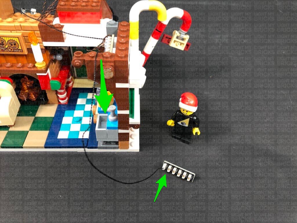
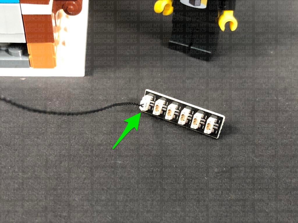
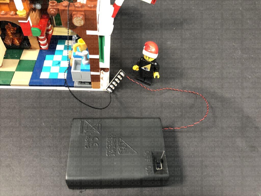
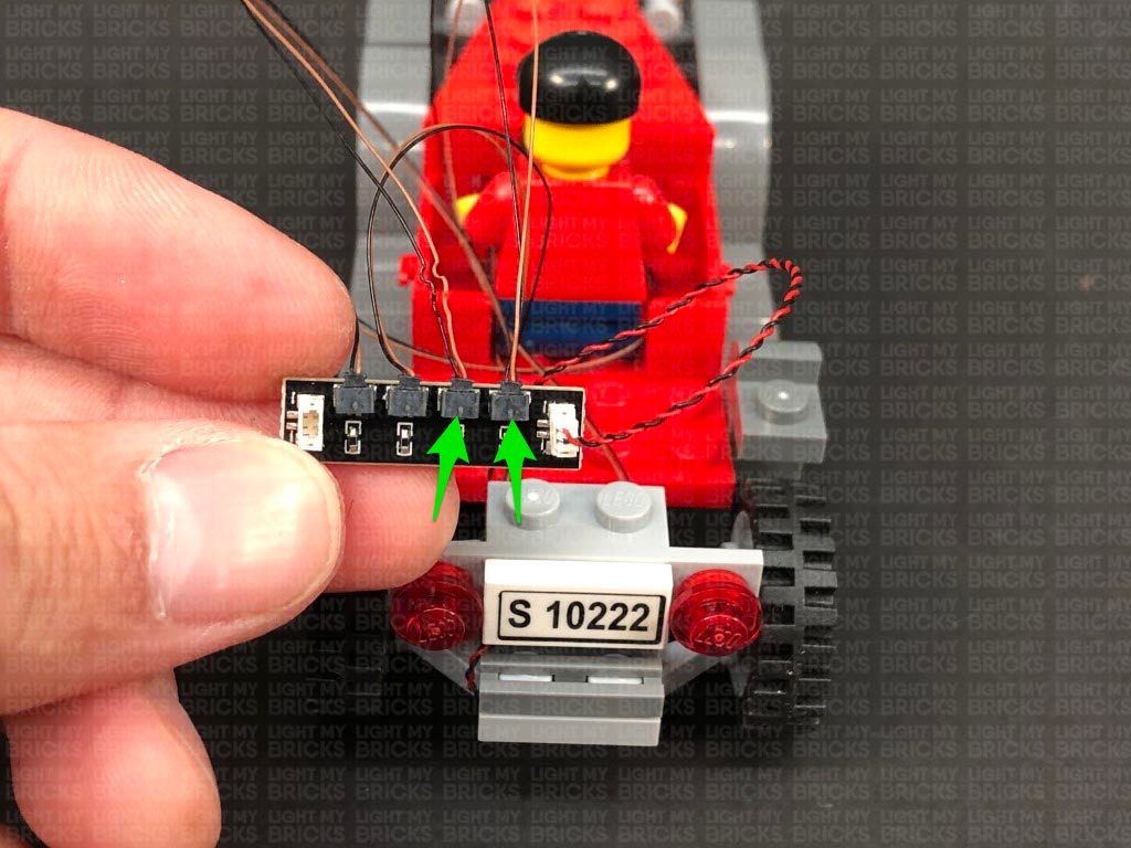
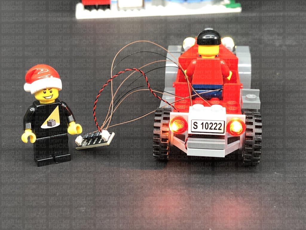
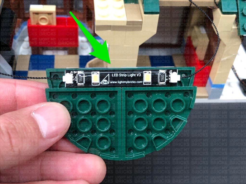
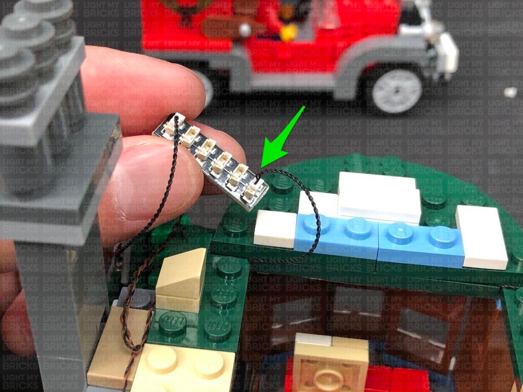
11.) Connect the White 15cm Bit Light to a White Strip Light, then take the AA Battery Pack and connect it to the Strip Light’s other port. Turn the Battery Pack ON to test the lamp and strip light is working OK.
Note: If you experience any issues with the lights not working and suspect an issue with a component, please try a different port on the expansion board to verify where the fault lies (with the light or expansion board). To correct any issues with expansion board ports, please view the section addressing expansion board issues on our online troubleshooting guide.
Disconnect the AA Battery Pack from the Strip Light, then reconnect all the sections we removed earlier surrounding the front window.
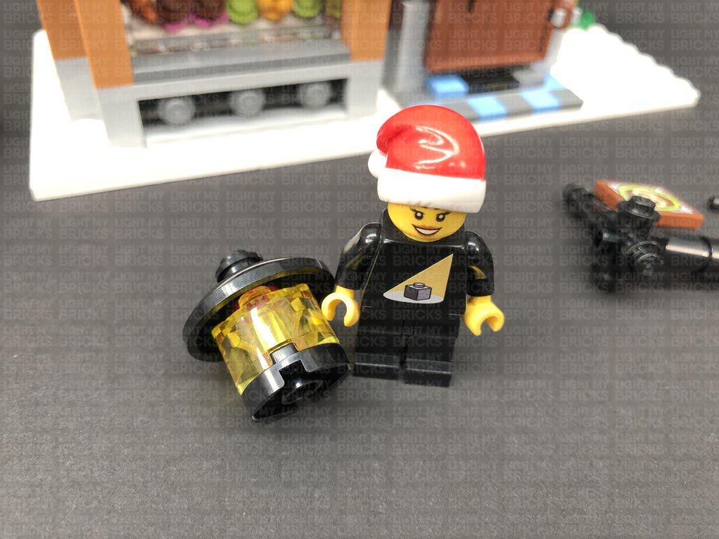
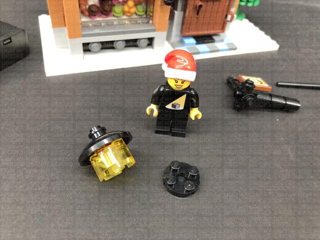
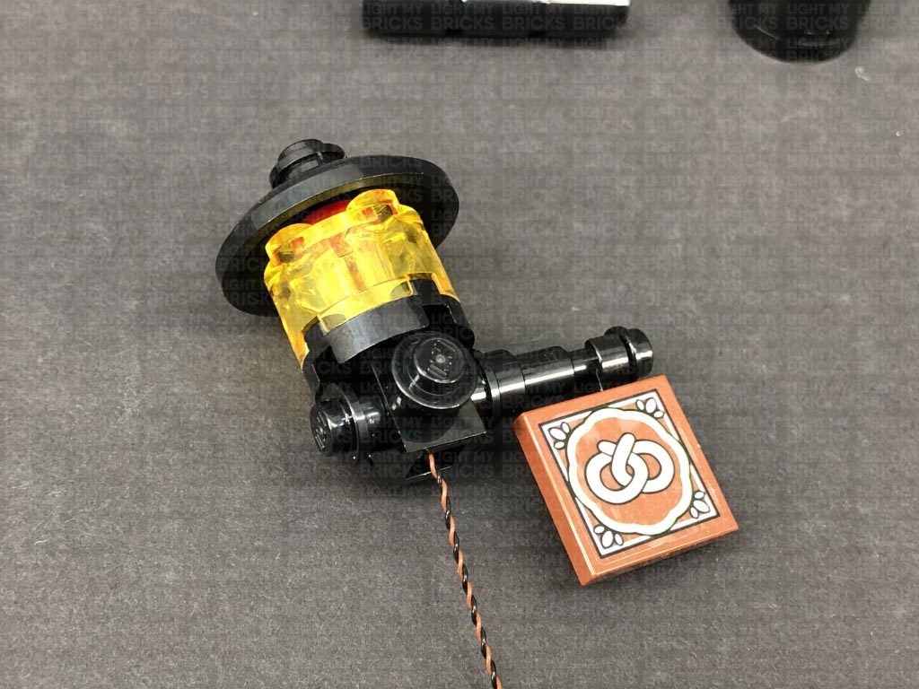
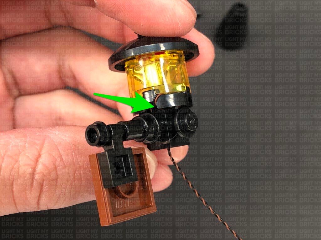
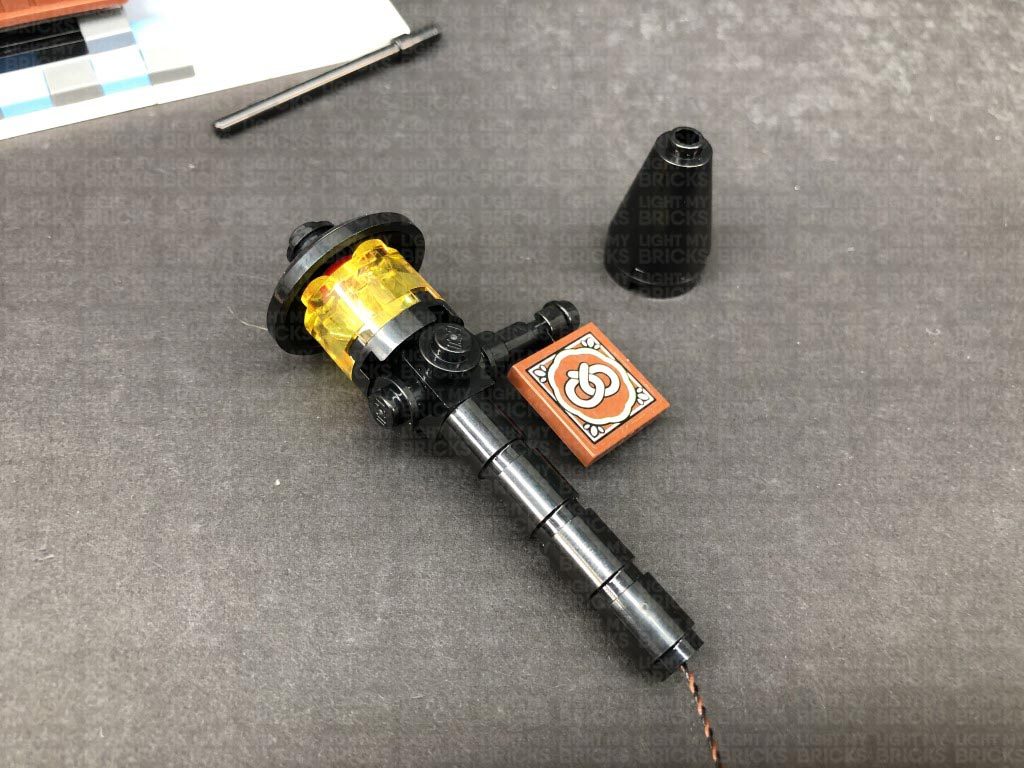
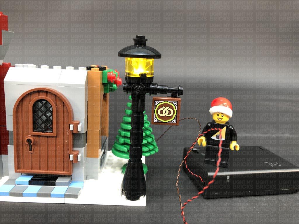
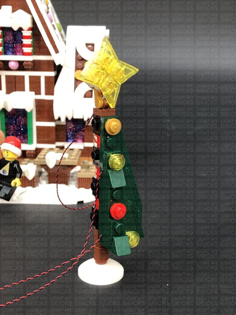
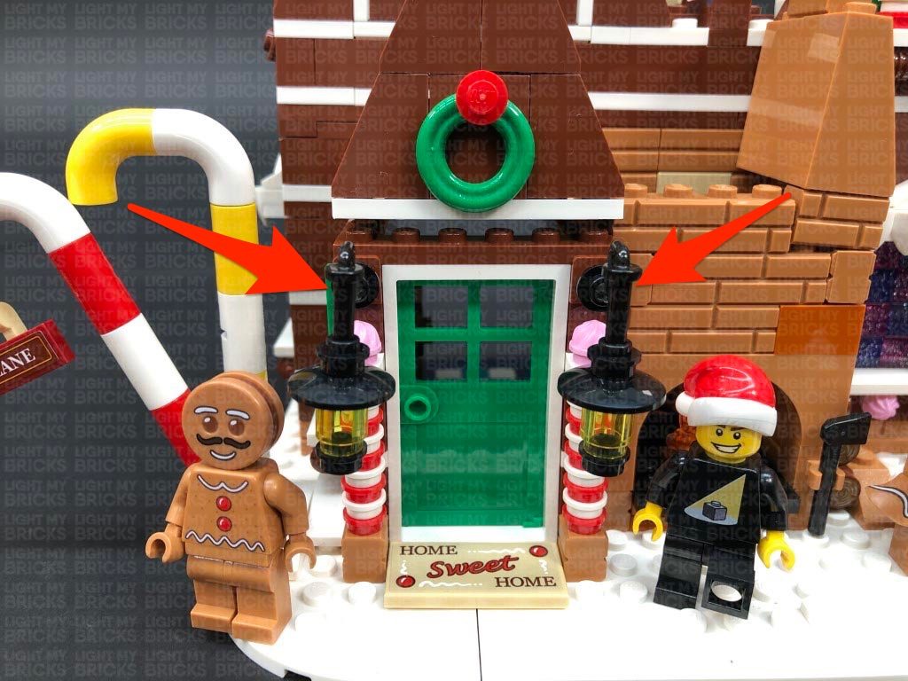
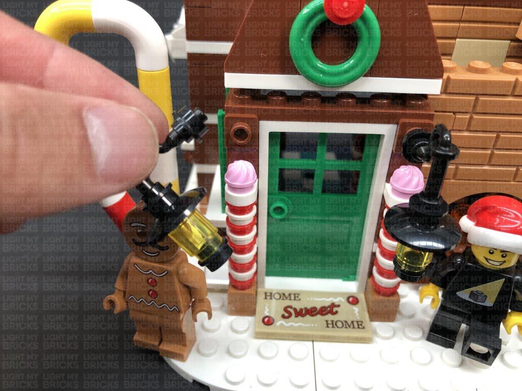
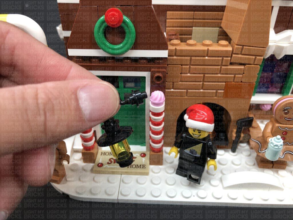
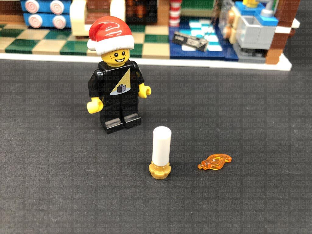
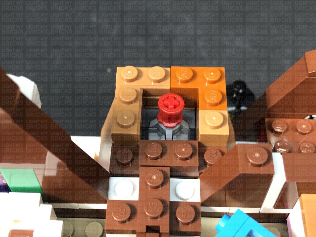
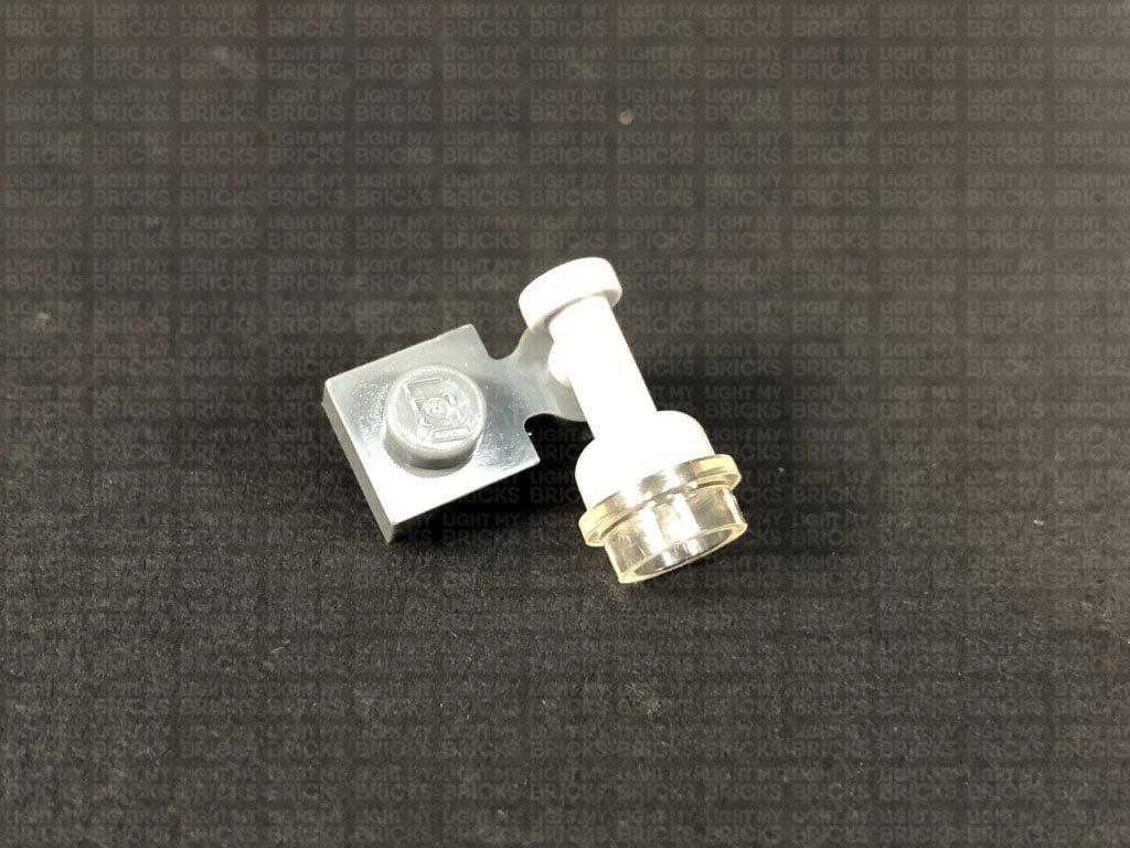
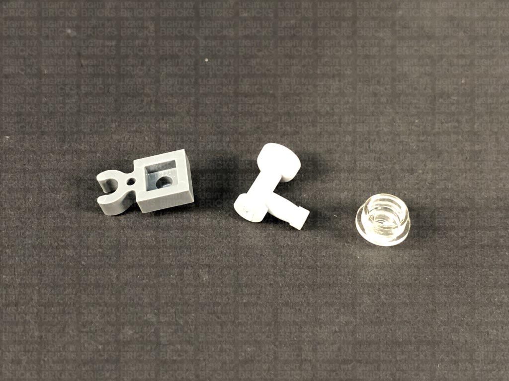
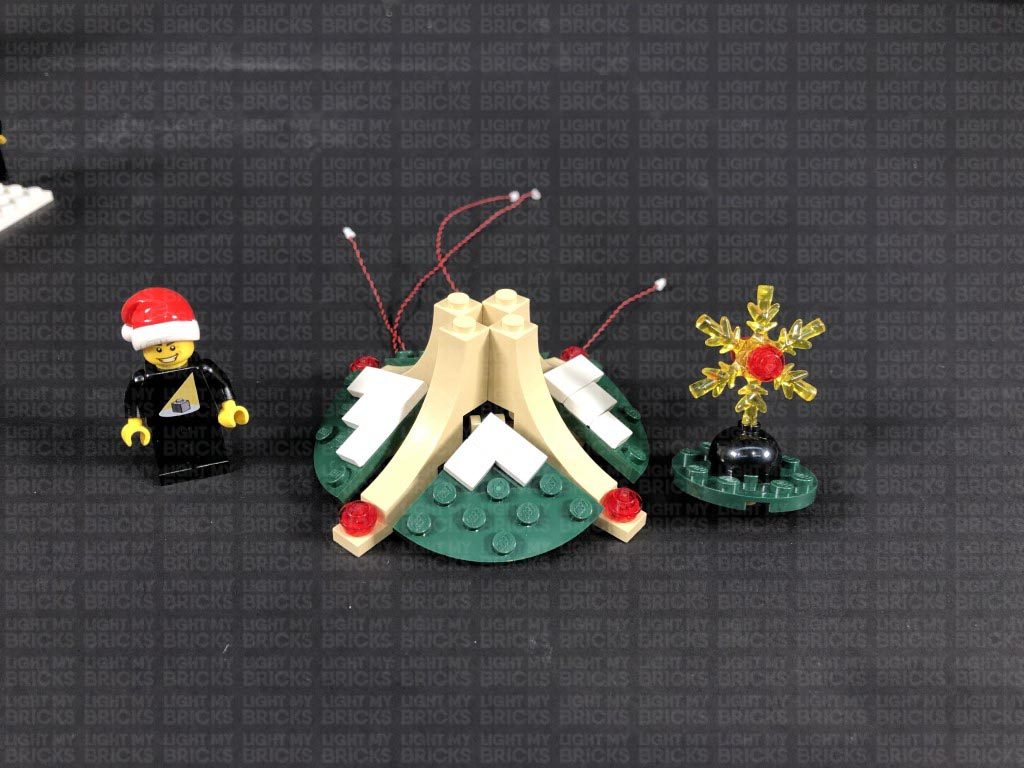
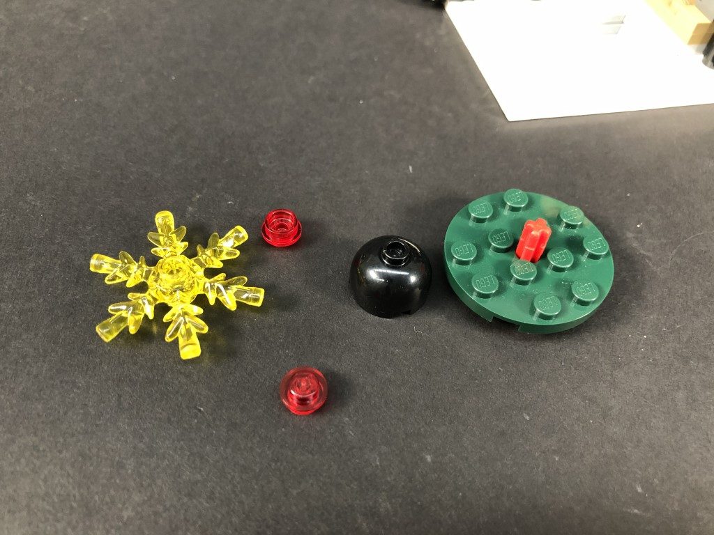
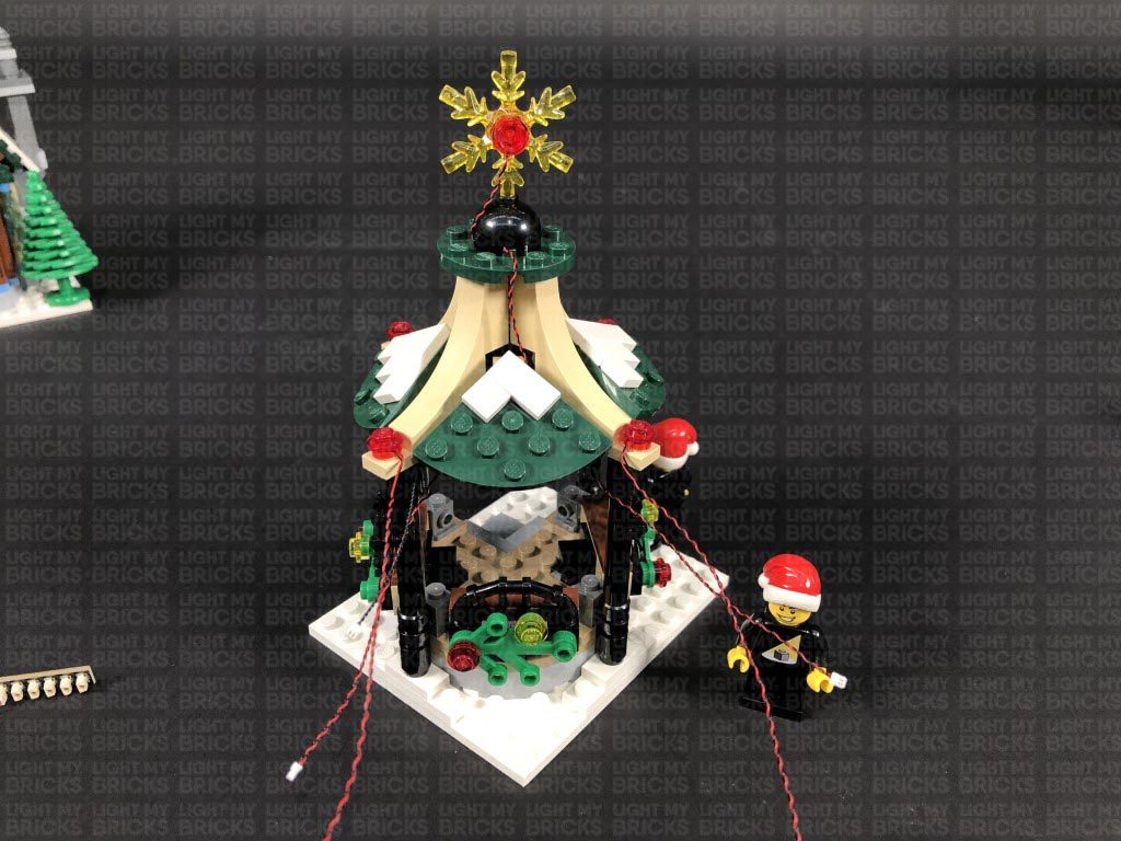
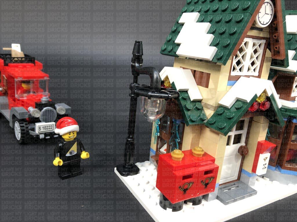
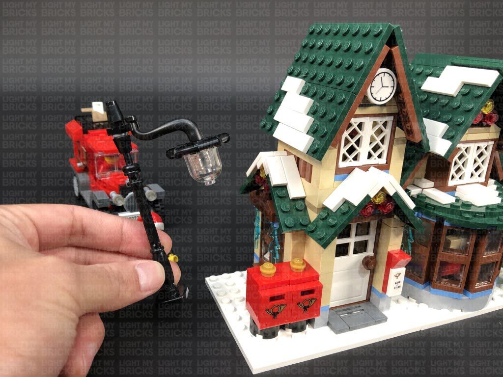
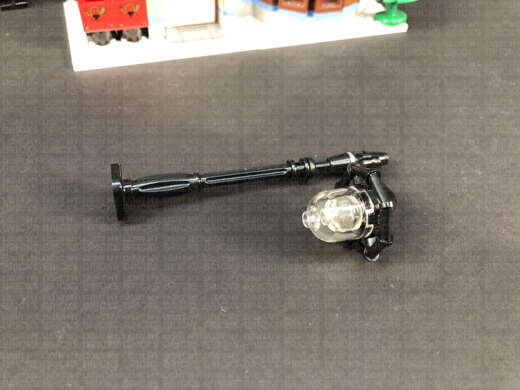
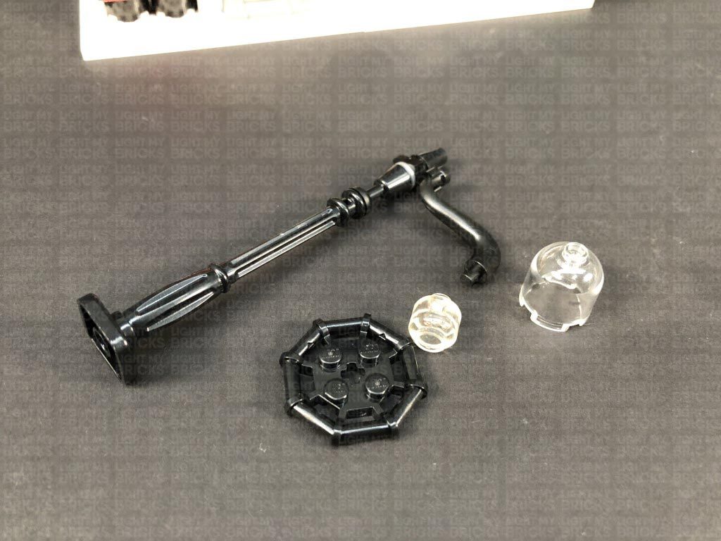
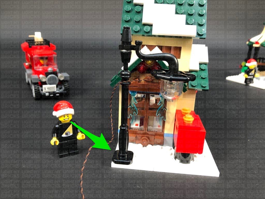
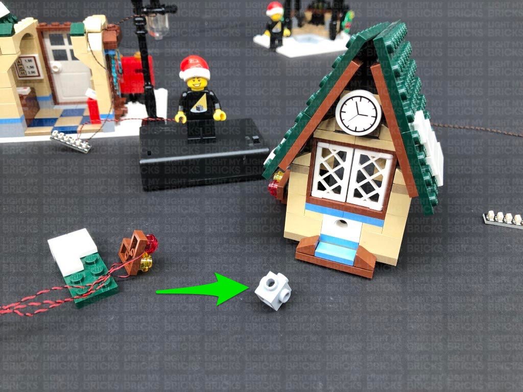
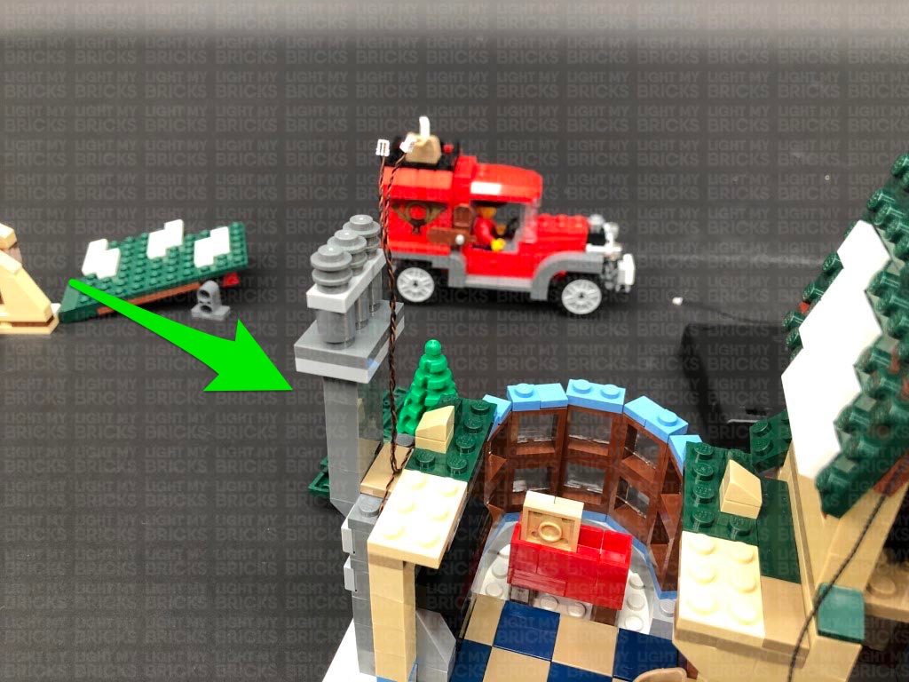
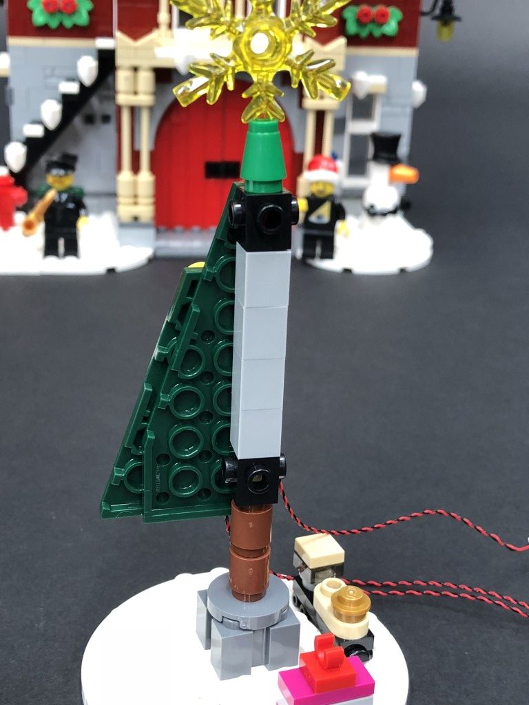
12.) We will now install a light to the lamp post. First disconnect and disassemble to lamp post as shown below:
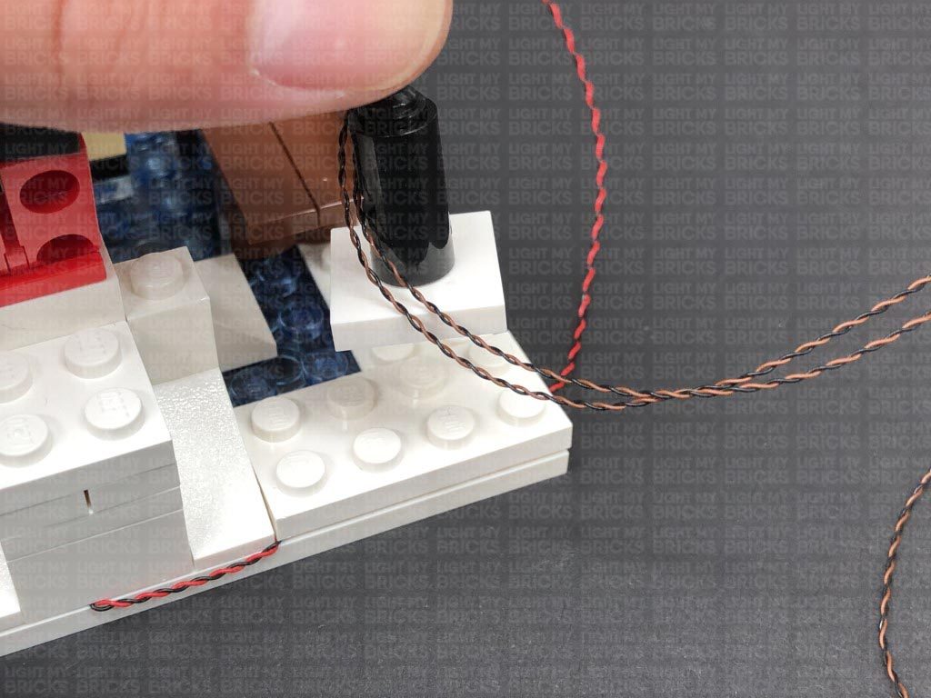
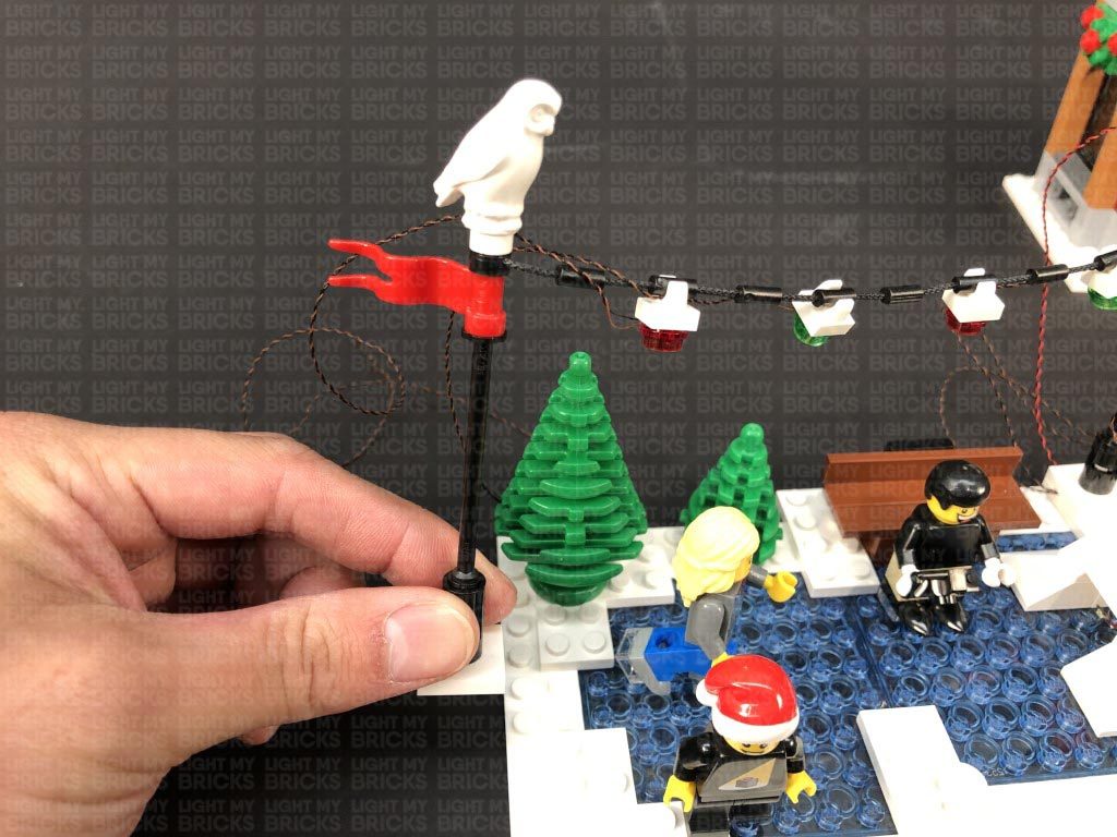
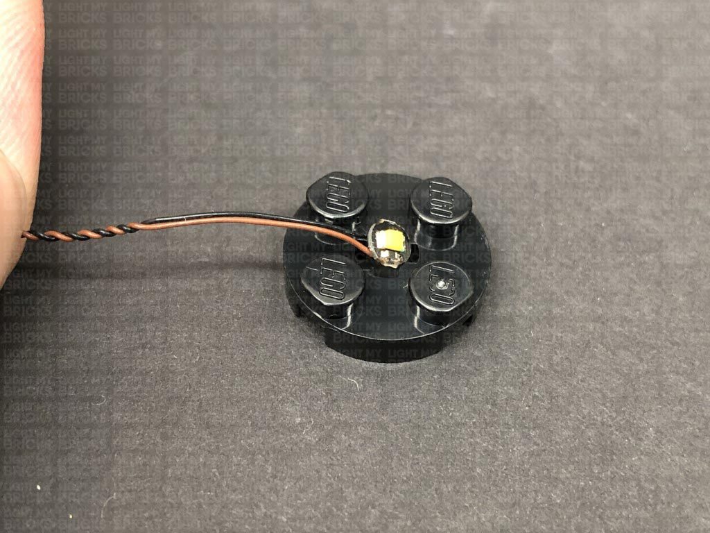
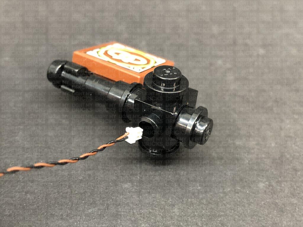
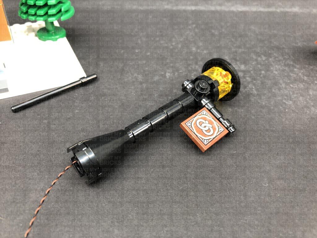
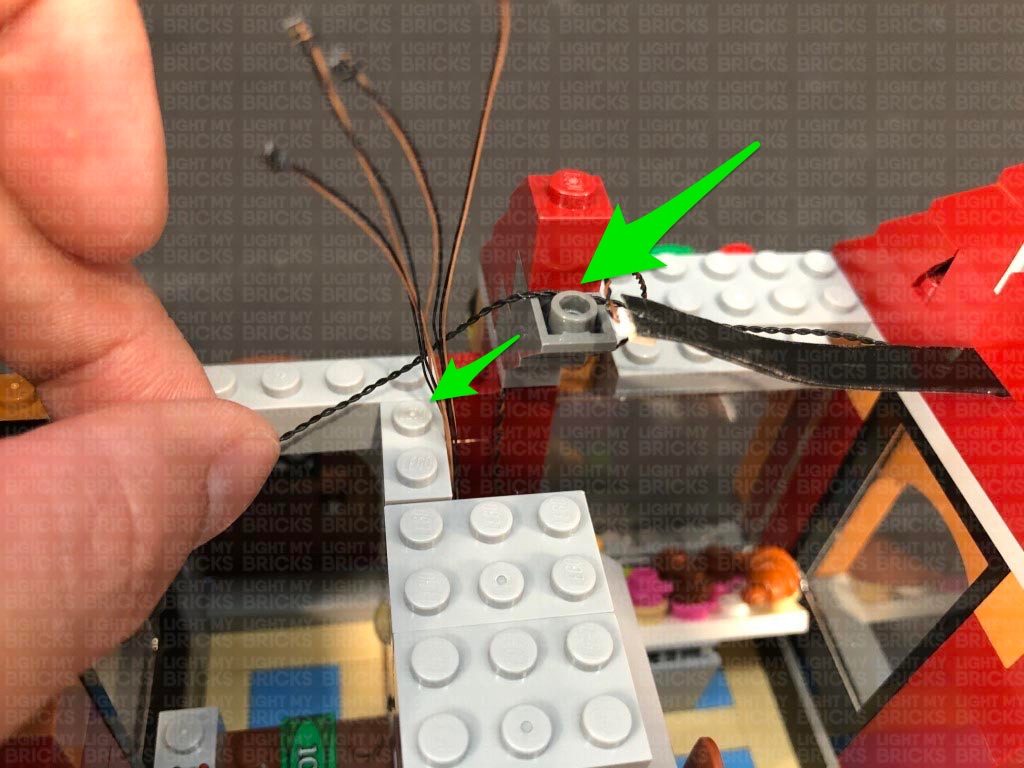
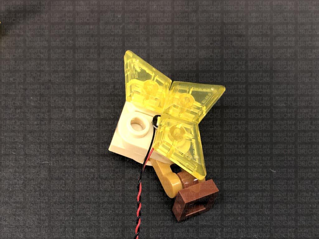
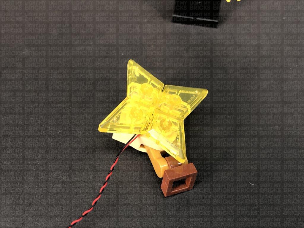
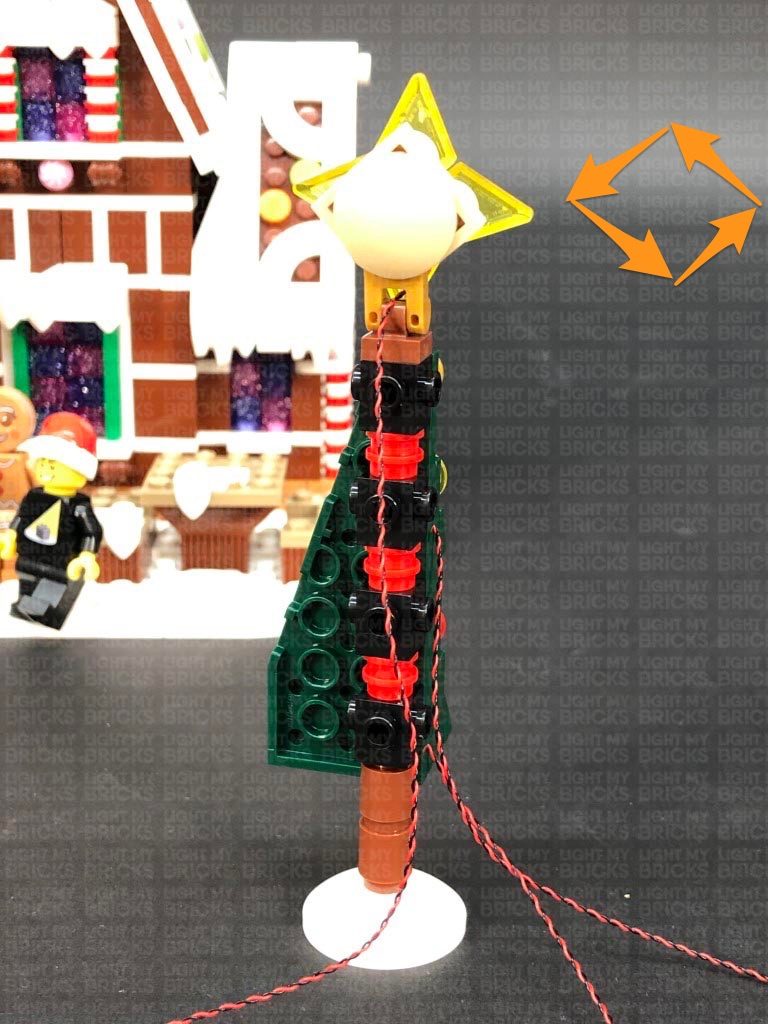
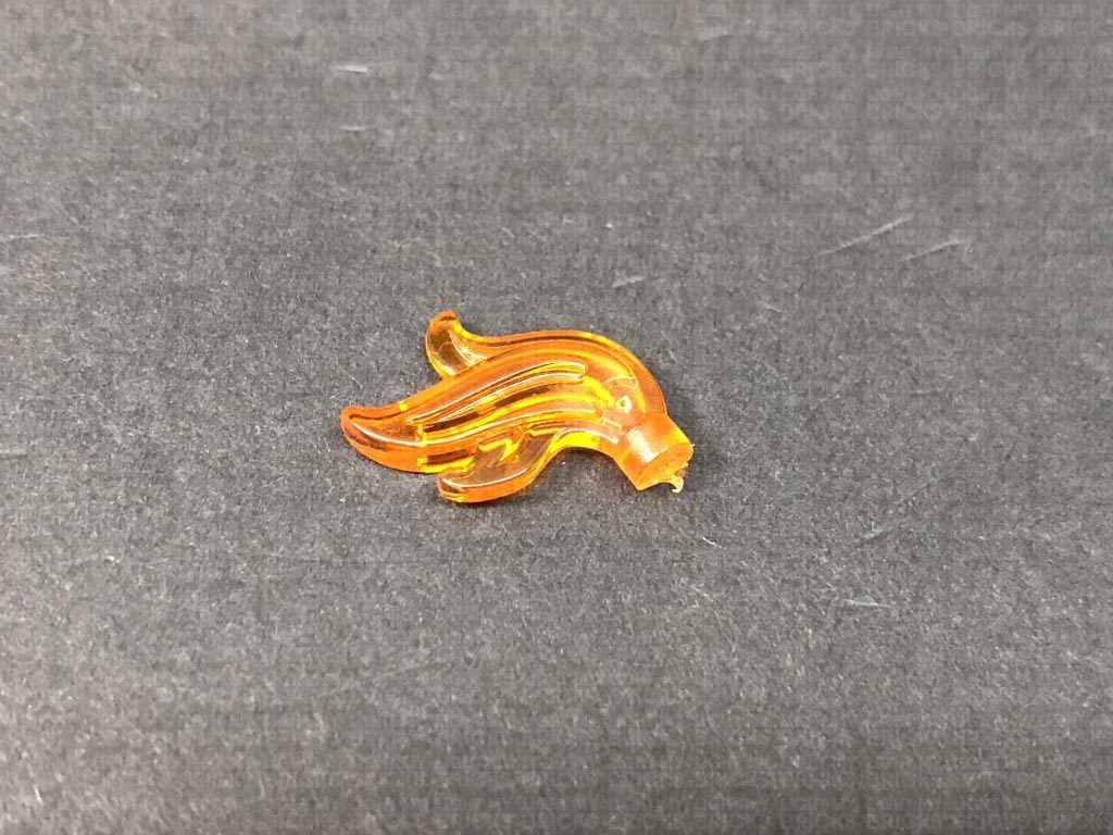
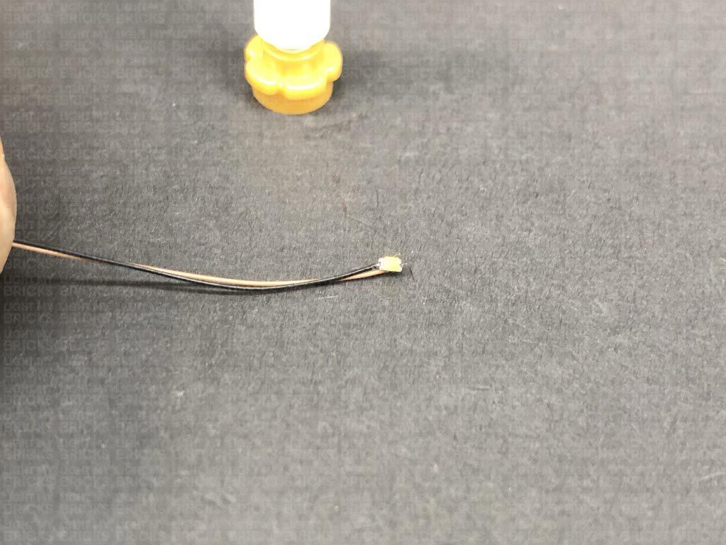
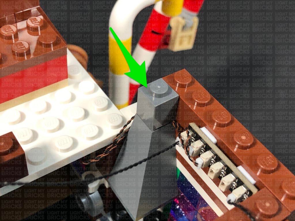
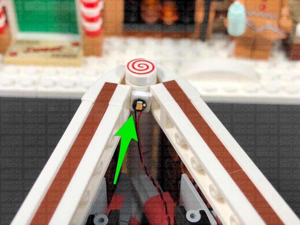
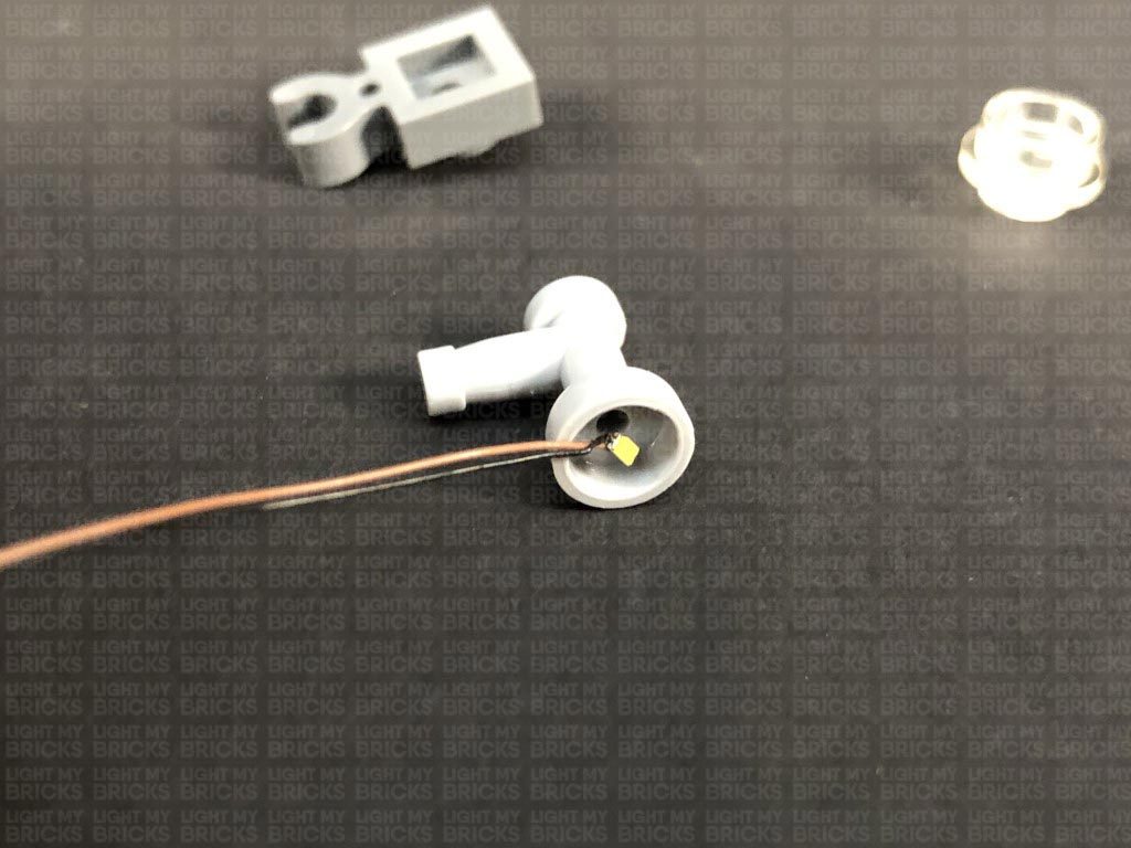
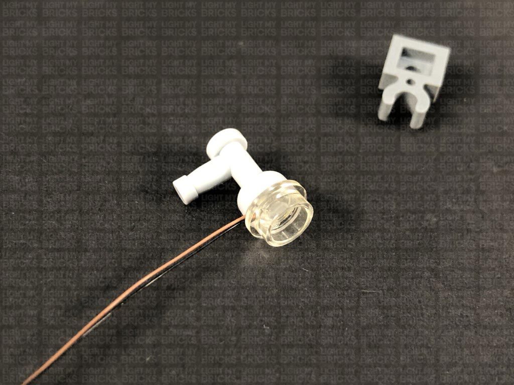
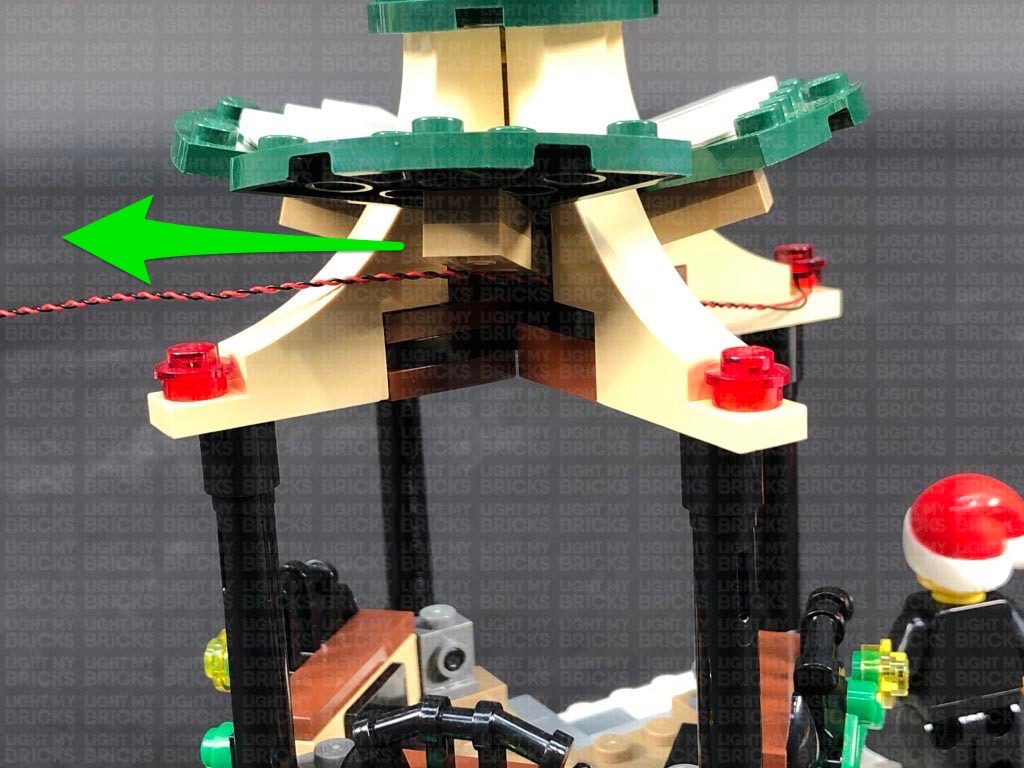
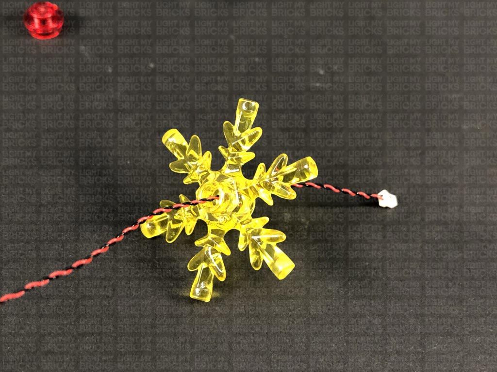
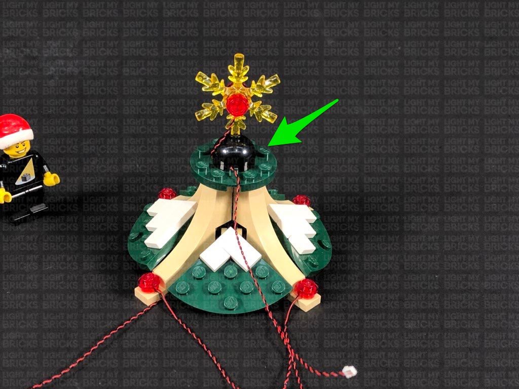
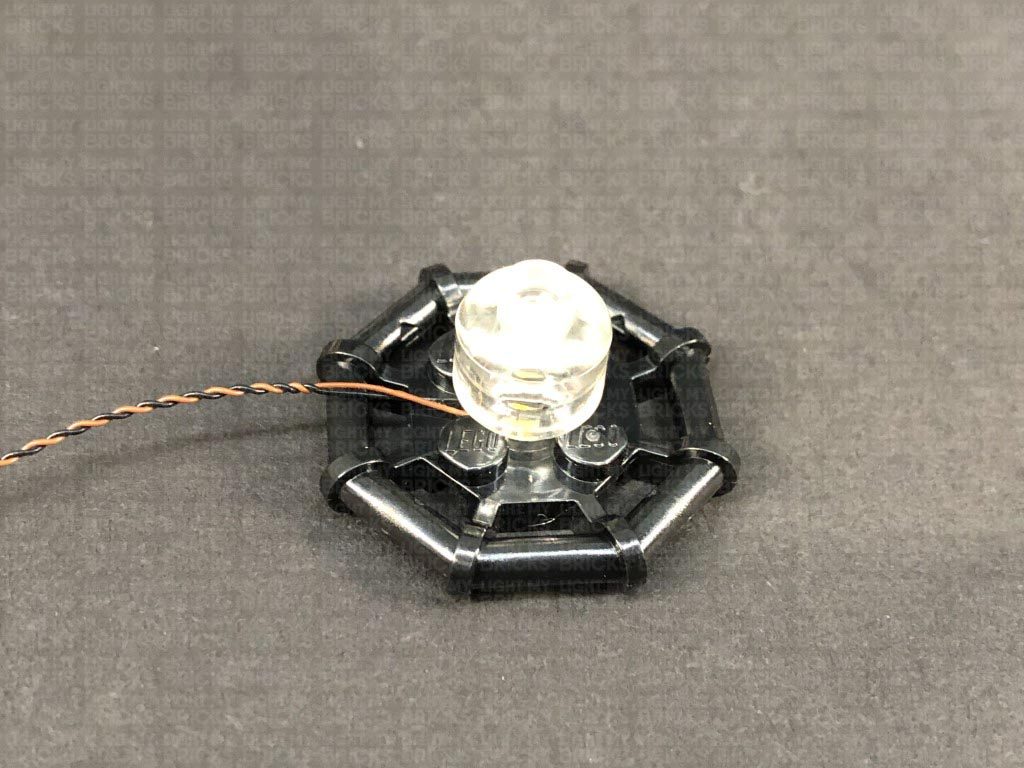
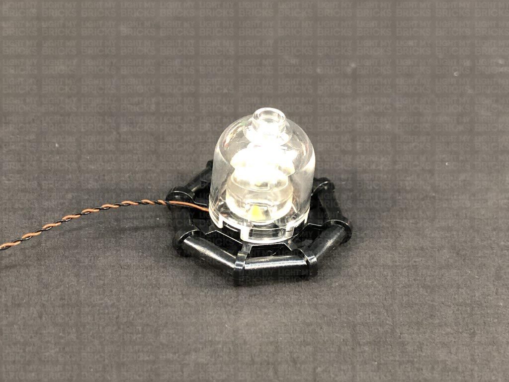
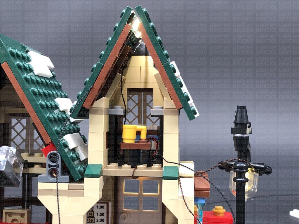
Take a White 30cm Bit Light and place it in the centre of the black round plate. Secure the Bit Light in place by reconnecting the trans yellow brick with black dish over the top. Thread the Bit Light cable through the top of the sign section via the top open stud on the black brick. Pull the cable all the way out from the bottom, then reconnect the lamp. Ensure the cable is tucked into the gap underneath the black stud.
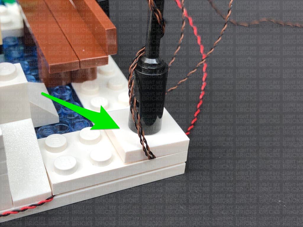
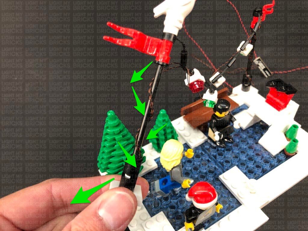
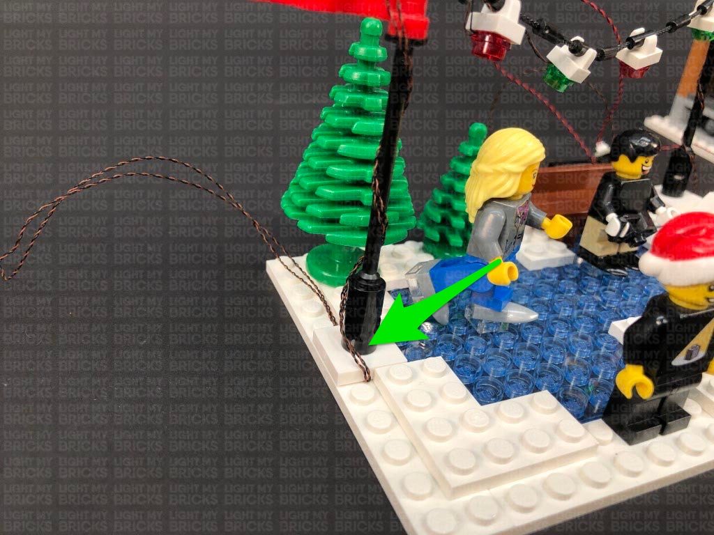
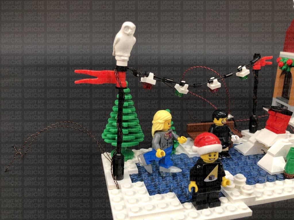
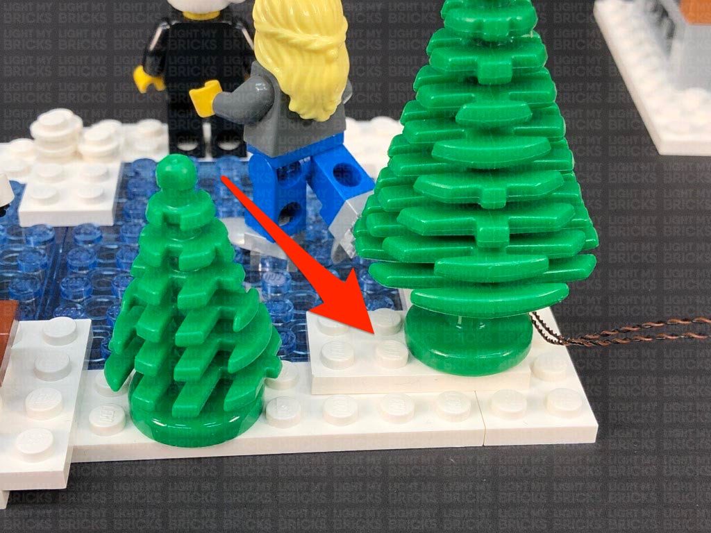
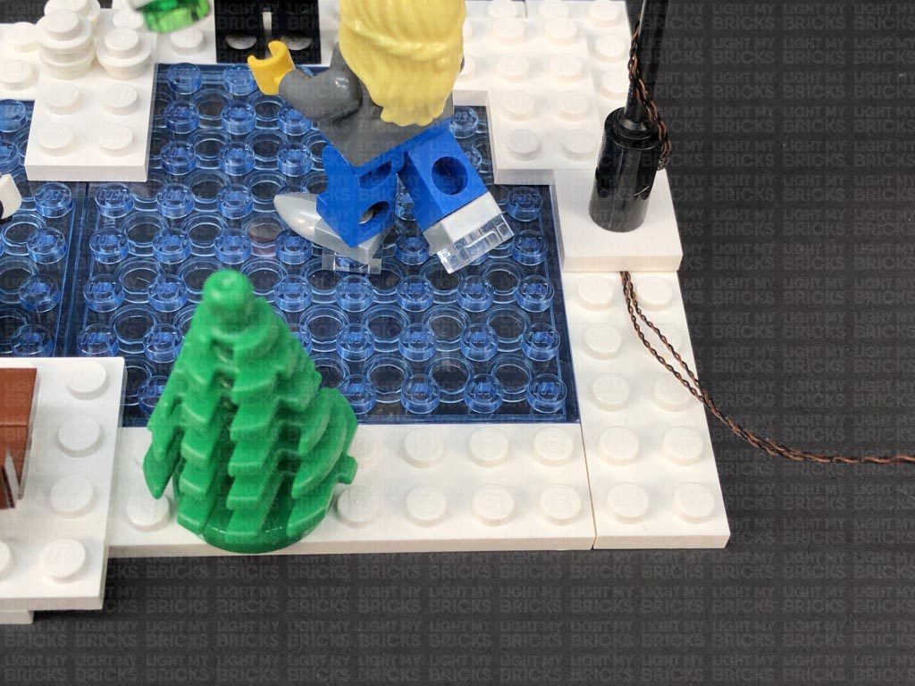
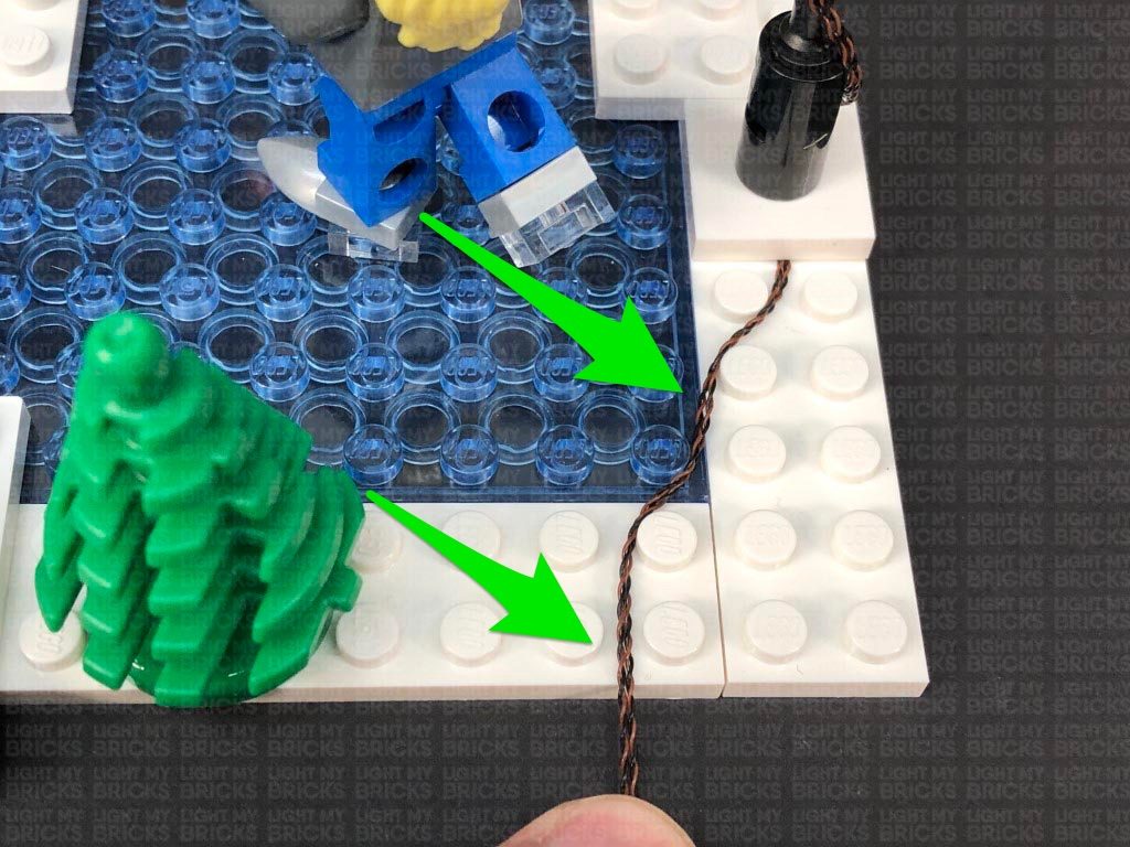
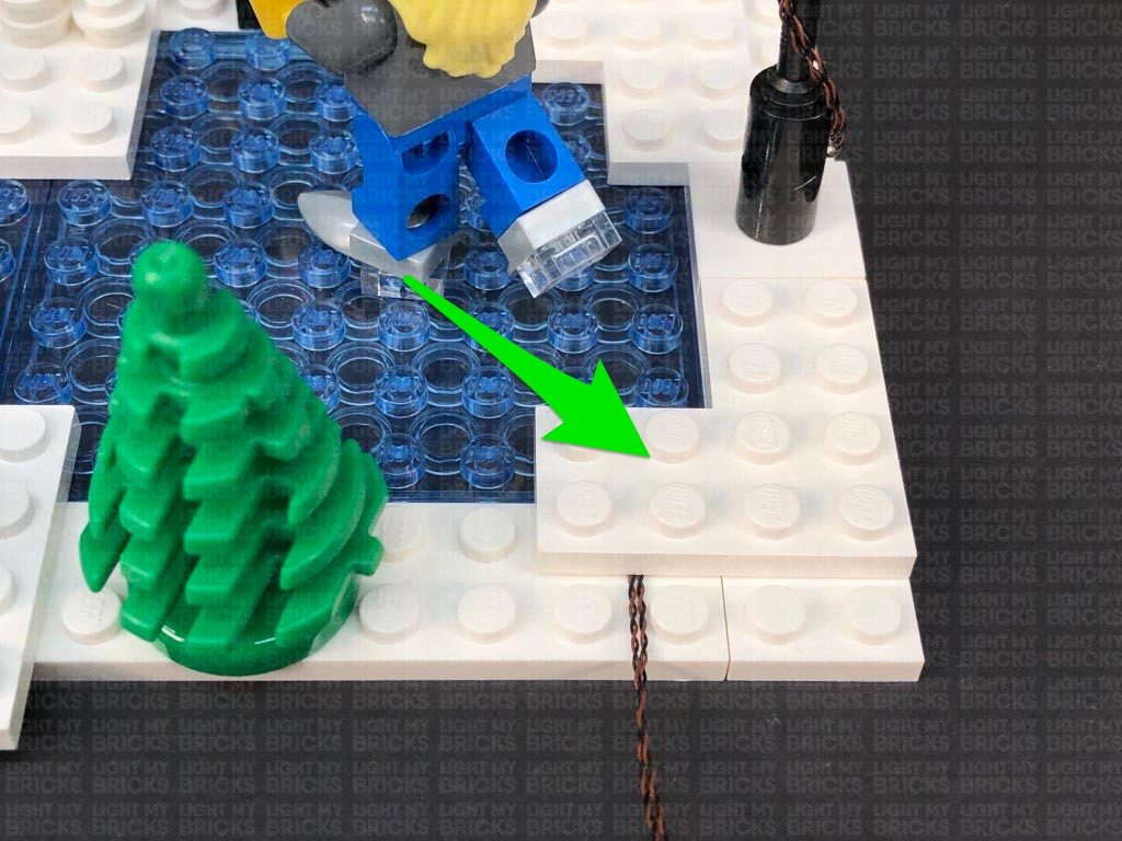
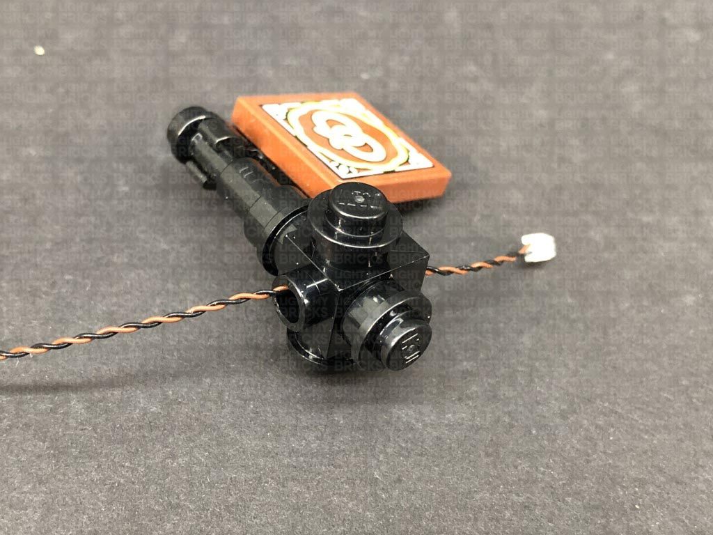
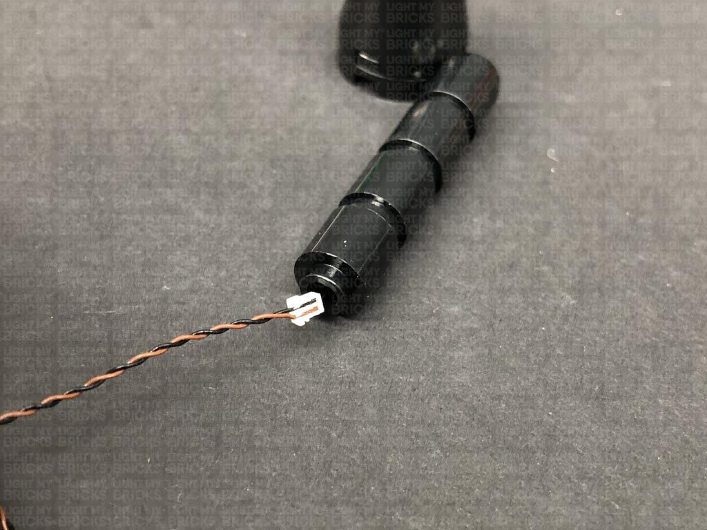
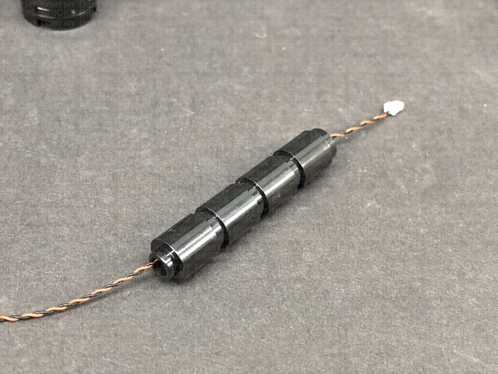
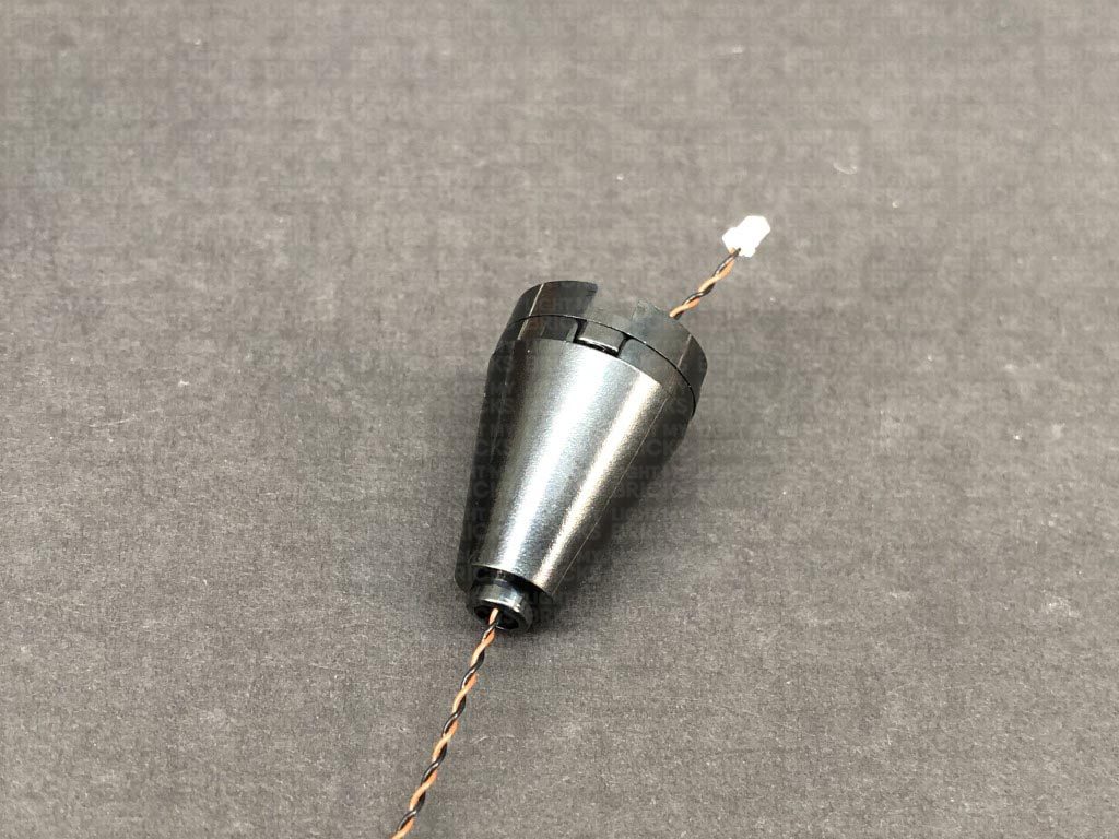
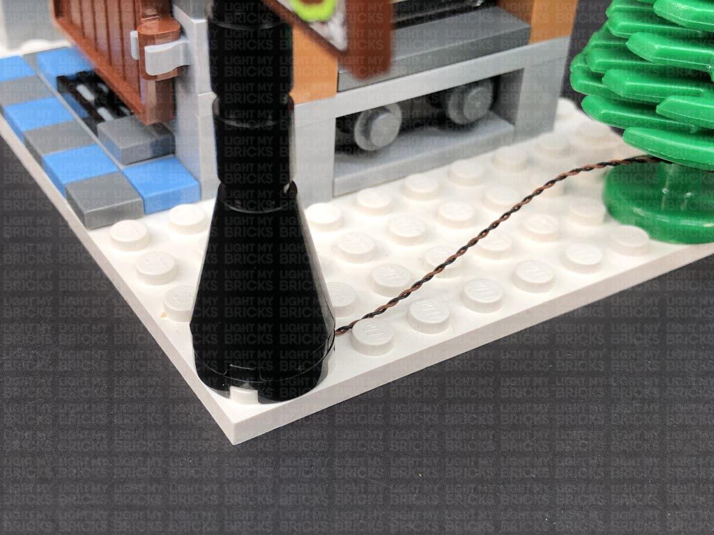
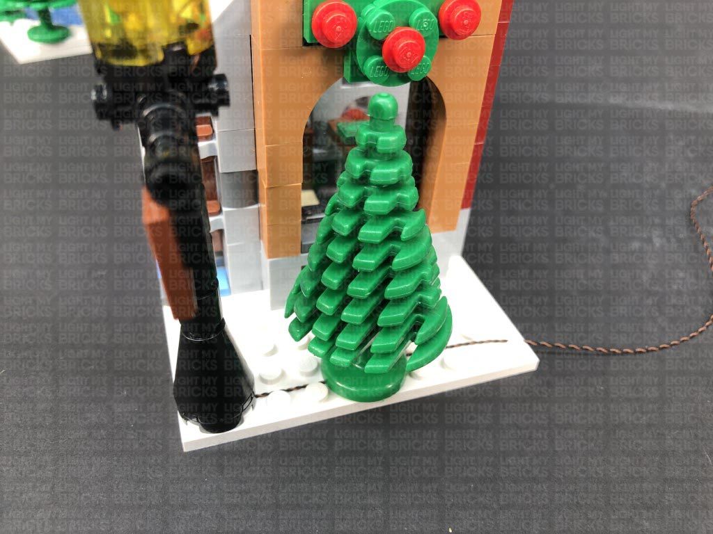
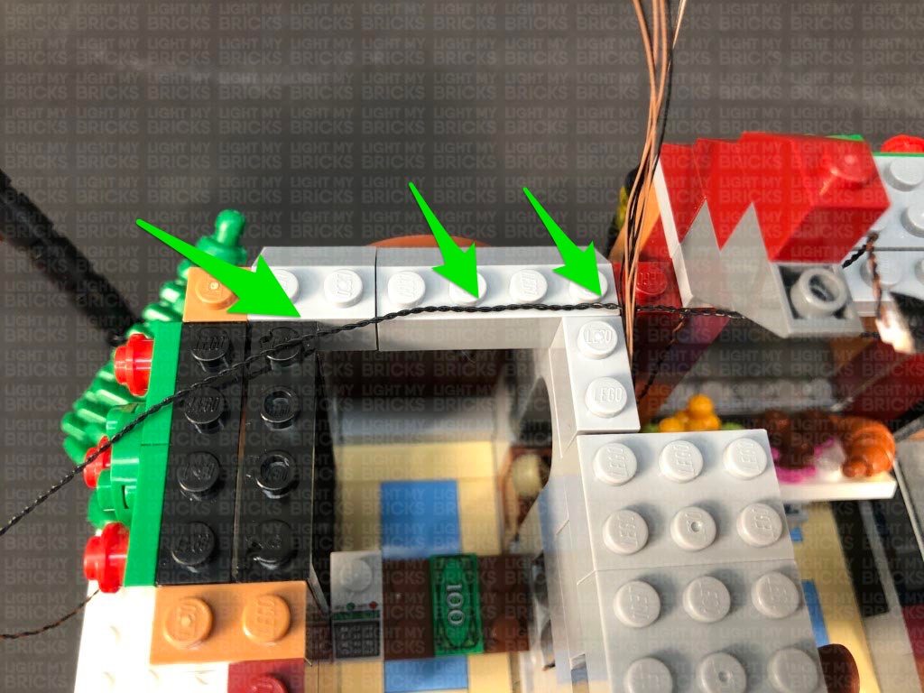
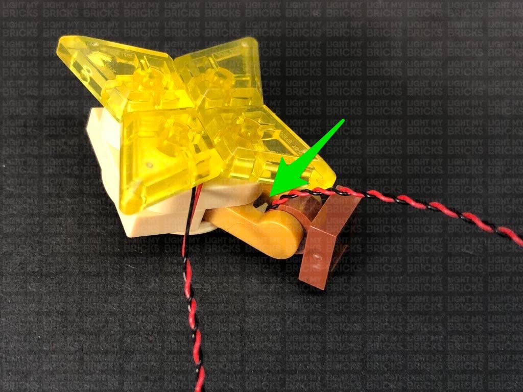
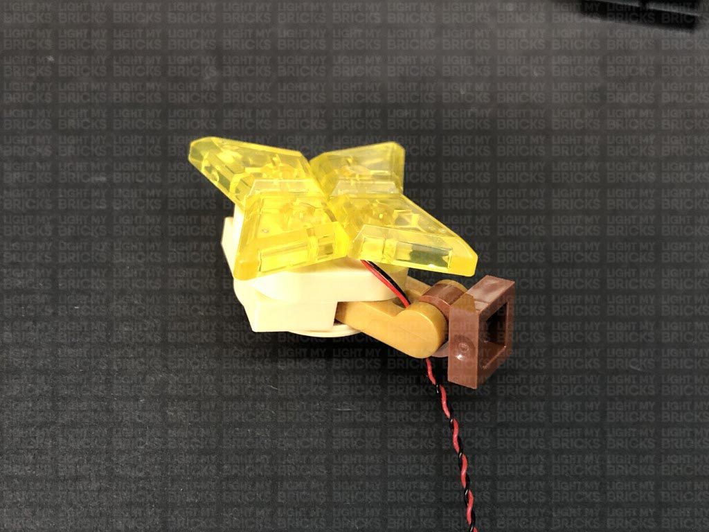
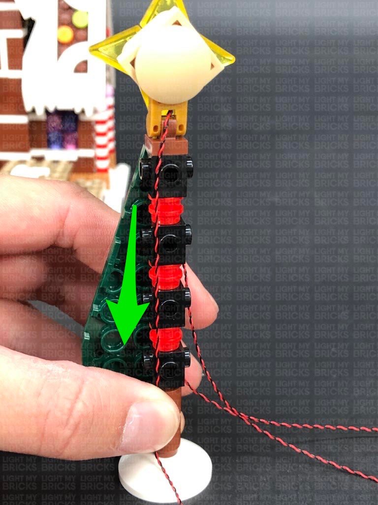
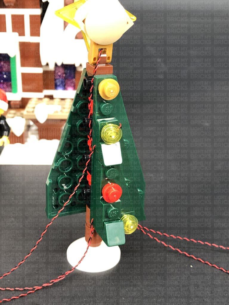
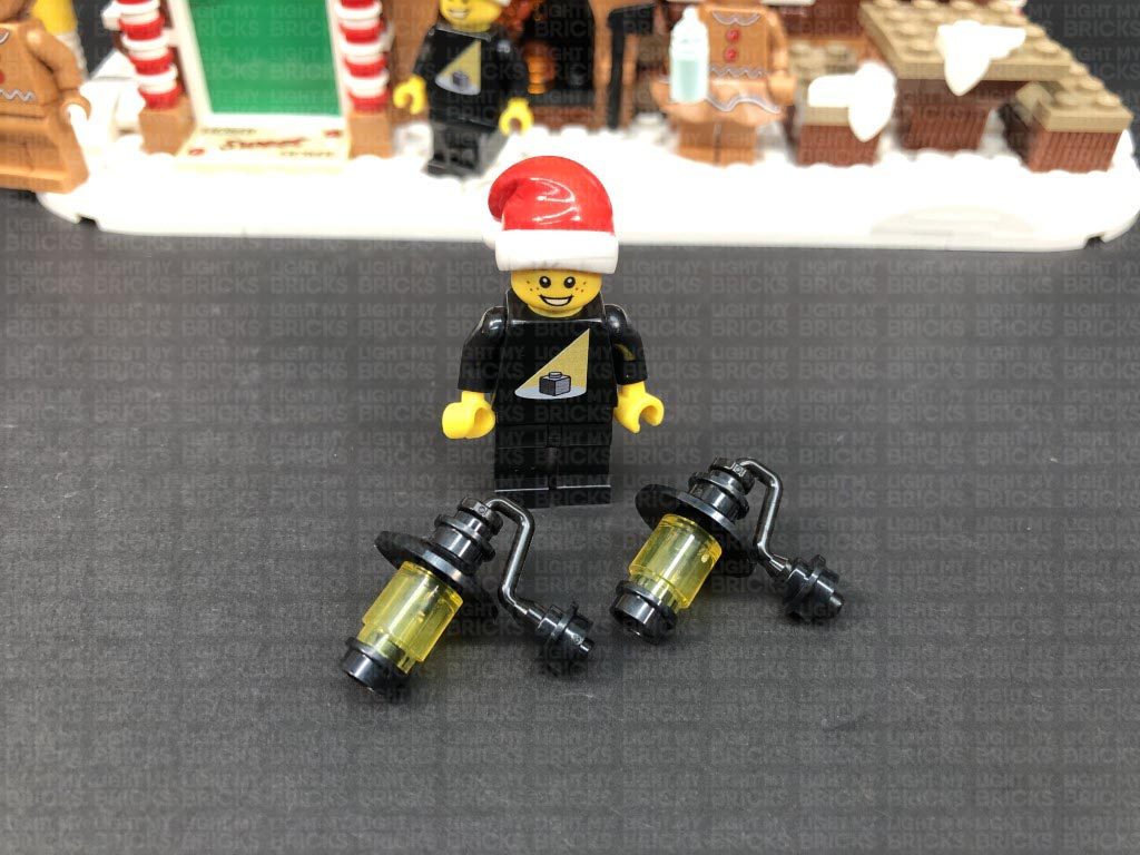
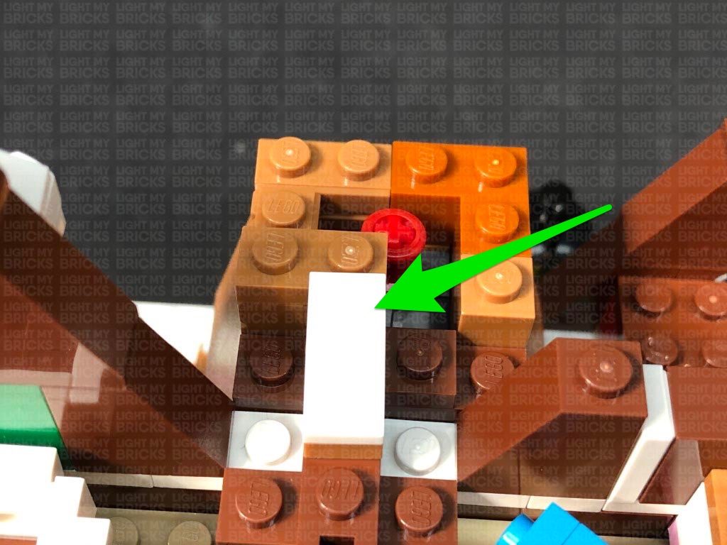
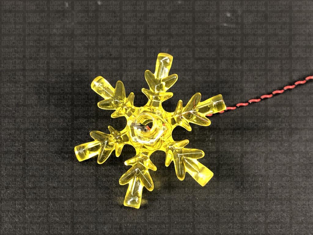
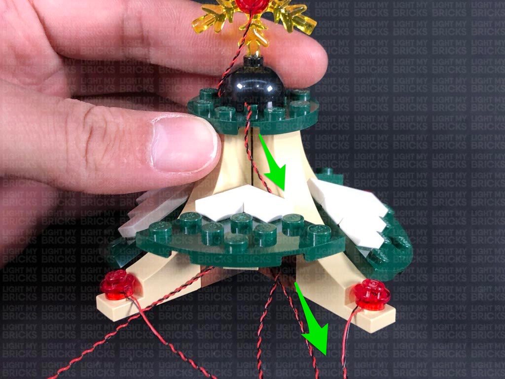
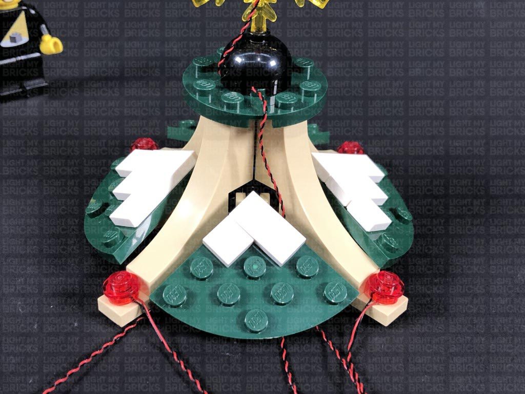
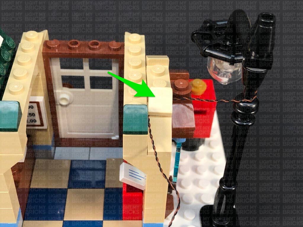
13.) Continue to thread the cable through all the black round bricks as well as the black cone brick at the bottom, then reconnect everything together (without the black bar). Reconnect the lamp post to the front of the set, then lay the cable behind it, in between studs. Reposition the tree in the middle of the plate to cover up the wire.
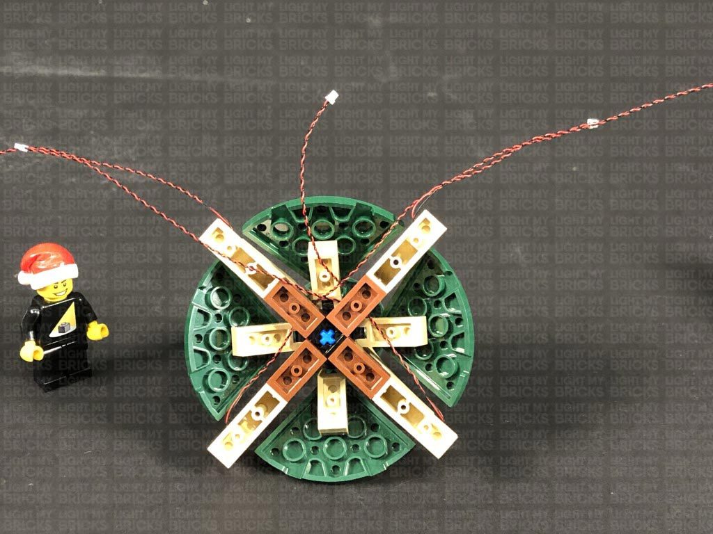
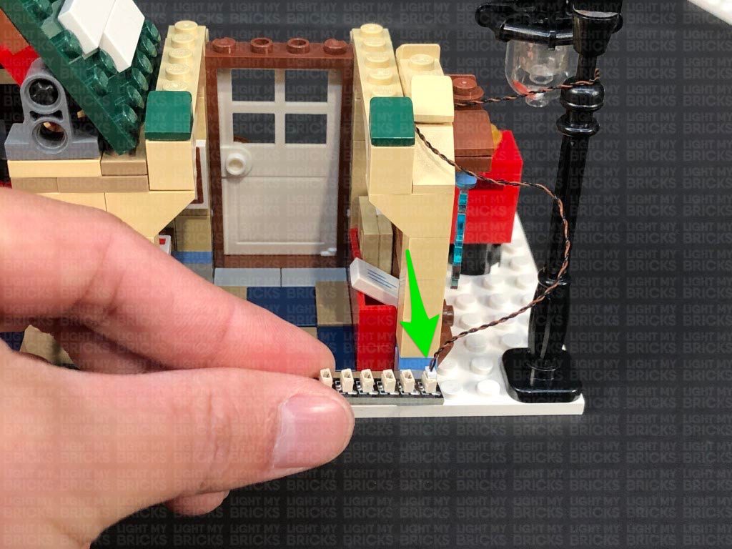
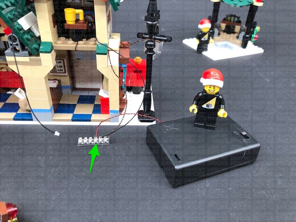
Turn the set around, then connect the Bit Light cable from the lamp post to an 8-Port Expansion Board. Take the AA Battery Pack and connect it to the expansion board, then turn ON the battery pack to test the lamp post is working OK.
Note: If you experience any issues with the lights not working and suspect an issue with a component, please try a different port on the expansion board to verify where the fault lies (with the light or expansion board). To correct any issues with expansion board ports, please view the section addressing expansion board issues on our online troubleshooting guide.
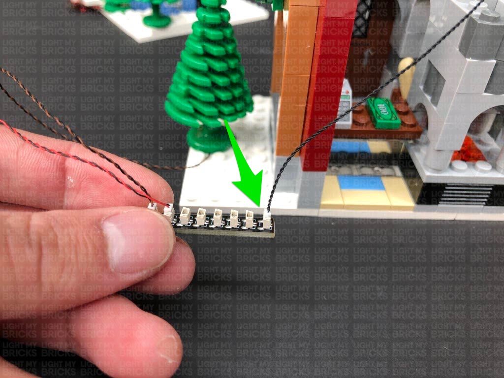
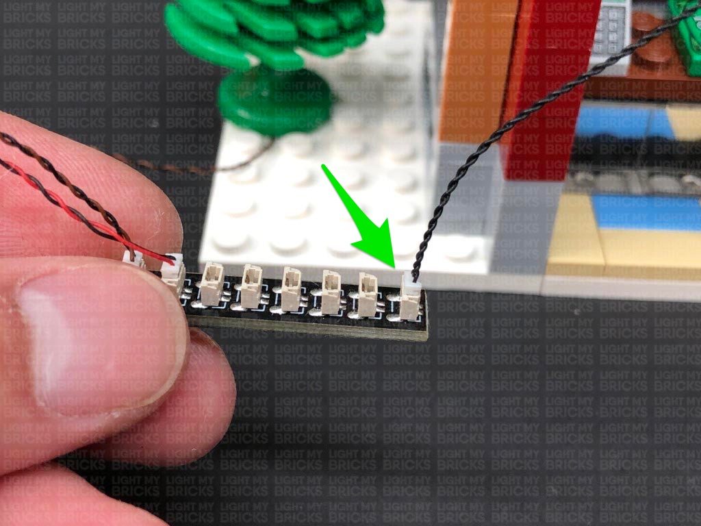
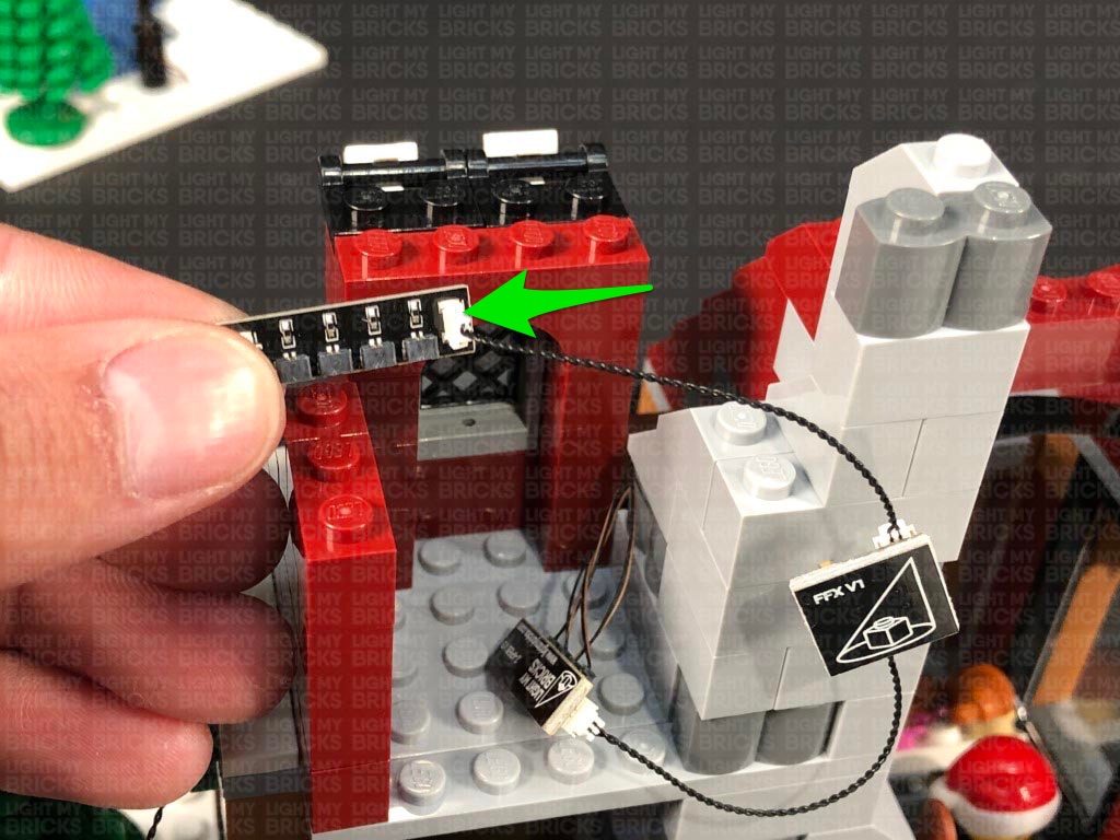
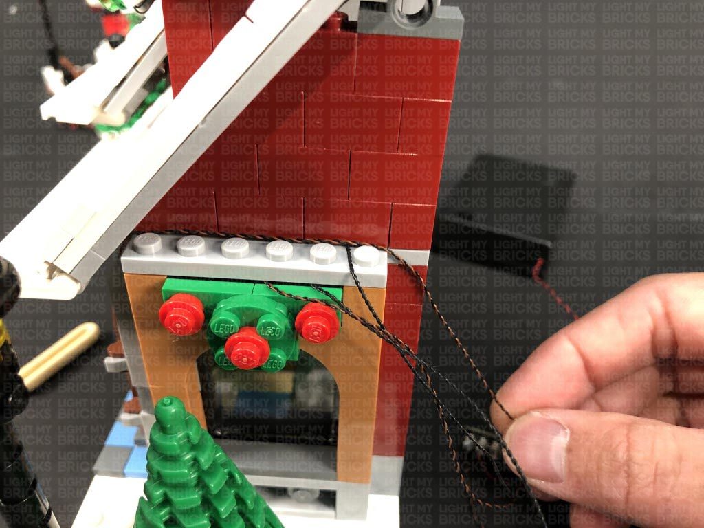
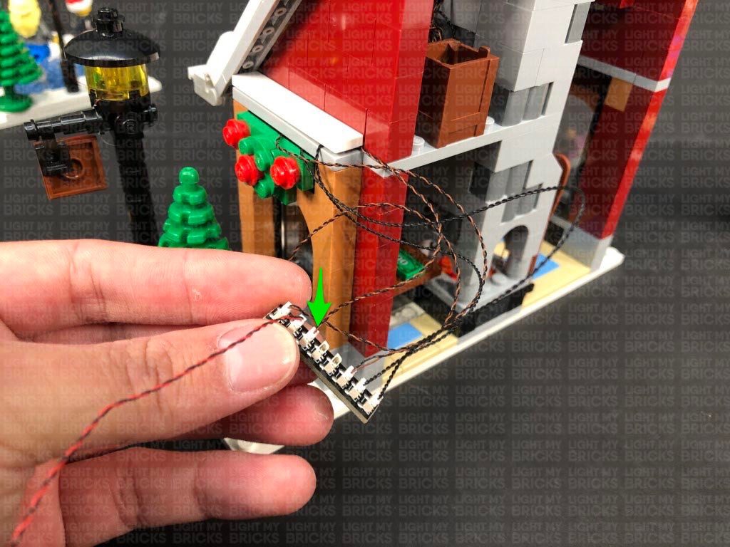
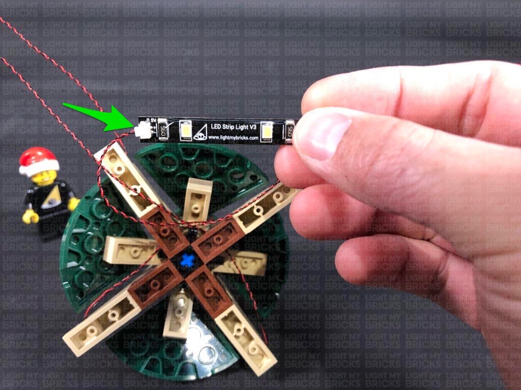
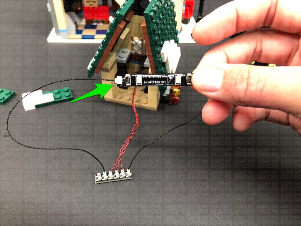
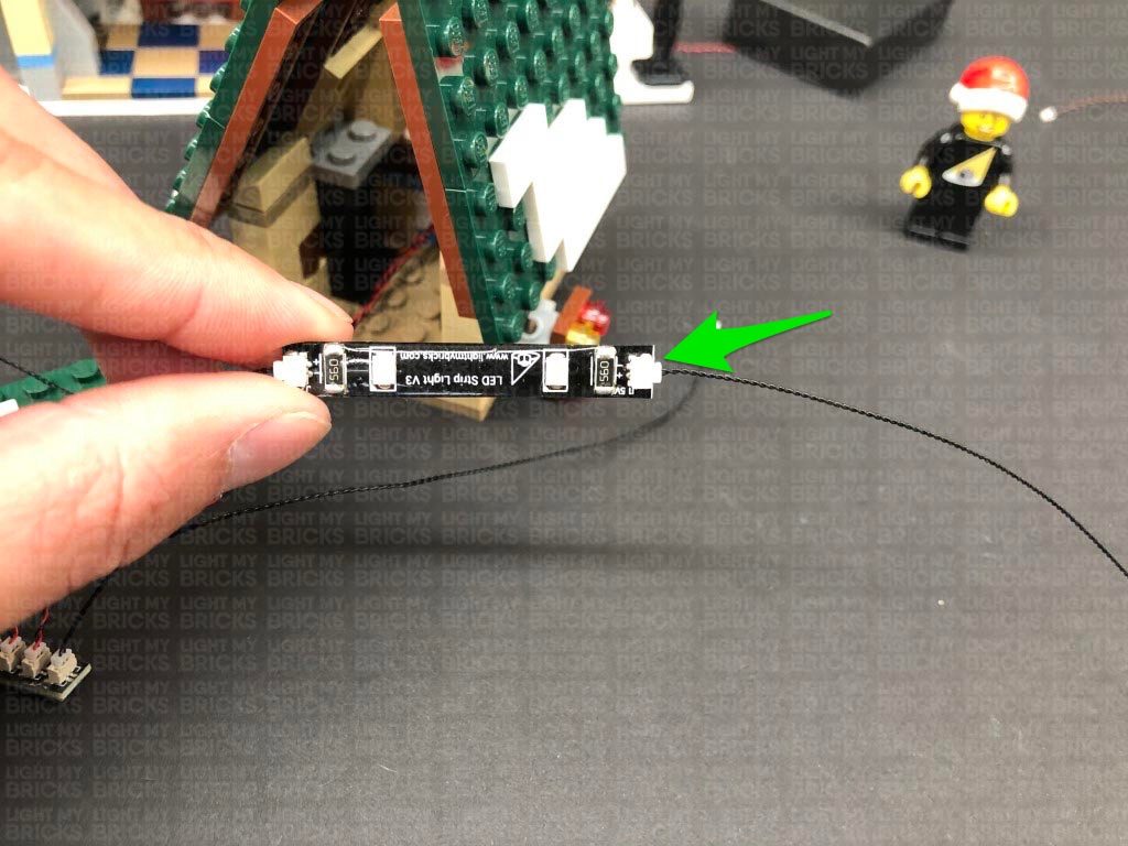
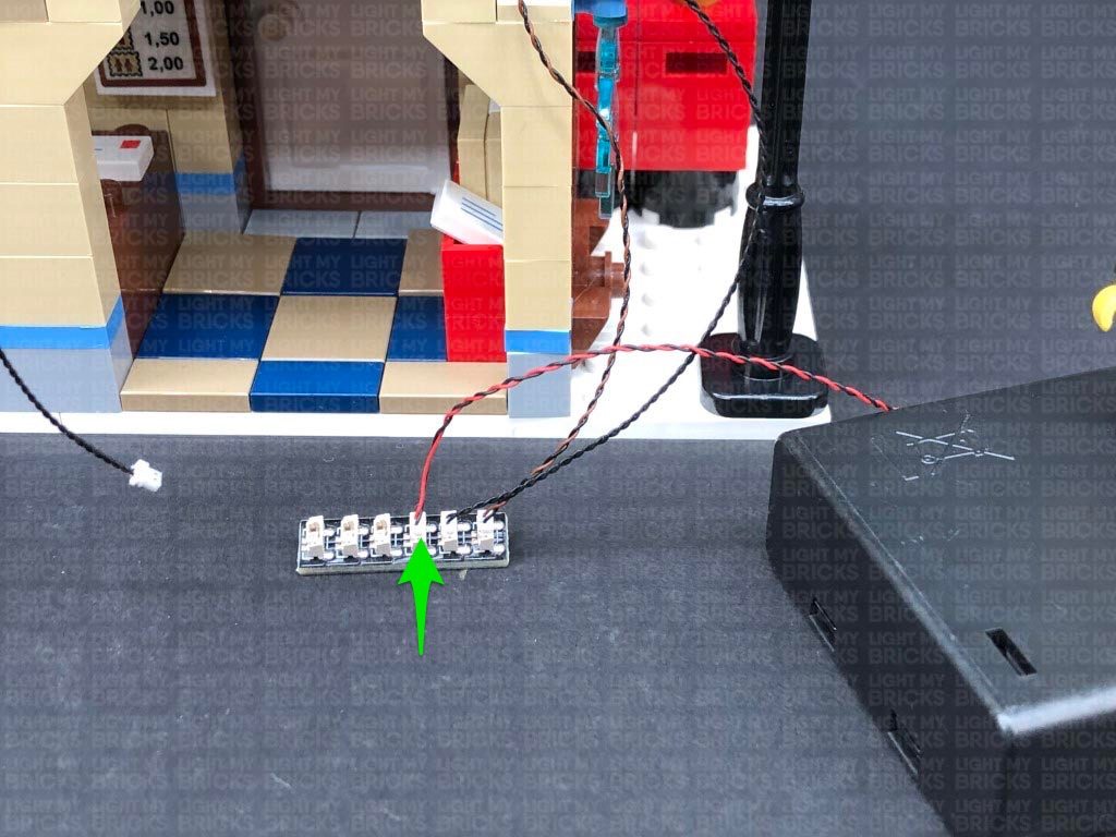
14.) Take a 30cm Connecting Cable and connect it to the 8-Port Expansion Board, then connect the other end of the cable to the other port on the White Strip Light from previous step.
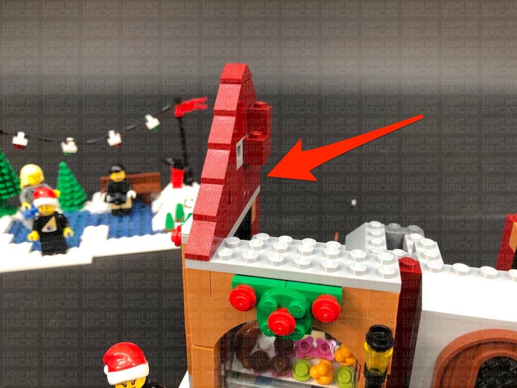
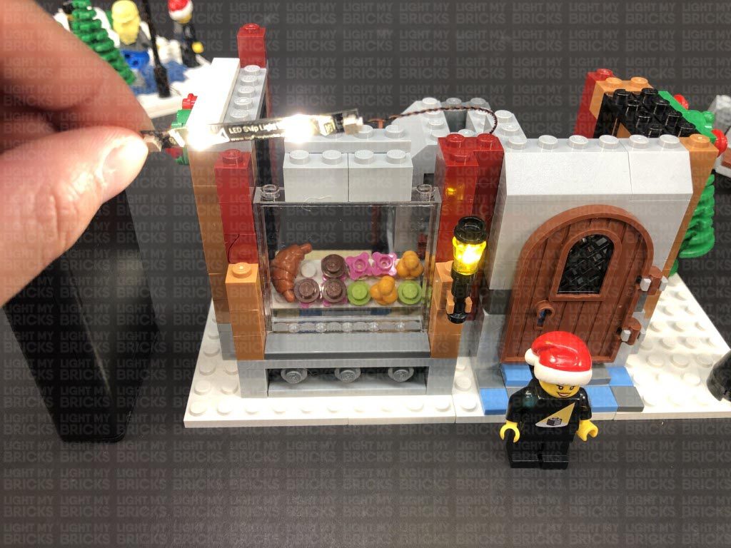
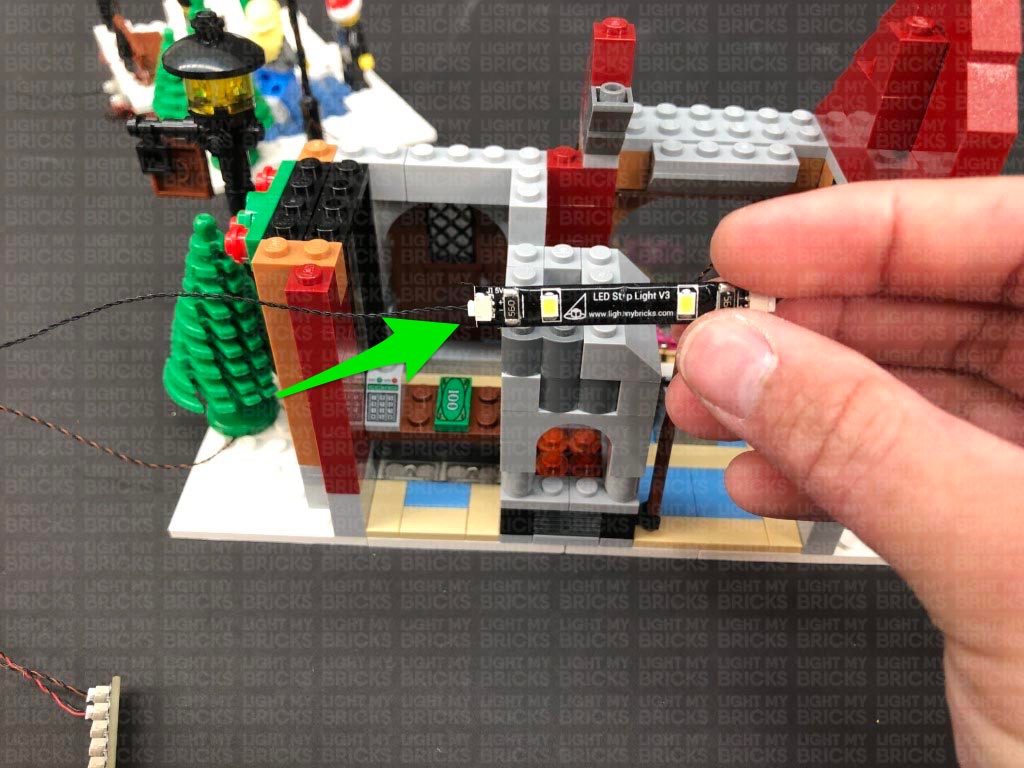
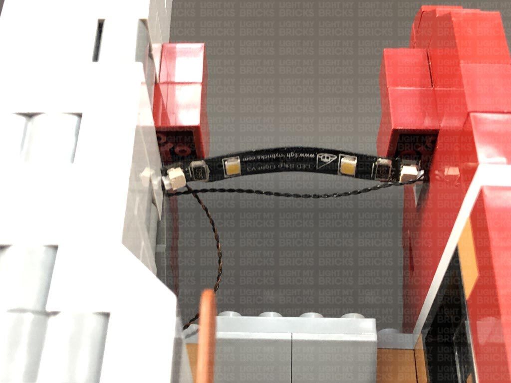
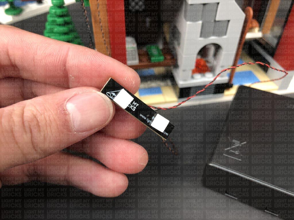
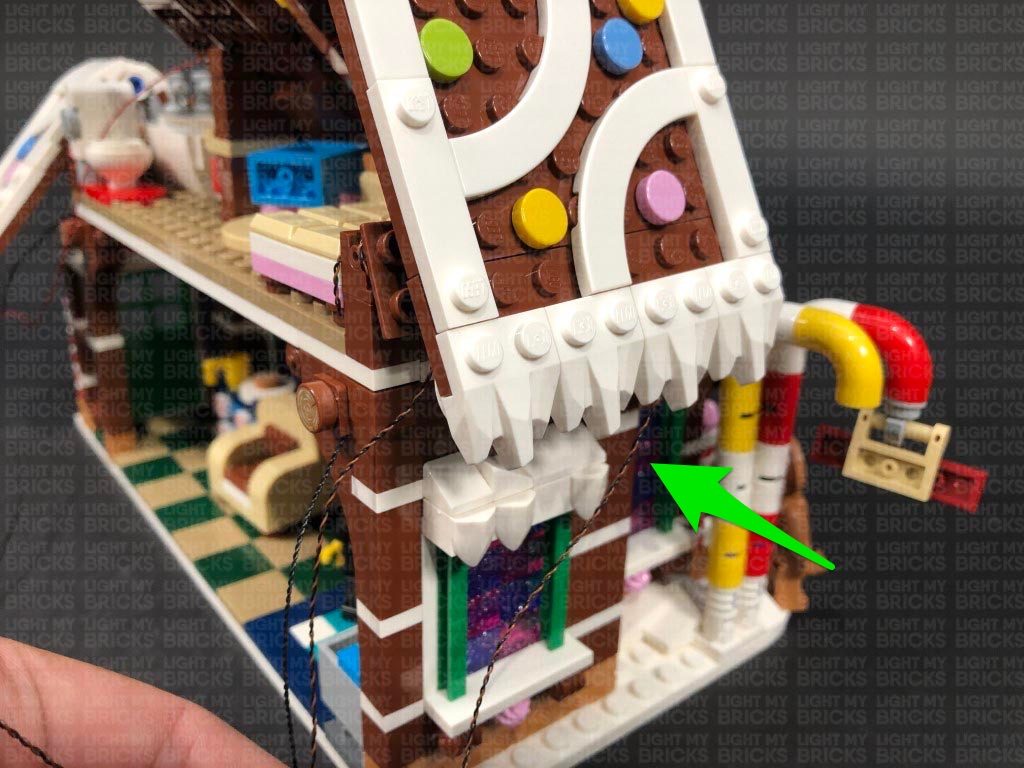
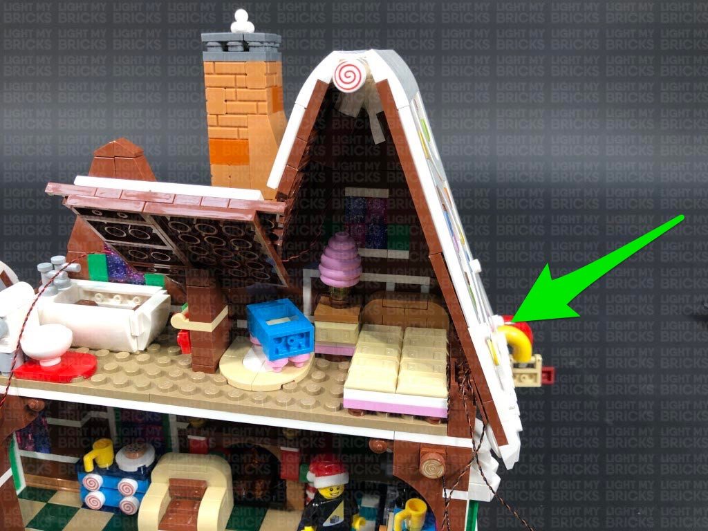
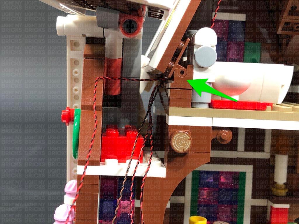
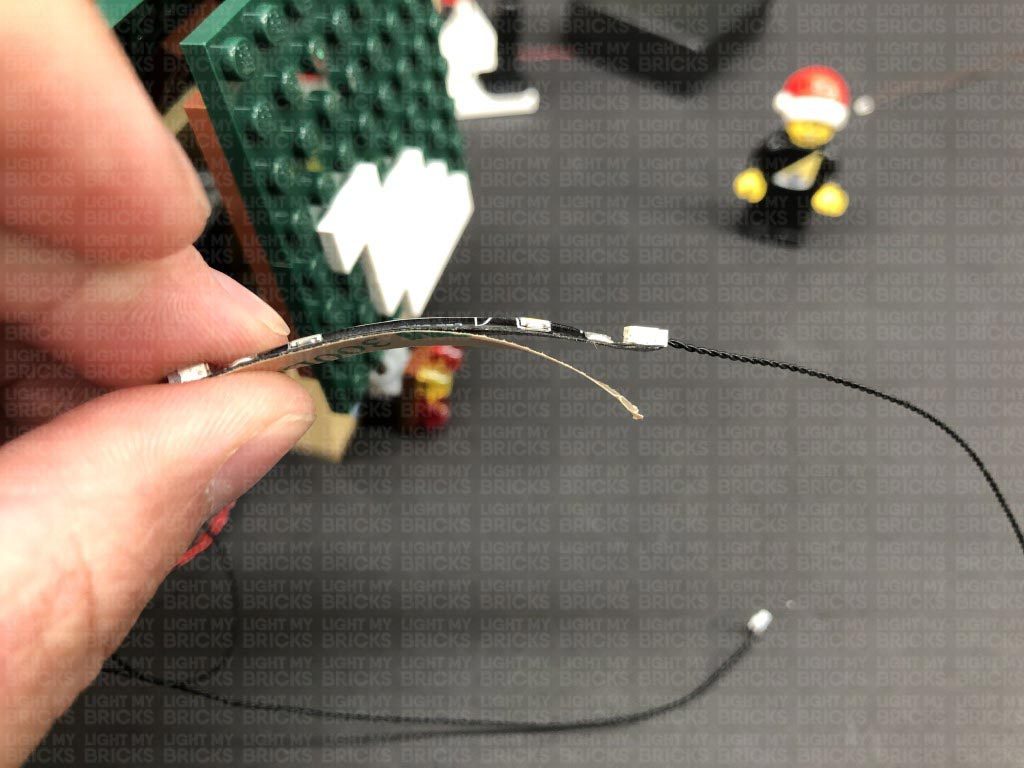
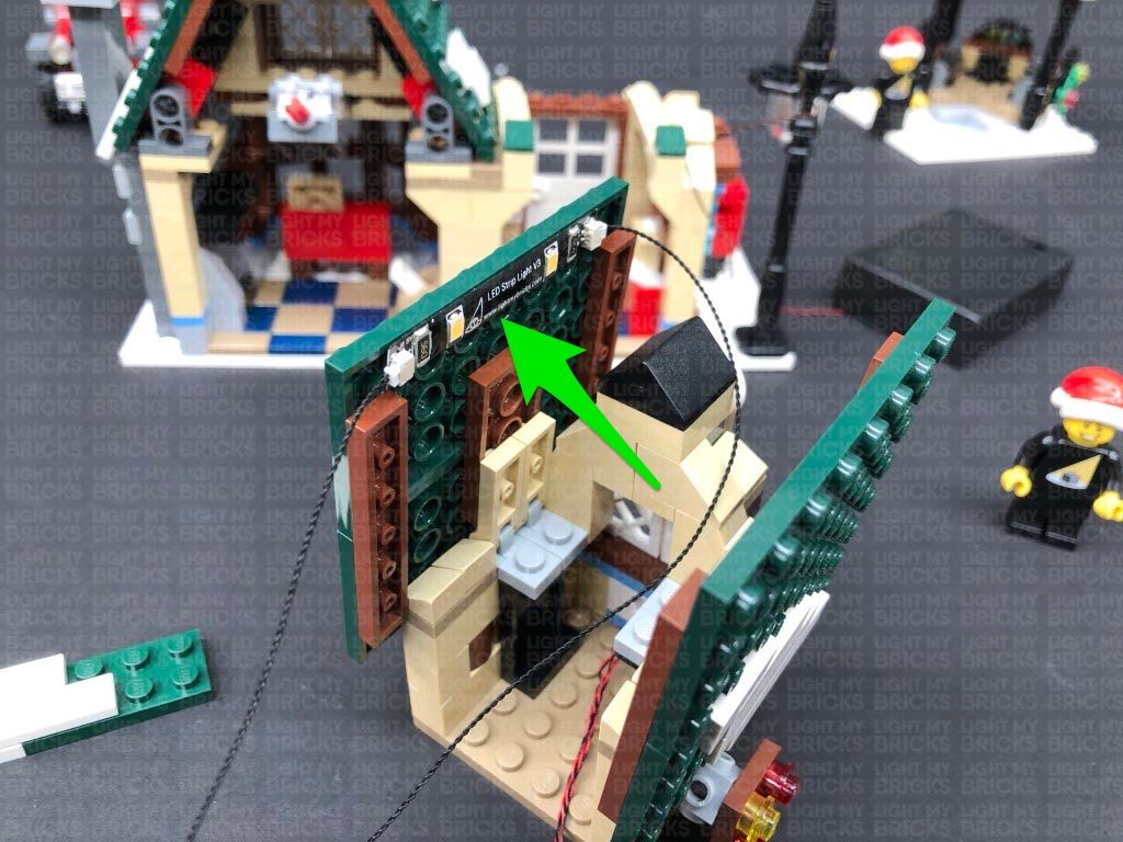
Using it’s adhesive backing, stick the right side of the Strip Light underneath the red bricks on the right. The Strip Light is currently only partially sticking to this section as we will stick the other side of the strip light at a later stage.
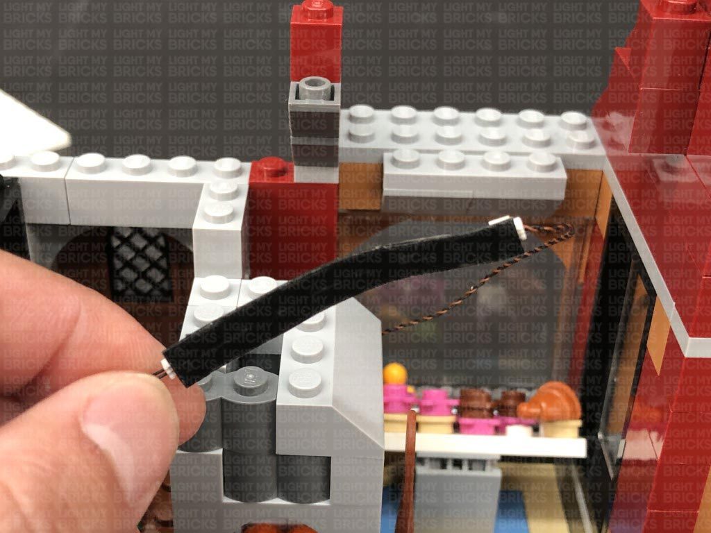
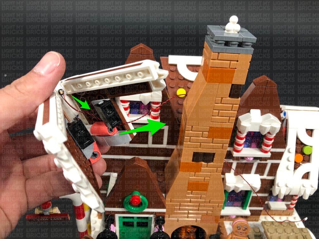
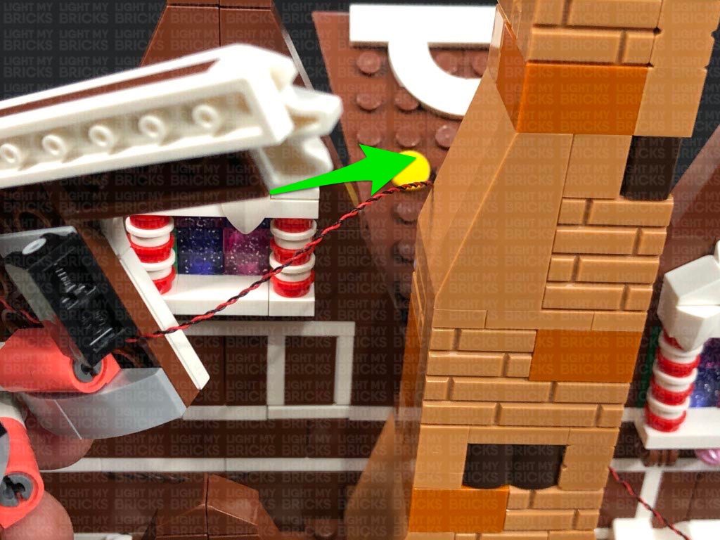
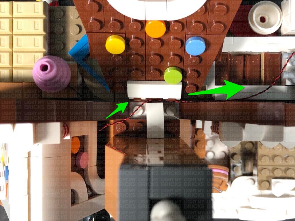
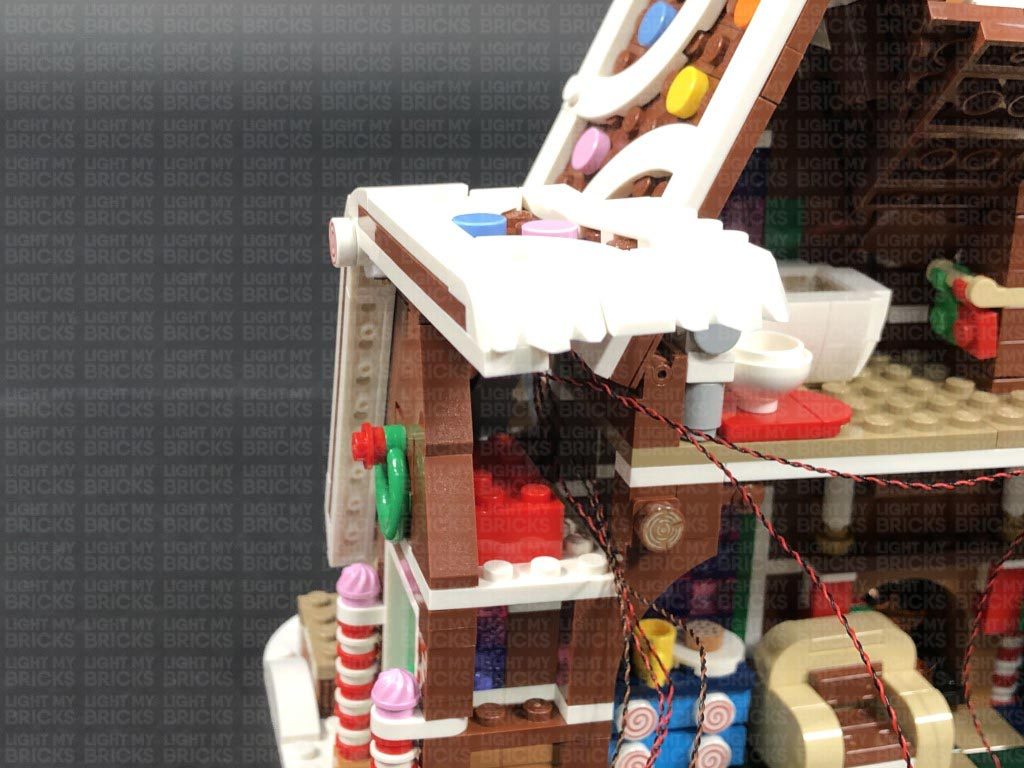
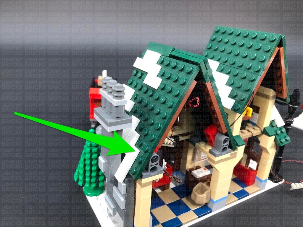
Secure the White 15cm Bit Light cable underneath the left roof pieces ensuring you first pull the cable up to prevent it from being seen from the outside. Lay the 30cm Connecting Cable across the top of the bottom floor in between studs as shown below.
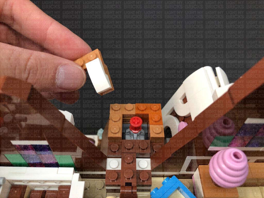
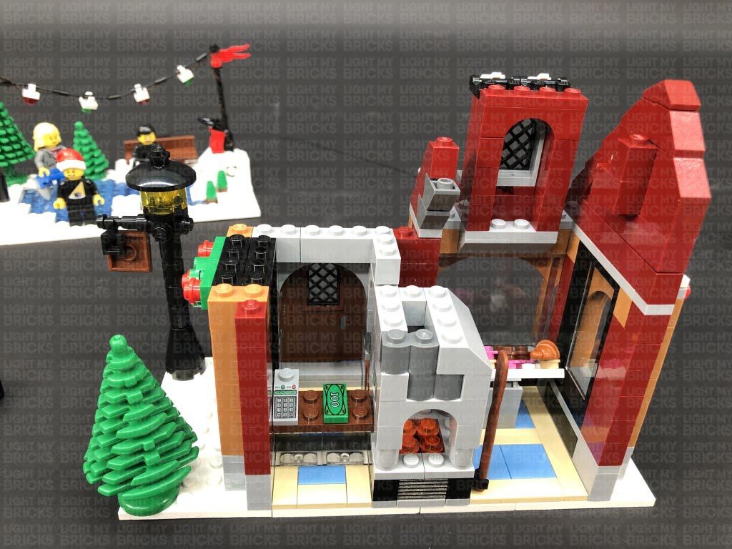
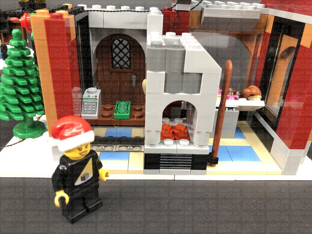
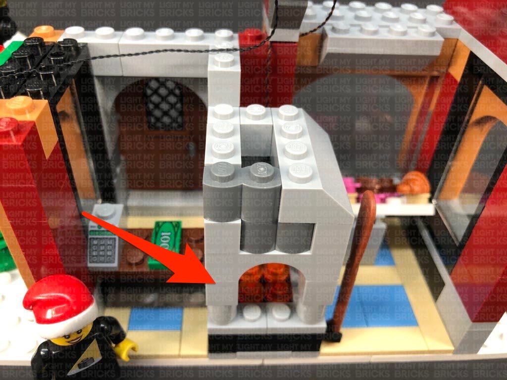
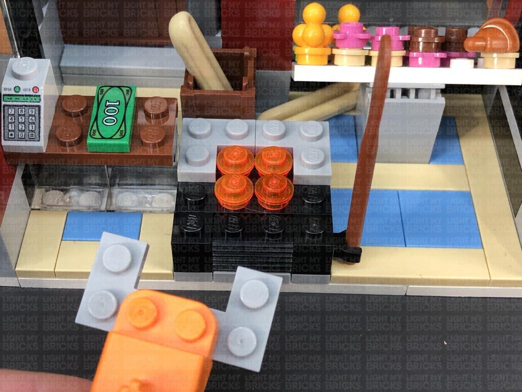
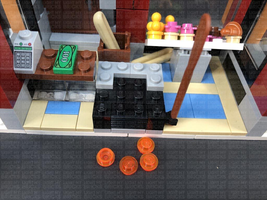
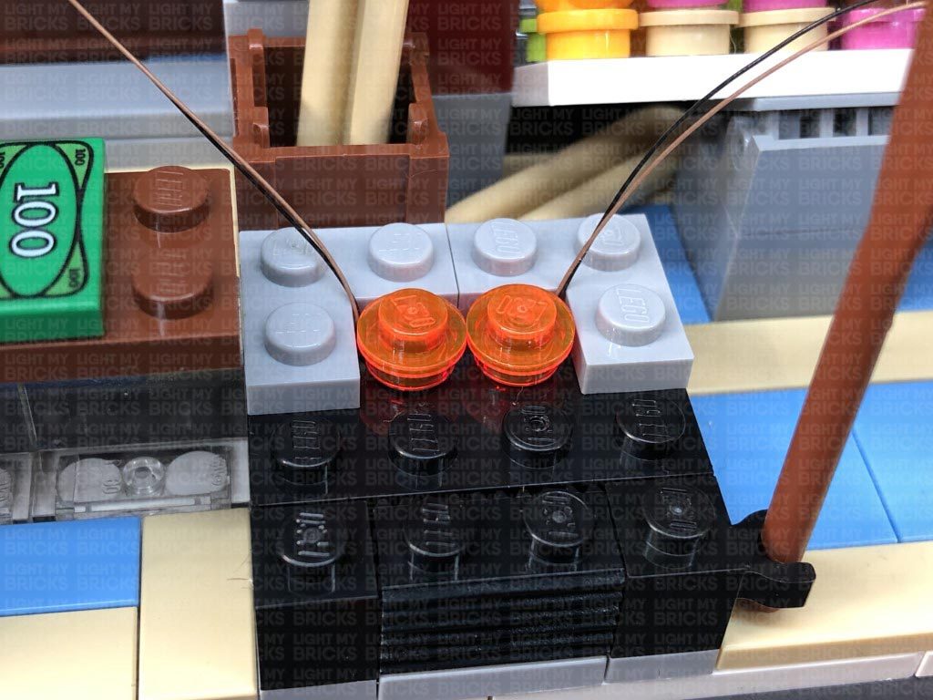
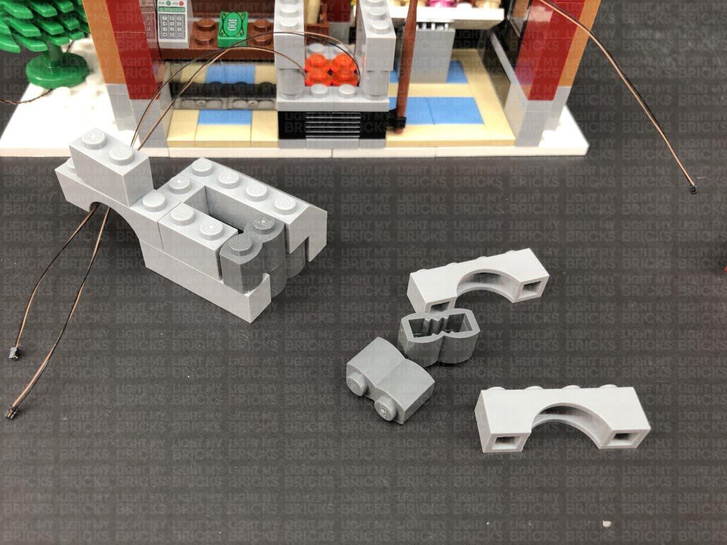
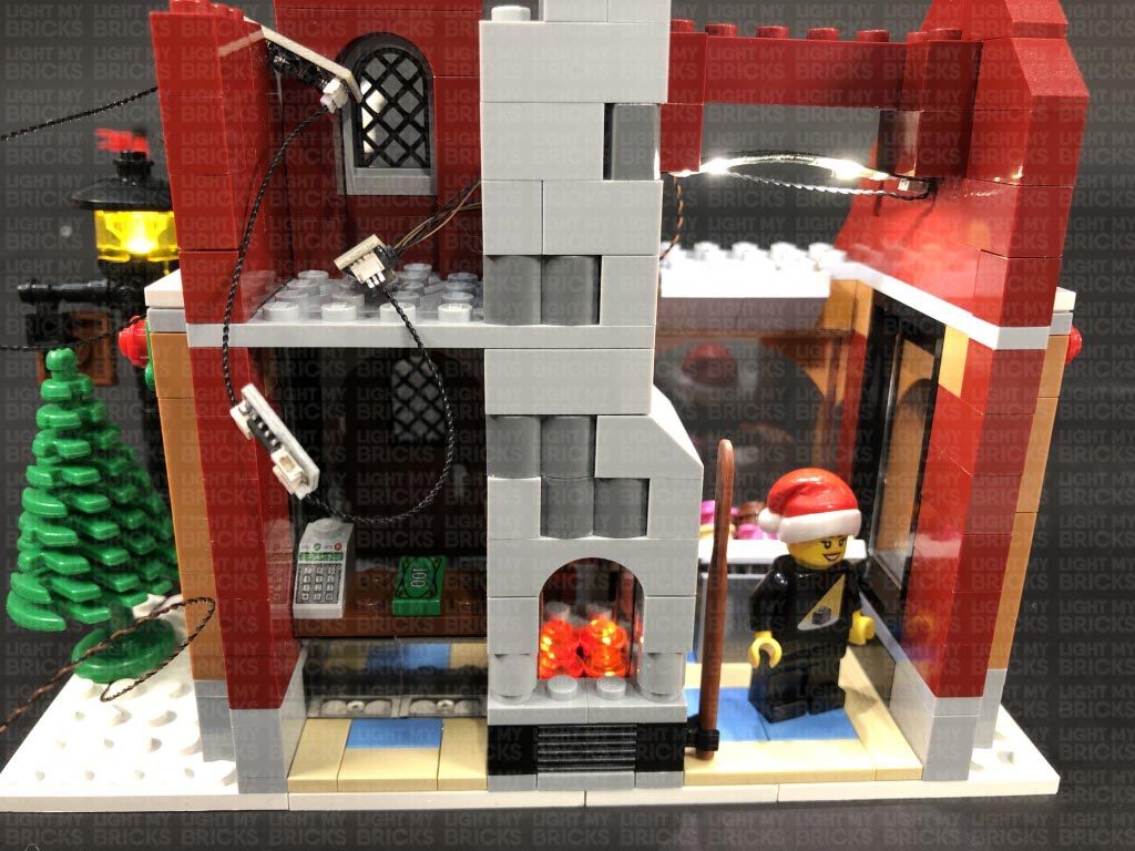
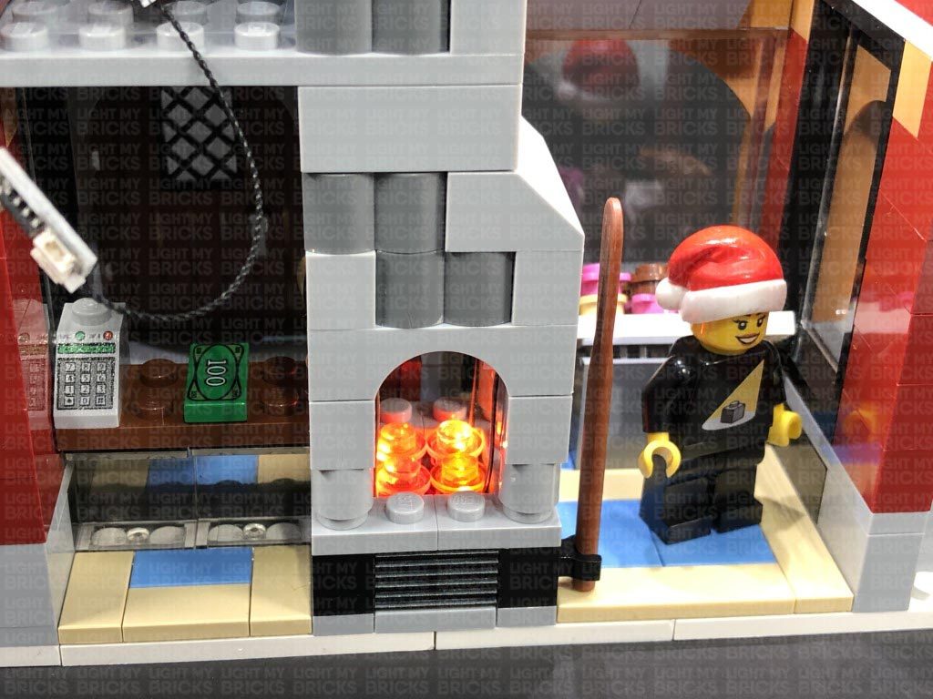
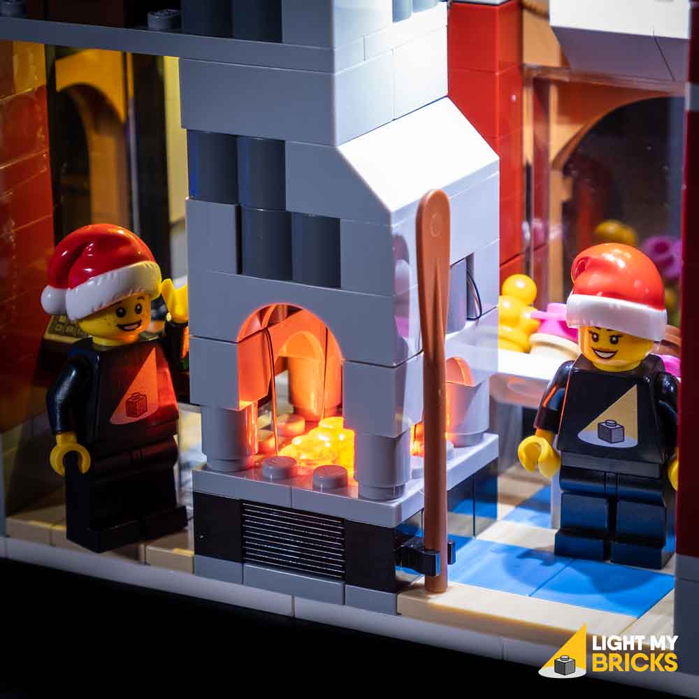
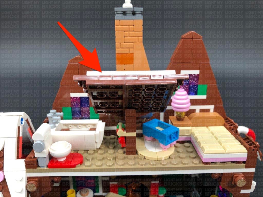
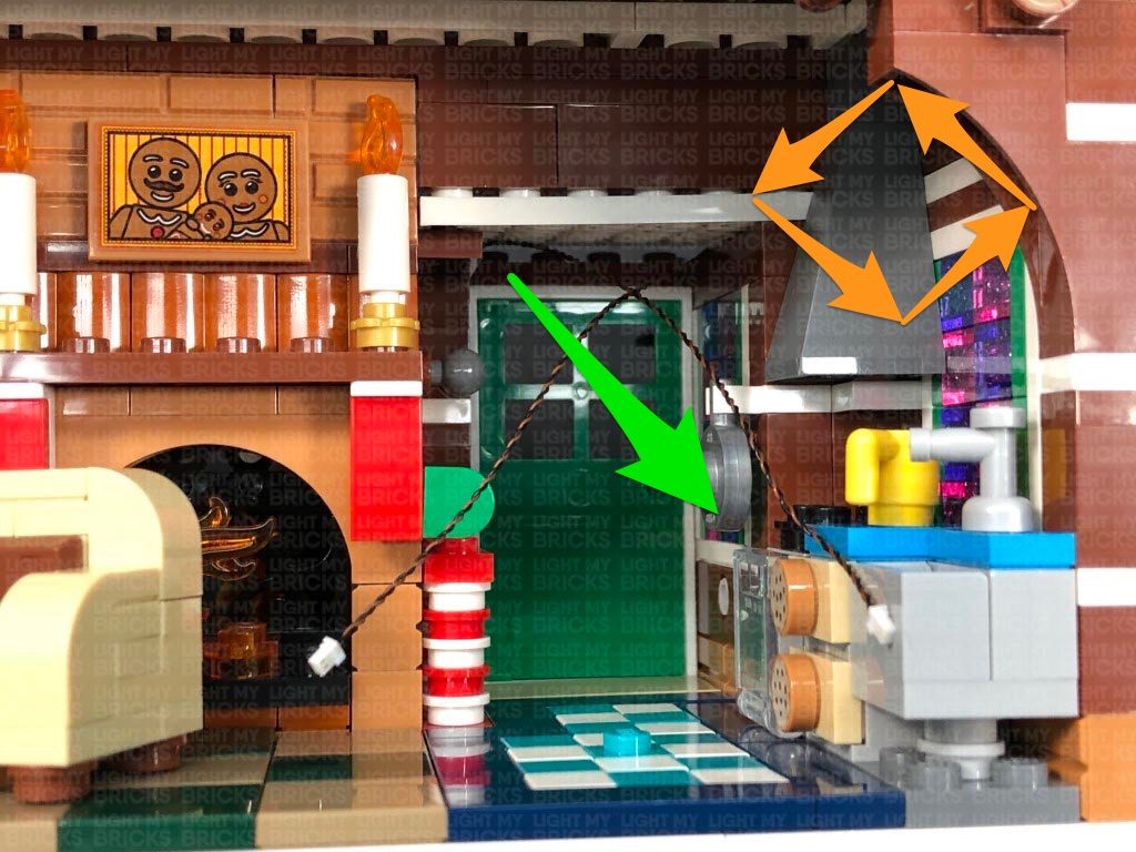
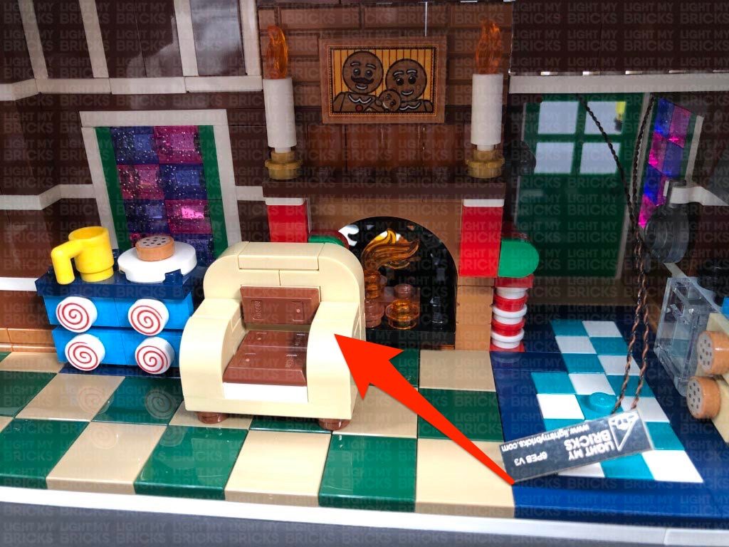
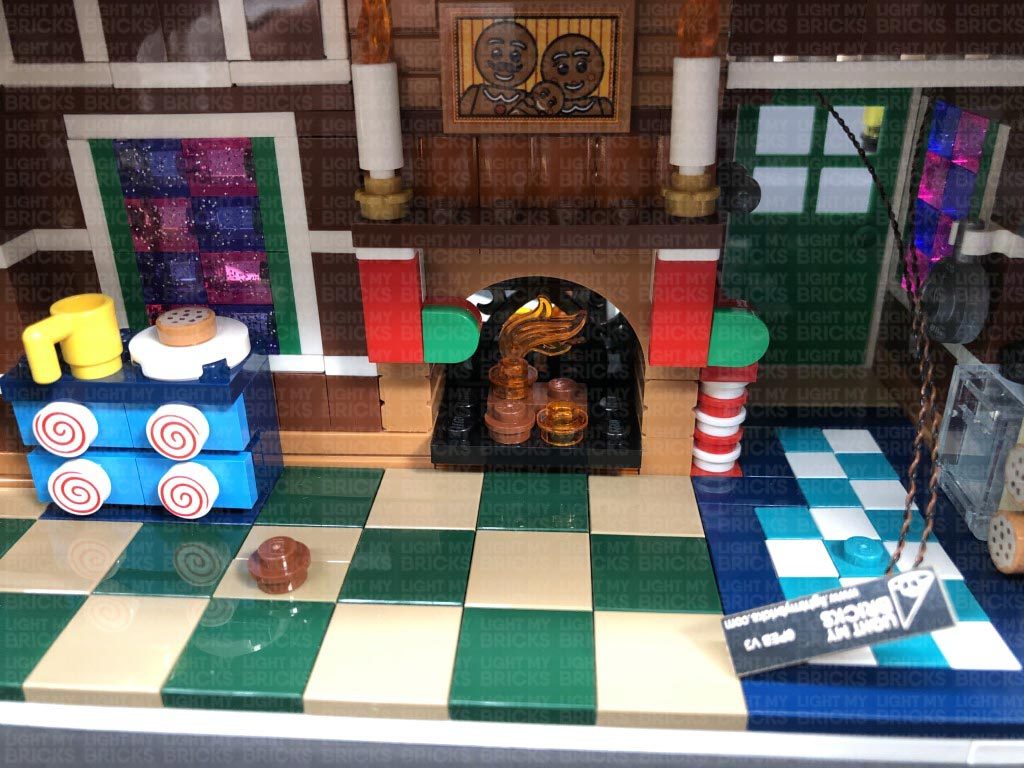
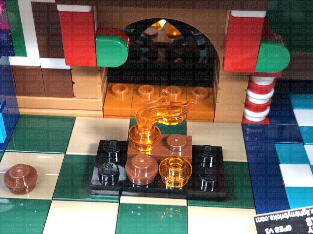
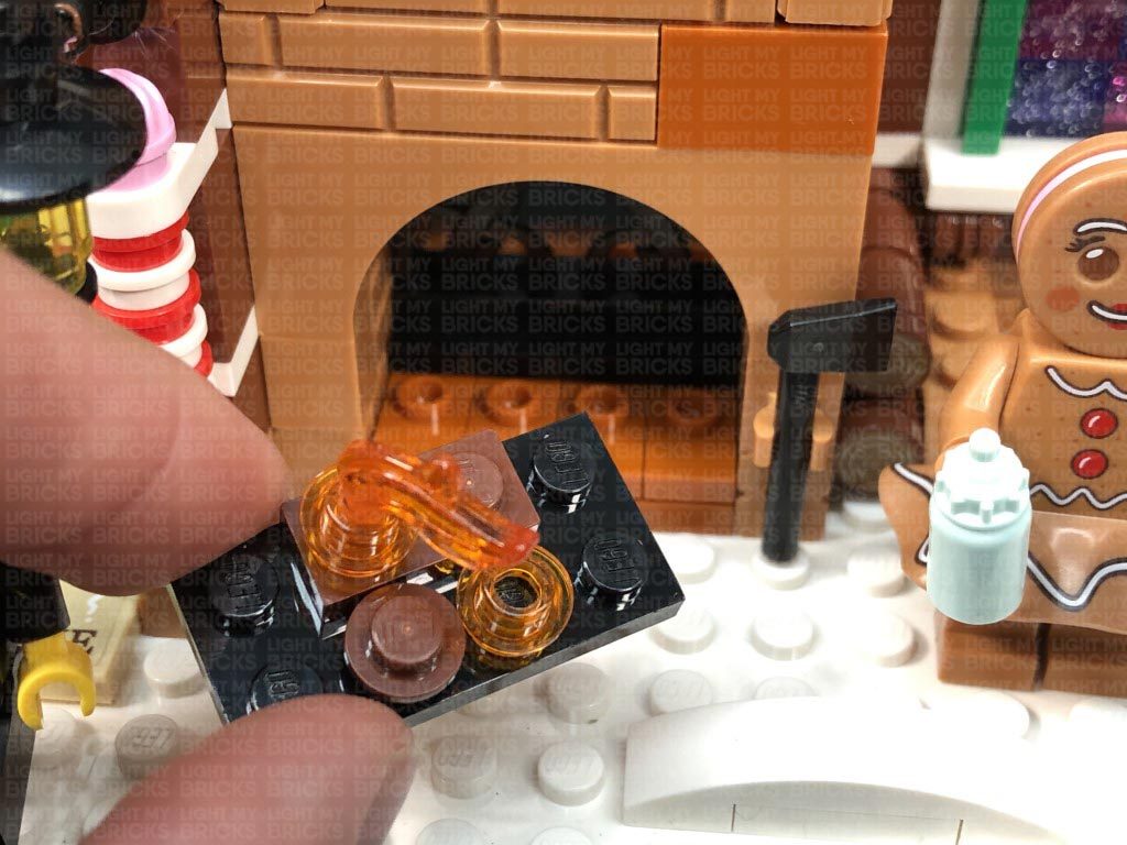
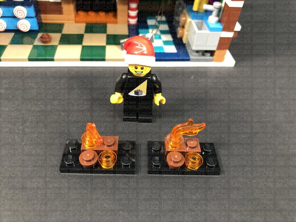
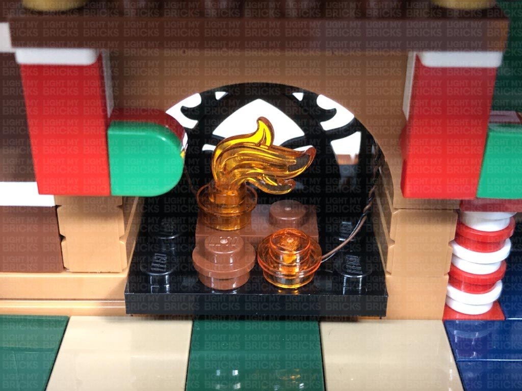
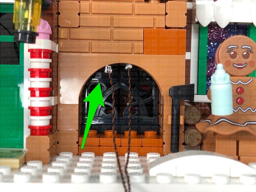
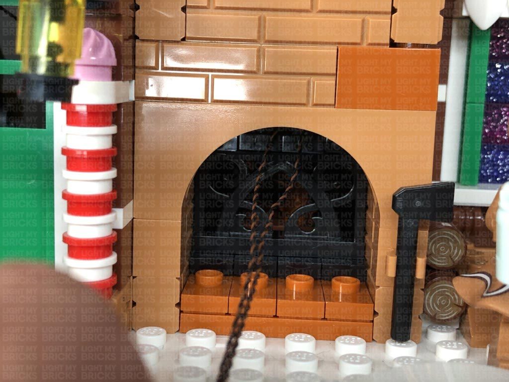
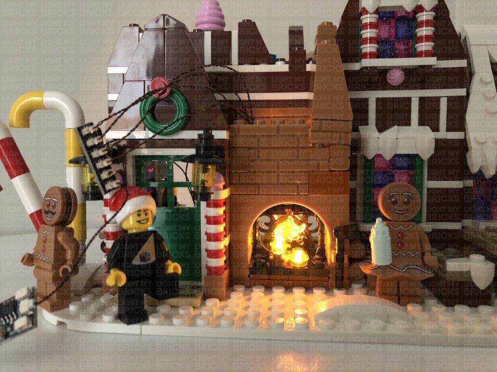
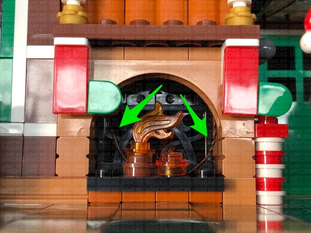
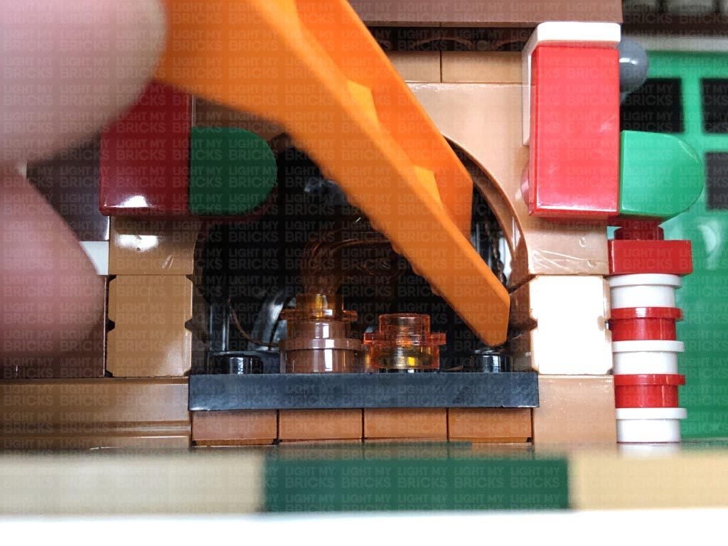
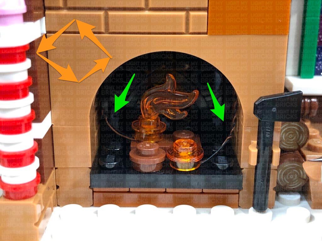
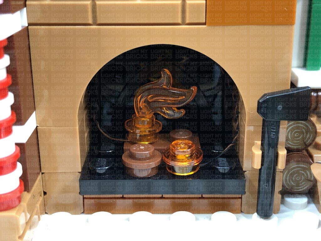
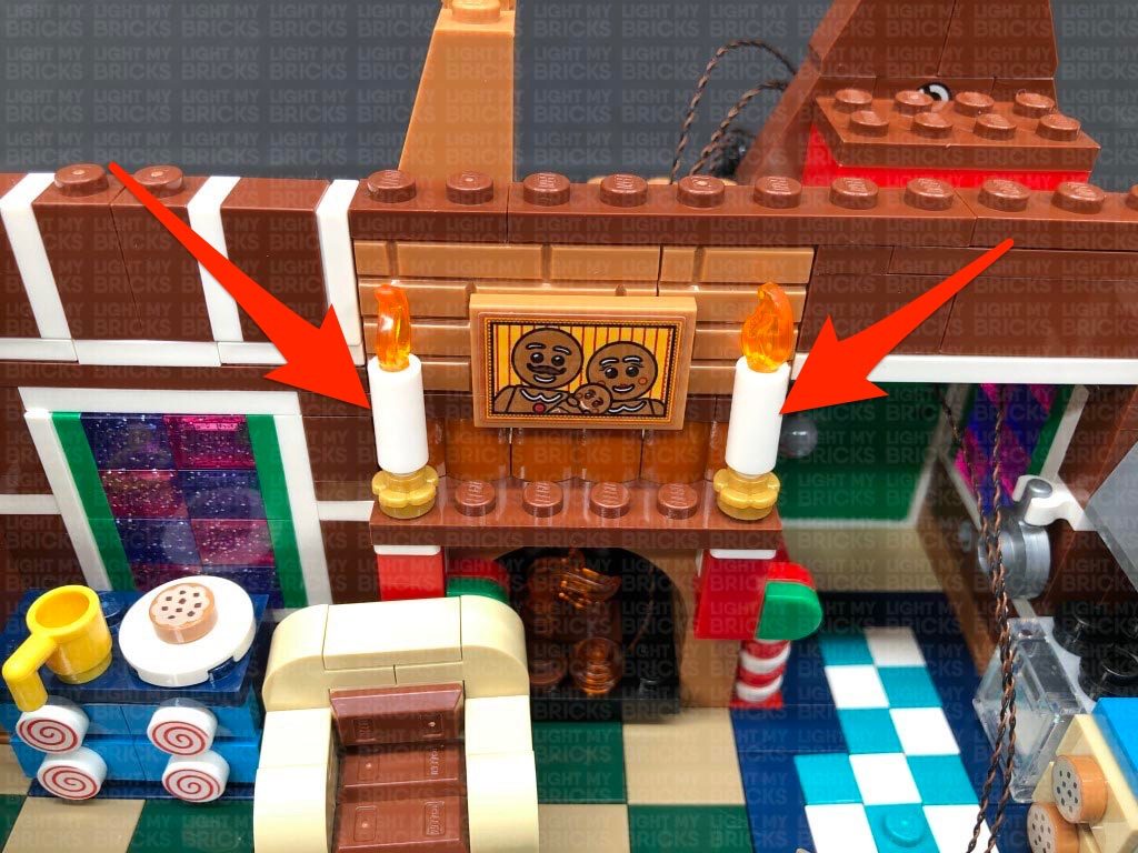
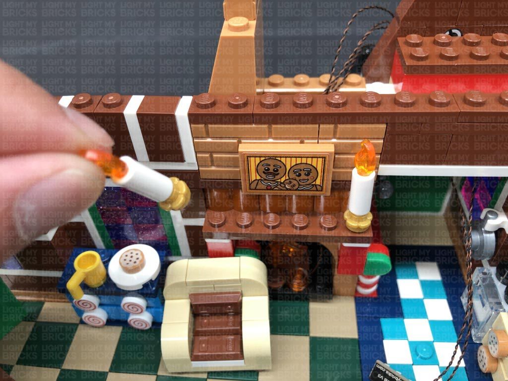
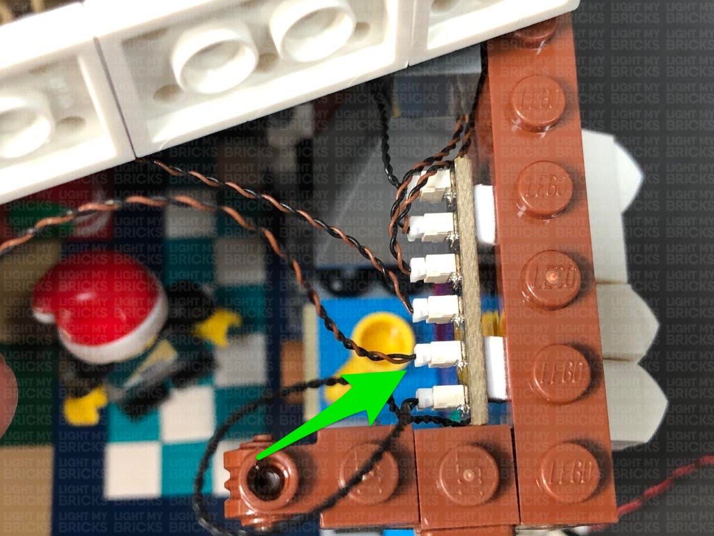
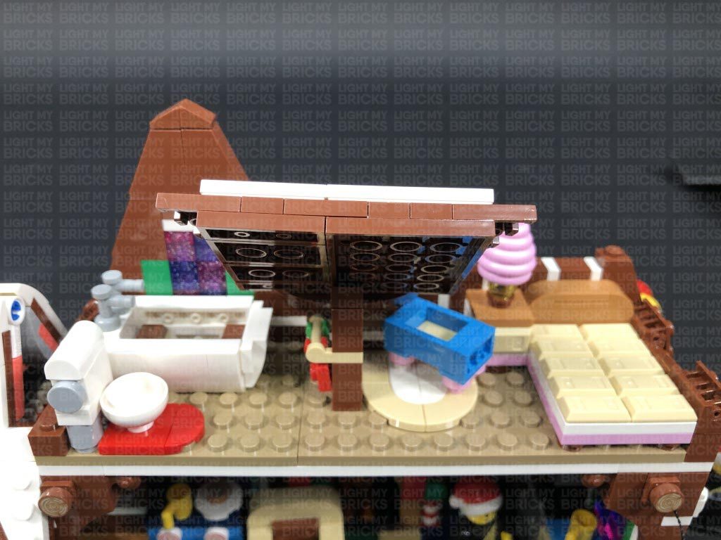
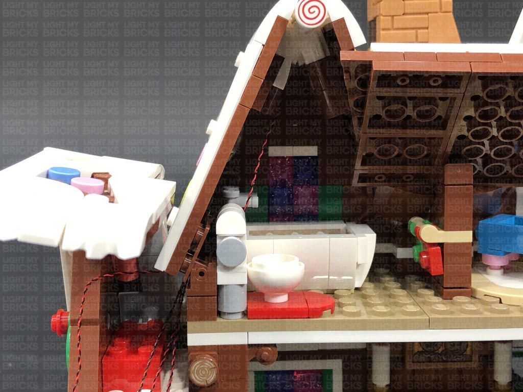
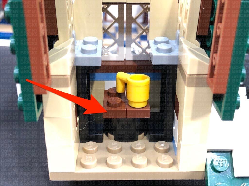
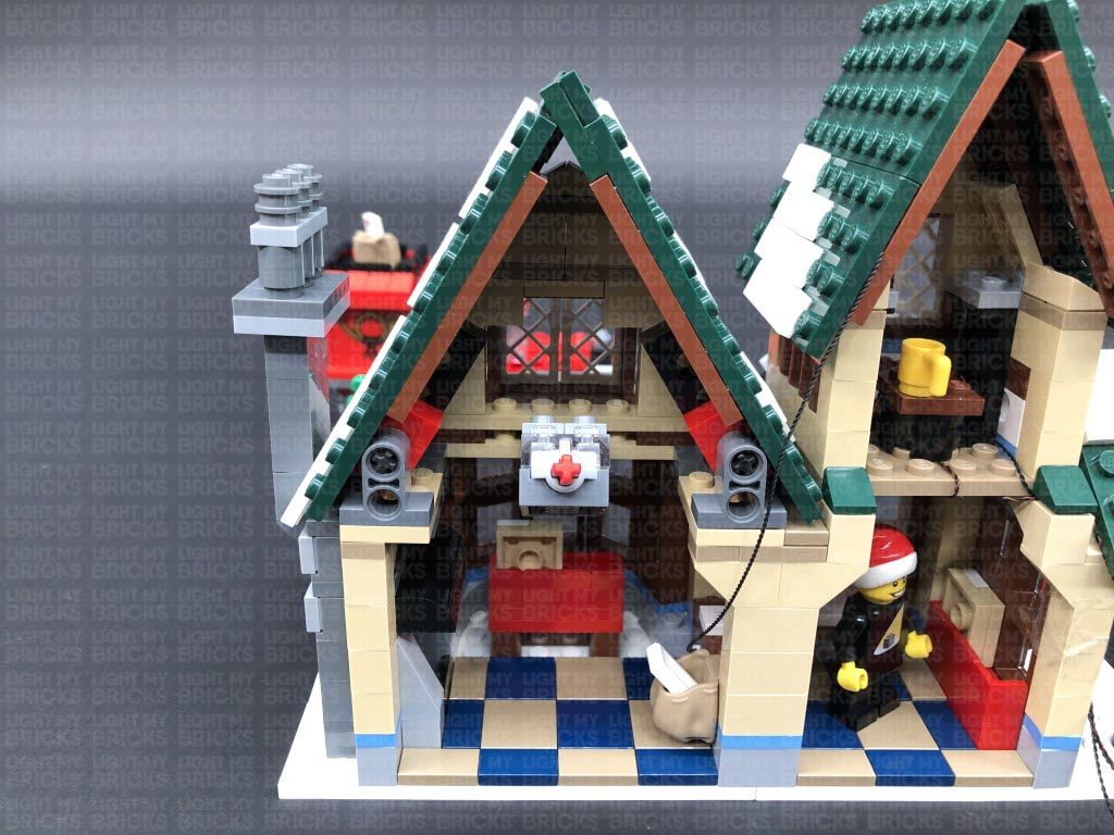
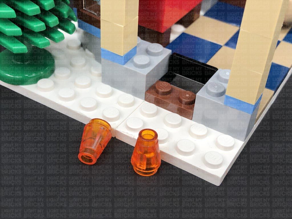
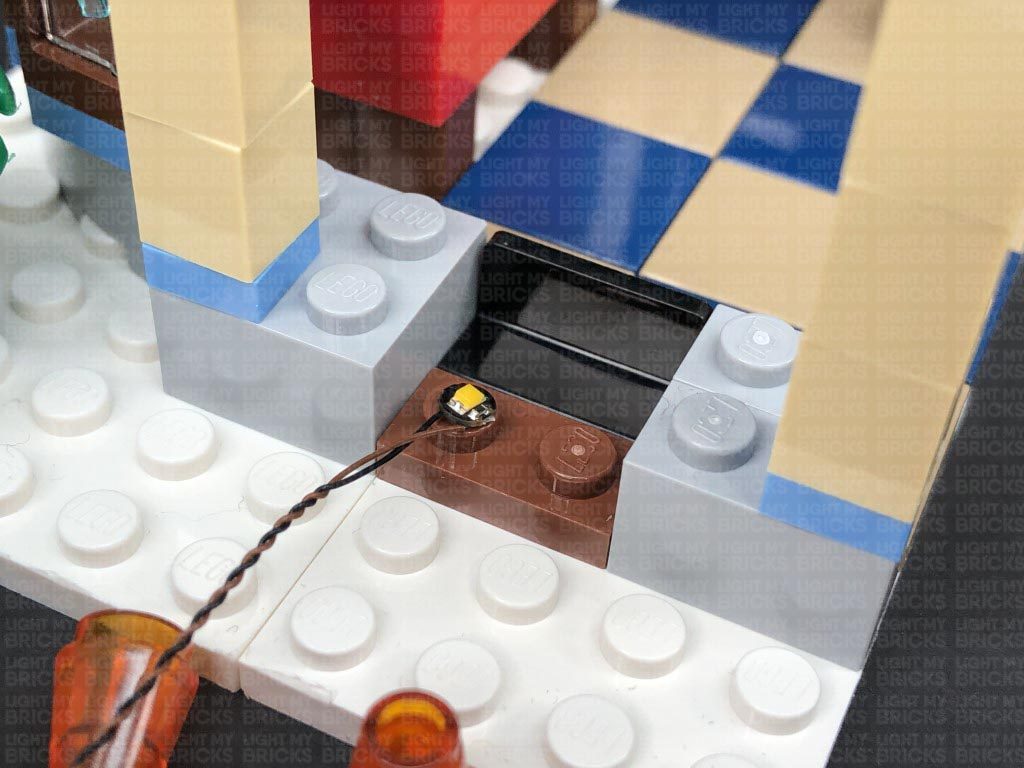
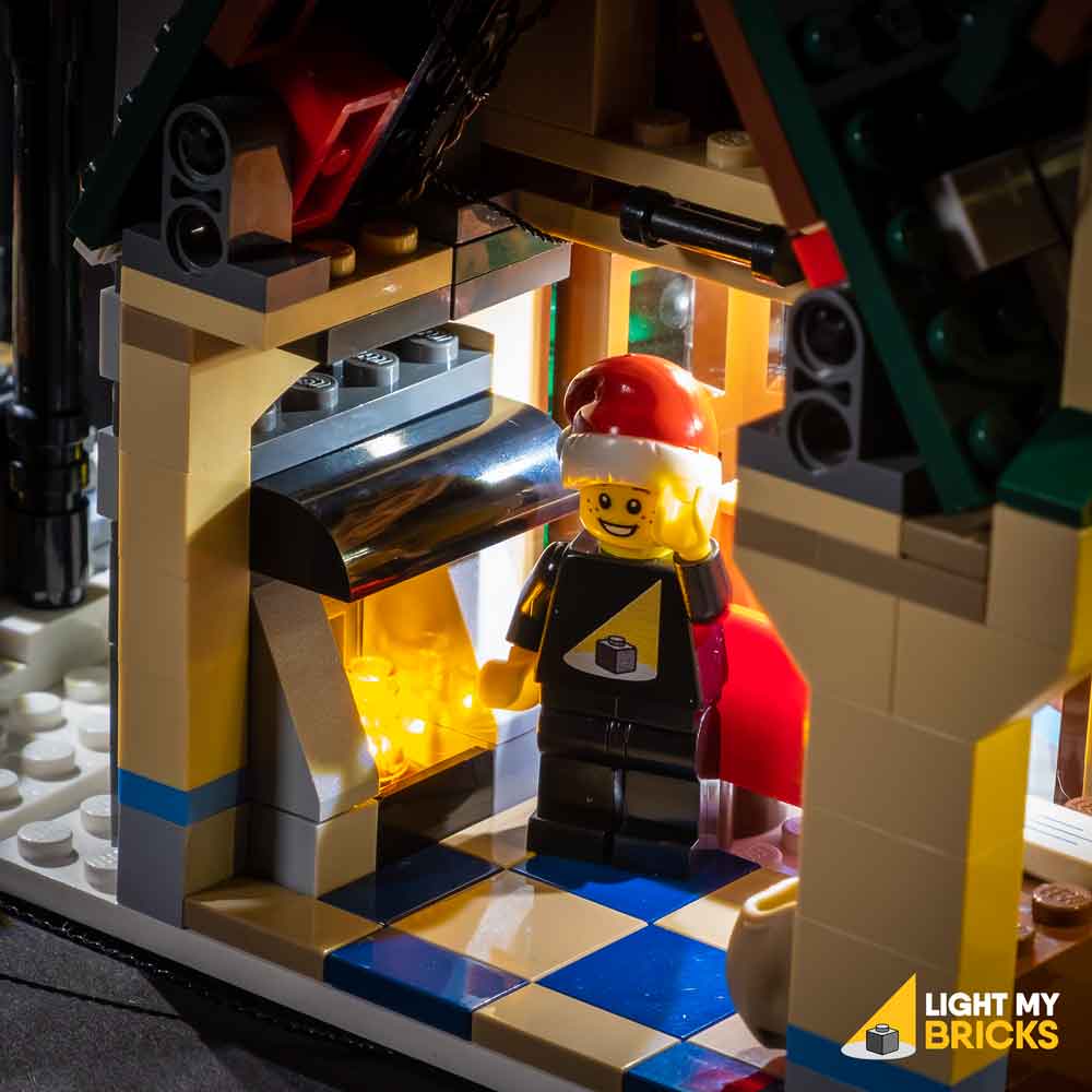
15.) We will now install flickering lights to the bakery oven. Follow the below images to disconnect sections of the oven to allow us to disconnect the trans orange round plates.
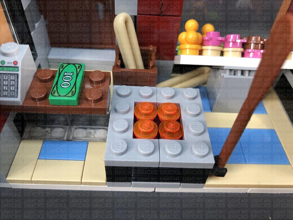
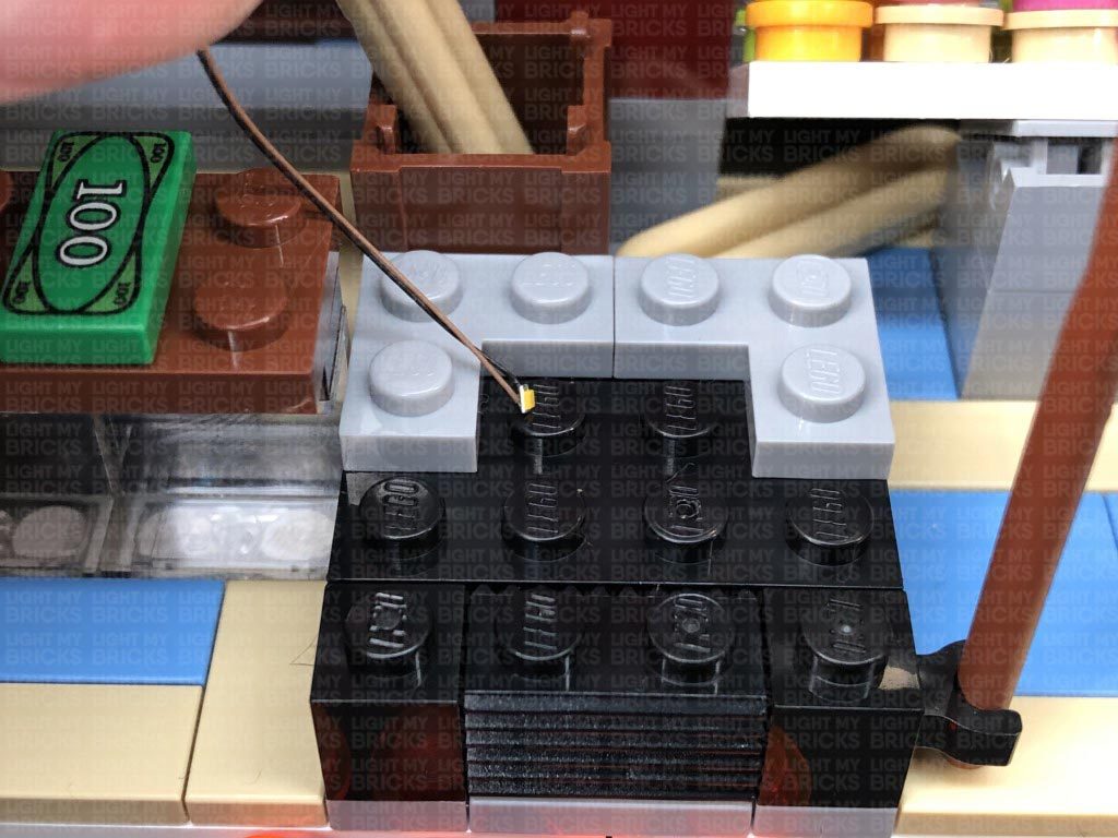
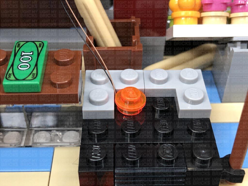
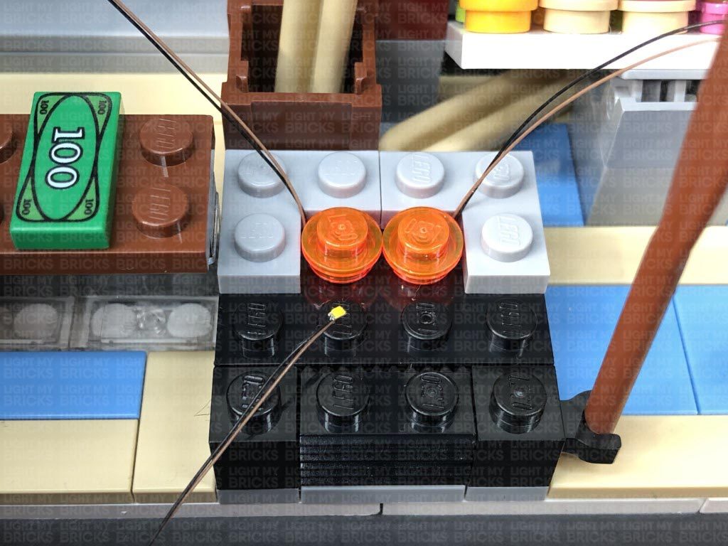
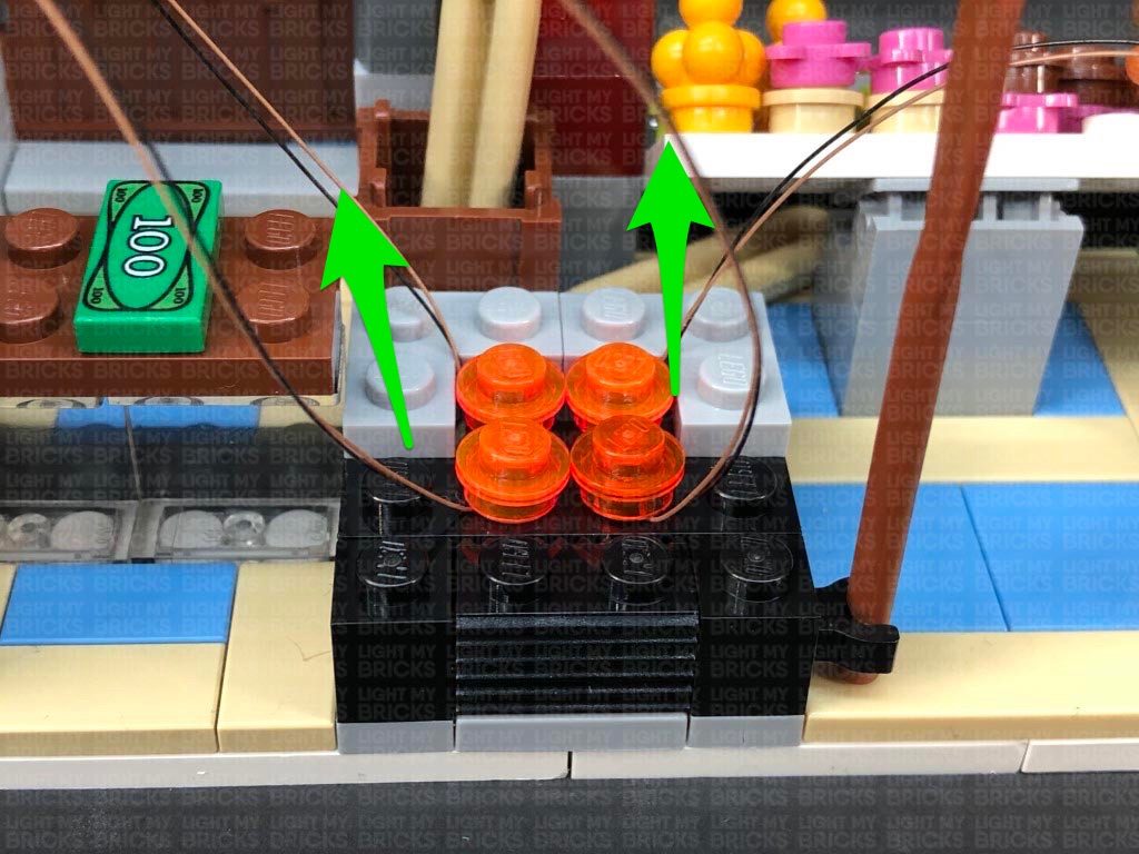
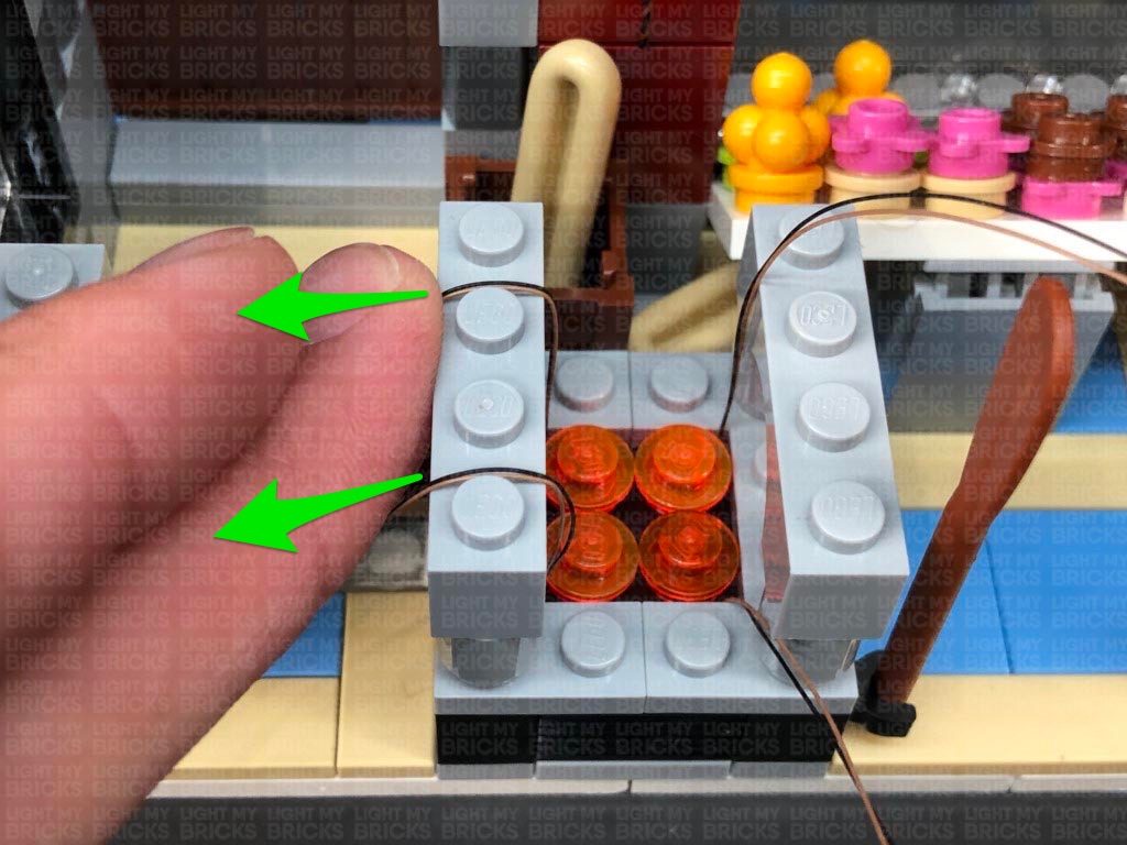
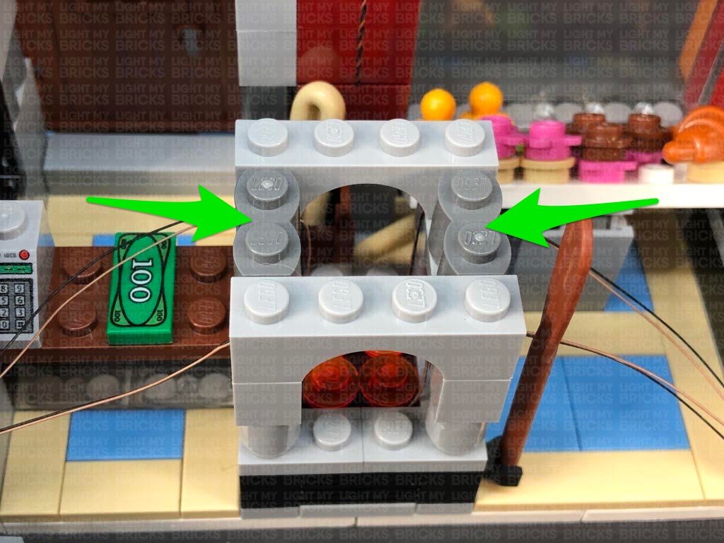
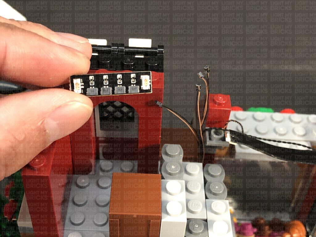
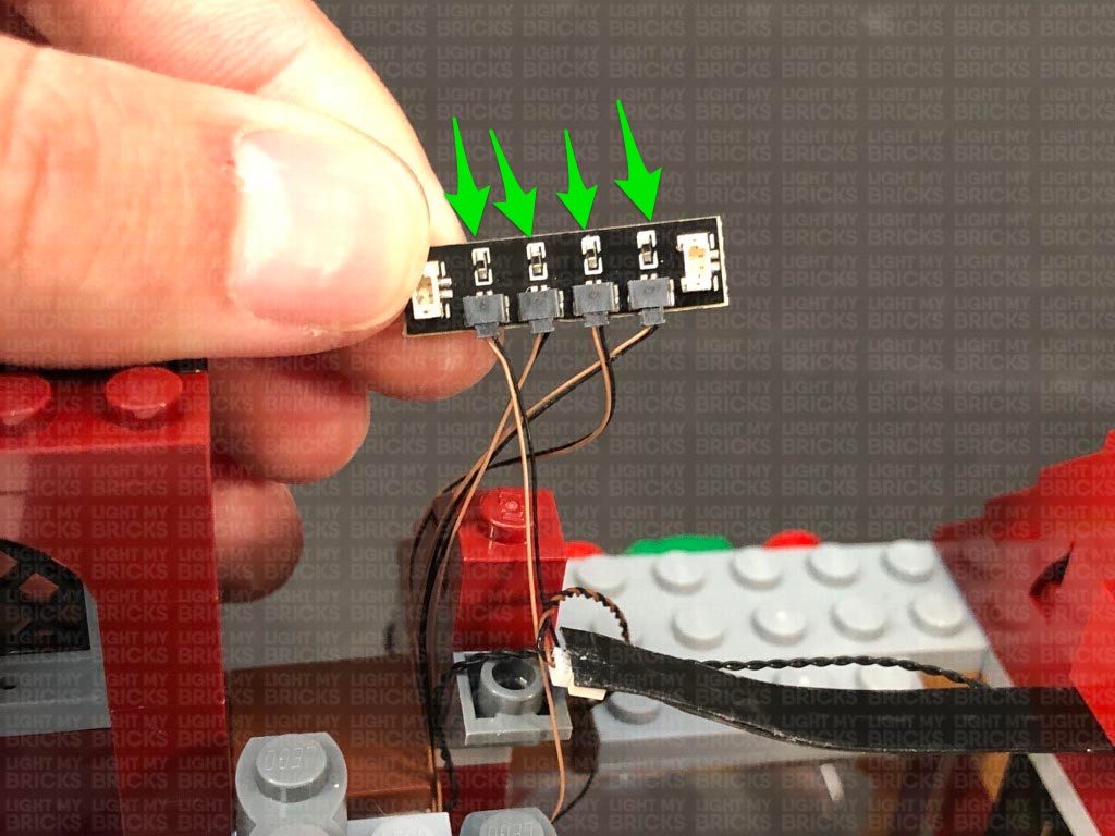
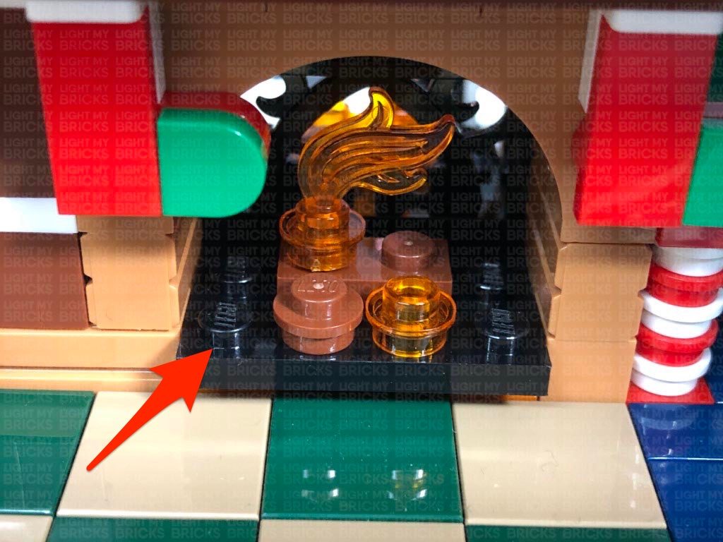
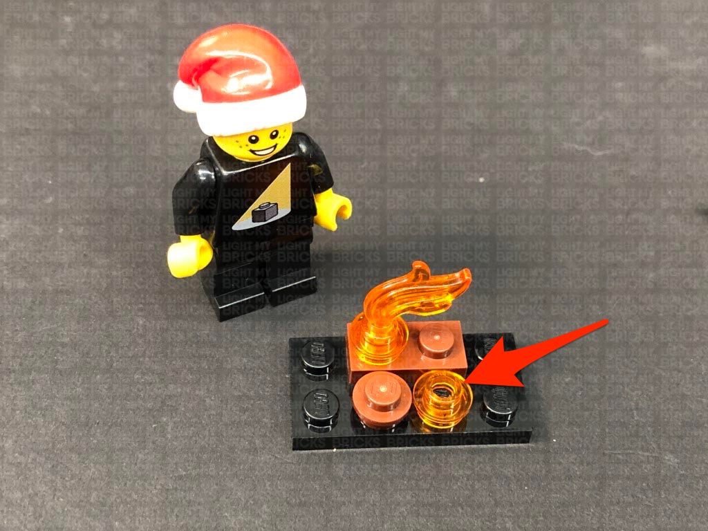
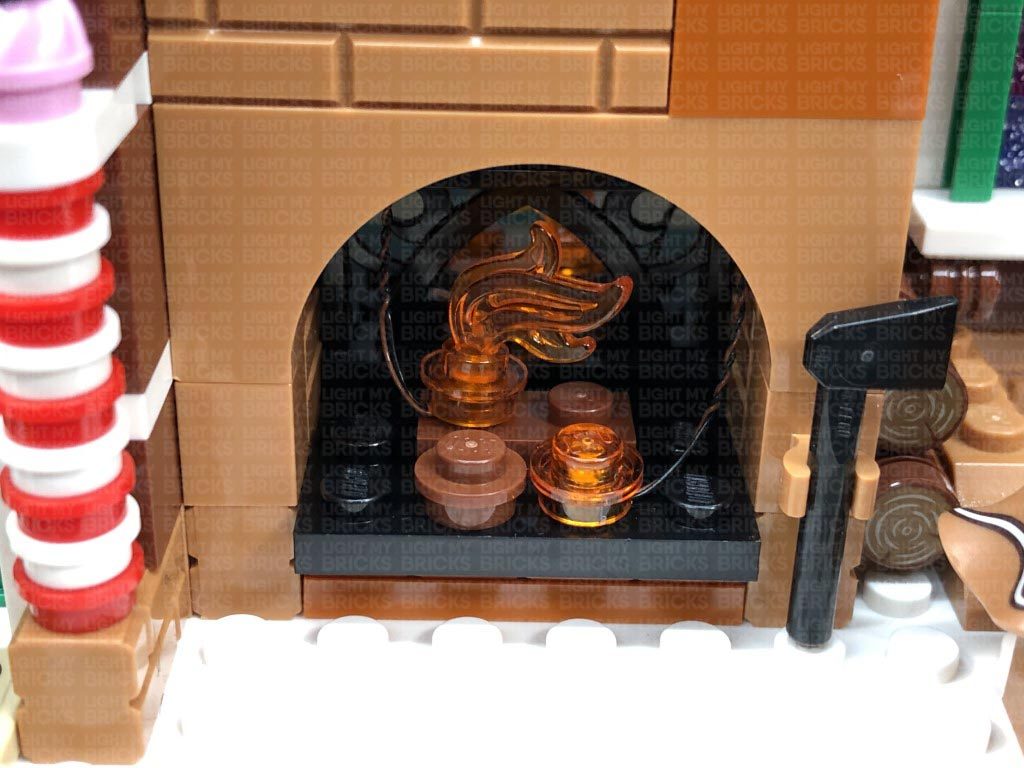
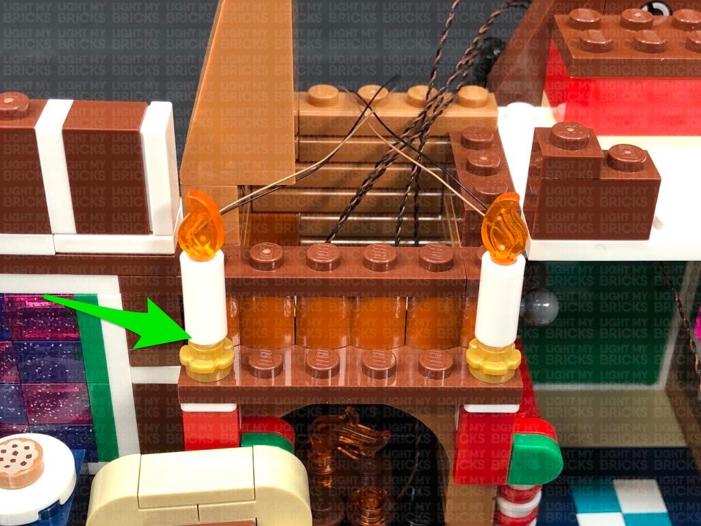
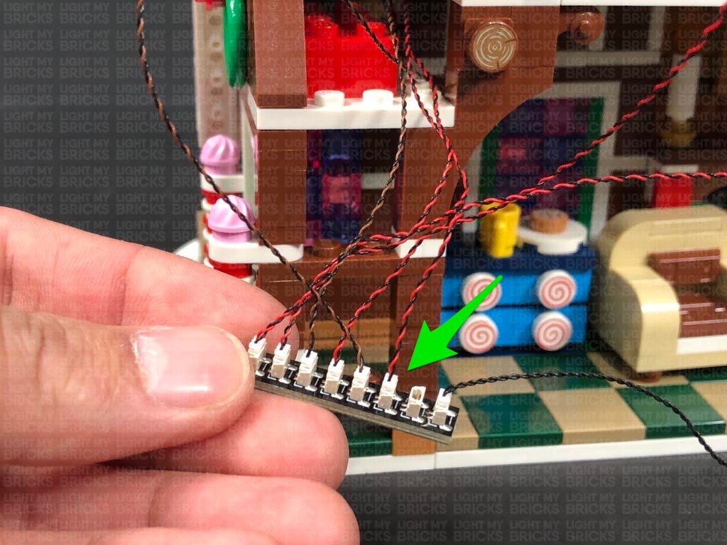
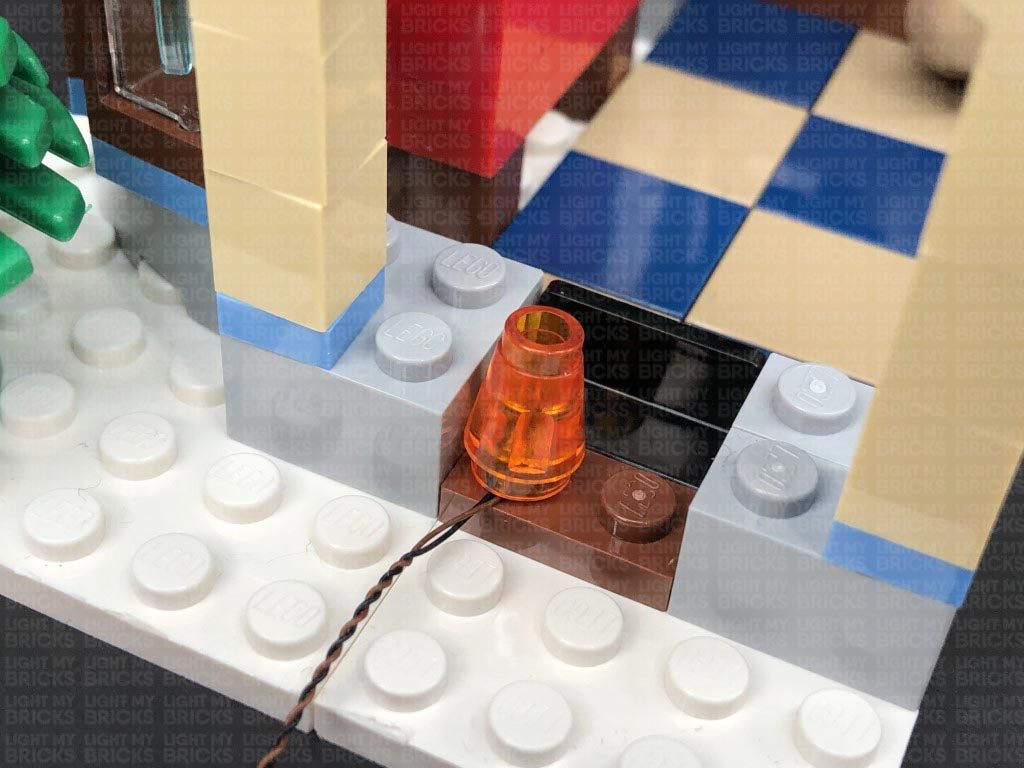
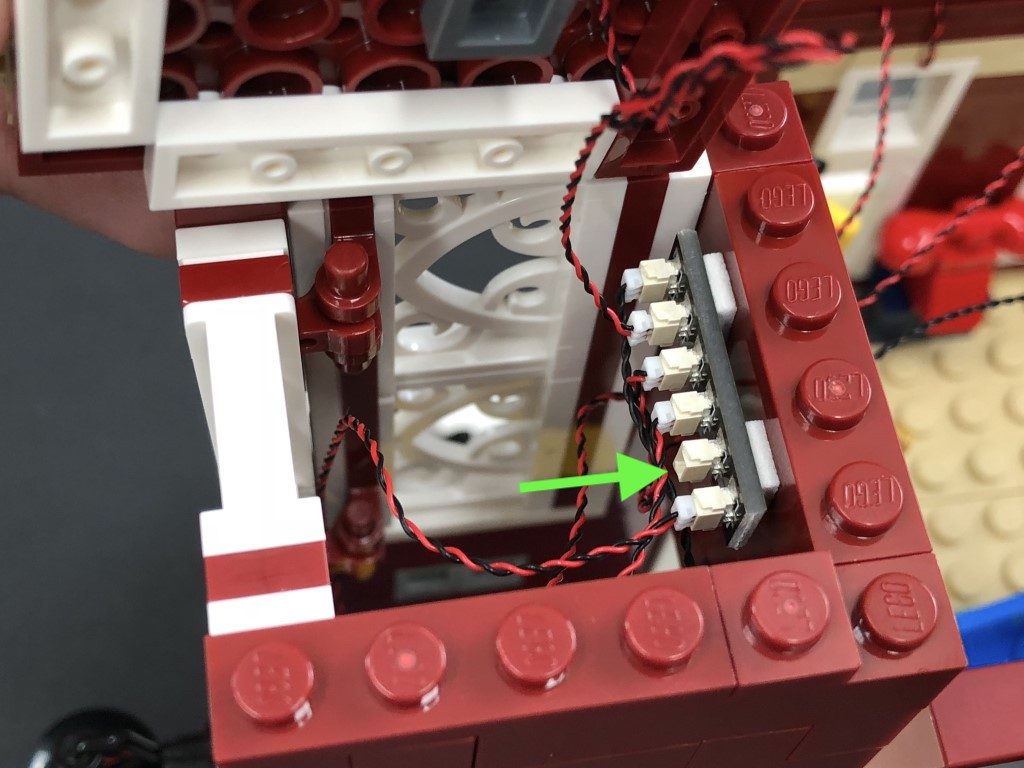
Take a White 15cm Micro Bit Light and with the cable facing the back corner, place the LED over the top left black stud. Secure the Micro Bit Light in place by reconnecting one of the trans orange round plates over the top. Repeat this to install another White 15cm Micro Bit Light to the right side.
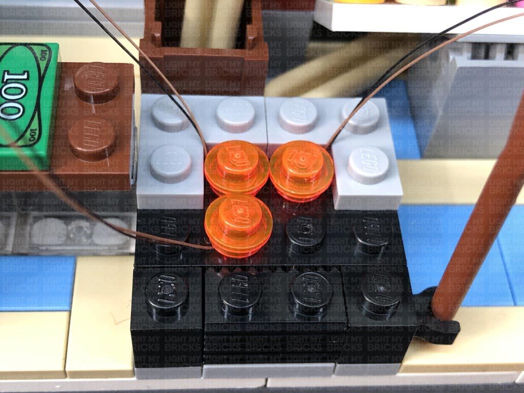
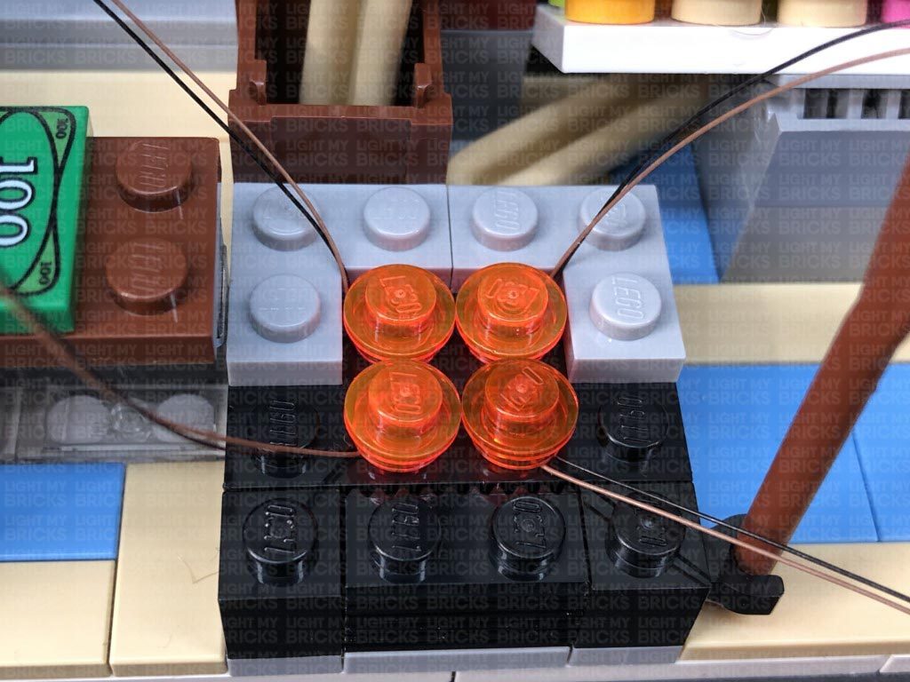
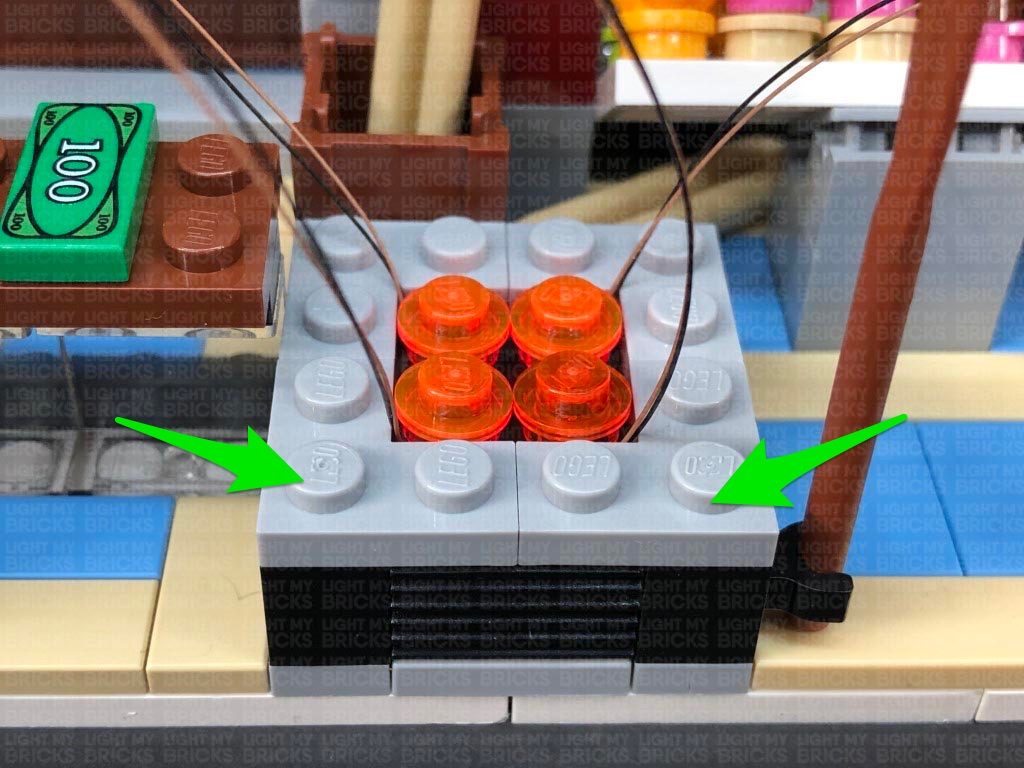
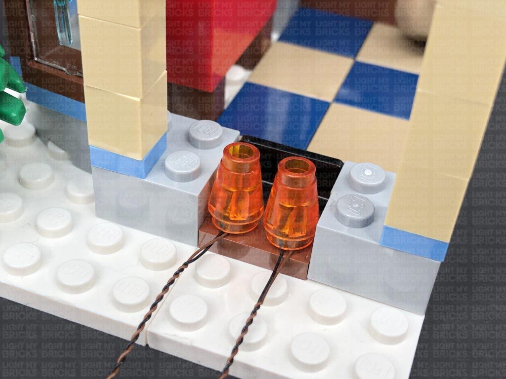
Install another 2x White 15cm Micro Bit Lights to the bottom two studs, ensuring the cables are this time facing the bottom corners before reconnecting the trans orange round plates over the top. Pull the front two cables up before reconnecting the light grey ‘L’ plates.
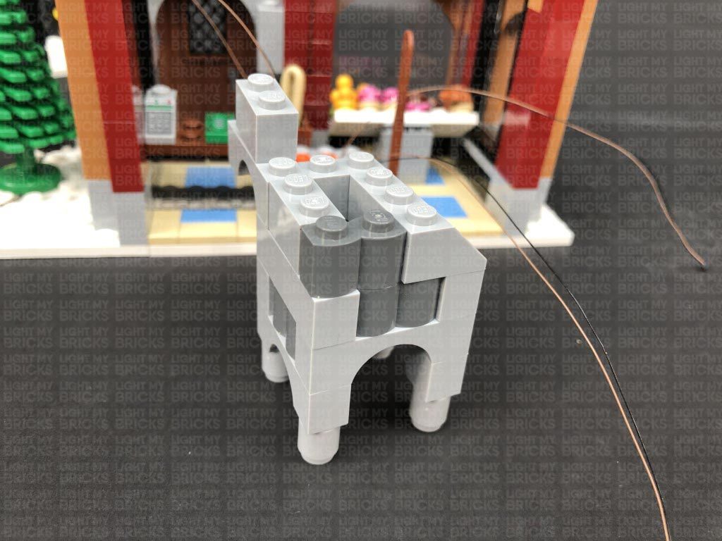
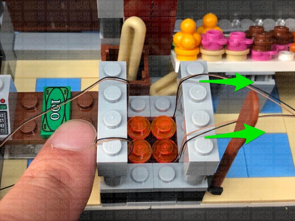
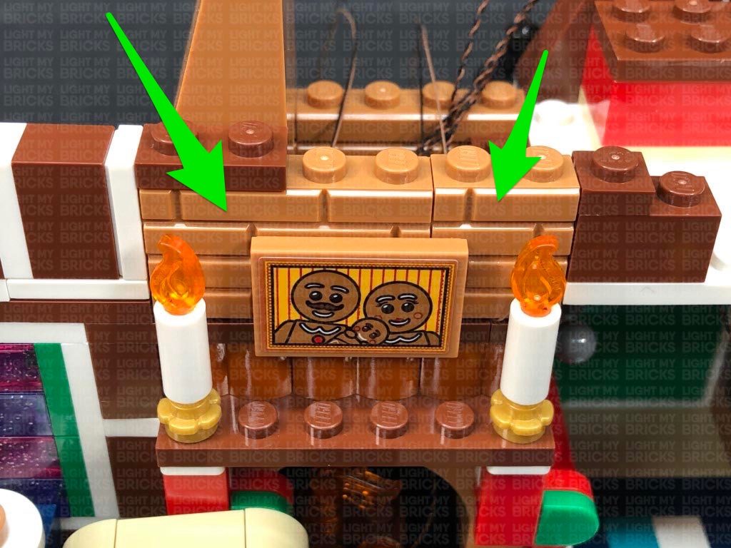
16.) Take the upper oven section and disconnect the following sections from the bottom of it. Reconnect these two sections to the oven, then lay the two cables from each side, over the top of these sections, laying them in between studs.
Disconnect the following sections from the bottom of the oven section, then reconnect these pieces over the top of the cables.
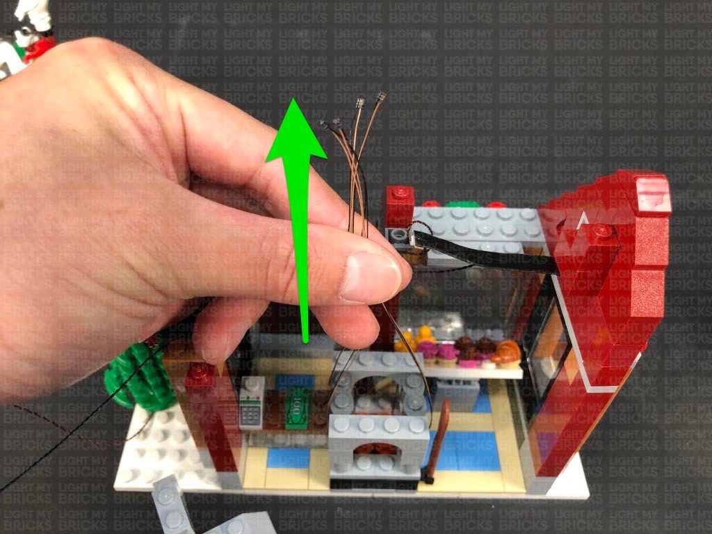
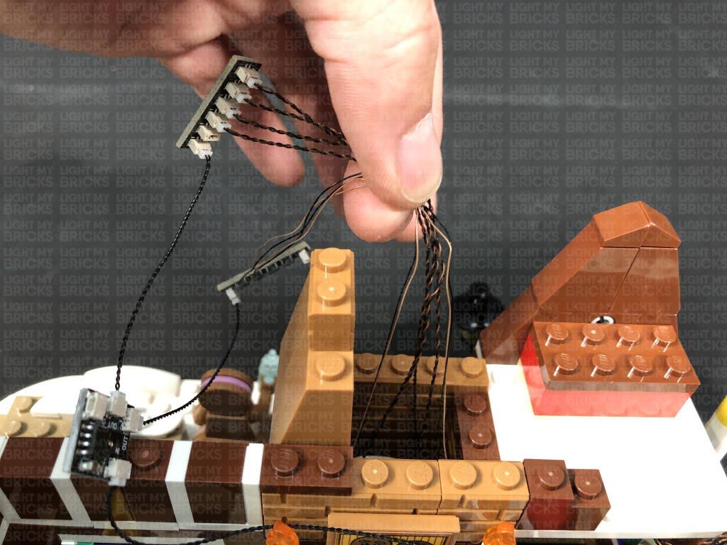
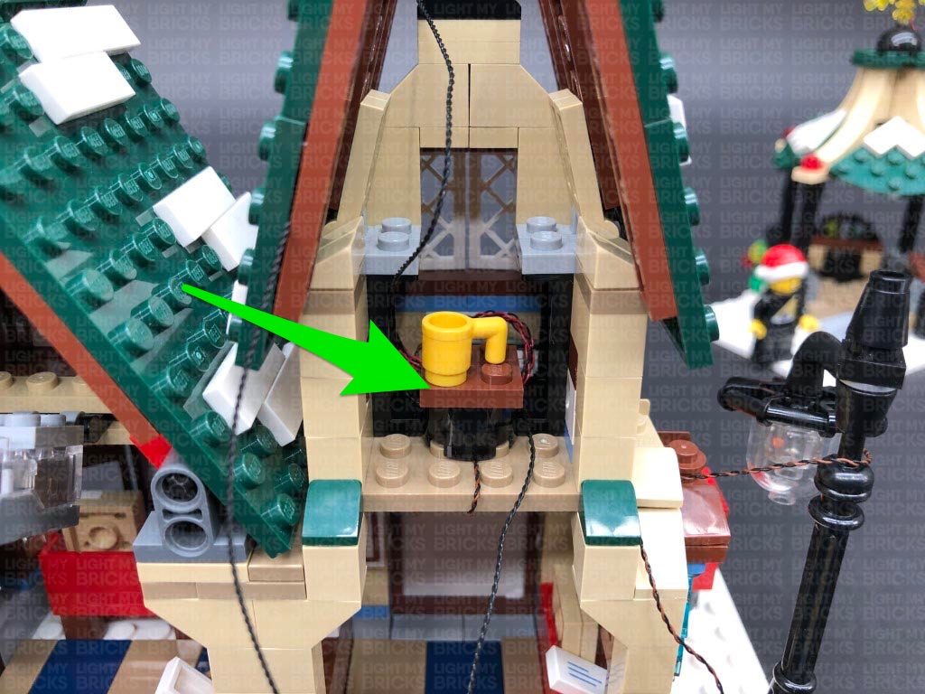
Pull all four cables up, then thread them through underneath the space on the remaining oven section pieces. Reconnect the top of the oven, then pull the cables toward to back (front of the bakery).
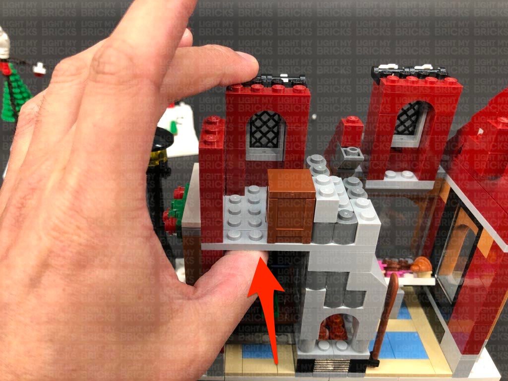
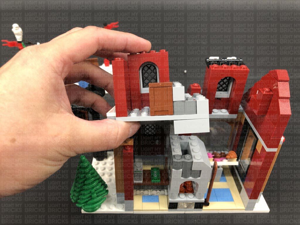
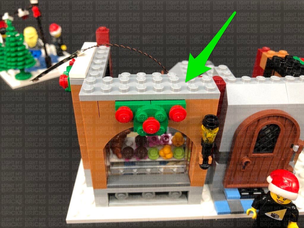
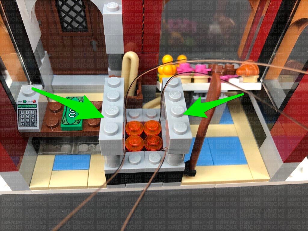
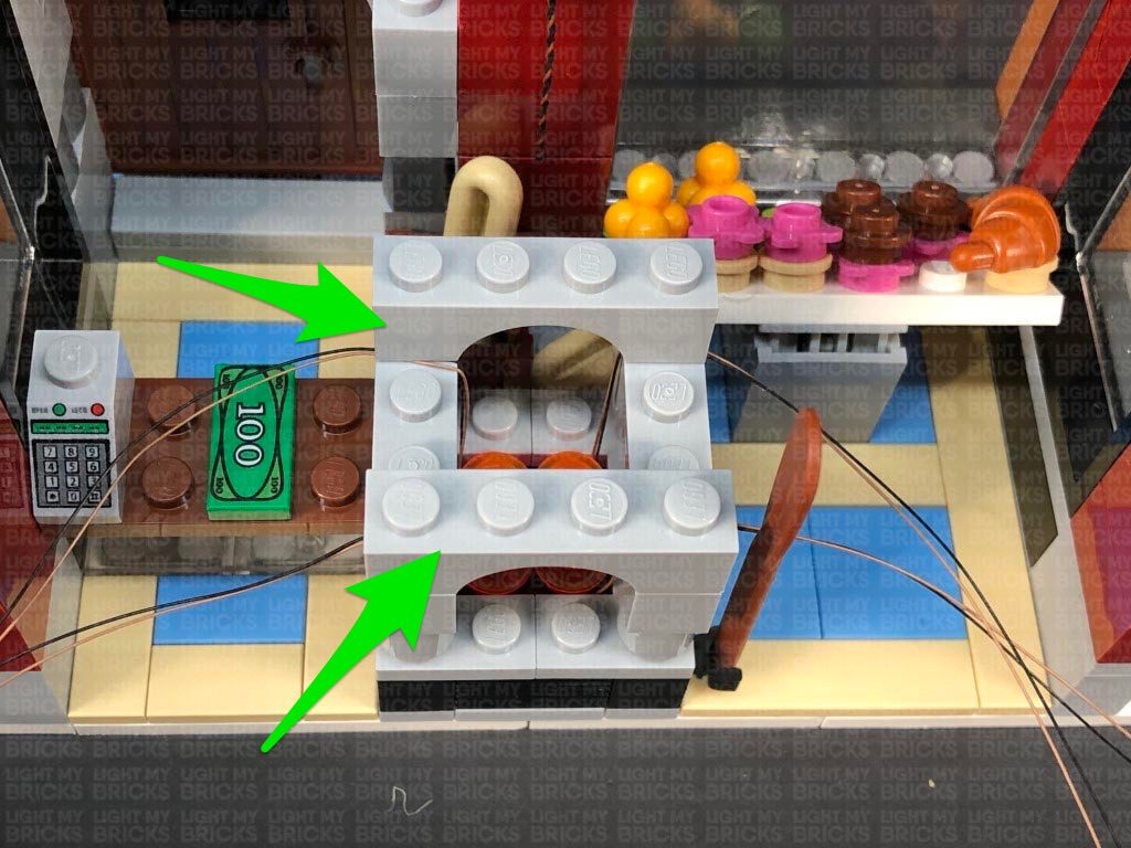
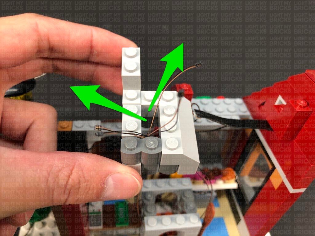
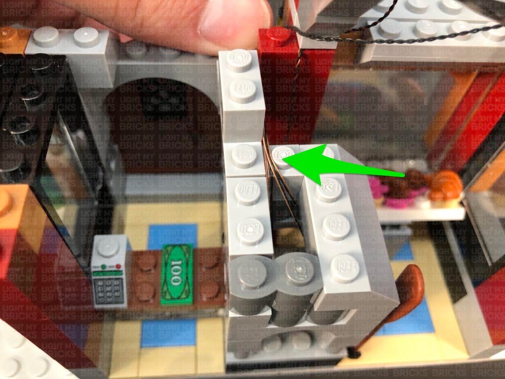
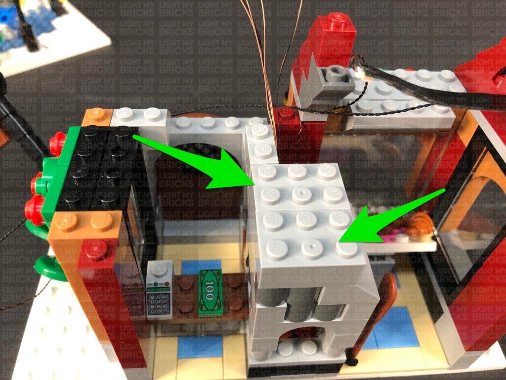
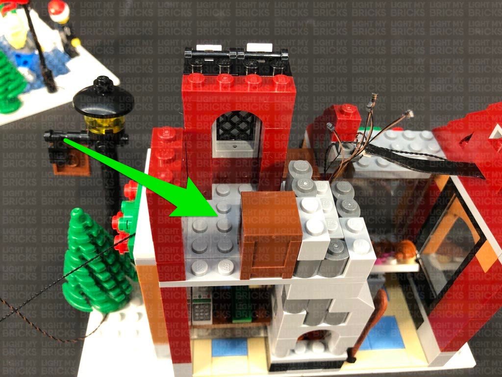
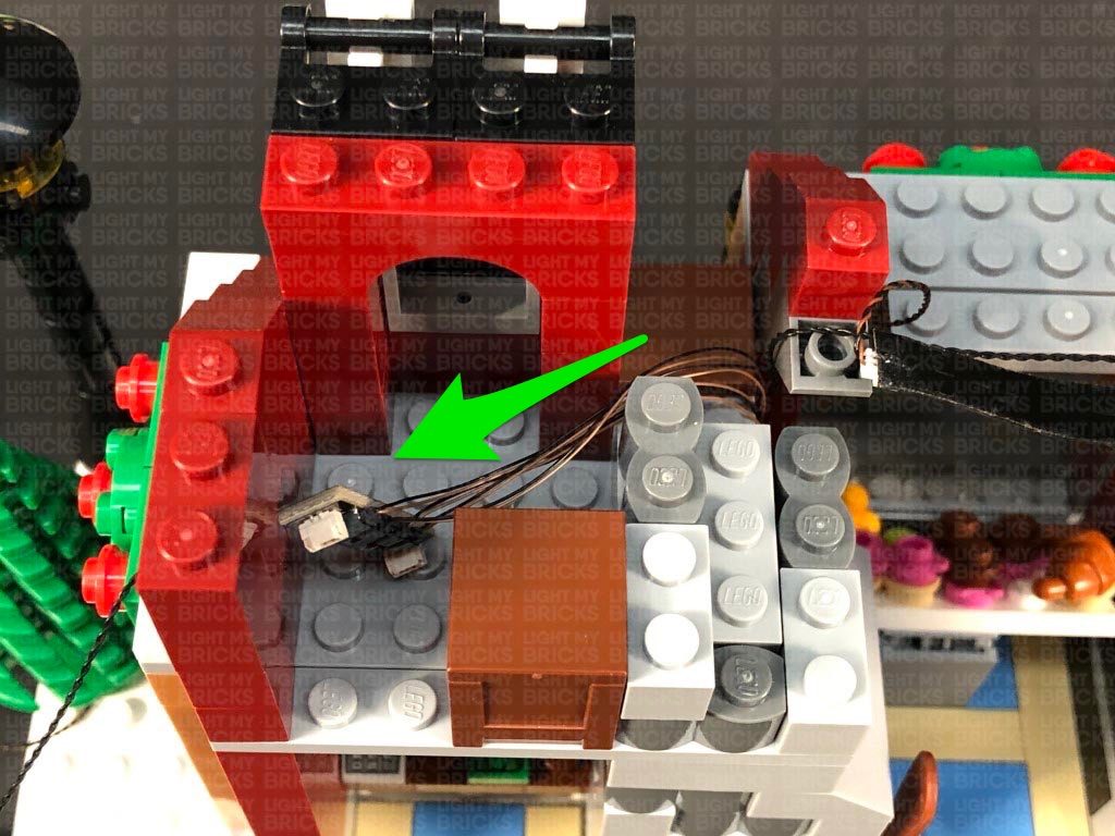
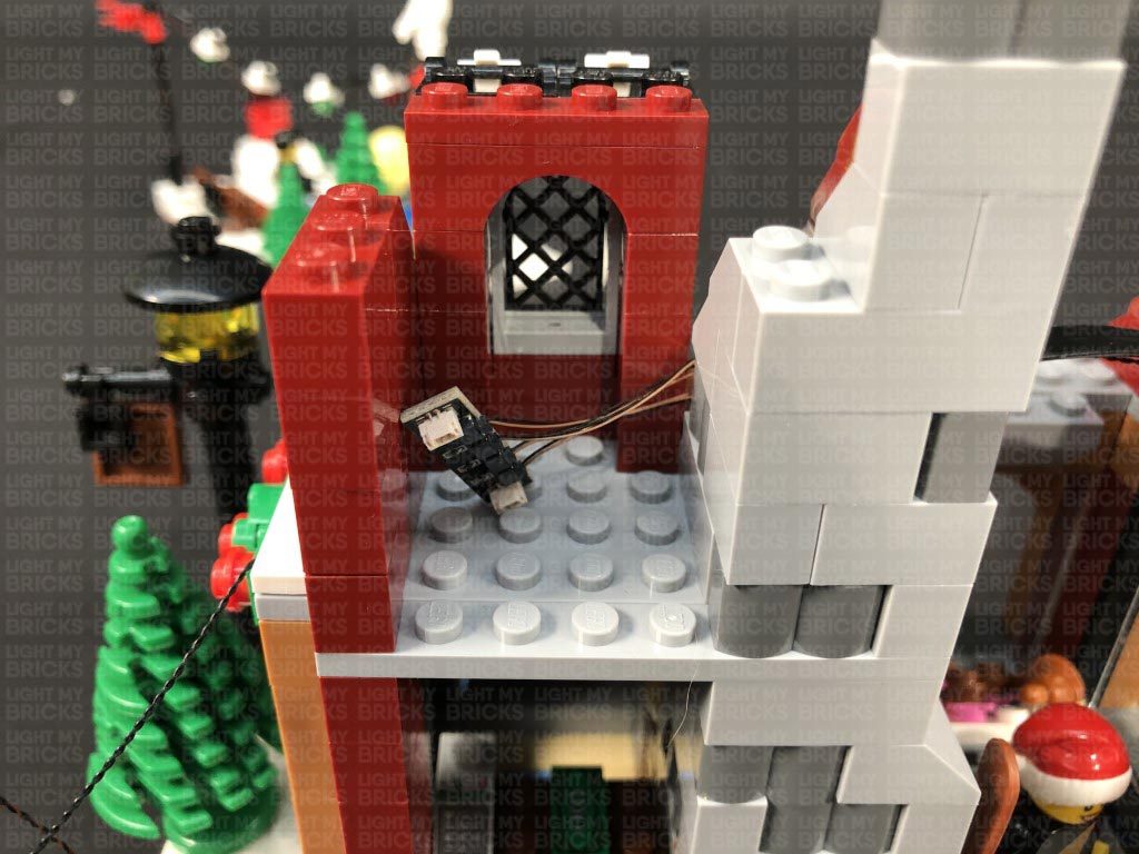
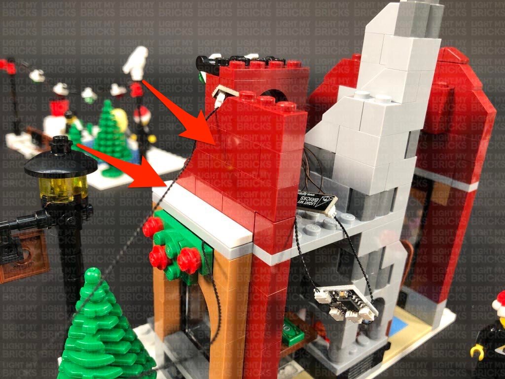
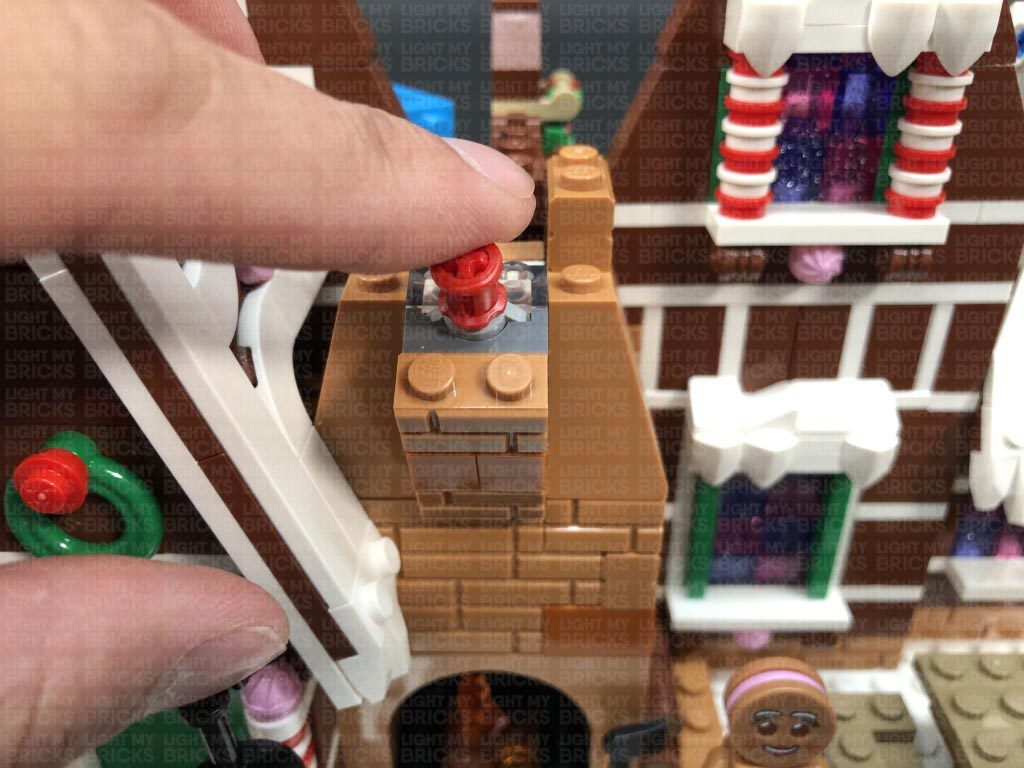
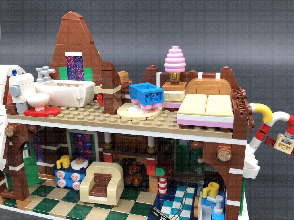
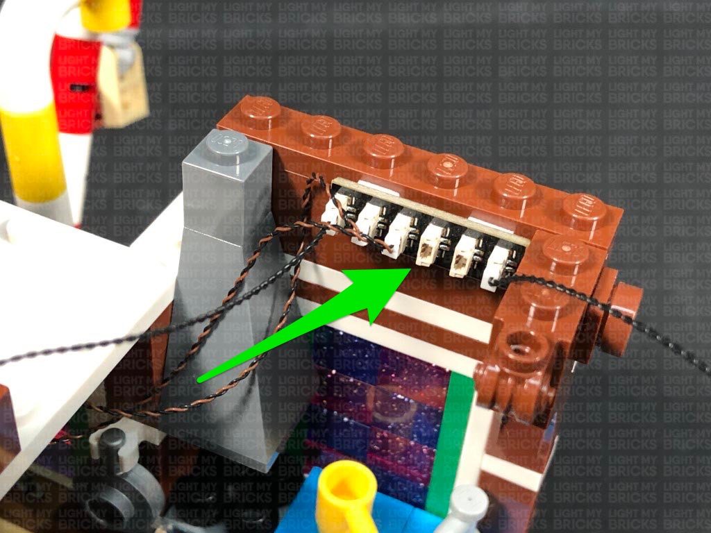
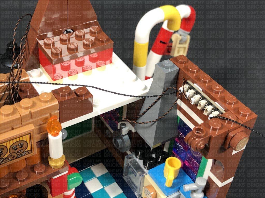
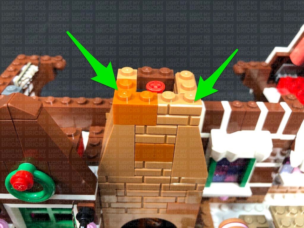
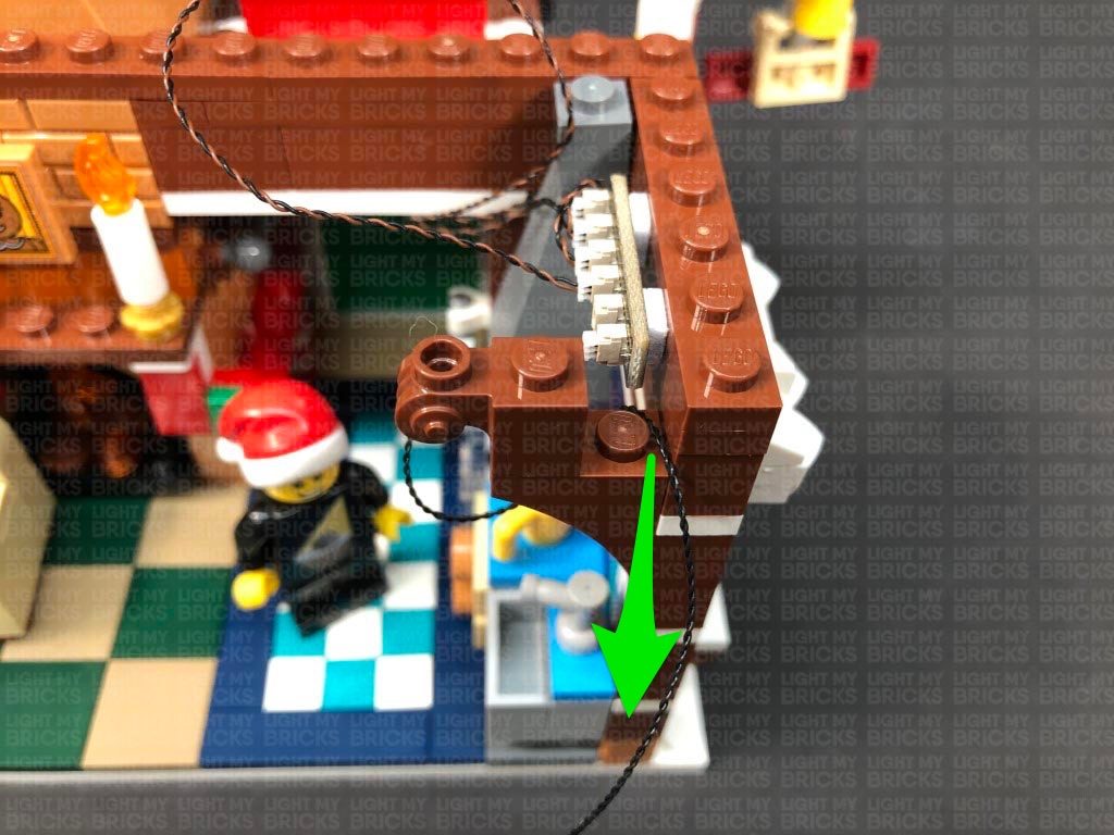
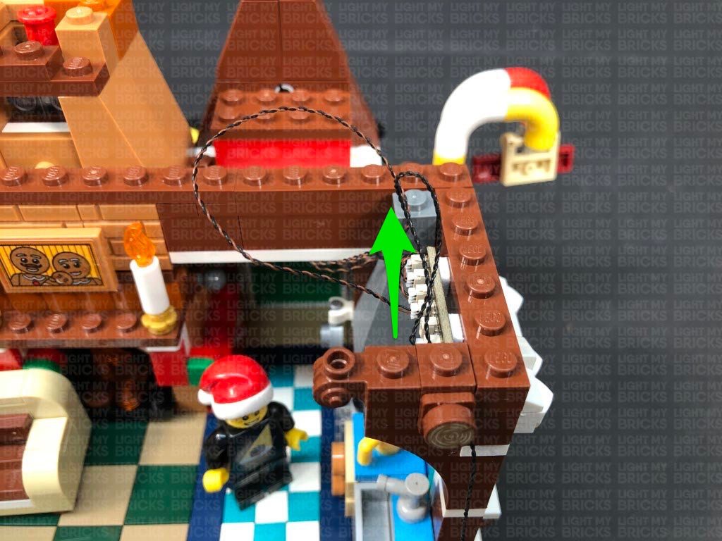
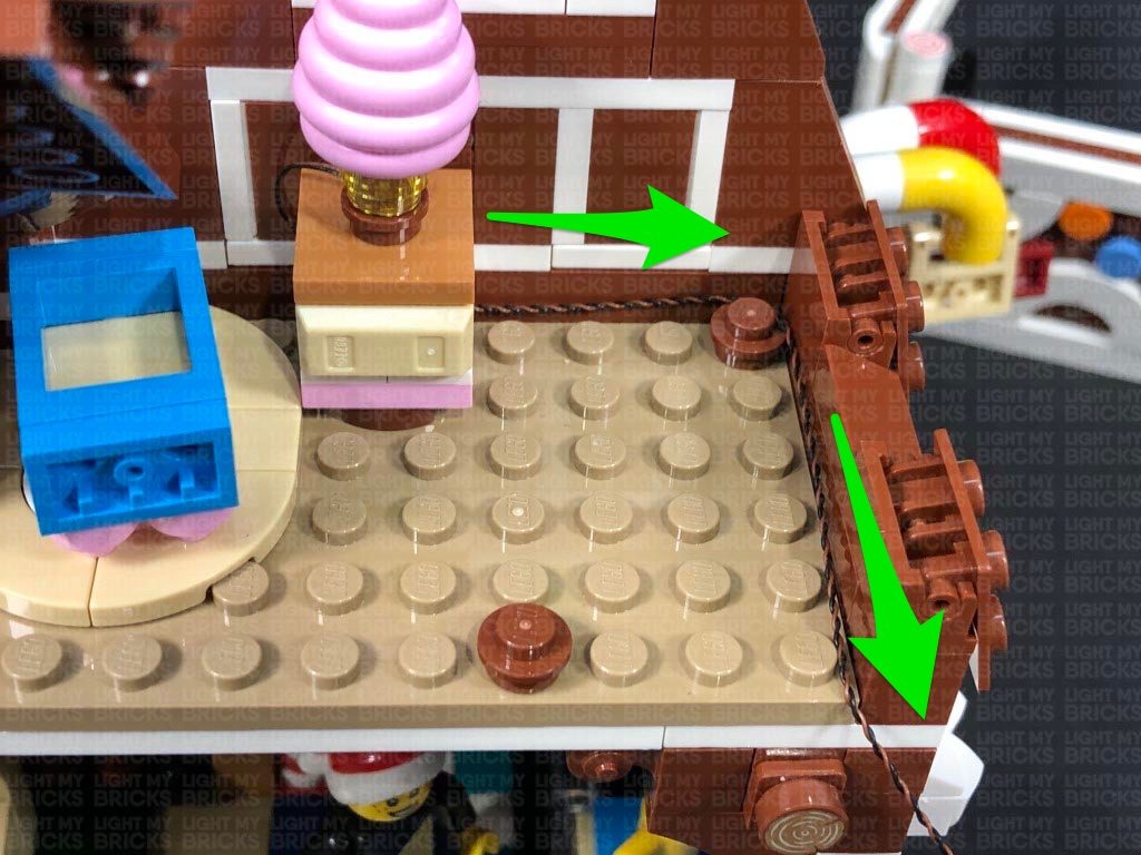
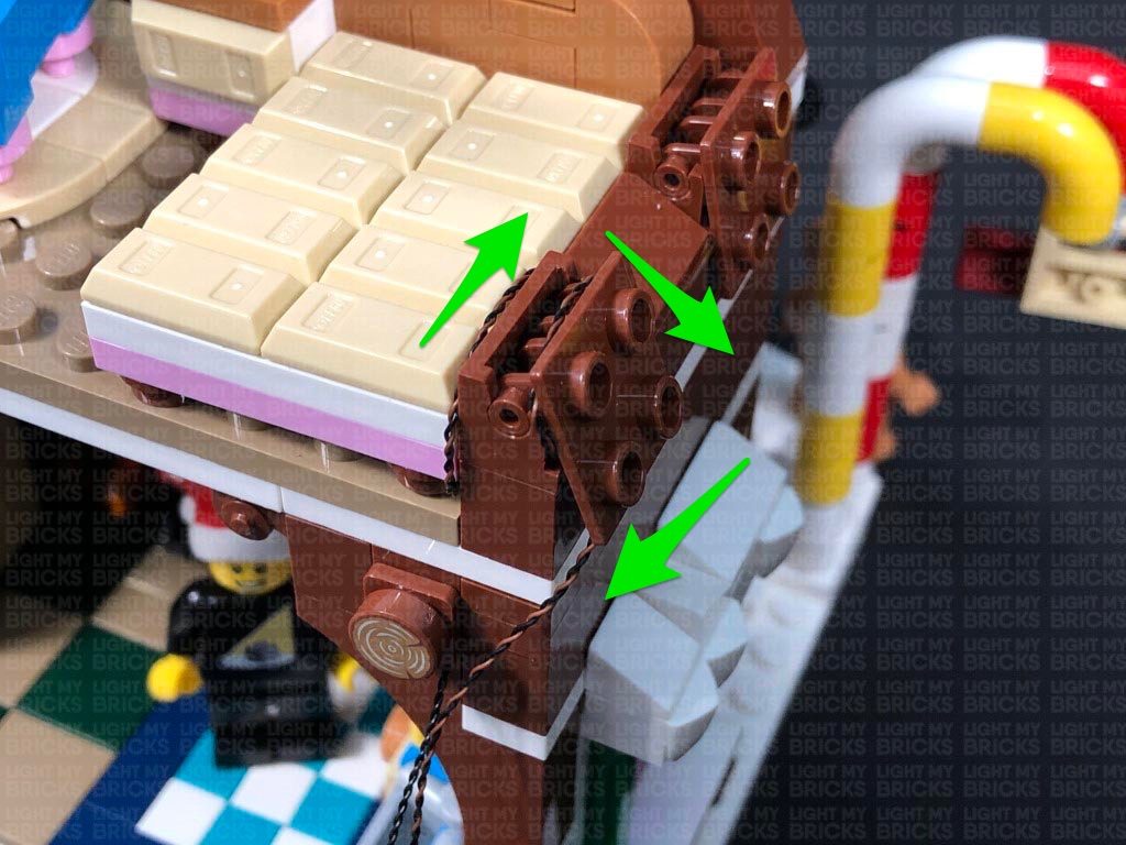
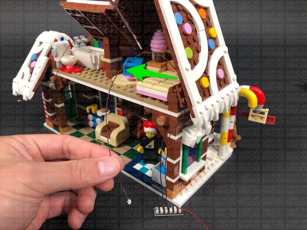
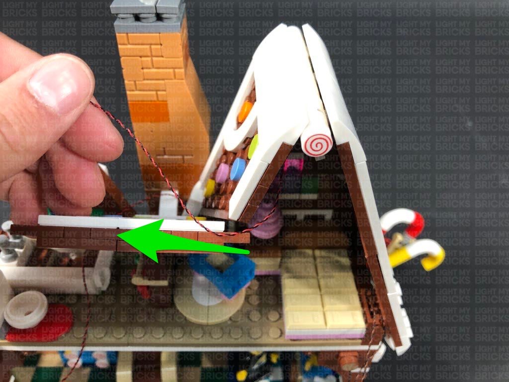
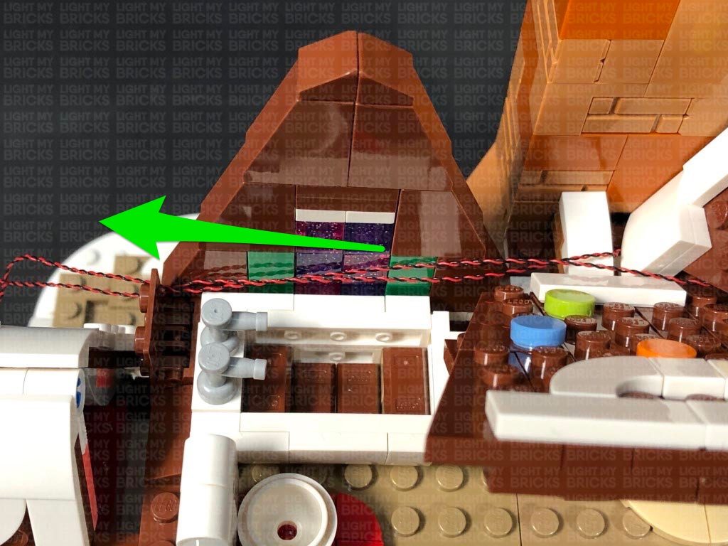
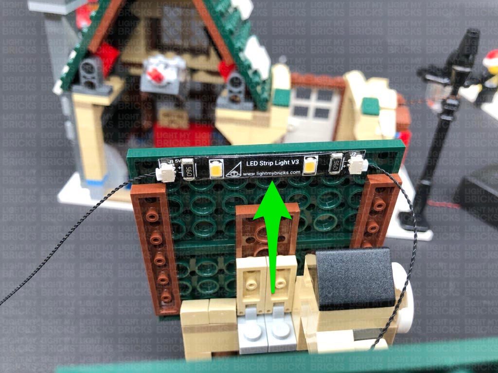
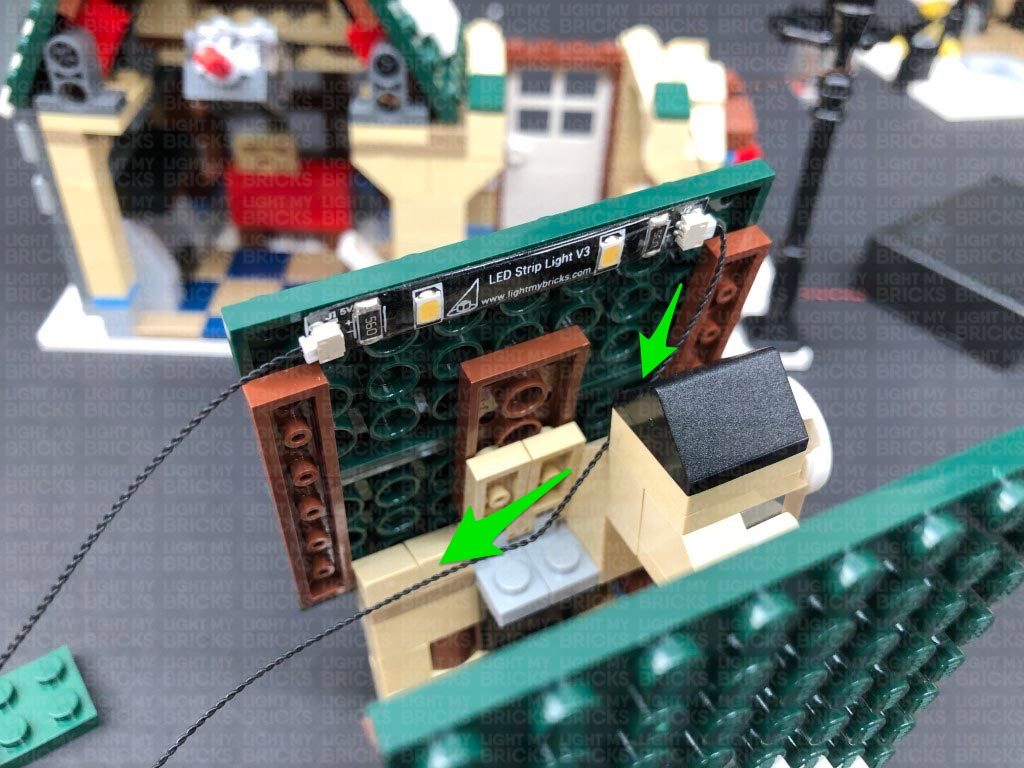
17.) Take the second level section which sits above the left side of the bakery and disconnect the two bricks from underneath of it. Ensuring the four micro bit light cables are laid in between studs, reconnect the two light grey bricks over the top of them.
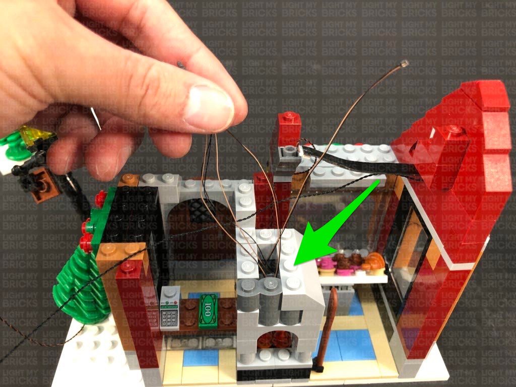
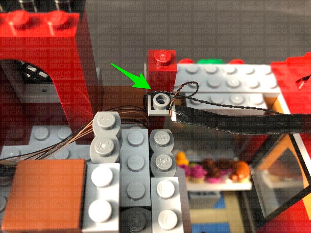
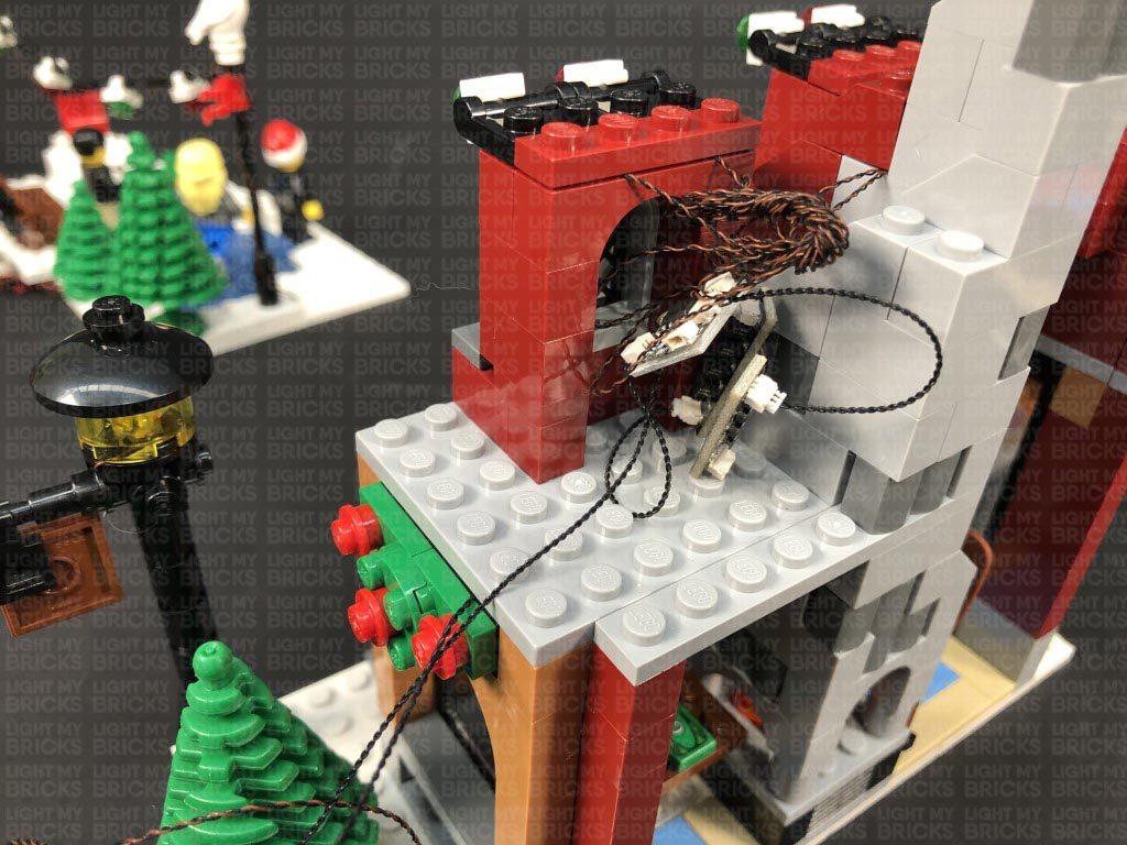
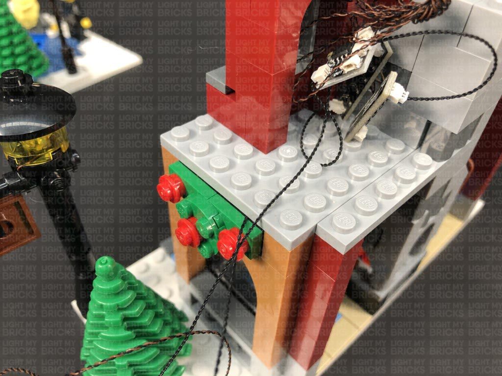
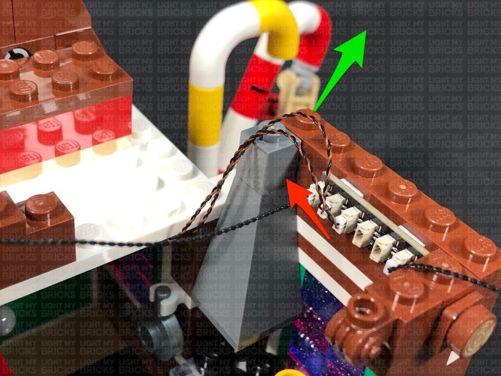
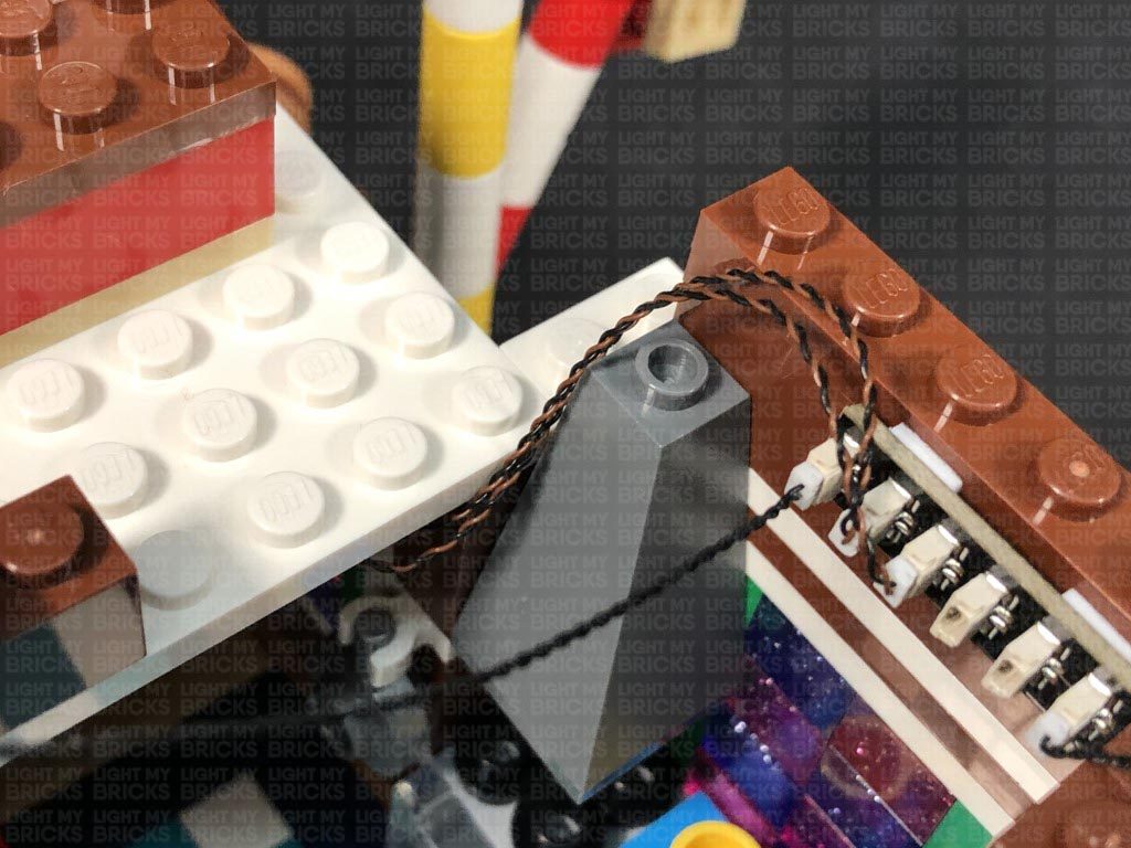
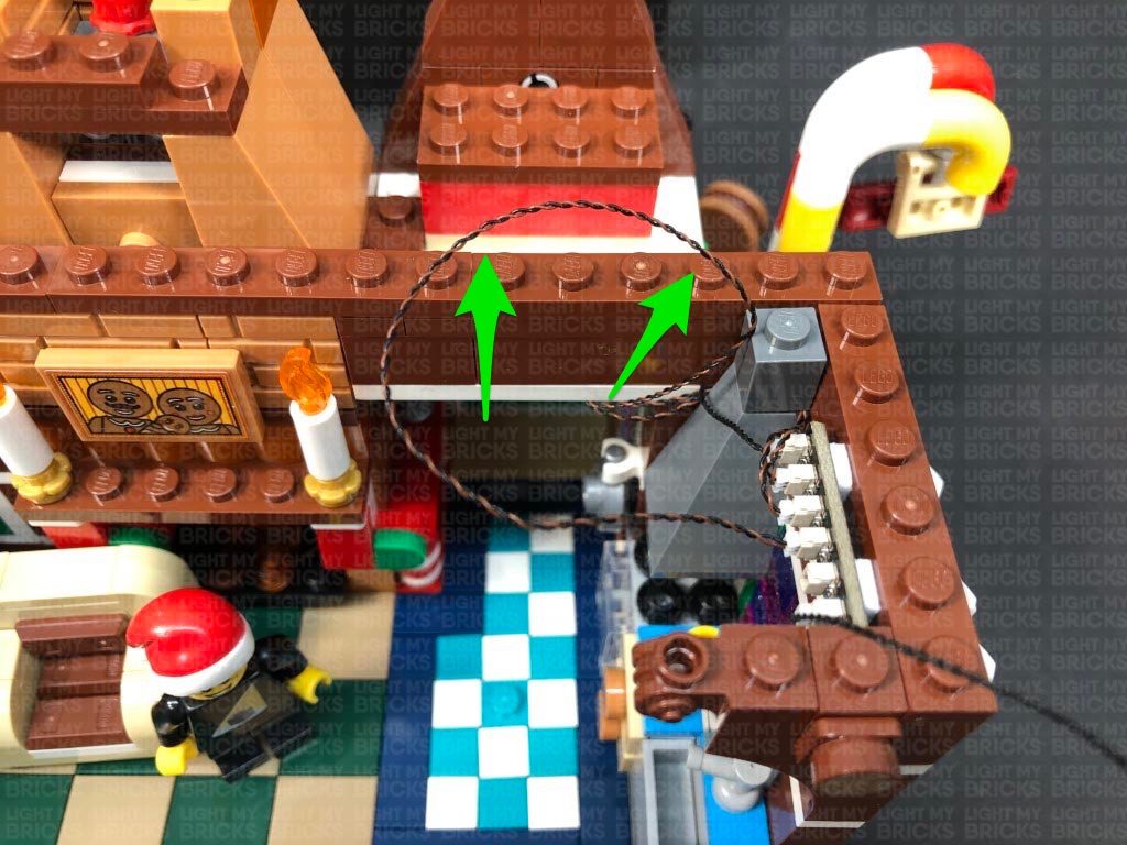
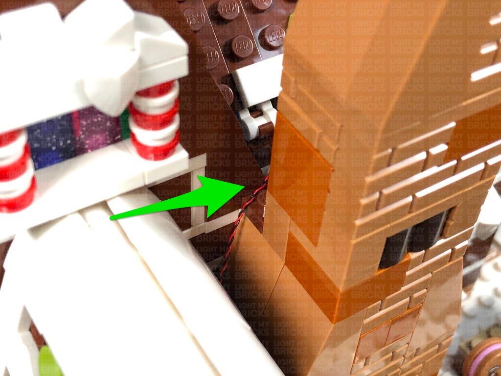
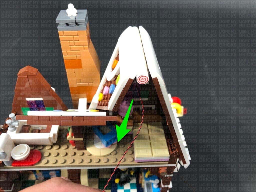
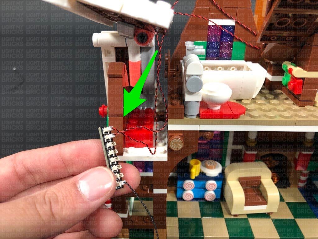
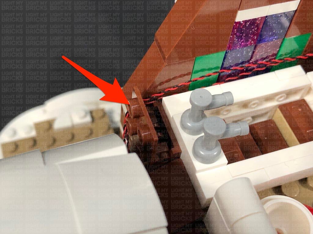
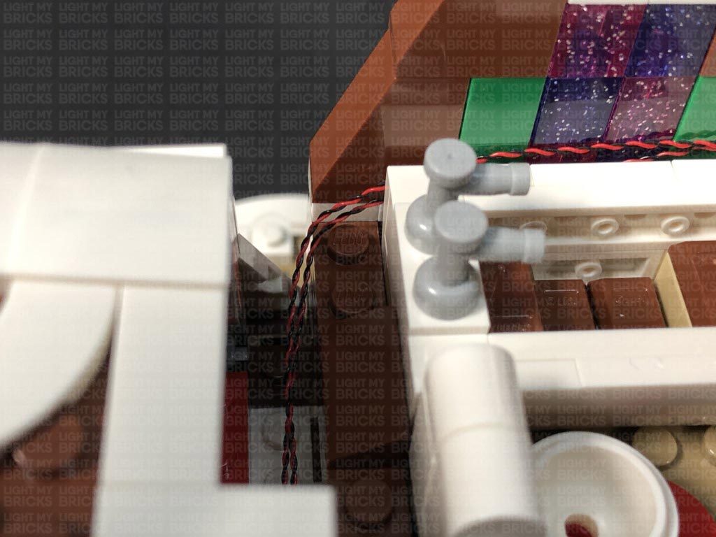
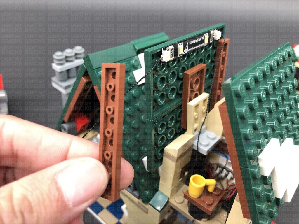
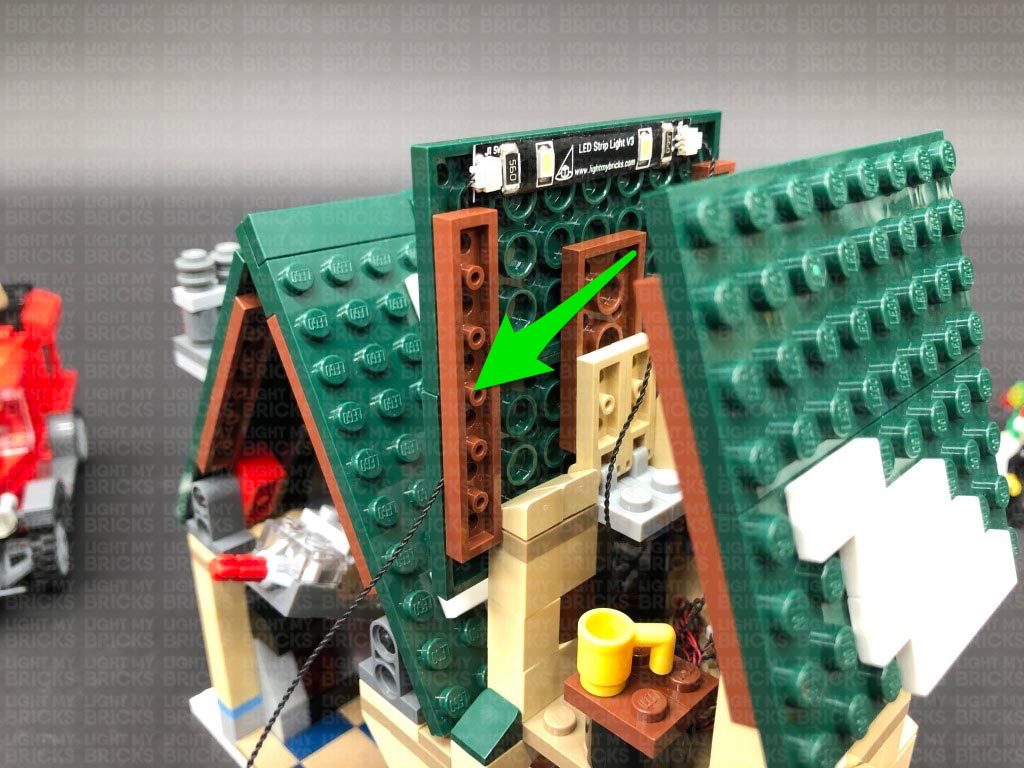
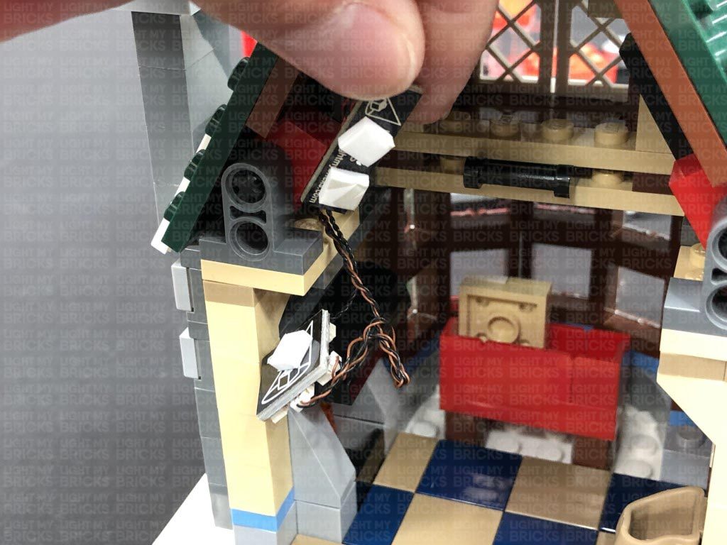
Lay the 30cm Connecting Cable in between the following studs (over the dark grey roof brick as well as in between studs below) before reconnecting the second level section over the top. Ensure the micro bit light cables are pulled up and are still accessible.
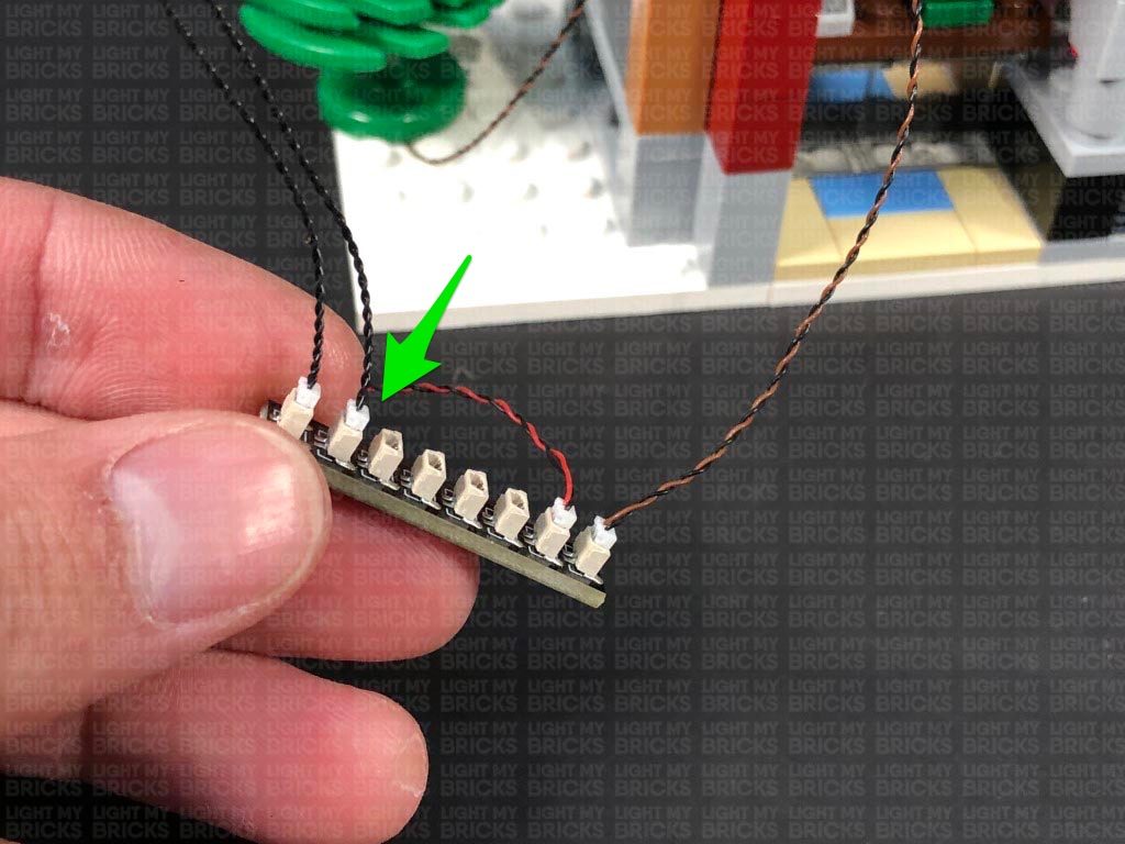
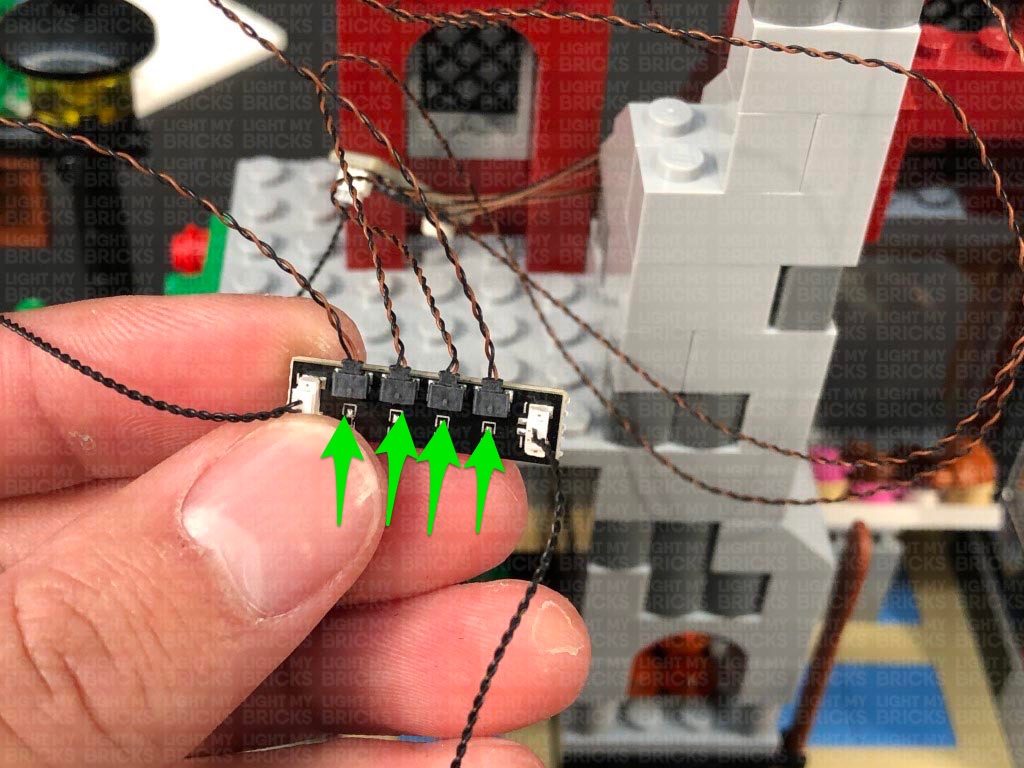
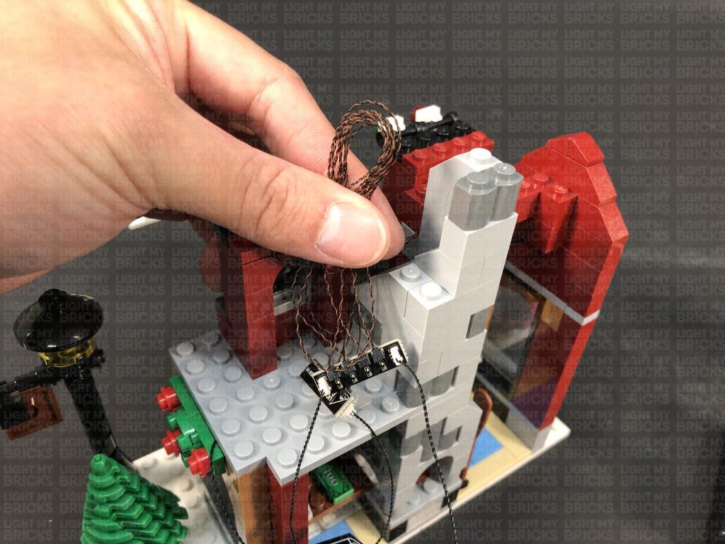
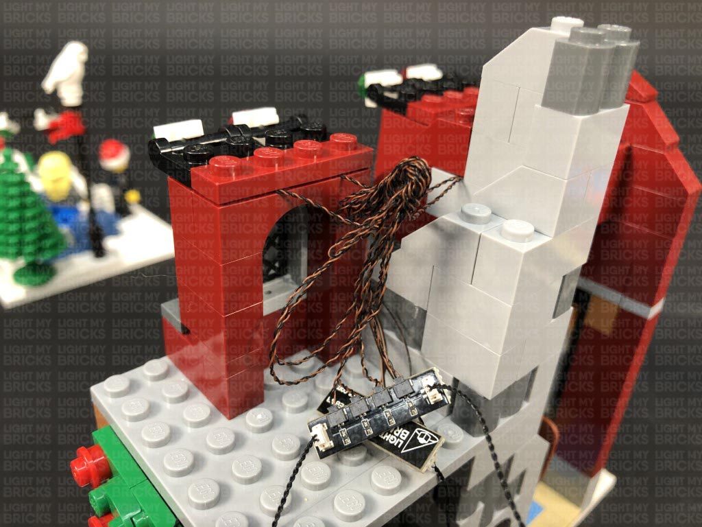
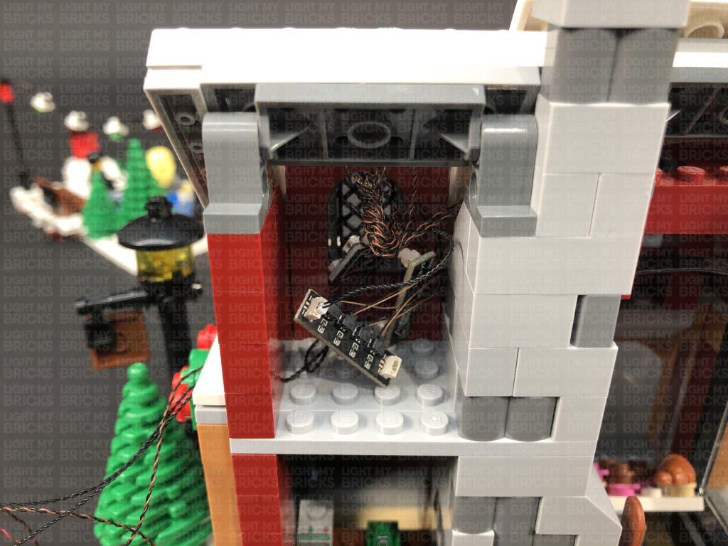
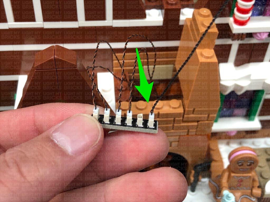
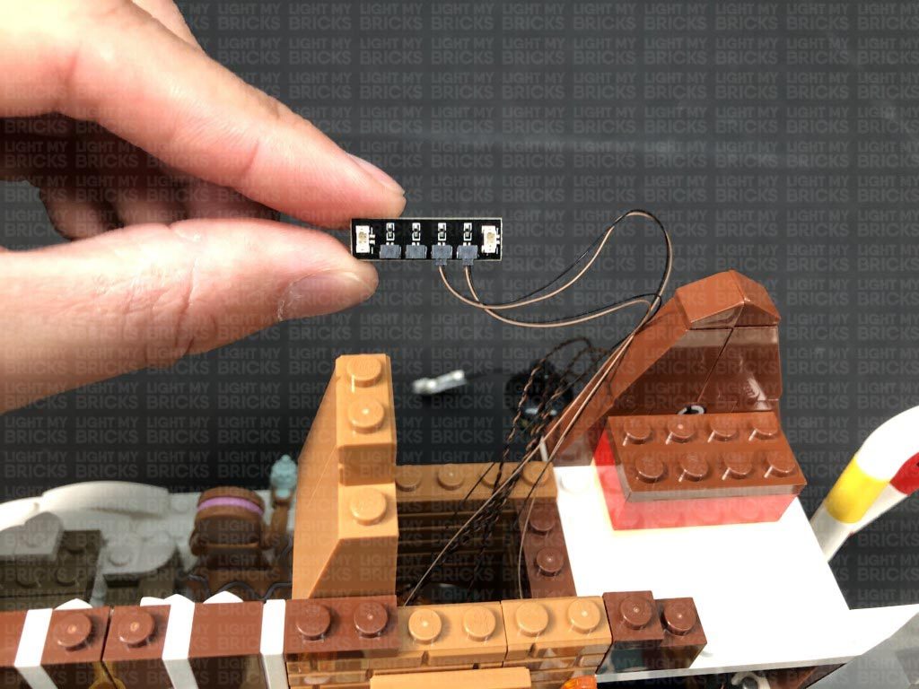
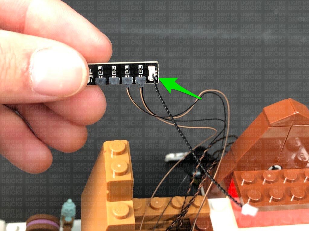
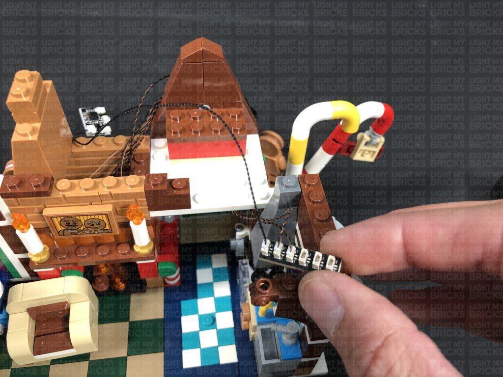
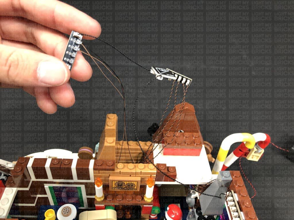
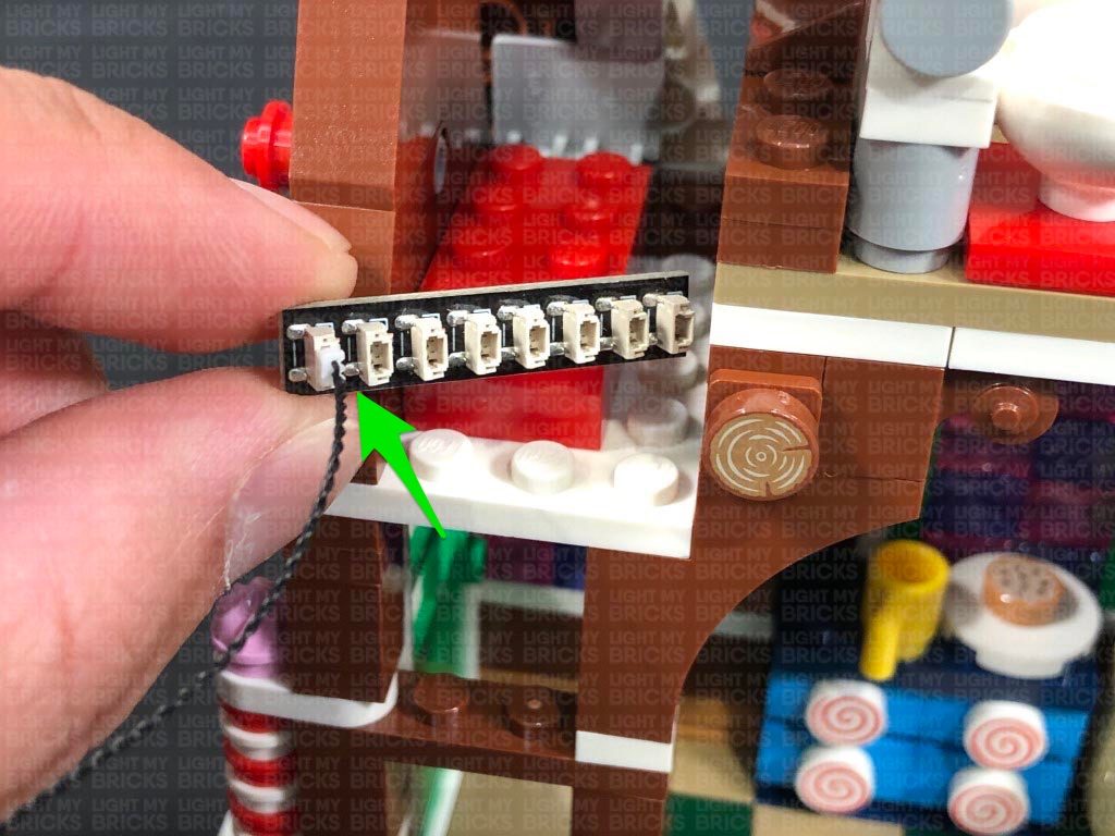
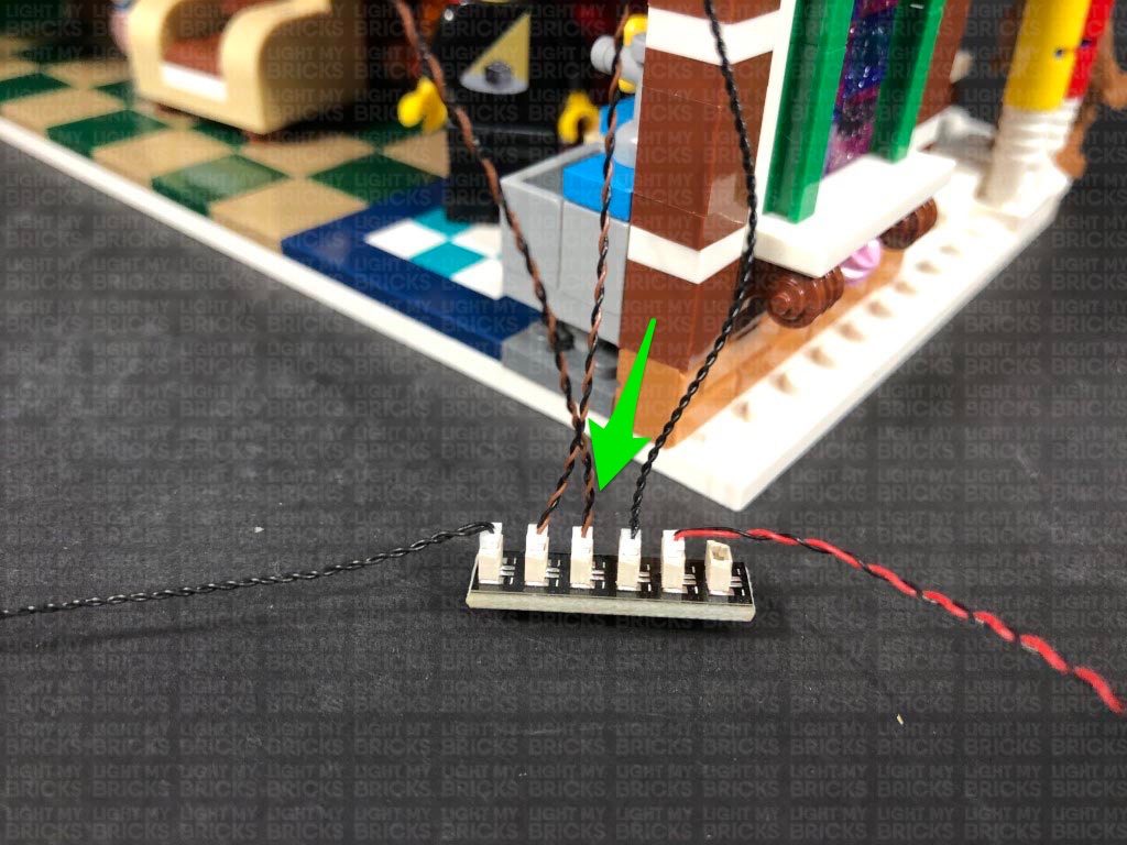
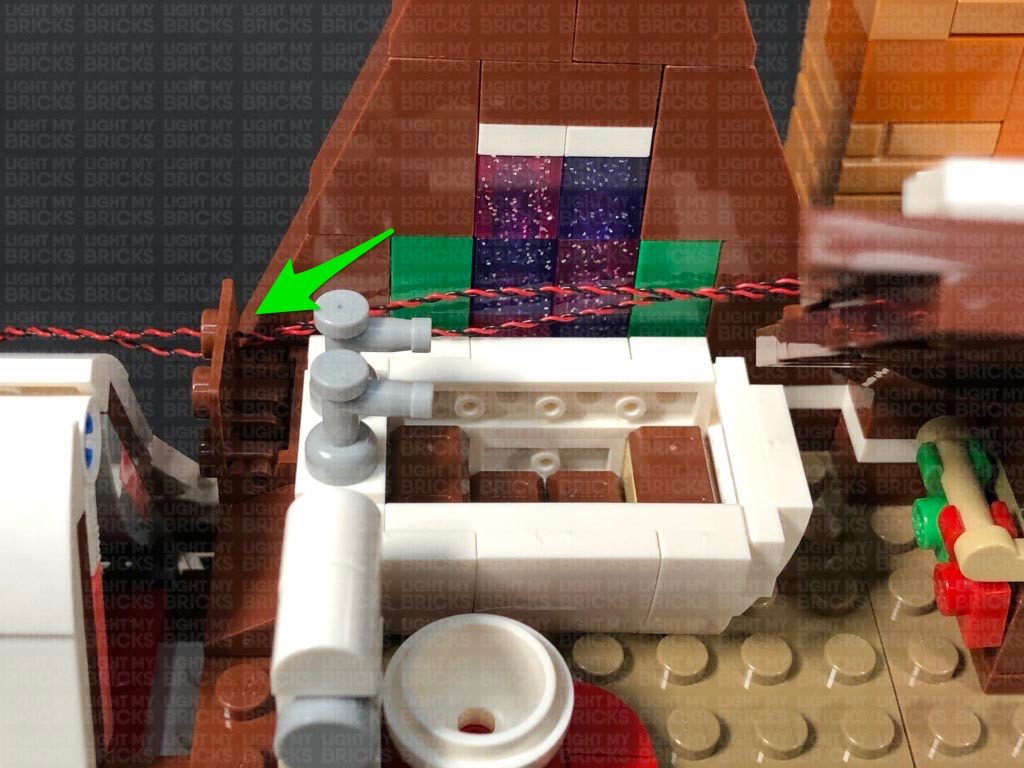
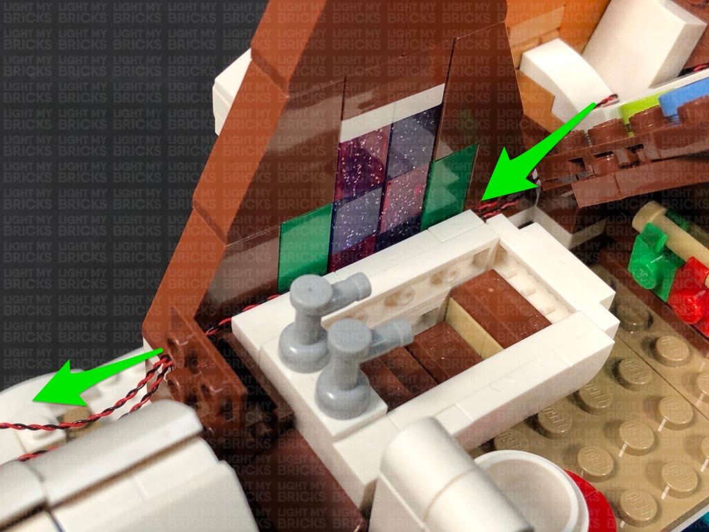
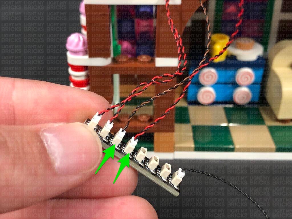
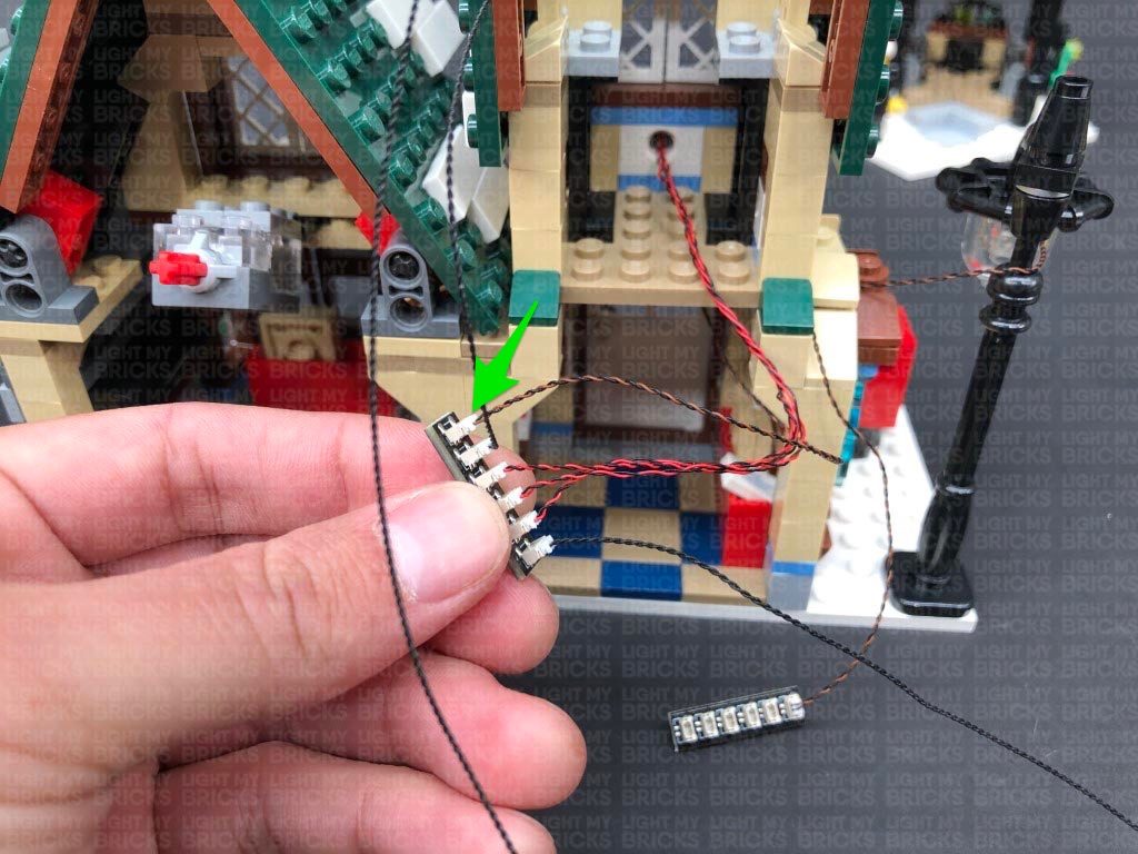
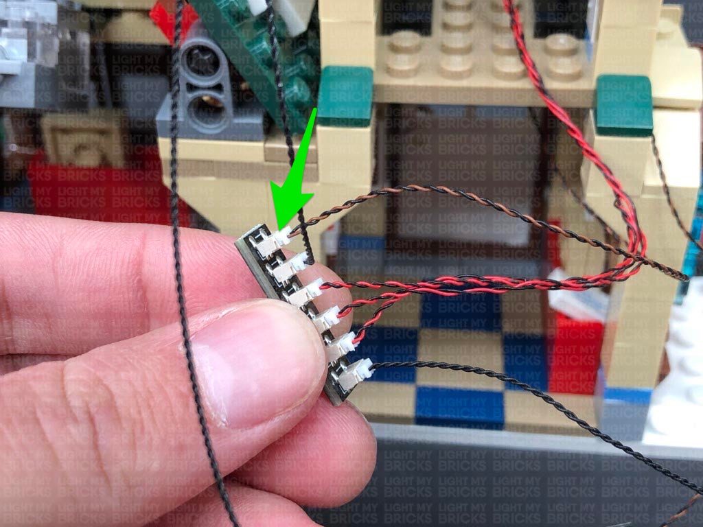
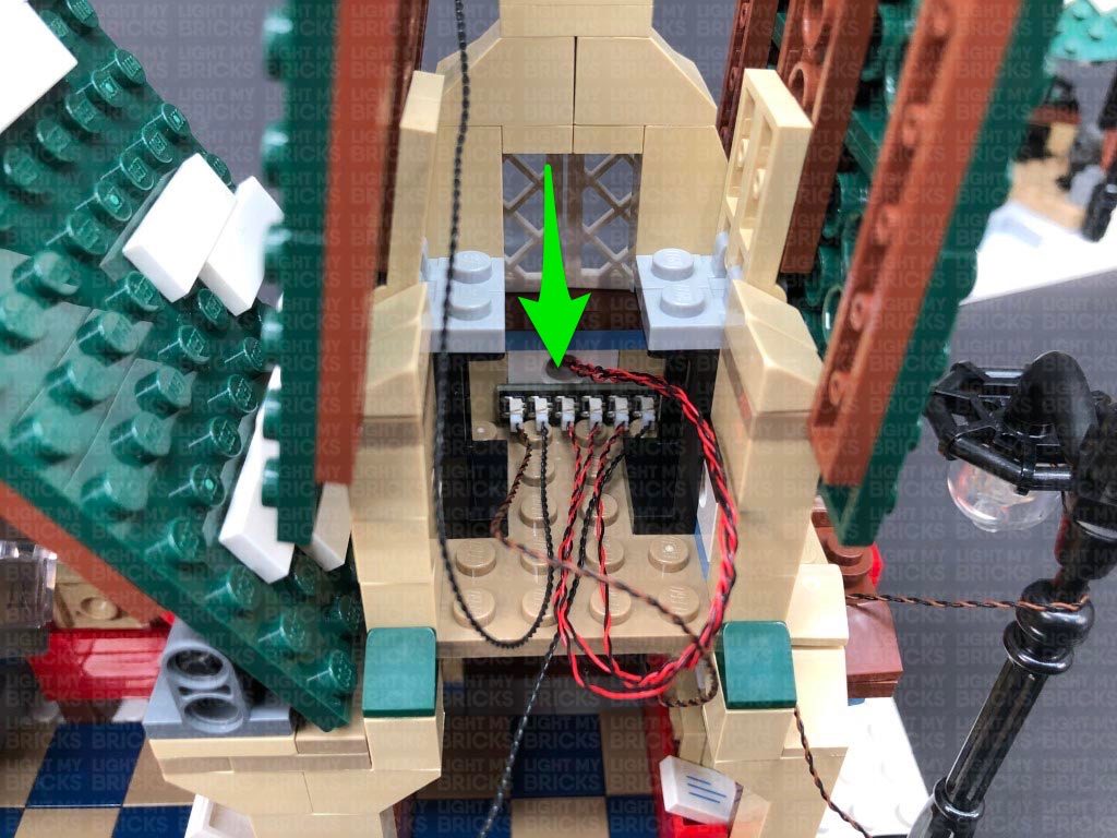
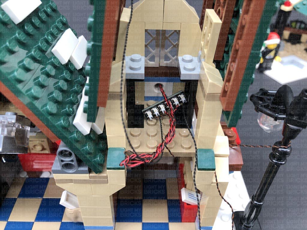
Take a new Micro 4-Port Expansion Board, and connect the four Micro Bit Lights to it. Slip the cables in between the bricks and leave the expansion board behind the brown crate for now, as we will connect this up later.
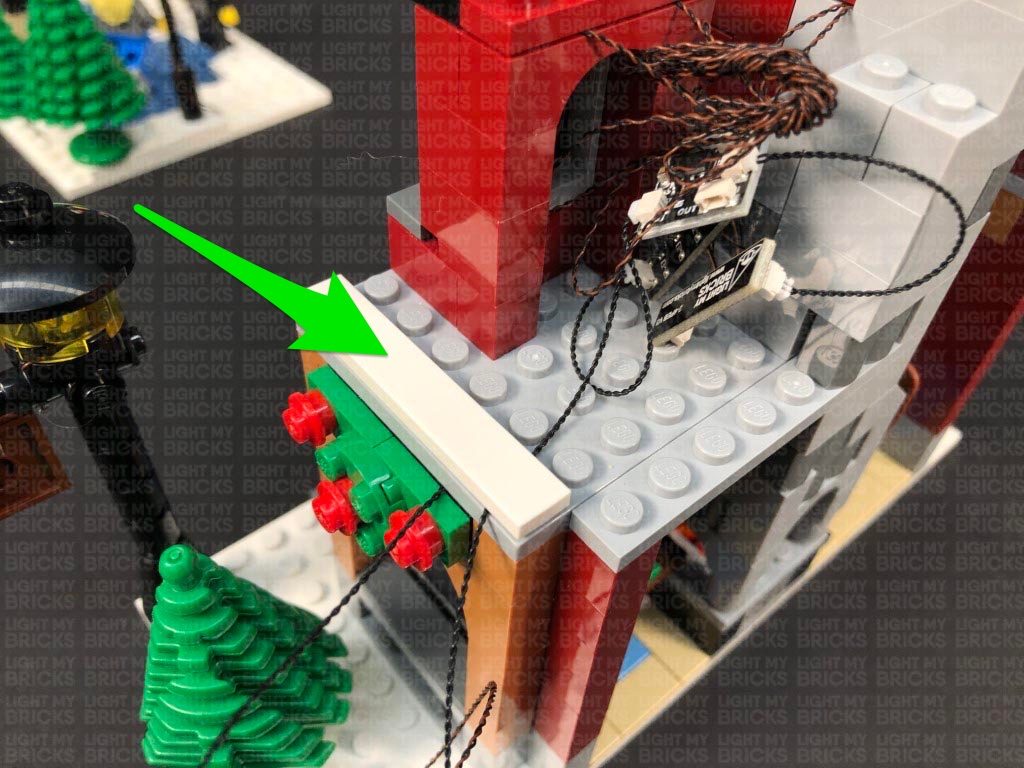
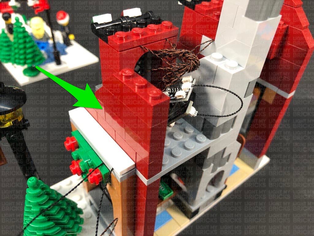
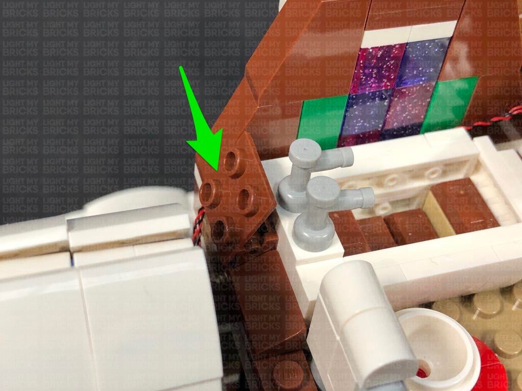
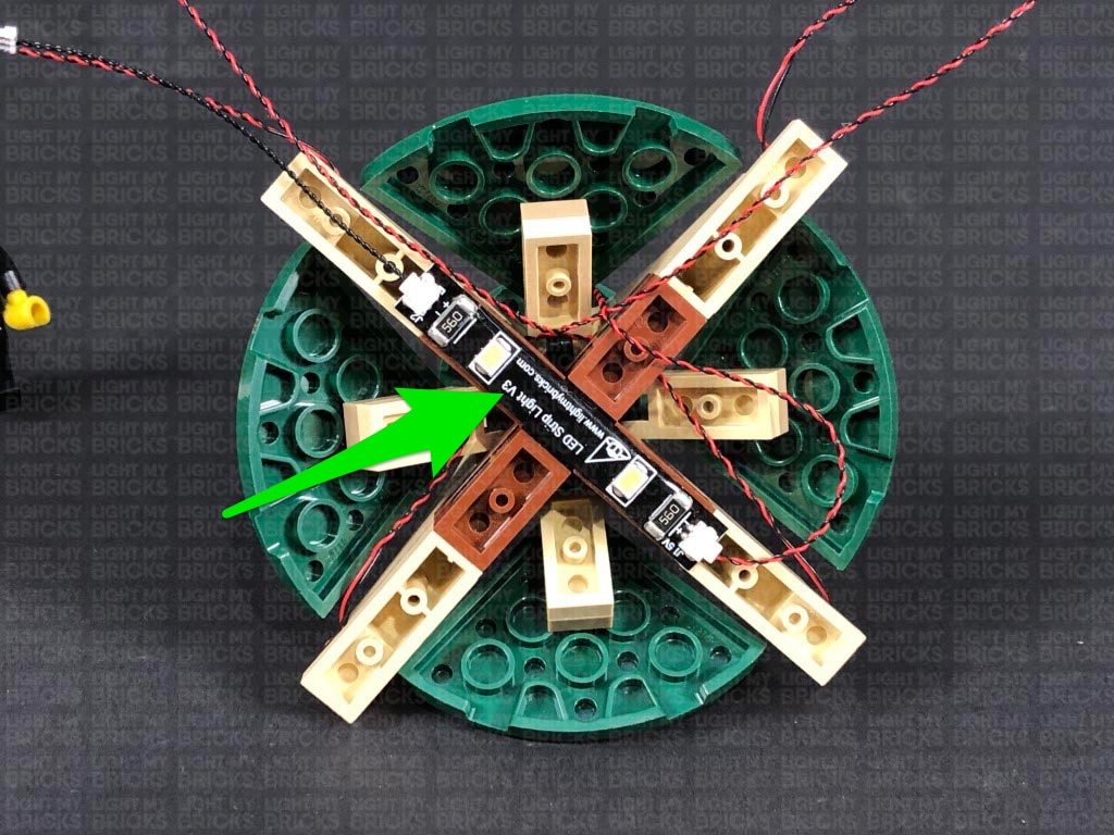
Ensure the cables are laid in between studs (30cm cable and white 15cm bit light cable), then reconnect the upper chimney section. Stick the left side of the White Strip Light underneath this section, then turn ON the Battery Pack to test the strip light is working and lighting up the bakery floor.
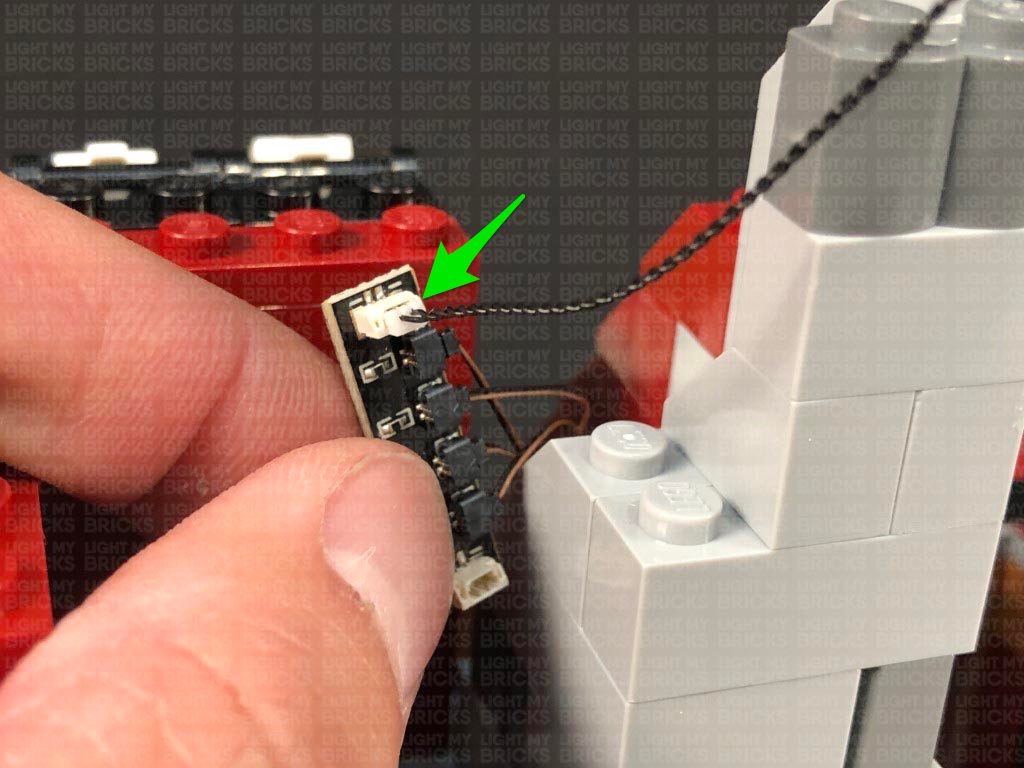
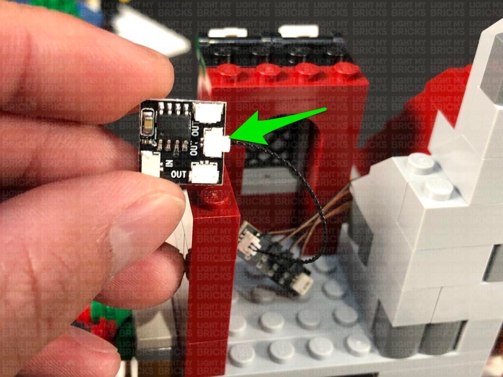
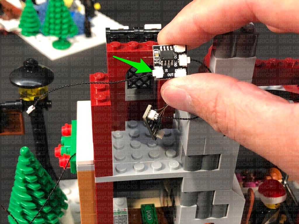
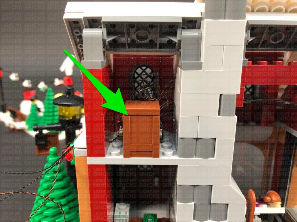
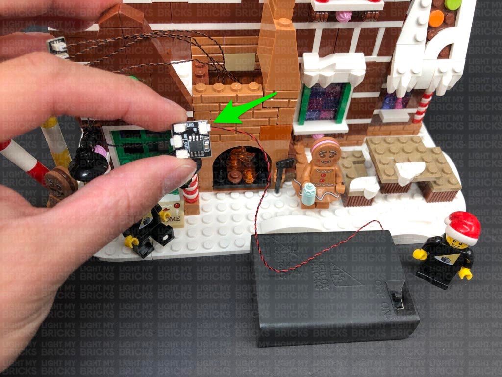
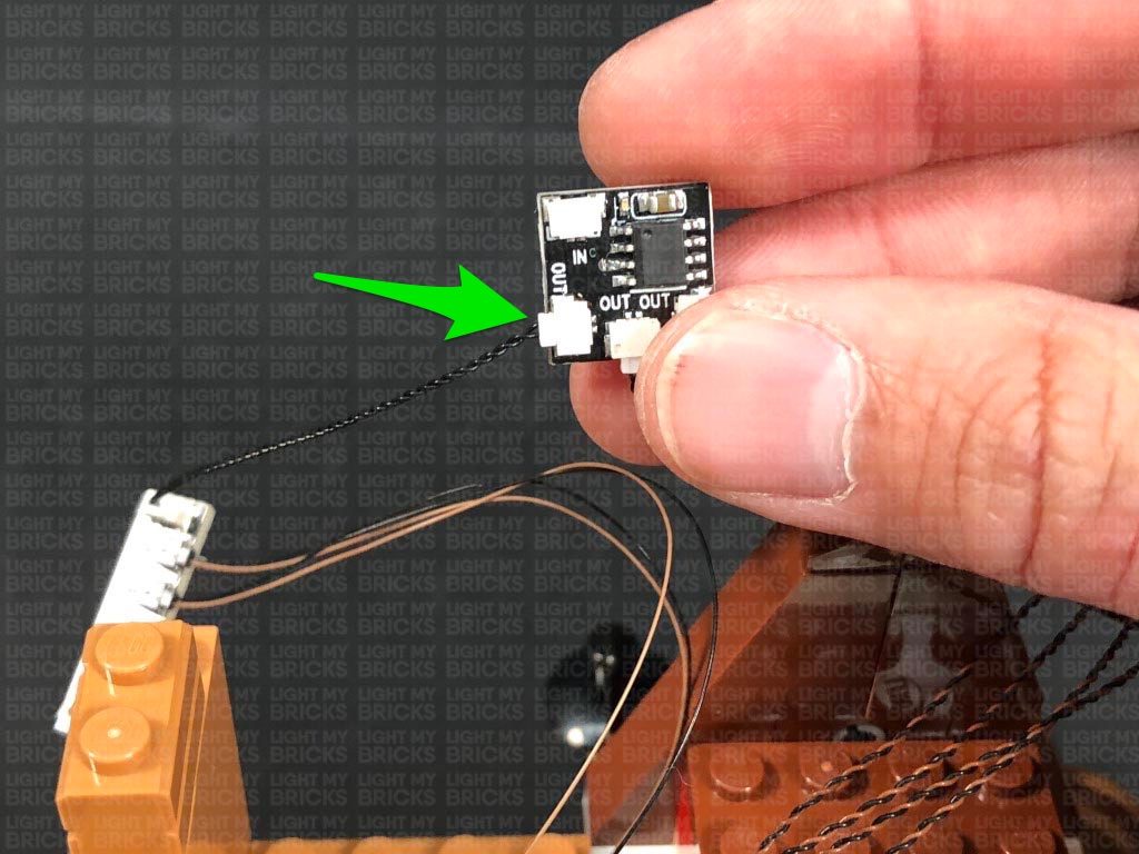
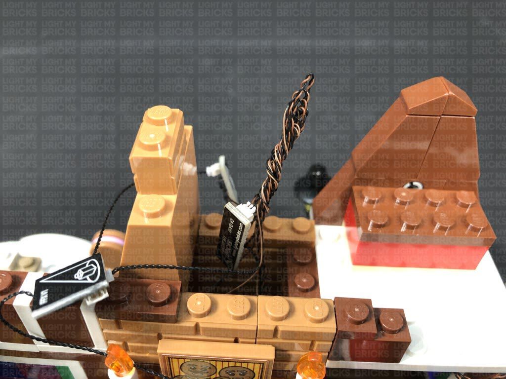
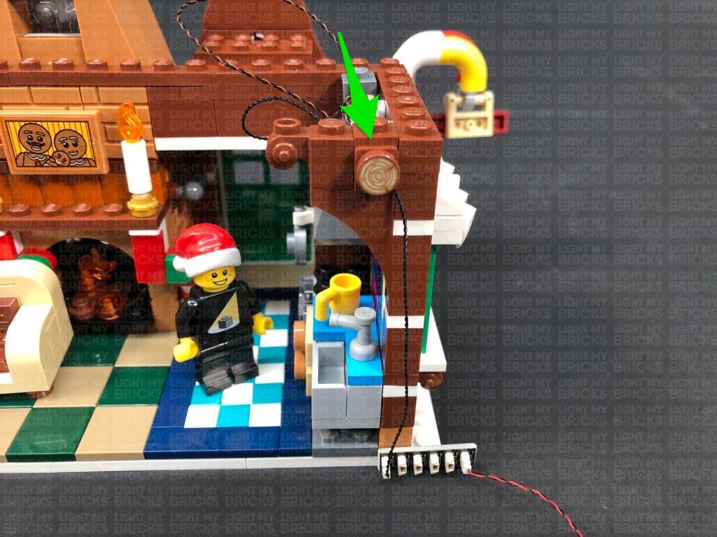
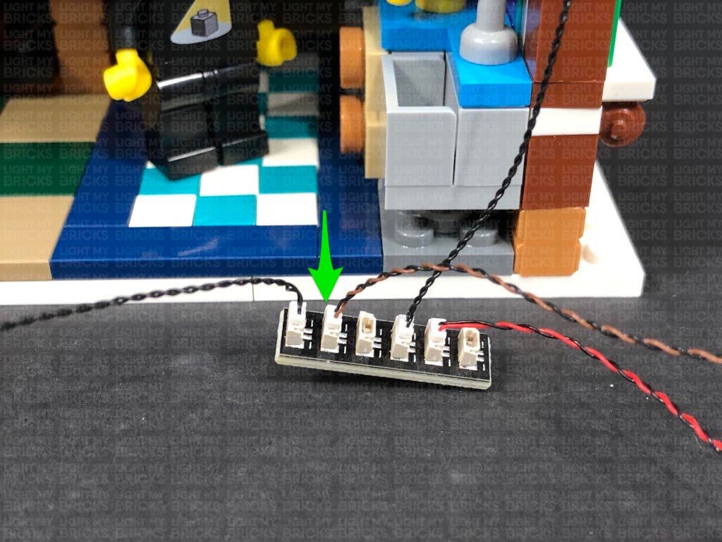
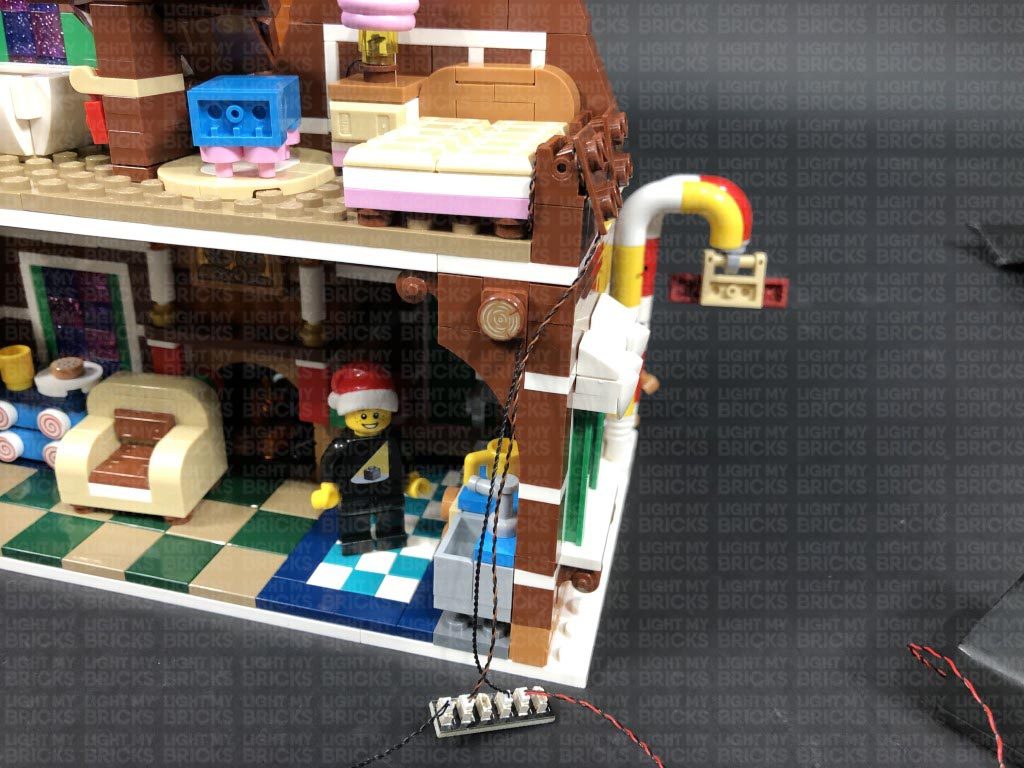
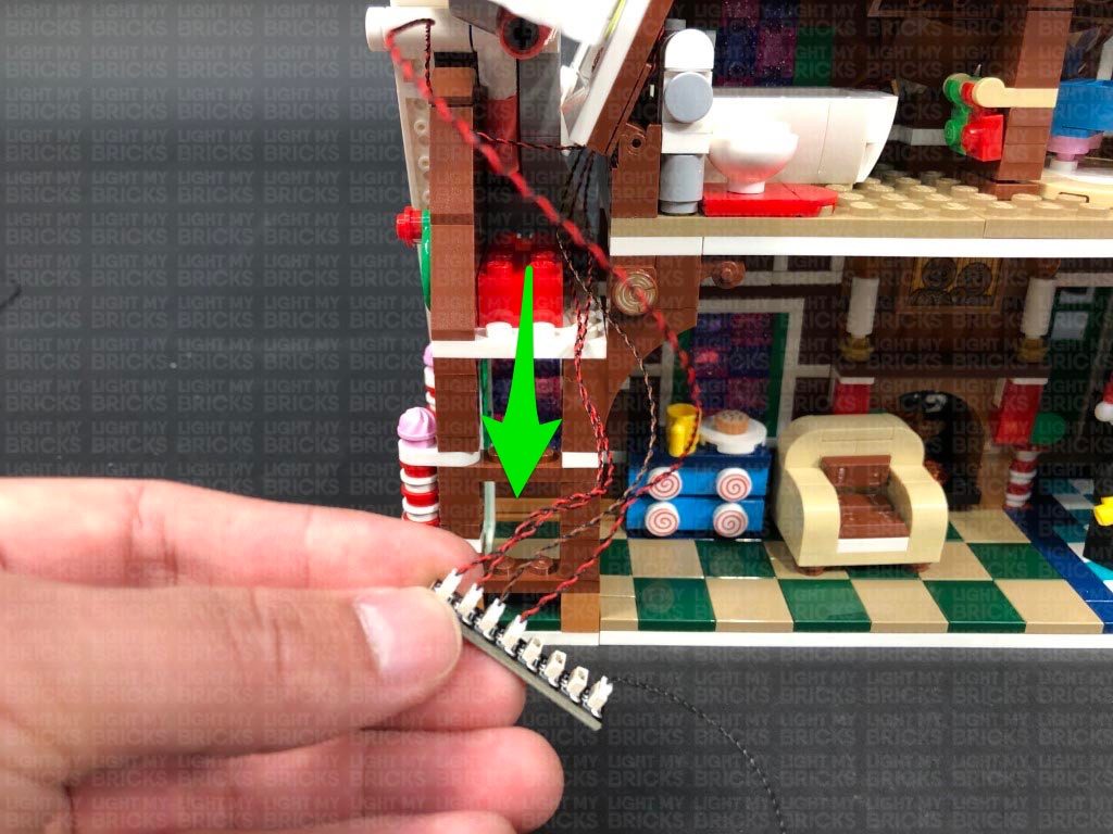
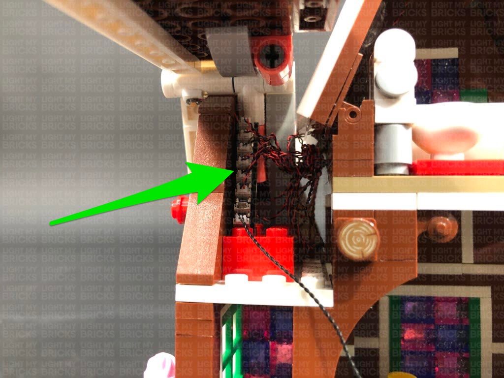
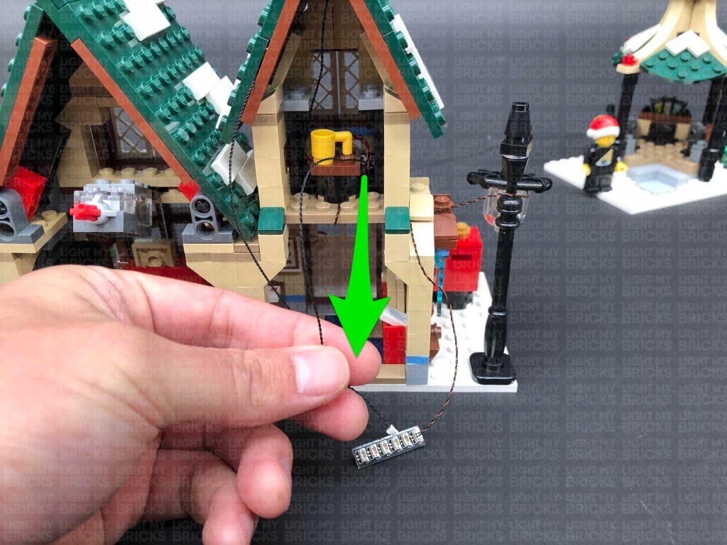
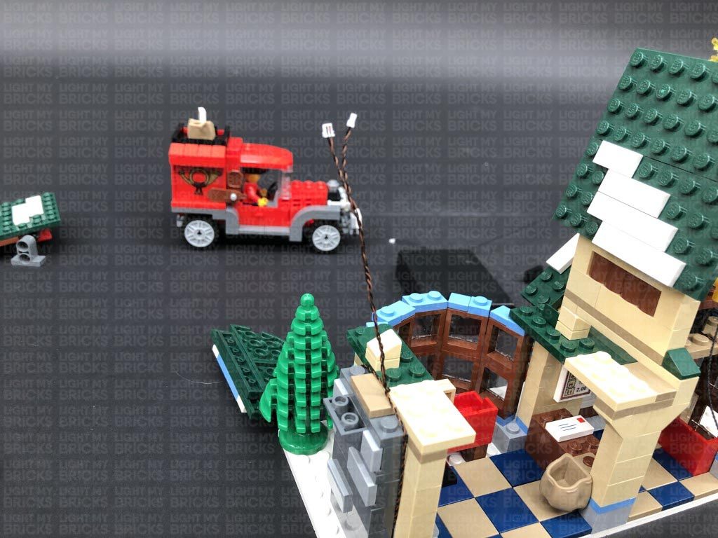
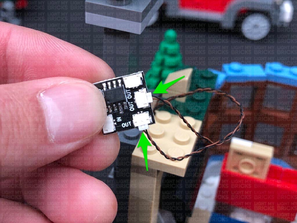
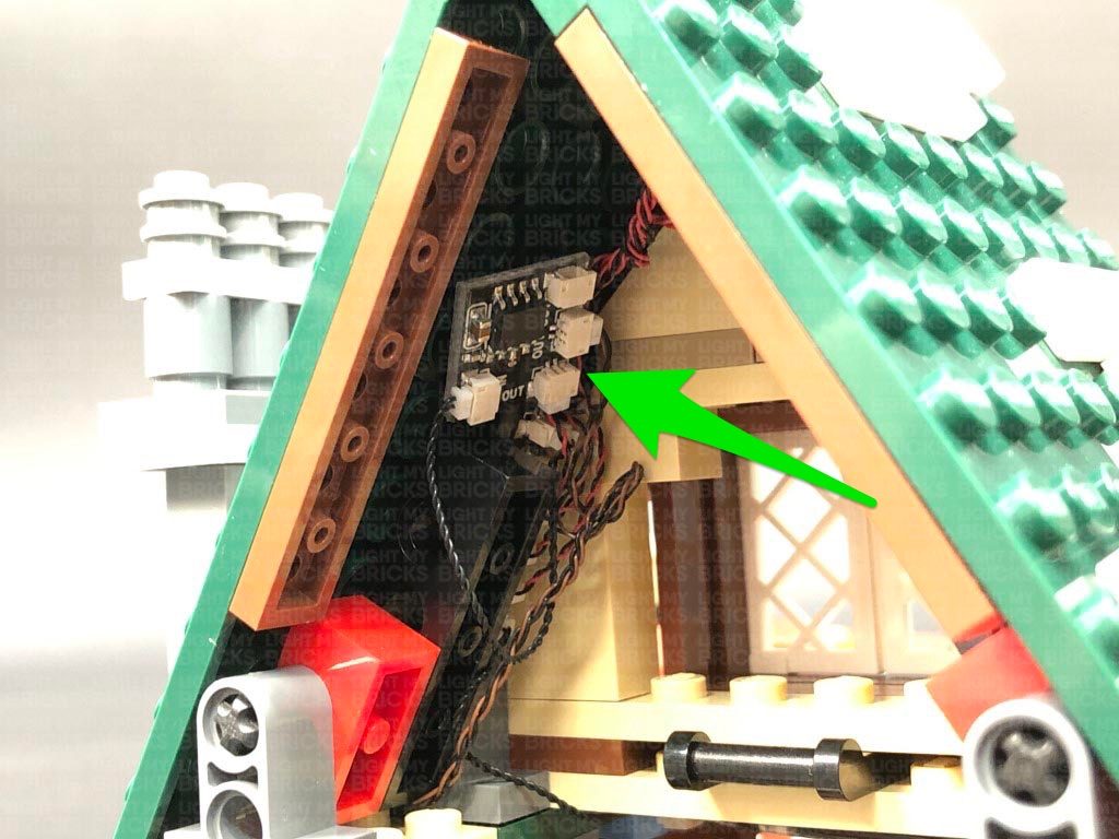
18.) Disconnect the crate from the second level, then take a 5cm Connecting Cable and connect it to the large port on the Micro Expansion Board. Connect the other end of the 5cm cable to one of the OUT ports on a Flicker Effects Board.
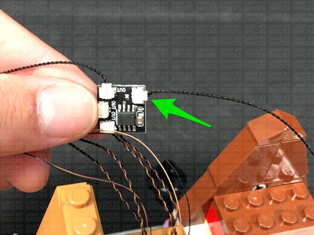
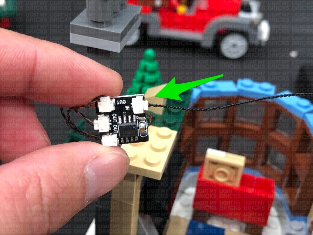
Take another 5cm Connecting Cable and connect it to the IN port on the Flicker Effects Board. Connect the other end of the 5cm connecting cable to the large port on a new Micro 4-Port Expansion Board.
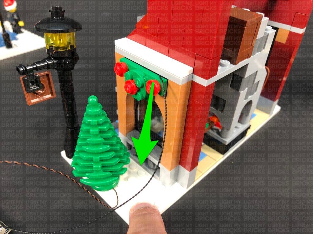
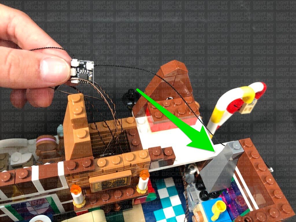
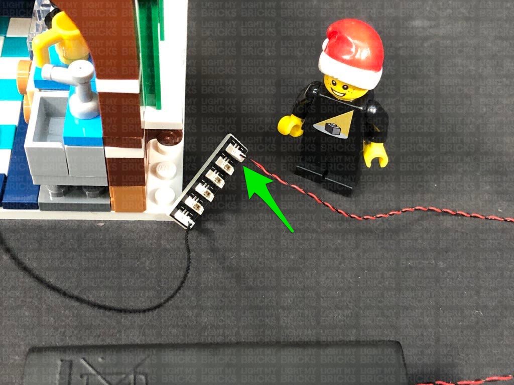
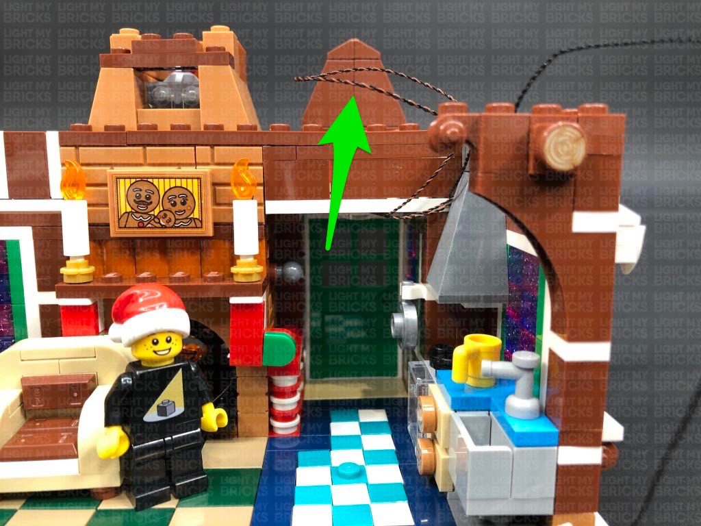
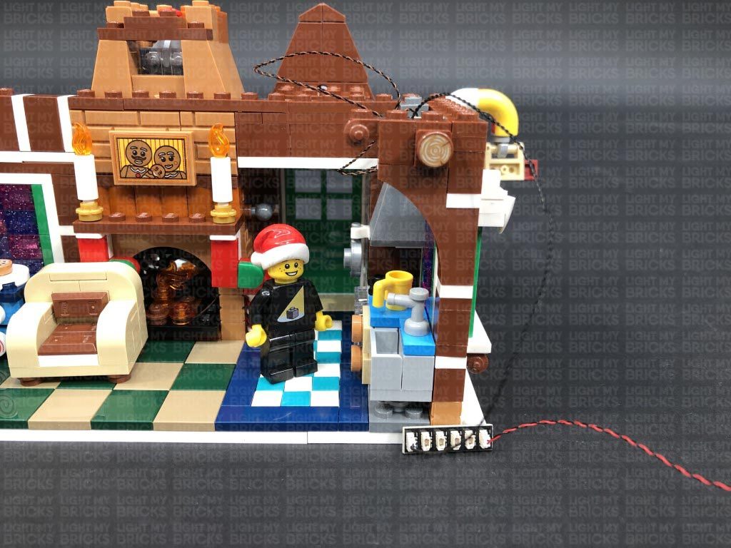
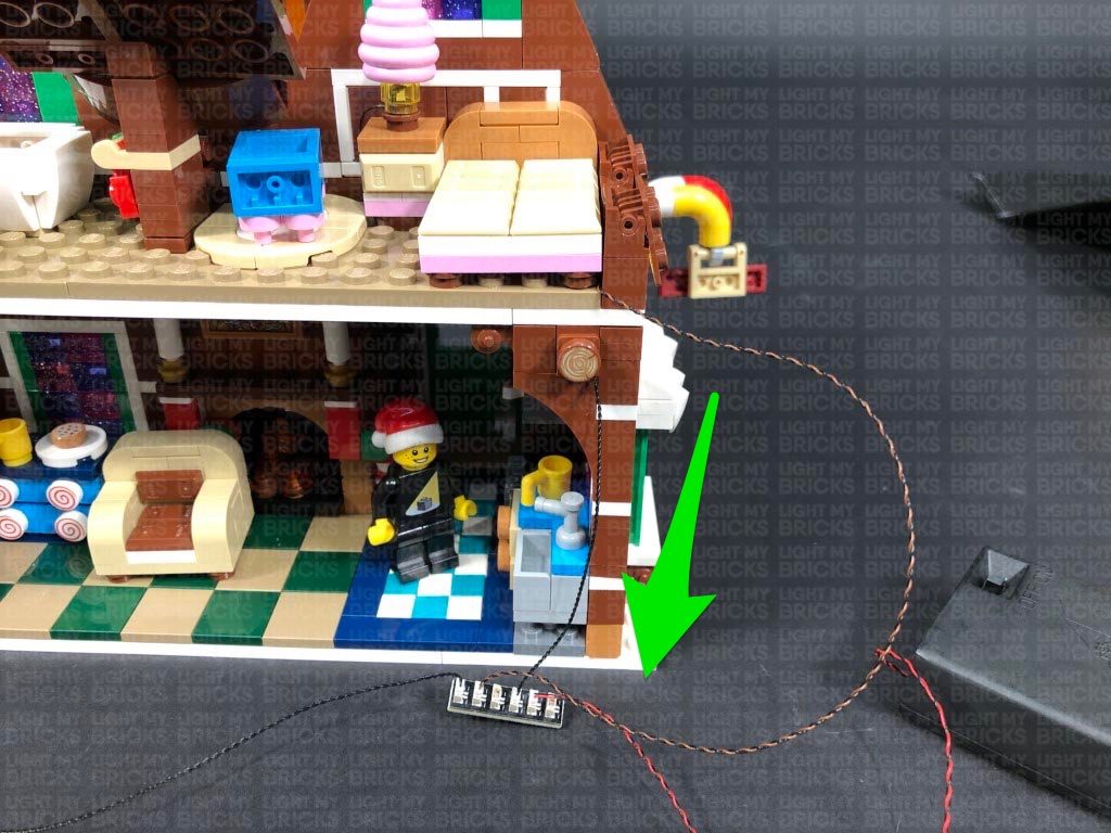
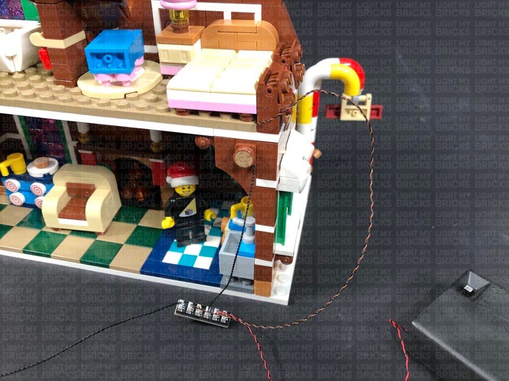
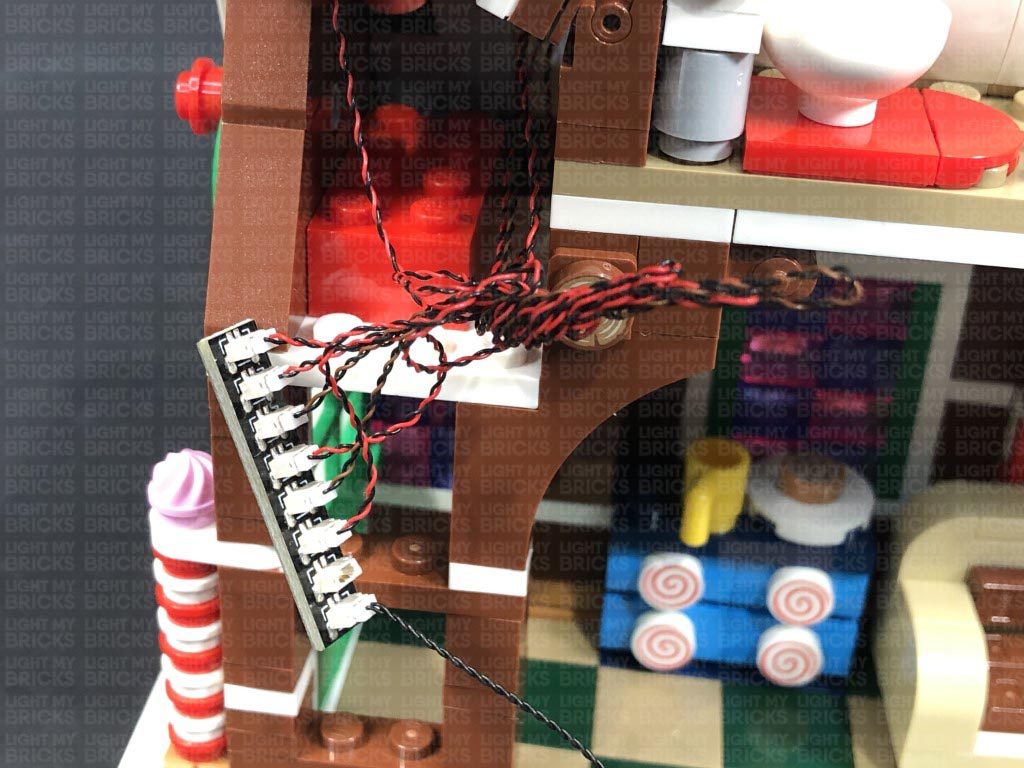
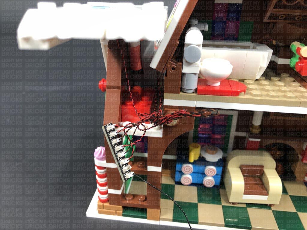
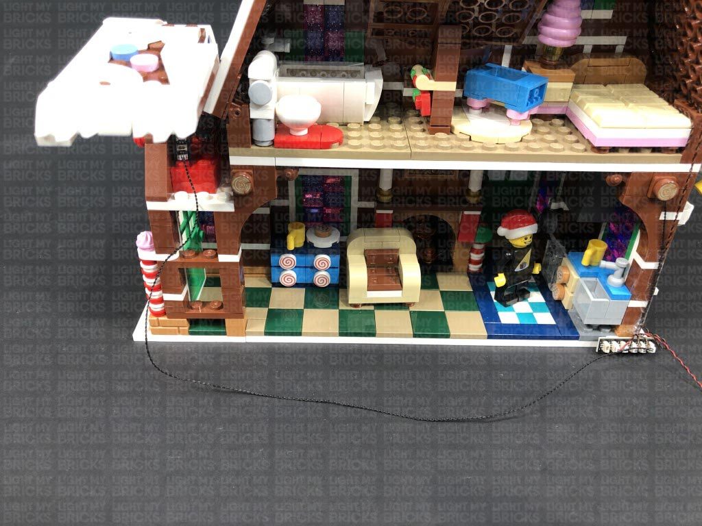
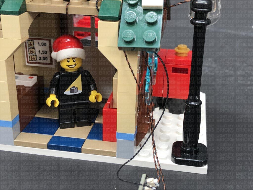
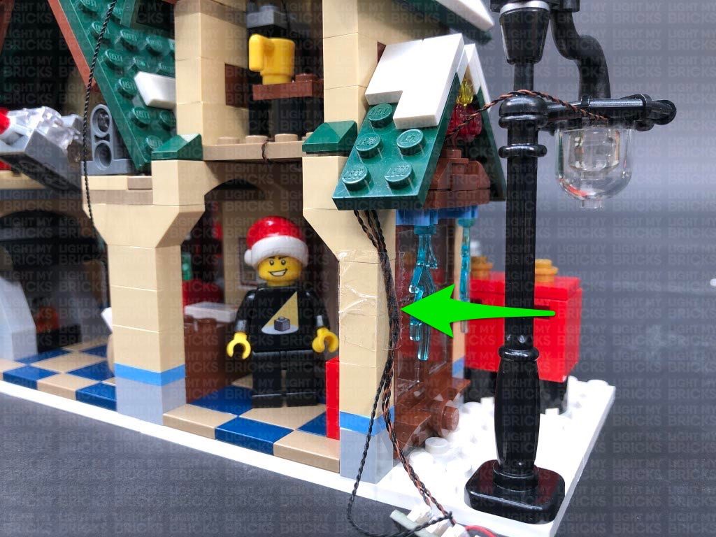
Take a 15cm Connecting Cable and connect it to the other large port on the Micro Expansion Board we just connected, then bring the cable down the left side of the bakery and connect it to a spare port on the 8-Port Expansion Board at the bottom of the set. Turn the Battery Pack ON to test the oven lights are working and flickering OK.
Note: If you experience any issues with the lights not working and suspect an issue with a component, please try a different port on the expansion board to verify where the fault lies (with the light or expansion board). To correct any issues with expansion board ports, please view the section addressing expansion board issues on our online troubleshooting guide.
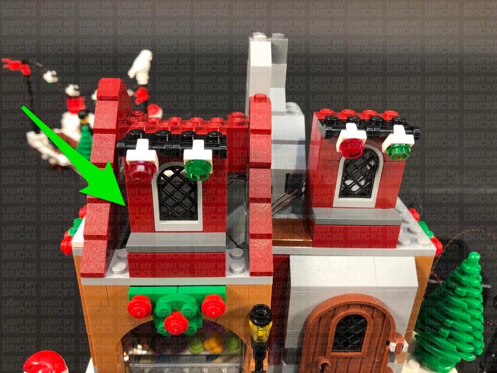
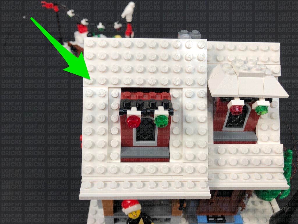
19.) Disconnect the white tile on the left side of the bakery, then disconnect the left wall section. Turn the set around to the front, then reconnect the window section to the left side.
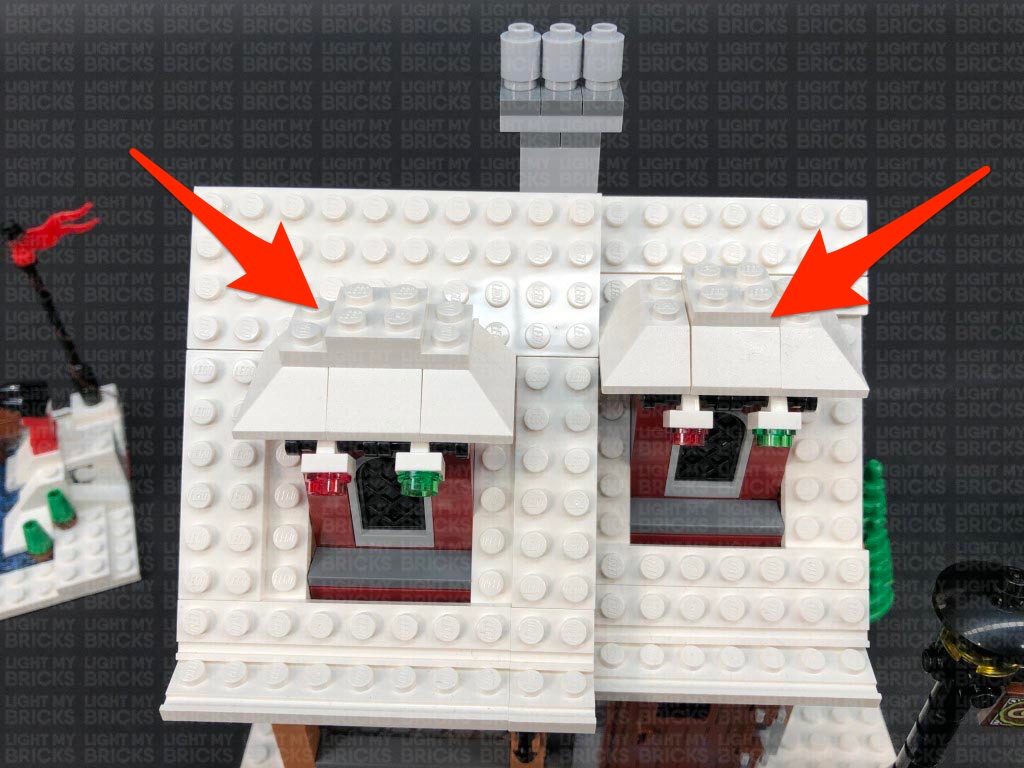
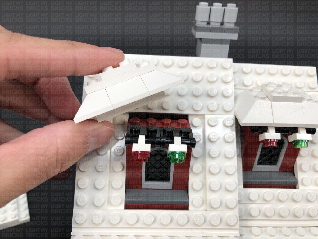
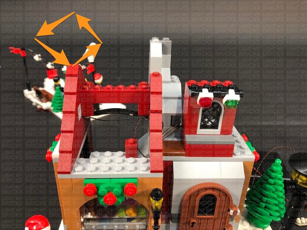
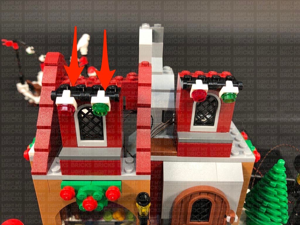
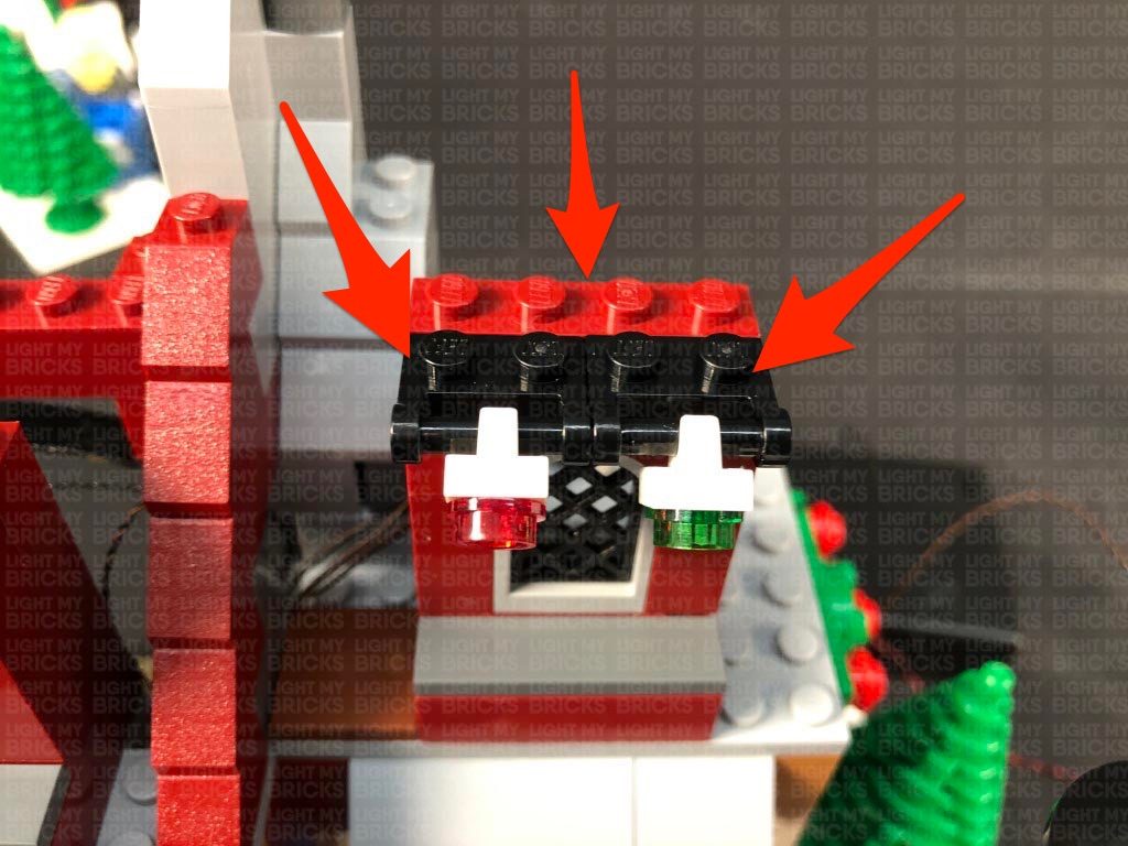
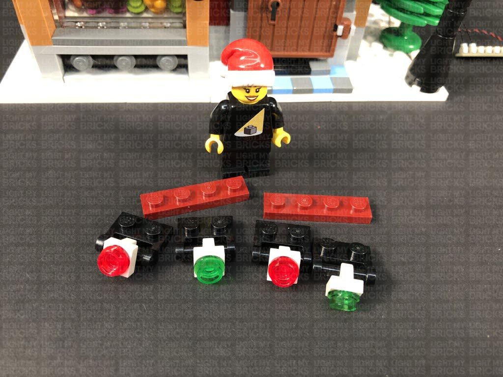
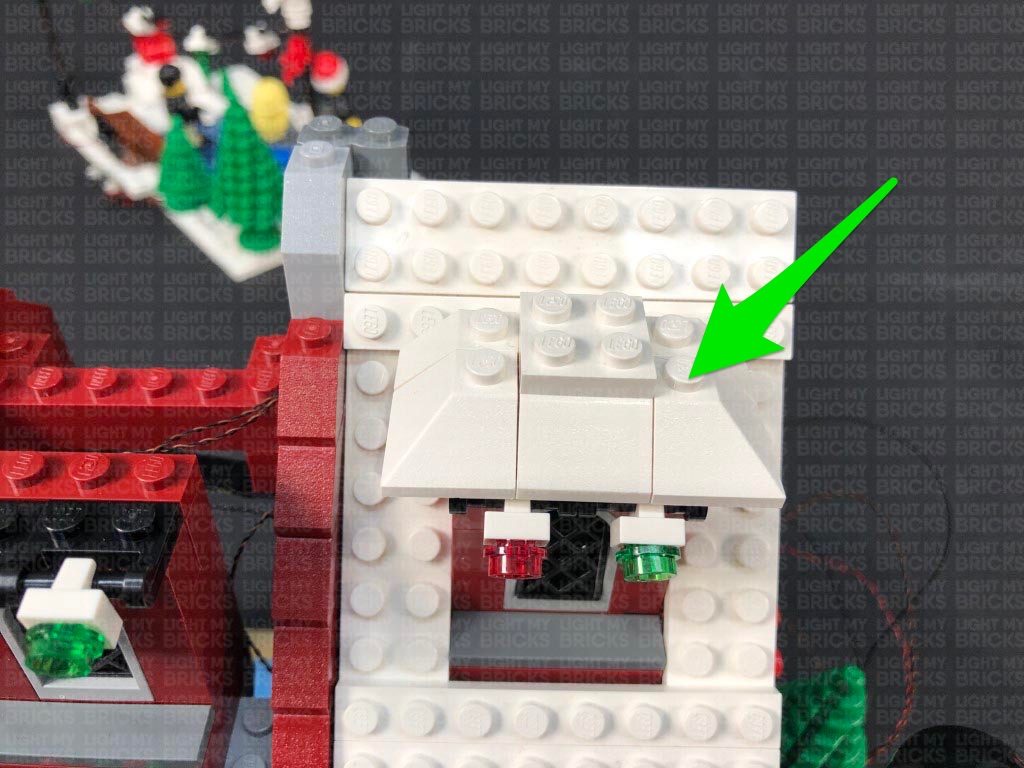
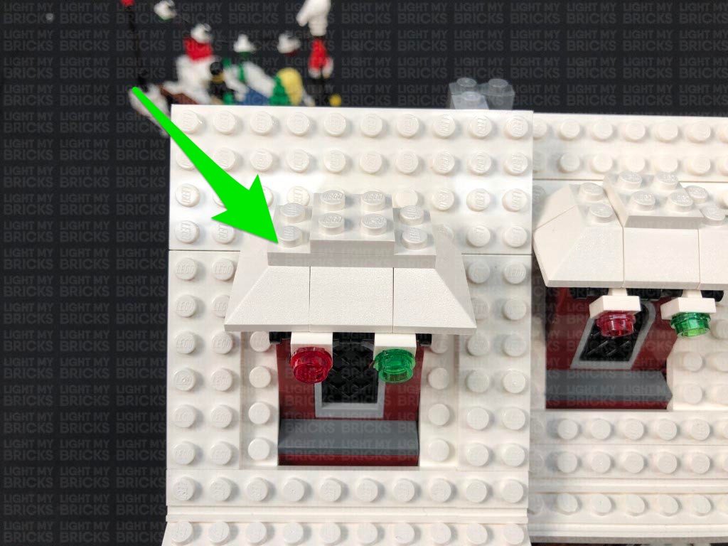
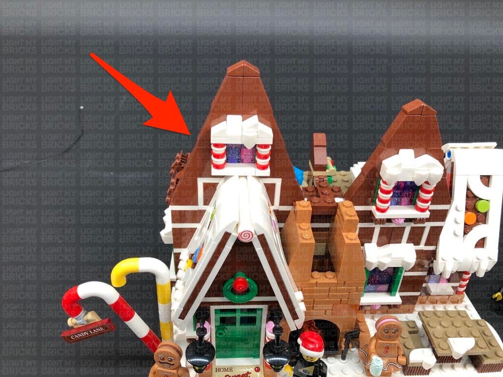
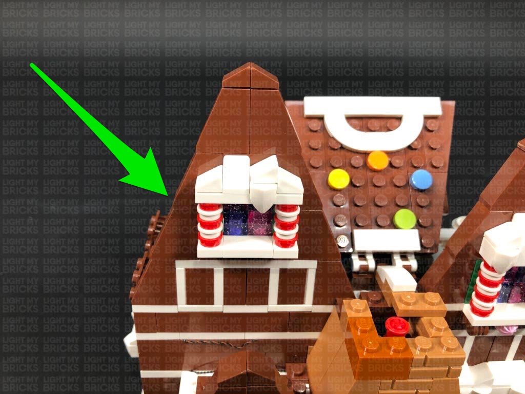
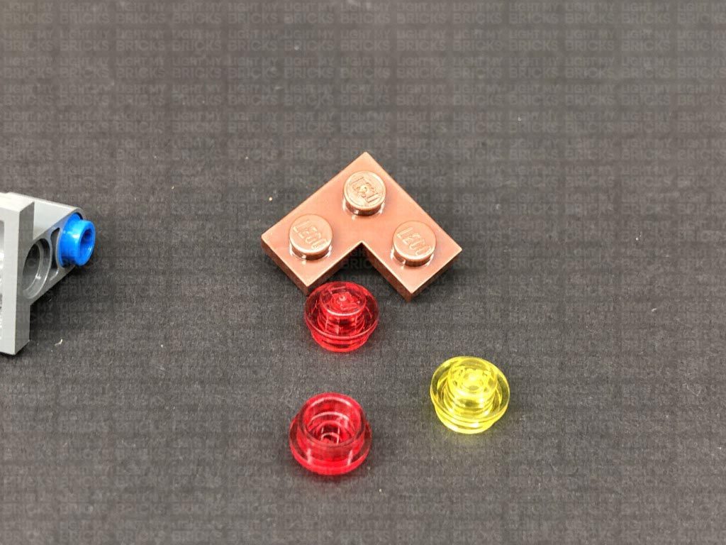
Remove all the light sections above both windows on the second floor, disconnecting them from the black plates with clips. Disconnect the red 1×4 plate behind them, then disconnect the trans coloured round plates from the white plates of the light sections as shown below.
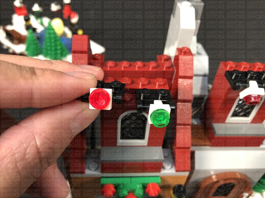
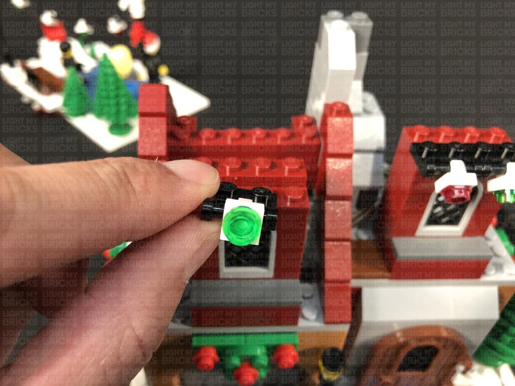
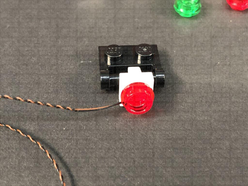
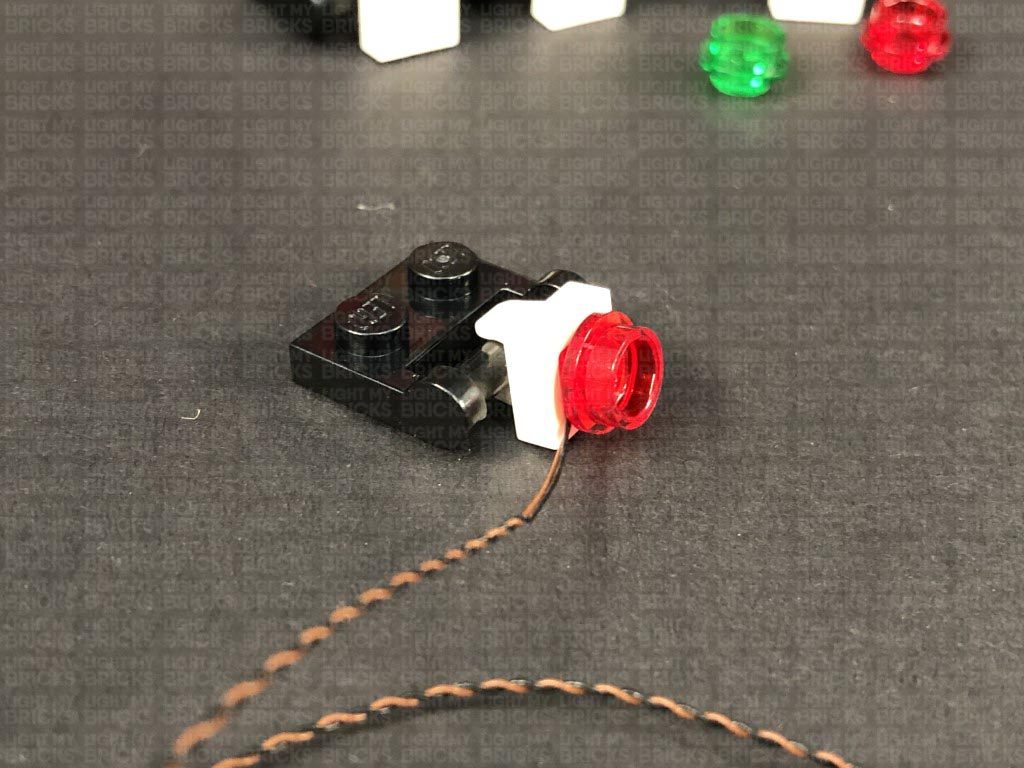
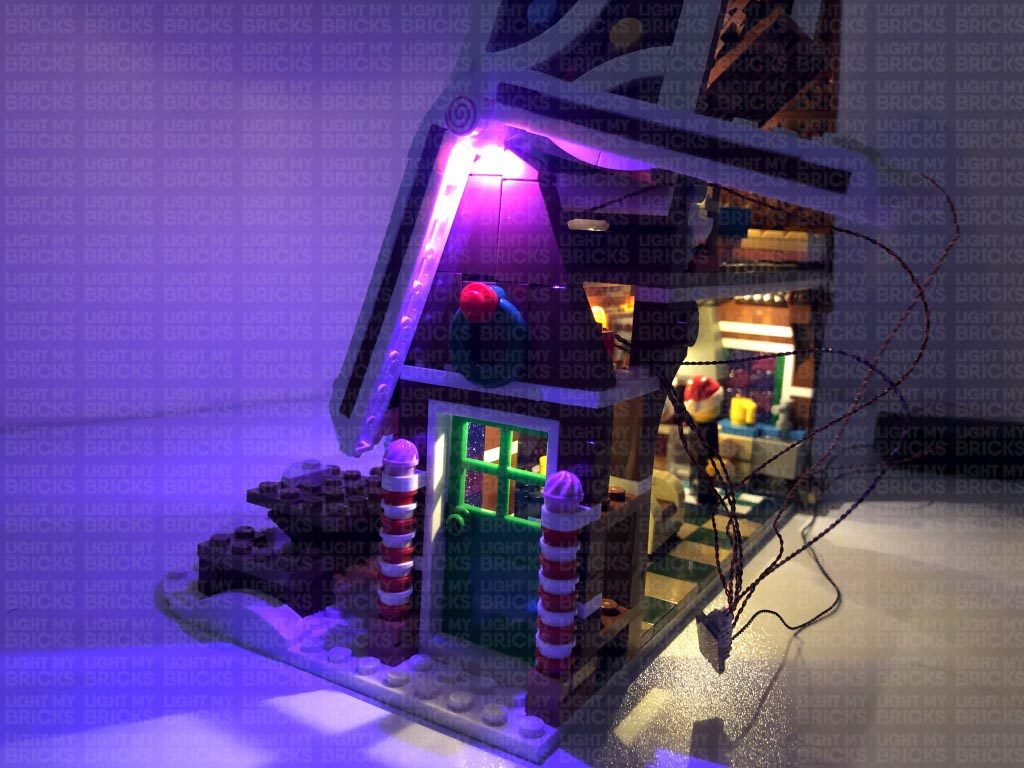
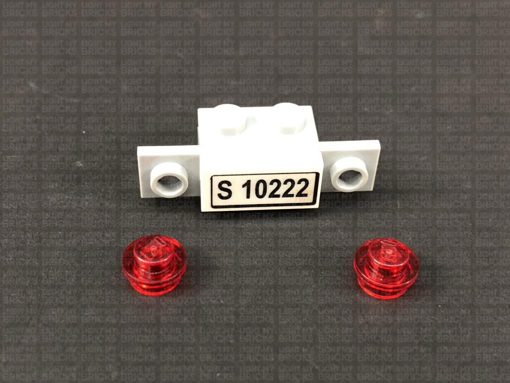
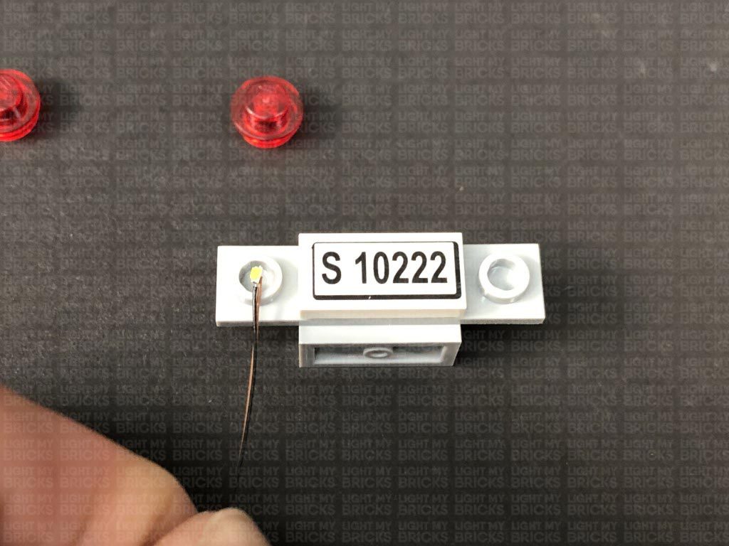
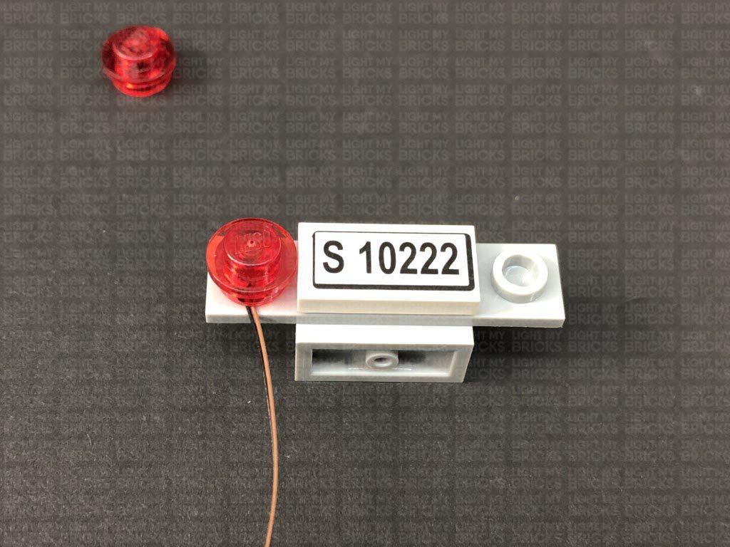
20.) Take a Flashing White 15cm Micro Bit Light and place the LED inside the white plate with clip. Secure the Bit Light in place by reconnecting one of the trans red round plates.
Remember – Do not forcefully connect the LEGO plate back inside the white plate. Because of the size of the micro LED, the plate will not fully connect inside. Forcing the plate to fully reconnect may cause the wire to break.
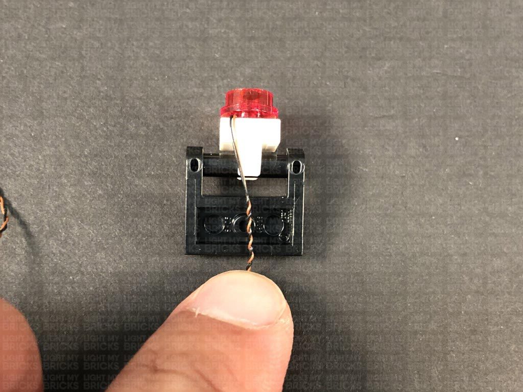
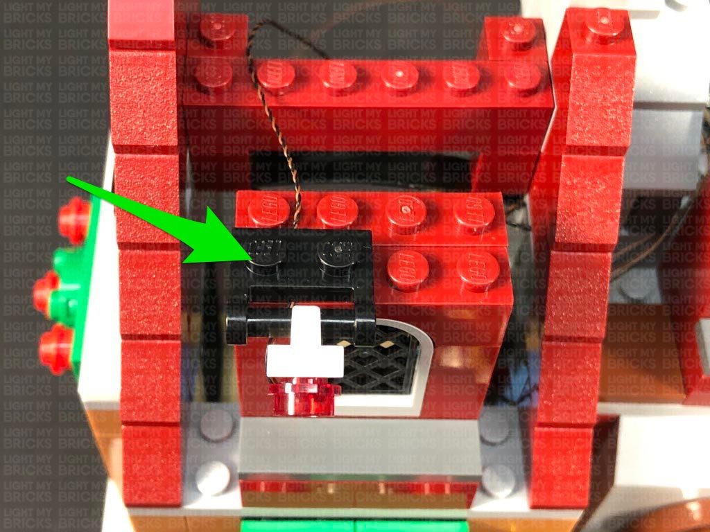
Lay the cable underneath the middle of the black plate, before reconnecting this section back to the top of the left window. Ensure the cable is laid in between studs underneath.
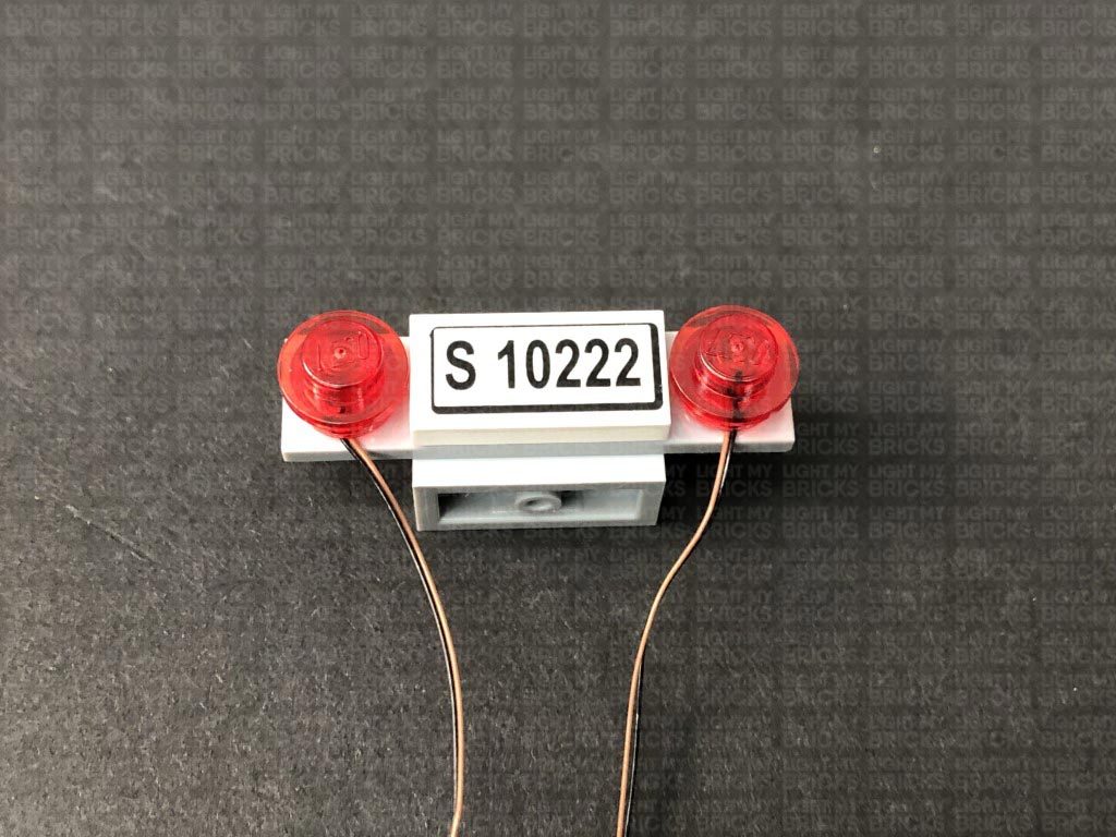
Install another Flashing White 15cm Micro Bit Light to the other light section, then reconnect it to the top of the left window.
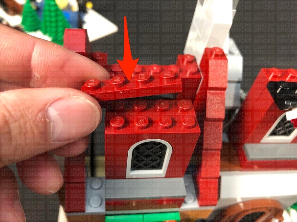
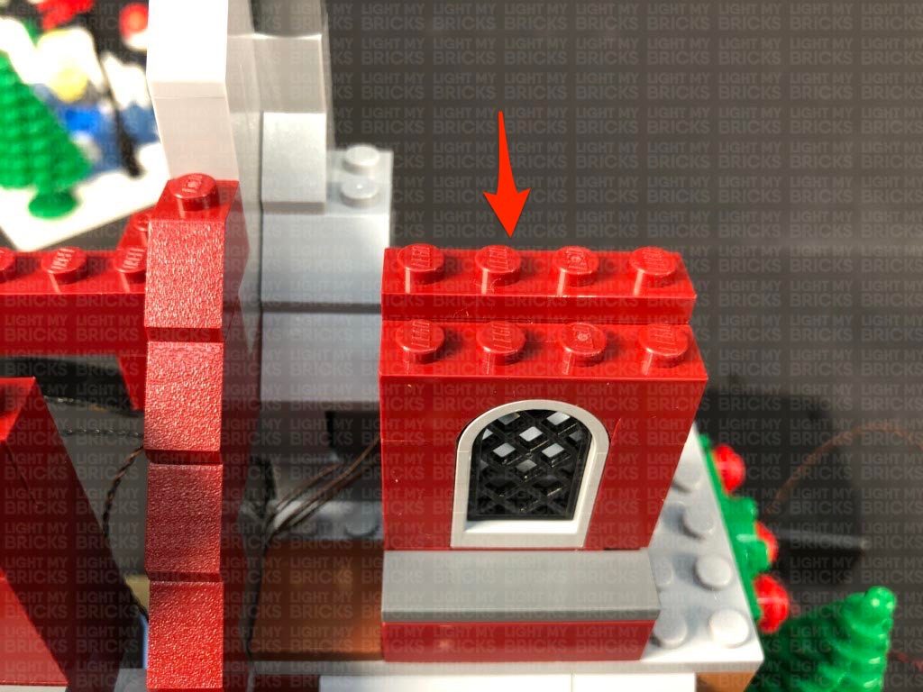
Ensuring both cables are laid in between studs, reconnect the red 1×4 plate behind, then bring both cables across to the right side and secure them down underneath the following angled red brick.
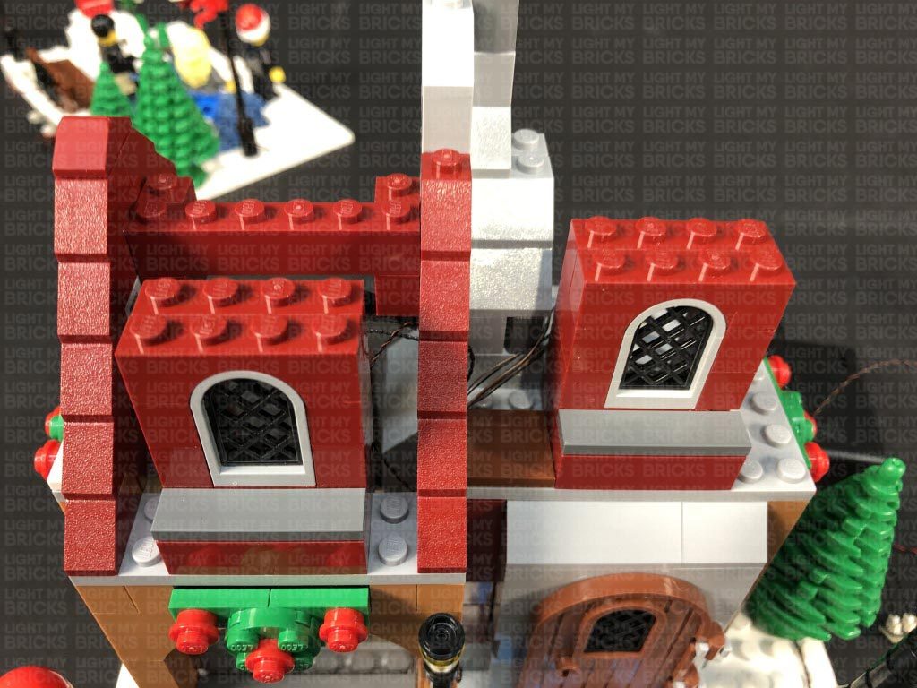
21.) Repeat the previous step to install another 2x Flashing White 15cm Micro Bit Lights to the remaining light sections, then reconnect them above the right window. Ensuring the cables are laid in between studs, reconnect the red 1×4 plate behind.
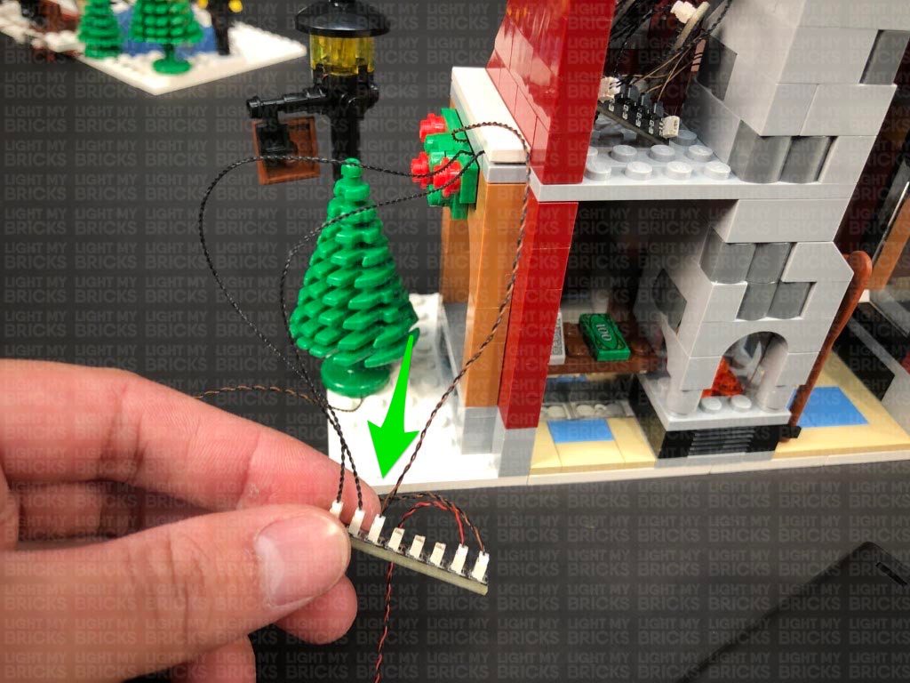
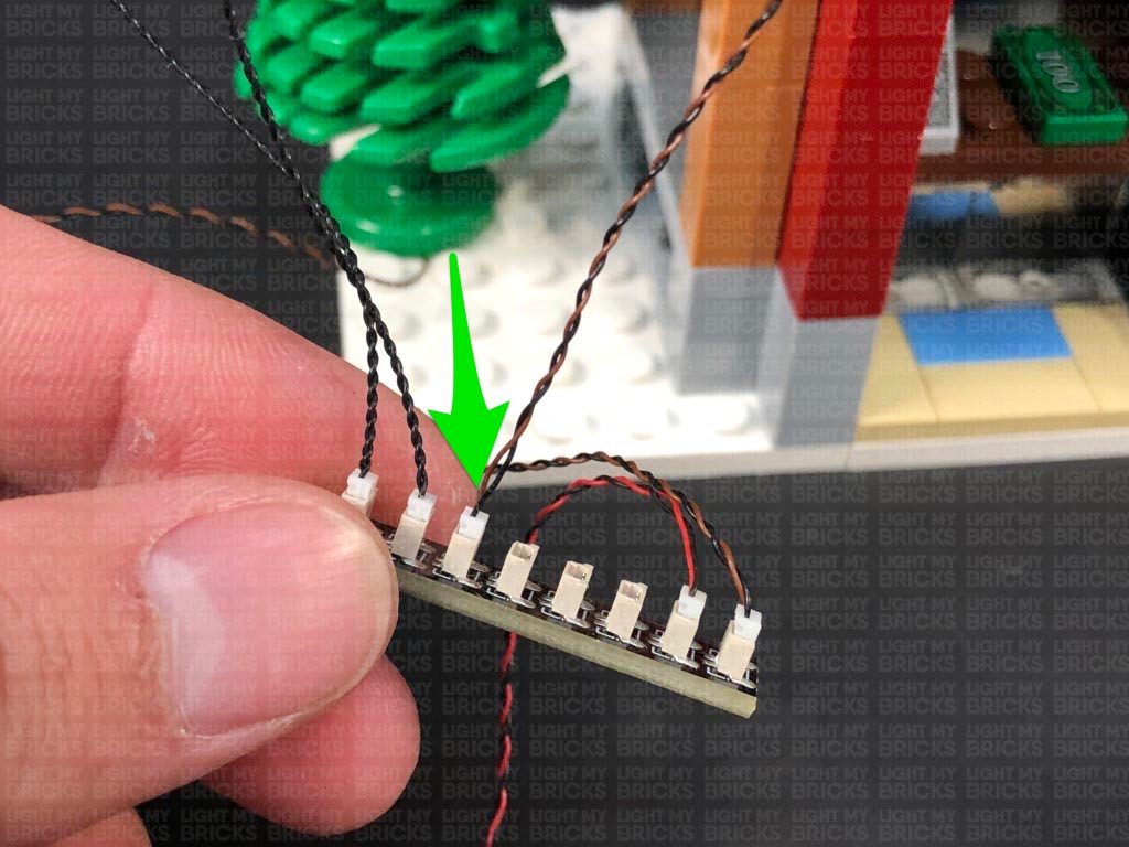
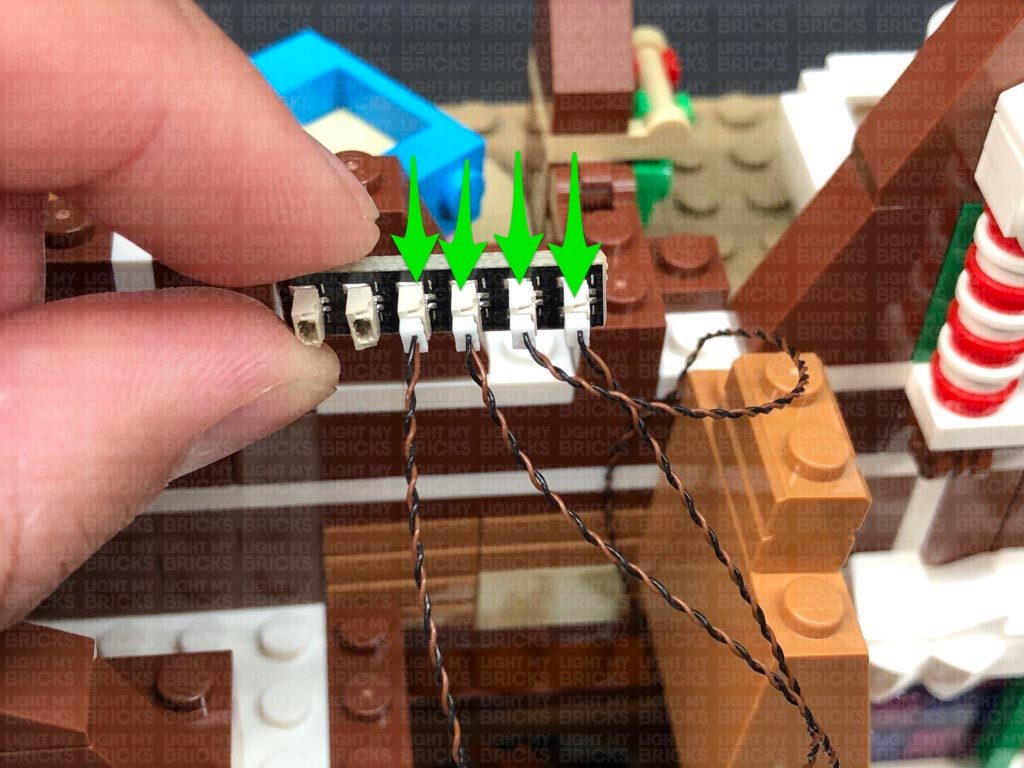
Turn the set around to the back and connect all four flashing micro bit lights to the Micro 4-Port Expansion Board (one with nothing connected to it). Turn ON the Battery Pack to test the flashing lights above the windows are working OK.
22.) Neaten up all the excess cabling from the Flashing lights by twisting and folding them altogether into a neat bunch. Group all the components on the second floor together, then lay the 15cm Connecting Cable in between studs on the left side. Secure the cable down by reconnecting the white tile and the left wall section we removed earlier.
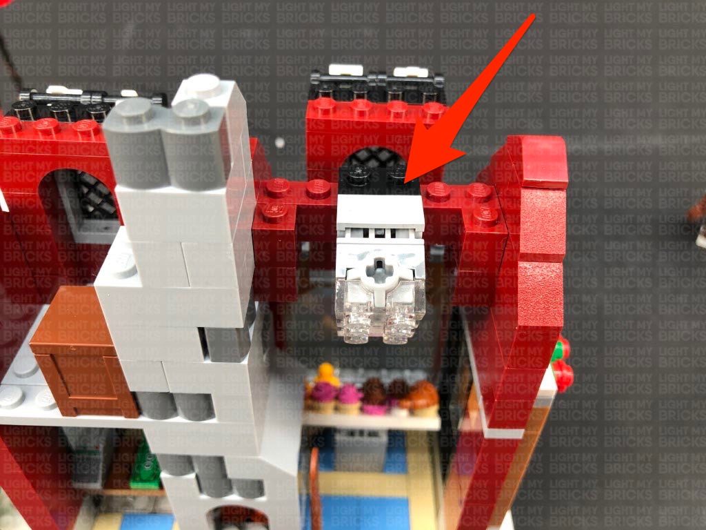
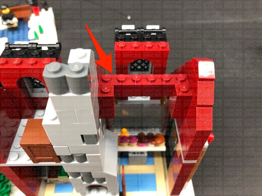
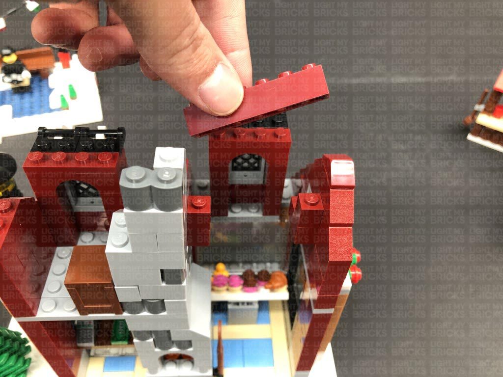
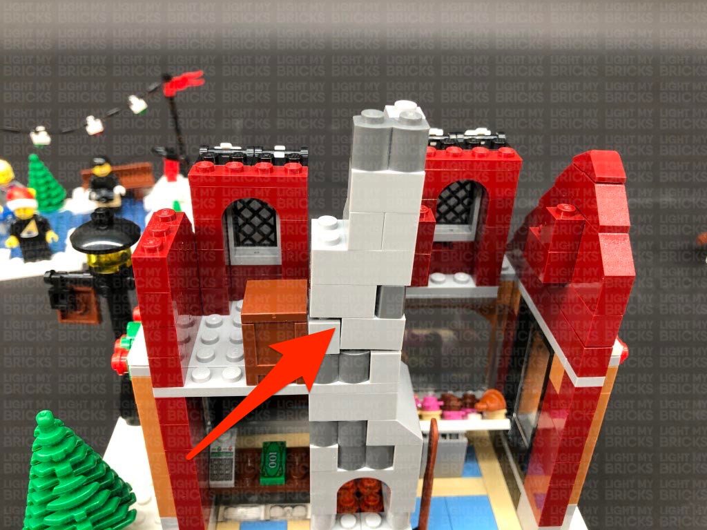
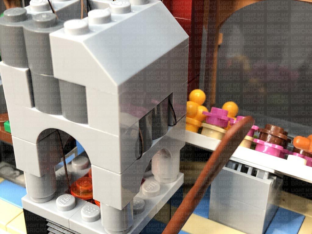
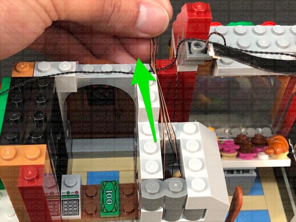
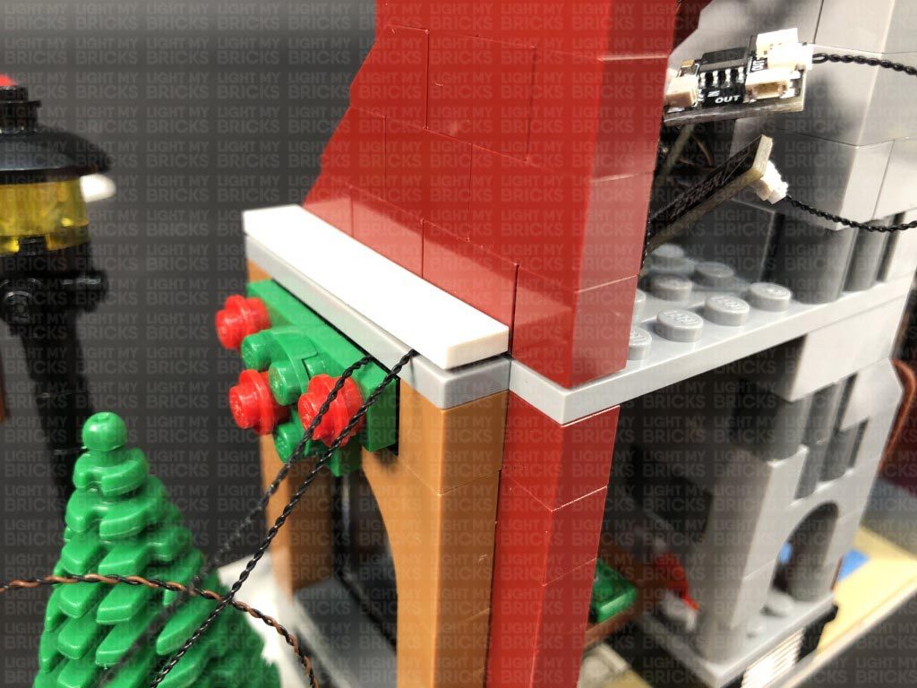
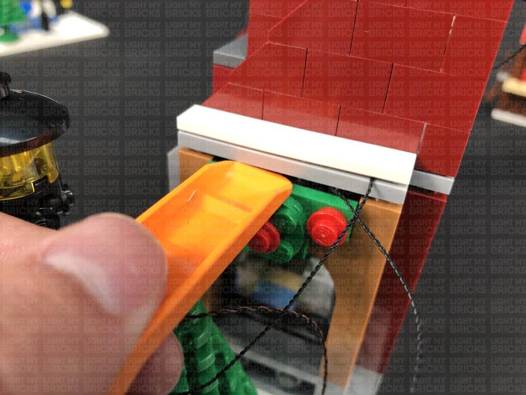
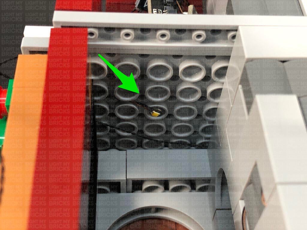
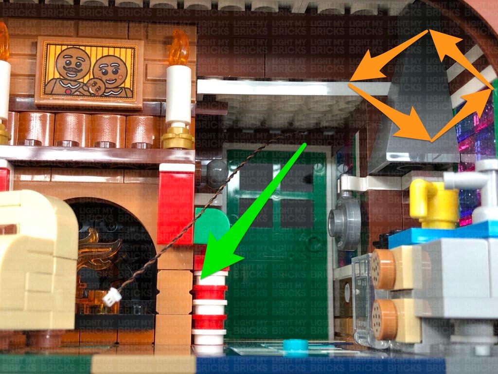
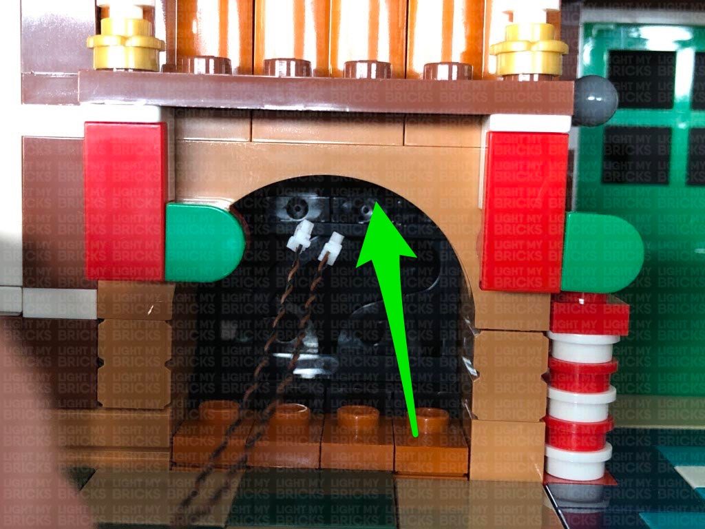
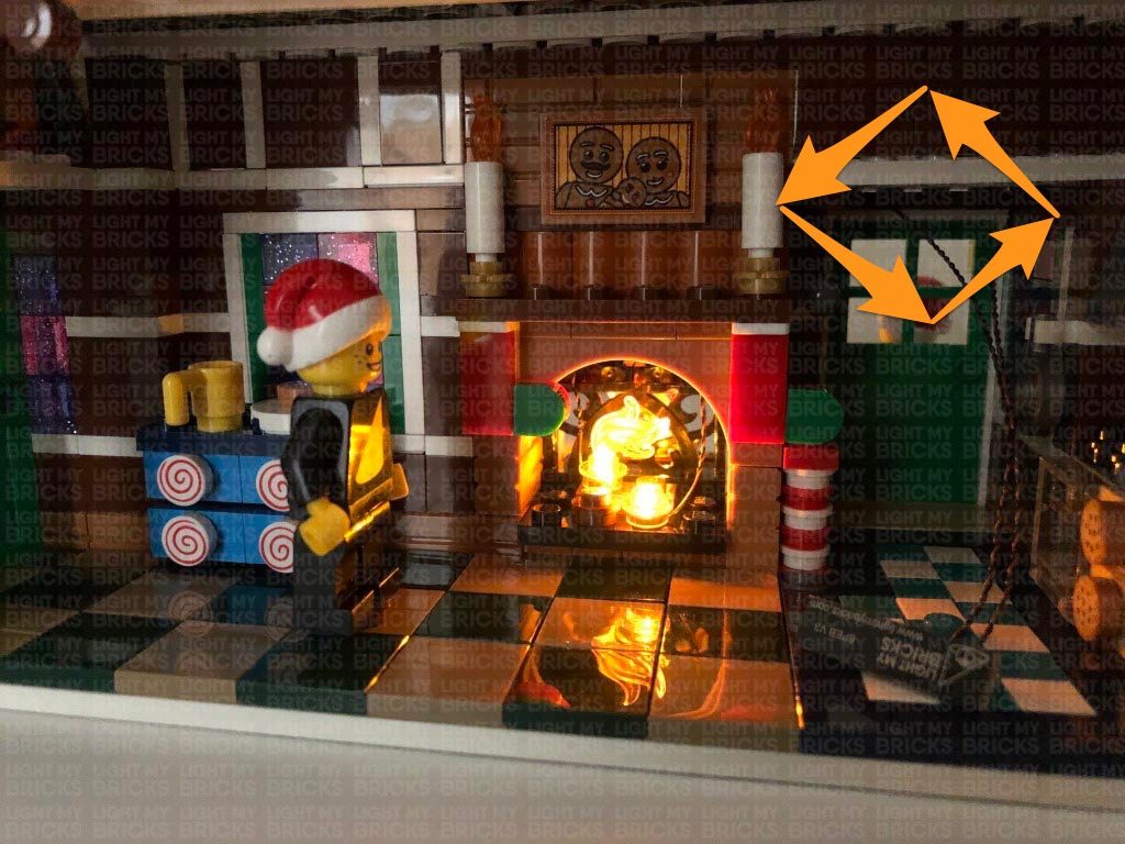
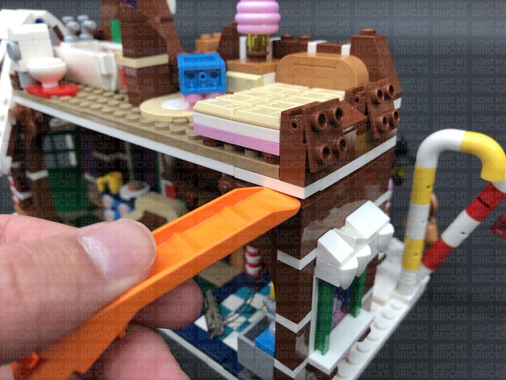
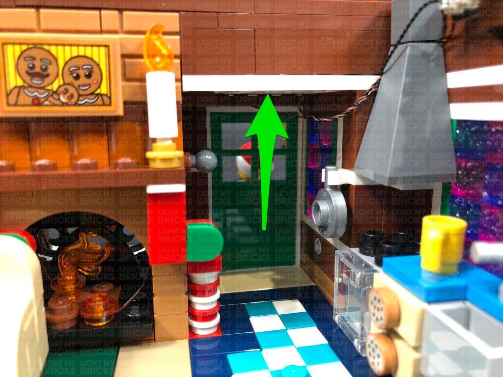
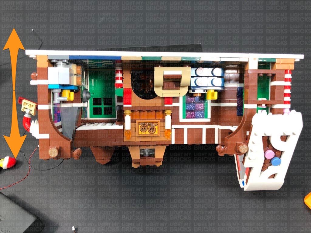
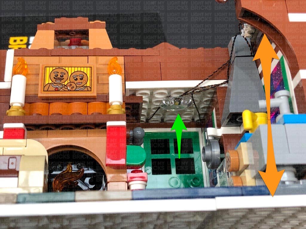
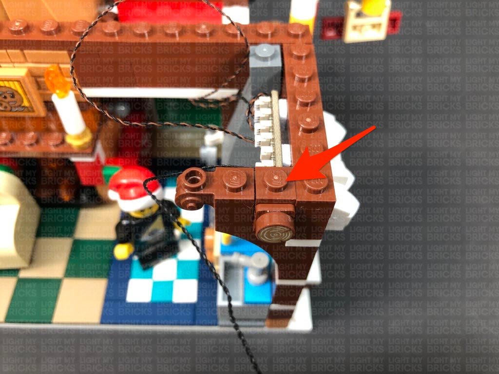
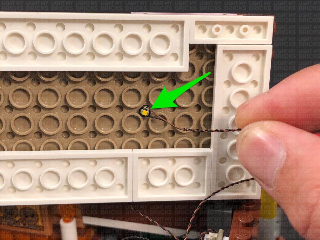
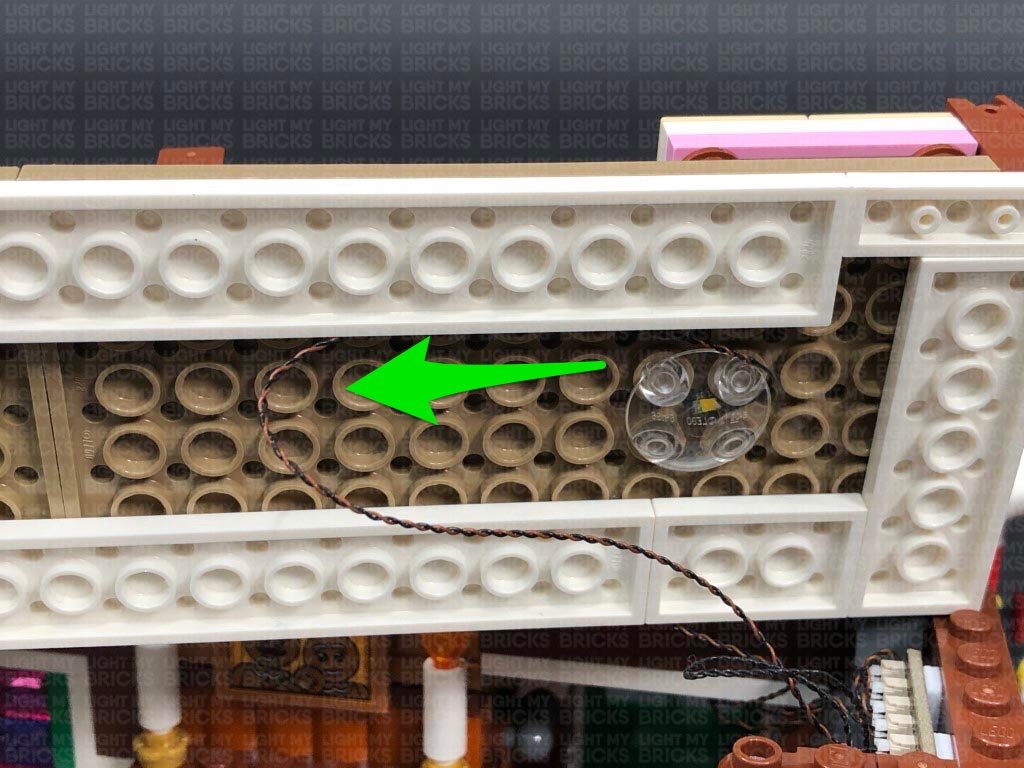
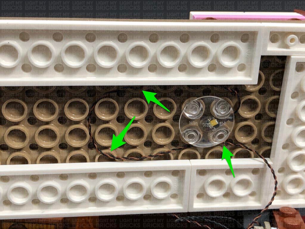
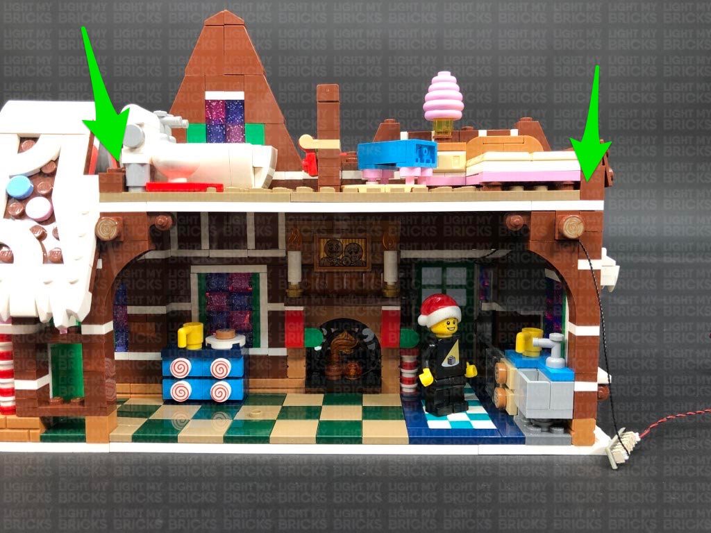
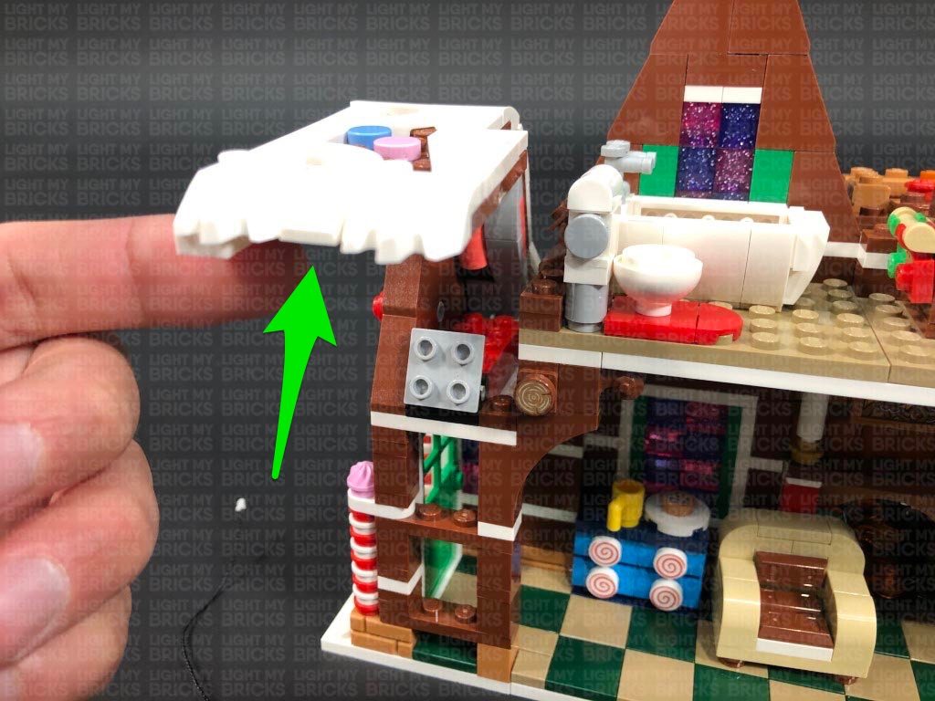
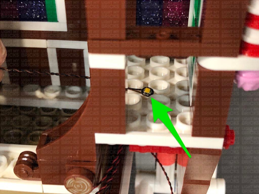
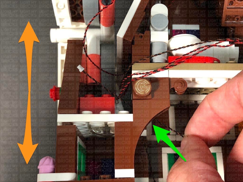
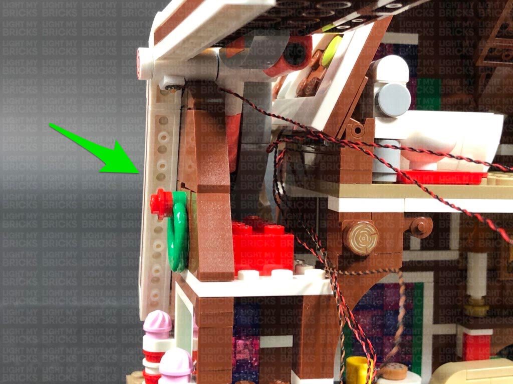
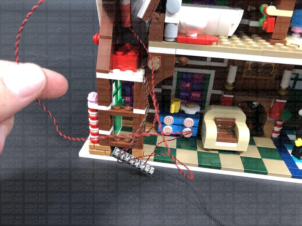
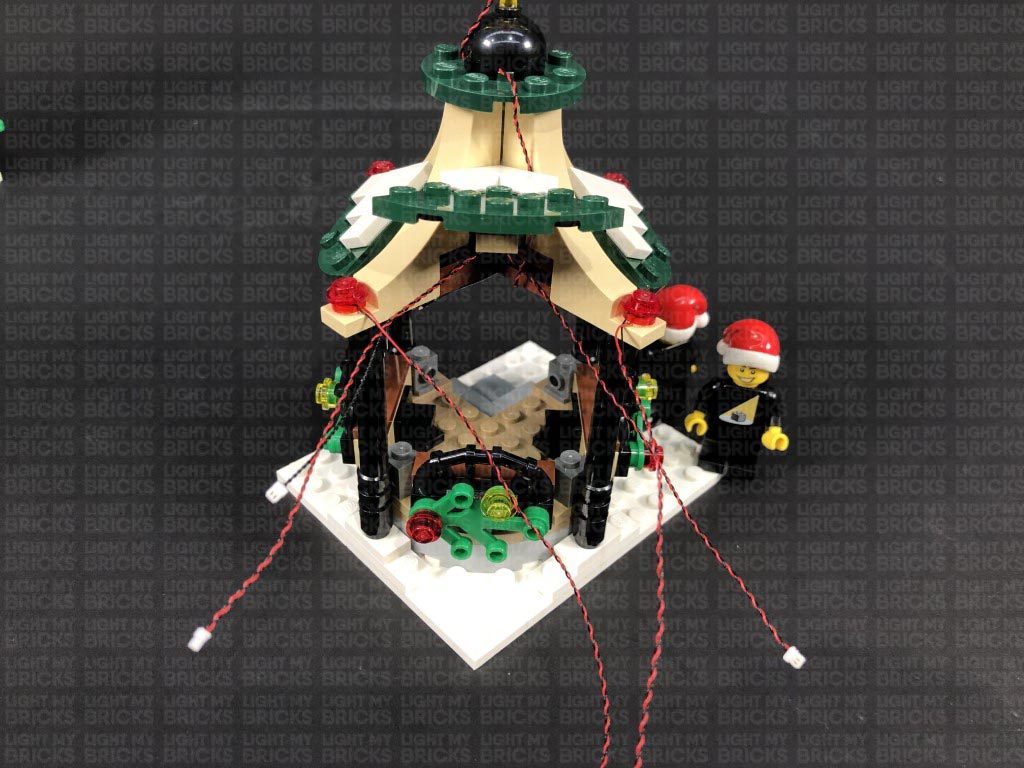
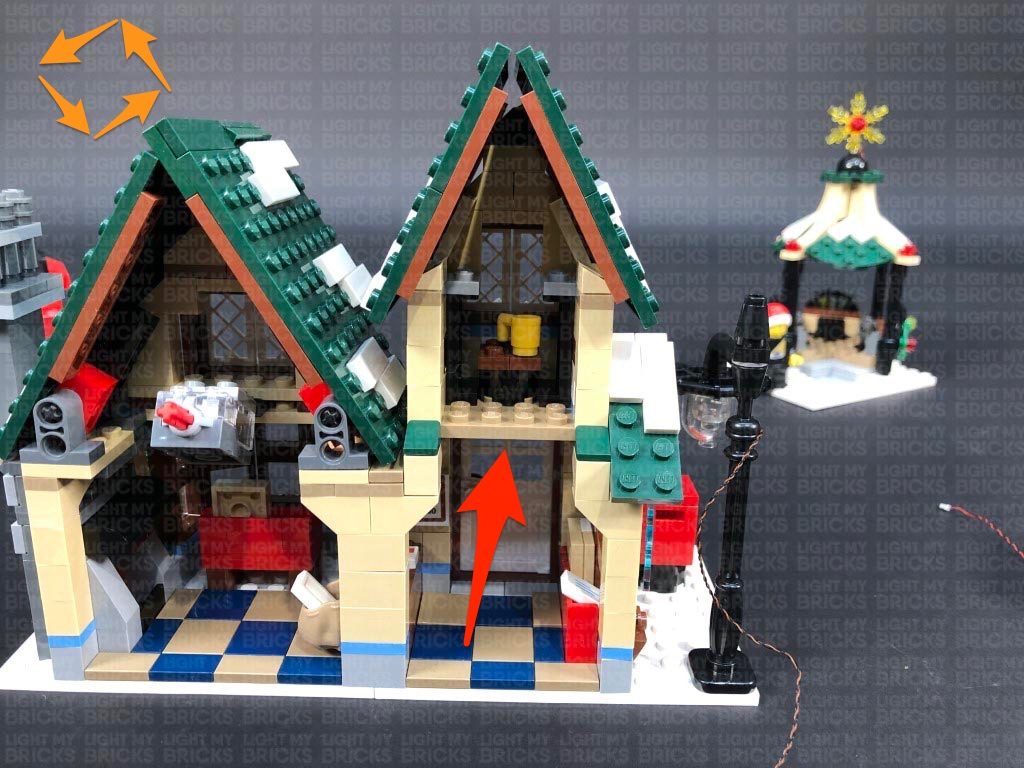
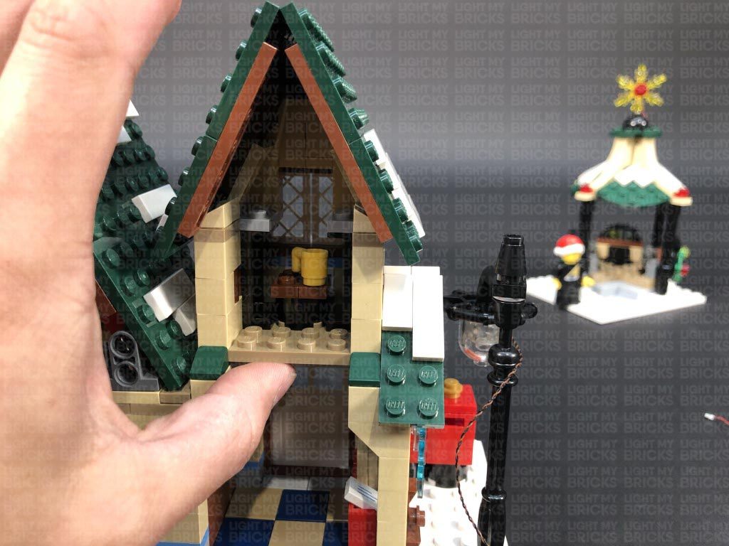
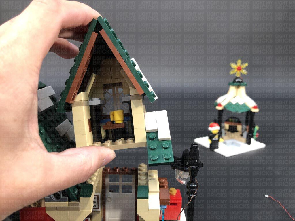
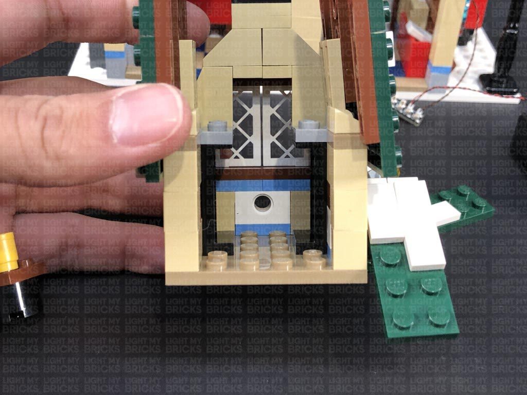
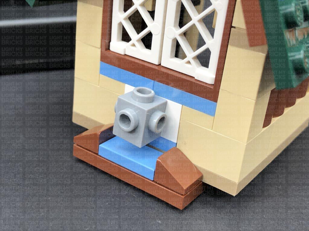
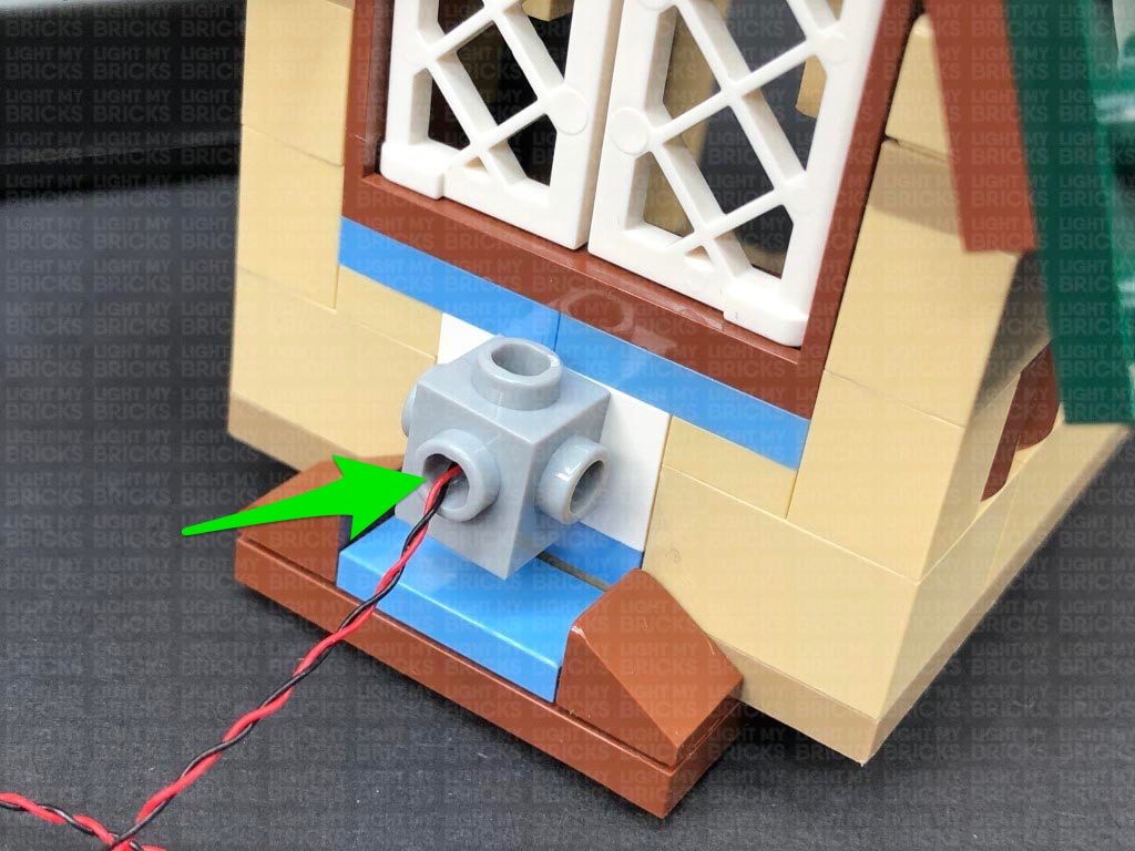
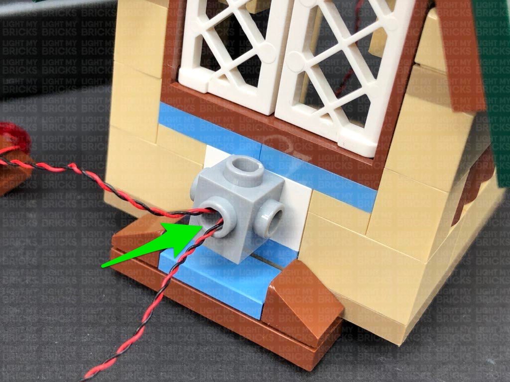
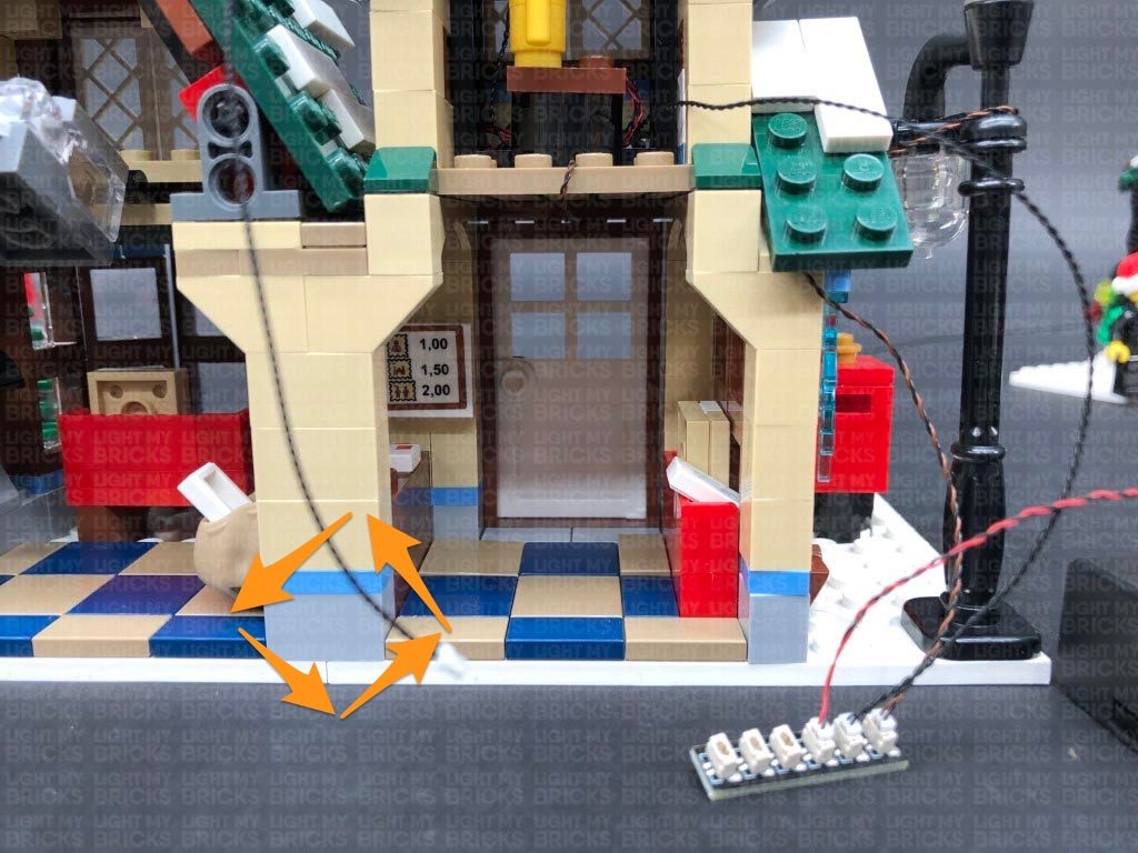
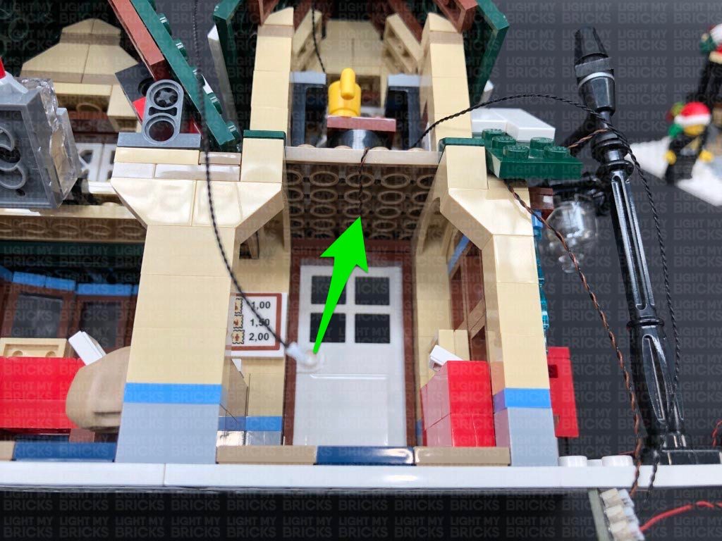
23.) We will now install a light to the bottom section of the bakery. Turn the set around to the side, and use your LEGO removal tool to create a gap just underneath the light grey plate above the side window.
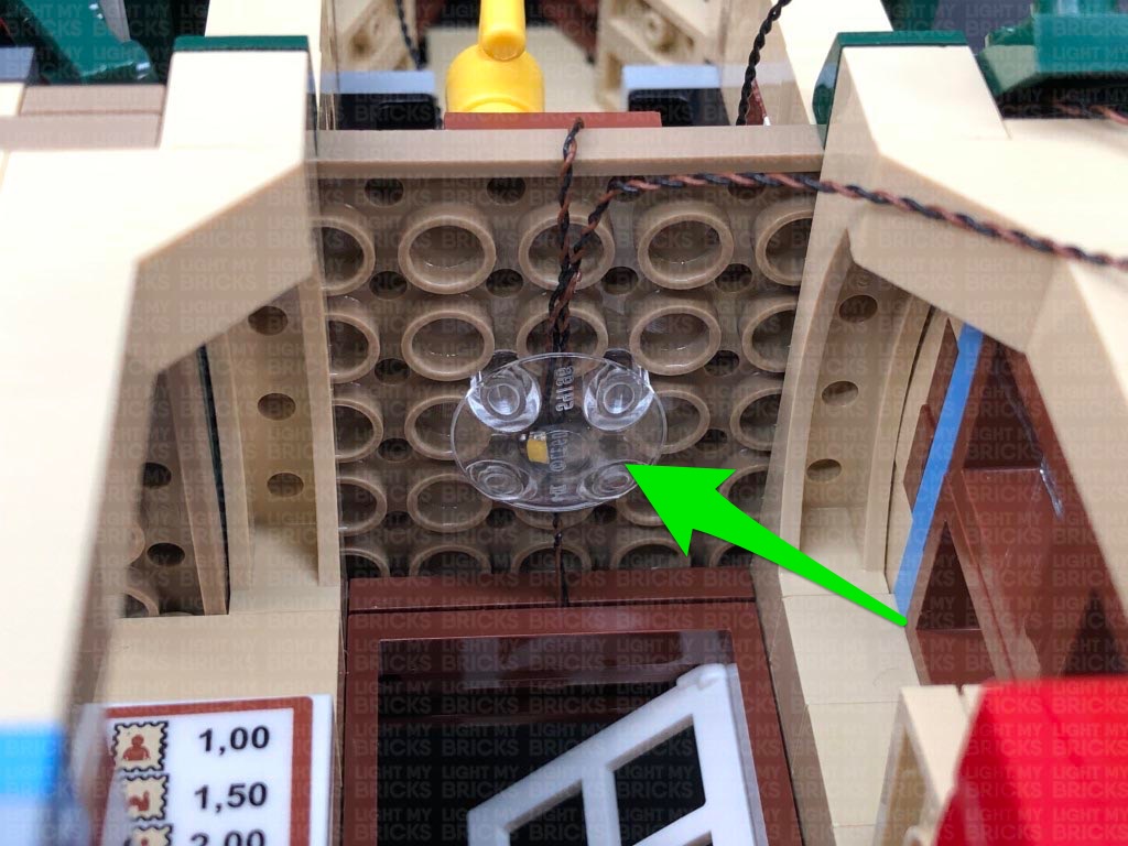
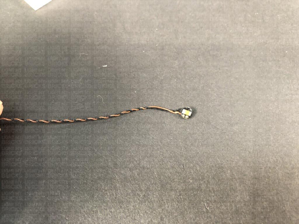
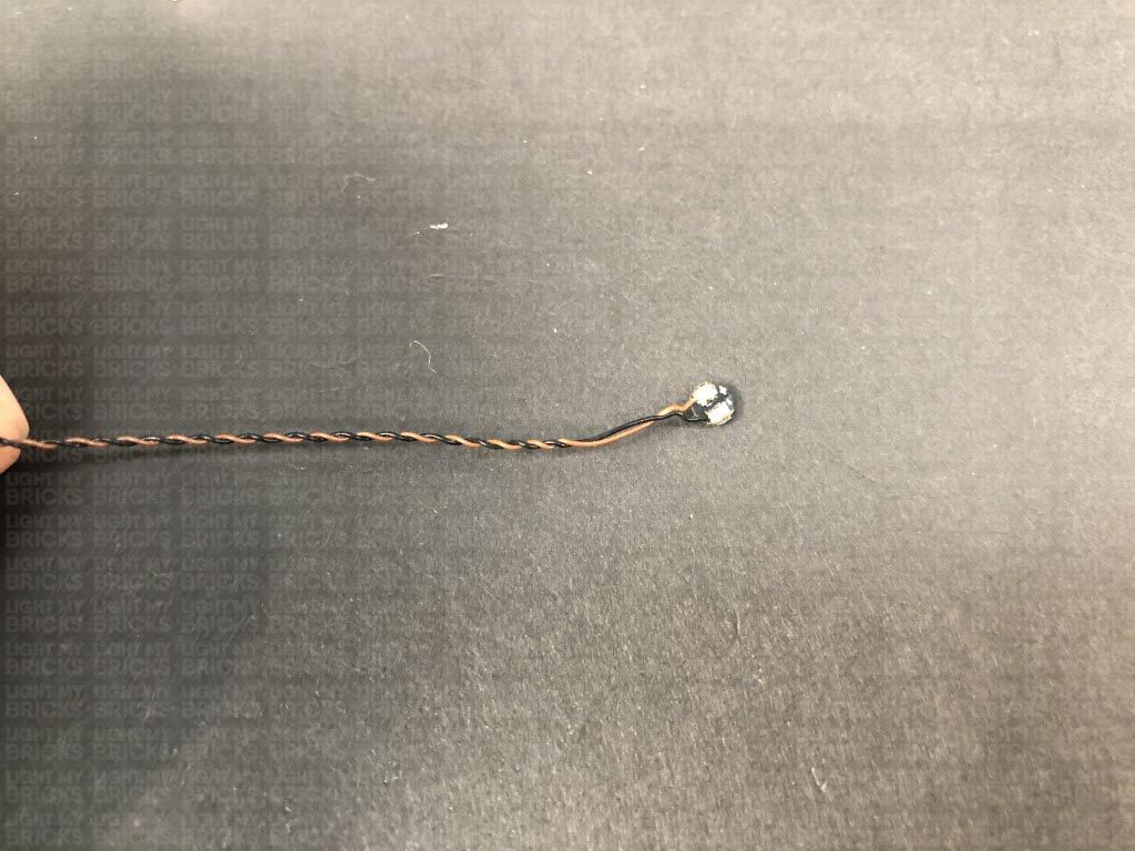
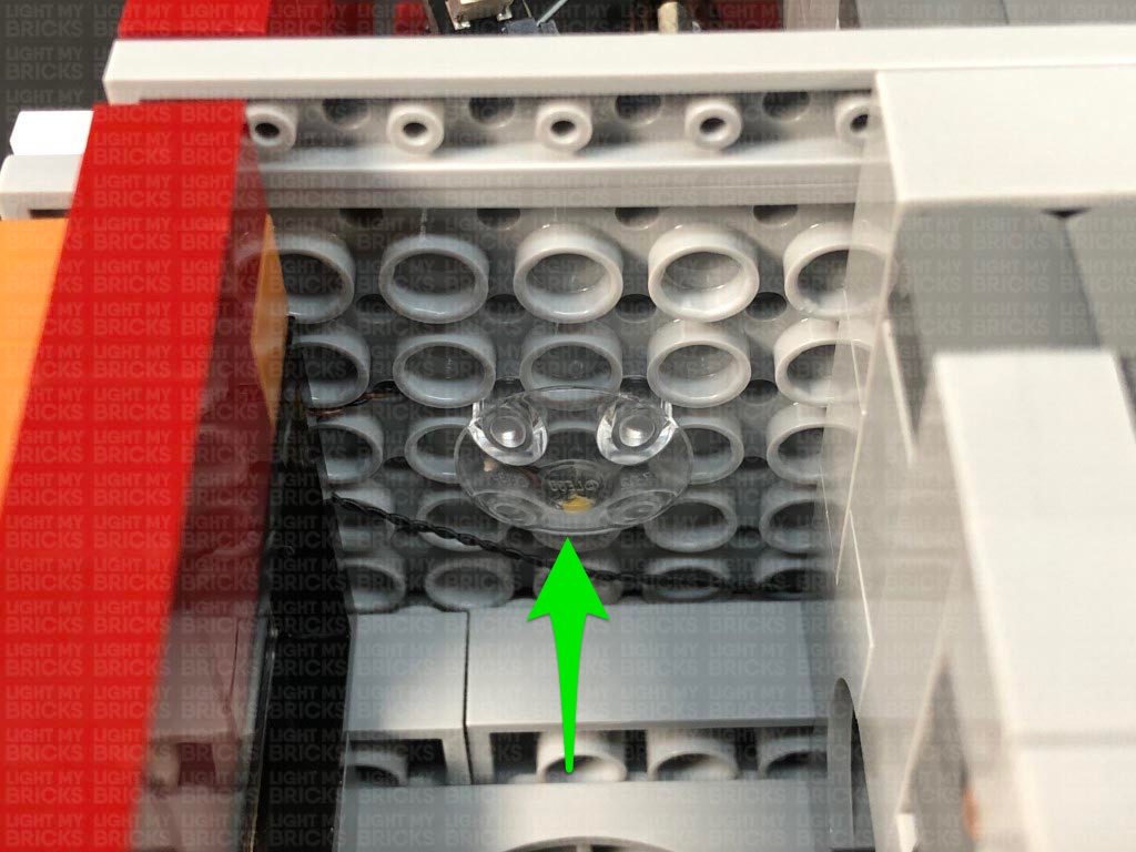
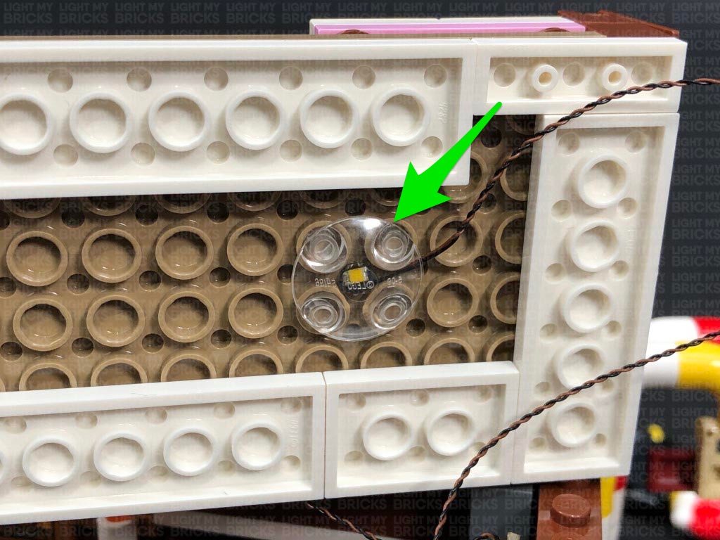
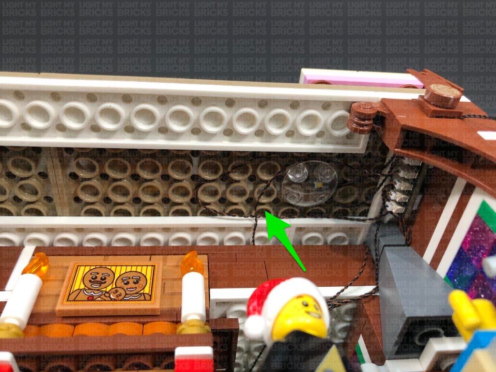
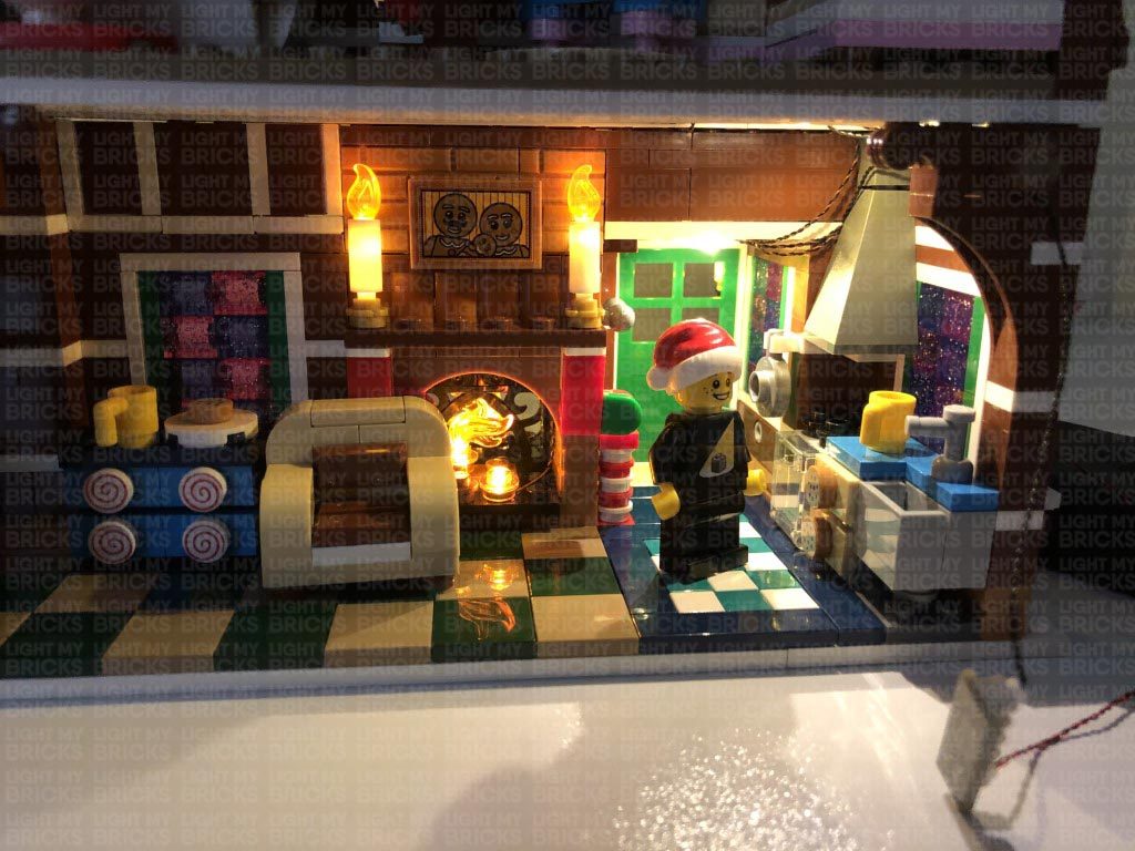
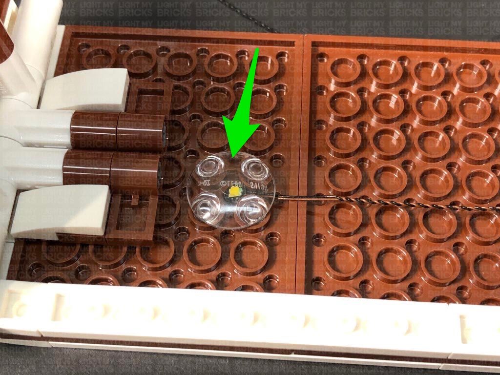
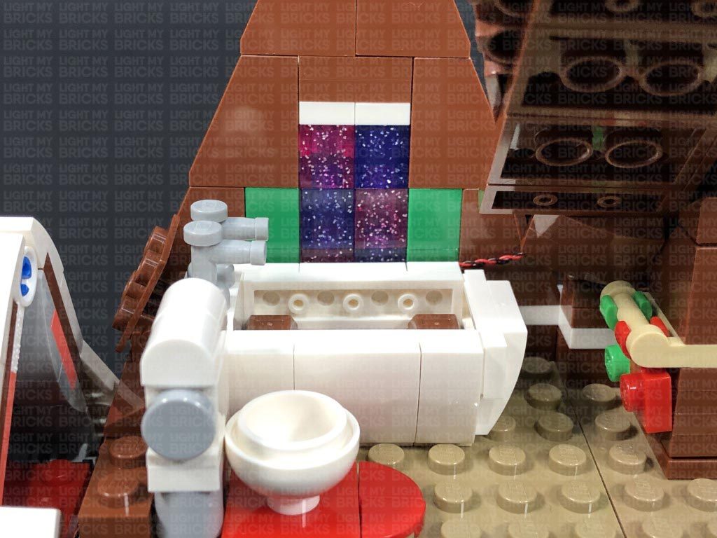
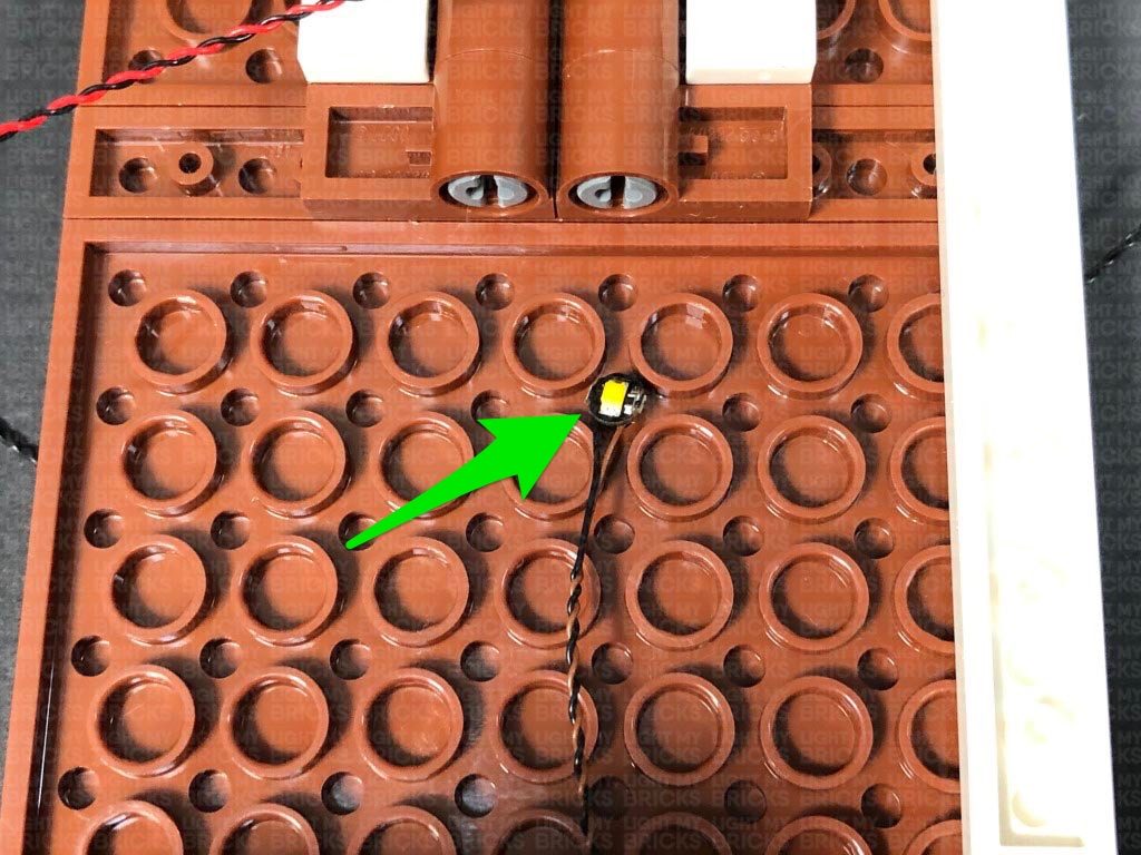
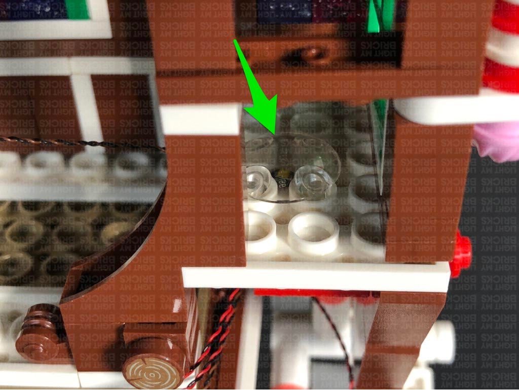
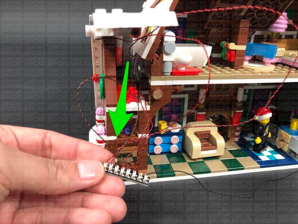
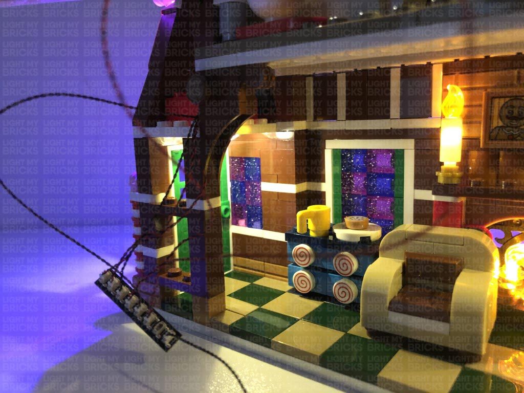
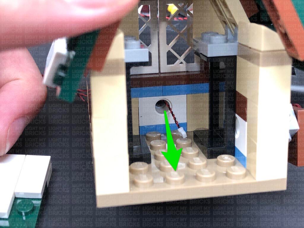
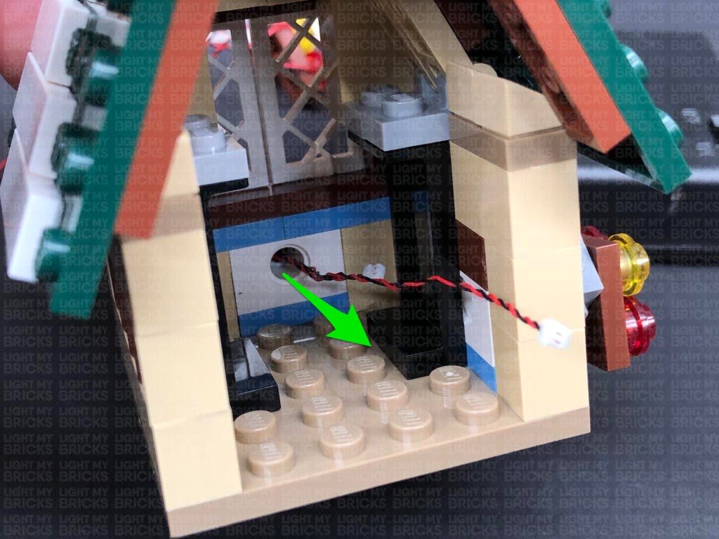
Take a White 15cm Bit Light and turn it over so that the LED is facing down, then thread the Bit Light through the gap we just created. Position the LED in the centre underneath the second floor, then secure it in place by connecting a provided LEGO Trans Clear Plate w Rounded Bottom 2×2 over it.The LED should be facing down and positioned in the middle of the trans clear plate.
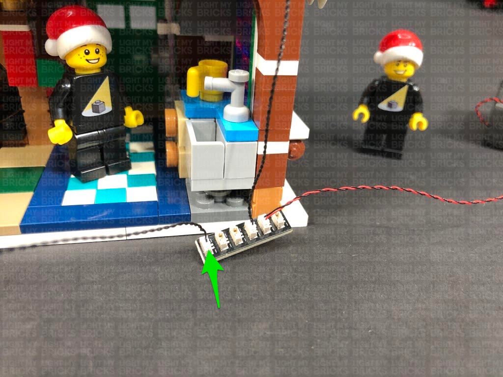
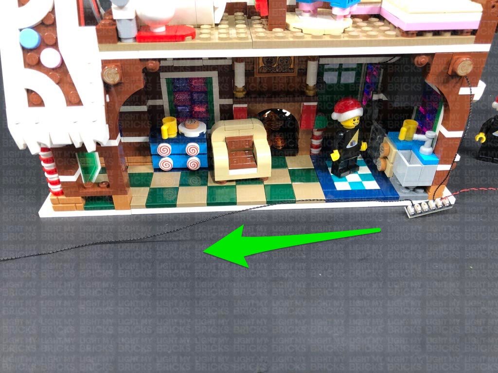
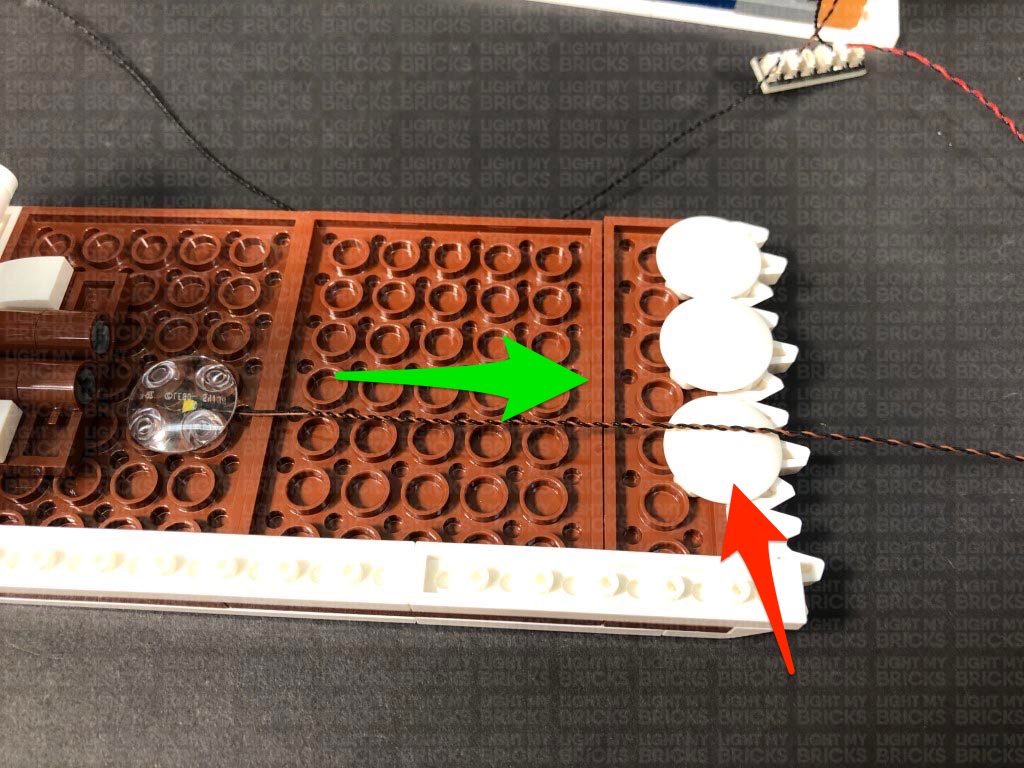
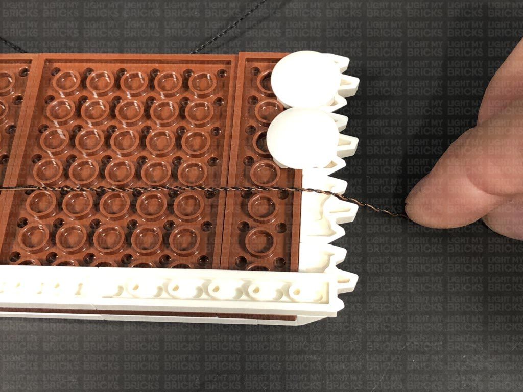
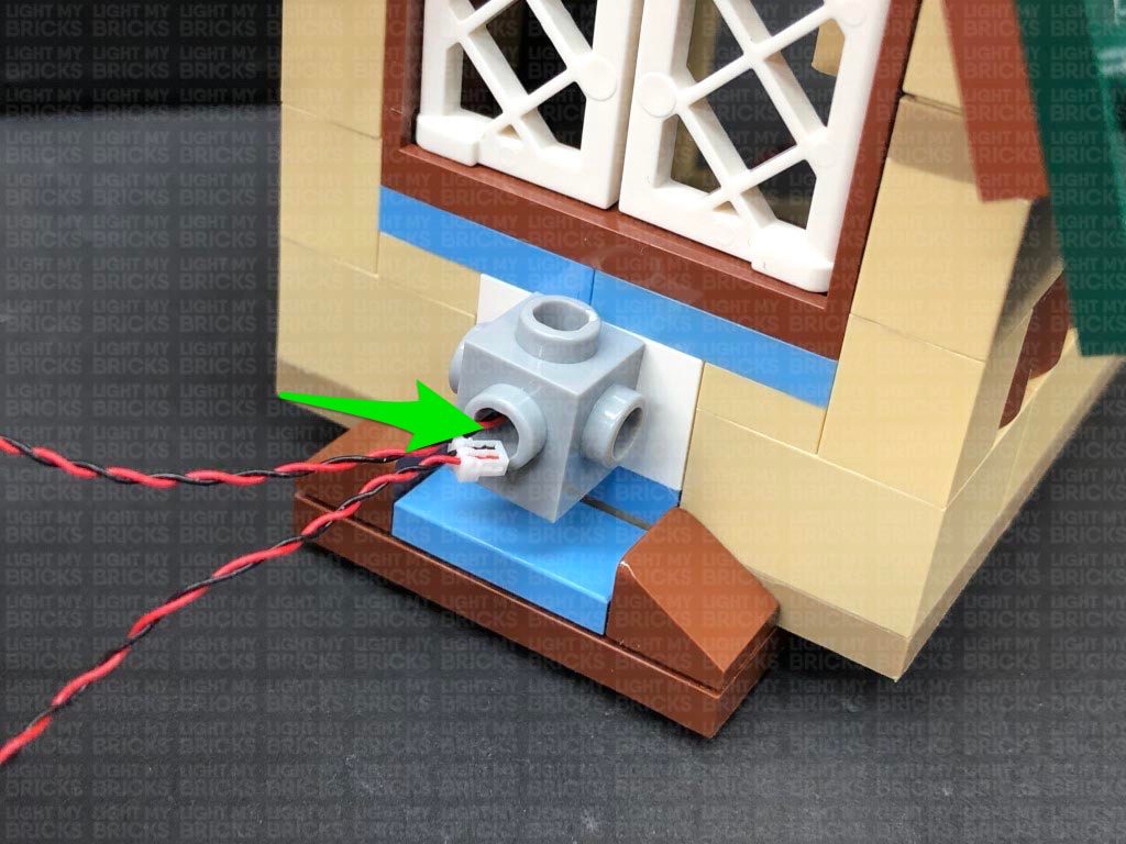
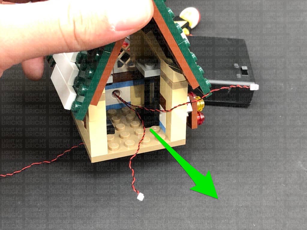
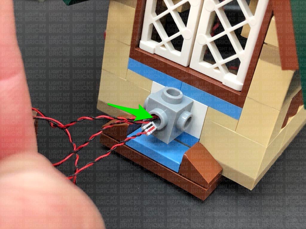
Close up the gap we created, ensuring the Bit Light cable is laid in between studs, then connect the Bit Light to a spare port on the 8-Port Expansion Board at the bottom of the set. Turn ON the Battery Pack to test the internal light is working OK.
Note: If you experience any issues with the lights not working and suspect an issue with a component, please try a different port on the expansion board to verify where the fault lies (with the light or expansion board). To correct any issues with expansion board ports, please view the section addressing expansion board issues on our online troubleshooting guide.
24.) Turn the set around to the front, then starting from the right side, reconnect the roof sections as well as the sections that connect on top of the windows.
Turn the set around and reconnect the top of the chimney, then reconnect the crate to the second floor ensuring the components are nicely tucked in and hidden behind it.
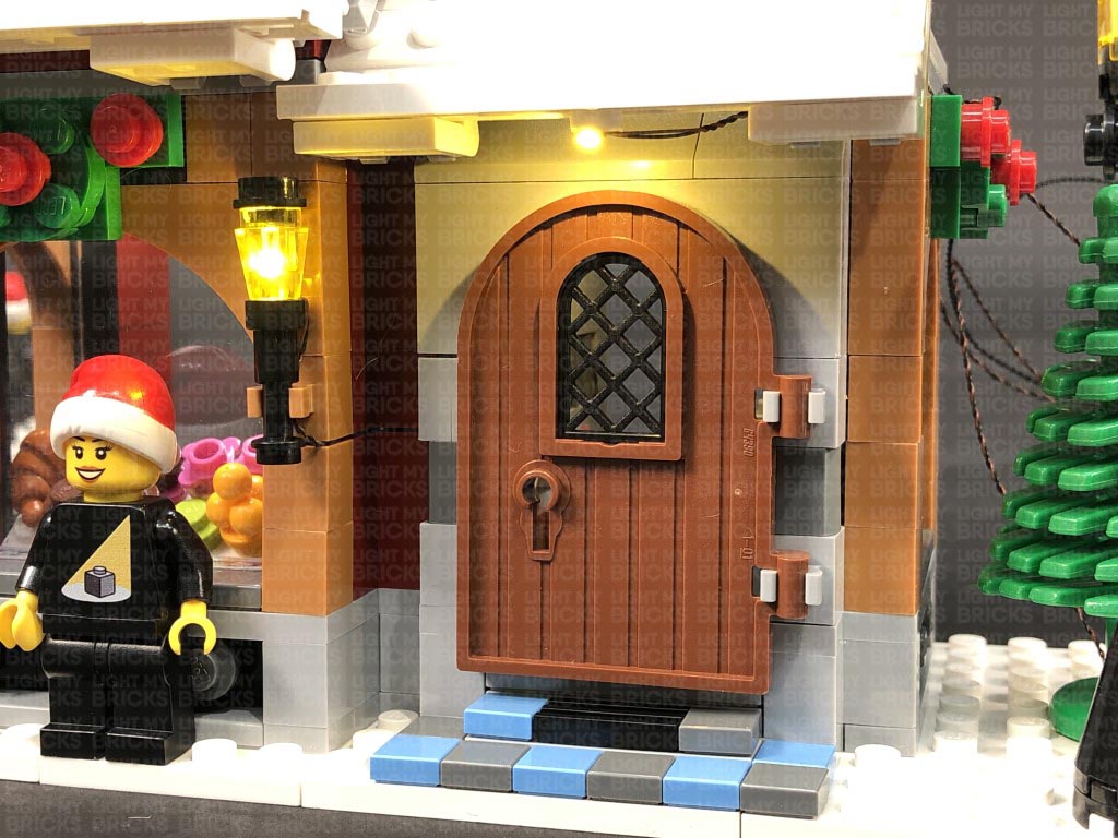
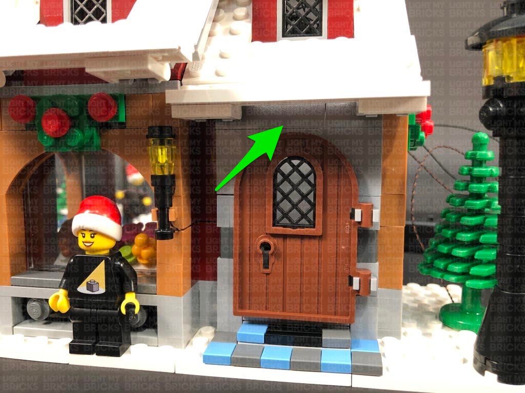
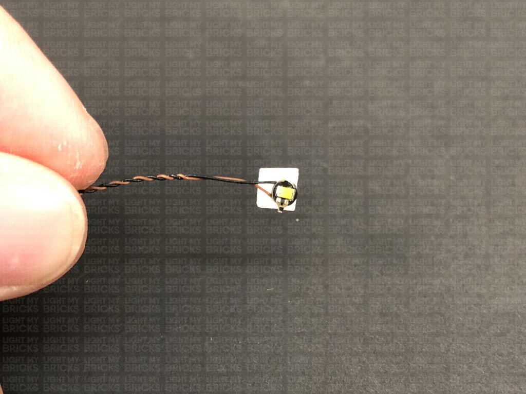
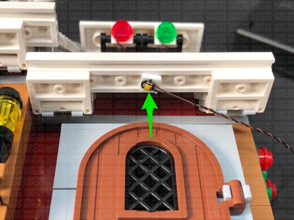
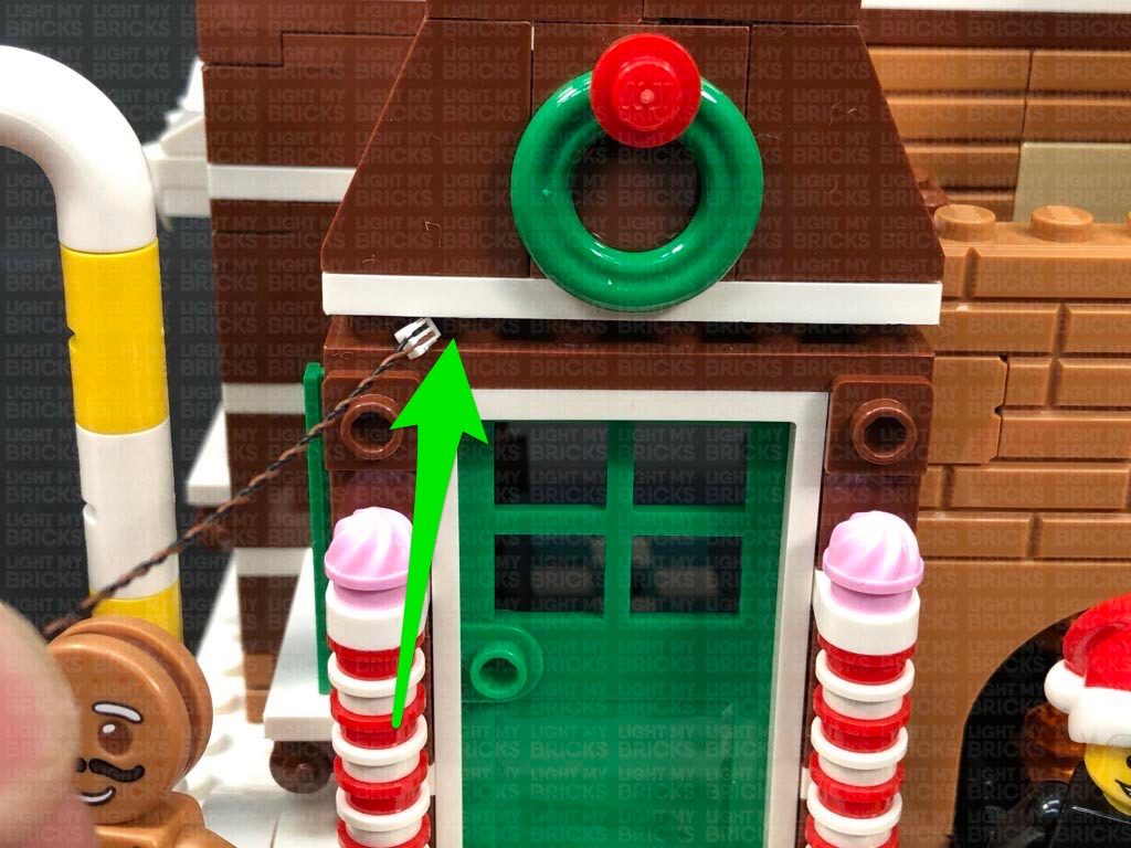
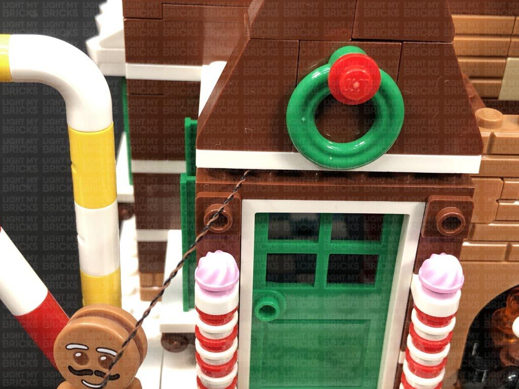
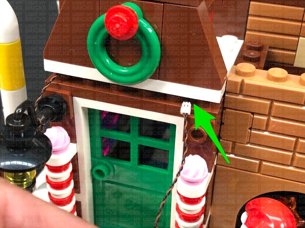
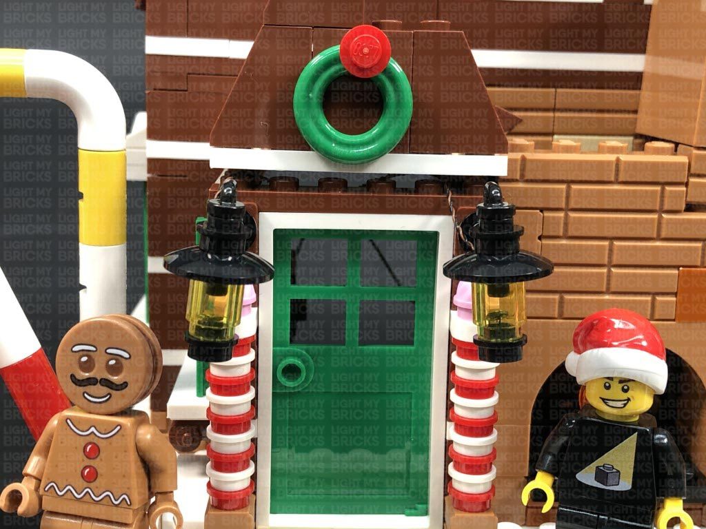
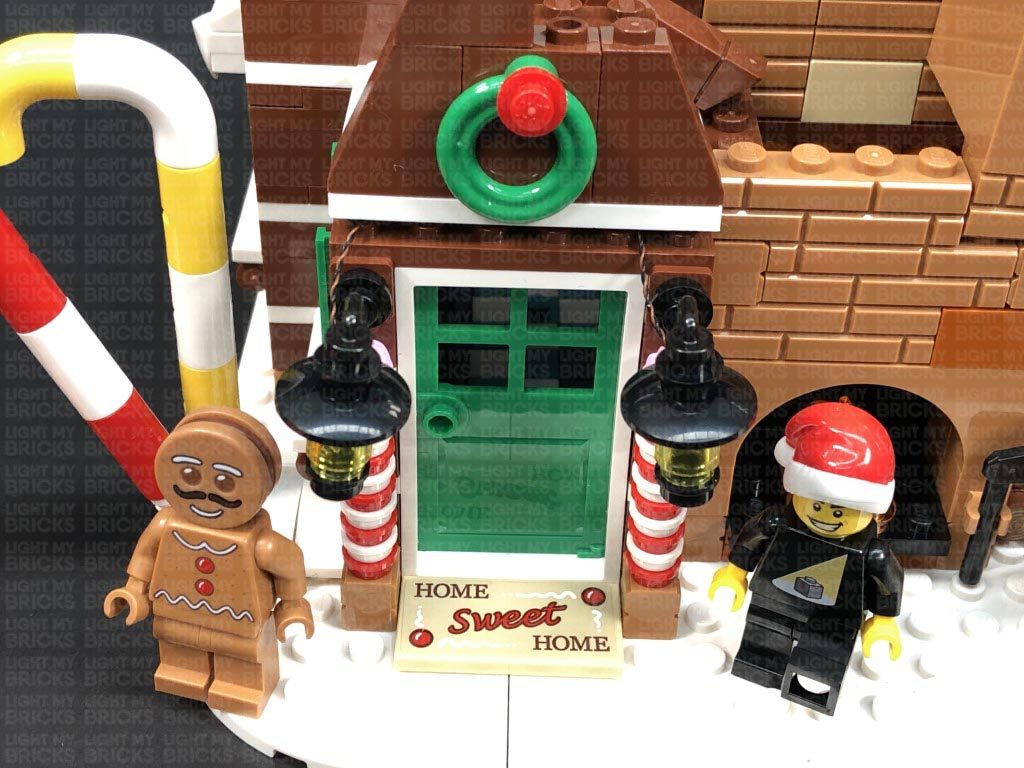
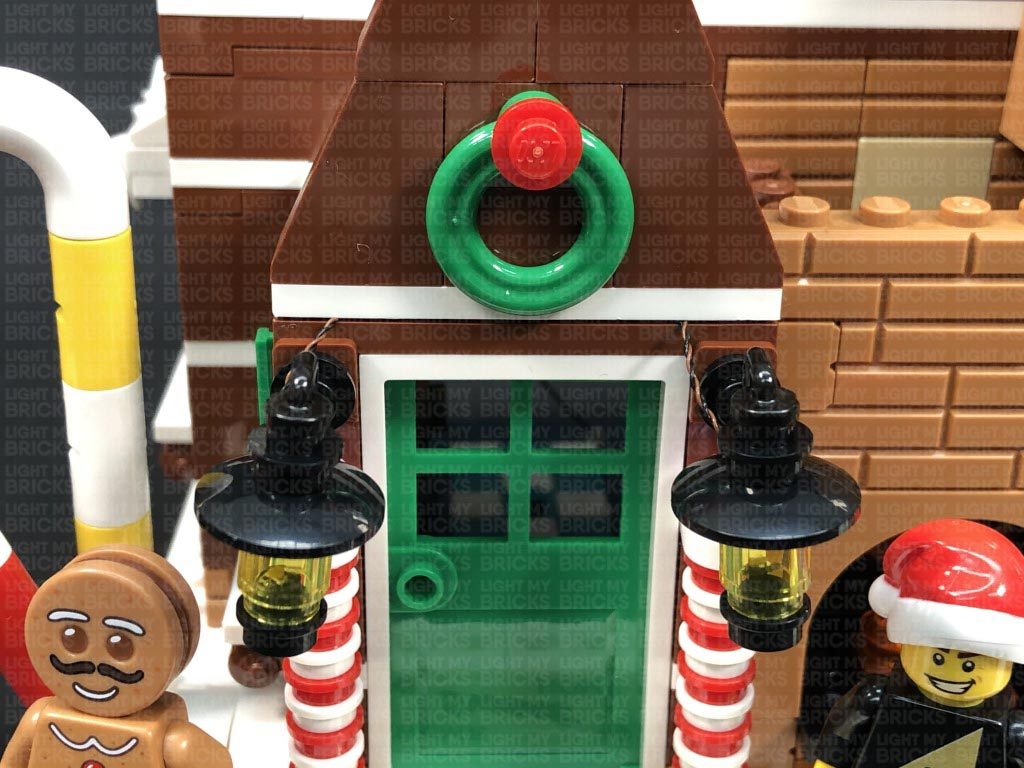
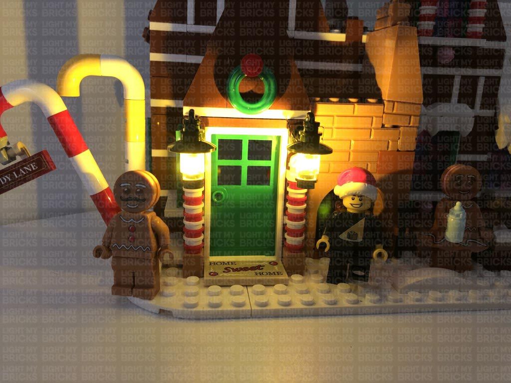
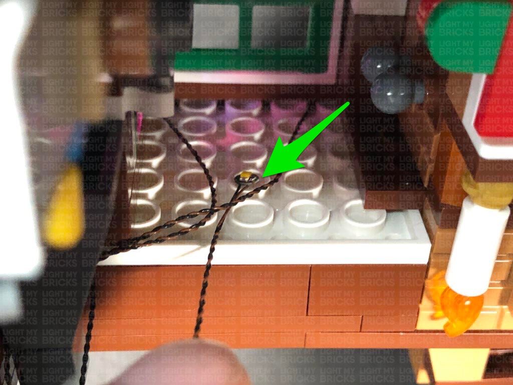
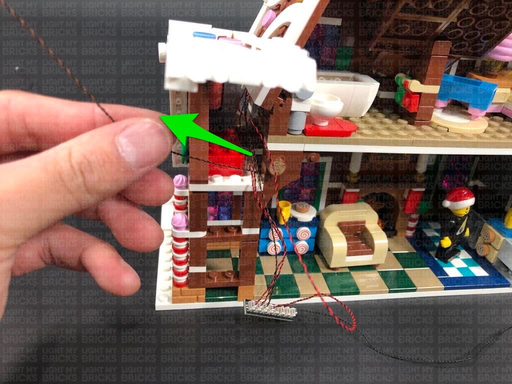
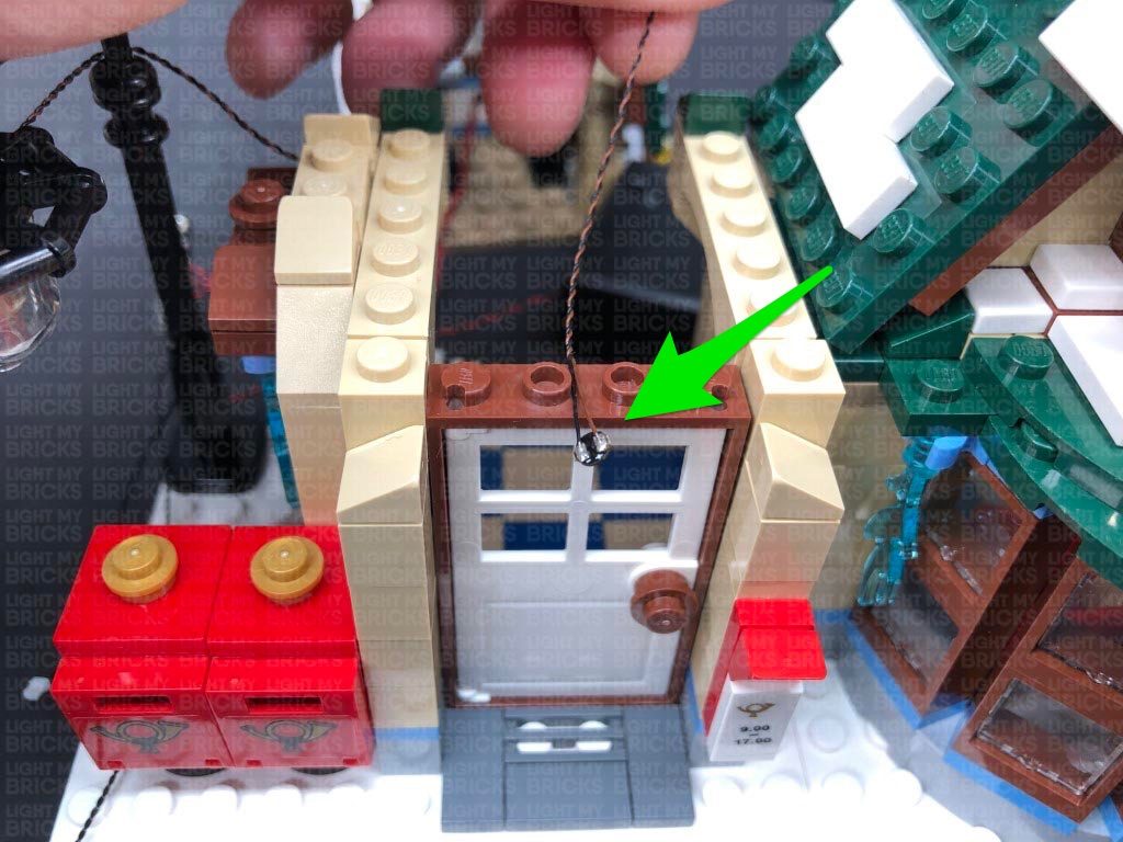
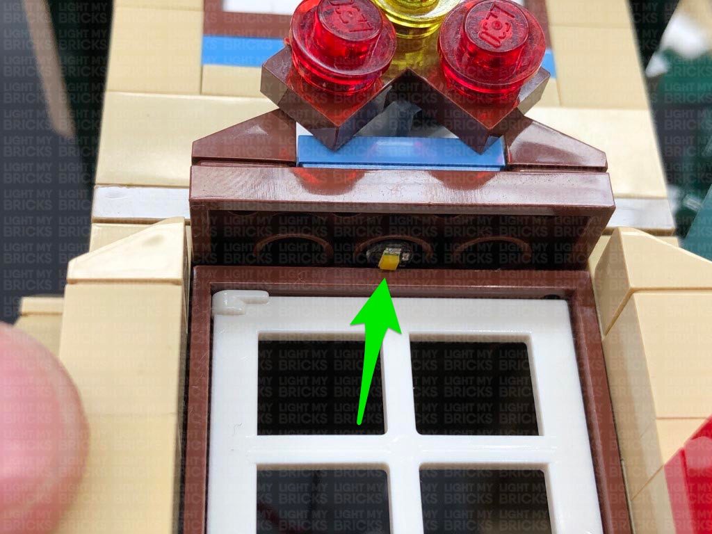
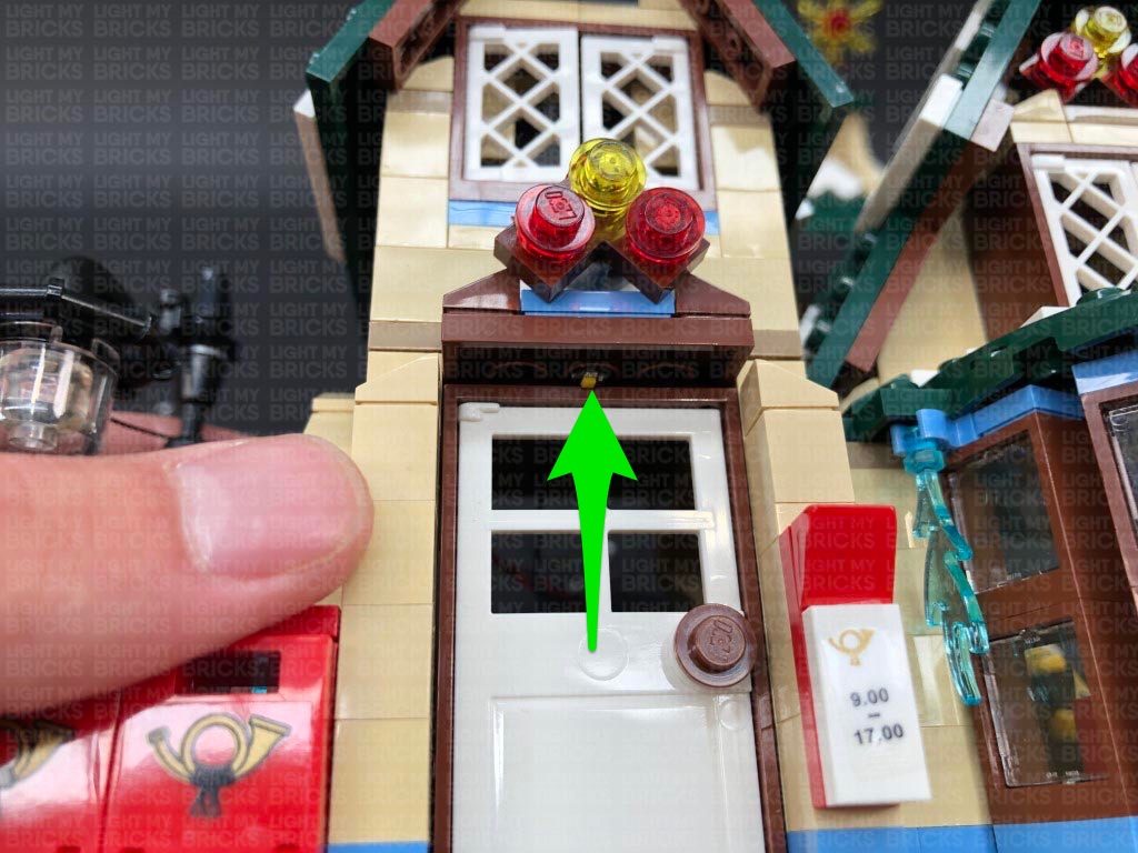
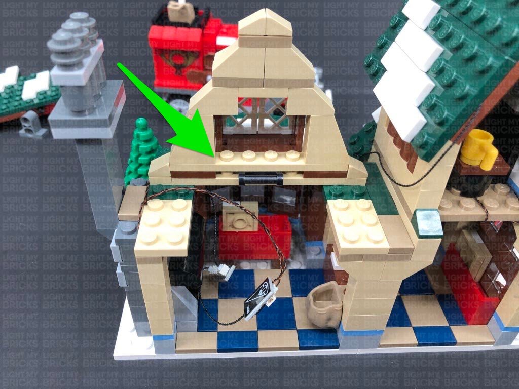
25.) The last light we need to install to the bakery is the one just above the front door. Take the remaining White 15cm Bit Light and stick it to an Adhesive Square. With the cable facing the right side, stick the Bit Light underneath the white plate above the door.
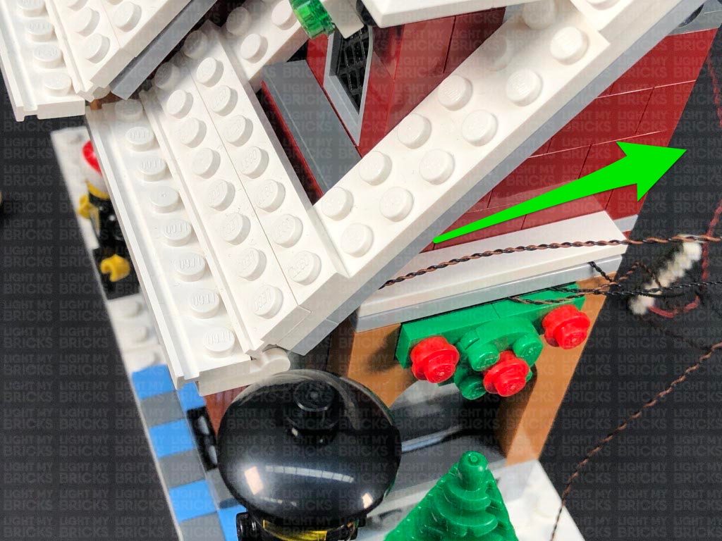
Bring the cable underneath the roof section and around to the back, then secure it underneath the white tile on the side of the building. Connect the Bit Light to a spare port on the 8-Port Expansion Board, then turn ON the AA Battery Pack to test the front door light is working OK.
5.) We will now install the other two flashing lights above the rink. Disconnect the two light sections on the left side, then following the same process used in previous steps, install another 2x Flashing White 30cm Micro Bit Lights to these lights.
6.) Reconnect the green light first, ensuring the trans green plate is facing down, then bring the cable over the flag. Reconnect the red light ensuring the cable from the green light is clipped inside the white clip of the red light. Bring both cables over the flag.
Wind both cables around the pole twice, then secure the cables underneath the white plate on the bottom of the pole. Ensure the cables are laid together in between studs underneath and that they are facing toward the back of this section.
7.) Turn the set around to the back and disconnect the white 2×4 plate underneath the larger tree on the right. Lay the two cables down in between studs as shown below, then reconnect the white plate as well as the larger tree.
Connect the two Micro Bit Lights to the remaining ports on the Micro Expansion Board. Turn ON the Battery Pack to test the flashing lights are all working OK.
8.) Disconnect the AA Battery Pack from the expansion board, then disconnect the bench as well as the white 2×4 plate to the right of it. Lay the cables from the Blue Bit Light and the two Flashing Micro Bit Lights toward the centre of this section in between studs. Reconnect the 2×4 plate over the top followed by the bench.
Secure the cables underneath the smaller tree, then twist the cables around each other a few times just behind the smaller tree. Take 2x Adhesive Squares and stick them to the back of the expansion board, then stick the expansion board on the back of the white plates behind the bench.
Continue to twist and fold up the cables into a neat bunch, then tuck any remaining cable underneath the plates.
Take a 30cm Connecting Cable and connect it to the larger port on the Micro Expansion Board. Leave the other end of the cable disconnected for now as this will be used to connect to an expansion board on the back of the bakery later on.
9.) We will now install lights to the bakery. First disconnect the sections just above the windows, then turn the set around and remove the roof and chimney sections as shown below.
Follow the below images to continue to disconnect sections from the top half of the bakery.
Turn the set around to the front and disconnect the following sections surrounding the front window.
10.) Take the front lamp section and disassemble it as shown below, then take a White 15cm Bit Light and thread the connector end of the cable through the bottom of the trans yellow cone piece. Thread the cable all the way through then, with the LED facing the front, reconnect the black post piece and re-clip it back to the orange brick. Reconnect the black round plate to the top.
Bring the cable down behind the black post, then underneath the brown brick before reconnecting it to the front of the Bakery. Ensuring the cable is laid in between studs, reconnect the red ‘L’ bricks over the top.
11.) Connect the White 15cm Bit Light to a White Strip Light, then take the AA Battery Pack and connect it to the Strip Light’s other port. Turn the Battery Pack ON to test the lamp and strip light is working OK.
Note: If you experience any issues with the lights not working and suspect an issue with a component, please try a different port on the expansion board to verify where the fault lies (with the light or expansion board). To correct any issues with expansion board ports, please view the section addressing expansion board issues on our online troubleshooting guide.
Disconnect the AA Battery Pack from the Strip Light, then reconnect all the sections we removed earlier surrounding the front window.
12.) We will now install a light to the lamp post. First disconnect and disassemble to lamp post as shown below:
Take a White 30cm Bit Light and place it in the centre of the black round plate. Secure the Bit Light in place by reconnecting the trans yellow brick with black dish over the top. Thread the Bit Light cable through the top of the sign section via the top open stud on the black brick. Pull the cable all the way out from the bottom, then reconnect the lamp. Ensure the cable is tucked into the gap underneath the black stud.
13.) Continue to thread the cable through all the black round bricks as well as the black cone brick at the bottom, then reconnect everything together (without the black bar). Reconnect the lamp post to the front of the set, then lay the cable behind it, in between studs. Reposition the tree in the middle of the plate to cover up the wire.
Turn the set around, then connect the Bit Light cable from the lamp post to an 8-Port Expansion Board. Take the AA Battery Pack and connect it to the expansion board, then turn ON the battery pack to test the lamp post is working OK.
Note: If you experience any issues with the lights not working and suspect an issue with a component, please try a different port on the expansion board to verify where the fault lies (with the light or expansion board). To correct any issues with expansion board ports, please view the section addressing expansion board issues on our online troubleshooting guide.
14.) Take a 30cm Connecting Cable and connect it to the 8-Port Expansion Board, then connect the other end of the cable to the other port on the White Strip Light from previous step.
Using it’s adhesive backing, stick the right side of the Strip Light underneath the red bricks on the right. The Strip Light is currently only partially sticking to this section as we will stick the other side of the strip light at a later stage.
Secure the White 15cm Bit Light cable underneath the left roof pieces ensuring you first pull the cable up to prevent it from being seen from the outside. Lay the 30cm Connecting Cable across the top of the bottom floor in between studs as shown below.
15.) We will now install flickering lights to the bakery oven. Follow the below images to disconnect sections of the oven to allow us to disconnect the trans orange round plates.
Take a White 15cm Micro Bit Light and with the cable facing the back corner, place the LED over the top left black stud. Secure the Micro Bit Light in place by reconnecting one of the trans orange round plates over the top. Repeat this to install another White 15cm Micro Bit Light to the right side.
Install another 2x White 15cm Micro Bit Lights to the bottom two studs, ensuring the cables are this time facing the bottom corners before reconnecting the trans orange round plates over the top. Pull the front two cables up before reconnecting the light grey ‘L’ plates.
16.) Take the upper oven section and disconnect the following sections from the bottom of it. Reconnect these two sections to the oven, then lay the two cables from each side, over the top of these sections, laying them in between studs.
Disconnect the following sections from the bottom of the oven section, then reconnect these pieces over the top of the cables.
Pull all four cables up, then thread them through underneath the space on the remaining oven section pieces. Reconnect the top of the oven, then pull the cables toward to back (front of the bakery).
17.) Take the second level section which sits above the left side of the bakery and disconnect the two bricks from underneath of it. Ensuring the four micro bit light cables are laid in between studs, reconnect the two light grey bricks over the top of them.
Lay the 30cm Connecting Cable in between the following studs (over the dark grey roof brick as well as in between studs below) before reconnecting the second level section over the top. Ensure the micro bit light cables are pulled up and are still accessible.
Take a new Micro 4-Port Expansion Board, and connect the four Micro Bit Lights to it. Slip the cables in between the bricks and leave the expansion board behind the brown crate for now, as we will connect this up later.
Ensure the cables are laid in between studs (30cm cable and white 15cm bit light cable), then reconnect the upper chimney section. Stick the left side of the White Strip Light underneath this section, then turn ON the Battery Pack to test the strip light is working and lighting up the bakery floor.
18.) Disconnect the crate from the second level, then take a 5cm Connecting Cable and connect it to the large port on the Micro Expansion Board. Connect the other end of the 5cm cable to one of the OUT ports on a Flicker Effects Board.
Take another 5cm Connecting Cable and connect it to the IN port on the Flicker Effects Board. Connect the other end of the 5cm connecting cable to the large port on a new Micro 4-Port Expansion Board.
Take a 15cm Connecting Cable and connect it to the other large port on the Micro Expansion Board we just connected, then bring the cable down the left side of the bakery and connect it to a spare port on the 8-Port Expansion Board at the bottom of the set. Turn the Battery Pack ON to test the oven lights are working and flickering OK.
Note: If you experience any issues with the lights not working and suspect an issue with a component, please try a different port on the expansion board to verify where the fault lies (with the light or expansion board). To correct any issues with expansion board ports, please view the section addressing expansion board issues on our online troubleshooting guide.
19.) Disconnect the white tile on the left side of the bakery, then disconnect the left wall section. Turn the set around to the front, then reconnect the window section to the left side.
Remove all the light sections above both windows on the second floor, disconnecting them from the black plates with clips. Disconnect the red 1×4 plate behind them, then disconnect the trans coloured round plates from the white plates of the light sections as shown below.
20.) Take a Flashing White 15cm Micro Bit Light and place the LED inside the white plate with clip. Secure the Bit Light in place by reconnecting one of the trans red round plates.
Remember – Do not forcefully connect the LEGO plate back inside the white plate. Because of the size of the micro LED, the plate will not fully connect inside. Forcing the plate to fully reconnect may cause the wire to break.
Lay the cable underneath the middle of the black plate, before reconnecting this section back to the top of the left window. Ensure the cable is laid in between studs underneath.
Install another Flashing White 15cm Micro Bit Light to the other light section, then reconnect it to the top of the left window.
Ensuring both cables are laid in between studs, reconnect the red 1×4 plate behind, then bring both cables across to the right side and secure them down underneath the following angled red brick.
21.) Repeat the previous step to install another 2x Flashing White 15cm Micro Bit Lights to the remaining light sections, then reconnect them above the right window. Ensuring the cables are laid in between studs, reconnect the red 1×4 plate behind.
Turn the set around to the back and connect all four flashing micro bit lights to the Micro 4-Port Expansion Board (one with nothing connected to it). Turn ON the Battery Pack to test the flashing lights above the windows are working OK.
22.) Neaten up all the excess cabling from the Flashing lights by twisting and folding them altogether into a neat bunch. Group all the components on the second floor together, then lay the 15cm Connecting Cable in between studs on the left side. Secure the cable down by reconnecting the white tile and the left wall section we removed earlier.
23.) We will now install a light to the bottom section of the bakery. Turn the set around to the side, and use your LEGO removal tool to create a gap just underneath the light grey plate above the side window.
Take a White 15cm Bit Light and turn it over so that the LED is facing down, then thread the Bit Light through the gap we just created. Position the LED in the centre underneath the second floor, then secure it in place by connecting a provided LEGO Trans Clear Plate w Rounded Bottom 2×2 over it.The LED should be facing down and positioned in the middle of the trans clear plate.
Close up the gap we created, ensuring the Bit Light cable is laid in between studs, then connect the Bit Light to a spare port on the 8-Port Expansion Board at the bottom of the set. Turn ON the Battery Pack to test the internal light is working OK.
Note: If you experience any issues with the lights not working and suspect an issue with a component, please try a different port on the expansion board to verify where the fault lies (with the light or expansion board). To correct any issues with expansion board ports, please view the section addressing expansion board issues on our online troubleshooting guide.
24.) Turn the set around to the front, then starting from the right side, reconnect the roof sections as well as the sections that connect on top of the windows.
Turn the set around and reconnect the top of the chimney, then reconnect the crate to the second floor ensuring the components are nicely tucked in and hidden behind it.
25.) The last light we need to install to the bakery is the one just above the front door. Take the remaining White 15cm Bit Light and stick it to an Adhesive Square. With the cable facing the right side, stick the Bit Light underneath the white plate above the door.
Bring the cable underneath the roof section and around to the back, then secure it underneath the white tile on the side of the building. Connect the Bit Light to a spare port on the 8-Port Expansion Board, then turn ON the AA Battery Pack to test the front door light is working OK.
 Note: If you experience any issues with the lights not working and suspect an issue with a component, please try a different port on the expansion board to verify where the fault lies (with the light or expansion board). To correct any issues with expansion board ports, please view the section addressing expansion board issues on our online troubleshooting guide.
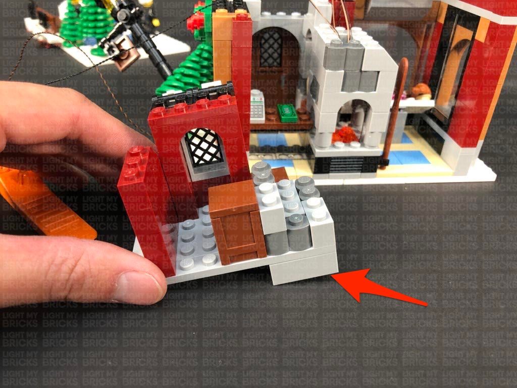
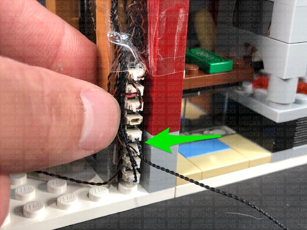
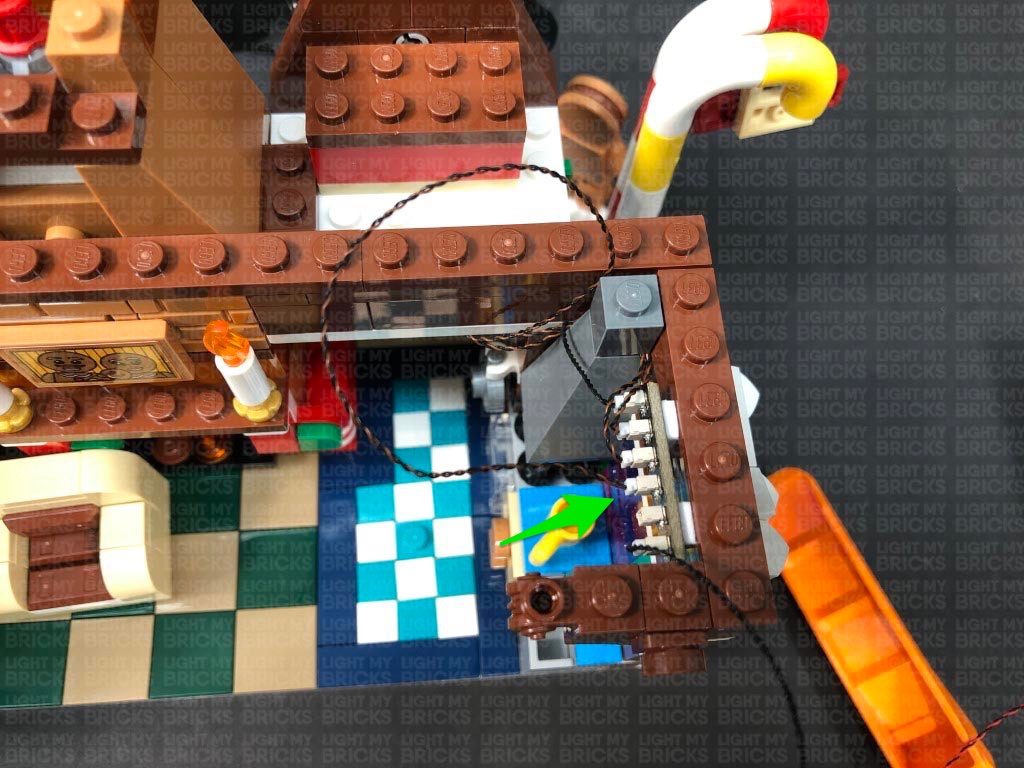
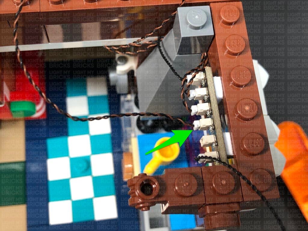
26.) Take 2x Adhesive Squares and stick them to the back of the 8-Port Expansion Board. Secure the expansion board to the back of the set in the following position, then neaten up the cables by twisting and folding them together into a neat bunch. Tuck the bunched up cables into the corner and secure them all down using tape.
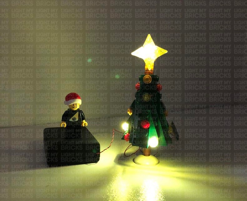
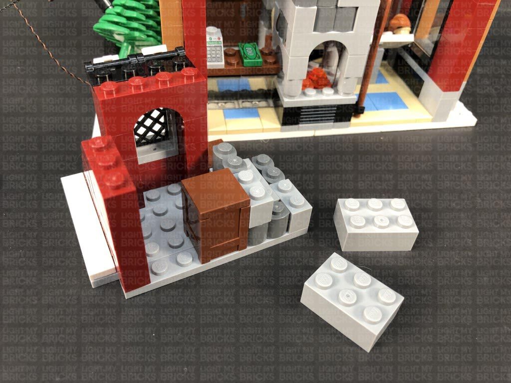
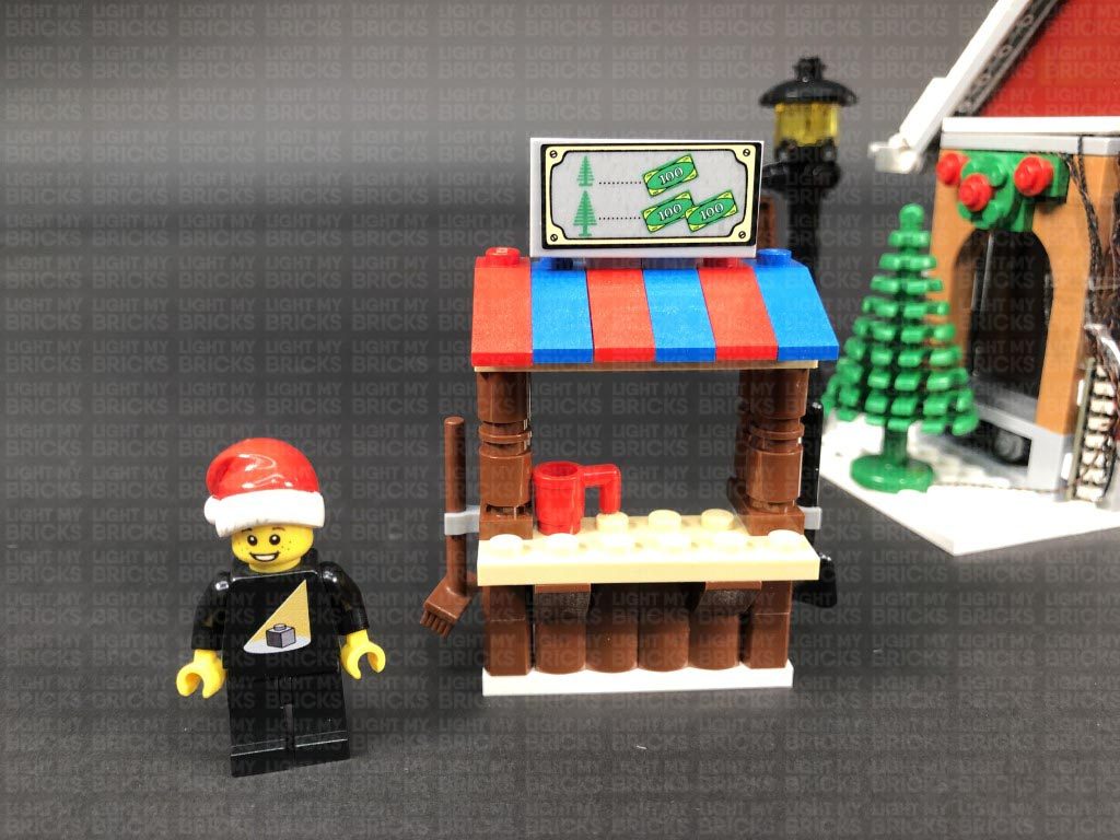
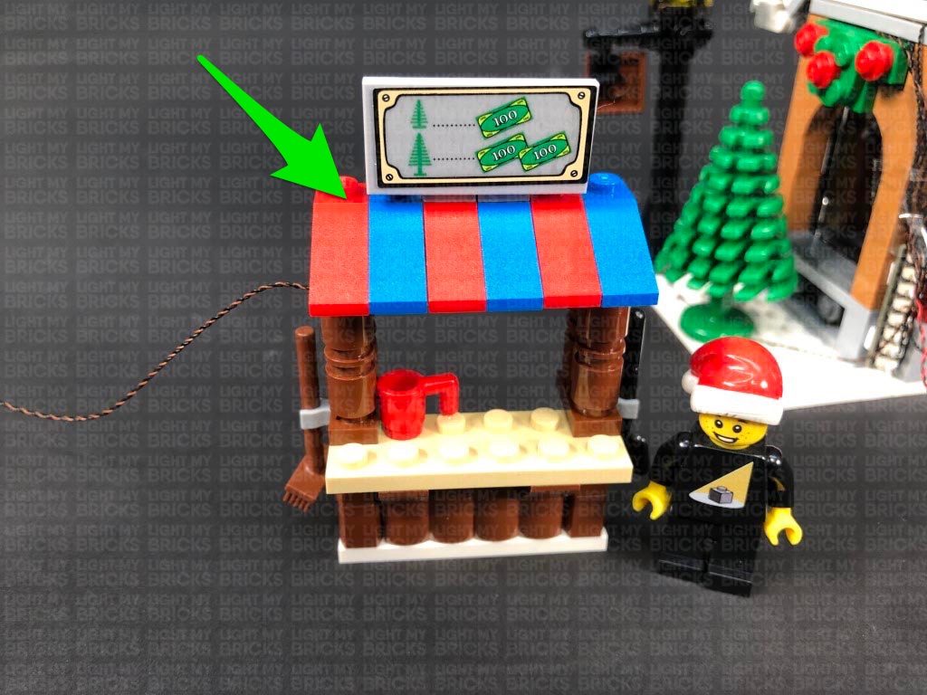
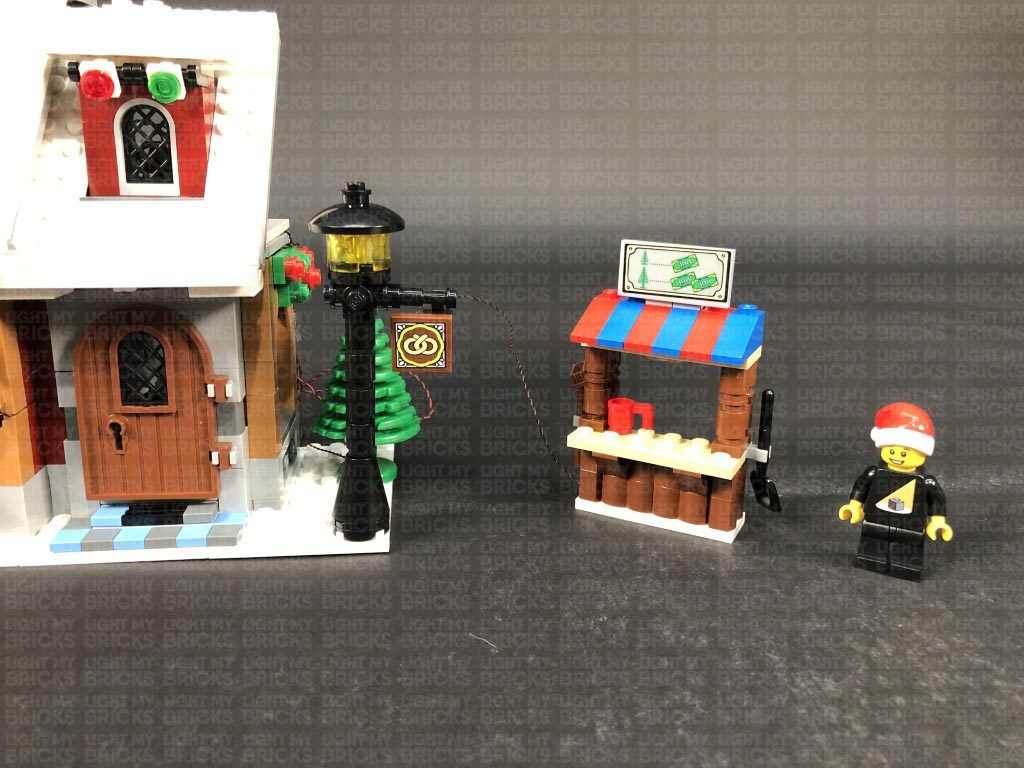
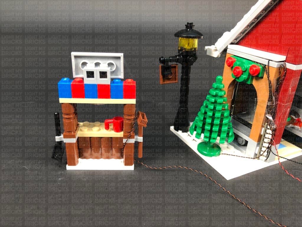
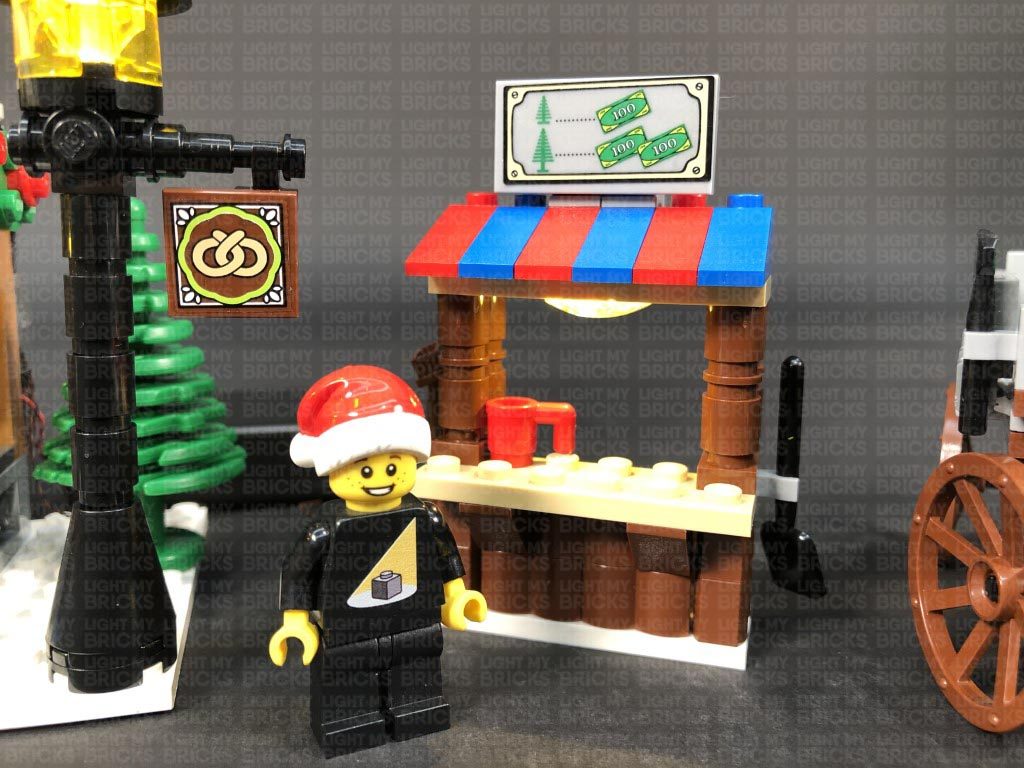
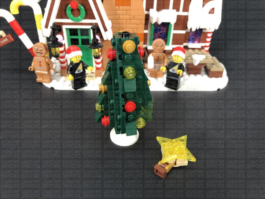
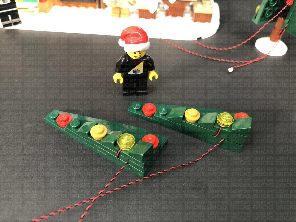
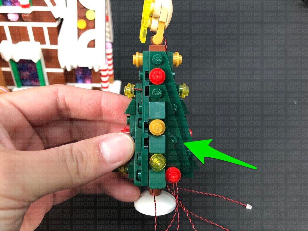
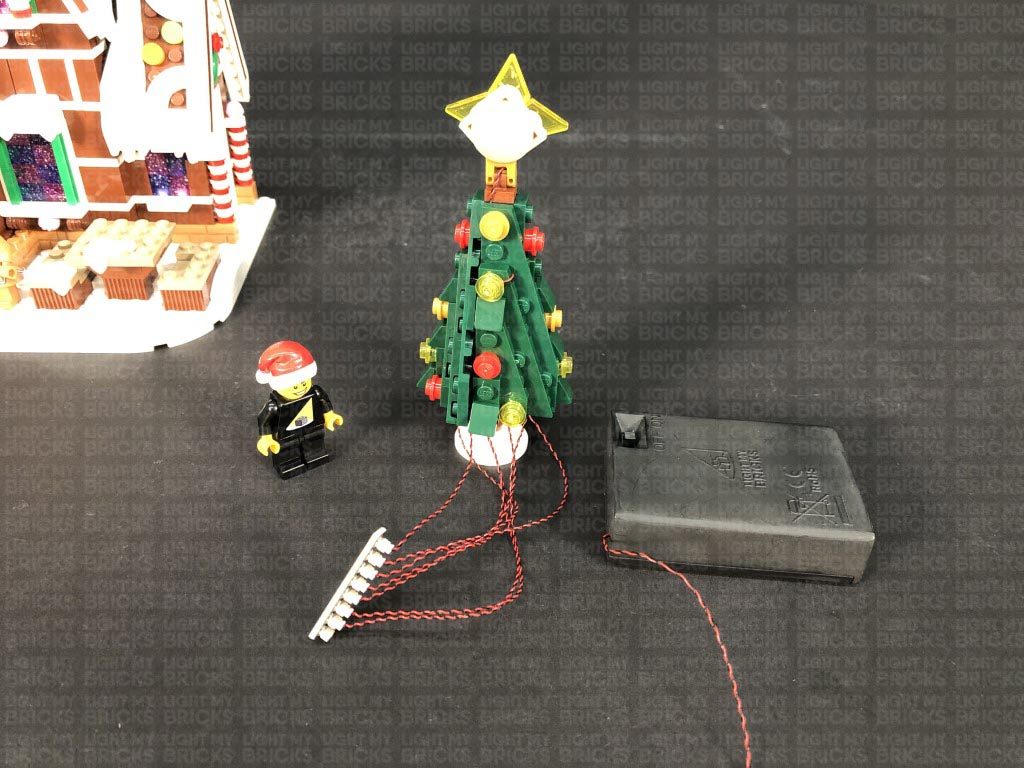
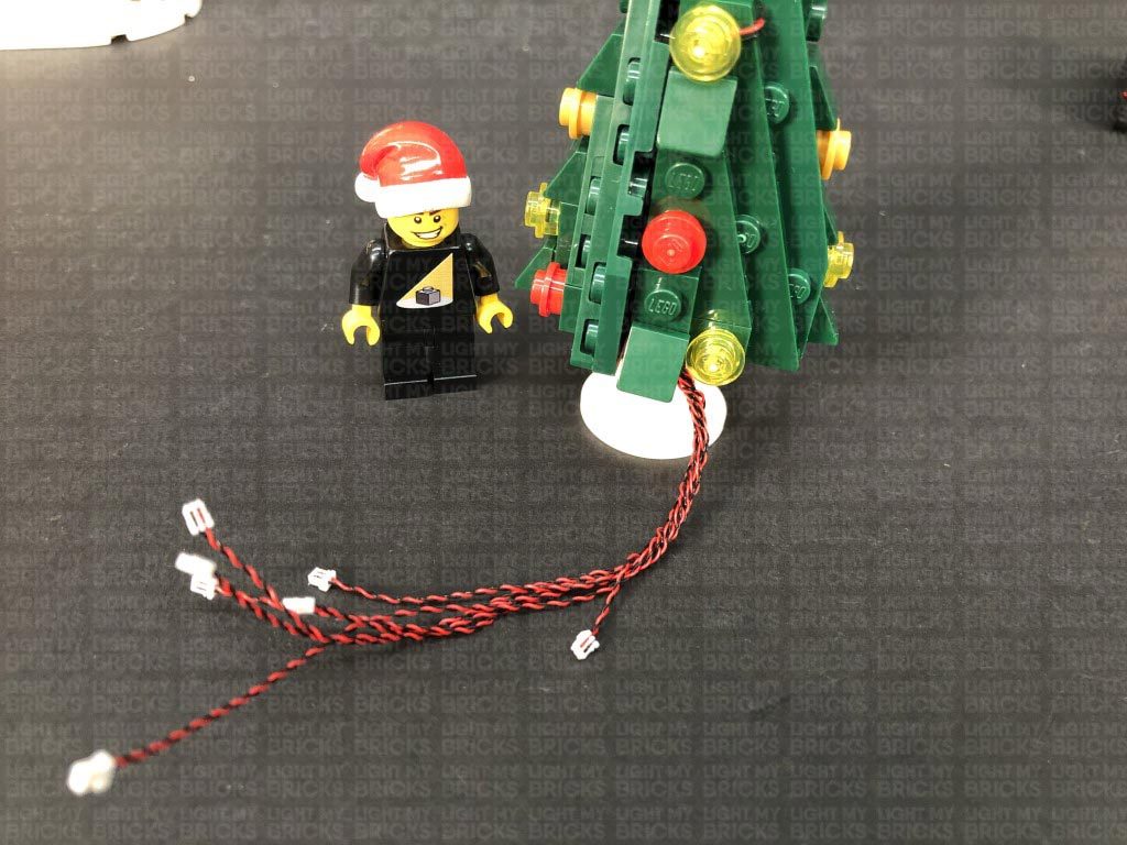
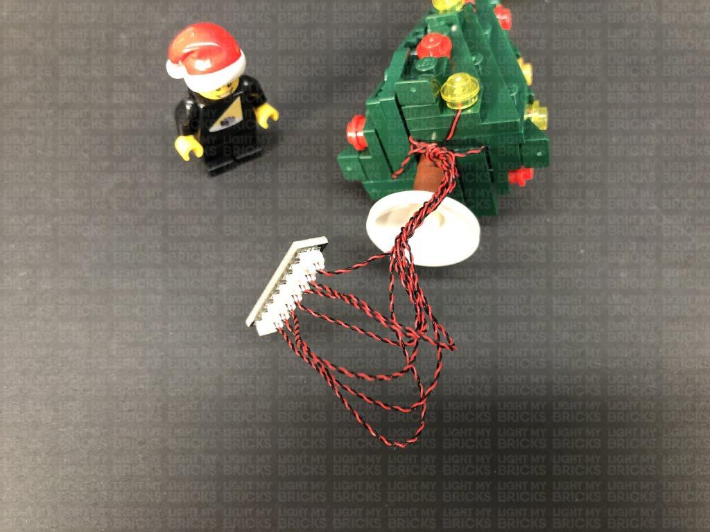
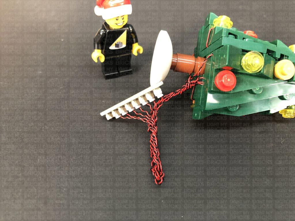
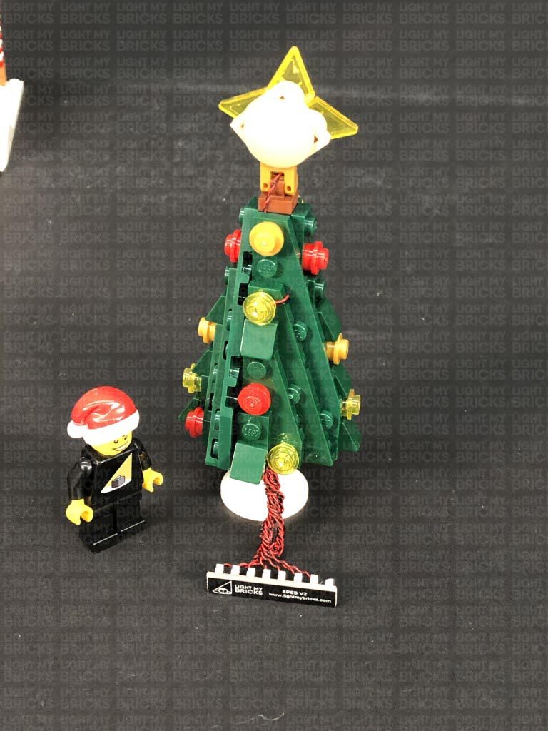
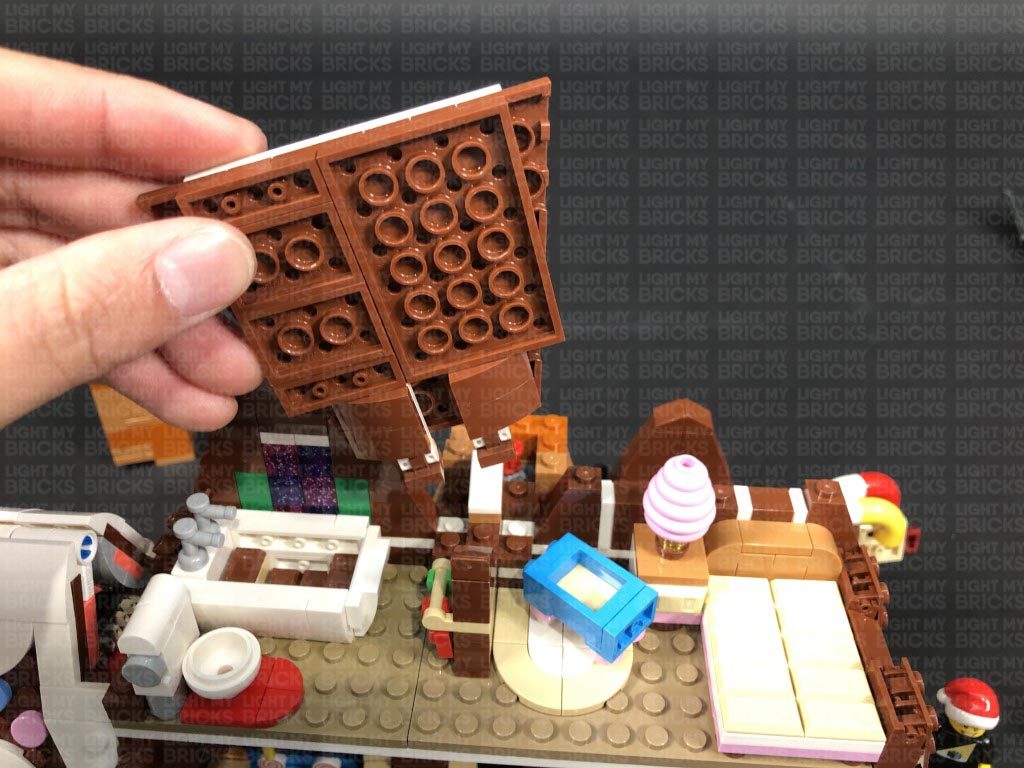
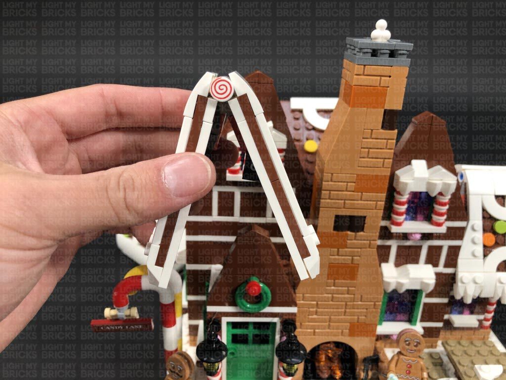
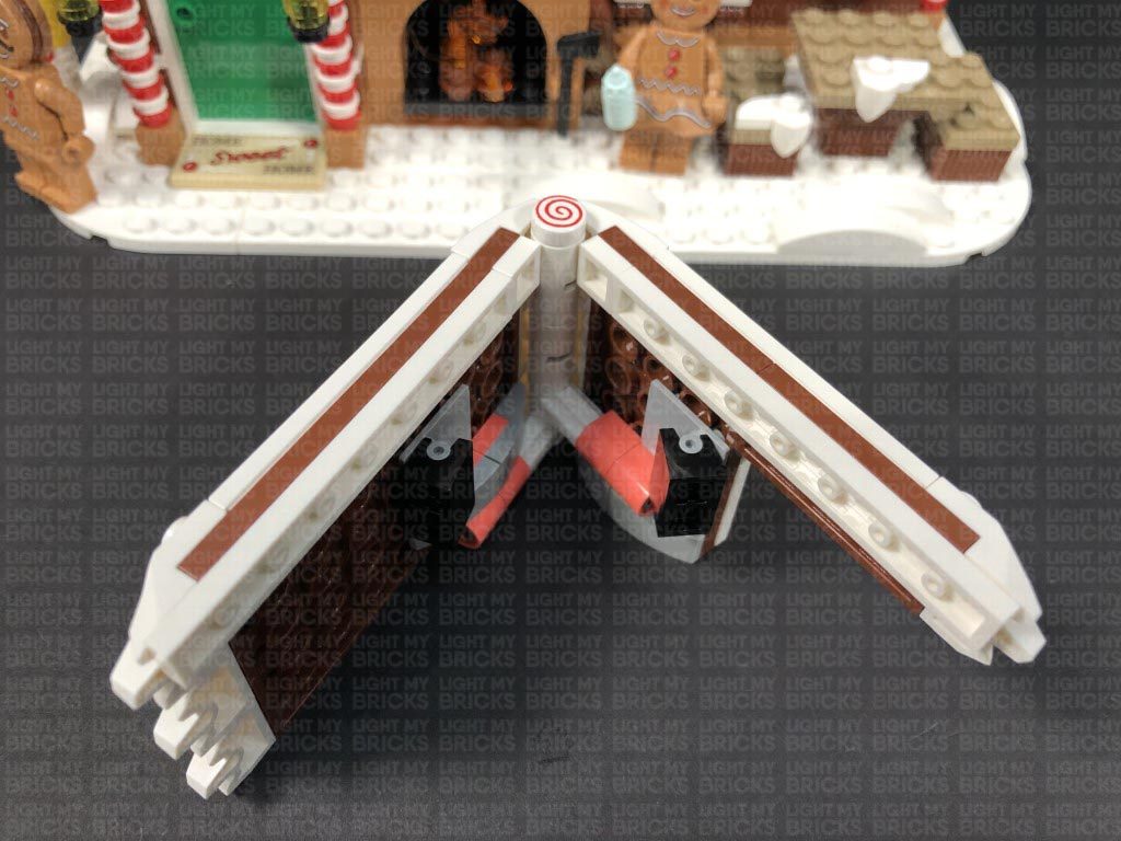
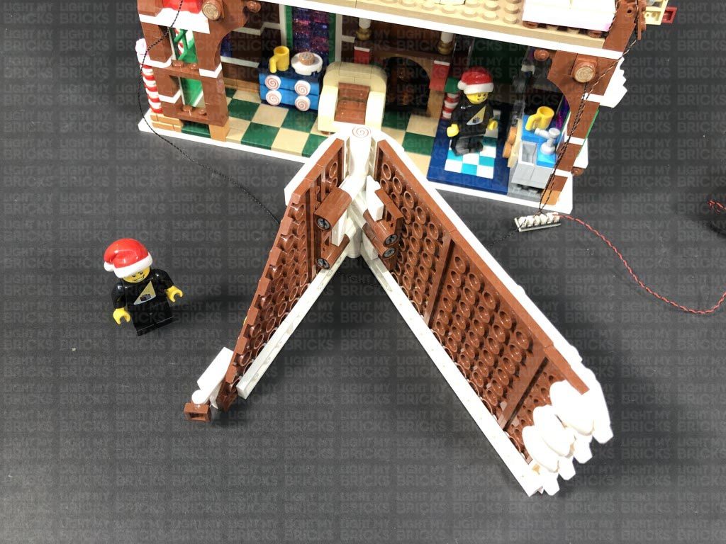
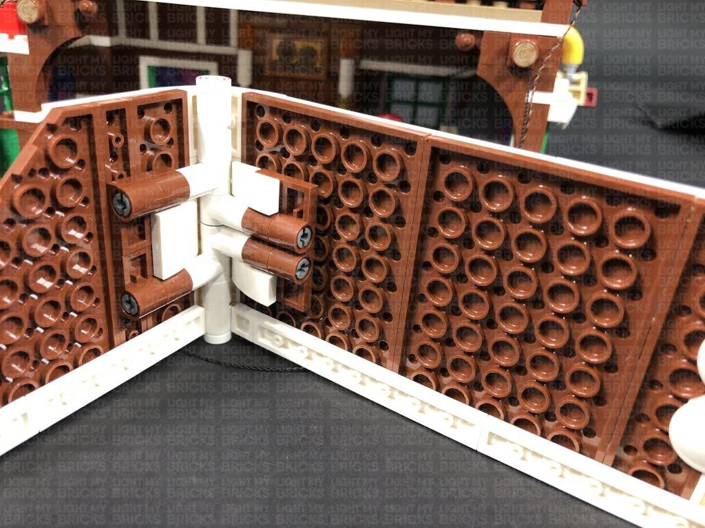
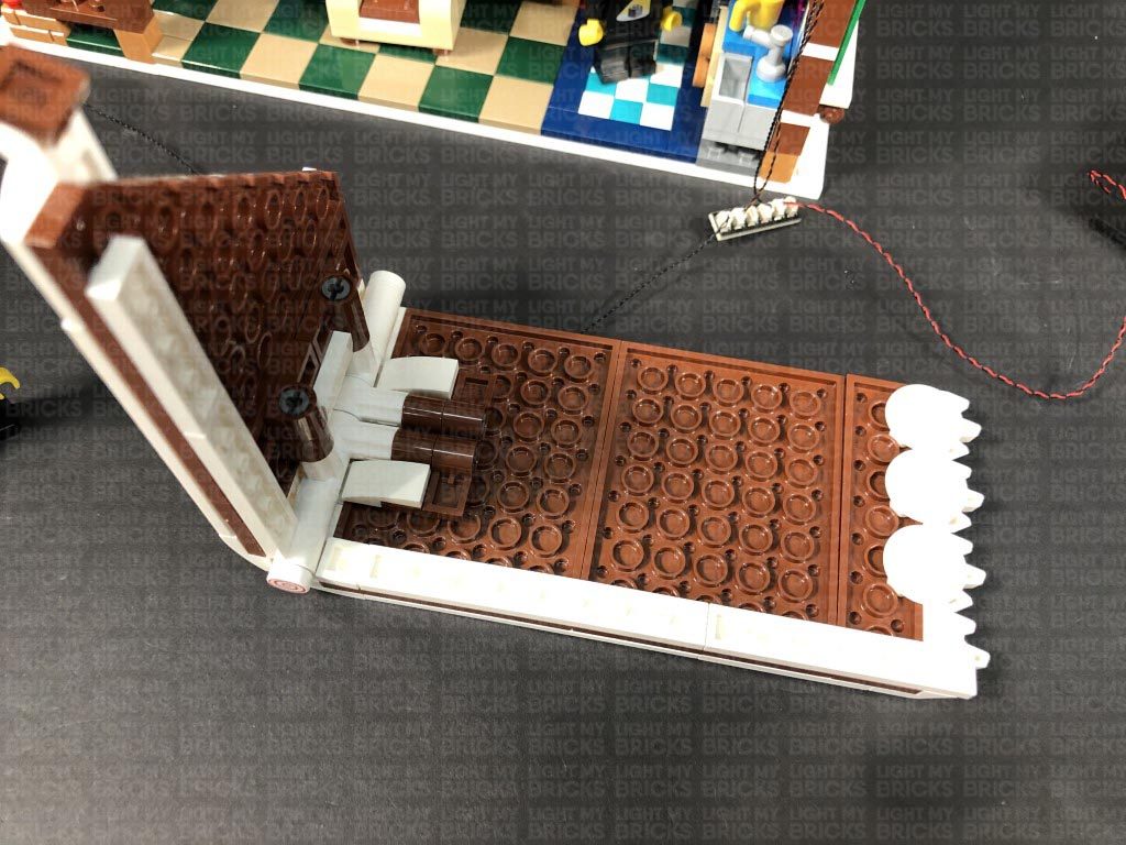
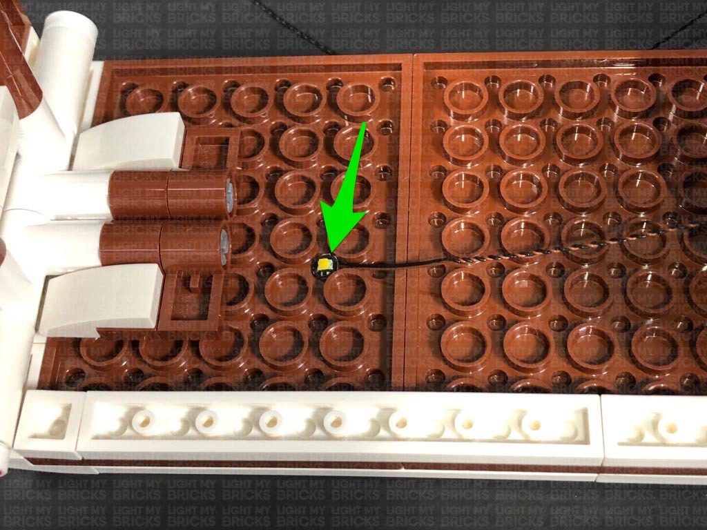
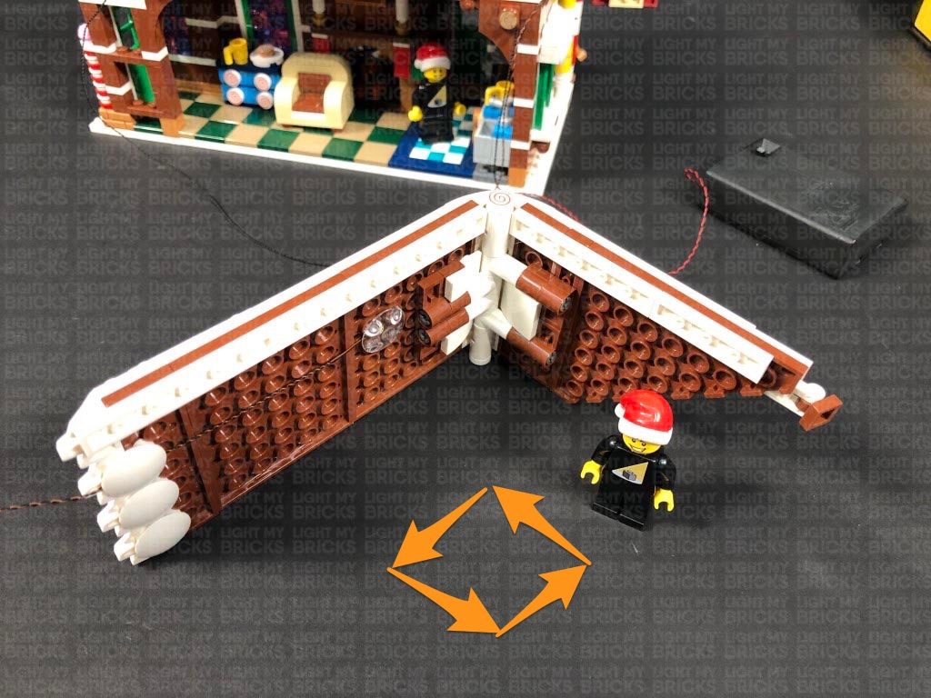
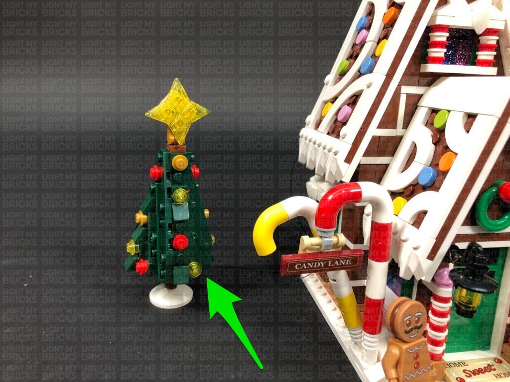
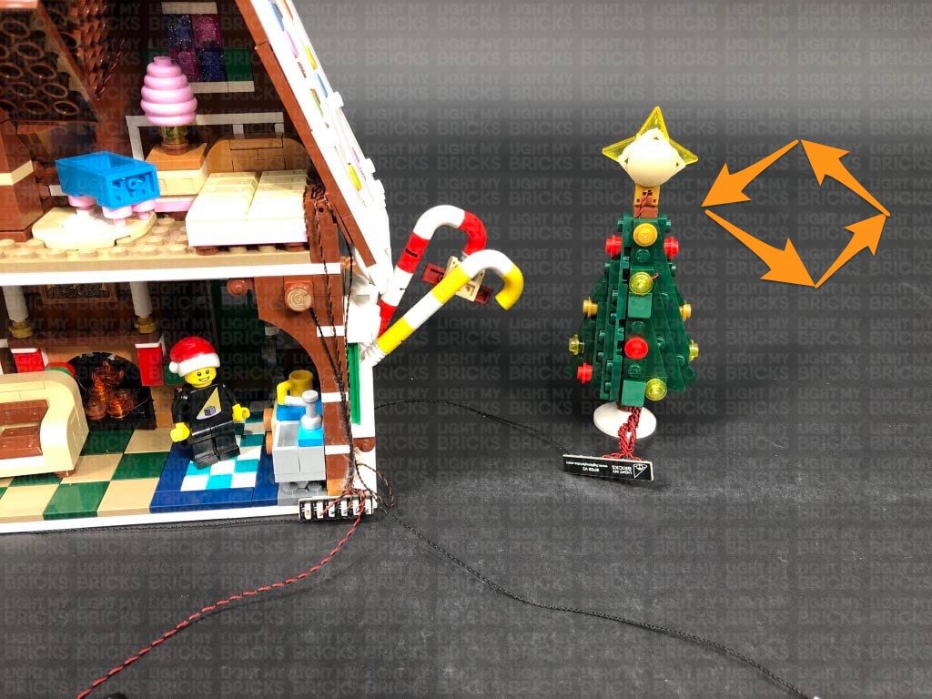
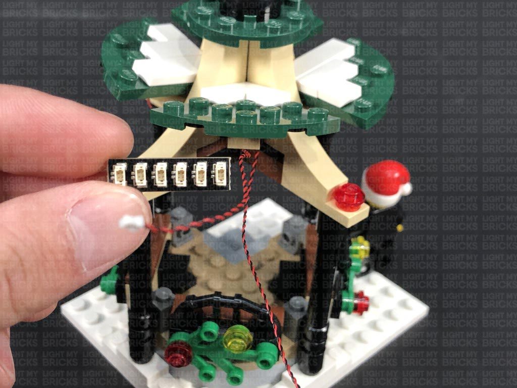
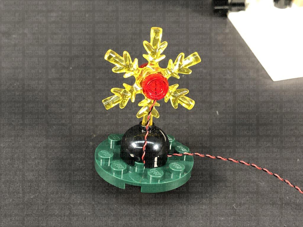
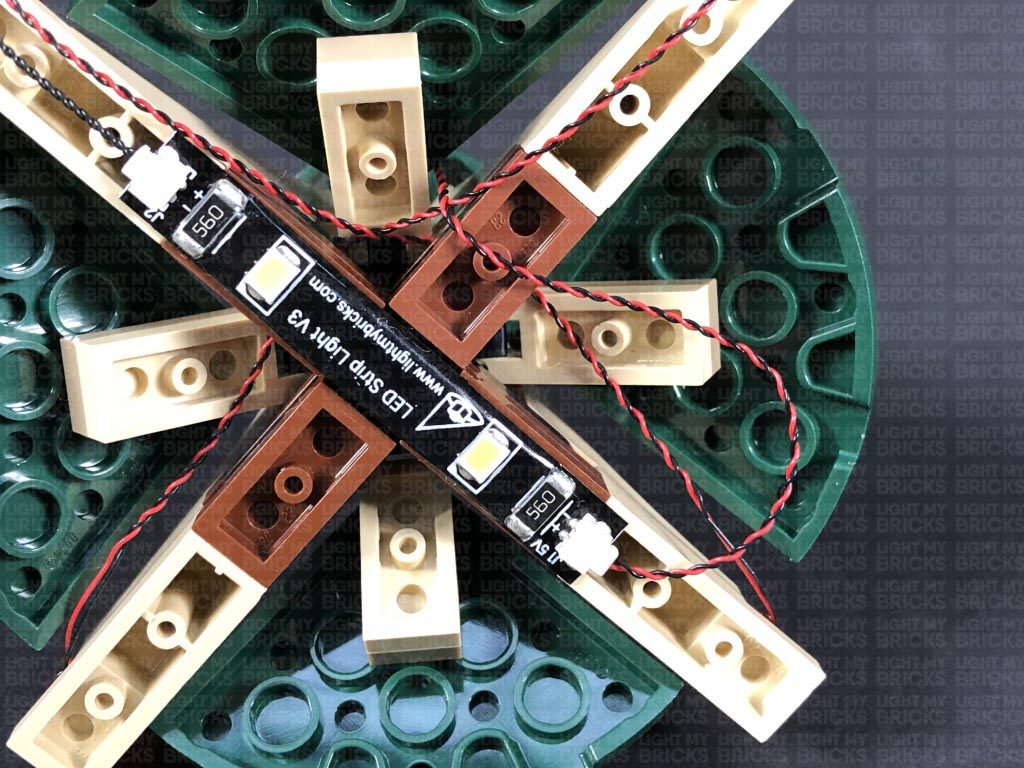
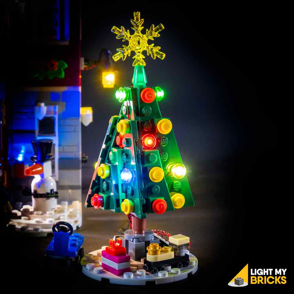
27.) We will now install a light to the tree shop. First disconnect the roof from this section, then flip it over so we can access underneath. Take a White 30cm Bit Light and with the cable on the left side, place the LED underneath the roof in the middle. Secure the Bit Light in place by connecting the remaining provided Trans Clear Plate w Rounded Bottom 2×2 over the top.
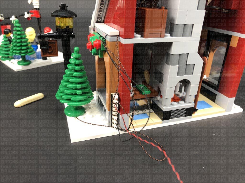
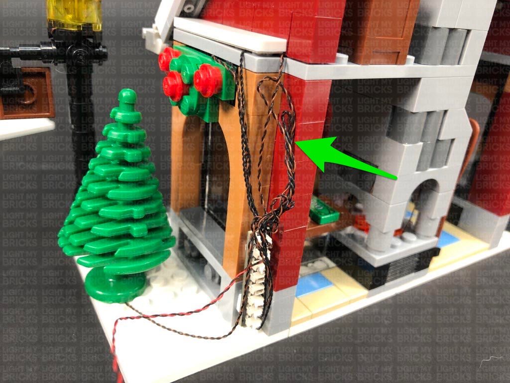
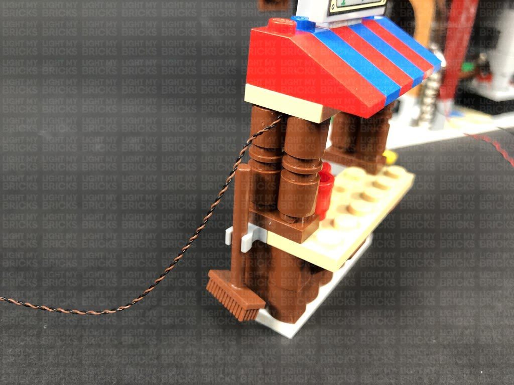
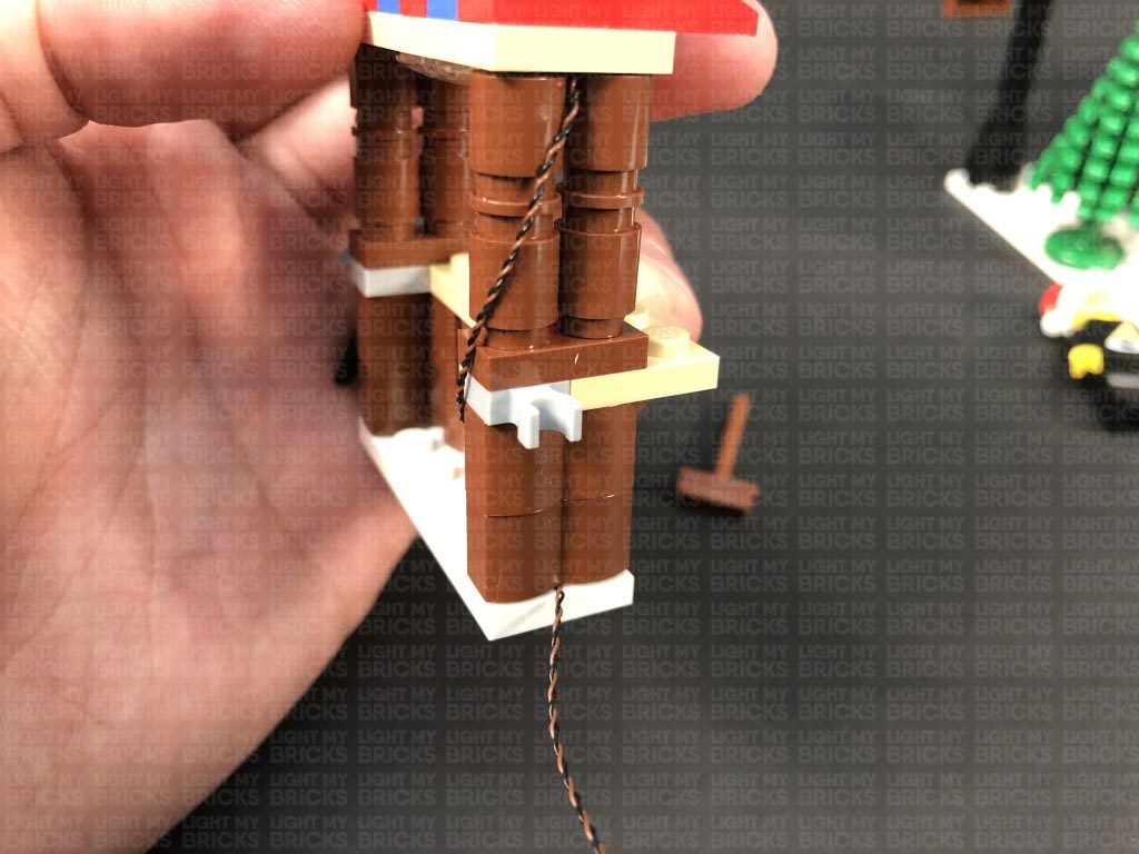
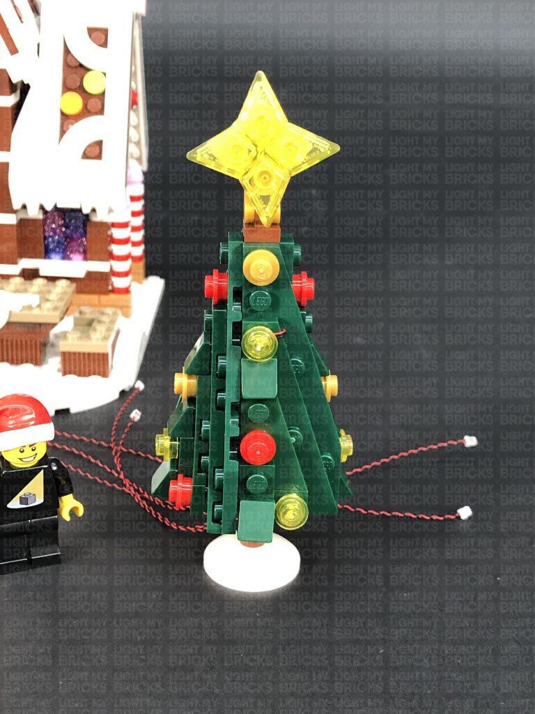
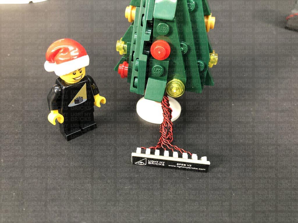
Flip the roof section back over and reconnect it to the tree shop, then bring the cable down the side of the shop and secure it underneath the side bricks, with the cable facing out.
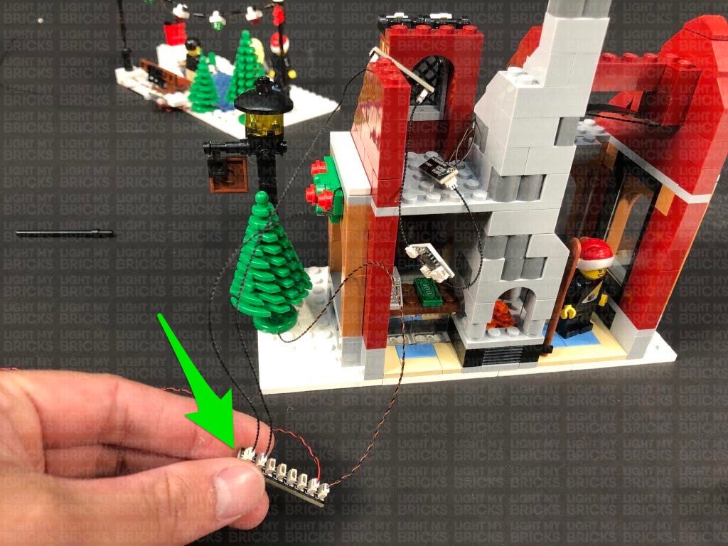
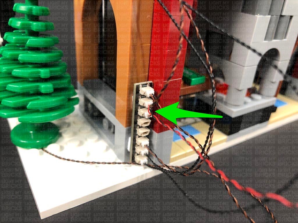
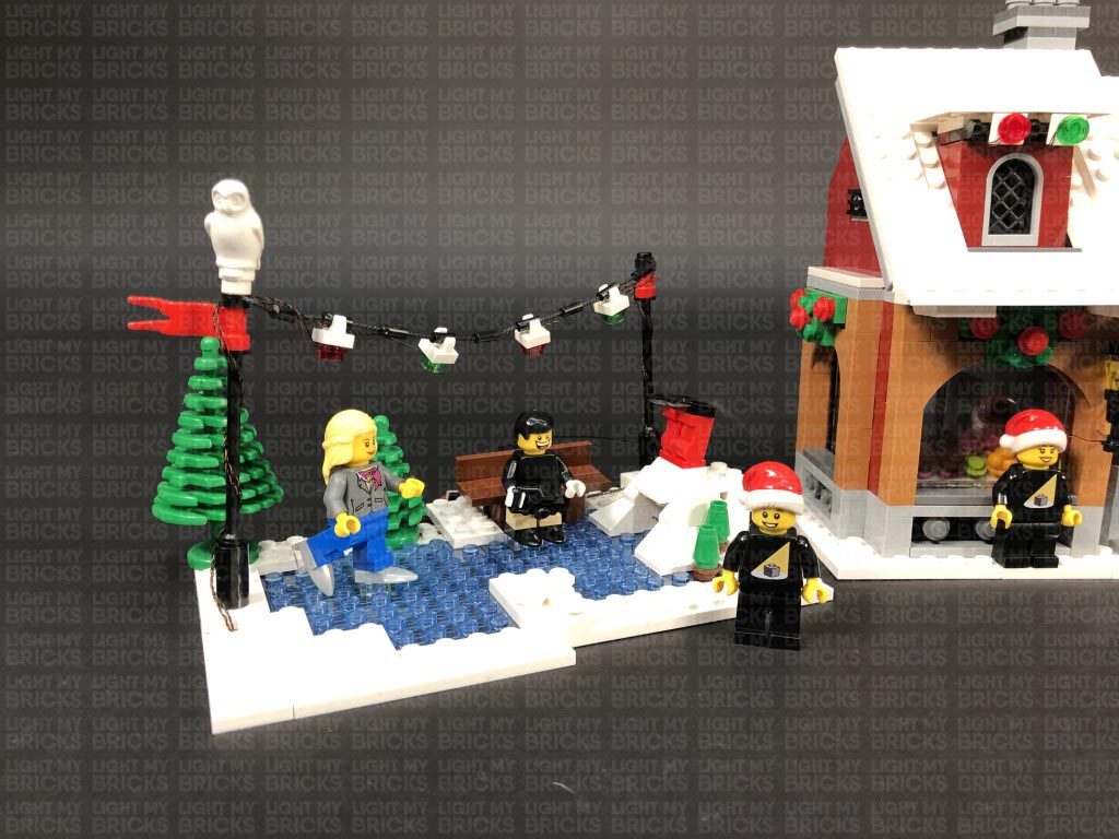
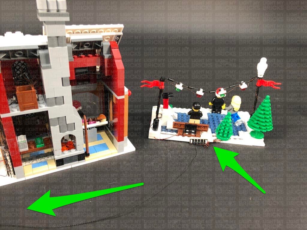
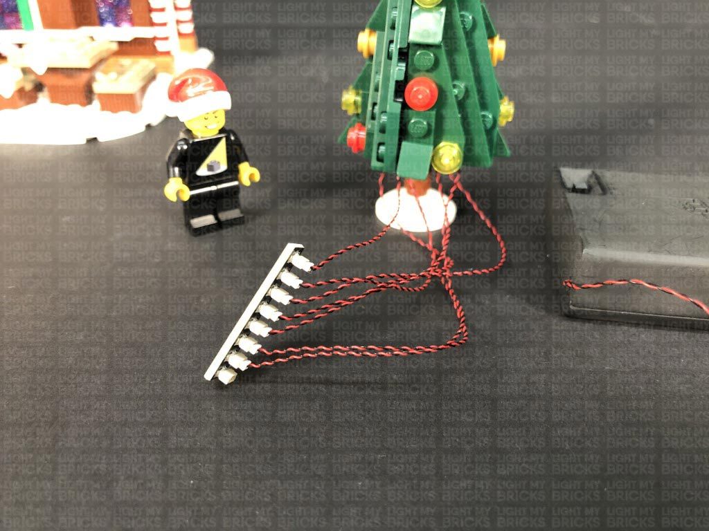
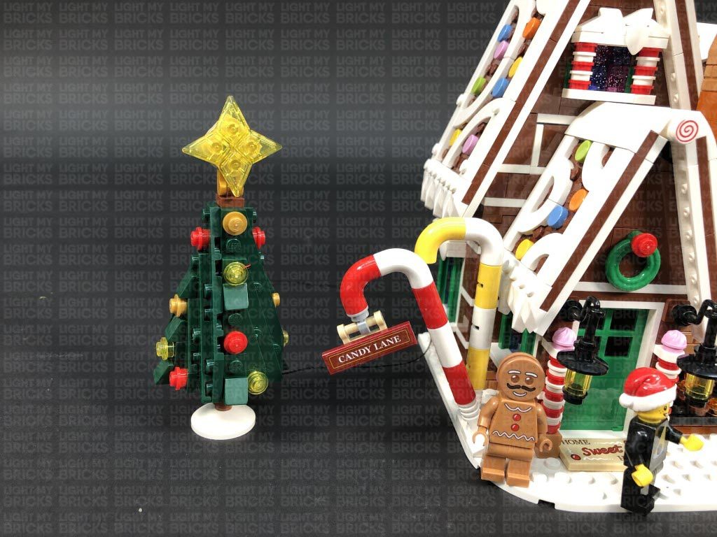
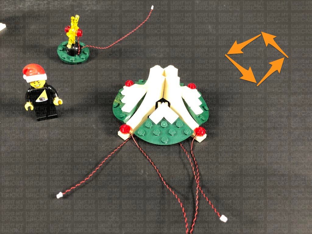
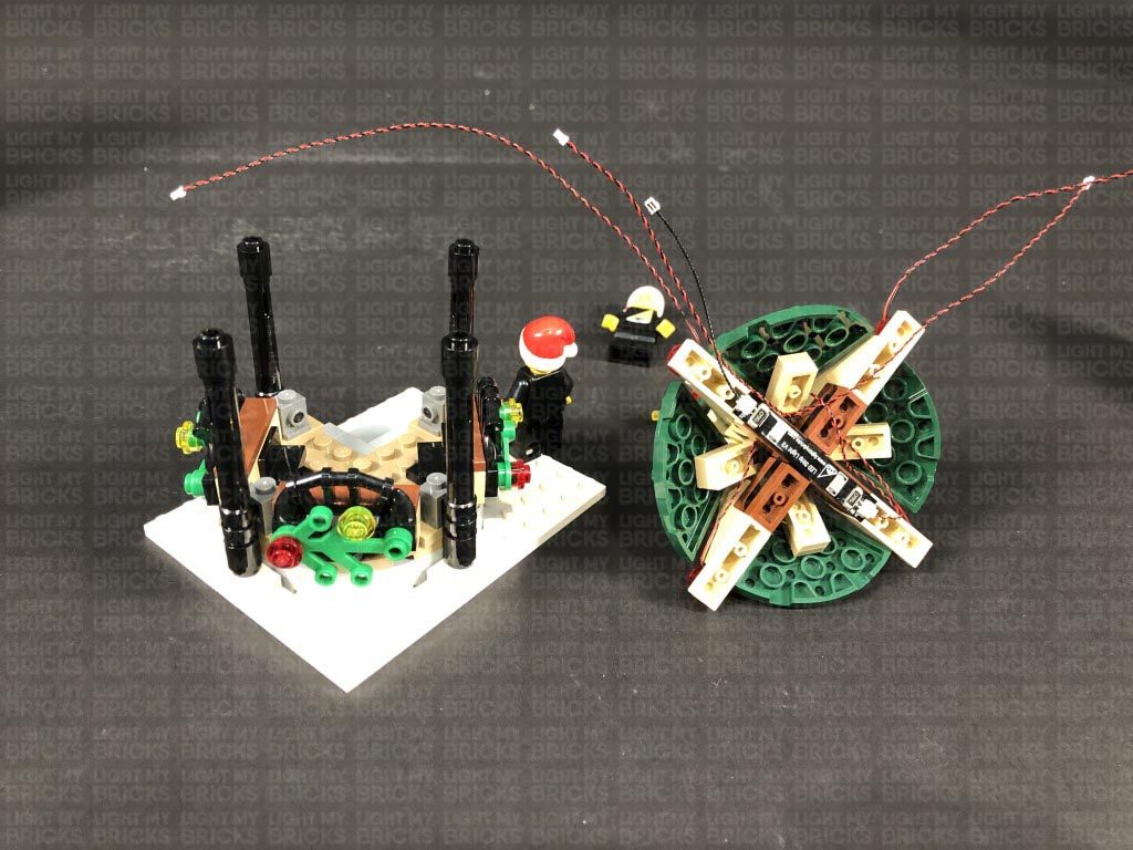
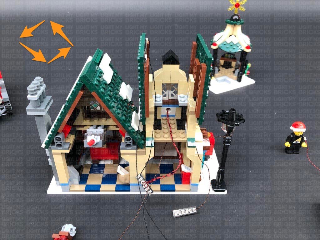
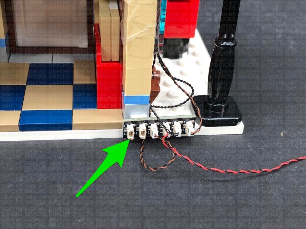
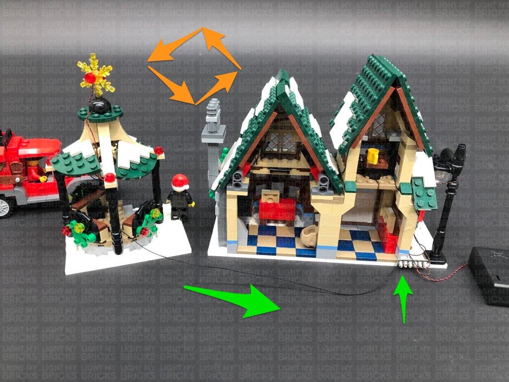
28.) Position the Ice Rink section on the left side of the Bakery. Take the other end of the 30cm Connecting Cable from this section and connect it to a spare port on the 8-Port Expansion Board.
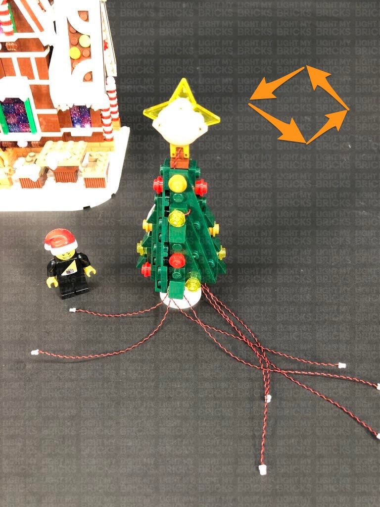
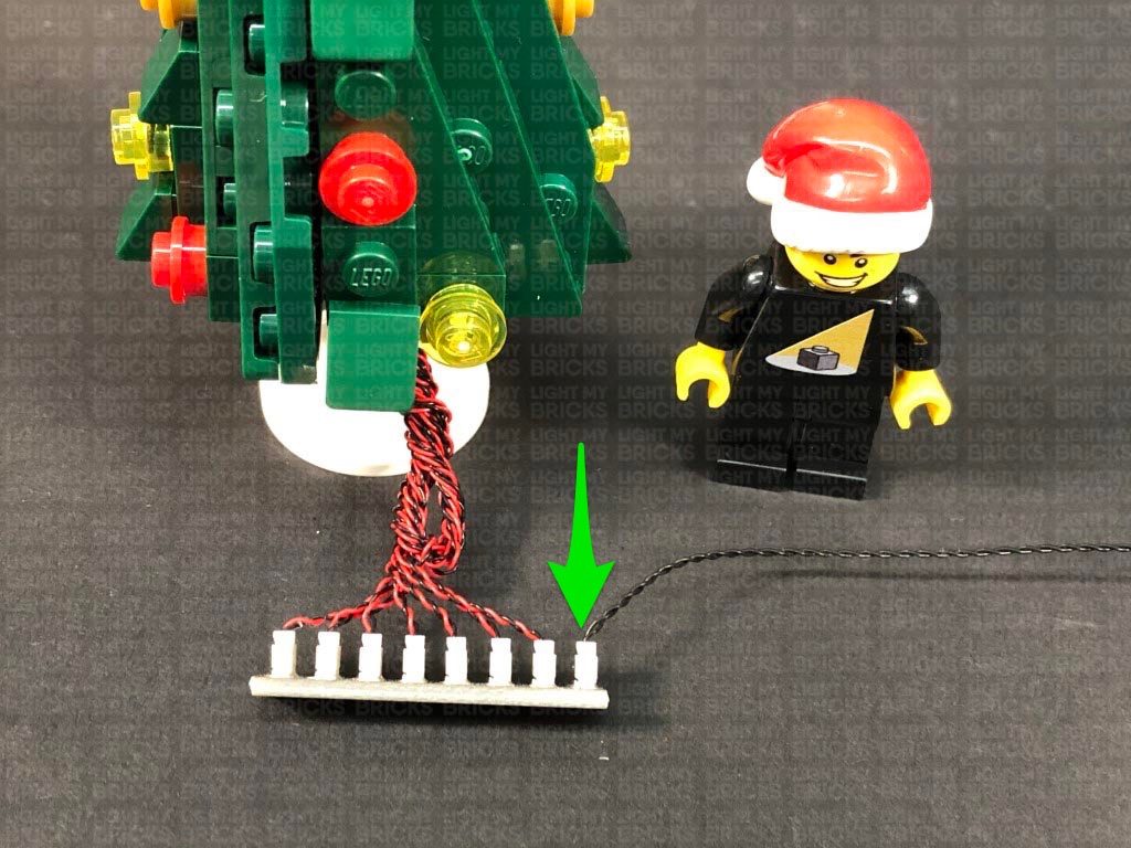
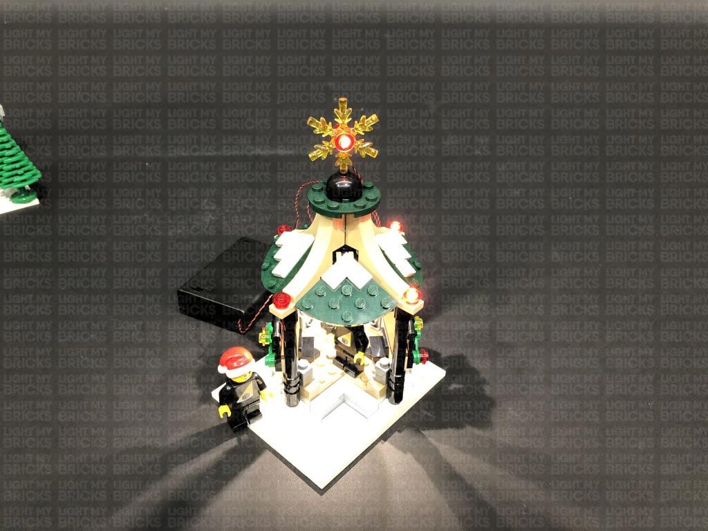
Position the Tree Shop to the other side of the Bakery, then connect the bit light cable to the remaining spare port on the 8-Port Expansion Board. Turn the Battery Pack ON to test all the lights connected are working OK.
Note: If you experience any issues with the lights not working and suspect an issue with a component, please try a different port on the expansion board to verify where the fault lies (with the light or expansion board). To correct any issues with expansion board ports, please view the section addressing expansion board issues on our online troubleshooting guide.
26.) Take 2x Adhesive Squares and stick them to the back of the 8-Port Expansion Board. Secure the expansion board to the back of the set in the following position, then neaten up the cables by twisting and folding them together into a neat bunch. Tuck the bunched up cables into the corner and secure them all down using tape.
27.) We will now install a light to the tree shop. First disconnect the roof from this section, then flip it over so we can access underneath. Take a White 30cm Bit Light and with the cable on the left side, place the LED underneath the roof in the middle. Secure the Bit Light in place by connecting the remaining provided Trans Clear Plate w Rounded Bottom 2×2 over the top.
Flip the roof section back over and reconnect it to the tree shop, then bring the cable down the side of the shop and secure it underneath the side bricks, with the cable facing out.
28.) Position the Ice Rink section on the left side of the Bakery. Take the other end of the 30cm Connecting Cable from this section and connect it to a spare port on the 8-Port Expansion Board.
Position the Tree Shop to the other side of the Bakery, then connect the bit light cable to the remaining spare port on the 8-Port Expansion Board. Turn the Battery Pack ON to test all the lights connected are working OK.
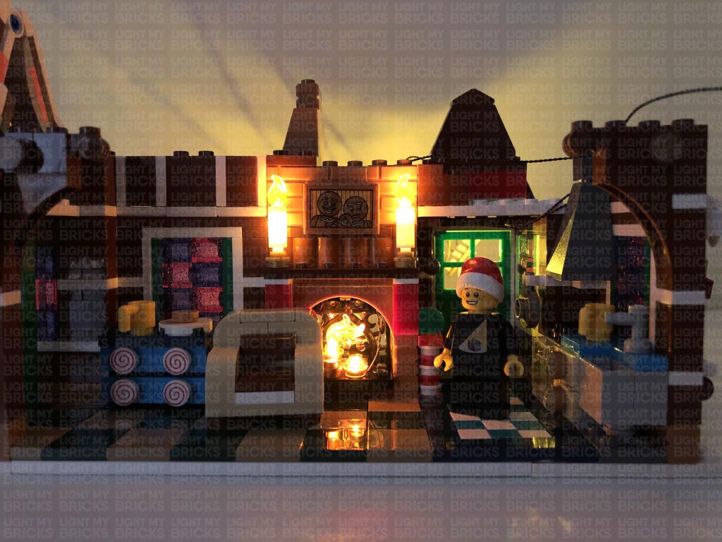
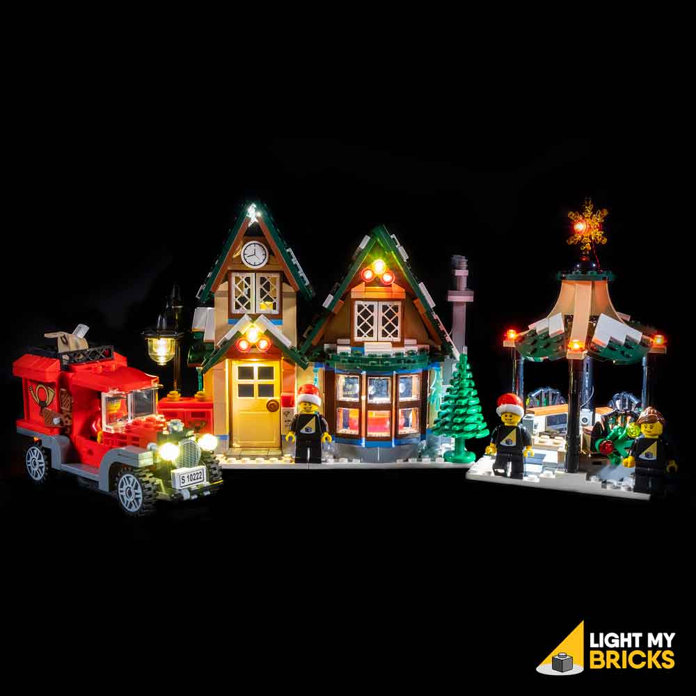
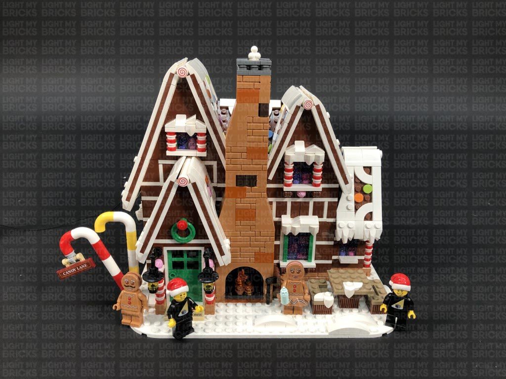
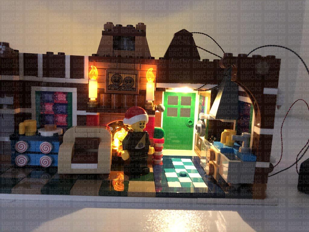
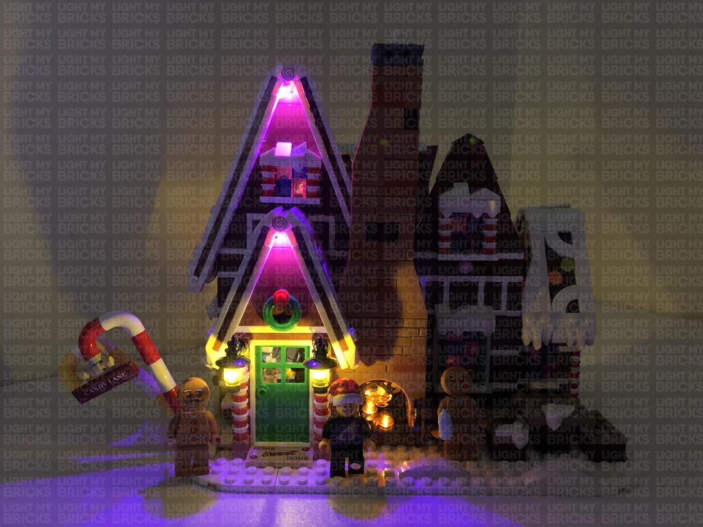
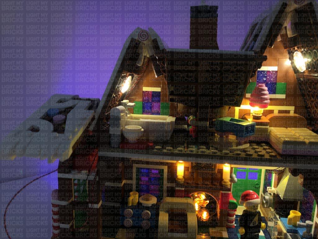
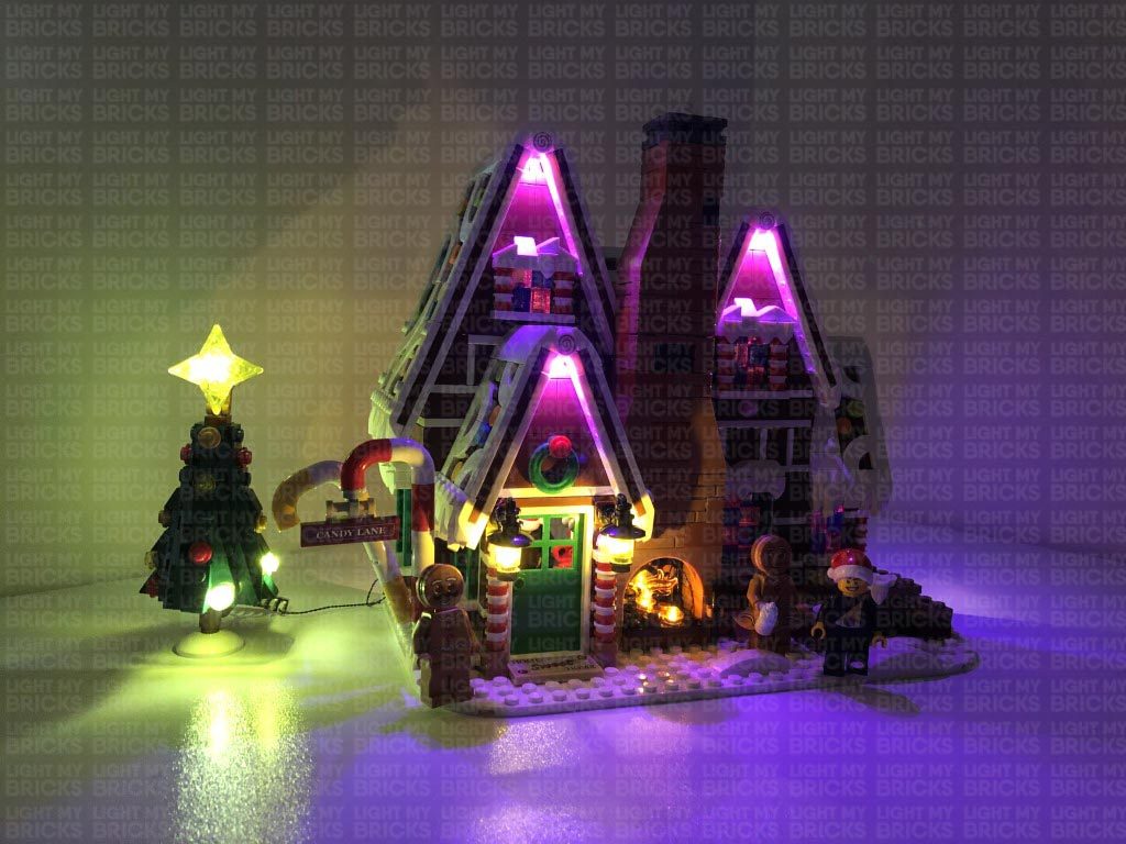
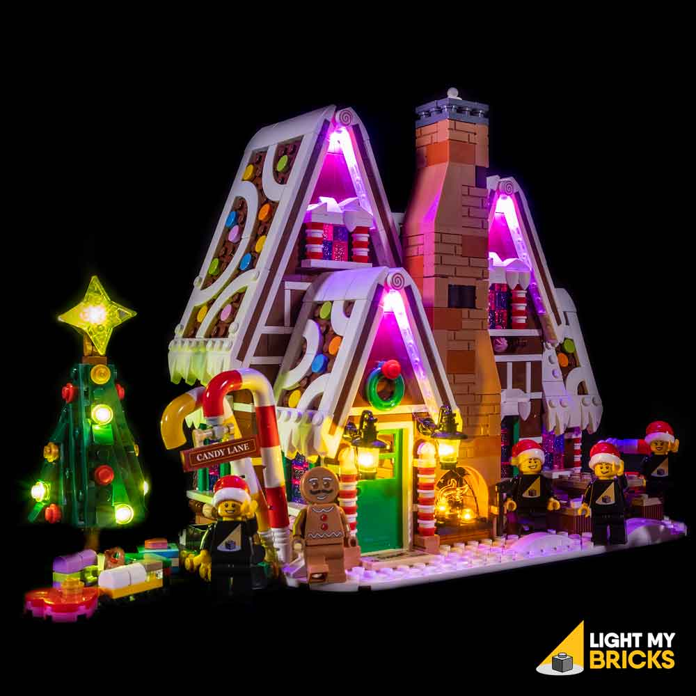
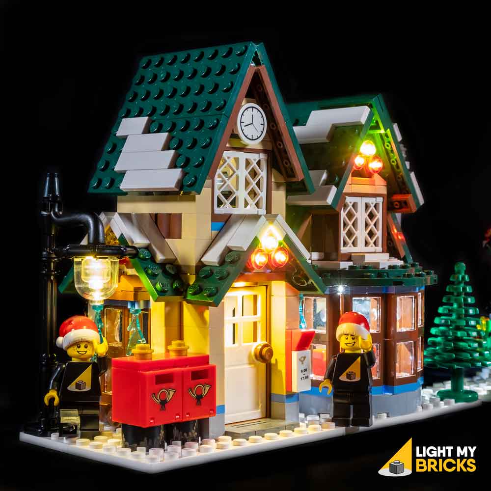
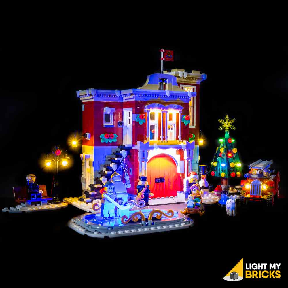
This finally completes installation of the Light My Bricks Winter Village Bakery Light Kit.
We thank you for purchasing this product and hope you Enjoy!


