To ensure a trouble-free installation of your light kit, please read and follow each step carefully. These instructions can be downloaded in PDF format here
Please note: This page lists instructions for the LED light kit only. If you are wishing to purchase the Light My Bricks LEGO Hogwarts Express (75955) LED light kit , please click here to view the product page
Package Contents:
7x White 15cm Bit Lights
2x White 30cm Bit Lights
3x White Strip Lights
1x Flicker Effects Board
3x 6-Port Expansion Boards
1x 5cm Connecting Cables
3x 15cm Connecting Cables
1x 30cm Connecting Cables
1x AA Battery Pack
1x USB Power Cable – USB Power Cable has replaced Flat or Round Battery Pack as of June 2022 due to child safety regulations
LEGO Pieces:
3x Plate 1×6 (any colour)
1x Trans Clear Plate 2×2 with Rounded Bottom
3x Trans Clear Round Plate 1×1
Important things to note:
Laying cables in between and underneath bricks
Cables can fit in between and underneath LEGO® bricks, plates, and tiles providing they are laid correctly between the LEGO® studs. Do NOT forcefully join LEGO® together around cables; instead ensure they are laying comfortably in between each stud.
CAUTION: Forcing LEGO® to connect over a cable can result in damaging the cable and light.
Connecting cable connectors to Expansion Boards
Take extra care when inserting connectors to ports of Expansion Boards. Connectors can be inserted only one way. With the expansion board facing up, look for the soldered “=” symbol on the left side of the port. The connector side with the wires exposed should be facing toward the soldered “=” symbol as you insert into the port. If a plug won’t fit easily into a port connector, do not force it.
Incorrectly inserting the connector can can result in bent pins inside the port or possible overheating of the expansion board when connected.
Connecting cable connectors to Strip Lights
Take extra care when inserting connectors to ports on the Strip Lights. Connectors can be inserted only one way. With the Strip Light facing up, ensure the side of the connector with the wires exposed is facing down. If a plug won’t fit easily into a port connector, don’t force it. Doing so will damage the plug and the connector.
Installing Bit Lights under LEGO® bricks and plates.
When installing Bit Lights under LEGO® pieces, ensure they are placed the correct way up (Yellow LED component exposed). You can either place them directly on top of LEGO® studs or in between.
OK, Let’s Begin!
1.) We will first light up the train station. First remove the train, then disconnect the bridge section and the following lamp sections by unclipping them from the wall.
2.) Disassemble the lamps as shown below, then take a White 30cm Bit Light and thread the connector end of the cable through the base (larger hole) of the trans yellow round brick. Thread it all the way in, then secure it in place by reconnecting the black clip on top. Ensure the LED on the bit light is facing the front of the brick.
Repeat this process to install another White 30cm Bit Light to the other lamp.
3.) Carefully disconnect the upper part of the wall so that it creates a gap where the lamps were connected to. Thread each lamp cable all the way through this space, then reconnect the lamp to the clip. Ensure the cables are laid neatly in between the studs as shown below:
Once the lamps are reconnected, carefully reconnect the upper wall section to close up the gap while ensuring the cables are laid neatly in between studs.
4.) Turn the station around to the back and fold down the cables against the wall so they run flat down the wall.
Secure the cables underneath the following bricks. First disconnect each brick, bring the cable inside, then reconnect the brick while ensuring the cable is laid in between studs. This will also eliminate unwanted cable from behind the set.
5.) Take a 6-Port Expansion Board and connect the two bit light cables to it. Take your AA Battery Pack and insert 3x AA Batteries to it. Connect the battery pack to the expansion board and turn it ON to test the lights we have installed so far are working OK.
USB Power Cable has replaced Flat & Round Battery Packs (CR2032) as of June 2022 due to child safety regulations. Please use the USB Power Cable in place of the Battery Pack.
Note: If you experience any issues with the lights not working and suspect an issue with a component, please try a different port on the expansion board to verify where the fault lies (with the light or expansion board). To correct any issues with expansion board ports, please view the section addressing expansion board issues on our online troubleshooting guide.6.) We will now light up the remaining wall lamp. First disconnect it then remove the black plate with clip from underneath.
Take a White 15cm Bit Light and with the cable facing the clip, lay it over the stud. Secure it in place by reconnecting the lamp piece over the top. Thread the cable through the top of the black plate’s clip, then pull it all the way out from underneath as shown below:
7.) Carefully disconnect the upper section of the wall to create another gap, then thread the bit light cable through the gap in between studs. Reconnect the lamp back to the wall, then close up the gap ensuring the cable is neatly laid in between studs.
Turn the set around to the back again and fold the cable down along the back of the wall. Turn the set onto it’s front so we can access underneath, then disconnect the long black brick. Connect the bit light cable to the next spare port on the 6-port Expansion Board below, then turn ON the battery pack to test the light is working OK.
Note: If you experience any issues with the lights not working and suspect an issue with a component, please try a different port on the expansion board to verify where the fault lies (with the light or expansion board). To correct any issues with expansion board ports, please view the section addressing expansion board issues on our online troubleshooting guide.8.) Take a 30cm Connecting Cable and connect it to a spare port on the expansion board, then reconnect the long black brick ensuring you first pull the 30cm cable all the way out, and pull the White 15cm Bit Light cable all the way inside. Also make sure each cable is laid in between studs before completely closing up the gaps.
9.) From the back of the set, take the other end of the 30cm Connecting Cable and thread it through the first gap on the bottom of the steps, then pull the cable all the way out from the front. From the front of the set, thread the cable back through the next gap up the steps and pull it all the way out from the back of the set.
10.) Partially disconnect the top section above the steps to create a gap, then bring the cable all the way up and thread it in between studs through this gap we created. Pull the cable all the way out from the other side, then close up the gap ensuring the cable is laid in between the studs.
Thread the cable underneath to bring the cable around to the front side
11.) Take the bridge section we removed earlier and turn it onto it’s back so we can access underneath. Take a White 15cm Bit Light and a provided LEGO Trans Clear Plate 2×2 with rounded bottom. Use this LEGO piece to install the Bit Light underneath the front platform of the bridge by connecting it to the roof with Bit Light LED facing down the centre of the trans clear piece. Ensure the other end of the cable is facing the bridge.
From the back of the bridge, partially disconnect the top section to create a gap above the dark grey brick. Bring the cable through this gap, then reconnect this section to close up the gap ensuring the cable is laid in between studs.
Follow the below images to continue to thread the cable around sections to eliminate excess cable:
12.) Take a White Strip Light and using it’s adhesive backing, stick it to the base of a provided LEGO Plate 1×6. Take the other end of the White 15cm Bit Light from underneath the bridge and connect it to the Strip Light.
Take the other end of the 30cm Connecting Cable from the other side of the station and connect it to the other side of the Strip Light. Mount the strip light underneath the bridge in the following position, then reconnect the bridge to the train station. Eliminate excess cabling from the White 15cm Bit Light by looping the cable underneath the strip light’s lego plate.
Eliminate excess cabling from the 30cm Connecting cable by twisting the cable around itself a few times, then tucking it in to the space underneath the steps as shown below ensuring they are tucked in between studs.
Follow the below images to continue to hide excess cables underneath and in between pieces.
Finally, turn ON the battery pack to test all lights installed to the train station are working OK.
13.) We will now light up the Hogwarts express train. First, disconnect the middle and back carriages, then disconnect the following sections from the front of the train.
14.) Take the following top section and disassemble it. Take a White 15cm Bit Light and with the cable facing the clip, place it over the gold stud. Secure it in place by connecting a provided Trans Clear Round Plate 1×1 over the top.
Thread the other side of the cable through the gap behind, then pull it all the way out from underneath. Reconnect the gold clip to the black piece, then reconnect this section to the front of the train.
Ensure the cable is laid in between the light grey studs before reconnecting the round Hogwarts Express dish piece over the top.
15.) Take the bottom section and disassemble it as per below.
Take a White 15cm Bit Light and place it over the left stud as per below. Secure it in place by connecting a provided LEGO Trans Clear Round Plate 1×1 over the top. Repeat this process to install another White 15cm Bit Light to the other side, securing it in place with another provided LEGO Trans Clear Round Plate 1×1.
Ensuring both cables are laid in between studs, reconnect the sections we removed earlier, then reconnect this bottom section back to the train.
16.) Turn the train over onto it’s side and disconnect the two sections underneath.
Take the three Bit Light Cables and thread them through the following gap in the middle of the back section we removed earlier, then connect them to a new 6-Port Expansion Board.
17.) Reconnect the two sections back underneath the train, ensuring all cables are laid in between studs.
Take a Round Battery Pack and insert 2x CR2032 Batteries to it. Connect the battery pack to the 6-port expansion board and turn it ON to test the lights on the front of the train are working OK.
Note: If you experience any issues with the lights not working and suspect an issue with a component, please try a different port on the expansion board to verify where the fault lies (with the light or expansion board). To correct any issues with expansion board ports, please view the section addressing expansion board issues on our online troubleshooting guide.18.) Disconnect the round battery pack and take 2x 15cm Connecting Cables and connect them to the 6-port expansion board.
Using the LEGO removal tool, disconnect the following black piece from the back of the train, then pull one of the 15cm cables all the way out towards the back. Secure the cable by reconnecting the black piece over the top ensuring the cable is laid in between studs.
Twist and fold excess cabling from underneath the train, then tuck them in neatly to prevent them from dangling down. Bring the other 15cm connecting cable toward the back and pull it up the left side of the train as shown below:
19.) Turn the train over and disconnect the following sections from the back.
Bring the other end of the 15cm cable from the left side and lay it in between studs before reconnecting the red 1×3 plate.
Lay the cable in between studs towards the front of the train, then secure it underneath the black and red plates.
20.) Connect the 15cm connecting cable to the IN port on the Flicker Effects Board.
Take the steam control cab and disconnect the following section from the back. Disassemble this section as per below:
21.) Take 2x White 15cm Bit Lights and hold them together over the studs on the front of the black brick. Ensuring the cables are facing the top of the black brick, secure them in place by reconnecting the red plate over the top.
Bring both cables over the top of the black brick, then reconnect the light grey brick over the top, ensuring cables are laid in between studs. Reconnect this section back to the steam control cab
22.) Take the following flame pieces and using a pair of scissors, carefully snip off the tips from the bottom. This will allow us to then reconnect them back to the control cab with Bit Lights installed underneath.
Connect the two bit light cables to the OUT ports on the Flicker Effects Board, then reconnect the control cab back to the train.
Eliminate excess cables by twisting/folding the bit light cables around each other so they come together in a neat bunch, then tuck them (along with the effects board) inside.
23.) Connect the other end of the 15cm Cable from the back of the train to a new 6-Port Expansion Board. Connect your Round Battery Pack to a spare port on the expansion board and turn it ON to test the flickering lights (along with the front lights) are working OK.
USB Power Cable has replaced Flat & Round Battery Packs (CR2032) as of June 2022 due to child safety regulations. Please use the USB Power Cable in place of the Battery Pack.
Note: If you experience any issues with the lights not working and suspect an issue with a component, please try a different port on the expansion board to verify where the fault lies (with the light or expansion board). To correct any issues with expansion board ports, please view the section addressing expansion board issues on our online troubleshooting guide.24.) Disconnect 15cm connecting cable from the expansion board, then reconnect all the sections surrounding the control cab on the back of the front carriage.
25.) Take the middle carriage and disconnect the roof and front wall. Reconnect the carriage to the front carriage, then bring the 15cm connecting cable inside.
Reconnect the connecting cable to the 6-port expansion board from previous step, then reconnect the front wall over the cable ensuring the cable is laid in between studs and that there is enough cable slack for the carriage to turn left/right.
26.) Take another 15cm Connecting Cable and connect it to the 6-port Expansion Board. Disconnect the back wall, then pull the other end of the cable all the way out the back. Reconnect the back wall over the top ensuring the cable is in between studs.
Neatly tuck the battery pack inside the carriage, then reconnect the roof.
27.) Take the back carriage and disconnect the roof as well as the following corner tile to allow us to remove the front wall section.
Reconnect the carriage to the middle carriage, then bring the other end of the 15cm cable back and inside the last carriage. Reconnect the front wall section over the cable ensuring it is laid in between studs. Ensure you also have enough cable slack between the two carriages for them to be able to turn left/right.
Tuck the cable in between the blue brick and front wall, then reconnect the corner tile.
28.) Take 2x White Strip Lights and using their adhesive backing, stick them to the back of 2x Plates 1×6. Connect the two strip lights together using a 5cm Connecting Cable.
Mount the two strip lights underneath the roof in the below positions.
29.) Bring the roof over the carriage and connect the other end of the 15cm connecting cable below to the Strip Light. Securely reconnect the roof.
Turn ON the battery pack to test the carriage lights are working OK.
This finally completes installation of the Light My Bricks Hogwarts Express Light Kit. We hope you enjoy and thank you for purchasing this product!
To ensure a trouble-free installation of your light kit, please read and follow each step carefully. These instructions can be downloaded in PDF format here
Please note: This page lists instructions for the LED light kit only. If you are wishing to purchase the Light My Bricks LEGO Hogwarts Castle (71043) LED light kit , please click here to view the product page
Package Contents:
32x White 30cm Bit Lights (30 required, includes 1-2 extra)
21x White 15cm Bit Lights (20 required, includes 1 extra)
5x White Strip Lights
1x Green Strip Light
5x 6-Port Expansion Boards
3x 8-Port Expansion Boards
3x 12-Port Expansion Board
2x Flicker Effects Boards
6x 5cm Connecting Cables
5x 15cm Connecting Cables
5x 30cm Connecting Cables
2x 50cm Connecting Cables
1x USB Power Cable
1x RGB Board
1x RGB IR Remote Control
5x RGB Strip Lights
3x RGB 15cm Connecting Cables
2x RGB 30cm Connecting Cables
LEGO Pieces:
6x Plate 1×6 (Any Colour)
1x Trans Yellow Round Plate 1×1
2x Trans Orange Round Plate 1×1
4x Trans Clear Plate w Rounded Bottom 2×2
10x Black Round Plate 1×1 with open stud
6x Pearl Gold Round Plate 1×1 with open stud
Spot Light LEGO Pieces
8x Black Plate 1×6
5x Black Plate 1×2 modified w Handle on End
5x Black Tile 1×1 w Clip
5x Black Plate 1×2 modified with stud jumper
2x Black Dish Inverted 3×3
Important things to note:
Laying cables in between and underneath bricks
Cables can fit in between and underneath LEGO® bricks, plates, and tiles providing they are laid correctly between the LEGO® studs. Do NOT forcefully join LEGO® together around cables; instead ensure they are laying comfortably in between each stud.
CAUTION: Forcing LEGO® to connect over a cable can result in damaging the cable and light.
Connecting cable connectors to Expansion Boards
Take extra care when inserting connectors to ports of Expansion Boards. Connectors can be inserted only one way. With the expansion board facing up, look for the soldered “=” symbol on the left side of the port. The connector side with the wires exposed should be facing toward the soldered “=” symbol as you insert into the port. If a plug won’t fit easily into a port connector, do not force it.
Incorrectly inserting the connector can can result in bent pins inside the port or possible overheating of the expansion board when connected.
Connecting cable connectors to Strip Lights
Take extra care when inserting connectors to ports on the Strip Lights. Connectors can be inserted only one way. With the Strip Light facing up, ensure the side of the connector with the wires exposed is facing down. If a plug won’t fit easily into a port connector, don’t force it. Doing so will damage the plug and the connector.
Installing Bit Lights under LEGO® bricks and plates.
When installing Bit Lights under LEGO® pieces, ensure they are placed the correct way up (Yellow LED component exposed). You can either place them directly on top of LEGO® studs or in between.
OK, Let’s Begin!
1.) We will start by installing lights to the left section of the castle. Split the two sections and then disconnect the boat house entrance at the very front of the set.
Disconnect the two torch pieces from the front of the boat house then disconnect the two round plates from each side:
Take out the following 2x Provided Black Round Plate 1×1 with open stud and 2x White 30cm Bit Lights.2.) Carefully bend the bit light component from each light up on a 90 degree angle as shown below:
Place the Bit Light facing up inside the bottom of one of the provided Black Round Plates. Secure the light in place by reconnecting the two round plates from one of the torch pieces over the top as shown below. Reconnect the torch section back to the brick with clip ensuring the cable is facing the back.
Repeat this step to install another Bit Light to the torch on the other side, then reconnect both sections to the outside of the boat house.
3.) Reconnect the boat house back to the front of the set ensuring the cables are laid behind and in between studs of the rear wall.
4.) Follow the below images to disconnect pieces around the entrance courtyard side wall
Lay the two Bit Light cables from the boat house across and then up the wall through to the inside of the court yard. Hide the cables behind the tree pieces and stone pieces. Lay the cables in between studs before reconnecting pieces we removed earlier to close up the wall.
5.) Disconnect the following section to allow us to remove the two side window sections near the great hall clock then disconnect the 1×1 plates from the bottom of each section.
Take a White 30cm Bit Light and place it over the stud of the 1×1 plate. Secure it in place by reconnecting the section over the top.
Repeat this step to install another White 30cm Bit Light to the other side.
6.) Reconnect the left section and then thread the cable through the space of the right window as shown below:
Take the right section and thread the cable through the space of the right window before reconnecting this, followed by middle section we removed earlier
7.) Take a 6-Port Expansion Board and connect the bit lights from the front of the boat house as well as from either side of the clock to it.
Test the lights we have installed so far by connecting the USB Power Cable to a spare port on the expansion board. Connect the cable to a USB Power Bank and verify all lights are working OK.
Disconnect the USB Power Cable and proceed to the next step.
8.) Remove the following pieces along the rear wall of the courtyard.
Take a 30cm Connecting Cable and a 50cm Connecting Cable and connect one end of each cable to spare ports on the 6-port expansion board.
Take both connecting cables and thread them over to the other side of the castle as shown below. Turn the set over and pull them out from the other side and ensure they are both slipped down the following space in between walls.
Lay both cables down in between studs before reconnecting pieces we removed earlier surrounding the rear wall. Ensure the components and cables are all neatly tucked into the sides so they are not obviously seen from above.
9.) We will now light up the lamps running along the left side of the castle. Starting with the first three, disconnect the following section which they sit on then disconnect the black lamp posts as well as trans yellow round plates.
Take 2x White 30cm Bit Lights and install them to the first two lamps by placing the bit light directly over the black lamp post and securing it in pace by reconnecting the trans yellow round plate over the top. Bend the cable slightly up at the base of the lamp post. This will help lay the cable down later on and help conceal the wiring. Reconnect the two lamps to the base.
Take a White 15cm Bit Light and install it to the third lamp post then reconnect this back to the base.
Reconnect this whole section back to the outside of the great hall then lay the three cables down toward the left side as shown below:
10.) Disconnect the next section along where the next three lamp posts are connected to. Take 3x White 15cm Bit Lights and install these to the lamps, following the same method used in previous step.
11.) Disconnect the two sections which the remaining three lamp posts are connected to then install another 3x White 15cm Bit Lights to them as per below except this time, ensure the cables are facing directly behind rather than toward the left
12.) Take a 12-Port Expansion Board and connect all nine light cables to it starting with the first ones we installed to the first ports on the right of the board.
Take a 15cm Connecting Cable and connect it to the far left port on the expansion board. Take your USB Power Cable and connect it to the next port along.
13.) Disconnect the three lamps on left side then neaten up cabling by first grouping the first six bit light cables together closest to the expansion board and then folding and twisting them around each other a few times so they bunch up nicely together. Tuck them into the space in between expansion board and edges.
Reconnect the three left lamp posts then group the cables closest to the expansion board and then fold and twist them around each other a few times then flatten the cables. Secure the cables underneath the plate section below then tuck the cables inside the following space underneath.
Tuck in any remaining excess cables to prevent them from being too obviously seen from the outside.
Hide the USB Power Cable and 15cm Connecting Cable underneath the following plate:
Test all lights are working OK by connecting the USB Power Cable to the USB Power Bank again.
14.) Take a 6-Port Expansion Board and connect the other end of the 15cm connecting cable to the far right port.
15.) We will now install lights to the four torches inside the great hall. First disconnect the four torch pieces and then disconnect the flame pieces from the pearl gold bases.
Take out the following provided 4x Pearl Gold Round Plate 1×1 with open stud
Take a White 30cm Bit Light and then slightly bend it up on a 90 degree angle as shown below.
Place the Bit Light (facing up) inside the pearl gold base. Secure the Bit Light in place by reconnecting one of the provided Pearl Gold Round Plate with open stud over the top (upside down). The Bit Light’s LED should be showing through the hole of the round plate as shown below:
Take one of the flame pieces and using a pair of scissors, cut the tip off the bottom of it then reconnect the flame piece to the torch base.
16.) Repeat the previous step to install another 3x White 30cm Bit Lights to the remaining three torches then reconnect each one back to the great hall ensuring the cable is facing behind and in between clips.
17.) Take a new 6-Port Expansion Board and connect all four bit light cables from the torches to it. Take a 5cm Connecting Cable and connect it a spare port on the expansion board.
Connect the other end of the 5cm Connecting Cable to one of the OUT ports on a Flicker Effects Board.
Take another 5cm Connecting Cable and connect it to the IN port on the Flicker Effects Board.
Take the other end of the 5cm Connecting Cable and connect it to a spare port on the 6-port Expansion board from the right side of the hall.
Test the Fire torch lights by connecting up the USB Power Bank again and verifying all is working OK.
18.) Take a Green Strip Light and using it’s adhesive backing, stick it to the base of a provided LEGO Plate 1×6
Take a 5cm Connecting Cable and connect it to one side of the strip light, then connect the other end of the cable to the 6-port Expansion board on the far right side of the set (expansion board without the fire torch cables connected to it).
19.) Take the other end of the 30cm Connecting Cable we pulled over from the front side of the castle and connect it to the other side of the Green Strip Light
Using it’s LEGO plate, mount the strip light to the ceiling of the chamber of secrets as shown below:
20.) We now need to hide the wires from the four torches in the great hall. First disconnect the following sections on the right of the hall.
Lay the two right cables across and then down the right side in between studs. Lay the two left cables across and then down in between the next studs to the left of the right cables. Secure them down by reconnecting sections over the top.
Disconnect the four torch bit light cables from the 6-port expansion board and then twist the cables around each other so they come together forming a larger cable. Reconnect the bit lights back to the expansion board.
Neatly tuck all the components into the space on the right side of the chamber of secrets then hide the connecting cable on the right side underneath rock pieces.
Turn On the USB Power Bank to verify all is working OK
21.) We will now move onto lighting the inside of the main tower. Disconnect the large wall sections from each side of the tower by pushing them out from the inside at the top and bottom using your finger, then pulling the entire section out.
Disconnect the right side of the roof and then pull up the other end of the 50cm Connecting Cable from the bottom of the tower. Secure the cable in place underneath the following dark grey piece on top of the tower.
22.) Take an 8-Port Expansion Board and connect the other end of the 50cm Connecting Cable to it then disconnect the left side of the roof.
Take another 50cm Connecting Cable and connect one end to the expansion board. Thread the other end of the 50cm Connecting Cable through the right side of the tower and then pull it all the way out from the left side. Secure the cable underneath the dark grey brick on the side then bring the cable all the way down to the bottom of the tower.
23.) Take a White 30cm Bit Light and a provided Trans Clear Plate w Rounded Bottom 2×2. Place the Bit Light facing down in the centre of the trans clear plate then connect it underneath the roof of the first staircase room (at the bottom of the tower) ensuring the cable is laid toward the right.
Bring the other end of the bit light all the way up to the top of the tower and connect it to the 8-port expansion board then tuck the cable underneath bricks in between floors (slightly disconnect and reconnect section over the top of the cable)
Take another White 30cm Bit Light and a provided Trans Clear Plate w Rounded Bottom 2×2. Place the Bit Light facing down in the centre of the trans clear plate then connect it underneath the roof of the second staircase room ensuring the cable is laid toward the right.
Bring the other end of the bit light all the way up to the top of the tower and connect it to the 8-port expansion board then tuck the cable underneath bricks in between floors (slightly disconnect and reconnect section over the top of the cable)
24.) Take a White 15cm Bit Light and a provided Trans Clear Plate w Rounded Bottom 2×2 and connect them underneath the roof of the top staircase level ensuring the cable is laid toward the right.
Connect the other end of the white 15cm bit light to the 8-port expansion board then tuck the cable underneath bricks in between floors (slightly disconnect and reconnect section over the top of the cable)
25.) Take another White 15cm Bit Light and a provided Trans Clear Plate w Rounded Bottom 2×2 and connect them underneath the roof of the very top floor ensuring the cable is laid toward the right.
Connect the other end of the bit light cable to the expansion board then turn ON the USB Power Bank to verify all lights in the tower are working OK
26.) We will now install lights to the two torches. First disconnect the round plates from each side and then follow method used in step 2 to install a Bit Light to each torch using provided 2x Black Round Plate 1×1 with open stud.
Use a White 15cm Bit Light for the right torch and use a White 30cm Bit Light for the Left torch.
Carefully bend the bit light component from each light up on a 90 degree angle as shown below:
Place the Bit Light facing up inside the bottom of one of the provided Black Round Plates. Secure the light in place by reconnecting the two round plates from one of the torch pieces over the top as shown below. Reconnect the torch section back to the brick with clip ensuring the cable is facing the back.
27.) Reconnect both torches to the tower then take the right torch cable (White 15cm Bit Light) and connect it to the 8-port expansion board
Use the LEGO Removal tool to slightly disconnect the the top section of the tower to create a small gap.
Slip both of the cables underneath (in between studs). Pull the left torch cable out the right side before securely reconnecting the top section of the tower then connect the left bit light cable to the expansion board.
28.) Eliminate excess cable by pulling up all six cables and grouping them together close the expansion board . Twist and fold them together so they bunch up nicely as shown below.
Neatly tuck the components inside the space on the right side of the roof then reconnect the main right wall section ensuring there are no visible cables hanging out on the sides.
Reconnect the right roof section then use some tape to tape down the cables along the right side of the tower.
29.) Before we reconnect the main left wall section we are going to install some lights for the tower windows. First disconnect the following sections of the tower.
30.) Take one of the thinner upper and lower wall sections and disconnect the following trans black plates only.
Take a White 30cm Bit Light and with the cable facing to the right, place it directly over one of the studs where the trans black plate was disconnected from. Secure the bit light in place by reconnecting one of the trans black plates over the top.
Repeat this step to install another 4x White 30cm Bit Lights to these two sections ensuring the cables are all facing toward the right side.
31.) Reconnect both of these sections back to the tower starting from the left side, then reconnect the larger centre wall section ensuring the five cables are pulled out.
Connect the five Bit Light cables as well as the other end of the 50cm Connecting Cable from the bottom of the tower to a new 12-port Expansion Board then turn the USB Power Bank ON to verify all the lights installed in the tower so far are working OK.
32.) Take the remaining upper and lower wall section of the tower and install 5x White 30cm Bit Lights underneath the following trans black plates (same as we did for the other wall section of the tower)
Reconnect these two sections back to the tower then connect the five Bit Light cables to the 12-port Expansion Board. Turn ON the power bank to confirm all the lights in the tower are working OK.
33.) Take a 30cm Connecting Cable and connect one end to the remaining port on the 12-port Expansion Board then pull all the cables down the edge of the tower and secure in place with your index finger.
While still holding down the cables with a finger, group the cables together and twist and fold them around each other to eliminate excess cable then push the cables into the space at the bottom of the tower in between walls.
Push the expansion board inside this space to completely hide the component and wiring. Ensure you keep the other end of the 30cm Connecting Cable out as we will require this to connect up to the other side later on.
34.) Reconnect the left roof section then ensure all cables are tucked in neatly in between walls before reconnecting the main left wall section.
This completes installation of lights to the left side of the Hogwarts Castle. Turn ON the power bank to ensure all lights we have installed so far are working OK.
35.) We will now install lights to the right side of the castle. Take this section and disconnect two lamps (round black and trans yellow plates) on the left side of this side, behind this side, and from the outside of the viaduct hall entrance (6 in total).
36.) Take 6x White 30cm Bit Lights and follow the same method used in step 2 to install them to each lamp section using provided 6x Black Round Plate 1×1 with open stud
Carefully bend the bit light component from each light up on a 90 degree angle as shown below:
Place the Bit Light facing up inside the bottom of one of the provided Black Round Plates. Secure the light in place by reconnecting the two round plates from one of the torch pieces over the top as shown below. Reconnect the torch section back to the brick with clip ensuring the cable is facing the back.
37.) Reconnect two lit torches to the left side as well to the outside of the Viaduct hall entrance.
Turn the set over and remove the two pillars before reconnecting the two torches to this wall.
Using a LEGO Removal tool, create a gap underneath the torches in the following position then tuck each cable underneath to lead to the other side of the wall. Reconnect the two pillars then reconnect and close up the gaps ensuring the cables are neatly laid in between studs.
38.) Disconnect the following brick and then group the two cables from each side together and lay them down along the floor in between studs before reconnecting the brick we just removed over the top.
Continue to lay the two sets of cables underneath rock pieces to secure them down the edges of the castle.
39.) Remove the following pieces from the left side of the Viaduct Hall entrance. Lay the cable from the left lamp down in between the following studs before reconnecting the 1×2 brick over the top.
Disconnect more pieces from the outside of the entrance then lay the cable from the right lamp down and across the ground in between studs before reconnecting pieces over the top.
Bring both cables down the edges of the set and hide them underneath the following rock pieces.
Be careful doing this to ensure you do not pinch the cables (which will result in Bit Lights not light up)40.) Take a 12-Port Expansion Board and connect all six Bit Light cables to it.
Bring the left side of the castle over and connect the other end of 30cm Connecting Cable from this side to the 12-port expansion board on the right side of the castle. Turn the Power Bank on to verify all six lamps are working OK.
Note: If you find that any of the lamps are not lighting up, check the cabling where we laid them underneath rock pieces on the front edges of the set (disconnect the rock pieces that are connected over the top of cables).
Disconnect the 30cm Connecting Cable to allow us to maneuverer the right side of the set more easily.
41.) Take a new 30cm Connecting Cable and connect one end of the cable to the 12-Port Expansion Board.
Disconnect the following brick again then use your LEGO removal tool to disconnect the dark tan plate from underneath as well as to create a gap underneath the light grey plate as shown below
42.) Take the other end of the 30cm Connecting Cable we connected to 12-port expansion board and thread it through the gap we just created. Turn the set around and from inside the chess board room, pull the cable out from the top right.
Take a White Strip Light and using it’s adhesive backing, stick it to the base of a provide LEGO Plate 1×6. Connect the cable from the top of the chess board room to the right port on the Strip Light then take a 15cm Connecting Cable and connect it to the left of the strip light.
Mount the strip light to the ceiling of the chess board room in the following position.
Pull the other end of the 15cm Connecting Cable over to the left side of the chess board room through to the mirror of erised room.
43.) Turn the set back over to the front and pull the 30cm Connecting Cable all the way out before reconnecting the grey plate and closing up the gap.
Lay the connecting cable down in between studs before reconnecting the 1×8 brick.
44.) Turn the set back over to the back side and then connect the other end of the 15cm Connecting Cable to a new 6-Port Expansion Board.
Disconnect the following sections that sit above the mirror of erised room then tuck the cable underneath the following section as shown below:
45.) Disconnect the whole section of Umbridge’s office as shown below then disconnect the pink dish as well as the round plates inside.
Discard the White round plate and replace it with a provided LEGO Trans Yellow Round Plate 1×1. Take a White 30cm Bit Light and place it over the top of one of the trans yellow round plates. Secure the light in place by reconnecting the other trans yellow round plate over the top.
Reconnect this back to the inside of the Pink dish then reconnect this back above Umbridge’s office ensuring the cable is facing the back.
Disconnect the roof section and thread the bit light cable through the back and then out the right side in between the following bricks as shown below then reconnect the roof section. Reconnect the whole Umbridge’s Office section to the castle.
Pull the Bit Light cable from Umbridge’s office down and connect it to the 6-port expansion board below.
46.) Disconnected all sections in the mirror of erised room then disassemble all four fire sections.
Using a pair of scissors, snip off the tips at the bottom of each flame piece.
Take a White 15cm Bit Light and place it over the top of a provided Trans Orange Round Plate 1×1. Secure the light in place by reconnecting the trans orange round plate with open stud over the top then reconnect a flame piece on top.
47.) Take the connector end of the Bit Light and thread it underneath the dark tan 2×8 plate. Pull it out from the other side then reconnect the fire section to the right side as shown below:
Using the same method used for the right fire section, install another White 15cm Bit Light to the left fire section using another provided Trans Orange Round Plate 1×1 then reconnect this to the mirror of erised room.
48.) Follow the same method used for the fire torches in the great hall in step 15 to install another 2x White 15cm Bit Lights to fire torches in this room using another provided 2x Pearl Gold Round Plate 1×1 with open stud.
Slightly bend the Bit Light up on a 90 degree angle as shown below.
Place the Bit Light (facing up) inside the pearl gold base. Secure the Bit Light in place by reconnecting one of the provided Pearl Gold Round Plate with open stud over the top (upside down). The Bit Light’s LED should be showing through the hole of the round plate as shown below:
Take one of the flame pieces and using a pair of scissors, cut the tip off the bottom of it then reconnect the flame piece to the torch base.
Reconnect both fire torches to the room ensuring both cables are pulled up underneath the 2×8 plate.
49.) Group the four cables together and twist them around each other so they all come together forming a larger cable then connect them to a new 6-Port Expansion Board
Take a 5cm Connecting Cable and connect it to the 6-port expansion board. Connect the other end of the cable to one of the OUT ports on a new Flicker Effects Board.
Take another 5cm Connecting Cable and connect it to the IN port on the Flicker Effects Board. Connect the other end of the connecting cable to the other 6-port expansion board (where the light from Umbridge’s Office is connected to).
Reconnect the 30cm Connecting Cable from the left side of the castle and then turn ON the power bank to verify all lights and effects installed to the right side of the castle are working OK.
50.) Neatly tuck in the cables, effects board and two expansion boards inside the back left side of the mirror of erised room.
Before completely tucking in the right expansion board (where the light from Umbridge’s Office is connected to), take a 30cm Connecting Cable and connect it to a spare port on this expansion board. Once done, tuck in the expansion board along with any other remaining cables as shown below.
Use a bit of tape to secure down the Bit Light cable from Umbridge’s office coming down the wall then reconnect all sections on top of the mirror of erised room.
51.) Take 2x White Strip Lights and stick them to 2x provided LEGO Plates 1×6. Take one of the strip lights and connect a 15cm Connecting Cable to it’s left port then take the other end of the 30cm Connecting Cable from the mirror of erised room and connect it to the strip light’s right port.
Mount the strip light we just connected cables to, to the ceiling of the Potions Classroom then feed the other end of the 15cm connecting cable over to the Room of Requirement and connect it to the right port on the other White Strip Light
Hide the connecting cable between the mirror of erised room and the potions classroom behind bricks and tree pieces as shown below:
52.) Take a 30cm Connecting Cable and connect it to the left port on the Strip Light from previous step then mount the strip light to the ceiling of the Room of Requirement in the following position:
Eliminate excess cable from the 15cm connecting cable in between strip lights by looping it underneath this strip light as shown below:
Bring the other end of the 30cm connecting cable over to the left and hide it behind the tree on the left side.
53.) Using your hand gently push up the roof of the Viaduct Entrance Hall to create a small gap at the bottom in between levels then thread the 30cm connecting cable through to the inside of the hall. Pull the cable all the way out from the inside then reconnect the roof down to close up the gap ensuring the cable is in between studs in the corner.
54.) Take another White Strip Light and stick it to a provided LEGO Plate 1×6. Connect the other end of the 30cm connecting cable to the left port on the strip light then take a new 15cm Connecting Cable and connect it to the strip light’s right port.
Thread the other end of the 15cm connecting cable up and over the following brick along the ceiling of the hall then mount the strip light to the hall ceiling above the library as shown below:
You can also pull up and hide excess cable from the 30cm connecting cable by looping it underneath the strip light and tucking it into the spaces above.
Thread the other end of the 15cm Connecting Cable through and over the next brick on the ceiling then pull it out from the other side and connect it to left port on the remaining White Strip Light stuck onto a provided LEGO Plate 1×6.
55.) Turn the set around then disconnect the left section surrounding the front of the circular opening above the viaduct entrance then take a new 15cm Connecting Cable and thread it through the space that leads down to the inside of the hall.
Turn the set back around and pull the cable down to connect the strip light’s right port.
Mount the strip light to the ceiling above the Gryffindor Common room area as shown below. Ensure the 15cm connecting cable we threaded through from above is on the left side.
Turn ON your USB Power Bank to test all the strip lights we have installed so far are working OK
56.) Turn the set around to the front again and disconnect the following sections surrounding the top of the viaduct entrance hall to allow us to remove the section with the four trans coloured round plates connected to it.
Take this section and disconnect the trans coloured round plates then take a White 15cm Bit Light and place it over one of the top studs. Ensuring the cable is facing down and in between studs, secure the light in place by reconnecting a trans coloured stud over the top.
Repeat this process to install another 3x White 15cm Bit Lights to the remaining studs ensuring the cables are all facing down and laid down the middle.
57.) Group the cables together and twist them around each other so they come together to form one larger cable. Reconnect this section back to the top of the viaduct entrance hall then connect all four cables as well as the 15cm connecting cable we threaded down to the remaining 8-Port Expansion Board58.) We will now install some lights to shine through the windows of the towers on each side of the viaduct entrance hall. First disconnect the top sections of each tower as shown below:
Use your LEGO Removal Tool to disconnect the following section and pieces from the right tower to allow us to remove the two windows sections.
59.) Remove the dark grey bricks from each window section then reconnect the window sections to the tower (without the dark grey bricks).
Take a White 15cm Bit Light and place it (facing down) over the top of the tower. Lay the cable down across to the left and then hold it in place with a finger. Secure the bit light down by reconnecting the bright green 2×2 plate then reconnect the corner section.
60.) Disconnect more sections from the right side of the roof then bring the Bit Light cable over and connect it to the 8-Port Expansion Board.
Lay the cable down in between studs then reconnect roof pieces over the top as well as the remaining sections that make up the roof of this tower.
61.) Repeat previous steps to disconnect sections off the top of the left tower and to install another White 15cm Bit Light to this side.
Turn ON the USB Power Bank to verify all lights installed so far are working OK.
62.) Fold the larger group of Bit Light cables in half and then thread the folded end down through the space that leads to the inside of the Hall. Neatly hide the rest of the cables and expansion board down underneath the trans coloured plates before reconnecting all roof and surrounding pieces over the top.
63.) Neaten up cabling on the outside of the set by grouping all cables together (except for the 30cm connecting cable in between the two sides of the set) and folding and twisting them around each other so they bunch up together neatly.
This finally completes installation of all the main lights for the Hogwarts Castle. Reconnect both sides together and then turn the power bank ON to verify all lights are working OK.
64.) We will now install spot lights on the outside of the set to project onto the castle. First take out the RGB Board and connect a 5cm Connecting Cable to the IN port (port with 5V). Take the other end of the cable and connect it to a spare port on the 12-Port Expansion Board at the front of the castle.
65.) Take out the following LEGO pieces and follow the below images to assemble them into two ground spot lights.
2x Black Plate 1×6
2x Black Plate 1×2 modified w Handle on End
2x Black Tile 1×1 w Clip
2x Black Plate 1×2 modified with stud jumper
2x Black Dish Inverted 3×3
Take out 2x RGB Strip Lights and using it’s adhesive backing, stick them each ground spotlight (to the base of the black 1×6 plates)
66.) Take out the following pieces and following the below images to assemble three upper spot lights
6x Black Plate 1×6
3x Black Plate 1×2 modified w Handle on End
3x Black Tile 1×1 w Clip
3x Black Plate 1×2 modified with stud jumper
Take out 3x RGB Strip Lights and using it’s adhesive backing, stick them to the three upper spot lights (to the base of the black 1×6 plates)
67.) Take a RGB 30cm Connecting Cable and connect one end to the left port on one of the ground spot lights. Connect the other end of the cable to the left port on one of the upper spot lights.
Place the ground spot light on the left of the set to project up onto the outside of the great hall then connect the upper spot light toward the right of the set to project up onto the other side. Hide the RGB cable underneath the base of the boat house entrance.68.) Take a RGB 15cm Connecting Cable and connect one end to the right side of the upper spot light we just installed then connect the other side of the cable to the other ground spot light. Place the ground spot light outside the front of the Viaduct bridge to project up onto the front of the Viaduct Entrance Hall
69.) Take a RGB 30cm Connecting Cable and connect one end to the ground spot light then thread the other end of the cable under the viaduct bridge through the following space.
Pull the cable through and then connect it to the left port on another upper spot light. Connect this upper spot light to the bottom outside the castle so that it will project up onto the right side of the castle.
70.)Take another RGB 15cm Connecting Cable and connect one end to the upper spot light we just installed then connect the other side of the cable to the left port on the remaining upper spot light.
Connect the spot light to the below position to allow it to project up onto the large main tower of the castle.
71.) Take the remaining RGB 15cm Connecting Cable and connect it to the right port on the upper spot light we just installed then connect the other side of the cable to one of the OUT ports on the RGB Board.
Lastly, ensure the RGB Board is facing the correct way up so that the IR sensor is visible and in line of sight to the remote control we will use to control it.
Controlling the RGB Spot Lights
Use the provided RGB Remote Control to control the RGB Spot Lights at the front of the Hogwarts Castle. Prior to using it, ensure you remove the plastic tag to activate the batteries inside.
By default the spot lights are turned off even when the other castle lights have been turned on.
To control the RGB lights, point the remote control toward the RGB Board and then turn the lights on via the ON button. Choose your desired colour by pressing any of the coloured buttons. You can also control the brightness as well as choose from one of the following effects:
Flash – Flash effect on your chosen colour
Strobe – Will flash quickly while cycling through all the colours
Fade – Will cycle through all the colours 3 seconds at each colour
Smooth – Will cycle through all the colours 7 seconds at each colour
This finally completes installation of your Light My Bricks Hogwarts Castle Light Kit.
We hope you enjoy and we thank you for purchasing this product.
To ensure a trouble-free installation of your light kit, please read and follow each step carefully. This instructions guide can be downloaded in PDF format here
Please note: This page lists instructions for the LED light kit only. If you are wishing to purchase the Light My Bricks LEGO Aston Martin DB5 (10221) LED light kit , please click here to view the product page
Package Contents:
11x White 15cm Bit Lights
1x 6-Port Expansion Board
1x 12-Port Expansion Board
1x 30cm Connecting Cable
1x USB Power Cable –
USB Power Cable has replaced Flat & Round Battery Packs (CR2032) as of June 2022 due to child safety regulations. Please use the USB Power Cable in place of the Battery Pack.
LEGO Pieces:
4x Trans Clear Round Plate 1×1
2x Trans Red Round Plate 1×1
1x Trans Clear Plate w Rounded Bottom 2×2
1x Plate 2×8 (Any Colour)
Important things to note:
Laying cables in between and underneath bricks
Cables can fit in between and underneath LEGO® bricks, plates, and tiles providing they are laid correctly between the LEGO® studs. Do NOT forcefully join LEGO® together around cables; instead ensure they are laying comfortably in between each stud.
CAUTION: Forcing LEGO® to connect over a cable can result in damaging the cable and light.
Connecting cable connectors to Expansion Boards
Take extra care when inserting connectors to ports of Expansion Boards. Connectors can be inserted only one way. With the expansion board facing up, look for the soldered “=” symbol on the left side of the port. The connector side with the wires exposed should be facing toward the soldered “=” symbol as you insert into the port. If a plug won’t fit easily into a port connector, do not force it.
Incorrectly inserting the connector can can result in bent pins inside the port or possible overheating of the expansion board when connected.
Connecting cable connectors to Strip Lights
Take extra care when inserting connectors to ports on the Strip Lights. Connectors can be inserted only one way. With the Strip Light facing up, ensure the side of the connector with the wires exposed is facing down. If a plug won’t fit easily into a port connector, don’t force it. Doing so will damage the plug and the connector.
Installing Bit Lights under LEGO® bricks and plates.
When installing Bit Lights under LEGO® pieces, ensure they are placed the correct way up (Yellow LED component exposed). You can either place them directly on top of LEGO® studs or in between.
OK, Let’s Begin!
1.) We will first install the headlights of the Aston Martin. Start by disconnecting the front sections that run along the side of the vehicle.
Disassemble the two sections as per below:
2.) Take a White 15cm Bit Light and place it directly over the stud of the grey piece. Secure the light in place by reconnecting the trans clear dish piece over the top. Ensure the cable is facing down with the clip behind it horizontal.
Reconnect this headlight back to one of the long sections, ensuring the cable is facing down, then repeat this process to install another White 15cm Bit Light to the other headlight.
3.) Disconnect the following sections from the front of the vehicle and then disassemble the left section as per below:
4.) Take a White 15cm Bit Light and thread the connector end of the Bit Light through the front hole of the light grey brick. Thread the cable all the way through and then out the bottom of the brick. Secure the Bit Light in place by connecting a provided Trans Clear Round Plate 1×1 over the top.
Reconnect the brick back to the rest of the section it was connected to ensuring the cable is facing the inside (toward the right).
Repeat this process to install another White 15cm Bit Light to the other light section using another provided Trans Clear Round Plate 1×1, this time ensuring the cable is facing toward the left.
5.) Reconnect one of the light sections we just installed to the front of the car then thread the cable back behind the wheel as shown below. Repeat this process for the other light section.
6.) Reconnect the two long sections (headlights) ensuring you first thread the Bit Light cable behind the wheel as shown below:
Pull the two light cables all the way out from underneath behind each front wheel.
7.) Take a 6-Port Expansion Board and connect all four Bit Light cables to it.
Take the Flat Battery Pack and insert 2x CR2032 Batteries to it. Connect the battery pack cable to the expansion board and turn the battery pack ON to verify all the lights installed so far are working OK.
Important Note:USB Power Cable has replaced Flat & Round Battery Packs (CR2032) as of June 2022 due to child safety regulations. Please use the USB Power Cable in place of the Battery Pack.
8.) Disconnect the Flat Battery Pack and connect a 30cm Connecting Cable to the expansion board.
Take the other end of the connecting cable and thread it through the following technic brick holes underneath the vehicle to lead to the back.
9.) To neaten up cabling underneath and to also ensure we have enough cable slack to easily flick the bottom head lights up and down, flick the headlights down and then from underneath the vehicle, pull the cables down and tuck the 6-port expansion board up into the following space.
Take the provided Plate 2×8 and then connect it over the top of the cables to prevent components and cabling from dropping down. Ensure the cables are laid in between studs before securing the plate down.
10.) Open the boot of the car and then use your finger to push up the rear wall.
Thread the other end of the 30cm Connecting Cable (underneath the car) up the following space which leads to the back of the boot.
Pull the cable all the way up from the other side and then push the rear wall of the boot back down to original position.
Connect the cable to the far end port of the 12-Port Expansion Board11.) Lift up the passenger roof section then place a finger/thumb underneath the roof to allow you to disconnect the main roof section as shown below:
12.) Turn the roof section over and then take a White 15cm Bit Light and place it over the following stud opening ensuring the LED is facing up. Secure the Bit Light in place by connecting a provided Trans Clear Plate with rounded bottom 2×2 over the top.
13.) Lift up the rear wall of the boot and then take the roof over the car. Thread the Bit Light cable down the following section that leads to the inside of the boot. Pull the cable out from the rear of the boot before securely reconnecting the roof.
Connect the cable to the next available port on the 12-port expansion board then push down the rear wall of the boot.
Take the Flat Battery Pack and connect it to the expansion board. Turn ON the battery pack to test the interior light is working OK.
Disconnect the battery pack
14.) We will now install the tail lights. First disconnect each tail light section as per below:
Lift up the boot door and disconnect the following section from each side
15.) Take the left tail light section and disconnect the trans coloured pieces from it.
Take a White 15cm Bit Light and carefully bend the Bit Light component on a 90 degree angle as shown below:
Place the Bit Light inside the tail light section and then secure it in place by reconnecting the trans orange round plate over the top. Ensure the cable is facing the inside of the car (right side)
16.) Take another White 15cm Bit Light and thread the connector side of the cable through the hole of the blue technic stud. Thread it all the way through and then secure it in place by connecting a provided Trans Red Round Plate 1×1 over the top.
17.) Take another White 15cm Bit Light and with the cable facing inward, place it directly over the tan coloured technic stud. Secure it in place by connecting a provided Trans Clear Round Plate 1×1 over the top.
18.) Repeat previous steps to install another 3x White 15cm Bit Lights to the right tail light section using another provided Trans Red and Trans Clear round plate. Ensure you lay the cables toward the inside of the car (left side of the section)
19.) Take the left tail light section and reconnect it to the back of the car. Group the three Bit Light cables together and lay them down in between studs before reconnecting the section we removed earlier over the top.
Connect the three cables to the 12-Port Expansion board.
20.) Repeat previous step to reconnect the right tail light section. Connect the three bit light cables to the right ports on the expansion board
21.) Neaten up excess cabling by grouping the three cables from each side and folding/twisting them around each other as shown below. Neatly tuck everything in toward the rear of the boot.
22.) Take the Flat Battery Pack and connect the battery pack cable to a spare port on the expansion board. Turn the battery pack ON to verify all tail lights are working OK then neatly place the battery pack in the boot of the car before closing the boot door.
Important Note:USB Power Cable has replaced Flat, Round, and AA Battery Packs as of June 2022 due to child safety regulations. Please use the USB Power Cable in place of the Battery Pack.If you are using the USB Power Cable, you most likely will be unable to hide the power source. Therefore, you will need to run the cable out from the back.
This finally completes installation of the Light My Bricks LEGO Aston Martin light kit.
Here is the instructions document for the LEGO The SHIELD Helicarrier LED lighting kit. Please read and follow the steps carefully to ensure this lighting kit is installed properly.
To ensure a trouble-free installation of your light kit, please read and follow each step carefully. These instructions can be downloaded in PDF format here
Package contents:
3x White Strip Lights
8x Blue Strip Lights
17x White 30cm Bit Lights
1x Flashing White 30cm Bit Light
1x Multi-Effects Board (3-effects)
3x 6-Port Expansion Boards
2x 12-Port Expansion Boards
5x 5cm Connecting Cables
11x 15cm Connecting Cables
8x Adhesive Squares
1x AA Battery Pack (requires 3x AA Batteries)
LEGO Pieces
3x Plate 1×6
1x Plate 6×6
1x Brick 2×2
Important things to note:
Laying cables in between and underneath bricks
Cables can fit in between and underneath LEGO® bricks, plates, and tiles providing they are laid correctly between the LEGO® studs. Do NOT forcefully join LEGO® together around cables; instead ensure they are laying comfortably in between each stud.
CAUTION: Forcing LEGO® to connect over a cable can result in damaging the cable and light.
Connecting cable connectors to Strip Lights
Take extra care when inserting connectors to ports on the Strip Lights. Connectors can be inserted only one way. With the Strip Light facing up, ensure the side of the connector with the wires exposed is facing down. If a plug won’t fit easily into a port connector, don’t force it. Doing so will damage the plug and the connector.
Connecting cable connectors to Expansion Boards
Take extra care when inserting connectors to ports of Expansion Boards. Connectors can be inserted only one way. With the expansion board facing up, look for the soldered “=” symbol on the left side of the port. The connector side with the wires exposed should be facing toward the soldered “=” symbol as you insert into the port. If a plug won’t fit easily into a port connector, do not force it.
WARNING: Incorrectly inserting the connector can result in bent pins inside the port or possible overheating of the expansion board when connected.
Installing Bit Lights under LEGO® bricks and plates.
When installing Bit Lights under LEGO® pieces, ensure they are placed the correct way up (Yellow LED component exposed). You can either place them directly on top of LEGO® studs or in between.
OK, Let’s Begin!
Instructions for installing this kit
1.) We will first install lights to the 2 jets at the back of the helicarrier. First remove the following sections from above then turn around to the back to remove the jet sections.
2.) Take one of the back jet sections and then disassemble and remove the following LEGO pieces.
Take the left plate of trans-orange plates and remove them, then take a White 30cm Bit Light and place it directly over the following stud as per below:
Ensure the cable is facing toward the top left, then secure the Bit Light in place by reconnecting one of the trans-orange plates over the top.
Install another 2x White 30cm Bit Lights to the below studs, following the same method we just used.
To install a Bit Light to the trans orange plate that connects to the “hole”, take another White 30cm Bit Light and then bend it up on a 90 degree angle and the place it inside the “hole” as per below:
Reconnect the trans-orange plate over the top (upside down) ensuring the cable is facing the same way as the below image.
Take all the cables from the Bit Lights we just installed and then twist/wind them together so they form one large cable.
Thread the cables all the way through from the outside toward the back (via the space behind) and then reconnect one of the LEGO sections we removed earlier.
We can now reconnect in place the dark grey plate with bit lights installed.
Follow this same method to install another 4x White 30cm Bit Lights to the dark grey plate on the right side of this section.
Reconnect pieces we removed earlier.
Take the 2 groups of cables and then pull them behind and twist/wind them together.
This completes installation of lights to one of the back jet sections. Now, using the same method, install another 8x White 30cm Bit Lights to the next back jet section.
3.) Remove the following LEGO road plates and other sections from the top of the helicarrier.
Reconnect one of the back jets and then loop the cable behind and then thread back up into the gap underneath which leads back into the inside of the helicarrier.
Connect all the cables to a 12-port Expansion Board
Take a 5cm connecting cable and then connect this to a spare port on the expansion board.
Repeat this step to reconnect the other back jet to the helicarrier, then connect the cables to another 12-port Expansion Board as well as another 5cm connecting cable.
4.) Connect the two 12-port expansion boards (with the other end of each 5cm cable) to the each “output” port on the Multi-Effects Board (side with 2 ports). Take another 5cm connecting cable and then connect it to a 6-port Expansion Board. Connect the other end of this 5cm connecting cable to the “input” port on the Multi Effects Board.
We can now test the lights we have installed with the chosen effect to ensure all is working ok. To do this, take the AA Battery pack and insert 3x AA batteries to it. Connect the battery pack cable to a spare port on the expansion board and then turn on and check that all lights on the back jets are working. Flick the switch on the effects board to far right for the ‘flicker’ effect (or choose your desired effect). You can adjust the speed of the effect by turning the wheel on the effects board.
Once you are happy with the speed of the effect, disconnect the battery pack and then move onto the next step.
5.) We will now install lights to light up the 2 back propeller sections. First take a 15cm connecting cable and connect it to the 6-port expansion board we connected earlier. Thread the other end of the cable through the following hole on the back left, which leads to the inside of back left propeller. Pull the cable up from underneath the inside of the propeller.
Disconnect the propeller section by pulling it out and then downward to remove it from underneath.
6.) Take a Blue Strip Light and then connect the 15cm cable we pulled through to the right port. Take another Blue Strip Light and 15cm connecting cable and connect them to the first Blue Strip Light as per below.
Using the adhesive backing for each strip light, stick them to the sides on the inside of this section.
To eliminate excess cable from showing, remove the octagon ring and then secure the cables underneath the following plates (disconnect plate, lay cable between stud, reconnect plate).
Reconnect the octagon ring and then reconnect the propeller.
We will now install another 2 blue lights to the back right propeller section. Take another 15cm connecting cable and connect to the 6-port expansion board, then thread other end through one of the holes which leads inside to the right propeller.
Remove the propeller.
Take 2x Blue Strip Lights and connect them together using another 15cm connecting cable. Connect the 15cm cable we threaded through to one of the Blue Strip Lights and then stick them to the sides on the inside in the following position.
Eliminate excess cable by connecting under LEGO plates and then reconnect propeller.
Connect the battery pack to the 6-port expansion and check that the propeller lights are working OK.
7.) Remove another LEGO road plate and then take another 15cm connecting cable and connect it to the 6-port expansion board. This cable will be used to connect this sections of lights to the front half of the helicarrier.
8.) We will now mount the AA Battery pack in a fixed position. First locate the following provided LEGO pieces: 6×6 Plate and 2×2 Brick. (colours may vary)
Connect the 2×2 brick to the following position inside the back of the helicarrier.
Take 4x adhesive squares and stick them to the following studs on the 6×6 plate, then connect the plate to the 2×2 brick as per below.
Place the AA Battery Pack on top of the 6×6 plate and secure down ensuring it is well mounted to the plate underneath.
Thread the battery pack cable back inside and then pull up from the inside and then connect it to the 6-port expansion board.
9.) Reconnect back the right LEGO road plate we removed earlier, followed by surrounding LEGO sections.
Connect another 15cm connecting cable to the 6-port expansion board then reconnect the left LEGO road plate ensuring both 15cm cables are still accessible.
10.) Take another 2x 6-port Expansion Boards and connect each of the 15cm cables we pulled through to one expansion board.
Remove the LEGO Road section with the SHIELD logo on it.
11.) We will now install lights to the front left propeller section. First remove the propeller and then take a 15cm connecting cable and connect it to one of the 6-port expansion boards below.
Thread the other end of this cable through one of the holes that leads to the inside of the left propeller section. Pull the cable up from the inside.
Take 2x Blue Strip Lights and connect them together using another 15cm connecting cable. Connect the other end of the 15cm cable from the inside to one of the Blue Strip Lights before sticking both strip lights to the sides of the inside of this section.
Eliminate excess cable by laying them underneath LEGO pieces then reconnect the propeller.
12.) We will now install another 2 blue lights to the front left propeller section. Turn the helicarrier over for easier access, then remove the propeller.
Connect another 15cm connecting cable to the same expansion board as in the previous step.
Follow previous steps to install another 2x Blue Strip Lights (and another 15cm connecting cable) to the front left propeller section.
Once all the propeller lights have been installed, turn on the battery pack to verify all is working OK.
13.) We will now install lights for the front part of the helicarrier. First take another 15cm connecting cable and connect it to the same expansion board used in the previous step.
Take 2x White Strip Lights and then stick them onto provided LEGO plates 1×6. Connect the 2 Strip Lights together using a 5cm connecting cablestick the strip lights to LEGO plates using adhesive backing
Take the LEGO Road plate section (with logo on the top) and then turn over to allow us to mount the 2x White Strip Lights underneath in the following position. Before mounting strip lights, connect the other end of the 15cm cable from expansion board to one of the White Strip Lights.
Reconnect the Road Plate and then turn on the battery pack to verify these lights are working OK
14.) Locate the other 6-port expansion board (which we connected in step 10) and then take a 5cm connecting cable and connect it to a White Strip Light (after sticking onto provided LEGO 1×6 plate). Connect the other end of the 5cm cable to the 6-port expansion board we located.
Set these components aside for now as we will connect these later.
15.) We will now install lights to the control room section that is positioned on the top of the helicarrier. First remove the window section.
Take a White 30cm Bit Light and then mount it to the top of the inside of the window using an adhesive square. Reconnect the window with bit light installed and ensure the cable is laid behind. The Bit Light should be shining down.
Turn over to the other side and then secure the bit light cable by disconnecting and reconnecting plates over the top.
Ensure cable is laid in between studs
Remove the satellite dish section and then take a Flashing White 30cm Bit Light and place it directly over the stud underneath. Secure the bit light in place by reconnecting the satellite dish section over the top. Ensure the cable is also laid behind.
Turn over to the other side and then lay the cable behind pieces at the back.
16.) Take the entire upper road section and then turn over so we can access underneath.
Locate the White Strip Light and 6-port expansion board from step 14 and mount them (using 2x adhesive squares) to the following positions underneath.
Take the control room section and then place it on top of the helicarrier towards the right and connect both the Bit Light cables from the control room to the 6-port expansion board.
Securely reconnect the entire upper road section and then reconnect the control room on top ensuring you neatly lay the cables behind.
Ensure cables from the control room are neatly laid in between and underneath the upper road section
It’s now time to finally turn on the battery pack to allow us to neaten up cabling underneath the upper road section. Lay the cables towards the side as much as possible before reconnecting the remaining LEGO road plate to secure cables and prevent them from being obviously seen.
Well done! You have finally completed installation of the SHIELD Helicarrier Lighting Kit. Turn on and ENJOY!
Here is the instructions document for the LEGO Dr Who LED lighting kit. Please read and follow the steps carefully to ensure this lighting kit is installed properly.
Cables can fit in between and underneath LEGO® bricks, plates, and tiles providing they are laid correctly between the LEGO® studs. Do NOT forcefully join LEGO® together around cables; instead ensure they are laying comfortably in between each stud.
CAUTION: Forcing LEGO® to connect over a cable can result in damaging the cable and light.
Connecting cable connectors to Expansion Boards
Take extra care when inserting connectors to ports of Expansion Boards. Connectors can be inserted only one way. With the expansion board facing up, look for the soldered “=” symbol on the left side of the port. The connector side with the wires exposed should be facing toward the soldered “=” symbol as you insert into the port. If a plug won’t fit easily into a port connector, do not force it.
WARNING: Incorrectly inserting the connector can result in bent pins inside the port or possible overheating of the expansion board when connected.
Installing Bit Lights under LEGO® bricks and plates.
When installing Bit Lights under LEGO® pieces, ensure they are placed the correct way up (Yellow LED component exposed). You can either place them directly on top of LEGO® studs or in between.
OK, Let’s Begin!
Instructions for installing this kit
Lighting the Tardis
1.) We will start installing a light to the Tardis first. Remove the roof and then disconnect the following pieces from the top.
2.) Take a White 15cm Bit Light and then place it directly over the top of the centre stud as per below. Secure the bit light in place by reconnecting the LEGO light pieces.
3.) Reconnect the ‘L’ shaped tiles ensuring the Bit Light cable is neatly laid in between studs.
Turn the roof over and then pull the cable down and then disconnect the grey 2×4 plate from underneath. Reconnect the plate over the top of the cable to secure it.
Place the roof back on top of the Tardis.
4.) Take the Flat Battery Pack and insert 2x CR2032 batteries to it. Insert the connecting cable to the input port of the Multi-Effects Board (side with 1 port)
Connect the Bit Light cable from the roof to one of the output ports of the Multi-Effects Board. Turn the channel far left for the “pulse” effect and then turn on the battery pack. Adjust the speed of the effect by turning the wheel either clockwise or anticlockwise.
5.) Place expansion board and battery pack into the middle of the Tardis before closing the doors.
6.) Lift up the top side panels and then turn the roof around before connecting down so that the cable is exposed (as we want to prevent the cable from being seen from the front of the Tardis)
You should be able to turn the light on/off by simply removing the roof and accessing the battery pack switch inside.
Lighting the Console Room
1.) Start by removing sections from the middle of the console room.
2.) We will install a flashing light to the green light below. First remove the panel section and then disassemble as per below.
3.) Take a Flashing White 15cm Bit Light and then place it directly over the grey stud. Secure it in place by connecting the provided Trans Green Round Plate over the top ensuring the cable is facing downward.
Pull the cable down and lay in between studs before reconnecting the grey plate over the top
Before reconnecting this panel section to the middle, thread the bit light cable underneath so that it leads to the back.
Thread the cable underneath the railings.
4.) We will now install another flashing light to the red light on the other side. First remove this section and disassemble pieces as per below.
5.) Take a Flashing White 15cm Bit Light and then place it directly over the grey stud. Secure it in place by connecting the provided Trans Red Round Plate over the top ensuring the cable is facing downward.
Pull the cable down and lay in between studs before reconnecting the grey plate over the top
Reconnect this panel section back to the middle ensuring you first thread the cable underneath so that it threads through to the back section.
6.) Turn the console room around to the back and then take the 8-Port Expansion Board and then connect the 2 light cables to the middle ports.
7.) We will now light up the floor lights starting from the ones located near the steps. First remove the steps section and then remove the octagon plate from underneath.
Remove the trans white square plates
8.) Take a White 15cm Bit Light and then place it directly over the grey stud on the left. Secure the light in place by reconnecting the trans white plate over the top as per below.
Install another White 15cm Bit Light to the right side using the same method as above.
9.) Pull both cables down underneath and then disconnect sections below to allow us to lay a cable from each side underneath them. Reconnect these sections to secure cable in place.
10.) Turn the Console Room around to the back and then pull the cables we have just installed to connect them to the 8-port Expansion Board.
11.) We will now install lights to the floor lights on the opposite side. First remove the following pieces from underneath.
Disconnect sections from each side as per below.
Turn back over and then disconnect the floor light section, followed by the trans white square plates from each side.
12.) Take a White 15cm Bit Light and then place it directly over the grey stud on the left. Ensure cable is facing toward the left and then secure the light in place by reconnecting the trans white plate over the top as per below.
Install another White 15cm Bit Light to the right side using the same method as above.
13.) Reconnect this floor section back and then pull the cables down underneath.
Reconnect the left and right sections back to the base ensuring the cable for each side is laid underneath.
Reconnect dark grey pieces we removed earlier.
14.) Pull cables from the 2 lights we just installed underneath and out toward the back before connecting them into the next available ports on the 8-Port Expansion Board.
15.) Take the AA Battery Pack and insert 3x AA batteries. Insert the battery pack cable to the port on the far right of the expansion board. Turn on the battery pack and ensure all the lights we have installed so far are working.
16.) Take a 5cm Connecting Cable and connect it to the remaining available port on the expansion board.
17.) We will now install lights to the middle of the time machine. First reconnect the following trans blue pieces followed by the round grey piece. Do not completely connect the grey piece but leave about a 5mm gap.
18.) We will be installing 3 Bit Lights facing down in between the gap we have created. One light on the left and right sides, and another in the middle toward the front. Take a White 15cm Bit Light and with the bit light facing down and cable facing toward the back, thread the bit light through the left side side. We want the bit light to be placed in between the trans blue studs at the front. Secure the light in place by pushing the grey piece above to close up the gap.
Take another White 15cm Bit Light and with the bit light facing down and cable facing the back , thread it through the left side. You may need to lift up the grey lego piece above to do this. Be careful and ensure the middle light we installed earlier does not fall out. We want the bit light to be placed in between the trans blue studs on the left side.
Cables for the bit lights should look like this from above.
Take the third White 15cm Bit Light and with the bit light facing down and cable facing the back , thread it through the right side. You may need to lift up the grey lego piece above to do this. Be careful and ensure the middle light we installed earlier does not fall out. We want the bit light to be placed in between the trans blue studs on the right side.
Cables for the bit lights should look like this from above.
19.) From the back of the console room, take the 3 cables and then twist them together at the top.
Remove one of the control panel sections below so that we can thread each cable in the spacing on the middle wheel.
Note: In order to get all three cables threaded through, you may have to lift this section up a little.
Thread the cables through the railing before reconnecting the control panel section.
20.) Take the 6-Port Expansion Board and then connect the 3 bit light cables into the ports.
21.) Take the last 5cm Connecting Cable and connect it to one of the ports on the 6-port Expansion Board. Take the Multi-Effects Board and then connect the 5cm connecting cable we just connected to one of the output ports (side with 2ports)
22.) Connect the other end of the 5cm connecting cable from the 8-port Expansion Board to the output channel of the Multi-Effects Board (side with 1 port)
Flick the channel switch to the far right for ‘Pulse’ effect and turn the wheel to adjust the speed of the effect.
23.) Use the provided double sided adhesive squares to stick onto the expansion boards. Mount both expansion boards underneath in the below positions.
Tuck the multi-effects board underneath before reconnecting the Octagon plate we removed earlier.
24.) Finally, reconnect all the sections we removed from the centre of the control panel.
Installation of your lighting kit is complete. Neatly place the battery pack behind, turn on and ENJOY!
This user guide is also available to download in PDF format here.
Package contents:
23x White 30cm Bit Lights (21 required, includes 1-2 extra)
7x White 15cm Bit Lights
2x LEGO Pearl Gold Torches with 30cm Bit Light Installed and 2 round plates
6x LED Strip Lights
2x Multi-Colour Strip Lights
1x Multi-Colour Light String
20x Adhesive Squares
3x 12-Port Expansion Boards
1x 6-Port Expansion Board
2x Flicker Effects Boards (FFX)
1x USB Power Cable (30cm)
Connecting Cables
3x 5cm Connecting Cables
5x 15cm Connecting Cables
3x 30cm Connecting Cables
2x 50cm Connecting Cables
Extra LEGO pieces
11x Trans Orange Round Plate 1×1
5x Plates 1×6
4x Plates 1×2
1x Green Flower 1×1
2x Plate 2×6
4x Plate, Modified 1×2 with Stud (jumper)
2x Dish 3×3 Inverted (Radar)
2x Plate, Modified 1×2 with handle on End — Close Ends
2x Tile, Modified 1×1 with Clip
Important things to note:
Laying cables in between and underneath bricks
Cables can fit in between and underneath LEGO® bricks, plates, and tiles providing they are laid correctly between the LEGO® studs. Do NOT forcefully join LEGO® together around cables; instead ensure they are laying comfortably in between each stud.
CAUTION: Forcing LEGO® to connect over a cable can result in damaging the cable and light.
Connecting cable connectors to Strip Lights
Take extra care when inserting connectors to ports on the Strip Lights. Connectors can be inserted only one way. With the Strip Light facing up, ensure the side of the connector with the wires exposed is facing down. If a plug won’t fit easily into a port connector, don’t force it. Doing so will damage the plug and the connector.
Connecting cable connectors to Expansion Boards
Take extra care when inserting connectors to ports of Expansion Boards. Connectors can be inserted only one way. With the expansion board facing up, look for the soldered “=” symbol on the left side of the port. The connector side with the wires exposed should be facing toward the soldered “=” symbol as you insert into the port. If a plug won’t fit easily into a port connector, do not force it.
WARNING: Incorrectly inserting the connector can result in bent pins inside the port or possible overheating of the expansion board when connected.
Installing Bit Lights under LEGO® bricks and plates.
When installing Bit Lights under LEGO® pieces, ensure they are placed the correct way up (Yellow LED component exposed). You can either place them directly on top of LEGO® studs or in between.
OK, Let’s Begin!
Instructions for installing this kit
1.) We will start by installing lights to the 2 lamps at the front door. Start by disconnecting the top sections of the castle so we can work with just the base. Remove the following lamp sections as per below.
You will require a LEGO Removal Tool to assist you in removing LEGO sections and creating gaps where required.
2.) Use the LEGO Removal Tool to lift and create a gap at the following position on the right side of the front door.
Remove the following sections
3.) Take one of the lamp sections and disassemble as per below
Take a White 30cm Bit Light and thread the connector side through the top (smaller hole) of the pearl gold round plate. Thread all the way through until the LED component of the Bit Light is right up against the bottom of the plate.
Reconnect the pearl gold plate back to the rest of the lamp ensuring the LED Component is clearly visible, then reconnect the remaining LEGO pieces to the lamp.
Ensure the LED Component is clearly visible from the front of the lamp
Reconnect the lamp with bit light installed back to the castle and then remove the right door.
4.) Thread the other end of the cable through to the inside of the castle and then lay the cable neatly underneath the gap we created. Reconnect the door to secure the cable in place.
Reconnect pieces we removed earlier and then close the gap by pushing down pieces together.
5.) Repeat step 2 to remove pieces and create another gap to the left side of the door.
6.) Repeat steps 3 and 4 to install another White 30cm Bit Light to the lamp on the right, then reconnect sections and push down on bricks to close up the gap.
7.) Turn the castle around so that we can access the inside and then pull the cables right through from the doorway.
Remove the following tiles from the base of the second floor and then remove the 6×8 plate from the middle, followed by the 2×10 plate behind.
Thread the 2 cables from front door up this space we have created and then set aside.
8.) Use the LEGO removal tool to lift and remove the middle section as per below.
Take a Strip Light and connect a 15cm connecting cable on each port (total 2x connecting cables). Since we are using several strip lights in this lighting kit, we will identify this one as striplight#1
Peel off the adhesive backing paper and to allow us to stick it to the base of balcony as close as possible to the 1×6 plate
Pull the connecting cables over before reconnecting the 2×10 brown plate and middle section we removed earlier
9.) Remove the following sections of the base of the second floor and then thread the connecting cable from the left port on striplight#1 underneath the 6×8 plate (but over the beam below) through to the left side.
Repeat this process for the right section and cable from the right port on striplight#1.
10.) We will now install lights to the chandelier. First remove this entire section at the 2×2 plate and then disassemble pieces as per below:
Take out 8 of the provided trans orange round plates which came in this set.
11.) Take a White 30cm Bit Light and then bend the LED component on a 90 degree angle with the component face up. Place the bit light inside one of the white round pieces and then secure by connecting a trans orange plate directly over it.
Repeat the above process to install another 7x White 30 Bit Lights using provided trans orange round plates to secure.
12.) Connect each light section back to the wheel ensuring each cable is facing toward the centre of the wheel.
Group all the cables together and then twist/wind them around each other so that they all come together to form one large cable.
Reconnect this section back to the roof of the ground floor.
13.) Bring the cables of the chandelier toward the front of the castle and then thread the cables up the space which leads to the second level. Lay the cables in between studs of the first brown brick before reconnecting the middle 6×8 plate directly over the top as well as the brown tiles we removed earlier.
14.) Take a 12-Port Expansion Board and then connect all lights from the chandelier as well as the 2 front door lights we installed at the start into available ports of the expansion board.
This is now a good time to test the lights we have installed so far. To do this take the USB Power Cable and connect it to your USB Power Bank. Connect the other end of the USB Power Cable into a spare port on the expansion board and turn on to confirm all the lights are working OK.
15.) Let’s move onto lighting the rest of the ground floor. Take a Strip Light (striplight#2) and then stick it onto a provided 1×6 plate. Connect a 5cm connecting cable into one of the ports. Take this strip light and connect the loose 15cm cable hanging from the left side of the roof into the spare port and then mount to the roof in the below position. Ensure the 5cm connecting cable is facing the right.
16.) Take another Strip Light (striplight#3) and stick to a 1×6 plate. Connect a 30cm connecting cable to one of the ports on the strip light. Take this strip light and connect the loose 15cm cable hanging from the right side of the roof into the spare port and mount to the roof in the below position. Ensure the 30cm connecting cable is facing the right.
You can prevent the cable from hanging down by looping them behind the strip light like what I have done here
Thread the other end of the 30cm cable up behind the back wall which leads up to the level above. Pull up from underneath and then connect the cable into one of the spare ports on the 12-port expansion board.
Take this time to test our lights we have installed so far by connecting back the USB Power Cable to the expansion board and verifying all is OK.
17.) We will now install lights to the 2 fire torches. First remove them and then disassemble pieces as per below:
Locate the provided 2x torch bases with Bit Light installed and connect your original 2x trans orange flame pieces over the top.
Reconnect these 2 sections back to the poles and then back to the pillars ensuring the cables are behind.
18.) We now need to thread the cable for each torch underneath the pillars at the below position.
To do this, use your LEGO removal tool to lift and create a gap opening to allow you to thread the bit light cable through the middle in between studs. Once threaded through close up the gap by reconnecting down the pillars.
Repeat this process for the torch cable on the other side.
19.) Take out one of the Flicker Effects Boards and connect the torch cables into the any 2 output ports as shown below:
20.) Locate the 5cm cable from striplight#2 hanging from the roof and connect this into the input port on the flicker effects board. Use 2x provided Adhesive Squares to mount the effects board to the top of the wall in the below position.
21.)We now need to eliminate excess cables from the 2 torches. To do this, bring the cables up and lay them underneath the grey tiles on the roof of the ground floor. You will need to first disconnect tiles, lay the cables in between studs, then reconnect the tiles over the top of them as shown below.
Test all the lights and effects are working together by connecting the USB Power Cable to the expansion board above. Turn on and verify all is OK.
22.) We will now move onto installing lights to each of the towers on the first floor. Remove the roof off the far left tower from the round white base as per below. Take a White 30cm Bit Light and stick underneath the white round plate in the below position using an adhesive square.
Reconnect this roof section back to the tower ensuring the cable for the bit light is laid over the grey bricks underneath toward the right.
Remove the roof off the next tower along and install another White 30cm Bit Light underneath the white round base using an adhesive square. Reconnect roof with cable in between the white round plate and grey brick underneath facing toward the centre.
23.) Repeat previous steps to install another 2x White 30cm Bit Lights for the two towers on the right side using adhesive squares(one bit light each).
You can use tape to neaten up and secure the cables to the sides of the tower.
24.) We will now install a light to the clock on the front. First remove the sections on each side of the front of the tower as per below.
From the back of the castle, use the LEGO removal tool to lift this section off at the following position.
Remove the clock piece as well as following pieces from the front.
25.) Take a White 30cm Bit Light and thread the connector side through one of the holes of the grey holes behind. Thread all the way through until you have about 5cm cable left. Stick the bit light to the following position using an adhesive square.
Reconnect the clock piece as well as other pieces we removed earlier.
Reconnect this whole section back to the castle and then reconnect the two sections on each side of the top.
26.) Take another 12-Port Expansion Board and connect a 5cm connecting cable to the first port. Connect the other end of the cable to the remaining port on the first expansion board.
Connect the Bit Light cables from the 4 towers as well as the clock light to the ports on the other side of the second expansion board.
Neaten up cabling by laying them down in between the centre section and walls of the castle. Tuck the expansion boards into the middle section as per below.
Test the lights we have installed again by connecting the USB Power Cable to the expansion board. Turn on to verify all is OK
27.) Take the Multi-Colour Changing Light String and connect it to the next spare port on the far right of the 12-port expansion board.
Lay the light string across the base of the second floor. Use 2x provided LEGO 1×2 plates to secure down at each side and do your best to ensure each of the 10 individual LEDs are facing up as we want them to shine as much as possible onto the front of the second level walls.
28.) Take a 30cm Connecting Cable as well as 2x 50cm Connecting Cables and connect them all into spare ports of the expansion board.
The 30cm connecting cable will be used to connect to lights on the second level of the tower. The 2x 50cm connecting cables will be used for the spot lights at the front of the castle which will shine on the front walls. Take the 50cm connecting cable connected to the left and neatly thread it toward the left side of the castle. Do the same for the other 50cm connecting cable, but thread it to the right side of the castle.
29.) Locate the following LEGO pieces which were provided in this kit and assemble them as per below to build 2x spotlights.
2x Black Plate 2×6
4x Plate, Modified 1×2 with Stud (jumper)
2x Dish 3×3 Inverted (Radar)
2x Plate, Modified 1×2 with handle on End — Close Ends
2x Tile, Modified 1×1 with Clip
Take the two Multi-Coloured Strip Lights and peel off the adhesive backing paper to stick on to the base of each 2×6 plate.
Stick one of the strip lights the correct way up (for the spot light on the left side) and stick the other strip light upside down (for the spot light on the right side)
Connect the other end of the 50cm cable from each side into the input port on the strip lights.
We can position the spot light at each side of the castle and adjust so that the light is shining on the walls. You can also take this time to connect the USB power bank and test.
The Multi-Coloured Strip Lights will automatically cycle through different colours
30.) Take the USB Power Cable and USB Power Bank and place it on the base of the second floor as per below. Connect the cable into a spare port on the 12-port expansion board.
As the USB Power Cable and Power Bank are now in their permanent position, you can test the connected lights at any stage of this user guide.
31.) We will now move onto lighting the next levels of the castle. Take the middle section and turn it to its back. Use the LEGO removal tool to remove the middle section of the roof, followed by some blue tiles which make up the roof.
32.) Take the middle roof section and install a White 30cm Bit Light underneath it using an adhesive square. Reconnect this middle roof section back to the top ensuring the cable is facing toward the right then reconnect the roof pieces following the below order. Ensure you thread the bit light cable through to the inside as you go.
33.) Remove section and pieces as per below.
34.) From the front of the castle, remove the following sections around the top of the window as well as the window section itself.
Disassemble pieces of the window as per below.
35.) Take a White 15cm Bit Light and place it underneath the top half of the window in below position. Hold the bit light in place with your finger before reconnecting window pieces, securing it in place. Ensure the LED component of the Bit Light is facing downward.
If you look from below up, you should be able to see the LED component peaking out
Reconnect the window section ensuring you first thread the cable through to the inside of the castle.
36.) Before you reconnect the top of the window section, install another White 15cm Bit Light by sticking it underneath using an adhesive square.
Reconnect this section back on top of the window ensuring you first thread the cable through to the inside of the castle, then reconnect all the pieces/sections we removed earlier.
From the inside, reconnect the curtain section over the top of the cables ensuring the cables are neatly laid in the middle.
37.) We will now install a light to the tower closest to the bedroom. First remove the roof off this tower as well as the white tile near by.
Use the LEGO removal to lift and create a gap at the following position
Take another White 15cm Bit Light and thread the connector end of the cable through from the top in through to the inside as per below. Stick the LED component part of the bit light to the roof of the tower using an Adhesive Square then reconnect the roof.
Reconnect the white tile we removed earlier
38.) Tuck all 4 cables in through the space which leads to the level below and then reconnect the 2 purple plates ensuring cables are neatly laid behind.
39.) We will now install a light to the tower on the left. First remove the roof of the tower at the white round plate and install a White 30cm Bit Light to the centre hole of the white round plate using a provided 1×2 plate to secure down. Ensure the Bit Light is facing downward then reconnect the roof section with the cable across to the right.
You should be able to see the LED component peaking out
40.) Take another White 30cm Bit Light and stick it to the roof corner on the level below using an adhesive square. Ensure the cable is facing toward the right.
Take the two cables and then thread them across to the other side toward the right.
We need to hide these 2 cables underneath the brown plates in the next room. First remove the following sections.
Neatly lay the two cables down in between the studs below before reconnecting brown plates back over the top, securing the cables in place. Then reconnect pieces we removed earlier
41.) Take another 12-Port Expansion Board and then connect the lights from the left tower we just lit as well as the light on the level below into the 2nd and 3rd port along the left (keep the first port on the left free).
Wind the cables around the expansion board about 4–5 times before then connecting the bit light from above the bed to the next port along (30cm bit light) and then connect the three 15cm bit lights from the windows and right tower to ports on the right side of the expansion board.
set aside the expansion board and cables for now and move onto the next step.
42.) We will now install lights to the candles (Lumière) on the level below. First remove this section as well as the table underneath and then disassemble pieces of the candle as per below.
Take a White 15cm Bit Light and place the LED component directly over the plate with stud and ensure the bit light is facing up. Reconnect the round white brick over the top securing it in place and then connect one of the provided trans orange round plates on top.
Take another White 15cm Bit Light and this time, place it inside the base one of the yellow plates with clip as shown below. Secure this in place by reconnecting one of the white round plates with hole and then connect another trans orange round plate on top. Repeat this process to install another White 15cm Bit Light to the other yellow plate with clip and connect another trans orange plate on top.
Reconnect the middle candle with bit light installed back to the “candle frame” piece followed by the 2 side candle sections ensuring the cables are all facing toward the back of the candles.
Take all 3 cables from the bit lights and twist them around each other so that they become one large cable then reconnect this section back to the table.
43.) Take out the Flicker Effects Board and connect all 3 light cables from the candle to the output ports of the effects board.
44.) Take a 30cm connecting cable and connect it to the input port of the effects board then stick 2 adhesive squares to the back.
45.) Mount the flicker effects board to the roof in the following position and then tuck in cables of the candle before reconnecting the table back securing the cables and hiding them behind.
46.) Take the other end of the 30cm connecting cable and bring it all the way up to the room above and connect it to the far left port on the 12-port expansion board.
47.) We will now install a light to the Beauty and the Beast Rose. Remove this whole section and then disconnect the trans clear case and red flower piece as per below.
Take the Green Flower piece which came provided in this light kit and then connect this on top of the green “stem”.
Take a White 30cm Bit Light and place the LED component in the centre of the green flower (facing up) and then reconnect the red flower piece over the top, securing the bit light in place. Reconnect the trans clear case.
Thread the cable of the bit light outside the window before reconnecting the table back to original position.
Bring the bit light cable up to the next level and then thread it back through the window above and then connect it to a spare port on the 12-port expansion board.
Leave the expansion board as is for now and move onto the next step.
48.) Take 2x Strip Lights and connect a 15cm Connecting Cable in between them (striplight#4 and striplight#5). Stick both strip lights onto provided 1×6 plates. Connect a 5cm Connecting Cable and connect it to the right port on striplight#5.
Connect another 15cm Connecting Cable to the left port on striplight#4
Mount striplight#4 to the following position above the spinning wheel and then thread the other end of the loose 15cm cable through the left window.
Take the 5cm connecting cable from striplight#5 and connect it to the next available port on the 12-port expansion board. Then mount the strip light to the following position above the treasure chest.
49.) Now take the entire middle section of the castle and securely connect it on top of the bottom section. Locate the other end of the 30cm connecting cable we had installed to an expansion board on lower floor (step 28) and thread this through the window to allow you to connect to a spare port on the 12-port expansion board.
Now that we have connected the middle section of the castle to the bottom we can turn on the power bank to test the lights we have installed.
50.) Take 2 adhesive squares and stick it to the back of the 12-port expansion board and then mount the expansion board onto the inside of the brown arch on the top as per below.
Do your best to prevent cables from being seen by neatening them up and using tape to secure them down (or up) to the building. See example images below.
51.) We will now move onto lighting the top section of the castle. Turn the top section around so that we can light the inside of it. Start by removing the roof section off the top as well as the mirror section from the level below.
Take the top roof and then disconnect the following 1×2 plate from underneath.
Take a White 30cm Bit Light and place it underneath in the middle (with bit light facing down) and then reconnect the 1×2 plate to secure the bit light in place.
Take another White 30cm Bit Light and place it in the below position. Secure this down by connecting one of the provided 1×2 plates over the top ensuring the bit light is facing down.
Reconnect this roof section back to the castle and then remove the following sections from the side.
Remove the 1×1 brick in the corner and then lay both cables underneath before reconnecting the brick over the top followed by the sections we removed earlier.
52.) We will be installing a light behind the mirror on the level below. Take a White 15cm Bit Light and stick it to an adhesive square. Mount this light to the wall as per below.
Take a 6-Port Expansion Board and then connect the bit light we just mounted into a spare port. Wind the cable around the port 2–3 times.
Take the 2 bit light cables from the level above as well as another 15cm Connecting Cable (which will be used to connect to the level below) and connect them to the next available ports on the expansion board.
Mount the expansion board to the wall underneath the bit light using 2 adhesive squares.
Bring the excess cables down and tuck them in behind before reconnecting the mirror section over the top. Neaten up cables and secure them down underneath the cup as per below.
Use tape to secure the cables to the side of the castle.
Take the 15cm cable from the expansion board and then loop it behind and then thread through the right side window as per below
53.) Take the last Strip Light (striplight#6) and stick onto a 1×6 plate. Connect the other end of the 15cm connecting cable from above to the right port.
Before we secure this strip light, take this entire top section and securely reconnect it to the rest of the castle. Locate the 15cm cable from striplight#4 on the level below. Pull this cable up and then thread into the window before connecting it to the left port on striplight#6.
Mount striplight#6 to the top of this level in the following position as per below
54.) Hide the following connecting cables behind sections by disconnecting and reconnecting them over the top as per below.
This now completes installation of the LEGO Disney Castle Lighting Kit. You can now finally turn ON using the USB Power Bank and ENJOY!
Here is the instructions document for the Lego Ghostbusters Firehouse Headquarters LED lighting kit. Please read and follow the steps carefully to ensure this lighting kit is installed properly.
These instructions can be downloaded in PDF format here
Package contents:
6x White Strip Lights
13x White 30 cm Bit Lights
3x Flashing Red 30cm Bit Lights
1x Flashing White 30cm Bit Light
1x 12-port Expansion Board
2x 6-port Expansion Boards
1x Traffic Light Effects Board
10x Adhesive squares
1x Battery Pack (requires 3x AA Batteries)
OR
1x USB Power Cable
Note – Battery Pack will be replaced with USB Power Cables from mid April 2020
Connecting Cables
4x 15cm cable
5x 30cm cable
Extra Lego Pieces
6x plate 1×6 (for mounting strip lights)
2x trans red 1×1 round plate
1x trans green 1×1 round plate
1x trans orange 1×1 round plate
2x trans red 1×1 round brick
2x light grey 1×1 modified brick with stud on one side
2x light grey “tap”
Important things to note:
Laying cables in between and underneath bricks
Cables can fit in between and underneath LEGO® bricks, plates, and tiles providing they are laid correctly between the LEGO® studs. Do NOT forcefully join LEGO® together around cables; instead ensure they are laying comfortably in between each stud.
CAUTION: Forcing LEGO® to connect over a cable can result in damaging the cable and light.
Connecting cable connectors to Strip Lights
Take extra care when inserting connectors to ports on the Strip Lights. Connectors can be inserted only one way. With the Strip Light facing up, ensure the side of the connector with the wires exposed is facing down. If a plug won’t fit easily into a port connector, don’t force it. Doing so will damage the plug and the connector.
Connecting cable connectors to Expansion Boards
Take extra care when inserting connectors to ports of Expansion Boards. Connectors can be inserted only one way. With the expansion board facing up, look for the soldered “=” symbol on the left side of the port. The connector side with the wires exposed should be facing toward the soldered “=” symbol as you insert into the port. If a plug won’t fit easily into a port connector, do not force it.
WARNING: Incorrectly inserting the connector can result in bent pins inside the port or possible overheating of the expansion board when connected.
Installing Bit Lights under LEGO® bricks and plates.
When installing Bit Lights under LEGO® pieces, ensure they are placed the correct way up (Yellow LED component exposed). You can either place them directly on top of LEGO® studs or in between.
OK, Let’s Begin!
Instructions for installing this kit
1.) This lighting kit is installed from the bottom up. Start by opening the building and removing the 2nd and top levels of the modular building.
We will be installing lights to the traffic light first. Remove the traffic light and pole, then disassemble the traffic light starting from the left yellow plate.
2.) Take 1 bit light and thread the connector side through the first hole on the side of the black traffic light piece as shown below. Pull the bit light all the way through from the base of the traffic light piece until the LED is at the top of the hole, then secure it in place by connecting one of the provided red trans round plates over the top. Ensure the LED component is facing the correct way up before securing.
Repeat this step to install another bit light to the next hole on the traffic light piece this time, using the provided orange trans round plate to secure the bit light.
3.) To install the green light, take another bit light and then place it directly over the stud with the LED facing up. Then secure it in place by connecting the provided green trans round plate directly over the top.
4.) Reconnect the black 1×2 plate we removed earlier as well as the yellow 1×3 tile ensuring the cables are laid in between and underneath the Lego pieces.
5.) Reconnect the traffic light with lights installed to the pole and then take the 3 cables and wind them around each other so they all come together as one thick cable.
Thread the cable around the top of the pole as shown below before reconnecting the pole back to the base plate.
6.) Take the battery pack and insert 3x AA batteries to it. Connect the battery cable into the top port of the 4-port traffic light board as shown below.
If you’re using the USB Power Cable, connect this to the board this instead of the battery pack, and connect the other end to a USB Power Bank or wall adaptor (sold separately) and turn it ON to test the front lights are working OK.
Ensure the effect switch is at the label “3”. (The other option “2” is for a 2-light traffic lights effect which we don’t for this)
Connect the 3 cables from the traffic light into the ports on the traffic light board labelled “G”, “Y” and “R”.
At this point you may be thinking, “Great, I’ve just mixed up my 3 cables, how am I meant to know which cable is for which port?”
The only way is to turn on the battery pack and seeing which light comes on for which port we connect to. We will need to ensure that each light is connected to the correct port otherwise the effect sequence will not be accurate. E.G if you connect a light into the port “G” but you notice the yellow light is on at the traffic light, then remove this light and connect it to port “Y”.
The effect sequence should go Green for 5 seconds, flash 3 times, Yellow for 3 seconds, flash 3 times, Red for 5 seconds, flash 3 times, Repeat.
7.) We can now remove the battery pack/usb cable from the top traffic light board (as we only connected this to test the traffic light board). Replace this with a 15cm connecting cable, then connect the other end to the first port on the 12-port expansion board
Take 4x adhesive squares and stick 2 to each board. Mount the traffic light board to the inside of the building in the top right corner. Hide the excess cables from the traffic light underneath the board.
Leave the expansion board for now as we will mount this later.
8.) We will now move onto installing lights to the front of the building. Start by disconnecting Lego pieces surrounding the red lights. Then remove the grey 1×1 brick with red light attached.
We will be replacing this section of pieces with the following pieces which came in this kit (3 pieces on the right)
2x trans red 1×1 round brick
2x light grey 1×1 modified brick with stud on one side 2x light grey “tap”
Before we reconnect these pieces, we will install flashing lights to them.
9.) Take one flashing red bit light and thread the connector end through the larger hole (base) of the trans red round brick. Pull it all the way through until the LED component is all the way inside the brick.
Take the light grey “tap” piece and then connect the tap end into the small hole of the trans red brick. Take extra care while doing this as this will push the LED slightly down as it connects.
Thread the connector end through the front hole of the light grey brick and then out through the base. Pull this all the way through until you can connect the grey tap piece to the grey brick.
Connect this new red light piece to the wall then reconnect the surrounding pieces of the wall we removed earlier ensuring the cable is laid in between studs.
Repeat this step for the red light on the right side.
10.) Connect the 2 cables from the lights we just installed to the 12-port expansion board. We can now also mount the expansion board to the inside of the building towards the centre beam as shown below. Ensure the expansion board is mounted as close as possible to the beam.
Do your best to hide the excess cables underneath the grey plates on the top.
11.) We will now light up the desk lamp where Janine is sitting. Disconnect this piece and then take one bit light and stick to the inside of the lamp using an adhesive square. The adhesive square should be able to squeeze into the round plate.
Thread the connector end of the bit light cable through hole of the grey base before reconnecting the lamp to it.
Reconnect the lamp with bit light installed to Janine’s desk.
Secure the cable underneath the desk and toward the right underneath one of the grey tiles. Reconnect Janine’s desk ensuring the cable is facing toward the back wall.
12.) Lay the cable from the desk lamp across the floor towards the wall (in between studs). You can secure the cable down using one of the Lego “boxes”.
Pull the cable up and then thread the cable through the holes in the beams. Then connect it to the first port you can reach on the expansion board (You should have just enough cable length to do this).
13.) We will now install a flashing light to the alarm. First disconnect this section and remove the red light piece.
Take another red flashing bit light and place it on top of the brown stud with the LED component facing up. Secure this by connecting one of the provided trans red round plates directly over the top.
Hide the cable underneath the brown tile.
Reconnect this section back to the wall and then thread the cable behind the expansion board before then connecting it to one of the spare ports.
You can hide the excess cable underneath the grey tiles in between studs as shown below.
14.) We will now install bit lights to the 2 ceiling lights. Start be disconnecting them and then disassemble them as pictured below
Take one bit light and thread the connector end through the front of the dish and then out the back. Thread this all the way through until the LED component is all way the against the dish and then secure it in place by connecting the trans 2×2 round plate directly over the top
Reconnect the light back onto the pole and then wind the cable around so that the cable isn’t too exposed.
Reconnecting the entire section back to the ceiling beam.
Repeat this same process for the other ceiling light
15.) Do your best to hide as much excess cable from the 2 lights underneath the dark grey tiles on top of the ceiling beam. Ensure all hidden cables are laying neatly between bricks, then connect the 2 light cables into the spare ports of the expansion board.
16.) It is now a good time to test our current light circuit. To do this, take the battery pack /USB cable and connect the cable into one of the spare ports of the expansion board and then turn on to test all is working OK.
17.) We will now install some strip lights to the right side of the building starting from the section where the lockers are. Take one LED strip light and connect a 15 cm connecting cable to the left port and a 30 cm connecting cable into the right port. Connect/Stick this strip light underneath the base of the 2nd floor in the following position ensuring the 15cm cable is on the left and the 30cm cable is on the right. Connect the other end of the 30cm cable to the expansion board. To neaten the 30 cm cable, you can lay this underneath the strip light before connecting over it.
19.) Hide the excess from the 30 cm cable by laying parts of the cable underneath the dark grey tiles as pictured below. Ensure you leave enough cable for this section to open the whole way.
20.) Take another strip light and connect the other end of the 15 cm cable from the below strip light into the left port and then connect/stick this strip light underneath the base of the 3rd level (above the bathroom) as picture below.
To secure the cable from being too obvious, use some tape to stick the cable to the side of the wall.
21.) We now need to install another 3 strip lights to the left section of this building. Take another 30cm connecting cable and connect it to a spare port on the expansion board.
Take another strip light and then connect the other end of the 30cm cable into the right port and then take a 15cm cable and connect it to the left port. Connect/stick the strip light onto the bottom of the second floor in the below position.
Secure the excess cable from the 30cm cable underneath tiles as shown below. Ensure you leave enough cable to open and close this section of the building.
22.) Take another strip light and then connect the other end of the 15cm cabe from below strip light to the left port. Take another 15cm cable and connect it to the right port and then connect/stick it underneath the base of the 3rd floor in the below position
Hide and secure cables underneath the following tiles as shown below.
23.) Take another strip light and then connect the 15cm cable from the strip light underneath to the right port, then stick/connect this strip light underneath the roof in the below position.
You can use sticky tape to secure cables, like what I have done here.
24.) We will now move on to lighting the second floor. Before we do so, connect another 30 cm cable to a spare port of the 12-port expansion board (spare port closest to the left side) and then lay it across the beams towards us.
25.) Take the entire second floor and place it on top of the ground floor. Then pull the 30cm cable up from underneath, and up the centre wall, up behind the bed head frame and then up underneath the ceiling beam.
26.) Connect this cable into the right port of one of the 6-port expansion boards. Mount the board to the inside of the ceiling beam using one of the adhesive squares. Ensure you are mounting it in the following position, then hide the excess cable underneath the dark grey tiles.
27.) We will now install a bit light to the bedroom lamp. Start by removing the lamp as well as drawers underneath, then remove the lamp shade.
Take one bit light and with the LED component facing down in the middle of the trans round piece, reconnect the lamp shade piece over the top.
Ensure the LED component for this bit light is facing down
Hide the cable for the lamp underneath the cream round plate, then in between the brown bricks and then underneath the brown 2×2 plate (in between studs)
Reconnect this section with bit light installed back to original position
28.) We need to hide the cable behind the bed on the right. First remove the bed and then lay the cable across the floor and then up the corner side of the wall. Reconnect the bed and then connect the bit light cable to the next available port on the 6-port expansion board. You can hide any excess cable underneath the tiles on the top.
29.) We will now install a flashing bit light to the video arcade game. Start by removing this section and then disassembling starting with the pieces below. Keep the two black bricks as we will require this for the next step
Take one flashing bit light (cool white) and stick it to the back of the two black bricks using an adhesive square (in the middle). Then reconnect these two pieces back so that the bit light is facing toward the front of the arcade game. Lay the cable in between the black studs before reconnecting the remaining pieces.
Reconnect the video arcade game with flashing light installed.
30.) We will now install a light to the fire place. Disconnect the fireplace section and the disassemble the following pieces.
Take one standard bit light and then thread the connector end through the hole of the back of the chimney piece and then pull it all the way through until the bit light can be placed in the middle of the 4 grey studs.
Ensure the LED is facing the correct way up
Secure the bit light in place by reconnecting the fire piece directly over the top, then reconnect the pieces of the fire place. Reconnect the chimney with light installed to original location.
31.) Thread the cable from the fire place light up the wall and then lay it behind the grey roof piece in between studs as shown below. Reconnect the grey room piece over the top of the cable and then thread the rest of the cable across toward the right of the building, laying underneath the tiles above.
32.) Connect the lights from the video arcade game and fire place to the next ports on the 6-port expansion board, then do your best to hide any remaining excess cable underneath tiles.
33.) We will now install a bit light to the kitchen ceiling light. Disconnect this light piece and then use the same method as we did for the lights on the ground floor to install another bit light (see step 14).
34.) Once you have installed another bit light to this light piece, reconnect it to the ceiling beam and then lay the cable across the beams toward the expansion board, laying excess cable underneath Lego tiles as shown below. Connect this cable into the next spare port of the expansion board.
35.) Take another 30 cm connecting cable and connect it to the last remaining port on the 6-port expansion board. Thread the cable across to the side of the building and hide underneath tiles as shown below
36.) Take the entire 3rd level and connect it over the 2nd level. Take the 30cm cable from the level below and then pull it up the side of the wall and then over the ceiling beam securing the cable underneath Lego tiles. Ensure the cable is laid in this position (shown in below images) as we need to ensure we have just enough cable length to reach the other side of the beam.
37.) Connect the 30cm cable into the right port of another 6-port expansion board. Turn the building around and then mount the expansion board to the inside of the ceiling beam as close as you can to the right (as far as the cable can reach).
Note: If you do not have enough cable length you will need to go back and ensure you have threaded the cable the exact way that I did.
38.) We will now install a light to the slime bowl next to the computer. Remove this as well as the brick underneath and disassemble the pieces as per below.
Take one bit light and place it in between the studs of the 2×2 brick, and then secure it in place by reconnecting the fluro trans green Lego head over the top. Ensure the LED component part is facing the correct way up. Reconnect the trans piece over the top and then reconnect this section back to the floor with the cable facing the wall.
Pull the cable up along the side wall and then hide the cable behind the wall piece as per below.
39.) Connect this cable into the port closest to the side on the 6-port expansion board on the other side of the room then do your best to hide all the excess cable underneath tiles across the ceiling beams.
40.) We will now install another bit light to the ceiling light above. Remove this piece and then follow step 14 again to install another bit light to this ceiling light.
Once you have installed another bit light to this ceiling light, reconnect it to the ceiling beam and then connect the other end into the next available port on the 6-port expansion board. Again, hide excess cable underneath the tiles.
41.) We will now install a light to the window lamp. First remove this lamp as well as 2×2 brick underneath. Install another bit light to this lamp following the same process as the bedside lamp in step 27.
Once you have installed a bit light to this lamp, lay the cable underneath across the round plate. Pull it across and then lay it back underneath the 2×2 brick across so it comes out the other side. Reconnect this piece back in front of the window ensuring the cable is facing toward the left.
42.) Connect the other end of the lamp bit light cable into the next port on the 6-port expansion board and then secure the cable to the back wall in between the dart board and score board. As always, hide any excess cable underneath tiles on the ceiling beams as shown below.
43.) We will now install a bit light to the final ceiling light. Remove this piece and then again, follow step 14 to install the last bit light to this ceiling light.
Once you have installed the last bit light, reconnect the ceiling light back to the ceiling beam and then connect the other end of the bit light to the next port on the 6-port expansion board. Hide the excess cable underneath the tiles on the ceiling beam as shown below.
44.) Take a 30cm connecting cable and connect it to the final port on the 6-port expansion board. From the front side, pull the cable across toward the right and then toward the front in between the studs and underneath tiles. Reconnect the tiles over the cable to secure it in place.
45.) Take the entire roof of the ghostbusters headquarters and reconnect it over the top ensuring you can still access the loose 30cm cable we just connected.
46.) Take the final strip light and connect the other end of the 30cm cable to the right port and then connect/stick the strip light to the roof above where Louis Tully is standing. Ensure the 30cm cable is on the right and the left port is free.
47.) Take the battery pack/ USB Cable and place it on roof in the following position. Ensure the on/off switch is facing upward.
Connect the battery cable into the left port of the strip light we just installed.
48.) Secure the battery pack/USB and cable using Lego pieces as shown below. This will prevent the battery pack from moving around when you turn it on/off.
You can use any spare Lego pieces, just ensure they are long enough.
This finally completes installation of the Ghostbusters Headquarters LED Lighting Kit.
Here is the instructions document for the Lego Ecto-1 & 2 set 75828 LED lighting kit. Please read and follow the steps carefully to ensure this lighting kit is installed properly.
Cables can fit in between and underneath LEGO® bricks, plates, and tiles providing they are laid correctly between the LEGO® studs. Do NOT forcefully join LEGO® together around cables; instead ensure they are laying comfortably in between each stud.
CAUTION: Forcing LEGO® to connect over a cable can result in damaging the cable and light.
Connecting cable connectors to Expansion Boards
Take extra care when inserting connectors to ports of Expansion Boards. Connectors can be inserted only one way. With the expansion board facing up, look for the soldered “=” symbol on the left side of the port. The connector side with the wires exposed should be facing toward the soldered “=” symbol as you insert into the port. If a plug won’t fit easily into a port connector, do not force it.
WARNING: Incorrectly inserting the connector can result in bent pins inside the port or possible overheating of the expansion board when connected.
Installing Bit Lights under LEGO® bricks and plates.
When installing Bit Lights under LEGO® pieces, ensure they are placed the correct way up (Yellow LED component exposed). You can either place them directly on top of LEGO® studs or in between.
OK, Let’s Begin!
Instructions for installing this kit
1.) We will start with installing headlights to Ecto-1. Start by removing the following pieces to allow us to then remove one of the headlight sections as per below.
2.) Disassemble the headlight piece and then take one bit light with 30cm cable and thread the connector side of the cable through the back of the white 1×1 brick with hole. Pull it all the way through from the front side of the brick until the LED component is sitting nicely in the inside of the brick. Ensure the LED component is facing the correct way.
You may need to bend the cable down on a 90 degree angle to ensure the LED component will face forward correctly
3.) Repeat this process to install the second bit light to this headlight section. Then reconnect the surrounding pieces of the headlight ensuring the cables for the bit lights are facing up in between the white triangular brick and 2 white bricks as per below.
4.) Before we can reconnect the headlight section back, remove the wheel from the same side then reconnect the headlight with installed lights ensuring the cables are facing toward the inside of the car.
Pull the cables toward the back and then down toward the middle, underneath the car. Secure the cables down by connecting them under the black LEGO 1×8 plate, then reconnect the wheel
5.) Repeat previous steps to install another 2 bit lights (with 30cm cable) to the headlight section on the left of the car.
Once you have both headlight sections installed, reconnect the LEGO pieces surrounding the bonnet of the car.
6.) We will now install lights to the tail lights. Start by removing the following pieces toward the back of the car, then remove the two sections of the tail lights followed by the back bumper with plate attached.
7.) Take one bit light (with 15cm cable) and place it on top of the bottom stud underneath the tail light. Secure it in place by reconnecting the tail light section directly over the top ensuring the cable is facing the inside of the car and LED component is facing the correct way up. Repeat this process for the other tail light and once complete, lay the 2 cables underneath the studs and then up the middle into the back of the car.
8.) Secure the cables in place by reconnecting the back bumper and flat white plate ensuring the cables are laid in between studs.
9.) Connect the other ends of the two tail light cables into to first available ports on the 12–port expansion board
10.) We now need to thread the cables from the headlights toward the back of the car. First remove the following pieces, to allow us to then remove one of the wheels.
11.) Take the first 2 cables from the right headlight and then thread them up the spacing where we removed the wheel, then secure these cables underneath the black LEGO 1×8 plate as per below. Reconnect the wheel over the top.
Pull the cables up from the inside of the car and then connect them into the next available ports on the 12-port expansion board
12.) Repeat the same process to thread the 2 light cables from the other side the car up behind the wheel, then secure it like we did underneath the other black LEGO 1×8 plate. Connect these 2 cables into the next available ports on the expansion board.
13.) Remove the following pieces from the back of the car and then wind all cables around the expansion board as per below. This will reduce any excess cable we do not require.
14.) Place the expansion board with wound up cables in the centre of the car and then reconnect the pieces on the side.
15.) Take the flat battery pack and insert 2x CR2032 batteries to it, then connect the battery pack cable into the next available port on the expansion board. Neatly place the battery pack in the back of the car ensuring that the battery switch is facing the back so that it is easily accessed when we want to turn on this light kit.
Reconnect the following pieces on the side.
Remember this section we removed earlier?
We will not be reconnecting this as we want to leave enough room in the back of the car for the expansion board and battery pack. We can discard these pieces. Don’t worry, we will still be able to connect the roof on properly later on.
16.) We will now move on to lighting sections of the roof starting with the back section. Disassemble the roof pieces as per below
Take 1x flashing bit light with 15 cm cable and place the LED component directly over the red stud as per below. Secure it in place by reconnecting the round black 2×2 plate over the top ensuring the LED component is clearly visible through the middle hole and that the cable is facing toward the front of the car. Reconnect the two trans red plates over the top.
17.) Take another flashing bit light with 15cm cable and place the LED component between the 2 grey studs on the left, as per below. Secure this in place by reconnecting the clear trans 2×2 plate over the top ensuring the cable is facing the same way as the other bit light and neatly laid in between the LEGO studs.
18.) Install another flashing bit light with 15cm cable to the next section, following the same process as the bit light on the left side (step 16). Reconnect the surrounding pieces of this section of the roof remembering to to lay all cables neatly in between studs.
19.) Take the 3 cables from the roof and wind them around each other so that they all come together forming one large cable.
Connect the 3 cables into the next available ports on the expansion board then reconnect this section back to the car
20.) We will now move onto installing another flashing light to the beacon at the front. Disconnect the front section of the roof by first removing the black plate underneath then remove the yellow beacon piece.
21.) Take the remaining flashing bit light with 15cm cable and place the LED component in the middle of the grey round 2×2 plate. Reconnect the yellow beacon piece over the top ensuring the cable is facing toward the back and laid neatly in between the studs.
22.) Take the middle section of the roof and remove the roof racks with equipment.
23.) Remove extra pieces from the middle roof section to allow us to lay the bit light cable underneath these pieces and in between studs. Reconnect these pieces we removed, securing the bit light cable in place.
Reconnect the roof rack with equipment, followed by the black plate underneath which holds the 2 sections of the roof together.
24.) Connect this flashing bit light cable for the yellow beacon into the next available port on the expansion board.
25.) Before we reconnect back the front and middle roof section, we need to install the last bit light to Kevin’s motorbike. Start by removing the clear trans round plate from the front, followed by the wheel.
Take the bit light with 30cm cable and place the LED component directly over the white stud and then secure it in place by reconnecting the clear trans round plate over the top.
Secure the cable in place by threading the cable underneath the black bike frame as per below. Reconnect the wheel.
26.) Thread the other end of the bit light cable through the back of the car and then connect it into the last remaining port of the expansion board. You can then reconnect the front and middle section of the roof back but first, don’t forget to place the mini figures in ecto-1!
27.) The bit light cable from the motorbike should be coming out the back of the car but the back door should still be able to close comfortably as per below.
This now completes the installation to your Light My Bricks lighting kit for Ecto-1 & 2. Simply open the back door, turn on the battery pack, and ENJOY!
Here is the instructions document for the Lego Batman Tumbler LED lighting kit. Please read and follow the steps carefully to ensure this lighting kit is installed properly.
To ensure a trouble-free installation of your light kit, please read and follow each step carefully. These instructions can be downloaded in PDF format here
Package contents:
8 x White Bit Lights (15cm)
1 x 12 Port Expansion board
1 x Round Battery Pack (requires two CR2032 batteries)
Important things to note:
Laying cables in between and underneath bricks
Cables can fit in between and underneath LEGO® bricks, plates, and tiles providing they are laid correctly between the LEGO® studs. Do NOT forcefully join LEGO® together around cables; instead ensure they are laying comfortably in between each stud.
CAUTION: Forcing LEGO® to connect over a cable can result in damaging the cable and light.
Connecting cable connectors to Expansion Boards
Take extra care when inserting connectors to ports of Expansion Boards. Connectors can be inserted only one way. With the expansion board facing up, look for the soldered “=” symbol on the left side of the port. The connector side with the wires exposed should be facing toward the soldered “=” symbol as you insert into the port. If a plug won’t fit easily into a port connector, do not force it.
Incorrectly inserting the connector can result in bent pins inside the port or possible overheating of the expansion board when connected.
Installing Bit Lights under LEGO® bricks and plates.
When installing Bit Lights under LEGO® pieces, ensure they are placed the correct way up (Yellow LED component exposed). You can either place them directly on top of LEGO® studs or in between.
OK, Let’s Begin!
Instructions for installing this kit
This model has 4 lights low on the front of the vehicle and another 4 above the windscreen. As we install the lights, we are going to run the wires into the cockpit. This is where we will connect them up to the expansion board as seen in the picture below. (Depending on what version of the kit you have, you may have a lot of excess wire as seen in this picture if 30cm bit lights are used).
We will start with the front lower lights. We need to deconstruct the model a bit so we can access the modified bricks with headlight.
Starting on the left hand side, remove the loose fitting piece that partially covers the windshield. Do this by lifting it straight up as seen in the picture above.
Remove the long wedge plate that has a smaller wedge plate attached to it. If you lift from the outside (thick end of the wedge) then the whole bit will easily come away.
Remove the 1 x 8 tile piece that is now accessible.
Remove the 2 x 8 plate that is next to the headlight pieces. This plate has a 1 x 2 tile on it that can stay where it is attached to the plate.
The outermost stud on this plate has a dark bluish grey bracket attached to it. It will detach from the other piece that it is joined to, but do this carefully so that everything remains roughly in place.
Press the bracket back into position so that everything is where is was before the 2 x 8 plate was removed.
Remove both headlight bricks.
There are a couple of slope bricks next to where the headlight bricks were. Remove both of them.
Now remove the 1 x 10 dark bluish grey brick (that has a black 1 x 2 plate attached to it). If you give it a wiggle, it will come loose. Feel free to use a brick separator if you have one handy.
Repeat these steps for the right hand side of the model.
Remove the 2 x 4 tile from the centre piece.
Remove the 1 x 2 brick from the left hand side of the centre piece. It is behind where the 2 x 4 tile you previously removed was.
There is 1 x 6 plate that had the 1 x 2 brick you just removed attached to it. Lift the plate from the left hand side to detach it and then push it out the right hand side of the model.
Remove the top two gold bars.
Behind where the gold bar was attached is a technic brick. There is half a hole in this brick that is accessible right at the centre piece of the model.
Grab two Bit Lights and feed them one at a time through this half hole in the technic brick.
Push the wires through leaving a few cm of wire outside the vehicle.
Run the Bit Light wires around the back of the upright pole that the gold bars connect to. Reconnect the gold bars.
Grab the 1 x 8 plate that still has a couple of other pieces attached to it. This is the one we removed from the centre. Feed it back through from the right hand side and lock it in to position.
Get the 1 x 2 brick and put that back into position on the left had side of the centre.
Grab the 2 x 4 tile and lock that back into position.
Grab the bit lights and feed the wires up behind the centre 1 x 8 plate. The gap is narrow so pry the 1 x 8 plate up a fraction on each side as needed to get the wires back there. Make sure the wires are side by side and not twisted around each other.
The Bit Light goes in through the back of the Headlight Brick. We want to make sure that the yellow LED element is facing the front for the best lighting effect.
Put a headlight brick back in place to help gauge the length of wire required to fit the bit light. Gently pull the bit light wires through from the cockpit, remembering to move that 1 x 8 plate as required to let the wires move relatively freely. We want the LED to be approximately at the centre of the headlight brick with very little excess wire.
Put the headlight bricks back in place, and work the LED end of the Bit Light in to the back, remember that the yellow LED element faces the front. I like to remove the trans clear round tiles so that I can more easily see what is going on inside the brick.
This part can be frustrating. Take your time. Getting this part right is important. Use a pen lid or another plastic implement to help you manoeuvre the lights into position.
Once you think you have your Bit Lights in the headlight brick and facing the right way, grab the 1 x 10 dark bluish grey brick (that should still have a 1 x 2 plate attached to it).
Put it back into position. This brick sits behind the headlight bricks and will hold everything in place.
Now is a good time to test the lights. Reach in through the cockpit and connect the Bit Lights to the 12 Port Expansion board.
Connect the battery pack to the 12 Port Expansion board as well and turn it on.
As you can see, the Bit Light on the right hand side is not as bright as the other three. Looks like I messed up!
It turns out that particular light was facing the back. So I removed the headlight brick, turned the Bit Light around and now all the lights are bright!
We can continue reassembling the front of the vehicle.
Put the two slope bricks back in place right next to the headlight pieces.
Put the 2 x 8 plate back in place remembering that one of the outer studs needs to fit under the dark bluish grey bracket piece.
Replace the 1 x 8 plate.
Replace the long wedge plate that has a smaller wedge plate attached to it.
Replace the loose fitting piece that partially covers the windshield.
Now we can work on the lights above the windshield.
Lift and remove the set of pieces that run along the top of the windshield and down over the top of the cockpit. These pieces contain the headlight bricks that we are going to light up.
There is a 1 x 4 panel piece on each side that covers the back of the headlight bricks. Remove the panel pieces.
Now that the back of the headlight bricks are visible, we can fit the bit lights. As we did before, we want the LED sitting inside the headlight brick with the yellow element facing the front.
Run the bit light wire back towards the centre.
Once you have two bit lights resting in position, grab the 1 x 4 panel and reattach it so that it holds the bit lights in position.
Repeat fitting bit lights to both sides. Try and keep the wires down so that they come out where the side of the panel is, rather than the top.
Fitting these lights is easier than fitting the first set of lights. All the same, go ahead and test them to make sure you are satisfied that they are all facing forward.
Replace the set of pieces that we have just been working with.
Connect the four bit lights that we have just fitted to the 12 port expansion board.
Connect the battery pack to the 12 port expansion board.
Push the 12 port expansion board down beside the seat.
Rest the battery pack on the seat and turn it on.
Replace the two top pieces and you’re done! Enjoy.
Here is the instructions document for the Lego Simpsons House LED lighting kit. Please read and follow the steps carefully to ensure this lighting kit is installed properly.
Cables can fit in between and underneath LEGO® bricks, plates, and tiles providing they are laid correctly between the LEGO® studs. Do NOT forcefully join LEGO® together around cables; instead ensure they are laying comfortably in between each stud.
CAUTION: Forcing LEGO® to connect over a cable can result in damaging the cable and light.
Connecting cable connectors to Strip Lights
Take extra care when inserting connectors to ports on the Strip Lights. Connectors can be inserted only one way. With the Strip Light facing up, ensure the side of the connector with the wires exposed is facing down. If a plug won’t fit easily into a port connector, don’t force it. Doing so will damage the plug and the connector.
Connecting cable connectors to Expansion Boards
Take extra care when inserting connectors to ports of Expansion Boards. Connectors can be inserted only one way. With the expansion board facing up, look for the soldered “=” symbol on the left side of the port. The connector side with the wires exposed should be facing toward the soldered “=” symbol as you insert into the port. If a plug won’t fit easily into a port connector, do not force it.
WARNING: Incorrectly inserting the connector can result in bent pins inside the port or possible overheating of the expansion board when connected.
Installing Bit Lights under LEGO® bricks and plates.
When installing Bit Lights under LEGO® pieces, ensure they are placed the correct way up (Yellow LED component exposed). You can either place them directly on top of LEGO® studs or in between.
OK, Let’s Begin!
Instructions for installing lights to the Simpsons Car
1.) Turn the car over and remove the two black 1×8 plates
2.) Remove the rego plate which will then allow us to remove the two head light sections.
Disassemble the sections as per below:
3.) Take a White 15cm Bit Light and then thread the LED up through the bottom of the pink brick ensuring the LED component is facing toward the front.
You can bend the wire in a hook angle so that the LED stays in place
Connect the base section back securing the cable in place.
Repeat this step to install another White 15cm Bit Light to the second headlight section.
4.) Reconnect both headlights to the front of the car ensuring cables are face toward the middle of the car, then reconnect the two black 1×8 plates as well as the rego plate we removed earlier.
Ensure cables are threaded toward the centre
5.) Remove the roof and back window, as well as the brown brick (and 2x grey 1×1 bricks underneath) in the back of the car.
Note: We will be discarding the brown and grey pieces in order to fit the battery pack in the back of the car
Turn the car over again and remove the two back 1×8 plates.
6.) Thread the two cables from the headlights up the spacing in between the wheels and then pull the cables up from the other side of the car.
7.) Remove the two tail light sections as well as the rego plate from the back.
Remove the trans red plate and then take a White 15cm Bit Light and then place it in the centre of the studs as per below.
Reconnect the trans red plate to secure the Bit Light in place and then repeat this process to install another White 15 cm Bit Light to the other tail light.
8.) Reconnect both tail light sections to the back of the car ensuring cables are facing toward the centre.
Lay the cables in between the grey studs below before reconnecting the rego plate over the top.
Turn the car over and then thread the two cables from the tail lights up the spacing in between the wheels. Pull the cables up from the other side.
9.) Take a 6-Port Expansion Board and then connect the two cables from the tail lights into the middle ports.
Wind the cables around the expansion board to eliminate excess cabling then connect the two cables from the headlights to the next ports.
10) Reconnect the two black 1×8 plate at the bottom of the car.
11.) Take the Flat Battery Pack and then insert 2x CR2032 batteries to it. Place the Expansion board over to the back seat so that you can then place the battery pack flat on top. Ensure the on/off switch is facing the back of the car.
12.) Take the Boot cover section and then connect it to the back window before reconnecting to the back of the car. We are connecting it this way as we have removed the brown piece underneath in order to fit the battery pack in.
Reconnect sections of the roof
This now completes installation of the Simpsons Car Light Kit. Turn on via the battery pack, close the boot and move on to installing the Light Kit for the Simpsons House.
Instructions for installing lights to the Simpsons House
This Lego tool will be required as it will be used to remove the the upper level as well as other Lego pieces.
1.) We will start by installing lights to the garage. First seperate the garage from the house and then install one LED strip light (striplight#1) by sticking/connecting it to the left side of the roof as pictured below. Take a 15cm connecting cable and connect it to the right port of the LED strip light.
2.) Insert 3x AA batteries into the battery pack and then place in the back of the garage. Plug the battery pack cable into the left port of the strip light and turn the battery pack on to test. You can use a few Lego bricks to secure the battery pack and to prevent it from moving around – I have used a few 1×4 and 2×2 bricks in this example.
Ensure the 15cm cable is pulled through to the outside underneath the roof. Place the right side of the roof back on.
3.) Remove the upstairs section of the house which sits on top of the living room and then install another LED strip light (striplight#2) to the follow position. Then take a 15cm cable and connect it to the left port as shown below:
Connect the 15cm cable from the garage into the right port of the strip light we just installed.
4.) Thread the other end of the 15cm cable from striplight#2 down the spacing in between the wall and kitchen then pull it through from the other side.
5.) Use the Lego removal tool to seperate the top floor from the bottom floor. You will need to slide the Lego tool all the way across to the left side of the house. We need to create enough space to thread cables in between the walls.
6.) Take another strip light (striplight#3) and connect another 15cm cable to the left port. Then connect the 15cm cable from striplight#2 into the right port of striplight#3
Connect the strip light to the ceiling of the kitchen in the follow position
7.) Remove the brown 1×12 Lego brick to then allow us to thread the other end of the 15cm cable from striplight#3 across to the next room.
Reconnect the brown Lego brick.
8.) Take another strip light (striplight#4) and connect another 15cm cable to the left port. Then connect the other end of the 15cm cable from striplight#3 to the right port.
Connect the strip light to the ceiling of the kitchen in the following position
9.) Remove the large Lego brick in the middle of the living room to allow us to then thread the 15cm cable from striplight#4 over to the wall into this room.
10.) Take another strip light (striplight#5) and connect a 5cm connecting cable to the left port. Connect the other end of this cable into any port on the 6-port expansion board.
Connect the other end of the 15cm cable from striplight#4 into the right port of striplight#5.
11.) Connect striplight#5 to the ceiling of the living room in the following position.
12.) We will now install an LED light to the lamp in Lisa’s room. Start by removing the blue shelf, followed by the lamp.
Disconnect the transparent yellow and pink pieces, then take a Bit Light and thread it through the smaller hole (plug side first). Thread it all the way through until the LED component is at the top.
Secure the Bit Light in place by reconnecting the transparent yellow and pink pieces we removed earlier over the top.
13.) Reconnect the lamp back to the bedside table and then reconnect the blue shelf ensuring the cable from the lamp is behind the shelf and pulled downward.
14.) We will now install another bit light to the front of the house. Use the lego removal tool to disconnect the upper level at the base as per below. You can slide the lego tool all the way across to help seperate the 2 levels.
15.) Turn the house over to the front and remove the top of the door frame (brown piece). Take another Bit Light and stick it underneath the door frame in the centre using the self adhesive square. Ensure the cable is facing behind.
16.) Remove the 1×6 lego brick as per below and then reconnect the top of the door frame ensuring the Bit Light cable is laid behind in between studs of the 1×6 brick. Reconnect this brick over the top of the cable.
17.) Pull the bit light cable behind the ceiling and then take this along with the bit light from Lisa’s room and then connect them both into spare ports on the expansion board.
18.) Take a 30cm connecting cable and connect this into a spare port of the expansion board.
19) Stick the expansion board to the left corner of the ceiling using one of the provided adhesive squares.
20.) Pull the cable from the bit light from Lisa’s room through to the living room ensuring the cable is laid in between the Lego studs as per below. Pull the 30cm cable from the expansion board toward the front of the house ensuring it is laid in between the same Lego studs.
Hide the rest of the cables behind the piano.
21.) Replace the long Lego brick we removed earlier and then reconnect the entire top floor by pushing down gently at the bases of the top floor.
22.) Remove the roof off the top floor section as well as the blue shelf from Lisa’s room and then pull the 30cm cable up and toward the back of corner of room. Secure/hide this cable along with the bit light cable behind the blue shelf.
23.) Lay the 30 cm cable underneath the Lego tile.
24.) Now take the roof of this main section and then stick/connect 3 striplights (striplight#6, #7, & #8) to the following positions. Take two 5cm cables and connect them between striplight#6 and #7, and #7 and #8.
25.) Connect a 15cm cable to the right port of striplight#8
26.) Take the 30cm cable from the back of Lisa’s room and then pull it to the front and the secure it underneath the Lego tile in the top left corner.
27.) Take the roof section with 3 strip lights installed and connect the 30cm cable to the left port of striplight#6
Before reconnecting the roof, secure the 15cm cable from striplight#8 by laying this underneath the Lego tile as shown below. Ensure you leave about 5–6 cm of cable free between this tile and the strip light. To make it easier to do this, you can remove the top of the chimney.
28.) Take the roof above Maggie’s crib off and then take another strip light (striplight#9) and connect/stick it to the following position. Then take another 15cm cable and connect it to the right port.
Connect the other end of the cable from striplight#8 and connect this to the left port of striplight#9. Then reconnect the roof back.
29.) Take the roof off the next section and the connect/stick another 3 strip lights (striplight#10 #11 & #12) to the following positions. Take a 5cm cable and connect it in between striplight#10 and #11 and connect another 5cm cable in between striplight#11 and #12
30.) Connect the 15cm cable from striplight#9 and connect this into striplight#10. Secure the cable in place by laying this underneath the brown Lego plate as shown below
Reconnect the roof.
This completes installation of the Simpsons House LED lighting kit. Turn on and enjoy!
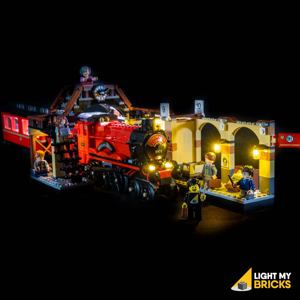

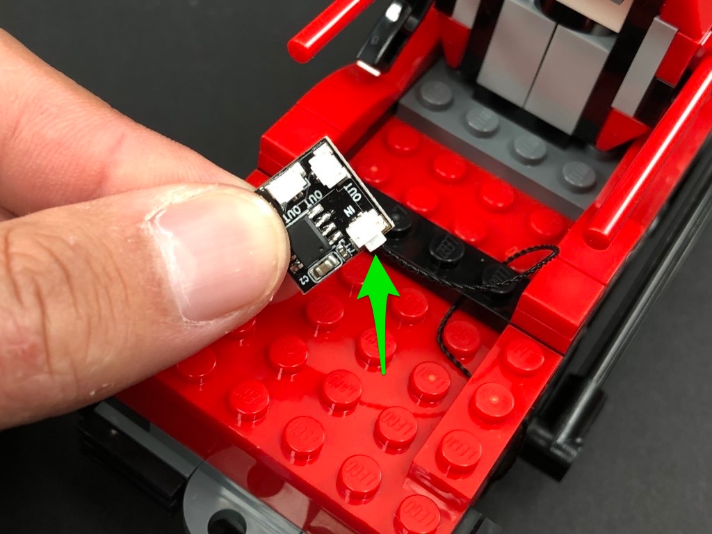 Take the steam control cab and disconnect the following section from the back. Disassemble this section as per below:
21.) Take 2x White 15cm Bit Lights and hold them together over the studs on the front of the black brick. Ensuring the cables are facing the top of the black brick, secure them in place by reconnecting the red plate over the top.
Bring both cables over the top of the black brick, then reconnect the light grey brick over the top, ensuring cables are laid in between studs. Reconnect this section back to the steam control cab
22.) Take the following flame pieces and using a pair of scissors, carefully snip off the tips from the bottom. This will allow us to then reconnect them back to the control cab with Bit Lights installed underneath.
Connect the two bit light cables to the OUT ports on the Flicker Effects Board, then reconnect the control cab back to the train.
Eliminate excess cables by twisting/folding the bit light cables around each other so they come together in a neat bunch, then tuck them (along with the effects board) inside.
23.) Connect the other end of the 15cm Cable from the back of the train to a new 6-Port Expansion Board. Connect your Round Battery Pack to a spare port on the expansion board and turn it ON to test the flickering lights (along with the front lights) are working OK.
USB Power Cable has replaced Flat & Round Battery Packs (CR2032) as of June 2022 due to child safety regulations. Please use the USB Power Cable in place of the Battery Pack.
Note: If you experience any issues with the lights not working and suspect an issue with a component, please try a different port on the expansion board to verify where the fault lies (with the light or expansion board). To correct any issues with expansion board ports, please view the section addressing expansion board issues on our online troubleshooting guide.
24.) Disconnect 15cm connecting cable from the expansion board, then reconnect all the sections surrounding the control cab on the back of the front carriage.
25.) Take the middle carriage and disconnect the roof and front wall. Reconnect the carriage to the front carriage, then bring the 15cm connecting cable inside.
Reconnect the connecting cable to the 6-port expansion board from previous step, then reconnect the front wall over the cable ensuring the cable is laid in between studs and that there is enough cable slack for the carriage to turn left/right.
26.) Take another 15cm Connecting Cable and connect it to the 6-port Expansion Board. Disconnect the back wall, then pull the other end of the cable all the way out the back. Reconnect the back wall over the top ensuring the cable is in between studs.
Neatly tuck the battery pack inside the carriage, then reconnect the roof.
27.) Take the back carriage and disconnect the roof as well as the following corner tile to allow us to remove the front wall section.
Reconnect the carriage to the middle carriage, then bring the other end of the 15cm cable back and inside the last carriage. Reconnect the front wall section over the cable ensuring it is laid in between studs. Ensure you also have enough cable slack between the two carriages for them to be able to turn left/right.
Tuck the cable in between the blue brick and front wall, then reconnect the corner tile.
28.) Take 2x White Strip Lights and using their adhesive backing, stick them to the back of 2x Plates 1×6. Connect the two strip lights together using a 5cm Connecting Cable.
Mount the two strip lights underneath the roof in the below positions.
29.) Bring the roof over the carriage and connect the other end of the 15cm connecting cable below to the Strip Light. Securely reconnect the roof.
Turn ON the battery pack to test the carriage lights are working OK.
Take the steam control cab and disconnect the following section from the back. Disassemble this section as per below:
21.) Take 2x White 15cm Bit Lights and hold them together over the studs on the front of the black brick. Ensuring the cables are facing the top of the black brick, secure them in place by reconnecting the red plate over the top.
Bring both cables over the top of the black brick, then reconnect the light grey brick over the top, ensuring cables are laid in between studs. Reconnect this section back to the steam control cab
22.) Take the following flame pieces and using a pair of scissors, carefully snip off the tips from the bottom. This will allow us to then reconnect them back to the control cab with Bit Lights installed underneath.
Connect the two bit light cables to the OUT ports on the Flicker Effects Board, then reconnect the control cab back to the train.
Eliminate excess cables by twisting/folding the bit light cables around each other so they come together in a neat bunch, then tuck them (along with the effects board) inside.
23.) Connect the other end of the 15cm Cable from the back of the train to a new 6-Port Expansion Board. Connect your Round Battery Pack to a spare port on the expansion board and turn it ON to test the flickering lights (along with the front lights) are working OK.
USB Power Cable has replaced Flat & Round Battery Packs (CR2032) as of June 2022 due to child safety regulations. Please use the USB Power Cable in place of the Battery Pack.
Note: If you experience any issues with the lights not working and suspect an issue with a component, please try a different port on the expansion board to verify where the fault lies (with the light or expansion board). To correct any issues with expansion board ports, please view the section addressing expansion board issues on our online troubleshooting guide.
24.) Disconnect 15cm connecting cable from the expansion board, then reconnect all the sections surrounding the control cab on the back of the front carriage.
25.) Take the middle carriage and disconnect the roof and front wall. Reconnect the carriage to the front carriage, then bring the 15cm connecting cable inside.
Reconnect the connecting cable to the 6-port expansion board from previous step, then reconnect the front wall over the cable ensuring the cable is laid in between studs and that there is enough cable slack for the carriage to turn left/right.
26.) Take another 15cm Connecting Cable and connect it to the 6-port Expansion Board. Disconnect the back wall, then pull the other end of the cable all the way out the back. Reconnect the back wall over the top ensuring the cable is in between studs.
Neatly tuck the battery pack inside the carriage, then reconnect the roof.
27.) Take the back carriage and disconnect the roof as well as the following corner tile to allow us to remove the front wall section.
Reconnect the carriage to the middle carriage, then bring the other end of the 15cm cable back and inside the last carriage. Reconnect the front wall section over the cable ensuring it is laid in between studs. Ensure you also have enough cable slack between the two carriages for them to be able to turn left/right.
Tuck the cable in between the blue brick and front wall, then reconnect the corner tile.
28.) Take 2x White Strip Lights and using their adhesive backing, stick them to the back of 2x Plates 1×6. Connect the two strip lights together using a 5cm Connecting Cable.
Mount the two strip lights underneath the roof in the below positions.
29.) Bring the roof over the carriage and connect the other end of the 15cm connecting cable below to the Strip Light. Securely reconnect the roof.
Turn ON the battery pack to test the carriage lights are working OK.
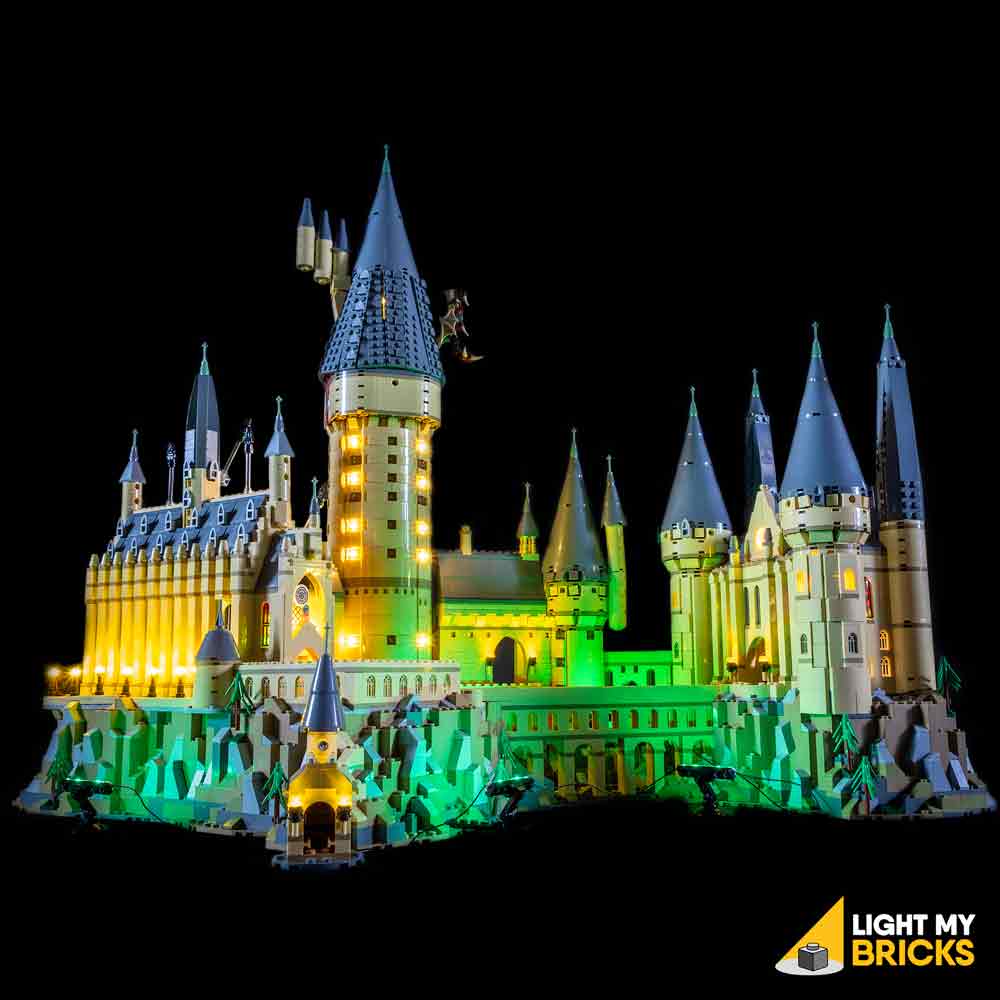


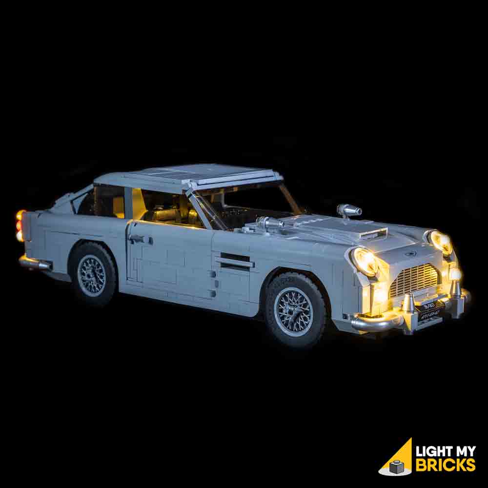

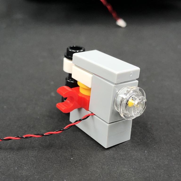
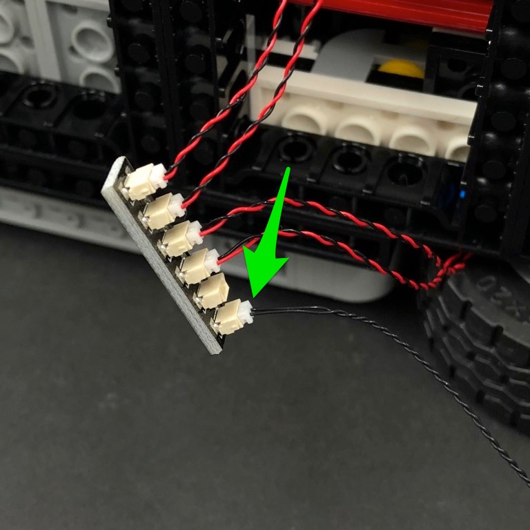

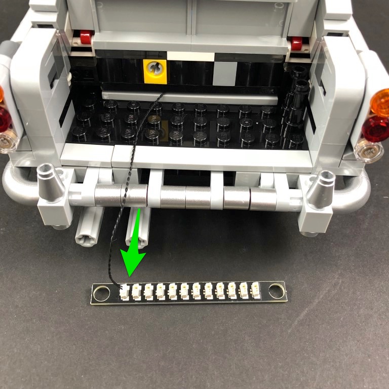
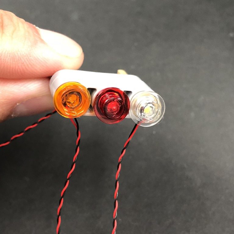


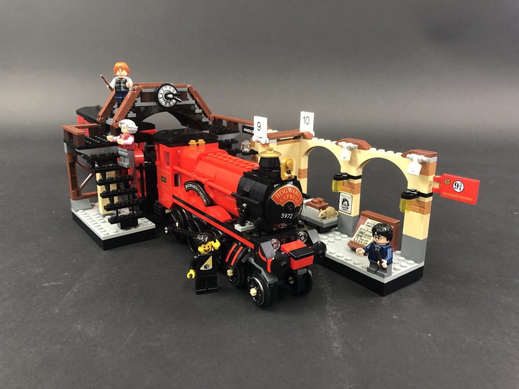
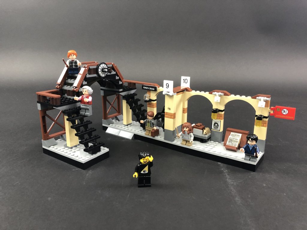
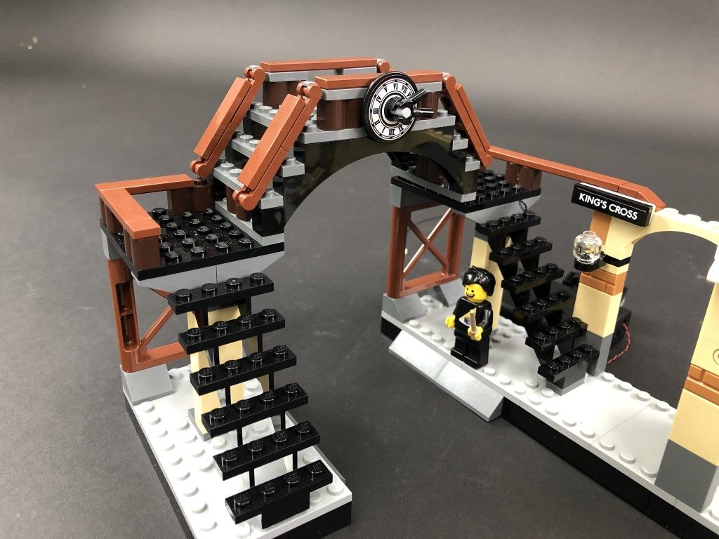
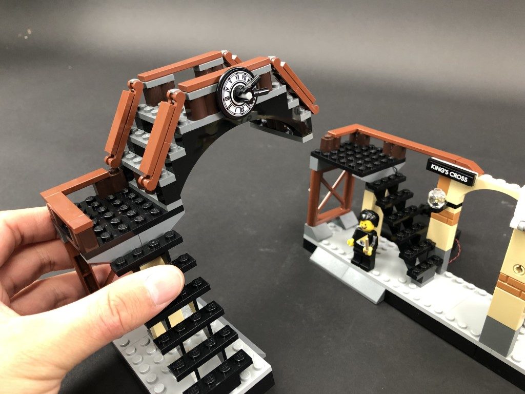
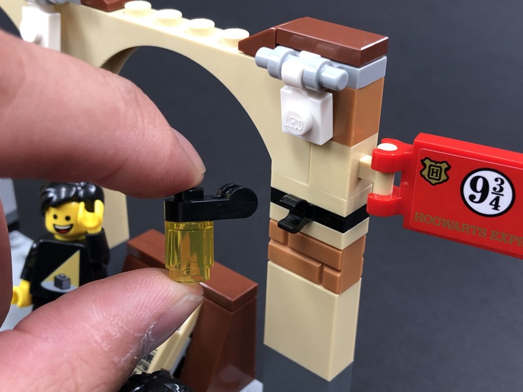
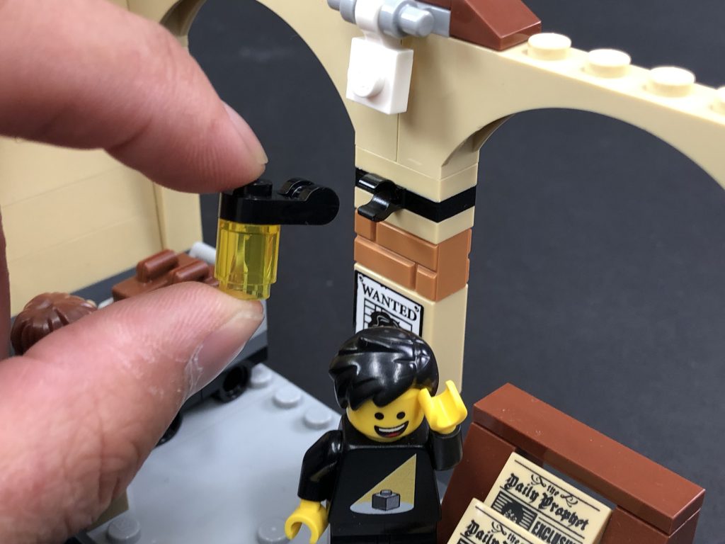
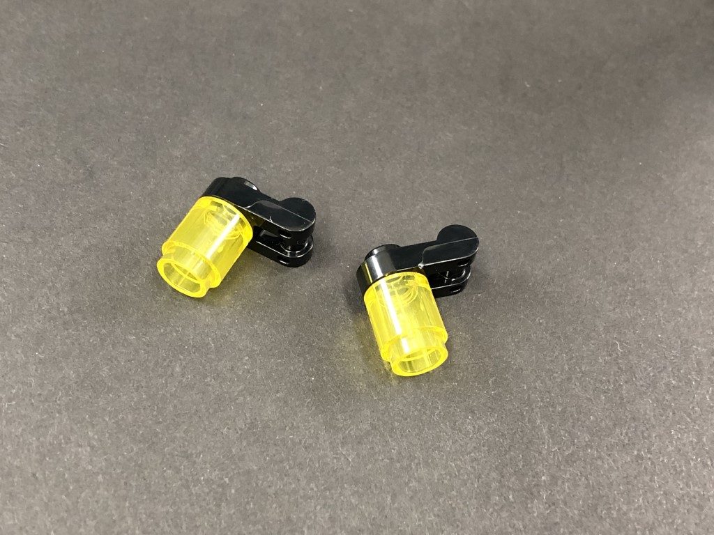
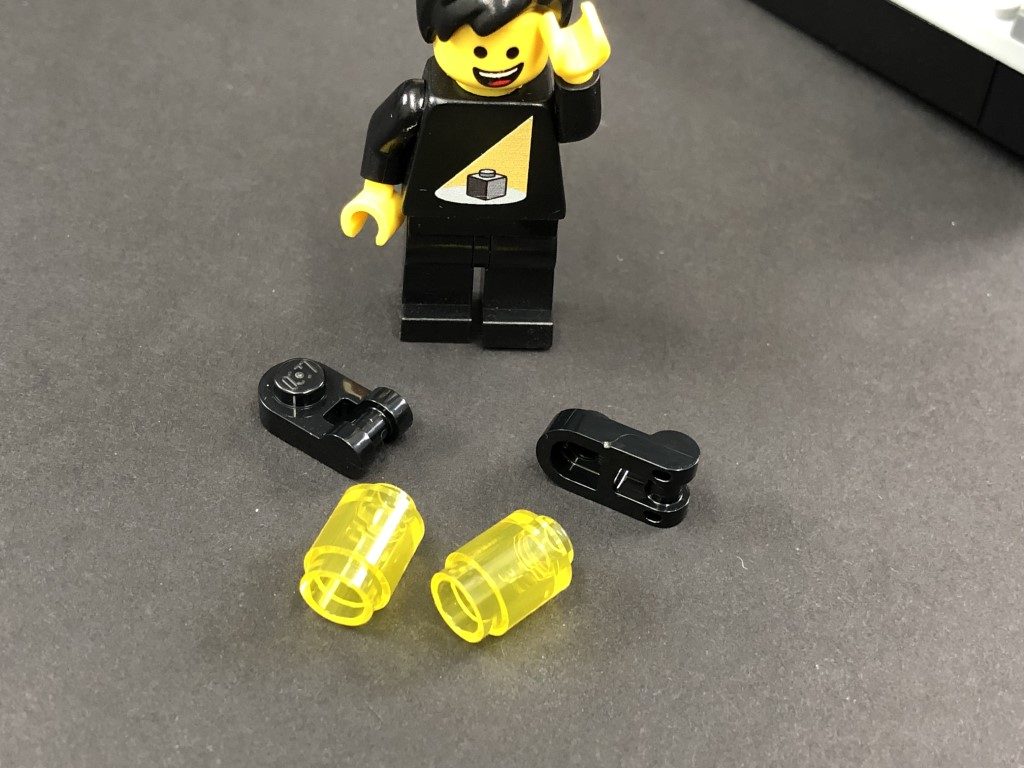
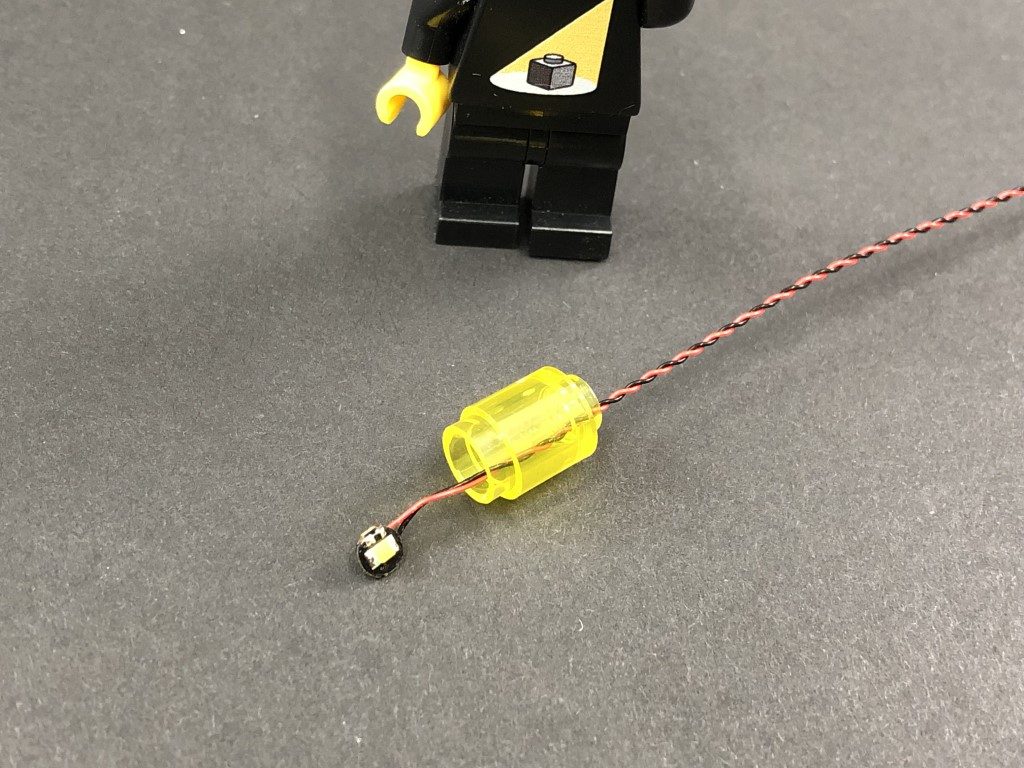
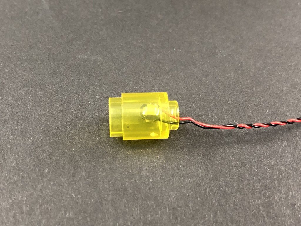
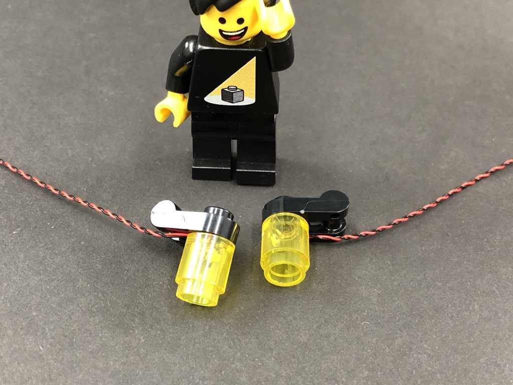
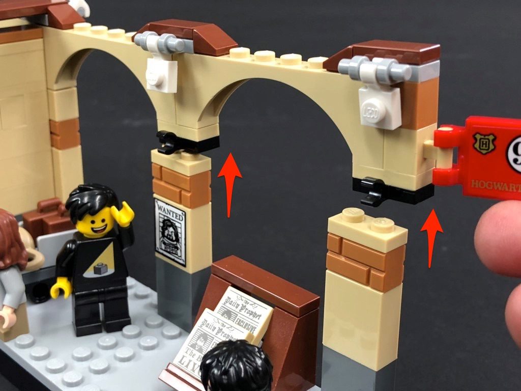
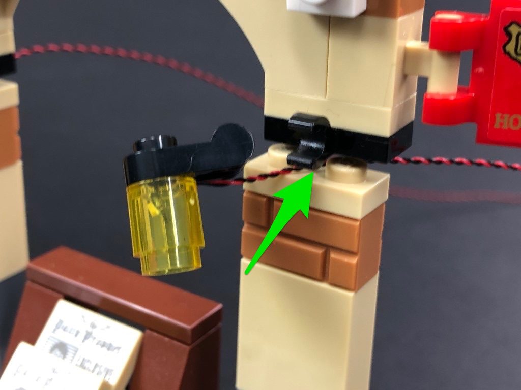
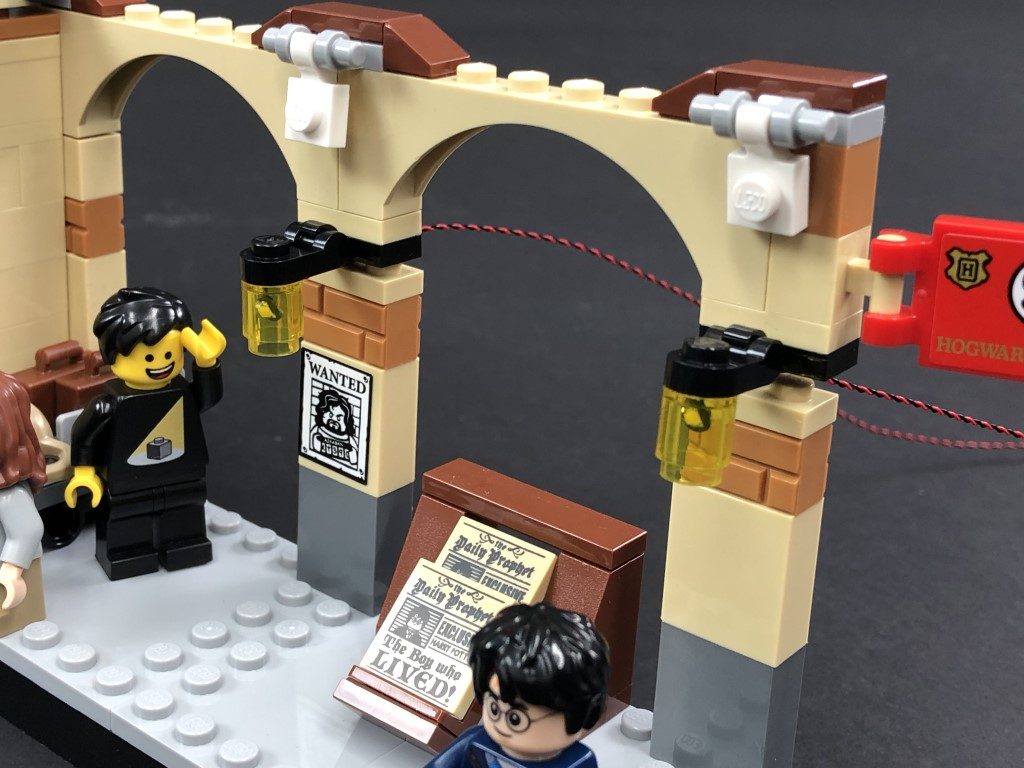
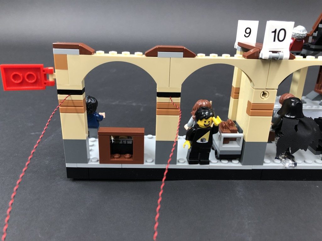
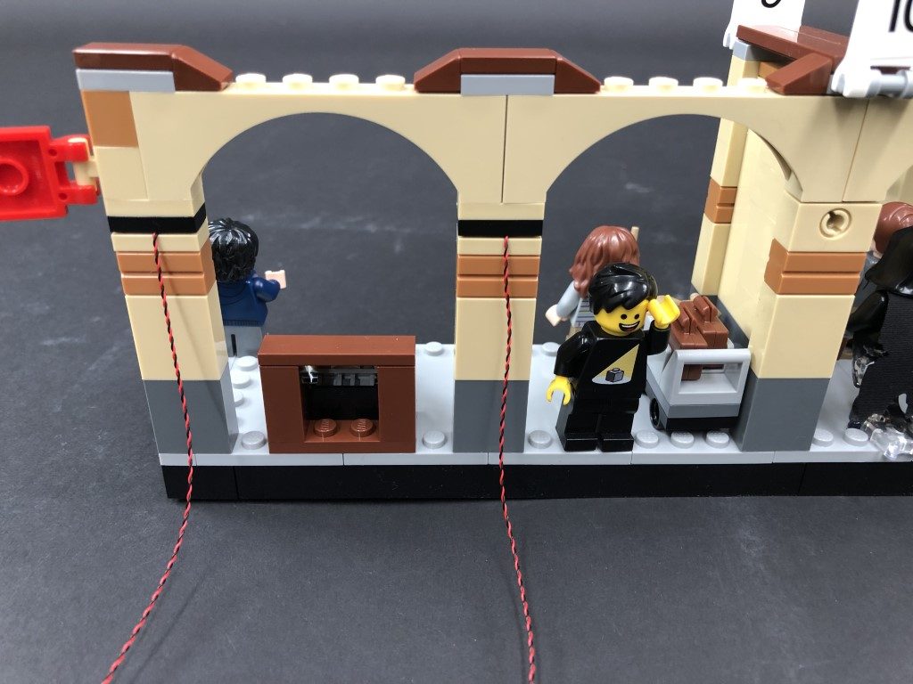
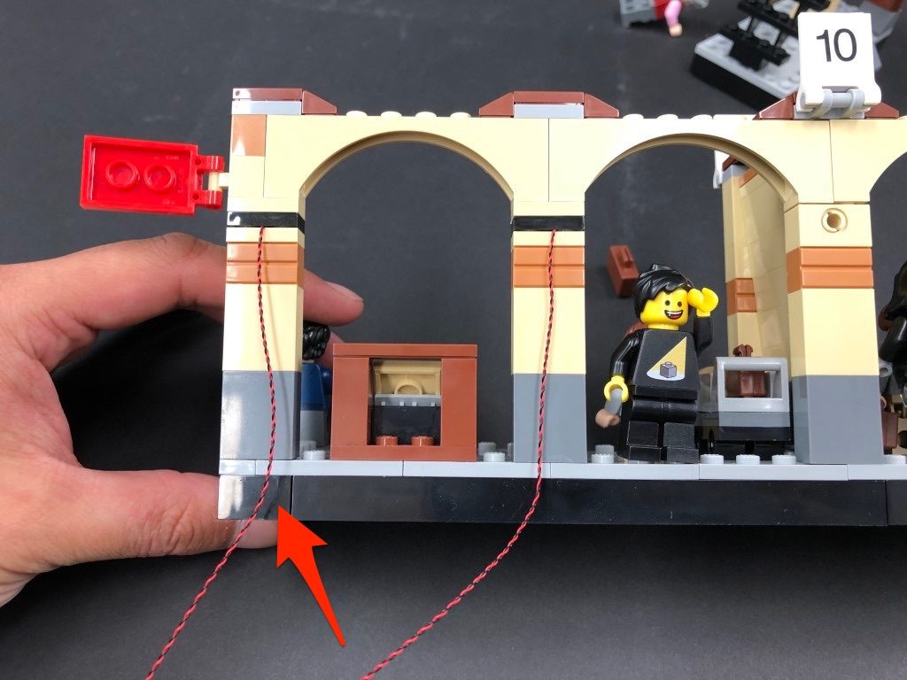
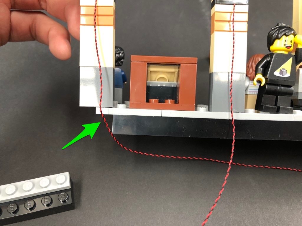
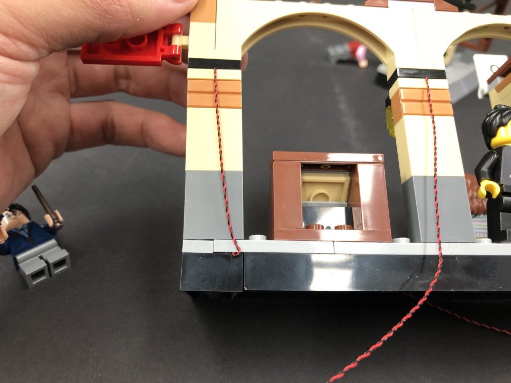
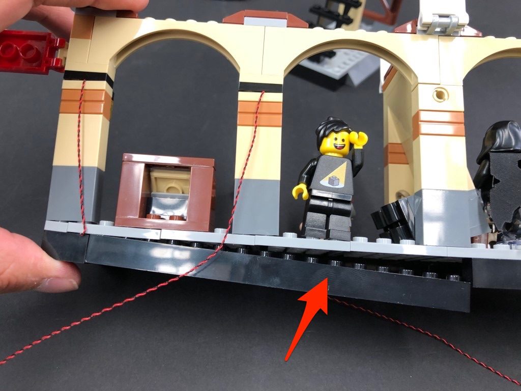
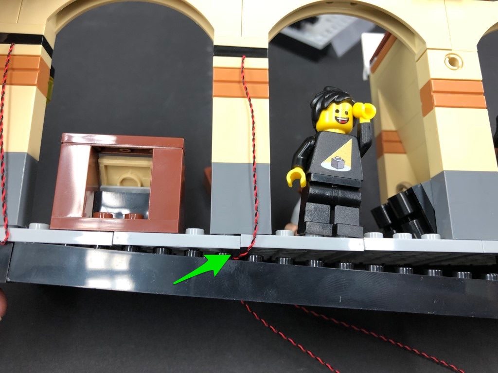
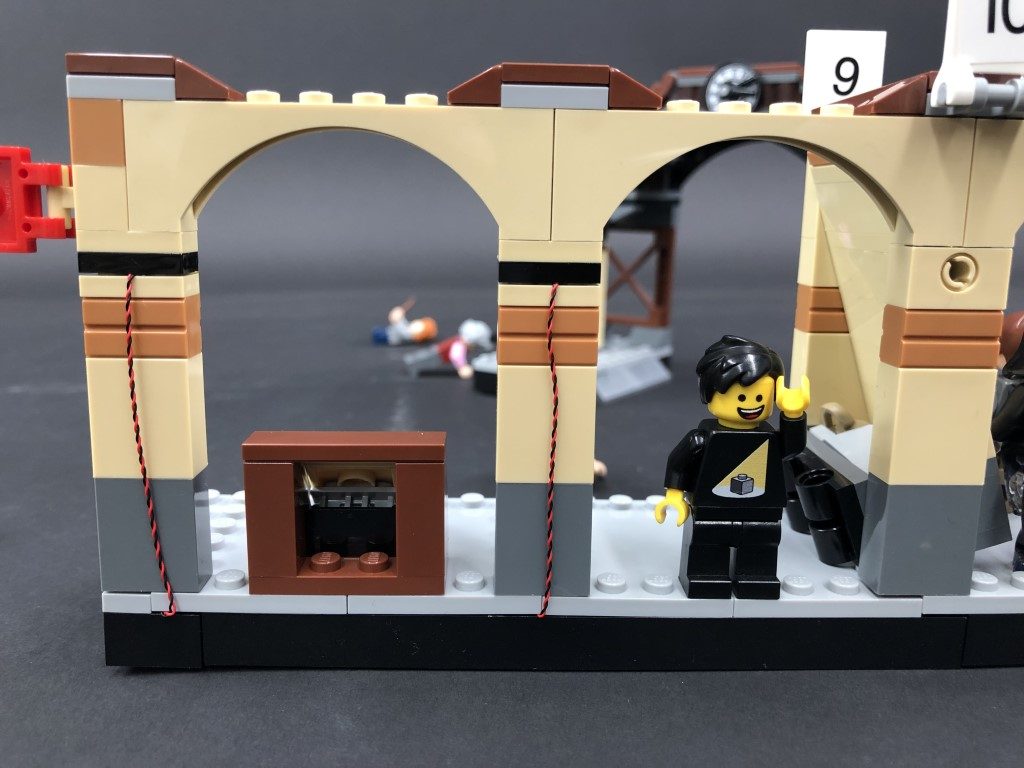
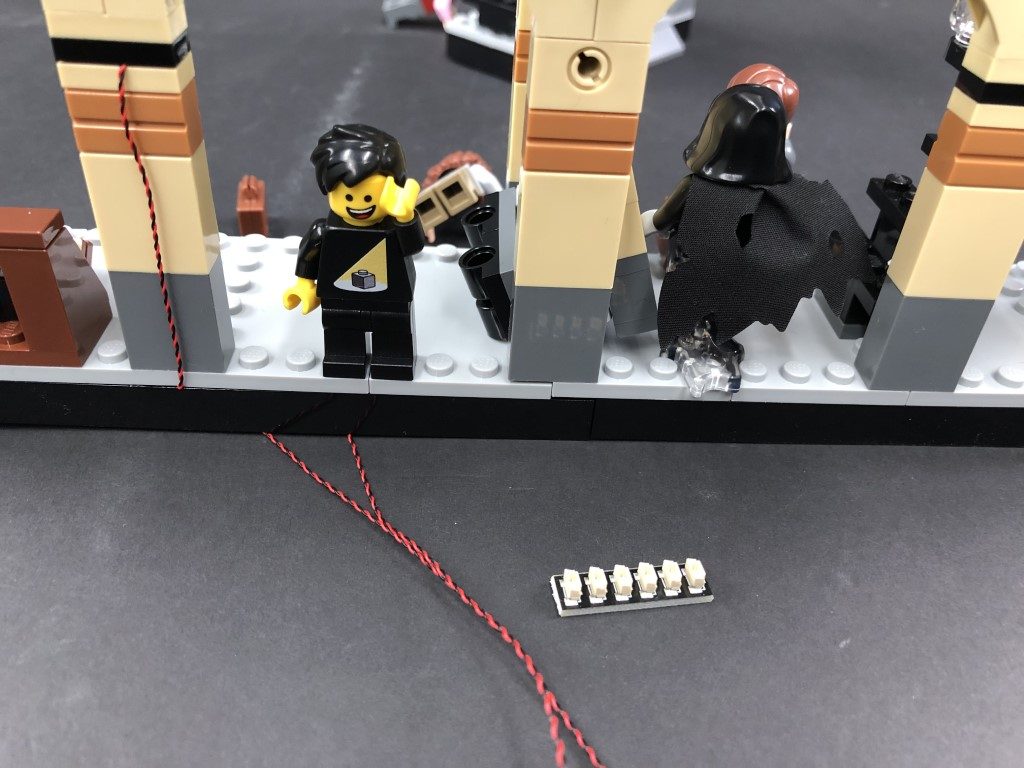
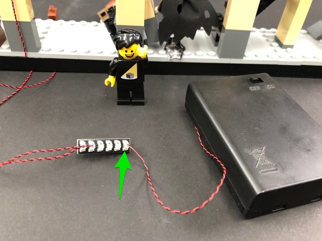
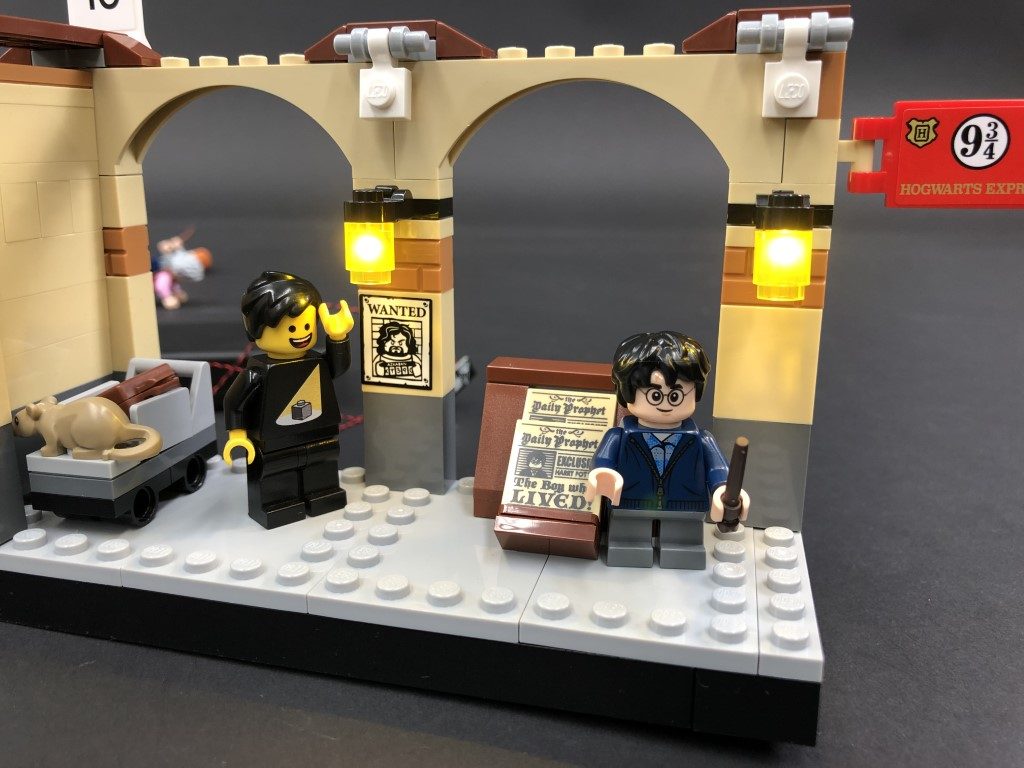
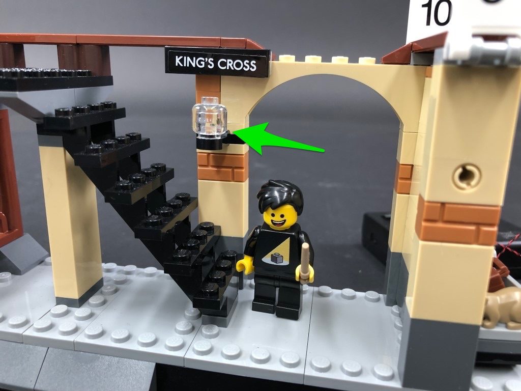
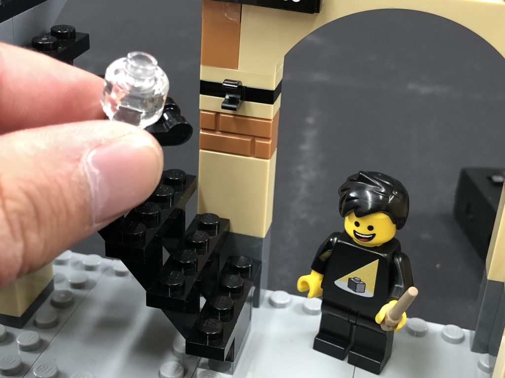
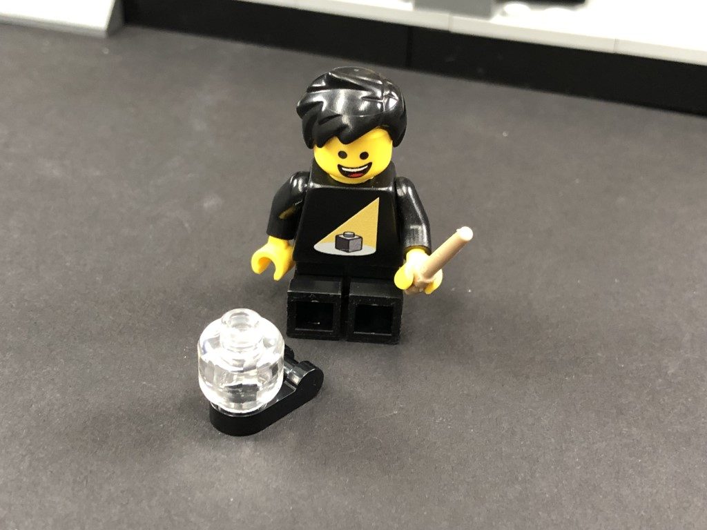
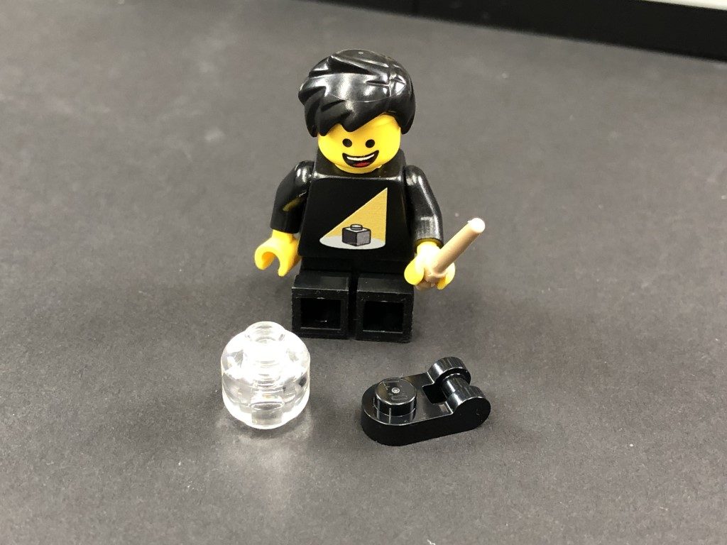
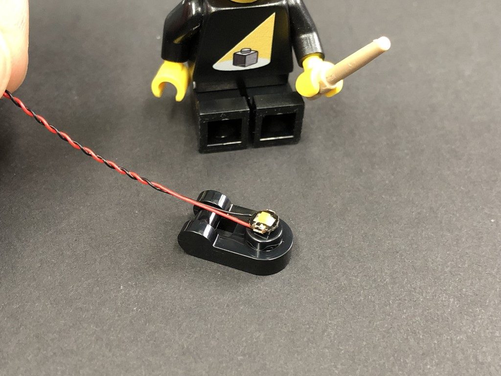
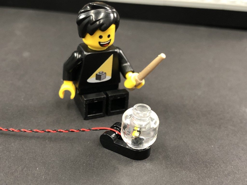
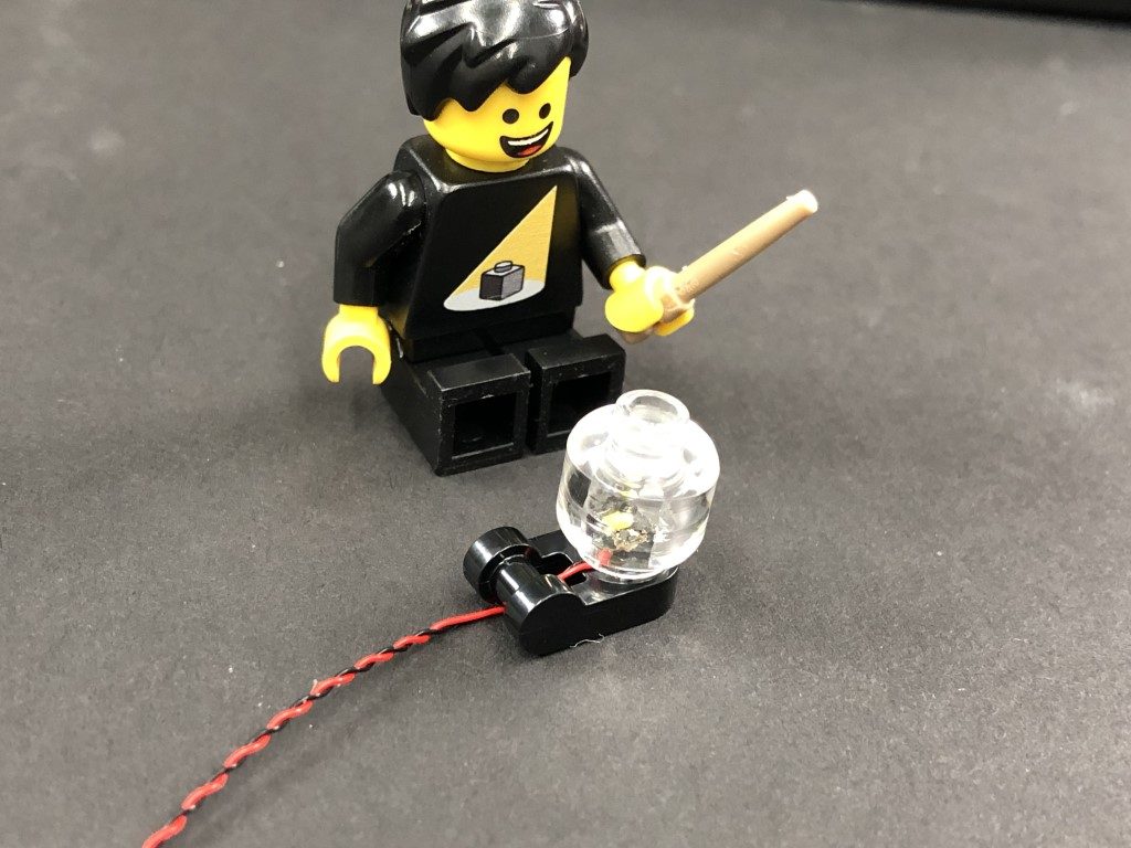
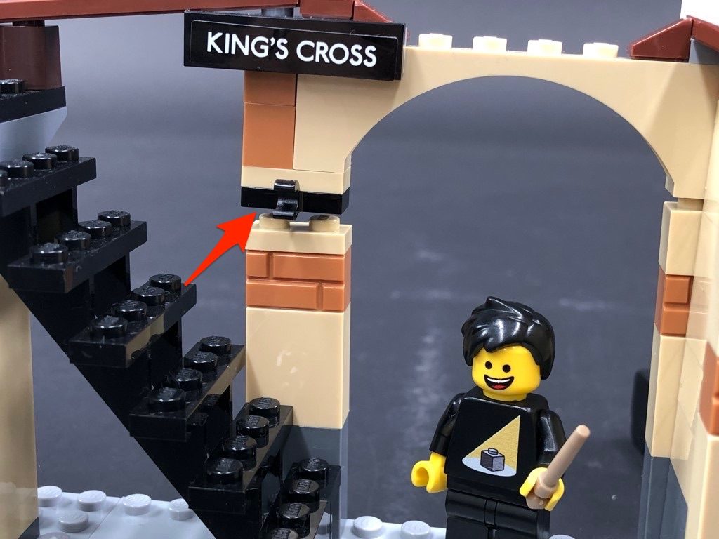
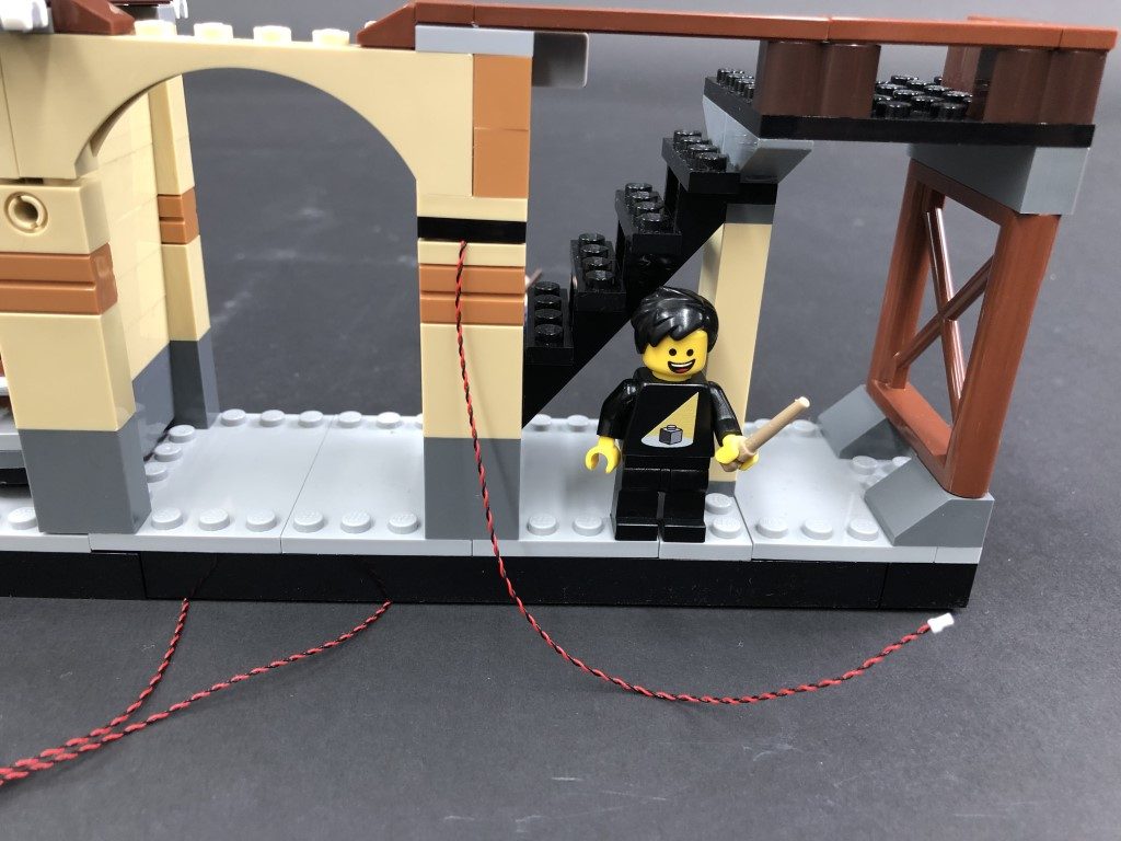
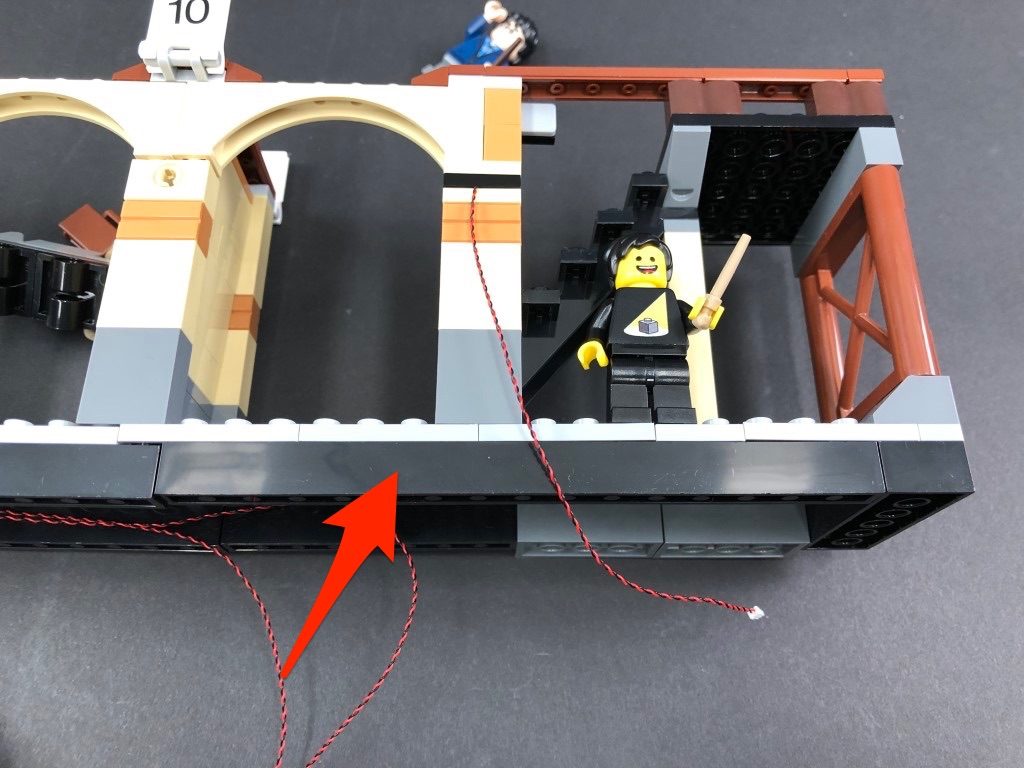
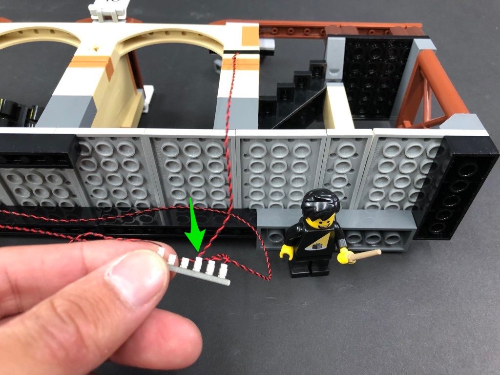
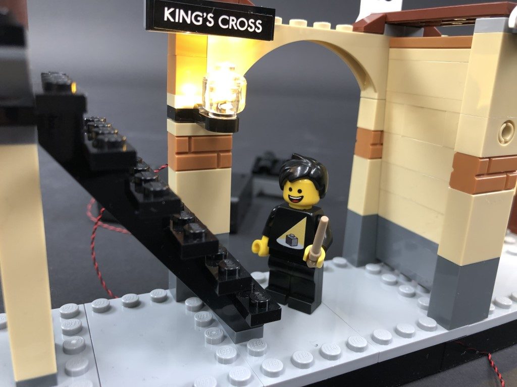
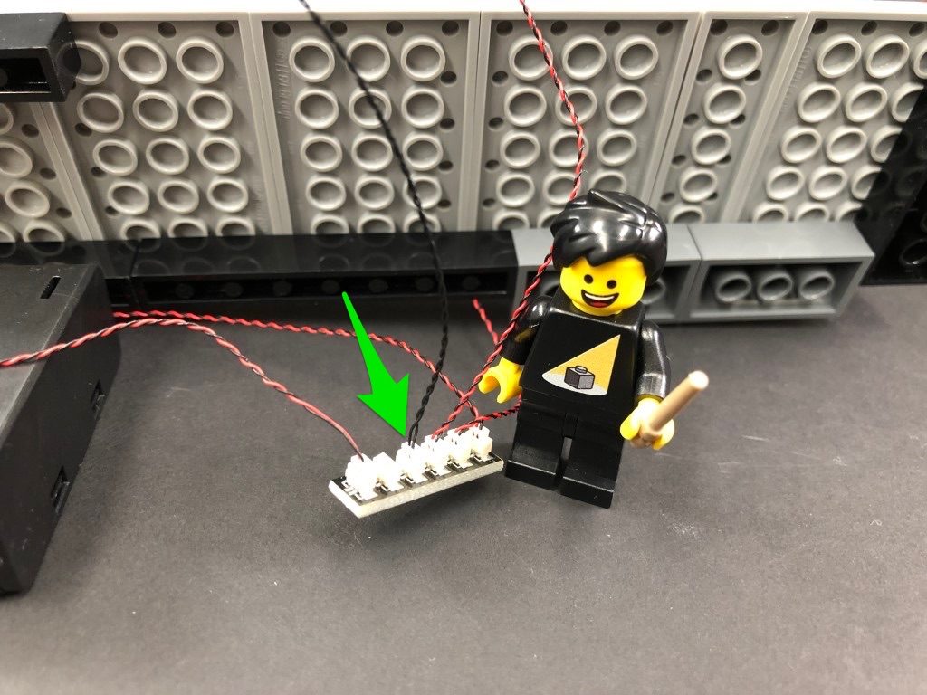
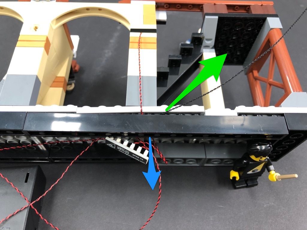
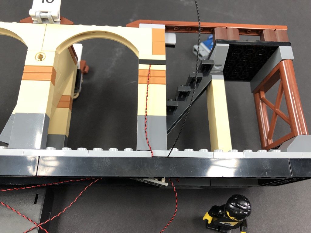
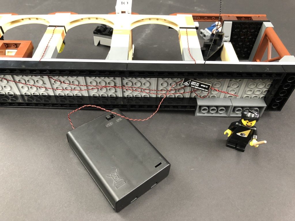
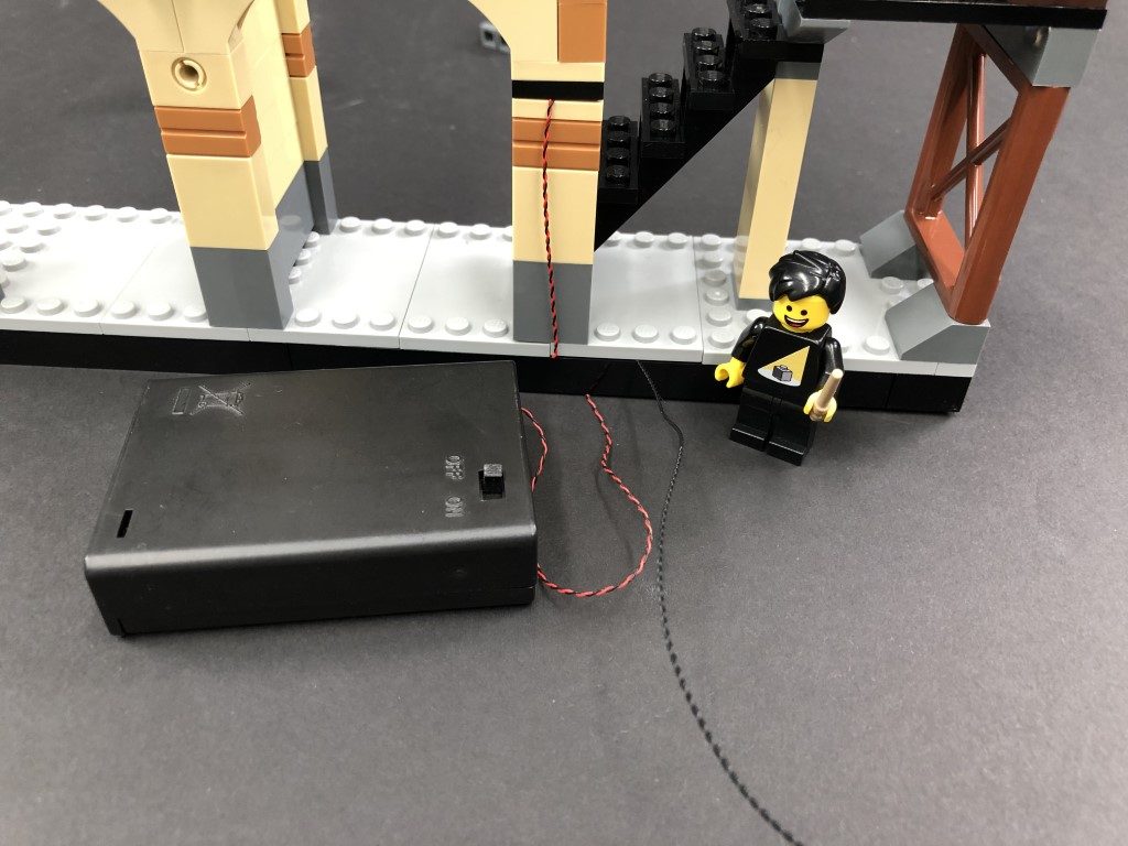
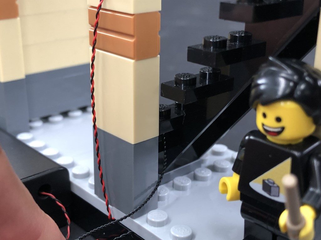
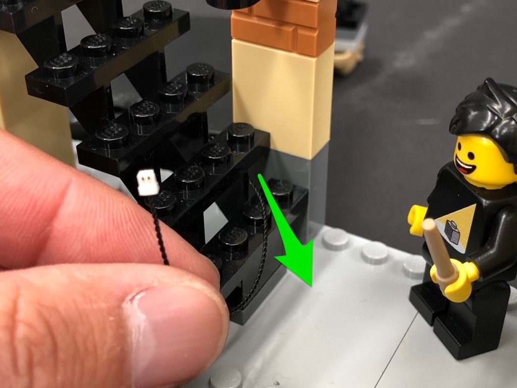
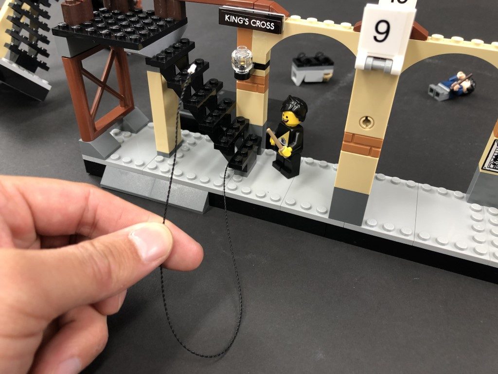
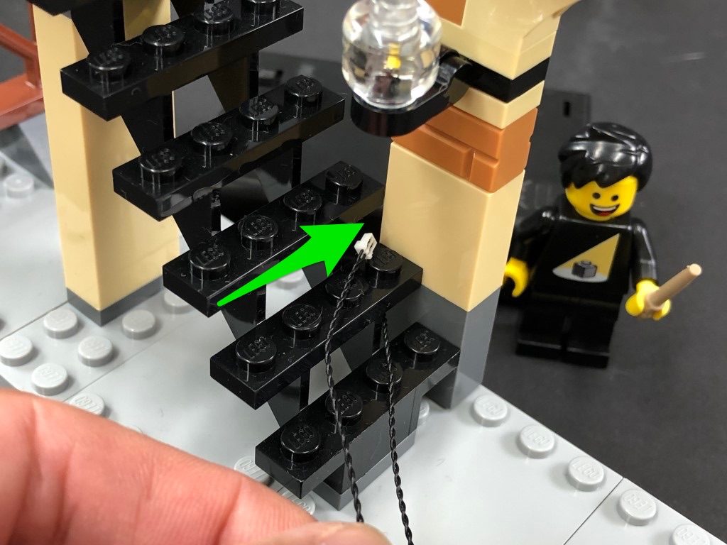
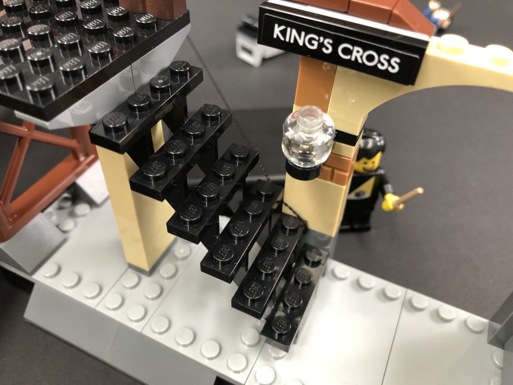
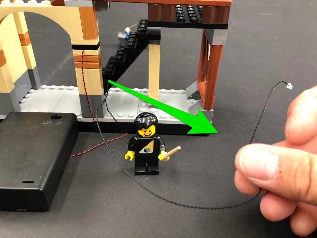
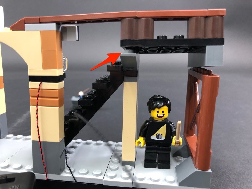
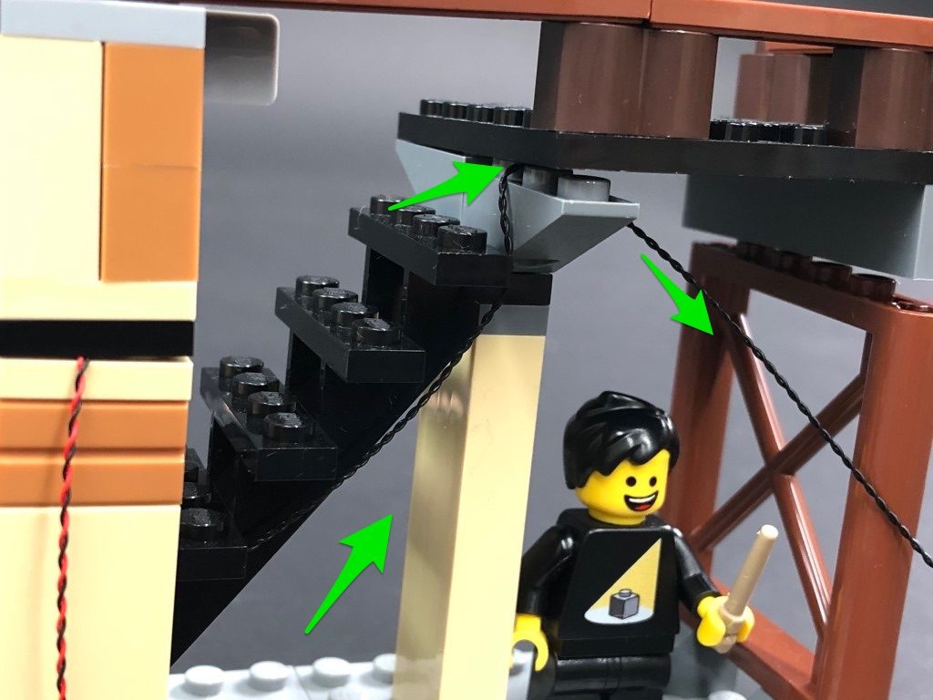
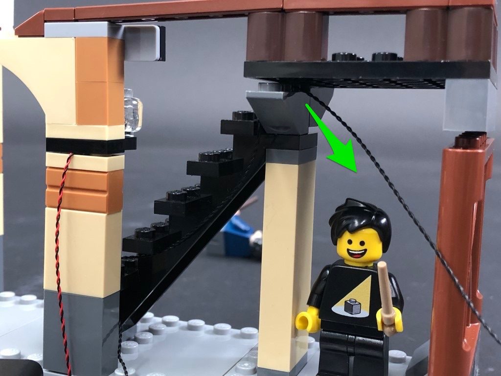
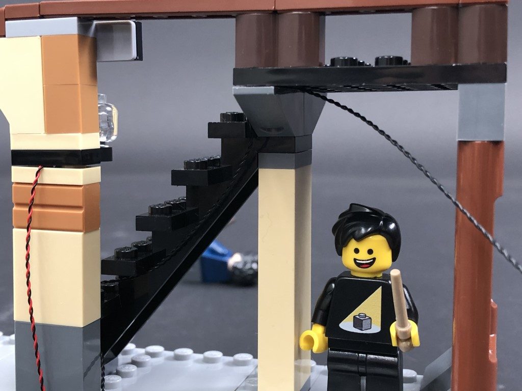
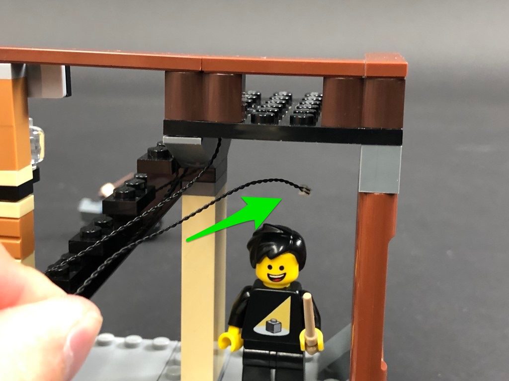
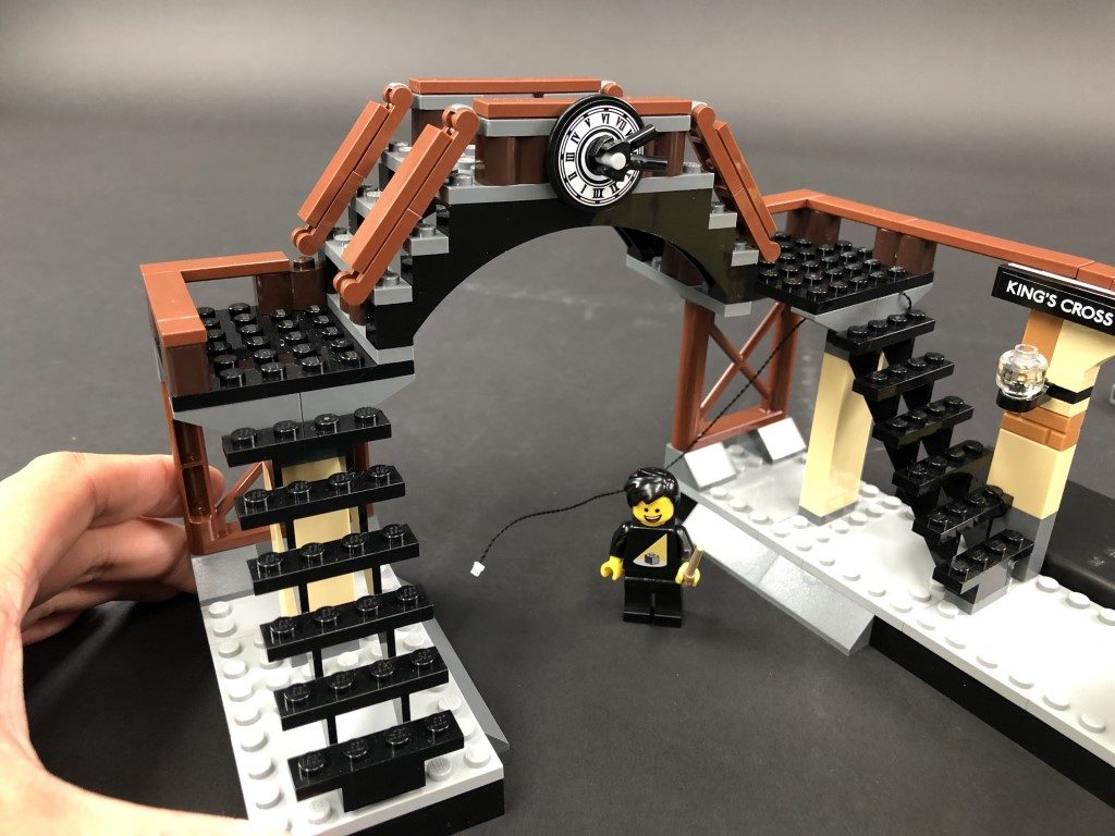
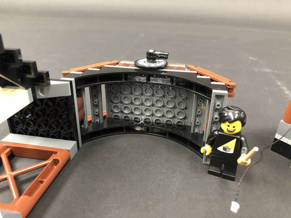
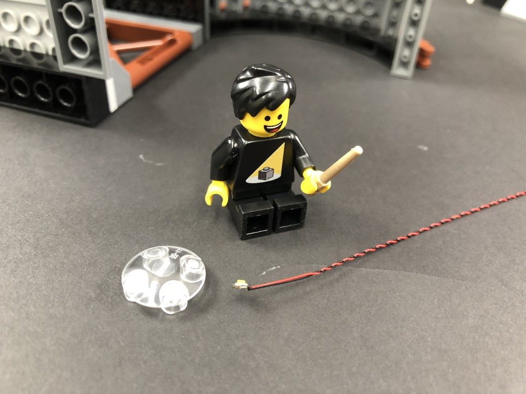
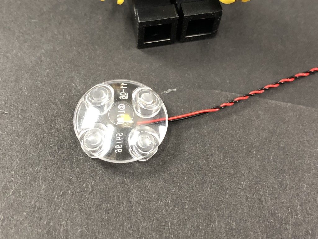
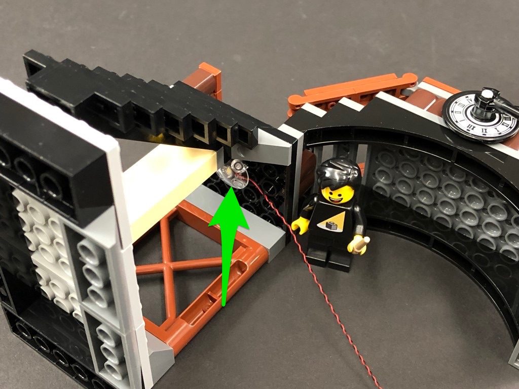
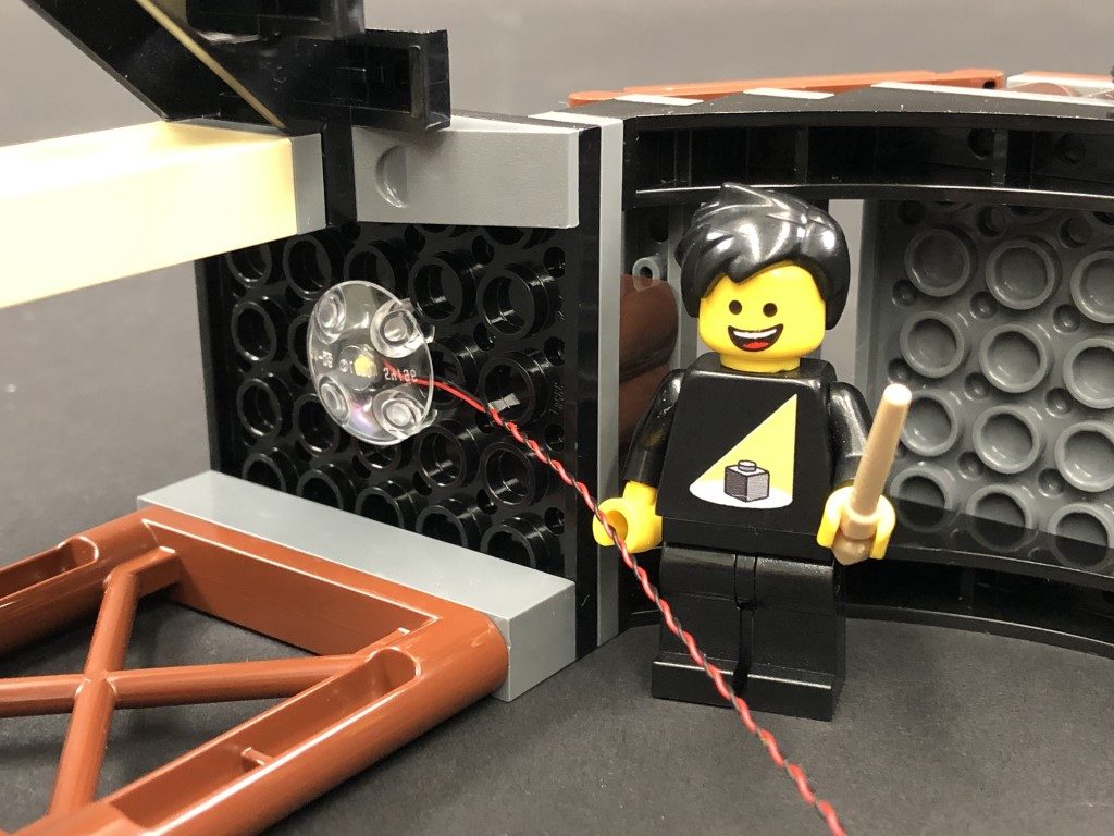
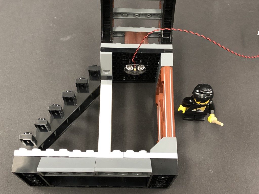
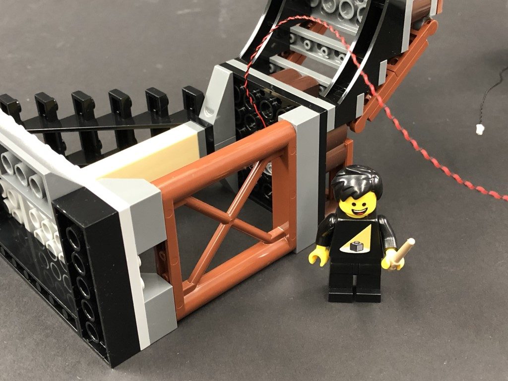
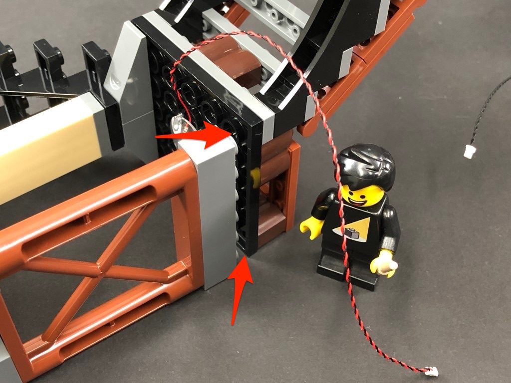
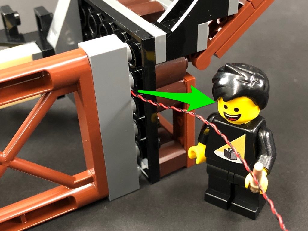
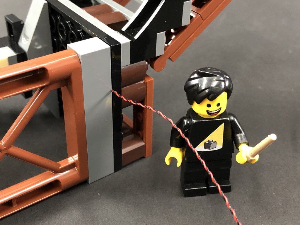
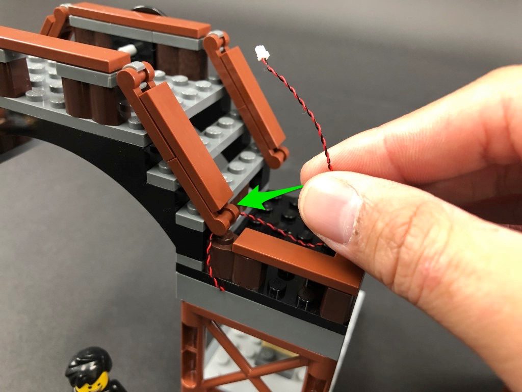
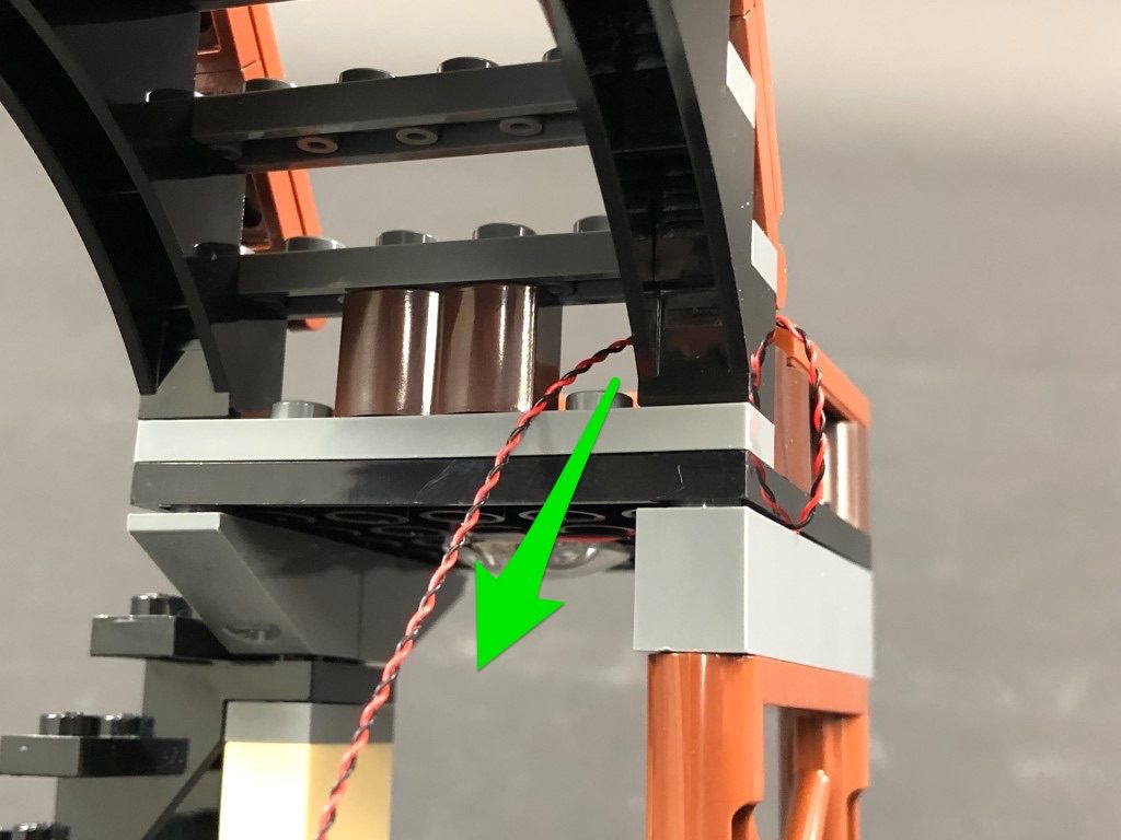
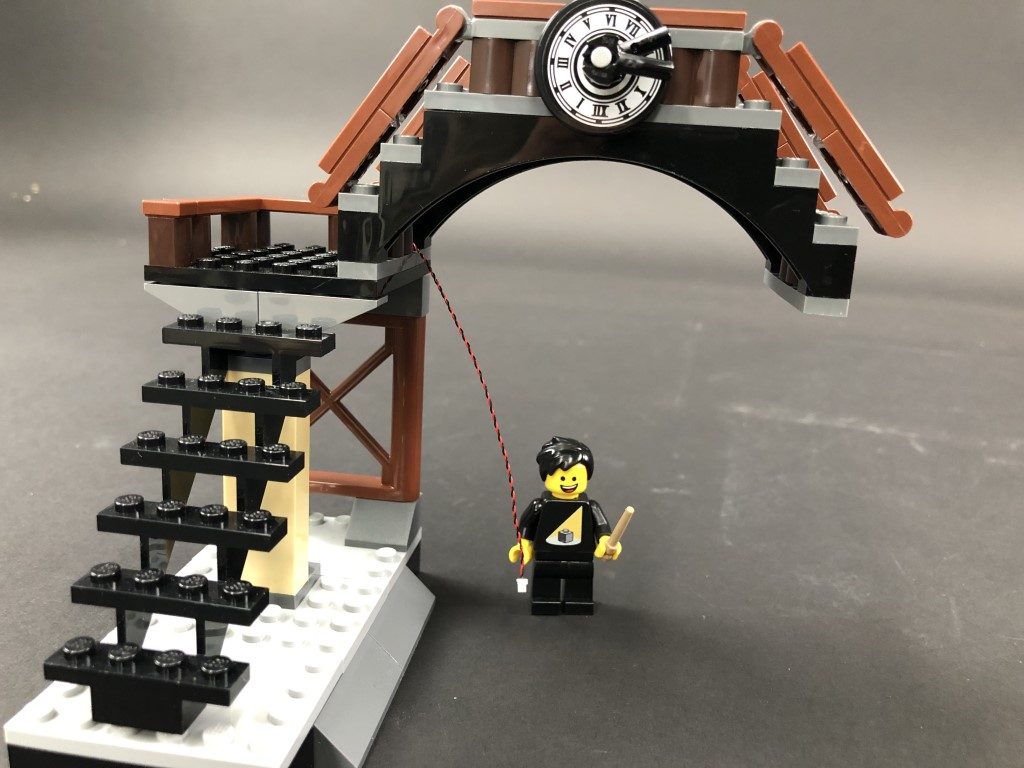
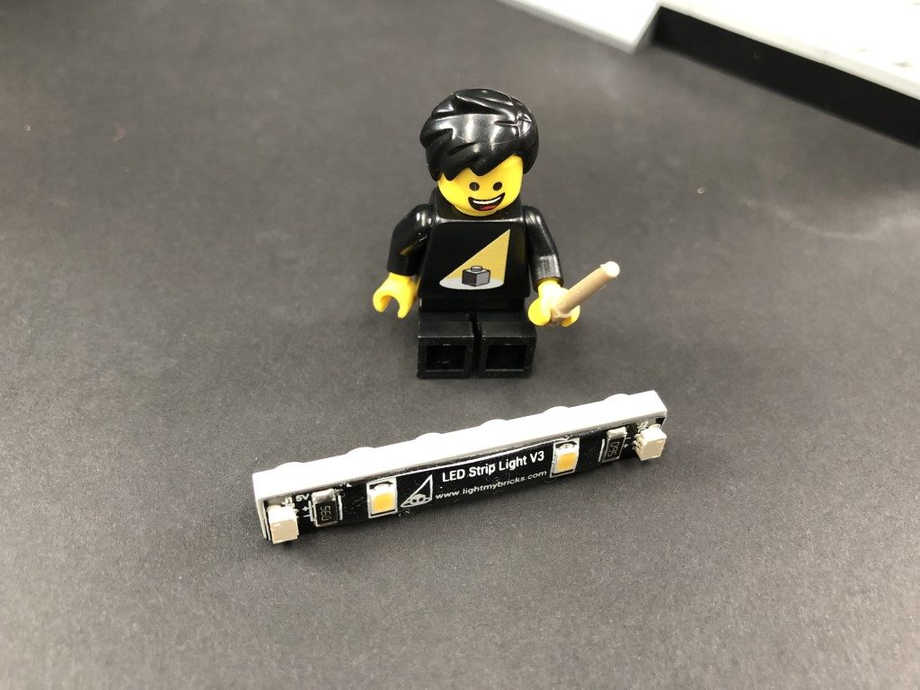
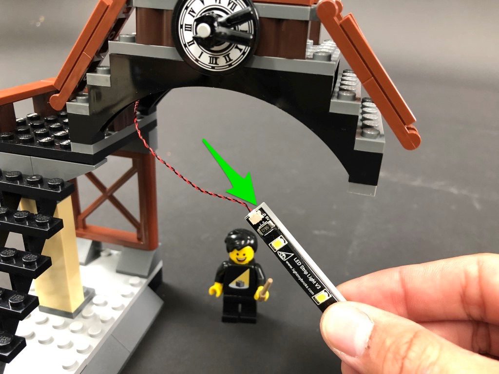
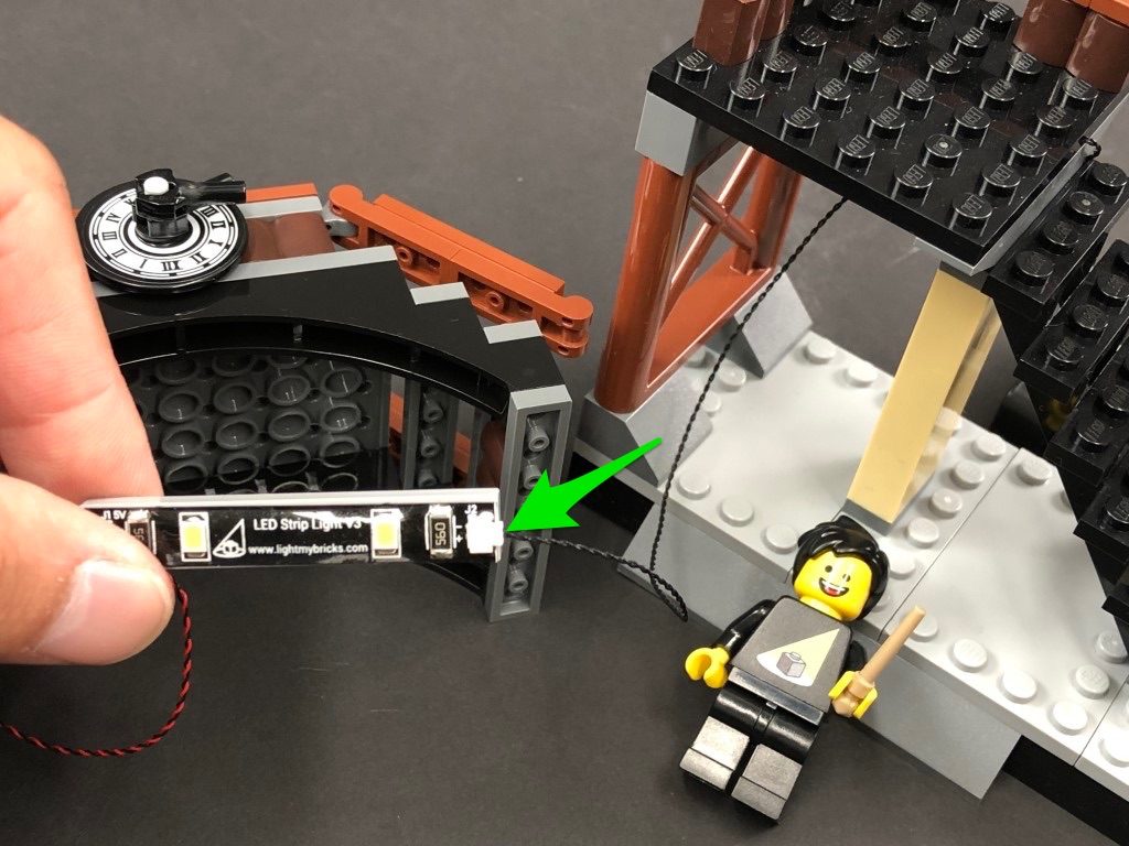
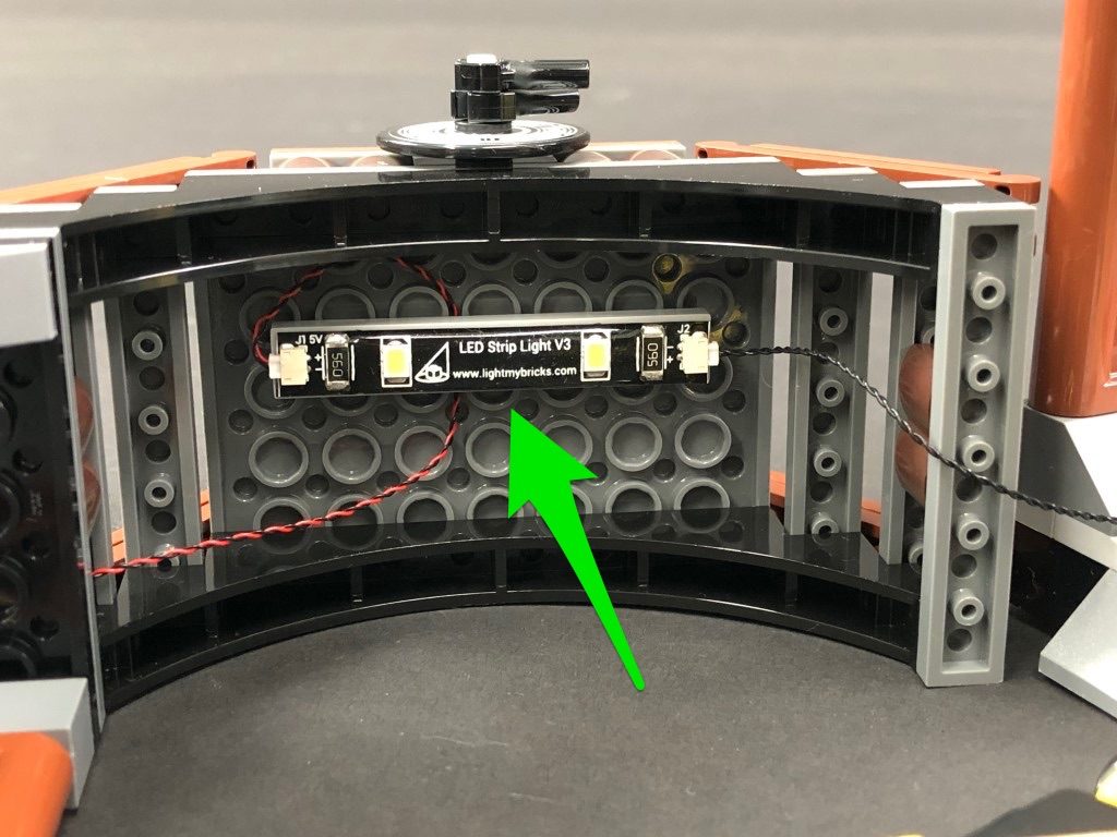
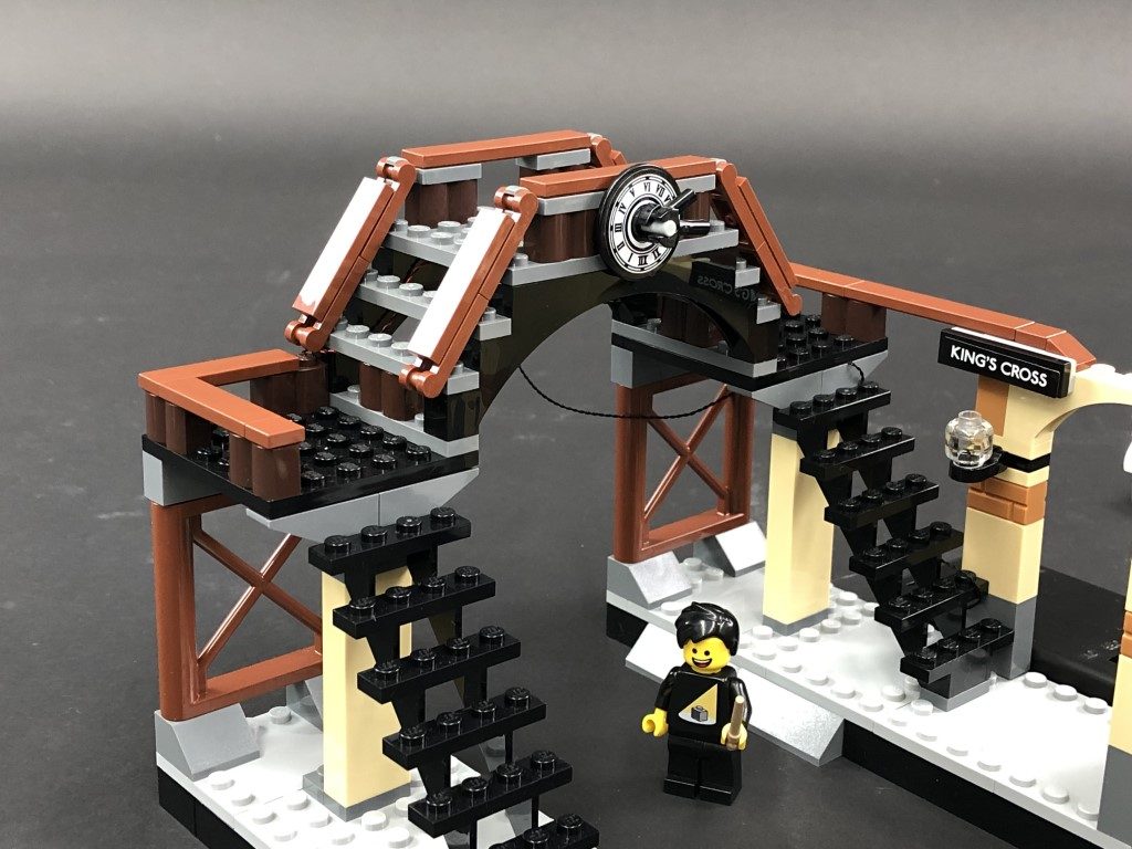
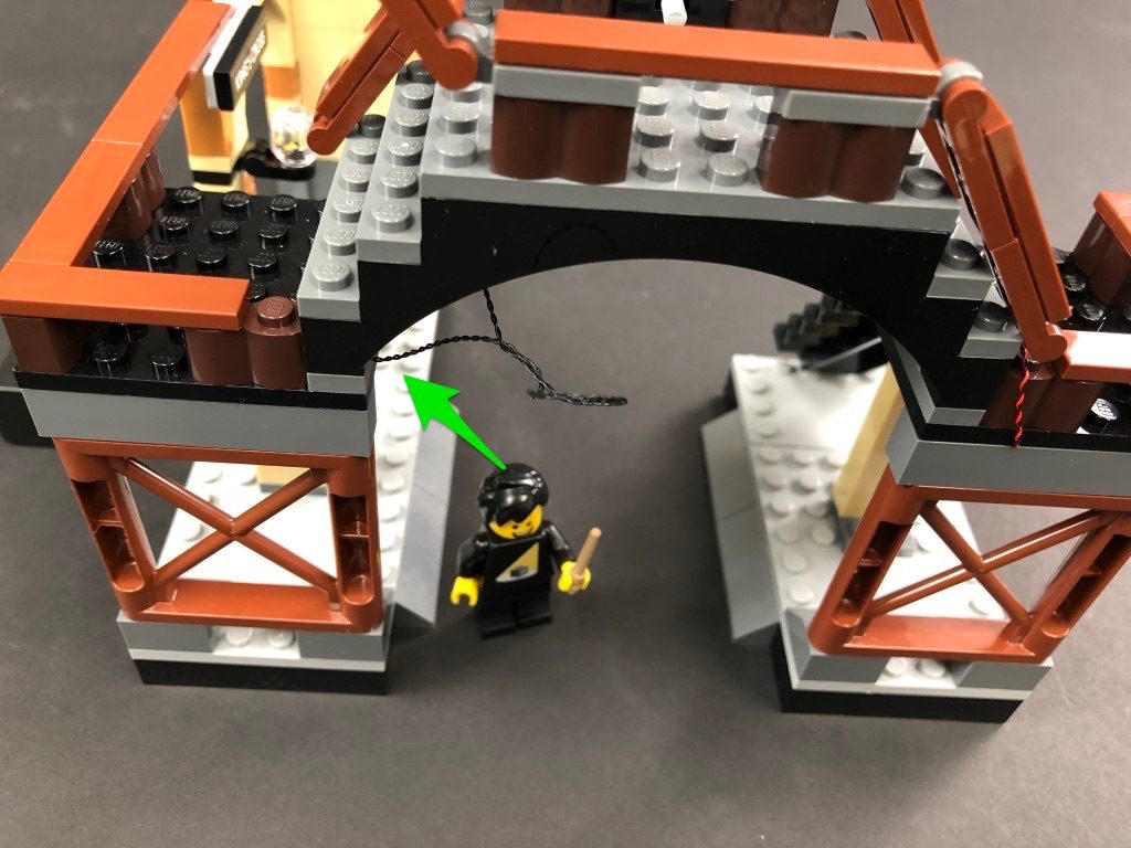
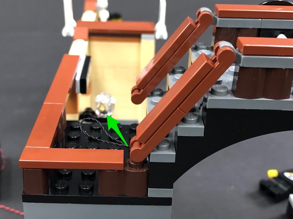
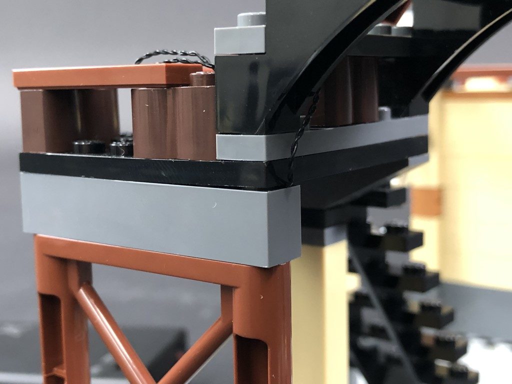
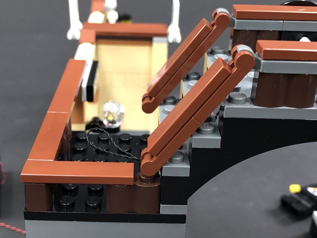
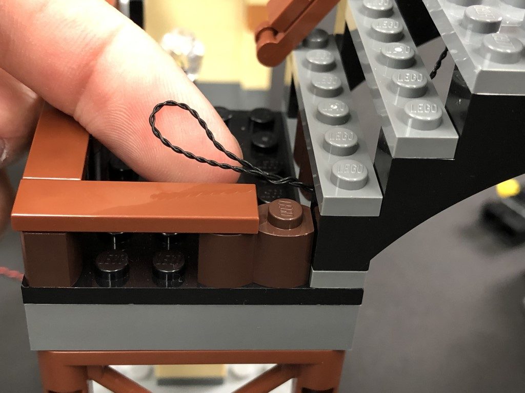
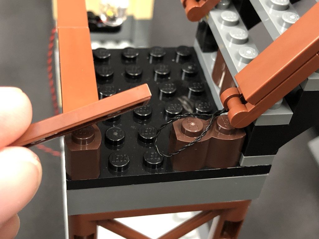
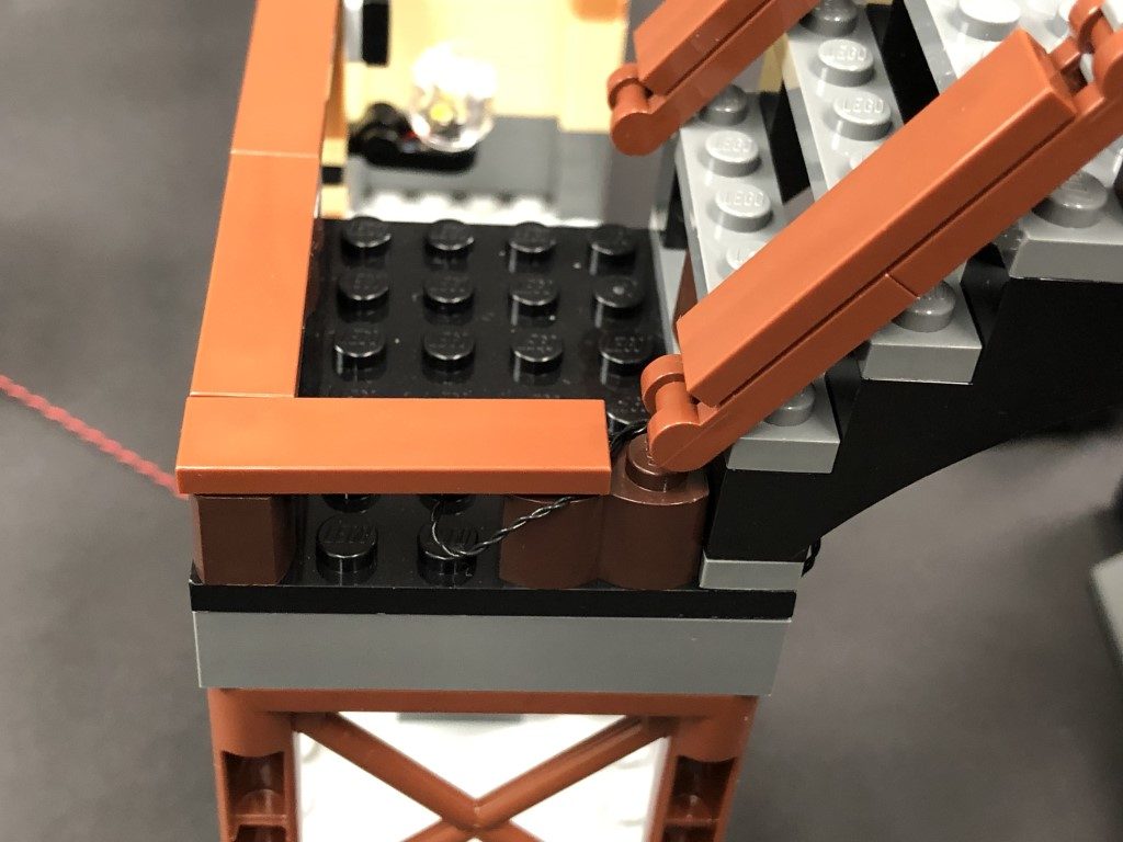
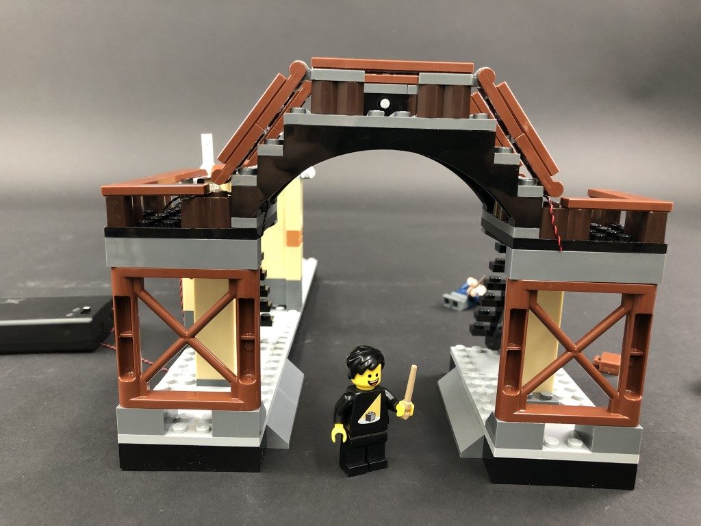
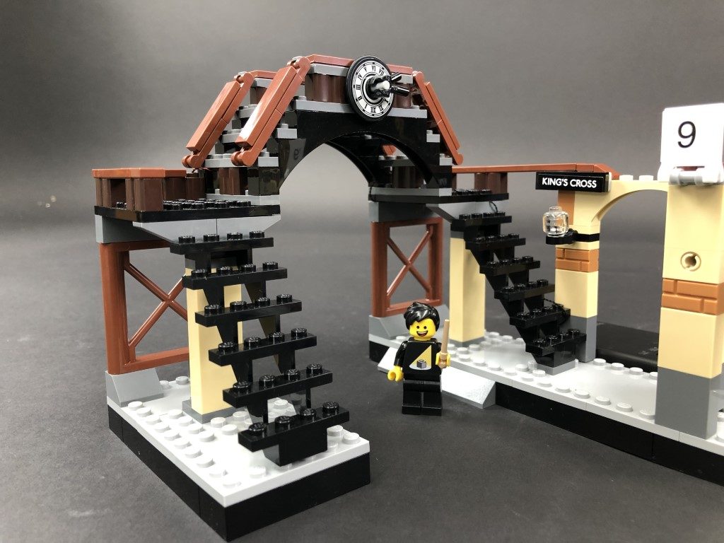
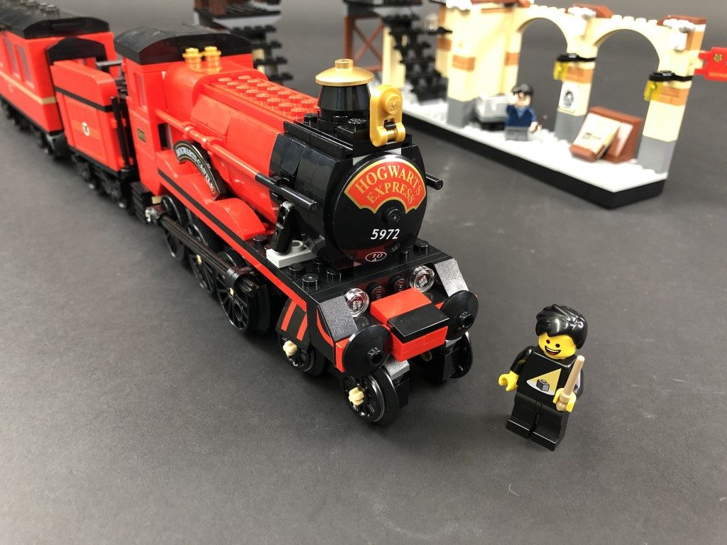
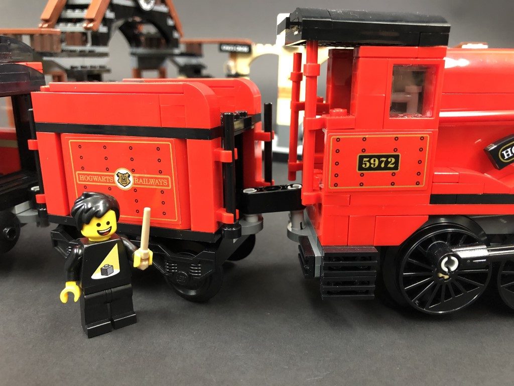
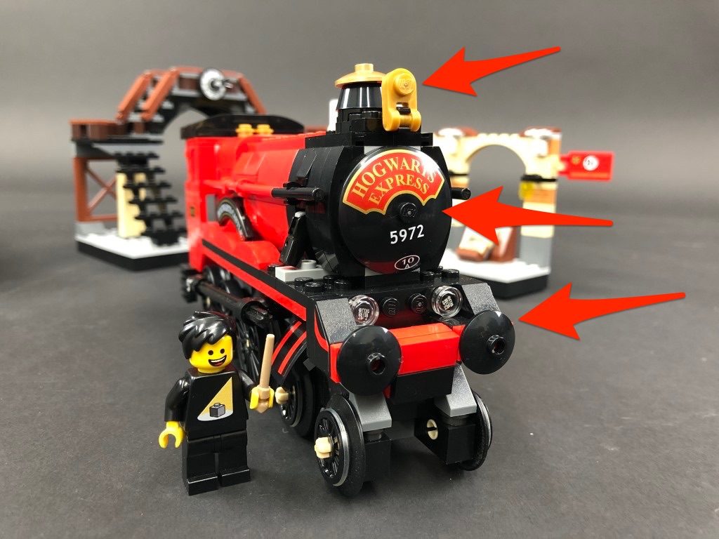
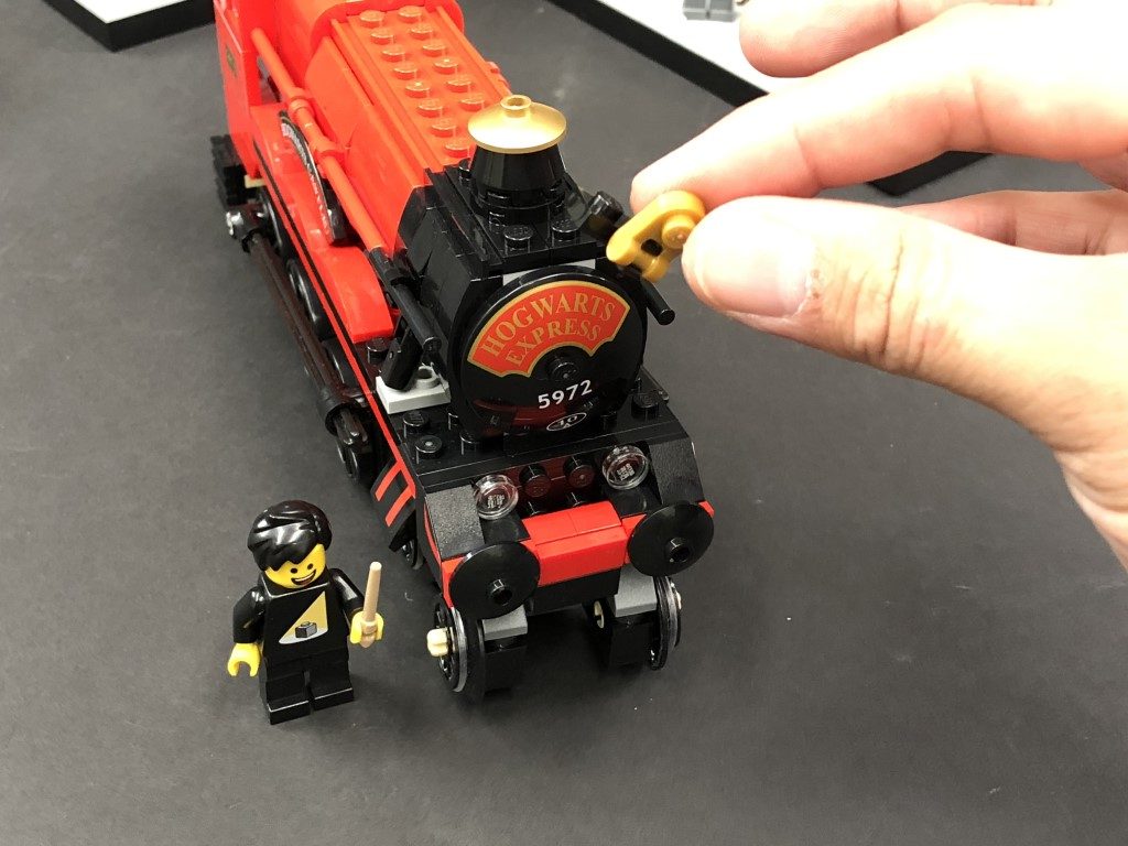
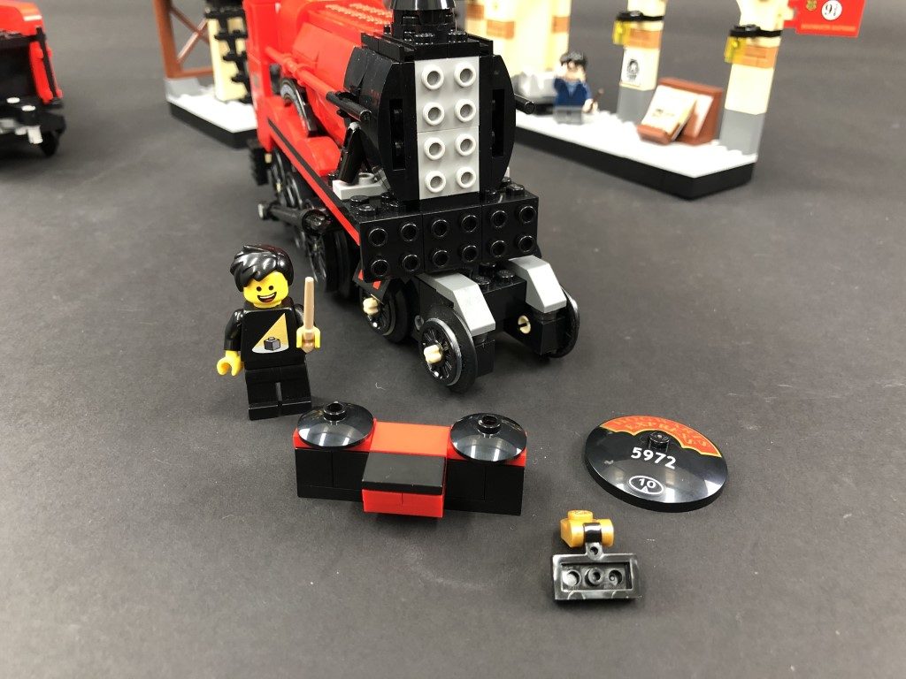
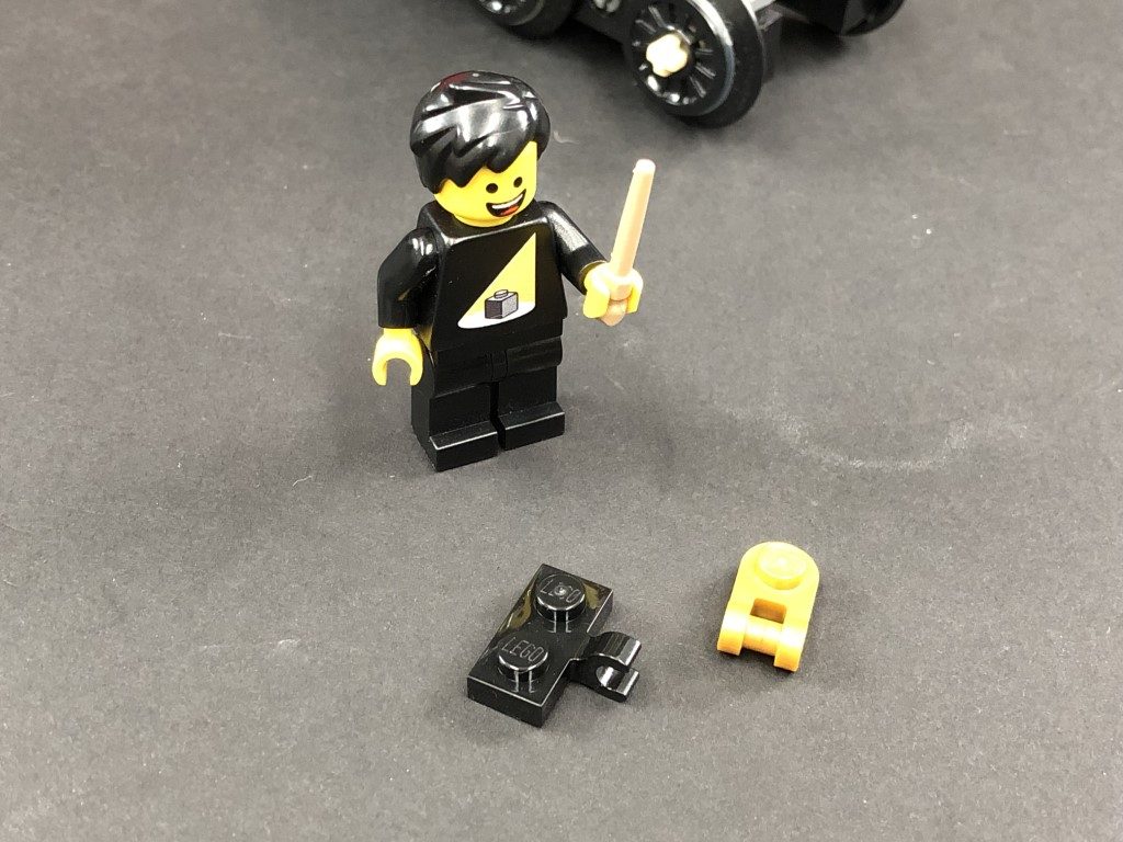
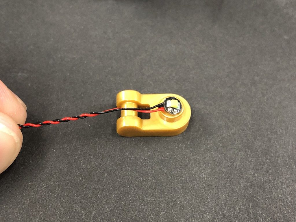
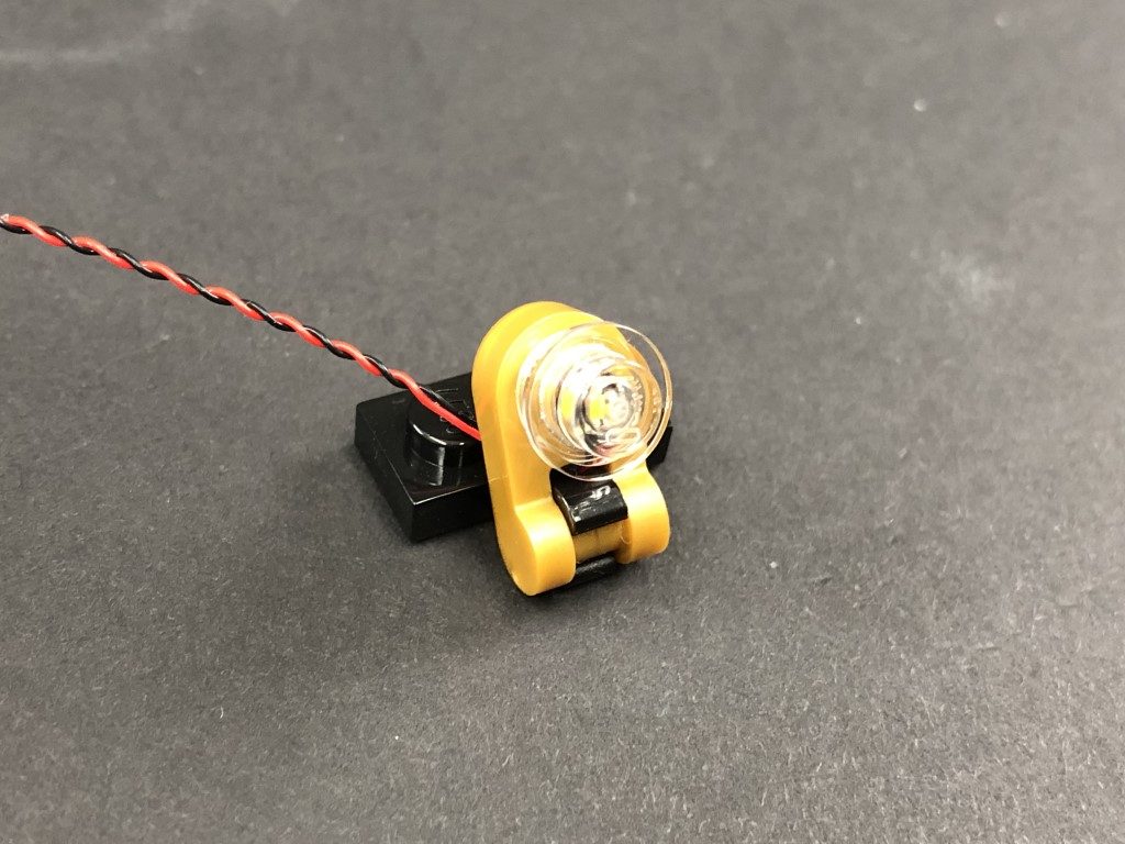
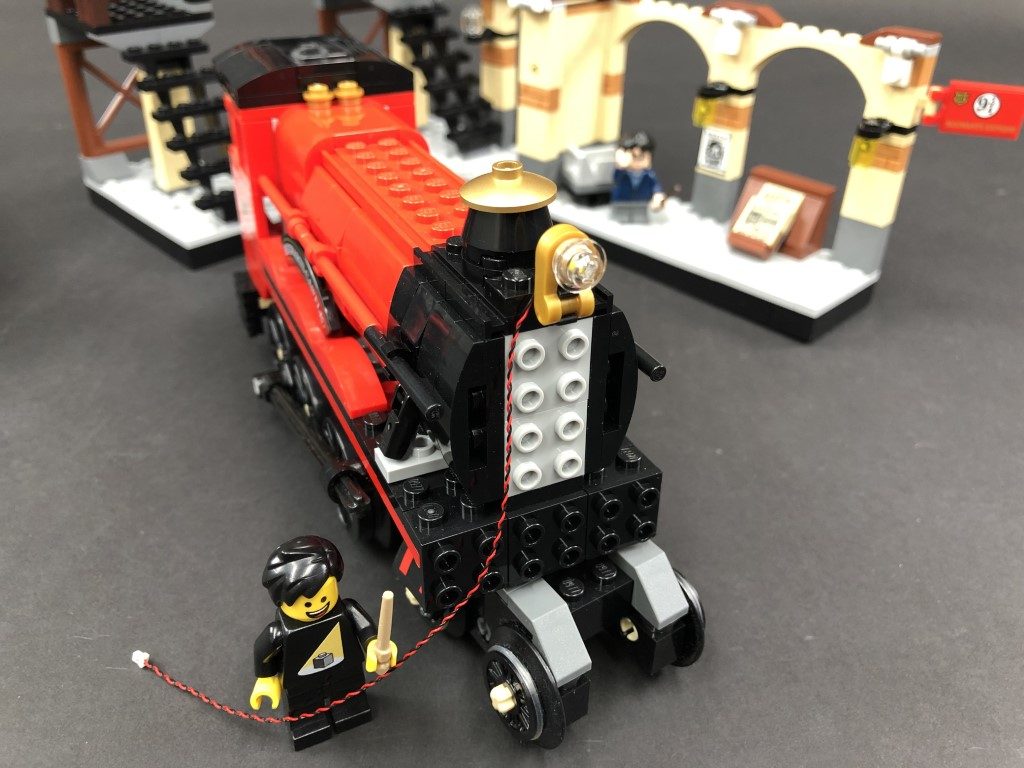
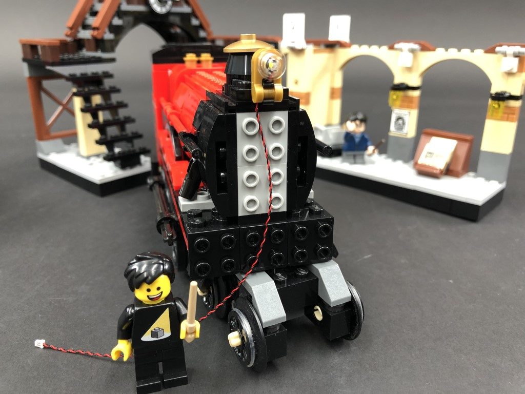
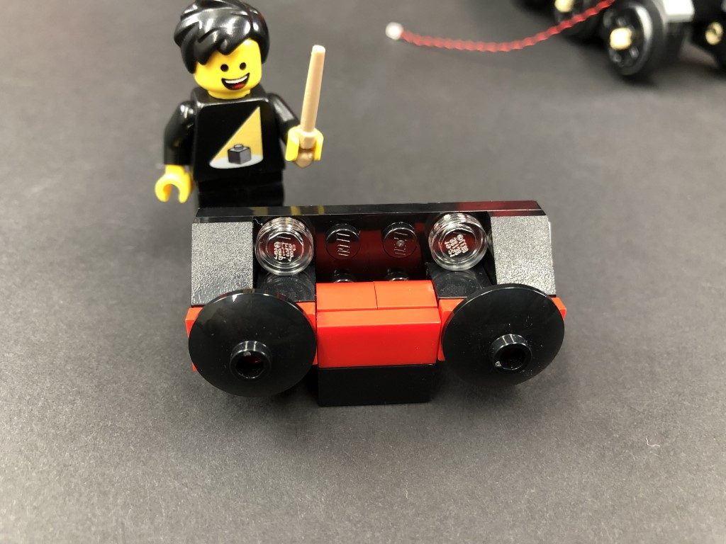
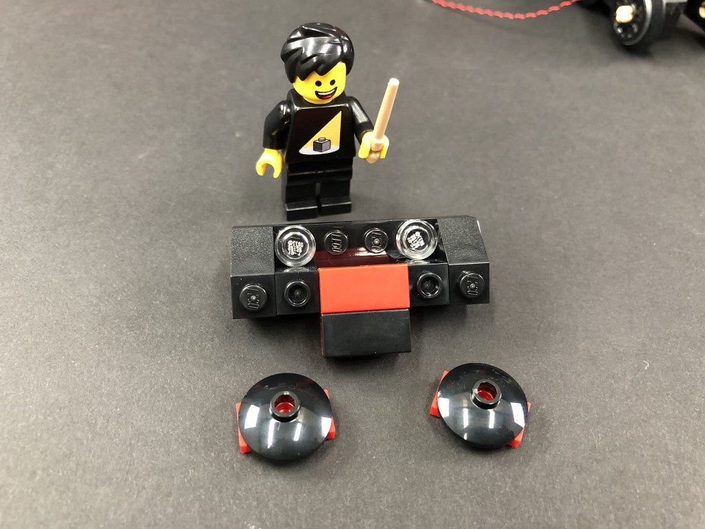
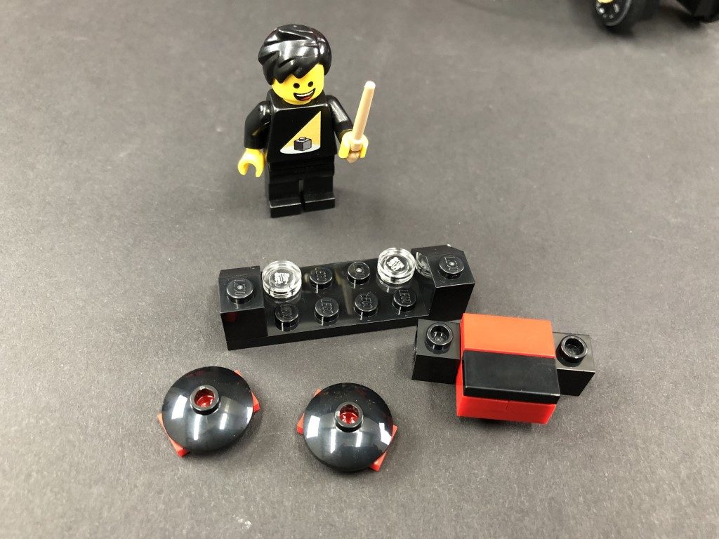
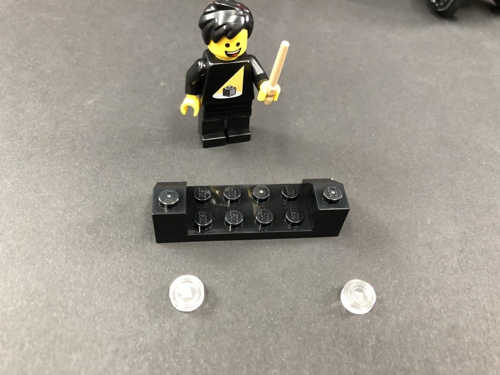
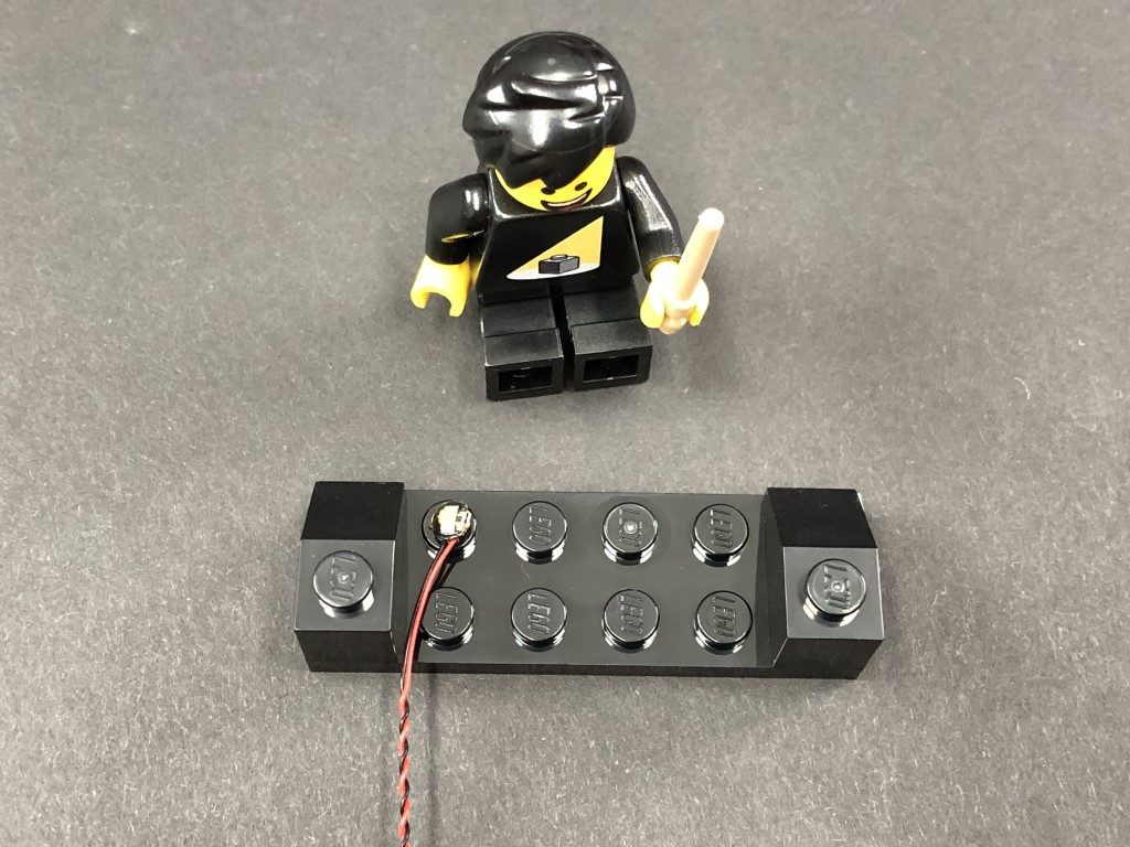
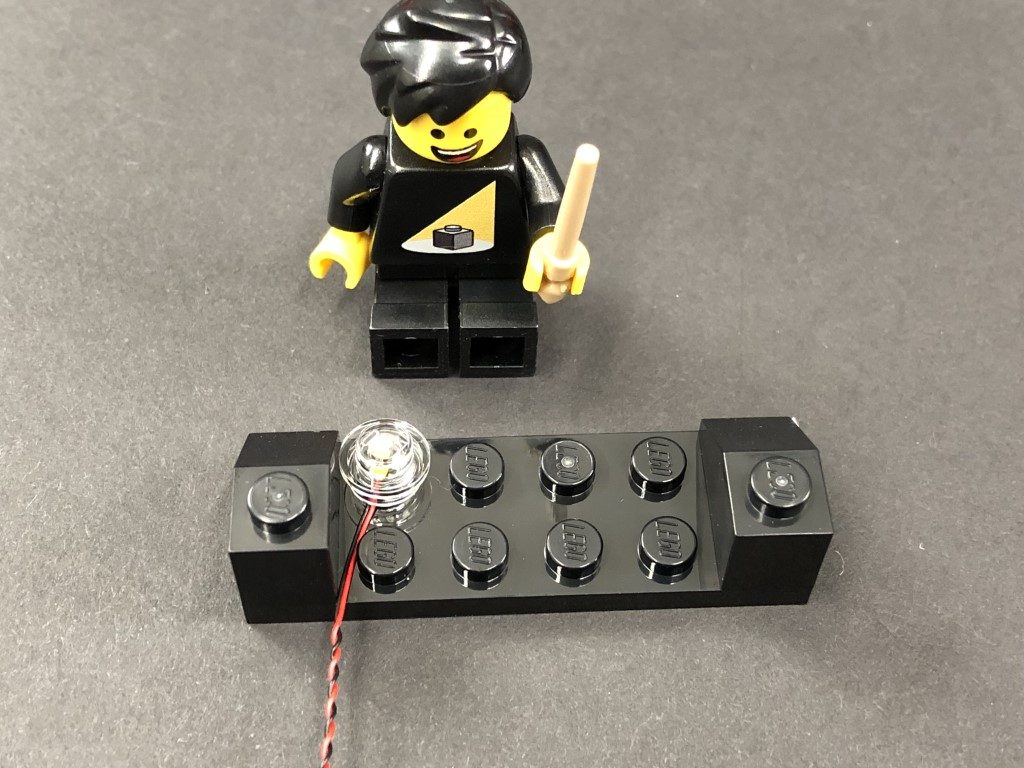
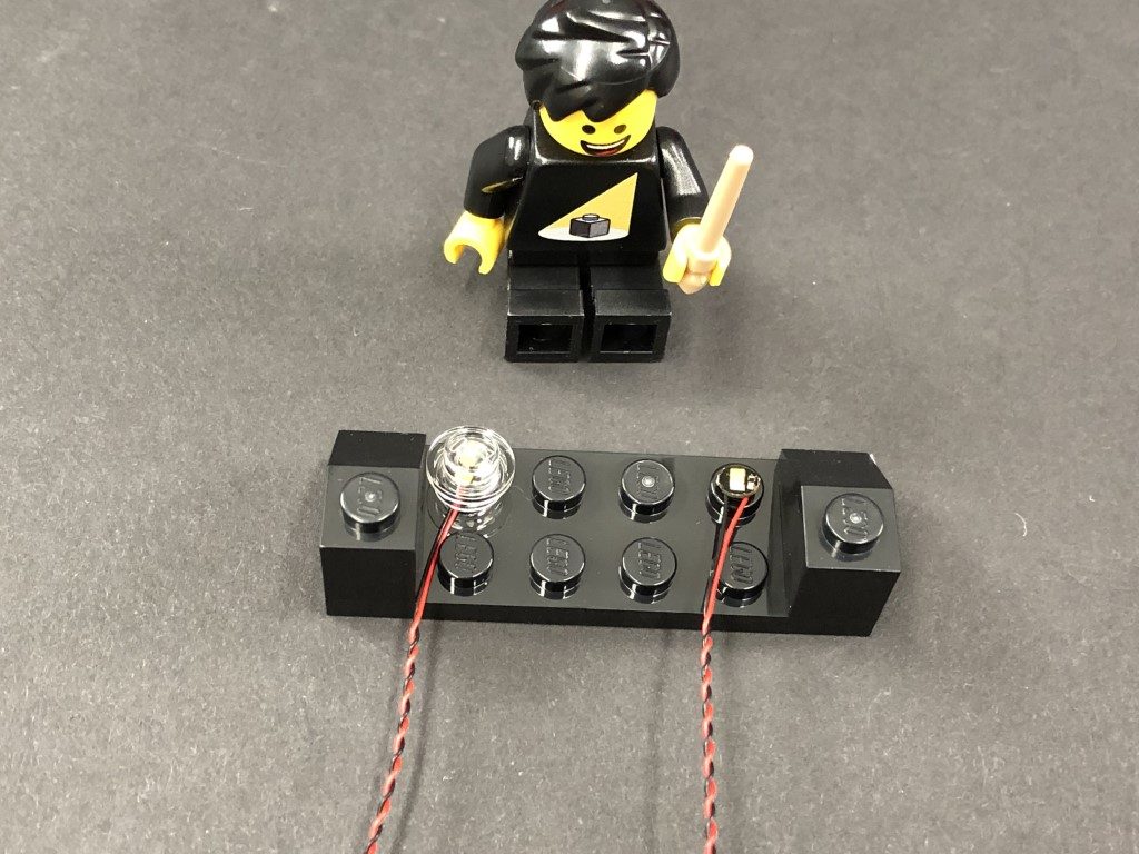
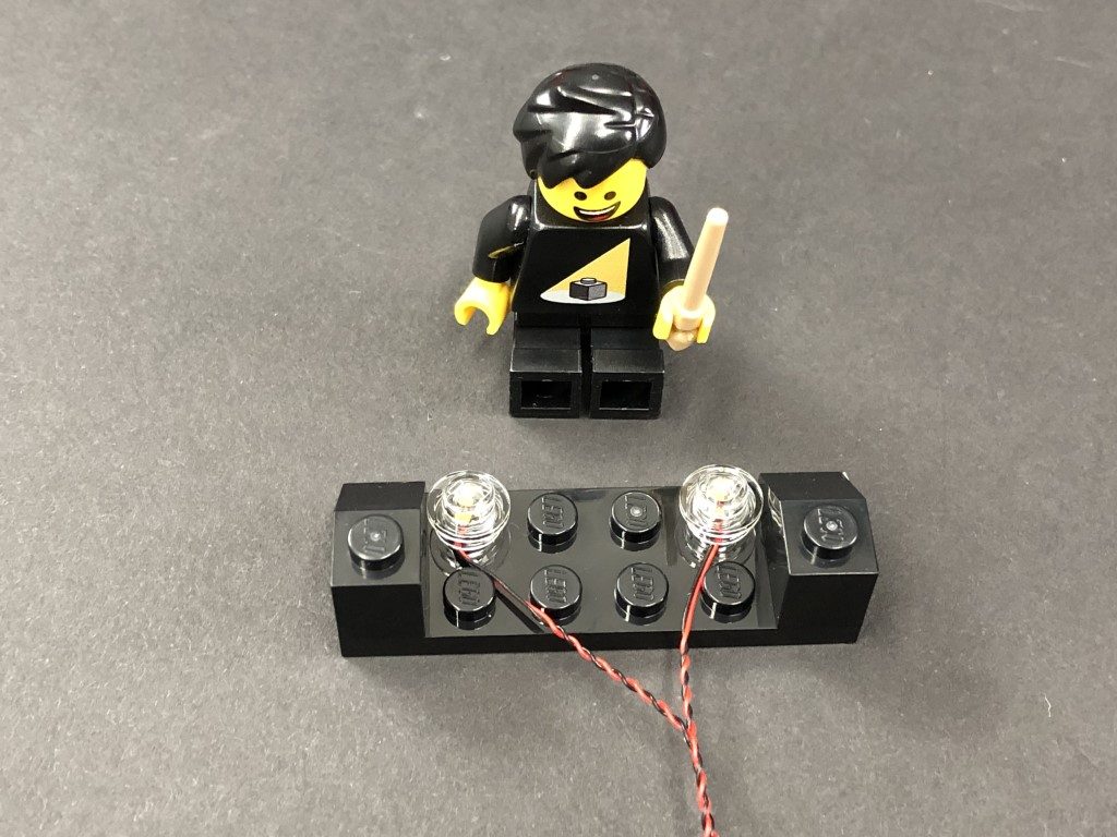
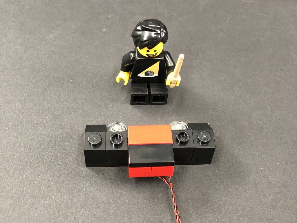
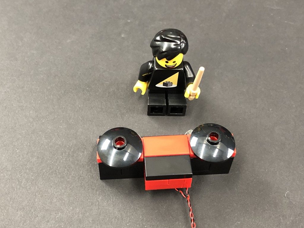
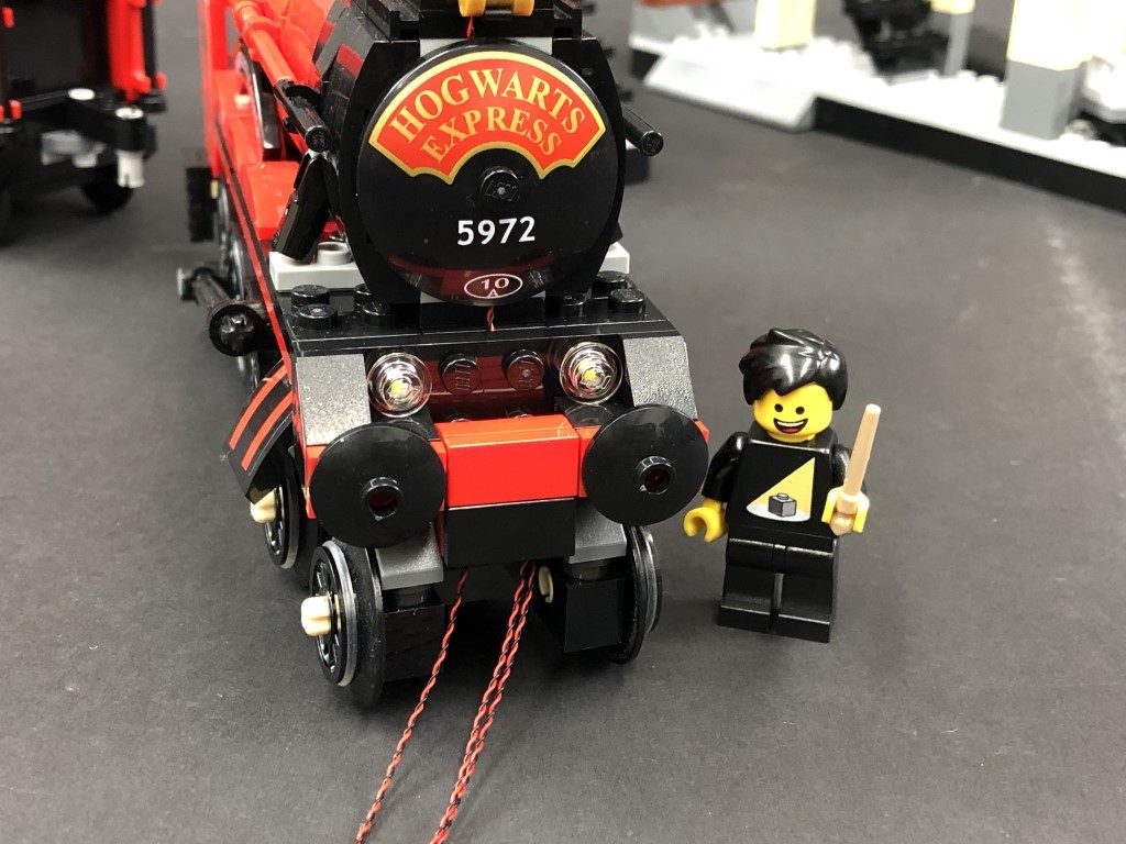
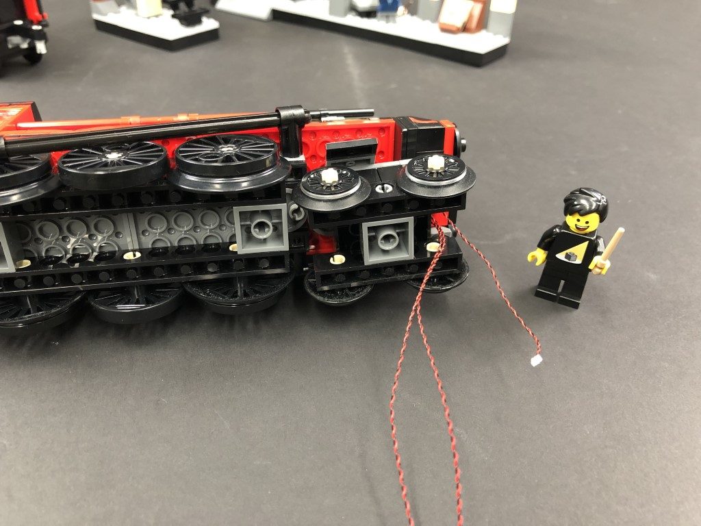
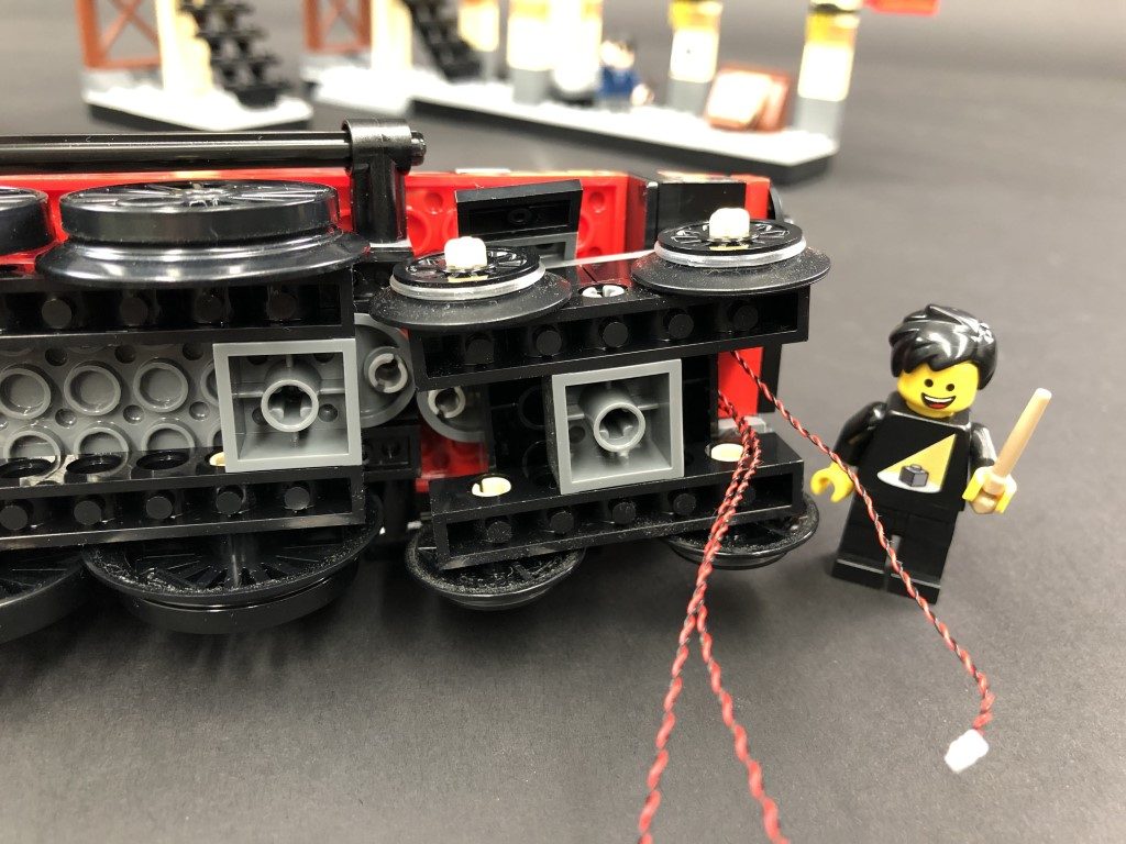
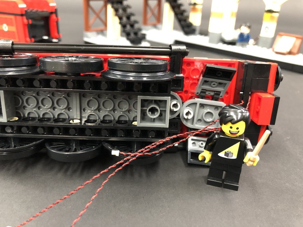
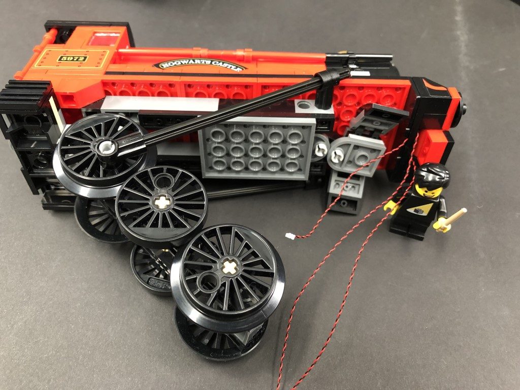
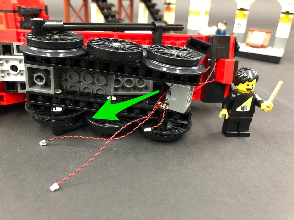
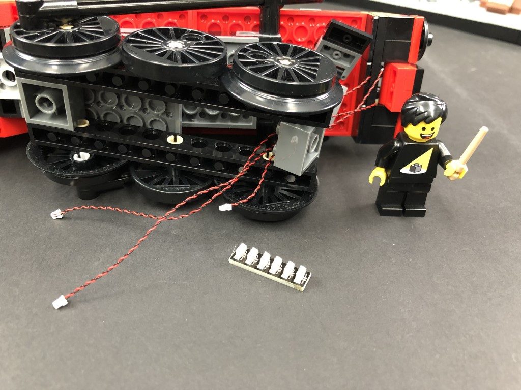
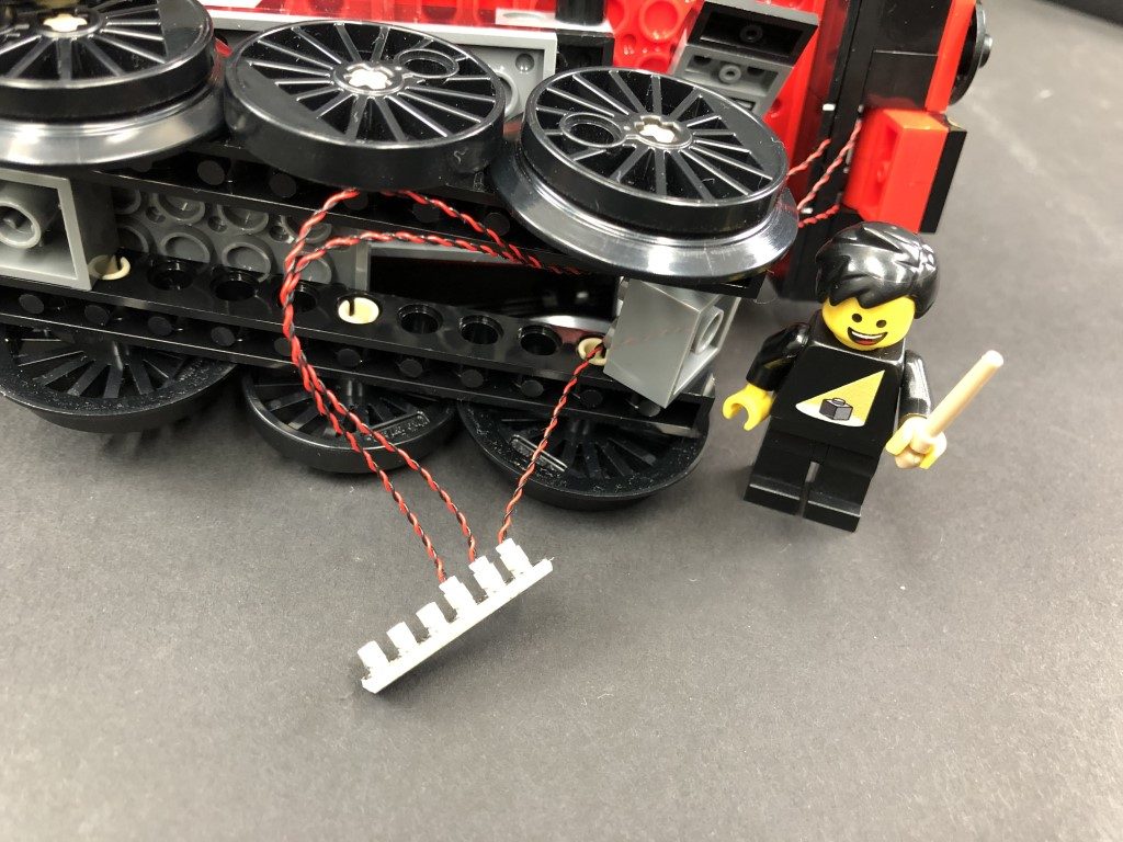
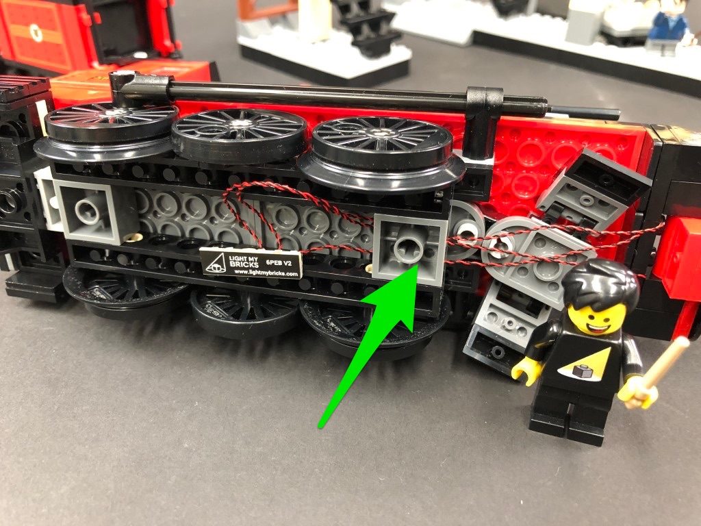
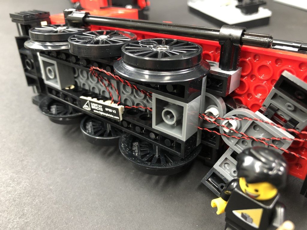
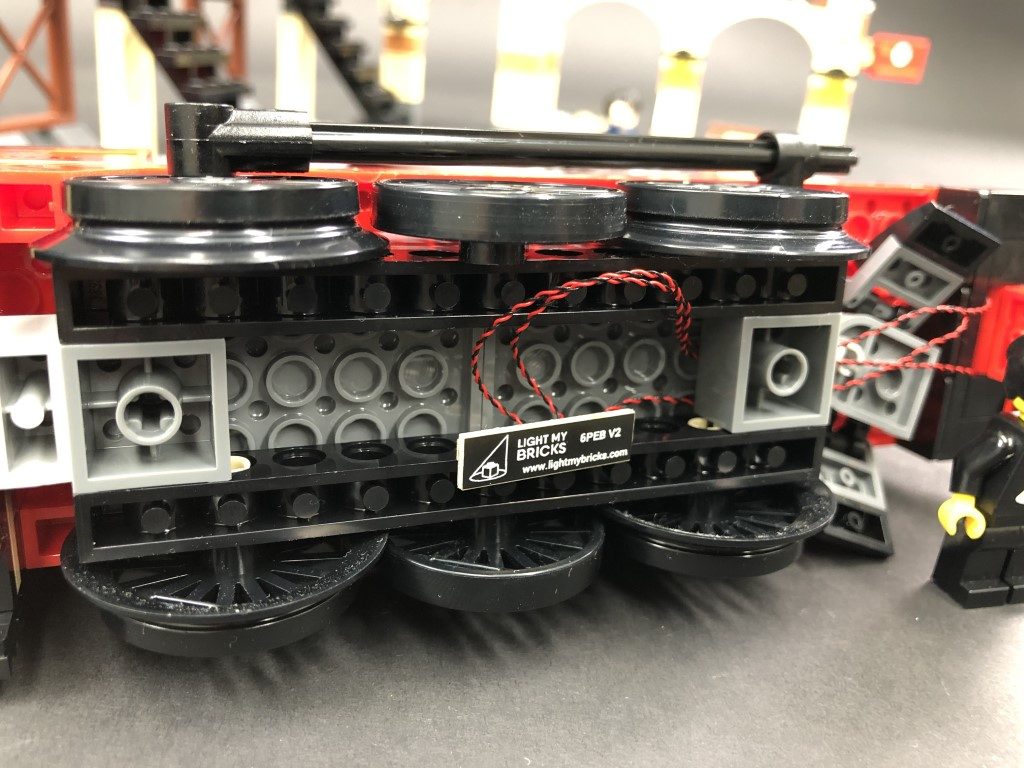
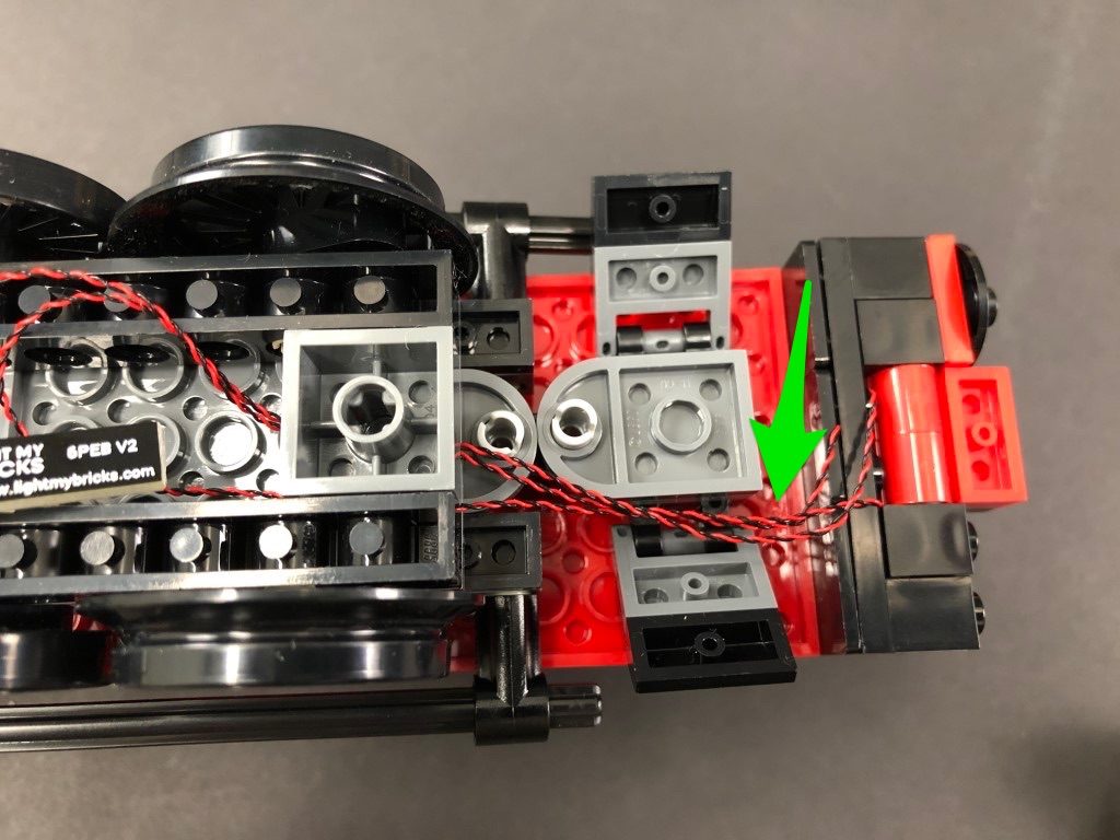
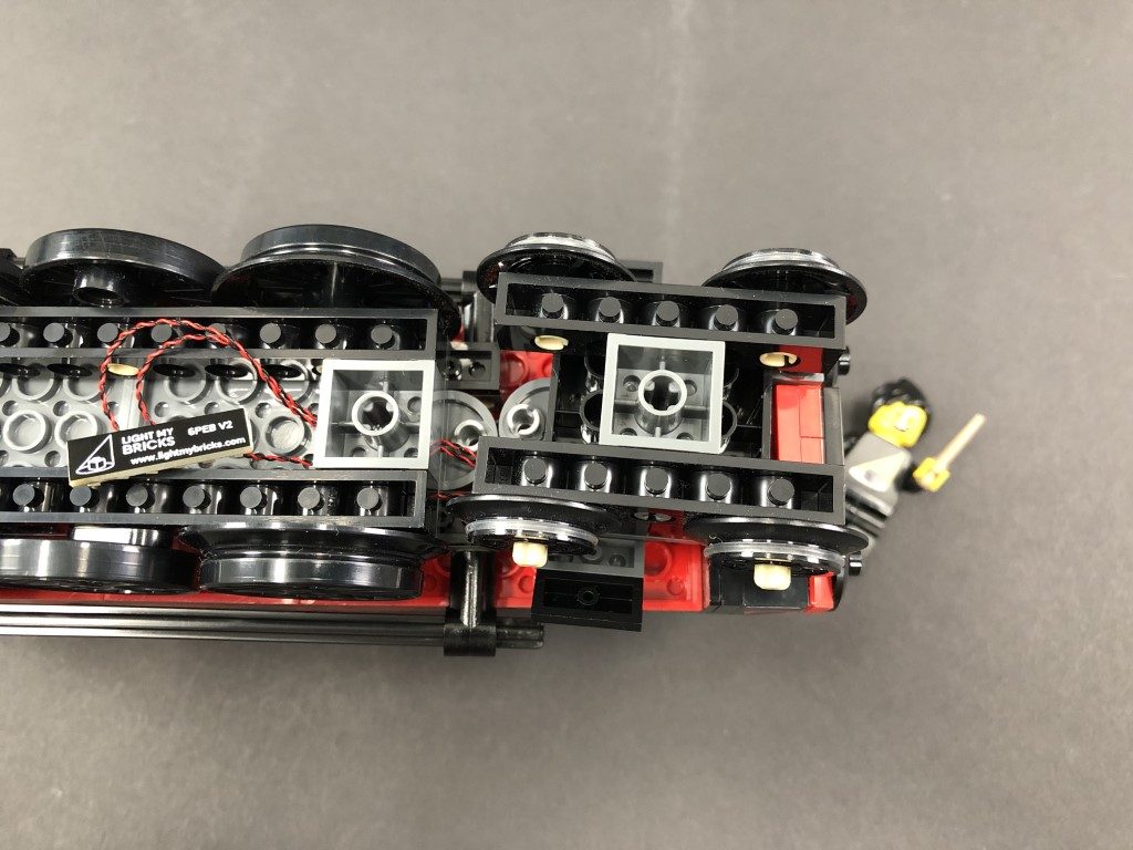
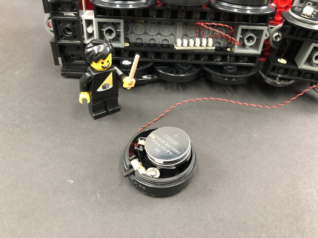
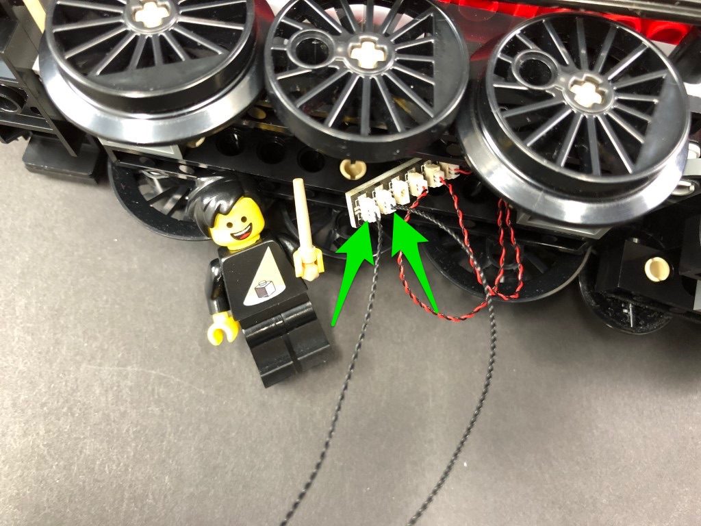
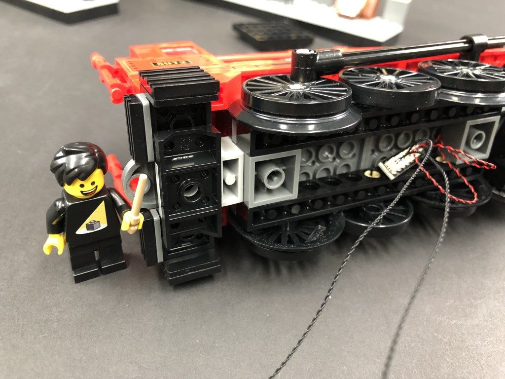
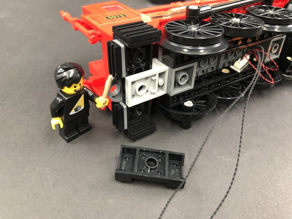
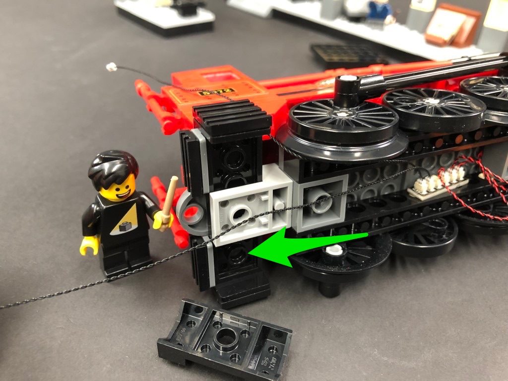
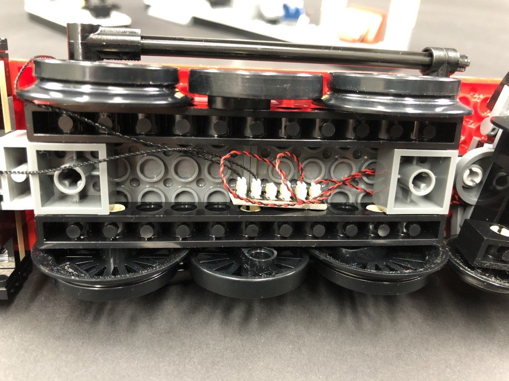
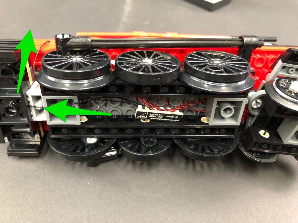
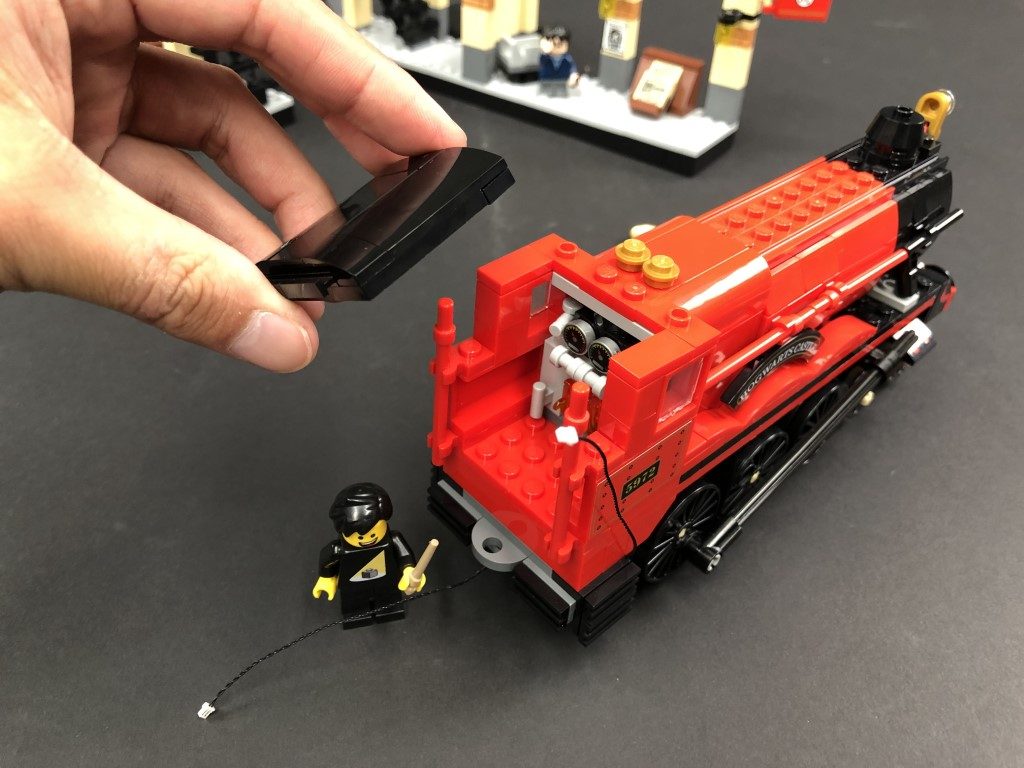
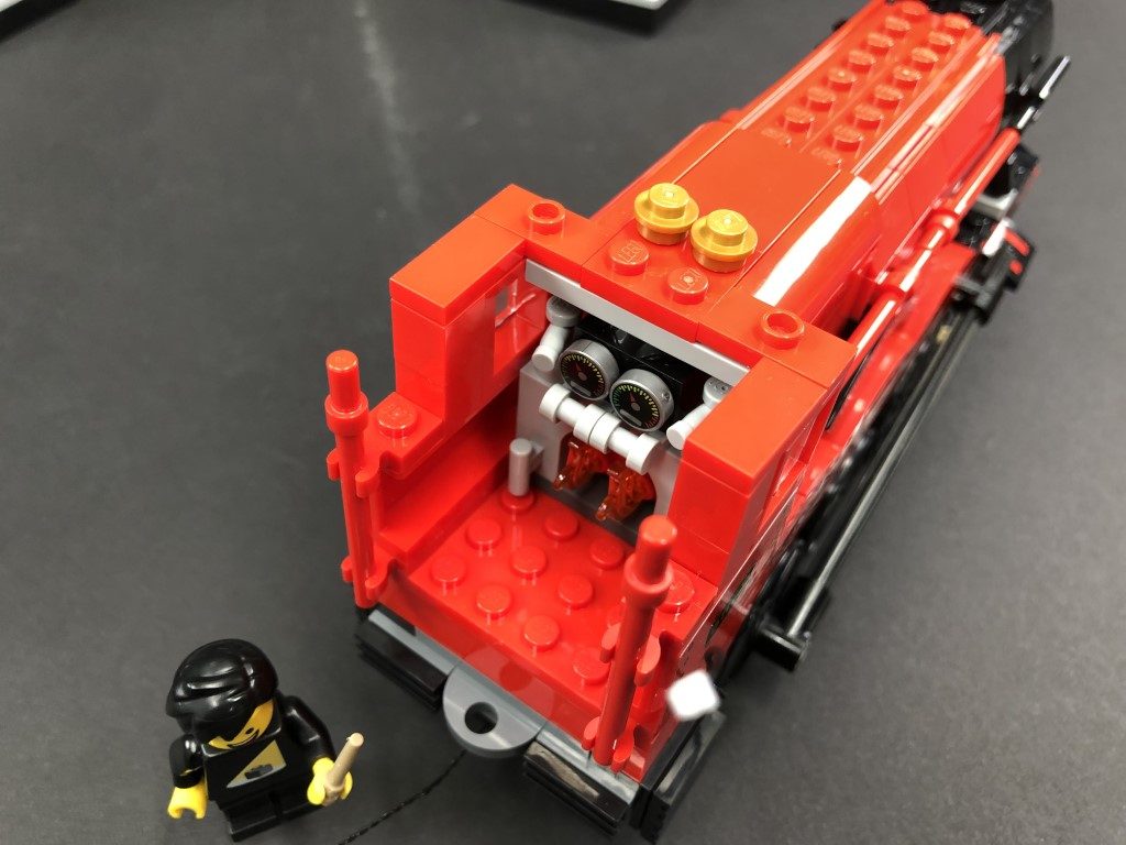
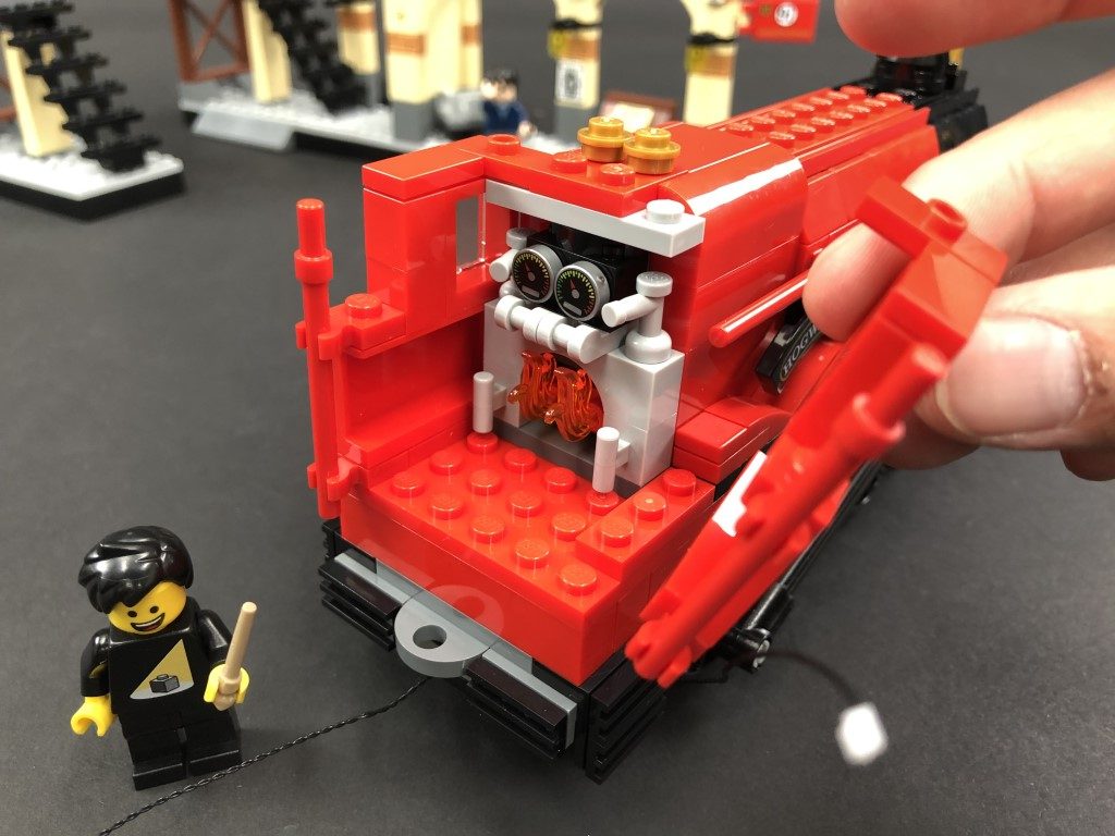
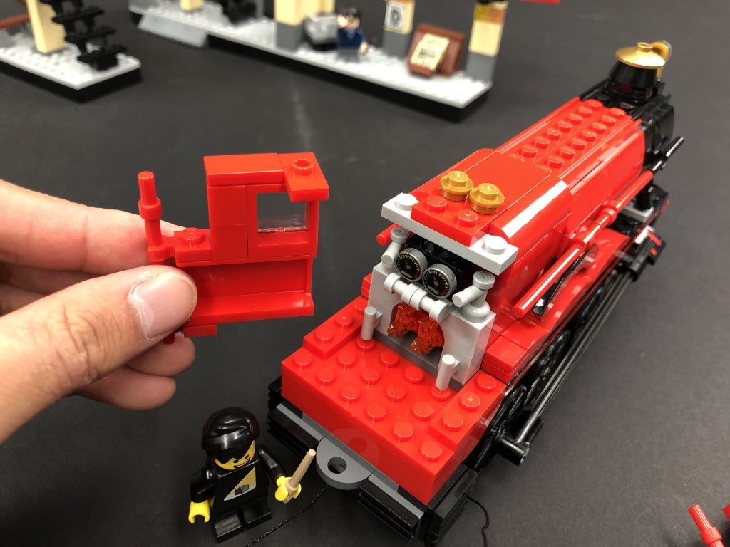
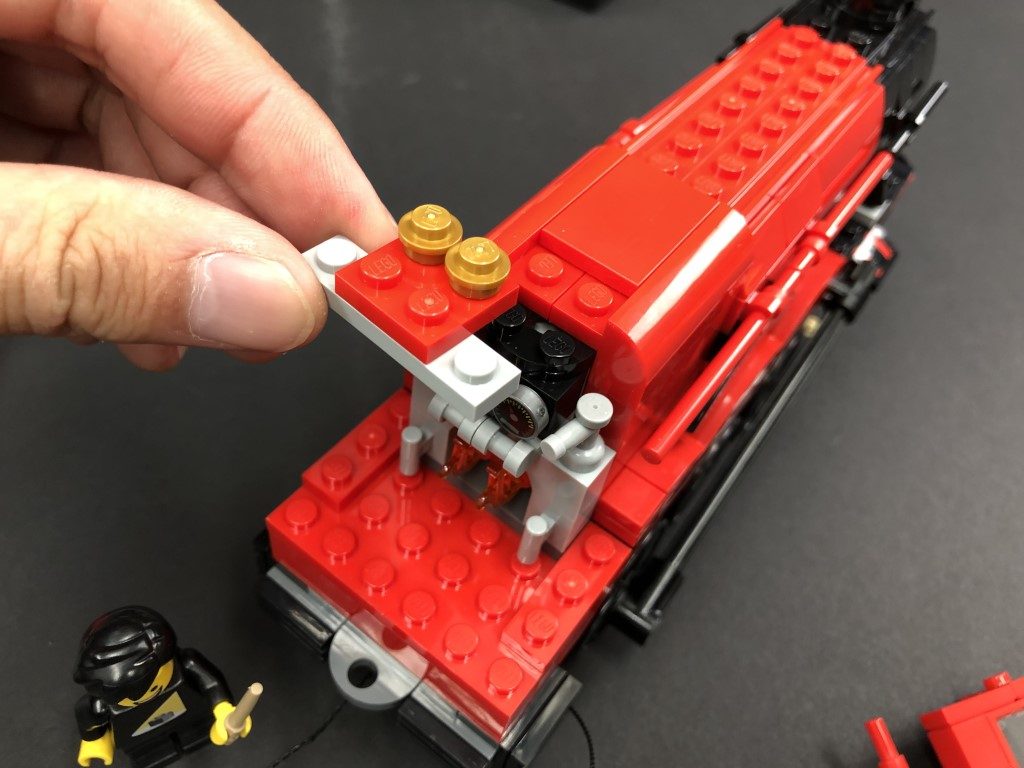
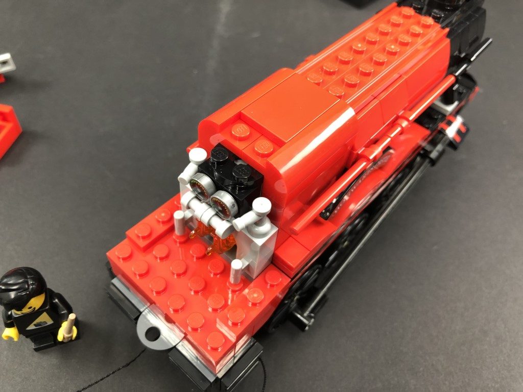
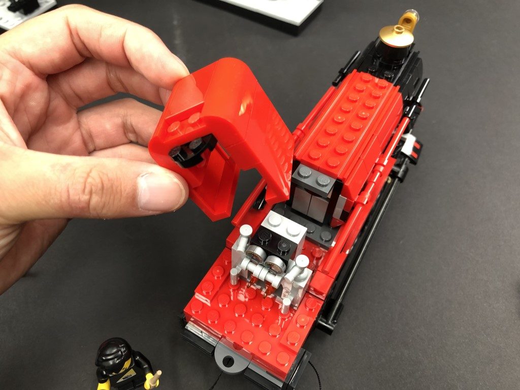
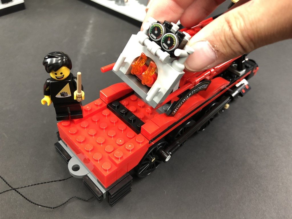
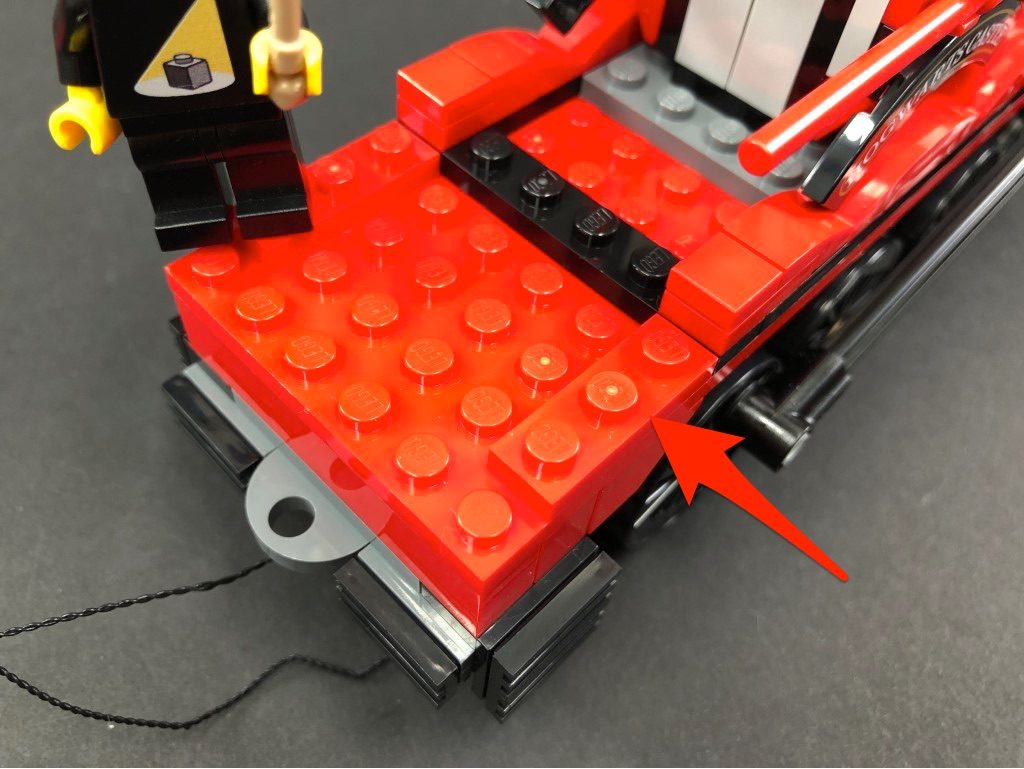
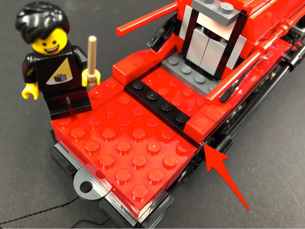
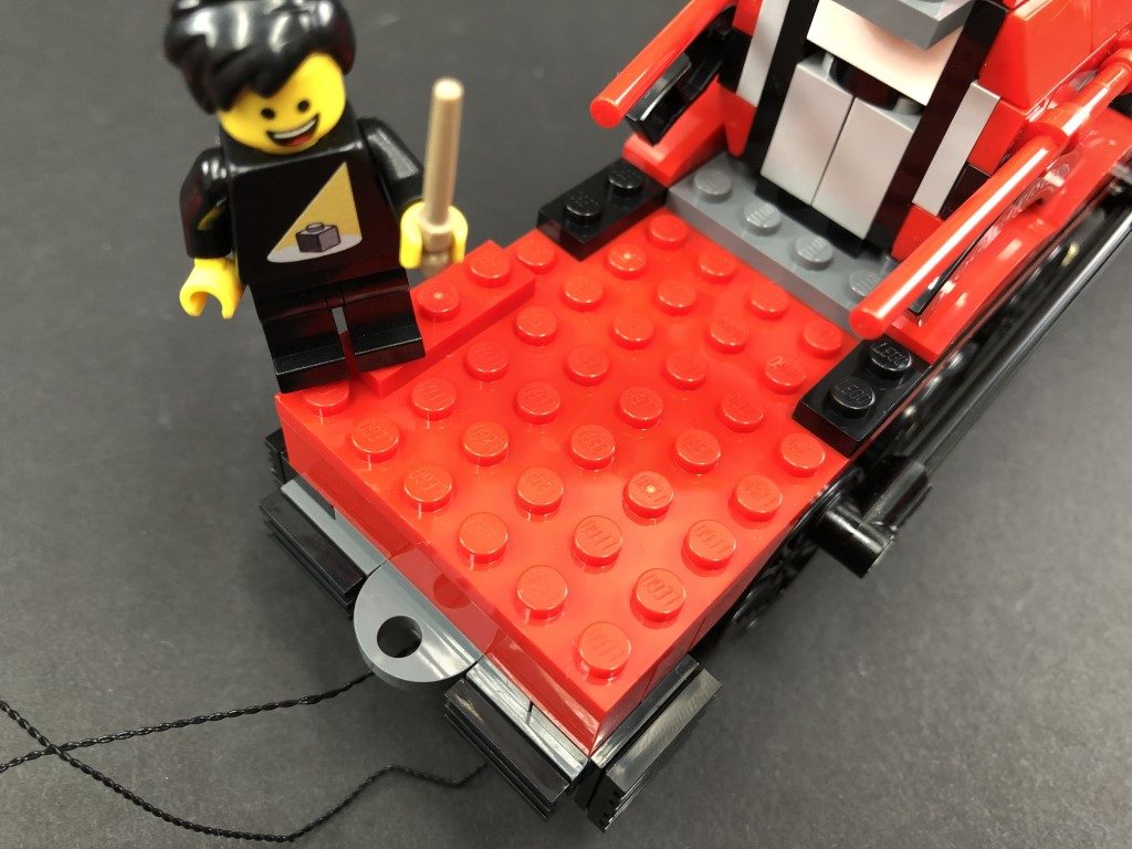
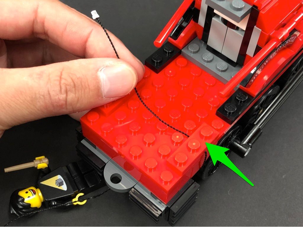
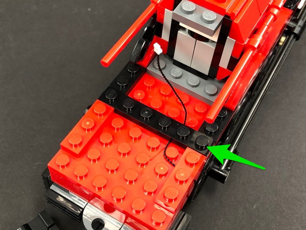
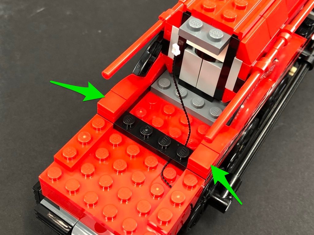
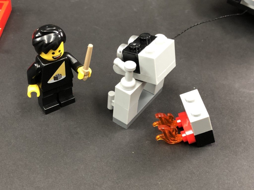
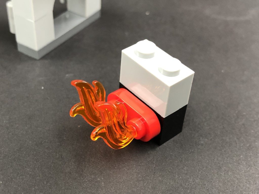
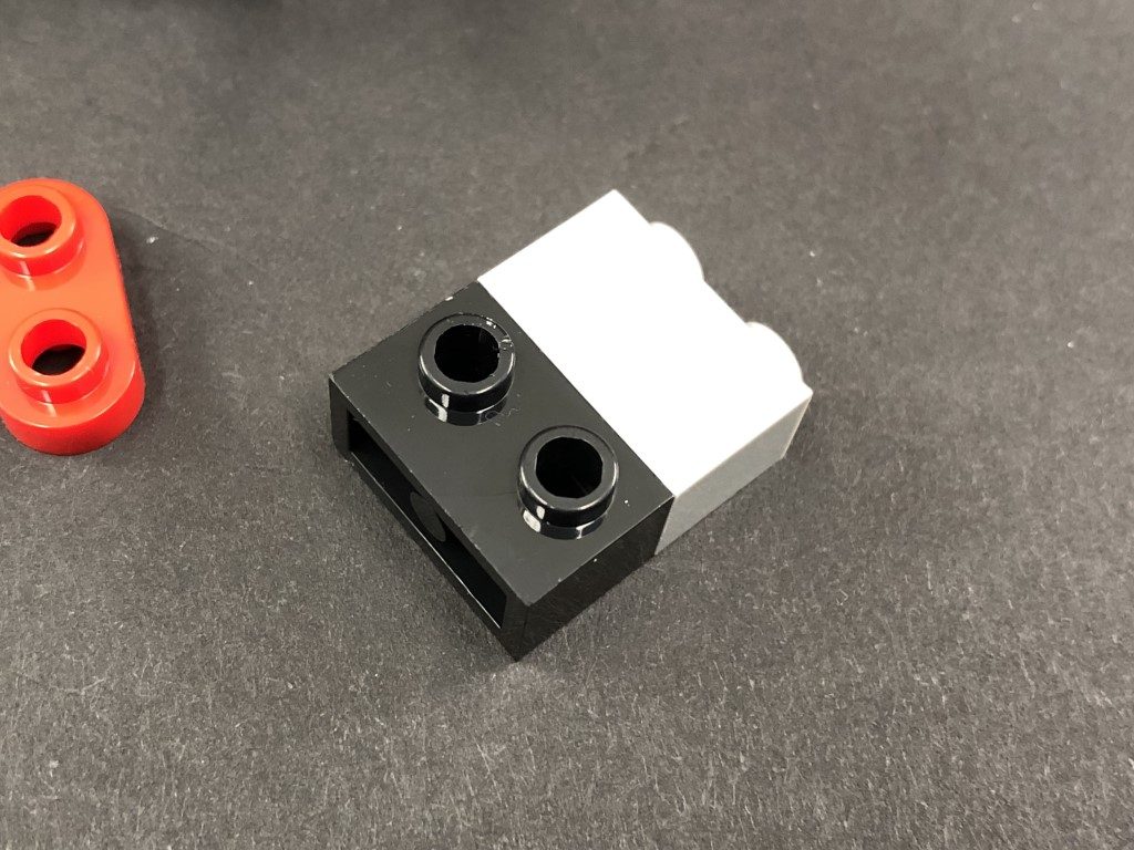
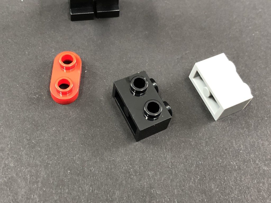
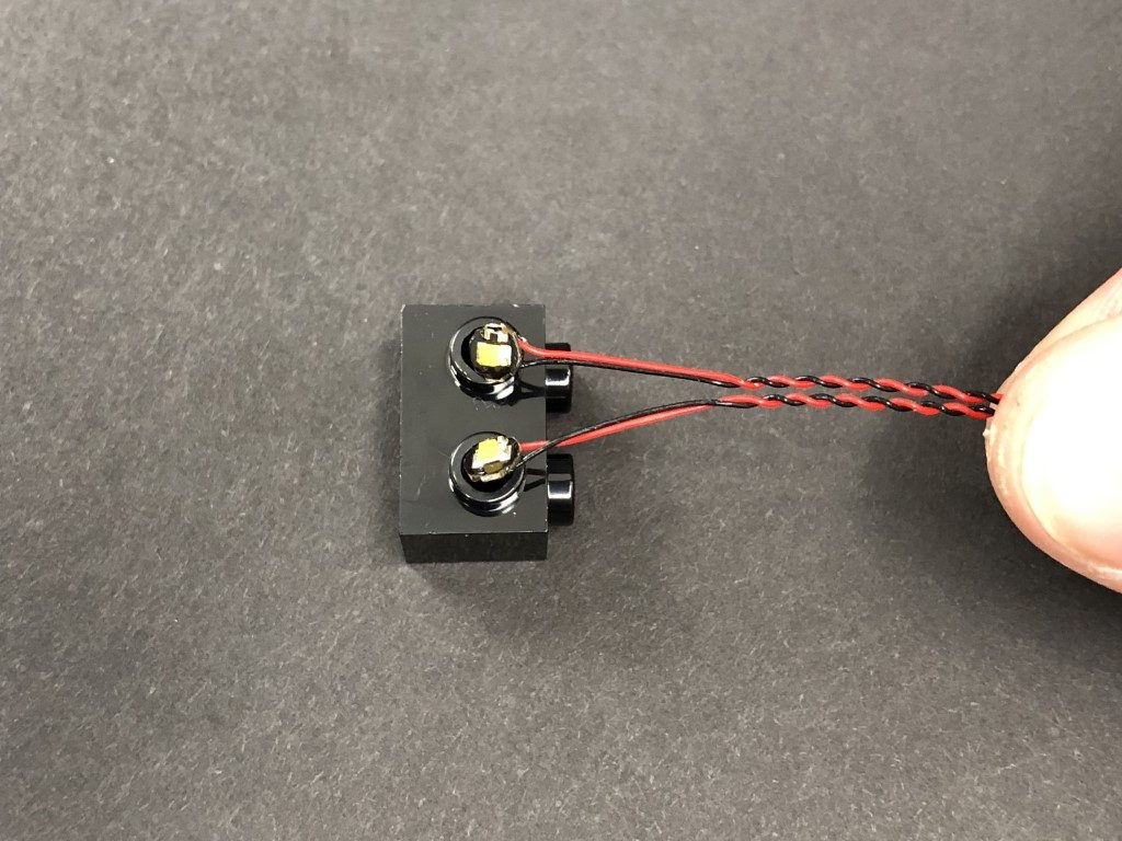
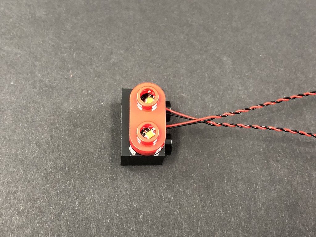
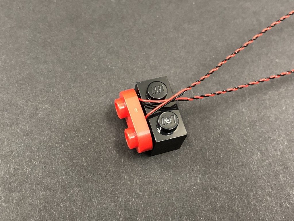
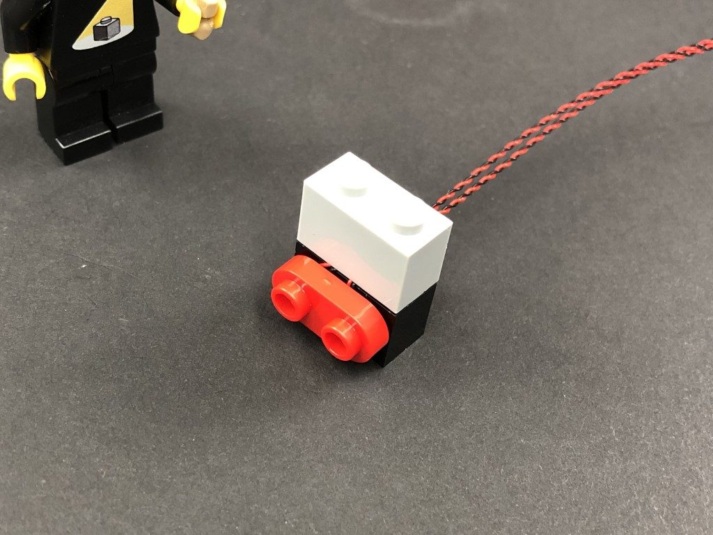
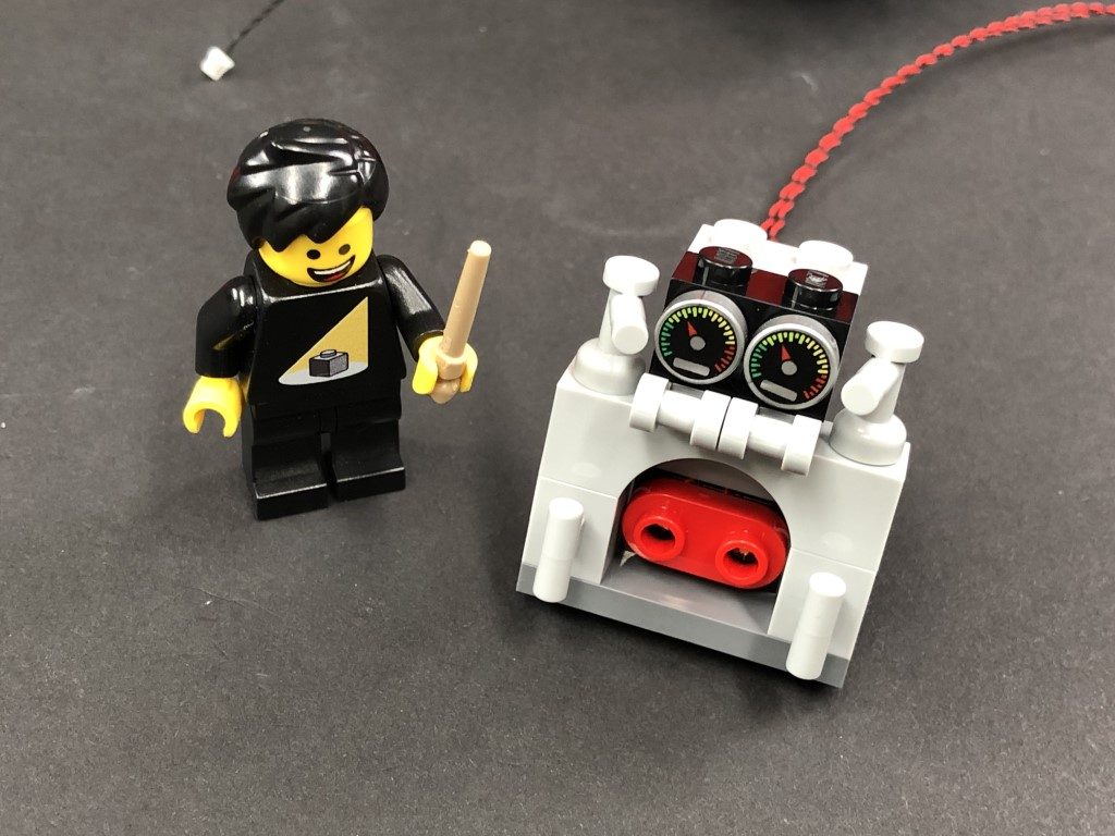
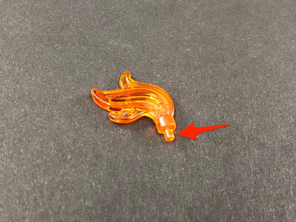
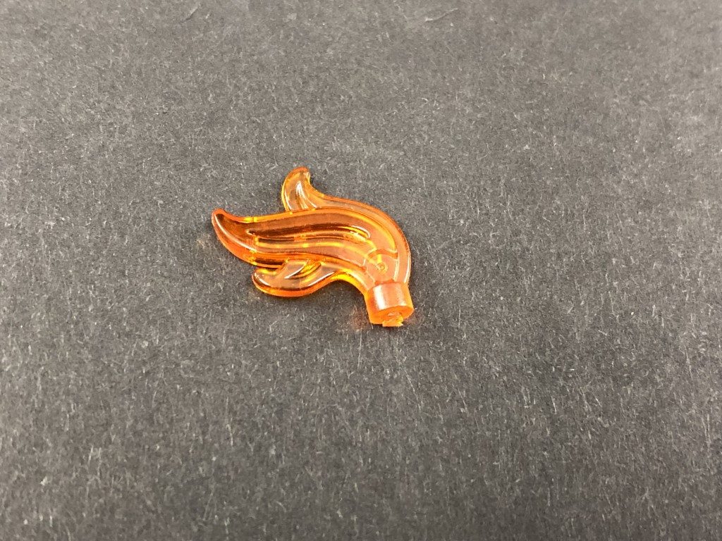
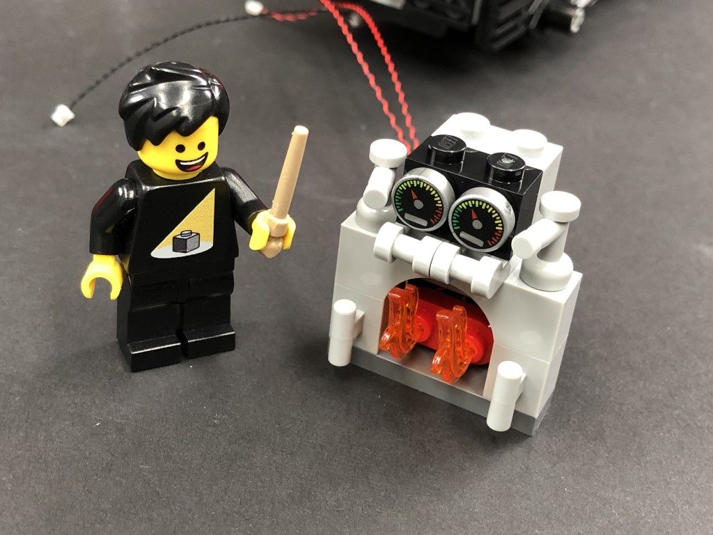
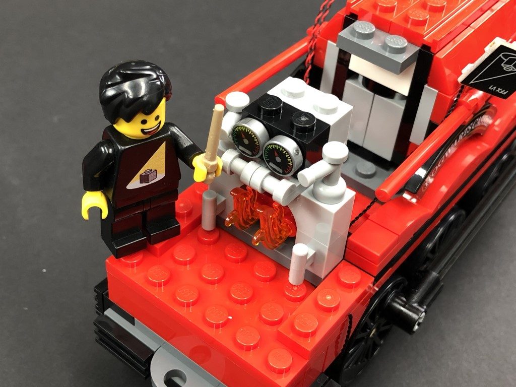
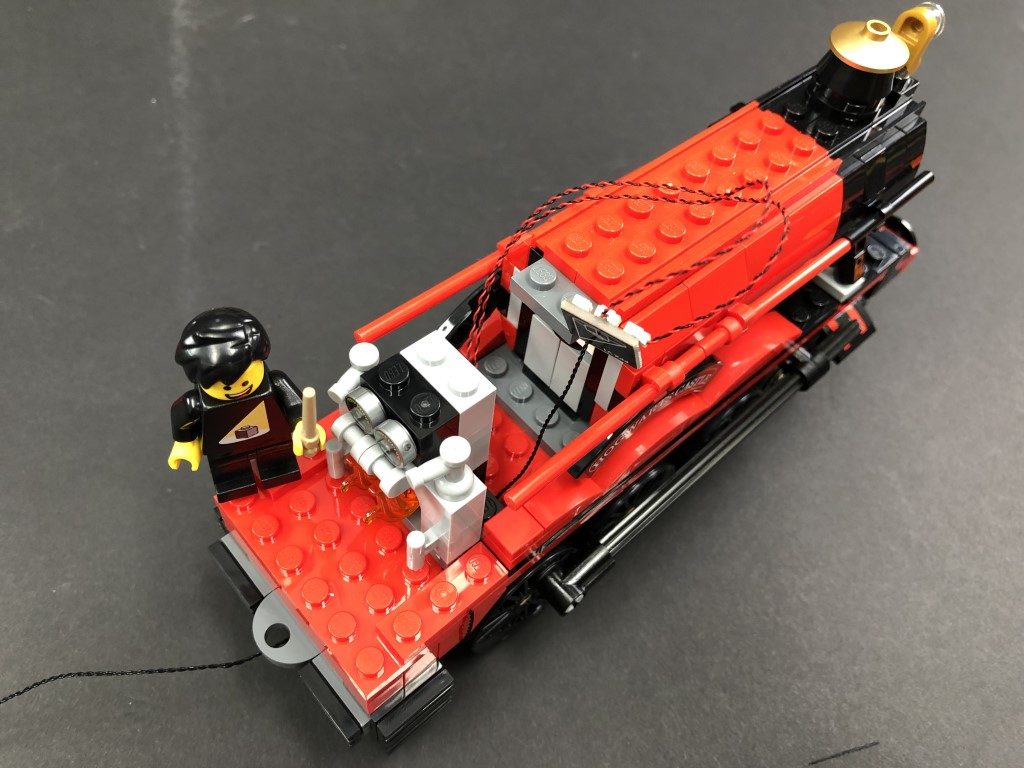
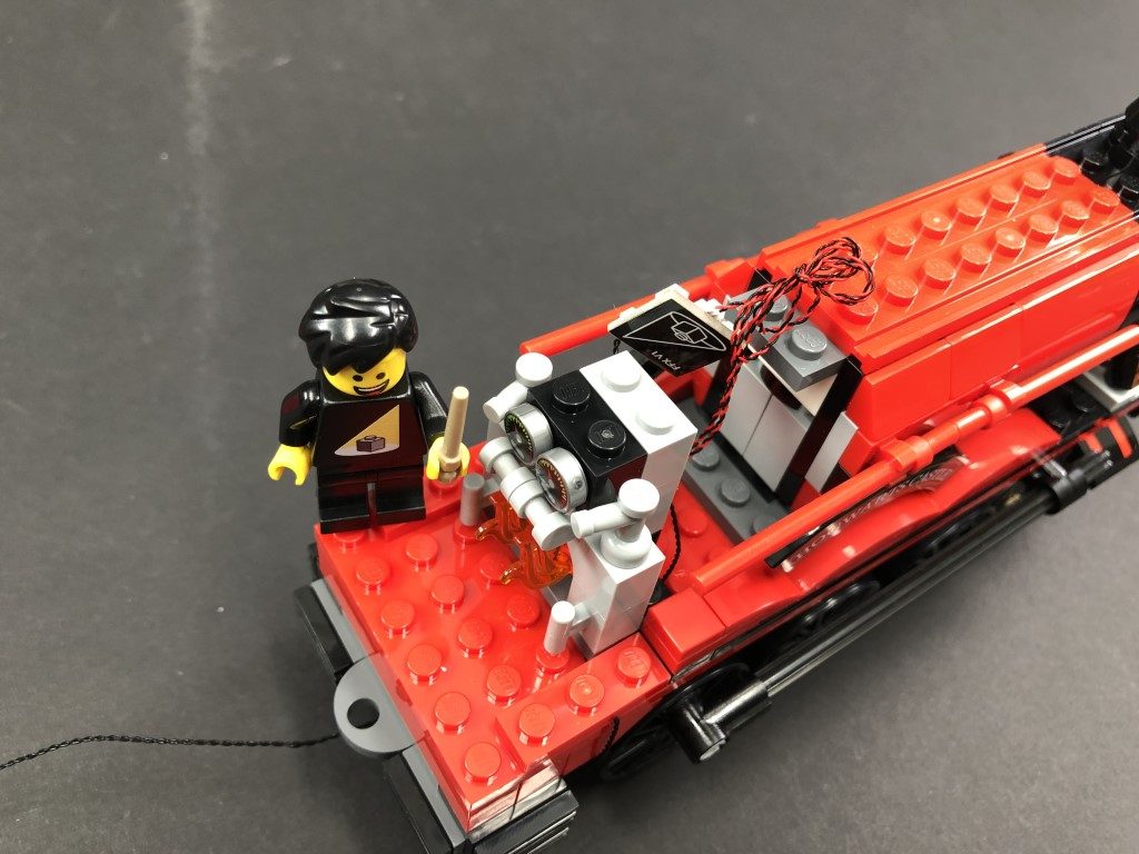
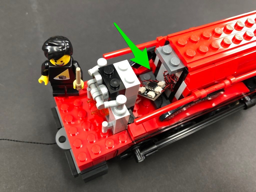
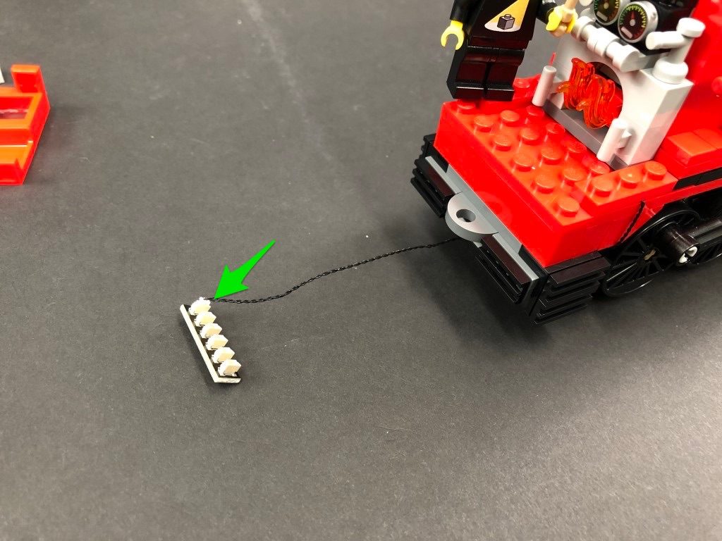
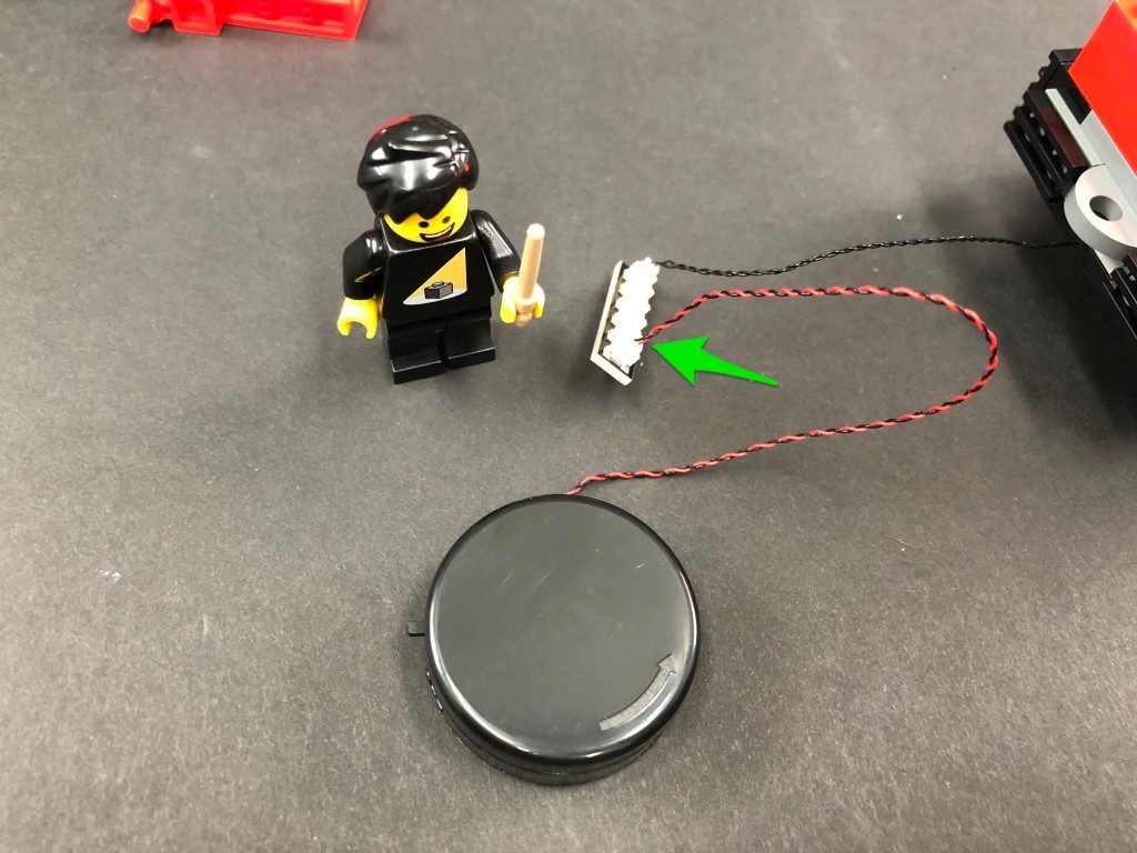
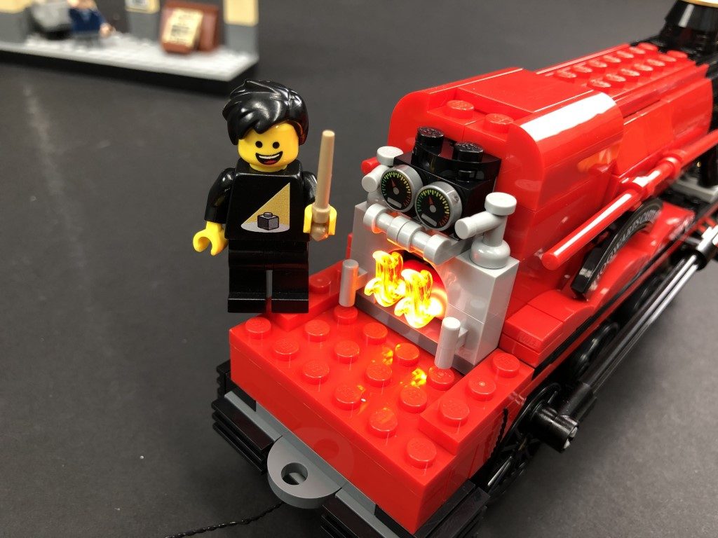
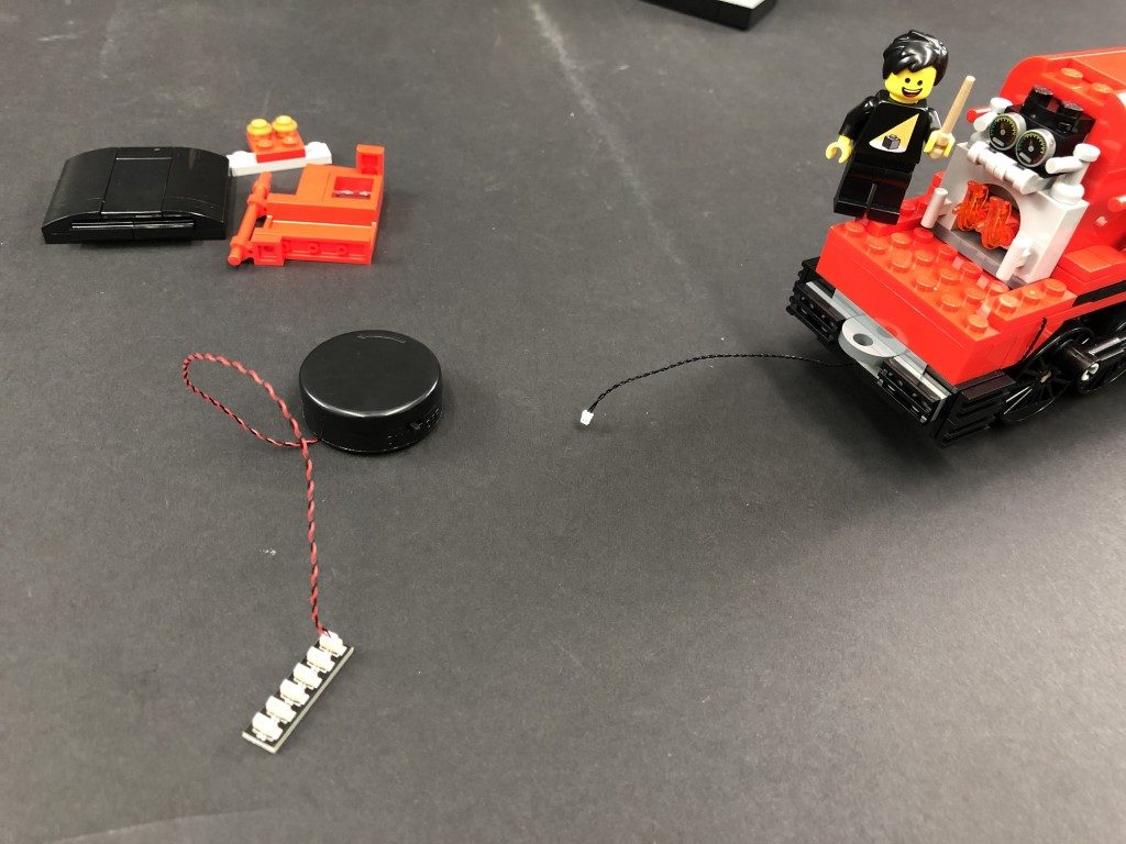
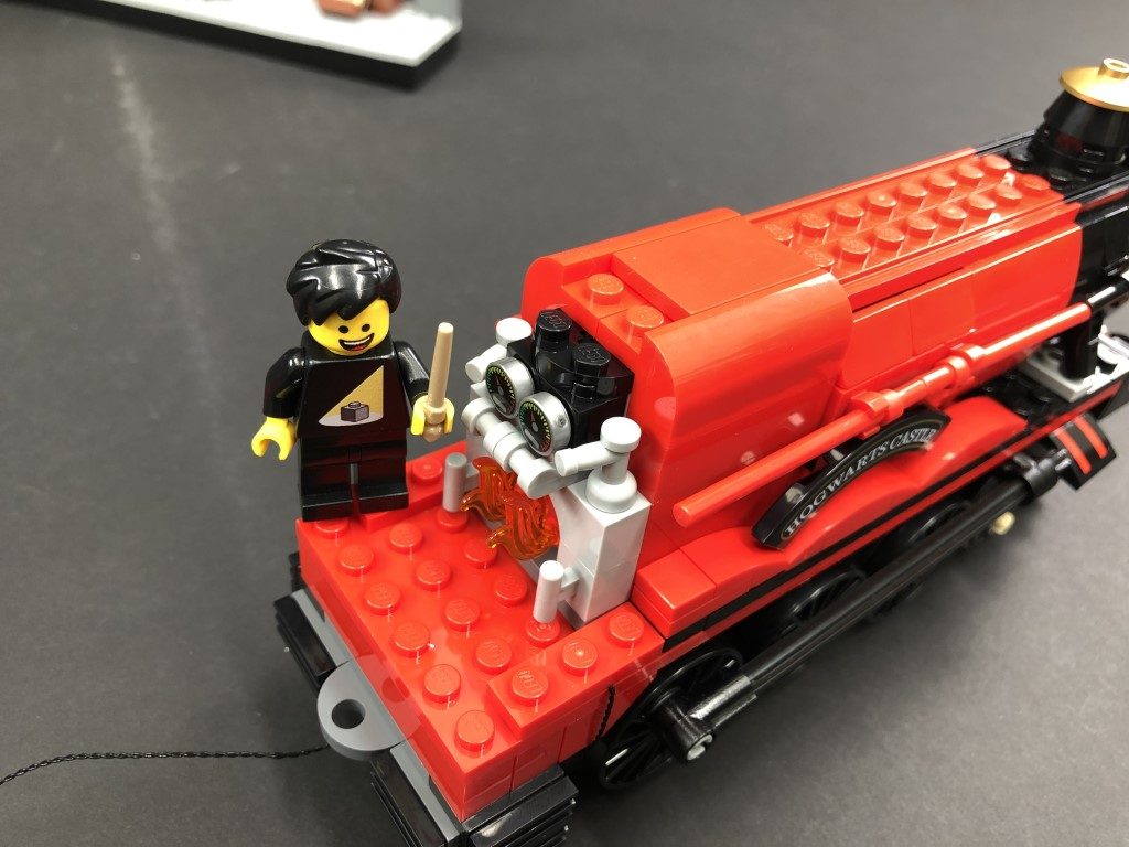
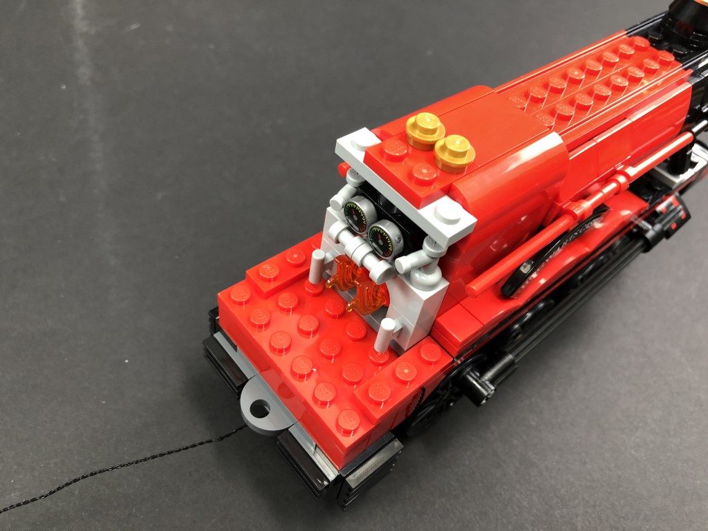
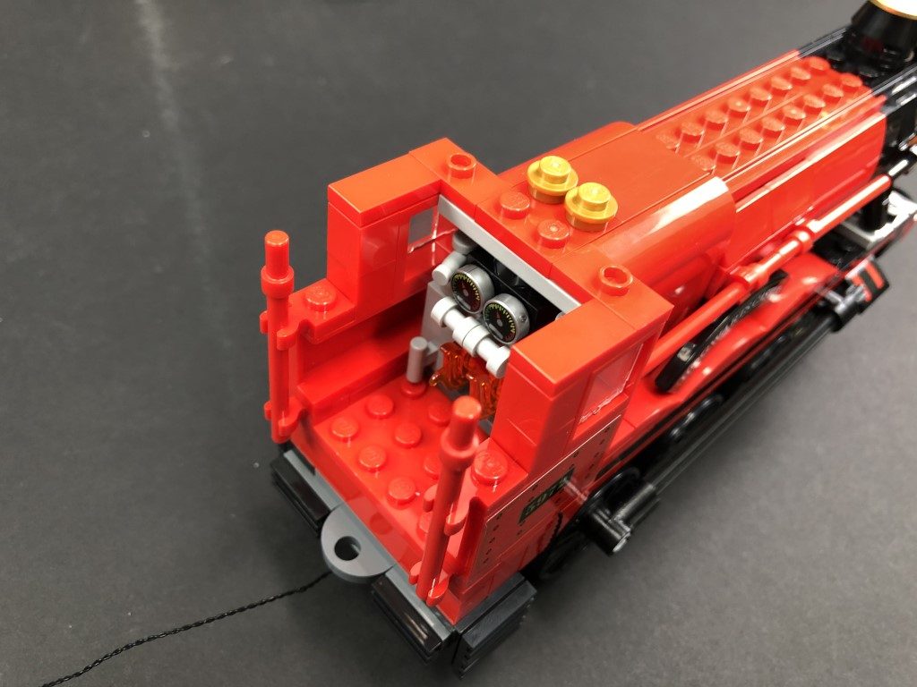
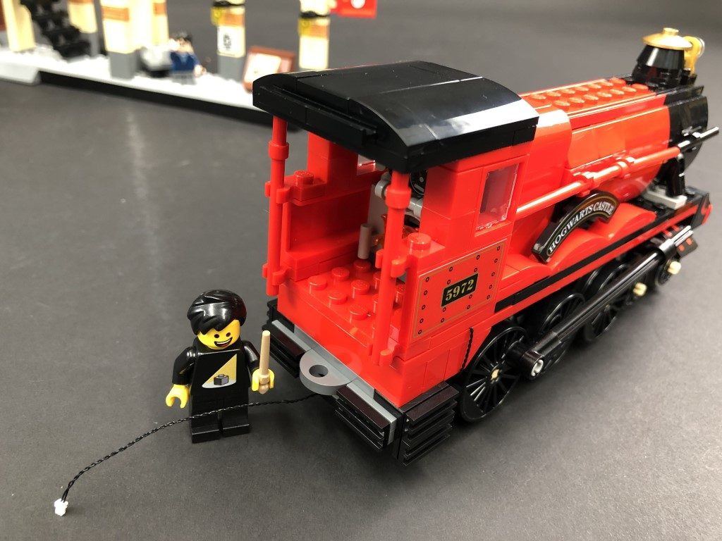
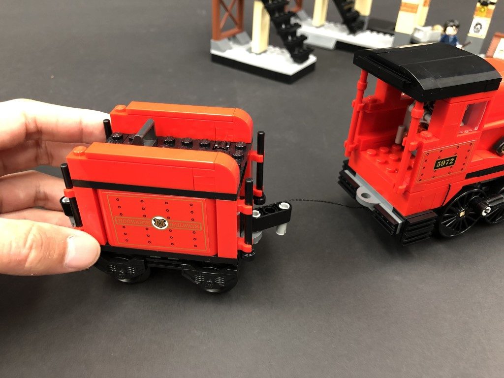
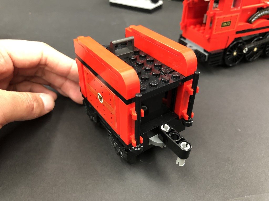
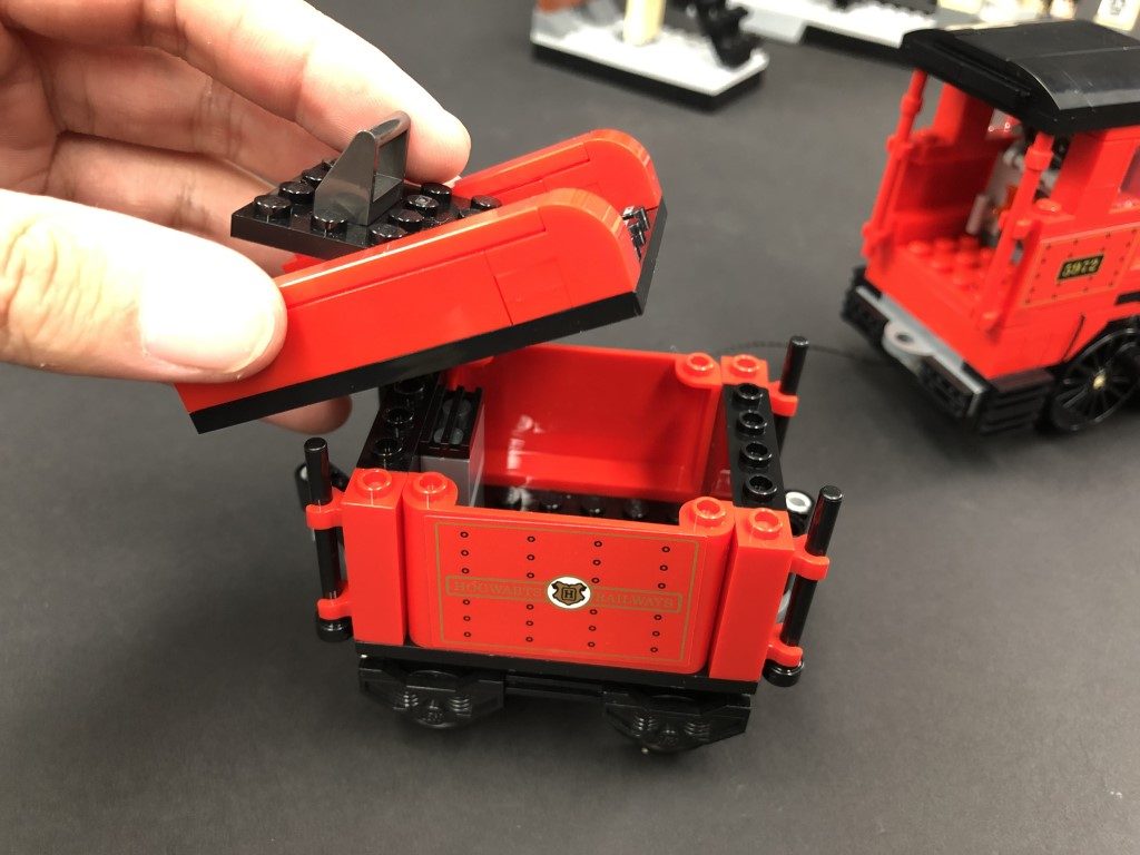
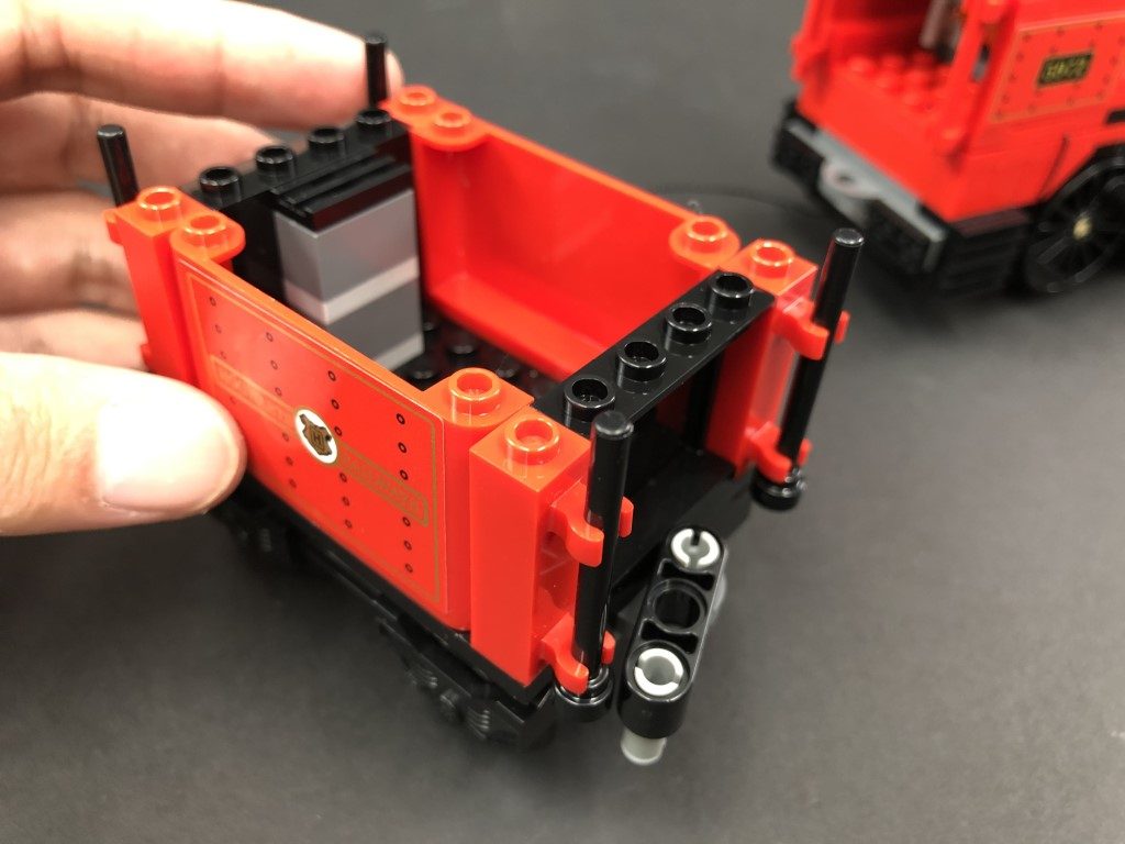
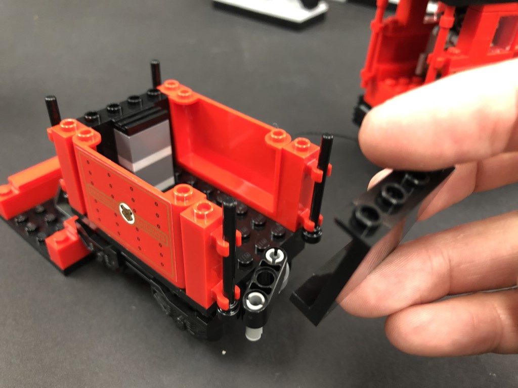
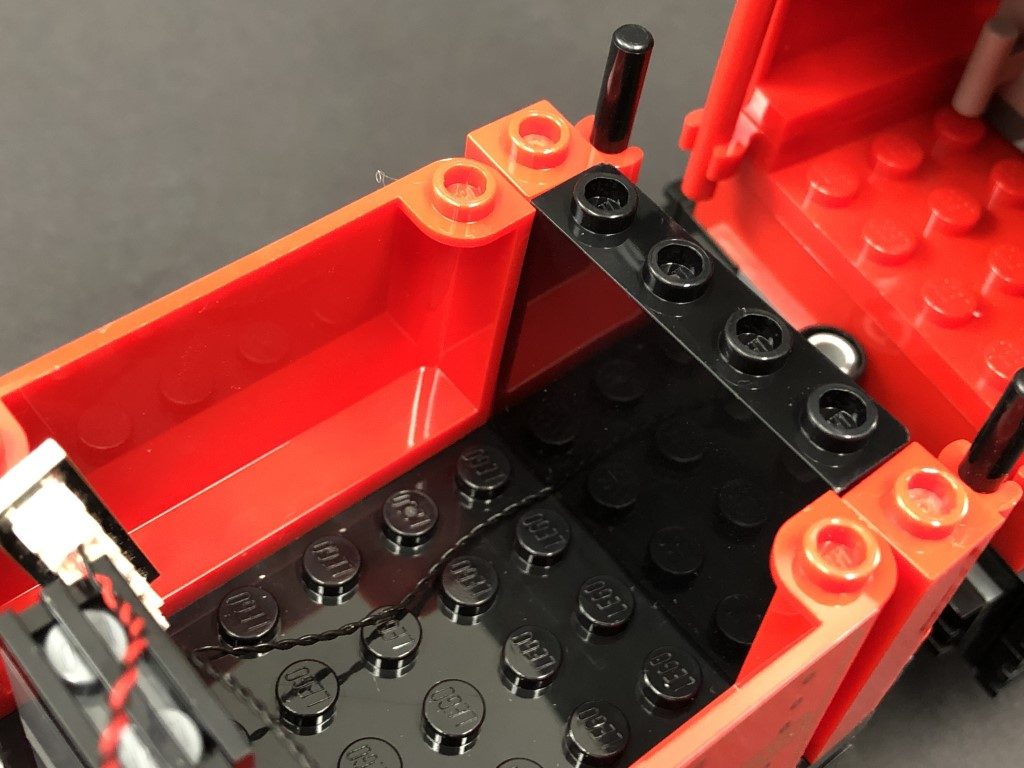
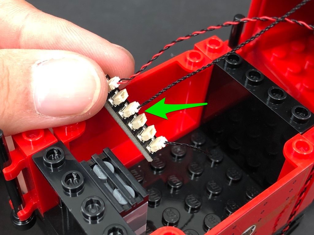
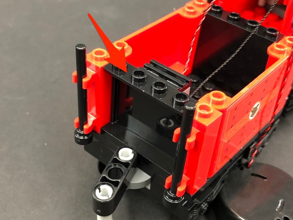
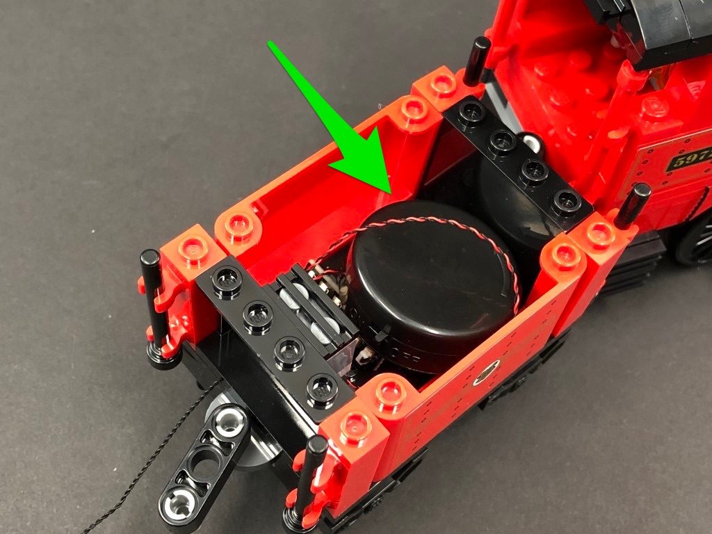
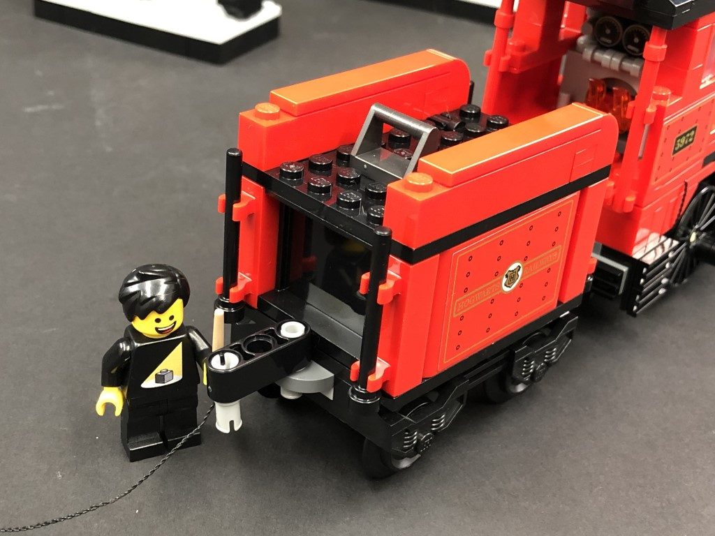
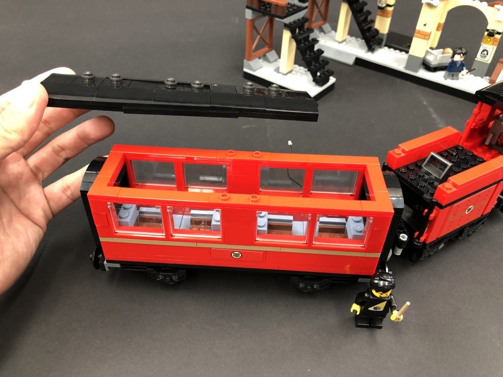
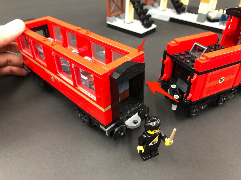
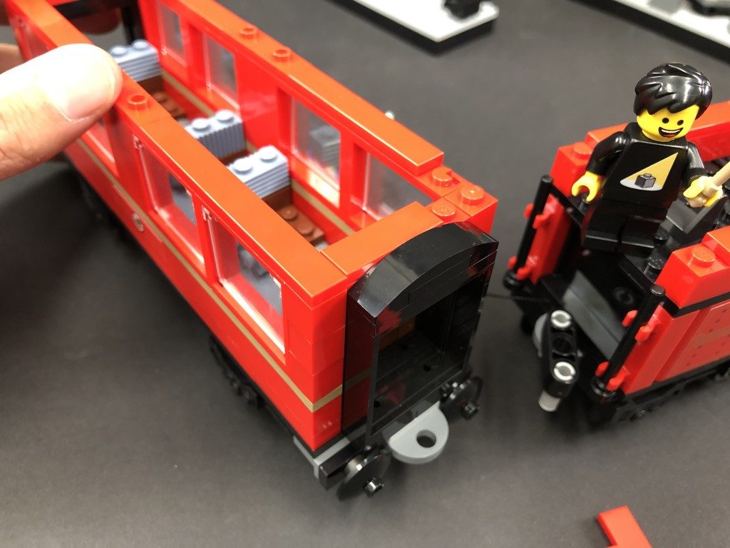
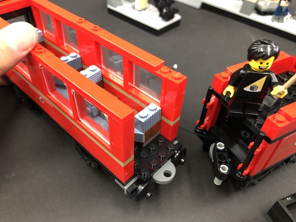
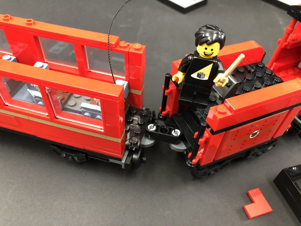
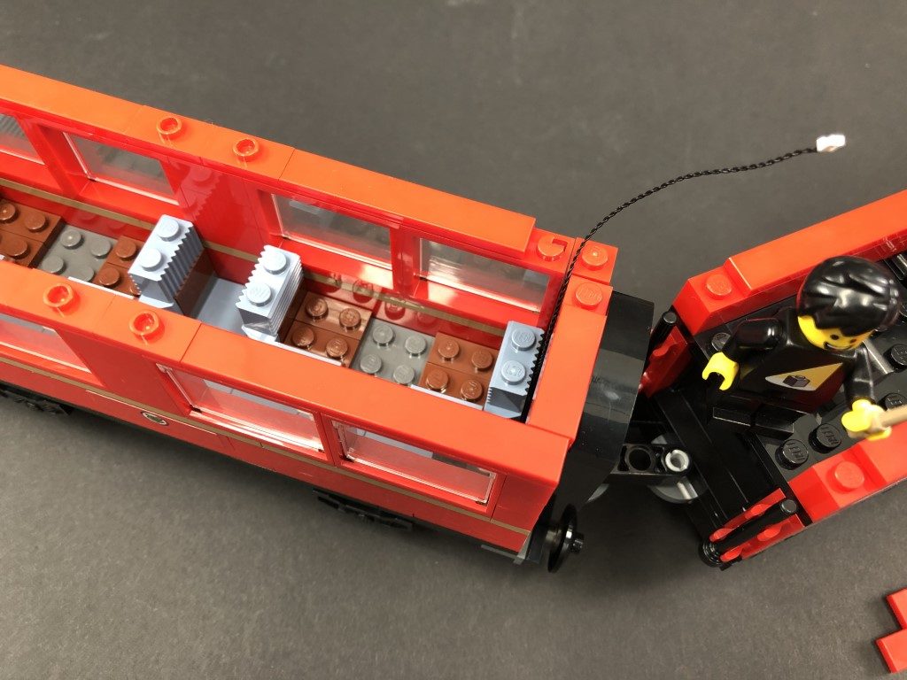
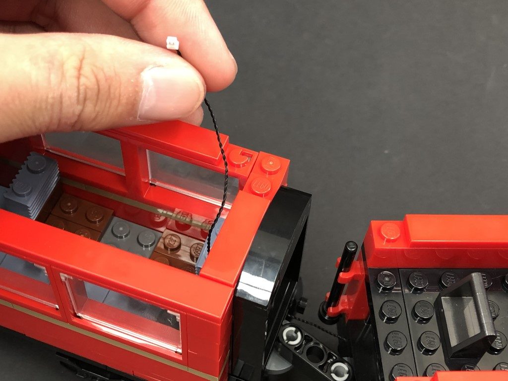
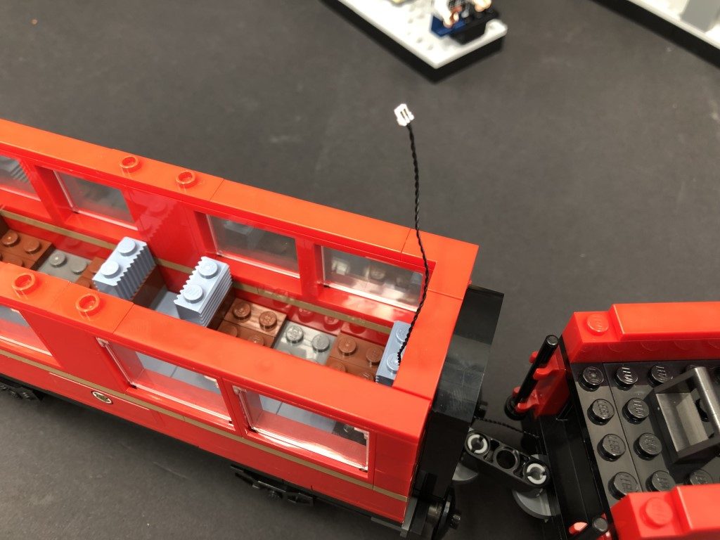
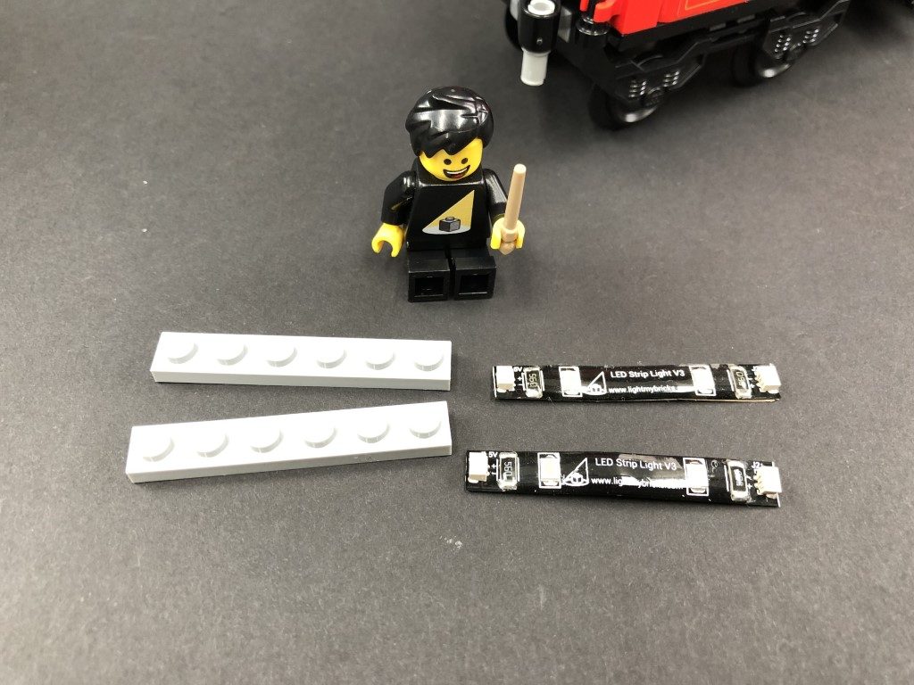
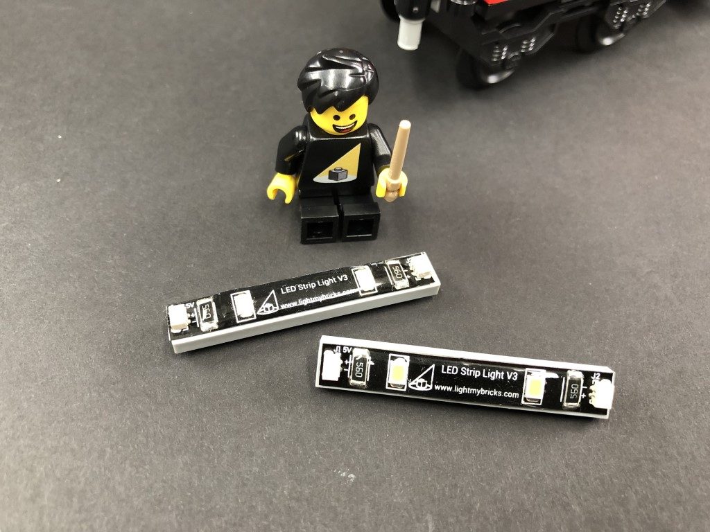
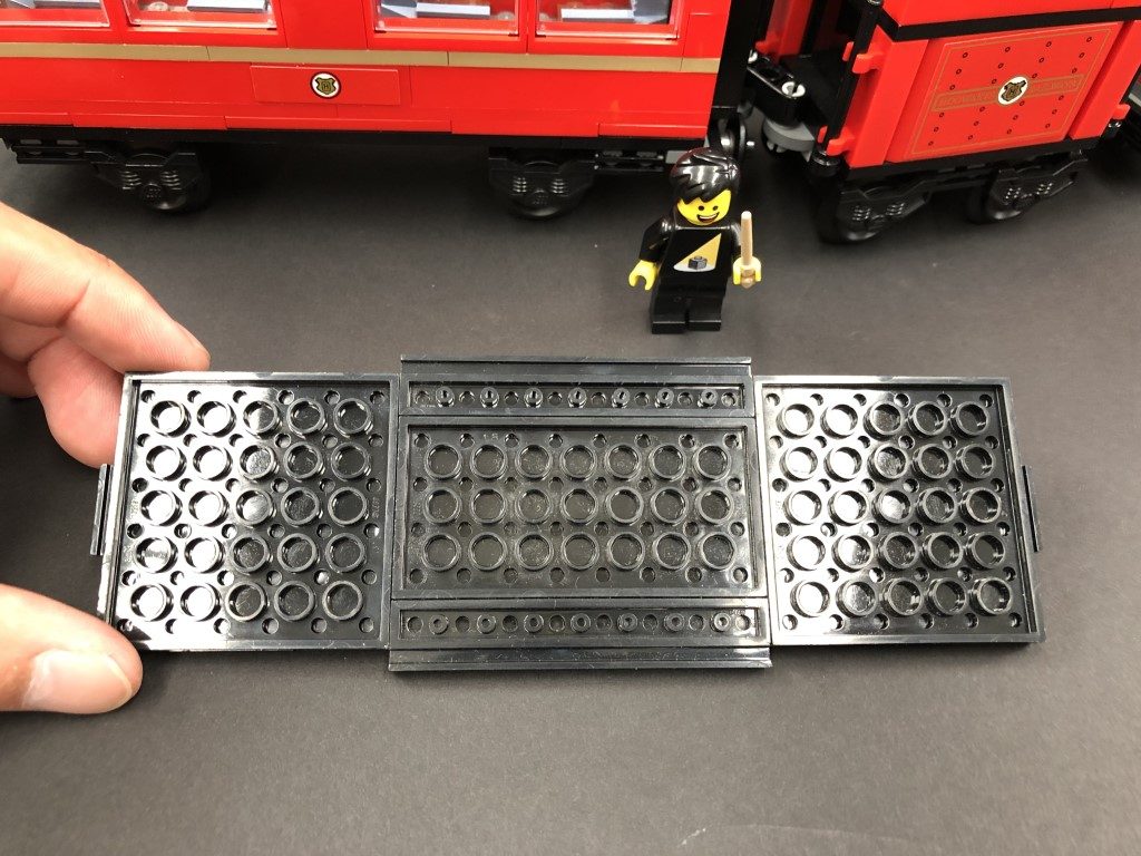
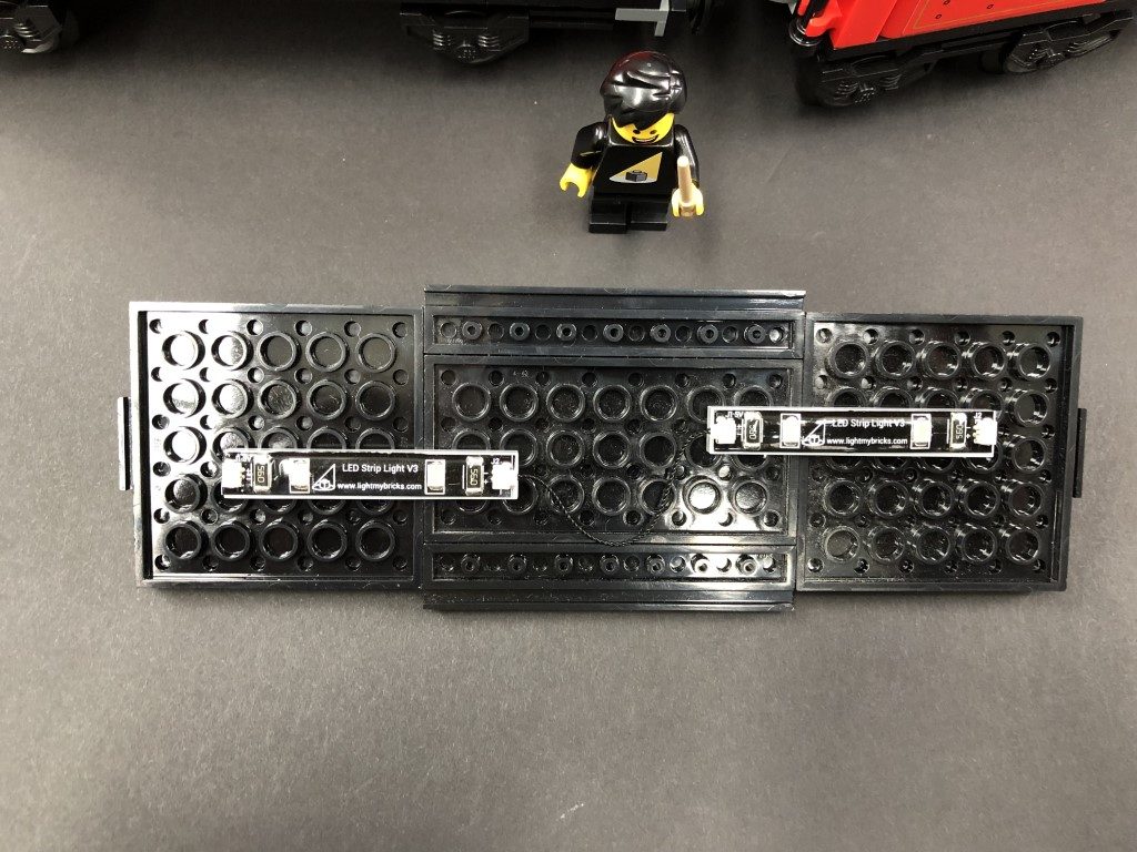
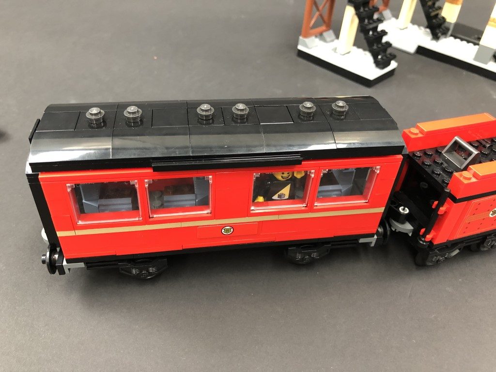
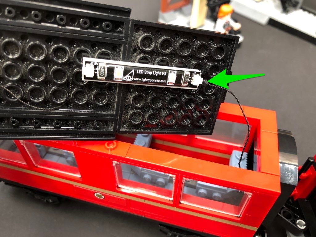
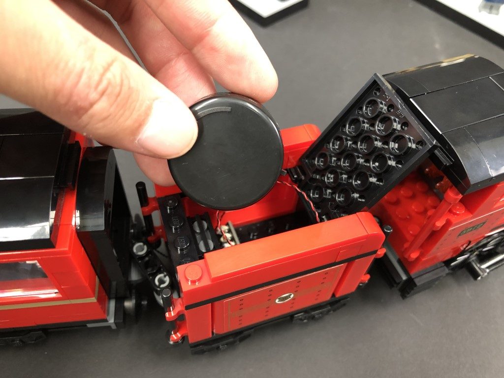
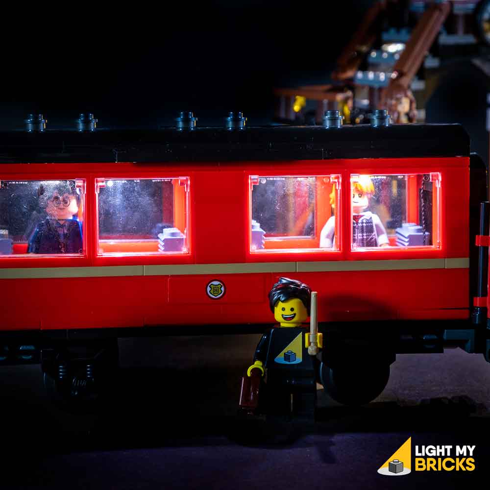
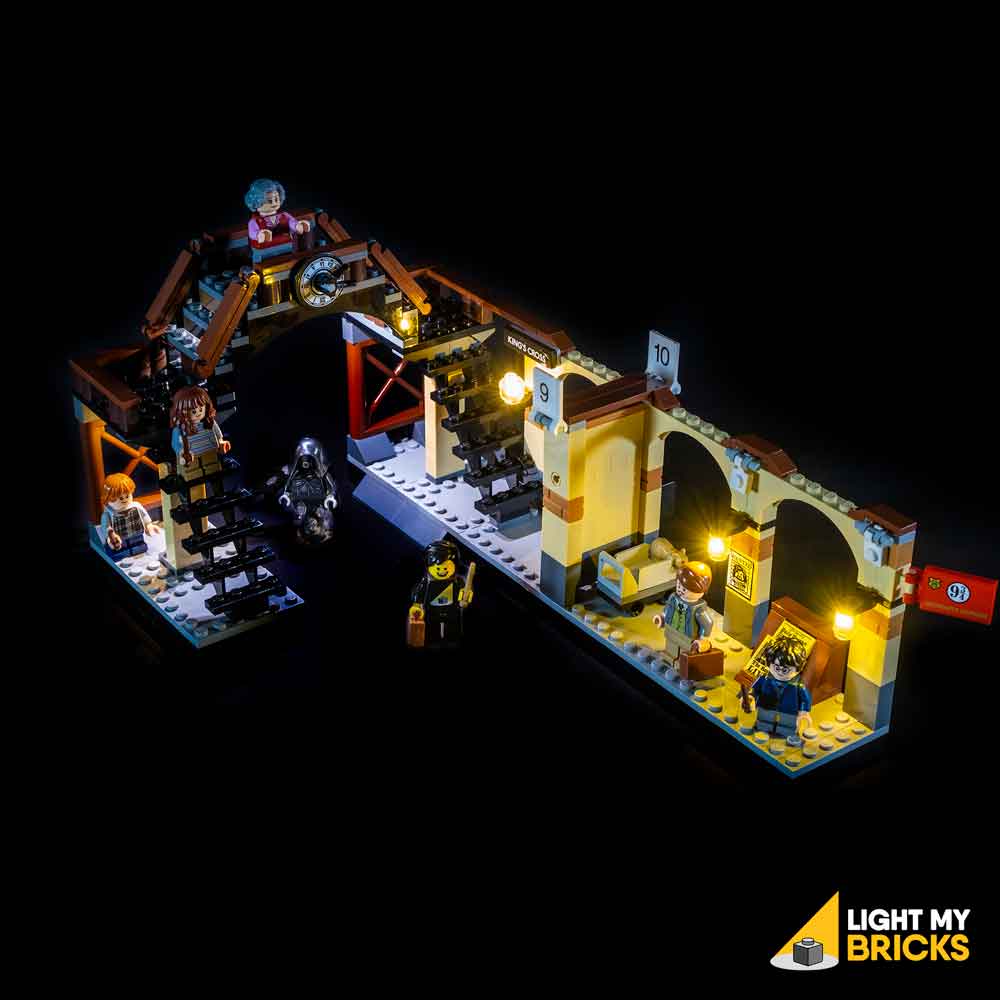
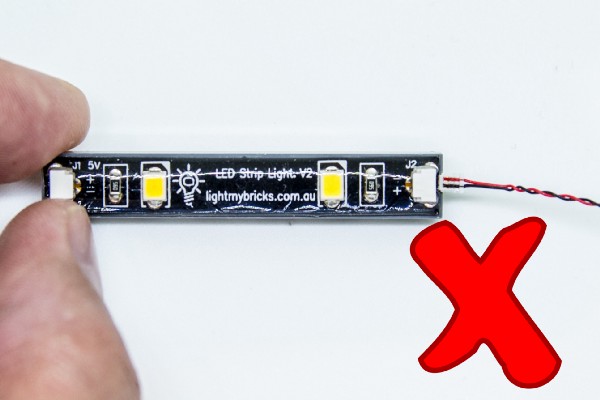
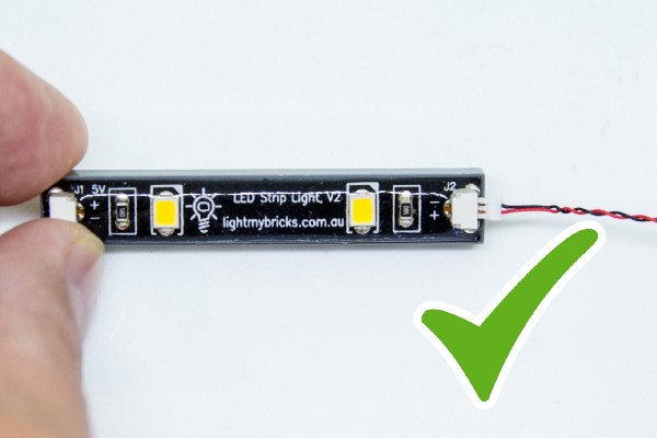
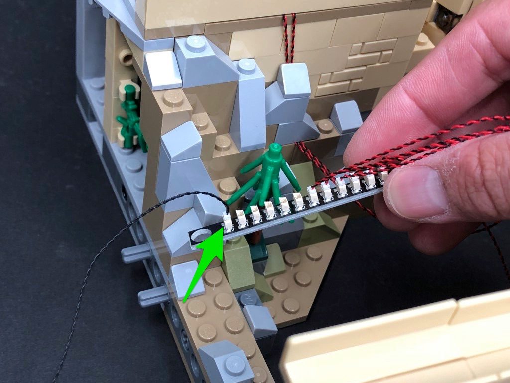
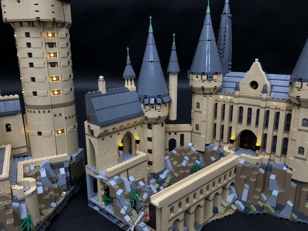
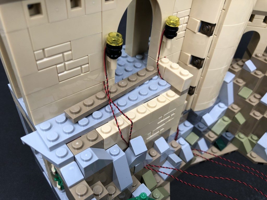
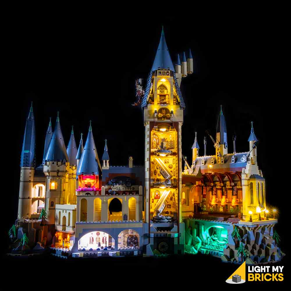
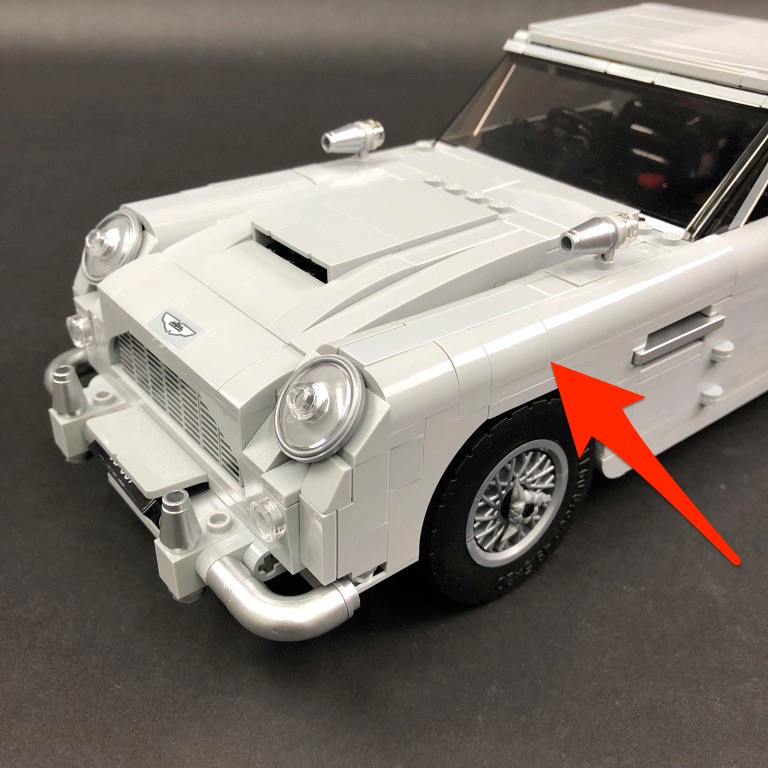
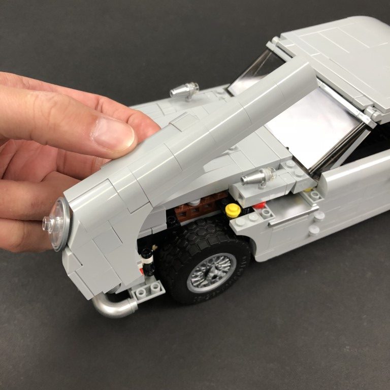
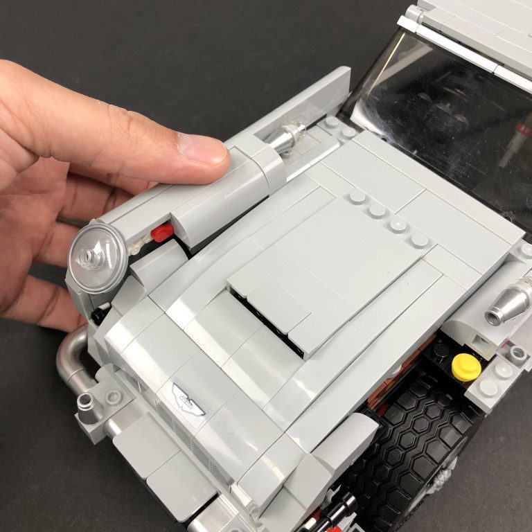
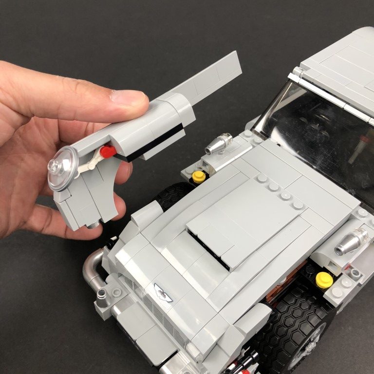
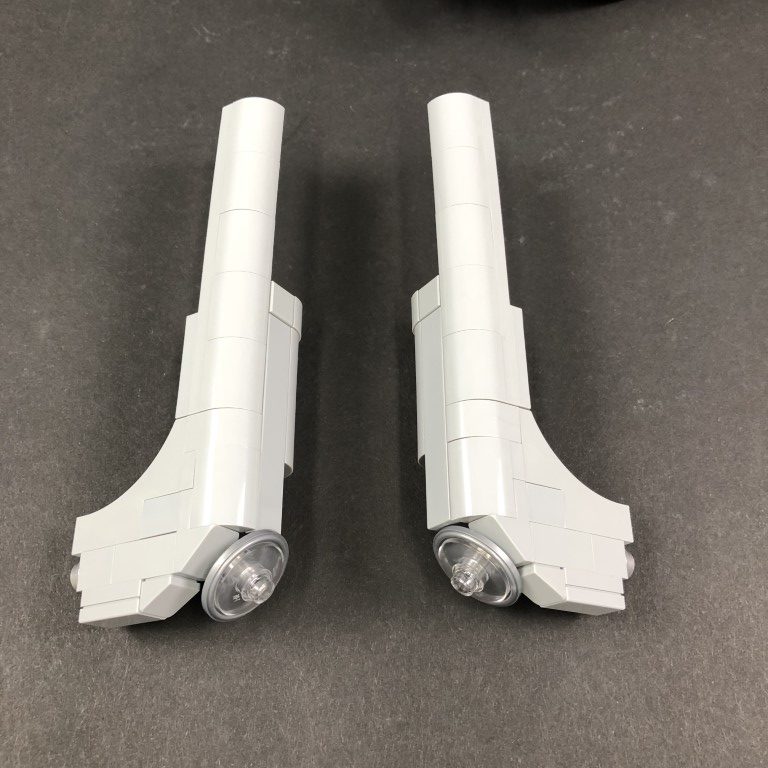
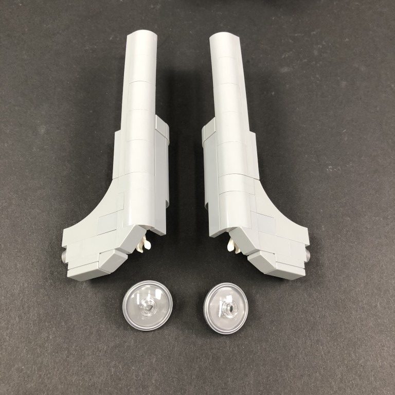
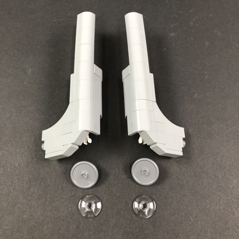
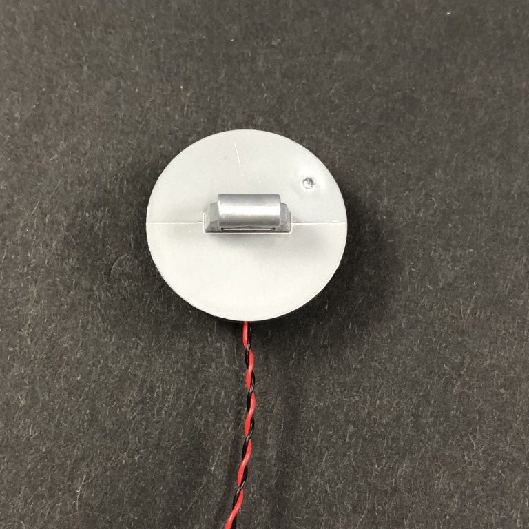
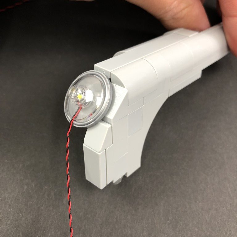
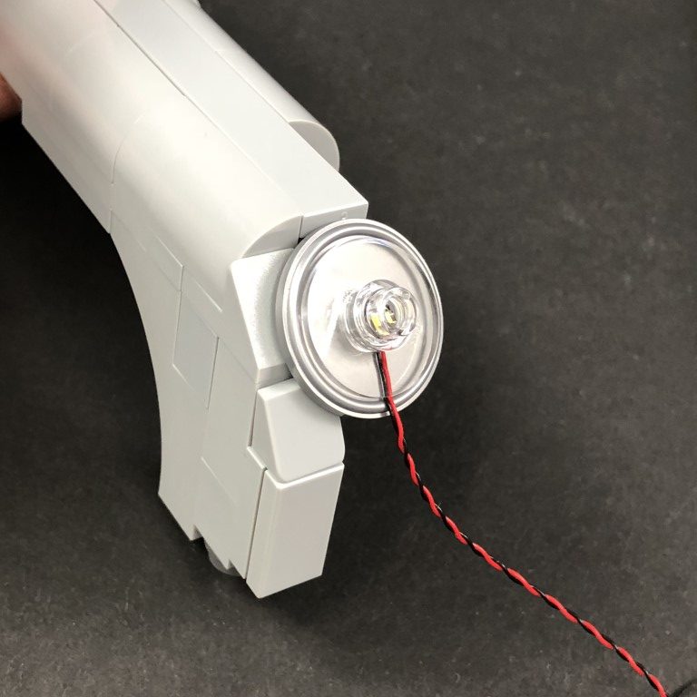
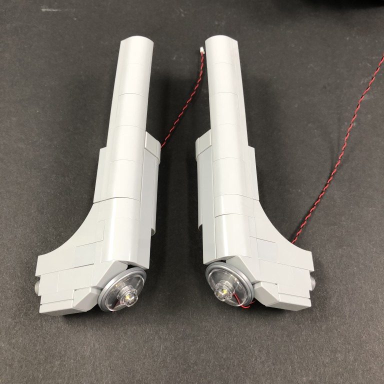
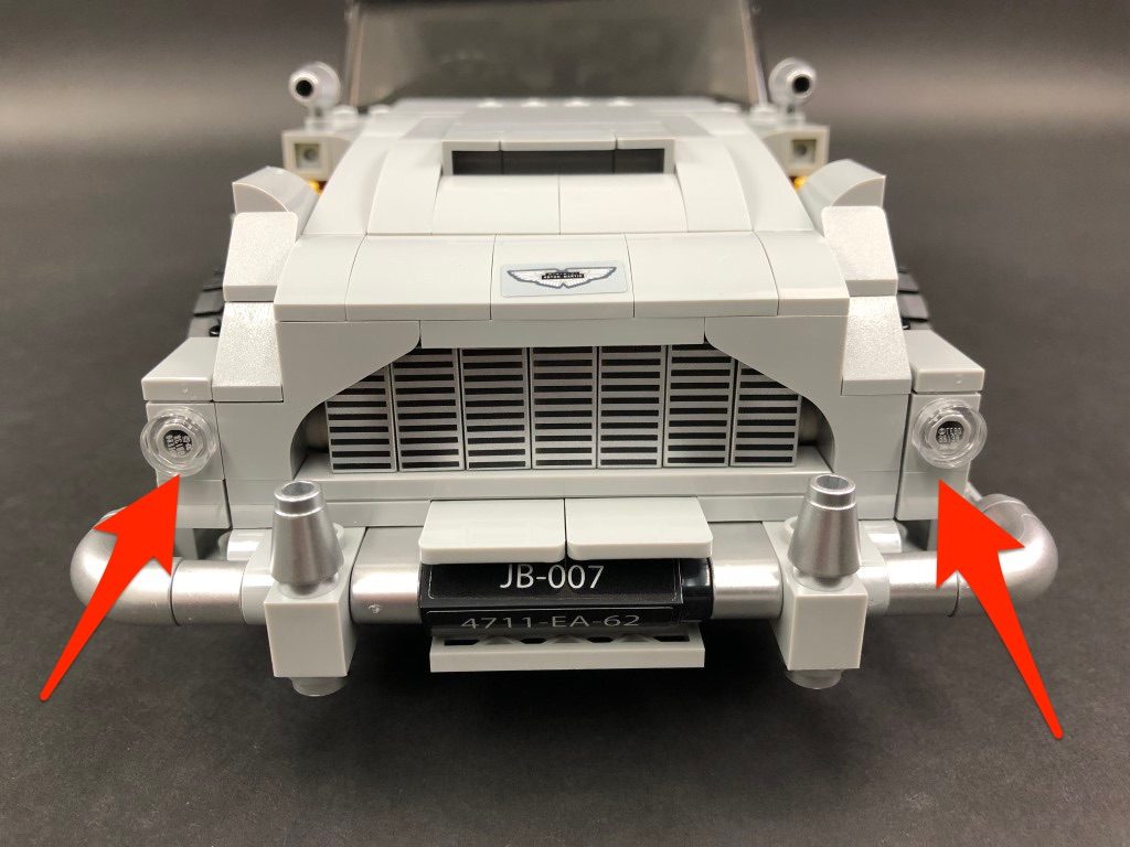
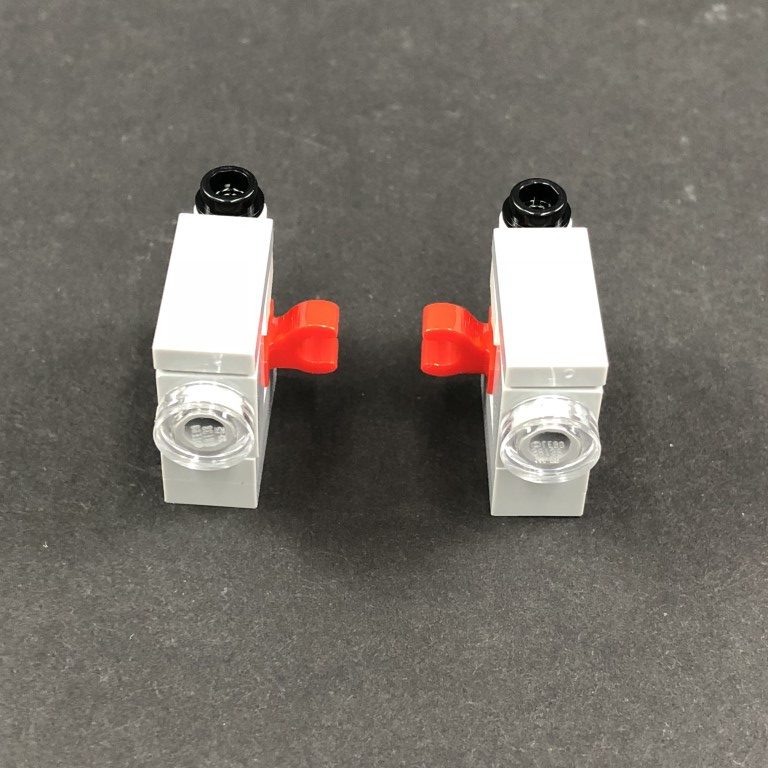
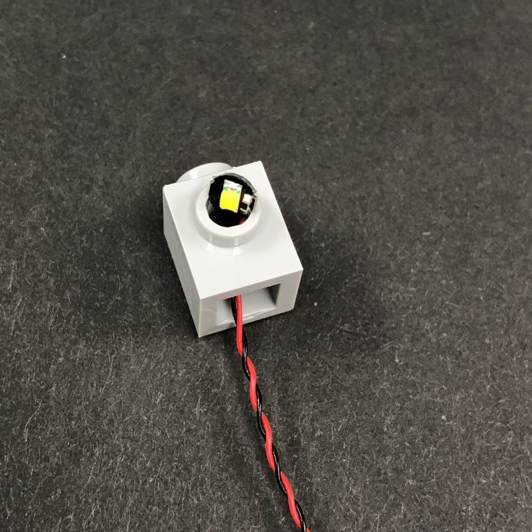
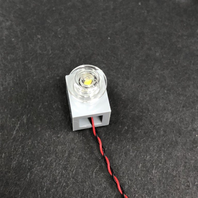
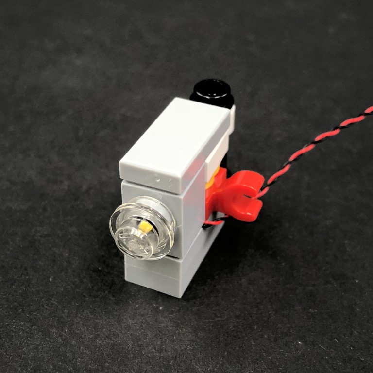
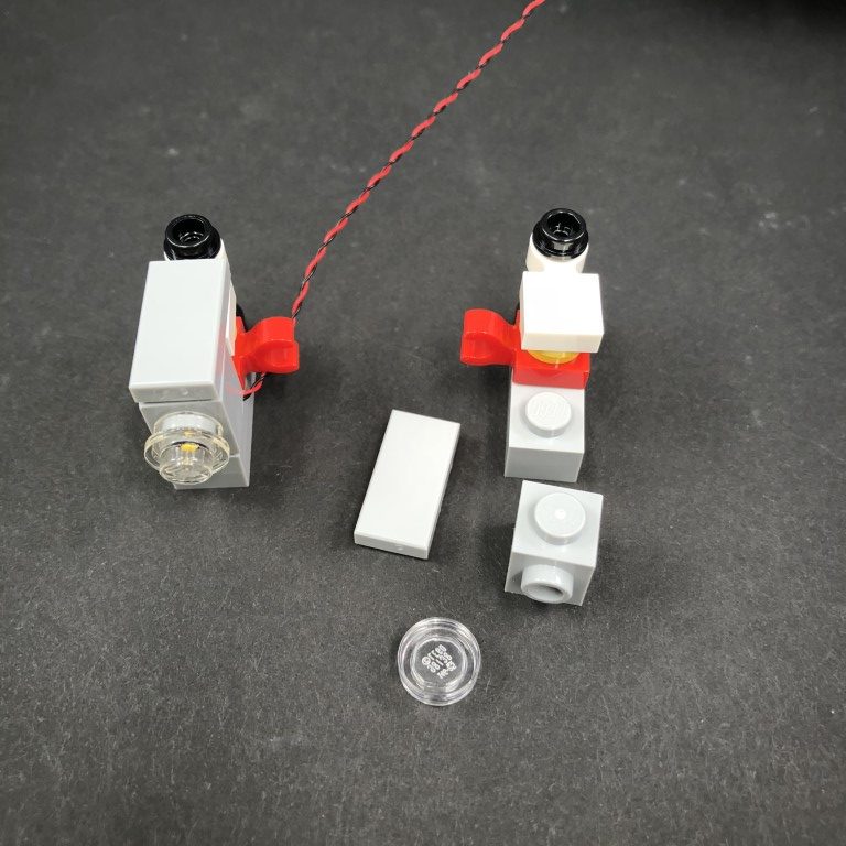
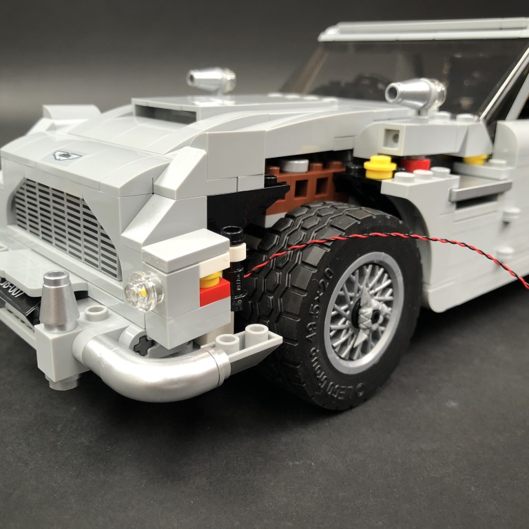
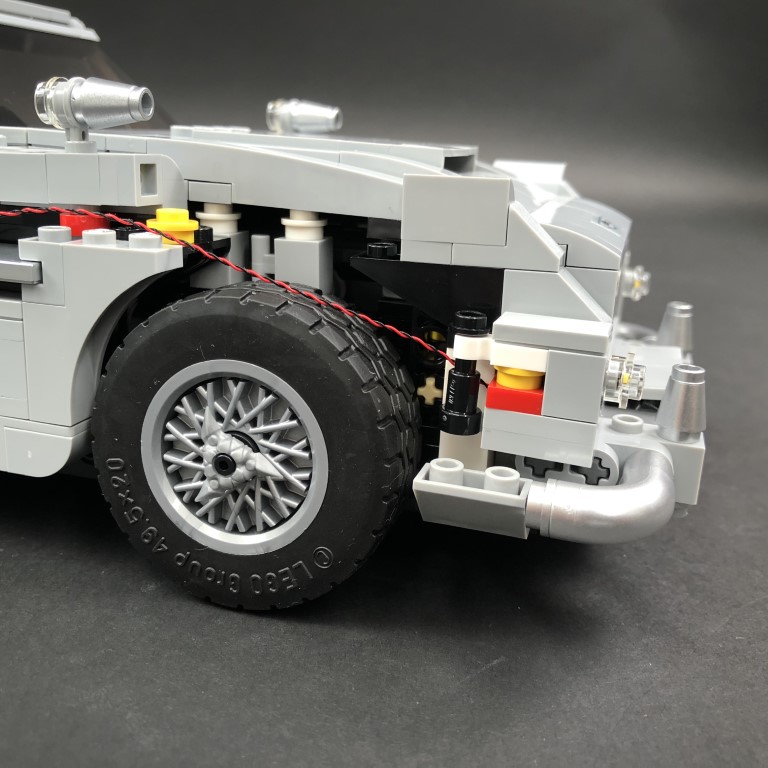
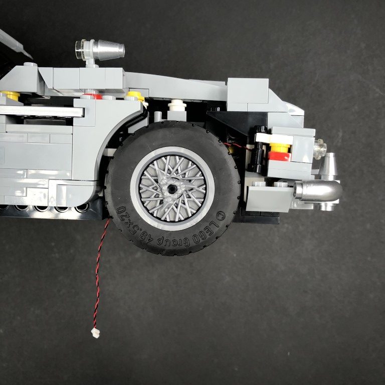
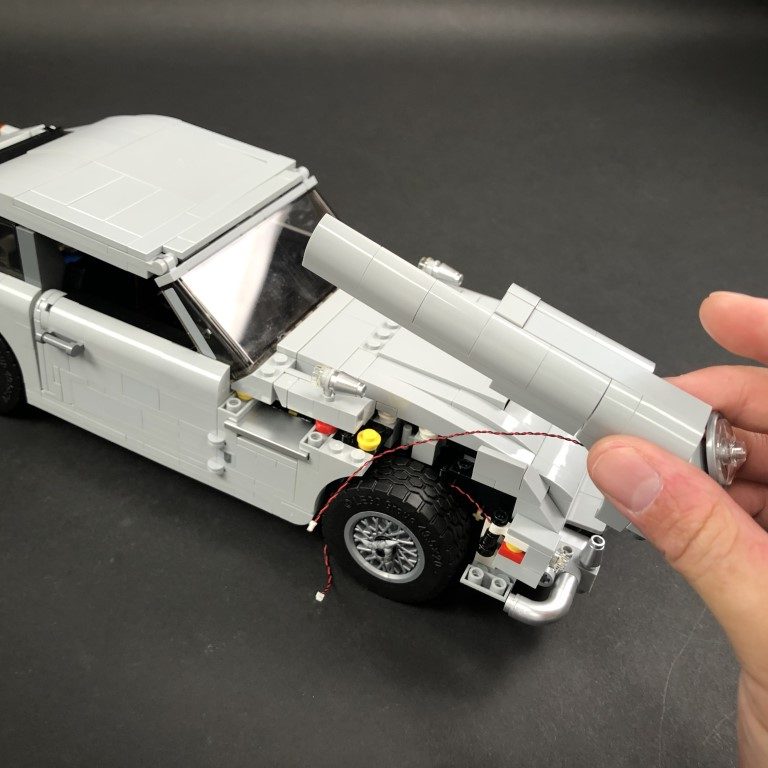
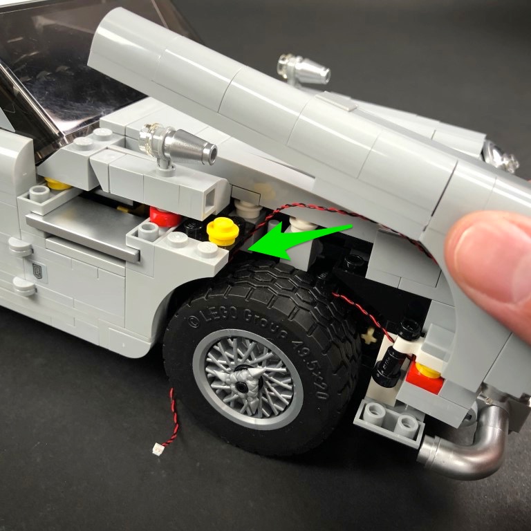
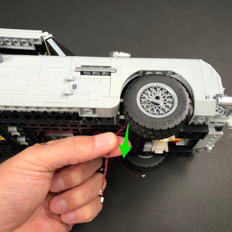
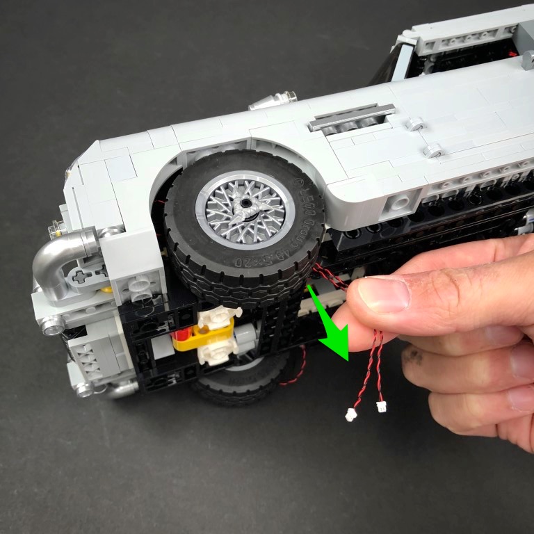
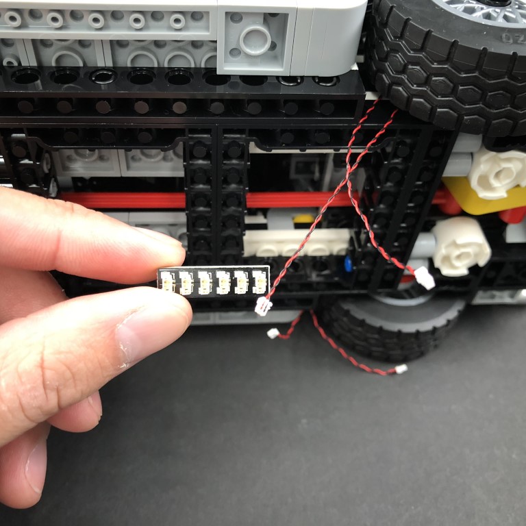
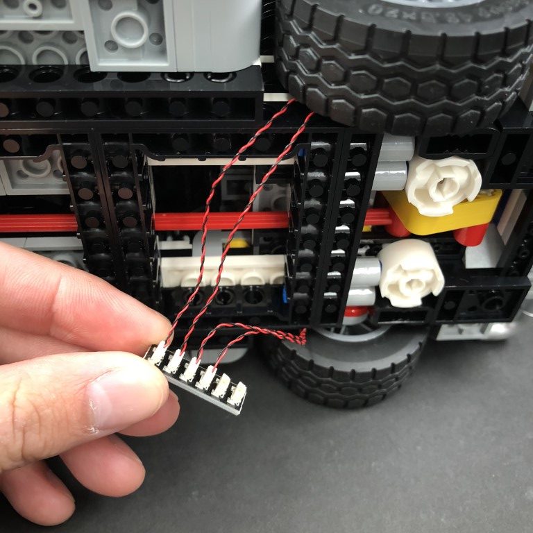
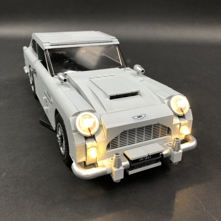
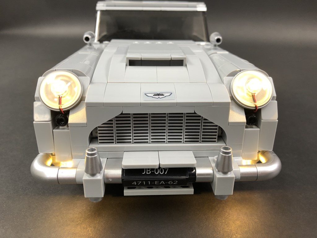
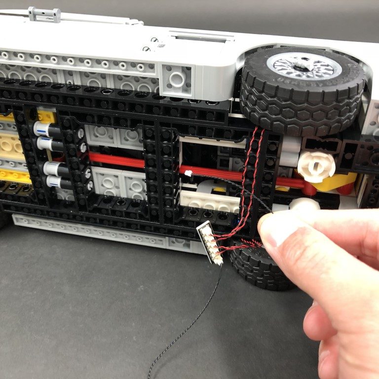
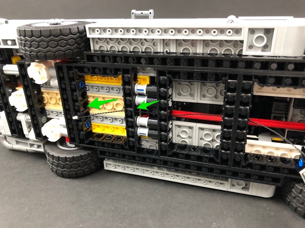
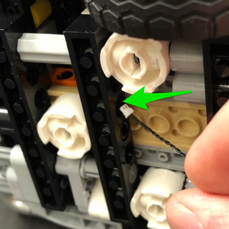
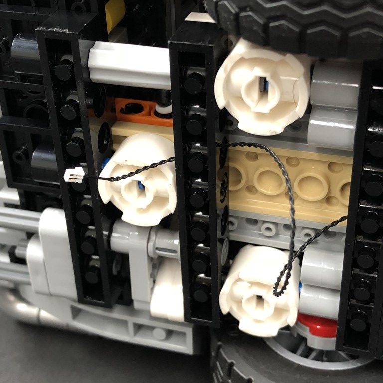
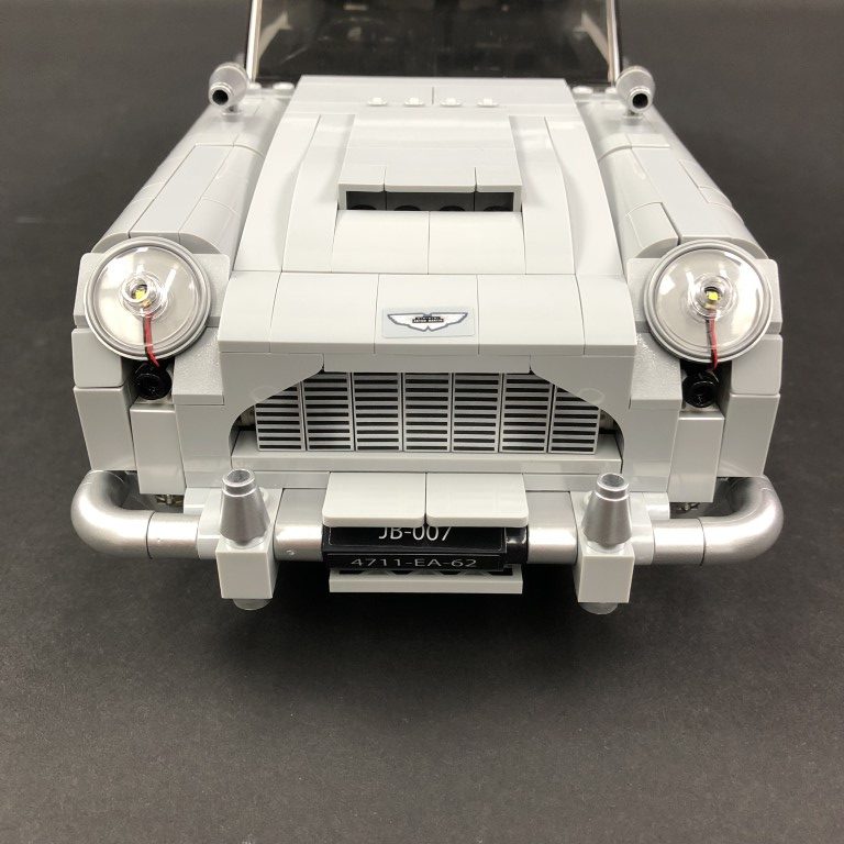
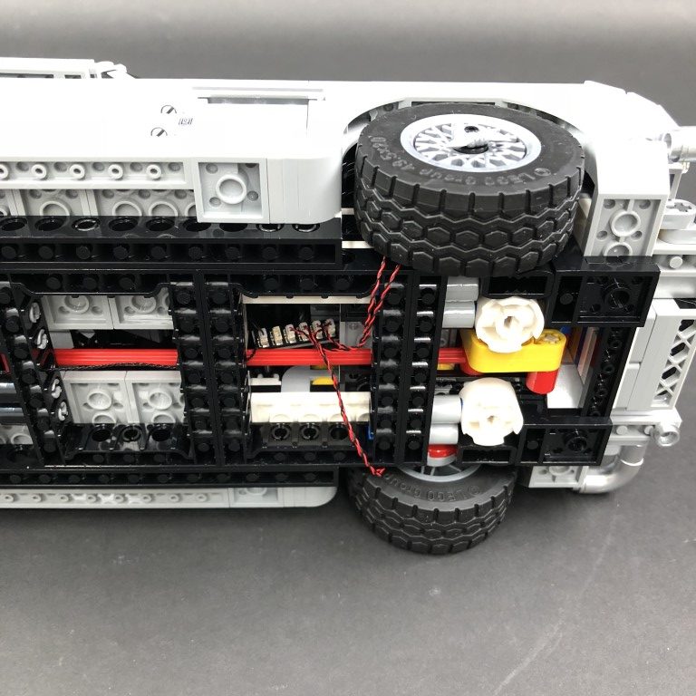
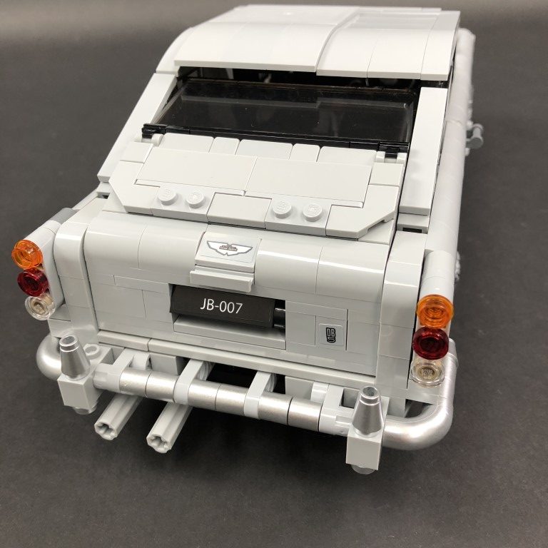
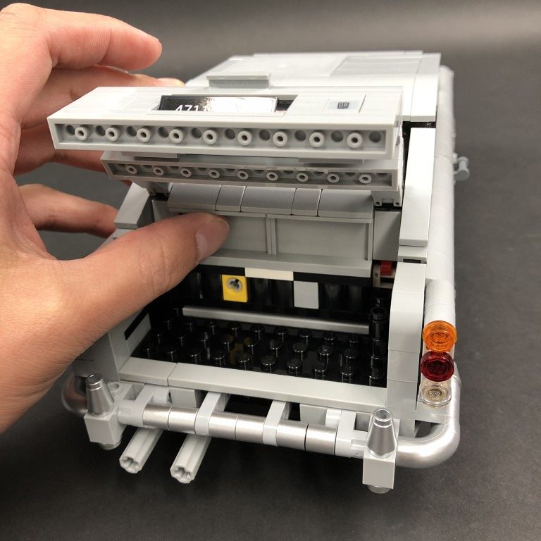
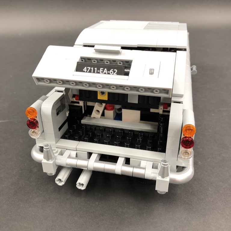
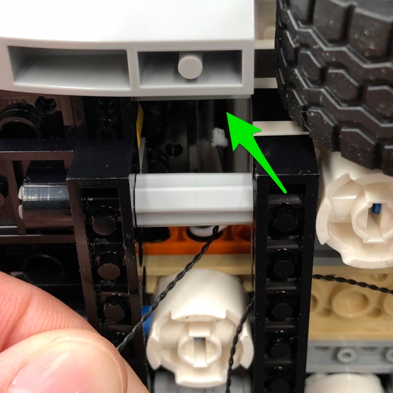
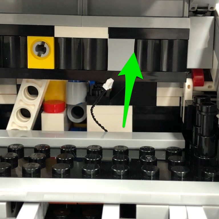
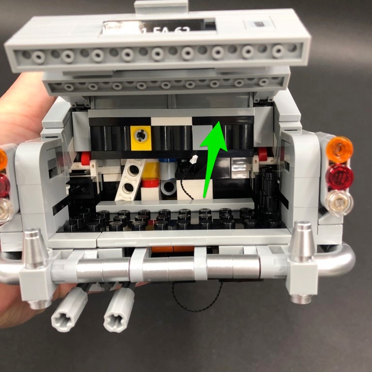
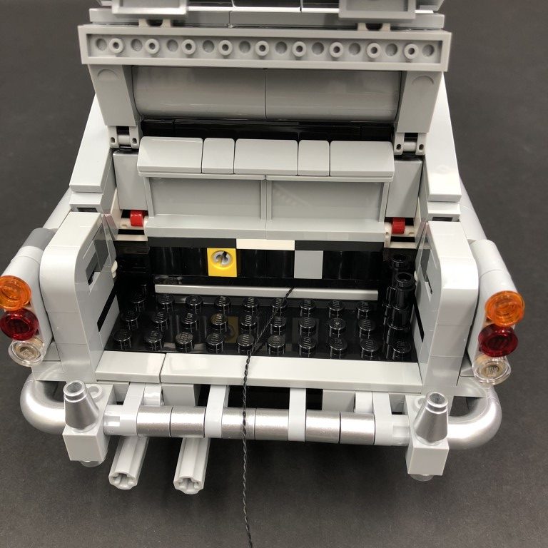
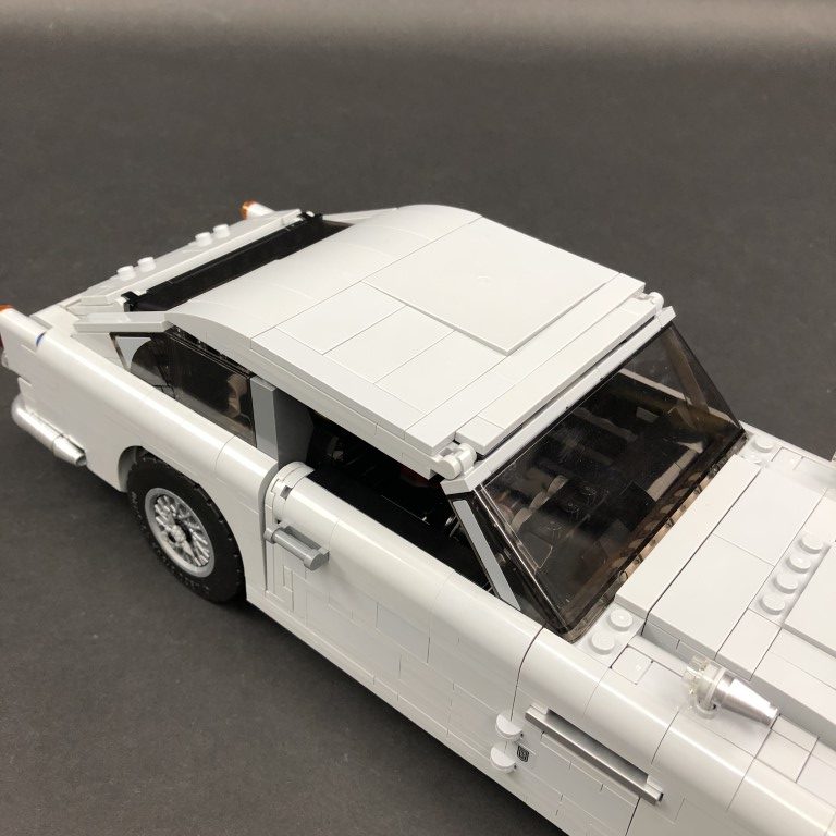
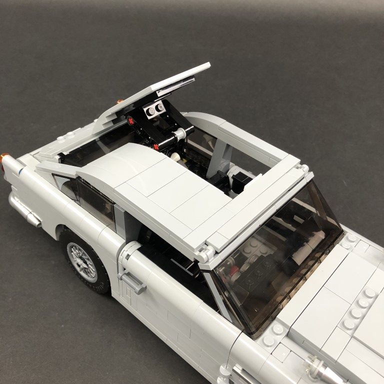
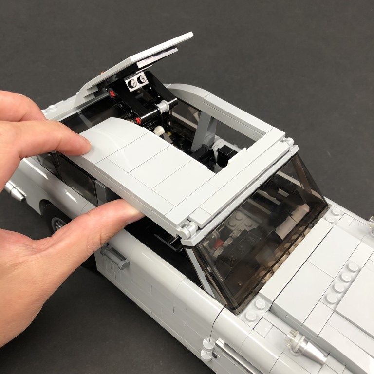
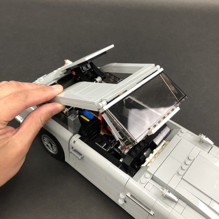
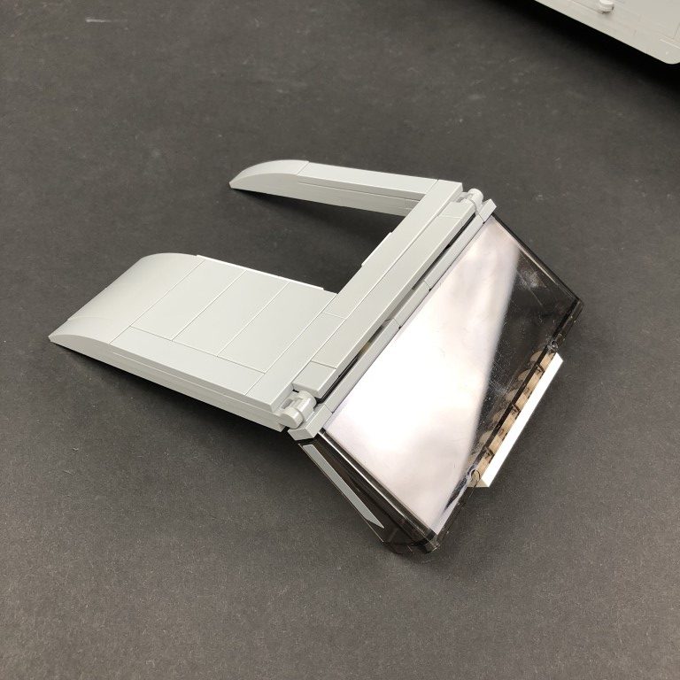
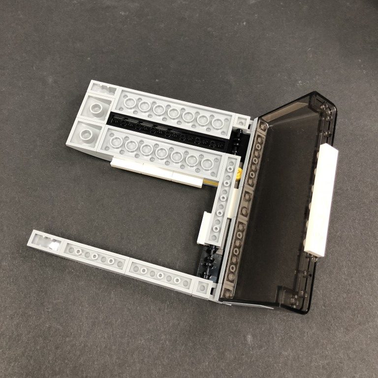
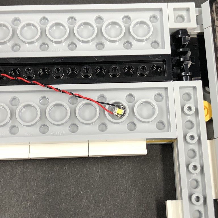
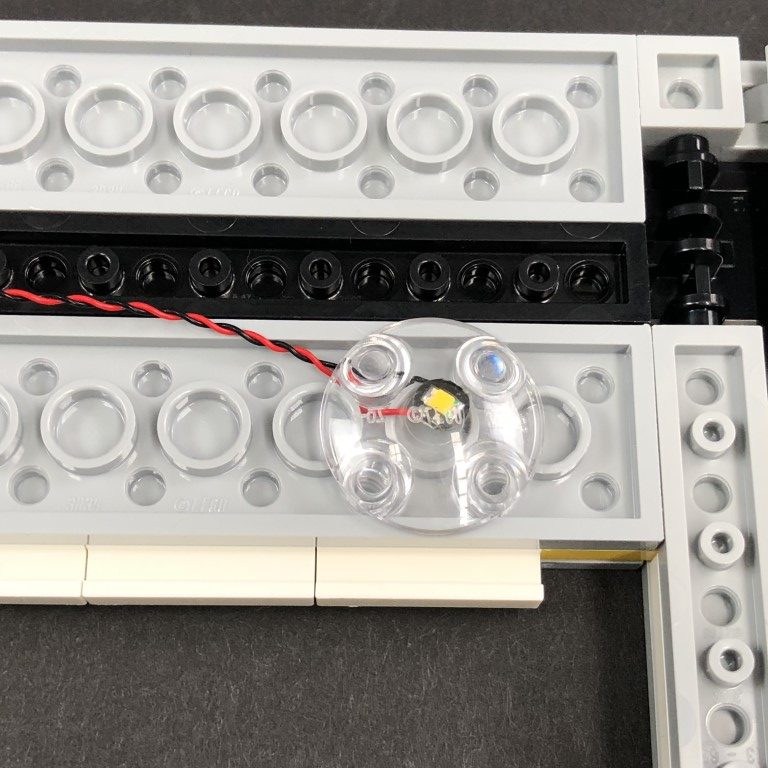
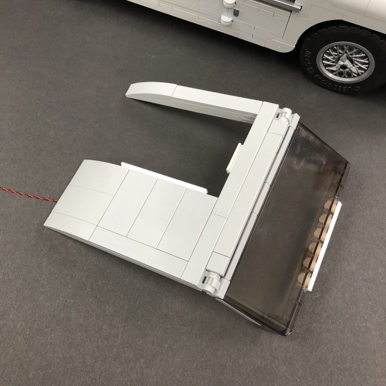
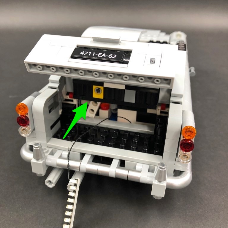
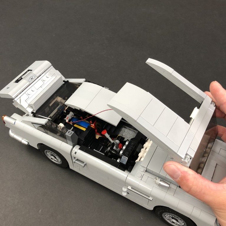
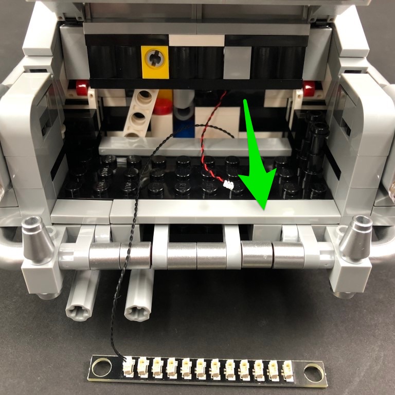
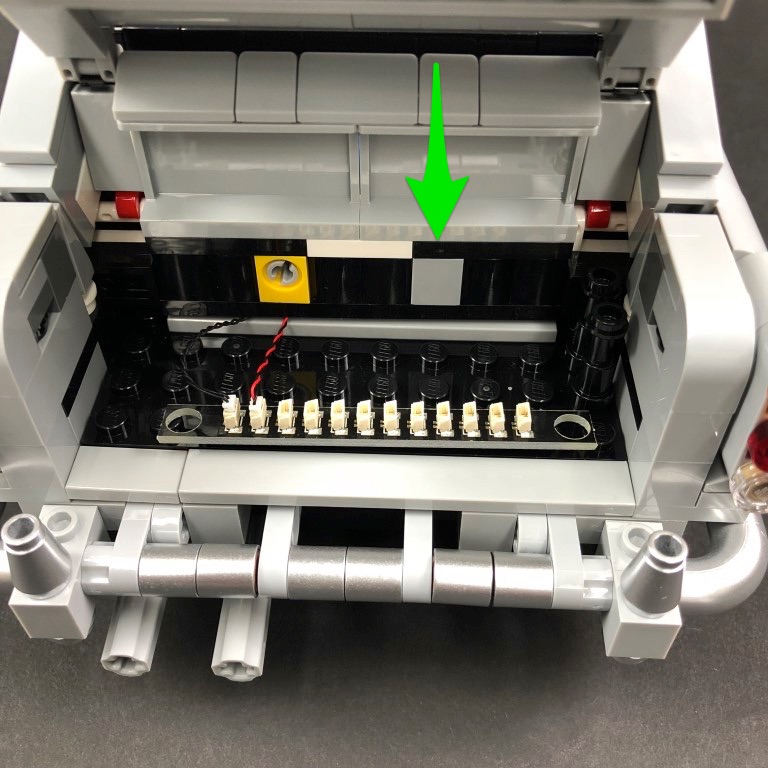
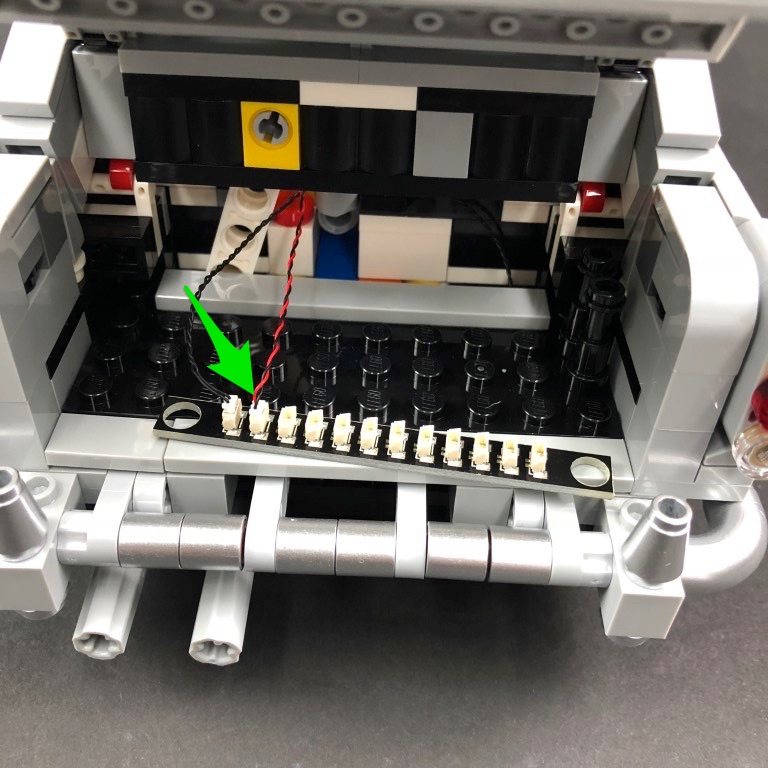
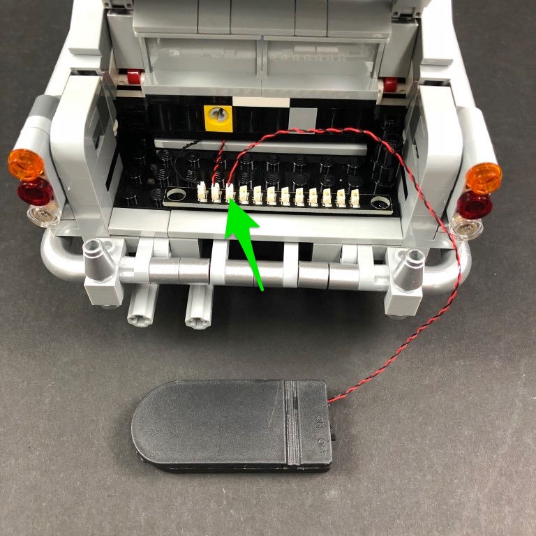
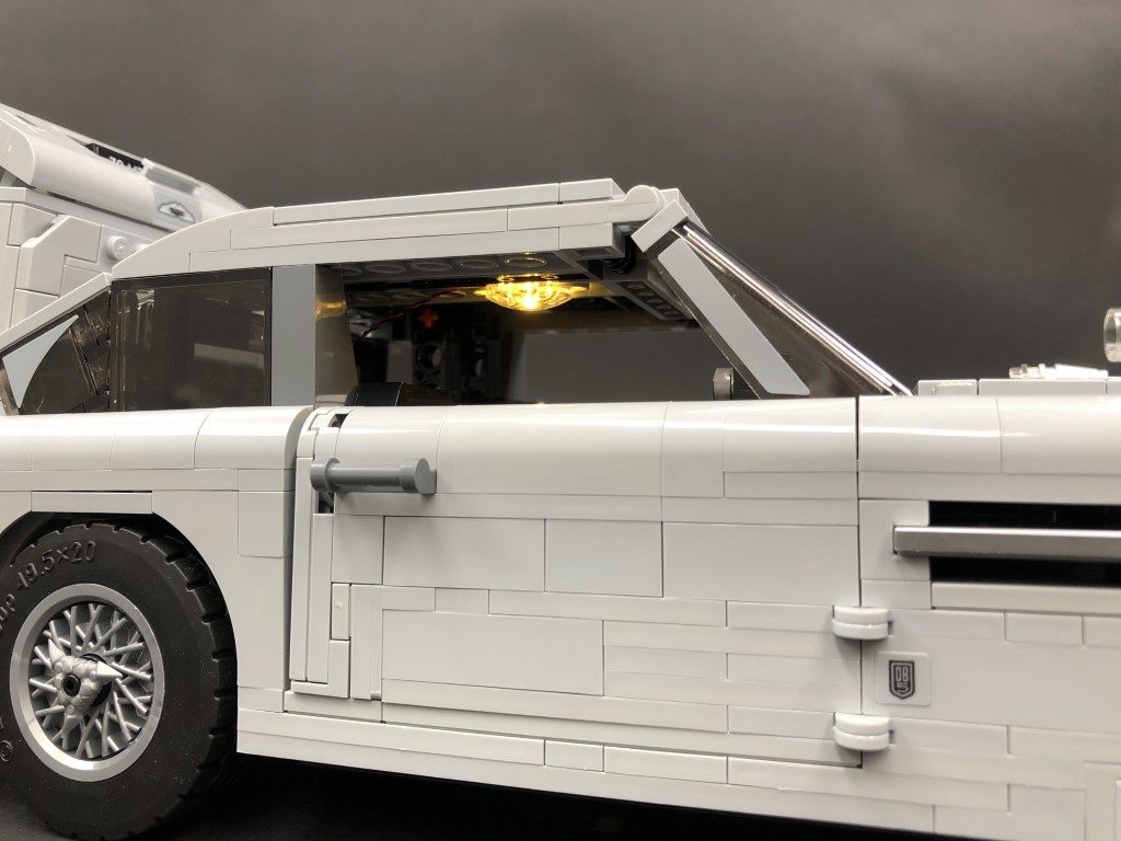
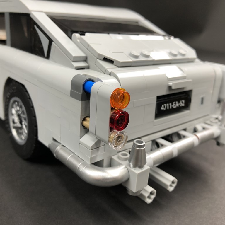
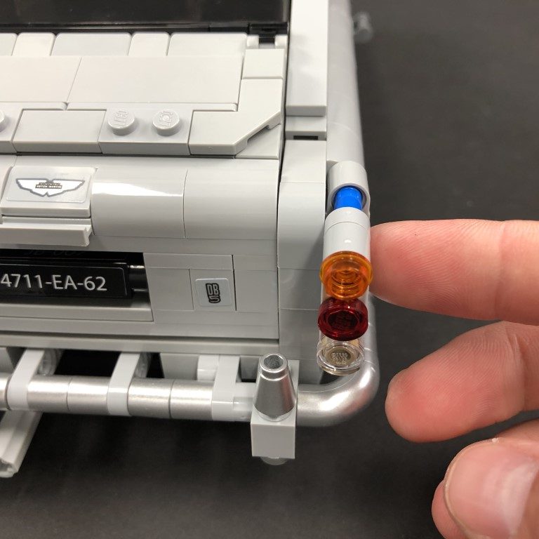
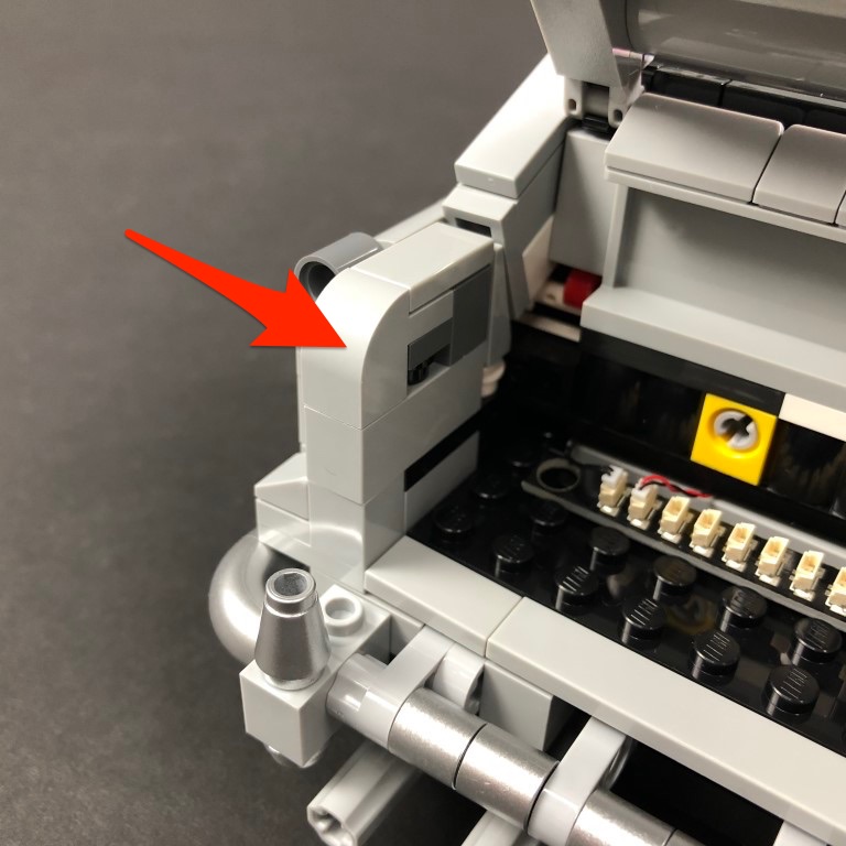
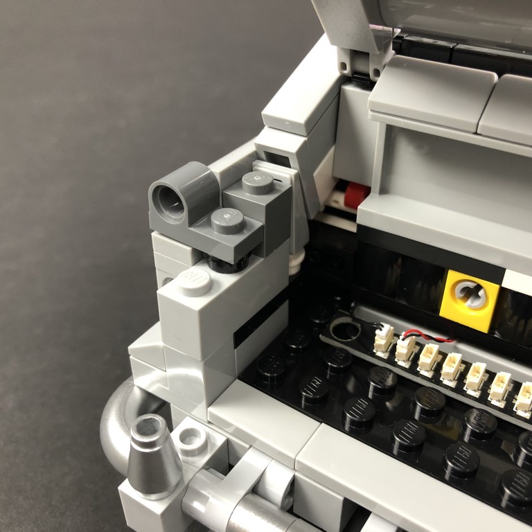
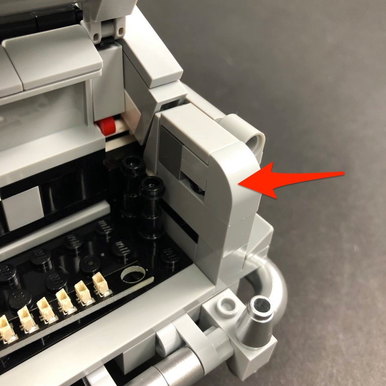
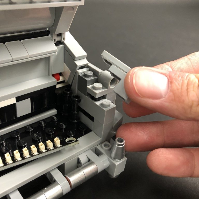
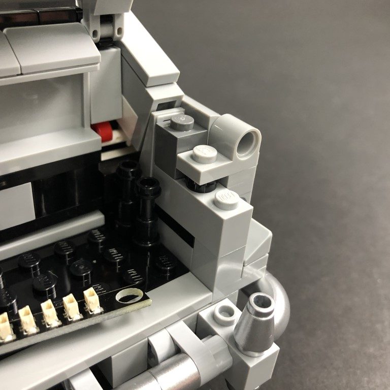
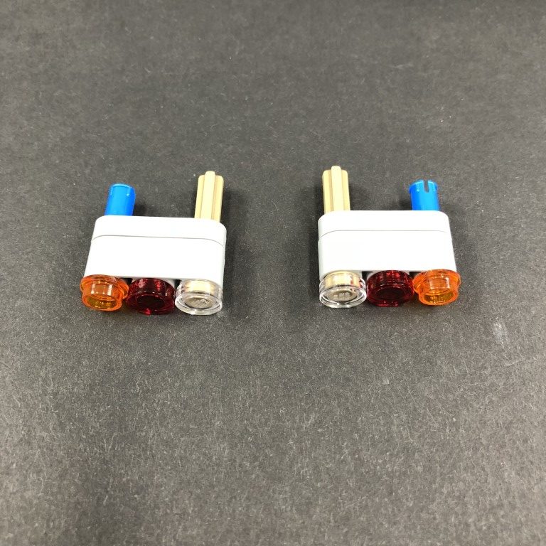
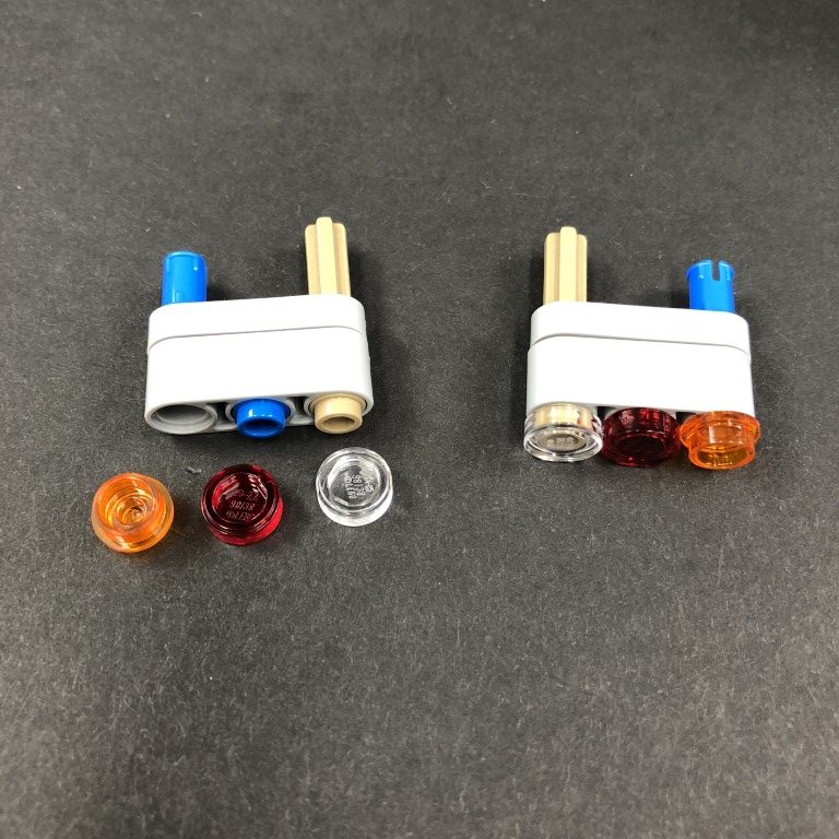
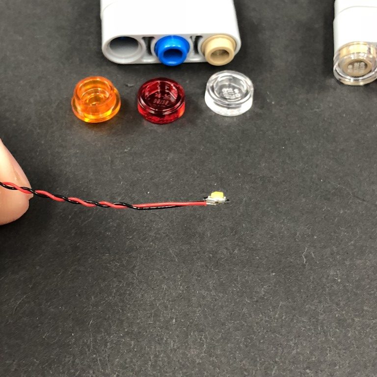
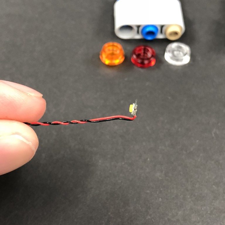
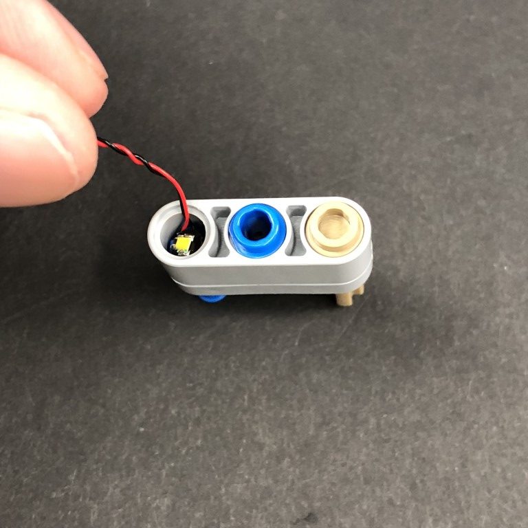
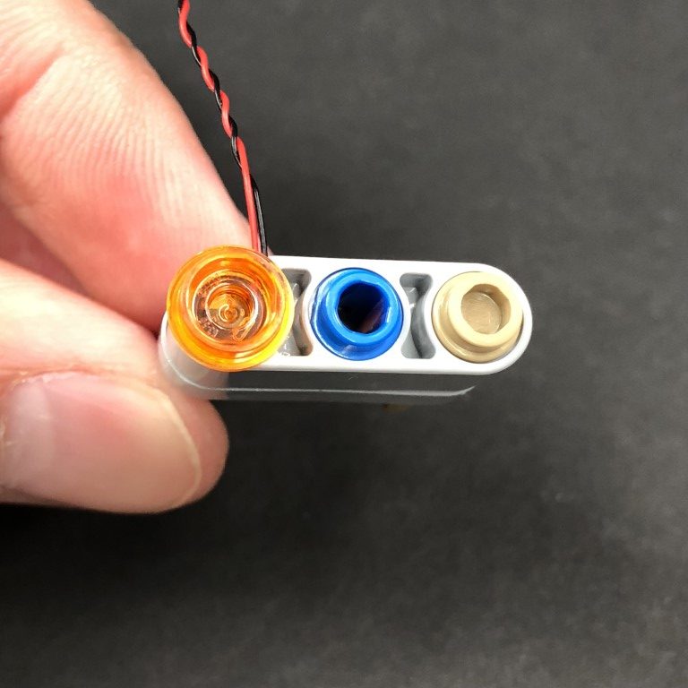
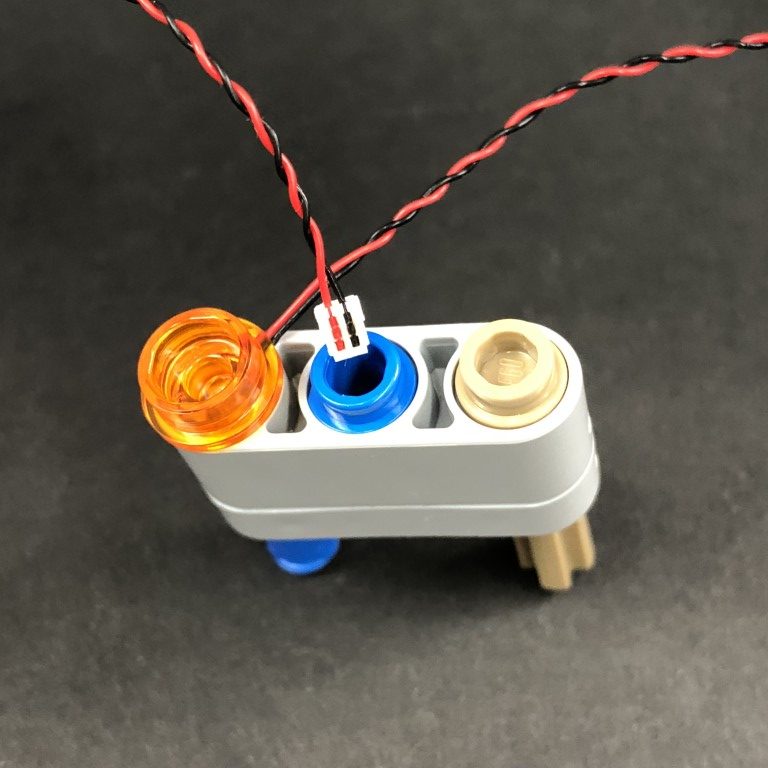
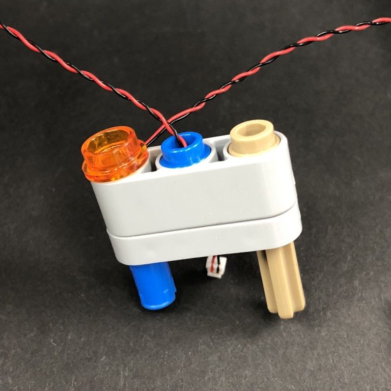
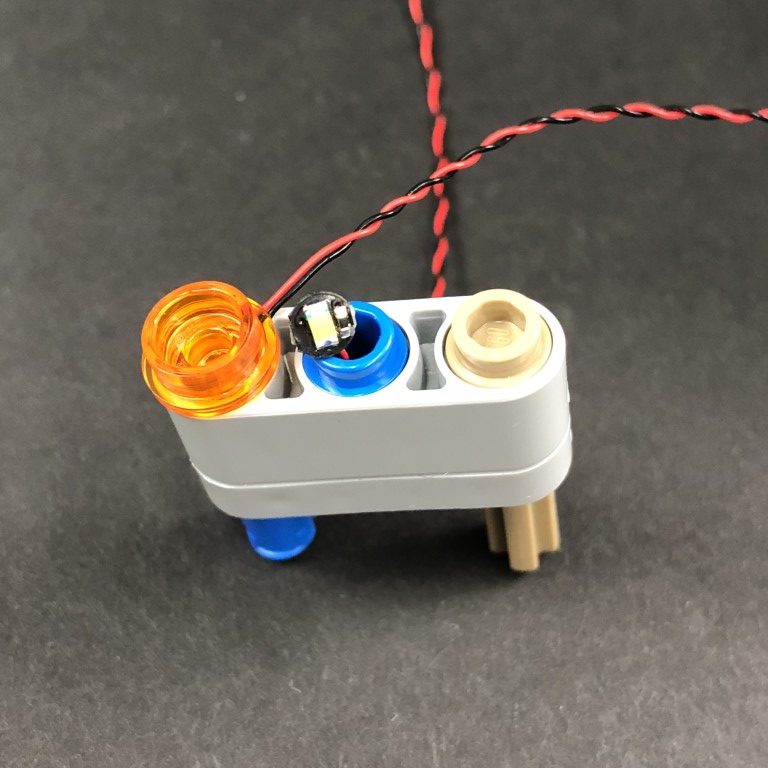
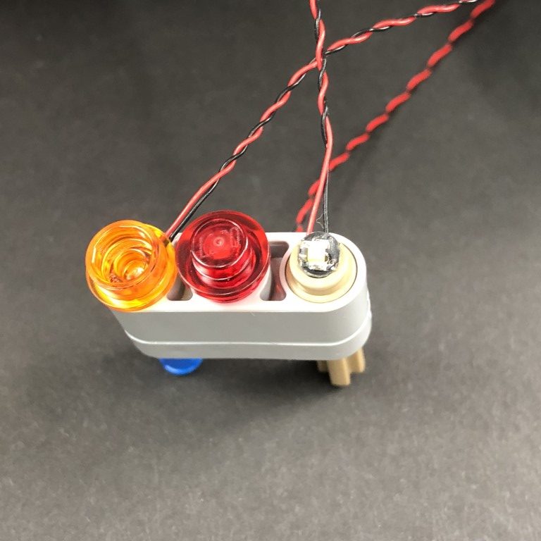
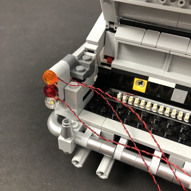
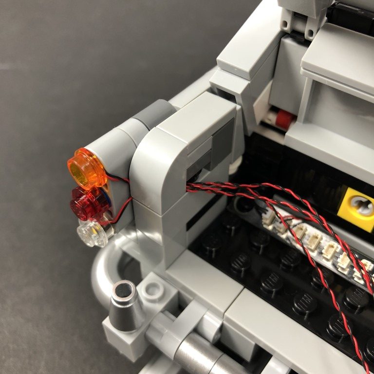
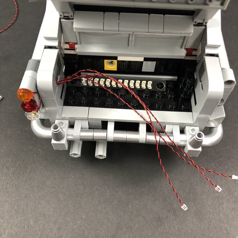
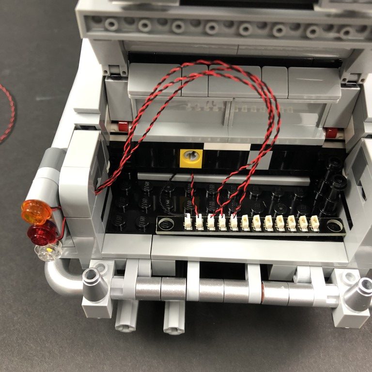
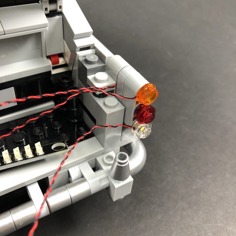
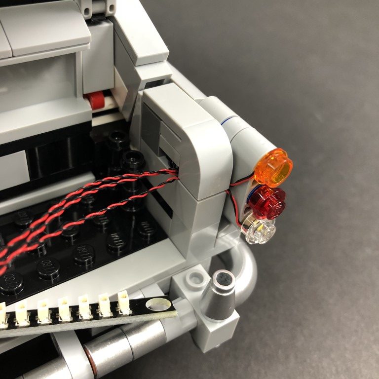
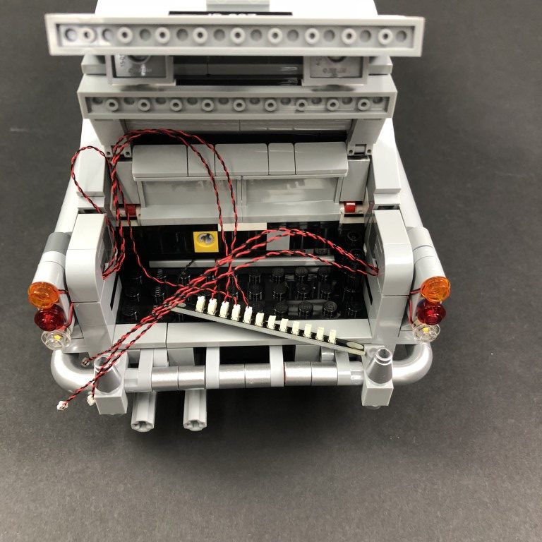
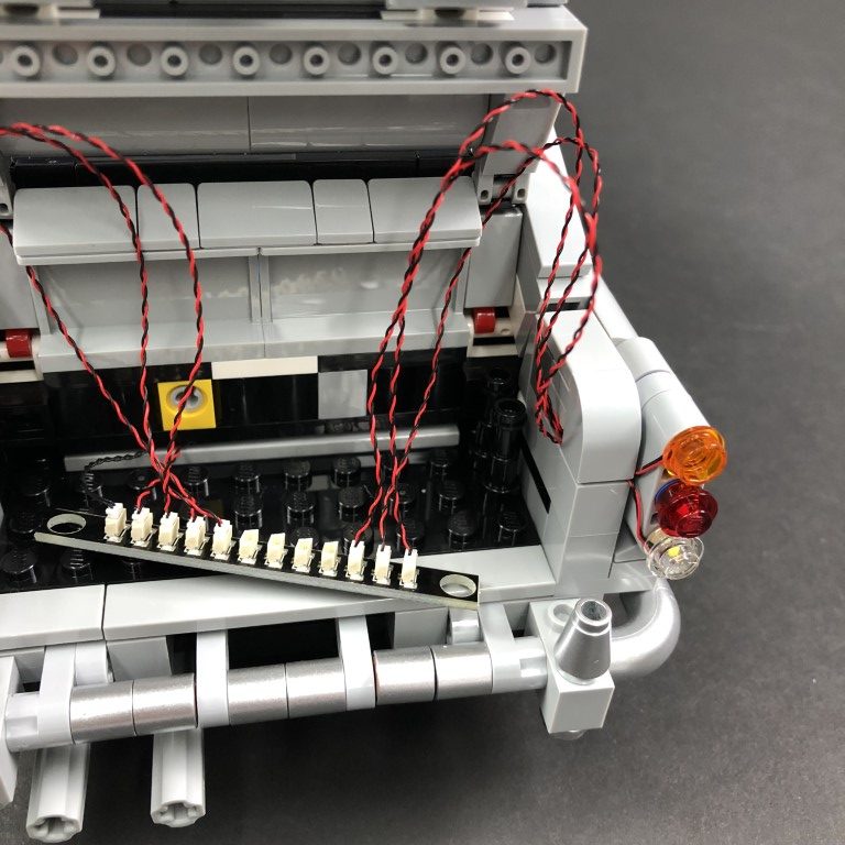
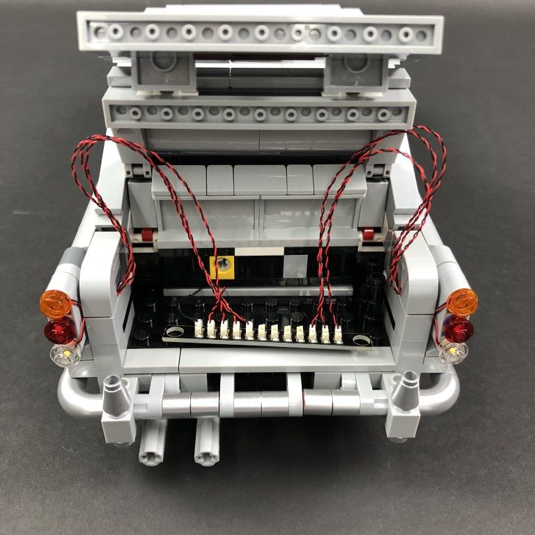
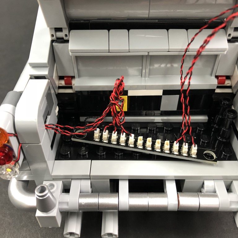
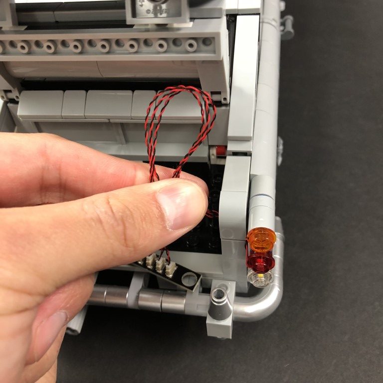
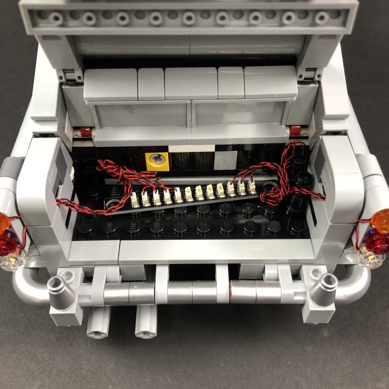
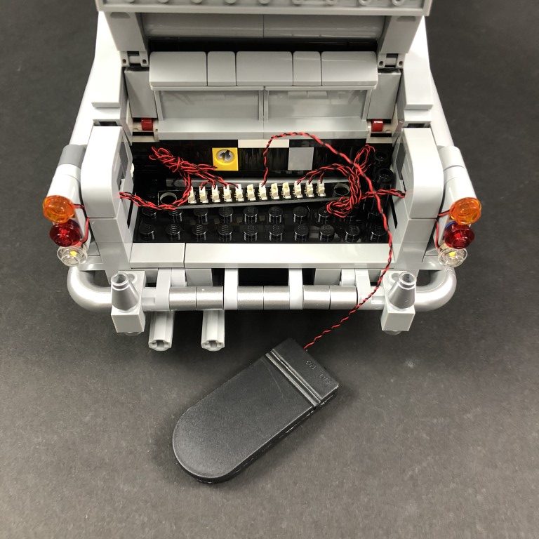
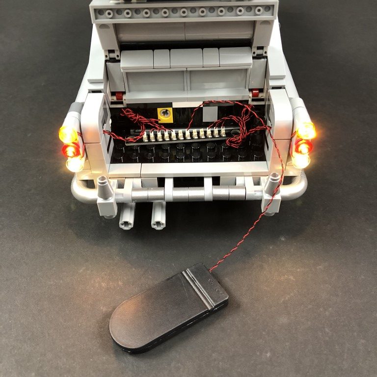
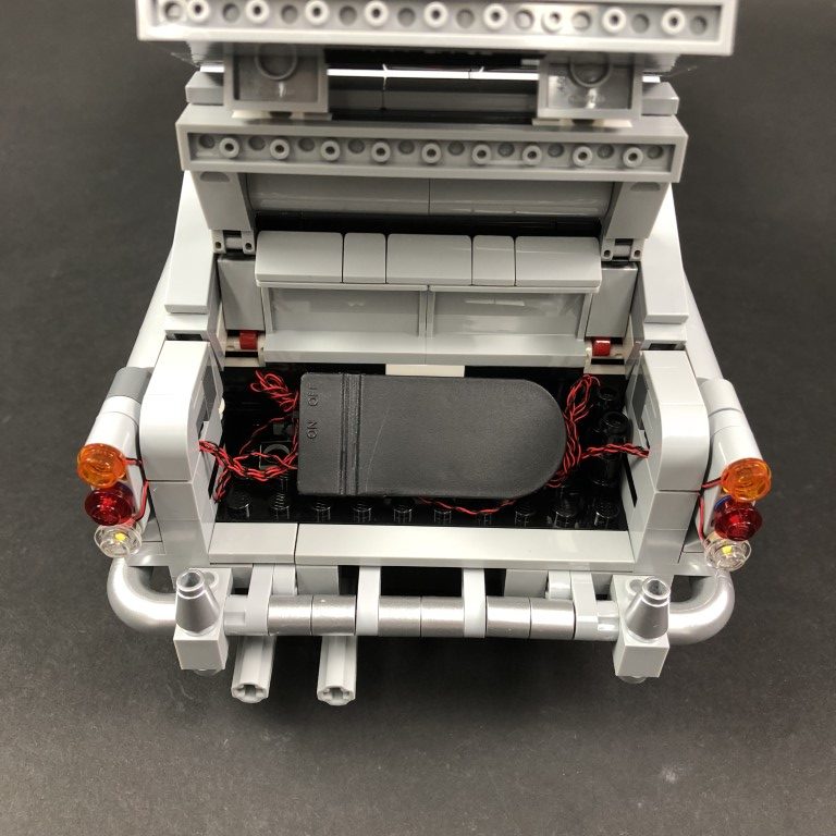
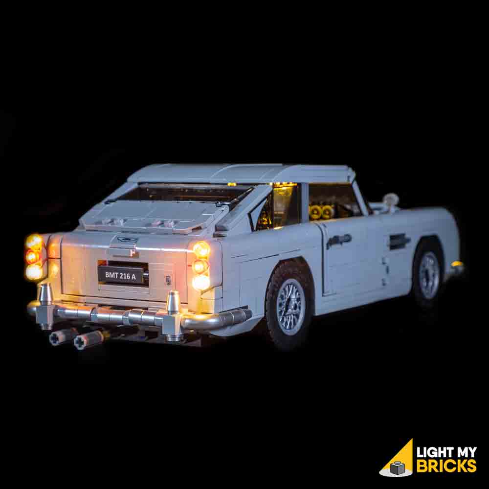
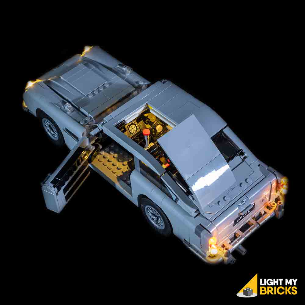